
Configuración de Avaya IP Office™ Platform ... - Avaya Support
Upload
khangminh22Category
view
1download
0
Administering Avaya G450 BranchGateway
Release 8.1.xIssue 8
January 2021

© 2010-2021, Avaya Inc.All Rights Reserved.
NoticeWhile reasonable efforts have been made to ensure that theinformation in this document is complete and accurate at the time ofprinting, Avaya assumes no liability for any errors. Avaya reservesthe right to make changes and corrections to the information in thisdocument without the obligation to notify any person or organizationof such changes.WarrantyAvaya provides a limited warranty on Avaya hardware and software.Refer to your sales agreement to establish the terms of the limitedwarranty. In addition, Avaya’s standard warranty language, as well asinformation regarding support for this product while under warranty isavailable to Avaya customers and other parties through the AvayaSupport website: https://support.avaya.com/helpcenter/getGenericDetails?detailId=C20091120112456651010 under the link“Warranty & Product Lifecycle” or such successor site as designatedby Avaya. Please note that if You acquired the product(s) from anauthorized Avaya Channel Partner outside of the United States andCanada, the warranty is provided to You by said Avaya ChannelPartner and not by Avaya.Third Party Components“Third Party Components” mean certain software programs orportions thereof included in the Software or Hosted Service maycontain software (including open source software) distributed underthird party agreements (“Third Party Components”), which containterms regarding the rights to use certain portions of the Software(“Third Party Terms”). As required, information regarding distributedLinux OS source code (for those products that have distributed LinuxOS source code) and identifying the copyright holders of the ThirdParty Components and the Third Party Terms that apply is availablein the products, Documentation or on Avaya’s website at: https://support.avaya.com/Copyright or such successor site as designatedby Avaya. The open source software license terms provided as ThirdParty Terms are consistent with the license rights granted in theseSoftware License Terms, and may contain additional rights benefitingYou, such as modification and distribution of the open sourcesoftware. The Third Party Terms shall take precedence over theseSoftware License Terms, solely with respect to the applicable ThirdParty Components to the extent that these Software License Termsimpose greater restrictions on You than the applicable Third PartyTerms.Preventing Toll Fraud“Toll Fraud” is the unauthorized use of your telecommunicationssystem by an unauthorized party (for example, a person who is not acorporate employee, agent, subcontractor, or is not working on yourcompany's behalf). Be aware that there can be a risk of Toll Fraudassociated with your system and that, if Toll Fraud occurs, it canresult in substantial additional charges for your telecommunicationsservices.Avaya Toll Fraud interventionIf You suspect that You are being victimized by Toll Fraud and Youneed technical assistance or support, call Technical Service CenterToll Fraud Intervention Hotline at +1-800-643-2353 for the UnitedStates and Canada. For additional support telephone numbers, seethe Avaya Support website: https://support.avaya.com or suchsuccessor site as designated by Avaya.Documentation disclaimer“Documentation” means information published in varying mediumswhich may include product information, operating instructions andperformance specifications that are generally made available to usersof products. Documentation does not include marketing materials.Avaya shall not be responsible for any modifications, additions, ordeletions to the original published version of Documentation unlesssuch modifications, additions, or deletions were performed by or onthe express behalf of Avaya. End User agrees to indemnify and holdharmless Avaya, Avaya's agents, servants and employees against allclaims, lawsuits, demands and judgments arising out of, or inconnection with, subsequent modifications, additions or deletions tothis documentation, to the extent made by End User.
Link disclaimerAvaya is not responsible for the contents or reliability of any linkedwebsites referenced within this site or Documentation provided byAvaya. Avaya is not responsible for the accuracy of any information,statement or content provided on these sites and does notnecessarily endorse the products, services, or information describedor offered within them. Avaya does not guarantee that these links willwork all the time and has no control over the availability of the linkedpages.LicensesTHE SOFTWARE LICENSE TERMS AVAILABLE ON THE AVAYAWEBSITE, HTTPS://SUPPORT.AVAYA.COM/LICENSEINFO,UNDER THE LINK “AVAYA SOFTWARE LICENSE TERMS (AvayaProducts)” OR SUCH SUCCESSOR SITE AS DESIGNATED BYAVAYA, ARE APPLICABLE TO ANYONE WHO DOWNLOADS,USES AND/OR INSTALLS AVAYA SOFTWARE, PURCHASEDFROM AVAYA INC., ANY AVAYA AFFILIATE, OR AN AVAYACHANNEL PARTNER (AS APPLICABLE) UNDER A COMMERCIALAGREEMENT WITH AVAYA OR AN AVAYA CHANNEL PARTNER.UNLESS OTHERWISE AGREED TO BY AVAYA IN WRITING,AVAYA DOES NOT EXTEND THIS LICENSE IF THE SOFTWAREWAS OBTAINED FROM ANYONE OTHER THAN AVAYA, AN AVAYAAFFILIATE OR AN AVAYA CHANNEL PARTNER; AVAYARESERVES THE RIGHT TO TAKE LEGAL ACTION AGAINST YOUAND ANYONE ELSE USING OR SELLING THE SOFTWAREWITHOUT A LICENSE. BY INSTALLING, DOWNLOADING ORUSING THE SOFTWARE, OR AUTHORIZING OTHERS TO DO SO,YOU, ON BEHALF OF YOURSELF AND THE ENTITY FOR WHOMYOU ARE INSTALLING, DOWNLOADING OR USING THESOFTWARE (HEREINAFTER REFERRED TOINTERCHANGEABLY AS “YOU” AND “END USER”), AGREE TOTHESE TERMS AND CONDITIONS AND CREATE A BINDINGCONTRACT BETWEEN YOU AND AVAYA INC. OR THEAPPLICABLE AVAYA AFFILIATE (“AVAYA”).Avaya grants You a license within the scope of the license typesdescribed below, with the exception of Heritage Nortel Software, forwhich the scope of the license is detailed below. Where the orderdocumentation does not expressly identify a license type, theapplicable license will be a Designated System License as set forthbelow in the Designated System(s) License (DS) section asapplicable. The applicable number of licenses and units of capacityfor which the license is granted will be one (1), unless a differentnumber of licenses or units of capacity is specified in thedocumentation or other materials available to You. “Software” meanscomputer programs in object code, provided by Avaya or an AvayaChannel Partner, whether as stand-alone products, pre-installed onhardware products, and any upgrades, updates, patches, bug fixes,or modified versions thereto. “Designated Processor” means a singlestand-alone computing device. “Server” means a set of DesignatedProcessors that hosts (physically or virtually) a software applicationto be accessed by multiple users. “Instance” means a single copy ofthe Software executing at a particular time: (i) on one physicalmachine; or (ii) on one deployed software virtual machine (“VM”) orsimilar deployment.License typesDesignated System(s) License (DS). End User may install and useeach copy or an Instance of the Software only on a number ofDesignated Processors up to the number indicated in the order.Avaya may require the Designated Processor(s) to be identified inthe order by type, serial number, feature key, Instance, location orother specific designation, or to be provided by End User to Avayathrough electronic means established by Avaya specifically for thispurpose.Heritage Nortel Software“Heritage Nortel Software” means the software that was acquired byAvaya as part of its purchase of the Nortel Enterprise SolutionsBusiness in December 2009. The Heritage Nortel Software is thesoftware contained within the list of Heritage Nortel Products locatedat https://support.avaya.com/LicenseInfo under the link “HeritageNortel Products” or such successor site as designated by Avaya. ForHeritage Nortel Software, Avaya grants Customer a license to useHeritage Nortel Software provided hereunder solely to the extent ofthe authorized activation or authorized usage level, solely for thepurpose specified in the Documentation, and solely as embedded in,

for execution on, or for communication with Avaya equipment.Charges for Heritage Nortel Software may be based on extent ofactivation or use authorized as specified in an order or invoice.CopyrightExcept where expressly stated otherwise, no use should be made ofmaterials on this site, the Documentation, Software, Hosted Service,or hardware provided by Avaya. All content on this site, thedocumentation, Hosted Service, and the product provided by Avayaincluding the selection, arrangement and design of the content isowned either by Avaya or its licensors and is protected by copyrightand other intellectual property laws including the sui generis rightsrelating to the protection of databases. You may not modify, copy,reproduce, republish, upload, post, transmit or distribute in any wayany content, in whole or in part, including any code and softwareunless expressly authorized by Avaya. Unauthorized reproduction,transmission, dissemination, storage, and or use without the expresswritten consent of Avaya can be a criminal, as well as a civil offenseunder the applicable law.VirtualizationThe following applies if the product is deployed on a virtual machine.Each product has its own ordering code and license types. Unlessotherwise stated, each Instance of a product must be separatelylicensed and ordered. For example, if the end user customer orAvaya Channel Partner would like to install two Instances of thesame type of products, then two products of that type must beordered.How to Get HelpFor additional support telephone numbers, go to the Avaya supportWebsite: http://www.avaya.com/support. If you are:
• Within the United States, click the Escalation Contacts linkthat is located under the Support Tools heading. Then click theappropriate link for the type of support that you need.
• Outside the United States, click the Escalation Contacts linkthat is located under the Support Tools heading. Then click theInternational Services link that includes telephone numbers forthe international Centers of Excellence.
Providing Telecommunications SecurityTelecommunications security (of voice, data, and/or videocommunications) is the prevention of any type of intrusion to (that is,either unauthorized or malicious access to or use of) your company'stelecommunications equipment by some party.Your company's “telecommunications equipment” includes both thisAvaya product and any other voice/data/video equipment that couldbe accessed via this Avaya product (that is, “networked equipment”).An “outside party” is anyone who is not a corporate employee, agent,subcontractor, or is not working on your company's behalf. Whereas,a “malicious party” is anyone (including someone who may beotherwise authorized) who accesses your telecommunicationsequipment with either malicious or mischievous intent.Such intrusions may be either to/through synchronous (time-multiplexed and/or circuit-based), or asynchronous (character-,message-, or packet-based) equipment, or interfaces for reasons of:
• Utilization (of capabilities special to the accessed equipment)• Theft (such as, of intellectual property, financial assets, or toll
facility access)• Eavesdropping (privacy invasions to humans)• Mischief (troubling, but apparently innocuous, tampering)• Harm (such as harmful tampering, data loss or alteration,
regardless of motive or intent)
Be aware that there may be a risk of unauthorized intrusionsassociated with your system and/or its networked equipment. Alsorealize that, if such an intrusion should occur, it could result in avariety of losses to your company (including but not limited to,human/data privacy, intellectual property, material assets, financialresources, labor costs, and/or legal costs).Responsibility for Your Company’s TelecommunicationsSecurityThe final responsibility for securing both this system and itsnetworked equipment rests with you - Avaya’s customer system
administrator, your telecommunications peers, and your managers.Base the fulfillment of your responsibility on acquired knowledge andresources from a variety of sources including but not limited to:
• Installation documents
• System administration documents
• Security documents
• Hardware-/software-based security tools
• Shared information between you and your peers
• Telecommunications security experts
To prevent intrusions to your telecommunications equipment, you andyour peers should carefully program and configure:
• Your Avaya-provided telecommunications systems and theirinterfaces
• Your Avaya-provided software applications, as well as theirunderlying hardware/software platforms and interfaces
• Any other equipment networked to your Avaya products
TCP/IP FacilitiesCustomers may experience differences in product performance,reliability and security depending upon network configurations/designand topologies, even when the product performs as warranted.Product Safety StandardsThis product complies with and conforms to the followinginternational Product Safety standards as applicable:
• IEC 60950-1 latest edition, including all relevant nationaldeviations as listed in the IECEE Bulletin—Product CategoryOFF: IT and Office Equipment.
• CAN/CSA-C22.2 No. 60950-1 / UL 60950-1 latest edition.
This product may contain Class 1 laser devices.
• Class 1 Laser Product
• Luokan 1 Laserlaite
• Klass 1 Laser Apparat
Electromagnetic Compatibility (EMC) StandardsThis product complies with and conforms to the followinginternational EMC standards, as applicable:
• CISPR 22, including all national standards based on CISPR22.
• CISPR 24, including all national standards based on CISPR24.
• IEC 61000-3-2 and IEC 61000-3-3.
Avaya Inc. is not responsible for any radio or television interferencecaused by unauthorized modifications of this equipment or thesubstitution or attachment of connecting cables and equipment otherthan those specified by Avaya Inc. The correction of interferencecaused by such unauthorized modifications, substitution orattachment will be the responsibility of the user. Pursuant to Part 15of the Federal Communications Commission (FCC) Rules, the user iscautioned that changes or modifications not expressly approved byAvaya Inc. could void the user’s authority to operate this equipment.Federal Communications Commission Part 15 Statement:For a Class A digital device or peripheral:
Note:This equipment has been tested and found to comply with thelimits for a Class A digital device, pursuant to Part 15 of theFCC Rules. These limits are designed to provide reasonableprotection against harmful interference when the equipment isoperated in a commercial environment. This equipmentgenerates, uses, and can radiate radio frequency energy and, ifnot installed and used in accordance with the instructionmanual, may cause harmful interference to radio

communications. Operation of this equipment in a residentialarea is likely to cause harmful interference in which case theuser will be required to correct the interference at his ownexpense.
For a Class B digital device or peripheral:
Note:This equipment has been tested and found to comply with thelimits for a Class B digital device, pursuant to Part 15 of theFCC Rules. These limits are designed to provide reasonableprotection against harmful interference in a residentialinstallation. This equipment generates, uses, and can radiateradio frequency energy and, if not installed and used inaccordance with the instruction manual, may cause harmfulinterference to radio communications. However, there is noguarantee that interference will not occur in a particularinstallation. If this equipment does cause harmful interferenceto radio or television reception, which can be determined byturning the equipment off and on, the user is encouraged to tryto correct the interference by one or more of the followingmeasures:
• Reorient or relocate the receiving antenna.
• Increase the separation between the equipment andreceiver.
• Connect the equipment into an outlet on a circuitdifferent from that to which the receiver is connected.
• Consult the dealer or an experienced radio/TVtechnician for help.
Equipment With Direct Inward Dialing (“DID”):Allowing this equipment to be operated in such a manner as to notprovide proper answer supervision is a violation of Part 68 of theFCC’s rules.Proper Answer Supervision is when:
1. This equipment returns answer supervision to the publicswitched telephone network (PSTN) when DID calls are:
• answered by the called station,
• answered by the attendant,
• routed to a recorded announcement that can beadministered by the customer premises equipment(CPE) user
• routed to a dial prompt
2. This equipment returns answer supervision signals on all(DID) calls forwarded back to the PSTN.
Permissible exceptions are:
• A call is unanswered
• A busy tone is received
• A reorder tone is received
Avaya attests that this registered equipment is capable of providingusers access to interstate providers of operator services through theuse of access codes. Modification of this equipment by callaggregators to block access dialing codes is a violation of theTelephone Operator Consumers Act of 1990.Automatic Dialers:When programming emergency numbers and (or) making test calls toemergency numbers:
• Remain on the line and briefly explain to the dispatcher thereason for the call.
• Perform such activities in the off-peak hours, such as earlymorning or late evenings.
Toll Restriction and least Cost Routing Equipment:The software contained in this equipment to allow user access to thenetwork must be upgraded to recognize newly established networkarea codes and exchange codes as they are placed into service.
Failure to upgrade the premises systems or peripheral equipment torecognize the new codes as they are established will restrict thecustomer and the customer’s employees from gaining access to thenetwork and to these codes.For equipment approved prior to July 23, 2001:This equipment complies with Part 68 of the FCC rules. On either therear or inside the front cover of this equipment is a label thatcontains, among other information, the FCC registration number, andringer equivalence number (REN) for this equipment. If requested,this information must be provided to the telephone company.For equipment approved after July 23, 2001:This equipment complies with Part 68 of the FCC rules and therequirements adopted by the Administrative Council on TerminalAttachments (ACTA). On the rear of this equipment is a label thatcontains, among other information, a product identifier in the formatUS:AAAEQ##TXXX. If requested, this number must be provided tothe telephone company.The REN is used to determine the quantity of devices that may beconnected to the telephone line. Excessive RENs on the telephoneline may result in devices not ringing in response to an incoming call.In most, but not all areas, the sum of RENs should not exceed 5.0.L’indice d’équivalence de la sonnerie (IES) sert à indiquer le nombremaximal de terminaux qui peuvent être raccordés à une interfacetéléphonique. La terminaison d’une interface peut consister en unecombinaison quelconque de dispositifs, à la seule condition que lasomme d’indices d’équivalence de la sonnerie de tous les dispositifsn’excède pas cinq.To be certain of the number of devices that may be connected to aline, as determined by the total RENs, contact the local telephonecompany. For products approved after July 23, 2001, the REN for thisproduct is part of the product identifier that has the formatUS:AAAEQ##TXXX. The digits represented by ## are the RENwithout a decimal point (for example, 03 is a REN of 0.3). For earlierproducts, the REN is separately shown on the label.Means of Connection:Connection of this equipment to the telephone network is shown inthe following table:
Manufacturer’s PortIdentifier
FIC Code SOC/ REN/A.S. Code
NetworkJacks
Offpremisesstation
OL13C 9.0F RJ2GX,RJ21X,RJ11C
DID trunk 02RV2.T AS.2 RJ2GX,RJ21X,RJ11C
CO trunk 02GS2 0.3A RJ21X,RJ11C
02LS2 0.3A RJ21X,RJ11C
Tie trunk TL31M 9.0F RJ2GXBasic RateInterface
02IS5 6.0F, 6.0Y RJ49C
1.544digitalinterface
04DU9.BN 6.0F RJ48C,RJ48M
04DU9.1KN
6.0F RJ48C,RJ48M
04DU9.1SN
6.0F RJ48C,RJ48M
120A4channelservice unit
04DU9.DN 6.0Y RJ48C
If this equipment causes harm to the telephone network, thetelephone company will notify you in advance that temporarydiscontinuance of service may be required. But if advance notice isnot practical, the telephone company will notify the customer as soon

as possible. Also, you will be advised of your right to file a complaintwith the FCC if you believe it is necessary.The telephone company may make changes in its facilities,equipment, operations or procedures that could affect the operationof the equipment. If this happens, the telephone company will provideadvance notice in order for you to make necessary modifications tomaintain uninterrupted service.If trouble is experienced with this equipment, for repair or warrantyinformation, please contact the Technical Service Center at1-800-242- 2121 or contact your local Avaya representative. If theequipment is causing harm to the telephone network, the telephonecompany may request that you disconnect the equipment until theproblem is resolved.A plug and jack used to connect this equipment to the premiseswiring and telephone network must comply with the applicable FCCPart 68 rules and requirements adopted by the ACTA. A complianttelephone cord and modular plug is provided with this product. It isdesigned to be connected to a compatible modular jack that is alsocompliant.Connection to party line service is subject to state tariffs. Contact thestate public utility commission, public service commission orcorporation commission for information.Installation and RepairsBefore installing this equipment, users should ensure that it ispermissible to be connected to the facilities of the localtelecommunications company. The equipment must also be installedusing an acceptable method of connection. The customer should beaware that compliance with the above conditions may not preventdegradation of service in some situations.Repairs to certified equipment should be coordinated by arepresentative designated by the supplier. It is recommended thatrepairs be performed by Avaya certified technicians.FCC Part 68 Supplier’s Declarations of ConformityAvaya Inc. in the United States of America hereby certifies that theequipment described in this document and bearing a TIA TSB-168label identification number complies with the FCC’s Rules andRegulations 47 CFR Part 68, and the Administrative Council onTerminal Attachments (ACTA) adopted technical criteria.Avaya further asserts that Avaya handset-equipped terminalequipment described in this document complies with Paragraph68.316 of the FCC Rules and Regulations defining Hearing AidCompatibility and is deemed compatible with hearing aids.Copies of SDoCs signed by the Responsible Party in the U. S. canbe obtained by contacting your local sales representative and areavailable on the following Web site: http://support.avaya.com/DoC.Canadian Conformity InformationThis Class A (or B) digital apparatus complies with CanadianICES-003.Cet appareil numérique de la classe A (ou B) est conforme à lanorme NMB-003 du Canada.This product meets the applicable Industry Canada technicalspecifications/Le présent materiel est conforme aux specificationstechniques applicables d’Industrie Canada.European Union Declarations of Conformity
Avaya Inc. declares that the equipment specified in this documentbearing the "CE" (Conformité Europeénne) mark conforms to theEuropean Union Radio and Telecommunications Terminal EquipmentDirective (1999/5/EC), including the Electromagnetic CompatibilityDirective (2004/108/EC) and Low Voltage Directive (2006/95/EC).Copies of these Declarations of Conformity (DoCs) can be obtainedby contacting your local sales representative and are available on thefollowing Web site: http://support.avaya.com/DoC.
European Union Battery Directive
Avaya Inc. supports European Union Battery Directive 2006/66/EC.Certain Avaya Inc. products contain lithium batteries. These batteriesare not customer or field replaceable parts. Do not disassemble.Batteries may pose a hazard if mishandled.JapanThe power cord set included in the shipment or associated with theproduct is meant to be used with the said product only. Do not usethe cord set for any other purpose. Any non-recommended usagecould lead to hazardous incidents like fire disaster, electric shock,and faulty operation.
If this is a Class A device:This is a Class A product based on the standard of the VoluntaryControl Council for Interference by Information TechnologyEquipment (VCCI). If this equipment is used in a domesticenvironment, radio disturbance may occur, in which case, the usermay be required to take corrective actions.
If this is a Class B device:This is a Class B product based on the standard of the VoluntaryControl Council for Interference from Information TechnologyEquipment (VCCI). If this is used near a radio or television receiver ina domestic environment, it may cause radio interference. Install anduse the equipment according to the instruction manual.
TrademarksThe trademarks, logos and service marks (“Marks”) displayed in thissite, the Documentation, Hosted Service(s), and product(s) providedby Avaya are the registered or unregistered Marks of Avaya, itsaffiliates, its licensors, its suppliers, or other third parties. Users arenot permitted to use such Marks without prior written consent fromAvaya or such third party which may own the Mark. Nothingcontained in this site, the Documentation, Hosted Service(s) andproduct(s) should be construed as granting, by implication, estoppel,or otherwise, any license or right in and to the Marks without theexpress written permission of Avaya or the applicable third party.Avaya is a registered trademark of Avaya Inc.All non-Avaya trademarks are the property of their respective owners.Linux® is the registered trademark of Linus Torvalds in the U.S. andother countries.Downloading DocumentationFor the most current versions of Documentation, see the AvayaSupport website: https://support.avaya.com, or such successor siteas designated by Avaya.Contact Avaya SupportSee the Avaya Support website: https://support.avaya.com forproduct or Hosted Service notices and articles, or to report a problemwith your Avaya product or Hosted Service. For a list of supporttelephone numbers and contact addresses, go to the Avaya Support

website: https://support.avaya.com (or such successor site asdesignated by Avaya), scroll to the bottom of the page, and selectContact Avaya Support.
Contents
Chapter 1: Introduction.......................................................................................................... 22Purpose................................................................................................................................ 22Change history...................................................................................................................... 22
Chapter 2: Configurations...................................................................................................... 23Basic configuration................................................................................................................ 23Port redundancy configuration................................................................................................ 23Port and switch redundancy configuration............................................................................... 24RSTP configuration............................................................................................................... 24RSTP and switch redundancy configuration............................................................................. 25
Chapter 3: Configuration overview....................................................................................... 26Defining the Console interface................................................................................................ 26Defining the USB-modem interface......................................................................................... 27Other interfaces.................................................................................................................... 27
Define other interfaces..................................................................................................... 27Configuration using CLI......................................................................................................... 28Configuration using GUI applications...................................................................................... 28
The Avaya IW................................................................................................................. 28The GIW......................................................................................................................... 28Avaya Gxxx Manager...................................................................................................... 29
Configuration changes and backup......................................................................................... 29Saving configuration changes and backing them up........................................................... 29
Firmware version control........................................................................................................ 30Using an older version of firmware.................................................................................... 30
Chapter 4: Branch Gateway access...................................................................................... 31CLI access............................................................................................................................ 31
Logging to CLI................................................................................................................ 31Disconnecting a Telnet session......................................................................................... 32CLI contexts.................................................................................................................... 32Using CLI help................................................................................................................ 32CLI access using the local network................................................................................... 33Accessing CLI using a computer....................................................................................... 33CLI access using modems............................................................................................... 34Accessing CLI using a USB modem.................................................................................. 34USB port settings............................................................................................................ 35Branch Gateway serial modems....................................................................................... 35Accessing the CLI using a modem connection to the S8300............................................... 36
CM access............................................................................................................................ 37Security overview.................................................................................................................. 37
Login permissions........................................................................................................... 37
January 2021 Administering Avaya G450 Branch Gateway 7Comments on this document? [email protected]

User account management.............................................................................................. 37Login authentication........................................................................................................ 41SSH protocol support....................................................................................................... 43SCP protocol support....................................................................................................... 45RADIUS authentication.................................................................................................... 45
Special security features........................................................................................................ 46Commands used to configure Telnet access...................................................................... 47Gateway secret management........................................................................................... 47DoS attacks.................................................................................................................... 48Managed Security Services.............................................................................................. 50
Enhanced Access Security Gateway (EASG).......................................................................... 55Managing EASG............................................................................................................. 55Viewing EASG product certificates.................................................................................... 58Managing EASG site certificates....................................................................................... 59Viewing EASG status....................................................................................................... 61Viewing product id........................................................................................................... 61
Service logins with Enhanced Access Security Gateway (EASG) authentication......................... 61Chapter 5: Basic device configuration................................................................................. 63
Defining an interface.............................................................................................................. 63Primary Management Interface (PMI) configuration.................................................................. 64
Setting the PMI of the Branch Gateway............................................................................. 64Active and configured PMI............................................................................................... 65PMI configuration CLI commands..................................................................................... 65
Example of defining a default gateway.................................................................................... 66Branch Gateway Controller configuration................................................................................. 67
Locating the Branch Gateway serial number...................................................................... 67Survivability and migration options.................................................................................... 67MGC list configuration..................................................................................................... 68About setting reset times.................................................................................................. 71Example for setting reset times......................................................................................... 71Accessing the registered MGC......................................................................................... 72H.248 Registration Source Port........................................................................................ 72ICC or Survivable Remote Server monitoring..................................................................... 73Summary of MGC list configuration commands.................................................................. 73
DNS resolver........................................................................................................................ 73DNS resolver features..................................................................................................... 74Typical DNS resolver application – VPN failover................................................................ 74Configuring DNS resolver................................................................................................. 75Using DNS resolver to resolve a hostname........................................................................ 78DNS resolver maintenance............................................................................................... 78DNS resolver configuration commands............................................................................. 78
Device status viewing............................................................................................................ 79The show mm command.................................................................................................. 79
Contents
January 2021 Administering Avaya G450 Branch Gateway 8Comments on this document? [email protected]

The show mm and show mg list config commands............................................................. 80Device status commands................................................................................................. 80
OOB..................................................................................................................................... 81oob-interface configuration............................................................................................... 81no oob-interface.............................................................................................................. 81show oob-interface.......................................................................................................... 81set non-oob-interfaces access.......................................................................................... 82
Software and firmware management....................................................................................... 82File transfer..................................................................................................................... 82Software and firmware upgrades...................................................................................... 82Software and firmware uploads from the gateway.............................................................. 86
Chapter 6: Standard Local Survivability (SLS).................................................................... 97Media module compatibility with SLS...................................................................................... 97SLS features......................................................................................................................... 98Avaya telephones supported in SLS........................................................................................ 98Call processing functionality in SLS mode............................................................................. 100Call processing functionality not supported by SLS................................................................ 101Provisioning data................................................................................................................. 101
Standard Local Survivability data sources and communication paths................................. 102SLS entry........................................................................................................................... 102
Unregistered state......................................................................................................... 103Setup state process....................................................................................................... 103Registered state process............................................................................................... 103Teardown state.............................................................................................................. 103
SLS interaction with specific Branch Gateway features........................................................... 104Direct Inward Dialing in SLS mode.................................................................................. 104Multiple call appearances in SLS mode........................................................................... 105Hold in SLS mode......................................................................................................... 105DCP and IP phones....................................................................................................... 106Using the Flash button................................................................................................... 106Using the switchhook button........................................................................................... 107Call Transfer in SLS mode............................................................................................. 107Using contact closure in SLS mode................................................................................. 109Administering IP Softphone in SLS mode........................................................................ 110
SLS logging activities........................................................................................................... 110Example of CDR log entries and format........................................................................... 111Example of CDR log with contact closure........................................................................ 112
SLS configuration................................................................................................................ 112SLS configuration rules.................................................................................................. 112Configuring CM for SLS................................................................................................. 113Inherited Class of Restriction (COR) permissions............................................................. 114Station screen field descriptions for the Branch Gateway.................................................. 115SLS ARS Entry page field descriptions............................................................................ 123
Contents
January 2021 Administering Avaya G450 Branch Gateway 9Comments on this document? [email protected]

Enabling SLS................................................................................................................ 124Disabling SLS............................................................................................................... 125Activating changes in SLS.............................................................................................. 125Prerequisites for using the CLI to manually configure SLS administration on the BranchGateway....................................................................................................................... 125DS1 circuit pack field descriptions................................................................................... 133Collecting signaling groups data..................................................................................... 137Signaling Group field descriptions................................................................................... 138Collecting administered ISDN-BRI trunks data................................................................. 138ISDN-BRI Trunk field descriptions................................................................................... 139Collecting Feature Access Codes data............................................................................ 140Feature Access Code field descriptions........................................................................... 141Collecting system parameters data................................................................................. 142Codecs supported in SLS............................................................................................... 143General system parameters field descriptions.................................................................. 143Collecting ARS dial patterns data.................................................................................... 143ARS Dial Patterns field descriptions................................................................................ 144Collecting Incoming Call Handling data........................................................................... 145Incoming call handling data field descriptions.................................................................. 145Configuration of the SLS data through the CLI................................................................. 146Creating the SLS administration data set on the Branch Gateway..................................... 147Administering station parameters.................................................................................... 149Class values in SLS station context................................................................................ 151Module-port values in SLS station configuration mode...................................................... 151Administering DS1 parameters....................................................................................... 152ISDN Layer 3 country codes........................................................................................... 154ISDN Layer 3 country protocols for ISDN Primary Rate service......................................... 155Administering BRI parameters........................................................................................ 156Trunk group assignment................................................................................................ 158Administering trunk-group parameters............................................................................. 158Maximum number of members in a trunk group............................................................... 163SLS group type assignments.......................................................................................... 163Module-port values in SLS trunk-group context for analog trunks...................................... 164Trunk port values in SLS trunk-group context for digital trunks.......................................... 164Administering signaling-group parameters....................................................................... 165Administering dial-pattern parameters............................................................................. 166Administering incoming-routing parameters..................................................................... 167Summary of SLS configuration commands...................................................................... 168
Chapter 7: Switch Ethernet port configuration.................................................................. 178Ethernet ports on the Gateway switch................................................................................... 178Ethernet ports on the Branch Gateway router........................................................................ 178Cables used for connecting devices to the fixed router........................................................... 178Roadmap for configuring switch Ethernet ports...................................................................... 179
Contents
January 2021 Administering Avaya G450 Branch Gateway 10Comments on this document? [email protected]

Summary of switch Ethernet port configuration CLI commands............................................... 179Configuring the WAN Ethernet port....................................................................................... 181
Roadmap for configuring additional features on the WAN Ethernet port............................. 181WAN Ethernet port traffic shaping................................................................................... 181About backup interfaces................................................................................................. 182Summary of WAN Ethernet port configuration CLI commands........................................... 182
DHCP client configuration.................................................................................................... 183DHCP client applications................................................................................................ 183Configuring the DHCP client........................................................................................... 184Examples of DHCP lease release and renew................................................................... 185Commands used for DHCP client maintenance................................................................ 186Examples of configuring DHCP client logging messages.................................................. 186Summary of DHCP client configuration CLI commands.................................................... 186
LLDP configuration.............................................................................................................. 187Supported TLVs............................................................................................................ 188Configuring LLDP.......................................................................................................... 189Summary of LLDP configuration CLI commands.............................................................. 190
Chapter 8: System logging.................................................................................................. 191Types of logging sinks......................................................................................................... 191Syslog server configuration.................................................................................................. 192
Defining Syslog servers................................................................................................. 192Disabling Syslog servers................................................................................................ 194Deleting Syslog servers................................................................................................. 194Displaying the status of the Syslog server....................................................................... 194Syslog sink default settings............................................................................................ 195Syslog message format................................................................................................. 195Commands used to copy a syslog file............................................................................. 195
Configuring a log file............................................................................................................ 196Disabling logging system messages to a log file............................................................... 196Deleting current log file and opening an empty log file...................................................... 196Log file message format................................................................................................. 197set logging file retention................................................................................................. 197show logging file retention.............................................................................................. 198
Configuring a session log..................................................................................................... 198Example discontinuation of the display of system messages............................................. 199Example display of session logging configuration............................................................. 199Session logging message format.................................................................................... 199
Logging filter configuration................................................................................................... 200Commands used to set the logging filters........................................................................ 200Severity levels............................................................................................................... 201Default sink severity levels............................................................................................. 201Application filtering........................................................................................................ 201Syslog server example................................................................................................... 203
Contents
January 2021 Administering Avaya G450 Branch Gateway 11Comments on this document? [email protected]

Log file example............................................................................................................ 203Session log example...................................................................................................... 203
Accessing diagnostic logs.................................................................................................... 204Summary of logging configuration CLI commands.................................................................. 205
Chapter 9: VoIP QoS............................................................................................................. 206RTP and RTCP configuration............................................................................................... 206Header compression configuration........................................................................................ 206
Header compression configuration options...................................................................... 207Header compression support by interface........................................................................ 207Configuring IPHC.......................................................................................................... 208Summary of IPHC header compression CLI commands................................................... 209Configuring VJ header compression............................................................................... 210Commands used to display and clear header compression statistics................................. 212
Commands used to configure QoS parameters...................................................................... 212Commands used to configure RTCP QoS parameters...................................................... 212Commands used to configure RSVP parameters............................................................. 212Summary of QoS, RSVP, and RTCP configuration CLI commands.................................... 213
Weighted Fair VoIP Queuing................................................................................................ 213Summary of WFVQ configuration CLI commands............................................................ 213
Priority queuing................................................................................................................... 214Summary of priority queueing configuration CLI commands.............................................. 215
Chapter 10: Modems and Branch Gateway........................................................................ 216USB-modem interface configuration...................................................................................... 216
Example of IP address to USB port assignment............................................................... 216The ppp authentication command parameters................................................................. 216Summary of CLI commands for configuring the USB port for modem use........................... 217
Console port and modem configuration................................................................................. 218Summary of CLI commands for configuring the Console port for modem use..................... 218
Chapter 11: WAN interfaces................................................................................................. 220Serial interface overview...................................................................................................... 220
Layer 1 T1 port with two channel groups......................................................................... 220E1/T1 port channel group............................................................................................... 221USP port using PPP protocol.......................................................................................... 221USP port using frame relay protocol................................................................................ 221Frame Relay multipoint topology support......................................................................... 222
Configuring the initial WAN................................................................................................... 222The Avaya MM340 E1/T1 WAN media module...................................................................... 223
Configuring Avaya MM340 E1/T1 WAN media module..................................................... 223E1/T1 default settings.................................................................................................... 225Commands used to reset and display controller counters................................................. 226Commands used to activate loopback mode on an E1/T1 line........................................... 226Summary of E1/T1 ports configuration commands........................................................... 226
Avaya MM342 USP WAN media module............................................................................... 228
Contents
January 2021 Administering Avaya G450 Branch Gateway 12Comments on this document? [email protected]

Configuring Avaya MM342 USP WAN media module....................................................... 228USP default settings...................................................................................................... 229Summary of USP port configuration commands............................................................... 229PPP configuration.......................................................................................................... 230PPPoE overview........................................................................................................... 231
Frame relay........................................................................................................................ 235Configuring frame relay.................................................................................................. 235Commands used to reset and display frame relay interface counters................................. 237Summary of frame relay commands................................................................................ 237
WAN configuration and testing connectivity........................................................................... 238Commands used for WAN configuration and testing connectivity....................................... 238Summary of WAN configuration verification commands.................................................... 239Backup interfaces.......................................................................................................... 240Modem dial backup....................................................................................................... 241
Modem dial backup logging messages.................................................................................. 253Dialer Messages........................................................................................................... 253Console messages........................................................................................................ 254USB Modem Messages................................................................................................. 255PPP Messages............................................................................................................. 256Summary of modem dial backup commands.................................................................... 257ICMP keepalive............................................................................................................. 258Dynamic CAC............................................................................................................... 261Object tracking.............................................................................................................. 263Frame relay encapsulation features................................................................................ 276Priority DLCI................................................................................................................. 278
Chapter 12: Emergency Transfer Relay.............................................................................. 283ETR state configuration....................................................................................................... 283
Activating ETR manually................................................................................................ 283Deactiving ETR manually............................................................................................... 284Restoring ETR to automatic activation............................................................................. 284
Summary of ETR commands................................................................................................ 284Chapter 13: SNMP................................................................................................................. 285
Agent and manager communication...................................................................................... 285SNMP versions................................................................................................................... 286
SNMPv1....................................................................................................................... 286SNMPv2c..................................................................................................................... 287SNMPv3....................................................................................................................... 287Users........................................................................................................................... 287Groups......................................................................................................................... 288Views........................................................................................................................... 289
SNMP trap configuration...................................................................................................... 290snmp-server host command parameters......................................................................... 290Notification types........................................................................................................... 291
Contents
January 2021 Administering Avaya G450 Branch Gateway 13Comments on this document? [email protected]

Summary of SNMP trap configuration commands............................................................ 292Summary of SNMP access configuration commands........................................................ 292
Dynamic trap manager......................................................................................................... 293Dynamic trap manager parameters................................................................................. 294Summary of dynamic trap manager configuration commands............................................ 294
SNMP configuration examples.............................................................................................. 294Chapter 14: Media encryption using AES-256................................................................... 297
Screen for administering Media encryption using AES-256..................................................... 297Administering Media encryption using AES-256..................................................................... 297Detailed description............................................................................................................. 298
Chapter 15: Encrypted SRTCP............................................................................................ 299Detailed description............................................................................................................. 299Encrypted SRTCP............................................................................................................... 299
Screen for administering Encrypted SRTCP.................................................................... 300Administering Encrypted SRTCP.................................................................................... 300
Interactions for Encrypted SRTCP........................................................................................ 300Chapter 16: Contact closure................................................................................................ 302
Configuring contact closure hardware................................................................................... 302Software contact closure...................................................................................................... 303
Contact closure modes.................................................................................................. 303Configuring contact closure software............................................................................... 303Showing contact closure status...................................................................................... 304Summary of contact closure commands.......................................................................... 304
Chapter 17: Announcement files......................................................................................... 305Uploading announcement files to a remote SCP server.......................................................... 305
Downloading announcement files from a remote SCP server............................................ 306Uploading announcement files to a remote FTP server........................................................... 306Downloading announcement files from an FTP server............................................................ 306Uploading an announcement file to a USB mass storage device............................................. 307Downloading an announcement file from a USB mass storage device..................................... 307Erasing an announcement file from the directory.................................................................... 307Renaming an announcement file in the directory.................................................................... 308Displaying the announcement files stored in the directory....................................................... 308Displaying the status of a download process.......................................................................... 308Displaying the status of an upload process............................................................................ 309Summary of announcement files commands.......................................................................... 309Dynamic time slots allocation............................................................................................... 310
Summary of dynamic time slots allocation commands...................................................... 310Chapter 18: Advanced switching......................................................................................... 311
VLAN configuration.............................................................................................................. 311VLAN Tagging............................................................................................................... 311Multi VLAN binding........................................................................................................ 312Gateway VLAN table..................................................................................................... 312
Contents
January 2021 Administering Avaya G450 Branch Gateway 14Comments on this document? [email protected]

Ingress VLAN Security................................................................................................... 313ICC-VLAN..................................................................................................................... 313Configuring ICC-VLAN................................................................................................... 313VLAN configuration examples........................................................................................ 314Summary of VLAN commands........................................................................................ 315
Port redundancy.................................................................................................................. 316Secondary port activation............................................................................................... 317Switchback................................................................................................................... 317Port redundancy configuration commands....................................................................... 317Port redundancy configuration examples......................................................................... 318Summary of port redundancy commands........................................................................ 318
Port mirroring...................................................................................................................... 319Port mirroring configuration examples............................................................................. 319Summary of port mirroring commands............................................................................. 319
Spanning tree..................................................................................................................... 320Spanning tree protocol................................................................................................... 320Spanning tree per port................................................................................................... 321Rapid Spanning Tree Protocol (RSTP)............................................................................ 321Spanning tree configuration examples............................................................................. 322Summary of spanning tree commands............................................................................ 324
Port classification................................................................................................................ 324Port classification configuration examples....................................................................... 325Summary of port classification commands....................................................................... 325
Chapter 19: Monitoring applications................................................................................... 326RMON................................................................................................................................ 326
RMON configuration examples....................................................................................... 326Summary of RMON commands...................................................................................... 328
RTP statistics...................................................................................................................... 328Configuring the RTP statistics application........................................................................ 329RTP statistics output...................................................................................................... 336RTP statistics examples................................................................................................. 349Summary of RTP statistics commands............................................................................ 358
Packet sniffing..................................................................................................................... 359What can be captured.................................................................................................... 360Roadmap for configuring packet sniffing.......................................................................... 360Configuring capture lists................................................................................................. 362Analyzing captured packets............................................................................................ 370About simulating packets............................................................................................... 374Summary of packet sniffing commands........................................................................... 374
Interface status reports........................................................................................................ 376Reporting of interface status........................................................................................... 377Summary of interface status commands.......................................................................... 377
Echo cancellation................................................................................................................ 377
Contents
January 2021 Administering Avaya G450 Branch Gateway 15Comments on this document? [email protected]

Summary of echo cancellation commands....................................................................... 378Integrated analog testing – Test and Heal.............................................................................. 379
Hardware support for integrated analog testing................................................................ 379Types of tests................................................................................................................ 379Types of test lines.......................................................................................................... 380Setting up a test profile.................................................................................................. 380Displaying and clearing profiles...................................................................................... 382Launching and cancelling a test...................................................................................... 382Displaying test results.................................................................................................... 382Healing trunks............................................................................................................... 383Displaying corrections.................................................................................................... 383Summary of integrated analog testing commands............................................................ 383
Service Level Agreement Monitor Agent................................................................................ 385Chapter 20: Router................................................................................................................ 386
Enabling and disabling the router.......................................................................................... 386Interface configuration......................................................................................................... 387
Router interface concepts.............................................................................................. 387Configuring an IP interface............................................................................................. 388Interface configuration examples.................................................................................... 389Summary of basic interface configuration commands....................................................... 389
Unnumbered IP interfaces.................................................................................................... 391Unnumbered IP on an interface configuration.................................................................. 391Configuring IP on an interface configuration.................................................................... 391Unnumbered IP examples.............................................................................................. 392Summary of unnumbered IP interface configuration commands........................................ 393
Routing sources.................................................................................................................. 393Routing table configuration................................................................................................... 394
Next hops..................................................................................................................... 394Static route types.......................................................................................................... 395Configuring multiple next hops........................................................................................ 395Deleting a route and its next hops................................................................................... 395Via-interface static route................................................................................................ 396Permanent static route................................................................................................... 396Discard routes............................................................................................................... 397Summary of routing table commands.............................................................................. 397
GRE tunneling.................................................................................................................... 398Packet routing to a GRE tunnel...................................................................................... 399Prevention of nested tunneling in GRE tunnels................................................................ 399Optional GRE tunnel features......................................................................................... 401Setting up a GRE tunnel................................................................................................ 403GRE tunnel application example..................................................................................... 404Summary of GRE tunneling commands........................................................................... 405
DHCP and BOOTP relay...................................................................................................... 407
Contents
January 2021 Administering Avaya G450 Branch Gateway 16Comments on this document? [email protected]

DHCP........................................................................................................................... 407BOOTP........................................................................................................................ 407DHCP/BOOTP relay...................................................................................................... 407Summary of DHCP and BOOTP relay commands............................................................ 408
DHCP server....................................................................................................................... 409Typical DHCP server application..................................................................................... 410Configuring the DHCP server......................................................................................... 410Deleting an IP address binding....................................................................................... 413DHCP pool configuration examples................................................................................. 413Commands for displaying DHCP server information......................................................... 415Summary of DHCP Server commands............................................................................ 415
Broadcast relay................................................................................................................... 417Directed broadcast forwarding........................................................................................ 417NetBIOS rebroadcast..................................................................................................... 417Summary of broadcast relay commands.......................................................................... 418
ARP table........................................................................................................................... 418Overview of ARP........................................................................................................... 418Static and dynamic table entries..................................................................................... 418Adding static ARP table entries...................................................................................... 419Removing static and dynamic entries.............................................................................. 420Changing an entry in the ARP table................................................................................ 420Summary of ARP table commands................................................................................. 420
Proxy ARP.......................................................................................................................... 421Summary of Proxy ARP commands................................................................................ 421
ICMP errors........................................................................................................................ 421Summary of ICMP errors commands.................................................................................... 421RIP.................................................................................................................................... 421
RIPv1........................................................................................................................... 422RIPv2........................................................................................................................... 422RIPv1 vs. RIPv2............................................................................................................ 422Prevention of routing loops in RIP................................................................................... 423Commands used to prevent routing loops in RIP.............................................................. 423RIP distribution access lists............................................................................................ 423Configuring a distribution access list example.................................................................. 423RIP limitations............................................................................................................... 424Summary of RIP commands........................................................................................... 424
OSPF................................................................................................................................. 426OSPF dynamic Cost...................................................................................................... 427OSPF limitations........................................................................................................... 427Summary of OSPF commands....................................................................................... 428
Route redistribution............................................................................................................. 430Export default metric...................................................................................................... 430Summary of route redistribution commands..................................................................... 431
Contents
January 2021 Administering Avaya G450 Branch Gateway 17Comments on this document? [email protected]

VRRP................................................................................................................................. 431VRRP configuration example.......................................................................................... 432Summary of VRRP commands....................................................................................... 433
Fragmentation..................................................................................................................... 434Summary of fragmentation commands............................................................................ 434
Chapter 21: IPSec VPN......................................................................................................... 435Overview of IPSec VPN configuration................................................................................... 435
IPSec VPN configuration model...................................................................................... 435Overview of IPSec VPN components.............................................................................. 436IPSec VPN components................................................................................................. 437Summary of configuration commands............................................................................. 437Site-to-site IPSec VPN................................................................................................... 439IPSec VPN maintenance................................................................................................ 454Typical installations for IPSec VPN................................................................................. 456
Typical failover applications.................................................................................................. 478Introduction to the failover mechanism............................................................................ 478VPN keepalives............................................................................................................. 479Backup peer mechanism................................................................................................ 479Failover using GRE....................................................................................................... 480Redundancy and load sharing modes............................................................................. 480Hub and spoke with hub redundancy/load sharing using GRE........................................... 481Configuring VPN hub redundancy and load sharing topologies using GRE......................... 481VPN hub redundancy and load sharing topologies........................................................... 482VPN hub redundancy and load sharing topologies example.............................................. 482Failover using DNS........................................................................................................ 485VPN DNS topology........................................................................................................ 486Configuring the VPN DNS topology................................................................................. 486VPN DNS topology example........................................................................................... 488Failover using a peer-group............................................................................................ 491Failover VPN topology using a peer-group....................................................................... 492Configuring the failover VPN topology using a peer-group................................................ 492Failover VPN topology using a peer-group example......................................................... 494Checklist for configuring site-to-site IPSec VPN............................................................... 497Summary of VPN commands......................................................................................... 500
Chapter 22: Policy lists........................................................................................................ 505Types of policy lists.............................................................................................................. 505
Access control lists........................................................................................................ 505QoS lists....................................................................................................................... 506QoS list parts................................................................................................................ 507Allowed values on QoS fields......................................................................................... 507Use of policy-based routing............................................................................................ 507
Policy list management........................................................................................................ 507Policy list configuration........................................................................................................ 508
Contents
January 2021 Administering Avaya G450 Branch Gateway 18Comments on this document? [email protected]

Creating or editing a policy list........................................................................................ 508Creating a list based on an existing list............................................................................ 509Defining list identification attributes................................................................................. 509Policy list attributes........................................................................................................ 510Default actions.............................................................................................................. 510Deleting a policy list....................................................................................................... 510
Policy list attachments......................................................................................................... 510Packets entering the interface......................................................................................... 511Packets exiting the interface........................................................................................... 511Policy lists to packets..................................................................................................... 511Policy list attachment configuration................................................................................. 511Attaching policy lists and access control lists................................................................... 512Attaching policy lists and QoS lists.................................................................................. 512Removing a list............................................................................................................. 512
Device-wide policy lists........................................................................................................ 513Defining global rules............................................................................................................ 513Policy rule configuration....................................................................................................... 514
Editing and creating rules............................................................................................... 515Policy lists rule criteria................................................................................................... 515
Composite operations.......................................................................................................... 519Pre-configured composite operations for access control lists............................................. 519Pre-configured composite operations for QoS lists........................................................... 520Configuring composite operations................................................................................... 521Adding composite operation to an IP rule........................................................................ 521Composite operation example........................................................................................ 522
DSCP table......................................................................................................................... 522Changing an entry in the DSCP table.............................................................................. 523
Policy list displays and tests................................................................................................. 523Policy list commands in context...................................................................................... 524Simulating packets........................................................................................................ 525Simulated packet properties........................................................................................... 525
Summary of access control list commands............................................................................ 526Summary of QoS list commands........................................................................................... 528
Chapter 23: Policy-based routing........................................................................................ 531Policy-based routing............................................................................................................ 531
Chapter 24: Synchronization............................................................................................... 533Defining a stratum clock source............................................................................................ 533Setting the synchronization source........................................................................................ 534Disassociating a clock source............................................................................................... 534Enabling and disabling automatic failover and failback........................................................... 535Synchronization status......................................................................................................... 535
Displaying synchronization status................................................................................... 535Summary of synchronization commands......................................................................... 536
Contents
January 2021 Administering Avaya G450 Branch Gateway 19Comments on this document? [email protected]

Chapter 25: TLS / Certificate Management......................................................................... 537TLS.................................................................................................................................... 537TLS certificate stores........................................................................................................... 537Certificate validation............................................................................................................ 538Mutual authentication........................................................................................................... 538
Chapter 26: Federal Information Processing Standards (FIPS)....................................... 539Federal Information Processing Standards............................................................................ 539FIPS Security Level of the Cryptographic Module................................................................... 539Determining FIPS Certified Firmware is installed.................................................................... 540FIPS Approved Mode of Operation....................................................................................... 540Prerequisites for entering FIPS Approved Mode..................................................................... 541Determining FIPS Approved Mode is enabled........................................................................ 541Determining Configuration is FIPS Compliant........................................................................ 541Backup and restore of Gateway configuration........................................................................ 542Before Enabling or Disabling FIPS Approved Mode................................................................ 542Enabling FIPS Approved Mode............................................................................................. 543Maintaining FIPS Approved Mode......................................................................................... 543Disabling FIPS Approved Mode............................................................................................ 543Administration procedures.................................................................................................... 543
FIPS-related CLI commands.......................................................................................... 544Non-compliant CLI Commands in FIPS Approved Mode................................................... 544Warnings for unencrypted communication in FIPS Approved Mode................................... 546Enabling FIPS Approved Mode....................................................................................... 546Disabling FIPS Approved Mode...................................................................................... 551
FIPS Error States and LED Status Indicators......................................................................... 555Power-up Testing.......................................................................................................... 555Error States.................................................................................................................. 555Zeroization Status during Error State 1............................................................................ 556
Chapter 27: Resources......................................................................................................... 557Branch Gateway documentation........................................................................................... 557
Finding documents on the Avaya Support website........................................................... 557Accessing the port matrix document................................................................................ 558Avaya Documentation Center navigation......................................................................... 558
Training.............................................................................................................................. 559Viewing Avaya Mentor videos............................................................................................... 560Support.............................................................................................................................. 560
Appendix A: Traps and MIBs............................................................................................... 561Branch Gateway traps......................................................................................................... 561Branch Gateway MIB files.................................................................................................... 574
MIB objects in the Load.MIB file...................................................................................... 575MIB objects in the RFC1315-MIB.my file......................................................................... 576MIB objects in the Q-BRIDGE-MIB.my file....................................................................... 577MIB objects in the ENTITY-MIB.my file............................................................................ 577
Contents
January 2021 Administering Avaya G450 Branch Gateway 20Comments on this document? [email protected]

MIB objects in the IP-FORWARD-MIB.my file.................................................................. 578MIB objects in the VRRP-MIB.my file.............................................................................. 579MIB objects in the UTILIZATION-MANAGEMENT-MIB.my file........................................... 579MIB objects in the ENTITY-SENSOR-MIB.my file............................................................. 580MIB objects in the RSTP-MIB.my file............................................................................... 580MIB objects in the APPLIC-MIB.my file............................................................................ 581MIB objects in the DS1-MIB.my file................................................................................. 581MIB objects in the PPP-IP-NCP-MIB.my file..................................................................... 583MIB objects in the RFC1213-MIB.my file......................................................................... 583MIB objects in the AVAYA-ENTITY-MIB.my file................................................................. 586MIB objects in the Rnd-MIB.my file................................................................................. 587MIB objects in the XSWITCH-MIB.my file........................................................................ 587MIB objects in the CROUTE-MIB.my file......................................................................... 588MIB objects in the RS-232-MIB.my file............................................................................ 590MIB objects in the RIPv2-MIB.my file.............................................................................. 591MIB objects in the IF-MIB.my file.................................................................................... 592MIB objects in the DS0BUNDLE-MIB.my file.................................................................... 593MIB objects in the RFC1406-MIB.my file......................................................................... 594MIB objects in the DS0-MIB.my file................................................................................. 595MIB objects in the POLICY-MIB.my file............................................................................ 596MIB objects in the BRIDGE-MIB.my file........................................................................... 600MIB objects in the CONFIG-MIB.my file........................................................................... 601MIB objects in the G700-MG-MIB.my file......................................................................... 604MIB objects in the FRAME-RELAY-DTE-MIB.my file......................................................... 608MIB objects in the IP-MIB.my file.................................................................................... 609MIB objects in the Load12-MIB.my file............................................................................ 610MIB objects in the PPP-LCP-MIB.my file.......................................................................... 611MIB objects in the WAN-MIB.my file................................................................................ 612MIB objects in the SNMPv2-MIB.my file.......................................................................... 613MIB objects in the OSPF-MIB.my file.............................................................................. 614MIB objects in the TUNNEL-MIB.my file.......................................................................... 617
Appendix B: ASG authentication........................................................................................ 618ASG authentication CLI commands...................................................................................... 618Replacing the ASG authentication file................................................................................... 618
Contents
January 2021 Administering Avaya G450 Branch Gateway 21Comments on this document? [email protected]

Chapter 1: Introduction
PurposeThis document describes how to set up, configure, and maintain Branch Gateway. It is intendedfor system administrators and support personnel.
Change historyThe following changes are made to this document since the last issue:
Issue Date Summary of changes8 January 2021 Updated the section: CM access on page 377 November 2020 Updated the section Configuring capture lists on page 362.6 October 2020 For Release 8.1.3, updated the following section:
• Configuration changes and backup on page 295 April 2020 Updated following sections:
• File transfer on page 82
• Example of an upgrade using SCP/FTP/TFTP on page 84
• Software and firmware management commands on page 87
• Replicating Branch Gateway using a USB mass-storage device onpage 91
• Defining Syslog servers on page 1924 March 2020 Added the logging file retention sections.3 October 2019 Updated the section about the status of PRI links.2 June 2019 Updated the SLA Monitor Agent and SNMP access configuration
sections.1 June 2019 Release 8.1 of the document.
January 2021 Administering Avaya G450 Branch Gateway 22Comments on this document? [email protected]

Chapter 2: Configurations
Basic configurationYou can deploy the Branch Gateway basic configuration in a LAN. The basic configuration doesnot support redundancy. You can connect Branch Gateway to an external LAN switch using one ofthe two Ethernet LAN ports located on the front panel of the gateway.
Port redundancy configurationYou can deploy the Branch Gateway port redundancy configuration in a LAN. You can connectBranch Gateway to an external LAN switch using both the Ethernet LAN ports located on the frontpanel of Branch Gateway.
Configure one of the ports on the Ethernet LAN as the active primary link and the other as thestandby, disabled link. When the gateway determines a primary link failure, the gatewayautomatically fails over to the secondary link. Both LAN ports of the peer LAN switch ports mustbe enabled for the gateway to fail over to the secondary link.
Related linksPort redundancy on page 316
January 2021 Administering Avaya G450 Branch Gateway 23Comments on this document? [email protected]

Port and switch redundancy configurationYou can deploy Branch Gateway in a LAN using the port and switch redundancy configuration.You can connect each LAN port on the front panel of Branch Gateway to two LAN switches.
Configure one of the ports on the Ethernet LAN as the active primary link and the other as thestandby, disabled link. When the gateway determines a primary link failure or malfunction of theswitch attached to it, the gateway automatically fails over to the secondary link to the backupswitch. Both LAN ports of the peer LAN switch ports must be enabled for the gateway to fail overto the secondary link.
Related linksPort redundancy on page 316
RSTP configurationYou can deploy Branch Gateway in a LAN using RSTP to provide redundancy. You can connecteach Ethernet LAN port on the front panel of the Branch Gateway to an external LAN switch.
A spanning tree protocol blocks one of the links from Branch Gateway to the external LAN switch.The spanning tree protocol must be configured on the external LAN switch and the Ethernet LANports on Branch Gateway. When the gateway determines a primary link failure, the gatewayautomatically fails over to the secondary link. Both LAN ports of the peer LAN switch ports mustbe enabled for the gateway to fail over to the secondary link.
Compared to port redundancy method, Fast RSTP is better because Fast RSTP controls the stateof the link between the gateway and the LAN switch based on the best LAN topology. However,Fast RSTP can have a time delay during RSTP convergence.
Configurations
January 2021 Administering Avaya G450 Branch Gateway 24Comments on this document? [email protected]

Related linksSpanning tree on page 320
RSTP and switch redundancy configurationYou can deploy Branch Gateway in a LAN using RSTP and switch redundancy configuration. Youcan connect each Ethernet LAN port on the front panel of the Branch Gateway to an external LANswitch.
Spanning tree protocol blocks one of the links from Branch Gateway to the external LAN switch.Spanning tree protocol must be configured on both the external LAN switch and the Ethernet LANports on the Branch Gateway. When the gateway determines a primary link failure or malfunctionof the switch attached to it, the gateway automatically fails over to the secondary link to thebackup switch. Both LAN ports of the peer LAN switch ports must be enabled for the gateway tofail over to the secondary link.
Compared to port redundancy method, Fast RSTP is better because Fast RSTP controls the stateof the link between the gateway and the LAN switch based on the best LAN topology. However,Fast RSTP can have a time delay during RSTP convergence.
Related linksSpanning tree on page 320
RSTP and switch redundancy configuration
January 2021 Administering Avaya G450 Branch Gateway 25Comments on this document? [email protected]

Chapter 3: Configuration overview
A new Branch Gateway has default configuration settings. Before using Branch Gateway, you mustconfigure certain items according to the system specifications. Configure other items depending onnetwork specifications.
A new Branch Gateway has three physical interfaces for management: Console interface, Servicesinterface, and USB-modem interface.
Configure Branch Gateway based on different access methods.
Defining the Console interfaceAbout this taskConfiguring an IP address to the Console interface is the first task of configuring a new BranchGateway instance. Configuring a subnet mask is optional.
Procedure1. Type interface console to enter the Console context.
2. Use the ip address command to define an IP address for the Console interface.
Note:
For more detailed installation instructions, including information on obtaining IPaddresses, refer to Installing and Upgrading Avaya G450 Media Gateway.
ExampleThe following example shows the configuration of 10.3.3.1 as the IP address of the Consoleinterface:Gxxx-001(super)# interface consoleGxxx-001(super-if:Console)# ip address 10.3.3.1Done!
January 2021 Administering Avaya G450 Branch Gateway 26Comments on this document? [email protected]

Defining the USB-modem interfaceAbout this taskConfigure an IP address to the USB-modem interface to connect to Branch Gateway using a USBmodem. Do not configure a subnet mask.
Procedure1. Type interface usb-modem to enter the USB-modem context.
2. Use the ip address command to define a new IP address for the USB-modem interface.
ExampleThe following example shows the configuration of 10.3.3.2 as the IP address of the USB-modeminterface:Gxxx-001(super)# interface usb-modemGxxx-001(super-if:USB-modem)# ip address 10.3.3.2Done!
The default IP address of the USB port is 10.3.248.253 255.255.255.252.
Other interfacesYour system specifications might require that you define other interfaces.
The Primary Management IP address (PMI) is the IP address assigned to Branch Gateway.Branch Gateway uses PMI for self-identification when communicating with other devices,particularly the Media Gateway Controller (MGC). Management data intended for the BranchGateway is routed to the interface defined as PMI. You can use any interface as the PMI. The PMIaddress can be IPv4 or IPv6.
The MGC is a call controller server that controls telephone services on the Branch Gateway. TheMGC can be internal or external and either IPv4 or IPv6.
Related linksDefining an interface on page 63
Define other interfacesYou can perform most Branch Gateway configuration tasks using the Branch Gateway CLI. Avayaalso provides several GUI applications using which you can perform the basic configuration tasksdescribed in this section. To define other interfaces, you must first define a PMI and then registerthe Branch Gateway with an MGC.
Defining the USB-modem interface
January 2021 Administering Avaya G450 Branch Gateway 27Comments on this document? [email protected]

After you have performed these steps, Branch Gateway is ready for use. You might have toperform other configuration tasks, but these tasks depend on the specifications of BranchGateway and the network.
Related linksPrimary Management Interface (PMI) configuration on page 64Branch Gateway Controller configuration on page 67
Configuration using CLIYou can use the Branch Gateway CLI to manage Branch Gateway. As the CLI is a commandprompt interface, you can type commands and view responses.
This guide contains information and examples about how to use CLI commands to configure theBranch Gateway.
For more information about the Branch Gateway CLI and a complete description of each CLIcommand, see Avaya Branch Gateway G450 CLI Reference.
Related linksCLI access on page 31
Configuration using GUI applicationsYou can perform some configuration tasks on Branch Gateway using Avaya GUI applications. Youcan use these applications for initial installation and provisioning.
The Avaya IWThe Avaya Installation Wizard (Avaya IW) is a Web-based installation wizard that leads the userthrough the key configuration steps of a Gateway installation. Use Avaya IW for initialconfiguration of a Media Gateway with S8300 installed as the Media Gateway’s primary (ICC) orbackup (LSP) call controller. For instructions on Gateway configuration the Avaya IW, seeInstallation of the Avaya Gateway.
The GIWThe Gateway Installation Wizard (GIW) is a standalone application that allows the user to performcertain basic Aura Media Gateway configuration tasks. Use GIW for initial configuration of an AuraMedia Gateway that does not have an S8300 installed as either the Aura Media Gateway’s
Configuration overview
January 2021 Administering Avaya G450 Branch Gateway 28Comments on this document? [email protected]

primary (ICC) or backup (LSP) call controller. For step-by-step instructions on how to configure theAura Media Gateway using the Avaya GIW, see Installation of the Avaya Media Gateway.
Avaya Gxxx ManagerYou can also use Avaya Gxxx Manager to configure most features of Branch Gateway. The AvayaGxxx Manager is a GUI application. You can access Avaya Gxxx Manager from the AvayaIntegrated Management software or from a web browser. Most of the commands that are availablethrough the Branch Gateway CLI are also available through Avaya Gxxx Manager.
Note:
Avaya Gxxx Manager supports SNMP over IPv4 only.
For more information about Avaya G450 Manager, see Avaya G450 Manager User Guide.
Configuration changes and backupWhen you make changes to the configuration of Branch Gateway, you must save the changes tomake them permanent. Branch Gateway has two sets of configuration information:
• Running configuration• Startup configuration
Branch Gateway operates according to the running configuration. When Branch Gateway is reset,Branch Gateway erases the running configuration and loads the startup configuration as the newrunning configuration. When you change the configuration of Branch Gateway, your changesaffect only the running configuration. If you do not save the changes and if Branch Gateway isreset, the changes are lost.
You can restore a backup copy of the configuration from the FTP or TFTP server or the USB flashdrive. When you restore the backup copy of the configuration, the backup copy becomes the newrunning configuration on the Branch Gateway.
Note:
In the FIPS mode, you can only restore from a backup that you perform on the same gateway.You cannot restore from a backup that you perform on a gateway that is in the non-FIPSmode.
Saving configuration changes and backing them upProcedure
1. To save changes to the configuration of the Branch Gateway, enter copy running-config startup-config
Configuration changes and backup
January 2021 Administering Avaya G450 Branch Gateway 29Comments on this document? [email protected]

A copy of the running configuration becomes the new startup configuration.
2. Back up either the running configuration or the startup configuration to an FTP, TFTP orSCP server on your network, or to a USB flash drive.
Firmware version controlFirmware is the software that runs Branch Gateway. Branch Gateway has two firmware banks:
• Bank A
• Bank B
Each firmware bank contains different versions of Branch Gateway firmware. The purpose ofproviding firmware banks is to provide firmware redundancy. You can save an old version of thefirmware for future use, for example, when uploading new versions.
Related linksSoftware and firmware upgrades on page 82
Using an older version of firmwareAbout this taskUse this procedure if you must use an older firmware version.
Procedure1. Enter set boot bank bank-x
2. Reset Branch Gateway to use the older version.
Configuration overview
January 2021 Administering Avaya G450 Branch Gateway 30Comments on this document? [email protected]

Chapter 4: Branch Gateway access
You can gain access to Branch Gateway using CLI and Avaya Aura® Communication Manager(CM). You can manage login permissions by either configuring username and password orconfiguring Branch Gateway to use RADIUS authentication.
Branch Gateway supports recovery of user passwords, Telnet connections, and SYN cookies toprevent SYN attacks.
CLI accessYou can use CLI, a command prompt interface, to configure Branch Gateway and media modules.
You can use the following methods to access CLI:
• A console device connected to the Console port
• SSH to establish a secure remote session with the network, Services port, or dial up PPPnetwork connection. SSH is enabled by default.
• Telnet connection with the network, Services port, or dial up PPP network connection. Telnetis disabled by default.
If you have a service contract with Avaya Services, Avaya Support engineers can connectremotely to service Branch Gateway with Telnet and SSH sessions. For higher security, you canconfigure Branch Gateway to authenticate remote service logins using the Enhanced AccessSecurity Gateway (EASG) authentication instead of the password authentication.
Logging to CLIProcedure
1. Log in to CLI with a username and password provided by your system administrator.
2. Use RADIUS authentication if your network has a RADIUS server.
Related linksLogin permissions on page 37
January 2021 Administering Avaya G450 Branch Gateway 31Comments on this document? [email protected]

Disconnecting a Telnet sessionProcedureIf you cannot log out from Telnet, press <Ctrl> +]ResultThe system disconnects the Telnet session.
CLI contextsCLI has various contexts. You can enter sets of related commands in these contexts. Contexts arenested in a hierarchy, with each context accessible from a parent context. The top level of the CLItree is called the general context. Each command has a related context. You can only use acommand in the proper context.
Entering the Loopback interfaceProcedureTo enter the Loopback interface context from the general context, enter the interfaceloopback 1 command.
Note:
When you are in the Loopback interface context, you can enter the Loopback interfacecommands. You can use the tree command to view the list of commands in each context
Using CLI helpAbout this taskThe help command or ? command displays the list of all CLI commands that you can use withinthe current context. The list includes a short explanation of each command.
ProcedureTo display the list of commands for the context you are in, type help or ?Specifically:
• You can view a list of all commands in the current context, which is similar to the command thatyou entered. You can accomplish the aforementioned by prefixing or postfixing the name of thecommand with help or ?.
For example, to view the list of IP commands available in the general context, enter help ip,ip help, ? ip, or ip ?.
Branch Gateway access
January 2021 Administering Avaya G450 Branch Gateway 32Comments on this document? [email protected]

• To view the syntax of the command and parameters along with an example of the command,you can prefix or postfix the name of the command with help or ?.
You must be in the context of the command to use the help command to display informationabout the respective command.
ExampleExample: The user enters the vlan 1 interface context and uses the help command to viewinformation about the bandwidth command.Gxxx-001(super)# interface vlan 1Gxxx-001(super-if:VLAN 1)# bandwidth ?Bandwidth commands:----------------------------------------------------------------------Syntax: bandwidth <kilobytes size> <kilobytes size> : integer (1-10000000)Example: bandwidth 1000
CLI access using the local networkYou can access CLI from a computer on the same local network as Branch Gateway by usingSSH or, if Telnet is active, any standard Telnet program. You can use the IP address of any BranchGateway interface as the host address.
Accessing CLI using a computerTo access CLI from a computer, connect the computer either to the Console port or to the Servicesport.
Alternatively, connect the PC device to the Console port on the front panel of the Branch Gateway.Use only an approved Avaya serial cable. For more information about approved Avaya serialcables, see Overview for the Avaya Branch Gateway G450.
Accessing Branch Gateway through the Services portProcedure
1. Use a computer with the SSH client software.
2. Use an Ethernet cable to connect the computer to the Services port located on the frontpanel of Branch Gateway.
3. Set the TCP/IP properties of the computer as follows:
a. IP address = 192.11.13.5
b. Subnet mask = 255.255.255.252
c. Disable DNS service
d. Disable WINS Resolution
CLI access
January 2021 Administering Avaya G450 Branch Gateway 33Comments on this document? [email protected]

Make a record of any IP addresses, DNS servers, or WINS entries that you change whenyou configure your laptop. Unless you use the NetSwitcher program or a similar program,you must restore these entries to connect to other networks.
4. Configure the Internet browser settings of the computer to disable the proxy server.
5. Set the IP address of SSH to 192.11.13.6.
Note:
By default, SSH is enabled and Telnet is disabled. If you wish to use Telnet, you mustenable it.
CLI access using modemsYou can use a dialup PPP network connection to access CLI from a remote location through anystandard SSH or Telnet program. You can use a USB modem connected to the USB port on thefront panel of the Branch Gateway or a serial modem connected to the Console port on the frontpanel of the Branch Gateway. You must only use an approved Avaya serial cable. For moreinformation about approved Avaya serial cables, see Overview for the Avaya Branch GatewayG450.
Related linksDisconnecting a Telnet session on page 32
Accessing CLI using a USB modemProcedure
1. Connect a modem to the USB port on the front panel of Branch Gateway.
Use a USB cable to connect the modem. Branch Gateway supports the MultitechMultiModem USB MT5634ZBA-USB-V92 and the USRobotics USB modem model 5637.
2. Ensure that the USB port is properly configured to be used with a modem.
3. From the remote computer, create a dialup network connection to Branch Gateway.
Use the TCP/IP and PPP protocols to create the connection. Configure the connectionaccording to the configuration of the COM port of the remote computer. By default, BranchGateway uses the RAS authentication. If your network has a RADIUS server, you can usethe RADIUS authentication for the PPP connection.
4. Open any standard SSH/Telnet program on the remote computer.
Note:
Telnet is disabled on Branch Gateway by default. To enable Telnet, use the iptelnet command.
Branch Gateway access
January 2021 Administering Avaya G450 Branch Gateway 34Comments on this document? [email protected]

5. Open an SSH/Telnet session that is mapped to the IP address of the USB port on BranchGateway.
To set the IP address of the USB port, that is, the USB-modem interface, use the ipaddress command.
6. Configure the serial connection on the remote computer to match the configuration of theUSB port on Branch Gateway.
Related linksUSB-modem interface configuration on page 216Login permissions on page 37Summary of CLI commands for configuring the USB port for modem use on page 217
USB port settings
Port setting ValueBaud -Data bits 8Parity noneStop bits 1flow control hardware
Branch Gateway serial modemsThe Branch Gateway supports the following serial modems:
• Multitech MultiModem ZBA, MT5634ZBA-V92.
• Multitech BRI-NT1 ISDN Modem w/ POTS, MTA128NT, for use in US and Canada.
• Multitech ISDN Modem w/ POTS, MTA128STBRI, for use in Europe and the rest of the world.The ISDN modems require DB-25 termination as well as the RJ-45 cable.
Accessing the CLI using a serial modemProcedure
1. Connect a modem to the Console port on the front panel of the Branch Gateway.
Use an RJ-45 serial cable to connect the modem.
2. Make sure the Console port is properly configured for modem use.
3. From the remote computer, create a dialup network connection to the Branch Gateway.
Use the TCP/IP and PPP protocols to create the connection. Configure the connectionaccording to the configuration of the COM port of the remote computer. By default, the
CLI access
January 2021 Administering Avaya G450 Branch Gateway 35Comments on this document? [email protected]

Branch Gateway uses PAP authentication. If your network has a RADIUS server, you canuse RADIUS authentication for the PPP connection.
4. Open any standard telnet program on the remote computer.
5. Open a telnet session to the IP address of the Console port on the Branch Gateway.
6. Configure the serial connection on the remote computer to match the configuration of theConsole port on the Branch Gateway.
The Console settings are the same as the USB port settings except for the baud parameterthat uses the highest possible setting.
Accessing the CLI using a modem connection to the S8300About this taskIf the Gateway includes an S8300 Server, you can access the CLI from a remote location. This isdone by establishing a PPP network connection from a modem at the remote location to a USBmodem connected to one of the USB ports on the front panel of the S8300. The S8300 supportsthe Multitech MultiModem USB MT5634ZBA-USB-V92, the MultiTech MT9234ZBA-USB, and theUSRobotics USB modem model 5637.
Note:In order to access the CLI via the S8300, the PMI of the Gateway must be configured.
Procedure1. Connect a USB modem to either of the two USB ports on the Avaya S8300 Server.
2. Use the Avaya Maintenance Web Interface (MWI) to configure the USB port on the S8300for modem use.
For instructions, see Installing and Upgrading the Avaya G450 Gateway.
3. From a remote computer, create a dialup network connection to the S8300.
Use the TCP/IP and PPP protocols to create the connection.
4. Open any standard Telnet program on the remote computer.
5. Enter the command telnet, followed by the IP address of the S8300 USB port to whichthe modem is connected.
6. Enter the command telnet, followed by the PMI of the Gateway.
Related linksPrimary Management Interface (PMI) configuration on page 64
Branch Gateway access
January 2021 Administering Avaya G450 Branch Gateway 36Comments on this document? [email protected]

CM accessYou can use the CM software to control telephone services provided by Branch Gateway. Run theCM software on a server. The network might have several servers that can control BranchGateway. Access CM on any server that is a Media Gateway Controller (MGC) for BranchGateway.
You can access CM with any of the following tools:
SSH to port 5023 on the MGC: For more information, see Administrator Guide for Avaya Aura®
Communication Manager.
Gateway CLI: For more information, see Accessing the registered MGC on page 72.
Related linksBranch Gateway Controller configuration on page 67
Security overviewBranch Gateway includes a security mechanism through which the system administrator definesusers and assigns each user a username, password, and privilege level. The privilege level of theuser determines which commands the user can perform.
Branch Gateway also supports secure data transfer through SSH and SCP.
You can configure Branch Gateway to work with an external RADIUS server to provide userauthentication. When you enable RADIUS authentication on Branch Gateway, the RADIUS serveroperates with Branch Gateway security mechanism. When the user enters a username, BranchGateway first searches its own database for the username. If Branch Gateway does not find theusername in its own database, it establishes a connection with the RADIUS server. The RADIUSserver, then, provides the necessary authentication services.
Login permissionsYou can manage login permissions to enable different privilege levels for each user and toregulate the security features.
User account managementYou must provide a user name and password when you perform any of the following actions:
• Access CLI.
• Access CLI using a modem with dialup PPP.
CM access
January 2021 Administering Avaya G450 Branch Gateway 37Comments on this document? [email protected]

• Open Avaya Gxxx Manager.
You can configure various password parameters to enhance the system security. Parameterscontrol password length, content, lockout and expiry policies.
When you open Avaya Gxxx Manager or access CLI, you must enter a user name. The user namethat you enter sets your privilege level. The commands that are available to you during the sessiondepend on your privilege level.
If your network has a RADIUS server, you can use the RADIUS authentication instead of a username and password. A RADIUS server provides centralized authentication service for manydevices on a network.
Related linksCLI access on page 31CLI access using modems on page 34
Privilege levelWhen you open Avaya Gxxx Manager or access CLI, you must enter a user name. The user namethat you enter sets your privilege level. The commands that are available to you during the sessiondepend on your privilege level. If you use RADIUS authentication, the RADIUS server sets yourprivilege level.
The Gateway provides the following three privilege levels:
Read-only: Administering Avaya G430 Branch Gateway
The default user name falls under the Admin privilege level. For security reasons, theadministrator usually changes the password of the default user name. For more information aboutprivilege levels, see Avaya Branch Gateway G450 CLI Reference.
Creating a user name, password, and privilege levelAbout this taskWhen you create a new user, you must define the password and privilege level for the user. Entera password that conforms with the password policies.
Note:You need an Admin privilege level to use the username and no username commands.
ProcedureAt the command prompt, type:
username <the username> password <password for user> access-type <access type>
Exampleg450ab2-025(super)# username john access-type read-writeEnter new password: *********Confirm password : *********User account added.
Branch Gateway access
January 2021 Administering Avaya G450 Branch Gateway 38Comments on this document? [email protected]

Changing user privilegesAbout this taskTo change the privilege level for a user name, remove the user name and add it again.
Procedure1. At the command prompt, type:
no username <the username>
2. At the command prompt, type username <the username> password <password foruser> access-type <access type>
Example:Gxxx-001(super)# username john password ******** access-type read-write
Commands to regulate password length and contentUse the following commands to regulate the password length and the characters:
• login authentication min-password-length• login authentication min-password-digit-chars• login authentication min-password-lower-chars• login authentication min-password-upper-chars• login authentication min-password-special-chars• login authentication max-password-class-repeated-chars• login authentication max-password-repeated-chars
For more information about these commands, see Avaya CLI Reference.
Commands used to manage password lockout and disablingWhen you lockout a user account, it remains locked out only for a specific time period. If youdisable an account, an administrator must intervene to reenable the account. An administratormust run the username command and reconfigure the account using the same user name andpassword. Use the following commands to manage password lockout and disabling:
• login authentication lockout• login authentication inactivity-period
For information about parameters and default settings, see Avaya G450 CLI Reference.
Password expiry managementYou can force all passwords to expire within a certain time period after they are created. Accountswith expired passwords are locked and an administrator must reset the account using theusername command. However, a user can change the password before expires using thepassword command.
Security overview
January 2021 Administering Avaya G450 Branch Gateway 39Comments on this document? [email protected]

Changing a passwordAbout this taskIf a password expiration policy is being implemented, it is recommended to change your passwordbefore it expires. When you are 10 days or less than 10 days from the password expiration date,the system displays a warning message during log on. The message specifies that your passwordwill expire in n days.
Procedure1. Use the password command to change your password.
Enter and confirm the new password.
2. Enter the copy running-config startup-config command so that the newpassword takes effect.
ResultThe new password you enter must match the password policies.
Commands used to display user account informationUse the following commands to display the account information of the user:
• show username• show login authentication
For a full description of the commands and their output fields, see Avaya Branch Gateway G450CLI Reference.
User accounts CLI commandsThe following table lists the commands to manage user accounts. For more information aboutthese commands, see Avaya Branch Gateway G450 CLI Reference.
Command Descriptionlogin authentication change-password-on-first-login
The command forces a new user to change the password onfirst login.
login authenticationinactivity-period
Disable a local user account after an inactivity period of 2 to365 days.
login authentication lockout Lock out or disable a local user account after successive failedlogin attempts.
You can configure the lock out period between 30 to 3600seconds. Both the lock out and the disabling policies come intoeffect after 1 to 10 successive failed login attempts.
login authentication min-password-digit-chars
Set the minimum number of digits and characters that apassword must contain.
Table continues…
Branch Gateway access
January 2021 Administering Avaya G450 Branch Gateway 40Comments on this document? [email protected]

Command Descriptionlogin authentication min-password-length
Set the minimum password length.
The minimum password length must not be less than the sumof the minimum number of lowercase characters, uppercasecharacters, digit characters, and special characters.
login authentication min-password-lower-chars
Set the minimum number of lowercase characters that apassword must contain.
login authentication min-password-special-chars
Set the minimum number of special characters that apassword must contain.
Special characters are any printable nonalphanumericcharacters except for white characters, either blank or tab anddouble quotation marks ("), which is the ASCII character 34.The default is zero special characters.
login authentication min-password-upper-chars
Set the minimum number of uppercase characters that apassword must contain.
login authentication password-expire
Cause all local user passwords to expire after a specifiednumber of days.
login authentication password-no-change-interval
Set the number of hours before a password can be changedagain.
login authenticationpasswords-dont-reuse
Set the number of previous passwords that cannot be reused.
login authentication max-password-repeated-chars
Set the maximum number of consecutive repeated charactersin a password (default not checked).
login authentication max-password-class-repeated-chars
Set the maximum number of consecutive characters of thesame class (uppercase, lowercase, digits, symbols) in apassword (default not checked).
password Change the password of a user account.show login authentication View the login authentication settings and information.
This includes information about the configured lockout period,inactivity period, expiration period, password length, andcharacters that must be included in the password.
show username Display information about the local user accounts.username Add or remove a local user account.
Login authenticationExamples for displaying Login authentication information
Procedure1. Display login authentication settings and information, using show login
authentication.
Security overview
January 2021 Administering Avaya G450 Branch Gateway 41Comments on this document? [email protected]

For example:(super)# show login authenticationServices logins: OnLocal craft: OnLockout time: 180 secondsLockout attempt threshold: 3Authentication response time: 120 secondsCLI logout timeout: Off
2. Display ASG authentication file information, using show auth-file info.
Note:
ASG authentication file is no longer supported from Release 7.1.2
For example:(super)# show auth-file infoAuthentication File (AF) information:AF-ID :7000012345Date/time : 15:02:27 23-AUG-2015Major release : 6.x
3. Display all locally defined user accounts, including services accounts and account typeinformation such as authentication method, using show username.
For example:(super)# show usernameUser Access Account Activeaccount level type -------------------------------- ----------- ---------- ----------------root admin local yes snmpv3 admin local yes craft admin Services yes inads tech Services yes init dev Services yes rasaccess read-only Services no sroot dev Services yes
4. View EASG status using EASGStatusFor example:super)# EASGStatusEASG is Enabled.
Examples of configuring Login authenticationYou can perform the following login configurations:
• Block login access of Avaya Logins using EASGManage disableEASG. This deactivates allAvaya logins. To reactivate, use EASGManage enableEASG.
• You can set the time duration the gateway waits for a user to respond to authenticationrequests before timing out a connection. Use login authentication response-timetime, where time is the time span in seconds following which the gateway aborts theconnection if no response is received.
Branch Gateway access
January 2021 Administering Avaya G450 Branch Gateway 42Comments on this document? [email protected]

The following example shows a connection being timed out if no response arrives within 180seconds of an authentication request:(super)# login authentication response-time 180
Use no login authentication response-time to restore the response time span tothe factory default of 120 seconds. The time value you enter is used for both:
- The response time interval between the user name prompt and the user name entry
- The response time interval between the challenge prompt and the challenge response
• Deactivate password authentication and activate EASG authentication of Avaya Serviceslocal connections to the Console port or Services port. To do this, use EASGManagedisableEASG. To enable password authentication of Avaya Services local connections tothe Console port or Services port, use EASGManage enableEASG. Enabling of password isset by default.
• Set a policy for blocking access to Branch Gateway following successive failed loginattempts. To do this, use the login authentication lockout time attempt countcommand. time is the time duration for which the lockout is enforced and count is thenumber of failed attempts following which lockout is enforced. Use no loginauthentication lockout to return the lockout time and lockout attempt threshold to theirdefault values. The default time span for lockout time and lockout attempt is 180 seconds and3 seconds respectively.
The following example shows blocking access of Avaya Services to the device for 360seconds following five failed login attempts:(super)# login authentication lockout 360 attempt 5
This lockout affects locally defined user accounts and Avaya Logins. Remote usersmaintained centrally in a Radius server are not subject to the lockout sanction.
SSH protocol supportSecure Shell (SSH) protocol is a network protocol that enables secure data communicationbetween two computers over an insecure network. SSH accomplishes this by creating atransparent, encrypted channel between the local and remote devices. In addition to the remoteshell, SSH provides secure file transfer between the local and remote devices. SSH is used forSecure Copy (SCP) file transfers. Branch Gateway supports two concurrent SSH users.
An SSH session can be established by RSA authentication or password authentication. Todetermine the means by which an SSH session has been established on your Branch Gateway,enter show ip ssh.
Note:
SSH supports IPv4 and IPv6.
Security overview
January 2021 Administering Avaya G450 Branch Gateway 43Comments on this document? [email protected]

RSA authentication process1. Branch Gateway generates a key of variable length (512-2048 bits) using the DSA
encryption method. This key is called the private key.2. Branch Gateway applies the MD5 hash function on the private key to generate the public
key. The public key is also called a fingerprint. The public key is always 16 bytes long.3. Branch Gateway sends the public key to the client computer. The client used the public key
to encrypt the data it sends to Branch Gateway. Branch Gateway decrypts data using theprivate key.
4. Both sides negotiate and must agree on the same encryption type. Branch Gateway onlysupports 3DES-CBC encryption. The user on the client side accepts the public key. Theclient maintains a cache containing a list of fingerprints for each server IP address. If theinformation in this cache changes, the client notifies the user.
5. The client chooses a random number that is used to encrypt and decrypt the informationsent.
6. This random number is encrypted using the public key of Branch Gateway and sent acrossto Branch Gateway.
7. When Branch Gateway receives the encrypted random number, Branch Gateway decryptsthe encrypted random number using the private key. This random number is now used withthe 3DES-CBC encryption method for all encryption and decryption of data. The public andprivate keys are no longer used.
Password authentication processBefore data transfer between the client and Branch Gateway, the client needs to supply a username and password to Branch Gateway. This process authenticates the user on the client side toBranch Gateway.
Enabling SSH on Branch GatewayProcedure
1. Use the hostname command to assign hostname identification.
2. To enable SSH to be used, you must also configure the server host key.
Use the crypto key generate rsa key-size 2048 command to generate an SSHhost key pair.
3. Enter ip ssh to enable SSH authentication.
SSH is enabled by default.
Disabling SSH on Branch GatewayProcedure
1. Use the disconnect ssh command to disconnect an existing SSH session.
2. Use the no ip ssh command to disable the SSH server that disconnects all active SSHsessions.
Branch Gateway access
January 2021 Administering Avaya G450 Branch Gateway 44Comments on this document? [email protected]

3. Use the show ip ssh command to display information on SSH configuration in additionto information about any active SSH sessions.
Summary of SSH configuration commandsFor more information about SSH configuration commands, see Avaya Branch Gateway G450 CLIReference.
SCP protocol supportIn addition to data communication through an SSH session, the SSH protocol is used to supportSCP for secure file transfer. When using SCP, Branch Gateway is the client, and an SCP servermust be installed on the management station. After users are defined on the SCP server, BranchGateway acts as an SCP client.
The process of establishing an SCP session is the same process as described in SSH protocolsupport on page 43, except that the roles of Branch Gateway and the client computer arereversed.
To perform file transfers secured by SCP, Branch Gateway launches a local SSH client using CLI.This establishes a secured channel to the secured file server. The Branch Gateway authenticatesitself to the server by providing a user name and password. With a Windows-based SSH server(WinSSHD), the user name provided must be a defined user on the Windows machine with read/write privileges. The files transferred via SCP are saved in the C:\Documents and Settings\username directory.
The network element performs file transfer in unattended mode.
Clearing the SSH of known host file contentAbout this taskEach SCP client maintains a list of server fingerprints. If a key changes, the client’s verification ofthe server’s fingerprint fails, thereby preventing client access to the SCP server. If this happens,the following command erases the client server fingerprint list. This enables the client to accessthe server and begin to recreate its list of fingerprints with the SCP server’s new fingerprint.
ProcedureEnter clear ssh-client known-hosts to clear the client’s list of SCP server fingerprints.
RADIUS authenticationIf your network has a RADIUS server, you can configure the Branch Gateway to use RADIUSauthentication. A RADIUS server provides centralized authentication service for many devices ona network. When you use RADIUS authentication, you do not need to configure usernames andpasswords on the Branch Gateway. When you try to access the Branch Gateway, the Branch
Security overview
January 2021 Administering Avaya G450 Branch Gateway 45Comments on this document? [email protected]

Gateway searches for your user name and password in its own database first. If it does not findthem, it activates RADIUS authentication.
For additional information on RADIUS configuration and authentication, go to the Avaya website at http://www.avaya.com/support, and search for the document Avaya RADIUS ConfigurationOverview.
Using RADIUS authenticationProcedure
1. Configure your RADIUS server with the usernames, passwords, and privilege levels thatyou want to use on the Branch Gateway.
2. Configure RADIUS authentication on the Branch Gateway.
RADIUS authentication configuration commandsFor more information about these commands, see Avaya Branch Gateway G450 CLI Reference.
Command Descriptionclear radiusauthentication server
Clear the primary or secondary RADIUS server IP address
set radius authentication Enable or disable RADIUS authenticationset radius authenticationretry-number
Set the number of times to resend an access request when there is noresponse
set radius authenticationretry-time
Set the time to wait before resending an access request
set radius authenticationsecret
Set the shared secret for RADIUS authentication
set radius authenticationserver
Set the IP address of the primary or secondary RADIUSauthentication server
set radius authenticationudp-port
Set the RFC 2138 approved UDP port number
show radiusauthentication
Display all RADIUS authentication configurations (shared secrets arenot displayed)
Special security featuresSpecial security features allow you to establish incoming and outgoing Telnet connections, copygateway configurations while keeping configuration secrets, and configure SYN cookies forpreventing SYN attacks.
Branch Gateway access
January 2021 Administering Avaya G450 Branch Gateway 46Comments on this document? [email protected]

Commands used to configure Telnet accessYou can enable and disable the Branch Gateway’s ability to establish incoming and outgoingTelnet connections using the following commands. These commands are secured commands andare not displayed together with the running configuration (using the show running-configcommand). To see the status of these commands, use the show protocol command.
• ip telnet• ip telnet-client• ip telnet-services
Telnet access configuration commandsFor more information about these commands, see Avaya Branch Gateway G450 CLI Reference.
Command Descriptionip telnet Enable the Branch Gateway to establish an incoming Telnet
connection, or disable its ability to establish an incoming Telnetconnection
no ip telnet Disable the Branch Gateway’s ability to establish an incoming Telnetconnection
ip telnet-client Enable the Branch Gateway to establish an outgoing Telnetconnection, or disable its ability to establish an outgoing Telnetconnection
You can use this command only when accessing the Branch Gatewayusing a direct connection to the Console or Services port.
no ip telnet-client Disable the Branch Gateway’s ability to establish an outgoing Telnetconnection.
ip telnet-services Enable the Telnet server on the Services interface
You can use this command only when accessing the Branch Gatewayusing a direct connection to the Console or Services port.
show ip telnet Display the status of the Telnet server and the current Telnetconnections
show protocol Display the status of the Telnet or Telnet-client protocoltelnet Initiate a login session via Telnet to a network host
Gateway secret managementThe Branch Gateway provides a mechanism for storage, backup, and restoration of sensitivematerials (passwords and keys) maintained in the Branch Gateways.
All sensitive materials are encrypted using a Master Configuration Key (MCK), derived from apassphrase entered by an administrator. The secrets are then stored in the configuration file in anencrypted format. This enables copying configurations, including secrets, from one device to
Special security features
January 2021 Administering Avaya G450 Branch Gateway 47Comments on this document? [email protected]

another. The only requirement is that the administrator must generate an identical MCK (by usingthe same passphrase) in the target device before executing the copy operation.
Note:
All Gateways have the same default MCK. For security reasons, it is recommended toconfigure a new MCK immediately upon Branch Gateway installation.
Configuring the Master Configuration KeyProcedure
1. Enter key config-key password-encryption followed by a phrase of 13 to 64printable ASCII characters.
2. Copy the running configuration to the start-up configuration using the copy running-config startup-config command.
ResultThe new MCK is now in effect.
DoS attacksThe Branch Gateway provides various TCP/IP services and is therefore exposed to a myriad ofTCP/IP based DoS attacks.
“DoS (Denial of Service) attacks” refers to a wide range of malicious attacks that can cause adenial of one or more services provided by a targeted host.
SYN attackSpecifically, a SYN attack, or SYN flood attack, is a well-known TCP/IP attack in which a maliciousattacker targets a vulnerable device and effectively denies it from establishing new TCPconnections.
The SYN attack is characterized by the following pattern:
Using a spoofed IP address, an attacker sends multiple SYN packets to a listening TCP port onthe target machine (the victim). For each SYN packet received, the target machine allocatesresources and sends an acknowledgement (SYN-ACK) to the source IP address. The TCPconnection is called a “half-open” connection at this point since the initiating side did not yet sendback an acknowledgment (termed the third ACK).
Because the target machine does not receive a response from the attacking machine, it attemptsto resend the SYN-ACK, typically five times, at 3-, 6-, 12-, 24-, and 48-second intervals, before de-allocating the resources, 96 seconds after attempting the last resend. Altogether, the targetmachine typically allocates resources for over three minutes to respond to a single SYN attack.
When an attacker uses this technique repeatedly, the target machine eventually runs out ofmemory resources since it holds numerous half-open connections. It is unable to handle any moreconnections, thereby denying service to legitimate users.
Branch Gateway access
January 2021 Administering Avaya G450 Branch Gateway 48Comments on this document? [email protected]

Moreover, flooding the victim with TCP SYN at a high rate can cause the internal queues to fill up,also causing a denial of service.
SYN cookiesSYN cookies refers to a well-known method of protection against a SYN attack.
SYN cookies protect against SYN attacks by employing the following strategies:
• Not maintaining any state for half-open inbound TCP sessions, thus preventing the SYNattack from depleting memory resources.
SYN cookies can maintain no state for half-open connections by responding to SYN requestswith a SYN-ACK that contains a specially crafted initial sequence number (ISN), called acookie. The value of the cookie is not a pseudo-random number generated by the system,but the result of a hash function. The hash result is generated from the source IP, sourceport, destination IP, destination port, and some secret values. The cookie can be verifiedwhen receiving a valid third ACK that establishes the connection. The verification ensuresthat the connection is a legitimate connection and that the source IP address was notspoofed.
• Employing the SYN cookies method at a lower point in the network stack then regular TCPhandling, closer to the start point of packet handling. This reduces the chances that a SYNattack will fill up the internal queues.
• Performing SYN attack fingerprinting and alerting an administrator about a SYN attack as itoccurs. This is implemented by keeping track of the rate at which half-open TCP connectionsare created, and sending an alert when the rate exceeds a certain threshold.
In addition, when the SYN cookies mechanism is active, a hostile port scan might be misled intoconcluding that all TCP ports are open.
Configuring SYN cookiesProcedure
1. Enter tcp syn-cookies.
2. Copy the running configuration to the start-up configuration using the copy running-config startup-config command.
3. Reset the device using the reset command.
ResultSYN cookies are now enabled on the device.
SYN attack notificationWhen the SYN cookies feature is enabled, the Branch Gateway alerts the administrator to asuspected SYN attack as it occurs by sending the following syslog message:SYN attack suspected! Number of unanswered SYN requests is greaterthan 20 in last 10 seconds.
Special security features
January 2021 Administering Avaya G450 Branch Gateway 49Comments on this document? [email protected]

Commands used to maintain SYN cookiesUse the following commands to show and clear SYN cookies statistics:
• show tcp syn-cookies• clear tcp syn-cookies
For more information about these commands, see Avaya Branch Gateway G450 CLI Reference.
SYN cookies configuration commandsFor more information about these commands, see Avaya Branch Gateway G450 CLI Reference.
Command Descriptionclear tcp syn-cookiescounters
Clear the SYN cookies counters
show tcp syn-cookies Show SYN cookies statistics for inbound TCP connectionstcp syn-cookies Enable or disable the TCP SYN cookies defense mechanism against
SYN attacks
Managed Security ServicesBranch Gateway IP interfaces and gateway applications such as WAN routers, PoE switches, andVPN devices can be at risk for DoS attacks. The Branch Gateway identifies predefined or custom-defined traffic patterns as suspected attacks and generates SNMP notifications, referred to asManaged Security Services (MSS) notifications.
MSS reporting mechanismMSS notifications are sent to the active MGC by the dynamic trap manager. MSS notifications sentto the active MGC by the dynamic trap manager are converted to syslog messages by the SNMPtrap manager on the MGC.
MSS notifications are intercepted and, if certain conditions are met, may be forwarded to theAvaya Security Operations Center (SOC) as INADS alarms. The SOC is an Avaya service groupthat handles DoS alerts, responding as necessary to any DoS attack or related security issue.
Note:
The syslog messages on the active MGC are stored in the messages file on the MGC harddisk. You can view the syslog messages through the Avaya Maintenance Web Interface (MWI)if you want to debug security issues directly.
Any additional SNMP recipients defined with the security notification group enabled alsoreceive the MSS notifications.
Related linksSyslog server configuration on page 192Viewing QoS traps, QoS fault traps, and QoS clear traps on page 343
Branch Gateway access
January 2021 Administering Avaya G450 Branch Gateway 50Comments on this document? [email protected]

Configuring MSSAbout this taskThe MSS feature is automatically enabled and monitors all IP interfaces, including WAN datainterfaces, IPSEC tunnels, Ethernet LAN and WAN ports, VoIP engine interfaces, and Dialer andSerial PPP interfaces.
Procedure1. Verify that the dynamic trap manager that automatically sets the IP address of the active
MGC SNMP trap manager, is configured so that security notifications are sent to the activeMGC.
By default, all types of notifications are enabled. You can enter show snmp to check whichnotification groups are configured to be sent to the active MGC. You can modify thedynamic trap manager configuration using the snmp-server dynamic-trap-managercommand, setting the notification type to all or security.
2. If required, define additional notification recipients using the snmp-server group,snmp-server host, and snmp-server user commands, and activating the securitynotification filter.
For example://define an SNMP group:Gxxx-001(super)# snmp-server group MSS_group v3 noauth read iso write isonotify isoDone!//create a new snmp user belonging to the SNMP group:Gxxx-001(super)# snmp-server user MSS MSS_group v3Done!//identify an SNMP trap recipient, activating the security notification filter:Gxxx-001(super)# snmp-server host 5.5.5.2 traps v3 noauth MSS securityDone!//view the SNMP configurationGxxx-001(super)# show snmpAuthentication trap disabled Community-Access Community-String---------------- ----------------read-only *****read-write ***** SNMPv3 Notifications Status-----------------------------Traps: EnabledInforms: Enabled Retries: 3 Timeout: 3 seconds SNMP-Rec-Address Model Level Notification Trap/Inform User name---------------- ----- ------- --------------- ----------- ------------------- 5.5.5.2 v3 noauth all trap MSSUDP port: 162
3. Use the set mss-notification rate command to modify the MSS reporting rate, ifnecessary.
The default is 300 seconds. The Branch Gateway counts events for each DoS class for theduration of the interval. At the end of each interval, if the count of each class of DoS eventssurpasses a defined threshold, the Branch Gateway generates an MSS notification,
Special security features
January 2021 Administering Avaya G450 Branch Gateway 51Comments on this document? [email protected]

reporting on the event type, event parameters, and the number of occurrences. To displaythe current MSS reporting rate, use the show mss-notification rate command.
4. Ensure that INADS reporting is configured on the active MGC.
For information about configuring INADS reporting in CM, see Avaya Aura®
Communication Manager documentation.
DoS attack classificationsTraffic patterns meeting the DoS attack classifications are automatically reported in MSSnotifications.
DoS Attack DescriptionLAND_ATTACK Land attack packets with the source IP the same as an
IP addressTCP_URGENT_ATTACK TCP packets with the URGENT option setICMP_RATE_LIMIT ICMP (echo) requests exceeding a pre-defined rateSMURF_ATTACK ICMP echo packets with limited broadcast destination
addressFRAGGLE_ATTACK UDP packets with limited broadcast destination
addressSYN-FLOOD The number of unacknowledged TCP SYN-ACK
exceeds a predefined rateUNREACHABLE_PORT_ ATTACK TCP/UDP IP packets sent to unreachable portsMALFRAGMENTED_IP Malfragmented IP packets on TO-ME interfacesMALFORMED_IP Malformed IP packets.
The Branch Gateway reports malformed IP packetswhen:
• The IP version in the IP header is a value other than4
• The IP header length is smaller than 20
• The total length is smaller than the header lengthMALFORMED_ARP ARP messages with bad opcodeSPOOFED_IP For all routable packets, the Branch Gateway report
reception of IP spoofed packetsUNKNOW_L4_IP_PROTOCOL Packets with unknown (unsupported or
administratively closed) protocol in IP packet with TO-ME interface as a destination
UNATHENTICATED_ACCESS Failure to authenticate services
Branch Gateway access
January 2021 Administering Avaya G450 Branch Gateway 52Comments on this document? [email protected]

Custom DoS classificationsYou can define custom DoS attack classifications using access control list (ACL) rules. ACL rulescontrol which packets are authorized to pass through an interface. A custom DoS class is definedby configuring criteria for an ACL rule and tagging the ACL with a DoS classification label.
Related linksPolicy lists on page 505
Examples for defining a DoS class using ACLs• Use the ip access-control-list command to enter the configuration mode of an ACL.
For example:Gxxx-001(super)# ip access-control-list 301
• Use the ip-rule command to enter the configuration mode of an ACL rule. For example:Gxxx-001(super)# ip-rule 1
• Use the dos-classification command to configure the name of the DoS attackclassification. Possible values are: fraggle, smurf, ip-spoofing, other-attack-100, other-attack-101, other-attack-102, other-attack-103, other-attack-104, and other-attack-105. Forexample:Gxxx-001(super-ACL 301/ip rule 1)# dos-classification smurfDone!
• Use destination-ip or ip-protocol commands to define the packet criteria to whichthe ACL rule should apply.
You can use destination-ip to specify that the rule applies to packets with a specificdestination address and you can use ip-protocol to specify that the rule applies topackets with a specific protocol:Gxxx-001(super-ACL 301/ip rule 1)# destination-ip 255.255.255.255 0.0.0.0Done!Gxxx-001(super-ACL 301/ip rule 1)# ip-protocol icmpDone!
• Use the composite-operation command to associate the ACL rule with the predefinedoperation “deny-notify,” that tells the Branch Gateway to drop any packet received thatmatches the ACL rule, and send a trap upon dropping the packet. For example:Gxxx-001(super-ACL 301/ip rule 1)# composite-operation deny-notifyDone!
• Use the following example to exit the ACL rule:Gxxx-001(super-ACL 301/ip rule 1)# exit
• Use the following example to exit the ACL:Gxxx-001(super-ACL 301)# exit
• An example for entering the configuration mode of the interface on which you want to activatethe ACL:Gxxx-001(super)# interface vlan 203
Special security features
January 2021 Administering Avaya G450 Branch Gateway 53Comments on this document? [email protected]

• An example for activating the configured ACL for incoming packets on the desired interface:Gxxx-001(super-if:vlan 203)# ip access-group 301 inDone!
Related linksPolicy lists rule criteria on page 515
Example of configuring MSS notifications using ACL rulesThe following example demonstrates the configuration of MSS notifications using ACL rules. Inthis example, smurf packets (ICMP packets that are sent to a limited broadcast destination)arriving at interface VLAN 203 are defined as a DoS attack to be reported in MSS notifications.//create and enter the configuration mode of access control list 301:Gxxx-001(super)# ip access-control-list 301//create and enter the configuration mode of ip rule 1:Gxxx-001(super-ACL 301/ip rule 1)# ip-rule 1//set the rule criteria for the custom DoS classification://use dos-classification command to specify to report on receiving smurf //packets (ICMP echo packets with limited broadcast destination address )Gxxx-001(super-ACL 301/ip rule 1)# dos-classification smurfDone!//apply predefined composite-operation deny-notify, which drops the packet and //causes the gateway to send a trap when it drops the packetGxxx-001(super-ACL 301)# composite-operation Deny-NotifyDone!//specify that the ip rule applies to packets with this destination ip address.Gxxx-001(super-ACL 301/ip rule 1)# destination-ip 255.255.255.255 0.0.0.0Done!//Specify that the ip rule applies to ICMP packetsGxxx-001(super-ACL 301/ip rule 1)# ip-protocol icmpDone!Gxxx-001(super-ACL 301/ip rule 1)# exitGxxx-001(super-ACL 301)# show ip-rule Index Protocol IP Wildcard Port Operation DSCP Fragment rule----- -------- --- ---------------- ----------- ------------ --------------1 icmp Src Any Any Type Deny-Notify Any Dst 255.255.255.255 Host Any Code NoDos classification: smurf Deflt Any Src Any Any Permit Any Dst Any Any No Gxxx-001(super-ACL 301)# exit Gxxx-001(super)# interface vlan 203//activate Access Control list 301 for incoming packets on interface vlan 203:Gxxx-001(super-if:VLAN 203)# ip access-group 301 inDone!
MSS configuration CLI commandsFor more information about these commands, see Avaya Branch Gateway G450 CLI Reference.
Command Descriptioncomposite-operation Edit the specified composite operation. If the composite
operation does not exist, it is createddestination-ip Specify the destination IP address of packets to which the
current rule applies
Table continues…
Branch Gateway access
January 2021 Administering Avaya G450 Branch Gateway 54Comments on this document? [email protected]

Command Descriptiondos-classification Set a label for a user-defined DoS attack classification to be
reported in MSS notificationsip access-control-list Enter configuration mode for the specified policy access
control list. If the specified list does not exist, the systemcreates it and enters its configuration mode.
ip-rule Enter configuration mode for the specified rule. If the specifiedrule does not exist, the system creates it and enters itsconfiguration mode.
ip-protocol Specify that the current rule applies to packets having thespecified IP protocol
set mss-notification rate Set the rate at which the Branch Gateway sends ManagedSecurity Services (MSS) notifications
show mss-notification rate Show the interval time, in seconds, between MSS notificationsshow snmp Display SNMP configuration informationsnmp-server dynamic-trap-manager
Modify the SNMP settings of the dynamic trap manager
snmp-server group Define a new SNMPv3 group, or configure settings for thegroup
snmp-server host Identify an SNMP management server, and specify the kind ofmessages it receives
snmp-server user Configure settings for an SNMPv3 user
Enhanced Access Security Gateway (EASG)EASG provides a secure method for Avaya services personnel to access the Avaya Aura®
application remotely and onsite. Access is under the control of the customer and can be enabledor disabled at any time. EASG must be enabled for Avaya Services to perform tasks necessary forthe ongoing support, management and optimization of the solution. EASG is also required toenable remote proactive support tools such as Avaya Expert Systems® and Avaya Healthcheck.
Managing EASGEnabling EASG authentication
About this taskYou can enable the EASG authentication for all Avaya logins.
Before you beginLogin to the application CLI interface.
Enhanced Access Security Gateway (EASG)
January 2021 Administering Avaya G450 Branch Gateway 55Comments on this document? [email protected]

Procedure1. To enable the EASG authentication, run the command:
EASGManage enableEASGThe system displays the following message:By enabling Avaya Logins you are granting Avaya access to your system.This is necessary to maximize the performance and value of you Avayasupport entitlements, allowing Avaya to resolve product issues in atimely manner.
In addition to enabling the Avaya Logins, this product should beregistered with Avaya and technically onboarded for remote connectivityand alarming. Please see the Avaya support site(support.avaya.com/registration) for additional information forregistering products and establishing remote access and alarming.Do you want to continue (Y/N)?
2. When the system prompts, type Y.
The system displays the following message:EASG is Enabled.Done!
Disabling EASG authenticationAbout this taskYou can disable the EASG authentication for all Avaya logins.
Before you beginLogin to the application CLI interface.
Procedure1. To disable the EASG authentication, run the command:
EASGManage disableEASGThe system displays the following message:By disabling Avaya Logins you are preventing Avaya access to your system.This is not recommended, as it impacts Avaya's ability to provide supportfor the product. Unless the customer is well versed in managing theproduct themselves, Avaya Logins should not be disabled.Do you want to continue (Y/N)?
2. When the system prompts, type Y.
Branch Gateway access
January 2021 Administering Avaya G450 Branch Gateway 56Comments on this document? [email protected]

The system displays the following message:EASG is disabled.Done!
Enabling EASG authentication for specified userAbout this taskYou can enable the EASG authentication for a specified user.
Before you beginLogin to the application CLI interface.
Procedure1. To enable the EASG authentication for a specified user, run the command:
EASGManage enable {user}The system displays the following message:You are about to enable EASG access for User "xxxx".Do you want to continue (Y/N)?
2. When the system prompts, type Y.
The system displays the following message:EASG access for User "xxxx" is enabled.Done!
Disabling EASG authentication for specified userAbout this taskYou can disable the EASG authentication for a specified user.
Before you beginLogin to the application CLI interface.
Procedure1. To disable the EASG authentication for a specified user, run the command:
EASGManage disable {user}The system displays the following message:You are about to disable EASG access for User "xxxx".Do you want to continue (Y/N)?
2. When the system prompts, type Y.
The system displays the following message:EASG access for User "xxxx" is disabled.Done!
Enhanced Access Security Gateway (EASG)
January 2021 Administering Avaya G450 Branch Gateway 57Comments on this document? [email protected]

Viewing available EASG users listAbout this taskYou can view the available EASG users list.
Before you beginLogin to the application CLI interface.
ProcedureTo view the available EASG users list, run the command:
EASGManage listUsersThe system displays the available EASG users list.
Viewing EASG product certificatesViewing EASG product certificate information
About this taskYou can view the EASG product certificate information.
Before you beginLogin to the application CLI interface.
ProcedureTo view the EASG product certificate information, run the command:
EASGProductCertThe system displays the following message:Subject: CN=G450 Media Gateway 7.1.2, OU=EASG, O=Avaya Inc.Serial Number: 10023Start Date: Jul 27 23:04:02 2017 GMT (-60 days)Expiration Date: Jul 27 04:00:00 2032 GMT (5418 days)Trust Chain: 1. O=Avaya, OU=IT, CN=AvayaITrootCA2 2. DC=com, DC=avaya, DC=global, CN=AvayaITserverCA2 3. O=Avaya Inc, OU=EASG, CN=EASG Intermediate CA 4. CN=Product EASG Intermediate CA, OU=EASG, O=Avaya Inc. 5. CN=G450 Media Gateway 7.1.2, OU=EASG, O=Avaya Inc.
Branch Gateway access
January 2021 Administering Avaya G450 Branch Gateway 58Comments on this document? [email protected]

Managing EASG site certificatesCopying and installing EASG site certificate using scp
About this taskYou can copy and install EASG site certificate using scp.
Before you beginLogin to the application CLI interface.
ProcedureTo copy and install EASG site certificate using scp, run the command:
EASGSiteCertManage copy scp {filename} {ip-address}The system copies and installs EASG site certificate.
Copying and installing EASG site certificate using usb deviceAbout this taskYou can copy and install EASG site certificate using usb device.
Before you beginLogin to the application CLI interface.
ProcedureTo copy and install EASG site certificate using usb device, run the command:
EASGSiteCertManage copy usb usb-device filenameThe system copies and installs EASG site certificate using usb device.
Deleting installed EASG site certificateAbout this taskYou can delete the installed EASG site certificate.
Before you beginLogin to the application CLI interface.
ProcedureTo delete the installed EASG site certificate, run the command:
EASGSiteCertManage delete {installed_pkcs7_name | all}The system deletes the installed site certificate
Enhanced Access Security Gateway (EASG)
January 2021 Administering Avaya G450 Branch Gateway 59Comments on this document? [email protected]
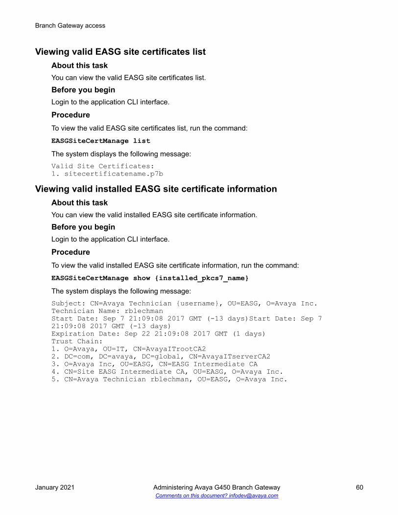
Viewing valid EASG site certificates listAbout this taskYou can view the valid EASG site certificates list.
Before you beginLogin to the application CLI interface.
ProcedureTo view the valid EASG site certificates list, run the command:
EASGSiteCertManage listThe system displays the following message:Valid Site Certificates:1. sitecertificatename.p7b
Viewing valid installed EASG site certificate informationAbout this taskYou can view the valid installed EASG site certificate information.
Before you beginLogin to the application CLI interface.
ProcedureTo view the valid installed EASG site certificate information, run the command:
EASGSiteCertManage show {installed_pkcs7_name}The system displays the following message:Subject: CN=Avaya Technician {username}, OU=EASG, O=Avaya Inc.Technician Name: rblechmanStart Date: Sep 7 21:09:08 2017 GMT (-13 days)Start Date: Sep 7 21:09:08 2017 GMT (-13 days)Expiration Date: Sep 22 21:09:08 2017 GMT (1 days)Trust Chain:1. O=Avaya, OU=IT, CN=AvayaITrootCA22. DC=com, DC=avaya, DC=global, CN=AvayaITserverCA23. O=Avaya Inc, OU=EASG, CN=EASG Intermediate CA4. CN=Site EASG Intermediate CA, OU=EASG, O=Avaya Inc.5. CN=Avaya Technician rblechman, OU=EASG, O=Avaya Inc.
Branch Gateway access
January 2021 Administering Avaya G450 Branch Gateway 60Comments on this document? [email protected]

Viewing EASG statusViewing EASG status
About this taskYou can view the EASG status is enabled or disabled.
Before you beginLogin to the application CLI interface.
ProcedureTo view the EASG status, run the command:
EASGStatusThe system displays the following message:EASG is Enabled.
Viewing product idAbout this taskYou can view the product id.
Before you beginLogin to the application CLI interface.
ProcedureTo view the product id, run the command:
product-idThe system displays the following message:39ad6805e054169a3da624581fd40976Done!Done!
Service logins with Enhanced Access Security Gateway(EASG) authentication
Branch Gateway supports EASG authentication for remote service logins. Branch Gateways,which are under service contract, do not have LSPs, and are controlled by external MGCs, need a
Service logins with Enhanced Access Security Gateway (EASG) authentication
January 2021 Administering Avaya G450 Branch Gateway 61Comments on this document? [email protected]

remote connection of services. EASG is a more secure method of authentication than passwordauthentication and does not require a static password.
EASG uses one-time tokens for authentication, in which a unique secret key is associated witheach login. EASG authentication is a challenge-response mechanism. The remote user receives achallenge from the gateway and the user returns an EASG authenticated response that thegateway verifies before permitting access. A new challenge is used for each access attempt.
EASG authentication is supported for remote services connecting to the gateway using Telnet orSSH protocols. The remote logins could be via any of the following:
• Dial-up modem connected to the USB, Console, or Services port
• Frame relay or leased line
• Secure gateway VPN
• Direct connection to the front panel Console port or Services port using the “craft” login
When EASG authentication is enabled on Branch Gateway, Branch Gateway recognizes any loginattempts that use Avaya Services reserved user names as service logins. Branch Gatewayrequests EASG authentication from the user instead of a static user password.
The following user names are reserved for Avaya Services usage: rasaccess, sroot, init,inads, and craft.
When EASG authentication is enabled on Branch Gateway, all user accounts with user namessimilar to the reserved service logins are deactivated.
Branch Gateway access
January 2021 Administering Avaya G450 Branch Gateway 62Comments on this document? [email protected]

Chapter 5: Basic device configuration
Basic device configuration lets you:
• Define a new interface and its IP address
• Configure parameters that identify the Branch Gateway to other devices
• Define a Gateway interface as the Branch Gateway’s default gateway
• Configure an MGC to work with the Branch Gateway
• Configure DNS resolver for resolving hostnames to IP addresses
• View the status of the Branch Gateway
• Manage and upgrade software, firmware, configuration, and other files on the Branch Gateway
• Backup and restore the Branch Gateway
Defining an interfaceAbout this taskAll interfaces on the Gateway must be defined by the administrator, after installation of the BranchGateway.
Procedure1. Use the interface command to enter the interface context.
Some types of interfaces require an identifier as a parameter. Other types of interfacesrequire the interface’s module and port number as a parameter.
For example:interface vlan 1interface serial 3/1interface fastethernet 10/2.0
2. Use the ip address command, followed by an IP address and subnet mask, to assign anIP address to the interface.
3. Use the load-interval command to set the load calculation interval for the interface.
For a list and descriptions of other interface configuration commands, see Interfaceconfiguration. For interface configuration examples, see Configuration example.
January 2021 Administering Avaya G450 Branch Gateway 63Comments on this document? [email protected]

Primary Management Interface (PMI) configurationThe Primary Management Interface (PMI) address is the IP address of an interface that you canspecify on the Branch Gateway. The first IP address you configure on the Branch Gatewayautomatically becomes the PMI. You can subsequently assign any IP interface to be the PMI.
The PMI is used as the IP address of the Branch Gateway for the following managementfunctions:
• Registration of the Branch Gateway to an MGC
• Sending SNMP traps
• Opening telnet sessions from the Branch Gateway
• Sending messages from the Branch Gateway using FTP and TFTP protocol
You can designate any of the Branch Gateway’s interfaces to serve as the Branch Gateway’s PMI.The PMI must be an IP address that the MGC recognizes. If you are not sure which interface touse as the PMI, check with your system administrator.
Setting the PMI of the Branch GatewayProcedure
1. Use the interface command to enter the context of the interface to which you want toset the PMI (primary management interface).
For example, to use the VLAN 1 interface as the PMI, enter interface vlan 1.
Note:
If the interface has not been defined, define it now.
2. Enter
• pmi for an IPv4 PMI
• pmi6 for an IPv6 PMI.
3. To return to general context, enter the exit command.
4. To save the new PMI in the startup configuration file, enter the copy running-configstartup-config command.
5. To reset the Branch Gateway, enter the reset command.
Note:
Most configuration changes take effect as soon as you make the change, but must besaved to the startup configuration file in order to remain in effect after you reset theBranch Gateway. The PMI address is an exception. A change to the PMI does not takeeffect at all until you reset the Branch Gateway.
Basic device configuration
January 2021 Administering Avaya G450 Branch Gateway 64Comments on this document? [email protected]

6. To verify the new PMI, enter show pmi in general context.
If you use this command before you reset the Branch Gateway:
• Active PMI, Active PMI6 and Configured PMI display
• Both the Active and the Configured PMI should be the same IP address.
7. Use the following commands to configure other identification information:
• set system contact• set system location• set system name
Active and configured PMIIf you use the show pmi command before you reset the Branch Gateway, two different PMIsdisplay:
Active PMI: The IPv4 PMI that the Branch Gateway is currently using, as defined in the runningconfiguration file.
Configured PMI: The PMI that the Branch Gateway is configured to use after reset, as defined inthe startup configuration file.
Active PMI6: The IPv6 PMI that the Branch Gateway is currently using, as defined in the runningconfiguration file.
PMI configuration CLI commandsFor more information about these commands, see Avaya Branch Gateway G450 CLI Reference.
Root level command Command Descriptioninterface(fastethernet|serial|tunnel|vlan|loopback|dialer)
- Enter configuration mode for theFastEthernet, Serial, Tunnel, VLAN,Loopback, or Dialer interface
Table continues…
Primary Management Interface (PMI) configuration
January 2021 Administering Avaya G450 Branch Gateway 65Comments on this document? [email protected]

Root level command Command Description- pmi
pmi6pmi6 [link-local]
Set the current interface as thePrimary Management Interface forthe system
Note:
You can define pmi6 or pmi6link-local on a VLAN interfaceonly.
You can define pmi and pmi6simultaneously on the Gateway,but only on the same VLANinterface
- no pmi
no pmi6
-
set systemcontact
- Set the contact information for thisBranch Gateway system
set systemlocation
- Set the location information for thisBranch Gateway system
set system name - Set the name of the Branch Gatewaysystem
show pmi - Display the current PrimaryManagement Interfaces
Example of defining a default gatewayThe Branch Gateway uses a default gateway to connect to outside networks that are not listed onthe Branch Gateway’s routing table. To define a default gateway, use the ip default-gatewaycommand, followed by either the IP address or name (type and number) of the interface you wantto define as the default gateway.
ExampleThe following example defines the interface with the IP address 132.55.4.45 as the defaultgateway:ip default-gateway 132.55.4.45ExampleThe following example defines Serial interface 3/1:1 as the default gateway:ip default-gateway serial 3/1:1ExampleTo define a default gateway with IPv6 address 2001:db8:2179::2
Basic device configuration
January 2021 Administering Avaya G450 Branch Gateway 66Comments on this document? [email protected]

Gxxx-001(super)# ipv6 default-gateway 2001:db8:2179::2
Branch Gateway Controller configurationThe Branch Gateway Controller (MGC) controls telephone services on the Branch Gateway. Youcan use a server with CM software as an MGC. The Branch Gateway supports both External CallControllers (ECC) and Internal Call Controllers (ICC). An ICC is an Avaya S8300 Server that youinstall in the Branch Gateway as a media module. An ECC is an external server thatcommunicates with the Branch Gateway over the network.
When the Branch Gateway uses an ECC, it can use a local S8300 as a backup controller forEnhanced Local Survivability (ELS). The S8300 functions in Survivable Remote Server (SRS)mode. If the ECC stops serving the Branch Gateway, the S8300 takes over the service.
Release 8.1.3 supports the following new commands:
• set allow-unencrypted: To allow or disallow media encryption requests from CM.
• set link-encryption: To specify what TLS versions will be offered by the gateway whenconnecting to a server.
Locating the Branch Gateway serial numberAbout this taskTo register the Branch Gateway with an MGC, you need the Branch Gateway’s serial number. Youcan find this serial number in either of the following ways:
Procedure1. Use the show system command
2. Look for a 12-character string located on a label on the back panel of the Branch Gateway
Survivability and migration optionsSeveral options exist to minimize network disruption if connectivity between the Branch Gatewayand the server or media gateway controller (MGC) is lost.
MGC list: You must specify at least one, and up to four, MGCs in the list. The first MGC on the listis the primary MGC. If the Branch Gateway cannot connect with, or loses its connection with, theprimary MGC, it attempts to connect with the other MGCs on the list.
Note:
When Standard Local Survivability (SLS) is enabled, the MGC list includes the SLS module asa fifth entry in the MGC list.
Branch Gateway Controller configuration
January 2021 Administering Avaya G450 Branch Gateway 67Comments on this document? [email protected]

Standard Local Survivability (SLS): SLS consists of a module built into the Branch Gateway toprovide partial backup MGC functionality in the event that the connection with the primary MGC islost. This feature allows a local Branch Gateway to provide a degree of MGC functionality when nolink is available to an external MGC. Alternatively, it can be configured on an individual BranchGateway using the CLI.
Enhanced Local Survivability (ELS): ELS is available for the Branch Gateway using a localS8300 or S85XX functioning in LSP mode. If the ECC stops serving the Branch Gateway, theS8300 takes over the service.
Auto fallback to primary MGC: This feature provides a means by which a Branch Gatewaybeing serviced by its LSP can return to its primary MGC automatically when the connection isrestored between the Branch Gateway and the MGC. By migrating the Branch Gateway to theMGC automatically, a fragmented network can be made whole faster, without the need for humanintervention. Auto fallback is configured via the CM. For details, see the Administrator Guide forAvaya Aura® Communication Manager.
Note:
Auto fallback does not include survivability. Therefore, there is a short period duringregistration with the MGC during which calls are dropped and service is not available. Thisproblem can be minimized using the connection preservation feature described below.
Connection preservation: This feature enables the Branch Gateway to preserve the bearerpaths of stable calls if the Branch Gateway migrates to another MGC (including an LSP), includingmigration back from an LSP to the primary MGC. A call for which the talk path between parties inthe call has been established is considered stable. A call consisting of a user listening toannouncements or music is not considered stable and is not preserved. Any change of state in thecall prevents the call from being preserved. For example, putting a call on hold during MGCmigration will cause the call to be dropped. Special features, such as conference and transfer, arenot available on preserved calls. Connection preservation preserves all types of bearerconnections except BRI. PRI trunk connections are also preserved. For details, see theAdministering Network Connectivity on Avaya Aura® Communication Manager, 555-233-504.
Modem dial-backup: This feature can be used to provide redundant WAN connectivity betweena Branch Gateway and its primary MGC using a serial modem. This connection uses a virtualinterface called the Dialer interface. This feature recognizes that even if the Branch Gateway isconfigured for survivability via SLS or ELS, the best solution is to maintain the gateway’sconnection with its primary MGC whenever possible.
Related linksStandard Local Survivability (SLS) on page 97Modem dial backup on page 241
MGC list configurationThe Branch Gateway must be registered with an MGC in order to provide telephone service. Youcan set the Branch Gateway’s MGC, and show the current MGC list used to determine the results.
Basic device configuration
January 2021 Administering Avaya G450 Branch Gateway 68Comments on this document? [email protected]

Branch Gateway MGC settingsUse the set mgc list command to set Branch Gateway MGC. You can enter the IP addressesof up to four MGCs with the set mgc list command. The first MGC on the list is the primaryMGC. Branch Gateway searches for the primary MGC first. If it cannot connect to the primaryMGC, it searches for the next MGC on the list, and so on. If there are both IPv4 and IPv6addresses in the same index on the MGC list, the IPv6 address is preferred.
This allows you to select the destination address; the source address is selected according to thedestination address, for example, if the first address in the MGC list is an IPv6 address and theGW has both IPv4 and IPv6 address then the gateway selects its IPv6 address as the sourceaddress.
When SLS is enabled, the MGC list includes the SLS module as a fifth entry on the MGC list.
Note:
If the MGC is a S87XX server, the first server on the list will normally be the primary C-LANboard connected to the server. If the MGC is a S8400 or S85XX, the first server on the list willbe either the primary C-LAN board connected to the server, or an Ethernet port on the serverthat has been enabled for processor Ethernet connections. If the MGC is an S8300, the firstserver on the list will be the IP address of the S8300. The remaining servers will be eitheralternate C-LAN boards connected to the S8400, S85XX, or S87XX servers, or a S8300configured as a LSP, or the port enabled as the Ethernet processor port on a S85XXconfigured as a LSP.
Related linksStandard Local Survivability (SLS) on page 97
Example of setting Branch Gateway MGCIn the following example of the set mgc list command, if the MGC with the IPv4 address135.6.8.99 and IPv6 address 2001:db8::370:7334 is available, that MGC becomes the BranchGateway’s MGC. If that server is not available, the Branch Gateway searches for the next MGC onthe list, and so on.Gxxx-001(super)# set mgc list 135.6.8.99+2001:db8::370:7334,135.34.54.2,2001:db8::1428:57ab
Done!
Results from the set mgc list commandTo determine the result of the set mgc list command, use the show mgc command. Thiscommand has the following output:
Field DescriptionRegistered Indicates whether Branch Gateway is registered with an MGC (YES or
NO)
Table continues…
Branch Gateway Controller configuration
January 2021 Administering Avaya G450 Branch Gateway 69Comments on this document? [email protected]

Field DescriptionActive Controller Displays the IP address of the active MGC. If there is no active MGC (that
is, if the set mgc list command failed to configure an MGC), this fielddisplays 255.255.255.255.
H248 Link Status Indicates whether the communication link between Branch Gateway andthe MGC is up or down
H248 Link Error Code If there is a communication failure between Branch Gateway and theMGC, this field displays the error code
PRIMARY MGC HOST IPv4 and IPv6 addresses of the primary MGC hostSECONDARY MGC HOST IPv4 and IPv6 addresses of the secondary MGC hostsH248 Link Encryption Indicates whether the communication link with the MGC is encrypted or
not, and the type of encryption (TLS, PTLS).
Showing the current MGC listAbout this taskThis command shows the IP addresses of the MGCs on the MGC list. It also shows whether SLSis enabled.
ProcedureTo show the current MGC list, use the show mgc list command.
ExampleGxxx-001(super)# sh mgc list
PRIMARY MGC HOST, Primary Search Time : 1 min(s)IPv4 Address IPv6 Address-------------------- ------------------------------------------------ Not Available -- 100:0:0:0:0:0:0:803
SECONDARY MGC HOSTIPv4 Address IPv6 Address-------------------- ------------------------------------------------ Not Available -- -- Not Available ---- Not Available -- -- Not Available ---- Not Available -- -- Not Available --
sls disabled
Done!
Removing MGCs from the MGC listProcedureEnter clear mgc list to remove one or more MGCs from the MGC list.
Specifically:
• To remove one or more MGCs from the MGC list, type the IP addresses of the MGC you wantto remove as an argument to remove that MGC.
Basic device configuration
January 2021 Administering Avaya G450 Branch Gateway 70Comments on this document? [email protected]

• To remove more than one MGC with one command, type the IP addresses of all the MGCs youwant to remove, separated by commas.
• To remove all the MGCs on the list, enter clear mgc list with no arguments.
Changing the MGC listProcedure
1. Enter clear mgc list with no arguments to clear the MGC list.
2. Enter set mgc list with a different set of IP addresses.
If you use the set mgc list command without first clearing the MGC list, the BranchGateway adds the new MGCs to the end of the MGC list.
About setting reset timesIf the connection between Branch Gateway and the registered MGC is lost, Branch Gatewayattempts to recover the connection. Use the set reset-times primary-search commandand the set reset-times total-search command to set the timeout for the BranchGateway’s search for the primary MGC and the other MGCs on its MGC list, respectively. Use theset reset-times transition-point command to configure the point at which the primaryMGCs in the list end and the LSPs begin.
Use the show recovery command to display the reset times.
Example for setting reset timesIf there are three IP addresses in the MGC list and the third address is the LSP, the transition pointshould be 2.
The default time for the primary search is one minute. The default time for the total search is 30minutes. The default transition point is 1.
ExampleGxxx-001(super)# set reset-times primary-search 20Done!Gxxx-001(super)# set reset-times total-search 40Done!Gxxx-001(super)# set reset-times transition-point 1Done!
In this example, in the event of a connection loss with the registered MGC, the Branch Gatewaysearches for the primary MGC on its MGC list for 20 minutes. If the Branch Gateway does notestablish a connection with the primary MGC within this time, it searches for the other MGCs onthe list for a total of 40 minutes.
Branch Gateway Controller configuration
January 2021 Administering Avaya G450 Branch Gateway 71Comments on this document? [email protected]

Accessing the registered MGCProcedureAccess the MGC according to the following:
a. If the MGC is an S8300 Server, enter session mgcThe session mgc does not work on an IPv6–only Branch Gateway.
b. If the MGC is an S88xx, Dell or HP, use the set mediaserver command to manuallydefine the MGC’s IP address, and then enter session mgc to access the MGC.
c. If the Branch Gateway includes a local S8300, enter session icc to access the S8300.You can use this command whether the local S8300 is the Branch Gateway’s registeredMGC.
Both the session mgc command and the session icc command open a telnetconnection to the MGC.
Use the session mgc on an S8300D running VSP.
d. To open a connection directly to the CM System Access Terminal (SAT) application in theMGC, add sat to the command.
For example:Gxxx-001(super)# session mgc sat
e. To open a connection to the MGC’s LINUX operating system, do not add sat to thecommand.
For example:Gxxx-001(super)# session mgc
H.248 Registration Source PortWith the following CLI commands, you can define or view the source port range that thegateway uses to register to CM.
• set registration source-port-range
• show registration source-port-range
• set registration default source-port-range
If you do not specify a range, the gateway will select a port within the default range of 1024 to65535.
Basic device configuration
January 2021 Administering Avaya G450 Branch Gateway 72Comments on this document? [email protected]

ICC or Survivable Remote Server monitoringWhen a local MGC controls telephone services on the Branch Gateway in ICC or SurvivableRemote Server mode, the Branch Gateway monitors the connection with the MGC. If theconnection with the MGC is lost, the Branch Gateway starts a recovery process.
• Use the set icc-monitoring command to control heartbeat monitoring of an ICC orSurvivable Remote Server . The enable parameter enables heartbeat monitoring. The disableparameter disables heartbeat monitoring.
• Use the show icc-monitoring command to display the status of the ICC or SurvivableRemote Server monitoring process.
Summary of MGC list configuration commandsFor more information about these commands, see Avaya Branch Gateway G450 CLI Reference.
Command Descriptionclear mgc list Remove one or more MGCs from the MGC listsession Open a telnet connection to the MGCset icc-monitoring Enable or disable heartbeat monitoring of an MGC in ICC or Survivable
Remote Server modeset mediaserver Set the MGC management address and portsset mgc list Create a list of valid Media Gateway Controller(s)set reset-times Set the timeout for the Branch Gateway’s search for the primary MGC, or
search for the other MGC’s on the MGC list, or configure the point atwhich the primary MGCs in the list end and the Survivable RemoteServers begin
show icc-monitoring Display the status of the ICC/Survivable Remote Server monitoringprocess
show mediaserver Display MGC configuration informationshow mgc Display the state and setup parameters of the currently active MGCshow mgc list Display the IP addresses of the MGCs on the MGC listshow recovery Show the Branch Gateway connection recovery setup
DNS resolverA DNS resolver resolves hostnames to IP addresses by querying DNS servers according to anordered list. The list of DNS servers is compiled using either DNS servers entered manually by theuser, or DNS servers gathered automatically by means of DHCP or PPP protocols, or both.
DNS resolver
January 2021 Administering Avaya G450 Branch Gateway 73Comments on this document? [email protected]
The user can also optionally aid the DNS resolver by specifying a list of domain names that theDNS resolver adds as a suffix to non-Fully Qualified Domain Name (FQDN) names, to helpresolve them to an IP address.
The DNS resolver feature is intended to provide a backup mechanism for VPN hubs using DNS.
Related linksIPSec VPN on page 435
DNS resolver featuresBranch Gateway supports the following DNS resolver features:
• Supports IPv4 and IPv6 — it can resolve a hostname to IPv4 and IPv6 addresses.• Fully compliant with RFC1034, RFC1035, and RFC1123• Maintains a global DNS database for all interfaces. The database is compiled using:
- Static (user-defined) DNS servers- Automatically-learned DNS servers. DNS servers can be automatically learned by the
FastEthernet 10/2 interface when it is configured as a DHCP client or configured for PPP.
Note:The following PPP interfaces can be configured to automatically learn the DNS serversin the system:
• FastEthernet with PPPoE• Dialer interface• Serial interface
The most common application of this configuration is for connecting Branch Gateway tothe Internet and getting the DNS server information from the ISP. Therefore, interfacesconfigured to automatically learn the DNS servers in the system are usually theFastEthernet with PPPoE interface and the Dialer interface.
Related linksConfiguring the DHCP client on page 184
Typical DNS resolver application – VPN failoverIn this typical application, the DNS resolver feature is used to provide a VPN failover mechanismbetween two main offices. The failover mechanism is implemented as follows.
The VPN branch office(s) connect to two main offices (the VPN remote peers) that are configuredwith the same FQDN name, but have different IP addresses. When a branch office makes a DNSquery to resolve the VPN remote peer name to an IP address, it receives a list with the IPaddresses of both main offices, selects the first one, and builds a VPN tunnel with it. If the firstmain office fails, the branch office sends another DNS query, and receives the IP address of thesecond main office in reply. It will then start a VPN tunnel with the second main office.
Basic device configuration
January 2021 Administering Avaya G450 Branch Gateway 74Comments on this document? [email protected]

Note:
VPN is supported in IPv4 only.
Related linksFailover using DNS on page 485
Configuring DNS resolverProcedure
1. Enter ip domain name-server-list 1 to create the DNS servers list.Gxxx-001(config)# ip domain name-server-list 1Gxxx-001(config-name-server-list:1)#
2. Use the description command to specify a description for the list.Gxxx-001(config-name-server-list:1)# description “All DNS servers”Done!Gxxx-001(config-name-server-list:1)#
3. Add a DNS server to the DNS servers list using the name-server command.
• Assign an index number that ranks the DNS server by priority.
• Specify the IP address of the DNS server.
4. Repeat Step 3 to configure additional DNS servers in the list.
You can configure up to six DNS servers.Gxxx-001(config-name-server-list:1)# name-server 1 1.1.1.1Done!
DNS resolver
January 2021 Administering Avaya G450 Branch Gateway 75Comments on this document? [email protected]

Gxxx-001(config-name-server-list:1)# name-server 2 2001:DB8::21F:3CFF:FE14:6E25Done!
5. Use the ip domain list command to configure a domain name.
This domain name will be used as a suffix to complete non-FQDN names (hostnames thatdo not end with a dot).
• Assign an index number that ranks the domain name by priority.
• Specify the domain name.
6. Repeat Step 5 to configure additional domain names.
You can configure up to six domain names.Gxxx-001(config)# ip domain list 1 avaya.comDone!Gxxx-001(config)# ip domain list 2 emea.avaya.comDone!
7. Optionally, configure the number of DNS query retries, using the ip domain retrycommand.
The default value is 2.Gxxx-001(config)# ip domain retry 4Done!
8. Optionally, configure the timeout for a DNS query using the ip domain timeoutcommand.
The default value is 3 seconds.Gxxx-001(config)# ip domain timeout 4Done!
9. The DNS resolver is enabled by default.Gxxx-001(config)# ip domain lookupDone!
10. If either DHCP Client or PPP are configured in the Branch Gateway, you do not need toconfigure DNS resolver because the DNS resolver is enabled by default. In addition, theDHCP Client and PPP discover DNS servers automatically, so the list of DNS serversinclude the automatically-learned DNS servers.
• For DHCP Client, enable DHCP Client by entering ip address dhcp. For informationabout DHCP Client see Configuring the DHCP client.
• For PPP, enable automatic discovery of DNS servers by entering ppp ipcp dnsrequest.
Basic device configuration
January 2021 Administering Avaya G450 Branch Gateway 76Comments on this document? [email protected]

Example
DNS resolver configuration exampleThe following example defines three DNS servers for the list of DNS servers, three domain namesto add as suffixes to hostnames, a DNS query retry value, and a DNS query timeout value. Thefinal command in the example enables the DNS resolver.Gxxx-001(config)# ip domain name-server-list 1Gxxx-001(config-name-server-list:1)# description “All DNS servers”Done!Gxxx-001(config-name-server-list:1)# name-server 1 1.1.1.1Done!Gxxx-001(config-name-server-list:1)# name-server 2 2.2.2.2Done!Gxxx-001(config-name-server-list:1)# name-server 3 2001:DB8::21F:3CFF:FE14:6E25
Done!Gxxx-001(config-name-server-list:1)# exitGxxx-001(config)# ip domain list 1 support.avaya.comDone!Gxxx-001(config)# ip domain list 2 global.avaya.comDone!Gxxx-001(config)# ip domain list 3 avaya.comDone!Gxxx-001(config)# ip domain retry 4Done!Gxxx-001(config)# ip domain timeout 5Done!Gxxx-001(config)# ip domain lookupDone!
DNS resolver
January 2021 Administering Avaya G450 Branch Gateway 77Comments on this document? [email protected]

Using DNS resolver to resolve a hostnameAbout this taskUse the nslookup command, followed by a hostname, to resolve the hostname to an IP address.
DNS resolver maintenanceThere are various commands you can use to display DNS resolver information, clear DNSresolver counters, and display DNS resolver log messages.
Examples of viewing DNS resolver logging1. Enter set logging session enable to enable session logging to the terminal.
Gxxx-001# set logging session enableDone!CLI-Notification: write: set logging session enable
2. Enter set logging session condition DNSC to view all DNS resolver messages oflevel Info and above.Gxxx-001# set logging session condition DNSC InfoDone!CLI-Notification: write: set logging session condition DNSC Info
Note:
You can also enable logging messages to a log file or a Syslog server.
Related linksSystem logging on page 191
DNS resolver configuration commandsFor more information about these commands, see Avaya Branch Gateway G450 CLI Reference.
Root level command Command Descriptionclear ip domainstatistics
- Clear the DNS resolver’s statistics counters
interface {dialer|serial|console| FastEthernet|USB-modem}
- Enter the interface configuration mode for a Dialer,Serial, Console, FastEthernet, or USB-modeminterface
- ppp ipcp dns request Enable or disable requesting DNS information fromthe remote peer during the PPP/IPCP session
Table continues…
Basic device configuration
January 2021 Administering Avaya G450 Branch Gateway 78Comments on this document? [email protected]

Root level command Command Descriptionip domain list - Specify static domain names (suffixes) to complete
non-FQDN names (hostnames that do not end with adot)
ip domain lookup - Enable or disable the DNS resolverip domain name-server-list
- Enter the context of the DNS servers list, or set up thelist
- description Set a name for the DNS servers list- name-server Add a DNS server to the list of up DNS servers
ip domain retry - Set the number of retries for a DNS queryip domain timeout - Set the timeout for a DNS querynslookup - Resolve a hostname to an IP addressshow ip domain - Display the DNS resolver’s configuration - the output
shows the DNS servers that were statically configuredand those which were gathered using DHCP or PPPprotocols, as well as the list of domain suffixes
The output shows the DNS servers that were staticallyconfigured and those which were gathered usingDHCP or PPP protocols, as well as the list of domainsuffixes.
show ip domainstatistics
- Display the DNS resolver’s statistics counters
show protocol - Display the status of a specific management protocol,or all protocols
Device status viewingThis section describes the commands used to view the status of the Branch Gateway. For moreinformation about these commands, see Avaya G450 Branch Gateway CLI Reference.
The show mm commandUse the show mm command to view information about media modules that are installed on theBranch Gateway. To view information about a specific media module, include the slot number ofthe media module as an argument. For example, to view information about the media module inslot 2, enter show mm v2. The output of the command shows the following information:
• Slot number
• Uptime
• Type of media module
Device status viewing
January 2021 Administering Avaya G450 Branch Gateway 79Comments on this document? [email protected]

• Description
• Serial number and other hardware identification numbers
• Firmware version
• Number of ports
• Fault messages
The show mm and show mg list config commandsUse the show module command or enter show mg list_config to view brief informationabout media modules that are installed in the Branch Gateway. To view brief information about aspecific media module, include the slot number of the media module as an argument. Forexample, to view information about the media module in slot 2, enter show module v2. Theoutput of the command shows the following information:
• Slot number
• Firmware version
• Type of media module
• Media module code
Device status commandsFor more information about these commands, see Avaya Branch Gateway G450 CLI Reference.
Command Descriptionset utilization cpu Enable CPU utilization measurementsshow faults Display information about currently active faultsshow image version Display the software version of the image on both memory banks of the
deviceshow mg list_config Display the current hardware and firmware configurations for the installed
Branch Gateway equipmentshow mgc Display information about the Media Gateway Controller with which the
Branch Gateway is registeredshow module Display brief information about the media modules installed in the Branch
Gatewayshow restart-log Display information about the last time the Branch Gateway was resetshow system Display information about the Branch Gatewayshow temp Display the device temperature
Table continues…
Basic device configuration
January 2021 Administering Avaya G450 Branch Gateway 80Comments on this document? [email protected]

Command Descriptionshow timeout Display the amount of time in minutes the terminal remains idle before timing
outshow utilization Display information about CPU and memory usage on the Branch Gatewayshow voltages Display power supply voltages
OOB
oob-interface configurationThe Out-of-Band Management interface can be used to access the gateway using CLI and SNMPand perform downloads or uploads. It is a dedicate management channel for device maintenanceand provides separation between device management and user data. Having distinct channelsisolates user and management/admin functions from data and allows more targeted auditingpractices to be implemented to detect insider threats. The oob-interface command executedin the context of a FastEthernet or VLAN interface defines the interface as an Out-of-BandManagement interface.
Note:• The Out-of-Band Management interface must be different from the PMI or PMI6
interface.• An IP address must be defined on the interface before it can be configured as the Out-of-
Band Management and a reboot is required after the Out-of-Band Management isconfigured.
no oob-interfaceThe no oob-interface command removes a configured out of band interface. The command isdenied if access on the other interfaces was disabled.
Note:A reboot is required after the out-of-band management interface is removed.
show oob-interfaceThe show oob-interface command displays the status of the Out-of-Band ManagementInterface.
OOB
January 2021 Administering Avaya G450 Branch Gateway 81Comments on this document? [email protected]

set non-oob-interfaces accessThe set non-oob-interfaces access command is used to enable or disable access to thegateway from all interfaces except the out-of-band management interface. If the access isdisabled then SSH, telnet, SNMP are only available on the Out-of-Band management interface.
Note:The command is denied if an Out-of-Band interface is not configured.
Software and firmware managementYou can manage Avaya Branch Gateway software and firmware, either:
• Remotely, using an FTP, TFTP, or SCP server, or
• Locally, using a USB mass storage device connected to the Avaya Branch Gateway USBport
File transferBranch Gateway can be a client for the SCP, FTP, and TFTP protocols. Use either a USB deviceor the SCP, FTP, or TFTP protocols to transfer files between Branch Gateway and other devices.You can use file transfer to:
• Install software and firmware upgrades on Branch Gateway
• Install firmware upgrades on media modules
• Backup and restore configuration settings
To use SCP/FTP/TFTP file transfer, you need to have an SCP, FTP server or TFTP server on yournetwork.
Note:
If you use an SCP or FTP server, Branch Gateway prompts you for a username and passwordwhen you enter a command to transfer a file. Also, when opening an FTP connection to theS8300, all anonymous FTP file transfers are restricted to the /pub directory. Permission foranonymous FTP users to create files in other directories is denied.
Software and firmware upgradesYou can upgrade software on Branch Gateway. Software used to control Branch Gateway itselfand media modules installed on Branch Gateway is called firmware. Use a USB device or the
Basic device configuration
January 2021 Administering Avaya G450 Branch Gateway 82Comments on this document? [email protected]

SCP, FTP, or TFTP protocol to download a new version of software or firmware. You can upgradethe following types of software and firmware:
• Firmware for Branch Gateway
• Java applet for Branch Gateway
• Firmware for media modules
Note:
You can also use Branch Gateway to upgrade the firmware and configuration files for IPphones.
For details, see Installing and Upgrading the Avaya G450 Branch Gateway
Firmware bank managementThe Branch Gateway has two firmware banks:
• Bank A
• Bank B
Each firmware bank contains a version of the Branch Gateway firmware. These may be differentversions. The purpose of this feature is to provide software redundancy. If one of the versionsbecomes corrupted, you can reset the Branch Gateway using the other version. This is particularlyimportant when downloading new versions.
Displaying firmware versions in the banksProcedureUse the show image version command to display the firmware version of the image on bothmemory banks of the Branch Gateway.
Bank management changesBy default, when you turn on or reset the Branch Gateway, the Branch Gateway loads firmwarefrom Bank B. To change the default bank from which firmware is loaded during startup, use theset boot bank command. For example, to configure the Branch Gateway to load firmware fromBank A on startup, enter set boot bank bank-A. Now, when you reset the Branch Gateway, itwill load firmware from Bank A.
To display the bank from which the Branch Gateway is currently set to load its firmware uponstartup or reset, use the show boot bank command.
Loading firmware from the non-default bankAbout this taskUse the ASB button on the Branch Gateway front panel to load firmware from a bank other thanthe default bank during startup:
Procedure1. Press and hold the reset button.
Software and firmware management
January 2021 Administering Avaya G450 Branch Gateway 83Comments on this document? [email protected]

2. Press and hold the ASB button.
3. Release the reset button.
4. Release the ASB button.
ResultFor example, if the Branch Gateway is configured to load firmware from Bank B, use the stepslisted above to reset the Branch Gateway to load the firmware from Bank A instead.
Software and firmware upgrades using SCP/FTP/TFTPTo upgrade software or firmware, you must obtain an upgrade file from Avaya. Place the file onyour SCP, FTP, or TFTP server. Then, use one of the following commands to upload the file toBranch Gateway. For each of these commands, include the full path of the file and the IP addressof the SCP, FTP, or TFTP host as parameters. When you enter the command, the CLI promptsyou for a username and password.
When using SCP, FTP, or TFTP commands, you must use the specific path of the file on the SCP,FTP, or TFTP server according to the home directory of the service (SCP, FTP, or TFTP) that youare using.
Example of an upgrade using SCP/FTP/TFTPTo upgrade the firmware of an MM710 media module in slot 2 from a TFTP server with the IPaddress 192.1.1.10, where the home directory is c:\home\ftp\ and the upgrade file is located in thedirectory c:\home\ftp\version, use the following command:copy tftp module \version\mm710v3.fdl 192.1.1.10 2
ExampleThe following example downloads a firmware version with the path and file nameC:\g450_sw_41_24_0.bin from an FTP server with the IP address 149.49.134.153 to Bank Aof Branch Gateway.copy ftp SW_imageA C:\g450_sw_41_24_0.bin 149.49.134.153
ExampleThe following example downloads a firmware version with the path and file nameC:\g450v4_sw_41_24_0.bin from an FTP server with the IP address 149.49.134.153 to BankA of Branch Gateway.copy ftp SW_imageA C:\g450v4_sw_41_24_0.bin 149.49.134.153
ExampleThe following example downloads a firmware version with the path and file nameC:\g450v4_sw_41_24_0.bin from an SCP server with the IP address 149.49.134.153 to BankA of Branch Gateway.copy scp SW_imageA g450/g450v4_41_24_0.bin 172.16.1.22
Note:The G450 hardware vintage 4 uses a different software image. The filename starts withg450v4_sw. G450 hardware vintage 1 to 3 use a software image starting with g450_sw.
Basic device configuration
January 2021 Administering Avaya G450 Branch Gateway 84Comments on this document? [email protected]

Upgrading software and firmware using a USB mass storage deviceAbout this taskYou can upgrade software and firmware using a USB mass storage device.
Procedure1. Obtain an upgrade file from Avaya and place it on your PC.
2. Insert the USB mass storage device into the PC’s USB port, and copy the software orfirmware file(s) to the USB mass storage device.
3. Remove the USB storage device from the PC, and insert it in Branch Gateway USB port.
4. Copy the software or firmware files to Branch Gateway using one of the followingcommands:
• copy usb SW_imageA• copy usb SW_imageB• copy usb module• copy usb phone-imageA (or imageB, or imageC, or imageD)
• copy usb phone-scriptA (or phone-scriptB)
• copy usb announcement-file• copy usb auth-file• copy usb startup-config• copy usb easg• EASGSiteCertManage copy usb
5. Use the show download software status command to display the status of thefirmware download process.
Upgrading firmware using the USB mass storage device “restore” commandAbout this taskThe primary use of the restore usb command is to restore the entire Branch Gateway. If youuse the command to upgrade firmware, take care to follow instructions carefully.
Procedure1. Backup the Branch Gateway by entering backup config usb usbdevice0 backup-
name, where backup-name is the backup directory path and file name you are creating onthe USB mass storage device.
A backup directory is created on the USB mass storage device.
2. Obtain the firmware upgrade file(s) from Avaya and place them on your PC.
Software and firmware management
January 2021 Administering Avaya G450 Branch Gateway 85Comments on this document? [email protected]

3. Insert the USB mass storage device into the PC’s USB port, and copy the firmware file(s)to the USB mass storage device as follows:
a. Copy Branch Gateway firmware files to the root directory.
b. Copy the Device Manager firmware file to the root directory.
c. Copy media modules’ firmware files to the MM sub directory.
d. Copy IP phone firmware files to the IPPHONE sub directory.
4. Remove the USB mass storage device from the PC, and insert it in the Branch GatewayUSB port.
5. Enter restore usb usbdevice0 backup-name, where backup-name is the rootdirectory path and name on the USB mass storage device.
6. Enter show restore status to check the status of the restore operation.
The report lists the upgraded files.
Related linksSample backup directory after backup on page 90
Software and firmware uploads from the gatewayFiles copied to a USB mass storage device
You can use a USB mass storage device inserted into the Branch Gateway USB port to copyindividual files to a USB mass storage device.
When you use the copy file usb command to upload a specific file from the gateway to theUSB mass storage device, file can be any of the following types:
• announcement-file. Announcements files
• phone-scriptA. Phone script bank A in the Branch Gateway’s TFTP directory
• phone-scriptB. Phone script bank B in the Branch Gateway’s TFTP directory
• startup-config. The startup configuration file
• capture-file. The packet sniffing buffer
• dhcp-binding. The DHCP binding file
• syslog-file. The syslog file
• cdr-file. A Call Detail Recording (CDR) file
Files copied to an FTP/SCP/TFTP serverWhen you use the copy file ftp command to upload a specific file from the Branch Gateway toan FTP server, file can be any of the following types:
• announcement-file. Announcements files
Basic device configuration
January 2021 Administering Avaya G450 Branch Gateway 86Comments on this document? [email protected]

• capture-file. The packet sniffing buffer
• cdr-file. A Call Detail Recording (CDR) file
• dhcp-binding. The DHCP binding file
When you use the copy file scp command to upload a specific file from the Branch Gateway toan SCP server, where file can be any of the following:
• announcement-file. Announcements files
• capture-file. The packet sniffing buffer
• cdr-file. A Call Detail Recording (CDR) file
• dhcp-binding. The DHCP binding file
When you use the copy file tftp command to upload a specific file from the G ateway to aTFTP server, where file can be any of the following:
• announcement-file. Announcements files
• capture-file. The packet sniffing buffer
• capture-file. The packet sniffing buffer
• cdr-file. A Call Detail Recording (CDR) file
• dhcp-binding. The DHCP binding file
Software and firmware management commandsFor more information about these commands, see Avaya Branch Gateway G450 CLI Reference.
Command Descriptioncopy file ftp Upload a specific file from Branch Gateway to an FTP server.copy file scp Upload a specific file from Branch Gateway to an SCP server.copy file tftp Upload a specific file from Branch Gateway to a TFTP server.copy file usb Upload a specific file from Branch Gateway to the USB mass storage
device.copy ftp module Upgrade the firmware on a media module from an FTP server by
entering this command followed by the module number of themodule you want to upgrade.
copy ftp SW_imageA Upgrade Branch Gateway firmware into Bank A from an FTP server.copy ftp SW_imageB Upgrade Branch Gateway firmware into Bank B from an FTP server.copy tftp module Upgrade the firmware on a media module from a TFTP server.copy tftp SW_imageA Upgrade Branch Gateway firmware into Bank A from a TFTP server.copy tftp SW_imageB Upgrade Branch Gateway firmware into Bank B from a TFTP server.copy usb announcement-file Upgrade announcements files from the USB mass storage device.copy usb auth-file Upgrade the authorization file from the USB mass storage device.
Table continues…
Software and firmware management
January 2021 Administering Avaya G450 Branch Gateway 87Comments on this document? [email protected]

Command Descriptioncopy usb module Upgrade the firmware on a media module from the USB mass
storage device.copy usb phone-image Upgrade phone images from the USB mass storage device.copy usb phone-script Upgrade phone scripts from the USB mass storage device.copy usb startup-config Upgrade the startup configuration file from the USB mass storage
device.copy scp SW_imageA Downloads a software image from an SCP server into Bank A. The
command prompts for the username and password.copy scp SW_imageB Downloads a software image from an SCP server into Bank B. The
command prompts for the username and password.copy scp easg Copy and install an EASG Site Certificate using scp.copy usb SW_image Upgrade Branch Gateway firmware into Bank A or into Bank B, from
the USB mass storage device.copy usb easg Copy and install an EASG Site Certificate using a USB device.dir List all files in the USB mass storage device connected to Branch
Gateway.EASGSiteCertManage copyscp
Copy and install an EASG site certificate using Secure CopyProtocol (scp).
EASGSiteCertManage copyusb
Copy and install an EASG Site Certificate using a USB device.
set boot bank Set the default bank from which firmware is loaded during startup.show boot bank Display the bank from which Branch Gateway is currently set to load
its firmware upon startup or reset.show download softwarestatus
Display the status of the firmware download process.
show image version Display the firmware version of the image on both memory banks ofthe device.
Note:Branch Gateway has four G450 hardware versions. Use the show system command tocheck the hardware version. If the Model is G450v4, it uses a different software image:g450v4_sw_x_y_z.bin.
Backup and restores using a USB mass storage deviceYou can use a USB flash drive and a USB externally-powered hub for backups and restores.Avaya Branch Gateway also supports USB 2.0 high speed (480 Mbits/sec) for faster file transferbetween Branch Gateway and USB mass storage devices.
Basic device configuration
January 2021 Administering Avaya G450 Branch Gateway 88Comments on this document? [email protected]

Note:
An external USB hub is supported on Branch Gateways with hardware suffix.vintage C.1 orabove. To check the hardware suffix and vintage, enter show system and check the HWsuffix and HW vintage values.
CLI commands for backing up and restoring files to or from a USB mass storage device enableyou to use a USB port for efficient restoration or replication of Branch Gateway and for replacingand upgrading media modules. Using the USB port you can back up or restore multiple files withone CLI command, which is simpler than the alternative TFTP/FTP/SCP method, in which files arecopied and restored individually.
A single CLI command backs up all the administration and configuration files of Branch Gatewayon USB mass storage device. Another single command restores all of the backed up files. If youneed to completely replicate Branch Gateway, you can also download Branch Gateway firmware,media modules’ firmware, Device Manager firmware, IP phone firmware, and Device Managerfirmware to the USB mass storage device, and use the restore usb command to restore thesefiles as well as the administration and configuration files.
Note:
The CLI backup config usb and restore usb commands (for efficient backup/restoreusing a USB mass storage device) only run on Branch Gateways R4.0 and higher.
You can also use the USB mass storage device to copy individual Branch Gateway files to or fromBranch Gateway.
Tip:
Use a USB mass storage device with LED indication.
Related linksUpgrading software and firmware using a USB mass storage device on page 85
Backing up administration and configuration files using a USB mass-storage deviceAbout this taskThe following procedure backs up all the Branch Gateway configuration and administration files,but does not back up any firmware files.Back up the Branch Gateway regularly to a USB mass-storage device. This backup can be veryhelpful in restoring the Branch Gateway’s configuration if it becomes faulty, or in restoring theentire Branch Gateway.Use at least a 128 MB USB mass-storage device since it can hold two full backup directories withall images and configuration files. You can create multiple backup directories as long as there isspace in the USB mass-storage device.
Procedure1. Connect a USB mass-storage device to the Branch Gateway USB port.
2. Type s to commit the current configuration to NVRAM.
Software and firmware management
January 2021 Administering Avaya G450 Branch Gateway 89Comments on this document? [email protected]

3. Enter backup config usb usbdevice0 backup-name, where backup-name is thebackup directory path and file name, you are creating on the USB mass-storage device.
A backup directory is created on the USB mass-storage device.
4. Before unplugging the USB mass-storage device, use the safe-removal usb commandto safely remove the USB mass-storage device.
5. You can use the show backup status command to display information regarding thestatus of a backup of the Branch Gateway configuration to a USB mass-storage device.
Sample backup directory after backupAfter the backup, a backup directory is created on the USB mass-storage device with the followingsample structure and file types:
Root directory Sub-directory Files Commentsbackup-23-Aug-2015 - - Backup directory name
- - readme.txt File with backupinformation
- - startup_config.cfg Configuration file- - audio.bin Customer-specific VoIP
parameters- - auth-file.cfg Authentication file- IPPHONE - IP phone scripts and
images directory- - 46xxupgrade.scr -- - 46xxsettings.txt -- MM - Media modules file
directory- GWANNC - Branch Gateway
announcements andmusic-on-hold file
- - GeorgeAnnouncement.wav -- - GeorgiaAnnouncement.wav -
Restoring backed up configuration and administration files to Branch Gateway usinga USB mass-storage device
Procedure1. Make sure you have a backup of Branch Gateway on a USB mass-storage device.
2. Connect the USB mass-storage device to Branch Gateway USB port.
3. Enter restore usb usbdevice0 backup-name, where backup-name is the backupdirectory path and file name on the USB mass-storage device.
4. Before unplugging the USB mass-storage device, use the safe-removal usb commandto safely remove the USB mass-storage device.
Basic device configuration
January 2021 Administering Avaya G450 Branch Gateway 90Comments on this document? [email protected]

Replicating Branch Gateway using a USB mass-storage deviceAbout this taskThe following procedure is useful for replicating Branch Gateway that has become faulty. Sincethe backup command backs up all the gateway configuration files, but does not back up anyfirmware files, the main task is to add the various firmware files before running restore.
Important:When adding files to a backup directory on a USB mass-storage device, follow the file anddirectory naming convention to enable a successful restore.
Procedure1. Make sure you have a backup of the faulty Branch Gateway on a USB mass-storage
device.
2. Transfer the media modules, including the S8300 if installed, from the faulty BranchGateway into the corresponding slots of the new Branch Gateway.
3. Connect the new Branch Gateway to a power source.
4. In the new Branch Gateway, enter show image version to find out which of the twoimage banks holds the older Branch Gateway firmware version, and what version it is.
5. If the new Branch Gateway firmware version is below 26.x.y, you must replace it withfirmware version 26.x.y or higher, in order to enable the restore option.
6. If the new Branch Gateway firmware version is 26.x.y or above, add Branch Gatewayfirmware to the USB mass-storage device, as follows:
a. From Avaya support Website, download to your PC the same version of BranchGateway firmware as was running in the faulty Branch Gateway.
b. Insert the USB mass-storage device into the PC’s USB port.
c. Copy Branch Gateway firmware file to the root backup directory in the USB mass-storage device.
7. Add the firmware files of the media modules to the USB mass-storage device, as follows:
a. From Avaya support Website, download to your PC the firmware files of the mediamodules installed in the gateway.
For each media module, download all firmware corresponding to the various hardwarevintage/suffix versions available for that module. If you are not sure which mediamodules you have, you can download the firmware files of all media modules. Therestore operation uses only the files needed.
b. Insert the USB mass-storage device into the PC’s USB port.
c. Copy the firmware files from the PC to the MM sub directory in the USB mass-storagedevice.
Do not change the firmware file names.
Software and firmware management
January 2021 Administering Avaya G450 Branch Gateway 91Comments on this document? [email protected]
8. You can optionally add the firmware files of the IP phones to the USB mass-storagedevice, as follows:
a. From Avaya support Website, download to your PC the firmware files (booter andapplication) of up to two supported IP phones, as well as the 1 or 2 file.
b. Insert the USB mass-storage device into the PC’s USB port.
c. Copy the IP phone files from the PC to the USB mass-storage device.
Place them in the IPPHONE sub directory under the root backup directory. Do notchange the names of the downloaded files.
Note:
You will need to reset the IP phones after the restore operation on the gateway.
9. You can optionally restore or add the Device Manager, as follows:
a. From Avaya support website, download to your PC the firmware file of the DeviceManager.
b. Insert the USB mass-storage device into the PC’s USB port.
c. Copy the Device Manager firmware file from the PC to the USB mass-storage device.
Place it in the root backup directory. Do not change the name of the firmware file.
10. View the backup directory on the USB mass-storage device.
11. Enter key config-key password-encryption followed by the same passphrase thatwas used to create the Master Configuration Key (MCK) in the faulty gateway.
This creates on the new gateway an MCK identical to the MCK in the faulty gateway, whichenables the restore operation to decrypt the secrets in the configuration file.
The restored configuration file will include all the configuration of the gateway, includinguser’s names and passwords, IKE pre-shared keys, etc.
12. Insert the USB mass-storage device in the new Branch Gateway USB port.
13. Enter restore usb usbdevice0 backup-name, where backup-name is the backupdirectory path and file name on the USB mass-storage device.
14. Enter show restore status to check the status of the restore operation.
The report lists the files restored.
15. Update the S8300 on the new Branch Gateway with the serial number of the new gateway,otherwise the gateway is not able to register in the CM.
See Administrator’s Guide for Avaya Aura® Communication Manager .
ResultThe new Branch Gateway is now a restored, fully-operational Branch Gateway.
1 46xxupgrade.txt2 46xxupgrade.scr
Basic device configuration
January 2021 Administering Avaya G450 Branch Gateway 92Comments on this document? [email protected]

Next stepsBefore unplugging the USB mass-storage device, use the safe-removal usb command tosafely remove the USB mass-storage device.
Related linksBacking up administration and configuration files using a USB mass-storage device on page 89
Sample backup directory after replicationAfter replicating Branch Gateway using a USB mass storage device, you can view the backupdirectory on the USB mass storage device. The file types and directory structure should match thefollowing convention:
Root directory Sub-directory Files Commentsbackup-23-Aug-2015 - - Backup directory name
- - readme.txt File with backup info- - startup_config.cfg Configuration file- - audio.bin Customer-specific VoIP
parameters- - auth-file.cfg Authentication file- - g450_sw_41_24_0.bin Branch Gateway hardware
versions 1.x, 2.x, and 3.x- - g450v4_sw_41_24_0.bin Branch Gateway hardware
version 4.x- IPPHONE - IP phone scripts and images
directory- - 46xxupgrade.scr -- - 46xxsettings.txt -- - 4601dape1_82.bin -- - 4601dbte1_82.bin -- MM - Media modules file directory- - mm722v2.fdl -- - mm714v67.fdl -- - mm711h20v67.fdl -- - mmanalogv67.fdl -- GWANNC - Branch Gateway
announcements and music-on-hold file directory
- - DanAnncouncement.wav -- - DanaAnncouncement.wav -
Software and firmware management
January 2021 Administering Avaya G450 Branch Gateway 93Comments on this document? [email protected]

Replacing/adding/upgrading media modules using a USB mass-storage deviceProcedure
1. Backup Branch Gateway by entering backup config usb usbdevice0 backup-name, where backup-name is the backup directory path and file name you are creating onthe USB mass-storage device.
A backup directory is created on the USB mass-storage device.
2. From Avaya support Website, download to your PC the firmware files of the mediamodules you are adding or upgrading.
For each media module, download all firmware corresponding to the various hardwarevintage/suffix versions available for that module. If you are not sure which files you need,you can download the firmware files of all media modules. The restore operation uses onlythe files needed.
3. Insert the USB mass-storage device into the PC’s USB port, and copy the media modules’firmware files to the MM subdirectory under the root backup directory.
Important:
When adding files to a backup directory on a USB mass-storage device, it is importantto follow the file and directory naming convention, in order to enable a successfulrestore.
4. Insert the USB mass-storage device into Branch Gateway USB port.
5. Enter restore usb usbdevice0 backup-name, where backup-name is the backupdirectory path and file name on the USB mass-storage device.
6. If you changed the placement of media modules in the slots, update the MGC managingBranch Gateway.
See Administrator’s Guide for Avaya Aura® Communication Manager.
Note:
Before unplugging the USB mass-storage device, use the safe-removal usbcommand to safely remove the USB mass-storage device.
Related linksSample backup directory after backup on page 90
USB backup, restore, and replication commandsFor more information about these commands, see Avaya Branch Gateway G450 CLI Reference.
Command Descriptionbackup config usb Back up the Branch Gateway configuration to a USB mass-storagecopy ftp sw_imageA Download a software image from an FTP server into Bank Acopy tftp sw_imageA Download a software image from a TFTP server into Bank A
Table continues…
Basic device configuration
January 2021 Administering Avaya G450 Branch Gateway 94Comments on this document? [email protected]

Command Descriptiondir Display information regarding the status of a restore operation of Branch
Gateway files from a USB mass-storage deviceerase usb Erase a file or directory on the USB mass-storage devicekey config-keypassword-encryption
Change the default Master Key of the Branch Gateway, which is used toencrypt Branch Gateway secrets in the Branch Gateway configuration file
restore usb Restore Branch Gateway files from a USB mass-storage devicesafe-removal usb Safely remove the USB mass-storage deviceshow backup status Display information regarding the status of a backup of the Branch
Gateway configuration to a USB mass-storage deviceshow image version Display the software version of the image on both memory banks of the
deviceshow system Display information about the deviceshow usb Display the USB devices connected to the Branch Gateway
Configuration file backup and restoreA configuration file is a data file that contains a complete set of configuration settings for BranchGateway. You can use configuration files to back up and restore the configuration of BranchGateway. You can back up either the running configuration or the startup configuration to theserver as a configuration file. When you restore a configuration file from a server, it becomes thestartup configuration on Branch Gateway.
Note:
The startup configuration file stores Branch Gateway secrets (passwords, etc.) in anencrypted format. Thus, secrets do not have to be re-entered if you are copying aconfiguration file from one Branch Gateway to another.
You can:
• Use the FTP/TFTP/SCP copy commands to transfer a configuration file between BranchGateway and a server on the network.
• Use a USB mass-storage device connected to Branch Gateway USB port to upload ordownload the startup configuration file of Branch Gateway. You can use either the USB copycommands, or use the USB backup and restore commands for a full backup and restore ofBranch Gateway.
Related linksConfiguration changes and backup on page 29Gateway secret management on page 47Backup and restores using a USB mass storage device on page 88
Configuration file backup and restore commandsFor more information about these commands, see Avaya Branch Gateway G450 CLI Reference.
Software and firmware management
January 2021 Administering Avaya G450 Branch Gateway 95Comments on this document? [email protected]

Command Descriptioncopy ftp startup-config
Download a Branch Gateway configuration file from an FTP server to theStartup Configuration NVRAM
copy scp startup-config
Download a Branch Gateway configuration from an SCP server to theStartup Configuration NVRAM
copy tftp startup-config
Download a Branch Gateway configuration file from a TFTP server to theStartup Configuration NVRAM
copy usb startup-config
Download a Branch Gateway configuration file from a USB mass-storagedevice to the Startup Configuration NVRAM
copy running-configftp
Upload the current Branch Gateway running configuration to a file on anFTP server
copy running-configscp
Upload the current Branch Gateway running configuration to a file on anSCP server
copy running-configtftp
Upload the current Branch Gateway running configuration to a file on aTFTP server
copy startup-configftp
Upload the current Branch Gateway startup configuration to a file on anFTP server
copy startup-configscp
Upload the current Branch Gateway startup configuration to a file on aSCP server
copy startup-configtftp
Upload the current Branch Gateway startup configuration to a file on aTFTP server
copy startup-configusb
Upload the current Branch Gateway startup configuration to a file on aUSB mass-storage device
show download status Display the status of the current Branch Gateway configuration filedownload process, as the file is being loaded into the device
List of files on the Branch GatewayUse the dir command to list all Branch Gateway files. When you list the files, you can see theversion numbers of the software components. The dir command also shows the booter file thatcannot be changed.
You can also use the dir command to list all files in the USB mass-storage device connected tothe Branch Gateway.
Basic device configuration
January 2021 Administering Avaya G450 Branch Gateway 96Comments on this document? [email protected]

Chapter 6: Standard Local Survivability(SLS)
Standard Local Survivability (SLS) provides a local Branch Gateway with a limited subset of MGCfunctionality when there is no IP-routed WAN link available to an MGC, or no MGC is available.
SLS is supported on IPv4 only.
SLS is not a replacement for ELS or SRS (Survivable Remote Server) survivability, which offer fullcall-feature functionality and full translations in the survivable mode. Instead, SLS is a cost-effectivesurvivability alternative offering limited call processing in survivable mode. Although the BranchGateway can host an S8300 Server in ICC or SRS mode, SLS offers both local survivability and callcontrol.
In contrast to the server-based survivability features, SLS operates entirely from the BranchGateway and requires a data set comprised of CM translations (survivable ARS analysis andconfiguration data). This data set can be configured manually from individual Branch Gatewaysusing CLI commands. For instructions on configuring SLS, see SLS configuration rules.
Media module compatibility with SLSSLS works on the Branch Gateway and its media modules only if they satisfy the minimumhardware vintage and firmware version requirements listed in the following table.
Media module Minimum firmware version requiredMM710 Vintage 16MM711, hw v20+ Vintage 69MM711, hw v30+ Vintage 84MM712 Vintage 8MM714, hw v1-v5 Vintage 69MM714, hw v10+ Vintage 84MM716 Vintage 84MM717 Vintage 8MM720 Vintage 7
Table continues…
January 2021 Administering Avaya G450 Branch Gateway 97Comments on this document? [email protected]

Media module Minimum firmware version requiredMM721 Vintage 1MM722 Vintage 7G450 MG 4.1, build 27_x
SLS features• Call capability for analog, DCP, and IP phones
• ISDN BRI/PRI trunk interfaces
• Non-ISDN digital DS1 trunk interfaces
• Outbound dialing through the local PSTN (local trunk gateway) from analog, DCP, and IPphones
• Inbound calls from each trunk to pre-configured local analog or IP phones that haveregistered
• Direct inward dialing
• Multiple call appearances
• Hold and call transfer functions
• Contact closure feature
• Local call progress tones (dial tone, busy, etc.)
• Emergency Transfer Relay (ETR) in cases of power loss
• Auto fallback to primary MGC
• IP station registration
Avaya telephones supported in SLSAnalog DCP IP2500 2402 4601
- 2410 4602- 2420 4602sw- 6402 4610sw- 6402D 4612- 6408 4620
Table continues…
Standard Local Survivability (SLS)
January 2021 Administering Avaya G450 Branch Gateway 98Comments on this document? [email protected]

Analog DCP IP- 6408+ 4620sw (default)- 6408D (default) 4621- 6408D+ 4622- 6416D+ 4624- 6424D+ 4625- 8403B -- 8405B -- 8405B+ -- 8405D -- 8405D+ -- 8410B -- 8410D -- 8411B -- 8411D -- 8434D -
The 96xx family and 16xx family of IP phones are not directly referenced in the Branch GatewayCLI. When you administer these phones using the CLI, use the following mapping:
Table 1: Mapping Avaya 96xx and 16xx IP phones for CLI administration
Module name CLI interface name1603 46101608 46101616 46209608 462039608G 462039610, FW V2.0 + 46063
9611G 462039620, FW V2.0 + 46103
9621G 462039630, FW V2.0 + 46203
9640, FW V2.0 + 46203
9641G 462039641GS 462039650, FW V2.0 + 46203
3 For R4.0, the firmware must be build 26_39 or newer. For R5.0, the firmware must be build 27_27 or newer.
Avaya telephones supported in SLS
January 2021 Administering Avaya G450 Branch Gateway 99Comments on this document? [email protected]

Call processing functionality in SLS modeIn survivable mode, SLS provides only a limited subset of CM call processing functionality:
• Limited call routing through a Survivable ARS Analysis Table (through the CLI) and CORcalling permissions
• Inbound calls are directed in one of three ways:- Using the Incoming-Routing screen- Using the Set Incoming-Destination on the Trunk group screen that enables mapping to
a given station- Inbound calls are directed to a previously-administered pool of available stations (the
Survivable Trunk Dest? field is y on the Station screen). The search algorithm is circularso that the incoming calls are fairly distributed.
Important:SLS permits 911 calls, but the specific location information is not transmitted to thePublic Service Answering Point (PSAP). Only the general trunk-identifying informationis transmitted. Emergency personnel will have a general location associated with thetrunk (for example, a building address), but nothing more specific (for example, a roomor office number). Also, if a 911 call disconnects for any reason, emergency personnelcannot reliably call the originator back. A small business office’s address is sufficientfrom the perspective of emergency routing.
• CM Feature Access Codes for ARS, contact closure, and Hold• Acts as an H.323 Gatekeeper that enables IP endpoints to register simultaneously• Direct Inward Dialing• Multiple call appearances• Hold and Call Transfer functions• Contact closure feature• Call Detail Recording (CDR)• Trunk Access Code (TAC) dialing• Non-ISDN DS1 trunks (with in-band signaling)• ISDN PRI/BRI trunks:
- T1 robbed-bit: . All 24 channels serve as trunks without full 64 kbps transmission- E1 CAS: . All 31 channels serve as trunks with full 64 kbps transmission
Related linksSLS logging activities on page 110
Standard Local Survivability (SLS)
January 2021 Administering Avaya G450 Branch Gateway 100Comments on this document? [email protected]

Call processing functionality not supported by SLS• Many small business customers employ custom calling features such as call waiting, from the
BOC/LEC, attempting a more PBX-like capability. These features are not supported by SLS.• Non-ISDN signaling:
- DMI BOS signaling for T1 and E1- R2-MFC signaling for E1
• Calling party name/number information to digital station displays• Caller ID on outgoing analog station calls• Caller ID on incoming analog loop-start trunk calls• Three party conferences• Last Number Redial• Call Forwarding-Busy/Don’t Answer• No Music On Hold source or announcement playback• Call Center features, including ASAI• Connection Preserving Failover/Failback for Branch Gateways
Provisioning dataSLS requires that the Branch Gateway has connected to an MGC at least once and has receivedprovisioning information, including:
• CM port information sent through the H.248 control channel:
- Tone sources, including a distinctly different dial tone to inform users that the system isoperating in survivable mode
- Loss plan
• CM provisioning information for the options in the station and trunk media modules is sentthrough the CCMS channel
• The provisioning may be entered manually via an SNMP MIB browser or via the local BranchGateway’s CLI interface.
Note:
The SLS data must be configured manually in the Branch Gateway using the BranchGateway’s CLI interface for SLS administration.
Call processing functionality not supported by SLS
January 2021 Administering Avaya G450 Branch Gateway 101Comments on this document? [email protected]

Standard Local Survivability data sources and communicationpaths
Table 2: Figure notes:
1. 248 call signaling and configuration data
2. CCMS messages through Clear Channel
3. Branch Gateway Maintenance Channel
4. SLS MIB delivered to the Branch Gateway through SNMP
5. Security codes (passwords) sent over SSH connection to CLI
NOTE: The SLS data must be configured manually in the Branch Gateway.
The required CM translations for SLS include fields on the Station and Branch Gateway screens.
Related linksConfiguring CM for SLS on page 113
SLS entryWhen SLS is enabled, the MGC list displays a fifth element called SLS. This element is alwayspast the Transition Point. After the Link Recovery search concludes for the primary MGC list(entries above the Transition Point), it searches the alternate MGC list (entries below theTransition Point), ending with SLS, the last choice for the Branch Gateway.
When the Link Recovery search settles on the SLS entry in the MGC list, the Branch Gatewayregisters with SLS (resident on the Branch Gateway) for its call control.
SLS transitions between four possible SLS states: Unregistered, Setup, Registered, andTeardown.
Standard Local Survivability (SLS)
January 2021 Administering Avaya G450 Branch Gateway 102Comments on this document? [email protected]
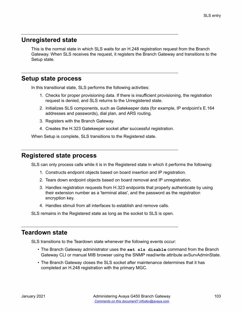
Unregistered stateThis is the normal state in which SLS waits for an H.248 registration request from the BranchGateway. When SLS receives the request, it registers the Branch Gateway and transitions to theSetup state.
Setup state processIn this transitional state, SLS performs the following activities:
1. Checks for proper provisioning data. If there is insufficient provisioning, the registrationrequest is denied, and SLS returns to the Unregistered state.
2. Initializes SLS components, such as Gatekeeper data (for example, IP endpoint’s E.164addresses and passwords), dial plan, and ARS routing.
3. Registers with the Branch Gateway.
4. Creates the H.323 Gatekeeper socket after successful registration.
When Setup is complete, SLS transitions to the Registered state.
Registered state processSLS can only process calls while it is in the Registered state in which it performs the following:
1. Constructs endpoint objects based on board insertion and IP registration.
2. Tears down endpoint objects based on board removal and IP unregistration.
3. Handles registration requests from H.323 endpoints that properly authenticate by usingtheir extension number as a 'terminal alias', and the password as the registrationencryption key.
4. Handles stimuli from all interfaces to establish and remove calls.
SLS remains in the Registered state as long as the socket to SLS is open.
Teardown stateSLS transitions to the Teardown state whenever the following events occur:
• The Branch Gateway administrator uses the set sls disable command from the BranchGateway CLI or manual MIB browser using the SNMP read/write attribute avSurvAdminState.
• The Branch Gateway closes the SLS socket after maintenance determines that it hascompleted an H.248 registration with the primary MGC.
SLS entry
January 2021 Administering Avaya G450 Branch Gateway 103Comments on this document? [email protected]

• SLS determines that it needs to unregister with the Branch Gateway due to internal errorconditions.
Teardown state process1. Tears down endpoint objects.
2. Sends unregistration requests to IP endpoints that are not on active calls. IP endpointslose registration with SLS and display the discovered IP address during re-registration withan MGC.
3. Closes the H.323 Gatekeeper socket.
After Teardown is complete, SLS transitions to the Unregistered state and starts searching at thetop of the MGC list for a controller.
SLS interaction with specific Branch Gateway featuresSLS interacts differently with the various Branch Gateway features.
Direct Inward Dialing in SLS modeDirect Inward Dialing (DID) is a service offered by telephone companies that enables callers to dialdirectly into an extension on a switch without the assistance of an operator or automated callattendant.
Note:
DID is a method of routing calls that applies to both analog and digital (T1/E1) lines. However,while the method is typically referred to as DID in the analog world, it is usually called DialedNumber Identification Service (DNIS) in the digital world. Despite the difference in names, theconcept is the same.
The Branch Gateways support DID central office trunk interfaces, and the digit transmission fromthe central office is configurable when ordering the service:
Immediate: The DID signaling starts immediately after the central office seizes the analog DIDtrunk by closing the loop (across tip and ring). In addition, analog DID trunk lines only supportinbound calls. For this reason, Customer Premise Equipment (CPE) utilizing DID trunk lines forinbound routing may utilize loop-start lines for outbound transmission.
Wink: The DID signaling starts after the Branch Gateway’s analog trunk interface reverses thebattery polarity and sends a “wink” to the central office.
Warning:
An analog two-wire DID trunk line is different from a standard analog loop-start line. Withanalog DID trunk lines, the battery (power feed) to the line is supplied by the Branch
Standard Local Survivability (SLS)
January 2021 Administering Avaya G450 Branch Gateway 104Comments on this document? [email protected]

Gateway’s analog trunk interface. With a standard loop-start line, the power is supplied by thecentral office, which is why damage can occur from connecting a loop-start PSTN trunk to theDID port.
The number of sent digits (3 to 4 typically) and signaling type (Pulse/DTMF) are also configurableat ordering time.
Multiple call appearances in SLS modeWhen a Branch Gateway is in SLS mode, three call appearances, each with limitations, aresupported:
• The first two call appearances are for incoming or outgoing calls. The first call appearance isthe default.
• The third call appearance is for outgoing calls only.
Note:
“First”, “second”, and “third”, refer to the order in which you use call appearances, not theorder of the Call Appearance buttons on your phone.
ExampleFor example, User A chooses the third call appearance to dial User B, and then User C calls UserA, which is sent to the first call appearance. In this situation, a subsequent inbound call to User Awill be denied (busy) because the first and third call appearances are in use, and the second callappearance is only available for outbound calls.
Hold in SLS modeUsing the Hold feature differs by user and by phone type, and the same is true of the Hold featurein Standard Local Survivability (SLS) mode. Some users return to a call on Hold by pressing theCall Appearance button, however, CM has an administrable parameter that allows users torelease a call on hold by pressing the Hold button a second time (if only one call is held). TheHold feature also works differently in DCP and IP phones and analog phones in the survivablemode.
The Hold feature in SLS does not support:
• Music on Hold
• Local mute on analog phones
• Specialized treatment of E-911 calls
• Call Hold indicator tones
SLS interaction with specific Branch Gateway features
January 2021 Administering Avaya G450 Branch Gateway 105Comments on this document? [email protected]

DCP and IP phonesWhen a Branch Gateway is in the survivable mode, you can release calls on Hold on all DCP andIP phones by either:
• Pressing the Hold button a second time if only one call is held
• Pressing the held Call Appearance button
Analog telephonesNewer analog telephones (for example, Avaya 62xx series) have buttons with specific functionsfor placing a call on Hold:
Hold button: A hold function that is local to the telephone
Pressing the Hold button causes the analog station to place a hold bridge in both directions at thetelephone set. No signaling notification is sent to the SLS call-engine and, therefore, there is noability to notify the other party that they have been placed on hold. Pressing the Hold button asecond time causes the analog phone to remove the hold bridge and the call path is restored. Inessence, this hold operation is equivalent to using the Mute button on station sets.
Flash button: A function that sends a switchhook signal to the server
Switchhook (receiver on/off hook): A function that sends a disconnect signal to the server
Using the Flash buttonProcedure
1. Press the Flash button on the analog phone.
You hear a dial tone; the other party hears nothing.
You can leave the call on Hold or transfer the call. Press the Flash button twice to return tothe call.
2. Dial the Feature Access Code (FAC) for Hold.
At this point you can leave the call on Hold or transfer the call.
3. To return to the call, press the Flash button again.
The call is re-established.
Note:
Either party can put the call on Hold or return to the call.
Standard Local Survivability (SLS)
January 2021 Administering Avaya G450 Branch Gateway 106Comments on this document? [email protected]

Using the switchhook buttonProcedure
1. Press the switchhook once.
You hear a dial tone.
2. Dial the FAC for Hold.
This places the call on Hard Hold which prevents you from transferring the call. To return tothe call, dial the FAC for Hold.
3. Do one of the following:
• Return to the call by dialing the FAC for Hold.
The call is re-established.• Dial a third party by dialing the number and flashing the switchhook once (you will hear a
stutter dial tone). Dial the FAC for Hold (the second call is now on Hold and the first callis re-established). If you want to toggle between the first and second calls, press theswitchhook and dial the FAC for Hold once each time you want to change calls.
• Hang up.
Your phone will ring to notify you that you have a call on Hold. When you lift the receiveryou will hear a dial tone and can perform any of the activities listed in Step 3.
Call Transfer in SLS modeUsing the Call Transfer feature differs by user and by phone type. The same is true of the Holdfeature in Standard Local Survivability (SLS) mode. Call Transfer also works differently in DCP/IPphones and analog phones in the survivable mode. Some limitations of the Call Transfer featureare:
• The established call must be initiated from a local station (administered on this BranchGateway) or from an incoming trunk. You can make only point-to-point call transfers to aphone that is local to the same Branch Gateway.
• Does not support E-911 calls• Does not support the Conference button on any phone• Does not support trunk-to-trunk transfer (for example, for voice messaging)
Transferring a call on DCP and IP phonesProcedure
1. While talking on a call or while you have a call on Hold, press the Transfer button on yourphone.
You hear a dial tone; the other party hears nothing.
SLS interaction with specific Branch Gateway features
January 2021 Administering Avaya G450 Branch Gateway 107Comments on this document? [email protected]

2. Dial the third party’s number on your phone.
3. You can either:
• Wait for the third party to answer and announce the call, then either press the Transferbutton again or hang up.
• Transfer the call before the third party answers by pressing the Transfer button again.
ResultThe person you were talking to is transferred to the third party.A message appears on your phone display to indicate that the call transfer is complete.
Note:If you do not completely dial the string or if you hear a fast-busy or re-order (French siren)tone, only a Hard Hold call connection (if present) remains at the station.
If the third party does not answer, the call does not ring back to the originating party. If a transferdoes not complete, the event is logged.
Transferring an established call from an analog phoneAbout this taskNewer analog phones (for example, Avaya 62xx series) have buttons with specific functions fortransferring a call. The switchhook (receiver on/off hook) sends a disconnect signal to the server,and the Transfer/Flash button sends a transfer message to the server.
Procedure1. While on a call, press the switchhook once or press the Transfer/Flash button.
You hear a dial tone; the other party hears nothing.
2. Dial the third party’s number on your phone.
3. You can either:
• Wait for the third party to answer and announce the call, then hang up.
• Transfer the call before the third party answers by hanging up.
ResultThe person you were talking to is transferred to the third party.A message appears on your phone display to indicate that the call transfer is complete. If thenecessary call processing resources are not available, the transfer does not complete and theevent is logged.
Note:Displays are not supported on analog phones unless they are supported locally by an analogphone.
Standard Local Survivability (SLS)
January 2021 Administering Avaya G450 Branch Gateway 108Comments on this document? [email protected]

Using contact closure in SLS modeAbout this taskWhen the Branch Gateway is in survivable mode, contact closure works as follows:
Procedure1. Lift the phone receiver and listen for the survivability dial tone.
2. Dial the appropriate contact closure FAC (Feature Access Code) — open, close, or pulse— on the phone.
• If you dial an invalid FAC code, then SLS plays an intercept tone and terminates thesession.
• If you dial a valid FAC code, then you will hear a standard dial tone and can proceed toStep 3 on page 109.
3. Dial the three-digit Branch Gateway number.
• If you enter fewer than three digits, then SLS times out and you must restart thisprocedure from the beginning.
• If the Branch Gateway number matches the local Branch Gateway number, then SLSplays a standard dial tone and you can proceed to Step 4 on page 109.
• If the Branch Gateway number does not match the local Branch Gateway number, SLSplays an intercept tone and terminates the session.
4. Dial the contact closure code, for example 1 for contact pair #1, and 2 for contact pair #2.
You hear stutter tone and then silence, confirming these valid codes. If you dial an invalidcontact closure number, you hear an intercept tone.
Contact closure feature activations appear in the CDR log.
Note:
If the contact closures are set to manual operation, the FAC operation will not workeven though the confirmation tone is heard. However, an event will be logged.
Related linksExample of CDR log entries and format on page 111
Contact closure / SLS feature interactions• There is no screening to authorize the use of the contact closure feature in SLS mode.
Security is provided by limiting the number of users who know the correct key sequencerequired for the contact closure feature.
• You cannot use the Hold or Transfer features while dialing the contact closure FAC keysequence.
• Contact closure will not work until you dial the full digit sequence and it is processed.
SLS interaction with specific Branch Gateway features
January 2021 Administering Avaya G450 Branch Gateway 109Comments on this document? [email protected]

• If two users try to simultaneously use contact closure, whoever dials the full FAC keysequence first gets precedence.
• Interdigit timing rules apply to the contact closure feature, so if you pause too long during theFAC key sequence, the feature times out.
• Call appearances are not released (available for calls) until you hang up.
• You cannot use the contact closure feature from outside trunk lines.
Related linksContact closure on page 302
Administering IP Softphone in SLS modeAbout this taskThe SLS mode supports shared administrative identity with the Avaya Softphone application, butrequires specific station administration.
Procedure1. Access the CM administrative SAT interface.
2. At the SAT interface, enter change station <extension> to display the Station screen.
3. Set the Terminal Type field to a 46xx IP phone.
4. Save the changes.
Note:
If you administer the Terminal Type field as a DCP phone, shared administrativeidentity functionality in SLS mode is not supported.
Related linksAccessing the registered MGC on page 72
SLS logging activitiesSLS exports call-recording data in survivability mode. The Call Detail Record (CDR) log containsdetailed information about each outgoing call that uses a trunk. This information can be stored inflash NVRAM or directed to an external server for later processing. It includes data for:
• Merged outgoing Trunk Access Codes (TACs), indicating successfully completed dialing
• Successfully completed ARS calls
Standard Local Survivability (SLS)
January 2021 Administering Avaya G450 Branch Gateway 110Comments on this document? [email protected]

Note:
The Syslog information is stored in a memory file that is configured as a FIFO with alength of 50 KB. Once the last entry in the memory is full, the newest log eventoverwrites the oldest entry. This provides for a storage of 667 call records that may besaved during SLS operation. If you have a Syslog server on a PC connected to the localarea network of the branch office, then these Syslog messages can be immediatelytransported from the Branch Gateway to the Syslog server. This enables the captureperiod to run for an extended period.
• Contact closure
Example of CDR log entries and formatGxxx-SLS(super)# show logging cdr file content08/23/2015,10:46:35:CDR-Informational: 10:46 00:00 A 700 50029555 52001 v30108/23/2015,10:45:46:CDR-Informational: 10:45 00:00 A 700 50029 52001 v30108/23/2015,10:45:14:CDR-Informational: 10:45 00:00 A 700 52 52001 v30108/23/2015,10:44:35:CDR-Informational: 10:44 00:00 A 700 445200 52001 v30108/22/2015,13:20:23:CDR-Informational: 13:20 00:00 A 700 50029 52001 v30108/22/2015,13:20:15:CDR-Informational: 13:20 00:00 A 700 50029 52000 v30108/22/2015,13:20:05:CDR-Informational: 13:20 00:00 A 700 44 52000 v30108/22/2015,13:19:59:CDR-Informational: 13:19 00:00 A 700 44500 52000 v301
An interpretation of the first entry is:
• 08/23/2015: is the date of the log entry
• 10:46:35: is the time of the log entry
• CDR-Informational: is the category (to aid sorting)
• 10:46: is the time the call was placed
• 00:00: is the duration of the call in hours and minutes or 99:99: if the duration is greaterthan 99 hours
• A: is the condition code. Possible values are:
- 7. Outgoing call
- 9. Incoming call
- A. Outgoing TAC call or emergency call
- B. Used for contact closure
• 700: is the FAC or TAC number
• 50029555: is the dialed number
• 52001: is the extension that originated the call
• v301: indicates the port through which the call was routed
SLS logging activities
January 2021 Administering Avaya G450 Branch Gateway 111Comments on this document? [email protected]

Example of CDR log with contact closureGxxx-SLS(super)# show logging cdr file content08/23/2015,03:59:24:(0 0 0:15:5)CDR-Informational: Aug 23 03:59 B 15840 PULSE 003 2
An interpretation of this entry is:
• Date (08/23/2015) and time (03:59:24) record when the feature was activated
B: is the condition code. Possible values are:
- 7. Outgoing call
- A. Outgoing TAC call or emergency call
- B. Used for contact closure
• 15840: is the extension that activated the feature
• PULSE: indicates the contact closure operation (could also be OPEN: or CLOSE: )• 003: is the Branch Gateway number
• 2: is the contact closure number
SLS configuration
SLS configuration rulesSLS is included as part of the resident firmware package that is installed as part of BranchGateway firmware upgrade. However, for SLS to function correctly, the following conditions mustbe met:
• CM must be configured for SLS and Auto Fallback.
• Branch Gateway can be manually configured for SLS and Auto Fallback using the CLI.
• SLS must be enabled on Branch Gateway.
• To activate any saved changes within SLS, the disable and enable SLS commands must beused together.
Related linksPrerequisites for using the CLI to manually configure SLS administration on the BranchGateway on page 125Enabling SLS on page 124Activating changes in SLS on page 125
Standard Local Survivability (SLS)
January 2021 Administering Avaya G450 Branch Gateway 112Comments on this document? [email protected]

Configuring CM for SLSAbout this taskYou must configure CM for SLS using manual CLI entry of SLS administration. Perform theconfiguration during the initial administration of the host CM server.
Procedure1. Access the CM administrative SAT interface.
2. At the SAT, enter change node-names ip to display the IP Node Names screen.
For example:change ip-codec-set-1 Page 1 of 3 IP NODE NAMES Name IP Address Name IP Address Denver Gateway1 192.168.1 .200 . . .procr 192.168.1 .201 . . .(X of X administered node-names were displayed )Use 'list node-names' command to see all the administered node-namesUse 'change node-names ip xxx' to change a node-name 'xxx' or add a node-name
3. In the Modem field, type v150mr.
Note:
Set the name of the Branch Gateway consistently with the Name field on the MediaGateway Administration screen in CM (add media-gateway) and with the nameused in the set system name command (gateway CLI).
4. Type the IP address of the Branch Gateway in the IP Address field.
5. Submit the screen.
6. At the SAT, enter change system-parameters mg-recovery-rule 1 to display theSystem Parameters Media Gateway Automatic Recovery Rule screen.
7. Type a description of the rule in the Rule Name field.
8. Set the Migrate H.248 MG to primary field to immediately.
Note:
The immediately value is only one of the four possible choices. See the AdministratorGuide for Avaya Aura® Communication Manager for more information on the values forthis field.
9. Submit the screen.
10. At the SAT, enter display media-gateway 1 to display the Media Gateway screen.
SLS configuration
January 2021 Administering Avaya G450 Branch Gateway 113Comments on this document? [email protected]

11. Verify the following fields:
• Name field (20 characters maximum) must match the administered name of thegateway.
• Max Survivable IP Ext field only appears when the Type field is Gxxx .
The current maximum product limits enforced by the SLS gateway’s firmware module is240.
These limits are enforced due to resource considerations in the given gateway.
Important:
Since the VoIP resources on the Branch Gateway are limited, the Max Survivable IPExt field should not exceed these values.
12. At the SAT, enter change station extension to display the Station screen.
13. Verify that the following fields are correct:
• Survivable GK Node Name• Survivable COR• Survivable Trunk Dest
14. Submit the screen.
Related linksAccessing the registered MGC on page 72Configuration of the SLS data through the CLI on page 146
Inherited Class of Restriction (COR) permissions
COR permissions show the hierarchical relationship among the calling-restriction categories.
Standard Local Survivability (SLS)
January 2021 Administering Avaya G450 Branch Gateway 114Comments on this document? [email protected]

Table 3: Figure notes:
1. Unrestricted: Users can dial any valid routable number, except an ARS pattern specificallyadministered as deny: . ETR functionality and calls through the CO are permitted in this class.
2. Local: Users can only dial these call types:
• locl: (public-network local number call)
• op: (operator)
• svc: (service)
• hnpa: (7-digit NANP call)
3. Toll: Users can only dial these call types:
• fnpa: (10-digit NANP call)
• natl: (non-NANP call)
4. Internal: Users can only dial other stations within the Branch Gateway and the emergency externalnumber (default)
5. Emergency: Users can only dial the emergency external number
Station screen field descriptions for the Branch Gateway
Security CodeThe security code required by users for specific system features and functions are as follows:
• Extended User Administration of Redirected Calls• Personal Station Access• Redirection of Calls Coverage Off-Net• Leave Word Calling• Extended Call Forwarding• Station Lock• Voice Message Retrieval• Terminal Self-Administration• Enterprise Mobility User• Extension to Cellular• Call Forwarding• Posted Messages• Security Violation Notification• Demand Printing
The required security code length is administered system wide.
SLS configuration
January 2021 Administering Avaya G450 Branch Gateway 115Comments on this document? [email protected]

TypeUse this field to specify the telephone type. You must administer the station type for each stationthat you add to the system.
The following table lists the telephones, virtual telephones, and personal computers that you canadminister on Communication Manager. Telephones that are not in the table require an alias to asupported set type.
Note:
If Terminal Translation Initialization is enabled, you cannot change the analog telephonesadministered with hardware to a virtual extension.
Telephone type Model Administered asSingle-line analog 500 500
2500, 2500 with Message WaitingAdjunct
2500
6210 62106211 62106218 62186219 62186220 62206221 6220
CallerID Analog telephone with Caller ID CallrID7101A, 7102A 7101A7103A Programmable and Original 7103A7104A 7104A8110 8110DS1FD DS1FD7302H, 7303H 7303SVoice Response Unit (VRU) with C&Dtones
VRU
VRU without C&D tones 2500Single-lineDS1/DSO
DS1 device without forward disconnect opsVRU with forward disconnect withoutC&D tones
ds1fd or ds1sa
VRU with forward disconnect withoutC&D tones
VRUFD or VRUSA
Terminals 510D 510515BCT 515
Table continues…
Standard Local Survivability (SLS)
January 2021 Administering Avaya G450 Branch Gateway 116Comments on this document? [email protected]

Telephone type Model Administered asMulti-appearancehybrid
7303S 7303S, 7313H7305H 7305S7305S 7305S, 7316H, 7317H7309H 7309H, 7313H7313H 7313H7314H 7314H7315H 7315H7316H 7316H7317H 7317H
Multi-appearancedigital
2402 24022410 24102420 24206402 64026402D 6402D6408 64086408+ 6408+6408D 6408D6408D+ 6408D+6416D+ 6416D+6424D+ 6424D+7401D 7401D7401+ 7401+7403D 7403D7404D 7404D7405D 7405D7406D 7406D7406+ 7406+7407D 7407D7407+ 7407+7410D 7410D7410+ 7410+7434D 7434D7444D 7444D8403B 8403B8405B 8405B
Table continues…
SLS configuration
January 2021 Administering Avaya G450 Branch Gateway 117Comments on this document? [email protected]

Telephone type Model Administered as8405B+ 8405B+8405D 8405D8405D+ 8405D+8410B 8410B8410D 8410D8411B 8411B8411D 8411D8434D 8434D9404 94049408 9408CALLMASTER I 602A1CALLMASTER II, III, IV 603A1, 603D1, 603E1, 603F1CALLMASTER VI 606A1IDT1 7403DIDT2 7406D
IP Telephone 4601+
Note:
When you add a new 4601 IPtelephone, you must use the 4601+station type. This station type hasthe Automatic Callback featureenabled.
4601+
4602+
Note:
When you add a new 4602 IPtelephone, you must use the 4602+station type. This station type hasthe Automatic Callback featureenabled.
4602+
4606 46064610 46104612 46124620SW IP (G3.5 hardware) 46204621 46214622 46224624 46244625 4625
Table continues…
Standard Local Survivability (SLS)
January 2021 Administering Avaya G450 Branch Gateway 118Comments on this document? [email protected]

Telephone type Model Administered as4690 46909608 96089610 96109611 96119620 96209621 96219630 96309640 96409641 96419650 9650
SIP IP Telephone • 4602SIP with SIP firmware
• 4610SIP with SIP firmware
• 4620SIP with SIP firmware
• 4620SIP CC (Call Center)
• SIP Softphone/Avaya one-X Desktop
• Toshiba SP-1020A
Note:
You must administer any telephonewith SIP firmware used for SIPnetworking as a 4620SIP, 96xxSIP,or 16CC SIP telephone.
Note:
Communication Manager Release6.2 and later do not support1616SIP CC and 4620SIP CCtelephones.
4620SIP
9601SIP 9608SIP9620, 9630, 9630G 9640, 9640G withSIP firmware
96xx or 96xxSIP telephone
9608 with SIP firmware 9608SIP9611 with SIP firmware 9611SIP9621 with SIP firmware 9621SIP9641 with SIP firmware 9641SIP9608 with SIP firmware (for call center) 9608SIPCC9611 with SIP firmware (for call center) 9611SIPCC9621 with SIP firmware (for call center) 9621SIPCC
Table continues…
SLS configuration
January 2021 Administering Avaya G450 Branch Gateway 119Comments on this document? [email protected]

Telephone type Model Administered as9641 with SIP firmware (for call center) 9641SIPCC
H.323 SoftPhone application Road Warrior H.323 or DCP typeNative H.323 H.323Singleconnect H.323 or DCP typeAny NI-BRI (N1 and N2) telephone NI-BRI7505D 7505D7506D 7506D7507D 7507D8503D 8503D8510T 8510T8520T 8520T
Personal computer 6300/7300 PC(voice/data) 6538/9 ConstellationTest Line ATMS 105TLNo hardwareassigned at thetime ofadministration.
• Use XDID when CommunicationManager assigns a DID number to thestation.
• Use XDIDVIP when the administratorlater assigns a DID number to thestation.
• Use virtual to map the station and otherextensions to one physical telephone.
Key telephonesystem interface
— K2500
AWOH any digital set —CTI station CTI
CTI CTI station CTIXMOBILE EC500, DECT, PHS XMOBILEISDN-BRI datamodule
7500 7500
SBS Extension SBS test extension (no hardware) sbs
PortThe Auxiliary and Analog ports assigned to the station are as follows.
Valid Entry Usage01 to 64 The first and second numbers are the cabinet numbers.A to E The third character is the carrier.
Table continues…
Standard Local Survivability (SLS)
January 2021 Administering Avaya G450 Branch Gateway 120Comments on this document? [email protected]

Valid Entry Usage01 to 20 The fourth and fifth characters are the slot numbers. G650 has 14 slots.01 to 32 The sixth and seventh characters are the port numbers.x or X Indicates that there is no hardware associated with the port assignment since the
switch was set up, and the administrator expects that the extension has a non-IPset. Or, the extension had a non-IP set, and it dissociated. Use x for AdministeredWithOut Hardware (AWOH) and Computer Telephony (CTI) stations, as well as forSBS Extensions.
IP Indicates that there is no hardware associated with the port assignment since theswitch was set up, and the administrator expects that the extension would have anIP set. This is automatically entered for certain IP station set types, but you canenter for a DCP set with softphone permissions. This changes to the s00000 typewhen the set registers.
xxxVmpp Specifies the Branch Gateway.
• xxx is the Branch Gateway number, which is in the range 001 to 250.
• m is the module number, which is in the range 1 to 9.
• pp is the port number, which is in the range 01 to 32.Analog Trunk port Analog trunk port is available with:
• MM711 and MM714 media modules
• TN747 and TN797 circuit packs
Survivable GK Node NameAny valid previously-administered IP node name. Identifies the existence of other H.323gatekeepers located within gateway products that offer survivable call features. For example, theMultiTech MVPxxx-AV H.323 gateway family and the SLS function within the Branch Gateways.When a valid IP node name is entered into this field, Communication Manager adds the IPaddress of this gateway to the bottom of the Alternate Gatekeeper List for this IP network region.As H.323 IP stations register with Communication Manager, this list is sent down in theregistration confirm message. With this, the IP station can use the IP address of this SurvivableGatekeeper as the call controller of last resort.
If blank, there are no external gatekeeper nodes within a customer's network. This is the defaultvalue.
Available only if the station type is an H.323 station for the 46xx or 96xx models.
Survivable CORSets a level of restriction for stations to be used with the survivable dial plan to limit certain usersto only to certain types of calls. You can list the restriction levels in order from the most restrictiveto least restrictive. Each level has the calling ability of the ones above it.
Available for all analog and IP station types.
SLS configuration
January 2021 Administering Avaya G450 Branch Gateway 121Comments on this document? [email protected]

Valid Entries Usageemergency This station can only be used to place emergency calls.internal This station can only make intra-switch calls. This is the default.local This station can only make calls that are defined as locl, op, svc, or hnpa in the
Survivable Gateway Call Controller's routing tables.toll This station can place any national toll calls that are defined as fnpa or natl on the
Survivable Gateway Call Controller's routing tables.unrestricted This station can place a call to any number defined in the Survivable Gateway Call
Controller's routing tables. Those strings marked as deny are also denied to theseusers.
Survivable Trunk DestDesignates certain telephones as not being allowed to receive incoming trunk calls when theBranch Gateway is in survivable mode.
Available for all analog and IP station types.
Valid Entry Usagey Allows this station to be an incoming trunk destination while the Branch Gateway is
running in survivability mode. This is the default.n Prevents this station from receiving incoming trunk calls when in survivable mode.
Switchhook FlashValid Entry Usagey Allows users to use the switchhook flash function to activate Conference/Transfer/
Hold and Call Waiting. Required for H.323 station types.n Disables the flash function so that when the switchhook is pressed while active on a
call, the call drops. Requires that Call Waiting Indication is disabled.
Expansion ModuleIndicates whether or not this telephone has an expansion module. Enables the administration ofthe buttons for the expansion module.
NameThe name of the person associated with this telephone or data module. The system uses thisvalue to create the system directory.
Note:
This field is supported by Unicode language display for the 4610SW,4620SW, 4621SW, and4622SW telephones.
For more information on Unicode language display, see Administering Avaya Aura®
Communication Manager.
Standard Local Survivability (SLS)
January 2021 Administering Avaya G450 Branch Gateway 122Comments on this document? [email protected]

Note:
In the display for emergency notification when completing the Name field, fill the mostimportant identifying information at the beginning of the field. When an emergency call ismade and a crisis alert station with a 27-character display is notified, only 17 characters of theName field appear on the first display line, followed by the extension. The second linecontains the last three characters of the Name field, followed by the word EMERGENCY.Characters 18 through 24 of the Name field are not displayed at all.
SLS ARS Entry page field descriptionsUse the following fields on the SLS ARS Entry page to administer an Automatic Route Selection inSLS.
Dialed StringCommunication Manager matches the dialed numbers with the entry in the Dialed String field thatmost closely matches the dialed number. You can enter up to 18 digits that the call-processingserver analyzes. You can also enter the wildcard characters, x and X.
MinUse this field to specify the minimum number of user-dialed digits that the system must collect tomatch the dialed string.
MaxUse this field to specify the maximum number of user-dialed digits that the system must collect tomatch the dialed string.
DelUse this field to enter the number of digits that the system must delete from the starting of thedialed string.
Replacement StringUse this field to specify the digit string that must replace the deleted portion of the dialed number.
Valid entry Usageblank To delete the digits without replacement.0 to 9, * To type the digit string.
The digit string can have up to 18 characters.# To indicate the end of dialing.
Call Type (ARS only)Use this field to enter the call type associated with each dialed string.
SLS configuration
January 2021 Administering Avaya G450 Branch Gateway 123Comments on this document? [email protected]

Valid entry Usage China Number 1,Call Type
intl Use this option for public-network international calls. toll-autoalrt Use this option to alert attendant consoles or other digital
telephones when a user places an emergency call.normal
emer Use this option for emergency calls. normalfnpa Use this option for ten-digit North American Numbering Plan
(NANP) calls.attendant
hpna Use this option for seven-digit NANP calls. normallop Use this option for international operator calls. attendantlocl Use this option for public-network local calls. normallpvt Use this option local private calls. normalnatl Use this option for non-NANP calls. normalnpvt Use this option for national private calls. normalnsvc Use this option for national service calls. normalop Use this option for operator calls. attendantpubu Use this option for public-network number (E.164)-unknown
calls.normal
svcl Use this option for national(2) calls. toll-autosvct Use this option for national(2) calls. normalsvfl Use this option for service call first party control calls. tollsvft Use this option for service call first party control calls. local
Trunk GroupValid Entry Usage1 to 2000 Trunk-group number selected from the drop-down choices of trunk groups found in
the SLS extract from the controlling CM server.
Permit / DenyIndicates whether the call should be permitted or denied.
Enabling SLSProcedureTo enable SLS on the Branch Gateway, enter set sls enable
Standard Local Survivability (SLS)
January 2021 Administering Avaya G450 Branch Gateway 124Comments on this document? [email protected]

Note:
If you enable SLS and then performed additional administration, you must first disable SLSand then re-enable it. This causes the SLS application to resynchronize its administrativedatabase with the Branch Gateway's global CLI command database.
The Branch Gateway responds with the message, Survivable Call Engine is enabled.
Disabling SLSProcedureTo disable SLS on the Branch Gateway, enter set sls disableThe Branch Gateway responds with the message Survivable Call Engine is disabled.
Activating changes in SLSAbout this taskTo activate changes you make in SLS, use the disable and enable SLS commands together. Toactivate changes in SLS, perform the following steps:
Procedure1. Make any changes to SLS administration desired.
2. While still in SLS mode, enter set sls disableThe Branch Gateway responds with the message Survivable Call Engine isdisabled.
3. Enter set sls enableThe Branch Gateway responds with the message Survivable Call Engine isenabled.
Prerequisites for using the CLI to manually configure SLSadministration on the Branch Gateway
Before configuring SLS administration on the Branch Gateway, ensure that:
• CM Release 6.3 or later is running on the host server
• The Branch Gateway is registered with CM
• The SLS is enabled on the Branch Gateway through its CLI
• S8300 is not serving as a Survivable Remote Server
SLS configuration
January 2021 Administering Avaya G450 Branch Gateway 125Comments on this document? [email protected]

• Branch Gateway is not subtending to another external server (including Survivable CoreServer or another Survivable Remote Server in another gateway)
Note:
Do not run two SLS data update sessions concurrently. The SLS data can be administeredlocally using CLI or a SNMP MIB browser. This can cause a situation where one administratorcan unknowingly undo the work of the other. For example, if a local administrator enters trunk-group context just before a remote administrator performs a SNMP write operation to changea trunk-group parameter, that parameter will be overwritten with the current CLI values whenthe local administrator exits the trunk-group context.
SLS data set preparationIt is recommended to plan the SLS coverage and gather information from CM before creating theSLS administration data set at the Branch Gateway command line. Strategic selection of thestations and trunks that participate in SLS can ensure that vital communications are sparedinterruptions caused by network outages.
Important:
Since you can administer your system for SLS either from the SAT or from the BranchGateway CLI, the two administration tasks must be synchronized with common data and portusage as well as system-defined capacities. For example, if a physical DCP station portnumber 10 is not administered on the CM server, even though the Branch Gateway’s SLSengine has that port administered, the port is unusable during SLS operation on the BranchGateway. This is because the hardware port configuration on the media modules is initiallyconfigured by CM in subtending gateway mode, by using the H.248 control channel to pushinformation down to the Branch Gateway.
SLS capacitiesThe maximum number of legacy stations and trunks that can be supported is dependent upon theslot-module configuration of what is installed.
Branch Gateway model IP stationsG4504 240
You can collect the CM data using the CM administrative SAT interface.
Related linksAccessing the registered MGC on page 72
Collecting analog stations dataProcedure
1. At the SAT, enter list media-gateway to display a list of administered gateways.
2. Look for supported gateways in the Type field.
4 340 stations maximum (all types)
Standard Local Survivability (SLS)
January 2021 Administering Avaya G450 Branch Gateway 126Comments on this document? [email protected]

3. Once you know the Branch Gateway of interest, match the Branch Gateway model with theanalog station ports.
• MM711
• MM714
• MM716
4. At the SAT, enter display port port-number, where port-number is the analog stationport on the Branch Gateway.
The system displays the extension number assigned to the port.
5. Once you know the extension, enter display station extension to display the Stationscreen for this extension.
6. Gather the necessary information for the following fields:
• Extension
• Port
• Type - Only 2500 is the accepted Type
• Survivable COR
• Survivable Trunk Dest
• Switchhook Flash
• Name
Related linksStation screen field descriptions for the Branch Gateway on page 115
Collecting DCP stations dataProcedure
1. At the SAT, enter list media-gateway to display a list of administered gateways.
2. Look for supported gateways in the Type field.
3. When you know the Branch Gateway of interest, match the gateway model with the digitalstation ports:
• MM712
• MM717
4. At the SAT, enter display port port-number, where port-number is the DCP station porton the gateway.
The system displays the extension number assigned to the port.
5. to display the Station screen for this extension, type display station extension.
SLS configuration
January 2021 Administering Avaya G450 Branch Gateway 127Comments on this document? [email protected]

6. Gather the necessary information for the following fields:
• Extension
• Port
• Security Code
(Optional) - used for the registration of an IP Softphone (RoadWarrior)
• Type - as any of the following types:
- 2402
- 2410
- 2420
- 6402
- 6402D
- 6408
- 6408+
- 6408D
- 6408D+
- 6416D+
- 6424D+
- 8403B
- 8405B
- 8405B+
- 8405D
- 8405D+
- 8410B
- 8410D
- 8411B
- 8411D
- 8434D
• Survivable COR
• Survivable Trunk Dest
• Expansion Module
• Name
For more information about these fields, see Station screen field descriptions for thebranch gateway.
Standard Local Survivability (SLS)
January 2021 Administering Avaya G450 Branch Gateway 128Comments on this document? [email protected]

Collecting IP stations dataProcedure
1. At the SAT, enter list media-gateway to display a list of administered gateways.
2. Look for supported gateways in the Type field.
3. Enter display media-gateway.
4. Read the reported IP address for this gateway.
5. Enter list node-name and compare the IP address of the Branch Gateway in the listwith the IP address of the gateway that you are administering for SLS.
When you find a match in the node-name screen, read the assigned node-name. This willbe used to do a pattern match with a field on the IP Station screen in Step 6 on page 129.
6. Enter list station type type, where type is one of the supported IP stations.
The report lists all IP phones that could have the Survivable GK Node-Nameadministered to the target media gateway. The Survivable GK Node-Name uniquelyassociates an IP phone with a particular Branch Gateway.
7. Once a match is made between the station screen's Survivable GK Node-Name and thetarget gateway's Node-Name , gather the values for the given IP station per:
• Extension
• Security Code
(IP only) - used for the registration of the IP endpoint
• Type — as any of the following types:
- 4601
- 4602
- 4602SW
- 4606
- 4610SW
- 4612
- 4620
- 4620SW
- 4621
- 4622
- 4624
- 4625
• Survivable COR
SLS configuration
January 2021 Administering Avaya G450 Branch Gateway 129Comments on this document? [email protected]

• Survivable Trunk Dest
• Expansion Module
• Name
Related linksStation screen field descriptions for the Branch Gateway on page 115
Collecting trunk groups dataProcedure
1. At the SAT, enter list media-gateway to display a list of administered gateways.
2. Look for supported gateways in the Type field.
3. At the SAT, enter display media gateway to view the media modules that areassigned to the various slots.
Use the table in SLS group type assignments on page 163 as a reference to identify howthe particular media module has been configured for serving as a trunk port, and then usethe various list commands on CM to look for physical port matches in the various trunkSAT forms in order to discover what translation information is needed.
4. Identify the analog trunk ports.
5. Identify the BRI trunk ports.
6. Identify the digital DS1 trunk ports.
7. Identify the Branch Gateway modules and check for provisioned trunk ports.
8. At the SAT, enter display port portid, where portid is the trunks port on the targetgateway.
The system reports the Trunk Group Number/Member Number for this particular port.
9. Once you know the Trunk Group Number, gather trunk-group information for the followingfields:
• Group Type
• Outgoing Dial Type
• Trunk Group Number
• TAC
• Port
• Digit Treatment
• Digits
• Trunk Type
• Group Name
• Codeset to Send Display
Standard Local Survivability (SLS)
January 2021 Administering Avaya G450 Branch Gateway 130Comments on this document? [email protected]

• Codeset to Sent National IEs
• Outgoing Channel ID Encoding
• Digit Handling (in/out)
• Network (Japan) Needs Connect Before Disconnect
• Send Name
• Send Calling Number
• Incoming Calling Number - Format
• Incoming Destination
• Trunk Hunt
• Sig Grp
Related linksModule-port values in SLS trunk-group context for analog trunks on page 164Trunk port values in SLS trunk-group context for digital trunks on page 164
Trunk Group screen field descriptionsName DescriptionGroup Type This field specifies the type of trunks associated
with this trunk groupOutgoing Dial Type The only acceptable values are tone and rotary. If
the field is set to automatic or mf, then the value oftone is used instead. Note that this does not applyto DS1 PRI links.
Trunk Group Number This value is used in the routing tableTAC This value is only necessary if the Dial Access?
field is set to y. If that field is set to n, the TAC valueis not pushed down to the media gateway.
Port There may be more than one port within a trunkgroup definition that pertains to a given mediagateway
Digit Treatment This only applies for DID analog trunks or for DS1tie trunks. Note that this does not apply to DS1 PRItie trunks.
Digits This field contains a value only when the DigitTreatment field is set to insert1, insert2, insert3, orinsert4
Table continues…
SLS configuration
January 2021 Administering Avaya G450 Branch Gateway 131Comments on this document? [email protected]

Name DescriptionTrunk Type Depends on trunk signaling type:
• Analog trunks:
- Loop-start
- Ground-start
- DID
• In-Band DS1 trunks with CO Group-Type:
- Loop-start
- Ground-start
• In-Band DS1 trunks with Tie Group-Type:
- Wink/wink
- Wink/immediate
- Wink/auto
- Immediate/Immediate
- Auto/auto
- Auto/winkGroup Name Customer identification of trunk groupCodeset to Send Display Describes which Q.931 code-sets are allowed to
send Display IEsCodeset to Send National IEs Describes which Q.931 code-sets are allowed to
send National supported IEsOutgoing Channel ID Encoding Used for encoding Channel ID IEDigit Handling (in/out) Defines overlap receiving and transmitting rulesNetwork (Japan) Needs Connect BeforeDisconnect
Sends a CONNECT message before sending aDISCONNECT message, if enabled
Send Name Specifies whether the Group Name is to bespecified with the message sent while connecting tothe network
Send Calling Number Specifies whether the Trunk Group Number is to bespecified with the message sent while connecting tothe network
Incoming Calling Number - Format Specifies how to fill the Calling Party Number andCalled Party Number IEs
Incoming Destination Sets a destination station for routing incoming trunkgroup calls
Trunk Hunt Determines the method in which the survivable-call-engine selects an available trunk from the trunkgroup pool
Table continues…
Standard Local Survivability (SLS)
January 2021 Administering Avaya G450 Branch Gateway 132Comments on this document? [email protected]

Name DescriptionSig Grp Specifies the Signaling Group Number that is the
manager of this ISDN trunk member
Collecting DS1 trunks dataProcedure
1. At the SAT, enter display ds1 location to display the DS1 administration for aparticular circuit pack location.
2. Gather the following DS1 information for each DS1 facility:
• Name
• Bit-Rate
• Signaling Mode
• Channel Numbering
• Connect
• Interface
• Side
• Country Protocol
• Protocol Version
• DCP/Analog Bearer Capability
• Interface Companding
• ITN-C7 Long Timers
3. Repeat the display ds1 location command and press Enter for each circuit packthat you want to include in the SLS data set.
DS1 circuit pack field descriptions
NameAssigns a significant, descriptive name to the DS1 link. Use the vendor’s circuit ID for the link inthis field because that information helps troubleshoot problems with the link. This field can also beused to indicate the function or the destination of this DS1 facility. Accepts up to 15 characters.
Note:
Avaya BRI deskphones support only ASCII characters because non-ASCII characters, suchas Eurofont and Kanafont, show up incorrectly.
SLS configuration
January 2021 Administering Avaya G450 Branch Gateway 133Comments on this document? [email protected]

Bit RateNote:
TN464C and later release circuit packs have an option switch that must be set to match thisBit Rate value.
Valid Entry Usage1.544 The maximum transmission rate for DS1 circuit packs that support T-1 service.2.048 The maximum transmission rate for DS1 circuit packs that support E-1 service.
Signaling ModeSelects the signaling method used for the DS1 link. This mode must match the method used bythe network services provider.
Valid Entry UsageCAS Channel Associated Signaling. Out-of band signaling with E1 service. This setting
yields 30 64-kbps B-channels for voice or data transmission. Channel 0 is used forframing while channel 16 carries signaling. Used for Enterprise Mobility User (EMU)/EC500 administration.
robbed-bit In-band signaling with T1 service. This setting yields 24 56-kbps B-channels forvoice transmission.
isdn-pri Either T1 or E1 ISDN service. This setting supports both Facility AssociatedSignaling and Non-Facility Associated Signaling.
isdn-ext Either T1 or E1 ISDN service. This setting supports only Non-Facility AssociatedSignaling.
Note:
NFAS is primarily a feature for ISDN-T1 connections offered by serviceproviders in North America and Hong Kong. However, it can also be used onprivate-network connections, and in that context it is possible to set up NFASusing ISDN-E1 interfaces.
common-chan Out-of-band signaling with T1 service. This setting yields 23 64-kbps B-channels forvoice or data transmission. Channel 24 is used for signaling.
Channel NumberingThe ETSI and ISO QSIG specifications require that B-channels on an E1 be encoded as 1 to 30 inthe Channel ID IE. Prior to the existence of this field, Communication Manager only used thisscheme for Country Protocols 2a (Australia) and 13a (Germany 1TR6). Available only with ISDN-PRI signaling on a private network. The interface must be peer master or peer slave.
2.048 bit rate options:
• timeslot
• sequential
Standard Local Survivability (SLS)
January 2021 Administering Avaya G450 Branch Gateway 134Comments on this document? [email protected]

If Communication Manager is connected via QSIG trunks to a switch or server supporting theETSI QSIG or ISO QSIG specifications, this field must be sequential.
ConnectTo control communications at layers 2 and 3 of the ISDN-PRI protocol, this field to specifies whatis on the far end of this DS1 link.
Available only for ISDN-PRI signaling.
Valid Entry Usagepbx The DS1 link is connected to another switch in a private network.line-side Communication Manager is acting as the network side of an ISDN-PRI interface.
Used to connect to Roll About Video equipment.network The DS1 link connects Communication Manager to a local telephone company
central office or any other public network switch.host The DS1 link connects Communication Manager to a computer.
InterfaceControls how the server negotiates glare with the far-end switch. The servers at either end of theDS1 link must have complementary settings in this field. Otherwise, the D-channel cannotfunction. For example, if the Avaya S8XXX server at one end of the link is administered asnetwork, the other end must be administered as user. Available only when this DS1 link isproviding an ISDN-PRI connection in a private network.
Private network applications in the U.S.
Valid Entry Usagenetwork The server overrides the other end when glare occurs, and when connecting the
server to a host computer.user The server releases the contested circuit and looks for another when glare occurs,
and when connecting the server to a public network.
Private network applications outside the U.S.
Valid Entry Usagepeer-master The switch overrides the other end when glare occurs.peer-slave The switch releases the contested circuit and looks for another when glare occurs.
SideUse this field to control how Communication Manager must resolve glare at layer 3 over an ISDN-PRI link in QSIG private networks. The system displays this field only if the Interface type is peer-master or peer-slave.
SLS configuration
January 2021 Administering Avaya G450 Branch Gateway 135Comments on this document? [email protected]

Caution:
You must correctly pair with the administration of the far-end server. If the far-end server isadministered as the b side, you must set the Side field to a, regardless of whether the layer 2is peer-master or peer-slave, and vice versa.
Valid entry Usagea The Interface is peer-master. Communication Manager overrides the far-end when
glare occurs.b The Interface is peer-slave. Communication Manager releases the contested circuit
and looks for another when glare occurs.
Country ProtocolThe country protocol used by the far-end server. For connections to a public network, yournetwork service provider can tell you which country protocol they are using.
Available only with ISDN-PRI and CAS signaling.
Valid Entry Usage1 to 25 The country protocol used by the local telephone company central office at which
this link terminates.etsi The network service provider uses the European Telecommunications Standards
Institute (ETSI) protocol and the Signaling Mode is isdn-pri.
Protocol VersionAvailable only when:
• The Signaling Mode is isdn-pri and the Connect type is network.
• The Signaling Mode is isdn-pri, the Connect typeis pbx, and the Interface type is user ornetwork.
Valid Entry Usagea, b, c, d Selects the protocol that matches the network service provider’s protocol in
countries whose public networks allow multiple layer-3 signaling protocols for ISDN-PRI service. Contact the network service provider to verify that the protocols match.
Warning:
The AT&T Switched Network Protocol prohibits restricted displays of connected numbers.Display problems occur if you administer the 1a country-protocol/ protocol-versioncombination on the DS1 screen and administer the ISDN-PRI Trunk Group to restrict sendingthe connected number.
DCP/ANALOG Bearer CapabilitySets the information transfer capability in a bearer capability IE of a setup message to speech or3.1kHz. Available only with the ISDN-PRI Signaling Mode.
Standard Local Survivability (SLS)
January 2021 Administering Avaya G450 Branch Gateway 136Comments on this document? [email protected]

Valid Entry Usage3.1kHz Provides 3.1 kHz audio encoding in the information transfer capability.speech Provides speech encoding in the information transfer capability.
InterfaceControls how the server negotiates glare with the far-end switch. The servers at either end of theDS1 link must have complementary settings in this field. Otherwise, the D-channel cannotfunction. For example, if the Avaya S8XXX server at one end of the link is administered asnetwork, the other end must be administered as user. Available only when this DS1 link isproviding an ISDN-PRI connection in a private network.
Private network applications in the U.S.
Valid Entry Usagenetwork The server overrides the other end when glare occurs, and when connecting the
server to a host computer.user The server releases the contested circuit and looks for another when glare occurs,
and when connecting the server to a public network.
Private network applications outside the U.S.
Valid Entry Usagepeer-master The switch overrides the other end when glare occurs.peer-slave The switch releases the contested circuit and looks for another when glare occurs.
ITN-C7 Long TimersControls the T302 and T303 timers.
Available only if the Signaling Mode is isdn-pri.
Valid Entry Usagey Increases the length of the long timers.n Uses the default long timers.
Collecting signaling groups data1. Collect the following information from the Communication Manager Signaling Group screen
for ISDN-PRI administration only:
• Trunk Group for Channel Selection
• Associated Signaling
• Primary D-channel
• Trunk Board
SLS configuration
January 2021 Administering Avaya G450 Branch Gateway 137Comments on this document? [email protected]

• Interface Id
Signaling Group field descriptionsTrunk Group for Channel Selection
Available only if Group Type is atm, h.323, or isdn-pri.
Valid Entry Usage1 to 2000 Trunk group number used for channel selection.
Associated SignalingAvailable only if Group Type field is isdn-pri.
Valid Entry Usagey Enables associated signaling.n Enables non-facility associated signaling.
Primary D-channelSpecifies the gateway port ID where the D-channel is located. For the gateways, the firstcomponent is the three digit gateway number, followed by a ‘v’, the slot number, and 24 (T1) or 16(E1).
Trunk BoardThis is needed only if the Associated Signaling is set to no . This does not apply to SLS on theG250. Specifies the gateway port ID where the D-channel is located. For the gateways, the firstcomponent is the three digit gateway number, followed by a “v”, and one numeric character for theslot number.
Interface IdNeeded only if the Associated Signaling is set to no. Specifies the channel of the DS1 circuit thatcarries the D-channel for ISDN signaling. This is an integer from 0 through 31.
Collecting administered ISDN-BRI trunks dataProcedure
1. At the SAT, enter display bri-trunk-board location to display the DS1administration for a particular circuit pack location.
2. Gather the following ISDN-BRI administration information for each location:
• Name
Standard Local Survivability (SLS)
January 2021 Administering Avaya G450 Branch Gateway 138Comments on this document? [email protected]

• Interface
• Side
• Country Protocol
• DCP/Analog Bearer Capability
• Companding Mode
• TEI
• Directory Number A
• Directory Number B
• SPID-A
• SPID-B
• Endpt Init
• Layer 1 Stable
ISDN-BRI Trunk field descriptions
NameThe name used to identify the circuit pack. Accepts up to 15 alphanumeric characters.
Note:
Avaya BRI deskphones support only ASCII characters because non-ASCII characters, suchas Eurofont and Kanafont, show up incorrectly.
ISDN-BRI Trunk/InterfaceDetermines glare handling.
ISDN-BRI Trunk/SideQSIG glare handling, when Interface is peerSlave.
ISDN-BRI Trunk/Country ProtocolSpecifies the Layer 3 signaling protocol used by the country-specific service provider.
ISDN-BRI Trunk/DCP/Analog Bearer CapabilitySets the Information Transfer capability in the Bearer Capability IE of the SETUP message.
Companding ModeSpecifies the companding mode used by the far end switch.
SLS configuration
January 2021 Administering Avaya G450 Branch Gateway 139Comments on this document? [email protected]

TEILAPD address assignment for the TEI field.
Directory NumberThe directory numbers assigned to the interface and allocated to two separate endpoints. Thisfield must be administered in pairs. Accepts up to 10 characters.
SPIDThe Service Profile Identifier (SPID) expected by the far end. Accepts up to 12 characters.Communication Manager prevents changing this field unless the port is busied out orunadministered. The only protocol supported for SPID initialization is Country Code 1. Trunks arenot put in service if SPID installation is unsuccessful. Leading zeroes are significant and must notbe ignored.
Endpt InitIndicates whether the far end supports endpoint initialization. Communication Manager blocks youfrom changing this field unless the port is busied out or unadministered.
Valid Entry Usagey Requires that an SPID be administered.n Requires that an SPID and Endpt ID not be administered.
Layer 1 StableThe system displays the field only if you set the Termination Type field to TE.
Valid Entry Usagey The far-end network is stable at Layer 1.n The far-end network can drop Layer 1 after a call is completed and near-end ignores
the Layer 1 disconnect message.
Collecting Feature Access Codes dataProcedure
1. At the SAT, enter display system-parameters customer-options to display theCustomer Options screen.
2. Scroll to page 5 and determine how the Multinational Locations or Multiple Locationsfields are set:
• If either of these fields is set to y (enabled), then proceed to Step 3 on page 141.
Standard Local Survivability (SLS)
January 2021 Administering Avaya G450 Branch Gateway 140Comments on this document? [email protected]
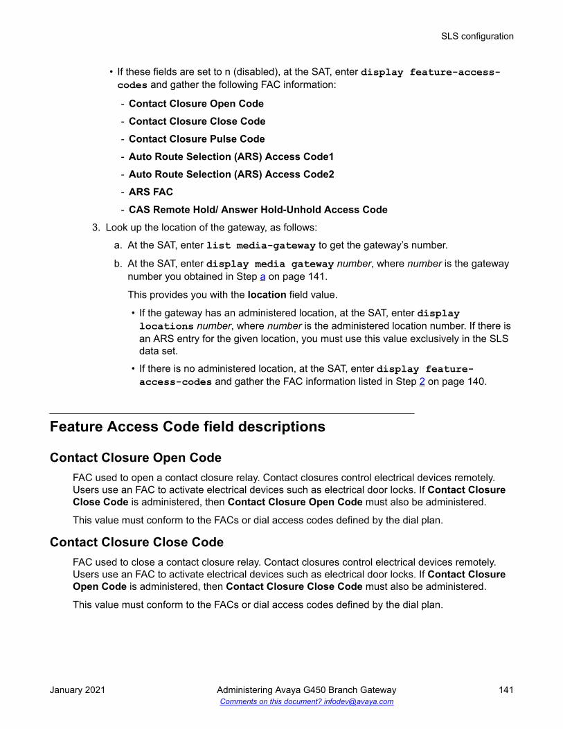
• If these fields are set to n (disabled), at the SAT, enter display feature-access-codes and gather the following FAC information:
- Contact Closure Open Code- Contact Closure Close Code- Contact Closure Pulse Code- Auto Route Selection (ARS) Access Code1- Auto Route Selection (ARS) Access Code2- ARS FAC- CAS Remote Hold/ Answer Hold-Unhold Access Code
3. Look up the location of the gateway, as follows:
a. At the SAT, enter list media-gateway to get the gateway’s number.
b. At the SAT, enter display media gateway number, where number is the gatewaynumber you obtained in Step a on page 141.
This provides you with the location field value.
• If the gateway has an administered location, at the SAT, enter displaylocations number, where number is the administered location number. If there isan ARS entry for the given location, you must use this value exclusively in the SLSdata set.
• If there is no administered location, at the SAT, enter display feature-access-codes and gather the FAC information listed in Step 2 on page 140.
Feature Access Code field descriptions
Contact Closure Open CodeFAC used to open a contact closure relay. Contact closures control electrical devices remotely.Users use an FAC to activate electrical devices such as electrical door locks. If Contact ClosureClose Code is administered, then Contact Closure Open Code must also be administered.
This value must conform to the FACs or dial access codes defined by the dial plan.
Contact Closure Close CodeFAC used to close a contact closure relay. Contact closures control electrical devices remotely.Users use an FAC to activate electrical devices such as electrical door locks. If Contact ClosureOpen Code is administered, then Contact Closure Close Code must also be administered.
This value must conform to the FACs or dial access codes defined by the dial plan.
SLS configuration
January 2021 Administering Avaya G450 Branch Gateway 141Comments on this document? [email protected]

Contact Closure Pulse CodeFAC used to pulse a contact closure relay.
This value must conform to the FACs or dial access codes defined by the dial plan.
Auto Route Selection (ARS) Access Code 1FAC used to access ARS. The system can automatically choose the least-expensive way to senda toll call. You can have one ARS access code for local and one for long distance, and routeaccordingly.
This value must conform to the FACs or dial access codes defined by the dial plan.
Auto Route Selection (ARS) Access Code 2Additional FAC used to access ARS.
This value must conform to the FACs or dial access codes defined by the dial plan.
ARS FACThis is used instead of the Features screen ARS FAC entry if the Loc No. that correlates to thegateway has an entry in this screen that overrides the general ARS FAC(s).
CAS Remote Hold/Answer Hold-Unhold Access CodeFAC used by a Centralized Attendant Service (CAS) attendant to place calls on hold and answercalls held at a remote server running Communication Manager. This FAC can also be used by ananalog station. Flashing the switch-hook for the proper interval (between 200 and 1000 ms) whiletalking on an existing call causes the existing call to be placed on soft hold, using which theanalog user can dial the Answer Hold-Unhold FAC to Hard hold the call.
This value must conform to the FACs or dial access codes defined by the dial plan.
Collecting system parameters dataProcedure
1. At the SAT, enter list media-gateway to display a list of administered gateways.
2. Look for supported gateways in the Type field.
3. Once you have determined the media gateway of interest, note its IP-Network-Region.
4. At the SAT, enter display ip-network-region n, where n is the gateway’sadministered IP-Network-Region.
Read the Codec-set field value from the IP Network Region screen.
5. At the SAT, enter display ip-codec-set n, where n is the Codec-set field value fromthe IP Network Region screen.
Standard Local Survivability (SLS)
January 2021 Administering Avaya G450 Branch Gateway 142Comments on this document? [email protected]

The report lists the supported codes in the Audio Codec field.
6. At the SAT, enter display system-parameters features to display the FeatureRelated System Parameters screen.
7. Scroll to page 10 and read the value of the Date Format on Terminals field.
8. At the SAT, enter display media-gateway n, where n is the administered number ofthe Media Gateway of interest, to display the Media Gateway screen.
9. Read the Max Survivable IP Ext field value.
Codecs supported in SLSThere can be up to seven distinct codec-sets in use in the system. However, only one codec set isactive for the network region in which the gateway is located.
SLS only supports two codecs:
• G.711 A-law
• G.711 U-law
General system parameters field descriptionsFor information about the fields on the IP codec set screen, see Avaya Aura® CommunicationManager Screen Reference.
Date Format on TerminalsApplies to 64xx and 24xx DCP terminals, and to 46xx IP terminals.
Max Survivable IP ExtThis field describes the maximum IP phone registrations allowed.
Collecting ARS dial patterns dataAbout this taskTo gather the route patterns and ARS analysis in CM, you must first know which trunk groups areassigned to the gateway of interest. After verifying this information, perform the following steps:
Procedure1. At the SAT, enter list route-pattern trunk-group n, where n is an administered
trunk group, to display the administered route patterns.
SLS configuration
January 2021 Administering Avaya G450 Branch Gateway 143Comments on this document? [email protected]

2. For the first preference for this route-pattern entry, read the values of the following fields:
• No Deleted Digits• Inserted Digits
3. At the SAT, enter list ars analysis to search the ARS Analysis table for row entrieswhose Route Pattern field matches the route-pattern values that were obtained in Step 1 on page 143. Once you discover a match with Route Pattern , use the entries from thisrow in the ARS Analysis table to complete the following three entries for the SLS Dial-Pattern table:
• Min
• Max
• Dialed String
ARS Dial Patterns field descriptionsNo Deleted Digits
Specifies the number of dialed digits to be deleted from the beginning of the dialed string. Thedefault is 0.
General system parameters/Inserted DigitsSpecifies the digit string to be inserted at the beginning of the dialed string. The default is blank.
MinUse this field to specify the minimum number of user-dialed digits that the system must collect tomatch the dialed string.
MaxUse this field to specify the maximum number of user-dialed digits that the system must collect tomatch the dialed string.
Dialed StringCommunication Manager matches the dialed numbers with the entry in the Dialed String field thatmost closely matches the dialed number. You can enter up to 18 digits that the call-processingserver analyzes. You can also enter the wildcard characters, x and X.
Standard Local Survivability (SLS)
January 2021 Administering Avaya G450 Branch Gateway 144Comments on this document? [email protected]

Collecting Incoming Call Handling dataAbout this taskTo gather the Incoming Call Handling Treatment and ARS Digit Conversion information in CM, youmust first know which trunk groups are assigned to the gateway of interest. After verifying thisinformation, perform the following steps:
Procedure1. At the SAT, enter display inc-call-handling-trmt trunk-group n, where n is
an administered trunk group.
2. For each entry, read the values of the following fields:
• Called Number
• Called Len
• Del
• Insert
Incoming call handling data field descriptions
Called NumberValid Entry Usage1 to 16 Specifies the leading digits received for an incoming call.blank Matches any number associated with the specified service or feature.
Called LenValid Entry Usage0 to 21 The number of digits received for an incoming call. Zero is used when the Public
Switched Telephone Network (PSTN) provider does not provide any “Number Digits”within the received Called Party IE, such as in Japan.
blank When Called Number has also been set to blank, so that any length of digitsassociated with the Called Party IE of the Incoming SETUP message matches thisfield.
SLS configuration
January 2021 Administering Avaya G450 Branch Gateway 145Comments on this document? [email protected]

DelValid Entry Usage1 to 21
blank
The number of leading digits to be deleted from the incoming Called Party Number.Calls of a particular type can be administered to be routed to a single destination bydeleting all incoming digits and then administering the Insert field with the requiredextension.
InsertValid Entry Usage1 to 16
*
#
The number of digits prepended to the front of the remaining digits after any optionaldigit deletions have been performed. The resultant number formed from digitdeletion and insertion is used to route the call, provided night service is not in effect.
Configuration of the SLS data through the CLIThe command line interface (CLI) has a root-level context of sls for administering the SLS dataset. After you enter sls at the CLI prompt, the prompt changes to indicate that you are in the slscontext. Once in this context, seven additional sub-contexts provide for station and trunkadministration, minimizing the need to type in a long command string:
• station context that is invoked by entering station <extension ><class> to enter a second-level sub-context for administering stations
• trunk-group context that is invoked by entering trunk-group <tgnum><group-type> to enterthe second-level sub-context for administering trunk groups
• ds1 context that is invoked by entering ds1 <port-address> to enter the second-level sub-context for administering DS1 trunks
• sig-group context that is invoked by entering sig-group <sgnum> to enter the second-levelsub-context for administering signaling groups
• bri context that is invoked by entering bri <port-address> to enter the second-level sub-context for administering ISDN BRI links
• dial-pattern context that is invoked by entering dial-pattern <dialed-string> to enter thesecond-level sub-context for administering dial pattern strings
• incoming-routing context that is invoked by entering incoming-routing <tgnum> <mode><pattern —length> to enter the second-level sub-context for administering incoming routing
Enter exit to leave the second-level sub-contexts and return to the (super-sls)# context.
Note:Review Summary of SLS configuration commands on page 168 in its entirety beforeproceeding with SLS administration. This summary of SLS commands guides you inunderstanding the various sub-commands of each sub-context.
Standard Local Survivability (SLS)
January 2021 Administering Avaya G450 Branch Gateway 146Comments on this document? [email protected]

Creating the SLS administration data set on the Branch GatewayProcedure
1. Log on to the Branch Gateway.
2. To administer the name, enter set system name <name>, where <name> is typedinside quotation marks (“”).
To remove the administered name, enter set system name, and then rename theBranch Gateway using the set system name <name> command.
Note:
Branch Gateway administered name must match the name in the CM administration.
3. At Branch Gateway command prompt, enter sls to begin entering SLS data.
The command line prompt changes to (super-sls)# to indicate that you are in SLS dataentry mode. Entering exit ends the SLS data entry mode session, and the command lineprompt returns to its original state.
4. If you want to change the maximum allowable IP registrations from the default, enter setmax-ip-registrations n, where n is from 1 to 240.
5. Use the set date-format command to set a date format for the SLS data set.
6. Use the set ip-codec-set command to select the country-specific G.711 codec setwithin the SLS data set: g.711mu or g.711a.
7. Administer the slot configuration information by entering set slot-config <slot-number> <board-type>, where <slot-number> is the slot where the Media Module islocated and <board-type> is the Media Module type.
8. Administer the station information.
9. Administer DS1 trunks as required.
10. Administer BRI links as required.
11. Administer the trunk groups.
Note that you can add members to the trunk group only after you administer the signalinggroup information.
12. Administer the signaling groups.
13. Administer ARS dial patterns for outgoing calls.
14. Administer digit treatment for incoming routed calls.
15. Optionally administer the attendant feature for the purpose of call routing by entering setattendant <access-code> <extension>, where <access-code> specifies the dial accesscode for the attendant feature, and <extension> specifies the station which serves as thebranch office attendant position.
SLS configuration
January 2021 Administering Avaya G450 Branch Gateway 147Comments on this document? [email protected]

Incoming trunk calls that have dialed strings that cannot be completely routed, will now berouted by SLS to this attendant position. In addition, stations in the branch office maydirectly dial the attendant using the <access-code>.
16. Administer the Feature Access Codes (FACs) by entering set fac <feature> <fac>,where <feature> is one of the following:
• ars1
• ars2
• hold
• contact-open
• contact-close
• contact-pulse
<fac> is a 1 to 4 digit string that includes the digits 0 through 9, excluding * and # foranalog rotary phones. The <fac> string must be unique and must not conflict with stationextension numbers and Trunk Access Codes (TACs).
Examples
• set fac ars2 *9• set fac contact-close 8
Note:
The “*” and “#” characters are not available on rotary-dial, analog phones.
17. At the Branch Gateway command prompt, enter exit to leave the sls context.
The Branch Gateway command prompt reverts to that of the original login.
18. After all of the SLS features are administered, at the Branch Gateway command promptenter set sls enable to enable SLS on the Branch Gateway.
Note:
If you enabled SLS and then entered additional administration, you must first disableSLS by entering set sls disable, and then re-enable it by entering set slsenable. This will cause the SLS application to resynchronize its administrativedatabase with the Branch Gateway's CLI command database.
19. At the Branch Gateway command prompt, enter copy running-config startup-config to save the changes.
Related linksAdministering DS1 parameters on page 152Administering BRI parameters on page 156Administering trunk-group parameters on page 158Administering signaling-group parameters on page 165Administering dial-pattern parameters on page 166
Standard Local Survivability (SLS)
January 2021 Administering Avaya G450 Branch Gateway 148Comments on this document? [email protected]

Administering incoming-routing parameters on page 167Media module compatibility with SLS on page 97
Administering station parametersProcedure
1. At the Branch Gateway command prompt, enter station <extension> <class> to enter asecond-level sub-context to administer each phone that you want covered by SLS.
In this command, <extension> is a 1 to 16 digit numeric string that may begin with 0, andclass <class> is analog, dcp, or ip.
For example, station 1234567 ip administers an IP phone with the extension“1234567”.
The command line prompt changes to sls-station <extension> to indicate that youare in the station context for SLS administration. Entering exit ends the stationconfiguration mode, and the command line prompt returns to its original state. If you wantto remove the station from the SLS administration, enter clear station <extension> atthe command line interface. Enter exit to leave the second-level station context to returnto the (super-sls)# context.
2. Depending on the class (analog, dcp, or ip, set in Step 1 on page 149), enter set type<model>, where <model>is a value from Class values in SLS station context on page 151.
For example, set type ip4620 sets the previously-administered extension “1234567”as an Avaya 4620 IP phone.
3. For analog and dcp classes only (set in Step 1 on page 149), enter set port <module-port> for this station, where <module-port> is a value in Module-port values in SLS stationconfiguration mode on page 151.
Note:
This command is required only for stations that support physical media module ports.
If the class is ip (set in Step 1 on page 149), you cannot run this command.
You cannot select these modules or ports if they are already assigned as DID trunks.
Examples:
• If an MM711 is inserted into slot V3 and an analog station is to be administered for port #5, then set port v305 sets the previously-administered analog station “1234567” tothe fifth physical analog station port on the Branch Gateway’s media module.
• If an MM712 is inserted into slot V2 and a DCP station is to be administered for port #1,then set port v201 sets the previously-administered dcp station “1234567” to the firstphysical DCP station port on the Branch Gateway’s media module.
SLS configuration
January 2021 Administering Avaya G450 Branch Gateway 149Comments on this document? [email protected]

4. Enter set cor <cor type> to set the class of restriction (COR) for this extension, where <cortype> is one of the following:
• emergency
• internal (default)
• local
• toll
• unrestricted
There exists a hierarchical relationship among the calling-restriction categories. As youmove from the most restricted COR (emergency) to the least restricted (unrestricted), eachlevel increases the range of dialing abilities. For example, toll includes the dialing privilegesof local, internal, and emergency.
For example, set cor unrestricted gives a station unrestricted dialing.
5. If this station is administered to be included into a pool of stations that are allowed toreceive incoming analog loop-start trunk calls, enter set trunk-destination yes.
6. If this is an IP phone (set in Step 1 on page 149), enter set password <password>,where <password> is from four to eight digits in length, to administer a password.
For example, set password 53136 establishes the password “53136” on a previously-administered IP phone.
The phone automatically registers to the Branch Gateway upon failure if the password andthe extension number are the same as those administered in CM.
Note:
Passwords are not required for analog or DCP phones unless an IP Softphone is usingthe administrative identity of a DCP phone, in which case the password is required.
7. To enable DCP or IP phones (set in Step 1 on page 149) to have an expansion module,enter set expansion-module yes.
8. For analog phones (set in Step 1 on page 149) that you want SLS to recognize theswitchhook flash signal (that offers subsequent transfer features), enter set swhook-flash yes.
9. Enter set name <name> to identify the user name for the station.
Use the 1 to 27 character name as specified on CM. Type the name string inside doublequotes.
10. Enter show to check the station administration of the station being programmed.
The report lists the station parameters. For example:Extension Type Port Cor Trunk-Des Exp-Mod Flash Password--------- ---- ---- ----- --------- ------- ------- --------49139 ip4620 IPaddr local y n - ******** ip station registered at address ‘aaa.bbb.ccc.ddd’
Standard Local Survivability (SLS)
January 2021 Administering Avaya G450 Branch Gateway 150Comments on this document? [email protected]

Note:
For currently-registered IP phones or IP Softphones, the IP address displays.
11. Enter exit to leave the station context in SLS.
Related linksInherited Class of Restriction (COR) permissions on page 114
Class values in SLS station contextanalog dcp ipanalog25005 dcp2402 ip4601
- dcp2410 ip4602- dcp2420 ip4602sw- dcp6402 ip4610sw- dcp6402D ip4612- dcp6408 ip4620- dcp6408+ ip4620sw (default)- dcp6408D (default) ip4621- dcp6408D+ ip4622- dcp6416D+ ip4624- dcp6424D+ ip4625- dcp8403B -- dcp8405B -- dcp8405B+ -- dcp8405D -- dcp8405D+ -- dcp8410B -- dcp8410D -- dcp8434D -
Module-port values in SLS station configuration modeGateway Media module Analog station ports* DCPG430 or G450 MM711 8 possible ports -
Table continues…
5 Since there is just one entry, the model is optional; analog2500 is the default value.
SLS configuration
January 2021 Administering Avaya G450 Branch Gateway 151Comments on this document? [email protected]

Gateway Media module Analog station ports* DCPMM712 - 8 possible portsMM714 4 possible ports (ports 1-4) -MM714B 4 possible ports (ports 1-4) -MM716 24 possible ports -MM717 - 24 possible ports
Administering DS1 parametersProcedure
1. Enter ds1 <slot-address>, where <slot-address> is any permitted port.
The command line prompt changes to super-sls/ds1-<port-address>. If you wantto remove the ds1 trunk from the SLS administration, enter exit to leave the second-levelds1 context and return to the (super-sls)# context, and then enter clear ds1 slot-address.
Note:
If configuration changes affecting trunk provisioning (such as, signaling and bit-rate)are made to a DS1 trunk where the trunk and its associated signaling group havealready been provisioned, an error message instructs you that the Administrativechange is in violation with existing trunk member provisioning,and the configuration change is rejected.
2. Enter set name <name> to identify the user name for the DS1 trunk.
Use the 1 to 27 character name as specified on CM (add trunk-group n). Type thename string inside double quotes.
3. Enter set bit-rate <rate> to set the maximum transmission rate in Mbps for the DS1facility.
The rate can be either 1544 (T1) or 2048 (E1).
4. Enter set signaling-mode <mode-type> to set the signaling mode for the DS1 facility,where <mode-type> is one of the following values:
• cas. Out-of-band signaling for E1 service, yielding thirty 64 kbps B-channels for voicetransmission
• robbed bit. In-band signaling for T1 service, yielding twenty-four 56 kbps B-channels forvoice transmission
• isdnpri. T1 or E1 ISDN Primary Rate service (supports both FAS and NFAS)
• isdnext. NFAS T1 or E1 ISDN service for:
- T1 facility, in which all 24 channels are for bearer transport
Standard Local Survivability (SLS)
January 2021 Administering Avaya G450 Branch Gateway 152Comments on this document? [email protected]

- E1 facility, in which all 31 channels are for bearer transport
5. Enter set channel-numbering <method> to select the channel-numbering method forB-channels on an E1 interface, where <method> is one of the following values:
• seq. Sequential codes of B-channels 1-30 in the ISDN Channel Identification IE
• tslot. Timeslot method
6. Enter set connect <far-end> to specify the equipment at the far-end of the DS1 link,where <far-end> is one of the following values:
• host. Data application (computer or server)
• lineside. Terminal equipment (video multiplexer)
• network. Central office
• pbx. Private communication system (another pbx)
7. If the far-end equipment is specified as pbx (set in Step 6), enter set interface <glare-mode> to specify the glare-handling convention, where <glare-mode> can be one of thefollowing values:
For non-QSIG calls: For QSIG calls:• network. If the Branch Gateway is connected to a
host computer and encounters glare, it overrides thefar-end
• user. If the Branch Gateway is connected to a publicnetwork and encounters glare, it releases the circuit
• peerMaster. SLS overrides theother end when glare occurs
• peerSlave. SLS releases thecircuit when glare occurs
8. If the DS1 link is employed with ISDN, and the glare-handling convention is specified aspeerMaster or peerSlave for the ISDN link (set in Step 7).
9. Enter set side <side> to specify the glare mode: either a or b.
10. If the DS1 link is employed with ISDN, enter set country-protocol <country-code> tospecify the ISDN Layer 3 country protocol type, where <country-code> is one of the valuesin ISDN Layer 3 country codes on page 154:
11. For countries whose public networks allow for multiple ISDN Layer 3 country protocols forISDN Primary Rate service, enter set protocol-version <option> to specify themode.
Verify that the protocol version matches the country specified in set country-protocol (set in Step 9).
12. If the DS1 link is employed with ISDN, enter set bearer-capability <bearer> to setthe Information Transfer Rate field of the Bearer Capability IE, where <bearer> is one ofthe following values:
• 3khz. 3.1 kHz audio encoding
• speech. Speech encoding
SLS configuration
January 2021 Administering Avaya G450 Branch Gateway 153Comments on this document? [email protected]

13. Enter set interface-companding <type> to set the interface to agree with thecompanding method used by the far-end of the DS1 circuit for SLS mode, where <type> isone of the following values:
• alaw. A-law companding
• ulaw. U-law companding
14. Enter set long-timer yes | no to increase the duration of the T303 (call establishment)timer, where:
• yes. The T303 timer is extended from 4 seconds to 13 seconds
• no. The T303 timer remains at 4 seconds
15. Enter show to check the DS1 administration.
The report lists the DS1 parameters. For example: Name = ‘Willow Steet 2’DS1 Rate Signaling Channel Connect Interface Side Protocol Ver Bearer Cmpd Ltm ---- ---- --------- ------- ------- --------- ---- -------- --- ------ ---- --- v3 1544 isdnpri seq network user a country1 a speech ulaw no
16. Enter exit to leave the ds1 context in SLS.
Related linksISDN Layer 3 country protocols for ISDN Primary Rate service on page 155
ISDN Layer 3 country codes
Country Code Country1 United States (AT&T mode, also known as 5ESS)2 Australia (Australia National PRI)3 Japan4 Italy5 Netherlands6 Singapore7 Mexico8 Belgium9 Saudi Arabia10 United Kingdom (ETSI)11 Spain12 France (ETSI)13 Germany (ETSI)
Table continues…
Standard Local Survivability (SLS)
January 2021 Administering Avaya G450 Branch Gateway 154Comments on this document? [email protected]

Country Code Country14 Czech Republic15 Russia16 Argentina17 Greece18 China19 Hong Kong20 Thailand21 Macedonia22 Poland23 Brazil24 Nordic countries25 South Africaetsi ETSI (no use of RESTART message)qsig QSIG
ISDN Layer 3 country protocols for ISDN Primary Rate service
Country code Description Possible ValuesCountry 1 (United States) AT&T mode (also known as 5ESS)
National ISDN-1
Nortel mode (also known as DMS)
Telecordia (NI-2)
a
b
c
dCountry 2 (Australia) Australia National PRI
ETSI
invalid
invalid
a
b
c
dCountry 10 (UnitedKingdom)
DASS
ETSI
invalid
invalid
a
b
c
dTable continues…
SLS configuration
January 2021 Administering Avaya G450 Branch Gateway 155Comments on this document? [email protected]

Country code Description Possible ValuesCountry 12 (France) French National PRI
ETSI
invalid
invalid
a
b
c
dCountry 13 (Germany) German National PRI
ETSI
invalid
invalid
a
b
c
dETSI Full message set, including RESTART
No RESTART message
invalid
invalid
a
b
c
d
Administering BRI parametersProcedure
1. Enter bri <slot-address>, where <slot-address> is any permitted port.
The command line prompt changes to sls-bri <slot-address>. If you want to remove theBRI link from the SLS administration, enter exit to leave the second-level bri context andreturn to the (super-sls)# context, and then enter clear bri <slot-address>.
2. Enter set name <name> to identify the user name for the DS1 trunk.
Use the 1-27 character name, as specified on CM (add trunk-group n). Type the namestring inside double quotes.
3. Enter set interface <glare-mode> to specify the glare-handling convention.
<glare-mode> can be one of the following values:
For non-QSIG calls: For QSIG calls:• network. If the Branch Gateway is connected to a
host computer and encounters glare, it overrides thefar-end
• user. If the Branch Gateway is connected to a publicnetwork and encounters glare, it releases the circuit
• peerMaster. SLS overrides theother end when glare occurs
• peerSlave. SLS releases thecircuit when glare occurs
4. If the BRI link is employed with ISDN, and the glare-handling convention is specified aspeerMaster or peerSlave for the ISDN link (set in Step 3),
5. Enter set side <side> to specify the glare mode: either a or b.
Standard Local Survivability (SLS)
January 2021 Administering Avaya G450 Branch Gateway 156Comments on this document? [email protected]

6. If the BRI link is employed with ISDN, enter set country-protocol <country-code> tospecify the ISDN Layer 3 country protocol type, where <country-code> is any of the valueslisted in ISDN Layer 3 country codes on page 154.
7. If the BRI link is employed with ISDN, enter set bearer-capability <bearer> to setthe Information Transfer Rate field of the Bearer Capability IE, where bearer is one ofthe following values:
• 3khz. 3.1 kHz audio encoding• speech. Speech encoding
8. Enter set interface-companding <type> to set the far-end companding method,where <type> is one of the following values:
• alaw. A-law companding• ulaw. U-law companding
9. If the BRI link is employed with ISDN, enter set tei-assignment <tei> to select themethod by which the Layer 2 (LAPD) protocol obtains its Terminal Endpoint Identification(TEI) address.
tei is one of the following values:
• auto. TEI is assigned by the network provider• zero. TEI is fixed administratively
10. Enter set directory-number-a <number> to assign a directory number to the B1channel of the BRI link.
<number> is the provisioned number received from the network provider. The numbervalue must be identical to the number the network provider has assigned to the circuit.
11. Enter set directory-number-b <number> to assign a directory number to the B2channel of the BRI link.
<number> is the provisioned number received from the network provider. The numbervalue must be identical to the number the network provider has assigned to the circuit.
12. Enter set spid-a number to assign an SPID to the B1 channel of the BRI link.
13. Enter set spid-b number to assign an SPID to the B2 channel of the BRI link.
Note:
All BRI links must have SPIDs properly configured for the link to function. SPIDs arereceived from the network service provider.
14. If the BRI link is employed with ISDN, enter set-endpoint-init {yes | no} to determinewhether or not the far-end supports endpoint initialization.
15. If the BRI link is employed with ISDN, enter set layer1-stable {yes | no} to determinewhether or not to keep the physical layer active (stable) between calls.
Some European countries require that the physical layer is deactivated when there is noactive call.
SLS configuration
January 2021 Administering Avaya G450 Branch Gateway 157Comments on this document? [email protected]

16. Enter show to check the BRI administration.
The report lists the BRI parameters. For example:Name = BRI-SLS1BRI Interface Side Country Bearer Compand Endpt-Init Layer1-Stable--- --------- ---- -------- ------ ------- ---------- -------------v301 user a country1 speech ulaw yes yesDir-NumberA Dir-NumberB Spid-A Spid-B----------- ----------- -------------- -------------- 3033234567 3033234568 30332345671111 30332345681111
17. Enter exit to leave the bri context in SLS.
Trunk group assignmentYou can create a trunk group that does not have any assigned members. Once a valid port isassigned as a trunk group member, this trunk group then becomes active and may be employedby SLS call processing for incoming/outgoing trunk operation. The slot-configuration table is used,together with the port capacity for the given module, to determine the validity of a port assignmentat administration time.
As a result, there may not be more active trunk groups than there are physical trunk memberswithin a given Branch Gateway. In addition, a combo-port may only be used for one activeassignment. For example, the analog station/DID trunk ports may be either allocated to serve asan analog station or as an analog DID trunk, but not both.
The maximum limits for a given trunk type are defined by the slot-configuration assignment for theBranch Gateway. The maximum number of ports allowed per interface module is defined in SLSgroup type assignments on page 163.
Exampletrunk-group 1 loop-start establishes an analog loop-start trunk group number 1.
Administering trunk-group parametersProcedure
1. Enter trunk-group <tgnum> <group-type>, where tgnum is any number from 1 to 2000and <group-type> can be one of the following:
• loop-start (analog)
• did (analog)
• ground-start (analog)
• bri (ISDN basic rate)
• t1-isdn (ISDN primary rate on 1.544 Mbps facility)
• e1-isdn (ISDN primary rate on 2.048 Mbps facility)
Standard Local Survivability (SLS)
January 2021 Administering Avaya G450 Branch Gateway 158Comments on this document? [email protected]

• t1-inband (non-ISDN rate on 1.544 Mbps facility)
• e1-inband (non-ISDN rate on 2.048 Mbps facility)
The command line prompt changes to super-sls/trunk-group-<tgnum>. If you wantto remove the trunk group from the SLS administration, enter exit to leave the second-level trunk-group context and return to the (super-sls)# context, and then enter cleartrunk-group <tgnum>.
2. Enter set dial <dial-type>, where <dial-type> is either rotary or dtmf.
For example, set dial dtmf establishes that the trunk group uses DTMF signaling.
3. Enter set tac <tac>, where <tac> is a 1 to 4 digit numeric value (plus initial # and * on allbut rotary dial phones) for this trunk’s access code (TAC).
The TAC value must be unique among all trunk groups, extension numbers, and ARSFeature Access Code (FAC) strings.
For example, set tac 88 establishes access to this trunk group by dialing “88”.
4. Enter add port <module> <port> <sig-group> to specify the port that is compatible withthe device and/or media module.
The <sig-group> argument is necessary for a digital ISDN-PRI trunk. It is an integernumber from 1 to 650 that specifies the signaling group associated with the managementof this trunk member.
Note:
Administer the signaling group and DS1 information before you add any ports to thetrunk group.
Example 1
If an MM711 is inserted into slot V3 and an analog loop-start trunk is to be administered forport 4, then add port V304 administers an analog loop-start trunk through port V304.
Example 2
If an MM722 is inserted into slot V2 and an ISDN BRI trunk is to be administered for port 1,then add port v201 adds a BRI trunk for the first physical port of the Branch Gatewaymedia module to a trunk group using one B-channel of the BRI link.
Note:
You cannot mix BRI and PRI trunks within the same trunk group. If you attempt toassign more than the maximum number of trunks to a trunk group, an error messageinstructs you to delete a trunk member before adding a new trunk. A physical trunk canbe a member of only one trunk group.
5. For an analog DID trunk group, enter set supervision <sup-type> to set the incomingsignaling supervision mode.
<sup-type> can be either immediate or wink.
SLS configuration
January 2021 Administering Avaya G450 Branch Gateway 159Comments on this document? [email protected]

For example, set supervision wink assigns wink-start incoming signaling supervisionto a DID trunk group.
6. For a non-ISDN digital trunk (t1-inband or e1-inband), enter set supervision <sup-type> to set the incoming signaling supervision mode, where <sup-type>can be one of thefollowing:
• loop-start
• ground-start
• wink-wink
• wink-immediate
• wink-auto
• immediate-immediate
• auto-auto
• auto-wink
7. For an analog DID trunk group or DS1 non-ISDN tie trunk group, enter set digit-treatment <digit-treat>, where <digit-treat> can be one of the following values:
• blank (use this value to prevent any absorb or insert digit treatment from being applied)
• absorb1
• absorb2
• absorb3
• absorb4
• absorb5
• insert1
• insert2
• insert3
• insert4
Examples
For example:
• set digit-treatment absorb1 removes the first digit from the incoming DID trunk
• set digit-treatment blank removes any digit treatment from the trunk group
8. For analog DID trunk groups or DS1 tie trunk groups, enter set digits <digits> to definethe inserted digit string, where digits is the number of digits.
Standard Local Survivability (SLS)
January 2021 Administering Avaya G450 Branch Gateway 160Comments on this document? [email protected]

Note:
The number of digits must comply with the digit-treat parameter in the setdigit-treatment command. If the digit-treat parameter is insert3, then the digitsparameter for this command must be three digits in length.
9. Enter set name <name> to identify the user name for the trunk group.
Use the 1 to 27 character name as specified on CM (add trunk-group n). Type the namestring inside double quotes.
10. For ISDN trunks, enter set codeset-display <codeset> to identify which Q.931codesets are allowed to send display information to the user phone: codeset0, codeset6,or codeset7.
11. For ISDN trunks, enter set codeset-national <codeset> to identify which Q.931codesets are allowed to send National Information Elements (IEs, or display information) tothe user phone: codeset6 or codeset7.
12. For ISDN trunks, enter set channel-preference <type> to define how the ChannelIdentification IE field is encoded, where <type> can be one of the following:
• exclusive. The central office must have the ability to grant a call on this channel or rejectthe call attempt
• preferred. The central office might offer the call request on another available channel
13. For ISDN trunks, enter set digit-handling method to define the order of reception/transmission to be considered with the flow of inbound/outbound:
• enbloc-enbloc
• enbloc-overlap
• overlap-enbloc
• overlap-overlap
Enbloc requires sending the entire collected digit string in one block. Overlap sends thedigits one at a time as they are collected.
14. For ISDN trunks, enter set japan-disconnect <yes | no> to specify whether toperform a disconnect sequence (CONNECT message followed by a DISCONNECTmessage).
15. For ISDN trunks, enter set send-name <method> to define whether or not the calling,connected, called, or busy party’s administered name is sent to the network on outgoing orincoming calls.
<method> can be one of the following:
• no. The name is not sent to the network for incoming or outgoing calls
• yes. The name is sent to the network for incoming or outgoing calls
• restricted. The name is sent to the network as “Presentation restricted”
SLS configuration
January 2021 Administering Avaya G450 Branch Gateway 161Comments on this document? [email protected]

Note:
For this release, specify <method> as no, since sending a Calling Party Name is afuture feature.
16. For ISDN trunks, enter set send-number <method> to define whether or not the calling,connected, called, or busy party’s administered number is sent to the network on outgoingor incoming calls.
<method> can be one of the following:
• no. The number is not sent to the network for incoming or outgoing calls
• yes. The number is sent to the network for incoming or outgoing calls
• restricted. The number is sent to the network as “Presentation restricted”
Note:
For this release, specify <method> as no, since sending a Calling Party Number is afuture feature.
17. For ISDN trunks, enter set numbering-format <type> to specify the numbering planfor this trunk in Standard Local Survivability (SLS).
The numbering plan encodes the Numbering Plan Indicator and Type of Number fieldsin the Calling/Connected Party Number IE in the ISDN protocol.
<type>can be one of the following:
• unknown. Both the Numbering Plan Indicator and Type of Number are unknown
• public. The Numbering Plan Indicator meets the E.164 standard and the Type ofNumber is national
Note:
The SLS application is intended to operate into PSTN trunk interfaces. For this reason,the only two choices for network numbering plans identification are public (E.464) andunknown (no particular plan). For this release, specify type as unknown since SLSdoes not currently support an administrative table to calculate the Calling PartyNumber that is consistent with the numbering plan of the PSTN service provider.
18. For non-ISDN digital trunks, analog loop-start and analog ground-start trunks, enter setincoming-destination extension to identify an extension to directly receive anincoming trunk call, for example, an attendant or a voice response/recording system.
19. For non-ISDN digital trunks, enter set incoming-dialtone <yes | no> to specifywhether to provide a dial tone in response to far-end trunk group seizures.
20. For a DS1 circuit, enter set trunk-hunt <type> to specify the trunk-hunting searchwithin a facility in an ISDN trunk group or through a non-ISDN digital trunk group, where<type> is one of the following:
• ascend. A linear search from the lowest to the highest numbered available channels
Standard Local Survivability (SLS)
January 2021 Administering Avaya G450 Branch Gateway 162Comments on this document? [email protected]

• circular. A circular search beginning with the point at which the search previously ended.When the search has reached the top of the channel list, it resumes at the bottom of thelist in wrap-around fashion
• descend. A linear search from the highest to the lowest numbered available channels
21. Enter show to check the trunk-group administration.
The following example shows all four trunk members assigned to one trunk-group:Group Type Dial Tac Supervision Treat Insert----- ---------- ------ ---- ------------------- ------- ------ 1 bri - *99 - - - Name = Willow Street 2Ports = v201,v202,v217,v218Codeset Codeset Channel Digit Japan Send Send Number TrunkDisplay National Preference Handling Discon Name Number Format Hunt----- ---------- ---------- ----------- -------- ------- ------ ------ ------codeset6 codeset6 exclusive enbloc-enbloc no yes yes public ascend
The following example shows twelve port members assigned as t1-inband signaling:Group Type Dial Tac Supervision Treat Insert----- ---------- ------ ---- ------------------- ------- ------ 1 t1inband dtmf *96 wink/immediate - - Name = Willow Street 2Ports = v201,v202,v203,v204,v205,v206,v207,v208,v209,v210,v211,v212Incoming-Dest Incoming-Dial Trunk-Hunt------------- ------------- ---------- - no ascend
The report lists the trunk-group parameters.
22. Enter exit to leave the trunk-group context in SLS.
Maximum number of members in a trunk groupYou can assign a maximum of 255 members to analog and digital trunks.
SLS group type assignmentsGroup type Media module Number of ports/
channelsDescription of trunks that may beassigned
loop-start ground-start did
MM711 8 Ports 1-8
loop-start ground-start
MM714 orMM714B
4 Ports 5, 6, 7, 8
did MM714orMM714B
4 Ports 1, 2, 3, 4
did MM716 24 Ports 1-24
Table continues…
SLS configuration
January 2021 Administering Avaya G450 Branch Gateway 163Comments on this document? [email protected]

Group type Media module Number of ports/channels
Description of trunks that may beassigned
bri MM720 16 Eight physical ports, each offering B1 andB2 channels
bri MM721 16 Eight physical ports, each offering B1 andB2 channels
bri MM722 4 Two physical ports, each offering B1 and B2channels
t1-isdn MM710 23 D-channel is associated with this facility(FAS)
t1-isdn MM710 24 D-channel is not associated with this facility(NFAS), and the DS1’s signaling-mode isset to isdnext
e1-isdn MM710 30 D-channel is associated with this facility(FAS)
e1-isdn MM710 31 D-channel is not associated with this facility(NFAS), and the DS1’s signaling-mode isset to isdnext
t1-inband MM710 24 T1 Robbed-bit signaling applicatione1-inband MM710 30 E1 CAS signaling application
Module-port values in SLS trunk-group context for analog trunksGroup Type Media Module Number of Ports/
ChannelsDescription
loop-start did ground-start
MM711 8 ports 1-8
loop-start ground-start MM714 or MM714B 4 ports 5,6,7,8did MM714 or MM714B 4 ports 1,2,3,4did MM716 24 ports 1-24
Trunk port values in SLS trunk-group context for digital trunksGroup Type Media Module Maximum Ports/Channelsbri MM720 16bri MM721 16bri MM722 4
Table continues…
Standard Local Survivability (SLS)
January 2021 Administering Avaya G450 Branch Gateway 164Comments on this document? [email protected]

Group Type Media Module Maximum Ports/Channelst1-isdn MM710 23 (FAS)
24 (NFAS)e1-isdn MM710 30 (FAS)
31 (NFAS)t1-inband MM710 24e1-inband MM710 30
Administering signaling-group parametersProcedure
1. Enter sig-group <sgnum>, where <sgnum> is any number from 1 to 650.
The command line prompt changes to sls-sig-group <sgnum>. If you want to removethe signaling group from the SLS administration, enter exit to leave the second-level sig-group context and return to the (super-sls)# context, and then enter clear sig-groupsgnum.
2. Enter set trunk-group-chan-select <tgnum> to specify the trunk-group number thataccepts incoming calls where the Information Channel Selection field does not specify apreferred channel for bearer transport.
This is useful if the signaling group controls more than one trunk group (in cases whereyou wish to manage a DS1 facility with more than one trunk group).
3. Enter set primary-dchannel <circuit-number>, where <circuit-number> is an identifierfor a Branch Gateway, slot, or T1/E1 circuit, to select the primary D-channel number.
For the value of <circuit-number>, you can use a 3-digit Branch Gateway identifier (forexample, 005), a 2-character slot identifier (for example, v2), or a 2-digit circuit number (24for T1-ISDN, 16 for E1-ISDN).
4. If your trunk is provisioned without a D-channel for signaling, enter set associated-signaling no to use Non-Facility Associated Signaling (NFAS).
Note:• NFAS is primarily a feature for ISDN-T1 connections offered by service providers in
North America and Hong Kong. However, it can also be used on private-networkconnections, and in that context it is possible to set up NFAS using ISDN-E1interfaces. If you are using NFAS, enter add nfas-interface gateway moduleinterface-id, where gateway is the 3-digit Branch Gateway identifier, moduleis the 2-character slot identifier, and interface-id is the DS1 circuit numberassociated with the NFAS group. The value of interface-id is received from thenetwork service provider.
SLS configuration
January 2021 Administering Avaya G450 Branch Gateway 165Comments on this document? [email protected]

• The North American Public Network Service Providers do not allow any part of a T1to be shared outside of this NFAS-trunk group. In other words, they do not allow oneof the T1 interfaces (of this NFAS group) to be fractionalized into two or more uses.It must be dedicated to this given customer. Therefore, the following usage rulesapply:
• All members of an NFAS DS1 (that are administered) must belong to the same trunk-group
• All members of this trunk-group must belong to a single signaling group
5. Enter show to check the signaling groups administration.
The report lists the signaling groups parameters. For example:Sig-group Tg-Select Assoc-Sig Prime-Dchan Nfas-Modules/Nfas-Id--------- --------- --------- ----------- ------------------------------------- 10 98 yes 005v424 -
6. Enter exit to leave the sig-group context in SLS.
Administering dial-pattern parametersProcedure
1. Enter dial-pattern <dialed-string>, where <dialed-string> is a dial pattern to be usedon outgoing calls.
The command line prompt changes to super-sls/dial-pattern <dialed-string>.If you want to remove the incoming routing treatment from the SLS administration, enterexit to leave the second-level dial-pattern context and return to the (super-sls)# context,and then enter clear dial-pattern <dialed-string>.
2. Enter set type <dial-type>, where <dial-type> specifies the type of outbound call and thedialing privileges available for outbound calls.
Each level of call includes the previous level’s dialing privileges. For example, locl hasthe calling privileges of iop, intl, etc.
3. Enter set max-length <length> to define the maximum length of the dialed string.
This must be set prior to the minimum length if the minimum length is larger than thedefault value.
4. Enter set min-length <length> to define the minimum length of the dialed string.
5. Enter set tgnum <tgnum> to designate a trunk-group for which this dialed string isassigned.
6. Enter set deny no to permit stations to originate outgoing trunk calls.
7. At the command-line enter set insert-digits<digits> to define the digits to insert intoa dialed string, if required.
Standard Local Survivability (SLS)
January 2021 Administering Avaya G450 Branch Gateway 166Comments on this document? [email protected]

8. Enter set delete-digits<digits> to define the number of digits to be deleted from adialed string, if required.
Note:
You can either insert or delete digits, but not both.
9. Enter show to check the outbound dial-pattern string administration.
The report lists the dial-pattern parameters. For example: Min/Max Trunk Delete/InsertDialed-String/Deny Length Type Group Digits------------------ ------ ---- ----- ---------------------- 5381000/n 9/9 locl 2 1/303 5385000/n 9/9 locl 3 1/720
10. Enter exit to leave the dial-pattern context in SLS.
Related linksInherited Class of Restriction (COR) permissions on page 114
Available call typesemer: Emergency calls only
fnpa: 10-digit North American Numbering Plan calls
hnpa: 7-digit North American Numbering Plan calls
intl: Public-network international number calls
iop: International operator calls
locl: Public-network local number calls
natl: Non-North American Numbering Plan calls
op: Operator calls
svc: Service calls
Administering incoming-routing parametersAbout this taskThe incoming-routing parameters are useful for mapping DNIS numbers directly into the stationextension numbers when the Service Provider's DNIS plan does not directly reflect the stationextension number length used in the Branch Gateway’s dial plan.
Procedure1. Enter incoming-routing <tgnum><mode>, where <tgnum> is an existing ISDN trunk
group number and mode is the protocol used for receiving incoming digits.
<mode> can be either enbloc or overlap.
SLS configuration
January 2021 Administering Avaya G450 Branch Gateway 167Comments on this document? [email protected]

The command line prompt changes to sls-incoming-routing <tgnum>. If you wantto remove the incoming routing treatment from the SLS administration, enter exit to leavethe second-level incoming-routing context and return to the (super-sls)# context, and thenenter clear internal-routing <tgnum> <mode>.
2. If the mode is set to enbloc (in Step 1), you must:
• Enter set delete-digits <digits> to define the number of digits to be deleted from adialed string.
• Enter set insert-digits <digits> to define the number of digits to be inserted at thebeginning of a dialed string.
• Enter set match-pattern <pattern>to define the beginning digit pattern of anincoming alphanumeric dial string to be matched against.
• Enter set length <length> to define the length of the dialed string.
3. If the mode is set to overlap (in Step 1), you may configure only one of the followingoptions:
• Enter set delete-digits<digits> to define the number of digits to be deleted from adialed string.
• Enter set insert-digits <digits> to define the number of digits to be inserted at thebeginning of a dialed string.
Note:
This action takes place after the deletion task has been completed for the enbloc-receivingmode.
4. Enter exit to leave the incoming-routing context in SLS.
5. Enter show to check the incoming-routing administration.
The report lists the incoming-routing parameters for all dial patterns that have beenadministered. For example:Match_pattern Length Del Insert-digits Mode tgnum------------- ------ --- ------------- ------ ----- 234 7 3 5381000 enbloc 98 235 7 3 5381001 enbloc 99
Summary of SLS configuration commandsFor more information about these commands, see Avaya Branch Gateway G450 CLI Reference.
Root LevelCommands
First Level ContextCommands
Second Level ContextCommands
Description
set sls - - Enable or disable SLS
Table continues…
Standard Local Survivability (SLS)
January 2021 Administering Avaya G450 Branch Gateway 168Comments on this document? [email protected]

Root LevelCommands
First Level ContextCommands
Second Level ContextCommands
Description
show sls - - Display SLS status: enabled ordisabled
sls - - Enter the sls context- bri - Administer an ISDN Basic Rate
Interface (BRI) port for SLS- - set bearer-
capabilitySet the Information TransferRate field of the BearerCapability IE in SLS
- - set country-protocol
Specify the ISDN Layer 3country protocol type in SLS
- - set directory-number-a
Assign a directory number tothe B1 channel of the BRIinterface in SLS
- - set directory-number-b
Assign a directory number tothe B2 channel of the BRIinterface in SLS
- - set endpoint-init Determine whether or not thefar-end supports endpointinitialization in SLS
- - set interface Specify the glare-handlingconvention for a BRI link in SLS
- - set interface-companding
Set the interface to agree withthe companding method usedby the far-end of the DS1 circuitfor SLS mode
- - set layer1-stable Determine whether or not tokeep the physical layer active(stable) between calls in SLS
- - set name Identify the user name for anISDN facility in SLS
- - set side Specify the glare-handlingconditions when the setinterface command isadministered as peerMaster orpeerSlave for the ISDN link inSLS
- - set spid-a Assign a Service ProfileIdentifier (SPID) to the B1channel of the BRI link in SLS
- - set spid-b Assign a Service ProfileIdentifier (SPID) to the B2channel of the BRI link in SLS
Table continues…
SLS configuration
January 2021 Administering Avaya G450 Branch Gateway 169Comments on this document? [email protected]

Root LevelCommands
First Level ContextCommands
Second Level ContextCommands
Description
- - set tei-assignment
Select the method by which theLayer 2 (LAPD) protocolobtains its Terminal EndpointIdentification (TEI) address inSLS
- - show List all BRI SLS parameters forthis BRI port
- clear attendant - Delete the administeredattendant provisioning in SLS
- clear bri - Delete the administration for agiven BRI channel in SLS
- clear dial-pattern
- Delete a single dialed stringpattern entry in the SLS dataset
- clear ds1 - Delete the administration for aspecific DS1 channel in SLS
- clear fac - Delete an administered FeatureAccess Code for SLS
- clear incoming-routing
- Delete an entry for a particularincoming routed string that isassociated with a given trunkgroup in SLS
- clear sig-group - Delete the administration for agiven ISDN signaling group inSLS
- clear slot-config - Delete the slot and the boardadministration in the BranchGateway for SLS
- clear survivable-config
- Set the SLS parameters to theirdefault values
- clear station - Delete a particular extensionnumber in the SLS data set
- clear trunk-group - Delete a trunk group entry fromthe SLS data set
- dial-pattern - Administer ARS dial patternsfor SLS
- - set delete-digits Specify the number of digits tobe deleted from the beginningof the dialed string for anoutbound call in SLS
Table continues…
Standard Local Survivability (SLS)
January 2021 Administering Avaya G450 Branch Gateway 170Comments on this document? [email protected]

Root LevelCommands
First Level ContextCommands
Second Level ContextCommands
Description
- - set deny Permit or deny access to anoutbound trunk in SLS
- - set insert-digits Specify the number of digits tobe inserted at the beginning ofthe dialed string for anoutbound call in SLS
- - set max-length Establish the maximum lengthof the dialed string in SLS
- - set min-length Establish the minimum lengthof the dialed string in SLS
- - set tgnum Designate the trunk-groupnumber in SLS
- - set type Administer the type ofoutbound call in SLS
- - show List all dial-pattern SLSparameters
- ds1 - Administer DS1 trunks for SLS- - set bearer-
capabilitySet the Information TransferRate field of the BearerCapability IE in SLS
- - set bit-rate Set the maximum transmissionrate for the DS1 facility in SLS
- - set channel-numbering
Select the channel-numberingmethod for B-channels on anE1 interface in SLS
- - set connect Specify the equipment at thefar-end of the DS1 link in SLS
- - set country-protocol
Specify the ISDN Layer 3country protocol type in SLS
- - set interface Specify the glare-handlingconvention for a DS1 link inSLS
- - set interface-companding
Set the interface to agree withthe companding method usedby the far-end of the DS1 circuitfor SLS mode
- - set long-timer Increase the duration of theT303 (call establishment) timerin SLS
- - set name Identify the user name for aDS1 facility in SLS
Table continues…
SLS configuration
January 2021 Administering Avaya G450 Branch Gateway 171Comments on this document? [email protected]

Root LevelCommands
First Level ContextCommands
Second Level ContextCommands
Description
- - set protocol-version
Specify country protocol forcountries whose publicnetworks allow for multipleISDN Layer 3 country protocolsfor ISDN Primary Rate servicein SLS
- - set side Specify the glare-handlingconditions when the setinterface command has beenadministered as peerMaster orpeerSlave for the ISDN link inSLS
- - set signaling-mode
Set the signaling mode for theDS1 facility in SLS
- - show List all SLS parameters for thisDS1 interface
- incoming-routing - Administer digit-treatment forincoming routed calls in SLS
- - set delete-digits Specify number of digits to bedeleted from the beginning ofthe dialed string for an inboundtrunk call in SLS
- - set insert-digits Specify number of digits to beinserted at the beginning of thedialed string for an inboundtrunk call in SLS
- - set length Specify the length of the dialedstring in SLS
- - set match-pattern Specify the beginning digitpattern of the incomingalphanumeric dial string to bematched against in SLS
- - show List all incoming-routing SLSparameters
- set attendant - Specify the dial access code forthe attendant feature, andspecify the station which servesas the branch office attendantposition
- set date-format - Set a date format for the SLSdata set
Table continues…
Standard Local Survivability (SLS)
January 2021 Administering Avaya G450 Branch Gateway 172Comments on this document? [email protected]

Root LevelCommands
First Level ContextCommands
Second Level ContextCommands
Description
- set fac - Administer the Feature AccessCode for SLS
- set ip-codec-set - Configure an IP codec setwithin the SLS data set
- set max-ip-registrations
- Configure the maximumnumber of IP registrationsallowed in the SLS data set
- set slot-config - Define the slot and the boardtype in the Branch Gateway forSLS
- show attendant - Display the administeredattendant provisioning
- show bri - List the administered BRIparameters for SLS
- show date-format - Display the current date formatfor the SLS data set
- show dial-pattern - List all dial-pattern strings in theSLS data set
- show ds1 - List the administered DS1parameters for SLS
- show fac - List the administered FeatureAccess Codes for SLS
- show incoming-routing
- Show all of the administereddial patterns in SLS for trunkgroups
- show ip-codec-set - List the codec set entries forSLS
- show max-ip-registrations
- Display the maximum IPregistration administration inthe SLS data set
- show sig-group - List all administered signalinggroups in SLS
- show slot-config - Define the slot and the boardadministration in the BranchGateway for SLS
- show station - Display extension-specific SLSdata parameters
- show trunk-group - Display trunk groupadministration in SLS
- sig-group - Administer signaling groups forSLS
Table continues…
SLS configuration
January 2021 Administering Avaya G450 Branch Gateway 173Comments on this document? [email protected]

Root LevelCommands
First Level ContextCommands
Second Level ContextCommands
Description
- - add nfas-interface
Identify a list of DS1 modulesthat are controlled by theprimary D-channel in SLS
- - remove nfas-interface
Remove a member from aNFAS-managed DS1 group inSLS
- - set associated-signaling
Specify whether the D-channelis physically present in the DS1interface in SLS
- - set primary-dchannel
Identify the D-channel numberin SLS
- - set trunk-group-chan-select
Specify the trunk-group numberthat can accept incoming callsin cases where theInformation ChannelSelection field does not specifya preferred channel for bearertransport in SLS
- - show List all SLS parameters for thissignaling-group
- station - Administer stations for SLS- - set cor Administer the class-of-
restriction values for eachstation that uses SLS
- - set expansion-module
Administer a DCP or IP stationfor an expansion module inSLS
- - set name Identify the user name for astation in SLS
- - set password Administer a station passwordin SLS for DCP and IP stationsets
- - set port Administer the port on a stationfor SLS
- - set swhook-flash Enable SLS to recognize theswitchhook flash signal from aparticular analog station and toprovide a subsequent transferservice
Table continues…
Standard Local Survivability (SLS)
January 2021 Administering Avaya G450 Branch Gateway 174Comments on this document? [email protected]

Root LevelCommands
First Level ContextCommands
Second Level ContextCommands
Description
- - set trunk-destination
Administer a station extensionto be included in a pool ofstations that can receiveincoming analog loop-starttrunk calls in circular queuing inSLS
- - set type Administer specific phonemodels for SLS
- - show List all Station SLS parametersfor this station
- trunk-group - Administer trunks for SLS- - add port Administer the port appropriate
for SLS- - clear tac Remove a trunk access code
(TAC) assignment from a trunkgroup in SLS
- - remove port Remove the port assignmentfrom a trunk group in SLS
- - set busy-disconnect
Specify whether the SLSanalog trunk call state machinewill monitor the trunk for thepresence of a busy tone, anddisconnect the call if a busytone is detected
- - set cbc Specify whether the ISDN trunkgroup will operate by declaringthe service type explicitly on acall-by-call basis
- - set cbc-parameter Specify the type of service orfeature being declared in theNetwork Services Facilityinformation element
- - set cbc-service-feature
Define what class of service isbeing specified, as part of thescocs service declared in theNetwork Services Facilityinformation element
- - set channel-preference
Define how the ChannelIdentification IE field isencoded in SLS
Table continues…
SLS configuration
January 2021 Administering Avaya G450 Branch Gateway 175Comments on this document? [email protected]

Root LevelCommands
First Level ContextCommands
Second Level ContextCommands
Description
- - set codeset-display
Specify which Q.931 codesetsare allowed to send displayinformation to the user phone inSLS
- - set codeset-national
Specify which Q.931 codesetsare allowed to send NationalInformation Elements to theuser phone in SLS
- - set dial Define the method for sendingoutbound digits in SLS
- - set digit-handling
Define how the inbound/outbound calls handle thetransmission/reception of thedialed pattern in SLS
- - set digits Define the inserted dial stringthat is added to the beginningof the received DID incomingdial string for analog DID trunksor for DS1 TIE trunks using in-band signaling in SLS
- - set digit-treatment
Define the incoming digittreatment for analog DID trunksor for DS1 TIE trunks using in-band signaling in SLS
- - set incoming-destination
Identify an extension to directlyreceive an incoming trunk callin SLS
- - set incoming-dialtone
Provide a dial tone in responseto far-end trunk group seizuresin SLS
- - set japan-disconnect
Perform a disconnect sequence(CONNECT message followedby a DISCONNECT message)in SLS
- - set name Identify the user name for atrunk group in SLS
- - set numbering-format
Specify the numbering plan forthis trunk in SLS
Table continues…
Standard Local Survivability (SLS)
January 2021 Administering Avaya G450 Branch Gateway 176Comments on this document? [email protected]
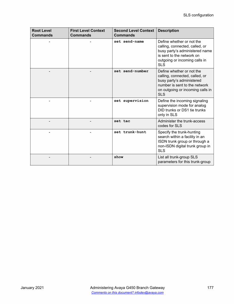
Root LevelCommands
First Level ContextCommands
Second Level ContextCommands
Description
- - set send-name Define whether or not thecalling, connected, called, orbusy party’s administered nameis sent to the network onoutgoing or incoming calls inSLS
- - set send-number Define whether or not thecalling, connected, called, orbusy party’s administerednumber is sent to the networkon outgoing or incoming calls inSLS
- - set supervision Define the incoming signalingsupervision mode for analogDID trunks or DS1 tie trunksonly in SLS
- - set tac Administer the trunk-accesscodes for SLS
- - set trunk-hunt Specify the trunk-huntingsearch within a facility in anISDN trunk group or through anon-ISDN digital trunk group inSLS
- - show List all trunk-group SLSparameters for this trunk-group
SLS configuration
January 2021 Administering Avaya G450 Branch Gateway 177Comments on this document? [email protected]

Chapter 7: Switch Ethernet portconfiguration
Ethernet ports on the Gateway switchThe switch on the Gateway has 10/100/1000 Mbps fixed switch ports on the front panel (ports10/5 and 10/6).
Ethernet ports on the Branch Gateway routerThe router on the Branch Gateway has 10/100 Mbps fixed router ports on the front panel (ports10/2 and 10/4).
Cables used for connecting devices to the fixed routerUse a standard network cable when you connect one of the following devices to the fixed routerport:
• WAN endpoint device
• Switch
• Router
Use a crossover network cable when you connect a computer or other endpoint device to the fixedrouter port. For all other Ethernet ports on the Branch Gateway, you can use either a standardnetwork cable or a crossover network cable to connect any device.
January 2021 Administering Avaya G450 Branch Gateway 178Comments on this document? [email protected]

Roadmap for configuring switch Ethernet portsFor basic configuration of a switch Ethernet port, use the commands listed below. You can alsoconfigure the following features on a switch Ethernet port:
• Advanced switching features, including VLANs.
• VoIP queuing. To configure VoIP queuing on a switch port, configure a VLAN for the port.Then configure VoIP queuing on the VLAN.
• Access control policy lists and QoS policy lists. To configure policy lists on a switch port,configure a VLAN for the port. Then configure policy on the VLAN.
• SNMP Link Up and Link Down traps.
Related linksAdvanced switching on page 311Commands used to configure QoS parameters on page 212Policy lists on page 505SNMP trap configuration on page 290
Summary of switch Ethernet port configuration CLIcommands
For more information about these commands, see Avaya Branch Gateway G450 CLI Reference.
Command Descriptionset port auto-negotiation-flowcontrol-advertisement
Set the flow control advertisement for the specified GigabitEthernet ports when performing auto-negotiation
set port duplex Configure the duplex type (full or half-duplex) of an Ethernet orFast Ethernet port or range of ports
You can configure Ethernet and FastEthernet interfaces toeither full-duplex or half-duplex. The duplex status of a port inauto-negotiation mode is determined by auto-negotiation.When auto-negotiation is enabled, an error message isgenerated if you attempt to set the transmission type of auto-negotiation Fast Ethernet ports to half-duplex or full-duplexmode.
set port enable | disable Enable or disable a port or a range of portsset port flowcontrol Set the send/receive mode for flow control frames (IEEE
802.3x or proprietary) for a full-duplex portset port level Set the default packet priority level for untagged packetsset port name Configure a name for a port
Table continues…
Roadmap for configuring switch Ethernet ports
January 2021 Administering Avaya G450 Branch Gateway 179Comments on this document? [email protected]

Command Descriptionset port negotiation Enable or disable auto-negotiation on the portset port speed Set the speed of a port or range of portsshow port auto-negotiation-flowcontrol-advertisement
Display the flow control advertisement for a Gigabit port usedto perform auto-negotiation
show port edge state Display the edge state of a portshow port flowcontrol Display port flow control information
Command Descriptionset port duplex Configure the duplex type (full or half-duplex) of an Ethernet or
Fast Ethernet port or range of portsset port edge admin state Determine whether the port is an edge port, for the purposes
of RSTP (Rapid Spanning Tree Protocol)
Edge port is a treatment assigned to ports for the purposes ofRSTP (Rapid Spanning Tree Protocol). For more informationabout using this command and RSTP configuration in general,see Rapid Spanning Tree Protocol (RSTP).
set port enable | disable Enable or disable a port or a range of portsset port flowcontrol Set the send/receive mode for flow control frames (IEEE
802.3x or proprietary) for a full-duplex port
Each direction (send or receive) can be configured separately.Use the show port flowcontrol command to display port flowcontrol information.
set port level Set the default packet priority level for untagged packets
Packets traveling through a port set at normal priority shouldbe served only after packets traveling through a port set athigh priority are served.
set port name Configure a name for a portset port negotiation Enable or disable auto-negotiation on the port
When negotiation is enabled, the speed and duplex of a FastEthernet port is determined by auto-negotiation. If negotiationis disabled, the user can set the speed and duplex of a FastEthernet port.
set port point-to-point adminstatus
Set the connection type of the port to one of the followingarguments:
• force-true. The port is treated as if it were connectedpoint-to-point
• force-false. The port is treated as if it were connected toshared media
• auto. The Branch Gateway tries to automatically detect theconnection type of the port
Table continues…
Switch Ethernet port configuration
January 2021 Administering Avaya G450 Branch Gateway 180Comments on this document? [email protected]

Command Descriptionset port speed Set the speed of a port or range of ports
An error message is generated if you attempt to set the speedwhen auto-negotiation is enabled.
show port edge state Display the edge state of a portshow port flowcontrol Display port flow control information
Configuring the WAN Ethernet portProcedure
1. Use the interface fastethernet 10/2 or interface fastethernet 10/4command to enter the context of the port interface.
2. Perform basic configuration of the interface.
3. Use the Ethernet WAN port configuration commands in the context of the port interface.
Related linksInterface configuration on page 387
Roadmap for configuring additional features on the WAN Ethernetport
• Primary Management Interface (PMI).• Advanced router features.• VoIP queuing.• Access control policy lists and QoS policy lists.• SNMP Link Up and Link Down traps.
Related linksPrimary Management Interface (PMI) configuration on page 64Router on page 386Commands used to configure QoS parameters on page 212Policy lists on page 505SNMP trap configuration on page 290
WAN Ethernet port traffic shapingYou can use traffic shaping to determine the data transfer rate on the WAN Ethernet port. To settraffic shaping, use the traffic-shape rate command in the interface context. To disable
Configuring the WAN Ethernet port
January 2021 Administering Avaya G450 Branch Gateway 181Comments on this document? [email protected]

traffic shaping, use the no form of the traffic-shape rate command. Traffic shaping works intandem with the configured bandwidth. If you change the traffic shape rate, this automaticallychanges the bandwidth. Similarly, if you change the bandwidth, this automatically changes thetraffic shape rate.
Note:
The traffic shape rate is determined in bits. The bandwidth is determined in kilobytes.
Related linksCommands used to configure QoS parameters on page 212
About backup interfacesYou can configure backup relations between a pair of any Layer 2 Serial interfaces, including theFastEthernet interface.
Related linksBackup interfaces on page 240
Summary of WAN Ethernet port configuration CLI commandsFor more information about these commands, see Avaya Branch Gateway G450 CLI Reference.
Root level command Command Descriptioninterfacefastethernet
Enter interface fastethernet configuration mode
autoneg Set the port speed and duplex to auto-negotiationmode
no autoneg Disable the auto-negotiation modeduplex Set the duplex setting (full or half) for the interfacekeepalive-track Bind an object tracker to the interface to check
whether it is up
When activated, the object tracker sends healthcheck packets at defined intervals to the other sideof the interface. If the configured number ofconsecutive keepalive requests are not answered,the interface track state changes to down. Theobject tracker continues monitoring the interface,and when its track state changes to up, theinterface state changes to up.
shutdown Set the administrative status of the currentinterface to down or up
Table continues…
Switch Ethernet port configuration
January 2021 Administering Avaya G450 Branch Gateway 182Comments on this document? [email protected]

Root level command Command Descriptionno shutdown Restore the administrative status of the interface to
up.speed Set the speed for the interfacetraffic-shape rate Configure traffic shaping for outbound traffic on the
current interface
DHCP client configurationBranch Gateway can be configured to function as a DHCP (Dynamic Host Configuration Protocol)client.
DHCP client enables Branch Gateway to receive an IP address from a DHCP server, according tothe DHCP client-server protocol. The DHCP server grants Branch Gateway DHCP client an IPaddress for a fixed amount of time, called the lease. After the lease expires, Branch GatewayDHCP client is required to stop using the IP address. Branch Gateway DHCP client periodicallysends requests to the server to renew or extend the lease.
In addition to receiving an IP address, Branch Gateway DHCP client can optionally request toreceive a domain name, a list of default routers, and a list of available DNS servers.
Note:
Branch Gateway can function as both a DHCP server and a DHCP client simultaneously. Thatis, you can connect a cable modem for an Internet connection to the WAN Fast Ethernet inorder to use Branch Gateway as a DHCP client. At the same time, you can activate the DHCPserver on Branch Gateway for use by clients, such as, IP phones and PCs connected to theLAN ports. The DHCP server on Branch Gateway does not serve Internet devices connectedover the WAN Fast Ethernet ports.
The DHCP client only supports IPv4.
Related linksDHCP server on page 409
DHCP client applicationsThe typical application of DHCP client in Branch Gateway involves requesting and receiving an IPaddress from the service provider’s DHCP server, to enable a broadband Internet connection viacable modem.
DHCP client configuration
January 2021 Administering Avaya G450 Branch Gateway 183Comments on this document? [email protected]

Configuring the DHCP clientProcedure
1. Enter the context of the FastEthernet interface.
For example:Gxxx-001# interface fastethernet 10/2Gxxx-001(config-if:FastEthernet 10/2)#
2. Optionally, configure DHCP client parameters.
If you do not configure these parameters, their default values are used:
• Use the ip dhcp client client-id command to set the client identifier for theDHCP client. By default, the client identifier is usually the MAC address of the BranchGateway FastEthernet interface.
• Use the ip dhcp client hostname command to set the hostname for the DHCPclient. By default, the DHCP client uses the Branch Gateway’s hostname.
• Use the ip dhcp client lease command to set the lease requested by the DHCPclient. The lease is the length of time that the IP address provided by the DHCP serverremains in effect. By default, the client does not request a specific lease from the DHCPserver and uses the lease set by the DHCP server.
• Use the ip dhcp client request command to determine which DHCP options theDHCP client requests from the DHCP server. By default, the DHCP client requests allDHCP options.
For example:Gxxx-001(config-if:FastEthernet 10/2)# ip dhcp client client-id hex 01:00:04:0D:29:DC:68Done!Gxxx-001(config-if:FastEthernet 10/2)# ip dhcp client hostname “Gxxx-A”
Switch Ethernet port configuration
January 2021 Administering Avaya G450 Branch Gateway 184Comments on this document? [email protected]

Done!Gxxx-001(config-if:FastEthernet 10/2)# ip dhcp client lease 1 4 15Done!Gxxx-001(config-if:FastEthernet 10/2)# no ip dhcp client request domain-nameDone!
3. Optionally, use the ip dhcp client route track command to apply an object trackerto monitor the DHCP client’s default route.
The object tracker continuously checks the validity of the default route, that is, whetherdata can be transmitted over the default route. Whenever the object tracker determinesthat the default route has become invalid, the route is dropped from the routing table andtraffic is routed to alternate routes. If the default route becomes valid again, it is addedback to the routing table.
Note that if several default routers are learned from a specific interface, the object trackertracks only the first one.
For example:Gxxx-001(config-if:FastEthernet 10/2)#ip dhcp client route track 3Done!
4. Enable the DHCP client by entering ip address dhcp.
A message appears, displaying the IP address and mask assigned by the DHCP server.For example:Gxxx-001(config-if:FastEthernet 10/2)# ip address dhcpDone!Interface FastEthernet 10/2 assigned DHCP address 193.172.104.161, mask 255.255.255.0
Note:
Whenever you change the value of a DHCP client parameter (such as, client-id, orclient hostname), enter ip address dhcp again to re-initiate DHCP addressnegotiation using the new values.
5. Use the show ip dhcp-client command to view the DHCP client parameters.
Related linksObject tracking provisioning on page 267Typical application – tracking the DHCP client default route on page 274Summary of DHCP Server commands on page 415
Examples of DHCP lease release and renew• The release dhcp command example:(super)# release dhcp FastEthernet 10/2 Done!
• The renew dhcp command example:(super)# renew dhcp FastEthernet 10/2 Done!
DHCP client configuration
January 2021 Administering Avaya G450 Branch Gateway 185Comments on this document? [email protected]

A message appears displaying the IP address and mask assigned by the DHCP server. Forexample:Interface FastEthernet 10/2 assigned DHCP address 193.172.104.161, mask 255.255.255.0
For a description of these commands, see Avaya G450 Branch Gateway CLI Reference.
Commands used for DHCP client maintenance• show ip dhcp-client• show ip dhcp-client statistics• clear ip dhcp-client statistics
For a description of these commands, see Avaya Branch Gateway G450 CLI Reference
Examples of configuring DHCP client logging messages• set logging session enable command example.Gxxx-001# set logging session enableDone!CLI-Notification: write: set logging session enable
• set logging session condition dhcpc example:Gxxx-001# set logging session condition dhcpc InfoDone!CLI-Notification: write: set logging session condition dhcpc Info
Note:
You can also enable logging messages to a log file or a Syslog server.
For a description of these commands, see Avaya G450 Branch Gateway CLI Reference.
Related linksSystem logging on page 191
Summary of DHCP client configuration CLI commandsFor more information about these commands, see Avaya Branch Gateway G450 CLI Reference.
Root levelcommand
Command Description
clear ip dhcp-clientstatistics
- Clear the DHCP client statistics counters
Table continues…
Switch Ethernet port configuration
January 2021 Administering Avaya G450 Branch Gateway 186Comments on this document? [email protected]

Root levelcommand
Command Description
interfacefastethernet
- Enter interface fastethernet configuration mode
- clear ip dhcp-clientstatistics
Clear the DHCP client statistics counters
- ip address dhcp Enable or disable IP address negotiation viaDHCP (applies to WAN FastEthernet interfacesonly)
- ip dhcp client client-id
Set the client identifier for the DHCP client
- ip dhcp clienthostname
Set the client hostname for the DHCP client
- ip dhcp client lease Set the lease requested by the DHCP client- ip dhcp client request Specify which DHCP options the DHCP client
requests from the DHCP server- ip dhcp client route
trackApply object tracking in order to monitor theDHCP client’s default route
- show ip dhcp-client Display the configuration of the DHCP client- show ip dhcp-client
statisticsDisplay the DHCP client statistics counters
release dhcp - Releases a DHCP lease for an interface. Thiseffectively releases the client IP address, and noIP address is allocated to the specified interface.
renew dhcp - Renews a DHCP lease for an interface. This iseffectively a request to renew an existing IPaddress, or the start of a new process ofallocating a new IP address.
show ip dhcp-client
- Display the configuration of the DHCP client
show ip dhcp-clientstatistics
- Display the DHCP client statistics counters
LLDP configurationIEEE 802.1AB Link Layer Discovery Protocol (LLDP) simplifies troubleshooting of enterprisenetworks and enhances the ability of network management tools to discover and maintainaccurate network topologies in multi-vendor environments. It defines a set of advertisementmessages, called TLVs, a protocol for transmitting and receiving the advertisements, and amethod for storing the information contained in the received advertisements.
LLDP configuration
January 2021 Administering Avaya G450 Branch Gateway 187Comments on this document? [email protected]

The LLDP protocol allows stations attached to a LAN to advertise information about the system(such as, its major capabilities and its management address) and information regarding thestation’s point of attachment to the LAN (port ID and VLAN information) to other stations attachedto the same LAN. These can all be reported to management stations via IEEE-defined SNMPMIBs.
LLDP information is transmitted periodically. The IEEE has defined a recommended transmissionrate of 30 seconds, but the transmission rate is adjustable. An LLDP device, after receiving anLLDP message from a neighboring network device, stores the LLDP information in an SNMP MIB.This information is valid only for a finite period of time after TLV reception. This time is defined bythe LLDP “Time to Live” (TTL) TLV value that is contained within the received packet unlessrefreshed by a newly received TLV. The IEEE recommends a TTL value of 120 seconds, but youcan change it if necessary. This ensures that only valid LLDP information is stored in the networkdevices and is available to network management systems.
LLDP information is associated with the specific device that sends it. The device itself is uniquelyidentified by the receiving party port via chassis ID and port ID values. Multiple LLDP devices canreside on a single port, using a hub for example, and all of the devices are reported via MIB. Youcan enable (Rx-only, TX-only, and Rx or Tx) or disable LLDP mode of operation on a per-portbasis.
Supported TLVsMandatory TLVs
• End-of-LDPDU
• Chassis ID
• Port ID
• Time to Live
Optional TLVs• Port description
• System description
• System name
• System capabilities
• Management address
Optional 802.1 TLVs• VLAN name
• Port VLAN
Switch Ethernet port configuration
January 2021 Administering Avaya G450 Branch Gateway 188Comments on this document? [email protected]

Configuring LLDPProcedure
1. Enable the LLDP agent globally using the set lldp system-control command.
For example:Gxxx-001(super)# set lldp system-control enableDone!
The device’s global topology information, including all mandatory TLVs, is now available toneighboring devices supporting LLDP.
2. Optionally, configure the administrative LLDP port status using the set port lldpcommand.
The default value is rx-and-tx.
The device now sends LLDP TLVs and accepts LLDP TLVs from neighboring devicessupporting LLDP on the specified port.
For example:Gxxx-001(super)# set port lldp 10/3 rx-and-txDone!
3. Optionally, configure additional TLVs transmission using the set port lldp tlvcommand.
This allows you to advertise additional data about the device’s and port’s VLANinformation, VLANs, and system capabilities. Additional TLVs are disabled by default.
For example:Gxxx-001(super)# set port lldp tlv 10/3 enable allDone!
The device now advertises all mandatory and optional TLVs to neighboring networkdevices supporting LLDP.
4. If required, change any of the following timing parameters:
• The interval at which the device transmits LLDP frames, using the command set lldptx-interval. The default is 30 seconds.
• The value of TxHoldMultiplier, using the command set lldp tx-hold-multiplier.TxHoldMultiplier is a multiplier on the interval configured by set lldp tx-intervalthat determines the actual TTL value sent in an LLDP frame. The default value is 30.The time-to-live value transmitted in TTL TLV is expressed by: TTL = min(65535,TxInterval * TxHoldMultiplier).
• The minimal delay between successive LLDP frame transmissions, on each port, usingthe command set lldp tx-delay. The default is 30 seconds.
• The delay from when a port is set to LLDP “disable” until re-initialization is attempted,using the command set lldp re-init-delay. The default is 2 seconds.
LLDP configuration
January 2021 Administering Avaya G450 Branch Gateway 189Comments on this document? [email protected]

5. Verify LLDP advertisements using the show lldp command.
Supported ports for LLDPYou can configure only ports 10/5 and 10/6 to support LLDP.
Summary of LLDP configuration CLI commandsFor more information about these commands, see Avaya Branch Gateway G450 CLI Reference.
Command Descriptionset lldp re-init-delay Set the delay from when a port is set to LLDP “disable” until
re-initialization is attemptedset lldp system-control Enable or disable the LLDP application globally per device or
stackset lldp tx-delay Set the TxDelay, which is the minimal delay in seconds
between successive LLDP frame transmissions, on each portset lldp tx-hold-multiplier Set the TxHoldMultiplier, which is a multiplier on the
TxInterval that determines the actual TTL value sent in anLLDP frame
set lldp tx-interval Set the TxInterval, the interval at which the devicetransmits LLDP frames
set port lldp Change the administrative LLDP status of a portset port lldp tlv Enable or disable the transmission of the optional TLVs on a
per port basisshow lldp Display the LLDP information received on each portshow lldp config Display the global LLDP configurationshow port lldp config Display port-level LLDP configurationshow port lldp vlan-nameconfig
Show the VLANs that are being transmitted on a specific port
Switch Ethernet port configuration
January 2021 Administering Avaya G450 Branch Gateway 190Comments on this document? [email protected]

Chapter 8: System logging
System logging is a method of collecting system messages generated by system events. TheBranch Gateway includes a logging package that collects system messages in several output types.Each of these types is called a sink. When the system generates a logging message, the messagecan be sent to each sink that you have enabled.
System messages do not always indicate problems. Some messages are informational, while othersmay help to diagnose problems with communications lines, internal hardware, and system software.
By default, all sinks are disabled. When enabled, log file and Syslog sink settings can be saved byusing the command: copy running-config startup-config to save the runningconfiguration to the startup configuration. However, the Session sink and its settings are deletedwhen the session is terminated.
You can define filters for each sink to limit the types of messages that the sink receives.
The logging facility logs configuration commands entered through the CLI or SNMP, and systemtraps and informative messages concerning the functioning of various processes. However, a userwith user privileges who enables the log can only see the entered commands. For example, a userwith read-only privileges cannot see entered commands having a read-write user level. In addition,the log does not display confidential information, such as, passwords and VPN pre-shared keys.
Related linksLogging filter configuration on page 200
Types of logging sinksSink DescriptionSyslog Logging messages are sent to up to three configured servers, using Syslog protocol as
defined in RFC 3164. Messages sent to the Syslog server are sent as UDP, TCP, and TLSmessages.
Log file Logging data is saved in the flash memory. These compressed, cyclic files serve as thesystem logging database.
Table continues…
January 2021 Administering Avaya G450 Branch Gateway 191Comments on this document? [email protected]

Sink DescriptionSession Logging messages are sent to the terminal screen as follows:
• For a local connection, messages appear online on the local terminal.
• For a remote Telnet/SSH connection, messages appear online on the remote terminal.
This sink is deleted whenever a session ends.
Syslog server configurationA Syslog server is a remote server that receives logging messages using the Syslog protocol. Thisenables storage of large log files that you can use to generate reports.
Defining Syslog serversAbout this taskYou can define up to three Syslog servers with either IPv4 or IPv6 addresses..
Procedure1. Define the Syslog server by entering set logging server followed by the IP address
of the server and optionally the transport (UDP, TCP or TLS) and server port.
For example (UDP Syslog server):Gxxx-001(super)# set logging server 147.2.3.66Done!
or (TLS Syslog server and certificate for TLS connection):Gxxx-001(super)# set logging server 2001:db8::2179::1tlsGxxx-001(super)# copy scp root-ca syslog syslogcert.crt 172.16.1.22Done!
2. Enable the Syslog server by entering set logging server enable followed by the IPaddress of the Syslog server.
When you define a new Syslog server, it is defined as disabled, so you must use thiscommand in order to enable the server.
For example:Gxxx-001(super)# set logging server enable 147.2.3.66Done!
3. Optionally, define an output facility for the Syslog server by typing the set loggingserver facility command, followed by the name of the output facility and the IPaddress of the Syslog server.
If you do not define an output facility, the default local7 facility is used.
System logging
January 2021 Administering Avaya G450 Branch Gateway 192Comments on this document? [email protected]

For example:Gxxx-001(super)# set logging server facility auth 147.2.3.66Done!
The following is a list of possible facilities:
• auth. Authorization
• daemon. Background system process
• clkd. Clock daemon
• clkd2. Clock daemon
• mail. Electronic mail
• local0 – local7. For local use
• ftpd. FTP daemon
• kern. kernel
• alert. Log alert
• audi. Log audit
• ntp. NTP subsystem
• lpr. Printing
• sec. Security
• syslog. System logging
• uucp. Unix-to-Unix copy program
• news. Usenet news
• user. User process
4. Optionally, limit access to the Syslog server output by typing the set logging serveraccess-level command, followed by an access level (read-only, read-write, or admin)and the IP address of the Syslog server.
If you do not define an access level, the default read-write level is used.
For example:Gxxx-001(super)# set logging server access-level read-only 147.2.3.66Done!
Only messages with the appropriate access level are sent to the Syslog output.
5. Optionally, define filters to limit the types of messages received.
Related linksLogging filter configuration on page 200
Syslog server configuration
January 2021 Administering Avaya G450 Branch Gateway 193Comments on this document? [email protected]

Disabling Syslog serversProcedureEnter set logging server disable followed by the IP address of the Syslog server.
For example:Gxxx-001(super)# set logging server disable 147.2.3.66Done!
Deleting Syslog serversAbout this taskYou can delete a Syslog server from the Syslog server table.
ProcedureEnter clear logging server followed by the IP address of the Syslog server you want todelete.
For example:Gxxx-001(super)# clear logging server 147.2.3.66Done!
Displaying the status of the Syslog serverProcedureEnter show logging server condition followed by the IP address of the Syslog server.
If you do not specify an IP address, the command displays the status of all Syslog servers definedfor the Branch Gateway.
ExampleAs the following example illustrates, the command displays whether the server is enabled ordisabled, and lists all filters defined on the server:Gxxx-001(super)# show logging server condition 10.129.179.178******************************************************Message logging configuration of SYSLOG sink ***Sink Is EnabledSink default severity: WarningServer name: 10.129.179.178Transport Type: TLSTLS state: connectedPort: 6514Server facility: local7Server access level: read-write
System logging
January 2021 Administering Avaya G450 Branch Gateway 194Comments on this document? [email protected]

Syslog sink default settingsSeverity: Warning
Facility: Local 7
Access level: Read-write
Syslog message formatSyslog messages are arranged chronologically and have the following format:<34> Oct 11 22:14:15 host LINKDOWN [005ms, SWICHFABRIC-Notification:Port 10/3 Link,ID=1234567890
The message provides the following information:• A priority (<34> in this example) that is calculated based on the syslog facility and the
severity level.• A header (Oct 11 22:14:15 host LINKDOWN in this example), providing the date and
time, the hostname, and a message mnemonic.• A message (005ms, SWICHFABRIC-Notification: Port 10/3 Link in this
example), detailing the milliseconds, the application being logged, the severity level, themessage text, and an Authentication File Identification number (AFID).
Commands used to copy a syslog fileYou can copy the syslog file from Branch Gateway to another location using FTP, SCP, or TFTP, orlocally to a USB mass storage device.
Use any of the following commands to copy a syslog file:
• copy syslog-file ftp.
• copy syslog-file scp• copy syslog-file tftp• copy syslog-file usb
For more information about these commands, see Avaya Branch Gateway G450 CLI Reference.
Related linksSummary of logging configuration CLI commands on page 205
Syslog server configuration
January 2021 Administering Avaya G450 Branch Gateway 195Comments on this document? [email protected]

Configuring a log fileAbout this taskA log file is a file of data concerning a system event, saved in the flash memory. The log filesserve as the system logging database, keeping an internal record of system events.
Procedure1. Enter set logging file enable.
Gxxx-001(super)# set logging file enableDone!
2. Optionally, define filters to limit the types of messages received.
Related linksLogging filter configuration on page 200
Disabling logging system messages to a log fileProcedureEnter set logging file disable.Gxxx-001(super)# set logging file disableDone!
Deleting current log file and opening an empty log fileProcedureEnter clear logging fileGxxx-001(super)# clear logging fileDone!
Example display of log file messagesThe show logging file content command displays the messages in the log file. Note thatthe user enabling the log sees only entered commands with a user-level no higher than the user’sprivileges. A user with read-only privileges does not see entered commands having a read-writeuser level.
Example
(super)# show logging file content<190>Aug 23 16:28:32 149.49.77.11 -NoTag: -NoUTC 2015 055 1mediagateway.g430 | 0 coldStart[BOOT-Informational: System boot upfrom cold reset, ID=N/A<187>Aug 23 16:28:32 149.49.77.11 -NoTag: -NoUTC 2015 525 1mediagateway.g430 | 0 MSY-TRPMAJNA[VOICE-Error: No Call ControllerFound, ID=N/A<190>Aug 23 14:30:25 149.49.77.11 -NoTag: -NoUTC 2015 965 1
System logging
January 2021 Administering Avaya G450 Branch Gateway 196Comments on this document? [email protected]

mediagateway.g430 | 0 BOOT MESSAGE[BOOT-Informational: Booting frombank B with firmware version 29.22.50, ID=N/A<190>Aug 23 14:30:25 149.49.77.11 -NoTag: -NoUTC 2015 965 1mediagateway.g430 | 0 coldStart[BOOT-Informational: System boot upfrom cold reset, ID=N/A<187>Aug 23 14:30:25 149.49.77.11 -NoTag: -NoUTC 2015 425 1mediagateway.g430 | 0 MSY-TRPMAJNA[VOICE-Error: No Call ControllerFound, ID=N/A
Example display of conditions defined for the file output sinkThe following example shows the output from the show logging file condition command.
Example
(super)# show logging file condition********************************************************* Message logging configuration of FILE sink ***Sink Is EnabledSink default severity: Informational
Log file message formatLog file messages appear in first-in, last-out order. They have the following format:08/23/2015,10:55:09:CLI-Notification: root: set port disable 10/608/23/2015,10:49:03:SWITCHFABRIC-Notification: Port Connection Lost on Module 10 port 5
Each message provides the following information:• Severity• The date and time (if available)• The logging application• The process ID (if available)• The UTC offset (if available)• The year• Milliseconds• Log format• The severity level• The Branch Gateway type• The message text
set logging file retentionDefines the period of time in days that log content will be retained.
Configuring a log file
January 2021 Administering Avaya G450 Branch Gateway 197Comments on this document? [email protected]

Syntaxset logging file retention {retention_days}retention_days must be either:
• A value between 1 and 9999, inclusive• Unlimited
Example:# set logging file retention unlimitedLog retention time is unlimited.Done!# show logging file retentionLog retention time is unlimited.Done!# set logging file retention 30Log retention time is 30 days.Done!# show logging file retentionLog retention time is 30 days.Done!# set logging file retention 10000Error: Parameter 1 (<retention_days>) value (10000) > maximum value(9999)set logging file retention -- Set log retention time in daysSyntax : set logging file retention <retention_days>
show logging file retentionShows the period of time in days that has been set using the set logging file retentioncommand
Syntaxshow logging file retentionExample:# set logging file retention 30Log retention time is 30 days.Done!# show logging file retentionLog retention time is 30 days.Done!
Configuring a session logAbout this taskA session log is the display of system messages on the terminal screen. It is automatically deletedwhen a session ends.
System logging
January 2021 Administering Avaya G450 Branch Gateway 198Comments on this document? [email protected]

Procedure1. Enter set logging session enable.
Gxxx-001(super)# set logging session enableDone!
Note:
If the device is connected to several terminals, a separate session log is establishedfor each terminal.
2. Optionally, define filters to limit the types of messages received.
Example discontinuation of the display of system messagesThe following output is an example of the set logging session disable command used todiscontinue the display of system messages to the terminal screen.
Example
(super)# set logging session disableDone!
Example display of session logging configurationThe following output is an example of the show logging session condition. command thatdisplays whether session logging is enabled or disabled, and lists all filters defined for sessionlogging.
Example
(super)# show logging session condition********************************************************* Message logging configuration of SESSION sink ***Sink Is EnabledSink default severity: WarningSession source ip: 172.16.1.231
Session logging message formatSession logging messages are arranged chronologically and have the format shown in thefollowing example:08/23/2015,10:49:03:SWITCHFABRIC-Notification: Port Connection Lost on Module 10 port 5 was cleared
08/23/2015,10:55:09:CLI-Notification: root: set port disable 10/6
Configuring a session log
January 2021 Administering Avaya G450 Branch Gateway 199Comments on this document? [email protected]

Each message provides the following information:• The date and time (if available)• The logging application• The severity level• The message text
Note:The user enabling the log only sees entered commands with a user-level no higher than theuser’s own privileges. For example, a user with read-write privileges cannot see enteredcommands with an admin user level.
Logging filter configurationYou can use filters to reduce the number of collected and transmitted messages. The filteringoptions are based on message classification by severity for each application. For a specified sink,you can define the threshold severity level for message output for each application. Messagespertaining to the specified applications, that have a severity level stronger than or equal to thedefined threshold, are sent to the specified sink. Messages with a severity level weaker than thedefined threshold are not sent.
Commands used to set the logging filtersFor each sink, you can set logging filters by specifying a severity level per application, as follows:
• set logging server condition application severity ip address creates afilter for messages sent to a specified Syslog server.
• set logging file condition application severity creates a filter for messagessent to a log file.
• set logging session condition application severity creates a filter formessages sent to a session log on a terminal screen where:- application is the application for which to view messages (use all to specify all
applications).- severity is the minimum severity to log for the specified application (use none to disable
logging messages for the specified application).- ip address is the IP address of the Syslog server.
For example:Gxxx-001(super)# set logging server condition dialer critical 147.2.3.66Done!Gxxx-001(super)# set logging file condition dhcps warningDone!Gxxx-001(super)# set logging session condition ISAKMP InformationDone!
System logging
January 2021 Administering Avaya G450 Branch Gateway 200Comments on this document? [email protected]

You can also filter the show logging file content command by severity for eachapplication, using the same variables as in the set logging file condition command. Inaddition, you can limit the number of messages to display.For example, to display the 50 most recent messages from the QoS application with a severitylevel of critical or higher, enter the following command:Gxxx-001(super)# show logging file content critical qos 50
Severity levelsSeverity level Code Descriptionemergency 0 System is unusablealert 1 Immediate action requiredcritical 2 Critical conditionerror 3 Error conditionwarning 4 Warning conditionnotification 5 Normal but significant conditioninformational 6 Informational message onlydebugging 7 Message that only appears during debugging
Default sink severity levelsSyslog: Warning
Log file: Informational
Session from terminal: Informational
Session from telnet/ssh: Warning
Application filteringYou can define filters for any application listed in the following table.
Application Descriptionarp Address Resolution Protocol mechanismboot System startup failurescdr Call Detail Recording. Registers the active calls in SLS mode.cli CLIconfig Configuration changes
Table continues…
Logging filter configuration
January 2021 Administering Avaya G450 Branch Gateway 201Comments on this document? [email protected]

Application Descriptionconsole Serial modem messagesdhcp-relay DHCP requests relayingdhcpc DHCP client packagedhcps DHCP server packagedialer Dialer interface messagesdnsc DNS client packagefan Cooling systemfilesys File system problem (flash)ids IDS events, specifically a SYN attack heuristic employed by the SYN
cookies featureiphc IP header compressionipsec VPN IPSEC packageisakmp VPN IKE packageospf Open Shortest Path First protocolpolicy Policy packageppp PPP protocolpppoe PPP over Ethernetproxy-arp Proxy ARPqos QoS messagesrouter Core routing system failuresrtp-stat RTP MIB statisticssaa RTR-probes messagessecurity Secure logging (authentication failure)snmp SNMP agentstp Spanning tree packagesupply Power supply systemswitchfabric Switch fabric failuressystem Operating system failurestftp Internal TFTP serverthreshold RMON alarmstracker Object tracker messagesusb USB devices messagesusb-modem USB modem messagesvj-comp Van Jacobson header compression messagesvlan VLAN package
Table continues…
System logging
January 2021 Administering Avaya G450 Branch Gateway 202Comments on this document? [email protected]

Application Descriptionvoice Voice failureswan WAN plugged-in expansion
Syslog server exampleThe following example defines a Syslog server with the following properties:
• IP address 147.2.3.66• Logging of messages enabled• Output to the Kernel facility• Only messages that can be viewed by read-write level users are received• Filter restricts receipt of messages from all applications to those less severe than errorGxxx-001(super)# set logging server 147.2.3.66Done!Gxxx-001(super)# set logging server enable 147.2.3.66Done!Gxxx-001(super)# set logging server facility kern 147.2.3.66Done!Gxxx-001(super)# set logging server access-level read-write 147.2.3.66Done!Gxxx-001(super)# set logging server condition all error 147.2.3.66Done!
Log file exampleThe following example enables the logging of system messages to a log file in the flash memoryand creates a filter to restrict the receipt of messages from the boot application to those withseverity level of informational or more severe, and messages from the cascade application tothose with severity level of alert or more severe.Gxxx-001(super)# set logging file enableDone!Gxxx-001(super)# set logging file condition boot informationalDone!Gxxx-001(super)# set logging file condition cascade alertDone!
Session log exampleThe following example enables a session log for a user wishing to debug the ISAKMP application,while only receiving messages of severity level error or stronger for all other applications.Therefore, the user sets the default severity level for all applications to error, and then sets theseverity of the ISAKMP application to informational. Finally, the user displays the filter settings.Gxxx-001(super)# set logging session enableDone!
Logging filter configuration
January 2021 Administering Avaya G450 Branch Gateway 203Comments on this document? [email protected]

Gxxx-001(super)# set logging session condition all ErrorDone!Gxxx-001(super)# set logging session condition ISAKMP InformationalDone!Gxxx-001(super)# show logging session condition********************************************************* Message logging configuration of CLI sink ***Sink Is EnabledSink default severity: ErrorApplication ! Severity Override-------------------------------------------ISAKMP ! Informational
Accessing diagnostic logsAbout this taskUse this procedure to capture log files.
Procedure1. Log on to the gateway as root.
2. Enable screen capture logging in your terminal emulation program.
3. Run the show all logs command.
4. Send a copy of the screen capture log file to Avaya through an email or as an attachment.
For more information about accessing diagnostic logs, see CLI Reference Avaya BranchGateway G450, 03-602056.
For example:iW}ZH~YL{}Z(^E^M}=}EsZ^E}ZZH~YL{}Zj^M}ZZZZZZDZJ@_3Zl{~=ZNLMR}EZZZZZZDZw3Zl~'=;^E}ZK}Esz~NZDZ"@:w:_3Z!lZjLMR}EZZZZZZZZDZ0:wZiW}Zl^>}YZn^=^ZzsDZ
)))))))))))))))))))))))))))))))))))))))))))))))))))))))))))))))
Z###Z.dizM}DZwD0TD0_Z###Z
?glgiZA~/2z{}Z}Md=OZ
)))))))))))))))))))))))))))))))))))))))))))))))))))))))))))))))ZZg??onZZZZHHpnn WWDMMDss:WsZZZZgKgjiZhtjnAgZZZZZZg??j+ZZZZZZZt.qwZZZZZZZt.q0 Z Z Z Z Z ZZZZZZZZZZZZZZZZZZZZZZZZZZZZZZZZZZZZZZZZZZli?ZZZZZZZZZZZZZ
)))))))))))))))))))))))))))))))))))))))))))))))))))))))))))))))Z?glgiZonZZHHpnn WWDMMDss:WsZZZZZZZZZZZZZZZZZZZZZZZZZZZZZli?
System logging
January 2021 Administering Avaya G450 Branch Gateway 204Comments on this document? [email protected]

Z Z
)))))))))))))))))))))))))))))))))))))))))))))))))))))))))))))))G450-gloin-031(super)#
Summary of logging configuration CLI commandsFor more information about these commands, see Avaya Branch Gateway G450 CLI Reference.
Command Descriptioncopy syslog-file ftp Copy the syslog file to a remote server using FTPcopy syslog-file scp Copy the syslog file to a remote server using SCPcopy syslog-file tftp Copy the syslog file to a remote server using TFTPcopy syslog-file usb Upload the syslog file from the Branch Gateway to the USB
mass storage deviceclear logging file Delete the message log file being stored in non-volatile
memory (NVRAM), including the history log, and open a new,empty log file
clear logging server Delete the specified Syslog message server from the Syslogserver table
set logging file Manage the logging of system messages to non-volatilememory (NVRAM)
set logging server Define a new Syslog output server for remote logging ofsystem messages
set logging server access-level
Set the access level associated with a Syslog server sink
set logging server condition Set a filter for messages sent to the specified Syslog server.Messages can be filtered by source system, severity, or both.
set logging server enable |disable
Enable or disable a specific Syslog server
set logging server facility Define an output facility for the specified Syslog serverset logging session Manage message logging for the current console sessionshow logging file condition Display all conditions that have been defined for the file output
sinkshow logging file content Output the messages in the log file to the CLI console. Note
that the user enabling the log sees only entered commandswith a user-level no higher than the user’s privileges. A userwith read-only privileges does not see entered commandshaving a read-write user level.
show logging server condition Display the filter conditions defined for the Syslog output sinkshow logging session condition Display the filter conditions defined for message logging to the
current console session
Summary of logging configuration CLI commands
January 2021 Administering Avaya G450 Branch Gateway 205Comments on this document? [email protected]

Chapter 9: VoIP QoS
Branch Gateway provides voice services over IP data networks using VoIP. VoIP is a group ofprotocols for transmitting and receiving various types of voice data over an IP network. VoIPincludes protocols for transmitting and receiving the following types of information:
• Digitally encoded voice data• Call signalling information• Call routing information• QoS information
VoIP uses the RTP and RTCP protocols to transmit and receive digitally encoded voice data.
You can use many types of telephones and trunks that do not directly support VoIP. Branch Gatewaytranslates voice and signalling data between VoIP and the system used by the telephones andtrunks.
RTP and RTCP configurationVoIP uses the RTP and RTCP protocols to transmit and receive digitally encoded voice data. RTPand RTCP are the basis of common VoIP traffic. RTP and RTCP run over UDP and incur a 12-byte header on top of other (IP, UDP) headers. Running on PPP or frame relay, these protocolscan be compressed.
Header compression configurationHeader compression reduces the size of packet headers, thus reducing the amount of bandwidthneeded for data. The header compression method is based on the fact that most of the headerfields remain constant or change in predictable ways throughout the session. Thus, instead ofconstantly retransmitting the header, each side keeps a context table of the sessions (the normalheaders), and while sending and receiving packets it replaces the full-length headers with one ortwo bytes CID (context-id) plus unpredictable deltas from the last packet.
The Branch Gateway offers both RTP header compression, for reducing the amount of bandwidthneeded for voice traffic, and TCP and UDP header compression, for reducing the amount ofbandwidth needed for non-voice traffic.
January 2021 Administering Avaya G450 Branch Gateway 206Comments on this document? [email protected]

For header compression purposes, any UDP packet with an even destination port within a user-configurable range of ports, is considered an RTP packet.
The Branch Gateway enables decompression whenever compression is enabled. However, whenenabling header compression on a Frame Relay interface, you must first verify that the remotehost is also employing header compression. Header compression on a Frame Relay interfacedoes not check what the remote host is employing. Thus, it may compress headers even when theremote host is not configured to decompress headers.
You can configure how often a full header is transmitted, either as a function of time or oftransmitted compressed packets.
Header compression configuration optionsThe Branch Gateway offers two options for configuring header compression:
• IP Header compression (IPHC) method, as defined by RFC 2507. IPHC-type compressionapplies to RTP, TCP, and UDP headers.
• Van Jacobson (VJ) method, as defined in RFC 1144. VJ compression applies to TCPheaders only.
Note:
VJ compression and IPHC cannot co-exist on an interface, and IPHC always overrides VJcompression. Thus, if you define both VJ compression and IPHC, only IPHC is enabled on theinterface regardless of the order of definition.
Header compression support by interfaceInterface type Supported compression methodsSerial - -
- PPP IPHC and VJ- Sub-Frame-Relay with IETF
encapsulationIPHC only
- Sub-Frame-Relay with non-IETFencapsulation
RTP header compression using the IPHC method,and TCP header compression using the VJ method
Dialer IPHC and VJ
Note:Non-IETF encapsulation is compatible with other vendors.
Header compression configuration
January 2021 Administering Avaya G450 Branch Gateway 207Comments on this document? [email protected]

Configuring IPHCAbout this taskIHPC applies to RTP, TCP, and UDP headers.
Note:You cannot specify IPHC for a Frame Relay non-IETF interface.
Procedure1. Optionally, configure the following header compression parameters.
If you do not configure these parameters, their default values are used.
• ip rtp compression-connections• ip tcp compression-connections• ip rtp max-period• ip rtp max-time• ip rtp non-tcp-mode
IETF mode is not compatible with non-IETF mode.
• ip rtp port-rangeFor example:Gxxx-001(config-if:Serial 4/1:1)# ip rtp compression-connections 48Done!Gxxx-001(config-if:Serial 4/1:1)# ip tcp compression-connections 48Done!Gxxx-001(config-if:Serial 4/1:1)# ip rtp max-period 512Done!Gxxx-001(config-if:Serial 4/1:1)# ip rtp max-time 20Done!Gxxx-001(config-if:Serial 4/1:1)# ip rtp non-tcp-mode ietfDone!Gxxx-001(config-if:Serial 4/1:1)# ip rtp port-range 40000 50000Done!
2. Use the ip rtp header-compression command if you want to enable RTP, TCP, andUDP header compression on the current interface.
The compression method employed is IPHC. Alternatively, you can use the followingequivalent command: ip tcp header-compression iphc-formatFor example:Gxxx-001# interface dialer 1Gxxx-001(config-if:Dialer 1)# ip rtp header-compressionDone
VoIP QoS
January 2021 Administering Avaya G450 Branch Gateway 208Comments on this document? [email protected]

Note:
Once header compression is enabled, any change to a header compression parameteris effective immediately.
3. To disable IPHC on an interface, use the no form of the command you employed (in theinterface context): no ip rtp header-compression or no ip tcp header-compression.
Summary of IPHC header compression CLI commandsFor more information about these commands, see Avaya Branch Gateway G450 CLI Reference.
Root level command First level command Descriptionclear ip rtpheader-compression
- Clear IP RTP header compression statistics forall enabled interfaces or for a specific interface.To clear RTP compression statistics for allendabled interfaces, do not enter an interfacetype and number. Clearing the statistics does notcause renegotiation of parameters.
clear ip tcpheader-compression
- Clear TCP header compression statistics for allenabled interfaces or for a specific interface. Toclear TCP compression sttistics for all enabledinterfaces, do not enter an interface type andnumber. Clearing the statistics does not causerenegotiation of parameters.
interface (dialer|serial)
- Enter the Dialer or Serial interface context
- ip rtp compression-connections
Control the number of Real-Time TransportProtocol (RTP) connections supported on thecurrent interface. Use the no form of thiscommand to restore the default value of 16. Thiscommand also sets the number of connectionsin the non-TCP space, not just RTP
- ip rtp header-compression
Enable both RTP and TCP header compressionon the current interface
- ip rtp max-period Set the maximum number of compressedheaders that can be sent between full headers
- ip rtp max-time Set the maximum number of seconds betweenfull headers
Table continues…
Header compression configuration
January 2021 Administering Avaya G450 Branch Gateway 209Comments on this document? [email protected]

Root level command First level command Description- ip rtp non-tcp-mode Set the type of IP header compression to ietf
or non-ietf. When set to ietf, the commandperforms IP header compression according toIPHC RFCs. When set to non-ietf, thecommand performs IP header compressioncompatible with other vendors, which do notstrictly follow the RFCs. The default headercompression mode is non-ietf.
- ip rtp port-range Set the range of UDP ports considered as RTPon the current interface
- ip tcp compression-connections
Set the total number of TCP headercompression connections supported on thecurrent interface. Use the no form this commandto restore the default value of 16.
show ip rtp header-compression
- Display header compression statistics for aspecific interface. If no interface is specified,statistics for all interfaces are displayed.
show ip rtp header-compression brief
- Display a subset of header compressionstatistics in the form of a table
show ip tcp header-compression
- Display TCP header compression statistics for aspecific interface
show ip tcp header-compression brief
- Display a subset of TCP header compressionstatistics in the form of a table
Configuring VJ header compressionAbout this taskVJ header compression applies to TCP headers only.
Note:You cannot specify VJ header compression for a Frame Relay IETF interface.
Procedure1. Optionally, use the ip tcp compression-connections command to control the
number of TCP header compression connections supported on the interface.
Use the no form of this command to restore the default value of 16 connections.
For example:Gxxx-001(config-if:Dialer 1)# ip tcp compression-connections 24Done!
2. Use the ip tcp header-compression command to enable TCP header compressionon the current interface.
VoIP QoS
January 2021 Administering Avaya G450 Branch Gateway 210Comments on this document? [email protected]

The compression method employed is the VJ compression.
Note:• The ip rtp header-compression command always overrides the ip tcpheader-compression command. Both commands enable TCP headercompression, but they differ in the methods employed.
• The ip tcp header-compression iphc-format command always overridesthe ip tcp header-compression command, and activates IPHC-typecompression.
For example:Gxxx-001# interface dialer 1Gxxx-001(config-if:Dialer 1)# ip tcp header-compressionDone!
Note:
Once header compression is enabled, any change to a header compression parameteris effective immediately.
3. To disable VJ TCP header compression on an interface, use the no ip tcp header-compression command in the interface context.
Summary of Van Jacobson header compression CLI commandsFor more information about these commands, see Avaya Branch Gateway G450 CLI Reference.
Root level command First level command Descriptionclear ip tcp header-compression
- Clear TCP header compression statistics for allenabled interfaces or for a specific interface
interface (dialer|serial)
- Enter the Dialer or Serial interface context
- ip tcp compression-connections
Set the total number of TCP headercompression connections supported on thecurrent interface
- ip tcp header-compression
Enable TCP header compression on thecurrent interface
show ip tcp header-compression
- Display TCP header compression statistics fora specific interface. If no interface is specified,statistics for all interfaces are displayed. Usethis command regardless of which compressionmethod is employed.
show ip tcp header-compression brief
- Display a subset of TCP header compressionstatistics in the form of a table
Header compression configuration
January 2021 Administering Avaya G450 Branch Gateway 211Comments on this document? [email protected]

Commands used to display and clear header compressionstatistics
For more information about these commands, see Avaya Branch Gateway G450 CLI Reference.
• show ip rtp header-compression• show ip tcp header-compression• clear ip rtp header-compression• clear ip tcp header-compression
Commands used to configure QoS parametersBranch Gateway uses MGCP (H.248) protocol for call signalling and call routing information. Usethe following commands to configure QoS for signalling and VoIP traffic.
• set qos control• set qos signal• show qos-rtcp• set qos bearer
For more information about these commands, see Avaya Branch Gateway G450 CLI Reference.
Commands used to configure RTCP QoS parametersUse the following commands to set the RTCP QoS parameters.
• set qos rtcp• show qos-rtcp
For more information about these commands, see Avaya Branch Gateway G450 CLI Reference.
Commands used to configure RSVP parametersVoIP can use the RSVP protocol to reserve network resources for voice data while communicatingwith other Gateways and other VoIP entities, such as, IP phones and Softphones.
• set qos rsvp• show qos-rtcp
For more information about these commands, see Avaya Branch Gateway G450 CLI Reference.
VoIP QoS
January 2021 Administering Avaya G450 Branch Gateway 212Comments on this document? [email protected]

Summary of QoS, RSVP, and RTCP configuration CLI commandsFor more information about these commands, see Avaya Branch Gateway G450 CLI Reference.
Command Descriptionset qos bearer Permit the setting of VoIP QoS-bearer related parameters for the Media
Gateway Processor and VoIP engines. The parameters you define using thiscommand may conflict with the default QoS list (400).
set qos control Define the source for QoS control parameters: local or remoteset qos rsvp Set values for the RSVP parameters of the VoIP engines. The parameters that
can be set include enabled/disabled, refresh rate (seconds), failure retry (y orn), and service profile (Guaranteed or Controlled).
set qos rtcp Set values for RTCP parameters. The RTCP parameters that can be set includeenabling or disabling RTCP reporting capability, setting the IP address of themonitor, setting the reporting period (the default is five seconds), and definingthe listening port number. This command supports IPv4 and IPv6.
set qos signal Set QoS signaling parameters (DSCP or 802.1Q) for the Media GatewayProcessor.
show qos-rtcp Display QoS, RSVP, and RTCP parameters for IPv4 and IPv6.
Weighted Fair VoIP QueuingWeighted Fair VoIP Queuing (WFVQ) combines weighted fair queuing (WFQ) for data streamsand priority VoIP queuing to provide the real-time response time that is required for VoIP.
WFQ is applied to data streams to provide fair bandwidth distribution among different datastreams, with faster response times for shorter packets that are typical for interactive applications,such as, telnet. Priority VoIP queuing is applied to VoIP bearer and signaling traffic.
WFVQ is the default queuing mode for all serial interfaces for which frame relay traffic-shaping isnot enabled, and all FastEthernet interfaces for which traffic-shaping is enabled. It is also the onlyqueueing mode available on a per-PVC basis for serial interfaces when frame relay traffic shapingis enabled.
Summary of WFVQ configuration CLI commandsFor more information about these commands, see Avaya Branch Gateway G450 CLI Reference.
Weighted Fair VoIP Queuing
January 2021 Administering Avaya G450 Branch Gateway 213Comments on this document? [email protected]

Root level command Command Descriptioninterface (serial|fastethernet| dialer)
- Enter the Serial, FastEthernet, or Dialer interfaceconfiguration context
- fair-queue-limit Specify the maximum number of packets that canbe queued in the weighted fair queue. The upperand lower limits of this command depend on theamount of bandwidth configured for the interface.
Use this command only for troubleshooting.- fair-voip-queue Enable Weighted Fair VoIP Queuing (WFVQ) on
the current interface. WFVQ is the recommendedqueuing mode for interfaces.
The no form of the fair-voip-queue commanddoes not exist. If you enter the command no fair-voip-queue, it will actually enable WFVQ ifWFVQ is not already enabled.
- priority-queue Enable or disable priority queuing mode in a Serialor FastEthernet interface.
- show queue Display information about the real-time status ofoutput queues for the current interface
- voip-queue Enable or disable custom queueing for VoIP traffic.If you disable custom queueing, WFVQ is re-enabled.
show queueing - Display the WFVG configuration
Priority queuingPriority queuing enables you to queue packets according to the priority of each packet. There arefour levels of priority. The total number of packets in all queues cannot exceed 5000.
You can enable priority queueing on the following interfaces:
• Serial (DS1 PPP L2-L3, DS1 PPP L2, USP PPP L2, USP PPP L2-L3)
• FastEthernet (L2, L2-L3) - when Traffic Shaping is configured
• Serial (DS1 FR L2, USP FR L2) - when Frame Relay Traffic Shaping is not configured
• Dialer (L2, L2-L3)
Priority queueing is disabled by default, since the default and recommended queueing method isWFVQ.
The high priority queue can be further split into two parts for voice traffic: control packets andbearer packets. This is called VoIP queueing. When VoIP queuing is enabled, the bearer queuesize is calculated to meet the estimated queueing delay, which is 20 ms by default. You can re-estimate the queueing delay, which results in a change in the bearer queue size.
VoIP QoS
January 2021 Administering Avaya G450 Branch Gateway 214Comments on this document? [email protected]
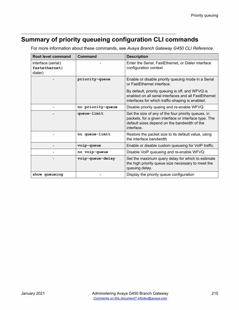
Summary of priority queueing configuration CLI commandsFor more information about these commands, see Avaya Branch Gateway G450 CLI Reference.
Root level command Command Descriptioninterface (serial|fastethernet|dialer)
- Enter the Serial, FastEthernet, or Dialer interfaceconfiguration context
- priority-queue Enable or disable priority queuing mode in a Serialor FastEthernet interface.
By default, priority queuing is off, and WFVQ isenabled on all serial interfaces and all FastEthernetinterfaces for which traffic-shaping is enabled.
- no priority-queue Disable priority queing and re-enable WFVQ.- queue-limit Set the size of any of the four priority queues, in
packets, for a given interface or interface type. Thedefault sizes depend on the bandwidth of theinterface.
- no queue-limit Restore the packet size to its default value, usingthe interface bandwidth
- voip-queue Enable or disable custom queueing for VoIP traffic.- no voip-queue Disable VoIP queueing and re-enable WFVQ- voip-queue-delay Set the maximum query delay for which to estimate
the high priority queue size necessary to meet thequeuing delay.
show queueing - Display the priority queue configuration
Priority queuing
January 2021 Administering Avaya G450 Branch Gateway 215Comments on this document? [email protected]

Chapter 10: Modems and Branch Gateway
You can connect either a USB or a serial modem to Branch Gateway. A USB modem must beconnected to the USB port on Branch Gateway chassis. A serial modem must be connected to theConsole port (CONSOLE) on Branch Gateway chassis.
The USB port and the Console port require configuration for modem use.
For more information about these commands, see Avaya Branch Gateway G450 CLI Reference.
Note:
If you have an Avaya Service contract, no configuration of the USB port is necessary forServices personnel to remotely access Branch Gateway through a USB modem.
USB-modem interface configurationBy default, the USB interface is enabled. Its default parameter values are:
• Interface status: = up
• PPP timeout absolute: = 10
• ppp authentication: = ras
• ip address: = 10.3.248.253 255.255.255.252
Example of IP address to USB port assignmentThe following example describes how the ip address command assigns the IP address192.168.22.33 to the USB port: (if:USB)# ip address 192.168.22.33 255.255.255.0
The default IP address for the USB port is 10.3.248.253 255.255.255.252.
The ppp authentication command parametersThe ppp authentication command is used with any of the following parameters:
• pap. Password Authentication Protocol. An unencrypted password is sent for authentication.
January 2021 Administering Avaya G450 Branch Gateway 216Comments on this document? [email protected]

• chap. Challenge Handshake Authentication Protocol. An encrypted password is sent forauthentication. To configure this password, use the ppp chap-secret command.
Note:
If the Branch Gateway firmware is replaced by an earlier firmware version, the pppchap-secret is erased, and must be re-configured.
• ras. Remote Access Service mode is being used for authentication. This is the default.
• none. No password is sent
Note:
The ppp authentication command changes the PPP authentication parameters of theConsole port as well as the USB port, even if you use the command in USB-modem interfacecontext.
Summary of CLI commands for configuring the USB port formodem use
For more information about these commands, see Avaya Branch Gateway G450 CLI Reference.
Root levelcommand
Command Description
interface usb-modem
- Enter USB-modem interface configuration context
- async modem-init-string
Change the default modem initialization string
- async reset-modem Reset the connected modem. You can use thiscommand from within an active PPP session over theUSB modem
- ip address Assign an IP address and mask to an interface. This isthe IP address to which a remote user can connectusing SSH/Telnet.
- ip peer address Change the IP address offered to a requesting callinghost during PPP/IPCP connection establishment. Bydefault, the interface offers its own IP address plus one.
- ppp authentication Configure the authentication method used whenstarting a client session on the PPP server.
- ppp chap-secret Configure the shared secret used in PPP sessions withCHAP authentication
- ppp timeoutauthentication
Set the maximum time to wait for an authenticationresponse
Table continues…
USB-modem interface configuration
January 2021 Administering Avaya G450 Branch Gateway 217Comments on this document? [email protected]

Root levelcommand
Command Description
- show pppauthentication
Display PPP authentication status
- shutdown Disconnect an active PPP session and shut down themodem
- timeout absolute Set the number of minutes until the systemautomatically disconnects an idle PPP incomingsession. By default, the timeout value is 10 minutes.
show interfaces - Display interface configuration and statistics for aparticular interface or all interfaces
show interfaces usb-modem Display the USB-modem interface parameters, thecurrent status of the USB port, and the identity of anyUSB modem connected to the USB port.
Console port and modem configurationThe Console port is labeled CONSOLE. The Console port is an RJ-45 socket that functions as aserial port. You can connect a console device or serial modem to the Console port to access theCLI.
You can set the Console port so that it automatically detects whether a console device or amodem is connected to it. Enter async mode interactive to set the Console port to usemodem mode every time an Avaya proprietary modem cable is plugged into the Console port. Ifyou do not want the Console port to automatically detect when a modem is connected to it, enterasync mode terminal to disable interactive mode.
Note:
By default, async mode is set to terminal.
Related linksCLI access on page 31
Summary of CLI commands for configuring the Console port formodem use
For more information about these commands, see the Avaya Branch Gateway G450 CLIReference.
Modems and Branch Gateway
January 2021 Administering Avaya G450 Branch Gateway 218Comments on this document? [email protected]

Root levelcommand
Command Description
interfaceconsole
- Enter Console interface configuration context. Use theno form of this command to set the console parametersto their default values.
- async modeinteractive
Enter modem mode every time the proprietary modemcable is plugged into the Console port
- async modeterminal
Disable interactive mode on the Console
- async modem-init-string
Change the default modem initialization string
- async reset-modem Reset the connected modem- ip address Assign an IP address and mask to an interface. This is
the IP address to which a remote user can connectusing Telnet.
- ip peer address Change the IP address offered to a requesting callinghost during PPP/IPCP connection establishment. Bydefault, the interface offers its own IP address plus one.
- ppp authentication Configure the authentication method used whenstarting a client session on the PPP server
- ppp chap-secret Configure the shared secret used in PPP sessions withCHAP authentication
- ppp timeoutauthentication
Set the maximum time to wait for an authenticationresponse
- show pppauthentication
Display PPP authentication status
- shutdown Disconnect an active PPP session and shut down themodem
- speed Set the PPP baud rate to be used by asynchronousPPP ports.
- timeout absolute Set the number of minutes until the systemautomatically disconnects an idle PPP incomingsession. By default, there is no timeout.
Console port and modem configuration
January 2021 Administering Avaya G450 Branch Gateway 219Comments on this document? [email protected]

Chapter 11: WAN interfaces
You can use an MM340 E1/T1 media module or an MM342 USP media module as an endpoint for aWAN line on Branch Gateway. You can use a Fast Ethernet port on Branch Gateway chassis as theendpoint for a WAN line by configuring the FastEthernet interface for PPP over Ethernet (PPPoE).Branch Gateway serves as a router, as well as the endpoint, for the WAN line.
Related linksRouter on page 386
Serial interface overviewA Serial interface is a virtual interface that is created over a portion of an E1/T1 or USP port on aWAN media module. Serial interfaces support PPP and frame relay encapsulation protocols.
Layer 1 T1 port with two channel groupsThe following figure illustrates a Layer 1 T1 port with two channel groups defined. All data fromeach channel group is encapsulated using PPP protocol, and is distributed over the multiple IPinterfaces defined for each channel group.
January 2021 Administering Avaya G450 Branch Gateway 220Comments on this document? [email protected]

E1/T1 port channel groupThe following figure illustrates an E1/T1 port channel group. All data from the channel group isencapsulated using frame relay protocol. The data is sent via a frame relay Serial interface andsub-interfaces over the multiple IP interfaces defined using Data Link Connection Identifier (DLCI).
USP port using PPP protocolThe following figure illustrates a USP port. All data from the USP port is encapsulated using thePPP protocol, and is sent via a Serial interface over the multiple IP interfaces defined for the Serialinterface.
USP port using frame relay protocolThe following figure illustrates a USP port. All data from the USP port is encapsulated using theframe relay protocol, and is sent through a frame relay Serial interface and sub-interfaces over thesingle IP interfaces defined using DLCI.
Serial interface overview
January 2021 Administering Avaya G450 Branch Gateway 221Comments on this document? [email protected]

Frame Relay multipoint topology supportBranch Gateway supports point-to-point frame relay connections. To enable you to use theGateway as an endpoint in a Point to Multi-Point (PTMP) topology, Branch Gateway supportsinverse ARP replies. Branch Gateway responds to inverse ARP queries received on frame relaysub-interfaces with the proper inverse ARP replies.
When you connect Branch Gateway as an endpoint in a PTMP configuration, you need toincrease the OSPF timers manually. Use the ip ospf network point-to-multipointcommand in Serial interface context to increase the OSPF timers with the following values:
• Increase the OSPF Hello Interval to 30 seconds• Increase the OSPF Dead Interval to 120 seconds
Related linksOSPF on page 426
Configuring the initial WANProcedure
1. Add one of the following WAN media modules:
• Avaya MM340 E1/T1 media module• Avaya MM342 USP media module
Note:
You can also use the Fast Ethernet port on the Branch Gateway chassis as theendpoint for a WAN line by configuring this interface for PPPoE.
2. Connect the WAN line to the media module.
For more information see
For more information, see Installing and Upgrading the Avaya Branch Gateway G450.
WAN interfaces
January 2021 Administering Avaya G450 Branch Gateway 222Comments on this document? [email protected]

3. Configure the WAN interface on the WAN media modules MM340 and MM342.
4. By default, a Branch Gateway WAN interface uses Point-to-Point Protocol (PPP).
5. If you want frame relay encapsulation on the WAN, configure frame relay.
6. Test the WAN configuration.
See WAN configuration and testing connectivity section.
7. Enter copy running-config startup-config to save the configuration.
Related linksConfiguring PPPoE on page 232
The Avaya MM340 E1/T1 WAN media module
Configuring Avaya MM340 E1/T1 WAN media moduleAbout this taskUse this procedure to configure Avaya MM340 E1/T1 WAN media module.
Procedure1. Optionally, use the show controllers command to display the current settings.
2. Enter show ds-mode to check whether the Branch Gateway is configured for E1 or T1operation.
3. Use the ds-mode command to set the mode of the Branch Gateway to E1 or T1.
Changing the line type requires resetting the module. The default value is T1.
4. Use the controller {e1 | t1} module_number/port_number command to enterController context for the port to be configured.
The prompt changes to:(super-if:Serial s/p)#, where s is the slot number of the mediamodule, and p is the port number.
5. Use the following commands to change the clock source, frame type, linecode, or cablelength parameters from the default settings:
• For T1 mode:
- clock source line|internal (default is line)
- framing sf|esf (default is sf)
- linecode ami|b8zs (default is ami)
- cablelength long|short (default is long, gain26, 0db)
The Avaya MM340 E1/T1 WAN media module
January 2021 Administering Avaya G450 Branch Gateway 223Comments on this document? [email protected]

Note:
Use the cablelength command to configure the cable’s transmit and receivelevels. If the cable is longer than 655 feet, use the command cablelengthlong gain26|gain36 -15db|-22.5db|-7.5db|0db (default is gain26,0db). If the cable is 655 feet or less, use the command cablelength short133ft|266ft|399ft|533ft|655ft (default is 133ft). When using thecablelength short form of the command, the transmit attenuation isconfigured using the loop length.
- fdl ansi|att|both (default is both)
Note:
The fdl command defines the type of Facility Data Link loopback that the remoteline is requested to enter. This command can only be used when ESF framing isdefined.
• For E1 mode:
- clock source line|internal (default is line)
- framing crc4|no-crc4|unframed (default is crc4)
- linecode ami|hdb3 (default is hdb3)
6. Use the channel-group command to specify the channel group and time slots to bemapped, as well as the DS0 speed.
Example:
• For T1 mode: channel-group 1 timeslots 1,3-5,7 speed 64 configures timeslots numbered 1, 3-5, and 7 to be mapped in channel-group number 1, and sets theDS0 speed to 64 kbps. The default DS0 speed for T1 mode is 56
• For E1 mode: channel-group 1 timeslots 1,3-5,7 speed 64 configures timeslots numbered 1, 3-5, and 7 to be mapped in channel-group number 1, and sets theDS0 speed to 64 kbps. The default DS0 speed for E1 mode is 64.
7. Enter exit to return to general context.
The prompt returns to:Gxxx-001(super)#
8. Use the interface serial command to enter the Serial interface context.
Specify the slot number of the media module, the port number, the channel group number,and optionally, the IP interface number.
If you do not specify an IP interface number for the first Serial interface that you define ona channel group, the Branch Gateway automatically assigns IP interface number 0. Foreach additional Serial interface that you define on the channel group, use a different IPinterface number.
WAN interfaces
January 2021 Administering Avaya G450 Branch Gateway 224Comments on this document? [email protected]

For example:
• interface serial 3/1:1. Enter a serial interface on the media module in slotnumber 3, on port number 1, with channel group number 1.
• interface serial 4/1:2.3. Enter a serial interface on the media module in slotnumber 4, on port number 1, with channel group number 2, and with IP interface number3.
Note:
If you use the framing unframed command in Step 5 for an E1 port, a channelgroup is automatically created on the entire E1 bandwidth. The channel group has thenumber 0. In Step 8, enter interface serial s/p:0, where s is the slot numberand p is the port number.
Note:
After the Serial interface is created, its default encapsulation is PPP.
9. Configure the interface encapsulation.
By default, the Serial interface uses PPP encapsulation.
10. Use the ip address command to configure the IP address and subnet mask of theinterface.
11. Enter exit to return to general context.
The prompt returns to:Gxxx-001(super)#
12. If needed, repeat Step 8 through Step 10 to configure additional IP interfaces on the samechannel group.
13. If needed, repeat Step 6 through Step 10 to configure additional channel groups on thesame E1 or T1 port.
14. Test the WAN configuration.
See WAN configuration and testing connectivity.
15. Enter copy running-config startup-config to save the configuration.
E1/T1 default settingsFunction Default settingDS mode T1E1 framing CRC4T1 framing SF
Table continues…
The Avaya MM340 E1/T1 WAN media module
January 2021 Administering Avaya G450 Branch Gateway 225Comments on this document? [email protected]

Function Default settingE1 linecode HDB3T1 linecode AMIClock source LineT1 cable length Long, Gain 26,0 dbSpeed E1: 64kbps
T1: 56kbps
Commands used to reset and display controller countersUse the following commands to reset counters on a controller interface:
• clear controller counters• remote
Use the following commands to display counters on a controller interface:
• show controllers• show controllers remote
For a full description of the commands and their output fields, see Avaya Branch Gateway G450CLI Reference.
Commands used to activate loopback mode on an E1/T1 lineUse the following loopback commands to activate or deactivate loopback mode for an E1 or T1line.
• loopback diag• loopback local• loopback remote
Summary of E1/T1 ports configuration commandsFor a full description of the commands and their output fields, see Avaya Branch Gateway G450CLI Reference.
WAN interfaces
January 2021 Administering Avaya G450 Branch Gateway 226Comments on this document? [email protected]

Root levelcommand
Command Description
clearcontrollercounters
- Reset the controller counters
controller - Enter configuration mode for a specific controller- cablelength long (T1) Set transmit and receive levels for a cable longer
than 655 feet- cablelength short (T1) Set transmit levels for a cable of length 655 feet or
shorter- channel-group Create a channel group logical interface for a PPP
or Frame Relay session- clock source Set the clock source for an E1 or T1 controller- fdl Define the type of Facility Data Link loopback that
the remote line is requested to enter- framing Set the frame type for an E1 or T1 data line- linecode Set the type of line-code transmission for the E1 or
T1 line- loopback Put a T1 or E1 line into loopback mode or disable
loopback mode- loopback remote Request a remote station to activate or deactivate
a line or payload loopback signal on the controllerinterface. This command is applicable only to a T1line.
ds-mode - Set the mode of the controller: e1 or t1interfaceserial
- Enter Serial interface or sub interfaceconfiguration context
- ip address Configure the IP address and subnet mask of theinterface
showcontrollers
- Display status information about a controllerinterface
showcontrollersremote
- Display controller statistics from a peer station
show ds-mode - Display the current mode of the controller
The Avaya MM340 E1/T1 WAN media module
January 2021 Administering Avaya G450 Branch Gateway 227Comments on this document? [email protected]

Avaya MM342 USP WAN media module
Configuring Avaya MM342 USP WAN media moduleProcedure
1. Use the interface serial command to enter the context of the interface.
Specify the slot number of the media module, the port number, and optionally the IPinterface number.
If you do not specify an IP interface number for the first Serial interface that you define ona port, the Branch Gateway automatically assigns IP interface number 0. For eachadditional Serial interface that you define on the port, use a different IP interface number.
For example:
• interface serial 3/1. Enter a serial interface on the media module in slot number3, on port number 1.
• interface serial 4/1.2. Enter a serial interface on the media module in slotnumber 4, on port number 1, with IP interface number 2.
Gxxx-001(super)# interface serial 3/1
The prompt changes to:Gxxx-001(super-if:serial 3/1)#
2. Use the following commands to change the idle characters, transmitter delay, encodingtype, bandwidth parameters, line monitoring, and from their default settings:
• idle character flags|marks. Set the bit pattern used to indicate an idle line. Usethe no form of this command to restore the default value (flags).
• transmitter-delay number. Set the minimum number of flags to be sent betweensuccessive packets. Use the no form of the command to restore the transmitter-delayvalue to the default (0).
Note:
The transmitter-delay command is usually used when the DCE equipment thatis connected directly to the Gateway, or the router on the WAN have a receive bufferthat is not large enough to hold the traffic sent by the Gateway. In this case,configure transmitter-delay on the DCE equipment or the remote router inorder to preserve the high performance that you had when transmitter-delaywas configured to 0 on the Gateway.
• nrzi-encoding. Enable the non-return-to-zero inverted (NRZI) line coding format onthe specified interface. Use the no form of the command to disable NRZI encoding.
• bandwidth kbps. Set the bandwidth parameter manually for the interface. Use the noform of this command to restore the bandwidth parameter to its default value (2,048).
WAN interfaces
January 2021 Administering Avaya G450 Branch Gateway 228Comments on this document? [email protected]

The manually specified bandwidth value overrides the dynamically calculated bandwidthduring route cost calculations.
Note:
If you are using the USP port as a clock source, configure the port’s bandwidth tomatch the DCE clock rate.
• ignore dcd. Specify how the system monitors the line to determine if it is up or down.Specify ignore dcd to ignore DCD signals, and instead use DSR/CTS signals todetermine the line’s status. Use the no form of the command to specify that DCD signalsare used to determine line status.
• invert txclock. Invert the transmit clock signal from the data communicationsequipment (DCE). Use the no form of the command to restore the signal to not inverted.
3. Configure the interface encapsulation.
4. Enter exit to return to general context.
The prompt returns to:Gxxx-001(super)#
5. Repeat Step 1 to configure additional Serial interfaces on the USP port.
6. Test the WAN configuration.
7. Enter copy running-config startup-config to save the configuration.
Related linksConfiguring frame relay on page 235Commands used for WAN configuration and testing connectivity on page 238
USP default settings
Function Default settingEncoding NRZBandwidth 2,048 kbpsLine-up indicator signal DCD
Summary of USP port configuration commandsFor more information about these commands, see Avaya Branch Gateway G450 CLI Reference.
Avaya MM342 USP WAN media module
January 2021 Administering Avaya G450 Branch Gateway 229Comments on this document? [email protected]

Root level command Command Descriptioninterface serial - Enter Serial interface or sub interface
configuration context- bandwidth Set the bandwidth parameter manually for this
interface- idle-character Set the bit pattern used to indicate an idle line- ignore dcd Specify how the system monitors the line to
determine if it is up or down- invert txclock Invert the transmit clock signal from the data
communications equipment (DCE)- ip address Configure the IP address and subnet mask of
the interface- nrzi-encoding Enable or disable the non-return-to-zero
inverted (NRZI) line coding format on theinterface
- transmitter-delay Set the minimum number of flags to be sentbetween successive packets
PPP configurationConfiguring PPP
About this taskPPP is the default encapsulation on a WAN port. If the encapsulation has been changed to framerelay and you want to restore PPP encapsulation, or to change the PPP parameters:
Procedure1. Ensure that you are in the context of a serial interface that is defined on the port.
If you are not in the context of a serial interface, use the interface serial command.To view all Serial interfaces that are defined, use the show interfaces serialcommand.
2. If the interface is not already configured to use PPP encapsulation, enter encapsulationppp to change the encapsulation to PPP.
3. (Optional) Change the queuing mode of the interface.
4. Use the following commands to change the interface parameters:
• ip address. Configure the IP address and subnet mask of the interface.• ppp timeout ncp. Set the maximum time to wait for the network layer to negotiate. If
this time is exceeded, the Gateway restarts the PPP session.• ppp timeout retry. Set the maximum time to wait for a response during PPP
negotiation.
WAN interfaces
January 2021 Administering Avaya G450 Branch Gateway 230Comments on this document? [email protected]

• keepalive. Enable keepalive or change the interval to which keepalive is set. Whenactivated, keepalive performs the initial negotiation and sends health checks at definedintervals to the other side of the interface. To deactivate keepalive, use the no form ofthe command or set the health check interval to 0.
5. Enter exit to return to general context.
The prompt returns to:Gxxx-001(super)#
6. Test the WAN configuration.
7. Enter copy running-config startup-config to save the configuration.
Related linksWeighted Fair VoIP Queuing on page 213Commands used for WAN configuration and testing connectivity on page 238
Summary of PPP configuration commandsFor more information about these commands, see the Avaya Branch Gateway G450 CLIReference.
Root level command Command Descriptioninterface serial - Enter Serial interface or sub interface
configuration context- encapsulation Set the encapsulation mode for a Serial
interface: PPP or frame relay- ip address Configure the IP address and subnet mask of
the interface- keepalive Enable PPP keepalive, in order to maintain a
persistent connection- ppp timeout ncp Set the maximum time, in seconds, that PPP
allows for negotiation of a network layerprotocol
- ppp timeout retry Set the maximum time to wait for a responseduring PPP negotiation
show interfaces - Display interface configuration and statistics fora particular interface or all interfaces
PPPoE overviewYou can configure ETH WAN Fast Ethernet ports as a WAN port using PPPoE (PPP overEthernet). PPPoE offers dialup style authentication and accounting and allows subscribers todynamically select their ISP.
Avaya MM342 USP WAN media module
January 2021 Administering Avaya G450 Branch Gateway 231Comments on this document? [email protected]

PPPoE is a client-server protocol used for carrying PPP-encapsulated data over Ethernet frames.A PPPoE client can establish a tunnel that carries PPP frames between a dialing host (the BranchGateway) and an access concentrator. This enables the use of PPP authentication protocols(CHAP and PAP). Unlike other tunneling protocols such as L2TP and PPTP, PPPoE works directlyover Ethernet rather than IP.
A typical broadband access network is based on ADSL modems configured as transparentEthernet bridges. ADSL modems use ATM protocol, and the transparent bridging is done to a wellknown ATM VC. On the other side of the telephone line is a device called a DSLAM. The DSLAMterminates the ADSL physical layer, collects the ATM cells from the various ADSL subscribers,and places them on the SP ATM infrastructure. The Ethernet frames from the customer’s hostdevice can reach one or more access concentrators, which are the remote access servers.
Configuring PPPoEProcedure
1. Enter the FastEthernet interface context with the interface fastethernet 10/2command.
2. Enter encapsulation pppoe to change the encapsulation to PPPoE.
You must change the encapsulation to PPPoE before configuring an IP address on theinterface.
Note:
You cannot use PPPoE if:
• An IP address must not be configured on the interface
• Dynamic CAC is not enabled on the interface.
• The interface is not part of a primary-backup interface pair.
WAN interfaces
January 2021 Administering Avaya G450 Branch Gateway 232Comments on this document? [email protected]

3. Use the ip address command to configure an IP address and subnet mask for theinterface.
In most cases, PPPoE tunnels require a 32-bit subnet mask.
Alternatively, you can enter ip address negotiated to obtain an IP address via PPP/IPCP negotiation.
Note:
You cannot configure PPP/IPCP address negotiation if DHCP address negotiation isalready configured on the interface.
4. Configure an authentication method and parameters:
• For PAP authenticating, enter ppp pap-sent username followed by a user name andpassword. For example:Gxxx-001(super-if:FastEthernet 10/2)# ppp pap-sent username avaya32 password ******Done!
• For CHAP authentication, enter ppp chap hostname followed by a hostname, andppp chap password followed by a password. For example:Gxxx-001(super-if:FastEthernet 10/2)# ppp chap hostname avaya32Done!Gxxx-001(super-if:FastEthernet 10/2)# ppp chap password ******Done!
5. If the Branch Gateway is connected to the Internet via the FastEthernet interfaceconfigured for PPPoE, and you define a VPN tunnel which specifies remote hosts byname, it is recommended to use the ppp ipcp dns request command.
The command requests the list of available DNS servers from the remote peer during thePPP/IPCP session. The DNS servers are used by the DNS resolver to resolve hostnamesto IP addresses.
6. Enter exit to return to general context.
The prompt returns to:Gxxx-001(super)#
7. Test the configuration.
See WAN configuration and testing connectivity.
8. Enter copy running-config startup-config to save the configuration.
9. Optionally, shut down the port and the PPPoE client, if configured, with the shutdowncommand in the interface context.
Related linksDynamic CAC on page 261Backup interfaces on page 240DHCP client configuration on page 183
Avaya MM342 USP WAN media module
January 2021 Administering Avaya G450 Branch Gateway 233Comments on this document? [email protected]

Summary of PPPoE commandsFor more information about these commands, see Avaya Branch Gateway G450 CLI Reference.
Root level command Command Descriptioninterfacefastethernet
- Enter the FastEthernet interface context
- encapsulation pppoe Change the encapsulation to PPPoE- ip address Configure an IP address and subnet mask for
the interface- ip address negotiated Obtain an IP address via PPP/IPCP
negotiation- keepalive Enable PPP keepalive, in order to maintain a
persistent connection- keepalive-track Bind interface status to an object tracker to
check whether the interface is up- mtu Set the interface’s MTU to 1492, which
ensures that overall packet size for the PPPoEinterface does not exceed 1500, which is theMTU for Ethernet
- ppp chap hostname Override the device hostname for PPP CHAPauthentication
- ppp chap password Set the CHAP password for authenticationwith a remote peer
- ppp chap refuse Prevent the device from authenticating withCHAP after the device is requested by theremote peer
- ppp ipcp dns request Enable or disable requesting the list ofavailable DNS servers from the remote peerduring the PPP/IPCP session
- ppp pap refuse Prevent the device from authenticating withPAP after the device is requested by theremote peer
- ppp pap-sent username Set the Password Authentication Protocol(PAP) password for authentication with theremote peer
- ppp timeout ncp Set the maximum time, in seconds, that PPPallows for negotiation of a network layerprotocol
- ppp timeout retry Set the maximum time to wait for a responseduring PPP negotiation
- pppoe-clientpersistent delay
Set the interval between pppoe-client dialattempts
Table continues…
WAN interfaces
January 2021 Administering Avaya G450 Branch Gateway 234Comments on this document? [email protected]

Root level command Command Description- pppoe-client
persistent max-attempts
Limit the number of consecutive connectionestablishment retries
- pppoe-client service-name
Set the PPPoE Client service-name
- pppoe-client wait-for-ipcp
Set the amount of time (in seconds) betweenestablishment of the PPPoE tunnel andestablishment of the IPCP tunnel. If this timeis exceeded, the PPPoE client terminates thePPPoE tunnel.
- shutdown Shut down the port, and the PPPoE client, ifconfigured
Frame relay
Configuring frame relayProcedure
1. Ensure that the port is configured on the media module.
2. Ensure that you are in the context of a serial interface that is defined on the port.
If you are not in the context of a serial interface, use the interface serial command.To view all Serial interfaces that are defined, use the show interfaces serialcommand.
3. Use the encapsulation frame-relay command to change the encapsulation to framerelay.
You can optionally specify the encapsulation type: IETF (RFC1490/RFC2427) or non-IETF.The default encapsulation type is IETF.
Note:
Non-IETF encapsulation is compatible with other vendors.
4. If needed, use the frame-relay lmi commands to change the Local ManagementInterface (LMI) parameters from their default values, or enter frame-relay traffic-shaping to activate traffic shaping on the frame relay interface.
5. Optionally, change the queuing mode of the interface.
6. Enter exit to return to general context.
Frame relay
January 2021 Administering Avaya G450 Branch Gateway 235Comments on this document? [email protected]

The prompt returns to:Gxxx-001(super)#
7. Enter interface serial if.fr-sub-if point-to-point to create a frame relaysub-interface and enter the context of the interface.
For example:
• interface serial 3/1:2.1 point-to-point. Create frame relay sub-interfacenumber 1 on the E1/T1 media module in slot number 3, on port number 1, with channelgroup number 2
• interface serial 4/1:2.3.2 point-to-point. Create frame relay sub-interface number 3 on the E1/T1 media module in slot number 4, on port number 1, withchannel group number 2, and with IP interface number 2
• interface serial 3/1.2 point-to-point. Create frame relay sub-interfacenumber 2 on the USP media module in slot number 3, on port number 1
• interface serial 4/1.2.1 point-to-point. Create frame relay sub-interfacenumber 2 on the USP media module in slot number 4, on port number 1, with IPinterface number 1
Note:
Currently only point-to-point frame relay sub-interfaces are supported.
8. Enter frame-relay interface-dlci DLCI-number to configure a Data LinkConnection Identifier (DLCI) for the frame relay sub-interface.
You can optionally specify the encapsulation type: IETF (RFC1490/RFC2427) or non-IETF.The default encapsulation type is IETF.
Note:
Non-IETF encapsulation is compatible with other vendors.
9. If required, use the frame-relay priority-dlci-group command to configure aPriority DLCI group.
The arguments for this command are the DLCIs you want to assign to high, medium,normal, and low priority traffic, respectively. For example, the command frame-relaypriority-dlci-group 17 18 19 assigns DLCI 17 to high priority traffic, DLCI 18 tomedium priority traffic, and DLCI 19 to normal and low priority traffic.
10. Use the ip address command to configure an IP address and subnet mask for the framerelay sub-interface.
11. Enter exit to return to general context.
The prompt returns to:Gxxx-001(super)#
12. If needed, repeat Step 7 on page 236 through Step 11 on page 236 to configure additionalframe relay sub-interfaces on the same Serial interface.
WAN interfaces
January 2021 Administering Avaya G450 Branch Gateway 236Comments on this document? [email protected]

13. If needed, repeat Step 2 on page 235 through Step 12 on page 236 to configure framerelay encapsulation for other Serial interfaces on the same WAN port.
14. Test the WAN configuration.
15. Enter copy running-config startup-config to save the configuration.
Related linksConfiguring Avaya MM342 USP WAN media module on page 228Configuring Avaya MM340 E1/T1 WAN media module on page 223Frame relay traffic shaping and FRF.12 fragmentation on page 276Weighted Fair VoIP Queuing on page 213
Commands used to reset and display frame relay interfacecounters
• clear frame-relay counters• show interfaces
For a full description of the commands and their output fields, see Avaya Branch Gateway G450CLI Reference.
Summary of frame relay commandsFor more information about these commands, see Avaya Branch Gateway G450 CLI Reference.
Root level command Command Descriptionclear frame-relaycounters
- Clear the frame relay counters
interface serial - Enter Serial interface or sub interfaceconfiguration mode
- encapsulation Set the encapsulation mode for a Serialinterface
- frame-relay class-dlci
Associate a Virtual Channel with a namedQoS or Traffic shaping template (map-class)
- frame-relayinterface-dlci
Associate a frame relay Virtual Channel withthe current interface
- frame-relay lmi-n391dte
Set the number of status enquiry intervals thatpass before issuing a full status enquirymessage
- frame-relay lmi-n392dte
Set the maximum number of unansweredstatus enquiries the equipment accepts beforedeclaring the interface down
Table continues…
Frame relay
January 2021 Administering Avaya G450 Branch Gateway 237Comments on this document? [email protected]

Root level command Command Description- frame-relay lmi-
n393dteSet the number of status polling intervals overwhich the error threshold is counted (themonitored event count)
- frame-relay lmi-type Manually define the type of the LocalManagement Interface (LMI) to use
- frame-relay priority-dlci-group
Assign Virtual Channels to priorityclassifications, for supporting traffic separation
- frame-relay traffic-shaping
Turn on or off traffic shaping and frame relayfragmentation
- ip address Configure an IP address and mask for theinterface
show interfaces - Display interface configuration and statisticsfor a particular interface or all interfaces
WAN configuration and testing connectivity
Commands used for WAN configuration and testing connectivityAfter configuring the new interface, you can perform the following tests to verify that the newinterface is operating correctly.
• For E1/T1 interfaces, use the show controllers command to view the status of theinterface’s controller. Verify that the controller is up, and that all error counters do notincrease.For all serial interfaces (E1/T1 and USB-modem), use the show interfaces serialcommand to verify that the interface and line protocol are both up. For example:Serial x/y:z is up, line protocol is up
• For the USB-modem interface and the Fast Ethernet interface, use the show interfacescommand to verify that all line signals are up. For example:DCD = up DSR = up DTR = up RTS = up CTS = up
• Use the show frame-relay pvc command to view detailed PVC information, or showframe-relay pvc brief for a brief summary of PVC configuration.
• Use the following commands for more information about frame relay configuration:- show frame-relay fragment. Display frame relay fragmentation statistics and
configuration on all PVCs associated with the interface.- show frame-relay lmi. Display LMI statistics for the interface.
- show frame-relay map. Display a summary table of frame relay sub-interfaces andDLCIs associated with the sub-interfaces.
WAN interfaces
January 2021 Administering Avaya G450 Branch Gateway 238Comments on this document? [email protected]

- show frame-relay traffic. Display frame relay protocol statistics, including ARPrequests and replies sent and received over the interface.
- show map-class frame-relay. Display the map-class Frame Relay table.
• Use the show traffic-shape command to view traffic shaping and frame relay trafficshaping configuration parameters for all interfaces.
• Use the show ip interface command to display information about IP interfaces. Todisplay information about a specific interface, include the name of the interface as anargument. To display information about the interface of a specific IP address, include the IPaddress as an argument.
• Enter show running-config to display the configuration running on the device.
• Enter show startup-config to display the configuration loaded at startup.
• Use the ping command to send ICMP echo request packets from the Branch Gateway to theinterface Serial peer IP address and verify that it responds.
Summary of WAN configuration verification commandsFor more information about these commands, see Avaya Branch Gateway G450 CLI Reference.
Command Descriptionping Check host reachability and network connectivityshow controllers Display status information about a controller interfaceshow frame-relay fragment Display frame relay fragmentation statistics and configuration on all
PVCs, all PVCs associated with an interface, or a specific PVCshow frame-relay lmi Display LMI statistics for a particular interface or for all interfaces.
The output displayed differs depending on the type of interface.show frame-relay map Display a summary table of Frame Relay sub-interfaces and DLCIs
associated with the sub-interfacesshow frame-relay pvc Display detailed PVC informationshow frame-relay pvcbrief
Display brief PVC information
show frame-relay traffic Display frame relay protocol statistics, including ARP requests andreplies sent and received over Frame Relay interfaces
show interfaces Display interface configuration and statistics for a particular interfaceor all interfaces
show ip interface Display information about an IP interfaceshow map-class frame-relay
Display the map-class Frame Relay table
show traffic-shape Display traffic shaping and frame relay traffic shaping configurationinformation
WAN configuration and testing connectivity
January 2021 Administering Avaya G450 Branch Gateway 239Comments on this document? [email protected]

Backup interfacesYou can configure backup relations between a pair of any Layer 2 Serial interfaces. A backupinterface is activated when the primary interface fails. The backup interface is deactivated whenthe primary interface is restored. A PPP session, frame relay interface, frame relay sub-interface,Dialer interface, FastEthernet interface, or Loopback interface can serve as a backup interface toany other Serial interface on the same module including interfaces on different serial ports.
Note:
A frame relay interface in a primary or backup role overrides the role of its sub-interfaces.
If the FastEthernet interface serving as a backup interface is configured as a DHCP client, itsends no DHCP packets. Therefore, its IP address is not renewed until it becomes the primaryinterface. If the FastEthernet interface serving as a primary interface is configured as a DHCPclient, the expiry of the leases on its IP address or no reception of an IP address does notactivate the backup interface.
Backup delay configurationConfigurable activation and deactivation delays provide a damping effect on the backup interfacepair. This eliminates primary-to-backup switching in case of fluctuating underlying Layer 2interfaces. You can configure the following backup delays with the backup delay command:
• failure delay. The time in seconds between the primary interface going down and thebackup interface activation. The default is 0 seconds. The maximum is 3600 seconds.
• secondary disable delay. The time in seconds between the primary interfacerestoration and the backup interface deactivation. The default is 0 seconds. The maximum is3600 seconds. Both interfaces are active during this time to enable a smooth transition forthe routing protocols. To keep the backup interface active indefinitely, use never as thesecondary disable delay.
ExampleYou can use the following command to switch over immediately to the backup interface in case offailure, and pause 60 seconds before reverting to the primary interface:Gxxx-001(super)# interface fastethernet 10/2Gxxx-001(super-if:FastEthernet 10/2)# backup delay 0 60Done!Gxxx-001(super-if:FastEthernet 10/2)#
Interface backup relations rules• Each interface can have only one backup interface.• A backup interface can serve as a backup for only one other interface.• Only one member of a primary and backup pair is active at any given time. An interface is
automatically deactivated when configured as backup.• The backup implementation does not protect against the failure of both interfaces. Therefore,
if a backup interface fails while active, no switch to the primary interface is attempted.
WAN interfaces
January 2021 Administering Avaya G450 Branch Gateway 240Comments on this document? [email protected]

When using frame relay encapsulation, the frame relay interface is considered down when itsprimary DLCI is down. The switchover back to the main interface occurs when the primary DataLink Connection Identifier (DLCI) is restored.
Note:
The backup interface is not activated when the primary interface is administratively disabled.
Summary of backup interfaces commandsFor more information about these commands, see Avaya Branch Gateway G450 CLI Reference.
Root levelcommand
Command Description
interface(fastethernet|loopback| serial|tunnel)
- Enter FastEthernet, Loopback, Serial, or Tunnel interfaceconfiguration context
- backup delay Set the time to wait before switching over to the backupinterface, in case of failure. You can also use thiscommand to set a delay before reverting back to theprimary interface.
- backup interface Set a backup interface for the current interface followedby the interface type and number. You must use thiscommand from the context of the interface for which youare setting a backup interface.
Modem dial backupThe modem dial backup feature allows Branch Gateway to utilize a modem to provide redundantconnectivity between Branch Gateway and IP phones in a small branch office and their primaryMedia Gateway Controller (MGC) at the headquarters or a regional branch office.
Even if Branch Gateway has Standard Local Survivability (SLS), or Enhanced Local Survivability(ELS) using a local S8300 in Survivable Remote Server mode, it is always preferable to continueworking with the primary MGC, since features are lost when the system is fragmented.
Analog modems have limited bandwidth and high latency, and are therefore unfit for carrying VoIPtraffic. However, using Dynamic Call Admission Control (CAC), Branch Gateway can beconfigured to report zero bandwidth for bearer traffic to the MGC when the primary WAN link fails.A matching configuration on the MGC allows it to block new calls, if their bearer is about to goover the modem dial backup interface, and to alert the user with a busy tone. In this case, the useris still able to place external calls manually if local PSTN trunks are available. Furthermore, CM3.0 Inter-Gateway Alternate Routing (IGAR) may be configured to become active in such a caseand to use the PSTN for transporting the voice bearer transparently between the sites,transparently to the user. For information about IGAR, see Administrator Guide for Avaya Aura®
Communication Manager.
WAN configuration and testing connectivity
January 2021 Administering Avaya G450 Branch Gateway 241Comments on this document? [email protected]

Modem dial backup is a generic data dial backup feature that can carry not only signalling butevery type of IP traffic. However, the low bandwidth of an analog modem would be likely to causecongestion. The administrator must therefore ensure that VoIP signaling has priority over theDialer interface. This can be performed using access control lists (ACL), QoS lists, and WeightedFair Queuing (WFQ) priority schemes. The administrator should apply these tools in both BranchGateway and the Remote Access Server (RAS).
You can configure modem dial backup to dial to an enterprise-owned RAS or to the Internet via anInternet Service Provider (ISP). Most ISPs mandate the use of the internal IPSec VPN gatewayprocess to encrypt the traffic as it goes over the Internet.
Note:
IPSec VPN adds overhead to each packet, further reducing available bandwidth.
Under ideal conditions, the bandwidth of the analog modem can reach 56 kbps for downlink (53kbps in the US) and 33.6 kbps for uplink. However, sub-optimal PSTN quality may degrade thedownlink bandwidth to 33.6 kbps, or even 28 kbps. This may not be enough to carry a singleISDN-PRI 64 kbps D-Channel for signalling over H.248 to and from the MGC, even withoutconsidering the need to support IP phones and/or analog or DCP trunks.
VoIP signaling consumes bandwidth when setting up and tearing down calls. However,calculations, testing, and field experience show that an analog modem can easily support a smallbranch office when the expected Busy Hour Call Completion (BHCC) is limited.
Note:
The low bandwidth and high Round-Trip-Time (RTT) of analog modems (~100 ms) may leadto acceptable changes in Post-Dial-Delay (PDD) and offhook-to-dialtone delays.
Modem dial backup uses Branch Gateway backup interface functionality to activate the Dialerinterface for modem dial backup when the primary interface fails and to deactivate the Dialerinterface when the primary interface is up again. Currently, modem dial backup does not supportsuch features as Dial On Demand Routing (DDR), callbacks, or RAS. Modem dial backup cannotreceive backup calls.
Note:
You can only backup one interface with modem dialer backup.
Using Branch Gateway backup interface functionality, you can designate the Dialer interface asthe backup for the main WAN link. However, this method is not always available, since an 'up'WAN link status does not ensure connectivity, and the main WAN link may not even be directlyconnected to Branch Gateway.
The workaround is to use Branch Gateway object tracking feature to verify connectivity to theprimary MGC using Respond Time Reports (RTRs) and object trackers. Configure object trackingto change the state of the Loopback interface accordingly, and configure the Dialer interface as abackup to the Loopback interface.
Modem dial backup uses a modem connected directly to Branch Gateway USB or Console port.The modem can also be used to access Branch Gateway CLI from a remote location. The modemcannot do both at the same time.
WAN interfaces
January 2021 Administering Avaya G450 Branch Gateway 242Comments on this document? [email protected]

Finally, IP routing must be configured so that traffic to and from the site uses the Dialer interfacewhen the primary interface is down. The Dialer interface can work both with static and dynamicrouting (OSPF and RIP). Note that the latter mandates the use of unnumbered IP interfaces.
Note:
Modem dial backup has complex interactions with other configuration modules within BranchGateway and on your network. Before configuring modem dial-backup, Avaya recommendsreading Application Note - VoIP Network Resiliency. This document discusses the issues ofnetwork design for maximum resiliency, capacity planning for optimum performance,configuration options for network devices, strategies for implementing routing across thenetwork, and security concerns. Based on your existing network design, several redundancyscenarios featuring modem dial backup are available.
Modem dial backup does not support backup dial-ins or callbacks. Some backupconfigurations require the remote host to receive a request for connection, acknowledge, endthe connection, and dial back the requester. This configuration is not supported.
Related linksDynamic CAC on page 261Policy lists on page 505Weighted Fair VoIP Queuing on page 213Backup interfaces on page 240Object tracking on page 263CLI access using modems on page 34Unnumbered IP interfaces on page 391Modem dial backup interactions with other features on page 247
Typical installationsThe Branch Gateways were designed for small branch offices of a larger enterprise.Consequently, the same RAS may serve many branch offices, and, therefore, many BranchGateways. A reasonable assumption is that not all branch offices would need modem dial backupat the same time. Therefore, the ratio of modem channels at the RAS to Branch Gateways atbranch offices can be less than 1:1. There are several practical ways to configure the RAS serverfor use with modem dial backup Dialer interfaces:
• The RAS can assign an IP address to the calling Branch Gateway. This requires the RAS toidentify the call gateway using the PAP/CHAP username, and install an appropriate staticroute to the branch office subnets accordingly. The username, password, and static route canbe configured in an external RADIUS/TACACS+ server.
• The RAS server can use OSPF to learn the branch office subnets. This is much simpler toconfigure as all branch offices can share the same username and password. The BranchGateway is configured to advertise the branch office subnets with OSPF. This featurerequires the use of unnumbered IP addresses at the Branch Gateway and the RAS. Sincethe Dialer and the primary interfaces are not expected to be up at the same time, the RASserver can use passive-OSPF-interface and the Branch Gateway can use static via routes.
WAN configuration and testing connectivity
January 2021 Administering Avaya G450 Branch Gateway 243Comments on this document? [email protected]

• The Branch Gateway can call an ISP RAS (which is likely to assign it a dynamic IP address)and open an IPSec VPN tunnel to an enterprise-owned VPN gateway.
While using OSPF and calling an ISP RAS are expected to be the most common scenarios, theyinvolve complex interaction with IP routing and the remote RAS server. For more detailedconfiguration examples, see Application Note - VoIP Network Resiliency.
Prerequisites for configuring modem dial backup• At least one dialer string, which determines the phone number(s) of the remote modem(s)
dialed by the Dialer interface• A configured interface to be backed up• Read/write or admin access level• A modem: Multitech MultiModem ZBA (MT5634ZBA), or MultimodemUSB (MT5634ZBA-
USB), or USRobotics USB modem (5637)
Note:Make sure policy is configured properly at the RAS server to ensure that signaling has priorityover regular traffic.Use the maximum UART speed for the serial modem (115400 BAUD).
Configuring modem dial backupProcedure
1. From the general context, use the show interfaces console or show interfacesUSB-modem command to verify that the modem is connected. You may be required toenable the modem.
2. Enter interface dialer, followed by the identifier, to create the Dialer interface.
For example:Gxxx-001(super)# interface dialer 1Gxxx-001(if:dialer 1)#
The Dialer interface is created and can now be defined as a backup interface for anexisting WAN interface.
3. Enter up to five dialer strings, using the dialer string command.
For example:Gxxx-001(if:dialer 1)# dialer string 1 5555555Done!Gxxx-001(if:dialer 1)# dialer string 2 1234567Done!
When the Dialer interface is activated, the Dialer first attempts to dial the numberassociated with dialer string 1. If that attempt fails, the Dialer attempts to connect to thenumber associated with the next dialer string, and so on.
4. Set the IP address of the Dialer interface with the ip address command.
WAN interfaces
January 2021 Administering Avaya G450 Branch Gateway 244Comments on this document? [email protected]

There are three options:
• Manually set the IP address and subnet mask. Use this option when you know to whichserver the dialed string is going to connect. For example:Gxxx-001(if:dialer 1)# ip address 4.5.6.7 255.255.255.0Done!
• Enter ip address negotiated.
• Enter ip unnumbered interface, where interface is the name of anotherinterface in the gateway (for example, the WAN interface) from which an IP address forthe Dialer interface is borrowed. Use this command when you do not know who willeventually be your peer and you want to run dynamic routing protocols (for example,OSPF or RIP) over the dialup link.
5. Enter dialer persistent initial delay, with the value 30 seconds, to preventdialup after boot, before the WAN link is fully functional.
For example:Gxxx-001(if:dialer 1)# dialer persistant initial delay 30Done!
6. If needed, set any of the following parameters:
• Use the dialer persistent max-attempts command to set the maximum numberof dial attempts. For example:Gxxx-001(if:dialer 1)# dialer persistent max-attempts 10Done!
The Dialer interface dials each number associated with a dialer string, in order, untileither a connection is made, or the number configured in the dialer persistentmax-attempts command is reached.
• Use the dialer persistent re-enable command to enable and configure a timerto re-enable dial attempts after the maximum number of dial attempts has been reached.For example:Gxxx-001(if:dialer 1)# dialer persistent re-enable 3600Done!
• Use the dialer order command to set which dial strings are used upon a new dialtrigger event. The default is to restart from the beginning of the dial list. For example:Gxxx-001(if:dialer 1)# dialer order last-successfulDone!
• Use the dialer persistent command to force the dialer to attempt to reconnectevery second, or at another redial interval, which you can configure using the dialerpersistent delay command. By default, redialing is disabled. For example:Gxxx-001(if:dialer 1)# dialer persistentDone!Gxxx-001(if:dialer 1)# dialer persistent delay 10Done!
WAN configuration and testing connectivity
January 2021 Administering Avaya G450 Branch Gateway 245Comments on this document? [email protected]

• Use the dialer wait-for-ipcp command to set the maximum time the dialer waitsbetween dialing a number to successfully establishing PPP/IPCP. The default is 45seconds. For example:Gxxx-001(if:dialer 1)# dialer wait-for-ipcp 100Done!
7. Configure an authentication method and parameters, if required:
• For PAP authenticating, enter ppp pap sent-username followed by a username andpassword. For example:Gxxx-001(if:dialer 1)# ppp pap sent-username avaya32 password ******Done!
• For CHAP authentication, enter ppp chap hostname followed by a hostname, andppp chap password followed by a password. For example:Gxxx-001(if:dialer 1)# ppp chap hostname avaya32Done!Gxxx-001(if:dialer 1)# ppp chap password 123456Done!
8. From the general context, use show interfaces dialer 1 to verify that the Dialerinterface has connected to the remote peer.
For example:Gxxx-001(super)# show interfaces dialer 1Dialer 1 is down, line protocol is down Internet address is 4.5.6.7, mask is 255.255.255.0 MTU 1500 bytes, Bandwidth 28 kbit IPSec PMTU: copy df-bit, Min PMTU is 300 Reliability 1/255 txLoad 255/255 rxLoad 255/255 Encapsulation PPP Link status trap disabled Keepalive track not set Keepalive set (10 sec) LCP Starting IPCP Starting Last dialed string: Dial strings: 1: 5555555 2: 1234567 Dialing order is sequential Persistent initial delay 5 sec Wait 45 sec for IPCP Weighted Fair VoIP queueing mode Last input never, Last output never Last clearing of 'show interface' counters never 5 minute input rate 0 bits/sec, 0 packets/sec
This command shows the interface status, including a summary of its definitions andsettings. The status also tells you whether the interface is up and the dialup succeeded. Inthe example status, the interface is down and inactive.
9. Enter the context of the interface which the Dialer is to back up, and use the backupinterface command to configure the Dialer interface as the backup interface.
WAN interfaces
January 2021 Administering Avaya G450 Branch Gateway 246Comments on this document? [email protected]

For example:Gxxx-001(if:serial 3/1:1)# backup interface dialer 1Done!
Interface Dialer 1 is now selected as the backup interface to the selected interface. TheDialer interface is activated in the event of a failure of the primary interface. Uponactivation, the Dialer interface dials the number associated with the first dialer string.
10. From the general context, use the ip default-gateway dialer command toconfigure backup routing.
The following example configures a simple low priority via static route:Gxxx-001(super)# ip default-gateway dialer 1 1 lowDone!
Note:
Define multiple routes to ensure that traffic reaches the Dialer interface.
Modem dial backup interactions with other featuresOptimal modem dial backup configuration is a complex undertaking, dependent on a large numberof factors. For an extensive discussion of network design, capacity planning, routing configuration,device configuration, and security considerations, see Application Note - VoIP Network Resiliency.Device and network configuration features that need to be taken into account include:
• The backup interface command allows you to designate the Dialer interface as thebackup to an existing WAN interface on the Branch Gateway. When the Branch Gatewayreports the primary WAN interface down for a specified period of time, the Dialer interface isautomatically activated and the modem dials.
• The Branch Gateway’s Console port is an RJ-45 asynchronous port that can be used tosupport the modem for dial backup. Thus, the Dialer can use the same serial modem that isused for remote access to the device. Asynchronous dialing and modem recognition optionsmust be set on the Console port to support creation of the Dialer interface.
• A Branch Gateway USB port can be used to support a USB modem for dial backup. Thus,the Dialer can use the same USB modem that is used for remote access to the device.Asynchronous dialing and modem recognition options must be set on the USB port to supportcreation of the Dialer interface.
• The Dialer interface supports PAP and CHAP authentication for PPP connections. Inaddition, the Dialer interface can be configured to be a member of a VPN, allowing encryptionof the modem traffic. Van Jacobsen compression is available for encrypted traffic over theDialer interface, allowing optimal use of bandwidth.
• It is recommended to filter traffic through the Dialer interface to permit only those packetsnecessary for continued interaction with the CM server. Filtering can be accomplished usingaccess control lists, which specify traffic permissible through a selected interface.
• Dynamic CAC can be used in conjunction with IGAR to provide a stable backup path forcontinued IP phone function in the event of a dial backup scenario. Dynamic CAC notifies theCM server that no bandwidth is available for bearer traffic, keeping the dial circuit frombecoming fully congested. IGAR provides a path for gateway-to-gateway traffic destined for a
WAN configuration and testing connectivity
January 2021 Administering Avaya G450 Branch Gateway 247Comments on this document? [email protected]

remote CM server by forcing voice calls to and from the branch office to use the PSTN forbearer traffic. For more information on configuring IGAR, see Administrator Guide for AvayaAura® Communication Manager .
• Static IP addressing for the Dialer interface may not be feasible. Dynamic IP addressing isavailable to enable you to connect to the remote network through an ISP. ISPs commonlyprovide IP addressing for connected ports on an as-needed basis. IP unnumbered links areavailable to supply addressing in situations where you wish to run routing over your networklink without committing a subnet.
• Object tracking can be used with the Loopback interface to provide an alternative method foractivating the Dialer interface when connectivity with the main office is lost. This is useful inconfigurations where the WAN interface is not connected directly to the Branch Gateway. Useobject tracking to configure RTRs to verify connectivity with the main office. If the RTR fails,the object tracker can be configured to change the status of the Loopback interface to down.If the Dialer interface is configured as the backup for the Loopback interface, the Dialerinterface will automatically dial when connectivity fails.
Note:
In a situation where the same modem is used for inbound Avaya Service calls and outbounddial backup calls, only one call can be active at any time.
Refer to www.multitech.com for a listing of modem AT commands used to configure themodem directly.
Related linksBackup interfaces on page 240Console port and modem configuration on page 218PPPoE overview on page 231Header compression configuration on page 206Policy lists on page 505Dynamic CAC on page 261Dynamic local peer IP on page 460Unnumbered IP interfaces on page 391Object tracking on page 263
Configuration exampleThis example sets up a modem dial backup for the WAN link between a branch office and theheadquarters data center. The branch office is connected to the corporate network using a BranchGateway. IP phone users in the branch office connect to an MGC located in the headquarters datacenter, and an RAS is located in the headquarters data center, with multiple phone lines availablefor dial access. The primary WAN connection is a PPP link connected to the serial 3/1 port. TheDialer PPP session uses CHAP encryption. The corporate network is routed using OSPF. Ananalog trunk connects the branch office to the PSTN for non-corporate bearer traffic.
WAN interfaces
January 2021 Administering Avaya G450 Branch Gateway 248Comments on this document? [email protected]

Note:
When using a broadband modem (either xDSL or cable), it is recommended to run the VPNapplication.
The following figure shows the network topology.
Command sequence!Step 1Gxxx-001(super-if:Loopback 1)# exitGxxx-001(super)# interface loopback 1Gxxx-001(super-if:Loopback 1)# ip address 149.49.4.5 255.255.255.252Done!Gxxx-001(super-if:Loopback 1)# exitGxxx-001(super)#!Step 2Gxxx-001(super)# ip access-control-list 305Gxxx-001(super-ACL 305)# name “Block-RTP-to_Modem-bkp”Done!Gxxx-001(super-ACL 305)# ip-rule 20Gxxx-001(super-ACL 305/ip rule 20)# composite-operation “Deny”Done!Gxxx-001(super-ACL 305/ip rule 20)# ip-protocol udpDone!Gxxx-001(super-ACL 305/ip rule 20)# dscp 46Done!Gxxx-001(super-ACL 305/ip rule 20)# description “Block-VoIP-Bearer”Done!Gxxx-001(super-ACL 305/ip rule 20)# exitGxxx-001(super-ACL 305)# exitGxxx-001(super)#!Steps 3-10 (Each command is an individual step)Gxxx-001(super)# interface dialer 1Gxxx-001(super-if:Dialer 1)# ppp chap hostname “area5”Done!
WAN configuration and testing connectivity
January 2021 Administering Avaya G450 Branch Gateway 249Comments on this document? [email protected]

Gxxx-001(super-if:Dialer 1)# dialer persistent initial delay 5Done!Gxxx-001(super-if:Dialer 1)# dialer persistent delay 5Done!Gxxx-001(super-if:Dialer 1)# dialer string 1 3035384867Done!Gxxx-001(super-if:Dialer 1)# dialer string 2 7325213412Done!Gxxx-001(super-if:Dialer 1)# dialer modem-interface consoleDone!Gxxx-001(super-if:Dialer 1)# ip unnumbered 1 Loopback 1Done!Gxxx-001(super-if:Dialer 1)# ip access-group 305 outDone!Gxxx-001(super-if:Dialer 1)# exitGxxx-001(super)#!Step 11Gxxx-001(super)# interface consoleGxxx-001(super-if:Console)# async mode interactiveDone!Gxxx-001(super-if:Console)# async modem-type MultiTech-ZBADone!Gxxx-001(super-if:Console)# exitGxxx-001(super)#Step 12Gxxx-001(super)# interface serial 3/1:1Gxxx-001(if:serial 3/1:1)# backup interface Dialer 1Done!Gxxx-001(if:serial 3/1:1)# exitGxxx-001(super)#Step 13Gxxx-001(super)# router ospfGxxx-001(super router:ospf)# network 149.49.4.4 0.0.0.3 area 0.0.0.5DoneGxxx-001(super router:ospf)# exitGxxx-001(super)#
Command sequence explanationProcedure
1. Assign an IP address to the Loopback interface for use with modem dial backup using theinterface loopback command.
This step allows the Dialer interface to be configured as an IP unnumbered link and stillparticipate in OSPF routing.
2. Create an access control list with the ip access-control-list command.
The access control list determines which traffic is permitted to use the interface. In thisexample, access control list 305 is configured to block all traffic other than VoIP signallingtraffic. The primary purpose of the access control list is to block bearer traffic from usingthe Dialer interface. The Dialer interface generally has insufficient bandwidth to supportbearer traffic.
3. Create the Dialer interface using the interface dialer command.
The Dialer interface is created and is available as a backup link for a WAN interface. Onlyone Dialer interface can be created on the Branch Gateway.
4. Assign a PPP authentication method with the ppp chap hostname command.
WAN interfaces
January 2021 Administering Avaya G450 Branch Gateway 250Comments on this document? [email protected]

The Dialer interface authenticates its PPP sessions to the remote RAS server using CHAPauthentication and a username of area5. The username area5 must be configured on theRAS as a legitimate user.
5. Assign an initial delay for dialing with the dialer persistent initial delaycommand.
The initial delay prevents the Dialer from dialing out unnecessarily on reboot. The primaryWAN interface often requires a few moments to register itself as up, and during that period,the initial delay prevents the device from activating the Dialer.
6. Assign a reset delay for the dialer string list using the dialer persistent delaycommand.
The reset delay determines the amount of time between cycles of call attempts, once alldialer strings have been attempted.
7. Enter up to five dialer strings using the dialer string command.
When the Dialer interface is activated, the Dialer first attempts to connect to the numberassociated with dialer string 1. If the connection attempt fails, the Dialer attempts toconnect to the number associated with the next dialer string. These strings represent huntgroup phone numbers configured on the RAS server in the headquarters data center.
8. Associate the Dialer interface with its physical port with the dialer modem-interfacecommand.
The Dialer interface must be configured to use a physical interface on the device to whichthe modem is connected. Modem dial backup is supported on both the Console port andthe USB port.
9. Configure the modem to participate in network routing with the ip unnumberedcommand.
An unnumbered interface uses the IP address of the interface configured in the command.In this example, the Loopback interface has been created for the Dialer interface to use itsIP information. This IP information allows the unnumbered interface to forward and receiveIP traffic without actually assigning a static IP address to the Dialer interface.
10. Assign an access control list to the Dialer interface using the ip access-groupcommand.
All traffic passing through the Dialer interface must meet the conditions of the accesscontrol list associated with this access group or be rejected. In this example, the access-group references access control list 305, which is created to block all outgoing trafficacross the Dialer interface other than the VoIP signalling traffic between the branch officegateway and the MGC in the headquarters data center.
11. Configure the Console port to support the modem with the interface consolecommand.
The physical interface must be configured to use the attached modem. Each modem typehas different initialization requirements. The only modems supporting modem dial backupare the MultiTech ZBA series modems.
WAN configuration and testing connectivity
January 2021 Administering Avaya G450 Branch Gateway 251Comments on this document? [email protected]

12. Assign the Dialer interface to the interface you want to back up with the backupinterface dialer command.
For example, interface Dialer 1 is selected as the backup interface to interface Serial 3/1:1,the primary WAN connection to the headquarters network. The Dialer activates in the eventof a failure of the serial port and all permitted traffic transverses the Dialer interface.
13. Configure the Loopback interface to participate in the OSPF network using the routerospf command.
For example, a group of branch offices are assigned to OSPF area 5. This configurationallows filtering to take place at the border points and minimizes topology updates on theheadquarters data center routers.
Related linksPolicy lists on page 505Modems and Branch Gateway on page 216Backup interfaces on page 240OSPF on page 426
Modem dial backup maintenanceThe Branch Gateway generates specific log messages for Dialer interface activity whenconfigured to do so. Certain dialer-related log messages are generated to aid you introubleshooting problems with modem dial backup. In addition, messages generated by themodem and the PPP session are available to help with troubleshooting modem dial backupissues.
Commands used to activate session loggingTo activate session logging for modem dial backup functions, type the following commands.Logging messages will be sent to the terminal screen.
• set logging session condition dialer information• set logging session condition console information• set logging session condition usb-modem information• set logging session condition ppp informationNote:
Not all logging messages indicate problems. Some are generated to provide information onnormal working activity of the Dialer interface.
Syslog and log file logging are also available.
Related linksSystem logging on page 191
Severity levels of the logging sessionThe set logging commands must include a severity level. All logging messages with thespecified severity and higher are displayed. The following are the available severity levels:
WAN interfaces
January 2021 Administering Avaya G450 Branch Gateway 252Comments on this document? [email protected]

Information: This message is for informational purposes and requires no action on your part.
Debug: This message provides information that can be useful in debugging certain problems, butrequires no action itself.
Warning: This message indicates a condition requiring user intervention and troubleshooting.
Modem dial backup logging messages
Dialer MessagesDialer Messages are messages generated by the Dialer interface.
Log Message Severity Possible cause ActionDialer 1 state is<state>
Debug The Dialer interface generates amessage when a change in itsoperational state has been detected.The default state for the Dialerinterface when it is used as a backupinterface for a WAN link is Standby.When the primary WAN link has failedand the backup interface mechanismis invoked, the state of the Dialerinterface changes to Up.
None required.
Dialer 1 trigger is<on/off>
Informational In a modem dial backup scenario, theevent triggering the Dialer interface isa failure of the primary WAN interfacefor which the Dialer interface hasbeen configured as the backupinterface. When the primary WANinterface has been determined to bedown, a message is sent indicatingthe occurrence of the triggering eventfor the Dialer. When the primary WANinterface is returned to an operationalstate, a message is generatedindicating that the conditions fortriggering the Dialer are no longerbeing met, and that the Dialer can bebrought down.
None required.
Dialer 1 string<string_ID><dialer_string>
Informational The value of <string_ID> is equal tothe ID of the string configured usingthe dialer string command. The valueof <dialer_string> is equal to the
None required.
Table continues…
Modem dial backup logging messages
January 2021 Administering Avaya G450 Branch Gateway 253Comments on this document? [email protected]

Log Message Severity Possible cause Actionphone number associated with thedialer string. For example, if youconfigured dialer string 3 to associatewith the phone number 5551314, andthe modem is attempting to connectusing dialer string 3, the messagereceived would be Dialer 1 string 35551314.
Dialer 1 timerexpired
Debug When the Dialer interface isconfigured with the dialer persistentre-enable command, a timer iscreated. This timer determines whenthe Dialer interface attempts to begindialing again after a failure to connectin as many attempts as wereconfigured in the dialer persistentmax-attempts command. Forexample, if you configured the valueof dialer persistent max-attempts as10, and dialer persistent re-enable isconfigured for the Dialer interface,after the Dialer has made tenunsuccessful attempts to connect tothe remote modem, the timer begins.When the timer expires, the Dialer 1timer expired message is sent, andthe Dialer begins attempting toconnect to the remote modem again.
None required.
Dialer 1 Modem isnot ready
Warning This message is generated when theDialer interface has been triggeredand the operational state of the Dialeris up, but the Dialer is unable tocommunicate with the modem.
Troubleshooting steps:
• Check modem cableconnection to serial port.
• Check modem cableconnection to modem.
• Check power to modem.
Console messagesConsole Messages are messages generated by a serial modem attached to the Console port.
WAN interfaces
January 2021 Administering Avaya G450 Branch Gateway 254Comments on this document? [email protected]

Log Message Severity Possible cause ActionModem cabledetected. Portspeed <speed>baud.
Informational When a modem cable is determinedto be connected to the serial port, amessage is generated indicating thesuccessful connection of the modemcable and advertising the capabilitiesof the serial port for potential modemconnections.
None required.
Modem DetectionFailed
Warning This message is generated when amodem cable is connected to theserial port, but no modem is detected.This message is generated every 30minutes until the modem is detected.
Troubleshooting steps:
• Check modem cableconnection to modem.
• Ensure that modem ispowered on.
• Check modem lights foran alarm.
Modem Ready Informational When the modem is discovered bythe device and the initialization stringis successful, a message isgenerated indicating that the device isready to dial.
None required.
Init string error Warning This message is generated when theUSB modem attempts to dial and hasan incorrect initialization string. Theattempt to dial fails.
Troubleshooting steps:
• Check modemconfiguration for properinitialization string.
Modem cableunplugged
Warning This message is generated when aDialer interface is defined, but nomodem cable is detected as beingconnected to the serial port.
Troubleshooting steps:
• Check modem cableconnection to serial portand reseat cable ifnecessary.
Connectionestablished
Informational When the modem successfullyconnects to a remote modem and aPPP session is fully established, amessage is sent indicating that thePPP is ready to transmit and receivetraffic.
None required.
USB Modem MessagesUSB Modem Messages are messages generated by a USB modem.
Modem dial backup logging messages
January 2021 Administering Avaya G450 Branch Gateway 255Comments on this document? [email protected]

Log Message Severity Possible cause ActionUSB modem wasdetected
Informational When the USB modem is discoveredby the device and the initializationstring is successful, a message isgenerated indicating that the device isready to dial.
None required.
USB modem -Connectionestablished
Informational When the USB modem successfullyconnects to a remote modem and aPPP session is fully established, amessage is sent indicating that thePPP is ready to transmit and receivetraffic.
None required.
USB modem -Unplugged
Warning This message is generated when amodem cable is connected to theUSB port, but no modem is detected.
Troubleshooting steps:
• Check modem cableconnection to modemand to USB port and re-seat if necessary.
USB modem -Initialization stringerror
Warning This message is generated when theUSB modem attempts to dial and hasan incorrect initialization string. Theattempt to dial fails.
Troubleshooting steps:
• Check modemconfiguration for properinitialization string.
PPP MessagesPPP Messages are messages generated by the PPP session.
Log Message Severity Possible cause ActionLCP Up/Down Informational LCP is used by PPP to initiate and
manage sessions. LCP is responsiblefor the initial establishment of the link,the configuration of the session, themaintenance of the session while inuse, and the termination of the link.LCP is considered Up when the link isbeing established and configured,and is considered down once thesession is fully established andpassing traffic. LCP then comes up topass Link Maintenance packetsduring the session, and goes downafter the maintenance is complete.LCP comes up when a terminationrequest is sent, and goes down whenthe link is terminated.
None required.
Table continues…
WAN interfaces
January 2021 Administering Avaya G450 Branch Gateway 256Comments on this document? [email protected]

Log Message Severity Possible cause ActionPAP passed/failed Debug This message is sent when the
authenticating station responds to thePAP authentication request.
None required.
CHAP passed/failed
Debug This message is sent when theauthenticating station responds to theCHAP authentication request.
None required.
IPCP Up/Down Debug PPP uses IPCP to define the IPcharacteristics of the session. IPpackets cannot be exchanged untilIPCP is in the Up state.
None required.
IPCP IP reject Warning This message is generated whenIPCP attempts to define the IPcharacteristics for a PPP session, butdoes not have the IP address of thelocal interface to define the session.Without IP address information onboth sides of the session, the PPPsession cannot begin passing IPtraffic.
Troubleshooting steps:
• Check Dialer interfaceconfiguration to ensurean IP address isconfigured, either as astatic address or throughDynamic IP addressingor through IPunnumbered.
Summary of modem dial backup commandsFor more information about these commands, see Avaya Branch Gateway G450 CLI Reference.
Root level command Command Descriptioninterface dialer - Enter the Dialer interface configuration context
- dialer modem-interface
Associate a Dialer with a modem interface
- dialer order Set which dial strings are used upon a new dialtrigger event
- dialer persistent Force the Dialer to attempt to reconnect everysecond
- dialer persistentdelay
Set the redial interval
- dialer persistentinitial delay
Set the minimum delay from boot to persistent dialing
- dialer persistentmax-attempts
Set the number of consecutive dial attempts for thedial list
- dialer persistentre-enable
Set the persistent re-enable timer after the maximumnumber of dial attempts has been reached
- dialer string Add a phone number to the dial list
Table continues…
Modem dial backup logging messages
January 2021 Administering Avaya G450 Branch Gateway 257Comments on this document? [email protected]

Root level command Command Description- dialer wait-for-
ipcpSet the maximum time the Dialer waits betweendialing a number to successfully establishing PPP/IPCP
- ip address Assign an IP address and mask to an interface- ip address
negotiatedEnable obtaining an IP address via PPP/IPCPnegotiation
- ip unnumbered Configure an interface to borrow an IP address fromanother interface
- ppp ipcp dnsrequest
Enable requesting DNS information from the remotepeer during the PPP/IPCP session
interface(fastethernet|loopback| serial|tunnel)
- Enter the Console, FastEthernet, Loopback, Serial,or Tunnel interface configuration context
- backup interfacedialer
Set the Dialer interface as the backup interface forthe current interface
ip default-gateway
- Define a default gateway (router)
router ospf - Enable OSPF protocol on the system and to enterthe Router configuration context
set loggingsession
- Manage message logging for the current consolesession
show interfaces - Display interface configuration and statistics for aparticular interface or all interfaces
ICMP keepaliveThe ICMP keepalive feature, formerly known as extended keepalive, is available for WANFastEthernet interfaces. ICMP keepalive is a mechanism for determining if a certain IP address isreachable. The source interface sends test packets (ping) and waits for a response. If no responseis received after a certain number of tries, the connection is declared to be down.
This feature provides a quick means to determine whether the interface is up or down. This isespecially important for policy-based routing, in which it is important to determine as quickly aspossible whether the next hop is available. See Policy-based routing section.
Note:
ICMP keepalive has been replaced by the object tracking feature that supports keepaliveprobes over WAN, FastEthernet, Loopback, PPPoE, Dialer PPP interfaces, and Frame relaysub-interfaces. ICMP keepalive is still supported for backward compatibility.
WAN interfaces
January 2021 Administering Avaya G450 Branch Gateway 258Comments on this document? [email protected]

Normal keepalive is sufficient for testing the status of a direct connection between two points.However, in many situations, the system needs to know the status of an entire path in order toensure that packets can safely traverse it.
ICMP keepalive is a mechanism that reports on the status of an IP address and its next hop. Thedestination interface is only declared to be alive if the next hop is also reachable. This feature iscritical for mechanisms such as policy-based routing that must guarantee service on a particularpath.
For example, your branch office may have an Branch Gateway that connects to Headquartersover a T1 line and via an xDSL connection to the Internet. The T1 line is used for voice traffic,while data packets are sent over the xDSL line. If the Fast Ethernet line protocol is up but thexDSL connected to it is down, then ICMP keepalive, which checks the next hop, correctly reportsthat the WAN path is down. Policy-based routing, which relies on the interface status to determinehow packets are routed, can use ICMP keepalive to know the status of the interfaces on its nexthop list.
Note:
ICMP keepalive is not used with a GRE Tunnel interface. The GRE tunnel has its ownkeepalive mechanism.
You cannot configure both DHCP Client and ICMP keepalive on the WAN FastEthernetinterface.You cannot configure both DHCP Client and ICMP keepalive on the same WANFastEthernet interface.
Related linksObject tracking on page 263GRE tunneling on page 398DHCP client configuration on page 183
Command used for enabling the ICMP keepalive featureUse the keepalive-icmp command in the context of the interface to enable the ICMP keepalivefeature.
For more information about this command, see Avaya Branch Gateway G450 CLI Reference.
Modem dial backup logging messages
January 2021 Administering Avaya G450 Branch Gateway 259Comments on this document? [email protected]

Commands used to define the ICMP keepalive parametersUse the following commands to define the ICMP keepalive parameters.
• keepalive-icmp timeout• keepalive-icmp success-retries• keepalive-icmp failure-retries• keepalive-icmp interval• keepalive-icmp source-address• show keepalive-icmp
For more information about these commands, see Avaya Branch Gateway G450 CLI Reference.
Example of configuring ICMP keepaliveThe following example configures ICMP keepalive on interface fastethernet 10/2 to send keepalivepackets to IP address 135.64.2.12 using MAC address 11.22.33.44.55.66, at five second intervals.If a response is not received within one second, the keepalive packet is considered to have failed.After three consecutive failed packets, the interface is declared to be down. After two consecutivesuccessful packets, the interface is declared to be up.Gxxx-001# interface fastethernet 10/2Gxxx-001(super-if:FastEthernet 10/2)# keepalive-icmp 135.64.2.12 11.22.33.44.55.66Gxxx-001(super-if:FastEthernet 10/2)# keepalive-icmp interval 5Gxxx-001(super-if:FastEthernet 10/2)# keepalive-icmp timeout 1Gxxx-001(super-if:FastEthernet 10/2)# keepalive-icmp failure-retries 3Gxxx-001(super-if:FastEthernet 10/2)# keepalive-icmp success-retries 2Done!
Summary of ICMP keepalive configuration commandsFor more information about these commands, see Avaya Branch Gateway G450 CLI Reference.
Root level command Command Descriptioninterfacefastethernet
- Enter the FastEthernet interface configurationcontext
- keepalive-icmp Enable the ICMP keepalive mechanism on aninterface in the context of the interface. Use the noform of this command to deactivate the feature.
Includes the following parameters:
• destination ip address. The destination IPaddress for the keepalive packets.
• next hop MAC address. The next hop MACaddress for the keepalive packets. This parameteris only relevant for the WAN Fast Ethernet ports.
Table continues…
WAN interfaces
January 2021 Administering Avaya G450 Branch Gateway 260Comments on this document? [email protected]

Root level command Command Description- keepalive-icmp
failure-retriesSet the number of consecutive failed keepalivepackets necessary to set the interface’s keepalivestatus as down. The default value is 4.
- keepalive-icmpinterval
Set the interval (in seconds) between keepalivepackets. The default value is 5.
- keepalive-icmpsource-address
Set the source IP address of the keepalive packets.The default value is the interface’s primary IPaddress.
- keepalive-icmpsuccess-retries
Set the number of consecutive successful keepalivepackets necessary to set the interface’s keepalivestatus as up
- keepalive-icmptimeout
Set the timeout (in seconds) for receiving thekeepalive response. The default value is 1.
- show keepalive-icmp
Display information about the extended keepalivesettings
Dynamic CACDynamic Call Admission Control (CAC) provides enhanced control over WAN bandwidth. WhenDynamic CAC is enabled on an interface, the Branch Gateway informs the MGC of the actualbandwidth of the interface and instructs the MGC to block calls when the bandwidth is exhausted.
Dynamic CAC is especially useful in situations where a primary link is down and a backup link withless bandwidth than the primary link is active in its place. Without dynamic CAC, the MGC isunaware that the interface has switched over to the backup link. Thus, the MGC is unaware of theresulting changes in network topology and bandwidth available for the interface. Consequently, theMGC might allow calls through the interface that require more than the currently availablebandwidth.
Note:
Dynamic CAC works in conjunction with the CM Call Admission Control: Bandwidth Limitation(CAC-BL) feature. A related feature is Inter-Gateway Alternate Routing (IGAR), whichprovides a mechanism to re-route bearer traffic from the WAN to the PSTN under certainconfigurable conditions. For more information on CAC-BL and IGAR, see Administrator Guidefor Avaya Aura® Communication Manager.
You can enable dynamic CAC on the following interface types:
• FastEthernet
• Serial (PPP or frame relay)
• GRE Tunnel
• VLAN
Modem dial backup logging messages
January 2021 Administering Avaya G450 Branch Gateway 261Comments on this document? [email protected]

Note:
Since VLAN interfaces are always up, configuring dynamic CAC on a VLAN interface providesa means to have a default dynamic CAC bandwidth.
Dynamic CAC tasksTask CommandEnabling dynamic CAC and setting maximumbandwidth
dynamic-cac bbl
Displaying bandwidth information show dynamic-cac
Note:Dynamic CAC also requires configuration of the CM. For details, see Administrator Guide forAvaya Aura® Communication Manager.
For more information about these commands, see Avaya Branch Gateway G450 CLI Reference .
Summary of dynamic CAC configuration commandsFor more information about these commands, see the Avaya G450 CLI Reference.
Root level command Command Descriptioninterface (dialer|serial|loopback|fastethernet|tunnel|vlan)
- Enter the Dialer, Serial, Loopback, FastEthernet,Tunnel, or VLAN interface configuration context
- dynamic-cac-bbl Enable dynamic CAC on the interface and set themaximum bandwidth for the interface. Thedynamic-cac bbl command includes the followingparameters:
• bbl. The bearer bandwidth limit (kbps). The MGCenforces this as the maximum bandwidth for theinterface. If you set the bbl to 0, the interface canonly be used for signalling.
• activation priority (optional). If dynamicCAC is activated on more than one activeinterface, the Branch Gateway reports the bearerbandwidth limit of the interface with the highestactivation priority. You can set the activation priorityto any number from 1 to 255. The default activationpriority is 50.
Table continues…
WAN interfaces
January 2021 Administering Avaya G450 Branch Gateway 262Comments on this document? [email protected]

Root level command Command Descriptionshow dynamic-cac - Display information about the most recent dynamic
CAC event.
The show dynamic-cac command displays thefollowing information:
• Current RBBL. The current actual bandwidthavailable on the interface.
• Last event. The amount of time since the mostrecent update by the CAC process.
• Last event BBL. The interface’s bandwidth at thetime of the most recent update by the CACprocess.
Object trackingWith the Object tracking feature, you can track the state (up/down) of various objects in thesystem using keepalive probes, and notify registered applications when the state changes. Inparticular, object tracking is used to monitor Interface states and routes states, where routes canbe static routes, the DHCP client default route, or PBR next hops.
The purpose of object tracking is to track the state (up/down) of various objects in the systemusing keepalive probes, and notify registered applications when the state changes. Configuringobject tracking is a two-stage operation:
• The first stage is to define Respond Time Reports (RTRs), the basic building blocks of objecttracking. RTRs actively monitor the reachability state of remote devices by generating probesat regular intervals. Each RTR, identified by a unique number, monitors one remote device,and learns the state of the device: up or down. The state of the RTR reflects the state of thedevice it is monitoring – either up or down.
• The second stage consists of defining Object Trackers using RTRs. The definition of objecttrackers is recursive. A simple object tracker monitors a single RTR, and its state directlyreflects the state of the RTR. A more advanced object tracker is a track list, which iscomposed of multiple simple object trackers. The state of the track list is calculated based onthe states of the objects in the list. Because a track list is itself an object tracker, the objectsin a track list can be previously-defined track lists.
You can view a track list as monitoring the “health” of an entire group of remote devices. Youcan define how to calculate the overall health of the group based on the health (up/down)state of each individual device. For example, you can specify that the overall state is up onlyif all remote devices are up, or if at least one device is up. Alternatively, you can base theoverall state on a threshold calculation.
Using object tracking, different applications can register with the tracking process, track the sameremote devices, and each take different action when the state of the remote devices changes.
Modem dial backup logging messages
January 2021 Administering Avaya G450 Branch Gateway 263Comments on this document? [email protected]

Configuring object trackingProcedure
1. Configure RTRs to monitor remote devices and learn if their state is up or down.
Each RTR has a state:
• inactive. Not running
• up. The remote device is considered up
• down. The remote device is considered down
2. Configure object trackers to track the states of RTRs.
Each object tracker calculates its own state as either up or down based on the states of theelements it is tracking. Whenever the state of an object tracker changes, it notifies theapplications registered with it.
An object tracker calculates its own state as follows:
• For an object tracker tracking a single RTR:
- If the state of the RTR is up, the state of the object tracker is up.
- If the state of the RTR is inactive or down, the state of the object tracker is down.
A track list applies a configurable formula (using a Boolean or a Threshold calculation) tothe states of the objects comprising the list, and the result (up/down) is the state of thetrack list. For example, if the configured formula is the Boolean AND argument, then thestate of the list is up if the state of all its objects is up, and down if the state of one or moreof its objects is down.
Note:
You can register either a VPN tunnel or an interface with an object tracker. For moreinformation see the definition of the keepalive-track command in the AvayaBranch Gateway G450 CLI Reference.
You cannot configure both DHCP Client and object tracking on the same WANFastEthernet interface. You can however, configure tracking on the DHCP clientdefault route.
Related linksDHCP client configuration on page 183
Configuring RTRAbout this taskFor each remote device whose state you wish to monitor:
Procedure1. Enter rtr, followed by a number from 1 to 30, to create the RTR.
WAN interfaces
January 2021 Administering Avaya G450 Branch Gateway 264Comments on this document? [email protected]

For example:Gxxx-001(config)# rtr 5Gxxx-001(config-rtr 5)#
2. Use the type command to specify the remote device by address, and specify the probingmethod to be employed by the RTR probe: ICMP Echo or TCP Connection.
If you specify a TCP Connection operation, also specify which port to probe in the remotedevice.
Examples:Gxxx-001(config-rtr 5)# type echo protocol ipIcmpEcho 10.0.0.1Gxxx-001(config-rtr icmp 5)#Gxxx-001(config-rtr 5)# type tcpConnect dest-ipaddr 147.42.11.1 dest-port 80Gxxx-001(config-rtr tcp 5)#
3. Optionally, use the frequency command to specify the frequency at which RTR probesare sent.
If you do not configure this parameter, the default value of five seconds is used.
For example:Gxxx-001(config-rtr icmp 5)# frequency 2 secondsDone!
4. Optionally, use the dscp command to set the DSCP value in the IP header of the probepacket, thus setting the packets’ priority.
If you do not configure this parameter, the default value of 48 is used.
For example:Gxxx-001(config-rtr icmp 5)# dscp 43Done!
5. Optionally, use the next-hop command to specify the next-hop for the RTR probe, andbypass normal routing.
The next-hop command is disabled by default.
Use the next-hop command when the Branch Gateway is connected to a remote devicevia more than one interface, and you wish to monitor the state of one specific interface.When you specify the next-hop as the interface you wish to monitor, you ensure that theRTR will probe that interface.
When the RTR is used to monitor a static route, a PBR next hop, or the DHCP clientdefault route, you must specify the same next-hop for the RTR. This ensures it will be sentover the next hop it should monitor.
If the interface is an Ethernet interface (FastEthernet not running PPPoE) or VLANinterface, specify also the interface’s MAC address.
Modem dial backup logging messages
January 2021 Administering Avaya G450 Branch Gateway 265Comments on this document? [email protected]

For example:Gxxx-001(config-rtr icmp 5)# next-hop interface fastethernet 10/2 mac-address 00:01:02:03:04:05Done!
6. Optionally, use the source-address command to specify a source IP address, instead ofusing the output interface’s address.
By default, the source-address command is disabled, and RTR probes use the outputinterface’s address.
Use the source-address command when you are probing a device located on theInternet, and specify as the source-address the Branch Gateway public IP address.
For example:Gxxx-001(config-rtr icmp 5)# source-address 135.64.102.5Done!
7. Optionally, configure the RTR parameters that determine when the state of the remotedevice is considered up or down.
If you do not configure these characteristics, their default values are used:
• Use the wait-interval command to specify how long to wait for a response from thedevice. When the wait-interval is exceeded, the probe is considered an unansweredprobe. The default value is the current value of frequency.
• Use the fail-retries command to specify how many consecutive unansweredprobes change the state of an RTR from up to down. The default value is 5.
Note:
When an RTR starts running, its state is considered up.
• Use the success-retries command to specify how many consecutive answeredprobes change the state of an RTR from down to up. The default value is 5.
For example:Gxxx-001(config-rtr icmp 5)# wait-interval 2 secondsDone!Gxxx-001(config-rtr icmp 5)# fail-retries 3Done!Gxxx-001(config-rtr icmp 5)# success-retries 1Done!
8. Exit the RTR type context, and activate the RTR with the rtr-schedule command.
To deactivate the RTR, use the no rtr-schedule command.
For example:Gxxx-001(config-rtr icmp 5)# exitGxxx-001(config)# rtr-schedule 5 start-time now life forever
Once an RTR’s probing method and remote device address are configured, you cannotchange them. If you exit the RTR type context and you want to modify the configuration ofthe RTR, you can enter the RTR context using the rtr command and specifying the RTR
WAN interfaces
January 2021 Administering Avaya G450 Branch Gateway 266Comments on this document? [email protected]

ID. From the RTR context, you can run the various modification commands described inSteps 3 to 7.
Object tracking provisioningAbout this taskTo configure object tracking, you must first configure at least one simple object tracker, that is, anobject tracker that tracks a single RTR. If you wish, you can then configure a track list whichcontains multiple simple object trackers and specifies how to calculate the overall state of the list.Note that a track list is itself an object tracker. Therefore, you can configure track lists containingobject trackers which are either simple object trackers, or other track lists.
Configuring a simple object trackerProcedure
1. Use the track id rtr command to specify the RTR to be tracked.
Enter a number from 1 to 50 as the unique ID for this object tracker.
For example:Gxxx-001(config)# track 1 rtr 5Gxxx-001(config-track rtr 1)#
2. Use the description command to enter a description for the object tracker.
For example:Gxxx-001(config-track rtr 1)# description “track rtr-5”Done!
Configuring a track listProcedure
1. Use the track id list command to enter track list configuration mode, to specify theunique ID of the track list from 1 to 50, and to specify how to calculate the state of the tracklist.
The calculation can be either a Boolean or a Threshold calculation.
Note:
If you do not specify how to calculate the state of the track list, it is calculated bydefault using the Boolean AND argument. This means that the list is up if all objectsare up, and down if one or more of the objects are down.
Examples:Gxxx-001(config-track list 10)# description “track list rtr-5 and rtr-6”Done!Gxxx-001(config)# track 10 list boolean orGxxx-001(config-track list 10)#
2. Use the description command to enter a description for the track list.
3. Use the object command to add an object tracker to the list.
Modem dial backup logging messages
January 2021 Administering Avaya G450 Branch Gateway 267Comments on this document? [email protected]

Note:
The object tracker can be a simple one tracking a single RTR, or a track list.
For example:Gxxx-001(config-track list 10)# object 1Done!
4. Repeat step 3 to add as many object trackers as you require, up to a maximum of 50.
5. If you specified a Threshold method of calculation in step 1, use the threshold countcommand to enter the threshold values.
For example, use the following command to specify that:
• The state of the object tracker will change from down to up if 2 or more hosts are up,and
• The state of the object tracker will change from up to down if 1 or less hosts are up
• Gxxx-001(config-track list 10)# threshold count up 2 down 1Done!
Note:
Object trackers operate indefinitely once they are defined. To stop the operation of anobject tracker, use the no track command to delete the object tracker.
Object tracking configuration workflowrtr type frequency dscp next-hop source-address wait-interval fail-retries success-retriesrtr-scheduletrack id rtr descriptiontrack id list description object 1 . . object n threshold count
Tasks for maintaining object trackingUsing the show commands, you can display RTR and Object Tracking configuration, and enableRTR and object tracking logging to a CLI terminal.
WAN interfaces
January 2021 Administering Avaya G450 Branch Gateway 268Comments on this document? [email protected]

Task CommandDisplay RTR configuration values, including alldefaults, for a specific RTR operation or for all RTRoperations.
show rtr configuration
Display the global operational status of the RTRfeature, for a specific RTR operation or for all RTRoperations.
show rtr operational-state
Display tracking information. show track
For more information about these commands, see Avaya Branch Gateway G450 CLI Reference .
Related linksSummary of object tracking configuration commands on page 275
Viewing RTR and object trackers loggingProcedure
1. Enter set logging session enable to enable logging to the CLI terminal.
For example:Gxxx-001# set logging session enableDone!CLI-Notification: write: set logging session enable
2. Use the set logging session condition saa to view all RTR messages of levelInfo and above.
For example:Gxxx-001# set logging session condition saa InfoDone!CLI-Notification: write: set logging session condition saa Info
3. Use the set logging session condition tracker command to view all objecttracker messages of level Info and above.
For example:Gxxx-001# set logging session condition tracker InfoDone!CLI-Notification: write: set logging session condition tracker Info
Example of tracking a single remote deviceAbout this task
Modem dial backup logging messages
January 2021 Administering Avaya G450 Branch Gateway 269Comments on this document? [email protected]

Procedure1. The first step is to configure an RTR which tracks a remote device.
In this case, RTR 5 is configured to track the device at IP address 10.0.0.1. For example:Gxxx-001(config)# rtr 5Gxxx-001(config-rtr 5)# type echo protocol ipIcmpEcho 10.0.0.1Gxxx-001(config-rtr icmp 5)# wait-interval 2 secondsDone!Gxxx-001(config-rtr icmp 5)# fail-retries 3Done!Gxxx-001(config-rtr icmp 5)# success-retries 1Done!Gxxx-001(config-rtr icmp 5)# exitGxxx-001(config)# rtr-schedule 5 start-time now life forever
2. The second step is to configure an object tracker which tracks the state of RTR 5.
For example:Gxxx-001(config)# track 1 rtr 5Gxxx-001(config-track rtr 1)# description “track rtr-5”Done!Gxxx-001(config-track rtr 1)# exit
Example of tracking a group of devicesAbout this task
Procedure1. The first step is to configure several RTRs.
In this case, RTR 5 tracks the device at IP address 10.0.0.1, and RTR 6 tracks the deviceat IP address 20.0.0.1. For example:Gxxx-001(config)# rtr 5Gxxx-001(config-rtr 5)# type echo protocol ipIcmpEcho 10.0.0.1Gxxx-001(config-rtr icmp 5)# wait-interval 2 secondsDone!Gxxx-001(config-rtr icmp 5)# fail-retries 3Done!Gxxx-001(config-rtr icmp 5)# success-retries 1Done!Gxxx-001(config-rtr icmp 5)# exitGxxx-001(config)# rtr-schedule 5 start-time now life foreverGxxx-001(config)# rtr 6
WAN interfaces
January 2021 Administering Avaya G450 Branch Gateway 270Comments on this document? [email protected]

Gxxx-001(config-rtr 6)# type tcpConnect dest-address 20.0.0.1 dest-port 80Gxxx-001(config-rtr tcp 6)# frequency 500 millisecondsDone!Gxxx-001(config-rtr tcp 6)# dscp 34Done!Gxxx-001(config-rtr tcp 6)# next-hop interface fastethernet 10/2 mac-address 00:01:02:03:04:05Done!Gxxx-001(config)# rtr-schedule 6 start-time now life foreverGxxx-001(config-rtr tcp 6)# exit
2. The second step is to configure several object trackers.
In this case, object tracker 1 tracks the state of RTR 5, and object tracker 2 tracks the stateof RTR 6. For example:Gxxx-001(config)# track 1 rtr 5Gxxx-001(config-track rtr 1)# description “track rtr-5”Done!Gxxx-001(config-track rtr 1)# exitGxxx-001(config)# track 2 rtr 6Gxxx-001(config-track rtr 2)# description “track rtr-6”Done!Gxxx-001(config-track rtr 2)# exit
3. The third step is to configure a track list object tracker which tracks the states of objecttrackers 1 and 2, and calculates its own state using a boolean or threshold calculation.
In this case, a Boolean OR argument is used. This means that the track list is up if eitherobject tracker 1 or object tracker 2 is up. For example:Gxxx-001(config)# track 10 list boolean orGxxx-001(config-track list 10)# description “track list rtr-5 and rtr-6”Done!Gxxx-001(config-track list 10)# object 1Done!Gxxx-001(config-track list 10)# object 2Done!Gxxx-001(config-track list 10)# exit
Typical object tracking applications• Trigger the failover mechanism for VPN.
• Trigger the failover mechanism for interfaces.
• Track the state of a route: a static route, a PBR next hop, or the DHCP client default route.
Typical application – VPN failover using object trackingIn this application, Branch Gateway is connected to a remote site through an IPSec VPN tunnel.The remote site can be reached through two or more VPN gateways that can back each other up,such as a main gateway and a backup gateway. Object tracking can monitor the state of thecurrent VPN connection, by monitoring one or more hosts that reside within the remote site'snetwork. If the current connection is lost, Branch Gateway can failover to a backup gateway, andattempt to establish a VPN connection to it.
Modem dial backup logging messages
January 2021 Administering Avaya G450 Branch Gateway 271Comments on this document? [email protected]

Related linksFailover using a peer-group on page 491
Typical application – backup for the WAN FastEthernet interfaceThis typical application illustrates the use of object tracking as a backup mechanism for PPPoEconfigured on the WAN FastEthernet interface. A track list monitors the state of the connection. Ifthe WAN FastEthernet interface is down, another connection is used.
In this application, the Branch Gateway is connected to an xDSL modem through PPPoEencapsulation configured on interface WAN FastEthernet 10/2. The Branch Gateway is connectedto the Internet through the xDSL modem.
Note:
When using a broadband modem (either xDSL or cable), it is recommended to run the VPNapplication.
Configuring the backup mechanismProcedure
1. Define four RTRs to probe the four entrances to the main office.
Configure each RTR to run immediately and forever.
2. Define four object trackers to track the four RTRs.
3. Define a track list consisting of all four object trackers, and configure it so that if all objecttrackers are up, the track list is up, and if two or less of the object trackers are up, the tracklist is down.
4. Register the WAN FastEthernet interface with the track list.
5. Define Serial 3/1:1 as a backup interface for the WAN FastEthernet interface.
Thus, when the track list is down the Serial interface will be up until the track list is upagain.
WAN interfaces
January 2021 Administering Avaya G450 Branch Gateway 272Comments on this document? [email protected]

Note that RTR packets continue to be sent over the PPPoE interface as long as the PPP-IPCP connection status is up.! Define four object trackers to track the four RTRs.!track 1 rtr 1 exittrack 2 rtr 2 exittrack 3 rtr 3 exittrack 4 rtr 4 exit!! Define a track list consisting of the four object trackers.! Define a threshold calculation such that if all four object trackers! are up, the list is up, and if 2 or less are up, the list is down.!track 50 list threshold count threshold count up 4 down 2 object 1 object 2 object 3 object 4 exit! ! Configure PPPoE encapsulation on interface WAN FastEthernet 10/2, and! register the interface with the track list.!interface fastethernet 10/2 bandwidth 96 encapsulation pppoe traffic-shape rate 96000 ip address negotiated keepalive-track 50 exit!! Configure the serial 3/1:1 interface!interface serial 3/1:1 encapsulation ppp ip address 10.0.0.1 255.0.0.0 exit!! Assign the serial 3/1:1 interface to be the backup interface for! interface WAN FastEthernet 10/2.!interface fastethernet 10/2 backup interface serial 3/1:1 backup delay 0 60 exit
Typical application – interface backup using policy-based routingIn the previous typical application, the backup interface command is used to specify a backupinterface. This typical application illustrates an alternative to the backup interface command,using policy-based routing (PBR) which configures a routing scheme for specified traffic based onconfigured characteristics of the traffic. Thus, PBR can be used in combination with object trackingto configure a backup mechanism for interfaces.
For an example that uses policy-based routing as an alternative to the backup interfacecommand, replace the last four lines of the previous typical application with the example below.
Modem dial backup logging messages
January 2021 Administering Avaya G450 Branch Gateway 273Comments on this document? [email protected]

The example creates a next hop list that sends the specified traffic to the WAN FastEthernetinterface that is running PPPoE encapsulation. If the WAN FastEthernet interface becomesunavailable, the next hop list routes the traffic to the Serial interface 3/1:1. PBR list 801 is createdand assigned to interface VLAN 1, so that traffic defined in PBR list 801 passing through interfaceVLAN 1 is routed according to the next hop list.
Note:
You can define a static route over the WAN FastEthernet interface running DHCP client. Insuch a case, the static route uses as the next hop the default router learned from the DHCPserver. This is useful for GRE tunnels which are defined over the WAN Fast Ethernet runningDHCP client. It is necessary to define static routes in order to prevent loops. Therefore, the IProute command allows configuration of static routes over WAN Fast Ethernet running DHCPclient.
When the WAN Fast Ethernet is up, policy-based routing routes this traffic via the WANFastEthernet interface. When the track list defined in the previous typical application is down,policy-based routing routes this traffic through the Serial interface 3/1:1. When the track list is upagain, the traffic is again routed through the WAN FastEthernet interface.! Create PBR list 801. This list routes traffic from IP address ! 149.49.42.1 to IP address 149.49.43.1 according to next hop list 10.!ip pbr-list 801 name “list #801” ip-rule 10 next-hop list 10 source-ip host 149.49.42.1 destination-ip host 149.49.43.1 exit exit!! Assign PBR list 801 to interface Vlan 1.!interface Vlan 1 icc-vlan ip pbr-group 801 ip address 149.49.42.254 255.255.255.0 exit!! Configure next hop list 10 with interface fastethernet 10/2 as the! first next hop, and interface Serial 3/1:1 as the second next hop.!ip next-hop-list 10 next-hop-interface 1 FastEthernet 10/2 next-hop-interface 2 Serial 3/1:1exit
Typical application – tracking the DHCP client default routeThis typical application demonstrates a case where a user configures DHCP client on the deviceto enable cable modem connection to the WAN FastEthernet interface. The user wishes to knowwhether the DHCP client default route can be used for routing decisions – that is, whether trafficcan be routed over this default route. To do so, the user activates tracking to monitor the remoteHQ peer. When the object tracker is up, the DHCP default route may be used. When the objecttracker is down, the DHCP default route is not used for routing and traffic is routed to alternateroutes.
WAN interfaces
January 2021 Administering Avaya G450 Branch Gateway 274Comments on this document? [email protected]

Note:
If several default routers are learned from a specific interface, the object tracker tracks onlythe first one.
! Apply DHCP client on the WAN Fast Ethernet !interface fastethernet 10/2 ip address dhcp exit!! Configure the RTRs and object trackers.! Use the next-hop command to ensure that the RTR is sent over the ! next hop it is monitoring, which is the WAN Fast Ethernet running ! DHCP client.!! 192.30.3.1 is the remote HQ peer IP address.!rtr 2 type echo protocol ipIcmpEcho 192.30.3.1 next-hop interface fastethernet 10/2 exittrack 2 rtr 2 exit!! Apply object tracking on the DHCP client.! interface fastethernet 10/2 ip dhcp client route track 2 exit
Summary of object tracking configuration commandsFor more information about these commands, see Avaya Branch Gateway G450 CLI Reference.
Root levelcommand
First levelcommand
Second levelcommand
Description
rtr - - Enter Respond Time Reports (RTR)configuration mode. RTRs are the basicbuilding blocks of object tracking.
- type - Set the type of operation an RTR shouldemploy in its probes, and specify theaddress of the remote device beingprobed
- - dscp Set the DSCP value for the packets ofthe RTR probes
- - fail-retries Set how many consecutive unansweredprobes change the status of an RTRoperation device from up to down
- - frequency Set the frequency of the RTR probes- - next-hop Specify the next hop for the RTR probes,
bypassing normal routing
Table continues…
Modem dial backup logging messages
January 2021 Administering Avaya G450 Branch Gateway 275Comments on this document? [email protected]

Root levelcommand
First levelcommand
Second levelcommand
Description
- - source-address Set the source IP address for RTRoperations
- - success-retries Set how many consecutive answeredprobes change the status of an RTRoperation device from down to up
- - wait-interval Set how long to wait for a device toanswer an RTR probe
rtr-schedule - - Activate or stop an RTR operationshow rtrconfiguration
- - Display RTR configuration values
show rtroperational-state
- - Display the global operational status ofthe RTR feature
show track - - Display tracking informationtrack - - Configure an object tracker
- description - Set a description for the object tracker- object - Add an object tracker to a track list- threshold count - Set the upper and lower thresholds for
the threshold in the track list command
Frame relay encapsulation featuresThe Media Gateway supports the following frame relay encapsulation features:
• Frame relay traffic shaping and FRF.12 fragmentation
• Priority DLCI
Note:
The terms PVC (Permanent Virtual Circuit) and DLCI (Data Link Connection Identifier)describe the same entity and are interchangeable.
Related linksPriority DLCI on page 278Header compression configuration on page 206
Frame relay traffic shaping and FRF.12 fragmentationFrame relay traffic shaping regulates the outgoing traffic rate on a per-DLCI basis. Each DLCImaintains a weighted fair VoIP queue scheduler to buffer the packets.
FRF.12 fragmentation allows for link fragmentation and interleaving (LFI), which reduces theserialization delay on narrow bandwidth PVCs. This is required for VoIP traffic.
WAN interfaces
January 2021 Administering Avaya G450 Branch Gateway 276Comments on this document? [email protected]

You can configure the traffic shaping and fragmentation parameters within traffic shapingtemplates called map classes. A map class is comprised of the following parameters:
• CIR. Default = 56,000 bps
• Committed Burst (BC) size. Default =7,000 bits
• Excess Burst (BE) size. Default = 0 bits
• Fragmentation. Fragment size, in bytes. Default = No Fragmentation.
You can configure up to 128 different map classes using different combinations of traffic shapingparameters. You then apply these map classes to a PVC.
Note:
For a Priority DLCI group you must configure the Primary VC before associating a DLCI mapclass to the Priority DLCI group VCs. Removing the Primary VC after associating a DLCI mapclass to the Priority LCI group VCs, removes their map class configuration.
You can enable traffic shaping on a frame relay interface with the frame-relay traffic-shaping command. After you enable traffic shaping, a default map class is applied to all currentlyconfigured PVCs.
Tasks used to configure map classes
Task CommandCreate a map class, and enter the configurationcontext of the map class.
map-class frame-relay
Configure the CIR, in bits per second, for theoutbound direction.
cir out
Configure the BC size, in bits, for the outbounddirection.
bc out
Configure the BE size, in bits, for the outbounddirection.
be out
Turn FRF.12 fragmentation on or off and toconfigure the fragment size.
fragment
For more information about these commands, see the Avaya Branch Gateway G450 CLIReference.
Task for displaying configured map classes
Task CommandDisplay a table of all configured map-classes. show map-class frame-relay
Summary of frame relay traffic shaping commandsFor more information about these commands, see Avaya Branch Gateway G450 CLI Reference.
Modem dial backup logging messages
January 2021 Administering Avaya G450 Branch Gateway 277Comments on this document? [email protected]

Root level command Command Descriptioninterface serial - Enter the Serial interface or sub interface
configuration context- frame-relay
traffic-shapingTurn on/off traffic shaping and frame relayfragmentation
map-class frame-relay
- Create a map class, a QoS template which canlater be assigned to DLCIs, and enter theconfiguration context of the map class
- bc out Configure the committed burst size in bits, for theoutbound direction
- be out Configure the excess burst size in bits, for theoutbound direction
- cir out Configure the Committed Information Rate in bitsper second, for the outbound direction
- fragment Turn FRF.12 fragmentation on or off and configurethe fragment size
show map-classframe-relay
- Display the map class table
Priority DLCITo implement new priority mechanisms, ISPs rely on new classes of service. Traffic types andusers are divided into these classes and treated differently during peak periods. A premium, orfirst class user or traffic stream receives higher priority than a general user. This rating systemensures that the critical Internet user maintains peak performance. It also provides a means forISPs to enhance the cost structure of network operations.
The Branch Gateway supports class-based traffic assignment (priority DLCI). Priority DLCI is ameans for implementing QoS on frame relay circuits. The Branch Gateway separates traffic withdifferent QoS levels to up to four different VCs on the same frame relay sub-interface. This featureenables you to assign unique Permanent VCs (PVC) for VoIP and non-VoIP traffic. You can setand adjust the priority using policy.
Configure Priority DLCI using the frame-relay priority-dlci-group command in theSerial sub-interface context. Specify the DLCIs in this command from the highest to lowest priority.If you specify less than four DLCIs, the last DLCI specified is automatically used for the missingpriorities.
When using Priority DLCI, the primary DLCI is used to determine the state of the sub frame relayinterface. When the primary DLCI is up, the sub frame relay interface is up. When the primaryDLCI is down, the sub frame relay interface is down. Therefore, when using Priority DLCI, it isrecommended to verify that the primary DLCI is set as the High Priority DLCI in the Priority DLCIgroup.
WAN interfaces
January 2021 Administering Avaya G450 Branch Gateway 278Comments on this document? [email protected]
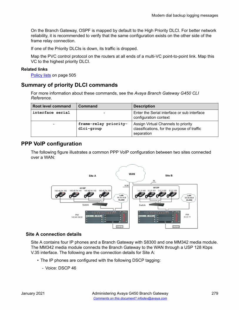
On the Branch Gateway, OSPF is mapped by default to the High Priority DLCI. For better networkreliability, it is recommended to verify that the same configuration exists on the other side of theframe relay connection.
If one of the Priority DLCIs is down, its traffic is dropped.
Map the PVC control protocol on the routers at all ends of a multi-VC point-to-point link. Map thisVC to the highest priority DLCI.
Related linksPolicy lists on page 505
Summary of priority DLCI commandsFor more information about these commands, see the Avaya Branch Gateway G450 CLIReference.
Root level command Command Descriptioninterface serial - Enter the Serial interface or sub interface
configuration context- frame-relay priority-
dlci-groupAssign Virtual Channels to priorityclassifications, for the purpose of trafficseparation
PPP VoIP configurationThe following figure illustrates a common PPP VoIP configuration between two sites connectedover a WAN:
Site A connection detailsSite A contains four IP phones and a Branch Gateway with S8300 and one MM342 media module.The MM342 media module connects the Branch Gateway to the WAN through a USP 128 KbpsV.35 interface. The following are the connection details for Site A:
• The IP phones are configured with the following DSCP tagging:
- Voice: DSCP 46
Modem dial backup logging messages
January 2021 Administering Avaya G450 Branch Gateway 279Comments on this document? [email protected]

- Voice control: DSCP 34
Note:
The policy list in the next configuration is based on the assumption that the BranchGateway, S8300, and the IP phones send VoIP control packets with a DSCP value of34 and voice with a DSCP value of 46. If any of the components of the topology aresending control or voice packets with other DSCP values, you must make changes inthe policy list.
• The default RTP UDP port range is 2048 to 3028• The Network IPs (24 bit subnet masks):
- IP phones: 149.49.54.0 (VLAN 1)- Data: 11.11.11.0 (VLAN 2)- Serial: 2.2.2.1- S8300: 149.49.54.81- Branch Gateway PMI: 149.49.54.82
Site B connection detailsSite B contains four IP phones and a Branch Gateway with S8300 and one MM340 media module.The MM340 media module connects the Branch Gateway to the WAN through two-timeslot (128Kbps) T1 interface. The following are the connection details for Site B:
• IP phones are configured with DSCP tagging:
- Voice = DSCP 46- Voice control = DSCP 34
• The default RTP UDP port range is 2048 to 3028• Network IPs (24 bit subnet masks):
- IP phones = 3.3.3.0 (VLAN 1)- Data = 33.33.33.0 (VLAN 2)- Serial = 2.2.2.2- S8300 = 4.4.4.10- Branch Gateway PMI = 4.4.4.11
Configuration example for Site AYou can configure PPP VoIP on the Branch Gateway at Site A. Commands with footnotes aredescribed at the end of the configuration procedure.
• Loopback and PMI interfaces configuration:Gxxx-001# interface loopback 1Gxxx-001(if:Loopback 1)# ip address 149.49.54.82 24Done!Gxxx-001(if:Loopback 1)# pmiThe Primary management interface has changed. Please copy the running configuration
WAN interfaces
January 2021 Administering Avaya G450 Branch Gateway 280Comments on this document? [email protected]

to the start-up configuration file, and reset the device.Gxxx-001(if:Loopback 1)# exitGxxx-001# copy running-config startup-configGxxx-001# reset
• VLAN interface configuration:Gxxx-001# interface Vlan 1Gxxx-001(if:Vlan 1)# ip address 149.49.54.24Done!Gxxx-001(if:Vlan 1)# exitGxxx-001# interface Vlan 2Gxxx-001(if:Vlan 2)# ip address 11.11.11.1 24Done!Gxxx-001(if:Vlan 2)# exit
• Serial interface configuration:Gxxx-001# interface serial 4/1Gxxx-001(if:Serial 4/1)# ip address 2.2.2.1 24Gxxx-001(if:Serial 4/1)# mtu 300
Note:
Some LAN data applications do not support fragmented packets. In this case, do notchange the MTU from its default of 1500.
Gxxx-001(if:Serial 4/1)# bandwidth 128• VoIP configuration:Gxxx-001(if:Serial 4/1)# ip rtp header-compressionGxxx-001(if:Serial 4/1)# ip rtp compression-connections 20 (4)Gxxx-001(if:Serial 4/1)# ip rtp port-range 2048 3028 (5)Gxxx-001(if:Serial 4/1)# exit
• Static routes configuration:Gxxx-001# ip default-gateway 4/1
* Description of footnoted commands (also applies to identical stages in configuring Site B):
(1) At this stage you apply Priority 7 to Voice Control traffic.
(2) At this stage you apply Priority 6 to RTP traffic.
(3) At this stage you apply maximum trust between 802.1p priority and DSCP.
(4) At this stage the number of connections (20) depends on the number of phones.
(5) At this stage you are matching the RTP port range to that of the Gateway.
(6) At this stage the default queue size is 6, and since RTP is enabled you can double the VoIPqueue size.
Configuration example for Site BYou can configure PPP VoIP on the Branch Gateway at Site B.
• Loopback and PMI interfaces configuration:Gxxx-001# interface loopback 1Gxxx-001(if:Loopback1)# ip address 4.4.4.11 32Done!Gxxx-001(if:Loopback 1)# pmiThe Primary management interface has changed. Please copy the running configuration
Modem dial backup logging messages
January 2021 Administering Avaya G450 Branch Gateway 281Comments on this document? [email protected]

to the start-up configuration file, and reset the device.Gxxx-001(if:Loopback1)# exitGxxx-001# copy running-config startup-configGxxx-001# reset
• VLAN interface configuration:Gxxx-001# interface Vlan 1Gxxx-001(if:Vlan 1)# ip address 3.3.3.1 24Gxxx-001(if:Vlan 1)# exitGxxx-001# interface Vlan 2Gxxx-001(if:Vlan 1:2)# ip address 33.33.33.1 24Gxxx-001(if:Vlan 1:2)# exit
• Serial interface configuration:Gxxx-001# controller t1 4/1Gxxx-001(controller:4/1)# channel-group 1 timeslots 1-2 speed 64Gxxx-001(controller:4/1)# exitGxxx-001# interface serial 4/1:1Gxxx-001(if:Serial 4/1:1)# ip address 2.2.2.2 24Gxxx-001(if:Serial 4/1:1)# mtu 300
Note:
Some LAN data applications do not support fragmented packets. In this case, do notchange the MTU from its default of 1500.
• VoIP configuration:Gxxx-001(if:Serial 4/1:1)# ip rtp header-compressionGxxx-001(if:Serial 4/1:1)# ip rtp compression-connections 20Gxxx-001(if:Serial 4/1:1)# ip rtp port-range 2048 3028Gxxx-001(if:Serial 4/1:1)# exit
• Static routes configuration:Gxxx-001# ip route 1.1.1.0 24 serial 4/1:1Gxxx-001# ip route 11.11.11.0 24 serial 4/1:1
WAN interfaces
January 2021 Administering Avaya G450 Branch Gateway 282Comments on this document? [email protected]

Chapter 12: Emergency Transfer Relay
The Emergency Transfer Relay (ETR) feature provides basic telephone services in the event ofsystem failure, such as a power outage or a failed connection to the MGC. An external ETR relaypanel can be used in conjunction with an analog media module (MM711, MM714, MM714B, orMM716). The ETR panel provides up to five incoming Central Office (CO) trunk loops to fiveselected G450 analog lines. Thus, one ETR panel supports up to five emergency lines. You cancascade a second ETR panel, providing support for up to 10 emergency analog phones. ETR isactivated automatically upon system failure by closing the tip/ring contacts between the analog linesand the analog trunks. When ETR is activated, all calls are directed by the analog relays betweenthe outside lines and the analog telephones. A current-loop detection circuit prevents ongoing callsfrom being disconnected when normal functioning resumes. If a call is in progress on an outside linewhen the problem ends, the call continues.The trunk port and analog line port passing through theETR panel do not start to operate until the active call ends.
In addition, each MM714B media module installed in the Branch Gateway can provide identical ETRservices in the event of system failure by connecting trunk port 5 to line port 4. You can install anMM714B media module in any slot. When ETR is active and the Branch Gateway has power, theETR LED is lit.
ETR state configurationBy default, ETR is set to go into effect automatically in the event of power outage or a failedconnection to the MGC. You can activate and deactivate ETR manually using the CLI.
Activating ETR manuallyAbout this taskUse this command only for testing.
ProcedureEnter set etr 10 manual-on
January 2021 Administering Avaya G450 Branch Gateway 283Comments on this document? [email protected]

Deactiving ETR manuallyProcedureEnter set etr 10 manual-off.
ResultETR does not become active in the event of a link failure.
Restoring ETR to automatic activationProcedureEnter set etr 10 autoIf the system fails, the trunk and port in the MM714B, or the analog line connections and analogtrunk connections passing through the ETR panel, are automatically latched.
Note:
A call in progress is terminated when ETR is activated either automatically or manually.
Summary of ETR commandsFor more information about these commands, see Avaya Branch Gateway G450 CLI Reference.
Command Descriptionset etr Enable or disable ETR mode on Branch Gateway chassis or on an
MM714B media module, or enable the gateway to control ETR modeautomatically.
show etr Display the status of ETR mode. This information includes the following:
• Admin state (auto, manual-off, or manual-on)
• Module status (in service, out of service, or out of service waiting foroff-hook)
• Trunk number of the trunk connected to ETR
• Line number of the line connected to ETR
• Line status (off hook or on hook)
ETR status on Branch Gateway chassis shows only the Admin state.
Emergency Transfer Relay
January 2021 Administering Avaya G450 Branch Gateway 284Comments on this document? [email protected]

Chapter 13: SNMP
SNMP uses software entities called managers and agents to manage network devices. Themanager monitors and controls all other SNMP-managed devices or network nodes on the network.There must be at least one SNMP Manager in a managed network. The manager is installed on aworkstation located on the network.
An agent resides in a managed device or network node. The agent receives instructions from theSNMP Manager, generates reports in response to requests from the SNMP Manager, and sendsmanagement information back to the SNMP Manager as events occur. The agent can reside on:
Note:
SNMP is supported on IPv4 only.
• Routers• Bridges• Hubs• Workstations• Printers• Other network devices
There are many SNMP management applications, but all these applications perform the same basictask. They allow SNMP managers to communicate with agents to configure, get statistics andinformation, and receive alerts from network devices. You can use any SNMP-compatible networkmanagement system to monitor and control a Branch Gateway.
Agent and manager communicationThere are several ways that the SNMP manager and the agent communicate. The manager can:
Retrieve a value (get): The SNMP manager requests information from the agent, such as thenumber of users logged on to the agent device or the status of a critical process on that device.The agent gets the value of the requested Management Information Base (MIB) variable andsends the value back to the manager.
Retrieve the value immediately after the variable you name (get-next): The SNMP managerretrieves different instances of MIB variables. The SNMP manager takes the variable you nameand then uses a sequential search to find the desired variable.
January 2021 Administering Avaya G450 Branch Gateway 285Comments on this document? [email protected]

Retrieve a number of values (get-bulk): The SNMP manager retrieves the specified number ofinstances of the requested MIB variable. This minimizes the number of protocol exchangesrequired to retrieve a large amount of data.
Note:
Get-bulk is not supported in SNMPv1.
Change a configuration on the agent (set): The SNMP manager requests the agent to changethe value of the MIB variable. For example, you can run a script or an application on a remotedevice with a set action.
Receive an unsolicited message (notification): The SNMP manager receives an unsolicitedmessage from an agent at any time if a significant, predetermined event takes place on that agent.When a notification condition occurs, the SNMP agent sends an SNMP notification to the devicespecified as the trap receiver or trap host. The SNMP Administrator configures the trap host,usually the SNMP management station, to perform the action needed when a trap is detected.
Note:
For a list of traps and MIBS, see Gateway Traps for the Avaya G450, and G700 MediaGateways.
SNMP versionsThere are currently three versions of SNMP:
• SNMPv1
• SNMPv2c
• SNMPv3
The Branch Gateway supports all three versions. The implementation of SNMPv3 on the BranchGateway is backwards compatible. That is, an agent that supports SNMPv3 will also supportSNMPv1 and SNMPv2c.
SNMPv1SNMPv1 uses community strings to limit access rights. Each SNMP device is assigned to a readcommunity and a write community. To communicate with a device, you must send an SNMPpacket with the relevant community name.
By default, if you communicate with a device using only the read community, you are assigned thesecurity name ReadCommN. This security name is mapped to the ReadCommG group by default.This allows you to view the agent’s MIB tree, but you cannot change any of the values in the MIBtree.
SNMP
January 2021 Administering Avaya G450 Branch Gateway 286Comments on this document? [email protected]

If you communicate with a device using the write community, you are assigned the security nameWriteCommN. This security name is mapped to the WriteCommG group by default. This allowsyou to view the agent’s MIB tree and change any of the values in the MIB tree.
Note:
If you delete the ReadCommN or WriteCommN users, the ReadCommG or WriteCommGgroups, or the snmpv1WriteView or snmpv1View, you may not be able to access the deviceusing SNMPv1 or SNMPv2c.
In addition, traps are sent to designated trap receivers. Packets with trap information also containa trap community string.
SNMPv2cSNMPv2c is very similar to SNMPv1. However, SNMPv2c adds support for the get-bulk action andsupports a different trap format.
SNMPv3SNMPv3 enables the following features over SNMPv1 or v2c:
• User authentication with a username and password
• Communication encryption between the Network Management Station (NMS) and the SNMPagent at the application level
• Access control definition for specific MIB items available on the SNMP agent
• Notification of specified network events directed toward specified users
• Definition of roles using access control, each with unique access permissions andauthentication and encryption requirements
The basic components in SNMPv3 access control are users, groups, and views. In addition,SNMPv3 uses an SNMP engine ID to identify SNMP identity. An SNMP engine ID is assigned toeach MAC address of each device in the network. Each SNMP engine ID should be unique in thenetwork.
UsersSNMPv3 uses the User-based Security Model (USM) for security, and the View-based AccessControl Model (VACM) for access control. USM uses the HMAC-MD5-96 and HMAC-SHA-96protocols for user authentication, and the CBC-DES56 protocol for encryption or privacy.
An unlimited number of users can access SNMPv3 at the same time.
SNMP versions
January 2021 Administering Avaya G450 Branch Gateway 287Comments on this document? [email protected]

SNMP security levels• NoAuthNoPriv: . This is the lowest level of SNMPv3 security. No MAC is provided with the
message, and no encryption is performed. This method maintains the same security level asSNMPv1, but provides a method for limiting the access rights of the user.
• AuthNoPriv: . User authentication is performed based on MD5 or SHA algorithms. Themessage is sent with an HMAC that is calculated with the user key. The data part is sentunencrypted.
• AuthPriv: . User authentication is performed based on MD5 or SHA algorithms. Themessage is sent in encrypted MAC that is calculated with the user key, and the data part issent with DES56 encryption using the user key.
snmp-server user commandUse the snmp-server user command to create a user or to change the parameters of anexisting user. This command includes the following parameters:
• A user name for the user
• The name of the SNMP group with which to associate the user
• The SNMP version functionality that the user is authorized to use. Possible values are: v1(SNMPv1), v2c (SNMPv2c), and v3 (SNMPv3).
• For an SNMPv3 user, which authentication protocol to use, if any. Possible values are: md5(HMAC MD5), and sha (HMAC SHA-1). If you specify an authentication protocol, you mustalso configure an authentication password for the user. The authentication password istransformed using the authentication protocol and the SNMP engine ID to create anauthentication key.
• For an SNMPv3 user, whether or not to use the DES/AES privacy protocol, and the user’sprivacy password if you enable DES/AES privacy.
Use the no form of the snmp-server user command to remove a user and its mapping to aspecified group. If you do not specify a group, the no form of the snmp-server user commandremoves the user from all groups.
GroupsIn SNMPv3, each user is mapped to a group. The group maps its users to defined views. Theseviews define sets of access rights, including read, write, and trap or inform notifications the userscan receive.
The group maps its users to views based on the security model and level with which the user iscommunicating with the Branch Gateway. Within a group, the following combinations of securitymodel and level can be mapped to views:
• SNMPv1 security model and NoAuthNoPriv security level
• SNMPv2c security model and NoAuthNoPriv security level
SNMP
January 2021 Administering Avaya G450 Branch Gateway 288Comments on this document? [email protected]

• SNMPv3 security model and NoAuthNoPriv security level
• SNMPv3 security model and AuthNoPriv security level
• SNMPv3 security model and AuthPriv security level
If views are not defined for all security models and levels, a user can access the highest level viewbelow the user’s security level. For example, if the SNMPv1 and SNMPv2c views are undefinedfor a group, anyone logging in using SNMPv1 and SNMPv2c cannot access the device. If theNoAuthNoPriv view is not defined for a group, SNMPv3 users with a NoAuthNoPriv security levelcan access the SNMPv2c view.
Pre-configured SNMP groupsThe Branch Gateway includes the following pre-configured groups:
Group name Securitymodel
Security level Read viewname
Write viewname
Notify viewname
initial v3 (USM) NoAuthNoPriv restricted restricted restrictedReadCommG v1 NoAuthNoPriv snmpv1View - snmpv1ViewReadCommG v2c NoAuthNoPriv snmpv1View - snmpv1ViewWriteCommG v1 NoAuthNoPriv snmpv1
WriteViewsnmpv1WriteView
snmpv1WriteView
WriteCommG v2c NoAuthNoPriv snmpv1WriteView
snmpv1WriteView
snmpv1WriteView
v3ReadOnlyG v3 (USM) AuthNoPriv v3configView - v3configViewv3AdminViewG v3 (USM) AuthPriv iso iso isov3ReadWriteG v3 (USM) AuthNoPriv v3configView v3configView v3configView
snmp-server group commandUse the snmp-server group command to create an SNMPv3 group. Use the no form of thecommand to remove the specified group. You can define the following parameters with thiscommand:
• The name of the group
• The SNMP security model
• The security level, for a group with the SNMPv3 security model
• The name of a read view to which the group maps users
• The name of a write view to which the group maps users
• The name of a notify view to which the group maps users
ViewsThere are three types of views:
SNMP versions
January 2021 Administering Avaya G450 Branch Gateway 289Comments on this document? [email protected]

Read Views: Allow read-only access to a specified list of Object IDs (OIDs) in the MIB tree
Write Views: Allow read-write access to a specified list of OIDs in the MIB tree
Notify Views: Allow SNMP notifications from a specified list of OIDs to be sent
Each view consists of a list of OIDs in the MIB tree. This list can be created using multiple snmp-server view commands to either add OIDs to the list or exclude OIDs from a list of all of theOIDs in the Branch Gateway’s MIB tree. You can use wildcards to include or exclude an entirebranch of OIDs in the MIB tree, using an asterisk instead of the specific node.
Related linksBranch Gateway MIB files on page 574
SNMPv3 view creationTo create an SNMPv3 view, the following information must be provided:
• ViewName: . A string of up to 32 characters representing the name of the view
• ViewType: . Indicates whether the specified OID is included or excluded from the view
• OIDs: . A list of the OIDs accessible using the view
SNMP trap configurationWhen SNMP traps are enabled on the device, SNMP traps are sent to all IP addresses listed inthe trap receivers table. You can add and remove addresses from the trap receivers table. Inaddition, you can limit the traps sent to specified receivers. You can also enable and disable linkup/down traps on specified Branch Gateway interfaces. Use the following commands to configurethe trap receivers table:
Note:
You need an Admin privilege level to use the SNMP commands.
snmp-server host command parametersYou can define the following parameters with this command:
• The IP address of the recipient.
• Whether to send traps or informs to the recipient.
• The SNMP security model (v1, v2c, v3). For SNMPv1 and SNMPv2c, you must also specifythe community name. For SNMPv3, you must specify the level of authentication and ausername to use in notifications. Authentication levels are:
- auth. Authentication without encryption
SNMP
January 2021 Administering Avaya G450 Branch Gateway 290Comments on this document? [email protected]

- noauth. No authentication
- priv. authentication with encryption
• The UDP port of the target host to use as the destination UDP port when sending anotification to this manager. Optional. The default is 162.
Notification filter groups, to modify the types of traps that are sent to the recipient. Optional. If notspecified, all notification groups are sent.
Notification typesVarious types of SNMP traps can be sent. You can modify the type of trap by setting thenotification-list parameter of the snmp-server host command to one of the followingtypes:
• all. All traps. This is the default.
• generic. Generic traps
• hardware. Hardware faults
• rmon. RMON rising/falling alarm
• dhcp server. DHCP server error, such as a DHCP IP conflict detection or notification of noIP address left for specific network
• dhcp-clients. DHCP client error, such as a DHCP client conflict detection
• rtp-stat-faults. RTP statistics: QoS fault/clear traps
• rtp-stat-qos. RTP statistics: end-of-call QoS traps
• wan. WAN router traps
• media-gateway. Branch Gateway traps (equivalent to G700 MGP traps)
• security. Security traps, such as unAuthAccess, macSecurity, unknownHostCopy, andaccountLockout
• config. Configuration change notifications
• eth-port-faults. Ethernet port fault notifications
• sw-redundancy. Software redundancy notifications
• temperature. Temperature warning notifications
• cam-change. Changes in CAM notifications
• 13-events. Duplicate IP, VLAN violations
• policy. Policy change notifications
• link-faults. ITC proprietary link down notifications
SNMP trap configuration
January 2021 Administering Avaya G450 Branch Gateway 291Comments on this document? [email protected]

• supply. Main and backup power supply notifications
Summary of SNMP trap configuration commandsFor more information about these commands, see Avaya Branch Gateway G450 CLI Reference.
Root level command Command Descriptioninterface (dialer|fastethernet| tunnel|usb-modem)
- Enter the context of the Dialer, Fast Ethernet,Tunnel, or USB-modem interface
- snmp trap link-status Enable or disable Link Up and Link Downtraps on an interface
set port trap - Enable or disable SNMP Link Up and LinkDown traps notifications and traps on a port
set snmp trapenable | disableauth
- Enable or disable authentication failure trapsfor all managers
set snmp trapenable | disableframe-relay
- Enable or disable frame relay traps for allmanagers
show port trap - Display information on SNMP generic Link Upand Link Down traps sent for a specific port orfor all ports
show snmp - Display SNMP configuration informationsnmp-server enablenotifications
- Enable or disable the sending of all traps andnotifications from the Branch Gateway
snmp-server host - Identify an SNMP management server, andspecify the kind of messages it receives. Usethe no form of the command to remove thespecified server, or to disable a particular setof notification types.
snmp-server informs - Configure the SNMPv3 timeout and retries fornotifications
Summary of SNMP access configuration commandsFor more information about these commands, see Avaya Branch Gateway G450 CLI Reference.
Command Descriptionip snmp Enable or disable the SNMP agent for the Branch Gatewayset snmp community Create or modify an SNMPv1 community
Table continues…
SNMP
January 2021 Administering Avaya G450 Branch Gateway 292Comments on this document? [email protected]

Command Descriptionset snmp retries Set the number of times to attempt to communicate with a particular nodeset snmp timeout Specify the time to wait for a response before retrying the communicationshow snmp Display SNMP configuration information, including a list of SNMP notification
receiversshow snmp engineID Display the SNMPv3 engine ID for the Branch Gatewayshow snmp group Display a list of SNMPv3 groupsshow snmp retries Display the number of retry attempts to make when attempting to
communicate with a nodeshow snmp timeout Display the time to wait before resending a communicationshow snmp user Display configuration information for a specified SNMP usershow snmpusertogroup
Display a table of SNMPv3 users and the groups to which they are mapped
show snmp view Display configuration information for all SNMP viewssnmp-servercommunity
Enable or disable SNMP access to the Branch Gateway
snmp-serverengineID
Specify the SNMP Engine ID for the Branch Gateway
snmp-server group Define a new SNMPv3 group, or configure settings for the groupsnmp-server remote-user
Configure settings for a remote SNMPv3 user. If the user does not exist, it iscreated.
snmp-server user Configure settings for an SNMPv3 user. If the user does not exist, it iscreated.
snmp-server view Configure settings for an SNMP MIB view. If the view does not exist, it iscreated.
Dynamic trap managerDynamic trap manager is a special feature that ensures that the Branch Gateway sends trapsdirectly to the currently active MGC. If the MGC fails, dynamic trap manager ensures that traps aresent to the backup MGC.
Note:
The dynamic trap manager is created by default and cannot be removed.
Dynamic trap manager
January 2021 Administering Avaya G450 Branch Gateway 293Comments on this document? [email protected]

Dynamic trap manager parametersWhen you use the snmp-server dynamic-trap-manager command, you can configure thefollowing parameters:
• Whether to send traps or informs to the recipient• The SNMP security model (v1 or v2c)• The SNMP community name• The UDP port of the target host to use as the destination UDP port when sending a
notification to this manager. Optional.• The types of traps to be sent. Optional. The default is to send all types of traps.
Related linksNotification types on page 291
Summary of dynamic trap manager configuration commandsFor more information about these commands, see Avaya Branch Gateway G450 CLI Reference.
Command Descriptionclear dynamic-trap-manager
Remove administration of the dynamic trap manager
snmp-server dynamic-trap-manager
Specify the parameters of the dynamic trap manager feature
SNMP configuration examplesThe following example enables link up/down traps on an Ethernet interface:Gxxx-001(super)# interface fastethernet 10/3Gxxx-001(super-if:FastEthernet 10/3)# snmp trap link-statusDone!
The following example displays SNMP information:Gxxx-001(super)# show snmpAuthentication trap disabledCommunity-Access Community-String---------------- ----------------read-only *****read-write *****SNMPv3 Notification Status----------------------------Traps: EnabledInforms: Enabled Retries: 3 Timeout: 3 secondsSNMP-Rec-Address Model Level Notification Trap/Inform User name---------------- ----- ------ ------------ ----------- ----------
SNMP
January 2021 Administering Avaya G450 Branch Gateway 294Comments on this document? [email protected]

149.49.70.137 v1 noauth all trap ReadCommN UDP port: 162 DM
The following example disables Link Up and Link Down traps on an Ethernet interface:Gxxx-001(super-if:FastEthernet 10/3)# no snmp trap link-statusEnter authentication password : ********Confirm authentication password : ********Enter privacy password : *********Confirm privacy password : *********Done!
The following example creates a read-only user:Gxxx-001# snmp-server user joseph ReadOnlyG v3 auth md5 priv des56 ktamatanEnter authentication password : ********Confirm authentication password : ********Enter privacy password : *********Confirm privacy password : *********Done!
The following example creates a read-write user:Gxxx-001# snmp-server user johnny ReadWriteG v3 auth md5 priv des56 ktamatanEnter authentication password : ********Confirm authentication password : ********Enter privacy password : *********Confirm privacy password : *********Done!
The following example creates an admin user:Gxxx-001# snmp-server user johnny v3AdminG v3 auth md5 priv des56 ktamatanEnter authentication password : ********Confirm authentication password : ********Enter privacy password : *********Confirm privacy password : *********Done!
The following example sets the SNMPv1 read-only community:Gxxx-001(super)# set snmp community read-only readSNMP read-only community string set.
The following example sets the SNMPv1 read-write community:Gxxx-001(super)# set snmp community read-write writeSNMP read-write community string set.
The following example enables link up/down trap on a LAN port on the G250:G250-001(super)# set port trap 10/3 enablePort 10/3 up/down trap enabled
The following example enables Link Up and Link Down traps on a LAN port on the BranchGateway:Gxxx-001(super)# set port trap 10/5 enablePort 10/5 up/down trap enabled
The following example disables link up/down trap on a LAN port on the G250:G250-001(super)# set port trap 10/4 disablePort 10/4 up/down trap disabled
SNMP configuration examples
January 2021 Administering Avaya G450 Branch Gateway 295Comments on this document? [email protected]

The following example disables Link Up and Link Down traps on a LAN port on the BranchGateway:Gxxx-001(super)# set port trap 10/5 disablePort 10/5 up/down trap disabled
SNMP
January 2021 Administering Avaya G450 Branch Gateway 296Comments on this document? [email protected]

Chapter 14: Media encryption usingAES-256
From Communication Manager Release 7.0, the AES encryption option now includes AES-256cipher suite. AES-256 applies to voice media streams and video media streams for the IP networkregion that governs the IP codec set. The feature also introduces a mechanism to define theencrypted SRTCP policy for calls governed by the IP network region.
Screen for administering Media encryption using AES-256
Screen name Purpose FieldsIp-codec-set To select a type of media
encryption.Media encryption
Administering Media encryption using AES-256Before you beginEnsure that the Media Encryption Over IP? field on the system-parameters customer-optionsscreen is set to y.
Procedure1. On the SAT screen, type change ip-codec-set n, where n is the number of the codec
set that you want to change.
2. In the Media encryption field, type one of the following values:
• To use encrypted and authenticated RTP with an 80-bit authentication tag, type 10-srtp-aescm256-hmac80.
• To use encrypted and authenticated RTP with a 32-bit authentication tag, type 11-srtp-aescm256-hmac32.
3. Save and exit.
January 2021 Administering Avaya G450 Branch Gateway 297Comments on this document? [email protected]

Detailed descriptionAdvanced Encryption Standard (AES) is a widely used specification for data encryption. The AESstandards describe a symmetric key algorithm. AES has a fixed block size of 128 bits and a keysize of 128, 192, or 256 bits. Avaya Aura® Release 6.3 Feature Pack 4 supports AES-256 as partof TLS support over control channels. From Release 7.0, the AES-256 support extends to securemedia streams.To enable Media encryption feature, two more encryption choices are available for the Mediaencryption field on the ip-codec-set SAT screen. The choices are as follows:
• srtp-aescm256-hmac80• srtp-aescm256-hmac32
Before Release 7.0, the Media Encryption field supported only three profiles. Release 7.0onwards, the field supports five profiles.You can add the following profiles to Media Encryption:
1. 10-srtp-aescm256-hmac802. 11-srtp-aescm256-hmac323. 1-srtp-aescm128-hmac804. 2-srtp-aescm128-hmac325. None
The AES-256 feature is supported on G450 Branch Gateway, G430 Branch Gateway, and AvayaAura® Media Server (MS).When you enable the AES-256 feature, Communication Manager determines the capabilityexchange with G450 Branch Gateway, G430 Branch Gateway, or Avaya Aura® Media Server (MS)and the 96x1 SIP phone. To establish call connections for media services encrypted withAES-256, an SDP media descriptor exchange occurs. During this exchange, CommunicationManager functions as a back-to-back user agent. In this role, Communication Manager supportspolicy management over the SIP endpoints when the endpoints exercise capability negotiation.
Media encryption using AES-256
January 2021 Administering Avaya G450 Branch Gateway 298Comments on this document? [email protected]

Chapter 15: Encrypted SRTCP
Detailed descriptionWith the Encrypted SRTCP feature, you can protect media control streams. To support thisfeature, the Encrypted SRTCP field is available on the ip-codec-set SAT screen. The followingare the available policy modes:
• Force Encrypted SRTCP: To permit only encrypted SRTCP calls and to achieve high securitystandards. If you set the field to enforce-enc-srtcp, all the crypto profiles enforceencrypted SRTCP.
• Best Effort: To facilitate negotiation of the encrypted SRTCP parameter. If you set the field tobest-effort, Communication Manager facilitates negotiation of Encrypted SRTCPcapability between the endpoints. All endpoints must support negotiation to enforce the BestEffort policy mode.
• Force Unencrypted SRTCP: To support backward compatibility. If you set the field toenforce-unenc-srtcp, all the crypto profiles enforce unencrypted SRTCP.Communication Manager does not support encrypted SRTCP. This value is the default valuein Communication Manager Release 8.1.3.
Encrypted SRTCPUse the Encrypted SRTCP feature to provide enhanced security for the media control streamsassociated with the RTP media stream.
Note:The RTP and RTCP streams are two consecutive UDP ports. The RTCP control streamconveys usage data. An example of usage data is the identification of the two parties on agiven call.
January 2021 Administering Avaya G450 Branch Gateway 299Comments on this document? [email protected]

Screen for administering Encrypted SRTCP
Screen name Purpose FieldsIp-codec-set To select a policy option to
activate the encrypted SRTCP.Encrypted SRTCP
Administering Encrypted SRTCPBefore you beginEnsure that the Media Encryption Over IP? field on the system-parameters customer-optionsscreen is set to y.
Procedure1. On the SAT screen, type change ip-codec-set n, where n is the number
corresponding to the codec set that you want to change.
2. In the Encrypted SRTCP field, type enforce-enc-srtcp. You can select the BestEffort option if you want Communication Manager to negotiate encrypted SRTCPcapability between endpoints.
Note:
The default value for Encrypted SRTCP is enforce-unenc-srtcp. Endpoints earlierthan Release 7.0 do not support encrypted SRTCP. Therefore, enforcing unencryptedSRTCP is preferable in networks that have Communication Manager Release 7.0 withearlier endpoints.
3. Save and exit.
Interactions for Encrypted SRTCPThis section provides information about how the Encrypted SRTCP feature interacts with otherfeatures in the system. Use this information to ensure that you receive the maximum benefits ofthe Encrypted SRTCP feature in any feature configuration.
Emergency callingUsing the encryption options, you cannot negotiate calls with the destination party because ofprotocol incompatibilities. The protocol incompatibility results in the inability to pass certain typesof emergency calls. Therefore, you must configure the network to ensure best routing of calls.
Encrypted SRTCP
January 2021 Administering Avaya G450 Branch Gateway 300Comments on this document? [email protected]

Media Encryption using AESIf the RTP media encryption is set to none, the enforce-encrypted SRTCP rules do not apply to theRTP/RTCP streams.
Interactions for Encrypted SRTCP
January 2021 Administering Avaya G450 Branch Gateway 301Comments on this document? [email protected]

Chapter 16: Contact closure
You can use contact closure to control up to two electrical devices remotely. With contact closure,you can dial feature access codes on a telephone to activate, deactivate, or pulse electrical devicessuch as electrical door locks. You can also activate and deactivate contact closure using CLIcommands. You can only use feature access codes if you configure the Branch Gateway to use aserver with CM software.
It is recommended that you use an Avaya Partner Contact Closure Adjunct™ for contact closure. Formore information, see Overview for the Avaya Branch Gateway G450. An Avaya Partner ContactClosure Adjunct™ contains two relays, one for each electrical device. You can control each relay inany of the following ways:
• When you dial the contact closure open access code, the relay opens (no contact)
• When you dial the contact closure close access code, the relay closes (contact)
• When you dial the contact closure pulse access code, the relay closes (contact) for the pulseduration and then opens (no contact)
• You can control each contact closure relay manually with CLI commands or with the BranchGateway
Note:
Configuration of the feature access code is performed through CM. For more information, seeAdministrator Guide for Avaya Aura® Communication Manager.
Related linksBranch Gateway Controller configuration on page 67
Configuring contact closure hardwareProcedureConnect an Avaya Partner Contact Closure Adjunct™ to the Contact Closure port on the BranchGateway front panel, labeled CCA.
Use a telephone cable with standard RJ-11 connectors.
A qualified electrician should connect the electrical devices to the relays on the Avaya PartnerContact Closure Adjunct™.
January 2021 Administering Avaya G450 Branch Gateway 302Comments on this document? [email protected]

For information on contact closure specifications, see Overview for the Avaya Branch GatewayG450.
Software contact closure
Contact closure modesMode Descriptionmgc The MGC controls contact closure. In mgc mode, the user dials feature
access codes to activate and deactivate contact closure.manual-trigger Activates contact closure for the specified relaymanual-off Deactivates contact closure for the specified relay
Configuring contact closure softwareAbout this taskTo configure the Branch Gateway to activate contact closure when the feature access code isdialed:
Procedure1. Enter the set contact-closure admin command.
In the following example, the command sets contact closure to work in relay 1 of the AvayaPartner Contact Closure Adjunct™ when activated by the call controller.set contact-closure admin 10/1:1 mgc
2. Use the set contact-closure pulse-duration command to set the length of timefor the relay to return to normal after the call controller triggers it.
In the following example, the command sets relay 2 of the Avaya Partner Contact ClosureAdjunct™ to return to normal five seconds after the call controller triggers contact closure inthe relay.set contact-closure pulse-duration 10/1:2 5
Activating a contact closure manuallyProcedureUse the set contact-closure admin command with the parameter manual-trigger.
Software contact closure
January 2021 Administering Avaya G450 Branch Gateway 303Comments on this document? [email protected]

In the following example, the command activates contact closure in relay 1 of the Avaya PartnerContact Closure Adjunct™. Contact closure remains active until you deactivate it by using the setcontact-closure admin command with the parameter manual-off or mgc.set contact-closure admin 10/1:1 manual-trigger
Deactivating a contact closure manuallyProcedureUse the set contact-closure admin command with the parameter manual-off.
In the following example, the command deactivates contact closure in relay 2 of the Avaya PartnerContact Closure Adjunct™. Contact closure will not operate, even automatically, until you use theset contact-closure admin command to change the status of contact closure to mgc ormanual-trigger.set contact-closure admin 10/1:2 manual-off
Showing contact closure statusProcedureUse the show contact-closure command to display the status of one or more contact closurerelays.
The following example displays the contact closure status of relay 1 of the Avaya Partner ContactClosure Adjunct™ box.Gxxx-001(super)# show contact-closureMODULE PORT RELAY ADMIN PULSE DURATION (secs) STATUS------- ----- ------ ---------------- --------------------- ------10 2 1 mgc 5 secs off10 2 2 mgc 3 secs off
Summary of contact closure commandsFor more information about these commands, see Avaya Branch Gateway G450 CLI Reference.
Command Descriptionset contact-closureadmin
Specify how the contact closure relay is controlled
set contact-closurepulse-duration
Set the length of time for the relay to return to normal after the callcontroller triggers the relay
show contact-closure Display the status of one or all contact closure relays
Contact closure
January 2021 Administering Avaya G450 Branch Gateway 304Comments on this document? [email protected]

Chapter 17: Announcement files
The Branch Gateway stores announcement files in an internal announcement directory. The BranchGateway supports up to 256 announcement files, totalling up to 45 minutes of audio forannouncements and music on hold. If a compact flash is installed with increased RAM, the BranchGateway supports up to 1024 announcement files, for a total of 240 minutes.A total of 63announcements can be played simultaneously, and one port may be used for recording. Recording,storing, and playing announcement files is controlled by CM.
Note:
For information about installing and using a compact flash and increased RAM, refer to Job Aid:Installing the upgrade memory kit in the G450 / G430 Branch Gateway .
Avaya Voice Announcement Manager (VAM) can be used to centrally manage announcement filesfor multiple voice systems, including Branch Gateways. VAM is designed to be installed on acustomer-provided platform at a remote location. For information about VAM, see Avaya VoiceAnnouncement Manager Reference .
The Branch Gateway supports:
• Secure transfer of announcement files to and from VAM using SCP• Simple management operations for the announcement files stored in the announcement
directory• Dynamic allocation of announcement time slots for 64 announcement ports on an as-needed
basis
Uploading announcement files to a remote SCP serverProcedureUpload an announcement file to a remote SCP server, using the copy announcement-filescp command.
Specify the file name of the announcement file in the Branch Gateway announcement directory,followed by the IP address of the remote SCP server, and, optionally, a destination file name,including the full path.
For example:Gxxx-001(super)# copy announcement-file scp local_announcement2.wav 192.168.49.10 remote_announcement2.wav
January 2021 Administering Avaya G450 Branch Gateway 305Comments on this document? [email protected]

Downloading announcement files from a remote SCP serverProcedureDownload an announcement file from a remote SCP server to the Branch Gateway announcementdirectory, using the copy scp announcement-file command.
Specify the file name of the announcement file on the remote SCP server, followed by the IPaddress of the remote SCP server, and, optionally, a destination file name, including the full path.
For example:Gxxx-001(super)# copy scp announcement-file announcement_file1.wav 192.168.49.10
Uploading announcement files to a remote FTP serverProcedureUpload an announcement file to a remote FTP server, using the copy announcement-fileftp command.
Specify the file name of the announcement file in the Branch Gateway announcement directory,followed by the IP address of the remote FTP server, and, optionally, a destination file name,including the full path.
ExampleGxxx-001(super)# copy announcement-file ftp local_announcement2.wav 192.168.49.10 remote_announcement2.wav
Downloading announcement files from an FTP serverProcedureDownload an announcement file from an FTP server to the Branch Gateway announcementdirectory, using the copy ftp announcement-file command.
Specify the file name of the announcement file on the FTP server, followed by the IP address ofthe FTP server, and, optionally, a destination file name, including the full path.
For example:Gxxx-001(super)# copy ftp announcement-file announcement_file1.wav 192.168.49.10
Announcement files
January 2021 Administering Avaya G450 Branch Gateway 306Comments on this document? [email protected]

Uploading an announcement file to a USB mass storagedevice
ProcedureUpload an announcement file to a USB mass storage device, using the copy announcement-file usb command.
Specify the file name of the announcement file in the Branch Gateway announcement directory,followed by the name of the USB device, and, optionally, a destination file name, including the fullpath.
ExampleGxxx-001(super)# copy announcement-file usb local_announcement2.wav usb-device0 remote_announcement2.wav
Downloading an announcement file from a USB massstorage device
ProcedureDownload an announcement file from a USB mass storage device to the Branch Gatewayannouncement directory, using the copy usb announcement-file command.
Specify the name of the USB device, followed by the file name of the announcement file on theUSB device, and, optionally, a destination file name, including the full path.
For example:Gxxx-001(super)# copy usb announcement-file usb-device0 \temp\announcement_file1.wav local_announcement_file2.wav
Erasing an announcement file from the directoryProcedureErase an announcement file from the Branch Gateway announcement directory, using the eraseannouncement-file command.
Specify the name of the file.
For example:Gxxx-001# erase announcement-file local_announcement1.wav
Uploading an announcement file to a USB mass storage device
January 2021 Administering Avaya G450 Branch Gateway 307Comments on this document? [email protected]

Renaming an announcement file in the directoryProcedureRename an announcement file in the Branch Gateway announcement directory, using the renameannouncement-file command.
Specify the current name of the file followed by the new name.
For example:Gxxx-001# rename announcement-file from_local_announcement1.wav to_local_announcement1.wav
Displaying the announcement files stored in the directoryProcedureDisplay the announcements files stored in the Branch Gateway announcement directory, using theshow announcements-files command.
Optionally add the keyword brief to display less detail.
For example:Gxxx-001(super)# show announcements filesMode: FTP-SERVER/SCP-CLIENTID File Description Size (Bytes) Date---- ---------------- ------------- ------------ -----------------5 46xxupgrade.scr Announcement1 4000 09:54:55 23 AUG 20158 4601dbte1_82.bin Announcement2 8000 09:55:55 23 AUG 20159 4602dbte1_82.bin Announcement3 16000 09:56:55 23 AUG 2015Nv-Ram:Total bytes used: 28000Total bytes free: 7344800Total bytes capacity(fixed) 7372800
Displaying the status of a download processProcedureDisplay the status of a download process of announcement files, using the show downloadannouncement-file status command.
For example:Gxxx-001(super)# show download announcement-file statusModule #9===========Module : 9Source file : hellosource.wavDestination file : hellodestination.wavHost : 135.64.102.64
Announcement files
January 2021 Administering Avaya G450 Branch Gateway 308Comments on this document? [email protected]

Running state : IdleFailure display : (null)Last warning : No-warningBytes Downloaded : 7825===========
Displaying the status of an upload processProcedureDisplay the status of an upload process of announcement files, using the show uploadannouncement-file status command.
For example:Gxxx-001(super)# show upload announcement-file statusModule #9===========Module : 9Source file : hellosource.wavDestination file : d:\hellodestination.wavHost : 135.64.102.64Running state : IdleFailure display : (null)Last warning : No-warning===========
Summary of announcement files commandsFor more information about these commands, see Avaya Branch Gateway G450 CLI Reference.
Command Descriptioncopy announcement-file ftp Upload an announcement file to a remote FTP servercopy announcement-file scp Upload an announcement file to a remote SCP servercopy announcement-file usb Upload an announcement file to a USB mass storage
devicecopy ftp announcement-file Download an announcement file from an FTP server to
Branch Gateway announcement directorycopy scp announcement-file Download an announcement file from a remote SCP
server to Branch Gateway announcement directorycopy usb announcement-file Download an announcement file from a USB mass
storage device to Branch Gateway announcementdirectory
erase announcement-file Erase an announcement file from Branch Gatewayannouncement directory
Table continues…
Displaying the status of an upload process
January 2021 Administering Avaya G450 Branch Gateway 309Comments on this document? [email protected]

Command Descriptionrename announcement-file Rename an announcement file in Branch Gateway
announcement directoryshow announcements files Display the announcements files stored in Branch
Gateway announcement directoryshow download announcement-filestatus
Display the status of a download process ofannouncement files from the remote SCP server
show upload announcement-filestatus
Display the status of an upload process of announcementfiles to the remote SCP server
Dynamic time slots allocationBranch Gateway dynamically allocates announcement time slots for announcement ports on anas-needed basis. This flexibility provides greater assurance of having time slots available for voicecalls. However, Branch Gateway can also potentially run out of time slots for voice calls. To protectBranch Gateway from running out of time slots, use the set fault-threshold timeslotcommand, which determines at what level of time slots occupancy an SNMP trap is sent to theCM. If you see that Branch Gateway is often at 100% time slot capacity, you may need to addanother Branch Gateway to your system.
Summary of dynamic time slots allocation commandsFor more information about these commands, see Avaya Branch Gateway G450 CLI Reference.
Command Descriptionset fault-thresholds timeslot Set time slot occupancy notification, by specifying the
occupancy rate at which an SNMP trap is generatedshow fault-thresholds timeslot Display time slot occupancy
Announcement files
January 2021 Administering Avaya G450 Branch Gateway 310Comments on this document? [email protected]

Chapter 18: Advanced switching
You can configure advanced switching on the switch ports of the Branch Gateway. The switch portsconsist of the ETH LAN ports located on the front panel.
VLAN configurationA VLAN is made up of a group of devices on one or more LANs that are configured so the devicesoperate as if they form an independent LAN. These devices can, in fact, be located on severaldifferent LAN segments. VLANs can be used to group together departments and other logicalgroups, thereby reducing network traffic flow and increasing security within the VLAN.
VLAN TaggingVLAN Tagging is a method of controlling the distribution of information on the network. The portson devices supporting VLAN Tagging are configured with the Port VLAN ID and Tagging Modeparameters.
The Port VLAN ID is the number of the VLAN to which the port is assigned.
Note:
You need to create a VLAN with the set vlan command before you can assign it to a port.You can also create a VLAN by using the interface vlan command, followed by thenumber of the VLAN (in other words., enter interface vlan 2 to create VLAN 2).
Untagged frames and frames tagged with VLAN 0 entering the port are assigned the port’s VLANID. Tagged frames are unaffected by the port’s VLAN ID.
The Tagging Mode determines the behavior of the port that processes outgoing frames:
• If Tagging Mode is set to clear, the port transmits frames that belong to the port’s VLAN table.These frames leave the device untagged.
• If Tagging Mode is set to IEEE-802.1Q, all frames keep their tags when they leave thedevice. Frames that enter the switch without a VLAN tag are tagged with the VLAN ID of theport through which they entered.
January 2021 Administering Avaya G450 Branch Gateway 311Comments on this document? [email protected]

Multi VLAN bindingMulti VLAN binding, also known as Multiple VLANs per port, allows access to shared resources bystations that belong to different VLANs through the same port. This is useful in applications suchas multi-tenant networks, where each user has a personal VLAN for privacy. The whole buildinghas a shared high-speed connection to the ISP.
In order to accomplish this, Branch Gateway enables multiple VLANs per port. The available PortMulti-VLAN binding modes are:
Bound to Configured: The port supports all the VLANs configured in the switch
Statically Bound: The port supports VLANs manually configured on the port
The following figure shows these binding modes.
Bind to Configured
• The VLAN table of the port supports all the Static VLAN entries and all the ports’ VLAN IDs(PVIDs) present in the switch
• VLANs 1, 3, 5, 9, 10 coming from the bus are allowed access through this port• All the ports in Bound to Configured mode support the same list of VLANs
Static Binding
• The user manually specifies the list of VLAN IDs to be bound to the port, up to 64 VLANs• Default mode for all ports• Only VLAN 9, and any other VLANs statically configured on the port will be allowed to access
this port
Gateway VLAN tableThe Branch Gateway VLAN table lists all VLANs configured on the Branch Gateway. You canconfigure up to 64 VLANs. To display a list of VLANs, use the show vlan command.
Advanced switching
January 2021 Administering Avaya G450 Branch Gateway 312Comments on this document? [email protected]

When the VLAN table reaches its maximum capacity, you cannot configure any more VLANs. Ifthis occurs, use the clear vlan command, followed by the name or number of the VLAN youwant to delete, to free space in the VLAN table. Any new VLANs configured by you are madeknown to all the modules in the system.
Ingress VLAN SecurityIngress VLAN Security enables easy implementation of security, and is always active. A port thatis assigned to a VLAN allows packets tagged for that VLAN only to enter through that port.Unassigned packets receive the PVID of the port and are therefore allowed to enter.
ICC-VLANWhen the Branch Gateway includes an ICC, the ICC connects to the Branch Gateway through aninternal switch. By default, the ICC is connected on Vlan 1. The VLAN to which the ICC connectsis called the ICC-VLAN.
You can use the icc-vlan command to attach the ICC to a different VLAN. Enter the context ofthe VLAN interface to which you want to attach the ICC switch, and enter icc-vlan.
You can use the show icc-vlan command from the general context to show the current ICC-VLAN.
Configuring ICC-VLANAbout this taskYou must enter the VLAN interface context to configure the ICC VLAN.
Procedure1. Enter the VLAN interface context by using the interface vlan CLI command
2. Enter icc-vlan.
ExampleThe following example sets Vlan 2 as the ICC-VLAN:Gxxx-001(super)# interface vlan 2Gxxx-001(super-if:Vlan 2)# icc-vlanDone!Gxxx-001(super-if:Vlan 2)# exitGxxx-001(super)# show icc-vlanVLAN 2Gxxx-001(super)#
VLAN configuration
January 2021 Administering Avaya G450 Branch Gateway 313Comments on this document? [email protected]

VLAN configuration examplesThe following example deletes a statically bound VLAN from a port:Gxxx-001(super)# clear port static-vlan 10/3 34VLAN 34 is unbound from port 10/3
The following example deletes a VLAN and its interface:Gxxx-001(super)# clear vlan 34This command will assign all ports on VLAN 34 to their default in the entire management domain – do you want to continue (Y/N)? y All ports on VLAN-id assigned to default VLAN.VLAN 34 was deleted successfully.
The following example sets the current VLAN as the ICC-VLAN:Gxxx-001(super)# interface Vlan 66Gxxx-001(super-if:Vlan 66)# icc-vlanDone!
The following example enters configuration mode for a VLAN interface:Gxxx-001(super)# interface Vlan 66Gxxx-001(super-if:Vlan 66)#
The following example deletes a VLAN interface:Gxxx-001(super)# no interface vlan 66Done!
The following example statically binds a VLAN to a port:Gxxx-001(super)# set port vlan-binding-mode 10/3 staticSet Port vlan binding method:10/3
The following example sets a port’s VLAN ID:Gxxx-001(super)# set port vlan 54 10/3Port 10/3 added to VLAN 54
The following example sets a port’s VLAN binding mode:Gxxx-001(super)# set port vlan-binding-mode 10/3 bind-to-configuredSet Port vlan binding method:10/3
The following example configures the VLAN tagging mode of a port:Gxxx-001(super)# set trunk 10/3 dot1qDot1Q VLAN tagging set on port 10/3.
The following example creates a VLAN:Gxxx-001(super)# set vlan 2121 name TrainingVLAN id 2121, vlan-name Training created.
The following example displays a list of the MAC addresses in the CAM of a VLAN:Gxxx-001(super)# show cam vlan 54Total Matching CAM Entries Displayed = 3Dest MAC/Route Dest VLAN Destination Ports------------------- ---- -----------------00:01:02:dd:2f:9f 54 6/13
Advanced switching
January 2021 Administering Avaya G450 Branch Gateway 314Comments on this document? [email protected]

00:02:2d:47:00:6f 54 10/300:02:4b:5b:28:40 54 6/13
The following example displays the ICC-VLAN:Gxxx-001(super)# show icc-vlanVLAN 1
The following example displays interface configuration and statistics for a VLAN:Gxxx-001(super)# show interfaces Vlan 1VLAN 1 is up, line protocol is upPhysical address is 00.04.0d.29.c6.bd. MTU 1500 bytes. Bandwidth 100000 kbit. Reliability 255/255 txLoad 1/255 rxLoad 1/255 Encapsulation ARPA, ICC-VLAN Link status trap disabled Full-duplex, 100Mb/s ARP type: ARPA, ARP Timeout 04:00:00 Last input never, Last output never Last clearing of 'show interface' counters never. 5 minute input rate 0 bits/sec, 0 packets/sec 5 minute output rate 0 bits/sec, 0 packets/sec 0 input drops, 0 output drops, 0 unknown protocols 0 packets input, 0 bytes 0 broadcasts received, 0 giants 0 input errors, 0 CRC 0 packets output, 0 bytes 0 output errors, 0 collisions
The following example displays port VLAN binding information:Gxxx-001(super)# show port vlan-binding-mode 10port 10/3 is bind to all configured VLANs
The following example displays VLAN tagging information:Gxxx-001(super)# show trunkPort Mode Binding mode Native VLAN------ ----- ------------------------- -----------10/3 dot1q bound to configured VLANs 54
The following example displays the VLANs configured on the device:Gxxx-001(super)# show vlanVLAN ID VLAN-name------- --------------------------------1 V154 Marketing66 V662121 TrainingTotal number of VLANs: 4
Summary of VLAN commandsFor more information about these commands, see Avaya Branch Gateway G450 CLI Reference.
VLAN configuration
January 2021 Administering Avaya G450 Branch Gateway 315Comments on this document? [email protected]

Root level command First levelCommand
Description
clear port static-vlan
- Delete statically configured VLANs from the port
clear vlan - Delete an existing VLAN and its interface, remove the entryfrom the VLAN table, and return ports from this VLAN tothe default VLAN 1
interface vlan - Create a VLAN interface, enter interface VLANconfiguration mode, or delete a VLAN interface
- icc-vlan Set the current VLAN as the ICC-VLANset port static-vlan - Assign a static VLAN to a portset port vlan - Set the port VLAN ID (PVID)set port vlan-binding-mode - Define the binding method used by portsset trunk - Configure the VLAN tagging mode of a portset vlan - Create or modify a VLANshow cam vlan - Display all MAC entries in the CAM table for a specific
VLANshow icc-vlan - Display the current ICC VLANshow interfaces - Display interface configuration and statistics for a particular
interface or all interfacesshow port vlan-binding-mode
- Display port VLAN binding mode information
show trunk - Display VLAN tagging information for all or some portsshow vlan - Display the VLANs configured in the Branch Gateway
Port redundancyRedundancy involves the duplication of devices, services, or connections, so that in the event of afailure, the redundant duplicate can take over for the one that failed.
Since computer networks are critical for business operations, it is vital to ensure that the networkcontinues to function even if a piece of equipment fails. Even the most reliable equipment mightfail on occasion, but a redundant component can ensure that the network continues to operatedespite such failure.
To achieve port redundancy, you can define a redundancy relationship between any two ports in aswitch. One port is defined as the primary port and the other as the secondary port. If the primaryport fails, the secondary port takes over.
Advanced switching
January 2021 Administering Avaya G450 Branch Gateway 316Comments on this document? [email protected]

Note:
When port redundancy is activated on Branch Gateway, manually disabling the primary portwill also disable the secondary port. To prevent the disabling of the secondary port, you mustdisable port redundancy before disabling the primary port.
Secondary port activationThe secondary port takes over within one second and is activated when the primary port link stopsfunctioning. Subsequent switchovers take place after the minimum time between switchovers haselapsed. To set the minimum time between switchovers, use the set port redundancy-intervals command.
SwitchbackIf switchback is enabled and the primary port recovers, a switchback takes place. Use the setport redundancy-intervals command to set the following switchback parameters:
• min-time-between-switchovers. The minimum time that is allowed to elapse before a primary-backup switchover.
• switchback-interval. The minimum time the primary port link has to be up before a switchbackto the primary port takes place. If you set this to none, there is no switchback to the primaryport when it recovers. In this case, switchback to the primary port only takes place if thesecondary port fails.
Port redundancy configuration commandsThe following commands are used to configure port redundancy. For more information about thesecommands, see Avaya Branch Gateway G450 CLI Reference.
Enabling and disabling redundancy pairsProcedureTo globally enable or disable the redundancy pairs you have defined, use the set portredundancy enable/disable command.
This command does not delete existing redundancy entries.
Defining or removing redundancy pairs1. To define or remove redundancy pairs, see the set port redundancy command.
2. To ensure that there is no redundancy scheme already defined on any of the links, entershow port redundancy.
Port redundancy
January 2021 Administering Avaya G450 Branch Gateway 317Comments on this document? [email protected]

Configuring time constantsProcedureTo configure the two time constants that determine redundancy switchover parameters, use theset port redundancy-intervals command.
Displaying port redundancy schemesProcedureTo display information about software port redundancy schemes defined for the switch, enter showport redundancy.
Port redundancy configuration examplesThe following example creates a port redundancy pair:G450-001(super)# set port redundancy 10/5 10/6 on 1Monitor: Port 10/6 is redundant to port 10/5.Port redundancy is active - entry is effective immediately
The following example deletes a port redundancy pair:G450-001(super)# set port redundancy 10/5 10/6 offEntry Monitor removed: Port 10/6 is not redundant to port 10/5
The following example enables all configured port redundancies:Gxxx-001(super)# set port redundancy enableAll redundancy schemes are now enabled
The following example disables all configured port redundancies:Gxxx-001(super)# set port redundancy disableAll redundancy schemes are disabled but not removed
The following example configures the switchback interval for all configured port redundancies:Gxxx-001(super)# set port redundancy-intervals 60 30Done!
The following example displays port redundancy information:G450-001(super)# show port redundancyRedundancy Name Primary Port Secondary Port Status----------------- -------------- ---------------- --------Monitor 10/5 10/6 primaryMinimum Time between Switchovers: 60Switchback interval: 30
Summary of port redundancy commandsFor more information about these commands, see Avaya Branch Gateway G450 CLI Reference.
Advanced switching
January 2021 Administering Avaya G450 Branch Gateway 318Comments on this document? [email protected]

Command Descriptionset port redundancy Define or remove redundancy pairsset port redundancy enable|disable
Globally enable or disable port redundancy pairs defined on theBranch Gateway
set port redundancy-intervals Configure the two time constants that determine redundancyswitchover parameters
show port redundancy Display information about software port redundancy pairsdefined on the Branch Gateway
Port mirroringPort mirroring copies all received and transmitted packets (including local traffic) from a sourceport to a predefined destination port, in addition to the normal destination port of the packets. Portmirroring, also known as “sniffing,” is useful in debugging network problems.
Port mirroring allows you to define a source port and a destination port, regardless of port type.For example, a 10 Mbps and a 100 Mbps port can form a valid source/destination pair. Youcannot, however, define the port mirroring source and destination ports as the same source anddestination ports.
You can define one source port and one destination port on each Branch Gateway for received(Rx), transmitted (Tx), or transmitted and received (both) traffic.
Port mirroring configuration examplesThe following example creates a port mirroring pair in the Branch Gateway:G450-001(super)# set port mirror source-port 10/5 mirror-port 10/6 sampling always direction rxMirroring rx packets from port 10/5 to port 10/6 is enabled
The following example displays port mirroring information for the Branch Gateway:G450-001(super)# show port mirrorport mirroringMirroring both Rx and Tx packets from port 10/5 to port 10/6 is enabled
The following example disables port mirroring:Gxxx-001(super)# clear port mirror
Summary of port mirroring commandsFor more information about these commands, see Avaya Branch Gateway G450 CLI Reference.
Port mirroring
January 2021 Administering Avaya G450 Branch Gateway 319Comments on this document? [email protected]

Command Descriptionclear port mirror Delete a port mirroring pairset port mirror Define a port mirroring source-destination pairshow port mirror Display mirroring information for a specified port or for all ports
• auto. Attempts to automatically detect the port’s connection type.
Spanning treeBranch Gateways support the enhanced Rapid Spanning Tree Protocol (802.1w). The 802.1wstandard is a faster and more sophisticated version of the 802.1d (STP) standard, and includesbackward compatibility with 802.1d. Spanning tree makes it possible to recover connectivity afteran outage within approximately a minute. RSTP, with its “rapid” algorithm, can usually restoreconnectivity to a network where a backbone link has failed in much less time.
Spanning tree protocolThe spanning tree algorithm ensures the existence of a loop-free topology in networks that containparallel bridges. A loop occurs when there are alternate routes between hosts. If there is a loop inan extended network, bridges may forward traffic indefinitely, which can result in increased trafficand degradation in network performance.
The spanning tree algorithm produces a logical tree topology out of any arrangement of bridges.The result is a single path between any two end stations on an extended network. In addition, thespanning tree algorithm provides a high degree of fault tolerance. It allows the network toautomatically reconfigure the spanning tree topology if there is a bridge or data-path failure.
The spanning tree algorithm requires five values to derive the spanning tree topology. These are:
• A multicast address specifying all bridges on the extended network. This address is media-dependent and is automatically determined by the software.
• A network-unique identifier for each bridge on the extended network
• A unique identifier for each bridge/LAN interface (a port)
• The relative priority of each port
• The cost of each port
After these values are assigned, bridges multicast and process the formatted frames (calledBridge Protocol Data Units, or BPDUs) to derive a single, loop-free topology throughout theextended network. The bridges exchange BPDU frames quickly, minimizing the time that service isunavailable between hosts.
Advanced switching
January 2021 Administering Avaya G450 Branch Gateway 320Comments on this document? [email protected]

Spanning tree per portSpanning tree can take up to 30 seconds to open traffic on a port. This delay can cause problemson ports carrying time-sensitive traffic. You can, therefore, enable or disable spanning tree in theBranch Gateway on a per-port basis to minimize this effect.
Rapid Spanning Tree Protocol (RSTP)The enhanced feature set of the 802.1w standard includes:
• Bridge Protocol Data Unit (BPDU) type 2• New port roles: Alternate port, Backup port• Direct handshaking between adjacent bridges regarding a desired topology change (TC).
This eliminates the need to wait for the timer to expire.• Improvement in the time it takes to propagate TC information. Specifically, TC information
does not have to be propagated all the way back to the Root Bridge (and back) to bechanged.
• Origination of BPDUs on a port-by-port basis
Port rolesAt the center of RSTP – specifically as an improvement over STP (802.1d) – are the roles that areassigned to the ports. There are four port roles:
Root port: The port closest to the root bridge
Designated port: The corresponding port on the remote bridge of the local root port
Alternate port: An alternate route to the root
Backup port: An alternate route to the network segment
The RSTP algorithm usually makes it possible to change port roles rapidly through its fasttopology change propagation mechanism. For example, a port in the blocking state can beassigned the role of alternate port. When the backbone of the network fails, the port can rapidly bechanged to forwarding.
Whereas the STA passively waited for the network to converge before turning a port into theforwarding state, RSTP actively confirms that a port can safely transition to forwarding withoutrelying on any specific, programmed timer configuration.
RSTP port typesRSTP provides a means of fast network convergence after a topology change. It does this byassigning different treatments to different port types.
Edge ports: Setting a port to edge-port admin state indicates that this port is connected directlyto end stations that cannot create bridging loops in the network. These ports transition quickly to
Spanning tree
January 2021 Administering Avaya G450 Branch Gateway 321Comments on this document? [email protected]

forwarding state. However, if BPDUs are received on an edge port, its operational state will bechanged to non-edge-port and bridging loops will be avoided by the RSTP algorithm. The defaultadmin state of 10/100 M ports is edge-port.
Enter set port edge admin state, followed by the module and port number – or a range ofport numbers – to specify whether or not a port is considered an edge port.
The following command specifies that port 10/5 is not an edge port:Gxxx-001(super)# set port edge admin state 10/5 non-edge-port
Enter show port edge state, followed by the module and port number, to display the edgestate of the specified port. Use this command without specifying a module number or port todisplay the edge state of all ports.
Non-edge ports: You must manually configure uplink and backbone ports to be non-edge ports,using the set port edge admin state command.
Point-to-point link ports: This port type applies only to ports interconnecting RSTP compliantswitches and is used to define whether the devices are interconnected using shared Ethernetsegment or point-to-point Ethernet link. RSTP convergence may be faster when switches areconnected using point-to-point links. The default setting for all ports – automatic detection of point-to-point link – is sufficient for most networks.
Enter set port point-to-point admin status, followed by the module and port numberor a range of port numbers, and an admin status parameter, to specify the port’s connection type.Admin status parameter values are:
• force-true. Treats the port as if it is connected point-to-point
• force-false. Treats the port as if it is connected to shared media
• auto. Attempts to automatically detect the port’s connection type
For example, the following command specifies that ports 10/5 and 10/6 are treated as if they wereconnected point-to-point:Gxxx-001(super)# set port point-to-point admin status 10/5-6 force-true
All ports: Enter show port point-to-point status, followed by the module and portnumber, to display the point-to-point status of the specified point-to-point status of all ports
Spanning tree configuration examplesThe following example enables spanning tree on a port:Gxxx-001(super)# set port spantree enable 10/5port 10/5 was enabled on spantree
The following example disables spanning tree on a port:Gxxx-001(super)# set port spantree disable 10/5port 10/5 was disabled on spantree
Advanced switching
January 2021 Administering Avaya G450 Branch Gateway 322Comments on this document? [email protected]

The following example sets the spanning tree cost of port 10/5 to 4096:Gxxx-001(super)# set port spantree cost 10/5 4096port 10/5 spantree cost is 4096
The following example configures the version of the spanning tree default path cost used by thisbridge:Gxxx-001(super)# set spantree default-path-cost common-spanning-treeSpanning tree default path costs is set to common spanning tree.
The following example configures the time used when transferring the port to the forwarding state:Gxxx-001(super)# set spantree forward-delay 16bridge forward delay is set to 16.
The following example configures the time interval between the generation of configurationBPDUs by the root:Gxxx-001(super)# set spantree hello-time 2bridge hello time is set to 2.
The following example configures the amount of time an information message is kept before beingdiscarded:Gxxx-001(super)# set spantree max-age 21bridge max age is set to 21.
The following example configures the bridge priority for spanning tree:Gxxx-001(super)# set spantree priority 36864Bridge priority set to 36864.
The following example sets the value in packets used by spanning tree in order to limit themaximum number of BPDUs transmitted during a hello-time period:Gxxx-001(super)# set spantree tx-hold-count 4tx hold count is set to 4.
The following example configures the version of spanning tree to use on the device:Gxxx-001(super)# set spantree version rapid-spanning-treeSpanning tree version is set to rapid spanning tree.
The following example displays spanning tree information:Spanning tree state is enabledDesignated Root: 00-04-0d-ea-b0-2dDesignated Root Priority: 32768Designated Root Cost: 0Designated Root Port: No root port, Bridge is Designated rootRoot Max Age: 20 Hello Time: 2Root Forward Delay: 15Bridge ID MAC ADDR: 00-04-0d-ea-b0-2dBridge ID priority: 32768Bridge Max Age: 20 Bridge Hello Time: 2Bridge Forward Delay: 15 Tx Hold Count 3Spanning Tree Version is rapid spanning treeSpanning Tree Default Path Costs is according to common spanning treePort State Cost Priority------ ------------- ---------- ------------10/5 not-connected 4 12810/6 not-connected 4 128
Spanning tree
January 2021 Administering Avaya G450 Branch Gateway 323Comments on this document? [email protected]

Summary of spanning tree commandsFor more information about these commands, see Avaya Branch Gateway G450 CLI Reference.
Command Descriptionset port edge admin state Assign or de-assign RSTP edge-port admin state to a port for
Rapid Spanning Tree Protocol (RSTP) treatmentset port point-to-point adminstatus
Specify a port’s connection type
set port spantree Enable or disable spanning tree for specific portsset port spantree cost Set the spanning tree cost of a portset port spantree force-protocol-migration
Force the port to send a rapid spanning tree hello packet(Bridge Protocol Data Unit)
set port spantree priority Set the spanning tree priority level of a portset spantree default-path-cost
Set the version of the spanning tree default path cost used bythe current bridge
set spantree enable|disable Enable or disable the spanning-tree algorithm for BranchGateway
set spantree forward-delay Specify the time used when transferring the state of a port to theforwarding state
set spantree hello-time Specify the time interval between the generation of configurationBPDUs by the root
set spantree max-age Specify the time to keep an information message before it isdiscarded
set spantree priority Set the bridge priority for the spanning treeset spantree tx-hold-count Set the value in packets used by the spanning tree in order to
limit the maximum number of BPDUs transmitted during a hello-time period
set spantree version Set the version of the spanning tree protocol used by the deviceshow port edge state Display the edge state of a specified portshow port point-to-pointstatus
Display the point-to-point status of a specific port or all ports
show spantree Display spanning-tree information
Port classificationWith the Branch Gateway, you can classify any port as either regular or valuable. Classifying aport as valuable means that a link fault trap is sent in the event of a link failure. The trap is sent
Advanced switching
January 2021 Administering Avaya G450 Branch Gateway 324Comments on this document? [email protected]

even when the port is disabled. This feature is particularly useful for the port redundancyapplication, where you need to be informed about a link failure on the dormant port.
Note:
The 1 GB ports are classified as valuable by default.
Port classification configuration examplesThe following example classifies a port as a valuable port:Gxxx-001(super)# set port classification 10/5 valuablePort 10/5 classification has been changed.
The following example displays the port classification of all ports:G450-001(super)# show port classificationPort Port Classification-------- -------------------------10/5 valuable10/6 regular
Summary of port classification commandsFor more information about these commands, see Avaya Branch Gateway G450 CLI Reference.
Command Descriptionset port classification Set the port classification to either regular or valuable (any
change in the spanning tree state from forwarding for a valuableport will erase all learned MAC addresses in the switch)
show port classification Display port classification for a specified port or all ports
Port classification
January 2021 Administering Avaya G450 Branch Gateway 325Comments on this document? [email protected]

Chapter 19: Monitoring applications
The Branch Gateway provides several software tools for monitoring and diagnosing your network.Use these tools to monitor the status of your network operations, and to analyze the flow ofinformation.
RMONRemote Monitoring (RMON), the internationally recognized network monitoring standard, is anetwork management protocol that allows network information to be gathered at a singleworkstation. You can use RMON probes to monitor and analyze a single segment only. When youdeploy a switch on the network, there are additional components in the network that cannot bemonitored using RMON. These components include the switch fabric, VLAN, and statistics for allports.
RMON is the internationally recognized and approved standard for detailed analysis of sharedEthernet media. It ensures consistency in the monitoring and display of statistics between differentvendors.
RMON's advanced remote networking capabilities provide the tools needed to monitor andanalyze the behavior of segments on a network. In conjunction with an RMON agent, RMONgathers details and logical information about network status, performance, and users runningapplications on the network.
An RMON agent is a probe that collects information about segments, hosts, and traffic, and sendsthe information to a management station. You use specific software tools to view the informationcollected by the RMON agent on the management station.
You can configure RMON for switching on the Branch Gateway. The Branch Gateway uses RMONI, which analyzes the MAC layer (Layer 2 in the OSI seven-layer model). You can also configure aport to raise an SNMP trap whenever the port fails.
RMON configuration examplesThe following example creates an RMON alarm entry:Gxxx-001(super)# rmon alarm 1 1.3.6.1.2.1.16.1.1.1.5.16777216 20 delta rising-threshold 10000 32 falling-threshold 1000 32 risingOrFalling rootalarm 1 was created successfully
January 2021 Administering Avaya G450 Branch Gateway 326Comments on this document? [email protected]

The following example creates an RMON event entry:Gxxx-001(super)# rmon event 32 log description “Change of device” owner rootevent 32 was created successfully
The following example creates an RMON history entry with an index of 80 on port 10/3, recordingactivity over 60 intervals (buckets) of 20 seconds each.Gxxx-001(super)# rmon history 80 10/3 interval 20 buckets 60 owner roothistory index 80 was created successfully
The following example displays information about an RMON alarm entry:Gxxx-001(super)# show rmon alarm 1alarmalarm 1 is active, owned by rootMonitors ifEntry.1.16777216 every 20 secondsTaking delta samples, last value was 0Rising threshold is 10000, assigned to event # 32Falling threshold is 1000, assigned to event # 32On startup enable rising or_falling alarms
The following example displays information about an RMON event entry:Gxxx-001(super)# show rmon event 32eventEvent 32 is active, owned by rootDescription is Change of deviceEvent firing causes log,last fired 12:36:04
The following example displays information about an RMON history entry:Gxxx-001(super)# show rmon history 80historyEntry 80 is active, owned by rootMonitors the port 10/3 every 20 secondsRequested # of time intervals, ie buckets, is 60Granted # of time intervals, ie buckets, is 60Sample # 2 began measuring at 0:21:16Received 4081 octets, 41 packets,0 broadcast and 10 multicast packets,0 undersize and 0 oversize packets,0 fragments and 0 jabbers,0 CRC alignment errors and 0 collisions,# of dropped packet events (due to a lack of resources): 0Network utilization is estimated at 0
The following example displays RMON statistics for a port:Gxxx-001(super)# show rmon statistics 10/3Statistics for port 10/3 is active, owned by MonitorReceived 6952909 octets, 78136 packets,26 broadcast and 257 multicast packets,0 undersize and 0 oversize packets,0 fragments and 0 jabbers,0 CRC alignment errors and 0 collisions,# of dropped packet events (due to a lack of resources): 0# of packets received of length (in octets):64:18965, 65-127:295657, 128-255:4033,256-511:137, 512-1023:156, 1024-1518:0,
RMON
January 2021 Administering Avaya G450 Branch Gateway 327Comments on this document? [email protected]

Summary of RMON commandsFor more information about these commands, see Avaya Branch Gateway G450 CLI Reference.
Command Descriptionclear rmonstatistics
Clear RMON statistics
rmon alarm Create or delete an RMON alarm entryrmon event Create or delete an RMON event entryrmon history Create or delete an RMON history entryshow rmon alarm Display information about a specific RMON alarm entry or all existing RMON
alarm entriesshow rmon event Display a specific RMON event entry or all RMON event entriesshow rmon history Display a specific RMON history entry or all RMON history entriesshow rmonstatistics
Display RMON statistics for a specific interface or for all interfaces
RTP statisticsThe RTP statistics application collects data and statistics for RTP sessions (streams) from BranchGateway VoIP engine. You can view the data and configure SNMP traps to be generated whenthe QoS level falls below a configured level. RTP statistics support IPv4 and IPv6 addresses.Insert content for the first section.
Note:An alternative tool available from Avaya for debugging QoS problems is VMON. VMON is anRTCP QoS reports collector. VMON support, available in all Avaya devices, is the capability ofa VoIP device to send a copy of an RTCP message to the IP address of a VMON server.VMON can collect RTCP reports, store them on its host hard disk, and analyze and generategraphic reports. However, VMON requires a dedicated Windows server. The RTP statistics,application runs on Branch Gateway firmware, and does not require any dedicated hardware.For information about configuring VMON in CM, see Administrator Guide for Avaya Aura®
Communication Manager.Branch Gateway performs traceroutes whenever RTP statistics is enabled.
The RTP statistics application provides the following functionality:1. Collects QoS data from Branch Gateway VoIP engines, including Real-Time Control
Protocol (RTCP) data, traceroute reports, and information from the DSP regarding jitterbuffer, internal delays, and so on.
Monitoring applications
January 2021 Administering Avaya G450 Branch Gateway 328Comments on this document? [email protected]

Note:RTCP is a standard QoS report companion protocol to RTP. RTP endpointsperiodically send RTCP report packets to their remote peer (or peers in multicast).RTCP reports include QoS data such as delay, jitter, and loss.
2. Collects call data from Branch Gateway, such as duration, start-time, and end-time.3. Displays the RTP statistics in CLI and MIB formats.4. Displays summary reports for the VoIP engines.5. Assesses QoS status based on configurable thresholds on an extensive set of QoS
metrics.6. Generates QoS traps.
QoS traps are notifications sent via SNMP upon termination of an RTP stream that suffersfrom bad QoS. These notifications include extensive data about the session that enablesoffline troubleshooting of QoS problems. The trap rate is controlled by a configurable traprate limiter.
Note:QoS trap generation is an especially convenient troubleshooting tool for largeinstallations, since all devices that support the RTP statistics application can beconfigured to send traps to a single SNMP trap manager.
7. Generates QoS fault and clear traps.QoS fault traps are notifications that are sent when more than a configurable number ofactive sessions have QoS indicators over the configured thresholds. A QoS clear trap is anotification that is sent after a QoS fault trap when the number of active RTP sessions withQoS indicators over the configured thresholds reduces to a specified number.
Configuring the RTP statistics applicationAbout this taskTo configure the RTP statistics application, work through a set of procedures.
Procedure1. View RTP statistics thresholds.
2. Set up RTP statistics thresholds on page 332.
3. Set up the RTP statistics application on page 332.
4. View the application configuration on page 333.
5. Set up QoS traps on page 334.
6. Set up QoS fault and clear traps on page 335.
7. Set up the trap rate limiter on page 336.
RTP statistics
January 2021 Administering Avaya G450 Branch Gateway 329Comments on this document? [email protected]

Viewing RTP statistics thresholdsThe RTP statistics application uses a system of thresholds to evaluate levels of QoS during RTPsessions. The thresholds are configured on several QoS metrics. Your configuration of thethresholds determines when the application evaluates a session as having bad QoS conditions.
This section describes the thresholds that you can configure, how you can view the thresholds thatare currently configured, and the metrics on which you can configure them.
The RTP statistics application samples the VoIP engine every RTCP interval, which is configuredin CM, where it is called “RTCP Report Period”. The RTCP interval is typically 5 to 8 seconds. Forinformation about configuring the RTCP interval (RTCP report period), see Administrator Guide forAvaya Aura® Communication Manager.
Thresholds typesAbout this taskA threshold on a metric: For example, you can configure a threshold on the metric ‘packet loss’.The application samples the metric every RTP interval and increments a counter (event counter) ifthe sampled value is over the threshold. Hence, the 'event-counter' represents the number oftimes the metric was sampled over its threshold.An event threshold: An event threshold is a threshold on an event counter. If QoS traps areconfigured, the application generates a QoS trap when, at the end of a session, one or more eventcounters are over their event thresholds. For example, if the event threshold for packet loss is 2,the application generates a QoS trap if packet loss is sampled over its threshold two or moretimes.Thresholds on metric averages: The application calculates averages of some of the metrics.When an RTP session terminates, the application evaluates the average metrics and generates aQoS trap (if QoS traps are configured) if one of them is over its corresponding threshold.
Note:All CLI commands described in this section are available in the general context of the CLI.
Viewing the configured thresholds1. Enter show rtp-stat thresholds. For example:
Gxxx-001(super)# show rtp-stat thresholdsItem Threshold Event Threshold-------------------- ------------- -----------------Codec Loss 6.0% 1Average Codec Loss 3.0% N/ACodec RTT 700mS 2Echo Return Loss 0dB 1Loss 6.0% 2Average Loss 3.0% N/ARemote Loss 6.0% 2Average Remote Loss 3.0% N/ARTT 500mS 2Local Jitter 50mS 2Remote Jitter 50mS 2SSRC Changes N/A 2
Monitoring applications
January 2021 Administering Avaya G450 Branch Gateway 330Comments on this document? [email protected]

QoS metricsThe following table describes the QoS metrics on which thresholds are configured, and the timewhen each metric is evaluated.
Metric Description Evaluation timeCodec Loss The percentage of time the codec plays fill frames
due to lack of valid RTP frames. Possible causesinclude jitter and packet loss.
Every RTCP interval
Average Codec Loss The average codec loss measurement since thebeginning of the RTP stream
At the end of thesession
Codec RTT An estimation of the overall Round Trip Time (RTT)on the voice-channel, including the network delay andinternal delays.
RTT is the time taken for a message to get to theremote peer and back to the local receiver.
Each time an RTCPpacket is received
Echo Return Loss The echo cancellation loss on the TDM bus Every RTCP intervalLoss The estimated network RTP packet loss.
The VoIP engine evaluates the current receivedpacket loss every RTCP interval – usually 5 to 8seconds. The VoIP engine postpones loss estimationuntil the next interval if the number of packetsreceived is less than the minimum statistic window.The minimum statistic window is configured with theCLI command rtp-stat min-stat-win.
Every RTCP interval
Average Loss The average packet loss evaluation since thebeginning of the RTP stream
At the end of thesession
Remote Loss The network loss according to the remote RTPreceiver. The device learns of the remote packet lossfrom received RTCP messages.
Each time an RTCPpacket is received
Average Remote Loss The average remote network loss measurementsince the beginning of the RTP stream
At the end of thesession
RTT The network RTT. This metric does not includeinternal delay. The device learns of the RTT fromRTCP messages.
Each time an RTCPpacket is received
Local Jitter Variation in delay of packet delivery to the local peer Every RTCP intervalRemote Jitter Variation in delay of packet delivery to the remote
peer. The device learns of the remote jitter fromRTCP messages.
Each time an RTCPpacket is received
SSRC Changes The number of times the RTP SSRC field in receivedRTP packets has changed
Every RTCP interval
RTP statistics
January 2021 Administering Avaya G450 Branch Gateway 331Comments on this document? [email protected]
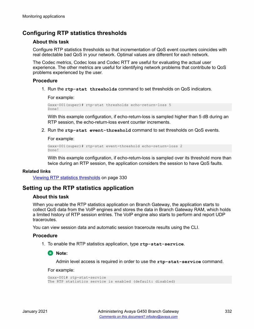
Configuring RTP statistics thresholdsAbout this taskConfigure RTP statistics thresholds so that incrementation of QoS event counters coincides withreal detectable bad QoS in your network. Optimal values are different for each network.The Codec metrics, Codec loss and Codec RTT are useful for evaluating the actual userexperience. The other metrics are useful for identifying network problems that contribute to QoSproblems experienced by the user.
Procedure1. Run the rtp-stat thresholds command to set thresholds on QoS indicators.
For example:Gxxx-001(super)# rtp-stat thresholds echo-return-loss 5Done!
With this example configuration, if echo-return-loss is sampled higher than 5 dB during anRTP session, the echo-return-loss event counter increments.
2. Run the rtp-stat event-threshold command to set thresholds on QoS events.
For example:Gxxx-001(super)# rtp-stat event-threshold echo-return-loss 2Done!
With this example configuration, if echo-return-loss is sampled over its threshold more thantwice during an RTP session, the application considers the session to have QoS faults.
Related linksViewing RTP statistics thresholds on page 330
Setting up the RTP statistics applicationAbout this taskWhen you enable the RTP statistics application on Branch Gateway, the application starts tocollect QoS data from the VoIP engines and stores the data in Branch Gateway RAM, which holdsa limited history of RTP session entries. The VoIP engine also starts to perform and report UDPtraceroutes.You can view session data and automatic session traceroute results using the CLI.
Procedure1. To enable the RTP statistics application, type rtp-stat-service.
Note:
Admin level access is required in order to use the rtp-stat-service command.
For example:Gxxx-001# rtp-stat-serviceThe RTP statistics service is enabled (default: disabled)
Monitoring applications
January 2021 Administering Avaya G450 Branch Gateway 332Comments on this document? [email protected]

2. To reset the RTP statistics application, type rtp-stat clear.
All counters are reset and the RTP statistics history is erased.
Viewing application configurationAbout this taskView the application configuration to see if the application is enabled, which types of traps areenabled, and how the trap rate limiter and minimum statistics window are configured. Theminimum statistics window is the minimum number of observed RTP sequence increments forwhich the application evaluates packet loss.
ProcedureType show rtp-stat config.Gxxx-001(super)# show rtp-stat configRTP Statistic: EnabledQoS Trap: EnabledQoS Fault Trap: Enabled Fault: 2 Clear: 0QoS Trap Rate Limiter: Token Interval: 10.00 seconds Bucket Size: 5Session Table: Size: 128 Reserved: 64Min Stat Win: 50
RTP statistics application outputsThe following table describes the output of the show rtp-stat config command.
Name DescriptionRTP Statistic Status of the RTP statistics application. Possible values:
• Enabled. The application is enabled.
• Disabled. The application is disabled.QoS Trap QoS trap status. Possible values:
• Enabled. The RTP statistics application is configured to generate QoS traps.
• Disabled. The RTP statistics application is not configured to generate QoStraps.
QoS Fault Trap QoS fault trap status. Possible values:
• Enabled. The RTP statistics application is configured to generate QoS faultand clear traps.
• Disabled. The RTP statistics application is not configured to generate QoSfault and clear traps.
Fault The QoS fault trap boundary. That is, the minimum number of active sessionswith QoS faults that triggers a QoS fault trap.
Table continues…
RTP statistics
January 2021 Administering Avaya G450 Branch Gateway 333Comments on this document? [email protected]

Name DescriptionClear The QoS clear trap boundary. That is, the reduced number of active sessions
with QoS faults that triggers a QoS clear trap to be sent after a QoS fault trapwas sent.
QoS Trap Rate Limiter:Token Interval The displayed token interval is in seconds. The maximum long term trap rate,
expressed as an interval in seconds. In the example shown, the maximum longterm trap rate is one trap every 10 seconds.
Bucket Size The maximum number of tokens stored in the token bucket of the trap ratelimiter. This item limits the size of a QoS trap burst.
Session Table:Size The maximum number of RTP session entries held in the session table in the
gateway RAMReserved The number of rows in the session table that are reserved for sessions with QoS
problems. In the example shown, the table size is 128 and the reserved numberis 64. If, from 1000 sessions only 300 had QoS problems, the session table willhold at least the last 64 sessions that had QoS problems. Note that if the last128 sessions all had QoS problems, all rows in the session table will be filledwith sessions that had QoS problems.
Min Stat Win The minimum statistic window configured for the RTP statistics application. Thatis, the minimum number of observed RTP sequence increments for which theapplication evaluates packet loss.
Enabling QoS trapsAbout this taskYou can configure the application to automatically generate QoS traps using SNMP at thetermination of RTP sessions that have QoS problems. SNMP traps are automatically sent to theSNMP trap manager on the active Media Gateway Controller (MGC). You can also configureSNMP traps to be sent to an external trap manager. The application generates a QoS trap when,at the end of an RTP session, one or more event counters are over their event thresholds.
Caution:If the thresholds for trap generation are set too low, a significant amount of trap traffic will begenerated and negatively impact network performance.
Procedure1. View the RTP statistic thresholds and modify their configurations as necessary.
2. If you need to modify the minimum statistic window, run the rtp-stat min-stat-wincommand.Gxxx-001(super)# rtp-stat min-stat-win 50Done!
The minimum statistic window is the minimum number of observed RTP sequenceincrements for which the application evaluates packet loss. The VoIP engine evaluates thecurrent received packet loss every RTCP interval. The VoIP engine postpones loss
Monitoring applications
January 2021 Administering Avaya G450 Branch Gateway 334Comments on this document? [email protected]

estimation to the next interval if the number of received packets is less than the minimumstatistic window. By modifying the minimum statistic window, you can prevent theapplication from generating loss-events based on too few packets and safely configure alow packet loss threshold.
3. To configure an additional trap destination, such as an external trap manager, use thecommand snmp-server host.Gxxx-001(super)# snmp-server host 136.9.71.47 traps v1 public
Note:
When using the snmp-server host command, you can specify only to send certaintypes of traps to the specified trap manager. For example, snmp-server host1.1.1.1 traps v1 public rtp-stat-qos rtp-stats-faults configuresonly QoS traps and QoS fault and clear traps to be sent to host 1.1.1.1.
To check your current SNMP configurations, enter show snmp. Traps are automaticallysent to the active MGC by the dynamic trap manager feature. To configure the dynamictrap manager, use the command snmp-server dynamic-trap-manager.
4. Type rtp-stat qos-trap to enable the traps, if not already enabled.Gxxx-001# rtp-stat qos-trapThe RTP statistics QoS trap is enabled
QoS traps are now enabled.
Related linksConfiguring RTP statistics thresholds on page 332Viewing RTP statistics thresholds on page 330Dynamic trap manager on page 293
QoS fault and clear trapsAbout this taskYou can configure the RTP statistics application to send QoS fault and clear traps. A QoS faulttrap is sent when a specified number of active RTP sessions have QoS indicators over theconfigured thresholds. A QoS clear trap is sent after a QoS fault trap when the number of activeRTP sessions with QoS indicators over the configured thresholds reduces to a specified number.Since some RTP sessions can be very long, and QoS traps are sent only after the termination ofthe stream, QoS fault and clear traps are important for providing timely information about QoSproblems.
Note:QoS fault traps appear in the Network Management Console Event Log Browser, indicating tothe user that there are QoS problems in a specific network device. See the Avaya NetworkManagement Console User Guide .
RTP statistics
January 2021 Administering Avaya G450 Branch Gateway 335Comments on this document? [email protected]

Configuring QoS fault and clear trapsProcedureUse the rtp-stat fault command.
For example:Gxxx-001(super)# rtp-stat fault 1 0The fault trap boundary was set to 1 (default: 3)The clear trap boundary was set to 0
With this example configuration, a QoS fault trap is sent if and when one active RTP session hasQoS problems. A QoS clear trap is then sent if and when the number of active RTP sessions withQoS problems reaches 0.
The trap rate limiterThe application features a trap rate limiter. The trap rate limiter limits the rate at which QoS trapsare sent. The rate limiter protects against overloading the trap manager with bursts of traps whena single event causes multiple RTP sessions to terminate simultaneously.
The trap rate limiter uses a token bucket scheme, in which traps are sent only if there are tokensin a virtual bucket. Tokens are added to the bucket every 'token interval,' which sets the maximumlong term trap rate. Each time a trap is sent, the number of tokens in the bucket decrements. The'bucket size' is the maximum number of tokens that the bucket can hold. The bucket size limits thetrap burst size.
Configuring the trap rate limiterProcedureUse the rtp-stat qos-trap-rate-limit command.
For example:Gxxx-001# rtp-stat qos-trap-rate-limit 2000 10
In this example configuration, the token-interval is 2000 and the bucket-size is 10. This means thata token is added to the bucket every 2000 hundredths of a second (20 seconds) and the bucket islimited to a maximum size of 10 tokens.
RTP statistics outputAbout this taskThis section describes the reports, statistics, and traps you can view, how to view them, and howto understand the output.
Monitoring applications
January 2021 Administering Avaya G450 Branch Gateway 336Comments on this document? [email protected]

Viewing RTP statistics summary reportsRTP statistics summary reports display QoS trap statistics for the VoIP engine(s).
1. Enter show rtp-stat summary. For example:Gxxx-001(super)# show rtp-stat summaryTotal QoS traps: 23QoS traps Drop : 0Qos FaultEngine Active Total Mean TxID Description Uptime Session Session Duration TTL--- -------------- ----------- ------- ------- -------- ----000 internal 04,18:15:15 2/1 35/24 01:04:44 64
RTP statistics summary reports outputAbout this taskThe following table describes the fields in the summary report.
Field DescriptionTotal QoS traps The total number of QoS traps sent since the RTP statistics application was
enabled or since the last use of the rtp-stat clear command
QoS traps Drop The number of QoS traps dropped by the rate limiter since the RTP statisticsapplication was enabled or since the last use of the rtp-stat clear command
Qos Fault/QoS Clear General QoS state: QoS Fault means that the number of active RTP sessions withQoS faults is currently higher than the QoS fault boundary. QoS Clear means thatthe number of active RTP sessions with QoS faults is currently less than or equalto the QoS clear boundary. You can configure the QoS fault and clear boundariesusing the rtp-stat fault command. See QoS fault and clear traps onpage 335.
Engine ID The ID of the VoIP engine. Since the Aura Media Gateway has one VoIP engine,one line appears in the table.
Description Description of the VoIP engineUptime The uptime of the RTP statistics application. This is the time since the RTP
statistics application was enabled or since the last use of the rtp-stat clearcommand.
Active Session The number of active sessions / number of active sessions with QoS problemsTotal Session The total number of sessions / number of sessions that had QoS problemsMean Duration The mean RTP session duration (calculated only for terminated calls)Tx TTL The IP Time To Live (TTL) field for transmitted RTP packets
Viewing RTP session statisticsAbout this taskUsing the CLI, you can view a summary of active and terminated sessions and you can view RTPstatistics for a given RTP session.
RTP statistics
January 2021 Administering Avaya G450 Branch Gateway 337Comments on this document? [email protected]

Procedure1. Use the show rtp-stat sessions command to display a summary of the active and/or
terminated RTP sessions in the session table.
For example:Gxxx-001(super)# show rtp-stat sessions last 5ID QoS Start date and time End Time Type Destination----- --- ------------------- -------- ------- ---------------00031 2015-08-23,10:51:36 10:59:07 G729 135.8.76.6400032 * 2015-08-23,10:53:42 10:57:36 G723 135.8.76.10700033 * 2015-08-23,10:58:21 10:59:06 G723 135.8.76.10700034 2015-08-23,11:08:40 - G729 135.8.76.6400035 * 2015-08-23,11:09:07 - G723 135.8.76.107
An asterisk (*) in the QoS column indicates that the session had QoS problems.
2. Use the show rtp-stat detailed command to display detailed information about aspecified active or terminated RTP session, including the QoS metrics reported by the RTPstatistics application.
For example:Gxxx-001(super)# show rtp-stat detailed 35Session-ID: 351Status: Terminated2, QOS: Faulted3, EngineId: 04Start-Time: 2015-08-235,11:09:076, End-Time: 2015-08-23,11:13:407Duration: 00:04:338CName: [email protected]: 69:201110Local-Address: 135.8.118.252:206111 SSRC 15461121212Remote-Address: 135.8.76.107:206113 SSRC 2989801899 (0)14Samples: 5415 (5 sec)16Codec:G72317 62B18 30mS19 Off20, Silence-suppression(Tx/Rx) Disabled21/Not-Supported22, Play-Time 272.610sec23, Loss 0.0%24 #125, Avg-Loss 0.1%26, RTT 741mS27 #3828, Avg-RTT 570mS29, JBuf-under/overruns 0.1%30/0.0%31, Jbuf-Delay 22mS32, Max-Jbuf-Delay 60mS33Received-RTP:
Monitoring applications
January 2021 Administering Avaya G450 Branch Gateway 338Comments on this document? [email protected]

Packets 923634, Loss 0.0%35 #036, Avg-Loss 0.0%37, RTT 604mS38 #3839, Avg-RTT 376mS40, Jitter 0mS41 #042, Avg-Jitter 0mS43, TTL(last/min/max) 63/63/6344, Duplicates 045, Seq-Fall 046, DSCP 4647, L2Pri 1248, RTCP 5449Transmitted-RTP:VLAN 150, DSCP 18451, L2Pri 652, RTCP 6253Remote-Statistics:Loss 0.0%54 #055, Avg-Loss 0.0%56, Jitter 0mS57 #058, Avg-Jitter 0mS59Echo-Cancellation:Loss 45dB60 #161, Len 32mS62RSVP:Status Disabled63, Failures 064
Detailed CLI output per RTP sessionThe following table describes the fields in the show rtp-stat detailed command outputaccording to the numbered labels in the example.
Field Label Description From the CLI exampleSession-ID 1 An arbitrary index number for the session in
the session tableSession-ID: 35
Status 2 The status of the session. Possible values:
• Active. The session is still open.
• Terminated. The session is finished.
Status: Terminated
QOS 3 The QoS status of the session. Possiblevalues:
• OK. There are no QoS problems in thesession.
• Faulted. There are QoS problems in thesession.
QOS: Faulted
Table continues…
RTP statistics
January 2021 Administering Avaya G450 Branch Gateway 339Comments on this document? [email protected]

Field Label Description From the CLI exampleEngineId 4 The ID of the VoIP engine. The Branch
Gateway has one VoIP engine.EngineId: 0
Start-Time 5 The date of the RTP session 2015-08-236 The start time of the RTP session Start-Time:
2015-08-23,11:09:07End-Time 7 The end time of the RTP session End-Time:
2015-08-23,11:13:40Duration 8 The duration of the RTP session Duration: 00:04:33CName 9 format: gwt@<MGP-address> CName:
[email protected] 10 The local extension number and conference
ID in format <conference ID>:<extensionnumber>.
Conference calls can involve more than oneentry in the session table. Multiple sessionsbelonging to the same conference call canusually be identified by a commonconference ID.
Notes:
• Phone data is received from CM only ifVMON is configured.
• If you are not running VMON, you cancause CM to send the phone data byconfiguring a dummy RTCP-server for theregion, with a 'localhost' IP address(127.x.x.x).
Phone: 69:2011
Local-Address 11 The PMI. The number after the colon is theUDP port number.
Local-Address:135.8.118.252:2061
Remote-Address 13 The remote VoIP engine, gateway PMI, or IPphone address. The number after the colonis the UDP port number.
Remote-Address:135.8.76.107:2061
12, 14 SSRC ID. The number in parentheses is thenumber of observed SSRC changes duringthe session.
SSRC 2989801899 (0)
Samples 15 The number of times the application hassampled the VoIP engine (RTP receiver)statistics.
Samples: 5415 (5 sec)
16 The sampling interval Samples: 54 (5 sec)16
Codec: 17 The codec used for the session G72318 The RTP packet size, in bytes 62B19 The RTP packet interval, in ms 30mS
Table continues…
Monitoring applications
January 2021 Administering Avaya G450 Branch Gateway 340Comments on this document? [email protected]

Field Label Description From the CLI example20 The encryption method Off
Silence suppression(Tx/Rx)
21 The received silence suppression method Silence-suppression(Tx/Rx)Disabled21/Not-Supported
22 The transmitted silence suppression method Silence-suppression(Tx/Rx)Disabled/Not-Supported22
Play-Time 23 The overall time the codec played validreceived frames
Play-Time 272.610sec
Codec
Loss codec-loss%
24 The last value of codec loss sampled. Codecloss is the percentage of time the codecplayed fill frames due to lack of valid RTPframes. Possible causes include jitter andpacket loss.
Loss 0.0%24 #1
#codec-loss-events 25 The codec loss event counter Loss 0.0% #125
Avg-Loss 26 The average of all codec loss valuessampled during the session
Avg-Loss 0.1%
RTT rtt ms 27 The last sampling of codec round trip time(RTT), in ms. Codec RTT is the round-tripdelay experienced by the user, includinginternal delay. This value is not entirelyaccurate since remote internal delays arenot always known.
RTT 741mS27 #38
#rtt-events 28 The codec RTT event counter RTT 741mS #3828
Avg-RTT 29 The average of all codec RTT valuessampled during the session
Avg-RTT 570mS
Jbuf-under/ overruns 30 The estimated percentage contribution ofjitter-buffer underruns to the average codecloss
JBuf-under/overruns0.1%30/0.0%
31 The estimated percentage contribution ofjitter-buffer overruns to the average codecloss
JBuf-under/overruns0.1%/0.0%31
Jbuf-delay 32 The last jitter buffer delay Jbuf-Delay 22mSMax-Jbuf-Delay 33 The maximum jitter buffer delay during the
sessionMax-Jbuf-Delay 60mS
Received RTP:Packets 34 The total number of received packets Packets 9236Loss
loss%
35 The last sampled value of network RTPpacket loss
Loss 0.0%35 #0
Table continues…
RTP statistics
January 2021 Administering Avaya G450 Branch Gateway 341Comments on this document? [email protected]

Field Label Description From the CLI example#loss-events 36 The network RTP packet loss event counter Loss 0.0% #036
Avg-loss 37 The average of all network RTP packet lossvalues during the session
Avg-Loss 0.0%
RTT rtt ms 38 The network RTT. The RTT is calculatedupon RTCP packet reception.
RTT 604mS38 #38
#rtt-events 39 The network RTT event counter RTT 604mS #3839
Avg-RTT 40 The average of all network RTT valuesduring the session
Avg-RTT 376mS
Jitter
jitter ms
41 The network jitter at the RTP receiver.
Combined with long RTT, a large jitter valuemay indicate WAN congestion.
Jitter 0mS41 #0
#jitter-event 42 The RTP receiver network jitter eventcounter
Jitter 0mS #042
Avg-Jitter 43 The average of all network jitter valuesduring the session
Avg-Jitter 0mS
TTL (last/min/max) 44 The last value of TTL, minimum value ofTTL, and maximum value of TTL sampledduring the session. TTL changes during asession may indicate route flaps in the IPnetwork.
TTL(last/min/max)63/63/63
Duplicates 45 This counter increments each time twoconsecutive RTP packets with the sampleRTP sequence number are received. A largenumber of duplicates may indicate problemsin the Layer 2/Ethernet topology (forexample, loops).
Duplicates 0
Seq-Fall 46 This counter increments each time an RTPpacket with a sequence number less thanthe last known sequence is received. Packetresequencing may be caused by switching toa backup WAN interface or route flaps.
Seq-Fall 0
DSCP 47 The last received DSCP value of the RTPpackets
DSCP 46
L2Pri 48 The last received Layer 2 priority value of anRTP packet (usually IEEE802.1p)
L2Pri 12
RTCP 49 The total number of received RTCP packets RTCP 54Transmitted-RTP:VLAN 50 The VLAN-ID on which the RTP packets are
transmittedVLAN 1
DSCP 51 The DSCP of RTP packets DSCP 184
Table continues…
Monitoring applications
January 2021 Administering Avaya G450 Branch Gateway 342Comments on this document? [email protected]

Field Label Description From the CLI exampleL2Pri 52 The Layer 2 priority of transmitted RTP
packets (usually 802.1p)L2Pri 6
RTCP 53 The total number of transmitted RTCPpackets
RTCP 62
Remote-Statistics:
(Remote-Statistics items are calculated and evaluated upon reception of RTCP messages)Loss
rem-loss%
54 The network loss experienced by the remoteRTP receiver. The local RTP receiver learnsabout its remote peer statistics from RTCPpackets.
Loss 0.0%54 #0
#rem-loss-ev 55 The number of samples that were over therem-loss threshold
Loss 0.0% #055
Avg-Loss 56 The average network loss experienced bythe remote RTP receiver
Avg-Loss 0.0%
Jitter
rem-jitter
57 The network jitter experienced by the remoteRTP receiver
Jitter 0mS57 #0
#rem-jitter-ev 58 The number of samples that were over theremote jitter threshold
Jitter 0mS #058
Avg-jitter 59 The average remote jitter Avg-Jitter 0mSEcho Cancellation:Loss
loss dbm
60 The echo cancellation loss on the TDM bus.A high value (that is, a low absolute value)may indicate impairment of DCP terminals.
Loss 45dB60 #1
#loss-ev 61 A counter that increments each time theecho-cancellation loss is sampled below itsthreshold
Loss 45dB #161
Len 62 The last echo-cancellation tail length usedfor this session
Len 32mS
RSVP:Status 63 The current (last) RSVP reservation state at
the end of the sessionStatus Disabled
Failures 64 The total number of reservation failuresduring the session
Failures 0
Viewing QoS traps, QoS fault traps, and QoS clear trapsAbout this taskQoS traps, QoS fault traps, and QoS clear traps sent to the active MGC by the dynamic trapmanager are converted to syslog messages by the SNMP Trap manager on the MGC.The syslog messages are stored in the messages file on the MGC hard disk. You can view thesyslog messages through the Avaya Maintenance Web Interface to debug the QoS problems.
RTP statistics
January 2021 Administering Avaya G450 Branch Gateway 343Comments on this document? [email protected]

Procedure1. In the Avaya Maintenance Web Interface, enter the Setup log viewing screen.
2. In the Select Log Types list, select Linux syslog.
3. Under Select Event Range, select the date range over which you want to view traps.
4. In the Match Pattern field, enter the string avrtp.
5. In the Number of Lines field, enter the maximum number of traps you want to view.
6. Click View Log.
Each line on the View System Logs screen contains one message.
Example of QoS trap outputThe following is an example of the syslog message for the QoS trap sent upon termination of RTPsession 35 (see the session ID in bold) that terminated at 11:13:40 on Oct. 20:Oct 201 11:13:402 LZ-SIT-SR1 snmptrapd[9407]: 135.8.118.2523 [135.8.118.252]: TrapsysUpTime.0 = Timeticks: (43147723) 4 days, 23:51:17.234, snmpTrapOID.0 = OID: avRtpQoSTrap5, avRtpSessionLocAddrV4.0 = IpAddress: 135.8.118.2526, avRtpSessionRemAddrV4.0 = IpAddress: 135.8.76.1077, avRtpSessionDuration.0 = INTEGER: 2738, avRtpSessionCname.0 = STRING: [email protected], avRtpSessionPhone.0 = STRING: 69:201110, avRtpSessionSeverity.0 = INTEGER: warning(4), avRtpSessionDebugStr.0 = STRING: Id{35
}11;Traps{2412/013};Stats{S 5414 RTCP 5415 RX 923616};Codec{g72317 62B18 encryptionOff19 SSup disabled20/disabled21 Loss 0.1%22 #123 RTT 570mS24 #3825 Jbuf 0.1%26/0.0%27};Net{Loss 0.0%28 #029 RTT 376mS30 #3831
Monitoring applications
January 2021 Administering Avaya G450 Branch Gateway 344Comments on this document? [email protected]

Jtr #032 TTL 63-6333 Dup 034 Fall 035};Rem{Loss 0.0%36 #037 Jtr #038} EC{Loss 45dB39}
QoS Trap output fieldsThe following table describes the fields in the QoS trap according to the numbered labels in theexample.
Label Description From the trap example1 The date on which the trap was received Oct 202 The time at which the trap was received 11:13:403 The IP address of the local MGP 135.8.118.2524 The Branch Gateway up time sysUpTime.0 = Timeticks:
(43147723) 4 days, 23:51:17.235 The trap name, which indicates that this is a QoS trap snmpTrapOID.0 = OID: av
RtpQoSTrap6 The local gateway PMI avRtpSessionLocAddrV4.0 =
IpAddress: 135.8.118.2527 The remote VoIP engine, gateway PMI, or IP phone
addressavRtpSessionRemAddrV4.0 =IpAddress: 135.8.76.107
8 The duration of the RTP session Duration: 00:04:339 Format: gwt@<MGP-address> avRtpSessionCname.0 =
STRING: [email protected] The local extension number and conference ID in format
<conference ID>:<extension number>.
Conference calls can involve more than one entry in thesession table. Multiple sessions belonging to the sameconference call can usually be identified by a commonconference ID.
Notes:
• The phone string data is received from CM if VMON isconfigured.
• If you are not running VMON, you can cause CM to sendthe phone string data by configuring a dummy RTCP-server for the region, with a 'localhost' IP address(127.x.x.x).
avRtpSessionPhone.0 =STRING: 69:2011
11 An arbitrary index number for the session in the sessiontable
avRtpSessionDebugStr.0 =STRING: Id{35}
Table continues…
RTP statistics
January 2021 Administering Avaya G450 Branch Gateway 345Comments on this document? [email protected]

Label Description From the trap example12 The total number of sent traps since the application was
enabledTraps{2411/0}
13 The number of traps that were dropped by the trap ratelimiter since the application was enabled. This item can beused, when analyzing received traps logs, to identifymissing traps (due to network conditions or the ratelimiter). This is also displayed by the show rtp-statsummary command.
Traps{24/012}
14 The number of times the application sampled the VoIPengine (RTP receiver) statistics
Stats{S 54}
15 The total number of received RTCP packets Stats{S 54 RTCP 5414 RX 9236}16 The total number of received RTP packets Stats{S 54 RTCP 54 RX 923615}17 The codec used for the session g72318 The codec packet size, in bytes 62B19 The encryption method encryptionOff20 The received silence suppression method SSup disabled19/disabled21 The transmitted silence suppression method SSup disabled/disabled20
22 The average of all codec loss values sampled during thesession
Loss 0.1%21 #1
23 The codec loss event counter Loss 0.1% #122
24 The average of all codec round trip time values sampledduring the session
RTT 570mS23 #38
25 The codec round trip time event counter RTT 570mS #3824
26 The percentage contribution of jitter-buffer underruns tothe average codec loss
Jbuf 0.1%25/0.0%
27 The percentage contribution of jitter-buffer overruns to theaverage codec loss
Jbuf 0.1%/0.0%26
28 The average of all network RTP packet loss valuessampled during the session
Loss 0.0%27 #0
29 The network RTP packet loss event counter Loss 0.0% #028
30 The average of all network RTT values during the session RTT 376mS29 #3831 The network RTT event counter RTT 376mS #3830
32 The network jitter at the RTP receiver Jtr #033 The minimum and maximum TTL values sampled in the
sessionTTL 63-63
34 A counter that increments each time two consecutive RTPpackets with the sample RTP sequence number arereceived
Dup 0
Table continues…
Monitoring applications
January 2021 Administering Avaya G450 Branch Gateway 346Comments on this document? [email protected]

Label Description From the trap example35 A counter that increments each time an RTP packet with a
sequence number less than the last known sequence isreceived
Fall 0
36 The average network loss experienced by the remote RTPreceiver
Rem{Loss 0.0%36 #0 Jtr #0}
37 A counter that increments each time the remote loss issampled over its threshold
Rem{Loss 0.0% #037 Jtr #0}
38 A counter that increments each time the network jitterexperienced by the remote RTP receiver is sampled overits threshold
Rem{Loss 0.0% #0 Jtr #038}
39 The echo cancellation loss on the TDM bus. A high value(that is, a low absolute value) may indicate impairment ofDCP terminals.
EC{Loss 45dB}
Example of QoS fault and clear trap outputThe following is an example of the syslog message for the QoS fault and clear traps sent duringRTP session 35, which terminated at 11:13:40 on October 20:Oct 201 11:10:542 LZ-SIT-SR1 snmptrapd[9407]: 135.8.118.252 [135.8.118.252]: TrapsysUpTime.0 = Timeticks: (43131114) 4 days, 23:48:31.143, snmpTrapOID.0 = OID: avRtpQoSFault4, avRtpQoSFaultTh.0 = INTEGER: 15, avRtpQoSClearTh.0 = INTEGER: 06Oct 201 11:13:402 LZ-SIT-SR1 snmptrapd[9407]: 135.8.118.252 [135.8.118.252]: TrapsysUpTime.0 = Timeticks: (43147723) 4 days, 23:51:17.233, snmpTrapOID.0 = OID: avRtpQoSClear4, avRtpQoSFaultTh.0 = INTEGER: 15, avRtpQoSClearTh.0 = INTEGER: 06
QoS fault and clear trap output fieldsThe following table describes the fields in the QoS fault and clear traps according to the numberedlabels on the example above.
Label Description From the QoS fault trapexample
From the QoS clear trapexample
1 The date on which the trapwas received
Oct 20 Oct 20
2 The time at which the trapwas received
11:10:54 11:13:40
Table continues…
RTP statistics
January 2021 Administering Avaya G450 Branch Gateway 347Comments on this document? [email protected]

Label Description From the QoS fault trapexample
From the QoS clear trapexample
3 The Branch Gateway uptime sysUpTime.0 = Timeticks:(43131114) 4 days,23:48:31.14
sysUpTime.0 = Timeticks:(43147723) 4 days,23:51:17.23
4 The trap name. Indicates thatthis is a QoS fault trap or aQoS clear trap.
snmpTrapOID.0 = OID:avRtpQoSFault
snmpTrapOID.0 = OID:avRtpQoSClear
5 The QoS fault trap boundary.That is, the number of activesessions with QoS faults thatcauses a QoS fault trap to besent.
avRtpQoSFaultTh.0 =INTEGER: 1
avRtpQoSFaultTh.0 =INTEGER: 1
6 The QoS clear trap boundary.That is, the reduced numberof active sessions with QoSfaults that causes a QoS cleartrap to be sent after a QoSfault trap was sent.
avRtpQoSClearTh.0 =INTEGER: 0
avRtpQoSClearTh.0 =INTEGER: 0
Viewing automatic traceroute resultsAbout this taskThe VoIP engine automatically performs UDP traceroutes whenever the RTP statistics applicationis enabled.A traceroute is performed per RTP session, 10 seconds after the session begins. A traceroute isnot performed if there is another active session to the same destination for which a traceroute wasalready performed within the last five seconds.
ProcedureUse the show rtp-stat traceroute command.
You can filter the results according to subnet address by adding destination-ip and specifyingthe remote subnet address and subnet mask, or by specifying the rtp-statistics session index.
The traceroute results are displayed with the most recent first.
For example:Gxxx-001(super)# show rtp-stat traceroute destination-ip 10.2.5.0 255.255.255.0Session ID: 1234From: 123.21.11.5, To: 10.2.4.15, At: 2015-08-23,12:21:55TTL HOP ADDRESS DELAY --- --------------- -------- 1 123.21.11.1 2ms 2 212.201.233.102 65ms 3 213.21.51.12 110ms 4 10.2.4.15 175msSession ID: 1234From: 123.21.11.5, To: 10.2.4.5, At: 2015-08-23,13:30:15
Monitoring applications
January 2021 Administering Avaya G450 Branch Gateway 348Comments on this document? [email protected]

RTP traceroute results outputName DescriptionSession ID The RTP statistics index for the RTP sessionFrom The IP address of the Branch GatewayTo The IP address of the session destination (in this
case, a destination within the specified subnet)At The time the traceroute is performedTTL The hop count and TTL field value of probe packetsHOP ADDRESS The hop IP addressDELAY The round trip time per probe packet. Three probe
packets are sent per hop address, and thedisplayed value is the average of the three round-trip times. An asterisk (*) indicates that the probepacket timed out.
RTP statistics examplesThis section includes an example of configuring the RTP statistics application for a samplenetwork. In addition, there are some example calls between various types of phones.
Four telephones in a sample networkThe following figure shows the locations of four telephone extensions in an example network.Telephones with extensions 2004 and 2111 are connected to the local Branch Gateway 1.Extensions 2002 and 2101 are connected to the remote Branch Gateway 2.
At the site of local Branch Gateway 1 – the administrator enabled and configured the RTP-MIBapplication as follows://to enable the RTP statistics application:Gxxx-001(super)# rtp-stat-service//to view the configuration of the application:
RTP statistics
January 2021 Administering Avaya G450 Branch Gateway 349Comments on this document? [email protected]

Gxxx-001(super)# show rtp-stat configRTP Statistic: EnabledQoS Trap: DisabledQoS Fault Trap: Disabled Fault: 0 Clear: 0QoS Trap Rate Limiter: Token Interval: 10.00 seconds Bucket Size: 5Session Table: Size: 128 Reserved: 64Min Stat Win: 1//to view the thresholds:Gxxx-001(super)# show rtp-stat thresholdsItem Threshold Event Threshold-------------------- ------------- -----------------Codec Loss 0.0% 1Average Codec Loss 1.0% N/ACodec RTT 5 mS 1Echo Return Loss 1 dB 1Loss 1.0% 1Average Loss 1.0% N/ARemote Loss 1.0% 1Average Remote Loss 1.0% N/ARTT 13mS 1Local Jitter 1mS 1Remote Jitter 1mS 1SSRC Changes N/A 1//to change the thresholds appropriately for the network:Gxxx-001(super)# rtp-stat thresholds codec-loss 6.0Gxxx-001(super)# rtp-stat thresholds average-codec-loss 0.0Gxxx-001(super)# rtp-stat thresholds codec-rtt 700Gxxx-001(super)# rtp-stat thresholds echo-return-loss 5Gxxx-001(super)# rtp-stat thresholds loss 6.0Gxxx-001(super)# rtp-stat thresholds remote-loss 6.0Gxxx-001(super)# rtp-stat thresholds average-loss 0.0Gxxx-001(super)# rtp-stat thresholds average-remote-loss 0.0Gxxx-001(super)# rtp-stat thresholds jitter 70Gxxx-001(super)# rtp-stat thresholds remote-jitter 70Gxxx-001(super)# rtp-stat thresholds rtt 500Gxxx-001(super)# rtp-stat event-threshold echo-return-loss 0Gxxx-001(super)# rtp-stat event-threshold loss 1Gxxx-001(super)# rtp-stat event-threshold remote-loss 0Gxxx-001(super)# rtp-stat event-threshold jitter 0Gxxx-001(super)# rtp-stat event-threshold remote-jitter 0Gxxx-001(super)# rtp-stat event-threshold rtt 0Gxxx-001(super)# rtp-stat event-threshold ssrc-change 0//to review the threshold configuration again:Gxxx-001(super)# show rtp-stat thresholdsItem Threshold Event Threshold-------------------- ------------- -----------------Codec Loss 6.0% 1Average Codec Loss 0.0% N/ACodec RTT 700mS 1Echo Return Loss 5dB 0Loss 6.0% 0Average Loss 0.0% N/ARemote Loss 6.0% 0Average Remote Loss 0.0% N/ARTT 500mS 0Local Jitter 70mS 0Remote Jitter 70mS 0SSRC Changes N/A 0//to configure the minimum statistics window for evaluating packet loss:
Monitoring applications
January 2021 Administering Avaya G450 Branch Gateway 350Comments on this document? [email protected]

Gxxx-001(super)# rtp-stat min-stat-win 50//to configure an external trap manager as a trap destination in addition to the active MGC:Gxxx-001(super)# snmp-server host 136.9.71.47 traps v1 public //to check SNMP configurationGxxx-001(super)# show snmpAuthentication trap enabledCommunity-Access Community-String---------------- ----------------read-only *****read-write *****SNMPv3 Notifications Status-----------------------------Traps: EnabledInforms: Enabled Retries: 3 Timeout: 3 seconds SNMP-Rec-Address Model Level Notification Trap/Inform User name---------------- ----- ------- --------------- ----------- -------------------135.9.77.47 v1 noauth all trap ReadCommN UDP port: 162 DM 136.9.71.47 v1 noauth all trap WriteCommN UDP port: 162//to enable the sending of QoS traps:Gxxx-001(super)# rtp-stat qos-trap//to enable and configure the sending of fault and clear traps:Gxxx-001(super)# rtp-stat fault 2 0//to view RTP statistics configuration again:Gxxx-001(super)# show rtp-stat configRTP Statistic: EnabledQoS Trap: EnabledQoS Fault Trap: Enabled Fault: 2 Clear: 0QoS Trap Rate Limiter: Token Interval: 10.00 seconds Bucket Size: 5Session Table: Size: 128 Reserved: 64Min Stat Win: 50
Remote calls from analog to IP telephoneAt 00:39 on August 23, 2015, an analog phone with an extension 2111 establishes a call with anIP phone with an extension 2002 in the network described in Four telephones in a samplenetwork on page 349.
RTP statistics
January 2021 Administering Avaya G450 Branch Gateway 351Comments on this document? [email protected]

You must configure the RTP statistics application as described in Four telephones in a samplenetwork on page 349. Following complaints related to QoS problems during the call, theadministrator performs a check as follows://to see if the RTP statistics application registered QoS problems for the call:Gxxx-001 (super)# show rtp sessionsID QoS Start date and time End Time Type Destination----- --- ------------------- -------- ---------- ---------------00001 *1 2015-08-23,00:39:26 00:41:01 G711U 20.20.20.2//to display more details on the session:Gxxx-001 (super)# show rtp-stat detailed 1Session-ID: 1Status: Terminated, QOS: Faulted2, EngineId: 0Start-Time: 2015-08-23,00:39:26, End-Time: 2015-08-23,00:41:01Duration: 00:01:35CName: [email protected]: 199:2111Local-Address: 30.30.30.1:2329 SSRC 2764463979 Remote-Address: 20.20.20.2:2329 SSRC 1260226 (0)Samples: 19 (5 sec)Codec:G711U 200B 20mS Off, Silence-suppression(Tx/Rx) Disabled/Disabled, Play-Time 63.916sec, Loss 11.0% #153, Avg-Loss 8.6%, RTT 201mS #0, Avg-RTT 210mS, JBuf-under/overruns 9.4%/0.0%, Jbuf-Delay 2mS, Max-Jbuf-Delay 35mSReceived-RTP:Packets 3225, Loss 0.0% #94, Avg-Loss 8.4%, RTT 124mS #0, Avg-RTT 96mS, Jitter 11mS #0, Avg-Jitter 9mS, TTL(last/min/max) 63/63/63, Duplicates 0, Seq-Fall 0, DSCP 46, L2Pri 12, RTCP 9Transmitted-RTP:VLAN 1, DSCP 46, L2Pri 6, RTCP 17Remote-Statistics:Loss 11.6% #145, Avg-Loss 8.9%, Jitter 33mS #0, Avg-Jitter 26mSEcho-Cancellation:Loss 49dB #0, Len 32mSRSVP:Status Disabled, Failures 0
A few points to note:
• The asterisk in the show rtp sessions output indicates that session 1 has QoS faults [1]
• The QoS is described as Faulted because of QoS faults [2]
Monitoring applications
January 2021 Administering Avaya G450 Branch Gateway 352Comments on this document? [email protected]

• QoS faults that can be seen in the output are:
- The codec loss event counter indicates that the codec loss exceeded the threshold 15times [3]
- The received-RTP packet loss event counter indicates that packet loss exceeded thethreshold nine times [4]
- The remote packet loss event counter indicates that remote packet loss exceeded thethreshold 14 times [5]
Local calls between an IP and an analog telephoneAt 00:57, a local call is placed between an IP telephone with an extension 2004 and an analogtelephone with an extension 2111 in the network described in Four telephones in a samplenetwork on page 349. The call ends at 00:59:19.
RTP statistics
January 2021 Administering Avaya G450 Branch Gateway 353Comments on this document? [email protected]

After the call ends, the administrator uses the CLI to view the QoS statistics://to see if there were QoS problems registered during the sessionGxxx-001 (super)# show rtp sessions last 1ID QoS1 Start date and time End Time Type Destination----- --- ------------------- -------- --------- ------------00001 2015-08-23,00:57:13 00:59:19 G711U 30.30.30.2//To display details of the session:Gxxx-001 (super)# show rtp-stat detailed 1Session-ID: 1Status: Terminated, QOS: Ok2, EngineId: 0Start-Time: 2015-08-23,00:57:13, End-Time: 2015-08-23,00:59:19Duration: 00:02:06CName: [email protected]: 200:2111Local-Address: 30.30.30.1:2165 SSRC 2533871380Remote-Address: 30.30.30.2:2165 SSRC 93269 (0) ip phone or another medi procSamples: 25 (5 sec)Codec:G711U 200B 20mS Off, Silence-suppression(Tx/Rx) Disabled/Disabled, Play-Time 130.080sec, Loss 0.0% #03, Avg-Loss 0.0%4, RTT 83mS #05, Avg-RTT 108mS6,JBuf-under/overruns 0.0%/0.0%, Jbuf-Delay 5mS, Max-Jbuf-Delay 27mSReceived-RTP:Packets 6503, Loss 0.0% #07, Avg-Loss 0.0%8, RTT 0mS #09, Avg-RTT 0mS10, Jitter 0mS#011, Avg-Jitter 0mS12, TTL(last/min/max) 64/64/64, Duplicates 0, Seq-Fall 0, DSCP46, L2Pri 12, RTCP 26Transmitted-RTP:VLAN 1, DSCP 46, L2Pri 6, RTCP 31
Monitoring applications
January 2021 Administering Avaya G450 Branch Gateway 354Comments on this document? [email protected]

Remote-Statistics:Loss 0.0% #013, Avg-Loss 0.0%14, Jitter 10mS #015, Avg-Jitter 10mS16Echo-Cancellation:Loss 49dB #017, Len 32mSRSVP:Status Disabled, Failures 0
A few points to note:
• The QoS column in the show rtp sessions output has no asterisk (*), indicating that nometrics exceeded their event thresholds or average thresholds during the session [1].
• The QoS is described as Ok because there were no QoS problems [2]• All average metric values are below the average thresholds [4] [5] [6] [8] [10] [12] [14] [16]• All event counters are zero [3] [5] [7] [9] [11] [13] [15] [17]
Remote calls from IP telephone to IP telephoneAn IP telephone with an extension 2004 establishes an unshuffled call to another IP telephonewith an extension 2002 in the network described in Four telephones in a sample network onpage 349.
The following commands are run after call termination://to display the RTP sessions:Gxxx-001 (super)# show rtp sessionsID QoS Start date and time End Time Type Destination----- --- ------------------- -------- ------------- --------------
RTP statistics
January 2021 Administering Avaya G450 Branch Gateway 355Comments on this document? [email protected]

00011 2015-08-23,00:57:13 00:59:19 G711U 30.30.30.200012 * 2015-08-23,00:39:26 00:41:01 G711U 20.20.20.200013 * 2015-08-23,01:02:45 01:05:15 G711U 20.20.20.200014 2015-08-23,01:02:50 01:05:15 G711U 30.30.30.2
Both sessions 13 and 14 are part of the call. The call architecture follows this pattern because anunshuffled call between two IP telephones use two VoIP channels: one channel between eachtelephone and the Branch GatewayVoIP engine.
Session 13 has QoS problems.//to display details of session 13:Gxxx-001 (super)# show rtp-stat detailed 13Session-ID: 13Status: Terminated, QOS: Faulted, EngineId: 0Start-Time: 2015-08-23,01:02:45, End-Time: 2015-08-23,01:05:15Duration: 00:02:30CName: [email protected]: 202:2004Local-Address: 30.30.30.1:2329 SSRC 3510756141Remote-Address: 20.20.20.2:2329 SSRC 1372162 (0)Samples: 30 (5 sec)Codec:G711U 200B 20mS Off, Silence-suppression(Tx/Rx) Disabled/Disabled, Play-Time 144.540sec, Loss 0.0% #17, Avg-Loss 6.9%, RTT 99mS #0, Avg-RTT 208mS, JBuf-under/overruns 7.4%/0.0%, Jbuf-Delay 9mS, Max-Jbuf-Delay 73mSReceived-RTP:Packets 7279, Loss 0.0% #17 , Avg-Loss 6.8%, RTT 8mS #0, Avg-RTT 68mS, Jitter 0mS#0, Avg-Jitter 6mS, TTL(last/min/max) 63/63/63, Duplicates 0, Seq-Fall 0, DSCP46, L2Pri 12, RTCP 23Transmitted-RTP:VLAN 1, DSCP 46, L2Pri 6, RTCP 27Remote-Statistics:Loss 0.4% #17 , Avg-Loss 6.5%, Jitter 3mS #0, Avg-Jitter 22mSEcho-Cancellation:Loss 49dB #0, Len 32mSRSVP:Status Disabled, Failures 0
Session 14 is free of QoS problems://to display details of session 14:Gxxx-001 (super)# show rtp-stat detailed 14Session-ID: 14Status: Terminated, QOS: Ok, EngineId: 0Start-Time: 2015-08-23,01:02:50, End-Time: 2015-08-23,01:05:15Duration: 00:02:25CName: [email protected]: 202:2002Local-Address: 30.30.30.1:2165 SSRC 247950253Remote-Address: 30.30.30.2:2165 SSRC 120077 (0)Samples: 29 (5 sec)Codec:G711U 200B 20mS Off, Silence-suppression(Tx/Rx) Disabled/Disabled, Play-Time 151.140sec, Loss 0.0% #0, Avg-Loss 0.0%, RTT 95mS #0, Avg-RTT 106mS, JBuf-under/overruns 0.0%/0.0%, Jbuf-Delay 11mS, Max-Jbuf-Delay 27mSReceived-RTP:Packets 7556, Loss 0.0% #0, Avg-Loss 0.0%, RTT 0mS #0, Avg-RTT 0mS, Jitter 0mS #0, Avg-Jitter 0mS, TTL(last/min/max) 64/64/64, Duplicates 0, Seq-Fall 0, DSCP 46, L2Pri 12, RTCP 31Transmitted-RTP:VLAN 1, DSCP 46, L2Pri 6, RTCP 25--type q to quit or space key to continue--Remote-Statistics:
Monitoring applications
January 2021 Administering Avaya G450 Branch Gateway 356Comments on this document? [email protected]

Loss 0.0% #0, Avg-Loss 0.0%, Jitter 7mS #0, Avg-Jitter 7mSEcho-Cancellation:Loss 49dB #0, Len 32mSRSVP:Status Disabled, Failures 0
Conference CallsA conference call is placed between two IP phones with extensions 1003 and 80886, and ananalog phone with an extension 80900. The IP phone with extension 1003 connects to the analogphone with an extension 80900. The conference function of the IP phone with an extension 1003is used to add the IP phone with an extension 80886 to the conference.
During the call, the system runs the following commands://to display the RTP sessions:Gxxx-001(super)# show rtp sessionsID QoS Start date and time End Time Type Destination----- --- ------------------- -------- --------------- ---------------00001 2015-08-23,09:55:17 - G729 16.16.16.10100002 2015-08-23,09:55:20 - G711U 149.49.41.50//to display details of session 1:Gxxx-001(super)# show rtp detailed 1Session-ID: 1Status: Active, QOS: Ok, EngineId: 0Start-Time: 2015-08-23,09:55:17, End-Time: -Duration: 00:00:48CName: [email protected]: 1401:80900:1003Local-Address: 33.33.33.33:61999 SSRC 3585271811Remote-Address: 16.16.16.101:61999 SSRC 1369159108 (0)Samples: 9 (5 sec)Codec:G729 40B 0mS Off, Silence-suppression(Tx/Rx) No-RTP/No-RTP, Play-Time 4.760sec,Loss 0.0% #0, Avg-Loss 0.8%, RTT 137mS #0, Avg-RTT 141mS, JBuf-under/overruns 0.8%/0.0%, Jbuf-Delay 20mS, Max-Jbuf-Delay 30mSReceived-RTP:
RTP statistics
January 2021 Administering Avaya G450 Branch Gateway 357Comments on this document? [email protected]

Packets 238, Loss 0.0% #0, Avg-Loss 0.0%, RTT 24mS #0, Avg-RTT 21mS, Jitter 0mS#0, Avg-Jitter 0mS, TTL(last/min/max) 0/61/61, Duplicates 0, Seq-Fall 0, DSCP 0, L2Pri 6, RTCP 26Transmitted-RTP:VLAN 400, DSCP 46, L2Pri 6, RTCP 34Remote-Statistics:Loss 0.0% #0, Avg-Loss 0.0%, Jitter 2mS #0, Avg-Jitter 1mSEcho-Cancellation:Loss 49dB #0, Len 0mSRSVP:Status Reserved, Failures 0//to display details of session 2:Gxxx-001(super)# show rtp detailed 2Session-ID: 2Status: Active, QOS: Ok, EngineId: 0Start-Time: 2015-08-23,09:55:20, End-Time: -Duration: 00:00:50CName: [email protected]: 1402:80886:1003Local-Address: 33.33.33.33:61175 SSRC 3702564610Remote-Address: 149.49.41.50:61175 SSRC 15161893 (0)Samples: 10 (5 sec)Codec:G711U 40B 0mS Off, Silence-suppression(Tx/Rx) Disabled/Disabled, Play-Time 161.900sec, Loss 0.0% #0, Avg-Loss 0.0%, RTT 103mS #0, Avg-RTT 105mS, JBuf-under/overruns 0.0%/0.0%, Jbuf-Delay 11mS, Max-Jbuf-Delay 13mSReceived-RTP:Packets 8094, Loss 0.0% #0, Avg-Loss 0.0%, RTT 8mS #0, Avg-RTT 9mS, Jitter 0mS #0, Avg-Jitter 0mS, TTL(last/min/max) 0/64/64, Duplicates 0, Seq-Fall 0, DSCP 0,L2Pri 6, RTCP 30Transmitted-RTP:VLAN 400, DSCP 46, L2Pri 6, RTCP 30Remote-Statistics:Loss 0.0% #0, Avg-Loss 0.0%, Jitter 1mS #0, Avg-Jitter 0mSEcho-Cancellation:Loss 49dB #0, Len 0mSRSVP:Status Reserved, Failures 0
For clarity, suggest: The conference ID that appears in the Phone string for session 1 and forsession 2 is identical and indicates that the two sessions belong to the same conference call [1][2].
Summary of RTP statistics commandsFor more information about these commands, see Avaya Branch Gateway G450 CLI Reference.
Command Descriptionrtp-stat clear Reset the RTP statistics applicationrtp-stat event-threshold Set a QoS event-threshold for RTP streamsrtp-stat fault Configure the RTP statistics application to send QoS fault and/or
clear trapsrtp-stat min-stat-win Set the RTP statistics minimum statistic window
Table continues…
Monitoring applications
January 2021 Administering Avaya G450 Branch Gateway 358Comments on this document? [email protected]

Command Descriptionrtp-stat qos-trap Configure the RTP statistics application to automatically send a
QoS trap upon the termination of an RTP stream in which one ormore QoS event counters exceeded their configured threshold
rtp-stat qos-trap-rate-limit Configure the QoS trap rate limiterrtp-stat-service Enable the RTP statistics applicationrtp-stat thresholds Set thresholds for the RTP statistics applicationsshow rtp-stat config Display the RTP statistics application configurationshow rtp-stat detailed Display a detailed QoS log for a specific RTP sessionshow rtp-stat sessions Display RTP sessions QoS statisticsshow rtp-stat summary Display a summary of the RTP statisticsshow rtp-stat thresholds Display the configured RTP statistic thresholdsshow rtp-stat traceroute Display the results of UDP traceroutes issued by the Branch
Gateway VoIP engine per active RTP session
Packet sniffingThe Branch Gateway packet sniffing service allows you to analyze packets that pass through theBranch Gateway’s interfaces. Packets are captured to a buffer based on criteria that you specify.The buffer is then uploaded via FTP to a file that can be analyzed using the Ethereal analysis tool.
The packet sniffing service on the Branch Gateway offers several advantages to the networkadministrator. Since the capture file is saved in the libpcap format, which is the industry standard,it is readable both by the S8300’s Tethereal software, and by standard versions of Ethereal forUnix, Windows, and Linux (see http://www.ethereal.com).
Note:
Ethereal is an open source application.
In addition, the Branch Gateway’s packet sniffing service is capable of capturing non-Ethernetpackets, such as frame-relay and PPP. Non-Ethernet packets are wrapped in a dummy Ethernetheader to allow them to be viewed in a libpcap format. Thus, the Branch Gateway allows you toanalyze packets on all the interfaces of the device.
The Branch Gateway’s packet sniffing service gives you full control over the memory usage of thesniffer. You can set a maximum limit for the capture buffer size, configure a circular buffer so thatolder information is overwritten when the buffer fills up, and specify a maximum number of bytes tocapture for each packet.
Packet sniffing
January 2021 Administering Avaya G450 Branch Gateway 359Comments on this document? [email protected]

What can be capturedThe Branch Gateway packet sniffing service captures only the packets handled by the BranchGateway and delivered to the device CPU (“non-promiscuous” mode). This is unlike regular snifferapplications that pick up all traffic on the network.
See Roadmap for configuring packet sniffing on page 360 for a description of how to configurepacket sniffing and analyze the resulting capture file.
Streams that can always be captured• H.248 registration
• RTP from the Branch Gateway
• ARP on the LAN (broadcast)
• All packets that traverse the WAN
• All traffic to/from the Branch Gateway
Streams that can never be capturedThe following streams can never be captured because they are switched by the internal Ethernetswitch and not by the CPU:
• H.323 Signaling from an IP phone on the LAN to an ICC on the LAN
• RTP stream between IP phones on the LAN
Streams that can sometimes be capturedIf the Branch Gateway is the WAN router of the following streams, they can be captured:
• H.323 Signaling from IP phones on the LAN to an ECC over the WAN
• DHCP when the DHCP server is behind the WAN (using the Branch Gateway DHCP relaycapability)
• RTP stream on an IP phone on the LAN to a remote IP phone
Roadmap for configuring packet sniffingAbout this taskPacket sniffing configuration consists of the following steps:
Procedure1. Enabling packet sniffing on page 361.
2. Limiting packet sniffing to specific interfaces on page 361 (if necessary).
3. Applying a capture list on page 368 that specifies which packets to capture.
Monitoring applications
January 2021 Administering Avaya G450 Branch Gateway 360Comments on this document? [email protected]

4. Rule criteria for a capture list on page 362.
5. Viewing the capture list on page 368.
6. Applying a capture list on page 368.
7. Configuring packet sniffing settings on page 368.
8. Starting the packet sniffing service on page 370.
Enabling and disabling packet sniffingAbout this taskSince the packet sniffing service presents a potential security breach, the administrator must firstenable the service on the Branch Gateway before a user can start capturing packets.
Procedure1. Enter capture-service to enable the packet sniffing service.
Note:
The packet sniffing service can only be enabled by an administrator connecting with aserial cable to the Branch Gateway Console port or the Services port.
2. To disable packet sniffing, enter no capture-service.
Limiting packet sniffing to specific interfacesAbout this taskBy default, the packet sniffing service captures packets and Ethernet frames from all the router’sinterfaces. You can use the capture interface command to limit packet sniffing to a specificinterface.For example, the following command limits packet sniffing to the FastEthernet Interface:Gxxx-001(super)# capture interface fastethernet 10/3Done!Gxxx-001(super)#
The following command enables packet sniffing on all available interfaces:Gxxx-001(super)# capture interface anyDone!Gxxx-001(super)#
Capture listsBy default, the packet sniffing service captures all packets passing through the interfaces on whichit is enabled. Use a capture list to selectively filter the packets that are captured by the service.
A capture list contains an ordered list of rules and actions. A rule specifies criteria against whichpackets are tested. The action tells the Branch Gateway whether to capture or not capture packetsmatching the rule criteria. Only packets that match the specified criteria and have an action ofcapture are captured to the capture file. The rules are evaluated one by one, according to their
Packet sniffing
January 2021 Administering Avaya G450 Branch Gateway 361Comments on this document? [email protected]

number. If none of the rules match the packet, the default action is executed. You can set thedefault action as desired. Use the command ip-rule default to set the default action.
Note:
ARP frames are not IP packets and therefore cannot be filtered by capture lists. However, in ahealthy network, the ARP frames rate is relatively low.
Configuring capture listsProcedureUse the ip capture-list command, followed by the list number, to enter the context of acapture list (and to create the capture list if it does not exist).
Capture lists are numbered from 501 to 599.
For example:Gxxx-001(super)# ip capture-list 510Gxxx-001(super-Capture 510)#
ExampleYou can use the following commands to set the parameters of the capture list:
• Use the name command to assign a name to the capture list.
• Use the owner command to record the name of the person that created the list.
• Use the ip-rule command to define rule criteria for the capture list.
Note:You can use the cookie command to set the list cookie for the capture list. However, capturelist cookies are not currently used by any application.
Rule criteria for a capture listOnce in the capture list context, use the ip-rule command, followed by a number from 1 to9999, to define a set of criteria against which to test packets. In addition to the rule criteria, eachrule must include a composite operation. The composite operation determines the action the ruletakes with respect to packets that match the rule criteria, and can be one of the following:
• capture
• no-capture
Configuring rule criteria for a capture listProcedureUse the composite-operation command to include a composite operation in a rule for acapture list.
Monitoring applications
January 2021 Administering Avaya G450 Branch Gateway 362Comments on this document? [email protected]

For example, the following commands create a rule (rule 10 in capture list 510) that determinesthat TCP packets are not captured:Gxxx-001(super)# ip capture-list 510Gxxx-001(super-Capture 510)# ip-rule 10Gxxx-001(super-Capture 510/ip rule 10)# composite-operation no-captureDone!Gxxx-001(super-Capture 510/ip rule 10)# ip-protocol tcpDone!Gxxx-001(super-Capture 510/ip rule 10)# composite-operation no-captureDone!Gxxx-001(super-Capture 510/ip rule 10)# ip-protocol tcpDone!Gxxx-001(super-Capture 510/ip rule 10)#
Rule applicationsRules work in the following ways, depending on the type of information in the packet, and thenumber of criteria in the rule:
• L4 rules with a Permit operation are applied to non-initial fragments
• L4 rules with a Deny operation are not applied to non-initial fragments, and the devicecontinues checking the next IP rule. This is to prevent cases in which fragments that belongto other L4 sessions may be blocked by the other L4 session which is blocked.
• L3 rules apply to non-initial fragments
• L3 rules that include the fragment criteria do not apply to initial fragments or non-fragmentpackets
• L3 rules that do not include the fragment criteria apply to initial fragments and non-fragmentpackets
• L4 rules apply to initial fragments and non-fragment packets
Rule criteria commandsYou can use the following rule criteria commands. These commands are described in more detailbelow.
• dscp• ip protocol• source ip address• destination ip address• tcp source-port• tcp destination-port• udp source-port• udp destination-port• icmp• fragment
Packet sniffing
January 2021 Administering Avaya G450 Branch Gateway 363Comments on this document? [email protected]

Note:
You can also use the description command in the rule context to add a description of therule.
Applying rules to packets with DSCP valuesProcedureUse the dscp command, followed by a DSCP value (from 0 to 63) to apply the rule to all packetswith the specified DSCP value.
For example, the following rule is defined to capture all VoIP Bearer packets (DSCP = 46):Gxxx-001(super)# ip capture-list 520Gxxx-001(super-Capture 520)# ip-rule 20Gxxx-001(super-Capture 520/ip rule 20)# composite-operation captureDone!Gxxx-001(super-Capture 520/ip rule 20)# dscp 46Done!Gxxx-001(super-Capture 520/ip rule 20)#
Applying rules to packets with IP protocolsProcedure
1. Use the ip-protocol command, followed by the name of an IP protocol, to apply the ruleto all packets with the specified IP protocol.
2. If you want the rule to apply to all protocols, use any after the command (ip-protocolany).
For example, the following rule is defined to capture all TCP packets:Gxxx-001(super)# ip capture-list 520Gxxx-001(super-Capture 520)# ip-rule 20Gxxx-001(super-Capture 520/ip rule 20)# composite-operation captureDone!Gxxx-001(super-Capture 520/ip rule 20)# ip-protocol tcpDone!Gxxx-001(super-Capture 520/ip rule 20)#
3. To apply the rule to all protocols except the specified protocol, use the no form of thiscommand.
For example:Gxxx-001(super-Capture 520/ip rule 20)# no ip-protocol tcpDone!Gxxx-001(super-Capture 520/ip rule 20)#
Applying rules to source or destination IP addressProcedure
1. Use the source-ip command to apply the rule to packets from the specified IP addressor range of addresses.
2. Use the destination-ip command to apply the rule to packets going to the specified IPaddress or range of addresses.
Monitoring applications
January 2021 Administering Avaya G450 Branch Gateway 364Comments on this document? [email protected]

IP range criteriaRange: Type two IP addresses to set a range of IP addresses to which the rule applies. You canuse wildcards in setting the range. For example:Gxxx-001(super-Capture 520/ip rule 20)# source-ip 135.64.102.0 0.0.255.255Done!Gxxx-001(super-Capture 520/ip rule 20)#
Single address: Type host, by an IP address, to set a single IP address to which the ruleapplies. For example:Gxxx-001(super-Capture 520/ip rule 20)# destination-ip host 135.64.104.102Done!Gxxx-001(super-Capture 520/ip rule 20)#
Wildcard: Type host, followed by an IP address using wildcards, to set a range of IP addressesto which the rule applies. For example:Gxxx-001(super-Capture 520/ip rule 20)# source-ip host 135.0.0.0Done!Gxxx-001(super-Capture 520/ip rule 20)#
Any: Type any to apply the rule to all IP addresses. For example:Gxxx-001(super-Capture 520/ip rule 20)# destination-ip anyDone!Gxxx-001(super-Capture 520/ip rule 20)#
To apply the rule to all source or destination IP addresses except the specified address or range ofaddresses, use the not form of the applicable command. For example:Gxxx-001(super-Capture 520/ip rule 20)# not destination-ip 135.64.102.0 0.0.255.255Done!Gxxx-001(super-Capture 520/ip rule 20)#
Commands used to specify a range of source and destination portsTo specify a range of source and destination ports to which the rule applies, use the followingcommands, followed by either port name or port number range criteria:
• tcp source-port. The rule applies to TCP packets from ports that match the definedcriteria
• tcp destination-port. The rule applies to TCP packets to ports that match the definedcriteria
• udp source-port. The rule applies to UDP packets from ports that match the definedcriteria
• udp destination-port. The rule applies to UDP packets to ports that match the definedcriteria
For information about parameters and default settings, see Avaya Branch Gateway G450 CLIReference.
Port name or number range criteriaThe port name or number range criteria can be any of the following:
Packet sniffing
January 2021 Administering Avaya G450 Branch Gateway 365Comments on this document? [email protected]

Range: Type range, followed by two port numbers, to set a range of port numbers to which therule applies. For example:Gxxx-001(super-Capture 520/ip rule 20)# tcp destination-port range 1 3Done!Gxxx-001(super-Capture 520/ip rule 20)#
Equal: Type eq, followed by a port name or number, to set a port name or port number to whichthe rule applies. For example:Gxxx-001(super-Capture 520/ip rule 20)# tcp source-port eq ftpDone!Gxxx-001(super-Capture 520/ip rule 20)#
Greater than: Type gt, followed by a port name or port number, to apply the rule to all ports witha name or number greater than the specified name or number. For example:Gxxx-001(super-Capture 520/ip rule 20)# udp destination-port gt 10Done!Gxxx-001(super-Capture 520/ip rule 20)#
Less than: Type lt, followed by a port name or port number, to apply the rule to all ports with aname or number less than the specified name or number. For example:Gxxx-001(super-Capture 520/ip rule 20)# udp source-port lt 10Done!Gxxx-001(super-Capture 520/ip rule 20)#
Any: Type any to apply the rule to all port names and port numbers. For example:Gxxx-001(super-Capture 520/ip rule 20)# tcp source-port anyDone!Gxxx-001(super-Capture 520/ip rule 20)#
To apply the rule to all protocols except the specified protocol, use the not form of the applicablecommand. For example:Gxxx-001(super-Capture 520/ip rule 20)# not udp source-port lt 10Done!Gxxx-001(super-Capture 520/ip rule 20)#
Applying rules to ICMPProcedure
1. To apply the rule to a specific type of ICMP packet, use the icmp command.
This command specifies an ICMP type and code to which the rule applies. You can specifythe ICMP type and code by integer or text string.
For example:Gxxx-001(super-Capture 520/ip rule 20)# icmp Echo-ReplyDone!Gxxx-001(super-Capture 520/ip rule 20)#
2. To apply the rule to all ICMP packets except the specified type and code, use the not formof this command.
Monitoring applications
January 2021 Administering Avaya G450 Branch Gateway 366Comments on this document? [email protected]

For example:Gxxx-001(super-Capture 520/ip rule 20)# not icmp 1 2Done!Gxxx-001(super-Capture 520/ip rule 20)#
Fragment commandTo apply the rule to non-initial fragments, enter fragment. You cannot use the fragmentcommand in a rule that includes UDP or TCP source or destination ports.
Capture list exampleThe following commands create a capture list that captures all traffic from subnet 135.122.50.149255.255.255.254 to an ECC at address 135.122.50.171, except telnet:Gxxx-001(super)# ip capture-list 511Gxxx-001(super-Capture 511)# name “list #511”Done!! Rules 10 and 15 provide that telnet packets are not captured.Gxxx-001(super-Capture 511)# ip-rule 10Gxxx-001(super-Capture 511/ip rule 10)# composite-operation no-captureDone!Gxxx-001(super-Capture 511/ip rule 10)# ip-protocol tcpDone!! You can use a port number instead of “telenet” (23).Gxxx-001(super-Capture 511/ip rule 10)# tcp destination-port eq telnetDone!Gxxx-001(super-Capture 511/ip rule 10)# exitGxxx-001(super-Capture 511)#Gxxx-001(super-Capture 511)# ip-rule 15Gxxx-001(super-Capture 511/ip rule 15)# composite-operation no-captureDone!Gxxx-001(super-Capture 511/ip rule 15)# ip-protocol tcpDone!! You can use a port number instead of “telenet” (23).Gxxx-001(super-Capture 511/ip rule 15)# tcp source-port eq telnetDone!Gxxx-001(super-Capture 511/ip rule 15)# exit! Rule 20 provides for capturing any packet coming from the host IP address! 135.122.50.171 and going to the subnet 135.122.50.128, including packets going ! to any of the 30 possible hosts in that subnet.Gxxx-001(super-Capture 511)# ip-rule 20Gxxx-001(super-Capture 511/ip rule 20)# ip-protocol tcpDone!Gxxx-001(super-Capture 511/ip rule 20)# source-ip host 135.122.50.171Done!Gxxx-001(super-Capture 511/ip rule 20)# destination-ip 135.122.50.128 0.0.0.31Done!Gxxx-001(super-Capture 511/ip rule 20)# exit! Rule 30 provides for capturing any packet coming from the subnet! 135.122.50.128 and going to the host IP address 135.122.50.171, including! packets from any of the 30 possible hosts in that subnet.Gxxx-001(super-Capture 511)# ip-rule 30Gxxx-001(super-Capture 511/ip rule 30)# source-ip 135.122.50.128 0.0.0.31Done!Gxxx-001(super-Capture 511/ip rule 30)# destination-ip host 135.122.50.171Done!Gxxx-001(super-Capture 511/ip rule 30)# exitGxxx-001(super-Capture 511)# ip-rule defaultGxxx-001(super-Capture 511/ip rule default)# composite-operation no-captureDone!
Packet sniffing
January 2021 Administering Avaya G450 Branch Gateway 367Comments on this document? [email protected]

Gxxx-001(super-Capture 511/ip rule default)# exitGxxx-001(super-Capture 511)# exitGxxx-001(super)#
Viewing the capture listProcedureUse the show ip capture-list command to display the capture list in an easy-to-read format.
For example:Gxxx-001# show ip capture-list 511Index Name Owner----- ------------------------------- --------------------------511 list #511 otherIndex Protocol IP Wildcard Port Operation DSCP----- -------- --- ---------------- --------------- ------------ -------------10 tcp Src Any Any No-Capture Any Dst Any eq Telnet15 tcp Src Any eq Telnet No-Capture Any Dst Any Any20 tcp Src 135.122.50.171 Host Any Capture Any Dst 135.122.50.128 0.0.0.31 Any30 Any Src 135.122.50.128 0.0.0.31 Any Any Dst 135.122.50.171 Host AnyDeflt Any Src Any Any No-Capture Any Dst Any AnyIndex Name Trust----- -------------------- ------------0 Capture No1 No-Capture No
Applying a capture listProcedureTo apply a capture list, use the capture filter-group command from the general context.
For example, to set the Branch Gateway to use capture list 511 on interfaces in which packetsniffing is enabled, specify the following command:Gxxx-001(super)# capture filter-group 511Done!Gxxx-001(super)#
ResultIf no capture list is applied, the packet sniffing service captures all packets.
Configuring packet sniffing settingsAbout this taskThe packet sniffing service provides several administrative settings you can use to control thecapture functionality. Use the following commands to configure packet sniffing settings. Thesecommands are all used from general context, and require read/write access.
Procedure1. Use the capture buffer-mode command to specify the type of buffer to use.
Monitoring applications
January 2021 Administering Avaya G450 Branch Gateway 368Comments on this document? [email protected]

The available parameters are:
• cyclic. Circular buffer that overwrites the oldest records when it is filled up. Use a cyclicbuffer to store the most recent history of packet activity.
• non-cyclic. Linear buffer that is used until it is filled up
For example:Gxxx-001(super)# capture buffer-mode cyclicDone!Gxxx-001(super)#
2. Use the capture buffer-size command to specify the maximum size of the capturebuffer.
Available values are 56 to 10000 kb. The default value is 1000. To activate the change inbuffer size, enter copy running-config startup-config, and reboot the BranchGateway.
For example:Gxxx-001(super)# capture buffer-size 2000To change capture buffer size, copy the runningconfiguration to the start-up configuration file, and reset the device.Gxxx-001(super)# copy running-config startup-configBeginning copy operation .................... Done!Gxxx-001(super)#
3. Use the capture max-frame-size command to specify the maximum number of bytescaptured for each packet.
This is useful, since in most cases, the packet headers contain the relevant information.Available values are 14 to 4096. The default value is 128.
For example:Gxxx-001(super)# capture max-frame-size 4000This command will clear the capture buffer - do you want to continue (Y/N)? yDone!Gxxx-001(super)#
Note:
When you change the maximum frame size, the Branch Gateway clears the capturebuffer.
4. Enter clear capture-buffer to clear the capture buffer.
Tip:
To reduce the size of the capture file, use any combination of the following methods:
• Use the capture interface command to capture only from a specific interface.
• Use the capture max-frame-size to capture only the first N octets of each frame.This is valuable since it is usually the packets headers that contain the interestinginformation.
Packet sniffing
January 2021 Administering Avaya G450 Branch Gateway 369Comments on this document? [email protected]

• Use capture lists to select specific traffic.
Starting the packet sniffing serviceAbout this taskUse this procedure to enable the packet sniffing service.You must apply a capture list using the capture filter-group command in order for thecapture list to be active. If you do not use the capture filter-group command, the packetsniffing service captures all packets.
Note:The capture start command resets the buffer before starting the sniffer.
ProcedureOnce you have defined and applied the packet capture lists, use the capture start commandin general context to instruct the packet sniffing service to start capturing packets.
ResultIf packet sniffing has been enabled by the administrator, the following appears:Gxxx-001(super)# capture startStarting the packet sniffing processGxxx-001(super)#
If packet sniffing has not been enabled by the administrator, the following appears:Gxxx-001(super)# capture startCapture service is disableTo enable, use the `capture-service` command in supervisor mode.Gxxx-001(super)#
Decrypted IPSec VPN packetsIPSec VPN packets are encrypted packets. The contents of encrypted packets cannot be viewedwhen captured. However, you can use the capture ipsec command to specify that IPSec VPNpackets, handled by the internal VPN Branch Gateway process, should be captured in plain textformat.
Analyzing captured packetsProcedureAnalyze the captured packets by stopping the packet sniffing service, uploading the capture file,and analyzing the capture file.
Stopping the packet sniffing serviceProcedureEnter capture stop to stop the packet sniffing service.
Stop the service in order to upload a capture file.
Monitoring applications
January 2021 Administering Avaya G450 Branch Gateway 370Comments on this document? [email protected]

Note:
The capture stop command is not saved in the startup configuration file.
Viewing packet sniffing informationProcedure
1. You can enter show capture to view information about the packet sniffing configurationand the capture state.
For example:Gxxx-001> show captureCapture service is enabled and inactiveCapture start time 23/08/2015-13:57:40Capture stop time 23/08/2015-13:58:23Current buffer size is 1024 KBBuffer mode is cyclicMaximum number of bytes captured from each frame: 1515Capture list 527 on interface “FastEthernet 10/3”Number of captured frames in file: 3596 (out of 3596 total captured frames)Size of capture file: 266 KB (26.6 %)
Note:
The number of captured frames can be larger than the number of the frames in thebuffer because the capture file may be in cyclic mode.
2. You can use the show capture-buffer hex command to view a hex dump of thecaptured packets.
However, for a proper analysis of the captured packets, you should upload the capture fileand analyze it using a sniffer application, as described in the following sections.
ExampleThe following is an example of the show capture-buffer hex command:Gxxx-001> show capture-buffer hexFrame number: 1Time relative to first frame (D H:M:S:Micro-S): 0, 0:0:0.0Packet time: 14/01/1970-13:24:55.583598Frame length: 60 bytesCapture Length: 60 bytes00000000:ffff ffff ffff 0040 0da9 4201 0806 0001 [email protected]:0800 0604 0001 0040 0da9 4201 9531 4e7a [email protected]:0000 0000 0000 9531 4e7a 0000 0000 0000 .......1Nz......00000030:0000 0000 0000 0000 0000 0000 ............Frame number: 2Time relative to first frame (D H:M:S:Micro-S): 0, 0:0:0.76838Packet time: 14/01/1970-13:24:55.660436Frame length: 60 bytesCapture Length: 60 bytes00000000:ffff ffff ffff 0040 0d8a 5455 0806 0001 [email protected]:0800 0604 0001 0040 0d8a 5455 9531 4e6a [email protected]:0000 0000 0000 9531 4e6a 0000 0000 0000 .......1Nj......00000030:0000 0000 0000 0000 0000 0000 ............
Packet sniffing
January 2021 Administering Avaya G450 Branch Gateway 371Comments on this document? [email protected]

Uploading the capture fileProcedureOnce the packet sniffing service is stopped, upload the capture file to a server for viewing andanalysis.
Note:
The capture file may contain sensitive information, such as usernames and passwords of non-encrypted protocols. It is therefore advisable to upload the capture file over a secure channel– via VPN or using SCP (Secure Copy).
In most cases, you can upload the capture file to a remote server. However, in cases where thecapture file is very large, or you encounter a WAN problem, you can upload the capture file to anS8300 Server and view it using Tethereal, which is a command-line version of Ethereal.
Uploading the capture file to a remote server or USB mass storage deviceProcedureUse one of the following commands to upload the capture file:
• copy capture-file ftp• copy capture-file tftp• copy capture-file scp• coyy capture-file usb
ResultNote:The use of the copy capture-file scp command is limited to uploading files of 1 MB orless.
For example:Gxxx-001(super)# copy capture-file ftp myCature.cap 135.64.103.66This command will stop the capture if capturing is startedConfirmation - do you want to continue (Y/N)? yUsername: xxxxPassword: xxxxBeginning upload operation ...This operation may take up to 20 seconds.Please refrain from any other operation during this time.For more information , use 'show upload status 10' commandGxxx-001(super)#
Uploading the capture file to an S8300 ServerProcedure
1. Telnet into the S8300 Server, for example by entering session mgc.
2. Open the Avaya Maintenance Web Interface.
For instructions on accessing the Avaya Maintenance Web Interface, see Installing andUpgrading the Avaya Branch Gateway G450.
Monitoring applications
January 2021 Administering Avaya G450 Branch Gateway 372Comments on this document? [email protected]

3. In the Avaya Maintenance Web Interface, select FTP under Security in the main menu.
4. Click Start Server.5. Log into the Branch Gateway.
6. Use the copy capture file ftp command to upload the capture file.
Specify that the capture file should be placed in the ftp /pub subdirectory.
For example:Gxxx-001(super)# copy capture-file ftp pub/capfile.cap 149.49.43.96
7. At the FTP login prompt, enter anonymous.
8. At the FTP password prompt, enter your e-mail address.
9. Optionally, enter show upload status 10 to view upload status.
For example:Gxxx-001(super)# show upload status 10Module #10===========Module : 10Source file : snifferDestination file : pub/capfile.capHost : 149.49.43.96Running state : ExecutingFailure display : (null)Last warning : No-warning
Capture file analysisThe uploaded capture file is in libpcap format and can therefore be viewed by most snifferapplications, including tcpdump, Ethereal and Tethereal.
If you uploaded the capture file to an S3800 server, view the file using Tethereal, a command-lineversion of Ethereal available on the S3800. See the Tethereal man pages for more informationabout the Tethereal application.
If you uploaded the capture file to a remote server, you can view the file using the industrystandard Ethereal application. The latest version of Ethereal for Windows, Linux, UNIX, and otherplatforms can be downloaded from http://www.ethereal.com.
Note:
Ethereal allows you to create filter expressions to filter the packets in the capture file anddisplay desired files only. For example, you can display only packets with a specific sourceaddress, or only those received from a specific interface. See Interface identification onpage 373.
Interface identificationThe Branch Gateway’s packet sniffing service can capture also non-Ethernet packets, such asframe-relay and PPP, into the capture file. This is achieved by wrapping non-Ethernet packets in adummy Ethernet header to allow the packets to be stored in a libpcap format. This enables you toanalyze packets on all the device interfaces.
Packet sniffing
January 2021 Administering Avaya G450 Branch Gateway 373Comments on this document? [email protected]

The dummy Ethernet headers are allocated according to the original packet type. DummyEthernet headers start with 00:00. Therefore, if the source or destination address of a packet youare viewing in Ethereal starts with 00:00, this indicates the packet is a non-Ethernet packet.
The dummy Ethernet header is identified by special MAC addresses. Packets sent from a non-Ethernet interface are identified with an SA address in the format 00:01:00:00:xx and a DAaddress which holds the interface index. Packets received over a non-Ethernet interface areidentified with DA address in the format 00:01:00:00:xx and an SA address which holds theinterface index. The show capture-dummy-headers command displays the dummy headeraddresses and their meaning according to the current configuration.
Note:
Ethernet packets received on a VLAN interface are identified by their VLAN tag. However,decrypted IPSec packets received on a VLAN interface are stored with a dummy header.
Gxxx-001> show capture-dummy-headers MAC Description----------------- ----------------------------------------------------00:00:01:00:00:00 Src/dst address of Packet to/from frame-relay or PPP00:00:01:00:00:01 Decrypted IPSec packet00:00:0a:00:0a:02 interface fastethernet 10/300:00:0c:a0:b0:01 interface vlan 100:00:21:20:10:01 interface serial 3/1:100:00:21:40:10:02 interface serial 4/1:200:00:31:00:00:01 interface dialer 1
About simulating packetsCapture lists support the IP simulate command. Refer to Simulating packets on page 525.
Summary of packet sniffing commandsFor more information about these commands, see Avaya Branch Gateway G450 CLI Reference.
Root levelcommand
First levelcommand
Second levelcommand
Description
capture buffer-mode
Set the capture buffer to cyclic mode
capture buffer-size
Change the size of the capture file
capture filter-group
Activate a capture list
captureinterface
Specify a capture interface (bydefault, the service captures from allinterfaces simultaneously)
Table continues…
Monitoring applications
January 2021 Administering Avaya G450 Branch Gateway 374Comments on this document? [email protected]

Root levelcommand
First levelcommand
Second levelcommand
Description
capture ipsec Set whether to capture IPSec VPNpackets, handled by the internal VPNprocess, decrypted (plaintext) orencrypted (cyphertext)
capture max-frame-size
Set the maximum octets that arecaptured from each frame
capture start Start capturing packetscapture stop Stop capturing packetscapture-service Enable or disable the capture serviceclear capture-buffer
Clear the capture buffer (useful incase it holds sensitive information)
copy capture-file ftp
Upload the packet sniffing buffer to afile on a remote FTP server
copy capture-file scp
Upload the packet sniffing buffer to afile on a remote SCP server
copy capture-file tftp
Upload the packet sniffing buffer to afile on a remote TFTP server
copy capture-file usb
Upload the capture file to a USBmass storage device
ip capture-list Enter the capture list configurationcontext, create a capture list, ordelete a capture list
cookie Set a number to identify a list (usedby the rule-manager application)
ip-rule Enter an ip-rule context or erase anip-ruleCreate or edit a composite operation
destination-ip Define an equation on the destinationIP
dscp Specify the DSCP value to be set bythe current IP rule
fragment Apply the current rule to non-initialfragments only
icmp Set 'ip-protocol' to ICMP and anequation on the types of ICMPmessages
ip-protocol Set the IP protocolsource-ip Set the current rule to apply to
packets from the specified source IPaddress
Table continues…
Packet sniffing
January 2021 Administering Avaya G450 Branch Gateway 375Comments on this document? [email protected]

Root levelcommand
First levelcommand
Second levelcommand
Description
tcpdestination-port
Set 'ip-protocol' to TCP and anequation on the destination port
tcp source-port Set 'ip-protocol' to TCP and anequation on the source port
udpdestination-port
Set 'ip-protocol' to UDP and anequation on the destination port
udp source-port Set 'ip-protocol' to UDP and anequation on the source port
name Name a capture listowner Set the name of the person or
application that has created the listshow capture Show the sniffer statusshow capture-buffer hex
Show a hex-dump of the capturedframes
show ip capture-list
Show capture list(s)
show uploadstatus
View capture file upload status
Interface status reportsYou report on the status of an interface using the show interfaces command. The commandreports on the administrative status of the interface, its operational status, and its extendedoperational status (the ICMP keepalive status). For information about ICMP keepalive status, referto ICMP keepalive on page 258.
For example, if an interface is enabled but normal keepalive packets are failing, show interfacesdisplays:FastEthernet 10/3 is up, line protocol is down
However, if normal keepalive reports that the connection is up but ICMP keepalive fails, thefollowing is displayed:FastEthernet 10/3 is up, line protocol is down (no KeepAlive)
Monitoring applications
January 2021 Administering Avaya G450 Branch Gateway 376Comments on this document? [email protected]

Reporting of interface statusPortstatus
Keepalivestatus
Show interfacesoutput
Administrativestate
Operationalstate
Extendedoperationalstate
Up NoKeepalive
FastEthernet 10/3 isup, line protocol is up
Up Up Up
Up KeepaliveUp
FastEthernet 10/3 isup, line protocol is up
Up Up Up
Up Keepalivedown
FastEthernet 10/3 isup, line protocol isdown (no keepalive)
Up Up KeepAlive-Down
Down N/A FastEthernet 10/3 isup, line protocol isdown
Up Down FaultDown
Standby N/A FastEthernet 10/3 isin standby mode, lineprotocol is down
Up Dormant DormantDown
Shutdown N/A FastEthernet 10/3 isadministrativelydown, line protocol isdown
Down Down AdminDown
For more information about these commands, see Avaya Branch Gateway G450 CLI Reference.
Summary of interface status commandsFor more information about these commands, see Avaya Branch Gateway G450 CLI Reference.
Command Descriptionshow interfaces Display interface information
Echo cancellationEcho canceller control is intended to improve voice quality on a call by call basis.
The Branch Gateway has multiple echo cancellers of various capabilities. For best echocancellation performance, the general rule is to enable only one echo canceller in any direction --the one with the greater capacity in terms of echo tail control in the steady state. Tandeming echocancellers in the same direction in a media path results in poorer performance in terms of echocontrol, double-talk performance, noise, etc. In addition, if a smaller tail echo canceller is in the
Echo cancellation
January 2021 Administering Avaya G450 Branch Gateway 377Comments on this document? [email protected]

echo path of a longer tail canceller, audible echo can result when echo exists partly in onecanceler's window and partly in the other.
For cases where there is no echo to cancel, it is usually best to disable any echo canceller in thepath. Echo cancellers are not totally transparent and sometimes introduce undesirable artifacts.
However, the best echo cancellation policy varies depending on each specific call configuration.The Branch Gateway has an internal table for determining which VoIP engine and analog cardecho cancellers to enable on a case-by-case basis. This table is consulted when the default automode is specified in the echo cancellation CLI commands. The CLI commands also offer theoption of overriding the default automatic mode, but those alternative modes are intended fordebugging and diagnostics purposes only.
Note:
DS1 echo cancellation can only be administered via the CM SAT, and these settings arealways honored by the Branch Gateway. Therefore, the Branch Gateway CLI controls only theoperation of the VoIP engine and analog trunk/line echo cancellers in relation to the DS1 echocanceller and between themselves.
Summary of echo cancellation commandsFor more information about these commands, see Avaya Branch Gateway G450 CLI Reference.
Command Descriptionset echo-cancellation analog Control echo cancellation on analog lines and trunks.
The recommended setting for all analog trunks and lines isthe default auto mode. In this mode, the Media Gatewaycontroller consults internal rules to determine when toemploy the analog echo canceller for each call.
set echo-cancellation configanalog
Configure echo cancellation on analog lines and trunks
The recommended setting for all analog trunks and lines isthe default configuration. The rest of the configurationoptions are intended for debugging or diagnosing issues inthe field.
set echo-cancellation config voip Configure echo cancellation on the VoIP engine
The recommended setting is the default configuration. Therest of the configuration options are meant for debuggingor diagnosing issues in the field.
set echo-cancellation voip Control echo cancellation on the VoIP engine
The recommended setting is the default auto mode. In thismode, the Media Gateway controller consults internal rulesto determine when to employ the VoIP echo canceller foreach call.
show echo-cancellation Display echo cancellation settings and configurationinformation
Monitoring applications
January 2021 Administering Avaya G450 Branch Gateway 378Comments on this document? [email protected]

Integrated analog testing – Test and HealThe analog trunk ports of the Branch Gateway are designed to meet certain standards. However,loop characteristics such as signal loss, noise, and crosstalk can cause deviation from thosestandards.
External testing of the loop typically involves removing the line from the Branch Gateway andconnecting it to measurement equipment, dialing into the Local Exchange Carrier's test facility,and taking measurements locally. Alternatively, a technician can dial into a remote location thatterminates in additional measurement equipment.
The Branch Gateway’s integrated analog testing feature provides a simpler procedure in which thenecessary testing is integrated into the Branch Gateway’s analog ports, and the Branch Gatewayplays the role of the measurement equipment. Using CLI commands, you can:
• Dial out on a specific trunk port to measure noise, receive-loss, crosstalk, trans-hybrid loss,or hybrid balance match
• Display the results of the measurements
• Take corrective action by manually setting a port’s balance, receive-gain, or transmit-gain
The integrated analog testing feature enables quick and accurate testing of the loops atinstallation, and custom modifications to the analog ports that require correction for the actual loopcharacteristics. After installation, you can run additional tests whenever needed and correct eachport that requires tuning.
Hardware support for integrated analog testing• The MM711 hardware vintage 30 and above• The MM714 hardware vintage 10 and above, and the MM716
For detailed information about accepted values and recommended corrections, see Analog Testand Heal User Guide .
Types of testsTests typically make a series of measurements in frequencies between 100Hz and 3400Hz in100Hz increments. You can run the following tests:
Noise test: Noise is the measure of unwanted signals in the transmission path. After the call isestablished and while the far end is silent, the Branch Gateway collects the noise level.
Receive-loss test: After the call is established and while the tone (or tones) specific to theresponder sequence is being received, the Branch Gateway collects the signal level at thereference frequency and compares it with the reference level. The difference in decibel betweenthe level sent and the level received is the loss.
Integrated analog testing – Test and Heal
January 2021 Administering Avaya G450 Branch Gateway 379Comments on this document? [email protected]
Crosstalk test: While the analog port under test is in a call and both ends of the call are silent,the crosstalk port establishes another call and plays a sequence of tones. The Branch Gatewaycollects during that time the tone level for different frequencies on the port under test.
Balance test: This test measures trans-hybrid loss. After the call is established and while the farend is silent, the Branch Gateway transmits a tone and measures the reflected signal level. Thetransmitted tone level minus the reflected tone level is the trans-hybrid loss at that frequency.
Match test: This test matches hybrid balance. Stored in the integrated analog testing firmware isa group of hybrid balance coefficient sets. Each entry in the group balances the hybrid against adifferent loop impedance. The match test executes a balance test for each set of coefficients anddetermines which set best matches the loop.
Types of test linesThe measurements performed by the analog trunk ports in the Branch Gateway are based onsome of the more common Centralized Automatic Reporting On Trunks (CAROT) test lines: Test100, Test 102, and Test 105.
• The Test 100 line answers an incoming call, sends a 1004 Hz tone at 0 dBm for 5.5 seconds,and then remains quiet until it is disconnected.
• The Test 102 line answers an incoming call, sends a 1004 Hz tone at 0 dBm for 9 seconds,and then remains quiet for 1 second. The line repeats the 1004Hz/quiet sequence untildisconnected.
• The Test 105 line answers an incoming call, then:
- Sends a 1004 Hz tone at -16 dBm for 9 seconds
- Remains quiet for 1 second
- Sends a 404 Hz tone at -16 dBm for 9 seconds
- Remains quiet for 1 second
- Sends a 2804 Hz tone at -16 dBm for 9 seconds
- Remains quiet for 30 second
- Sends a 2225 Hz tone (progress tone) at -16 dBm for half a second
- Forces disconnect
Setting up a test profileAbout this taskA test profile is a set of definitions for running a particular test. In essence, it specifies whatmeasurements to run on which port. Once you set up a test profile, you can run it whenevernecessary using the single launch command. You can define up to 30 profiles.
Monitoring applications
January 2021 Administering Avaya G450 Branch Gateway 380Comments on this document? [email protected]

Procedure1. Enter analog-test to enter the analog-test context.
2. Use the profile command to enter the analog-test-profile context, for configuring aspecific test profile.
3. In the analog-test-profile context, setup the test profile:
• Use the set type command to specify what type of test to run, that is, what type ofmeasurements to run.
• Use the set port command to specify which port to test. Note that only analog trunkports are accepted.
• Use the set destination command to set the Local Exchange Carrier (LEC) numberdestination of the measurement call. This number is called by the port being tested.
Note:
If you enter set destination none, the port does not attempt to make a calltoward any destination but makes the measurement on the current call. The test isperformed while the port is in use. Remember to start the call before launching thetest.
4. Use the set responder command to specify a responder port.
A responder is an analog trunk port that answers an incoming call and then plays asequence of tones. The analog media module or the LEC collect the measurements whilethe responder plays its specific sequence. The responder can be a port in the mediamodule, or the Local Exchange Carrier (LEC).
5. Use the set responder-type command to specify the responder type.
The different types send different sequences of tones, as explained in Types of testlines on page 380.
6. If the type of the current profile is crosstalk, use the following commands:
• Use the set crosstalk-port command to specify the crosstalk port. The port mustbe on the same board as the port being tested, but it must be a different port from theport being tested.
• Use the set crosstalk-destination command to set the Local Exchange Carriernumber destination of the call from the crosstalk port.
Note:
If you enter set crosstalk-destination none, this indicates that thecrosstalk port does not attempt to make a call toward any destination but expects anincoming call. Remember to start the call before launching the test.
• Use the set crosstalk-responder command to specify the responder port for thecrosstalk port.
Integrated analog testing – Test and Heal
January 2021 Administering Avaya G450 Branch Gateway 381Comments on this document? [email protected]

Displaying and clearing profilesProcedureUse any of the following commands to display or clear profiles:
• In the analog-test-profile context, use the show command to display the test profile.
• In the analog-test context, use the show profile command to display a particular profile or allprofiles.
• In the analog-test context, use the clear profile command to delete a particular test profileor all profiles.
Launching and cancelling a testAbout this taskOnce you created a test profile, you can launch it when desired. However, due to memoryconstraints on the analog media modules, only one test can be run at a time.
Note:A test fails if the port specified for the test is in use for a call, unless you specify setdestination none for this test profile.
Procedure1. Enter analog-test to enter the analog-test context.
2. Use the launch command to launch a specific test.
The port specified in the test profile must be busied out from CM before the test islaunched.
As soon as launch is issued, the results of previous measurements on the port arecleared.
3. (Optional) To abort a currently running analog test, use the cancel command.
Displaying test resultsProcedureUse any of the following commands to display test results:
• In the analog-test context, use the show result command to display the result of the latestmeasurements performed for a particular profile.
• In the analog-test-profile context, use the show result command to display the results of thelatest measurements performed by the test profile.
Monitoring applications
January 2021 Administering Avaya G450 Branch Gateway 382Comments on this document? [email protected]

ResultIf a test did not succeed, the output indicates the reason for the test failure.
Healing trunksAbout this taskYou can manually tune three parameters on each analog trunk port: balance, receive-gain, andtransmit gain.
Procedure1. Enter analog-test to enter the analog-test context.
2. Correct the balance, receive-gain, or transmit-gain of a port using the following commands:
• Use the set balance command to set the balance on a specific port.
• Use the set receive-gain command to set the receive-gain on a specific port.
• Use the set transmit-gain command to set the transmit-gain on a specific port.
Displaying correctionsAbout this taskAfter correcting the balance, receive-gain or transmit-gain, you can view the corrections applied toeach port.
Procedure1. Enter analog-test to enter the analog-test context.
2. Use the show correction command to display the balance, receive-gain, and transmit-gain corrections applied to each port.
Summary of integrated analog testing commandsFor more information about these commands, see Avaya Branch Gateway G450 CLI Reference.
Root LevelCommands
First level command Second level command Description
analog-test Enter the analog-test contextcancel Abort an analog test if it is
already runningclear profile Delete a test profile
Table continues…
Integrated analog testing – Test and Heal
January 2021 Administering Avaya G450 Branch Gateway 383Comments on this document? [email protected]

Root LevelCommands
First level command Second level command Description
launch Launch a specific testprofile Enter the analog-test-profile
context to setup or edit a testprofile
set crosstalk-destination
Set the Local ExchangeCarrier number destination ofthe call from the crosstalk port
set crosstalk-port Specify the crosstalk portset crosstalk-responder
Specify the responder port forthe crosstalk port
set destination Set the Local ExchangeCarrier number destination ofthe measurement call
set port Specify the port to testset responder Specify the responder portset responder-type Specify the responder typeset type Specify what type of test to runshow Display a test profileshow result Display the results of the latest
measurement obtained by thistest profile
set balance Set the balance on a specificport
set receive-gain Set the receive-gain on aspecific port
set transmit-gain
Set the transmit-gain on aspecific port
show correction Display the balance, receive-gain, and transmit-gaincorrections applied to eachport
show profile Display the details of a testprofile
show result Display the result of the lastmeasurement performed for aparticular profile
Monitoring applications
January 2021 Administering Avaya G450 Branch Gateway 384Comments on this document? [email protected]

Service Level Agreement Monitor AgentThe Service Level Agreement (SLA) Monitor is a diagnostic and monitoring system for theconverged network. It employs the use of a web-based server application to communicate withagents embedded in the components of IP telephony as well as other sources to reveal how thenetwork contributes to the performance of audio and video applications.
The SLA Monitor performs analysis on the following network elements:
• Correct Differentiated Services (DiffServ) issues.
• Handle rogue applications.
• Provide real-time visibility to live sessions.
For more information on the SLA Monitor server and agent, see Operations Intelligence SuiteAdvanced Implementation Guide for SLA Mon.
Root LevelCommands
First level command Second level command Description
copy scp root-casla
Copy and install a trusted CAcertificate to be used for theTLS connection to the SLAserver.
copy usb root-casla
Copy and install a trusted CAcertificate to be used for theTLS connection to the SLAserver.
set sla-monitor Enables or disables the SLAMonitor Agent.
show root-ca sla Display the trusted CAcertificates to be used for theSLA TLS connection.
show sla-monitor Displays the state of the SLAMonitor Agent for example,enabled or disabled. Thecommand also displays allgateway parameterspertaining to the SLA MonitorAgent.
Service Level Agreement Monitor Agent
January 2021 Administering Avaya G450 Branch Gateway 385Comments on this document? [email protected]

Chapter 20: Router
The Branch Gateway has an internal router. You can configure the following routing features on therouter:
Note:
WAN features are supported on IPv4 only.
• Interfaces
• Unnumbered IP interfaces
• Routing table
• GRE tunneling
• DHCP and BOOTP relay
• DHCP server
• Broadcast relay
• ARP table
• ICMP errors
• RIP
• OSPF
• Route redistribution
• VRRP
• Fragmentation
You can configure multiple routing schemes on the Branch Gateway. See Routing sources onpage 393 for an explanation of the priority considerations employed by the Branch Gateway todetermine the next hop source.
Enabling and disabling the routerProcedure
1. Use the ip routing command to enable the router.
January 2021 Administering Avaya G450 Branch Gateway 386Comments on this document? [email protected]

2. Use the no ip routing command to disable the router.
Interface configurationYou can use the CLI to configure interfaces on the router.
Router interface conceptsThe router in the Branch Gateway includes the following interface categories:
• Physical• Layer 2 virtual• Layer 3 routing
Physical router interfacesThe physical interfaces of the Branch Gateway router include:
WAN Interfaces: When you add a WAN media module to the Branch Gateway, the media moduleprovides a WAN interface. You can add one of the following types of WAN media modules:
• The Avaya MM340 media module provides an E1/T1 WAN interface• The Avaya MM342 media module provides a USP WAN interface
FastEthernet Interface: The 10/3 and 10/4 Fast Ethernet ports on the front panel of the BranchGateway provide a FastEthernet interface. This interface is an autosensing 10/100 Mbps FastEthernet port. It can be used to connect to a LAN, an external firewall, an external Virtual PrivateNetwork (VPN), or a DeMilitarized Zone (DMZ). This interface can also be used as a WANinterface when configured for PPPoE. For more information, see Configuring PPPoE on page 232.
Switching Interface: An internal 100 Mbps connection to the Branch Gateway internal switchprovides a switching interface. The switching interface supports VLANs. By default, the switchinginterface is associated with the first VLAN (Vlan 1).
When you configure the Branch Gateway without an external VPN or firewall, Vlan 1 is used toconnect the internal Branch Gateway router to the internal Branch Gateway switch. If an externalfirewall or VPN is connected to the Fast Ethernet port, it is important to disable Vlan 1 to prevent adirect flow of packets from the WAN to the LAN.
Layer 2 virtual interfacesLoopback: The Loopback interface is a virtual Layer 2 interface over which loopback IPaddresses are configured. The Loopback interface represents the router by an IP address that isalways available, a feature necessary mainly for network troubleshooting.
Since the Loopback interface is not connected to any physical interface, an entry in the routingtable can not have the Loopback interface’s subnet as its next hop.
Interface configuration
January 2021 Administering Avaya G450 Branch Gateway 387Comments on this document? [email protected]

GRE tunnel: A GRE tunnel is a virtual point-to-point link using two routers at two ends of anInternet cloud as its endpoints. GRE tunneling encapsulates packets and sends them over a GREtunnel. At the end of the GRE tunnel, the encapsulation is removed and the packet is sent to itsdestination in the network at the far end of the GRE tunnel. For more information, see GREtunneling on page 398.
Layer 2 logical interfacesVLAN (on the Switching Interface): The Branch Gateway switch can have multiple VLANsdefined within its switching fabric. The Branch Gateway router supports up to 64 VLANs that canbe configured over their internal switching interface connections.
Serial Interface: The Serial interface is a virtual interface that is created over a portion of anE1/T1 or USP port. Serial interfaces support PPP and frame relay encapsulation protocols. Formore information about configuring Serial interfaces for a WAN, see Configuring the initial WAN onpage 222.
Dialer Interface: The Dialer interface is used for the modem dial-backup feature. Refer to Modemdial backup on page 241.
Note:
One or more IP interfaces can be defined over each Serial, FastEthernet, switching, andLoopback interface.
Configuring an IP interfaceProcedure
1. To create an interface, enter interface followed by the type of interface you want tocreate.
Some types of interfaces require an identifier as a parameter. Other types of interfacesrequire the interface’s module and port number as a parameter.
For example:interface vlan 1interface serial 3/1interface fastethernet 10/2
2. Enter ip address, followed by an IP address and subnet mask, to assign an IP addressto the interface.
Use the no form of this command to delete the IP interface.
Router
January 2021 Administering Avaya G450 Branch Gateway 388Comments on this document? [email protected]

Interface configuration examplesUse the following commands to configure the fixed router port with IP address 10.20.30.40 andsubnet mask 255.255.0.0:Gxxx-001# interface fastethernet 10/3Gxxx-001(if:FastEthernet 10/3)# ip address 10.20.30.40 255.255.0.0Done!
Use the following commands to create VLAN 2 on the switching interface and configure it with IPaddress 10.30.50.70 and subnet mask 255.255.0.0:Gxxx-001# interface Vlan 2Gxxx-001(if:Vlan 2)# ip address 10.30.50.70 255.255.0.0Done!
Summary of basic interface configuration commandsFor more information about these commands, see Avaya Branch Gateway G450 CLI Reference.
Root levelcommand
Command Description
interfaceconsole
Enter the Console interface configuration context,create the interface if it does not exist, or delete theConsole interface
ip address Assign an IP address and mask to an interface ordelete an interface
interfacedialer
Enter the Dialer interface context, create the Dialerinterface if it does not exist, or delete the Dialerinterface
ip address Assign an IP address and mask to an interface ordelete an interface
ip admin-state Set the administrative state of an IP interfaceip broadcast-address
Update the interface broadcast address
interfacefastethernet
Enter FastEthernet interface configuration context,create a FastEthernet interface if it does not exist, ordelete a FastEthernet interface
ip address Assign an IP address and mask to an interface ordelete an interface
ip admin-state Set the administrative state of an IP interfaceip broadcast-address
Update the interface broadcast address
Table continues…
Interface configuration
January 2021 Administering Avaya G450 Branch Gateway 389Comments on this document? [email protected]

Root levelcommand
Command Description
interfaceloopback
Enter loopback interface configuration context, createa Loopback interface if it does not exist, or delete aLoopback interface or sub-interface
ip address Assign an IP address and mask to an interface ordelete an interface
ip admin-state Set the administrative state of an IP interfaceinterfaceserial
Enter Serial interface or sub-interface configurationcontext, create a serial interface if it does not exist, ordelete a serial interface or sub-interface
ip address Assign an IP address and mask to an interface ordelete an interface
ip admin-state Set the administrative state of an IP interfaceip broadcast-address Update the interface broadcast address
interfacetunnel
Enter tunnel interface configuration context, create atunnel interface if it does not exist, or delete a tunnelinterface or sub-interface
ip address Assign an IP address and mask to an interface ordelete an interface
ip admin-state Set the administrative state of an IP interfaceinterface usb-modem
Enter the USB-modem interface configuration context,reset the USB-modem interface settings to theirfactory defaults
ip address Assign an IP address and mask to an interface ordelete an interface
interface vlan Enter VLAN interface configuration context, create aVLAN interface if it does not exist, or delete a VLANinterface
ip address Assign an IP address and mask to an interface ordelete an interface
ip admin-state Set the administrative state of an IP interfaceip broadcast-address Update the interface broadcast address
show ipinterface brief
Display a summary of the interface configurationinformation for a specific interface or for all of theinterfaces
Router
January 2021 Administering Avaya G450 Branch Gateway 390Comments on this document? [email protected]

Unnumbered IP interfacesUnnumbered IP is a feature that enables you to configure a point-to-point interface to borrow an IPaddress from another interface. Unnumbered IP enables IP processing on a point-to-pointinterface without assigning an explicit IP address to the interface.
Although unnumbered IP is supported on all point-to-point interfaces, the main use of the featureis to enable dynamic routing on the Dialer interface. The Dialer interface is used for the modemdial-backup feature. Refer to Modem dial backup on page 241. Modem dial-backup is a featurethat sets up a backup dialing destination for a Branch Gateway. Modem dial-backup requiresunnumbered IP to be configured on the Dialer interface of the Branch Gateway and at both thedefault and the backup dialing destinations.
Related linksModem dial backup on page 241
Unnumbered IP on an interface configurationTo configure unnumbered IP on an interface, you must specify the interface from which to borrowthe IP address. The borrowed interface must already exist and have an IP address configured onit.
The status of an unnumbered IP interface is down whenever the borrowed interface is down.Therefore, it is recommended to borrow the IP address from an interface that is always up, suchas the Loopback interface.
Routes discovered on an unnumbered interface by the RIP and OSPF routing protocols aredisplayed as via routes in the routing table. The next hop is listed as via the IP unnumberedinterface instead of the source address of the routing update.
Configuring IP on an interface configurationProcedure
1. Decide which interface from which to borrow the IP address.
If necessary, configure the interface. You can use the show interfaces command todisplay existing interface configuration.
2. Enter the context of the interface on which you want to configure an unnumbered IPaddress (usually the Dialer interface).
3. Use the ip unnumbered command, specifying the interface from which to borrow the IPaddress.
Unnumbered IP interfaces
January 2021 Administering Avaya G450 Branch Gateway 391Comments on this document? [email protected]

Unnumbered IP examplesIn the following example, a VLAN interface is configured, and then the Dialer interface isconfigured with an unnumbered IP address, borrowing the IP address from the VLAN interface.//enter the context of vlan interface 1:Gxxx-001(super)# interface Vlan 1//to configure the IP address of the vlan interface:Gxxx-001(super-if:Vlan 1)# ip address 180.0.0.1 255.255.255.0Gxxx-001(super-if:Vlan 1)# exitGxxx-001# !//enter the context of the Dialer interface:Gxxx-001(super)# interface dialer 1Gxxx-001(super-if:Dialer 1)# dialer string 1 3001Gxxx-001(super-if:Dialer 1)# dialer persistent delay 1Gxxx-001(super-if:Dialer 1)# dialer modem-interface USB-modem//to configure IP unnumbered on the Dialer interface, borrowing the IP address from vlan interface 1, configured above:Gxxx-001(super-if:Dialer 1)# ip unnumbered 1 Vlan 1Gxxx-001(super-if:Dialer 1)# exitGxxx-001(super)# !
The following sample routing table shows how routes discovered on unnumbered interfaces byrouting protocols are listed as via routes in the Next-Hop column:
Network Mask Interface Next-Hop Cost TTL Source----------- ----- ------------- --------------- -------- ----- ---------0.0.0.0 0 FastEth10/3 149.49.54.1 1 n/a STAT-HI2.2.2.0 24 Vlan15 2.2.2.1 1 n/a LOCAL10.0.0.0 8 Vlan1 0.0.0.40 1 n/a LOCAL3.0.0.0 8 Tunnel1 Via Dia.1 2 172 RIP4.0.0.0 8 Tunnel 1 Via Dia.1 2 172 RIP20.0.0.0 8 Tunnel 1 Via Dia.1 11112 n/a OSPF20.0.0.1 32 Tunnel 1 Via Dia.1 22222 n/a OSPF26.0.0.0 8 Vlan 15 2.2.2.2 3 n/a STAT-LO31.0.0.0 8 Serial 3/1:1.1 31.0.0.1 1 n/a LOCAL32.0.0.0 8 Serial 3/1:1.2 32.0.0.1 1 n/a LOCAL33.0.0.0 8 Serial 3/1:1.3 33.0.0.1 1 n/a LOCAL99.0.0.0 8 Vlan 99 99.1.1.1 1 n/a LOCAL135.64.0.0 16 FastEth 10/3 149.49.54.1 1 n/a STAT-HI138.0.0.0 8 Serial 3/1:1.1 Via Ser.3/1:1.1 2 n/a STAT-LO139.0.0.0 8 Serial 3/1:1.1 Via Ser.3/1:1.1 1 n/a STAT-LO149.49.54.0 24 FastEth 10/3 149.49.54.112 1 n/a LOCAL180.0.0.0 8 Loopback 1 180.0.0.1 1 n/a LOCAL
Router
January 2021 Administering Avaya G450 Branch Gateway 392Comments on this document? [email protected]

Summary of unnumbered IP interface configuration commandsFor more information about these commands, see Avaya Branch Gateway G450 CLI Reference.
Root level command Command Descriptioninterface(dialer|fastethernet|serial|tunnel)
Enter the Dialer, FastEthernet, Serial, orTunnel interface context
ip unnumbered Configure an interface to borrow an IP address fromanother interface or remove an unnumbered IPconfiguration from an interface
Routing sourcesThe Branch Gateway router supports both static and dynamic routing per interface. You canconfigure static routes with two levels of priority, high and low, and you can enable and configureOpen Shortest Path First (OSPF) and Routing Information Protocol (RIP) dynamic routingprotocols. Additionally, when DHCP client is configured on an interface, you can configure DHCPclient to request a default router address from the DHCP server (DHCP option 3).
The actual source from which the router learns the next hop for any given interface is determinedas follows: The router seeks the best match to a packet’s destination IP address from all enabledrouting sources. If there is no best match, the next hop source is determined according to thefollowing priority order:
1. High priority static route (highest)
If a high priority static route is configured on the interface, this route overrides all othersources.
2. OSPF
If no high priority static route is configured on the interface, but OSPF is enabled, thenOSPF determines the next hop.
3. RIP
If no high priority static router is configured on a given interface, and OSPF is not enabled,but RIP is enabled, RIP determines the next hop.
4. EXT OSPF
5. DHCP
If no high priority static router is configured on a given interface, and neither OSPF nor RIPare enabled, and DHCP client is configured on the interface with a default router requestedfrom the DHCP server (DHCP option 3), then the default router provided by DHCP is used.
Routing sources
January 2021 Administering Avaya G450 Branch Gateway 393Comments on this document? [email protected]

6. Low priority static route (lowest)
When more than one next hop is learned from the same source, the router uses an equal costmulti path algorithm that performs load balancing between routes.
• For information about configuring static routes, see Routing table configuration on page 394.
• For information about configuring OSPF, see OSPF on page 426.
• For information about configuring RIP, see RIP on page 421.
• For information about configuring DHCP client, see DHCP client configuration on page 183.
Routing table configurationWhen you configure the routing table, you can:
• View information about the routing table
• Add entries to the routing table
• Delete entries from the routing table
Note:
To change an entry in the routing table, delete the entry and then add it as a new entry.
The routes in the routing table are static routes. They are never timed-out, and can only beremoved manually. If you delete the interface, all static routes on the interface are also deleted.
A static route becomes inactive whenever the underlying Layer 2 interface is down, except forpermanent static routes. You can disable the interface manually using the ip admin-statedown command. For more information, see Permanent static route on page 396. When theunderlying Layer 2 interface becomes active, the static route enters the routing table again.
You can monitor the status of non-permanent static routes by applying object tracking to the route.Thus, if the track state is changed to down then the static route state is changed to inactive, and ifthe track state is changed to up then the static route state is changed to active. For moreinformation on object tracking, see Object tracking on page 263.
Static routes can be advertised by routing protocols, such as RIP and OSPF. For moreinformation, see Route redistribution on page 430. Static routes also support load-balancingsimilar to OSPF.
Next hopsStatic routes can be configured with the following as next hops:
Via-interface route: Specifies a Serial interface as the next hop, without a specific next hop IPaddress.
Router
January 2021 Administering Avaya G450 Branch Gateway 394Comments on this document? [email protected]

Next-hop IP address: Specifies the IP address of a router as a next hop. The next hop routermust belong to one of the directly attached networks for which the Branch Gateway has an IPinterface.
Static route typesTwo kinds of static routes can be configured:
High Preference static routes: Preferred to routes learned from any routing protocol
Low Preference static routes: Used temporarily until the route is learned from a routing protocol
By default, a static route has low preference.
Configuring multiple next hopsProcedureYou can configure up to three next hops for each static route in one of the following manners:
• Enter all of the next hops using a single ip route command. To add a new next hop to anexisting static route, enter the new next hop individually, as in the following option.
• Enter each next hop individually with its own ip route command
Note:
If you apply tracking to a static route, you can only configure one next hop for the route.
Metrics are used to choose between routes of the same protocol. Preferences are used tochoose between routes of different protocols.
Deleting a route and its next hopsProcedureUse the no ip route command to delete the route including all of its next-hops.
This deletes all of the next-hops, whether entered individually or with a single command. Forexample, to specify next hops 149.49.54.1 and 149.49.75.1 as a static route to the network10.1.1.0, do one of the following:
• Enter ip route 10.1.1.0 24 149.49.54.1 149.49.75.1, specifying all next hopstogether
• Enter both ip route 10.1.1.0 24 149.49.54.1 and ip route 10.1.1.0 24149.49.75.1
Routing table configuration
January 2021 Administering Avaya G450 Branch Gateway 395Comments on this document? [email protected]

Via-interface static routePPP and frame relay allow for a Layer 3 interface to be established without knowing in advancethe next-hop on the other side of a serial link. In this case, you can specify a Serial Layer 2interface or a GRE tunnel as a next-hop instead of providing a specific next hop IP address. Thisis equivalent to specifying the node on the other side of the serial link as the next hop when its IPaddress is unknown. The via interface option is configured by specifying the type and the numberof the Serial interface using the ip route command.
Note:
The interface used in the via route must have an IP address attached to it.
For example, the command ip route 193.168.10.0 24 serial 3/1:1 creates a staticroute to the network 193.168.10.0 24 via the Serial 3/1:1 interface.
A static route can have both via interface and IP addressed next hops, with a maximum of threenext-hops. If such a combination is required, separate ip route commands should be used forthe via interface static route and the IP addressed next hop routes. Also, if more than one viainterface next hop is required, each must be configured by separate ip route commands.
Note:
You cannot define a static route through the FastEthernet Interface unless the interface waspreviously configured to use PPPoE encapsulation or was configured as a DHCP Client. See Configuring PPPoE on page 232 and DHCP client configuration on page 183.
Permanent static routeThe Branch Gateway enables you to configure a static route as a permanent route. Configuringthis option prevents the static route from becoming inactive when the underlying Layer 2 interfaceis down. This prevents routing table updates from being sent each time an interface goes up ordown when there is a fluctuating Layer 2 interface on the static route. Configure the permanentoption using the ip route command.
For example, the command ip route 193.168.10.0 24 serial 3/1:1 permanentcreates a permanent static route to the network 193.168.10.0 24 via the serial 3/1:1 interface.
The command ip route 132.55.0.0 255.255.0.0 132.55.4.45 3 high creates a highstatic route to the network 132.55.0.0/255.255.0.0 using next-hop ip address 132.55.4.45 and withcost 3.
Permanent static routes should not be configured over Serial Layer 2 interfaces that participate ina Primary-Backup pair.
For more information on Backup interfaces, see Backup interfaces on page 240.
Router
January 2021 Administering Avaya G450 Branch Gateway 396Comments on this document? [email protected]

Note:
You cannot configure tracking on a permanent static route.
Discard routesAbout this taskDiscard route enables you to prevent forwarding traffic to specific networks. You can configure astatic route that drops all packets destined to the route. This is called a discard route, indicated bythe null0 parameter.
ProcedureUse the ip route<network><mask>null0 CLI command.
Note:
You cannot configure tracking on a discard route.
ExampleFor example, the command ip route 134.66.0.0 16 Null0 configures the network134.66.0.0 16 as a discard route
Summary of routing table commandsFor more information about these commands, see Avaya Branch Gateway G450 CLI Reference.
Command Descriptionclear ip route Delete all the dynamic routing entries from the routing tableip default-gateway Define a default gateway for the routerno ip default-gateway Removes a default gateway for the routerip netmask-format Specify the format of subnet masks in the output of show commandsip redirects Enable the sending of redirect messages on the current interfaceno ip redirects Disable the sending of redirect messages on the current interfaceip route Establish a static routeno ip route Removes a static routeip routing Enable IP routingshow ip route Display information about the IP routing tableshow ip route best-match
Display a routing table for a destination address
show ip route static Display static routesshow ip route summary Display the number of routes known to the device
Table continues…
Routing table configuration
January 2021 Administering Avaya G450 Branch Gateway 397Comments on this document? [email protected]

Command Descriptionshow ip route track-table
Display all routes with configured object trackers
traceroute Trace the route packets are taking to a particular IP address by displayingthe hops along the path
The Branch Gateway traces the route by launching UDP probe packetswith a small TTL, then listening for an ICMP time exceeded reply from agateway.
You can also trace the route inside a locally-terminated tunnel (GRE,VPN)
GRE tunnelingGeneric Routing Encapsulation (GRE) is a multi-carrier protocol that encapsulates packets with anIP header and enables them to pass through the Internet via a GRE tunnel. A GRE tunnel is avirtual interface in which two routers serve as endpoints. The first router encapsulates the packetand sends it over the Internet to a router at the far end of the GRE tunnel. The second routerremoves the encapsulation and sends the packet towards its destination.
A GRE tunnel is set up as an IP interface, which allows you to use the GRE tunnel as a routingdestination. A GRE tunnel can transport multicast packets, which allows it to work with routingprotocols such as RIP and OSPF.
To set up a GRE tunnel, you must create the interface and assign it an IP address, a tunnel sourceaddress, and a tunnel destination address. GRE tunnels can be configured as next hops on staticroutes and policy-based routing next hop lists. Packets can also be routed to GRE tunnelsdynamically.
Note:
There may be cases in which the GRE tunnel is not used for routing. In such cases, it may notbe necessary to assign an IP address to the tunnel.
The main application for GRE tunneling is to allow packets that use protocols not supported on theInternet, or packets that use private IP addresses that cannot be routed on the Internet, to travelacross the Internet. The following are examples of situations in which this can be useful:
• Providing multiprotocol local networks over a single-protocol backbone
• Providing workarounds for networks containing protocols that have limited hop counts, suchas AppleTalk
• Connecting discontinuous subnetworks
• Enabling virtual private networks (VPNs) over a WAN
You can also configure a GRE tunnel to serve as a backup interface. For information onconfiguring backup interfaces, see Backup interfaces on page 240.
Router
January 2021 Administering Avaya G450 Branch Gateway 398Comments on this document? [email protected]

For an example of a GRE tunneling application, see GRE tunnel application example onpage 404.
Packet routing to a GRE tunnelPackets can be routed to a GRE tunnel in the following ways:
• The Tunnel interface is configured as the next hop in a static route. See Routing tableconfiguration on page 394.
• The packet is routed to the Tunnel interface dynamically by a routing protocol (RIP or OSPF)• The packet is routed to the Tunnel interface via policy-based routing. See Policy-based
routing section.
Prevention of nested tunneling in GRE tunnelsNested tunneling occurs when the tunnel’s next hop for its destination is another tunnel, or thetunnel itself. When the next hop is the tunnel itself, a tunnel loop occurs. This is also known asrecursive routing.
When the Branch Gateway recognizes nested tunneling, it brings down the Tunnel interface andproduces a message that the interface is temporarily disabled due to nested tunneling. The tunnelremains down until the tunnel is re-configured to eliminate the nested tunneling.
In addition to checking for nested tunneling, the Branch Gateway prevents loops in connectionwith GRE tunnels by preventing the same packet from being encapsulated more than once in theBranch Gateway.
Reasons for nested tunneling in a GRE tunnel• A static route exists on the source tunnel endpoint that tells the tunnel to route packets
addressed to the receiving tunnel endpoint via the tunnel itself• The local endpoint of the tunnel learns the tunnel as a route to the tunnel’s remote endpoint
via OSPF or RIP• A combination of static routes via parallel tunnels lead to a situation in which each tunnel is
routing packets via another tunnel. For example:Gxxx-001(super)# interface tunnel 1Gxxx-001(super-if:Tunnel 1)# tunnel source x.x.x.xGxxx-001(super-if:Tunnel 1)# tunnel destination 1.0.0.1Done!Gxxx-001(super-if:Tunnel 1)# exitGxxx-001(super)# interface tunnel 2Gxxx-001(super-if:Tunnel 2)# tunnel source x.x.x.xGxxx-001(super-if:Tunnel 2)# tunnel destination 2.0.0.1Done!Gxxx-001(super-if:Tunnel 2)# exitGxxx-001(super)# interface tunnel 3Gxxx-001(super-if:Tunnel 3)# tunnel source x.x.x.xGxxx-001(super-if:Tunnel 3)# tunnel destination 3.0.0.1
GRE tunneling
January 2021 Administering Avaya G450 Branch Gateway 399Comments on this document? [email protected]

Done!Gxxx-001(super-if:Tunnel 3)# exitGxxx-001(super)# ip route 1.0.0.1 tunnel 2Done!Gxxx-001(super)# ip route 2.0.0.1 tunnel 3Done!Gxxx-001(super)# ip route 3.0.0.1 tunnel 1Done!
Using the network shown in Nested tunneling example on page 400 as an illustration, if Router 1has an entry in its routing table regarding the tunnel’s receiving endpoint, this will cause aninternal route in which all packets exiting the tunnel will be redirected back into the tunnel itself.
Nested tunneling example
Recommendations on avoiding nested tunnelingAnnounce policy: Configure a policy rule on the receiving tunnel endpoint (router 2) that causesthe receiving endpoint to block advertisements of the source network (192.68.1.0) in its routingupdates. This prevents the source endpoint (router 1) from learning the route. This solution is fornested tunneling caused by RIP. For example, using the network shown in Figure on page 400 asan illustration, configure the following policy rule on router 2 and activate it on the router RIP withthe matching interface:Gxxx-001(super)# ip distribution access-list-name 1 “list #1”Done!Gxxx-001(super)# ip distribution access-default-action 1 default-action-permitDone!Gxxx-001(super)# ip distribution access-list 1 10 “deny” 192.68.1.0 0.0.0.255Done!Gxxx-001(super)# router ripGxxx-001(super router:rip)# distribution-list 1 out FastEthernet 10/3Done!Gxxx-001(super router:rip)# exitGxxx-001(super)#
Accept policy: Configure a policy rule on the source tunnel endpoint (router 1) that will cause thesource endpoint to not accept routing updates that include the source network (192.68.1.0). Thissolution is for nested tunneling caused by RIP. For example, using the network shown in Nested
Router
January 2021 Administering Avaya G450 Branch Gateway 400Comments on this document? [email protected]

tunneling example on page 400 as an illustration, you would configure the following policy rule onrouter 1 and activate it on the router RIP with the matching interface:Gxxx-001(super)# ip distribution access-list-name 1 “list #1”Done!Gxxx-001(super)# ip distribution access-default-action 1 default-action-permitDone!Gxxx-001(super)# ip distribution access-list 1 10 “deny” 192.68.1.0 0.0.0.255Done!Gxxx-001(super)# router ripGxxx-001(super router:rip)# distribution-list 1 in FastEthernet 10/3Done!Gxxx-001(super router:rip)# exitGxxx-001(super)#
Static route: Configure a static rule on router 1 telling it the route for packets destined to thetunnel’s receiving endpoint (192.68.1.2). This route should be configured with a high routepreference. For example:Gxxx-001(super)# ip route 192.68.1.2 255.255.0.0 192.68.1.3 high permanentDone!Gxxx-001(super)#
Optional GRE tunnel featuresYou can configure optional features in GRE tunnels. The tunnel keepalive feature enables periodicchecking to determine if the tunnel is up or down. The dynamic MTU discovery feature determinesand updates the lowest MTU on the current route through the tunnel.
Keepalive featureThe tunnel keepalive feature sends keepalive packets through the Tunnel interface to determinewhether the tunnel is up or down. This feature enables the tunnel’s source interface to inform thehost if the tunnel is down. When the tunnel keepalive feature is not active, if the tunnel is down,the tunnel’s local endpoint continues to attempt to send packets over the tunnel without informingthe host that the packets are failing to reach their destination.
Enabling the keepalive featureProcedureUse the keepalive command in the GRE Tunnel interface context to enable the tunnel keepalivefeature.
Note:
You do not have to configure tunnel keepalive on both sides of the tunnel.
Use the no form of this command to deactivate the feature.
ExampleThe following example configures Tunnel 1 to send keepalive packets every 20 seconds. If thetunnel’s destination interface fails to respond to three consecutive packets, the tunnel’s source
GRE tunneling
January 2021 Administering Avaya G450 Branch Gateway 401Comments on this document? [email protected]

interface concludes that the tunnel is down. The source interface continues to send keepalivepackets, but until it receives a response from the tunnel’s destination interface, the tunnel informshosts that send packets to the tunnel that the tunnel is down.Gxxx-001# interface tunnel 1Gxxx-001(if:Tunnel 1)# keepalive 20 3Done!
Keepalive command parametersThe keepalive command includes the following parameters:
seconds: The length, in seconds, of the interval at which the source interface sends keepalivepackets. The default value is 10.
retries: The number of retries after which the source interface declares that the tunnel is down.The default value is 3.
Dynamic MTU discoveryThe size of packets that can travel through a GRE tunnel is limited by the lowest MTU of anyrouter along the route through the tunnel. When dynamic MTU discovery is enabled, the tunnelmaintains an MTU limit.
When a large packet is sent from the host with the DF bit on, and a router in the tunnel path hasan MTU that is smaller than the size of the packet, since the DF bit is set, the router sends anICMP unreachable message back in the originator (in this case, the GRE router). The GRE routerthen updates the tunnel’s MTU limit accordingly. When a packet larger than the MTU arrives at thetunnel, if the packet is marked “do not fragment”, the tunnel’s source interface sends the packetback to the host requesting the host to fragment the packet. When dynamic MTU discovery isdisabled, the tunnel’s source interface marks each packet as may be fragmented, even if thepacket’s original setting is do not fragment. For more information on MTU and fragmentation, referto Fragmentation on page 434.
Enabling and deactivating dynamic MTU discoveryProcedure
1. Use the tunnel path-mtu-discovery command in the GRE Tunnel interface contextto enable dynamic MTU discovery by the tunnel.
2. To deactivate the feature, use the no tunnel path-mtu-discovery command.
tunnel path-mtu-discovery parametersThe tunnel path-mtu-discovery command includes the following parameters:
age-timer: How long until the local tunnel endpoint returns the tunnel MTU to its default. Thedefault value of this parameter is 10 minutes.
infinite: The tunnel does not update the MTU, and its value remains permanent
Router
January 2021 Administering Avaya G450 Branch Gateway 402Comments on this document? [email protected]

Setting up a GRE tunnelProcedure
1. Enter interface tunnel, followed by a number identifying the tunnel, to create the newTunnel interface.
If you are changing the parameters of an existing tunnel, enter interface tunnel,followed by a number identifying the tunnel, to enter the Tunnel context.
For example:Gxxx-001(super)# interface tunnel 2Gxxx-001(super-if:Tunnel 2)#
2. In the Tunnel interface context, enter tunnel source, followed by the public IP addressof the local tunnel endpoint, to set the source address of the tunnel.
For example:Gxxx-001(super-if:Tunnel 2)# tunnel source 70.70.70.2Done!Gxxx-001(super-if:Tunnel 2)#
3. In the Tunnel interface context, enter tunnel destination, followed by the IP addressof the remote tunnel endpoint, to set the destination address of the tunnel.
For example:Gxxx-001(super-if:Tunnel 2)# tunnel destination 20.0.1.1Done!Gxxx-001(super-if:Tunnel 2)#
Note:
The Branch Gateway does not check whether the configured tunnel source IP addressis an existing IP address registered with the Branch Gateway router.
4. In most cases, it is recommended to configure keepalive in the tunnel so that the tunnel’ssource interface can determine and inform the host if the tunnel is down.
For more information on keepalive, see Keepalive feature on page 401.
To configure keepalive for a Tunnel interface, enter keepalive in the Tunnel interfacecontext, followed by the length (in seconds) of the interval at which the source interfacesends keepalive packets, and the number of retries necessary in order to declare thetunnel down.
The following example configures the tunnel to send a keepalive packet every 20 seconds,and to declare the tunnel down if the source interface sends three consecutive keepalivepackets without a response.Gxxx-001(super-if:Tunnel 2)# keepalive 20 3Done!Gxxx-001(super-if:Tunnel 2)#
5. In most cases, it is recommended to configure dynamic MTU discovery in the tunnel.
GRE tunneling
January 2021 Administering Avaya G450 Branch Gateway 403Comments on this document? [email protected]

This prevents fragmentation of packets larger than the tunnel’s MTU. When dynamic MTUdiscovery is not enabled, the tunnel fragments packets larger than the tunnel’s MTU, evenwhen the packet is marked do not fragment. For more information on dynamic MTUdiscovery, see Dynamic MTU discovery on page 402.
The following example configures dynamic MTU discovery, with an age timer of 15minutes.Gxxx-001(super-if:Tunnel 2)# tunnel path-mtu-discovery age-timer 15Done!Gxxx-001(super-if:Tunnel 2)#
6. Enter copy running-config startup-config.
This saves the new Tunnel interface configuration in the startup configuration file.
ResultFor a list of optional GRE tunnel features, refer to Optional GRE tunnel features on page 401. Fora list of additional GRE tunnel CLI commands, refer to Summary of GRE tunneling commands onpage 405.
GRE tunnel application exampleThis section provides an example of a GRE tunnel application and its configuration.
In the example shown in this figure, Host 1 and Host 2 are private networks using a GRE tunnel toconnect them via the Internet. 11.0.0.10 and 12.0.0.20 are public IP addresses used by the GREtunnel for the tunnel encapsulation.
A packet originating from 10.0.0.1 on Host 1 is sent to the destination 8.0.0.2 on Host 2. Since thedestination IP address is a private IP address, the packet cannot be routed as is over the Internet.Instead, Router 1 receives the packet from host 1, looks up the packet’s destination address in itsrouting table, and determines that the next hop to the destination address is the remote end of theGRE tunnel.
Router 1 encapsulates the packet with a GRE header and a new IP header that assigns the IPaddress of Router 2 (12.0.0.20) as the destination IP address and the IP address of Router 1(11.0.0.10) as the source IP address. When the packet arrives at Router 2, which is the end point
Router
January 2021 Administering Avaya G450 Branch Gateway 404Comments on this document? [email protected]
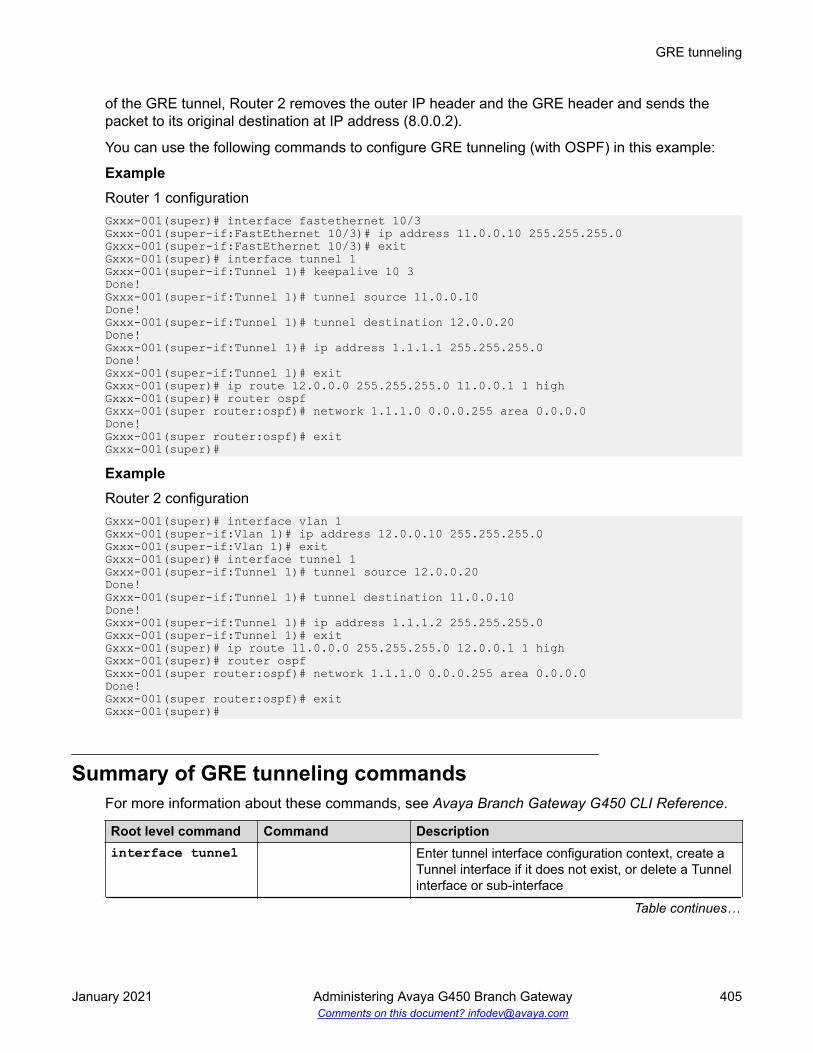
of the GRE tunnel, Router 2 removes the outer IP header and the GRE header and sends thepacket to its original destination at IP address (8.0.0.2).
You can use the following commands to configure GRE tunneling (with OSPF) in this example:
ExampleRouter 1 configurationGxxx-001(super)# interface fastethernet 10/3Gxxx-001(super-if:FastEthernet 10/3)# ip address 11.0.0.10 255.255.255.0Gxxx-001(super-if:FastEthernet 10/3)# exitGxxx-001(super)# interface tunnel 1Gxxx-001(super-if:Tunnel 1)# keepalive 10 3Done!Gxxx-001(super-if:Tunnel 1)# tunnel source 11.0.0.10Done!Gxxx-001(super-if:Tunnel 1)# tunnel destination 12.0.0.20Done!Gxxx-001(super-if:Tunnel 1)# ip address 1.1.1.1 255.255.255.0Done!Gxxx-001(super-if:Tunnel 1)# exitGxxx-001(super)# ip route 12.0.0.0 255.255.255.0 11.0.0.1 1 highGxxx-001(super)# router ospfGxxx-001(super router:ospf)# network 1.1.1.0 0.0.0.255 area 0.0.0.0Done!Gxxx-001(super router:ospf)# exitGxxx-001(super)#
ExampleRouter 2 configurationGxxx-001(super)# interface vlan 1Gxxx-001(super-if:Vlan 1)# ip address 12.0.0.10 255.255.255.0Gxxx-001(super-if:Vlan 1)# exitGxxx-001(super)# interface tunnel 1Gxxx-001(super-if:Tunnel 1)# tunnel source 12.0.0.20Done!Gxxx-001(super-if:Tunnel 1)# tunnel destination 11.0.0.10Done!Gxxx-001(super-if:Tunnel 1)# ip address 1.1.1.2 255.255.255.0Gxxx-001(super-if:Tunnel 1)# exitGxxx-001(super)# ip route 11.0.0.0 255.255.255.0 12.0.0.1 1 highGxxx-001(super)# router ospfGxxx-001(super router:ospf)# network 1.1.1.0 0.0.0.255 area 0.0.0.0Done!Gxxx-001(super router:ospf)# exitGxxx-001(super)#
Summary of GRE tunneling commandsFor more information about these commands, see Avaya Branch Gateway G450 CLI Reference.
Root level command Command Descriptioninterface tunnel Enter tunnel interface configuration context, create a
Tunnel interface if it does not exist, or delete a Tunnelinterface or sub-interface
Table continues…
GRE tunneling
January 2021 Administering Avaya G450 Branch Gateway 405Comments on this document? [email protected]

Root level command Command Descriptionkeepalive Enable the tunnel keepalive featuretunnel checksum Add a checksum to the GRE header of packets
traveling through the tunnel
When a checksum is included on one endpoint, thereceiving tunnel endpoint performs checksumvalidation on incoming packets and packets without avalid checksum are discarded.
no tunnelchecksum
Disables checksums
tunneldestination
Set the destination address of the tunnel
tunnel dscp Assign a DSCP value to packets traveling through thetunnel
The DSCP value is placed in the packet’s Carrier IPheader. You can assign a DSCP value of from 0 to 63.If you do not assign a DSCP value, the DSCP value iscopied from the packet’s original IP header.
Note:
The Carrier IP header identifies the source anddestination IP address of the tunnel.
tunnel key Enable and set an ID key for the tunnel
Tunnel ID keys are used as a security device. The keymust be set to the same value on the tunnelendpoints. Packets without the configured key mustbe discarded.
no tunnel key Disables key checkingtunnel path- mtu-discovery
Enable dynamic MTU discovery by the tunnel
tunnel source Set the source address of the tunneltunnel ttl Assign a TTL value to packets traveling through the
tunnel
The TTL value is placed in the packet’s Carrier IPheader. You can assign a TTL value of from 1 to 255.The default tunnel TTL value is 255.
show interfacestunnel
Show interface configuration and statistics for aparticular tunnel or all GRE tunnels
If the Tunnel interface is down, this command displaysthe MTU value as not available.
Router
January 2021 Administering Avaya G450 Branch Gateway 406Comments on this document? [email protected]

DHCP and BOOTP relayYou can configure the router to relay Dynamic Host Configuration Protocol (DHCP) andBOOTstrap Protocol (BOOTP) client broadcasts to a server on a different segment of the network.When you configure DHCP and BOOTP relay, you can control how the router relays DHCP andBOOTP packets. The router also relays replies from the server back to the client. The BranchGateway can alternatively function as a DHCP server, providing DHCP service to local devices.For information about configuring DHCP server on the Branch Gateway, see DHCP server onpage 409. For information about configuring DHCP client on the Branch Gateway, see DHCPclient configuration on page 183.
DHCPDHCP assigns dynamic IP addresses to devices on a network. With dynamic addressing, a devicecan have a different IP address whenever the device connects to the network. In some systems,the device’s IP address can even change while it is still connected. DHCP also supports a mix ofstatic and dynamic IP addresses.
Dynamic addressing simplifies network administration because the software keeps track of IPaddresses rather than requiring an administrator to manage the task. This means you can add anew computer to a network without needing to manually assign a unique IP address. Many ISPsuse dynamic IP addressing for dial-up users. However, dynamic addressing may not be desirablefor a network server.
BOOTPBOOTP is an Internet protocol that allows a diskless workstation to discover the following:
• Its own IP address
• The IP address of a BOOTP server on the network
• A file to be loaded into memory to boot the workstation
BOOTP allows the workstation to boot without requiring a hard disk or floppy disk drive. It is usedwhen the user or station location changes frequently. The protocol is defined by RFC 951.
DHCP/BOOTP relayThe Branch Gateway supports the DHCP/BOOTP relay agent function. This is an application thataccepts DHCP/BOOTP requests that are broadcast on one VLAN. The application sends them toa DHCP/BOOTP server. That server connects to another VLAN or a server that might be locatedacross one or more routers that might otherwise not get the broadcast request. The relay agenthandles the DHCP/BOOTP replies as well. The relay agent transmits the replies to the clientdirectly or as broadcast, according to a flag in the reply message.
DHCP and BOOTP relay
January 2021 Administering Avaya G450 Branch Gateway 407Comments on this document? [email protected]

Note:
The same DHCP/BOOTP relay agent serves both the BOOTP and DHCP protocols.
When there is more than one IP interface on a VLAN, the Branch Gateway chooses the lowest IPaddress on this VLAN when relaying DHCP/BOOTP requests. The DHCP/BOOTP server thenuses this address to decide the network from which to allocate the address. When there aremultiple networks configured, the Branch Gateway performs a round-robin selection process.
When the DHCP/BOOTP server is configured to allocate addresses only from a single subnetworkamong the different subnetworks defined on the VLAN, you might need to configure the BranchGateway with the relay address on that subnet so the DHCP/BOOTP server can accept therequest.
DHCP/BOOTP Relay in the Branch Gateway is configurable per VLAN and allows for two DHCP/BOOTP servers to be specified. In this case, the Branch Gateway duplicates each request, andsends it to both servers. This duplication provides redundancy and prevents the failure of a singleserver from blocking hosts from loading. You can enable or disable DHCP/BOOTP Relay in theBranch Gateway.
Summary of DHCP and BOOTP relay commandsFor more information about these commands, see Avaya Branch Gateway G450 CLI Reference.
Root level command Command Descriptioninterface(fastethernet|VLAN)
Enter the FastEthernet or VLAN interfaceconfiguration context
ip bootp-dhcpnetwork
Select the network from which the BOOTP/DHCPserver should allocate an address
This command is required only when there aremultiple IP interfaces over the VLAN. You must be inan interface context to use this command
no ip bootp-dhcpnetwork
Restores the default value.
ip bootp-dhcpserver
Add or remove a BOOTP/DHCP server to handleBOOTP/DHCP requests received by the currentinterface
A maximum of two servers can be added to a singleinterface. You must be in an interface context to usethis command
no ip bootp-dhcpserver
Removes a server.
Table continues…
Router
January 2021 Administering Avaya G450 Branch Gateway 408Comments on this document? [email protected]

Root level command Command Descriptionip bootp-dhcprelay
Enable or disable relaying of BOOTP and DHCPrequests to the BOOTP/DHCP server
You must be in general context to use this command.no ip bootp-dhcprelay
Disables the relaying of BOOTP and DHCPrequests.
DHCP serverThe Branch Gateway supports DHCP server. DHCP server is a protocol for automaticallyassigning IP addresses and other configuration parameters to clients on a TCP/IP network. DHCPserver minimizes the maintenance of a network of, among other things, IP telephones and PCs, byremoving the need to assign and maintain IP addresses and other parameters for each device onthe network individually.
Since a DHCP server can be configured on the Branch Gateway, local branch devices are notdependant on receiving configuration parameters over the WAN from a remote DHCP server and,therefore, can be assigned IP configuration parameters in case of WAN failure.
The Branch Gateway supports the following DHCP server features:
• Up to 32 DHCP pools
• Up to 120 users
• Up to 1024 IP addresses for all DHCP pools together
• Automatic and reservation pools
• Standard DHCP options and IP phone and wireless special options
• Vendor specific information option
• DHCP relay packets
• Global statistics
• Syslog/traps for special events
The Branch Gateway can function as a DHCP server, as a DHCP relay, or both simultaneously,with each interface configured in either DHCP server mode or DHCP relay mode. For example,you can configure the Branch Gateway to provide DHCP service to voice devices while DHCPrequests by data devices are routed to a central remote DHCP server using DHCP relay.
The Branch Gateway can function as a DHCP server or as a DHCP client, or both simultaneously.For information about configuring DHCP client on the Branch Gateway, see DHCP clientconfiguration on page 183.
Related linksDHCP client configuration on page 183
DHCP server
January 2021 Administering Avaya G450 Branch Gateway 409Comments on this document? [email protected]

Typical DHCP server applicationIn the typical application shown in the following table, the Branch Gateway is configured as a localDHCP server and router for IP phones and PCs in the branch office. The remote DHCP serverallocates IP addresses for headquarters users. The local DHCP server allocates IP addresses inthe branch offices. If there is a local ICC or LSP, calls can still be made. If there is no ICC or LSPto control calls, the DHCP server can allocate IP addresses to all devices, but, since no calls canbe made, the IP address allocation effectively applies to PCs only.
The branch DHCP server does not depend on the headquarters’ DHCP server. There is nobackup mechanism between the servers. The branch DHCP server operates continuallyregardless of the status of the centralized DHCP server or the WAN link.
By default, the DHCP server is inactive. Before activating DHCP server, you configure DHCPpools to define ranges of IP addresses and other network configuration information to be assignedto clients. Create a minimum of two dynamic pools: at least one pool for data devices (PCs) and atleast one pool for voice devices (IP phones). The Branch Gateway also supports reservationpools, which map hardware addresses/client identifiers to specific IP addresses. Reservationpools may be required for security issues or servers.
Overlap between pools is not allowed. You cannot configure a reservation pool on an IP addressthat falls within the range of another pool.
Configuring the DHCP serverProcedure
1. Enter ip dhcp pool, followed by a number from 1 to 32, to create a DHCP pool.
2. Use the name command to configure the pool’s name.
Router
January 2021 Administering Avaya G450 Branch Gateway 410Comments on this document? [email protected]

3. Configure a range of available IP addresses that the DHCP server may assign to clients,using start-ip-addr to set the start IP address of the range and end-ip-addr to setthe end IP address of the range.
Consider the following:
• For a manual/reservation pool, set identical IP addresses for the start and end IPaddresses
• The start IP address and end IP address must be on the same network according to thesubnet mask
• The start IP address must be lower than the end IP address
• The combined number of IP addresses in all pools must not exceed 256 addresses
• Both the start IP address and end IP address can be up to 223.255.255.255
• The start IP address and end IP address may not be network/broadcast addressesaccording to the subnet mask
4. Use the subnet-mask command to configure the subnet mask of the pool.
5. Use the lease command to configure the lease period for IP address assignment.
By default, the lease is eight days.
6. For a manual/reservation pool, use the client identifier command to reserve thepool’s IP address for assignment to a specific client.
To configure a reservation, the start IP address and end IP address must be identical. Youcannot configure more than one reservation on a single pool.
7. Configure DHCP options for the pool, if required.
See Configuring options on page 412 and, for vendor specific options, Configuring vendor-specific options on page 413.
8. Repeat steps 1 to 7 to configure as many DHCP pools as you require.
You can configure up to 32 DHCP pools. By default, all pools are inactive until you activatethem. This enables you to modify each pool’s configuration without affecting networkdevices.
9. Activate each of the DHCP pools you configured using the ip dhcp activate poolcommand in general context, followed by the pool number.
10. Enter ip dhcp-server to activate DHCP server.
DHCP server is now active. If you change the pool configuration, it is recommended to doso while the pool is active.
Note:
If you try to configure a new start and end IP address that is not part of the currentnetwork and beyond the allowed maximum of 256 IP addresses, first use the no
DHCP server
January 2021 Administering Avaya G450 Branch Gateway 411Comments on this document? [email protected]

start ip address and no end ip address commands before configuring thenew start and end IP addresses.
Configuring optionsAbout this taskDHCP options are various types of network configuration information that the DHCP client canreceive from the DHCP server. The Branch Gateway supports all DHCP options. The mostcommon options used for IP phones are listed in Common user-configurable DHCP options onpage 412. Some options are configured with specific CLI commands that are also listed in Common user-configurable DHCP options on page 412. Options 0, 50, 51, 52, 53, 54, 55, 56, and255 are not configurable.
Procedure1. Use the option command to specify the option code and enter the context for the option.
Note:
To configure an option that is listed in Common user-configurable DHCP options onpage 412 with an entry in the “Specific command” column, use the specific commandinstead of the option command.
2. Use the name command to set the name of the DHCP option (optional).
3. Use the value command to enter the option data type and the option data.
Common user-configurable DHCP optionsOption Description Specific command1 Subnet Mask subnet-mask3 Router default-router6 Domain name server dns_server7 Log Server15 Domain Name domain-name43 vendor-specific information vendor-specific-option44 Wins/NBNS server46 Wins/NBT Node Type51 IP Address Lease Time lease66 TFTP server name69 SMTP server176 Avaya IP phone private
Router
January 2021 Administering Avaya G450 Branch Gateway 412Comments on this document? [email protected]

Configuring vendor-specific optionsAbout this taskYou can configure an option unique to an individual vendor class. This is called a vendor-specificoption (option 43).
Procedure1. Use the vendor-specific-option command to create a vendor-specific option with a
unique index.
2. Use the name command to name the option (optional).
3. Use the class-identifier command to set a vendor-specific identifier.
4. Use the value command to set the data type and value of the vendor-specific option.
Deleting an IP address bindingAbout this taskWhen the DHCP server detects an IP address conflict after attempting to allocate an IP addressthat is already in use, the server locks the IP address for half an hour by marking the IP addresswith client identifier 00:00:00:00:00:00:00. If you have solved the conflict within half an hour, youcan use this command to free the IP address for reallocation
ProcedureTo delete an IP address binding, use the clear ip dhcp-server binding command.
DHCP pool configuration examplesThe following example defines a dynamic pool for voice devices:Gxxx-001(super)# ip dhcp pool 1Gxxx-001(super-DHCP 1)# name “IP phone Pool”Done!Gxxx-001(super-DHCP 1)# start-ip-addr 135.64.20.2Done!Gxxx-001(super-DHCP 1)# end-ip-addr 135.64.20.30Done!Gxxx-001(super-DHCP 1)# subnet-mask 255.255.255.0Done!Gxxx-001(super-DHCP 1)# default-router 135.64.20.1Done!Gxxx-001(super-DHCP 1)# option 176Gxxx-001(super-DHCP 1/option 176)# name “Avaya IP phone option”Done!Gxxx-001(super-DHCP 1/option 176)# value ascii “MCIPADD=10.10.2.140,MCPORT=1719, TFTPSRVR=10.10.5.188”Done!Gxxx-001(super-DHCP 1/option 176)# exitGxxx-001(super-DHCP 1)# exitGxxx-001(super)# ip dhcp activate pool 1
DHCP server
January 2021 Administering Avaya G450 Branch Gateway 413Comments on this document? [email protected]

Done!Gxxx-001(super)# ip dhcp-serverDone!Gxxx-001(super)#
The following example defines a dynamic pool for data devices:Gxxx-001(super)# ip dhcp pool 2Gxxx-001(super-DHCP 2)# name “Data Pool”Done!Gxxx-001(super-DHCP 2)# start-ip-addr 135.64.20.34Done!Gxxx-001(super-DHCP 2)# end-ip-addr 135.64.20.60Done!Gxxx-001(super-DHCP 2)# subnet-mask 255.255.255.0Done!Gxxx-001(super-DHCP 2)# default-router 135.64.20.33Done!Gxxx-001(super-DHCP 2)# dns-server 10.10.1.1Done!Gxxx-001(super-DHCP 2)# domain-name my.domain.comDone!Gxxx-001(super-DHCP 2)# option 176Gxxx-001(super-DHCP 2/option 176)# value ascii “MCIPADD=192.168.50.17,192.168.50.15, MCPORT=1719, TFTPSRVR=192.168.50.1, TFTPDIR=/phonedir/”Done!Gxxx-001(super-DHCP 2/option 176)# exitGxxx-001(super-DHCP 2)# exitGxxx-001(super)# ip dhcp activate pool 2Done!Gxxx-001(super)# ip dhcp-serverDone!Gxxx-001(super)#
The following example configures a vendor-specific option for DHCP pool 5:Gxxx-001(super-DHCP 5)# vendor-specific-option 1Gxxx-001(super-DHCP 5/vendor specific 1)# class-identifier“ccp.avaya.com”Done!Gxxx-001(super-DHCP 5/vendor specific 1)# value raw ascii “gfdgfd”Done!Gxxx-001(super-DHCP 5/vendor specific 1)# exitGxxx-001(super-DHCP 5)#
The following example defines a reservation pool for data devices:Gxxx-001(super)# ip dhcp pool 3Gxxx-001(super-DHCP 3)# name “Data 1 Server”Done!Gxxx-001(super-DHCP 3)# start-ip-addr 135.64.20.61Done!Gxxx-001(super-DHCP 3)# end-ip-addr 135.64.20.61Done!Gxxx-001(super-DHCP 3)# subnet-mask 27Done!Gxxx-001(super-DHCP 3)# client identifier 01:11:22:33:44:55:66Done!Gxxx-001(super-DHCP 3)# default-router 135.64.20.33Done!Gxxx-001(super-DHCP 3)# dns-server 10.10.1.1Done!Gxxx-001(super-DHCP 3)# exitGxxx-001(super)# ip dhcp activate pool 3Done!Gxxx-001(super)#
Router
January 2021 Administering Avaya G450 Branch Gateway 414Comments on this document? [email protected]

Commands for displaying DHCP server information• show ip dhcp-pool• show ip dhcp-server bindings• show ip dhcp-server statistics
For more information about these commands, see Summary of DHCP Server commands onpage 415 or the Avaya Branch Gateway G450 CLI Reference.
Summary of DHCP Server commandsFor more information about these commands, see Avaya Branch Gateway G450 CLI Reference.
Root levelcommand
First levelcommand
Second levelcommand
Description
clear ip dhcp-server binding
Delete IP address binding
clear ip dhcp-serverstatistics
Clear the statistics of the DHCPserver
ip dhcpactivate pool
Activate configured DHCP pools
ip dhcp pingpackets
Enable the sending of a pingpacket by the DHCP server tocheck if the IP address it is aboutto allocate is already in use byanother client
ip dhcp pingtimeout
Set the time the DHCP serverwaits for a reply to a sent pingpacket before allocating an IPaddress to a DHCP client
ip dhcp pool Create a DHCP poolbootfile Provide startup parameters for the
DHCP client deviceclient-identifier
Reserve the pool’s IP address forassignment to a specific client
default- router Set up to eight default router IPaddresses in order of preference
dns-server Set up to eight Domain NameServer (DNS) IP addresses
Table continues…
DHCP server
January 2021 Administering Avaya G450 Branch Gateway 415Comments on this document? [email protected]

Root levelcommand
First levelcommand
Second levelcommand
Description
domain-name Set a domain name string for theclient
end-ip-addr Set the end IP address of therange of available IP addressesthat the DHCP server may assignto clients
lease Configure the lease period for IPaddress assignment
name Configure the pool’s namenext-server Specify the IP address of the next
server in the boot process of aDHCP client
option Enter the context of a DHCP optionname Configure a name for the DHCP
optionvalue Enter the option data type and the
option dataserver-name Specify the optional server name in
the boot process of a DHCP clientshow ip dhcp-pool
Display DHCP pool configurations
start-ip-addr Set the start IP address of therange of available IP addressesthat the DHCP server may assignto clients
subnet-mask Configure the subnet mask of thepool
vendor-specific-option
Create a vendor-specific optionwith a unique index
name Name the vendor-specific optionclass-identifier Set a vendor-specific identifiervalue Set the data type and value of the
vendor-specific optionip dhcp-server Activate DHCP servershow ip dhcp-server bindings
Display bindings
show ip dhcp-serverstatistics
Display DHCP server statistic
Router
January 2021 Administering Avaya G450 Branch Gateway 416Comments on this document? [email protected]

Broadcast relayWhen you configure broadcast relay, the router forwards broadcast packets across interfaces. Youcan configure broadcast relay types including directed broadcast forwarding, NetBIOSrebroadcast, DHCP, and BOOTP client broadcast.
For more information about DHCP and BOOTP client broadcast, see DHCP and BOOTP relay onpage 407.
Directed broadcast forwardingAbout this taskA directed broadcast is an IP packet whose destination address is the broadcast address of anetwork or subnet. A directed broadcast causes every host on the network to respond. You canuse directed broadcasts to obtain a list of all active hosts on the network. A hostile user can exploitdirected broadcasts to launch a denial-of-service attack on the network. For each interface on theBranch Gateway, you can configure whether the Branch Gateway forwards directed broadcastpackets to the network address or subnet mask address of the interface.
ProcedureEnter ip directed-broadcast to enable directed broadcast forwarding on an interface. Usethe no form of this command to disable directed broadcast forwarding on an interface.
NetBIOS rebroadcastNetwork Basic Input Output System (NetBIOS) is a protocol for sharing resources among desktopcomputers on a LAN. You can configure the Branch Gateway to relay NetBIOS UDP broadcastpackets. This feature is used for applications such as WINS that use broadcast but might need tocommunicate with stations on other subnetworks or VLANs.
Configuration is performed on a per-interface basis. A NetBIOS broadcast packet arrives from aninterface on which NetBIOS rebroadcast is enabled. The packet is distributed to all otherinterfaces configured to rebroadcast NetBIOS.
• If the NetBIOS packet is a net-directed broadcast, for example, 149.49.255.255, the packet isrelayed to all other interfaces on the list, and the IP destination of the packet is replaced bythe appropriate interface broadcast address.
• If the NetBIOS broadcast packet is a limited broadcast, for example, 255.255.255.255, it isrelayed to all VLANs on which there are NetBIOS-enabled interfaces. In that case, thedestination IP address remains the limited broadcast address.
Broadcast relay
January 2021 Administering Avaya G450 Branch Gateway 417Comments on this document? [email protected]

Summary of broadcast relay commandsFor more information about these commands, see Avaya Branch Gateway G450 CLI Reference.
Root level command Command Descriptioninterface(dialer|fastethernet|tunnel| vlan)
Enter the Dialer, FastEthernet, Tunnel, or VLANinterface context
ip directed-broadcast
Enable or disable directed broadcast forwarding onthe interface
ip netbios-rebroadcast
Enable or disable NetBIOS rebroadcasts on theinterface
ARP tableWhen you configure the Address Resolution Protocol (ARP) table, you can:
• View information about the ARP table
• Add entries to the ARP table
• Delete entries from the ARP table
• Configure the ARP timeout
Overview of ARPIP logical network addresses are independent of physical addresses. The physical address mustbe used to convey data in the form of a frame from one device to another. Therefore, amechanism is required to acquire a destination device hardware address from its IP address. Thismechanism is called ARP.
Static and dynamic table entriesThe ARP table stores pairs of IP and MAC addresses. This storage saves time andcommunication costs, since the host looks in the ARP table first when transmitting a packet. If theinformation is not there, then the host sends an ARP Request.
There are two types of entries in the ARP table:
Static ARP table entries: Static ARP table entries do not expire.
Router
January 2021 Administering Avaya G450 Branch Gateway 418Comments on this document? [email protected]

Dynamic ARP table entries: Dynamic ARP table entries are mappings between IP addressesand MAC addresses that the switch used recently. Dynamic ARP table entries expire after aconfigurable amount of time. The following diagram shows how a switch adds dynamic ARP tableentries:
Adding static ARP table entriesProcedureTo add static ARP table entries manually, use the arp command.
For example, to add a static ARP table entry for station 192.168.7.8 with MAC address00:40:0d:8c:2a:01, use the following command:Gxxx-001# arp 192.168.7.8 00:40:0d:8c:2a:01
ARP table
January 2021 Administering Avaya G450 Branch Gateway 419Comments on this document? [email protected]

Removing static and dynamic entriesProcedureTo remove static and dynamic entries from the ARP table, use the no arp command .
For example, to remove the ARP table entry for the station 192.168.13.76:Gxxx-001# no arp 192.168.13.76
Changing an entry in the ARP tableProcedureTo change an entry in the ARP table, delete the entry and reinsert it with revised parameters.
Summary of ARP table commandsFor more information about these commands, see Avaya Branch Gateway G450 CLI Reference.
Command Descriptionarp Add a permanent entry to the ARP tableno arp Remove either a static entry or a dynamically-learned entry from the ARP tablearp timeout Configure the amount of time, in seconds, that an entry remains in the ARP
table
Entering this command without a time parameter displays the current timeoutvalue.
no arp timeout Restore the default value (four hours)clear arp-cache Delete all dynamic entries from the ARP table and the IP route cacheip max-arp-entries Specify the maximum number of ARP table entries allowed in the ARP tableno ip max-arp-entrie
Restore the maximum number of ARP table entries allowed in the ARP table todefault value
show ip arp Display a list of the ARP resolved MAC to IP addresses in the ARP tableshow ip reverse-arp
Display the IP address of a host, based on a known MAC address
Router
January 2021 Administering Avaya G450 Branch Gateway 420Comments on this document? [email protected]

Proxy ARPThe Branch Gateway supports proxy ARP. Proxy ARP is a technique by which a router provides afalse identity when answering ARP requests intended for another device. By falsifying its identify,the router accepts responsibility for routing packets to their true destination.
Proxy ARP can help devices on a subnet to reach remote subnets without the need to configurerouting or a default gateway.
Summary of Proxy ARP commandsFor more information about these commands, see Avaya Branch Gateway G450 CLI Reference.
Root level command Command Descriptioninterface (fastethernet|vlan)
Enter the FastEthernet or VLAN interface context
ip proxy-arp Enable proxy ARP on an Branch Gateway interfaceno ip proxy-arp Disable proxy ARP on an interface
ICMP errorsYou can control whether the router sends Internet Control Message Protocol (ICMP) errormessages. The router sends an ICMP error message to the source of a packet if the router rejectsthe packet.
Summary of ICMP errors commandsFor more information about these commands, see Avaya Branch Gateway G450 CLI Reference.
Command Descriptionip icmp-errors Set ICMP error messages to ON or OFFshow ip icmp Display the status (enabled or disabled) of ICMP error messages
RIPThe Routing Information Protocol (RIP) enables routers to compute the path that an IP packetshould follow. Routers exchange routing information using RIP to determine routes that other
Proxy ARP
January 2021 Administering Avaya G450 Branch Gateway 421Comments on this document? [email protected]

routers are connected to. OSPF is a newer protocol that serves a similar purpose. For moreinformation about OSPF, see OSPF on page 426.
You can configure route redistribution between OSPF, RIP, and static routes. With routeredistribution, you can configure the Branch Gateway to redistribute routes learned from oneprotocol into the domain of the other routing protocol. For more information, see Routeredistribution on page 430.
RIP is a distance vector protocol. The router decides which path to use on distance or the numberof intermediate hops. In order for this protocol to work correctly, all the routers, and possibly thenodes, need to gather information on how to reach each destination in the Internet. However thevery simplicity of RIP has a disadvantage. This protocol does not take into account networkbandwidth, physical cost, and data priority. The Branch Gateway supports two versions of RIP:
• RIPv1 on page 422
• RIPv2 on page 422
RIPv1RIPv1 is the original version of the RIP protocol. The RIPv1 protocol imposes some limitations onthe network design with regard to subnetting. When operating RIPv1, you must not configurevariable length subnetwork masks (VLMS). Each IP network must have a single mask, implyingthat all subnetworks in a given IP network are of the same size. Also, when operating RIPv1, youmust not configure supernets. RIPv1 is defined in RFC 1058.
RIPv2RIPv2 is a newer version of the RIP routing protocol. RIPv2 solves some of the problemsassociated with RIPv1. The most important change in RIPv2 is the addition of a subnetworkmask field which allows RIPv2 to support variable length subnetworks. RIPv2 also includes anauthentication mechanism similar to the one used in OSPF. RIPv2 is defined in RFC 2453. Formore information, see RIPv1 vs. RIPv2 on page 422.
RIPv1 vs. RIPv2RIPv1 RIPv2Broadcast addressing Multicast addressingTimer-based – updated every 30 seconds Timer-based – updated every 30 secondsFixed subnetwork masks VLSM support – subnet information transmittedNo security Security (authentication)No provision for external protocols Provision for EGP/BGP (Route tag)
Router
January 2021 Administering Avaya G450 Branch Gateway 422Comments on this document? [email protected]
Prevention of routing loops in RIPYou can use the following features in RIP to help avoid routing loops:
• Split-horizon: The split-horizon technique prevents information about routes from exiting therouter interface through which the information was received. This prevents small routingloops.
• Poison-reverse: Poison-reverse updates explicitly indicate that a network or subnet isunreachable. Poison-reverse updates are sent to defeat large routing loops.
For information on the CLI commands, see Commands used to prevent routing loops in RIP onpage 423
Commands used to prevent routing loops in RIPSplit-horizon technique
• Enter ip rip split-horizon to enable the split-horizon mechanism.
• Use the no form of this command to disable the split-horizon mechanism. By default, split-horizon is enabled.
Poison-reverse updates• Enter ip rip poison-reverse to enable split-horizon with poison-reverse on an
interface.• Use the no form of this command to disable the poison-reverse mechanism.
RIP distribution access listsRIP distribution access lists consist of rules that specify how a router distributes and accepts RIProuting information from other routers. Before sending an update, the router consults an accesslist to determine if it should include specific routes in the update. When receiving an update, therouter first checks a set of rules which apply to incoming updates to determine if it should insertthose routes into its routing table. You can assign the rules per interface and per direction.
You can configure up to 99 RIP distribution access lists on the Branch Gateway.
Configuring a distribution access list exampleAbout this taskFor example, to configure RIP distribution access list number 10 permitting distribution andlearning of network 10.10.0.0, do the following:
RIP
January 2021 Administering Avaya G450 Branch Gateway 423Comments on this document? [email protected]

Procedure1. Enter the command: ip distribution access-list 10 1 permit 10.10.0.0
0.0.255.255The default action of the access list is deny and can be changed using the ipdistribution access-default-action command.
Note:
Whenever at least one permit rule exists, distributing and learning of all the remainingnetworks is denied, unless specifically permitted by another rule.
2. Apply the distribution access list created in Step 1 by performing the following procedurewithin the Router RIP context:
a. Enter the distribution-list 10 in command to apply list number 10 created inStep 1 on all updates received on all interfaces.
b. Enter the distribution-list 10 in FastEthernet 10/3 command to applyAccess List 10 on updates received on interface ‘FastEthernet 10/3’.
c. Enter the distribution-list 10 out command to apply Access List 10 to alladvertised updates.
d. Enter the distribution-list 10 out ospf command to apply Access List 10 toall advertised updates that were learned from OSPF (redistributed from OSPF intoRIP).
ResultIf no distribution access list is defined, learning and advertising is allowed for all of the routinginformation. This is the default.
RIP limitationsConfiguration of RIPv1 and RIPv2 is per IP interface. Configuration must be homogeneous on allrouters on each subnetwork. That is, RIPv1 and RIPv2 routers should not be configured on thesame subnetwork. However, you can configure different IP interfaces of the Branch Gateway withdifferent RIP versions. This configuration is valid as long as all routers on the subnet areconfigured with the same version.
RIPv2 and RIPv1 are considered the same protocol with regard to redistribution to and from OSPFand static route preferences.
Summary of RIP commandsFor more information about these commands, see Avaya Branch Gateway G450 CLI Reference.
Router
January 2021 Administering Avaya G450 Branch Gateway 424Comments on this document? [email protected]

Root level command Command Descriptionip distribution access-default-action
Set the default action for a specific RIPdistribution access list
ip distribution access-list
Create a RIP distribution access list
ip distribution access-list-cookie
Set the access list cookie
ip distribution access-list-copy
Copy the distribution access list
ip distribution access-list-name
Set the name of the distribution list
ip distribution access-list-owner
Set the owner of the distribution list
interface (dialer|fastethernet|loopback|serial|vlan|tunnel)
Enter the Dialer, FastEthernet,Loopback, Serial, Tunnel, or VLANinterface context
ip ripauthentication key
Set the authentication string used on theinterface
no ip ripauthentication key
Clear the password
ip ripauthentication mode
Specify the type of authentication usedin RIP v2 packets
no ip ripauthentication mode
Restore the default value, none
ip rip default-route-mode
Enable learning of the default routereceived by the RIP protocol. The defaultstate is talk-listen.
The default state is talk-listen.no ip rip default-route-mode
Disable listening to default routes.
ip rip poison-reverse
Enable or disable split-horizon withpoison-reverse on an interface
no ip rip poison-reverse
Disable the poison-reverse mechanism
ip rip rip-version Specify the RIP version running on theinterface
ip rip send-receive-mode
Set the RIP send and receive modes onan interface
no ip rip send-receive-mode
Set the RIP to talk, that is, to sendreports
ip rip split-horizon Enable or disable the split-horizonmechanism
Table continues…
RIP
January 2021 Administering Avaya G450 Branch Gateway 425Comments on this document? [email protected]

Root level command Command Descriptionno ip rip split-horizon
Disable the split-horizon mechanism. Bydefault split-horizon is enabled.
router rip Enable the RIP and enter the routerconfiguration context or disable the RIP
no router rip Restore the default value by disablingRIP
default-metric Set or reset the interface RIP routemetric value
no default-metric restore the interface RIP route metricdefault value.
distribution-list Apply a distribution access list forincoming or outgoing routing informationin route updates or deactivate the list
no distribution-list Deactivate the distribution access listnetwork Specify a list of networks on which the
RIP is runningno network Remove an entry from the list of
networksredistribute Redistribute routing information from
other protocols into RIPno redistribute Restore the default value, disable
redistribution by RIPtimers basic Set RIP timersno timers basic Set the RIP timers to their default value
show ip distributionaccess-lists
Display the contents of all currentdistribution lists or of a specific list
show ip protocols Display parameters and statistics of agiven IP routing protocol
OSPFThe Open Shortest Path First (OSPF) protocol enables routers to compute the path that an IPpacket should follow. Routers exchange routing information with OSPF to determine where tosend each IP packet on its next hop. RIP is an older protocol that serves a similar purpose. Formore information about RIP, see RIP on page 421.
OSPF is based on the shortest-path-first or link-state algorithm. It was introduced to overcome thelimitations of RIP in increasingly complex network designs. OSPF uses the cost of a path as thecriterion for comparing paths. In contrast, RIP uses the number of hops as the criterion forcomparing paths. Also, updates are sent when there is a topological change in the network, ratherthan every 30 seconds as with RIP.
Router
January 2021 Administering Avaya G450 Branch Gateway 426Comments on this document? [email protected]

The advantage of shortest-path-first algorithms is that under stable conditions, there are lessfrequent updates (thereby saving bandwidth). They converge quickly, thus preventing suchproblems as routing loops and Count-to-Infinity, when routers continuously increment the hopcount to a particular network. These algorithms make a stable network. The disadvantage ofshortest-path-first algorithms is that they require a lot of CPU power and memory.
In OSPF, routers use link-state updates to send routing information to all nodes in a network bycalculating the shortest path to each node. This calculation is based on a topography of thenetwork constructed by each node. Each router sends that portion of the routing table thatdescribes the state of its own links, and it also sends the complete routing structure (topography).
You can configure route redistribution between OSPF, RIP, and static routes. With routeredistribution, you can configure the Branch Gateway to redistribute routes learned from oneprotocol into the domain of the other routing protocol. For more information, see Routeredistribution on page 430.
OSPF dynamic CostAn OSPF interface on the Branch Gateway can dynamically set a Cost. The Cost represents theprice assigned to each interface for purposes of determining the shortest path.
By default the OSPF interface Cost is calculated based on the interface bandwidth, according tothe following formula: Cost = 100,000 / bandwidth (in kbps)
The result is that the higher the bandwidth, the lower the Cost.
When manually configuring the Cost of an OSPF interface (ip ospf cost command), dynamicbandwidth updates do not change the Cost.
When manually adjusting the interface’s bandwidth, (bandwidth command), if Cost is beingdetermined dynamically, it is this configured bandwidth and not the actual interface bandwidth thatis used to calculate Cost.
OSPF limitationsYou can configure the Branch Gateway as an OSPF Autonomous System Boundary Router(ASBR) using route redistribution. The Branch Gateway can be installed in the OSPF backbonearea (area 0.0.0.0) or in any OSPF area that is part of a multiple areas network. However, theBranch Gateway cannot be configured to be an OSPF area border router itself.
The Branch Gateway supports the ECMP equal-cost multipath (ECMP) feature which allows loadbalancing by splitting traffic between several equivalent paths.
While you can activate OSPF with default values for each interface using a single command, youcan configure many of the OSPF parameters.
OSPF
January 2021 Administering Avaya G450 Branch Gateway 427Comments on this document? [email protected]

Summary of OSPF commandsFor more information about these commands, see Avaya Branch Gateway G450 CLI Reference.
Root level command Command Descriptioninterface (dialerfastethernet| loopback|serial| tunnel|vlan)
Enter the Dialer, FastEthernet,Loopback, Serial, Tunnel, or VLANinterface context
bandwidth Set the bandwidth parameter manuallyfor this interface
ip ospf authentication Specify the authentication type for aninterface
no ip ospfauthentication
Remove the authentication type for aninterface.
ip ospfauthentication-key
Configure the interface authenticationpassword
no ip ospfauthentication-key
Remove the OSPF password
ip ospf cost Configure the Cost of an OSPFinterface, for the purpose of determiningthe shortest path
no ip ospf cost Set the cost to its default valueip ospf dead-interval Configure the interval before declaring
the neighbor as deadno ip ospf dead-interval
Set the dead-interval to its default value
ip ospf hello-interval Specify the time interval between hellopackets sent by the router
no ip ospf hello-interval
Set the hello-interval to its default value
ip ospf message-digest-key
Specify the message-digest key for theinterface and enable OSPF MD5authentication
no ip ospf message-digest-key
Return the interface to its default value
ip ospf network point-to-multipoint
Specify the network type for theinterface
ip ospf network point-to-multipoint
Return the interface to its default value
ip ospf priority Configure interface priority used inDesignated Router election
Table continues…
Router
January 2021 Administering Avaya G450 Branch Gateway 428Comments on this document? [email protected]

Root level command Command Descriptionno ip ospf priority Set the OSPF priority to its default
valueip ospf router-id Configure the router IDno ip ospf router-id Return the router ID to its default valuerouter ospf Enable OSPF protocol on the system
and to enter the router configurationcontext
no router ospf Restore the default value and disableOSPF globally
area Configure the OSPF area ID of therouter
no area Delete the OSPF area iddefault-metric Set the interface OSPF route metric
valuenetwork Enable OSPF in a networkno network Disable OSPF in a network. The default
value is disabled.passive-interface Suppress OSPF routing updates on an
interface. Used to allow interfaces to beflooded into the OSPF domain as OSPFroutes rather than external routes.
Note:
Use the network command withthis command to make the networkpassive.
redistribute Redistribute routing information fromother protocols into OSPF
no redistribute Disable resistribution by OSPFtimers spf Configure the delay between runs of
OSPFs (SPF) calculationno timers spf Restore the default value
show ip ospf Display general information aboutOSPF routing
show ip ospf database Display lists of information related to theOSPF database for a specific router
show ip ospf interface Display the OSPF-related interfaceinformation
show ip ospf neighbor Display OSPF neighbor information ona per-interface basis
show ip protocols Display OSPF parameters and statistics
OSPF
January 2021 Administering Avaya G450 Branch Gateway 429Comments on this document? [email protected]

Route redistributionRoute redistribution is the interaction of multiple routing protocols. OSPF and RIP can be operatedconcurrently in the Branch Gateway. In this case, you can configure the Branch Gateway toredistribute routes learned from one protocol into the domain of the other routing protocol.Similarly, static routes can be redistributed to RIP and OSPF.
Note:
Take care when you configure route redistribution. It involves metric changes and might causerouting loops in the presence of other routes with incompatible schemes for routeredistribution and route preferences.
The Branch Gateway scheme for metric translation in route redistribution is as follows:
• Static to RIP metric configurable (default 1)
• OSPF internal metric N to RIP metric (default 1)
• OSPF external type 1 metric N to RIP metric (default 1)
• OSPF external type 2 metric N to RIP metric (default 1)
• Static to OSPF external type 2, metric configurable (default 20)
• RIP metric N to OSPF external type 2, metric (default 20)
• Direct to OSPF external type 2, metric (default 20)
By default, the Branch Gateway does not redistribute routes between OSPF and RIP.Redistribution from one protocol to the other can be configured. Static routes are, by default,redistributed to RIP and OSPF. The Branch Gateway allows the user to globally disableredistribution of static routes to RIP, and separately to globally disable redistribution of staticroutes to OSPF. In addition you can configure, on a per static route basis, whether the route is tobe redistributed to RIP and OSPF, and what metric to use (in the range of 1-15). The default stateis to allow the route to be redistributed at metric 1. When static routes are redistributed to OSPF,they are always redistributed as external type 2.
Export default metricThe Branch Gateway enables you to configure the metric to be used in updates that areredistributed from one routing protocol to another.
In RIP, the default is 1 and the maximum value is 16. In OSPF, the default is 20.
Set the default metric value before redistribution, using the default-metric command fromwithin the Router RIP or Router OSPF contexts. This value is used for all types of redistributedroutes, regardless of the protocol from which the route was learned.
Router
January 2021 Administering Avaya G450 Branch Gateway 430Comments on this document? [email protected]

Summary of route redistribution commandsFor more information about these commands, see Avaya Branch Gateway G450 CLI Reference.
Root level command Command Descriptionrouter ospf Enable OSPF and enter the router configuration
contextredistribute Redistribute routing information from other protocols
into OSPF
• Use in the Router RIP context to configure routeredistribution into RIP.
• Use in the Router OSPF context to configure routeredistribution into OSPF.
default-metric Configure the metric to be used in updates that areredistributed from one routing protocol to another
router rip Enable RIP and enter the router configurationcontext
redistribute Redistribute routing information from other protocolsinto RIP
default-metric Configure the metric to be used in updates that areredistributed from one routing protocol to another
VRRPVirtual Router Redundancy Protocol (VRRP) is an IETF protocol designed to support redundancyof routers on the LAN and load balancing of traffic. VRRP is open to host stations, making it anideal option when redundancy, load balancing, and ease of configuration are required.
The concept underlying VRRP is that a router can back up other routers, in addition to performingits primary routing functions. This redundancy is achieved by introducing the concept of a virtualrouter. A virtual router is a routing entity associated with multiple physical routers. One of thephysical routers with which the virtual router is associated performs the routing functions. Thisrouter is known as the master router. For each virtual router, VRRP selects a master router. If theselected master router fails, another router is selected as master router.
In VRRP, two or more physical routers can be associated with a virtual router, thus achievingextreme reliability. In a VRRP environment, host stations interact with the virtual router. Thestations are not aware that this router is a virtual router, and are not affected when a new routertakes over the role of master router. Thus, VRRP is fully interoperable with any host station.
You can activate VRRP on an interface using a single command while allowing for the necessaryfine-tuning of the many VRRP parameters. For a detailed description of VRRP, see VRRPstandards and published literature.
VRRP
January 2021 Administering Avaya G450 Branch Gateway 431Comments on this document? [email protected]

VRRP configuration exampleThe following diagram illustrates an example of a VRRP configuration:
There is one main router on IP subnet 20.20.20.0, such as a Branch Gateway, switch, or anyrouter that supports VRRP, and a backup router. You can configure more backup routers.
• The Branch Gateway itself must have an interface on the IP subnetwork, for example,20.20.20.2
• Configure all the routers under the same VRID, for example,1. You must configure the routersper VLAN.
• An assigned VRID must not be used in the network, even in a different VLAN
• When router configuration is complete and the network is up, the main router for each virtualrouter is selected according to the following order of preference:
- The virtual router IP address is also the router’s interface IP address
- It has the highest priority (you can configure this parameter)
- It has the highest IP address if the previous conditions do not apply
• The virtual router IP address needs to be configured as the default gateway on the stations
• The Main router advertises a six-byte Virtual MAC address, in the format 00.00.5E.00.01.02VRID, as a response to the stations’ ARP requests
• The redundant router uses a VRRP polling protocol to check the Main router integrity at one-second intervals (default). Otherwise, it is idle.
• If the Main router fails, the redundant router that does not receive a response from fourconsecutive polling requests (default) takes over and starts to advertise the same VirtualMAC for ARP requests. Therefore, the stations will not detect any change either in theconfigured default gateway or at the MAC level.
Router
January 2021 Administering Avaya G450 Branch Gateway 432Comments on this document? [email protected]

• VRRP has no provisions for routing database synchronization among the redundant routers.You must perform this manually, if needed.
Summary of VRRP commandsFor more information about these commands, see Avaya Branch Gateway G450 CLI Reference.
Root level command Command Descriptioninterface(fastethernet|vlan)
Enter the FastEthernet or VLAN interfaceconfiguration context
ip vrrp Create a virtual router on an interfaceno ip vrrp Delete a virtual routerip vrrp address Assign an IP address to a virtual routerno ip vrrp address Remove an IP address from a virtual routerip vrrp auth-key Set the virtual router simple password authentication
key for the virtual router IDno ip vrrp auth-key
Disable simple password authentication for thevirtual router instance
ip vrrp overrideaddr owner
Accept packets addressed to the IP addressesassociated with the virtual router, such as ICMP,SNMP, and telnet (if it is not the IP address owner)
no ip vrrpoverride addrowner
Discard the packets
ip vrrp preempt Configure a router to preempt a lower priority masterfor the virtual router ID
no ip vrrp preempt Disable preemption for a virtual router instance. Bydefault, preemption is enabled.
ip vrrp primary Set the primary address used as the source addressof VRRP packets for the virtual router ID
no ip vrrp primary Restore the default primary address for a virtualrouter instance. By default, the primary address isselected automatically by the device.
ip vrrp priority Set the virtual router priority value used whenselecting a master router
ip vrrp timer Set the virtual router advertisement timer value forthe virtual router ID
router vrrp Enable or disable VRRP routing globallyshow ip vrrp Display VRRP information
VRRP
January 2021 Administering Avaya G450 Branch Gateway 433Comments on this document? [email protected]

FragmentationBranch Gateway supports IP fragmentation and reassembly. The Branch Gateway router canfragment and reassemble IP packets according to RFC 791. This feature allows the router to sendand receive large IP packets where the underlying data link protocol constrains the MaximumTransport Unit (MTU).
IP fragmentation involves breaking a datagram into a number of pieces that can be reassembledlater. The IP source, destination, identification, total length, and fragment offset fields, along withthe more fragment and don’t fragment flags in the IP header, are used for IP fragmentation andreassembly.
IP fragmentation works as follows:
• Each IP packet is divided into fragments
• Each fragment becomes its own IP packet
• Each packet has same identifier, source, and destination address
Fragments are usually not reassembled until final destination. The Branch Gateway supportsfragmentation of IP packets according to RFC 791, and reassembly of IP packets destined only toits interfaces.
Summary of fragmentation commandsFor more information about these commands, see Avaya Branch Gateway G450 CLI Reference.
Command Descriptionclear fragment Clear the fragment database and restore its default valuesfragment chain Set the maximum number of fragments that can comprise a single IP packet
destined to the routerno fragment chain Set the fragment chain to its default valuefragment size Set the maximum number of fragmented IP packets destined to the router to
reassemble at any given timeno fragment size Set the fragment size to its default valuefragment timeout Set the maximum number of seconds to reassemble a fragmented IP packet
destined to the routerno fragmenttimeout
Set the fragment timeout to its default value.
show fragment Display information regarding fragmented IP packets that are destined to arouter
Router
January 2021 Administering Avaya G450 Branch Gateway 434Comments on this document? [email protected]

Chapter 21: IPSec VPN
VPN (Virtual Private Network) defines a private secure connection between two nodes on a publicnetwork such as the Internet. VPN at the IP level is deployed using IP Security (IPSec). IPSec is astandards-based set of protocols defined by the IETF that provide privacy, integrity, and authenticityto information transferred across IP networks.
The standard key exchange method employed by IPSec uses the Internet Key Exchange (IKE)protocol to exchange key information between the two nodes (referred to as peers). Each peermaintains Security Associations (SAs) to maintain the private secure connection. IKE operates intwo phases:
• The Phase-1 exchange negotiates an IKE SA
• The IKE SA created in Phase-1 secures the subsequent Phase-2 exchanges, which in turngenerate IPSec SAs
IPSec SAs secure the actual traffic between the protected networks behind the peers, while the IKESA only secures the key exchanges that generate the IPSec SAs between the peers.
The Branch Gateway IPSec VPN feature is designed to support site-to-site topologies, in which thetwo peers are gateways.
Note:
To configure IPSec VPN, you need at least a basic knowledge of IPSec. Refer to the followingguide for a suitable introduction:
http://www.tcpipguide.com/free/t_IPSecurityIPSecProtocols.htm
Overview of IPSec VPN configuration
IPSec VPN configuration modelThe following figure summarizes the components you need to define and the order in which youneed to define them.
January 2021 Administering Avaya G450 Branch Gateway 435Comments on this document? [email protected]

Table 4: Figure notes:
1. ISAKMP Policy
2. IPSEC Transform-set
3. ISAKMP Peer or Peer Group
4. Crypto Map
5. Crypto List
6. Interface
Overview of IPSec VPN componentsThe basic IPSec VPN building blocks define how to secure packets, as follows:
ISAKMP policies: Define parameters for IKE phase 1 negotiation
Transform-sets: Define parameters for IKE phase 2 negotiation
Once the building blocks are defined, IPSec VPN is implemented using a crypto list. The crypto listdefines, for the interface to which it applies, which packets should be secured and how, as follows:
Each rule in the crypto list points to a crypto-map. A crypto-map points to a transform-set, and to apeer or peer-group. The peer or peer-group, in turn, point to an ISAKMP policy.
IPSec VPN
January 2021 Administering Avaya G450 Branch Gateway 436Comments on this document? [email protected]

IPSec VPN componentsThe following figure describes the relationships among the various VPN components.
Summary of configuration commandsThe commands required to configure a VPN are listed below. For a step-by-step description of theVPN procedures, see Site-to-site IPSec VPN on page 439.
Overview of IPSec VPN configuration
January 2021 Administering Avaya G450 Branch Gateway 437Comments on this document? [email protected]

Note:
You must configure VPN in the order shown in the summary. Commands appearing in boldare mandatory.
• ISAKMP policy – crypto isakmp policy on page 440
- description
- authentication pre-share
- encryption
- hash
- group
- lifetime
• IPSEC transform-set – crypto ipsec transform-set on page 441
- set pfs
- set security-association lifetime seconds
- set security-association lifetime kilobytes
- mode (tunnel/transport)
• ISAKMP peer – crypto isakmp peer on page 443
- description
- isakmp-policy- pre-shared-key- initiate mode
- self-identity
- keepalive
- keepalive-track
- continuous-channel
• (Optional) ISAKMP peer group – crypto isakmp peer-group on page 446
- description
- set peer
• Crypto map – crypto map on page 447
- description
- set transform-set- set peer or set peer-group- set dscp
IPSec VPN
January 2021 Administering Avaya G450 Branch Gateway 438Comments on this document? [email protected]

- continuous-channel
• IP crypto list – ip crypto-list on page 448
- local-address- ip-rule
• description
• source-ip• destination-ip• protect crypto map• ip-protocol
• tcp
• udp
• icmp
• dscp
• fragment
• Access control list – ip access-control-list on page 451
• global parameters on page 451
- crypto isakmp invalid-spi-recovery
- crypto ipsec nat-transparency udp-encapsulation
- crypto isakmp nat keepalive
• assigning a crypto-list to an interface on page 453
- crypto ipsec df-bit
- crypto ipsec minimal-pmtu
- ip crypto-group
Site-to-site IPSec VPNThis section describes the concepts and procedures for VPN configuration.
To configure a site-to-site IPSec VPN, two devices (the Branch Gateway and a peer Gateway)must be configured symmetrically.
In some cases, you may wish to configure global VPN parameters (see Configuring globalparameters on page 451).
Overview of IPSec VPN configuration
January 2021 Administering Avaya G450 Branch Gateway 439Comments on this document? [email protected]

Note:
In the following sections, all IPSec VPN parameters that you must configure are indicated asmandatory parameters. Non-mandatory VPN parameters have default values that are usedunless otherwise set. Thus for example, although it is mandatory to define at least oneISAKMP policy, it is not mandatory to set the values for that ISAKMP policy since the BranchGateway contains default ISAKMP policy settings.
VPN peer coordinationBefore commencing IPSec VPN configuration, you must resolve jointly with your VPN peer thebasic parameters so that IPSec VPN can be set up symmetrically in the two peers. If the IPSecVPN configuration in the two peers does not match, no VPN is created.
Note:
If you will be defining a peer-group which maintains a list of redundant peers, each of thepeers in the group must be configured to match the Branch Gateway.
The basic parameters include:
• The IKE phase 1 parameters (as defined in the ISAKMP policy, see Configuring ISAKMPpolicies on page 440)
• The IKE phase 2 parameters (as defined in the transform-set, see Configuring transform-sets on page 441)
• The ISAKMP peer parameters (see Configuring ISAKMP peer information on page 443)
• Which packets should be secured (as defined in the crypto list, see Configuring cryptolists on page 448)
• The peer addresses. For each peer, the local address entered in the crypto list (see Configuring crypto lists on page 448) should match the ISAKMP peer address in the otherpeer (see Configuring ISAKMP peer information on page 443).
• NAT Traversal, if your installation includes one or more NAT devices between the local andremote VPN peers. See Configuring global parameters on page 451.
See Configuring IPSec VPN logging on page 455 for information on how to view IPSec VPNconfiguration in both peers so as to pinpoint the problem in case of a mismatch between the twopeers.
Configuring ISAKMP policiesAbout this taskAn ISAKMP policy defines the IKE phase 1 parameters.
Note:You can configure up to 40 ISAKMP policies.
Important:Define at least one ISAKMP policy.
IPSec VPN
January 2021 Administering Avaya G450 Branch Gateway 440Comments on this document? [email protected]

Procedure1. Enter crypto isakmp policy, followed by an index number from 1 to 20, to enter the
context of an ISAKMP policy list and to create the list if it does not exist.
For example:Gxxx-001# crypto isakmp policy 1Gxxx-001(config-isakmp:1)#
2. You can use the following commands to set the parameters of the ISAKMP policy:
• Use the description command to assign a description to the ISAKMP policy.
• Use the authentication pre-share command to set the authentication of ISAKMPpolicy to pre-shared secret.
• Use the encryption command to set the encryption algorithm for the ISAKMP policy.Possible values are des (default), 3des, aes, aes-192 and aes-256.
• Use the hash command to set the hash (authentication) algorithm for the ISAKMPpolicy. Possible values are md5 and sha (default).
• Use the group command to set the Diffie-Hellman group for the ISAKMP policy.Possible values are 1 (default), 2, 5 and 14.
• Use the lifetime command to set the lifetime of the ISAKMP SA, in seconds. Therange of values is 60 to 86,400 seconds (default is 86,400). For example:Gxxx-001(config-isakmp:1)# description “lincroft ike”Done!Gxxx-001(config-isakmp:1)# authentication pre-shareDone!Gxxx-001(config-isakmp:1)# encryption desDone!Gxxx-001(config-isakmp:1)# hash md5Done!Gxxx-001(config-isakmp:1)# group 1Done!Gxxx-001(config-isakmp:1)# lifetime 60000Done!
3. Exit the ISAKMP policy context with the exit command.
For example:Gxxx-001(config-isakmp:1)# exitGxxx-001#
Configuring transform-setsAbout this taskA transform-set defines the IKE phase 2 parameters. It specifies the encryption and authenticationalgorithms to be used, sets a security association lifetime, and specifies whether PFS is enabledand which DH group it uses. In addition, it specifies the IPSec VPN mode (tunnel or transport).
Note:You can define up to 40 transform-sets.
Overview of IPSec VPN configuration
January 2021 Administering Avaya G450 Branch Gateway 441Comments on this document? [email protected]

Important:Define at least one transform-set.
Procedure1. Use the crypto ipsec transform-set command to enter the context of a transform-
set (and to create the transform-set if it does not exist).
The command variables include:
• The name of the transform-set
• The encryption algorithm used by the transform-set. Possible values are esp-des,esp-3des, esp-aes, esp-aes-192, esp-aes-256 and esp-null (no encryption).
• The authentication algorithm used by the transform-set. Possible values are esp-md5-hmac and esp-sha-hmac.
• The IP compression algorithm used by the transform-set. The only possible value iscomp-lzs.
For example:Gxxx-001# crypto ipsec transform-set ts1 esp-3des esp-md5-hmac comp-lzsGxxx-001(config-transform:ts1)#
2. You can use the following commands to set the parameters of the transform-set:
• Use the set pfs command to specify whether each IKE phase 2 negotiation employsPerfect Forward Secrecy (PFS), and if yes, which Diffie-Hellman group to employ. PFSensures that even if someone were to discover the long-term secret(s), the attackerwould not be able to recover the session keys, both past and present. In addition, thediscovery of a session key compromises neither the long-term secrets nor the othersession keys. The default setting is no set pfs.
• Use the set security-association lifetime seconds command to set thesecurity association lifetime in seconds.
• Use the set security-association lifetime kilobytes command to set thesecurity association lifetime in kilobytes.
• Use the mode command to set the IPSec mode (tunnel or transport). Transport modedoes not add an additional IP header (i.e., a tunnel header), but rather uses the originalpacket’s header. However, it can be used only when the VPN tunnel endpoints areequivalent to the original packet’s source and destination IP addresses. This is generallythe case when using GRE over IPSec. Note that transport mode cannot be used unlessthe remote VPN peer supports that mode and was configured to use it.Gxxx-001001(config-transform:ts1ts1)# set pfs group2Done!Gxxx-001(config-transform:ts1)# set security-association lifetime seconds 7200Done!Gxxx-001(config-transform:ts1)# set security-association lifetime kilobytes 268435456Gxxx-001(config-transform:ts1)# mode tunnelDone!
IPSec VPN
January 2021 Administering Avaya G450 Branch Gateway 442Comments on this document? [email protected]

3. Exit the crypto transform-set context with the exit command.Gxxx-001(config-transform:ts1)# exitGxxx-001#
Configuring ISAKMP peer informationAbout this taskISAKMP peer information defines the remote peer identification, the pre-shared key used for peerauthentication, and the ISAKMP policy to be used for IKE phase 1 negotiations between thepeers.
Note:You can define up to 100 ISAKMP peers.
Important:Define at least one ISAKMP peer.
Procedure1. Enter crypto isakmp peer, followed by the address of the ISAKMP peer or its Fully
Qualified Domain Name (FQDN), to enter the context of an ISAKMP peer and to create thepeer if it does not exist.
Note:
If you want to specify the ISAKMP peer by its FQDN name, configure the BranchGateway as a DNS client. and verify that the peer’s name is listed in a DNS server.See DNS resolver on page 73.
Note:
Do not specify an ambiguous ISAKMP peer. In other words, do not configure an FQDNthat translates to an IP address which is already associated with another ISAKMPpeer.
For example:Gxxx-001# crypto isakmp peer address 149.49.70.1Gxxx-001(config-peer:149.49.70.1)#Gxxx-001# crypto isakmp peer fqdn vpn.lnd.ny.avaya.comGxxx-001(config-peer:vpn.lnd.ny.avaya.com)#
2. Use the description command to enter a description for the peer.
For example:Gxxx-001(config-peer:149.49.70.1)# description “New York office”Done!
3. Specify an ISAKMP policy to be used with the peer, using the isakmp policy command.
Important:
isakmp policy is a mandatory command.
Overview of IPSec VPN configuration
January 2021 Administering Avaya G450 Branch Gateway 443Comments on this document? [email protected]

For example:Gxxx-001(config-peer:149.49.70.1)# isakmp-policy 1Done!
4. Enter the preshared key for peer authentication using the pre-shared-key command.
Important:
pre-shared-key is a mandatory command.
For example:Gxxx-001(config-peer:149.49.70.1)# pre-shared-key GNpi1odGNBrB5z4GJLDone!
Alternatively, you can obtain a cryptographic-grade random key from the Branch Gatewaywith the suggest-key command, and then enter it using the pre-shared-keycommand. The suggested key-length can vary from 8 to 127 alphanumeric characters, orfrom 8 to 64 bytes represented in hexadecimal notation. The default length is 32characters.
For example:Gxxx-001(config-peer:149.49.70.1)# suggest-key 24The suggest key: yjsYIz9ikcwaq0FUPTF3CIrwGxxx-001(config-peer:149.49.70.1) pre-shared-key yjsYIz9ikcwaq0FUPTF3CIrwDone!
5. If you wish to work in IKE aggressive mode, use the initiate mode aggressivecommand.
Note:
Aggressive mode is one of the prerequisites for working with dynamic local peer IPaddresses. For more information about working with dynamic local peer IP addresses,see Dynamic local peer IP on page 460.
For example:Gxxx-001(config-peer:149.49.70.1)# initiate mode aggressiveDone!
6. If you want to listen in to communication from a remote peer that has a dynamic IPaddress, use the initiate mode none command.
In this mode, the device can only accept inbound IKE Aggressive Mode connections fromthe peer, and is not able to initiate IKE phase-1 (Main Mode or Aggressive Mode) to thepeer, nor is the peer able to participate as part of a peer-group. In addition, specifying thecontinuous-channel command when configuring the crypto ISAKMP peer informationhas no effect in this mode. For more information on continuous-channel, see Continuouschannel on page 463.
7. Specify the branch device (Branch Gateway) by its address or by the FQDN name thatidentifies the Branch Gateway in the remote peer, using the self-identity command.
IPSec VPN
January 2021 Administering Avaya G450 Branch Gateway 444Comments on this document? [email protected]

Note:
Specifying self-identity as a name is one of the prerequisites for working with dynamiclocal peer IP addresses. For more information about working with dynamic local peerIP addresses, see Dynamic local peer IP on page 460.
For example:Gxxx-001(config-peer:149.49.70.1)# self-identity addressDone!Gxxx-001(config-peer:149.49.70.1)# self-identity fqdn vpn.avaya.comDone!
8. Enable Dead Peer Detection (DPD) keepalives that check whether the remote peer is upusing the keepalive command, followed by the number of seconds between DPDkeepalive probes, and the number of seconds between retries if keepalive fails.
The following example sets DPD keepalive to send probes every 10 seconds, and to sendretries every two seconds if DPD keepalive fails.Gxxx-001(config-peer:149.49.70.1)# keepalive 10 retry 2Done!
9. Bind peer status to an object tracker that can monitor hosts inside the remote peer’sprotected network.
To do so, use the keepalive-track command. For more information on object trackers,see Object tracking on page 263.
For example:Gxxx-001(config-peer:149.49.70.1)# keepalive-track 5Done!
Note:
DPD and object tracking can coexist and augment each other. However, objecttracking does not impose any requirements on the remote peer. You can, therefore,use object tracking rather than DPD keepalives if the remote peer does not supportDPD.
10. Specify whether to enable continuous-channel IKE phase 1, with the continuous-channel command.
The default setting is no continuous-channel that disables continuous-channel IKEphase 1. For more information on continuous-channel see Continuous channel onpage 463.
For example:Gxxx-001(config-peer:149.49.70.1)# continuous-channelDone!
11. Exit the peer context with the exit command.
Overview of IPSec VPN configuration
January 2021 Administering Avaya G450 Branch Gateway 445Comments on this document? [email protected]

For example:Gxxx-001(config-peer:149.49.70.1)# exitGxxx-001#
Configuring an ISAKMP peer-groupAbout this taskAn ISAKMP peer-group maintains an ordered list of redundant peers. The purpose of the peer-group is to provide a backup in the case of remote peer failure. At any point in time, only one peeris active and acting as the remote peer. If the active peer is presumed dead, the next peer in thepeer-group becomes the active remote peer. For a full explanation of the redundancy mechanismsee Introduction to the failover mechanism on page 478.
Note:You can define up to 50 peer-groups.
Note:A peer configured as initiate mode none cannot be a member of a peer-group.
Procedure1. Use the crypto isakmp peer-group command, followed by the name of a peer-group
(a string of up to 110 characters), to enter the context of an ISAKMP peer-group (and tocreate the peer-group if it does not exist).
For example:Gxxx-001# crypto isakmp peer-group NY-VPN-groupGxxx-001(config-peer-grp:NY-VPN-group)#
2. Use the description command to enter a description for the ISAKMP peer-group.
For example:Gxxx-001(config-peer-grp:NY-VPN-group)# description “Avaya peer group”Done!
3. Add a peer to the list of peers in the group, using the set peer command:
Specify the peer’s name or address.
Note:
You can define up to a maximum of five peers in a peer-group.
Important:
Each of the peers listed in the peer-group must be configured as an ISAKMP peer (see Configuring ISAKMP peer information on page 443).
Optionally enter an index number, specifying the relative position of the peer within thepeer-group. If you do not enter an index number, the peer is added at the end of the peer-group list, and is assigned an index following the last peer’s index.
IPSec VPN
January 2021 Administering Avaya G450 Branch Gateway 446Comments on this document? [email protected]

For example:Gxxx-001(config-peer-grp:NY-VPN-group)# set peer 149.49.52.135 1Done!
4. Repeat Step 3 on page 446 for every peer you want to add to the list.
Configuring crypto mapsAbout this taskA crypto map points to a transform-set and to a peer that in turn points to an ISAKMP policy. If youdefined a peer-group, the crypto map can point to the peer-group. The transform-set and ISAKMPpolicy define how to secure the traffic that matches the ip-rule that points to this crypto map.
Important:It is mandatory to create at least one crypto map.
Note:You can configure up to 100 crypto maps.
Procedure1. Use the crypto map command, followed by an index number from 1 to 50, to enter the
context of a crypto map and to create the crypto map if it does not exist.
For example:Gxxx-001# crypto map 1Gxxx-001(config-crypto:1)#
2. Use the description command to enter a description for the crypto map.
For example:Gxxx-001(config-crypto:1)# description “vpn lincroft branch”Done!
3. Do one of the following commands:
• Specify the remote peer, using the set peer command. For example:Gxxx-001(config-crypto:1)# set peer 149.49.60.60Done!
• Specify a peer-group, using the set peer-group command. For example:Gxxx-001(config-crypto:1)# set peer-group NY-VPN-groupDone!
Important:
Specify either set peer or set peer-group, but not both.
4. Specify the specific transform-set to which this crypto map points, using the settransform-set command.
Important:
set transform-set is a mandatory command.
Overview of IPSec VPN configuration
January 2021 Administering Avaya G450 Branch Gateway 447Comments on this document? [email protected]

For example:Gxxx-001(config-crypto:1)# set transform-set ts1Done!
5. Set the static DSCP value in the DS field of the tunneled packet by using the set dscpcommand, followed by a value from 0 to 63.
The default setting is no set dscp that specifies that the DSCP is copied from the DSfield of the original packet.
For example:Gxxx-001(config-crypto:1)# set dscp 38Done!
6. Specify whether to enable continuous-channel IPSec (IKE phase 2) with thecontinuous-channel command.
The default setting is no continuous-channel that disables continuous-channel IPSec.For more information on continuous-channel see Continuous channel on page 463.
For example:Gxxx-001(config-crypto:1)# continuous-channelDone!
7. Exit crypto map context with the exit command.
For example:Gxxx-001(config-crypto:1)# exitGxxx-001#
Configuring crypto listsAbout this taskA crypto list is an ordered list of ip-rules that control which traffic requires IPSec protection andwhich does not, based on IP groups (source and destination IP addresses and wildcard). A cryptolist is activated on an interface. The Branch Gateway can have multiple crypto lists activated ondifferent interfaces.
Important:It is mandatory to create at least one crypto list.
Note:You can configure up to 100 crypto lists.
Procedure1. Use the ip crypto-list command, followed by an index number from 901 to 999, to
enter the context of a crypto list (and to create the list if it does not exist).
For example:Gxxx-001# ip crypto-list 901Gxxx-001(Crypto 901)#
IPSec VPN
January 2021 Administering Avaya G450 Branch Gateway 448Comments on this document? [email protected]

2. Specify the local IP address for the IPSec tunnels derived from this crypto list, using thelocal-address command.
The local address can be either the IP address or the name of an IP interface of thedevice.
Important:
local-address is a mandatory command.
Examples:Gxxx-001(Crypto 901)# local-address 192.168.49.1Done!Gxxx-001(Crypto 901)# local-address FastEthernet 10/3Done!
Note:
Specifying the interface as a name is one of the prerequisites for working with dynamiclocal peer IP addresses. For more information about working with dynamic local peerIP addresses, see Dynamic local peer IP on page 460.
3. Specify the name of the crypto list using the name command.
For example:Gxxx-001(Crypto 901)# name “Public Network via ADSL”Done!
4. Use the ip-rule command, followed by an index number from 1 to 1000, to enter thecontext of an ip-rule and to create the ip-rule if it does not exist.
Important:
It is mandatory to create at least one ip-rule.
For example:Gxxx-001(Crypto 901)# ip-rule 10Gxxx-001(Crypto 901/ip rule 10)#
5. Configure ip-rule parameters as follows:
• Use the description command to assign a description to the ip-rule.
• To specify a range of source and destination IP addresses to which the rule applies, usethe source-ip and destination-ip commands, followed by the IP range criteria.The IP range criteria can be one of the following:
- single address: . Type host, followed by an IP address, to set a single IP address towhich the rule applies.
- wildcard: . Type host, followed by an IP address using wildcards, to set a range ofIP addresses to which the rule applies.
- All addresses: . Type any to apply the rule to all IP addresses.
• Use the no form of the appropriate command to return to the default value, any.
Overview of IPSec VPN configuration
January 2021 Administering Avaya G450 Branch Gateway 449Comments on this document? [email protected]

• Define the action by specifying whether to protect traffic that matches the source anddestination addresses, using one of the following commands:
- no protect. Do not protect traffic that matches the source and destinationaddresses.
- protect crypto map crypto-map-id. Protect traffic that matches the sourceand destination addresses. The specified crypto map specifies how to secure thetraffic. For instructions on configuring crypto maps, see Configuring crypto maps onpage 447.
For example:Gxxx-001(Crypto 901/ip rule 10)# description “vpn tunnel to uk main office”Done!Gxxx-001(Crypto 901/ip rule 10)# source-ip 10.1.0.0 0.0.255.255Done!Gxxx-001(Crypto 901/ip rule 10)# destination-ip anyDone!Gxxx-001(Crypto 901/ip rule 10)# protect crypto map 1Done!
• For rules whose action is no protect, you can fine-tune the definition of packets thatmatch this rule by using the following commands. For a full description of the commandssee Avaya CLI Reference. Note that this fine-tuning is not applicable for rules whoseaction is protect crypto map.
- ip-protocol. Specify the IP protocol to match.
- tcp. Specify the TCP settings to match.
- udp. Specify the UDP settings to match.
- icmp. Specify the ICMP protocol settings to match.
- dscp. Specify the DSCP to match.
- fragment. Specify whether this rule applies to non-initial fragments only.
6. Exit ip-rule context with the exit command.
For example:Gxxx-001(Crypto 901/ip rule 10)# exitGxxx-001(Crypto 901)#
7. Repeat Steps 4 to 6 for every ip-rule you wish to define in the crypto list.
8. Exit crypto list context with the exit command.
For example:Gxxx-001(Crypto 901)# exitGxxx-001#
Deactivating crypto lists to modify IPSec VPN parametersAbout this taskMost IPSec VPN parameters cannot be modified if they are linked to an active crypto list.
IPSec VPN
January 2021 Administering Avaya G450 Branch Gateway 450Comments on this document? [email protected]

Procedure1. To modify a parameter linked to an active crypto list, you must first deactivate the list using
the no ip crypto-group command in the context of the interface on which the cryptolist is activated.
Note:
If the crypto list is activated on more than one interface, deactivate the crypto list foreach of the interfaces on which it is activated.
For example:Gxxx-001# interface serial 3/1Gxxx-001(if:serial 3/1)# no ip crypto-groupDone!
2. After modifying IPSec VPN parameters as desired, re-activate the crypto list on theinterface using the ip crypto-group crypto-list-id command.
For example:Gxxx-001# interface serial 3/1Gxxx-001(if:serial 3/1)# ip crypto-group 901Done!
Changing parameters of a crypto list.Procedure
1. Use the ip policy-list-copyold listnew list command
2. Edit the new list
3. Activate it on the interface.
Note that activating the new list causes all the current IPSec tunnels to close.
Access control listsSince VPN is intended for a public network such as the Internet, it is recommended to define anaccess control list using the ip access-control-list command, to avoid traffic that shouldnot enter the device. You should, therefore, define an ingress access control list that allows onlyIKE, ESP, and ICMP traffic to enter the device from the public interface. For a configurationexample see the access control list in Simple VPN topology – VPN hub and spokes on page 456.
Configuring global parametersEnabling invalid SPI recovery
About this taskInvalid SPI Recovery enables an IKE SA to be established when an invalid security parameterindex error occurs during packet processing. A notification of the invalid SPI error is sent to theoriginating peer so that the SA databases can be re-synchronized, and successful packetprocessing can be resumed.
Overview of IPSec VPN configuration
January 2021 Administering Avaya G450 Branch Gateway 451Comments on this document? [email protected]

Note:Invalid SPI recovery is enabled by default. Configure invalid SPI recovery only if you wish tore-enable it after it was disabled.
Procedure1. Enable invalid SPI recovery with the crypto isakmp invalid-spi-recovery
command.
For example:Gxxx-001# crypto isakmp invalid-spi-recoveryDone!
2. Configure NAT Traversal global parameters as described in NAT Traversal on page 452
NAT TraversalNetwork Address Translation (NAT) is a solution to the problem of the scarcity and cost of publicIP addresses. An organization with a single public IP address can use a NAT device to connectmultiple computers to the Internet sharing a single public IP address. However, NAT causescompatibility problems for many types of network applications, including VPN.
NAT Traversal enables detecting the presence of NAT devices along the path of the VPN tunnel.Once detected, the two peers tunnel IKE and IPSEC traffic through an agreed-upon UDP port,allowing the NAT device to work seamlessly with VPN. The standard UDP port used is port 4500;to find out the port number, use the show crypto ipsec sa command.
The Branch Gateway IPSec VPN feature supports NAT Traversal. If your installation includes oneor more NAT devices between the local and remote VPN peers, NAT Traversal should be enabled,although in some rare cases it may not be required.
Note:
NAT Traversal is enabled by default. Configure NAT Traversal only if you need to re-enable itafter it was disabled, using the no crypto ipsec nat-transparency udp-encapsulation command. NAT Traversal keepalive is also enabled by default (with adefault value of 20 seconds). Configure NAT Traversal keepalive only if you need to re-enableit after it was disabled, using the no crypto isakmp nat keepalive command.
Configuring NAT TraversalProcedure
1. Enable NAT Traversal by entering crypto ipsec nat-transparency udp-encapsulation.
For example:Gxxx-001# crypto ipsec nat-tranparency udp-encapsulationDone!
2. Enable NAT Traversal keepalives and configure the keepalive interval in seconds byentering crypto isakmp nat keepalive, followed by a number from 5 to 3600.
IPSec VPN
January 2021 Administering Avaya G450 Branch Gateway 452Comments on this document? [email protected]

NAT Traversal keepalives are empty UDP packets that the device sends on a periodicbasis at times of inactivity when a dynamic NAT is detected along the way. Thesekeepalives are intended to maintain the NAT translation alive in the NAT device, and not letit age-out due to periods of inactivity. Set the NAT Traversal keepalive interval on theBranch Gateway to be less than the NAT translation aging time on the NAT device.
For example:Gxxx-001# crypto isakmp nat keepalive 60Done!
Assigning a crypto list to an interfaceAbout this taskA crypto list is activated on an interface. You can assign multiple crypto lists to different interfaceson the Branch Gateway.
Procedure1. Enter interface context using the interface command.
For example:Gxxx-001# interface fastethernet 10/3Gxxx-001(config-if:FastEthernet 10/3)#
2. Configure the IP address of the interface.
You can configure either a static or a dynamic IP address.
• To configure a static IP address:
- Be sure to specify an IP address (not an interface name) as the local-address inthe crypto list (see Configuring crypto lists on page 448)
- Within the interface context, specify the IP address and mask using the ip addresscommand
For example:Gxxx-001(config-if:FastEthernet 10/3)# ip address 192.168.49.1 25.255.255.0
• To configure a dynamic IP address, see Dynamic local peer IP on page 460
3. Use the ip crypto-group command, followed by the index of the crypto-group, toassign a crypto-group to the interface.
Important:
ip crypto-group is a mandatory command.
4. Optionally, you can set the following parameters:
• The crypto ipsec minimal-pmtu command is intended for advanced users only. Itsets the minimal PMTU value which can be applied to an SA when the Branch Gatewayparticipates in Path MTU Discovery (PMTUD) for the tunnel pertaining to that SA.
Overview of IPSec VPN configuration
January 2021 Administering Avaya G450 Branch Gateway 453Comments on this document? [email protected]

• The crypto ipsec df-bit command is intended for advanced users only. It sets theDo Not Fragment (DF) bit to either clear or copy mode:
- copy. The DF bit of the encapsulated packet is copied from the original packet, andPMTUD is maintained for the IPSec tunnel.
- clear. The DF bit of the encapsulated packet is never set, and PMTUD is notmaintained for the IPSec tunnel. Packets traversing an IPSec tunnel are pre-fragmented according to the MTU of the SA, regardless of their DF bit. In casepackets are fragmented, the DF bit is copied to every fragment of the original packet.
For example:Gxxx-001(config-if:FastEthernet 10/3)# ip crypto-group 901Done!Gxxx-001(config-if:FastEthernet 10/3)# crypto ipsec minimal pmtu 500Done!Gxxx-001(config-if:FastEthernet 10/3)# crypto ipsec df-bit copyDone!
5. Exit the interface context with the exit command.
For example:Gxxx-001(config-if:FastEthernet 10/3)# exitGxxx-001#
IPSec VPN maintenanceYou can display IPSec VPN configuration and status, and clear IPSec VPN data, using certainshow and clear commands. In addition, you can display the IPSec VPN log to verify the successor failure of IPSec VPN operations, and to view the actual configuration of both peers for asuccessful debug in case of a problem.
For a description of these commands, see Summary of VPN commands on page 500 or AvayaBranch Gateway G450 CLI Reference.
Commands used to display an IPSec VPN configuration• show crypto ipsec transform-set• show crypto isakmp policy• show crypto isakmp peer• show crypto isakmp peer-group• show crypto map• show ip crypto-list list#• show ip crypto-list• show ip active-lists
For a description of these commands, see Summary of VPN commands on page 500
IPSec VPN
January 2021 Administering Avaya G450 Branch Gateway 454Comments on this document? [email protected]

For a full description of the commands and their output fields, see Avaya Branch Gateway G450CLI Reference.
Commands used to display IPSec VPN statusThe following show commands show runtime IPSec VPN database status and statistics, and clearruntime statistics.
• show crypto isakmp sa• show crypto ipsec sa• show crypto ipsec sa address• show crypto ipsec sa list
Tip:
The detail option in the various show crypto ipsec sa commands, providesdetailed counters information on each IPSec SA. To pinpoint the source of a problem,check for a counter whose value grows with time.
• clear crypto sa countersFor a description of these commands, see Summary of VPN commands on page 500 .
For a full description of the commands and their output fields, see Avaya Branch Gateway G450CLI Reference.
Clearing both ISAKMP connection and IPSec SAsProcedure
1. Clear the IPSec SAs with the clear crypto sa all command.
2. Clear the ISAKMP SA with the clear crypto isakmp command.
Configuring IPSec VPN loggingAbout this taskIPSec VPN logging allows you to view the start and finish of IKE phase 1 and IKE phase 2negotiations. Most importantly, it displays the configuration of both peers, so that you can pinpointthe problem in case of a mismatch between the IPSec VPN configuration of the peers.
Note:For more information about logging, see System logging on page 191.
Procedure1. Use the set logging session enable command to enable session logging.
Gxxx-001# set logging session enableDone!CLI-Notification: write: set logging session enable
2. Use the set logging session condition ISAKMP command to view all ISAKMPmessages of Info level and above.
Overview of IPSec VPN configuration
January 2021 Administering Avaya G450 Branch Gateway 455Comments on this document? [email protected]

For example:Gxxx-001# set logging session condition ISAKMP InfoDone!CLI-Notification: write: set logging session condition ISAKMP Info
3. Use the set logging session condition IPSEC command to view all IPSecmessages of Info level and above.
For example:Gxxx-001# set logging session condition IPSEC InfoDone!CLI-Notification: write: set logging session condition IPSEC Info
4. Initiate a session by pinging the peer device.
For example.Gxxx-001# ping 135.64.102.109
ResultThe logging information details the IKE negotiations, including the ISAKMP SA and IPSec SAconfiguration of the peers.ExampleIPSEC-Informational: Call IKE negotiation for outgoing SPD entry 901_20: Peers 149.49.77.202<->135.64.102.109 ISAKMP-Informational: Initiating IKE phase 1 negotiation: Peers 149.49.77.202<->135.64.102.109 ISAKMP-Informational: Finished IKE phase 1 negotiation, creating ISAKMP SA: Peers 149.49.77.202<->135.64.102.109 Icookie - 0e2fb5ac12ec04b2, Rcookie - 541b912b0a30085d esp-des, esp-sha-hmac, DH group 1, Lifetime 86400 seconds ISAKMP-Informational: Initiating IKE phase 2 negotiation: Peers 149.49.77.202<->135.64.102.109 ISAKMP-Informational: Finished IKE phase 2, creating outbound IPSEC SA: SPI 0x4d706e3, Peers 149.49.77.202<->135.64.102.109 Identities: 149.49.77.0/255.255.255.0->135.64.102.0/255.255.255.0 esp-des, esp-md5-hmac, 3600 seconds, 4608000 KB ISAKMP-Informational: Finished IKE phase 2, creating inbound IPSEC SA: SPI 0x6798, Peers 135.64.102.109<->149.49.77.202 Identities: 135.64.102.0/255.255.255.0->149.49.77.0/255.255.255.0 esp-des, esp-md5-hmac, 3600 seconds, 4608000 KB
Typical installations for IPSec VPNIncluded in the typical installations, are examples of installing VPN hub and spokes, full or partialmesh, and a hub-and-spoke with VPN for data and VoIP control backup.
Simple VPN topology – VPN hub and spokesThe simple VPN topology consists of several VPN spokes (branch offices) connected via theInternet to the VPN hub (Main Office).
IPSec VPN
January 2021 Administering Avaya G450 Branch Gateway 456Comments on this document? [email protected]

In this topology:
• The Broadband Internet connection uses cable or DSL modem, with a static public IPaddress
• There is a VPN tunnel from each spoke to the VPN hub over the Internet
• Only VPN traffic is allowed via the Internet connection
Configuring the simple VPN topologyProcedure
1. Configure each branch as follows:
• The default gateway is the Internet interface
• VPN policy is configured on the Internet interface egress as follows:
- Traffic from the local subnets to any IP address is encrypted, using tunnel modeIPSec
- The remote peer is the Main Office (the VPN Hub)
• An access control list (ACL) is configured on the Internet interface to allow only theVPN / ICMP traffic. See Simple VPN topology on page 458 for configuration settings.
2. Configure the VPN Hub (Main Office) as follows:
• Static routing: Branch subnets > Internet interface
• The VPN policy portion for the branch is configured as a mirror image of the branch, asfollows:
- Traffic from any to branch local subnets > encrypt, using tunnel mode IPSec
- The remote peer is the VPN spoke (Branch Internet address)
Note:
For information about using access control lists, see Policy lists on page 505.
Overview of IPSec VPN configuration
January 2021 Administering Avaya G450 Branch Gateway 457Comments on this document? [email protected]

Simple VPN topologyTraffic direction ACL parameter ACL value DescriptionIngress IKE Permit -Ingress ESP Permit -Ingress ICMP Permit This enables the PMTUD
application to workIngress All allowed services from
any IP address to any localsubnet
Permit Due to the definition of the VPNPolicy, this will be allowed only iftraffic comes over ESP
Ingress Default VPN policy Deny -Egress IKE Permit -Egress ESP Permit -Egress ICMP Permit This enables the PMTUD
application to workEgress All allowed services from
any IP address to any localsubnet
Permit This traffic is tunnelled usingVPN
Egress Default Deny -
Simple VPN topology examplecrypto isakmp policy 1 encryption aes hash sha group 2 exitcrypto isakmp peer address <Main Office Public Internet Static IP Address> pre-shared-key <secret key> isakmp-policy 1 exit crypto ipsec transform-set ts1 esp-3des esp-sha-hmac set pfs 2 exit crypto map 1 set peer <Main OfficeMain Office Public Internet Static IP Address> set transform-set ts1 exitip crypto-list 901 local-address <Branch Office Public Internet Static IP Address> ip-rule 10 source-ip <Branch Subnet1> <Branch Subnet1 Mask> destination-ip any protect crypto map 1 exit ip-rule 20 source-ip <Branch Subnet2> <Branch Subnet2 Mask> destination-ip any protect crypto map 1 exit exitip access-control-list 301 ip-rule 10
IPSec VPN
January 2021 Administering Avaya G450 Branch Gateway 458Comments on this document? [email protected]

source-ip any destination-ip any ip-protocol udp udp destination-port eq Ike composite-operation Permit exit ip-rule 11 source-ip any destination-ip any ip-protocol udp udp destination-port eq Ike-nat-t composite-operation permit exit ip-rule 12 source-ip any destination-ip any ip-protocol udp udp destination-port eq Ike-nat-t-vsu composite-operation permit exit ip-rule 20 source-ip any destination-ip any ip-protocol esp composite-operation Permit exit ip-rule 30 source-ip any destination-ip any ip-protocol icmp composite-operation Permit exit ip-rule 40 source-ip any destination-ip host <Branch Subnet1> <Branch Subnet1 Mask> composite-operation Permit exit ip-rule 50 source-ip any destination-ip host <Branch Subnet2> <Branch Subnet2 Mask> composite-operation Permit exit ip-rule default composite-operation deny exit exit ip access-control-list 302 ip-rule 10 source-ip any destination-ip any ip-protocol udp udp destination-port eq Ike composite-operation Permit exit ip-rule 11 source-ip any destination-ip any ip-protocol udp udp destination-port eq Ike-nat-t composite-operation permit exit ip-rule 12 source-ip any destination-ip any ip-protocol udp
Overview of IPSec VPN configuration
January 2021 Administering Avaya G450 Branch Gateway 459Comments on this document? [email protected]

udp destination-port eq Ike-nat-t-vsu composite-operation permit exit ip-rule 20 source-ip any destination-ip any ip-protocol esp composite-operation Permit exit ip-rule 30 source-ip any destination-ip any ip-protocol icmp composite-operation Permit exit ip-rule 40 desintation-ip any source-ip host <Branch Subnet1> <Branch Subnet1 Mask> composite-operation Permit exit ip-rule 50 destination-ip any source-ip host <Branch Subnet2> <Branch Subnet2 Mask> composite-operation Permit exit ip-rule default composite-operation deny exit exitinterface vlan 1.1 ip-address <Branch Subnet1> <Branch Subnet1 Mask> pmi icc-vlan exitinterface vlan 1.2 ip-address <Branch Subnet2> <Branch Subnet2 Mask> exitinterface FastEthernet 10/3 encapsulation PPPoE traffic-shape rate 256000 ip Address <Branch Office Public Internet Static IP Address> <Branch Office Public Internet network mask> ip crypto-group 901 ip access-group 301 in ip access-group 302 out exitip default-gateway FastEthernet 10/3 high
Dynamic local peer IPWhen the number of static IP addresses in an organization is limited, the ISP allocates temporaryIP addresses to computers wishing to communicate over IP. These temporary addresses arecalled dynamic IP addresses.
The Branch Gateway IPSec VPN feature provides dynamic local peer IP address support. To workwith dynamic local peer IP, you must first configure some prerequisites and then instruct theBranch Gateway to learn the IP address dynamically using either PPPoE or DHCP client.
IPSec VPN
January 2021 Administering Avaya G450 Branch Gateway 460Comments on this document? [email protected]

Note:
When working with dynamic local peer IP, you must verify that it is the Branch Gateway thatinitiates the VPN connection. The VPN peer cannot initiate the connection since it does notknow the Branch Gateway’s IP address. To maintain the Branch Gateway as the initiator, doone of the following:
• Specify continuous channel in the context of the VPN peer, to maintain the IKE phase 1connection even when no traffic is sent (see Continuous channel on page 463).
• Maintain a steady transmission of traffic by sending GRE keepalives or employing objecttracking.
Prerequisites for dynamic local peer IP
• Specify IKE aggressive mode with the initiate mode aggressive command whenentering the ISAKMP peer information (see Configuring ISAKMP peer information onpage 443).Gxxx-001(config-peer:149.49.70.1)# initiate mode aggressiveDone!
• Specify the local device by its FQDN name, using the self-identity command, whenentering the ISAKMP peer information (see Configuring ISAKMP peer information onpage 443). For example:Gxxx-001(config-peer:149.49.70.1)# self-identity fqdn vpn.avaya.comDone!
• Specify the local address by name in the ip crypto lists, using the local-addresscommand (see Configuring crypto lists on page 448). You must specify the local address byinterface name. For example:Gxxx-001(Crypto 901)# local-address FastEthernet 10/3Done!
Configuring dynamic local peer IP on a PPPoE interfaceProcedure
1. Enter the context of the FastEthernet interface.
For example:Gxxx-001(config)# interface fastethernet 10/3Gxxx-001(config-if:FastEthernet 10/3)#
2. Enter the following commands in the context of the interface: no ip address,encapsulation pppoe, and ip address negotiated.Gxxx-001(config-if:FastEthernet 10/3)# no ip addressDone!Gxxx-001(config-if:FastEthernet 10/3)# encapsulation pppoeDone!Gxxx-001(config-if:FastEthernet 10/3)# ip address negotiatedDone!
3. Exit the context of the interface, and set the interface name as the next hop.
Overview of IPSec VPN configuration
January 2021 Administering Avaya G450 Branch Gateway 461Comments on this document? [email protected]

For example:Gxxx-001(config-if:FastEthernet 10/3)# exitGxxx-001(config)# ip default-gateway FastEthernet 10/3Done!
Note:
PPP over Ethernet (PPPoE) is a client-server protocol used for carrying PPP-encapsulated data over Ethernet frames. You can configure PPPoE on the BranchGateway’s ETH WAN Fast Ethernet port. For more information about PPPoE on theBranch Gateway, see Configuring PPPoE on page 232.
Configuring dynamic local peer IP for a DHCP ClientProcedure
1. Permit DHCP packets in the ingress access control list (ACL) and the egress ACL.
To do so, perform the following:
a. Use the no ip access-group command to deactivate both the ingress ACL andthe egress ACL on the FastEthernet interface.
b. Add a rule to the ingress ACL and to the egress ACL, permitting DHCP packets topass (for information on defining ACL policy rules, see Policy rule configuration onpage 514).
c. Use the ip access-group command to activate the ingress ACL and the egressACL on the FastEthernet interface.
For example:! Deactivate the Ingress and Egress ACLs on the FastEthernet Interface!Gxxx-001(config)# interface fastethernet 10/3Gxxx-001(config-if:FastEthernet 10/3)# no ip access-group inDone!Gxxx-001(config-if:FastEthernet 10/3)# no ip access-group outDone!Gxxx-001(config-if:FastEthernet 10/3)# exit!! Add a Permit rule to the Ingress ACL for DHCP!Gxxx-001(config)# ip access-control-list 301Gxxx-001(config-ACL 301)# ip-rule 25Gxxx-001(config-ACL 301/ip rule 25)# source-ip anyDone!Gxxx-001(config-ACL 301/ip rule 25)# destination-ip anyDone!Gxxx-001(config-ACL 301/ip rule 25)# ip-protocol udpDone!Gxxx-001(config-ACL 301/ip rule 25)# udp source-port eq bootpsDone!Gxxx-001(config-ACL 301/ip rule 25)# udp destination-port eq bootpcDone!Gxxx-001(config-ACL 301/ip rule 25)# composite-operation permitDone!Gxxx-001(config-ACL 301/ip rule 25)# exitGxxx-001(config-ACL 301)# exit!! Add a Permit rule to the Egress ACL for DHCP
IPSec VPN
January 2021 Administering Avaya G450 Branch Gateway 462Comments on this document? [email protected]

!Gxxx-001(config)# ip access-control-list 302Gxxx-001(config-ACL 302)# ip-rule 25Gxxx-001(config-ACL 302/ip rule 25)# source-ip anyDone!Gxxx-001(config-ACL 302/ip rule 25)# destination-ip anyDone!Gxxx-001(config-ACL 302/ip rule 25)# ip-protocol udpDone!Gxxx-001(config-ACL 302/ip rule 25)# udp source-port eq bootpcDone!Gxxx-001(config-ACL 302/ip rule 25)# udp destination-port eq bootpsDone!Gxxx-001(config-ACL 302/ip rule 25)# composite-operation permitDone!Gxxx-001(config-ACL 302/ip rule 25)# exitGxxx-001(config-ACL 302)# exit!! Activate the Ingress and Egress ACLs on the FastEthernet Interface!Gxxx-001(config)# interface fastethernet 10/3Gxxx-001(config-if:FastEthernet 10/3)# ip access-group 301 inDone!Gxxx-001(config-if:FastEthernet 10/3)# ip access-group 302 outDone!
2. Specify no ip address and then ip address dhcp in the context of the FastEthernetInterface.
For example:Gxxx-001(config-if:FastEthernet 10/3)# no ip addressno ip address defined on this interfaceGxxx-001(config-if:FastEthernet 10/3)# ip address dhcpDone!
3. Exit the context of the interface, and set the interface name as the next hop.
For example:Gxxx-001(config-if:FastEthernet 10/3)#exitGxxx-001(config)# ip route 5.0.0.0 255.0.0.0 FastEthernet 10/3Done!
Note:
For more information on DHCP client in the Branch Gateway, see DHCP clientconfiguration on page 183.
Continuous channelAn IPSec VPN connection exists as long as traffic is traversing the connection, or the timeoutshave not expired. However, there are advantages to keeping the connection continuously alive,such as eliminating the waiting time necessary to construct a new IPSec VPN connection.
The Branch Gateway IPSec VPN feature supports continuous channel, which maintains acontinuous IPSec VPN connection. That means that when you activate the ip crypto-groupcommand on the defined interface, the IPSec VPN tunnel is immediately started, even if no trafficis traversing the interface and the timeouts have expired.
Overview of IPSec VPN configuration
January 2021 Administering Avaya G450 Branch Gateway 463Comments on this document? [email protected]

Enabling continuous channelAbout this taskYou can set continuous channel for either or both IKE phase 1 and IKE phase 2, as follows:
Procedure1. To set continuous channel for IKE phase 1, enter continuous-channel when
configuring the crypto ISAKMP peer information (see Configuring ISAKMP peerinformation on page 443).
For example:Gxxx-001# crypto isakmp peer address 149.49.70.1Gxxx-001(config-peer:149.49.70.1)# continuous-channelDone!
2. To set continuous channel for IKE phase 2, enter continuous-channel whenconfiguring the crypto map.
See Configuring crypto maps on page 447.
For example:Gxxx-001# crypto map 1Gxxx-001(config-crypto:1)# continuous-channelDone!
Full or partial meshThis installation is very similar to the simple hub and spokes installation, but instead of connectingto a single central site, the branch is also connected to several other branch sites by direct IPSecVPN tunnels. The configuration is therefore very similar to the previous one, duplicated severaltimes.
In this topology:
• The Broadband Internet connection uses cable or DSL modem, with a static public IPaddress
• There is a VPN tunnel from each spoke to the VPN hub over the Internet
• There is a VPN tunnel from one spoke to another spoke
• Only VPN traffic is allowed via the Internet connection
IPSec VPN
January 2021 Administering Avaya G450 Branch Gateway 464Comments on this document? [email protected]

Full or partial mesh diagram
Configuring the mesh VPN topologyProcedure
1. Configure Branch Office 1 as follows:
• The default gateway is the Internet interface
• VPN policy is configured on the Internet interface egress as follows:
- Traffic from the local subnets to the second spoke subnets -> encrypt, using tunnelmode IPSec, with the remote peer being the second spoke
- Traffic from the local subnets to any IP address -> encrypt, using tunnel mode IPSec,with the remote peer being the main office (VPN hub)
• An access control list (ACL) is configured on the Internet interface to allow only theVPN / ICMP traffic. See step 2 for configuration settings.
Note:
For information about using access control lists, see Policy lists on page 505.
2. Configure Branch Office 2 as follows:
• The default gateway is the Internet interface
Overview of IPSec VPN configuration
January 2021 Administering Avaya G450 Branch Gateway 465Comments on this document? [email protected]

• VPN policy is configured on the Internet interface egress as follows:
- Traffic from the local subnets to the First Spoke subnets -> encrypt, using tunnelmode IPSec, with the remote peer being the First Spoke
- Traffic from the local subnets to any IP address -> encrypt, using tunnel mode IPSec,with the remote peer being the Main Office (VPN hub)
• An ACL is configured on the Internet interface to allow only the VPN / ICMP traffic. See Mesh VPN topology – Branch Office 2 on page 467 for configuration settings.
Note:
For information about using access control lists, see Policy lists on page 505.
3. Configure the VPN Hub (Main Office) as follows:
• Static routing: Branch subnets -> Internet interface
• The VPN policy portion for the branch is configured as a mirror image of the branch, asfollows:
- Traffic from any IP address to branch local subnets -> encrypt, using tunnel modeIPSec
- The remote peer is the VPN Spoke (Branch Internet address)
Mesh VPN topology – Branch Office 1Trafficdirection
ACL parameter ACL value Description
Ingress IKE from Main Office IP toBranch IP
Permit -
Ingress ESP from Main Office IP toBranch IP
Permit -
Ingress IKE from Second Branch IP toBranch IP
Permit -
Ingress ESP from Second Branch IP toBranch IP
Permit -
Ingress ICMP from any IP address tolocal tunnel endpoint
Permit This enables the PMTUD application towork
Ingress All allowed services from any IPaddress to any local subnet
Permit Due to the definition of the VPN Policy,this will be allowed only if traffic comesover ESP
Ingress Default Deny -Egress IKE from Branch IP to Main
Office IPPermit -
Egress ESP from Branch IP to MainOffice IP
Permit -
Table continues…
IPSec VPN
January 2021 Administering Avaya G450 Branch Gateway 466Comments on this document? [email protected]

Trafficdirection
ACL parameter ACL value Description
Egress IKE from Branch IP to SecondBranch IP
Permit This enables the PMTUD application towork
Egress ESP from Branch IP to SecondBranch IP
Permit This traffic is tunnelled using VPN
Egress ICMP from local tunnel endpointto any IP address
Permit This enables the PMTUD application towork
Egress All allowed services from anylocal subnet to any IP address
Permit This traffic is tunnelled using VPN
Egress Default Deny -
Mesh VPN topology – Branch Office 2Trafficdirection
ACL parameter ACLvalue
Description
Ingress IKE from Main Office IP to Branch IP Permit -Ingress ESP from Main Office IP to Branch IP Permit -Ingress IKE from First Branch IP to Branch IP Permit -Ingress ESP from First Branch IP to Branch IP Permit -Ingress ICMP from any IP address to local
tunnel endpointPermit This enables the PMTUD application
to workIngress All allowed services from any IP
address to any local subnetPermit Due to the definition of the VPN
Policy, this will be allowed only if trafficcomes over ESP
Ingress Default Deny -Egress IKE from Branch IP to Main Office IP Permit -Egress ESP from Branch IP to Main Office IP Permit -Egress IKE from Branch IP to First Branch IP Permit This enables the PMTUD application
to workEgress ESP from Branch IP to First Branch IP Permit This traffic is tunnelled using VPNEgress ICMP from local tunnel endpoint to
any IP addressPermit This enables the PMTUD application
to workEgress All allowed services from any local
subnet to any IP addressPermit This traffic is tunnelled using VPN
Egress Default Deny -
Mesh VPN topology exampleBranch Office 1 configuration
crypto isakmp policy 1 encryption aes hash sha group 2 exit
Overview of IPSec VPN configuration
January 2021 Administering Avaya G450 Branch Gateway 467Comments on this document? [email protected]

crypto isakmp peer address <Main Office Public Internet Static IP Address> pre-shared-key <secret key> isakmp-policy 1 exit crypto isakmp peer address <Second Branch Office Public Internet Static IP Address> pre-shared-key <secret key 2> isakmp-policy 1 exit crypto ipsec transform-set ts1 esp-3des esp-sha-hmac set pfs 2 exit crypto map 1 set peer <Main Office Public Internet Static IP Address> set transform-set ts1 exitcrypto map 2 set peer <Second Branch Office Public Internet Static IP Address> set transform-set ts1 exitip crypto-list 901 local-address <Branch Office Public Internet Static IP Address> ip-rule 1
source-ip <Branch Subnet1> <Branch Subnet1 Mask> destination-ip <Second Branch Subnet1> <Second Branch Subnet1 Mask> protect crypto map 2 exit ip-rule 2 source-ip <Branch Subnet2> <Branch Subnet2 Mask> destination-ip <Second Branch Subnet1> <Second Branch Subnet1 Mask> protect crypto map 2 exit ip-rule 3 source-ip <Branch Subnet1> <Branch Subnet1 Mask> destination-ip <Second Branch Subnet2> <Second Branch Subnet2 Mask> protect crypto map 2 exit ip-rule 4
source-ip <Branch Subnet2> <Branch Subnet2 Mask> destination-ip <Second Branch Subnet2> <Second Branch Subnet2 Mask> protect crypto map 2 exit ip-rule 10 source-ip <Branch Subnet1> <Branch Subnet1 Mask> destination-ip any protect crypto map 1 exit ip-rule 20 source-ip <Branch Subnet2> <Branch Subnet2 Mask> destination-ip any protect crypto map 1
IPSec VPN
January 2021 Administering Avaya G450 Branch Gateway 468Comments on this document? [email protected]

exit exitip access-control-list 301 ip-rule 10 source-ip any destination-ip any ip-protocol udp udp destination-port eq Ike composite-operation Permit exit ip-rule 11 source-ip any destination-ip any ip-protocol udp udp destination-port eq Ike-nat-t composite-operation permit exit ip-rule 12 source-ip any destination-ip any ip-protocol udp udp destination-port eq Ike-nat-t-vsu composite-operation permit exit ip-rule 20 source-ip any destination-ip any ip-protocol esp composite-operation Permit exit ip-rule 30 source-ip any destination-ip any ip-protocol icmp composite-operation Permit exit ip-rule 40 source-ip any destination-ip host <Branch Subnet1> <Branch Subnet1 Mask> composite-operation Permit exit ip-rule 50 source-ip any destination-ip host <Branch Subnet2> <Branch Subnet2 Mask> composite-operation Permit exit ip-rule default composite-operation deny exit exitip access-control-list 302 ip-rule 10 source-ip any destination-ip any ip-protocol udp udp destination-port eq Ike composite-operation Permit exit ip-rule 11 source-ip any destination-ip any ip-protocol udp udp destination-port eq Ike-nat-t composite-operation permit exit
Overview of IPSec VPN configuration
January 2021 Administering Avaya G450 Branch Gateway 469Comments on this document? [email protected]

ip-rule 12 source-ip any destination-ip any ip-protocol udp udp destination-port eq Ike-nat-t-vsu composite-operation permit exit ip-rule 20 source-ip any destination-ip any ip-protocol esp composite-operation Permit exit ip-rule 30 source-ip any destination-ip any ip-protocol icmp composite-operation Permit exit ip-rule 40 desintation-ip any source-ip host <Branch Subnet1> <Branch Subnet1 Mask> composite-operation Permit exit ip-rule 50 destination-ip any source-ip host <Branch Subnet2> <Branch Subnet2 Mask> composite-operation Permit exit ip-rule default composite-operation deny exit exitinterface vlan 1.1 ip-address <Branch Subnet1> <Branch Subnet1 Mask> pmi icc-vlan exitinterface vlan 1.2 ip-address <Branch Subnet2> <Branch Subnet2 Mask> exitinterface fastethernet 10/3 encapsulation PPPoE traffic-shape rate 256000 ip Address <Branch Office Public Internet Static IP Address> <Branch Office Public Internet network mask> ip crypto-group 901 ip access-group 301 in ip access-group 302 out exitip default-gateway FastEthernet 10/3 high
Note:The highlighted commands are the CLI commands that add the mesh capabilities to thesimple hub and spokes configuration.
Branch Office 2 configurationcrypto isakmp policy 1 encryption aes hash sha group 2
IPSec VPN
January 2021 Administering Avaya G450 Branch Gateway 470Comments on this document? [email protected]

exitcrypto isakmp peer address <Main Office Public Internet Static IP Address> pre-shared-key <secret key> isakmp-policy 1 exit crypto isakmp peer address <First Branch Office Public Internet Static IP Address> pre-shared-key <secret key 2> isakmp-policy 1 exit crypto ipsec transform-set ts1 esp-3des esp-sha-hmac set pfs 2 exit crypto map 1 set peer <Main Office Public Internet Static IP Address> set transform-set ts1 exitcrypto map 2 set peer <First Branch Office Public Internet Static IP Address> set transform-set ts1 exitip crypto-list 901 local-address <Branch Office Public Internet Static IP Address> ip-rule 1
source-ip <Branch Subnet1> <Branch Subnet1 Mask> destination-ip <First Branch Subnet1> <Second Branch Subnet1 Mask> protect crypto map 2 exit ip-rule 2 source-ip <Branch Subnet2> <Branch Subnet2 Mask> destination-ip <First Branch Subnet1> <Second Branch Subnet1 Mask> protect crypto map 2 exit ip-rule 3 source-ip <Branch Subnet1> <Branch Subnet1 Mask> destination-ip <First Branch Subnet2> <Second Branch Subnet2 Mask> protect crypto map 2 exit ip-rule 4
source-ip <Branch Subnet2> <Branch Subnet2 Mask> destination-ip <First Branch Subnet2> <Second Branch Subnet2 Mask> protect crypto map 2 exit ip-rule 10 source-ip <Branch Subnet1> <Branch Subnet1 Mask> destination-ip any protect crypto map 1 exit ip-rule 20 source-ip <Branch Subnet2> <Branch Subnet2 Mask> destination-ip any protect crypto map 1
Overview of IPSec VPN configuration
January 2021 Administering Avaya G450 Branch Gateway 471Comments on this document? [email protected]

exit exitip access-control-list 301 ip-rule 10 source-ip any destination-ip any ip-protocol udp udp destination-port eq Ike composite-operation Permit exit ip-rule 11 source-ip any destination-ip any ip-protocol udp udp destination-port eq Ike-nat-t composite-operation permit exit ip-rule 12 source-ip any destination-ip any ip-protocol udp udp destination-port eq Ike-nat-t-vsu composite-operation permit exit ip-rule 20 source-ip any destination-ip any ip-protocol esp composite-operation Permit exit ip-rule 30 source-ip any destination-ip any ip-protocol icmp composite-operation Permit exit ip-rule 40 source-ip any destination-ip host <Branch Subnet1> <Branch Subnet1 Mask> composite-operation Permit exit ip-rule 50 source-ip any destination-ip host <Branch Subnet2> <Branch Subnet2 Mask> composite-operation Permit exit ip-rule default composite-operation deny exit exit ip access-control-list 302 ip-rule 10 source-ip any destination-ip any ip-protocol udp udp destination-port eq Ike composite-operation Permit exit ip-rule 11 source-ip any destination-ip any ip-protocol udp udp destination-port eq Ike-nat-t composite-operation permit
IPSec VPN
January 2021 Administering Avaya G450 Branch Gateway 472Comments on this document? [email protected]

exit ip-rule 12 source-ip any destination-ip any ip-protocol udp udp destination-port eq Ike-nat-t-vsu composite-operation permit exit ip-rule 20 source-ip any destination-ip any ip-protocol esp composite-operation Permit exit ip-rule 30 source-ip any destination-ip any ip-protocol icmp composite-operation Permit exit ip-rule 40 desintation-ip any source-ip host <Branch Subnet1> <Branch Subnet1 Mask> composite-operation Permit exit ip-rule 50 destination-ip any source-ip host <Branch Subnet2> <Branch Subnet2 Mask> composite-operation Permit exit ip-rule default composite-operation deny exit exitinterface vlan 1.1 ip-address <Branch Subnet1> <Branch Subnet1 Mask> pmi icc-vlan exitinterface vlan 1.2 ip-address <Branch Subnet2> <Branch Subnet2 Mask> exitinterface fastethernet 10/3 encapsulation PPPoE traffic-shape rate 256000 ip Address <Branch Office Public Internet Static IP Address> <Branch Office Public Internet network mask> ip crypto-group 901 ip access-group 301 in ip access-group 302 outexitip default-gateway FastEthernet 10/3 high
Note:The highlighted commands are the CLI commands that add the mesh capabilities to thesimple hub and spokes configuration.
Full solution: hub and spoke with VPNThe full solution consists of a hub-and-spoke with VPN for data and VoIP control backup.
Overview of IPSec VPN configuration
January 2021 Administering Avaya G450 Branch Gateway 473Comments on this document? [email protected]

In this topology:
• There is a direct WAN connection to the Main Office for VoIP bearer and as primary VoIPcontrol connection.
• The Broadband Internet connection uses cable or DSL modem, with a static public IPaddress
• There is a VPN tunnel to the hub over the Internet for intranet data, and as backupconnection for VoIP control
• The local hosts access the Internet directly through the local broadband connection
• The PSTN connection backs up the voice bearer
Full solution: hub-and-spoke with VPN for data and VoIP control backup
Configuring hub-and-spoke with VPN for data and VoIP control backupProcedure
1. Configure the Branch Office as follows:
• The default gateway is the Internet interface.
• VPN policy is configured on the Internet interface egress as follows: Traffic from thelocal GRE tunnel endpoint to the remote GRE tunnel endpoint > encrypt, using IPSectunnel mode, with the remote peer being the Main Office.
• An access control list (ACL) is configured on the Internet interface to allow only the VPNtunnel and ICMP traffic. See Configuring hub-and-spoke with VPN for data and VoIPcontrol backup on page 474 for configuration settings.
Note:
For information about using access control lists, see Policy lists on page 505.
IPSec VPN
January 2021 Administering Avaya G450 Branch Gateway 474Comments on this document? [email protected]

• Policy Based Routing (PBR) is configured as follows on VoIP VLAN and loopbackinterfaces:
- Destination IP = local subnets > Route: DBR
- DSCP = bearer > Route: WAN
- DSCP = control > Route: 1. WAN 2. DBR
Note:
For information about PBR, see Policy-based routing section.
2. Configure the VPN Hub (Main Office) as follows:
• The VPN policy portion for the branch is configured as a mirror image of the branch
• The ACL portion for the branch is a mirror image of the branch, with some minormodifications
• Static routing is configured as follows:
Branch subnets > Internet interface
• The PBR portion for the branch is configured as follows, on most interfaces:
- Destination IP = branch VoIP subnets or GW address (PMI), DSCP = bearer > Route:WAN
- Destination IP = branch VoIP subnets or GW address (PMI), DSCP = control > Route:1. WAN 2. DBR
• ACM is configured to route voice calls through PSTN when the main VoIP trunk is down.
Hub-and-spoke with VPNTrafficdirection
ACL parameter ACL value
Ingress IKE (UDP/500) from remote tunnel endpoint to local tunnel endpoint PermitIngress ESP/AH from remote tunnel endpoint to local tunnel endpoint PermitIngress Remote GRE tunnel endpoint to local GRE tunnel endpoint PermitIngress Allowed ICMP from any IP address to local tunnel endpoint PermitIngress Default DenyEgress IKE (UDP/500) from local tunnel endpoint to remote tunnel endpoint PermitEgress Local GRE tunnel endpoint to remote GRE tunnel endpoint PermitEgress All allowed services from any local subnet to any IP address PermitEgress Allowed ICMP from local tunnel endpoint to any IP address PermitEgress Default Deny
Hub-and-spoke with VPN examplecrypto isakmp policy 1 encryption aes hash sha group 2
Overview of IPSec VPN configuration
January 2021 Administering Avaya G450 Branch Gateway 475Comments on this document? [email protected]

authentication pre-share exitcrypto isakmp peer address <Main Office Internet public Static IP Address> pre-shared-key <key1> isakmp-policy 1 exitcrypto ipsec transform-set ts1 esp-3des esp-sha-hmac exitcrypto map 1 set peer <Main Office Internet public Static IP Address> set transform-set ts1 exitip crypto-list 901 local-address <Branch Office Public Internet Static IP Address> ip-rule 10 source-ip <Branch data Subnet> <Branch data Subnet Mask> destination-ip any protect crypto map 1 exit ip-rule 20 source-ip <Branch voice Subnet> <Branch voice Subnet Mask> destination-ip any protect crypto map 1 exit exitip access-control-list 301 ip-rule 10 source-ip any destination-ip any ip-protocol udp udp destination-port eq Ike composite-operation Permit exit ip-rule 11 source-ip any destination-ip any ip-protocol udp udp destination-port eq Ike-nat-t composite-operation permit exit ip-rule 12 source-ip any destination-ip any ip-protocol udp udp destination-port eq Ike-nat-t-vsu composite-operation permit exit ip-rule 20 source-ip any destination-ip any ip-protocol esp composite-operation Permit exit ip-rule 30 source-ip any destination-ip any ip-protocol icmp composite-operation Permit exit ip-rule 40 source-ip any destination-ip <Branch data Subnet> <Branch data Subnet
IPSec VPN
January 2021 Administering Avaya G450 Branch Gateway 476Comments on this document? [email protected]

Mask> composite-operation Permit exit ip-rule 50 source-ip any destination-ip <Branch voice Subnet> <Branch voice Subnet Mask> composite-operation Permit exit ip-rule default composite-operation deny exit exit ip access-control-list 302 ip-rule 10 source-ip any destination-ip any ip-protocol udp udp destination-port eq Ike composite-operation Permit exit ip-rule 11 source-ip any destination-ip any ip-protocol udp udp destination-port eq Ike-nat-t composite-operation permit exit ip-rule 12 source-ip any destination-ip any ip-protocol udp udp destination-port eq Ike-nat-t-vsu composite-operation permit exit ip-rule 20 source-ip any destination-ip any ip-protocol esp composite-operation Permit exit ip-rule 30 source-ip any destination-ip any ip-protocol icmp exit ip-rule 40 source-ip <Branch data Subnet> <Branch data Subnet Mask> destination-ip any composite-operation Permit exit ip-rule 50 source-ip <Branch voice Subnet> <Branch voice Subnet Mask> destination-ip any composite-operation Permit exit ip-rule default composite-operation deny exit exit interface vlan 1 description “VoIP_VLAN” ip address <branch voice subnet IP address> <branch voice subnet mask> icc-vlan
Overview of IPSec VPN configuration
January 2021 Administering Avaya G450 Branch Gateway 477Comments on this document? [email protected]

pmi exitinterface vlan 2 description “DATA_VLAN” ip address <branch data subnet IP address> <branch data subnet mask> exit interface fastethernet 10/3 encapsulation pppoetraffic-shape rate 256000 ip address <Branch Office Internet public Static IP Address> <Branch Office Internet public net mask>ip crypto-group 901 ip access-group 301 in ip access-group 302 out exitinterface serial 3/1 ip address <Branch Office serial IP address> <Branch Office serial net mask> exit ip next-hop-list 1 next-hop-interface 1 serial 3/1 exitip next-hop-list 2 next-hop-interface 1 FastEthernet 10/3 next-hop-interface 2 serial 3/1 exitip pbr-list 801 ip-rule 10!! The following command specifies the Voice bearer! dscp 46 next-hop list 1 exit ip-rule 20!! The following command specifies the Voice Control! dscp 34 next-hop list 2 exit ip-rule default next-hop PBR exit exit
Typical failover applications
Introduction to the failover mechanismThe failover mechanism provides switchover to backup peers in case of remote peer failure. Toenable the failover mechanism, you must:
• Configure VPN keepalives, which check the remote peer periodically and announce when theremote peer is dead
IPSec VPN
January 2021 Administering Avaya G450 Branch Gateway 478Comments on this document? [email protected]

• Provide backup peers and a mechanism for switching to a backup in case of remote peerfailure
In addition to the GRE failover mechanism (see Failover using GRE on page 480), the BranchGateway supports several additional failover mechanisms which are described in the followingsections.
VPN keepalivesVPN keepalives can improve the speed with which the Branch Gateway detects loss ofconnectivity with the remote VPN peer. Two types of VPN keepalives are available. You can useeither or both methods:
• Enable DPD keepalives, a standard VPN keepalive, that check whether the remote peer isup. This type of detection can be used only if it is supported also by the remote peer.
• Bind peer status to an object tracker. Object trackers track the state (up/down) of remotedevices using keepalive probes, and notify registered applications such as VPN when thestate changes. Object tracking allows monitoring of hosts inside the remote peer’s protectednetwork, not just of the remote peer itself as in DPD.
Backup peer mechanismYou can use any one of these alternate backup peer mechanisms:
• DNS server (see Failover using DNS on page 485). This method uses the Branch Gateway’sDNS resolver capability for dynamically resolving a remote peer’s IP address via a DNSquery.
Use this feature when your DNS server supports failover through health-checking ofredundant hosts. On your DNS server, configure a hostname to translate to two or moreredundant hosts, which act as redundant VPN peers. On the Branch Gateway, configure thathostname as your remote peer. The Branch Gateway will perform a DNS query in order toresolve the hostname to an IP address before establishing an IKE connection. Your DNSserver should be able to provide an IP address of a living host. The Branch Gateway willperform a new DNS query and try to re-establish the VPN connection to the newly providedIP address whenever it senses that the currently active remote peer stops responding. TheBranch Gateway can sense that a peer is dead when IKE negotiation times-out, through DPDkeepalives, and through object tracking.
• Using the Branch Gateway’s peer-group entity (see Failover using a peer-group onpage 491):
- Define a peer-group. A peer-group is an ordered list of redundant remote peers, only oneof which is active at any time. When the active peer is considered dead, the next peer inthe list becomes the active remote peer.
- When configuring a crypto map, point to the peer-group instead of to a single peer
Typical failover applications
January 2021 Administering Avaya G450 Branch Gateway 479Comments on this document? [email protected]

Failover using GREA branch with a Branch Gateway can connect to two or more VPN hub sites, in a way that willprovide either redundancy or load sharing.
In this topology, the Branch Gateway is connected through its 10/100 WAN Ethernet port to a DSLmodem.
• Define two GRE Tunnel interfaces:
- GRE1 that leads to a Primary Main Office GRE End Point behind the VPN Hub Gateway
- GRE2 that leads to a Backup Main Office GRE End Point behind the VPN Hub Gateway
• Define two VPNs
• Connectivity to the networks in Primary/Backup Main Office is determined through GREkeepalives. If network connectivity is lost due to failures in the WAN, in the Primary MainOffice, the GRE keep-alive will fail and the GRE interface will transition to a “down” state.
Redundancy and load sharing modesThe two GRE tunnels can then be used for branch to Primary/Backup Main Office in eitherRedundancy or Load sharing mode:
Redundancy: GRE2 is configured as a backup interface for GRE1, and is activated only whenGRE1 is down
Load sharing: Both Tunnel interfaces are active. Routing protocols (RIP or OSPF) route traffic todestinations based on route cost and availability, as follows:
For two routes of equal cost to the same destination, one through the Primary Main Office and onethrough the Backup Main Office, OSPF will automatically distribute traffic through both routes,effectively sharing the load between routes.
IPSec VPN
January 2021 Administering Avaya G450 Branch Gateway 480Comments on this document? [email protected]

Hub and spoke with hub redundancy/load sharing using GRE
Configuring VPN hub redundancy and load sharing topologiesusing GRE
Procedure1. Configure the Branch Office as follows:
a. VPN policy is configured on the Internet interface egress as follows:
GRE Traffic from the local tunnel endpoint to remote tunnel endpoint 1 -> encrypt,using IPSec tunnel mode, with the remote peer being tunnel endpoint 1
GRE Traffic from the local tunnel endpoint to remote tunnel endpoint 2 -> encrypt,using IPSec tunnel mode, with the remote peer being tunnel endpoint 2
b. An access control list (ACL) is configured on the Internet interface to allow only theVPN / ICMP traffic. See VPN hub redundancy and load sharing topologies onpage 482 for configuration settings.
For information about using access control lists, see Policy lists on page 505.
c. Configure dynamic routing (OSPF or RIP) to run over local data interfaces (dataVLANs) and on the GRE interfaces
2. Configure the VPN Hubs (Main Offices) as follows:
a. The VPN policy portion for the branch is configured as a mirror image of the branch
b. The ACL portion for the branch is a mirror image of the branch, with some minormodifications
c. The GRE Tunnel interface is configured for the branch
Typical failover applications
January 2021 Administering Avaya G450 Branch Gateway 481Comments on this document? [email protected]
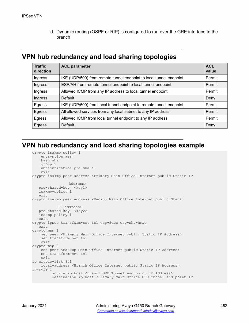
d. Dynamic routing (OSPF or RIP) is configured to run over the GRE interface to thebranch
VPN hub redundancy and load sharing topologiesTrafficdirection
ACL parameter ACLvalue
Ingress IKE (UDP/500) from remote tunnel endpoint to local tunnel endpoint PermitIngress ESP/AH from remote tunnel endpoint to local tunnel endpoint PermitIngress Allowed ICMP from any IP address to local tunnel endpoint PermitIngress Default DenyEgress IKE (UDP/500) from local tunnel endpoint to remote tunnel endpoint PermitEgress All allowed services from any local subnet to any IP address PermitEgress Allowed ICMP from local tunnel endpoint to any IP address PermitEgress Default Deny
VPN hub redundancy and load sharing topologies examplecrypto isakmp policy 1 encryption aes hash sha group 2 authentication pre-share exitcrypto isakmp peer address <Primary Main Office Internet public Static IP Address> pre-shared-key <key1> isakmp-policy 1 exitcrypto isakmp peer address <Backup Main Office Internet public Static IP Address> pre-shared-key <key2> isakmp-policy 1 exitcrypto ipsec transform-set ts1 esp-3des esp-sha-hmac exitcrypto map 1 set peer <Primary Main Office Internet public Static IP Address> set transform-set ts1 exitcrypto map 2 set peer <Backup Main Office Internet public Static IP Address> set transform-set ts1 exitip crypto-list 901 local-address <Branch Office Internet public Static IP Address>ip-rule 1 source-ip host <Branch GRE Tunnel end point IP Address> destination-ip host <Primary Main Office GRE Tunnel end point IP
IPSec VPN
January 2021 Administering Avaya G450 Branch Gateway 482Comments on this document? [email protected]

Address>protect crypto map 1 exitip-rule 2 source-ip host <Branch GRE Tunnel end point IP Address> destination-ip host <Backup Main Office GRE Tunnel end point IP Address>protect crypto map 2 exit exitip access-control-list 301 ip-rule 30 source-ip any destination-ip any ip-protocol udp udp destination-port eq Ike composite-operation Permit exit ip-rule 31 source-ip any destination-ip any ip-protocol udp udp destination-port eq Ike-nat-t composite-operation permit exit ip-rule 32 source-ip any destination-ip any ip-protocol udp udp destination-port eq Ike-nat-t-vsu composite-operation permit exit ip-rule 40 source-ip any destination-ip any ip-protocol esp composite-operation Permit exit ip-rule 50 source-ip any destination-ip host <Branch Office Public Internet Static IP Address> ip-protocol icmp composite-operation Permit exit ip-rule 60 source-ip any destination-ip any composite-operation Permit exit ip-rule 70 source-ip host <Backup Main Office GRE Tunnel end point IP Address> destination-ip host <Branch GRE Tunnel end point IP Address> composite-operation Permit exit ip-rule default composite-operation deny exit exit
Typical failover applications
January 2021 Administering Avaya G450 Branch Gateway 483Comments on this document? [email protected]

ip access-control-list 302 ip-rule 30 source-ip any destination-ip any ip-protocol udp udp destination-port eq Ike composite-operation Permit exit ip-rule 31 source-ip any destination-ip any ip-protocol udp udp destination-port eq Ike-nat-t composite-operation permit exit ip-rule 32 source-ip any destination-ip any ip-protocol udp udp destination-port eq Ike-nat-t-vsu composite-operation permit exit ip-rule 40 source-ip any destination-ip any ip-protocol esp composite-operation Permit exit ip-rule 50 source-ip any destination-ip any ip-protocol icmp exit ip-rule 60 source-ip host <Branch GRE Tunnel end point IP Address> destination-ip host <Primary Main Office GRE Tunnel end point IP Address> composite-operation Permit exit ip-rule 70 source-ip host <Branch GRE Tunnel end point IP Address> destination-ip host <Backup Main Office GRE Tunnel end point IP Address> composite-operation Permit exit ip-rule default composite-operation deny exit exit interface vlan 1 description “VoIP_VLAN” ip address <branch voice subnet IP address> <branch voice subnet mask> icc-vlan pmi exitinterface vlan 2 description “DATA_VLAN” ip address <branch data subnet IP address> <branch data subnet mask> exitinterface fastethernet 10/3 encapsulation pppoe
IPSec VPN
January 2021 Administering Avaya G450 Branch Gateway 484Comments on this document? [email protected]

traffic-shape rate 256000 ip address <Branch Office Internet public Static IP Address> <Branch Office Internet public net mask>ip crypto-group 901 ip access-group 301 in ip access-group 302 out exitinterface Tunnel 1!! The following two backup commands specify redundant mode.! To specify load-sharing mode, omit them. !backup interface tunnel 2 backup delay 20 15 keepalive 10 3 tunnel source <Branch GRE Tunnel end point IP Address> tunnel destination <Primary MainPrimary Main Office GRE Tunnel end point IP Address> ip address 10.10.10.1 255.255.255.252 exitinterface Tunnel 2 keepalive 10 3 tunnel source <Branch GRE Tunnel end point IP Address> tunnel destination <Backup Main Office GRE Tunnel end point IP Address> ip address 20.20.20.1 255.255.255.252 exitip route <Primary Main Offfice GRE Tunnel end point IP Address> 255.255.255.255 FastEthernet 10/3 highip route <Backup Main Offfice GRE Tunnel end point IP Address> 255.255.255.255 FastEthernet 10/3 highrouter ospf network 10.10.10.0 0.0.0.3 area 0.0.0.0 network 20.20.20.0 0.0.0.3 area 0.0.0.0 exit
Failover using DNSThe VPN DNS topology provides failover by utilizing the DNS resolver feature.
Use this feature when your DNS server supports failover through health-checking of redundanthosts. On your DNS server configure a hostname to translate to two or more redundant hosts,which act as redundant VPN peers. On the Branch Gateway configure that hostname as yourremote peer. The Gateway will perform a DNS query in order to resolve the hostname to an IPaddress before establishing an IKE connection. Your DNS server should be able to provide an IPaddress of a living host. The Branch Gateway will perform a new DNS query and try to re-establish the VPN connection to the newly provided IP address whenever it senses that thecurrently active remote peer stops responding. The Branch Gateway can sense that a peer isdead when IKE negotiation times-out through DPD keepalives and through object tracking.
Typical failover applications
January 2021 Administering Avaya G450 Branch Gateway 485Comments on this document? [email protected]

VPN DNS topology
Note:
For an explanation of DNS resolver, see DNS resolver on page 73.
Configuring the VPN DNS topologyProcedure
1. Define the private VLAN1 and VLAN2 interfaces (IP address and mask), and define one ofthem as the PMI and ICC-VLAN.
2. Define the public FastEthernet10/3 interface (IP address and mask).
3. Define the default gateway (the IP of the next router).
4. Define the DNS name-server-list and the IP address of the DNS server.
Note:
Alternatively, you can use DHCP Client or PPPoE to dynamically learn the DNSserver’s IP address. Use the ip dhcp client request command when usingDHCP client, or use the ppp ipcp dns request command when using PPPoE.
5. Define the ISAKMP policy, using the crypto isakmp policy command.
IPSec VPN
January 2021 Administering Avaya G450 Branch Gateway 486Comments on this document? [email protected]

6. Define the remote peer with FQDN, using the crypto isakmp peer addresscommand, including:
• the pre-shared key• the ISAKMP policy
7. Define the IPSEC transform-set, using the crypto ipsec transform-set command.
8. Define the crypto map, using the crypto map command.
9. Define the crypto list as follows:
a. Set the local address to the public interface name (for example, FastEthernet 10/3.0)b. For each private interface, define an ip-rule using the following format:
• source-ip <private subnet> <private subnet wild card mast>. For example,10.10.10.0 0.0.0.255
• destination-ip any• protect crypto map 1
10. Define the ingress access control list (ACL) to protect the device from Incoming traffic fromthe public interface, as follows:
a. Permit DNS traffic to allow clear (unencrypted) DNS trafficb. Permit IKE Traffic (UDP port 500) for VPN control traffic (IKE)c. Permit ESP traffic (IP Protocol ESP) for VPN data traffic (IPSEC)d. Permit ICMP traffic, to support PMTU application support, for a better fragmentation
processe. For each private subnet, add a permit rule, with the destination being the private
subnet and the source being any.
This traffic will be allowed only if it tunnels under the VPN, because of the crypto list.f. Define all other traffic (default rule) as deny in order to protect the device from non-
secure traffic
11. Define the egress access control list to protect the device from sending traffic that is notallowed to the public interface (optional):
a. Permit DNS traffic to allow clear (unencrypted) DNS trafficb. Permit IKE Traffic (UDP port 500) for VPN control traffic (IKE)c. Permit ESP traffic (IP Protocol ESP) for VPN data traffic (IPSEC)d. Permit ICMP traffic, to support PMTU application support, for a better fragmentation
processe. For each private subnet, add a permit rule, with the source being the private subnet,
and the destination being anyf. Define all other traffic (default rule) as deny in order to protect the device from sending
non-secure traffic
Typical failover applications
January 2021 Administering Avaya G450 Branch Gateway 487Comments on this document? [email protected]

12. Activate the crypto list, the ingress access control list, and the egress access control list,on the public interface.
VPN DNS topology example! ! Define the Private Subnet1 !interface vlan 1 description “Branch Subnet1” ip address 10.0.10.1 255.255.255.0 icc-vlan pmi exit! ! Define the Private Subnet2!interface vlan 2 description “Branch Subnet2” ip address 10.0.20.1 255.255.255.0 exit! ! Define the Public Subnet !interface fastethernet 10/3 ip address 100.0.0.2 255.255.255.0 exit!! Define the default gateway to be on the public subnet !ip default-gateway 100.0.0.1 !! Define the DNS name server ! that is accessible without VPN.!ip domain name-server-list 1 name-server 1 123.124.125.126 exit!! Define the IKE Entity !crypto isakmp policy 1 encryption aes hash sha group 2 authentication pre-share exit!! Define the remote peer as FQDN (DNS Name) !crypto isakmp peer fqdn main-vpn.avaya.com pre-shared-key <key1> isakmp-policy 1 exit!! Define the IPSEC Entity !crypto ipsec transform-set ts1 esp-3des esp-sha-hmac exit
IPSec VPN
January 2021 Administering Avaya G450 Branch Gateway 488Comments on this document? [email protected]

!! Define the VPN Tunnel ! crypto map 1 set peer main-vpn.avaya.com set transform-set ts1 exit!! Define the crypto list for the public interface!ip crypto-list 901 local-address “Fast Ethernet 10/3.0” !! ip-rule 5 allows un-encrypted traffic for DNS! ip-rule 5 source-ip any destination-ip 123.124.125.126 no protect exit ip-rule 10 source-ip 10.0.10.0 0.0.0.255 destination-ip any protect crypto map 1 exit ip-rule 20 source-ip 10.0.20.0 0.0.0.255 destination-ip any protect crypto map 1 exit exit!! Define the Ingress access control list for the public interface!ip access-control-list 301 ip-rule 5 source-ip any destination-ip any ip-protocol udp udp destination-port eq Dns composite-operation Permit exit ip-rule 10 source-ip any destination-ip any ip-protocol udp udp destination-port eq Ike composite-operation Permit exit ip-rule 11 source-ip any destination-ip any ip-protocol udp udp destination-port eq Ike-nat-t composite-operation permit exit ip-rule 12 source-ip any destination-ip any ip-protocol udp udp destination-port eq Ike-nat-t-vsu composite-operation permit exit ip-rule 20
Typical failover applications
January 2021 Administering Avaya G450 Branch Gateway 489Comments on this document? [email protected]

source-ip any destination-ip any ip-protocol esp composite-operation Permit exit ip-rule 30 source-ip any destination-ip any ip-protocol icmp composite-operation Permit exit ip-rule 40 source-ip any destination-ip 10.0.10.0 0.0.0.255 composite-operation Permit exit ip-rule 50 source-ip any destination-ip 10.0.20.0 0.0.0.255 composite-operation Permit exit ip-rule default composite-operation deny exit exit!! Define the Egress access control list for the public interface!ip access-control-list 302 ip-rule 5 source-ip any destination-ip any ip-protocol udp udp destination-port eq dns composite-operation Permit exit ip-rule 10 source-ip any destination-ip any ip-protocol udp udp destination-port eq Ike composite-operation Permit exit ip-rule 11 source-ip any destination-ip any ip-protocol udp udp destination-port eq Ike-nat-t composite-operation permit exit ip-rule 12 source-ip any destination-ip any ip-protocol udp udp destination-port eq Ike-nat-t-vsu composite-operation permit exit ip-rule 20 source-ip any destination-ip any ip-protocol esp composite-operation Permit exit ip-rule 30 source-ip any
IPSec VPN
January 2021 Administering Avaya G450 Branch Gateway 490Comments on this document? [email protected]

destination-ip any ip-protocol icmp composite-operation Permit exit ip-rule 40 source-ip 10.0.10.0 0.0.0.255 destination-ip any composite-operation Permit exit ip-rule 50 source-ip 10.0.20.0 0.0.0.255 destination-ip any composite-operation Permit exit ip-rule default composite-operation deny exit exit! ! Activate the crypto list and the access control list on the public interface!interface fastethernet 10/3 ip crypto-group 901 ip access-group 301 in ip access-group 302 out exit
Failover using a peer-groupThe failover VPN topology utilizes a peer-group which lists a group of redundant peers. At anypoint in time, only one peer is active and acting as the remote peer. An object tracker monitors thestate of the active peer. If the active peer is presumed dead, the next peer in the peer-groupbecomes the active remote peer. For more information on object trackers, see Object tracking onpage 263.
Typical failover applications
January 2021 Administering Avaya G450 Branch Gateway 491Comments on this document? [email protected]

Failover VPN topology using a peer-group
Configuring the failover VPN topology using a peer-group1. Define the private VLAN1 and VLAN2 interfaces (IP address and mask), and define one of
them as the PMI and ICC-VLAN.2. Define the public FastEthernet 10/3 interface (IP address and mask).3. Define the default gateway (the IP address of the next router).4. Define the object tracking configuration, and define when an object tracker is considered
down, as follows:
Define a track list that will monitor (by ICMP) five hosts behind the specific peer. If two ormore hosts are not working then the object tracker is down. The Branch Gateway will thenpass on to the next peer in the peer group list.
5. Define the ISAKMP policy, using the crypto isakmp policy command.
6. Define the 3 remote peers, using the crypto isakmp peer address command, andspecify for each one:
• the pre-shared key• the ISAKMP policy• keepalive track. This track is the object tracker that checks if the peer is still alive. If an
active peer is considered dead, the next peer in the peer group becomes the activepeer.
7. Define a peer group that include all three remote peers, using the crypto isakmppeer-group command.
IPSec VPN
January 2021 Administering Avaya G450 Branch Gateway 492Comments on this document? [email protected]

8. Define the IPSEC transform-set, using the crypto ipsec transform-set command.
9. Define the Crypto map entity, using the crypto map command.
10. Define the crypto list as follows:
a. Set the local address to the public interface name (for example, FastEthernet 10/3.0).b. For each private interface, define an ip-rule using the following format:
• source-ip <private subnet> <private subnet wild card mast>. For example,10.10.10.0 0.0.0.255
• destination-ip any• protect crypto map 1
11. Define the ingress access control list to protect the device from incoming traffic from thepublic interface, as follows:
a. Permit IKE Traffic (UDP port 500) for VPN control traffic (IKE)
Note:
If you are using NAT Traversal, you must also open UDP port 4500 and 2070.b. Permit ESP traffic (IP Protocol ESP) for VPN data traffic (IPSEC)c. Permit ICMP traffic, to support PMTU application support, for a better fragmentation
processd. For each private subnet, add a permit rule, with the destination being the private
subnet, and the source being any. This traffic will be allowed only if it tunnels underthe VPN, because of the crypto list.
e. Define all other traffic (default rule) as deny in order to protect the device from non-secure traffic
12. Optionally, define the egress access control list to protect the device from sending trafficthat is not allowed to the public interface:
a. Permit IKE Traffic (UDP port 500) for VPN control traffic (IKE)
Note:
If you are using NAT Traversal, you also need to open UDP port 4500 and 2070.b. Permit ESP traffic (IP Protocol ESP) for VPN data traffic (IPSEC)c. Permit ICMP traffic, to support the PMTU application, for a better fragmentation
processd. For each private subnet add a permit rule, with the source being the private subnet,
and the destination being anye. Define all other traffic (default rule) as deny in order to protect the device from sending
non-secure traffic13. Activate the crypto list, the ingress access control list, and the egress access control list,
on the public interface.
Typical failover applications
January 2021 Administering Avaya G450 Branch Gateway 493Comments on this document? [email protected]

Failover VPN topology using a peer-group example! ! Define the Private Subnet1 !interface vlan 1 description “Branch Subnet1” ip address 10.0.10.1 255.255.255.0 icc-vlan pmi exit! ! Define the Private Subnet2!interface vlan 2 description “Branch Subnet2” ip address 10.0.20.1 255.255.255.0 exit! ! Define the Public Subnet !interface fastethernet 10/3 ip address 100.0.0.2 255.255.255.0 exit!! Define the default gateway the public interfce !ip default-gateway 100.0.0.1 !! We wish to check 5 hosts in the Corporate intranet behind the current VPN ! remote peer, and if 2 or more hosts don’t work then keepalive-track will fail , ! and we will move to the next peer in the peer-group!rtr 1 type echo protocol ipIcmpEcho <host1 IP> exitrtr-schedule 1 start-time now life foreverrtr 2 type echo protocol ipIcmpEcho <host2 IP> exitrtr-schedule 2 start-time now life foreverrtr 3 type echo protocol ipIcmpEcho <host3 IP> exitrtr-schedule 3 start-time now life foreverrtr 4 type echo protocol ipIcmpEcho <host4 IP> exitrtr-schedule 4 start-time now life foreverrtr 5 type echo protocol ipIcmpEcho <host5 IP> exitrtr-schedule 5 start-time now life forevertrack 11 rtr 1 exittrack 12 rtr 2 exittrack 13 rtr 3 exittrack 14 rtr 4
IPSec VPN
January 2021 Administering Avaya G450 Branch Gateway 494Comments on this document? [email protected]

exittrack 15 rtr 5 exit track 1 list threshold count threshold count up 5 down 3 object 11 object 12 object 13 object 14 object 15 exit!! Define the IKE Entity !crypto isakmp policy 1 encryption aes hash sha group 2 authentication pre-share exit! Define the remote peers (3 main offices)!crypto isakmp peer address <First Main Office VPN address> pre-shared-key <key1> isakmp-policy 1 keepalive-track 1 exitcrypto isakmp peer address <Second Main Office VPN address> pre-shared-key <key2> isakmp-policy 1 keepalive-track 1 exitcrypto isakmp peer address <Third Main Office VPN address> pre-shared-key <key3> isakmp-policy 1 keepalive-track 1 exitcrypto isakmp peer-group main-hubs set peer <First Main Office VPN address> set peer <Second Main Office VPN address> set peer <Third Main Office VPN address> exit!! Define the IPSEC Entity !crypto ipsec transform-set ts1 esp-3des esp-sha-hmac exit!! Define the VPN Tunnel ! crypto map 1 set peer-group main-hubs set transform-set ts1 exit! Define the crypto list for the public interface! ip crypto-list 901 local-address “Fast Ethernet 10/3.0” ip-rule 10 source-ip 10.0.10.0 0.0.0.255 destination-ip any protect crypto map 1 exit ip-rule 20
Typical failover applications
January 2021 Administering Avaya G450 Branch Gateway 495Comments on this document? [email protected]

source-ip 10.0.20.0 0.0.0.255 destination-ip any protect crypto map 1 exit exit!! Define the Ingress access control list for the public interface!ip access-control-list 301 ip-rule 10 source-ip any destination-ip any ip-protocol udp udp destination-port eq Ike composite-operation Permit exit ip-rule 11 source-ip any destination-ip any ip-protocol udp udp destination-port eq Ike-nat-t composite-operation permit exit ip-rule 12 source-ip any destination-ip any ip-protocol udp udp destination-port eq Ike-nat-t-vsu composite-operation permit exit ip-rule 20 source-ip any destination-ip any ip-protocol esp composite-operation Permit exit ip-rule 30 source-ip any destination-ip any ip-protocol icmp composite-operation Permit exit ip-rule 40 source-ip any destination-ip 10.0.10.0 0.0.0.255 composite-operation Permit exit ip-rule 50 source-ip any destination-ip 10.0.20.0 0.0.0.255 composite-operation Permit exit ip-rule default composite-operation deny exit exit! Define the Egress access control list for the public interface!ip access-control-list 302 ip-rule 10 source-ip any destination-ip any ip-protocol udp udp destination-port eq Ike composite-operation Permit
IPSec VPN
January 2021 Administering Avaya G450 Branch Gateway 496Comments on this document? [email protected]

exit ip-rule 11 source-ip any destination-ip any ip-protocol udp udp destination-port eq Ike-nat-t composite-operation permit exit ip-rule 12 source-ip any destination-ip any ip-protocol udp udp destination-port eq Ike-nat-t-vsu composite-operation permit exit ip-rule 20 source-ip any destination-ip any ip-protocol esp composite-operation Permit exit ip-rule 30 source-ip any destination-ip any ip-protocol icmp composite-operation Permit exit ip-rule 40 source-ip 10.0.10.0 0.0.0.255 destination-ip any composite-operation Permit exit ip-rule 50 source-ip 10.0.20.0 0.0.0.255 destination-ip any composite-operation Permit exit ip-rule default composite-operation deny exit exit!! Activate the crypto list and the access control list on the public interface!interface fastethernet 10/3 ip crypto-group 901 ip access-group 301 in ip access-group 302 out exit
Checklist for configuring site-to-site IPSec VPNUse the following table to gather the information for simple Gateway site-to-site IPSec VPN.
Parameter Possible values Actual value1. Type of connection to the ISP • ADSL
• Cable Modem
Table continues…
Typical failover applications
January 2021 Administering Avaya G450 Branch Gateway 497Comments on this document? [email protected]

Parameter Possible values Actual value2. VPN Interface • FastEthernet10/3
• Serial port X/Y3. VPN Local IP Address Type:
• Static
– If static, provide:
IP Address
Mask
Next-hop Router
• Dynamic (DHCP/PPPoE)4. Coordinating with the VPN Remote peera.) VPN IKE (Control) Phase 1 Parameters— Encryption • des
• 3des
• aes
• aes-192
• aes-256— Authentication Hash • sha
• md5— DH Group • 1
• 2
• 5
• 14— Lifetime seconds • 60 to 86,400 default: 86,400 (1 day)b.) VPN IPSEC (Data) Phase 2 Parameters— Encryption • esp-des
• esp-3des
• esp-aes
• esp-aes-192
• esp-aes-256— Authentication Hash • esp-sha-hmac
• esp-md5-hmac— IP compression • enable (comp-lzs)
• disable
Table continues…
IPSec VPN
January 2021 Administering Avaya G450 Branch Gateway 498Comments on this document? [email protected]

Parameter Possible values Actual value— PFS Group • no pfs (default)
• 1
• 2
• 5
• 14— Lifetime seconds • 120 to 86,400 default: 3,600 (1 hour)— Lifetime kilobytes • 2,560 to 536,870,912 default:
4,608,000 kb
• disable5. Which packets should be secureda. Protect rules matching options • IP source address
• IP destination addressb. Bypass rules matching options • IP source address
• IP destination address
• udp
• tcp
• dscp
• fragment
• icmp
• IP protocol6. The remote peer (crypto isakmp peer) parametersa. Remote peer • IP address
• FQDN (dns name)b. Pre-shared key • 1 to 127 alphanumerical characters.
1 to 64 bytes in hexadecimal notation7. If the branch IP is dynamic
• If the branch IP is an initiator, setinitiate mode to none (device is aresponder)
• If the branch IP is a responder, setinitiate mode to aggressive (device isan initiator)
• Set self identity to identify the devicein the remote peer
Typical failover applications
January 2021 Administering Avaya G450 Branch Gateway 499Comments on this document? [email protected]

Summary of VPN commandsFor more information about these commands, see the Avaya Branch Gateway G450 CLIReference.
Root level command First levelcommand
Second levelcommand
Description
clear cryptoisakmp
Flush a specific ISAKMP SA or allthe ISAKMP SAs
clear crypto sa Clear all or specific IPSec SAsclear crypto sacounters
Clear the crypto SA counters
crypto ipsec nat-transparency udp-encapsulation
Re-enable NAT Traversal if it wasdisabled
crypto ipsectransform-set
Enter the IKE phase 2 (IPSec)transform-set context and create oredit IPSec parameters for the VPNtunnel
mode Set security-association lifetimeset pfs Specify whether each IKE phase 2
negotiation will employ PFS and, ifyes, which Diffie-Hellman group toemploy
set security-associationlifetime
Set the IKE phase 2 (IPSec) SAlifetime
crypto isakmpinvalid-spi-recovery
Enable invalid SPI recovery (defaultsetting)
crypto isakmp natkeepalive
Re-enable NAT Traversal keepaliveif it was disabled, and configure thekeepalive interval. This commandkeeps the NAT devices tablesupdated.
crypto isakmp peer Enter the crypto ISAKMP peercontext and create or edit anISAKMP peer
continuous-channel
Enable continuous-channel IKE,which keeps the IKE phase1 sessionalways up and running, even if thereis no traffic
Table continues…
IPSec VPN
January 2021 Administering Avaya G450 Branch Gateway 500Comments on this document? [email protected]

Root level command First levelcommand
Second levelcommand
Description
description Enter a description for the ISAKMPpeer
initiate mode Specify which IKE Phase-1 mode touse when communicating with thepeer: aggressive or none
isakmp- policy Set the ISAKMP policy for theISAKMP peer
keepalive Enable DPD keepalives that checkwhether the remote peer is up
keepalive-track
Bind an object tracker to a remoteVPN peer or to an interface, tocheck whether the remote peer orthe interface is up
pre-shared- key Configure the IKE pre-shared keyself- identity Set the identity of this devicesuggest-key Generate a random string which you
can use as a pre-shared key for IKE.You must use the same key on bothpeers.
crypto isakmppeer-group
Enter the crypto ISAKMP peer-groupcontext and create or edit anISAKMP peer group
description Enter a description for the ISAKMPpeer group
set peer Add a peer to the peer-groupcrypto isakmppolicy
Enter the crypto ISAKMP policycontext and create or edit IKE Phase1 parameters
authentication Set the authentication of ISAKMPpolicy to pre-shared secret
description Enter a description for the ISAKMPpolicy
encryption Set the encryption algorithm for anISAKMP policy
group Set the Diffie-Hellman group for anISAKMP policy
hash Set the hash method for an ISAKMPpolicy
lifetime Set the lifetime of the ISAKMP SA inseconds
Table continues…
Typical failover applications
January 2021 Administering Avaya G450 Branch Gateway 501Comments on this document? [email protected]
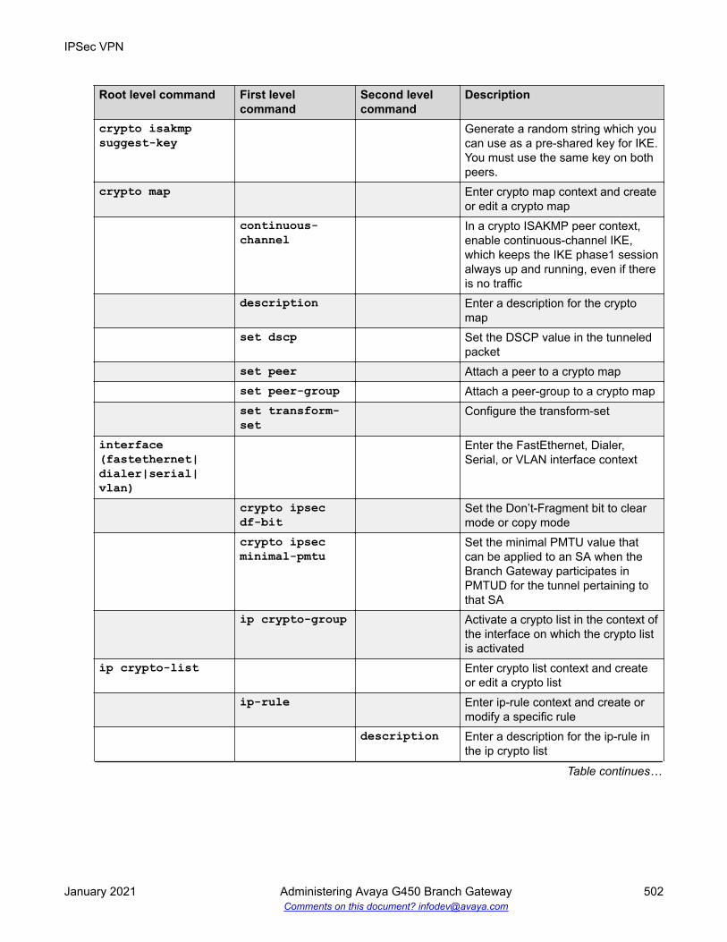
Root level command First levelcommand
Second levelcommand
Description
crypto isakmpsuggest-key
Generate a random string which youcan use as a pre-shared key for IKE.You must use the same key on bothpeers.
crypto map Enter crypto map context and createor edit a crypto map
continuous-channel
In a crypto ISAKMP peer context,enable continuous-channel IKE,which keeps the IKE phase1 sessionalways up and running, even if thereis no traffic
description Enter a description for the cryptomap
set dscp Set the DSCP value in the tunneledpacket
set peer Attach a peer to a crypto mapset peer-group Attach a peer-group to a crypto mapset transform-set
Configure the transform-set
interface(fastethernet|dialer|serial|vlan)
Enter the FastEthernet, Dialer,Serial, or VLAN interface context
crypto ipsecdf-bit
Set the Don’t-Fragment bit to clearmode or copy mode
crypto ipsecminimal-pmtu
Set the minimal PMTU value thatcan be applied to an SA when theBranch Gateway participates inPMTUD for the tunnel pertaining tothat SA
ip crypto-group Activate a crypto list in the context ofthe interface on which the crypto listis activated
ip crypto-list Enter crypto list context and createor edit a crypto list
ip-rule Enter ip-rule context and create ormodify a specific rule
description Enter a description for the ip-rule inthe ip crypto list
Table continues…
IPSec VPN
January 2021 Administering Avaya G450 Branch Gateway 502Comments on this document? [email protected]

Root level command First levelcommand
Second levelcommand
Description
destination-ip
Specify the destination IP address ofpackets to which the current ruleapplies
protectcrypto map
Protect traffic that matches this ruleby applying the IPSec processingconfigured by the specific cryptomap
source-ip Indicate that the current rule appliesto packets from the specified sourceIP address
local-address Set the local IP address for theIPSec tunnels derived from thiscrypto list
show crypto ipsecsa
Display the IPSec SA database andrelated runtime, statistical, andconfiguration information
Note:
The detail option in thevarious show crypto ipsecsa commands, providesdetailed counters informationon each IPSec SA. To pinpointthe source of a problem, it isuseful to check for a counterwhose value grows with time.
show crypto ipsectransform-set
Display the configuration for thespecified transform-set or alltransform-sets
show crypto isakmppeer
Display crypto ISAKMP peerconfiguration
show crypto isakmppeer-group
Display crypto ISAKMP peer-groupconfiguration
show crypto isakmppolicy
Display ISAKMP policy configuration
show crypto isakmpsa
Display the ISAKMP SA databasestatus
show crypto map Display all or specific crypto mapconfigurations
show ip active-lists
Display information about a specificpolicy list or all lists
Table continues…
Typical failover applications
January 2021 Administering Avaya G450 Branch Gateway 503Comments on this document? [email protected]

Root level command First levelcommand
Second levelcommand
Description
show ip crypto-list
Display all or specific crypto listconfigurations
IPSec VPN
January 2021 Administering Avaya G450 Branch Gateway 504Comments on this document? [email protected]

Chapter 22: Policy lists
Policy lists enable you to control the ingress and egress of traffic to a router or port. You can usepolicies to manage security, determine packet priority through an interface, implement quality ofservice, or determine routing for a specific application or user. Each policy list consists of a set ofrules determining the behavior of a packet entering or leaving the interface on which the list isapplied.
Note:
Policy lists are supported on IPv4 only.
Types of policy listsThere are various policy lists on the Branch Gateway, including access control lists, QoS lists, andPolicy-based routing.
Access control listsAccess lists include the following:
Global rules: A set of rules that are executed before the list is evaluated.
Rule list: A list of filtering rules that determine the action taken by Branch Gateway. These actionsare pointers to the composite operation table.
Actions (composite operation table): A table that describes actions to be performed when apacket matches a rule. The table includes predefined actions, such as permit and deny. Toconfigure more complex rules, see Composite operations on page 519.
Access control list rule specificationsYou can use access control lists to control which packets are authorized to pass through aninterface. When a packet matches a rule on the access control list, the rule specifies whether theBranch Gateway:
• Accepts the packet or drops the packet.
• Sends an ICMP error reply if it drops the packet.
January 2021 Administering Avaya G450 Branch Gateway 505Comments on this document? [email protected]

• Sends an SNMP trap if it drops the packet.
Network security using access control listsThe primary use of access control lists is to act as a component of network security. You can useaccess control lists to determine which applications, networks, and users can access hosts onyour network. Also, you can restrict internal users from accessing specific sites or applicationsoutside the network. Access control lists can be based on permitting or denying specific values orgroups of IP addresses, protocols, ports, IP fragments, or DSCP values. The following figureillustrates how access control lists are used to control traffic into and out of your network:
QoS listsYou can use QoS lists to change the DSCP and Ethernet IEEE 802.1p CoS fields in packets.Changing these fields adjusts the priority of packets meeting the criteria of the QoS list. DSCPvalues are mapped to a CoS value. Rules can be created determining the priority behavior ofeither individual DSCP values or CoS values, and can be based on specific values or groups of IPaddresses, protocols, ports, IP fragments, or DSCP values. When a packet matches a rule on theQoS list, the Branch Gateway sets one or both of the QoS fields in the packet. See Allowed valueson QoS fields on page 507.
Each QoS list also includes a DSCP table. The DSCP table enables you to set one or both of theQoS fields in a packet, based on the previous value of the DSCP field in the packet.
Policy lists
January 2021 Administering Avaya G450 Branch Gateway 506Comments on this document? [email protected]

QoS list partsRule list: A list of filtering rules and actions for the Branch Gateway to take when a packetmatches the rule. Match actions on this list are pointers to the composite operation table.
Actions (composite operation table): A table that describes actions to be performed when apacket matches a rule. The table includes pre-defined actions, such as permit and deny. You canconfigure more complex rules. Refer to Composite operations on page 519.
DSCP map: A table that contains DSCP code points and match action pairs. Match actions arepointers to the composite operation table. Refer to DSCP table on page 522.
Allowed values on QoS fieldsLayer QoS field Allowed values2 802.1p 0–73 DSCP 0–63
Use of policy-based routingYou can use policy-based routing to determine the routing path a packet takes based on the typeof packet, or the packet’s source or destination IP addresses, or its DSCP field. This enables youto route different types of traffic over different routes or interfaces. For example, you use policy-based routing to route voice traffic over a WAN interface and data traffic over the Internet. Policy-based routing is implemented by means of policy-based routing (PBR) lists. PBR lists are similarin many respects to access control lists and QoS lists. However, since there are also some keydifferences, policy-based routing is explained in a separate chapter. Refer to Policy-based routingsection.
Policy list managementYou can manage policy lists on the Branch Gateway with CLI commands. You can also managepolicy lists throughout your network with Avaya QoS Manager. Avaya QoS Manager is part ofAvaya Integrated Management. The following figure illustrates the operation of policy lists on theBranch Gateway:
Policy list management
January 2021 Administering Avaya G450 Branch Gateway 507Comments on this document? [email protected]

Policy list configurationYou can create and edit policy lists, and define the list identification attributes. You can also deletean unnecessary policy list.
Creating or editing a policy listProcedureTo create or edit a list, do one of the following tasks:
• To create or edit a policy list, enter the context of the list.
If the list already exists, you can edit the list from the list context. If the list does not exist,entering the list context creates the list.
• To create or edit an access control list, enter ip access-control-list followed by a listnumber in the range 300-399. The Branch Gateway includes one pre-configured access controllist. The pre-configured access control list is list number 300.
For example, to create access control list 301, enter the following command:ip access-control-list 301
• To create or edit a QoS list, enter ip qos-list followed by a list number in the range400-499. The Branch Gateway includes one pre-configured QoS list. The pre-configured QoSlist is list number 400.
For example, to create a new QoS list 401, enter the following command:ip qos-list 401
Policy lists
January 2021 Administering Avaya G450 Branch Gateway 508Comments on this document? [email protected]

Creating a list based on an existing listProcedure
1. To create a new policy list based on an existing list, use the ip policy-list-copycommand followed by the name of the list from which you want to copy.
The source and destination lists must be of the same type. For example, you cannot copyan access control list to a QoS list.
The following example creates a new access control list, number 340, based on accesscontrol list 330. You can then enter the context of access control list 340 to modify it.Gxxx-001(super)# ip policy-list-copy 330 340Done!
2. Once you have entered the list context, you can perform the following actions:
• Configure rules - see Policy rule configuration on page 514
• Configure composite operations - see Composite operations on page 519
• Configure DSCP mapping (QoS lists only) - see DSCP table on page 522
Defining list identification attributesAbout this taskThe policy list attributes including name, owner, and cookie, are used by Avaya QoS Managersoftware to identify policy lists.
Procedure1. Enter the context of the policy list in which you want to define the attribute.
2. Enter one of the following commands, followed by a text string or integer:
• name• owner• cookie
3. To set a policy list attribute to its default setting, use the no form of the appropriatecommand.
For example, to set a list to its default name, use the command no name.
4. To view the attributes, use the show list command in the context of the list.
Policy list configuration
January 2021 Administering Avaya G450 Branch Gateway 509Comments on this document? [email protected]

Policy list attributesCommand Descriptionname Defines a list name (text string). The default value is owner.owner Defines a list owner (text string). The default value is list#
<listnumber>.cookie Defines a list cookie (integer). The Avaya QoS Manager uses the
cookie attribute internally. Normally, you should not change thisattribute.
show list View the attributes.
Default actionsWhen no rule matches a packet, the Branch Gateway applies the default action for the list. Thefollowing table shows the default action for each type of policy list:
List Default actionAccess control list Accept all packetsQoS list No change to the priority or DSCP
Deleting a policy listProcedureTo delete a list, enter one of the following commands:
• To delete an access control list, enter no ip access-control-list followed by the numberof the list you want to delete.
• To delete a QoS list, enter no ip qos-list followed by the number of the list you want todelete.
Policy list attachmentsAttached to each interface on the Branch Gateway are policy lists, including the ingress accesscontrol list, ingress QoS list, egress access control list, and egress QoS list.
Note:
You can also attach PBR lists to certain interfaces, but PBR lists are not attached to anyinterface by default.
Policy lists
January 2021 Administering Avaya G450 Branch Gateway 510Comments on this document? [email protected]

Packets entering the interfaceWhen a packet enters the Branch Gateway through an interface, the Branch Gateway applies thepolicy lists in the following order:
1. Apply the ingress access control list.
2. If the ingress access control list does not drop the packet:
• Apply the ingress QoS list.
• Apply the PBR list (if any).
The packet enters the Branch Gateway through the interface.
Packets exiting the interfaceWhen a packet exits the Branch Gateway through an interface, the Branch Gateway applies thepolicy lists in the following order:
1. Apply the egress access control list.
2. If the egress access control list does not drop the packet, apply the egress QoS list.
The packet exits the Branch Gateway through the interface.
Policy lists to packetsThe following figure illustrates the order in which the Branch Gateway applies policy lists topackets.
Policy list attachment configurationYou can configure which policy lists are attached to each interface. You can choose:
• The ingress access control list and the egress access control list from among the accesscontrol lists that are configured on the Branch Gateway.
Policy list attachments
January 2021 Administering Avaya G450 Branch Gateway 511Comments on this document? [email protected]

• The ingress QoS list and the egress QoS list from among the QoS lists that are configured onthe Branch Gateway.
Attaching policy lists and access control listsProcedureChoose one of the following commands:
• To attach an access control list to an interface as its ingress access control list, enter theinterface context and enter ip access-group list number in.
• To attach an access control list to an interface as its egress access control list, enter theinterface context and enter ip access-group list number out.
Attaching policy lists and QoS listsProcedureChoose one of the following commands:
• To attach a QoS list to an interface as its ingress QoS list, enter the interface context and enterip qos-group list number in.
• To attach an access control list to an interface as its egress QoS list, enter the interface contextand enter ip qos-group list number out.
For example, the following sequence of commands attach policy lists to the VLAN 2 interface.Access control list 301 becomes the ingress access control list for VLAN 2. QoS list 401 becomesthe egress QoS list for VLAN 2.Gxxx-001# interface vlan 2Gxxx-001(if:VLAN 2)# ip access-group 301 inDone!Gxxx-001(if:VLAN 2)# ip qos-group 401 outDone!
Removing a listProcedureTo remove a list from an interface, use the no form of the appropriate command.
For example, if the ingress access control list for the VLAN 1 interface is list number 302, you canremove the list from the interface by entering the following commands:Gxxx-001(super)# interface vlan 1Gxxx-001(super-if:VLAN 1)# no ip access-group inDone!
Policy lists
January 2021 Administering Avaya G450 Branch Gateway 512Comments on this document? [email protected]

Note:
You cannot change or delete a default list. You cannot change or delete any list when it isattached to an interface. In order to change or delete a list that is attached to an interface, youmust first remove the list from the interface. You can then change or delete the list. Afterchanging the list, you can reattach the list to the interface.
Device-wide policy listsYou can attach a policy list (other than a policy-based routing list) to every interface on the BranchGateway using one command. To do this, attach a list to the Loopback 1 interface. For moreinformation, see Policy list attachments on page 510.
Note:
If you attach a policy list to a Loopback interface other than Loopback 1, the policy list has noeffect.
When you attach a policy list to the Loopback 1 interface, thereby creating a device-wide policylist, and you also attach policy lists to specific interfaces, the Branch Gateway applies the lists inthe following order:
• Incoming packets:
1. Apply the ingress policy lists that are attached to the interface
2. Apply the device-wide ingress policy lists
• Outgoing packets:
1. Apply the device-wide egress policy lists
2. Apply the egress policy lists that are attached to the interface
Defining global rulesAbout this taskIn an access control list, you can define global rules for packets that contain IP fragments and IPoptions. These rules apply to all packets. This is in contrast to individual rules, which apply topackets that match certain defined criteria. See Policy rule configuration on page 514.The Branch Gateway applies global rules before applying individual rules.
Procedure1. Enter the context of the access control list in which you want to define the rule.
Device-wide policy lists
January 2021 Administering Avaya G450 Branch Gateway 513Comments on this document? [email protected]

2. Enter one of the following commands, followed by the name of a composite command:
• ip-fragments-in. Applies to incoming packets that contain IP fragments
• ip-option-in. Applies to incoming packets that contain IP options
ResultThe composite command can be any command defined in the composite operation list. Thesecommands are case-sensitive. To view the composite operation list for the access control list youare working with, use the command show composite-operation in the context of the accesscontrol list.ExampleThe following example defines a rule in access control list 301 that denies access to all incomingpackets that contain IP fragments:Gxxx-001(super)# ip access-control-list 301Gxxx-001(super/ACL 301)# ip-fragments-in DenyDone!
Policy rule configurationYou can configure policy rules to match packets based on one or more of the following criteria:
• Source IP address, or a range of addresses
• Destination IP address, or a range of addresses
• IP protocol, such as TCP, UDP, ICMP, or IGMP
• Source TCP or UDP port or a range of ports
• Destination TCP or UDP port or a range of ports
• ICMP type and code
• Fragment
• DSCP
Use IP wildcards to specify a range of source or destination IP addresses. The zero bits in thewildcard correspond to bits in the IP address that remain fixed. The one bits in the wildcardcorrespond to bits in the IP address that can vary. Note that this is the opposite of how bits areused in a subnet mask.
For access control lists, you can require the packet to be part of an established TCP session. Ifthe packet is a request for a new TCP session, the packet does not match the rule. You can alsospecify whether an access control list accepts packets that have an IP option field.
Policy lists
January 2021 Administering Avaya G450 Branch Gateway 514Comments on this document? [email protected]
Editing and creating rulesAbout this taskTo create or edit a policy rule, you must enter the context of the rule. If the rule already exists, youcan edit the rule from the rule context. If the rule does not exist, entering the rule context createsthe rule.
Procedure1. Enter the context of the list in which you want to create or edit a rule.
2. Enter ip-rule followed by the number of the rule you want to create or edit.
For example, to create rule 1, enter ip-rule 1.
Policy lists rule criteriaRules work in the following ways, depending on the type of list and the type of information in thepacket:
• Layer 4 rules in an access control list with a Permit operation are applied to non-initialfragments
• Layer 4 rules in an access control list with a Deny operation are not applied to non-initialfragments, and the device continues checking the next IP rule. This is to prevent cases inwhich fragments that belong to other L4 sessions may be blocked by the other L4 sessionwhich is blocked.
• Layer 3 rules apply to non-initial fragments
• Layer 3 rules that include the fragment criteria do not apply to initial fragments or non-fragment packets
• Layer 3 rules that do not include the fragment criteria apply to initial fragments and non-fragment packets
• Layer 4 rules apply to initial fragments and non-fragment packets
• Layer 3 and Layer 4 rules in QoS and policy-based routing lists apply to non-initial fragments
Specifying IP protocolProcedureTo specify the IP protocol to which the rule applies, enter ip-protocol followed by the name ofan IP protocol.
If you want the rule to apply to all protocols, use any with the command. If you want the rule toapply to all protocols except for one, use the no form of the command, followed by the name ofthe protocol to which you do not want the rule to apply.
Policy rule configuration
January 2021 Administering Avaya G450 Branch Gateway 515Comments on this document? [email protected]

ExampleThe following command specifies the UDP protocol for rule 1 in QoS list 401:Gxxx-001(QoS 401/rule 1)# ip-protocol udp
The following command specifies any IP protocol except IGMP for rule 3 in access control list 302:Gxxx-001(ACL 302/ip rule 3)# no ip-protocol igmp
Specifying a range of IP addressesProcedureTo specify a range of source and destination IP addresses to which the rule applies, use thecommands source-ip and destination-ip, followed by the IP range criteria.
Choose one of the following options as the IP range criteria:
• To specify a range, type two IP addresses to set a range of IP addresses to which the ruleapplies
• To specify a single address, type host, followed by an IP address to set a single IP address towhich the rule applies
• To specify a wildcard, type host, followed by an IP address using wildcards to set a range of IPaddresses to which the rule applies
• To specify all addresses, type any to apply the rule to all IP addresses
Use the no form of the appropriate command to specify that the rule does not apply to the IPaddress or addresses defined by the command.
ExampleThe following command specifies a source IP address of 10.10.10.20 for rule 1 in access controllist 301:Gxxx-001(ACL 301/ip rule 1)# source-ip host 10.10.10.20
The following command allows any destination IP address for rule 3 in QoS list 404:Gxxx-001(QoS 404/rule 3)# destination-ip any
The following command specifies a source IP address in the range 10.10.0.0 through10.10.255.255 for rule 1 in access control list 301:Gxxx-001(ACL 301/ip rule 1)# source-ip 10.10.0.0 0.0.255.255
The following command specifies a source IP address outside the range 64.236.24.0 through64.236.24.255 for rule 7 in access control list 308:Gxxx-001(ACL 308/ip rule 7)# no source-ip 64.236.24.0 0.0.0.255
The following command specifies a source IP address in the range 64.<any>.24.<any> for rule 6in access control list 350:Gxxx-001(ACL 350/ip rule 6)# source-ip 64.*.24.*
Policy lists
January 2021 Administering Avaya G450 Branch Gateway 516Comments on this document? [email protected]

Specifying source and destination port rangeProcedure
1. To specify a range of source and destination ports to which the rule applies, use any of thefollowing commands followed by either port name or port number range criteria:
• tcp source-port• tcp destination-port• udp source-port• udp destination-port
This command also sets the IP protocol parameter to TCP or UDP.
For more information about these commands, see Summary of access control listcommands on page 526, Summary of QoS list commands on page 528, or Avaya CLIReference.
2. Select the port name or number range criteria using one of the following options:
• To set a range of port numbers to which the rule applies, type range, followed by twoport numbers.
• To set a port name or port number to which the rule applies, type eq (equal) followed bya port name or number.
• To apply the rule to all ports with a name or number greater than the specified name ornumber, type gt (greater than) followed by a port name or port number.
• To apply the rule to all ports with a name or number less than the specified name ornumber, type lt (less than) followed by a port name or port number.
• To apply the rule to all port names and port numbers, type anyUse the no form of the appropriate command to specify that the rule does not apply tothe ports defined by the command.
ExampleThe following command specifies a source TCP port named “telnet” for rule 1 in access control list301:Gxxx-001(ACL 301/ip rule 1)# tcp source-port eq telnet
The following command specifies any destination UDP port less than 1024 for rule 3 in QoS list404:Gxxx-001(QoS 404/rule 3)# udp destination-port lt 1024
The following command specifies any destination TCP port in the range 5000 through 5010 forrule 1 in access control list 301:Gxxx-001(ACL 301/ip rule 1)# tcp destination-port range 5000 5010
The following command specifies any source TCP port except a port named “http” for rule 7 inaccess control list 304:Gxxx-001(ACL 304/ip rule 7)# no tcp source-port eq http
Policy rule configuration
January 2021 Administering Avaya G450 Branch Gateway 517Comments on this document? [email protected]

Applying the rule to ICMP type and codeProcedure
1. To apply the rule to a specific type of ICMP packet, use the icmp command.
This command sets the IP protocol parameter to ICMP, and specifies an ICMP type andcode to which the rule applies. You can specify the ICMP type and code by integer or textstring, as shown in the examples below.
2. To apply the rule to all ICMP packets except the specified type and code, enter no icmpExampleFor example, the following command specifies an ICMP echo reply packet for rule 1 in QoS list401:Gxxx-001(QoS 401/rule 1)# icmp Echo-Reply
The following command specifies any ICMP packet except type 1 code 2 for rule 5 in accesscontrol list 321:Gxxx-001(ACL 321/ip rule 5)# no icmp 1 2
Specifying TCP establish bitAbout this taskThis procedure is applicable to access control lists only.
Procedure1. To specify that the rule only applies to packets that are part of an established TCP session
(a session in with the TCP ACK or RST flag is set), use the tcp establishedcommand.
2. Enter no tcp established to specify that the rule applies to all TCP packets.
In either case, the command also sets the IP protocol parameter to TCP.
ExampleThe following command specifies that rule 6 in access control list 301 only matches packets thatare part of an established TCP session:Gxxx-001(ACL 301/ip rule 6)# tcp established
Specifying fragmentsProcedureEnter fragment to apply the rule to non-initial fragments.
You cannot use the fragment command in a rule that includes UDP or TCP source or destinationports.Gxxx-001(super-ACL 301/ip rule 5)# fragmentDone!Gxxx-001(super-ACL 301/ip rule 5)#
Policy lists
January 2021 Administering Avaya G450 Branch Gateway 518Comments on this document? [email protected]

Specifying DSCPProcedure
1. Enter dscp, followed by a DSCP value (from 0 to 63), to apply the rule to all packets withthe specified DSCP value.
2. Enter no dscp to remove the rule from the list.
ExampleFor example, the following command specifies that rule 5 in access control list 301 only matchespackets in which the DSCP value is set to 56:Gxxx-001(ACL 301/ip rule 5)# dscp 56
Composite operation instructionsFor instructions on assigning a composite operation to an ip rule, see Adding composite operationto an ip rule on page 521.
Composite operationsA composite operation is a set of operations that the Branch Gateway can perform when a rulematches a packet. Every rule in a policy list has an operation field that specifies a compositeoperation. The operation field determines how the Branch Gateway handles a packet when therule matches the packet.
There are different composite operations for access control list rules and QoS list rules. For eachtype of list, the Branch Gateway includes a pre-configured list of composite operations. You cannotchange or delete pre-configured composite operations. You can define additional compositeoperations.
Pre-configured composite operations for access control listsThe following table lists the pre-configured entries in the composite operation table for rules in anaccess control list:
No Name Access Notify Reset Connection0 Permit forward no trap no reset1 Deny deny no trap no reset2 Deny-Notify deny trap all no reset3 Deny-Rst deny no trap reset4 Deny-Notify-Rst deny trap all reset
Each column represents the following:
Composite operations
January 2021 Administering Avaya G450 Branch Gateway 519Comments on this document? [email protected]

No: A number identifying the operationName: A name identifying the operation. Use this name to attach the operation to a rule.Access: Determines whether the operation forwards (forward) or drops (deny) the packetNotify: Determines whether the operation causes the Branch Gateway to send a trap when itdrops a packetReset Connection: Determines whether the operation causes the Branch Gateway to reset theconnection when it drops a packet
Pre-configured composite operations for QoS listsThe following table lists the pre-configured entries in the composite operation table for rules in aQoS list:
No Name CoS DSCP Trust0 CoS0 cos0 no change No1 CoS1 cos1 no change No2 CoS2 cos2 no change No3 CoS3 cos3 no change No4 CoS4 cos4 no change No5 CoS5 cos5 no change No6 CoS6 cos6 no change No7 CoS7 cos7 no change No9 No-Change no change no change No10 Trust-DSCP - - DSCP11 Trust-DSCP-CoS - - DSCP and CoS
Each column represents the following:No: A number identifying the operationName: A name identifying the operation. Use this name to attach the operation to a rule.CoS: The operation sets the Ethernet IEEE 802.1p CoS: field in the packet to the value listed inthis columnDSCP: The operation sets the DSCP: field in the packet to the value listed in this columnTrust: Determines how to treat packets that have been tagged by the originator or other networkdevices. If the composite operation is set to Trust-DSCP, the packet’s CoS tag is set to 0 beforethe QoS list rules and DSCP map are executed. If the composite operation is set to CoSX, theDSCP map is ignored, but the QoS list rules are executed on the Ethernet IEEE 802.1p CoSfield. (For example, the composite operation CoS3 changes the CoS field to 3.) If the compositeoperation is set to Trust-DSCP-CoS, the operation uses the greater of the CoS or the DSCP value.If the composite operation is set to No Change, the operation makes no change to the packet’sQoS tags.
Policy lists
January 2021 Administering Avaya G450 Branch Gateway 520Comments on this document? [email protected]

Configuring composite operationsAbout this taskYou can configure additional composite operations for QoS lists. You can also edit compositeoperations that you configured. You cannot edit pre-configured composite operations.
Note:You cannot configure additional composite operations for access control lists, since allpossible composite operations are pre-configured.
Procedure1. Enter the context of a QoS list.
2. Enter composite-operation followed by an index number.
The number must be 12 or higher, since numbers 1 through 11 are assigned to pre-configured lists.
3. Use one or more of the following commands to set the parameters of the compositeoperation:
• dscp - to ignore the DSCP field, use the argument no change, or enter no dscp.
• cos - to ignore the CoS field, use the argument no change, or enter no cos.
4. Enter name, followed by a text string, to assign a name to the composite operation.
You must assign a name to the composite operation, because when you attach thecomposite operation to a rule, you use the name, not the index number, to identify thecomposite operation.
Adding composite operation to an IP ruleProcedureTo add or delete composite operations to or from an IP rule, use the [no] composite-operation command followed by the name of the composite operation you want to add ordelete, in the context of the rule.
For an example, see Composite operation example on page 522.
Composite operations
January 2021 Administering Avaya G450 Branch Gateway 521Comments on this document? [email protected]

Composite operation exampleThe following commands create a new composite operation called “dscp5” and assign the newcomposite operation to rule 3 in QoS list 402. If the packet matches a rule, the Branch Gatewaychanges the value of the DSCP field in the packet to 5.Gxxx-001# ip qos-list 402Gxxx-001(QoS 402)# composite-operation 12Gxxx-001(QoS 402/cot 12)# name dscp5Done!Gxxx-001(QoS 402/cot 12)# dscp 5Done!Gxxx-001(QoS 402/cot 12)# cos no-changeDone!Gxxx-001(QoS 402/cot 12)# exitGxxx-001(QoS 402)# ip-rule 3Gxxx-001(QoS 402/rule 3)# composite-operation dscp5Done!
DSCP tableDSCP is a standards-defined method for determining packet priority through an interface, eitherinto or out of a router.
There are three ways you can use the DSCP field:
Classifier: Select a packet based on the contents of some portions of the packet header andapply behavioral policies based on service characteristic defined by the DSCP value
Marker: Set the DSCP field based on the traffic profile, as determined by the defined rules
Metering: Check compliance to traffic profile using filtering functions
A DSCP value can be mapped to a Class of Service (CoS). Then, for a CoS, rules can be appliedto determine priority behavior for packets meeting the criteria for the entire CoS. Multiple DSCPvalues can be mapped to a single CoS. Rules can also be applied to individual DSCP values.
The default value of DSCP in a packet is 0, which is defined as “best-effort.” You can determine ahigher priority for a traffic type by changing the DSCP value of the packet using a QoS rule orcomposite operation.
Each QoS list includes a DSCP table. A DSCP lists each possible DSCP value, from 0 to 63. Foreach value, the list specifies a composite operation. See Pre-configured composite operations forQoS lists on page 520.
QoS rules on the list take precedence over the DSCP table. If a QoS rule other than the defaultmatches the packet, the Branch Gateway does not apply the DSCP table to the packet. TheBranch Gateway applies only the operation specified in the QoS rule.
Policy lists
January 2021 Administering Avaya G450 Branch Gateway 522Comments on this document? [email protected]

Changing an entry in the DSCP tableProcedure
1. Enter the context of a QoS list.
2. Enter dscp-table followed by the number of the DSCP value for which you want tochange its composite operation.
3. Enter composite-operation followed by the name of the composite operation you wantto execute for packets with the specified DSCP value.
ResultThe following commands specify the pre-configured composite operation CoS5 for DSCP tableentry 33 in QoS list 401. Every packet with DSCP equal to 33 is assigned CoS priority 5.Gxxx-001# ip qos-list 401Gxxx-001(QoS 401)# dscp-table 33Gxxx-001(QoS 401/dscp 33)# composite-operation CoS5Done!
The following commands create a new composite operation called dscp5 and assign the newcomposite operation to DSCP table entry 7 in QoS list 402. Every packet with DSCP equal to 7 isassigned a new DSCP value of 5.Gxxx-001(super)# ip qos-list 402Gxxx-001(super/QoS 402)# composite-operation 12Gxxx-001(super/QoS 402/CompOp 12)# name dscp5Done!Gxxx-001(super/QoS 402/CompOp 12)# dscp 5Done!Gxxx-001(super/QoS 402/CompOp 12)# cos No-ChangeDone!Gxxx-001(super/QoS 402/CompOp 12)# exitGxxx-001(super/QoS 402)# dscp-table 7Gxxx-001(super/QoS 402/dscp 7)# composite-operation dscp5Done!
Composite operation dscp5 changes the mapping of packets entering the router with a DSCPvalues of 7. DSCP value 5 is most likely to be mapped to a different CoS, making these packetssubject to a different set of behavioral rules.
Policy list displays and testsTo verify access control lists, QoS lists, and policy-based routing (PBR) lists, you can view theconfiguration of the lists. You can also test the effect of the lists on simulated IP packets.
Policy list displays and tests
January 2021 Administering Avaya G450 Branch Gateway 523Comments on this document? [email protected]

Policy list commands in contextWhen viewing information about policy lists and their components, these commands producedifferent results in different contexts.
• In general context:
- show ip access-control-list. Displays a list of all configured access control lists,with their list numbers and owners
- show ip access-control-list list number detailed. Displays all theparameters of the specified access control list
- show ip qos-list. Displays a list of all configured QoS lists, with their list numbers andowners
- show ip qos-list detailed. Displays all the parameters of the specified QoS list.
• In ip access-control-list context:
- show composite-operation- show ip-rule. Displays a list of all rules configured for the list
- show list. displays the parameters of the current list, including its rules
• In ip access-control-list/ip-rule context:
- show composite-operation. Displays the parameters of the composite operationassigned to the current rule
- show ip-rule. Displays the parameters of the current rule
• In ip qos-list context:
- show composite-operation. Displays a list of all composite operations configured forthe list
- show dscp-table. Displays the current list’s DSCP table
- show ip-rule. Displays a list of all rules configured for the list
- show list. Displays the parameters of the current list, including its rules
• In ip qos-list/ip-rule context:
- show composite-operation. Displays the parameters of the composite operationassigned to the current rule
- show dscp-table. Displays the current list’s DSCP table
- show ip-rule. Displays the parameters of the current rule
• In ip qos-list/dscp-table context:
- show dscp-table. Displays the parameters of the current DSCP table entry
Policy lists
January 2021 Administering Avaya G450 Branch Gateway 524Comments on this document? [email protected]

• In ip qos-list/composite-operation context:
- show composite-operation. Displays the parameters of the current compositeoperation
Simulating packetsProcedureUse the ip simulate command in the context of an interface to test a policy list.
The command tests the effect of the policy list on a simulated IP packet in the interface. Specifythe number of a policy list, the direction of the packet (in or out), and a source and destination IPaddress. You may also specify other parameters. For a full list of parameters, see Avaya BranchGateway G450 CLI Reference.
ExampleFor example, the following command simulates the effect of applying QoS list number 401 to apacket entering Branch Gateway through interface VLAN 2:Gxxx-001(if:VLAN 2)# ip simulate 401 in CoS1 dscp46 10.1.1.1 10.2.2.2 tcp 1182 20
When you use the ip simulate command, the Branch Gateway displays the effect of the policyrules on the simulated packet. For example:Gxxx-001(super-if:VLAN 2)# ip simulate 401 in CoS1 dscp46 10.1.1.1 10.2.2.2 tcp 1182 20Rule match for simulated packet is the default ruleComposite action for simulated packet is CoS6New priority value is fwd6Dscp value is not changed
Simulated packet properties• CoS priority is 1
• DSCP is 46
• source IP address is 10.1.1.1
• destination IP address is 10.2.2.2
• IP protocol is TCP
• source TCP port is 1182
• destination TCP port is 20
Policy list displays and tests
January 2021 Administering Avaya G450 Branch Gateway 525Comments on this document? [email protected]

Summary of access control list commandsFor more information about these commands, see the Avaya Branch Gateway G450 CLIReference.
Root levelcommand
Command Command Description
interface {dialer|loopback|fastethernet| tunnel|vlan}
Enter the Dialer, Loopback,FastEthernet, Tunnel or VLANinterface configuration context
ip access-group Activate a specific Access Controllist, for a specific direction, on thecurrent interface
ip simulate Test the action of a policy on asimulated packet
show ip access-control-list
Display the attributes of a specificaccess control list or of all accesscontrol lists on the currentinterface
ip access-control-list
Enter configuration mode for thespecified policy access control list,and create the list if it does notexist
cookie Set the cookie for the current listip-fragments-in Specify the action taken on
incoming IP fragmentation packetsfor the current access control list
ip-option-in Specify the action taken onincoming packets carrying an IPoption for the current accesscontrol list
ip-rule Enter configuration mode for aspecified policy rule or, if the ruledoesn’t exist, create it and enter itsconfiguration mode
composite-operation
Assign the specified compositeoperation to the current rule
destination-ip Apply the current rule to packetswith the specified destination IPaddress
dscp Apply the current rule to packetswith the specified DSCP value
Table continues…
Policy lists
January 2021 Administering Avaya G450 Branch Gateway 526Comments on this document? [email protected]

Root levelcommand
Command Command Description
fragment Apply the current rule for non-initial fragments only
icmp Apply the current rule to a specifictype of ICMP packet
ip-protocol Apply the current rule to packetswith the specified IP protocol
show composite-operation
Display the parameters of thecomposite operation assigned tothe current rule
show ip-rule Display the attributes of thecurrent rule
source-ip Apply the current rule to packetsfrom the specified source IPaddress
tcp destination-port
Apply the current rule to TCPpackets with the specifieddestination port
tcp established Apply the current rule only topackets that are part of anestablished TCP session
tcp source-port Apply the current rule to TCPpackets from ports with specifiedsource port
udp destination-port
Apply the rule to UDP packets withthe specified destination port
udp source-port Apply the rule to UDP packetsfrom the specified source port
name Assign a name to the current listowner Specify the owner of the current
listshow composite-operation
Display the composite operationsconfigured for the list
show ip-rule Display the rules configured for thecurrent list attributes of a specificrule
show list Display the attributes of thecurrent list, including its rules
ip policy-list-copy
Copy an existing policy list to anew list
show ip access-control-list
Display the attributes of a specificaccess control list or of all accesscontrol lists
Summary of access control list commands
January 2021 Administering Avaya G450 Branch Gateway 527Comments on this document? [email protected]

Summary of QoS list commandsFor more information about these commands, see the Avaya Branch Gateway G450 CLIReference.
Root levelcommand
Command Command Description
interface {dialer|loopback|fastethernet|tunnel| vlan}
Enter the Dialer, Loopback,FastEthernet, Tunnel, or VLANinterface configuration context
ip qos-group Activate a specific QoS list, for aspecific direction, on the currentinterface
ip simulate Test the action of a policy on asimulated packet
show ip qos-list Display the attributes of a specificQoS list or all QoS lists for thecurrent interface
ip policy-list-copy Copy an existing policy list to a newlist
ip qos-list Enter configuration mode for thespecified QoS list, and create thelist if it does not exist
composite-operation Enter the configuration mode forone of the current list’s compositeoperations
cos Set the CoS priority value for thecurrent composite operation
dscp Set the DSCP value for the currentcomposite operation
name Assign a name to the currentcomposite operation
showcomposite-operation
Display the attributes of the currentcomposite operation
cookie Set the cookie for the current listdscp-table Enter the DSCP table entry context
for a particular DSCP value for thecurrent QoS list
composite-operation
Specify the composite operation toexecute for packets with thespecified DSCP value
Table continues…
Policy lists
January 2021 Administering Avaya G450 Branch Gateway 528Comments on this document? [email protected]

Root levelcommand
Command Command Description
name Assign a name to the current DSCPtable entry
show dscp-table
Display the parameters of thecurrent DSCP table entry
ip-rule Enter configuration mode for aspecified policy rule or, if the ruledoes not exist, create it and enterits configuration mode
composite-operation
Assign the specified compositeoperation to the current rule
destination-ip
Apply the current rule to packetswith the specified destination IPaddress
dscp Apply the current rule to packetswith the specified DSCP value
fragment Apply the current rule for non-initialfragments only
icmp Apply the current rule to a specifictype of ICMP packet
ip-protocol Apply the current rule to packetswith the specified IP protocol
showcomposite-operation
Display the parameters of thecomposite operation assigned tothe current rule
show dscp-table
Display the current list’s DSCPtable
show ip-rule Display the attributes of the currentrule
source-ip Apply the current rule to packetsfrom the specified source IPaddress
tcpdestination-port
Apply the current rule to TCPpackets with the specifieddestination port
tcp source-port
Apply the current rule to TCPpackets from ports with specifiedsource port
udpdestination-port
Apply the rule to UDP packets withthe specified destination port
Table continues…
Summary of QoS list commands
January 2021 Administering Avaya G450 Branch Gateway 529Comments on this document? [email protected]

Root levelcommand
Command Command Description
udp source-port
Apply the rule to UDP packets fromthe specified source port
name Assign a name to the current listowner Specify the owner of the current listpre-classification Specify which priority tag the
current QoS list uses for data flowsshow composite-operation
Display all composite operationsconfigured for the list
show dscp-table Display the current list’s DSCPtable
show ip-rule Display the rules configured for thecurrent list attributes of a specificrule
show list Display the attributes of the currentlist, including its rules
show ip qos-list
Display the attributes of a specificQoS list or all QoS lists
Policy lists
January 2021 Administering Avaya G450 Branch Gateway 530Comments on this document? [email protected]
Chapter 23: Policy-based routing
Policy-based routingPolicy-based routing enables you to configure a routing scheme based on traffic’s source IPaddress, destination IP address, IP protocol, and other characteristics. You can use policy-basedrouting (PBR) lists to determine the routing of packets that match the rules defined in the list. EachPBR list includes a set of rules, and each rule includes a next hop list. Each next hop list containsup to 20 next hop destinations to which the Branch Gateway sends packets that match the rule. Adestination can be either an IP address or an interface.
Policy-based routing takes place only when the packet enters the interface, not when it leaves.Policy-based routing takes place after the packet is processed by the Ingress Access Control Listand the Ingress QoS list. Thus, the PBR list evaluates the packet after the packet’s DSCP fieldhas been modified by the Ingress QoS List. See Policy lists to packets on page 511.
Note:
The Loopback 1 interface is an exception to this rule. On the Loopback 1 interface, PBR listsare applied when the packet leaves the interface. This enables the PBR list to handle packetssent by the Branch Gateway device itself, as explained below.
Note:
ICMP keepalive provides the interface with the ability to determine whether a next hop is or isnot available. See ICMP keepalive on page 258.
Note:
Policy-based routing is supported on IPv4 only.
Policy-based routing only operates on routed packets. Packets traveling within the same subnetare not routed, and are, therefore, not affected by policy-based routing.
The Loopback interface is a logical interface which handles traffic that is sent to and from theBranch Gateway itself. This includes ping packets to or from the Branch Gateway, as well asTelnet, SSH, FTP, DHCP Relay, TFTP, HTTP, NTP, SNMP, H.248, and other types of traffic. TheLoopback interface is also used for traffic to and from analog and DCP phones connected to thedevice via IP phone entities.
The Loopback interface is always up. You should attach a PBR list to the Loopback interface if youwant to route specific packets generated by the Branch Gateway to a specific next-hop.
January 2021 Administering Avaya G450 Branch Gateway 531Comments on this document? [email protected]

Unlike the case with other interfaces, PBR lists on the Loopback interface are applied to packetswhen they leave the Branch Gateway, rather than when they enter.
Certain types of packets are not considered router packets (on the Loopback interface only), andare, therefore, not affected by policy-based routing. These include RIP, OSPF, VRRP, GRE, andkeepalive packets. On the other hand, packets using SNMP, Telnet, Bootp, ICMP, FTP, SCP,TFTP, HTTP, NTP, and H.248 protocols are considered routed packets, and are, therefore,affected by policy-based routing on the Loopback interface.
Policy-based routing
January 2021 Administering Avaya G450 Branch Gateway 532Comments on this document? [email protected]

Chapter 24: Synchronization
If the Branch Gateway contains an MM710 T1/E1 media module, it is advisable to define the MM710as the primary synchronization source for the Branch Gateway. In so doing, clock synchronizationsignals from the Central Office (CO) are used by the MM710 to synchronize all operations of theBranch Gateway. ISDN BRI trunks Media Modules (MM720, MM722) can also use signals from theCentral Office, to synchronize all operations of the Branch Gateway. If MM710, MM720 and MM722are not present, it is not necessary to set synchronization.
Where traditional synchronization is not available, you can use Clock Synchronization over IP(CSoIP). CSoIP to provide timing information across IP networks. CSoIP is also needed to supportTDM-based devices, such as an H.320 video device, that customers would like to retain andtransmit within an IP infrastructure. Use the CM SAT Administration forms to administerSynchronization over IP.
The relevant screens are:
• change system features to enable the synchronization over IP feature
• change media gateway <n> to enable synchronization over IP for the gateway.
• change synchronization media-gateway <n> to configure synchronization sources on thegateway
Defining a stratum clock sourceProcedureEnter set sync interface primary|secondary mmID portID to define a potential stratumclock source (T1/E1 Media Module, ISDN-BRI), where:
• mmID is the Media Module ID of an MM stratum clock source of the form vn, where n is the MMslot number
• portID is the port number for an ISDN clock source candidate. The port ID consists of the slotnumber of the media module and the number of the port. You can set more than one port. Forexample, v2 1, 3, 5-8.
Note:
The port ID parameter only applies if the source is a BRI module.
January 2021 Administering Avaya G450 Branch Gateway 533Comments on this document? [email protected]

By setting the clock source to primary, normal failover occurs. The identity of the currentsynchronization source is not stored in persistent storage. Persistent storage is used to preservethe parameters set by this command.
Note:
Setting the source to secondary overrides normal failover, generates a trap, and asserts afault. Thus, it is only recommended to set the clock source to secondary for testing purposes.
Setting the synchronization sourceProcedureTo determine which reference source is the active source, use the set sync sourceprimary|secondary command.
If you choose secondary, the secondary source becomes active, and the primary source goes onstandby. In addition, fallback to the primary source does not occur even when the primary sourcebecomes available.
ResultIf neither primary nor secondary sources are identified, the local clock becomes the active source.ExampleThe following example sets the MM710 media module located in slot 2 of the Branch Gatewaychassis as the primary clock synchronization source for the Branch Gateway.set sync interface primary v2set sync source primary
If the Branch Gateway includes a second MM710 media module, enter the following command:set sync interface secondary v3set sync source secondary
If, for any reason, the primary MM710 media module cannot function as the clock synchronizationsource, the system uses the MM710 media module located in slot 3 of the Branch Gatewaychassis as the clock synchronization source. If neither MM710 media module can function as theclock synchronization source, the system defaults to the local clock running on the chassis.
Disassociating a clock sourceProcedureTo disassociate an interface previously specified as the primary or secondary clocksynchronization source, enter clear sync interface primary or clear syncinterface secondary.
Synchronization
January 2021 Administering Avaya G450 Branch Gateway 534Comments on this document? [email protected]

Enabling and disabling automatic failover and failbackProcedureTo enable or disable automatic failover and failback between designated primary and secondarysynchronization sources, enter set sync switching enable or set sync switchingdisable.
Synchronization statusThe yellow ACT LED on the front of the MM710 media module displays the synchronization statusof that module.
• If the yellow ACT LED is solidly on or off, it has not been defined as a synchronizationsource. If it is on, one or more channels is active. If it is an ISDN facility, the D-channelcounts as an active channel and causes the yellow ACT LED to be on.
• When the MM710 is operating as a clock synchronization source, the yellow ACT LEDindicates that the MM710 is the clock synchronization source by flashing at three secondintervals, as follows:
- The yellow ACT LED is on for 2.8 seconds and off for 200 milliseconds if the MM710media module has been specified as a clock synchronization source and is receiving asignal that meets the minimum requirements for the interface
- The yellow ACT LED is on for 200 milliseconds and off for 2.8 seconds if the MM710media module has been specified as a synchronization source and is not receiving asignal, or is receiving a signal that does not meet the minimum requirements for theinterface
Displaying synchronization statusProcedureEnter show sync timing to display the status of the local and remote primary, secondary, andlocal clock sources.
The status can be Active, Standby, or Not Configured. The status is Not Configured when asource has not been defined, for example, when there are no T1 cards installed.
ExampleGxxx-???(super)# sh sync timingSYNCHRONIZATION CONTROL: --- Local ---
SOURCE MM or VoIP STATUS FAILURE--------- ------------------- ----------------------- ---------------Primary Not ConfiguredSecondary Not ConfiguredLocal v0 Active None
Enabling and disabling automatic failover and failback
January 2021 Administering Avaya G450 Branch Gateway 535Comments on this document? [email protected]

Active Source: v0 Sync Source Switching: Enabled
Done!
Summary of synchronization commandsFor more information about these commands, see Avaya Branch Gateway G450 CLI Reference.
Command Descriptionclear sync interface Disassociate a previously specified interface as the primary or secondary
clock synchronization sourceset sync interface Define the specified module and port as a potential source for clock
synchronization for the Branch Gatewayset sync source Specify which clock source is the active clock source. The identity of the
current synchronization source is not stored in persistent storage.set sync switching Toggle automatic sync source switchingshow sync timing Display the status of the primary, secondary, and local clock sources
Synchronization
January 2021 Administering Avaya G450 Branch Gateway 536Comments on this document? [email protected]

Chapter 25: TLS / Certificate Management
TLSTLS is the recommended protocol to be selected for H.248 communications between the G430,G450 Media Gateway, and CM. TLS is also used by the Media Gateway SLA Monitor Agent tocommunicate with the SLA Monitor Server, Avaya Diagnostic Server (ADS).To use TLS with CM, the link-encryption type must be set on both CM and the Media Gateway.On CM, you can specify whether TLS must be used for H.248 communication . Selecting tls-onlyrestricts the use to only TLS communication, whereas when you select any, either TLS or PTLScan be used. Avaya recommends TLS as it is more secure whereas PTLS is an older proprietaryprotocol that was used by older gateway releases prior to TLS being supported.Similarly, the types of link encryption the gateway will use is administered using the set link-encryption CLI command on the gateway. When using this command , ensure that at least oneTLS version is enabled and that the version is also supported on CM. By default, TLS version 1.2is enabled on the gateway.For more information, see Administering Avaya Aura® Communication Manager, Avaya Aura®G430 Branch Gateway CLI Reference, and Avaya Aura® G450 Branch Gateway CLI Reference.
TLS certificate storesThe Gateway currently maintains two certificate stores to hold TLS CA and Identity certificates forthe following applications:
• h248reg: Used for H.248 communication with CM.• sla: For providing diagnostic information to the SLA Monitor Server.• syslog: For syslog certificates.
TLS connections can only be established if valid certificates are installed on both the gateway andthe server it communicates with. Specifically, TLS communication on the gateway requires thefollowing:
• A CM Identity certificate must be installed on Communication Manager, and a correspondingCM CA certificate must be installed on the Gateway.
• To use SLA Monitor Agent, a SLA Monitor Server Identity certificate must be installed on theSLA Monitor Server and a corresponding SLA Monitor CA certificate must be installed on theGateway.
January 2021 Administering Avaya G450 Branch Gateway 537Comments on this document? [email protected]

• If an Identity certificate is installed on the Gateway, a corresponding Gateway CA certificatemust be installed on CM.
Note:A Gateway Identity certificate only needs to be installed if mutual authentication is set toRequired on the Communication Manager Media Gateway form.
The commands used to copy, show, and erase certificates on the Gateway are provided throughthe Gateway CLI interface. For more information, see Avaya Branch Gateway G430 CLIReference and Avaya Branch Gateway G450 CLI Reference.The forms and commands used to copy, show, and erase certificates on CM and the ADS SLAMonitor Server are available in their corresponding administration guides.
Certificate validationThe gateway provides a variety of options for certificate validation, including Common NameValidation, Subject Alternate Name validation, and the degree of Certificate Revocation checkingto be performed using CRLs and/or OCSP.For more information about the types of certificate validation that can be enabled on the gateway,see Avaya Aura® G430 Branch Gateway CLI Reference and Avaya Aura® G450 Branch GatewayCLI Reference.
Mutual authenticationRequiring mutual authentication sets a condition where both CM and the gateway are required toexchange and validate each other’s identity certificates.The Mutual Authentication field on the Communication Manager Media Gateway formsupports the following keyword options:
• Optional• Required
Avaya recommends administrators to select the Required option because it provides a higherdegree of security. If Optional is selected, and no identity certificate is loaded in the gateway’sH248 application directory; CM establishes a TLS connection without the gateway having to offeran identity certificate. For more information, see Administering Avaya Aura® CommunicationManager.
TLS / Certificate Management
January 2021 Administering Avaya G450 Branch Gateway 538Comments on this document? [email protected]

Chapter 26: Federal Information ProcessingStandards (FIPS)
Federal Information Processing StandardsFederal Information Processing Standards (FIPS) are a set of publicly announced standardsdeveloped by the National Institute of Standards and Technology (NIST) that describe documentprocessing, encryption algorithms and other information technology standards for use within non-military government agencies and by government contractors and vendors who work with theagencies.G430 or G450 gateways with FIPS approved mode enabled will operate as a FIPS 140-2Cryptographic Module (Level 1) if and only if your organization complies with all policies defined inthe following Security Policy publications:
• Avaya G430 FIPS 140-2 Cryptographic Module Security Policy• Avaya G450 FIPS 140-2 Cryptographic Module Security Policy
These documents are later referred in this administration guide as the “Security Policy”.Strict adherence to the Security Policy is necessary to assure FIPS 140-2 compliance. Therefore,it is recommended that you do not enable FIPS approved mode until the Security Policy has beencompletely read and its requirements fully understood.
FIPS Security Level of the Cryptographic ModuleThe gateway’s cryptographic module meets the overall requirements applicable to Level 1 securityof FIPS 140-2. The following are security rules enforced by the cryptographic module to implementthe security requirements of this FIPS 140-2 Level 1 module:
1. When entering or exiting FIPS-140-2 approved mode, the gateway will be zeroized.Zeroization will erase the entire existing gateway configuration including Critical SecurityParameters (CSPs) and the gateway will return to its factory default settings.
2. The cryptographic module performs Power up Self-Tests (POST) to confirm that it canreliably perform FIPS compliant operations. These include:
• Non-Volatile Random-Access Memory (NVRAM) Integrity Tests
• Electronically Erasable Programmable Read Only Memory (E2PROM) Integrity Tests
January 2021 Administering Avaya G450 Branch Gateway 539Comments on this document? [email protected]

• Cryptographic algorithm Tests
• Gateway Software/Firmware Integrity Tests
• Digital Signal Processor (DSP) Power Up Self-Tests (POST)
• Critical Functions Tests
• Conditional Self-Tests
3. Users can instruct the module to perform the power-up self-tests at any time by executingthe reset CLI command or by power cycling the gateway.
4. Prior to each use, the internal entropy source is tested using FIPS 140-2 approvedconditional tests.
5. Data output is inhibited at power-up during self-tests, zeroization, and error states.
6. When the gateway is in FIPS approved mode, the gateway’s cryptographic module willonly provide FIPS approved algorithms and the gateway will be FIPS compliant providedthat all policies described in the Security Policy are strictly adhered to.
Determining FIPS Certified Firmware is installedProcedureTo determine if the crypotographic module of the gateway has FIPS certified firmware installed inboth Bank A and Bank B, run the following command:
show image versionBoth gateway firmware banks must be running a FIPS-approved firmware version to beconsidered FIPS-compliant.
To verify that the version(s) you have installed is certified for FIPS 140-2 compliance, see theCertificate Module Validation Program (CMVP) lists on the NIST website at http://www.nist.gov.
FIPS Approved Mode of OperationWhen the gateway is in FIPS approved mode, the gateway’s cryptographic module will onlyprovide FIPS approved algorithms and the gateway will be FIPS compliant provided that allpolicies described in the Security Policy are strictly adhered to.When not in FIPS approved mode, the gateway’s cryptographic module may provide bothapproved and unapproved algorithms and the gateway may freely operate in non-FIPS-compliantways.Details of the algorithms used in both FIPS approved and unapproved modes are described in theSecurity Policy.
Federal Information Processing Standards (FIPS)
January 2021 Administering Avaya G450 Branch Gateway 540Comments on this document? [email protected]

Prerequisites for entering FIPS Approved Mode• User type – Cryptographic Officer with administration privileges. For example, root.• FIPS-approved Media Gateway hardware. G430 or G450 Version 3.0.x or higher.• FIPS-approved Media Gateway firmware.• Strict adherence to all policies described in the following publications:
- Avaya G430 FIPS 140-2 Cryptographic Module Security Policy- Avaya G450 FIPS 140-2 Cryptographic Module Security Policy
To verify that the version(s) you have installed is certified for FIPS 140-2 compliance, see theCertificate Module Validation Program (CMVP) lists on the NIST website at http://www.nist.gov.
Determining FIPS Approved Mode is enabledProcedureTo determine whether FIPS approved mode is enabled or disabled, run the following command:
show fips-mode
Determining Configuration is FIPS CompliantBoth gateway firmware banks must be running a FIPS-approved firmware version to beconsidered FIPS-compliant. To determine if the cryptographic module of the gateway has FIPScertified firmware, run the show image version command and verify that both Bank A andBank B have FIPS-approved firmware versions installed.To verify that the version(s) you have installed is certified for FIPS 140-2 compliance, see theCertificate Module Validation Program (CMVP) lists on the NIST website at http://www.nist.gov.Prior to enabling FIPS approved mode, the show fips-mode command will attempt to detectwhether any non-FIPS compliant CLI commands are currently configured. This may help identifywhether any currently configured CLI commands will automatically be disabled when FIPSapproved mode is enabled.In the example below, the show fips-mode command reveals that FIPS approved mode iscurrently disabled and that PTLS link encryption for H.248 registration with CM will not be allowedif FIPS approved mode were to be enabled.G450(super)# show fips-mode FIPS Mode: DisabledThese configuration settings are not FIPS-compliant andwill be automatically disabled if FIPS-mode is enabled: set link-encryption h248reg ptls yes
Prerequisites for entering FIPS Approved Mode
January 2021 Administering Avaya G450 Branch Gateway 541Comments on this document? [email protected]

Be aware that the show fips-mode command might not detect all non-compliant configurations.Therefore, the Security Policy must be always used as the definitive source for determiningwhether a configuration is FIPS compliant.
Backup and restore of Gateway configurationBackup configuration can only be restored to a gateway that is in the same mode as the one onwhich the backup is taken.The following rules apply when you backup or restore configuration :
• Backup made in non-FIPS approved mode can only be restored to a gateway in non-FIPSapproved mode.
• Backup made in FIPS approved mode can only be restored to the same gateway.• In addition, backup made in FIPS approved mode can no longer be restored if the nvraminit or zeroize CLI commands are executed, or if FIPS approved mode is disabled at anytime after the backup has been made.
™ recommends that you obtain a complete copy of the gateway’s current running configurationbefore enabling or disabling FIPS approved mode.For more information about the backup and restore commands, see Avaya Branch GatewayG430 CLI Reference and Avaya Branch Gateway G450 CLI Reference.
Before Enabling or Disabling FIPS Approved ModeBefore enabling or disabling FIPS approved mode, it is recommended that you keep a completecopy of the gateway’s current running configuration. The gateway’s current running configurationcan be viewed by executing the following command:
• show running-configAlternatively, the running-config command made be saved to an external text file for laterviewing by using one of the following commands:
• copy running-config ftp <destination_file_name> <ip_address>• copy running-config tftp <destination_file_name> <ip_address>• copy running-config scp <destination_file_name> <ip_address>
This can be especially helpful when enabling or disabling FIPS approved mode since the gatewayconfiguration will not be able to be restored from a backup made in a different mode.
Federal Information Processing Standards (FIPS)
January 2021 Administering Avaya G450 Branch Gateway 542Comments on this document? [email protected]

Enabling FIPS Approved ModeProcedureTo enable the FIPS Approved Mode, run the following CLI command:
• set fips-mode enableNote:
When FIPS approved mode is first enabled, the gateway’s existing configuration will beerased and replaced with a basic configuration that is FIPS compliant. The basic FIPScompliant configuration must then be further customized as needed.
Maintaining FIPS Approved ModeIt is imperative that you consult the Security Policy before changing any gateway configuration.When changing the gateway’s configuration via CLI commands, an error or warning will be issuedany time a command is entered that is not FIPS compliant. The “show fips-mode” CLI commandmay be used to verify whether FIPS approved mode is currently enabled. The command will alsoattempt to detect whether any non-compliant CLI commands are currently configured. However,the Security Policy must be used as the definitive source for FIPS compliance since not all non-compliant configurations may be detected.
Disabling FIPS Approved ModeProcedureTo disable FIPS Approved Mode, run the following CLI command:
• set fips-mode disableNote:
When FIPS approved mode is first disabled, the gateway’s existing configuration will beerased and replaced with a basic configuration. The basic configuration must then be furthercustomized as needed.
Administration proceduresAdministration procedures consist of the commands required to enable or disable FIPS approvedmode, limitations and the prerequisites. It also includes failure scenarios and repair actions.
Enabling FIPS Approved Mode
January 2021 Administering Avaya G450 Branch Gateway 543Comments on this document? [email protected]

FIPS-related CLI commands• set fips-mode• show fips-mode• show image version
For a full description of these commands, see Avaya Branch Gateway G430 CLI Reference andAvaya Branch Gateway G450 CLI Reference.
Non-compliant CLI Commands in FIPS Approved ModeThe following CLI commands are not permitted in FIPS approved mode:
Command name SyntaxCHAP ppp chapIP License Server ip license-serverLink Encryption for H.248 Registration(Proprietary TLS)
set link-encryption h248reg ptls
Master Key key config-key password-encryptionOSPF router ospfPAP ppp papPPP • encapsulation pppoe
• interface USB-Modem• interface console• interface Serial• ppp
RADIUS set radius authentication enableRIP router ripSLA Monitor for Avaya Diagnostic Server(ADS)
set sla-monitor enable
SLS set sls enableTable continues…
Federal Information Processing Standards (FIPS)
January 2021 Administering Avaya G450 Branch Gateway 544Comments on this document? [email protected]

Command name SyntaxSNMPv1 and SNMPv2 • set snmp-community
• snmp-server remote-user <username> <engineID><group-name> auth md5
• snmp-server remote-user <username> <engineID><group-name> auth sha priv des56
• snmp-server user <username> <group-name> v1• snmp-server user <username> <group-name> v2c• snmp-server user <username> <group-name> v3auth md5
• snmp-server user <username> <group-name> v3auth sha priv des56
Telnet Client ip telnet-clientTelnet Server ip telnetTelnet Services ip telnet-servicesVPN (IPSEC) • crypto ipsec
• crypto isakmp• crypto map• ip crypto-list• vpn hw• vpn init• vpn memory• vpn monitor• vpn policy• vpn report• vpn show
For a full description of these commands, see Avaya Branch Gateway G430 CLI Reference andAvaya Branch Gateway G450 CLI Reference.
Note:
Details concerning non-compliant CLI commands can be found in the Security Policy.
Administration procedures
January 2021 Administering Avaya G450 Branch Gateway 545Comments on this document? [email protected]

Warnings for unencrypted communication in FIPS ApprovedMode
Although the following commands are all FIPS-compliant, a warning is given and confirmation isrequested if any of the following CLI commands are executed while in FIPS approved mode:
• set link-encryption h248reg unencrypted yes• set link-encryption h248reg all yes• set allow-unencrypted rtp yes
In addition, the show fips-mode command indicates a warning if any of the above commandsare enabled. The warning is given to alert the user that an unsecure form of communication isrequested.
For a full description of these commands, see Avaya Branch Gateway G430 CLI Reference andAvaya Branch Gateway G450 CLI Reference.
Enabling FIPS Approved ModeAbout this taskThe gateway’s current configuration will be zeroized anytime FIPS Approved Mode is enabled ordisabled.
Procedure1. Log in to the gateway using a user login account that has administrative privileges.
For example:Login:rootPassword: ****Password accepted
Note:
It is recommended that the gateway’s serial console or IP services port be used whenlogging onto the gateway to enable FIPs mode. This way FIPS related test results anderror states that occur during boot-up can be viewed when the gateway attempts tofirst enter FIPS mode. The gateway’s serial console or IP services port is also requiredto login to the gateway for the first time after FIPS approved mode is enabled becausethe zeroization that accompanies the enabling of FIPS mode erases all networkconfiguration.
2. Verify that both firmware banks contain FIPS-approved firmware images using the showimage version command as shown below.
Federal Information Processing Standards (FIPS)
January 2021 Administering Avaya G450 Branch Gateway 546Comments on this document? [email protected]

To verify that the version(s) you have installed is certified for FIPS 140-2 compliance, seethe Certificate Module Validation Program (CMVP) lists on the NIST website at http://www.nist.gov.G450-001(super)# show image versionBank Version----------- -------A 39.27.0B (current) 41.9.0
Note:
Banks that do not have a FIPS-approved firmware image must be upgraded.
3. To review the impact FIPS Approved Mode will have on the existing configuration, run theshow fips-mode command as shown below.G450(super)# show fips-mode
FIPS Mode: Disabled
These configuration settings are not FIPS-compliant andwill be automatically disabled if FIPS-mode is enabled: set link-encryption h248reg unencrypted yes set allow-unencrypted rtp yes
4. Run the show running-config command and make a copy of its output since thecurrent gateway configuration will be erased once FIPS approved mode is enabled.G450(super)# show running-config
Note:
Alternatively, the gateway’s current running configuration can be saved to an externaltext file for later viewing by using the copy running-config command.
5. Run the set fips-mode enable command to enable FIPS mode as shown below.G450(super)# set fips-mode enable
WARNING: This Gateway will be ZEROIZED and RESET if you continue to enable FIPS mode.Do you want to continue (Y/N)? Y
Enabling FIPS Mode.
The Gateway will now be Zeroized and Reset…6. The gateway will reset and perform a variety of FIPS related Power On Self Tests (POST)
as shown below.FIPS POST TEST - STARTED
NVRAM POST Integrity Test OKE2PROM POST Integrity Test OKFIPS Object Module POST Started Integrity Test OK DRBG AES-256-CTR DF Test OK DRBG AES-256-CTR Test OK Digest SHA1 Test OK Digest SHA1 Test OK Digest SHA1 Test OK
Administration procedures
January 2021 Administering Avaya G450 Branch Gateway 547Comments on this document? [email protected]

Digest SHA256 Test OK Digest SHA256 Test OK Digest SHA256 Test OK Digest SHA512 Test OK Digest SHA512 Test OK Digest SHA512 Test OK HMAC SHA1 Test OK HMAC SHA224 Test OK HMAC SHA256 Test OK HMAC SHA384 Test OK HMAC SHA512 Test OK Cipher AES-128-ECB Test OK GCM Test OK Cipher DES-EDE3-ECB Test OK Cipher DES-EDE3-ECB Test OK Signature RSA 2048 SHA256 PKCS#1 Test OK Signature RSA 3072 SHA256 PKCS#1 Test OK Signature ECDSA P-256 Test OK Signature ECDSA P-384 Test OK Signature ECDSA P-521 Test OK FIPS Object Module POST SuccessSW/FW POST Integrity Test OKVoIP DSP0 FIPS POST Started Core0 AES Test OK Core0 HMAC Test OK Core0 SHA1 Test OK Core1 AES Test OK Core1 HMAC Test OK Core1 SHA1 Test OK Core2 AES Test OK Core2 HMAC Test OK Core2 SHA1 Test OK Core3 AES Test OK Core3 HMAC Test OK Core3 SHA1 Test OKVoIP DSP0 FIPS POST SuccessVoIP DSP1 FIPS POST Started Core0 AES Test OK Core0 HMAC Test OK Core0 SHA1 Test OK Core1 AES Test OK Core1 HMAC Test OK Core1 SHA1 Test OK Core2 AES Test OK Core2 HMAC Test OK Core2 SHA1 Test OK Core3 AES Test OK Core3 HMAC Test OK Core3 SHA1 Test OKVoIP DSP1 FIPS POST SuccessGenerating RSA key, This command may take a few minutes................Key was created!Key version: SSH2, RSAKey Fingerprint: SHA256:X31EqBa0+ikMUASGS0zbFVcjFUCkKzw+U3OGYY/aI/o
FIPS POST TEST - COMPLETED
Enabling External Data Ports
Federal Information Processing Standards (FIPS)
January 2021 Administering Avaya G450 Branch Gateway 548Comments on this document? [email protected]

7. After verifying successful completion of the Power-On Self Tests (POST), theCryptographic Officer must log in to the gateway using the root login account and defaultroot password as shown below.G450 Login: rootPassword: ****Response accepted
Password accepted
Note:
Only the root user login may be initially used after enabling FIPS approved mode sinceall other administrative accounts are deleted during zeroization.
8. The Cryptographic Officer must change the root password from the default password to anew, more secure password as shown below.Enter new password: Confirm new password:
9. The Cryptographic Officer must confirm whether Enhanced Access Security Access(EASG) is to be enabled or disabled as shown below.*****************************************************Enhanced Access Security Gateway (EASG) Confirmation.*****************************************************Please confirm whether Avaya is granted login access to this system.You may change this setting any time after confirmation is completed.
Enable EASG:By enabling Avaya Logins you are granting Avaya access to your system.This is necessary to maximize the performance and value of your Avaya supportentitlements, allowing Avaya to resolve product issues in a timely manner.
In addition to enabling the Avaya Logins, this product should be registeredwith Avaya and technically onboarded for remote connectivity and alarming.Please see the Avaya support site (support.avaya.com/registration) foradditional information for registering products and establishing remoteaccess and alarming.
Disable EASG:By disabling Avaya Logins you are preventing Avaya access to your system.
Enter 1 to Enable EASG or 2 to Disable EASG? 2
You have requested Avaya Logins be Disabled.Do you want to continue (Y/N)? Y
Avaya Logins have been Disabled.10. If you use the Gateway Configuration script to complete basic configuration of the gateway
complete the required process as shown below. The gateway will then reset.--- Gateway Configuration Script ---The script will provide you basic gateway connectivity configuration.Configuration Script - do you want to continue (Y/N)? Y
Default settings are in square brackets '[]'.Vlan [1] :IPv4 Enabled (Y/N)? [Y] :
IPv4 address [169.254.0.2] :172.16.1.230
Administration procedures
January 2021 Administering Avaya G450 Branch Gateway 549Comments on this document? [email protected]

IPv4 Subnet mask [255.255.255.0] :255.255.254.0IPv4 Default gateway [172.16.1.1] :172.16.1.254IPv6 Enabled (Y/N)? [N] :
MGC controllers [0.0.0.0] :172.16.1.168Hostname [G450] :G450Enable Spanning Tree on LAN ports (Y/N/Help)? [Y] :
The following parameters are about to be configured:Vlan : 1IPv4 address : 172.16.1.230Subnet mask : 255.255.254.0Default gateway : 172.16.1.254MGC controllers : 172.16.1.168Hostname : G450Spanning Tree Protocol : enabledThe gateway will save those parameters in startup-config and then reset - do you want to continue (Y/N)? Y
Please connect your gateway to the network via any Ethernet portSaving configuration...Resetting the device...
11. The Cryptographic Officer must log in to the gateway using a user login account that hasadministrative privileges as shown below.Login: root Password: **** Password accepted
12. Run the show fips-mode command to verify if FIPS-mode and any non-recommendedcommands are enabled as shown below.G450G450(super)# show fips
FIPS Mode: Enabled13. Run the username command to define new user logins for Crypto-officer, administrators,
and users as required.G450(super)# username crypto-officer access-type adminEnter new password: *********Confirm password : *********User account added.
14. Run the show username command to verify the successful addition of users.G450-???(super)# show username User Access Account Activeaccount level type -------------------------------- ----------- ---------- ----------------root admin local yes crypto-officer admin local yes
15. To define SNMPv3 parameters for SNMPv3 users, run auth sha priv aes128.G450-001(super)# snmp-server user fips_snmp_user v3ReadWriteG v3 auth sha priv aes128Enter authentication password : ********Confirm authentication password : ********Enter privacy password : ********Confirm privacy password : ********Done!
Federal Information Processing Standards (FIPS)
January 2021 Administering Avaya G450 Branch Gateway 550Comments on this document? [email protected]

Note:
Other combinations of auth-type and priv-type are not permitted in FIPS approvedmode.
16. If you have saved a copy of your previous configuration prior to enabling FIPS approvedmode, refer to it now to perform any additional configuration as needed. For moreinformation, see Configuration changes and backup on page 29.
Note:
When changing the gateway’s configuration using CLI commands, the system displaysan error or warning, if the entered command is not FIPS compliant. However, it isimportant that you consult the Security Policy when making changes to the gatewayconfiguration to insure FIPS compliance.
Disabling FIPS Approved ModeAbout this taskThe gateway’s current configuration will be zeroized anytime FIPS Approved Mode is enabled ordisabled.
Procedure1. The Cryptographic Officer must log in to the gateway using a user login account that has
administrative privileges.
For example:Login:rootPassword: ****Password accepted
Note:
It is recommended that the gateway’s serial console or IP services port be used whenlogging onto the gateway to disable FIPs mode. The gateway’s serial console or IPservices port is required to login to the gateway for the first time after FIPS approvedmode is disabled because the zeroization that accompanies the disabling of FIPSmode erases all network configuration.
2. Run the set fips-mode disable command to disable FIPS mode.G450(super)# set fips-mode disable
WARNING: This Gateway will be ZEROIZED and RESET if you continue to disable FIPS mode.Do you want to continue (Y/N)? Y
Disabling FIPS Mode.
The Gateway will now be Zeroized and Reset…
Administration procedures
January 2021 Administering Avaya G450 Branch Gateway 551Comments on this document? [email protected]

3. The gateway will reset and perform a variety of FIPS related Power On Self Tests (POST)as shown below.FIPS POST TEST - STARTED
NVRAM POST Integrity Test OKE2PROM POST Integrity Test OKFIPS Object Module POST Started Integrity Test OK DRBG AES-256-CTR DF Test OK DRBG AES-256-CTR Test OK Digest SHA1 Test OK Digest SHA1 Test OK Digest SHA1 Test OK Digest SHA256 Test OK Digest SHA256 Test OK Digest SHA256 Test OK Digest SHA512 Test OK Digest SHA512 Test OK Digest SHA512 Test OK HMAC SHA1 Test OK HMAC SHA224 Test OK HMAC SHA256 Test OK HMAC SHA384 Test OK HMAC SHA512 Test OK Cipher AES-128-ECB Test OK GCM Test OK Cipher DES-EDE3-ECB Test OK Cipher DES-EDE3-ECB Test OK Signature RSA 2048 SHA256 PKCS#1 Test OK Signature RSA 3072 SHA256 PKCS#1 Test OK Signature ECDSA P-256 Test OK Signature ECDSA P-384 Test OK Signature ECDSA P-521 Test OK FIPS Object Module POST SuccessSW/FW POST Integrity Test OKVoIP DSP0 FIPS POST Started Core0 AES Test OK Core0 HMAC Test OK Core0 SHA1 Test OK Core1 AES Test OK Core1 HMAC Test OK Core1 SHA1 Test OK Core2 AES Test OK Core2 HMAC Test OK Core2 SHA1 Test OK Core3 AES Test OK Core3 HMAC Test OK Core3 SHA1 Test OKVoIP DSP0 FIPS POST SuccessVoIP DSP1 FIPS POST Started Core0 AES Test OK Core0 HMAC Test OK Core0 SHA1 Test OK Core1 AES Test OK Core1 HMAC Test OK Core1 SHA1 Test OK Core2 AES Test OK Core2 HMAC Test OK Core2 SHA1 Test OK Core3 AES Test OK Core3 HMAC Test OK Core3 SHA1 Test OKVoIP DSP1 FIPS POST Success
Federal Information Processing Standards (FIPS)
January 2021 Administering Avaya G450 Branch Gateway 552Comments on this document? [email protected]

Generating RSA key, This command may take a few minutes................Key was created!Key version: SSH2, RSAKey Fingerprint: SHA256:X31EqBa0+ikMUASGS0zbFVcjFUCkKzw+U3OGYY/aI/o
FIPS POST TEST - COMPLETED
Enabling External Data Ports4. After verifying successful completion of the Power-On Self Tests (POST), the
Cryptographic Officer must log in to the gateway using the root login account and defaultroot password as shown below.G450 Login: rootPassword: ****Response accepted
Password accepted
Note:
Only the root user login may be initially used after disabling FIPS approved mode sinceall other administrative accounts are deleted during zeroization.
5. The Cryptographic Officer must change the root password from the default password to anew, more secure password as shown below.Enter new password: Confirm new password:
6. The Cryptographic Officer must confirm whether Enhanced Access Security Access(EASG) is to be enabled or disabled as shown below.*****************************************************Enhanced Access Security Gateway (EASG) Confirmation.*****************************************************Please confirm whether Avaya is granted login access to this system.You may change this setting any time after confirmation is completed.
Enable EASG: (Recommended)By enabling Avaya Logins you are granting Avaya access to your system.This is necessary to maximize the performance and value of your Avaya supportentitlements, allowing Avaya to resolve product issues in a timely manner.
In addition to enabling the Avaya Logins, this product should be registeredwith Avaya and technically onboarded for remote connectivity and alarming.Please see the Avaya support site (support.avaya.com/registration) foradditional information for registering products and establishing remoteaccess and alarming.
Disable EASG:By disabling Avaya Logins you are preventing Avaya access to your system.This is not recommended, as it impacts Avaya's ability to provide supportfor the product. Unless the customer is well versed in managing theproduct themselves, Avaya Logins should not be disabled.
Enter 1 to Enable EASG (Recommended) or 2 to Disable EASG? 1
You have requested Avaya Logins be Enabled.Do you want to continue (Y/N)? Y
Administration procedures
January 2021 Administering Avaya G450 Branch Gateway 553Comments on this document? [email protected]

Avaya Logins have been Enabled.7. If you use the Gateway Configuration script to complete basic configuration of the gateway
complete the required process as shown below. The gateway will then reset.--- Gateway Configuration Script ---The script will provide you basic gateway connectivity configuration.Configuration Script - do you want to continue (Y/N)? Y
Default settings are in square brackets '[]'.Vlan [1] :IPv4 Enabled (Y/N)? [Y] :
IPv4 address [169.254.0.2] :172.16.1.230IPv4 Subnet mask [255.255.255.0] :255.255.254.0IPv4 Default gateway [172.16.1.1] :172.16.1.254IPv6 Enabled (Y/N)? [N] :
MGC controllers [0.0.0.0] :172.16.1.168Hostname [G450] :G450Enable Spanning Tree on LAN ports (Y/N/Help)? [Y] :
The following parameters are about to be configured:Vlan : 1IPv4 address : 172.16.1.230Subnet mask : 255.255.254.0Default gateway : 172.16.1.254MGC controllers : 172.16.1.168Hostname : G450Spanning Tree Protocol : enabledThe gateway will save those parameters in startup-config and then reset - do you want to continue (Y/N)? Y
Please connect your gateway to the network via any Ethernet portSaving configuration...Resetting the device...
8. The Cryptographic Officer must log in to the gateway using a user login account that hasadministrative privileges as shown below.Login: root Password: **** Password accepted
9. Run the show fips-mode command to verify if FIPS-mode is disabled.G450G450(super)# show fipsFIPS Mode: Disabled
10. Run the username command to define new user logins for Cryptographic officer,administrators and users as shown below.G450(super)# username crypto-officer access-type adminEnter new password: *********Confirm password : *********User account added.
11. Run the show username command to verify the successful addition of users as shownbelow.G450-???(super)# show username
User Access Account Active
Federal Information Processing Standards (FIPS)
January 2021 Administering Avaya G450 Branch Gateway 554Comments on this document? [email protected]

account level type -------------------------------- ----------- ---------- ----------------root admin local yes crypto-officer admin local yes
12. If you have saved a copy of your previous configuration prior to disabling FIPS approvedmode, refer to it to perform any additional configuration as needed. For more information,see Configuration changes and backup on page 29.
FIPS Error States and LED Status IndicatorsThe CPU, ALM, MDM, and PWR LED lamps on the gateway’s faceplate provide status and errorstates during power-up self-tests. Status messages and error states may be also be viewed on amonitor using the G450 Branch Gateway’s serial console port.
Power-up TestingWhen the Module is performing Power-up Self-Test, the LED states will be as follows:
• CPU LED: flashing
• ALM LED: on
If FIPS power-up testing completes successfully, the System CPU and ALM LEDS will resumetheir normal operational state:
• CPU LED: on
• ALM LED: off
If Power-up Self-Test does not complete successfully, the Module will reset and enter the ErrorState 1 or Error State 3 depending on the nature of the failure.
Error StatesThe gateway’s cryptographic module defines three Error States which may be entered due to hardor soft operational failures. Upon entering an Error State, the System CPU and ALM LED lampswill indicate the type of failure by providing a unique pattern of flashing and/or steadily lit lamps onthe LEDS of the gateway’s faceplate. Additionally, G450 Branch Gateway has a serial console portthat allows one to view status and error states using a monitor.
Error State 1Error State 1 processes hard errors due to failures of the Module’s Power-up Self-Tests. Exitis via operator selection of reboot or zeroization with reboot.
FIPS Error States and LED Status Indicators
January 2021 Administering Avaya G450 Branch Gateway 555Comments on this document? [email protected]

LED flash patterns:• MDM: continuous ON 15 seconds, OFF 15 seconds• ALM: continuous ON-OFF flash• CPU: continuous cycles of two ON-OFF flashes separated by 2.25s OFF• PWR: on if all power supplies are healthy, flashing otherwise
Error State 2Error State 2 processes soft errors related to conditional self-test failures. Exit is throughautomatic reboot.LED flash patterns:
• MDM: on• ALM: continuous on-off flash• CPU: continuous cycles of three on-off flashes• PWR: on if all power supplies are healthy, flashing otherwise
Error State 3Error State 3 processes hard errors linked to critical function failures. Exit is automatic withimmediate zeroization.LED flash patterns:
• MDM: on• ALM: continuous on-off flashes• CPU: continuous cycles of four on-off flashes• PWR: on if all power supplies are healthy, flashing otherwise
Zeroization Status during Error State 1When the user is given the option to zeroize as a result of being in Error State 1, the CPUand ALM LEDs will indicate this using the following unique pattern:
• CPU LED: 2 blinks
• ALM LED: flashing
For a 2-hour period, the MDM LED will alternate on and off in 15 second intervals to indicatewhether zeroization will occur when the reset button is pressed.
1. MDM LED On: Zeroize and Reset
2. MDM LED Off: Reset only
After 2 hours, the MDM LED will remain off and the user will no longer be given the option tozeroize using the reset button. However,G450 Branch Gateway users may also use the serialconsole port to select the appropriate action.
Federal Information Processing Standards (FIPS)
January 2021 Administering Avaya G450 Branch Gateway 556Comments on this document? [email protected]

Chapter 27: Resources
Branch Gateway documentationThe following table lists the documents related to Branch Gateway. Download the documents fromthe Avaya Support website at http://support.avaya.com.
Title Description AudienceInstalling and implementingQuick Start for HardwareInstallation: Avaya G450 BranchGateway
Describes how to install G450 BranchGateway in the basic configuration.
Solution architects,implementationengineers, andsupport personnel
Deploying and Upgrading AvayaG450 Branch Gateway
Describes how to install and upgrade G450Branch Gateway, perform basicconfiguration tasks, insert media modules,and connect external devices.
Solution architects,implementationengineers, andsupport personnel
AdministeringAdministering Avaya G450 BranchGateway
Describes how to configure and manageG450 Branch Gateway after the installation.Contains the detailed information aboutG450 Branch Gateway features and theirimplementation.
Solution architects,implementationengineers, andsupport personnel
Avaya Branch Gateway G450 CLIReference
Describes the CLI commands for G450Branch Gateway configuration.
Solution architects,implementationengineers, andsupport personnel
Avaya Aura® G450 Data PrivacyGuidelines
Describes how to administer G450 BranchGateway to fulfill Data Privacyrequirements.
Solution architects,implementationengineers, andsupport personnel
Finding documents on the Avaya Support websiteProcedure
1. Go to https://support.avaya.com.
2. At the top of the screen, type your username and password and click Login.
January 2021 Administering Avaya G450 Branch Gateway 557Comments on this document? [email protected]

3. Click Support by Product > Documents.
4. In Enter your Product Here, type the product name and then select the product from thelist.
5. In Choose Release, select the appropriate release number.
The Choose Release field is not available if there is only one release for the product.
6. In the Content Type filter, click a document type, or click Select All to see a list of allavailable documents.
For example, for user guides, click User Guides in the Content Type filter. The list onlydisplays the documents for the selected category.
7. Click Enter.
Accessing the port matrix documentProcedure
1. Go to https://support.avaya.com.
2. Log on to the Avaya website with a valid Avaya user ID and password.
3. On the Avaya Support page, click Support by Product > Documents.
4. In Enter Your Product Here, type the product name, and then select the product from thelist of suggested product names.
5. In Choose Release, select the required release number.
6. In the Content Type filter, select one or both the following categories:
• Application & Technical Notes• Design, Development & System Mgt
The list displays the product-specific Port Matrix document.
7. Click Enter.
Avaya Documentation Center navigationThe latest customer documentation for some programs is now available on the AvayaDocumentation Center website at https://documentation.avaya.com.
Important:
For documents that are not available on Avaya Documentation Center, click More Sites >Support on the top menu to open https://support.avaya.com.
Resources
January 2021 Administering Avaya G450 Branch Gateway 558Comments on this document? [email protected]

Using the Avaya Documentation Center, you can:
• Search for content by doing one of the following:
- Click Filters to select a product and then type key words in Search.
- From Products & Solutions, select a solution category and product, and then select theappropriate document from the list.
• Sort documents on the search results page.
• Click Languages ( ) to change the display language and view localized documents.
• Publish a PDF of the current section in a document, the section and its subsections, or theentire document.
• Add content to your collection by using My Docs ( ).
Navigate to the Manage Content > My Docs menu, and do any of the following:
- Create, rename, and delete a collection.
- Add topics from various documents to a collection.
- Save a PDF of selected content in a collection and download it to your computer.
- Share content in a collection with others through email.
- Receive collection that others have shared with you.
• Add yourself as a watcher using the Watch icon ( ).
Navigate to the Manage Content > Watchlist menu, and do the following:
- Enable Include in email notification to receive email alerts.
- Unwatch selected content, all content in a document, or all content on the Watch list page.
As a watcher, you are notified when content is updated or deleted from a document, or thedocument is removed from the website.
• Share a section on social media platforms, such as Facebook, LinkedIn, and Twitter.
• Send feedback on a section and rate the content.
Note:
Some functionality is only available when you log on to the website. The available functionalitydepends on the role with which you are logged in.
TrainingThe following courses are available on https://www.avaya-learning.com. To search for the course,in the Search field, enter the course code and click Go.
Training
January 2021 Administering Avaya G450 Branch Gateway 559Comments on this document? [email protected]

Course code Course title20980W What's New with Avaya Aura® Release 8.1
Viewing Avaya Mentor videosAvaya Mentor videos provide technical content on how to install, configure, and troubleshootAvaya products.
About this taskVideos are available on the Avaya Support website, listed under the video document type, and onthe Avaya-run channel on YouTube.
• To find videos on the Avaya Support website, go to https://support.avaya.com/ and do one ofthe following:
- In Search, type Avaya Mentor Videos, click Clear All and select Video in the ContentType.
- In Search, type the product name. On the Search Results page, click Clear All and selectVideo in the Content Type.
The Video content type is displayed only when videos are available for that product.
In the right pane, the page displays a list of available videos.
• To find the Avaya Mentor videos on YouTube, go to www.youtube.com/AvayaMentor and doone of the following:
- Enter a key word or key words in the Search Channel to search for a specific product ortopic.
- Scroll down Playlists, and click a topic name to see the list of videos available for the topic.For example, Contact Centers.
Note:
Videos are not available for all products.
SupportGo to the Avaya Support website at https://support.avaya.com for the most up-to-datedocumentation, product notices, and knowledge articles. You can also search for release notes,downloads, and resolutions to issues. Use the online service request system to create a servicerequest. Chat with live agents to get answers to questions, or request an agent to connect you to asupport team if an issue requires additional expertise.
Resources
January 2021 Administering Avaya G450 Branch Gateway 560Comments on this document? [email protected]

Appendix A: Traps and MIBs
Branch Gateway trapsName Parameters
(MIBvariables)
Class MsgFacility
Severity Trap Name /Mnemonic
Format Description
coldStart STD Boot Warning coldStart Agent Up withPossibleChanges(coldStartTrap)enterprise:$E($e)args($#):$*
A coldStarttrap indicatesthat the entitysending theprotocol isreinitializingitself in such away as topotentiallycause thealteration ofeither theagent'sconfigurationor the entity'simplementation.
warmStart STD Boot Warning warmStart Agent Up withNo Changes(warmStartTrap)enterprise:$E($e)args($#):$*
A warmStarttrap indicatesthat the entitysending theprotocol isreinitializingitself in such away as to keepboth the agentconfigurationand the entity'simplementation intact.
LinkUp ifIndex,ifAdminStatus,
STD System Warning LinkUp AgentInterface Up(linkUp Trap)
A linkUp trapindicates thatthe entity
Table continues…
January 2021 Administering Avaya G450 Branch Gateway 561Comments on this document? [email protected]

Name Parameters(MIBvariables)
Class MsgFacility
Severity Trap Name /Mnemonic
Format Description
ifOperStatus
enterprise:$E($e) oninterface $1
sending theprotocolrecognizesthat one of thecommunicationlinksrepresented inthe agent'sconfigurationhas come up.
The datapassed withthe event is
1) The nameand value ofthe ifIndexinstance forthe affectedinterface. Thename of theinterface canbe retrievedvia ansnmpgetof.1.3.6.1.2.1.2.2.1.2.INST,where INST isthe instancereturned withthe trap.
linkDown ifIndex,ifAdminStatus,ifOperStatus
STD System Warning linkDown AgentInterfaceDown(linkDownTrap)enterprise:$E($e) oninterface $1
A linkDowntrap indicatesthat the entitythat is sendingthe protocolrecognizes afailure in oneof thecommunicationlinksrepresented inthe agent'sconfiguration.
Table continues…
Traps and MIBs
January 2021 Administering Avaya G450 Branch Gateway 562Comments on this document? [email protected]

Name Parameters(MIBvariables)
Class MsgFacility
Severity Trap Name /Mnemonic
Format Description
The datapassed withthe event is
1) The nameand value ofthe ifIndexinstance forthe affectedinterface. Thename of theinterface canbe retrievedvia ansnmpgetof.1.3.6.1.2.1.2.2.1.2.INST,where INST isthe instancereturned withthe trap.
SNMP_Authen_
Failure
P330 SECURITY
Notification
authentic
Failure
IncorrectCommunityName(authentication FailureTrap)enterprise:$E($e)args($#):$*
Anauthenticationfailure trapindicates thatthe protocol isnot properlyauthenticated.
risingAlarm
alarmIndex,alarmVariable,alarmSample Type,alarmValue,alarmRisingThreshold
RMON THRESHOLD
Warning rising Alarm Rising Alarm:$2 exceededthreshold $5;value = $4.(Sample type= $3; alarmindex = $1)
The SNMPtrap that isgeneratedwhen an alarmentry crossesits risingthreshold andgenerates anevent that isconfigured forsending SNMPtraps
fallingAlarm
alarmIndex,alarmVariable,alarmSampl
RMON THRESHOLD
Warning falling Alarm Falling Alarm:$2 fell belowthreshold $5;value = $4.
The SNMPtrap that isgeneratedwhen an alarm
Table continues…
Branch Gateway traps
January 2021 Administering Avaya G450 Branch Gateway 563Comments on this document? [email protected]

Name Parameters(MIBvariables)
Class MsgFacility
Severity Trap Name /Mnemonic
Format Description
e Type,alarmValue,alarmRisingThreshold,alarmFallingThreshold
(Sample type= $3; alarmindex = $1)
entry crossesits fallingthreshold andgenerates anevent that isconfigured forsending SNMPtraps
deleteSWRedundancy Trap
softRedundancy Status
P330 SWITCHFABRIC
Info deleteSWRedundancyTrap
SoftwareRedundancy$1 definitiondeleted
The trapnotifies themanager of thedeletion of thespecifiedredundant link,which isidentified bythesoftRedundancyId. It isenabled/disabled bychLntAgConfigChangeTraps.
createSWRedundancy Trap
softRedundancy Status
P330 SWITCHFABRIC
Info createSWRedundancyTrap
SoftwareRedundancy$1 definitioncreated
The trap isgenerated onthe creation ofthe redundantlinks for thespecified ports.It gives thelogical name ofthe redundantlink theidentification ofthe main andsecondaryports and thestatus of thelink. ThesoftRedundancyId defines theinstances ofthe above-mentionedvariables. Thetrap is
Table continues…
Traps and MIBs
January 2021 Administering Avaya G450 Branch Gateway 564Comments on this document? [email protected]

Name Parameters(MIBvariables)
Class MsgFacility
Severity Trap Name /Mnemonic
Format Description
enabled/disabled bychLntAgConfigChangeTraps.
lseIntPortCAMLastChangeTrap
lseIntPortCAMLastChange
P330 SWITCHFABRIC
Info lseIntPortCAMLastChange Trap
CAM Changeat $1
This trapreports of theoccurredconfigurationchanges. It isenabled/disabled bychLntAgCAMChangeTraps.
duplicateIP Trap
ipNetToMediaPhysAddress,ipNetToMediaNetAddress
P330 ROUTER Warning duplicateIPTrap
Duplicate IPaddress $2detected;MAC address$1
This trapreports to theManagementstation onDuplicate IPidentification.CRP identifythe new IP onthe network. Ifit similar to oneof its IPinterfaces, theCRP will issuea SNMP trap,containing theMAC of theintruder.
lntPolicyChangeEvent
ipPolicyActivationEntID,ipPolicyActivationList, ipPolicyActivationifIndex,ipPolicyActivationSub Context
P330 POLICY Info lntPolicyChangeEvent
Module $1 -Active policylist changed to$2
The trapreports achange in theactive listspecific for apolicy-enabledbox or module.
lntPolicyAccessControlViolationFlt
ipPolicyAccessControl
P330 POLICY Warning lntPolicyAccessControlViolationFlt
IPPolicyAccessControlviolation, if-
This trapreports to theManagementstation on IP
Table continues…
Branch Gateway traps
January 2021 Administering Avaya G450 Branch Gateway 565Comments on this document? [email protected]

Name Parameters(MIBvariables)
Class MsgFacility
Severity Trap Name /Mnemonic
Format Description
ViolationEntID, ipPolicyAccessControlViolationSrc Addr,ipPolicyAccessControl
ViolationDstAddr,ipPolicyAccessControl
ViolationProtocol,ipPolicyAccessControl
Violation
L4SrcPort,ipPolicyAccessControl
ViolationL4DstPort,ipPolicyAccessControlViolationEstablished,ipPolicyRuleID,ipPolicyRule ListID,ipPolicyAccessControlViolationIf Index,ipPolicyAccessControl
ViolationSub Ctxt,ipPolicy
index$9 ip-protocol=$4src-ip=$2 dst-ip=$3 src-port=$5 dst-port=$6 rule-id=$8 rule-list=$$9
PolicyAccessControlviolation. Thetrap includes inits varbindinformationabout the slotwhere theeventoccurred. Theid of the rulethat wasviolated in thecurrent rulestable, and thequintuplet thatidentifies thefaulty packet.Amanagementapplicationwould displaythis trap andthe relevantinformation ina log entry.This trap willnot be sent atintervalssmaller thanone minute foridenticalinformation inthe varbindslist variables.
Table continues…
Traps and MIBs
January 2021 Administering Avaya G450 Branch Gateway 566Comments on this document? [email protected]

Name Parameters(MIBvariables)
Class MsgFacility
Severity Trap Name /Mnemonic
Format Description
AccessControl
ViolationTime
DormantPort Fault
genPortSWRdFault,genPortGroup Id,genPortId
P330 SWITCHFABRIC
Warning DormantPortFault
Dormant PortConnectionLost onModule $2Port $3;
This trapreports theloss ofconnection ona dormantport.
DormantPort Ok
genPortSWRdFault,genPortGroup Id,genPortId
P330 SWITCHFABRIC
Notification
DormantPortOk
Dormant PortConnectionReturned toNormal onModule $2Port $3;
This trapreports thereturn ofconnection ona dormantport.
InlinePwrFlt
genGroupFaultMask,genGroupId, genGroupBUPSActivity Status
P330 POE Error InlinePwr Flt Module $2Inline PowerSupply failure
This trapreports thefailure of aninline powersupply.
InlinePwrFltOK
genGroupFaultMask,genGroupId, genGroupBUPSActivity Status
P330 POE Notification
InlinePwrFltOK
Module $2Inline PowerSupply failurewas cleared
This trapreports thecorrection of afailure on aninline powersupply.
WanPhysicalAlarmOn
ifIndex,ifAdminStatus,ifOperStatus, ifName,ifAlias,dsx1LineStatus
WAN WAN Critical WanPhysicalAlarmOn
CableProblem onport $4
An E1/T1/serial cablewasdisconnected.
wanPhysicalAlarmOff
ifIndex,ifAdminStatus,ifOperStatus, ifName,ifAlias,dsx1LineStatus
WAN WAN Notification
wanPhysicalAlarmOff
CableProblem onport $4 wascleared
An E1/T1/serial cablewasreconnected.
Table continues…
Branch Gateway traps
January 2021 Administering Avaya G450 Branch Gateway 567Comments on this document? [email protected]

Name Parameters(MIBvariables)
Class MsgFacility
Severity Trap Name /Mnemonic
Format Description
wanLocalAlarmOn
ifIndex,ifAdminStatus,ifOperStatus, ifName,ifAlias,dsx1LineStatus
WAN WAN Error wanLocalAlarmOn
Local Alarmon interface$4
Local alarms,such as LOS.
wanLocalAlarmOff
ifIndex,ifAdminStatus,ifOperStatus, ifName,ifAlias,dsx1LineStatus
WAN WAN Notification
wanLocalAlarmOff
Local Alarmon interface$4 wascleared
Local alarms,such as LOS,was cleared.
wanRemote AlarmOn
ifIndex,ifAdminStatus,ifOperStatus, ifName,ifAlias,dsx1LineStatus
WAN WAN Error wan RemoteAlarmOn
Remote Alarmon interface$4
Remotealarms, suchas AIS.
wanRemote AlarmOff
ifIndex,ifAdminStatus,ifOperStatus, ifName,ifAlias,dsx1LineStatus
WAN WAN Notification
wan RemoteAlarmOff
Remote Alarmon interface$4 wascleared
Remotealarms, suchas AIS, wascleared.
wanMinorAlarmOn
ifIndex,ifAdminStatus,ifOperStatus, ifName,ifAlias,dsx1LineStatus
WAN WAN Warning wanMinorAlarmOn
Minor Alarmon interface$4
Low BER.
wanMinorAlarm Off
ifIndex,ifAdminStatus,ifOperStatu
WAN WAN Notification
wanMinorAlarmOff
Minor Alarmon interface$4 wascleared
Normal BER.
Table continues…
Traps and MIBs
January 2021 Administering Avaya G450 Branch Gateway 568Comments on this document? [email protected]

Name Parameters(MIBvariables)
Class MsgFacility
Severity Trap Name /Mnemonic
Format Description
s, ifName,ifAlias,dsx1LineStatus
AvEntFanFlt
entPhysicalIndex,entPhysicalDescr,entPhySensorValue,avEntPhySensorLoWarning
AVAYA-ENTITY
TEMP AvEntFan Flt Fan $2 isFaulty
This trapreports a faultyfan.
AvEntFanOk
entPhysicalIndex,entPhysicalDescr,entPhySensor Value,avEntPhySensorLoWarning
AVAYA-ENTITY
TEMP Notification
AvEntFanOk Fan $2 is OK This trapreports thereturn tofunction of afaulty fan.
avEnt48vPwr Flt
entPhysicalIndex,entPhysicalDescr,entPhySensor Value,avEntPhySensorHiWarning,avEntPhySensorLoWarningentPhysicalParentRelPos
AVAYA-ENTITY
SUPPLY avEnt48vPwrFlt
48V powersupply Fault
This trapreports aproblem with a48V powersupply.
avEnt5vPwrFlt
entPhysicalIndex,entPhysicalDescr,entPhySensor Value,avEntPhySensorHi
AVAYA-ENTITY
SUPPLY avEnt5vPwrFlt
5V powersupply Fault
This trapreports aproblem with a5V powersupply.
Table continues…
Branch Gateway traps
January 2021 Administering Avaya G450 Branch Gateway 569Comments on this document? [email protected]

Name Parameters(MIBvariables)
Class MsgFacility
Severity Trap Name /Mnemonic
Format Description
Warning,avEntPhySensorLoWarningentPhysicalParentRelPos
avEnt3300mv PwrFlt
entPhysicalIndex,entPhysicalDescr,entPhySensor Value,avEntPhySensorHiWarning,avEntPhySensorLoWarningentPhysicalParentRelPos
AVAYA-ENTITY
SUPPLY avEnt3300mv PwrFlt
3.3V(3300mv)power supplyFault
This trapreports aproblem with a3.3V powersupply.
avEnt2500mv PwrFlt
entPhysicalIndex,entPhysicalDescr,entPhySensor Value,avEntPhySensorHiWarning,avEntPhySensorLoWarningentPhysicalParentRelPos
AVAYA-ENTITY
SUPPLY avEnt2500mv PwrFlt
2.5V(2500mv)power supplyFault
This trapreports aproblem with a2.5V powersupply.
avEnt1800mv PwrFlt
entPhysicalIndex,entPhysicalDescr,entPhySensor Value,avEntPhySensorHi
AVAYA-ENTITY
SUPPLY avEnt1800mv PwrFlt
1.8V(1800mv)power supplyFault
This trapreports aproblem with a1.8V powersupply.
Table continues…
Traps and MIBs
January 2021 Administering Avaya G450 Branch Gateway 570Comments on this document? [email protected]

Name Parameters(MIBvariables)
Class MsgFacility
Severity Trap Name /Mnemonic
Format Description
Warning,avEntPhySensorLoWarningentPhysicalParentRelPos
avEnt1600mv PwrFlt
entPhysicalIndex,entPhysicalDescr,entPhySensor Value,avEntPhySensorHiWarning,avEntPhySensorLoWarningentPhysicalParentRelPos
AVAYA-ENTITY
SUPPLY avEnt1600mv PwrFlt
1.6V(1600mv)power supplyFault
This trapreports aproblem with a1.6V powersupply.
avEnt48vPwr FltOk
entPhysicalIndex,entPhysicalDescr,entPhySensor Value,avEntPhySensorHiWarning,avEntPhySensorLoWarningentPhysicalParentRelPos
AVAYA-ENTITY
SUPPLY Notification
avEnt48vPwrFltOk
48V powersupply FaultCleared
This trapreports thecorrection of aproblem with a48V powersupply.
avEnt5vPwrFltOk
entPhysicalIndex,entPhysicalDescr,entPhySensor Value,avEntPhySensorHi
AVAYA-ENTITY
SUPPLY Notification
avEnt5vPwrFltOk
5V powersupply FaultCleared
This trapreports thecorrection of aproblem with a5V powersupply.
Table continues…
Branch Gateway traps
January 2021 Administering Avaya G450 Branch Gateway 571Comments on this document? [email protected]

Name Parameters(MIBvariables)
Class MsgFacility
Severity Trap Name /Mnemonic
Format Description
Warning,avEntPhySensorLoWarningentPhysicalParentRelPos
avEnt3300mvPwrFltOk
entPhysicalIndex,entPhysicalDescr,entPhySensor Value,avEntPhySensorHiWarning,avEntPhySensorLoWarningentPhysicalParentRelPos
AVAYA-ENTITY
SUPPLY Notification
avEnt3300mv PwrFlt Ok
3.3V(3300mv)power supplyFault Cleared
This trapreports thecorrection of aproblem with a3.3V powersupply.
avEnt2500mvPwrFltOk
entPhysicalIndex,entPhysicalDescr,entPhySensor Value,avEntPhySensorHiWarning,avEntPhySensorLoWarningentPhysicalParentRelPos
AVAYA-ENTITY
SUPPLY Notification
avEnt2500mvPwrFlt Ok
2.5V(2500mv)power supplyFault Cleared
This trapreports thecorrection of aproblem with a2.5V powersupply.
avEnt1800mvPwrFltOk
entPhysicalIndex,entPhysicalDescr,entPhySensor Value,avEntPhySensorHi
AVAYA-ENTITY
SUPPLY Notification
avEnt1800mvPwrFlt Ok
1.8V(1800mv)power supplyFault Cleared
This trapreports thecorrection of aproblem with a1.8V powersupply.
Table continues…
Traps and MIBs
January 2021 Administering Avaya G450 Branch Gateway 572Comments on this document? [email protected]

Name Parameters(MIBvariables)
Class MsgFacility
Severity Trap Name /Mnemonic
Format Description
Warning,avEntPhySensorLoWarningentPhysicalParentRelPos
avEnt1600mvPwrFltOk
entPhysicalIndex,entPhysicalDescr,entPhySensor Value,avEntPhySensorHiWarning,avEntPhySensorLoWarningentPhysicalParentRelPos
AVAYA-ENTITY
SUPPLY Notification
avEnt1600mv PwrFlt Ok
1.6V(1600mv)power supplyFault Cleared
This trapreports thecorrection of aproblem with a1.6V powersupply.
avEntAmbientTempFlt
entPhysicalIndex,entPhysicalDescr,entPhySensor Value,avEntPhySensorHiWarning,entPhysicalParentRelPos
AVAYA-ENTITY
TEMP avEntAmbientTempFlt
AmbientTemperaturefault ($3)
This trapreports that theambienttemperature inthe device isnot within theacceptabletemperaturerange for thedevice.
avEntAmbientTempOk
entPhysicalIndex,entPhysicalDescr,entPhySensor Value,avEntPhySensorHiWarning,entPhysicalParentRelPos
AVAYA-ENTITY
TEMP Notification
avEntAmbientTempOk
AmbientTemperaturefault ($3)cleared
This trapreports that theambienttemperature inthe device hasreturned to theacceptablerange for thedevice.
Branch Gateway traps
January 2021 Administering Avaya G450 Branch Gateway 573Comments on this document? [email protected]

Branch Gateway MIB filesMIB File MIB Module Supported by Branch GatewayLoad.MIB LOAD-MIBRFC1315-MIB.my RFC1315-MIBQ-BRIDGE-MIB.my Q-BRIDGE-MIBENTITY-MIB.my ENTITY-MIBIP-FORWARD-MIB.my IP-FORWARD-MIBVRRP-MIB.my VRRP-MIBUTILIZATION-MANAGEMENT-MIB.my UTILIZATION-MANAGEMENT-MIBENTITY-SENSOR-MIB.my ENTITY-SENSOR-MIBRSTP-MIB.my RSTP-MIBAPPLIC-MIB.MY APPLIC-MIBPPP-IP-NCP-MIB.my PPP-IP-NCP-MIBRFC1213-MIB.my RFC1213-MIBAVAYA-ENTITY-MIB.MY AVAYA-ENTITY-MIBRnd.MIB RND-MIBXSWITCH-MIB.MY XSWITCH-MIBCROUTE-MIB.MY CROUTE-MIBRS-232-MIB.my RS-232-MIBRIPv2-MIB.my RIPv2-MIBIF-MIB.my IF-MIBDS0-MIB.my DS0-MIBPOLICY-MIB.MY POLICY-MIBBRIDGE-MIB.my BRIDGE-MIBCONFIG-MIB.MY CONFIG-MIBG700-MG-MIB.MY G700-MG-MIBFRAME-RELAY-DTE-MIB.my FRAME-RELAY-DTE-MIBIP-MIB.my IP-MIBLoad12.MIB LOAD-MIBPPP-LCP-MIB.my PPP-LCP-MIBWAN-MIB.MY WAN-MIBSNMPv2-MIB.my SNMPv2-MIBUSM-MIB.my USM-MIBVACM-MIB.my VACM-MIBOSPF-MIB.my OSPF-MIBTunnel-MIB.my TUNNEL-MIB
Traps and MIBs
January 2021 Administering Avaya G450 Branch Gateway 574Comments on this document? [email protected]

MIB objects in the Load.MIB fileThe following table provides a list of the MIBs in the Load.MIB file that are supported by theBranch Gateway and their OIDs:
Object OIDgenOpModuleId 1.3.6.1.4.1.1751.2.53.1.2.1.1genOpIndex 1.3.6.1.4.1.1751.2.53.1.2.1.2genOpRunningState 1.3.6.1.4.1.1751.2.53.1.2.1.3genOpSourceIndex 1.3.6.1.4.1.1751.2.53.1.2.1.4genOpDestIndex 1.3.6.1.4.1.1751.2.53.1.2.1.5genOpServerIP 1.3.6.1.4.1.1751.2.53.1.2.1.6genOpUserName 1.3.6.1.4.1.1751.2.53.1.2.1.7genOpPassword 1.3.6.1.4.1.1751.2.53.1.2.1.8genOpProtocolType 1.3.6.1.4.1.1751.2.53.1.2.1.9genOpFileName 1.3.6.1.4.1.1751.2.53.1.2.1.10genOpRunningStateDisplay 1.3.6.1.4.1.1751.2.53.1.2.1.11genOpLastFailureIndex 1.3.6.1.4.1.1751.2.53.1.2.1.12genOpLastFailureDisplay 1.3.6.1.4.1.1751.2.53.1.2.1.13genOpLastWarningDisplay 1.3.6.1.4.1.1751.2.53.1.2.1.14genOpErrorLogIndex 1.3.6.1.4.1.1751.2.53.1.2.1.15genOpResetSupported 1.3.6.1.4.1.1751.2.53.1.2.1.16genOpEnableReset 1.3.6.1.4.1.1751.2.53.1.2.1.17genOpNextBootImageIndex 1.3.6.1.4.1.1751.2.53.1.2.1.18genOpLastBootImageIndex 1.3.6.1.4.1.1751.2.53.1.2.1.19genOpFileSystemType 1.3.6.1.4.1.1751.2.53.1.2.1.20genOpReportSpecificFlags 1.3.6.1.4.1.1751.2.53.1.2.1.21genOpOctetsReceived 1.3.6.1.4.1.1751.2.53.1.2.1.22genAppFileId 1.3.6.1.4.1.1751.2.53.2.1.1.1genAppFileName 1.3.6.1.4.1.1751.2.53.2.1.1.2genAppFileType 1.3.6.‘1.4.1.1751.2.53.2.1.1.3genAppFileDescription 1.3.6.1.4.1.1751.2.53.2.1.1.4genAppFileSize 1.3.6.1.4.1.1751.2.53.2.1.1.5genAppFileVersionNumber 1.3.6.1.4.1.1751.2.53.2.1.1.6genAppFileLocation 1.3.6.1.4.1.1751.2.53.2.1.1.7genAppFileDateStamp 1.3.6.1.4.1.1751.2.53.2.1.1.8genAppFileRowStatus 1.3.6.1.4.1.1751.2.53.2.1.1.9
Branch Gateway MIB files
January 2021 Administering Avaya G450 Branch Gateway 575Comments on this document? [email protected]

MIB objects in the RFC1315-MIB.my fileThe following table provides a list of the MIBs in the RFC1315-MIB.my file that are supported bythe Branch Gateway and their OIDs:
Object OIDfrDlcmiIfIndex 1.3.6.1.2.1.10.32.1.1.1frDlcmiState 1.3.6.1.2.1.10.32.1.1.2frDlcmiAddress 1.3.6.1.2.1.10.32.1.1.3frDlcmiAddressLen 1.3.6.1.2.1.10.32.1.1.4frDlcmiPollingInterval 1.3.6.1.2.1.10.32.1.1.5frDlcmiFullEnquiryInterval 1.3.6.1.2.1.10.32.1.1.6frDlcmiErrorThreshold 1.3.6.1.2.1.10.32.1.1.7frDlcmiMonitoredEvents 1.3.6.1.2.1.10.32.1.1.8frDlcmiMaxSupportedVCs 1.3.6.1.2.1.10.32.1.1.9frDlcmiMulticast 1.3.6.1.2.1.10.32.1.1.10frCircuitIfIndex 1.3.6.1.2.1.10.32.2.1.1frCircuitDlci 1.3.6.1.2.1.10.32.2.1.2frCircuitState 1.3.6.1.2.1.10.32.2.1.3frCircuitReceivedFECNs 1.3.6.1.2.1.10.32.2.1.4frCircuitReceivedBECNs 1.3.6.1.2.1.10.32.2.1.5frCircuitSentFrames 1.3.6.1.2.1.10.32.2.1.6frCircuitSentOctets 1.3.6.1.2.1.10.32.2.1.7frCircuitReceivedFrames 1.3.6.1.2.1.10.32.2.1.8frCircuitReceivedOctets 1.3.6.1.2.1.10.32.2.1.9frCircuitCreationTime 1.3.6.1.2.1.10.32.2.1.10frCircuitLastTimeChange 1.3.6.1.2.1.10.32.2.1.11frCircuitCommittedBurst 1.3.6.1.2.1.10.32.2.1.12frCircuitExcessBurst 1.3.6.1.2.1.10.32.2.1.13frCircuitThroughput 1.3.6.1.2.1.10.32.2.1.14frErrIfIndex 1.3.6.1.2.1.10.32.3.1.1frErrType 1.3.6.1.2.1.10.32.3.1.2frErrData 1.3.6.1.2.1.10.32.3.1.3frErrTime 1.3.6.1.2.1.10.32.3.1.4frTrapState 1.3.6.1.2.1.10.32.4.1
Traps and MIBs
January 2021 Administering Avaya G450 Branch Gateway 576Comments on this document? [email protected]

MIB objects in the Q-BRIDGE-MIB.my fileThe following table provides a list of the MIBs in the Q-BRIDGE-MIB.my file that are supported bythe Branch Gateway and their OIDs:
Object OIDdot1qVlanVersionNumber 1.3.6.1.2.1.17.7.1.1.1dot1qMaxVlanId 1.3.6.1.2.1.17.7.1.1.2dot1qMaxSupportedVlans 1.3.6.1.2.1.17.7.1.1.3dot1qNumVlans 1.3.6.1.2.1.17.7.1.1.4dot1qGvrpStatus 1.3.6.1.2.1.17.7.1.1.5dot1qVlanTimeMark 1.3.6.1.2.1.17.7.1.4.2.1.1dot1qVlanIndex 1.3.6.1.2.1.17.7.1.4.2.1.2dot1qVlanFdbId 1.3.6.1.2.1.17.7.1.4.2.1.3dot1qVlanCurrentEgressPorts 1.3.6.1.2.1.17.7.1.4.2.1.4dot1qVlanCurrentUntaggedPorts 1.3.6.1.2.1.17.7.1.4.2.1.5dot1qVlanStatus 1.3.6.1.2.1.17.7.1.4.2.1.6dot1qVlanCreationTime 1.3.6.1.2.1.17.7.1.4.2.1.7dot1qVlanStaticName 1.3.6.1.2.1.17.7.1.4.3.1.1dot1qVlanStaticEgressPorts 1.3.6.1.2.1.17.7.1.4.3.1.2dot1qVlanForbiddenEgressPorts 1.3.6.1.2.1.17.7.1.4.3.1.3dot1qVlanStaticUntaggedPorts 1.3.6.1.2.1.17.7.1.4.3.1.4dot1qVlanStaticRowStatus 1.3.6.1.2.1.17.7.1.4.3.1.5dot1qNextFreeLocalVlanIndex 1.3.6.1.2.1.17.7.1.4.4dot1qPvid 1.3.6.1.2.1.17.7.1.4.5.1.1dot1qPortAcceptableFrameTypes 1.3.6.1.2.1.17.7.1.4.5.1.2dot1qPortIngressFiltering 1.3.6.1.2.1.17.7.1.4.5.1.3dot1qPortGvrpStatus 1.3.6.1.2.1.17.7.1.4.5.1.4dot1qPortGvrpFailedRegistrations 1.3.6.1.2.1.17.7.1.4.5.1.5dot1qPortGvrpLastPduOrigin 1.3.6.1.2.1.17.7.1.4.5.1.6
MIB objects in the ENTITY-MIB.my fileThe following table provides a list of the MIBs in the ENTITY-MIB.my file that are supported by theBranch Gateway and their OIDs:
Branch Gateway MIB files
January 2021 Administering Avaya G450 Branch Gateway 577Comments on this document? [email protected]

Object OIDentPhysicalIndex 1.3.6.1.2.1.47.1.1.1.1.1entPhysicalDescr 1.3.6.1.2.1.47.1.1.1.1.2entPhysicalVendorType 1.3.6.1.2.1.47.1.1.1.1.3entPhysicalContainedIn 1.3.6.1.2.1.47.1.1.1.1.4entPhysicalClass 1.3.6.1.2.1.47.1.1.1.1.5entPhysicalParentRelPos 1.3.6.1.2.1.47.1.1.1.1.6entPhysicalName 1.3.6.1.2.1.47.1.1.1.1.7entPhysicalHardwareRev 1.3.6.1.2.1.47.1.1.1.1.8entPhysicalFirmwareRev 1.3.6.1.2.1.47.1.1.1.1.9entPhysicalSoftwareRev 1.3.6.1.2.1.47.1.1.1.1.10entPhysicalSerialNum 1.3.6.1.2.1.47.1.1.1.1.11entPhysicalMfgName 1.3.6.1.2.1.47.1.1.1.1.12entPhysicalModelName 1.3.6.1.2.1.47.1.1.1.1.13entPhysicalAlias 1.3.6.1.2.1.47.1.1.1.1.14entPhysicalAssetID 1.3.6.1.2.1.47.1.1.1.1.15entPhysicalIsFRU 1.3.6.1.2.1.47.1.1.1.1.16
MIB objects in the IP-FORWARD-MIB.my fileThe following table provides a list of the MIBs in the IP-FORWARD-MIB.my file that are supportedby the Branch Gateway and their OIDs:
Object OIDipCidrRouteNumber 1.3.6.1.2.1.4.24.3ipCidrRouteDest 1.3.6.1.2.1.4.24.4.1.1ipCidrRouteMask 1.3.6.1.2.1.4.24.4.1.2ipCidrRouteTos 1.3.6.1.2.1.4.24.4.1.3ipCidrRouteNextHop 1.3.6.1.2.1.4.24.4.1.4ipCidrRouteIfIndex 1.3.6.1.2.1.4.24.4.1.5ipCidrRouteType 1.3.6.1.2.1.4.24.4.1.6ipCidrRouteProto 1.3.6.1.2.1.4.24.4.1.7ipCidrRouteAge 1.3.6.1.2.1.4.24.4.1.8ipCidrRouteInfo 1.3.6.1.2.1.4.24.4.1.9ipCidrRouteNextHopAS 1.3.6.1.2.1.4.24.4.1.10ipCidrRouteMetric1 1.3.6.1.2.1.4.24.4.1.11ipCidrRouteMetric2 1.3.6.1.2.1.4.24.4.1.12
Table continues…
Traps and MIBs
January 2021 Administering Avaya G450 Branch Gateway 578Comments on this document? [email protected]

Object OIDipCidrRouteMetric3 1.3.6.1.2.1.4.24.4.1.13ipCidrRouteMetric4 1.3.6.1.2.1.4.24.4.1.14ipCidrRouteMetric5 1.3.6.1.2.1.4.24.4.1.15ipCidrRouteStatus 1.3.6.1.2.1.4.24.4.1.16
MIB objects in the VRRP-MIB.my fileThe following table provides a list of the MIBs in the VRRP-MIB.my file that are supported by theBranch Gateway and their OIDs:
Object OIDvrrpNodeVersion 1.3.6.1.2.1.68.1.1.1vrrpOperVrId 1.3.6.1.2.1.68.1.1.3.1.1vrrpOperVirtualMacAddr 1.3.6.1.2.1.68.1.1.3.1.2vrrpOperState 1.3.6.1.2.1.68.1.1.3.1.3vrrpOperAdminState 1.3.6.1.2.1.68.1.1.3.1.4vrrpOperPriority 1.3.6.1.2.1.68.1.1.3.1.5vrrpOperIpAddrCount 1.3.6.1.2.1.68.1.1.3.1.6vrrpOperMasterIpAddr 1.3.6.1.2.1.68.1.1.3.1.7vrrpOperPrimaryIpAddr 1.3.6.1.2.1.68.1.1.3.1.8vrrpOperAuthType 1.3.6.1.2.1.68.1.1.3.1.9vrrpOperAuthKey 1.3.6.1.2.1.68.1.1.3.1.10vrrpOperAdvertisementInterval 1.3.6.1.2.1.68.1.1.3.1.11vrrpOperPreemptMode 1.3.6.1.2.1.68.1.1.3.1.12vrrpOperVirtualRouterUpTime 1.3.6.1.2.1.68.1.1.3.1.13vrrpOperProtocol 1.3.6.1.2.1.68.1.1.3.1.14vrrpOperRowStatus 1.3.6.1.2.1.68.1.1.3.1.15vrrpAssoIpAddr 1.3.6.1.2.1.68.1.1.4.1.1vrrpAssoIpAddrRowStatus 1.3.6.1.2.1.68.1.1.4.1.2
MIB objects in the UTILIZATION-MANAGEMENT-MIB.my fileThe following table provides a list of the MIBs in the UTILIZATION-MANAGEMENT-MIB.my filethat are supported by Branch Gateway and their OIDs:
Branch Gateway MIB files
January 2021 Administering Avaya G450 Branch Gateway 579Comments on this document? [email protected]

Object OIDgenCpuIndex 1.3.6.1.4.1.6889.2.1.11.1.1.1.1.1genCpuUtilizationEnableMonitoring 1.3.6.1.4.1.6889.2.1.11.1.1.1.1.2genCpuUtilizationEnableEventGeneration 1.3.6.1.4.1.6889.2.1.11.1.1.1.1.3genCpuUtilizationHighThreshold 1.3.6.1.4.1.6889.2.1.11.1.1.1.1.4genCpuAverageUtilization 1.3.6.1.4.1.6889.2.1.11.1.1.1.1.5genCpuCurrentUtilization 1.3.6.1.4.1.6889.2.1.11.1.1.1.1.6genCpuUtilizationHistorySampleIndex 1.3.6.1.4.1.6889.2.1.11.1.1.2.1.1genCpuHistoryUtilization 1.3.6.1.4.1.6889.2.1.11.1.1.2.1.2genMemUtilizationTotalRAM 1.3.6.1.4.1.6889.2.1.11.1.2.1genMemUtilizationOperationalImage 1.3.6.1.4.1.6889.2.1.11.1.2.2genMemUtilizationDynAllocMemUsed 1.3.6.1.4.1.6889.2.1.11.1.2.3.1genMemUtilizationDynAllocMemMaxUsed 1.3.6.1.4.1.6889.2.1.11.1.2.3.2genMemUtilizationDynAllocMemAvailable 1.3.6.1.4.1.6889.2.1.11.1.2.3.3genMemUtilizationAllocationFailures 1.3.6.1.4.1.6889.2.1.11.1.2.4genMemUtilizationID 1.3.6.1.4.1.6889.2.1.11.1.2.6.1.1genMemUtilizationPhyRam 1.3.6.1.4.1.6889.2.1.11.1.2.6.1.2genMemUtilizationPercentUsed 1.3.6.1.4.1.6889.2.1.11.1.2.6.1.3
MIB objects in the ENTITY-SENSOR-MIB.my fileThe following table provides a list of the MIBs in the ENTITY-SENSOR-MIB.my file that aresupported by the Branch Gateway and their OIDs:
Object OIDentPhySensorType 1.3.6.1.2.1.99.1.1.1.1entPhySensorScale 1.3.6.1.2.1.99.1.1.1.2entPhySensorPrecision 1.3.6.1.2.1.99.1.1.1.3entPhySensorValue 1.3.6.1.2.1.99.1.1.1.4entPhySensorOperStatus 1.3.6.1.2.1.99.1.1.1.5entPhySensorUnitsDisplay 1.3.6.1.2.1.99.1.1.1.6entPhySensorValueTimeStamp 1.3.6.1.2.1.99.1.1.1.7entPhySensorValueUpdateRate 1.3.6.1.2.1.99.1.1.1.8
MIB objects in the RSTP-MIB.my fileThe following table provides a list of the MIBs in the RSTP-MIB.my file that are supported by theBranch Gateway and their OIDs:
Traps and MIBs
January 2021 Administering Avaya G450 Branch Gateway 580Comments on this document? [email protected]

Object OIDdot1dStpVersion 1.3.6.1.2.1.17.2.16dot1dStpTxHoldCount 1.3.6.1.2.1.17.2.17dot1dStpPathCostDefault 1.3.6.1.2.1.17.2.18dot1dStpPortProtocolMigration 1.3.6.1.2.1.17.2.19.1.1dot1dStpPortAdminEdgePort 1.3.6.1.2.1.17.2.19.1.2dot1dStpPortOperEdgePort 1.3.6.1.2.1.17.2.19.1.3dot1dStpPortAdminPointToPoint 1.3.6.1.2.1.17.2.19.1.4dot1dStpPortOperPointToPoint 1.3.6.1.2.1.17.2.19.1.5dot1dStpPortAdminPathCost 1.3.6.1.2.1.17.2.19.1.6
MIB objects in the APPLIC-MIB.my fileThe following table provides a list of the MIBs in the APPLIC-MIB.my file that are supported by theBranch Gateway and their OIDs:
Object OIDlseIntPortGroupId 1.3.6.1.4.1.81.19.1.2.1.1.1lseIntPortId 1.3.6.1.4.1.81.19.1.2.1.1.2lseIntPortCAMLastChange 1.3.6.1.4.1.81.19.1.2.1.1.39lseIntPortMACAddGroupId 1.3.6.1.4.1.81.19.1.2.2.1.1.1lseIntPortMACAddPortId 1.3.6.1.4.1.81.19.1.2.2.1.1.2lseIntPortMACAddLAId 1.3.6.1.4.1.81.19.1.2.2.1.1.3lseIntPortMACAddList 1.3.6.1.4.1.81.19.1.2.2.1.1.4
MIB objects in the DS1-MIB.my fileThe following table provides a list of the MIBs in the DS1-MIB.my file that are supported by BranchGateway and their OIDs only for the MM340:
Object OIDdsx1LineIndex 1.3.6.1.2.1.10.18.6.1.1dsx1IfIndex 1.3.6.1.2.1.10.18.6.1.2dsx1TimeElapsed 1.3.6.1.2.1.10.18.6.1.3dsx1ValidIntervals 1.3.6.1.2.1.10.18.6.1.4dsx1LineType 1.3.6.1.2.1.10.18.6.1.5dsx1LineCoding 1.3.6.1.2.1.10.18.6.1.6
Table continues…
Branch Gateway MIB files
January 2021 Administering Avaya G450 Branch Gateway 581Comments on this document? [email protected]

Object OIDdsx1SendCode 1.3.6.1.2.1.10.18.6.1.7dsx1CircuitIdentifier 1.3.6.1.2.1.10.18.6.1.8dsx1LoopbackConfig 1.3.6.1.2.1.10.18.6.1.9dsx1LineStatus 1.3.6.1.2.1.10.18.6.1.10dsx1SignalMode 1.3.6.1.2.1.10.18.6.1.11dsx1TransmitClockSource 1.3.6.1.2.1.10.18.6.1.12dsx1Fdl 1.3.6.1.2.1.10.18.6.1.13dsx1InvalidIntervals 1.3.6.1.2.1.10.18.6.1.14dsx1LineLength 1.3.6.1.2.1.10.18.6.1.15dsx1LineStatusLastChange 1.3.6.1.2.1.10.18.6.1.16dsx1LineStatusChangeTrapEnable 1.3.6.1.2.1.10.18.6.1.17dsx1LoopbackStatus 1.3.6.1.2.1.10.18.6.1.18dsx1Ds1ChannelNumber 1.3.6.1.2.1.10.18.6.1.19dsx1Channelization 1.3.6.1.2.1.10.18.6.1.20dsx1CurrentIndex 1.3.6.1.2.1.10.18.7.1.1dsx1CurrentESs 1.3.6.1.2.1.10.18.7.1.2dsx1CurrentSESs 1.3.6.1.2.1.10.18.7.1.3dsx1CurrentSEFSs 1.3.6.1.2.1.10.18.7.1.4dsx1CurrentUASs 1.3.6.1.2.1.10.18.7.1.5dsx1CurrentCSSs 1.3.6.1.2.1.10.18.7.1.6dsx1CurrentPCVs 1.3.6.1.2.1.10.18.7.1.7dsx1CurrentLESs 1.3.6.1.2.1.10.18.7.1.8dsx1CurrentBESs 1.3.6.1.2.1.10.18.7.1.9dsx1CurrentDMs 1.3.6.1.2.1.10.18.7.1.10dsx1CurrentLCVs 1.3.6.1.2.1.10.18.7.1.11dsx1IntervalIndex 1.3.6.1.2.1.10.18.8.1.1dsx1IntervalNumber 1.3.6.1.2.1.10.18.8.1.2dsx1IntervalESs 1.3.6.1.2.1.10.18.8.1.3dsx1IntervalSESs 1.3.6.1.2.1.10.18.8.1.4dsx1IntervalSEFSs 1.3.6.1.2.1.10.18.8.1.5dsx1IntervalUASs 1.3.6.1.2.1.10.18.8.1.6dsx1IntervalCSSs 1.3.6.1.2.1.10.18.8.1.7dsx1IntervalPCVs 1.3.6.1.2.1.10.18.8.1.8dsx1IntervalLESs 1.3.6.1.2.1.10.18.8.1.9dsx1IntervalBESs 1.3.6.1.2.1.10.18.8.1.10
Table continues…
Traps and MIBs
January 2021 Administering Avaya G450 Branch Gateway 582Comments on this document? [email protected]

Object OIDdsx1IntervalDMs 1.3.6.1.2.1.10.18.8.1.11dsx1IntervalLCVs 1.3.6.1.2.1.10.18.8.1.12dsx1IntervalValidData 1.3.6.1.2.1.10.18.8.1.13dsx1TotalIndex 1.3.6.1.2.1.10.18.9.1.1dsx1TotalESs 1.3.6.1.2.1.10.18.9.1.2dsx1TotalSESs 1.3.6.1.2.1.10.18.9.1.3dsx1TotalSEFSs 1.3.6.1.2.1.10.18.9.1.4dsx1TotalUASs 1.3.6.1.2.1.10.18.9.1.5dsx1TotalCSSs 1.3.6.1.2.1.10.18.9.1.6dsx1TotalPCVs 1.3.6.1.2.1.10.18.9.1.7dsx1TotalLESs 1.3.6.1.2.1.10.18.9.1.8dsx1TotalBESs 1.3.6.1.2.1.10.18.9.1.9dsx1TotalDMs 1.3.6.1.2.1.10.18.9.1.10dsx1TotalLCVs 1.3.6.1.2.1.10.18.9.1.11
MIB objects in the PPP-IP-NCP-MIB.my fileThe following table provides a list of the MIBs in the PPP-IP-NCP-MIB.my file that are supportedby Branch Gateway and their OIDs:
Object OIDpppIpOperStatus 1.3.6.1.2.1.10.23.3.1.1.1pppIpLocalToRemoteCompressionProtocol 1.3.6.1.2.1.10.23.3.1.1.2pppIpRemoteToLocalCompressionProtocol 1.3.6.1.2.1.10.23.3.1.1.3pppIpRemoteMaxSlotId 1.3.6.1.2.1.10.23.3.1.1.4pppIpLocalMaxSlotId 1.3.6.1.2.1.10.23.3.1.1.5pppIpConfigAdminStatus 1.3.6.1.2.1.10.23.3.2.1.1pppIpConfigCompression 1.3.6.1.2.1.10.23.3.2.1.2
MIB objects in the RFC1213-MIB.my fileThe following table provides a list of the MIBs in the RFC1213-MIB.my file that are supported bythe Branch Gateway and their OIDs:
Object OIDsysDescr 1.3.6.1.2.1.1.1
Table continues…
Branch Gateway MIB files
January 2021 Administering Avaya G450 Branch Gateway 583Comments on this document? [email protected]

Object OIDsysObjectID 1.3.6.1.2.1.1.2sysUpTime 1.3.6.1.2.1.1.3sysContact 1.3.6.1.2.1.1.4sysName 1.3.6.1.2.1.1.5sysLocation 1.3.6.1.2.1.1.6sysServices 1.3.6.1.2.1.1.7ifNumber 1.3.6.1.2.1.2.1ifIndex 1.3.6.1.2.1.2.2.1.1ifDescr 1.3.6.1.2.1.2.2.1.2ifType 1.3.6.1.2.1.2.2.1.3ifMtu 1.3.6.1.2.1.2.2.1.4ifSpeed 1.3.6.1.2.1.2.2.1.5ifPhysAddress 1.3.6.1.2.1.2.2.1.6ifAdminStatus 1.3.6.1.2.1.2.2.1.7ifOperStatus 1.3.6.1.2.1.2.2.1.8ifLastChange 1.3.6.1.2.1.2.2.1.9ifInOctets 1.3.6.1.2.1.2.2.1.10ifInUcastPkts 1.3.6.1.2.1.2.2.1.11ifInNUcastPkts 1.3.6.1.2.1.2.2.1.12ifInDiscards 1.3.6.1.2.1.2.2.1.13ifInErrors 1.3.6.1.2.1.2.2.1.14ifInUnknownProtos 1.3.6.1.2.1.2.2.1.15ifOutOctets 1.3.6.1.2.1.2.2.1.16ifOutUcastPkts 1.3.6.1.2.1.2.2.1.17ifOutNUcastPkts 1.3.6.1.2.1.2.2.1.18ifOutDiscards 1.3.6.1.2.1.2.2.1.19ifOutErrors 1.3.6.1.2.1.2.2.1.20ifOutQLen 1.3.6.1.2.1.2.2.1.21ifSpecific 1.3.6.1.2.1.2.2.1.22ipForwarding 1.3.6.1.2.1.4.1ipDefaultTTL 1.3.6.1.2.1.4.2ipInReceives 1.3.6.1.2.1.4.3ipInHdrErrors 1.3.6.1.2.1.4.4ipInAddrErrors 1.3.6.1.2.1.4.5ipForwDatagrams 1.3.6.1.2.1.4.6
Table continues…
Traps and MIBs
January 2021 Administering Avaya G450 Branch Gateway 584Comments on this document? [email protected]

Object OIDipInUnknownProtos 1.3.6.1.2.1.4.7ipInDiscards 1.3.6.1.2.1.4.8ipInDelivers 1.3.6.1.2.1.4.9ipOutRequests 1.3.6.1.2.1.4.10ipOutDiscards 1.3.6.1.2.1.4.11ipOutNoRoutes 1.3.6.1.2.1.4.12ipReasmTimeout 1.3.6.1.2.1.4.13ipReasmReqds 1.3.6.1.2.1.4.14ipReasmOKs 1.3.6.1.2.1.4.15ipReasmFails 1.3.6.1.2.1.4.16ipFragOKs 1.3.6.1.2.1.4.17ipFragFails 1.3.6.1.2.1.4.18ipFragCreates 1.3.6.1.2.1.4.19ipAdEntAddr 1.3.6.1.2.1.4.20.1.1ipAdEntIfIndex 1.3.6.1.2.1.4.20.1.2ipAdEntNetMask 1.3.6.1.2.1.4.20.1.3ipAdEntBcastAddr 1.3.6.1.2.1.4.20.1.4ipAdEntReasmMaxSize 1.3.6.1.2.1.4.20.1.5ipRouteDest 1.3.6.1.2.1.4.21.1.1ipRouteIfIndex 1.3.6.1.2.1.4.21.1.2ipRouteMetric1 1.3.6.1.2.1.4.21.1.3ipRouteMetric2 1.3.6.1.2.1.4.21.1.4ipRouteMetric3 1.3.6.1.2.1.4.21.1.5ipRouteMetric4 1.3.6.1.2.1.4.21.1.6ipRouteNextHop 1.3.6.1.2.1.4.21.1.7ipRouteType 1.3.6.1.2.1.4.21.1.8ipRouteProto 1.3.6.1.2.1.4.21.1.9ipRouteAge 1.3.6.1.2.1.4.21.1.10ipRouteMask 1.3.6.1.2.1.4.21.1.11ipRouteMetric5 1.3.6.1.2.1.4.21.1.12ipRouteInfo 1.3.6.1.2.1.4.21.1.13ipNetToMediaIfIndex 1.3.6.1.2.1.4.22.1.1ipNetToMediaPhysAddress 1.3.6.1.2.1.4.22.1.2ipNetToMediaNetAddress 1.3.6.1.2.1.4.22.1.3ipNetToMediaType 1.3.6.1.2.1.4.22.1.4
Table continues…
Branch Gateway MIB files
January 2021 Administering Avaya G450 Branch Gateway 585Comments on this document? [email protected]

Object OIDipRoutingDiscards 1.3.6.1.2.1.4.23snmpInPkts 1.3.6.1.2.1.11.1snmpOutPkts 1.3.6.1.2.1.11.2snmpInBadVersions 1.3.6.1.2.1.11.3snmpInBadCommunityNames 1.3.6.1.2.1.11.4snmpInBadCommunityUses 1.3.6.1.2.1.11.5snmpInASNParseErrs 1.3.6.1.2.1.11.6snmpInTooBigs 1.3.6.1.2.1.11.8snmpInNoSuchNames 1.3.6.1.2.1.11.9snmpInBadValues 1.3.6.1.2.1.11.10snmpInReadOnlys 1.3.6.1.2.1.11.11snmpInGenErrs 1.3.6.1.2.1.11.12snmpInTotalReqVars 1.3.6.1.2.1.11.13snmpInTotalSetVars 1.3.6.1.2.1.11.14snmpInGetRequests 1.3.6.1.2.1.11.15snmpInGetNexts 1.3.6.1.2.1.11.16snmpInSetRequests 1.3.6.1.2.1.11.17snmpInGetResponses 1.3.6.1.2.1.11.18snmpInTraps 1.3.6.1.2.1.11.19snmpOutTooBigs 1.3.6.1.2.1.11.20snmpOutNoSuchNames 1.3.6.1.2.1.11.21snmpOutBadValues 1.3.6.1.2.1.11.22snmpOutGenErrs 1.3.6.1.2.1.11.24snmpOutGetRequests 1.3.6.1.2.1.11.25snmpOutGetNexts 1.3.6.1.2.1.11.26snmpOutSetRequests 1.3.6.1.2.1.11.27snmpOutGetResponses 1.3.6.1.2.1.11.28snmpOutTraps 1.3.6.1.2.1.11.29snmpEnableAuthenTraps 1.3.6.1.2.1.11.30
MIB objects in the AVAYA-ENTITY-MIB.my fileThe following table provides a list of the MIBs in the AVAYA-ENTITY-MIB.my file that aresupported by the Branch Gateway and their OIDs:
Traps and MIBs
January 2021 Administering Avaya G450 Branch Gateway 586Comments on this document? [email protected]

Object OIDavEntPhySensorHiShutdown 1.3.6.1.4.1.6889.2.1.99.1.1.1avEntPhySensorHiWarning 1.3.6.1.4.1.6889.2.1.99.1.1.2avEntPhySensorHiWarningClear 1.3.6.1.4.1.6889.2.1.99.1.1.3avEntPhySensorLoWarningClear 1.3.6.1.4.1.6889.2.1.99.1.1.4avEntPhySensorLoWarning 1.3.6.1.4.1.6889.2.1.99.1.1.5avEntPhySensorLoShutdown 1.3.6.1.4.1.6889.2.1.99.1.1.6avEntPhySensorEventSupportMask 1.3.6.1.4.1.6889.2.1.99.1.1.7
MIB objects in the Rnd-MIB.my fileThe following table provides a list of the MIBs in the Rnd.MIB file that are supported by the BranchGateway and their OIDs:
Object OIDgenGroupHWVersion 1.3.6.1.4.1.81.8.1.1.24genGroupConfigurationSymbol 1.3.6.1.4.1.81.8.1.1.21genGroupHWStatus 1.3.6.1.4.1.81.8.1.1.17
MIB objects in the XSWITCH-MIB.my fileThe following table provides a list of the MIBs in the XSWITCH-MIB.my file that are supported bythe Branch Gateway and their OIDs:
Object OIDscGenPortGroupId 1.3.6.1.4.1.81.28.1.4.1.1.1scGenPortId 1.3.6.1.4.1.81.28.1.4.1.1.2scGenPortVLAN 1.3.6.1.4.1.81.28.1.4.1.1.3scGenPortPriority 1.3.6.1.4.1.81.28.1.4.1.1.4scGenPortSetDefaults 1.3.6.1.4.1.81.28.1.4.1.1.5scGenPortLinkAggregationNumber 1.3.6.1.4.1.81.28.1.4.1.1.9scGenPortGenericTrap 1.3.6.1.4.1.81.28.1.4.1.1.15scGenPortLagCapability 1.3.6.1.4.1.81.28.1.4.1.1.20scGenPortCapability 1.3.6.1.4.1.81.28.1.4.1.1.21scGenSwitchId 1.3.6.1.4.1.81.28.1.5.1.1.1scGenSwitchSTA 1.3.6.1.4.1.81.28.1.5.1.1.13scEthPortGroupId 1.3.6.1.4.1.81.28.2.1.1.1.1
Table continues…
Branch Gateway MIB files
January 2021 Administering Avaya G450 Branch Gateway 587Comments on this document? [email protected]

Object OIDscEthPortId 1.3.6.1.4.1.81.28.2.1.1.1.2scEthPortFunctionalStatus 1.3.6.1.4.1.81.28.2.1.1.1.27scEthPortMode 1.3.6.1.4.1.81.28.2.1.1.1.28scEthPortSpeed 1.3.6.1.4.1.81.28.2.1.1.1.29scEthPortAutoNegotiation 1.3.6.1.4.1.81.28.2.1.1.1.30scEthPortAutoNegotiationStatus 1.3.6.1.4.1.81.28.2.1.1.1.31scEthPortPauseCapabilities 1.3.6.1.4.1.81.28.2.1.1.1.44scEthPortFlowControl 1.3.6.1.4.1.81.28.2.1.1.1.47
MIB objects in the CROUTE-MIB.my fileThe following table provides a list of the MIBs in the CROUTE-MIB.my file that are supported byBranch Gateway and their OIDs:
Object OIDipGlobalsBOOTPRelayStatus 1.3.6.1.4.1.81.31.1.1.1ipGlobalsICMPErrMsgEnable 1.3.6.1.4.1.81.31.1.1.2ipGlobalsARPInactiveTimeout 1.3.6.1.4.1.81.31.1.1.3ipGlobalsPrimaryManagementIPAddress 1.3.6.1.4.1.81.31.1.1.4ipGlobalsNextPrimaryManagementIPAddress 1.3.6.1.4.1.81.31.1.1.5ipInterfaceAddr 1.3.6.1.4.1.81.31.1.2.1.1ipInterfaceNetMask 1.3.6.1.4.1.81.31.1.2.1.2ipInterfaceLowerIfAlias 1.3.6.1.4.1.81.31.1.2.1.3ipInterfaceType 1.3.6.1.4.1.81.31.1.2.1.4ipInterfaceForwardIpBroadcast 1.3.6.1.4.1.81.31.1.2.1.5ipInterfaceBroadcastAddr 1.3.6.1.4.1.81.31.1.2.1.6ipInterfaceProxyArp 1.3.6.1.4.1.81.31.1.2.1.7ipInterfaceStatus 1.3.6.1.4.1.81.31.1.2.1.8ipInterfaceMainRouterAddr 1.3.6.1.4.1.81.31.1.2.1.9ipInterfaceARPServerStatus 1.3.6.1.4.1.81.31.1.2.1.10ipInterfaceName 1.3.6.1.4.1.81.31.1.2.1.11ipInterfaceNetbiosRebroadcast 1.3.6.1.4.1.81.31.1.2.1.12ipInterfaceIcmpRedirects 1.3.6.1.4.1.81.31.1.2.1.13ipInterfaceOperStatus 1.3.6.1.4.1.81.31.1.2.1.14ipInterfaceDhcpRelay 1.3.6.1.4.1.81.31.1.2.1.15ripGlobalsRIPEnable 1.3.6.1.4.1.81.31.1.3.1
Table continues…
Traps and MIBs
January 2021 Administering Avaya G450 Branch Gateway 588Comments on this document? [email protected]

Object OIDripGlobalsLeakOSPFIntoRIP 1.3.6.1.4.1.81.31.1.3.2ripGlobalsLeakStaticIntoRIP 1.3.6.1.4.1.81.31.1.3.3ripGlobalsPeriodicUpdateTimer 1.3.6.1.4.1.81.31.1.3.4ripGlobalsPeriodicInvalidRouteTimer 1.3.6.1.4.1.81.31.1.3.5ripGlobalsDefaultExportMetric 1.3.6.1.4.1.81.31.1.3.6ripInterfaceAddr 1.3.6.1.4.1.81.31.1.4.1.1ripInterfaceMetric 1.3.6.1.4.1.81.31.1.4.1.2ripInterfaceSplitHorizon 1.3.6.1.4.1.81.31.1.4.1.3ripInterfaceAcceptDefaultRoute 1.3.6.1.4.1.81.31.1.4.1.4ripInterfaceSendDefaultRoute 1.3.6.1.4.1.81.31.1.4.1.5ripInterfaceState 1.3.6.1.4.1.81.31.1.4.1.6ripInterfaceSendMode 1.3.6.1.4.1.81.31.1.4.1.7ripInterfaceVersion 1.3.6.1.4.1.81.31.1.4.1.8ospfGlobalsLeakRIPIntoOSPF 1.3.6.1.4.1.81.31.1.5.1ospfGlobalsLeakStaticIntoOSPF 1.3.6.1.4.1.81.31.1.5.2ospfGlobalsLeakDirectIntoOSPF 1.3.6.1.4.1.81.31.1.5.3ospfGlobalsDefaultExportMetric 1.3.6.1.4.1.81.31.1.5.4relayVlIndex 1.3.6.1.4.1.81.31.1.6.1.1relayVlPrimaryServerAddr 1.3.6.1.4.1.81.31.1.6.1.2relayVlSeconderyServerAddr 1.3.6.1.4.1.81.31.1.6.1.3relayVlStatus 1.3.6.1.4.1.81.31.1.6.1.4relayVlRelayAddr 1.3.6.1.4.1.81.31.1.6.1.5ipRedundancyStatus 1.3.6.1.4.1.81.31.1.9.1ipRedundancyTimeout 1.3.6.1.4.1.81.31.1.9.2ipRedundancyPollingInterval 1.3.6.1.4.1.81.31.1.9.3ipShortcutARPServerStatus 1.3.6.1.4.1.81.31.1.10.1distributionListRoutingProtocol 1.3.6.1.4.1.81.31.1.12.1.1distributionListDirection 1.3.6.1.4.1.81.31.1.12.1.2distributionListIfIndex 1.3.6.1.4.1.81.31.1.12.1.3distributionListRouteProtocol 1.3.6.1.4.1.81.31.1.12.1.4distributionListProtocolSpecific1 1.3.6.1.4.1.81.31.1.12.1.5distributionListProtocolSpecific2 1.3.6.1.4.1.81.31.1.12.1.6distributionListProtocolSpecific3 1.3.6.1.4.1.81.31.1.12.1.7distributionListProtocolSpecific4 1.3.6.1.4.1.81.31.1.12.1.8distributionListProtocolSpecific5 1.3.6.1.4.1.81.31.1.12.1.9
Table continues…
Branch Gateway MIB files
January 2021 Administering Avaya G450 Branch Gateway 589Comments on this document? [email protected]

Object OIDdistributionListAccessListNumber 1.3.6.1.4.1.81.31.1.12.1.10distributionListEntryStatus 1.3.6.1.4.1.81.31.1.12.1.11ipVRRPAdminStatus 1.3.6.1.4.1.81.31.1.14.1iphcIfIndex 1.3.6.1.4.1.81.31.1.15.1.1.1iphcControlTcpAdminStatus 1.3.6.1.4.1.81.31.1.15.1.1.2iphcTcpSessions 1.3.6.1.4.1.81.31.1.15.1.1.3iphcNegotiatedTcpSessions 1.3.6.1.4.1.81.31.1.15.1.1.4iphcControlRtpAdminStatus 1.3.6.1.4.1.81.31.1.15.1.1.5iphcRtpSessions 1.3.6.1.4.1.81.31.1.15.1.1.6iphcNegotiatedRtpSessions 1.3.6.1.4.1.81.31.1.15.1.1.7iphcControlNonTcpAdminStatus 1.3.6.1.4.1.81.31.1.15.1.1.8iphcNonTcpSessions 1.3.6.1.4.1.81.31.1.15.1.1.9iphcNegotiatedNonTcpSessions 1.3.6.1.4.1.81.31.1.15.1.1.10iphcMaxPeriod 1.3.6.1.4.1.81.31.1.15.1.1.11iphcMaxTime 1.3.6.1.4.1.81.31.1.15.1.1.12iphcControRtpMinPortNumber 1.3.6.1.4.1.81.31.1.15.1.1.13iphcControRtpMaxPortNumber 1.3.6.1.4.1.81.31.1.15.1.1.14iphcControlRtpCompressionRatio 1.3.6.1.4.1.81.31.1.15.1.1.15iphcControlNonTcpMode 1.3.6.1.4.1.81.31.1.15.1.1.16ospfXtndIfIpAddress 1.3.6.1.4.1.81.31.1.16.1.1ospfXtndIfAddressLessIf 1.3.6.1.4.1.81.31.1.16.1.2ospfXtndIfPassiveMode 1.3.6.1.4.1.81.31.1.16.1.3vlConfIndex 1.3.6.1.4.1.81.31.3.1.1.1vlConfAlias 1.3.6.1.4.1.81.31.3.1.1.2vlConfStatus 1.3.6.1.4.1.81.31.3.1.1.3
MIB objects in the RS-232-MIB.my fileThe following table provides a list of the MIBs in the RS-232-MIB.my file that are supported by theBranch Gateway and their OIDs:
Object OIDrs232Number 1.3.6.1.2.1.10.33.1rs232PortIndex 1.3.6.1.2.1.10.33.2.1.1rs232PortType 1.3.6.1.2.1.10.33.2.1.2rs232PortInSigNumber 1.3.6.1.2.1.10.33.2.1.3
Table continues…
Traps and MIBs
January 2021 Administering Avaya G450 Branch Gateway 590Comments on this document? [email protected]

Object OIDrs232PortOutSigNumber 1.3.6.1.2.1.10.33.2.1.4rs232PortInSpeed 1.3.6.1.2.1.10.33.2.1.5rs232PortOutSpeed 1.3.6.1.2.1.10.33.2.1.6rs232PortInFlowType 1.3.6.1.2.1.10.33.2.1.7rs232PortOutFlowType 1.3.6.1.2.1.10.33.2.1.8rs232SyncPortIndex 1.3.6.1.2.1.10.33.4.1.1rs232SyncPortClockSource 1.3.6.1.2.1.10.33.4.1.2rs232SyncPortFrameCheckErrs 1.3.6.1.2.1.10.33.4.1.3rs232SyncPortTransmitUnderrunErrs 1.3.6.1.2.1.10.33.4.1.4rs232SyncPortReceiveOverrunErrs 1.3.6.1.2.1.10.33.4.1.5rs232SyncPortInterruptedFrames 1.3.6.1.2.1.10.33.4.1.6rs232SyncPortAbortedFrames 1.3.6.1.2.1.10.33.4.1.7rs232SyncPortRole 1.3.6.1.2.1.10.33.4.1.8rs232SyncPortEncoding 1.3.6.1.2.1.10.33.4.1.9rs232SyncPortRTSControl 1.3.6.1.2.1.10.33.4.1.10rs232SyncPortRTSCTSDelay 1.3.6.1.2.1.10.33.4.1.11rs232SyncPortMode 1.3.6.1.2.1.10.33.4.1.12rs232SyncPortIdlePattern 1.3.6.1.2.1.10.33.4.1.13rs232SyncPortMinFlags 1.3.6.1.2.1.10.33.4.1.14rs232InSigPortIndex 1.3.6.1.2.1.10.33.5.1.1rs232InSigName 1.3.6.1.2.1.10.33.5.1.2rs232InSigState 1.3.6.1.2.1.10.33.5.1.3rs232InSigChanges 1.3.6.1.2.1.10.33.5.1.4rs232OutSigPortIndex 1.3.6.1.2.1.10.33.6.1.1rs232OutSigName 1.3.6.1.2.1.10.33.6.1.2rs232OutSigState 1.3.6.1.2.1.10.33.6.1.3rs232OutSigChanges 1.3.6.1.2.1.10.33.6.1.4
MIB objects in the RIPv2-MIB.my fileThe following table provides a list of the MIBs in the RIPv2-MIB.my file that are supported by theBranch Gateway and their OIDs:
Object OIDrip2GlobalRouteChanges 1.3.6.1.2.1.23.1.1rip2GlobalQueries 1.3.6.1.2.1.23.1.2
Table continues…
Branch Gateway MIB files
January 2021 Administering Avaya G450 Branch Gateway 591Comments on this document? [email protected]

Object OIDrip2IfStatAddress 1.3.6.1.2.1.23.2.1.1rip2IfStatRcvBadPackets 1.3.6.1.2.1.23.2.1.2rip2IfStatRcvBadRoutes 1.3.6.1.2.1.23.2.1.3rip2IfStatSentUpdates 1.3.6.1.2.1.23.2.1.4rip2IfStatStatus 1.3.6.1.2.1.23.2.1.5rip2IfConfAddress 1.3.6.1.2.1.23.3.1.1rip2IfConfDomain 1.3.6.1.2.1.23.3.1.2rip2IfConfAuthType 1.3.6.1.2.1.23.3.1.3rip2IfConfAuthKey 1.3.6.1.2.1.23.3.1.4rip2IfConfSend 1.3.6.1.2.1.23.3.1.5rip2IfConfReceive 1.3.6.1.2.1.23.3.1.6rip2IfConfDefaultMetric 1.3.6.1.2.1.23.3.1.7rip2IfConfStatus 1.3.6.1.2.1.23.3.1.8rip2IfConfSrcAddress 1.3.6.1.2.1.23.3.1.9
MIB objects in the IF-MIB.my fileThe following table provides a list of the MIBs in the IF-MIB.my file that are supported by theBranch Gateway and their OIDs:
Object OIDifNumber 1.3.6.1.2.1.2.1ifIndex 1.3.6.1.2.1.2.2.1.1ifDescr 1.3.6.1.2.1.2.2.1.2ifType 1.3.6.1.2.1.2.2.1.3ifMtu 1.3.6.1.2.1.2.2.1.4ifSpeed 1.3.6.1.2.1.2.2.1.5ifPhysAddress 1.3.6.1.2.1.2.2.1.6ifAdminStatus 1.3.6.1.2.1.2.2.1.7ifOperStatus 1.3.6.1.2.1.2.2.1.8ifLastChange 1.3.6.1.2.1.2.2.1.9ifInOctets 1.3.6.1.2.1.2.2.1.10ifInUcastPkts 1.3.6.1.2.1.2.2.1.11ifInNUcastPkts 1.3.6.1.2.1.2.2.1.12ifInDiscards 1.3.6.1.2.1.2.2.1.13ifInErrors 1.3.6.1.2.1.2.2.1.14
Table continues…
Traps and MIBs
January 2021 Administering Avaya G450 Branch Gateway 592Comments on this document? [email protected]

Object OIDifInUnknownProtos 1.3.6.1.2.1.2.2.1.15ifOutOctets 1.3.6.1.2.1.2.2.1.16ifOutUcastPkts 1.3.6.1.2.1.2.2.1.17ifOutNUcastPkts 1.3.6.1.2.1.2.2.1.18ifOutDiscards 1.3.6.1.2.1.2.2.1.19ifOutErrors 1.3.6.1.2.1.2.2.1.20ifOutQLen 1.3.6.1.2.1.2.2.1.21ifSpecific 1.3.6.1.2.1.2.2.1.22ifName 1.3.6.1.2.1.31.1.1.1.1ifInMulticastPkts 1.3.6.1.2.1.31.1.1.1.2ifInBroadcastPkts 1.3.6.1.2.1.31.1.1.1.3ifOutMulticastPkts 1.3.6.1.2.1.31.1.1.1.4ifOutBroadcastPkts 1.3.6.1.2.1.31.1.1.1.5ifHCInOctets 1.3.6.1.2.1.31.1.1.1.6ifHCInUcastPkts 1.3.6.1.2.1.31.1.1.1.7ifHCInMulticastPkts 1.3.6.1.2.1.31.1.1.1.8ifHCInBroadcastPkts 1.3.6.1.2.1.31.1.1.1.9ifHCOutOctets 1.3.6.1.2.1.31.1.1.1.10ifHCOutUcastPkts 1.3.6.1.2.1.31.1.1.1.11ifHCOutMulticastPkts 1.3.6.1.2.1.31.1.1.1.12ifHCOutBroadcastPkts 1.3.6.1.2.1.31.1.1.1.13ifLinkUpDownTrapEnable 1.3.6.1.2.1.31.1.1.1.14ifHighSpeed 1.3.6.1.2.1.31.1.1.1.15ifPromiscuousMode 1.3.6.1.2.1.31.1.1.1.16ifConnectorPresent 1.3.6.1.2.1.31.1.1.1.17ifAlias 1.3.6.1.2.1.31.1.1.1.18ifCounterDiscontinuityTime 1.3.6.1.2.1.31.1.1.1.19
MIB objects in the DS0BUNDLE-MIB.my fileThe following table provides a list of the MIBs in the DS0BUNDLE-MIB.my file that are supportedby Branch Gateway and their OIDs only for the MM340:
Object OIDdsx0BundleIndex 1.3.6.1.2.1.10.82.3.1.1dsx0BundleIfIndex 1.3.6.1.2.1.10.82.3.1.2
Table continues…
Branch Gateway MIB files
January 2021 Administering Avaya G450 Branch Gateway 593Comments on this document? [email protected]

Object OIDdsx0BundleCircuitIdentifier 1.3.6.1.2.1.10.82.3.1.3dsx0BundleRowStatus 1.3.6.1.2.1.10.82.3.1.4
MIB objects in the RFC1406-MIB.my fileThe following table provides a list of the MIBs in the RFC1406-MIB.my file that are supported byBranch Gateway and their OIDs only for the MM340:
Object OIDdsx1LineIndex 1.3.6.1.2.1.10.18.6.1.1dsx1IfIndex 1.3.6.1.2.1.10.18.6.1.2dsx1TimeElapsed 1.3.6.1.2.1.10.18.6.1.3dsx1ValidIntervals 1.3.6.1.2.1.10.18.6.1.4dsx1LineType 1.3.6.1.2.1.10.18.6.1.5dsx1LineCoding 1.3.6.1.2.1.10.18.6.1.6dsx1SendCode 1.3.6.1.2.1.10.18.6.1.7dsx1CircuitIdentifier 1.3.6.1.2.1.10.18.6.1.8dsx1LoopbackConfig 1.3.6.1.2.1.10.18.6.1.9dsx1LineStatus 1.3.6.1.2.1.10.18.6.1.10dsx1SignalMode 1.3.6.1.2.1.10.18.6.1.11dsx1TransmitClockSource 1.3.6.1.2.1.10.18.6.1.12dsx1Fdl 1.3.6.1.2.1.10.18.6.1.13dsx1CurrentIndex 1.3.6.1.2.1.10.18.7.1.1dsx1CurrentESs 1.3.6.1.2.1.10.18.7.1.2dsx1CurrentSESs 1.3.6.1.2.1.10.18.7.1.3dsx1CurrentSEFSs 1.3.6.1.2.1.10.18.7.1.4dsx1CurrentUASs 1.3.6.1.2.1.10.18.7.1.5dsx1CurrentCSSs 1.3.6.1.2.1.10.18.7.1.6dsx1CurrentPCVs 1.3.6.1.2.1.10.18.7.1.7dsx1CurrentLESs 1.3.6.1.2.1.10.18.7.1.8dsx1CurrentBESs 1.3.6.1.2.1.10.18.7.1.9dsx1CurrentDMs 1.3.6.1.2.1.10.18.7.1.10dsx1CurrentLCVs 1.3.6.1.2.1.10.18.7.1.11dsx1IntervalIndex 1.3.6.1.2.1.10.18.8.1.1dsx1IntervalNumber 1.3.6.1.2.1.10.18.8.1.2dsx1IntervalESs 1.3.6.1.2.1.10.18.8.1.3
Table continues…
Traps and MIBs
January 2021 Administering Avaya G450 Branch Gateway 594Comments on this document? [email protected]

Object OIDdsx1IntervalSESs 1.3.6.1.2.1.10.18.8.1.4dsx1IntervalSEFSs 1.3.6.1.2.1.10.18.8.1.5dsx1IntervalUASs 1.3.6.1.2.1.10.18.8.1.6dsx1IntervalCSSs 1.3.6.1.2.1.10.18.8.1.7dsx1IntervalPCVs 1.3.6.1.2.1.10.18.8.1.8dsx1IntervalLESs 1.3.6.1.2.1.10.18.8.1.9dsx1IntervalBESs 1.3.6.1.2.1.10.18.8.1.10dsx1IntervalDMs 1.3.6.1.2.1.10.18.8.1.11dsx1IntervalLCVs 1.3.6.1.2.1.10.18.8.1.12dsx1TotalIndex 1.3.6.1.2.1.10.18.9.1.1dsx1TotalESs 1.3.6.1.2.1.10.18.9.1.2dsx1TotalSESs 1.3.6.1.2.1.10.18.9.1.3dsx1TotalSEFSs 1.3.6.1.2.1.10.18.9.1.4dsx1TotalUASs 1.3.6.1.2.1.10.18.9.1.5dsx1TotalCSSs 1.3.6.1.2.1.10.18.9.1.6dsx1TotalPCVs 1.3.6.1.2.1.10.18.9.1.7dsx1TotalLESs 1.3.6.1.2.1.10.18.9.1.8dsx1TotalBESs 1.3.6.1.2.1.10.18.9.1.9dsx1TotalDMs 1.3.6.1.2.1.10.18.9.1.10dsx1TotalLCVs 1.3.6.1.2.1.10.18.9.1.11
MIB objects in the DS0-MIB.my fileThe following table provides a list of the MIBs in the DS0-MIB.my file that are supported by theBranch Gateway and their OIDs:
Object OIDdsx0Ds0ChannelNumber 1.3.6.1.2.1.10.81.1.1.1dsx0RobbedBitSignalling 1.3.6.1.2.1.10.81.1.1.2dsx0CircuitIdentifier 1.3.6.1.2.1.10.81.1.1.3dsx0IdleCode 1.3.6.1.2.1.10.81.1.1.4dsx0SeizedCode 1.3.6.1.2.1.10.81.1.1.5dsx0ReceivedCode 1.3.6.1.2.1.10.81.1.1.6dsx0TransmitCodesEnable 1.3.6.1.2.1.10.81.1.1.7dsx0Ds0BundleMappedIfIndex 1.3.6.1.2.1.10.81.1.1.8dsx0ChanMappedIfIndex 1.3.6.1.2.1.10.81.3.1.1
Branch Gateway MIB files
January 2021 Administering Avaya G450 Branch Gateway 595Comments on this document? [email protected]

MIB objects in the POLICY-MIB.my fileThe following table provides a list of the MIBs in the POLICY-MIB.MY file that are supported byBranch Gateway and their OIDs:
Object OIDipPolicyListSlot 1.3.6.1.4.1.81.36.1.1.1ipPolicyListID 1.3.6.1.4.1.81.36.1.1.2ipPolicyListName 1.3.6.1.4.1.81.36.1.1.3ipPolicyListValidityStatus 1.3.6.1.4.1.81.36.1.1.4ipPolicyListChecksum 1.3.6.1.4.1.81.36.1.1.5ipPolicyListRowStatus 1.3.6.1.4.1.81.36.1.1.6ipPolicyListDefaultOperation 1.3.6.1.4.1.81.36.1.1.7ipPolicyListCookie 1.3.6.1.4.1.81.36.1.1.8ipPolicyListTrackChanges 1.3.6.1.4.1.81.36.1.1.9ipPolicyListOwner 1.3.6.1.4.1.81.36.1.1.10ipPolicyListErrMsg 1.3.6.1.4.1.81.36.1.1.11ipPolicyListTrustedFields 1.3.6.1.4.1.81.36.1.1.12ipPolicyListScope 1.3.6.1.4.1.81.36.1.1.13ipPolicyListIpOptionOperation 1.3.6.1.4.1.81.36.1.1.14ipPolicyListIpFragmentationOperation 1.3.6.1.4.1.81.36.1.1.15ipPolicyListType 1.3.6.1.4.1.81.36.1.1.16ipPolicyListEtherTypeDefaultOperation 1.3.6.1.4.1.81.36.1.1.17ipPolicyRuleSlot 1.3.6.1.4.1.81.36.2.1.1ipPolicyRuleListID 1.3.6.1.4.1.81.36.2.1.2ipPolicyRuleID 1.3.6.1.4.1.81.36.2.1.3ipPolicyRuleSrcAddr 1.3.6.1.4.1.81.36.2.1.4ipPolicyRuleSrcAddrWild 1.3.6.1.4.1.81.36.2.1.5ipPolicyRuleDstAddr 1.3.6.1.4.1.81.36.2.1.6ipPolicyRuleDstAddrWild 1.3.6.1.4.1.81.36.2.1.7ipPolicyRuleProtocol 1.3.6.1.4.1.81.36.2.1.8ipPolicyRuleL4SrcPortMin 1.3.6.1.4.1.81.36.2.1.9ipPolicyRuleL4SrcPortMax 1.3.6.1.4.1.81.36.2.1.10ipPolicyRuleL4DestPortMin 1.3.6.1.4.1.81.36.2.1.11ipPolicyRuleL4DestPortMax 1.3.6.1.4.1.81.36.2.1.12ipPolicyRuleEstablished 1.3.6.1.4.1.81.36.2.1.13
Table continues…
Traps and MIBs
January 2021 Administering Avaya G450 Branch Gateway 596Comments on this document? [email protected]

Object OIDipPolicyRuleOperation 1.3.6.1.4.1.81.36.2.1.14ipPolicyRuleApplicabilityPrecedence 1.3.6.1.4.1.81.36.2.1.15ipPolicyRuleApplicabilityStatus 1.3.6.1.4.1.81.36.2.1.16ipPolicyRuleApplicabilityType 1.3.6.1.4.1.81.36.2.1.17ipPolicyRuleErrMsg 1.3.6.1.4.1.81.36.2.1.18ipPolicyRuleStatus 1.3.6.1.4.1.81.36.2.1.19ipPolicyRuleDSCPOperation 1.3.6.1.4.1.81.36.2.1.20ipPolicyRuleDSCPFilter 1.3.6.1.4.1.81.36.2.1.21ipPolicyRuleDSCPFilterWild 1.3.6.1.4.1.81.36.2.1.22ipPolicyRuleIcmpTypeCode 1.3.6.1.4.1.81.36.2.1.23ipPolicyRuleSrcAddrNot 1.3.6.1.4.1.81.36.2.1.24ipPolicyRuleDstAddrNot 1.3.6.1.4.1.81.36.2.1.25ipPolicyRuleProtocolNot 1.3.6.1.4.1.81.36.2.1.26ipPolicyRuleL4SrcPortNot 1.3.6.1.4.1.81.36.2.1.27ipPolicyRuleL4DestPortNot 1.3.6.1.4.1.81.36.2.1.28ipPolicyRuleIcmpTypeCodeNot 1.3.6.1.4.1.81.36.2.1.29ipPolicyRuleSrcPolicyUserGroupName 1.3.6.1.4.1.81.36.2.1.30ipPolicyRuleDstPolicyUserGroupName 1.3.6.1.4.1.81.36.2.1.31ipPolicyControlSlot 1.3.6.1.4.1.81.36.3.1.1ipPolicyControlActiveGeneralList 1.3.6.1.4.1.81.36.3.1.2ipPolicyControlAllowedPolicyManagers 1.3.6.1.4.1.81.36.3.1.3ipPolicyControlCurrentChecksum 1.3.6.1.4.1.81.36.3.1.4ipPolicyControlMinimalPolicyManagmentVersion 1.3.6.1.4.1.81.36.3.1.5ipPolicyControlMaximalPolicyManagmentVersion 1.3.6.1.4.1.81.36.3.1.6ipPolicyControlMIBversion 1.3.6.1.4.1.81.36.3.1.7ipPolicyDiffServSlot 1.3.6.1.4.1.81.36.4.1.1ipPolicyDiffServDSCP 1.3.6.1.4.1.81.36.4.1.2ipPolicyDiffServOperation 1.3.6.1.4.1.81.36.4.1.3ipPolicyDiffServName 1.3.6.1.4.1.81.36.4.1.4ipPolicyDiffServAggIndex 1.3.6.1.4.1.81.36.4.1.5ipPolicyDiffServApplicabilityPrecedence 1.3.6.1.4.1.81.36.4.1.6ipPolicyDiffServApplicabilityStatus 1.3.6.1.4.1.81.36.4.1.7ipPolicyDiffServApplicabilityType 1.3.6.1.4.1.81.36.4.1.8ipPolicyDiffServErrMsg 1.3.6.1.4.1.81.36.4.1.9ipPolicyQuerySlot 1.3.6.1.4.1.81.36.5.1.1
Table continues…
Branch Gateway MIB files
January 2021 Administering Avaya G450 Branch Gateway 597Comments on this document? [email protected]

Object OIDipPolicyQueryListID 1.3.6.1.4.1.81.36.5.1.2ipPolicyQuerySrcAddr 1.3.6.1.4.1.81.36.5.1.3ipPolicyQueryDstAddr 1.3.6.1.4.1.81.36.5.1.4ipPolicyQueryProtocol 1.3.6.1.4.1.81.36.5.1.5ipPolicyQueryL4SrcPort 1.3.6.1.4.1.81.36.5.1.6ipPolicyQueryL4DestPort 1.3.6.1.4.1.81.36.5.1.7ipPolicyQueryEstablished 1.3.6.1.4.1.81.36.5.1.8ipPolicyQueryDSCP 1.3.6.1.4.1.81.36.5.1.9ipPolicyQueryOperation 1.3.6.1.4.1.81.36.5.1.10ipPolicyQueryRuleID 1.3.6.1.4.1.81.36.5.1.11ipPolicyQueryDSCPOperation 1.3.6.1.4.1.81.36.5.1.12ipPolicyQueryPriority 1.3.6.1.4.1.81.36.5.1.13ipPolicyQueryIfIndex 1.3.6.1.4.1.81.36.5.1.14ipPolicyQuerySubContext 1.3.6.1.4.1.81.36.5.1.15ipPolicyQueryEtherTypeType 1.3.6.1.4.1.81.36.5.1.16ipPolicyQueryEtherTypeTrafficType 1.3.6.1.4.1.81.36.5.1.17ipPolicyQueryIcmpTypeCode 1.3.6.1.4.1.81.36.5.1.18ipPolicyDiffServControlSlot 1.3.6.1.4.1.81.36.6.1.1ipPolicyDiffServControlChecksum 1.3.6.1.4.1.81.36.6.1.2ipPolicyDiffServControlTrustedFields 1.3.6.1.4.1.81.36.6.1.3ipPolicyDiffServControlValidityStatus 1.3.6.1.4.1.81.36.6.1.4ipPolicyDiffServControlErrMsg 1.3.6.1.4.1.81.36.6.1.5ipPolicyAccessControlViolationEntID 1.3.6.1.4.1.81.36.7.1.1ipPolicyAccessControlViolationSrcAddr 1.3.6.1.4.1.81.36.7.1.2ipPolicyAccessControlViolationDstAddr 1.3.6.1.4.1.81.36.7.1.3ipPolicyAccessControlViolationProtocol 1.3.6.1.4.1.81.36.7.1.4ipPolicyAccessControlViolationL4SrcPort 1.3.6.1.4.1.81.36.7.1.5ipPolicyAccessControlViolationL4DstPort 1.3.6.1.4.1.81.36.7.1.6ipPolicyAccessControlViolationEstablished 1.3.6.1.4.1.81.36.7.1.7ipPolicyAccessControlViolationDSCP 1.3.6.1.4.1.81.36.7.1.8ipPolicyAccessControlViolationIfIndex 1.3.6.1.4.1.81.36.7.1.9ipPolicyAccessControlViolationSubCtxt 1.3.6.1.4.1.81.36.7.1.10ipPolicyAccessControlViolationTime 1.3.6.1.4.1.81.36.7.1.11ipPolicyAccessControlViolationRuleType 1.3.6.1.4.1.81.36.7.1.12ipPolicyCompositeOpEntID 1.3.6.1.4.1.81.36.8.1.1
Table continues…
Traps and MIBs
January 2021 Administering Avaya G450 Branch Gateway 598Comments on this document? [email protected]

Object OIDipPolicyCompositeOpListID 1.3.6.1.4.1.81.36.8.1.2ipPolicyCompositeOpID 1.3.6.1.4.1.81.36.8.1.3ipPolicyCompositeOpName 1.3.6.1.4.1.81.36.8.1.4ipPolicyCompositeOp802priority 1.3.6.1.4.1.81.36.8.1.5ipPolicyCompositeOpAccess 1.3.6.1.4.1.81.36.8.1.6ipPolicyCompositeOpDscp 1.3.6.1.4.1.81.36.8.1.7ipPolicyCompositeOpRSGQualityClass 1.3.6.1.4.1.81.36.8.1.8ipPolicyCompositeOpNotify 1.3.6.1.4.1.81.36.8.1.9ipPolicyCompositeOpRowStatus 1.3.6.1.4.1.81.36.8.1.10ipPolicyCompositeOpErrorReply 1.3.6.1.4.1.81.36.8.1.11ipPolicyCompositeOpKeepsState 1.3.6.1.4.1.81.36.8.1.12ipPolicyDSCPmapEntID 1.3.6.1.4.1.81.36.9.1.1ipPolicyDSCPmapListID 1.3.6.1.4.1.81.36.9.1.2ipPolicyDSCPmapDSCP 1.3.6.1.4.1.81.36.9.1.3ipPolicyDSCPmapOperation 1.3.6.1.4.1.81.36.9.1.4ipPolicyDSCPmapName 1.3.6.1.4.1.81.36.9.1.5ipPolicyDSCPmapApplicabilityPrecedence 1.3.6.1.4.1.81.36.9.1.6ipPolicyDSCPmapApplicabilityStatus 1.3.6.1.4.1.81.36.9.1.7ipPolicyDSCPmapApplicabilityType 1.3.6.1.4.1.81.36.9.1.8ipPolicyDSCPmapErrMsg 1.3.6.1.4.1.81.36.9.1.9ipPolicyActivationEntID 1.3.6.1.4.1.81.36.10.1.1ipPolicyActivationifIndex 1.3.6.1.4.1.81.36.10.1.2ipPolicyActivationSubContext 1.3.6.1.4.1.81.36.10.1.3ipPolicyActivationSubContextName 1.3.6.1.4.1.81.36.10.1.4ipPolicyActivationList 1.3.6.1.4.1.81.36.10.1.5ipPolicyActivationAclList 1.3.6.1.4.1.81.36.10.1.6ipPolicyActivationQoSList 1.3.6.1.4.1.81.36.10.1.7ipPolicyActivationSourceNatList 1.3.6.1.4.1.81.36.10.1.8ipPolicyActivationDestinationNatList 1.3.6.1.4.1.81.36.10.1.9ipPolicyActivationAntiSpoofignList 1.3.6.1.4.1.81.36.10.1.10ipPolicyActivationPBRList 1.3.6.1.4.1.81.36.10.1.11ipPolicyValidListEntID 1.3.6.1.4.1.81.36.11.1.1.1ipPolicyValidListIfIndex 1.3.6.1.4.1.81.36.11.1.1.2ipPolicyValidListSubContext 1.3.6.1.4.1.81.36.11.1.1.3ipPolicyValidListListID 1.3.6.1.4.1.81.36.11.1.1.4
Table continues…
Branch Gateway MIB files
January 2021 Administering Avaya G450 Branch Gateway 599Comments on this document? [email protected]

Object OIDipPolicyValidListStatus 1.3.6.1.4.1.81.36.11.1.1.5ipPolicyValidListErrMsg 1.3.6.1.4.1.81.36.11.1.1.6ipPolicyValidListIpOption 1.3.6.1.4.1.81.36.11.1.1.7ipPolicyValidListIpFragmentation 1.3.6.1.4.1.81.36.11.1.1.8ipPolicyValidRuleEntID 1.3.6.1.4.1.81.36.11.2.1.1ipPolicyValidRuleIfIndex 1.3.6.1.4.1.81.36.11.2.1.2ipPolicyValidRuleSubContext 1.3.6.1.4.1.81.36.11.2.1.3ipPolicyValidRuleListID 1.3.6.1.4.1.81.36.11.2.1.4ipPolicyValidRuleRuleID 1.3.6.1.4.1.81.36.11.2.1.5ipPolicyValidRuleStatus 1.3.6.1.4.1.81.36.11.2.1.6ipPolicyValidRuleApplicabilityType 1.3.6.1.4.1.81.36.11.2.1.7ipPolicyValidRuleErrMsg 1.3.6.1.4.1.81.36.11.2.1.8ipPolicyValidDSCPEntID 1.3.6.1.4.1.81.36.11.3.1.1ipPolicyValidDSCPIfIndex 1.3.6.1.4.1.81.36.11.3.1.2ipPolicyValidDSCPSubContext 1.3.6.1.4.1.81.36.11.3.1.3ipPolicyValidDSCPListID 1.3.6.1.4.1.81.36.11.3.1.4ipPolicyValidDSCPvalue 1.3.6.1.4.1.81.36.11.3.1.5ipPolicyValidDSCPStatus 1.3.6.1.4.1.81.36.11.3.1.6ipPolicyValidDSCPApplicabilityType 1.3.6.1.4.1.81.36.11.3.1.7ipPolicyValidDSCPErrMsg 1.3.6.1.4.1.81.36.11.3.1.8
MIB objects in the BRIDGE-MIB.my fileThe following table provides a list of the MIBs in the BRIDGE-MIB.my file that are supported byBranch Gateway and their OIDs:
Object OIDdot1dBaseBridgeAddress 1.3.6.1.2.1.17.1.1dot1dBaseNumPorts 1.3.6.1.2.1.17.1.2dot1dBaseType 1.3.6.1.2.1.17.1.3dot1dBasePort 1.3.6.1.2.1.17.1.4.1.1dot1dBasePortIfIndex 1.3.6.1.2.1.17.1.4.1.2dot1dBasePortCircuit 1.3.6.1.2.1.17.1.4.1.3dot1dBasePortDelayExceededDiscards 1.3.6.1.2.1.17.1.4.1.4dot1dBasePortMtuExceededDiscards 1.3.6.1.2.1.17.1.4.1.5dot1dStpProtocolSpecification 1.3.6.1.2.1.17.2.1
Table continues…
Traps and MIBs
January 2021 Administering Avaya G450 Branch Gateway 600Comments on this document? [email protected]

Object OIDdot1dStpPriority 1.3.6.1.2.1.17.2.2dot1dStpTimeSinceTopologyChange 1.3.6.1.2.1.17.2.3dot1dStpTopChanges 1.3.6.1.2.1.17.2.4dot1dStpDesignatedRoot 1.3.6.1.2.1.17.2.5dot1dStpRootCost 1.3.6.1.2.1.17.2.6dot1dStpRootPort 1.3.6.1.2.1.17.2.7dot1dStpMaxAge 1.3.6.1.2.1.17.2.8dot1dStpHelloTime 1.3.6.1.2.1.17.2.9dot1dStpHoldTime 1.3.6.1.2.1.17.2.10dot1dStpForwardDelay 1.3.6.1.2.1.17.2.11dot1dStpBridgeMaxAge 1.3.6.1.2.1.17.2.12dot1dStpBridgeHelloTime 1.3.6.1.2.1.17.2.13dot1dStpBridgeForwardDelay 1.3.6.1.2.1.17.2.14dot1dStpPort 1.3.6.1.2.1.17.2.15.1.1dot1dStpPortPriority 1.3.6.1.2.1.17.2.15.1.2dot1dStpPortState 1.3.6.1.2.1.17.2.15.1.3dot1dStpPortEnable 1.3.6.1.2.1.17.2.15.1.4dot1dStpPortPathCost 1.3.6.1.2.1.17.2.15.1.5dot1dStpPortDesignatedRoot 1.3.6.1.2.1.17.2.15.1.6dot1dStpPortDesignatedCost 1.3.6.1.2.1.17.2.15.1.7dot1dStpPortDesignatedBridge 1.3.6.1.2.1.17.2.15.1.8dot1dStpPortDesignatedPort 1.3.6.1.2.1.17.2.15.1.9dot1dStpPortForwardTransitions 1.3.6.1.2.1.17.2.15.1.10dot1dTpAgingTime 1.3.6.1.2.1.17.4.2dot1dTpFdbAddress 1.3.6.1.2.1.17.4.3.1.1dot1dTpFdbPort 1.3.6.1.2.1.17.4.3.1.2dot1dTpFdbStatus 1.3.6.1.2.1.17.4.3.1.3
MIB objects in the CONFIG-MIB.my fileThe following table provides a list of the MIBs in the CONFIG-MIB.MY file that are supported byBranch Gateway and their OIDs:
Object OIDchHWType 1.3.6.1.4.1.81.7.1chNumberOfSlots 1.3.6.1.4.1.81.7.2
Table continues…
Branch Gateway MIB files
January 2021 Administering Avaya G450 Branch Gateway 601Comments on this document? [email protected]

Object OIDchReset 1.3.6.1.4.1.81.7.7chLntAgMaxNmbOfMngrs 1.3.6.1.4.1.81.7.9.3.1chLntAgPermMngrId 1.3.6.1.4.1.81.7.9.3.2.1.1chLntAgPermMngrAddr 1.3.6.1.4.1.81.7.9.3.2.1.2chLntAgMngrTraps 1.3.6.1.4.1.81.7.9.3.2.1.3chLntAgTrapsPermMngrId 1.3.6.1.4.1.81.7.9.3.7.1.1chLntAgTrapsId 1.3.6.1.4.1.81.7.9.3.7.1.2chLntAgTrapsEnableFlag 1.3.6.1.4.1.81.7.9.3.7.1.3chLntAgMaxTrapsNumber 1.3.6.1.4.1.81.7.9.3.100chGroupList 1.3.6.1.4.1.81.7.18chLogFileGroupId 1.3.6.1.4.1.81.7.22.1.1chLogFileIndex 1.3.6.1.4.1.81.7.22.1.2chLogFileName 1.3.6.1.4.1.81.7.22.1.3chLogFileAbsoluteTime 1.3.6.1.4.1.81.7.22.1.4chLogFileMessage 1.3.6.1.4.1.81.7.22.1.5chLogFileEncryptedMessage 1.3.6.1.4.1.81.7.22.1.6genGroupId 1.3.6.1.4.1.81.8.1.1.1genGroupSWVersion 1.3.6.1.4.1.81.8.1.1.2genGroupKernelVersion 1.3.6.1.4.1.81.8.1.1.3genGroupType 1.3.6.1.4.1.81.8.1.1.4genGroupDescr 1.3.6.1.4.1.81.8.1.1.5genGroupNumberOfPorts 1.3.6.1.4.1.81.8.1.1.6genGroupNumberOfIntPorts 1.3.6.1.4.1.81.8.1.1.7genGroupReset 1.3.6.1.4.1.81.8.1.1.8genGroupAutoMan 1.3.6.1.4.1.81.8.1.1.9genGroupFullConfig 1.3.6.1.4.1.81.8.1.1.10genGroupRedun12 1.3.6.1.4.1.81.8.1.1.11genGroupRedun34 1.3.6.1.4.1.81.8.1.1.12genGroupStandAloneMode 1.3.6.1.4.1.81.8.1.1.14genGroupInterProcCommStatus 1.3.6.1.4.1.81.8.1.1.15genGroupCommStatus 1.3.6.1.4.1.81.8.1.1.16genGroupHWStatus 1.3.6.1.4.1.81.8.1.1.17genGroupSupplyVoltageFault 1.3.6.1.4.1.81.8.1.1.18genGroupIntTemp 1.3.6.1.4.1.81.8.1.1.19genGroupSpecificOID 1.3.6.1.4.1.81.8.1.1.20
Table continues…
Traps and MIBs
January 2021 Administering Avaya G450 Branch Gateway 602Comments on this document? [email protected]

Object OIDgenGroupConfigurationSymbol 1.3.6.1.4.1.81.8.1.1.21genGroupLastChange 1.3.6.1.4.1.81.8.1.1.22genGroupRedunRecovery 1.3.6.1.4.1.81.8.1.1.23genGroupHWVersion 1.3.6.1.4.1.81.8.1.1.24genGroupHeight 1.3.6.1.4.1.81.8.1.1.25genGroupWidth 1.3.6.1.4.1.81.8.1.1.26genGroupIntrusionControl 1.3.6.1.4.1.81.8.1.1.27genGroupThresholdStatus 1.3.6.1.4.1.81.8.1.1.28genGroupEavesdropping 1.3.6.1.4.1.81.8.1.1.29genGroupMainSWVersion 1.3.6.1.4.1.81.8.1.1.30genGroupMPSActivityStatus 1.3.6.1.4.1.81.8.1.1.31genGroupBUPSActivityStatus 1.3.6.1.4.1.81.8.1.1.32genGroupPrepareCounters 1.3.6.1.4.1.81.8.1.1.33genGroupPortLastChange 1.3.6.1.4.1.81.8.1.1.34genGroupIntPortLastChange 1.3.6.1.4.1.81.8.1.1.35genGroupFaultMask 1.3.6.1.4.1.81.8.1.1.36genGroupTypeName 1.3.6.1.4.1.81.8.1.1.37genGroupAgentSlot 1.3.6.1.4.1.81.8.1.1.38genGroupMngType 1.3.6.1.4.1.81.8.1.1.39genGroupNumberOfLogicalPorts 1.3.6.1.4.1.81.8.1.1.40genGroupNumberOfInterfaces 1.3.6.1.4.1.81.8.1.1.41genGroupCascadUpStatus 1.3.6.1.4.1.81.8.1.1.42genGroupCascadDownStatus 1.3.6.1.4.1.81.8.1.1.43genGroupSTARootPortID 1.3.6.1.4.1.81.8.1.1.44genGroupCopyPortInstruction 1.3.6.1.4.1.81.8.1.1.45genGroupLicenseKey 1.3.6.1.4.1.81.8.1.1.46genGroupLogFileClear 1.3.6.1.4.1.81.8.1.1.47genGroupBootVersion 1.3.6.1.4.1.81.8.1.1.48genGroupResetLastStamp 1.3.6.1.4.1.81.8.1.1.49genGroupSerialNumber 1.3.6.1.4.1.81.8.1.1.50genGroupShowModuleInformation 1.3.6.1.4.1.81.8.1.1.51genGroupCascadingUpFault 1.3.6.1.4.1.81.8.1.1.52genGroupCascadingDownFault 1.3.6.1.4.1.81.8.1.1.53genGroupPortClassificationMask 1.3.6.1.4.1.81.8.1.1.54genGroupPSUType 1.3.6.1.4.1.81.8.1.1.55
Table continues…
Branch Gateway MIB files
January 2021 Administering Avaya G450 Branch Gateway 603Comments on this document? [email protected]

Object OIDgenGroupPolicyType 1.3.6.1.4.1.81.8.1.1.56genPortGroupId 1.3.6.1.4.1.81.9.1.1.1genPortId 1.3.6.1.4.1.81.9.1.1.2genPortFunctionality 1.3.6.1.4.1.81.9.1.1.3genPortType 1.3.6.1.4.1.81.9.1.1.4genPortDescr 1.3.6.1.4.1.81.9.1.1.5genPortAdminStatus 1.3.6.1.4.1.81.9.1.1.10genPortFaultMask 1.3.6.1.4.1.81.9.1.1.14genPortSWRdFault 1.3.6.1.4.1.81.9.1.1.15genPortVLANMode 1.3.6.1.4.1.81.9.1.1.19genPortAdminPermission 1.3.6.1.4.1.81.9.1.1.20genPortName 1.3.6.1.4.1.81.9.1.1.21genPortClassification 1.3.6.1.4.1.81.9.1.1.22genPortVLANBindingMode 1.3.6.1.4.1.81.9.1.1.23softRedundancyId 1.3.6.1.4.1.81.11.1.1.1softRedundancyName 1.3.6.1.4.1.81.11.1.1.2softRedundancyGroupId1 1.3.6.1.4.1.81.11.1.1.3softRedundancyPortId1 1.3.6.1.4.1.81.11.1.1.4softRedundancyGroupId2 1.3.6.1.4.1.81.11.1.1.5softRedundancyPortId2 1.3.6.1.4.1.81.11.1.1.6softRedundancyStatus 1.3.6.1.4.1.81.11.1.1.7softRedundancyGlobalStatus 1.3.6.1.4.1.81.11.2softRedundancyMinTimeBetweenSwitchOvers 1.3.6.1.4.1.81.11.4softRedundancySwitchBackInterval 1.3.6.1.4.1.81.11.5
MIB objects in the G700-MG-MIB.my fileThe following table provides a list of the MIBs in the G700-MG-MIB.MY file that are supported bythe Branch Gateway and their OIDs:
Object OIDcmgHWType 1.3.6.1.4.1.6889.2.9.1.1.1cmgModelNumber 1.3.6.1.4.1.6889.2.9.1.1.2cmgDescription 1.3.6.1.4.1.6889.2.9.1.1.3cmgSerialNumber 1.3.6.1.4.1.6889.2.9.1.1.4cmgHWVintage 1.3.6.1.4.1.6889.2.9.1.1.5
Table continues…
Traps and MIBs
January 2021 Administering Avaya G450 Branch Gateway 604Comments on this document? [email protected]

Object OIDcmgHWSuffix 1.3.6.1.4.1.6889.2.9.1.1.6cmgStackPosition 1.3.6.1.4.1.6889.2.9.1.1.7cmgModuleList 1.3.6.1.4.1.6889.2.9.1.1.8cmgReset 1.3.6.1.4.1.6889.2.9.1.1.9cmgHardwareFaultMask 1.3.6.1.4.1.6889.2.9.1.1.10.12cmgHardwareStatusMask 1.3.6.1.4.1.6889.2.9.1.1.10.13cmgModuleSlot 1.3.6.1.4.1.6889.2.9.1.1.11.1.1.1cmgModuleType 1.3.6.1.4.1.6889.2.9.1.1.11.1.1.2cmgModuleDescription 1.3.6.1.4.1.6889.2.9.1.1.11.1.1.3cmgModuleName 1.3.6.1.4.1.6889.2.9.1.1.11.1.1.4cmgModuleSerialNumber 1.3.6.1.4.1.6889.2.9.1.1.11.1.1.5cmgModuleHWVintage 1.3.6.1.4.1.6889.2.9.1.1.11.1.1.6cmgModuleHWSuffix 1.3.6.1.4.1.6889.2.9.1.1.11.1.1.7cmgModuleFWVersion 1.3.6.1.4.1.6889.2.9.1.1.11.1.1.8cmgModuleNumberOfPorts 1.3.6.1.4.1.6889.2.9.1.1.11.1.1.9cmgModuleFaultMask 1.3.6.1.4.1.6889.2.9.1.1.11.1.1.10cmgModuleStatusMask 1.3.6.1.4.1.6889.2.9.1.1.11.1.1.11cmgModuleReset 1.3.6.1.4.1.6889.2.9.1.1.11.1.1.12cmgModuleNumberOfChannels 1.3.6.1.4.1.6889.2.9.1.1.11.1.1.13cmgGatewayNumber 1.3.6.1.4.1.6889.2.9.1.2.1.1cmgMACAddress 1.3.6.1.4.1.6889.2.9.1.2.1.2cmgFWVersion 1.3.6.1.4.1.6889.2.9.1.2.1.3cmgCurrentIpAddress 1.3.6.1.4.1.6889.2.9.1.2.1.4cmgMgpFaultMask 1.3.6.1.4.1.6889.2.9.1.2.1.15cmgQosControl 1.3.6.1.4.1.6889.2.9.1.2.2.1cmgRemoteSigDscp 1.3.6.1.4.1.6889.2.9.1.2.2.2cmgRemoteSig802Priority 1.3.6.1.4.1.6889.2.9.1.2.2.3cmgLocalSigDscp 1.3.6.1.4.1.6889.2.9.1.2.2.4cmgLocalSig802Priority 1.3.6.1.4.1.6889.2.9.1.2.2.5cmgStatic802Vlan 1.3.6.1.4.1.6889.2.9.1.2.2.6cmgCurrent802Vlan 1.3.6.1.4.1.6889.2.9.1.2.2.7cmgPrimaryClockSource 1.3.6.1.4.1.6889.2.9.1.2.3.1cmgSecondaryClockSource 1.3.6.1.4.1.6889.2.9.1.2.3.2cmgActiveClockSource 1.3.6.1.4.1.6889.2.9.1.2.3.3cmgRegistrationState 1.3.6.1.4.1.6889.2.9.1.3.1
Table continues…
Branch Gateway MIB files
January 2021 Administering Avaya G450 Branch Gateway 605Comments on this document? [email protected]

Object OIDcmgActiveControllerAddress 1.3.6.1.4.1.6889.2.9.1.3.2cmgH248LinkStatus 1.3.6.1.4.1.6889.2.9.1.3.3cmgH248LinkErrorCode 1.3.6.1.4.1.6889.2.9.1.3.4cmgUseDhcpForMgcList 1.3.6.1.4.1.6889.2.9.1.3.5cmgStaticControllerHosts 1.3.6.1.4.1.6889.2.9.1.3.6cmgDhcpControllerHosts 1.3.6.1.4.1.6889.2.9.1.3.7cmgPrimarySearchTime 1.3.6.1.4.1.6889.2.9.1.3.8cmgTotalSearchTime 1.3.6.1.4.1.6889.2.9.1.3.9cmgTransitionPoint 1.3.6.1.4.1.6889.2.9.1.3.10cmgVoipEngineUseDhcp 1.3.6.1.4.1.6889.2.9.1.4.1cmgActiveControllerSoftwareVersion 1.3.6.1.4.1.6889.2.9.1.3.11cmgActiveControllerInetAddressType 1.3.6.1.4.1.6889.2.9.1.3.12cmgActiveControllerInetAddress 1.3.6.1.4.1.6889.2.9.1.3.13cmgVoipQosControl 1.3.6.1.4.1.6889.2.9.1.4.2cmgVoipRemoteBbeDscp 1.3.6.1.4.1.6889.2.9.1.4.3.1.1cmgVoipRemoteEfDscp 1.3.6.1.4.1.6889.2.9.1.4.3.1.2cmgVoipRemote802Priority 1.3.6.1.4.1.6889.2.9.1.4.3.1.3cmgVoipRemoteMinRtpPort 1.3.6.1.4.1.6889.2.9.1.4.3.1.4cmgVoipRemoteMaxRtpPort 1.3.6.1.4.1.6889.2.9.1.4.3.1.5cmgVoipRemoteRtcpEnabled 1.3.6.1.4.1.6889.2.9.1.4.3.2.1cmgVoipRemoteRtcpMonitorIpAddress 1.3.6.1.4.1.6889.2.9.1.4.3.2.2cmgVoipRemoteRtcpMonitorPort 1.3.6.1.4.1.6889.2.9.1.4.3.2.3cmgVoipRemoteRtcpReportPeriod 1.3.6.1.4.1.6889.2.9.1.4.3.2.4cmgVoipRemoteRsvpEnabled 1.3.6.1.4.1.6889.2.9.1.4.3.3.1cmgVoipRemoteRetryOnFailure 1.3.6.1.4.1.6889.2.9.1.4.3.3.2cmgVoipRemoteRetryDelay 1.3.6.1.4.1.6889.2.9.1.4.3.3.3cmgVoipRemoteRsvpProfile 1.3.6.1.4.1.6889.2.9.1.4.3.3.4cmgVoipLocalBbeDscp 1.3.6.1.4.1.6889.2.9.1.4.4.1.1cmgVoipLocalEfDscp 1.3.6.1.4.1.6889.2.9.1.4.4.1.2cmgVoipLocal802Priority 1.3.6.1.4.1.6889.2.9.1.4.4.1.3cmgVoipLocalMinRtpPort 1.3.6.1.4.1.6889.2.9.1.4.4.1.4cmgVoipLocalMaxRtpPort 1.3.6.1.4.1.6889.2.9.1.4.4.1.5cmgVoipLocalRtcpEnabled 1.3.6.1.4.1.6889.2.9.1.4.4.2.1cmgVoipLocalRtcpMonitorIpAddress 1.3.6.1.4.1.6889.2.9.1.4.4.2.2cmgVoipLocalRtcpMonitorPort 1.3.6.1.4.1.6889.2.9.1.4.4.2.3
Table continues…
Traps and MIBs
January 2021 Administering Avaya G450 Branch Gateway 606Comments on this document? [email protected]

Object OIDcmgVoipLocalRtcpReportPeriod 1.3.6.1.4.1.6889.2.9.1.4.4.2.4cmgVoipLocalRsvpEnabled 1.3.6.1.4.1.6889.2.9.1.4.4.3.1cmgVoipLocalRetryOnFailure 1.3.6.1.4.1.6889.2.9.1.4.4.3.2cmgVoipLocalRetryDelay 1.3.6.1.4.1.6889.2.9.1.4.4.3.3cmgVoipLocalRsvpProfile 1.3.6.1.4.1.6889.2.9.1.4.4.3.4cmgVoipSlot 1.3.6.1.4.1.6889.2.9.1.4.5.1.1cmgVoipMACAddress 1.3.6.1.4.1.6889.2.9.1.4.5.1.2cmgVoipStaticIpAddress 1.3.6.1.4.1.6889.2.9.1.4.5.1.3cmgVoipCurrentIpAddress 1.3.6.1.4.1.6889.2.9.1.4.5.1.4cmgVoipJitterBufferSize 1.3.6.1.4.1.6889.2.9.1.4.5.1.5cmgVoipTotalChannels 1.3.6.1.4.1.6889.2.9.1.4.5.1.6cmgVoipChannelsInUse 1.3.6.1.4.1.6889.2.9.1.4.5.1.7cmgVoipAverageOccupancy 1.3.6.1.4.1.6889.2.9.1.4.5.1.8cmgVoipHyperactivity 1.3.6.1.4.1.6889.2.9.1.4.5.1.9cmgVoipAdminState 1.3.6.1.4.1.6889.2.9.1.4.5.1.10cmgVoipDspFWVersion 1.3.6.1.4.1.6889.2.9.1.4.5.1.11cmgVoipDspStatus 1.3.6.1.4.1.6889.2.9.1.4.5.1.12cmgVoipEngineReset 1.3.6.1.4.1.6889.2.9.1.4.5.1.13cmgVoipFaultMask 1.3.6.1.4.1.6889.2.9.1.4.5.1.14cmgCcModule 1.3.6.1.4.1.6889.2.9.1.6.1.1.1cmgCcPort 1.3.6.1.4.1.6889.2.9.1.6.1.1.2cmgCcRelay 1.3.6.1.4.1.6889.2.9.1.6.1.1.3cmgCcAdminState 1.3.6.1.4.1.6889.2.9.1.6.1.1.4cmgCcPulseDuration 1.3.6.1.4.1.6889.2.9.1.6.1.1.5cmgCcStatus 1.3.6.1.4.1.6889.2.9.1.6.1.1.6cmgEtrModule 1.3.6.1.4.1.6889.2.9.1.7.1.1.1cmgEtrAdminState 1.3.6.1.4.1.6889.2.9.1.7.1.1.2cmgEtrNumberOfPairs 1.3.6.1.4.1.6889.2.9.1.7.1.1.3cmgEtrStatus 1.3.6.1.4.1.6889.2.9.1.7.1.1.4cmgEtrCurrentLoopDetect 1.3.6.1.4.1.6889.2.9.1.7.1.1.5cmgDynCacStatus 1.3.6.1.4.1.6889.2.9.1.8.1cmgDynCacRBBL 1.3.6.1.4.1.6889.2.9.1.8.2cmgDynCacLastUpdate 1.3.6.1.4.1.6889.2.9.1.8.3cmgSLAMonitorState 1.3.6.1.4.1.6889.2.9.1.9.1cmgSLAMonitorServerInetAddressType 1.3.6.1.4.1.6889.2.9.1.9.2
Table continues…
Branch Gateway MIB files
January 2021 Administering Avaya G450 Branch Gateway 607Comments on this document? [email protected]

Object OIDcmgSLAMonitorServerInetAddress 1.3.6.1.4.1.6889.2.9.1.9.3cmgSLAMonitorServerPort 1.3.6.1.4.1.6889.2.9.1.9.4cmgSLAMonitorPacketCaptureMode 1.3.6.1.4.1.6889.2.9.1.9.10cmgSLAMonitorVersion 1.3.6.1.4.1.6889.2.9.1.9.99
MIB objects in the FRAME-RELAY-DTE-MIB.my fileThe following table provides a list of the MIBs in the FRAME-RELAY-DTE-MIB.my file that aresupported by the Branch Gateway and their OIDs:
Object OIDfrDlcmiIfIndex 1.3.6.1.2.1.10.32.1.1.1frDlcmiState 1.3.6.1.2.1.10.32.1.1.2frDlcmiAddress 1.3.6.1.2.1.10.32.1.1.3frDlcmiAddressLen 1.3.6.1.2.1.10.32.1.1.4frDlcmiPollingInterval 1.3.6.1.2.1.10.32.1.1.5frDlcmiFullEnquiryInterval 1.3.6.1.2.1.10.32.1.1.6frDlcmiErrorThreshold 1.3.6.1.2.1.10.32.1.1.7frDlcmiMonitoredEvents 1.3.6.1.2.1.10.32.1.1.8frDlcmiMaxSupportedVCs 1.3.6.1.2.1.10.32.1.1.9frDlcmiMulticast 1.3.6.1.2.1.10.32.1.1.10frDlcmiStatus 1.3.6.1.2.1.10.32.1.1.11frDlcmiRowStatus 1.3.6.1.2.1.10.32.1.1.12frCircuitIfIndex 1.3.6.1.2.1.10.32.2.1.1frCircuitDlci 1.3.6.1.2.1.10.32.2.1.2frCircuitState 1.3.6.1.2.1.10.32.2.1.3frCircuitReceivedFECNs 1.3.6.1.2.1.10.32.2.1.4frCircuitReceivedBECNs 1.3.6.1.2.1.10.32.2.1.5frCircuitSentFrames 1.3.6.1.2.1.10.32.2.1.6frCircuitSentOctets 1.3.6.1.2.1.10.32.2.1.7frCircuitReceivedFrames 1.3.6.1.2.1.10.32.2.1.8frCircuitReceivedOctets 1.3.6.1.2.1.10.32.2.1.9frCircuitCreationTime 1.3.6.1.2.1.10.32.2.1.10frCircuitLastTimeChange 1.3.6.1.2.1.10.32.2.1.11frCircuitCommittedBurst 1.3.6.1.2.1.10.32.2.1.12frCircuitExcessBurst 1.3.6.1.2.1.10.32.2.1.13
Table continues…
Traps and MIBs
January 2021 Administering Avaya G450 Branch Gateway 608Comments on this document? [email protected]

Object OIDfrCircuitThroughput 1.3.6.1.2.1.10.32.2.1.14frCircuitMulticast 1.3.6.1.2.1.10.32.2.1.15frCircuitType 1.3.6.1.2.1.10.32.2.1.16frCircuitDiscards 1.3.6.1.2.1.10.32.2.1.17frCircuitReceivedDEs 1.3.6.1.2.1.10.32.2.1.18frCircuitSentDEs 1.3.6.1.2.1.10.32.2.1.19frCircuitLogicalIfIndex 1.3.6.1.2.1.10.32.2.1.20frCircuitRowStatus 1.3.6.1.2.1.10.32.2.1.21frErrIfIndex 1.3.6.1.2.1.10.32.3.1.1frErrType 1.3.6.1.2.1.10.32.3.1.2frErrData 1.3.6.1.2.1.10.32.3.1.3frErrTime 1.3.6.1.2.1.10.32.3.1.4frErrFaults 1.3.6.1.2.1.10.32.3.1.5frErrFaultTime 1.3.6.1.2.1.10.32.3.1.6frTrapState 1.3.6.1.2.1.10.32.4.1frTrapMaxRate 1.3.6.1.2.1.10.32.4.2
MIB objects in the IP-MIB.my fileThe following table provides a list of the MIBs in the IP-MIB.my file that are supported by BranchGateway and their OIDs:
Object OIDipForwarding 1.3.6.1.2.1.4.1ipDefaultTTL 1.3.6.1.2.1.4.2ipInReceives 1.3.6.1.2.1.4.3ipInHdrErrors 1.3.6.1.2.1.4.4ipInAddrErrors 1.3.6.1.2.1.4.5ipForwDatagrams 1.3.6.1.2.1.4.6ipInUnknownProtos 1.3.6.1.2.1.4.7ipInDiscards 1.3.6.1.2.1.4.8ipInDelivers 1.3.6.1.2.1.4.9ipOutRequests 1.3.6.1.2.1.4.10ipOutDiscards 1.3.6.1.2.1.4.11ipOutNoRoutes 1.3.6.1.2.1.4.12ipReasmTimeout 1.3.6.1.2.1.4.13
Table continues…
Branch Gateway MIB files
January 2021 Administering Avaya G450 Branch Gateway 609Comments on this document? [email protected]
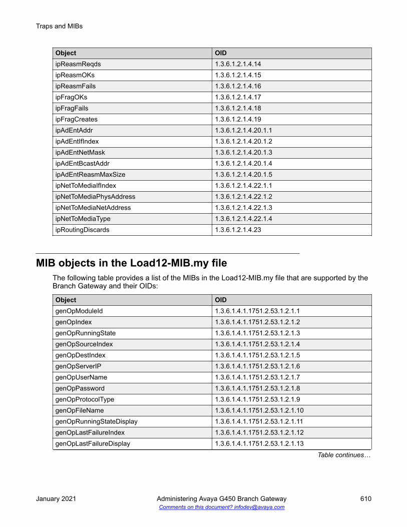
Object OIDipReasmReqds 1.3.6.1.2.1.4.14ipReasmOKs 1.3.6.1.2.1.4.15ipReasmFails 1.3.6.1.2.1.4.16ipFragOKs 1.3.6.1.2.1.4.17ipFragFails 1.3.6.1.2.1.4.18ipFragCreates 1.3.6.1.2.1.4.19ipAdEntAddr 1.3.6.1.2.1.4.20.1.1ipAdEntIfIndex 1.3.6.1.2.1.4.20.1.2ipAdEntNetMask 1.3.6.1.2.1.4.20.1.3ipAdEntBcastAddr 1.3.6.1.2.1.4.20.1.4ipAdEntReasmMaxSize 1.3.6.1.2.1.4.20.1.5ipNetToMediaIfIndex 1.3.6.1.2.1.4.22.1.1ipNetToMediaPhysAddress 1.3.6.1.2.1.4.22.1.2ipNetToMediaNetAddress 1.3.6.1.2.1.4.22.1.3ipNetToMediaType 1.3.6.1.2.1.4.22.1.4ipRoutingDiscards 1.3.6.1.2.1.4.23
MIB objects in the Load12-MIB.my fileThe following table provides a list of the MIBs in the Load12-MIB.my file that are supported by theBranch Gateway and their OIDs:
Object OIDgenOpModuleId 1.3.6.1.4.1.1751.2.53.1.2.1.1genOpIndex 1.3.6.1.4.1.1751.2.53.1.2.1.2genOpRunningState 1.3.6.1.4.1.1751.2.53.1.2.1.3genOpSourceIndex 1.3.6.1.4.1.1751.2.53.1.2.1.4genOpDestIndex 1.3.6.1.4.1.1751.2.53.1.2.1.5genOpServerIP 1.3.6.1.4.1.1751.2.53.1.2.1.6genOpUserName 1.3.6.1.4.1.1751.2.53.1.2.1.7genOpPassword 1.3.6.1.4.1.1751.2.53.1.2.1.8genOpProtocolType 1.3.6.1.4.1.1751.2.53.1.2.1.9genOpFileName 1.3.6.1.4.1.1751.2.53.1.2.1.10genOpRunningStateDisplay 1.3.6.1.4.1.1751.2.53.1.2.1.11genOpLastFailureIndex 1.3.6.1.4.1.1751.2.53.1.2.1.12genOpLastFailureDisplay 1.3.6.1.4.1.1751.2.53.1.2.1.13
Table continues…
Traps and MIBs
January 2021 Administering Avaya G450 Branch Gateway 610Comments on this document? [email protected]

Object OIDgenOpLastWarningDisplay 1.3.6.1.4.1.1751.2.53.1.2.1.14genOpErrorLogIndex 1.3.6.1.4.1.1751.2.53.1.2.1.15genOpResetSupported 1.3.6.1.4.1.1751.2.53.1.2.1.16genOpEnableReset 1.3.6.1.4.1.1751.2.53.1.2.1.17genOpNextBootImageIndex 1.3.6.1.4.1.1751.2.53.1.2.1.18genOpLastBootImageIndex 1.3.6.1.4.1.1751.2.53.1.2.1.19genOpFileSystemType 1.3.6.1.4.1.1751.2.53.1.2.1.20genOpReportSpecificFlags 1.3.6.1.4.1.1751.2.53.1.2.1.21genOpOctetsReceived 1.3.6.1.4.1.1751.2.53.1.2.1.22genAppFileId 1.3.6.1.4.1.1751.2.53.2.1.1.1genAppFileName 1.3.6.1.4.1.1751.2.53.2.1.1.2genAppFileType 1.3.6.1.4.1.1751.2.53.2.1.1.3genAppFileDescription 1.3.6.1.4.1.1751.2.53.2.1.1.4genAppFileSize 1.3.6.1.4.1.1751.2.53.2.1.1.5genAppFileVersionNumber 1.3.6.1.4.1.1751.2.53.2.1.1.6genAppFileLocation 1.3.6.1.4.1.1751.2.53.2.1.1.7genAppFileDateStamp 1.3.6.1.4.1.1751.2.53.2.1.1.8genAppFileRowStatus 1.3.6.1.4.1.1751.2.53.2.1.1.9
MIB objects in the PPP-LCP-MIB.my fileThe following table provides a list of the MIBs in the PPP-LCP-MIB.my file that are supported byBranch Gateway and their OIDs:
Object OIDpppLinkStatusPhysicalIndex 1.3.6.1.2.1.10.23.1.1.1.1.1pppLinkStatusBadAddresses 1.3.6.1.2.1.10.23.1.1.1.1.2pppLinkStatusBadControls 1.3.6.1.2.1.10.23.1.1.1.1.3pppLinkStatusPacketTooLongs 1.3.6.1.2.1.10.23.1.1.1.1.4pppLinkStatusBadFCSs 1.3.6.1.2.1.10.23.1.1.1.1.5pppLinkStatusLocalMRU 1.3.6.1.2.1.10.23.1.1.1.1.6pppLinkStatusRemoteMRU 1.3.6.1.2.1.10.23.1.1.1.1.7pppLinkStatusLocalToPeerACCMap 1.3.6.1.2.1.10.23.1.1.1.1.8pppLinkStatusPeerToLocalACCMap 1.3.6.1.2.1.10.23.1.1.1.1.9pppLinkStatusLocalToRemoteACCompression 1.3.6.1.2.1.10.23.1.1.1.1.12pppLinkStatusRemoteToLocalACCompression 1.3.6.1.2.1.10.23.1.1.1.1.13
Table continues…
Branch Gateway MIB files
January 2021 Administering Avaya G450 Branch Gateway 611Comments on this document? [email protected]

Object OIDpppLinkStatusTransmitFcsSize 1.3.6.1.2.1.10.23.1.1.1.1.14pppLinkStatusReceiveFcsSize 1.3.6.1.2.1.10.23.1.1.1.1.15pppLinkConfigInitialMRU 1.3.6.1.2.1.10.23.1.1.2.1.1pppLinkConfigReceiveACCMap 1.3.6.1.2.1.10.23.1.1.2.1.2pppLinkConfigTransmitACCMap 1.3.6.1.2.1.10.23.1.1.2.1.3pppLinkConfigMagicNumber 1.3.6.1.2.1.10.23.1.1.2.1.4pppLinkConfigFcsSize 1.3.6.1.2.1.10.23.1.1.2.1.5
MIB objects in the WAN-MIB.my fileThe following table provides a list of the MIBs in the WAN-MIB.my file that are supported by theBanch Gateway and their OIDs:
Object OIDds0BundleMemmbersList 1.3.6.1.4.1.6889.2.1.6.1.1.2.1.1ds0BundleSpeedFactor 1.3.6.1.4.1.6889.2.1.6.1.1.2.1.2ds1DeviceMode 1.3.6.1.4.1.6889.2.1.6.2.1.1ifTableXtndIndex 1.3.6.1.4.1.6889.2.1.6.2.2.1.1.1ifTableXtndPeerAddress 1.3.6.1.4.1.6889.2.1.6.2.2.1.1.2ifTableXtndVoIPQueue 1.3.6.1.4.1.6889.2.1.6.2.2.1.1.3ifTableXtndCableLength 1.3.6.1.4.1.6889.2.1.6.2.2.1.1.4ifTableXtndGain 1.3.6.1.4.1.6889.2.1.6.2.2.1.1.5ifTableXtndDescription 1.3.6.1.4.1.6889.2.1.6.2.2.1.1.6ifTableXtndKeepAlive 1.3.6.1.4.1.6889.2.1.6.2.2.1.1.7ifTableXtndMtu 1.3.6.1.4.1.6889.2.1.6.2.2.1.1.8ifTableXtndInvertTxClock 1.3.6.1.4.1.6889.2.1.6.2.2.1.1.9ifTableXtndDTELoopback 1.3.6.1.4.1.6889.2.1.6.2.2.1.1.10ifTableXtndIgnoreDCD 1.3.6.1.4.1.6889.2.1.6.2.2.1.1.11ifTableXtndIdleChars 1.3.6.1.4.1.6889.2.1.6.2.2.1.1.12ifTableXtndBandwidth 1.3.6.1.4.1.6889.2.1.6.2.2.1.1.13ifTableXtndEncapsulation 1.3.6.1.4.1.6889.2.1.6.2.2.1.1.14ifTableXtndOperStatus 1.3.6.1.4.1.6889.2.1.6.2.2.1.1.15ifTableXtndBackupCapabilities 1.3.6.1.4.1.6889.2.1.6.2.2.1.1.16ifTableXtndBackupIf 1.3.6.1.4.1.6889.2.1.6.2.2.1.1.17ifTableXtndBackupEnableDelay 1.3.6.1.4.1.6889.2.1.6.2.2.1.1.18ifTableXtndBackupDisableDelay 1.3.6.1.4.1.6889.2.1.6.2.2.1.1.19
Table continues…
Traps and MIBs
January 2021 Administering Avaya G450 Branch Gateway 612Comments on this document? [email protected]

Object OIDifTableXtndPrimaryIf 1.3.6.1.4.1.6889.2.1.6.2.2.1.1.20ifTableXtndCarrierDelay 1.3.6.1.4.1.6889.2.1.6.2.2.1.1.21ifTableXtndDtrRestartDelay 1.3.6.1.4.1.6889.2.1.6.2.2.1.1.22ifTableXtndDtrPulseTime 1.3.6.1.4.1.6889.2.1.6.2.2.1.1.23ifTableXtndLoadInterval 1.3.6.1.4.1.6889.2.1.6.2.2.1.1.24ifTableXtndInputRate 1.3.6.1.4.1.6889.2.1.6.2.2.1.1.25ifTableXtndOutputRate 1.3.6.1.4.1.6889.2.1.6.2.2.1.1.26ifTableXtndInputLoad 1.3.6.1.4.1.6889.2.1.6.2.2.1.1.27ifTableXtndOutputLoad 1.3.6.1.4.1.6889.2.1.6.2.2.1.1.28ifTableXtndReliability 1.3.6.1.4.1.6889.2.1.6.2.2.1.1.29ifTableXtndCacBBL 1.3.6.1.4.1.6889.2.1.6.2.2.1.1.31ifTableXtndCacPriority 1.3.6.1.4.1.6889.2.1.6.2.2.1.1.32ifTableXtndCacifStatus 1.3.6.1.4.1.6889.2.1.6.2.2.1.1.33frDlcmiXtndIndex 1.3.6.1.4.1.6889.2.1.6.2.4.1.1.1frDlcmiXtndLMIAutoSense 1.3.6.1.4.1.6889.2.1.6.2.4.1.1.2frStaticCircuitSubIfIndex 1.3.6.1.4.1.6889.2.1.6.2.4.2.1.1frStaticCircuitDLCI 1.3.6.1.4.1.6889.2.1.6.2.4.2.1.2frStaticCircuitDLCIrole 1.3.6.1.4.1.6889.2.1.6.2.4.2.1.3frStaticCircuitStatus 1.3.6.1.4.1.6889.2.1.6.2.4.2.1.4frSubIfDlcmiIndex 1.3.6.1.4.1.6889.2.1.6.2.4.3.1.1frSubIfSubIndex 1.3.6.1.4.1.6889.2.1.6.2.4.3.1.2frSubIfType 1.3.6.1.4.1.6889.2.1.6.2.4.3.1.3frSubIfStatus 1.3.6.1.4.1.6889.2.1.6.2.4.3.1.4
MIB objects in the SNMPv2-MIB.my fileThe following table provides a list of the MIBs in the SNMPv2-MIB.my file that are supported bythe Branch Gateway and their OIDs:
Object OIDsysDescr 1.3.6.1.2.1.1.1sysObjectID 1.3.6.1.2.1.1.2sysUpTime 1.3.6.1.2.1.1.3sysContact 1.3.6.1.2.1.1.4sysName 1.3.6.1.2.1.1.5sysLocation 1.3.6.1.2.1.1.6
Table continues…
Branch Gateway MIB files
January 2021 Administering Avaya G450 Branch Gateway 613Comments on this document? [email protected]

Object OIDsysServices 1.3.6.1.2.1.1.7snmpInPkts 1.3.6.1.2.1.11.1snmpInBadVersions 1.3.6.1.2.1.11.3snmpInBadCommunityNames 1.3.6.1.2.1.11.4snmpInBadCommunityUses 1.3.6.1.2.1.11.5snmpInASNParseErrs 1.3.6.1.2.1.11.6snmpEnableAuthenTraps 1.3.6.1.2.1.11.30snmpOutPkts 1.3.6.1.2.1.11.2snmpInTooBigs 1.3.6.1.2.1.11.8snmpInNoSuchNames 1.3.6.1.2.1.11.9snmpInBadValues 1.3.6.1.2.1.11.10snmpInReadOnlys 1.3.6.1.2.1.11.11snmpInGenErrs 1.3.6.1.2.1.11.12snmpInTotalReqVars 1.3.6.1.2.1.11.13snmpInTotalSetVars 1.3.6.1.2.1.11.14snmpInGetRequests 1.3.6.1.2.1.11.15snmpInGetNexts 1.3.6.1.2.1.11.16snmpInSetRequests 1.3.6.1.2.1.11.17snmpInGetResponses 1.3.6.1.2.1.11.18snmpInTraps 1.3.6.1.2.1.11.19snmpOutTooBigs 1.3.6.1.2.1.11.20snmpOutNoSuchNames 1.3.6.1.2.1.11.21snmpOutBadValues 1.3.6.1.2.1.11.22snmpOutGenErrs 1.3.6.1.2.1.11.24snmpOutGetRequests 1.3.6.1.2.1.11.25snmpOutGetNexts 1.3.6.1.2.1.11.26snmpOutSetRequests 1.3.6.1.2.1.11.27snmpOutGetResponses 1.3.6.1.2.1.11.28snmpOutTraps 1.3.6.1.2.1.11.29
MIB objects in the OSPF-MIB.my fileThe following table provides a list of the MIBs in the OSPF-MIB.my file that are supported by theBranch Gateway and their OIDs:
Traps and MIBs
January 2021 Administering Avaya G450 Branch Gateway 614Comments on this document? [email protected]

Object OIDospfRouterId 1.3.6.1.2.1.14.1.1ospfAdminStat 1.3.6.1.2.1.14.1.2ospfVersionNumber 1.3.6.1.2.1.14.1.3ospfAreaBdrRtrStatus 1.3.6.1.2.1.14.1.4ospfASBdrRtrStatus 1.3.6.1.2.1.14.1.5ospfExternLsaCount 1.3.6.1.2.1.14.1.6ospfExternLsaCksumSum 1.3.6.1.2.1.14.1.7ospfTOSSupport 1.3.6.1.2.1.14.1.8ospfOriginateNewLsas 1.3.6.1.2.1.14.1.9ospfRxNewLsas 1.3.6.1.2.1.14.1.10ospfExtLsdbLimit 1.3.6.1.2.1.14.1.11ospfMulticastExtensions 1.3.6.1.2.1.14.1.12ospfExitOverflowInterval 1.3.6.1.2.1.14.1.13ospfDemandExtensions 1.3.6.1.2.1.14.1.14ospfAreaId 1.3.6.1.2.1.14.2.1.1ospfAuthType 1.3.6.1.2.1.14.2.1.2ospfImportAsExtern 1.3.6.1.2.1.14.2.1.3ospfSpfRuns 1.3.6.1.2.1.14.2.1.4ospfAreaBdrRtrCount 1.3.6.1.2.1.14.2.1.5ospfAsBdrRtrCount 1.3.6.1.2.1.14.2.1.6ospfAreaLsaCount 1.3.6.1.2.1.14.2.1.7ospfAreaLsaCksumSum 1.3.6.1.2.1.14.2.1.8ospfAreaSummary 1.3.6.1.2.1.14.2.1.9ospfAreaStatus 1.3.6.1.2.1.14.2.1.10ospfLsdbAreaId 1.3.6.1.2.1.14.4.1.1ospfLsdbType 1.3.6.1.2.1.14.4.1.2ospfLsdbLsid 1.3.6.1.2.1.14.4.1.3ospfLsdbRouterId 1.3.6.1.2.1.14.4.1.4ospfLsdbSequence 1.3.6.1.2.1.14.4.1.5ospfLsdbAge 1.3.6.1.2.1.14.4.1.6ospfLsdbChecksum 1.3.6.1.2.1.14.4.1.7ospfLsdbAdvertisement 1.3.6.1.2.1.14.4.1.8ospfIfIpAddress 1.3.6.1.2.1.14.7.1.1ospfAddressLessIf 1.3.6.1.2.1.14.7.1.2ospfIfAreaId 1.3.6.1.2.1.14.7.1.3
Table continues…
Branch Gateway MIB files
January 2021 Administering Avaya G450 Branch Gateway 615Comments on this document? [email protected]

Object OIDospfIfType 1.3.6.1.2.1.14.7.1.4ospfIfAdminStat 1.3.6.1.2.1.14.7.1.5ospfIfRtrPriority 1.3.6.1.2.1.14.7.1.6ospfIfTransitDelay 1.3.6.1.2.1.14.7.1.7ospfIfRetransInterval 1.3.6.1.2.1.14.7.1.8ospfIfHelloInterval 1.3.6.1.2.1.14.7.1.9ospfIfRtrDeadInterval 1.3.6.1.2.1.14.7.1.10ospfIfPollInterval 1.3.6.1.2.1.14.7.1.11ospfIfState 1.3.6.1.2.1.14.7.1.12ospfIfDesignatedRouter 1.3.6.1.2.1.14.7.1.13ospfIfBackupDesignatedRouter 1.3.6.1.2.1.14.7.1.14ospfIfEvents 1.3.6.1.2.1.14.7.1.15ospfIfAuthKey 1.3.6.1.2.1.14.7.1.16ospfIfStatus 1.3.6.1.2.1.14.7.1.17ospfIfMulticastForwarding 1.3.6.1.2.1.14.7.1.18ospfIfDemand 1.3.6.1.2.1.14.7.1.19ospfIfAuthType 1.3.6.1.2.1.14.7.1.20ospfIfMetricIpAddress 1.3.6.1.2.1.14.8.1.1ospfIfMetricAddressLessIf 1.3.6.1.2.1.14.8.1.2ospfIfMetricTOS 1.3.6.1.2.1.14.8.1.3ospfIfMetricValue 1.3.6.1.2.1.14.8.1.4ospfIfMetricStatus 1.3.6.1.2.1.14.8.1.5ospfNbrIpAddr 1.3.6.1.2.1.14.10.1.1ospfNbrAddressLessIndex 1.3.6.1.2.1.14.10.1.2ospfNbrRtrId 1.3.6.1.2.1.14.10.1.3ospfNbrOptions 1.3.6.1.2.1.14.10.1.4ospfNbrPriority 1.3.6.1.2.1.14.10.1.5ospfNbrState 1.3.6.1.2.1.14.10.1.6ospfNbrEvents 1.3.6.1.2.1.14.10.1.7ospfNbrLsRetransQLen 1.3.6.1.2.1.14.10.1.8ospfNbmaNbrStatus 1.3.6.1.2.1.14.10.1.9ospfNbmaNbrPermanence 1.3.6.1.2.1.14.10.1.10ospfNbrHelloSuppressed 1.3.6.1.2.1.14.10.1.11ospfExtLsdbType 1.3.6.1.2.1.14.12.1.1ospfExtLsdbLsid 1.3.6.1.2.1.14.12.1.2
Table continues…
Traps and MIBs
January 2021 Administering Avaya G450 Branch Gateway 616Comments on this document? [email protected]

Object OIDospfExtLsdbRouterId 1.3.6.1.2.1.14.12.1.3ospfExtLsdbSequence 1.3.6.1.2.1.14.12.1.4ospfExtLsdbAge 1.3.6.1.2.1.14.12.1.5ospfExtLsdbChecksum 1.3.6.1.2.1.14.12.1.6ospfExtLsdbAdvertisement 1.3.6.1.2.1.14.12.1.7
MIB objects in the TUNNEL-MIB.my fileThe following table provides a list of the MIBs in the TUNNEL-MIB.my file that are supported bythe Branch Gateway and their OIDs:
Object OIDtunnelIfLocalAddress 1.3.6.1.2.1.10.131.1.1.1.1.1tunnelIfRemoteAddress 1.3.6.1.2.1.10.131.1.1.1.1.2tunnelIfEncapsMethod 1.3.6.1.2.1.10.131.1.1.1.1.3tunnelIfTOS 1.3.6.1.2.1.10.131.1.1.1.1.4tunnelIfHopLimit 1.3.6.1.2.1.10.131.1.1.1.1.5tunnelConfigLocalAddress 1.3.6.1.2.1.10.131.1.1.2.1.1tunnelConfigRemoteAddress 1.3.6.1.2.1.10.131.1.1.2.1.2tunnelConfigEncapsMethod 1.3.6.1.2.1.10.131.1.1.2.1.3tunnelConfigID 1.3.6.1.2.1.10.131.1.1.2.1.4tunnelConfigStatus 1.3.6.1.2.1.10.131.1.1.2.1.5ipTunnelIfIndex 1.3.6.1.4.1.81.31.8.1.1.1ipTunnelIfChecksum 1.3.6.1.4.1.81.31.8.1.1.2ipTunnelIfKey 1.3.6.1.4.1.81.31.8.1.1.3ipTunnelIfkeyMode 1.3.6.1.4.1.81.31.8.1.1.4ipTunnelIfAgingTimer 1.3.6.1.4.1.81.31.8.1.1.5ipTunnelIfMTUDiscovery 1.3.6.1.4.1.81.31.8.1.1.6ipTunnelIfMTU 1.3.6.1.4.1.81.31.8.1.1.7ipTunnelIfKeepaliveRate 1.3.6.1.4.1.81.31.8.1.1.8ipTunnelIfKeepaliveRetries 1.3.6.1.4.1.81.31.8.1.1.9
Branch Gateway MIB files
January 2021 Administering Avaya G450 Branch Gateway 617Comments on this document? [email protected]

Appendix B: ASG authentication
ASG authentication CLI commandsNote:ASG is no longer supported from Release 7.1.2 and has been replaced with EASG. ASGauthentication file commands can be used if you downgrade to the release previous toRelease 7.1.2.
The commands listed in the table manage ASG authentication. For more information about thesecommands, see Avaya G450 Branch Gateway CLI Reference.
Command Descriptioncopy ftp auth-file Download an ASG authentication file from a remote FTP
servercopy scp auth-file Download an ASG authentication file from a remote SCP
servercopy tftp auth-file Download an ASG authentication file from a remote TFTP
servercopy usb auth-file Download an ASG authentication file from a USB mass
storage deviceerase auth-file Erase the gateway’s ASG authentication fileno login authenticationservices-logins
Deactivate all Avaya Services logins.
show auth-file info Display ASG authentication file informationshow login authentication Display login authentication settings and information.show download auth-file status Display download status of ASG authentication file, after using
copy ftp|scp|tftp|usb auth-file to download anauthentication file to the gateway
Replacing the ASG authentication fileBefore you beginIf you need to install an authentication file with a different ID, delete the current authentication fileusing the erase auth-file command. This command requires Supervisor level access and
January 2021 Administering Avaya G450 Branch Gateway 618Comments on this document? [email protected]

can be used only when directly connecting to the Console or Services port. You can delete theauthentication file and replace it with one that has a new ID. However, you must ensure that theauthentication file label on the gateway chassis is replaced.
About this taskIf there are any problems with the ASG authentication file, you can download a new authenticationfile from Authentication File System (AFS). You cannot install an authentication file with anauthentication file ID different from the authentication file installed on Branch Gateway.
Note:ASG is no longer supported from Release 7.1.2 and has been replaced with EASG. ASGauthentication file commands can be used if you downgrade to the release previous toRelease 7.1.2.
Procedure1. Use the show auth-file info command to view the current ASG authentication file.
For example:Gxxx-001(super)# show auth-file infoAuthentication File (AF) information:AF-ID :7000012345Date/time : 15:02:27 23-AUG-2015Major release : 6.x
2. Use Windows File Explorer or another file management program to create a directory onan FTP, SCP or TFTP server for storing authentication files.
For example, C:\licenses.
3. Open Internet Explorer and go to rfa.avaya.com.
4. Log in using your SSO login and password.
The AFS and RFA information home page displays.
5. Start the AFS application from the RFA information page.
Follow the instructions outlined in Authentication File System (AFS) Guide to create anddownload the authentication file.
6. Download the authentication file on to Branch Gateway from an FTP, SCP or TFTP server,or a USB mass storage device.
filename contains the name of the authentication file and the path of the file. ip is the IPaddress of the host. source-usb-device is the source USB mass storage device andsource-filename contains the name of the authentication file and the path of the file.Branch Gateway prompts you for a user name and password after you enter thecommand. To install the authentication file, use one of the following commands:
• copy ftp auth-file filename ip
• copy scp auth-file filename ip
• copy tftp auth-file filename ip
Replacing the ASG authentication file
January 2021 Administering Avaya G450 Branch Gateway 619Comments on this document? [email protected]

• copy usb auth-file source-usb-device source-filename
Auth-files are used in releases prior to Release 7.1.2.
7. After the authentication file is downloaded, you can view the download status using theshow download auth-file status command.
ASG authentication
January 2021 Administering Avaya G450 Branch Gateway 620Comments on this document? [email protected]

Index
AAccess Code 2 ...................................................................142Access control list
CLI commands ........................................................... 526access-control-list .............................................................. 250access control list rule specifications .................................505access control lists, policy ................................................. 505Accessing
Avaya Aura Communication Manager ..........................37MGC ............................................................................. 37via modem .................................................................... 34via S8300 ......................................................................36
Accessing Branch Gateway .................................................31accessing port matrix .........................................................558Access through Services port .............................................. 33Active PMI ............................................................................65add nfas-interface ...................................................... 165, 168add port ......................................................................158, 168Address Resolution Protocol table .....................................418Administering Encrypted SRTCP .......................................300Administering Media encryption .........................................297administration
fips .............................................................................. 543AES-256 ............................................................................ 297analog telephones ............................................................. 106analog-test ................................................................. 380, 383Announcement files
CLI commands ........................................................... 309managing and transferring using SCP ........................305
area ....................................................................................428arp ..............................................................................418–420ARP table ...........................................................................418
changing an entry ....................................................... 420CLI commands ........................................................... 420description .................................................................. 418dynamic entries .......................................................... 418static entries ............................................................... 418
ARP table entries ...............................................................419arp timeout .........................................................................420ARS ................................................................................... 142ARS Dial Patterns ..............................................................144ARS dial patterns data .......................................................143ARS FAC ........................................................................... 142ASG commands .................................................................618Associated Signaling ......................................................... 138async-limit-string ................................................................217async mode interactive ...................................................... 218async mode terminal ..........................................................218async-reset-modem ........................................................... 217Authenticating
Service logins ............................................................... 61authentication .................................................................... 500
Auto Fallback in SLS ........................................................... 98automatically activating ETR ............................................. 284automatic failover and failback .......................................... 535autoneg ..............................................................................182Autonomous System Boundary Router ............................. 427Auto Route Selection (ARS) Access Code 1 ..................... 142Avaya Aura Communication Manager
accessing ......................................................................37configuring for SLS ..................................................... 113functions ....................................................................... 37
Avaya Aura™ Communication Managerconfiguring for SLS ..................................................... 113
Avaya courses ................................................................... 559Avaya Services
authenticating logins with EASG .................................. 61Avaya Site Administration ....................................................37Avaya support website .......................................................560Avaya Voice Announcement Manager (VAM) ....................305
BBacking up the Branch Gateway
using the Branch Gateway USB port ............................89Backup and Restore of Gateway Configuration .................542backup config usb ..........................................................89, 94backup control for data and VoIP .......................................474backup delay ..............................................................240, 241backup interface ................................ 241, 244, 247, 250, 257Backup interfaces .............................................................. 240
CLI commands ........................................................... 241dynamic bandwidth reporting ......................................261GRE tunnels as .......................................................... 398limitations ....................................................................240modem dial backup, Modem dial backup ................... 241modem dial backup, see Modem dial backup ............ 241overview ..................................................................... 182
backup mechanism configuration ...................................... 272backup peer mechanism ....................................................479Backup service .................................................................. 283bandwidth .................................................. 228, 229, 427, 428Bandwidth
dynamic reporting ....................................................... 261manual adjustment ..................................................... 427reducing via header compression ...............................206used to calculate Cost ................................................ 427
BasicLAN deployment ........................................................... 23
bc out ................................................................................. 277Before Enabling or Disabling FIPS Approved Mode ..........542be out .................................................................................277Bit Rate .............................................................................. 134bootfile ............................................................................... 415BOOTP
January 2021 Administering Avaya G450 Branch Gateway 621Comments on this document? [email protected]

BOOTP (continued)description .................................................................. 407
BOOTP relay ..................................................................... 407BOOTstrap Protocol
see BOOTP ................................................................ 407BPDU .........................................................................320, 321Branch Gateway
documentation ............................................................ 557Branch Gateway access ...................................................... 31Branch Office 1 configuration .............................................467Branch Office 2 configuration .............................................470bri ...............................................................................156, 168Bridge Protocol Data Units
see BPDU ...................................................................320Bridges
direct handshaking ..................................................... 321loops ........................................................................... 320
Broadcast relayCLI commands ........................................................... 418description .................................................................. 417directed broadcast forwarding .................................... 417NetBIOS rebroadcast ................................................. 417
Ccablelength long .................................................................223cable length long ................................................................226cablelength short ............................................................... 223cable length short .............................................................. 226CAC-BL ..............................................................................261Call admission control
Dynamic CAC ............................................................. 261Call admission control, see Dynamic CAC ........................ 261Called Len ..........................................................................145Called Number ...................................................................145Call Type ARS only
AAR and ARS Digit Analysis Table .............................123call types ............................................................................167cancel ........................................................................ 382, 383capture buffer mode ...........................................................368capture buffer-mode ...........................................................374capture buffer-size ............................................................. 374captured packets ............................................................... 370capture filter-group .....................................................368, 370capture interface ........................................................ 361, 368capture max-frame-size ..................................................... 368capture start .......................................................................370capture stop ....................................................................... 370CAS Remote Hold/Answer Hold-Unhold Access Code ..... 142CDR, SLS information ........................................................110certificate validation ........................................................... 538Challenge Handshake Authentication Protocol ................. 216Changing crypto list parameters ........................................ 451channel-group ............................................................223, 226Channel Groups
creating .......................................................................223illustration ................................................................... 220
Channel Groups (continued)mapping ......................................................................223
Channel Numbering ...........................................................134CHAP .................................................................................216CIR .....................................................................................276cir out ................................................................................. 277class-identifier ............................................................413, 415Class values in SLS station context ...................................151clear arp-cache .................................................................. 420clear attendant ................................................................... 168clear bri ...................................................................... 156, 168clear capture-buffer ............................................................368clear crypto isakmp ....................................................455, 500clear crypto sa ................................................................... 500clear crypto sa all ...............................................................455clear crypto sa counters .............................................455, 500clear dial-pattern ........................................................ 166, 168clear ds1 .................................................................... 152, 168clear dynamic-trap-manager ..............................................294clear extension ...................................................................168clear fac ............................................................................. 168clear fragment ....................................................................434clear frame-relay counters ................................................. 237clear incoming-routing ....................................................... 168clear ip dhcp-client statistics .............................................. 186clear ip dhcp-server binding .......................................413, 415clear ip dhcp-server statistics ............................................ 415clear ip domain statistics ......................................................78clear ip route ...................................................................... 397clear ip rtp header-compression ................................ 209, 212clear ip tcp header-compression ........................209, 211, 212clear logging file .........................................................196, 205clear logging server ........................................................... 194clear mgc list ..................................................................70, 73clear port mirror ................................................................. 319clear port static-vlan ...........................................................315clear profile ................................................................ 382, 383clear radius authentication server ........................................46clear rmon statistics ........................................................... 328clear sig-group ........................................................... 165, 168clear slot-config ..................................................................168clear ssh-client known-hosts ................................................45clear station ....................................................................... 168clear survivable-config ....................................................... 168clear sync interface ....................................................534, 536clear tac ............................................................................. 168clear tcp syn-cookies ........................................................... 50clear tcp syn-cookies counters ............................................ 50clear trunk-group ........................................................158, 168clear vlan ................................................................... 312, 315CLI
accessing from local network ....................................... 33accessing from remote location ....................................34accessing with modem ................................................. 34commands .................................................................. 544contexts ........................................................................ 32contexts example ..........................................................32
Index
January 2021 Administering Avaya G450 Branch Gateway 622Comments on this document? [email protected]

CLI (continued)FIPS ............................................................................544listing files ..................................................................... 96managing configuration files .........................................95managing firmware banks ............................................ 83online help .................................................................... 32remote access with S8300 Server ................................36upgrading firmware using SCP/FTP/TFTP ................... 84using to configure the system .......................................28viewing device status ....................................................79
CLI access using a PC device ............................................. 33client identifier ....................................................................410client identifiers .................................................................. 415CLI output per RTP session ...............................................339clock source ...............................................................223, 226Codec ................................................................................ 212Codecs in SLS ................................................................... 143collection
delete ..........................................................................558edit name ....................................................................558generating PDF .......................................................... 558sharing content ........................................................... 558
Commands ................................................................ 217, 428async modem-init-string ............................................. 218async reset-modem .................................................... 218bri ................................................................................146capture filter-group ..................................................... 374capture interface .........................................................374capture ipsec .............................................................. 374capture max-frame-size ..............................................374capture-service ................................................... 361, 374capture start ................................................................374capture stop ................................................................374clear capture-buffer .....................................................374composite-operation, packet sniffing .......................... 374cookie, capture list ......................................................374copy auth-file ftp ......................................................... 618copy auth-file scp ........................................................618copy auth-file tftp ........................................................ 618copy auth-file usb ....................................................... 618copy capture-file ftp ............................................ 372, 374copy capture-file scp ...........................................372, 374copy capture-file tftp ........................................... 372, 374copy capture-file usb .......................................... 372, 374copy ftp auth-file ......................................................... 618copy running-config startup-config ............................... 48copy scp auth-file ........................................................618copy tftp auth-file ........................................................ 618copy usb auth-file ....................................................... 618crypto ipsec df-bit ....................................................... 453destination-ip, packet sniffing ..................................... 374dial-pattern ..................................................................146ds1 ..............................................................................146dscp, packet sniffing ................................................... 374dscp, policy lists ..........................................................519erase auth-file .............................................................618fragment, packet sniffing .....................................367, 374
Commands (continued)icmp ............................................................................ 374incoming-routing ......................................................... 146interface console ........................................................ 389interface dialer ............................................................ 389interface fastethernet, interface configuration ............ 389interface loopback ...................................................... 389interface serial, interface configuration .......................389interface tunnel ........................................................... 389interface usb-modem ..................................................389interface vlan .............................................................. 389ip address, console port ............................................. 218ip admin-state ............................................................. 389ip broadcast-address .................................................. 389ip capture-list .............................................................. 374ip peer address ...........................................................218ip-protocol, packet sniffing ..........................................374ip rtp compression-connections ..................................208ip rtp header-compression ..................................208, 210ip rtp max-period .........................................................208ip rtp max-time ............................................................208ip rtp non-tcp-mode .................................................... 208ip rtp port-range .......................................................... 208ip-rule, packet sniffing .................................................374ip tcp compression-connections ......................... 208, 210ip tcp header-compression ................................. 208, 210key config-key password-encryption ............................ 48login authentication local-craft-password ................... 618login authentication lockout ........................................ 618login authentication response-time .............................618login authentication services-logins ............................618name, packet sniffing ..................................................374owner, packet sniffing ................................................. 374ping .............................................................................238ppp authentication, ASG authentication ..................... 618ppp authentication, console port .................................218ppp chap-secret ..........................................................218ppp timeout authentication, console port ....................218rtp-stat qos-trap-rate-limit ........................................... 336set logging session, object tracking ............................269set mgc list ....................................................................71set sls ......................................................................... 125show auth-file info .......................................................618show auth-file status ...................................................618show capture ...................................................... 371, 374show capture-buffer hex ..................................... 371, 374show controllers ..........................................................238show frame-relay fragment .........................................238show frame-relay lmi .................................................. 238show frame-relay map ................................................ 238show frame-relay pvc ................................................. 238show frame-relay traffic .............................................. 238show interfaces, WAN configuration ...........................238show ip capture-list .....................................................374show ip interface .........................................................238show ip interface brief .................................................389show login authentication ........................................... 618
Index
January 2021 Administering Avaya G450 Branch Gateway 623Comments on this document? [email protected]

Commands (continued)show map-class frame-relay .......................................238show ppp authentication .............................................218show rtp-stat config .................................................... 333show rtp-stat detailed ................................................. 337show rtp-stat sessions ................................................ 337show running-config ................................................... 238show startup-config .................................................... 238show traffic-shape .......................................................238show upload auth-file status ....................................... 618show upload status .....................................................374shutdown, console port ...............................................218sig-group .....................................................................146sls ............................................................................... 146snmp-server view ....................................................... 289source-ip, packet sniffing ............................................374speed ..........................................................................218station ......................................................................... 146tcp destination-port ..................................................... 374tcp source-port ............................................................374timeout absolute ......................................................... 218trunk-group ................................................................. 146tunnel path-mtu-discovery .......................................... 402udp destination-port ....................................................374udp source-port .......................................................... 374
command sequence .......................................................... 249Committed Burst size .........................................................276communication methods for agents and managers on SNMP............................................................................................285composite-operation
IP rule configuration ....................................................521composite-operation, access control list ............................526composite-operation, DSCP table ............................. 523, 528composite-operation, MSS configuration .............................53composite-operation, QoS list ....................................521, 528composite operations .........................................................519Composite operations
adding to IP rule ......................................................... 521configuring .................................................................. 521deleting from IP rule ................................................... 521example ...................................................................... 522pre-configured for access control lists ........................ 519
Computer, connecting to fixed router port ..........................178conference call ...................................................................357Configuration
defining an interface ..................................................... 63DHCP client ................................................................ 184dynamic trap manager ................................................293header compression ................................................... 206installation and setup ....................................................26LLDP ...........................................................................189managing configuration files .........................................95MGC list ........................................................................68modem ........................................................................216primary management interface .....................................64RTCP ..........................................................................206RTP .............................................................................206
Configuration (continued)running configuration .................................................... 29saving configuration changes ....................................... 29startup .........................................................................238startup configuration ..................................................... 29switching ..................................................................... 311using GUI applications ............................................27, 28using the CLI ................................................................ 28WAN ethernet port ...................................................... 181
Configuration fileCLI commands ............................................................. 95
Configured PMI ....................................................................65Connect ............................................................................. 135Console device
configuring console port to detect ...............................218console interface ..................................................................26Console messages ............................................................ 254Console port
associating with Dialer interface ................................. 250CLI commands ........................................................... 218configuring for modem use ........................................... 35configuring to detect console device .......................... 218configuring to detect modem ...................................... 218connecting modem ....................................................... 35description .................................................................. 218entering interface context ........................................... 218
contact closure ...................................................................109Contact closure
activating when access code dialed ........................... 303closure modes ............................................................ 303configuring software ................................................... 303deactivating manually ................................................. 303displaying status ......................................................... 304overview ..................................................................... 302relay control methods ................................................. 302setting manually ..........................................................303setting pulse duration ................................................. 303using in SLS mode ..................................................... 109
Contact Closure Close Code ............................................. 141Contact closure configuration
CLI commands ........................................................... 304Contact Closure Open Code ..............................................141Contact Closure Pulse Code ............................................. 142content
publishing PDF output ................................................ 558searching .................................................................... 558sharing ........................................................................558sort by last updated .................................................... 558watching for updates .................................................. 558
Contexts ...............................................................................32Contexts example ................................................................ 32continuous-channel ....................................443, 447, 464, 500Continuous channel in VPN .......................................463, 464controller .................................................................... 223, 226Controller
configuring mode ........................................................ 223displaying configuration .............................................. 223
Index
January 2021 Administering Avaya G450 Branch Gateway 624Comments on this document? [email protected]

Controller (continued)entering context .......................................................... 223
cookie, access control list .................................................. 526cookie, capture list ............................................................. 362cookie, policy list ................................................................509cookie, QoS list ..................................................................528copy announcement-file ftp ....................86, 87, 305, 306, 309copy announcement-file scp .......................... 86, 87, 305, 309copy announcement-file usb ..................86, 87, 306, 307, 309copy auth-file ftp .................................................... 86, 87, 618copy auth-file scp ...................................................86, 87, 618copy auth-file tftp ............................................................... 618copy auth-file usb ...................................................86, 87, 618copy capture-file ftp ....................................................... 86, 87copy capture-file scp ......................................................86, 87copy capture-file usb ......................................................86, 87copy cdr-file ftp .............................................................. 86, 87copy cdr-file scp .............................................................86, 87copy cdr-file usb .............................................................86, 87copy dhcp-binding ftp .....................................................86, 87copy dhcp-binding scp ................................................... 86, 87copy dhcp-binding usb ...................................................86, 87copy file usb .........................................................................86copy ftp announcement-file ........................................306, 309copy ftp auth-file ................................................................ 618copy ftp module ............................................................. 84, 87copy ftp startup-config ......................................................... 95copy ftp sw_imageA .......................................................91, 94copy ftp SW_imageA ..................................................... 84, 87copy ftp SW_imageB ........................................................... 87copying and installing EASG site certificate using scp
copying EASG site certificate ....................................... 59copying and installing EASG site certificate using usb device
copying EASG site certificate using usb device ........... 59copy license-file usb ...................................................... 86, 87copy phone-script usb ....................................................86, 87copy running-config ftp ........................................................ 95copy running-config scp .......................................................95copy running-config startup-config .......................................49copy running-config tftp ....................................................... 95copy scp announcement-file .............................. 305, 306, 309copy scp auth-file ...............................................................618copy scp startup-config ........................................................95copy scp SW_imageA ..........................................................84copy startup-config ftp ......................................................... 95copy startup-config scp ........................................................95copy startup-config tftp ........................................................ 95copy startup-config usb ............................................86, 87, 95copy syslog-file ftp ..................................................... 195, 205copy syslog-file scp ....................................................195, 205copy syslog-file tftp ............................................................ 205copy syslog-file usb ....................................... 86, 87, 195, 205copy tftp auth-file ............................................................... 618copy tftp module .................................................................. 87copy tftp startup-config ........................................................ 95copy tftp sw_imageA ......................................................91, 94copy tftp SW_imageA .................................................... 84, 87
copy tftp SW_imageB .......................................................... 87copy usb .............................................................................. 85copy usb announcement-file ................................87, 307, 309copy usb auth-file .........................................................87, 618copy usb modules ................................................................87copy usb phone-image ........................................................ 87copy usb phone-script ..........................................................87copy usb startup-config ..................................................87, 95copy usb SW_image ............................................................87cos ............................................................................. 521, 528Cost ................................................................................... 427Country Protocol ................................................................ 136crypto-group .......................................................................453crypto ipsec df-bit ...............................................................500crypto ipsec minimal pmtu ................................................. 453crypto ipsec minimal-pmtu ................................................. 500crypto ipsec nat-transparency udp-encapsulation ..... 452, 500crypto ipsec transform-set ......................... 441, 486, 492, 500crypto isakmp invalid-spi-recovery .............................451, 500crypto isakmp nat keepalive ...................................... 452, 500crypto isakmp peer .................................... 443, 486, 492, 500crypto isakmp peer-group .................................. 446, 492, 500crypto isakmp policy .......................................... 486, 492, 500crypto isakmp suggest-key ................................................ 500crypto ispec nat-transparency udp-encapsulation ............. 500crypto ispec transform-set ................................................. 500crypto key generate ....................................................... 44, 45crypto list
overview ..................................................................... 436Crypto list
configuring .................................................................. 448deactivating ................................................................ 450
crypto list parameterschanging ..................................................................... 451
crypto map ................................................. 447, 486, 492, 500Crypto map
configuring .................................................................. 447overview ..................................................................... 436
cyrpto isakmp policy .......................................................... 440
Ddata and VoIP control backup ............................................474Data Link Connection Identifier ..........................................235
see DLCI .....................................................................235Date Format on Terminals ................................................. 143DCP/ANALOG Bearer Capability .......................................136DCP stations data ..............................................................127DCP telephones .................................................................106decrypted IPSec VPN packets ...........................................370Default gateway
defining ......................................................................... 66default-metric ............................................. 424, 428, 430, 431default-router ..................................................................... 412default-routers ....................................................................415default sink severity levels ................................................. 201defining other interfaces ...................................................... 27
Index
January 2021 Administering Avaya G450 Branch Gateway 625Comments on this document? [email protected]

DelAAR Digit Conversion Table ....................................... 123ARS Digit Conversion Table ....................................... 123Incoming Call Handling Treatment ............................. 146
Deleting EASG site certificatedeleting site certificate .................................................. 59
deleting site certificate ......................................................... 59DeMilitarized Zone
see DMZ ..................................................................... 387Denial of Service reporting .................................................. 50Deployments
basic ............................................................................. 23introduction ................................................................... 23overview ....................................................................... 23port redundancy ......................................................23, 24RSTP ............................................................................ 24RSTP and switch redundancy ...................................... 25switch redundancy ........................................................24
description, crypto list rule ................................................. 500description, crypto map ......................................................500description, DNS servers list ................................................78description, ISAKMP peer ..........................................443, 500description, ISAKMP peer-group ....................................... 500description, ISAKMP policy ........................................440, 500description, object tracker ..................................................275description, policy rule ....................................................... 515destination-ip
packet sniffing .............................................................364destination-ip, access control list ....................................... 526destination-ip, crypto list rule ..................................... 448, 500destination-ip, MSS configuration ........................................ 53destination-ip, policy list .....................................................516destination-ip, QoS list .......................................................528determining ........................................................................ 540
enabled or disabled .................................................... 541FIPS ............................................................................541
Determining Configuration is FIPS Compliant ................... 541Device status
CLI commands ............................................................. 80viewing ..........................................................................79
DHCPBOOTP relay .............................................................. 407description .................................................................. 407
DHCP and BOOTP relayCLI commands ........................................................... 408
DHCP clientapplications .................................................................183CLI commands ........................................................... 186CLI logging, enabling ..................................................186CLI logging, setting logging session conditions ..........186CLI logging, viewing ................................................... 186configuring .................................................................. 184determining DHCP option requests ............................ 184displaying configuration .............................................. 186displaying parameters ................................................ 184enabling ...................................................................... 184interface fastethernet, DHCP client ............................ 184
DHCP client (continued)ip address dhcp .......................................................... 184ip dhcp client client-id ................................................. 184ip dhcp client hostname ..............................................184ip dhcp client lease ..................................................... 184ip dhcp client request ..................................................184ip dhcp client route track .............................................184lease, releasing .......................................................... 185lease, renewing .......................................................... 185maintaining ................................................................. 186overview ..................................................................... 183setting the client identifier ........................................... 184setting the client lease ................................................ 184setting the hostname .................................................. 184show ip dhcp-client ..................................................... 184
DHCP Client configuration .................................................462DHCP options .................................................................... 412DHCP relay ........................................................................407DHCP server
CLI commands ........................................................... 415configuration examples ...............................................413configuring DHCP options .......................................... 412configuring vendor-specific options ............................ 413overview ..................................................................... 409typical application ....................................................... 410
Diagnosingand monitoring the network ........................................ 326
Dialed StringAAR and ARS Digit Analysis Table .....................123, 144AAR and ARS Digit Conversion Table ................123, 144
dialer interface ................................................................... 252Dialer interface
activating with object tracking .....................................247as backup for Loopback interface ...............................241as backup for WAN interface ...................................... 241assigning access control list to ................................... 250assigning to Console port ........................................... 250authentication method ................................................ 244CHAP authentication .................................................. 244CLI commands ........................................................... 257configuring .................................................................. 244configuring as backup .................................................244configuring backup routing ......................................... 244dynamic IP ..................................................................247dynamic routing .......................................................... 241giving priority to VoIP ..................................................241logging ........................................................................ 252setting IP address .......................................................244static routing ............................................................... 241unnumbered IP ........................................... 241, 247, 391verifying connection ....................................................244
Dialer Messages ................................................................ 253dialer modem-interface .............................................. 250, 257dialer order .................................................................244, 257dialer persistent ......................................................... 244, 257dialer persistent delay ........................................244, 250, 257dialer persistent initial delay ...............................244, 250, 257
Index
January 2021 Administering Avaya G450 Branch Gateway 626Comments on this document? [email protected]
dialer persistent max-attempts ...................................244, 257dialer persistent re-enable ......................................... 244, 257dialer string ........................................................ 244, 250, 257Dialer strings ......................................................................244dialer wait-for-ipcp ..................................................... 244, 257Dial On Demand Routing (DDR) ........................................241dial-pattern .................................................................166, 168dir .............................................................................87, 94, 96Directed broadcast forwarding ...........................................417Directory Number ...............................................................140disabling EASG ....................................................................56disabling EASG authentication
disabling EASG ............................................................ 56disabling EASG authentication for a specified user
disabling EASG for user ............................................... 57disabling EASG for specified user ....................................... 57disabling FIPS
administration ............................................................. 551Disabling FIPS Approved Mode .........................................543Discard routes ....................................................................397disconnect ssh ............................................................... 44, 45displaying DHCP server information ..................................415Distribution access lists ..................................................... 423distribution list .................................................................... 423distribution-list ....................................................................424DLCI
configuring for frame relay sub-interface .................... 235OSPF mapping ........................................................... 278Priority ........................................................................ 235Priority, see Priority DLCI ............................................235
DMZ ................................................................................... 387DNS resolver
CLI commands ............................................................. 78configuration example .................................................. 77features .........................................................................74maintaining ................................................................... 78overview ....................................................................... 73typical application ......................................................... 74when not necessary ......................................................75
dns-server ..................................................................412, 415DNS servers
requesting list of DNS servers during a PPP/IPCPsession ....................................................................... 232requesting list of DNS servers from a DHCP server ...184
documentationBranch Gateway ......................................................... 557
documentation center ........................................................ 558finding content ............................................................ 558navigation ................................................................... 558
documentation portal ......................................................... 558finding content ............................................................ 558navigation ................................................................... 558
document changes .............................................................. 22domain-name .....................................................................415
lease ........................................................................... 412dos-classification ................................................................. 53DoS reporting .......................................................................50
downloading announcement files ...................................... 306ds1 ..................................................................................... 168DSA encryption ....................................................................44dscp
packet sniffing .............................................................364DSCP
as access control list rule criteria ................................519as policy-based routing rule criteria ............................519as QoS list rule criteria ............................................... 519in RTR probes .............................................................264in VPN packets ........................................................... 447
dscp, access control list .....................................................526dscp, object tracking .................................................. 264, 275dscp, QoS list .............................................................521, 528DSCP table
Policy .......................................................................... 522dscp-table .................................................................. 523, 528DSCP table, see Policy ......................................................522ds-mode .....................................................................223, 226duplex ................................................................................ 182Dynamic CAC
and modem dial backup ..................................... 241, 247CLI commands ........................................................... 262description .................................................................. 261
dynamic-cac .......................................................................262Dynamic CAC tasks ...........................................................262Dynamic Host Configuration Protocol
see DHCP ...................................................................407Dynamic IP
configuring .................................................................. 461Dialer interface ........................................................... 247overview ..................................................................... 460
dynamic local peer IP ........................................................ 462dynamic MTU discovery .................................................... 402Dynamic routes
redistributing ............................................................... 430Dynamic time slots allocation
CLI commands ........................................................... 310overview ..................................................................... 310
Dynamic trap managerCLI commands ........................................................... 294configuring .................................................................. 293
dynamic trap manager parameters ....................................294
EE1/T1 default settings ........................................................ 225E1/T1 lines
CLI commands ........................................................... 226connecting to WAN media module ............................. 220default settings ........................................................... 223
E1/T1 ports ........................................................................ 223EASG
Enhanced Access Security Gateway ............................55EASG authentication ..................................................... 42, 61EASG site certificate information ......................................... 60EASG Status enabled or disabled ....................................... 61
Index
January 2021 Administering Avaya G450 Branch Gateway 627Comments on this document? [email protected]

EASG users list ....................................................................58Echo cancellation
CLI commands ........................................................... 378overview ..................................................................... 377
ECMP ................................................................................ 427Emergency Transfer Relay
see ETR ......................................................................283enabling EASG .................................................................... 55enabling EASG authentication
enabling EASG ............................................................. 55enabling EASG authentication for a specified user
enabling EASG for user ................................................57enabling EASG for specified user ........................................57enabling FIPS
administration ............................................................. 546Enabling FIPS Approved Mode ......................................... 543encapsulation .............................................230, 231, 235, 237encapsulation pppoe ..................................................232, 234encrypted SRTCP ..............................................................299Encrypted SRTCP ......................................................299, 300Encrypting gateway secrets .................................................47encryption .................................................................. 440, 500end-ip-addr ................................................................ 410, 415Endpt Init ............................................................................140Enhanced Access Security Gateway ...................................55Enhanced Access Security Gateway (EASG) authentication..............................................................................................61erase announcement-file ........................................... 307, 309erase auth-file .................................................................... 618error states 1
FIPS ............................................................................555Ethernet ports
CLI commands ........................................................... 179configuring switch port ................................................179connecting devices to ................................................. 178list of ........................................................................... 178port redundancy ..........................................................316WAN Ethernet port ......................................................181WAN Ethernet port, see WAN Ethernet port ...............181
Ethernet ports on the router ...............................................178ETR
CLI commands ........................................................... 284deactivating ................................................................ 284description .................................................................. 283LED .............................................................................283manual activation ........................................................283setting state ................................................................ 283trunk-to-port latchings .................................................283
ETR automatic activation ...................................................284Excess Burst size .............................................................. 276exit ....................................................................................... 64Expansion Module ............................................................. 122
FFAC data ............................................................................140failback ...............................................................................535
failover ............................................................................... 535fail-retries ................................................................... 264, 275fair-queue-limit ................................................................... 213Fair VoIP queue ................................................................. 213fair-voip-queue ...................................................................213FastEthernet interface
checking status ...........................................................258dynamic bandwidth reporting ......................................261ICMP keepalive .......................................................... 258
FastEthernet Interfacedescribed .................................................................... 387
Fast Ethernet interfaceconfiguring PPPoE ..................................................... 231
Fast Ethernet port .............................................................. 260configuring interface ................................................... 181firewall connected .......................................................387VPN connected ...........................................................387
fdl ....................................................................................... 226File transfer
SCP, FTP or TFTP ........................................................82File transfer, see SCP, FTP or TFTP ................................... 82finding content on documentation center ...........................558finding port matrix .............................................................. 558FIPS
next hops static routes ................................................394FIPS (Federal Information Processing Standards) ............ 539FIPS Approved Mode of Operation ....................................540FIPS Certified Firmware is Installed .................................. 540FIPS error states ................................................................555FIPS Security Level of the Cryptographic Module ............. 539Firewall .............................................................................. 387Firmware
CLI commands ............................................................. 87firmware bank defaults ................................................. 83firmware banks ............................................................. 30load with ASB button .................................................... 83managing firmware banks ............................................ 83redundancy ...................................................................83upgrade overview ......................................................... 82upgrading using SCP/FTP/TFTP ..................................84upgrading using USB mass storage device ..................85version control .............................................................. 30
firmware versions in the banks displays .............................. 83Fixed analog trunk port ...................................................... 283fragment .............................................................................277fragment, access control list ...................................... 518, 526fragment, QoS list .............................................................. 528Fragmentation
as map class parameter ............................................. 276CLI commands ........................................................... 434description .................................................................. 434GRE tunneling ............................................................ 402
fragment chain ................................................................... 434fragment size ..................................................................... 434fragment timeout ................................................................434Frame relay
displaying configuration .............................................. 238
Index
January 2021 Administering Avaya G450 Branch Gateway 628Comments on this document? [email protected]

Frame relay (continued)enabling traffic shaping ...............................................276
frame-relay class-dlci .........................................................237frame-relay counters ..........................................................237Frame relay encapsulation
CLI commands ........................................................... 237down status ................................................................ 240encapsulation types ....................................................235establishing Layer 3 interface .....................................396IETF ............................................................................235illustration ................................................................... 221non-IETF .....................................................................235supported features ......................................................276supported on Serial interfaces ............................220, 388
frame-relay interface-dlci ........................................... 235, 237frame-relay lmi-n391dte .............................................235, 237frame-relay lmi-n392dte .............................................235, 237frame-relay lmi-n393dte .............................................235, 237frame-relay lmi-type ................................................... 235, 237frame-relay priority-dlci-group ............................235, 237, 278Frame relay traffic shaping
CLI commands ........................................................... 277configuring within map classes ...................................276description .................................................................. 276displaying configuration .............................................. 238enabling ...................................................................... 276
frame-relay traffic-shaping ......................... 235, 237, 276, 277framing .......................................................................223, 226frequency ................................................................... 264, 275FRF.12 fragmentation
configuring within map classes ...................................276description .................................................................. 276
FTP ...................................................................................... 82
GGeneral context ................................................................... 32General context example .....................................................32Generic Routing Encapsulation
GRE tunneling ............................................................ 398Generic Routing Encapsulation, see GRE tunneling ......... 398Gigabit Ethernet port
port redundancy ..........................................................316global parameters .............................................................. 451GRE ................................................................................... 404GRE application example .................................................. 404GRE tunnel ........................................................................ 404GRE tunneling
applications .................................................................398checking tunnel status ........................................ 401, 403CLI commands ........................................................... 405compared to VPN ....................................................... 398dynamic bandwidth reporting ......................................261dynamic MTU discovery ............................................. 402optional features ......................................................... 401overview ............................................................. 387, 398preventing recursive routing ....................................... 399
GRE tunneling (continued)routing packets to tunnel ............................................ 399
group ..........................................................................440, 500GUI tools, configuring the system with .......................... 27, 28
Hhash ........................................................................... 440, 500Header compression
clearing rtp header compression statistics ................. 212clearing tcp header compression statistics .................212decompression ........................................................... 206IPCH method - RTP and TCP header compression, CLIcommands .................................................................. 209IPCH method - RTP and TCP header compression,disabling ..................................................................... 208IPCH method - RTP and TCP header compression,enabling ...................................................................... 208IPCH method - RTP and TCP header compression,overview ..................................................................... 207IPHC method - RTP and TCP header compression,configuring UDP ports range ...................................... 208methods ......................................................................207overview ..................................................................... 206showing rtp header compression statistics .................212showing tcp header compression statistics ................ 212show ip rtp header-compression ................................ 212show ip tcp header-compression ................................212supported methods per interface type ........................ 207transmission rate ........................................................ 206Van Jacobson Method - TCP header compression, CLIcommands .................................................................. 211Van Jacobson Method - TCP header compression,configuring .................................................................. 210Van Jacobson Method - TCP header compression,disabling ..................................................................... 210Van Jacobson Method - TCP header compression,enabling ...................................................................... 210Van Jacobson Method - TCP header compression,overview ..................................................................... 207
help ...................................................................................... 32Help
CLI ................................................................................ 32commands .................................................................... 32
High Preference static routes ............................................ 395hostname ....................................................................... 44, 45hub-and-spoke with VPN ................................................... 474
Iicc-vlan .......................................................................313, 315ICC-VLAN .......................................................................... 313
configuring .................................................................. 313Configuring ................................................................. 313icc-vlan ....................................................................... 313ICC-VLAN ...................................................................313
icmp ........................................................... 366, 518, 526, 528
Index
January 2021 Administering Avaya G450 Branch Gateway 629Comments on this document? [email protected]

ICMP errors ....................................................................... 421CLI commands ........................................................... 421
ICMP keepalive ..................................................................258and policy-based routing ............................................ 531CLI commands ........................................................... 260
ICMP keepalive feature, enabling ......................................259idle character ..................................................................... 228idle-character ..................................................................... 229IGAR .................................................................. 241, 247, 261ignore dcd .................................................................. 228, 229IKE
phase 1 .......................................................................435phase 2 .......................................................................435
incoming call handling data ............................................... 145incoming-routing ........................................................ 167, 168Ingress Access Control List ............................................... 531Ingress QoS List ................................................................ 531initiate mode .............................................................. 443, 500Insert
Incoming Call Handling Treatment ............................. 146installing EASG site certificate .............................................59installing EASG site certificate using usb device ................. 59Integrated analog testing
CLI commands ........................................................... 383displaying corrections ................................................. 383displaying test results ................................................. 382healing trunks ............................................................. 383overview ..................................................................... 379profiles, clearing ......................................................... 382profiles, configuring .................................................... 380profiles, displaying ...................................................... 382test cancelling .............................................................382test launching ............................................................. 382test lines ..................................................................... 380types of tests .............................................................. 379
Interactions for Encrypted SRTCP .....................................300interface ................................................................. 63, 64, 257Interface .....................................................................135, 137Interface configuration
CLI commands ........................................................... 389interface console ........................................................218, 250interface dialer ................................................... 244, 250, 257interface fastethernet, DHCP and BOOTP relay ............... 408interface fastethernet, DHCP client ................................... 186interface fastethernet, PPPoE ........................................... 232interface fastethernet, WAN Ethernet port ................. 181, 182interface Loopback ............................................................ 250Interfaces
adjusting bandwidth ....................................................427assigning Cost ............................................................ 427assigning IP addresses ................................................ 63backup ........................................................................ 182configuration ............................................................... 387configuration examples ...............................................389defining ......................................................................... 63disabling ..................................................................... 394displaying information .................................................238
Interfaces (continued)displaying status ......................................................... 376dynamic bandwidth reporting ......................................261fastethernet .................................................................387frame relay ..................................................................235GRE tunnel, GRE tunneling ........................................387GRE tunnel, see GRE tunneling .................................387IP ................................................................................ 388IP, see IP interfaces ....................................................388Layer 2 ................................................................387, 394Layer 3 ........................................................................396logical ......................................................................... 388Loopback ............................................................ 387, 531physical .......................................................................387Serial .................................................................. 220, 388Serial, see Serial interfaces ........................................220setting load calculation intervals ...................................63switching .............................................................387, 388testing configuration ................................................... 238USP WAN ................................................................... 387virtual .................................................................. 220, 387WAN ........................................................................... 387
interface serial ................................................................... 229E1/T1 ports ................................................................. 226frame relay ..................................................................237frame relay traffic shaping .......................................... 277
interface Serial ...................................................................223interface serial, frame relay ............................................... 235interface serial, PPP .................................................. 230, 231interface serial, USP port ...................................................228Interface status
CLI commands ........................................................... 377interface tunnel .......................................................... 403, 405interface usb-modem ................................................. 216, 217interface vlan ..............................................................311, 315Inter-Gateway Alternate Routing
IGAR ...........................................................................261Inter-Gateway Alternate Routing, see IGAR ......................261Internet Key Exchange (IKE) ............................................. 435invalid SPI recovery ........................................................... 451invert txclock .............................................................. 228, 229ip access-control-list .................................... 53, 451, 508, 526ip access group ..................................................................511ip access-group ................................................. 250, 462, 526ip address .......................................................................... 229
E1/T1 ports ................................................................. 226IP address
assigning to USB port ...................................................27defining ....................................................................... 388obtaining via DHCP .................................................... 183obtaining via PPP/IPCP negotiation ........................... 232storing in ARP table ....................................................418
ip address, dialer interface .........................................244, 257ip address, E1/T1 ports ......................................................223ip address, frame relay .............................................. 235, 237ip address, interface configuration ...............................63, 388ip address, PPP ......................................................... 230, 231
Index
January 2021 Administering Avaya G450 Branch Gateway 630Comments on this document? [email protected]

ip address, PPPoE .....................................................232, 234ip address, USB port ..........................................................217ip address dhcp ........................................................... 75, 186ip address negotiated ........................ 232, 234, 244, 257, 461ip bootp-dhcp network ....................................................... 408ip bootp-dhcp relay ............................................................ 408ip bootp-dhcp server .......................................................... 408ip capture-list ..................................................................... 362ip crypto-group ...................................................450, 463, 500ip crypto list ........................................................................448ip crypto-list ........................................................................500ip default-gateway ................................................66, 257, 397ip default-gateway dialer ....................................................244ip dhcp activate pool .................................................. 410, 415ip dhcp client client-id ........................................................ 186ip dhcp client hostname ..................................................... 186ip dhcp client lease ............................................................ 186ip dhcp client request .................................................186, 486ip dhcp client route track ....................................................186ip dhcp ping packets .......................................................... 415ip dhcp ping timeout ...........................................................415ip dhcp pool ....................................................................... 410ip dhcp pools ......................................................................415ip dhcp-server ............................................................ 410, 415ip directed-broadcast ................................................. 417, 418ip distribution access-default-action ...........................423, 424ip distribution access-list ............................................423, 424ip distribution access-list-cookie ........................................ 424ip distribution access-list-copy ........................................... 424ip distribution access-list-name ..........................................424ip distribution access-list-owner .........................................424ip domain list ..................................................................75, 78ip domain lookup ............................................................75, 78ip domain name-server-list ............................................ 75, 78ip domain retry ............................................................... 75, 78ip domain timeout .......................................................... 75, 78ip-fragments-in ...........................................................513, 526ip icmp-errors .....................................................................421IP interfaces .......................................................................388ip max-arp-entries ..............................................................420ip netbios-rebroadcast ............................................... 417, 418ip netmask-format .............................................................. 397ip-option-in ................................................................. 513, 526ip ospf authentication .........................................................428ip ospf authentication-key .................................................. 428ip ospf cost .................................................................427, 428ip ospf dead-interval .......................................................... 428ip ospf hello-interval ...........................................................428ip ospf message-digest-key ............................................... 428ip ospf network point-to-multipoint ............................. 222, 428ip ospf priority .................................................................... 428ip ospf router-id ..................................................................428ip peer address .................................................................. 217ip policy-list-copy ............................... 450, 508, 509, 526, 528ip-protocol
packet sniffing .............................................................364ip-protocol, access control list ............................................526
ip-protocol, MSS configuration .............................................53ip-protocol, policy list ......................................................... 515ip-protocol, QoS list ........................................................... 528ip proxy-arp ........................................................................421ip qos-group ...............................................................512, 528ip qos-list ....................................................................508, 528ip redirects ......................................................................... 397ip rip authentications key ................................................... 424ip rip authentications mode ................................................424ip rip default-route-mode ....................................................424ip rip poison-reverse .................................................. 423, 424ip rip rip-version ................................................................. 424ip rip send-receive-mode ................................................... 424ip rip split-horizon .......................................................423, 424ip route .......................................................................395–397ip routing .................................................................... 386, 397ip rtp compression-connections ......................................... 209ip rtp header-compression ................................................. 209ip rtp max-period ................................................................209ip rtp max-time ................................................................... 209ip rtp non-tcp-mode ............................................................209ip rtp port-range ................................................................. 209ip rule ................................................................................. 515ip-rule, access control list .................................................. 526ip-rule, crypto list ................................................................448ip-rule, MSS configuration ................................................... 53ip-rule, packet sniffing ................................................361, 362ip-rule, QoS list .................................................................. 528ip-rule, VPN ....................................................................... 500IP Security
VPN ............................................................................ 435IP Security, see VPN ..........................................................435IPSec VPN .........................................................................435IPSec VPN, see VPN .........................................................435IPSec VPN configuration display ....................................... 454IPSec VPN packets decryption ..........................................370ip show rule ........................................................................515ip simulate ..........................................................525, 526, 528ip ssh ............................................................................. 44, 45IP stations data .................................................................. 129ip tcp compression-connections .................................209, 211ip tcp header-compression .................................................211IP telephones .....................................................................106ip telnet ................................................................................ 47ip telnet-client .......................................................................47ip telnet-services ..................................................................47ip unnumbered ...................................................244, 250, 391IP unnumbered interface configuration
CLI commands ........................................................... 393ip vrrp .................................................................................433ip vrrp address ................................................................... 433ip vrrp auth-key .................................................................. 433ip vrrp override addr owner ................................................433ip vrrp preempt ...................................................................433ip vrrp primary ....................................................................433ip vrrp priority ..................................................................... 433ip vrrp timer ........................................................................433
Index
January 2021 Administering Avaya G450 Branch Gateway 631Comments on this document? [email protected]

ISAKMPpeer-group configuration ............................................ 446policies ........................................................................440VPN peer configuration .............................................. 443
isakmp policy ..................................................................... 443isakmp-policy ..................................................................... 500ITN-C7 Long Timers .......................................................... 137
Kkeepalive ....................230–232, 234, 401, 403, 405, 443, 500
configuring on PPP WAN line ..................................... 230Keepalive, GRE tunnel ...................................................... 401keepalive feature ............................................................... 401keepalive ICMP
ICMP keepalive .......................................................... 258keepalive-icmp ...........................................................259, 260keepalive ICMP, see ICMP keepalive ................................ 258keepalive-icmp failure-retries .............................................260keepalive-icmp interval ...................................................... 260keepalive-icmp source-address ......................................... 260keepalive-icmp success-retries ..........................................260keepalive-icmp timeout ...................................................... 260keepalive-track ...................................182, 232, 234, 443, 500
configuring in VPN ......................................................443configuring on PPPoE interface ..................................232
key config-key password-encryption ....................................94
LLAN ....................................................................................387launch ........................................................................ 382, 383Layer 1 Stable ....................................................................140Layer 2 interfaces .............................................................. 394Layer 2 logical interfaces ................................................... 388Layer 2 virtual interfaces ....................................................387Layer 3 interfaces .............................................................. 396lease .......................................................................... 410, 415LEDs, ETR .........................................................................283legal notice ...............................................................................lifetime ....................................................................... 440, 500linecode ..................................................................... 223, 226Link Layer Discovery Protocol
LLDP ...........................................................................187Link Layer Discovery Protocol, see LLDP ......................... 187Link-state algorithm ........................................................... 426Listing files ........................................................................... 96list rule specification for access control ............................. 505LLDP
802.1 TLVs (optional) ..................................................188CLI commands ........................................................... 190configuration ............................................................... 189enabling ...................................................................... 189mandatory TLVs ..........................................................188optional TLVs ..............................................................188overview ..................................................................... 187setting additional TLVs ................................................189
LLDP (continued)setting port status ....................................................... 189supported ports ...........................................................190supported TLVs ...........................................................188verify advertisements ..................................................189
LMI parameters ..................................................................235Load balancing
ECMP ......................................................................... 427VRRP ..........................................................................431
load-interval ......................................................................... 63load sharing topologies ......................................................481local-address ............................................................. 448, 500local calls between IP and analog telephones ...................353Local Management Interface ............................................. 235
see LMI parameters ....................................................235Log file
see Logging ................................................................ 196Log file generation ............................................................. 204log file messages ............................................................... 196Logging
CLI commands ........................................................... 205configuring and enabling the log file ........................... 196configuring session log ............................................... 198configuring Syslog server ........................................... 192copying the Syslog file ................................................195default severity levels ................................................. 201defining filters ............................................................. 200deleting log file ............................................................196deleting Syslog server ................................................ 194Dialer interface ........................................................... 252disabling log file .......................................................... 196disabling session log .................................................. 199disabling Syslog server ...............................................192displaying log file contents ..........................................196displaying Syslog server status .................................. 194enabling session log ................................................... 198enabling Syslog server ............................................... 192filtering by application ................................................. 201introduction ................................................................. 191limiting Syslog access ................................................ 192log file ......................................................................... 191log file example ...........................................................203log file filter contents ...................................................200log file message format .............................................. 197modem dial backup .................................................... 252object trackers ............................................................ 269object tracking ............................................................ 269overview ..................................................................... 191RTR ............................................................................ 269saving settings ............................................................191session log ..........................................................191, 199session log example ................................................... 203session log message format .......................................199setting filters ............................................................... 200sinks ........................................................................... 191specifying Syslog output facility ..................................192Syslog default settings ................................................194
Index
January 2021 Administering Avaya G450 Branch Gateway 632Comments on this document? [email protected]

Logging (continued)Syslog server ..............................................................191Syslog server example ............................................... 203Syslog server message format ................................... 195VPN ............................................................................ 455
Logging sessionLogging .......................................................................198
Logging session, see Logging ........................................... 198Logical interfaces ...............................................................388login authentication ..............................................................42login authentication inactivity-period ..............................39, 40login authentication lockout ........................................... 39, 40login authentication min-password-digit-chars ...............39, 40login authentication min-password-length ..................... 39, 40login authentication min-password-lower-chars .............39, 40login authentication min-password-special-chars .......... 39, 40login authentication min-password-upper-chars ............ 39, 40login authentication password-expire ............................ 39, 40login authentication response-time ...................................... 42loopback ............................................................................ 226loopback activation on an E1/T1 line ................................. 226Loopback interface ............................................ 241, 387, 531loopback remote ................................................................ 226Loops
defined ........................................................................320preventing in GRE tunneling .......................................399preventing in RIP ........................................................ 423
Low preference static routes ..............................................395
MMAC addresses, storing in ARP table ............................... 418Maintaining FIPS Approved Mode ..................................... 543Managed Security Services
MSS ..............................................................................50Managed Security Services, see MSS ................................ 50map classes .......................................................................277
configuring .................................................................. 277Map classes
applying to all configured Permanent Virtual Channels.....................................................................................276default .........................................................................276number that can be configured ...................................276parameters ................................................................. 276
map-class frame-relay ....................................................... 277Master Configuration Key
CLI commands ............................................................. 50configuring .................................................................... 48
MaxAAR Digit Conversion Table ............................... 123, 144ARS Digit Conversion Table ............................... 123, 144
MCGCLI commands ............................................................. 73
MCK (Master Configuration Key) .........................................47Media encryption ............................................................... 297media encryption using AES 256 .......................................298Media Gateway Controller (MGC) ....................................... 27
Media modulesadding, using a USB mass-storage device ...................94MM340 ........................................................222, 223, 387MM342 ........................................................222, 228, 387upgrading, using a USB mass-storage device ............. 94USP WAN, MM342 media module ............................. 228USP WAN, see MM342 media module .......................228WAN ........................................................................... 222
mesh VPN topology configuration ..................................... 465Metrics ............................................................................... 430MGC
accessing ......................................................................37accessing the registered MGC ..................................... 72auto fallback to primary ................................................ 67changing the list ............................................................71checking connectivity with .......................................... 241clearing the list ..............................................................70displaying the list .......................................................... 69monitoring the ICC ........................................................73monitoring the Survivable Remote Server ....................73overview ....................................................................... 67reporting bandwidth to ................................................ 261running Avaya Aura Communication Manager .............37setting reset times ........................................................ 71setting the list ................................................................68
MGC listSLS entry ....................................................................102
MIB files ............................................................................. 574Min
AAR Digit Conversion Table ............................... 123, 144ARS Digit Conversion Table ............................... 123, 144
MM340 media moduleconfiguring .................................................................. 223E1/T1 WAN interface .................................................. 387
MM342 media moduleconfiguring .................................................................. 228USP WAN interface .................................................... 387
mode ..........................................................................441, 500Modem
configuring .................................................................. 216configuring console port to detect ...............................218connecting to Console port ...........................................35connecting to S8300 Server ......................................... 36connecting to USB port .................................................34connecting via USB modem ......................................... 36dial backup, Modem dial backup ................................ 241dial backup, see Modem dial backup ......................... 241serial ........................................................................... 218USB ............................................................................ 216
Modem dial backupactivating with object tracking .....................................247and dynamic CAC ...............................................241, 247as backup interface .................................................... 241authentication method ................................................ 244bandwidth available for ...............................................241CHAP authentication .................................................. 244configuration example ................................................ 248
Index
January 2021 Administering Avaya G450 Branch Gateway 633Comments on this document? [email protected]
Modem dial backup (continued)configuring backup routing ......................................... 244entering dialer strings ................................................. 244feature interactions ..................................................... 247logging ........................................................................ 252overview ..................................................................... 241policy lists and ............................................................ 241prerequisites ............................................................... 244RAS configuration .......................................................244typical installations ......................................................243using VPN ...................................................................241Weighted Fair Queuing and ........................................241
Monitoring applicationsconfiguring .................................................................. 326
MSSCLI commands ............................................................. 54configuring .................................................................... 51example ........................................................................ 54Overview .......................................................................50predefined DoS classes ................................................52reporting mechanism .................................................... 50user-defined DoS classes .............................................53
mtu .............................................................................232, 234Multipoint topology support ................................................222mutual ................................................................................ 538mutual authentication
authentication ............................................................. 538My Docs .............................................................................558
NName
DS1 Circuit Pack ........................................................ 133ISDN BRI Trunk Circuit Pack ......................................139Station ........................................................................ 122
name, access control list ................................................... 526name, crypto list .................................................................448name, DHCP option ...................................................412, 415name, DHCP server ...................................................410, 415name, DHCP vendor specific option ..........................413, 415name, packet sniffing .........................................................362name, policy list ................................................................. 509name, QoS list ........................................................... 521, 528name server .........................................................................75name-server .........................................................................78NAT Traversal
configuring .................................................................. 452overview ..................................................................... 452
Nested tunneling ................................................................399NetBIOS .............................................................................417network .............................................................................. 428Network monitoring
applications .................................................................326next-hop .....................................................................264, 275Next hops ...........................................................................395next-server .........................................................................415non-compliant CLI commands
non-compliant CLI commands (continued)FIPS ............................................................................544
no oob-interface ...................................................................81nrzi-encoding ............................................................. 228, 229nslookup .............................................................................. 78
Oobject ......................................................................... 267, 275object tracker ..................................................................... 267object tracking
configuration workflow ................................................ 267Object tracking
activating Dialer interface ........................................... 247applying to DHCP client ..............................................184applying to static routes ..............................................394backup for the FastEthernet interface ........................ 272CLI commands ........................................................... 275configuration ............................................................... 264enabling logging ......................................................... 269interface backup using policy-based routing .............. 273maintenance ............................................................... 268object tracker configuration ........................................ 267overview ..................................................................... 263RTR configuration .......................................................264verifying MGC connectivity ......................................... 241viewing log messages ................................................ 269VPN failover ................................................................271
oob-interface configuration .................................................. 81Open Shortest Path First protocol
see OSPF ................................................................... 426option ......................................................................... 412, 415OSPF
advertising static routes ..............................................394CLI commands ........................................................... 428compared to RIP .................................................421, 426default metric .............................................................. 430description .................................................................. 426DLCI mapping .............................................................278dynamic Cost ..............................................................427limitations ....................................................................427modem dial backup and ............................................. 243shortest-path-first algorithm ........................................426using with RIP .............................................................430
OSPF Autonomous System Boundary Router ...................427owner, access control list ...................................................526owner, packet sniffing ........................................................ 362owner, policy list .................................................................509owner, QoS list ...................................................................528
Ppackets, simulating
Policy .......................................................................... 525packets, simulating, see Policy ..........................................525Packet sniffing
analyzing captured packets ........................................ 370
Index
January 2021 Administering Avaya G450 Branch Gateway 634Comments on this document? [email protected]

Packet sniffing (continued)analyzing capture file ..................................................373applying a capture-list .................................................368applying rules to an address range ............................ 364applying rules to packets with DSCP values .............. 364applying rules to packets with ip protocols ................. 364capture list examples ..................................................367clearing the capture buffer ..........................................368CLI commands ........................................................... 374configuring .................................................................. 360creating capture-list .................................................... 361defining rule criteria .................................................... 362disabling ..................................................................... 361enabling ...................................................................... 361enabling the service ....................................................370excepting protocols from rules ....................................364identifying the interface ...............................................373information, viewing ....................................................371overview ..................................................................... 359packets captured ........................................................ 360reducing the size of the capture file ............................368rule criteria commands ............................................... 362scp file upload limit ..................................................... 372service, starting .......................................................... 370service, stopping .........................................................370setting buffers ............................................................. 368setting capture list context .................................. 361, 362setting capture list parameters ................................... 362setting max frame size ................................................368settings ....................................................................... 368simulating packets ...................................................... 374specifying and excluding ICMP type and code ...........366specifying bugger size ................................................ 368specifying capture actions .......................................... 361specifying interfaces ................................................... 361streams that always be captured ................................360streams that can be captured ..................................... 360streams that can never be captured ........................... 360uploading capture file ................................................. 372uploading capture files to remote servers or USB storagedevice ......................................................................... 372uploading capture files to the S8300 .......................... 372viewing, captured packet hex dump ........................... 371viewing the capture-list ............................................... 368with conditional capture requirements ........................ 360
passive-interfaces ..............................................................428password ............................................................................. 40Password authentication process ........................................ 44Password Authentication Protocol ..................................... 216password changes ...............................................................40Passwords
creating by the admin ................................................... 38disabling ....................................................................... 39displaying password information .................................. 40managing ......................................................................37managing contents ....................................................... 39managing expiry ........................................................... 39
Passwords (continued)managing length ........................................................... 39managing lockout ......................................................... 39overview ....................................................................... 37
PBR listsattaching to Loopback interface ..................................531
PC device for CLI access .................................................... 33Permanent routes .............................................................. 396Permit / Deny ..................................................................... 124ping .................................................................................... 239Ping ....................................................................................238pmi ................................................................................. 64, 65PMI
CLI commands ............................................................. 65configuration ................................................................. 64entering the interface context ....................................... 64explanation ................................................................... 64resetting the interface ................................................... 64setting location information ...........................................64setting system contact information ............................... 64setting the system name ...............................................64showing the PMI ........................................................... 64
PMI, active and configured .................................................. 65pmi6 ..................................................................................... 65Point to Multi-Point topology .............................................. 222Point-to-Point frame relay .................................................. 222Poison-reverse ...................................................................423policy
access control lists ..................................................... 505network security with access control lists ................... 506simulated packet properties ........................................525simulating packets ...................................................... 525
Policyattaching policy lists to an interface ............................510attaching policy list to interface at IACL ......................511attaching QoS list to interface at ingress QoS list ...... 512changing DSCP table entries ..................................... 522configuring composite operations ...............................521copy list ...............................................................508, 509create access control lost ........................................... 508create QoS list ............................................................ 508creating policy lists ..................................................... 508creating rules .............................................................. 515default actions ............................................................ 510defining global rules ....................................................513defining list identification attributes .............................509defining policy lists ......................................................508deleting a policy list .................................................... 510deleting a QoS list ...................................................... 510destination port range .................................................517device wide policy lists ............................................... 513displaying access control lists .................................... 513displaying composite operation lists ........................... 513displaying ip rules ....................................................... 515displaying policy lists in DSCP table context .............. 524displaying policy lists in general context .....................524displaying policy lists in QoS list context .................... 524
Index
January 2021 Administering Avaya G450 Branch Gateway 635Comments on this document? [email protected]

Policy (continued)displaying policy lists in QoS list rule context ............. 524DSCP as rule criteria .................................................. 519DSCP default value .................................................... 522DSCP methods ...........................................................522DSCP table .................................................................522edit access control list ................................................ 508editing policy lists ........................................................508editing rules ................................................................ 515example composite operation .....................................522fragments ....................................................................518ICMP code ..................................................................518ICMP type ...................................................................518managing policy lists .................................................. 507mapping DSCP to a CoS ............................................522modem dial backup and ............................................. 241overview ..................................................................... 505policy-based routing, Policy-based routing .................507policy-based routing, see Policy-based routing .......... 507policy lists and loopback interfaces ............................ 513precongifured composite operations .......................... 519precongifured for QoS lists ......................................... 520QoS fields ................................................................... 506QoS list ....................................................................... 508QoS list parts ...................................................... 506, 507QoS lists ..................................................................... 506rule criteria ..................................................................514sequence of device-wide policy list application .......... 513sequence of policy list application .............................. 510simulated packet properties ........................................525source port range ....................................................... 517specifying a destination ip address .............................516specifying an ip protocol ............................................. 515specifying operations ..................................................519TCP, establish bit ........................................................518testing policy lists ........................................................523using ip wildcards ....................................................... 514
Policy-based routingobject tracking and ..................................................... 273overview ..................................................................... 531packets not considered router packets .......................531PBR lists, PBR lists .................................................... 531PBR lists, see PBR lists ..............................................531routing to GRE tunnel ................................................. 399
PortStation ........................................................................ 120
Port classificationCLI commands ........................................................... 325Ports ........................................................................... 324
Port classification, see Ports ..............................................324port matrix ..........................................................................558Port mirroring
CLI commands ........................................................... 319description .................................................................. 319
Port redundancyCLI commands ........................................................... 318configuration ............................................................... 317
Port redundancy (continued)description .................................................................. 316disabling ..................................................................... 317displaying information .................................................317enabling ...................................................................... 317LAN deployment ..................................................... 23, 24secondary port activation ............................................317setting redundancy-intervals .......................................317switchback .................................................................. 317
port redundancy schemes ................................................. 318Ports
alternate ......................................................................321analog line .................................................................. 283backup ........................................................................ 321classification ............................................................... 324configuring E1 port ..................................................... 223configuring T1 port ......................................................223FastEthernet ............................................................... 387Fast Ethernet, Fast Ethernet port ............................... 181FastEthernet, see Fast Ethernet port ......................... 387Fast Ethernet, see Fast Ethernet port ........................ 181mirroring, see Port mirroring .......................................319opening traffic ............................................................. 321redundancy, Port redundancy .....................................316redundancy, see Port redundancy ..............................316roles in RSTP ............................................................. 321USP, see USP ports ....................................................228USP, USP ports .......................................................... 228
power-uptesting ......................................................................... 555
PPPas default WAN protocol ............................................. 222CLI commands ........................................................... 231configuring on WAN line ............................................. 230connection .............................................................. 34, 35establishing Layer 3 interface .....................................396supported on Serial interfaces ............................220, 388
PPP/IPCP address negotiation ..........................................232ppp authentication, USB port .....................................216, 217ppp chap hostname ................................... 232, 234, 244, 250ppp chap password ............................................232, 234, 244ppp chap refuse ......................................................... 232, 234ppp chap-secret ......................................................... 216, 217PPP configuration .............................................................. 230ppp ipcp dns request ..................... 75, 78, 232, 234, 257, 486PPPoE
authentication ............................................................. 232CLI commands ........................................................... 234description .................................................................. 231shutting down client .................................................... 232
pppoe-client persistent delay ..................................... 232, 234pppoe-client persistent max-attempts ........................232, 234pppoe-client service-name .........................................232, 234pppoe-client wait-for-ipcp ...........................................232, 234ppp pap refuse ...........................................................232, 234ppp pap sent username ..................................................... 234ppp pap sent-username .....................................................244
Index
January 2021 Administering Avaya G450 Branch Gateway 636Comments on this document? [email protected]

ppp pap-sent username .....................................................232PPP protocol and USP ports ............................................. 221ppp timeout authentication .................................................216ppp timeout authentication, USB port ................................ 217ppp timeout ncp ................................................. 230–232, 234ppp timeout retry ................................................230–232, 234PPP VoIP configuration ..................................................... 279PPP VoIP configuration example ...............................280, 281pre-classification ................................................................ 528preparing SLS data set ...................................................... 127Prerequisites for entering FIPS Approved Mode ............... 541pre-shared-key ...........................................................443, 500Primary Management IP address (PMI) .............................. 27Priority DLCI
applying map classes ................................................. 276CLI commands ........................................................... 279configuring .......................................................... 235, 278description .................................................................. 278
priority-queue .............................................................213, 215Priority queueing
CLI commands ........................................................... 215Priority queuing
general ........................................................................276Priority Queuing ................................................................. 214Priority VoIP queuing ......................................................... 213Privilege levels
creating .........................................................................38description .................................................................... 38
product-id .............................................................................61profile ......................................................................... 380, 383protect crypto-map .....................................................448, 500Protocol Version .................................................................136Proxy ARP ......................................................................... 421
CLI commands ........................................................... 421PTMP, see Point to Multi-Point topology ............................222
QQoS
analyzing fault and clear trap output ...........................347CLI commands ........................................................... 213configuration ............................................................... 212displaying parameters ................................................ 212fair packet scheduling .................................................213fault and clear traps .................................................... 335metrics for RTP statistics application ..................330, 331policy, Policy ............................................................... 212policy, see Policy ........................................................ 212Priority DLCI, see Priority DLCI .................................. 278Priority Queuing ..........................................................214queue sizes for VoIP traffic .........................................212resolving conflicts ....................................................... 212SNMP traps ................................................................ 334traps, viewing ..............................................................343traps in messages file .................................................344VoIP Queuing ............................................................. 214Weighted Fair VoIP Queuing ...................................... 213
QoS allowed values ........................................................... 507QoS list
CLI commands ........................................................... 528queue-limit ......................................................................... 215Queues
fair packet scheduling .................................................213Priority ........................................................................ 214Priority Queuing ..........................................................214VoIP ............................................................................ 214VoIP Queuing ............................................................. 214Weighted Fair VoIP Queuing ...................................... 213
RRADIUS authentication ..................................................37, 45RAS
dialer strings for modem dial backup ..........................250modem dial backup and ............................................. 241modem dial backup configuration options .................. 243modem dial backup prerequisites ...............................244serving multiple branch offices ................................... 243
redistribute ................................................. 424, 428, 430, 431Registration Source Port
H.248 ............................................................................ 72release dhcp .............................................................. 185, 186Remote Access Server
RAS ............................................................................ 241Remote Access Server, see RAS ...................................... 241remote calls from analog to IP telephones ........................ 351remote calls from IP telephone to IP telephone .................355Remote services logins ........................................................61remove nfas-interface ........................................................ 168remove port ........................................................................168rename announcement-file ........................................ 307–309renew dhcp ................................................................ 185, 186Replacement String
AAR Digit Conversion Table ....................................... 123ARS Digit Conversion Table ....................................... 123
reset .....................................................................................64reset and display controller counters ................................. 226reset and display frame-relay counters ..............................237restore ............................................................................91, 94restore usb ...............................................................85, 90, 94restoring ETR to automatic activation ................................284Restoring the Branch Gateway
using the Branch Gateway USB port ............................90RIP
advertising static routes ..............................................394CLI commands ........................................................... 424compared to OSPF .....................................................426default metric .............................................................. 430description .................................................................. 421distribution access lists ...............................................423limitations ....................................................................424poison-reverse ............................................................423preventing loops ......................................................... 423RIPv1 ..........................................................................422
Index
January 2021 Administering Avaya G450 Branch Gateway 637Comments on this document? [email protected]

RIP (continued)RIPv2 ..........................................................................422split-horizon ................................................................ 423using with OSPF .........................................................430versions supported ..................................................... 421
RIPv1 and RIPv2 differences .............................................422RMON
agent ...........................................................................326CLI commands ........................................................... 328overview ..................................................................... 326
rmon alarm .........................................................................328RMON configuration examples ..........................................326rmon event .........................................................................328rmon history ....................................................................... 328Router
backup ........................................................................ 431computing path ........................................................... 426configuration commands ........................................ 45–47configuring BOOTP .................................................... 407configuring broadcast relay ........................................ 417configuring DHCP .......................................................407configuring unnumbered ip addresses ....................... 391connecting to fixed router port .................................... 178determining shortest path ........................................... 427disabling ..................................................................... 386displaying interfaces ................................................... 391enabling ...................................................................... 386features .......................................................................386fragmentation ..............................................................434fragmentation, see Fragmentation ..............................434interfaces .................................................................... 387load balancing ............................................................ 431OSPF Autonomous System Boundary ....................... 427overview ..................................................................... 386redundancy .................................................................431RIP ..............................................................................421RIP, see RIP ............................................................... 421setting the borrowed ip interface ................................ 391unnumbered ip interfaces in table .............................. 392virtual .......................................................................... 431
Route redistribution ............................................................421CLI commands ........................................................... 431configuration ............................................................... 430description .................................................................. 430metrics ........................................................................ 430metric translation ........................................................ 430
router ospf ..................................................250, 257, 428, 431Router port, connecting to ................................................. 178router rip .................................................................... 424, 431router vrrp .......................................................................... 433Routes
setting route preference ..............................................399Routing
policy based, Policy .................................................... 507policy based, see Policy ............................................. 507
Routing Information Protocolsee RIP .......................................................................421
routing sources .................................................................. 393Routing table
CLI commands ........................................................... 397deleting static routes ...................................................394description .................................................................. 394
RSA authentication ........................................................ 43, 44RSTP
designating ports as edge ports ................................. 321displaying port point-to-point status ............................321displaying the port edge state .....................................321fast network convergence ...........................................321features .......................................................................321LAN deployment ..................................................... 24, 25manually configure uplink and backbone ports .......... 321role of ports .................................................................321setting port-to-port admin status .................................321
RSVP ................................................................................. 212RTCP ................................................................................. 206RTP
configuring .................................................................. 206overview ..................................................................... 328statistics application functionality ................................328viewing configuration thresholds ................................ 330
RTP header compressionHeader compression .................................................. 206
RTP header compression, see Header compression ........ 206RTP session data ...............................................................328rtp-stat clear ...............................................................332, 358rtp-stat event-threshold ..............................................332, 358rtp-stat fault ........................................................335, 336, 358RTP statistics
CLI commands ........................................................... 358RTP statistics application
configuration and output examples .............................349configuring .................................................................. 329configuring additional trap destinations ...................... 334configuring fault and clear traps ................................. 335configuring QoS traps .................................................334displaying RTP session statistics ................................337displaying VoIP engine RTP statistics ........................ 337display session information ........................................ 337enabling ...................................................................... 332enabling traps ............................................................. 334modifying the statistics window .................................. 334QoS metrics ........................................................330, 331QoS metric thresholds ................................................ 330resetting ......................................................................332sample network .......................................................... 349setting QoS event thresholds ..................................... 332setting QoS indicator thresholds .................................332setting the trap rate limiter .......................................... 336statistics summary report output .................................337viewing configuration .................................................. 333viewing QoS traps in messages file ............................344
rtp-stat min-stat-win ................................................... 334, 358rtp-stat qos-trap ......................................................... 334, 358rtp-stat qos-trap-rate-limit .......................................... 336, 358
Index
January 2021 Administering Avaya G450 Branch Gateway 638Comments on this document? [email protected]

rtp-stat service ................................................................... 358rtp-stat-service ................................................................... 332rtp-stat thresholds ...................................................... 332, 358rtr ............................................................................... 264, 275RTR
Object tracking ............................................................264RTR, see Object tracking ...................................................264rtr-schedule ................................................................264, 275running-config startup-config ............................................... 29
SS8300 Server
accessing gateway via ..................................................36connecting modem ....................................................... 36remote connection to .................................................... 36
safe-removal usb ................................................................. 94SCP ............................................................................... 45, 82
transferring announcement files using ........................305SCP/FTP/TFTP used for upgrades ......................................84searching for content ......................................................... 558Secure Shell protocol
SSH .............................................................................. 43Security
DoS attack detection .................................................... 50overview ....................................................................... 37special features ............................................................ 46VLANs ........................................................................ 313
Security Associations (SAs) ...............................................435Security Code .....................................................................115self-identity .................................................................443, 500Serial interfaces ................................................................. 388
configuring encapsulation ...........................................223default encapsulation ..................................................223dynamic bandwidth reporting ......................................261entering context .................................................. 223, 228
serial modems ..................................................................... 35server-name .......................................................................415Services port
connecting console and PC devices .............................33session ...........................................................................72, 73Session log
Logging .......................................................................198Session log, see Logging ...................................................198session mgc .......................................................................372set associated-signaling ............................................ 165, 168set attendant .............................................................. 147, 168set balance ........................................................................ 383set bearer-capability (bri) ........................................... 156, 168set bearer-capability (ds1) ......................................... 155, 168set bit-rate ..................................................................152, 168set boot bank ................................................................. 83, 87set busy-disconnect ........................................................... 168set cbc ............................................................................... 168set cbc-parameter ..............................................................168set cbc-service-feature ...................................................... 168set channel-numbering ...................................................... 168
set channel-preferences ............................................ 158, 168set codeset-display .................................................... 158, 168set codeset-national ...........................................................168set connect ................................................................ 152, 168set contact-closure admin ..........................................303, 304set contact-closure pulse-duration .............................303, 304set cor ........................................................................ 149, 168set country-protocol (bri) ............................................156, 168set country-protocol (ds1) .................................. 152, 154, 168set crosstalk-destination ............................................ 380, 383set crosstalk-port ....................................................... 380, 383set crosstalk-responder ............................................. 380, 383set date-format ...........................................................147, 168set delete-digits (dial-pattern) .................................... 166, 168set delete-digits (incoming-routing) ............................167, 168set deny ..................................................................... 166, 168set destination ............................................................380, 383set dial ....................................................................... 158, 168set digit-handling ........................................................158, 168set digits .....................................................................158, 168set digit-treatment ...................................................... 158, 168set directory-number-a ...............................................156, 168set directory-number-b ...............................................156, 168set dscp ..................................................................... 447, 500set echo-cancellation analog ............................................. 378set echo-cancellation config analog ...................................378set echo-cancellation config voip .......................................378set echo-cancellation voip ................................................. 378set endpoint-init ......................................................... 156, 168set etr .................................................................................283set etr 10 auto ....................................................................284set expansion-module ................................................149, 168set fac ................................................................................ 168set fault-threshold timeslot .................................................310set icc-monitoring .................................................................73set incoming-destination ............................................ 158, 168set incoming-dialtone .................................................158, 168set insert-digits (dial-pattern) ..................................... 166, 168set insert-digits (incoming-routing) .............................167, 168set interface (bri) ........................................................156, 168set interface (ds1) ...................................................... 152, 168set interface-companding (bri) ................................... 156, 168set interface-companding (ds1) ................................. 152, 168set ip-codec-set ......................................................... 147, 168set japan-disconnect ..................................................158, 168set layer 1-stable ....................................................... 156, 168set length ................................................................... 167, 168set lldp re-init-delay ....................................................189, 190set lldp system-control ............................................... 189, 190set lldp tx-delay ..........................................................189, 190set lldp tx-hold-multiplier ............................................ 189, 190set lldp tx-interval .......................................................189, 190set logging file ............................................................200, 205set logging file condition .................................................... 200set logging file disable ....................................................... 196set logging file enable ........................................................ 196set logging file retention .....................................................197
Index
January 2021 Administering Avaya G450 Branch Gateway 639Comments on this document? [email protected]

set logging server ...................................................... 192, 205set logging server access level ..........................................205set logging server access-level ..........................................192set logging server condition ....................................... 200, 205set logging server disable .................................................. 192set logging server enable ...................................................192set logging server facility ........................................... 192, 205set logging session .................................................... 205, 252set logging session, dialer interface ...................................257set logging session, DNS resolver .......................................78set logging session, session log ........................................ 198set logging session, VPN ...................................................455set logging session condition .............................................200set logging session condition dhcpc .................................. 186set logging session disable ................................................199set logging session enable ................................................ 186set long-timer ............................................................. 152, 168set match-pattern .......................................................167, 168set max-ip-registrations ............................................. 147, 168set max-length ........................................................... 166, 168set mediaserver ............................................................. 72, 73set mgc list .....................................................................68, 73set min-length ............................................................ 166, 168set mss-notification rate .......................................................51set name (bri) .............................................................156, 168set name (ds1) ...........................................................152, 168set name (station) ...................................................... 149, 168set name (trunk-group) .............................................. 158, 168set non-oob-interfaces ......................................................... 82set numbering-format .................................................158, 168set password ..............................................................149, 168set peer ..............................................................446, 447, 500set peer group ....................................................................447set peer-group ................................................................... 500set pfs ........................................................................ 441, 500set pim-lockout ...........................................................147, 168set port .......................................................149, 168, 380, 383set port auto-negotiation-flowcontrol-advertisement ..........179set port classification ......................................................... 325set port duplex ................................................................... 179set port edge admin state .................................. 179, 321, 324set port flowcontrol .............................................................179set port level ...................................................................... 179set port lldp ................................................................ 189, 190set port lldp tlv ............................................................189, 190set port mirror .................................................................... 319set port name .....................................................................179set port negotiation ............................................................ 179set port point-to-point admin status ................... 179, 321, 324set port redundancy ................................................... 317, 318set port redundancy enable|disable ...........................317, 318set port redundancy-intervals .................................... 317, 318set port spantree ................................................................324set port spantree cost ........................................................ 324set port spantree force-protocol-migration .........................324set port spantree priority .................................................... 324set port speed .................................................................... 179
set port static-vlan ..............................................................315set port trap ........................................................................292set port vlan ....................................................................... 315set port vlan-binding-mode ................................................ 315set primary-dchannel ................................................. 165, 168set protocol-version ................................................... 154, 168set qos bearer ............................................................212, 213set qos control ........................................................... 212, 213set qos rsvp ............................................................... 212, 213set qos rtcp ................................................................ 212, 213set qos signal .............................................................212, 213set radius authentication ......................................................46set radius authentication retry-number ................................ 46set radius authentication retry-time ......................................46set radius authentication secret ........................................... 46set radius authentication server ...........................................46set radius authentication udp-port ....................................... 46set receive-gain ................................................................. 383set registration source-port-range ........................................72set reset-times ............................................................... 71, 73set responder .............................................................380, 383set responder-type .....................................................380, 383set security-association lifetime ......................................... 500set security-association lifetime kilobytes .......................... 441set security-association lifetime seconds ...........................441set send-name ........................................................... 158, 168set send-number ........................................................158, 168set side (bri) ............................................................... 156, 168set side (ds1) ............................................................. 152, 168set signaling-mode .....................................................152, 168set slot-config .............................................................147, 168set sls .................................................................124, 147, 168set snmp community ..........................................................292set snmp retries ................................................................. 292set snmp timeout ............................................................... 292set snmp trap ..................................................................... 292set spantree default-path-cost ........................................... 324set spantree enable/disable ...............................................324set spantree forward-delay ................................................ 324set spantree hello-time ...................................................... 324set spantree max-age ........................................................ 324set spantree priority ........................................................... 324set spantree tx-hold-count ................................................. 324set spantree version .......................................................... 324set spid-a ................................................................... 156, 168set spid-b ................................................................... 156, 168set supervision ...........................................................158, 168set swhook-flash ........................................................ 149, 168set sync interface .......................................................533, 536set sync source ..................................................533, 534, 536set sync switching ......................................................534, 536set system contact ......................................................... 64, 65set system location ........................................................ 64, 65set system name ............................................................64, 65set tac ........................................................................ 158, 168set tei-assignment ......................................................156, 168set tgnum ................................................................... 166, 168
Index
January 2021 Administering Avaya G450 Branch Gateway 640Comments on this document? [email protected]

setting buffer-size ...............................................................368Setting synchronization
Synchronization .......................................................... 533Setting synchronization, see Synchronization ................... 533set transform-set ........................................................447, 500set transmit-gain ................................................................ 383set trunk ............................................................................. 315set trunk-destination .................................................. 149, 168set trunk-group-chan-select ....................................... 165, 168set trunk-hunt .............................................................158, 168set type ...................................................................... 380, 383set type (dial-pattern) .................................................166, 168set type (station) ........................................................ 149, 168set utilization cpu ................................................................. 80set vlan .......................................................................311, 315sharing content .................................................................. 558show (bri) ................................................................... 156, 168show (dial-pattern) ..................................................... 166, 168show (ds1) ................................................................. 152, 168show (incoming-routing) ............................................ 167, 168show (profile) ............................................................. 382, 383show (sig-group) ........................................................ 165, 168show (station) ............................................................ 149, 168show (trunk-group) .....................................................158, 168show all logs ...................................................................... 204show announcement-file ....................................................309show announcements-files ................................................ 308show attendant .................................................................. 168show auth-file info ........................................................41, 618show backup status ............................................................. 94show boot bank ..............................................................83, 87show bri ............................................................................. 168show cam vlan ................................................................... 315show capture-dummy-headers .......................................... 373show composite-operation, access control list .......... 513, 526show composite-operation, policy list ................................ 524show composite-operation, QoS list .................................. 528show contact-closure ......................................................... 304show controller ...................................................................239show controllers .................................................................223show controllers remote .....................................................226show correction ..................................................................383show crypto ipsec sa ................................................. 452, 500show crypto ipsec transform-set ................................ 454, 500show crypto isakmp peer ........................................... 454, 500show crypto isakmp peer-group .................................454, 500show crypto isakmp policy ......................................... 454, 500show crypto isakmp sa .............................................. 455, 500show crypto ispsec sa ........................................................455show crypto map ........................................................454, 500show date-format ............................................................... 168show dial-pattern ............................................................... 168show download announcement-file status .................308, 309show download software status .....................................85, 87show download status ......................................................... 95show ds1 ............................................................................168show dscp-table .........................................................524, 528
show ds-mode ................................................................... 223show dynamic-cac ............................................................. 262show echo-cancellation ..................................................... 378show extension .................................................................. 168show fac .............................................................................168show faults ...........................................................................80show fault-threshold timeslot ............................................. 310show fragment ................................................................... 434show frame-relay fragment ................................................ 239show frame-relay lmi ..........................................................239show frame-relay map ....................................................... 239show frame-relay pvc .........................................................239show frame-relay traffic ......................................................239show icc-monitoring ............................................................. 73show icc-vlan ............................................................. 313, 315show image version ........................................... 80, 87, 91, 94show incoming-routing .......................................................168show interface ....................................................................217show interfaces
frame relay ..................................................................237show interfaces, dialer interface ................................ 244, 257show interfaces, frame relay ..............................................235show interfaces, GRE tunnel ............................................. 405show interfaces, interface status ....................................... 376show interfaces, PPP .................................................230, 231show interfaces, unnumbered IP interface ........................ 391show interfaces, VLANs .....................................................315show interfaces, WAN configuration .................................. 239show ip access-control-list .........................................524, 526show ip active-lists .....................................................454, 500show ip arp ........................................................................ 420show ip capture-list ............................................................ 368show ip-codec-set ..............................................................168show ip crypto-list .............................................................. 454show ip crypto-list list# .......................................................454show ip crypto-lists ............................................................ 500show ip dhcp-client ............................................................ 186show ip dhcp-client statistics ............................................. 186show ip dhcp-pool ..............................................................415show ip dhcp-server bindings ............................................ 415show ip dhcp-server statistics ............................................415show ip distribution access-lists .........................................424show ip domain ....................................................................78show ip domain statistics ..................................................... 78show ip icmp ...................................................................... 421show ip interfaces .............................................................. 239show ip ospf .......................................................................428show ip ospf database ....................................................... 428show ip ospf interface ........................................................ 428show ip ospf neighbor ........................................................428show ip ospf protocols ....................................................... 428show ip protocols ............................................................... 424show ip qos-list .......................................................... 524, 528show ip-qos-list .................................................................. 528show ip reverse-arp ........................................................... 420show ip route ..................................................................... 397show ip route best-match ...................................................397
Index
January 2021 Administering Avaya G450 Branch Gateway 641Comments on this document? [email protected]

show ip route static ............................................................ 397show ip route summary ......................................................397show ip rtp header-compression ........................................209show ip rtp header-compression brief ................................209show ip-rule, access control list ......................................... 526show ip-rule, policy list .......................................................524show ip-rule, QoS list .........................................................528show ip ssh .................................................................... 44, 45show ip tcp header-compression ............................... 209, 211show ip tcp header-compression brief ....................... 209, 211show ip telnet .......................................................................47show ip track-table .............................................................397show ip vrrp ....................................................................... 433show keepalive-icmp ......................................................... 260show last-pim-update .........................................................168show list ..................................................... 509, 524, 526, 528show lldp ....................................................................189, 190show lldp config ................................................................. 190show logging file condition .........................................197, 205show logging file content ................................... 196, 200, 205show logging file retention ................................................. 198show logging server condition ................................... 194, 205show logging session condition ................................. 199, 205show login authentication .............................................. 40, 41show map-class frame-relay ..............................................239show max-ip-registration ....................................................168show mediaserver ................................................................73show mgc .................................................................69, 73, 80show mgc list ................................................................. 70, 73show mg list_config ....................................................... 79, 80show mm ............................................................................. 79show module ..................................................................79, 80show oob-interface .............................................................. 81show pim-lockout ............................................................... 168show pmi ........................................................................64, 65show point-to-point status ..................................................324show port auto-negotiation-flowcontrol-advertisement ...... 179show port classification ......................................................325show port edge state ................................................. 321, 324show port edge status ........................................................179show port flowcontrol ......................................................... 179show port lldp config .......................................................... 190show port lldp vlan-name config ........................................ 190show port mirror .................................................................319show port point-to-point status ...........................................321show port redundancy ............................................... 317, 318show port trap .................................................................... 292show port vlan-binding-mode .............................................315show ppp authentication .................................................... 217show profile ................................................................382, 383show protocol .......................................................................47show protocols .....................................................................78show qos-rtcp ............................................................ 212, 213show queue ....................................................................... 213show queueing ...........................................................213, 215show radius authentication .................................................. 46show recovery ................................................................71, 73
show restart-log ................................................................... 80show restore status ........................................................85, 91show result .................................................................382, 383show result (profile) ................................................... 382, 383show rmon alarm ............................................................... 328show rmon event ............................................................... 328show rmon history ..............................................................328show rmon statistics .......................................................... 328show rtp-stat config ............................................................358show rtp-stat detailed .........................................................358show rtp-stat sessions ....................................................... 358show rtp-stat summary .............................................. 337, 358show rtp-stat thresholds .............................................330, 358show rtp-stat traceroute ............................................. 348, 358show rtr configuration ................................................ 268, 275show rtr operational-state .......................................... 268, 275show sig-group .................................................................. 168show slot-config ................................................................. 168show sls ............................................................................. 168show snmp ...........................................................51, 292, 334show snmp engineID ......................................................... 292show snmp group .............................................................. 292show snmp retries ..............................................................292show snmp timeout ............................................................292show snmp user .................................................................292show snmp usertogroup .................................................... 292show snmp view ................................................................ 292show spantree ................................................................... 324show station .......................................................................168show sync timing ....................................................... 535, 536show system ...................................................... 67, 80, 88, 94show tcp syn-cookies ...........................................................50show temp ........................................................................... 80show timeout ........................................................................80show track ..................................................................268, 275show traffic-shape ..............................................................239show trunk ......................................................................... 315show trunk-group ............................................................... 168show upload announcement-file status ..................... 308, 309show upload auth-file status .............................................. 618show upload status ............................................................ 372show username ............................................................. 40, 41show utilization .................................................................... 80show vlan ...................................................................312, 315show voltages ...................................................................... 80shutdown
WAN port .................................................................... 182shutdown, PPPoE ......................................................232, 234shutdown, USB port ...........................................................217Side
DS1 Circuit Pack ........................................................ 135sig-group ....................................................................165, 168signaling groups data .........................................................137Signaling Mode .................................................................. 134sink severity levels defaults ............................................... 201site certificates list ................................................................60site-to-site IPSec VPN ....................................................... 497
Index
January 2021 Administering Avaya G450 Branch Gateway 642Comments on this document? [email protected]

SLA monitoroverview ..................................................................... 385
sls .............................................................................. 147, 168SLS .................................................................................... 127
Avaya telephones supported in SLS .............................98call processing not supported by SLS ........................ 101call processing supported by SLS .............................. 100capabilities ....................................................................97capacities ....................................................................126capacities by Branch Gateway model ........................ 126CDR log ...................................................................... 110CLI command hierarchy ............................................. 168configuring .................................................................. 112configuring Avaya Aura™ Communication Manager forSLS ............................................................................. 113configuring Communication Manager for SLS ............ 113disabling ............................................................. 124, 125enabling .............................................................. 124, 125entry in MGC list ......................................................... 102features .........................................................................98interaction with, call transfer ....................................... 107interaction with, contact closure ................................. 109interaction with, Direct Inward Dialing ........................ 104interaction with, Hold feature ...................................... 105interaction with, multiple call appearances ................. 105interaction with, shared administrative identity withsoftphone .................................................................... 110introduction ................................................................... 97IP Softphone administration in SLS mode .................. 110logging ........................................................................ 110manual CLI configuration, administering BRI parameters.....................................................................................156manual CLI configuration, administering dial-patternparameters ................................................................. 166manual CLI configuration, administering DS1 parameters.....................................................................................152manual CLI configuration, administering incoming-routingparameters ................................................................. 167manual CLI configuration, administering signaling-groupparameters ................................................................. 165manual CLI configuration, administering stationparameters ................................................................. 149manual CLI configuration, administering trunk-groupparameters ................................................................. 158manual CLI configuration, commands hierarchy ........ 168manual CLI configuration, command sub-contexts .... 146manual CLI configuration, instructions ....................... 147manual CLI configuration, introduction ....................... 125manual CLI configuration, preparing SLS data set .....126manual CLI configuration, prerequisites ..................... 125preparing SLS data set.....................................126, 129, 137, 140, 142, 143, 145preparing SLS data set, analog stations data .............126preparing SLS data set, DS1 trunks data ................... 133preparing SLS data set, ISDN-BRI trunks data .......... 138provisioning data ........................................................ 101registered state process ............................................. 103
SLS (continued)states .......................................................................... 102states, registered ........................................................ 103states, setup ............................................................... 103states, teardown ......................................................... 103states, unregistered .................................................... 103supported functionality ................................................100
SLS changes ..................................................................... 125SLS codecs ........................................................................143SLS feature interactions .................................................... 109SLS station context class values ....................................... 151SNMP
agent and manager communication methods ............ 285changing user parameters ..........................................288configuration examples ...............................................294configuring traps ......................................................... 290creating OID lists ........................................................ 289creating user groups ...................................................289creating users ............................................................. 288default security name, read ........................................ 286default security name, write ........................................286DoS alerts .....................................................................50enabling traps and notifications .................................. 290mapping user groups to views ....................................288MSS notifications ..........................................................50overview ..................................................................... 285potential agent residences ..........................................285predefined user groups .......................................288, 289QoS ............................................................................ 334required information for creating views .......................290setting dynamic trap manager parameters ................. 293user-based security model (USM) .............................. 287user groups .................................................................288USM security levels .................................................... 287version 1 ..................................................................... 286version 2 ..................................................................... 287version 3 ..................................................................... 287versions ...................................................................... 286views ...........................................................................289
SNMP access configurationCLI commands ........................................................... 292
snmp-server community .................................................... 292snmp-server dynamic-trap-manager ............51, 293, 294, 334snmp-server enable notification .........................................292snmp-server enable notifications ....................................... 290snmp-server engineID ....................................................... 292snmp-server group .......................................................51, 292snmp-server host ................................................. 51, 292, 334snmp-server informs .......................................................... 292snmp-server remote-user .................................................. 292snmp-server user .................................................51, 288, 292snmp-server view ...............................................................292SNMP trap configuration
CLI commands ........................................................... 292snmp trap link-status ..........................................................292Software
Firmware .......................................................................30
Index
January 2021 Administering Avaya G450 Branch Gateway 643Comments on this document? [email protected]

Software, see Firmware .......................................................30sort documents by last updated .........................................558source-address .......................................................... 264, 275source-ip
packet sniffing .............................................................364source-ip, access control list ..............................................526source-ip, crypto list rule ............................................448, 500source-ip, policy list ........................................................... 516source-ip, QoS list ............................................................. 528Spanning tree
CLI commands ........................................................... 324configuration ............................................................... 320disabling ..................................................................... 321examples .................................................................... 322protocol .......................................................................320
speed ................................................................................. 182speed, USB port ................................................................ 217SPID .................................................................................. 140SPI recovery ...................................................................... 451Split-horizon .......................................................................423SSH
configuration ................................................................. 44overview ....................................................................... 43
Standard Local SurvivabilitySLS ...............................................................................97
Standard Local Survivability, see SLS ................................. 97start-ip-addr ............................................................... 410, 415static ARP table entries ..................................................... 419Static routes
advertising .................................................................. 394applying object tracking ...................................... 394, 395configuring next hops ......................................... 394, 395deleting ............................................................... 394, 395description .................................................................. 394discard route ...............................................................397dropping packets to .................................................... 397High Preference ..........................................................395inactive ....................................................................... 394IP addressed next hops ..............................................396load-balancing ............................................................ 394Low Preference .......................................................... 395permanent .................................................................. 396redistributing to RIP and OSPF .................................. 430types ........................................................................... 395via interface ................................................................ 396
station ................................................................................ 168subnet-mask ...................................................... 410, 412, 415success-retries ...........................................................264, 275suggest-key ............................................................... 443, 500support ...............................................................................560Survivability
auto fallback to primary MGC ....................................... 67configuring the MGC list ............................................... 68connection preserving migration ...................................67ELS ...............................................................................67enhanced local survivability, ELS ................................. 67enhanced local survivability, see ELS ...........................67
Survivability (continued)MGC list ........................................................................67modem dial-backup ...................................................... 67options .......................................................................... 67overview ....................................................................... 67setting reset times ........................................................ 71SLS, see SLS ............................................................... 67SLS, SLS ...................................................................... 67
Survivable COR ................................................................. 121Survivable GK Node Name ................................................121Survivable Trunk Dest ........................................................122Switch
connecting to fixed router port .................................... 178displaying configuration .............................................. 238interface ..............................................................387, 388
Switchback .........................................................................317Switchhook Flash ...............................................................122Switching
configuring .................................................................. 311interface ..............................................................387, 388
Switch portsconfiguring .................................................................. 179
Switch redundancyLAN deployment ..................................................... 24, 25
SYN attacks protectionSYN cookies ................................................................. 48
SYN attacks protection, see SYN cookies ...........................48Synchronization
CLI commands ........................................................... 536defining a stratum clock source .................................. 533disassociating specified primary or secondary clocksource .........................................................................534displaying synchronization timing ............................... 535LED status .................................................................. 535overview ..................................................................... 533setting interface .......................................................... 533setting the sync source .......................................533, 534toggling sync source switching ................................... 534
SYN cookies ........................................................................ 50attack notification ..........................................................49configuring .................................................................... 49introduction ................................................................... 48overview ....................................................................... 48strategies employed ..................................................... 49
SYN flood attack protectionSYN cookies ................................................................. 48
SYN flood attack protection, see SYN cookies ....................48Syslog server
see Logging ................................................................ 192system parameters data .................................................... 142
TTCP/IP connection .........................................................34, 35tcp destination-port .................................... 365, 517, 526, 528tcp established ...........................................................518, 526TCP header compression
Index
January 2021 Administering Avaya G450 Branch Gateway 644Comments on this document? [email protected]

TCP header compression (continued)Header compression .................................................. 206
TCP header compression, see Header compression ........ 206tcp source-port ...........................................365, 517, 526, 528tcp syn-cookies .............................................................. 49, 50Telephones supported in SLS mode ....................................98telnet .............................................................................. 36, 47Telnet
accessing gateway via ............................................34, 35accessing S8300 via .....................................................36enabling and disabling access ......................................47
Telnet sessiondisconnecting ................................................................32
TFTP ....................................................................................82threshold count .......................................................... 267, 275time constants, configuring ................................................ 318timeout absolute ................................................................ 217timers basic ........................................................................424timers spf ........................................................................... 428Time slots, mapping ...........................................................223TLS certificates .................................................................. 537TLS Certificate Stores ........................................................537TLVs
802.1 (optional) ...........................................................188mandatory ...................................................................188optional ....................................................................... 188supported ....................................................................188
Toolsfor monitoring ..............................................................326VMON .........................................................................328
traceroute ...........................................................................397track ........................................................................... 267, 275track list ..............................................................................267track rtr ...............................................................................267Traffic marking ................................................................... 276traffic-shape rate ........................................................181, 182Traffic shaping
activating on frame relay interface ..............................235displaying configuration .............................................. 238DLCI ........................................................................... 235enabling on frame relay interface ............................... 276per Virtual Channel .....................................................276WAN Ethernet port ......................................................181
training ............................................................................... 559Transform-sets
overview ..................................................................... 436VPN, defining ..............................................................441
transmitter-delay ........................................................ 228, 229trap manager parameters .................................................. 294traps ...................................................................................561TRK port
see Fixed analog trunk port ........................................ 283Trunk Group .......................................................................124trunk-group ........................................................................ 168trunk group data collection .................................................130Trunk Group for Channel Selection ................................... 138tunnel checksum ................................................................405
tunnel destination .......................................................403, 405tunnel dscp ........................................................................ 405tunnel key .......................................................................... 405tunnel path-mtu-discovery ................................................. 405tunnel source ............................................................. 403, 405tunnel ttl ............................................................................. 405type ............................................................................ 264, 275Type
Station .........................................................................116
UUDP
header compression ................................................... 206udp destination-port ................................... 365, 517, 526, 528udp source-port ..........................................365, 517, 526, 528unencrypted communication
FIPS ............................................................................546Unnumbered IP interface
configuring .................................................................. 391Dialer interface ................................................... 241, 247examples .................................................................... 392feature overview ......................................................... 391in routing table ............................................................ 392
upgrade using SCP/FTP/TFTP ............................................84USB mass storage device
overview ....................................................................... 88upgrading firmware .......................................................85
USB mass-storage devicebacking up the Branch Gateway ...................................89CLI commands ............................................................. 94restoring the Branch Gateway ...................................... 90upgrading media modules ............................................ 94
USB port .............................................................................. 88assigning IP address .................................................... 27CLI commands ........................................................... 217configuring for modem use ........................................... 34connecting modem ....................................................... 34default parameters ......................................................216description .................................................................. 216enabling ...................................................................... 216resetting ......................................................................216setting authentication method .....................................216
User accountsCLI commands ............................................................. 40managing ......................................................................37
User authentication ..............................................................37SSH .............................................................................. 43
username .............................................................................40Usernames
managing ......................................................................37overview ....................................................................... 37
User namescreating .........................................................................38
user privilege changes .........................................................39USP default settings .......................................................... 229USP port and PPP protocol ............................................... 221
Index
January 2021 Administering Avaya G450 Branch Gateway 645Comments on this document? [email protected]

USP portsCLI commands ........................................................... 229configuring .................................................................. 228illustration ................................................................... 221
USP WAN lines ..................................................................220default settings ........................................................... 228
USP WAN media moduleMM342 media module ................................................ 228
USP WAN media module, see MM342 media module ...... 228
Vvalidation ............................................................................538value .................................................................. 412, 413, 415VAM ................................................................................... 305vendor-specific-option ................................................413, 415via interface static routes ................................................... 396videos ................................................................................ 560viewing available EASG users list
EASG users list ............................................................ 58viewing EASG product certificate information
EASG product certificate information ........................... 58viewing EASG status
EASG status ................................................................. 61viewing product id
product id ......................................................................61viewing valid EASG site certificate information ....................60viewing valid EASG site certificates list
viewing valid sites certificates list ................................. 60Virtual Channels
applying map classes ................................................. 276assigning by QoS level ............................................... 278described .................................................................... 276
Virtual interface ..................................................................387Virtual Private Network
see VPN ..................................................................... 387VPN ............................................................................ 435
Virtual Private Network, see VPN ...................................... 435Virtual router ...................................................................... 431Virtual Router Redundancy Protocol
VRRP ..........................................................................431Virtual Router Redundancy Protocol, see VRRP ...............431Vlan 1 .................................................................................387VLANs
binding modes ............................................................ 312clearing the VLAN table ..............................................312CLI commands ........................................................... 315configuration examples ...............................................314description .................................................................. 388DHCP/BOOTP requests ............................................. 407displaying the VLAN table .......................................... 312dynamic bandwidth reporting ......................................261ICC-VLAN ...................................................................313ingress security ...........................................................313multi VLAN binding ..................................................... 312overview ......................................................................311setting the VLAN .........................................................311
VLANs (continued)setting vlan 2 example ................................................313switching interface .............................................. 387, 388table ............................................................................312tagging ........................................................................ 311
VLMS ................................................................................. 422VMON, for troubleshooting QoS ........................................ 328VoIP
assigning to unique Virtual Channel ........................... 278available transmission protocols .................................206enabling queuing ........................................................ 212fair packet scheduling .................................................213overview ..................................................................... 206PPP configuration example ........................................ 279priority over Dialer interface ........................................241queue delay ................................................................ 212queue size .................................................................. 212RSVP protocol ............................................................ 212VoIP queuing .............................................................. 214Weighted Fair VoIP Queuing ...................................... 213
voip-queue ................................................................. 213, 215voip-queue-delay ............................................................... 215VoIP Queuing .....................................................................214VPN ........................................................................... 387, 398
activating .................................................................... 453assigning an access control list .................................. 451basic parameters ........................................................ 440clearing VPN data .......................................................455CLI commands ........................................................... 500commands summary .................................................. 437components and relationships ....................................437components overview .................................................436configuration, overview ...............................................439configuration, procedure .............................................439continuous channel .............................................463, 464coordinating with the VPN peer .................................. 440crypto list, assigning to an interface ........................... 453crypto list, configuring .................................................448crypto list, deactivating ............................................... 450crypto list, overview .................................................... 436crypto map, configuring .............................................. 447crypto map, overview ..................................................436failover mechanisms ...................................................478introduction ................................................................. 435ISAKMP policies, configuring ..................................... 440ISAKMP policies, overview .........................................436logging ........................................................................ 455maintenance ............................................................... 454modem dial backup and ............................................. 241NAT Traversal .............................................................452object tracking for failover ...........................................271peer, configuring ......................................................... 443peer, overview ............................................................ 436peer-group, configuring .............................................. 446peer-group, overview ..................................................436show status .................................................................455simple VPN topology .................................................. 456
Index
January 2021 Administering Avaya G450 Branch Gateway 646Comments on this document? [email protected]

VPN (continued)site-to-site configuration ............................................. 439transform-sets, configuring ......................................... 441transform-sets, overview ............................................ 436typical failover applications, failover using a peer-group.....................................................................................491typical failover applications, failover using DNS ......... 485typical failover applications, failover using GRE .........480typical failover applications, failover using object-tracking.....................................................................................491typical failover applications, overview .........................478typical installations, configuring dynamic IP ............... 461typical installations, enabling continuous channel.............................................................................463, 464typical installations, full or partial mesh ...................... 464typical installations, full solution ..................................473typical installations, hub and spokes installation ........ 456
VPN hub-and-spoke .......................................................... 474VPN hub redundancy .........................................................481VPN topology .............................................................457, 465VRRP
CLI commands ........................................................... 433configuration example ................................................ 432description .................................................................. 431
Wwait-interval ................................................................264, 275WAN
checking interface status ............................................ 258default encapsulation ..................................................230default protocol ........................................................... 222Dialer interface as backup .......................................... 241dynamic bandwidth reporting ......................................261features .......................................................................220ICMP keepalive .................................................. 258, 531initial configuration ......................................................222interfaces .................................................................... 387overview ..................................................................... 220PPP ............................................................................ 222PPP configuration .......................................................230testing configuration ................................................... 238testing configuration, CLI commands ......................... 239
WAN endpoint deviceconnecting to fixed router port .................................... 178
WAN Ethernet portbackup interfaces ....................................................... 182configuring .................................................................. 181traffic shaping ............................................................. 181
WAN Ethernet port feature configuration ........................... 181WAN Ethernet ports
CLI commands ........................................................... 182watch list ............................................................................ 558Weighted Fair VoIP Queuing ..................................... 213, 241WFVQ
CLI commands ........................................................... 213Weighted Fair VoIP Queuing ...................................... 213
WFVQ, see Weighted Fair VoIP Queuing ..........................213
Zzeroization
error state1 ................................................................. 556status .......................................................................... 556
Index
January 2021 Administering Avaya G450 Branch Gateway 647Comments on this document? [email protected]
Copyright © 2022 FDOKUMEN