
Application Notes for Configuring Avaya Aura
77
CMN; Reviewed: SPOC 1/21/2020 Solution & Interoperability Test Lab Application Notes ©2020 Avaya Inc. All Rights Reserved. 1 of 77 Swiss_CMSM81SBC Avaya Solution & Interoperability Test Lab Application Notes for Configuring Avaya Aura ® Communication Manager R8.1, Avaya Aura ® Session Manager R8.1 and Avaya Session Border Controller for Enterprise R8.0 to support Swisscom Enterprise SIP Service - Issue 1.0 Abstract These Application Notes describe the steps used to configure Session Initiation Protocol (SIP) trunking between the Swisscom Enterprise SIP Service and an Avaya SIP enabled Enterprise Solution. The Avaya solution consists of Avaya Aura® Communication Manager R8.1, Avaya Aura® Session Manager R8.1, Avaya Aura® Experience Portal R7.2 and Avaya Session Border Controller for Enterprise R8.0. The Swisscom Enterprise SIP Platform provides PSTN access via a SIP trunk connected to the Swisscom Voice over Internet Protocol (VoIP) network as an alternative to legacy analogue or digital trunks. Readers should pay attention to Section 2, in particular the scope of testing as outlined in Section 2.1 as well as the observations noted in Section 2.2, to ensure that their own use cases are adequately covered by this scope and results. Swisscom is a member of the DevConnect Service Provider program. Information in these Application Notes has been obtained through DevConnect compliance testing and additional technical discussions. Testing was conducted via the DevConnect Program at the Avaya Solution and Interoperability Test Lab.
-
Upload
khangminh22 -
Category
Documents
-
view
20 -
download
0
Transcript of Application Notes for Configuring Avaya Aura

CMN; Reviewed:
SPOC 1/21/2020
Solution & Interoperability Test Lab Application Notes
©2020 Avaya Inc. All Rights Reserved.
1 of 77
Swiss_CMSM81SBC
Avaya Solution & Interoperability Test Lab
Application Notes for Configuring Avaya Aura ®
Communication Manager R8.1, Avaya Aura ® Session
Manager R8.1 and Avaya Session Border Controller for
Enterprise R8.0 to support Swisscom Enterprise SIP Service
- Issue 1.0
Abstract
These Application Notes describe the steps used to configure Session Initiation Protocol (SIP)
trunking between the Swisscom Enterprise SIP Service and an Avaya SIP enabled Enterprise
Solution. The Avaya solution consists of Avaya Aura® Communication Manager R8.1, Avaya
Aura® Session Manager R8.1, Avaya Aura® Experience Portal R7.2 and Avaya Session
Border Controller for Enterprise R8.0.
The Swisscom Enterprise SIP Platform provides PSTN access via a SIP trunk connected to the
Swisscom Voice over Internet Protocol (VoIP) network as an alternative to legacy analogue or
digital trunks.
Readers should pay attention to Section 2, in particular the scope of testing as outlined in
Section 2.1 as well as the observations noted in Section 2.2, to ensure that their own use cases
are adequately covered by this scope and results.
Swisscom is a member of the DevConnect Service Provider program. Information in these
Application Notes has been obtained through DevConnect compliance testing and additional
technical discussions. Testing was conducted via the DevConnect Program at the Avaya
Solution and Interoperability Test Lab.

CMN; Reviewed:
SPOC 1/21/2020
Solution & Interoperability Test Lab Application Notes
©2020 Avaya Inc. All Rights Reserved.
2 of 77
Swiss_CMSM81SBC
Table of Contents 1. Introduction ............................................................................................................................. 4
2. General Test Approach and Test Results ................................................................................ 4
2.1. Interoperability Compliance Testing ................................................................................ 5
2.2. Test Results ...................................................................................................................... 6
2.3. Support ............................................................................................................................. 6
3. Reference Configuration ......................................................................................................... 7
4. Equipment and Software Validated ........................................................................................ 8
5. Configure Avaya Aura® Communication Manager ............................................................... 9
5.1. Confirm System Features ................................................................................................. 9
5.2. Administer IP Node Names ............................................................................................ 10
5.3. Administer IP Network Region ...................................................................................... 11
5.4. Administer IP Codec Set ................................................................................................ 12
5.5. Administer SIP Signaling Groups .................................................................................. 13
5.6. Administer SIP Trunk Groups ........................................................................................ 14
5.7. Administer Calling Party Number Information ............................................................. 16
5.8. Administer Route Selection for Outbound Calls ............................................................ 16
5.9. Administer Incoming Digit Translation ......................................................................... 18
5.10. EC500 Configuration .................................................................................................. 19
6. Configuring Avaya Aura® Session Manager ....................................................................... 20
6.1. Log in to Avaya Aura® System Manager ...................................................................... 20
6.2. Administer SIP Domain ................................................................................................. 21
6.3. Administer Locations ..................................................................................................... 22
6.4. Administer Adaptations .................................................................................................. 23
6.5. Administer SIP Entities .................................................................................................. 25
6.5.1. Avaya Aura® Session Manager SIP Entity ............................................................ 26
6.5.2. Avaya Aura® Communication Manager SIP Entity .............................................. 27
6.5.3. Avaya Aura® Experience Portal SIP Entity ........................................................... 28
6.5.4. Avaya Session Border Controller for Enterprise SIP Entity ................................... 29
6.6. Administer Entity Links ................................................................................................. 30
6.7. Administer Routing Policies .......................................................................................... 31
6.8. Administer Dial Patterns ................................................................................................ 32
7. Configure Avaya Aura® Experience Portal ......................................................................... 35
7.1. Background .................................................................................................................... 35
7.2. Logging In and Licensing .............................................................................................. 36
7.3. VoIP Connection ............................................................................................................ 37
7.4. Speech Servers ............................................................................................................... 38
7.5. Application References .................................................................................................. 38
7.6. MPP Servers and VoIP Settings ..................................................................................... 40
8. Configure Avaya Session Border Controller for Enterprise ................................................. 43
8.1. Access Avaya Session Border Controller for Enterprise ............................................... 43
8.2. Define Network Management ........................................................................................ 45
CMN; Reviewed:
SPOC 1/21/2020
Solution & Interoperability Test Lab Application Notes
©2020 Avaya Inc. All Rights Reserved.
3 of 77
Swiss_CMSM81SBC
8.3. Define TLS Profiles ....................................................................................................... 48
8.3.1. Certificates .............................................................................................................. 48
8.3.2. Client Profile ........................................................................................................... 49
8.3.3. Server Profile .......................................................................................................... 50
8.4. Define Interfaces ............................................................................................................ 51
8.4.1. Signalling Interfaces ............................................................................................... 51
8.4.2. Media Interfaces ...................................................................................................... 52
8.5. Define Server Interworking ............................................................................................ 53
8.5.1. Server Interworking Avaya ..................................................................................... 53
8.5.2. Server Interworking – Swisscom ............................................................................ 55
8.6. Signalling Manipulation ................................................................................................. 57
8.7. Define Servers ................................................................................................................ 58
8.7.1. Server Configuration – Avaya ................................................................................ 58
8.7.2. Server Configuration – Swisscom .......................................................................... 60
8.8. Routing ........................................................................................................................... 62
8.8.1. Routing – Avaya ..................................................................................................... 62
8.8.2. Routing – Swisscom ............................................................................................... 63
8.9. Topology Hiding ............................................................................................................ 65
8.10. Domain Policies .......................................................................................................... 66
8.10.1. Media Rules ......................................................................................................... 67
8.11. End Point Policy Groups ............................................................................................ 68
8.11.1. End Point Policy Group – Session Manager ....................................................... 68
8.11.2. End Point Policy Group – Swisscom .................................................................. 69
8.12. Server Flows ............................................................................................................... 70
9. Swisscom SIP Trunk Configuration ..................................................................................... 73
10. Verification Steps .................................................................................................................. 73
11. Conclusion ............................................................................................................................ 75
12. Additional References ........................................................................................................... 76

CMN; Reviewed:
SPOC 1/21/2020
Solution & Interoperability Test Lab Application Notes
©2020 Avaya Inc. All Rights Reserved.
4 of 77
Swiss_CMSM81SBC
1. Introduction These Application Notes describe the steps used to configure Session Initiation Protocol (SIP)
trunking between the Swisscom Enterprise SIP Service and an Avaya SIP-enabled enterprise
solution. The Avaya solution consists of the following: Avaya Aura ® Communication Manager
R8.1 (Communication Manager); Avaya Aura ® Session Manager R8.1 (Session Manager);
Avaya Aura® Experience Portal 7.2 (Experience Portal) and Avaya Session Border Controller
for Enterprise R8.0 (Avaya SBCE).
Customers using this Avaya SIP-enabled enterprise solution with the Swisscom Enterprise SIP
Service are able to place and receive PSTN calls via a dedicated Internet connection and the SIP
protocol. This approach generally results in lower cost for the enterprise customer.
2. General Test Approach and Test Results The general test approach was to configure a simulated enterprise site using an Avaya SIP
telephony solution consisting of Communication Manager, Session Manager and Avaya SBCE.
The enterprise site was configured to connect to the Swisscom Enterprise SIP platform.
DevConnect Compliance Testing is conducted jointly by Avaya and DevConnect members. The
jointly-defined test plan focuses on exercising APIs and/or standards-based interfaces pertinent
to the interoperability of the tested products and their functionalities. DevConnect Compliance
Testing is not intended to substitute full product performance or feature testing performed by
DevConnect members, nor is it to be construed as an endorsement by Avaya of the suitability or
completeness of a DevConnect member’s solution.
Avaya recommends our customers implement Avaya solutions using appropriate security and
encryption capabilities enabled by our products. The testing referenced in these DevConnect
Application Notes included the enablement of supported encryption capabilities in the Avaya
products. Readers should consult the appropriate Avaya product documentation for further
information regarding security and encryption capabilities supported by those Avaya products.
Support for these security and encryption capabilities in any non-Avaya solution component is
the responsibility of each individual vendor. Readers should consult the appropriate vendor-
supplied product documentation for more information regarding those products.

CMN; Reviewed:
SPOC 1/21/2020
Solution & Interoperability Test Lab Application Notes
©2020 Avaya Inc. All Rights Reserved.
5 of 77
Swiss_CMSM81SBC
2.1. Interoperability Compliance Testing
The interoperability test included the following:
• Incoming calls to the enterprise site from PSTN phones using the Swisscom Enterprise
SIP Service, calls made to SIP and H.323 telephones at the enterprise.
• Outgoing calls from the enterprise site completed via the Swisscom Enterprise SIP
Service to PSTN destinations, calls made from SIP and H.323 telephones.
• Incoming and Outgoing PSTN calls to/from Avaya one-X® Communicator and Avaya
Equinox™ for Windows soft phones.
• Calls using the G.711A and G.729 codecs.
• Fax calls to/from a group 3 fax machine to a PSTN-connected fax machine using T.38
and G.711 pass-through fax transmissions.
• DTMF transmission using RFC 2833 with successful Voice Mail/Vector navigation for
inbound and outbound calls.
• User features such as hold and resume, transfer, conference, call forwarding, etc.
• Caller ID Presentation and Caller ID Restriction.
• Call coverage and call forwarding for endpoints at the enterprise site.
• Transmission and response of SIP OPTIONS messages sent by the Swisscom requiring
Avaya response and sent by Avaya requiring Swisscom response.
• Inbound caller interaction with Experience Portal applications, including prompting,
caller DTMF input, wait treatment (e.g., announcements and/or music on hold).
• Experience Portal use of SIP REFER to redirect inbound calls, via the Avaya SBCE, to
the appropriate Communication Manager agents and extensions.
• Call and two-way talk path establishment between callers and Communication Manager
agents and extensions following redirection from Experience Portal.
• Routing inbound vector call to call center agent queues.

CMN; Reviewed:
SPOC 1/21/2020
Solution & Interoperability Test Lab Application Notes
©2020 Avaya Inc. All Rights Reserved.
6 of 77
Swiss_CMSM81SBC
2.2. Test Results
Interoperability testing of the sample configuration was completed with successful results for the
Swisscom SIP Trunking Service with the following observations:
• It was observed during testing that Experience Portal uses REFER to complete Blind
transfers to the PSTN which led to signalling issues and Blind transfer failures between
Avaya and the Swisscom SIP trunk. In order to complete Blind transfers successfully
within Experience Portal, REFER Handling needs to be enabled on the Swisscom Server
Interworking (Section 8.5.2) on the Avaya SBCE. When the REFER message comes
from an Avaya enterprise element such as Experience Portal, the Avaya SBCE translates
that REFER into a reINVITE which will then be routed towards the trunk server (i.e.
Swisscom) based on the trunk server interworking profile configuration.
• For the compliance testing, Swisscom requested different values for the Session-Expires
and Min-SE timers. Swisscom required values of 1800 for Session-Expires and 360 for
Min-SE. A script was implemented on the Avaya SBCE to change the value of the Min-
SE timer from 1800 to 360. The details of the Sigma Script and how to configure the
script on the Avaya SBCE are outlined in Section 8.6.
• No Inbound Toll-Free access available for test.
• No Emergency Services test call booked with Operator.
2.3. Support
For technical support on the Avaya products described in these Application Notes visit
http://support.avaya.com.
For technical support on Swisscom products please contact the Swisscom support team: Email:

CMN; Reviewed:
SPOC 1/21/2020
Solution & Interoperability Test Lab Application Notes
©2020 Avaya Inc. All Rights Reserved.
7 of 77
Swiss_CMSM81SBC
3. Reference Configuration Figure 1 illustrates the test configuration. The test configuration shows an Enterprise site
connected to the Swisscom SIP platform. Located at the Enterprise site is an Avaya SBCE,
Experience Portal, Session Manager and Communication Manager. Endpoints are Avaya 96x1
series IP telephones (with SIP and H.323 firmware), Avaya 16xx series IP telephones (with
H.323 firmware), Avaya analogue telephones and an analogue fax machine. Also included in the
test configuration was an Avaya one-X® Communicator soft phone and Avaya Equinox™ for
Windows running on laptop PCs.
Figure 1: Test Setup Swisscom Enterprise SIP Service to Avaya Enterprise

CMN; Reviewed:
SPOC 1/21/2020
Solution & Interoperability Test Lab Application Notes
©2020 Avaya Inc. All Rights Reserved.
8 of 77
Swiss_CMSM81SBC
4. Equipment and Software Validated The following equipment and software were used for the sample configuration provided:
Equipment/Software Release/Version
Avaya
Avaya Aura® System Manager 8.1.1.0
Build No. – 8.1.0.0.733078
Software Update Revision No:
8.1.1.0.031054 Feature Pack 1
Avaya Aura® Session Manager 8.1.1.0.811021
Avaya Aura® Communication Manager 8.1.1.0 – 25763 (FP1)
Avaya Aura® Experience Portal 7.2.2
Avaya Session Border Controller for
Enterprise
8.0.1.0-10-175555
Avaya G430 Media Gateway 41.16.0
Avaya Aura® Media Server v.8.0.2.61
Avaya 1600 IP Deskphone (H.323) 1.3.12
Avaya 96x1 IP DeskPhone (H.323) 6.8.3
Avaya 9611 IP DeskPhone (SIP) 7.1.7.0
Avaya 9608 IP DeskPhone (SIP) 7.1.7.0
Avaya one–X® Communicator (H.323 &
SIP)
6.2.14.1 -SP14
Avaya Equinox™ for Windows 3.6.4.31.2
Analogue Handset N/A
Analogue Fax N/A
Swisscom Enterprise SIP
eSBC Cisco 897VA 15.7 (3) M4 ES2
C-SBC Acme Packet 6300 SCZ8.3.0 Patch 5
(Build 75)
SESM Genband MCP_19.0.21.2_2019-02-27-
0907

CMN; Reviewed:
SPOC 1/21/2020
Solution & Interoperability Test Lab Application Notes
©2020 Avaya Inc. All Rights Reserved.
9 of 77
Swiss_CMSM81SBC
5. Configure Avaya Aura® Communication Manager This section describes the steps for configuring Communication Manager for SIP Trunking. SIP
trunks are established between Communication Manager and Session Manager. These SIP trunks
will carry SIP signalling associated with the Swisscom SIP Trunking Service. For incoming
calls, Session Manager receives SIP messages from the Avaya SBCE and directs the incoming
SIP messages to Communication Manager. Once the message arrives at Communication
Manager further incoming call treatment, such as incoming digit translations and class of service
restrictions may be performed. All outgoing calls to the PSTN are processed within
Communication Manager and may be first subject to outbound features such as automatic route
selection, digit manipulation and class of service restrictions. Once Communication Manager
selects a SIP trunk, the SIP signalling is routed to Session Manager. The Session Manager directs
the outbound SIP messages to the Avaya SBCE at the enterprise site that then sends the SIP
messages to the Swisscom network. Communication Manager configuration was performed
using the System Access Terminal (SAT). Some screens in this section have been abridged and
highlighted for brevity and clarity in presentation. The general installation of the Servers and
Avaya G430 Media Gateway is presumed to have been previously completed and is not
discussed here.
5.1. Confirm System Features
The license file installed on the system controls the maximum values for these attributes. If a
required feature is not enabled or there is insufficient capacity, contact an authorized Avaya sales
representative to add additional capacity. Use the display system-parameters customer-options
command and on Page 2, verify that the Maximum Administered SIP Trunks supported by the
system is sufficient for the combination of trunks to the Swisscom SIP Trunking Service and any
other SIP trunks used.
display system-parameters customer-options Page 2 of 12
OPTIONAL FEATURES
IP PORT CAPACITIES USED
Maximum Administered H.323 Trunks: 4000 0
Maximum Concurrently Registered IP Stations: 2400 3
Maximum Administered Remote Office Trunks: 4000 0
Maximum Concurrently Registered Remote Office Stations: 2400 0
Maximum Concurrently Registered IP eCons: 68 0
Max Concur Registered Unauthenticated H.323 Stations: 100 0
Maximum Video Capable Stations: 2400 0
Maximum Video Capable IP Softphones: 2400 0
Maximum Administered SIP Trunks: 4000 20
Maximum Administered Ad-hoc Video Conferencing Ports: 4000 0
Maximum Number of DS1 Boards with Echo Cancellation: 80 0

CMN; Reviewed:
SPOC 1/21/2020
Solution & Interoperability Test Lab Application Notes
©2020 Avaya Inc. All Rights Reserved.
10 of 77
Swiss_CMSM81SBC
On Page 5, verify that IP Trunks field is set to y.
display system-parameters customer-options Page 5 of 12
OPTIONAL FEATURES
Emergency Access to Attendant? y IP Stations? y
Enable 'dadmin' Login? y
Enhanced Conferencing? y ISDN Feature Plus? n
Enhanced EC500? y ISDN/SIP Network Call Redirection? y
Enterprise Survivable Server? n ISDN-BRI Trunks? y
Enterprise Wide Licensing? n ISDN-PRI? y
ESS Administration? y Local Survivable Processor? n
Extended Cvg/Fwd Admin? y Malicious Call Trace? y
External Device Alarm Admin? y Media Encryption Over IP? y
Five Port Networks Max Per MCC? n Mode Code for Centralized Voice Mail? n
Flexible Billing? n
Forced Entry of Account Codes? y Multifrequency Signaling? y
Global Call Classification? y Multimedia Call Handling (Basic)? y
Hospitality (Basic)? y Multimedia Call Handling (Enhanced)? y
Hospitality (G3V3 Enhancements)? y Multimedia IP SIP Trunking? y
IP Trunks? y
IP Attendant Consoles? y
5.2. Administer IP Node Names
The node names defined here will be used in other configuration screens to define a SIP
signalling group between Communication Manager and Session Manager. In the IP Node
Names form, assign the node Name and IP Address for Session Manager. In this case, Session
Manager and 10.10.3.42 are the Name and IP Address for the Session Manager SIP interface.
Also note the procr IP address as this is the processor interface that Communication Manager
will use as the SIP signalling interface to Session Manager.
display node-names ip
IP NODE NAMES
Name IP Address
AMS 10.10.3.45
Session_Manager 10.10.3.42
default 0.0.0.0
procr 10.10.3.44
procr6 ::

CMN; Reviewed:
SPOC 1/21/2020
Solution & Interoperability Test Lab Application Notes
©2020 Avaya Inc. All Rights Reserved.
11 of 77
Swiss_CMSM81SBC
5.3. Administer IP Network Region
Use the change ip-network-region n command where n is the chosen value of the configuration
for the SIP Trunk. Set the following values:
• The Authoritative Domain field is configured to match the domain name configured on
Session Manager. In this configuration, the domain name is avaya.com.
• By default, IP-IP Direct Audio (both Intra- and Inter-Region) is enabled (yes) to allow
audio traffic to be sent directly between endpoints without using gateway VoIP resources.
When a PSTN call is shuffled or the call is set up with initial IP-IP direct media, the
media stream is established directly between the enterprise end-point and the internal
media interface of the Avaya SBCE.
• The Codec Set is set to the number of the IP codec set to be used for calls within the IP
network region. In this case, codec set 1 is used.
• The rest of the fields can be left at default values.
change ip-network-region 1 Page 1 of 20
IP NETWORK REGION
Region: 2
Location: Authoritative Domain: avaya.com
Name: Trunk Stub Network Region: n
MEDIA PARAMETERS Intra-region IP-IP Direct Audio: yes
Codec Set: 1 Inter-region IP-IP Direct Audio: yes
UDP Port Min: 2048 IP Audio Hairpinning? n
UDP Port Max: 3329
DIFFSERV/TOS PARAMETERS
Call Control PHB Value: 46
Audio PHB Value: 46
Video PHB Value: 26
802.1P/Q PARAMETERS
Call Control 802.1p Priority: 6
Audio 802.1p Priority: 6
Video 802.1p Priority: 5 AUDIO RESOURCE RESERVATION PARAMETERS
H.323 IP ENDPOINTS RSVP Enabled? n
H.323 Link Bounce Recovery? y
Idle Traffic Interval (sec): 20
Keep-Alive Interval (sec): 5
Keep-Alive Count: 5

CMN; Reviewed:
SPOC 1/21/2020
Solution & Interoperability Test Lab Application Notes
©2020 Avaya Inc. All Rights Reserved.
12 of 77
Swiss_CMSM81SBC
5.4. Administer IP Codec Set
Open the IP Codec Set form for the codec set specified in the IP Network Region form in
Section 5.3 by typing change ip-codec set n where n is the chosen value of the configuration for
the SIP Trunk. Enter the list of audio codec’s eligible to be used in order of preference. For the
interoperability test the codecs supported by Swisscom were configured, namely G.711A and
G.729.
In addition to the codec’s, the Media Encryption is defined here. For the compliance test, a
value of srtp-aescm128-hmac80 was used.
change ip-codec-set 1 Page 1 of 2
IP MEDIA PARAMETERS
Codec Set: 2
Audio Silence Frames Packet
Codec Suppression Per Pkt Size(ms)
1: G.711A n 2 20
2: G.729 n 2 20
Media Encryption Encrypted SRTCP: enforce-unenc-srtcp
1: srtp-aescm128-hmac80
2: none
Swisscom SIP Trunk supports T.38 for transmission of fax. Navigate to Page 2 and define fax
properties as follows:
• Set the FAX - Mode to t.38-standard.
• Leave ECM at default value of y.
change ip-codec-set 2 Page 2 of 2
IP MEDIA PARAMETERS
Allow Direct-IP Multimedia? n
Redun- Packet
Mode dancy Size(ms)
FAX t.38-standard 0 ECM: y
Modem off 0
TDD/TTY US 3
H.323 Clear-channel n 0
SIP 64K Data n 0 20

CMN; Reviewed:
SPOC 1/21/2020
Solution & Interoperability Test Lab Application Notes
©2020 Avaya Inc. All Rights Reserved.
13 of 77
Swiss_CMSM81SBC
5.5. Administer SIP Signaling Groups
This signalling group (and trunk group) will be used for inbound and outbound PSTN calls to the
Swisscom SIP Trunking Service. Configure the Signaling Group using the add signaling-
group n command as follows:
• Set Group Type to sip.
• Set Transport Method to tls.
• Set Peer Detection Enabled to y allowing Communication Manager to automatically
detect if the peer server is a Session Manager.
• Set Near-end Node Name to the processor interface (node name procr as defined in the
IP Node Names form shown in Section 5.2).
• Set Far-end Node Name to Session Manager interface (node name Session_Manager as
defined in the IP Node Names form shown in Section 5.2).
• Set Near-end Listen Port and Far-end Listen Port as required. The standard value for
TLS is 5061.
• Set Far-end Network Region to the IP Network Region configured in Section 5.3
(logically establishes the far-end for calls using this signalling group as region 1).
• Leave Far-end Domain blank to allow Communication Manager to accept calls from
any SIP domain on the associated trunk.
• Leave DTMF over IP at default value of rtp-payload (Enables RFC2833 for DTMF
transmission from Communication Manager).
• Set Direct IP-IP Audio Connections to y.
• Set both H.323 Station Outgoing Direct Media and Initial IP-IP Direct Media to y so
that the call is set up to use direct media.
The default values for the other fields may be used.
add signaling-group 1 Page 1 of 2
SIGNALING GROUP
Group Number: 2 Group Type: sip
IMS Enabled? n Transport Method: tls
Q-SIP? n
IP Video? n Enforce SIPS URI for SRTP? n
Peer Detection Enabled? y Peer Server: SM
Prepend '+' to Outgoing Calling/Alerting/Diverting/Connected Public Numbers? y
Remove '+' from Incoming Called/Calling/Alerting/Diverting/Connected Numbers? n
Alert Incoming SIP Crisis Calls? n
Near-end Node Name: procr Far-end Node Name: Session_Manager
Near-end Listen Port: 5061 Far-end Listen Port: 5061
Far-end Network Region: 1
Far-end Domain:
Bypass If IP Threshold Exceeded? n
Incoming Dialog Loopbacks: eliminate RFC 3389 Comfort Noise? n
DTMF over IP: rtp-payload Direct IP-IP Audio Connections? y
Session Establishment Timer(min): 3 IP Audio Hairpinning? n
Enable Layer 3 Test? n Initial IP-IP Direct Media? y
H.323 Station Outgoing Direct Media? y Alternate Route Timer(sec): 6

CMN; Reviewed:
SPOC 1/21/2020
Solution & Interoperability Test Lab Application Notes
©2020 Avaya Inc. All Rights Reserved.
14 of 77
Swiss_CMSM81SBC
5.6. Administer SIP Trunk Groups
A trunk group is associated with the signalling group described in Section 5.5. Configure the
trunk group using the add trunk-group n command, where n is an available trunk group for the
SIP Trunk. On Page 1 of this form:
• Set the Group Type field to sip.
• Choose a descriptive Group Name.
• Specify a trunk access code (TAC) consistent with the dial plan.
• The Direction is set to two-way to allow incoming and outgoing calls.
• Set the Service Type field to public-netwrk.
• Specify the signalling group associated with this trunk group in the Signaling Group
field as previously configured in Section 5.5.
• Specify the Number of Members administered for this SIP trunk group.
add trunk-group 1 Page 1 of 21
TRUNK GROUP
Group Number: 1 Group Type: sip CDR Reports: y
Group Name: OUTSIDE CALL COR: 1 TN: 1 TAC: 101
Direction: two-way Outgoing Display? n
Dial Access? n Night Service:
Queue Length: 0
Service Type: public-ntwrk Auth Code? n
Member Assignment Method: auto
Signaling Group: 1
Number of Members: 10
On Page 2 of the trunk-group form, the Preferred Minimum Session Refresh Interval (sec)
field should be set to a value mutually agreed with Swisscom to prevent unnecessary SIP
messages during call setup. During testing, a value of 900 was used that sets Min-SE and
Session-Expires to 1800 in the SIP signalling. (Refer to Section 2.2 and Section 8.6 regarding
Session-Expires and Min-SE timer values).
add trunk-group 1 Page 2 of 21
Group Type: sip
TRUNK PARAMETERS
Unicode Name: auto
Redirect On OPTIM Failure: 5000
SCCAN? n Digital Loss Group: 18
Preferred Minimum Session Refresh Interval(sec): 900
Disconnect Supervision - In? y Out? y
XOIP Treatment: auto Delay Call Setup When Accessed Via IGAR? n
Caller ID for Service Link Call to H.323 1xC: station-extension

CMN; Reviewed:
SPOC 1/21/2020
Solution & Interoperability Test Lab Application Notes
©2020 Avaya Inc. All Rights Reserved.
15 of 77
Swiss_CMSM81SBC
On Page 3, set the Numbering Format field to public. This allows delivery of CLI in format of
E.164 with leading “+”. Also, set the Hold/Unhold Notifications to y.
add trunk-group 1 Page 3 of 21
TRUNK FEATURES
ACA Assignment? n Measured: none
Maintenance Tests? y
Suppress # Outpulsing? n Numbering Format: public
UUI Treatment: service-provider
Replace Restricted Numbers? n
Replace Unavailable Numbers? n
Hold/Unhold Notifications? n
Modify Tandem Calling Number: no
Show ANSWERED BY on Display? y
On Page 4 of this form:
• Set Mark Users as Phone to y.
• Set Send Transferring Party Information to n.
• Set Network Call Direction to n.
• Set Send Diversion Header to y.
• Set Support Request History to n.
• Set the Telephone Event Payload Type to 101 as requested by Swisscom.
• Set Always Use re-INVITE for Display Updates to y.
• Set the Identity for Calling Party Display to P-Asserted-Identity.
add trunk-group 2 Page 4 of 21
PROTOCOL VARIATIONS
Mark Users as Phone? y
Prepend '+' to Calling/Alerting/Diverting/Connected Number? n
Send Transferring Party Information? n
Network Call Redirection? n
Send Diversion Header? y
Support Request History? n
Telephone Event Payload Type: 101
Convert 180 to 183 for Early Media? n
Always Use re-INVITE for Display Updates? y
Identity for Calling Party Display: P-Asserted-Identity
Block Sending Calling Party Location in INVITE? n
Accept Redirect to Blank User Destination? n
Enable Q-SIP? N
Interworking of ISDN Clearing with In-Band Tones: keep-channel-active
Request URI Contents: may-have-extra-digits

CMN; Reviewed:
SPOC 1/21/2020
Solution & Interoperability Test Lab Application Notes
©2020 Avaya Inc. All Rights Reserved.
16 of 77
Swiss_CMSM81SBC
5.7. Administer Calling Party Number Information
Use the change public-unknown-numbering command to configure Communication Manager
to send the calling party number in the format required. These calling party numbers are sent in
the SIP From, Contact and PAI headers as well as the Diversion header for forwarded calls. The
numbers are displayed on display-equipped PSTN telephones with any reformatting performed
in the network. The public numbering table is used for numbers in E.164 format.
change public-unknown-numbering 0 Page 1 of 2
NUMBERING - PUBLIC/UNKNOWN FORMAT
Total
Ext Ext Trk CPN CPN
Len Code Grp(s) Prefix Len
Total Administered: 4
4 6102 1 41438xxxxx80 13 Maximum Entries: 240
4 6010 1 41438xxxxx81 13
4 6020 1 41438xxxxx82 13 Note: If an entry applies to
4 6104 1 41438xxxxx83 13 a SIP connection to Avaya
Aura(R) Session Manager,
the resulting number must
be a complete E.164 number.
Communication Manager
automatically inserts
a '+' digit in this case.
5.8. Administer Route Selection for Outbound Calls
In the test environment, the Automatic Route Selection (ARS) feature was used to route
outbound calls via the SIP trunk to the Swisscom SIP Trunking Service. The single digit 9 was
used as the ARS access code providing a facility for telephone users to dial 9 to invoke ARS
directly. Use the change feature-access-codes command to configure a digit as the Auto Route
Selection (ARS) - Access Code 1.
change feature-access-codes Page 1 of 10
FEATURE ACCESS CODE (FAC)
Abbreviated Dialing List1 Access Code:
Abbreviated Dialing List2 Access Code:
Abbreviated Dialing List3 Access Code:
Abbreviated Dial - Prgm Group List Access Code:
Announcement Access Code: *69
Answer Back Access Code:
Attendant Access Code:
Auto Alternate Routing (AAR) Access Code: 7
Auto Route Selection (ARS) - Access Code 1: 9 Access Code 2:
CMN; Reviewed:
SPOC 1/21/2020
Solution & Interoperability Test Lab Application Notes
©2020 Avaya Inc. All Rights Reserved.
17 of 77
Swiss_CMSM81SBC
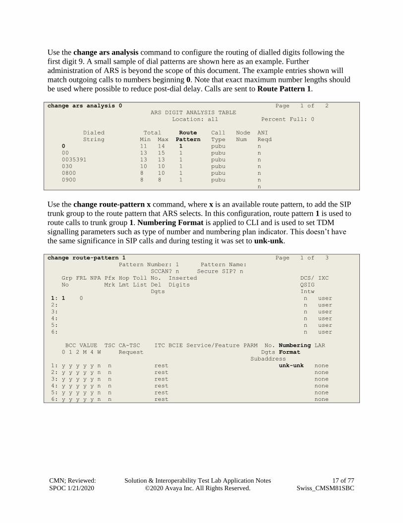
Use the change ars analysis command to configure the routing of dialled digits following the
first digit 9. A small sample of dial patterns are shown here as an example. Further
administration of ARS is beyond the scope of this document. The example entries shown will
match outgoing calls to numbers beginning 0. Note that exact maximum number lengths should
be used where possible to reduce post-dial delay. Calls are sent to Route Pattern 1.
change ars analysis 0 Page 1 of 2
ARS DIGIT ANALYSIS TABLE
Location: all Percent Full: 0
Dialed Total Route Call Node ANI
String Min Max Pattern Type Num Reqd
0 11 14 1 pubu n
00 13 15 1 pubu n
0035391 13 13 1 pubu n
030 10 10 1 pubu n
0800 8 10 1 pubu n
0900 8 8 1 pubu n
n
Use the change route-pattern x command, where x is an available route pattern, to add the SIP
trunk group to the route pattern that ARS selects. In this configuration, route pattern 1 is used to
route calls to trunk group 1. Numbering Format is applied to CLI and is used to set TDM
signalling parameters such as type of number and numbering plan indicator. This doesn’t have
the same significance in SIP calls and during testing it was set to unk-unk.
change route-pattern 1 Page 1 of 3
Pattern Number: 1 Pattern Name:
SCCAN? n Secure SIP? n
Grp FRL NPA Pfx Hop Toll No. Inserted DCS/ IXC
No Mrk Lmt List Del Digits QSIG
Dgts Intw
1: 1 0 n user
2: n user
3: n user
4: n user
5: n user
6: n user
BCC VALUE TSC CA-TSC ITC BCIE Service/Feature PARM No. Numbering LAR
0 1 2 M 4 W Request Dgts Format
Subaddress
1: y y y y y n n rest unk-unk none
2: y y y y y n n rest none
3: y y y y y n n rest none
4: y y y y y n n rest none
5: y y y y y n n rest none
6: y y y y y n n rest none

CMN; Reviewed:
SPOC 1/21/2020
Solution & Interoperability Test Lab Application Notes
©2020 Avaya Inc. All Rights Reserved.
18 of 77
Swiss_CMSM81SBC
5.9. Administer Incoming Digit Translation
This step configures the settings necessary to map incoming DDI calls to the proper
Communication Manager extension(s). The incoming digits sent in the INVITE message from
Swisscom can be manipulated as necessary to route calls to the desired extension. In the
examples used in the compliance testing, the incoming DDI numbers provided by Swisscom
Enterprise SIP platform correlate to the internal extensions assigned within Communication
Manager. The entries displayed below translate incoming DDI numbers +41438xxxxx80,
+41438xxxxx81, +41438xxxxx82 and +41438xxxxx83 to a 4-digit extension by deleting all of
the incoming digits and inserting an extension.
change inc-call-handling-trmt trunk-group 1 Page 1 of 3
INCOMING CALL HANDLING TREATMENT
Service/ Number Del Insert
Feature Len Digits
public-ntwrk 13 +41438xxxxx80 all 6102
public-ntwrk 13 +41438xxxxx81 all 6010
public-ntwrk 13 +41438xxxxx82 all 6020
public-ntwrk 13 +41438xxxxx83 all 6104

CMN; Reviewed:
SPOC 1/21/2020
Solution & Interoperability Test Lab Application Notes
©2020 Avaya Inc. All Rights Reserved.
19 of 77
Swiss_CMSM81SBC
5.10. EC500 Configuration
When EC500 is enabled on a Communication Manager station, a call to that station will generate
a new outbound call from Communication Manager to the configured EC500 destination,
typically a mobile phone.
The following screen shows an example EC500 configuration for the user with station extension
6102. Use the command change off-pbx-telephone station-mapping x where x is
Communication Manager station.
• The Station Extension field will automatically populate with station extension.
• For Application enter EC500.
• Enter a Dial Prefix if required by the routing configuration, none was required during
testing.
• For the Phone Number enter the phone that will also be called (e.g. 0035389434xxxx).
• Set the Trunk Selection to ars so that the ARS table will be used for routing.
• Set the Config Set to 1.
change off-pbx-telephone station-mapping 6102 Page 1 of 3
STATIONS WITH OFF-PBX TELEPHONE INTEGRATION
Station Application Dial CC Phone Number Trunk Config Dual
Extension Prefix Selection Set Mode
6102 EC500 - 0035389434xxxx ars 1
Note: The phone number shown is for a mobile phone in the Avaya Lab. To use facilities for
calls coming in from EC500 mobile phones, the calling party number received in
Communication Manager must exactly match the number specified in the above table.
Save Communication Manager configuration by entering save translation.

CMN; Reviewed:
SPOC 1/21/2020
Solution & Interoperability Test Lab Application Notes
©2020 Avaya Inc. All Rights Reserved.
20 of 77
Swiss_CMSM81SBC
6. Configuring Avaya Aura® Session Manager This section provides the procedures for configuring Session Manager. Session Manager is
configured via System Manager. The procedures include the following areas:
• Log in to Avaya Aura® System Manager.
• Administer SIP Domain.
• Administer SIP Location.
• Administer Conditions.
• Administer Adaptations.
• Administer SIP Entities.
• Administer Entity Links.
• Administer Routing Policies.
• Administer Dial Patterns.
It may not be necessary to create all the items above when creating a connection to the service
provider since some of these items would have already been defined as part of the initial Session
Manager installation. This includes items such as certain SIP domains, locations, SIP entities,
and Session Manager itself. However, each item should be reviewed to verify the configuration.
6.1. Log in to Avaya Aura® System Manager
Access the System Manager using a web browser and entering http://<FQDN >/SMGR, where
<FQDN> is the fully qualified domain name of System Manager. Log in using appropriate
credentials (not shown) and the Dashboard tab will be presented with menu options shown
below.

CMN; Reviewed:
SPOC 1/21/2020
Solution & Interoperability Test Lab Application Notes
©2020 Avaya Inc. All Rights Reserved.
21 of 77
Swiss_CMSM81SBC
Most of the configuration items are performed in the Routing Element. Click on Routing in the
Elements column shown above to bring up the Introduction to Network Routing Policy screen.
6.2. Administer SIP Domain
Create a SIP domain for each domain for which Session Manager will need to be aware in order
to route calls. Expand Elements → Routing and select Domains from the left navigation menu,
click New (not shown). Enter the following values and use default values for remaining fields.
• Name Enter a Domain Name. In the sample configuration, avaya.com was used.
• Type Verify SIP is selected.
• Notes Add a brief description [Optional].
Click Commit to save. The screen below shows the SIP Domain defined for the sample
configuration.

CMN; Reviewed:
SPOC 1/21/2020
Solution & Interoperability Test Lab Application Notes
©2020 Avaya Inc. All Rights Reserved.
22 of 77
Swiss_CMSM81SBC
6.3. Administer Locations
Locations can be used to identify logical and/or physical locations where SIP Entities reside for
purposes of bandwidth management and call admission control. To add a location, navigate to
Routing →Locations in the left-hand navigation pane and click the New button in the right pane
(not shown). In the General section, enter the following values. Use default values for all
remaining fields:
• Name: Enter a descriptive name for the location.
• Notes: Add a brief description (optional).
The Location Pattern is used to identify call routing based on IP address. Session Manager
matches the IP address against the patterns defined in this section. If a call is from a SIP Entity
that does not match the IP address pattern, then Session Manager uses the location administered
for the SIP Entity.
In the Location Pattern section, click Add and enter the following values.
• IP Address Pattern Enter the logical pattern used to identify the location.
• Notes Add a brief description [Optional].
Click Commit to save. The screenshot below shows the Location SMGR_8 defined for the
compliance testing.

CMN; Reviewed:
SPOC 1/21/2020
Solution & Interoperability Test Lab Application Notes
©2020 Avaya Inc. All Rights Reserved.
23 of 77
Swiss_CMSM81SBC
6.4. Administer Adaptations
Session Manager Adaptations can be used to alter parameters in the SIP message headers. An
Adaptation was used during testing to remove Avaya proprietary headers from messages sent
Adaptations can be used to modify the called and calling party numbers to meet the requirements
of the service. The called party number present in the SIP INVITE Request URI is modified by
the Digit Conversion in the Adaptation. In order to improve interoperability with third party
elements, Session Manager R8.1 incorporates the ability to use Adaptation modules to remove
specific SIP headers that are either Avaya proprietary unnecessary for non-Avaya elements
For the compliance test, an Adaptation named “Swiss” was created to block the following
headers from outbound messages, before they were forwarded to the Avaya SBCE: AV-Global-
Session-ID, AV-Correlation-ID, Alert-Info, Endpoint-View, P-AV-Message-ID, P-Charging-
Vector, and P-Location. These headers contain private information from the enterprise and also
add unnecessary size to outbound messages, while they have no significance to the service
provider.
To add an adaptation, under the Routing tab select Adaptations on the left-hand menu and then
click on the New button (not shown). Under Adaptation Details →General:
• Adaption Name: Enter an appropriate name such as Swisscom.
• Module Name: Select DigitConversionAdapter.
• Modular Parameter Type: Select Name-Value Parameter.
Click Add to add the name and value parameters.
• Name: Enter eRHdrs. This parameter will remove the specific headers from
messages in the egress direction.
• Value: Enter AV-Global-Session-ID, AV-Correlation-ID, Alert-Info,
Endpoint-View, P-AV-Message-ID, P-Charging-Vector, P-Location.
• Name: Enter fromto. Modifies From and To header of a message.
• Value: Enter true.
• Name: Enter MIME. Remove MIME message bodies from Session Manager.
• Value: Enter no.

CMN; Reviewed:
SPOC 1/21/2020
Solution & Interoperability Test Lab Application Notes
©2020 Avaya Inc. All Rights Reserved.
24 of 77
Swiss_CMSM81SBC
Scroll down the page and under Digit Conversion for Outgoing Calls from SM, click the Add
button and specify the digit manipulation to be performed as follows:
• Enter the leading digits that will be matched in the Matching Pattern field.
• In the Min and Max fields set the minimum and maximum digits allowed in the digit
string to be matched.
• In the Delete Digits field enter the number of leading digits to be removed.
• In the Insert Digits field specify the digits to be prefixed to the digit string.
• In the Address to modify field specify the digits to manipulate by the adaptation. In this
configuration the dialed number is the target so both have been selected.
This will ensure any outgoing numbers matching 00 will be deleted and have + inserted being
converted to E.164 format before being forwarded to the Avaya SBCE.

CMN; Reviewed:
SPOC 1/21/2020
Solution & Interoperability Test Lab Application Notes
©2020 Avaya Inc. All Rights Reserved.
25 of 77
Swiss_CMSM81SBC
6.5. Administer SIP Entities
A SIP Entity must be added for each SIP-based telephony system supported by a SIP connection
to Session Manager. To add a SIP Entity, select SIP Entities on the left panel menu and then
click on the New button (not shown). The following will need to be entered for each SIP Entity.
Under General:
• In the Name field enter an informative name.
• In the FQDN or IP Address field enter the IP address of Session Manager or the
signalling interface on the connecting system.
• In the Type field use Session Manager for a Session Manager SIP Entity, CM for a
Communication Manager SIP Entity, Voice Portal for an Experience Portal SIP Entity
and SIP Trunk for the Avaya SBCE SIP Entities.
• In the Location field select the appropriate location from the drop-down menu.
• In the Time Zone field enter the time zone for the SIP Entity.
In this configuration there are four SIP Entities.
• Session Manager SIP Entity.
• Communication Manager SIP Entity.
• Experience Portal SIP Entity.
• Avaya SBCE SIP Entity.

CMN; Reviewed:
SPOC 1/21/2020
Solution & Interoperability Test Lab Application Notes
©2020 Avaya Inc. All Rights Reserved.
26 of 77
Swiss_CMSM81SBC
6.5.1. Avaya Aura® Session Manager SIP Entity
The following screens show the SIP entity for Session Manager. The FQDN or IP Address field
is set to the IP address of the Session Manager SIP signalling interface and Type is Session
Manager. Set the Location to that defined in Section 6.3 and the Time Zone to the appropriate
time.
Session Manager must be configured with the port numbers on the protocols that will be used by
the other SIP entities. To configure these scroll to the bottom of the page and under Port, click
Add, then edit the fields in the resulting new row.
• In the Port field enter the port number on which the system listens for SIP requests.
• In the Protocol field enter the transport protocol to be used for SIP requests.
• In the Default Domain field, from the drop-down menu select the domain added in
Section 6.2 as the default domain.

CMN; Reviewed:
SPOC 1/21/2020
Solution & Interoperability Test Lab Application Notes
©2020 Avaya Inc. All Rights Reserved.
27 of 77
Swiss_CMSM81SBC
6.5.2. Avaya Aura® Communication Manager SIP Entity
The following screen shows the SIP entity for Communication Manager which is configured as
an Evolution Server. This SIP Entity is used for the SIP Trunk. The FQDN or IP Address field
is set to the IP address of the interface on Communication Manager that will be providing SIP
signalling. Set the Location to that defined in Section 6.3.
Other parameters can be set for the SIP Entity as shown in the following screenshot, but for test,
these were left at default values.
CMN; Reviewed:
SPOC 1/21/2020
Solution & Interoperability Test Lab Application Notes
©2020 Avaya Inc. All Rights Reserved.
28 of 77
Swiss_CMSM81SBC
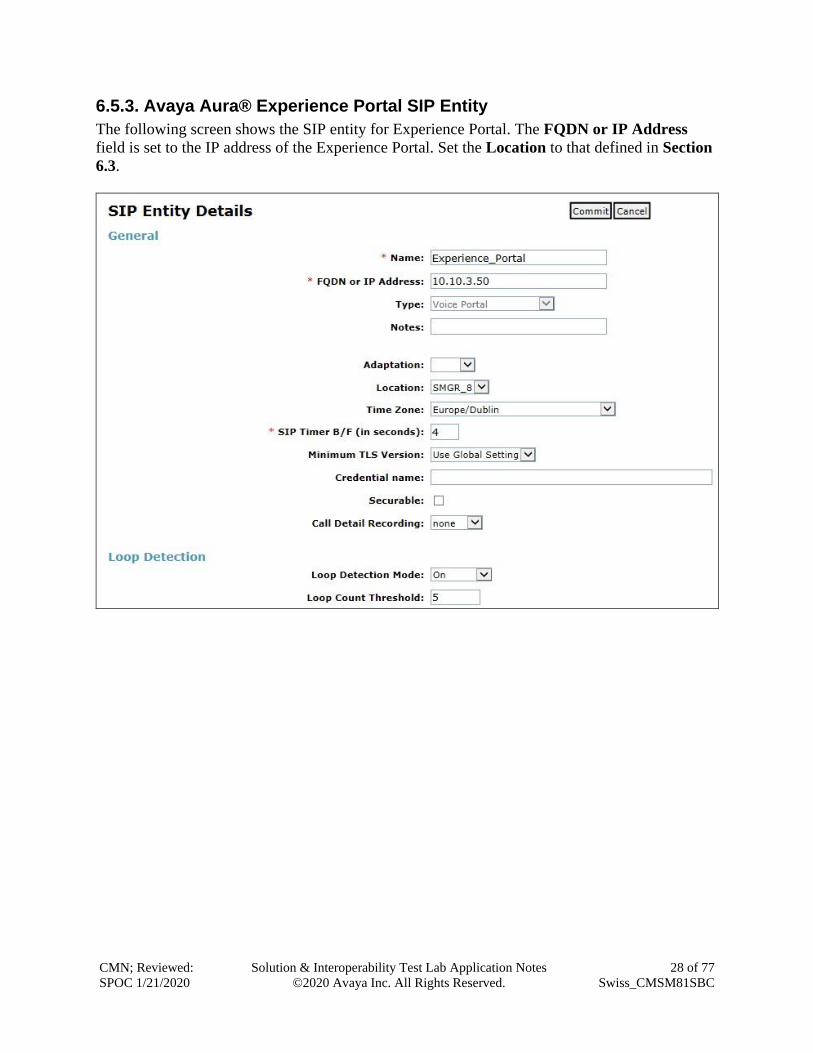
6.5.3. Avaya Aura® Experience Portal SIP Entity
The following screen shows the SIP entity for Experience Portal. The FQDN or IP Address
field is set to the IP address of the Experience Portal. Set the Location to that defined in Section
6.3.

CMN; Reviewed:
SPOC 1/21/2020
Solution & Interoperability Test Lab Application Notes
©2020 Avaya Inc. All Rights Reserved.
29 of 77
Swiss_CMSM81SBC
6.5.4. Avaya Session Border Controller for Enterprise SIP Entity
The following screen shows the SIP Entity for the Avaya SBCE used for PSTN destinations. The
FQDN or IP Address field is set to the IP address of the Avaya SBCE private network interface
(See Section 8.4.1). Set the Adaptation to that defined in Section 6.4, the Location to that
defined in Section 6.3 and the Time Zone to the appropriate time zone.

CMN; Reviewed:
SPOC 1/21/2020
Solution & Interoperability Test Lab Application Notes
©2020 Avaya Inc. All Rights Reserved.
30 of 77
Swiss_CMSM81SBC
6.6. Administer Entity Links
A SIP trunk between a Session Manager and another system is described by an Entity Link. To
add an Entity Link, select Entity Links on the left panel menu and click on the New button (not
shown). Fill in the following fields in the new row that is displayed.
• In the Name field enter an informative name.
• In the SIP Entity 1 field select Session Manager.
• In the Protocol field enter the transport protocol to be used to send SIP requests.
• In the Port field enter the port number to which the other system sends its SIP requests.
• In the SIP Entity 2 field enter the other SIP Entity for this link, created in Section 6.5.
• In the Port field enter the port number to which the other system expects to receive SIP
requests.
• Select Trusted from the drop-down menu to make the other system trusted.
Click Commit to save changes. The following screenshot shows the Entity Links used in this
configuration.

CMN; Reviewed:
SPOC 1/21/2020
Solution & Interoperability Test Lab Application Notes
©2020 Avaya Inc. All Rights Reserved.
31 of 77
Swiss_CMSM81SBC
6.7. Administer Routing Policies
Routing policies must be created to direct how calls will be routed to a system. To add a routing
policy, select Routing Policies on the left panel menu and then click on the New button (not
shown). Under General:
• Enter an informative name in the Name field
• Under SIP Entity as Destination, click Select, and then select the appropriate SIP entity
to which this routing policy applies
• Under Time of Day, click Add, and then select the time range
The following screen shows the routing policy for calls inbound from the SIP Trunk to
Communication Manager.
The following screen shows the routing policy for Avaya SBCE for the Swisscom SIP trunk.

CMN; Reviewed:
SPOC 1/21/2020
Solution & Interoperability Test Lab Application Notes
©2020 Avaya Inc. All Rights Reserved.
32 of 77
Swiss_CMSM81SBC
The following screen shows the routing policy for calls inbound from the SIP Trunk to
Experience Portal.
6.8. Administer Dial Patterns
A dial pattern must be defined to direct calls to the appropriate telephony system. To configure a
dial pattern, select Dial Patterns on the left panel menu and then click on the New button (not
shown).
Under General:
• In the Pattern field enter a dialled number or prefix to be matched.
• In the Min field enter the minimum length of the dialled number.
• In the Max field enter the maximum length of the dialled number.
• In the SIP Domain field select ALL or alternatively one of those configured in Section
6.2.
Under Originating Locations and Routing Policies:
• Click Add, in the resulting screen (not shown).
• Under Originating Location, select the location defined in Section 6.3 or ALL.
• Under Routing Policies select one of the routing policies defined in Section 6.7.
• Click Select button to save.
CMN; Reviewed:
SPOC 1/21/2020
Solution & Interoperability Test Lab Application Notes
©2020 Avaya Inc. All Rights Reserved.
33 of 77
Swiss_CMSM81SBC
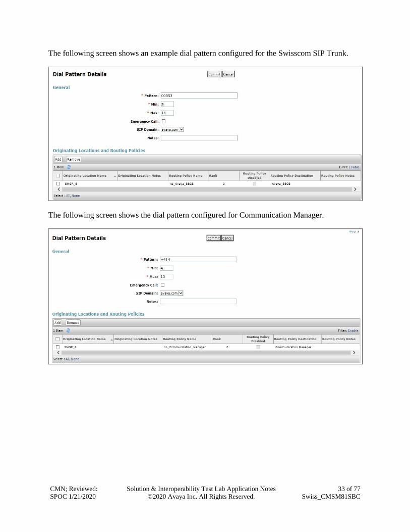
The following screen shows an example dial pattern configured for the Swisscom SIP Trunk.
The following screen shows the dial pattern configured for Communication Manager.

CMN; Reviewed:
SPOC 1/21/2020
Solution & Interoperability Test Lab Application Notes
©2020 Avaya Inc. All Rights Reserved.
34 of 77
Swiss_CMSM81SBC
The following screen shows the dial pattern configured for Experience Portal.

CMN; Reviewed:
SPOC 1/21/2020
Solution & Interoperability Test Lab Application Notes
©2020 Avaya Inc. All Rights Reserved.
35 of 77
Swiss_CMSM81SBC
7. Configure Avaya Aura® Experience Portal These Application Notes assume that the necessary Experience Portal licenses have been
installed and basic Experience Portal administration has already been performed. Consult [13] in
the References section for further details if necessary.
7.1. Background
Experience Portal consists of one or more Media Processing Platform (MPP) servers and an
Experience Portal Manager (EPM) server. A single “server configuration” was used in the
reference configuration. This consisted of a single MPP and EPM, running on a VMware
environment, including an Apache Tomcat Application Server (hosting the Voice XML (VXML)
and/or Call Control XML (CCXML) application scripts), that provide the directives to
Experience Portal for handling the inbound calls.
References to the Voice XML and/or Call Control XML applications are administered on
Experience Portal, along with one or more called numbers for each application reference. When
an inbound call arrives at Experience Portal, the called party DDI number is matched against
those administered called numbers. If a match is found, then the corresponding application is
accessed to handle the call. If no match is found, Experience Portal informs the caller that the
call cannot be handled, and disconnects the call sample configuration described in these
Application Notes. A simple VXML test application was used to exercise various SIP call flow
scenarios with the Swisscom SIP Trunk service. In production, enterprises can develop their own
VXML and/or CCXML applications to meet specific customer self-service needs, or consult
Avaya Professional Services and/or authorized Avaya Business Partners. The development and
deployment of VXML and CCXML applications is beyond the scope of these Application Notes.

CMN; Reviewed:
SPOC 1/21/2020
Solution & Interoperability Test Lab Application Notes
©2020 Avaya Inc. All Rights Reserved.
36 of 77
Swiss_CMSM81SBC
7.2. Logging In and Licensing
This section describes the steps on Experience Portal for administering a SIP connection to the
Session Manager.
Step 1 - Launch a web browser, enter http://<IP address of the Avaya EPM server>/ in the URL,
log in with the appropriate credentials and the following screen is displayed.
Step 2 - In the left pane, navigate to Security→Licensing. On the Licensing page, verify that
Experience Portal is properly licensed. If required licenses are not enabled, contact an
authorized Avaya representative to obtain the licenses.
CMN; Reviewed:
SPOC 1/21/2020
Solution & Interoperability Test Lab Application Notes
©2020 Avaya Inc. All Rights Reserved.
37 of 77
Swiss_CMSM81SBC
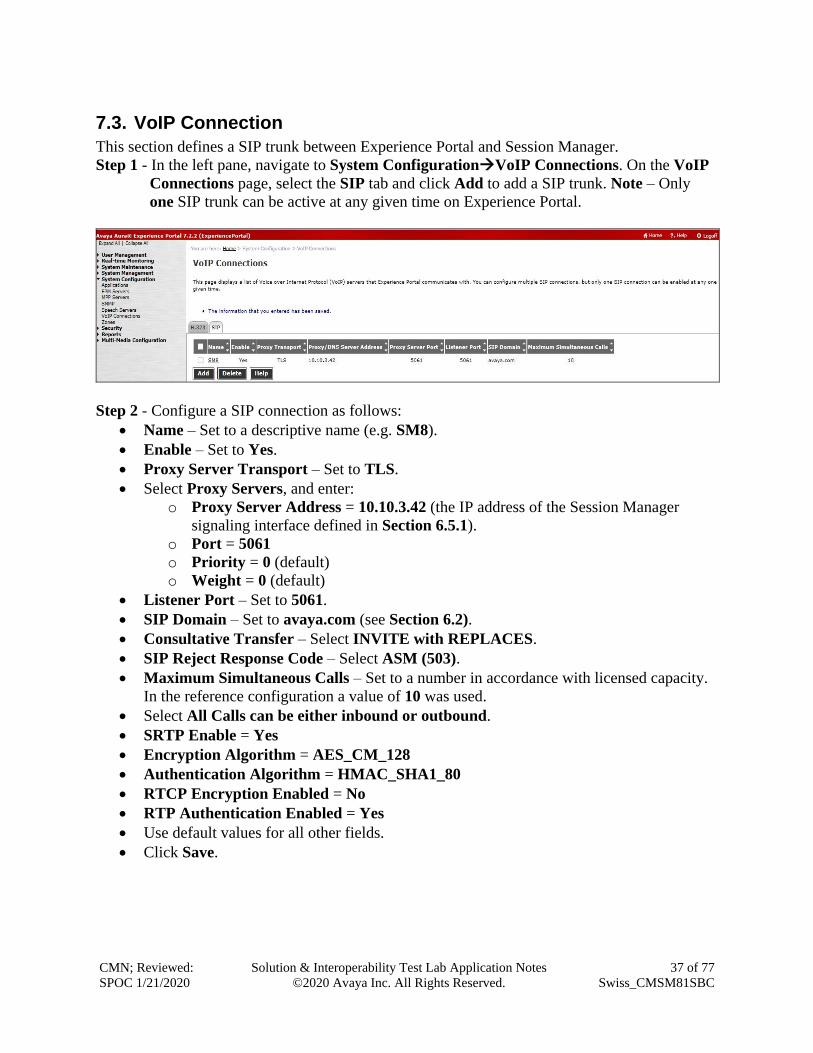
7.3. VoIP Connection
This section defines a SIP trunk between Experience Portal and Session Manager.
Step 1 - In the left pane, navigate to System Configuration→VoIP Connections. On the VoIP
Connections page, select the SIP tab and click Add to add a SIP trunk. Note – Only
one SIP trunk can be active at any given time on Experience Portal.
Step 2 - Configure a SIP connection as follows:
• Name – Set to a descriptive name (e.g. SM8).
• Enable – Set to Yes.
• Proxy Server Transport – Set to TLS.
• Select Proxy Servers, and enter:
o Proxy Server Address = 10.10.3.42 (the IP address of the Session Manager
signaling interface defined in Section 6.5.1).
o Port = 5061
o Priority = 0 (default)
o Weight = 0 (default)
• Listener Port – Set to 5061.
• SIP Domain – Set to avaya.com (see Section 6.2).
• Consultative Transfer – Select INVITE with REPLACES.
• SIP Reject Response Code – Select ASM (503).
• Maximum Simultaneous Calls – Set to a number in accordance with licensed capacity.
In the reference configuration a value of 10 was used.
• Select All Calls can be either inbound or outbound.
• SRTP Enable = Yes
• Encryption Algorithm = AES_CM_128
• Authentication Algorithm = HMAC_SHA1_80
• RTCP Encryption Enabled = No
• RTP Authentication Enabled = Yes
• Use default values for all other fields.
• Click Save.
CMN; Reviewed:
SPOC 1/21/2020
Solution & Interoperability Test Lab Application Notes
©2020 Avaya Inc. All Rights Reserved.
38 of 77
Swiss_CMSM81SBC
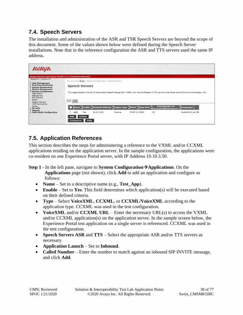
7.4. Speech Servers
The installation and administration of the ASR and TSR Speech Servers are beyond the scope of
this document. Some of the values shown below were defined during the Speech Server
installations. Note that in the reference configuration the ASR and TTS servers used the same IP
address.
7.5. Application References
This section describes the steps for administering a reference to the VXML and/or CCXML
applications residing on the application server. In the sample configuration, the applications were
co-resident on one Experience Portal server, with IP Address 10.10.3.50.
Step 1 - In the left pane, navigate to System Configuration→Applications. On the
Applications page (not shown), click Add to add an application and configure as
follows:
• Name – Set to a descriptive name (e.g., Test_App).
• Enable – Set to Yes. This field determines which application(s) will be executed based
on their defined criteria.
• Type – Select VoiceXML, CCXML, or CCXML/VoiceXML according to the
application type. CCXML was used in the test configuration.
• VoiceXML and/or CCXML URL – Enter the necessary URL(s) to access the VXML
and/or CCXML application(s) on the application server. In the sample screen below, the
Experience Portal test application on a single server is referenced. CCXML was used in
the test configuration.
• Speech Servers ASR and TTS – Select the appropriate ASR and/or TTS servers as
necessary.
• Application Launch – Set to Inbound.
• Called Number – Enter the number to match against an inbound SIP INVITE message,
and click Add.

CMN; Reviewed:
SPOC 1/21/2020
Solution & Interoperability Test Lab Application Notes
©2020 Avaya Inc. All Rights Reserved.
39 of 77
Swiss_CMSM81SBC

CMN; Reviewed:
SPOC 1/21/2020
Solution & Interoperability Test Lab Application Notes
©2020 Avaya Inc. All Rights Reserved.
40 of 77
Swiss_CMSM81SBC
7.6. MPP Servers and VoIP Settings
This section illustrates the procedure for viewing or changing the MPP Settings. In the sample
configuration, the MPP Server is co-resident on a single server with the Experience Portal
Management server (EPM).
Step 1 - In the left pane, navigate to System Configuration→MPP Servers and the following
screen is displayed. Click Add.
Step 2 - Enter any descriptive name in the Name field (e.g. mpp1) and the IP address of the
MPP server in the Host Address field and click Continue (not shown).
Step 3 - The certificate page will open. Check the Trust this certificate box (not shown). Once
complete, click Save.

CMN; Reviewed:
SPOC 1/21/2020
Solution & Interoperability Test Lab Application Notes
©2020 Avaya Inc. All Rights Reserved.
41 of 77
Swiss_CMSM81SBC
Step 4 - Click VoIP Settings tab on the screen displayed in Step 1, and the following screen is
displayed.
• In the Port Ranges section, default ports were used.
• In the Codecs section set:
o Set Packet Time to 20.
o Verify the G711alaw, G729 and G711ulaw codecs are enabled.
o Set G729 Discontinuous Transmission to No (G.729A).
o Set the Offer Order to the preferred codec.
• Use default values for all other fields.
Step 5 - Click on Save.

CMN; Reviewed:
SPOC 1/21/2020
Solution & Interoperability Test Lab Application Notes
©2020 Avaya Inc. All Rights Reserved.
42 of 77
Swiss_CMSM81SBC
After saving the configuration changes, restart the MPP server for the change to take effect. As
shown below, the MPP may be restarted using the Restart button available via the Experience
Portal GUI at System Management → MPP Manager. Note that the State column shows when
the MPP is running after the restart.

CMN; Reviewed:
SPOC 1/21/2020
Solution & Interoperability Test Lab Application Notes
©2020 Avaya Inc. All Rights Reserved.
43 of 77
Swiss_CMSM81SBC
8. Configure Avaya Session Border Controller for Enterprise This section describes the configuration of the Session Border Controller for Enterprise (Avaya
SBCE). The Avaya SBCE provides security and manipulation of signalling to provide an
interface to the Service Provider’s SIP Trunk that is standard where possible and adapted to the
Service Provider’s SIP implementation where necessary.
8.1. Access Avaya Session Border Controller for Enterprise
Access the Avaya SBCE using a web browser by entering the URL https://<ip-address>, where
<ip-address> is the management IP address configured at installation and enter the Username
and Password.
Once logged in, on the top-left of the screen, under Device: select the required device from the
drop-down menu. with a menu on the left-hand side. In this case, GSSCP_R8 is used as a
starting point for all configuration of the Avaya SBCE.

CMN; Reviewed:
SPOC 1/21/2020
Solution & Interoperability Test Lab Application Notes
©2020 Avaya Inc. All Rights Reserved.
44 of 77
Swiss_CMSM81SBC
To view system information that was configured during installation, navigate to Device
Management. A list of installed devices is shown in the right pane. In the case of the sample
configuration, a single device named GSSCP_R8 is shown. To view the configuration of this
device, click View (the third option from the right).
The System Information screen shows the General Configuration, Device Configuration,
License Allocation, Network Configuration, DNS Configuration and Management IP
information.

CMN; Reviewed:
SPOC 1/21/2020
Solution & Interoperability Test Lab Application Notes
©2020 Avaya Inc. All Rights Reserved.
45 of 77
Swiss_CMSM81SBC
8.2. Define Network Management
Network information is required on the Avaya SBCE to allocate IP addresses and masks to the
interfaces. Note that only the A1 and B1 interfaces are used, typically the A1 interface is used for
the internal side and B1 is used for external. Each side of the Avaya SBCE can have only one
physical interface assigned.
To define the network information, navigate to Network & Flows → Network Management in
the main menu on the left-hand side and click on Add. Enter details for the external interfaces in
the dialogue box:
• Enter a descriptive name in the Name field.
• Enter the default gateway IP address for the external interfaces in the Default Gateway
field.
• Enter the subnet mask in the Network Prefix or Subnet Mask field.
• Select the external physical interface to be used from the Interface drop down menu. In
the test environment, this was B1.
• Click on Add and an additional row will appear allowing an IP address to be entered.
• Enter the external IP address of the Avaya SBCE on the SIP trunk in the IP Address
field and leave the Public IP and Gateway Override fields blank.
• Click on Finish to complete the interface definition.

CMN; Reviewed:
SPOC 1/21/2020
Solution & Interoperability Test Lab Application Notes
©2020 Avaya Inc. All Rights Reserved.
46 of 77
Swiss_CMSM81SBC
Click on Add to define the internal interfaces or Edit if it was defined during installation of the
Avaya SBCE. Enter details in the dialogue box:
• Enter a descriptive name in the Name field.
• Enter the default gateway IP address for the internal interfaces in the Default Gateway
field.
• Enter the subnet mask in the Network Prefix or Subnet Mask field.
• Select the internal physical interface to be used from the Interface drop down menu. In
the test environment, this was A1.
• Click on Add and an additional row will appear allowing an IP address to be entered.
• Enter the internal IP address of the Avaya SBCE on the SIP trunk in the IP Address field
and leave the Public IP and Gateway Override fields blank.
• Click on Finish to complete the interface definition.
The following screenshot shows the completed Network Management configuration:

CMN; Reviewed:
SPOC 1/21/2020
Solution & Interoperability Test Lab Application Notes
©2020 Avaya Inc. All Rights Reserved.
47 of 77
Swiss_CMSM81SBC
Select the Interfaces tab and click on the Status of the physical interface to toggle the state.
Change the state to Enabled where required.
Note: to ensure that the Avaya SBCE uses the interfaces defined, the Application must be
restarted.
• Click on Device Management in the main menu (not shown).
• Select Restart Application indicated by an icon in the status bar (not shown).
A status box will appear that will indicate when the restart is complete.

CMN; Reviewed:
SPOC 1/21/2020
Solution & Interoperability Test Lab Application Notes
©2020 Avaya Inc. All Rights Reserved.
48 of 77
Swiss_CMSM81SBC
8.3. Define TLS Profiles
For the compliance test, TLS transport is used for signalling on the SIP trunk between Session
Manager and the Avaya SBCE. Compliance testing was done using identity certificates signed
by a local certificate authority. The generation and installation of these certificates are beyond
the scope of these Application Notes.
The following procedures show how to view the certificates and configure the Client and Server
profiles to support the TLS connection.
8.3.1. Certificates
To view the certificates currently installed on the Avaya SBCE, navigate to TLS Management
→ Certificates:
• Verify that an Avaya SBCE identity certificate (asbce40int.pem) is present under
Installed Certificates.
• Verify that certificate authority root certificate (SystemManagerCA.pem) is present
under Installed CA certificates.
• Verify that private key associated with the identity certificate (asbce40int.key) is present
under Installed Keys.

CMN; Reviewed:
SPOC 1/21/2020
Solution & Interoperability Test Lab Application Notes
©2020 Avaya Inc. All Rights Reserved.
49 of 77
Swiss_CMSM81SBC
8.3.2. Client Profile
To create a new client profile, navigate to TLS Management → Client Profile in the left pane
and click Add (not shown).
• Set Profile Name to a descriptive name. GSSCP_Client was used in the compliance testing.
• Set Certificate to the identity certificate asbce40int.pem used in the compliance testing.
• Peer Verification is automatically set to Required.
• Set Peer Certificate Authorities to the SystemManagerCA.pem identity certificate.
• Set Verification Depth to 1.
Click Next to accept default values for the next screen and click Finish (not shown).

CMN; Reviewed:
SPOC 1/21/2020
Solution & Interoperability Test Lab Application Notes
©2020 Avaya Inc. All Rights Reserved.
50 of 77
Swiss_CMSM81SBC
8.3.3. Server Profile
To create a new server profile, navigate to TLS Management → Server Profile in the left pane
and click Add (not shown).
• Set Profile Name to a descriptive name. GSSCP_Server was used in the compliance testing
• Set Certificate to the identity certificate asbce40int.pem used in the compliance testing.
• Set Peer Verification to Optional.
Click Next to accept default values for the next screen and click Finish (not shown).

CMN; Reviewed:
SPOC 1/21/2020
Solution & Interoperability Test Lab Application Notes
©2020 Avaya Inc. All Rights Reserved.
51 of 77
Swiss_CMSM81SBC
8.4. Define Interfaces
When the IP addresses and masks are assigned to the interfaces, these are then configured as
signalling and media interfaces.
8.4.1. Signalling Interfaces
To define the signalling interfaces on the Avaya SBCE, navigate to Network & Flows →
Signaling Interface from the menu on the left-hand side. Details of transport protocol and ports
for the internal and external SIP signalling are entered here.
To enter details of transport protocol and ports for the SIP signalling on the internal interface:
• Select Add and enter details of the internal signalling interface in the pop-up menu (not
shown).
• In the Name field enter a descriptive name for the interface.
• For Signaling IP, select the A1_Internal signalling interface IP addresses defined in
Section 8.2.
• Select TLS port number, 5061 is used for Session Manager.
• Select a TLS Profile defined in Section 8.3.3 from the drop-down menu.
• Click Finish.
To enter details of transport protocol and ports for the SIP signalling on the external interface:
• Select Add and enter details of the external signalling interface in the pop-up menu (not
shown).
• In the Name field enter a descriptive name for the external signalling interface.
• For Signaling IP, select the B1_external signalling interface IP address defined in
Section 8.2.
• Select TCP port number, 5060 is used for the Swisscom SIP Trunk.
• Click Finish.

CMN; Reviewed:
SPOC 1/21/2020
Solution & Interoperability Test Lab Application Notes
©2020 Avaya Inc. All Rights Reserved.
52 of 77
Swiss_CMSM81SBC
8.4.2. Media Interfaces
To define the media interfaces on the Avaya SBCE, navigate to Network & Flows → Media
Interface from the menu on the left-hand side. Details of the RTP and SRTP port ranges for the
internal and external media streams are entered here. The IP addresses for media can be the same
as those used for signalling.
To enter details of the media IP and RTP port range for the internal interface to be used in the
server flow:
• Select Add Media Interface and enter details in the pop-up menu.
• In the Name field enter a descriptive name for the internal media interface.
• For Media IP, select the A1_Internal media interface IP address defined in Section 8.2.
• For Port Range, enter 35000-40000.
• Click Finish.
To enter details of the media IP and RTP port range on the external interface to be used in the
server flow.
• Select Add Media Interface and enter details in the pop-up menu.
• In the Name field enter a descriptive name for the external media interface.
• For Media IP, select the B1_External media interface IP address defined in Section 8.2.
• Select Port Range, enter 35000-40000.
• Click Finish.

CMN; Reviewed:
SPOC 1/21/2020
Solution & Interoperability Test Lab Application Notes
©2020 Avaya Inc. All Rights Reserved.
53 of 77
Swiss_CMSM81SBC
8.5. Define Server Interworking
Server interworking is defined for each server connected to the Avaya SBCE. In this case,
Swisscom is connected as the Trunk Server and Session Manager is connected as the Call Server.
8.5.1. Server Interworking Avaya
Server Interworking allows the configuration and management of various SIP call server-specific
capabilities such as call hold and T.38. From the left-hand menu select Configuration Profiles
→ Server Interworking and click on Add.
• Enter profile name such as Avaya and click Next (Not Shown).
• Check Hold Support = None.
• Check T.38 Support.
• All other options on the General Tab can be left at default.

CMN; Reviewed:
SPOC 1/21/2020
Solution & Interoperability Test Lab Application Notes
©2020 Avaya Inc. All Rights Reserved.
54 of 77
Swiss_CMSM81SBC
On the Advanced Tab:
• Check Record Routes = Both Sides.
• Ensure Extensions = Avaya.
• Check Has Remote SBC.
• All other options on the Advanced Tab can be left at default.
Click Finish.

CMN; Reviewed:
SPOC 1/21/2020
Solution & Interoperability Test Lab Application Notes
©2020 Avaya Inc. All Rights Reserved.
55 of 77
Swiss_CMSM81SBC
8.5.2. Server Interworking – Swisscom
Server Interworking allows the configuration and management of various SIP call server-specific
capabilities such as call hold and T.38. From the left-hand menu select Configuration Profiles
→ Server Interworking and click on Add.
• Enter profile name such as Swisscom and click Next (Not Shown).
• Check Hold Support = None.
• Check Refer Handling as per Section 2.2.
• Check T.38 Support.
• All other options on the General Tab can be left at default.

CMN; Reviewed:
SPOC 1/21/2020
Solution & Interoperability Test Lab Application Notes
©2020 Avaya Inc. All Rights Reserved.
56 of 77
Swiss_CMSM81SBC
On the Advanced Tab:
• Check Record Routes = Both Sides.
• Ensure Extensions = None.
• Check Has Remote SBC.
• All other options on the Advanced Tab can be left at default.
Click Finish.

CMN; Reviewed:
SPOC 1/21/2020
Solution & Interoperability Test Lab Application Notes
©2020 Avaya Inc. All Rights Reserved.
57 of 77
Swiss_CMSM81SBC
8.6. Signalling Manipulation
The Signaling Manipulation feature allows the ability to add, change and delete any of the
headers in a SIP message. This feature will add the ability to configure such manipulation in a
highly flexible manner using a proprietary scripting language called SigMa. The SigMa scripting
language is designed to express any of the SIP header manipulation operations to be done by the
Avaya SBCE
During compliance testing, Swisscom required different timer values for the Session-Expires and
Min-SE timers. Swisscom required values of 1800 for Session-Expires and 360 for Min-SE. A
script was implemented on the Avaya SBCE to change the value of the Min-SE timer from 1800
to 360.
To define the signalling manipulation to change the value of the Min-SE timer from 1800 to 360,
navigate to Configuration Profiles → Signaling Manipulation and click on Add (not shown)
and enter a title. A new blank SigMa Editor window will pop up. The script text is as follows:
/*Script to change Min-SE Value */
within session "INVITE"
{
act on request where %DIRECTION="OUTBOUND" and %ENTRY_POINT="POST_ROUTING"
{
if(exists(%HEADERS["Min-SE"][1])) then
{
%HEADERS["Min-SE"][1].regex_replace("1800", "360");
}
}
}
Once entered and saved, the script appears as shown in the following screenshot:

CMN; Reviewed:
SPOC 1/21/2020
Solution & Interoperability Test Lab Application Notes
©2020 Avaya Inc. All Rights Reserved.
58 of 77
Swiss_CMSM81SBC
8.7. Define Servers
Servers are defined for each server connected to the Avaya SBCE. In this case, Swisscom is
connected as the Trunk Server and Session Manager is connected as the Call Server.
8.7.1. Server Configuration – Avaya
From the left-hand menu select Services → SIP Servers and click on Add and enter a
descriptive name. On the Add Server Configuration Profiles tab, set the following:
• Select Server Type to be Call Server.
• Select TLS Client Profile to be GSSCP_Client as defined in Section 8.3.2.
• Enter IP Address / FQDN to 10.10.3.42 (Session Manager IP Address).
• For Port, enter 5061.
• For Transport, select TLS.
• Click on Next (not shown) to use default entries on the Authentication and Heartbeat
tabs.

CMN; Reviewed:
SPOC 1/21/2020
Solution & Interoperability Test Lab Application Notes
©2020 Avaya Inc. All Rights Reserved.
59 of 77
Swiss_CMSM81SBC
On the Advanced tab:
• Check Enable Grooming.
• Select Avaya for Interworking Profile.
• Click Finish.

CMN; Reviewed:
SPOC 1/21/2020
Solution & Interoperability Test Lab Application Notes
©2020 Avaya Inc. All Rights Reserved.
60 of 77
Swiss_CMSM81SBC
8.7.2. Server Configuration – Swisscom
To define the Swisscom Trunk Server, navigate to Services → SIP Servers and click on Add
and enter a descriptive name. On the Add Server Configuration Profile tab, set the following:
• Select Server Type to be Trunk Server.
• Enter IP Address / FQDN to 10.254.150.52 (Swisscom SIP Platform).
• For Port, enter 5060.
• For Transport, select TCP.
• Click on Next (not shown) to use default entries on the Authentication and Heartbeat
tabs.

CMN; Reviewed:
SPOC 1/21/2020
Solution & Interoperability Test Lab Application Notes
©2020 Avaya Inc. All Rights Reserved.
61 of 77
Swiss_CMSM81SBC
On the Advanced tab:
• Check Enable Grooming.
• Select Swisscom for Interworking Profile.
• Select MIN-SE for Signalling Manipulation Script as per Section 8.6.
• Click Finish.

CMN; Reviewed:
SPOC 1/21/2020
Solution & Interoperability Test Lab Application Notes
©2020 Avaya Inc. All Rights Reserved.
62 of 77
Swiss_CMSM81SBC
8.8. Routing
Routing profiles define a specific set of packet routing criteria that are used in conjunction with
other types of domain policies to identify a particular call flow and thereby ascertain which
security features will be applied to those packets. Parameters defined by Routing Profiles include
packet transport settings, name server addresses and resolution methods, next hop routing
information, and packet transport types.
Routing information is required for routing to Session Manager on the internal side and
Swisscom address on the external side. The IP addresses and ports defined here will be used as
the destination addresses for signalling. If no port is specified in the Next Hop IP Address,
default 5060 is used.
8.8.1. Routing – Avaya
Create a Routing Profile for Session Manager.
• Navigate to Configuration Profiles → Routing and select Add Profile.
• Enter a Profile Name and click Next.
The Routing Profile window will open. Use the default values displayed and click Add.

CMN; Reviewed:
SPOC 1/21/2020
Solution & Interoperability Test Lab Application Notes
©2020 Avaya Inc. All Rights Reserved.
63 of 77
Swiss_CMSM81SBC
On the Next Hop Address window, set the following:
• Priority/Weight = 1.
• SIP Server Profile = Avaya (Section 8.7.1) from drop down menu.
• Next Hop Address = Select 10.10.3.42:5061(TLS) from drop down menu.
• Click Finish.
8.8.2. Routing – Swisscom
Create a Routing Profile for Swisscom SIP network.
• Navigate to Configuration Profiles → Routing and select Add Profile.
• Enter a Profile Name and click Next.

CMN; Reviewed:
SPOC 1/21/2020
Solution & Interoperability Test Lab Application Notes
©2020 Avaya Inc. All Rights Reserved.
64 of 77
Swiss_CMSM81SBC
The Routing Profile window will open. Use the default values displayed and click Add.
On the Next Hop Address window, set the following:
• Priority/Weight = 1.
• SIP Server Profile = Swisscom (Section 8.7.2) from drop down menu.
• Next Hop Address = Select 10.254.150.52 (TCP) from drop down menu.
• Click Finish.

CMN; Reviewed:
SPOC 1/21/2020
Solution & Interoperability Test Lab Application Notes
©2020 Avaya Inc. All Rights Reserved.
65 of 77
Swiss_CMSM81SBC
8.9. Topology Hiding
Topology hiding is used to hide local information such as private IP addresses and local domain
names. The local information can be overwritten with a domain name or IP addresses. The
default Replace Action is Auto, this replaces local information with IP addresses, generally the
next hop. Topology hiding has the advantage of presenting single Via and Record-Route headers
externally where multiple headers may be received from the enterprise. In some cases where
Topology Hiding can’t be applied, in particular the Contact header, IP addresses are translated to
the Avaya SBCE external addresses using NAT.
To define Topology Hiding for Session Manager, navigate to Configuration Profiles →
Topology Hiding from menu on the left-hand side. Click on Add and enter details in the
Topology Hiding Profile pop-up menu (not shown).
• Enter a descriptive Profile Name such as Avaya.
• If the required Header is not shown, click on Add Header.
• Under the Header field for To, From and Request Line, select IP/Domain under
Criteria and Overwrite under Replace Action. For Overwrite value, insert avaya.com.
• Click Finish (not shown).

CMN; Reviewed:
SPOC 1/21/2020
Solution & Interoperability Test Lab Application Notes
©2020 Avaya Inc. All Rights Reserved.
66 of 77
Swiss_CMSM81SBC
To define Topology Hiding for Swisscom, navigate to Configuration Profiles → Topology
Hiding from the menu on the left-hand side. Click on Add and enter details in the Topology
Hiding Profile pop-up menu (not shown).
• In the Profile Name field enter a descriptive name for Swisscom and click Next.
• If the required Header is not shown, click on Add Header.
• Under the Header field for To, From and Request Line, select IP/Domain under
Criteria and Auto under Replace Action.
• Click Finish (not shown).
8.10. Domain Policies
Domain Policies allow the configuration of sets of rules designed to control and normalize the
behavior of call flows, based upon various criteria of communication sessions originating from
or terminating in the enterprise. Domain Policies include rules for Application, Media, Signaling,
Security, etc.
In the reference configuration, only new Media Rules were defined. All other rules under
Domain Policies, linked together on End Point Policy Groups later in this section, used one of
the default sets already pre-defined in the configuration. Please note that changes should not be
made to any of the defaults. If changes are needed, it is recommended to create a new rule by
cloning one the defaults and then make the necessary changes to the new rule.

CMN; Reviewed:
SPOC 1/21/2020
Solution & Interoperability Test Lab Application Notes
©2020 Avaya Inc. All Rights Reserved.
67 of 77
Swiss_CMSM81SBC
8.10.1. Media Rules
A media rule defines the processing to be applied to the selected media. For the compliance test,
a media rule was created for Session Manager to use SRTP, while the predefined default-low-
med media rule was used for the Swisscom SIP trunk.
To define the Media Rule for Session Manager, navigate to Domain Policies →Media Rules in
the main menu on the left-hand side. Click on Add and enter details in the Media Rule pop-up
box (not shown)
• In the Rule Name field enter a descriptive name such as Avaya_SRTP.
• Set Preferred Format #1 to SRTP_AES_CM_128_HMAC_SHA1_80.
• Set Preferred Format #2 to RTP.
• Uncheck Encrypted RTCP.
• Check Capability Negotiation under Miscellaneous (not shown).
Default values were used for all other fields. Click Finish (not shown).
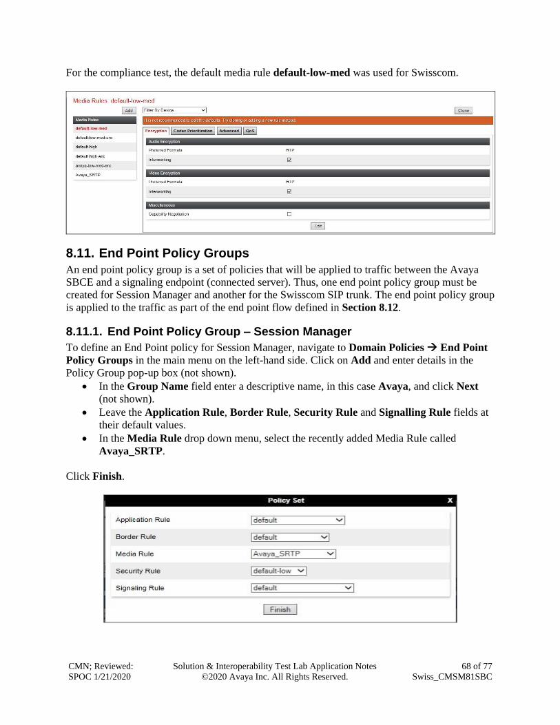
CMN; Reviewed:
SPOC 1/21/2020
Solution & Interoperability Test Lab Application Notes
©2020 Avaya Inc. All Rights Reserved.
68 of 77
Swiss_CMSM81SBC
For the compliance test, the default media rule default-low-med was used for Swisscom.
8.11. End Point Policy Groups
An end point policy group is a set of policies that will be applied to traffic between the Avaya
SBCE and a signaling endpoint (connected server). Thus, one end point policy group must be
created for Session Manager and another for the Swisscom SIP trunk. The end point policy group
is applied to the traffic as part of the end point flow defined in Section 8.12.
8.11.1. End Point Policy Group – Session Manager
To define an End Point policy for Session Manager, navigate to Domain Policies → End Point
Policy Groups in the main menu on the left-hand side. Click on Add and enter details in the
Policy Group pop-up box (not shown).
• In the Group Name field enter a descriptive name, in this case Avaya, and click Next
(not shown).
• Leave the Application Rule, Border Rule, Security Rule and Signalling Rule fields at
their default values.
• In the Media Rule drop down menu, select the recently added Media Rule called
Avaya_SRTP.
Click Finish.

CMN; Reviewed:
SPOC 1/21/2020
Solution & Interoperability Test Lab Application Notes
©2020 Avaya Inc. All Rights Reserved.
69 of 77
Swiss_CMSM81SBC
8.11.2. End Point Policy Group – Swisscom
For the compliance test, the predefined End Point Policy default-low was used for the Swisscom
End Point Policy Group.

CMN; Reviewed:
SPOC 1/21/2020
Solution & Interoperability Test Lab Application Notes
©2020 Avaya Inc. All Rights Reserved.
70 of 77
Swiss_CMSM81SBC
8.12. Server Flows
Server Flows combine the previously defined profiles into outgoing flows from Session Manager
to Swisscom’s SIP Trunk and incoming flows from Swisscom s SIP Trunk to Session Manager.
The following screen illustrates the flow through the Avaya SBCE to secure a SIP Trunk call.
This configuration ties all the previously entered information together so that calls can be routed
from Session Manager to Swisscom SIP Trunk and vice versa. The following screenshot shows
all configured flows.

CMN; Reviewed:
SPOC 1/21/2020
Solution & Interoperability Test Lab Application Notes
©2020 Avaya Inc. All Rights Reserved.
71 of 77
Swiss_CMSM81SBC
To define a Server Flow for the Swisscom SIP Trunk, navigate to Network & Flows → End
Point Flows.
• Click on the Server Flows tab.
• Select Add Flow and enter details in the pop-up menu.
• In the Name field enter a descriptive name for the server flow for Swisscom SIP Trunk,
in the test environment Trunk_Server was used.
• In the Server Configuration drop-down menu, select the Swisscom server configuration
defined in Section 8.7.2.
• In the Received Interface drop-down menu, select the internal SIP signalling interface
defined in Section 8.4.1.
• In the Signaling Interface drop-down menu, select the external SIP signalling interface
defined in Section 8.4.1.
• In the Media Interface drop-down menu, select the external media interface defined in
Section 8.4.2.
• Set the End Point Policy Group to the endpoint policy group Avaya.
• In the Routing Profile drop-down menu, select the routing profile of the Session
Manager defined in Section 8.8.1.
• In the Topology Hiding Profile drop-down menu, select the topology hiding profile of
the Swisscom SIP Trunk defined in Section 8.9 and click Finish (not shown).

CMN; Reviewed:
SPOC 1/21/2020
Solution & Interoperability Test Lab Application Notes
©2020 Avaya Inc. All Rights Reserved.
72 of 77
Swiss_CMSM81SBC
To define an incoming server flow for Session Manager from the Swisscom network, navigate to
Network & Flows → End Point Flows.
• Click on the Server Flows tab.
• Select Add Flow and enter details in the pop-up menu.
• In the Name field enter a descriptive name for the server flow for Session Manager, in
the test environment Call_Server was used.
• In the Server Configuration drop-down menu, select the server configuration for
Session Manager defined in Section 8.7.1.
• In the Received Interface drop-down menu, select the internal SIP signalling interface
defined in Section 8.4.1.
• In the Signaling Interface drop-down menu, select the external SIP signalling interface
defined in Section 8.4.1.
• In the Media Interface drop-down menu, select the external media interface defined in
Section 8.4.2.
• Set the End Point Policy Group to the endpoint policy group default-low.
• In the Routing Profile drop-down menu, select the routing profile of the Swisscom SIP
Trunk defined in Section 8.8.2.
• In the Topology Hiding Profile drop-down menu, select the topology hiding profile of
Session Manager defined in Section 8.9 and click Finish (not shown).

CMN; Reviewed:
SPOC 1/21/2020
Solution & Interoperability Test Lab Application Notes
©2020 Avaya Inc. All Rights Reserved.
73 of 77
Swiss_CMSM81SBC
9. Swisscom SIP Trunk Configuration The configuration of the Swisscom equipment used to support Swisscom’s SIP Trunk is outside
of the scope of these Application Notes and will not be covered. To obtain further information on
Swisscom equipment and system configuration please contact an authorized Swisscom
representative.
10. Verification Steps This section provides steps that may be performed to verify that the solution is configured
correctly.
1. From System Manager Home tab click on Session Manager and navigate to Session
Manager → System Status → SIP Entity Monitoring. Select the relevant SIP Entities
from the list and observe if the Conn Status and Link Status are showing as UP.
2. From Communication Manager SAT interface run the command status trunk n where n
is a previously configured SIP trunk. Observe if all channels on the trunk group display
in-service/idle.
status trunk 2
TRUNK GROUP STATUS
Member Port Service State Mtce Connected Ports
Busy
0002/001 T00011 in-service/idle no
0002/002 T00012 in-service/idle no
0002/003 T00013 in-service/idle no
0002/004 T00014 in-service/idle no
0002/005 T00015 in-service/idle no
0002/006 T00016 in-service/idle no

CMN; Reviewed:
SPOC 1/21/2020
Solution & Interoperability Test Lab Application Notes
©2020 Avaya Inc. All Rights Reserved.
74 of 77
Swiss_CMSM81SBC
3. Verify that endpoints at the enterprise site can place calls to the PSTN and that the call
remains active.
4. Verify that endpoints at the enterprise site can receive calls from the PSTN and that the
call can remain active.
5. Verify that the user on the PSTN can end an active call by hanging up.
6. Verify that an endpoint at the enterprise site can end an active call by hanging up.
7. Should issues arise with the SIP trunk, use the Avaya SBCE trace facility to check that
the OPTIONS requests sent from Session Manager via the Avaya SBCE to the network
SBCs are receiving a response.
To define the trace, navigate to Device Specific Settings → Advanced Options →
Troubleshooting → Trace in the main menu on the left-hand side and select the Packet
Capture tab.
• Select the SIP Trunk interface from the Interface drop down menu.
• Select the signalling interface IP address or from the Local Address drop down menu.
• Enter the IP address of the network SBC in the Remote Address field or enter a * to
capture all traffic.
• Specify the Maximum Number of Packets to Capture, 1000 is shown as an example.
• Specify the filename of the resultant pcap file in the Capture Filename field.
• Click on Start Capture.

CMN; Reviewed:
SPOC 1/21/2020
Solution & Interoperability Test Lab Application Notes
©2020 Avaya Inc. All Rights Reserved.
75 of 77
Swiss_CMSM81SBC
To view the trace, select the Captures tab and click on the relevant filename in the list of traces.
The trace is viewed as a standard pcap file in Wireshark. If the SIP trunk is working correctly, a
SIP response to OPTIONS in the form of a 200 OK will be seen from the Swisscom network.
11. Conclusion These Application Notes describe the configuration necessary to connect Avaya Aura ®
Communication Manager R8.1, Avaya Aura ® Session Manager 8.1 and Avaya Session Border
Controller for Enterprise R8.0 to the Swisscom Enterprise SIP platform. The Swisscom
Enterprise SIP Service is a SIP-based Voice over IP solution providing businesses a flexible,
cost-saving alternative to traditional hardwired telephony trunks. The service was successfully
tested with a number of observations listed in Section 2.2.

CMN; Reviewed:
SPOC 1/21/2020
Solution & Interoperability Test Lab Application Notes
©2020 Avaya Inc. All Rights Reserved.
76 of 77
Swiss_CMSM81SBC
12. Additional References This section references the documentation relevant to these Application Notes. Additional Avaya
product documentation is available at http://support.avaya.com.
[1] Deploying Avaya Appliance Virtualization Platform, Release 8.1, Jun 2019.
[2] Upgrading Avaya Aura® applications, Release 8.1, Jun 2019.
[3] Deploying Avaya Aura® applications from System Manager, Release 8.1, Jun 2019
[4] Deploying Avaya Aura® Communication Manager, Release 8.1, Jul 2019
[5] Administering Avaya Aura® Communication Manager, Release 8.1, Jul 2019
[6] Upgrading Avaya Aura® Communication Manager, Release 8.1, Jun 2019
[7] Deploying Avaya Aura® System Manager Release 8.1, Jul 2019
[8] Upgrading Avaya Aura® System Manager to Release 8.1, Jul 2019.
[9] Administering Avaya Aura® System Manager for Release 8.1, Jul 2019
[10] Deploying Avaya Aura® Session Manager, Release 8.1 Jun 2019
[11] Upgrading Avaya Aura® Session Manager Release 8.1, Jun 2019
[12] Administering Avaya Aura® Session Manager Release 8.1, Jun 2019
[13] Deploying Avaya Session Border Controller for Enterprise Release 8.0, Jul 2019
[14] Upgrading Avaya Session Border Controller for Enterprise Release 8.0, Jul 2019
[15] Administering Avaya Session Border Controller for Enterprise Release 8.0, Jul 2019
[16] RFC 3261 SIP: Session Initiation Protocol, http://www.ietf.org/

CMN; Reviewed:
SPOC 1/21/2020
Solution & Interoperability Test Lab Application Notes
©2020 Avaya Inc. All Rights Reserved.
77 of 77
Swiss_CMSM81SBC
©2020 Avaya Inc. All Rights Reserved.
Avaya and the Avaya Logo are trademarks of Avaya Inc. All trademarks identified by ® and
™ are registered trademarks or trademarks, respectively, of Avaya Inc. All other trademarks
are the property of their respective owners. The information provided in these Application
Notes is subject to change without notice. The configurations, technical data, and
recommendations provided in these Application Notes are believed to be accurate and
dependable, but are presented without express or implied warranty. Users are responsible for
their application of any products specified in these Application Notes.
Please e-mail any questions or comments pertaining to these Application Notes along with the
full title name and filename, located in the lower right corner, directly to the Avaya
DevConnect Program at [email protected].


![Aura e imagen dialéctica [final]](https://static.fdokumen.com/doc/165x107/631d416593f371de1901d874/aura-e-imagen-dialectica-final.jpg)