
Configuration of Avaya Aura® Session Manager 6.1, Avaya
94
VG; Reviewed: SPOC 12/01/2011 Solution & Interoperability Test Lab Application Notes ©2011 Avaya Inc. All Rights Reserved. Page 1 of 94 SmVcsEndpoints Avaya Solution & Interoperability Test Lab Configuration of Avaya Aura ® Session Manager 6.1, Avaya Aura ® Communication Manager 6.0.1 Supporting Avaya Video Endpoints and Cisco TelePresence Video Communication Server (VCS) Supporting Cisco Video Endpoints - Issue 1.0 Abstract These Application Notes describe the configuration steps necessary to connect Avaya Aura ® Session Manager 6.1 to Avaya video endpoints and Cisco TelePresence Video Communication Server (VCS) to Cisco video endpoints.
-
Upload
khangminh22 -
Category
Documents
-
view
1 -
download
0
Transcript of Configuration of Avaya Aura® Session Manager 6.1, Avaya

VG; Reviewed: SPOC 12/01/2011
Solution & Interoperability Test Lab Application Notes ©2011 Avaya Inc. All Rights Reserved.
Page 1 of 94 SmVcsEndpoints
Avaya Solution & Interoperability Test Lab
Configuration of Avaya Aura® Session Manager 6.1, Avaya Aura® Communication Manager 6.0.1 Supporting Avaya Video Endpoints and Cisco TelePresence Video Communication Server (VCS) Supporting Cisco Video Endpoints - Issue 1.0
Abstract
These Application Notes describe the configuration steps necessary to connect Avaya Aura®
Session Manager 6.1 to Avaya video endpoints and Cisco TelePresence Video Communication Server (VCS) to Cisco video endpoints.

VG; Reviewed: 11/07/2011
Solution & Interoperability Test Lab Application Notes ©2011 Avaya Inc. All Rights Reserved.
Page 2 of 94 SmVcsEndpoints SmVcsEndpoints
Table of Contents 1. Introduction ...................................................................................................................... 5
1.1. Avaya Aura® Session Manager .........................................................................................6 1.2. Avaya Aura® System Manager .........................................................................................6 1.3. Avaya Aura® Communication Manager as an Evolution Server ......................................7 1.4. Cisco TelePresence Video Communication Server ..........................................................7 1.5. Cisco TelePresence Management Suite ............................................................................7 1.6. Cisco TelePresence MCU 4501 ........................................................................................7 1.7. Network Configuration .....................................................................................................8
1.7.1. IP Addressing ............................................................................................................ 9 1.7.2. Dial Plan .................................................................................................................. 10 1.7.3. Equipment and Software Validated ........................................................................ 11
2. Configuration ................................................................................................................. 12 2.1. Administer Avaya Aura® Session Manager ....................................................................12
2.1.1. Access Avaya Aura® System Manager ................................................................... 13 2.1.2. Administer SIP Domain .......................................................................................... 13 2.1.3. Add Location .......................................................................................................... 14 2.1.4. Administer Avaya Aura® Session Manager SIP Entity .......................................... 15 2.1.5. Administer Communication Manager Evolution Server SIP Entity ....................... 17 2.1.6. Administer SIP Entity Links ................................................................................... 18 2.1.7. Define Routing Policies .......................................................................................... 19 2.1.8. Define Dial Patterns ................................................................................................ 20 2.1.9. Add Avaya Aura® Session Manager ....................................................................... 21 2.1.10. Add Avaya Aura® Communication Manager ..................................................... 23 2.1.11. Add SIP Users ..................................................................................................... 29
2.2. Avaya Aura® Communication Manager Evolution Server .............................................34 2.2.1. Verify System Capabilities and Communication Manager Licensing .................... 35 2.2.2. Administer IP Node-Name ..................................................................................... 37 2.2.3. Administer IP Codec Type ...................................................................................... 38 2.2.4. Configure IP Network Region ................................................................................ 39 2.2.5. Administer Signaling Group ................................................................................... 40 2.2.6. Add SIP Trunk Group ............................................................................................. 42

VG; Reviewed: 11/07/2011
Solution & Interoperability Test Lab Application Notes ©2011 Avaya Inc. All Rights Reserved.
Page 3 of 94 SmVcsEndpoints SmVcsEndpoints
2.2.7. Administer Dial Plan Analysis ................................................................................ 43 2.2.8. Check Station Endpoints ......................................................................................... 44 2.2.9. Check Off PBX Endpoint Mapping ........................................................................ 46 2.2.10. Save Translations ................................................................................................ 47
2.3. Administer Avaya 10x0 Video Endpoints ......................................................................47 2.3.1. Log In Avaya 1010 Video Endpoint ....................................................................... 48 2.3.2. Set Network Preferences ......................................................................................... 48 2.3.3. Configure Communications .................................................................................... 49 2.3.4. Configure System.................................................................................................... 51
2.4. Administer Avaya one-X® Communicator .....................................................................52 2.4.1. General Settings ...................................................................................................... 52
2.5. Administer Avaya Desktop Video Device (ADVD) A175 .............................................53 2.5.1. Enable G.722 Codec on ADVD .............................................................................. 57
2.6. Administer Cisco VCS ....................................................................................................57 2.6.1. Continuing Configuration Using Web Interface ..................................................... 58 2.6.2. VCS Configuration ................................................................................................. 58
2.7. Administer Cisco C20 Video Endpoint ...........................................................................68 2.7.1. Continuing Configuration Using Web Interface ..................................................... 68 2.7.2. Administering H.323 or SIP ................................................................................... 68
2.8. Administer Cisco 1700 MXP Video Endpoint ................................................................72 2.8.1. Continuing Configuration Using Web Interface ..................................................... 73 2.8.2. Administer System Configuration .......................................................................... 73
2.9. Administer Cisco EX-90 Video Endpoint .......................................................................75 2.10. Administer Cisco E20 Registered to VCS ......................................................................75
2.10.1. Access Cisco E20’s Menu System ...................................................................... 76 2.10.2. Configure IP Address Settings ............................................................................ 76 2.10.3. Turn Off Binary Flow Control Protocol (BFCP) ................................................ 76 2.10.4. Enable Network Services .................................................................................... 77 2.10.5. Configure SIP Profile Settings ............................................................................ 78
2.11. Administer Cisco Movi Endpoint ...................................................................................80 2.11.1. Adding an Endpoint Profile on the TMS Server ................................................. 80 2.11.2. Movi Client Configuration .................................................................................. 81
2.12. Administer Cisco TelePresence MCU 4501 ...................................................................83

VG; Reviewed: 11/07/2011
Solution & Interoperability Test Lab Application Notes ©2011 Avaya Inc. All Rights Reserved.
Page 4 of 94 SmVcsEndpoints SmVcsEndpoints
2.12.1. Continue Configuration Using Web Interface .................................................... 83 2.12.2. Administer Endpoints .......................................................................................... 87
3. Conclusion ..................................................................................................................... 91 4. References ...................................................................................................................... 91

VG; Reviewed: 11/07/2011
Solution & Interoperability Test Lab Application Notes ©2011 Avaya Inc. All Rights Reserved.
Page 5 of 94 SmVcsEndpoints SmVcsEndpoints
1. Introduction These Application Notes describe the configuration steps necessary to connect Avaya Aura®
Session Manager 6.1 and Avaya Aura® Communication Manager 6.0.1 via SIP Trunk supporting Avaya video endpoints, using both SIP and H.323, registered to Avaya Aura® Session Manager 6.1 and Avaya Aura® Communication Manager 6.0.1 respectively. These Application Notes also describe basic configuration steps for Cisco Video Communication Server (VCS) supporting Cisco video endpoints, using the Cisco VCS as an H.323 gatekeeper or SIP registrar. The Cisco VCS will have the protocol translation feature enabled, allowing it to translate communication between SIP and H.323 devices. Further, these Application Notes describe steps to configure Cisco TelePresence Media Conferencing MCU 4501. The headquarters location has Avaya 10x0 series conference endpoints registered to the Session Manager using the SIP protocol. Avaya one-X® Communicator, supporting video, is installed on Microsoft Windows stations. The Avaya one-X® Communicator supports both SIP and H.323 configurations and is registered to Session Manager and Communication Manager Evolution Server respectively depending on the configuration selected. The headquarters location has the following video endpoints:
• Avaya 1010 • Avaya 1020 • Avaya 1030 • Avaya 1040 • Avaya 1050 • one-X® Communicator (Windows/H.323) • one-X® Communicator (Windows/SIP)
The branch/B2BP location has Cisco the following video endpoints:
• Quick Set C20 • 1700 MXP • EX90
Each of the above Cisco endpoints located in the branch can be configured to use the H.323 or the SIP protocol and use the Cisco Video Communication Server (VCS) for registration, functioning as their H.323 gatekeeper or SIP registrar respectively. These Application Notes describe configuration steps for both the cases- H.323 and SIP. In addition, the following SIP-only video endpoints (also in the branch location) are registered to the VCS:
• Cisco Movi (Windows)

VG; Reviewed: 11/07/2011
Solution & Interoperability Test Lab Application Notes ©2011 Avaya Inc. All Rights Reserved.
Page 6 of 94 SmVcsEndpoints SmVcsEndpoints
• Cisco Movi (Mac) • Cisco E20
The aim of these Application Notes is to be able to configure endpoints in both, the headquarters and branch locations, to make calls locally within their own locations. Configuration for end-to-end connectivity between the two locations is not included. Detailed administration of other aspects of Session Manager, Communication Manager, Cisco VCS, MCU 4501, and video endpoints will not be described. For more information on these other administration actions, see the appropriate documentation listed in Section 4.
1.1. Avaya Aura® Session Manager Avaya Aura® Session Manager is a SIP routing and integration tool and the core component within the Avaya Aura® Enterprise Edition solution. It integrates all the SIP entities across the entire enterprise network within a company. Avaya Aura® Session Manager offers a new perspective on enterprise communication where individual locations are no longer managed as separate units within the enterprise. Each location, branch, or application is part of the overall enterprise, managed as an enterprise, and seen as an enterprise. Avaya Aura® Session Manager offers a simplified network-wide feature deployment; centralized routing, SIP trunking, and user profiles; cost-effective scalability from small to very large deployments, high availability with geographic redundancy and a secure environment that conforms to specific SIP standards and practices.
1.2. Avaya Aura® System Manager Central management of Avaya Aura® Session Manager is handled through the Avaya Aura® System Manager application. Avaya Aura® System Manager delivers a set of shared, secure management services and a common console across multiple products. Avaya Aura® System Manager includes the following central management services.
• User Management allows for the administration of users and user groups. Communication System Management allows for the administration of individual and group stations and mailboxes.
• Network Routing Policy is used for the administration of routing policy for all Avaya Aura® Session Manager instances within an Enterprise.
• Alarm Management Service supports alarm monitoring, acknowledgement, configuration, clearing, and retiring.
• The Logging Service receives log events formatted in the common log format. The Avaya Aura® System Manager provides miscellaneous management functions for Session Manager elements, including administering instances, configuring SIP firewalls, sequencing applications, monitoring SIP entities and security module, and managing bandwidth usage. A central database that resides on the System Manager server stores all the Avaya Aura® System Manager central data, the Avaya Aura® Session Manager administration data, and the Central Data Distribution Service information. The last item is used to detect changes to the Avaya Aura® System Manager central database and then distribute these changes to all Avaya Aura® Session Manager instances.

VG; Reviewed: 11/07/2011
Solution & Interoperability Test Lab Application Notes ©2011 Avaya Inc. All Rights Reserved.
Page 7 of 94 SmVcsEndpoints SmVcsEndpoints
1.3. Avaya Aura® Communication Manager as an Evolution Server Avaya Aura® Communication Manager as an evolution server provides Communication Manager features to both SIP and non-SIP endpoints. It uses the full call model with Communication Manager as the only supported application. Communication Manager is administered as an evolution server by disabling the IMS-enabled? field on the signaling group form. With an evolution server:
• H.323, digital, and analog endpoints register with Communication Manager
• SIP endpoints register with Session Manager
• All endpoints receive services from Communication Manager The connection from the evolution server to the Session Manager is a non-IMS signaling group. The Session Manager routes calls from and to SIP endpoints. The SIP endpoints can then communicate with all other endpoints that are connected to the Communication Manager.
1.4. Cisco TelePresence Video Communication Server The Cisco TelePresence Video Communications Server (VCS) provides internal video control and administration for Cisco SIP and H.323 video devices. The VCS operates as a SIP registrar for SIP video endpoints and as a H.323 gatekeeper for H.323 video endpoints. The VCS provides H.323 ↔ SIP interworking. The VCS can also support both SIP and H.323 trunks to other devices, such as the MCU 4501, providing local routing to the conference bridge.
1.5. Cisco TelePresence Management Suite The Cisco TelePresence Management Suite (TMS) is a video conferencing and telepresence network management platform that supports management and deployment of the Cisco video network. It works in conjunction with the Cisco VCS to form an integral part of the network comprising the Cisco TelePresence Movi client, which registers to the Cisco VCS but is provisioned by the TMS.
1.6. Cisco TelePresence MCU 4501 The MCU 4501 is an entry-level, high definition (HD) video conferencing bridge. It supports 1080p HD multipoint video conferencing. The MCU 4501 is selectable between six HD and 12 SD video ports. It provides custom layouts for video conference formats. Administration of the MCU 4501 is provided through a web based interface.

VG; Reviewed: 11/07/2011
Solution & Interoperability Test Lab Application Notes ©2011 Avaya Inc. All Rights Reserved.
Page 8 of 94 SmVcsEndpoints SmVcsEndpoints
1.7. Network Configuration
Enterprise Headquarters
Avaya Aura® Session Manager 6.1, Avaya Aura® Communication Manager 6.0.1 acting as an Evolution Server
Interoperating with Cisco VCS Via SIP Trunk and Cisco MCU 4501 registered to VCS as SIP, H.323 entity
Solution and Interoperability Test Lab
Active Directory
Ethernet Switch 192.168.230.xxx /24
Video/Data Center
G450: 192.168.230.119S8300D: 192.168.230.117
Communication Manager (Evolution Server)
Session Manager
192.168.230.123 Admin10.80.120.124 SIP
System Manager192.168.230.122Other Servers
DHCP/HTTPDNS
192.168.88.10120.20.20.199
Pow erE dg eR200
Pow erE dg eR200
Pow erE dg eR200
Pow erE dg eR200 TFTP Server
Domain: dr.avaya.com SIP Domain: tandberg.avaya.com
Video Endpoints
Avaya 1010Video Conferencing Endpoint
Avaya 1020Video Conferencing
Endpoint
Avaya 1030Video Conferencing
Endpoint
Avaya 1040Video Conferencing
Endpoint
Avaya 1050Video Conferencing Endpoint
Avaya 1XC (H.323)
Windows
Avaya 1XC (SIP)
Windows
H.323 SIP
H.3
23
SIP
GW: 135.9.230.254
Remote Branch / B2B Partner
SIP
SIP trunk
Ethernet Switch 192.168.231.xxx /24
Cisco TelePresence VCS
Video/Data Center
tandberg-1-vcs: 192.168.231.51
Cisco TelePresence MCU 4501
tandberg-1-codian: 192.168.231.52
H.323/SIP
Video Endpoints
Cisco 1700 MXPCisco EX-90
GW: 192.168.230.254
GW: 192.168.231.254
NTP: 192.168.1.2
H.3
23, S
IP
Avaya Flare(A175)
H.323, SIP
Cisco Movi(Windows)
Cisco Movi(MAC)
SIP
Video Endpoints
Cisco TelePresence TMS:192.168.231.80
WAN
Cisco C20
Cisco E20
Figure 1: Sample Configuration

VG; Reviewed: 11/07/2011
Solution & Interoperability Test Lab Application Notes ©2011 Avaya Inc. All Rights Reserved.
Page 9 of 94 SmVcsEndpoints SmVcsEndpoints
1.7.1. IP Addressing The following tables provide the IP address settings used to configure the specified devices and endpoints in the sample configuration used during testing. All devices and endpoints in this sample configuration use static IP address assignments. This was done for testing purposes and to allow monitoring and trace collection as needed. This may differ from production deployments where DHCP may be used to hand out IP address configurations. Please check with your network administrator for details on DHCP addressing assignments.
Avaya (HQ) Subnet: 192.168.230.xxx
Device IP Mask Gateway DNS CM-ES: S8300D 192.168.230.117 255.255.255.0 192.168.230.254 192.168.1.2 CM-ES: G450 192.168.230.119 255.255.255.0 192.168.230.254 192.168.1.2 Session Manager: Admin 192.168.230.123 255.255.255.0 192.168.230.254 192.168.1.2 Session Manager: SIP 192.168.230.124 255.255.255.0 192.168.230.254 192.168.1.2 System Manager 192.168.230.122 255.255.255.0 192.168.230.254 192.168.1.2 Avaya 1010 192.168.230.138 255.255.255.0 192.168.230.254 192.168.1.2 Avaya 1020 192.168.230.139 255.255.255.0 192.168.230.254 192.168.1.2 Avaya 1030 192.168.230.140 255.255.255.0 192.168.230.254 192.168.1.2 Avaya 1040 192.168.230.141 255.255.255.0 192.168.230.254 192.168.1.2 Avaya 1050 192.168.230.142 255.255.255.0 192.168.230.254 192.168.1.2 Avaya ADVD #1 (A175) 192.168.230.132 255.255.255.0 192.168.230.254 192.168.1.2 Avaya ADVD #2 (A175) 192.168.230.133 255.255.255.0 192.168.230.254 192.168.1.2 Avaya 1XC-Win (SIP) 192.168.230.135 255.255.255.0 192.168.230.254 192.168.1.2 Avaya 1XC-Win (H.323) 192.168.230.136 255.255.255.0 192.168.230.254 192.168.1.2
Table 1: Avaya (HQ) IP Address Assignment
Cisco (Remote Branch/B2B Partner) Subnet: 192.168.231.xxx
Device IP Mask Gateway DNS VCS 192.168.231.51 255.255.255.0 192.168.231.254 192.168.1.2 MCU 4501 192.168.231.52 255.255.255.0 192.168.231.254 192.168.1.2 TMS 192.168.231.80 255.255.255.0 192.168.231.254 192.168.1.2 Cisco C20-1 192.168.231.60 255.255.255.0 192.168.231.254 192.168.1.2 Cisco C20-2 192.168.231.61 255.255.255.0 192.168.231.254 192.168.1.2 Cisco 1700 MXP 192.168.231.65 255.255.255.0 192.168.231.254 192.168.1.2 Cisco EX90 192.168.231.66 255.255.255.0 192.168.231.254 192.168.1.2 Cisco Movi- Win 192.168.231.67 255.255.255.0 192.168.231.254 192.168.1.2 Cisco Movi- Mac 192.168.231.68 255.255.255.0 192.168.231.254 192.168.1.2 Cisco E20 192.168.231.63 255.255.255.0 192.168.231.254 192.168.1.2
Table 2: Cisco (Remote Branch/B2B Partner) IP Address Assignment

VG; Reviewed: 11/07/2011
Solution & Interoperability Test Lab Application Notes ©2011 Avaya Inc. All Rights Reserved.
Page 10 of 94 SmVcsEndpoints
1.7.2. Dial Plan The dial plan used for calling between locations and into conference bridges is show in the table below:
Avaya Video Endpoints (HQ)
Video Endpoint – Line # Ext. Protocol Registration
Name
First Last Login
@tandberg.avaya.com
Avaya 1010 – 1 60000 SIP SM 60000(TANDBERG_SM) AV1010 60000 Avaya 1010 – 2 60001 SIP SM 60001(TANDBERG_SM) AV1010 60001 Avaya 1020 – 1 60002 SIP SM 60002(TANDBERG_SM) AV1020 60002 Avaya 1020 – 2 60003 SIP SM 60003(TANDBERG_SM) AV1020 60003 Avaya 1030 – 1 60004 SIP SM 60004(TANDBERG_SM) AV1030 60004 Avaya 1030 – 2 60005 SIP SM 60005(TANDBERG_SM) AV1030 60005 Avaya 1040 – 1 60006 SIP SM 60006(TANDBERG_SM) AV1040 60006 Avaya 1040 – 2 60007 SIP SM 60007(TANDBERG_SM) AV1040 60007 Avaya 1050 – 1 60008 SIP SM 60008(TANDBERG_SM) AV1050 60008 Avaya 1050 – 2 60009 SIP SM 60009(TANDBERG_SM) AV1050 60009 Avaya ADVD – 1 60010 SIP SM 60010(TANDBERG_SM) A175 60010 Avaya ADVD – 2 60011 SIP SM 60011(TANDBERG_SM) A175 60011 Avaya ADVD – 1 60012 SIP SM 60012(TANDBERG_SM) A175 60012 Avaya ADVD – 2 60013 SIP SM 60013(TANDBERG_SM) A175 60013 Avaya 1XC – Win 60020 SIP SM 60020(TANDBERG_SM) 1XC-SIP 60020 Avaya 1XC – Win 61000 H.323 CM 61000(TANDBERG_SM) 1XC-H323 61000
Table 3: Avaya HQ Dial Plan
Cisco Video Endpoints (Remote Branch/B2B Partner)
Video Endpoint Ext. Protocol Registration Name Cisco C20 65000 H.323/SIP VCS 65000 Cisco C20 65001 H.323/SIP VCS 65001
Cisco 1700 MXP 65005 H.323/SIP VCS 65005 Cisco EX90 65010 H.323/SIP VCS 65010
Cisco Movi- Win 65014 SIP VCS 65014 Cisco Movi- Mac 65012 SIP VCS 65012
Cisco TelePresence MCU 4501
69500 H.323/SIP VCS 69500
Cisco E20 66001 SIP VCS 66001 Table 4: Cisco Remote Branch Dial Plan

VG; Reviewed: 11/07/2011
Solution & Interoperability Test Lab Application Notes ©2011 Avaya Inc. All Rights Reserved.
Page 11 of 94 SmVcsEndpoints
1.7.3. Equipment and Software Validated The following equipment and software were used for the sample configuration provided:
Provider Component Version
Avaya Avaya Aura® Communication Manager acting as an Evolution Server S8300D with G450 Media Gateway
Version: 00.1.510.1-19080
Avaya S8800 Media Server Session Manager 6.1 Avaya S8800 Media Server System Manager 6.1 Avaya 1010 Video Conferencing Endpoint Version: 4.7.3(14) Avaya 1020 Video Conferencing Endpoint Version: 4.7.3(14) Avaya 1030 Video Conferencing Endpoint Version: 4.7.3(14) Avaya 1040 Video Conferencing Endpoint Version: 4.7.3(14) Avaya 1050 Video Conferencing Endpoint Version: 4.7.3(14)
Avaya Avaya one-X® Communicator (Windows/H.323) Version: 6.1.1.02-SP1-32858
Avaya Avaya one-X® Communicator (Windows/SIP) Version: 6.1.1.02-SP1-32858
Avaya Avaya Flare™ Experience / Avaya Desktop Video Device Version: 1.0.3
Cisco Video Conference Server Version: X6.0 Build: 211839 Cisco TelePresence MCU 4501 Version: 4.2(1.43) Build: 6.17(1.43) Cisco TelePresence Management Suite Server Version 13.1 Cisco EX-90 Desktop Video System Version: TC4.1.0.247017 Cisco 1700 MXP Desktop Video System Version: F9.0.2 NTSC Cisco Quick Set C20 Version: TC4.0.1.240265 Cisco Movi- Win Version 4.2 (4.2.0.10318) Cisco Movi- Mac Version 4.1 (4.1.1.9724) Cisco E20 Version TE4.0.0.246968

VG; Reviewed: 11/07/2011
Solution & Interoperability Test Lab Application Notes ©2011 Avaya Inc. All Rights Reserved.
Page 12 of 94 SmVcsEndpoints
2. Configuration The sample configuration used in these Application Notes will focus on configuring:
• Avaya Headquarters o Avaya Aura® Session Manager o Avaya Aura® Communication Manager acting as an Evolution Server o Avaya 10x0 Video Endpoints o Avaya one-X® Communicator o Avaya Desktop Video Device (ADVD) A175
• Cisco Remote Branch/B2BP
o Cisco TelePresence VCS o Cisco TMS o Cisco C20 Video Endpoints o Cisco 1700 MXP Video Endpoint o Cisco EX-90 Video Endpoint o Cisco Movi
2.1. Administer Avaya Aura® Session Manager The following section describes administering SIP Entities between Session Manager and the Communication Manager Evolution Server in order to establish a SIP Entity link between Session Manager and the Communication Manager Evolution Server and a SIP Entity link between Session Manager and the Cisco VCS at the remote branch location.
• Access Avaya Aura® System Manager • Add SIP Domain • Add Location • Administer Avaya Aura® Session Manager SIP Entity • Administer Avaya Aura® Communication Manager Evolution Server SIP Entity • Administer SIP Entity Links • Define Routing Policies, which control call routing between the SIP Entities. • Define Dial Patterns, which govern to which SIP Entity a call is routed. • Add Avaya Aura® Session Manager • Add Avaya Aura® Communication Manager • Add SIP Users

VG; Reviewed: 11/07/2011
Solution & Interoperability Test Lab Application Notes ©2011 Avaya Inc. All Rights Reserved.
Page 13 of 94 SmVcsEndpoints
2.1.1. Access Avaya Aura® System Manager Access the System Manager web interface, by entering http://<ip-addr>/SMGR as the URL in an Internet browser, where <ip-addr> is the IP address of the server running System Manager graphical user interface. Log in with the appropriate Username and Password and press the Log On button to access System Manager.
2.1.2. Administer SIP Domain From Home , under the Elements section, select Routing → Domains and click on the New button to add a new domain. Enter the following values and use default values for remaining fields.
• Name Enter the Authoritative Domain Name. In the sample configuration, “tandberg.avaya.com” was used.
• Type Verify “SIP” is selected. • Notes Add a brief description. [Optional]
Click Commit to save. The screen below shows the SIP Domain defined for the tandberg.avaya.com domain.

VG; Reviewed: 11/07/2011
Solution & Interoperability Test Lab Application Notes ©2011 Avaya Inc. All Rights Reserved.
Page 14 of 94 SmVcsEndpoints
2.1.3. Add Location Locations are used to identify logical and physical locations where SIP entities reside for the purposes of bandwidth management or location based routing. To add a new Location, click on Routing → Locations and click on the New button. In the General section, enter the following values and use default values for remaining fields.
• Name: Enter a descriptive name for the location. For the sample configuration, “VIDEO_LOCATION” was used.
• Notes: Add a brief description. [Optional]
In the Per-Call Bandwidth Parameters section, enter the following value. • Default Audio
Bandwidth: The default values of “80” Kbit/sec was used. Click Commit to save. The screen below shows the Location defined for the sample configuration.

VG; Reviewed: 11/07/2011
Solution & Interoperability Test Lab Application Notes ©2011 Avaya Inc. All Rights Reserved.
Page 15 of 94 SmVcsEndpoints
2.1.4. Administer Avaya Aura® Session Manager SIP Entity A SIP Entity must be added for each video/telephony system connected to Session Manager over SIP trunk(s). Create a SIP Entity for the Session Manager by selecting Routing → SIP Entities and then click on the New button. In the General section, enter the following values and use default values for remaining fields.
• Name: Enter an identifier for the SIP Entity. “TANDBERG_SM” was used for the sample configuration.
• FQDN or IP Address: Enter IP Address of Session Manager: SIP address. Refer to Table 1.
• Type: Select “Session Manager”. • Notes: Enter a brief description. [Optional]

VG; Reviewed: 11/07/2011
Solution & Interoperability Test Lab Application Notes ©2011 Avaya Inc. All Rights Reserved.
Page 16 of 94 SmVcsEndpoints
• Location: Select the Location Defined for Session Manager. “VIDEO_LOCATION” was used for the sample configuration.
• Time Zone: Select the appropriate time zone for Session Manager.
In the SIP Link Monitoring section: • SIP Link
Monitoring: Select “Use Session Manager Configuration”
In the Port section, click the Add button and populate with the following values:
• Port “5060” • Protocol “TCP” • Default Domain tandberg.avaya.com • Notes Enter a brief description. [Optional]
Click the Add button to create another entry and populate with the following values:
• Port “5060” • Protocol “UDP” • Default Domain “tandberg.avaya.com” • Notes Enter a brief description. [Optional]
Once again, click the Add button to create another entry and populate with the following values:
• Port “5061” • Protocol “TLS” • Default Domain “tandberg.avaya.com” • Notes Enter a brief description. [Optional]

VG; Reviewed: 11/07/2011
Solution & Interoperability Test Lab Application Notes ©2011 Avaya Inc. All Rights Reserved.
Page 17 of 94 SmVcsEndpoints
Click the Commit button to save the definition of the new SIP Entity. The following screen shows the port setting configured for this sample configuration.
Click the Commit button to confirm changes.
2.1.5. Administer Communication Manager Evolution Server SIP Entity The CM-ES SIP Entity is the second part of the link between the Session Manager and the Communication Manager Evolution Server. Create a SIP Entity for the CM-ES by selecting Routing → SIP Entities and then click on the New button. In the General section, enter the following values and use default values for remaining fields.
• Name: Enter an identifier for the SIP Entity. “CM_ES” was used for the sample configuration.
• FQDN or IP Address: Enter IP Address of S8300D card in G450 Media gateway. Refer to CM-ES: S8300D in Table 1.
• Type: Select “CM”. • Notes: Enter a brief description. [Optional] • Location: Select the Location defined in Section 2.1.3.
“VIDEO_LOCATION” was used for the sample configuration. • Time Zone: Select the appropriate time zone for the CM-ES.
In the SIP Link Monitoring section:
• SIP Link Monitoring: Select “Use Session Manager Configuration”.
Click the Commit button to confirm changes.

VG; Reviewed: 11/07/2011
Solution & Interoperability Test Lab Application Notes ©2011 Avaya Inc. All Rights Reserved.
Page 18 of 94 SmVcsEndpoints
2.1.6. Administer SIP Entity Links A SIP trunk between Session Manager and a video/telephony system is described by an Entity Link. In the sample configuration, a SIP Entity Link was added between Session Manager and Communication Manager. Create the SIP Entity Link by selecting Routing → Entity Links and clicking on the New button. Enter the following values:
• Name Enter an identifier for the link to each video/telephony system. • SIP Entity 1 Select SIP Entity defined for Session Manager in Section 2.1.4. • SIP Entity 2 Select the SIP Entity defined for CM-ES in Section 2.1.5. • Protocol After selecting both SIP Entities, select “TCP” as the required
protocol. • Port Verify Port for both SIP entities is the default listen port.
For the sample configuration, default listen port is “5060”. • Trusted Enter . • Notes Enter a brief description. [Optional]
Click Commit to save the Entity Link definition. The following screen shows the entity link defined for the SIP trunk between Session Manager and Avaya Communication Manager Evolution Server.

VG; Reviewed: 11/07/2011
Solution & Interoperability Test Lab Application Notes ©2011 Avaya Inc. All Rights Reserved.
Page 19 of 94 SmVcsEndpoints
2.1.7. Define Routing Policies Routing policies describe the conditions under which calls will be routed to the SIP Entities specified in Sections 2.1.4, 2.1.5. Create a routing policy by selecting Routing → Routing Policies and then click on the New button. In the General section, enter the following values:
• Name: Enter an identifier to define the routing policy. • Disabled: Leave unchecked, . • Notes: Enter a brief description. [Optional]
In the SIP Entity as Destination section, click Select. The SIP Entity Link page opens (not shown).
• Select the SIP Entity associated with CM-ES defined in Section 2.1.5 and click Select.
• The selected SIP Entity displays on the Routing Policy Details page. Use default values for remaining fields. Click commit to save Routing Policy definition.

VG; Reviewed: 11/07/2011
Solution & Interoperability Test Lab Application Notes ©2011 Avaya Inc. All Rights Reserved.
Page 20 of 94 SmVcsEndpoints
2.1.8. Define Dial Patterns Define dial patterns to direct calls to the appropriate video/telephony system. All local Avaya HQ extensions will fall under a general 5-digit dial plan for numbers starting with “6”. The numbering scheme used in the sample configuration has 60xxx extensions for Avaya SIP video endpoints and “61xxx” for Avaya H.323 video endpoints. Create a dial plan by selecting Routing → Dial Patterns and then clicking on the New button. In the General section, enter the following values and use default values for remaining fields.
• Pattern: Enter dial pattern for calls to CM. In the sample configuration, “6” was used as the pattern.
• Min: Enter the minimum number digits that must be dialed. • Max: Enter the maximum number digits that may be dialed. • SIP Domain: Select the SIP Domain from drop-down menu or select “All” if
Session Manager should accept incoming calls from all SIP domains. The sample configuration used “tandberg.avaya.com”.
• Notes: Enter a brief description. [Optional] In the Originating Locations and Routing Policies section, click Add. The Originating Locations and Routing Policy List page opens (not shown).
• In Originating Locations table, select “ALL”. • In Routing Policies table, select the Routing Policy defined for CM_ES.

VG; Reviewed: 11/07/2011
Solution & Interoperability Test Lab Application Notes ©2011 Avaya Inc. All Rights Reserved.
Page 21 of 94 SmVcsEndpoints
• In Routing Policy Destination, select CM_ES. Click Select to save these changes and return to Dial Pattern Details page. Click Commit to save. The following screen shows the Dial Pattern defined for the “6”. The following screen shows the Dial Pattern defined for routing calls to all local Avaya HQ extensions, including SIP and H.323.
2.1.9. Add Avaya Aura® Session Manager In order to provide the link between Session Manager and System Manager, Session Manager must be added to the configuration. From the Home Menu Tab, under Elements select Session Manager to open the tabbed menu for Session Manager. Select Session Manager Administration on the left hand side of the Session Manager GUI. In Session Manager Instances section, select the New button to create a new instance.

VG; Reviewed: 11/07/2011
Solution & Interoperability Test Lab Application Notes ©2011 Avaya Inc. All Rights Reserved.
Page 22 of 94 SmVcsEndpoints
In the General section, enter the following values:
• SIP Entity Name Select the SIP Entity name for the Session Manager created in Section 2.1.4.
• Description Enter a brief description. • Management Access
Point Host Name/IP IP Address of the Session Manager: Admin interface. Refer to Section 1.7.1, Table 1.
• Direct Routing to Endpoints Select “Enable”.

VG; Reviewed: 11/07/2011
Solution & Interoperability Test Lab Application Notes ©2011 Avaya Inc. All Rights Reserved.
Page 23 of 94 SmVcsEndpoints
In the Security Module section, complete with the following values:
• SIP Entity IP Address Enter the IP Address of the Session Manager: SIP interface. Refer to Section 1.7.1, Table 1.
• Network Mask Enter the Network Mask of the Session Manager: SIP interface. Refer to Section 1.7.1, Table 1.
• Default Gateway Enter the Default Gateway for the Session Manager: SIP interface. Refer to Section 1.7.1, Table 1.
Click Commit to save.
2.1.10. Add Avaya Aura® Communication Manager In order for Communication Manager to provide configuration and feature support to Avaya SIP video/telephones when they register to Session Manager, Communication Manager Evolution Server must be added as an application for Session Manager. This is a four step process.
2.1.10.1 Step 1: Create a Communication Manager Element From the Home Menu Tab, under Elements select Inventory to open the tabbed menu for Inventory. Select Manage Elements on the left. Click on New (not shown). Under the Application tab, enter the following fields, and use defaults for the remaining fields:
• Name A descriptive name. The sample configuration uses “CM_ES-Element”.
• Type Select “CM” • Node Enter IP address for Communication Manager SAT access.

VG; Reviewed: 11/07/2011
Solution & Interoperability Test Lab Application Notes ©2011 Avaya Inc. All Rights Reserved.
Page 24 of 94 SmVcsEndpoints
Under the Attributes tab, enter the following fields, and use defaults for the remaining fields:
• Login Login used for SAT access. • Password Password used for SAT access. • Confirm
Password Password used for SAT access. • Is SSH
Connection Checked, . • Port “5022”

VG; Reviewed: 11/07/2011
Solution & Interoperability Test Lab Application Notes ©2011 Avaya Inc. All Rights Reserved.
Page 25 of 94 SmVcsEndpoints
Click Commit to save. This will set up data synchronization with Communication Manager to occur periodically in the background.

VG; Reviewed: 11/07/2011
Solution & Interoperability Test Lab Application Notes ©2011 Avaya Inc. All Rights Reserved.
Page 26 of 94 SmVcsEndpoints
2.1.10.2 Step 2: Configure Application From the Session Manager tab, select Session Manager → Application Configuration → Applications on the left. Click on New (not shown). Enter the following fields, and use defaults for the remaining fields:
• Name Enter a descriptive name. • SIP Entity Select the Communication Manager SIP Entity defined in Section
2.1.5. • CM System for
SIP Entity Select Communication Manager Element defined in Step 1. • Description Enter a brief description. [Optional]
Click on Commit. The screen shown below is the Edit screen from the sample configuration, since the Application has already been configured.

VG; Reviewed: 11/07/2011
Solution & Interoperability Test Lab Application Notes ©2011 Avaya Inc. All Rights Reserved.
Page 27 of 94 SmVcsEndpoints
2.1.10.3 Step 3: Configure Application Sequence From the Session Manager tab, select Session Manager → Application Configuration → Application Sequences on the left. Click the New button (not shown). Under the Application Sequence section, enter the following fields, and use default values for all other fields.
• Name Enter a descriptive name. The sample configuration uses “CM_ES-Seq”.
• Description Enter a brief description. [Optional] Under the Available Applications, click on the “+” sign next to the appropriate Available Applications, and the selected available application will be moved up to the Applications in this Sequence section. The Application Sequence for the CM_ES can only contain a single application. In this sample configuration, “CM_ES-App” was shown in the screen below (which is the Edit screen since the Application Sequence has already been configured). Click on Commit.

VG; Reviewed: 11/07/2011
Solution & Interoperability Test Lab Application Notes ©2011 Avaya Inc. All Rights Reserved.
Page 28 of 94 SmVcsEndpoints
2.1.10.4 Step 4: Synchronize CM Data From the Inventory tab, select Inventory → Synchronization → Communication System on the left. Select the check box next to the appropriate Element Name (“CM_ES-Element” in this case). Check the radio button next to “Initialize data for selected devices”. Then click on the Now button to start a data synchronization task. This may take some time to complete.
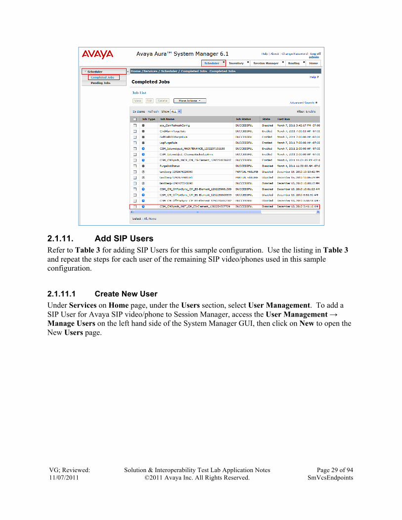
Under Services on Home page, select Scheduler to open the scheduler tab. Select Scheduler → Completed Jobs to determine when the task has completed, as shown below (see entry with embedded Communication Manager name “CM_ES-Element” from the sample configuration).
VG; Reviewed: 11/07/2011
Solution & Interoperability Test Lab Application Notes ©2011 Avaya Inc. All Rights Reserved.
Page 29 of 94 SmVcsEndpoints
2.1.11. Add SIP Users Refer to Table 3 for adding SIP Users for this sample configuration. Use the listing in Table 3 and repeat the steps for each user of the remaining SIP video/phones used in this sample configuration.
2.1.11.1 Create New User Under Services on Home page, under the Users section, select User Management. To add a SIP User for Avaya SIP video/phone to Session Manager, access the User Management → Manage Users on the left hand side of the System Manager GUI, then click on New to open the New Users page.

VG; Reviewed: 11/07/2011
Solution & Interoperability Test Lab Application Notes ©2011 Avaya Inc. All Rights Reserved.
Page 30 of 94 SmVcsEndpoints
2.1.11.2 Identify New User These Application Notes will refer to the configuration for the first user listed in Table 3, which can be used as a reference for configuring the remaining stations listed in Table 3. In the Identity section on the Identity tab, enter the following fields with the information described below and use default values for any remaining fields.
• Last Name: Enter the Last Name of the user. In the sample configuration, “AV1010” was used.
• First Name: Enter the First Name of the user. In the sample configuration, “60000(TANDBERG_SM)” was used.
• Middle Name: Enter the Middle Name of the user. [Optional] • Login Name: Enter extension <no.>@<sip domain>.
In the sample configuration, “[email protected]” was used.
• Authentication Type: Select “Basic” from the drop down list.
• Password: Enter password which will be used to log into System Manager application (password). Note: This field is only displayed if adding a new user.
• Confirm Password: Enter valued entered above. Note: This field is only displayed if adding a new user.

VG; Reviewed: 11/07/2011
Solution & Interoperability Test Lab Application Notes ©2011 Avaya Inc. All Rights Reserved.
Page 31 of 94 SmVcsEndpoints
2.1.11.3 Create a New User Communication Profile Select the Communication Profile tab and under the Communication Profile section, click on the New button to define a Communication Profile for the new SIP user. Enter values for the following required attributes and use default values for the remaining fields.
• Communication Profile Password: Enter a numeric value which will be used to logon to SIP video/phone.
• Confirm Password: Repeat numeric password entered above. • Name: Enter name of communication profile.
“Primary”, the default username, was used in the sample configuration.
• Default: Enter checkmark to indicate this profile is the default profile.

VG; Reviewed: 11/07/2011
Solution & Interoperability Test Lab Application Notes ©2011 Avaya Inc. All Rights Reserved.
Page 32 of 94 SmVcsEndpoints
Select New to define a Communication Address for the new SIP user. Enter values for the following required attributes:
• Type: Select Avaya SIP. • Fully Qualified
Address: Enter extension number. Note: value is shown in Handle field after address is added.
• @ Enter SIP domain. The sample configuration uses “tandberg.avaya.com”.
Click Add (not shown) to save the Communication Address for the new SIP user.
2.1.11.4 Assign Application Sequence to Communication Profile Assign the Application Sequence defined in Section 2.1.10.3 to the new SIP user as part of defining the Communication Profile. The Application Sequence must be used for both the originating and terminating sequence. Select the Session Manager Profile box and enter the appropriate values for the following attributes:

VG; Reviewed: 11/07/2011
Solution & Interoperability Test Lab Application Notes ©2011 Avaya Inc. All Rights Reserved.
Page 33 of 94 SmVcsEndpoints
• Primary Session Manager: Select the appropriate Session Manager instance. The sample configuration uses “TANDBERG_SM”.
• Origination Application Sequence: Enter the Application Sequence. The sample configuration uses “CM_ES-Seq”.
• Termination Application Sequence: Enter the Application Sequence. The sample configuration uses “CM_ES-Seq”.
• Home Location: Select the appropriate location that was created in Section 2.1.3. The Session Manager Profile section from the sample configuration is shown below.
2.1.11.5 Configure the Endpoint Profile Select the Endpoint Profile box and enter the appropriate values for the following attributes:
• System: Select the Communication Manager Element defined in Section 2.1.10.1 from drop down menu.
• Profile Type: Enter “Endpoint”. • Use Existing
Stations: Enter a checkmark if station was already defined, else, station will automatically be created.
• Extension: Enter extension number. • Template: Select the template (system defined or user defined) you want to
associate with the endpoint. Select the template based on the set type you want to add.
• Set Type: Select “9630SIP” for this video endpoint.

VG; Reviewed: 11/07/2011
Solution & Interoperability Test Lab Application Notes ©2011 Avaya Inc. All Rights Reserved.
Page 34 of 94 SmVcsEndpoints
• Security Code: Enter numeric value which will be used to logon to SIP phone. Note: This field must match the value entered for the Communication Profile Password field.
• Port: Select “IP” from the search list. The screen below show the Endpoint Profile section used in the sample configuration.
Repeat Section 2.1.11.1 – 2.1.11.5 to add the remaining Avaya SIP Users assigned to station numbers in Table 3.
2.2. Avaya Aura® Communication Manager Evolution Server This section describes the administration of Communication Manager Evolution Server using the Communication Manager section on System Manager. These instructions assume the G450 Media Gateway is already configured on the Communication Manager Evolution Server. Some administration screens have been abbreviated for clarity.
• Verify System Capabilities and Communication Manager Licensing • Administer IP Node-Name • Administer Codec Type • Administer IP Network Region • Administer Signaling Group • Administer Trunk Group • Administer Numbering Plan • Check Station Endpoints • Check Off PBX Endpoint Mapping • Save Translations

VG; Reviewed: 11/07/2011
Solution & Interoperability Test Lab Application Notes ©2011 Avaya Inc. All Rights Reserved.
Page 35 of 94 SmVcsEndpoints
2.2.1. Verify System Capabilities and Communication Manager Licensing Under Services on Home page, under the Elements section, select Communication Manager → Parameters → System Parameters – Customer Options. Select the radio button for the platform, and select View (not shown).
2.2.1.1 Check Off-PBX Telephones – OPS License Verify that Maximum Off-PBX Telephones – OPS has been set to the value that has been licensed, and that this value will accommodate addition of the SIP video endpoints. If a required feature is not enabled or there is insufficient capacity, contact an authorized Avaya sales representative to obtain additional capacity. The sample configuration screen below shows the customer options available.
2.2.1.2 Check Maximum Video Capable Station Licenses Verify that there are sufficient licenses to administer Video Capable Stations. This is the Maximun Video Capable Stations value on Page 2 of SystemParameter-Customer Options.
2.2.1.3 Check Maximum Video Capable IP Softphone Licenses Verify that there are sufficient licenses to administer Video Capable IP Softphones. This is the Maximum Video Capable IP Softphones value on Page 2 of System Parameter-Customer Options.

VG; Reviewed: 11/07/2011
Solution & Interoperability Test Lab Application Notes ©2011 Avaya Inc. All Rights Reserved.
Page 36 of 94 SmVcsEndpoints
2.2.1.4 Check Maximum Administered SIP Trunk Licenses Verify there are sufficient licenses to administer the SIP Trunk. This is the Maximum Administered SIP Trunks value on Page 2 of the System Parameter Customer Options. The sample configuration screen below shows Page 2 of the System Parameter Customer Options.
2.2.1.5 Check Trunk-To-Trunk Transfer From the Home tab, under the Elements section, select Communication Manager → Parameters → System Parameters – Features. Select the radio button for the CM-ES system, and select Edit. Verify the feature related system parameter Trunk-to-Trunk Transfer is set to “all” from the drop down list. Click the Enter button to save changes.

VG; Reviewed: 11/07/2011
Solution & Interoperability Test Lab Application Notes ©2011 Avaya Inc. All Rights Reserved.
Page 37 of 94 SmVcsEndpoints
2.2.2. Administer IP Node-Name From the Home Menu Tab, under Elements, select Communication Manager. Select Communication Manager → Network → Node Names. Add the node-name and IP address for the Session Manager’s software asset card, if not previously added, by selecting the New button and filling out the Name and IP Address of the Session Manager: SIP interface from Table 1.

VG; Reviewed: 11/07/2011
Solution & Interoperability Test Lab Application Notes ©2011 Avaya Inc. All Rights Reserved.
Page 38 of 94 SmVcsEndpoints
2.2.3. Administer IP Codec Type This configuration parameter uses the System Access Terminal (SAT) to administer the codec selection and order on the CM-ES. From the command line inside the SAT, issue the command change ip-codec-set n where “n” is the next available number. Enter the following values:
• Audio Codec: Enter the appropriate codec name. • Silence Suppression: Retain the default value “n”.
Note: some codec selections do not support silence suppression.
• Frames Per Pkt: Enter “2”. Note: G.722.1-32K defaults to “1” frame per packet.
• Packet Size (ms): Enter “20”. • Media Encryption: Enter the value based on the system requirement. For the
sample configuration “none” was used. change ip-codec-set 1 Page 1 of 2 IP Codec Set Codec Set: 1 Audio Silence Frames Packet Codec Suppression Per Pkt Size(ms) 1: G.722-64K 2 20 2: G.722.1-32K 1 20 3: G.711MU n 2 20 4: G.729 n 2 20 5: G.729B n 2 20 6: G.729AB n 2 20 7: Media Encryption 1: none 2: 3:
2.2.3.1 Allow Direct-IP Multimedia Advance to Page 2 of the IP Codec Set screen and configure the following:
• Allow Direct-IP Multimedia? Enter “y”. • Maximum Call Rate for
Direct-IP Multimedia: Enter “15360:Kbits”. • Maximum Call Rate for
Priority Direct-IP Multimedia: Enter “15360:Kbits”.

VG; Reviewed: 11/07/2011
Solution & Interoperability Test Lab Application Notes ©2011 Avaya Inc. All Rights Reserved.
Page 39 of 94 SmVcsEndpoints
change ip-codec-set 1 Page 2 of 2 IP Codec Set Allow Direct-IP Multimedia? y Maximum Call Rate for Direct-IP Multimedia: 15360:Kbits Maximum Call Rate for Priority Direct-IP Multimedia: 15360:Kbits Mode Redundancy FAX relay 0 Modem off 0 TDD/TTY US 3 Clear-channel n 0
2.2.4. Configure IP Network Region Using the System Manager web administration and starting from the Home Menu Tab, under Elements, select Communication Manager. Select Communication Manager → Network → IP Network Regions. Select Region 1 and click the Edit button.
Set the following fields as listed below and leave all other fields at their default values:
• Authoritative Domain: Enter the Authoritative Domain to use. The sample configuration uses “tandberg.avaya.com”.
• Name: Enter the name for this ip-network-region. • Intra-region IP-IP
Direct Audio: Enter “yes”. • Inter-region IP-IP
Direct Audio: Enter “yes”.

VG; Reviewed: 11/07/2011
Solution & Interoperability Test Lab Application Notes ©2011 Avaya Inc. All Rights Reserved.
Page 40 of 94 SmVcsEndpoints
The screen below shows the settings used in the sample configuration.
2.2.5. Administer Signaling Group Select Communication Manager → Network → Signaling Groups from the navigation menu on the left. Click the New button. Select the CM-ES and enter the signaling group number in the “Enter Qualifier” field. In the sample configuration “10” was entered. Click on the Add button to enter the Signaling Group configuration screen.
Set the following fields as listed below and leave all other fields at their default values:

VG; Reviewed: 11/07/2011
Solution & Interoperability Test Lab Application Notes ©2011 Avaya Inc. All Rights Reserved.
Page 41 of 94 SmVcsEndpoints
• Group Type: “sip” • IMS Enabled? “n” • Transport Method: “tcp” • IP Video? “y” • Priority Video? “y” • Peer Detection
Enabled? “y” • Peer Server: Use default value. • Near-end Node Name: “procr” • Far-end Node Name: Session Manager node name from Section 2.2.2. • Near-end Listen Port: “5060” • Far-end Listen Port: “5060” • Far-end Network
Region: “1” • Far-end Domain: Leave blank. • Direct IP-IP
Audio Connections? “y” • Enable Layer 3 Test: “y” • Initial IP-IP
Direct Media? “y”
Press the Enter button to save.

VG; Reviewed: 11/07/2011
Solution & Interoperability Test Lab Application Notes ©2011 Avaya Inc. All Rights Reserved.
Page 42 of 94 SmVcsEndpoints
2.2.6. Add SIP Trunk Group Add the corresponding trunk group controlled by this signaling group by selecting Communication Manager → Groups → Trunk Group and clicking the New button. Select the CM-ES and enter the trunk group number in the “Enter Qualifier” field. This was set to “10” in the sample configuration. Click on the Add button to enter the Trunk Group configuration page.
Set the following fields as listed below and leave all other fields at their default values:
• Group Type: “sip” • Group Name: Enter a descriptive name. • TAC: Enter an available trunk access code.
*10 was used in the sample configuration. • Service Type: “tie” • Signaling Group: The number of the signaling group added in Section 2.2.5. • Number of
Members: The number of SIP trunks to be allocated to calls routed to Session Manager (must be within the limits of the total number of trunks configured).

VG; Reviewed: 11/07/2011
Solution & Interoperability Test Lab Application Notes ©2011 Avaya Inc. All Rights Reserved.
Page 43 of 94 SmVcsEndpoints
Click the Enter button to save.
2.2.7. Administer Dial Plan Analysis This section describes the Dial Plan Analysis configuration. This is Communication Manager’s way of translating digits dialed by the user. The user can determine the beginning digits and total length for each type of call that Communication Manager needs to interpret. The Dialed String beginning with the number “6” and with a Total Length of 5 digits will be used to administer the extension range used for the SIP video/phones. From the Communication Manager tab, select Communication Manager → System → Dialplan Analysis. Click on the New button. Select CM-ES and enter the digit(s) in the “Enter Qualifier” field. The sample configuration uses “6”. Click the Add button to configure the Dialplan Analysis page.

VG; Reviewed: 11/07/2011
Solution & Interoperability Test Lab Application Notes ©2011 Avaya Inc. All Rights Reserved.
Page 44 of 94 SmVcsEndpoints
Set the following fields as listed below and leave all other fields at their default values:
• Dialed String “6” • Total Length “5” • Call Type “ext”
Click the Enter button to save.
2.2.8. Check Station Endpoints The method is the same for administering all of the Avaya 1000 series video endpoints with the exception of the 1040 and 1050’s. The only difference is that the 1040 can be administered to have up to 3 call appearances and the 1050 can have up to 7 call appearances for conferencing via their internal MCU’s. The 1010, 1020, and 1030 have to be administered with only one call-appearance since they are a single-line endpoint with no conferencing or transferring capabilities. For each SIP user to be defined in Session Manager, add a corresponding station on the Communication Manager Evolution Server. Note: instead of manually defining each station using the Communication Manager SAT interface, the preferred option is to automatically generate the SIP station when adding a new SIP user. From the Communication Manager tab, select Communication Manager → Endpoints → Manage Endpoints. Check the box next to the station extension to be checked and select the Edit button to enter the Endpoint configuration page. Note: It is important to assign only one call-appearance for the 1010, 1020, and 1030’s.

VG; Reviewed: 11/07/2011
Solution & Interoperability Test Lab Application Notes ©2011 Avaya Inc. All Rights Reserved.
Page 45 of 94 SmVcsEndpoints
Check the number of call-appearances by selecting the Button Assignment (B) tab from the edit page. Below the screen will refresh with the listing of the Main Buttons in a numbered list with the function listed at the side. Check that the Avaya 1010, 1020, and 1030 models only have number one assigned to “call-appr” and the rest are set to “Select”. See the screen below for the Avaya 1010 with station number “60000”.
Check all the Avaya 1000 series video endpoints for the proper configuration for call-appearance based on the specific model.

VG; Reviewed: 11/07/2011
Solution & Interoperability Test Lab Application Notes ©2011 Avaya Inc. All Rights Reserved.
Page 46 of 94 SmVcsEndpoints
2.2.9. Check Off PBX Endpoint Mapping All endpoint stations created in Section 2.1.11 should already have the Off PBX Endpoint Mapping configured. This is just a check from the CM-ES side. To check an endpoint, select the Communication Manager tab. Select Communication Manager → Endpoints → Off PBX Endpoint Mapping. Select an extension and click the Edit button to enter the configuration page. On Page 1, check the following:
• Application Verify “OPS” is assigned • Phone Number Contains the correct phone extension • Trunk Selection “aar”. • Config Set “1”
On Page 2, check the following:
• Mapping Mode “both” • Calls Allowed “all”

VG; Reviewed: 11/07/2011
Solution & Interoperability Test Lab Application Notes ©2011 Avaya Inc. All Rights Reserved.
Page 47 of 94 SmVcsEndpoints
2.2.10. Save Translations Configuration of the Communication Manager Evolution Server is complete. To save the recent configurations, select the Inventory tab and then select Inventory → Synchronization → Communication System. Check the box next to the CM-ES element name and click the radio button “Save Translations for selected devices”. Click the “Now” button to save the translations.
2.3. Administer Avaya 10x0 Video Endpoints The Avaya 10x0 configuration screens are very similar, and require the same basic configuration information listed for each of the devices in Table 1. Therefore, this application note will cover setting up the configuration for one of the Avaya 10x0 series endpoints, the Avaya 1010 and individual references for each of the Avaya 10x0 series models can be found under References in Section 4, items 8 – 12 for further information. To administer the 10x0 video endpoints log in to the web interface using the IP address of the video endpoint. You will be redirected to a screen that looks similar to the one below. This is a sample configuration on how to administer a 10x0 video endpoint.

VG; Reviewed: 11/07/2011
Solution & Interoperability Test Lab Application Notes ©2011 Avaya Inc. All Rights Reserved.
Page 48 of 94 SmVcsEndpoints
2.3.1. Log In Avaya 1010 Video Endpoint Enter the proper login credentials and press Submit. Most of the Preferences can be customized to meet your needs. Mentioned below are the absolute necessary items that need to be administered to get the 10x0 up and running on the network.
2.3.2. Set Network Preferences Once logged in select the Preferences tab and then the Network option.
Select the General option and enter values for the following required attributes.
• DHCP: Select from the drop down menu, Enabled or Disabled. Note: DHCP was used the first time the Avaya 10x0 was powered on to gain access to the web administration interface. It was changed to Disabled and assigned static addresses for testing.
• IP Address: Enter the assigned static IP Address if DHCP is disabled. Refer to Table 1 for addresses used for the sample configuration.
• Subnet Mask: Enter the Subnet Mask if DHCP is disabled. Refer to Table 1.
• Default Gateway: Enter the Default Gateway IP Address. Refer to Table 1.
• Hostname: Enter the appropriate Hostname. • DNS Servers: Enter the appropriate DNS Servers. Refer to Table 1.

VG; Reviewed: 11/07/2011
Solution & Interoperability Test Lab Application Notes ©2011 Avaya Inc. All Rights Reserved.
Page 49 of 94 SmVcsEndpoints
• Network Speed: Select “Auto”. • NTP Server
Hostname: Enter the Network Time Protocol (NTP) Server’s IP Address. The sample configuration uses “192.168.1.2”.
Select the Save Changes button to save.
2.3.3. Configure Communications Select the Preferences option and select the Communications option.
Select the SIP option.
• SIP: Select “Enabled”. • SIP Username: Enter the SIP Username for the device.
Note: The SIP Username should be unique and meaningful to the endpoint.
• Authorization Name: Enter the SIP Server authorization username. Note: The Authorization Name should be unique and meaningful to the endpoint.

VG; Reviewed: 11/07/2011
Solution & Interoperability Test Lab Application Notes ©2011 Avaya Inc. All Rights Reserved.
Page 50 of 94 SmVcsEndpoints
• Authorization Password: Enter the SIP Server authorization password.
• SIP Registration: Select the communication path to use when registering with a SIP Registrar
• SIP Proxy: Select “Enabled” to use the SIP proxy • Proxy Hostname: Enter the hostname or IP address of the SIP proxy server.
Note: This is the Session Manager software asset card IP address • Proxy IP Port: Enter the IP port number of SIP proxy server • SIP Registrar: Select “Enabled” to use the SIP registrar • Registrar
Hostname: Enter the hostname or IP address of the SIP registrar server.
• Registrar
IP Port: Enter the IP port number of the SIP registrar server. • UDP Signaling
Port: Enter the UDP port number of the SIP configuration. • TCP Signaling: Select “Enabled” to use TCP for placing SIP calls. • TCP Signaling
Port: Enter the TCP port number of the SIP configuration. Select the Save Changes button to save the administration just added.

VG; Reviewed: 11/07/2011
Solution & Interoperability Test Lab Application Notes ©2011 Avaya Inc. All Rights Reserved.
Page 51 of 94 SmVcsEndpoints
2.3.4. Configure System Select the Preferences tab and select System option.
Select the Identification option. This option will allow the user to display the name and video/voice numbers on the menu bar.
• System Name: Enter a descriptive name for the system. • Video Number: Enter the video number of the system. • Voice Number: Enter the voice number of the system.
Select the Save Changes button to save the administration just added.
Repeat the configuration steps in Section 2.3 for the remaining Avaya 10x0 series video endpoints listed in Table 1.

VG; Reviewed: 11/07/2011
Solution & Interoperability Test Lab Application Notes ©2011 Avaya Inc. All Rights Reserved.
Page 52 of 94 SmVcsEndpoints
2.4. Administer Avaya one-X® Communicator These Application Notes assume that the Avaya one-X® Communicator has been installed on a personal computer installed with a High Definition camera and the computer meets at least the minimum requirement for the Avaya one-X® Communicator. See Reference 14 in Section 4 for more information about installing the Avaya one-X® Communicator.
2.4.1. General Settings
2.4.1.1 Phone Click Phone on the left pane of the General Settings window. The Phone settings appear on the right pane of the General Settings window. This pane displays different fields depending on whether you selected H.323 or SIP protocol during installation. H.323 protocol
1. Enter the following information: a. Extension: enter the extension for this device on the Avaya server. b. Password: enter this extension’s password.
2. To specify the IP address of the server, click Add below the Server List field.
The Add Server dialog box appears (not shown).
3. In the Server field, enter the IP address of the server. This would be the IP address of CM-ES:S8300D in Table 1.
4. Check the Enable Video Calls check box. 5. Click OK.
Click the OK button to save the configuration. SIP protocol
1. Enter the following information: a. Extension: enter the extension for this device on the Avaya server. b. Password: enter this extension’s password.
2. To specify the IP address of the server, click Add below the Server List field.
The Add Server dialog box appears.
3. In the Proxy Server field, enter the IP address of the proxy server. This would be the IP address of the Session Manager: SIP in Table 1.

VG; Reviewed: 11/07/2011
Solution & Interoperability Test Lab Application Notes ©2011 Avaya Inc. All Rights Reserved.
Page 53 of 94 SmVcsEndpoints
4. (Optional) In the Port field, enter the port number of the server. If the port is not specified, Avaya one-X® Communicator uses the default 5061 port.
5. Enter the following information: a. In the Domain field, enter the domain of the Session Manager.
b. In the Failback Policy field, select Auto to make Avaya one-X® Communicator
automatically recover after failback. Select Admin if you want Avaya one-X® Communicator to use the failback policy defined by the system administrator.
c. In the Registration Policy field, select a registration policy to specify how your extension manages proxies.
6. Check the box next to Enable Video Calls.
Click the OK button to save the configuration.
2.5. Administer Avaya Desktop Video Device (ADVD) A175 This section describes steps needed to configure and connect the Avaya Desktop Video Device to Session Manager. It will explain the configuration steps needed to register the Avaya Desktop Video Device to Session Manager with Communication Manager running as an Evolution Server. It will explain how to assign an IP Address to the Avaya Desktop Video Device for access through the LAN. On applying power to the Avaya Desktop Video Device, the following screenshot is shown. Click on the Settings icon on the left hand side of the Avaya Desktop Video Device. The Settings menu appears with a number of options to configure the device. Click on the Network and Wireless option.

VG; Reviewed: 11/07/2011
Solution & Interoperability Test Lab Application Notes ©2011 Avaya Inc. All Rights Reserved.
Page 54 of 94 SmVcsEndpoints
Within the Network and Wireless Settings menu is a further configuration menu. Click on the option for Ethernet Settings.
Within the Ethernet Settings menu is a subheading called Ethernet Settings. Click on Ethernet Settings as this is where the Ethernet interface is configured. The Configure Ethernet Device page is displayed. Enter the field values below, refering to Table 1 for IP network address settings of the ADVD devices.
• Static IP Radio button selected for Static IP. • IP Address Enter the IP Address of the device.
Refer to Table 1. • Netmask Enter the Netmask to use for the device. • Gateway Enter the Gateway to use for the device. • DNS Address 1 Enter the DNS server to use for the device. • DNS Address 2 Leave blank. • Domain Name Enter the network domain name to use.
The sample configuration uses “dr.avaya.com”. Click the Save button to save the network configuration. The screen below shows the configuration used from a device in the sample configuration.

VG; Reviewed: 11/07/2011
Solution & Interoperability Test Lab Application Notes ©2011 Avaya Inc. All Rights Reserved.
Page 55 of 94 SmVcsEndpoints
To configure the SIP Global Settings select the Settings option on the left hand side of the screen. Within the Settings menu select Administrator Options. Within Administrator Options you will be prompted to input an Administrator password. Input the password and press OK.
To configure the SIP Settings of the Avaya Desktop Video Device within Administrator Options, scroll down to the SIP Settings option.
Within the SIP Settings menu, select the SIP Global Settings option.
Within the SIP Global Settings Option, select the SIP Domain option.

VG; Reviewed: 11/07/2011
Solution & Interoperability Test Lab Application Notes ©2011 Avaya Inc. All Rights Reserved.
Page 56 of 94 SmVcsEndpoints
The SIP Domain was set as tandberg.avaya.com. Press the Save button to save the configuration.
In the SIP Settings menu, select SIP Proxy Settings.
Enter the appropriate SIP Proxy settings for the following fields:
• SIP Proxy Server Enter the IP Address of the Session Manager: SIP. Refer to Table 1.
• Transport Select the transport method. The sample configuration uses “TCP”.
• SIP Proxy Port Enter the SIP Proxy Port to use. The sample configuration uses “5060”.
Click the Save button to save the configuration.

VG; Reviewed: 11/07/2011
Solution & Interoperability Test Lab Application Notes ©2011 Avaya Inc. All Rights Reserved.
Page 57 of 94 SmVcsEndpoints
2.5.1. Enable G.722 Codec on ADVD The ADVD will download the Axxxsettings.txt configuration file upon boot up. This file is similar to the 46xxsettings.txt file used for the Avaya 46xx and 96xx phone configuration settings. On the http/https server used to store the configuration setting files for the phones, find the Axxxsettings.txt file and open with a text editor. Set the following variables as follows:
• SET ENABLE_G722 1 • SET ENABLE_G726 0
Note: It was found during testing that both settings, G.722 and G.726, needed to be configured as described above in order to have the ADVD interoperate with the Cisco E20 and other devices using the G.722 codec.
2.6. Administer Cisco VCS These Application Notes assume that the initial network configuration for the Cisco VCS has been completed and the VCS web admin page can be accessed from a computer’s browser on the network. The sample configuration uses IP network settings for the VCS listed in Table 2. Please see Reference 15 in Section 4 for more information about getting started with the VCS. The remaining configuration for the VCS will be done through a web based admin. These configuration areas include:
• VCS Configuration o Protocols

VG; Reviewed: 11/07/2011
Solution & Interoperability Test Lab Application Notes ©2011 Avaya Inc. All Rights Reserved.
Page 58 of 94 SmVcsEndpoints
§ H.323 § SIP § Interworking
o Authentication § Devices – Configuration § Devices – Local Database
o Zones § Default Zone
o Dial plan § Configuration § Transforms § Search Rules
o Bandwidth § Configuration
2.6.1. Continuing Configuration Using Web Interface Open a web browser; enter http://xxx.xxx.xxx.xxx for the URL, where xxx.xxx.xxx.xxx is the IP address of the Cisco VCS. Refer to Table 2 for IP Address information of Cisco devices. Click on the Administrator Login button. The default Administrator Login uses “admin” for the Username and “TANDBERG” for the password. Note: This may be different if the password was changed while following the Cisco Getting Started Guide, Reference 15 in Section 4. After completing the fields with the proper credentials, click the Login button.
2.6.2. VCS Configuration
2.6.2.1 Protocols The VCS supports the H.323 protocol: it is an H.323 gatekeeper. It will also provide interworking between H.323 and SIP, translating between the two protocols to enable endpoints that only support one of these protocols to call each other. In order to support H.323, the H.323 mode must be enabled.
2.6.2.1.1 Configure H.323 As an H.323 gatekeeper, the VCS accepts registrations from H.323 endpoints and provides call control functions such as address translation and admission control. To configure H.323, start by

VG; Reviewed: 11/07/2011
Solution & Interoperability Test Lab Application Notes ©2011 Avaya Inc. All Rights Reserved.
Page 59 of 94 SmVcsEndpoints
bringing up the H.323 configuration page by selecting form the top menu VCS configuration → Protocols → H.323. Configure the following fields and leaving any additional fields at their default values:
• H.323 mode Select “On”. • Registration conflict
mode Select “Reject”. • Auto discover Select if the VCS will respond to “Gatekeeper Discovery
Requests” sent out by H.323 endpoints. Default is “On”. The sample configuration uses “Off”.
• Caller ID Select if Caller ID displayed on the H.323 endpoint will include or exclude the prefix of the ISDN gateway when displaying the callers E.164 number. Default is “Exclude prefix”. The sample configuration uses “Include prefix”.
Click the Save button to save the configuration. The screen below shows the settings for the sample configuration.
2.6.2.1.2 Configure SIP The VCS supports the SIP protocol. It can act as a:

VG; Reviewed: 11/07/2011
Solution & Interoperability Test Lab Application Notes ©2011 Avaya Inc. All Rights Reserved.
Page 60 of 94 SmVcsEndpoints
• SIP registrar • SIP proxy • SIP Presence Server
The VCS can provide interworking between SIP and H.323, translating between the two protocols to enable endpoints that only support one of these protocols to call each other. Even though SIP endpoints were not registered to the VCS in these application notes, the configuration for the SIP protocol had been configured in support of the SIP domain used by the SIP trunk the MCU uses to connect to the Avaya Aura® Session Manager. Select VCS configuration → Protocols → SIP → Configuration to enter the SIP configuration page. The following fields are configured as described below with all remaining fields left at their default values:
• SIP mode To enable SIP functionality select “On”. • SIP registration
proxy mode Enter how proxied registrations and requests containing Route Sets are handled: Off, Proxy to known only, or Proxy to any. Default if “Off”. The sample configuration sets this field to “Proxy to any”.
• UDP mode Select “On” to enable UDP. • UDP port Select “5060” as the listen port for UDP. • TCP mode Select “On” to enable TCP. • TCP port Select “5060” as the listen port for TCP. • TLS mode Select “On” to enable TLS. • TLS port Select “5061” as the listen port for TLS. • Session refresh
interval (seconds) Enter “1800”. • Minimum session
refresh interval (secs) Enter “180”. • Require UDP
BFCP mode Select “On”. Default is “On”. • Require duo
video mode Select “On”. Default is “On”. Click the Save button to save the configuration. The screen below shows the settings for the sample configuration.

VG; Reviewed: 11/07/2011
Solution & Interoperability Test Lab Application Notes ©2011 Avaya Inc. All Rights Reserved.
Page 61 of 94 SmVcsEndpoints
Add a SIP Domain by selecting VCS configuration → Protocols → SIP → Domain and clicking the New button. Enter the SIP Domain to be used and click on the Create domain button. The sample configuration uses “tandberg.avaya.com”.
2.6.2.1.3 Interworking To enable interworking between H.323 and SIP select VCS configuration → Protocols → Interworking. In the “H.323 <-> SIP interworking mode” field, select “On”. Click the save button to save the configuration.

VG; Reviewed: 11/07/2011
Solution & Interoperability Test Lab Application Notes ©2011 Avaya Inc. All Rights Reserved.
Page 62 of 94 SmVcsEndpoints
2.6.2.2 Authentication In order for an endpoint to use the VCS as its H.323 gatekeeper or SIP registrar, the endpoint must first register with the VCS. The VCS can be configured to control which devices are allowed to register with it. Two separate mechanisms are provided:
• a device authentication process based on the username and password supplies by the endpoint
• a simple Registration Restriction Policy that uses Allow Lists or Deny Lists to specify which aliases can and cannot register with the VCS, and the ability to control registrations based on IP addresses and subnet ranges through the specification of subzone membership rules and subzone registration policies1
The sample configuration uses the first method of username and password authentication provided by the endpoint to the VCS.
2.6.2.2.1 Devices – Configuration Select VCS configuration → Authentication → Devices → Configuration to enter the configuration page. In the “Database type” field select “Local database” and then click the Save button.
2.6.2.2.2 Devices – Local Database Select VCS configuration → Authentication → Devices → Local Database. To add a new entry, click the New button. Refer to Table 4 and enter the Name of the first device and a desired password. Click Create credential to enter the device into the local database. 1 Note. From Cisco TelePresence Video Communication Server Administration Guide, Software Version X6, Doc ID: D14049.09, December 2010

VG; Reviewed: 11/07/2011
Solution & Interoperability Test Lab Application Notes ©2011 Avaya Inc. All Rights Reserved.
Page 63 of 94 SmVcsEndpoints
The following screen below shows an entry from the sample configuration.
Repeat for each of the H.323 devices listed in Table 4.
2.6.2.3 Zones
2.6.2.3.1 DefaultZone By default the “DefaultZone” is automatically created. To check the settings of the “DefaultZone” select VCS configuration → Zones → DefaultZone. Set the field for “Authentication policy” to “Check credentials” and click on the Save button.
2.6.2.4 Dial plan
2.6.2.4.1 Configuration

VG; Reviewed: 11/07/2011
Solution & Interoperability Test Lab Application Notes ©2011 Avaya Inc. All Rights Reserved.
Page 64 of 94 SmVcsEndpoints
Select VCS configuration → Dial plan → Configuration and select “Direct” for the field “Calls to unknown IP addresses”. Click the Save button.
2.6.2.4.2 Search Rules Several search rules were created on the Cisco VCS to match on incoming and outgoing calls and route them to the appropriate device or Zone. The Remote Branch location has only one extension for all its endpoints:
• 65xxx Cisco H.323 video endpoints (registered to VCS) Any additional search rules created are for advanced configurations involving end-to-end connectivity between the Remote Branch and the Headquarters. The screen below shows the list of search rules created for an advanced configuration. For just connectivity between endpoints on the Branch, the Search Rules ‘Local Zone Match 1’ and ‘Calls to Local 65 numbers, strip domain suffix‘ are suffice.

VG; Reviewed: 11/07/2011
Solution & Interoperability Test Lab Application Notes ©2011 Avaya Inc. All Rights Reserved.
Page 65 of 94 SmVcsEndpoints
To configure the search rules, select VCS configuration → Dial plan → Search rules. Click the New button to enter the search rule configuration page.
2.6.2.4.2.1 Search Rule “Calls to Local 65 numbers, strip domain suffix” The first search rule, “Calls to Local 65 numbers, strip domain suffix” handles incoming calls from the Headquarters to the VCS LocalZone via the SIP trunk from Session Manager and contains the domain suffix “@tandberg.avaya.com” which needs to be stripped in order to work with video endpoints attached register to the VCS. Enter the following field values and leaving the remaining fields set to their default values:
• Rule name Enter a name for the new rule. The sample configuration uses “Calls to Local 65 numbers, strip domain suffix”.
• Description Enter a short description of the rule. The sample configuration uses “Strips domain both local and incoming from SM”.
• Priority Enter the priority of the search rule with the highest priority starting at 1 and going up to 65534. The default is “100”. The sample configuration uses “75”.
• Source Select the source of the requests for which this rule is applied. The sample configuration uses “Any”.
• Request must be authenticated Specifies whether this search rule applies only to authenticated search requests. The sample configuration uses “No”.
• Mode Select the type of alias for which this search rule applies. The sample configuration uses “Alias pattern match”.
• Pattern type Select how the pattern string must match the alias for the rule to be applied. The sample configuration uses “Suffix”.
• Pattern string Enter the pattern against which the alias is compared. The sample configuration uses “@tandberg.avaya.com”.
• Pattern behavior Select how the matching part of the pattern is modified. The sample configuration uses “Strip”.

VG; Reviewed: 11/07/2011
Solution & Interoperability Test Lab Application Notes ©2011 Avaya Inc. All Rights Reserved.
Page 66 of 94 SmVcsEndpoints
• On successful match Select the ongoing search behavior if the alias matches all of the search rule’s conditions. The sample configuration uses “Continue”.
• Target Select the zone or policy service to query if the alias matches the search rule. The sample configuration uses “LocalZone”.
• State Select if the search rule is enabled or disabled. The sample configuration uses “Enabled”.
Click the Create search rule button to save the new search rule. Note: The sample configuration screen below was taken from the edit page and shows the Save button instead.
2.6.2.4.2.2 Search Rule “LocalZone Match1” The other search rule, “LocalZone Match1” handles local calls to the VCS. Similarly, enter the following fields as shown in the snapshot below:

VG; Reviewed: 11/07/2011
Solution & Interoperability Test Lab Application Notes ©2011 Avaya Inc. All Rights Reserved.
Page 67 of 94 SmVcsEndpoints
2.6.2.5 Bandwidth
2.6.2.5.1 Configuration Increase the default call bandwidth by selecting VCS configuration → Bandwidth → Configuration to enter the configuration page. Enter the following field values:
• Default call bandwidth (kbps) Enter “5120”. The default is “384”.
• Downspeed per call mode Select “On”.
• Downspeed total mode Select “On”.
Click the Save button.

VG; Reviewed: 11/07/2011
Solution & Interoperability Test Lab Application Notes ©2011 Avaya Inc. All Rights Reserved.
Page 68 of 94 SmVcsEndpoints
2.7. Administer Cisco C20 Video Endpoint These Application Notes assume that the initial network configuration for the Cisco Quick Set C20 has been completed and the C20 web admin page can be accessed from a computer’s browser on the network. These Application Notes will show steps to configure this endpoint as a H.323 endpoint and a SIP endpoint. Depending on the configuration, the endpoint may be configured to use the required protocol- SIP or H.323. The sample configuration uses IP network settings for the C20’s listed in Table 2. Please see Reference 23 & 24 in Section 4 for more information about getting started with the C20.
2.7.1. Continuing Configuration Using Web Interface Open a web browser; enter http://xxx.xxx.xxx.xxx for the URL, where xxx.xxx.xxx.xxx is the IP address of the Cisco C20. Refer to Table 2 for IP Address information of Cisco devices. The default Administrator Login uses “admin” for the Username and “TANDBERG” for the password. Note: This may be different if the password was changed while following the Cisco Administrator’s Guide for the C20, Reference 24 in Section 4. After completing the fields with the proper credentials, click the Sign In button.
2.7.2. Administering H.323 or SIP Depending on the configuration required, the endpoint can be configured to use H.323 (Section 2.7.2.1) or SIP (Section 2.7.2.2).
2.7.2.1 Administering H.323
2.7.2.1.1 H.323 Select Advanced Configuration from the left menu. Expand the H323 folder. Now expand each of the following folders under Profile 1:
• H323Alias • CallSetup • Gatekeeper • Authentication
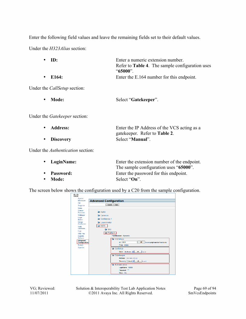
VG; Reviewed: 11/07/2011
Solution & Interoperability Test Lab Application Notes ©2011 Avaya Inc. All Rights Reserved.
Page 69 of 94 SmVcsEndpoints
Enter the following field values and leave the remaining fields set to their default values. Under the H323Alias section:
• ID: Enter a numeric extension number. Refer to Table 4. The sample configuration uses “65000”.
• E164: Enter the E.164 number for this endpoint. Under the CallSetup section:
• Mode: Select “Gatekeeper”. Under the Gatekeeper section:
• Address: Enter the IP Address of the VCS acting as a gatekeeper. Refer to Table 2.
• Discovery Select “Manual”. Under the Authentication section:
• LoginName: Enter the extension number of the endpoint. The sample configuration uses “65000”.
• Password: Enter the password for this endpoint. • Mode: Select “On”.
The screen below shows the configuration used by a C20 from the sample configuration.

VG; Reviewed: 11/07/2011
Solution & Interoperability Test Lab Application Notes ©2011 Avaya Inc. All Rights Reserved.
Page 70 of 94 SmVcsEndpoints
2.7.2.1.2 Administer Network Services Select Advanced Configuration from the left menu. Expand the NetworkServices folder and the H323 and SIP sub-folders. Select “On” mode for the H323 and “Off” for the SIP. Now expand the NTP folder. Enter for following field values:
• Mode Select “Manual”. • Address: Enter the Network Time Server’s IP Address.
The screen below shows the configuration used by a C20 from the sample configuration.

VG; Reviewed: 11/07/2011
Solution & Interoperability Test Lab Application Notes ©2011 Avaya Inc. All Rights Reserved.
Page 71 of 94 SmVcsEndpoints
2.7.2.2 Administering SIP
2.7.2.2.1 SIP Select Advanced Configuration from the left menu. Expand the SIP folder. Now under Profile 1:
• URI 1: Enter a numeric extension number. Refer to Table 4. The sample configuration uses “[email protected]”.
• DefaultTransport Select “TCP” • TlsVerify Select “Off” • Type Select “Standard” • Outbound Select “Off”
Under Proxy 1 folder:
• Discovery Select “Manual” • Address: Enter the IP address of the VCS acting as a SIP
Registrar. The screen below shows the configuration used by a C20 from the sample configuration.

VG; Reviewed: 11/07/2011
Solution & Interoperability Test Lab Application Notes ©2011 Avaya Inc. All Rights Reserved.
Page 72 of 94 SmVcsEndpoints
2.7.2.2.2 Administer Network Services Select Advanced Configuration from the left menu. Expand the NetworkServices folder and the H323 and SIP sub-folders. Select “On” mode for the SIP and “Off” for the H.323. Now expand the NTP folder. Enter for following field values:
• Mode Select “Manual”. • Address: Enter the Network Time Server’s IP Address.
The screen below shows the configuration used by a C20 from the sample configuration.
2.8. Administer Cisco 1700 MXP Video Endpoint These Application Notes assume that the initial network configuration for the Cisco 1700 MXP has been completed and the 1700 MXP web admin page can be accessed from a computer’s browser on the network. The sample configuration uses IP network settings for the 1700 MXP

VG; Reviewed: 11/07/2011
Solution & Interoperability Test Lab Application Notes ©2011 Avaya Inc. All Rights Reserved.
Page 73 of 94 SmVcsEndpoints
listed in Table 2. Please see Reference 22 in Section 4 for more information about getting started with the 1700 MXP.
2.8.1. Continuing Configuration Using Web Interface Open a web browser; enter http://xxx.xxx.xxx.xxx for the URL, where xxx.xxx.xxx.xxx is the IP address of the Cisco 1700 MXP. Refer to Table 2 for IP Address information of Cisco devices. The default Administrator Login uses “admin” for the Username and “TANDBERG” for the password. Note: This may be different if the password was changed while following the Cisco Administrator’s Guide for the 1700 MXP, Reference 22 in Section 4. After completing the fields with the proper credentials, click the Ok button. The “Welcome” menu screen appears.
2.8.2. Administer System Configuration Click on the System Configuration tab at the top of the menu.
To configure this endpoint to use H.323 refer to Section 2.8.2.1, else, to administer it to be a SIP endpoint, refer to Section 2.8.2.2.
2.8.2.1 H323 Settings Click the H.323 menu item under the System Configuration tab. Enter the following field values and leave the remaining fields set to their default values:

VG; Reviewed: 11/07/2011
Solution & Interoperability Test Lab Application Notes ©2011 Avaya Inc. All Rights Reserved.
Page 74 of 94 SmVcsEndpoints
Under the H323 Settings section: • Callsetup Mode Select “Gatekeeper”. • H.323 Auto Prefix Leave blank. • E.164 Alias Enter the extension number of the device.
The sample configuration uses “65005”. Under the Gatekeeper Settings section:
• H.323 ID Enter the extension number of the device. • Gatekeeper Discovery Select “Manual”. • Gatekeeper Address Enter the IP Address of the VCS (gatekeeper).
Refer to Table 2. • Authentication Mode Select “Auto”. • Authentication ID Enter the extension number of the device. • Authentication Password Enter the password of the device. • Multiple H.323 Aliases Select”Off”.
Click the Save button to save the configuration.
2.8.2.2 SIP Settings Click the SIP menu item under the System Configuration tab. Enter the following field values and leave the remaining fields set to their default values:
• Mode Select “On” • SIP Address (URI) Enter the [email protected]. In this sample
configuration, it is “[email protected]” • Server Discovery Select “Manual” • Server Address Enter IP address of VCS as SIP Registrar. • Server Type Select “Cisco”

VG; Reviewed: 11/07/2011
Solution & Interoperability Test Lab Application Notes ©2011 Avaya Inc. All Rights Reserved.
Page 75 of 94 SmVcsEndpoints
• Transport Select “TCP” • Verify TLS Select “Off”
Under SIP Authentication:
• Username Enter username configured on the VCS for this endpoint.
• Password Enter password. Click the Save button to save the configuration.
2.9. Administer Cisco EX-90 Video Endpoint The steps to configure the Cisco EX-90 video endpoint are the same as that for the C-20 video endpoint. See Section 2.7 for detailed configuration steps.
2.10. Administer Cisco E20 Registered to VCS This section describes steps needed to configure and connect the Cisco E20 to Cisco VCS. The configuration method used in this documentation will use the keypad method on the device and

VG; Reviewed: 11/07/2011
Solution & Interoperability Test Lab Application Notes ©2011 Avaya Inc. All Rights Reserved.
Page 76 of 94 SmVcsEndpoints
the on screen menus. It is assumed that basic configuration of the E20 is already done. Please refer to Reference 29 under Section 4 for more information on configuring Cisco E20.
2.10.1. Access Cisco E20’s Menu System To start configuration of the Cisco E20, press the (Menu Button) to display the menu. Using the navigation keys move the selection at the top of the menu to highlight the “Menu” tab. Once again use the navigation keys to move down the menu selection to “Advanced settings” as shown in the screen below. Open the Advance settings submenu by pressing the ü button or by using the right navigation button .
2.10.2. Configure IP Address Settings Select the IP settings submenu by pressing the ü button or by using the right navigation button
. Select the IP assignment field and change the setting to “Static”. Refer to Table 2 in Section 2.1.1 to assign the IP Address, Subnet Mask, and Gateway. When finished, move down to “OK” and press the ü button to save changes. The screen below show an example configuration for the IP Address assignment used for a Cisco E20 in the sample configuration.
2.10.3. Turn Off Binary Flow Control Protocol (BFCP) The Avaya Aura® Communication Manager version used during testing for these Application Notes did not support Binary Flow Control Protocol (BFCP) and is planned for future releases of Avaya Aura® Communication Manager. Therefore, BFCP is disabled. However, it may be left enabled if it is supported. To turn off BFCP on the Cisco E20 follow these steps:

VG; Reviewed: 11/07/2011
Solution & Interoperability Test Lab Application Notes ©2011 Avaya Inc. All Rights Reserved.
Page 77 of 94 SmVcsEndpoints
1. Return to the Advanced settings menu by pressing the left navigation button . Use the navigation button to highlight System configuration submenu selection and press the ü button to open the System configuration menu.
2. Use the navigation button select the Conference 1 setting and press the right navigation button to expand the contents. Once again use the navigation button to select BFCP setting and change the Mode to Off. Press the left navigation button to return to the previous menu. Repeat this step until the top level of the System configuration menu is reached. Note: The highlight will be on the Conference 1 item.
2.10.4. Enable Network Services Network services for the following protocols need to be enabled on the Cisco E20. Turning on the HTTP protocol allows easy access via a web browser to the Cisco E20 to upgrade firmware of the device if needed. Turning on the SIP protocol allows the Cisco E20 to register with the VCS via SIP as well as establish SIP video calls with other video devices.

VG; Reviewed: 11/07/2011
Solution & Interoperability Test Lab Application Notes ©2011 Avaya Inc. All Rights Reserved.
Page 78 of 94 SmVcsEndpoints
Turning on the SSH protocol allows command line access to the Cisco E20 for advanced configurations via the command line as well as access to debugging tools if needed.
2.10.4.1 HTTP To turn on HTTP network services, navigate through the System Configuration menu to NetworkServices → HTTP submenu item and change the Mode setting to “On”.
2.10.4.2 SIP To turn on SIP network services, navigate through the System Configuration menu to NetworkServices → SIP submenu item and change the Mode setting to “On”.
2.10.4.3 SSH To turn on SSH network services, navigate through the System Configuration menu to NetworkServices → SSH submenu item and change the Mode setting to”On”.
2.10.5. Configure SIP Profile Settings Configure the SIP profile settings for registering with the Session Manager by navigating through the System Configuration menu to SIP → Profile 1 and change the following settings:
• Default Transport: “TCP” • URI: Enter the full Uniform Resource Identifier (URI).
In this sample configuration [email protected] is used.
• Display Name: Enter the name to display for caller.
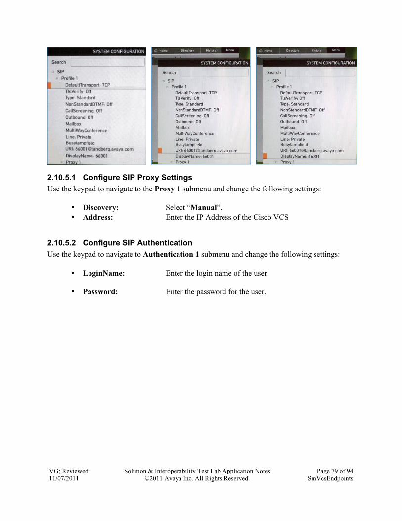
VG; Reviewed: 11/07/2011
Solution & Interoperability Test Lab Application Notes ©2011 Avaya Inc. All Rights Reserved.
Page 79 of 94 SmVcsEndpoints
2.10.5.1 Configure SIP Proxy Settings Use the keypad to navigate to the Proxy 1 submenu and change the following settings:
• Discovery: Select “Manual”. • Address: Enter the IP Address of the Cisco VCS
2.10.5.2 Configure SIP Authentication Use the keypad to navigate to Authentication 1 submenu and change the following settings:
• LoginName: Enter the login name of the user.
• Password: Enter the password for the user.

VG; Reviewed: 11/07/2011
Solution & Interoperability Test Lab Application Notes ©2011 Avaya Inc. All Rights Reserved.
Page 80 of 94 SmVcsEndpoints
2.11. Administer Cisco Movi Endpoint These Application Notes assume that the initial network configuration for the Cisco Movi has been completed. This involves installation and functioning of the Cisco TelePresence Management Suite (TMS) and its provisioning with the Cisco VCS. It is assumed that the web-admin interface of the TMS can be accessed, and that provisioning is successful between the TMS and the VCS. Please refer to References 25, 26, and 27 in Section 4 for more information on installation of the TMS, its configuration, provisioning the TMS with the VCS, and any troubleshooting tips. This document solely illustrates the procedure to add a Cisco Movi client to an already existing network comprising the TMS and the VCS. It is assumed that the endpoints for the Movi-Win and Movi-Mac are already configured on the VCS as already explained in Section 2.6.2.2
Additional steps that need to be performed for administering a Movi client on a PC/Mac are:
• Adding an endpoint profile on the TMS • Movi client configuration
2.11.1. Adding an Endpoint Profile on the TMS Server There are 2 ways to add users to the TMS: via synchronization with Microsoft Active Directory, and manually creation of users. This sample configuration shows the addition of users via the latter procedure- manual. The webconsole can be reached by xxx.xxx.xxx.xxx/tms on an internet browser. Select SystemsàProvisioningàDirectory on the webconsole of the TMS server. Select the ‘Group’ folder the user is to be added in. In this sample configuration, the default ‘root’ folder is used to add the users.

VG; Reviewed: 11/07/2011
Solution & Interoperability Test Lab Application Notes ©2011 Avaya Inc. All Rights Reserved.
Page 81 of 94 SmVcsEndpoints
Click on ‘Add user’. On the ‘Workspace’ pane that appears, enter user details such as username, password, email address, and a unique user ID. Click on ‘Save’. Repeat the same procedure for all other endpoints.
2.11.2. Movi Client Configuration The Movi client registers with the VCS. So, configuration on the Movi client should match that on the VCS. Select Advanced Configuration.

VG; Reviewed: 11/07/2011
Solution & Interoperability Test Lab Application Notes ©2011 Avaya Inc. All Rights Reserved.
Page 82 of 94 SmVcsEndpoints
Enter the Internal VCS IP address in the field shown, and if used, the IP address of the VCS External. In this sample configuration, VCS External is not used. In the field of the SIP Domain, enter the SIP domain. This should match that configured on the VCS under VCS configurationàProtocolsàSIPàDomains. Click on OK.
Enter the Username and Password to match with those configured for this endpoint on the VCS and the TMS and click on ‘Sign in’.

VG; Reviewed: 11/07/2011
Solution & Interoperability Test Lab Application Notes ©2011 Avaya Inc. All Rights Reserved.
Page 83 of 94 SmVcsEndpoints
2.12. Administer Cisco TelePresence MCU 4501 These Application Notes assume that the initial network configuration for the Cisco TelePresence MCU has been completed and the MCU 4501 web admin page can be accessed from a computer’s browser on the network. The sample configuration uses IP network settings for the MCU 4501 listed in Table 2. Please see Reference 18, in Section 4 for more information about getting started with the Cisco TelePresence MCU 4500 series. The remaining configuration for the MCU 4501 will be done through a web based admin. These configuration areas include:
• Settings o H.323 Gatekeeper Settings o SIP Registrar Settings o Content Settings
• Endpoints o H.323 o SIP
2.12.1. Continue Configuration Using Web Interface Open a web browser, enter http://xxx.xxx.xxx.xxx for the URL, where xxx.xxx.xxx.xxx is the IP address of the Cisco TelePresence MCU. Refer to Table 2 for IP Address information of Cisco

VG; Reviewed: 11/07/2011
Solution & Interoperability Test Lab Application Notes ©2011 Avaya Inc. All Rights Reserved.
Page 84 of 94 SmVcsEndpoints
devices. Click on the Log in button. The default Administrator Login uses “admin” for the Username and leave the Password field blank. Note: This may be different if the password was changed while following the Cisco Getting Started Guild for MCU 4500 Series, Reference 18 in Section 4. After completing the fields with the proper credentials, click on the OK button.
2.12.1.1 H.323 Gatekeeper Settings Select Settings → H.323 tab to enter the H.323 gatekeeper settings configuration page. Enter the following field values and leave the remaining fields set to their default values:
• H.323 gatekeeper usage Select “Enabled”. • H.323 gatekeeper address Enter the IP Address of the gatekeeper.
Refer to Table 2. • Gatekeeper registration type Select “MCU (standard)”. • Ethernet port association Check Port A. • (Mandatory) H.323 ID
to register Enter the extension assigned to the MCU from Table 4. The sample configuration uses “69500”.
• Use Password Checked . • Password Enter the matching password used to create
the device for the MCU 4501 on the VCS
• Prefix for MCU registrations Leave blank. • MCU service prefix Enter the extension number of the MCU
4501. • Allow numeric ID registration
for conferences Checked . • Send resource availability indications Unchecked . • Thresholds: conferences Leave blank. • Threshold: video ports Leave blank.

VG; Reviewed: 11/07/2011
Solution & Interoperability Test Lab Application Notes ©2011 Avaya Inc. All Rights Reserved.
Page 85 of 94 SmVcsEndpoints
Click the Apply changes button to save configuration.
2.12.1.2 SIP Registrar Settings Select Settings → SIP tab to enter the SIP registrar settings configuration page. Enter the following field values and leave the remaining fields set to their default values: Under SIP registrar settings section:
• SIP registrar usage Select “Enabled”. • SIP registrar domain Enter the IP Address of the SIP Registrar • SIP registrar type Select “Standard SIP”. • Username Enter the extension number of the
MCU. • Password Enter the password of the above user. • Allow number ID registration
for conferences Unchecked . Under the SIP call settings section:
• SIP proxy address Enter the IP address of the SIP Proxy • Maximum bit rate from
Microsoft OCS/LCS clients Select “1.00 Mbit/s”. • Outgoing Transport Select “TCP”. • Use local certificate for outgoing
connections and registrations Unchecked . Click the Apply changes button to save the configuration.

VG; Reviewed: 11/07/2011
Solution & Interoperability Test Lab Application Notes ©2011 Avaya Inc. All Rights Reserved.
Page 86 of 94 SmVcsEndpoints
2.12.1.3 Content Settings Select Settings → Content tab to enter the Content settings configuration page. Enter the following field values and leave the remaining fields set to their default values:
• Content status Select “Disabled”. • Display content in normal
video channel Select “Enabled”. • Video fast update request
filtering Select “Enabled”. • Web viewing applet
bandwidth Select “384 kbit/s”. • Markup of content channel
video Select “Disabled”. • Automatic content handover Select “Disabled”.
Click the Apply changes button to save configuration. The screen below shows the settings for content used by the sample configuration.

VG; Reviewed: 11/07/2011
Solution & Interoperability Test Lab Application Notes ©2011 Avaya Inc. All Rights Reserved.
Page 87 of 94 SmVcsEndpoints
2.12.2. Administer Endpoints Endpoints are added to the MCU 4501 to allow conferences to be able to add participants for the dial-out feature. This allows a conference which is setup with dial-out participants to call the endpoints extensions when the conference starts. The sample configuration for the MCU 4501 contains both Cisco (H.323) endpoints and Avaya (SIP) endpoints. This section will describe how to configure an endpoint on the MCU 4501 and will refer to both Table 3 and Table 4 for names and extensions. Select Endpoints from the top menu selection to enter the Endpoints tab which lists all created endpoints.
2.12.2.1 H.323 Endpoint To create an H.323 endpoint, click the Add H.323 button. Enter the following field values and leave the remaining fields set to their default values: Display parameters:
• Name Enter the name associated with the endpoint. Refer to Table 4.
Call-out parameters: • Address Enter the IP Address, host name, or an E.164
address (phone number). • H.323 gateway Select “<none>”. • DTMF sequence Leave blank.
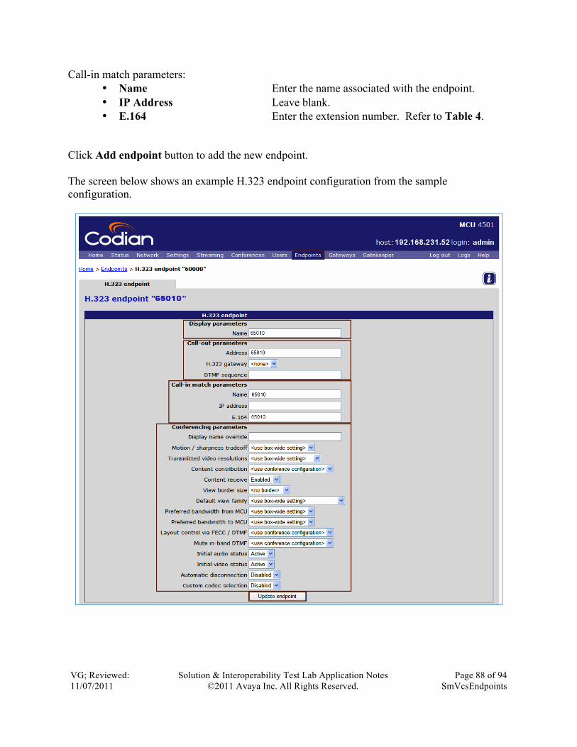
VG; Reviewed: 11/07/2011
Solution & Interoperability Test Lab Application Notes ©2011 Avaya Inc. All Rights Reserved.
Page 88 of 94 SmVcsEndpoints
Call-in match parameters: • Name Enter the name associated with the endpoint. • IP Address Leave blank. • E.164 Enter the extension number. Refer to Table 4.
Click Add endpoint button to add the new endpoint. The screen below shows an example H.323 endpoint configuration from the sample configuration.

VG; Reviewed: 11/07/2011
Solution & Interoperability Test Lab Application Notes ©2011 Avaya Inc. All Rights Reserved.
Page 89 of 94 SmVcsEndpoints
2.12.2.2 SIP Endpoint To create a SIP endpoint, click the Add SIP button. Enter the following field values and leave the remaining fields set to their default values: Display parameters:
• Name Enter the name associated with the endpoint. Refer to Table 3.
Call-out parameters: • Address Enter the IP Address, host name, or an E.164
address (phone number). • Use SIP registrar Checked . • Outgoing transport Select “<use box-wide setting>”. • DTMF sequence Leave blank.
Call-in match parameters:
• Username Enter the name associated with the endpoint. • IP Address Leave blank.
Click Add endpoint button to add the new endpoint. The screen below shows an example SIP endpoint configuration from the sample configuration.

VG; Reviewed: 11/07/2011
Solution & Interoperability Test Lab Application Notes ©2011 Avaya Inc. All Rights Reserved.
Page 90 of 94 SmVcsEndpoints

VG; Reviewed: 11/07/2011
Solution & Interoperability Test Lab Application Notes ©2011 Avaya Inc. All Rights Reserved.
Page 91 of 94 SmVcsEndpoints
3. Conclusion These Application Notes have described the administration steps required to configure Avaya Aura® Session Manager with Avaya Aura® Communication Manager running as an Evolution Server, Avaya 10x0 series video endpoints, Avaya one-X® Communicator, and Avaya Desktop Video Devices registered via SIP to the Session Manager. Also included in these Application Notes is the configuration of Cisco’s TelePresence Video Communications Server (VCS) and MCU 4501 supporting Cisco video endpoints (C20, 1700 MXP, Movi, E20 and EX-90) in a remote site location.
4. References The following references are relevant to these Application Notes: Avaya
[1] Avaya Aura® Session Manager Overview, Doc ID 03-603323, available at http://support.avaya.com.
[2] Installing and Administering Avaya Aura® Session Manager, Doc ID 03-603324, available at http://support.avaya.com.
[3] Avaya Aura® Session Manager Case Studies, dated January 2, 2010, available at http://support.avaya.com
[4] Maintaining and Troubleshooting Avaya Aura® Session Manager, Doc ID 03-603325, available at http://support.avaya.com.
[5] Hardware Description and Reference for Avaya Aura® Communication Manager (COMCODE 555-245-207) http://support.avaya.com/elmodocs2/comm_mgr/r4_0/avayadoc/03_300151_6/245207_6/245207_6.pdf
[6] SIP Support in Avaya Aura® Communication Manager Running on Avaya S8xxx Servers, Doc ID 555-245-206, May 2009, available at http://support.avaya.com.
[7] Administering Avaya Aura® Communication Manager, Doc ID 03-300509, May 2009, available at http://support.avaya.com.
[8] Avaya 1010/1020 Installation Guide, Issue 1, June 2010, available at http://support.avaya.com

VG; Reviewed: 11/07/2011
Solution & Interoperability Test Lab Application Notes ©2011 Avaya Inc. All Rights Reserved.
Page 92 of 94 SmVcsEndpoints
[9] Avaya 1010/1020 User Guide, Issue 1, June 2010, available at http://support.avaya.com
[10] Avaya 1030 Installation Guide, Issue 1, June 2010, available at http://support.avaya.com
[11] Avaya 1040 Installation Guide, Issue 1, June 2010, available at http://support.avaya.com
[12] Avaya 1050 Installation Guide, Issue 1, June 2010, available at http://support.avaya.com
[13] Avaya Video Communications System Administrator Guide (1050/1040/1030) , Issue 1, June 2010, available at http://support.avaya.com
[14] Avaya one-X Communicator Getting Started R6, August 2010, available at http://support.avaya.com
Cisco [15] Cisco TelePresence Video Communication Server: Getting Started, Version X6, Doc
ID: D14350.05, December 2010, available at http://www.tandberg.com
[16] Cisco TelePresence Deployment Guide: Single Cisco VCS Control, Doc ID: D14524.02, October 2010, available at http://www.tandberg.com
[17] Cisco TelePresence Video Communication Server Administration Guide, Software Version X6, Doc ID: D14049.09, December 2010, available at http://www.tandberg.com
[18] Cisco TelePresence MCU 4500 Series Getting Started, Doc ID: 61-0011-07, available at http://www.tandberg.com
[19] Connecting H.323 MCUs to Cisco VCSs for resilience and capacity: Cisco TelePresence Deployment Guide, Doc. ID: D14375.02, November 2010, available at http://www.tandberg.com
[20] Cisco TelePresence System EX90 User Guide, Software Version TC4.0, Doc ID: D14724.03, November 2010, available at http://www.tandberg.com
[21] Cisco TelePresence System EX90/EX60 Administrator Guide, Software Version TC4.0, Doc ID: D14726.03, December 2010, available at http://www.tandberg.com
[22] Tandberg MXP Administrator guide, Software Version F9, Doc ID: D14033.08, October 2010, available at http://www.tandberg.com

VG; Reviewed: 11/07/2011
Solution & Interoperability Test Lab Application Notes ©2011 Avaya Inc. All Rights Reserved.
Page 93 of 94 SmVcsEndpoints
[23] Cisco TelePresence System Profile-series, C-series codecs, Quick Set C20: User Guide, Software Version TC4.0, Doc ID: D14582.04, November 2010, available at http://www.tandberg.com
[24] Cisco TelePresence System Quick Set C20/C20 Plus and Profiles using C20: Administrator Guide, Software Version TC4.0, Doc. ID: D14637.04, November 2010, available at http://www.tandberg.com
[25] Cisco TelePresence Management Suite Provisioning Troubleshooting Guide (13.0), December 2010, available at http://www.tandberg.com
[26] Cisco TMS Provisioning Deployment Guide 13.0, January 2011, available at http://www.tandberg.com
[27] Cisco TelePresence Management Suite Administrator Guide (13.1), June 2011, available at http://www.tandberg.com
[28] Cisco IP Video Phone E20 Software Release Notes TE4, Doc ID: D1481002, April 2011, available at http://www.tandberg.com
[29] Cisco IP Video Phone E20 Administrator Guide TE4.0, Doc ID: D14330.11, March 2011, available at http://www.tandberg.com

VG; Reviewed: 11/07/2011
Solution & Interoperability Test Lab Application Notes ©2011 Avaya Inc. All Rights Reserved.
Page 94 of 94 SmVcsEndpoints
©2011 Avaya Inc. All Rights Reserved. Avaya and the Avaya Logo are trademarks of Avaya Inc. All trademarks identified by ® and ™ are registered trademarks or trademarks, respectively, of Avaya Inc. All other trademarks are the property of their respective owners. The information provided in these Application Notes is subject to change without notice. The configurations, technical data, and recommendations provided in these Application Notes are believed to be accurate and dependable, but are presented without express or implied warranty. Users are responsible for their application of any products specified in these Application Notes. Please e-mail any questions or comments pertaining to these Application Notes along with the full title name and filename, located in the lower right corner, directly to the Avaya Solution & Interoperability Test Lab at [email protected]
![Aura e imagen dialéctica [final]](https://static.fdokumen.com/doc/165x107/631d416593f371de1901d874/aura-e-imagen-dialectica-final.jpg)