Application Notes for IPC Alliance MX 16.01 with Avaya Aura ...
25
TLT; Reviewed: SPOC 9/1/2011 Solution & Interoperability Test Lab Application Notes ©2011 Avaya Inc. All Rights Reserved. 1 of 25 All-CM6-Q Avaya Solution & Interoperability Test Lab Application Notes for IPC Alliance MX 16.01 with Avaya Aura® Communication Manager 6.0.1 using QSIG Trunks – Issue 1.0 Abstract These Application Notes describe the configuration steps required for IPC Alliance MX 16.01 to interoperate with Avaya Aura® Communication Manager 6.0.1 using QSIG trunks. IPC Alliance MX is a trading communication solution. In the compliance testing, IPC Alliance MX used E1 QSIG trunks to Avaya Aura® Communication Manager, for turret users on IPC to reach users on Avaya Aura® Communication Manager and on the PSTN. Information in these Application Notes has been obtained through DevConnect compliance testing and additional technical discussions. Testing was conducted via the DevConnect Program at the Avaya Solution and Interoperability Test Lab.
-
Upload
khangminh22 -
Category
Documents
-
view
2 -
download
0
Transcript of Application Notes for IPC Alliance MX 16.01 with Avaya Aura ...

TLT; Reviewed:
SPOC 9/1/2011
Solution & Interoperability Test Lab Application Notes
©2011 Avaya Inc. All Rights Reserved.
1 of 25
All-CM6-Q
Avaya Solution & Interoperability Test Lab
Application Notes for IPC Alliance MX 16.01 with Avaya
Aura® Communication Manager 6.0.1 using QSIG Trunks
– Issue 1.0
Abstract
These Application Notes describe the configuration steps required for IPC Alliance MX 16.01
to interoperate with Avaya Aura® Communication Manager 6.0.1 using QSIG trunks.
IPC Alliance MX is a trading communication solution. In the compliance testing, IPC
Alliance MX used E1 QSIG trunks to Avaya Aura® Communication Manager, for turret users
on IPC to reach users on Avaya Aura® Communication Manager and on the PSTN.
Information in these Application Notes has been obtained through DevConnect compliance
testing and additional technical discussions. Testing was conducted via the DevConnect
Program at the Avaya Solution and Interoperability Test Lab.

TLT; Reviewed:
SPOC 9/1/2011
Solution & Interoperability Test Lab Application Notes
©2011 Avaya Inc. All Rights Reserved.
2 of 25
All-CM6-Q
1. Introduction These Application Notes describe the configuration steps required for IPC Alliance MX 16.01 to
interoperate with Avaya Aura® Communication Manager 6.0.1 using QSIG trunks.
IPC System Interconnect is a trading communication solution. In the compliance testing, IPC
Alliance MX used E1 QSIG trunks to Avaya Aura® Communication Manager, for turret users
on IPC to reach users on Avaya Aura® Communication Manager and on the PSTN.
2. General Test Approach and Test Results The feature test cases were performed manually. Calls were manually established among IPC
turret users with Avaya SIP, Avaya H.323, and/or PSTN users. Call controls were performed
from the various users to verify the various call scenarios.
The serviceability test cases were performed manually by disconnecting and reconnecting the E1
connection to IPC Alliance MX.
2.1. Interoperability Compliance Testing
The interoperability compliance test included feature and serviceability testing.
The feature testing included basic call, basic display, G.711, hold/reconnect, DTMF, call
forwarding unconditional/ring-no-answer/busy, blind/attended transfer, and attended conference.
The serviceability testing focused on verifying the ability of IPC Alliance MX to recover from
adverse conditions, such as disconnecting/reconnecting the E1 connection to IPC Alliance MX.
2.2. Test Results
All test cases were executed and passed.
2.3. Support
Technical support on IPC Alliance MX can be obtained through the following:
Phone: (800) NEEDIPC, (203) 339-7800
Email: [email protected]

TLT; Reviewed:
SPOC 9/1/2011
Solution & Interoperability Test Lab Application Notes
©2011 Avaya Inc. All Rights Reserved.
3 of 25
All-CM6-Q
3. Reference Configuration As shown in the test configuration below, IPC Alliance MX at the Remote Site consists of
Alliance MX, System Center, and Turrets.
There is a physical connection between the DS1 circuit pack on Avaya Aura® Communication
Manager with the QSIG card on IPC System Center. E1 QSIG trunks are used from IPC
Alliance MX to Avaya Aura® Communication Manager, to reach users on Avaya Aura®
Communication Manager and on the PSTN.
A five digit Uniform Dial Plan (UDP) was used to facilitate dialing between the Central and
Remote sites. Unique extension ranges were associated with Avaya Aura® Communication
Manager users at the Central site (65xxx-66xxx), and IPC turret users at the Remote site (63xxx).
The Avaya Aura® Session Manager was used in the configuration to support Avaya SIP
endpoints, and the configuration of Avaya Aura® Session Manager was performed via the web
interface of Avaya Aura® System Manager.

TLT; Reviewed:
SPOC 9/1/2011
Solution & Interoperability Test Lab Application Notes
©2011 Avaya Inc. All Rights Reserved.
4 of 25
All-CM6-Q
4. Equipment and Software Validated The following equipment and software were used for the sample configuration provided:
Equipment Software
Avaya Aura® Communication Manager on
Avaya S8800 Server
6.0.1 SP2 with special patch 18993
(R016x.00.1.510.1-18993)
Avaya G650 Media Gateway
TN799DP C-LAN Circuit Pack
TN2302AP IP Media Processor
TN464HP DS1 Interface
HW01 FW038
HW20 FW122
HW02 FW024
Avaya Aura® Session Manager 6.1 SP2
Avaya Aura® System Manager 6.1 SP2
Avaya A175 Desktop Video Device (SIP) 1.0.2
Avaya 1608 IP Telephone (H.323) 1.3
Avaya 9630 IP Telephone (SIP) 2.6.4
IPC
Alliance MX
System Center
o QSIG Line Card
Turrets
16.01.01.04.0005
16.01.01.04.0005
16.01.01.04.0005
16.01.01.04.0005

TLT; Reviewed:
SPOC 9/1/2011
Solution & Interoperability Test Lab Application Notes
©2011 Avaya Inc. All Rights Reserved.
5 of 25
All-CM6-Q
5. Configure Avaya Aura® Communication Manager This section provides the procedures for configuring Avaya Aura® Communication Manager.
The procedures include the following areas:
Verify Communication Manager license
Administer system parameters special applications
Administer system parameters features
Administer system parameters coverage forwarding
Administer DS1 circuit pack
Administer ISDN trunk group
Administer ISDN signaling group
Administer trunk group members
Administer route pattern
Administer public unknown numbering
Administer uniform dial plan
Administer AAR analysis
Administer PSTN trunk group
Administer tandem calling party number
5.1. Verify Communication Manager License
Log into the System Access Terminal (SAT) to verify that the Communication Manager license
has proper permissions for features illustrated in these Application Notes. Use the “display
system-parameters customer-options” command. Navigate to Page 4, and verify that ISDN-PRI
is enabled, as shown below.
display system-parameters customer-options Page 4 of 11
OPTIONAL FEATURES
Emergency Access to Attendant? y IP Stations? y
Enable 'dadmin' Login? y
Enhanced Conferencing? y ISDN Feature Plus? n
Enhanced EC500? y ISDN/SIP Network Call Redirection? y
Enterprise Survivable Server? n ISDN-BRI Trunks? y
Enterprise Wide Licensing? n ISDN-PRI? y
ESS Administration? y Local Survivable Processor? n
Extended Cvg/Fwd Admin? y Malicious Call Trace? y
External Device Alarm Admin? y Media Encryption Over IP? n
Five Port Networks Max Per MCC? n Mode Code for Centralized Voice Mail? n
Flexible Billing? n
Forced Entry of Account Codes? y Multifrequency Signaling? y
Global Call Classification? y Multimedia Call Handling (Basic)? y
Hospitality (Basic)? y Multimedia Call Handling (Enhanced)? y
Hospitality (G3V3 Enhancements)? y Multimedia IP SIP Trunking? y
IP Trunks? y
IP Attendant Consoles? y

TLT; Reviewed:
SPOC 9/1/2011
Solution & Interoperability Test Lab Application Notes
©2011 Avaya Inc. All Rights Reserved.
6 of 25
All-CM6-Q
Navigate to Page 8, and verify the highlighted QSIG features are enabled, as shown below.
display system-parameters customer-options Page 8 of 11
QSIG OPTIONAL FEATURES
Basic Call Setup? y
Basic Supplementary Services? y
Centralized Attendant? y
Interworking with DCS? y
Supplementary Services with Rerouting? y
Transfer into QSIG Voice Mail? y
Value-Added (VALU)? y
5.2. Administer System Parameters Special Applications
Use the “change system-parameters special-applications” command, and navigate to Page 3 to
enable (SA8440) – Unmodified QSIG Reroute Number.
Under the QSIG call forwarding feature, when a call comes into Communication Manager over
the ISDN trunk administered for supplementary service option B and terminates to a station with
call forwarding activated to an off-net number, Communication Manager sends an ISDN facility
message back to the originating switch with the complete forward-to number that can include
dial plan prefixes and route pattern digit manipulation, etc.
The Unmodified QSIG ReRoute Number special application allows the option of bypassing
the number manipulation for the forwarded-to party.
change system-parameters special-applications Page 3 of 9
SPECIAL APPLICATIONS
(SA8141) - LDN Attendant Queue Priority? n
(SA8143) - Omit Designated Extensions From Displays? n
(SA8146) - Display Update for Redirected Calls? n
(SA8156) - Attendant Priority Queuing by COR? n
(SA8157) - Toll Free Vectoring until Answer? n
(SA8201) - Start Time and 4-Digit Year CDR Custom Fields? n
(SA8202) - Intra-switch CDR by COS? n
(SA8211) - Prime Appearance Preference? n
(SA8240) - Station User Admin of FBI? n
(SA8312) - Meet-Me Paging? n
(SA8323) - Idle Call Preference Display? n
(SA8339) - PHS X-Station Mobility? n
(SA8348) - Map NCID to Universal Call ID? n
(SA8428) - Station User Button Ring Control? n
(SA8434) - Delay PSTN Connect on Agent Answer? n
(SA8439) - Forward Held-Call CPN? n
(SA8440) - Unmodified QSIG Reroute Number? y
(SA8475) - SOSM? n

TLT; Reviewed:
SPOC 9/1/2011
Solution & Interoperability Test Lab Application Notes
©2011 Avaya Inc. All Rights Reserved.
7 of 25
All-CM6-Q
5.3. Administer System Parameters Features
Use the “change system-parameters features” command to allow for trunk-to-trunk transfers.
This feature is needed to be able to transfer an incoming call from IPC back out to IPC
(incoming trunk to outgoing trunk), and to transfer an outgoing call to IPC to another outgoing
call to IPC (outgoing trunk to outgoing trunk). For ease of compliance testing, the Trunk-to-
Trunk Transfer field was set to “all” to enable all trunk-to-trunk transfers on a system wide
basis. Note that this feature poses significant security risk, and must be used with caution. For
alternatives, the trunk-to-trunk feature can be implemented on the Class Of Restriction or Class
Of Service levels. Refer to [1] for more details.
change system-parameters features Page 1 of 19
FEATURE-RELATED SYSTEM PARAMETERS
Self Station Display Enabled? y
Trunk-to-Trunk Transfer: all
Automatic Callback with Called Party Queuing? n
Automatic Callback - No Answer Timeout Interval (rings): 3
Call Park Timeout Interval (minutes): 10
Off-Premises Tone Detect Timeout Interval (seconds): 20
AAR/ARS Dial Tone Required? y
Music (or Silence) on Transferred Trunk Calls? no
DID/Tie/ISDN/SIP Intercept Treatment: attd
Internal Auto-Answer of Attd-Extended/Transferred Calls: none
Automatic Circuit Assurance (ACA) Enabled? n
Navigate to Page 16. Enable Chained Call Forwarding, to allow changes to the maximum
number of call forwarding hops parameter in Section 5.4.
change system-parameters features Page 16 of 19
FEATURE-RELATED SYSTEM PARAMETERS
SPECIAL TONE
Special Dial Tone? n
Special Dial Tone for Digital/IP Stations: none
REDIRECTION NOTIFICATION
Display Notification for Do Not Disturb? n
Display Notification for Send All Calls? n
Display Notification for Call Forward? n
Display Notification for Enhanced Call Forward? n
Display Notification for a locked Station? n
Display Notification for Limit Number of Concurrent Calls? n
Display Notification for Posted Messages? n
Scroll Status messages Timer(sec.):
Chained Call Forwarding? y

TLT; Reviewed:
SPOC 9/1/2011
Solution & Interoperability Test Lab Application Notes
©2011 Avaya Inc. All Rights Reserved.
8 of 25
All-CM6-Q
5.4. Administer System Parameters Coverage Forwarding
Use the “change system-parameters coverage-forwarding” command. Set Threshold for
Blocking Off-Net Redirection of Incoming Trunk Calls to the desired value. In the
compliance testing, the threshold was disabled so that there will be no blocking on number of
calls being redirected off-net within the Call Forward timer.
change system-parameters coverage-forwarding Page 1 of 2
SYSTEM PARAMETERS CALL COVERAGE / CALL FORWARDING
CALL COVERAGE/FORWARDING PARAMETERS
Local Cvg Subsequent Redirection/CFWD No Ans Interval (rings): 2
Off-Net Cvg Subsequent Redirection/CFWD No Ans Interval (rings): 2
Coverage - Caller Response Interval (seconds): 4
Threshold for Blocking Off-Net Redirection of Incoming Trunk Calls: n
Location for Covered and Forwarded Calls: called
PGN/TN/COR for Covered and Forwarded Calls: caller
COR/FRL check for Covered and Forwarded Calls? n
QSIG/SIP Diverted Calls Follow Diverted to Party's Coverage Path? y
COVERAGE
Navigate to Page 2, and set Maximum Number Of Call Forwarding Hops to a value mutually
agreeable with IPC.
change system-parameters coverage-forwarding Page 2 of 2
SYSTEM PARAMETERS CALL COVERAGE / CALL FORWARDING
COVERAGE OF CALLS REDIRECTED OFF-NET (CCRON)
Coverage Of Calls Redirected Off-Net Enabled? n
CHAINED CALL FORWARDING
Maximum Number Of Call Forwarding Hops: 6
Station Coverage Path For Coverage After Forwarding: principal

TLT; Reviewed:
SPOC 9/1/2011
Solution & Interoperability Test Lab Application Notes
©2011 Avaya Inc. All Rights Reserved.
9 of 25
All-CM6-Q
5.5. Administer DS1 Circuit Pack
Use the “add ds1 n” command, where “n” is the slot number of the DS1 circuit pack with
physical connectivity to IPC. Enter the following values for the specified fields, and retain the
default values for the remaining fields.
Name: A descriptive name.
Bit Rate: “2.048”
Line Coding: “hdb3”
Signaling Mode: “isdn-pri”
Connect: “pbx”
Interface: “peer-master”
Peer Protocol: “Q-SIG”
Interface Companding: “alaw”
Channel Numbering: “timeslot”
add ds1 1a14 Page 1 of 1
DS1 CIRCUIT PACK
Location: 01A14 Name: IPC QSIG
Bit Rate: 2.048 Line Coding: hdb3
Signaling Mode: isdn-pri
Connect: pbx Interface: peer-master
TN-C7 Long Timers? n Peer Protocol: Q-SIG
Interworking Message: PROGress Side: a
Interface Companding: alaw CRC? y
Idle Code: 11111111 Channel Numbering: timeslot
DCP/Analog Bearer Capability: 3.1kHz
T303 Timer(sec): 4
Disable Restarts? n
Slip Detection? n Near-end CSU Type: other
Echo Cancellation? n

TLT; Reviewed:
SPOC 9/1/2011
Solution & Interoperability Test Lab Application Notes
©2011 Avaya Inc. All Rights Reserved.
10 of 25
All-CM6-Q
5.6. Administer ISDN Trunk Group
Administer an ISDN trunk group to interface with IPC. Use the “add trunk-group n” command,
where “n” is an available trunk group number. Enter the following values for the specified
fields, and retain the default values for the remaining fields.
Group Type: “isdn”
Group Name: A descriptive name.
TAC: An available trunk access code.
Direction: “two-way”
Carrier Medium: “PRI/BRI”
Service Type: “tie”
add trunk-group 63 Page 1 of 21
TRUNK GROUP
Group Number: 63 Group Type: isdn CDR Reports: y
Group Name: IPC QSIG COR: 1 TN: 1 TAC: 1063
Direction: two-way Outgoing Display? n Carrier Medium: PRI/BRI
Dial Access? n Busy Threshold: 255 Night Service:
Queue Length: 0
Service Type: tie Auth Code? n TestCall ITC: rest
Far End Test Line No:
TestCall BCC: 4
Navigate to Page 2. For Supplementary Service Protocol, enter “b” for QSIG. For Digit
Handling (in/out), enter “overlap/enbloc”. For Format, enter “unk-unk”. Retain the default
values for the remaining fields.
add trunk-group 63 Page 2 of 21
Group Type: isdn
TRUNK PARAMETERS
Codeset to Send Display: 6 Codeset to Send National IEs: 6
Max Message Size to Send: 260 Charge Advice: none
Supplementary Service Protocol: b Digit Handling (in/out): overlap/enbloc
Digit Treatment: Digits:
Trunk Hunt: cyclical
Digital Loss Group: 13
Incoming Calling Number - Delete: Insert: Format: unk-unk
Bit Rate: 1200 Synchronization: async Duplex: full
Disconnect Supervision - In? y Out? n
Answer Supervision Timeout: 0
Administer Timers? n CONNECT Reliable When Call Leaves ISDN? n
Delay Call Setup When Accessed Via IGAR? N

TLT; Reviewed:
SPOC 9/1/2011
Solution & Interoperability Test Lab Application Notes
©2011 Avaya Inc. All Rights Reserved.
11 of 25
All-CM6-Q
Navigate to Page 3. Enable Send Name, Send Calling Number, and Send Connected
Number. For Format, enter “unknown”. Disable Modify Reroute Number, as shown below.
add trunk-group 63 Page 3 of 21
TRUNK FEATURES
ACA Assignment? n Measured: none Wideband Support? n
Internal Alert? n Maintenance Tests? y
Data Restriction? n NCA-TSC Trunk Member:
Send Name: y Send Calling Number: y
Used for DCS? n Hop Dgt? n Send EMU Visitor CPN? n
Suppress # Outpulsing? n Format: unknown
Outgoing Channel ID Encoding: preferred UUI IE Treatment: service-provider
Replace Restricted Numbers? n
Replace Unavailable Numbers? n
Send Connected Number: y
Hold/Unhold Notifications? y
Send UUI IE? y Modify Tandem Calling Number: no
Send UCID? n
Send Codeset 6/7 LAI IE? y Ds1 Echo Cancellation? n
Modify Reroute Number? n
Apply Local Ringback? n
Show ANSWERED BY on Display? y
Network (Japan) Needs Connect Before Disconnect? n
5.7. Administer ISDN Signaling Group
Administer an ISDN signaling group for the new trunk group to use for signaling. Use the “add
signaling-group n” command, where “n” is an available signaling group number. For Primary
D-Channel, enter the slot number for the DS1 circuit pack from Section 5.5 and port “16”. Set
desired values for Max number of NCA TSC and Max number of CA TSC.
For Trunk Group for NCA TSC and Trunk Group for Channel Selection, enter the ISDN
trunk group number from Section 5.6. For the Supplementary Service Protocol field, enter “b”
for QSIG. Retain the default values for the remaining fields.
add signaling-group 63 Page 1 of 1
SIGNALING GROUP
Group Number: 63 Group Type: isdn-pri
Associated Signaling? y Max number of NCA TSC: 5
Primary D-Channel: 1a1416 Max number of CA TSC: 5
Trunk Group for NCA TSC: 63
Trunk Group for Channel Selection: 63 X-Mobility/Wireless Type: NONE
TSC Supplementary Service Protocol: b Network Call Transfer? n

TLT; Reviewed:
SPOC 9/1/2011
Solution & Interoperability Test Lab Application Notes
©2011 Avaya Inc. All Rights Reserved.
12 of 25
All-CM6-Q
5.8. Administer Trunk Group Members
Use the “change trunk-group n” command, where “n” is the ISDN trunk group number added in
Section 5.6. Navigate to Page 3. For NCA-TSA Trunk Member, enter the highest trunk group
member number to use for routing of tandem QSIG call independent signaling connections.
change trunk-group 63 Page 3 of 21
TRUNK FEATURES
ACA Assignment? n Measured: none Wideband Support? n
Internal Alert? n Maintenance Tests? y
Data Restriction? n NCA-TSC Trunk Member: 30
Send Name: y Send Calling Number: y
Used for DCS? n Hop Dgt? n Send EMU Visitor CPN? n
Suppress # Outpulsing? n Format: unknown
Outgoing Channel ID Encoding: preferred UUI IE Treatment: service-provider
Replace Restricted Numbers? n
Replace Unavailable Numbers? n
Send Connected Number: y
Hold/Unhold Notifications? y
Send UUI IE? y Modify Tandem Calling Number: no
Send UCID? n
Send Codeset 6/7 LAI IE? y Ds1 Echo Cancellation? n
Modify Reroute Number? n
Apply Local Ringback? n
Show ANSWERED BY on Display? y
Network (Japan) Needs Connect Before Disconnect? n
Navigate to Page 5 and 6. Enter all 30 ports of the DS1 circuit pack into the Port fields, and the
corresponding Code and Sfx fields will be populated automatically. Enter the ISDN signaling
group number from Section 5.7 into the Sig Grp fields as shown below.
change trunk-group 63 Page 5 of 21
TRUNK GROUP
Administered Members (min/max): 0/0
GROUP MEMBER ASSIGNMENTS Total Administered Members: 0
Port Code Sfx Name Night Sig Grp
1: 1a1401 TN464 G 63
2: 1a1402 TN464 G 63
3: 1a1403 TN464 G 63
4: 1a1404 TN464 G 63
5: 1a1405 TN464 G 63
6: 1a1406 TN464 G 63
7: 1a1407 TN464 G 63
8: 1a1408 TN464 G 63
9: 1a1409 TN464 G 63
10: 1a1410 TN464 G 63
11: 1a1411 TN464 G 63
12: 1a1412 TN464 G 63
13: 1a1413 TN464 G 63
14: 1a1414 TN464 G 63
15: 1a1415 TN464 G 63

TLT; Reviewed:
SPOC 9/1/2011
Solution & Interoperability Test Lab Application Notes
©2011 Avaya Inc. All Rights Reserved.
13 of 25
All-CM6-Q
change trunk-group 63 Page 6 of 21
TRUNK GROUP
Administered Members (min/max): 0/0
GROUP MEMBER ASSIGNMENTS Total Administered Members: 0
Port Code Sfx Name Night Sig Grp
16: 01A1417 TN464 H 63
17: 01A1418 TN464 H 63
18: 01A1419 TN464 H 63
19: 01A1420 TN464 H 63
20: 01A1421 TN464 H 63
21: 01A1422 TN464 H 63
22: 01A1423 TN464 H 63
23: 01A1424 TN464 H 63
24: 01A1425 TN464 H 63
25: 01A1426 TN464 H 63
26: 01A1427 TN464 H 63
27: 01A1428 TN464 H 63
28: 01A1429 TN464 H 63
29: 01A1430 TN464 H 63
30: 01A1431 TN464 H 63
5.9. Administer Route Pattern
Use the “change route-pattern n” command, where “n” is the existing route pattern number to
reach IPC, in this case “63”. Enter the following values for the specified fields, and retain the
default values for the remaining fields.
Pattern Name: A descriptive name.
Grp No: The ISDN trunk group number from Section 5.6.
FRL: A level that allows access to this trunk, with 0 being least restrictive.
TSC: “y”
CA-TSC Request: “as-needed”
Numbering Format: “unk-unk”
change route-pattern 63 Page 1 of 3
Pattern Number: 63 Pattern Name: IPC
SCCAN? n Secure SIP? n
Grp FRL NPA Pfx Hop Toll No. Inserted DCS/ IXC
No Mrk Lmt List Del Digits QSIG
Dgts Intw
1: 63 0 n user
2: n user
3: n user
4: n user
5: n user
6: n user
BCC VALUE TSC CA-TSC ITC BCIE Service/Feature PARM No. Numbering LAR
0 1 2 M 4 W Request Dgts Format
Subaddress
1: y y y y y n y as-needed rest unk-unk none
2: y y y y y n n rest none
3: y y y y y n n rest none

TLT; Reviewed:
SPOC 9/1/2011
Solution & Interoperability Test Lab Application Notes
©2011 Avaya Inc. All Rights Reserved.
14 of 25
All-CM6-Q
5.10. Administer Public Unknown Numbering
Use the “change public-unknown-numbering 0” command, to define the calling party number to
send to IPC. Add an entry for the trunk group defined in Section 5.6. In the example shown
below, all calls originating from a 5-digit extension beginning with 6 and routed to trunk group
63 will result in a 5-digit calling number.
change public-unknown-numbering 0 Page 1 of 2
NUMBERING - PUBLIC/UNKNOWN FORMAT
Total
Ext Ext Trk CPN CPN
Len Code Grp(s) Prefix Len
Total Administered: 3
5 6 63 5 Maximum Entries: 9999
5.11. Administer Uniform Dial Plan
This section provides a sample AAR routing used for routing calls with dialed digits 63xxx to
IPC. Note that other methods of routing may be used. Use the “change uniform-dialplan 0”
command, and add an entry to specify the use of AAR for routing digits 63xxx, as shown below.
change uniform-dialplan 0 Page 1 of 2
UNIFORM DIAL PLAN TABLE
Percent Full: 0
Matching Insert Node
Pattern Len Del Digits Net Conv Num
63 5 0 aar n
5.12. Administer AAR Analysis
Use the “change aar analysis 0” command, and add an entry to specify how to route calls to
63xxx. In the example shown below, calls with digits 63xxx will be routed as an AAR call
using route pattern “63” from Section 5.9.
change aar analysis 0 Page 1 of 2
AAR DIGIT ANALYSIS TABLE
Location: all Percent Full: 2
Dialed Total Route Call Node ANI
String Min Max Pattern Type Num Reqd
63 5 5 63 aar n

TLT; Reviewed:
SPOC 9/1/2011
Solution & Interoperability Test Lab Application Notes
©2011 Avaya Inc. All Rights Reserved.
15 of 25
All-CM6-Q
5.13. Administer PSTN Trunk Group
Use the “change trunk-group n” command, where “n” is the existing ISDN trunk group number
used to reach the PSTN, in this case “10”.
For Modify Tandem Calling Number, enter “tandem-cpn-form” to allow for the calling party
number from IPC to be modified.
change trunk-group 10 Page 3 of 21
TRUNK FEATURES
ACA Assignment? n Measured: none Wideband Support? n
Internal Alert? n Maintenance Tests? y
Data Restriction? n NCA-TSC Trunk Member:
Send Name: y Send Calling Number: y
Used for DCS? n Send EMU Visitor CPN? y
Suppress # Outpulsing? n Format: public
Outgoing Channel ID Encoding: preferred UUI IE Treatment: service-provider
Replace Restricted Numbers? n
Replace Unavailable Numbers? n
Send Connected Number: n
Network Call Redirection: none Hold/Unhold Notifications? n
Send UUI IE? y Modify Tandem Calling Number: tandem-cpn-form
Send UCID? n
Send Codeset 6/7 LAI IE? y Ds1 Echo Cancellation? n
Apply Local Ringback? n US NI Delayed Calling Name Update? n
Show ANSWERED BY on Display? y
Network (Japan) Needs Connect Before Disconnect? n
5.14. Administer Tandem Calling Party Number
Use the “change tandem-calling-party-num” command, to define the calling party number to
send to the PSTN for tandem calls from IPC turret users.
In the example shown below, all calls originating from a 5-digit extension beginning with 6 and
routed to trunk group 10, which includes IPC turret users, will result in a 10-digit calling
number. For Number Format, use an applicable format, in this case “pub-unk”.
change tandem-calling-party-num Page 1 of 8
CALLING PARTY NUMBER CONVERSION
FOR TANDEM CALLS
CPN Trk Number
Len Prefix Grp(s) Delete Insert Format
5 6 10 90884 pub-unk

TLT; Reviewed:
SPOC 9/1/2011
Solution & Interoperability Test Lab Application Notes
©2011 Avaya Inc. All Rights Reserved.
16 of 25
All-CM6-Q
6. Configure IPC Alliance MX This section provides the procedures for configuring IPC Alliance MX. The procedures include
the following areas:
Launch One Management System
Administer line data view
Administer wire data view
Administer wire groups
The configuration of System Interconnect is typically performed by IPC installation technicians.
The procedural steps are presented in these Application Notes for informational purposes.
6.1. Launch One Management System
Access the One Management System web interface by using the URL “http://ip-
address/oneview” in an Internet browser window, where “ip-address” is the IP address of IPC
System Center. Log in using the appropriate credentials.
The Login screen is displayed. Enter the appropriate credentials. Check I agree to the terms
and conditions, and click Login.
The License Login screen is displayed next (not shown). Enter the appropriate password and
click Login. In the subsequent Login Information screen (not shown), click Continue.

TLT; Reviewed:
SPOC 9/1/2011
Solution & Interoperability Test Lab Application Notes
©2011 Avaya Inc. All Rights Reserved.
17 of 25
All-CM6-Q
6.2. Administer Line Data View
The screen below is displayed next, with the Main Menu screen in the forefront. Select LINE
CONFIG > Lines > Line Data View, as shown below.
The Line Data View screen is displayed. For Card LAC, select the relevant QSIG trunk card
number from the drop-down list, in this case “16638”. Click Submit.
TLT; Reviewed:
SPOC 9/1/2011
Solution & Interoperability Test Lab Application Notes
©2011 Avaya Inc. All Rights Reserved.
18 of 25
All-CM6-Q
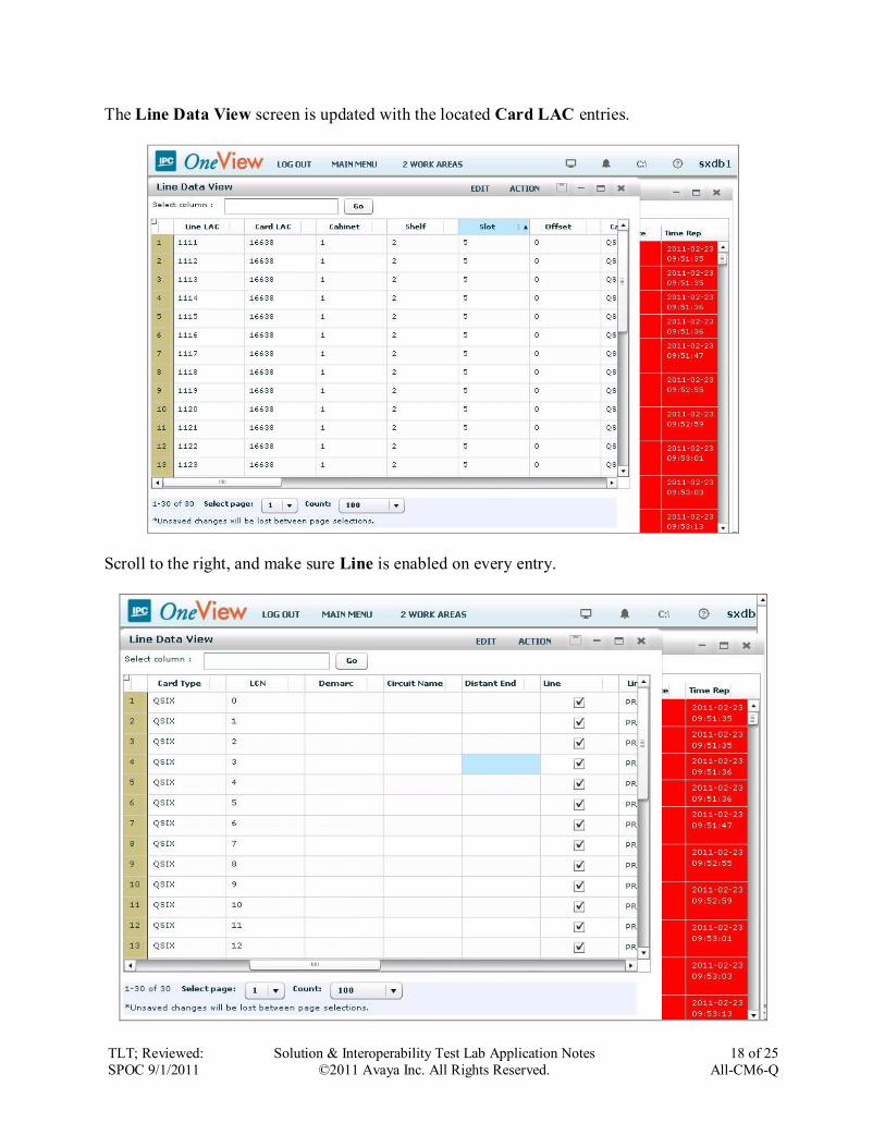
The Line Data View screen is updated with the located Card LAC entries.
Scroll to the right, and make sure Line is enabled on every entry.

TLT; Reviewed:
SPOC 9/1/2011
Solution & Interoperability Test Lab Application Notes
©2011 Avaya Inc. All Rights Reserved.
19 of 25
All-CM6-Q
6.3. Administer Wire Data View
Select MAIN MENU from the top menu to display the Main Menu screen. Select LINE
CONFIG > Wires > Wire Data View, as shown below.
The Wire Data View screen is displayed. For Card LAC, select the relevant QSIG trunk card
number from the drop-down list, in this case “16638”. Click Submit.
The Wire Data View screen is updated with the located Card LAC entry. Set the Card Type,
Wired For, and Wire Group parameters as shown below.

TLT; Reviewed:
SPOC 9/1/2011
Solution & Interoperability Test Lab Application Notes
©2011 Avaya Inc. All Rights Reserved.
20 of 25
All-CM6-Q
6.4. Administer Wire Groups
Select MAIN MENU from the top menu to display the Main Menu screen. Select GROUPS >
Engineering Groups > Wire Groups, as shown below.
The Wire Groups screen is displayed next. Select “QSIG” from the Select Wire Group drop-
down list, and “Edit” from the Select Operation drop-down list, as shown below.

TLT; Reviewed:
SPOC 9/1/2011
Solution & Interoperability Test Lab Application Notes
©2011 Avaya Inc. All Rights Reserved.
21 of 25
All-CM6-Q
The Edit Wire Groups screen is displayed. Scroll down the screen as necessary to locate the
entry with Param ID of “142”. Double click on the corresponding Param Value field, and
enter “1” to denote IPC as the slave in the ISDN connection.
Locate the entry with Param ID of “143”. Double click on the corresponding Param Value
field, and enter “1” to enable CRC4_ENABLE.
Scroll down the screen as necessary to locate the entry with Param ID of “327”. Double click
on the corresponding Param Value field, and enter “1” to enable Alliance to send tones.
Locate the entry with Param ID of “358”. Double click on the corresponding Param Value
field, and enter “2” for VIRTUAL_MASTER.

TLT; Reviewed:
SPOC 9/1/2011
Solution & Interoperability Test Lab Application Notes
©2011 Avaya Inc. All Rights Reserved.
22 of 25
All-CM6-Q
Scroll down the screen as necessary to locate entries with Param ID of “364-374” and “603-
604”. Double click on the corresponding Param Value field, and set the values as shown below.
INTERDIGIT_TO: “0”
PBX_PROVIDER: “2”
CHANNEL_TIMESLOT: “2”
VM_SERVER: “2”
CFT1_TIMEOUT: “1000”
MAX_DIVERTS: “6”
FS_ENABLE: “3”
FS_DELAY: “200”
DDI_TIMEOUT: “2000”
Type of Number: “1”
Numbering Plan: “1”
BEARER_CAP_IE_CODE: “1”
COMPANDING_METHOD: “0”
Note that the MAX_DIVERTS value should match the maximum number of call forwarding
hops from Section 5.4.
Follow the system load procedure in [2] to reboot the QSIG trunk card.

TLT; Reviewed:
SPOC 9/1/2011
Solution & Interoperability Test Lab Application Notes
©2011 Avaya Inc. All Rights Reserved.
23 of 25
All-CM6-Q
7. Verification Steps This section provides tests that can be performed to verify proper configuration of Avaya Aura®
Communication Manager and IPC Alliance MX.
From the Communication Manager SAT interface, verify the status of the ISDN trunk group by
using the “status trunk n” command, where “n” is the ISDN trunk group number administered in
Section 5.6. Verify that all trunks are in the “in-service/idle” state as shown below.
status trunk 63 Page 1
TRUNK GROUP STATUS
Member Port Service State Mtce Connected Ports
Busy
0063/001 01A1401 in-service/idle no
0063/002 01A1402 in-service/idle no
0063/003 01A1403 in-service/idle no
0063/004 01A1404 in-service/idle no
0063/005 01A1405 in-service/idle no
0063/006 01A1406 in-service/idle no
0063/007 01A1407 in-service/idle no
0063/008 01A1408 in-service/idle no
0063/009 01A1409 in-service/idle no
0063/010 01A1410 in-service/idle no
0063/011 01A1411 in-service/idle no
0063/012 01A1412 in-service/idle no
0063/013 01A1413 in-service/idle no
0063/014 01A1414 in-service/idle no
Verify the status of the ISDN signaling groups by using the “status signaling-group n” command,
where “n” is the ISDN signaling group number administered in Section 5.7. Verify that the
signaling group is “in-service” as indicated in the Group State and Level 3 State fields shown
below.
status signaling-group 63
STATUS SIGNALING GROUP
Group ID: 63 Active NCA-TSC Count: 0
Group Type: isdn-pri Active CA-TSC Count: 0
Signaling Type: facility associated signaling
Group State: in-service
Primary D-Channel
Port: 01A1416 Level 3 State: in-service

TLT; Reviewed:
SPOC 9/1/2011
Solution & Interoperability Test Lab Application Notes
©2011 Avaya Inc. All Rights Reserved.
24 of 25
All-CM6-Q
8. Conclusion These Application Notes describe the configuration steps required for IPC Alliance MX 16.01 to
successfully interoperate with Avaya Aura® Communication Manager 6.0.1 using QSIG trunks.
All feature and serviceability test cases were completed.
9. Additional References This section references the product documentation relevant to these Application Notes.
1. Administering Avaya AuraTM Communication Manager, Document 03-300509, Issue 6.0,
Release 6.0, June 2010, available at http://support.avaya.com.
2. Alliance MX 16.1 Loads and Syncs, Part Number B02200152, Revision Number 00, upon
request to IPC Support.
3. Alliance MX 16.1 Configuring Call Diversions, Part Number B02200138, Revision
Number 00, upon request to IPC Support.

TLT; Reviewed:
SPOC 9/1/2011
Solution & Interoperability Test Lab Application Notes
©2011 Avaya Inc. All Rights Reserved.
25 of 25
All-CM6-Q
©2011 Avaya Inc. All Rights Reserved.
Avaya and the Avaya Logo are trademarks of Avaya Inc. All trademarks identified by ® and ™
are registered trademarks or trademarks, respectively, of Avaya Inc. All other trademarks are the
property of their respective owners. The information provided in these Application Notes is
subject to change without notice. The configurations, technical data, and recommendations
provided in these Application Notes are believed to be accurate and dependable, but are
presented without express or implied warranty. Users are responsible for their application of any
products specified in these Application Notes.
Please e-mail any questions or comments pertaining to these Application Notes along with the
full title name and filename, located in the lower right corner, directly to the Avaya DevConnect
Program at [email protected].