MTP-NT - IPC Teknik
55
KMT - Kraus Messtechnik GmbH Gewerbering 9, D-83624 Otterfing, Germany, +49-8024-48737, Fax.-5532 Home Page http://www.kmt-telemetry.com, Email: [email protected] MTP-NT “Preliminary version” Sophisticated multi-channel telemetry system for rotating application, fully software programmable with 16 bit resolution INSTRUCTIONS FOR QUALIFIED PERSONNEL ONLY! • 2 to 256 channels • 16 bit ADC (internal 18 bit) • Signal bandwidth up to 24000 Hz • Fully software programmable • Inputs: STG, IEPE, VOLT, THERMO • Inductive or battery powered • Auto offset compensation (STG/VOLT) • Rugged housing, water protected • 4V Bridge excitation • Analog output +/- 10V • STG Input ranges ±40 to ±0.3 mV/V • Digital Ethernet output for PC
-
Upload
khangminh22 -
Category
Documents
-
view
5 -
download
0
Transcript of MTP-NT - IPC Teknik

KMT - Kraus Messtechnik GmbH Gewerbering 9, D-83624 Otterfing, Germany, +49-8024-48737, Fax.-5532 Home Page http://www.kmt-telemetry.com, Email: [email protected]
MTP-NT
“Preliminary version”
Sophisticated multi-channel telemetry system
for rotating application, fully software
programmable with 16 bit resolution
INSTRUCTIONS FOR QUALIFIED PERSONNEL ONLY!
• 2 to 256 channels • 16 bit ADC (internal 18 bit)
• Signal bandwidth up to 24000 Hz • Fully software programmable
• Inputs: STG, IEPE, VOLT, THERMO • Inductive or battery powered
• Auto offset compensation (STG/VOLT) • Rugged housing, water protected
• 4V Bridge excitation • Analog output +/- 10V
• STG Input ranges ±40 to ±0.3 mV/V • Digital Ethernet output for PC

Version 2018-11-CN 2 Technical Data are subject to change without notice!
Safety notes
• The device should only applied by instructed personnel.
• The power head emits strong magnetic radiation at 30-60 kHz to a distance of 300 mm. Therefore persons with cardiac pacemakers should not work with this device!
• Magnetic data storage media should be kept in a distance of at least 3m from the power head to avoid data loss. The same is valid for electromagnetic sensitive parts, devices and systems.
• Do not place the power head in the switched-on state on metallic objects, because this results in eddy currents which could overload the device and strong heat up small objects. Also the probe could be destroyed!
• No metallic objects, other than the disc-type coil, should be located in the air gap of the power head. The same applies to metallic parts within a radius of up to 50 mm in all directions.
• Do not use damaged or faulty cables!
• Never touch in the area between shaft and inductive head, the rotating shaft itself or rotor electronic contacts during operation!
• This is a “Class A” system suitable for operation in a laboratory or industrial environment. The system can cause electromagnetic interferences when used in residential areas or environments. In this case the operator is responsible for establishing protective procedures.

Version 2018-11-CN 3 Technical Data are subject to change without notice!
Short description:
The MTP-NT telemetry is a miniaturized measurement system suitable for sophisticated industrial measurement tasks and rotating applications. Each 2-channel sensor module is equipped with signal conditioning, anti-aliasing filters, analog-to-digital converters (16 bit) and a digital communication bus connection. All these up to 128 modules (=256 channels) will be controlled by the MTP-NT-Controller module via a daisy-chain system bus (extendable to several meters). By this concept it’s possible to install the acquisition modules close to the sensor to have short connections for the analog sensor lines. This avoids undesired interferences in noisy environments. The MTP-NT Controller outputs a PCM bit stream signal in NRZ format with data rates up to 5000 kbit/s. The inductive transmitter module transfers the signal over distances of up to 50 mm and the radio transmitter is able to cover ranges of 10m, depends of application.
MTP-NT acquisition modules (rotor side)
60 x 40 x 10 mm
Weight 40 grams
MTP-NT-STG2 Acquisition module for 2 strain gauges Full, half and quarter bridge (≥ 350 Ω) Full, half and quarter bridge (120 Ω) Fixed excitation 4 Vdc Offset compensation by auto zero Manual offset shifting after auto zero Input ranges ±40 to ±0.3 mV/V Shunt-calibration 100 kΩ 0.1% Signal bandwidth 0 Hz to 24000 Hz* (*see table of cut-off-frequencies)
ADC Resolution 16 Bit Measurement uncertainty < 0.1% Power supply: 6 to 9 Vdc Current consumption (with two full bridges 350 Ohm) 100 mA
60 x 40 x 10 mm Weight 40 grams
MTP-NT-IEPE2
Acquisition module for 2 IEPE/ICP® sensors Current EXC. 4mA Input ranges 20 to ±0.3 Vpp Signal bandwidth 3 Hz to 24000Hz* (*see table of cut-off-frequency)
ADC Resolution 16 Bit Measurement uncertainty < 0.1% Power supply: 6 to 9 Vdc Current consumption 140 mA
Coming soon
MTP-NT-VOLT Acquisition module for 2x high level inputs Input ranges ±10 to ±0.08 V Signal bandwidth 0 Hz to 24000 Hz* (*see table of cut-off-frequencies)
+4 V sensor excitation max. 20 mA ADC Resolution 16 Bit Measurement uncertainty < 0.1% Power supply: 6 to 9 Vdc Current consumption 60 mA
Coming soon
MTP-NT-TH-K Acquisition module for 2x TH-K Inputs galvanic isolated Range -50 to 1000°C, -50 to 500°C or -50 to 250°C Cut-off filter 30 Hz (more on request) ADC Resolution 16 Bit Measurement uncertainty: 1 K Power supply: 6 to 9 Vdc Current consumption 90 mA
Coming soon
MTP-NT-Pt100/1000 (RTD) Acq. module for 2 RTD sensors Range -100 to 600°C, -50 to 300°C or -25 to 150°C Type Pt100 or Pt1000 Current EXC. 1 mA Connection: 4-, 3- and 2 wire Sensor break detection Signal bandwidth 6 Hz ADC Resolution 16 Bit Measurement uncertainty: 1 K Power supply: 6 to 9 Vdc Current consumption 120 mA
60 x 40 x 10 mm Weight 40 grams
MTP-NT-CON-IND-Tx Controller 1- 128 acquisition modules Output: PCM built-in inductive transmitter Programmable via RS232/USB adapter and remote software Power supply: 6 to 9 Vdc Current consumption 150 mA
Common characteristics / Environment Vibration (random) 0.1 g²/Hz (20 Hz to 2 kHz) Vibration (sine) 20 g (20 Hz to 2 kHz) Shock (½ sine) 10000 g peak (11 ms) Static Acceleration 3000 g (depends of mounting!)
Operating temperature -40 to +85°C optional -40 to +125°C Storage temperature -40 to +125°C Humidity 100 %

Version 2018-11-CN 4 Technical Data are subject to change without notice!
MTP-NT connection overview

Version 2018-11-CN 5 Technical Data are subject to change without notice!
MTP-NT housing dimensions for 2- and 4-channels

Version 2018-11-CN 6 Technical Data are subject to change without notice!
MTP-NT Bock diagram

Version 2018-11-CN 7 Technical Data are subject to change without notice!
MTP-NT Modules mounting plate example for shaft diameters 100-200 or 150-250mm

Version 2018-11-CN 8 Technical Data are subject to change without notice!
MTP-NT – Setting of parameters or firmware update of all modules via RS232
MTP-NT-CON-IND-Tx pin connection
All parameters are programmable over RS232, USB, Ethernet adapter or *Bluetooth (*require MTP-NT Bluetooth module)
RS232 connection
BUS I/O BUS I/O
Inductive coil connection

Version 2018-11-CN 9 Technical Data are subject to change without notice!
MTP-NT – Easy setting of parameters with Config-Control software free download under: http://x.kmt-telemetry.com/nt/

Version 2018-11-CN 10 Technical Data are subject to change without notice!
MTP-NT – Easy to connect with daisy-chain connection with the same MTP-NT-BUS-C cable
The bus is extendable to several meters!
AMP "Locking-Clip" crimp connectors withstand ultra-harsh vibration and shock environment
Caution: Locking-Clip must be complete connected!
GOOD 😊
BAD

Version 2018-11-CN 11 Technical Data are subject to change without notice!
MTP-NT-DEC8/16/24/32 Receiver unit for max 32 Channels output via 37 pol. D-sub Inductive transmission 45 MHz version up to 5000 Mbit (10000Mbit on special request!)
Plug-side
Optional BNC16/32 Box. Connect on 37pol D-Sub
MTP-NT –DEC8/16/24/32 System Parameters:
Channels: 8,16,24 or 32x +/-10 V analog outputs via D-sub female socket
Resolution: 16 bit D/A converter, with smoothing filter
Power supply input: 10-30 Vdc, power consumption < 24 Watt
Dimensions: 205 x 105 x 65mm
Weight: 1.25 kg without cables and data pickup head
Overall measurement uncertainty (sensor input → decoder output): < 0.1% without sensor influences
Environmental
Operating: -20°C to +70°C
Humidity: +80% not condensing (@ +20°C)
Vibration: 5g
Static acceleration: 10g in all directions
Shock: 100g in all directions
Front side view Rear side view
Power Switch
7-pole female TUCHEL connector for power supply input (10–30V DC)
IND-Pickup head connection
Active level LED of Pickup head
Female 37 pole D-sub for analog signal output, CH 1 to 32
Power ON LED
IND-Pickup head #2 connection (diversity option)
Active level LED of Pickup head
Transmission error LED
inductive power transmission status LED

Version 2018-11-CN 12 Technical Data are subject to change without notice!
Data frame:
For 4 Channels: 32 bit Barker Synch Code + 4x16 bit Data + 4x16 bit Data + 4x16 bit Data + 4x16 bit Data + 32 bit reserved
For 8 Channels: 32 bit Barker Synch Code + 8x16 bit Data + 8x16 bit Data + 32 bit reserved
For 16 Channels: 32 bit Barker Synch Code + 16x16 bit Data + 32 bit reserved
For 32 Channels: 32 bit Barker Synch Code + 16x16 bit Data + 32 bit reserved (Frame Nr.1 = CH1..Ch16) +
32 bit Barker Synch Code + 16x16 bit Data + 32 bit reserved (Frame Nr.2 = CH17..Ch32)
For 64 Channels: 32 bit Barker Synch Code + 16x16 bit Data + 32 bit reserved (Frame Nr.1 = CH1..Ch16) +
32 bit Barker Synch Code + 16x16 bit Data + 32 bit reserved (Frame Nr.2 = CH17..Ch32) +
32 bit Barker Synch Code + 16x16 bit Data + 32 bit reserved (Frame Nr.3 = CH33..Ch48) +
32 bit Barker Synch Code + 16x16 bit Data + 32 bit reserved (Frame Nr.4 = CH49..Ch64)
MTP-NT DEC4/8/16/24/32 with analog output via BNC (4/8) or Sub-D 16/24/32
4 CH
8 CH
16/24/32 CH
MTP-NT-DIG-DEC with ethernet output via LAN
2-256 CH

Version 2018-11-CN 13 Technical Data are subject to change without notice!
MTP-NT STG - Acquisition module for 2 channels strain gages (STG)
MTP-NT-STG2 Acquisition module for 2 strain gauges Full, half and quarter bridge (≥ 350 Ω) Full, half and quarter bridge (120 Ω) Fixed excitation 4 Vdc Offset compensation by auto zero Manual offset shifting after auto zero Gain 62.5-8000 (40 to 0.3 mV/V) Shunt-calibration 100 kΩ 0.1% Signal bandwidth 0 Hz to 24000 Hz* (*see table of cut-off-frequencies) ADC Resolution 16 Bit Gain uncertainty < 0.1% Power supply: VBB = 6 to 9 Vdc Current consumption (with full bridge 350 Ohm) 90 mA
STG connection for 2 channels
Status LED ON = OK
Powering and digital bus I/O
BUS I/O BUS I/O

Version 2018-11-CN 14 Technical Data are subject to change without notice!

Version 2018-11-CN 15 Technical Data are subject to change without notice!
MTP-NT ICP - Acquisition module for 2 channels IEPE sensor
MTP-NT-IEPE2/ICP
Acquisition module for 2 IEPE/ICP® sensors Current EXC. 4mA Gain: 1-2-4-8-16-32 Signal bandwidth 3 Hz to 24000Hz* (*see table of cut-off-frequency)
ADC Resolution 16 Bit Gain uncertainty < 0.1% Power supply: 6 to 9 Vdc Current consumption 120 mA
Shield for noisy environmental (Return = GND)
ICP connection for 2 channels
Status LED ON = OK
Powering and digital bus I/O
BUS I/O BUS I/O

Version 2018-11-CN 16 Technical Data are subject to change without notice!
MTP-NT CON-IND-Tx - Controller for 256 channels with integrated IND-Tx
MTP-NT-CON-IND-Tx Controller 1- 128 acquisition modules = 256 channels Output: PCM IND-Transmitter included Programmable via RS232/USB adapter and remote software Power supply: VBB= 6 to 9 Vdc Current consumption 150 mA
BUS I/O BUS I/O RF+ = Data coil RF- = Data coil

Version 2018-11-CN 17 Technical Data are subject to change without notice!
MTP-NT IND-PWR - AC/DC Module for inductive power transmission
MTP-NT IND-PWR 6V AC/DC Module for inductive power Input: 30-60 kHz 10-40V AC Output: 6.1 Vdc Current: up to 2400 mA (more on request) Weight: 40 grams Vibration: 5 g Shock: 3000 g Don’t power ON without connected Analog modules like MTP-NT-STG, ICP …… Otherwise you can damage it!!
Control pin assignment
IND- PWR COIL AC INPUT - 30-60kHz
VBB = 6V OUT GND
BUS I/O BUS I/O
Instructions for adjusting the resonance The secondary coil for power transmission creates a parallel resonant circuit with a capacitor, which must be tuned to the frequency of the power generator, so that the best possible efficiency is achieved. This (switchable) capacitor is installed in the power module; the capacity is variable between 150 nF and 470 nF. With the "test set-up" (see wiring diagram on the right) you can optimize the resonance. If the lowest capacitance (both switches open) is still insufficient to provide a good coil-to-powerhead distance, the coil should be experimentally decreased by one turn. If the largest capacity (both switches closed) is insufficient, the coil should be increased by one turn.

Version 2018-11-CN 18 Technical Data are subject to change without notice!
Allowed voltage range between VMM and VBB This voltage is the (rectified) internal operating voltage of the power module.
The absolute maximum value of this voltage is 60 volts DC, and under no circumstances should it be exceeded. Therefore, during initial start-up, the power head should not be brought too close to the secondary coil, and then slowly approached to the coil while observing the voltmeter.
The minimum value is 18 volts DC [TBD]. Below this value, a function of the power module is no longer guaranteed.
The ideal voltage should be in the range of about 25 volts to 40 volts DC.
Relationship between switch setting and capacity Once the optimal capacity has been found, the required connections can be fixed with a three-pin female connector. This socket connector must have solder bridges as shown in the wiring diagram on the right, and must be plugged on the middle three post pins (on the bottom row of posts). A socket connector with high insertion force must be used, so that it can't get lose in operation.

Version 2018-11-CN 19 Technical Data are subject to change without notice!
Inductive transmission (2500kbit) with MTP-NT-IND-TX-RX with 45MHz carrier! With 45MHz carrier is only 1x winding necessary!
Attach for electromagnetic insulation “Ferrite Tape” 2 x one layer around the shaft.
Make transmitting coil with 1x winding and twisted the
end of wire. Use CUL 0.63-1.00mm wire (CUL = Enamelled copper wire)
Fixed it with 3 layers mounting tape
Extend the CUL wire flexible 0.14-0.25mm wire (to decouple the inflexible 1mm wire!,
at 0.63 not necessary)
Twisted also the flexible wire and solder it on the MTP-NT IND-Tx (isolate all solder points with shrink tubing)
Strip the isolation from the end of the wire with a skinning tool or head up you soldering iron over 450°C to burn off the insulation from the wire!

Version 2018-11-CN 20 Technical Data are subject to change without notice!
MTP-NT CON-IND-TX with 45MHz carrier!
Pickup head (2500kbit)
Inductive Pick-Up head mount in this position! Distance between head and Tx coil can be up to 100mm
Typical 50mm, distance deepens of application!!
CAUTION: If you want to install also an inductive power coil close to the data coil, the minimal distance must be <5mm!
(distance between IND-PWR coil to IND-DATA coil)

Version 2018-11-CN 21 Technical Data are subject to change without notice!
Picture of IND-PICKUP-HEAD 45MHz
IND-PICKUP-HEAD 45MHz - cable rear side (radial to shaft)
IND-PICKUP-HEAD 45MHz – cable right side (axial to shaft)

Version 2018-11-CN 22 Technical Data are subject to change without notice!
Dimensions of IND-PICKUP-HEAD 45MHz - cable rear side (radial to shaft)

Version 2018-11-CN 23 Technical Data are subject to change without notice!
Dimensions of IND-PICKUP-HEAD 45MHz – cable right side (axial to shaft)

Version 2018-11-CN 24 Technical Data are subject to change without notice!
MTP-NT-DEC 8/16/32 Receiver unit for max 32 Channels output via 37 pol. Sub D (radio transmission version with HF BOX Quad with 4 receiver 1250 … 5000kbit)
HF BOX Quad System Parameters:
HF receivers 4
Antenna connection SMA
Output PCM
Power supply input: 10-30 VDC, power consumption <24 Watt
Dimensions: 205 x 105 x 65mm
Weight: 1.050 kg without cables and antenna
Environmental
Operating: -20 … +70°C
Humidity: 20 ... 80% not condensing
Vibration: 5g
Static acceleration: 10g in all directions
Shock: 100g in all directions
Active DATA LED, up to 2 receivers can be active! If a fault data is identified, it will switch automatically to a valid data from other receiver
4x SMA inputs for RX antenna
Transmission error LED
Fuse of powering defect LED
7-pole female TUCHEL connector for power supply input (10–30V DC)
PCM OUT Pin 1 ----- Pin 2 = PCM + (pink wire) Pin 3 = PCM -- (blue wire) Pin 4/5 = common GND & shield (black/green) Pin 6 -----
Power Switch
4x HF Level display
PCM/ DATA cable Length 5m standard
(up to 25m on request)

Version 2018-11-CN 25 Technical Data are subject to change without notice!
HF-TX - Radio transmitter
MTP-HF-TX (New version 2016) for MTP and MTP-NT Radio data transmission transmitter Transmission rate 312.5, 625, 1250, 2500 and 5000kbit/s, Distance up to 1m (between wire antenna and receiving antenna) Consumption of current: 100mA Powering: 5V DC (powering comes via MTP-Controller) Vibration: 5g Static acceleration: 3000g Shock: 10000g Water protected, but not connectors!
Wire antenna for shaft application with SMA connector
Pins are for KMT internal use only!
Typical connection
Power and data
MTP-NT-Control with MTP HF-Tx
MT32-IND-TX (Version until 2015) for MTP Inductive data transmission transmitter with 45MHz carrier Transmission rate 2500kbit/s Distance up to 100mm, typical 50mm (between coil and pickup) Consumption of current: 70mA Powering: 5V DC (powering comes via MTP-Controller) Vibration: 5g Static acceleration: 3000g Shock: 10000g Water non-protected
HF LED ON if OK
HF SMA antenna
connection

Version 2018-11-CN 26 Technical Data are subject to change without notice!
MTP 312.5 - 5000k Installation of the radio transmitter on a shaft For rotating application we normal recommend an inductive transmission
instead of radio transmission!
Cable Red = +5V Cable Black = GND (Ground) Cable Brown = PCM In Cable White = Wire antenna All cable connections should be soldered.
This coaxial adapter (Tx-TNC-adapter) makes it possible to connect an antenna with TNC connector for point to point applications. (option)
Transmitting antenna 0dB with magnetic foot (option)
Installation of quad antennas (4x): Install about 1m far from shaft, 1x up and 1x down side and 1x left and 1x right side About 1m distance to each other antenna
Installation of diversity antennas (2x): Install about 1m far from shaft, 1x up and 1x down side
Mount the cable antenna exactly one winding around the shaft and fix all with 3 windings mounting tape – finish! The cable antenna can extend or shorten depending upon requires! (Isolate the solder connection, if you extend the wire antenna cable!)
At quad 1m
At diversity 1m
At quad 1m
Up
Down
Left
Right
Antenna polarization vertical:
Shaft

Version 2018-11-CN 27 Technical Data are subject to change without notice!
Recommend position of receiving standard magnetic foot antennas if the radio transmitter antenna is mount on top of end of shaft

Version 2018-11-CN 28 Technical Data are subject to change without notice!
KMT - Kraus Messtechnik GmbH Gewerbering 9, D-83624 Otterfing, Germany, 08024-48737, Fax. 08024-5532 Home Page: http://www.kmt-telemetry.com, Email: [email protected]
MTP-NT
INDUCTIVE POWER XL,
XXL and XXXL with flat COIL
User Manual
Inductive power supply set
Picture shows standard Inductive Power Supply for diameter up to 300mm
INSTRUCTIONS FOR QUALIFIED PERSONNEL ONLY!
25 and 50mm mounting tape to fix coil on shaft
Optional AC/DC Adapter 120Watt (24V 5A)
IND-PWR AC/DC module Input: AC from coil
Output 6.1VDC, 2400mA
CUL 1.00 mm (Enamelled copper wire)
Ferrite tape 30mmx3m
Power Head with 5m cable
DC Power cable
Power supply for power head

Version 2018-11-CN 29 Technical Data are subject to change without notice!
Safety notes for inductive powering
• The device should only applied by instructed personnel.
• The power head emits strong magnetic radiation at 30-60 kHz to a distance of 300 mm. Therefore persons with cardiac pacemakers should not work with this device!
• Magnetic data storage media should be kept in a distance of at least 3m from the power head to avoid data loss. The same is valid for electromagnetic sensitive parts, devices and systems.
• Do not place the power head in the switched-on state on metallic objects, because this results in eddy currents which could overload the device and strong heat up small objects. Also the probe could be destroyed!
• No metallic objects, other than the disc-type coil, should be located in the air gap of the power head. The same applies to metallic parts within a radius of up to 50 mm in all directions.
• Do not use damaged or faulty cables!
• Never touch in the area between shaft and inductive head, the rotating shaft itself or rotor electronic contacts during operation!
• This is a “Class A” system suitable for operation in a laboratory or industrial environment. The system can cause electromagnetic interferences when used in residential areas or environments. In this case the operator is responsible for establishing protective procedures.

Version 2018-11-CN 30 Technical Data are subject to change without notice!
MTP-NT IND-PWR - AC/DC Module for inductive power transmission
MTP-NT IND-PWR 6V AC/DC Module for inductive power Input: 30-60 kHz 10-40V AC Output: 6.1 Vdc Current: up to 2400 mA (more on request) Weight: 40 grams Vibration: 5 g Shock: 3000 g Don’t power ON without connected Analog modules like MTP-NT-STG, ICP …… Otherwise you can damage it!!
Control pin assignment
IND- PWR COIL AC INPUT - 30-60kHz
VBB = 6V OUT GND
BUS I/O BUS I/O
Instructions for adjusting the resonance The secondary coil for power transmission creates a parallel resonant circuit with a capacitor, which must be tuned to the frequency of the power generator, so that the best possible efficiency is achieved. This (switchable) capacitor is installed in the power module; the capacity is variable between 150 nF and 470 nF. With the "test set-up" (see wiring diagram on the right) you can optimize the resonance. If the lowest capacitance (both switches open) is still insufficient to provide a good coil-to-powerhead distance, the coil should be experimentally decreased by one turn. If the largest capacity (both switches closed) is insufficient, the coil should be increased by one turn.

Version 2018-11-CN 31 Technical Data are subject to change without notice!
Allowed voltage range between VMM and VBB This voltage is the (rectified) internal operating voltage of the power module.
The absolute maximum value of this voltage is 60 volts DC, and under no circumstances should it be exceeded. Therefore, during initial start-up, the power head should not be brought too close to the secondary coil, and then slowly approached to the coil while observing the voltmeter.
The minimum value is 18 volts DC [TBD]. Below this value, a function of the power module is no longer guaranteed.
The ideal voltage should be in the range of about 25 volts to 40 volts DC.
Relationship between switch setting and capacity Once the optimal capacity has been found, the required connections can be fixed with a three-pin female connector. This socket connector must have solder bridges as shown in the wiring diagram on the right and must be plugged on the middle three post pins (on the bottom row of posts). A socket connector with high insertion force must be used, so that it can't get lose in operation.

Version 2018-11-CN 32 Technical Data are subject to change without notice!
MTP-NT inductive power supply Installation of coil for inductive powering on shaft
Attach for electromagnetic isolation “Ferrite Tape” 2x parallel and
1x in the middle over two layer around the shaft
Make power coil with 3-18 windings for 1000-20mm diameter (see diagram) and twisted the end of wire.
Use 0.63…1.00 mm (1.00mm for diameter of 100-1000mm) CUL wire (Enamelled copper wire)
Strip the isolation from the end of the wire with a skinning tool or head up you soldering iron over 450°C to burn off the insulation from the wire!

Version 2018-11-CN 33 Technical Data are subject to change without notice!
Solder the end of the wire on the AC IN of the
IND-PWR module and isolate all solder points with shrink tubing.
Fixed with 3 layers mounting tape
Note: “The inductive load of the MTP-NT IND-PWR and the capacitor in the Power Head must be in resonance to get the optimal transmission. The
inductive load of the shaft depends of diameters, material and number of windings!
Control the output voltage and move the power-head in
the max distance to the coil. The output voltage must be 6.5 V!
The pins “Coil” are the AC power input from the coil. On the pins “+6.5” and “GND“ you get a stabilized output voltage of 6.5V DC. The max. load current on the DC output is 2400mA. The IND-PWR converter will use instead battery pack! Never use any battery together with the MTP-NT IndPwr!
You should mount the power head at a fixed location that it’s as free as possible from vibration influences.
The center of the coil should be in the same horizontal position as the center of the power head. The distance is optimal in the range between 5 and 10mm. (depends of shaft and current consumption)
AC IN
6.5 DC OUT
max. 2400mA

Version 2018-11-CN 34 Technical Data are subject to change without notice!
Find the correct amount of windings of inductive power coil
Missing turns occasionally can be compensated by increasing the tuning capacity from 150nF up to 470nF
Windings (+/-1)
nF Diameter (mm)
4 250nF 1000
5 150nF 600
6 150nF 490
8 150nF 205
9 150nF 160
10 150nF 135
12 150nF 95
15 150nF 40
18 150nF 35
21 150nF 25
23 150nF 20
Distance dependent of current consumption e.g. 2000mA at 5-10mm, 500mA at 10-15mm
0
200
400
600
800
1000
1200
0 5 10 15 20 25
Dia
me
ter
mm
Windings
Optimum windings for steel shafts
Magnetic field Distance 5-15mm

Version 2018-11-CN 35 Technical Data are subject to change without notice!
Recommend power heads:
Diameter: 150mm 300mm 500mm 1000mm
4 - Channel XL XL XL XXL
8 - Channel XL XL XXL XXXL
16 - Channel XL XXL XXXL XXXL
32 - Channel XXL XXXL XXXL On request
IND-PWR-HEAD-XL and XXL
IND-PWR-HEAD-XXXL
Caution for use of XXL and XXXL power heads!
Cable must unrolled for use, otherwise it will warm up!

Version 2018-11-CN 36 Technical Data are subject to change without notice!
Dimensions of IND-PWR-HEAD- XL and XXL

Version 2018-11-CN 37 Technical Data are subject to change without notice!
Dimensions of IND-PWR-HEAD-XXXL

Version 2018-11-CN 38 Technical Data are subject to change without notice!
MTP-NT IND-PWR Following must be considered at the mounting of the inductive power head
Example of mounting
Magnetic field
Shaft with Cu wire Coil
Don’t use for mounting any kind metal in this area (25-30mm)! Otherwise magnetic energy will flow in the metal and decrease the distance between power head and coil (on shaft)!
25-30mm
Wrong!!! Mounting (only if metal) plate cover the active area of inductive head

Version 2018-11-CN 39 Technical Data are subject to change without notice!
IND-Power generator for L, XL, XXL and XXXL Powerhead
Technical data
Power output: AC 25-35kHz for power head L, XL, XXL and XXXL
Power input: 10-30 V DC, typical 24V
Power consumption <100 Watt, deepens of power head
Dimensions: 205 x 105 x 65mm
Weight: 1.275 kg
Environmental
Operating: -20 … +70°C
Humidity: 20 ... 80% not condensing
Vibration: 5g Mil Standard
Static acceleration: 10g in all directions
Shock: 50g in all directions

Version 2018-11-CN 40 Technical Data are subject to change without notice!
MTP-NT IND-PWR-XXL
Pin connection
CONTROL - Not used!
DC 10-30V AC 25-35kHz output typical 24V power head
(up to 100 WATT* * deepens of power head) E= have no function
Powering and AC out
Power Switch
Power INPUT DC 10-30V typical 24V
(up to 100WATT*)
LED flashing = auto adjustment LED ON = finish ON= Inductive resonance freq. of power head reached! Can take up to 20sec.!
Power control LED
Control out of function
AC 25-35kHz output for power head

Version 2018-11-CN 41 Technical Data are subject to change without notice!
KMT - Kraus Messtechnik GmbH Gewerbering 9, D-83624 Otterfing, Germany, 08024-48737, Fax. 08024-5532 Home Page http://www.kmt-telemetry.com, Email: [email protected]
MTP
INDUCTIVE POWER with RING COIL
User Manual
Inductive power supply set
INSTRUCTIONS FOR QUALIFIED PERSONNEL ONLY!
IND-PWR AC/DC module Input: AC from coil
Output 6.5VDC max. 2400mA
Power Head with 5m cable (optional longer cable up to 25m)
Power supply for power head
Inductive ring coil
CUL 0.63 mm for IND-PWR coil and
IND-DATA coil (Enamelled copper wire)
DC power cable
AC/DC Adapter 120Watt (24V 5A)
(Option)
Version 2018-11-CN 42 Technical Data are subject to change without notice!
Safety notes for inductive powering
• The device should only applied by instructed personnel.
• The power head emits strong magnetic radiation at 30-60 kHz to a distance of 300 mm. Therefore persons with cardiac pacemakers should not work with this device!
• Magnetic data storage media should be kept in a distance of at least 3m from the power head to avoid data loss. The same is valid for electromagnetic sensitive parts, devices and systems.
• Do not place the power head in the switched-on state on metallic objects, because this results in eddy currents which could overload the device and strong heat up small objects. Also the probe could be destroyed!
• No metallic objects, other than the disc-type coil, should be located in the air gap of the power head. The same applies to metallic parts within a radius of up to 50 mm in all directions.
• Do not use damaged or faulty cables!
• Never touch in the area between shaft and inductive head, the rotating shaft itself or rotor electronic contacts during operation!
• This is a “Class A” system suitable for operation in a laboratory or industrial environment. The system can cause electromagnetic interferences when used in residential areas or environments. In this case the operator is responsible for establishing protective procedures.

Version 2018-11-CN 43 Technical Data are subject to change without notice!

Version 2018-11-CN 44 Technical Data are subject to change without notice!
MTP-NT IND-PWR - AC/DC Module for inductive power transmission
MTP-NT IND-PWR 6V AC/DC Module for inductive power Input: 30-60 kHz 10-40V AC Output: 6.1 Vdc Current: up to 2400 mA (more on request) Weight: 40 grams Vibration: 5 g Shock: 3000 g Don’t power ON without connected Analog modules like MTP-NT-STG, ICP …… Otherwise you can damage it!!
Control pin assignment
IND- PWR COIL AC INPUT - 30-60kHz
VBB = 6V OUT GND
BUS I/O BUS I/O
Instructions for adjusting the resonance The secondary coil for power transmission creates a parallel resonant circuit with a capacitor, which must be tuned to the frequency of the power generator, so that the best possible efficiency is achieved. This (switchable) capacitor is installed in the power module; the capacity is variable between 150 nF and 470 nF. With the "test set-up" (see wiring diagram on the right) you can optimize the resonance. If the lowest capacitance (both switches open) is still insufficient to provide a good coil-to-powerhead distance, the coil should be experimentally decreased by one turn. If the largest capacity (both switches closed) is insufficient, the coil should be increased by one turn.

Version 2018-11-CN 45 Technical Data are subject to change without notice!
Allowed voltage range between VMM and VBB This voltage is the (rectified) internal operating voltage of the power module.
The absolute maximum value of this voltage is 60 volts DC, and under no circumstances should it be exceeded. Therefore, during initial start-up, the power head should not be brought too close to the secondary coil, and then slowly approached to the coil while observing the voltmeter.
The minimum value is 18 volts DC [TBD]. Below this value, a function of the power module is no longer guaranteed.
The ideal voltage should be in the range of about 25 volts to 40 volts DC.
Relationship between switch setting and capacity Once the optimal capacity has been found, the required connections can be fixed with a three-pin female connector. This socket connector must have solder bridges as shown in the wiring diagram on the right, and must be plugged on the middle three post pins (on the bottom row of posts). A socket connector with high insertion force must be used, so that it can't get lose in operation.

Version 2018-11-CN 46 Technical Data are subject to change without notice!
Inductive power supply RING COIL - Distance power head and pickup head
Data cable CAT. 7A S/FTP 4P AWG22 (= solid bare copper wire 0.64mm-diameter) recommend
or Data cable CAT. 7 S/FTP 4P AWG23 (= solid bare copper wire 0.55mm-diameter)
IND-Data Pickup Distance to coil typical 5-50mm
In ideal case upto 100mm
IND-PWR Head Distance to coil
5-30 mm
IND-Data Pickup Distance to coil
+/-50mm
IND-Data Pickup Distance to coil
+/-50mm
Solder pins for data coil and wire to IND-TX 45MHz Please use twisted wire
If you use longer wires >100mm, please use shied and twisted wire e.g. LAN cable CAT 7 !
max. 1000mm recommend (only shielded!)
Solder pins for power coil and wire to IND-PWR 6.5V Please use twisted wire (must not shield!)
CUL 0.63 mm for IND-DATA coil - 1 winding
CUL 0.63 mm for IND-PWR
coil - 5 winding (Enamelled copper wire)

Version 2018-11-CN 47 Technical Data are subject to change without notice!
RING COIL – uncouple the 45MHz frequency from inductive data coil with ferrite core filter to reach better transmitting range!
Power wire from power coil. Must not be shield Add. Ferrite core not more necessary!
Data wire from data coil. We recommend at longer wires <100mm to us shield cable!

Version 2018-11-CN 48 Technical Data are subject to change without notice!
Inductive power supply RING COIL – wire connection
We recommend to fix the wire of coil with some epoxy resin
(data & power coil)
Use shrink tubing
Direct behind the solder pins the data wire must be twisted, otherwise you can get data transmission problems! Best use shield twisted pair cable or
cover wire with aluminum foil
Avoid this bad wiring! Here you can get transmission problems!
Good
Bad

Version 2018-11-CN 49 Technical Data are subject to change without notice!
Inductive power supply RING COIL – Distance power head
Distance 5-30mm
PWR-COIL 5 winding with
CUL wire 0.63mm
(Enamelled copper wire)
Windings depends of diameter!! See label on RING Coil
DATA-COIL 1 winding with
CUL wire 0.63mm
(Enamelled copper wire)
Distance
+/-9mm

Version 2018-11-CN 50 Technical Data are subject to change without notice!
Inductive power supply Example of a RING COIL with inner diameter 191mm
Version 2018-11-CN 51 Technical Data are subject to change without notice!
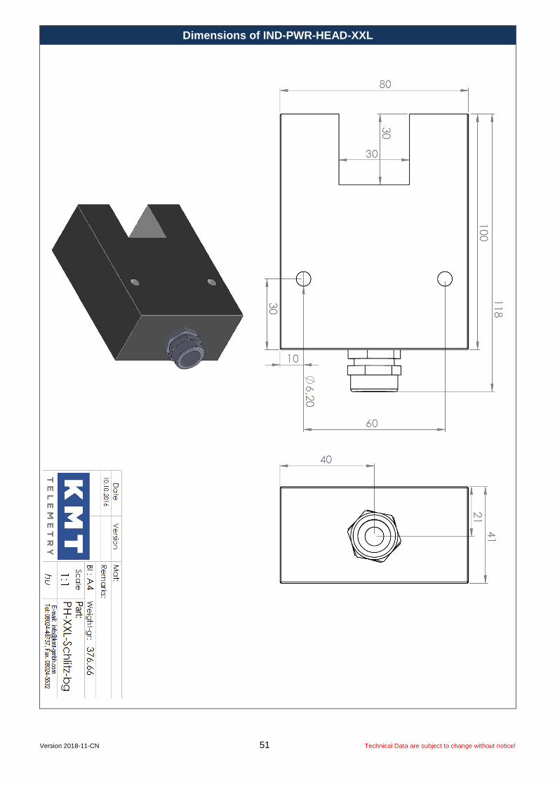
Dimensions of IND-PWR-HEAD-XXL

Version 2018-11-CN 52 Technical Data are subject to change without notice!
Dimensions of IND-PWR-HEAD-XXL

Version 2018-11-CN 53 Technical Data are subject to change without notice!
IND-PWR-HEAD-XXL
Caution for use of power heads! Cable must unrolled for use, otherwise it will warm up!

Version 2018-11-CN 54 Technical Data are subject to change without notice!
Dimensions of IND-PWR-HEAD-XXXL

Version 2018-11-CN 55 Technical Data are subject to change without notice!
IND-PWR-HEAD-XXXL
Caution for use of power heads! Cable must unrolled for use, otherwise it will warm up!