
Application Notes for IPC Alliance MX 16.01 with Avaya Aura ...
Upload
khangminh22Category
view
2download
0
LYM; Reviewed:
SPOC 03/03/2014
Solution & Interoperability Test Lab Application Notes
©2014 Avaya Inc. All Rights Reserved.
1 of 49
SvcPilot-CM63
Avaya Solution & Interoperability Test Lab
Application Notes for ServicePilot ISM 8.3.1 with Avaya
Aura® Communication Manager 6.3 - Issue 1.0
Abstract
These Application Notes describe the procedures for configuring ServicePilot ISM 8.3.1 to
interoperate with Avaya Aura® Communication Manager 6.3.
ServicePilot ISM is a performance monitoring solution for multi-vendor infrastructure and
unified communications. ServicePilot ISM provides visibility of Avaya and other vendor’s IP
Telephony solutions from a single console. Targeted at multi-site enterprises and managed
service providers of IP telephony solutions, ServicePilot ISM monitoring solution is non-
intrusive as there is no need to install any agent on the communication servers or their
infrastructure and can be installed in a virtualized environment.
ServicePilot ISM integrates directly to Communication Manager using Secure Shell (SSH) or
Telnet. At the same time, it processes Simple Network Management Protocol (SNMP), Real-
time Transport Control Protocol (RTCP) and Call Detail Recording (CDR) information from
Communication Manager, Gateways and Avaya Endpoints.
Information in these Application Notes has been obtained through DevConnect compliance
testing and additional technical discussions. Testing was conducted via the DevConnect
Program at the Avaya Solution and Interoperability Test Lab.

LYM; Reviewed:
SPOC 03/03/2014
Solution & Interoperability Test Lab Application Notes
©2014 Avaya Inc. All Rights Reserved.
2 of 49
SvcPilot-CM63
1. Introduction These Application Notes describe the compliance tested configuration used to validate
ServicePilot ISM 8.3.1 with Avaya Aura® Communication Manager 6.3.
ServicePilot ISM provides enterprises and Managed Service Providers with the following
capabilities:
Monitoring
Troubleshooting
Reporting
ServicePilot ISM uses four methods to monitor a Communication Manager system.
System Access Terminal (SAT) – ServicePilot ISM uses telnet/SSH connections to the
SAT using the IP address of the Avaya Server. By default, the solution establishes 2
concurrent SAT connections to the Communication Manager system and uses the
connections to execute SAT commands.
Real Time Transport Control Protocol (RTCP) Collection - ServicePilot ISM collects
RTCP information sent by the Avaya IP Media Processor (MEDPRO) boards, media
gateways, and IP Telephones. The call quality metrics including packet loss, latency, and
jitter are collected and from these metrics, the MOS (mean opinion score) is computed,
which measures overall call quality.
Simple Network Management Protocol (SNMP) Collection – ServicePilot ISM uses
SNMP to collect configuration and status information and SNMP traps from
Communication Manager and its gateways.
Call Detail Recording (CDR) Collection - ServicePilot ISM collects CDR information
sent by Communication Manager.
LYM; Reviewed:
SPOC 03/03/2014
Solution & Interoperability Test Lab Application Notes
©2014 Avaya Inc. All Rights Reserved.
3 of 49
SvcPilot-CM63
2. General Test Approach and Test Results The general test approach was to use ServicePilot ISM web interface to display the
configurations of the Communication Manager systems and verify against what is displayed on
the SAT interface. The SAT interface is accessed by using either telnet or Secure SHell (SSH) to
the Avaya S8800 and S8300D Servers. Calls were placed between various Avaya endpoints and
ServicePilot ISM web interface was used to display the RTCP and CDR information collected
via the Call logs.
DevConnect Compliance Testing is conducted jointly by Avaya and DevConnect members. The
jointly-defined test plan focuses on exercising APIs and/or standards-based interfaces pertinent
to the interoperability of the tested products and their functionalities. DevConnect Compliance
Testing is not intended to substitute full product performance or feature testing performed by
DevConnect members, nor is it to be construed as an endorsement by Avaya of the suitability or
completeness of a DevConnect member’s solution.
2.1. Interoperability Compliance Testing
For feature testing, ServicePilot ISM web interface was used to view the configurations of
Communication Manager such as port networks, cabinets, media gateways, ESS, LSP, trunk
groups, route patterns, CLAN, MEDPRO and DS1 boards, IP network regions, stations,
processor occupancy, alarm and error information. For the collection of RTCP and CDR
information, the endpoints included Avaya H323, SIP, digital and analog telephones, and Avaya
one-X® Communicator users. The types of calls made included intra-switch calls,
inbound/outbound PSTN calls, inbound/outbound inter-switch IP trunk calls, transfer and
conference calls.
For serviceability testing, reboots were applied to the ISM Server and Avaya Servers to simulate
system unavailability. Interchanging of the Avaya S8800 Servers and failover to ESS and LSP
were also performed during testing.
2.2. Test Results
All test cases passed successfully with the following observations:
The following CDR formats are supported:
a. Expanded
b. Enhanced Expanded
c. Unformatted
d. Enhanced Unformatted
2.3. Support
For technical support on ServicePilot ISM, contact the ServicePilot Support Team at:
Hotline: +33 2 4060-8052
Email: [email protected]

LYM; Reviewed:
SPOC 03/03/2014
Solution & Interoperability Test Lab Application Notes
©2014 Avaya Inc. All Rights Reserved.
4 of 49
SvcPilot-CM63
3. Reference Configuration Figure 1 illustrates the test configuration used to verify ServicePilot ISM interoperability with
Communication Manager. It consists of a Communication Manager system running on a pair of
Avaya S8800 Servers with one Avaya G650 Media Gateway, an Avaya G430 Media Gateway
with Avaya S8300D Server as a Local Survivability Processor (LSP) and an Avaya G250-BRI
Media Gateway. An Enterprise Survivable Server (ESS) running on VMware was also
configured for failover testing. A second Communication Manager system runs on an Avaya
S8300D Server with an Avaya G450 Media Gateway. Both systems have Avaya IP, digital and
analog telephones, and Avaya one-X® Communicator users configured for making and receiving
calls. IP Trunks connect the two systems together to allow calls between them. Avaya Aura®
System Manager and Avaya Aura® Session Manager provided SIP support to the Avaya SIP
telephones. ServicePilot ISM was installed on a server running Microsoft Windows Server 2008
R2 with Service Pack 1. The Avaya 4548GT-PWR Ethernet Routing Switch provides Ethernet
connectivity to the servers, media gateways and IP telephones.
Figure 1: Test Configuration

LYM; Reviewed:
SPOC 03/03/2014
Solution & Interoperability Test Lab Application Notes
©2014 Avaya Inc. All Rights Reserved.
5 of 49
SvcPilot-CM63
4. Equipment and Software Validated
The following equipment and software were used for the sample configuration provided:
Equipment/Software Release/Version
Avaya Aura® Communication Manager
running on Avaya S8800 Servers
(System A)
6.3 SP 2.1
G650 Media Gateway
- TN2312BP IP Server Interface
- TN799DP C-LAN Interface (x 4)
- TN2602AP IP Media Processor (x 2)
- TN2302AP IP Media Processor (x 2)
- TN2464BP DS1 Interface
- TN2464CP DS1 Interface
- TN793CP Analog Line
- TN2214CP Digital Line
HW07, FW057
HW01, FW040
HW02 FW063 and
HW02 FW063
HW20 FW121 and
HW20 FW121
HW05, FW025
HW02 FW025
HW09, FW011
HW08, FW015
G250 Media Gateway 30.27.1
Avaya Aura® Communication Manager
running on Avaya S8300D Server
(System B)
6.3 SP 2.1
G450 Media Gateway
- MM722AP BRI Media Module (MM)
- MM712AP DCP MM
- MM714AP Analog MM
- MM717AP DCP MM
- MM710BP DS1 MM
34.5.1
HW01 FW008
HW07 FW014
HW10 FW098
HW03 FW014
HW11 FW052
Avaya Aura® Communication Manager
running on Avaya S8300D Server
(G430 Media Gateway - LSP)
6.3 SP 2.1
G430 Media Gateway
- MM712AP DCP MM
- MM714AP Analog MM
- MM711AP Analog MM
- MM710AP DS1 MM
34.5.1
HW07 FW014
HW12 FW098
HW31 FW098
HW05 FW022
Avaya Aura® Communication Manager
running on VMware 5.0 (ESS)
6.3 SP 2.1
HP DL360 G7 running Avaya Aura®
System Manager
6.3 SP4
Avaya S8800 Server running Avaya Aura®
Session Manager
6.2 SP4

LYM; Reviewed:
SPOC 03/03/2014
Solution & Interoperability Test Lab Application Notes
©2014 Avaya Inc. All Rights Reserved.
6 of 49
SvcPilot-CM63
Equipment/Software Release/Version
96xx Series IP Telephones
- 9640G
- 9620
3.2 (H323) or 2.6
SP10 (SIP)
96x1 Series IP Telephones
- 9641G
- 9611G
6.3 (H.323) or
6.2.2 (SIP)
1600 Series IP Telephones
- 1616
- 1603SW
1.34 (H.323)
Digital Telephones
- 1416
- 1408
SP1
Avaya Analog Phones -
Desktop PC with Avaya one-X
Communicator
6.1 SP8 (H.323)
Avaya 4548GT-PWR Ethernet Routing
Switch
V5.6.1.052
ServicePilot ISM on
Windows 2008 R2 SP1
8.3.1

LYM; Reviewed:
SPOC 03/03/2014
Solution & Interoperability Test Lab Application Notes
©2014 Avaya Inc. All Rights Reserved.
7 of 49
SvcPilot-CM63
5. Configure Communication Manager This section describes the steps needed to configure Communication Manager to interoperate
with ServicePilot ISM. This includes creating a login account and a SAT User Profile for ISM to
access Communication Manager, enabling RTCP and CDR reporting and setting up SNMP. The
steps are repeated for each Communication Manager system, ESS and LSP Servers. SNMP
setup is also required for gateways.
5.1. Configure SAT User Profile
A SAT User Profile specifies which SAT screens may be accessed by the user assigned the
profile and the type of access to each screen. As ServicePilot ISM does not modify any system
configuration, create a SAT User Profile with limited permissions to assign to the ServicePilot
ISM login account.
Step Description
1. Enter the add user-profile n command, where n is the next unused profile number. Enter
a descriptive name for User Profile Name and enable all categories by setting the Enbl
field to y. In this test configuration, the user profile 23 is created.
add user-profile 23 Page 1 of 41
USER PROFILE 23
User Profile Name: SPISM
This Profile is Disabled? n Shell Access? n
Facility Test Call Notification? n Acknowledgement Required? n
Grant Un-owned Permissions? n Extended Profile? n
Name Cat Enbl Name Cat Enbl
Adjuncts A y Routing and Dial Plan J y
Call Center B y Security K y
Features C y Servers L y
Hardware D y Stations M y
Hospitality E y System Parameters N y
IP F y Translations O y
Maintenance G y Trunking P y
Measurements and Performance H y Usage Q y
Remote Access I y User Access R y

LYM; Reviewed:
SPOC 03/03/2014
Solution & Interoperability Test Lab Application Notes
©2014 Avaya Inc. All Rights Reserved.
8 of 49
SvcPilot-CM63
Step Description
2. On Pages 2 to 41 of the USER PROFILE forms, set the permissions of all objects to rm
(read and maintenance). This can be accomplished by typing rm into the field Set All
Permissions To. Submit the form to create the user profile.
add user-profile 23 Page 2 of 41
USER PROFILE 23
Set Permissions For Category: To: Set All Permissions To: rm
'-'=no access 'r'=list,display,status 'w'=add,change,remove+r 'm'=maintenance
Name Cat Perm
aar analysis J rm
aar digit-conversion J rm
aar route-chosen J rm
abbreviated-dialing 7103-buttons C rm
abbreviated-dialing enhanced C rm
abbreviated-dialing group C rm
abbreviated-dialing personal C rm
abbreviated-dialing system C rm
aca-parameters P rm
access-endpoints P rm
adjunct-names A rm
administered-connections C rm
aesvcs cti-link A rm
aesvcs interface A rm

LYM; Reviewed:
SPOC 03/03/2014
Solution & Interoperability Test Lab Application Notes
©2014 Avaya Inc. All Rights Reserved.
9 of 49
SvcPilot-CM63
5.2. Configure Login Group
Create an Access-Profile Group on Communication Manager SMI to correspond to the SAT
User Profile created in Section 5.1.
Step Description
1. Using a web browser, enter https://<IP address of Communication Manager> to connect
to the Communication Manager Server being configured and log in using appropriate
credentials.

LYM; Reviewed:
SPOC 03/03/2014
Solution & Interoperability Test Lab Application Notes
©2014 Avaya Inc. All Rights Reserved.
10 of 49
SvcPilot-CM63
Step Description
2. Click Administration Server (Maintenance). This will open up the Server
Administration Interface that will allow the user to complete the configuration process.

LYM; Reviewed:
SPOC 03/03/2014
Solution & Interoperability Test Lab Application Notes
©2014 Avaya Inc. All Rights Reserved.
11 of 49
SvcPilot-CM63
Step Description
3. From the navigation panel on the left side, click Administrator Accounts. Select Add
Group and click Submit.

LYM; Reviewed:
SPOC 03/03/2014
Solution & Interoperability Test Lab Application Notes
©2014 Avaya Inc. All Rights Reserved.
12 of 49
SvcPilot-CM63
Step Description
4. Select Add a new access-profile group and select prof23 from the drop-down box to
correspond to the user-profile created in Section 5.1 Step 1. Click Submit. This
completes the creation of the login group.

LYM; Reviewed:
SPOC 03/03/2014
Solution & Interoperability Test Lab Application Notes
©2014 Avaya Inc. All Rights Reserved.
13 of 49
SvcPilot-CM63
5.3. Configure Login
Create a login account for ServicePilot ISM to access the Communication Manager SAT.
Step Description
1. From the navigation panel on the left side, click Administrator Accounts. Select Add
Login and SAT Access Only to create a new login account with SAT access privileges
only. Click Submit.

LYM; Reviewed:
SPOC 03/03/2014
Solution & Interoperability Test Lab Application Notes
©2014 Avaya Inc. All Rights Reserved.
14 of 49
SvcPilot-CM63
Step Description
2. For the field Login name, enter the login. In this configuration, the login iptm is created.
Configure the other parameters for the login as follows:
Primary group: users [Limits the permissions of the login]
Additional groups (profile): prof23 [Select the login group created in Section
5.2.]
Select type of authentication: Password [Uses a password for authentication.]
Enter password or key / Re-enter password or key [Define the password.]
Click Submit to continue. This completes the configuration of the login.

LYM; Reviewed:
SPOC 03/03/2014
Solution & Interoperability Test Lab Application Notes
©2014 Avaya Inc. All Rights Reserved.
15 of 49
SvcPilot-CM63
5.4. Configure RTCP Monitoring
To allow ServicePilot ISM to monitor the quality of IP calls, configure Communication Manager
to send RTCP reporting to the IP address of the ISM server. This is done through the SAT
interface.
Step Description
1. Enter the change system-parameters ip-options command. In the RTCP MONITOR
SERVER section, set Server IPV4 Address to the IP address of the ISM server. Set
IPV4 Server Port to 5005 and RTCP Report Period (secs) to 5.
change system-parameters ip-options Page 1 of 4
IP-OPTIONS SYSTEM PARAMETERS
IP MEDIA PACKET PERFORMANCE THRESHOLDS
Roundtrip Propagation Delay (ms) High: 800 Low: 400
Packet Loss (%) High: 40 Low: 15
Ping Test Interval (sec): 20
Number of Pings Per Measurement Interval: 10
Enable Voice/Network Stats? n
RTCP MONITOR SERVER
Server IPV4 Address: 10.1.10.122 RTCP Report Period(secs): 5
IPV4 Server Port: 5005
Server IPV6 Address:
IPV6 Server Port: 5005
AUTOMATIC TRACE ROUTE ON
Link Failure? y
H.323 IP ENDPOINT
H.248 MEDIA GATEWAY Link Loss Delay Timer (min): 5
Link Loss Delay Timer (min): 5 Primary Search Time (sec): 75
Periodic Registration Timer (min): 20
Short/Prefixed Registration Allowed? y
2. Enter the change ip-network-region n command, where n is IP network region number
to be monitored. On Page 2, set RTCP Reporting Enabled to y and Use Default Server
Parameters to y.
Note: Only one RTCP MONITOR SERVER can be configured per IP network region.
change ip-network-region 1 Page 2 of 20
IP NETWORK REGION
RTCP Reporting Enabled? y
RTCP MONITOR SERVER PARAMETERS
Use Default Server Parameters? Y
3. Repeat Step 2 for all IP network regions that are required to be monitored.

LYM; Reviewed:
SPOC 03/03/2014
Solution & Interoperability Test Lab Application Notes
©2014 Avaya Inc. All Rights Reserved.
16 of 49
SvcPilot-CM63
5.5. Configure CDR Monitoring
To allow ServicePilot ISM to monitor the CDR information, configure Communication Manager
to send CDR information to the IP address of the ISM server.
Step Description
1. Enter the change ip-interface procr command to enable the processor-ethernet interface
on the Avaya Server. Set Enable Interface to y. This interface will be used by
Communication Manager to send out the CDR information.
change ip-interface procr Page 1 of 2
IP INTERFACES
Type: PROCR
Target socket load: 1700
Enable Interface? y Allow H.323 Endpoints? y
Allow H.248 Gateways? y
Network Region: 1 Gatekeeper Priority: 5
IPV4 PARAMETERS
Node Name: procr IP Address: 10.1.10.230
Subnet Mask: /24
2. Enter the change node-names ip command to add a new node name for the ISM server.
In this configuration, the name SPISM is added with the IP address specified as
10.1.10.122. Note also the node name procr which is automatically added.
change node-names ip Page 1 of 2
IP NODE NAMES
Name IP Address
ESS 10.1.10.239
Gateway001 10.1.10.1
Gateway002 10.1.50.1
IPOffice 10.1.30.10
Invision 10.1.10.126
PC1 10.1.10.151
PC2 10.1.10.152
RDTT 10.1.10.153
SPISM 10.1.10.122
cms1 10.1.10.85
default 0.0.0.0
lsp-g430 10.1.40.10
n 10.3.10.253
procr 10.1.10.230
procr6 ::
s8500-clan1 10.1.10.21
( 16 of 24 administered node-names were displayed )
Use 'list node-names' command to see all the administered node-names
Use 'change node-names ip xxx' to change a node-name 'xxx' or add a node-name

LYM; Reviewed:
SPOC 03/03/2014
Solution & Interoperability Test Lab Application Notes
©2014 Avaya Inc. All Rights Reserved.
17 of 49
SvcPilot-CM63
Step Description
3. Enter the change ip-services command to define the CDR link. To define a primary CDR
link, the following information should be provided:
Service Type: CDR1 [If needed, a secondary link can be defined by setting
Service Type to CDR2.]
Local Node: procr [Communication Manager will use the processor-ethernet
interface to send out the CDR]
Local Port: 0 [The Local Port is set to 0 because Communication Manager
initiates the CDR link.]
Remote Node: SPISM [The Remote Node is set to the node name previously
defined in Step 2]
Remote Port: 50000 [The Remote Port may be set to a value between 5000 and
64500 inclusive. 50000 is the default port number used by ServicePilot ISM. Note
that ISM server uses the same port number for all Avaya Servers sending CDR
information to it.]
change ip-services Page 1 of 4
IP SERVICES
Service Enabled Local Local Remote Remote
Type Node Port Node Port
AESVCS y procr 8765
CDR1 procr 0 SPISM 50000
On Page 3 of the form, disable the Reliable Session Protocol (RSP) for the CDR link by
setting the Reliable Protocol field to n.
change ip-services Page 3 of 4
SESSION LAYER TIMERS
Service Reliable Packet Resp Session Connect SPDU Connectivity
Type Protocol Timer Message Cntr Cntr Timer
CDR1 n 30 3 3 60

LYM; Reviewed:
SPOC 03/03/2014
Solution & Interoperability Test Lab Application Notes
©2014 Avaya Inc. All Rights Reserved.
18 of 49
SvcPilot-CM63
Step Description
4. Enter the change system-parameters cdr command to set the parameters for the type of
calls to track and the format of the CDR data. The following settings were used during the
compliance test.
CDR Date Format: month/day [day/month Date Format is also supported]
Primary Output Format: unformatted [Other Output Format include expanded,
enhanced expanded, enhanced unformatted]
Primary Output Endpoint: CDR1
The remaining parameters define the type of calls that will be recorded and what data will
be included in the record. See Reference [1] for a full explanation of each field. The test
configuration used some of the more common fields described below.
Intra-switch CDR: y [Allows call records for internal calls involving specific
stations. Those stations must be specified in the INTRA-SWITCH-CDR form.]
Record Outgoing Calls Only? n [Allows incoming trunk calls to appear in the
CDR records along with the outgoing trunk calls.]
Outg Trk Call Splitting? y [Allows a separate call record for any portion of an
outgoing call that is transferred or conferenced.]
Inc Trk Call Splitting? y [Allows a separate call record for any portion of an
incoming call that is transferred or conferenced.]
change system-parameters cdr Page 1 of 1
CDR SYSTEM PARAMETERS
Node Number (Local PBX ID): 1 CDR Date Format: month/day
Primary Output Format: unformatted Primary Output Endpoint: CDR1
Secondary Output Format:
Use ISDN Layouts? n Enable CDR Storage on Disk? y
Use Enhanced Formats? n Condition Code 'T' For Redirected Calls? n
Use Legacy CDR Formats? n Remove # From Called Number? y
Modified Circuit ID Display? n Intra-switch CDR? y
Record Outgoing Calls Only? n Outg Trk Call Splitting? y
Suppress CDR for Ineffective Call Attempts? y Outg Attd Call Record? y
Disconnect Information in Place of FRL? n Interworking Feat-flag? n
Force Entry of Acct Code for Calls Marked on Toll Analysis Form? n
Calls to Hunt Group - Record: group-ext
Record Called Vector Directory Number Instead of Group or Member? n
Record Agent ID on Incoming? n Record Agent ID on Outgoing? y
Inc Trk Call Splitting? y Inc Attd Call Record? n
Record Non-Call-Assoc TSC? n Call Record Handling Option: warning
Record Call-Assoc TSC? n Digits to Record for Outgoing Calls: outpulsed
Privacy - Digits to Hide: 0 CDR Account Code Length: 7
Remove '+' from SIP Numbers? Y
5. If the Intra-switch CDR field is set to y on Page 1 of the SYSTEM-PARAMETERS
CDR form, then enter the change intra-switch-cdr command to define the extensions
that will be subjected to call detail recording. In the Assigned Members field, enter the
specific extensions whose usage will be tracked with the CDR records.

LYM; Reviewed:
SPOC 03/03/2014
Solution & Interoperability Test Lab Application Notes
©2014 Avaya Inc. All Rights Reserved.
19 of 49
SvcPilot-CM63
Step Description change intra-switch-cdr Page 1 of 3
INTRA-SWITCH CDR
Assigned Members: 11 of 5000 administered
Extension Extension Extension Extension
10001
10002
10003
10005
10016
10049
10050
10701
20001
481122
481123
6. For each trunk group for which CDR records are desired, verify that CDR reporting is
enabled. Enter the change trunk-group n command, where n is the trunk group number,
to verify that the CDR Reports field is set to y. Repeat for all trunk groups to be reported.
change trunk-group 1 Page 1 of 21
TRUNK GROUP
Group Number: 1 Group Type: isdn CDR Reports: y
Group Name: PSTN - BRI COR: 95 TN: 1 TAC: #01
Direction: two-way Outgoing Display? n Carrier Medium: PRI/BRI
Dial Access? y Busy Threshold: 255 Night Service:
Queue Length: 0
Service Type: public-ntwrk Auth Code? n TestCall ITC: rest
Far End Test Line No:
TestCall BCC: 4
5.6. Configure SNMP on Communication Manager
Step Description
1. Access the Avaya Aura® Communication Manager System Management Web Interface
as in Section 5.2 Steps 1 and 2. Navigate to Administration Server Administration
to display the following web page.

LYM; Reviewed:
SPOC 03/03/2014
Solution & Interoperability Test Lab Application Notes
©2014 Avaya Inc. All Rights Reserved.
20 of 49
SvcPilot-CM63
Step Description
2. Click Alarms Agent Status. Click Stop the Master Agent if the Master Agent
status is UP to allow setup of SNMP Agent.
3. To allow ServicePilot ISM to use SNMP to collect configuration and status information
from Communication Manager, navigate to Alarms SNMP Agents in the left pane.
Under IP Addresses for SNMP Access, select Any IP address. Under SNMP Users /
Communities, configure the SNMP Version 2c section. Set the Community Name
(read-only) field to spism and the drop-down box to the right to enabled. Click Submit
at the bottom of the web page (not shown in the figure).

LYM; Reviewed:
SPOC 03/03/2014
Solution & Interoperability Test Lab Application Notes
©2014 Avaya Inc. All Rights Reserved.
21 of 49
SvcPilot-CM63
Step Description
4. Navigate to Alarms SNMP Traps web page below and configure ServicePilot as an
SNMP trap receiver under the Add Trap Destination section. Next, configure the
SNMP Version 2c parameters. Set the Status field to enabled, specify the IP address of
ServicePilot ISM, set the Notification field to trap, and set the Community Name to
spism. Click the Submit button.
5. Lastly, the SNMP agent must be started. Navigate to Alarms Agent Status. . If the
Master Agent status is Down, then click the Start Agent button. If the Master Agent
status is Up, then the agent must be stopped and restarted.

LYM; Reviewed:
SPOC 03/03/2014
Solution & Interoperability Test Lab Application Notes
©2014 Avaya Inc. All Rights Reserved.
22 of 49
SvcPilot-CM63
5.7. Configure SNMP for Media Gateway
This section provides the procedures for configuring SNMP on the Avaya G430 Media Gateway.
The procedures include the following areas. Repeat these procedures for G250 and G450 Media
Gateway.
Administer community string
Administer SNMP traps
Show SNMP
5.7.1. Administer Community String
Use the “snmp-server community” command shown below to set the desired community strings
for read-only and read-write access, where public and private can be any desired community
string.
G430-003(super)#
G430-003(super)# snmp-server community read-only public read-write public
Done!
G430-003(super)#
5.7.2. Administer SNMP Traps
Use the snmp-server host command shown below to enable SNMP traps to ServicePilot ISM,
where 10.1.10.122 is the IP address of the ISM server, and public is the read-only community
string.
G430-003(super)#
G430-003(super)# snmp-server host 10.1.10.122 traps v2c public
Done!
G430-003(super)#

LYM; Reviewed:
SPOC 03/03/2014
Solution & Interoperability Test Lab Application Notes
©2014 Avaya Inc. All Rights Reserved.
23 of 49
SvcPilot-CM63
5.7.3. Show SNMP
The show snmp command can be used to display the list of SNMP receivers as shown below.
G430-003(super)# show snmp
Authentication trap disabled
Community-Access Community-String
---------------- ----------------
read-only *****
read-write *****
SNMPv3 Notifications Status
-----------------------------
Traps: Enabled
Informs: Enabled Retries: 3 Timeout: 3 seconds
SNMP-Rec-Address Model Notification Trap/Inform
UDP port Level
User name
--------------------------------------------- ------- -------------- -----------
10.1.10.230 v1 all trap
162 - Dynamic Trap Manager noauth
ReadCommN
10.1.10.122 v2c all trap
162 noauth

LYM; Reviewed:
SPOC 03/03/2014
Solution & Interoperability Test Lab Application Notes
©2014 Avaya Inc. All Rights Reserved.
24 of 49
SvcPilot-CM63
6. Configure ServicePilot ISM This section describes the configuration required for ServicePilot ISM to interoperate with
Communication Manager. It assumes that the application and all required software components
have been installed and properly licensed. The procedures cover the following operations:
Launch ServicePilot ISM
Run the New Configuration Wizard
Add an Avaya Aura® Communication Manager
Configure RTCP packets and CDRs
Configure Call Quality thresholds
Add an Avaya Media Gateway
Configure the SNMP alarm server
Create an Avaya dashboard
6.1. Launch ServicePilot ISM
ServicePilot ISM is initially configured using the Administration Console. Launch ServicePilot
ISM Administration Console on the ServicePilot ISM server using the following procedure.
Step Description
1. From the Windows Start menu, navigate to All Programs ServicePilot
ServicePilot ISM Enterprise ServicePilot ISM Enterprise.
The main ServicePilot ISM Administration Console window appears as shown below.

LYM; Reviewed:
SPOC 03/03/2014
Solution & Interoperability Test Lab Application Notes
©2014 Avaya Inc. All Rights Reserved.
25 of 49
SvcPilot-CM63
6.2. Run the New Configuration Wizard
In order to interoperate with the Communication Manager, a new configuration needs to be
created for ServicePilot ISM, following the steps below.
Step Description
1. From the ServicePilot ISM Administration Console run the New Configuration Wizard
by selecting File New
Select Basic Configuration then click Next.

LYM; Reviewed:
SPOC 03/03/2014
Solution & Interoperability Test Lab Application Notes
©2014 Avaya Inc. All Rights Reserved.
26 of 49
SvcPilot-CM63
6.3. Add an Avaya Aura® Communication Manager
To add a Communication Manager to the newly created configuration, run the import wizard,
(which will have been automatically launched by the previous procedure) following the steps
below.
NOTE: If this procedure is not being run after the New Configuration Wizard, for example to
deploy an additional Communication Manager into the monitoring environment, the Import
Package can be started by doing a drag-and-drop of the Avaya Monitoring package, from the
Packages tab onto the main window.
2. From the drop-down list select VoIP and then select Avaya in the VoIP box. Optionally,
enter a company name and choose a logo.
Then click Next.
This will create the Avaya VoIP Portal on the main window.
This completes the New Configuration Wizard and automatically launches the Import
Package wizard for the Communication Manager (see next section)

LYM; Reviewed:
SPOC 03/03/2014
Solution & Interoperability Test Lab Application Notes
©2014 Avaya Inc. All Rights Reserved.
27 of 49
SvcPilot-CM63
Step Description
1. On the Import Package window, enter the following parameters for the Communication
Manager:
- Name, e.g. CM-01
- SNMP read-only community, e.g. public
- SNMP port, e.g. 161
Click Next.

LYM; Reviewed:
SPOC 03/03/2014
Solution & Interoperability Test Lab Application Notes
©2014 Avaya Inc. All Rights Reserved.
28 of 49
SvcPilot-CM63
Step Description
2. Specify the right architecture by selecting one of the following 2 options:
- Standalone / Cluster
- Spatial Redundancy
If Spatial Redundancy was selected, enter the following parameters:
- Virtual / shared IP address for the Main nodes
- Virtual / shared IP address for the Standby nodes.
Click Next.
LYM; Reviewed:
SPOC 03/03/2014
Solution & Interoperability Test Lab Application Notes
©2014 Avaya Inc. All Rights Reserved.
29 of 49
SvcPilot-CM63
Step Description
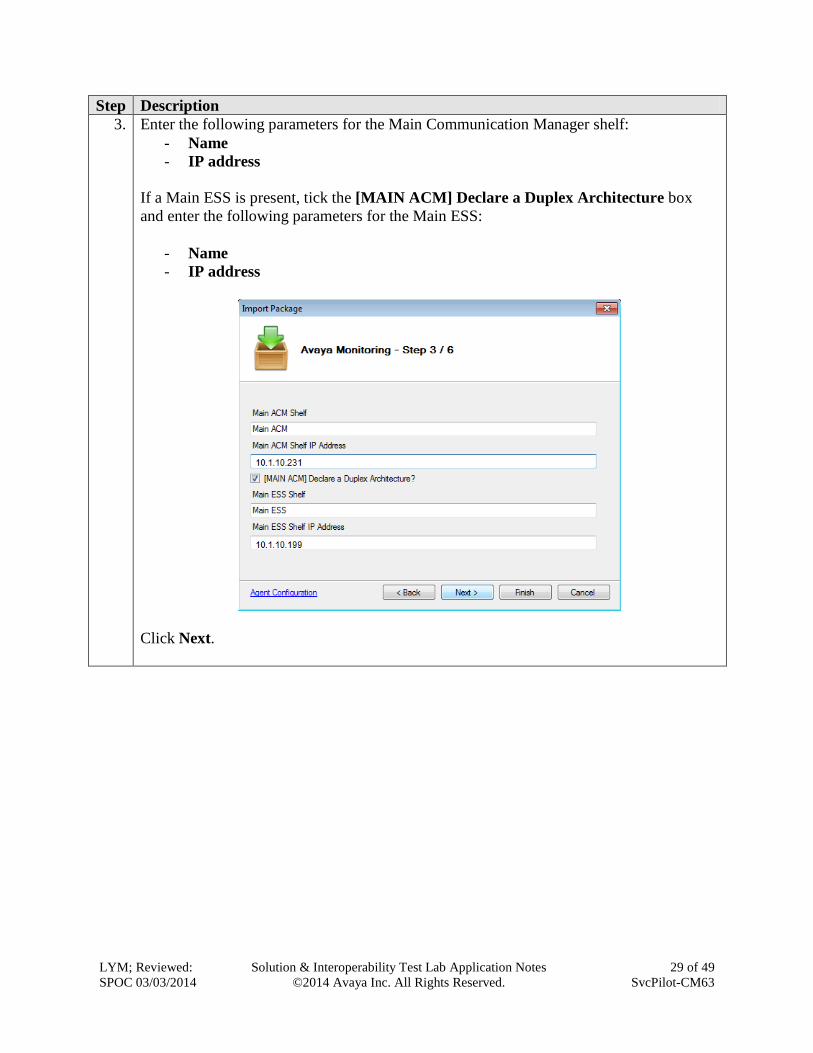
3. Enter the following parameters for the Main Communication Manager shelf:
- Name
- IP address
If a Main ESS is present, tick the [MAIN ACM] Declare a Duplex Architecture box
and enter the following parameters for the Main ESS:
- Name
- IP address
Click Next.

LYM; Reviewed:
SPOC 03/03/2014
Solution & Interoperability Test Lab Application Notes
©2014 Avaya Inc. All Rights Reserved.
30 of 49
SvcPilot-CM63
Step Description
4. If the Standalone / Cluster option was selected on Step 2, skip this step.
Otherwise, enter the following parameters for the Standby Communication Manager shelf:
- Name
- IP address
If a Standby ESS is present, tick the [REDUNDANT ACM] Declare a Duplex
Architecture box and enter the following parameters for the Standby ESS:
- Name
- IP address
Click Next.

LYM; Reviewed:
SPOC 03/03/2014
Solution & Interoperability Test Lab Application Notes
©2014 Avaya Inc. All Rights Reserved.
31 of 49
SvcPilot-CM63
Step Description
5. Leave the Customer Name field blank and enter the following parameters for the SAT
connection between ServicePilot ISM and the Communication Manager:
- Connection type: from the drop-down list select either Telnet or SSH
- Port: enter 5023 (if Telnet was selected) or 5022 (if SSH was selected)
- Login: enter the same Login name as Step 2 in Section 5.3.
- Password: enter the same password as Step 2 in Section 5.3.
Click Next.

LYM; Reviewed:
SPOC 03/03/2014
Solution & Interoperability Test Lab Application Notes
©2014 Avaya Inc. All Rights Reserved.
32 of 49
SvcPilot-CM63
Step Description
6. Tick or un-tick the following options, depending on the available Communication
Manager’s components to monitor:
- Trunk Groups
- Network Regions
- Media Gateways
- LSPs
- Boards
- Call Admission Control (CAC policies)
- Cabinets.
Click Finish.
7. Click Close on the Package Information window that appears.
8. Click Close on the New Configuration Wizard window that appears.
Skip this step if this procedure was started independently of the New Configuration
Wizard.
6.4. Configure RTCP Packets and CDRs
To provide call statistics and call quality details, ServicePilot ISM relies on the RTCP packets
received from Avaya end points and on the CDRs received from the Communication Manager.
Both features need to be configured in ServicePilot ISM following the procedure below.

LYM; Reviewed:
SPOC 03/03/2014
Solution & Interoperability Test Lab Application Notes
©2014 Avaya Inc. All Rights Reserved.
33 of 49
SvcPilot-CM63
Step Description
1. From the Administration Console, click on Avaya VoIP Portal Avaya VoIP
Infrastructure Avaya PBX Servers.
2. Right-click on the newly imported Communication Manager (e.g. CM-01) and select
Agent Properties.

LYM; Reviewed:
SPOC 03/03/2014
Solution & Interoperability Test Lab Application Notes
©2014 Avaya Inc. All Rights Reserved.
34 of 49
SvcPilot-CM63
Step Description
3. Click on Open Avaya collector parameters.
4. On the Avaya Collector window that appears, enter the following:
- CDR port: enter the same value as Remote Port in Step 3, Section 5.5, e.g.
50000
- CDR date format: from the drop-down list select either Month/Day or
Day/Month, so the selection matches the format in Step 4, Section 5.5
- RTCP port: enter the same port as Step 1, Section 5.4, e.g. 5005
- Tick the RTCP calls with no CDR box
- Interval: specify how often ServicePilot ISM will process received RTCP packets
and CDR records (default is 60 seconds)
Click OK.

LYM; Reviewed:
SPOC 03/03/2014
Solution & Interoperability Test Lab Application Notes
©2014 Avaya Inc. All Rights Reserved.
35 of 49
SvcPilot-CM63
Step Description
5. NOTE: this step is optional.
Click on Show advanced parameters.
On the Advanced Parameters window that appears, you can adjust the following
parameters for the SAT connection to the Communication Manager:
(default values are shown in brackets)
- Minimum time between requests (500 ms)
- Number of simultaneous connections for Communication Manager (2)
- Polling interval (60 seconds)
- Phones discovery interval (3 hours)
- Trunk groups discovery interval (1 hour).
Click OK.
6. Click OK to accept the changes.
6.5. Configure Call Quality Thresholds
The following procedure can be used to customize how ServicePilot ISM classifies calls as
Good, Average or Bad.

LYM; Reviewed:
SPOC 03/03/2014
Solution & Interoperability Test Lab Application Notes
©2014 Avaya Inc. All Rights Reserved.
36 of 49
SvcPilot-CM63
Step Description
1. From the Administration Console, click on Avaya VoIP Portal Avaya VoIP
Infrastructure Avaya PBX Servers, as in Step 1 in Section 6.4.
2. Right-click on the newly imported Communication Manager (e.g. CM-01) and select
Agent Properties, as in Step 2 in Section 6.4.
3. Select the Call Quality tab.
4. To configure how ServicePilot ISM classifies call quality based on the four standard QoS
(Quality of Service) metrics below, adjust the values for the Good and Average
thresholds:
(default values are shown in brackets)
- Packet Loss Rate (< 1%, < 3%)
- Jitter (< 20ms, < 50ms)
- Latency (< 150ms, < 400ms)
- MOS (Mean Opinion Score, 1-5) (> 4, > 3)
NOTE (1): Calls falling outside the specified thresholds (above or below, depending on
the metric) will automatically be classified as Bad.
NOTE (2): Calls without sufficient call quality metrics will be classified as
Other/Unknown.

LYM; Reviewed:
SPOC 03/03/2014
Solution & Interoperability Test Lab Application Notes
©2014 Avaya Inc. All Rights Reserved.
37 of 49
SvcPilot-CM63
Step Description
5. NOTE: this step and Step 6 are optional.
Click on Call Quality by Zone/Network.
On the Call Quality by Zone/Network window that appears, tick the Activate Call
Quality Statistics by Zone/Network box and select Call Quality by Zone.
Then click on Edit Zones.

LYM; Reviewed:
SPOC 03/03/2014
Solution & Interoperability Test Lab Application Notes
©2014 Avaya Inc. All Rights Reserved.
38 of 49
SvcPilot-CM63
Step Description
6. On the Zones Setup window that appears,
- Use the Add button to add one or more zones
- For each zone, use the buttons in the Includes/Excludes sections to define the
zone in terms of any combination of any of the following elements:
o Single IP address
o Range of IP addresses
o Network (IP address + subnet mask).
Click on Save Zones. Click Ok (not shown).
7. Select the Other tab.
Make sure the Call Quality Replay and Voice Stream Path boxes are both ticked.
8. Click OK to accept the changes.

LYM; Reviewed:
SPOC 03/03/2014
Solution & Interoperability Test Lab Application Notes
©2014 Avaya Inc. All Rights Reserved.
39 of 49
SvcPilot-CM63
6.6. Add an Avaya Media Gateway
ServicePilot ISM automatically discovers Avaya Media Gateways by means of its SAT
connection into the Communication Manager. However ServicePilot ISM can monitor Avaya
Media Gateways directly by means of SNMP, and irrespective of the Communication Manager,
as this provides a much richer set of metrics and statistics. Follow the procedure below to
explicitly add an Avaya Media Gateway to the monitoring environment.
Step Description
1. From the Administration Console, click on Avaya VoIP Portal Avaya VoIP
Infrastructure Avaya VoIP Gateways, (see screenshot in Step 1 Section 6.4 as a
reference).
NOTE: This step is optional if there is no Avaya VoIP Portal on the main window.
2. From the Packages tab, drag and drop the Avaya Gateway package into the Avaya VoIP
Gateways window, as shown in the screenshot below.
NOTE: The procedure works irrespective of where the Avaya Gateway package is
actually dropped and irrespective of the Avaya VoIP Portal having been previously
created.

LYM; Reviewed:
SPOC 03/03/2014
Solution & Interoperability Test Lab Application Notes
©2014 Avaya Inc. All Rights Reserved.
40 of 49
SvcPilot-CM63
3, On the Import Package window that appears, enter the following parameters for the
Avaya Media Gateway:
- Name
- IP Address / Host
- SNMP port
- SNMP read-only community
4. Click Finish to complete the operation.

LYM; Reviewed:
SPOC 03/03/2014
Solution & Interoperability Test Lab Application Notes
©2014 Avaya Inc. All Rights Reserved.
41 of 49
SvcPilot-CM63
6.7. Configure the SNMP Alarm Server
To receive and display SNMP traps from the Communication Manager and the rest of the Avaya
infrastructure, ServicePilot ISM’s internal alarm server must be enabled and configured, using
the procedure below.
Step Description
1. From the Administration Console select Setup Options.
On the Options window (not shown) that appears, select the Alarm Server tab.
2. Tick the Enable Alarm Server box and make sure that Any is selected in the drop-down
list next to IP Address.
3. Click OK to accept the changes.

LYM; Reviewed:
SPOC 03/03/2014
Solution & Interoperability Test Lab Application Notes
©2014 Avaya Inc. All Rights Reserved.
42 of 49
SvcPilot-CM63
6.8. Create an Avaya Dashboard
To provide a unified view of all the data collected by ServicePilot ISM from the Communication
Manager and the rest of the Avaya infrastructure (call quality statistics and performance
measurements), a dedicated dashboard must be created, following the procedure below.
Step Description
1. Open the ServicePilot ISM Web Interface by launching an Internet browser and
navigating to the following URL:
http://localhost:8080/
Alternatively, the Internet browser can be launched from a machine other than the
ServicePilot ISM server. In which case, navigate to the following URL:
http://<ServicePilot_ISM_IP_Address>:8080/
Note: No authentication will be required at this point to access the ServicePilot ISM web
interface with administrative privileges.
2. From the main menu bar, select Dashboard Setup.

LYM; Reviewed:
SPOC 03/03/2014
Solution & Interoperability Test Lab Application Notes
©2014 Avaya Inc. All Rights Reserved.
43 of 49
SvcPilot-CM63
3. On the Dashboards Setup window that will appear,
- Select the Add (“+”) button to create a new dashboard
- Select Avaya VoIP from the Template drop-down list
- Select the desired width, choosing between Full and 1200 pixels.
Click Save.
4. The newly created dashboard is now accessible from the main menu bar, by selecting
Dashboard Avaya VoIP, as shown in the following example.

LYM; Reviewed:
SPOC 03/03/2014
Solution & Interoperability Test Lab Application Notes
©2014 Avaya Inc. All Rights Reserved.
44 of 49
SvcPilot-CM63
7. Verification Steps This section provides the tests that can be performed to verify proper configuration of
Communication Manager and ServicePilot ISM.
7.1. Verify Communication Manager
Verify ServicePilot ISM has established two concurrent connections to the SAT by using the
status logins command.
status logins
COMMUNICATION MANAGER LOGIN INFORMATION
Login Profile User's Address Active Command Session
acpsnmp 17 1
127.0.0.1
*init 0 stat logins 3
192.168.100.18
SPISM 23 4
10.1.10.122
SPISM 23 5
10.1.10.122
Using the status cdr-link command, verify that the Link State of the primary CDR link
configured in Section 5.5 shows up.
status cdr-link
CDR LINK STATUS
Primary Secondary
Link State: up CDR not administered
Date & Time: 2013/11/07 19:04:59 0000/00/00 00:00:00
Forward Seq. No: 0 0
Backward Seq. No: 0 0
CDR Buffer % Full: 0.00 0.00
Reason Code: OK

LYM; Reviewed:
SPOC 03/03/2014
Solution & Interoperability Test Lab Application Notes
©2014 Avaya Inc. All Rights Reserved.
45 of 49
SvcPilot-CM63
7.2. Verify ServicePilot ISM
Step Description
1. Logging into the web interface of ServicePilot ISM, click on Dashboards VoIP
Avaya VoIP. The list of VoIP devices including Communication Manager Servers, Media
Gateways configured is shown on the “Today Availability & Performance for VoIP
Devices” pane on the lower right. An overview of Physical and Logical Resources is
shown on the left. In order to troubleshoot VoIP calls, Call Distribution, Call Tracking
and Call Status by Call Manager is also displayed on the screen.

LYM; Reviewed:
SPOC 03/03/2014
Solution & Interoperability Test Lab Application Notes
©2014 Avaya Inc. All Rights Reserved.
46 of 49
SvcPilot-CM63
2. Make a call between two Avaya IP telephones that belong to an IP Network Region that
has been configured to send RTCP information to the ISM server. Hang up the call after
say 1 minute. Verify that the call log in Call Tracking under Troubleshoot VoIP Calls
section shows the quality of the call. By drilling into the Call Details, the graphical
values of MOS, Jitter, Packet Loss and Latency are also plotted.

LYM; Reviewed:
SPOC 03/03/2014
Solution & Interoperability Test Lab Application Notes
©2014 Avaya Inc. All Rights Reserved.
47 of 49
SvcPilot-CM63

LYM; Reviewed:
SPOC 03/03/2014
Solution & Interoperability Test Lab Application Notes
©2014 Avaya Inc. All Rights Reserved.
48 of 49
SvcPilot-CM63
8. Conclusion These Application Notes describe the steps required to configure ServicePilot ISM to
interoperate with Avaya Aura® Communication Manager, including establishing a CDR link,
sending RTCP data from the Avaya IP Telephones to ServicePilot ISM, enabling SNMP for
collecting configuration data, and enabling ServicePilot ISM as an SNMP trap receiver. All test
passed with observations in Section 2.2.
9. Additional References The following Avaya documentation can be obtained on the http://support.avaya.com.
[1] Avaya Aura® Communication Manager Feature Description and Implementation, Release
6.3, Issue 11.0, October 2013, Document Number 555-245-205.
[2] Administering Avaya Aura® Communication Manager, Release 6.3, Issue 9.0, October 2013,
Document Number 03-300509.
The following ServicePilot ISM documentation can be obtained directly from the ServicePilot
website http://www.servicepilot.com or contacting the ServicePilot Support Team (see Section
2.3 for contact details).
[3] ServicePilot® ISM QuickStart Guide, Release 8.3.1, November 2013
[4] ServicePilot UC datasheet for Avaya
[5] ServicePilot ISM Technical Overview for Avaya
[6] ServicePilot®ISM Administrator & User’s Guide, Release 8.3.1, November 2013

LYM; Reviewed:
SPOC 03/03/2014
Solution & Interoperability Test Lab Application Notes
©2014 Avaya Inc. All Rights Reserved.
49 of 49
SvcPilot-CM63
©2014 Avaya Inc. All Rights Reserved.
Avaya and the Avaya Logo are trademarks of Avaya Inc. All trademarks identified by ® and
™ are registered trademarks or trademarks, respectively, of Avaya Inc. All other trademarks
are the property of their respective owners. The information provided in these Application
Notes is subject to change without notice. The configurations, technical data, and
recommendations provided in these Application Notes are believed to be accurate and
dependable, but are presented without express or implied warranty. Users are responsible for
their application of any products specified in these Application Notes.
Please e-mail any questions or comments pertaining to these Application Notes along with the
full title name and filename, located in the lower right corner, directly to the Avaya
DevConnect Program at [email protected].
Copyright © 2022 FDOKUMEN


![Hunter ISM .ppt.ppt [Read-Only]](https://static.fdokumen.com/doc/165x107/6328b333051fac18490edaa4/hunter-ism-pptppt-read-only.jpg)


![Aura e imagen dialéctica [final]](https://static.fdokumen.com/doc/165x107/631d416593f371de1901d874/aura-e-imagen-dialectica-final.jpg)