Multifrequency Compelled Signaling Fundamentals - Avaya ...
202
Nortel Communication Server 1000 Multifrequency Compelled Signaling Fundamentals Release: 7.0 Document Revision: 04.01 www.nortel.com NN43001-284 .
-
Upload
khangminh22 -
Category
Documents
-
view
4 -
download
0
Transcript of Multifrequency Compelled Signaling Fundamentals - Avaya ...

Nortel Communication Server 1000
Multifrequency CompelledSignaling FundamentalsRelease: 7.0Document Revision: 04.01
www.nortel.com
NN43001-284.

Nortel Communication Server 1000Release: 7.0Publication: NN43001-284Document release date: 4 June 2010
Copyright © 2003-2010 Nortel Networks. All Rights Reserved.
While the information in this document is believed to be accurate and reliable, except as otherwise expresslyagreed to in writing NORTEL PROVIDES THIS DOCUMENT "AS IS" WITHOUT WARRANTY OR CONDITION OFANY KIND, EITHER EXPRESS OR IMPLIED. The information and/or products described in this document aresubject to change without notice.
Nortel, Nortel Networks, the Nortel logo, and the Globemark are trademarks of Nortel Networks.
All other trademarks are the property of their respective owners.
.

3.
ContentsNew in this release 9Features 9
RLI and DMI enhancement 9Other changes 9
Introduction 11Subject 11Applicable systems 11Intended audience 12Conventions 12Related information 12How to get Help 13
R2MFC signaling and basic features 15Contents 15Introduction 15MFC signals 16SMFC signals 18Signal functions 18Signaling level 1 for DID/TIE trunks 20Signaling level 2 for DID/TIE trunks 22MFC DID/TIE operation 24Tandem call procedures 29R2 Modification 31Calling Number Identification feature 31Backward Signal Suppression feature 32
Calling Number Display Restriction 33Contents 33Introduction 33Restricting the display of CLID information 34Internetworking 36Operating parameters 36Feature interactions 37Feature packaging 39
Nortel Communication Server 1000Multifrequency Compelled Signaling Fundamentals
NN43001-284 04.01 4 June 2010
Copyright © 2003-2010 Nortel Networks. All Rights Reserved.
.

4
Feature implementation 39Feature operation 42
Calling Party Privacy 45Calling Party Privacy enhancement 45
China Number 1 Signaling 47Contents 47Introduction 48Active Feature Dial Tone 48Audible Alarm 49CNI on Outgoing MFC Signaling 50Called Party Control 51Calling Party Control 54Flexible Feature Codes 56KE Multifrequency Compelled Tandem Signaling 61Malicious Call Trace enhancement 61Off-hook Tone 63Toll Call Identification 65Toll Operator Call Back 66Toll Operator Call Back Enhancement 68Toll Operator Break-in 69Vacant Number Announcement 75
China Number 1 Signaling Enhancements 79Contents 79Introduction 79Operating parameters 80Feature interactions 80Feature packaging 80Feature implementation 80Feature operation 81
CIS Multifrequency Shuttle 83Contents 83Introduction 83Operating parameters 88Feature interactions 89Feature packaging 90Feature implementation 91Feature operation 94
India Phase 2 95Contents 95Introduction 95Operating parameters 96
Nortel Communication Server 1000Multifrequency Compelled Signaling Fundamentals
NN43001-284 04.01 4 June 2010
Copyright © 2003-2010 Nortel Networks. All Rights Reserved.
.

5
Feature interactions 96Feature packaging 96Feature implementation 97Feature operation 100
MFC Interworking with AML-based Applications 101Contents 101Introduction 101Operating parameters 102Feature interactions 102Feature packaging 103Feature implementation 103Feature operation 103
Process Notification for Networked Calls 105Contents 105Introduction 105Operating parameters 106Feature interactions 106Feature packaging 107Feature implementation 108Feature operation 110
R2 Multifrequency Compelled Signaling 1.5 Mbit/s Digital TrunkInterface 111Contents 111Introduction 111Operating parameters 111Feature interactions 112Feature packaging 112Feature implementation 112Feature operation 113
R2MFC CNI/CDR Enhancements 115Contents 115Introduction 115Operating parameters 116Feature interactions 116Feature packaging 117Feature implementation 118Feature operation 133
R2 Multifrequency Compelled Signaling DID/DTMF DOD 135Contents 135Introduction 135Operating parameters 135
Nortel Communication Server 1000Multifrequency Compelled Signaling Fundamentals
NN43001-284 04.01 4 June 2010
Copyright © 2003-2010 Nortel Networks. All Rights Reserved.
.

6
Feature interactions 136Feature packaging 136Feature implementation 136Feature operation 138
R2 Multifrequency Compelled Selective Route to Attendant 139Contents 139Introduction 139Operating parameters 139Feature interactions 139Feature packaging 139Feature implementation 140Feature operation 140
R2 Multifrequency Compelled Signaling to DPNSS1 Gateway141Contents 141Introduction 141Operating parameters 142Feature interactions 143Feature packaging 146Feature implementation 146Feature operation 148
Semi-compelled MFC and Calling Number Identificationchanges 149Contents 149Introduction 149Operating parameters 150Feature interactions 150Feature packaging 150Feature implementation 150Feature operation 150
Taiwan R1 Modified Signaling 151Contents 151Introduction 151Operating parameters 161Feature interactions 162Feature packaging 166Feature implementation 166Maintenance and diagnostics guidelines 176Feature operation 177
Multifrequency Signaling for Socotel 179Contents 179Description 179
Nortel Communication Server 1000Multifrequency Compelled Signaling Fundamentals
NN43001-284 04.01 4 June 2010
Copyright © 2003-2010 Nortel Networks. All Rights Reserved.
.

7
Limitation 180Signaling 181
Hardware description 187Contents 187Sender/Receiver circuit cards 187
Engineering information 193Contents 193MFC provisioning 193MFC service change 197MFC maintenance 200
Nortel Communication Server 1000Multifrequency Compelled Signaling Fundamentals
NN43001-284 04.01 4 June 2010
Copyright © 2003-2010 Nortel Networks. All Rights Reserved.
.

8
Nortel Communication Server 1000Multifrequency Compelled Signaling Fundamentals
NN43001-284 04.01 4 June 2010
Copyright © 2003-2010 Nortel Networks. All Rights Reserved.
.

9.
New in this releaseThe following sections detail what’s new in Multifrequency CompelledSignaling Fundamentals (NN43001-284) for Communication Server 1000Release 7.0.
• “Features” (page 9)
• “Other changes” (page 9)
FeaturesSee the following sections for information about feature changes:
RLI and DMI enhancementFor Communication Server Release 7.0, the range of allowable Route ListIndex (RLI) and Digit Manipulation Index (DMI) values is increased from0–999 to 0–1999. For more information about RLI and DMI values, seeTable 79 "LD 86 : Configure Digit Manipulation Index." (page 174).
Other changesSee the following sections for information about changes that are notfeature-related:
Revision History
June 2010 Standard 04.01. This document is up-issued to support CommunicationServer 1000 Release 7.0.
May 2009 Standard 03.01. This document is up-issued to support CommunicationServer 1000 Release 6.0.
December 2007 Standard 02.01. This document is up-issued to support CommunicationServer 1000 Release 5.5.
June 2007 Standard 01.02. This document is up-issued to remove the Nortel NetworksConfidential statement.
Nortel Communication Server 1000Multifrequency Compelled Signaling Fundamentals
NN43001-284 04.01 4 June 2010
Copyright © 2003-2010 Nortel Networks. All Rights Reserved.
.

10 New in this release
May 2007 Standard 01.01. Up-issued to support Communication Server 1000 Release5.0.This document contains information previously contained in the followinglegacy document, now retired: Multifrequency Compelled Signaling(553-3001-184) (). No new content has been added for CommunicationServer Release 5.0. All references to Communication Server Release 4.5are applicable to Communication Server 1000 Release 5.0.
August 2005 Standard 3.00. Up-issued to support Communication Server 1000 Release4.5.
September 2004 Standard 2.00. Up-issued to support Communication Server 1000 Release4.0.
October 2003 Standard 1.00. This document is a new NTP for Succession 3.0. It wascreated to support a restructuring of the Documentation Library.This document contains information previously contained in the followinglegacy document, now retired: Multifrequency Compelled Signaling Guide(553-2861-100).
Nortel Communication Server 1000Multifrequency Compelled Signaling Fundamentals
NN43001-284 04.01 4 June 2010
Copyright © 2003-2010 Nortel Networks. All Rights Reserved.
.

11.
IntroductionThis document is a global document. Contact your system supplier or yourNortel representative to verify that the hardware and software describedare supported in your area.
SubjectThis document provides descriptions, hardware information, andengineering guidelines for signaling protocols, based on MultifrequencyCompelled Signaling (MFC).
This document includes the MFC-dependent signaling systems, R2MFCand Multifrequency Signaling for Socotel. The features supported by MFCand R2MFC are included as part of this document.
Note on legacy products and releasesThis NTP contains information about systems, components, and featuresthat are compatible with Nortel Communication Server 1000 Release 7.0software. For more information on legacy products and releases, click theTechnical Documentation link under Support & Training on the Nortelhome page:
www.nortel.com
Applicable systemsThis document applies to the following systems:
• Communication Server 1000E (CS 1000E)
• Communication Server 1000M Single Group (CS 1000M SG)
• Communication Server 1000M Multi Group (CS 1000M MG)
• Meridian 1 PBX 61C
• Meridian 1 PBX 81C
Note: When upgrading software, memory upgrades may be requiredon the Signaling Server, the Call Server, or both.
Nortel Communication Server 1000Multifrequency Compelled Signaling Fundamentals
NN43001-284 04.01 4 June 2010
Copyright © 2003-2010 Nortel Networks. All Rights Reserved.
.

12 Introduction
System migrationWhen particular Meridian 1 systems are upgraded to run CS 1000 Release7.0 and configured to include a Signaling Server, they become CS 1000systems. Table 1 "Meridian 1 systems to CS 1000 systems" (page 12) listseach Meridian 1 system that supports an upgrade path to a CS 1000system.
Table 1Meridian 1 systems to CS 1000 systems
This Meridian 1 system Maps to this CS 1000 system
Meridian 1 PBX 11C Chassis CS 1000E
Meridian 1 PBX 11C Cabinet CS 1000E
Meridian 1 PBX 61C CS 1000M Single Group
Meridian 1 PBX 81C CS 1000M Multi Group
For more information, see one or more of the following NTPs:
• CS 1000M and Meridian 1 Large System Upgrades Overview(NN43021-458)
• Communication Server 1000E Upgrades (NN43041-458)
Intended audienceThis document is intended for individuals responsible for configuring theR2 Multifrequency Compelled Signaling (MFC) protocol.
ConventionsTerminologyIn this document, the following systems are referred to generically as"system":
• Communication Server 1000E (CS 1000E)
• Communication Server 1000M (CS 1000M)
• Meridian 1
Related informationThis section lists information sources that relate to this document.
Nortel Communication Server 1000Multifrequency Compelled Signaling Fundamentals
NN43001-284 04.01 4 June 2010
Copyright © 2003-2010 Nortel Networks. All Rights Reserved.
.

How to get Help 13
NTPsThe following NTPs are referenced in this document:
• Software Input Output Administration (NN43001-611)
• Software Input Output Reference - System Messages (NN43001-712)
• Software Input Output Reference - Maintenance (NN43001-711)
OnlineTo access Nortel documentation online, click the TechnicalDocumentation link under Support & Training on the Nortel home page:
www.nortel.com
CD-ROMTo obtain Nortel documentation on CD-ROM, contact your Nortel customerrepresentative.
How to get HelpGetting Help from the Nortel Web site
The best source of support for Nortel products is the Nortel Support Website:
www.nortel.com/support
This site enables customers to:
• download software and related tools
• download technical documents, release notes, and product bulletins
• sign up for automatic notification of new software and documentation
• search the Support Web site and Nortel Knowledge Base
• open and manage technical support cases
Getting Help over the phone from a Nortel Solutions CenterIf you have a Nortel support contract and cannot find the information yourequire on the Nortel Support Web site, you can get help over the phonefrom a Nortel Solutions Center.
In North America, call 1-800-4NORTEL (1-800-466-7865).
Outside North America, go to the Web site below and look up the phonenumber that applies in your region:
www.nortel.com/callus
Nortel Communication Server 1000Multifrequency Compelled Signaling Fundamentals
NN43001-284 04.01 4 June 2010
Copyright © 2003-2010 Nortel Networks. All Rights Reserved.
.
14 Introduction
When you speak to the phone agent, you can reference an ExpressRouting Code (ERC) to more quickly route your call to the appropriatesupport specialist. To locate the ERC for your product or service, go to:
www.nortel.com/erc
Getting Help through a Nortel distributor or resellerIf you purchased a service contract for your Nortel product from adistributor or authorized reseller, you can contact the technical supportstaff for that distributor or reseller.
Nortel Communication Server 1000Multifrequency Compelled Signaling Fundamentals
NN43001-284 04.01 4 June 2010
Copyright © 2003-2010 Nortel Networks. All Rights Reserved.
.

15.
R2MFC signaling and basic features
ContentsThis section contains information on the following topics:
“Introduction” (page 15)
“MFC signals” (page 16)
“SMFC signals” (page 18)
“Signal functions” (page 18)
“Signaling level 1 for DID/TIE trunks” (page 20)
“Signaling level 2 for DID/TIE trunks” (page 22)
“MFC DID/TIE operation” (page 24)
“Tandem call procedures” (page 29)
“R2 Modification” (page 31)
“Calling Number Identification feature” (page 31)
“Backward Signal Suppression feature” (page 32)
IntroductionR2 Multifrequency Compelled (MFC) signaling is an optionalsoftware/hardware package available with system software.
MFC is a signaling protocol that allows a system to exchange informationwith another system or with a Central Office (CO)/Public ServiceTelephone Network (PSTN). In addition to providing a medium fortransmitting called address digits, MFC offers both exchanges anextensive set of signals describing the status and category of the callingand called parties.
Nortel Communication Server 1000Multifrequency Compelled Signaling Fundamentals
NN43001-284 04.01 4 June 2010
Copyright © 2003-2010 Nortel Networks. All Rights Reserved.
.

16 R2MFC signaling and basic features
SoftwareThe Multifrequency Compelled Signaling (MFC) package 128 (optional)provides R2MFC signaling for Direct Inward Dialing (DID) or TIE trunks.
HardwareMFC signaling requires the system to be equipped with MFCSender/Receiver (MFC S/R) circuit cards.
MFC signalsThe MFC feature uses CCITT R2 signaling to establish communicationbetween a system and a CO/PSTN (DID operation) or between twosystems (TIE operation). It can also be configured to provide Chinese No.1 Signaling, R2MFC signaling for India (India Phase 2), and MultifrequencyShuttle signaling in CIS.
Forward signalsForward signals are signals transmitted from the originating end to theterminating end. There are two groups of forward signals:
• Group I "Forward" signals are dialed address digits which identify thecalled party.
• Group II "Forward" signals identify the category of the calling party (forexample, Restricted Station).
Backward signalsBackward signals are signals transmitted from the terminating end to theoriginating end. There are two groups of backward signals:
• Group A "Backward" signals are the response to the Group 1"Forward" signals.
• Group B "Backward" signals identify the status of the called party (forexample, Station Busy).
The MFC Signals are combinations of two of six possible frequencies. Twodifferent sets of frequencies are used, one for "Forward" signals, and onefor "Backward" signals (see Table 2 "MFC Frequency values" (page 16)).Table 3 "MFC frequency combinations" (page 17) provides the possiblefrequency combinations.
Table 2MFC Frequency values
FrequenciesBackward signals
(Hz)Forward signals
(Hz)
f0 1140 1380
f1 1020 1500
Nortel Communication Server 1000Multifrequency Compelled Signaling Fundamentals
NN43001-284 04.01 4 June 2010
Copyright © 2003-2010 Nortel Networks. All Rights Reserved.
.

MFC signals 17
Table 2MFC Frequency values (cont’d.)
FrequenciesBackward signals
(Hz)Forward signals
(Hz)
f2 900 1620
f3 780 1740
f4 660 1860
f5 540 1980
Table 3MFC frequency combinations
Combinationnumber
Frequencies
1 f0 + f1
2 f0 + f2
3 f1 + f2
4 f0 + f3
5 f1 + f3
6 f2 + f3
7 f0 + f4
8 f1 + f4
9 f2 + f4
10 f3 + f4
11 f0 + f5
12 f1 + f5
13 f2 + f5
14 f3 + f5
15 f4 + f5
Multifrequency Compelled signals are sent over the regular voice channelsand are transmitted as readily as speech. Each Forward Signal sent ona trunk is steadily maintained until acknowledged by a Backward Signal.When the Backward Signal is received, the Forward Signal is removedwhich in turn forces the Backward Signal to be removed. This "compelled"sequence is repeated until the protocol is complete and the call isestablished. Backward signals can also be sent in pulse form without theprior reception of a Forward signal.
Nortel Communication Server 1000Multifrequency Compelled Signaling Fundamentals
NN43001-284 04.01 4 June 2010
Copyright © 2003-2010 Nortel Networks. All Rights Reserved.
.

18 R2MFC signaling and basic features
The application of the MFC feature is compatible with the line signalingmethods available with DID and TIE trunks. Line signaling involves theprocedures required for trunk seizure, answer, and disconnection. Trunkseizure is immediate. Standard CCITT R2 protocols recommended forCO/PSTN operation are slightly modified for DID/TIE trunk operation.
R2MFC signals are defined by the fact that they are programmable interms of frequency combinations. This allows users to assign them to suittheir particular needs. R2MFC signals are assigned a function within asignaling level (Group I and Group A signals constitute Level 1 Forwardand Backward signals respectively and Group II and Group B are Level 2Forward and Backward signals). A signaling level is a set of signals usedto connect to a user on a different switch. Level 1 signals are used forexchanging called party and calling party address information. Level 2signals are used for exchanging calling party and called party status. EachMFC route is associated with a data block containing the R2MFC signalfunctions required and supported for the route. When required, two levelsare sequentially used through an R2MFC protocol.
Further flexibility is provided by associating an R2MFC table with eachMFC route. Up to 127 tables can be defined on a system basis. AnR2MFC table contains one or two levels. Each level in a table contains upto 15 Forward and 15 Backward signals representing up to 30 signals.
SMFC signalsSemi Compelled MFC has been introduced to reduce signaling times inlarge areas that are serviced by satellites. When Semi Compelled MFC(SMFC) is enabled, the MFC backward signals (A and B) are sent for150ms instead of waiting for forward signals (I and II) to terminate. Thesystem will be able to handle backward pulsed signals in the range of 150ms ±20%.
When the prompt SMFC has been configured to YES in the R2MFCincoming table, backward signals will be sent for 150 ms. When theprompt SMFC is configured to YES in the R2MFC outgoing table, thesystem will recognize pulsed signals of 150 ms.
Signal functionsRefer to Table 4 "Functions for MFC signals (Incoming and Outgoingtables for DID/TIE routes)" (page 19) and the following descriptions fordetailed information on signal function mnemonics.
Nortel Communication Server 1000Multifrequency Compelled Signaling Fundamentals
NN43001-284 04.01 4 June 2010
Copyright © 2003-2010 Nortel Networks. All Rights Reserved.
.

Signal functions 19
Table 4Functions for MFC signals (Incoming and Outgoing tables for DID/TIE routes)
GroupFunction
Mnemonic Description of mnemonic
The TFST function will be transmitted in only certain applications.
ForwardLevel 1Group 1
DGT1 – DGT9
DGT0
digits 1 to 9
digit 0
ECNIEODL
CNI (Calling NumberIdentification)end of dialingend of CPN (Calling PartyNumber)request not accepted
BackwardLevel 1Group A
CCN1 send categorysend 1st CNI digitsend next CNI digit
COMP address complete, next group
CONG congestion
FAIL call failure
NEXT send next digit (fixed value)
SCAT send category
SCNI send 1st CNI digitsend next CNI digit
TERM terminated
TFST tandem, send first digit (SeeNote)
TNM1* send last but one digit
TNM2* send last but two digits
TNM3* send last but three digits
TNXT* tandem, send next digit
VACO vacant office
ForwardLevel 2Group II
OPERNOPRPRIO
operator/attendantsubscriber no prioritysubscriber with priority
REST restricted station
RICA route incoming call to attendant
TOBI toll operator break in
* Function is not transmitted. (Receive only)** Function is not received. (Transmit only)
Nortel Communication Server 1000Multifrequency Compelled Signaling Fundamentals
NN43001-284 04.01 4 June 2010
Copyright © 2003-2010 Nortel Networks. All Rights Reserved.
.

20 R2MFC signaling and basic features
Table 4Functions for MFC signals (Incoming and Outgoing tables for DID/TIE routes) (cont’d.)
GroupFunction
Mnemonic Description of mnemonic
TOLL toll call
BackwardLevel 2Group B
BUBA**BUBN**BUSY
busy (break in allowed afterTOBI)busy (break in not allowed afterTOBI)station busy
CONG congestion
FAIL failure
IDCT idle call trace
IDLE station idle
OUTT station out of order
VACC vacant number
* Function is not transmitted. (Receive only)** Function is not received. (Transmit only)
Signaling level 1 for DID/TIE trunksLevel 1 forward signals (Group I) digits 0 thru 9
Compelled interregister signaling must always begin with a Level 1 forwardsignal. The following signals apply to Group I.
Digit 0-9These numerical signals indicate the address required for setting up acall. Such address signals are sent by the CO/PSTN either spontaneouslyand immediately after the seizure of the trunk or in response to one of thebackward signals requesting address digits.
End Calling Number Identification (CNI)This non-numerical signal indicates the end of forward CNI digits. Thesending office will respond with this signal to a request for another CNIdigit when all CNI digits have been forwarded or when the CNI is notavailable.
If the R2MFC to DPNSS Gateway feature is not enabled, CNI is notsupported for TIE trunks. A CNI request on a TIE trunk will result in aCNI not available (ECNI) message. If the R2MFC to DPNSS feature isenabled, CNI is supported.
Nortel Communication Server 1000Multifrequency Compelled Signaling Fundamentals
NN43001-284 04.01 4 June 2010
Copyright © 2003-2010 Nortel Networks. All Rights Reserved.
.

Signaling level 1 for DID/TIE trunks 21
End of dialingThis non-numerical signal indicates the end of a sequence of forwardinter-register signals. The sending CO/PSTN will respond with this signalto a request from a system for another digit.
Level 1 backward signals (Group A)These signals are required to acknowledge Level 1 forward signals and,under certain conditions, Level 2 forward signals. They also conveysignaling information as described below.
Send next digit (n + 1)This signal requests transmission of the next digit (n + 1) after receptionof digit n.
Address complete, next groupThis signal indicates that the incoming end needs no additional addressdigit and is about to transmit Level 2 backward Group B signals.
CongestionThis signal indicates network blocking or unsuccessful termination.
Call terminatedIf, after receiving all digits, the system does not require the calling partycategory, this signal is sent to the originating end thus discontinuing theMFC sequence.
Send categoryThis signal requests the originating party’s information as a Level 2 forwardsignal.
Tandem call send first digitThis signal requires that the first digit be sent again because an alternateroute is to be tried at a tandem PBX.
Tandem call send next digitThis signal indicates that a tandem PBX has been encountered, a speechpath has been set up, and the next address digit should be sent.
Call failureThis signal indicates that the call failed due to time-out expiry, insufficientdigits to identify the called station, or an invalid number.
Send CNIThis signal is used for the following two purposes:
• send 1st CNI digit
• send next digit
Nortel Communication Server 1000Multifrequency Compelled Signaling Fundamentals
NN43001-284 04.01 4 June 2010
Copyright © 2003-2010 Nortel Networks. All Rights Reserved.
.

22 R2MFC signaling and basic features
The specific purpose is determined by the point in the sequence at whichthe receiving exchange detects the signal.
Category and CNIThis signal is used for the following three purposes:
• send Group II signal (no changeover)
• send 1st CNI digit
• send next CNI digit
The specific purpose is determined by the point in the sequence at whichthe receiving exchange detects the signal.
Send last but one digitThis signal is used to request the sending of digit (n-1) after reception ofdigit n.
Send last but two digitThis signal is used to request the sending of digit (n-2) after reception ofdigit n.
Send last but three digitThis signal is used to request the sending of digit (n-3) after reception ofdigit n.
Signaling level 2 for DID/TIE trunksLevel 2 Forward signals (Group II)
The Level 2 forward signals are calling party’s category signals sent bythe originating end in response to a request by the terminating end. Thefollowing signals apply to Group II.
Subscriber no priorityIn response to a request from a system for the calling party category, theoriginating office will notify the system that the call should be treated asa normal call. Calls from maintenance equipment or calls used for datatransmission are treated as "Subscriber No Priority."
Subscriber with priorityThis signal indicates that the call has been originated from a subscriber’sline to which priority status is assigned. In case of an unsuccessfultermination the call will be optionally rerouted to the operator.
Operator callThis signal indicates that the call is placed by an operator and willoptionally be routed to an attendant when termination on an idle stationis not possible.
Nortel Communication Server 1000Multifrequency Compelled Signaling Fundamentals
NN43001-284 04.01 4 June 2010
Copyright © 2003-2010 Nortel Networks. All Rights Reserved.
.

Signaling level 2 for DID/TIE trunks 23
Restricted stationThis signal indicates that the call originated from a restricted station (thatis, SRE, FRE, FR1, FR3).
Route incoming calls to attendantThis signal routes DID calls, such as those from a toll operator, to asystem attendant.
Toll operator Break InThis signal indicates that the call is placed by a toll operator and "Break In"is requested if the destination is busy on a non-toll call.
Toll operatorThis signal indicates that the call is placed by a toll operator.
Level 2 Backward signals (Group B)These signals are required to acknowledge Level 2 forward signals. Theyalso convey signaling information as indicated below.
Station idleThis signal indicates that the called station is idle.
Station busyThis signal indicates that the called station is busy.
CongestionThe system will return this signal indicating that a network blockingcondition has been encountered.
Station out of orderThe system will return this signal when the called party is maintenancebusy.
Vacant numberThis signal indicates that the address is invalid or has not been allocated.
FailureThis signal indicates a call failure due to time-out.
Idle call traceThis signal is used to initiate an automatic "Malicious Call Trace"procedure in the CO/PSTN. Although the "Idle Call Trace" function may bedefined, it is not at present supported.
Nortel Communication Server 1000Multifrequency Compelled Signaling Fundamentals
NN43001-284 04.01 4 June 2010
Copyright © 2003-2010 Nortel Networks. All Rights Reserved.
.

24 R2MFC signaling and basic features
Busy, Break-in is allowedThis signal indicates that the called party is busy on a non-toll call andBreak In is permitted. It is in reply to the Forward Level 2 "Toll OperatorBreak In" signal.
Busy, Break-in is not allowedThis signal indicates that the called party is busy on a toll call or break inis not permitted. It is in reply to the Forward Level 2 "Toll Operator BreakIn" signal.
MFC DID/TIE operationIncoming DID/TIE calls
The following steps outline the sequence of events when a call is receivedon an incoming MFC DID/TIE trunk.
1. An incoming MFC DID/TIE trunk is seized.
2. A search is performed until an MFC S/R is found. If there is noMFC S/R available, the request to obtain one is linked into thewaiting queue.
3. When an MFC S/R is found and attached to the trunk, a "ValidOrigination" timer is started and a Forward Group I signal isexpected. If the timer expires before a signal (DGT0–9) is received,then overflow tone is returned for 30s, after which the trunk islocked out. This timer is programmable on a route basis as "MFC"timer.
4. When the signal is received, the timer is canceled.
An attempt is made to terminate the call with the received digit. One of thefollowing Group A Backward signals is returned according to the statusof the call after the attempt.
Incomplete callIf more address digits are required, a Send Next Digit signal is returned.The "end of dialing" (MFC) timer is started. If the timer expires before thenext digit is received, the MFC S/R is released, and the trunk is locked out.
Call interceptedThe call cannot be terminated due to network blocking (congestion).After a Congestion signal is sent to the originating end, the MFC S/R isreleased, and the trunk is locked out.
Nortel Communication Server 1000Multifrequency Compelled Signaling Fundamentals
NN43001-284 04.01 4 June 2010
Copyright © 2003-2010 Nortel Networks. All Rights Reserved.
.

MFC DID/TIE operation 25
Call failureThe call cannot be terminated due to an end of dialing (MFC) time-out,or insufficient digits have been received to identify the called party afterreceiving an end of dialing signal, or the number of digits received isinvalid. After a Call Failure signal is sent, the MFC S/R is released, andthe trunk is locked out.
Tandem callIf the call is successfully routed to another MFC trunk route, a Tandem Callsignal is returned indicating to the originating end that the next digits areexpected. The end of dialing (MFC) timer is started.
Call terminatedWhen the last signal received is an end of dialing signal, and Group IIsignals are not defined for the route, the terminating station is notified.After a Call Terminated signal is returned to the originating end, the MFCS/R is released, and an indication tone (ringback, busy, etc.) is returned.
Address completeWhen the last signal received was an end of dialing signal, and Level 2signals are defined for this route, an Address Complete signal is sent.The end of dialing (MFC) timer is set. When one of the Group II Forwardsignals is received, the protocol is completed by sending one of thefollowing Group B Backward signals.
Station busyThe terminating station is busy. After this signal is sent, the MFC S/R isreleased, busy tone is returned for 30s, after which the trunk is locked out.
CongestionA blocking condition is encountered. After this signal is sent, the MFC S/Ris released, busy tone is returned for 30s, after which the trunk is lockedout.
Vacant numberThe dialed number is invalid. After this signal is sent, the MFC S/R isreleased, overtone is returned for 30s, after which the trunk is locked out.
Station idleThe called station is idle. The calling station is notified. After this signal issent the MFC S/R is released, and an indication tone is returned to theoriginating end.
Call failureA partial dialing condition has been found. After this signal has been sent,the MFC S/R is released and the trunk is locked out.
Nortel Communication Server 1000Multifrequency Compelled Signaling Fundamentals
NN43001-284 04.01 4 June 2010
Copyright © 2003-2010 Nortel Networks. All Rights Reserved.
.

26 R2MFC signaling and basic features
The MFC S/R used for the incoming trunk is released within 30ms afterdetecting the cessation of the Group B Backward signal. When applicable,a speech path is enabled a minimum of 75ms after the MFC S/R has beenreleased.
R2MFC Incoming DID/TIE calls terminating on a CDNNormal operationTable 5 "CCR Treatment/MFC Signal Mapping" (page 26) lists the R2MFCGroup B Backward signals returned by the system upon successfulcompletion of the first CCR request on an incoming R2MFC call.
Table 5CCR Treatment/MFC Signal Mapping
CCR/HERtreatment
R2MFC Group Bsignal Comment
DEFAULT "STATION IDLE"
QUEUE TO "STATION IDLE"
Signal returned when the callterminates directly on an ACDqueue.
ROUTE TO Varies Signal must identify the status ofthe party to whom the call has beenrouted.
FORCE BUSY "STATIONBUSY" or "BUSY,BREAK IN NOTALLOWED"
FORCE OVERFLOW
"CONGESTION"
Allows the faster release of resourcesinvolved in the unsuccessful call.
FORCE DISCONNECT
"STATION IDLE" The call is answered before the forceddisconnect.
GIVE IVR "STATION IDLE"
GIVE MUSIC "STATION IDLE"
GIVE RAN "STATION IDLE"
GIVE RINGBACK "STATION IDLE"
GIVE SILENCE "STATION IDLE"
Dialing phase successfully completed.
Abnormal operationCCR time-out: As with other calls, R2MFC calls receive defaulttreatment. If the incoming call notification fails to be acknowledged withina non-configurable time (4 or 6 seconds), the call is placed in the defaultACD queue and the "STATION IDLE" is returned.
Nortel Communication Server 1000Multifrequency Compelled Signaling Fundamentals
NN43001-284 04.01 4 June 2010
Copyright © 2003-2010 Nortel Networks. All Rights Reserved.
.

MFC DID/TIE operation 27
MFC time-out: An R2MFC call may be aborted by either end if any signalfails to be acknowledged within the configured time. If an R2MFC routemay convey calls to a CDN in controlled mode, the corresponding MFCtimer should be increased to a value superior to the CCR timer.
Failure to provide treatment: If for any reason a CCR request fails tocomplete, the call will not be automatically disconnected. In most cases adefault treatment, that is a ringback tone, is given. If this is the first CCRrequest, the "STATION IDLE" signal is returned. If the request fails with notreatment, no Group B signal is returned.
Outgoing DID/TIE callsThe following steps outline the sequence of events when a call is placedover an outgoing MFC TIE trunk.
1. The access code to an outgoing MFC DID/TIE trunk is dialed.
2. An idle trunk is seized.
3. The first digit (after the access code) is dialed. This initiates asearch for an idle MFC S/R and its corresponding path to the trunk.If no MFC S/R is available, the request to obtain one is placed in aqueue until an MFC S/R is found or the call is canceled.
4. When the MFC S/R is found, the dialed digit is translated into oneof the predefined Forward Group 1 signals (DGT0 to DGT9) andsent over the trunk.
5. A "Signal On" timer is set.
6. When a Backward Group A signal is received from the far end, the"Signal On" timer is canceled and a "Signal Off" timer is set. The"Signal Off" timer remains on until the Backward Group A signalis removed.
Note: If either the "Signal on" or the "Signal off" timer expires, thecompelled sequence is considered to be broken. The sequence iscanceled, the MFC S/R is released, and the trunk is disconnected.Overflow tone is returned to the originating station. These timers areprogrammable on a route basis as "MFC" timer.
When one of the following Group A Backward signals is received, the callis processed according to the function assigned.
Send next digitThe next digit dialed is sent through the trunk following the same sequenceas described above. If the next digit is not available, the trunk is put in a"no-outpulsing" condition and an end of dialing (MFC) timer is started. If
Nortel Communication Server 1000Multifrequency Compelled Signaling Fundamentals
NN43001-284 04.01 4 June 2010
Copyright © 2003-2010 Nortel Networks. All Rights Reserved.
.

28 R2MFC signaling and basic features
this timer expires, an end of dialing signal is sent. If another digit is dialedbefore the timer expires, the timer is canceled; the digit is immediately sentand the timer is restarted.
CongestionThe terminating end has encountered network blocking (that is, no speechpath is available). The R2MFC sequence is ended, the MFC S/R isreleased, the trunk is disconnected, and overflow tone is returned to theoriginating end.
Send categoryThe terminating end requests the originating party’s status. One of theGroup II Forward signals is sent to the terminating end. One of the GroupB Backward signals is expected in response, and when received, the callis treated accordingly.
Call terminatedThe terminating end has successfully completed the call, the speech pathbetween the originating and terminating parties is enabled, the R2MFCsequence is ended, and the MFC S/R is released.
Call failureThe terminating end has failed to complete the call. The R2MFC sequenceis ended, the MFC S/R is released, and the trunk is disconnected. Thecall is given an intercept treatment according to the originating party’sinformation.
Tandem Call, send first digitThe terminating end requests the first digit after a route access code.
Tandem Call, send next digitThe terminating end has recognized the access code to an outgoing routeas a tandem call and is requesting the next digit.
Address completeThe terminating end has completed the call and has changed over to sendGroup B Backward signals. If Group II is defined for the route, one ofthe Group II Forward signals is sent according to the originating stationidentification (station or attendant).
One of the following Group B Backward signals are expected from theterminating end. The call is then treated accordingly.
Station busyThe terminating station is busy. The R2MFC sequence is ended, the MFCS/R is released, the trunk is disconnected, and busy tone is returned to theoriginating end.
Nortel Communication Server 1000Multifrequency Compelled Signaling Fundamentals
NN43001-284 04.01 4 June 2010
Copyright © 2003-2010 Nortel Networks. All Rights Reserved.
.

Tandem call procedures 29
CongestionA blocking condition is encountered at the terminating end. The R2MFCsequence is ended, the MFC S/R is released, the trunk is disconnected,and overflow tone is returned to the originating end.
Vacant numberThe terminating end has intercepted the call (that is, a vacant number wasdialed). The R2MFC sequence is ended, the MFC S/R is released, thetrunk is disconnected, and overflow tone is returned to the originating end.
Station idleThe called station is idle, the terminating end notifies the called station andreturns the corresponding indication tone. The R2MFC sequence is ended,the MFC S/R is released, and the speech path is set up.
Call failureThe terminating end has encountered a partial dial condition or theSignaling Server has failed. The R2MFC sequence is ended, the MFC S/Ris released, the trunk is disconnected, and overflow tone is returned
The MFC S/R used at the outgoing trunk is released within 30 ms afterdetecting the cessation of the last backward signal received. Whenrequired, a speech path is enabled within 75ms after the MFC S/R usedhas been released.
Tandem call proceduresMFC incoming to MFC outgoing
The incoming trunk has a MFC S/R circuit card attached from the momentthe call was originated. A Backward signal is sent after the received signalis processed. When a route access code is recognized and an outgoingtrunk is successfully seized, one of the two following tandem treatmentsmay occur.
End-to-End SignalingIf both routes are using the same R2 data block, or different data blockswith the same end to end signaling code (EECD), then End-to-Endsignaling is provided. A Send Next Digit signal is returned to theoriginating system. After this signal has been sent, the MFC S/R isreleased, and a speech path is set up between the outgoing and incomingtrunks. End-to-End signaling between the originating and terminatingsystem proceeds through this speech path.
Buffered SignalingIf the R2 Data associated with each route is different, Forward signalsreceived from the originating end must be translated to that required forthe terminating end. Two MFC S/R cards are required for this type oftandem connection.
Nortel Communication Server 1000Multifrequency Compelled Signaling Fundamentals
NN43001-284 04.01 4 June 2010
Copyright © 2003-2010 Nortel Networks. All Rights Reserved.
.

30 R2MFC signaling and basic features
Each successive Group I signal received at the tandem system is collectedand acknowledged. When all the required signals have been received,the tandem system initiates a signaling protocol with the terminating enduntil the address phase is complete. At this point, there will be a changeover to the second MFC level, or one of the following call setup situationsmay occur:
• If the outgoing call has been terminated by either the terminating ortandem system, and no further information exchange is required, theMFC S/R cards are released.
• If at any time the originating end cancels the call, or the tandemsystem aborts the call, both MFC S/R cards are released, the outgoingtrunk is disconnected and the incoming trunk is locked out.
• If the outgoing call is aborted by either the tandem or terminating end,the MFC S/R attached to the outgoing trunk is released. A Call Failuresignal is sent to the originating end and the trunk is locked out.
• If the end of dialing (MFC) timer expires at the incoming trunk, theMFC S/R is released, and an end of dialing signal is sent to theterminating end.
After the call has been set up and more information is required to completethe call, the signaling protocol is changed over to the next level. The signalrequesting more information is repeated towards the originating end. Whenthe requested information is received it is relayed to the terminating end.This protocol is repeated until the call is established.
Call failureIf the outgoing call is aborted by the tandem or terminating end, the MFCS/R attached to the outgoing trunk is released. A Call Failure signal isreturned to the originating end and the incoming trunk is locked out.
MFC incoming to non-MFC outgoingThe digits received on the incoming trunk are buffered by the tandemsystem. Each digit is immediately acknowledged by a Send Next Digitsignal. The collected digits are sent to the terminating end using thespecified signaling (for example, DTN and DIP). If an EOD time-outoccurs at the incoming trunk, the MFC S/R is released and the state of theoutgoing trunk depends on the digits already sent.
In the case of an outgoing trunk, when dialing the trunk access codes, theDN and no octothorpe (#), the default values for the MFC timer (12032 ms)and the EOD timer (13953 ms) result in a timeout of the MFC timer if thecall is not answered before the MFC timer times out. This condition causesthe ringing to stop and the call is disconnected. Changing the value of oneof these timers such that the MFC timer setting exceeds the EOD timersetting will allow the backward message "address complete" to be sent.
Nortel Communication Server 1000Multifrequency Compelled Signaling Fundamentals
NN43001-284 04.01 4 June 2010
Copyright © 2003-2010 Nortel Networks. All Rights Reserved.
.

Calling Number Identification feature 31
Non-MFC incoming to MFC outgoingThis type of call is treated as though the call originated from a station atthe tandem system.
R2 ModificationThe R2 Modification (R2MOD) feature allows the terminating end of acall to suppress the sending of the "NEXT" signal after a user specifiednumber of digits have been received.
This feature is normally used at a tandem node in buffered mode. Tandemwould normally send a "NEXT" signal after "N" digits have been received,even though "N" digits are enough to terminate the call. This is becausethe "COMPLETE" signal is not propagated back from the terminating endin time. In some cases, the CO/PSTN is not expecting the "NEXT" signalafter the "N" digit. This feature will suppress it.
Calling Number Identification featureThe Calling Number Identification (CNI) feature allows the terminating endof a call (system) to request and receive the Calling Party Number (CPN)from the originating end (CO/PSTN). This applies to DID and incomingtrunks using R2MFC signaling.
CNI operationThe signal "Send Category" (SCAT) is used to request the calling partycategory (CPC) and prevent the CO/PSTN from changing over to expectGroup B signals. On receipt of the CPC, the system will send "SCNI"(send 1st CNI digit). If the CPN is not available the CO/PSTN will return"ECNI" (CNI not available). Otherwise it will return the 1st digit. Thesystem will then send "SCNI" again with the second interpretation (sendnext CNI digit).
The "CCN1" signal and its three interpretations (send category, send 1stCNI digit, send next CNI digit) can also be used, if required, to request theCPN. However, both methods should not be defined since the "CCN1"signal takes precedence over the "SCAT" and "SCNI" signals.
Once the CPN sequence is completed with an "EODL" (end of CPN)signal from the CO/PSTN, a second party category is sent using the signal"COMP" (address complete, next group).
CNI transmission adaptationDuring an outgoing MFC call, when the SCNT prompt has been configuredto YES in the R2MFC outgoing table, if the system receives a NEXT signal(configured as TNM1, TNM2, or TNM3) during CNI transmission, it willabort the CNI transmission, and resume transmitting the called number.
Nortel Communication Server 1000Multifrequency Compelled Signaling Fundamentals
NN43001-284 04.01 4 June 2010
Copyright © 2003-2010 Nortel Networks. All Rights Reserved.
.

32 R2MFC signaling and basic features
CNI request optionsThe R2MFC to DPNSS Gateway feature provides the followingenhancements to the R2MFC incoming CNI request functionalities:
• an option to request CNI for an incoming R2MFC call immediately aftera pre-determined number of address digits are received
• an option to request CNI for an incoming R2MFC call immediately afteran ESN code is dialed
Backward Signal Suppression featureThe Backward Signal Suppression (BSSU) feature allows the suppressionof backward signals under error conditions (for example, the "FAIL" signal).This option is used by a (CO/PSTN) which does not recognize thesesignals. If this feature is active, the system will not abort the call undererror conditions (for example, time-out); the trunk will be held up until theCO/PSTN times out and disconnects.
Nortel Communication Server 1000Multifrequency Compelled Signaling Fundamentals
NN43001-284 04.01 4 June 2010
Copyright © 2003-2010 Nortel Networks. All Rights Reserved.
.

33.
Calling Number Display Restriction
ContentsThis section contains information on the following topics:
“Introduction” (page 33)
“Restricting the display of CLID information” (page 34)
“Operating parameters” (page 36)
“Feature interactions” (page 37)
“Feature packaging” (page 39)
“Feature implementation” (page 39)
“Feature operation” (page 42)
IntroductionWith the Calling Number Display Restriction (CNDR) feature, Calling LineIdentification (CLID) information can be denied or allowed for calls overR2MFC trunks.
The CNDR feature provides the following functionalities:
• restricts/allows the display of CLID information for calls over R2MFCtrunks
• overrides the display restriction for emergency incoming calls
• outpulses the asterisk (*) and octothorpe (#) to a Central Office (CO)over R2MFC trunks
Nortel Communication Server 1000Multifrequency Compelled Signaling Fundamentals
NN43001-284 04.01 4 June 2010
Copyright © 2003-2010 Nortel Networks. All Rights Reserved.
.

34 Calling Number Display Restriction
Restricting the display of CLID informationThe CNDR feature uses the Calling Party Number and Name per-lineBlocking Allowed (CLBA) and the Calling Party Number and Nameper-line Blocking Denied (CLBD) Class of Service options in LD 10 andLD 11. CLBA restricts CLID information from being displayed on theterminating telephone. CLBD allows CLID information to be displayed onthe terminating telephone.
The following two scenarios describe how the user of the originatingtelephone restricts this CLID information from being displayed on theterminating telephone.
Call scenario 1The originating telephone has CLS = CLBA in LD 10 or LD 11. When theuser of the originating telephone places a call over an R2MFC trunk, theCLID information is not displayed on the terminating telephone.
Call scenario 2The originating telephone has CLS = CLBD in LD 10 or LD 11. Theuser of the originating telephone dials the Calling Party Privacy (CPP)Flexible Feature Code (FFC) (defined in LD 57) before dialing the DirectoryNumber (DN) of the terminating telephone. The CLID information is notdisplayed on the terminating telephone.
Emergency callsIf a call arrives in on an Emergency route, its CLID information is displayedregardless of the received signal (that is, "Display Allowed" or "DisplayDenied").
Outpulsing the asterisk and octothorpeThe CNDR feature treats the asterisk (*) and the octothorpe (#) as dialeddigits. The asterisk (*) and the octothorpe (#) are outpulsed using signalsdefined for the CNDR route interface (see Table 7 "Signals introducedfor the CNDR feature" (page 37)). The user simply dials the asterisk andoctothorpe as normal digits.
R2MFC signalsCLID is transmitted for all calls. Whether the CLID information is displayedon the terminating telephone depends on the R2MFC signal received bythe terminating telephone. The received signal can be either "DisplayAllowed" or "Display Denied".
Nortel Communication Server 1000Multifrequency Compelled Signaling Fundamentals
NN43001-284 04.01 4 June 2010
Copyright © 2003-2010 Nortel Networks. All Rights Reserved.
.

Restricting the display of CLID information 35
For outgoing calls, a "Display Allowed" signal is sent in the followingsituations:
• when CLS = CLBD on the originating telephone
• when CLS = CLBA on the originating telephone, and the user dials theCalling Party Privacy Override (CPPO) FFC prior to dialing the DN ofthe terminating telephone
A "Display Denied" signal is sent in the following situations:
• when CLS = CLBA on the originating telephone
• when CLS = CLBD on the originating telephone, and the user dials theCPP FFC prior to dialing the DN of the terminating telephone.
For incoming calls, CLID information is displayed on the terminatingtelephone when the "Display Allowed" signal is received. CLID informationis restricted when the "Display Denied" signal is received. When the"Display Denied" signal is received, the terminating telephone displaysthe Access Code (ACOD) minus (-) the Member Number of the incomingroute.
Table 6 "CNDR display and signal information" (page 35) summarizes thesignal and display information for the CNDR feature.
Table 6CNDR display and signal information
OriginatingCLS FFC dialed Signal sent
TerminatingEmergencyConference
Display onterminatingtelephone
Any Any Any Yes CLID
CLBD None I 12 No CLID
CLBD CPP I 15 No ACOD - Member#
CLBD CPPO I 12 No CLID
CLBA None I 15 No ACOD - Member#
CLBA CPP I 15 No ACOD - Member#
CLBA CPPO I 12 No CLID
Nortel Communication Server 1000Multifrequency Compelled Signaling Fundamentals
NN43001-284 04.01 4 June 2010
Copyright © 2003-2010 Nortel Networks. All Rights Reserved.
.

36 Calling Number Display Restriction
InternetworkingR2MFC CNDR Route to R2MFC standard
When a call from the CNDR route tandems over a standard R2MFCnetwork, the following translations are performed:
• The "Display Denied" and "Display Allowed" signals received on theCNDR route are translated to ECNI signals.
• The asterisk (*) and octothorpe (#) are both translated to EODL beforebeing sent over the standard R2MFC network.
Note: When a call leaves the CNDR network and enters a standardR2MFC network, the CLID is always displayed on the terminatingtelephone, due to the performed translations.
R2MFC Standard to R2MFC CNDR RouteThe ECNI signal received on the originating side is translated into the"Display Allowed" signal and sent to the terminating CNDR route.
R2MFC CNDR Route to ISDN networkThe setup message sent to the ISDN side is manipulated as follows:
• When a "Display Restricted" signal is received, the Presentationindicator is set to "Presentation Restricted" in the setup message sentfrom the tandem node.
• When the "Display Allowed" signal is received, the Presentationindicator is set to "Presentation Allowed" in the setup message sentfrom the tandem node.
• The asterisk (*) and octothorpe (#) signals are translated based onexisting call processing.
ISDN to R2MFC CNDR RouteThe "Display Denied"/ "Display Allowed" signal is sent over R2MFCtrunks based on the Presentation Indicator field on the incoming setupmessage. The Presentation Indicator is set to either "PresentationRestricted" or "Presentation Allowed". The Presentation Indicator field isset to "Presentation Denied"/ "Presentation Allowed" in the setup messagereceived at the tandem node.
Operating parametersThe CLBA/CLBD Classes of Service apply to analog (500/2500-type)telephones and digital telephones.
The CNDR feature restricts the display of CLID information on theterminating telephone only. It does not restrict its appearance, for instance,in Call Detail Recording (CDR) records.
Nortel Communication Server 1000Multifrequency Compelled Signaling Fundamentals
NN43001-284 04.01 4 June 2010
Copyright © 2003-2010 Nortel Networks. All Rights Reserved.
.

Feature interactions 37
The CNDR feature introduces four signals. Table 7 "Signals introduced forthe CNDR feature" (page 37) provides the signals defined for the CNDRfeature.
Table 7Signals introduced for the CNDR feature
Frequency Index Definition
Incoming table: Level 1: RECV
11 "*" (ASTX)
12 Display Allowed (DPAL)
13 "#" (POND)
15 Display Denied (DPDN)
Outgoing table: Level 1: XMIT
11 Digit "*" (ASTX)
12 Display Allowed (DPAL)
13 Digit "#" (POND)
15 Display Denied (DPDN)
When one side of the route (for instance, the originating route) isconfigured with standard MFC and the other side (for instance, theterminating side) is configured with CNDR tables, the call can becompleted. However, the call will not be completed if the call originateson the CNDR side and DPAL, DPDN, ASTX, or POUND signals are sentto the MFC side.
A system connected to the CO can outpulse the asterisk (*) andoctothorpe (#) as dialed digits. However, a system cannot tandem a callto another network from the CO when the asterisk (*) and octothorpe (#)are received as dialed digits. They are translated to EODL on a standardR2MFC network.
Note: For the purpose of this feature document, CO refers to a CentralOffice that supports CNDR routing.
When a system is connected to the CO and acts as a tandem node, the"Display Allowed" and "Display Denied" signals received from the CO aretranslated into "End of CNI" for an R2MFC network and "PresentationAllowed" for an ISDN network.
Feature interactionsAttendant ConsoleIf an attendant wants to restrict the display of a number, they must dialCPP FFC + Destination DN. No special Class of Service is provided in LD12.
Nortel Communication Server 1000Multifrequency Compelled Signaling Fundamentals
NN43001-284 04.01 4 June 2010
Copyright © 2003-2010 Nortel Networks. All Rights Reserved.
.

38 Calling Number Display Restriction
AutodialAutodial honors the CNDR feature. For example, the stored FFC andClass of Service are considered before the "Display Allowed"/ "DisplayDenied" signal is sent.
Call Detail RecordingThe CNDR feature does not change the format of CDR output.
Call ForwardWhen an incoming call is forwarded to another local telephone, the displayof the telephone acts as if the call has arrived directly on that telephone.When an incoming call is forwarded over a trunk, the CNDR is honoredonly when the outgoing trunk is either ISDN or a similar CNDR route. TheCNDR tandems over ISDN as "Presentation Restricted". If a call comes inon an emergency route and is then forwarded, it always displays its CLIDinformation.
Call TransferTelephone A calls Telephone B across nodes (using CNDR). TelephoneB transfers the call to local Telephone C. The display of Telephone Cfollows that of Telephone B. That is, if Telephone B does not display CLIDinformation, then Telephone C does not display it either. If the incomingCNDR call is transferred over a trunk, display restrictions do not apply.
Calling Party PrivacyCNDR extends Calling Party Privacy (CPP) functionality over R2MFCsignaling trunks. The existing FCC for CPP is used for CNDR. TheCPP package is required for the CNDR feature. CNDR provides CPPfunctionality using MFC signals. When CNDR is configured, CPP is set toNO on CNDR routes.
ConferenceNo Hold ConferenceIn a conference, the users’ CLID information is not displayed; therefore,there is no interaction with the CNDR feature. In a three party conference,when one party disconnects, the call becomes a normal call. In this case,the display restrictions of the normal call apply.
Dialed Inward System AccessWhen an incoming call arrives on a telephone through Dialed InwardSystem Access (DISA), CNDR is honored. The display on the terminatingtelephone depends on the signal received (for non-emergency routes).
Display of Calling Party DeniedLike CPP, CNDR overrides Display of Calling Party Denied (DPD). Thedisplay, however, is based on DPD. The display shows ACOD - MemberNumber.
Nortel Communication Server 1000Multifrequency Compelled Signaling Fundamentals
NN43001-284 04.01 4 June 2010
Copyright © 2003-2010 Nortel Networks. All Rights Reserved.
.

Feature implementation 39
Last Number RedialLast Number Redial (LNR) is honored based on the CPP and the CPPOfeature. For example, if a call is made using a CPP/CPPO FFC and thenext call is dialed using the LNR key, the FFC is honored.
Stored Number RedialIf CPP FFC is stored along with the dialed DN, it is honored based on theCalling Party Privacy (CPP) feature.
Feature packagingThe Calling Number Display Restriction (CNDR) feature requires thefollowing packages:
• Multifrequency Compelled Signaling (MFC) package 128
• Flexible Feature Codes (FFC) package 139
• Calling Party Privacy (CPP) package 301
Feature implementationTask summary list
The following is a summary of the tasks in this section:
• Table 8 "LD 94 : Configure CNDR for an incoming table." (page 39)
• Table 9 "LD 94 : Configure CNDR for an outgoing table." (page 40)
• Table 10 "LD 16 : Configure a CNDR route as an emergency route."(page 41)
• Table 11 "LD 57 : Configure Calling Party Privacy (CPP) FlexibleFeature Codes (FFC)." (page 41)
• Table 12 "LD 10/11 : Define the Class of Service for analog(500/2500-type) and Meridian 1 proprietary telephones." (page 42)
Table 8LD 94 : Configure CNDR for an incoming table.
Prompt Response Description
REQ NEWCHG
Add new data.Change existing data.
TYPE R2MF R2MFC data block.
ICOG ICT Incoming table.
MAXT (1)-127 Maximum number of tables.
TBNO 1-127 Incoming table number.
...
Nortel Communication Server 1000Multifrequency Compelled Signaling Fundamentals
NN43001-284 04.01 4 June 2010
Copyright © 2003-2010 Nortel Networks. All Rights Reserved.
.

40 Calling Number Display Restriction
Table 8LD 94 : Configure CNDR for an incoming table. (cont’d.)
Prompt Response Description
SMFC
(NO)
YES
Send MFC.Backward signals are stopped when the forward signal isrecognized as having stopped.Backward signals are sent (incoming calls) pulsed for 150ms. or received (outgoing calls) pulsed 150 ms. +/- 20%.
CNDR YES Set the table for the CNDR.
LVNO 1 Level Number 1.
DFLT 0 Default table number 0 (default).
RECV <CR> Enter a Carriage Return, <CR> for the default values.
The default values are 11 ASTX, 12 DPAL, 13 POND, and15 DPDN.
...
Table 9LD 94 : Configure CNDR for an outgoing table.
Prompt Response Description
REQ NEWCHG
Add new data.Change existing data.
TYPE R2MF R2MFC data block.
ICOG OGT Outgoing table.
MAXT (1)-127 Maximum number of tables.
TBNO 1-127 Outgoing table number.
...
SCNT
(NO)
YES
Switch CNI on Next.When the NEXT signal is received during CNI transmission onLevel 1, the system continues sending the calling number.When the NEXT signal is received during CNI transmission onLevel 1, the system switches to called number and then sends thenext called number digit.
CNDR YES Set the table for the CNDR.
LVNO 1 Level Number 1.
DFLT 0 Default table number 0.
Nortel Communication Server 1000Multifrequency Compelled Signaling Fundamentals
NN43001-284 04.01 4 June 2010
Copyright © 2003-2010 Nortel Networks. All Rights Reserved.
.
Feature implementation 41
Table 9LD 94 : Configure CNDR for an outgoing table. (cont’d.)
Prompt Response Description
XMIT <CR> Enter a Carriage Return, <CR>, for the default values.
The default values are: ASTX 11, DPAL 12, POND 13, and DPDN15.
...
Table 10LD 16 : Configure a CNDR route as an emergency route.
Prompt Response Description
REQ NEWCHG
Add new data.Change existing data.
TYPE RDB Route Data Block.
CUST xx Customer number as defined in LD 15.
...
ROUT Route number
0-511 Range for Large Systemand CS 1000Esystem.
0-127 Range for CS 1000M Small System, Meridian 1 Small System,CS 1000S system, Media Gateway 1000B, and Media Gateway1000T.
ICOG IAOICT
Incoming and Outgoing.Incoming only Trunk.
...
MFCI 1-127 MFC incoming table number as defined at the TBNO prompt inLD 94.
...
MFCO 1-127 MFC outgoing table number as defined at the TBNO prompt in LD94. CNDR must be set to YES.
EMGY YES Emergency Route. All calls on this route will have their CLIDinformation displayed.
NO = Not an Emergency Route (default).
...
Table 11LD 57 : Configure Calling Party Privacy (CPP) Flexible Feature Codes (FFC).
Prompt Response Description
REQ NEWCHG
Add new data.Change existing data.
Nortel Communication Server 1000Multifrequency Compelled Signaling Fundamentals
NN43001-284 04.01 4 June 2010
Copyright © 2003-2010 Nortel Networks. All Rights Reserved.
.

42 Calling Number Display Restriction
Table 11LD 57 : Configure Calling Party Privacy (CPP) Flexible Feature Codes (FFC). (cont’d.)
Prompt Response Description
TYPE FFC Flexible Feature Codes data block.
CUST xx Customer number as defined in LD 15.
FFCT (NO) YES Flexible Feature Confirmation Tone.
CEPT (NO) YES Conference European des Postes Tel. If CEPT = YES, all CEPTdefaults are set.
...
CPP *67 x...x Calling Party Privacy code.
CPP is prompted only if CPP package 301 is equipped. CPPcan be up to four digits, seven with Directory Number Expansion(DNXP) package 150. CPP is reprompted until a Carriage Return,<CR>, is entered. The default value for CPP is *67.
CPPO x...x Calling Party Privacy Override code.
CPPO can be up to four digits, seven with DNXP package 150.CPPO is reprompted until a Carriage Return, <CR>, is entered.
Table 12LD 10/11 : Define the Class of Service for analog (500/2500-type) and Meridian 1 proprietarytelephones.
Prompt Response Description
REQ: NEWCHG
Add new data.Change existing data.
TYPE: xxxx Type of telephone.
TN Terminal number
l s c u Format for Large Systemand CS 1000Esystem, where l = loop, s= shelf, c = card, and u = unit.
c u Format for Small System, CS 1000S system, Media Gateway1000B, and Media Gateway 1000T, where c = card and u = unit.
...
CLS CLBA(CLBD)
Calling Party Number and Name per-line Blocking Allowed. CLBD= Calling Party Number and Name per-line Blocking Denied(default).
Feature operationBlocking the display of CLID informationIf your telephone has CLS set to CLBD and you want to restrict the displayof your DN on the terminating telephone, dial CPP FFC + Terminatingtelephone’s DN.
Nortel Communication Server 1000Multifrequency Compelled Signaling Fundamentals
NN43001-284 04.01 4 June 2010
Copyright © 2003-2010 Nortel Networks. All Rights Reserved.
.

Feature operation 43
If your telephone has CLS set to CLBA and you want to restrict the displayof your DN on the terminating telephone, dial the DN of the terminatingtelephone.
Note 1: If you dial CPP FFC + DN when CLS = CLBA, there is noeffect. That is, the CLID is still blocked.
Note 2: If you dial CPP FFC + DN when CLS = CLBD, there is noeffect. That is, the CLID is still displayed.
Overriding the blocking of CLID informationIf your telephone has CLS = CLBA and you want to display your CLIDinformation on the terminating telephone, dial CPPO FFC + Terminatingtelephone’s DN.
Including asterisk and octothorpe as dialed digitsThe asterisk (*) and the octothorpe (#) are outpulsed using signalsdefined for the CNDR route interface. To include the asterisk (*) and theoctothorpe (#) as dialed digits, just dial them as normal digits.
Nortel Communication Server 1000Multifrequency Compelled Signaling Fundamentals
NN43001-284 04.01 4 June 2010
Copyright © 2003-2010 Nortel Networks. All Rights Reserved.
.

44 Calling Number Display Restriction
Nortel Communication Server 1000Multifrequency Compelled Signaling Fundamentals
NN43001-284 04.01 4 June 2010
Copyright © 2003-2010 Nortel Networks. All Rights Reserved.
.

45.
Calling Party PrivacyThe Calling Party Privacy (CPP) feature enables the system to supportthe blocking of a Calling Party’s Number and Name from being displayedat the terminating set on an individual call basis. Users can dial a CallingParty Privacy code (for example, *67 from a proprietary set or 1167 froman analog (500/2500 type) set) to prevent their telephone number andname from being displayed on a receiving telephone across the PublicSwitched Telephone Network (PSTN). Internal calls within the system haveoriginating numbers or names displayed, even though the originating callhas requested privacy.
This feature also allows a per-line blocking Class of Service to beprogrammed for station sets for public network calls. This relieves the userfrom having to dial the Flexible Feature Code (FFC) for every call, but inevery other way is equivalent to the per-call blocking.
Calling Party Privacy enhancementThe Calling Party Privacy Enhancement (CPPE) feature provides a routeoption to ignore the Calling Party Privacy Indicator on incoming callsreceived from all the ISDN interfaces. The AUXP prompt in overlay 16selectively allows or rejects sending calling party number to Auxiliary (Aux)applications like Contact Center Manager (CCM) when the calling partynumber is received with presentation indicator set to restrict.
The AUXP route option is applicable to the Calling Line Identification(CLID) Presentation Indicator in the Calling Number IE and the CPNDIndicator in the Display IE in the incoming SETUP messages only.
For more information on CPPE, see ISDN Primary Rate InterfaceFundamentals (NN43001-569).
Nortel Communication Server 1000Multifrequency Compelled Signaling Fundamentals
NN43001-284 04.01 4 June 2010
Copyright © 2003-2010 Nortel Networks. All Rights Reserved.
.

46 Calling Party Privacy
Nortel Communication Server 1000Multifrequency Compelled Signaling Fundamentals
NN43001-284 04.01 4 June 2010
Copyright © 2003-2010 Nortel Networks. All Rights Reserved.
.

47.
China Number 1 Signaling
ContentsThis section contains information on the following topics:
“Introduction” (page 48)
“Active Feature Dial Tone” (page 48)
“Audible Alarm” (page 49)
“CNI on Outgoing MFC Signaling” (page 50)
“Called Party Control” (page 51)
“Calling Party Control” (page 54)
“Flexible Feature Codes” (page 56)
“Flexible Timers” (page 60)
“KE Multifrequency Compelled Tandem Signaling” (page 61)
“Malicious Call Trace enhancement” (page 61)
“Off-hook Tone” (page 63)
“Toll Call Identification” (page 65)
“Toll Operator Call Back” (page 66)
“Toll Operator Call Back Enhancement” (page 68)
“Feature packaging” (page 69)
“Feature implementation” (page 69)
“Toll Operator Call Back” (page 66)
Nortel Communication Server 1000Multifrequency Compelled Signaling Fundamentals
NN43001-284 04.01 4 June 2010
Copyright © 2003-2010 Nortel Networks. All Rights Reserved.
.

48 China Number 1 Signaling
“Vacant Number Announcement” (page 75)
IntroductionThe features described in this section have been designed to interface withthe special needs of the Chinese Public Network. Many of the featurescan be used independently of China 1 Signaling, particularly those notinvolving an external operator.
Active Feature Dial ToneThis capability provides a distinctive dial tone to a station going off-hookwhen it has one of the following features active:
• Do Not Disturb (DND), or
• Make Set Busy (MSB).
Operating parametersActive Feature Dial Tone is only supported on fully-supervised analog or 2Mbps digital DID/DOD trunks.
Active Feature Dial Tone is only available on a route basis.
Active Feature Dial Tone is not given when Call Forward (CFW), MessageWaiting (MW), or CFW MW dial tone is to be given.
Feature interactionsThere are no interactions with other features.
Feature packagingThe Active Feature Dial Tone feature requires the following packages:
• Operator Call Back China #1 (OPCB) package 126
• Multifrequency Compelled Signaling (MFC) package 128
For digital trunks, the following package is required:
• 2 Mbps Digital Trunk Interface (DTI2) package 129, which depends on:
— International Supplementary Features (SUPP) package 131
Feature implementation
Table 13LD 56 : Modify or change tone and ringing parameters.
Prompt Response Description
REQ NEWCHG
Add new data.Change existing data.
Nortel Communication Server 1000Multifrequency Compelled Signaling Fundamentals
NN43001-284 04.01 4 June 2010
Copyright © 2003-2010 Nortel Networks. All Rights Reserved.
.

Audible Alarm 49
Table 13LD 56 : Modify or change tone and ringing parameters. (cont’d.)
Prompt Response Description
TYPE FTC Flexible Tones and Cadences data block.
...
- ACTN x xx xx xx Active Feature Dial Tone.
- - TDSH i bb cc tt TDS external, burst, cadence and tone.
- - XTON 0-(4)-255 NT8D17 TDS tone code.
- - XCAD 0-255 NT8D17 TDS cadence code for FCAD.
Feature operationNo specific operating procedures are required to use this feature.
Audible AlarmThis capability provides for an audible alarm which is sounded when anemergency number has been dialed, or when the system is alerted of anincoming malicious call.
Operating parametersAudible Alarm is only supported on fully-supervised analog or 2 Mbpsdigital DID/DOD trunks.
Audible Alarm is only available on a route basis.
A maximum of 100 emergency numbers can be marked to set off thealarm.
Feature interactionsThere are no feature interactions with this feature.
Feature packagingAudible Alarm requires the following packages:
• Operator Call Back China #1 (OPCB) package 126
• Multifrequency Compelled Signaling (MFC) package 128
For digital trunks, the following package is required:
• 2 Mbps Digital Trunk Interface (DTI2) package 129, which depends on:
— International Supplementary Features (SUPP) package 131
Nortel Communication Server 1000Multifrequency Compelled Signaling Fundamentals
NN43001-284 04.01 4 June 2010
Copyright © 2003-2010 Nortel Networks. All Rights Reserved.
.

50 China Number 1 Signaling
Feature implementation
Table 14LD 15 : Create or modify data blocks for customers.
Prompt Response Description
REQ: NEWCHG
Add new data.Change existing data.
TYPE: FTR Features and options.
...
- ALDN xxxx Alarm directory number (must be a single-appearance500-type telephone DN).
<CR> No value when REQ = NEW and no change when REQ =CHG.
CNI on Outgoing MFC SignalingThe CNI on Outgoing MFC signaling feature allows Calling NumberIdentification (CNI) to apply to Direct Outward Dialing (DOD) trunks.Category (CA) codes can be assigned in LD 10, LD 11 and LD 94. Boththe CA and CNI digits can be sent by the system to the Public SwitchedTelephone Network (PSTN) upon its request. The PSTN can send CCN1(category and CNI), SCAT (category code) and SCNI (CNI) signals. TheCCN1 signals may be followed by the CCN1, SCNI or NEXT signals. Referto “R2MFC CNI/CDR Enhancements” (page 115) for additional information.
Operating parametersThe CNI on Outgoing MFC feature is only supported on fully-supervisedanalog or 2 Mbps digital DID/DOD trunks.
The CNI on Outgoing MFC feature is only available on a route basis.
The request for outgoing CNI must be made during LEVEL 1 signaling.
The trunk originating the CNI must have Multifrequency Compelled andCalling Number Allowed Class of Service.
Feature interactionsThere are no interactions with other features.
Feature packagingCNI on Outgoing MFC requires Operator Call Back China #1 (OPCB)package 126.
For digital trunks, the following package is required:
• 2 Mbps Digital Trunk Interface (DTI2) package 129, which depends on:
Nortel Communication Server 1000Multifrequency Compelled Signaling Fundamentals
NN43001-284 04.01 4 June 2010
Copyright © 2003-2010 Nortel Networks. All Rights Reserved.
.

Called Party Control 51
— International Supplementary Features (SUPP) package 131.
Feature implementationLD 10 – Respond to the CAC prompt by entering the 0-10 Category Code(default is 0) for analog (500/2500-type) telephones.
LD 11 – Respond to the CAC prompt by entering the 0-10 Category Code(default is 0) for digital telephones.
LD 15 – Respond to the CNDN prompt by entering a 1-4 digit customerDN to be sent with the Calling Party DN for CNI. Respond to the CNATprompt, which appears after the CNDN prompt, by entering a 1-4 digitattendant DN, to be sent with the Calling Party DN when the calling Partyis an attendant.
LD 94 – Respond to the CACD prompt to change the CAC default valuesif the CAC in LD 10 or LD 11 is set to 0, or to define the LEVEL 2 TOLLsignal.
Feature operationNo specific operating procedures are required to use this feature.
Called Party ControlCalled Party Control (CDPC) provides the far-end (PSTN operator) of anoutgoing call with disconnect control. If the calling party dials a SpecialService number that is identified in LD 18, then CDPC is invoked. Thecalling party can go on-hook and be placed on hold for a designated time(set in LD 16) after talking to the PSTN operator.
This allows the PSTN operator to call back the originating station onthe system by sending a special operator signal instead of redialingthe complete number. Analog (500/2500-type) telephones must havepermanent hold available.
Operating parametersCalled Party Control is only supported on fully-supervised analog or 2Mbps digital DID/DOD trunks.
Called Party Control is only available on a route basis.
Called Party Control is not supported on tandem trunks.
With Called Party Control active on an incoming call, a disconnect receivedfrom the originating-end is ignored (until the incoming hold timer has timedout).
Nortel Communication Server 1000Multifrequency Compelled Signaling Fundamentals
NN43001-284 04.01 4 June 2010
Copyright © 2003-2010 Nortel Networks. All Rights Reserved.
.

52 China Number 1 Signaling
During an established incoming call, Called Party Control is activated whena Meridian 1 proprietary telephone user presses the trace (TRC) key, orwhen an analog (500/2500-type) telephone user dials the Special Prefix(SPRE) code followed by 83 (or equivalent Flexible Feature Code).
For Special Service calls, the calling party must be an ordinary station.
Call Waiting and Camp-on are not allowed on an analog (500/2500-type)telephone which is on an outgoing trunk call that follows a Called PartyControl call.
Feature interactionsAttendant Break-InAttendant Break-In is not allowed on an outgoing Called Party Control call.
Attendant CallsCalled Party Control is denied on Special Service calls if the calling partyis an attendant.
Automatic Call Distribution (ACD)Called Party Control is not supported on the ACD DN key. Called PartyControl is supported on calls made by an ACD agent to a Special Serviceif the calls are made on an IDN key which is not designated as an ACD DNkey. ACD agents may still receive incoming ACD calls while waiting for aCall Back on a non-ACD IDN. While waiting for a Call Back, statistics onthe ACD position show that the agent has been active on an IDN call.
Call Detail RecordingCall Detail Recording (CDR) records are printed for a Called Party Controlcall after the controlling party disconnects. The recorded duration ofthe call includes the time spent waiting for Call Back. If Call Back is notreceived before the time-out period, or the controlling party does notdisconnect, then the CDR record is generated when the trunk is lockedout and the internal station idled. Called Party Control does not affect theoriginator or terminator field of the CDR record. Calls which cannot receiveCall Back have CDR records printed when they go on-hook. The CDRrecord does not include the wait time for the disconnect signal from thePublic Switched Telephone Network.
Call ModificationsCall Transfer or Conference may be applied to a Special Service call.However, Called Party Control is not supported on the post-transfer call. ASpecial Service call made from Meridian 1000 and digital telephones thatis not held is disconnected when the station returns to the original call. Ifthe party on the other DN disconnects, leaving the Special Service call onthe Conference or Transfer key the only active call, Called Party Control isstill not supported. For PBX stations, Called Party Control is not supported
Nortel Communication Server 1000Multifrequency Compelled Signaling Fundamentals
NN43001-284 04.01 4 June 2010
Copyright © 2003-2010 Nortel Networks. All Rights Reserved.
.

Called Party Control 53
when a Special Service call is made with another party on hold. TheSpecial Service call is disconnected when the PBX station returns to theheld party. If the held party disconnects, Called Party Control is supported.
Call WaitingAn attendant cannot apply Call Waiting on an outgoing call that followsCalled Party Control.
Camp-OnA local attendant cannot Camp-on a call to an analog (500/2500-type)telephone that is on an outgoing trunk call that follows Called PartyControl.
Direct Inward System AccessIf an external station is allowed access to the trunk on which a SpecialService resides via Direct Inward System Access (DISA), the station mayalso access that Special Service. However, Called Party Control is notsupported.
Electronic Switched NetworkIf a station on the Electronic Switched Network (ESN) is allowed to accessthe trunk on which a Special Service resides, the station can also accessthe Special Service. However, Called Party Control is not supported.
Trunk CallsCalled Party Control is only supported on trunks that are fully-supervisedat both the far end and near end. Called Party Control is not supported onall types of calls involving more than one trunk, such as an ESN calling aSpecial Service.
Feature packagingCalled Party Control requires Operator Call Back China #1 (OPCB)package 126.
For digital trunks, the following package is required:
• 2 Mbps Digital Trunk Interface (DTI2) package 129, which depends on:
— International Supplementary Features (SUPP) package 131
Feature implementationLD 16 – Respond to the CDPC (Called Party Control) prompt with YES orNO to specify whether or not to apply Called Party Control. The CDPCprompt appears after the SSDG (Special Service Digit) prompt. Whendialed, the entered SSDG would enable Calling Party Control.
Nortel Communication Server 1000Multifrequency Compelled Signaling Fundamentals
NN43001-284 04.01 4 June 2010
Copyright © 2003-2010 Nortel Networks. All Rights Reserved.
.

54 China Number 1 Signaling
Feature operationNo specific operating procedures are required to use this feature.
Calling Party ControlCalling Party Control (CGPC) gives disconnect control to the originator ofan answered trunk call, which has been extended by an external operator.
For incoming calls, if the calling party goes on-hook, the call isdisconnected as normal. If the called party goes on-hook, the call is put onhold for a period of time designated in LD 16.
Operating parametersCall Waiting is only supported on fully-supervised analog or 2 Mbps digitalDID/DOD trunks.
Call Waiting is only available on a route basis.
Call Waiting is not supported on tandem trunks.
Attendant Break-in is allowed on incoming Calling Party Control calls whichare not toll calls.
Call Waiting and Camp-on is not allowed on an analog (500/2500-type)telephone which is on an incoming trunk call that follows a Calling PartyControl call.
For outgoing calls, the calling party must be an ordinary station. Forincoming calls, the disconnecting party must be an ordinary station.
Feature interactionsAttendant Barge-InBusy VerifyA local attendant cannot barge into a trunk or busy-verify a trunk that isalready established on a call to a station where Calling Party Control is tobe applied.
Attendant CallsCalling Party Control is not supported on calls when the called party is anattendant.
Automatic Call Distribution (ACD)Calling Party Control is not supported on the ACD DN key.
Call Detail RecordingCall Detail Recording records are printed for a Calling Party Control callafter the controlling party disconnects. The recorded duration of the callincludes the time spent waiting for Call Back. If Call Back is not received
Nortel Communication Server 1000Multifrequency Compelled Signaling Fundamentals
NN43001-284 04.01 4 June 2010
Copyright © 2003-2010 Nortel Networks. All Rights Reserved.
.

Calling Party Control 55
before the time-out period, or the controlling party does not disconnect,then the CDR record is generated when the trunk is locked out and theinternal station idled.
Call WaitingCall Waiting is not allowed when the terminating party is alreadyestablished on a call to a station where Calling Party Control is tobe applied. An attendant cannot apply Call Waiting to an analog(500/2500-type) telephone that is on an incoming trunk call that followsCalling Party Control.
Camp-OnA local attendant cannot Camp-on calls to a station already establishedon a call to a station where Calling Party Control is to be applied. Anattendant cannot Camp-on a call to an analog (500/2500-type) telephonethat is on an incoming trunk call that follows Calling Party Control.
Direct Inward System AccessIf an external station is allowed access to the trunk on which a SpecialService resides via Direct Inward System Access (DISA), the station mayalso access that Special Service. However, Calling Party Control is notsupported.
Electronic Switched NetworkIf a station on the Electronic Switched Network (ESN) is allowed to accessthe trunk on which a Special Service resides, the station can also accessthe Special Service. However, Calling Party Control is not supported.
Trunk CallsCalling Party Control is only supported on trunks that are fully-supervisedat both the far end and near end. Calling Party Control is not supported onall types of calls involving more than one trunk, such as an ESN calling aSpecial Service.
Feature packagingCalling Party Control requires Operator Call Back China #1 (OPCB)package 126.
For digital trunks, the following package is required:
• 2 Mbps Digital Trunk Interface (DTI2) package 129, which depends on:
Nortel Communication Server 1000Multifrequency Compelled Signaling Fundamentals
NN43001-284 04.01 4 June 2010
Copyright © 2003-2010 Nortel Networks. All Rights Reserved.
.

56 China Number 1 Signaling
— International Supplementary Features (SUPP) package 131
Feature implementationLD 16 – Respond to the CGPC (Calling Party Control) prompt with YES orNO to specify whether or not to apply Calling Party Control to all incomingcalls.
Feature operationA Special Operator Signal, generated by the external operator, is expectedto Call Back the originating station. During this period, a call cannot bemade or received by the called party DN holding the call. If the calledparty goes off-hook, speechpath between the called party and trunk isre-established. A timer is applied to this period. If the called party doesnot go off-hook before time-out, the trunk is locked out. Calls can then bemade or received on the DN.
For outgoing calls, if the called party goes on-hook, a disconnect signal issent to the Private Branch Exchange. The system waits for the OutgoingHold Timer to time out, and then disconnects the trunk and returns busysignal to the calling party. If the called party goes off-hook again, beforethe Outgoing Hold Timer times out, the call is reconnected. If the callingparty goes on-hook, the trunk is disconnected.
Flexible Feature CodesThe Flexible Feature Code enhancement answers China’s Ministry ofElectronic Industry’s requirement to access the following features from ananalog (500/2500-type) telephone, using Flexible Feature Codes:
• Autodial
• Call Waiting
• Make Set Busy
• Multiple Wake-up
AutodialA user may define an Autodial DN that is automatically dialed by thesystem, in one of two ways:
• in LD 10, while defining the Autodial DN length under the feature (FTR)ADL, or
• using the Autodial Activate (ATDA) FFC, defined in LD 57. Thismethod requires that the length of the Autodial must first be definedin LD 10. The user goes off-hook and dials the ATDA FFC. Uponreceiving dial tone, the user enters the desired Autodial DN, and thengoes on-hook.
Nortel Communication Server 1000Multifrequency Compelled Signaling Fundamentals
NN43001-284 04.01 4 June 2010
Copyright © 2003-2010 Nortel Networks. All Rights Reserved.
.

Flexible Feature Codes 57
If, after going off-hook, no digits are entered within a customer-definedperiod of time (defined in LD 15) under ADLD (Auto Dial Delay), theAutodial DN is automatically dialed.
Note: In LD 10, the user may define a partial DN as an Autodial DN.The user may enter the remaining digits while making a call – the usergoes off-hook, waits for the dial tone to time out, and then enters theremaining digits of the desired DN. The call is then dialed out.
To deactivate Autodial, the user dials either the Autodial Deactivate(ATDD) or the general Deactivate (DEAF) FFC, both defined in LD 57.
Call WaitingA user may activate Call Waiting from an analog (500/2500-type)telephone with Call Wait Class of Service, by dialing the Call WaitingActivate (CWGA) FFC, defined in LD 57. To deactivate Call Waiting,the user dials either the Call Waiting Deactivate (CWGD) or the generalDeactivate (DEAF) FFC, both defined in LD 57.
If Call Waiting is deactivated using FFCs, then station-to-station callwaiting is also deactivated at the telephone.
If Class of Service (COS) is CWA, then ACTIV or DEACT will be printed inbrackets when CWT is activated or deactivated.
The CWT FFCs do not affect Precedence Call Waiting.
Make Set BusyA user may activate Make Set Busy from an analog (500/2500-type)telephone by dialing the Make Set Busy Activate (MSBA) FFC, defined inLD 57. To deactivate Make Set Busy, the user dials the Make Set BusyDeactivate (MSBD) or the general Deactivate (DEAF) FFC, both definedin LD 57.
Multiple Wake-upMultiple Wake-up allows up to four wake-up calls to be entered using aFFC, and allows those calls to be repeated daily, if desired, by entering aseparate FFC. The time is in a four-digit 24-hour format (H1 H2 M1 M2).To activate Repeat Multiple Wake-up, the user dials "MWRA H1 H2 M1M2".
If a wake-up time has already been entered using the standard AutomaticWake-up Activate (AWUA) FFC, then only three other multiple wake-uptimes may be entered.
Nortel Communication Server 1000Multifrequency Compelled Signaling Fundamentals
NN43001-284 04.01 4 June 2010
Copyright © 2003-2010 Nortel Networks. All Rights Reserved.
.

58 China Number 1 Signaling
To deactivate a single wake-up time, the user enters "MWUD H1 H2 M1M2", where MWUD is the Multiple Wake-up Deactivate FFC. To deactivateall wake-up times, the user enters "MWUD#".
The general Deactivate (DEAF) FFC does not apply to Multiple Wake-up.
If the MWUD FFC is entered again after all wake-up times have beendeactivated, confirmation tone is given. If the MWUD FFC is enteredagain to deactivate a wake-up time that has been already deactivated,overflow tone is given. If an attempt is made to enter an existing wake-uptime, confirmation tone is give. If an attempt is made to enter an existingwake-up time as a repeat wake-up time, then that time is activated as arepeat wake-up time. If an attempt is made to enter an existing repeatwake-up time as a single wake-up time, then that time is activated as asingle wake-up time. In both cases, confirmation tone is given.
To verify a Multiple Wake-Up time, the user dials "AWUV H1 H2 M1 M2"(where AWUV is the existing Verify Automatic Wake-up FFC).
Operating parametersThe FFCs selected must be unique numbers up to seven digits long. Theycannot conflict with any DN already in the dialing plan.
The FFC functionality is not supported on the A, B, C, or D button ofthe 16-button DTMF telephone. The new FFC functions may be used,however, by manually dialing the appropriate FFC.
The following are not supported:
• the attendant query for the Multiple Wake-up time
• Multiple Wake-up from attendant administration
• the Background Terminal, Background Terminal Display for MultipleWake-up
• Traffic for Multiple Wake-up
Feature interactionsThe same feature interactions apply as for the Make Set Busy and CallWaiting features.
Automatic Wake-up The Automatic Wake-up feature may be active thesame time as Multiple Wake-up.
Dial Intercom Group The FFC feature and the Dial Intercom Groupfeature are mutually exclusive.
Nortel Communication Server 1000Multifrequency Compelled Signaling Fundamentals
NN43001-284 04.01 4 June 2010
Copyright © 2003-2010 Nortel Networks. All Rights Reserved.
.

Flexible Feature Codes 59
Hotline Flexible Hotline and/or Enhanced Hotline are mutually exclusivewith the Autodial FFC functionality.
Feature packagingFlexible Feature Codes (FFC) package number 139 is required. Thefollowing packages are also required:
• Optional Features (OPTF) package 1, for the Autodial FFC
• Make Set Busy (MSB) package 17
• Automatic Wake-up (AWU) package 102
• Background Terminal (BGD) package 99
Feature implementationLD 15 – Define the Autodial time delay (the number of seconds that theuser is allowed, while off-hook, to enter DN digits before the Autodial DNis automatically dialed), by responding to the ADLD prompt with a valuebetween 0 -20, in two-second intervals. If a default value of 0 seconds isentered, Autodial is inhibited. The ADLD time must be greater than theDIND/DIDT time designed for analog (500/2500-type) telephones.
LD 10 – In response to the FTR prompt, define the number of digits in theAutodial DN, and enter the Autodial DN if desired.
LD 57 – Respond to the following prompts to define the DNs to be used asFFCs (up to seven digits):
• ATDA — Autodial activate
• ATDD — Autodial deactivate
• CWGA — Call Waiting activate
• CWGD — Call Waiting deactivate
• DEAF — Deactivate all FFCs
• MSBA — Make Set Busy activate
• MSBD — Make Set Busy deactivate
• MWUA — Multiple Wake-up activate
• MWRA — Repeat Multiple Wake-up activate
• MWUD — Multiple Wake-up deactivated
Note: The same FFC may be programmed to both activate anddeactivate any of the features described above.
Nortel Communication Server 1000Multifrequency Compelled Signaling Fundamentals
NN43001-284 04.01 4 June 2010
Copyright © 2003-2010 Nortel Networks. All Rights Reserved.
.

60 China Number 1 Signaling
Feature operationFrom an analog (500/2500-type) telephone, enter the appropriate FFClisted above to activate or deactivate Autodial, Call Waiting, Make SetBusy, or Multiple Wake-up.
Flexible TimersThe Digit Pause Timer provides customer-defined parameters to controlthe following time-outs:
• The dial tone timeout, after the telephone has been placed off-hookand no digits dialed. After timeout, the telephone is placed in linelockout.
• The inter-digit pause timeout, between the first and second digits.
• The inter-digit pause timeout, after the second digit.
The Delayed Answer Timer provides a customer-defined timeout to controlthe period that a telephone remains ringing before it is answered. Iftimeout occurs, the ringing and ringback stop, and the call is disconnected.
Operating parametersFlexible Timers are only supported on fully-supervised analog or 2 Mbpsdigital DID/DOD trunks
Flexible Timers are only available on a route basis.
Feature packagingFlexible Timers require Operator Call Back (OPCB) package 126.
For digital trunks, the following package is required:
• 2 Mbps Digital Trunk Interface (DTI2) package 129, which depends on:
— Supplementary Features (SUPP) package 131
Feature implementationLD 15 – Respond to DPTO with the digit pause time-outs in seconds.Respond to DLAT with a value, between 0 and 120, for the delayedanswer timer for internal calls. (A value of 0 turns off the timer; there is notime limit.) Respond to MWDC with YES, to leave Multi-Wake Up activeuntil deactivated using an FFC, or with NO to allow deactivation as withAutomatic Wake Up. Respond to AUDD with a value from 0 to 7 seconds,setting the auto dial delay. (If 0 is specified, auto delay dial will not takeplace.)
Feature operationNo specific operating procedures are required to use this feature.
Nortel Communication Server 1000Multifrequency Compelled Signaling Fundamentals
NN43001-284 04.01 4 June 2010
Copyright © 2003-2010 Nortel Networks. All Rights Reserved.
.
Malicious Call Trace enhancement 61
KE Multifrequency Compelled Tandem SignalingThis feature causes the system to send an H MFC Level 1 forward signalto the CO, to indicate that a call is to be tandemed through it to the nextCO. The H signal is sent immediately before the called party number issent.
Note: If the CO is a DMS-100, the H signal is not sent.
Operating parametersOnly supported on fully-supervised analog or 2 Mbps digital DID/DODtrunks
It is only available on a route basis.
The MFC KE H signal is not included in the CDR record.
Feature packagingKE Multifrequency Compelled Tandem Signaling requires Operator CallBack (OPCB) package 126
For digital trunks, the following package is required:
• 2 Mbps Digital Trunk Interface (DTI2) package 129, which depends on:
— Supplementary Features (SUPP) package 131
— Multifrequency Compelled Signaling (MFC) package number 128
Feature implementationLD 18 – Respond to the TNDM N prompt with YES, to allow transmissionof the MFC H signal, or NO to prevent such transmission.
LD 94 – Define the HTDM (H Tandem signal) under forward Level 1signaling.
Feature operationNo specific operating procedures are required to use this feature.
Malicious Call Trace enhancementWith the Malicious Call Trace (MCT) enhancement, a system can haveCalled Party Control on incoming calls when the MCT feature is activatedfrom a station, or when the MFC Idle Call Trace (IDCT) signal is sent. Ifthe MFC calling number identification digits are available from the callingparty, they will appear in the printing of the MCT records.
An outgoing call will become a Called Party Control call when the MFCIDCT signal is received.
Nortel Communication Server 1000Multifrequency Compelled Signaling Fundamentals
NN43001-284 04.01 4 June 2010
Copyright © 2003-2010 Nortel Networks. All Rights Reserved.
.

62 China Number 1 Signaling
Operating parametersThis feature is only supported on fully-supervised analog or 2 Mbps digitalDID/DOD trunks.
It is only available on a route basis.
For this feature to operate, the MCT feature and the Operator Call Backpackage must be equipped.
Feature packagingMalicious Call Trace Enhancement requires Operator Call Back China #1(OPCB) package 126.
For digital trunks, the following package is required:
• 2 Mbps Digital Trunk Interface (DTI2) package 129, which depends on:
— International Supplementary Features (SUPP) package 131
— Malicious Call Trace (MCT) package 107
Feature implementationTask summary listThe following is a summary of the tasks in this section:
• Table 15 "LD 16 : Create or modify data for trunk routes." (page 62)
• Table 16 "LD 18 : Create or modify the Special Service digits that theroute uses to determine if the call is a Special Service." (page 63)
Table 15LD 16 : Create or modify data for trunk routes.
Prompt Response Description
REQ NEWCHG
Add new data.Change existing data.
TYPE RDB Route Data Block.
...
CDPC (NO) YES Calling Party Control is (is not) enabled when MCT feature isactivated on incoming calls on this route enabled (not enabled).Prompted when OPCB = YES.
ALRM (NO) YES Alarm is (is not) to sound on an incoming call when the MCTfeature is activated.
CDCT (NO) YES Called Party Control is (is not) enabled on incoming calls whenMFC IDCT signal is sent. Prompted when OPCB = YES.
CGPC (NO) YES Calling party control on incoming calls on this route enabled(not enabled). Prompted when CNTL = YES and OPCD = YES.
Nortel Communication Server 1000Multifrequency Compelled Signaling Fundamentals
NN43001-284 04.01 4 June 2010
Copyright © 2003-2010 Nortel Networks. All Rights Reserved.
.

Off-hook Tone 63
Table 16LD 18 : Create or modify the Special Service digits that the route uses to determine if the callis a Special Service.
Prompt Response Description
REQ NEWCHG
Add new data.Change existing data.
TYPE SSL Special Service List data block.
SSL 1-15 Special Service List number.
SSDG 0-9999 1 to 4 digit Special Service number.
CDPC (NO) YES Called Party Control is (is not) enabled.
TOLL (NO) YES The SSDG entry is (is not) a toll number.
ALRM (NO) YES Alarm is (is not) enabled.
Note: The SSDG prompt, followed by the CDPC, TOLL and ALRMprompts, reappear after each ALRM prompt until the list contains 100entries or a <CR> is entered for SSDG.
Feature operationNo specific operating procedures are required to use this feature.
Off-hook ToneA new tone, called the howler tone, is used to signal an analog(500/2500-type) telephone that it is off-hook. This tone is activatedmanually by the attendant. To supply howler tone to a telephone inline lockout, the attendant breaks in on the telephone. If the locked-outtelephone is on the source side, the attendant presses the Signal Sourcekey, followed by either the Release key (when there is no destinationparty) or the Release Source key. If the locked-out telephone is on thedestination side, the attendant presses the Signal Destination key followedby the Release Destination key. The locked-out telephone then receiveshowler tone.
Operating parametersThe Off-hook Tone feature is only supported on fully-supervised analogor 2 Mbps digital DID/DOD trunks.
The Off-hook Tone is only available on a route basis.
Any release operation at the Attendant Console that would cause thesource and destination sides to be connected will not turn on the howlertone.
Once the howler tone is activated, it continues until either the telephonegoes on-hook, or the howler tone timer times out.
Nortel Communication Server 1000Multifrequency Compelled Signaling Fundamentals
NN43001-284 04.01 4 June 2010
Copyright © 2003-2010 Nortel Networks. All Rights Reserved.
.

64 China Number 1 Signaling
Calls cannot be Camped-on or Call Waited to a station which is in linelockout or receiving howler tone.
A Break-in attempt on a station receiving howler tone is given temporarilydenied treatment.
Feature packagingOff-hook Tone requires Operator Call Back China #1 (OPCB) package126.
For digital trunks, the following package is required:
• 2 Mbps Digital Trunk Interface (DTI2) package 129, which depends on:
— Multifrequency Compelled Signaling (MFC) package 128
— International Supplementary Features (SUPP) package 131
— Attendant Break-in/Trunk Offer (BKI) package 127
Feature implementationTask summary listThe following is a summary of the tasks in this section:
• Table 17 "LD 56 : Modify or change customer tone and ringingparameters." (page 64)
• Table 18 "LD 15 : Modify or change customer data blocks." (page 64)
Table 17LD 56 : Modify or change customer tone and ringing parameters.
Prompt Response Description
REQ NEWCHG
Add new data.Change existing data.
TYPE FTC Flexible Tones and Cadences data block.
...
HOWL i bb cc tt Howler tone in decimal. The default is overflow tone. TDSexternal, burst, cadence, m and tone. The default is 0017.
...
Table 18LD 15 : Modify or change customer data blocks.
Prompt Response Description
REQ: NEWCHG
Add new data.Change existing data.
TYPE: FTR Features and options.
Nortel Communication Server 1000Multifrequency Compelled Signaling Fundamentals
NN43001-284 04.01 4 June 2010
Copyright © 2003-2010 Nortel Networks. All Rights Reserved.
.
Toll Call Identification 65
Table 18LD 15 : Modify or change customer data blocks. (cont’d.)
Prompt Response Description
...
- ALDN xxxx Alarm Directory Number.
TYPE: TIM Timers
...
- HWTT 0-(300)-600 Length of howler tone in seconds (0 = continuous tone).
Feature operationNo specific operating procedures are required to use this feature.
Toll Call IdentificationGenerally, outgoing toll calls can be identified by using the existing NATLor TDG prompts in LD 16. However, Toll Call Identification is provided forroutes having MFC Signaling by using the TOLL prompt in LD 18. Thisis assigned to Special Service numbers to be marked as toll call within aSpecial Service List (SSL) within LD 18 and assigned to the route in LD16.
Operating parametersToll Call Identification is only supported on fully-supervised analog or 2Mbps digital DID/DOD trunks.
Toll Call Identification is only available on a route basis.
Feature interactionsThere are no feature interactions associated with this feature.
Feature packagingToll Call Identification requires Operator Call Back China #1 (OPCB)package 126.
For digital trunks, the following package is required:
• 2 Mbps Digital Trunk Interface (DTI2) package 129, which depends on:
Nortel Communication Server 1000Multifrequency Compelled Signaling Fundamentals
NN43001-284 04.01 4 June 2010
Copyright © 2003-2010 Nortel Networks. All Rights Reserved.
.

66 China Number 1 Signaling
— International Supplementary Features (SUPP) package 131
Feature implementationTask summary listThe following is a summary of the tasks in this section:
• Table 19 "LD 16 : Create or modify data for trunk routes." (page 66)
• Table 20 "LD 18 : Create or modify data for the 16-Button DTMFoperation." (page 66)
Table 19LD 16 : Create or modify data for trunk routes.
Prompt Response Description
REQ NEWCHG
Add new data.Change existing data.
TYPE RDB Route Data Block.
...
TKTP TIE SEMITIE AUTOTIE TONE
Semi-automatic TIE trunk data block.Automatic TIE trunk data block.Tone TIE trunk data block.
Table 20LD 18 : Create or modify data for the 16-Button DTMF operation.
Prompt Response Description
REQ NEWCHG
Add new data.Change existing data.
TYPE SSL Special Service List data block.
...
SSDG nnnn 1-4 digit Special Service number.
TOLL (NO) YES The SSDG entry is (is not) a toll number.
Feature operationNo specific operating procedures are required to use this feature.
Toll Operator Call BackThe Toll Operator Call Back feature allows a station on an establishedingoing or outgoing trunk call extended by an external operator to beput on hold for a pre-defined length of time, by going on-hook. Later,the external operator can ring this station by sending a Special OperatorSignal to the station, rather than having to redial.
Nortel Communication Server 1000Multifrequency Compelled Signaling Fundamentals
NN43001-284 04.01 4 June 2010
Copyright © 2003-2010 Nortel Networks. All Rights Reserved.
.

Toll Operator Call Back 67
The station is put on hold only if the far-end has control of the call. It iskept on hold for a pre-defined length of time, depending on the call type.During this period of hold, the speechpath between the station and trunkis not idled. If the station goes off-hook, the speechpath is reestablished.If the Special Operator Signal is received while the station is on hold, thestation is rerung. If the hold times out, the held station is idled.
On fully-supervised DID and DOD trunks, the system checks whetherthe call is a regular call or a Special Service call. Examples of SpecialServices are time-of-day announcements, the police department, and thefire department. There may be several Special Services located in a PublicSwitched Telephone Network. In most countries, a reserved first digit isused to access the Special Service. This digit is called the Special ServiceDigit and distinguishes regular calls from Special Service calls on DID andDOD trunks. If the first digit outpulsed to the Public Switched TelephoneNetwork is a Special Service Digit, then the call is interpreted as being aSpecial Services call. These Special Service calls must begin with the"SSDG" digit or digits.
The Public Switched Telephone Network must be able to handle thisspecial signaling requirement.
The Call Back feature is used by the Called Party Control, Calling PartyControl, and Toll Operator Break-in features as follows:
• for Called Party Control/Calling Party Control, when a PrivateBranch Exchange station is established on an answered outgoingfully-supervised DOD/DID trunk Special Service call. The PrivateBranch Exchange expects to receive the Special Operator Signal whenthe station goes on-hook and is put on hold for Call Back.
• for Toll Operator Break-in, after Break-in has been performed on astation, the Calling Party feature is activated when the station goeson-hook. The station is put on hold and the Private Branch Exchangeexpects to receive the Special Operator Signal for Call Back.
Operating parametersThe Toll Operator Call Back feature is only supported on fully-supervisedanalog or 2 Mbps digital DID/DOD trunks.
The Toll Operator Call Back feature is only available on a route basis.
While waiting for the Special Operator Signal on one DN, calls may bemade or received on another DN.
Calls cannot be made or received on an analog (500/2500-type) telephonewhile the telephone is on hold waiting for the Special Operator Signal.
Nortel Communication Server 1000Multifrequency Compelled Signaling Fundamentals
NN43001-284 04.01 4 June 2010
Copyright © 2003-2010 Nortel Networks. All Rights Reserved.
.

68 China Number 1 Signaling
A station cannot receive a Call Back while being held for a SpecialOperator Signal for another Call Back.
A locked-out trunk expecting a Special Operator Signal is sent overflowtone.
For supervised trunks, the Private Branch Exchange assumes that allSpecial Service calls require the Special Operator Signal to Call Back astation.
There is no restriction to the number of times that any station may receiveCall Back.
Feature packagingToll Operator Call Back requires Operator Call Back China #1 (OPCB)package 126.
For digital trunks, the following package is required:
• 2 Mbps Digital Trunk Interface (DTI2) package 129, which depends on:
— International Supplementary Features (SUPP) package 131
Feature implementationLD 16 – Respond to the OPCB (Operator Call Back) prompt with YES orNO, to enable or disable Operator Call Back.
LD 73 – Respond to the SOSI (Special Operator Signal Internal) promptwhen creating incoming call signals, with A, B, C, or D. The default valueis N (undefined). The SOSI prompt will appear after the CLRF prompt onlyif the OPCB package is equipped and the OPCA prompt is undefined.Respond to the SOSO (Special Operator Signal Outgoing) prompt whencreating outgoing call signals, with A, B, C, or D. The default value is N(undefined). The SOSI prompt will appear after the CLRF prompt only ifthe OPRC package is equipped and the OPCA prompt is undefined.
Feature operationThe operator presses the Call Back key on the console to send theSpecial Operator Signal. This signal persists as long as the key remainspressed. The attendant can control the ringing cadence of the stationreceiving Call Back. This configuration is possible only on 2 Mbps DigitalDID/DOD trunks.
Toll Operator Call Back EnhancementThis enhancement provides the ability to Call Wait or Camp-on to someCalling Party Control and Called Party Control calls on 2 Mbps digital DIDor DOD trunks.
Nortel Communication Server 1000Multifrequency Compelled Signaling Fundamentals
NN43001-284 04.01 4 June 2010
Copyright © 2003-2010 Nortel Networks. All Rights Reserved.
.

Toll Operator Break-in 69
Operating parametersThe Toll Operator Call Back enhancement is only supported onfully-supervised analog or 2 Mbps digital DID/DOD trunks.
The Toll Operator Call Back enhancement is only available on a routebasis.
Feature packagingToll Operator Call Back Enhancement requires Operator Call Back China#1 (OPCB) package 126.
For digital trunks, the following package is required:
• 2 Mbps Digital Trunk Interface (DTI2) package 129, which depends on:
— International Supplementary Features (SUPP) package 131
Feature implementation
Table 21LD 16 : Create or modify data for trunk routes.
Prompt Response Description
REQ NEWCHG
Add new data.Change existing data.
TYPE RDB Route Data Block.
...
OPCB (NO) YES Turn on (off) detection of Operator Call Back Signal (a NOresponse also removes SSDG data).
Feature operationThis enhancement also provides operator control of ringing cadences usedin Toll Operator Call Back. When a telephone is rung in a call back froman external operator, it is rung continuously without cadence. Only whenthe operator releases the call back key does the station begin ringing withthe normal (internal) cadence.
Toll Operator Break-inThe Toll Operator Break-in (TOBI) feature allows a toll operator to break-into and extend a toll call to a busy station, and also to Call Back the stationwithout having to redial it.
Operating parametersToll Operator Break-in is only supported on fully-supervised analog or 2Mbps digital DID/DOD trunks.
Toll Operator Break-in is only available on a route basis.
Nortel Communication Server 1000Multifrequency Compelled Signaling Fundamentals
NN43001-284 04.01 4 June 2010
Copyright © 2003-2010 Nortel Networks. All Rights Reserved.
.

70 China Number 1 Signaling
Toll Operator Break-in is only available on MFC trunks.
Call modification is not allowed during a Toll Operator Break-in conference.
Feature interactionsAttendant Barge-inBusy VerifyA local attendant cannot barge into a trunk or busy-verify a trunk that isalready established on a Toll Operator Break-in conference.
Attendant Break-inLocal Attendant Break-in is temporarily denied if the party to whom thecall is being extended is already on a Toll Operator Break-in conferenceestablished on a trunk call where Calling Party Control is to be applied, orawaiting the Special Operator Signal. Attendant Break-in is not allowed onoutgoing Called Party Control calls.
Attendant CallsToll Operator Break-in is denied if the party to whom the call is beingextended is on an established connection to an attendant.
Automatic Call Distribution (ACD)Toll Operator Break-in is not supported on the ACD DN key. Toll OperatorBreak-in is allowed on a non-ACD DN key of an ACD position.
Camp-OnToll Operator Break-in is not allowed on calls where the party to whom thecall is being extended already has a camped-on call, nor if the party isalready connected to a camped-on call in the system. A local attendantcannot camp calls to either party involved in a break-in while the partiesare established on a Toll Operator Break-in conference. A local attendantcannot camp calls to a station already established on a call to a SpecialService or toll operator, or already established on a call with a stationawaiting Call Back.
Call Detail RecordingCall Detail Recording (CDR) records are printed for a Toll OperatorBreak-in call after the controlling party disconnects. The recorded durationof the call includes the time spent waiting for Call Back. If Call Back isnot received before the time-out period, or the controlling party does notdisconnect, then the CDR record is generated when the trunk is locked outand the internal station idled. Calls which cannot receive Call Back haveCDR records printed when they go on-hook. The CDR record does notinclude the wait time for the disconnect signal from the Public SwitchedTelephone Network.
Nortel Communication Server 1000Multifrequency Compelled Signaling Fundamentals
NN43001-284 04.01 4 June 2010
Copyright © 2003-2010 Nortel Networks. All Rights Reserved.
.

Toll Operator Break-in 71
Call Forward All CallsCall Forward All Calls takes precedence over Toll Operator Break-in. CallBack takes precedence over Call Forward All Calls. Internal stations mayCall Forward All Calls to a Special Service.
Call Forward BusyToll Operator Break-in takes precedence over Call Forward Busy. CallForward Busy is applied to new incoming DID calls if the called party isawaiting Call Back.
Call Forward No AnswerCall Forward No Answer can be applied to Toll Operator Break-in calls toan idle station. Once Call Forward No Answer has been applied, Call Backis no longer supported on the call unless the Calling Party Control featureis enabled on that route.
Call ModificationsNo call modifications are allowed during a Break-in conference.
Call ParkToll Operator Break-in is not allowed when the party to whom the call isbeing extended is parked, or is recalling a parked call.
Call WaitingCall Waiting is not allowed when the terminating party is either of theBreak-in parties, already established on a call to a Special Service,or already established on a call with a station awaiting Call Back. TollOperator Break-in is not allowed on calls where the party to whom the callis being extended already has a call waiting, or is call waiting within thesystem.
Centralized Attendant ServiceToll Operator Break-in is not allowed on calls involving a CentralizedAttendant Service (CAS) attendant or RLT trunk. A CAS attendant that hasaccess to a trunk on which a Special Service exists may also access thatSpecial Service. However, Call Back is not supported.
Digit DisplayThe digit display on Meridian 1000 series and digital telephones is blankwhen its user is on a Toll Operator Break-in conference, or is waiting forCall Back. When the Call Back is answered, the display shows the routeaccess code and the trunk member number. For Special Service calls, thedialed digits are shown. If a Special Service call is call-modified, the routeaccess code and member number are displayed when reconnected to theSpecial Service.
Nortel Communication Server 1000Multifrequency Compelled Signaling Fundamentals
NN43001-284 04.01 4 June 2010
Copyright © 2003-2010 Nortel Networks. All Rights Reserved.
.

72 China Number 1 Signaling
Digital TrunksToll Operator Break-in and Call Back are not supported on 1.5 Mbps digitaltrunks.
Electronic Switched NetworkToll Operator Break-in is allowed on calls where the party broken into is onan Electronic Switched Network (ESN) trunk with warning tone allowedClass of Service. Toll Operator Break-in is not allowed on calls where theparty to whom the call is being extended is at the far end of an ESN trunk.If a station on the ESN is allowed to access the trunk on which a SpecialService resides, the station can also access the Special Service.
HuntingHunting may be applied on non-DID calls if the called party is on-hookwaiting for Call Back.
Multifrequency Compelled Signaling Interworking withApplication Module Link Based ApplicationsThe Toll Operator Break-In feature is activated after the MFC LevelII processing forward signal TOLL OPERATOR BREAK-IN has beenreceived prior to termination on a station busy on a non-toll call for whichbreak-in is allowed. The Level II MFC backward signal that is returned isBUSY, BREAK-IN IS ALLOWED, instead of the standard STATION BUSY.This feature is supported if CCR routes such an incoming R2MFC call to abusy station.
However, if CCR gives the FORCE BUSY treatment to the call, the signalreturned is BUSY, BREAK-IN IS NOT ALLOWED, since in this case thereis no call in which to break-in. This is also true if the call terminates on aCDN in default mode and is given busy treatment, because the maximumnumber of calls in the default ACD queue via this CDN has already beenreached.
Multiple Appearance DNs (multiple-call arrangement)Toll Operator Break-in is only allowed on multiple-call Multiple AppearanceDNs when all appearances of the DN are busy. The Break-in occurson the last least-restricted station of the DN’s appearance. Only theappearance that is expecting Call Back is rung. Other appearances maystill receive or make calls during the wait period.
Multiple Appearance DNs (single-call arrangement)Toll Operator Break-in is allowed on single-call Multiple AppearanceDNs when at least one appearance of the DN is busy. If only oneappearance is busy, that appearance is broken into. If more than oneappearance is busy, all the busy DNs are broken into. Call Back occursonly when all appearances are on-hook. Other appearances are notincluded in the break-in conference when one of the appearances is in a
Nortel Communication Server 1000Multifrequency Compelled Signaling Fundamentals
NN43001-284 04.01 4 June 2010
Copyright © 2003-2010 Nortel Networks. All Rights Reserved.
.

Toll Operator Break-in 73
break-in conference. If one appearance is expecting Call Back, the otherappearances cannot make or receive calls. If one appearance is expectingCall Back and another appearance goes off hook, the appearance that isoff-hook becomes connected to the DID/DOD trunk, and is considered tobe the last station connected to the Public Switched Telephone Network.It is only this station that receives the Call Back signal. The lamps on theother appearances flash but the appearances are not rung.
OverrideDigital telephone users cannot override stations awaiting Call Back, thathave received the backward MFC Break-in signal but not the SpecialOperator Signal, or that are established on a call that may require CallBack.
Pulsed E and M DTI SignalingCancel Offering (Toll Operator Break Out) is added to the Toll OperatorBreak-in feature. Calling Party Control is enhanced to use the OHTT, aswell as the OHT prompt in LD 16.
Ring AgainA user at an internal station may apply ring again on any one of the partiesestablished in a Toll Operator Break-in conference, including the DIDtrunk. Ring Again may be applied to stations which are established on aSpecial Service or toll operator call, are established on a Special Serviceor toll operator call at the far end and established on a call to an internalstation, or are waiting for or about to receive Call Back.
Trunk CallsToll Operator Break-in is only supported on trunks that are fully-supervisedat both the far end and near end.
Feature packagingToll Operator Break-in requires the following packages:
• International Supplementary Features (SUPP) package 131
• Attendant Break-in/Trunk Offer (BKI) package 127
For digital trunks, the following package is required:
• 2 Mbps Digital Trunk Interface (DTI2) package 129, which depends on:
— Operator Call Back China #1 (OPCB) package 126
Nortel Communication Server 1000Multifrequency Compelled Signaling Fundamentals
NN43001-284 04.01 4 June 2010
Copyright © 2003-2010 Nortel Networks. All Rights Reserved.
.

74 China Number 1 Signaling
Feature implementationThe following is a summary of the tasks in this section:
• Table 22 "LD 16 : Create or modify data for trunk routes." (page 74)
• Table 23 "LD 94 : Implement an MFE signal Table." (page 74)
Table 22LD 16 : Create or modify data for trunk routes.
Prompt Response Description
REQ NEWCHG
Add new data.Change existing data.
TYPE RDB Route Data Block.
...
TKTP DID Direct Inward Dialing trunk.
...
MFC YES MFC Route.
Table 23LD 94 : Implement an MFE signal Table.
Prompt Response Description
REQ NEWCHG
Add new data.Change existing data.
TYPE R2MF To implement MFC or MFE table and to provide for TOBI.
Feature operationThe status of the party to be broken into determines the call terminationtreatment. If the party is idle, the station is rung and the call is extended.If the party is busy, and Toll Operator Break-in is denied, a level twobackward BUBN (Busy, Toll Operator Break-in Not Allowed) signal isreturned to the operator.
If Toll Operator Break-in is allowed, a level two backward BUBA (Busy,Toll Operator Break-in Allowed) signal is returned to the toll operator.Upon Break-in, the toll operator, the party whose call is being broken into,and the party to whom the call is being extended become connected in athree-party conference. The intrusion tone is given, at periodic intervals, tothe conference parties.
If the party broken into goes on-hook, the operator and the party to whomthe call is being extended remain connected in a simple call. Intrusion toneis removed. The operator can then extend the call.
Nortel Communication Server 1000Multifrequency Compelled Signaling Fundamentals
NN43001-284 04.01 4 June 2010
Copyright © 2003-2010 Nortel Networks. All Rights Reserved.
.

Vacant Number Announcement 75
If the party to whom the call is to be extended goes on-hook, theconference is canceled, intrusion tone is removed, and the party brokeninto is idled. If there were more than one party in the conference, theremaining parties become reconnected.
Immediate Call BackIf the Immediate Call Back option is equipped, the party to whom the callis to be extended is rung immediately upon going on-hook. No SpecialOperator Signal is sent. If this option is not equipped, the party is puton hold, and is rung when the Special Operator Signal is sent. If thecall is extended to a PBX station, the station must be equipped with thePermanent Hold feature.
If neither party goes on-hook, the operator may still extend the call. Inthis case, the party being extended replaces the operator in the Break-inconference, with intrusion tone still being given to the conference parties.
Force ReleaseIf equipped, the Force Release option allows the toll operator to break-into a call, without giving intrusion tone, and establish a simple call with theparty to whom the call is to be extended. The other parties, meanwhile,remain connected to each other, if restrictions allow.
Force Release is ignored if more than one party in the Break-in conferenceis a multiple appearance of the party to whom the call is to be extended.
If the party to whom the call is to be extended refuses to accept the callextension, and the toll operator goes on-hook, the Break-in conference iscanceled, intrusion tone is removed, and the established parties remainin a simple call.
Vacant Number AnnouncementA vacant number announcement is given to a caller that has dialed avacant number (MFVN treatment), a vacant office (MFVO treatment), orhas encountered congestion (MFCG treatment) after dialing.
Operating parametersVacant Number Announcement is only supported on fully-supervisedanalog or 2 Mbps digital DID/DOD trunks.
Vacant Number Announcement is only available on a route basis.
Feature interactionsVacant Number Announcement does not interact with other features.
Nortel Communication Server 1000Multifrequency Compelled Signaling Fundamentals
NN43001-284 04.01 4 June 2010
Copyright © 2003-2010 Nortel Networks. All Rights Reserved.
.

76 China Number 1 Signaling
Feature packagingVacant Number Announcement requires the following packages:
• Operator Call Back China #1 (OPCB) package 126
• Multifrequency Compelled Signaling (MFC) package 128
For digital trunks, the following package is required:
• 2 Mbps Digital Trunk Interface (DTI2) package 129, which depends on:
— International Supplementary Features (SUPP) package 131
Feature implementationLD 15 displays the following prompts only if MFC package 128 isequipped.
Table 24LD 15 : Set Vacant Number Announcement treatment.
Prompt Response Description
REQ: NEWCHG
Add new data.Change existing data.
TYPE: INT Intercept treatments.
...
- MFVO (OVF OVF OVFATN) OVF ATNRAN NAP BSYSRC1-8
MFC call to a Vacant Office, four entries are required.
RAN route number
0-511 Range for Large Systemand CS 1000Esystem.
0-127 Range for Small System, CS 1000S system, Media Gateway1000B, and Media Gateway 1000T.
- - RANR
x Precede with x to remove.
- MFVN (OVF OVF OVFATN) OVF ATNRAN NAP BSYSRC1-8
MFC call to a Vacant Number, four entries required.
RAN route number
0-511 Range for Large Systemand CS 1000Esystem.
0-127 Range for Small System, CS 1000S system, Media Gateway1000B, and Media Gateway 1000T.
- - RANR
x Precede with x to remove.
Nortel Communication Server 1000Multifrequency Compelled Signaling Fundamentals
NN43001-284 04.01 4 June 2010
Copyright © 2003-2010 Nortel Networks. All Rights Reserved.
.

Vacant Number Announcement 77
Table 24LD 15 : Set Vacant Number Announcement treatment. (cont’d.)
Prompt Response Description
- MFCG (OVF OVF OVFATN) OVF ATNRAN NAP BSYSRC1-8
MFC congestion, four entries required.
RAN route number
0-511 Range for Large Systemand CS 1000Esystem.
0-127 Range for Small System, CS 1000S system, Media Gateway1000B, and Media Gateway 1000T.
- - RANR
x Precede with x to remove.
Feature operationNo specific operating procedures are required to use this feature.
Nortel Communication Server 1000Multifrequency Compelled Signaling Fundamentals
NN43001-284 04.01 4 June 2010
Copyright © 2003-2010 Nortel Networks. All Rights Reserved.
.

78 China Number 1 Signaling
Nortel Communication Server 1000Multifrequency Compelled Signaling Fundamentals
NN43001-284 04.01 4 June 2010
Copyright © 2003-2010 Nortel Networks. All Rights Reserved.
.

79.
China Number 1 SignalingEnhancements
ContentsThis section contains information on the following topics:
“Introduction” (page 79)
“Operating parameters” (page 80)
“Feature interactions” (page 80)
“Feature packaging” (page 80)
“Feature implementation” (page 80)
“Feature operation” (page 81)
IntroductionThe China Number 1 Signaling Enhancements feature provides thefollowing:
• Greater flexibility is given the system to allow delayed outpulsing ofdigits on an outgoing Central (CO) or Direct Outward Dialing (DOD)trunk. This will ensure, when necessary, that long intervals are not leftbetween outpulsed digits. (The PSTN may require only short intervalsbetween outpulsed digits.)
• The system will allow a request for Call Number Identification only ifthe incoming trunk has CNA Class of Service, and the dialed stationhas MCTA Class of Service. (Prior to this enhancement, only CNAtrunk Class of Service was needed.)
• Busy Tone to Calling Party tone can be given to the last party forCalling Party Control and Called Party Control connections, upon therelease of the first party.
Nortel Communication Server 1000Multifrequency Compelled Signaling Fundamentals
NN43001-284 04.01 4 June 2010
Copyright © 2003-2010 Nortel Networks. All Rights Reserved.
.

80 China Number 1 Signaling Enhancements
Operating parametersThere are no operating parameters for this feature.
Feature interactionsDelay Digit Outpulsing will be denied when dialing is done by way of any ofthe following functions:
• autodial
• last number redial
• speed call
• store number redial
Feature packagingChina Number 1 Signaling Enhancements requires InternationalSupplementary Features (SUPP) package 131.
Feature implementationTask summary list
The following is a summary of the tasks in this section:
• Table 25 "LD 16 : Enable or disable the delay digits outpulsed option."(page 80)
• Table 26 "LD 16 : Enable or disable the Calling Number Identificationoption." (page 80)
Table 25LD 16 : Enable or disable the delay digits outpulsed option.
Prompt Response Description
REQ NEWCHG
Add new data.Change existing data.
TYPE RDB Route Data Block.
...
DDO (NO) YES (Disable) enable the Delay Digits Outpulsing for DOD and COtrunks. The DDO prompt will appear only if the SUPP package131 is equipped, and ICOG = OGT or IAO.
Table 26LD 16 : Enable or disable the Calling Number Identification option.
Prompt Response Description
REQ NEWCHG
Add new data.Change existing data.
TYPE RDB Route Data Block.
Nortel Communication Server 1000Multifrequency Compelled Signaling Fundamentals
NN43001-284 04.01 4 June 2010
Copyright © 2003-2010 Nortel Networks. All Rights Reserved.
.

Feature operation 81
Table 26LD 16 : Enable or disable the Calling Number Identification option. (cont’d.)
Prompt Response Description
...
CNIT (NO) YES (Disable) enable Call Number Identification Trace. RequestMFC Call Number Identification digits only if the dialed stationhas MCTA Class of Service.
Prompted when the following occur:MCT and MFC packages are equippedTKTP = DID or TIEMFC = R2MF, andAn MFC signaling table has been defined on the route.
Feature operationNo specific operating procedures are required to use this feature.
Nortel Communication Server 1000Multifrequency Compelled Signaling Fundamentals
NN43001-284 04.01 4 June 2010
Copyright © 2003-2010 Nortel Networks. All Rights Reserved.
.

82 China Number 1 Signaling Enhancements
Nortel Communication Server 1000Multifrequency Compelled Signaling Fundamentals
NN43001-284 04.01 4 June 2010
Copyright © 2003-2010 Nortel Networks. All Rights Reserved.
.

83.
CIS Multifrequency Shuttle
ContentsThis section contains information on the following topics:
“Introduction” (page 83)
“Operating parameters” (page 88)
“Feature interactions” (page 89)
“Feature packaging” (page 90)
“Feature implementation” (page 91)
“Feature operation” (page 94)
IntroductionThe CIS Multifrequency Shuttle (CIS MF Shuttle) feature provides theexisting Commonwealth of Independent States (CIS) Digital TrunkInterface with the ability to handle the Multifrequency Shuttle signalingprotocol.
CIS MF Shuttle uses a combination of two out of six tones forMultifrequency Signaling between exchange connections. With CIS MFShuttle, call setup time is reduced as a result of its faster transmissionspeed.
CIS MF Shuttle supports the following common features:
• Multifrequency Shuttle signaling
• Buffered Dial Pulse signaling outpulsing performed by card firmware
• Dial Pulse signaling digit collection performed by card firmware
• Downloadable Dial Pulse speed and Make/Break ratio
• Cyclic Redundancy Check (CRC) multiframe format (allowedoptionally)
Nortel Communication Server 1000Multifrequency Compelled Signaling Fundamentals
NN43001-284 04.01 4 June 2010
Copyright © 2003-2010 Nortel Networks. All Rights Reserved.
.

84 CIS Multifrequency Shuttle
• A-law/µ-law conversion
• Periodic Pulse Metering (PPM) when working in non-CIS mode
• Continuous Pulsing Detection (CPD) when working in non-CIS mode
• Expansion of the call types recognition mechanism based on theSpecial Service List (SSL) with the addition of a new call type - SpecialService Unanswered Calls
• Man Machine Interface (MMI) port for debugging
• CIS digital trunks signaling (outgoing, incoming toll, and incoming localcalls)
• Automatic Number Information (ANI) transmission on request from theCentral Office (CO)
• Dial Tone to the calling party, after the system seizes an outgoing CIStrunk
• Special disconnect procedure (two-way release) providing MaliciousCall Trace in CIS telephone network
• Unanswered free special service calls
• CIS transmission plan
• Downloading of the required firmware mode per loop-limited ordinaryDTI2 or CIS DTI2
Sending and receiving digitsIn order to meet the needs of CIS MF Shuttle signaling, two new SSLtables have been created: the ENBLOCK SSL table and the Flexible DNSize SSL table. These tables are implemented separately. When theoutgoing trunk is idle, CIS MF Shuttle uses the ENBLOCK SSL table forENBLOCK dialing. For incoming calls, the Flexible DN Size SSL table isused. The total number of SSL tables in the system has increased to 31with the CIS MF Shuttle feature.
For outgoing CIS MF Shuttle trunks, the ENBLOCK Special Service List(SSL) table in LD 18 is used to collect digits for optimal dialing operation.The ENBLOCK SSL table uses the number of digits dialed to determinethe End of Dialing situation. It is recommended that all possible numbersthat can be dialed through the outgoing CIS MF Shuttle trunk be definedin the ENBLOCK SSL table. If an extra digit is dialed that has not beendefined, the CIS MF Shuttle protocol considers the call a failure. Outgoingtoll calls should be defined in the SSL table in LD 18 at the TOLL prompt.ENBLOCK signaling for outgoing toll calls remains active until all the tollaccess digits are dialed. The Special Service Digits combination (SSDG)field of the ENBLOCK SSL table should not include the outgoing CIS MFShuttle trunk access code.
Nortel Communication Server 1000Multifrequency Compelled Signaling Fundamentals
NN43001-284 04.01 4 June 2010
Copyright © 2003-2010 Nortel Networks. All Rights Reserved.
.

Introduction 85
Table Table 27 "Example of DN groups" (page 85) provides an example ofDN groups which may be included in a CIS CO dialing plan.
Table 27Example of DN groups
DN Format DN Length DN Type
77XXXX 6 regular
95XXXXX 7 regular
6XXXXXX 7 regular
01 2 SSUC (Special Service Unanswered Call)
02 2 SSUC
03 2 SSUC
8... 1 Toll access code digit
Note: X represents any digit.
Table 28 "Example of ENBLOCK SSL table" (page 85) provides anexample of the ENBLOCK SSL table for the outgoing CIS MF Shuttle routethat would be defined based on the sample DNs described in Table 1.ENBLOCK SSL tables are defined in LD 18.
Table 28Example of ENBLOCK SSL table
SSDG 77 95 6 01 02 03 8
CPDC NO NO NO NO NO NO NO
TOLL NO NO NO NO NO NO YES
ALRM NO NO NO NO NO NO NO
TNDM NO NO NO NO NO NO NO
SSUC NO NO NO YES YES YES NO
NDGT 6 7 7 2 2 7 1
For incoming CIS MF Shuttle trunks, the DN size is defined as eitherfixed or flexible. The DN size is an important aspect of CIS MF Shuttleconfiguration because it determines the number of digits that are expectedfrom the CIS CO for incoming CIS MF Shuttle routes. Therefore, enteringthe DN size is obligatory for all calls which originate from an incoming CISMF Shuttle trunk. When the number of digits expected from the CIS CO isconstant, and does not vary between different call types, then the DN sizefor the incoming CIS MF Shuttle route is fixed. Fixed DN size is defined atthe DN Size DNSZ prompt in LD 16. For example, if it is known that foreach incoming CIS MF Shuttle call the CIS CO dials four digits, then thefixed DN size would be defined as four at the DNSZ prompt in LD 16.
Nortel Communication Server 1000Multifrequency Compelled Signaling Fundamentals
NN43001-284 04.01 4 June 2010
Copyright © 2003-2010 Nortel Networks. All Rights Reserved.
.

86 CIS Multifrequency Shuttle
When the number of digits expected from the CIS CO varies from callto call, the DN size for the incoming CIS MF Shuttle route is flexible. Ifthis is the case, it is necessary to define a separate DN size for eachtandem direction. As introduced with the CIS MF Shuttle feature, flexibleDN size is defined in relation to a DN prefix of up to four digits of the DNdialed by the CIS CO. Flexible DNs are defined using the Flexible DNsize SSL table in LD 18. The table contains information on the number ofDNs associated with each DN prefix. A DN prefix should be as short aspossible while being explicit about the DN size. For example, if there is atandem outgoing route with the access code "966" and it is the only DNthat begins with the digit "9," then the DN prefix should be the single digit"9." If there is more than one DN type beginning with the same digit, oneof the DNs should be defined using the single digit as a prefix and all theothers should be defined using longer DN prefixes that allow for distinctionbetween DN types.
ExampleAssume that the following DNs may be received from the CIS CO via theincoming CIS MF Shuttle trunks — DNs in the 200-399 range are localsystem DNs
Tandem calls from the incoming CIS MF Shuttle trunk may be performedto the routes shown in Table 29 "Example of DNs received from CIS CO"(page 86).
Table 29Example of DNs received from CIS CO
Outgoing tandemroute number Access code
DN length includingaccess code
1 4 5
2 5 6
3 6 7
As described in Table 29 "Example of DNs received from CIS CO" (page86), five digits (including the outgoing tandem route access code) areexpected when tandem calls from the incoming CIS MFS trunk to theoutgoing route 1 trunks are originated. Six digits are expected for theoutgoing route 2, and seven digits are expected for the outgoing route 3.Therefore, all DNs which start with the digits 0, 1, 7, 8 and 9 are vacant.
The DN size for the incoming CIS MFS route cannot be defined as fixedbecause the route may receive DNs which contain 3, 5, 6 or 7 digits.Thus, the Flexible DN Size SSL Table for this route should be defined asdescribed in Table 30 "Example of a Flexible DN Size SSL table" (page87).
Nortel Communication Server 1000Multifrequency Compelled Signaling Fundamentals
NN43001-284 04.01 4 June 2010
Copyright © 2003-2010 Nortel Networks. All Rights Reserved.
.

Introduction 87
Table 30Example of a Flexible DN Size SSL table
SSDG 2 3 4 5 6
CPDC - - - - -
TOLL - - - - -
ALRM - - - - -
TNDM - - - - -
SSUC - - - - -
NDGT 3 3 5 6 7
The information in Table 30 "Example of a Flexible DN Size SSL table"(page 87) is added to the Route Data Block in LD 16.
Multifrequency SignalsTable 31 "MF Shuttle protocol signals" (page 87) defines forward andbackward Multifrequency Shuttle protocol signals.
Table 31MF Shuttle protocol signals
Signal Forward signals. A Backward signal. B
1 700+900 Digit 1. Send first digit of the calledsubscriber.
2 700+1100 Digit 2. Send next digit.
3 900+1100 Digit 3. Send previous digit.
4 700+1300 Digit 4. The called subscriber is free.
5 900+1300 Digit 5. The called subscriber is busy.
6 1100+1300 Digit 6. Request of the previously sent digitreceived with mistake. (repetition).
7 700+1500 Digit 7. Congestion signal.
8 900+1500 Digit 8. Request to transmit the whole numberin form of Dial Pulses.
9 1100+1500 Digit 9. Request to transmit the remainingdigits in Dial Pulse form.
10 1300+1500 Digit 0. (zero digit). Request to transmit all digits,beginning with previously sent in theDial Pulse form.
11 700+1700 Automatic call priority.(TOLL call only).
Request to send TOLL call category.
12 900+1700 Confirmation of thebackwards signals:4,5,8 9 and 10.
Spare.
Nortel Communication Server 1000Multifrequency Compelled Signaling Fundamentals
NN43001-284 04.01 4 June 2010
Copyright © 2003-2010 Nortel Networks. All Rights Reserved.
.

88 CIS Multifrequency Shuttle
Table 31MF Shuttle protocol signals (cont’d.)
Signal Forward signals. A Backward signal. B
13 1100+1700 Request to repeat the lastsignal.
Spare.
14 1300+1700 Automatic call no priority.(TOLL call only).
Spare.
15 1500+1700 Operator call. (TOLL callonly).
No information received.
Operating parametersThe functionality of Special Service List (SSL) tables has been expandedwith the CIS MF Shuttle feature. The Number of Digits (NDGT) promptis introduced in LD 18 to determine the number of digits which should becollected before the seizure of an outgoing CIS MFS trunk or received byan incoming CIS MFS trunk. The values provided in NDGT are used in theconfiguration of ENBLOCK or Flexible DN Size SSL tables. In addition, thetotal number of SSL tables in the system has been expanded to 31.
If a call starts in the MF Shuttle mode and ends in the Dial Pulse mode,it is necessary to test for proper Partial Dialing operation. Partial Dialingis unnecessary when the dialing is performed in MF Shuttle mode. MFShuttle protocol fails when the incoming party issues a backward signalnext digit request and the outgoing party has no more dial digits.
It is recommended that Auto DN trunks be defined with the DIP (DialPulse) Class of Service.
Feature limitationsThe existing limitations of the CIS-specific Digital Trunk Interface cards stillapply to CIS MF Shuttle. Therefore, as with existing functionality:
• The data in Automatic Number Identification (ANI) always refers tothe first originator of the call. Thus, when a call is transferred theinformation provided in the ANI message does not correspond with theDN and ANI category of the telephone to which the call is transferred.
• On outgoing local calls, there is a 700 ms delay in the "Answer" signalrecognition before the call is established. This delay is in addition tostandard system answer validation timing.
• Data calls are not supported.
• Incoming and outgoing trunks should not be mixed within the sameroute.
Nortel Communication Server 1000Multifrequency Compelled Signaling Fundamentals
NN43001-284 04.01 4 June 2010
Copyright © 2003-2010 Nortel Networks. All Rights Reserved.
.
Feature interactions 89
• Toll Operator Break-In/Trunk Offer abilities are not supported.
• Toll Operator Manual Ringing capability is not supported.
Overlap signaling is not supported on outgoing MF Shuttle calls.
Auto Directory Numbers are not allowed in the MF Shuttle protocol.
30 MF Shuttle detectors are simultaneously available on the NTCG01ABCDTI2-MF Shuttle card, and 20 MF Shuttle detectors are simultaneouslyavailable on the NTCG02AB CSDTI-MF Shuttle card.
Dial Tone for incoming trunks is not supported by the CIS MF Shuttlefeature.
Virtual Network Services are not supported for CIS MF Shuttle trunks.
Feature interactionsAutomatic RedialAutomatic Redial (ARDL) receives B-Free/B-Busy information whenmaking CIS MF Shuttle outgoing calls. In this situation, it is not necessaryto connect a Tone Detector. If the call is terminated in the Dial Pulsemode, it is necessary to connect a Tone Detector for ARDL.
CIS Digital Trunk InterfaceCIS MF Shuttle is based on the CIS Digital Trunk Interface feature. Thesetwo features are completely compatible.
Chinese Number 1 SignalingThe CIS MF Shuttle feature uses Chinese #1 Direct Dial Outward (DDO) todetect the End of Dialing situation. With the introduction of CIS MF Shuttle,End of Dialing conditions are detected with the ENBLOCK SSL tables, aswell as the methods already used by Chinese #1 Signaling.
Nortel Communication Server 1000Multifrequency Compelled Signaling Fundamentals
NN43001-284 04.01 4 June 2010
Copyright © 2003-2010 Nortel Networks. All Rights Reserved.
.

90 CIS Multifrequency Shuttle
NARSNetwork Alternate Route Selection (NARS) has its own ENBLOCK dialingprocessing. Outgoing local CIS MF Shuttle trunks also require and performENBLOCK dialing. Thus, for outgoing NARS calls through CIS MF Shuttletrunks, the following conditions must be met:
• NARS must be configured with the Flexible digit number (FLEN) equalto the maximum possible length of the dial number.
• Inhibit Timeout Handling (ITOH) must be set to NO to allow a call to beattempted after the NARS Interdigit Number (NIT) timer in LD 15 hasexpired (even if fewer digits than the FLEN capacity have been dialed).
• The ENBLOCK SSL table should include only the DNs which have tobe sent to the CIS Central Office (CO). For example, DNs which aregenerated after the NARS translation of the dialed number.
For incoming CIS MF Shuttle calls, the NARS call processing is activatedonly after all the dialed digits are received from the CIS CO. When theFixed DN size is used to define the expected number of digits, there is nointeraction with NARS. When the Flexible DN size feature is used to definethe expected number of digits, the Flexible DN size SSL table must bedefined to include DNS which are received from CIS CO. DNs which aregenerated after the NARS translation are not to be included in the FlexibleDN size SSL table.
Networking featuresOnly B-Free and B-Busy condition transmitting and receiving aresupported. CIS MF Shuttle supports B-Free/B-Busy networkinginteractions with the following signaling protocols:
• R2MFC
• ISDN (DPNSS, QSIG, EuroISDN, and MCDN)
• CIS MF Shuttle
• CIS Dial Pulse DID and CO
Incoming CIS MF Shuttle trunks only accept the networking informationfrom the trunks which support the Direct Inward Dial (DID) gateways andthe CIS Dial Pulse outgoing CO trunks. Outgoing local CIS MF Shuttletrunks may pass the B-Free/B-Busy networking information to the R2MFC,ISDN, CIS MF Shuttle and CIS Dial Pulse DID trunks.
Feature packagingThe CIS MF Shuttle (CISMFS) feature requires the following packages:
• Flexible Tones and Cadences (FTC) package 125
• 2 Mbps DTI (DTI2) package 129
Nortel Communication Server 1000Multifrequency Compelled Signaling Fundamentals
NN43001-284 04.01 4 June 2010
Copyright © 2003-2010 Nortel Networks. All Rights Reserved.
.
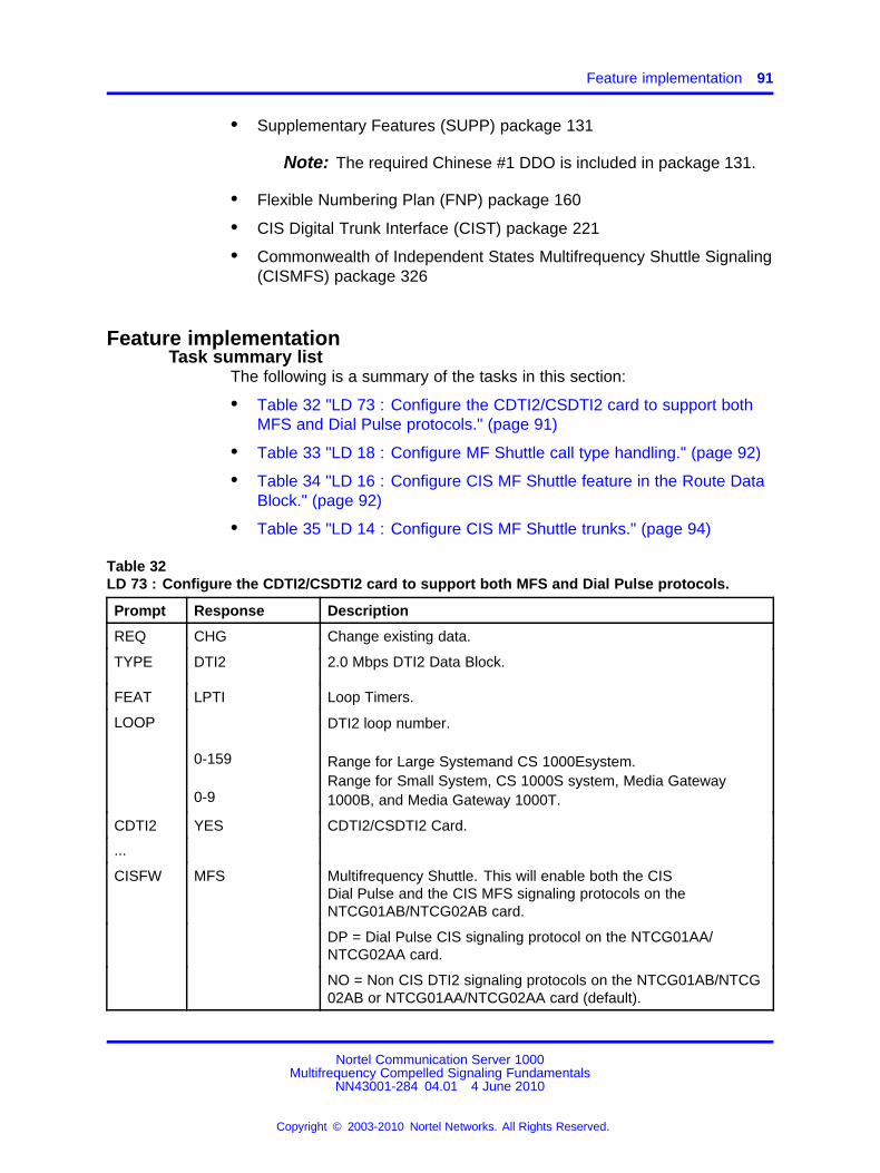
Feature implementation 91
• Supplementary Features (SUPP) package 131
Note: The required Chinese #1 DDO is included in package 131.
• Flexible Numbering Plan (FNP) package 160
• CIS Digital Trunk Interface (CIST) package 221
• Commonwealth of Independent States Multifrequency Shuttle Signaling(CISMFS) package 326
Feature implementationTask summary list
The following is a summary of the tasks in this section:
• Table 32 "LD 73 : Configure the CDTI2/CSDTI2 card to support bothMFS and Dial Pulse protocols." (page 91)
• Table 33 "LD 18 : Configure MF Shuttle call type handling." (page 92)
• Table 34 "LD 16 : Configure CIS MF Shuttle feature in the Route DataBlock." (page 92)
• Table 35 "LD 14 : Configure CIS MF Shuttle trunks." (page 94)
Table 32LD 73 : Configure the CDTI2/CSDTI2 card to support both MFS and Dial Pulse protocols.
Prompt Response Description
REQ CHG Change existing data.
TYPE DTI2 2.0 Mbps DTI2 Data Block.
FEAT LPTI Loop Timers.
LOOP
0-159
0-9
DTI2 loop number.
Range for Large Systemand CS 1000Esystem.Range for Small System, CS 1000S system, Media Gateway1000B, and Media Gateway 1000T.
CDTI2 YES CDTI2/CSDTI2 Card.
...
CISFW MFS Multifrequency Shuttle. This will enable both the CISDial Pulse and the CIS MFS signaling protocols on theNTCG01AB/NTCG02AB card.
DP = Dial Pulse CIS signaling protocol on the NTCG01AA/NTCG02AA card.
NO = Non CIS DTI2 signaling protocols on the NTCG01AB/NTCG02AB or NTCG01AA/NTCG02AA card (default).
Nortel Communication Server 1000Multifrequency Compelled Signaling Fundamentals
NN43001-284 04.01 4 June 2010
Copyright © 2003-2010 Nortel Networks. All Rights Reserved.
.

92 CIS Multifrequency Shuttle
Table 33LD 18 : Configure MF Shuttle call type handling.
Prompt Response Description
REQ CHG Change existing data.
TYPE SSL Special Service List.
SSL 1-31 Special Service List number.
SSDG 0-9999 Special Service Digits combination.
NDGT (0)-15 Number of digits which should be collected before seizure of theoutgoing CIS MFS trunk or recognition by an incoming CIS MFStrunk. This information comes from the ENBLOCK SSL table orthe Flexible DN size SSL table.
If the outgoing call is recognized as an MFS call, then the trunk isnot seized until the number digits dialed by the user is equal tothe NDGT, or the End Of Dialing timer expires, or the OCTO (#) isdialed.
If the incoming call is recognized as an MFS call, then the trunk isrequested to issue the backward MFS signal to the CIS CO partyuntil the number of digits accepted from the trunk is equal to theNDGT.
Table 34LD 16 : Configure CIS MF Shuttle feature in the Route Data Block.
Prompt Response Description
REQ CHG Change existing data.
TYPE RDB Route Data Block.
CUST xx Customer number as defined in LD 15.
ROUT
0-511
0-127
Route number
Range for Large Systemand CS 1000Esystem.
Range for Small System, CS 1000S system, Media Gateway1000B, and Media Gateway 1000T.
TKTP DIDCOT
Direct Inward Dialing. For the incoming trunk route.Central Office Trunk. For the outgoing trunk route.
...
ICOG ICTOGT
Incoming only trunks.Outgoing only trunks.MFS routes can be either only incoming or only outgoing.
...
Nortel Communication Server 1000Multifrequency Compelled Signaling Fundamentals
NN43001-284 04.01 4 June 2010
Copyright © 2003-2010 Nortel Networks. All Rights Reserved.
.
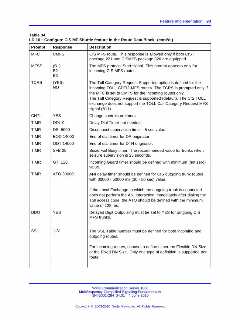
Feature implementation 93
Table 34LD 16 : Configure CIS MF Shuttle feature in the Route Data Block. (cont’d.)
Prompt Response Description
MFC CMFS CIS MFS route. This response is allowed only if both CISTpackage 221 and CISMFS package 326 are equipped.
MFSS (B1)B2B3
The MFS protocol Start signal. This prompt appears only forincoming CIS MFS routes.
TCRS (YES)NO
The Toll Category Request Supported option is defined for theincoming TOLL CDTI2-MFS routes. The TCRS is prompted only ifthe MFC is set to CMFS for the incoming routes only.The Toll Category Request is supported (default). The CIS TOLLexchange does not support the TOLL Call Category Request MFSsignal (B11).
CNTL YES Change controls or timers.
TIMR DDL 0 Delay Dial Timer not needed.
TIMR DSI 5000 Disconnect supervision timer - 5 sec value.
TIMR EOD 14000 End of dial timer for DP originator.
TIMR ODT 14000 End of dial timer for DTN originator.
TIMR SFB 25 Seize Fail Busy timer. The recommended value for trunks whenseizure supervision is 25 seconds.
TIMR GTI 128 Incoming Guard timer should be defined with minimum (not zero)value.
TIMR ATO 30000 ANI delay timer should be defined for CIS outgoing trunk routeswith 30000 - 50000 ms (30 - 50 sec) value.
If the Local Exchange to which the outgoing trunk is connecteddoes not perform the ANI interaction immediately after dialing theToll access code, the ATO should be defined with the minimumvalue of 128 ms.
DDO YES Delayed Digit Outpulsing must be set to YES for outgoing CISMFS trunks.
...
SSL 1-31 The SSL Table number must be defined for both incoming andoutgoing routes.
For incoming routes, choose to define either the Flexible DN Sizeor the Fixed DN Size. Only one type of definition is supported perroute.
...
Nortel Communication Server 1000Multifrequency Compelled Signaling Fundamentals
NN43001-284 04.01 4 June 2010
Copyright © 2003-2010 Nortel Networks. All Rights Reserved.
.

94 CIS Multifrequency Shuttle
Table 34LD 16 : Configure CIS MF Shuttle feature in the Route Data Block. (cont’d.)
Prompt Response Description
DNSZ 1-7 For the incoming trunks only. The Fixed DN Size can not be usedtogether with the Flexible DN Size.
...
Table 35LD 14 : Configure CIS MF Shuttle trunks.
Prompt Response Description
REQ CHG Change existing data.
TYPE DIDCOT
Direct Inward Dialing. For incoming trunks.Central Office Trunk. For outgoing trunks.
TN Terminal number
l ch Format for Large Systemand CS 1000E, where l = loop and ch= channel.
c u Format for Small System, CS 1000S system, Media Gateway1000B, and Media Gateway 1000T, where c = card and u = unit.
CLS CMFS CIS MF Shuttle protocol is supported by the trunk.
CMFS may be defined only for trunks on the CDTI2/CSDTI2cards with "CDTI2=YES" and "CISFW=MFS" and only if both theCISMFS package 326 and the CIST package 221 are equipped.
Each trunks member of the CIS MFS route can be defined asCFMS or DIP or DIPF.
Feature operationNo specific operating procedures are required to use this feature.
Nortel Communication Server 1000Multifrequency Compelled Signaling Fundamentals
NN43001-284 04.01 4 June 2010
Copyright © 2003-2010 Nortel Networks. All Rights Reserved.
.

95.
India Phase 2
ContentsThis section contains information on the following topics:
“Introduction” (page 95)
“Operating parameters” (page 96)
“Feature interactions” (page 96)
“Feature packaging” (page 96)
“Feature implementation” (page 97)
“Feature operation” (page 100)
IntroductionR2MFC signaling for India modifies the existing R2MFC signalingoperations of the system to meet the needs of the Indian market. UsingR2MFC for India, a system can work with both analog and digital (DTI2)interfaces to support India’s R2 modified MFC signaling.
The development of R2MFC signaling for India introduces two newprompts in LD 16. The India R2MFC (INDMF) prompt enables R2MFCoperations for India. The CNI length (CLEN) prompt allows for theselection of one to 16 digits for Calling Number Identification (CNI)operation. CNI operation for India requires ten digits to be configuredat the CLEN prompt. The information provided by CNI can be used forappropriate displays in the system and in features like Malicious Call Trace(MCT).
For India, the following enhancements have been made to existing R2MFCsignaling operation:
• Since India’s Central Offices use MFC signaling that support signalsdefined on two out of five frequency combinations, a system in India
Nortel Communication Server 1000Multifrequency Compelled Signaling Fundamentals
NN43001-284 04.01 4 June 2010
Copyright © 2003-2010 Nortel Networks. All Rights Reserved.
.
96 India Phase 2
must be configured to recognize only ten signals. Thus, only tenfrequency signals should be configured in LD 94.
• CNI operation in India allows the terminating party to send the SendCategory (SCAT) signal at any time while the address information isbeing exchanged in the protocol. For this to occur at the originatingend, the SCNT prompt in LD 94 must be set to YES.
• The Called Line Free with Metering signal (B.6) is used in India toindicate that the called party is free from calls (idle). The system’sexisting IDLE signal should be configured as B.6 to meet thisrequirement.
• The Called Line Free With No Metering signal (B.7) is not supported bysystems in India and should not be configured because it is used fortest purposes.
• India’s Central Offices use the A.2 signal, Restart, to request theoriginating party to start resending the dialed digits from the beginning.The existing Tandem First (TFST) signal should be configured as A.2in LD 94 for the system to support this signal.
• The A.3, A.4, and A.5 signals are used in LD 94 for the applicationof CNI signals. In the operation of R2MFC signaling for India the A.3signal acts as the MFC Complete signal, A.4 acts as the Send/ReceiveCNI signal, and A.5 acts as the Send/Receive CNI category signal.
• The length of CNI digits for India is fixed at ten. Once the terminatingend receives ten digits, it sends a COMP signal to end the CNIsequence and the level 1 signaling. For R2MFC signaling in India, themaximum number of CNI digits should be defined as ten in LD 16.However, configuration of up to 16 digits is now available as a resultof this feature.
Operating parametersFor a tandem system, the incoming and outgoing R2MFC Data Blocksshould be configured with different values of EECD in LD 94. This willprevent a system nearest to an Indian CO from establishing an end-to-endconnection between the Indian CO and a far-end system that may notsupport R2MFC signaling for India. The far end system must have SCNTset to YES in LD 94.
Feature interactionsThere are no specific Feature interactions for this feature.
Feature packagingR2MFC for India requires Multifrequency Compelled Signaling (MFC)package 128.
Nortel Communication Server 1000Multifrequency Compelled Signaling Fundamentals
NN43001-284 04.01 4 June 2010
Copyright © 2003-2010 Nortel Networks. All Rights Reserved.
.

Feature implementation 97
Feature implementationTask summary list
The following is a summary of the tasks in this section:
• Table 36 "LD 94 : Configure MFC table for incoming signaling." (page97)
• Table 37 "LD 94 : Configure MFC table for outgoing signaling." (page98)
• Table 38 "LD 13 : Configure MFC TNs." (page 98)
• Table 39 "LD 16 : Configure R2MFC Route Data Block." (page 99)
• Table 40 "LD 14 : Configure trunk on the Route as MFC Trunk." (page99)
Note: To disable certain signals, assign the value of zero (0) to therespective signal name.
Table 36LD 94 : Configure MFC table for incoming signaling.
Prompt Response Description
REQ NEWCHG
Add new dataChange existing data
TYPE R2MF R2MFC table
ICOG ICT Incoming table
MAXT (1) - 127 Maximum number of tables
TBNO 1 - 127 Table number to configure
EECD 1 - 127 End-to-end signaling code. EECD defaults to the TBNOtable number when REQ = NEW.For a tandem system, the incoming and outgoing R2MFCData Blocks should be configured with different values ofEECD.
LVNO 1 MFC signal level number
DFLT 0 - 127 Table to use for default values
RECV
XMIT COMP 3 A.3 as MFC Complete signal
XMIT SCNI 4 A.4 as Send CNI signal
XMIT SCAT 5 A.5 as Send Category signal
LVNO 2 MFC signal level number
DFLT 0 - 127 Table to use for default values
RECV <cr> Stop RECV prompts
XMIT IDLE 6 B.6 to be used as the IDLE signal
Nortel Communication Server 1000Multifrequency Compelled Signaling Fundamentals
NN43001-284 04.01 4 June 2010
Copyright © 2003-2010 Nortel Networks. All Rights Reserved.
.

98 India Phase 2
Table 37LD 94 : Configure MFC table for outgoing signaling.
Prompt Response Description
REQ NEWCHG
Add new dataChange existing data
TYPE R2MF R2MFC table
ICOG OGT Outgoing table
MAXT (1) - 127 Maximum number of tables
TBNO 1 - 127 Table number to configure
...
EECD 1 -127 End-to-end signaling code. EECD defaults to the TBNOtable number when REQ = NEW.For a tandem system, the incoming and outgoing R2MFCData Blocks should be configured with different values ofEECD.
SCNT YES To allow processing of SCAT signal at any time duringsignaling exchange.
LVNO 1 MFC signal level number
DFLT 0 - 127 Table to use for default values
RECV 2 TFST A.2 to be interpreted as Tandem First Signal (Restart)
RECV 3 COMP A.3 as MFC Complete signal
RECV 4 SCNI A.4 as Receive CNI signal
RECV 5 SCAT A.5 as Receive Category signal
XMIT <cr> Stop XMIT prompts
LVNO 2 MFC signal level number
DFLT 0 - 127 Table to use for default values
RECV 6 IDLE B.6 to be interpreted as IDLE
Table 38LD 13 : Configure MFC TNs.
Prompt Response Description
REQ NEWCHG
Add new dataChange existing data
TYPE MFC Multifrequency Compelled Sender/Receiver data block.Multifrequency Compelled Signaling (MFC) package 128is required.
Nortel Communication Server 1000Multifrequency Compelled Signaling Fundamentals
NN43001-284 04.01 4 June 2010
Copyright © 2003-2010 Nortel Networks. All Rights Reserved.
.

Feature implementation 99
Table 38LD 13 : Configure MFC TNs. (cont’d.)
Prompt Response Description
Terminal number
l s c u Format for Large Systemand CS 1000Esystem, where l =loop, s = shelf, c = card, and u = unit.
TN
c u Format for Small System, CS 1000S system, MediaGateway 1000B, and Media Gateway 1000T, where c =card and u = unit.
Table 39LD 16 : Configure R2MFC Route Data Block.
Prompt Response Description
REQ CHG Change existing data
TYPE RDB Route Data Block
CUST xx Customer number as defined in LD 15
Route number
0-511 Range for Large Systemand CS 1000Esystem.
ROUT
0-127 Range for Small System, CS 1000S system, MediaGateway 1000B, and Media Gateway 1000T.
...
SIGO STD Standard signaling arrangement
MFC YES Multifrequency Compelled (MFC) Signaling
INDMF (NO)YES
Indian R2MFC operations disabledIndian R2MFC operations (enabled)
- CLEN 1-(10)-16 Select 10 CNI digits for Indian operations
MFCI 1-127 MFC Incoming table number configured in LD 94
...
MFCO 1-127 MFC Outgoing table number configured in LD 94
Table 40LD 14 : Configure trunk on the Route as MFC Trunk.
Prompt Response Description
REQ CHG Change existing data
TYPE xxx Trunk type (DID or TIE)
Nortel Communication Server 1000Multifrequency Compelled Signaling Fundamentals
NN43001-284 04.01 4 June 2010
Copyright © 2003-2010 Nortel Networks. All Rights Reserved.
.

100 India Phase 2
Table 40LD 14 : Configure trunk on the Route as MFC Trunk. (cont’d.)
Prompt Response Description
Terminal number
l s c u Format for Large Systemand CS 1000Esystem, where l =loop, s = shelf, c = card, and u = unit.
TN
c u Format for Small System, CS 1000S system, MediaGateway 1000B, and Media Gateway 1000T, where c =card and u = unit.
CUST xx Customer number as defined in LD 15
NCOS 7 Network Class of Service
CLS MFC CNA Allow MFC Class of Service and Calling NumberIdentification
Feature operationNo specific operating procedures are required to use this feature.
Nortel Communication Server 1000Multifrequency Compelled Signaling Fundamentals
NN43001-284 04.01 4 June 2010
Copyright © 2003-2010 Nortel Networks. All Rights Reserved.
.

101.
MFC Interworking with AML-basedApplications
ContentsThis section contains information on the following topics:
“Introduction” (page 101)
“Operating parameters” (page 102)
“Feature interactions” (page 102)
“Feature packaging” (page 103)
“Feature implementation” (page 103)
“Feature operation” (page 103)
IntroductionThe Multifrequency Compelled Signaling (MFC) Interworking withApplication Module Link (AML) Based Applications feature improves theinterworking of AML based applications, specifically Customer ControlledRouting (CCR) and Host Enhanced Routing (HER), and R2MFC trunks.R2MFC trunks are widely used throughout Europe, Asia/Pacific, and LatinAmerica. The same degree of conformance to the R2MFC protocol isensured for calls terminating on a Control DN (CDN) which is controlled byCCR or HER, as for calls terminating on any other DN.
R2MFC signaling on DID or TIE trunks provides a register signaling(trunk dialing) method in addition to the other methods supported onthe system. DID or TIE trunks using R2MFC signaling continue to havenormal treatment, except during the dialing phase where R2MFC protocolsare followed. These protocols call for forward signals to be used by theoriginating end to convey address information, and backward signals tobe used by the terminating end to acknowledge the forward signals andindicate the status of the terminating party or request additional information
Nortel Communication Server 1000Multifrequency Compelled Signaling Fundamentals
NN43001-284 04.01 4 June 2010
Copyright © 2003-2010 Nortel Networks. All Rights Reserved.
.
102 MFC Interworking with AML-based Applications
from the originating party. When the backward signal is received, theforward signal is removed, which in turn forces the backward signal to alsobe removed. This compelled sequence is repeated until the protocol iscompleted.
In order to increase the signaling capacity, each of the 15 forward andbackward signals is used with more than one meaning or function. A setof functions is defined to be a signaling level. When required, one or moregroups are sequentially used throughout an R2MFC protocol.
When the called party is a CDN controlled by CCR, the attempt toterminate the call results in the call being temporarily queued in theCDN queue. The system then sends a message over the AML link tothe application module, notifying the CCR application of the call. AfterCCR determines the first treatment to be given to the call, it sends theappropriate request message to the system. This treatment determines thebackward signal to be returned to the originating end before the call can becompleted. Once this is done, R2MFC signaling no longer affects the call.
Operating parametersThere are no operating parameters for this feature.
Feature interactionsCalling Line IdentificationIf the Calling Line Identification (CLID) package is equipped and if theincoming R2MFC trunk is configured with Calling Number Allowed (CNA)Class of Service, the Calling Number Identification is passed to the CCRapplication in the incoming call notification message and can be used byCCR in routing decisions.
China Number 1 Signaling - Toll Operator Break-InThe Toll Operator Break-In feature is activated after the MFC LevelII processing forward signal TOLL OPERATOR BREAK-IN has beenreceived prior to termination on a station busy on a non-toll call for whichbreak-in is allowed. The Level II MFC backward signal that is returned isBUSY, BREAK-IN IS ALLOWED, instead of the standard STATION BUSY.This feature is supported if CCR routes such an incoming R2MFC call to abusy station.
However, if CCR gives the FORCE BUSY treatment to the call, the signalreturned is BUSY, BREAK-IN IS NOT ALLOWED, since in this case thereis no call in which to break-in. This is also true if the call terminates on aCDN in default mode and is given busy treatment, because the maximumnumber of calls in the default ACD queue via this CDN has already beenreached.
Nortel Communication Server 1000Multifrequency Compelled Signaling Fundamentals
NN43001-284 04.01 4 June 2010
Copyright © 2003-2010 Nortel Networks. All Rights Reserved.
.

Feature operation 103
Dialed Number Identification Services Length FlexibilityIf the R2MFC route is configured with the Dialed Number IdentificationService (DNIS) option, the DNIS is passed to the CCR application in theincoming call notification message and can be used by CCR in routingdecisions.
GatewaysThe CCR ROUTE TO command may route the incoming R2MFC call toan outgoing trunk. It succeeds only for those trunks for which a gatewaywith MFC exists.
Feature packagingThe MFC Interworking with AML Based Applications feature requires thefollowing packages:
• Multifrequency Compelled Signaling (MFC) package 128
• Enhanced Automatic Call Distribution Routing (EAR) package 214
• Enhanced Call Trace (ECT) package 215.
Feature implementationNo change to existing configuration is required for the MFC Interworkingwith AML Based Applications feature.
Feature operationNo specific operating procedures are required to use this feature.
Nortel Communication Server 1000Multifrequency Compelled Signaling Fundamentals
NN43001-284 04.01 4 June 2010
Copyright © 2003-2010 Nortel Networks. All Rights Reserved.
.

104 MFC Interworking with AML-based Applications
Nortel Communication Server 1000Multifrequency Compelled Signaling Fundamentals
NN43001-284 04.01 4 June 2010
Copyright © 2003-2010 Nortel Networks. All Rights Reserved.
.

105.
Process Notification for NetworkedCalls
ContentsThis section contains information on the following topics:
“Introduction” (page 105)
“Operating parameters” (page 106)
“Feature interactions” (page 106)
“Feature packaging” (page 107)
“Feature implementation” (page 108)
“Feature operation” (page 110)
IntroductionIn an existing R2MFC system network, when an outgoing call hops throughmore than two R2MFC steps, it experiences a delay during which thecaller may drop the call.
The Process Notification for Networked Calls feature informs the user thatthe call is in progress during such a delay, using a configured messageor a tone. This feature is enabled on a per route basis. The user has anoption to configure the choice of announcement, a message or a tone.When the first digit on an MFC trunk is outpulsed, and if the user waits formore than 6 seconds (default configuration) between the digits or after allthe digits, the Process Notification tone or message is given.
If the announcement is a RAN message and it ends, a pause timer isstarted, otherwise a tone is given as per the configuration in the FTC table.When the pause timer expires the RAN announcement is given again(depending on the configuration of NMSG).
Nortel Communication Server 1000Multifrequency Compelled Signaling Fundamentals
NN43001-284 04.01 4 June 2010
Copyright © 2003-2010 Nortel Networks. All Rights Reserved.
.

106 Process Notification for Networked Calls
If the user continues to dial, the announcement is stopped and thenotification delay timer is restarted. The digit is outpulsed.
The Process Notification is abruptly stopped in the event that the call iscompleted successfully, or in the event the call is dropped due to a busydestination telephone, one of the legs of the R2MFC trunks is busy, theMFC timed out waiting for a response, or the caller hangs up.
Operating parametersThis feature applies to all systems. The feature can be configured on anytype of outgoing trunks supporting MFC signaling.
This feature requires a RAN route already configured to give a RANannouncement. It will not impact the functionality of the RAN hardware.
If the RAN trunks are busy and unavailable to give a message, then toneis given.
When an attendant receives a Process Notification announcement andputs the call on hold/presses another loop key, the Process Notificationannouncement is stopped.
Feature interactionsCall ForwardWhen a call of any sort is forwarded on an MFC route configured forProcess Notification, the originating party listens to the announcementif the call takes more than the notification delay timer value configuredfor the route. The originating party must be in the same system. Thistreatment will not be given for an external call forwarded to an externalnumber.
DISAWhen a user calls an external number using DISA on a ProcessNotification configured route, the user is given the announcement as perthe configuration on the route.
Call TransferThe Process Notification announcement is given only to the user whotransfers the call.
ConferenceThe Process Notification announcement is given only to the user whoinitiates the conference.
Nortel Communication Server 1000Multifrequency Compelled Signaling Fundamentals
NN43001-284 04.01 4 June 2010
Copyright © 2003-2010 Nortel Networks. All Rights Reserved.
.

Feature packaging 107
No-Hold ConferenceDuring the establishment of No-Hold Conference, the Process Notificationannouncement is taken off. Therefore, the Process Notificationannouncement is not heard by any of the parties involved.
Special Dial Tone after Dialed NumbersIf at any time a special dial tone is given by another feature, the ProcessNotification treatment will not be provided. During the Process Notificationannouncement, if a special dial tone has to be given, the preference isgiven for the special dial tone and the Process Notification announcementis removed immediately.
MFC SignalingThe Process Notification for Networked Calls feature does not affect thesignaling protocol, it only initiates certain actions for the feature.
Recorded AnnouncementThe feature has to use an Recorded Announcement (RAN) route alreadyconfigured to give a Recorded Announcement. It does not impact thefunctionality of the RAN machine, Universal Trunk card, or RAN card, itonly uses the functionality provided by it.
RAN BroadcastThe Process Notification for Networked Calls feature does not affect thesignaling protocol, it only initiates certain actions for the feature.
Expensive route warning toneThis feature, and other features like this, which introduce a tone before thetrunk is seized and the first digit is outpulsed, do not have any interactionswith the Process Notification for Networked Calls feature.
Feature packagingThe Process Notification for Networked Calls feature requiresMultifrequency Compelled Signaling (MFC) package128.
The Flexible Tones and Cadences (FTC) package 125 is required if a toneis to be provided.
The Recorded Announcement (RAN) package is required in order toprovide a recorded announcement.
Nortel Communication Server 1000Multifrequency Compelled Signaling Fundamentals
NN43001-284 04.01 4 June 2010
Copyright © 2003-2010 Nortel Networks. All Rights Reserved.
.

108 Process Notification for Networked Calls
Feature implementationTask summary list
The following is a summary of the tasks in this section:
• Table 41 "LD 56 : Configure Flexible Tones and Cadences." (page108)
• Table 42 "LD 56 : Configure FCAD." (page 108)
• Table 43 "LD 56 : Configure MCAD." (page 109)
• Table 44 "LD 16 : Enable PNNC and configure route to provideRecorded Announcement message." (page 109)
• Table 45 "LD 16 : Enable PNNC and configure route to provide tone."(page 109)
Note: A RAN machine/RAN card is used to play the recordedannouncement. This RAN machine/RAN card is started/stopped bythe software. The requirement of a RAN machine/RAN card alreadyconfigured is mandatory for a message to be played
Table 41LD 56 : Configure Flexible Tones and Cadences.
Prompt Response Description
REQ NEWCHG
Add new data.Change existing data.
TYPE FTC Flexible Tones and Cadences.
TABL 0-31 FTC table number.
DFLT 0-31 Default table number.
RING <CR>
HCCT <CR>
SCCT YES Change software controlled cadence tone definitions.
... ... ...
PNNC <CR> PNNC Cadence.
- XTON (0)-255 NT8D17 TDS Tone code.
- XCAD (0)-255 NT8D17 cadence code for FCAD.
- CDNC (0)-255 MCAD table entry for this cadence.
... ... ...
Table 42LD 56 : Configure FCAD.
Prompt Response Description
REQ NEWCHG
Add new data.Change existing data.
Nortel Communication Server 1000Multifrequency Compelled Signaling Fundamentals
NN43001-284 04.01 4 June 2010
Copyright © 2003-2010 Nortel Networks. All Rights Reserved.
.

Feature implementation 109
Table 42LD 56 : Configure FCAD. (cont’d.)
Prompt Response Description
TYPE FCAD Firmware cadence table.
WCAD 0-255 Cadence number in master cadence table.
CDNC 0410 0820 2 seconds on, 4 seconds off.
Table 43LD 56 : Configure MCAD.
Prompt Response Description
REQ NEWCHG
Add new data.Change existing data.
TYPE MCAD Master cadence table.
WCAD 0-255 Cadence number in master cadence table.
CDNC 0410 0820 2 seconds on, 4 seconds off.
Table 44LD 16 : Enable PNNC and configure route to provide Recorded Announcement message.
Prompt Response Description
REQ CHG Change existing data.
TYPE RDB Route Data Block.
CUST xx Customer number as defined in LD 15.
ROUT Route number
0-511 Range for Large Systemand CS 1000Esystem.
0-127 Range for Small System, CS 1000S system, MediaGateway 1000B, and Media Gateway 1000T.
... ... ...
PNNC YES PNNC feature is enabled.
- PNDL 2-(6)-10 Notification delay timer value.
- SLCT MSG RAN message is configured.
- - NRT 0-511 Enter the already configured RAN route number.
- - NMSG (0)-30 Number of times the message should be repeated.
- - PNPS (0)-30 The interval between the recorded announcements.
... ...
Table 45LD 16 : Enable PNNC and configure route to provide tone.
Prompt Response Description
REQ CHG Change existing data.
Nortel Communication Server 1000Multifrequency Compelled Signaling Fundamentals
NN43001-284 04.01 4 June 2010
Copyright © 2003-2010 Nortel Networks. All Rights Reserved.
.

110 Process Notification for Networked Calls
Table 45LD 16 : Enable PNNC and configure route to provide tone. (cont’d.)
Prompt Response Description
TYPE RDB Route Data Block.
CUST xx Customer number as defined in LD 15.
ROUT Route number
0-511 Range for Large Systemand CS 1000Esystem.
0-127 Range for Small System, CS 1000S system, MediaGateway 1000B, and Media Gateway 1000T.
... ... ...
PNNC YES PNNC feature is enabled.
- PNDL 2-(6)-10 Notification delay timer value.
- SLCT TONE Tone is configured.
... ... ...
Feature operationThere are no specific operating procedures required to use this feature.
Nortel Communication Server 1000Multifrequency Compelled Signaling Fundamentals
NN43001-284 04.01 4 June 2010
Copyright © 2003-2010 Nortel Networks. All Rights Reserved.
.

111.
R2 Multifrequency CompelledSignaling 1.5 Mbit/s Digital TrunkInterface
ContentsThis section contains information on the following topics:
“Introduction” (page 111)
“Operating parameters” (page 111)
“Feature interactions” (page 112)
“Feature packaging” (page 112)
“Feature implementation” (page 112)
“Feature operation” (page 113)
IntroductionThe R2MFC 1.5 Mbit/s Digital Trunk Interface feature enables R2MFCsignaling on 1.5 Mbit/s DTI trunks.
Prior to this development, R2 Multifrequency Compelled Signaling(R2MFC) inter-register signaling was only supported on DTI2 and analogtrunks.
Operating parametersAlternative Loss Plan is not supported.
This product improvement does not support the R2MFC DID/DTMF DODfeature.
Nortel Communication Server 1000Multifrequency Compelled Signaling Fundamentals
NN43001-284 04.01 4 June 2010
Copyright © 2003-2010 Nortel Networks. All Rights Reserved.
.

112 R2 Multifrequency Compelled Signaling 1.5 Mbit/s Digital Trunk Interface
Feature interactionsAlternative Loss PlanAlternative Loss Plan is not supported on 1.5 Mbit/s DTI.
MFC SignalingSince this product improvement introduces MFC on DTI trunks, anyinteraction with existing MFC signaling also applies to this feature.
1.5 Mbit/s DTISince this product improvement introduces MFC on DTI trunks, anyinteraction with 1.5 Mbit/s DTI also applies to this feature.
Feature packagingThe R2MFC 1.5 Mbit/s Digital Trunk Interface feature requires thefollowing packages:
• 1.5 Mbit/s Digital Trunk Interface (PBXI) package 75.
• Multifrequency Compelled Signaling (MFC) package 128.
Feature implementationTask summary list
The following is a summary of the tasks in this section:
• Table 46 "LD 16 : Enable MFC to be configured on a DTI route." (page112)
• Table 47 "LD 14 : Enable MFC Class of Service on a 1.5 Mbit/s route."(page 113)
Table 46LD 16 : Enable MFC to be configured on a DTI route.
Prompt Response Description
REQ NEW CHG Add, or change.
TYPE RDB Route Data Block.
...
DTRK YES Digital Trunk Route.
DGTP DTI Digital Trunk Type for Route.
...
MFC YES Multifrequency Compelled Signaling.
MFCI 1-127 MFC Incoming table number.Enter 0 to remove Incoming table.
R2MD (NO) YES R2 modification.
SGL (NO) YES Return MFC idle signal.
Nortel Communication Server 1000Multifrequency Compelled Signaling Fundamentals
NN43001-284 04.01 4 June 2010
Copyright © 2003-2010 Nortel Networks. All Rights Reserved.
.

Feature operation 113
Table 46LD 16 : Enable MFC to be configured on a DTI route. (cont’d.)
Prompt Response Description
BSSU (NO) YES Backward Signal Suppression.
MFCO 1-127 MFC Outgoing table number.Enter 0 to remove Outgoing table.
Table 47LD 14 : Enable MFC Class of Service on a 1.5 Mbit/s route.
Prompt Response Description
REQ NEW CHG Add, or change.
TYPE TIE DID Trunk type.
...
RTMB Route number and Member number
0-511 1-4000 Range for Large Systemand CS 1000Esystem.
0-127 1-4000 Range for Small System, CS 1000S system, MediaGateway 1000B, and Media Gateway 1000T.
CLS MFC MFC Class of Service.
MFL XX Multifrequency Digit Level.
Note: The MFPD prompt will not appear.
Feature operationNo specific operating procedures are required to use this feature.
Nortel Communication Server 1000Multifrequency Compelled Signaling Fundamentals
NN43001-284 04.01 4 June 2010
Copyright © 2003-2010 Nortel Networks. All Rights Reserved.
.

114 R2 Multifrequency Compelled Signaling 1.5 Mbit/s Digital Trunk Interface
Nortel Communication Server 1000Multifrequency Compelled Signaling Fundamentals
NN43001-284 04.01 4 June 2010
Copyright © 2003-2010 Nortel Networks. All Rights Reserved.
.

115.
R2MFC CNI/CDR Enhancements
ContentsThis section contains information on the following topics:
“Introduction” (page 115)
“Operating parameters” (page 116)
“Feature interactions” (page 116)
“Feature packaging” (page 117)
“Feature implementation” (page 118)
“Feature operation” (page 133)
IntroductionThe R2 Multifrequency Compelled Signaling (R2MFC) Calling NumberIdentification (CNI)/Call Detail Recording (CDR) Enhancements featureprovides the following capabilities across an R2MFC/ISDN gateway:
• Mapping the R2MFC CNI to/from the ISDN CLID.
• Optionally providing the location of the captured CNI in the CDR to acustomer. The CNI may appear in the digits field, the CLID field in linetwo, or not at all, in the CDR.
• Providing the CNI to the ACD MAX, Network ACD, and RadioPaging equipment, similar to how the CLID was provided prior to theintroduction of this feature.
Examples of CDR formatsThe following examples provide cases of the CNI 23008 appearing in thedigits field, in the CLID field in line two, and not at all, in the CDR.
Nortel Communication Server 1000Multifrequency Compelled Signaling Fundamentals
NN43001-284 04.01 4 June 2010
Copyright © 2003-2010 Nortel Networks. All Rights Reserved.
.

116 R2MFC CNI/CDR Enhancements
CDR record with CNI in digits field
N 003 00 T078001 T008001 31/05 1:40:05 05:30.5 C23008
& 0000 0000
CDR record with CNI in CLID field
N 003 00 T078001 T008001 31/05 13:40:05 0:05:30.5 71082317
&23008xxxxxxxxxxx 0000 0000
CDR record with no CNI appearance
N 003 00 T078001 T008001 31/05 13:40:05 0:05:30.5 71082317
& 0000 0000
Operating parametersThis feature is applicable to all systems.
The maximum length of the CLID field in the CDR is 16 digits.
This feature applies to all supported ISDN interfaces.
On the ISDN side of the R2MFC/ISDN gateway, the ISDN access may bevia ISDN Primary Rate Interface (PRI), ISDN Signaling Link (ISL), VirtualNetwork Services (VNS) or Basic Rate Interface (BRI) trunks.
This feature does not affect the manner in which the CNI is composed atthe originating switch of an R2MFC/ISDN gateway.
If the CNI cannot be composed at a R2MFC/ISDN gateway tandemswitch, the CNI DN and the Trunk ID will be sent in the CNI (as was thefunctionality prior to the introduction of this feature).
Feature interactionsCalling Party PrivacyIf the CLID is received with presentation denied, it is not mapped to theCNI. Instead, the CNI is composed of the CNI DN and the Trunk ID.Optionally, the CNI request may set to ECNI (the CNI End-of-CNI R2MFClevel 1 forward signal).
Display Calling Party DeniedIf the CLID is received with Display Calling Party Denied, it is not mappedto the CNI. Instead, the CNI is composed of the CNI DN and the Trunk ID.Optionally, the CNI request may set to ECNI (the CNI End-of-CNI R2MFClevel 1 forward signal).
Nortel Communication Server 1000Multifrequency Compelled Signaling Fundamentals
NN43001-284 04.01 4 June 2010
Copyright © 2003-2010 Nortel Networks. All Rights Reserved.
.

Feature packaging 117
EuroISDN ContinuationThe outgoing CLID element of the EuroISDN Continuation feature ismutually exclusive with the R2MFC CNI/CDR Enhancements feature. If theCLID is to be composed from the EuroISDN Continuation feature, it will notcontain the CNI. If the CLID is to be composed from the CNI, no prefixeswill be added to the number.
Feature Group DFeature Group D trunks do not support CNI. If a CNI is available inaddition to the CLID on a Feature Group D trunk, the CLID of the FeatureGroup D trunk would be used for the CLID.
In-Band Automatic Number IdentificationInband Automatic Number Identification (IANI) trunks do not support CNI. Ifa CNI is available in addition to the IANI on an IANI trunk, the IANI wouldbe used for the CLID.
Incoming Trunk Programmable CLIDIncoming Trunk Programmable CLID takes precedence over the R2MFCCNI/CDR Enhancements feature. If the outgoing ISDN trunk is allowed tosend a billing number, the billing number is sent out as the CLID, not theCNI from the incoming trunk.
M911M911 trunks do not support CNI. If a CNI is available on an M911 trunk inaddition to the ANI, the ANI would be used for the CLID.
R2MFC to DPNSS1 GatewayThe R2MFC CNI/CDR Enhancements feature uses the CNI requestenhancement (Upfront CNI) developed for the R2MFC to DPNSS1Gateway feature.
Feature packagingThe CNI/CLID Enhancement requires the following packages:
• Multifrequency Compelled Signaling (MFC) package 128
• Integrated Services Digital Network (ISDN) package 145
• 1.5 Mbps Primary Rate Access (PRA) package 146; or ISDN SignalingLink (ISL) package 147; or 2.0 Mbps Primary Rate Access (PRI2)package 154; or Virtual Network Services (VNS) package 183; orBasic Rate Interface Trunk Access (BRIT) package 233; which requiresBasic Rate Interface (BRI) package 216
• For EuroISDN applications, EuroISDN (EUROISDN) package 261
• For QSIG applications, QSIG (QSIG) package 263
Nortel Communication Server 1000Multifrequency Compelled Signaling Fundamentals
NN43001-284 04.01 4 June 2010
Copyright © 2003-2010 Nortel Networks. All Rights Reserved.
.

118 R2MFC CNI/CDR Enhancements
The CDR Enhancement requires the following packages:
• Call Detail Recording (CDR) package 4
• To print or store the CDR record, Call Detail Recording on TeletypeMachine (CTY) package 5
• Calling Line Identification in Call Detail Recording (CCDR) package118
• New Format Call Detail Recording (FCDR) package 234
Feature implementationTask summary list
The following is a summary of the tasks in this section:
• Table 48 "LD 17 : Configure CDR system parameters." (page 118)
• Table 49 "LD 15 : Configure CDR field in which the CNI will appear."(page 119)
• Table 50 "LD 15 : Configure CNI presentation option." (page 119)
• Table 51 "LD 16 : Configure CDR option to provide CDR records forcalls." (page 120)
• Table 52 "LD 16 : Configure CLID/CNI request options for an R2MFCtrunk route (incoming)." (page 120)
• Table 53 "LD 16 : Configure CLID/CNI request options for an R2MFCtrunk route (outgoing)." (page 122)
• Table 54 "LD 16 : Configure CLID/CNI request options for an R2MFCtrunk route (incoming and outgoing)." (page 123)
• Table 55 "LD 16 - Configure CLID/CNI request options for an ISDNtrunk route (incoming)." (page 125)
• Table 56 "LD 16 - Configure CLID/CNI request options for an ISDNtrunk route (outgoing)." (page 127)
• Table 57 "LD 16 - Configure CLID/CNI request options for an ISDNtrunk route (incoming and outgoing)." (page 129)
• Table 58 "LD 16 - Configure the CLID/CNI request options for anR2MFC route (incoming and outgoing) whose signaling is supportedby a D-Channel (ISL)." (page 130)
Table 48LD 17 : Configure CDR system parameters.
Prompt Response Description
REQ CHG Change existing data.
Nortel Communication Server 1000Multifrequency Compelled Signaling Fundamentals
NN43001-284 04.01 4 June 2010
Copyright © 2003-2010 Nortel Networks. All Rights Reserved.
.

Feature implementation 119
Table 48LD 17 : Configure CDR system parameters. (cont’d.)
Prompt Response Description
TYPE PARM Change system parameters.
- FCDR NEW New format for Call Detail Recording.
...
- CLID YES Calling Line ID in the CDR.
...
Table 49LD 15 : Configure CDR field in which the CNI will appear.
Prompt Response Description
REQ: CHG Change existing data.
TYPE: CDR Call Detail Recording data.
CUST Customer number
0-99 Range for Large Systemand CS 1000Esystem.
0-31 Range for Small System, CS 1000S system, Media Gateway1000B, and Media Gateway 1000T.
...
- PORT 0-15 CDR port.
- CNI The CDR field (if any) in which the CNI will appear.
(DGTS)CLIDNONE
The CNI is recorded in the digits field.The CNI is recorded in the CLID field.The CNI is not captured in the CDR.
...
Table 50LD 15 : Configure CNI presentation option.
Prompt Response Description
REQ: CHG Change existing data.
TYPE: NET Networking data.
CUST Customer number
0-99 Range for Large Systemand CS 1000Esystem.
0-31 Range for Small System, CS 1000S system, Media Gateway1000B, and Media Gateway 1000T.
ISDN YES ISDN.
...
Nortel Communication Server 1000Multifrequency Compelled Signaling Fundamentals
NN43001-284 04.01 4 June 2010
Copyright © 2003-2010 Nortel Networks. All Rights Reserved.
.

120 R2MFC CNI/CDR Enhancements
Table 50LD 15 : Configure CNI presentation option. (cont’d.)
Prompt Response Description
- CNDN 0-99999999 Customer CNI DN on outgoing MFC calls (maximum length iseight digits.)
- CNIP (YES) NO Option to send CNI when CLID has presentation denied.
YES = The default. Send the CNI DN and the Trunk ID.
NO = Do not send a CNI.
Table 51LD 16 : Configure CDR option to provide CDR records for calls.
Prompt Response Description
REQ CHG Change existing data.
TYPE RDB Route Data Block.
CUST xx Customer number as defined in LD 15.
ROUT Route number
0-511 Range for Large Systemand CS 1000Esystem.
0-127 Range for Small System, CS 1000S system, Media Gateway1000B, and Media Gateway 1000T.
TKTP DIDTIE
Trunk route type.
...
CDR YES Call Detail Recording.
- INC YES CDR on incoming calls.
...
- OAL YES CDR on outgoing calls.
...
Table 52LD 16 : Configure CLID/CNI request options for an R2MFC trunk route (incoming).
Prompt Response Description
REQ CHG Change existing data.
TYPE RDB Route Data Block.
CUST xx Customer number as defined in LD 15.
ROUT Route number
0-511 Range for Large Systemand CS 1000Esystem.
Nortel Communication Server 1000Multifrequency Compelled Signaling Fundamentals
NN43001-284 04.01 4 June 2010
Copyright © 2003-2010 Nortel Networks. All Rights Reserved.
.

Feature implementation 121
Table 52LD 16 : Configure CLID/CNI request options for an R2MFC trunk route (incoming). (cont’d.)
Prompt Response Description
0-127 Range for Small System, CS 1000S system, Media Gateway1000B, and Media Gateway 1000T.
TKTP DIDTIE
Trunk route type.
...
ICOG ICT Incoming trunk route
...
MFC YES Multi-frequency Compelled signaling
MFCI 1-127 MFC Incoming table number; must be a non-zero value.
...
ICIS Incoming Identifier that is sent.
YES YES = The default. Use the CLID/CNI from the incomingISDN/R2MFC trunk.
Prompted for incoming trunks (that is, if ICOG = ICT), and if theroute type is R2MFC or ISDN.
ICNP Incoming Numbering Plan.
(UKWN)PRVPUB
Unknown.PrivatePublic
Prompted if the route type is R2MFC and ICIS = YES.
ICNT Incoming Numbering Type.
(UKWN)INTLNTNLCLLOCCDPSPN
Unknown Number.International Number.National Number.Local Number.Location Number.Coordinated Dialing Plan.Special Number.
Prompted if the route type is R2MFC and ICIS = YES.
ICPS Incoming Presentation Status.
YES YES = Indicate the presentation status of the CLID.
Prompted if the route type is R2MFC and ICIS = YES.
CNTL ...
...
ALRM ...
Nortel Communication Server 1000Multifrequency Compelled Signaling Fundamentals
NN43001-284 04.01 4 June 2010
Copyright © 2003-2010 Nortel Networks. All Rights Reserved.
.

122 R2MFC CNI/CDR Enhancements
Table 52LD 16 : Configure CLID/CNI request options for an R2MFC trunk route (incoming). (cont’d.)
Prompt Response Description
NCNI (0)-7 Request CNI after the defined number of digits are received.
If NCNI = 0 (the default), the CNI request does not depend onthe number of digits received.
If the value for NCNI is defined to be greater than the acceptednumber of digits required for routing the call, CNI will not berequested but the call is routed.
The NCNI prompt is requested if the trunk type is DID or TIE,the MFC signaling is R2MFC, and the MFC signaling table isdefined on the route.
CNIE YES (NO) Request CNI after an ESN code is dialled.
If the value of NCNI has been defined as greater than zero (inresponse to the NCNI prompt) and CNIE is set to YES, CNI isrequested when either one of the conditions is met.
The CNIE prompt is requested if the trunk type is DID or TIE,the MFC signaling is R2MFC, and the MFC signaling table isdefined on the route.
CNIT ...
Table 53LD 16 : Configure CLID/CNI request options for an R2MFC trunk route (outgoing).
Prompt Response Description
REQ CHG Change existing data.
TYPE RDB Route Data Block.
CUST xx Customer number as defined in LD 15.
ROUT Route number
0-511 Range for Large Systemand CS 1000Esystem.
0-127 Range for Small System, CS 1000S system, Media Gateway1000B, and Media Gateway 1000T.
TKTP DIDTIE
Trunk route type.
...
ICOG OGT Outgoing trunk route
...
MFC YES Multi-frequency Compelled signaling
Nortel Communication Server 1000Multifrequency Compelled Signaling Fundamentals
NN43001-284 04.01 4 June 2010
Copyright © 2003-2010 Nortel Networks. All Rights Reserved.
.

Feature implementation 123
Table 53LD 16 : Configure CLID/CNI request options for an R2MFC trunk route (outgoing). (cont’d.)
Prompt Response Description
MFCO 1-127 MFC outgoing table number; must be a non-zero value.
...
SWP ...
OGIS Outgoing Identifier that is sent.
YES YES = The default. Use the CLID/CNI from the incomingISDN/R2MFC trunk, or from the calling telephone.
Prompted for outgoing trunks (that is, if ICOG = OGT), and ifthe route type is R2MFC or ISDN.
CNTL ...
...
ALRM ...
NCNI (0)-7 Request CNI after the defined number of digits are received.
If NCNI = 0 (the default), the CNI request does not depend onthe number of digits received.
If the value for NCNI is defined to be greater than the acceptednumber of digits required for routing the call, CNI will not berequested but the call is routed.
The NCNI prompt is requested if the trunk type is DID or TIE,the MFC signaling is R2MFC and the MFC signaling table isdefined on the route.
CNIE YES (NO) Request CNI after an ESN code is dialed.
If the value of NCNI has been defined as greater than zero (inresponse to the NCNI prompt) and CNIE is set to YES, CNI isrequested when either one of the conditions is met.
The CNIE prompt is requested if the trunk type is DID or TIE,the MFC signaling is R2MFC and the MFC signaling table isdefined on the route.
CNIT ...
Table 54LD 16 : Configure CLID/CNI request options for an R2MFC trunk route (incoming andoutgoing).
Prompt Response Description
REQ CHG Change existing data.
Nortel Communication Server 1000Multifrequency Compelled Signaling Fundamentals
NN43001-284 04.01 4 June 2010
Copyright © 2003-2010 Nortel Networks. All Rights Reserved.
.

124 R2MFC CNI/CDR Enhancements
Table 54LD 16 : Configure CLID/CNI request options for an R2MFC trunk route (incoming andoutgoing). (cont’d.)
Prompt Response Description
TYPE RDB Route Data Block.
CUST xx Customer number as defined in LD 15.
ROUT Route number
0-511 Range for Large Systemand CS 1000Esystem.
0-127 Range for Small System, CS 1000S system, Media Gateway1000B, and Media Gateway 1000T.
TKTP DIDTIE
Trunk route type.
...
ICOG IAO Incoming and outgoing trunk route.
...
MFC YES MFC.
MFCI 1-127 MFC Incoming table number; must be a non-zero value.
...
MFCO 1-127 MFC outgoing table number; must be a non-zero value.
...
SWP ...
ICIS Incoming Identifier that is sent.
YES YES = The default. Use the CLID/CNI from the incomingISDN/R2MFC trunk.
Prompted for incoming trunks (that is, if ICOG = ICT), and if theroute type is R2MFC or ISDN.
ICNP Incoming Numbering Plan.
(UKWN)PRVPUB
Unknown.PrivatePublic
Prompted if the route type is R2MFC and ICIS = YES.
ICNT Incoming Numbering Type.
(UKWN)INTLNTNLCLLOCCDPSPN
Unknown Number.International Number.Local Number.Location Number.Coordinated Dialing Plan.Special Number.
Nortel Communication Server 1000Multifrequency Compelled Signaling Fundamentals
NN43001-284 04.01 4 June 2010
Copyright © 2003-2010 Nortel Networks. All Rights Reserved.
.

Feature implementation 125
Table 54LD 16 : Configure CLID/CNI request options for an R2MFC trunk route (incoming andoutgoing). (cont’d.)
Prompt Response Description
Prompted if the route type is R2MFC and ICIS = YES.
ICPS Incoming Presentation Status.
YES YES = Indicate the presentation status of the CLID.
Prompted if the route type is R2MFC and ICIS = YES.
OGIS Outgoing Identifier that is sent.
YES YES = The default. Use the CLID/CNI from the incomingISDN/R2MFC trunk, or from the calling set.
Prompted for outgoing trunks (that is, if ICOG = OGT), and ifthe route type is R2MFC or ISDN.
CNTL ...
...
ALRM ...
NCNI (0)-7 Request CNI after the defined number of digits are received.
If NCNI = 0 (the default), the CNI request does not depend onthe number of digits received.
If the value for NCNI is defined to be greater than the acceptednumber of digits required for routing the call, CNI will not berequested but the call is routed.
The NCNI prompt is requested if the trunk type is DID or TIE,the MFC signaling is R2MFC, and the MFC signaling table isdefined on the route.
CNIE (NO) YES Request CNI after an ESN code is dialed.
If the value of NCNI has been defined as greater than zero (inresponse to the NCNI prompt) and CNIE is set to YES, CNI isrequested when either one of the conditions is met.
The CNIE prompt is requested if the trunk type is DID or TIE,the MFC signaling is R2MFC, and the MFC signaling table isdefined on the route.
Table 55LD 16 - Configure CLID/CNI request options for an ISDN trunk route (incoming).
Prompt Response Description
REQ CHG Change existing data.
Nortel Communication Server 1000Multifrequency Compelled Signaling Fundamentals
NN43001-284 04.01 4 June 2010
Copyright © 2003-2010 Nortel Networks. All Rights Reserved.
.
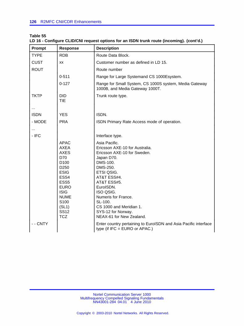
126 R2MFC CNI/CDR Enhancements
Table 55LD 16 - Configure CLID/CNI request options for an ISDN trunk route (incoming). (cont’d.)
Prompt Response Description
TYPE RDB Route Data Block.
CUST xx Customer number as defined in LD 15.
ROUT Route number
0-511 Range for Large Systemand CS 1000Esystem.
0-127 Range for Small System, CS 1000S system, Media Gateway1000B, and Media Gateway 1000T.
TKTP DIDTIE
Trunk route type.
...
ISDN YES ISDN.
- MODE PRA ISDN Primary Rate Access mode of operation.
...
- IFC Interface type.
APACAXEAAXESD70D100D250ESIGESS4ESS5EUROISIGNUMES100(SL1)SS12TCZ
Asia Pacific.Ericsson AXE-10 for Australia.Ericsson AXE-10 for Sweden.Japan D70.DMS-100.DMS-250.ETSI QSIG.AT&T ESS#4.AT&T ESS#5.EuroISDN.ISO QSIG.Numeris for France.SL-100.CS 1000 and Meridian 1.SYS-12 for Norway.NEAX-61 for New Zealand.
- - CNTY Enter country pertaining to EuroISDN and Asia Pacific interfacetype (if IFC = EURO or APAC.)
Nortel Communication Server 1000Multifrequency Compelled Signaling Fundamentals
NN43001-284 04.01 4 June 2010
Copyright © 2003-2010 Nortel Networks. All Rights Reserved.
.

Feature implementation 127
Table 55LD 16 - Configure CLID/CNI request options for an ISDN trunk route (incoming). (cont’d.)
Prompt Response Description
AUSAUSTDENDUTEIR(ETSI)FINFRAGERHKNGITANORPORSINGSWE
Austria.Australia.Denmark.Holland.Ireland.ETSI basic protocol.Finland.France.Germany.Hong Kong.Italy.Norway.Portugal.Singapore.Sweden.
...
ICOG ICT Incoming trunk route.
...
ICIS Incoming Identifier that is sent.
YES YES = The default. Use the CLID/CNI from the incomingISDN/R2MFC trunk.
Prompted for incoming trunks (that is, if ICOG = ICT), and if theroute type is R2MFC or ISDN.
CNTL ...
Table 56LD 16 - Configure CLID/CNI request options for an ISDN trunk route (outgoing).
Prompt Response Description
REQ CHG Change existing data.
TYPE RDB Route Data Block.
CUST xx Customer number as defined in LD 15.
ROUT Route number
0-511 Range for Large Systemand CS 1000Esystem.
0-127 Range for Small System, CS 1000S system, Media Gateway1000B, and Media Gateway 1000T.
TKTP DIDTIE
Trunk route type.
...
ISDN YES ISDN.
Nortel Communication Server 1000Multifrequency Compelled Signaling Fundamentals
NN43001-284 04.01 4 June 2010
Copyright © 2003-2010 Nortel Networks. All Rights Reserved.
.

128 R2MFC CNI/CDR Enhancements
Table 56LD 16 - Configure CLID/CNI request options for an ISDN trunk route (outgoing). (cont’d.)
Prompt Response Description
- MODE PRA ISDN Primary Rate Access mode of operation.
...
- IFC Interface type.
APACAXEAAXESD70D100D250ESIGESS4ESS5EUROISIGNUMES100(SL1)SS12TCZ
Asia Pacific.Ericsson AXE-10 for Australia.Ericsson AXE-10 for Sweden.Japan D70.DMS-100.DMS-250.ETSI QSIG.AT&T ESS#4.AT&T ESS#5.EuroISDN.ISO QSIG.Numeris for France.SL-100.CS 1000 and Meridian 1.SYS-12 for Norway.NEAX-61 for New Zealand.
- - CNTY Enter country pertaining to EuroISDN and Asia Pacific interfacetype (if IFC = EURO or APAC.)
AUSAUSTDENDUTEIR(ETSI)FINFRAGERHKNGITANORPORSINGSWE
Austria.Australia.Denmark.Holland.Ireland.ETSI basic protocol.Finland.France.Germany.Hong Kong.Italy.Norway.Portugal.Singapore.Sweden.
...
ICOG OGT Outgoing trunk route.
...
OGIS Outgoing Identifier that is sent.
YES YES = The default. Use the CLID/CNI from the incomingISDN/R2MFC trunk, or from the calling telephone.
Nortel Communication Server 1000Multifrequency Compelled Signaling Fundamentals
NN43001-284 04.01 4 June 2010
Copyright © 2003-2010 Nortel Networks. All Rights Reserved.
.

Feature implementation 129
Table 56LD 16 - Configure CLID/CNI request options for an ISDN trunk route (outgoing). (cont’d.)
Prompt Response Description
Prompted for outgoing trunks (that is, if ICOG = OGT), and ifthe route type is R2MFC or ISDN.
CNTL ...
Table 57LD 16 - Configure CLID/CNI request options for an ISDN trunk route (incoming and outgoing).
Prompt Response Description
REQ CHG Change existing data.
TYPE RDB Route Data Block.
CUST xx Customer number as defined in LD 15.
ROUT Route number
0-511 Range for Large Systemand CS 1000Esystem.
0-127 Range for Small System, CS 1000S system, Media Gateway1000B, and Media Gateway 1000T.
TKTP DIDTIE
Trunk route type.
...
ISDN YES ISDN.
- MODE PRA ISDN Primary Rate Access mode of operation.
...
- IFC Interface type.
APACAXEAAXESD70D100D250ESIGESS4ESS5EUROISIGNUMES100(SL1)SS12TCZ
Asia Pacific.Ericsson AXE-10 for Australia.Ericsson AXE-10 for Sweden.Japan D70.DMS-100.DMS-250.ETSI QSIG.AT&T ESS#4.AT&T ESS#5.EuroISDN.IISO QSIG.Numeris for France.SL-100.CS 1000 and Meridian 1.SYS-12 for Norway.NEAX-61 for New Zealand.
- - CNTY Enter country pertaining to EuroISDN and Asia Pacific interfacetype (if IFC = EURO or APAC.)
Nortel Communication Server 1000Multifrequency Compelled Signaling Fundamentals
NN43001-284 04.01 4 June 2010
Copyright © 2003-2010 Nortel Networks. All Rights Reserved.
.

130 R2MFC CNI/CDR Enhancements
Table 57LD 16 - Configure CLID/CNI request options for an ISDN trunk route (incoming and outgoing).(cont’d.)
Prompt Response Description
AUSAUSTDENDUTEIR(ETSI)FINFRAGERHKNGITANORPORSINGSWE
Austria.Australia.Denmark.Holland.Ireland.ETSI basic protocol.Finland.France.Germany.Hong Kong.Italy.Norway.Portugal.Singapore.Sweden.
...
ICOG IAO Incoming and outgoing trunk route.
...
ICIS Incoming Identifier that is sent.
YES YES = The default. Use the CLID/CNI from the incomingISDN/R2MFC trunk.
Prompted for incoming trunks (that is, if ICOG = ICT), and if theroute type is R2MFC or ISDN.
OGIS Outgoing Identifier that is sent.
YES YES = The default. Use the CLID/CNI from the incomingISDN/R2MFC trunk, or from the calling telephone.
Prompted for outgoing trunks (that is, if ICOG = OGT), and ifthe route type is R2MFC or ISDN.
CNTL ...
Table 58LD 16 - Configure the CLID/CNI request options for an R2MFC route (incoming and outgoing)whose signaling is supported by a D-Channel (ISL).
Prompt Response Description
REQ CHG Change existing data.
TYPE RDB Route Data Block.
CUST xx Customer number as defined in LD 15.
ROUT Route number
Nortel Communication Server 1000Multifrequency Compelled Signaling Fundamentals
NN43001-284 04.01 4 June 2010
Copyright © 2003-2010 Nortel Networks. All Rights Reserved.
.

Feature implementation 131
Table 58LD 16 - Configure the CLID/CNI request options for an R2MFC route (incoming and outgoing)whose signaling is supported by a D-Channel (ISL). (cont’d.)
Prompt Response Description
0-511 Range for Large Systemand CS 1000Esystem.
0-127 Range for Small System, CS 1000S system, Media Gateway1000B, and Media Gateway 1000T.
TKTP DIDTIE
Trunk route type.
...
ISDN YES ISDN.
- MODE ISLD ISL mode of operation.
...
- IFC Interface type.
APACAXEAAXESD70D100D250ESIGESS4ESS5EUROISIGNUMES100(SL1)SS12TCZ
Asia Pacific.Ericsson AXE-10 for Australia.Ericsson AXE-10 for Sweden.Japan D70.DMS-100.DMS-250.ETSI QSIG.AT&T ESS#4.AT&T ESS#5.EuroISDN.ISO QSIG.Numeris for France.SL-100.CS 1000 and Meridian 1.SYS-12 for Norway.NEAX-61 for New Zealand.
- CNTY Enter country pertaining to EuroISDN and Asia Pacific interfacetype (if IFC = EURO or APAC.)
AUSAUSTDENDUTEIR(ETSI)FINFRAGERHKNGITANORPOR
Austria.Australia.Denmark.Holland.Ireland.ETSI basic protocol.Finland.France.Germany.Hong Kong.Italy.Norway.Portugal.
Nortel Communication Server 1000Multifrequency Compelled Signaling Fundamentals
NN43001-284 04.01 4 June 2010
Copyright © 2003-2010 Nortel Networks. All Rights Reserved.
.

132 R2MFC CNI/CDR Enhancements
Table 58LD 16 - Configure the CLID/CNI request options for an R2MFC route (incoming and outgoing)whose signaling is supported by a D-Channel (ISL). (cont’d.)
Prompt Response Description
SINGSWE
Singapore.Sweden.Switzerland.New Zealand.Thailand.
...
ICOG IAO Incoming and outgoing trunk route.
...
MFC YES MFC.
MFCI 1-127 MFC Incoming table number; must be a non-zero value.
...
MFCO 1-127 MFC outgoing table number; must be a non-zero value.
...
SWP ...
ICIS Incoming Identifier that is sent.
YES YES = The default. Use the CLID/CNI from the incomingISDN/R2MFC trunk.
Prompted for incoming trunks (that is, if ICOG = ICT), and if theroute type is R2MFC or ISDN.
ICNP Incoming Numbering Plan.
(UKWN)PRVPUB
Unknown.PrivatePublic
Prompted if the route type is R2MFC and ICIS = YES.
ICNT Incoming Numbering Type.
(UKWN)INTLNTNLCLLOCCDPSPN
Unknown Number.International Number.National Number.Local Number.Location Number.Coordinated Dialing Plan.Special Number.
Prompted if the route type is R2MFC and ICIS = YES.
ICPS Incoming Presentation Status.
YES YES = Indicate the presentation status of the CLID.
Prompted if the route type is R2MFC and ICIS = YES.
Nortel Communication Server 1000Multifrequency Compelled Signaling Fundamentals
NN43001-284 04.01 4 June 2010
Copyright © 2003-2010 Nortel Networks. All Rights Reserved.
.

Feature operation 133
Table 58LD 16 - Configure the CLID/CNI request options for an R2MFC route (incoming and outgoing)whose signaling is supported by a D-Channel (ISL). (cont’d.)
Prompt Response Description
OGIS Outgoing Identifier that is sent.
YES YES = The default. Use the CLID/CNI from the incomingISDN/R2MFC trunk, or from the calling telephone.
Prompted for outgoing trunks (that is, if ICOG = OGT), and ifthe route type is R2MFC or ISDN.
Feature operationNo specific operating procedures are required to use this feature.
Nortel Communication Server 1000Multifrequency Compelled Signaling Fundamentals
NN43001-284 04.01 4 June 2010
Copyright © 2003-2010 Nortel Networks. All Rights Reserved.
.

134 R2MFC CNI/CDR Enhancements
Nortel Communication Server 1000Multifrequency Compelled Signaling Fundamentals
NN43001-284 04.01 4 June 2010
Copyright © 2003-2010 Nortel Networks. All Rights Reserved.
.

135.
R2 Multifrequency CompelledSignaling DID/DTMF DOD
ContentsThis section contains information on the following topics:
“Operating parameters” (page 135)
“Feature interactions” (page 136)
“Feature packaging” (page 136)
“Feature implementation” (page 136)
“Feature operation” (page 138)
IntroductionThe R2 MFC DID/DTMF DOD feature allows a single trunk to handleboth incoming DID calls with International Telegraph and TelephoneConsultative Committee (CCITT) R2 Multifrequency Compelled signaling,and to initiate outgoing DOD calls with DTMF register signaling. The endresult is the ability for a customer with R2 MFC DIDs and DTMF DODs toprovision fewer trunks.
This feature is required in countries where the Central Office/PublicExchange does not provide an MFC signaling capability on DOD trunks.
Operating parametersThis feature supports MFC signaling on DID and DTMF signaling on DODwith Multifrequency Mixed Signaling (MFX) Class of Service.
Tone and Digit Switch (TDS)/Extended Conference and TDS (XCT) cardsare required to send DTMF tones.
MFC Sender/Receiver (S/R) cards are required to send and receive MFCtones.
Nortel Communication Server 1000Multifrequency Compelled Signaling Fundamentals
NN43001-284 04.01 4 June 2010
Copyright © 2003-2010 Nortel Networks. All Rights Reserved.
.

136 R2 Multifrequency Compelled Signaling DID/DTMF DOD
This feature does not support any trunk types other than DID/DOD.
Analog and DTI2 trunks are only supported.
MFC Signaling for Socotel (MFE) and Multifrequency Signaling for KD3(MFK) are not supported by the R2 MFC DID/DTMF DOD feature.
The External Multifrequency Compelled Sender/Receiver (XMFC/XMFE)card (NT5K21) is required for Intelligent Peripheral Equipment (IPE).
Feature interactionsSet Based Administration - Automatic Trunk InstallationSet-based administration procedures must be able to accept the newtrunk-based Class of Service introduced by the R2MFC DID/DTMF DODfeature.
DTMF SignalingAny feature interaction with outgoing Digitone signaling will apply tooutgoing MFX calls. Any feature using Digitone signaling on incomingtrunks (DID/DOD) is not supported on MFX trunks.
MFC SignalingAny feature interaction with incoming MFC signaling will apply to incomingMFX calls. Any feature using MFC signaling on outgoing trunks (DID/DOD)is not supported on MFX trunks.
Semi-compelled MFC and Calling Name IdentificationSemi-compelled MFC (SMFC) and Calling Name Identification (CNI) onoutgoing calls with MFX Class of Service are not supported. Incoming callsare not affected.
Feature packagingThe R2 MFC DID/DTMF DOD feature requires Multifrequency CompelledSignaling (MFC) package 128.
Feature implementationTask summary list
The following is a summary of the tasks in this section:
• Table 59 "LD 13 : Configure MFC/XMFC units." (page 137)
• Table 60 "LD 94 : Configure MFC table for incoming trunks." (page137)
Nortel Communication Server 1000Multifrequency Compelled Signaling Fundamentals
NN43001-284 04.01 4 June 2010
Copyright © 2003-2010 Nortel Networks. All Rights Reserved.
.

Feature implementation 137
• Table 61 "LD 16 : Configure Route Data Block for DID with MFC."(page 137)
• Table 62 "LD 14 : Define DID trunk with MFX Class of Service." (page138)
Table 59LD 13 : Configure MFC/XMFC units.
Prompt Response Description
REQ NEW Configure.
TYPE MFC MFC type.
TN Terminal number
l s c u Format for Large Systemand CS 1000Esystem, where l = loop,s = shelf, c = card, and u = unit.
c u Format for Small System, CS 1000S system, Media Gateway1000B, and Media Gateway 1000T, where c = card and u =unit.
Table 60LD 94 : Configure MFC table for incoming trunks.
Prompt Response Description
REQ NEW Configure MFC table.
TYPE R2MF MFC table.
ICOG ICT Incoming table.
...
MAXT (1)-127 Maximum number of tables.
TBNO 1-127 MFC table number.
Table 61LD 16 : Configure Route Data Block for DID with MFC.
Prompt Response Description
REQ NEW CHG Configure or change the Route Data Block.
TYPE RDB Route Data Block.
CUST xx Customer Number as defined in LD 15.
ROUT Route number
0-511 Range for Large Systemand CS 1000Esystem.
0-127 Range for Small System, CS 1000S system, Media Gateway1000B, and Media Gateway 1000T.
TKTP DID Direct Inward Dial trunk.
...
Nortel Communication Server 1000Multifrequency Compelled Signaling Fundamentals
NN43001-284 04.01 4 June 2010
Copyright © 2003-2010 Nortel Networks. All Rights Reserved.
.

138 R2 Multifrequency Compelled Signaling DID/DTMF DOD
Table 61LD 16 : Configure Route Data Block for DID with MFC. (cont’d.)
Prompt Response Description
ICOG IAO Incoming and outgoing trunk.
...
MFC YES MFC signaling.
MFCI 1-127 MFC incoming table number.
Table 62LD 14 : Define DID trunk with MFX Class of Service.
Prompt Response Description
REQ NEW CHG. Configure or change.
TYPE DID DID trunk.
TN Terminal number
l s c u Format for Large Systemand CS 1000Esystem, where l = loop,s = shelf, c = card, and u = unit.
c u Format for Small System, CS 1000S system, Media Gateway1000B, and Media Gateway 1000T, where c = card and u =unit.
...
CLS MFX Mixed signaling Class of Service.
Feature operationNo specific operating instructions are required to use this feature.
Nortel Communication Server 1000Multifrequency Compelled Signaling Fundamentals
NN43001-284 04.01 4 June 2010
Copyright © 2003-2010 Nortel Networks. All Rights Reserved.
.

139.
R2 Multifrequency Compelled SelectiveRoute to Attendant
ContentsThis section contains information on the following topics:
“Introduction” (page 139)
“Operating parameters” (page 139)
“Feature interactions” (page 139)
“Feature packaging” (page 139)
“Feature implementation” (page 140)
“Feature operation” (page 140)
IntroductionThe R2 Multifrequency Compelled (MFC) Selective Route to Attendantsignal prevents system stations from accepting collect (reverse-charged)calls from international operators by routing the incoming calls to theattendant. This is established by adding a new station Class of Servicethat will permit indicated stations to receive these calls, while routingothers to the attendant.
Operating parametersThere are no operating parameters for this feature.
Feature interactionsThere are no interactions with other features.
Feature packagingThe R2 Multifrequency Compelled (MFC) Selective Route to Attendantfeature requires Multifrequency Compelled Signaling (MFC) package 128.
Nortel Communication Server 1000Multifrequency Compelled Signaling Fundamentals
NN43001-284 04.01 4 June 2010
Copyright © 2003-2010 Nortel Networks. All Rights Reserved.
.

140 R2 Multifrequency Compelled Selective Route to Attendant
Feature implementationTable 63LD 10/11 : Define Class of Service to restrict collect calls.
Prompt Response Description
REQ: NEWCHG
Add new data.Change existing data.
TYPE: xxxx Type of telephone.
TN Terminal number
l s c u Format for Large Systemand CS 1000Esystem, where l =loop, s = shelf, c = card, and u = unit.
c u Format for Small System, CS 1000S system, MediaGateway 1000B, and Media Gateway 1000T, where c =card and u = unit.
...
CLS UCC(RCC)
This station is unrestricted from receiving collect calls.This station is restricted from receiving collect calls.(default).
Feature operationNo specific operating procedures are required to use this feature.
Nortel Communication Server 1000Multifrequency Compelled Signaling Fundamentals
NN43001-284 04.01 4 June 2010
Copyright © 2003-2010 Nortel Networks. All Rights Reserved.
.

141.
R2 Multifrequency CompelledSignaling to DPNSS1 Gateway
ContentsThis section contains information on the following topics:
“Introduction” (page 141)
“Operating parameters” (page 142)
“Feature interactions” (page 143)
“Feature packaging” (page 146)
“Feature implementation” (page 146)
“Feature operation” (page 148)
IntroductionPrior to the introduction of this feature, several countries in Europe, CentralAmerica, and South America required interworking to Other EquipmentManufacturer’s PBXs in multivendor networking environments using DigitalPrivate Network Signaling System One (DPNSS1). In these countries, theCentral Office protocol is R2 Multifrequency Compelled Signaling (R2MFC)Direct Inward Dialing (DID) and in some cases R2MFC Direct OutwardDialing (DOD). In order for the system to operate in these environments,interworking of DPNSS1 and R2MFC trunks must be provided.
The R2MFC to DPNSS1 Gateway feature provides an interface betweenR2MFC DID/DOD trunks and DPNSS1 trunks, and can also provideCalling Number Identification (CNI) support for incoming calls.
Nortel Communication Server 1000Multifrequency Compelled Signaling Fundamentals
NN43001-284 04.01 4 June 2010
Copyright © 2003-2010 Nortel Networks. All Rights Reserved.
.

142 R2 Multifrequency Compelled Signaling to DPNSS1 Gateway
In addition, the R2MFC to DPNSS1 Gateway feature introducesthe following enhancements to the R2MFC incoming CNI requestfunctionalities:
• The ability to request CNI for an incoming R2MFC call is possibleimmediately after a predetermined number of digits are received. Theallowable range for this option is 0 to 7.
• The ability to request CNI for an incoming R2MFC call is possibleimmediately after an Electronic Switched Network (ESN) code isdialed. The ESN codes recognized for this purpose are DistantSteering Codes (DSC), Trunk Steering Codes (TSC), and NARS/BARSAccess Codes (AC1, and AC2).
By using these CNI request options, CNI information will be availablebefore the incoming R2MFC call is routed. This is necessary to provideCNI support for R2MFC DID to DPNSS1 gateway calls, but also providesan alternative for supporting CNI requests for incoming R2MFC calls ingeneral. These options are applicable for incoming R2MFC DID/TIE calls.
Operating parametersSystem DPNSS1 networks currently support only Coordinated Dialing Plan(CDP), Special Numbers (SPNs), and Basic Automatic Route Selection(BARS) (for outgoing calls), therefore the R2MFC to DPNSS1 feature doesnot support Universal Dialing Plans (UDPs).
For R2MFC DID calls routing to DPNSS1 trunks, the option Accept CNI(ACNI) is provided in the DPNSS1 route data block to identify if CNIinformation should be passed at the gateway. If the ACNI option is setto YES, the far end PBX must accept the Originating Line Identity (OLI)string for Called/Calling Line Category (CLC) Public Switched TelephoneNetwork (PSTN) calls in the Initial Service Request Message (ISRM).
Two additional options are provided for requesting CNI before theR2MFC DID call is even routed as previously described. Using oneof these options is the only mechanism that will provide CNI for anR2MFC-DPNSS1 gateway call (unless the call is the result of callredirection). If the interfacing Central Office cannot support such options,both of these options have to be disabled and therefore no CNI will beavailable for the R2MFC-DPNSS1 gateway call.
CNI is for R2MFC trunks tandeming to DPNSS1 trunks only. For callsoriginating from DPNSS1 trunks, and tandeming to an outgoing R2MFCtrunk, the CNI information in the DPNSS1 call is not used. Existingmethods of generating the CNI locally at the gateway node are used.
Interworking of R2MFC TIE trunks and DPNSS1 trunks is not supportedfor this feature.
Nortel Communication Server 1000Multifrequency Compelled Signaling Fundamentals
NN43001-284 04.01 4 June 2010
Copyright © 2003-2010 Nortel Networks. All Rights Reserved.
.

Feature interactions 143
Interworking between MFE DID/DOD trunks and DPNSS1 trunks is notsupported by this feature. Interworking between MFE KD3 DID/DODtrunks and DPNSS1 trunks is also not supported by this feature.
External Operator Features and Toll Call Identification (from China Number1 signaling) are not supported by this feature.
No new hardware is required for this feature.
Feature interactionsCDR Calling Line ID for DPNSS1At the terminating PBX, the OLI string for the R2MFC DID originatedcall may contain the CNI information. The CDR Enhancement featureautomatically prints the contents of the OLI string in the CLID field of theCDR. Hence, the CNI information will be made available on the CDR (thatis, it will be printed in the CLID field).
DPNSS1 Basic CallThe R2MFC Gateway feature introduces a change in the content sentin the Initial Service Request Message (ISRM) when the originator ofa DPNSS1 call is an R2MFC DID trunk. If CNI information has beenobtained from the incoming trunk, the CNI digits are sent as an OLI stringin the IRSM. In that case, the Trunk Identity (TID) string is not sent. If noCNI information is available from the originating trunk, the TID string issent. The transport of the CNI digits as an OLI is controlled by the AcceptCNI (ACNI) option on the outgoing DPNSS1 route.
At the terminating node of the DPNSS1 call, an OLI string instead of aTID string may now be received for calls that originate from trunks whichare not using ISDN or Integrated Digital Access (IDA) signaling. Theinformation available for call display is now different. If the terminatingnode cannot handle receiving an OLI from such trunk calls, the ACNIoption should be set to NO on the outgoing DPNSS1 route at thatgateway.
The Step Back on Congestion (SBOC) option programmed for an outgoingDPNSS1 route is ignored for R2MFC-DPNSS1 gateway calls. Specifically,if an R2MFC DID to DPNSS1 gateway call receives a Clear RequestMessage (CRM) due to congestion, the call is not rerouted (that is, doesnot search for an idle trunk based on the next entry in the Route ListBlock), regardless of whether or not the SBOC option is programmed.Instead, the call is treated as a congested call and intercept is providedif necessary. If the SBOC option is allowed, there is a potential problemin the gateway signaling because the next outgoing route may not be aDPNSS1 route.
Nortel Communication Server 1000Multifrequency Compelled Signaling Fundamentals
NN43001-284 04.01 4 June 2010
Copyright © 2003-2010 Nortel Networks. All Rights Reserved.
.

144 R2 Multifrequency Compelled Signaling to DPNSS1 Gateway
Digital Private Network Signaling System (DPNSS1)/DigitalAccess Signaling System (DASS2) Uniform Dialing Plan (UDP)InterworkingThe R2MFC to DPNSS1 Gateway is supported with UDP numbers at thesame level as it is supported with CDP numbers.
Virtual Network ServicesIf the call on the DPNSS1 (or R2MFC) trunk is tandeming to the R2MFC or(DPNSS1) trunk on a Virtual Network Services (VNS) call, the R2MFC toDPNSS1 Gateway feature does not apply. If a DPNSS1/R2MFC tandemis encountered during the routing of a VNS call, the R2MFC to DPNSS1Gateway feature applies. Figure 1 "Applicability of R2MFC-DPNSS1Gateway to VNS Calls" (page 145) shows how the R2MFC-DPNSS1gateway may apply to a VNS call.
Nortel Communication Server 1000Multifrequency Compelled Signaling Fundamentals
NN43001-284 04.01 4 June 2010
Copyright © 2003-2010 Nortel Networks. All Rights Reserved.
.

Feature interactions 145
Figure 1Applicability of R2MFC-DPNSS1 Gateway to VNS Calls
Nortel Communication Server 1000Multifrequency Compelled Signaling Fundamentals
NN43001-284 04.01 4 June 2010
Copyright © 2003-2010 Nortel Networks. All Rights Reserved.
.

146 R2 Multifrequency Compelled Signaling to DPNSS1 Gateway
Feature packagingThe R2MFC to DPNSS1 Gateway feature requires the following packagesat the gateway system to provide the basic DPNSS1 and R2MFC signalingfunctionalities:
• Integrated Digital Access (IDA) package 122
• Digital Private Network Signaling System 1 (DPNSS1) package 123
• Multifrequency Compelled Signaling (MFC) package 128
Note: The CNI request enhancements are included in MFCpackage 128.
For network numbering, Nortel recommends the following packages:
• Coordinated Dialing Plan (CDP) package 59
• Basic Automatic Route Selection (BARS) package 57
• Pretranslation (PXLT) package 92
• Incoming Digit Conversion (IDC) package 113
• Flexible Numbering Plan (FNP) package 160
Feature implementationTask summary list
The following is a summary of the tasks in this section:
• Table 64 "LD 16 : Define CNI request options for the R2MFC route."(page 146)
• Table 65 "LD 16 : Define whether the DPNSS1 route supports R2MFCCNI." (page 147)
Table 64LD 16 : Define CNI request options for the R2MFC route.
Prompt Response Description
REQ NEW CHG New, or change.
TYPE RDB Route data block.
...
TKTP DID Direct Inward Dialing trunk data block.
...
MFC YES
...
Nortel Communication Server 1000Multifrequency Compelled Signaling Fundamentals
NN43001-284 04.01 4 June 2010
Copyright © 2003-2010 Nortel Networks. All Rights Reserved.
.

Feature implementation 147
Table 64LD 16 : Define CNI request options for the R2MFC route. (cont’d.)
Prompt Response Description
NCNI (0)-7 Request CNI after the defined number of digits arereceived.
If NCNI = 0, the CNI request does not depend on thenumber of digits received.
If NCNI is defined to be greater than the number of digitsrequired for routing the call, the CNI will not be requestedbut the call will be routed.
CNIE (NO) YES Request CNI after an ESN code is dialed.
This R2MFC route requests/(does not request) CNI afteran ESN code is dialed. The ESN code could be a DistantSteering Code (DSC), a Trunk Steering Code (TSC), theNARS Access Code 1 (AC1) or the NARS Access Code 2(AC2).
NCNI and CNIE are prompted when the following occurs:the MFC package is equippedTKTP = DID or TIEMFC = R2MF, andthe MFC signaling table is defined on the route.
If NCNI > 0 and CNIE = YES, CNI is requested wheneither one of the conditions is first met.
CNIT (NO) YES Request CNI only if the dialed station has Malicious CallTrace Allowed (MCTA) Class of Service.
Table 65LD 16 : Define whether the DPNSS1 route supports R2MFC CNI.
Prompt Response Description
REQ NEW CHG New, or change.
TYPE RDB Route Data Block.
...
TKTP IDA Integrated Digital Access.
SIGL DPN APNS DPN for DPNSS1 signaling.APNS for APNSS signaling.
...
Nortel Communication Server 1000Multifrequency Compelled Signaling Fundamentals
NN43001-284 04.01 4 June 2010
Copyright © 2003-2010 Nortel Networks. All Rights Reserved.
.

148 R2 Multifrequency Compelled Signaling to DPNSS1 Gateway
Table 65LD 16 : Define whether the DPNSS1 route supports R2MFC CNI. (cont’d.)
Prompt Response Description
TTBL ...
ACNI (NO) YES Accept Call Number Identification (CNI).
This DPNSS1 route allows/(does not allow) R2MFC CNIsent as an Originating Line Identity (OLI) string in theinitial service request message (ISRM).
This is prompted when the following occurs:the IDA package is equippedthe MFC package is equippedTKTP = IDA, andSIGL = DPN/APNS.
Feature operationNo specific operating procedures are required to use this feature.
Nortel Communication Server 1000Multifrequency Compelled Signaling Fundamentals
NN43001-284 04.01 4 June 2010
Copyright © 2003-2010 Nortel Networks. All Rights Reserved.
.

149.
Semi-compelled MFC and CallingNumber Identification changes
ContentsThis section contains information on the following topics:
“Introduction” (page 149)
“Operating parameters” (page 150)
“Feature interactions” (page 150)
“Feature packaging” (page 150)
“Feature implementation” (page 150)
“Feature operation” (page 150)
IntroductionSemi compelled MFC and Calling Number Identification changes areenhancements to the R2 Multifrequency Compelled Signaling (MFC)feature.
Semi-compelled MFC provides Semi-compelled MFC signaling on trunks;this capability is typically desirable in markets where there is a high rate ofsatellite transmission. To reduce signaling times, MFC backward signals(A and B) are sent for 150 milliseconds instead of being compelled (that is,having to wait for forward signals (I and II) to terminate).
The Calling Number Identification (CNI) enhancement provides the optionof ending CNI transmission when a NEXT signal is received, and switchingto called number transmission.
Both options are configured in LD 94.
Nortel Communication Server 1000Multifrequency Compelled Signaling Fundamentals
NN43001-284 04.01 4 June 2010
Copyright © 2003-2010 Nortel Networks. All Rights Reserved.
.

150 Semi-compelled MFC and Calling Number Identification changes
Operating parametersThe MFC software pack QPC327 or the XMFC/XFME software packNT5K21AA must be equipped.
Incoming trunks must support MFC register signaling.
Feature interactionsThere are no interactions with other features.
Feature packagingSemi compelled MFC and Calling Number Identification changes requireMultifrequency Compelled Signaling (MFC) package 128.
Feature implementationTable 66LD 94 : Allow or deny Semi-compelled MFC and Calling Number Identification transmission.
Prompt Response Description
...
EECD ...
SMFC (NO) YES Enter YES for Semi-compelled MFC. If NO is entered,backward signals are stopped when the forward signal isrecognized as having stopped.
SCNT (NO) YES Enter YES to stop CNI transmission at the reception of aNEXT signal, and to switch to called number transmission.If NO is entered, CNI transmission continues at thereception of a NEXT signal.
Feature operationNo specific operating procedures are required to use this feature.
Nortel Communication Server 1000Multifrequency Compelled Signaling Fundamentals
NN43001-284 04.01 4 June 2010
Copyright © 2003-2010 Nortel Networks. All Rights Reserved.
.
151.
Taiwan R1 Modified Signaling
ContentsThis section contains information on the following topics:
“Introduction” (page 151)
“Operating parameters” (page 161)
“Feature interactions” (page 162)
“Feature packaging” (page 166)
“Feature implementation” (page 166)
“Maintenance and diagnostics guidelines” (page 176)
“Feature operation” (page 177)
IntroductionThe Taiwan R1 Modified Signaling feature supports Taiwan R1 ModifiedSignaling (TWR1 MS) over Taiwan R1 Direct Inward Dial (DID) or DirectOutward Dial (DOD) DTI trunks. With TWR1 MS, the capability to carryCalling Line Identification (CLID) across a system network is supported forlocal and national calls. Please note that, in a networking environment, theCLID is supported only for TWR1 calls that are tandemed over MCDN,ISDN, or QSIG trunks. CLID processing for TWR1 MS is described in“CLID processing” (page 152).
The Taiwan R1 Modified Signaling feature may operate in a standalone ornetwork environment. In a standalone environment, the system connectsdirectly to a Taiwan Public Exchange over Taiwan R1 Modified Signalingtrunks.
In a networking environment, the tandem system connects to a TaiwanPublic Exchange over Taiwan R1 or Taiwan ISDN trunks, and to oneor more other Private Exchange(s) over MCDN, QSIG, Dual Tone Multi
Nortel Communication Server 1000Multifrequency Compelled Signaling Fundamentals
NN43001-284 04.01 4 June 2010
Copyright © 2003-2010 Nortel Networks. All Rights Reserved.
.

152 Taiwan R1 Modified Signaling
Frequency (DTMF), or Dial Pulse (DP) trunks. Connectivity to the PrivateExchange over Taiwan R1 Modified Signaling, Digital Private NetworkingSignaling System No. 1 (DPNSS1), or Level 2 Multi Frequency CompelledSignaling (R2 MFC) trunks is not supported.
Types of supported TWR1 protocolsThe Taiwan R1 Modified Signaling feature supports the following callsignaling protocols, for national and international calls:
• incoming local or national call protocol
Note: Incoming international calls are accepted and treated by thesystem using the national call protocol.
• outgoing local or national call protocol
• outgoing international call protocol
“How the system handles the supported types of TWR1 protocols”(page 155) describes the call processing to handle the supported TWR1protocols. First, how the system processes CLID information for theTaiwan R1 Modified Signaling feature, for incoming and outgoing calls,is described.
CLID processingIncoming CLIDAn incoming TWR1 route on the system may be configured with or withoutthe CLID option. If a Central Office expects to receive the 210 - 220msCLID request wink signal from the Answer signal, then the TW_INC_CLIDprompt in LD16 may be set to YES for the incoming route. If the prompt isset to YES, once the called number is received from the Central Office,the system will send out a CLID request wink to request CLID digits. Thecalled number received is not processed until after the CLID informationhas been received. When the TW_INC_CLID prompt is set to YES, if CLIDdigits are not received within a specified time, the call is completed withCLID failure treatment, as follows:
• A series of seven ’-’ (dashes) is shown on the displays of telephonesthat have displays.
• The CLID field in the CDR ticket for the call is left blank.
• No CLID is made available to the Application Module Link (AML),Application Processor Link (APL), and the High Speed Link (HSL).
For a Central Office that does not expect to receive the CLID request winksignal, the TW_INC_CLID prompt must be set to NO for the incomingroute. CLID failure treatment is given to such calls because no CLID isreceived. In this case, the called number received is processed as soonas it is received.
Nortel Communication Server 1000Multifrequency Compelled Signaling Fundamentals
NN43001-284 04.01 4 June 2010
Copyright © 2003-2010 Nortel Networks. All Rights Reserved.
.
Introduction 153
The CLID information received is made available to existing featuresthat use CLID such as an answering digital terminal’s display and suchapplications as Meridian Link, Customer Controlled Routing, Meridian Mail,Meridian MAX, and ACD MAX using the Application Module Link (AML),Application Processor Link (APL), and High Speed Link (HSL).
For a Taiwan R1 initiated tandem call to an outgoing MCDN, QSIG, orTaiwan ISDN trunk, the CLID that is received with the incoming call maybe sent out over the MCDN, QSIG, or Taiwan ISDN trunk to identify thecaller. If the outgoing trunk is either a DTMF or DP trunk, no CLID is sentover the outgoing trunk.
Outgoing CLIDStation (telephone or attendant console) initiated call On astandalone PBX, whenever a call is made from a telephone or anattendant console, the CLID is generated to identify the caller. If theresponse to the CLID prompt for a customer in LD 15 is YES, theexisting customer CLID database is used. This function allows thesystem administrator to control the CLID contents using the CLID entryconfiguration in LD 15. If the response to the CLID prompt is NO, there isno CLID composed for calls originated by telephones belonging to thatcustomer.
If the response to the existing CLID prompt for a customer in LD 15 isYES, a CLID table can then be defined for the customer. The size of theCLID table is service changeable, ranging from 0 to a maximum of 4000entries, with a default of 256 entries. Each entry in the table is a CLIDentry. Each CLID entry contains the codes for:
• Home National Code (HNTN) — This is the national number, which isthe area code for Taiwan.
• Home Local Code (HLCL) — This is the home local code, which is theoffice code for Taiwan.
• Direct Inward Dialing DN (DIDN) — If DIDN is set to YES, then HLCLis suffixed with the DN of the active key. If DIDN is set to NO, thenHLCL is not suffixed with anything. If DIDN is set to SRCH (search),then starting from key 0, all keys are searched until the key for whichDIDN is set to YES is found. Then the DN of that key is used.
A CLID entry can be assigned to a DN of an analog (500/2500) set or anISDN BRI set, and to a DN key for a digital telephone. For a station setinitiated Taiwan call, the CLID is composed based on the CLID entry thatthe originating DN uses. If the user does not select a CLID entry number,CLID entry 0 is used as the default. During set administration, there isno cross-checking of the CLID entry associated with the set against the
Nortel Communication Server 1000Multifrequency Compelled Signaling Fundamentals
NN43001-284 04.01 4 June 2010
Copyright © 2003-2010 Nortel Networks. All Rights Reserved.
.

154 Taiwan R1 Modified Signaling
CLID entry in the customer data block. If a CLID entry is removed from theCLID table and the CLID entry is still assigned to a DN key, CLID is notgenerated and CLID failure indication is sent out.
For an attendant console initiated Taiwan call, the CLID compositionis based on CLID entry 0. If CLID entry 0 is not defined, CLID is notgenerated and CLID failure indication is sent out.
Once the CLID is composed, it is sent to the far-end. If the originatingterminal has requested privacy as per the Calling Party Privacy (CPP) orDisplay Party Denied (DPD) features, then CLID is sent out with the CLIRindicator. Otherwise the CLIP indicator is sent.
Trunk initiated tandem call For an MCDN, ISDN, or QSIG trunkinitiated tandem call, the system does not compose any CLID for theincoming trunk. If CLID is available, and presentation is allowed, the CLIDthat is passed in by the incoming trunk may be directly passed on to theTWR1 trunk to identify the caller. The CLIP indicator is sent out in thiscase. If CLID is available, but the caller has requested privacy, CLID issent out with the CLIR indicator.
If, no CLID is available, as is the case for a DTMF or DP trunk initiatedtandem call, the CLID failure indicator is sent to the outgoing trunk.
The possibility of an invalid CLID composition The Taiwan R1Modified Signaling feature builds the CLID from the CLID entry in LD15. Itis up to the craftsperson to ensure that the right digits are entered. Thereis no validation of digits in the CLID entries of the CLID table. Therefore,it is possible that the CLID built from the CLID entries may be an invalidnumber or not match the number of the dialing station.
TWR1 Calling Party Privacy CLIDThe following sections discuss how the system handles incoming CLIDinformation with CLIR indicator, and how and when the system sends outCLID information with CLIR indicator.
Incoming CLID digits with CLIR indicator If an incoming TaiwanR1 call with a CLIR indicator is received by the system in a standalonescenario, seven ’-’ (dashes) will be displayed on the answering set or ACDagent set, and CLID digits are not sent to such applications as MeridianMail, Meridian Link, Meridian CCR, and Meridian MAX. However, the CLIDdigits are sent to CDR.
If the system is a network PBX, the call with the CLIR indicator will betandemed to an outgoing MCDN, QSIG, or Taiwan ISDN trunk with theCLID Restriction indicator. If the call is tandemed to an outgoing DTMF orDP trunk, no CLID is sent.
Nortel Communication Server 1000Multifrequency Compelled Signaling Fundamentals
NN43001-284 04.01 4 June 2010
Copyright © 2003-2010 Nortel Networks. All Rights Reserved.
.
Introduction 155
Outgoing CLID digits with CLIR indicator For outgoing calls from astandalone system PBX, if the caller requests privacy as per the existingCalling Party Privacy (CPP) and Display Party Denied (DPD) features,CLID is sent out with the CLIR indicator.
If the system is a network PBX, if the incoming MCDN, QSIG, or TaiwanISDN call contains the "CLID Presentation Restricted" indicator, the call istandemed to Taiwan R1 trunks with the CLIR indicator. For tandem callsfrom a DTMF or DP trunk, the CLID failure indicator is sent.
How the system handles the supported types of TWR1 protocolsIncoming local and national call processingThe Central Office seizes a TWR1 trunk, and sends a called number tothe system. If the TW_INC_CLID is set to NO, then the call terminates assoon as the called number is received. The call is given the following CLIDfailure treatment:
• A series of seven ’-’ (dashes) is shown on the displays of telephonesthat have displays.
• The CLID field in the CDR ticket for the call is left blank.
• No CLID is made available to the Application Module Link (AML),Application Processor Link (APL), and the High Speed Link (HSL).
If the TW_INC_CLID is set to YES, on receiving the called number, thesystem sends a request wink signal to the Central Office, to request thecalling number and CLID information. The CO sends the calling number inMF tones. The calling number includes the Information digit "I", where "I"may be one of the following values:
• 0 or 1 — CLID is available with Calling Line Identification Presentation(CLIP) allowed. This is the normal CLID delivery.
• 2 — CLID is not available. The call receives the CLID call failuretreatment described above.
• 3 — CLID is available with Calling Line Identification Restriction (CLIR).The call receives the following treatment:
— A series of seven ’-’ (dashes) is shown on the displays oftelephones that have displays.
— The CLID field in the CDR ticket for the call is appropriately filled.
— No CLID is made available to the Application Module Link (AML),Application Processor Link (APL), and the High Speed Link (HSL).
Nortel Communication Server 1000Multifrequency Compelled Signaling Fundamentals
NN43001-284 04.01 4 June 2010
Copyright © 2003-2010 Nortel Networks. All Rights Reserved.
.

156 Taiwan R1 Modified Signaling
Outgoing local and national call processingFor outgoing calls, Electronic Switched Network (ESN) and Trunk AccessCode (ACOD) dialing are supported. To handle the inconsistent dialingpatterns for outgoing calls, the Flexible Numbering (FNP) package 160 hasto be equipped on the system PBX. For ESN dialing, the call is terminatedas soon as soon as the Flexible Length (FLEN) value is reached for thedialed Special Number (SPN). For ACOD dialing, the call is terminatedafter a time of five seconds elapses from when a last digit, or ’#’ isimmediately dialed.
When a called number is composed using ESN dialing, the systemcollects the dialed digits, as determined by the Flexible Numbering Planconfiguration, and seizes an outgoing TWR1 trunk to the far-end CentralOffice. The system sends the called number digit string to the CO, andawaits for the calling number and CLID information request wink signal.If this signal is not received within a specified period of time, as definedby the Taiwan Time Out timer (TTO) (see “Taiwan Time-Out (TTO) timer”(page 156) ), the calling number is not sent.
On receiving the CLID request wink signal from the Central Office, thesystem sends the calling number in MF tones. The calling number includesthe Information digit "I", where "I" may be one of the following values:
• 0 — CLID is available with Calling Line Identification Presentation(CLIP) allowed. A value of ’0’ is sent to the far-end CO if the originatingtelephone has not requested privacy as per the Calling Party Privacy(CPP) or Display Party Denied (DPD) features.
• 2 — CLID is not available.
For outgoing calls, as long as a CLID has been configured for theoriginating telephone, CLID information will always be sent. It is up tothe far-end CO to handle the CLID accordingly.
• 3 — CLID is available with Calling Line Identification Restriction (CLIR).The CLIR indicator is sent to the far-end CO to request calling partyprivacy, if one of the following conditions exists:
— For a call originating from a telephone or attendant, the originatorrequests calling party privacy as defined by the Calling PartyPrivacy (CPP), Display Party Denied (DPD), Calling Party PrivacyOverride (CPPO), or BRI telephone privacy feature.
— For tandem calls over MCDN, ISDN, or QSIG trunks, the tandemcall contains a Presentation Restriction indicator.
Taiwan Time-Out (TTO) timer The TTO is a programmable waiting timerfor the CLID request wink signal on outgoing trunks. TTO is defined in LD16 to be in a range of 128 ms (default) to 7 seconds.
Nortel Communication Server 1000Multifrequency Compelled Signaling Fundamentals
NN43001-284 04.01 4 June 2010
Copyright © 2003-2010 Nortel Networks. All Rights Reserved.
.

Introduction 157
The TTO has been implemented for the following reasons. For users whodo not expect CLID request wink from the CO, the called party hears theringback tone from the terminating end only after seven seconds, which istoo long. For users who do expect CLID request wink from the CO, theprogrammable timer provides a flexibility to configure the proper timersaccording to the different situations of different COs.
The default value for TTO (128 ms) is defined for users who do not expecta CLID request wink from the CO. However, users who do expect a CLIDrequest wink from the CO must configure the TTO timer as a suitablevalue. The value may differ depending on different COs, because differentCOs may have different delays when they send the wink signal. Usersmay change the value through testing.
Outgoing international call processingTaiwan R1 Modified Signaling uses two stage outpulsing of the called partynumber for outgoing international calls. The first stage includes sendingthe international call access code (002) to the CO, and the second stageincludes sending the country code and the called number to the CO. Thesecond stage of outpulsing is started by the system when the "secondstage outpulsing request" wink is received from the CO.
Note: There is no CLID sent for outgoing international calls.
Both ESN dialing and ACOD dialing are supported for making TWR1outgoing international calls. If using ESN dialing, it is the responsibility ofthe craftsperson to configure a Special Number (SPN) of "002", which isthe Taiwan international call access code. The SPN 002 is configuredusing LD 90. Also in LD 90, an appropriate Flexible Length (FLEN) of atleast 16 digits should be defined, and the Inhibit Time Out Handler (ITOH)should be set to a value of "NO". Refer to “Feature implementation” (page166).
Taiwan numbering plansThis section describes the called party and calling party numbering planformat used by the Taiwan Public Switched Telephone Network (PSTN)system. The numbering plan is variable, having different digit stringlengths for large cities and small cities.
For outgoing calls, Electronic Switched Network (ESN) and Trunk AccessCode (ACOD) dialing are supported. To handle the inconsistent dialingpatterns for outgoing calls, the Flexible Numbering (FNP) package 160has to be equipped on the system PBX, if ESN dialing is used. With FNPequipped, the call is terminated as soon as soon as the Flexible Length
Nortel Communication Server 1000Multifrequency Compelled Signaling Fundamentals
NN43001-284 04.01 4 June 2010
Copyright © 2003-2010 Nortel Networks. All Rights Reserved.
.

158 Taiwan R1 Modified Signaling
(FLEN) value is reached for the dialed Special Number (SPN). For ACODdialing, the call is terminated after a time of five seconds elapses fromwhen a last digit is dialed, or if ’#’ is dialed immediately.
Note: Large cities in Taiwan will soon be upgrading to the new dialingplan, indicated by "Large cities (future)."
Table 67 "Taiwan PSTN numbering plan formats" (page 158) representthe dialing plans used by the Taiwan PSTN. The sections that followthen show the numbering plans, according to incoming and outgoing callformats.
Table 67Taiwan PSTN numbering plan formats
Area Code Office CodeSubscriberNumber
Large cities(future)
A +BCDD’ +XXXX
Large cities(current)
A +BCD +XXXX
Small cities AB +CD +XXXX
The letters represent the variable digits allowed in each position.
• The first digit of the area code can be 2-8.
• The first digit of the office code can be 2-9.
• All other letters imply that the digits can be 0-9.
• The service code numbers can be three digits, such as 10X, 11X, and 16X.
Incoming call formats - Local/National and International callsThis section shows the numbering plan formats for the supportedincoming call protocols (Local/National) calls. The system treats incomingInternational calls using the same protocol as for incoming Local/Nationalcalls. Therefore, the tables in this section also refer to International calls.
Incoming National and International Called Party Numberformat Table 68 "Called party number format for Local/National andInternational incoming calls" (page 159) shows the format for a called partynumber of a Local/National or International incoming call.
Nortel Communication Server 1000Multifrequency Compelled Signaling Fundamentals
NN43001-284 04.01 4 June 2010
Copyright © 2003-2010 Nortel Networks. All Rights Reserved.
.

Introduction 159
Table 68Called party number format for Local/National and International incomingcalls
Call type Called Area
Called Party Numberformat expected by thesystem
Large city (future) A+BCDD’+XXXXorBCDD’+XXXX
Large city (current) A+BCD+XXXXorBCD+XXXX
Local/National,International*
Small city AB+CD+XXXXorCD+XXXX
* For international calls, the system uses the same protocol as for nationalcalls.
Note: There is no CLID sent for International incoming calls.
Incoming Local/National Calling Party Number format Table 69"Calling party composition for Local/National incoming calls" (page159) shows the Calling Party composition for a Local/National incomingcall.
Note: For International incoming calls, no CLID is available from the farend, as per the Taiwan R1 Modified Signaling protocol.
Table 69Calling party composition for Local/National incoming calls
Call type Calling Area
Calling Party Numberformat expected by thesystem
Large city (future) A+BCDD’+XXXX
Large city (current) A+BCD+XXXX
Small city AB+CD+XXXX
Global System for Mobilecommunication (GSM)
93X+XXXXXX
Local/National
Advanced Mobile PhoneService (AMPS)
90+XXXX
Nortel Communication Server 1000Multifrequency Compelled Signaling Fundamentals
NN43001-284 04.01 4 June 2010
Copyright © 2003-2010 Nortel Networks. All Rights Reserved.
.

160 Taiwan R1 Modified Signaling
Outgoing call formats - Local/National, and International callsThis section shows the numbering plan formats for the supported outgoingcall protocols (Local/National and International calls).
Outgoing Local/National, International Called Party Numberformat Table 70 "Called party format for Local/National and Internationaloutgoing calls" (page 160) shows the format for a called party number ofa Local/National and International outgoing call.
Table 70Called party format for Local/National and International outgoing calls
Call type Called AreaCalled Party Number formatsent from the system
All 1XXService call
Large city (future) BCDD’+XXXX
Large city (current) BCD+XXXX
Small city CD+XXXX
Local
Large city (future) A+BCDD’+XXXX
Large city (current) A+BCD+XXXX
Small city AB+CD+XXXX
Global System forMobile communication(GSM)
93X+XXXXXX
Advanced MobilePhone Service(AMPS)
90+XXXX
National
Pager AB+XXXXXX or ABB’+XXXXXX
International All 002+Country Code+AreaCode+Subscriber Code
Outgoing Local/National Calling Party Number format Table 71"Called party format for Local/National and International outgoing calls"(page 161) shows the Calling Party composition for a Local and Nationaloutgoing call.
Note: There is no CLID sent for outgoing International calls.
Nortel Communication Server 1000Multifrequency Compelled Signaling Fundamentals
NN43001-284 04.01 4 June 2010
Copyright © 2003-2010 Nortel Networks. All Rights Reserved.
.

Operating parameters 161
Table 71Called party format for Local/National and International outgoing calls
Call type Calling AreaCalling Party Number formatsent from the system
Large city (future) A+BCDD’+XXXXorBCDD’+XXXX
Local orNational
Large city (current) A+BCD+XXXXorBCD+XXXX
Small city AB+CD+XXXXorCD+XXXX
Operating parametersThe Taiwan R1 trunk is a one-way trunk, being either outgoing only orincoming only (as configured in LD 16 in response to the ICOG prompt).
Taiwan R1 trunks use Multi Frequency (MF) signaling only. Dual ToneMulti Frequency (DTMF) signaling and Dial Pulse (DP) signaling are notsupported.
Taiwan R1 trunks support Loop Dial Repeating Signaling (LDR) only.
Only DID/DOD and DTI Taiwan R1 trunks are supported for this feature.
Both ESN and ACOD dialing are supported for making TWR1 outgoinginternational calls. If using ESN dialing is used for making outgoinginternational calls, it is the responsibility of the craftsperson to configure aSpecial Number (SPN) of "002", the Taiwan international call access code,in LD 90.
The Taiwan R1 Modified Signaling feature builds the CLID based on theCLID entry defined in LD 15. Since there is no system validation of theCLID digits entered by the craftsperson for the CLID table, it is possiblethat the CLID that is built from the CLID entries may be invalid. It is theresponsibility of the craftsperson to ensure integrity.
The CLID digit string received is not validated by the system software.For a standalone PBX, the CLID digits are displayed on the answeringterminal exactly as they are received, without any manipulation. The sameinformation is made available to other applications via the AML, APL andHSL. For a network PBX, the CLID digits are passed on to the outgoingMCDN, QSIG, Taiwan R1 or Taiwan ISDN trunk.
Nortel Communication Server 1000Multifrequency Compelled Signaling Fundamentals
NN43001-284 04.01 4 June 2010
Copyright © 2003-2010 Nortel Networks. All Rights Reserved.
.

162 Taiwan R1 Modified Signaling
All timers, other than the Disconnect Supervision Timer (DSI), the SeizureSupervision timer (SST) and the Taiwan Time Out timer (TTO), arehard-coded and not programmable. The DSI and SST are existing timersthat are programmable via LD 16. The TTO is a new timer that has beenintroduced to provide flexibility in handling delays pertaining to outgoingtrunk calls. TTO is also programmable using LD 16.
Hardware requirementsFor Large Systems, the 1.5 Mbit NT5D12xx Dual-port DTI/PRI (DDP) cardis required, operating in DTI mode.
For Small Systems and CS 1000S systems, the 1.5 Mbit NTAK09 DTI/PRIcard is required, operating in DTI mode.
These cards send the timed wink (modified wink start) required for theTaiwan R1 Modified Signaling operation.
Feature interactionsAutomatic Call DistributionFor incoming calls over Taiwan R1 trunks to an ACD telephone, the CLIDinformation of a calling party is displayed on the ACD telephone. If CLIDis not available, or if Calling Line Identification Restriction (CLIR) applies,seven "-" (dashes) are displayed on the ACD telephone instead.
BRI telephonesISDN BRI telephones, and their associated privacy functionality, aresupported on the Taiwan R1 Modified Signaling feature. When the CallerNumber Presentation Denied capability is configured on an ISDN BRItelephone that originates a call over a Taiwan R1 trunk, the Calling LineIdentification Restriction (CLIR) indicator in the TWR1 protocol is sent outwith the CLID.
Call HoldWhen an incoming call over a Taiwan R1 trunk is taken off hold on atelephone, the CLID display remains on that telephone.
Call Forward (all types)Hunt (including Network Hunt)Consider the scenario where Calling Line Identification Restriction(CLIR) applies to incoming calls over Taiwan R1 trunks. These callsare forwarded to an MCDN, QSIG, or Taiwan ISDN trunk as a result oftreatment by all types of Call Forward, and by Hunt (including NetworkHunt).
In this scenario, the Privacy Indicator of the call is sent to the outgoingtrunk to inhibit the display of the calling party number.
Nortel Communication Server 1000Multifrequency Compelled Signaling Fundamentals
NN43001-284 04.01 4 June 2010
Copyright © 2003-2010 Nortel Networks. All Rights Reserved.
.

Feature interactions 163
In the case where an incoming call with CLIR originates from an MCDN,QSIG, or Taiwan ISDN trunk, and is forwarded or hunted to a Taiwan R1trunk, the CLID is sent with the CLIR indicator.
If an incoming trunk call is forwarded or hunted to a Taiwan R1 trunk,and Calling Party Privacy has been activated for the forwarding DN, theCLIR indicator is sent over the Taiwan R1 trunk to inhibit the display of thenumber of the forwarding telephone.
Call TransferIn the case where an incoming call with CLIR originates from an MCDN,QSIG, or Taiwan ISDN trunk, and is transferred over a Taiwan R1 trunk,the outgoing CLID is sent with the CLIR indicator.
In the case where a call comes in over a Taiwan R1 trunk, and the CLIRindicator is received with the CLID, and the call is transferred, then thePresentation Restricted indicator is set for the outgoing call to inhibit thedisplay of the number of the transferring telephone.
If an incoming call over a Dual Tone Multi Frequency (DTMF) or Dial Pulse(DP) trunk is transferred to a Taiwan R1 trunk, or if an incoming call overa Taiwan R1 trunk is transferred to a DTMF or DP trunk, no CLID is sentover the outgoing trunk.
Call PickupCall Pickup Network WideIf a call with the Calling Line ID Presentation (CLIP) indicator comes inover a Taiwan R1 trunk, and is picked up locally or remotely, the CLID ofthe incoming call is displayed on the telephone performing the call pickup.
If the incoming call would have had the Calling Line IdentificationRestriction (CLIR) indicator instead of CLIP, then seven "-" (dashes) wouldhave been displayed on the telephone performing the call pickup.
Calling Party PrivacyIf the Calling Party Privacy Flexible Feature Code is dialed, or if CallingParty Number and Name Blocking Allowed (CLBA) Class of Service isactivated, for a call going out over a Taiwan R1 trunk, then the CLIRindicator is sent with the CLID over the outgoing trunk. Both of theseactions block the CLID of the originating telephone from being displayedon the terminating telephone.
Calling Party Privacy OverrideFor an outgoing call over a Taiwan R1 trunk, if the Calling Party PrivacyOverride Flexible Feature Code is dialed, the Calling Line ID Presentation(CLIP) indicator in the TWR1 protocol is sent out over the Taiwan R1trunk.
Nortel Communication Server 1000Multifrequency Compelled Signaling Fundamentals
NN43001-284 04.01 4 June 2010
Copyright © 2003-2010 Nortel Networks. All Rights Reserved.
.

164 Taiwan R1 Modified Signaling
Custom Local Area Signaling Services telephonesIf the CLID delivery on a Custom Local Area Signaling Services (CLASS)telephone is restricted, the information that is displayed depends on thetype of vendor CLASS telephone being used.
ConferenceThe Conference feature is supported over Taiwan R1 trunks. If anincoming or originating local call is conferenced over an outgoing TaiwanR1 trunk, the CLID is passed over the Taiwan R1 trunk.
If an incoming call over a Dual Tone Multi Frequency (DTMF) or Dial Pulse(DP) trunk is conferenced over an outgoing Taiwan R1 trunk, no CLID issent over the outgoing Taiwan R1 trunk. The same applies if an incomingTaiwan R1 call is conferenced over an outgoing DTMF or DP trunk.
If the telephone originating the conference has requested Calling PartyPrivacy by dialing the Flexible Feature Code, or if Calling Party Numberand Name blocking (CLBA) Class of Service is activated for the telephone,then the CLIR indicator is sent with the CLID over the outgoing TaiwanR1 trunk.
Display Calling Party DeniedIf a local telephone with a Class of Service of Display on other Set Denied(DDGD) originates a call over an outgoing Taiwan R1 trunk, then thePresentation Indicator field for the call is set to Presentation Restricted.
For incoming Taiwan R1 calls, there is no interaction with the DisplayCalling Party Denied feature.
Emergency Services AccessESA calls may be made over Taiwan R1 trunks. The rules that apply forthe CLID composition for ESA calls are in effect.
Flexible Numbering PlanIf ESN dialing is used, the Flexible Numbering Plan is required toaccommodate Taiwan’s variable numbering plan.
Incoming Digit ConversionThe incoming digits received from the Central Office via Taiwan R1 trunkscan be converted to unrelated extension numbers within the system.
Incoming Trunk Programmable CLIDFor calls coming in over Taiwan R1 trunks to a network PBX that hasIncoming Trunk Programmable CLID configured, then the billing numberand not the incoming CLID is passed over the outgoing Taiwan R1 trunkconnected to the Central Office.
Nortel Communication Server 1000Multifrequency Compelled Signaling Fundamentals
NN43001-284 04.01 4 June 2010
Copyright © 2003-2010 Nortel Networks. All Rights Reserved.
.

Feature interactions 165
Network Message ServicesAn call incoming over a Taiwan R1 trunk to a Message Center attendantwill not display the CLID if the Calling Line Identification Restriction (CLIR)is sent with the CLID.
ACD MAXThe Taiwan R1 Modified Signaling feature provides the proper CLIDinformation to the ACD MAX operation, via the High Speed Link (HSL)messages. If the Calling Line Identification Restriction (CLIR) is sent withthe CLID, the CLID information is not included in the HSL messages sentto ACD MAX.
Application Module Base (AM Base)The Taiwan R1 Modified Signaling feature provides the proper CLIDinformation to the Application Module Base (AM Base), via the ApplicationModule Link (AML) messages. If the Calling Line Identification Restriction(CLIR) is sent with the CLID, the CLID information is not included in theAML messages sent to the AM Base.
Customer Controlled RoutingThe Taiwan R1 Modified Signaling feature provides the proper CLIDinformation to the Customer Controlled Routing (CCR) operation, via theApplication Module Link (AML) messages. If the Calling Line IdentificationRestriction (CLIR) is sent with the CLID, the CLID information is notincluded in the AML messages sent to CCR.
Call Detail RecordingThe Taiwan R1 Modified Signaling feature provides the proper CLIDinformation to the CDR operation. If the Calling Line IdentificationRestriction (CLIR) is sent with the CLID, the CLID information is stillincluded in the CDR ticket.
Meridian IVRThe Taiwan R1 Modified Signaling feature provides the proper CLIDinformation to the Meridian IVR operation, via the Application ModuleLink (AML) messages. If the Calling Line Identification Restriction (CLIR)is sent with the CLID, the CLID information is not included in the AMLmessages sent to Meridian IVR.
Meridian LinkThe Taiwan R1 Modified Signaling feature provides the proper CLIDinformation to the Meridian Link operation, via the Application ModuleLink (AML) messages. If the Calling Line Identification Restriction (CLIR)is sent with the CLID, the CLID information is not included in the AMLmessages sent to Meridian Link.
Nortel Communication Server 1000Multifrequency Compelled Signaling Fundamentals
NN43001-284 04.01 4 June 2010
Copyright © 2003-2010 Nortel Networks. All Rights Reserved.
.

166 Taiwan R1 Modified Signaling
Meridian MailThe Taiwan R1 Modified Signaling feature provides the proper CLIDinformation to the Meridian Link operation, via the Application Module Link(AML) messages.
If the Calling Line Identification Restriction (CLIR) is sent with the CLID foran incoming call over a Taiwan R1 trunk to a Meridian Mail telephone, theCLID information is not sent to Meridian Mail to be recorded. When thecalled party retrieves the message, no CLID information will be played.The Call Sender feature cannot be initiated by the called party, since theCLID was not recorded.
Meridian MAXThe Taiwan R1 Modified Signaling feature provides the proper CLIDinformation to the Meridian MAX operation, via the Application ModuleLink (AML) messages. If the Calling Line Identification Restriction (CLIR)is sent with the CLID, the CLID information is not included in the AMLmessages sent to Meridian MAX.
Meridian VISITThe Taiwan R1 Modified Signaling feature provides the proper CLIDinformation to the Meridian VISIT Messenger, via the Application ModuleLink (AML) messages. If the Calling Line Identification Restriction (CLIR)is sent with the CLID, the CLID information is not included in the AMLmessages sent to the Meridian Messenger.
Feature packagingThe Taiwan R1 Modified Signaling feature requires the following packages:
• Automatic Number Identification (ANI) package 12
• Taiwan R1 (TWR1) package 347
If ESN dialing is used, Flexible Numbering Plan (FNP) package 160 isrequired to support Taiwan’s variable numbering plan
Feature implementationTask summary list
The following is a summary of the tasks in this section:
• Table 72 "LD 17 - Configure the digital Taiwan R1 trunks." (page 167)
• Table 73 "LD 13 : Configure a Multifrequency Receiver (MFR)." (page167) Required for incoming calls.
• Table 74 "LD 15 : Configure customer CLID database." (page168) Required for outgoing calls, if ICOG = OGT in LD 16.
• Table 75 "LD 16 - Configure a Taiwan R1 route in the Route DataBlock." (page 170)
Nortel Communication Server 1000Multifrequency Compelled Signaling Fundamentals
NN43001-284 04.01 4 June 2010
Copyright © 2003-2010 Nortel Networks. All Rights Reserved.
.

Feature implementation 167
• Table 76 "LD 14 - Configure Taiwan R1 trunks." (page 171)
• Table 77 "LD 10 : Configure CLID entry for analog (500/2500-type)telephones." (page 172) Required for outgoing calls, if ICOG = OGT inLD 16.
• Table 78 "LD 11 - Define CLID entry for DN keys for digitaltelephones." (page 172) Required for outgoing calls, if ICOG = OGT inLD 16.
• Table 79 "LD 86 : Configure Digit Manipulation Index." (page174) Required for incoming calls.
• Table 80 "LD 86 : Configure Route List Index." (page 174)
• Table 81 "LD 86 : Configure ESN data." (page 175)
• Table 82 "LD 90 : Configure Special Number Translation." (page 175)
• Table 69 "Calling party composition for Local/National incoming calls"(page 159)
Table 72LD 17 - Configure the digital Taiwan R1 trunks.
Prompt Response Description
REQ CHG Change existing data.
TYPE CEQU Common Equipment Information.
...
- XCT 0, 2, 4,...158 Loop number (even-numbered) for the ExtendedConference/TDS/MFS card.
...
- DLOP ll dd ff Digital trunk loop options.
ll = loop numberdd = number of voice or data callsff = frame format
- MODE TRK Mode of operation is digital trunk.
...
Table 73LD 13 : Configure a Multifrequency Receiver (MFR).
Prompt Response Description
REQ NEWCHG
Add new data.Change existing data.
TYPE MFR Multifrequency Receiver.
TN Terminal number
Nortel Communication Server 1000Multifrequency Compelled Signaling Fundamentals
NN43001-284 04.01 4 June 2010
Copyright © 2003-2010 Nortel Networks. All Rights Reserved.
.
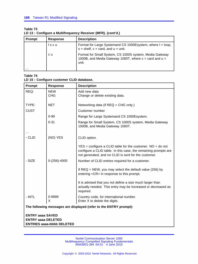
168 Taiwan R1 Modified Signaling
Table 73LD 13 : Configure a Multifrequency Receiver (MFR). (cont’d.)
Prompt Response Description
l s c u Format for Large Systemand CS 1000Esystem, where l = loop,s = shelf, c = card, and u = unit.
c u Format for Small System, CS 1000S system, Media Gateway1000B, and Media Gateway 1000T, where c = card and u =unit.
...
Table 74LD 15 : Configure customer CLID database.
Prompt Response Description
REQ: NEWCHG
Add new dataChange or delete existing data.
TYPE: NET Networking data (if REQ = CHG only.)
CUST Customer number
0-99 Range for Large Systemand CS 1000Esystem.
0-31 Range for Small System, CS 1000S system, Media Gateway1000B, and Media Gateway 1000T.
...
- CLID (NO) YES CLID option.
YES = configure a CLID table for the customer. NO = do notconfigure a CLID table. In this case, the remaining prompts arenot generated, and no CLID is sent for the customer.
- SIZE 0-(256)-4000 Number of CLID entries required for a customer.
If REQ = NEW, you may select the default value (256) byentering <CR> in response to this prompt.
It is advised that you not define a size much larger thanactually needed. This entry may be increased or decreased asrequired.
- INTL 0-9999X
Country code, for international number.Enter X to delete the digits.
The following messages are displayed (refer to the ENTRY prompt):
ENTRY aaaa SAVEDENTRY aaaa DELETEDENTRIES aaaa-bbbb DELETED
Nortel Communication Server 1000Multifrequency Compelled Signaling Fundamentals
NN43001-284 04.01 4 June 2010
Copyright © 2003-2010 Nortel Networks. All Rights Reserved.
.
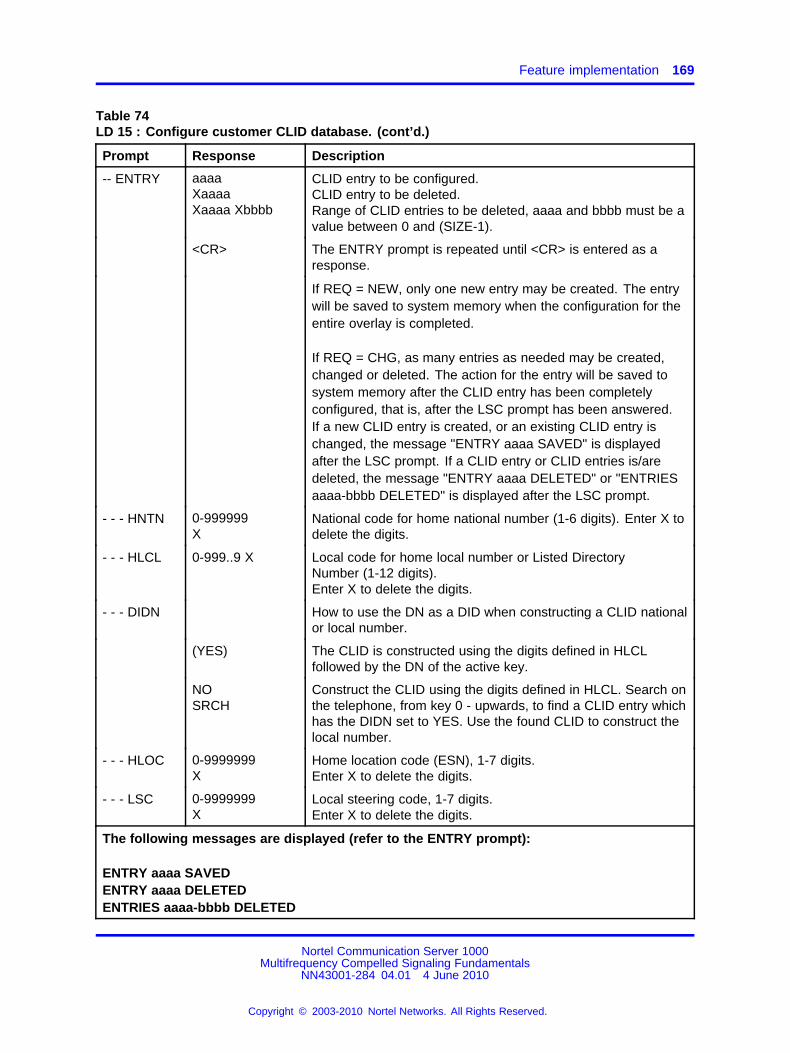
Feature implementation 169
Table 74LD 15 : Configure customer CLID database. (cont’d.)
Prompt Response Description
-- ENTRY aaaaXaaaaXaaaa Xbbbb
CLID entry to be configured.CLID entry to be deleted.Range of CLID entries to be deleted, aaaa and bbbb must be avalue between 0 and (SIZE-1).
<CR> The ENTRY prompt is repeated until <CR> is entered as aresponse.
If REQ = NEW, only one new entry may be created. The entrywill be saved to system memory when the configuration for theentire overlay is completed.
If REQ = CHG, as many entries as needed may be created,changed or deleted. The action for the entry will be saved tosystem memory after the CLID entry has been completelyconfigured, that is, after the LSC prompt has been answered.If a new CLID entry is created, or an existing CLID entry ischanged, the message "ENTRY aaaa SAVED" is displayedafter the LSC prompt. If a CLID entry or CLID entries is/aredeleted, the message "ENTRY aaaa DELETED" or "ENTRIESaaaa-bbbb DELETED" is displayed after the LSC prompt.
- - - HNTN 0-999999X
National code for home national number (1-6 digits). Enter X todelete the digits.
- - - HLCL 0-999..9 X Local code for home local number or Listed DirectoryNumber (1-12 digits).Enter X to delete the digits.
- - - DIDN How to use the DN as a DID when constructing a CLID nationalor local number.
(YES) The CLID is constructed using the digits defined in HLCLfollowed by the DN of the active key.
NOSRCH
Construct the CLID using the digits defined in HLCL. Search onthe telephone, from key 0 - upwards, to find a CLID entry whichhas the DIDN set to YES. Use the found CLID to construct thelocal number.
- - - HLOC 0-9999999X
Home location code (ESN), 1-7 digits.Enter X to delete the digits.
- - - LSC 0-9999999X
Local steering code, 1-7 digits.Enter X to delete the digits.
The following messages are displayed (refer to the ENTRY prompt):
ENTRY aaaa SAVEDENTRY aaaa DELETEDENTRIES aaaa-bbbb DELETED
Nortel Communication Server 1000Multifrequency Compelled Signaling Fundamentals
NN43001-284 04.01 4 June 2010
Copyright © 2003-2010 Nortel Networks. All Rights Reserved.
.

170 Taiwan R1 Modified Signaling
Table 75LD 16 - Configure a Taiwan R1 route in the Route Data Block.
Prompt Response Description
REQ NEWCHG
Add new data.Change existing data.
TYPE RDB Route Data Block.
CUST xx Customer number as defined in LD 15.
ROUT Route number
0-511 Range for Large Systemand CS 1000Esystem.
0-127 Range for Small System, CS 1000S system, Media Gateway1000B, and Media Gateway 1000T.
TKTP Trunk type.
DID Taiwan R1 trunks must be Direct Inward Dialing (DID).
TW_ROUTE YES Configure a Taiwan R1 route.
This prompt is generated only if TKTP = DID. It is displayed ifREQ = CHG.
...
DTRK YES Taiwan R1 routes are digital.
The prompt and response are auto-printed, if TW_ROUTE =YES.
DGTP DTI Taiwan R1 route trunks are digital.
The prompt and response are auto-printed, if TW_ROUTE =YES.
...
ICOG ICTOGT
Taiwan R1 trunk is incoming only.Taiwan R1 trunk is outgoing only.
If TW_ROUTE = YES, the incoming and outgoing trunk (IAO)option is not allowed.
TW_INC_CLID
(NO) YES YES = the system sends the CLID request wink signal after thecalled number has been received.NO = The call is terminated as soon as the called number isreceived.
This prompt appears only if ICOG = ICT.
...
INST 1-99999999 Number of digits to be inserted before the leading digit.(Required for incoming calls).
Nortel Communication Server 1000Multifrequency Compelled Signaling Fundamentals
NN43001-284 04.01 4 June 2010
Copyright © 2003-2010 Nortel Networks. All Rights Reserved.
.
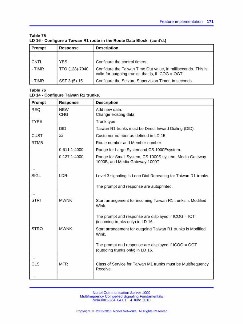
Feature implementation 171
Table 75LD 16 - Configure a Taiwan R1 route in the Route Data Block. (cont’d.)
Prompt Response Description
...
CNTL YES Configure the control timers.
- TIMR TTO (128)-7040 Configure the Taiwan Time Out value, in milliseconds. This isvalid for outgoing trunks, that is, if ICOG = OGT.
- TIMR SST 3-(5)-15 Configure the Seizure Supervision Timer, in seconds.
Table 76LD 14 - Configure Taiwan R1 trunks.
Prompt Response Description
REQ NEWCHG
Add new data.Change existing data.
TYPE Trunk type.
DID Taiwan R1 trunks must be Direct Inward Dialing (DID).
CUST xx Customer number as defined in LD 15.
RTMB Route number and Member number
0-511 1-4000 Range for Large Systemand CS 1000Esystem.
0-127 1-4000 Range for Small System, CS 1000S system, Media Gateway1000B, and Media Gateway 1000T.
...
SIGL LDR Level 3 signaling is Loop Dial Repeating for Taiwan R1 trunks.
The prompt and response are autoprinted.
...
STRI MWNK Start arrangement for incoming Taiwan R1 trunks is ModifiedWink.
The prompt and response are displayed if ICOG = ICT(incoming trunks only) in LD 16.
STRO MWNK Start arrangement for outgoing Taiwan R1 trunks is ModifiedWink.
The prompt and response are displayed if ICOG = OGT(outgoing trunks only) in LD 16.
...
CLS MFR Class of Service for Taiwan M1 trunks must be MultifrequencyReceive.
...
Nortel Communication Server 1000Multifrequency Compelled Signaling Fundamentals
NN43001-284 04.01 4 June 2010
Copyright © 2003-2010 Nortel Networks. All Rights Reserved.
.

172 Taiwan R1 Modified Signaling
Table 77LD 10 : Configure CLID entry for analog (500/2500-type) telephones.
Prompt Response Description
REQ: NEWCHG
Add new data.Change existing data.
TYPE: 500 500 telephone.
TN Terminal number
l s c u Format for Large Systemand CS 1000Esystem, where l = loop,s = shelf, c = card, and u = unit.
c u Format for Small System, CS 1000S system, Media Gateway1000B, and Media Gateway 1000T, where c = card and u =unit.
DES d...d Office Data Administration System (ODAS) Station Designatorof 1-6 alphanumeric characters.
CUST xx Customer number as defined in LD 15.
...
DIG xx yy Dial Intercom group number and member number.
DN xxxx (0)-N DN and CLID entry.N = CLID SIZE-1 (SIZE defined in LD 15).
...
Table 78LD 11 - Define CLID entry for DN keys for digital telephones.
Prompt Response Description
REQ: NEWCHG
Add new data.Change existing data.
TYPE: xxxx Type of telephone.
TN Terminal number
l s c u Format for Large Systemand CS 1000Esystem, where l = loop,s = shelf, c = card, and u = unit.
c u Format for Small System, CS 1000S system, Media Gateway1000B, and Media Gateway 1000T, where c = card and u =unit.
DES d...d Office Data Administration System (ODAS) Station Designatorof 1-6 alphanumeric characters.
CUST xx Customer number as defined in LD 15.
...
Nortel Communication Server 1000Multifrequency Compelled Signaling Fundamentals
NN43001-284 04.01 4 June 2010
Copyright © 2003-2010 Nortel Networks. All Rights Reserved.
.

Feature implementation 173
Table 78LD 11 - Define CLID entry for DN keys for digital telephones. (cont’d.)
Prompt Response Description
KEY xx aaa yyyy(0)-N/D
Telephone function key assignments, where:
xx = key number.aa = one of the following key assignments:MCN —Multiple Call Non-ringing keyMCR — Multiple Call Ringing keyPVN — Private Line Non-Ringing keyPVR — Private Line Ringing keySCN — Single Call Non-ringing keySCR — Single Call Ringing keyyyyy = DN(0)-N = CLID entry, with N = CLID SIZE-1 (SIZE as defined inLD 15).D = CLID entry. Search for a CLID entry from key 0 upwards,to find a DN key. The found CLID is used as the CLID entry forthe active DN key.
KEY xx HOT D ddyyy...y zzzz m(0)-N/D
Two-way Hotline Direct key, where:
xx = key number.dd = number of digits dialed.yyy...y = target number (terminating DN, maximum of 31 digits).zzzz = two-way hotline DN.m = one of the following Terminating Modes:H = Hotline (default)N = Non-ringingR = RingingV = Voice(0)-N = CLID entry, with N = CLID SIZE-1 (SIZE defined in LD15).D = CLID entry. Search for a CLID entry from key 0 upwards,to find a DN key. The found CLID is used as the CLID entry forthe active DN key.
Nortel Communication Server 1000Multifrequency Compelled Signaling Fundamentals
NN43001-284 04.01 4 June 2010
Copyright © 2003-2010 Nortel Networks. All Rights Reserved.
.

174 Taiwan R1 Modified Signaling
Table 78LD 11 - Define CLID entry for DN keys for digital telephones. (cont’d.)
Prompt Response Description
KEY xx HOT L bbbzzzz (0)-N/D
Two-way Hotline List key, where:
xx = key number.bbb = Hot Line List entry (0-999).zzzz = two-way hotline DN.(0)-N = CLID entry, with N = CLID SIZE-1 (SIZE defined in LD15).D = CLID entry. Search for a CLID entry from key 0 upwards,to find a DN key. The found CLID is used as the CLID entry forthe active DN key.
KEY xx ACD aaaa0-N/D bbbb
ACD key, where:
xx = key number.aaaa = ACD DN or Message Center DN.0-N = CLID entry, with N = CLID SIZE-1 (SIZE defined in LD15).D = CLID entry. Search for a CLID entry from key 0 upwards,to find a DN key. The found CLID is used as the CLID entry forthe active DN key.bbbb = ACD agent’s position ID.
Note: When assigning a CLID entry to an ACD telephone, youcannot use the same position ID already on the telephone. Thetelephone must be first outed, or the ACD key must be nulledand then rebuilt with the table entry number
Table 79LD 86 : Configure Digit Manipulation Index.
Prompt Response Description
REQ NEW Add data.
CUST xx Customer number as defined in LD 15.
FEAT DGT Digit Manipulation Index.
DMI (0)-1999 Digit Manipulation Index number.
DEL (0)-19 Number of leading digits to be deleted.
...
Table 80LD 86 : Configure Route List Index.
Prompt Response Description
REQ NEW Add data.
Nortel Communication Server 1000Multifrequency Compelled Signaling Fundamentals
NN43001-284 04.01 4 June 2010
Copyright © 2003-2010 Nortel Networks. All Rights Reserved.
.

Feature implementation 175
Table 80LD 86 : Configure Route List Index. (cont’d.)
Prompt Response Description
CUST xx Customer number as defined in LD 15.
FEAT RLB Route List Index.
RLI xxx Route List Index to be accessed.
ENTR xxx Entry Number for Route List.
LTER (NO) YES Local Termination entry (required for incoming calls).
Enter NO.
ROUT Route number
0-511 Range for Large Systemand CS 1000Esystem.
0-127 Range for Small System, CS 1000S system, Media Gateway1000B, and Media Gateway 1000T.
DMI (0)-1999 Digit Manipulation Index number as defined in previous step(required for incoming calls).
...
Table 81LD 86 : Configure ESN data.
Prompt Response Description
REQ NEW Add data.
CUST xx Customer number as defined in LD 15.
FEAT ESN ESN data.
...
AC2 xx NARS Access Code 2.
...
Table 82LD 90 : Configure Special Number Translation.
Prompt Response Description
REQ NEW Add data.
CUST xx Customer number as defined in LD 15.
FEAT NET Network Translation Table.
TRAN aaa Translator.aaa = AC1, AC2, or SUM.
Enter AC2.
TYPE SPN Type is Special Number Translation.
Nortel Communication Server 1000Multifrequency Compelled Signaling Fundamentals
NN43001-284 04.01 4 June 2010
Copyright © 2003-2010 Nortel Networks. All Rights Reserved.
.

176 Taiwan R1 Modified Signaling
Table 82LD 90 : Configure Special Number Translation. (cont’d.)
Prompt Response Description
SPN x...x Special Number Translation.
- FLEN (0)-24 Flexible Length (required for outgoing calls).
- ITOH NO Do not inhibit Time-out Handler (required for outgoing calls).
- RLI xxx Route List Index.
Table 83LD 90 - Define Special Number (002) for outgoing Taiwan international calls, and configureappropriate SPN and ITOH values.
Prompt Response Description
REQ NEW Add data.
CUST xx Customer number as defined in LD 15.
FEAT NET Network Translation Table.
TRANaaa
Translator.aaa = AC1, AC2, or SUM.
Enter AC2.
TYPE SPN Type is Special Number Translation.
SPN 002 Define 002 as the Special Number for outgoing Taiwan R1international calls.
- FLEN (0)-24 Flexible Length (required for outgoing calls). Enter a value ofat least 16.
- ITOH NO Do not inhibit Time-out Handler (required for outgoing calls).
- RLI xxx Route List Index.
Maintenance and diagnostics guidelinesCall Trace (LD 80)If a Taiwan R1 call is traced using LD 80, the CLID information isdisplayed in addition to the regular call information. For an incomingTaiwan R1 call, the display is as follows:
TWR1 call (ORIG)
Calling No = 4159405336
For an outgoing Taiwan R1 call, the CLID information is displayed only ifthe call is not yet established. The display is as follows:
TWR1 call (TERM)
Nortel Communication Server 1000Multifrequency Compelled Signaling Fundamentals
NN43001-284 04.01 4 June 2010
Copyright © 2003-2010 Nortel Networks. All Rights Reserved.
.

Feature operation 177
Calling No = 4159405336
If an invalid digit (valid digits being KP or digits 0-9) is stored in the CLIDfield for an incoming or outgoing Taiwan R1 call, message TRA0319 isprinted.
TDS, MFR and dual-port DTI/PRI cardsExisting maintenance and diagnostic procedures for the TDS, MFR andtrunk cards are supported.
Maintenance and diagnostics procedures for the TDS card involve thefollowing:
• enabling and disabling the TDS loop and obtaining the TDS loop statususing LD 34 and LD 46
• self-testing the TDS loop using LD 34 and LD 46
Maintenance and diagnostics procedures for the MFR card involve thefollowing:
• enabling and disabling the MFR card and obtaining the MFR cardstatus using LD 32 and LD 34
• self-testing the MFR card using LD 32 and LD 34
• monitoring the MFR using LD 77
Maintenance and diagnostics procedures for the Dual-port DTI/PRI cards(NT5D12) involve the following:
• enabling and disabling the Dual-port DTI/PRI card and obtaining thecard status using LD 60
• self-testing the Dual-port DTI/PRI card using LD 60
Feature operationNo operating procedures are required to use this feature.
Nortel Communication Server 1000Multifrequency Compelled Signaling Fundamentals
NN43001-284 04.01 4 June 2010
Copyright © 2003-2010 Nortel Networks. All Rights Reserved.
.

178 Taiwan R1 Modified Signaling
Nortel Communication Server 1000Multifrequency Compelled Signaling Fundamentals
NN43001-284 04.01 4 June 2010
Copyright © 2003-2010 Nortel Networks. All Rights Reserved.
.
179.
Multifrequency Signaling for Socotel
ContentsThis section contains information on the following topics:
“Description” (page 179)
“Limitation” (page 180)
“Hardware” (page 180)
“Signaling” (page 181)
DescriptionMultifrequency Signaling for Socotel is referred to as MFE, package 135.It consists of Multifrequency Sender/Receiver circuit cards and optionalsoftware.
MFE is a signaling protocol that allows a System to communicate with aPublic Exchange (Central Office) using Socotel signaling on DID/DODtrunks. A private network can be throughout in a public network. The DODnumbering plan is divided in two parts: calls to other installations whichuse a 6-digit plan and calls to special services which use a 2-digit plan.The difference is made by analyzing the first digit. The values of the firstdigit for special services are programmable.
Note 1: A tandem call to MFE outgoing trunk is supported, providingthere are no access restrictions. The digits are outpulsed as soon asthey are received.
Note 2: MFE is not supported on ISDN PR, but MFE can tandem ineither direction.
Note 3: A call on a Electronic Switched Network (ESN) can access anMFE outgoing trunk.
Nortel Communication Server 1000Multifrequency Compelled Signaling Fundamentals
NN43001-284 04.01 4 June 2010
Copyright © 2003-2010 Nortel Networks. All Rights Reserved.
.

180 Multifrequency Signaling for Socotel
LimitationThe digits are outpulsed as soon as the customer dials them. If a veryshort time between two digits is required, this could create a problem butusing the optional feature Delay Digit Outpulsing (DDO) overcomes thatproblem. Call set-up is delayed by the length of a timer.
HardwarePhysical
The MFE Sender/Receiver (S/R) circuitry is packaged as a printed circuitcard (NTD9464) with the dimensions shown in Table Table 84 "MFE S/Rcircuit card dimensions" (page 180).
Table 84MFE S/R circuit card dimensions
Length 12.5 in (320mm)
Width 10.0 in (254mm)
Depth 1.25 in (32mm)
The LED mounted on the faceplate indicates the status of the circuit card(ON when disabled).
Either µ-law or A-law is available as determined by a jumper on the circuitcard (factory installed).
FunctionsThe M/F S/R card provides the signaling interface between the CentralProcessing Unit (CPU) and the DID/DOD trunk. The appropriate trunkcircuit card handles the line signaling on the trunk, and the MFE S/Rhandles the multifrequency signaling according to the Socotel signalingspecification. The signaling consists of code signals composed of two outof five frequencies (700, 900, 1100, 1300, 1500 Hz) or a control signal(acknowledge) composed of a ’control’ frequency of 1900 Hz. The card iscapable of transmitting and receiving the Pulse Code Modulation (PCM)multifrequencies simultaneously on two channels.
LocationThe MFE S/R card mounts in any of the printed circuit slots of theperipheral equipment shelf.
Environmental considerationsThe NTD9464 MFE S/R circuit card must not be subject to an environmentoutside the constraints shown in Table Table 85 "MFE S/R circuit cardenvironmental requirements" (page 181).
Nortel Communication Server 1000Multifrequency Compelled Signaling Fundamentals
NN43001-284 04.01 4 June 2010
Copyright © 2003-2010 Nortel Networks. All Rights Reserved.
.

Signaling 181
Table 85MFE S/R circuit card environmental requirements
Ambient temperature Relative humidity
Non-operating 0 to + 70� C up to 90%
Operating 0 to + 35� C 20 to 80%
SignalingLine signaling
Line signaling seizes the equipment, supervises the call and releases thecall. It does not affect MFE register signaling, but is necessary to completea call.
MFE signaling is independent from the line signaling. Any line signalingmethod (2 wire E & M, 4-wire E & M, DX2. DX4, LOOP, 2-Mb/s and1.5-Mb/s DTI) can be used with MFE.
Any trunk type between the system and a Central Office may be used asfar as the Central Office is able to support MFE on this trunk.
Register signalingMFE register signaling is used to communicate between a system andthe Public Exchange. For DID, register signaling commences once theincoming trunk has been seized, seizure acknowledgement has beenreturned, if required, and an MFE S/R has been attached. The firstsignal (SEND) comes from the incoming side of the call requesting digitsfrom the Public Exchange. For DOD, register signaling commencesonce the outgoing trunk has been seized, seizure acknowledgementhas been received if required and an MFE S/R has been attached. TheMFE signaling commences with the reception of a signal from the PublicExchange.
Signals are divided into two main groups, forward signals and backwardsignals. With DID, forward signals are those received from the PublicExchange, and backward signals are those sent to the Public Exchange.With DOD, forward signals are those sent to the Public Exchange, andbackward signals are those received from the Public Exchange. Thesignals are sent over a speech path and are combinations of two outof five frequencies. Refer to Table 86 "MFE frequency combinations"(page 181). Forward and backward signals are comprised of the samefrequencies.
Table 86MFE frequency combinations
Signal number Frequencies
Nortel Communication Server 1000Multifrequency Compelled Signaling Fundamentals
NN43001-284 04.01 4 June 2010
Copyright © 2003-2010 Nortel Networks. All Rights Reserved.
.

182 Multifrequency Signaling for Socotel
Table 86MFE frequency combinations (cont’d.)
1 700 + 900
2 700 + 1100
3 900 + 1100
4 700 + 1300
5 900 + 1300
6 1100 + 1300
7 700 + 1500
8 900 + 1500
9 1100 + 1500
10 1300 + 1500
Each signal is acknowledged by the control frequency which is set to 1900Hz and cannot be changed. (There are six possible frequencies, of whichfive are used by MFE.) It is the only signal which is not a combination offrequencies. This control frequency indicates to the opposite side of thecall that the signal has been received and its transmission can cease. Thelevel at which each frequency is sent is determined in the trunk data, LD14. Frequencies of 700 and 900 Hz are sent at -10.5 dBm base level,1100 and 1300 Hz at a level one dBm higher and 1500 Hz at a level stillone dBm higher. The level for the control frequency (-7.0 dBm) is alsodetermined here.
A signal corresponds to a certain combination of frequencies. However,signals are assigned to have certain functions determined by tables indata administration LD 94. In this way the meaning of each forward signalfrom the Public Exchange can be deciphered and frequency combinationscorresponding to the desired functions can be sent as backward signals.
Table 87 "MFE signals" (page 182) lists the MFE signals and theassociated function mnemonics. The function mnemonics are described inthe following sections.
Table 87MFE signals
Group 1Signalnumber
Functionmnemonic Description
Forward Level 1 1-9 DGT1-DGT9 digit 1 to digit 9
10 DGT0 digit 0
ACOC access code for a call to otherinstallation
Nortel Communication Server 1000Multifrequency Compelled Signaling Fundamentals
NN43001-284 04.01 4 June 2010
Copyright © 2003-2010 Nortel Networks. All Rights Reserved.
.

Signaling 183
Table 87MFE signals (cont’d.)
Group 1Signalnumber
Functionmnemonic Description
ACSS access code for a call to specialservices
Backward Level 1 SACD send access code and digits
2 SEND send digits
3 COMP address complete, change to level 2
TRAN transit connection
FAIL failure, new attempt
CONG congestion
1 IDLE station idle, charge call
3 BUSY station busy
3 CONG access denied or lack of resources
3 OUTT out of order
Backward Level 2
3 VACC vacant DN
Forward signalsForward signals are sent by the Public Exchange to the system andDID/DOD trunks.
Note: Timers MFI and MFF, and other MFE table information are set inLD 16 (Trunk Route).
Forward Level 1 functionsDGT
These signals represent the ten digits (DGT1 to DGT0).
ACOC
It is sent after the SACD signal has been received. It is followed by thefirst four digits of the called number.
ACSS
It is sent after the SACD signal has been received. It is followed by thetwo first digits of the called number.
Nortel Communication Server 1000Multifrequency Compelled Signaling Fundamentals
NN43001-284 04.01 4 June 2010
Copyright © 2003-2010 Nortel Networks. All Rights Reserved.
.

184 Multifrequency Signaling for Socotel
Backward signalsBackward signals are sent by the system to the Public Exchange. Thefunction of each signal is determined in LD 94. The corresponding signalto be sent is retrieved from the MFE table in that program. One signal maybe used for more than one function.
There are two levels of backward signals. The first level of signals arecalled Level 1 signals and are used to request information. The secondlevel of signals are called Level 2 signals and are used to indicatethe state of the called party at the system. Level 2 signals are alwayspreceded by a Level 1 signal whose function is COMP.
Backward Level 1 functionsSACD
It is the first signal received after the seizure of the trunk. After receivingthis signal, the access code is sent (DGT1 or DGT5) followed by four ortwo signals for the first digits depending on the access code.
SEND
A signal with this function is used to indicate to the Public Exchange thatseizure was successful and transmission of digits should begin. Four orfive group I signals, determined by the DGTS prompt in LD96, will beexpected.
COMP
This function indicates that the received digits have been translated into aDN, valid or invalid, and that the next signal sent will be a backward Level2 signal indicating the state of the called DN. The Level 2 signal will besent immediately after this signal has been properly acknowledged.
TRAN
Its reception means that the Public Exchange had made a cut-through forthe two installations. After the reception of this signal, the meaning of theSEND is changed (the last four digits will be sent).
FAIL
This signal occurs when there is a failure. Make a new attempt.
CONG
Nortel Communication Server 1000Multifrequency Compelled Signaling Fundamentals
NN43001-284 04.01 4 June 2010
Copyright © 2003-2010 Nortel Networks. All Rights Reserved.
.
Signaling 185
A congestion signal corresponding to this function is sent to the PublicExchange when one of the units involved in the connection has failed. It isonly used if there is no Level 2 defined.
Background Level 2 functionsLevel 2 signals indicate the state of the called DN. Different functions canbe assigned to have the same signal. For example, the same signal canbe used to represent busy and congestion.
To return corresponding tones with signals, the answer to the SGL promptin LD16 (Trunk Route) must have been NO. In this case both the signaland the tone are indicative of the state of the called DN. Otherwise, ifthe reply to the SGL prompt was YES, an IDLE Level 2 signal is alwaysreturned and the tone alone indicates the called party status.
Vacant DN (VACC) and Out of Service (OUTT) signals are only used ifthe intercept treatment specified in LD15 (Customer Data) is other thanrecorded announcement or attendant. If the intercept is to the attendant ora recorded announcement then the signal returned will depend on theirstatus.
IDLE
The called party is idle and the call must be charged. Ringback tone isreturned if SGL is NO. Otherwise the tone corresponding to the calledparty status is sent.
BUSY
The called party is off-hook and busy tone is returned. If a busy trunkgroup is encountered then busy tone or overflow tone, as indicated by thecustomer intercept table, is returned.
CONG
The unit at the receiving end of the call is ’access denied’ or ’termination isunsuccessful’ and the tone specified by the intercept table is returned.
OUTT
The called extension is out of order and the tone specified by the intercepttable is returned.
VACC
The called extension does not exist and the tone specified by the intercepttable is returned.
Nortel Communication Server 1000Multifrequency Compelled Signaling Fundamentals
NN43001-284 04.01 4 June 2010
Copyright © 2003-2010 Nortel Networks. All Rights Reserved.
.

186 Multifrequency Signaling for Socotel
Nortel Communication Server 1000Multifrequency Compelled Signaling Fundamentals
NN43001-284 04.01 4 June 2010
Copyright © 2003-2010 Nortel Networks. All Rights Reserved.
.

187.
Hardware description
ContentsThis section contains information on the following topic:
“Sender/Receiver circuit cards” (page 187)
Sender/Receiver circuit cardsThe MFC feature requires that the system be equipped with QPC327 MFCSender/Receiver (MFC S/R) circuit cards. The MFC S/R printed circuitcard provides the signaling interface between the Central Processing Unit(CPU) and the MFC Trunk. The card transmits and receives PCM Forwardand Backward signals simultaneously on two channels. Each channeloperates like a typical peripheral source with a unique time slot for sendingand receiving signals.
The MFC S/R circuit cards operate in systems using either A-Law or µ-Lawcompanding (selected by a jumper plug on the circuit card).
DescriptionThe MFC S/R circuitry is housed in a standard peripheral card of thedimensions shown in Table 88 "MFC S/R circuit card dimensions" (page187).
Table 88MFC S/R circuit card dimensions
Height 12.50 inches (317.50 mm)
Depth 10.00 inches (254.00 mm)
Thickness 0.25 inches (31.75 mm)
The LED mounted on the faceplate indicates the status of the card.
LocationThe MFC S/R circuit cards fit into any peripheral circuit card positions ona peripheral equipment (PE) shelf.
Nortel Communication Server 1000Multifrequency Compelled Signaling Fundamentals
NN43001-284 04.01 4 June 2010
Copyright © 2003-2010 Nortel Networks. All Rights Reserved.
.

188 Hardware description
Quantities requiredSee “Engineering information” (page 193) to determine the requirednumber of MFC S/R cards (a minimum of two is required).
Power requirementsThe MFC S/R card is powered from the -48VDC regulated supply availableon the backplane of the PE shelf. At -48V the power requirements are:
Typical 0.28 A
Maximum
0.46 A
A switching power regulator converts this -48 to +5 V for use bythe circuitry on the card. The power regulator sits on a single-sideddaughter-board mounted above the double-sided main board of the card.
Operating environmentThe environmental conditions shown in Table Table 89 "MFC S/R circuitcard environmental requirements" (page 188) must be met to permit properfunctioning of the MFC S/R Circuit card:
Table 89MFC S/R circuit card environmental requirements
Card locationAmbient
temperature Relative humidity
Card in isolation 0 to 70� C32 to 158� F
up to 90%
Card in system 0 to 35� C32 to 95� F
20 to 80%
ComponentsThe MFC S/R circuit card (Figure 2 "Block diagram of MFC S/R circuitcard" (page 189)) has five main components:
1. Peripheral Shelf Interface
2. Digital Sender
3. Digital Receiver
4. Microprocessor Subsystem
5. Control Sequencer.
Nortel Communication Server 1000Multifrequency Compelled Signaling Fundamentals
NN43001-284 04.01 4 June 2010
Copyright © 2003-2010 Nortel Networks. All Rights Reserved.
.

Sender/Receiver circuit cards 189
Figure 2Block diagram of MFC S/R circuit card
Peripheral shelf interfaceA buffer in the peripheral shelf interface converts the 0 to 10V backplanesignals of the peripheral shelf into the standard TTL signals used on theMFC S/R circuit card. The peripheral shelf interface controls:
• MFC signaling (PCM data)
• CPU signaling
• I/O synchronizing circuitry.
Digital senderThis circuit in the MFC S/R card can generate any of the 30 PCM tonepairs required for Forward (15 tone pairs) and Backward (15 tone pairs)signaling on each of the two MFC channels. The CPU specifies one out ofeight output signal levels for each channel. The level specified is 0 through
Nortel Communication Server 1000Multifrequency Compelled Signaling Fundamentals
NN43001-284 04.01 4 June 2010
Copyright © 2003-2010 Nortel Networks. All Rights Reserved.
.
190 Hardware description
7 for signals of -8, -11, -12, -13, -14, -15, -16, and -35dBm respectively.Table 90 "Performance specifications for MFC sender" (page 190) givesthe sender performance specifications.
Digital receiverThe MFC receiver processes incoming PCM tones on both channelsthrough one of two groups of eight digital filters. The receiver accumulatesthe magnitude of the output signal from each filter and feeds thisinformation to the MFC microprocessor once every 8ms. Table 91"Performance specification for MFC receiver" (page 191) gives the receiverperformance specifications.
Microprocessor subsystemThis subsystem performs the following functions:
• receives commands and "digits to send" from the CPU
• drives the Sender
• receives signal level data from the digital receiver and processes thisdata to decode the digit received
• executes part of the MFC protocol, such as requests for sending thenext digit
• provides self-test capability.
Control SequencerThe control sequencer generates timing and control signals for the circuitryon the MFC S/R card. The sequencer consists of counters which feedPROM for decoding timing control signals. The counters are synchronizedby the PCM data samples every 125 ms. A sample counter drives theSender and generates the Microprocessor interrupt signals.
Table 90Performance specifications for MFC sender
Description Specifications
Forward frequencies (originating) 1380, 1500, 1620, 1740, 1860, 1980Hz
Backward frequencies (terminating) 1140, 1020, 900, 780, 660, 540Hz
Frequency tolerance ±0.5Hz from Nominal
Power level of each non-modulated frequency (at thesending point)
Selectable (1 out of 8 for signals of -8, -11,-12, -13, -14, -15, -16, and -35 dBm)
Level difference between two signaling frequencies <0.5 dB
Harmonic distortion and intermodulation 37 dB below the level of one signalingfrequency
Nortel Communication Server 1000Multifrequency Compelled Signaling Fundamentals
NN43001-284 04.01 4 June 2010
Copyright © 2003-2010 Nortel Networks. All Rights Reserved.
.

Sender/Receiver circuit cards 191
Table 90Performance specifications for MFC sender (cont’d.)
Description Specifications
Time interval between the start of sending of each ofthe two frequencies
125 µs
Time interval between the cessation of sending ofeach of the two frequencies
125 µs
Table 91Performance specification for MFC receiver
Description Specification Condition
Input sensitivity
— must accept -5 to -35dBm ±10Hz of nominal
— must reject -42dBm/tone Single sine wave or acombination of two sine wavesin 300–3400Hz band
Bandwidth
— must accept fc ±10Hz
— must reject fc - 60Hz>f>fc + 60Hz
Amplitude Twist
— must accept difference of 5dB Between adjacentfrequency
— must accept difference of 7dB Between nonadjacent
frequency
— must reject difference of 20dB Between any two frequencies
Operating Time <32ms Tests, Type A and B
Releasing Time <32ms Tests, Type A and B
Tone Interruptioncausing no release
<8ms Receiver on, while tone missing
Longest Input Tone to beignored by receiver
<8ms Combination of frequency eachat -5 dBm
S/N>18dB No degradation with white noiseof 300 – 3400 Hz
Noise Rejection
S/N<17dB Disturbance in the backwardband while operating in DIDmode
ORDisturbance in the forward bandwhile operating in DOD mode.
Nortel Communication Server 1000Multifrequency Compelled Signaling Fundamentals
NN43001-284 04.01 4 June 2010
Copyright © 2003-2010 Nortel Networks. All Rights Reserved.
.

192 Hardware description
Nortel Communication Server 1000Multifrequency Compelled Signaling Fundamentals
NN43001-284 04.01 4 June 2010
Copyright © 2003-2010 Nortel Networks. All Rights Reserved.
.

193.
Engineering information
ContentsThis section contains information on the following topics:
“MFC provisioning” (page 193)
“MFC service change” (page 197)
“MFC maintenance” (page 200)
MFC provisioningFollow these steps to determine the required number of MFC S/R circuitcards.
ABSBH MFC channel traffic.Calculate (a) the ABSBH for MFC calls and (b) the ABSBH MFC ChannelTraffic in CCS as follows:
(a) ABSBH for MFC = (a x 100)/b
where
a = MFC trunk traffic (in CCS)b = call holding time (in seconds).
Note: Assume call holding time to be 135s if unknown.
(b) ABSBH MFC Channel Traffic = (a x b)/100
where
a = ABSBH for MFCb = MFC channel holding time (in seconds).
Note: Assume MFC channel holding time, if unknown, to be:2.33s for 4-digit MFC calling1.7518s for 3-digit MFC calling
Nortel Communication Server 1000Multifrequency Compelled Signaling Fundamentals
NN43001-284 04.01 4 June 2010
Copyright © 2003-2010 Nortel Networks. All Rights Reserved.
.

194 Engineering information
Delay Grade of ServiceUse Table 92 "Delay Grade of Service for MFC provisioning, P (Delaygreater than 0.5s)" (page 194) to choose delay grade of service of MFCchannels that meet response requirements of the Central Office (CO) orPublic Service Telephone Network (PSTN).
Table 92Delay Grade of Service for MFC provisioning, P (Delay greater than 0.5s)
CO/PE responserequirement
% Delayover 0.5s
fast response 0.5
medium response 1.5
slow response 3.0
ABSBH Voice Loop trafficCalculate the ABSBH voice loop traffic in CCS as follows:
• ABSBH Voice Loop Traffic = a/b
where
a = total network trafficb = total number of voice loops
Note: If voice loop traffic is greater than 600 CCS, then all voice loopsmust be unloaded to 600 CCS ABSBH.
Use Table 93 "Number of MFC cards required : loop traffic, 0:500 CCS"(page 195) or Table 94 "Number of MFC cards required : loop traffic,501:600 CCS" (page 196), depending on the following:
• Use Table 93 "Number of MFC cards required : loop traffic, 0:500CCS" (page 195) if voice loop traffic calculated above is in range0–500 CCS.
• Use Table 94 "Number of MFC cards required : loop traffic, 501:600CCS" (page 196) if voice loop traffic calculated above is in range501–600 CCS.
Nortel Communication Server 1000Multifrequency Compelled Signaling Fundamentals
NN43001-284 04.01 4 June 2010
Copyright © 2003-2010 Nortel Networks. All Rights Reserved.
.

MFC provisioning 195
Number of MFC CardsUsing either Table 93 "Number of MFC cards required : loop traffic, 0:500CCS" (page 195) or Table 94 "Number of MFC cards required : looptraffic, 501:600 CCS" (page 196), determine the number of MFC cardsrequired.
• Select the left-hand column headed by delay grade of service chosenin Table 92 "Delay Grade of Service for MFC provisioning, P (Delaygreater than 0.5s)" (page 194).
• Read down the column to the first figure that is either equal to orgreater than the MFC Channel Traffic calculated in “ABSBH MFCchannel traffic.” (page 193).
• Read across to right-hand columns and determine the number of MFCchannels and the number of MFC cards required.
Note 1: Distribute the MFC cards among the network groups inproportion to the number of MFC trunks in each group. If a groupcontains more voice loops than MFC cards, install one card per voiceloop starting from the loop with the lowest voice traffic and workingupwards.
Note 2: The minimum number of MFC cards is 2.
1. Assume:
— ABSBH loop traffic of 450 CCS
— 1.5% delay over 0.5 seconds
— MFC channel traffic of 120 CCS.
2. Using Table 7, Column 2:
— Number of MFC cards = 5.
Example If delay grade of service is 3% delay over 0.5 seconds, Column3 of Table 93 "Number of MFC cards required : loop traffic, 0:500 CCS"(page 195) gives the number of MFC cards = 4.
Table 93Number of MFC cards required : loop traffic, 0:500 CCS
Percent delay over 0.5 second No. ofMFC
No. ofMFC
0.5% 1.5% 3.0% channels cards
20 30 38 4 2
52 67 80 6 3
90 110 125 8 4
Nortel Communication Server 1000Multifrequency Compelled Signaling Fundamentals
NN43001-284 04.01 4 June 2010
Copyright © 2003-2010 Nortel Networks. All Rights Reserved.
.

196 Engineering information
Table 93Number of MFC cards required : loop traffic, 0:500 CCS (cont’d.)
Percent delay over 0.5 second No. ofMFC
No. ofMFC
0.5% 1.5% 3.0% channels cards
131 155 173 10 5
175 203 224 12 6
221 253 277 14 7
269 304 331 16 8
318 357 385 18 9
369 410 441 20 10
420 465 498 22 11
473 520 555 24 12
525 576 613 26 13
580 633 672 28 14
634 690 731 30 15
Table 94Number of MFC cards required : loop traffic, 501:600 CCS
Percent delay over 0.5 second No. ofMFC
No. ofMFC
0.5% 1.5% 3.0% channels cards
--- 10 322 4 2
40 62 76 6 3
81 105 122 8 4
123 151 171 10 5
167 200 222 12 6
213 250 274 14 7
261 301 328 16 8
310 353 383 18 9
360 406 439 20 10
411 461 495 22 11
463 516 553 24 12
516 572 611 26 13
570 629 669 28 14
624 686 728 30 15
Nortel Communication Server 1000Multifrequency Compelled Signaling Fundamentals
NN43001-284 04.01 4 June 2010
Copyright © 2003-2010 Nortel Networks. All Rights Reserved.
.

MFC service change 197
MFC service changeMFC service change involves two types of assignments:
• assignment of MFC S/R circuit cards
• assignment of MFC features.
Note: Refer to Software Input Output Administration (NN43001-611)for additional service change information.
Circuit card assignmentThe following program assigns MFC hardware:
• DIGITONE Receivers, LD 13
MFC ImplementationTask summary listThe following is a summary of the tasks in this section:
• Table 95 "LD 13 : Configure MFC units." (page 197)
• Table 96 "LD 94 : Configure MFC table for outgoing trunks." (page197)
• Table 97 "LD 16 : Configure R2MFC interworking timer in route datablock." (page 198)
• Table 98 "LD 14 : Configure DID trunks with the MFC Class ofService." (page 199)
Table 95LD 13 : Configure MFC units.
Prompt Response Description
REQ NEW Add new data to the system
TYPE MFC Multifrequency Compelled sender/receiver data block
TN Terminal number
l s c u Format for Large Systemand CS 1000Esystem, where l =loop, s = shelf, c = card, and u = unit.
c u Format for Small System, CS 1000S system, MediaGateway 1000B, and Media Gateway 1000T, where c =card and u = unit.
c u Terminal number (Cabinet system)
Table 96LD 94 : Configure MFC table for outgoing trunks.
Prompt Response Description
REQ NEW Add new data to the system.
Nortel Communication Server 1000Multifrequency Compelled Signaling Fundamentals
NN43001-284 04.01 4 June 2010
Copyright © 2003-2010 Nortel Networks. All Rights Reserved.
.

198 Engineering information
Table 96LD 94 : Configure MFC table for outgoing trunks. (cont’d.)
Prompt Response Description
TYPE R2MF R2MFC data block
ICOG OGT Outgoing table
MAXT (1) - 127 Maximum number of tables
TBNO 1 - 127 Table number
Table 97LD 16 : Configure R2MFC interworking timer in route data block.
Prompt Response Description
REQ NEW Add new data block to the system
TYPE RDB Route data block
CUST xx Customer number as defined in LD 15
ROUT Route number
0-511 Range for Large Systemand CS 1000Esystem.
0-127 Range for Small System, CS 1000S system, MediaGateway 1000B, and Media Gateway 1000T.
TKTP DID Direct Inward Dialing route data block
...
ICOG IAO Incoming and outgoing
...
ACOD x..x Access Code for the trunk route
...
MFC YES Multifrequency Compelled or MFC Signalling
...
MFCO 1 - 127 MFC Outgoing table number as defined in LD 94
...
CNTL YES Make changes to controls or timers
TIMR MFC128-(12032)-65408
Multifrequency Compelled Signaling (MFC) timer.
R2MFC Interdigit timer.
MFID (0)-25088 This timer is in the range of 0-25 seconds, in 128msincrements. A value of 0 will indicate that the timer isdisabled and existing timing functionality will be used.
Nortel Communication Server 1000Multifrequency Compelled Signaling Fundamentals
NN43001-284 04.01 4 June 2010
Copyright © 2003-2010 Nortel Networks. All Rights Reserved.
.

MFC service change 199
Table 97LD 16 : Configure R2MFC interworking timer in route data block. (cont’d.)
Prompt Response Description
MFO (0)-16256 MFC Transmit timer. If 0, then use current value of MFCTimer.
MFC Reception timer.
MFR128-(2048)-16256
MFC Transmission timer.
MFX128-(4096)-16256
Table 98LD 14 : Configure DID trunks with the MFC Class of Service.
Prompt Response Description
REQ NEW Add new data to the system
TYPE DID Direct inward dialing trunk data block
TN Terminal number
l s c u Format for Large Systemand CS 1000Esystem, where l =loop, s = shelf, c = card, and u = unit.
c u Format for Small System, CS 1000S system, MediaGateway 1000B, and Media Gateway 1000T, where c =card and u = unit.
...
XTRK aaaa Extended trunk. Prompted for superloops when definingthe first unit where:
aaaa = EXUT, XUT, XDID, XEM, or XCOT.
CUST xx Customer number as defined in LD 15
RTMB Route number and Member number
0-511 1-4000 Range for Large Systemand CS 1000Esystem.
0-127 1-4000 Range for Small System, CS 1000S system, MediaGateway 1000B, and Media Gateway 1000T.
....
CLS MFC R2 Multifrequency Compelled Signaling.
Nortel Communication Server 1000Multifrequency Compelled Signaling Fundamentals
NN43001-284 04.01 4 June 2010
Copyright © 2003-2010 Nortel Networks. All Rights Reserved.
.

200 Engineering information
MFC maintenanceRefer to Software Input Output Reference - Maintenance (NN43001-711)for a complete description of the MFC maintenance programs and a listingof the maintenance I/O codes.
LD 54 : MFDThis diagnostic program tests card hardware by performing loop-back testson both channels of the MFC S/R circuit card. These self-tests involvelooping the Sender output of each channel back to the Receiver input.The MFD program performs this loop-back test on one S/R channel at atime. This program allows the status of the MFC S/R to be changed ordisplayed.
The MFD program can be loaded:
• by the system as a midnight routine or after every system load
• by maintenance personnel using TTY or maintenance telephones.
MFC error handlerThis is a resident program that monitors the number of MFC signalingerrors. A one-word error field in the MFC block is initialized to zero. TheMFC Error Handler allows a maximum of ten errors. After every successfuluse of the MFC channel, the error field is decremented by one, if it is notalready at zero. After every failure of the MFC channel, the error field isincremented by one. An error message is printed whenever the error fieldexceeds the threshold of ten errors. The error message includes the MFCterminal number.
Nortel Communication Server 1000Multifrequency Compelled Signaling Fundamentals
NN43001-284 04.01 4 June 2010
Copyright © 2003-2010 Nortel Networks. All Rights Reserved.
.


Nortel Communication Server 1000
Multifrequency Compelled Signaling FundamentalsRelease: 7.0Publication: NN43001-284Document revision: 04.01Document release date: 4 June 2010
Copyright © 2003-2010 Nortel Networks. All Rights Reserved.
While the information in this document is believed to be accurate and reliable, except as otherwise expressly agreed to in writingNORTEL PROVIDES THIS DOCUMENT "AS IS" WITHOUT WARRANTY OR CONDITION OF ANY KIND, EITHER EXPRESSOR IMPLIED. The information and/or products described in this document are subject to change without notice.
Nortel, Nortel Networks, the Nortel logo, and the Globemark are trademarks of Nortel Networks.
All other trademarks are the property of their respective owners.
To provide feedback or to report a problem in this document, go to www.nortel.com/documentfeedback.
www.nortel.com