
Configuración de Avaya IP Office™ Platform ... - Avaya Support
Upload
khangminh22Category
view
0download
0
Nortel Communication Server 1000
ISDN Primary Rate InterfaceFeatures Fundamentals — Book3 of 3Release: 7.0Document Revision: 04.01
www.nortel.com
NN43001-569.
Nortel Communication Server 1000Release: 7.0Publication: NN43001-569Document release date: 4 June 2010
Copyright © 2003-2010 Nortel Networks. All Rights Reserved.
While the information in this document is believed to be accurate and reliable, except as otherwise expresslyagreed to in writing NORTEL PROVIDES THIS DOCUMENT "AS IS" WITHOUT WARRANTY OR CONDITION OFANY KIND, EITHER EXPRESS OR IMPLIED. The information and/or products described in this document aresubject to change without notice.
Nortel, Nortel Networks, the Nortel logo, and the Globemark are trademarks of Nortel Networks.
All other trademarks are the property of their respective owners.
.
3.
ContentsNew in this release 15Features 15Other 15
Revision History 15
Japan D70 nB+D 17Applicable regions 17Feature description 17Operating parameters 17Feature interactions 18Feature packaging 18Feature implementation 18Feature operation 20
Japan TTC Common Channel Signaling 21Applicable regions 21Feature description 21Operating parameters 22Feature interactions 23Feature packaging 25Feature implementation 25Feature operation 29
Malicious Call Trace Enhancements 31Feature description 31Operating parameters 33Feature interactions 34Feature packaging 35Feature implementation 36Feature operation 42
MCDN Alternate Routing 43Feature description 43Operating parameters 51Feature interactions 51Feature packaging 57
Nortel Communication Server 1000ISDN Primary Rate Interface Features Fundamentals — Book 3 of 3
NN43001-569 04.01 4 June 2010
Copyright © 2003-2010 Nortel Networks. All Rights Reserved.
.
4
Feature implementation 57Feature operation 58
MCDN End to End Transparency 59Feature description 59Operating parameters 61Feature interactions 63Feature packaging 64Feature implementation 67Feature operation 80
Meridian Hospitality Voice Services 83Feature description 83Operating parameters 85Feature interactions 85Feature packaging 86Feature implementation 87Feature operation 88
Meridian Mail Trunk Access Restriction 89Feature description 89Operating parameters 91Feature interactions 92Feature packaging 92Feature implementation 92Feature operation 93
Message Waiting Indication Interworking with DMS 97Feature description 97Operating parameters 99Feature interactions 100Feature packaging 101Feature implementation 102Feature operation 107
MSDL Idle Code Selection 109Applicable regions 109Feature description 109Operating parameters 111Feature interactions 111Feature packaging 112Feature implementation 112Feature operation 112
MSDL Port Overload Counter 113Feature description 113Operating parameters 115
Nortel Communication Server 1000ISDN Primary Rate Interface Features Fundamentals — Book 3 of 3
NN43001-569 04.01 4 June 2010
Copyright © 2003-2010 Nortel Networks. All Rights Reserved.
.

5
Feature interactions 115Feature packaging 116Feature implementation 116Feature operation 116Maintenance and Diagnostics 116Fault Clearance Procedures 117
MSDL Status Enquiry Message Throttle 119Applicable regions 119Feature description 119Operating parameters 120Feature interactions 120Feature packaging 120Feature implementation 120Feature operation 122
National ISDN 2 TR-1268 Primary Rate Interface 123Applicable regions 123Feature description 123Operating parameters 124Feature interactions 125Feature packaging 125Feature implementation 125
Network ACD 129Feature description 129Operating parameters 130Feature interactions 130Feature packaging 130Feature implementation 131Feature operation 131
Network Application Protocol Link Enhancement 133Feature description 133Operating parameters 134Feature interactions 134Feature packaging 134Feature implementation 134Feature operation 134
Network Attendant Service 135Feature description 135Operating parameters 142Feature interactions 143Feature packaging 144Feature implementation 146
Nortel Communication Server 1000ISDN Primary Rate Interface Features Fundamentals — Book 3 of 3
NN43001-569 04.01 4 June 2010
Copyright © 2003-2010 Nortel Networks. All Rights Reserved.
.
6
Feature operation 151
Network Break-in and Force Disconnect 153Feature description 153Operating parameters 156Feature interactions 157Feature packaging 159Feature implementation 159Feature operation 162
Network Call Party Name Display/Network Name Delivery 167Feature description 167Network Name Delivery 168Operating parameters 169Feature interactions 169Feature packaging 169Feature implementation 169
Network Call Redirection 173Feature description 173Operating parameters 184Feature interactions 184Feature packaging 185Feature implementation 186Feature operation 189
Network Call Transfer and Network Extended Calls 191Feature description 191Operating parameters 191Feature interactions 191Feature packaging 191Feature implementation 192Feature operation 192
Network Drop Back Busy and Off-hook Queuing 193Feature description 193Operating parameters 194Feature interactions 194Feature packaging 195Feature implementation 195Feature operation 197
Network and Executive Distinctive Ringing 199Feature description 199Operating parameters 200Feature interactions 200Feature packaging 200
Nortel Communication Server 1000ISDN Primary Rate Interface Features Fundamentals — Book 3 of 3
NN43001-569 04.01 4 June 2010
Copyright © 2003-2010 Nortel Networks. All Rights Reserved.
.
7
Feature implementation 201Feature operation 203
Network Individual Do Not Disturb 205Feature description 205Operating parameters 205Feature interactions 206Feature packaging 206Feature implementation 206Feature operation 208
Network Intercom (Hot Type D and Hot Type I Enhancements) 209Feature description 209Operating parameters 210Feature interactions 211Feature packaging 214Feature implementation 214Feature operation 216
Network Message Services 217Feature description 217
Network Message Services - SIP MWI 220Operating parameters 220Feature interactions 221Feature packaging 222Feature packaging for SIP MWI 223Feature implementation 224Feature operation 227
Network Ring Again 229Feature description 229Operating parameters 230Feature interactions 231Feature packaging 232Feature implementation 232Feature operation 234
Network Signaling on Virtual Network Services 235Applicable regions 235Feature description 235Operating parameters 239Feature interactions 240Feature packaging 240Feature implementation 240Feature operation 241
Nortel Communication Server 1000ISDN Primary Rate Interface Features Fundamentals — Book 3 of 3
NN43001-569 04.01 4 June 2010
Copyright © 2003-2010 Nortel Networks. All Rights Reserved.
.
8
Network Tenant Service 243Feature description 243Operating parameters 244Feature interactions 245Feature packaging 245Feature implementation 245Feature operation 248
Network Time Synchronization 249Description 249Operating parameters 251Feature interactions 251Feature packaging 251Feature implementation 251Feature operation 256
Network-wide Listed Directory Number 259Feature description 259Operating parameters 259Feature interactions 260Feature packaging 261Feature implementation 261Feature operation 262
NI-2 B-channel Service Messaging 263Applicable regions 263Feature description 263Operating parameters 267Feature interactions 267Feature packaging 268Feature implementation 268Feature operation 268
NI-2 Call By Call Service Selection 269Applicable regions 269Feature description 269Operating parameters 279Feature interactions 279Feature packaging 279Feature implementation 279Sample configuration 283Feature operation 285
NI-2 Name Display Supplementary Service 287Applicable regions 287Feature description 287
Nortel Communication Server 1000ISDN Primary Rate Interface Features Fundamentals — Book 3 of 3
NN43001-569 04.01 4 June 2010
Copyright © 2003-2010 Nortel Networks. All Rights Reserved.
.
9
Operating parameters 289Feature interactions 289Feature packaging 293Feature implementation 293Feature operation 296
NI-2/QSIG Compliance Update 297Feature description 297Operating parameters 298Feature interactions 298Feature packaging 298Feature implementation 299Feature operation 300
NPI and TON in CDR 301Feature description 301Operating parameters 308Feature interactions 309Feature packaging 309Feature implementation 309Feature operation 309
Overlap Signaling on ISDN Networks 311Feature description 311Operating parameters 314Feature interactions 314Feature packaging 315Feature implementation 315Feature operation 317
Private to Public CLID Conversion 319Applicable regions 319Feature description 319Operating parameters 329Feature interactions 331Feature packaging 333Feature implementation 333Feature operation 335
QSIG Message Waiting Indication Supplementary Service 337Feature description 337Operating parameters 340Feature interactions 341Feature packaging 341Feature implementation 341
Nortel Communication Server 1000ISDN Primary Rate Interface Features Fundamentals — Book 3 of 3
NN43001-569 04.01 4 June 2010
Copyright © 2003-2010 Nortel Networks. All Rights Reserved.
.
10
Recall with Priority during Night Service Network Wide 345Feature description 345Operating parameters 346Feature interactions 346Feature packaging 346Feature implementation 346Feature operation 347
Recorded Announcement for Calls Diverted to ExternalTrunks 349Feature description 349Operating parameters 350Feature interactions 350Feature packaging 351Feature implementation 351Feature operation 352
Redirecting Name Display Enhancement for QSIG CallRerouting 353Feature description 353Operating parameters 353Feature interactions 353Feature packaging 354Feature implementation 354Feature operation 354
Reference Clock Switching 355Applicable regions 355Feature description 355Operating parameters 356Feature interactions 356Feature packaging 356Feature implementation 356Feature operation 357
Remote Virtual Queuing 359Feature description 359Operating parameters 360Feature interactions 362Feature packaging 363Feature implementation 364Feature operation 366
Ring Again on No Answer 371Feature description 371Operating parameters 371
Nortel Communication Server 1000ISDN Primary Rate Interface Features Fundamentals — Book 3 of 3
NN43001-569 04.01 4 June 2010
Copyright © 2003-2010 Nortel Networks. All Rights Reserved.
.
11
Feature interactions 372Feature packaging 372Feature implementation 372Feature operation 373
SDID Number as CLID for EuroISDN Trunks 375Applicable regions 375Feature description 375Operating parameters 376Feature interactions 377Feature packaging 377Feature implementation 378Feature operation 379
Singapore ISDN Restart Message Enhancement 381Feature description 381Operating parameters 382Feature interactions 382Feature packaging 382Feature implementation 382Feature operation 382
Software Defined Network Access 383Applicable regions 383Feature description 383Operating parameters 383Feature interactions 384Feature packaging 384Feature implementation 384Feature operation 385
Software Release ID 387Feature description 387Operating parameters 388Feature interactions 388Feature packaging 388Feature implementation 388Feature operation 388
Trunk Route Optimization 389Feature description 389Operating parameters 406Feature interactions 425Feature packaging 453Feature implementation 454Feature operation 456
Nortel Communication Server 1000ISDN Primary Rate Interface Features Fundamentals — Book 3 of 3
NN43001-569 04.01 4 June 2010
Copyright © 2003-2010 Nortel Networks. All Rights Reserved.
.
12
Trunk to Trunk Connection 457
UIPE D-channel Monitoring Tool Enhancement 459Feature description 459Operating parameters 463Feature interactions 463Feature packaging 463Feature implementation 463Feature operation 467
Virtual Network Services 469Feature description 469Operating parameters 475Feature interactions 481Feature packaging 491Feature implementation 491Feature operation 497
Virtual Network Services Virtual Directory NumberExpansion 499Feature description 499Operating parameters 500Feature interactions 500Feature packaging 500Feature implementation 501Feature operation 505
Zone Based Dialing 507Feature description 507
Engineering and configuration guidelines 509Description 509System compatibility 510Inter-system compatibility 510Primary Rate Interface (PRI) hardware requirements 511ISDN Signaling Link (ISL) hardware 512Cable and channel information 514Configuration parameters 514Data characteristics 514Transmission characteristics 515Loss and level plan 515Call connection limitations 517Software packages 518Software and hardware compatibility 520Cable information 530
Nortel Communication Server 1000ISDN Primary Rate Interface Features Fundamentals — Book 3 of 3
NN43001-569 04.01 4 June 2010
Copyright © 2003-2010 Nortel Networks. All Rights Reserved.
.
13
Service verification 531Testing PRI 531Testing DCH 536MSDL local loopback test (NT6D80) 540MSDL remote loopback tests (NT6D80) 542Testing applications 544
Call scenarios for name display 547Public protocol does not update name display during call transfer 547Name display for call forward no answer over public-private network using EURO
interface 549Private name displayed for call originates locally and CFNA/CFW in public
network 553Access code is displayed for a call transfer through QSIG/NI2 IFC from a local
call 556
Nortel Communication Server 1000ISDN Primary Rate Interface Features Fundamentals — Book 3 of 3
NN43001-569 04.01 4 June 2010
Copyright © 2003-2010 Nortel Networks. All Rights Reserved.
.

14
Nortel Communication Server 1000ISDN Primary Rate Interface Features Fundamentals — Book 3 of 3
NN43001-569 04.01 4 June 2010
Copyright © 2003-2010 Nortel Networks. All Rights Reserved.
.
15.
New in this releaseThe following sections detail what’s new in ISDN Primary Rate InterfaceFeature Fundamentals — Book 3 of 3 (NN43001-569) for Release 7.0:
FeaturesSee the following section for information about feature changes:
• “Vacant Number Routing” (page 53)
OtherRevision History
June 2010 Standard 04.01. This document is up-issued to support CommunicationServer 1000 Release 7.0.
March 2010 Standard 03.03. This document is up-issued to support CommunicationServer 1000 Release 6.0. This document is up-issued to reflect changes inthe section Network Message Services.
January 2010 Standard 03.02. This document is up-issued to support CommunicationServer 1000 Release 6.0. This document is up-issued to reflect changes inchapter Network Message Services.
May 2009 Standard 03.01. This document is up-issued to support CommunicationServer 1000 Release 6.0.
August 2008 Standard 02.06. This document is up-issued to reflect changes in technicalcontent in the table "LD 86: Configure the MCDN Alternate Routingoptions".
December 2007 Standard 02.05. This document has been up-issued to supportCommunication Server Release 5.5.
Nortel Communication Server 1000ISDN Primary Rate Interface Features Fundamentals — Book 3 of 3
NN43001-569 04.01 4 June 2010
Copyright © 2003-2010 Nortel Networks. All Rights Reserved.
.

16 New in this release
July 2006 Standard 5.00. This document is up-issued to reflect changes in technicalcontent:
• Addition of Feature Packaging in the Network and Distinctive Ringingchapter.
• Addition to Trunk Route Optimization chapter.
• Addition of Table 137 to Engineering and Configuration Guidelineschapter.
August 2005 Standard 3.00. This document is up-issued to support CommunicationServer 1000 Release 4.5.
September 2004 Standard 2.00. This document is up-issued for Communication Server 1000Release 4.0.
October 2003 Standard 1.00. This document is a new technical document for Succession3.0. It was created to support a restructuring of the Documentation Library,which resulted in the merging of multiple legacy technical documents.This new document consolidates information previously contained in thefollowing legacy document, now retired:
• International ISDN Primary Rate Interface: Feature description andadministration (553-2901-301)
Nortel Communication Server 1000ISDN Primary Rate Interface Features Fundamentals — Book 3 of 3
NN43001-569 04.01 4 June 2010
Copyright © 2003-2010 Nortel Networks. All Rights Reserved.
.
17.
Japan D70 nB+D
ContentsThis section contains information on the following topics:
“Applicable regions” (page 17)
“Feature description” (page 17)
“Operating parameters” (page 17)
“Feature interactions” (page 18)
“Feature packaging” (page 18)
“Feature implementation” (page 18)
“Feature operation” (page 20)
Applicable regionsThe information presented in this section does not pertain to all regions.Contact your system supplier or your Nortel representative to verifysupport of this product in your area.
Feature descriptionThis feature provides nB+D ISDN Primary Rate connectivity between thesystem and the INS1500 D70 for Japan. The capability of a D-channel isexpanded to support multiple PRIs (up to nine) in an nB+D configuration,where 1 ? n ? 215. This enhancement allows for non-facility associatedD-channels, so that a PRI might consist of 24 B-channels. The D-channelcontrolling these B-channels can be shared with another PRI link. The bitrate is 1.5 Mb.
The nB+D enhancement adheres to current trunk assignment limitationson the number of trunks that can be assigned to an individual trunk group.
Operating parametersFor the ISDN layer 1 interface, the circuit pack QPC720 (Digital TrunkInterface) is used for the system to D70 connectivity.
Nortel Communication Server 1000ISDN Primary Rate Interface Features Fundamentals — Book 3 of 3
NN43001-569 04.01 4 June 2010
Copyright © 2003-2010 Nortel Networks. All Rights Reserved.
.
18 Japan D70 nB+D
The QPC757E version of the D-channel Handler (DCH) circuit packprovides the Layer 2 functions and incoming Layer 3 preprocessing for thesystem to D70 connectivity.
The NTAK09AA (DTI/PRI) circuit pack is used for Small Systemsalong with the NTAK93 D-channel Interface (DCHI) and NTAK20 ClockController.
A Multi-purpose Serial Data Link (MSDL) can be used in place of the DCHcircuit pack (NT6D80AA).
Feature interactionsPRI Channel NegotiationWhen a D-channel has one or more secondary PRIs associated withit while using the D70 interface, channel negotiation requires that thePRI interface be explicitly defined for all B-channels not on the primaryinterface.
Japan D70 ConnectivityInterface Identifiers are required on all PRIs, including the primary PRI.This interface is used in channel negotiation.
Feature packagingThis feature requires the following packages:
• Digit Display (DDSP) package 19 for Calling Line Identification onISDN PRI
• 1.5 Mbit Digital Trunk Interface (PBXI) package 75
• Integrated Services Digital Network (ISDN) package 145
• Primary Rate Access (PRA) package 146
• International Primary Rate Access (IPRA) package 202
• Multi-purpose Serial Data Link (MSDL) package 222 for use of theMSDL card in place of the DCH card
All of the software packages required for Japan D70 ISDN PRI connectivityare used to configure Japan D70 ISDN nB+D PRI with the addition ofInternational nB+D (INDB) package 255.
Feature implementationTable 1LD 17: Configure nB+D for D70.
Prompt Response Description
REQ CHG Change existing data.
Nortel Communication Server 1000ISDN Primary Rate Interface Features Fundamentals — Book 3 of 3
NN43001-569 04.01 4 June 2010
Copyright © 2003-2010 Nortel Networks. All Rights Reserved.
.
Feature implementation 19
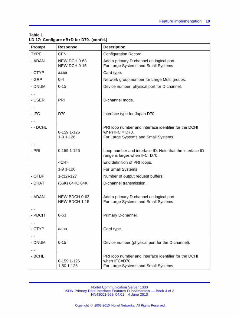
Table 1LD 17: Configure nB+D for D70. (cont’d.)
Prompt Response Description
TYPE CFN Configuration Record.
- ADAN NEW DCH 0-63NEW DCH 0-15
Add a primary D-channel on logical port.For Large Systems and Small Systems
- CTYP aaaa Card type.
- GRP 0-4 Network group number for Large Multi groups.
- DNUM 0-15 Device number; physical port for D-channel.
…
- USER PRI D-channel mode.
…
- IFC D70 Interface type for Japan D70.
…
- - DCHL0-159 1-1261-9 1-126
PRI loop number and interface identifier for the DCHIwhen IFC = D70.For Large Systems and Small Systems
…
- PRI 0-159 1-126 Loop number and interface ID. Note that the interface IDrange is larger when IFC=D70.
<CR> End definition of PRI loops.
1-9 1-126 For Small Systems
- OTBF 1-(32)-127 Number of output request buffers.
- DRAT (56K) 64KC 64KI D-channel transmission.
…
- ADAN NEW BDCH 0-63NEW BDCH 1-15
Add a primary D-channel on logical port.For Large Systems and Small Systems
…
- PDCH 0-63 Primary D-channel.
…
- CTYP aaaa Card type.
…
- DNUM 0-15 Device number (physical port for the D-channel).
…
- BCHL0-159 1-1261-50 1-126
PRI loop number and interface identifier for the DCHIwhen IFC=D70.For Large Systems and Small Systems
Nortel Communication Server 1000ISDN Primary Rate Interface Features Fundamentals — Book 3 of 3
NN43001-569 04.01 4 June 2010
Copyright © 2003-2010 Nortel Networks. All Rights Reserved.
.

20 Japan D70 nB+D
Feature operationNo specific operating procedures are required to use this feature.
Nortel Communication Server 1000ISDN Primary Rate Interface Features Fundamentals — Book 3 of 3
NN43001-569 04.01 4 June 2010
Copyright © 2003-2010 Nortel Networks. All Rights Reserved.
.

21.
Japan TTC Common Channel Signaling
ContentsThis section contains information on the following topics:
“Applicable regions” (page 21)
“Feature description” (page 21)
“Operating parameters” (page 22)
“Feature interactions” (page 23)
“Feature packaging” (page 25)
“Feature implementation” (page 25)
“Task summary list” (page 25)
“Feature operation” (page 29)
Applicable regionsThe information presented in this section does not pertain to all regions.Contact your system supplier or your Nortel representative to verifysupport of this product in your area.
Feature descriptionThe Japan Telecommunication Technology Committee (JTTC) CommonChannel Signaling is the Japanese version of the International StandardOrganization (ISO) ISDN QSIG. It specifies the Layer 3 protocol signalingrequirement for support of circuit switched call control at the "Q" referencepoint between a Private Integrated Services Digital Network (PISN) and aPrivate Telecommunication Network (PTN).
The JTTC Common Channel Signaling feature provides basic call serviceon the system ISDN 1.5 Mbit PRI on TTC connectivity. It also supportsother supplementary services.
Nortel Communication Server 1000ISDN Primary Rate Interface Features Fundamentals — Book 3 of 3
NN43001-569 04.01 4 June 2010
Copyright © 2003-2010 Nortel Networks. All Rights Reserved.
.
22 Japan TTC Common Channel Signaling
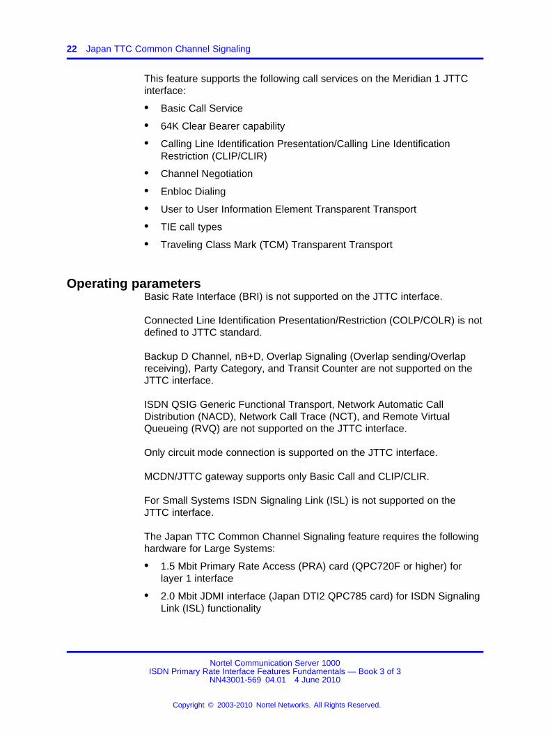
This feature supports the following call services on the Meridian 1 JTTCinterface:
• Basic Call Service
• 64K Clear Bearer capability
• Calling Line Identification Presentation/Calling Line IdentificationRestriction (CLIP/CLIR)
• Channel Negotiation
• Enbloc Dialing
• User to User Information Element Transparent Transport
• TIE call types
• Traveling Class Mark (TCM) Transparent Transport
Operating parametersBasic Rate Interface (BRI) is not supported on the JTTC interface.
Connected Line Identification Presentation/Restriction (COLP/COLR) is notdefined to JTTC standard.
Backup D Channel, nB+D, Overlap Signaling (Overlap sending/Overlapreceiving), Party Category, and Transit Counter are not supported on theJTTC interface.
ISDN QSIG Generic Functional Transport, Network Automatic CallDistribution (NACD), Network Call Trace (NCT), and Remote VirtualQueueing (RVQ) are not supported on the JTTC interface.
Only circuit mode connection is supported on the JTTC interface.
MCDN/JTTC gateway supports only Basic Call and CLIP/CLIR.
For Small Systems ISDN Signaling Link (ISL) is not supported on theJTTC interface.
The Japan TTC Common Channel Signaling feature requires the followinghardware for Large Systems:
• 1.5 Mbit Primary Rate Access (PRA) card (QPC720F or higher) forlayer 1 interface
• 2.0 Mbit JDMI interface (Japan DTI2 QPC785 card) for ISDN SignalingLink (ISL) functionality
Nortel Communication Server 1000ISDN Primary Rate Interface Features Fundamentals — Book 3 of 3
NN43001-569 04.01 4 June 2010
Copyright © 2003-2010 Nortel Networks. All Rights Reserved.
.
Feature interactions 23
• Multi-purpose Serial Data Link (MSDL) card (NT6D80)
• Clock Controller (NTRB53)
The Japan TTC Common Channel Signaling feature requires the followinghardware for Small Systems:
• 1.5 Mbit Primary Rate Interface (PRI)/Digital Trunk Interface (DTI) card(NTAK09)
• Downloadable D-Channel Daughterboard (NTBK51)
• Clock Controller (NTAK20)
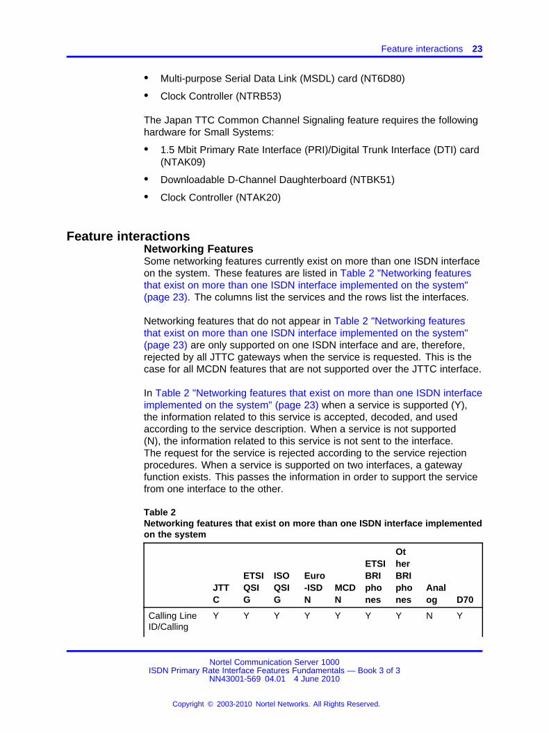
Feature interactionsNetworking FeaturesSome networking features currently exist on more than one ISDN interfaceon the system. These features are listed in Table 2 "Networking featuresthat exist on more than one ISDN interface implemented on the system"(page 23). The columns list the services and the rows list the interfaces.
Networking features that do not appear in Table 2 "Networking featuresthat exist on more than one ISDN interface implemented on the system"(page 23) are only supported on one ISDN interface and are, therefore,rejected by all JTTC gateways when the service is requested. This is thecase for all MCDN features that are not supported over the JTTC interface.
In Table 2 "Networking features that exist on more than one ISDN interfaceimplemented on the system" (page 23) when a service is supported (Y),the information related to this service is accepted, decoded, and usedaccording to the service description. When a service is not supported(N), the information related to this service is not sent to the interface.The request for the service is rejected according to the service rejectionprocedures. When a service is supported on two interfaces, a gatewayfunction exists. This passes the information in order to support the servicefrom one interface to the other.
Table 2Networking features that exist on more than one ISDN interface implementedon the system
JTTC
ETSIQSIG
ISOQSIG
Euro-ISDN
MCDN
ETSIBRIphones
OtherBRIphones
Analog D70
Calling LineID/Calling
Y Y Y Y Y Y Y N Y
Nortel Communication Server 1000ISDN Primary Rate Interface Features Fundamentals — Book 3 of 3
NN43001-569 04.01 4 June 2010
Copyright © 2003-2010 Nortel Networks. All Rights Reserved.
.

24 Japan TTC Common Channel Signaling
JTTC
ETSIQSIG
ISOQSIG
Euro-ISDN
MCDN
ETSIBRIphones
OtherBRIphones
Analog D70
PartySubaddress
TransitCounter
N Y N N Y N N N N
CallCharge
N N N Y N N N Y N
ISDN Signaling LinkThe existing Integrated Signaling Link (ISL) operation is supported on theJTTC interface on the JDMI 2 Mbit interface only.
Only the first 23 TIE trunks of the JDMI loop are configurable for ISLoperation.
Network Attendant ServiceJTTC interacts with Network Attendant Service (NAS) as though the call isbeing sent to a route without NAS being equipped.
Network Call RedirectionThe existing Network Call Redirection limitation on unsupported interfacesapplies to the JTTC interface.
When a call is terminated on the system and Network Call Redirection isactive, Japan TTC Common Channel Signaling can still operate. However,the original called number and the redirection number IEs that are used bythe Network Call Redirection feature are not sent on the JTTC interface.
Network Calling Party Name DisplayThe Network Calling Party Name Display (NCPND) feature is supportedwithin an MCDN network only. When the JTTC interface is involved inthe call setup, the existing NCPND operation on unsupported interfacesapplies to the JTTC interface also.
Network Message ServiceNetwork Message Service (NMS) is supported within an MCDN networkonly. The NMS operation on the JTTC interface is the same as that of theexisting treatment for unsupported interfaces.
Nortel Communication Server 1000ISDN Primary Rate Interface Features Fundamentals — Book 3 of 3
NN43001-569 04.01 4 June 2010
Copyright © 2003-2010 Nortel Networks. All Rights Reserved.
.

Feature implementation 25
Network Ring AgainNetwork Ring Again (NRAG) signaling is supported within a MeridianCustomer Defined Network (MCDN) only. When a user requests NRAG onthe JTTC interface, the request is rejected.
Trunk Route OptimizationTrunk Route Optimization (TRO) is supported within an MCDN networkonly. When a redirecting node sends a message to the originating nodeand the TRO request is accepted, the new call goes through the JTTCinterface as a normal basic call. However, TRO signaling does not operateon the JTTC interface.
Virtual Network Services (VNS)A JTTC link can be used as a B-Channel for Virtual Network Service(VNS) over a private network. All VNS services are supported normally.JTTC is used only as a speech bearer.
Feature packagingJapan TTC Common Channel Signaling is Japan TTC (JTTC) package335. The following packages are also required for JTTC:
• Japan Digital Multiplex Interface (JDMI) package 136 for ISLfunctionality
• Integrated Services Digital Network (ISDN) package 145
• Primary Rate Access (PRA) package 146
• International Primary Rate Access (IPRA) package 202
• Multi-purpose Serial Data Link (MSDL) package 222
Feature implementationTask summary list
The following is a summary of the tasks in this section:
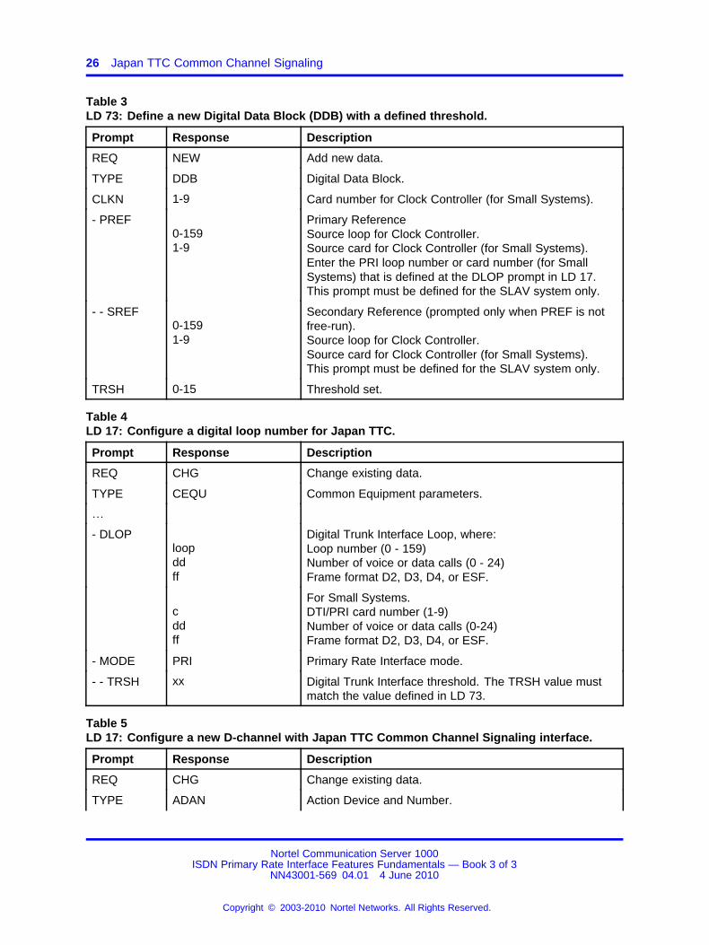
1. Table 3 "LD 73: Define a new Digital Data Block (DDB) with a definedthreshold." (page 26)
2. Table 4 "LD 17: Configure a digital loop number for Japan TTC." (page26)
3. Table 5 "LD 17: Configure a new D-channel with Japan TTC CommonChannel Signaling interface." (page 26)
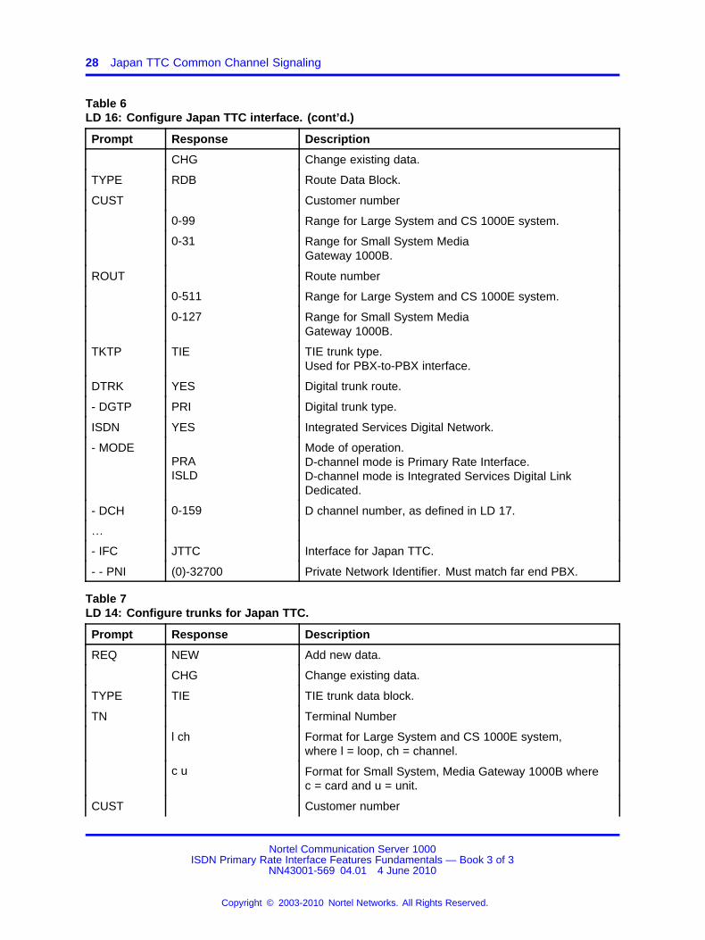
4. Table 6 "LD 16: Configure Japan TTC interface." (page 27)
5. Table 7 "LD 14: Configure trunks for Japan TTC." (page 28)
Nortel Communication Server 1000ISDN Primary Rate Interface Features Fundamentals — Book 3 of 3
NN43001-569 04.01 4 June 2010
Copyright © 2003-2010 Nortel Networks. All Rights Reserved.
.
26 Japan TTC Common Channel Signaling
Table 3LD 73: Define a new Digital Data Block (DDB) with a defined threshold.
Prompt Response Description
REQ NEW Add new data.
TYPE DDB Digital Data Block.
CLKN 1-9 Card number for Clock Controller (for Small Systems).
- PREF0-1591-9
Primary ReferenceSource loop for Clock Controller.Source card for Clock Controller (for Small Systems).Enter the PRI loop number or card number (for SmallSystems) that is defined at the DLOP prompt in LD 17.This prompt must be defined for the SLAV system only.
- - SREF0-1591-9
Secondary Reference (prompted only when PREF is notfree-run).Source loop for Clock Controller.Source card for Clock Controller (for Small Systems).This prompt must be defined for the SLAV system only.
TRSH 0-15 Threshold set.
Table 4LD 17: Configure a digital loop number for Japan TTC.
Prompt Response Description
REQ CHG Change existing data.
TYPE CEQU Common Equipment parameters.
…
- DLOPloopddff
Digital Trunk Interface Loop, where:Loop number (0 - 159)Number of voice or data calls (0 - 24)Frame format D2, D3, D4, or ESF.
cddff
For Small Systems.DTI/PRI card number (1-9)Number of voice or data calls (0-24)Frame format D2, D3, D4, or ESF.
- MODE PRI Primary Rate Interface mode.
- - TRSH xx Digital Trunk Interface threshold. The TRSH value mustmatch the value defined in LD 73.
Table 5LD 17: Configure a new D-channel with Japan TTC Common Channel Signaling interface.
Prompt Response Description
REQ CHG Change existing data.
TYPE ADAN Action Device and Number.
Nortel Communication Server 1000ISDN Primary Rate Interface Features Fundamentals — Book 3 of 3
NN43001-569 04.01 4 June 2010
Copyright © 2003-2010 Nortel Networks. All Rights Reserved.
.

Feature implementation 27
Table 5LD 17: Configure a new D-channel with Japan TTC Common Channel Signaling interface.(cont’d.)
Prompt Response Description
ADAN NEW DCH x Create a new D-channel.x = 0 - 63x = 0-15 (for Small Systems)
- CTYP MSDL Multi-purpose Serial Data Link card type.The MSDL card is the only card type that supports JapanTTC.
Note: The MSDL card cannot be used for Small Systems.For Small Systems; however, MSDL must be entered atthe CTYP prompt for Downloadable D-Channel.
- GRP 0-4 Network Group number (Option 81C).Group numbers cannot be changed until the I/O devicesassociated with that group are disabled.
- DNUM xx Device number.All ports on the MSDL card share the same DNUM.
- PORT 0-3 Port number on the MSDL card.
- USRPRIISLD
D Channel mode.Primary Rate Interface.Integrated Services Digital Link Dedicated.
- IFC JTTC Interface ID for Japan TTC.
- -ISDN_MCNT
60-(300)-350 Layer 3 call control message count per 5 second timeinterval.
- - ISLM 1-382 Integrated Services Signaling Link Maximum.
- -DCHL x PRI loop number for D-channel, as defined in LD 17 at theDLOP prompt.
…
- BPS xxxxx Asynchronous baud rates (bits per second), where xxxxxis:1200, 2400, 4800, 9600, 19200, 48000, 56000, 64000.
- SIDE(USR)NET
system node type.Slave to the controller.Network, the controlling switch.
- RLS 23 Release ID of the switch at the far-end of the D-channel.
Table 6LD 16: Configure Japan TTC interface.
Prompt Response Description
REQ NEW Add new data.
Nortel Communication Server 1000ISDN Primary Rate Interface Features Fundamentals — Book 3 of 3
NN43001-569 04.01 4 June 2010
Copyright © 2003-2010 Nortel Networks. All Rights Reserved.
.
28 Japan TTC Common Channel Signaling
Table 6LD 16: Configure Japan TTC interface. (cont’d.)
Prompt Response Description
CHG Change existing data.
TYPE RDB Route Data Block.
CUST Customer number
0-99 Range for Large System and CS 1000E system.
0-31 Range for Small System MediaGateway 1000B.
ROUT Route number
0-511 Range for Large System and CS 1000E system.
0-127 Range for Small System MediaGateway 1000B.
TKTP TIE TIE trunk type.Used for PBX-to-PBX interface.
DTRK YES Digital trunk route.
- DGTP PRI Digital trunk type.
ISDN YES Integrated Services Digital Network.
- MODEPRAISLD
Mode of operation.D-channel mode is Primary Rate Interface.D-channel mode is Integrated Services Digital LinkDedicated.
- DCH 0-159 D channel number, as defined in LD 17.
…
- IFC JTTC Interface for Japan TTC.
- - PNI (0)-32700 Private Network Identifier. Must match far end PBX.
Table 7LD 14: Configure trunks for Japan TTC.
Prompt Response Description
REQ NEW Add new data.
CHG Change existing data.
TYPE TIE TIE trunk data block.
TN Terminal Number
l ch Format for Large System and CS 1000E system,where l = loop, ch = channel.
c u Format for Small System, Media Gateway 1000B wherec = card and u = unit.
CUST Customer number
Nortel Communication Server 1000ISDN Primary Rate Interface Features Fundamentals — Book 3 of 3
NN43001-569 04.01 4 June 2010
Copyright © 2003-2010 Nortel Networks. All Rights Reserved.
.

Feature operation 29
Table 7LD 14: Configure trunks for Japan TTC. (cont’d.)
Prompt Response Description
0-99 Range for Large System and CS 1000E system.
0-31 Range for Small System MediaGateway 1000B.
SICA (1)-16 Signaling category table number.The default is 16 if the loop type = JDMI.
RTMB Route number and Member Number
0-511 1-4000 Range for Large System and CS 1000E system.
0-127 1-4000 Range for Small System, Media Gateway 1000B.
TGAR 0 - (1) - 31 Trunk Group Access Restriction. The default value (1)automatically blocks direct access.
Feature operationNo specific operating procedures are required to use this feature.
Nortel Communication Server 1000ISDN Primary Rate Interface Features Fundamentals — Book 3 of 3
NN43001-569 04.01 4 June 2010
Copyright © 2003-2010 Nortel Networks. All Rights Reserved.
.

30 Japan TTC Common Channel Signaling
Nortel Communication Server 1000ISDN Primary Rate Interface Features Fundamentals — Book 3 of 3
NN43001-569 04.01 4 June 2010
Copyright © 2003-2010 Nortel Networks. All Rights Reserved.
.
31.
Malicious Call Trace Enhancements
ContentsThis section contains information on the following topics:
“Feature description” (page 31)
“Operating parameters” (page 33)
“Feature interactions” (page 34)
“Feature packaging” (page 35)
“Feature implementation” (page 36)
“Task summary list” (page 36)
“Feature operation” (page 42)
Feature descriptionMalicious Call Trace (MCT) allows users of selected phones to activate acall trace that results in a printed report of the calling and called parties.The report is generated on all system TTYs designated as maintenance(MTC) terminals.
The Malicious Call Trace feature has been enhanced to offer advancedcapabilities across an ISDN PRI network, as explained in the followingsections. For a description of the basic Malicious Call Trace feature, referto Features and Services Fundamentals (NN43001-106).
Functional enhancementsThe following enhancements add to the functionality of the basic MaliciousCall Trace feature:
• For a call (from or to a Central Office on an analog CO or DID trunk),a special signal (hook flash and optional DTMF digit string) is sent tothe Central Office if the option is configured.
• Alarm operation is maintained; however, the duration of the alarm isnow flexible (0-15 minutes), instead of being fixed at 15 minutes.
Nortel Communication Server 1000ISDN Primary Rate Interface Features Fundamentals — Book 3 of 3
NN43001-569 04.01 4 June 2010
Copyright © 2003-2010 Nortel Networks. All Rights Reserved.
.
32 Malicious Call Trace Enhancements
• The malicious call can be recorded using a recording trunk, ifprovisioned.
• The call trace record can now be printed on any Serial Data Interface(SDI) port with MCT defined as a user.
• The flexible firmware flash can be transmitted on the EXUT andXFCOT cards. This functionality is used by the Enhanced MaliciousCall Trace, Meridian 911, and Autodial Tandem Transfer features.
• The MCT feature can be activated from a proprietary phone during theestablished state of the call or during call clearing when interfaced withAXE10 Australia on 2 Mbit PRI trunks.
MCT recordPrior to this enhancement, during an established call, the user of a phonehaving Malicious Call Trace (MCT) Allowed Class of Service could invokea call trace against the call. Activation of the feature resulted in the printingof a call trace record on the maintenance teletype terminal (TTY) of thesystem. The Malicious Call Trace record did not contain any identifier ofwhether the call was external or internal; the format of these records ischanged to provide information about the type of call (internal or external).
Malicious Call Trace for Saudi ArabiaIn Saudi Arabia, from a user’s perspective, the Malicious Call Trace featureactivation remains the same as it was prior to this enhancement. However,with this enhancement, the feature is now available for different types ofanalog and digital (CO, DID, and DOD) trunks. In order to send the MCTrequest, a special digit string is transmitted to the CO for an analog ordigital trunk interface.
Malicious Call Trace for AXE-10 AustraliaIn Australia, MCT can be activated during the established state of the callwhen interfaced with AXE-10 Australia on 2.0 Mbit Primary Rate Interface(PRI) trunks. MCT can also be activated during the call clearing state ofthe call (within a maximum of 30 seconds from the caller going on hook).When MCT is activated, a special FACILITY message, with a keypadinformation element, is transmitted to the CO.
Trace Number (TRC) Key Lamp StatusThe TRC key lamp status indicates the progress and success of theMalicious Call Trace request signaling to the CO and the availability of therecorder. The following are the lamp states:
Nortel Communication Server 1000ISDN Primary Rate Interface Features Fundamentals — Book 3 of 3
NN43001-569 04.01 4 June 2010
Copyright © 2003-2010 Nortel Networks. All Rights Reserved.
.
Operating parameters 33
Lamp WinkingActivation of the TRC key changes its lamp from dark to winking if thetrunk involved in the call requires the signaling to be done. The lampremains winking, indicating a transient state, until the call trace requestsignaling to the CO has been completed.
In a Meridian Customer Defined Network (MCDN) tandem scenario, thephone which originated the call trace remains winking until a Facilitymessage is received from the node nearest to the Central Office. The usercannot invoke MCT again while the lamp is in the winking state.
Lamp LitIf the call trace request to the CO is successful and the recorder isconferenced in the call, the lamp state is changed to lit.
In an MCDN tandem scenario, the lamp goes from winking to lit if a Facilitymessage received from the node nearest to the CO indicates that the MCTrequest was successful. Activation of the TRC key during this state isignored.
Lamp FlashingThis lamp state indicates that the call trace request to the CO wastransmitted successfully, but a recorder could not be conferenced in.Activation of the TRC key during this state regenerates the MCT record,activates the alarm, and again attempts to conference in the recorder. Thecall trace request signaling to the Central Office is not transmitted again.
Lamp DarkThis lamp state indicates an idle TRC key or failure of the call tracerequest to the CO.
In an MCDN tandem scenario, the lamp goes from winking to dark if aFacility message received from the node nearest the CO indicates thatthe MCT request was unsuccessful.
Activation of the TRC during this state initiates all call trace elementsagain, including: transmission of trunk hook flash, conferencing a recorder(if one is not already hooked in), generating an MCT record, and activatingan alarm.
Operating parametersAny country using flexible firmware flash timing (60-1536 msec.) requiresthe Generic XFCOT cards NTCK16AE or NTCK16BE; or the EXUT cardNT8D14BA. For any country not using either the Generic XFCOT card orthe EXUT card, the same functionality is provided by software control.
Nortel Communication Server 1000ISDN Primary Rate Interface Features Fundamentals — Book 3 of 3
NN43001-569 04.01 4 June 2010
Copyright © 2003-2010 Nortel Networks. All Rights Reserved.
.

34 Malicious Call Trace Enhancements
Downloadable D-channel for Small Systems must be used to support MCTfor AXE-10 Australia (2 Mbit PRI).
The following hardware is required to activate this feature on LargeSystems:
• Analog CO/FX/WATS QPC 525A
• DID trunk QPC449B LP TRK, QPC825
• 2.0 Mbit DTI interface QPC 536 B
• PRI2 interface NT8D72BA
• Digitone Receiver QPC574A, NT8D16AB
• TDS QPC609D, NTAK03AA
• Recorded phone trunk QPC71
• Conference card QPC444A
• MSDL card NT6D80AA
The following hardware is required for Small Systems :
• XUT NT8D14A
• TDS/DTR NTAK03AA
• System Controller Card NTDK20
• 2.0 Mbit PRI NTAK79AA
• DCH loadware NTBK50, NTBK51
• 1.5 Mbit DTI NTAK09AA
• 2.0 Mbit DTI NTAK10AA
• Recorded phone trunk NT8D14
• XFCOT card NTCK16AE, NTCK16BE
• EXUT card NT8D14BA
Feature interactionsFor feature interactions pertaining to the basic Malicious Call Tracefeature, refer to Features and Services Fundamentals (NN43001-106).
Malicious Call Trace EnhancementsACD Emergency Key (EMR) The Malicious Call Trace feature operatesin a similar manner to the ACD Emergency key feature when conferencinga recording. In this enhancement, the ACD phone can activate both theMalicious Call Trace and ACD EMR features.
Nortel Communication Server 1000ISDN Primary Rate Interface Features Fundamentals — Book 3 of 3
NN43001-569 04.01 4 June 2010
Copyright © 2003-2010 Nortel Networks. All Rights Reserved.
.
Feature packaging 35
Autodial Tandem TransferThe Trunk Hook Flash functionality is used by Autodial Tandem Transferand Enhanced Malicious Call Trace.
Centrex Switchhook FlashInteraction with the Centrex Switchhook Flash results because the flashrange is changed for this feature. Communication to the CO (trunk hookflash) is performed by using the Centrex Switchhook Flash feature basecode. The enhanced range is available for the Centrex Switchhook Flash.
Called Party Control (CDPC) OptionPrior to this feature, the CDPC option was not supported for conferencecalls. This has changed; the CDPC option is now supported if theconference contains exactly one recording trunk, one MCT activating party,and one other trunk. This is done to make the recorder transparent to theuser. The CDPC option remains unsupported for all other conference calls.
Malicious Call Trace Idle SignalThe existing operation of the Malicious Call Trace Idle Signal feature isunchanged.
MCT DN/TN PrintIf the option MCDC (in LD 15) is set, a second line is added in the MCTreports to show the DN of both parties of the call. If CLID is available it isprinted in the second line.
M911The Trunk Hook Flash functionality is used by M911 and EnhancedMalicious Call Trace.
Feature packagingEnhanced Malicious Call Trace is packaged under the existing MaliciousCall Trace (MCT) package 107.
For ISDN environments, ISDN packages are required based on the nodeand network interface applicable to the specific country. In addition,International Supplementary ISDN Features (ISDN INTL SUPP) package161 is required.
In order to send an MCT message request to a tandem node, NetworkAttendant Service (NAS) package 159 must be equipped.
Nortel Communication Server 1000ISDN Primary Rate Interface Features Fundamentals — Book 3 of 3
NN43001-569 04.01 4 June 2010
Copyright © 2003-2010 Nortel Networks. All Rights Reserved.
.
36 Malicious Call Trace Enhancements
Feature implementationTask summary list
The following is a summary of the tasks in this section:
1. Table 8 "LD 10: Enable MCTA for an analog (500/2500-type) phone."(page 37)
2. Table 9 "LD 11: Enable MCTA for a digital proprietary phone." (page37)
To activate Malicious call Trace from a Meridian 1 Proprietary Phone,Class of Service MCTA, and TRC KEY should be defined. However,the same function can be achieved using a transfer or conference keyand the SPRE + 83 or the MCT FFC.
3. Table 10 "LD 17: Define the TTY as an MCT port." (page 37)
In order to print the MCT record on a dedicated MCT TTY port, USERtype MCT must be defined.
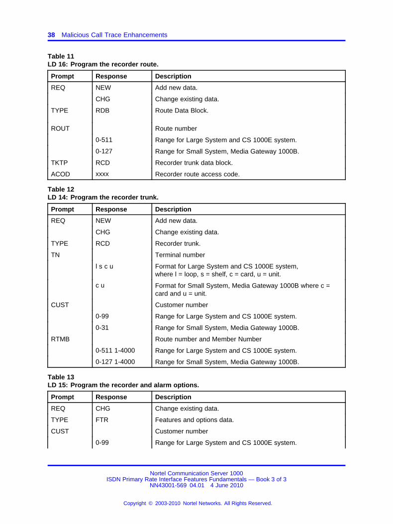
4. Table 11 "LD 16: Program the recorder route." (page 38)
5. Table 12 "LD 14: Program the recorder trunk." (page 38)
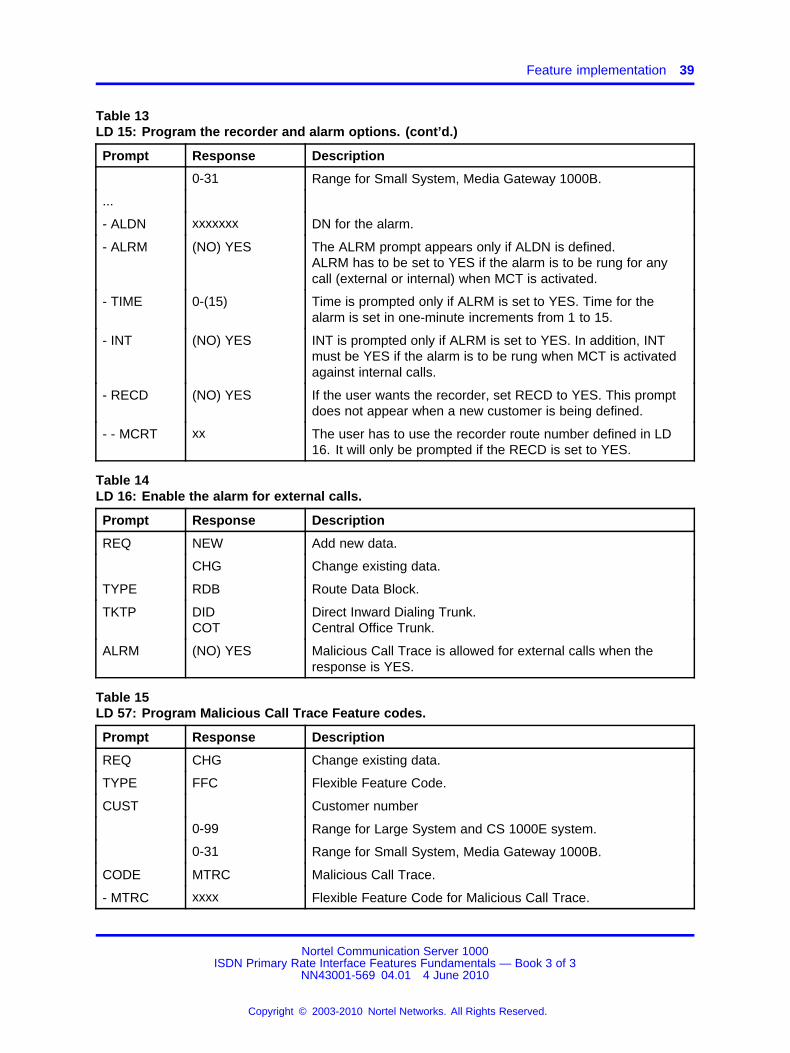
6. Table 13 "LD 15: Program the recorder and alarm options." (page 38)
7. Table 14 "LD 16: Enable the alarm for external calls." (page 39)
8. Table 15 "LD 57: Program Malicious Call Trace Feature codes." (page39)
In order to activate malicious call trace from the analog (500/2500-type)phone without using the SPRE and 83, the MCT FFC must be defined.
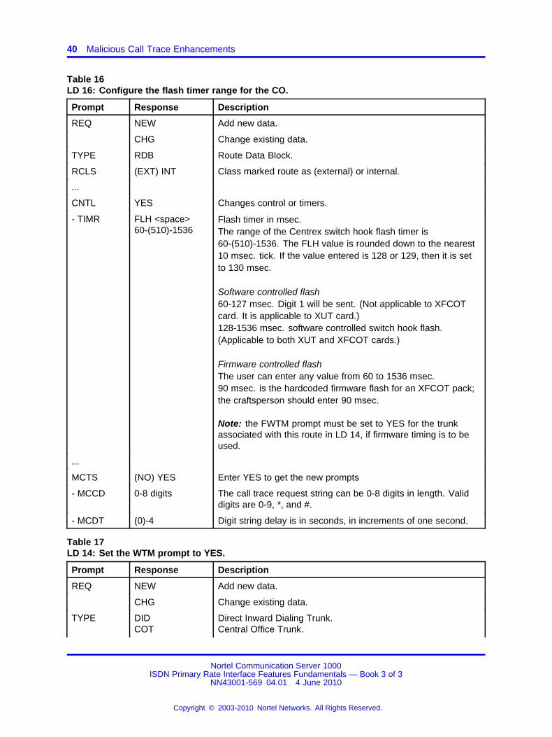
9. Table 16 "LD 16: Configure the flash timer range for the CO." (page40)
For analog and 2.0 Mbit digital trunks, the flash range to be sent to theCentral Office is configured using the FLH timer. In order to send thestring to the Central Office, MCCD must be defined.
10.Table 17 "LD 14: Set the WTM prompt to YES." (page 40)
The WTM prompt is provided for EXUT and XCOT cards. This promptshould be set to YES if firmware timing is to be done for the flash andthe card supports this functionality. If the prompt is set to YES for oneunit, it is also set to YES for all other units.
11.Table 18 "LD 73: Define the DTI2 flash time range." (page 41)
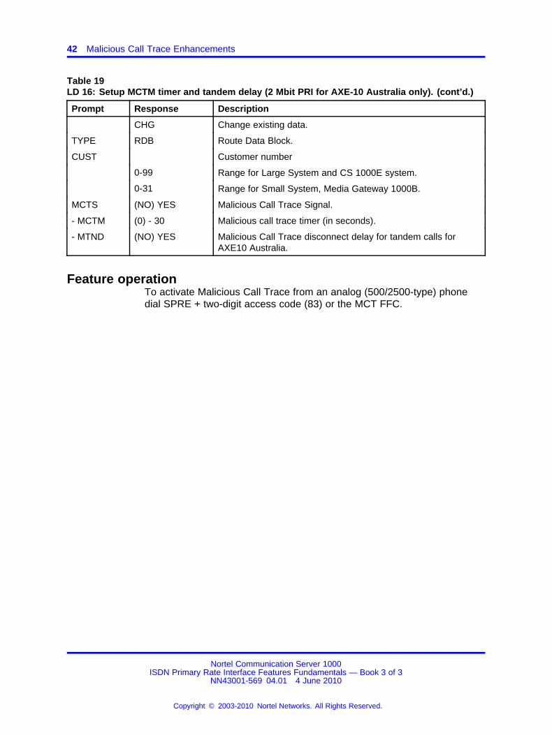
12.Table 19 "LD 16: Setup MCTM timer and tandem delay (2 Mbit PRI forAXE-10 Australia only)." (page 41)
Nortel Communication Server 1000ISDN Primary Rate Interface Features Fundamentals — Book 3 of 3
NN43001-569 04.01 4 June 2010
Copyright © 2003-2010 Nortel Networks. All Rights Reserved.
.

Feature implementation 37
Table 8LD 10: Enable MCTA for an analog (500/2500-type) phone.
Prompt Response Description
REQ NEW Add new data.
CHG Change existing data.
TYPE 500 Phone type.
TN Terminal number
l s c u Format for Large System and CS 1000E system,where l = loop, s = shelf, c = card, u = unit.
c u Format for Small System, Media Gateway 1000B where c =card and u = unit.
CLS (MCTD) MCTA Malicious Call Trace is allowed if class is MCTA.
Table 9LD 11: Enable MCTA for a digital proprietary phone.
Prompt Response Description
REQ NEW Add new data.
CHG Change existing data.
TYPE a...a Telephone type. Type ? for a list of possible responses.
TN Terminal number
l s c u Format for Large System and CS 1000E system,where l = loop, s = shelf, c = card, u = unit.
c u Format for Small System, Media Gateway 1000B where c =card and u = unit.
CLS (MCTD) MCTA Malicious Call Trace is allowed if class is MCTA.
Table 10LD 17: Define the TTY as an MCT port.
Prompt Response Description
REQ CHG Change existing data.
TYPE CFN Type of data block.
ADAN xxx TTY yy xxx = new or change.
yy = port number 0-63 (for Large Systems)yy = port number 0-15 (for Small Systems)
USR MCT Dedicated TTY port for MCT record.
Nortel Communication Server 1000ISDN Primary Rate Interface Features Fundamentals — Book 3 of 3
NN43001-569 04.01 4 June 2010
Copyright © 2003-2010 Nortel Networks. All Rights Reserved.
.
38 Malicious Call Trace Enhancements
Table 11LD 16: Program the recorder route.
Prompt Response Description
REQ NEW Add new data.
CHG Change existing data.
TYPE RDB Route Data Block.
ROUT Route number
0-511 Range for Large System and CS 1000E system.
0-127 Range for Small System, Media Gateway 1000B.
TKTP RCD Recorder trunk data block.
ACOD xxxx Recorder route access code.
Table 12LD 14: Program the recorder trunk.
Prompt Response Description
REQ NEW Add new data.
CHG Change existing data.
TYPE RCD Recorder trunk.
TN Terminal number
l s c u Format for Large System and CS 1000E system,where l = loop, s = shelf, c = card, u = unit.
c u Format for Small System, Media Gateway 1000B where c =card and u = unit.
CUST Customer number
0-99 Range for Large System and CS 1000E system.
0-31 Range for Small System, Media Gateway 1000B.
RTMB Route number and Member Number
0-511 1-4000 Range for Large System and CS 1000E system.
0-127 1-4000 Range for Small System, Media Gateway 1000B.
Table 13LD 15: Program the recorder and alarm options.
Prompt Response Description
REQ CHG Change existing data.
TYPE FTR Features and options data.
CUST Customer number
0-99 Range for Large System and CS 1000E system.
Nortel Communication Server 1000ISDN Primary Rate Interface Features Fundamentals — Book 3 of 3
NN43001-569 04.01 4 June 2010
Copyright © 2003-2010 Nortel Networks. All Rights Reserved.
.
Feature implementation 39
Table 13LD 15: Program the recorder and alarm options. (cont’d.)
Prompt Response Description
0-31 Range for Small System, Media Gateway 1000B.
...
- ALDN xxxxxxx DN for the alarm.
- ALRM (NO) YES The ALRM prompt appears only if ALDN is defined.ALRM has to be set to YES if the alarm is to be rung for anycall (external or internal) when MCT is activated.
- TIME 0-(15) Time is prompted only if ALRM is set to YES. Time for thealarm is set in one-minute increments from 1 to 15.
- INT (NO) YES INT is prompted only if ALRM is set to YES. In addition, INTmust be YES if the alarm is to be rung when MCT is activatedagainst internal calls.
- RECD (NO) YES If the user wants the recorder, set RECD to YES. This promptdoes not appear when a new customer is being defined.
- - MCRT xx The user has to use the recorder route number defined in LD16. It will only be prompted if the RECD is set to YES.
Table 14LD 16: Enable the alarm for external calls.
Prompt Response Description
REQ NEW Add new data.
CHG Change existing data.
TYPE RDB Route Data Block.
TKTP DIDCOT
Direct Inward Dialing Trunk.Central Office Trunk.
ALRM (NO) YES Malicious Call Trace is allowed for external calls when theresponse is YES.
Table 15LD 57: Program Malicious Call Trace Feature codes.
Prompt Response Description
REQ CHG Change existing data.
TYPE FFC Flexible Feature Code.
CUST Customer number
0-99 Range for Large System and CS 1000E system.
0-31 Range for Small System, Media Gateway 1000B.
CODE MTRC Malicious Call Trace.
- MTRC xxxx Flexible Feature Code for Malicious Call Trace.
Nortel Communication Server 1000ISDN Primary Rate Interface Features Fundamentals — Book 3 of 3
NN43001-569 04.01 4 June 2010
Copyright © 2003-2010 Nortel Networks. All Rights Reserved.
.
40 Malicious Call Trace Enhancements
Table 16LD 16: Configure the flash timer range for the CO.
Prompt Response Description
REQ NEW Add new data.
CHG Change existing data.
TYPE RDB Route Data Block.
RCLS (EXT) INT Class marked route as (external) or internal.
...
CNTL YES Changes control or timers.
- TIMR FLH <space>60-(510)-1536
Flash timer in msec.The range of the Centrex switch hook flash timer is60-(510)-1536. The FLH value is rounded down to the nearest10 msec. tick. If the value entered is 128 or 129, then it is setto 130 msec.
Software controlled flash60-127 msec. Digit 1 will be sent. (Not applicable to XFCOTcard. It is applicable to XUT card.)128-1536 msec. software controlled switch hook flash.(Applicable to both XUT and XFCOT cards.)
Firmware controlled flashThe user can enter any value from 60 to 1536 msec.90 msec. is the hardcoded firmware flash for an XFCOT pack;the craftsperson should enter 90 msec.
Note: the FWTM prompt must be set to YES for the trunkassociated with this route in LD 14, if firmware timing is to beused.
...
MCTS (NO) YES Enter YES to get the new prompts
- MCCD 0-8 digits The call trace request string can be 0-8 digits in length. Validdigits are 0-9, *, and #.
- MCDT (0)-4 Digit string delay is in seconds, in increments of one second.
Table 17LD 14: Set the WTM prompt to YES.
Prompt Response Description
REQ NEW Add new data.
CHG Change existing data.
TYPE DIDCOT
Direct Inward Dialing Trunk.Central Office Trunk.
Nortel Communication Server 1000ISDN Primary Rate Interface Features Fundamentals — Book 3 of 3
NN43001-569 04.01 4 June 2010
Copyright © 2003-2010 Nortel Networks. All Rights Reserved.
.

Feature implementation 41
Table 17LD 14: Set the WTM prompt to YES. (cont’d.)
Prompt Response Description
TN Terminal number
l s c u Format for Large System and CS 1000E system,where l = loop, s = shelf, c = card, u = unit.
c u Format for Small System, Media Gateway 1000B where c =card and u = unit.
XTRK EXUTXCOT
Enhanced Extended Universal Trunk.Extended Central Office trunk card.
FWTM (NO) YES Firmware timing for the trunk hook flash is available. Thisprompt is set to YES if firmware timing for trunk hook flash issupported by the pack.
CUST Customer number
0-99 Range for Large System and CS 1000E system.
0-31 Range for Small System, Media Gateway 1000B.
RTMB Route number and Member Number
0-511 1-4000 Range for Large System and CS 1000E system.
0-127 1-4000 Range for Small System, Media Gateway 1000B.
Table 18LD 73: Define the DTI2 flash time range.
Prompt Response Description
REQ NEW Add new data.
CHG Change existing data.
TYPE DTI2 2.0 Mbit Digital Trunk Interface
FEAT ABCD Digital signaling category.
SICA 2-16 SICA table number.
...
FALT (R) ABCDN
Fault (DTI out-of-service).If Fault is not required.
P RRC (S) ABCD Register recall signal activated by MCT.
TIME 10-(100)-630 Time of RRC(S) signal in milliseconds. This is the flashduration used for 2.0 Mbit DTI trunks. It is programmable inone-millisecond increments from 10 to 630.
Table 19LD 16: Setup MCTM timer and tandem delay (2 Mbit PRI for AXE-10 Australia only).
Prompt Response Description
REQ NEW Add new data.
Nortel Communication Server 1000ISDN Primary Rate Interface Features Fundamentals — Book 3 of 3
NN43001-569 04.01 4 June 2010
Copyright © 2003-2010 Nortel Networks. All Rights Reserved.
.
42 Malicious Call Trace Enhancements
Table 19LD 16: Setup MCTM timer and tandem delay (2 Mbit PRI for AXE-10 Australia only). (cont’d.)
Prompt Response Description
CHG Change existing data.
TYPE RDB Route Data Block.
CUST Customer number
0-99 Range for Large System and CS 1000E system.
0-31 Range for Small System, Media Gateway 1000B.
MCTS (NO) YES Malicious Call Trace Signal.
- MCTM (0) - 30 Malicious call trace timer (in seconds).
- MTND (NO) YES Malicious Call Trace disconnect delay for tandem calls forAXE10 Australia.
Feature operationTo activate Malicious Call Trace from an analog (500/2500-type) phonedial SPRE + two-digit access code (83) or the MCT FFC.
Nortel Communication Server 1000ISDN Primary Rate Interface Features Fundamentals — Book 3 of 3
NN43001-569 04.01 4 June 2010
Copyright © 2003-2010 Nortel Networks. All Rights Reserved.
.
43.
MCDN Alternate Routing
ContentsThis section contains information on the following topics:
“Feature description” (page 43)
“Operating parameters” (page 51)
“Feature interactions” (page 51)
“Feature packaging” (page 57)
“Feature implementation” (page 57)
“Feature operation” (page 58)
Feature descriptionThe Meridian Customer Defined Network (MCDN) Alternate Routingfeature provides a solution to calls encountering congestion due to hightraffic situations within an MCDN network. The MCDN Alternate Routingfeature is supported over an MCDN-based ISDN protocol.
The MCDN Alternate Routing feature uses the routing capability ofNetwork Alternate Route Selection (NARS) to re-route a congested call.For each MCDN call translated at a system node, NARS selects one routefrom up to 512 routes to complete the call. These routes are programmedin a route list. Each route in the list is called an entry. There can be up to64 entries in each route list. Any combination of trunks can be specified ina route list.
The MCDN Alternate Routing feature can be configured for each of the512 different routes.
Congestion occurs when channels within the network are not available.With the introduction of the MCDN Alternate Routing feature, each entryof a route list on one node can be configured to take an alternate entry(route) from the route list of that node (Private Exchange or Central Office),if congestion is encountered.
Nortel Communication Server 1000ISDN Primary Rate Interface Features Fundamentals — Book 3 of 3
NN43001-569 04.01 4 June 2010
Copyright © 2003-2010 Nortel Networks. All Rights Reserved.
.
44 MCDN Alternate Routing
Alternate routing configuration takes place in LD 86, the ElectronicSwitched Network (ESN) administration overlay. The option defined for theStep Back On Congestion (SBOC) prompt determines the type of alternaterouting available to calls over a particular route.
Alternate routing options are:
• NRR: no alternate routing is performed. The call receives congestiontreatment.
• RRO: re-route at the originating node if a call encounters congestion.If congestion is encountered at a transit node, the call drops back tothe preceding node, so that the preceding node decides if re-routingis required.
• RRA: re-route the call at any node, whether originating or transit node,when congestion is encountered.
The MCDN Alternate Routing feature is triggered at the controlling nodewhen a Call Clearing message (DISCONNECT or RELEASE COMPLETE)is received, and the cause value in the Call Clearing message is supportedfor the MCDN Alternate Routing feature.
The cause values which activate the MCDN Alternate Routing feature are:
• Cause 3 = No route to destination
• Cause 27 = Destination is out of service
• Cause 34 = No channel/circuit available
• Cause 38 = Network out of order
• Cause 41 = Temporary failure
• Cause 42 = Congestion
Note: To ensure that MCDN Alternate Routing occurs for all nodes ina system, define all nodes as SBOC = RRA. Conversely, to preventMCDN Alternate Routing from occurring on any nodes, define all nodesas SBOC = NRR.
Refer to “Originating node operation” (page 45), “Transit node operation”(page 47), and “MCDN Alternate Routing examples” (page 48) for moreinformation on MCDN Alternate Routing operation for each SBOC prompt.
Note: If any of the cause values listed below are received in a CallClearing message, the non-MCDN Alternate Routing retry operationoccurs. That is, an attempt is made to retry the call. The retry firstattempts to find another idle channel in the same route. If all thechannels in that route are busy, it attempts to find another channel inthe next alternate route in the Route List Block.
Nortel Communication Server 1000ISDN Primary Rate Interface Features Fundamentals — Book 3 of 3
NN43001-569 04.01 4 June 2010
Copyright © 2003-2010 Nortel Networks. All Rights Reserved.
.
Feature description 45
Cause values received in a Call Clearing message in order for thenon-MCDN Alternate Routing retry operation to occur:
• Cause 6 = Channel unacceptable
• Cause 44 = Requested circuit/channel not available
• Cause 82 = Identified channel does not exist
Refer to “Originating node operation” (page 45), Originating nodeoperation. If Node C sends one of the non-MCDN Alternate Routingcause values, the Call Clearing message is sent back to Node A whichattempts non-MCDN Alternate Routing.
Refer to Figure 2 "Transit node RRA operation" (page 48), Transit nodeoperation. If Node C receives one of the non-MCDN Alternate Routingcause values:
• Node C attempts to find an alternate route but none is available.
• Node B is a transit note and does not attempt to find an alternate route.
• Node A attempts to find an alternate route but none is available.
Originating node operationConsider the following calling scenario for an originating node operation.An attempt is being made to establish a call over an MCDN link, fromoriginating node A to terminating node D, through transit nodes B and C.Congestion occurs between nodes C and D.
Whether node C is defined as SBOC = RRA or RRO or NRR, thecongestion message, along with a MCDN Alternate Routing feature causevalue, is always sent back to node B.
At node B, the SBOC option is checked to determine the routing treatmentif:
• Node B is defined as SBOC = NRR, the Call Clearing message issent back to the preceding node A.
• Node B is defined as SBOC = RRO, the Call Clearing message issent back to node A because A is the originating node.
• Node B is defined as SBOC = RRA, an attempt is made to find anavailable alternate route until all of the alternate routes, as defined inthe Route List (the RLB prompt in LD 86) are tried. If no alternate routeis available, the congestion message information is sent from node Bto the preceding node A.
Nortel Communication Server 1000ISDN Primary Rate Interface Features Fundamentals — Book 3 of 3
NN43001-569 04.01 4 June 2010
Copyright © 2003-2010 Nortel Networks. All Rights Reserved.
.
46 MCDN Alternate Routing
In the originating node operation, node A must be defined asSBOC = RRA or RRO to perform MCDN alternate routing from node A toE to D.
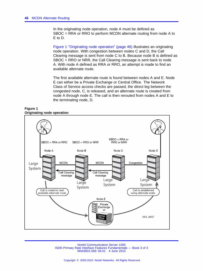
Figure 1 "Originating node operation" (page 46) illustrates an originatingnode operation. With congestion between nodes C and D, the CallClearing message is sent from node C to B. Because node B is defined asSBOC = RRO or NRR, the Call Clearing message is sent back to nodeA. With node A defined as RRA or RRO, an attempt is made to find anavailable alternate route.
The first available alternate route is found between nodes A and E. NodeE can either be a Private Exchange or Central Office. The NetworkClass of Service access checks are passed, the direct leg between thecongested node, C, is released, and an alternate route is created fromnode A through node E. The call is then rerouted from nodes A and E tothe terminating node, D.
Figure 1Originating node operation
Nortel Communication Server 1000ISDN Primary Rate Interface Features Fundamentals — Book 3 of 3
NN43001-569 04.01 4 June 2010
Copyright © 2003-2010 Nortel Networks. All Rights Reserved.
.
Feature description 47
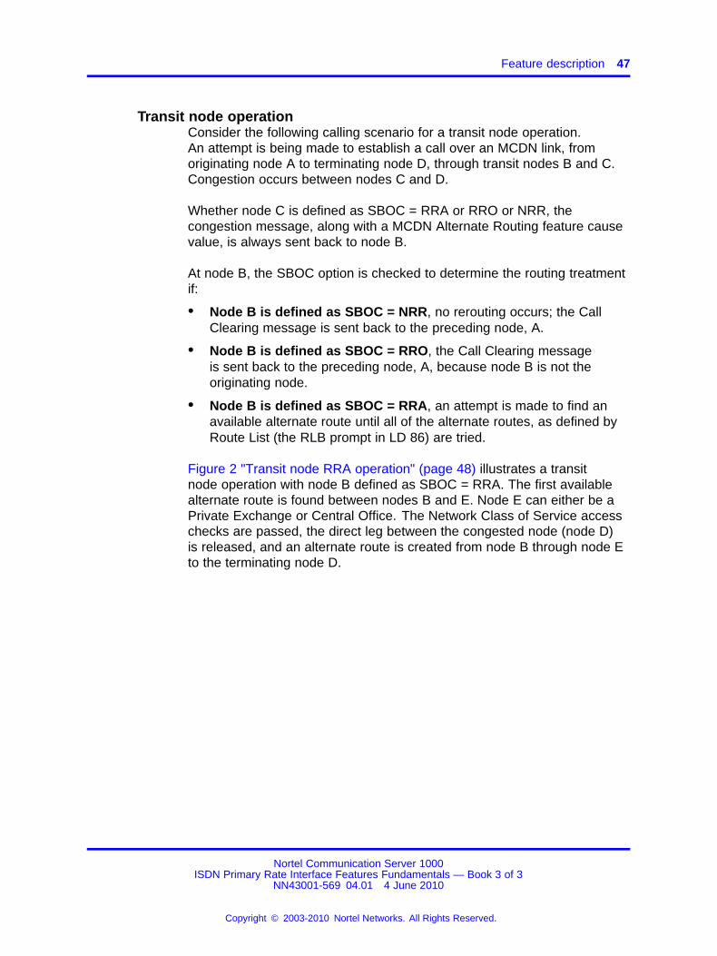
Transit node operationConsider the following calling scenario for a transit node operation.An attempt is being made to establish a call over an MCDN link, fromoriginating node A to terminating node D, through transit nodes B and C.Congestion occurs between nodes C and D.
Whether node C is defined as SBOC = RRA or RRO or NRR, thecongestion message, along with a MCDN Alternate Routing feature causevalue, is always sent back to node B.
At node B, the SBOC option is checked to determine the routing treatmentif:
• Node B is defined as SBOC = NRR, no rerouting occurs; the CallClearing message is sent back to the preceding node, A.
• Node B is defined as SBOC = RRO, the Call Clearing messageis sent back to the preceding node, A, because node B is not theoriginating node.
• Node B is defined as SBOC = RRA, an attempt is made to find anavailable alternate route until all of the alternate routes, as defined byRoute List (the RLB prompt in LD 86) are tried.
Figure 2 "Transit node RRA operation" (page 48) illustrates a transitnode operation with node B defined as SBOC = RRA. The first availablealternate route is found between nodes B and E. Node E can either be aPrivate Exchange or Central Office. The Network Class of Service accesschecks are passed, the direct leg between the congested node (node D)is released, and an alternate route is created from node B through node Eto the terminating node D.
Nortel Communication Server 1000ISDN Primary Rate Interface Features Fundamentals — Book 3 of 3
NN43001-569 04.01 4 June 2010
Copyright © 2003-2010 Nortel Networks. All Rights Reserved.
.

48 MCDN Alternate Routing
Figure 2Transit node RRA operation
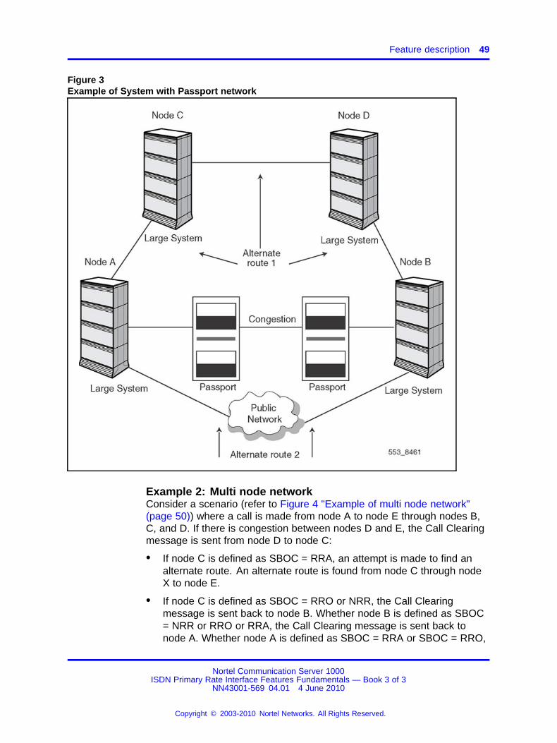
MCDN Alternate Routing examplesExample 1: System networked with PassportIn this scenario (refer to Figure 3 "Example of System with Passportnetwork" (page 49)), node A attempts to call node B using a primary routethrough Passport. The primary route is congested. Passport sends thecause value in the Call Clearing message to node A. With node A definedas SBOC = RRA or RRO, the cause value triggers a retry to make thecall through the next alternate route. Alternate route 1 is from node A tonode B through nodes C and D. If alternate route 1 is unavailable, thenan attempt is made to route the call through alternate route 2: node A tonode B through the Public Network.
Nortel Communication Server 1000ISDN Primary Rate Interface Features Fundamentals — Book 3 of 3
NN43001-569 04.01 4 June 2010
Copyright © 2003-2010 Nortel Networks. All Rights Reserved.
.
Feature description 49
Figure 3Example of System with Passport network
Example 2: Multi node networkConsider a scenario (refer to Figure 4 "Example of multi node network"(page 50)) where a call is made from node A to node E through nodes B,C, and D. If there is congestion between nodes D and E, the Call Clearingmessage is sent from node D to node C:
• If node C is defined as SBOC = RRA, an attempt is made to find analternate route. An alternate route is found from node C through nodeX to node E.
• If node C is defined as SBOC = RRO or NRR, the Call Clearingmessage is sent back to node B. Whether node B is defined as SBOC= NRR or RRO or RRA, the Call Clearing message is sent back tonode A. Whether node A is defined as SBOC = RRA or SBOC = RRO,
Nortel Communication Server 1000ISDN Primary Rate Interface Features Fundamentals — Book 3 of 3
NN43001-569 04.01 4 June 2010
Copyright © 2003-2010 Nortel Networks. All Rights Reserved.
.

50 MCDN Alternate Routing
an attempt is made to find an alternate route. Alternate routes in thiscase are either from node A through node X to node E or from node Ato node E through the Public Network.
Figure 4Example of multi node network
Example 3: Tandem call with non-ISDN originating nodeThis scenario (refer to Figure 5 "Example of a tandem call with non-ISDNoriginating node" (page 51)) shows a tandem call with a non-ISDNoriginating node. When a call is made from node A to node D, the call isrouted through nodes B and C. Congestion is encountered between nodesC and D.
Whether node C is defined as SBOC = RRA or RRO or NRR, the CallClearing message is always sent back to node B.
• If node B is defined as SBOC = RRA, an attempt is made to find analternate route. The alternate route through node X or through thePublic Network to terminating node D is used to route the call.
• If node B is defined as SBOC = RRO or NRR, no alternate routing isattempted because the link between nodes B and A is non-ISDN. Thecall is cleared according to non-MCDN Alternate Routing operations.
Nortel Communication Server 1000ISDN Primary Rate Interface Features Fundamentals — Book 3 of 3
NN43001-569 04.01 4 June 2010
Copyright © 2003-2010 Nortel Networks. All Rights Reserved.
.

Feature interactions 51
Figure 5Example of a tandem call with non-ISDN originating node
Operating parametersRoute Access codes are not supported for MCDN Alternate Routing.The Coordinated Dialing Plan (CDP) or the Uniform Dialing Plan (UDP)is required for MCDN Alternate Routing, but not both. If UDP is used,Network Alternate Route Selection (NARS) or Basic Alternate RouteSelection (BARS) must be provisioned.
The MCDN Alternate Routing feature does not support MCDN ISDN BRItrunks.
Feature interactionsAutomatic Least Cost Routing
When a Call Clearing message is received, the MCDN Alternate Routingfeature attempts a retry through the next alternative route, whether thealternative route is an Initial Set (ISET) or an Extend Set (ESET) route.
Drop Back BusyIf both the MCDN Alternate Routing feature and Drop Back Busy featureare configured in the same MCDN network, the MCDN Alternate Routingfeature takes precedence.
Nortel Communication Server 1000ISDN Primary Rate Interface Features Fundamentals — Book 3 of 3
NN43001-569 04.01 4 June 2010
Copyright © 2003-2010 Nortel Networks. All Rights Reserved.
.
52 MCDN Alternate Routing
Expensive Route Warning ToneThe Expensive Route Warning Tone is provided at the originating nodewhen the MCDN Alternate Routing attempts to re-route the call throughan expensive route. The Expensive Route Warning Tone is not providedwhen re-route to an expensive route occurs at a transit node.
Intercept treatmentThe intercept treatment for network blocking is not applied at the transitnode if the MCDN Alternate Routing feature is active at the transit node.The call is dropped back with the appropriate congestion IE information.
If the MCDN Alternate Routing feature fails to find an alternate route fora call encountering congestion at a transit node, intercept treatment isnot applied at the transit node. The call is dropped back to the originatingnode with the appropriate congestion IE information.
Integrated Services AccessThe MCDN Alternate Routing feature is supported for MCDN IntegratedServices Access (ISA) routes.
ISDN Signaling LinkThe MCDN Alternate Routing feature is supported for MCDN D-ChannelISDN Signaling Link (ISL) routes.
Network Attendant ServiceThe Network Attendant Service (NAS) feature operation is transparent tothe MCDN Alternate Routing. The NAS drop back function takes priorityover the MCDN Alternate Routing drop back function.
Off-Hook QueuingOff-Hook Queuing (OHQ) takes precedence over the MCDN AlternateRouting feature. At the node where congestion is first encountered, ifall outgoing routes are busy, the call is cleared back immediately to thepreceding node only if there are no queuing features at this node.
The MCDN Alternate Routing feature comes into operation only at thepreceding node when a Call Clearing message is received. OHQ waitsuntil the busy route becomes available. If this route does not becomeavailable before OHQ times out, a Call Clearing message is sent.
Overlap SignalingThe MCDN Alternate Routing feature is supported over both the enblocand overlap signaling methods.
Nortel Communication Server 1000ISDN Primary Rate Interface Features Fundamentals — Book 3 of 3
NN43001-569 04.01 4 June 2010
Copyright © 2003-2010 Nortel Networks. All Rights Reserved.
.

Feature interactions 53
Remote Virtual QueuingThe MCDN Alternate Routing feature takes precedence over RemoteVirtual Queuing (RVQ) when congestion is encountered at the tandemnode: an attempt is made to find an alternative route instead of informingthe call originator to activate Ring Again Allowed.
Trunk BarringIf trunk barring prevents any trunk to trunk connection at the tandem node,the MCDN Alternate Routing feature retries on the next available route inthe Route List Index (RLI).
Vacant Number RoutingVacant Number Routing (VNR) is a default route used for routinguntranslatable, invalid or unassigned dialed numbers (DN). IP networksusually contain only a subset of the numbers that can be used to reachthem. An enterprise network rarely has sufficient data to route calls basedon prefixes. Therefore, calls to the IP network need to be able to rerouteto alternate routes, while maintaining the ability to receive vacant numbertreatment when the called destination is an unassigned number. The mainpurpose of the VNR enhancement feature is to provide appropriate callclearing treatment for ’vacant number’ calls over IP domain.
This feature combines the functionality of VNR and Meridian CustomerDefined Network Alternate Routing (MALT) for calls routed over IP, toroute the call to the correct destination and provide appropriate vacantnumber treatment.
This feature also allows the user to configure predefined cause values toperform MALT, using Element Manager. The feature interacts with theElement Manager to determine whether to provide MALT for a particularcause. EM provides ten causes to perform MALT for VNR calls. For moreinformation about configuring MALT VNR, see Element Manager SystemReference - Administration (NN43001-632) and IP Peer NetworkingInstallation and Commissioning (NN43001-313).
The MALT and VNR on IP feature uses Call to Vacant Number (CTVN) toprovide treatment for the VNR call, but does not change any of the CTVNfunctionality.
There are no specific requirements for upgrade. However, when a systemis downgraded from 7.0, ensure that the lower release systems havethe correct patches to build reason header when interacting with higherreleases.
Nortel Communication Server 1000ISDN Primary Rate Interface Features Fundamentals — Book 3 of 3
NN43001-569 04.01 4 June 2010
Copyright © 2003-2010 Nortel Networks. All Rights Reserved.
.

54 MCDN Alternate Routing
MALT on calls routed by VNR to the IP domainWhen a call is routed by Vacant Number Routing (VNR) to the IP network,the user can perform MCDN Alternate Routing (MALT) for an additionalten causes, along with the existing six causes. These extra MALT causescan be configured in Element Manager. If the call is determined to be aVNR call, which is tried at least once to route over an IP route, then vacantnumber treatment is provided to the call.
When a call fails to route to the destination over H.323/SIP (for example,with reason "No entry present in the NRS/SPS" or due to rejection from thedestination side), the call disconnects with a cause, which matches one ofthe original MALT cause codes, or disconnects with an indication to “useMALT”. Based on this information, MALT is performed at the Call Server toretry the call using an alternate route.
If MALT exhausts all routes in the VNR route list block (RLB) identified bythe then the Route List Index (RLI), or an intermediate entry to a TDMroute fails with a cause code other than the original MALT cause codes,then the treatment corresponding to the disconnect cause is provided. Ifthe call clearing message has the cause ‘Unassigned Number’ or ‘InvalidNumber format’ in all the accessed entries of the VNR RLI, then vacantnumber treatment is provided.
If any of the accessed entries clear the call with a cause other thanUnassigned Number or Invalid number format, and the last entry clearedthe call as an Unassigned Number, then the treatment corresponding tothe previous cause is provided. Vacant number treatment is not providedto that call.
If MALT fails at an intermediate entry in the RLB (which is indexed by theRLI) then the alternate routing may end abruptly. For a non IP route, onlythe six MALT cause codes are used. For non QSIG or non MCDN routes,alternate routing is not triggered.
Note: MALT is performed in the CS when there is an IP FEATURE IEwith MALT indication in the call clearing message, irrespective of thecall type (VNR/non VNR). This feature is limited to VNR calls over IP,originating from a CS 1000.
Configurable MALT causes for different vendors IP gatewaysElement Manager allows different vendors (subdivided into “All NortelComponent” and “Third Party”) to configure ten causes (in addition to theexisting six MALT causes) to perform MALT at CS 1000.
If a call is disconnected prior to establishing, and the call clearing messageuses one of the ten causes on the Signaling Server to perform MALT, thena new IP Information Element (IE) is built with an indication “use MALT”
Nortel Communication Server 1000ISDN Primary Rate Interface Features Fundamentals — Book 3 of 3
NN43001-569 04.01 4 June 2010
Copyright © 2003-2010 Nortel Networks. All Rights Reserved.
.

Feature interactions 55
with the cause in the received clearing message. This IE is sent to theCall Server with the ’Disconnect’ message, and it triggers MALT for theparticular cause.
In Element Manager, the ’Unassigned Number’ cause is selected bydefault to perform MALT for Nortel and third party vendors.
The feature does not introduce any new configuration changes in CS.Table 20 "Parameters added for MALT causes configuration" (page55) details the ten parameters added to support VNR and MALTconfiguration for Nortel and third party vendors.
Table 20Parameters added for MALT causes configuration
Parameter EM Description Defaultvalue
Range
01 - UnassignedNumber Unassigned number 1 0 and 1
20 - SubscriberAbsent Subscriber absent 0 0 and 1
47 - ResourcesUnavailable Resources unavailable 0 0 and 1
51 - CallRejected Call rejected 0 0 and 1
52 - OutgoingCallBarred Outgoing call barred 0 0 and 1
53 - OutgoingCallBarredCUG Outgoing call barred CUG 0 0 and 1
54 - IncomingCallBarred Incoming call barred 0 0 and 1
55 - IncomingCallBarredCUG Incoming call barred CUG 0 0 and 1
63 - ServiceOrOptionNotAvailable Service or option not available 0 0 and 1
127 - InternetworkingUnspecified Internetworking unspecified 0 0 and 1
For more information about configuring MALT VNR, see Element ManagerSystem Reference - Administration (NN43001-632)
LimitationsThe feature is supported only for IP routes (H323/SIP).
The feature supports only PRI/PRI2/ISL over TDM SL1 interface as a fallback route/first route. Other interfaces such as QSIG, EURO, DPNSS, andANALOG are not considered a part of this feature.
The CS 1000 uses MCDN between the CS and SS and therefore as theTDM to IP protocol; it does not use QSIG.
The feature is supported only with Element Manager on Linux.
Nortel Communication Server 1000ISDN Primary Rate Interface Features Fundamentals — Book 3 of 3
NN43001-569 04.01 4 June 2010
Copyright © 2003-2010 Nortel Networks. All Rights Reserved.
.
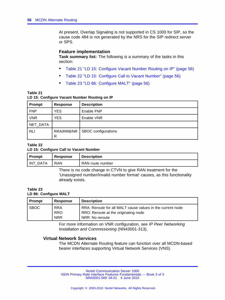
56 MCDN Alternate Routing
At present, Overlap Signaling is not supported in CS 1000 for SIP, so thecause code 484 is not generated by the NRS for the SIP redirect serveror SPS.
Feature implementationTask summary list: The following is a summary of the tasks in thissection:
• Table 21 "LD 15: Configure Vacant Number Routing on IP" (page 56)
• Table 22 "LD 15: Configure Call to Vacant Number" (page 56)
• Table 23 "LD 86: Configure MALT" (page 56)
Table 21LD 15: Configure Vacant Number Routing on IP
Prompt Response Description
FNP YES Enable FNP
VNR YES Enable VNR
NET_DATA
RLI RRA/RRB/NRR
SBOC configurations
Table 22LD 15: Configure Call to Vacant Number
Prompt Response Description
INT_DATA RAN RAN route number
There is no code change in CTVN to give RAN treatment for the’Unassigned number/Invalid number format’ causes, as this functionalityalready exists.
Table 23LD 86: Configure MALT
Prompt Response Description
SBOC RRARRONRR
RRA: Reroute for all MALT cause values in the current nodeRRO: Reroute at the originating nodeNRR: No reroute
For more information on VNR configuration, see IP Peer NetworkingInstallation and Commissioning (NN43001-313).
Virtual Network ServicesThe MCDN Alternate Routing feature can function over all MCDN-basedbearer interfaces supporting Virtual Network Services (VNS).
Nortel Communication Server 1000ISDN Primary Rate Interface Features Fundamentals — Book 3 of 3
NN43001-569 04.01 4 June 2010
Copyright © 2003-2010 Nortel Networks. All Rights Reserved.
.
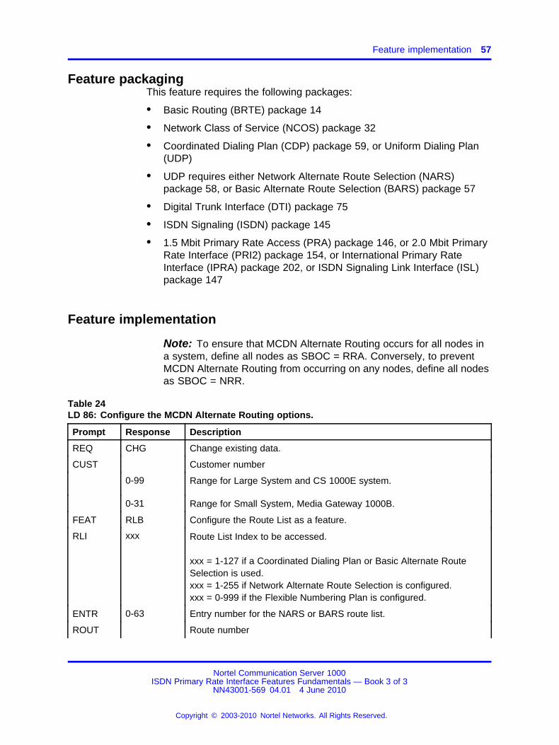
Feature implementation 57
Feature packagingThis feature requires the following packages:
• Basic Routing (BRTE) package 14
• Network Class of Service (NCOS) package 32
• Coordinated Dialing Plan (CDP) package 59, or Uniform Dialing Plan(UDP)
• UDP requires either Network Alternate Route Selection (NARS)package 58, or Basic Alternate Route Selection (BARS) package 57
• Digital Trunk Interface (DTI) package 75
• ISDN Signaling (ISDN) package 145
• 1.5 Mbit Primary Rate Access (PRA) package 146, or 2.0 Mbit PrimaryRate Interface (PRI2) package 154, or International Primary RateInterface (IPRA) package 202, or ISDN Signaling Link Interface (ISL)package 147
Feature implementation
Note: To ensure that MCDN Alternate Routing occurs for all nodes ina system, define all nodes as SBOC = RRA. Conversely, to preventMCDN Alternate Routing from occurring on any nodes, define all nodesas SBOC = NRR.
Table 24LD 86: Configure the MCDN Alternate Routing options.
Prompt Response Description
REQ CHG Change existing data.
CUST Customer number
0-99 Range for Large System and CS 1000E system.
0-31 Range for Small System, Media Gateway 1000B.
FEAT RLB Configure the Route List as a feature.
RLI xxx Route List Index to be accessed.
xxx = 1-127 if a Coordinated Dialing Plan or Basic Alternate RouteSelection is used.xxx = 1-255 if Network Alternate Route Selection is configured.xxx = 0-999 if the Flexible Numbering Plan is configured.
ENTR 0-63 Entry number for the NARS or BARS route list.
ROUT Route number
Nortel Communication Server 1000ISDN Primary Rate Interface Features Fundamentals — Book 3 of 3
NN43001-569 04.01 4 June 2010
Copyright © 2003-2010 Nortel Networks. All Rights Reserved.
.
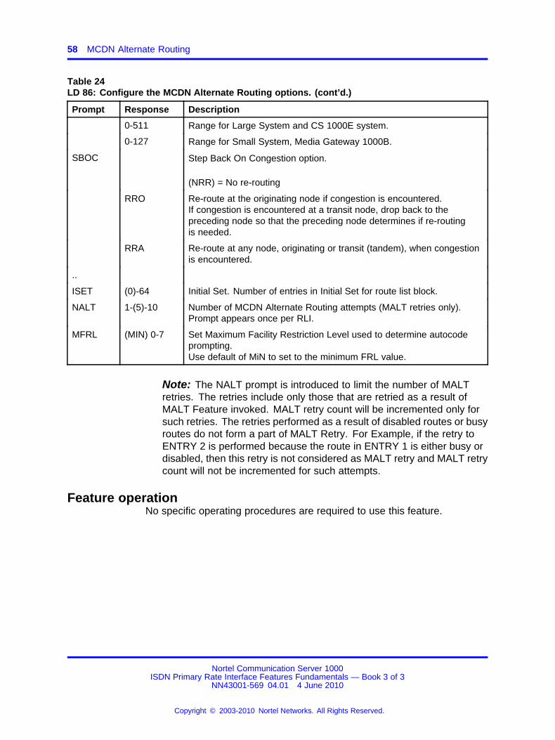
58 MCDN Alternate Routing
Table 24LD 86: Configure the MCDN Alternate Routing options. (cont’d.)
Prompt Response Description
0-511 Range for Large System and CS 1000E system.
0-127 Range for Small System, Media Gateway 1000B.
SBOC Step Back On Congestion option.
(NRR) = No re-routing
RRO Re-route at the originating node if congestion is encountered.If congestion is encountered at a transit node, drop back to thepreceding node so that the preceding node determines if re-routingis needed.
RRA Re-route at any node, originating or transit (tandem), when congestionis encountered.
..
ISET (0)-64 Initial Set. Number of entries in Initial Set for route list block.
NALT 1-(5)-10 Number of MCDN Alternate Routing attempts (MALT retries only).Prompt appears once per RLI.
MFRL (MIN) 0-7 Set Maximum Facility Restriction Level used to determine autocodeprompting.Use default of MiN to set to the minimum FRL value.
Note: The NALT prompt is introduced to limit the number of MALTretries. The retries include only those that are retried as a result ofMALT Feature invoked. MALT retry count will be incremented only forsuch retries. The retries performed as a result of disabled routes or busyroutes do not form a part of MALT Retry. For Example, if the retry toENTRY 2 is performed because the route in ENTRY 1 is either busy ordisabled, then this retry is not considered as MALT retry and MALT retrycount will not be incremented for such attempts.
Feature operationNo specific operating procedures are required to use this feature.
Nortel Communication Server 1000ISDN Primary Rate Interface Features Fundamentals — Book 3 of 3
NN43001-569 04.01 4 June 2010
Copyright © 2003-2010 Nortel Networks. All Rights Reserved.
.

59.
MCDN End to End Transparency
ContentsThis section contains information on the following topics:
“Feature description” (page 59)
“Operating parameters” (page 61)
“Feature interactions” (page 63)
“Feature packaging” (page 64)
“Feature implementation” (page 67)
“Feature operation” (page 80)
Feature descriptionMeridian Customer Defined Network (MCDN) services are based onpropriety specific Integrated Services Digital Network (ISDN) signaling.The MCDN End to End Transparency (MEET) feature conveys MCDNproprietary services on a standardized interface, ISDN QSIG. The QSIGgateway supports MCDN features both in a QSIG network and a mixedMCDN/QSIG network. It is the MCDN QSIG conversion tool whichprovides the basis for support of the selected MCDN applications such asNetwork Attendant Service (NAS), Network Automatic Call Distribution(NACD), and Network Message Service (NMS). MEET supports thefollowing features:
• MCDN to QSIG encapsulation conversion tool
• NAS using the QSIG transport
• NACD using the QSIG transport
• Network Message Service - Message Center (NMS-MC) and NetworkMessage Service - Meridian Mail (NMS-MM) using the QSIG transport
Nortel Communication Server 1000ISDN Primary Rate Interface Features Fundamentals — Book 3 of 3
NN43001-569 04.01 4 June 2010
Copyright © 2003-2010 Nortel Networks. All Rights Reserved.
.
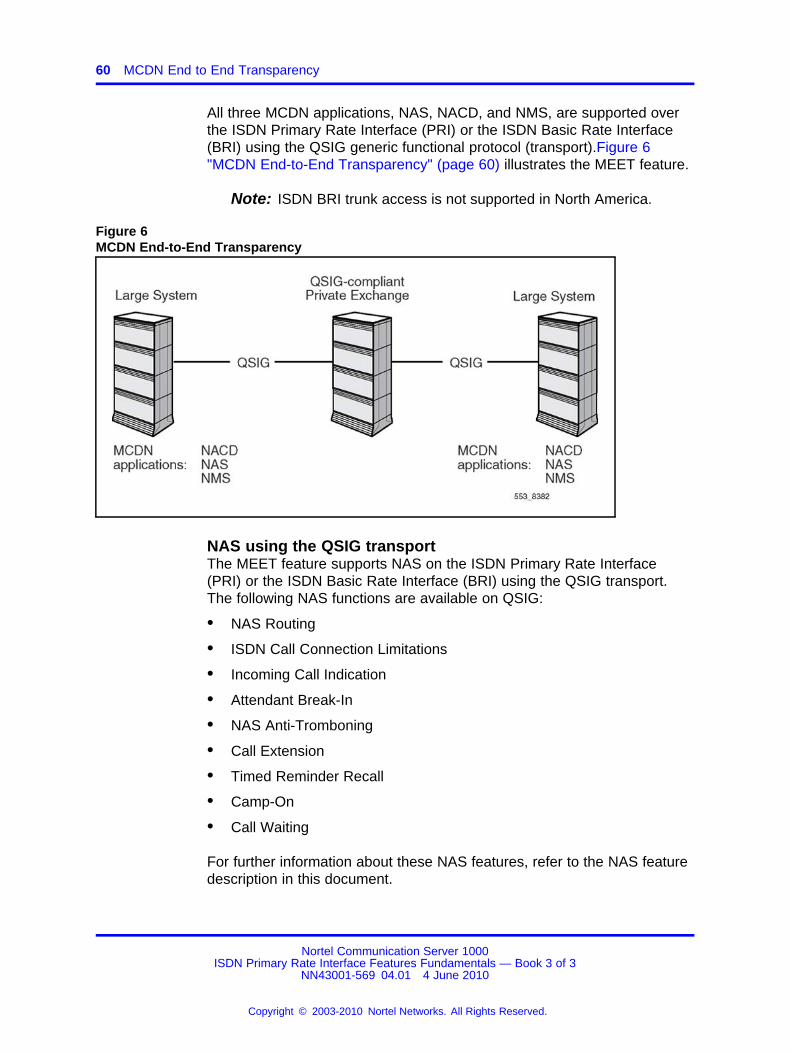
60 MCDN End to End Transparency
All three MCDN applications, NAS, NACD, and NMS, are supported overthe ISDN Primary Rate Interface (PRI) or the ISDN Basic Rate Interface(BRI) using the QSIG generic functional protocol (transport).Figure 6"MCDN End-to-End Transparency" (page 60) illustrates the MEET feature.
Note: ISDN BRI trunk access is not supported in North America.
Figure 6MCDN End-to-End Transparency
NAS using the QSIG transportThe MEET feature supports NAS on the ISDN Primary Rate Interface(PRI) or the ISDN Basic Rate Interface (BRI) using the QSIG transport.The following NAS functions are available on QSIG:
• NAS Routing
• ISDN Call Connection Limitations
• Incoming Call Indication
• Attendant Break-In
• NAS Anti-Tromboning
• Call Extension
• Timed Reminder Recall
• Camp-On
• Call Waiting
For further information about these NAS features, refer to the NAS featuredescription in this document.
Nortel Communication Server 1000ISDN Primary Rate Interface Features Fundamentals — Book 3 of 3
NN43001-569 04.01 4 June 2010
Copyright © 2003-2010 Nortel Networks. All Rights Reserved.
.
Operating parameters 61
NACD using the QSIG transportThe MEET feature supports NACD on the ISDN Primary Rate Interface(PRI) or the ISDN Basic Rate Interface (BRI) using the QSIG transport.The ESN Coordinated Dialing Plan (CDP) or Uniform Dialing Plan (UDP)is required but cannot be mixed together. The following NACD functionsare available on QSIG:
• Make Set Busy (MSB) key
• Not Ready (NRD) key
• Individual DN key (IDN)
• Dialed Number Identification Service (DNIS) and DNIS Name Display
• Calling Line Identification (CLID)
• ACD-C and ACD-D reports
For information about these NACD features, see Automatic CallDistribution Fundamentals (NN43001-351).
NMS-MC and NMS-MM using the QSIG transportThe MEET feature supports both NMS-MC and NMS-MM on the ISDNPrimary Rate Interface (PRI) or the ISDN Basic Rate Interface (BRI) usingthe QSIG transport.
NMS-MC using the QSIG transport provides:
• Message Center access (direct or indirect)
• Message Waiting Indication notification
A direct call results from a station dialing the DN of the Message Centeror pressing the Message Waiting key. An indirect call is a call networkredirected to the Message Center.
NMS-MM using the QSIG transport provides:
• Meridian Mail access (direct or indirect)
• Message Waiting Indication notification
• NMS-MM features except Call Sender and Thru-Dialing
For further information about these NMS-MC and MNS-MM features, seethe NAS feature description in this document.
Operating parametersThe Manufacturer Specific Information (MSI) carries the MCDN proprietaryinformation transparently over a QSIG network. The third-party node mustsupport the QSIG generic functional protocol (transport) and MSI.
Nortel Communication Server 1000ISDN Primary Rate Interface Features Fundamentals — Book 3 of 3
NN43001-569 04.01 4 June 2010
Copyright © 2003-2010 Nortel Networks. All Rights Reserved.
.

62 MCDN End to End Transparency
Directory Number (DN) address translation requires the association with acustomer number, as configured using the CUST prompt in LD 15.
Either CDP or UDP is required, but they can not be mixed together.
Digit manipulation is not supported for DN transported on QSIG.
Operating parameters for NAS using the QSIG transportAttendant and users must be located on system nodes to obtain full NAScapabilities.
For NAS Anti-Tromboning capability, both legs must be on the sameD-Channel. If the tromboning occurs with one MCDN trunk and oneQSIG trunk, the redundant legs are not removed because they are notassociated with the same D-Channel.
For a call established through International Standards Organization (ISO)QSIG trunks, the transit counter information is not updated at a QSIGtandem node because the message information is transparent; therefore,the transit counter does not reflect exactly the number of transit nodes thecall has gone through.
NAS using the QSIG transport does not support Supervisory Console,Call Park, Charge Account, Do Not Disturb and Group Do Not Disturb,Barge-in, or Emergency Transfer.
There is no gateway developed between NAS functionalities usingthe QSIG transport and the corresponding DPNSS services. At aQSIG/DPNSS gateway, if NAS information is present, the NAS informationis discarded.
Operating parameters for NACD using the QSIG transportWith the MEET feature, NACD continues to work fully with Symposiumin an MCDN network. The MEET feature does not support NACD withSymposium using the QSIG transport or a mixed MCDN/QSIG network.
Messages which are resent at the first timer expiration on MCDN are sentonce only on QSIG. At the first timer expiration on QSIG, the transaction iscancelled. This applies to the following messages: database update, thelogical call request, the cancellation (from source or from target and forany reason) and the status exchange.
Operating parameters for NMS-MC and NMS-MM using the QSIGtransport
NMS-MC and NMS-MM using the QSIG transport indirect access arebased on the QSIG Call Diversion feature. The QSIG Call Diversionfeature must be available and configured in the network.
Nortel Communication Server 1000ISDN Primary Rate Interface Features Fundamentals — Book 3 of 3
NN43001-569 04.01 4 June 2010
Copyright © 2003-2010 Nortel Networks. All Rights Reserved.
.
Feature interactions 63
NMS-MC using the QSIG transport is provided for NMS-MC users andoperations located on system nodes.
NMS-MM using the QSIG transport supports all NMS-MM features exceptCall Sender and Thru-Dialing.
Feature interactionsFeature interactions with NAS using the QSIG transport
Interactions specific to NAS using the QSIG transport are discussed in thefollowing section. Refer to the NAS feature description in this document forgeneric NAS feature interactions.
QSIG Transit CounterThe QSIG Transit Counter Information Element (IE) is defined only withthe ETSI interface; it carries the number of transit nodes the call has gonethrough. It is updated when a SETUP is sent on an ETSI QSIG trunk.Similarly, the NAS ISDN Call Connection Limitations (ICCL) information isupdated when a SETUP is sent on a NAS MCDN or QSIG trunk.
For a call established using the International Standards Organization (ISO)interface for QSIG trunks, the counter information is not updated at a QSIGtandem node because the message information is transparent; therefore,the transit counter does not reflect exactly the number of transit nodes thecall has gone through.
QSIG Attendant RecallQSIG Attendant Recall allows a call extended on an ETSI QSIG trunk torecall the attendant if it is not answered within a customer-defined time.When ETSI QSIG is used and MQC_FEAT is set to NAS, NAS TimedReminder Recall is enabled and takes precedence over QSIG AttendantRecall.
QSIG ANF Path Replacement/QSIG Call TransferQSIG ANF Path Replacement allows an established connection througha QSIG private network to be replaced by a new connection after a callmodification to obtain a more efficient connection. It handles triangulationas well as tromboning mechanisms.
QSIG ANF Path Replacement take precedence on NAS anti-tromboningif the "Call transfer complete" FACILITY message is received beforethe ÔCall extension complete" FACILITY message. Otherwise, NASanti-tromboning applies and the QSIG ANF Path Replacement is notinitiated when a ÔCall transfer complete’ FACILITY message is received.
Nortel Communication Server 1000ISDN Primary Rate Interface Features Fundamentals — Book 3 of 3
NN43001-569 04.01 4 June 2010
Copyright © 2003-2010 Nortel Networks. All Rights Reserved.
.
64 MCDN End to End Transparency
Feature interactions with NACD using the QSIG transportInteractions specific to NACD using the QSIG transport are discussed inthe following section. Refer to Automatic Call Distribution Fundamentals(NN43001-351) for information on generic NACD feature interactions.
QSIG Name DisplayWhen QSIG Name Display is configured using the QSIG transportD-Channels and the name is allowed to be displayed and if the call isdiverted to the target node through NACD routing, the originator’s name isdisplayed on the target agent’s phone and the name of the target agent’sACD DN is displayed on the originator’s phone when the target agentanswers the call.
Feature interactions with NMS-MC using the QSIG transportInteractions specific to NMS-MC using the QSIG transport are discussedin the following section. Refer toAutomatic Call Distribution Fundamentals(NN43001-351) for information on generic NACD feature interactions.
NACD and NAS encapsulation within QSIGFor ACD and attendant Message Centers that are NACD or NAS, theACD agents and attendants can reside at different nodes. With packagingrequirements satisfied at the node where the MC call is presented, eitherthe NACD agents or the NAS attendants are treated as a Message Center.
If the Message Center is an attendant, the NMS-MC feature operationremains the same as for a simple NMS-MC phone. If the attendantNMS-MC has a specific ICI key defined, when a message Waiting callterminates to the attendant NMC-MC, the ICI lamp changes to lit toindicate a NMS-MC call.
As for MCDN, it is not recommended to use NACD or NAS as a NMS-MCunless the message data base can be made available to all agents orattendants at different nodes.
Feature packagingThis feature requires the following packages:
• Multi-purpose Serial Data Link (MSDL) package 222
• QM reference signaling point Interface (QSIG) package 263
• QSIG Generic Functional protocol (QSIGGF) package 305
• MCDN End to End Transparency (MEET) package 348
Depending on the application, other packages are also required.
For the QSIG ISDN PRI interface, the following packages are alsorequired:
Nortel Communication Server 1000ISDN Primary Rate Interface Features Fundamentals — Book 3 of 3
NN43001-569 04.01 4 June 2010
Copyright © 2003-2010 Nortel Networks. All Rights Reserved.
.
Feature packaging 65
• ISDN Signaling (ISDN) package 145
• Advanced ISDN Network Services (NTWK) package 148
• 1.5 Mbit Primary Rate Access (PRA) package 146, or
• 2.0 Mbit Primary Rate Interface (PRI2) package 154, or
• International Primary Rate Interface (IPRA) package 202
The following software packages are required for this feature to operateover QSIG ISDN BRI Trunks:
Note: ISDN BRI trunk access is not supported in North America.
• Basic Rate Interface (BRI) 216
• ISDN BRI Trunk Access (BRIT) 233
For NAS using the QSIG transport, you must have the ISDN PRI packagesor ISDN BRI package and the following packages (the same packages asrequired for on the MCDN transport):
• Basic Routing (BRTE) package 14
• Basic Queuing (BQUE) package 28
• Network Class of Service (NCOS) package 32
• Network Alternate Route Selection (NARS) package 58
• Coordinated Dialing Plan (CDP) package 59
• Flexible Call Back Queuing (FCBQ) package 61
• Multi-Tenant Service (TENS) package 86
• Attendant Break-In/Trunk Offer (BKI) package 127
• Network Attendant Service (NAS) package 159
• ISDN Supplementary Features (ISDN INTL SUP) package 161
• Remote Virtual Queuing (ORC/RVQ) package 192
Note 1: NAS packages and Attendant Overflow Position (AOP) aremutually exclusive and cannot be equipped on the same system.
Note 2: NAS packages and Centralized Attendant Service (CAS) aremutually exclusive and cannot be packaged together.
For NACD using the QSIG transport, you must have the ISDN PRIpackages or the ISDN BRI package and the following packages (the samepackages as required for NACD on the MCDN transport):
• Basic Routing (BRTE) package 14
• Digit Display (DDSP) package 19
Nortel Communication Server 1000ISDN Primary Rate Interface Features Fundamentals — Book 3 of 3
NN43001-569 04.01 4 June 2010
Copyright © 2003-2010 Nortel Networks. All Rights Reserved.
.
66 MCDN End to End Transparency
• Basic Queuing (BQUE) package 28
• Network Class of Service (NCOS) package 32
• Basic Automatic Call Distribution (BACD) package 40
• Automatic Call Distribution, Package B (ACDB), package 41
• Basic Alternate Route Selection (BARS) package 57 or CoordinatedDialing Plan (CDP) package 59 or Network Alternate Route Selection(NARS) package 58
• ACD Enhanced Flow (EOVF) package 178
• Network Automatic Call Distribution (NACD) package 207
For NMS-MC using the QSIG transport, you must have the ISDN PRIpackages or ISDN BRI package and the following packages (the samepackages as required for NMS-MC on the MCDN transport):
• Message Waiting Center (MWC) package 46
• Network Message Services (NMS) package 175
In addition, Automatic Call Distribution (ACD) Messages Services requirethe following ACD packages.
• Basic Automatic Call Distribution (BACD) package 40
• Automatic Call Distribution, Package B (ACDB), package 41
• Automatic Call Distribution, Package C, (ACDC) package 42
• Automatic Call Distribution, Package A (ACDA) package 45
For NMS-MM using the QSIG transport, you must have the ISDN PRIpackages or ISDN BRI package and the following packages (the samepackages as required for NMS-MM on the MCDN transport):
• End-to-End Signaling (EES) package 10
• Integrated Message System (IMS) package 35 (for home node only)
• Basic Automatic Call Distribution (BACD) package 40
• Automatic Call Distribution, Package A (ACDA) package 45
• Message Waiting Center (MWC) package 46
• Command/Status Link (Class of Service) package 77
• Network Message Services (NMS) package 175
Nortel Communication Server 1000ISDN Primary Rate Interface Features Fundamentals — Book 3 of 3
NN43001-569 04.01 4 June 2010
Copyright © 2003-2010 Nortel Networks. All Rights Reserved.
.
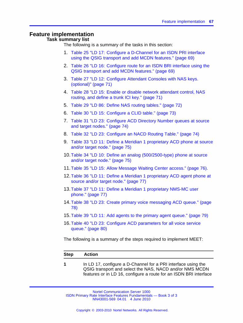
Feature implementation 67
Feature implementationTask summary list
The following is a summary of the tasks in this section:
1. Table 25 "LD 17: Configure a D-Channel for an ISDN PRI interfaceusing the QSIG transport and add MCDN features." (page 69)
2. Table 26 "LD 16: Configure route for an ISDN BRI interface using theQSIG transport and add MCDN features." (page 69)
3. Table 27 "LD 12: Configure Attendant Consoles with NAS keys.(optional)" (page 71)
4. Table 28 "LD 15: Enable or disable network attendant control, NASrouting, and define a trunk ICI key." (page 71)
5. Table 29 "LD 86: Define NAS routing tables." (page 72)
6. Table 30 "LD 15: Configure a CLID table." (page 73)
7. Table 31 "LD 23: Configure ACD Directory Number queues at sourceand target nodes." (page 74)
8. Table 32 "LD 23: Configure an NACD Routing Table." (page 74)
9. Table 33 "LD 11: Define a Meridian 1 proprietary ACD phone at sourceand/or target node." (page 75)
10.Table 34 "LD 10: Define an analog (500/2500-type) phone at sourceand/or target node." (page 75)
11.Table 35 "LD 15: Allow Message Waiting Center access." (page 76).
12.Table 36 "LD 11: Define a Meridian 1 proprietary ACD agent phone atsource and/or target node." (page 77)
13.Table 37 "LD 11: Define a Meridian 1 proprietary NMS-MC userphone." (page 77)
14.Table 38 "LD 23: Create primary voice messaging ACD queue." (page78)
15.Table 39 "LD 11: Add agents to the primary agent queue." (page 79)
16.Table 40 "LD 23: Configure ACD parameters for all voice servicequeue." (page 80)
The following is a summary of the steps required to implement MEET:
Step Action
1 In LD 17, configure a D-Channel for a PRI interface using theQSIG transport and select the NAS, NACD and/or NMS MCDNfeatures or in LD 16, configure a route for an ISDN BRI interface
Nortel Communication Server 1000ISDN Primary Rate Interface Features Fundamentals — Book 3 of 3
NN43001-569 04.01 4 June 2010
Copyright © 2003-2010 Nortel Networks. All Rights Reserved.
.
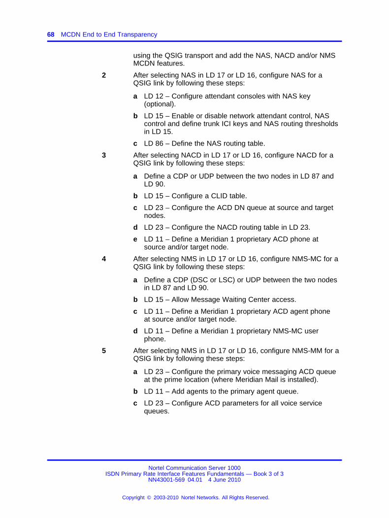
68 MCDN End to End Transparency
using the QSIG transport and add the NAS, NACD and/or NMSMCDN features.
2 After selecting NAS in LD 17 or LD 16, configure NAS for aQSIG link by following these steps:
a LD 12 – Configure attendant consoles with NAS key(optional).
b LD 15 – Enable or disable network attendant control, NAScontrol and define trunk ICI keys and NAS routing thresholdsin LD 15.
c LD 86 – Define the NAS routing table.
3 After selecting NACD in LD 17 or LD 16, configure NACD for aQSIG link by following these steps:
a Define a CDP or UDP between the two nodes in LD 87 andLD 90.
b LD 15 – Configure a CLID table.
c LD 23 – Configure the ACD DN queue at source and targetnodes.
d LD 23 – Configure the NACD routing table in LD 23.
e LD 11 – Define a Meridian 1 proprietary ACD phone atsource and/or target node.
4 After selecting NMS in LD 17 or LD 16, configure NMS-MC for aQSIG link by following these steps:
a Define a CDP (DSC or LSC) or UDP between the two nodesin LD 87 and LD 90.
b LD 15 – Allow Message Waiting Center access.
c LD 11 – Define a Meridian 1 proprietary ACD agent phoneat source and/or target node.
d LD 11 – Define a Meridian 1 proprietary NMS-MC userphone.
5 After selecting NMS in LD 17 or LD 16, configure NMS-MM for aQSIG link by following these steps:
a LD 23 – Configure the primary voice messaging ACD queueat the prime location (where Meridian Mail is installed).
b LD 11 – Add agents to the primary agent queue.
c LD 23 – Configure ACD parameters for all voice servicequeues.
Nortel Communication Server 1000ISDN Primary Rate Interface Features Fundamentals — Book 3 of 3
NN43001-569 04.01 4 June 2010
Copyright © 2003-2010 Nortel Networks. All Rights Reserved.
.
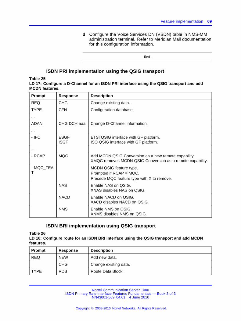
Feature implementation 69
d Configure the Voice Services DN (VSDN) table in NMS-MMadministration terminal. Refer to Meridian Mail documentationfor this configuration information.
--End--
ISDN PRI implementation using the QSIG transport
Table 25LD 17: Configure a D-Channel for an ISDN PRI interface using the QSIG transport and addMCDN features.
Prompt Response Description
REQ CHG Change existing data.
TYPE CFN Configuration database.
...
ADAN CHG DCH aaa Change D-Channel information.
...
- IFC ESGFISGF
ETSI QSIG interface with GF platform.ISO QSIG interface with GF platform.
...
- RCAP MQC Add MCDN QSIG Conversion as a new remote capability.XMQC removes MCDN QSIG Conversion as a remote capability.
--MQC_FEAT
MCDN QSIG feature type.Prompted if RCAP = MQC.Precede MQC feature type with X to remove.
NAS Enable NAS on QSIG.XNAS disables NAS on QSIG.
NACD Enable NACD on QSIG.XACD disables NACD on QSIG
NMS Enable NMS on QSIG.XNMS disables NMS on QSIG.
ISDN BRI implementation using QSIG transport
Table 26LD 16: Configure route for an ISDN BRI interface using the QSIG transport and add MCDNfeatures.
Prompt Response Description
REQ NEW Add new data.
CHG Change existing data.
TYPE RDB Route Data Block.
Nortel Communication Server 1000ISDN Primary Rate Interface Features Fundamentals — Book 3 of 3
NN43001-569 04.01 4 June 2010
Copyright © 2003-2010 Nortel Networks. All Rights Reserved.
.

70 MCDN End to End Transparency
Table 26LD 16: Configure route for an ISDN BRI interface using the QSIG transport and add MCDNfeatures. (cont’d.)
Prompt Response Description
TKTP a...a Trunk Type.
...
DTRK (NO) YES Digital Trunk Route.
- BRIP (NO) YES ISDN BRI Packet handler route
- DGTP a...a
BRI
Digital Trunk Type for route.
Basic Rate Interface (Allowed if TKTP = TIE, COT or DID andBRIP = NO
...
- IFC ESGFISGF
ETSI QSIG interface with GF platform.ISO QSIG interface with GF platform.
...
- RCAP MQC Add MCDN QSIG Conversion as a new remote capability.XMQC removes MCDN QSIG Conversion as a remote capability.
-- MQC_FEAT
MCDN QSIG feature type.Prompted if RCAP = MQC.Precede MQC feature type with X to remove.
NAS Enable NAS on QSIG.
NACD Enable NACD on QSIG.
NMS Enable NMS-MC and NMS-MM on QSIG.
NAS implementation using the QSIG transportTo configure NAS using the QSIG transport, follow these steps:
• Configure an ISDN PRI interface using the QSIG transport and selectNAS as an MCDN feature in LD 17, or configure an ISDN BRI interfaceusing the QSIG transport or and select NAS as an MCDN feature inLD 16.
• Configure NAS for a QSIG link:
— Configure attendant consoles with NAS key (optional) in LD 12.
— Enable or disable network attendant control, NAS control anddefine trunk ICI keys and NAS routing thresholds in LD 15.
— Define the NAS routing table in LD 86.
Nortel Communication Server 1000ISDN Primary Rate Interface Features Fundamentals — Book 3 of 3
NN43001-569 04.01 4 June 2010
Copyright © 2003-2010 Nortel Networks. All Rights Reserved.
.
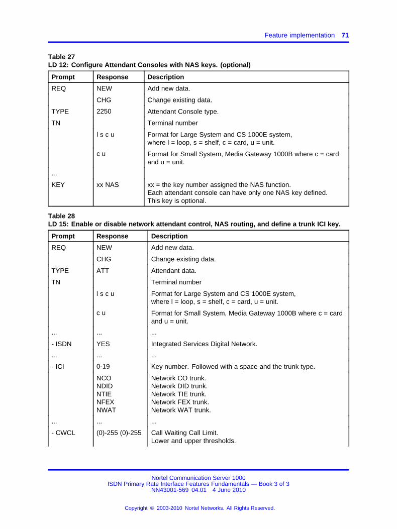
Feature implementation 71
Table 27LD 12: Configure Attendant Consoles with NAS keys. (optional)
Prompt Response Description
REQ NEW Add new data.
CHG Change existing data.
TYPE 2250 Attendant Console type.
TN Terminal number
l s c u Format for Large System and CS 1000E system,where l = loop, s = shelf, c = card, u = unit.
c u Format for Small System, Media Gateway 1000B where c = cardand u = unit.
...
KEY xx NAS xx = the key number assigned the NAS function.Each attendant console can have only one NAS key defined.This key is optional.
Table 28LD 15: Enable or disable network attendant control, NAS routing, and define a trunk ICI key.
Prompt Response Description
REQ NEW Add new data.
CHG Change existing data.
TYPE ATT Attendant data.
TN Terminal number
l s c u Format for Large System and CS 1000E system,where l = loop, s = shelf, c = card, u = unit.
c u Format for Small System, Media Gateway 1000B where c = cardand u = unit.
... ... ...
- ISDN YES Integrated Services Digital Network.
... ... ...
- ICI 0-19 Key number. Followed with a space and the trunk type.
NCONDIDNTIENFEXNWAT
Network CO trunk.Network DID trunk.Network TIE trunk.Network FEX trunk.Network WAT trunk.
... ... ...
- CWCL (0)-255 (0)-255 Call Waiting Call Limit.Lower and upper thresholds.
Nortel Communication Server 1000ISDN Primary Rate Interface Features Fundamentals — Book 3 of 3
NN43001-569 04.01 4 June 2010
Copyright © 2003-2010 Nortel Networks. All Rights Reserved.
.

72 MCDN End to End Transparency
Table 28LD 15: Enable or disable network attendant control, NAS routing, and define a trunk ICI key.(cont’d.)
Prompt Response Description
- CWTM (0)-511 (0)-511 Call Waiting Time.Lower and upper thresholds (in seconds).
... ... ...
- NAS ATCL YES (NO) Allow/deny attendant control for call extension.
- NAS ACTV YES (NO) Allow/deny NAS routing.
Table 29LD 86: Define NAS routing tables.
Prompt Response Description
REQ NEW Add new data.
CHG Change existing data.
CUST Customer number
0-99 Range for Large System and CS 1000E system.
0-31 Range for Small System, Media Gateway 1000B.
FEAT NAS Type of data.
TBL 0-63 Routing table number.Without Multi-Tenant Service, 0 is the customer routing table.With Multi-Tenant Service enabled, NAS tables 1-63 can beassociated with Console Presentation Groups (CPGs) 1-63.
ALT 1-7 An alternative attendant or routing table.(To clear an old number, type an X before typing the newnumber. The old number cannot be cleared if it is associated witha schedule period. Reach TODS by pressing the return key.)
ID xx...x<CR>
The dialed digits (including the network access code) needed toreach an attendant associated with the alternative number.Respond with a string of up to 16 digits to change the attendantID.Press the return key to leave the ID unchanged, exit the prompt,and return to ALT.
TODS 0-31 Time of Day schedule where;
0 = default to handle all time periods not defined in 1 through 31.Press the return key to continue the NAS feature setup process.
- PER hr: mm hr: mm Specify start and stop times for the period using 24-hour format.Start time must be before stop time.mm = 00 or 30 only.
<CR> <CR> = leave times unchanged; move to the DAYS prompt.
Nortel Communication Server 1000ISDN Primary Rate Interface Features Fundamentals — Book 3 of 3
NN43001-569 04.01 4 June 2010
Copyright © 2003-2010 Nortel Networks. All Rights Reserved.
.
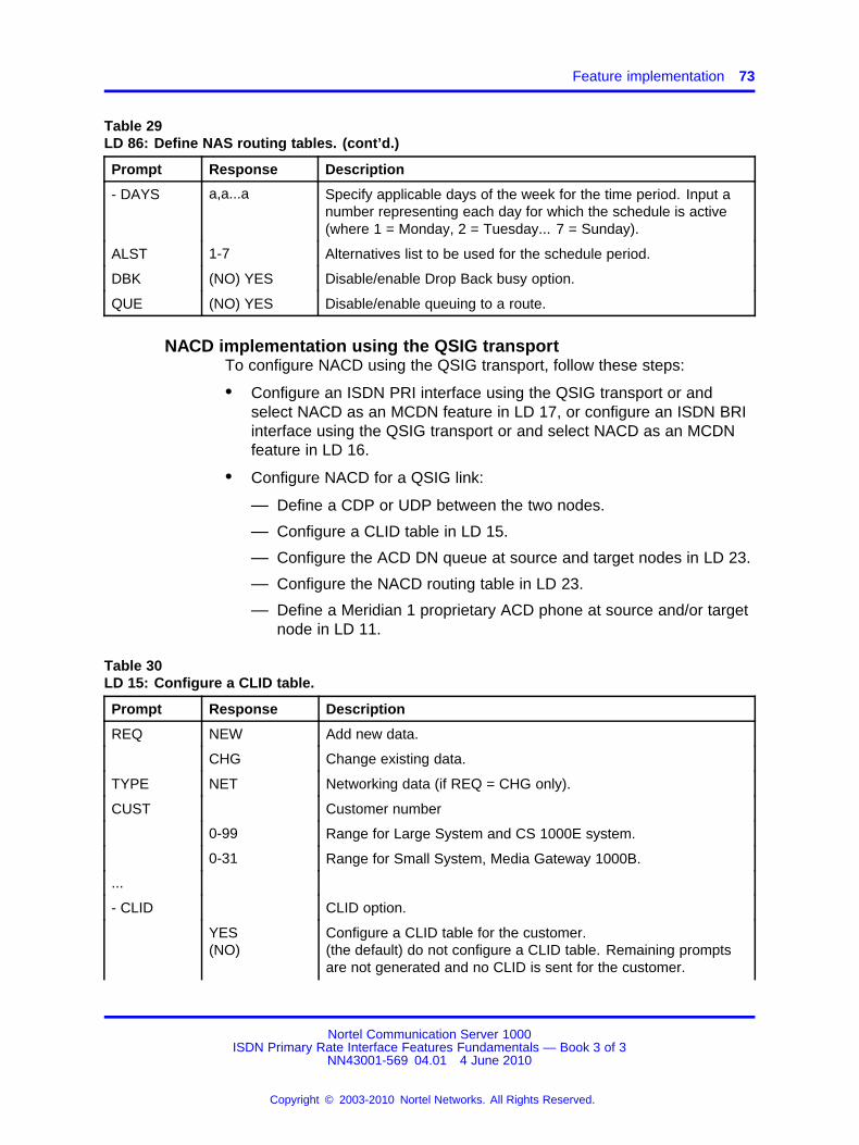
Feature implementation 73
Table 29LD 86: Define NAS routing tables. (cont’d.)
Prompt Response Description
- DAYS a,a...a Specify applicable days of the week for the time period. Input anumber representing each day for which the schedule is active(where 1 = Monday, 2 = Tuesday... 7 = Sunday).
ALST 1-7 Alternatives list to be used for the schedule period.
DBK (NO) YES Disable/enable Drop Back busy option.
QUE (NO) YES Disable/enable queuing to a route.
NACD implementation using the QSIG transportTo configure NACD using the QSIG transport, follow these steps:
• Configure an ISDN PRI interface using the QSIG transport or andselect NACD as an MCDN feature in LD 17, or configure an ISDN BRIinterface using the QSIG transport or and select NACD as an MCDNfeature in LD 16.
• Configure NACD for a QSIG link:
— Define a CDP or UDP between the two nodes.
— Configure a CLID table in LD 15.
— Configure the ACD DN queue at source and target nodes in LD 23.
— Configure the NACD routing table in LD 23.
— Define a Meridian 1 proprietary ACD phone at source and/or targetnode in LD 11.
Table 30LD 15: Configure a CLID table.
Prompt Response Description
REQ NEW Add new data.
CHG Change existing data.
TYPE NET Networking data (if REQ = CHG only).
CUST Customer number
0-99 Range for Large System and CS 1000E system.
0-31 Range for Small System, Media Gateway 1000B.
...
- CLID CLID option.
YES(NO)
Configure a CLID table for the customer.(the default) do not configure a CLID table. Remaining promptsare not generated and no CLID is sent for the customer.
Nortel Communication Server 1000ISDN Primary Rate Interface Features Fundamentals — Book 3 of 3
NN43001-569 04.01 4 June 2010
Copyright © 2003-2010 Nortel Networks. All Rights Reserved.
.
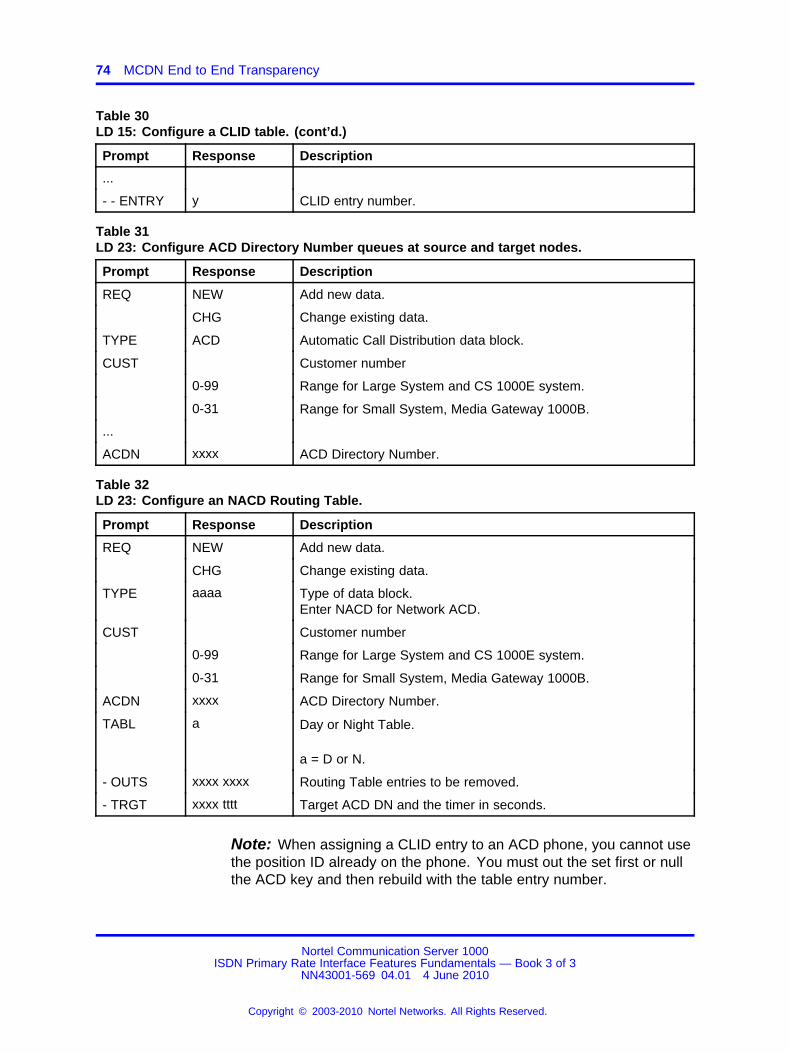
74 MCDN End to End Transparency
Table 30LD 15: Configure a CLID table. (cont’d.)
Prompt Response Description
...
- - ENTRY y CLID entry number.
Table 31LD 23: Configure ACD Directory Number queues at source and target nodes.
Prompt Response Description
REQ NEW Add new data.
CHG Change existing data.
TYPE ACD Automatic Call Distribution data block.
CUST Customer number
0-99 Range for Large System and CS 1000E system.
0-31 Range for Small System, Media Gateway 1000B.
...
ACDN xxxx ACD Directory Number.
Table 32LD 23: Configure an NACD Routing Table.
Prompt Response Description
REQ NEW Add new data.
CHG Change existing data.
TYPE aaaa Type of data block.Enter NACD for Network ACD.
CUST Customer number
0-99 Range for Large System and CS 1000E system.
0-31 Range for Small System, Media Gateway 1000B.
ACDN xxxx ACD Directory Number.
TABL a Day or Night Table.
a = D or N.
- OUTS xxxx xxxx Routing Table entries to be removed.
- TRGT xxxx tttt Target ACD DN and the timer in seconds.
Note: When assigning a CLID entry to an ACD phone, you cannot usethe position ID already on the phone. You must out the set first or nullthe ACD key and then rebuild with the table entry number.
Nortel Communication Server 1000ISDN Primary Rate Interface Features Fundamentals — Book 3 of 3
NN43001-569 04.01 4 June 2010
Copyright © 2003-2010 Nortel Networks. All Rights Reserved.
.

Feature implementation 75
Table 33LD 11: Define a Meridian 1 proprietary ACD phone at source and/or target node.
Prompt Response Description
REQ NEW Add new data.
CHG Change existing data.
TYPE a...a Telephone type. Type ? for a list of possible responses.
TN Terminal number
l s c u Format for Large System and CS 1000E system,where l = loop, s = shelf, c = card, u = unit.
c u Format for Small System, Media Gateway 1000B, where c =card and u = unit.
...
CLS (AGN)SPV
Class of Service group.AGN = (default) ACD Agent.SPV = ACD Supervisor.
...
KEY xx ACD yyyy 0-N/Dzzzz
ACD key, where:
xx = key number (must be key 0).yyyy = ACD DN or Message Center DN.0-N = CLID entry, with N = CLID SIZE-1 (SIZE defined in LD15).D = CLID entry, Search for a CLID entry from key 0 upwards,to find a DN key. the found CLID is used as the CLID entry forthe active DN key.zzzz = ACD agent’s position ID.
Refer to the note at the top of LD 11 on assigning a CLID entryto an ACD phone.
KEY Phone function key assignments.
xx MSB yyyy(0)-N/D)xx NRD yyy (0)-N/D
xx = key number.MSB = Make Set Busy key.NRD = Not Ready key.
Table 34LD 10: Define an analog (500/2500-type) phone at source and/or target node.
Prompt Response Description
REQ NEW Add new data.
CHG Change existing data.
TYPE 500 Analog (500/2500-type) phone.
Nortel Communication Server 1000ISDN Primary Rate Interface Features Fundamentals — Book 3 of 3
NN43001-569 04.01 4 June 2010
Copyright © 2003-2010 Nortel Networks. All Rights Reserved.
.
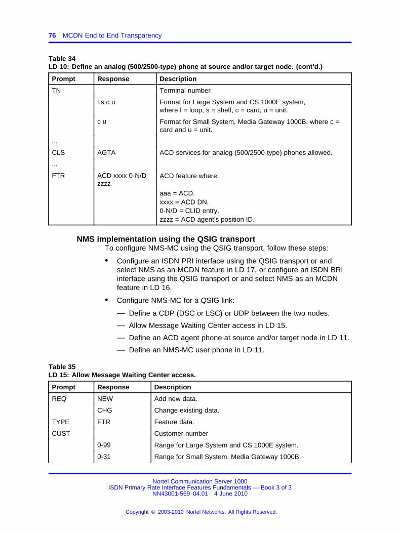
76 MCDN End to End Transparency
Table 34LD 10: Define an analog (500/2500-type) phone at source and/or target node. (cont’d.)
Prompt Response Description
TN Terminal number
l s c u Format for Large System and CS 1000E system,where l = loop, s = shelf, c = card, u = unit.
c u Format for Small System, Media Gateway 1000B, where c =card and u = unit.
...
CLS AGTA ACD services for analog (500/2500-type) phones allowed.
...
FTR ACD xxxx 0-N/Dzzzz
ACD feature where:
aaa = ACD.xxxx = ACD DN.0-N/D = CLID entry.zzzz = ACD agent’s position ID.
NMS implementation using the QSIG transportTo configure NMS-MC using the QSIG transport, follow these steps:
• Configure an ISDN PRI interface using the QSIG transport or andselect NMS as an MCDN feature in LD 17, or configure an ISDN BRIinterface using the QSIG transport or and select NMS as an MCDNfeature in LD 16.
• Configure NMS-MC for a QSIG link:
— Define a CDP (DSC or LSC) or UDP between the two nodes.
— Allow Message Waiting Center access in LD 15.
— Define an ACD agent phone at source and/or target node in LD 11.
— Define an NMS-MC user phone in LD 11.
Table 35LD 15: Allow Message Waiting Center access.
Prompt Response Description
REQ NEW Add new data.
CHG Change existing data.
TYPE FTR Feature data.
CUST Customer number
0-99 Range for Large System and CS 1000E system.
0-31 Range for Small System, Media Gateway 1000B.
Nortel Communication Server 1000ISDN Primary Rate Interface Features Fundamentals — Book 3 of 3
NN43001-569 04.01 4 June 2010
Copyright © 2003-2010 Nortel Networks. All Rights Reserved.
.
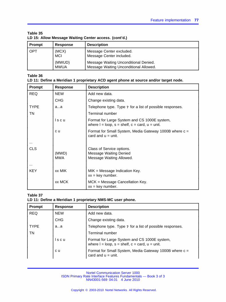
Feature implementation 77
Table 35LD 15: Allow Message Waiting Center access. (cont’d.)
Prompt Response Description
OPT (MCX)MCI
Message Center excluded.Message Center included.
(MWUD)MWUA
Message Waiting Unconditional Denied.Message Waiting Unconditional Allowed.
Table 36LD 11: Define a Meridian 1 proprietary ACD agent phone at source and/or target node.
Prompt Response Description
REQ NEW Add new data.
CHG Change existing data.
TYPE a...a Telephone type. Type ? for a list of possible responses.
TN Terminal number
l s c u Format for Large System and CS 1000E system,where l = loop, s = shelf, c = card, u = unit.
c u Format for Small System, Media Gateway 1000B where c =card and u = unit.
...
CLS(MWD)MWA
Class of Service options.Message Waiting DeniedMessage Waiting Allowed.
...
KEY xx MIK MIK = Message Indication Key.xx = key number.
xx MCK MCK = Message Cancellation Key.xx = key number.
Table 37LD 11: Define a Meridian 1 proprietary NMS-MC user phone.
Prompt Response Description
REQ NEW Add new data.
CHG Change existing data.
TYPE a...a Telephone type. Type ? for a list of possible responses.
TN Terminal number
l s c u Format for Large System and CS 1000E system,where l = loop, s = shelf, c = card, u = unit.
c u Format for Small System, Media Gateway 1000B where c =card and u = unit.
Nortel Communication Server 1000ISDN Primary Rate Interface Features Fundamentals — Book 3 of 3
NN43001-569 04.01 4 June 2010
Copyright © 2003-2010 Nortel Networks. All Rights Reserved.
.
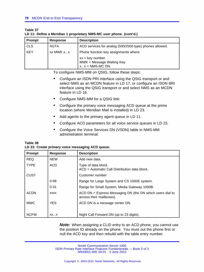
78 MCDN End to End Transparency
Table 37LD 11: Define a Meridian 1 proprietary NMS-MC user phone. (cont’d.)
Prompt Response Description
CLS AGTA ACD services for analog (500/2500-type) phones allowed.
KEY xx MWK x...x Phone function key assignments where:
xx = key number.MWK = Message Waiting Keyx...x = NMS-MC DN.
To configure NMS-MM on QSIG, follow these steps:
• Configure an ISDN PRI interface using the QSIG transport or andselect NMS as an MCDN feature in LD 17, or configure an ISDN BRIinterface using the QSIG transport or and select NMS as an MCDNfeature in LD 16.
• Configure NMS-MM for a QSIG link:
• Configure the primary voice messaging ACD queue at the primelocation (where Meridian Mail is installed) in LD 23.
• Add agents to the primary agent queue in LD 11.
• Configure ACD parameters for all voice service queues in LD 23.
• Configure the Voice Services DN (VSDN) table in NMS-MMadministration terminal.
Table 38LD 23: Create primary voice messaging ACD queue.
Prompt Response Description
REQ NEW Add new data.
TYPE ACD Type of data block.ACD = Automatic Call Distribution data block.
CUST Customer number
0-99 Range for Large System and CS 1000E system.
0-31 Range for Small System, Media Gateway 1000B.
ACDN xxxx ACD DN = Express Messaging DN (the DN which users dial toaccess their mailboxes).
MWC YES ACD DN is a message center DN.
.
NCFW xx...x Night Call Forward DN (up to 23 digits).
Note: When assigning a CLID entry to an ACD phone, you cannot usethe position ID already on the phone. You must out the phone first ornull the ACD key and then rebuild with the table entry number.
Nortel Communication Server 1000ISDN Primary Rate Interface Features Fundamentals — Book 3 of 3
NN43001-569 04.01 4 June 2010
Copyright © 2003-2010 Nortel Networks. All Rights Reserved.
.

Feature implementation 79
Table 39LD 11: Add agents to the primary agent queue.
Prompt Response Description
REQ NEW Add new data.
TYPE xx ACD data block.
TN Terminal number
l s c u Format for Large System and CS 1000E system,where l = loop, s = shelf, c = card, u = unit.
c u Format for Small System, Media Gateway 1000B, where c =card and u = unit.
...
CLS VMA Allow voice messaging.
...
KEY xx = key number
xx ACD yyyy0-N/D zzzz ACD key, where:
xx = key number (must be key 0).yyyy = ACD DN or Message Center DN.0-N = CLID entry, with N = CLID SIZE-1 (SIZE defined in LD15).D = CLID entry, Search for a CLID entry from key 0 upwards,to find a DN key. the found CLID is used as the CLID entry forthe active DN key.zzzz = ACD agent’s position ID.
Please refer to the note at the top of LD 11 on assigning aCLID entry to an ACD phone.
xx SCN yyyy (cccor D).
Single Call Non-Ringing DN where:
yyyy = DNccc = CLID entry of (0)-N, where N = the value entered at theSIZE prompt in LD 15 minus 1. D = the character D can beentered to search a CLID entry from key 0 and up to find aDN key. The CLID associated with the found DN key will thenbe used.
The DN can be up to 4 digits, up to 7 digits with DirectoryNumber Expansion (DNXP) package 150. Once the SCN keyhas been defined, MARO is prompted.
xx MSB Make Set Busy key.
xx NRD Not Ready key.
Nortel Communication Server 1000ISDN Primary Rate Interface Features Fundamentals — Book 3 of 3
NN43001-569 04.01 4 June 2010
Copyright © 2003-2010 Nortel Networks. All Rights Reserved.
.
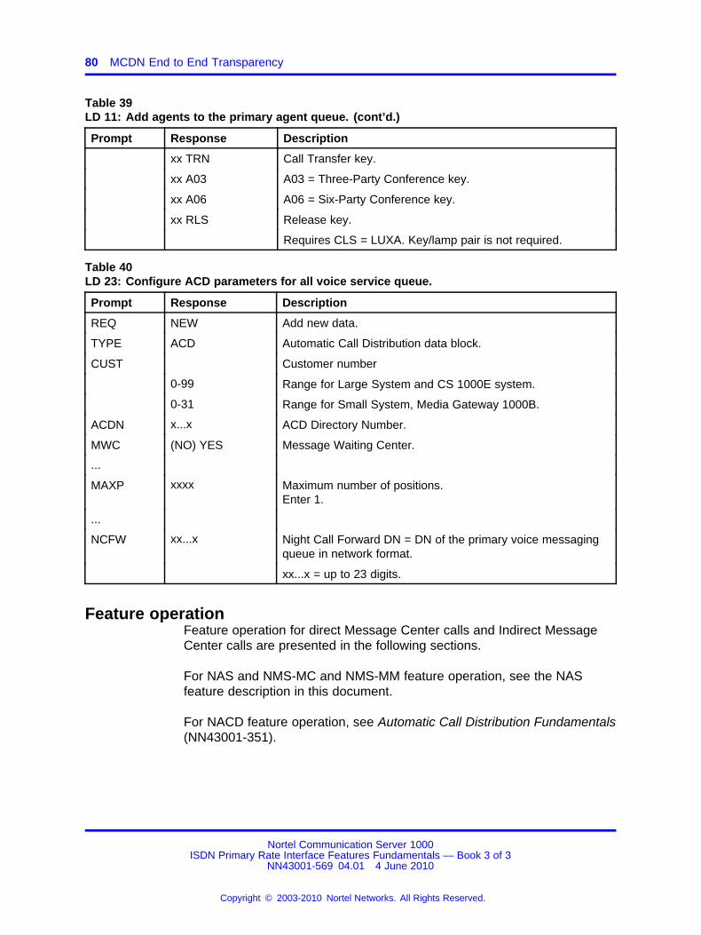
80 MCDN End to End Transparency
Table 39LD 11: Add agents to the primary agent queue. (cont’d.)
Prompt Response Description
xx TRN Call Transfer key.
xx A03 A03 = Three-Party Conference key.
xx A06 A06 = Six-Party Conference key.
xx RLS Release key.
Requires CLS = LUXA. Key/lamp pair is not required.
Table 40LD 23: Configure ACD parameters for all voice service queue.
Prompt Response Description
REQ NEW Add new data.
TYPE ACD Automatic Call Distribution data block.
CUST Customer number
0-99 Range for Large System and CS 1000E system.
0-31 Range for Small System, Media Gateway 1000B.
ACDN x...x ACD Directory Number.
MWC (NO) YES Message Waiting Center.
...
MAXP xxxx Maximum number of positions.Enter 1.
...
NCFW xx...x Night Call Forward DN = DN of the primary voice messagingqueue in network format.
xx...x = up to 23 digits.
Feature operationFeature operation for direct Message Center calls and Indirect MessageCenter calls are presented in the following sections.
For NAS and NMS-MC and NMS-MM feature operation, see the NASfeature description in this document.
For NACD feature operation, see Automatic Call Distribution Fundamentals(NN43001-351).
Nortel Communication Server 1000ISDN Primary Rate Interface Features Fundamentals — Book 3 of 3
NN43001-569 04.01 4 June 2010
Copyright © 2003-2010 Nortel Networks. All Rights Reserved.
.
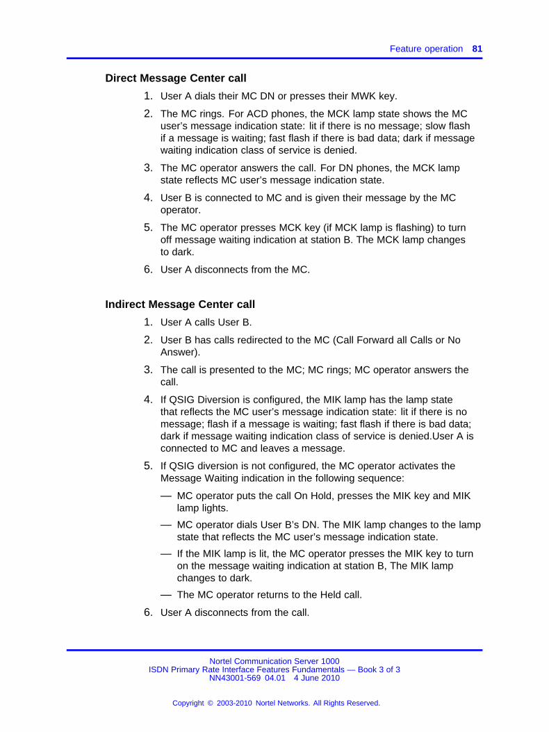
Feature operation 81
Direct Message Center call
1. User A dials their MC DN or presses their MWK key.
2. The MC rings. For ACD phones, the MCK lamp state shows the MCuser’s message indication state: lit if there is no message; slow flashif a message is waiting; fast flash if there is bad data; dark if messagewaiting indication class of service is denied.
3. The MC operator answers the call. For DN phones, the MCK lampstate reflects MC user’s message indication state.
4. User B is connected to MC and is given their message by the MCoperator.
5. The MC operator presses MCK key (if MCK lamp is flashing) to turnoff message waiting indication at station B. The MCK lamp changesto dark.
6. User A disconnects from the MC.
Indirect Message Center call
1. User A calls User B.
2. User B has calls redirected to the MC (Call Forward all Calls or NoAnswer).
3. The call is presented to the MC; MC rings; MC operator answers thecall.
4. If QSIG Diversion is configured, the MIK lamp has the lamp statethat reflects the MC user’s message indication state: lit if there is nomessage; flash if a message is waiting; fast flash if there is bad data;dark if message waiting indication class of service is denied.User A isconnected to MC and leaves a message.
5. If QSIG diversion is not configured, the MC operator activates theMessage Waiting indication in the following sequence:
— MC operator puts the call On Hold, presses the MIK key and MIKlamp lights.
— MC operator dials User B’s DN. The MIK lamp changes to the lampstate that reflects the MC user’s message indication state.
— If the MIK lamp is lit, the MC operator presses the MIK key to turnon the message waiting indication at station B, The MIK lampchanges to dark.
— The MC operator returns to the Held call.
6. User A disconnects from the call.
Nortel Communication Server 1000ISDN Primary Rate Interface Features Fundamentals — Book 3 of 3
NN43001-569 04.01 4 June 2010
Copyright © 2003-2010 Nortel Networks. All Rights Reserved.
.

82 MCDN End to End Transparency
Nortel Communication Server 1000ISDN Primary Rate Interface Features Fundamentals — Book 3 of 3
NN43001-569 04.01 4 June 2010
Copyright © 2003-2010 Nortel Networks. All Rights Reserved.
.
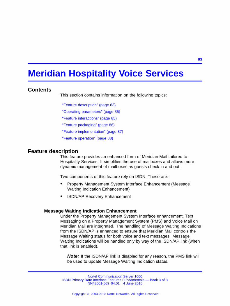
83.
Meridian Hospitality Voice Services
ContentsThis section contains information on the following topics:
“Feature description” (page 83)
“Operating parameters” (page 85)
“Feature interactions” (page 85)
“Feature packaging” (page 86)
“Feature implementation” (page 87)
“Feature operation” (page 88)
Feature descriptionThis feature provides an enhanced form of Meridian Mail tailored toHospitality Services. It simplifies the use of mailboxes and allows moredynamic management of mailboxes as guests check in and out.
Two components of this feature rely on ISDN. These are:
• Property Management System Interface Enhancement (MessageWaiting Indication Enhancement)
• ISDN/AP Recovery Enhancement
Message Waiting Indication EnhancementUnder the Property Management System Interface enhancement, TextMessaging on a Property Management System (PMS) and Voice Mail onMeridian Mail are integrated. The handling of Message Waiting Indicationsfrom the ISDN/AP is enhanced to ensure that Meridian Mail controls theMessage Waiting status for both voice and text messages. MessageWaiting Indications will be handled only by way of the ISDN/AP link (whenthat link is enabled).
Note: If the ISDN/AP link is disabled for any reason, the PMS link willbe used to update Message Waiting Indication status.
Nortel Communication Server 1000ISDN Primary Rate Interface Features Fundamentals — Book 3 of 3
NN43001-569 04.01 4 June 2010
Copyright © 2003-2010 Nortel Networks. All Rights Reserved.
.

84 Meridian Hospitality Voice Services
ISDN/AP recovery enhancementThe ISDN/AP link is used to pass all of the command and statusinformation between the system and any Value Added Server (VAS).When the ISDN/AP link fails, due either to faults in the link itself or failureof the VAS, all signaling between the system and the VAS stops. Callscould be left in various ringing states indefinitely (until the ISDN/AP linkis restored).
The ISDN/AP Recovery Enhancement ensures that callers to any VAS,using a particular ISDN/AP link, are redirected to some alternate DN,should that ISDN/AP link fail. This redirection only applies to calls in theringing state which are being presented to virtual Voice Messaging Serviceagents.
Calls in the following call states can be recovered under this enhancement:
• calls ringing to a virtual Voice Messaging Service agent, but not yetanswered by the VAS
• calls in an ACD queue at the time the failure is detected
• new calls arriving at the queue after the failure is detected, but beforethe link is restored
Calls are recovered from ACD queues under the following conditions:
• The ACD queue is defined as a Message Waiting Center.
• The ACD queue uses the ISDN/AP.
• All ISDN/AP links associated with the ACD queue are not active.
• If an ACD agent is involved in the call, the agents must be defined asVirtual Voice Messages access agents for the enhancement to takeeffect.
When calls are redirected, they are routed to the Night Call Forward DN(NCFW) for the particular ACD queue involved. The treatment of callswill be identical to that of existing Night Call Forward operation for ACDqueues, except that the Night Call Forward DN must be located on thesame switch as the attendant and room phones.
When the ISDN/AP link fails, any calls without disconnect supervisionwhich are connected to the VAS are disconnected immediately. Callswith disconnect supervision remain connected, until the originating enddisconnects. In either case, a CDR record is produced when the call isreleased from the agent.
When the ISDN/AP link becomes operational once again (through eitherautomatic or manual recovery), the handling of new calls will return tonormal.
Nortel Communication Server 1000ISDN Primary Rate Interface Features Fundamentals — Book 3 of 3
NN43001-569 04.01 4 June 2010
Copyright © 2003-2010 Nortel Networks. All Rights Reserved.
.

Feature interactions 85
Operating parametersNo operating parameters are specified for this feature.
Feature interactionsAttendant End-to-End Signaling (AEES)AEES, which uses Dual-tone Multifrequency signaling, requires anadditional Attendant EES key.
Attendant Overflow Position (AOP)Attendant Overflow allows unanswered calls to the attendant to beforwarded to a customer-defined DN after a defined time. With AOPequipped, overflowed calls can be directed to Meridian Mail. The AOP DNmust be defined as an ACD DN, and the ACD DN must be an ACD agentconfigured as a Virtual Voice Messaging Service (VMS) agent. A call canalso be overflowed if all the attendants are in Position Busy.
Centralized Attendant Service (CAS)The attendant must be located on the same switch as Meridian Mail for theattendant to use Meridian Mail features.
Digit Key Signaling (DKS)With the DKS package (180) equipped, attendants assist callers inoperating Meridian Mail Voice Messaging Service. The attendant entersthe digits for Meridian Mail and extends the call to Meridian Mail. Thecaller can then access voice messaging. DKS is only supported from theattendant consoles local to Meridian Mail. The attendant can also placedirect calls to Meridian Mail.
Digit Key Signaling at Console (DKS)With DKS equipped, attendants assist callers in Meridian Mail activities.The attendant extends source calls to Meridian Mail or direct calls toMeridian Mail.
Do Not Disturb (DND)Individual DND allows the attendant to place a DN in the Do Not Disturbmode. A DN in this mode is free to originate calls, but appears busy toincoming calls. With DND equipped, callers can be redirected to MeridianMail for Voice Mail Services. A called phone must have Hunting Allowed(HTA) Class of Service and the Customer Route Data Block must be set to"YES" in LD 15.
M2317 and Meridian Modular soft key menusM2317 or Meridian Modular soft key menus are not supported by MHVS.These three phones with CCSA Class of Service are not presented withthe Meridian Mail softkey menus when connected to Meridian Mail.
Nortel Communication Server 1000ISDN Primary Rate Interface Features Fundamentals — Book 3 of 3
NN43001-569 04.01 4 June 2010
Copyright © 2003-2010 Nortel Networks. All Rights Reserved.
.
86 Meridian Hospitality Voice Services
Network Automatic CallDistributionThe Night Number specified for the Automatic Call Distribution (ACD)involved in the ISDN/AP recovery operation must be local to the node.
PMSI, DKS, DND, and Message Waiting IndicationThese operations are only supported when PMSI, Meridian Mail, andattendant room phones are located on the same switch.
PretranslationPrior to MHVS, the setup of calls using the ISDN/AP was not supportedfrom phones using the Pretranslation feature. With MHVS equipped, callsetup using the ISDN/AP is supported.
Stripping of Calling Party Name Display (CPND) BlanksThe maximum length of a CPND name sent from the PMSI/Background(BGD) terminal is 27 characters. When the full 27-character length is used,part of the CPND name can scroll off the screen. To avoid this problem,the PMSI/BGD software has been updated to strip all trailing blanks fromthe CPND name from the screen.
Feature packagingMeridian Hospitality Voice Services (MHVS) requires software package179.
The standard Meridian Mail packages must be equipped for thePretranslation and Do Not Disturb functions to operate properly. Theseinclude:
• Recorded Announcement (RAN) package 7
• End-to-End Signaling (EES) package 10
• Make Set Busy (MSB) package 17
• Integrated Message Services (IMS) package 35
• Basic Automatic Call Distribution (BACD) package 40
• Automatic Call Distribution Package A (ACDA) package 45
• Message Waiting Center (MWC) package 46
• Command Status Link (CSL) package 77
• CSL with Alpha Signaling (CSLA) package 85
• Auxiliary Processor Link (APL) package 109
The Property Management System Interface (PMSI) package requires thefollowing packages:
Nortel Communication Server 1000ISDN Primary Rate Interface Features Fundamentals — Book 3 of 3
NN43001-569 04.01 4 June 2010
Copyright © 2003-2010 Nortel Networks. All Rights Reserved.
.
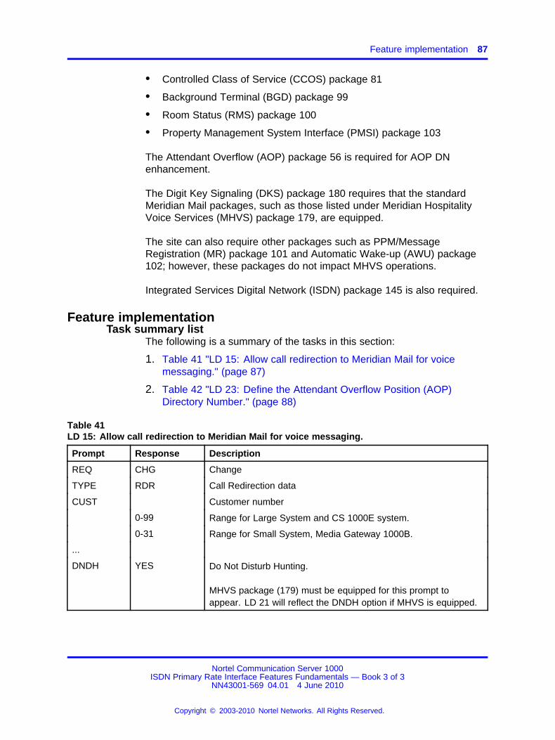
Feature implementation 87
• Controlled Class of Service (CCOS) package 81
• Background Terminal (BGD) package 99
• Room Status (RMS) package 100
• Property Management System Interface (PMSI) package 103
The Attendant Overflow (AOP) package 56 is required for AOP DNenhancement.
The Digit Key Signaling (DKS) package 180 requires that the standardMeridian Mail packages, such as those listed under Meridian HospitalityVoice Services (MHVS) package 179, are equipped.
The site can also require other packages such as PPM/MessageRegistration (MR) package 101 and Automatic Wake-up (AWU) package102; however, these packages do not impact MHVS operations.
Integrated Services Digital Network (ISDN) package 145 is also required.
Feature implementationTask summary list
The following is a summary of the tasks in this section:
1. Table 41 "LD 15: Allow call redirection to Meridian Mail for voicemessaging." (page 87)
2. Table 42 "LD 23: Define the Attendant Overflow Position (AOP)Directory Number." (page 88)
Table 41LD 15: Allow call redirection to Meridian Mail for voice messaging.
Prompt Response Description
REQ CHG Change
TYPE RDR Call Redirection data
CUST Customer number
0-99 Range for Large System and CS 1000E system.
0-31 Range for Small System, Media Gateway 1000B.
...
DNDH YES Do Not Disturb Hunting.
MHVS package (179) must be equipped for this prompt toappear. LD 21 will reflect the DNDH option if MHVS is equipped.
Nortel Communication Server 1000ISDN Primary Rate Interface Features Fundamentals — Book 3 of 3
NN43001-569 04.01 4 June 2010
Copyright © 2003-2010 Nortel Networks. All Rights Reserved.
.
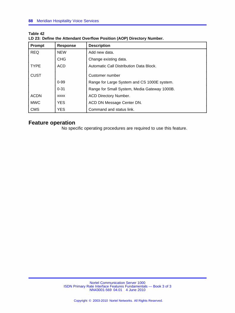
88 Meridian Hospitality Voice Services
Table 42LD 23: Define the Attendant Overflow Position (AOP) Directory Number.
Prompt Response Description
REQ NEW Add new data.
CHG Change existing data.
TYPE ACD Automatic Call Distribution Data Block.
CUST Customer number
0-99 Range for Large System and CS 1000E system.
0-31 Range for Small System, Media Gateway 1000B.
ACDN xxxx ACD Directory Number.
MWC YES ACD DN Message Center DN.
CMS YES Command and status link.
Feature operationNo specific operating procedures are required to use this feature.
Nortel Communication Server 1000ISDN Primary Rate Interface Features Fundamentals — Book 3 of 3
NN43001-569 04.01 4 June 2010
Copyright © 2003-2010 Nortel Networks. All Rights Reserved.
.

89.
Meridian Mail Trunk Access Restriction
ContentsThis section contains information on the following topics:
“Feature description” (page 89)
“Operating parameters” (page 91)
“Feature interactions” (page 92)
“Feature packaging” (page 92)
“Feature implementation” (page 92)
“Feature operation” (page 93)
Feature descriptionThe Meridian Mail Trunk Access Restriction (MTAR) feature preventsdirect or indirect call transfer or conference of external calls to MeridianMail. In this feature, external calls are defined as incoming/outgoing trunkcalls that originate or terminate outside a private network.
This definition is applicable to all types of trunks, with the exception of TIEtrunk calls. External calls are separated from a transferring/conferencingphone on a network using TIE trunks. MTAR operation is dependant onthe information sent to the remote node from the node that is attempting totransfer/conference.
MTAR is triggered if the network information (such as Network AttendantService or Calling Line Identification) indicates that an external call and atransfer/conference attempt to Meridian Mail is occurring. MTAR is alsotriggered if local information, such as Route Class, indicates an externalcall and a transfer/conference attempt to Meridian Mail is occurring.
Nortel Communication Server 1000ISDN Primary Rate Interface Features Fundamentals — Book 3 of 3
NN43001-569 04.01 4 June 2010
Copyright © 2003-2010 Nortel Networks. All Rights Reserved.
.
90 Meridian Mail Trunk Access Restriction
Meridian Mail Trunk Access Restriction averts potential Meridian Mailsystem abuse by distinguishing between internal and external calls that aredirected to Meridian Mail. When activated, Meridian Mail Trunk AccessRestriction impacts the operation of the following features:
• Call Transfer
• Conference
• No Hold Conference
• Call Join capabilities of the Multi-Party Operation feature
Meridian Mail Trunk Access Restriction prevents the completion of anyCall Transfer, Conference, No Hold Conference or Call Join attempts onincoming/outgoing external calls to Meridian Mail.
As illustrated in Figure 7 "Meridian Mail Trunk Access Restriction CallTransfer" (page 91), MTAR capabilities prevent an established callbetween Phone A, an internal call, and Phone B, an external call, frombeing forwarded to Meridian Mail. When Phone A attempts to eitherTransfer, Conference, No Hold Conference or Call Join Phone B to PhoneC, which is either a direct Meridian Mail DN or has activated Call ForwardAll Calls (CFAC) to Meridian Mail, the transfer and conference keys areignored when pressed to complete operation.
Nortel Communication Server 1000ISDN Primary Rate Interface Features Fundamentals — Book 3 of 3
NN43001-569 04.01 4 June 2010
Copyright © 2003-2010 Nortel Networks. All Rights Reserved.
.
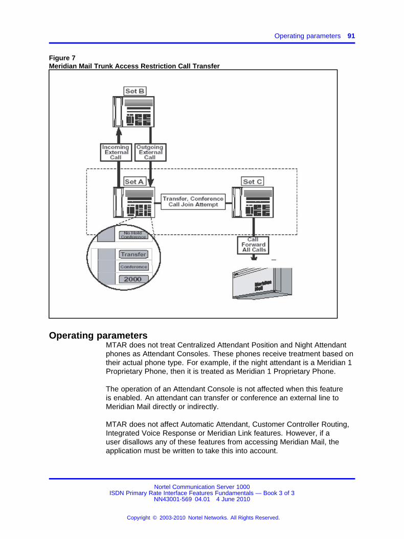
Operating parameters 91
Figure 7Meridian Mail Trunk Access Restriction Call Transfer
Operating parametersMTAR does not treat Centralized Attendant Position and Night Attendantphones as Attendant Consoles. These phones receive treatment based ontheir actual phone type. For example, if the night attendant is a Meridian 1Proprietary Phone, then it is treated as Meridian 1 Proprietary Phone.
The operation of an Attendant Console is not affected when this featureis enabled. An attendant can transfer or conference an external line toMeridian Mail directly or indirectly.
MTAR does not affect Automatic Attendant, Customer Controller Routing,Integrated Voice Response or Meridian Link features. However, if auser disallows any of these features from accessing Meridian Mail, theapplication must be written to take this into account.
Nortel Communication Server 1000ISDN Primary Rate Interface Features Fundamentals — Book 3 of 3
NN43001-569 04.01 4 June 2010
Copyright © 2003-2010 Nortel Networks. All Rights Reserved.
.
92 Meridian Mail Trunk Access Restriction
Call transfer from ISDN Basic Rate Interface (BRI) phone is not supported.
In a networking environment, Meridian Mail must reside on the same nodeas the transferring/conferencing phone.
Feature interactionsTraffic ReportingTraffic Reporting and Meridian Administration Tool’s (MAT) trafficreport, TFC005, are modified to report the number of times this featureis requested. A new line is added for the Meridian Mail Trunk AccessRestriction which is identified by the feature number "27" and its pegcount.
Network Call TransferNetwork Call ConferenceMeridian Mail Trunk Access Restriction (MTAR) requires the transferringor conferencing phone and Meridian Mail to be located on the same node.If the transferring or conferencing phone are located not on the samenode as Meridian Mail, the MTAR feature is not provoked because the calltransfer/conference attempt is terminated by a network on Meridian Mail.
However, an external call can be transferred or conferenced over thenetwork, using TIE trunks. This operation is dependant on the typeof network information the remote node forwards to the node wherethe transfer/conference attempt is made. Meridian Mail must be onthe transferring/conferencing node. If network information is provided,indicating that an external call is attempting to transfer/conference toMeridian Mail, the MTAR feature is invoked. When no network informationis provided, MTAR is provoked if the local information (Route Class)indicates that an external call to Meridian Mail is being attempted.
Feature packagingMeridian Mail Trunk Access Restriction requires Message Waiting Center(MWC) package 46.
Feature implementation
Note: Meridian Mail Trunk Access Restriction feature requires priorinstallation of Meridian Mail. The implementation of this feature,therefore, assumes that Meridian Mail has been properly configured.
Table 43LD 15: Enable Meridian Mail Trunk Access Restriction.
Prompt Response Description
REQ CHG Change existing data.
Nortel Communication Server 1000ISDN Primary Rate Interface Features Fundamentals — Book 3 of 3
NN43001-569 04.01 4 June 2010
Copyright © 2003-2010 Nortel Networks. All Rights Reserved.
.

Feature operation 93
Table 43LD 15: Enable Meridian Mail Trunk Access Restriction. (cont’d.)
Prompt Response Description
TYPE FTR Customer Features and Options.
CUST Customer number
0-99 Range for Large System and CS 1000E system.
0-31 Range for Small System, Media Gateway 1000B.
- OPT MCI Message Centre Included.
...
- MTAR YES Meridian Mail Trunk Access restricted.NO = Meridian Mail Trunk Access allowed.
Feature operationCall Transfer/Conferencedigital phone Phone A is a digital proprietary phone with Transfer Keyand Conference Key.
1. An incoming/outgoing external call is established between Phone Aand Phone B, an external party. The call between Phone A and PhoneB is active on Key X.
2. Phone A presses the Transfer/Conference Key that automatically putsPhone B on Hold.
3. Phone A dials Phone C. Phone C has either Call Forward All Calls toMeridian Mail or is a Meridian Mail DN.
4. When Phone A attempts to transfer/conference Phone B by pressingmore than once the Transfer/Conference Key it is ignored.
5. Phone A recovers Phone B by pressing Key X.
No Hold ConferenceDigital phone/ISDN BRI phone When Meridian Mail Trunk AccessRestriction is enabled, direct or indirect no hold conference to an externalcall is permitted. During direct or indirect no hold conference, the callingparty is never put on hold.
Nortel Communication Server 1000ISDN Primary Rate Interface Features Fundamentals — Book 3 of 3
NN43001-569 04.01 4 June 2010
Copyright © 2003-2010 Nortel Networks. All Rights Reserved.
.
94 Meridian Mail Trunk Access Restriction
Phone A is a digital proprietary phone or an ISDN BRI phone with aNo Hold Conference Key configured as either No Hold Conference,Conference Autodial, Conference Speed or Conference Hotline.
1. An incoming/outgoing external call is established between Phone Aand Phone B, an external party. The call between Phone A and PhoneB is active on Key X.
2. Phone A presses the No Hold Conference Key.
3. Phone A dials Phone C. Phone C is has either Call Forward All Calls toMeridian Mail enabled or is a Meridian Mail DN.
4. The conference is set up as normal. However a two party connectionbetween Phone B, an external party, and Meridian Mail is not allowed ifthe call controller releases. If this occurs, the connection between thetrunk and Meridian Mail party is dropped.
Transferanalog (500/2500-type) phone Phone A is an analog(500/2500-type) phone with a XFA Class of Service (transfer and three/sixparty conference allowed).
1. An incoming or outgoing external call is established between Phone Aand Phone B, an external party.
2. Phone A performs a switchhook flash that puts Phone B on hold.
3. Phone A dials Phone C. Phone C has either Call Forward All Calls toMeridian Mail enabled or is a Meridian Mail DN.
4. Before or after the Meridian Mail has answered, Phone A attempts totransfer Phone B to Meridian Mail by going on-hook.
5. This attempt is treated as an illegal transfer. Phone A is re-rung andreconnected with Phone B when going off-hook.
Conferenceanalog (500/2500-type) phone Phone A is an analog(500/2500-type) phone with a XFA Class of Service (transfer and three/sixparty conference allowed).
• An incoming or outgoing external call is established between Phone Aand Phone B, an external party.
• Phone A performs a switch hook flash that puts Phone B on hold.
• Phone A dials Phone C. Phone C has either Call Forward All Calls toMeridian Mail enabled or is a Meridian Mail DN.
Nortel Communication Server 1000ISDN Primary Rate Interface Features Fundamentals — Book 3 of 3
NN43001-569 04.01 4 June 2010
Copyright © 2003-2010 Nortel Networks. All Rights Reserved.
.
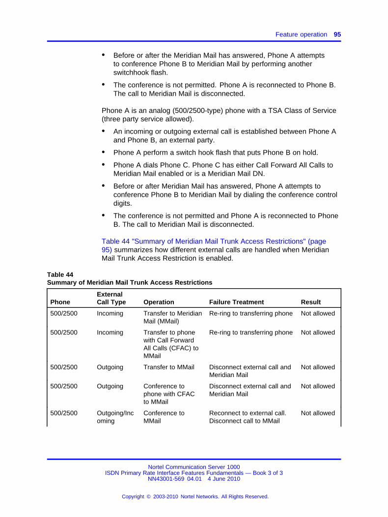
Feature operation 95
• Before or after the Meridian Mail has answered, Phone A attemptsto conference Phone B to Meridian Mail by performing anotherswitchhook flash.
• The conference is not permitted. Phone A is reconnected to Phone B.The call to Meridian Mail is disconnected.
Phone A is an analog (500/2500-type) phone with a TSA Class of Service(three party service allowed).
• An incoming or outgoing external call is established between Phone Aand Phone B, an external party.
• Phone A perform a switch hook flash that puts Phone B on hold.
• Phone A dials Phone C. Phone C has either Call Forward All Calls toMeridian Mail enabled or is a Meridian Mail DN.
• Before or after Meridian Mail has answered, Phone A attempts toconference Phone B to Meridian Mail by dialing the conference controldigits.
• The conference is not permitted and Phone A is reconnected to PhoneB. The call to Meridian Mail is disconnected.
Table 44 "Summary of Meridian Mail Trunk Access Restrictions" (page95) summarizes how different external calls are handled when MeridianMail Trunk Access Restriction is enabled.
Table 44Summary of Meridian Mail Trunk Access Restrictions
PhoneExternalCall Type Operation Failure Treatment Result
500/2500 Incoming Transfer to MeridianMail (MMail)
Re-ring to transferring phone Not allowed
500/2500 Incoming Transfer to phonewith Call ForwardAll Calls (CFAC) toMMail
Re-ring to transferring phone Not allowed
500/2500 Outgoing Transfer to MMail Disconnect external call andMeridian Mail
Not allowed
500/2500 Outgoing Conference tophone with CFACto MMail
Disconnect external call andMeridian Mail
Not allowed
500/2500 Outgoing/Incoming
Conference toMMail
Reconnect to external call.Disconnect call to MMail
Not allowed
Nortel Communication Server 1000ISDN Primary Rate Interface Features Fundamentals — Book 3 of 3
NN43001-569 04.01 4 June 2010
Copyright © 2003-2010 Nortel Networks. All Rights Reserved.
.

96 Meridian Mail Trunk Access Restriction
Table 44Summary of Meridian Mail Trunk Access Restrictions (cont’d.)
PhoneExternalCall Type Operation Failure Treatment Result
500/2500 Outgoing/Incoming
Conference tophone with CFACto MMail
Reconnect to external call.Disconnect call to MMail
Not allowed
Meridian 1Proprietary
Outgoing/Incoming
Transfer/Conference to MMail
Operation ignored Not allowed
Meridian 1Proprietary
Outgoing/Incoming
Transfer/Conference to phone withCFAC to MMail
Operation ignored Not allowed
Meridian 1Proprietary
Outgoing/Incoming
No Hold Conference to Meridian Mailor to set CFAC toMMail
Not applicable Allow
Meridian 1Proprietary
Outgoing/Incoming
No Hold Conference release tomake MMail totrunk two-partyconnection
Disconnect MMail andexternal trunk
Not allowed
Meridian 1Proprietary
Outgoing/Incoming
Call Join of externalcall to MMail
Operation ignored Not allowed
Basic RateInterface
Outgoing/Incoming
Conference toMMail
Operation ignored Not allowed
Basic RateInterface
Outgoing/Incoming
Conference to setwith CFAC to MMail
Operation ignored Not allowed
Attendant Outgoing/Incoming
Transfer/Conference to Meridian Mail
Not Applicable Allowed
Attendant Outgoing/Incoming
Transfer/Conference to phone with CallForward All Calls toMeridian Mail
Not Applicable Allowed
Nortel Communication Server 1000ISDN Primary Rate Interface Features Fundamentals — Book 3 of 3
NN43001-569 04.01 4 June 2010
Copyright © 2003-2010 Nortel Networks. All Rights Reserved.
.
97.
Message Waiting IndicationInterworking with DMS
ContentsThis section contains information on the following topics:
“Feature description” (page 97)
“Operating parameters” (page 99)
“Feature interactions” (page 100)
“Feature packaging” (page 101)
“Feature implementation” (page 102)
“Task summary list” (page 102)
“Feature operation” (page 107)
Feature descriptionThis interworking feature allows a Message Center on either a system orDMS-100 (Centrex) to exchange Message Waiting Indicator informationwith phones serviced by either type of system on the network. Callsredirected to the Message Center can be from private or public networkcallers on either system. A caller served by the system can use theMessage Center on DMS. A caller served by DMS can use the MessageCenter (Meridian Mail) on the system. The system must use Meridian Mailas its Message Center.
MWI uses the non-call associated Facility messages on ISDN PRI fortransporting the TCAP information.
The system and DMS systems can be connected directly or in tandem towhichever system hosts the Message Center. When a caller from eithersystem leaves a message on either system, the Message Waiting Indicatoris activated. When the receiver retrieves the message, the MessageWaiting Indicator is deactivated. The indicator is either a visual LED (lightemitting diode), an icon, or an audible tone in the phone handset.
Nortel Communication Server 1000ISDN Primary Rate Interface Features Fundamentals — Book 3 of 3
NN43001-569 04.01 4 June 2010
Copyright © 2003-2010 Nortel Networks. All Rights Reserved.
.
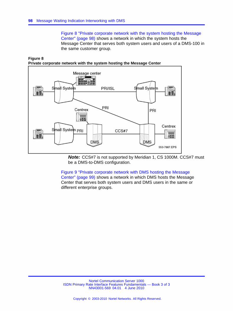
98 Message Waiting Indication Interworking with DMS
Figure 8 "Private corporate network with the system hosting the MessageCenter" (page 98) shows a network in which the system hosts theMessage Center that serves both system users and users of a DMS-100 inthe same customer group.
Figure 8Private corporate network with the system hosting the Message Center
Note: CCS#7 is not supported by Meridian 1, CS 1000M. CCS#7 mustbe a DMS-to-DMS configuration.
Figure 9 "Private corporate network with DMS hosting the MessageCenter" (page 99) shows a network in which DMS hosts the MessageCenter that serves both system users and DMS users in the same ordifferent enterprise groups.
Nortel Communication Server 1000ISDN Primary Rate Interface Features Fundamentals — Book 3 of 3
NN43001-569 04.01 4 June 2010
Copyright © 2003-2010 Nortel Networks. All Rights Reserved.
.
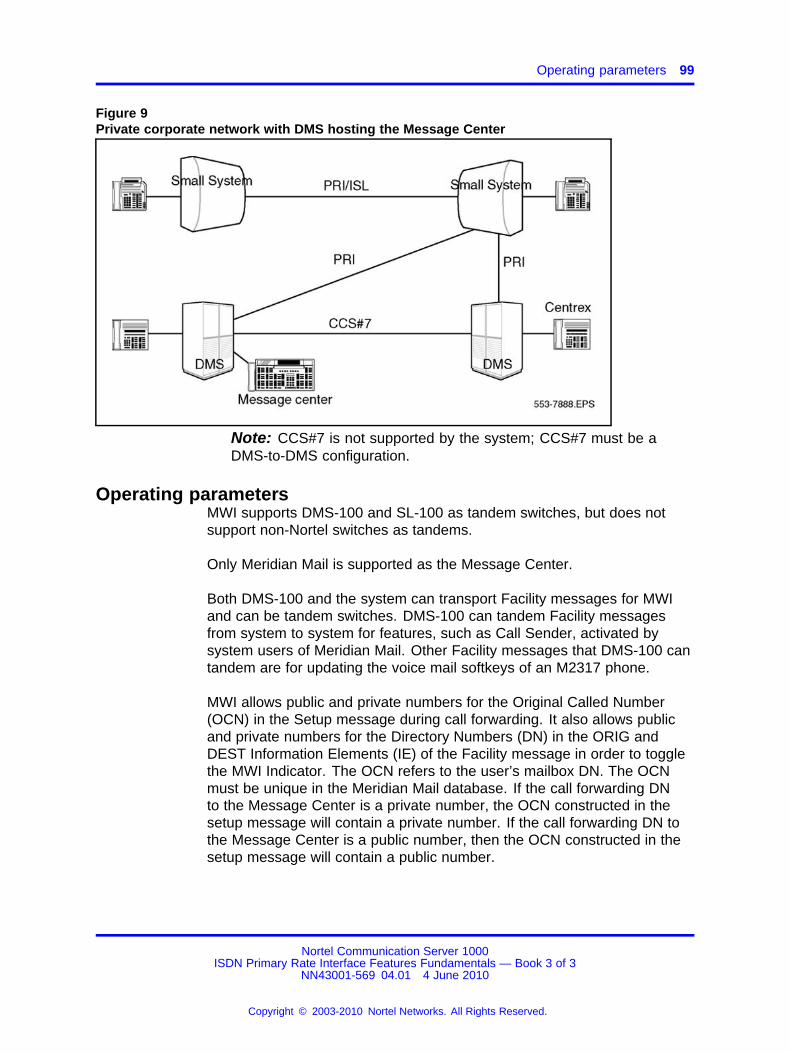
Operating parameters 99
Figure 9Private corporate network with DMS hosting the Message Center
Note: CCS#7 is not supported by the system; CCS#7 must be aDMS-to-DMS configuration.
Operating parametersMWI supports DMS-100 and SL-100 as tandem switches, but does notsupport non-Nortel switches as tandems.
Only Meridian Mail is supported as the Message Center.
Both DMS-100 and the system can transport Facility messages for MWIand can be tandem switches. DMS-100 can tandem Facility messagesfrom system to system for features, such as Call Sender, activated bysystem users of Meridian Mail. Other Facility messages that DMS-100 cantandem are for updating the voice mail softkeys of an M2317 phone.
MWI allows public and private numbers for the Original Called Number(OCN) in the Setup message during call forwarding. It also allows publicand private numbers for the Directory Numbers (DN) in the ORIG andDEST Information Elements (IE) of the Facility message in order to togglethe MWI Indicator. The OCN refers to the user’s mailbox DN. The OCNmust be unique in the Meridian Mail database. If the call forwarding DNto the Message Center is a private number, the OCN constructed in thesetup message will contain a private number. If the call forwarding DN tothe Message Center is a public number, then the OCN constructed in thesetup message will contain a public number.
Nortel Communication Server 1000ISDN Primary Rate Interface Features Fundamentals — Book 3 of 3
NN43001-569 04.01 4 June 2010
Copyright © 2003-2010 Nortel Networks. All Rights Reserved.
.
100 Message Waiting Indication Interworking with DMS
If Meridian Mail is on the system:
• For Meridian 1and CS 1000Musers, Meridian Mail provides the samefunctions as for the NMS-MM users, if a private number is used.
• For DMS users, some Meridian Mail features are not available. Contactyour local DMS administrator for available Meridian Mail features.
If the Message Center is on DMS:
• If a phone on the system does not have a DID number, the callforwarding DN to the Message Center should be private. Thus,a phone that cannot receive DID calls will still be able to use theMessage Center services provided that the DMS Message Centersupports private numbers for the mailbox DNs.
End-to-End in-band signaling is required for accessing Message Centerfeatures for a local or remote switch.
The call forwarding connection from the caller to the Message Centeron another switch must be with ISDN conductivity between the systemand DMS. This is for passing the OCN from the caller’s switch to theswitch that hosts the Message Center for leaving voice messages and fortransporting TCAP messages to toggle the MWI Indicator.
Feature interactionsMultiple CustomerServing multiple customers requires multiple Meridian Mail servers. MWIitself does not support multiple customers.
Multi-Tenant ServiceMeridian Mail Phase 8 supports Multi-Tenant Service. Tenants fromthe same customer can use one or more Message Center servers.Tenants from different customers cannot use the same Meridian Mail. Thecustomer controls tenant access to MWI using the phones that belong tothe tenant.
Network Message Services, Meridian MailAlthough the Facility message for MWI uses a different TCAP format fromthat used for NMS, the functions continue to operate.
DCH Error MonitoringThe DCH Error Monitoring monitors ISDN messages for each feature. Ifthe MWI RCAP for the D-channel is added or deleted in LD 17, DCH ErrorMonitoring will work properly for the NMS feature when the D-channelmessage monitoring is disabled and then enabled.
Nortel Communication Server 1000ISDN Primary Rate Interface Features Fundamentals — Book 3 of 3
NN43001-569 04.01 4 June 2010
Copyright © 2003-2010 Nortel Networks. All Rights Reserved.
.

Feature packaging 101
Trunk Optimization Before AnswerThere is no Trunk Optimization when the call is redirected to DMS oranswered by Meridian Mail. This applies to applications such as AutoAttendant.
AML Link RecoveryAML Link Recovery redirects the calls to the ACD queue of the ACD NightForward DN when the AML link goes down. This recovery is also availablefor calls in the Meridian Mail ACD queue on the system when the AML linkgoes down.
Feature packagingThe package requirements for Message Waiting Indication (MWI) aredifferent for each node. The following packages are required for an MWIoriginating node:
• End-to-End Signaling (EES) package 10
• Basic ACD (BACD) package 40
• ACD package A (ACDA) package 45
• Message Center (MWC) package 46
• ISDN Signaling (ISDN) package 145
• ISDN Primary Rate Access (PRI) package 146 or ISDN Signaling Link(ISL) package 147 (for system to system
• ISDN Network Service (NTWK) package 148
• Network Message Service (NMS) package 175
• Message Waiting Indication (MWI) package 219 (if connected to DMSfor interworking)
Note: Packages 40 and 45 are required only if ACD is used as theMessage Center DN.
The following packages are also necessary:
• End-to-End Signaling (EES) package 10
• Integrated Message Service (IMS) package 35
• Basic ACD (BACD) package 40
• ACD package A (ACDA) package 45
• Message Center (MWC) package 46
• Command Status Link (CSL) package 77
• ISDN Signaling (ISDN) package 145
Nortel Communication Server 1000ISDN Primary Rate Interface Features Fundamentals — Book 3 of 3
NN43001-569 04.01 4 June 2010
Copyright © 2003-2010 Nortel Networks. All Rights Reserved.
.
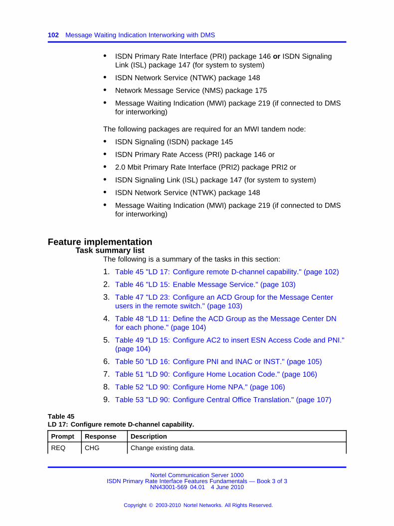
102 Message Waiting Indication Interworking with DMS
• ISDN Primary Rate Interface (PRI) package 146 or ISDN SignalingLink (ISL) package 147 (for system to system)
• ISDN Network Service (NTWK) package 148
• Network Message Service (NMS) package 175
• Message Waiting Indication (MWI) package 219 (if connected to DMSfor interworking)
The following packages are required for an MWI tandem node:
• ISDN Signaling (ISDN) package 145
• ISDN Primary Rate Access (PRI) package 146 or
• 2.0 Mbit Primary Rate Interface (PRI2) package PRI2 or
• ISDN Signaling Link (ISL) package 147 (for system to system)
• ISDN Network Service (NTWK) package 148
• Message Waiting Indication (MWI) package 219 (if connected to DMSfor interworking)
Feature implementationTask summary list
The following is a summary of the tasks in this section:
1. Table 45 "LD 17: Configure remote D-channel capability." (page 102)
2. Table 46 "LD 15: Enable Message Service." (page 103)
3. Table 47 "LD 23: Configure an ACD Group for the Message Centerusers in the remote switch." (page 103)
4. Table 48 "LD 11: Define the ACD Group as the Message Center DNfor each phone." (page 104)
5. Table 49 "LD 15: Configure AC2 to insert ESN Access Code and PNI."(page 104)
6. Table 50 "LD 16: Configure PNI and INAC or INST." (page 105)
7. Table 51 "LD 90: Configure Home Location Code." (page 106)
8. Table 52 "LD 90: Configure Home NPA." (page 106)
9. Table 53 "LD 90: Configure Central Office Translation." (page 107)
Table 45LD 17: Configure remote D-channel capability.
Prompt Response Description
REQ CHG Change existing data.
Nortel Communication Server 1000ISDN Primary Rate Interface Features Fundamentals — Book 3 of 3
NN43001-569 04.01 4 June 2010
Copyright © 2003-2010 Nortel Networks. All Rights Reserved.
.

Feature implementation 103
Table 45LD 17: Configure remote D-channel capability. (cont’d.)
Prompt Response Description
TYPE CFN Configuration record.
- ADAN CHG DCH x Change Primary D-Channel. x = 0-63
...
- RLS xx yy Release ID of the switch at the far end of the D-channel interface (xx =systems, yy = DMS).
- RCAP MWIXMWI
Add remote D-channel capabilities for MWIRemove remote D-channel capabilities for MWI
If the Message Center is on a system, it must be a Meridian Mail. Noother messaging devices are supported for the system. The DMS can useMeridian Mail or other messaging devices (Octel) for its Message Center.
Table 46LD 15: Enable Message Service.
Prompt Response
Description
REQ CHG Change existing data.
TYPE IMS Integrated Message Service data.
CUST Customer number
0-99 Range for Large System and CS 1000E system.
0-31 Range for Small System, Media Gateway 1000B.
- IMS YES Change Integrated Message System.
- IMA YES Enable Integrated Message System.
Table 47LD 23: Configure an ACD Group for the Message Center users in the remote switch.
Prompt Response Description
REQ NEW Add new data.
CHG Change existing data.
TYPE ACD Automatic Call Distribution.
CUST Customer number
0-99 Range for Large System and CS 1000E system.
0-31 Range for Small System, Media Gateway 1000B.
ACDN xxxx ACD Directory Number.
Nortel Communication Server 1000ISDN Primary Rate Interface Features Fundamentals — Book 3 of 3
NN43001-569 04.01 4 June 2010
Copyright © 2003-2010 Nortel Networks. All Rights Reserved.
.
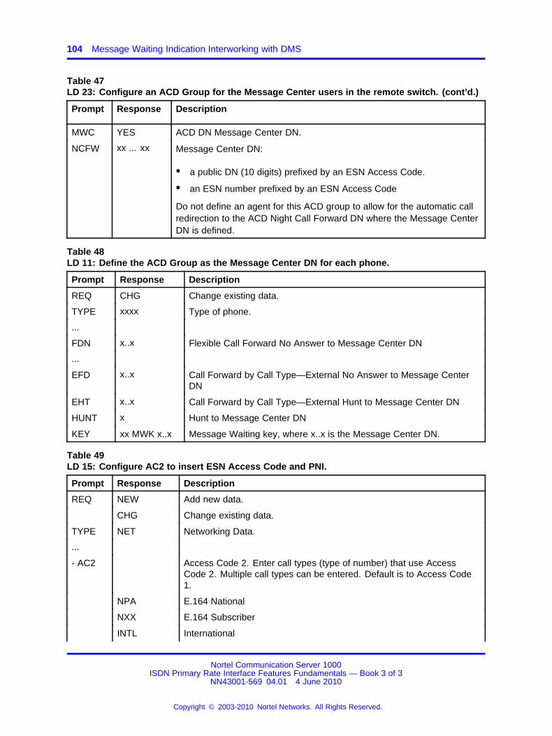
104 Message Waiting Indication Interworking with DMS
Table 47LD 23: Configure an ACD Group for the Message Center users in the remote switch. (cont’d.)
Prompt Response Description
MWC YES ACD DN Message Center DN.
NCFW xx ... xx Message Center DN:
• a public DN (10 digits) prefixed by an ESN Access Code.
• an ESN number prefixed by an ESN Access Code
Do not define an agent for this ACD group to allow for the automatic callredirection to the ACD Night Call Forward DN where the Message CenterDN is defined.
Table 48LD 11: Define the ACD Group as the Message Center DN for each phone.
Prompt Response Description
REQ CHG Change existing data.
TYPE xxxx Type of phone.
...
FDN x..x Flexible Call Forward No Answer to Message Center DN
...
EFD x..x Call Forward by Call Type—External No Answer to Message CenterDN
EHT x..x Call Forward by Call Type—External Hunt to Message Center DN
HUNT x Hunt to Message Center DN
KEY xx MWK x..x Message Waiting key, where x..x is the Message Center DN.
Table 49LD 15: Configure AC2 to insert ESN Access Code and PNI.
Prompt Response Description
REQ NEW Add new data.
CHG Change existing data.
TYPE NET Networking Data.
...
- AC2 Access Code 2. Enter call types (type of number) that use AccessCode 2. Multiple call types can be entered. Default is to Access Code1.
NPA E.164 National
NXX E.164 Subscriber
INTL International
Nortel Communication Server 1000ISDN Primary Rate Interface Features Fundamentals — Book 3 of 3
NN43001-569 04.01 4 June 2010
Copyright © 2003-2010 Nortel Networks. All Rights Reserved.
.
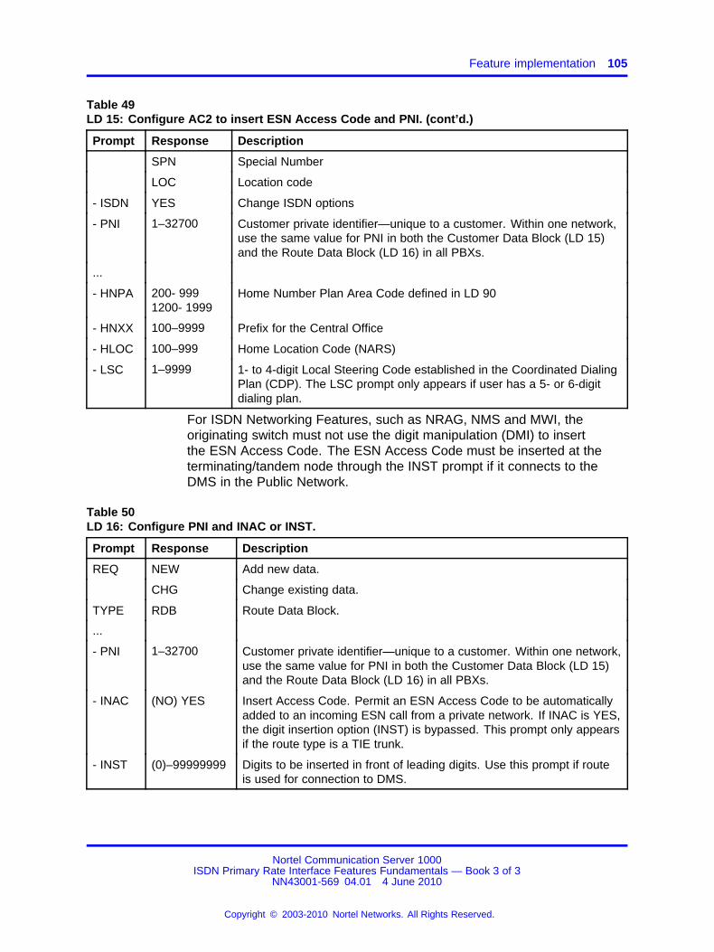
Feature implementation 105
Table 49LD 15: Configure AC2 to insert ESN Access Code and PNI. (cont’d.)
Prompt Response Description
SPN Special Number
LOC Location code
- ISDN YES Change ISDN options
- PNI 1–32700 Customer private identifier—unique to a customer. Within one network,use the same value for PNI in both the Customer Data Block (LD 15)and the Route Data Block (LD 16) in all PBXs.
...
- HNPA 200- 9991200- 1999
Home Number Plan Area Code defined in LD 90
- HNXX 100–9999 Prefix for the Central Office
- HLOC 100–999 Home Location Code (NARS)
- LSC 1–9999 1- to 4-digit Local Steering Code established in the Coordinated DialingPlan (CDP). The LSC prompt only appears if user has a 5- or 6-digitdialing plan.
For ISDN Networking Features, such as NRAG, NMS and MWI, theoriginating switch must not use the digit manipulation (DMI) to insertthe ESN Access Code. The ESN Access Code must be inserted at theterminating/tandem node through the INST prompt if it connects to theDMS in the Public Network.
Table 50LD 16: Configure PNI and INAC or INST.
Prompt Response Description
REQ NEW Add new data.
CHG Change existing data.
TYPE RDB Route Data Block.
...
- PNI 1–32700 Customer private identifier—unique to a customer. Within one network,use the same value for PNI in both the Customer Data Block (LD 15)and the Route Data Block (LD 16) in all PBXs.
- INAC (NO) YES Insert Access Code. Permit an ESN Access Code to be automaticallyadded to an incoming ESN call from a private network. If INAC is YES,the digit insertion option (INST) is bypassed. This prompt only appearsif the route type is a TIE trunk.
- INST (0)–99999999 Digits to be inserted in front of leading digits. Use this prompt if routeis used for connection to DMS.
Nortel Communication Server 1000ISDN Primary Rate Interface Features Fundamentals — Book 3 of 3
NN43001-569 04.01 4 June 2010
Copyright © 2003-2010 Nortel Networks. All Rights Reserved.
.

106 Message Waiting Indication Interworking with DMS
Use "INST" in LD 16 at the system location A for incomingtandem/terminating calls. Use "INAC" at the system locations B and C. Forthe Message Center users on the system, configure Home Location Codeand Home NPA to terminate a Facility message from the Message Center,either on the system or on DMS to the Message Center user’s switch. TheFacility message is for turning on/off the Message Waiting Indicator forthe user.
For the private ESN Uniform Dialing Plan, use LD 90 to configure HomeLocation Code (HLOC).
Table 51LD 90: Configure Home Location Code.
Prompt Response Description
REQ NEW Add new data.
CHG Change existing data.
CUST Customer number
0-99 Range for Large System and CS 1000E system.
0-31 Range for Small System, Media Gateway 1000B.
FEAT NET Network translation tables.
TRAN AC1AC2
Access Code 1.Access Code 2.
TYPE HLOC Home Location Code.
HLOC xxx Home Location Code (3–7 digits).
For the public numbering plan, a 10 digit number (NPA+NXX+XXXX) isused in the ORIG and DEST IE of the Facility message. Use LD 90 toconfigure Home NPA and Central Office Translation (NXX) to terminate theFacility message onto the Message Center user’s DN.
Table 52LD 90: Configure Home NPA.
Prompt Response Description
REQ NEW Add new data.
CHG Change existing data.
CUST Customer number
0-99 Range for Large System and CS 1000E system.
0-31 Range for Small System, Media Gateway 1000B.
FEAT NET Network Translation Tables.
TRAN AC1AC2
Access Code 1.Access Code 2.
Nortel Communication Server 1000ISDN Primary Rate Interface Features Fundamentals — Book 3 of 3
NN43001-569 04.01 4 June 2010
Copyright © 2003-2010 Nortel Networks. All Rights Reserved.
.
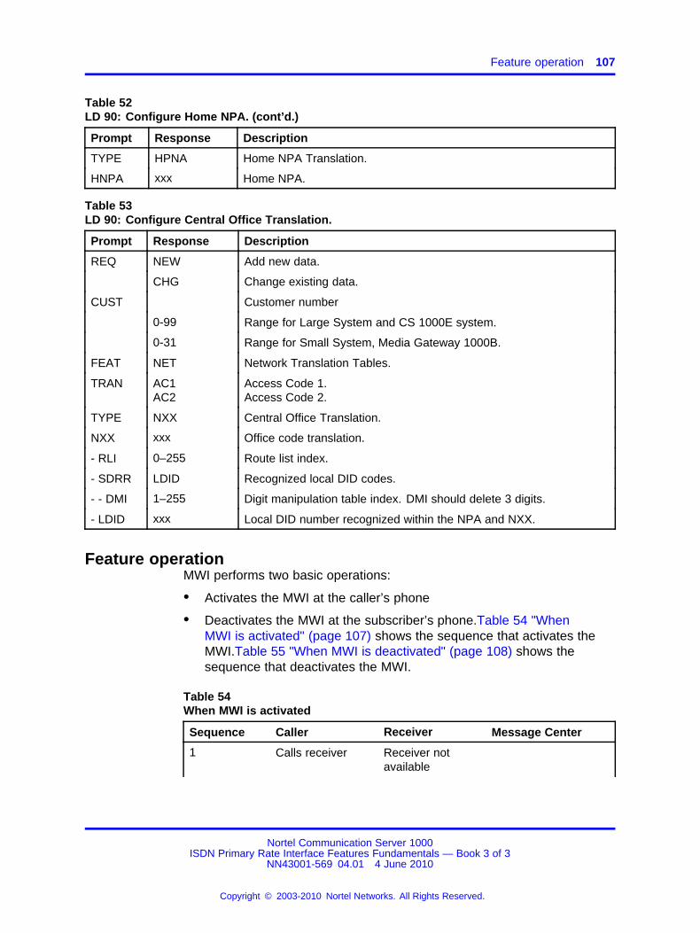
Feature operation 107
Table 52LD 90: Configure Home NPA. (cont’d.)
Prompt Response Description
TYPE HPNA Home NPA Translation.
HNPA xxx Home NPA.
Table 53LD 90: Configure Central Office Translation.
Prompt Response Description
REQ NEW Add new data.
CHG Change existing data.
CUST Customer number
0-99 Range for Large System and CS 1000E system.
0-31 Range for Small System, Media Gateway 1000B.
FEAT NET Network Translation Tables.
TRAN AC1AC2
Access Code 1.Access Code 2.
TYPE NXX Central Office Translation.
NXX xxx Office code translation.
- RLI 0–255 Route list index.
- SDRR LDID Recognized local DID codes.
- - DMI 1–255 Digit manipulation table index. DMI should delete 3 digits.
- LDID xxx Local DID number recognized within the NPA and NXX.
Feature operationMWI performs two basic operations:
• Activates the MWI at the caller’s phone
• Deactivates the MWI at the subscriber’s phone.Table 54 "WhenMWI is activated" (page 107) shows the sequence that activates theMWI.Table 55 "When MWI is deactivated" (page 108) shows thesequence that deactivates the MWI.
Table 54When MWI is activated
Sequence Caller Receiver Message Center
1 Calls receiver Receiver notavailable
Nortel Communication Server 1000ISDN Primary Rate Interface Features Fundamentals — Book 3 of 3
NN43001-569 04.01 4 June 2010
Copyright © 2003-2010 Nortel Networks. All Rights Reserved.
.
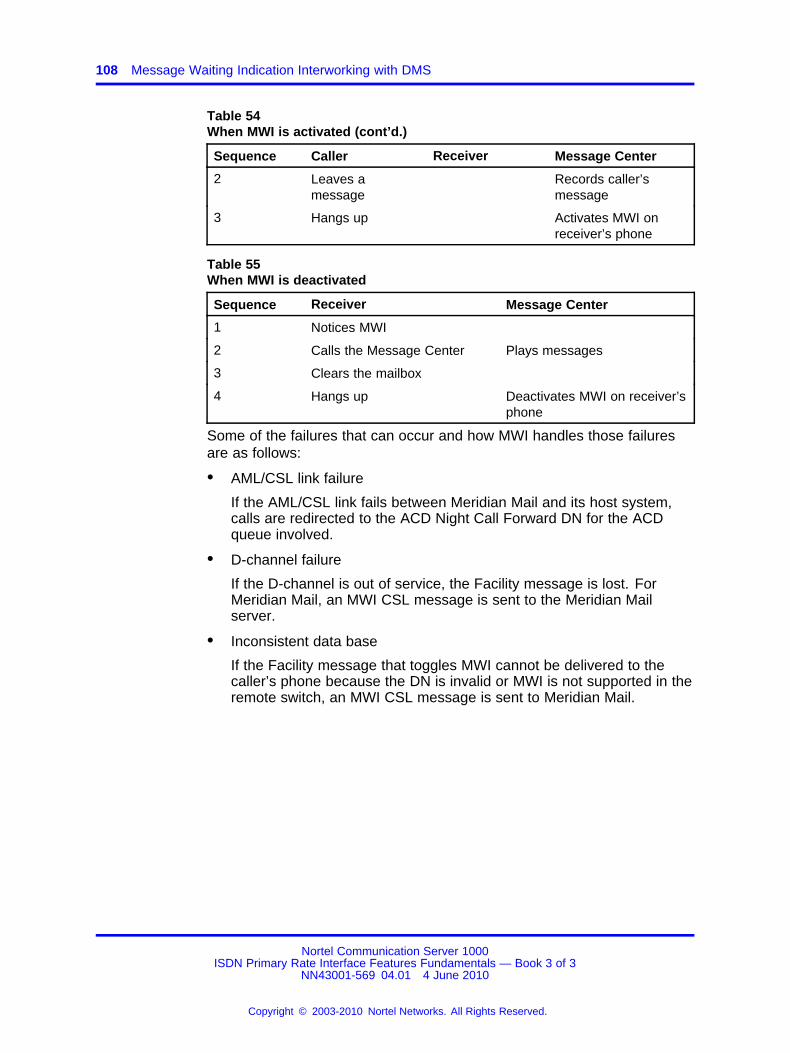
108 Message Waiting Indication Interworking with DMS
Table 54When MWI is activated (cont’d.)
Sequence Caller Receiver Message Center
2 Leaves amessage
Records caller’smessage
3 Hangs up Activates MWI onreceiver’s phone
Table 55When MWI is deactivated
Sequence Receiver Message Center
1 Notices MWI
2 Calls the Message Center Plays messages
3 Clears the mailbox
4 Hangs up Deactivates MWI on receiver’sphone
Some of the failures that can occur and how MWI handles those failuresare as follows:
• AML/CSL link failure
If the AML/CSL link fails between Meridian Mail and its host system,calls are redirected to the ACD Night Call Forward DN for the ACDqueue involved.
• D-channel failure
If the D-channel is out of service, the Facility message is lost. ForMeridian Mail, an MWI CSL message is sent to the Meridian Mailserver.
• Inconsistent data base
If the Facility message that toggles MWI cannot be delivered to thecaller’s phone because the DN is invalid or MWI is not supported in theremote switch, an MWI CSL message is sent to Meridian Mail.
Nortel Communication Server 1000ISDN Primary Rate Interface Features Fundamentals — Book 3 of 3
NN43001-569 04.01 4 June 2010
Copyright © 2003-2010 Nortel Networks. All Rights Reserved.
.
109.
MSDL Idle Code Selection
ContentsThis section contains information on the following topics:
“Applicable regions” (page 109)
“Feature description” (page 109)
“Operating parameters” (page 111)
“Feature interactions” (page 111)
“Feature packaging” (page 112)
“Feature implementation” (page 112)
“Task summary list” (page 112)
“Feature operation” (page 112)
Applicable regionsThe information presented in this section does not pertain to all regions.Contact your system supplier or your Nortel representative to verifysupport of this product in your area.
Feature descriptionWhen a T1 carrier is disabled at the remote end, the remote T1 or ISDNPRI hardware raises a "Red Alarm" status and sends a "Yellow Alarm," tothe local (near end) system, which takes all trunks and channels out ofservice, and responds to the remote end by sending an "Unassigned PCM"(FF) code. However, some switches do not recognize the "UnassignedPCM" code, and instead expect an "Idle PCM" (7F) code.
The Idle Code Selection feature allows a system, upon receiving a "YellowAlarm" condition from the remote end with a disabled T1 carrier, to beconfigured to respond by sending an "Idle PCM" code instead of an"Unassigned PCM" code. Therefore, a remote switch, such as a Lucent5ESS, which expects to receive an "Idle PCM" code can be cleared of aRed Alarm, the system can be cleared of a Yellow Alarm, and trunks andchannels can be brought back into service.
Nortel Communication Server 1000ISDN Primary Rate Interface Features Fundamentals — Book 3 of 3
NN43001-569 04.01 4 June 2010
Copyright © 2003-2010 Nortel Networks. All Rights Reserved.
.
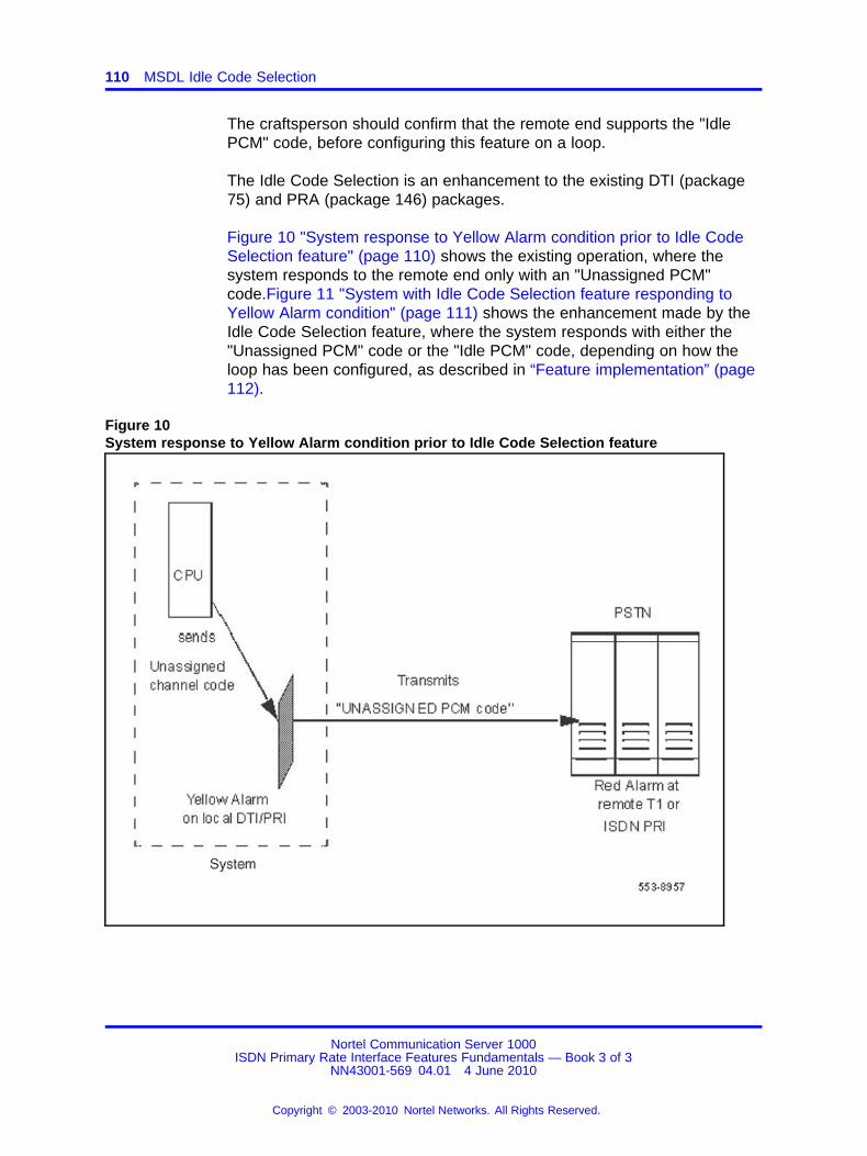
110 MSDL Idle Code Selection
The craftsperson should confirm that the remote end supports the "IdlePCM" code, before configuring this feature on a loop.
The Idle Code Selection is an enhancement to the existing DTI (package75) and PRA (package 146) packages.
Figure 10 "System response to Yellow Alarm condition prior to Idle CodeSelection feature" (page 110) shows the existing operation, where thesystem responds to the remote end only with an "Unassigned PCM"code.Figure 11 "System with Idle Code Selection feature responding toYellow Alarm condition" (page 111) shows the enhancement made by theIdle Code Selection feature, where the system responds with either the"Unassigned PCM" code or the "Idle PCM" code, depending on how theloop has been configured, as described in “Feature implementation” (page112).
Figure 10System response to Yellow Alarm condition prior to Idle Code Selection feature
Nortel Communication Server 1000ISDN Primary Rate Interface Features Fundamentals — Book 3 of 3
NN43001-569 04.01 4 June 2010
Copyright © 2003-2010 Nortel Networks. All Rights Reserved.
.
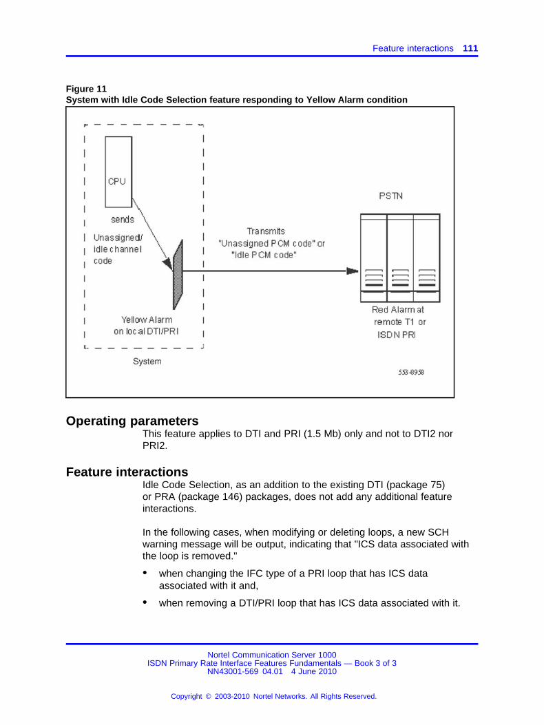
Feature interactions 111
Figure 11System with Idle Code Selection feature responding to Yellow Alarm condition
Operating parametersThis feature applies to DTI and PRI (1.5 Mb) only and not to DTI2 norPRI2.
Feature interactionsIdle Code Selection, as an addition to the existing DTI (package 75)or PRA (package 146) packages, does not add any additional featureinteractions.
In the following cases, when modifying or deleting loops, a new SCHwarning message will be output, indicating that "ICS data associated withthe loop is removed."
• when changing the IFC type of a PRI loop that has ICS dataassociated with it and,
• when removing a DTI/PRI loop that has ICS data associated with it.
Nortel Communication Server 1000ISDN Primary Rate Interface Features Fundamentals — Book 3 of 3
NN43001-569 04.01 4 June 2010
Copyright © 2003-2010 Nortel Networks. All Rights Reserved.
.
112 MSDL Idle Code Selection
Feature packagingIdle Code Selection is not a separate package, but is an enhancement tothe existing DTI (package 75) and PRA (package 146) packages. IdleCode Selection requires either the DTI or PRA package. ISDN package145 is required for ISDN.
Feature implementationTask summary list
The following is the task in this section:
1. Table 56 "LD 73: Activate (or deactivate) a loop to send Idle PCMcode." (page 112)
Table 56LD 73: Activate (or deactivate) a loop to send Idle PCM code.
Prompt Response Description
REQ CHG Change existing data.
TYPE DDB Digital Data Block
... ...
SRMM 1-(2)-127 Slip Rate Maintenance Maximum.
ICS0-1590-63(Xnnn)
Idle Code Selection loop numberFor Large SystemsFor Small SystemsTo deactivate the feature on loop xxx.
Feature operationNo specific operating procedures are required to use this feature.
Nortel Communication Server 1000ISDN Primary Rate Interface Features Fundamentals — Book 3 of 3
NN43001-569 04.01 4 June 2010
Copyright © 2003-2010 Nortel Networks. All Rights Reserved.
.

113.
MSDL Port Overload Counter
ContentsThis section contains information on the following topics:
“Feature description” (page 113)
“Operating parameters” (page 115)
“Feature interactions” (page 115)
“Feature packaging” (page 116)
“Feature implementation” (page 116)
“Feature operation” (page 116)
“Maintenance and Diagnostics” (page 116)
“Fault Clearance Procedures” (page 117)
“Overloaded MSDL port running a DCH Application” (page 117)
“Overloaded MSDL port running an AML Application” (page 118)
“Overloaded MSDL port running an SDI Application” (page 118)
Feature descriptionThe MSDL Port Overload Counter feature provides the capability of lockingout individual MSDL ports when incoming messages through a port exceedor equal the port overload threshold of 200 messages in a two-second timeperiod.
When any of the four ports on the MSDL card reaches the port overloadthreshold it is locked-out, but the operation of other ports on the MSDLcard will not be affected.
The MSDL card is still subject to a card overload threshold, which willcause a lock-out if it receives 300 or more messages for every twoseconds. However, when an individual MSDL port becomes overloaded,
Nortel Communication Server 1000ISDN Primary Rate Interface Features Fundamentals — Book 3 of 3
NN43001-569 04.01 4 June 2010
Copyright © 2003-2010 Nortel Networks. All Rights Reserved.
.

114 MSDL Port Overload Counter
the messages to that port are subtracted from the total card messagesused in performing the card overload check. Furthermore, port overloadchecks have priority over card overload checks.
The overloaded port on the MSDL card is locked-out so that the card stopsresponding to the incoming messages from the overloaded port. Thisprevents the CPU from servicing a very high incoming message rate fromthe port, which could cause system degradation.
Figure 12 "MSDL card lock-out" (page 114) shows the existing MSDLcard lockout, whileFigure 13 "MSDL port overload check preceding cardoverload check" (page 114) shows the port lockout functionality introducedby the Port Overload Counter feature. Figure 13 "MSDL port overloadcheck preceding card overload check" (page 114) demonstrates a portoverload check being performed before a card overload check.
Figure 12MSDL card lock-out
Figure 13MSDL port overload check preceding card overload check
Nortel Communication Server 1000ISDN Primary Rate Interface Features Fundamentals — Book 3 of 3
NN43001-569 04.01 4 June 2010
Copyright © 2003-2010 Nortel Networks. All Rights Reserved.
.
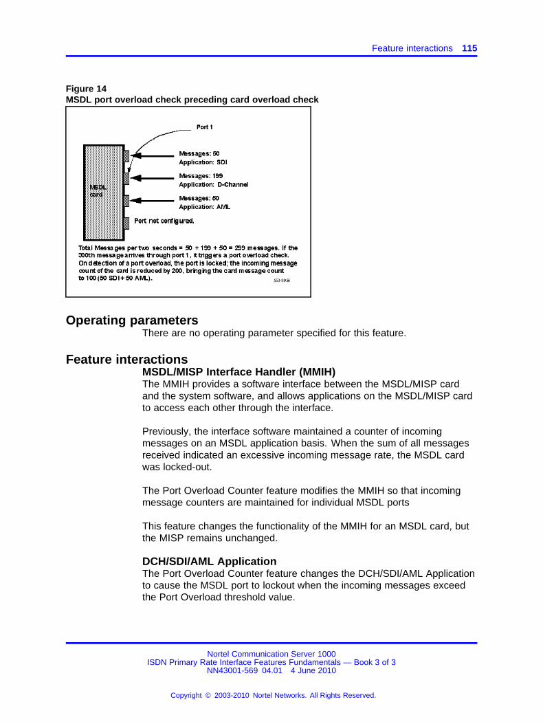
Feature interactions 115
Figure 14MSDL port overload check preceding card overload check
Operating parametersThere are no operating parameter specified for this feature.
Feature interactionsMSDL/MISP Interface Handler (MMIH)The MMIH provides a software interface between the MSDL/MISP cardand the system software, and allows applications on the MSDL/MISP cardto access each other through the interface.
Previously, the interface software maintained a counter of incomingmessages on an MSDL application basis. When the sum of all messagesreceived indicated an excessive incoming message rate, the MSDL cardwas locked-out.
The Port Overload Counter feature modifies the MMIH so that incomingmessage counters are maintained for individual MSDL ports
This feature changes the functionality of the MMIH for an MSDL card, butthe MISP remains unchanged.
DCH/SDI/AML ApplicationThe Port Overload Counter feature changes the DCH/SDI/AML Applicationto cause the MSDL port to lockout when the incoming messages exceedthe Port Overload threshold value.
Nortel Communication Server 1000ISDN Primary Rate Interface Features Fundamentals — Book 3 of 3
NN43001-569 04.01 4 June 2010
Copyright © 2003-2010 Nortel Networks. All Rights Reserved.
.
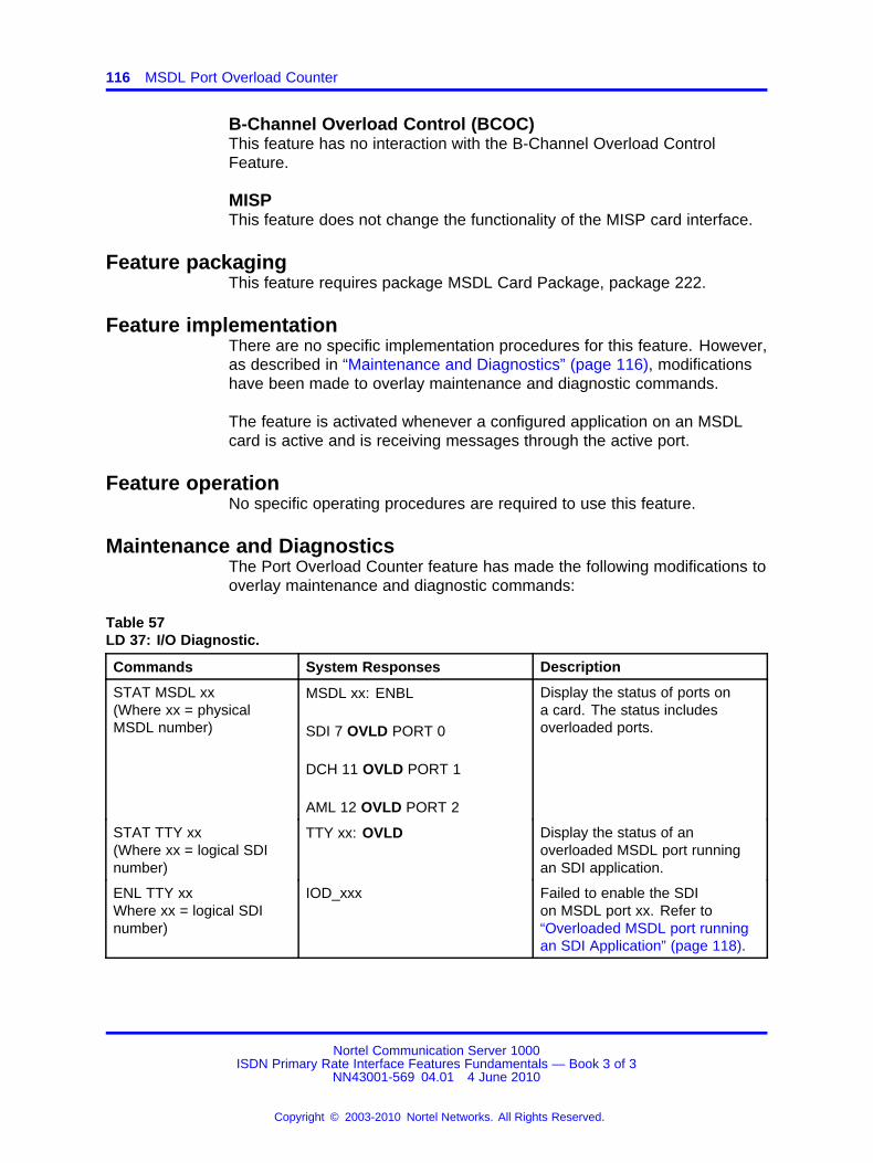
116 MSDL Port Overload Counter
B-Channel Overload Control (BCOC)This feature has no interaction with the B-Channel Overload ControlFeature.
MISPThis feature does not change the functionality of the MISP card interface.
Feature packagingThis feature requires package MSDL Card Package, package 222.
Feature implementationThere are no specific implementation procedures for this feature. However,as described in “Maintenance and Diagnostics” (page 116), modificationshave been made to overlay maintenance and diagnostic commands.
The feature is activated whenever a configured application on an MSDLcard is active and is receiving messages through the active port.
Feature operationNo specific operating procedures are required to use this feature.
Maintenance and DiagnosticsThe Port Overload Counter feature has made the following modifications tooverlay maintenance and diagnostic commands:
Table 57LD 37: I/O Diagnostic.
Commands System Responses Description
STAT MSDL xx(Where xx = physicalMSDL number)
MSDL xx: ENBL
SDI 7 OVLD PORT 0
DCH 11 OVLD PORT 1
AML 12 OVLD PORT 2
Display the status of ports ona card. The status includesoverloaded ports.
STAT TTY xx(Where xx = logical SDInumber)
TTY xx: OVLD Display the status of anoverloaded MSDL port runningan SDI application.
ENL TTY xxWhere xx = logical SDInumber)
IOD_xxx Failed to enable the SDIon MSDL port xx. Refer to“Overloaded MSDL port runningan SDI Application” (page 118).
Nortel Communication Server 1000ISDN Primary Rate Interface Features Fundamentals — Book 3 of 3
NN43001-569 04.01 4 June 2010
Copyright © 2003-2010 Nortel Networks. All Rights Reserved.
.
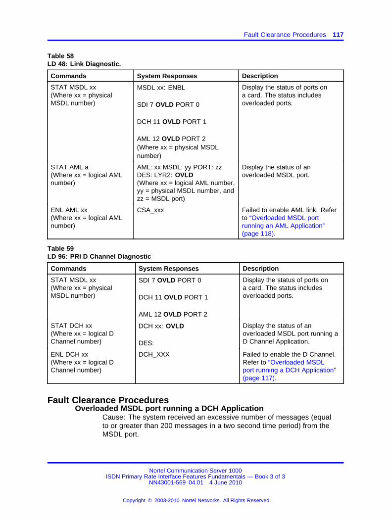
Fault Clearance Procedures 117
Table 58LD 48: Link Diagnostic.
Commands System Responses Description
STAT MSDL xx(Where xx = physicalMSDL number)
MSDL xx: ENBL
SDI 7 OVLD PORT 0
DCH 11 OVLD PORT 1
AML 12 OVLD PORT 2(Where xx = physical MSDLnumber)
Display the status of ports ona card. The status includesoverloaded ports.
STAT AML a(Where xx = logical AMLnumber)
AML: xx MSDL: yy PORT: zzDES: LYR2: OVLD(Where xx = logical AML number,yy = physical MSDL number, andzz = MSDL port)
Display the status of anoverloaded MSDL port.
ENL AML xx(Where xx = logical AMLnumber)
CSA_xxx Failed to enable AML link. Referto “Overloaded MSDL portrunning an AML Application”(page 118).
Table 59LD 96: PRI D Channel Diagnostic
Commands System Responses Description
STAT MSDL xx(Where xx = physicalMSDL number)
SDI 7 OVLD PORT 0
DCH 11 OVLD PORT 1
AML 12 OVLD PORT 2
Display the status of ports ona card. The status includesoverloaded ports.
STAT DCH xx(Where xx = logical DChannel number)
DCH xx: OVLD
DES:
Display the status of anoverloaded MSDL port running aD Channel Application.
ENL DCH xx(Where xx = logical DChannel number)
DCH_XXX Failed to enable the D Channel.Refer to “Overloaded MSDLport running a DCH Application”(page 117).
Fault Clearance ProceduresOverloaded MSDL port running a DCH Application
Cause: The system received an excessive number of messages (equalto or greater than 200 messages in a two second time period) from theMSDL port.
Nortel Communication Server 1000ISDN Primary Rate Interface Features Fundamentals — Book 3 of 3
NN43001-569 04.01 4 June 2010
Copyright © 2003-2010 Nortel Networks. All Rights Reserved.
.
118 MSDL Port Overload Counter
To clear the fault: Manually disable the D-Channel in LD 96 using thecommand DIS DCH xx, where xx is the D-Channel number. Enable theD-Channel using LD 96 using the command ENL DCH xx.
Overloaded MSDL port running an AML ApplicationCause: The system received an excessive number of messages (equalto or greater than 200 messages in a two second time period) from theMSDL port.
To clear the fault: Manually disable the AML Link in LD 48 using thecommand DIS AML xx, where xx is the AML Link number. Enable the AMLLink using LD 48 using the command ENL AML xx.
Overloaded MSDL port running an SDI ApplicationCause: The system received an excessive number of messages (equalto or greater than 200 messages in a two second time period) from theMSDL port. One scenario of the overloaded SDI port is the case of asmart-modem setup for "smart" vs. "dumb" mode. The system and themodem can be bouncing the same messages back and forth until the 200port message threshold is reached.
To clear the fault: Manually disable the link in LD 37 using the commandDIS TTY xx, where xx is the SDI number. Enable the AML Link using LD37 using the command ENL TTY xx.
Nortel Communication Server 1000ISDN Primary Rate Interface Features Fundamentals — Book 3 of 3
NN43001-569 04.01 4 June 2010
Copyright © 2003-2010 Nortel Networks. All Rights Reserved.
.
119.
MSDL Status Enquiry Message Throttle
ContentsThis section contains information on the following topics:
“Applicable regions” (page 119)
“Feature description” (page 119)
“Operating parameters” (page 120)
“Feature interactions” (page 120)
“Feature packaging” (page 120)
“Feature implementation” (page 120)
“Feature operation” (page 122)
Applicable regionsThe information presented in this section does not pertain to all regions.Contact your system supplier or your Nortel representative to verifysupport of this product in your area.
Feature descriptionWhen a D-channel recovers from data link failure, in a system to systemnetwork interface, the "network" (master) side of the "network" side to"user" (slave) side interface sends a Status Enquiry message to the "user"side, for every established B-channel, to request the call state.
The Status Enquiry Message Throttle feature regulates the sending ofStatus Enquiry messages, by limiting the Status Enquiry messages sentwithin a 128 millisecond time period. The Network side of the interfaceuses a fixed number of Status Enquiry messages that is configurablefor each D-channel through a Status Enquiry Message Throttle (SEMT)parameter in LD 17.
By reducing the number of Status Enquiry messages sent in a given 128msec time period, this feature improves the amount of network congestionexperienced after a D-channel recovers from data link failure. This alsofrees up some timeslots for call processing.
Nortel Communication Server 1000ISDN Primary Rate Interface Features Fundamentals — Book 3 of 3
NN43001-569 04.01 4 June 2010
Copyright © 2003-2010 Nortel Networks. All Rights Reserved.
.

120 MSDL Status Enquiry Message Throttle
By default the SEMT parameter is 1. The valid input range is 1 to 5.
Operating parametersThis feature applies to DTI and PRI (1.5 Mb) only and not to DTI2 norPRI2.
This feature supports both the NT6D80 Multi-Purpose SerialData Link (MSDL) card and the NT5D12 Dual Port DTI/PRIcard with the Downloadable D-channel daughterboard for DDP(NTBK51AA/NTBK51CA). ISDN PRI and ISL interfaces are supported.
This feature applies only to system to system interfaces (MCDNinter-networking).
The new prompt, SEMT, only applies to the "network" side interface of thesystem to system network.
Feature interactionsThere are no feature interactions associated with this feature.
Feature packagingThis feature requires the following packages:
• ISDN Signaling (ISDN), package 145
• ISDN Primary Rate Access (PRA), package 146, or
• ISDN Signaling Link (ISL), package 147
• Multi-Purpose Serial Data Link (MSDL), package 222
Feature implementationTable 60LD 17: Configure the Status Enquiry Message Throttle (SEMT) parameter.
Prompt Response Description
REQ CHG Change existing data.
TYPE CEQU All input/output devices.
ADAN aaa DCH xx Primary D-channel number. Where:
aaa = NEW or CHG.xx = 0-63 (For Large Systems)xx = 1-9 (For Small Systems)
CTYP MSDL Multipurpose Serial Data Link card.
GRP 0-4 Network Group number for Large Multi-Group Systems.
Nortel Communication Server 1000ISDN Primary Rate Interface Features Fundamentals — Book 3 of 3
NN43001-569 04.01 4 June 2010
Copyright © 2003-2010 Nortel Networks. All Rights Reserved.
.
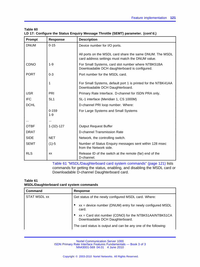
Feature implementation 121
Table 60LD 17: Configure the Status Enquiry Message Throttle (SEMT) parameter. (cont’d.)
Prompt Response Description
DNUM 0-15 Device number for I/O ports.
All ports on the MSDL card share the same DNUM. The MSDLcard address settings must match the DNUM value.
CDNO 1-9 For Small Systems, card slot number where NTBK51BADownloadable DCH daughterboard is configured.
PORT 0-3
1
Port number for the MSDL card.
For Small Systems, default port 1 is printed for the NTBK41AADownloadable DCH Daughterboard.
USR PRI Primary Rate Interface. D-channel for ISDN PRA only.
IFC SL1 SL-1 interface (Meridian 1, CS 1000M)
DCHL D-channel PRI loop number. Where:
0-1591-9
For Large Systems and Small Systems
... ...
OTBF 1-(32)-127 Output Request Buffer
DRAT D-channel Transmission Rate
SIDE NET Network, the controlling switch.
SEMT (1)-5 Number of Status Enquiry messages sent within 128 msecfrom the Network side.
RLS xx Release ID of the switch at the remote (far) end of theD-channel.
Table 61 "MSDL/Daughterboard card system commands" (page 121) listscommands for getting the status, enabling, and disabling the MSDL card orDownloadable D-channel Daughterboard card.
Table 61MSDL/Daughterboard card system commands
Command Response
STAT MSDL xx Get status of the newly configured MSDL card. Where:
• xx = device number (DNUM) entry for newly configured MSDLcard.
• xx = Card slot number (CDNO) for the NTBK51AA/NTBK51CADownloadable DCH Daughterboard.
The card status is output and can be any one of the following:
Nortel Communication Server 1000ISDN Primary Rate Interface Features Fundamentals — Book 3 of 3
NN43001-569 04.01 4 June 2010
Copyright © 2003-2010 Nortel Networks. All Rights Reserved.
.
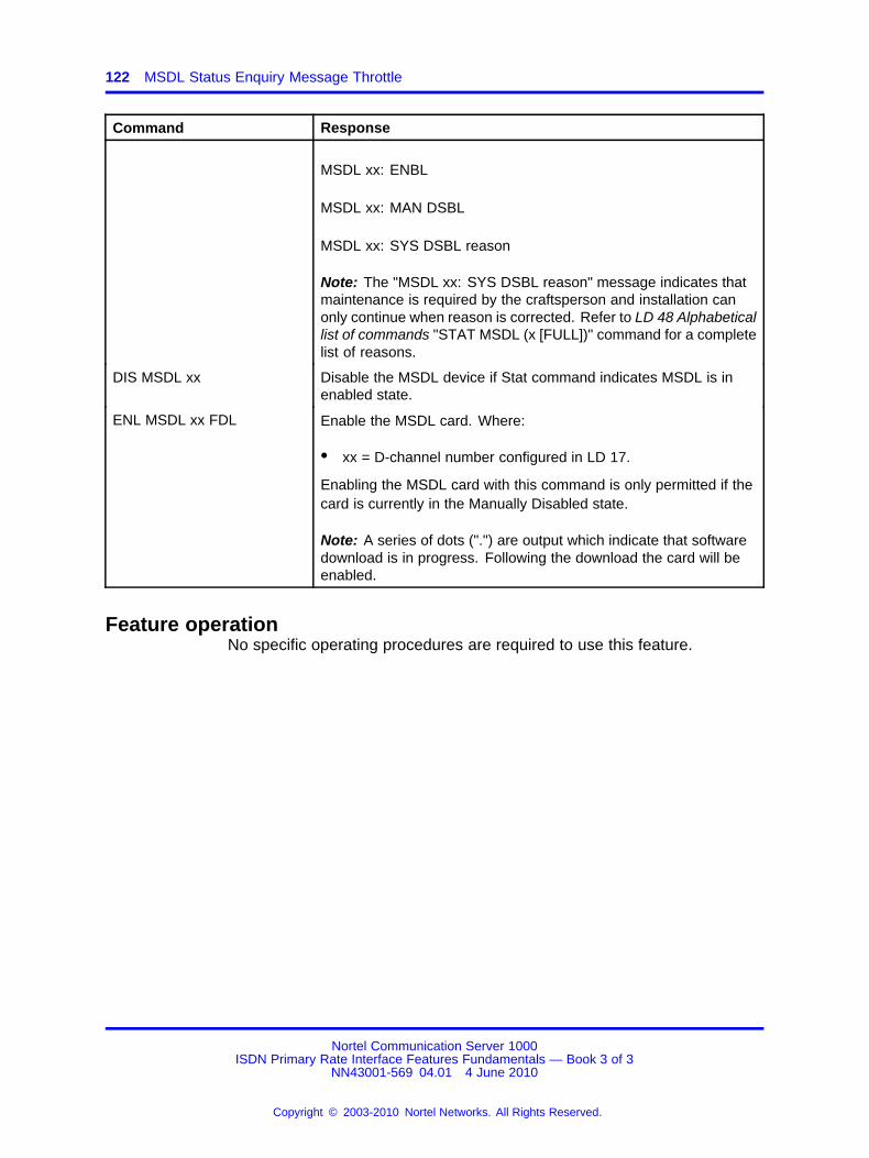
122 MSDL Status Enquiry Message Throttle
Command Response
MSDL xx: ENBL
MSDL xx: MAN DSBL
MSDL xx: SYS DSBL reason
Note: The "MSDL xx: SYS DSBL reason" message indicates thatmaintenance is required by the craftsperson and installation canonly continue when reason is corrected. Refer to LD 48 Alphabeticallist of commands "STAT MSDL (x [FULL])" command for a completelist of reasons.
DIS MSDL xx Disable the MSDL device if Stat command indicates MSDL is inenabled state.
ENL MSDL xx FDL Enable the MSDL card. Where:
• xx = D-channel number configured in LD 17.
Enabling the MSDL card with this command is only permitted if thecard is currently in the Manually Disabled state.
Note: A series of dots (".") are output which indicate that softwaredownload is in progress. Following the download the card will beenabled.
Feature operationNo specific operating procedures are required to use this feature.
Nortel Communication Server 1000ISDN Primary Rate Interface Features Fundamentals — Book 3 of 3
NN43001-569 04.01 4 June 2010
Copyright © 2003-2010 Nortel Networks. All Rights Reserved.
.
123.
National ISDN 2 TR-1268 Primary RateInterface
ContentsThis section contains information on the following topics:
“Applicable regions” (page 123)
“Feature description” (page 123)
“Operating parameters” (page 191)
“Feature implementation” (page 192)
“Feature packaging” (page 251)
“Feature implementation” (page 125)
“Task summary list” (page 252)
“Feature operation” (page 256)
Applicable regionsThis feature is only available in North America. Contact your systemsupplier or your Nortel representative to verify support of this product inyour area.
Feature descriptionThe National ISDN-2 TR-NWT-001268 Primary Rate Interface (PRI)feature provides an Integrated Services Digital Network (ISDN) PRIinterface to the Public Exchange/Central Office that conforms to portionsof the National ISDN-2 (NI-2) specification as developed by the NationalISDN users Forum (NIUF) and documented in Bellcore SpecificationTR-1268.
The system supports the following call services on the NI-2 interface:
• Basic call service
• Circuit-mode bearer capabilities (speech, 3.1 kHz audio, 64 Kbit/sdigital, and adapted 56 Kbit/s to 64 Kbit/s digital)
Nortel Communication Server 1000ISDN Primary Rate Interface Features Fundamentals — Book 3 of 3
NN43001-569 04.01 4 June 2010
Copyright © 2003-2010 Nortel Networks. All Rights Reserved.
.

124 National ISDN 2 TR-1268 Primary Rate Interface
• Enbloc sending
• Channel negotiation
• In-band tone and announcement
• Calling number delivery
• Calling Party Number Privacy, using the Calling Party Name feature(*67)
• A back-up D-channel is provided to improve the reliability of an ISDNPRI interface that consists of more than one Digital Signal Level 1(DS1) facility. The primary and back-up D-channels reside on the 24thchannel of separate DS1 facilities. Both D-channels provide signalinginformation for the interface, but only one can be in service at anygiven time.
The system does not support the following TR-1268 functionalities:
• Packet Mode Unrestricted Digital Information bearer capability
• Circuit Mode Unrestricted Digital Information at n x 64 Kbit/s, H0 andH11 channels bearer capability (due to the lack of hardware supportof providing contiguous timeslots)
• Up to two Calling Party Number information elements for terminatingcalls
• Up to two redirecting numbers provided for originating and terminatingcalls
• Subaddressing
• Calling party number privacy on subscription basis
• Call-by-Call Service Selection, and
• Switched DS1/Switched Fractional DS1 Service.
Operating parametersThe existing Network Call Redirection limitation on unsupported interfaceapplies to the NI-2 interface. The NI-2 interface generates the RedirectingNumber (RN) Information Element (IE) of the most recent instance ofredirection of an internal call forward call. If the system receives an RN IEat the NI-2 interface, it passes it along. If there are more than one RN IEs,the later ones are treated as duplicates and are discarded.
Nortel Communication Server 1000ISDN Primary Rate Interface Features Fundamentals — Book 3 of 3
NN43001-569 04.01 4 June 2010
Copyright © 2003-2010 Nortel Networks. All Rights Reserved.
.
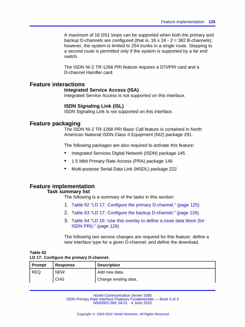
Feature implementation 125
A maximum of 16 DS1 loops can be supported when both the primary andbackup D-channels are configured (that is, 16 x 24 - 2 = 382 B-channels);however, the system is limited to 254 trunks in a single route. Stepping toa second route is permitted only if the system is supported by a far endswitch.
The ISDN NI-2 TR-1268 PRI feature requires a DTI/PRI card and aD-channel Handler card.
Feature interactionsIntegrated Service Access (ISA)Integrated Service Access is not supported on this interface.
ISDN Signaling Link (ISL)ISDN Signaling Link is not supported on this interface.
Feature packagingThe ISDN NI-2 TR-1268 PRI Basic Call feature is contained in NorthAmerican National ISDN Class II Equipment (NI2) package 291.
The following packages are also required to activate this feature:
• Integrated Services Digital Network (ISDN) package 145
• 1.5 Mbit Primary Rate Access (PRA) package 146
• Multi-purpose Serial Data Link (MSDL) package 222
Feature implementationTask summary list
The following is a summary of the tasks in this section:
1. Table 62 "LD 17: Configure the primary D-channel." (page 125)
2. Table 63 "LD 17: Configure the backup D-channel." (page 126)
3. Table 64 "LD 16: Use this overlay to define a route data block (forISDN PRI)." (page 126)
The following two service changes are required for this feature: define anew interface type for a given D-channel; and define the download.
Table 62LD 17: Configure the primary D-channel.
Prompt Response Description
REQ NEW Add new data.
CHG Change existing data.
Nortel Communication Server 1000ISDN Primary Rate Interface Features Fundamentals — Book 3 of 3
NN43001-569 04.01 4 June 2010
Copyright © 2003-2010 Nortel Networks. All Rights Reserved.
.

126 National ISDN 2 TR-1268 Primary Rate Interface
Table 62LD 17: Configure the primary D-channel. (cont’d.)
Prompt Response Description
TYPE CFN Configuration Record.
ADAN NEW CHG OUTDCH xx
Add, change, or remove primary D-channel.
CTYP MSDL Supported only on Multi-purpose Serial Data Link (MSDL) orDownloadable D-channel cards.
…
USR PRI D-channel mode.
IFC NI2 NI-2 TR-1268 interface type.
CO_TYPE (STD) ATT Central Office switch type (prompted only if IFC = NI2).
STD = Totally compatible with Bellcore standard.ATT = AT&T 5ESS.
PRI lll nn lll = PRI loop using the same D-channel (0,1,...159)nn = Interface identifier (2,3,...15)
Table 63LD 17: Configure the backup D-channel.
Prompt Response Description
REQ NEW Add new data.
CHG Change existing data.
TYPE CFN Configuration Record.
ADAN NEW CHG OUTBDCH yy
Add, change or remove backup D-channel data.
PDCH xx Associated primary D-channel.
CTYP MSDL Card type.
…
Table 64LD 16: Use this overlay to define a route data block (for ISDN PRI).
Prompt Response Description
REQ NEW Add new data.
CHG Change existing data.
TYPE RDB Route data block.
…
DGTP PRI Digital route type.
IFC NI2 New DCH interface ID.
Nortel Communication Server 1000ISDN Primary Rate Interface Features Fundamentals — Book 3 of 3
NN43001-569 04.01 4 June 2010
Copyright © 2003-2010 Nortel Networks. All Rights Reserved.
.
Feature operation 127
Feature operationNo specific operating instructions are required to use this feature.
Nortel Communication Server 1000ISDN Primary Rate Interface Features Fundamentals — Book 3 of 3
NN43001-569 04.01 4 June 2010
Copyright © 2003-2010 Nortel Networks. All Rights Reserved.
.

128 National ISDN 2 TR-1268 Primary Rate Interface
Nortel Communication Server 1000ISDN Primary Rate Interface Features Fundamentals — Book 3 of 3
NN43001-569 04.01 4 June 2010
Copyright © 2003-2010 Nortel Networks. All Rights Reserved.
.
129.
Network ACD
ContentsThis section contains information on the following topics:
“Feature description” (page 129)
“Operating parameters” (page 130)
“Feature interactions” (page 130)
“Feature packaging” (page 130)
“Feature implementation” (page 131)
“Feature operation” (page 131)
Feature descriptionNetwork ACD allows call centers with multiple locations to solve theproblem of fluctuating call traffic. The Network ACD feature usesIntegrated Services Digital Network (ISDN) to efficiently and quickly routecalls to available agents within a network of systems. Using the timedoverflow routing tables associated with ACD, customers can specifyACD-DNs within the system network to which calls should be directed.
NACD is cost effective because calls remain in queue at their originallocation while waiting for an agent to become available in either thesource queue or one of the target queues located throughout the network.Only when an agent becomes available in a remote queue will the callactually be sent over an ISDN voice channel. Prior to the call being sent,communication between locations is handled through the ISDN D-Channel.
The management report information on package C reflects the changesintroduced by the NACD feature.
ACD-MAX supports the NACD feature. Three new reports and threeadditional management displays are provided to allow customers todetermine call traffic patterns and service levels throughout the network.Centralization of this information will be provided with the introduction
Nortel Communication Server 1000ISDN Primary Rate Interface Features Fundamentals — Book 3 of 3
NN43001-569 04.01 4 June 2010
Copyright © 2003-2010 Nortel Networks. All Rights Reserved.
.
130 Network ACD
of the Network Administration Center. Network Administration Centerrequires an ACD-MAX in each network location and provides reports anddisplays on the entire NACD environment.
For correct display on ACD-MAX, NACD supports only a UDP numberingplan. CDP will be supported at a later date. It is important to note that thesystem regular users can operate using one dialing plan (i.e. CDP or UDP)while the NACD operates using another numbering scheme (i.e. UDP withlocation codes).
Operating parametersThe small systems only support Meridian ACD-MAX.
This feature is currently incompatible with the similar Network ACD featureon the SL-100.
NACD is not supported on Package D, PDP 11 - Generic 9000 software.
Feature interactionsThere are no feature interactions associated with this feature.
Feature packagingThis feature requires Network Automatic Call Distribution (NACD) package207. The following packages are also required:
• Basic Routing (BRTE) package 14
• Digit Display (DDSP) package 19
• Basic Queuing (BQUE) package 28
• Network Class Of Service (NCOS) package 32
• Network Signaling (NSIG) package 37
• Basic Automatic Call Distribution (BACD) package 40
• Automatic Call Distribution, Package B (ACDB) package 41
• Automatic Call Distribution, Package A (ACDA) package 45
• Automatic Answerback (AAB) package 47
• Network Alternate Route Selection (NARS) package 58 or
• Coordinated Dialing Plan (CDP) package 59
• Flexible Call Back Queuing (FCBQ) package 61
• 1.5 Mbit Digital Trunk Interface (PBXI) package 75 or
• 2.0 Mbit Digital Trunk Interface (PBXI) package 129
• Timed Overflow Queuing (TOF) package 111
Nortel Communication Server 1000ISDN Primary Rate Interface Features Fundamentals — Book 3 of 3
NN43001-569 04.01 4 June 2010
Copyright © 2003-2010 Nortel Networks. All Rights Reserved.
.

Feature operation 131
• Integrated Services Digital Network (ISDN) package 145
• International Primary Rate Access (PRI) package 146 or
• 2.0 Mbit Primary Rate Access (PRI2) package 154 or
• ISDN signaling Link (ISL) package 147
• Advanced ISDN Network Services (NTWK) package 148
• ACD Enhanced Overflow (EOVF) package 178
Feature implementationThere are no specific implementation procedures for this feature.
Feature operationNo specific operating procedures are required to use this feature.
Nortel Communication Server 1000ISDN Primary Rate Interface Features Fundamentals — Book 3 of 3
NN43001-569 04.01 4 June 2010
Copyright © 2003-2010 Nortel Networks. All Rights Reserved.
.

132 Network ACD
Nortel Communication Server 1000ISDN Primary Rate Interface Features Fundamentals — Book 3 of 3
NN43001-569 04.01 4 June 2010
Copyright © 2003-2010 Nortel Networks. All Rights Reserved.
.
133.
Network Application Protocol LinkEnhancement
ContentsThis section contains information on the following topics:
“Feature description” (page 133)
“Operating parameters” (page 134)
“Feature interactions” (page 134)
“Feature packaging” (page 134)
“Feature implementation” (page 134)
“Feature operation” (page 134)
Feature descriptionThis enhancement of the ISDN Network Application Protocol (ISDN NAP)feature for Meridian Mail services provides improved fault-detectionresponses. When a NAP link fails, a predefined time period is allowed topass before the link is declared ’out-of-service’. Restoration of the linkwithin this recovery time period will result in uninterrupted service.
The signaling from the caller’s phone is ignored during the link failure.However, calls which were already established will remain establishedduring the recovery period. Should the link be declared ’out of service’,only those established calls which use trunks without disconnectsupervision will not be maintained. (Such calls will be requeued to the frontof the waiting queue.)
When a link is in the recovery period, calls ringing to an agent are heldin the ringing state, until either the recovery period ends or the link isreestablished. Incoming calls requiring Meridian Mail services are placedin the ACD queue, linked to an agent (if possible) and given ringback tone.
Nortel Communication Server 1000ISDN Primary Rate Interface Features Fundamentals — Book 3 of 3
NN43001-569 04.01 4 June 2010
Copyright © 2003-2010 Nortel Networks. All Rights Reserved.
.
134 Network Application Protocol Link Enhancement
When a link is declared ’out of service’, calls which are ringing at an agentare requeued. Requeued calls and incoming calls on the out-of-servicelink receive night-service treatment.
Normal operations resume when the link is restored.
Operating parametersThis feature applies only to the ISDN environment.
Feature interactionsThere are no feature interactions associated with this feature.
Feature packagingThis feature requires the following packages:
• ISDN Application Protocol Link for Third-party Vendors (IAP3P)package 153, which is dependent on
— Basic Automatic Call Distribution (BACD) package 40
Feature implementationThere are no specific implementation procedures for this feature.
Feature operationNo specific operating procedures are required to use this feature.
Nortel Communication Server 1000ISDN Primary Rate Interface Features Fundamentals — Book 3 of 3
NN43001-569 04.01 4 June 2010
Copyright © 2003-2010 Nortel Networks. All Rights Reserved.
.
135.
Network Attendant Service
ContentsThis section contains information on the following topics:
“Feature description” (page 135)
“Operating parameters” (page 142)
“Feature interactions” (page 143)
“Feature packaging” (page 144)
“Feature implementation” (page 146)
“Task summary list” (page 146)
“Feature operation” (page 151)
Feature descriptionNetwork Attendant Service (NAS) provides stand-alone attendantcapabilities throughout a network. Any node in the network can have itsattendant services located part-time or full-time at any other node in thenetwork.
The activation of Network Attendant Service is controlled by the NAS keyon the Attendant Console. When a call is presented to an attendant andthe NAS key is not activated, the call receives normal attendant service. Ifthe NAS key is activated, the call receives alternate treatment, based onone of the NAS conditions described below.
Network Attendant Service scheduleThe NAS schedule allows a prioritized list of attendant alternatives(attendant locations) to be defined for up to 31 half-hour time periods.Each period can have up to four alternate attendants defined against it.During one of these time periods, a request for attendant service will use
Nortel Communication Server 1000ISDN Primary Rate Interface Features Fundamentals — Book 3 of 3
NN43001-569 04.01 4 June 2010
Copyright © 2003-2010 Nortel Networks. All Rights Reserved.
.
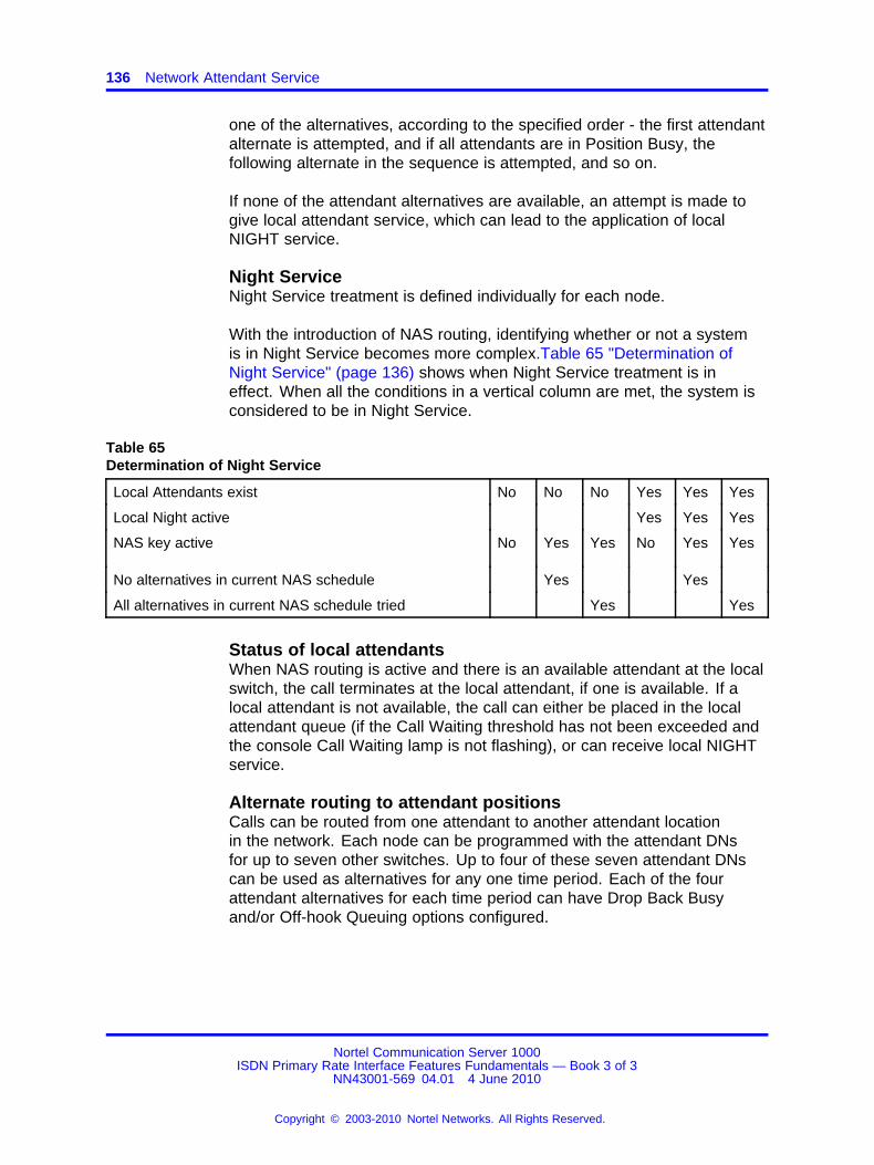
136 Network Attendant Service
one of the alternatives, according to the specified order - the first attendantalternate is attempted, and if all attendants are in Position Busy, thefollowing alternate in the sequence is attempted, and so on.
If none of the attendant alternatives are available, an attempt is made togive local attendant service, which can lead to the application of localNIGHT service.
Night ServiceNight Service treatment is defined individually for each node.
With the introduction of NAS routing, identifying whether or not a systemis in Night Service becomes more complex.Table 65 "Determination ofNight Service" (page 136) shows when Night Service treatment is ineffect. When all the conditions in a vertical column are met, the system isconsidered to be in Night Service.
Table 65Determination of Night Service
Local Attendants exist No No No Yes Yes Yes
Local Night active Yes Yes Yes
NAS key active No Yes Yes No Yes Yes
No alternatives in current NAS schedule Yes Yes
All alternatives in current NAS schedule tried Yes Yes
Status of local attendantsWhen NAS routing is active and there is an available attendant at the localswitch, the call terminates at the local attendant, if one is available. If alocal attendant is not available, the call can either be placed in the localattendant queue (if the Call Waiting threshold has not been exceeded andthe console Call Waiting lamp is not flashing), or can receive local NIGHTservice.
Alternate routing to attendant positionsCalls can be routed from one attendant to another attendant locationin the network. Each node can be programmed with the attendant DNsfor up to seven other switches. Up to four of these seven attendant DNscan be used as alternatives for any one time period. Each of the fourattendant alternatives for each time period can have Drop Back Busyand/or Off-hook Queuing options configured.
Nortel Communication Server 1000ISDN Primary Rate Interface Features Fundamentals — Book 3 of 3
NN43001-569 04.01 4 June 2010
Copyright © 2003-2010 Nortel Networks. All Rights Reserved.
.
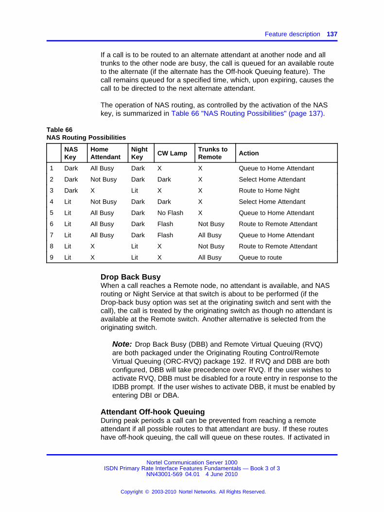
Feature description 137
If a call is to be routed to an alternate attendant at another node and alltrunks to the other node are busy, the call is queued for an available routeto the alternate (if the alternate has the Off-hook Queuing feature). Thecall remains queued for a specified time, which, upon expiring, causes thecall to be directed to the next alternate attendant.
The operation of NAS routing, as controlled by the activation of the NASkey, is summarized in Table 66 "NAS Routing Possibilities" (page 137).
Table 66NAS Routing Possibilities
NASKey
HomeAttendant
NightKey CW Lamp
Trunks toRemote Action
1 Dark All Busy Dark X X Queue to Home Attendant
2 Dark Not Busy Dark Dark X Select Home Attendant
3 Dark X Lit X X Route to Home Night
4 Lit Not Busy Dark Dark X Select Home Attendant
5 Lit All Busy Dark No Flash X Queue to Home Attendant
6 Lit All Busy Dark Flash Not Busy Route to Remote Attendant
7 Lit All Busy Dark Flash All Busy Queue to Home Attendant
8 Lit X Lit X Not Busy Route to Remote Attendant
9 Lit X Lit X All Busy Queue to route
Drop Back BusyWhen a call reaches a Remote node, no attendant is available, and NASrouting or Night Service at that switch is about to be performed (if theDrop-back busy option was set at the originating switch and sent with thecall), the call is treated by the originating switch as though no attendant isavailable at the Remote switch. Another alternative is selected from theoriginating switch.
Note: Drop Back Busy (DBB) and Remote Virtual Queuing (RVQ)are both packaged under the Originating Routing Control/RemoteVirtual Queuing (ORC-RVQ) package 192. If RVQ and DBB are bothconfigured, DBB will take precedence over RVQ. If the user wishes toactivate RVQ, DBB must be disabled for a route entry in response to theIDBB prompt. If the user wishes to activate DBB, it must be enabled byentering DBI or DBA.
Attendant Off-hook QueuingDuring peak periods a call can be prevented from reaching a remoteattendant if all possible routes to that attendant are busy. If these routeshave off-hook queuing, the call will queue on these routes. If activated in
Nortel Communication Server 1000ISDN Primary Rate Interface Features Fundamentals — Book 3 of 3
NN43001-569 04.01 4 June 2010
Copyright © 2003-2010 Nortel Networks. All Rights Reserved.
.
138 Network Attendant Service
the NAS programming and on the route list for the call, queuing occursbefore the system attempts other alternatives. The alternatives are triedafter the Off-hook Queuing (OHQ) timer expires.
Network Attendant Service capabilitiesThe following sections describe the network capabilities that are offeredas part of NAS.
Break-inThe Break-in feature allows an attendant to enter an established callanywhere in the network and to offer another call or important message toone of the parties involved in the call. Break-in is provided as a key (BKI)function. The BKI key can be pressed before dialing the DN of the requiredstation (pre-dial) or after (post-dial).
When the BKI key is pressed, the following situations can exist:
• Break-in request recognized — this is a temporary processing state,that occurs when an attendant tries to break-in to a party at anothernode, and lasts until the signaling protocol for the break-in attempt iscompleted.
• Break-in ignored — this state occurs if the required party hasdisconnected at the point of break-in, is idle without the Make SetBusy or Do Not Disturb features active, or is idle with the Call Forwardfeature active. In all cases, the party is rung, and the attendant canextend the call.
• Break-in allowed — the attendant can break into the required party,consult with the required party, and extend another call to the partyif (a) the source is an external call, (b) Camp-on is available on therequired party, and (c) the established call is a basic call.
• Break-in denied — break-in is not allowed if any of the aboveconditions are not met.
• Break-in temporarily denied — the attendant temporarily cannotbreak-in to the required party, but can try again later. This situationoccurs if:
— the required party is dialing, involved in a consultation call, or is onhold
— the required party’s phone is ringing or receiving an indication tone
— the required party’s phone is connected to a paging, dictation,recorded announcement, or integrated voice messaging trunk
Nortel Communication Server 1000ISDN Primary Rate Interface Features Fundamentals — Book 3 of 3
NN43001-569 04.01 4 June 2010
Copyright © 2003-2010 Nortel Networks. All Rights Reserved.
.
Feature description 139
— the party to be extended is a local party or trunk with warning tonedenied Class of Service
— network blocking to a remote node has been encountered
• Break-in consult only — the attendant can break into the requiredparty, and can consult with the party but cannot extend another call.This situation occurs if:
— the attendant originates the call
— the source is an internal call
— the source is an external call and neither Camp-on nor Call Waitingis possible on the required party
— the attendant attempts a pre-dial break-in and the required party isbusy with Call Forward active.
Call extensionRestrictions that apply to attendants at local nodes also apply to callsextended across the network to remote node attendants.
Attendant control prevents the calling phone from disconnecting until theattendant releases. Once the attendant releases or extends and releasesthe call, attendant control is relinquished.
Timed reminder recallsTimed reminder recalls are attendant-extended calls that return to theattendant when their timers expire. The timers apply to slow answer calls,camped on calls, and call waiting calls.
When the attendant extends the call to a party at another node, thetrunks between the attendant and the source and the attendant and thedestination are not taken down after the Release key is pressed. This istrue even if tromboning has occurred. This allows the attendant nodeto monitor the outgoing trunk for an answer signal. If no answer signaloccurs within the specified time, the call is presented again to an attendant(or to the original attendant, if Recall to Same Attendant is active on theattendant node).
Anti-tromboning is only invoked after the destination has answered and theattendant has released from the call.
Incoming Call IndicationThe Incoming Call Indicators (ICI) will operate in the same manner as astand-alone system for incoming calls from stations or trunks.
Nortel Communication Server 1000ISDN Primary Rate Interface Features Fundamentals — Book 3 of 3
NN43001-569 04.01 4 June 2010
Copyright © 2003-2010 Nortel Networks. All Rights Reserved.
.

140 Network Attendant Service
New ICI types are introduced for NAS routed calls for each trunk type. Theindicators can be the following:
• a dial 0 call (ordinary or fully restricted)
• a recall request
• a line lockout intercept
• Call Redirection (Call Forward No Answer, Call Forward Busy)
• an interpositional call
• a Listed Directory Number (LDN)
• a Message Center call
• NAS trunk types (type of trunk on which the call came into theoriginating switch. The choices are: NDID, NCO, NTIE, NFEX, andNWAT)
Attendant DisplayThree features which pass information useful for attendant display are:
• Calling Line Identification (CLID)
• Network Call Party Name Display
• Network Call Redirection
For incoming calls, the CLID received (if available), is displayed insteadof the Trunk Route Access Code and Trunk Member Number. If the callcomes from the private ISDN network and there is a name associated withthe calling phone, the name is displayed on consoles with alphanumericdisplays.
Reason for redirection codes are displayed if the call has been redirectedby a feature such as Call Forward All Calls.
Camp-on and Call WaitingBoth Camp-on and Call Waiting allow calls extended to a busy phone afurther opportunity to reach that phone. If the call is extended across thenetwork to a busy phone, Camp-on or Call Waiting can be attempted in thesame manner as in the stand-alone case.
Tenant ServiceIf Multi-Tenant (TENS) software package 86 is equipped, the table numberin the NAS overlay programming can be referenced to an individualConsole Presentation Group. Each tenant can have its own individual NASrouting programmed.
Nortel Communication Server 1000ISDN Primary Rate Interface Features Fundamentals — Book 3 of 3
NN43001-569 04.01 4 June 2010
Copyright © 2003-2010 Nortel Networks. All Rights Reserved.
.

Feature description 141
Centralized Attendant Service vs. Network Attendant ServiceNAS has some similarities to a previous non-ISDN application calledCentralized Attendant Service (CAS). There are significant differences aswell.
Note: NAS and CAS cannot be configured on the same system.
Centralized Attendant Service
• Allows attendants to be centralized at one Main switch connected toRemote switches with Release Link Trunks (RLTs).
• When a remote switch has the CAS feature key activated, incomingcalls to the Remote switch are redirected to the Main switch where anattendant answers the call.
• The call comes into the Main switch on an RLT. The attendant canextend the call back to a phone at the Remote switch. The call isrouted on the same RLT trunk which was used when the call came intothe Main switch.
• Once the call is ringing at the phone, the RLT trunk is released.
• If the phone goes unanswered, the call recalls to the attendant at theMain switch. A Release Link Trunk is used for the recall.
• The CAS feature is activated using a key on a proprietary phone orconsole at the Remote switch.
• When users at different switches call each other or the attendantplaces a call to another switch, normal TIE trunks are used.
Network Attendant Service
• NAS allows several switches to have attendants who answer callswhich have been redirected by the NAS feature. The switches areconnected with Primary Rate Interface (PRI) or ISDN Signaling Link(ISL) connections.
• NAS routing allows a call destined for the local attendant to bediverted to a Remote attendant. This routing is governed by a NASschedule, a NAS key, or a permanent NAS Active setting which canbe programmed.
• NAS calls can result in tromboned trunk connections between theRemote switch and the Attendant switch. These connections remainuntil the ringing phone answers the call. This can result in twotromboned TIE trunks or channels being held up while a phone isringing.
Nortel Communication Server 1000ISDN Primary Rate Interface Features Fundamentals — Book 3 of 3
NN43001-569 04.01 4 June 2010
Copyright © 2003-2010 Nortel Networks. All Rights Reserved.
.
142 Network Attendant Service
• If anti-tromboning has been programmed, the tromboning is correctedafter the phone is answered.
• If the phone goes unanswered, the call recalls to the attendant at theMain switch. A PRI channel or ISL trunk is used for the recall.
• A NAS key can be programmed as an option on an Attendant Console.
• NAS calls and normal user calls all use the same PRI/ISL trunks.
There are three additional differences between NAS and CAS:
• NAS routing is used when calls waiting in the local attendant queueexceed one of two thresholds. CAS routes all calls to the Main CASswitch.
• NAS chooses an attendant from up to four alternatives for each timeperiod. With CAS, each Remote site has only one Main switch to whichto route calls.
• NAS routing can also be based on the status of trunks to other nodesand Night Service indicator status. These factors do not affect callrouting with CAS.
Operating parametersNAS and the Centralized Answering Position (CAP) capability are mutuallyexclusive. A system can not have an actual attendant console. Instead,the system can be configured to use a Centralized Answering Position(using a Meridian 2616 digital phone.) The CAP Directory Number (DN) isthe customer Night DN. Since no attendant is configured, the customer isviewed to be in Night Service and any calls for the attendant are directedto the CAP.
Note: An attendant answering position must be an attendant console,and not a Meridian digital phone.
NAS and Centralized Attendant Service packages are mutually exclusiveand can not be packaged together.
NAS and Attendant Overflow Position packages are mutually exclusiveand can not be packaged together.
Trunk Group Busy applies only to trunk groups on the node where theattendant resides.
The Uninterrupted Line Connection feature continues to work on astand-alone switch basis; however, Network-wide Break-in, based onwarning tone Class of Service, cannot be guaranteed. Only one Attendant
Nortel Communication Server 1000ISDN Primary Rate Interface Features Fundamentals — Book 3 of 3
NN43001-569 04.01 4 June 2010
Copyright © 2003-2010 Nortel Networks. All Rights Reserved.
.
Feature interactions 143
at a time is allowed to break into a connection. Break-in is allowed forphones only, not trunks or other attendants. Attendant Control is notprovided if the connection is a result of a Network Break-in.
Unsupported featuresNAS does not support:
• Supervisory Console
• Charge Account
• Do-Not-Disturb and Group Do-Not-Disturb.
The following functions and features are not supported across the network:
• Barge-in
• Busy Verify
• Emergency transfer.
Feature interactionsAttendant Interposition CallAn attendant is not able to call a specific attendant on another node bydialing the attendant DN followed by the attendant number. The attendantdials the Network Alternate Route Selection (NARS), Coordinated DialingPlan (CDP), or Listed Directory Number (LDN) the same way a phonedials to reach the attendants at another node.
Busy VerifyPre-dial Break-in provides equivalent functionality but has severaladvantages over Busy Verify. Busy Verify does not operate on anetwork-wide basis.
Call Forward, Break-In and Hunt Internal or External NetworkWideWhen a call is transferred, a new facility message is sent to the transferredparty’s node to transport the terminal indicator parameter or the accesstrunk information parameter.
DPNSS1 Route Optimization/MCDN Trunk Anti-TromboningInterworkingIf tromboning trunks are removed on the MCDN side of a RO/TATInterworking gateway scenario by the Network Attendant Service feature(since NAS has presence over TAT), the RO/TAT Interworking functionalityis not invoked. The result is that, if NAS is equipped, attendant-extendedcalls that are in a tromboning state are optimized on the MCDN side, butDPNSS1 trunks are not optimised on the DPNSS1 side of the RO/TATInterworking gateway scenario.
Nortel Communication Server 1000ISDN Primary Rate Interface Features Fundamentals — Book 3 of 3
NN43001-569 04.01 4 June 2010
Copyright © 2003-2010 Nortel Networks. All Rights Reserved.
.

144 Network Attendant Service
EuroISDN Trunk - Network SideNAS signaling is not supported on a EuroISDN Trunk - Network Sideconnectivity. However, NAS will interwork with an incoming call from theEuroISDN Trunk - Network Side (routing and call handling).
INIT ACD Queue Call RestoreCall information associated with Network Attendant Service is lost aftersystem initialization and call restoration.
ISDN QSIG Basic CallISDN QSIG Basic Call interacts with Network Attendant Services (NAS) asif the call is going to a route without NAS being equipped.
Listed Directory Numbers, Network-wideThis feature enables LDNs to be recognized network- wide when NAS isused. Up to six LDNs can be defined on each system. The same LDNsmust be configured in multiple nodes. The LDN which users dial can beprogrammed as a CDP number, for example, and input in the NAS overlayas the ID of remote attendants.
Recall to Same AttendantThis feature operates on a network-wide basis for the following call types:
• Slow Answer Recall
• Camp-on Recall, and
• Call Waiting Recall.
The operation of this feature is affected by the programming for the optionin the Customer Data Block of the system where the attendant answeringthe call resides.
Virtual Network ServicesAs stated earlier, NAS and CAS cannot be configured together on thesame system. Since VNS requires NAS, this means that VNS and CAScannot be configured together on the same system, either.
Feature packagingThis feature requires the following packages:
• Basic Routing (BRTE) package 14
• Basic Queuing (BQUE) package 28
• Network Class of Service (NCOS) package 32
• Network Automatic Routing System (NARS) package 58 or
• Coordinated Dialing Plan (CDP) package 59
Nortel Communication Server 1000ISDN Primary Rate Interface Features Fundamentals — Book 3 of 3
NN43001-569 04.01 4 June 2010
Copyright © 2003-2010 Nortel Networks. All Rights Reserved.
.
Feature packaging 145
• Flexible Call Back Queuing (FCBQ) package 61
• Attendant Break-In/Trunk Offer (BKI) package 127
• Integrated Services Digital Network (ISDN) package 145
• Advanced ISDN Network Services (NTWK) package 148
• International Primary Access (PRA) package 146 or
• 2.0 Mbit Primary Rate Interface (PRI2) package 154 or
• ISDN Signaling Link (ISL) package 147
• Network Attendant Services (NAS) package 159
• ISDN Supplementary Features (ISDNS) package 161
• Originating Routing Control/Remote Virtual Queuing (ORC-RVQ)package 192 for Drop Back Busy (please see note under "Drop BackBusy" description.)
Example of NAS implementationFigure 15 "A simple application of NAS functionality in a private ISDN PRInetwork" (page 146) illustrates a simple application of the NAS functionalityin a private ISDN PRI network connecting three systems. Although thisexample uses NARS, the same functionality can be accomplished usingCDP.
Each system has the translations in place for a HLOC and the two LOCcodes for the other two system locations. This programming was done inthe NARS database. The route lists required in order to process thesetypes of calls have been programmed also.
The INAC implementation was part of the basic ISDN/Networkingprogramming.
The NAS programming involves the configuration of the D-channel forNAS functionality, the ID of the other attendants to be used, a list of thesequence in which these attendants are to be scanned for availability andthe time periods for each list.
System B, in this example, is the location where attendants should beavailable 24 hours a day. During the day, the other two locations areprogrammed to use System B as their first choice backup and then asa second choice System A uses System C and System C uses SystemA. At night, Systems A and C use System B as the only backup. If it isunavailable, calls will be given Night Service.
Nortel Communication Server 1000ISDN Primary Rate Interface Features Fundamentals — Book 3 of 3
NN43001-569 04.01 4 June 2010
Copyright © 2003-2010 Nortel Networks. All Rights Reserved.
.
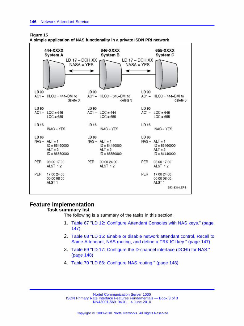
146 Network Attendant Service
Figure 15A simple application of NAS functionality in a private ISDN PRI network
Feature implementationTask summary list
The following is a summary of the tasks in this section:
1. Table 67 "LD 12: Configure Attendant Consoles with NAS keys." (page147)
2. Table 68 "LD 15: Enable or disable network attendant control, Recall toSame Attendant, NAS routing, and define a TRK ICI key." (page 147)
3. Table 69 "LD 17: Configure the D-channel interface (DCHI) for NAS."(page 148)
4. Table 70 "LD 86: Configure NAS routing." (page 148)
Nortel Communication Server 1000ISDN Primary Rate Interface Features Fundamentals — Book 3 of 3
NN43001-569 04.01 4 June 2010
Copyright © 2003-2010 Nortel Networks. All Rights Reserved.
.
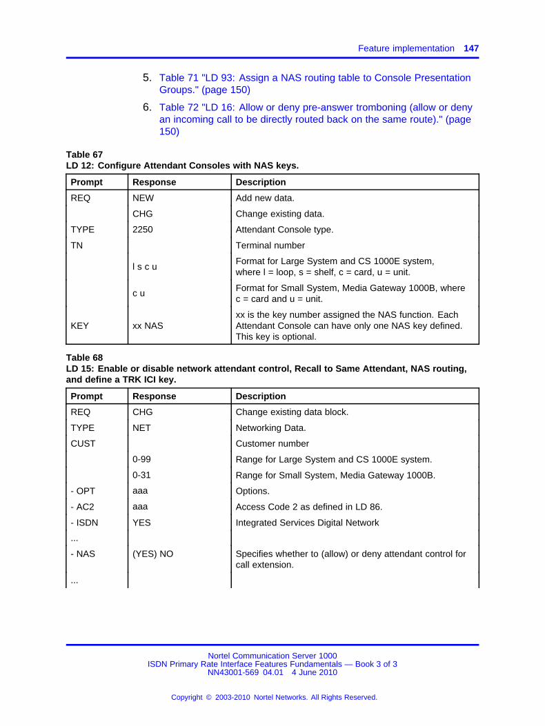
Feature implementation 147
5. Table 71 "LD 93: Assign a NAS routing table to Console PresentationGroups." (page 150)
6. Table 72 "LD 16: Allow or deny pre-answer tromboning (allow or denyan incoming call to be directly routed back on the same route)." (page150)
Table 67LD 12: Configure Attendant Consoles with NAS keys.
Prompt Response Description
REQ NEW Add new data.
CHG Change existing data.
TYPE 2250 Attendant Console type.
TN Terminal number
l s c uFormat for Large System and CS 1000E system,where l = loop, s = shelf, c = card, u = unit.
c u Format for Small System, Media Gateway 1000B, wherec = card and u = unit.
KEY xx NASxx is the key number assigned the NAS function. EachAttendant Console can have only one NAS key defined.This key is optional.
Table 68LD 15: Enable or disable network attendant control, Recall to Same Attendant, NAS routing,and define a TRK ICI key.
Prompt Response Description
REQ CHG Change existing data block.
TYPE NET Networking Data.
CUST Customer number
0-99 Range for Large System and CS 1000E system.
0-31 Range for Small System, Media Gateway 1000B.
- OPT aaa Options.
- AC2 aaa Access Code 2 as defined in LD 86.
- ISDN YES Integrated Services Digital Network
...
- NAS (YES) NO Specifies whether to (allow) or deny attendant control forcall extension.
...
Nortel Communication Server 1000ISDN Primary Rate Interface Features Fundamentals — Book 3 of 3
NN43001-569 04.01 4 June 2010
Copyright © 2003-2010 Nortel Networks. All Rights Reserved.
.
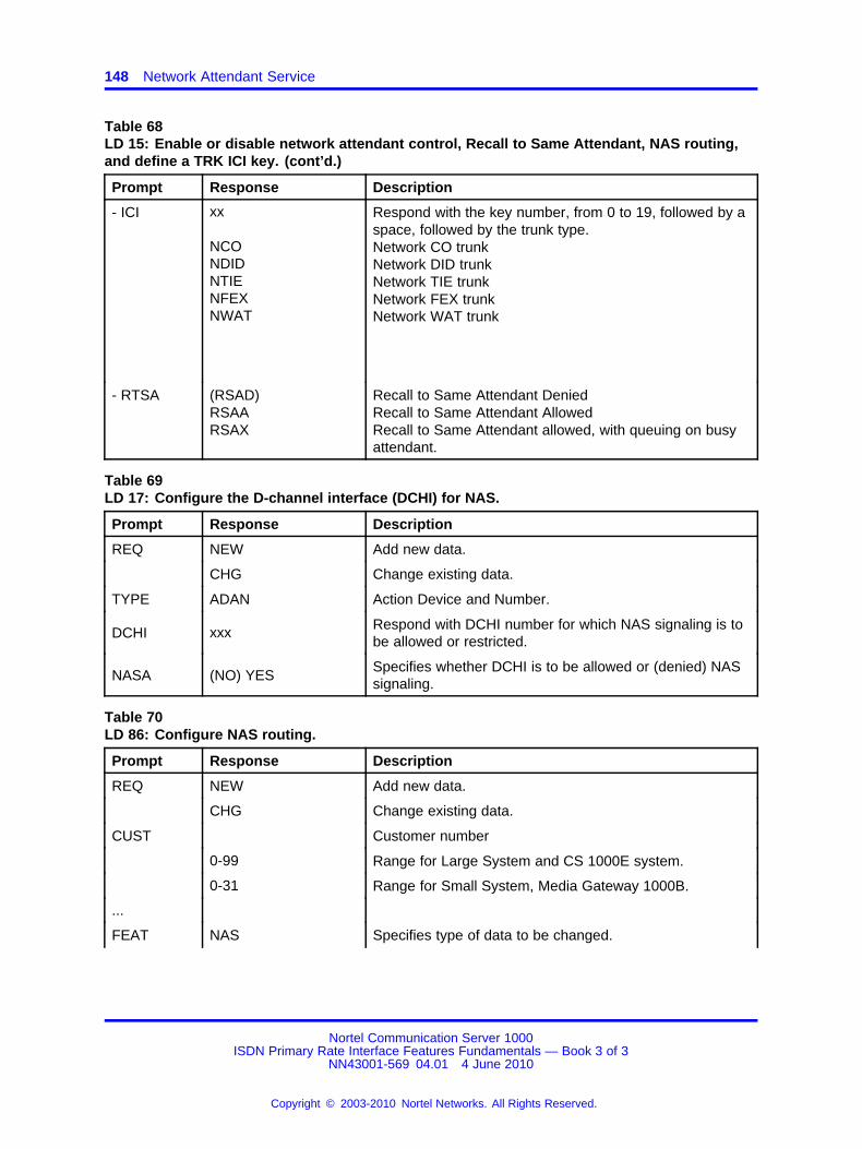
148 Network Attendant Service
Table 68LD 15: Enable or disable network attendant control, Recall to Same Attendant, NAS routing,and define a TRK ICI key. (cont’d.)
Prompt Response Description
- ICI xx
NCONDIDNTIENFEXNWAT
Respond with the key number, from 0 to 19, followed by aspace, followed by the trunk type.Network CO trunkNetwork DID trunkNetwork TIE trunkNetwork FEX trunkNetwork WAT trunk
- RTSA (RSAD)RSAARSAX
Recall to Same Attendant DeniedRecall to Same Attendant AllowedRecall to Same Attendant allowed, with queuing on busyattendant.
Table 69LD 17: Configure the D-channel interface (DCHI) for NAS.
Prompt Response Description
REQ NEW Add new data.
CHG Change existing data.
TYPE ADAN Action Device and Number.
DCHI xxx Respond with DCHI number for which NAS signaling is tobe allowed or restricted.
NASA (NO) YESSpecifies whether DCHI is to be allowed or (denied) NASsignaling.
Table 70LD 86: Configure NAS routing.
Prompt Response Description
REQ NEW Add new data.
CHG Change existing data.
CUST Customer number
0-99 Range for Large System and CS 1000E system.
0-31 Range for Small System, Media Gateway 1000B.
...
FEAT NAS Specifies type of data to be changed.
Nortel Communication Server 1000ISDN Primary Rate Interface Features Fundamentals — Book 3 of 3
NN43001-569 04.01 4 June 2010
Copyright © 2003-2010 Nortel Networks. All Rights Reserved.
.
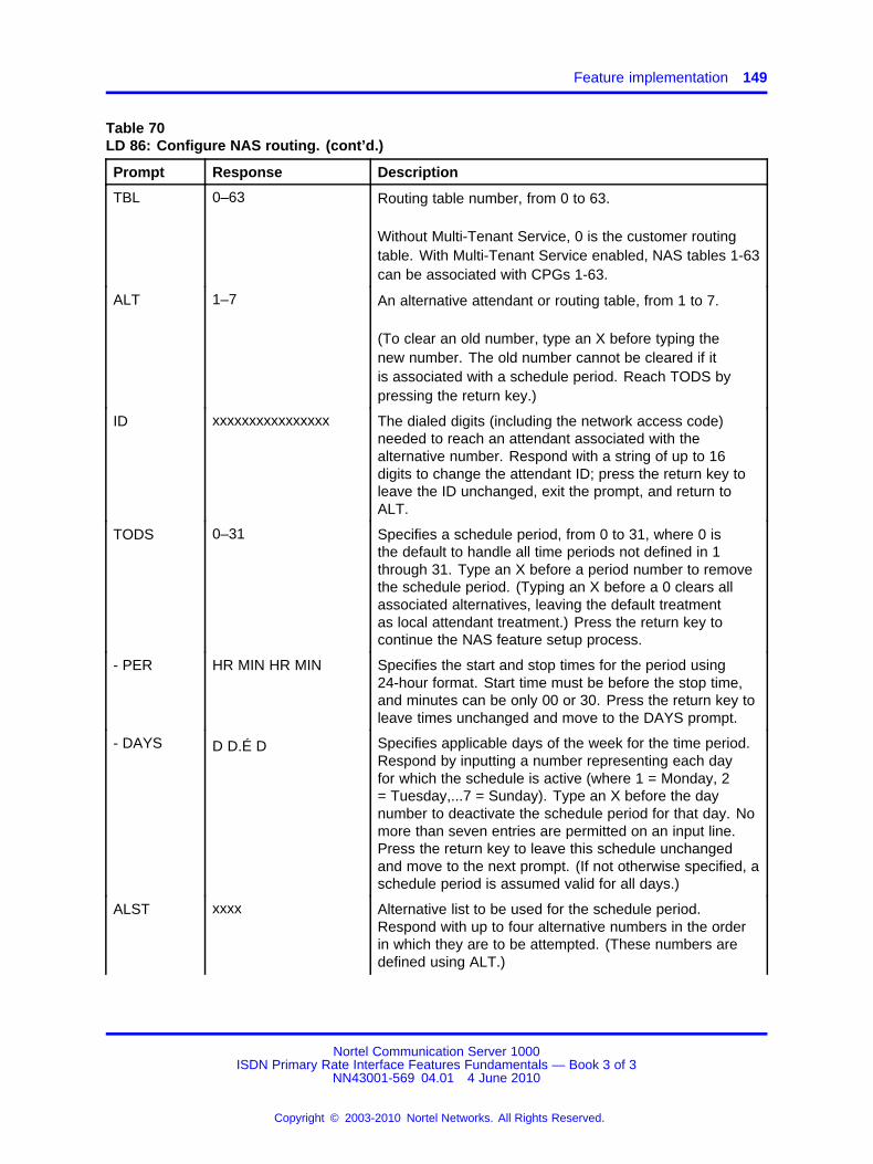
Feature implementation 149
Table 70LD 86: Configure NAS routing. (cont’d.)
Prompt Response Description
TBL 0–63 Routing table number, from 0 to 63.
Without Multi-Tenant Service, 0 is the customer routingtable. With Multi-Tenant Service enabled, NAS tables 1-63can be associated with CPGs 1-63.
ALT 1–7 An alternative attendant or routing table, from 1 to 7.
(To clear an old number, type an X before typing thenew number. The old number cannot be cleared if itis associated with a schedule period. Reach TODS bypressing the return key.)
ID xxxxxxxxxxxxxxxx The dialed digits (including the network access code)needed to reach an attendant associated with thealternative number. Respond with a string of up to 16digits to change the attendant ID; press the return key toleave the ID unchanged, exit the prompt, and return toALT.
TODS 0–31 Specifies a schedule period, from 0 to 31, where 0 isthe default to handle all time periods not defined in 1through 31. Type an X before a period number to removethe schedule period. (Typing an X before a 0 clears allassociated alternatives, leaving the default treatmentas local attendant treatment.) Press the return key tocontinue the NAS feature setup process.
- PER HR MIN HR MIN Specifies the start and stop times for the period using24-hour format. Start time must be before the stop time,and minutes can be only 00 or 30. Press the return key toleave times unchanged and move to the DAYS prompt.
- DAYS D D.É D Specifies applicable days of the week for the time period.Respond by inputting a number representing each dayfor which the schedule is active (where 1 = Monday, 2= Tuesday,...7 = Sunday). Type an X before the daynumber to deactivate the schedule period for that day. Nomore than seven entries are permitted on an input line.Press the return key to leave this schedule unchangedand move to the next prompt. (If not otherwise specified, aschedule period is assumed valid for all days.)
ALST xxxx Alternative list to be used for the schedule period.Respond with up to four alternative numbers in the orderin which they are to be attempted. (These numbers aredefined using ALT.)
Nortel Communication Server 1000ISDN Primary Rate Interface Features Fundamentals — Book 3 of 3
NN43001-569 04.01 4 June 2010
Copyright © 2003-2010 Nortel Networks. All Rights Reserved.
.
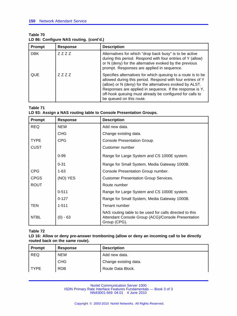
150 Network Attendant Service
Table 70LD 86: Configure NAS routing. (cont’d.)
Prompt Response Description
DBK Z Z Z Z Alternatives for which "drop back busy" is to be activeduring this period. Respond with four entries of Y (allow)or N (deny) for the alternative evoked by the previousprompt. Responses are applied in sequence.
QUE Z Z Z Z Specifies alternatives for which queuing to a route is to beallowed during this period. Respond with four entries of Y(allow) or N (deny) for the alternatives evoked by ALST.Responses are applied in sequence. If the response is Y,off-hook queuing must already be configured for calls tobe queued on this route.
Table 71LD 93: Assign a NAS routing table to Console Presentation Groups.
Prompt Response Description
REQ NEW Add new data.
CHG Change existing data.
TYPE CPG Console Presentation Group.
CUST Customer number
0-99 Range for Large System and CS 1000E system.
0-31 Range for Small System, Media Gateway 1000B.
CPG 1-63 Console Presentation Group number.
CPGS (NO) YES Customer Presentation Group Services.
ROUT Route number
0-511 Range for Large System and CS 1000E system.
0-127 Range for Small System, Media Gateway 1000B.
TEN 1-511 Tenant number
NTBL (0) - 63NAS routing table to be used for calls directed to thisAttendant Console Group (ACG)/Console PresentationGroup (CPG).
Table 72LD 16: Allow or deny pre-answer tromboning (allow or deny an incoming call to be directlyrouted back on the same route).
Prompt Response Description
REQ NEW Add new data.
CHG Change existing data.
TYPE RDB Route Data Block.
Nortel Communication Server 1000ISDN Primary Rate Interface Features Fundamentals — Book 3 of 3
NN43001-569 04.01 4 June 2010
Copyright © 2003-2010 Nortel Networks. All Rights Reserved.
.
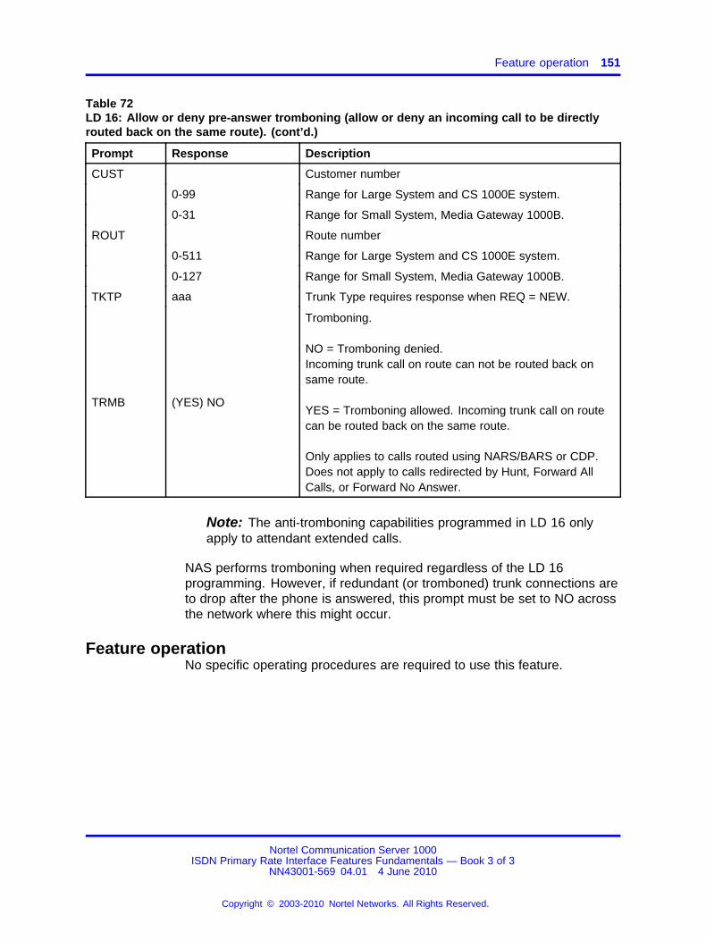
Feature operation 151
Table 72LD 16: Allow or deny pre-answer tromboning (allow or deny an incoming call to be directlyrouted back on the same route). (cont’d.)
Prompt Response Description
CUST Customer number
0-99 Range for Large System and CS 1000E system.
0-31 Range for Small System, Media Gateway 1000B.
ROUT Route number
0-511 Range for Large System and CS 1000E system.
0-127 Range for Small System, Media Gateway 1000B.
TKTP aaa Trunk Type requires response when REQ = NEW.
TRMB (YES) NO
Tromboning.
NO = Tromboning denied.Incoming trunk call on route can not be routed back onsame route.
YES = Tromboning allowed. Incoming trunk call on routecan be routed back on the same route.
Only applies to calls routed using NARS/BARS or CDP.Does not apply to calls redirected by Hunt, Forward AllCalls, or Forward No Answer.
Note: The anti-tromboning capabilities programmed in LD 16 onlyapply to attendant extended calls.
NAS performs tromboning when required regardless of the LD 16programming. However, if redundant (or tromboned) trunk connections areto drop after the phone is answered, this prompt must be set to NO acrossthe network where this might occur.
Feature operationNo specific operating procedures are required to use this feature.
Nortel Communication Server 1000ISDN Primary Rate Interface Features Fundamentals — Book 3 of 3
NN43001-569 04.01 4 June 2010
Copyright © 2003-2010 Nortel Networks. All Rights Reserved.
.

152 Network Attendant Service
Nortel Communication Server 1000ISDN Primary Rate Interface Features Fundamentals — Book 3 of 3
NN43001-569 04.01 4 June 2010
Copyright © 2003-2010 Nortel Networks. All Rights Reserved.
.
153.
Network Break-in and ForceDisconnect
ContentsThis section contains information on the following topics:
“Feature description” (page 153)
“Operating parameters” (page 156)
“Feature interactions” (page 157)
“Feature packaging” (page 159)
“Feature implementation” (page 159)
“Task summary list” (page 159)
“Feature operation” (page 162)
Feature descriptionThe Network Break-in and Force Disconnect feature allows an analog(500/2500-type) or a digital phone to perform the following functions:
• break-in to an established two-party call
• force disconnect an established two-party call
Network Break-inWith Network Break-in, a phone can break-in to an established two-partycall. When the phone initiates a break-in operation, it is placed inconference with the other two parties. A warning tone can be providedto all parties. The warning tone option must be allowed in LD 15 for thewanted party’s customer group.
Nortel Communication Server 1000ISDN Primary Rate Interface Features Fundamentals — Book 3 of 3
NN43001-569 04.01 4 June 2010
Copyright © 2003-2010 Nortel Networks. All Rights Reserved.
.

154 Network Break-in and Force Disconnect
The user of the overriding phone can initiate the break-in operation usingone of the following:
• Priority Override Network Wide (PONW) key for Meridian Digitalphones. The PONW lamp on the overriding phone provides the statusof the break-in operation.
• Priority Override Network Wide (PONW) Flexible Feature Code (FFC)for analog (500/2500 type) phones
Network break-in applies to both pre- and post-dial operations. For apre-dial operation, the user of the overriding phone presses the PONW keyor dials the PONW FFC prior to dialing the wanted party’s DN.
For a post-dial operation, the user of the overriding phone dials the wantedparty’s DN. When they receive a busy tone, they then press the PONWkey or dial the PONW FFC.
Network Force DisconnectNetwork Force Disconnect allows a phone to disconnect an establishedtwo-party call. A call is then established between the overriding phone andthe wanted phone. A single warning tone can be provided to all partiesbefore the disconnect operation takes place. The warning tone option mustbe allowed in LD 15 for the wanted party’s customer group.
The user of the overriding phone can initiate the force disconnect operationusing one of the following:
• Forced Disconnect (FDIS) key for Meridian Digital phones TheFDIS lamp on the overriding phone provides the status of the forcedisconnect operation
• Forced Disconnect Flexible Feature Code (FFC) for analog (500/2500type) phones
Network Force Disconnect applies to both pre- and post-dial operations.For a pre-dial operation, the user of the overriding phone presses the FDISkey or dials the PONW FFC prior to dialing the wanted party’s DN.
For a post-dial operation, the user of the overriding phone dials the wantedparty’s DN. When they receive busy tone, they then press the FDIS keyor dial the FDIS FFC.
Network Break-in and Force Disconnect post-dial exampleAs illustrated in Figure 16 "Example of a network break-in and forcedisconnect operation" (page 155), Node X and Node Y are two systemsconnected by a Meridian Customer Defined Network (MCDN) Primary
Nortel Communication Server 1000ISDN Primary Rate Interface Features Fundamentals — Book 3 of 3
NN43001-569 04.01 4 June 2010
Copyright © 2003-2010 Nortel Networks. All Rights Reserved.
.
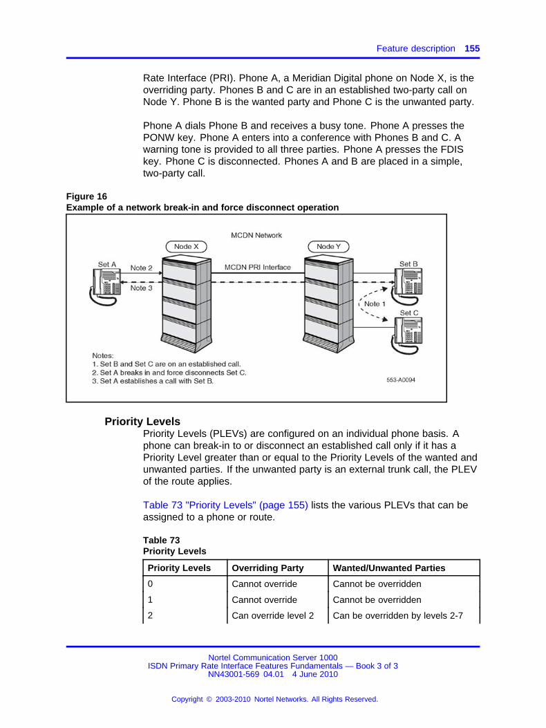
Feature description 155
Rate Interface (PRI). Phone A, a Meridian Digital phone on Node X, is theoverriding party. Phones B and C are in an established two-party call onNode Y. Phone B is the wanted party and Phone C is the unwanted party.
Phone A dials Phone B and receives a busy tone. Phone A presses thePONW key. Phone A enters into a conference with Phones B and C. Awarning tone is provided to all three parties. Phone A presses the FDISkey. Phone C is disconnected. Phones A and B are placed in a simple,two-party call.
Figure 16Example of a network break-in and force disconnect operation
Priority LevelsPriority Levels (PLEVs) are configured on an individual phone basis. Aphone can break-in to or disconnect an established call only if it has aPriority Level greater than or equal to the Priority Levels of the wanted andunwanted parties. If the unwanted party is an external trunk call, the PLEVof the route applies.
Table 73 "Priority Levels" (page 155) lists the various PLEVs that can beassigned to a phone or route.
Table 73Priority Levels
Priority Levels Overriding Party Wanted/Unwanted Parties
0 Cannot override Cannot be overridden
1 Cannot override Cannot be overridden
2 Can override level 2 Can be overridden by levels 2-7
Nortel Communication Server 1000ISDN Primary Rate Interface Features Fundamentals — Book 3 of 3
NN43001-569 04.01 4 June 2010
Copyright © 2003-2010 Nortel Networks. All Rights Reserved.
.
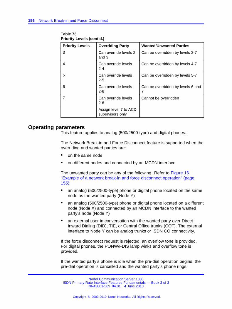
156 Network Break-in and Force Disconnect
Table 73Priority Levels (cont’d.)
Priority Levels Overriding Party Wanted/Unwanted Parties
3 Can override levels 2and 3
Can be overridden by levels 3-7
4 Can override levels2-4
Can be overridden by levels 4-7
5 Can override levels2-5
Can be overridden by levels 5-7
6 Can override levels2-6
Can be overridden by levels 6 and7
7 Can override levels2-6
Cannot be overridden
Assign level 7 to ACDsupervisors only
Operating parametersThis feature applies to analog (500/2500-type) and digital phones.
The Network Break-in and Force Disconnect feature is supported when theoverriding and wanted parties are:
• on the same node
• on different nodes and connected by an MCDN interface
The unwanted party can be any of the following. Refer to Figure 16"Example of a network break-in and force disconnect operation" (page155):
• an analog (500/2500-type) phone or digital phone located on the samenode as the wanted party (Node Y)
• an analog (500/2500-type) phone or digital phone located on a differentnode (Node X) and connected by an MCDN interface to the wantedparty’s node (Node Y)
• an external user in conversation with the wanted party over DirectInward Dialing (DID), TIE, or Central Office trunks (COT). The externalinterface to Node Y can be analog trunks or ISDN CO connectivity.
If the force disconnect request is rejected, an overflow tone is provided.For digital phones, the PONW/FDIS lamp winks and overflow tone isprovided.
If the wanted party’s phone is idle when the pre-dial operation begins, thepre-dial operation is cancelled and the wanted party’s phone rings.
Nortel Communication Server 1000ISDN Primary Rate Interface Features Fundamentals — Book 3 of 3
NN43001-569 04.01 4 June 2010
Copyright © 2003-2010 Nortel Networks. All Rights Reserved.
.
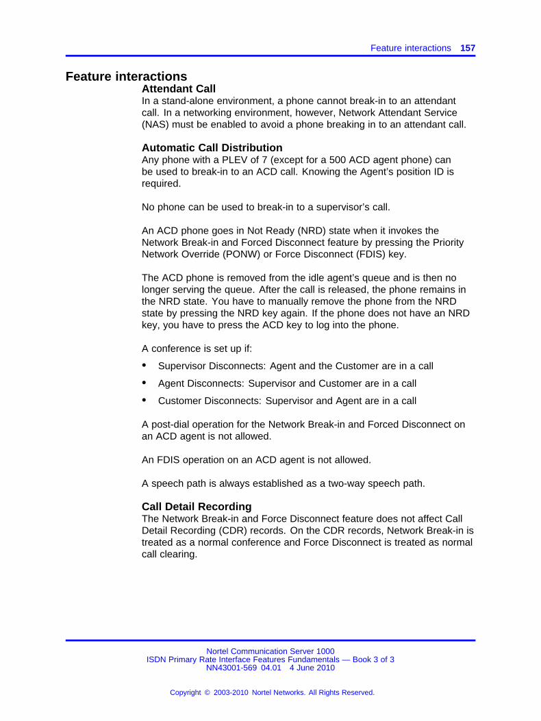
Feature interactions 157
Feature interactionsAttendant CallIn a stand-alone environment, a phone cannot break-in to an attendantcall. In a networking environment, however, Network Attendant Service(NAS) must be enabled to avoid a phone breaking in to an attendant call.
Automatic Call DistributionAny phone with a PLEV of 7 (except for a 500 ACD agent phone) canbe used to break-in to an ACD call. Knowing the Agent’s position ID isrequired.
No phone can be used to break-in to a supervisor’s call.
An ACD phone goes in Not Ready (NRD) state when it invokes theNetwork Break-in and Forced Disconnect feature by pressing the PriorityNetwork Override (PONW) or Force Disconnect (FDIS) key.
The ACD phone is removed from the idle agent’s queue and is then nolonger serving the queue. After the call is released, the phone remains inthe NRD state. You have to manually remove the phone from the NRDstate by pressing the NRD key again. If the phone does not have an NRDkey, you have to press the ACD key to log into the phone.
A conference is set up if:
• Supervisor Disconnects: Agent and the Customer are in a call
• Agent Disconnects: Supervisor and Customer are in a call
• Customer Disconnects: Supervisor and Agent are in a call
A post-dial operation for the Network Break-in and Forced Disconnect onan ACD agent is not allowed.
An FDIS operation on an ACD agent is not allowed.
A speech path is always established as a two-way speech path.
Call Detail RecordingThe Network Break-in and Force Disconnect feature does not affect CallDetail Recording (CDR) records. On the CDR records, Network Break-in istreated as a normal conference and Force Disconnect is treated as normalcall clearing.
Nortel Communication Server 1000ISDN Primary Rate Interface Features Fundamentals — Book 3 of 3
NN43001-569 04.01 4 June 2010
Copyright © 2003-2010 Nortel Networks. All Rights Reserved.
.
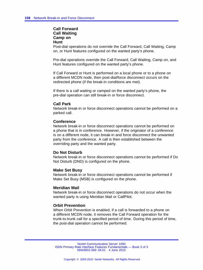
158 Network Break-in and Force Disconnect
Call ForwardCall WaitingCamp onHuntPost-dial operations do not override the Call Forward, Call Waiting, Campon, or Hunt features configured on the wanted party’s phone.
Pre-dial operations override the Call Forward, Call Waiting, Camp on, andHunt features configured on the wanted party’s phone.
If Call Forward or Hunt is performed on a local phone or to a phone ona different MCDN node, then post-dial/force disconnect occurs on theredirected phone (if the break-in conditions are met).
If there is a call waiting or camped on the wanted party’s phone, thepre-dial operation can still break-in or force disconnect.
Call ParkNetwork break-in or force disconnect operations cannot be performed on aparked call.
ConferenceNetwork break-in or force disconnect operations cannot be performed ona phone that is in conference. However, if the originator of a conferenceis on a different node, it can break-in and force disconnect the unwantedparty from the conference. A call is then established between theoverriding party and the wanted party.
Do Not DisturbNetwork break-in or force disconnect operations cannot be performed if DoNot Disturb (DND) is configured on the phone.
Make Set BusyNetwork break-in or force disconnect operations cannot be performed ifMake Set Busy (MSB) is configured on the phone.
Meridian MailNetwork break-in or force disconnect operations do not occur when thewanted party is using Meridian Mail or CallPilot.
Orbit PreventionWhen Orbit Prevention is enabled, if a call is forwarded to a phone ona different MCDN node, it removes the Call Forward operation for thetrunk-to-trunk call for a specified period of time. During this period of time,the post-dial operation cannot be performed.
Nortel Communication Server 1000ISDN Primary Rate Interface Features Fundamentals — Book 3 of 3
NN43001-569 04.01 4 June 2010
Copyright © 2003-2010 Nortel Networks. All Rights Reserved.
.
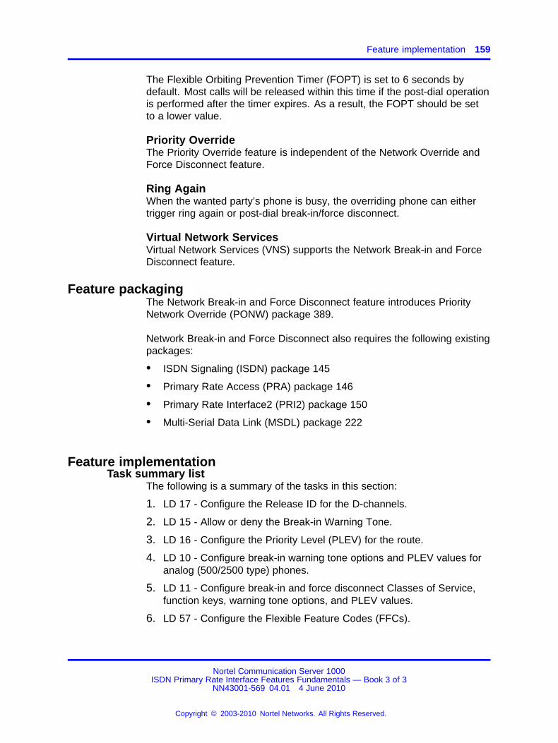
Feature implementation 159
The Flexible Orbiting Prevention Timer (FOPT) is set to 6 seconds bydefault. Most calls will be released within this time if the post-dial operationis performed after the timer expires. As a result, the FOPT should be setto a lower value.
Priority OverrideThe Priority Override feature is independent of the Network Override andForce Disconnect feature.
Ring AgainWhen the wanted party’s phone is busy, the overriding phone can eithertrigger ring again or post-dial break-in/force disconnect.
Virtual Network ServicesVirtual Network Services (VNS) supports the Network Break-in and ForceDisconnect feature.
Feature packagingThe Network Break-in and Force Disconnect feature introduces PriorityNetwork Override (PONW) package 389.
Network Break-in and Force Disconnect also requires the following existingpackages:
• ISDN Signaling (ISDN) package 145
• Primary Rate Access (PRA) package 146
• Primary Rate Interface2 (PRI2) package 150
• Multi-Serial Data Link (MSDL) package 222
Feature implementationTask summary list
The following is a summary of the tasks in this section:
1. LD 17 - Configure the Release ID for the D-channels.
2. LD 15 - Allow or deny the Break-in Warning Tone.
3. LD 16 - Configure the Priority Level (PLEV) for the route.
4. LD 10 - Configure break-in warning tone options and PLEV values foranalog (500/2500 type) phones.
5. LD 11 - Configure break-in and force disconnect Classes of Service,function keys, warning tone options, and PLEV values.
6. LD 57 - Configure the Flexible Feature Codes (FFCs).
Nortel Communication Server 1000ISDN Primary Rate Interface Features Fundamentals — Book 3 of 3
NN43001-569 04.01 4 June 2010
Copyright © 2003-2010 Nortel Networks. All Rights Reserved.
.
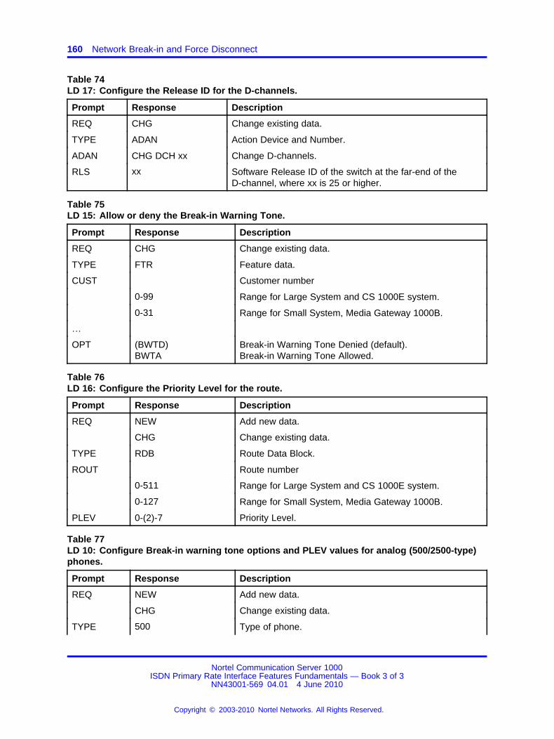
160 Network Break-in and Force Disconnect
Table 74LD 17: Configure the Release ID for the D-channels.
Prompt Response Description
REQ CHG Change existing data.
TYPE ADAN Action Device and Number.
ADAN CHG DCH xx Change D-channels.
RLS xx Software Release ID of the switch at the far-end of theD-channel, where xx is 25 or higher.
Table 75LD 15: Allow or deny the Break-in Warning Tone.
Prompt Response Description
REQ CHG Change existing data.
TYPE FTR Feature data.
CUST Customer number
0-99 Range for Large System and CS 1000E system.
0-31 Range for Small System, Media Gateway 1000B.
…
OPT (BWTD)BWTA
Break-in Warning Tone Denied (default).Break-in Warning Tone Allowed.
Table 76LD 16: Configure the Priority Level for the route.
Prompt Response Description
REQ NEW Add new data.
CHG Change existing data.
TYPE RDB Route Data Block.
ROUT Route number
0-511 Range for Large System and CS 1000E system.
0-127 Range for Small System, Media Gateway 1000B.
PLEV 0-(2)-7 Priority Level.
Table 77LD 10: Configure Break-in warning tone options and PLEV values for analog (500/2500-type)phones.
Prompt Response Description
REQ NEW Add new data.
CHG Change existing data.
TYPE 500 Type of phone.
Nortel Communication Server 1000ISDN Primary Rate Interface Features Fundamentals — Book 3 of 3
NN43001-569 04.01 4 June 2010
Copyright © 2003-2010 Nortel Networks. All Rights Reserved.
.

Feature implementation 161
Table 77LD 10: Configure Break-in warning tone options and PLEV values for analog (500/2500-type)phones. (cont’d.)
Prompt Response Description
CLS (NOVD)NOVA
Network Override/Break-in Denied (default).Network Override/Break-in Allowed.
CLS (FDSD)FDSA
Force Disconnect Denied (default)Force Disconnect Allowed
PLEV 0-(2)-7 Priority Levels.
Table 78LD 11: Configure break-in and force disconnect Classes of Service, function keys, warningtone options, and PLEV values.
Prompt Response Description
REQ NEW Add new data.
CHG Change existing data.
TYPE a... a Telephone type. Type ? for a list of possible responses.
CLS (NOVD)NOVA
Network Override/Breakin Denied (default).Network Override/Breakin Allowed.
CLS (FDSD)FDSA
Force Disconnect Denied (default)Force Disconnect Allowed
KEY PONW Priority Override/Breakin Networkwide Key.
KEY FDIS Force Disconnect Key.
PLEV 0-(2)-7 Priority Levels.
Table 79LD 57: Configure the Flexible Feature Codes (FFCs).
Prompt Response Description
REQ NEW Add new data.
CHG Change existing data.
TYPE FFC Flexible Feature Code.
CUST Customer number
0-99 Range for Large System and CS 1000E system.
0-31 Range for Small System, MediaGateway 1000B.
…
CODE PONW FFC Type.
PONW xxxx Activate PONW.
CODE FDIS FFC Type.
FDIS xxxx Activate FDIS.
Nortel Communication Server 1000ISDN Primary Rate Interface Features Fundamentals — Book 3 of 3
NN43001-569 04.01 4 June 2010
Copyright © 2003-2010 Nortel Networks. All Rights Reserved.
.

162 Network Break-in and Force Disconnect
Feature operationThis section describes the procedures for performing the network break-inand force disconnect operations on both Meridian Digital and analog(500/2500 type) phones. The feature operation is described using PhonesA, B, and C fromFigure 16 "Example of a network break-in and forcedisconnect operation" (page 155) on Figure 16 "Example of a networkbreak-in and force disconnect operation" (page 155).
Network Break-in operationPost-dial operation for Meridian Digital phonesTable 80 "Post-dial network break-in operation for a Meridian Digitalphone" (page 162) shows the post-dial network break-in operation for aMeridian Digital phone.
Table 80Post-dial network break-in operation for a Meridian Digital phone
Actions ResponsePhone A PONWlamp status
Phones B and C are involved ina two-party call.
— —
Phone A dials Phone B. Phone A receives a busy tone. —
Phone A presses the PONWkey.
Phone A enters into a Conference withPhones B and C. If configured, a warningtone is provided to all three parties.
PONW key lamp islit.
If Phone C disconnects… Phones A and B are placed in a simple,two-party call. The warning tone isremoved.
PONW key lampgoes dark.
If Phone B disconnects… Phone C is disconnected. The warningtone is removed. Phone B rings.
Meridian PONWkey lamp goesdark.
Pre-dial operation for Meridian Digital phonesTable 81 "Pre-dial network break-in operation for a Meridian Digital phone"(page 162) shows the pre-dial network break-in operation for a MeridianDigital phone.
Table 81Pre-dial network break-in operation for a Meridian Digital phone
Actions ResponsePhone A PONWlamp status
Phones B and C are involved ina two-party call.
— —
Nortel Communication Server 1000ISDN Primary Rate Interface Features Fundamentals — Book 3 of 3
NN43001-569 04.01 4 June 2010
Copyright © 2003-2010 Nortel Networks. All Rights Reserved.
.
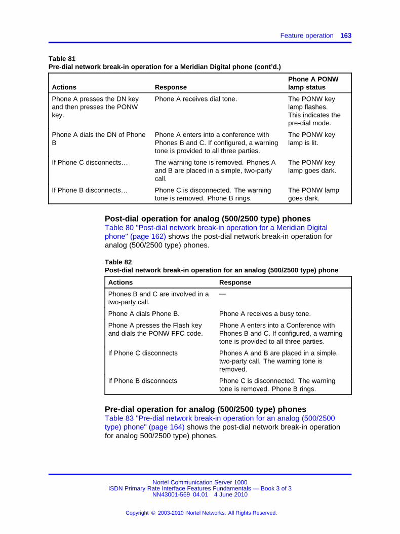
Feature operation 163
Table 81Pre-dial network break-in operation for a Meridian Digital phone (cont’d.)
Actions ResponsePhone A PONWlamp status
Phone A presses the DN keyand then presses the PONWkey.
Phone A receives dial tone. The PONW keylamp flashes.This indicates thepre-dial mode.
Phone A dials the DN of PhoneB
Phone A enters into a conference withPhones B and C. If configured, a warningtone is provided to all three parties.
The PONW keylamp is lit.
If Phone C disconnects… The warning tone is removed. Phones Aand B are placed in a simple, two-partycall.
The PONW keylamp goes dark.
If Phone B disconnects… Phone C is disconnected. The warningtone is removed. Phone B rings.
The PONW lampgoes dark.
Post-dial operation for analog (500/2500 type) phonesTable 80 "Post-dial network break-in operation for a Meridian Digitalphone" (page 162) shows the post-dial network break-in operation foranalog (500/2500 type) phones.
Table 82Post-dial network break-in operation for an analog (500/2500 type) phone
Actions Response
Phones B and C are involved in atwo-party call.
—
Phone A dials Phone B. Phone A receives a busy tone.
Phone A presses the Flash keyand dials the PONW FFC code.
Phone A enters into a Conference withPhones B and C. If configured, a warningtone is provided to all three parties.
If Phone C disconnects Phones A and B are placed in a simple,two-party call. The warning tone isremoved.
If Phone B disconnects Phone C is disconnected. The warningtone is removed. Phone B rings.
Pre-dial operation for analog (500/2500 type) phonesTable 83 "Pre-dial network break-in operation for an analog (500/2500type) phone" (page 164) shows the post-dial network break-in operationfor analog 500/2500 type) phones.
Nortel Communication Server 1000ISDN Primary Rate Interface Features Fundamentals — Book 3 of 3
NN43001-569 04.01 4 June 2010
Copyright © 2003-2010 Nortel Networks. All Rights Reserved.
.
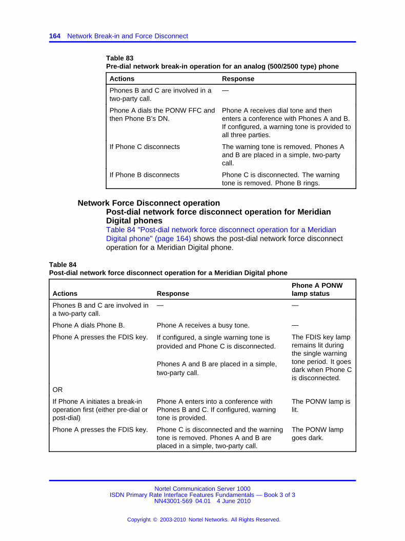
164 Network Break-in and Force Disconnect
Table 83Pre-dial network break-in operation for an analog (500/2500 type) phone
Actions Response
Phones B and C are involved in atwo-party call.
—
Phone A dials the PONW FFC andthen Phone B’s DN.
Phone A receives dial tone and thenenters a conference with Phones A and B.If configured, a warning tone is provided toall three parties.
If Phone C disconnects The warning tone is removed. Phones Aand B are placed in a simple, two-partycall.
If Phone B disconnects Phone C is disconnected. The warningtone is removed. Phone B rings.
Network Force Disconnect operationPost-dial network force disconnect operation for MeridianDigital phonesTable 84 "Post-dial network force disconnect operation for a MeridianDigital phone" (page 164) shows the post-dial network force disconnectoperation for a Meridian Digital phone.
Table 84Post-dial network force disconnect operation for a Meridian Digital phone
Actions ResponsePhone A PONWlamp status
Phones B and C are involved ina two-party call.
— —
Phone A dials Phone B. Phone A receives a busy tone. —
Phone A presses the FDIS key. If configured, a single warning tone isprovided and Phone C is disconnected.
Phones A and B are placed in a simple,two-party call.
The FDIS key lampremains lit duringthe single warningtone period. It goesdark when Phone Cis disconnected.
OR
If Phone A initiates a break-inoperation first (either pre-dial orpost-dial)
Phone A enters into a conference withPhones B and C. If configured, warningtone is provided.
The PONW lamp islit.
Phone A presses the FDIS key. Phone C is disconnected and the warningtone is removed. Phones A and B areplaced in a simple, two-party call.
The PONW lampgoes dark.
Nortel Communication Server 1000ISDN Primary Rate Interface Features Fundamentals — Book 3 of 3
NN43001-569 04.01 4 June 2010
Copyright © 2003-2010 Nortel Networks. All Rights Reserved.
.

Feature operation 165
Pre-dial network force disconnect operation for Meridian DigitalphonesTable 85 "Pre-dial network force disconnect operation for a Meridian Digitalphone" (page 165) shows the pre-dial network force disconnect operationfor a Meridian Digital phone.
Table 85Pre-dial network force disconnect operation for a Meridian Digital phone
Actions ResponsePhone A PONWlamp status
Phones B and C are involved ina two-party call.
— —
Phone A presses the DN keyand then the FDIS key.
Phone A receives dial tone. The FDIS lampflashes. Thisindicates thepre-dial mode.
Phone A dials the DN of PhoneB.
If configured, a single warning tone isprovided and Phone C is disconnected.Phones A and B are placed in a simple,two-party call.
The FDIS lampremains lit duringthe single warningtone period. It goesdark when Phone Cis disconnected.
Post-dial force disconnect operation for analog (500/2500 type)phonesTable 86 "Post-dial network force disconnect operation for an analog(500/2500 type) phone" (page 165) shows the post-dial network forcedisconnect operation for an analog (500/2500 type) phone.
Table 86Post-dial network force disconnect operation for an analog (500/2500 type)phone
Actions Response
Phones B and C are involved in atwo-party call.
—
Phone A dials Phone B. Phone A receives a busy tone.
Phone A presses the Flash keyand then dials the FDIS FFC code.
If configured, a single warning tone isprovided and Phone C is disconnected.Phones A and B are placed in a simple,two-party call.
OR
Nortel Communication Server 1000ISDN Primary Rate Interface Features Fundamentals — Book 3 of 3
NN43001-569 04.01 4 June 2010
Copyright © 2003-2010 Nortel Networks. All Rights Reserved.
.
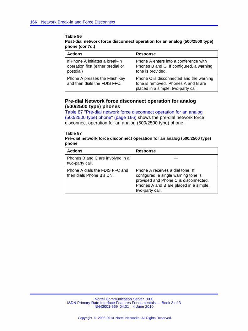
166 Network Break-in and Force Disconnect
Table 86Post-dial network force disconnect operation for an analog (500/2500 type)phone (cont’d.)
Actions Response
If Phone A initiates a break-inoperation first (either predial orpostdial)
Phone A enters into a conference withPhones B and C. If configured, a warningtone is provided.
Phone A presses the Flash keyand then dials the FDIS FFC.
Phone C is disconnected and the warningtone is removed. Phones A and B areplaced in a simple, two-party call.
Pre-dial Network force disconnect operation for analog(500/2500 type) phonesTable 87 "Pre-dial network force disconnect operation for an analog(500/2500 type) phone" (page 166) shows the pre-dial network forcedisconnect operation for an analog (500/2500 type) phone.
Table 87Pre-dial network force disconnect operation for an analog (500/2500 type)phone
Actions Response
Phones B and C are involved in atwo-party call.
—
Phone A dials the FDIS FFC andthen dials Phone B’s DN.
Phone A receives a dial tone. Ifconfigured, a single warning tone isprovided and Phone C is disconnected.Phones A and B are placed in a simple,two-party call.
Nortel Communication Server 1000ISDN Primary Rate Interface Features Fundamentals — Book 3 of 3
NN43001-569 04.01 4 June 2010
Copyright © 2003-2010 Nortel Networks. All Rights Reserved.
.

167.
Network Call Party NameDisplay/Network Name Delivery
ContentsThis section contains information on the following topics:
“Feature description” (page 167)
“Network Name Delivery” (page 168)
“Operating parameters” (page 169)
“Feature interactions” (page 169)
“Feature packaging” (page 169)
“Feature implementation” (page 169)
“Task summary list” (page 169)
“Feature operation” (page 171)
Feature descriptionNetwork Call Party Name Display
Network Call Party Name Display (NCPND) provides a network-wide visualdisplay of names and phone numbers to both parties of a call. For phonesequipped with an alphanumeric display, NCPND provides the display ofthe calling party’s name on the terminating phone and the called party’sname on the calling phone. The name and number display lasts for theduration of the call.
The sending of the names over the private network is an option set upon a per route basis. The name is provided by Call Party Name Display(CPND) configured in each switch. For call redirections, a phone optionprovides a display of the redirecting name instead of the calling name.
Nortel Communication Server 1000ISDN Primary Rate Interface Features Fundamentals — Book 3 of 3
NN43001-569 04.01 4 June 2010
Copyright © 2003-2010 Nortel Networks. All Rights Reserved.
.
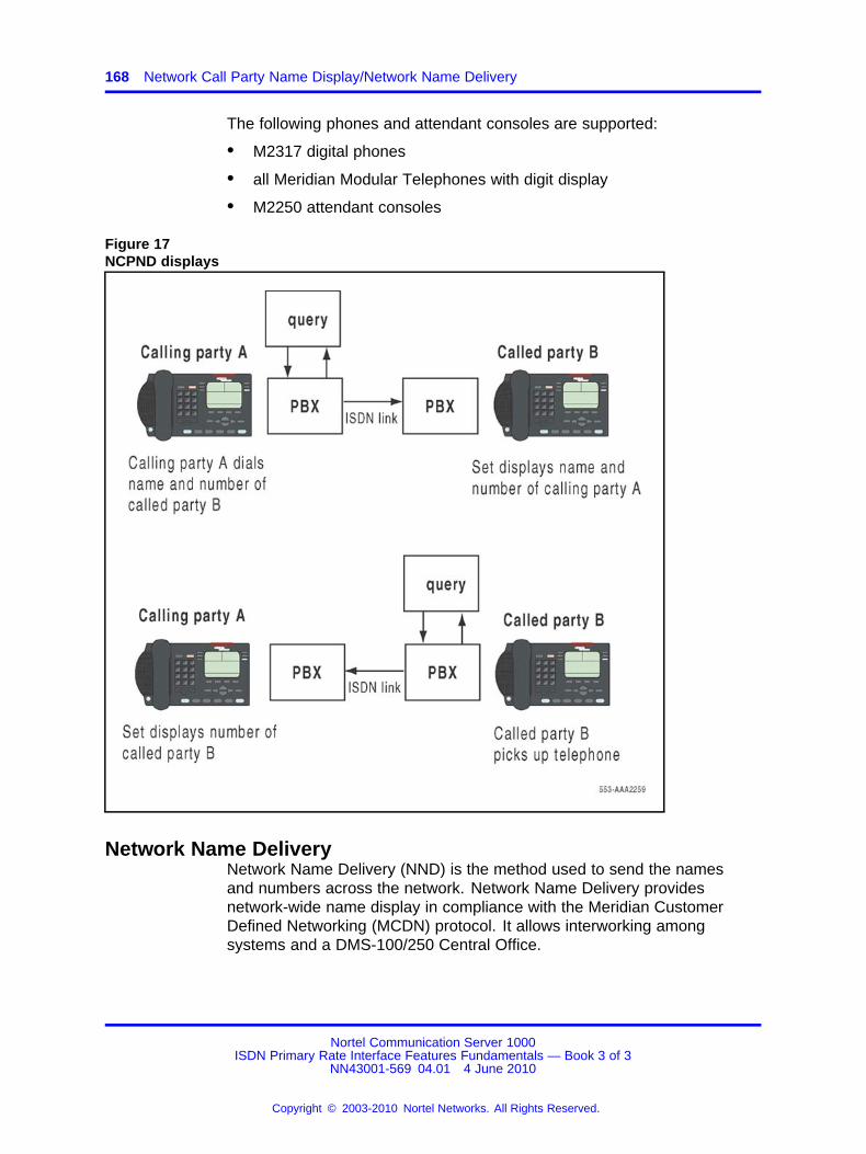
168 Network Call Party Name Display/Network Name Delivery
The following phones and attendant consoles are supported:
• M2317 digital phones
• all Meridian Modular Telephones with digit display
• M2250 attendant consoles
Figure 17NCPND displays
Network Name DeliveryNetwork Name Delivery (NND) is the method used to send the namesand numbers across the network. Network Name Delivery providesnetwork-wide name display in compliance with the Meridian CustomerDefined Networking (MCDN) protocol. It allows interworking amongsystems and a DMS-100/250 Central Office.
Nortel Communication Server 1000ISDN Primary Rate Interface Features Fundamentals — Book 3 of 3
NN43001-569 04.01 4 June 2010
Copyright © 2003-2010 Nortel Networks. All Rights Reserved.
.
Feature implementation 169
Operating parametersThe following list describes the Network Name Delivery operatingparameters.
• For system to system, the maximum number of characters in adisplayed name is 24. When connecting to a Central Office, 15characters only are supported. Names exceeding this length aretruncated.
• Name Delivery is supported for Call Pickup, Call Transfer, Hunt, andCall Forward All Calls/No Answer/Busy.
• A CPND enhancement allows the display of the redirecting name onthe terminating phone instead of the calling name by a service changeoption only if the first redirecting party is on the terminating switch.
• In all cases, when the name is available, the called party name isdisplayed on the caller’s display during the ringing phase. This is anenhancement over ND1 which displays names on connect.
Feature interactionsThe same feature interactions apply as those for Call Party Name Display;refer to the Call Party Name Display description in Features and ServicesFundamentals (NN43001-106)
Feature packagingThis feature requires the following packages:
• Calling Party Name Display (CPND) package 95
• Integrated Services Digital Network (ISDN) package 145
• ISDN Primary Rate Interface (PRI) package 146 or
• 2.0 Mbit Primary Rate Access (PRI2)
Feature implementationTask summary list
The following is a summary of the tasks in this section:
1. Table 88 "LD 95: Configure the Calling Party Name Display." (page170)
2. Table 89 "LD 16: Enable NCPND for each required trunk route." (page170)
3. Table 90 "LD 17: Indicate the remote capability (which Network NameDelivery protocol is supported by the remote node/switch on this DCHinterface)." (page 170)
Nortel Communication Server 1000ISDN Primary Rate Interface Features Fundamentals — Book 3 of 3
NN43001-569 04.01 4 June 2010
Copyright © 2003-2010 Nortel Networks. All Rights Reserved.
.
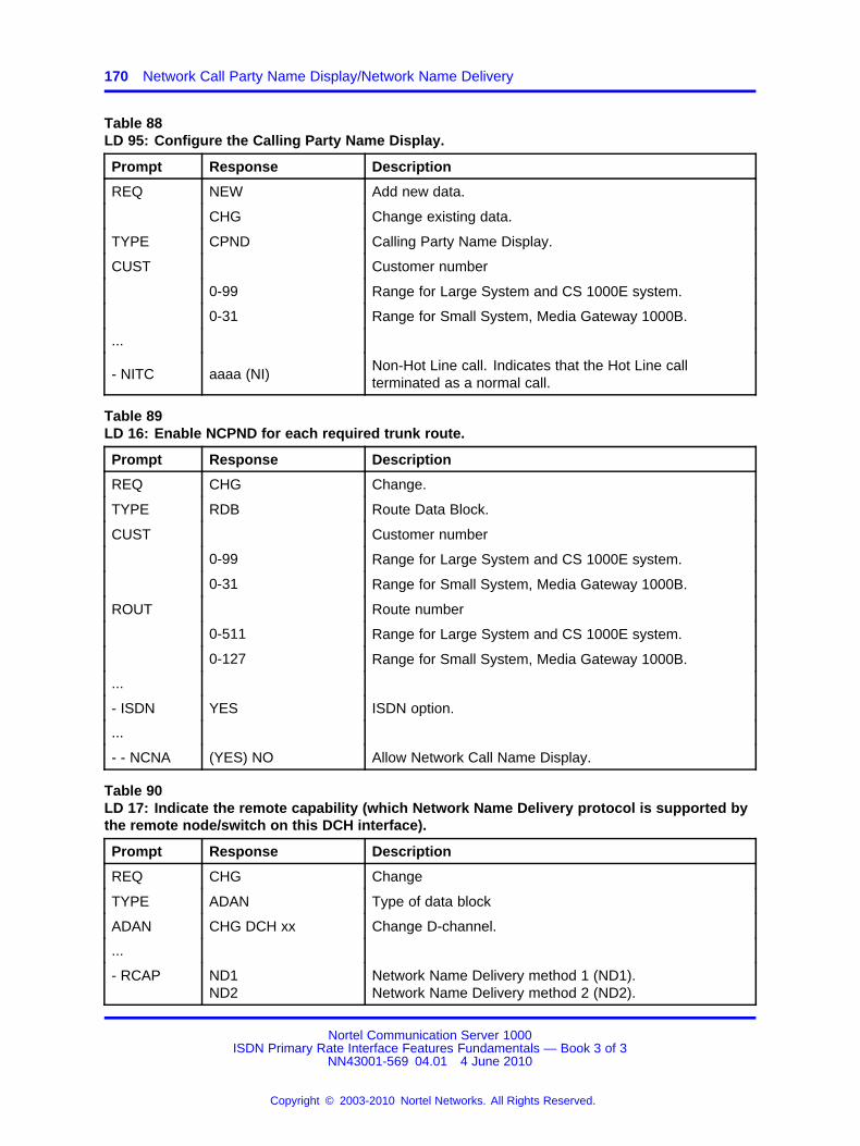
170 Network Call Party Name Display/Network Name Delivery
Table 88LD 95: Configure the Calling Party Name Display.
Prompt Response Description
REQ NEW Add new data.
CHG Change existing data.
TYPE CPND Calling Party Name Display.
CUST Customer number
0-99 Range for Large System and CS 1000E system.
0-31 Range for Small System, Media Gateway 1000B.
...
- NITC aaaa (NI)Non-Hot Line call. Indicates that the Hot Line callterminated as a normal call.
Table 89LD 16: Enable NCPND for each required trunk route.
Prompt Response Description
REQ CHG Change.
TYPE RDB Route Data Block.
CUST Customer number
0-99 Range for Large System and CS 1000E system.
0-31 Range for Small System, Media Gateway 1000B.
ROUT Route number
0-511 Range for Large System and CS 1000E system.
0-127 Range for Small System, Media Gateway 1000B.
...
- ISDN YES ISDN option.
...
- - NCNA (YES) NO Allow Network Call Name Display.
Table 90LD 17: Indicate the remote capability (which Network Name Delivery protocol is supported bythe remote node/switch on this DCH interface).
Prompt Response Description
REQ CHG Change
TYPE ADAN Type of data block
ADAN CHG DCH xx Change D-channel.
...
- RCAP ND1ND2
Network Name Delivery method 1 (ND1).Network Name Delivery method 2 (ND2).
Nortel Communication Server 1000ISDN Primary Rate Interface Features Fundamentals — Book 3 of 3
NN43001-569 04.01 4 June 2010
Copyright © 2003-2010 Nortel Networks. All Rights Reserved.
.

Feature operation 171
Feature operationNo specific operating procedures are required to use this feature.
Nortel Communication Server 1000ISDN Primary Rate Interface Features Fundamentals — Book 3 of 3
NN43001-569 04.01 4 June 2010
Copyright © 2003-2010 Nortel Networks. All Rights Reserved.
.

172 Network Call Party Name Display/Network Name Delivery
Nortel Communication Server 1000ISDN Primary Rate Interface Features Fundamentals — Book 3 of 3
NN43001-569 04.01 4 June 2010
Copyright © 2003-2010 Nortel Networks. All Rights Reserved.
.

173.
Network Call Redirection
ContentsThis section contains information on the following topics:
“Feature description” (page 173)
“Operating parameters” (page 184)
“Feature interactions” (page 184)
“Feature packaging” (page 185)
“Feature implementation” (page 186)
“Task summary list” (page 186)
“Feature operation” (page 189)
Feature descriptionThe Network Call Redirection feature provides Network Call Forward NoAnswer (NCFNA) and Network Call Forward All Calls (NCFAC) over anISDN PRA or ISL network. Calls can also be transferred over the network,but the CLID display will not reflect the transfer.
The Network Call Redirection (NCRD) feature is based on the stand-aloneCall Redirection feature. Stand-alone Call Redirection permits redirectionwithin a single system. Using Network Call Redirection, calls areredirected over more than one system. The user cannot tell the differencebetween a call-redirected and a network call-redirected call. The CLID digitand the name displays are the same for both call scenarios.
NCRD supports system to system connections. The private numberingplans, the Uniform Dialing Plan (UDP), and the Coordinated Dialing Plan(CDP) are supported by both network configurations.
For NCFNA, the call can pass through (hop) only one switch. However,as shown in Figure 18 "Network configurations for NCFAC and NCFNA"(page 174), a multiple-hop configuration is permitted for NCFAC.
Nortel Communication Server 1000ISDN Primary Rate Interface Features Fundamentals — Book 3 of 3
NN43001-569 04.01 4 June 2010
Copyright © 2003-2010 Nortel Networks. All Rights Reserved.
.

174 Network Call Redirection
The number of times a call is redirected depends on the Class of Serviceof the redirecting phone. If the redirecting phone has a Class of Servicewith second-level NCFNA denied, only one NCFNA is allowed. If a secondNCFNA attempt is made, it is rejected and the call continues to ring atthe first redirected station. If the redirecting phone has a Class of Servicewith second-level NCFNA allowed, the call can have an additional CFNAredirection.
Note: A redirected call over PRA that terminates on a busy phonecannot activate the Network Ring Again (NRAG) feature. Also, CLIDname display is not supported in call transfer, call forward busy, hunt, orcall pickup.
Figure 18Network configurations for NCFAC and NCFNA
Nortel Communication Server 1000ISDN Primary Rate Interface Features Fundamentals — Book 3 of 3
NN43001-569 04.01 4 June 2010
Copyright © 2003-2010 Nortel Networks. All Rights Reserved.
.
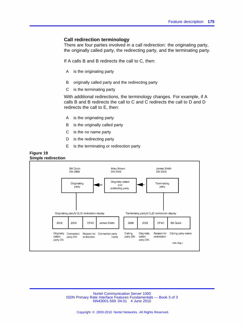
Feature description 175
Call redirection terminologyThere are four parties involved in a call redirection: the originating party,the originally called party, the redirecting party, and the terminating party.
If A calls B and B redirects the call to C, then:
A is the originating party
B originally called party and the redirecting party
C is the terminating party
With additional redirections, the terminology changes. For example, if Acalls B and B redirects the call to C and C redirects the call to D and Dredirects the call to E, then:
A is the originating party
B is the originally called party
C is the no name party
D is the redirecting party
E is the terminating or redirection party
Figure 19Simple redirection
Nortel Communication Server 1000ISDN Primary Rate Interface Features Fundamentals — Book 3 of 3
NN43001-569 04.01 4 June 2010
Copyright © 2003-2010 Nortel Networks. All Rights Reserved.
.
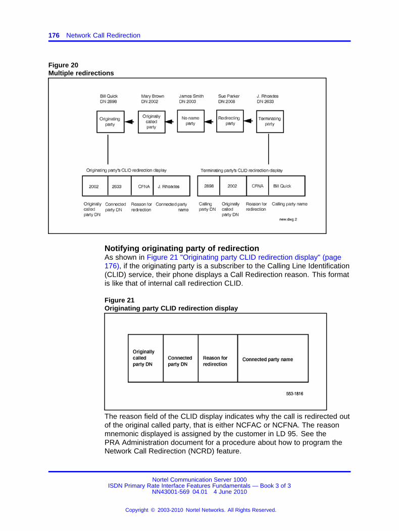
176 Network Call Redirection
Figure 20Multiple redirections
Notifying originating party of redirectionAs shown in Figure 21 "Originating party CLID redirection display" (page176), if the originating party is a subscriber to the Calling Line Identification(CLID) service, their phone displays a Call Redirection reason. This formatis like that of internal call redirection CLID.
Figure 21Originating party CLID redirection display
The reason field of the CLID display indicates why the call is redirected outof the original called party, that is either NCFAC or NCFNA. The reasonmnemonic displayed is assigned by the customer in LD 95. See thePRA Administration document for a procedure about how to program theNetwork Call Redirection (NCRD) feature.
Nortel Communication Server 1000ISDN Primary Rate Interface Features Fundamentals — Book 3 of 3
NN43001-569 04.01 4 June 2010
Copyright © 2003-2010 Nortel Networks. All Rights Reserved.
.

Feature description 177
If the originally called party information is not available, the redirectingparty DN is displayed in place of the originally called DN. For single callredirection, the originally called party is also the redirecting party.
Notifying terminating party of redirectionAs shown in Figure 22 "Terminating party CLID redirection display"(page 177), if the terminating party is a subscriber to the CLID service,their phone displays a call redirection reason. The display format for theterminating party is the same as that for an internal Call Redirection.
Figure 22Terminating party CLID redirection display
If the originating party information is not available, the redirecting party DNis displayed instead.
Redirection tonesThe tone the originating party receives is determined by the cause of theredirection. When a call cannot terminate because the forward-to DN isbusy and none of the redirections are due to Network Call Forward NoAnswer (NCFNA), the originator receives a busy tone. However, if oneredirection is due to NCFNA, an attempt is made to re-ring the phone thatinitiated the NCFNA.
When the call cannot terminate for any reason other than the forward-toDN is busy and no redirections are due to NCFNA, the originator receivesan overflow tone. Again, if one redirection is due to NCFNA, an attempt ismade to re-ring the phone that initiated the NCFNA.
A redirection counter value is passed with the call-forwarding information.When the redirection counter maximum is exceeded, there are twoscenarios. If all call redirections are due to Network Call Forward AllCalls (NCFAC), the calling party receives an overflow tone. If one of theredirections is due to NCFNA, an attempt is made to re-ring the phone thatinitiated the NCFNA.
Nortel Communication Server 1000ISDN Primary Rate Interface Features Fundamentals — Book 3 of 3
NN43001-569 04.01 4 June 2010
Copyright © 2003-2010 Nortel Networks. All Rights Reserved.
.
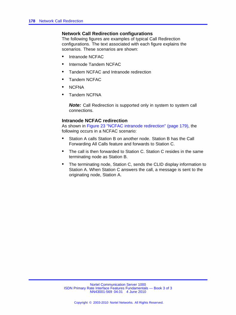
178 Network Call Redirection
Network Call Redirection configurationsThe following figures are examples of typical Call Redirectionconfigurations. The text associated with each figure explains thescenarios. These scenarios are shown:
• Intranode NCFAC
• Internode Tandem NCFAC
• Tandem NCFAC and Intranode redirection
• Tandem NCFAC
• NCFNA
• Tandem NCFNA
Note: Call Redirection is supported only in system to system callconnections.
Intranode NCFAC redirectionAs shown in Figure 23 "NCFAC intranode redirection" (page 179), thefollowing occurs in a NCFAC scenario:
• Station A calls Station B on another node. Station B has the CallForwarding All Calls feature and forwards to Station C.
• The call is then forwarded to Station C. Station C resides in the sameterminating node as Station B.
• The terminating node, Station C, sends the CLID display information toStation A. When Station C answers the call, a message is sent to theoriginating node, Station A.
Nortel Communication Server 1000ISDN Primary Rate Interface Features Fundamentals — Book 3 of 3
NN43001-569 04.01 4 June 2010
Copyright © 2003-2010 Nortel Networks. All Rights Reserved.
.
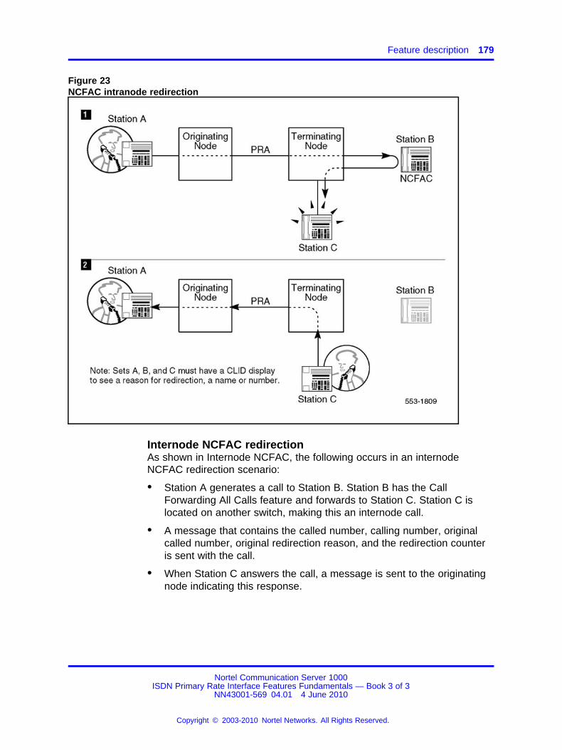
Feature description 179
Figure 23NCFAC intranode redirection
Internode NCFAC redirectionAs shown in Internode NCFAC, the following occurs in an internodeNCFAC redirection scenario:
• Station A generates a call to Station B. Station B has the CallForwarding All Calls feature and forwards to Station C. Station C islocated on another switch, making this an internode call.
• A message that contains the called number, calling number, originalcalled number, original redirection reason, and the redirection counteris sent with the call.
• When Station C answers the call, a message is sent to the originatingnode indicating this response.
Nortel Communication Server 1000ISDN Primary Rate Interface Features Fundamentals — Book 3 of 3
NN43001-569 04.01 4 June 2010
Copyright © 2003-2010 Nortel Networks. All Rights Reserved.
.
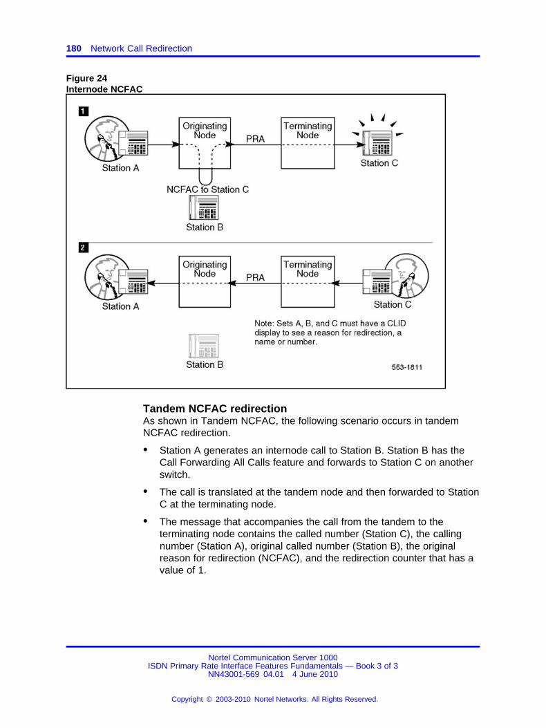
180 Network Call Redirection
Figure 24Internode NCFAC
Tandem NCFAC redirectionAs shown in Tandem NCFAC, the following scenario occurs in tandemNCFAC redirection.
• Station A generates an internode call to Station B. Station B has theCall Forwarding All Calls feature and forwards to Station C on anotherswitch.
• The call is translated at the tandem node and then forwarded to StationC at the terminating node.
• The message that accompanies the call from the tandem to theterminating node contains the called number (Station C), the callingnumber (Station A), original called number (Station B), the originalreason for redirection (NCFAC), and the redirection counter that has avalue of 1.
Nortel Communication Server 1000ISDN Primary Rate Interface Features Fundamentals — Book 3 of 3
NN43001-569 04.01 4 June 2010
Copyright © 2003-2010 Nortel Networks. All Rights Reserved.
.

Feature description 181
• The terminating node sends a message to the originating node thatcontains the call forwarding information along with an indication ofringing Station C.
• When Station C answers the call, a message indicating this responseis sent first to the tandem node and then relayed to the originatingnode.
Figure 25Tandem NCFAC
Tandem NCFAC and intranode redirectionThe following occurs in a tandem NCFAC. This is followed by an intranoderedirection scenario, as shown in Tandem NCFAC intranode.
• Station A generates an internode call to Station B. This Station B hasthe Call Forwarding All Calls feature and forwards to Station C onanother node. In this scenario, Station C has the Call Forwarding AllCalls feature and forwards the call to station D on the same node.
• The call is forwarded from the tandem node to the terminating nodefor Station C. The CLID information is also sent as a message alongwith the call. This information includes the called number (Station C),the calling number (Station A), the original called number (Station B),
Nortel Communication Server 1000ISDN Primary Rate Interface Features Fundamentals — Book 3 of 3
NN43001-569 04.01 4 June 2010
Copyright © 2003-2010 Nortel Networks. All Rights Reserved.
.
182 Network Call Redirection
the original redirection reason (CFAC or NCFAC), and the redirectioncounter (1).
• The call is then forwarded to station D within the terminating node.The terminating node sends the call forwarding information to theoriginating node (Station A).
• The redirection counter is still 1 since there was a single networkredirection.
• Station D answers and a message is sent notifying the originating nodeof this response.
Figure 26Tandem NCFAC intranode
NCFNA redirectionAs shown in NCFNA, the following occurs in an NCFNA redirectionscenario.
• Station A generates an internode call to Station B which has the CallForwarding No Answer feature and forwards to Station C.
• The call is transferred to Station C when the ringing (or alerting)phase times out. The terminating node sends a message to the
Nortel Communication Server 1000ISDN Primary Rate Interface Features Fundamentals — Book 3 of 3
NN43001-569 04.01 4 June 2010
Copyright © 2003-2010 Nortel Networks. All Rights Reserved.
.
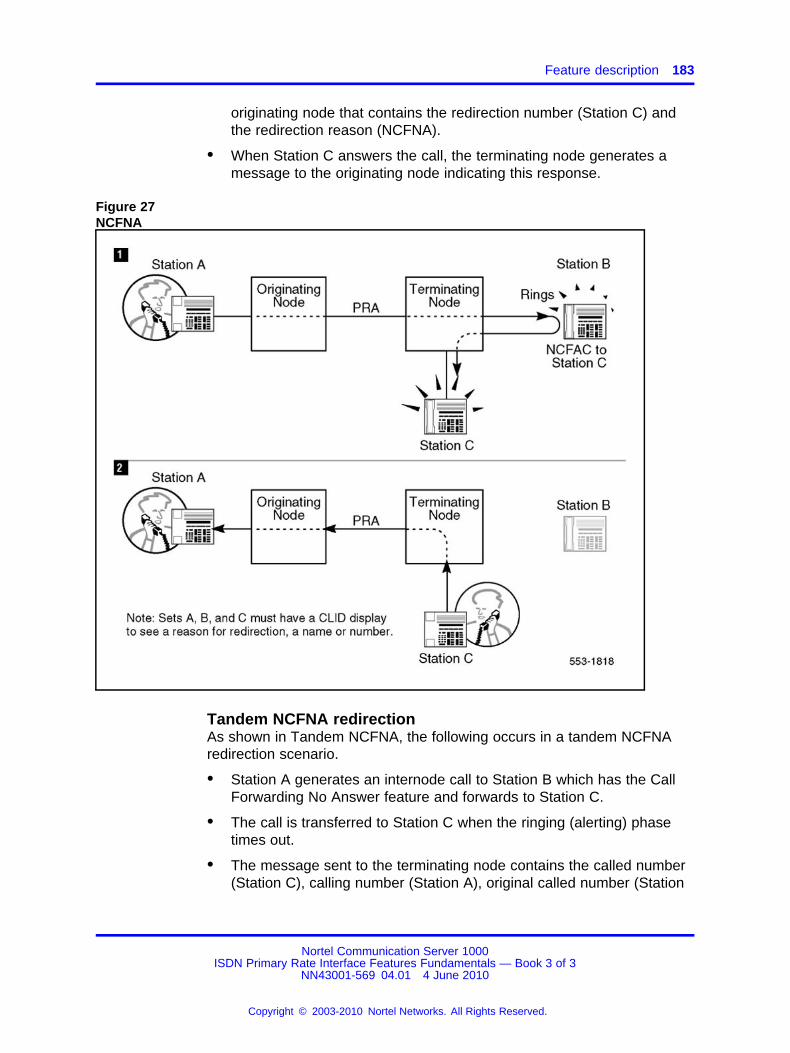
Feature description 183
originating node that contains the redirection number (Station C) andthe redirection reason (NCFNA).
• When Station C answers the call, the terminating node generates amessage to the originating node indicating this response.
Figure 27NCFNA
Tandem NCFNA redirectionAs shown in Tandem NCFNA, the following occurs in a tandem NCFNAredirection scenario.
• Station A generates an internode call to Station B which has the CallForwarding No Answer feature and forwards to Station C.
• The call is transferred to Station C when the ringing (alerting) phasetimes out.
• The message sent to the terminating node contains the called number(Station C), calling number (Station A), original called number (Station
Nortel Communication Server 1000ISDN Primary Rate Interface Features Fundamentals — Book 3 of 3
NN43001-569 04.01 4 June 2010
Copyright © 2003-2010 Nortel Networks. All Rights Reserved.
.
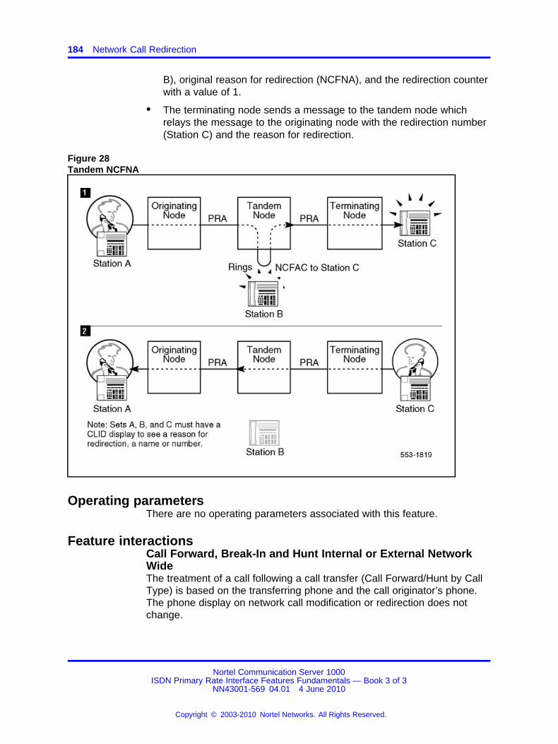
184 Network Call Redirection
B), original reason for redirection (NCFNA), and the redirection counterwith a value of 1.
• The terminating node sends a message to the tandem node whichrelays the message to the originating node with the redirection number(Station C) and the reason for redirection.
Figure 28Tandem NCFNA
Operating parametersThere are no operating parameters associated with this feature.
Feature interactionsCall Forward, Break-In and Hunt Internal or External NetworkWideThe treatment of a call following a call transfer (Call Forward/Hunt by CallType) is based on the transferring phone and the call originator’s phone.The phone display on network call modification or redirection does notchange.
Nortel Communication Server 1000ISDN Primary Rate Interface Features Fundamentals — Book 3 of 3
NN43001-569 04.01 4 June 2010
Copyright © 2003-2010 Nortel Networks. All Rights Reserved.
.

Feature packaging 185
DPNSS1 Route Optimisation/MCDN Trunk Anti-TromboningInterworkingIf Network Call Redirection is not configured in a DPNSS1/MCDN gateway,the displays are updated normally, since the RO/TAT Interworking featureis not affected.
If Network Call Redirection is not configured in an MCDN/DPNSS1gateway, the displays are not updated on the bridged phones on theMCDN side. However, if the bridged phones are on the same node, thedisplays are updated, even though NCRD is not configured.
EuroISDN Trunk - Network SideIt is possible to have a phone Call Forward, Call Forward No Answeror Hunt to an external number over a EuroISDN Trunk - Network Sideconnectivity ISDN PRI or ISDN BRI trunk. It is also possible to transfer orconference a call to an external number over a EuroISDN Trunk - NetworkSide connectivity ISDN PRI or ISDN BRI trunk. Access restrictions canblock some transfers from being completed.
Notices of call redirection or call modification are not transmitted over aEuroISDN Trunk - Network Side connectivity.
INIT ACD Queue Call RestoreCall information associated with Network Call Redirection is lost aftersystem initialization and call restoration.
ISDN QSIG Basic CallWhen a call is terminated on the system and Network Call Redirection(NCR) is active, the QSIG Basic Call can still operate; however, theoriginal called number and redirection number IE that are used by NCR willnot be sent on the QSIG interface.
Non-ISDN TrunksIf the call is forwarded over DTI/Analog trunks, the redirection informationwill not be carried over, as DTI/Analog trunks do not have the ability tocarry redirection information.
If the call is CFNA over DTI/Analog trunks, and if the call cannot terminateon the forwarded to party, the call drops.
Feature packagingThere are no packaging requirements specified for this feature.
Nortel Communication Server 1000ISDN Primary Rate Interface Features Fundamentals — Book 3 of 3
NN43001-569 04.01 4 June 2010
Copyright © 2003-2010 Nortel Networks. All Rights Reserved.
.
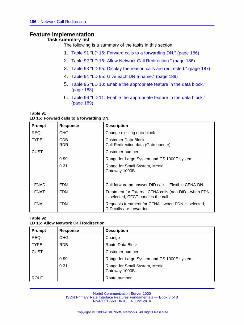
186 Network Call Redirection
Feature implementationTask summary list
The following is a summary of the tasks in this section:
1. Table 91 "LD 15: Forward calls to a forwarding DN." (page 186)
2. Table 92 "LD 16: Allow Network Call Redirection." (page 186)
3. Table 93 "LD 95: Display the reason calls are redirected." (page 187)
4. Table 94 "LD 95: Give each DN a name." (page 188)
5. Table 95 "LD 10: Enable the appropriate feature in the data block."(page 188)
6. Table 96 "LD 11: Enable the appropriate feature in the data block."(page 189)
Table 91LD 15: Forward calls to a forwarding DN.
Prompt Response Description
REQ CHG Change existing data block.
TYPE CDBRDR
Customer Data Block.Call Redirection data (Gate opener).
CUST Customer number
0-99 Range for Large System and CS 1000E system.
0-31 Range for Small System, MediaGateway 1000B.
...
- FNAD FDN Call forward no answer DID calls—Flexible CFNA DN.
- FNAT FDN Treatment for External CFNA calls (non-DID—when FDNis selected, CFCT handles the call.
- FNAL FDN Requests treatment for CFNA—when FDN is selected,DID calls are forwarded.
Table 92LD 16: Allow Network Call Redirection.
Prompt Response Description
REQ CHG Change
TYPE RDB Route Data Block
CUST Customer number
0-99 Range for Large System and CS 1000E system.
0-31 Range for Small System, MediaGateway 1000B.
ROUT Route number
Nortel Communication Server 1000ISDN Primary Rate Interface Features Fundamentals — Book 3 of 3
NN43001-569 04.01 4 June 2010
Copyright © 2003-2010 Nortel Networks. All Rights Reserved.
.
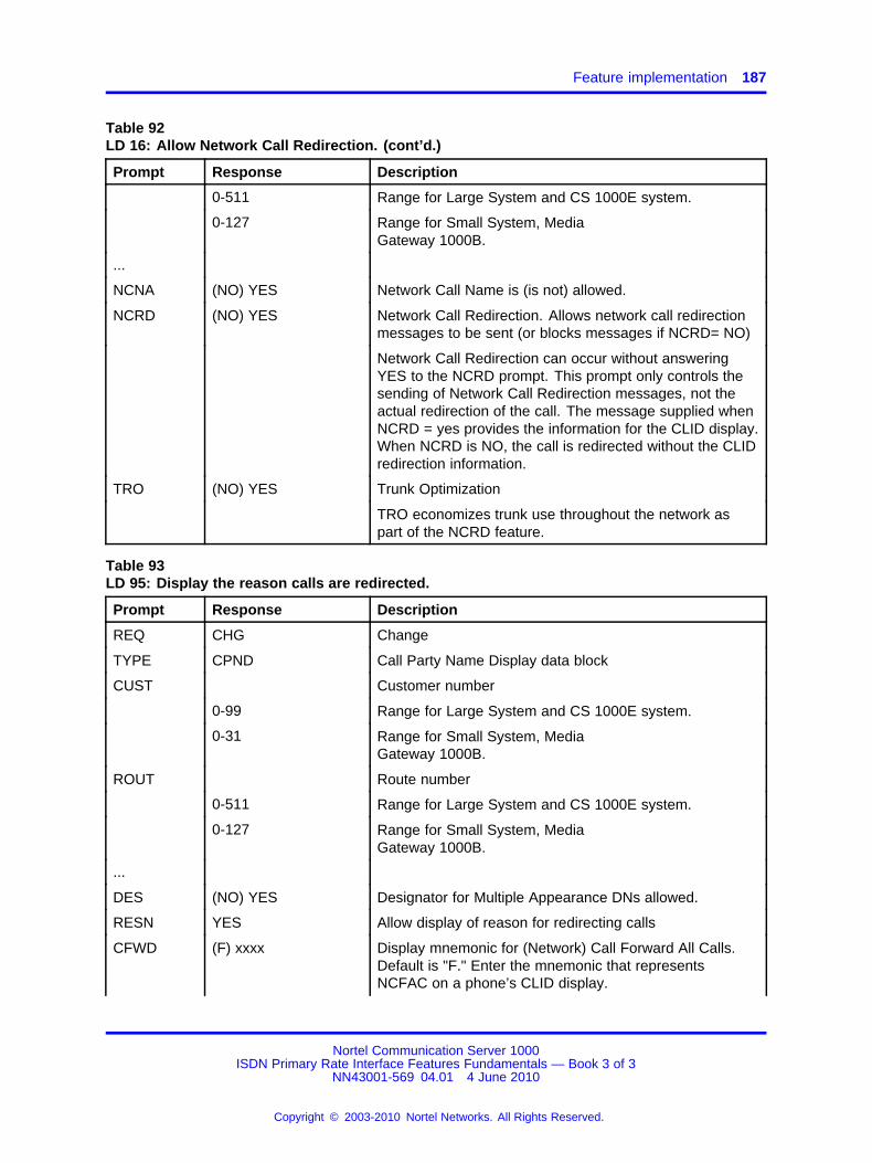
Feature implementation 187
Table 92LD 16: Allow Network Call Redirection. (cont’d.)
Prompt Response Description
0-511 Range for Large System and CS 1000E system.
0-127 Range for Small System, MediaGateway 1000B.
...
NCNA (NO) YES Network Call Name is (is not) allowed.
NCRD (NO) YES Network Call Redirection. Allows network call redirectionmessages to be sent (or blocks messages if NCRD= NO)
Network Call Redirection can occur without answeringYES to the NCRD prompt. This prompt only controls thesending of Network Call Redirection messages, not theactual redirection of the call. The message supplied whenNCRD = yes provides the information for the CLID display.When NCRD is NO, the call is redirected without the CLIDredirection information.
TRO (NO) YES Trunk Optimization
TRO economizes trunk use throughout the network aspart of the NCRD feature.
Table 93LD 95: Display the reason calls are redirected.
Prompt Response Description
REQ CHG Change
TYPE CPND Call Party Name Display data block
CUST Customer number
0-99 Range for Large System and CS 1000E system.
0-31 Range for Small System, MediaGateway 1000B.
ROUT Route number
0-511 Range for Large System and CS 1000E system.
0-127 Range for Small System, MediaGateway 1000B.
...
DES (NO) YES Designator for Multiple Appearance DNs allowed.
RESN YES Allow display of reason for redirecting calls
CFWD (F) xxxx Display mnemonic for (Network) Call Forward All Calls.Default is "F." Enter the mnemonic that representsNCFAC on a phone’s CLID display.
Nortel Communication Server 1000ISDN Primary Rate Interface Features Fundamentals — Book 3 of 3
NN43001-569 04.01 4 June 2010
Copyright © 2003-2010 Nortel Networks. All Rights Reserved.
.
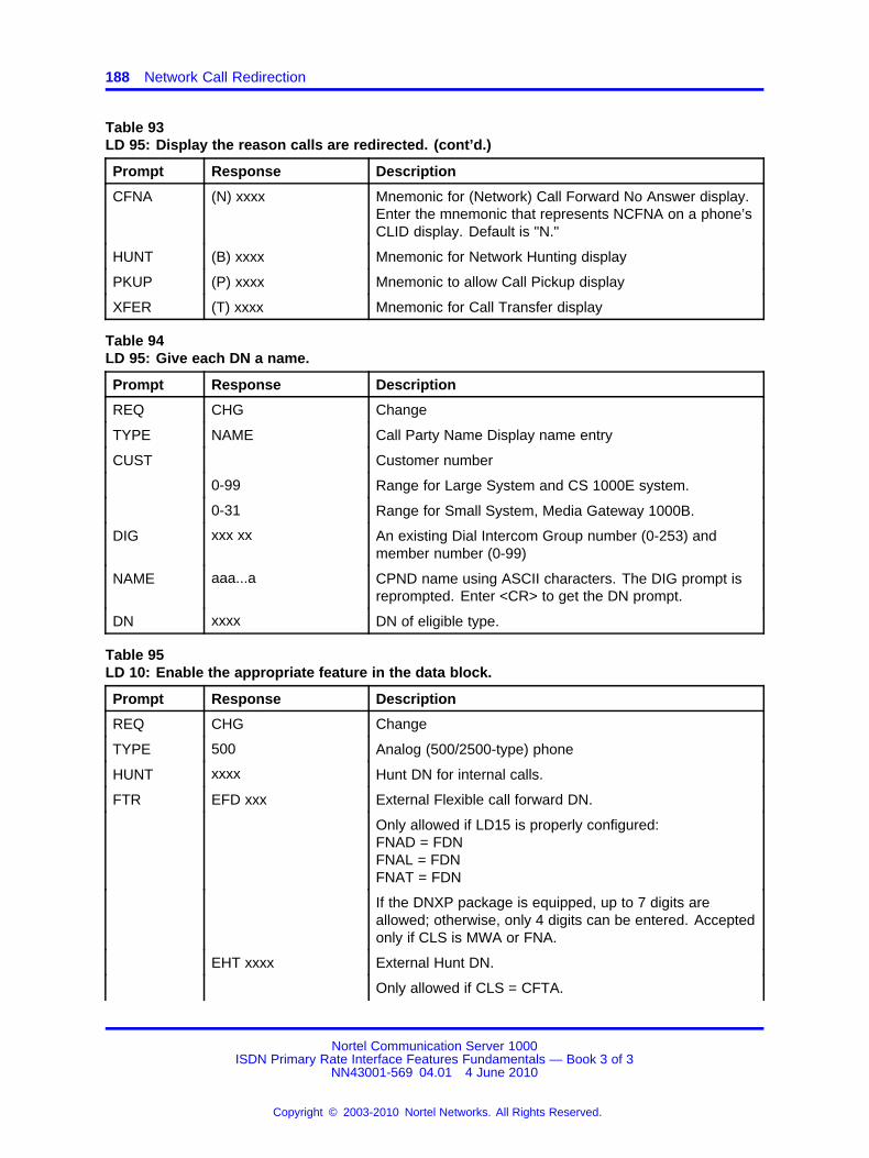
188 Network Call Redirection
Table 93LD 95: Display the reason calls are redirected. (cont’d.)
Prompt Response Description
CFNA (N) xxxx Mnemonic for (Network) Call Forward No Answer display.Enter the mnemonic that represents NCFNA on a phone’sCLID display. Default is "N."
HUNT (B) xxxx Mnemonic for Network Hunting display
PKUP (P) xxxx Mnemonic to allow Call Pickup display
XFER (T) xxxx Mnemonic for Call Transfer display
Table 94LD 95: Give each DN a name.
Prompt Response Description
REQ CHG Change
TYPE NAME Call Party Name Display name entry
CUST Customer number
0-99 Range for Large System and CS 1000E system.
0-31 Range for Small System, Media Gateway 1000B.
DIG xxx xx An existing Dial Intercom Group number (0-253) andmember number (0-99)
NAME aaa...a CPND name using ASCII characters. The DIG prompt isreprompted. Enter <CR> to get the DN prompt.
DN xxxx DN of eligible type.
Table 95LD 10: Enable the appropriate feature in the data block.
Prompt Response Description
REQ CHG Change
TYPE 500 Analog (500/2500-type) phone
HUNT xxxx Hunt DN for internal calls.
FTR EFD xxx External Flexible call forward DN.
Only allowed if LD15 is properly configured:FNAD = FDNFNAL = FDNFNAT = FDN
If the DNXP package is equipped, up to 7 digits areallowed; otherwise, only 4 digits can be entered. Acceptedonly if CLS is MWA or FNA.
EHT xxxx External Hunt DN.
Only allowed if CLS = CFTA.
Nortel Communication Server 1000ISDN Primary Rate Interface Features Fundamentals — Book 3 of 3
NN43001-569 04.01 4 June 2010
Copyright © 2003-2010 Nortel Networks. All Rights Reserved.
.
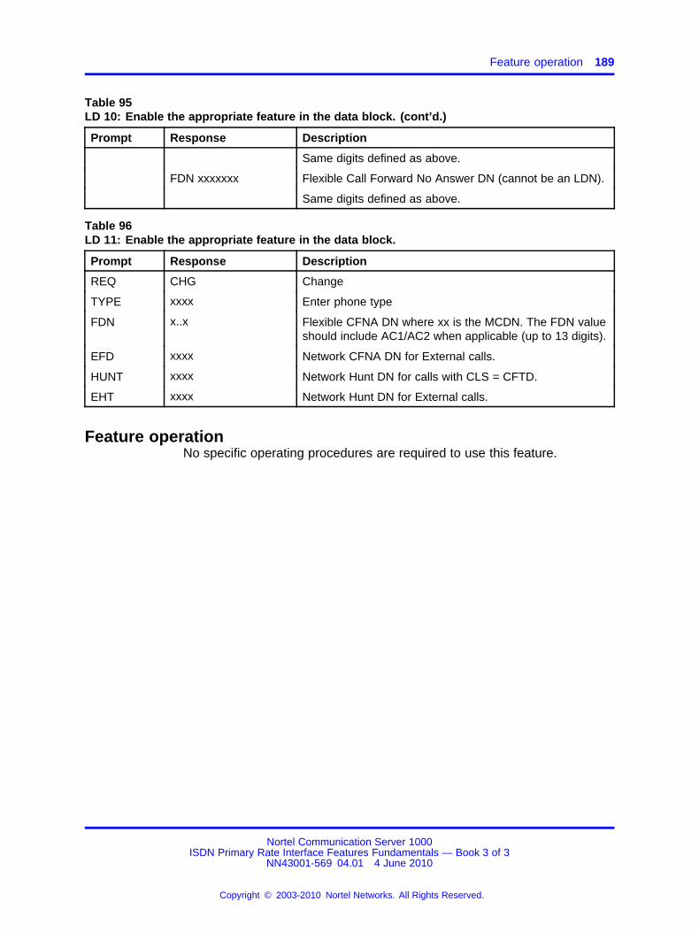
Feature operation 189
Table 95LD 10: Enable the appropriate feature in the data block. (cont’d.)
Prompt Response Description
Same digits defined as above.
FDN xxxxxxx Flexible Call Forward No Answer DN (cannot be an LDN).
Same digits defined as above.
Table 96LD 11: Enable the appropriate feature in the data block.
Prompt Response Description
REQ CHG Change
TYPE xxxx Enter phone type
FDN x..x Flexible CFNA DN where xx is the MCDN. The FDN valueshould include AC1/AC2 when applicable (up to 13 digits).
EFD xxxx Network CFNA DN for External calls.
HUNT xxxx Network Hunt DN for calls with CLS = CFTD.
EHT xxxx Network Hunt DN for External calls.
Feature operationNo specific operating procedures are required to use this feature.
Nortel Communication Server 1000ISDN Primary Rate Interface Features Fundamentals — Book 3 of 3
NN43001-569 04.01 4 June 2010
Copyright © 2003-2010 Nortel Networks. All Rights Reserved.
.

190 Network Call Redirection
Nortel Communication Server 1000ISDN Primary Rate Interface Features Fundamentals — Book 3 of 3
NN43001-569 04.01 4 June 2010
Copyright © 2003-2010 Nortel Networks. All Rights Reserved.
.
191.
Network Call Transfer and NetworkExtended Calls
ContentsThis section contains information on the following topics:
“Feature description” (page 191)
“Operating parameters” (page 191)
“Feature interactions” (page 191)
“Feature packaging” (page 191)
“Feature implementation” (page 192)
“Feature operation” (page 192)
Feature descriptionNetwork Call Transfer and Attendant Extended Calls display the callingparty name and number to the "Transferred to "extended to" party acrossthe network. Also, if NCPND is optioned, the calling party’s display isupdated to show the connected party’s name and number.
Note: Network Call Transfer over PRI does not provide the ESNNetwork Transfer feature. This feature eliminates tandem trunkconnections that double back over the same route. PRI NetworkTransfer allows calls to be blindly transferred across the ISDN network.
Operating parametersThere are no operating parameters associated with this feature.
Feature interactionsThere are no feature interactions associated with this feature.
Feature packagingThis feature is included in base System Software.
Nortel Communication Server 1000ISDN Primary Rate Interface Features Fundamentals — Book 3 of 3
NN43001-569 04.01 4 June 2010
Copyright © 2003-2010 Nortel Networks. All Rights Reserved.
.

192 Network Call Transfer and Network Extended Calls
Feature implementationThere are no specific implementation procedures for this feature.
Feature operationNo specific operating procedures are required to use this feature.
Nortel Communication Server 1000ISDN Primary Rate Interface Features Fundamentals — Book 3 of 3
NN43001-569 04.01 4 June 2010
Copyright © 2003-2010 Nortel Networks. All Rights Reserved.
.
193.
Network Drop Back Busy and Off-hookQueuing
ContentsThis section contains information on the following topics:
“Feature description” (page 193)
“Operating parameters” (page 194)
“Feature interactions” (page 194)
“Feature packaging” (page 195)
“Feature implementation” (page 195)
“Task summary list” (page 195)
“Feature operation” (page 197)
Feature descriptionThe Network Drop Back Busy (DBB) feature allows network calls thatare blocked at a tandem node to be rerouted (dropped back) to theoriginating node. The calls are then directed over an alternate route. TheNetwork Off-Hook Queuing (OHQ) feature allows Off-Hook Queuing to beconfigured at a tandem node, thereby allowing Off-Hook Queuing at thatnode.
Both DBB and OHQ give the originating node control over the routing ofall outgoing network calls.
The DBB and OHQ capabilities are only supported over an ISDN network.When DBB and/or OHQ is configured, an ISDN call to a tandem nodemight encounter one of the following conditions.
Nortel Communication Server 1000ISDN Primary Rate Interface Features Fundamentals — Book 3 of 3
NN43001-569 04.01 4 June 2010
Copyright © 2003-2010 Nortel Networks. All Rights Reserved.
.

194 Network Drop Back Busy and Off-hook Queuing
Table 97Conditions and treatments of an ISDN call to a tandem node, with DBB and/or OHQconfigured
Configuration Condition Treatment
IDBB All routes in initial (I) set busy Drop back to originating node.
IDBB All routes in "I" set and extended (E)set busy
If all routes in "I" set busy, attemptrouting over "E" set. If all routes in "E"set are busy, drop back to originatingnode.
This is the default configuration.
OHQ, IDBB All routes in "I" set busy Off-hook queue. If OHQ timer timesout, drop back to originating node.
OHQ, IDBB All routes in "I" set and "E" set busy Off-hook queue to "I" set. When OHQtimer times out, attempt routing over"E" set. If all routes in "E" set arebusy, drop back to originating node.
An Initial set of routes (I set) are those routes in a route list which havebeen customer-defined for a node as being inexpensive. The systemattempts to complete a call over these routes before testing for queueeligibility. An Extended set of routes (E set) are those routes in a route listthat are not part of the initial set. These routes are usually designated asexpensive. The system attempts to complete a call over the E Set routesonly when the I set queuing times out.
Operating parametersThere are no operating parameters associated with this feature.
Feature interactionsOff-Hook Queuing
Message InterceptIf the Message Intercept feature is equipped, a caller in an off-hookqueue can receive the message intercept voice response rather than theOff-Hook Queuing tone.
Drop Back BusyRemote Virtual QueuingDrop Back Busy (DBB) and Remote Virtual Queuing (RVQ) are bothpackaged under Originating Routing Control/Remote Virtual Queuing(ORC-RVQ) package 192. If DBB and RVQ are both configured, DBBwill take precedence over RVQ. If the user wishes to activate RVQ, DBBmust be disabled for a route entry in response to the IDBB prompt. If theuser wishes to activate DBB, it must be enabled by entering DBI or DBA.Refer to the "Feature administration" section in this feature module formore information.
Nortel Communication Server 1000ISDN Primary Rate Interface Features Fundamentals — Book 3 of 3
NN43001-569 04.01 4 June 2010
Copyright © 2003-2010 Nortel Networks. All Rights Reserved.
.

Feature implementation 195
Network Attendant ServiceNetwork Attendant Service (NAS) routing takes precedence over DBB.
Feature packagingThis feature requires the following packages:
• Basic Routing (BRTE) package 14
• Network Class of Service (NCOS) package 32
• Network Alternate Route Selection (NARS) package 58
• Flexible Call Back Queuing (FCBQ) package 61
• Off-hook Queuing (OHQ) package 62 for Off-Hook Queuing
• Integrated Services Digital Network (ISDN) package 145
• 2.0 Mbit Primary Rate Access (PRI2) package 154
• Network Attendant Service (NAS) package 159
• ISDN Supplementary (ISDNS) package 161
• Originating Routing Control/Remote Virtual Queuing (ORC-RVQ)package 192 for Drop Back Busy
Feature implementationTask summary list
The following is a summary of the tasks in this section:
1. Table 98 "LD 87: Allow OHQ Network Class of Service for thecustomer." (page 195)
2. Table 99 "LD 86: Configure the originating node for Remote VirtualQueuing." (page 196)
Note: Drop Back Busy (DBB) and Remote Virtual Queuing (RVQ)are both packaged under the Originating Routing Control/RemoteVirtual Queuing (ORC-RVQ) package 192. If DBB and RVQ are bothconfigured, DBB will take precedence over RVQ. If the user wishes toactivate RVQ, DBB must be disabled for a route entry in response to theIDBB prompt. If the user wishes to activate DBB, it must be enabled byentering DBI or DBA.
Table 98LD 87: Allow OHQ Network Class of Service for the customer.
Prompt Response Description
REQ CHG Change existing data
CUST Customer number
Nortel Communication Server 1000ISDN Primary Rate Interface Features Fundamentals — Book 3 of 3
NN43001-569 04.01 4 June 2010
Copyright © 2003-2010 Nortel Networks. All Rights Reserved.
.
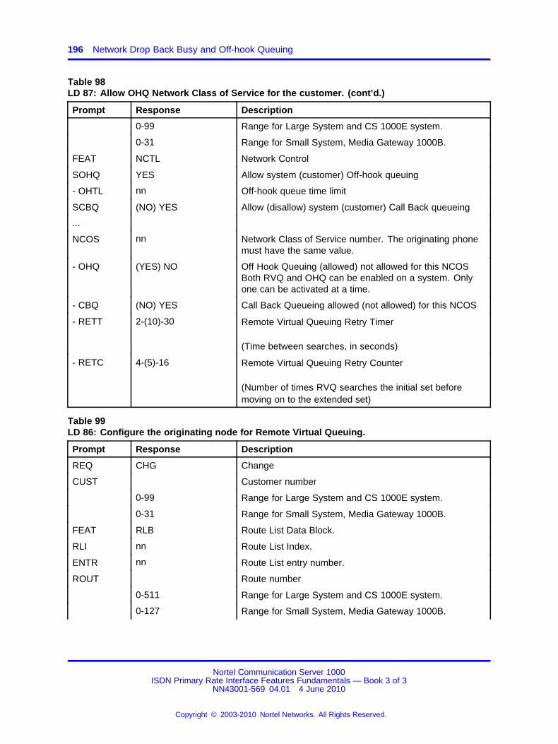
196 Network Drop Back Busy and Off-hook Queuing
Table 98LD 87: Allow OHQ Network Class of Service for the customer. (cont’d.)
Prompt Response Description
0-99 Range for Large System and CS 1000E system.
0-31 Range for Small System, Media Gateway 1000B.
FEAT NCTL Network Control
SOHQ YES Allow system (customer) Off-hook queuing
- OHTL nn Off-hook queue time limit
SCBQ (NO) YES Allow (disallow) system (customer) Call Back queueing
...
NCOS nn Network Class of Service number. The originating phonemust have the same value.
- OHQ (YES) NO Off Hook Queuing (allowed) not allowed for this NCOSBoth RVQ and OHQ can be enabled on a system. Onlyone can be activated at a time.
- CBQ (NO) YES Call Back Queueing allowed (not allowed) for this NCOS
- RETT 2-(10)-30 Remote Virtual Queuing Retry Timer
(Time between searches, in seconds)
- RETC 4-(5)-16 Remote Virtual Queuing Retry Counter
(Number of times RVQ searches the initial set beforemoving on to the extended set)
Table 99LD 86: Configure the originating node for Remote Virtual Queuing.
Prompt Response Description
REQ CHG Change
CUST Customer number
0-99 Range for Large System and CS 1000E system.
0-31 Range for Small System, Media Gateway 1000B.
FEAT RLB Route List Data Block.
RLI nn Route List Index.
ENTR nn Route List entry number.
ROUT Route number
0-511 Range for Large System and CS 1000E system.
0-127 Range for Small System, Media Gateway 1000B.
Nortel Communication Server 1000ISDN Primary Rate Interface Features Fundamentals — Book 3 of 3
NN43001-569 04.01 4 June 2010
Copyright © 2003-2010 Nortel Networks. All Rights Reserved.
.
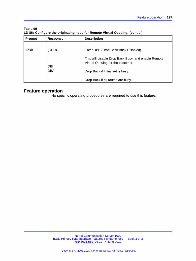
Feature operation 197
Table 99LD 86: Configure the originating node for Remote Virtual Queuing. (cont’d.)
Prompt Response Description
... ... ...
IDBB (DBD)
DBIDBA
Enter DBB (Drop Back Busy Disabled).
This will disable Drop Back Busy, and enable RemoteVirtual Queuing for the customer.
Drop Back if Initial set is busy.
Drop Back if all routes are busy.
Feature operationNo specific operating procedures are required to use this feature.
Nortel Communication Server 1000ISDN Primary Rate Interface Features Fundamentals — Book 3 of 3
NN43001-569 04.01 4 June 2010
Copyright © 2003-2010 Nortel Networks. All Rights Reserved.
.

198 Network Drop Back Busy and Off-hook Queuing
Nortel Communication Server 1000ISDN Primary Rate Interface Features Fundamentals — Book 3 of 3
NN43001-569 04.01 4 June 2010
Copyright © 2003-2010 Nortel Networks. All Rights Reserved.
.

199.
Network and Executive DistinctiveRinging
ContentsThis section contains information on the following topics:
“Feature description” (page 199)
“Operating parameters” (page 200)
“Feature interactions” (page 200)
“Feature packaging” (page 200)
“Feature implementation” (page 201)
“Task summary list” (page 201)
“Feature operation” (page 203)
Feature descriptionNetwork Distinctive Ringing (NDRG) allows a distinctive ringing cadenceto be configured throughout a system network. Distinctive ringing isdefined on a route basis. There are four NDRG distinctive ringing cadenceindices that can be defined for a route. These indices are contained inthe Flexible Tone and Cadences (FTC) table. If one of these indiceshas been defined for a route and an incoming trunk call over that routeterminates on the local node, the terminating phone receives distinctiveringing. If the incoming call tandems to another node through an IntegratedServices Digital Network (ISDN) TIE trunk, the terminating phone at theterminating node receives distinctive ringing. This occurs if the TIE trunkhas been marked as distinctive and if the NDRG feature is equipped at theterminating node; otherwise, normal ringing is given.
Executive Distinctive Ringing applies to both network and stand-aloneenvironments. This feature allows a Class of Service to be entered for aphone, marking the phone as "executive". When a call is made from anexecutive phone, the called phone is rung distinctively. This feature usesthe distinctive cadences introduced by the Network Distinctive Ringing(NDRG) feature.
Nortel Communication Server 1000ISDN Primary Rate Interface Features Fundamentals — Book 3 of 3
NN43001-569 04.01 4 June 2010
Copyright © 2003-2010 Nortel Networks. All Rights Reserved.
.
200 Network and Executive Distinctive Ringing
One of five Classes of Service can be entered – EXR1, EXR2, EXR3,EXR4, or EXR0. EXR is the Class of Service mnemonic that marks thephone as executive, and the digits one to four indicate which of the fourdistinctive ringing cadences is to be applied. EXR0 is the default; it marksa phone as normal.
Operating parametersBoth Network Distinctive Ringing and Executive Distinctive Ringing can beequipped for a phone. In this case, a cadence that is selected for NDRGcan also be selected for EDRG.
Within a network, if there are five routes marked as distinctive, and if anincoming call tandems between two nodes that are connected by a singleTIE trunk, the terminating node can provide unique distinctive ringingfor only four of the five routes. The originating node can provide uniquedistinctive ringing to all five routes since each route can use a differentFlexible Tone and Cadence (FTC) table.
Feature interactionsIncoming trunkAn incoming trunk call that is redirected or attendant-extended will ringdistinctively at the terminating phone, according to the cadence index ofthe originating trunk route. If the terminating phone is located at anothernode, it will ring distinctively according to the cadence index of theoriginating trunk route (if the NDRG feature is equipped at the terminatingnode).
BuzzNetwork Distinctive Ringing and Executive Distinctive Ringing do not affectthe buzzing of a phone.
ConferenceIf a new party is to be included in an established conference, the ringingthat is applied to the phone of the new party depends on the phones ofthe established parties. The system scans the trunks and phones of theconferees for a trunk marked as distinctive or a phone designated asexecutive. The ringing cadence of the new phone depends on the highestindex found by the scan.
Feature packagingThis feature requires the following packages:
• Distinctive Ringing (DRNG) package 74
• Flexible Tones and Cadences (FTC) package 125
• Integrated Services Digital Network (ISDN) package 145
Nortel Communication Server 1000ISDN Primary Rate Interface Features Fundamentals — Book 3 of 3
NN43001-569 04.01 4 June 2010
Copyright © 2003-2010 Nortel Networks. All Rights Reserved.
.

Feature implementation 201
• Network Attendant Service (NAS) package 159
• Integrated Services Digital Network Supplementary Features (ISDNS)package 161
• Executive Distinctive Ringing (EDRG) package 185
Feature implementationTask summary list
The following is a summary of the tasks in this section:
1. Table 100 "LD 10: Define the distinctive ringing cadence for analog(500/2500-type)." (page 201)
2. Table 101 "LD 11: Define the distinctive ringing cadence/tone to beused for Meridian digital phones." (page 201)
3. Table 102 "LD 16: Deny or allow Distinctive Ringing and defineNetwork Ring Index." (page 202)
4. Table 103 "LD 56: Define Flexible Tones and Cadences." (page 202)
Table 100LD 10: Define the distinctive ringing cadence for analog (500/2500-type).
Prompt Response Description
REQ CHG Change existing data.
TYPE 500 Type of phone
TN Terminal number
l s c u Format for Large System and CS 1000E system, where l= loop, s = shelf, c = card, u = unit.
c u Format for Small System, Media Gateway 1000B wherec = card and u = unit.
...
CLS (EXR0)EXR1EXR2EXR3EXR4
Executive Distinctive Ringing Off 0.Executive Distinctive Ringing On 1.Executive Distinctive Ringing On 2.Executive Distinctive Ringing On 3.Executive Distinctive Ringing On 4.
Table 101LD 11: Define the distinctive ringing cadence/tone to be used for Meridian digital phones.
Prompt Response Description
REQ CHG Change existing data.
TYPE a...a Telephone type. Type ? for a list of possible responses.
TN Terminal number
Nortel Communication Server 1000ISDN Primary Rate Interface Features Fundamentals — Book 3 of 3
NN43001-569 04.01 4 June 2010
Copyright © 2003-2010 Nortel Networks. All Rights Reserved.
.
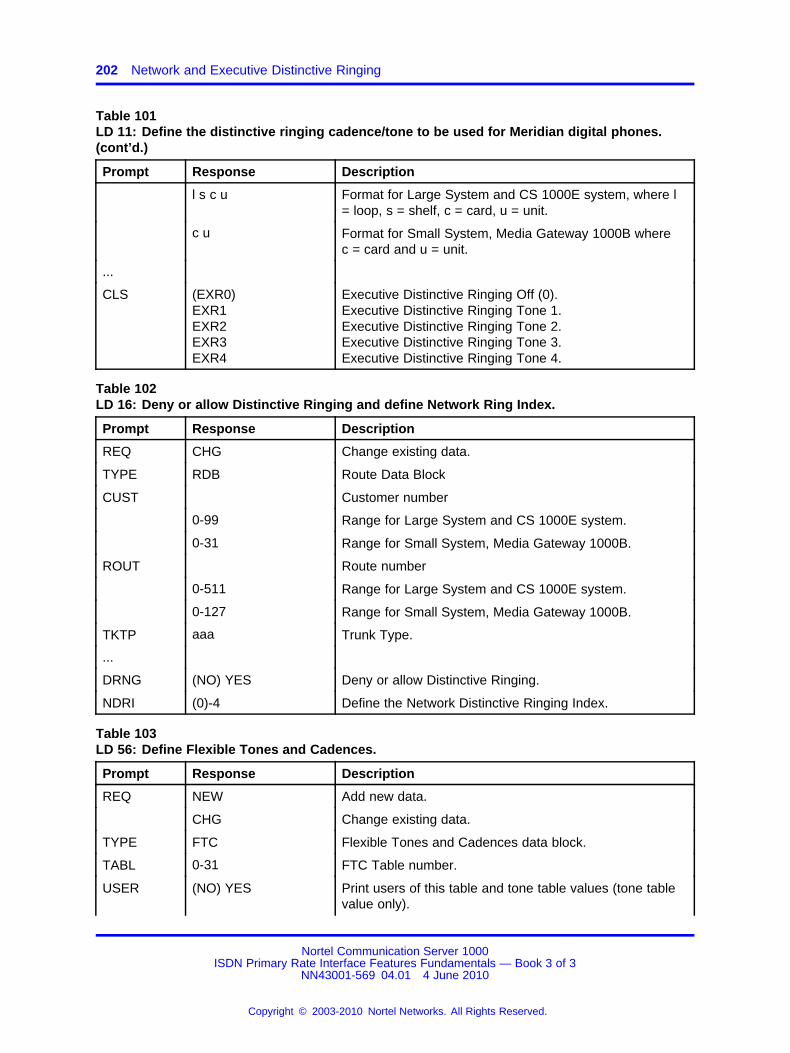
202 Network and Executive Distinctive Ringing
Table 101LD 11: Define the distinctive ringing cadence/tone to be used for Meridian digital phones.(cont’d.)
Prompt Response Description
l s c u Format for Large System and CS 1000E system, where l= loop, s = shelf, c = card, u = unit.
c u Format for Small System, Media Gateway 1000B wherec = card and u = unit.
...
CLS (EXR0)EXR1EXR2EXR3EXR4
Executive Distinctive Ringing Off (0).Executive Distinctive Ringing Tone 1.Executive Distinctive Ringing Tone 2.Executive Distinctive Ringing Tone 3.Executive Distinctive Ringing Tone 4.
Table 102LD 16: Deny or allow Distinctive Ringing and define Network Ring Index.
Prompt Response Description
REQ CHG Change existing data.
TYPE RDB Route Data Block
CUST Customer number
0-99 Range for Large System and CS 1000E system.
0-31 Range for Small System, Media Gateway 1000B.
ROUT Route number
0-511 Range for Large System and CS 1000E system.
0-127 Range for Small System, Media Gateway 1000B.
TKTP aaa Trunk Type.
...
DRNG (NO) YES Deny or allow Distinctive Ringing.
NDRI (0)-4 Define the Network Distinctive Ringing Index.
Table 103LD 56: Define Flexible Tones and Cadences.
Prompt Response Description
REQ NEW Add new data.
CHG Change existing data.
TYPE FTC Flexible Tones and Cadences data block.
TABL 0-31 FTC Table number.
USER (NO) YES Print users of this table and tone table values (tone tablevalue only).
Nortel Communication Server 1000ISDN Primary Rate Interface Features Fundamentals — Book 3 of 3
NN43001-569 04.01 4 June 2010
Copyright © 2003-2010 Nortel Networks. All Rights Reserved.
.
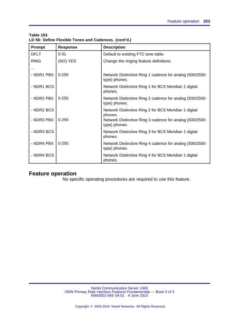
Feature operation 203
Table 103LD 56: Define Flexible Tones and Cadences. (cont’d.)
Prompt Response Description
DFLT 0-31 Default to existing FTC tone table.
RING (NO) YES Change the ringing feature definitions.
...
- NDR1 PBX 0-255 Network Distinctive Ring 1 cadence for analog (500/2500-type) phones.
- NDR1 BCS Network Distinctive Ring 1 for BCS Meridian 1 digitalphones.
- NDR2 PBX 0-255 Network Distinctive Ring 2 cadence for analog (500/2500-type) phones.
- NDR2 BCS Network Distinctive Ring 2 for BCS Meridian 1 digitalphones.
- NDR3 PBX 0-255 Network Distinctive Ring 3 cadence for analog (500/2500-type) phones.
- NDR3 BCS Network Distinctive Ring 3 for BCS Meridian 1 digitalphones.
- NDR4 PBX 0-255 Network Distinctive Ring 4 cadence for analog (500/2500-type) phones.
- NDR4 BCS Network Distinctive Ring 4 for BCS Meridian 1 digitalphones.
Feature operationNo specific operating procedures are required to use this feature.
Nortel Communication Server 1000ISDN Primary Rate Interface Features Fundamentals — Book 3 of 3
NN43001-569 04.01 4 June 2010
Copyright © 2003-2010 Nortel Networks. All Rights Reserved.
.

204 Network and Executive Distinctive Ringing
Nortel Communication Server 1000ISDN Primary Rate Interface Features Fundamentals — Book 3 of 3
NN43001-569 04.01 4 June 2010
Copyright © 2003-2010 Nortel Networks. All Rights Reserved.
.

205.
Network Individual Do Not Disturb
ContentsThis section contains information on the following topics:
“Feature description” (page 205)
“Operating parameters” (page 205)
“Feature interactions” (page 206)
“Feature packaging” (page 206)
“Feature implementation” (page 206)
“Task summary list” (page 206)
“Feature operation” (page 208)
Feature descriptionThis feature extends several functionalities of the Individual Do Not Disturbfeature to operate within a network environment.
A DN in the Do Not Disturb mode is free to make calls, but appears busyto incoming calls. Incoming Direct Inward Dialing (DID) calls to a DN in theDo Not Disturb mode are intercepted to the local attendant, or the networkattendant servicing the call. All other calls receive customer-definedintercept treatment defined in LD 15 (i.e., busy treatment, call routed to theattendant, or call routed to recorded announcement).
An attendant dialing a busy DN receives overflow (the DN can be on thesame or different node as the attendant). The attendant can then verifywhether or not the DN is in Do Not Disturb mode by pressing the IND DNDkey on the console; if the associated lamp remains steadily lit, it indicatesthat the DN is in Do Not Disturb mode. The attendant can then temporarilyoverride Do Not Disturb by activating the Break-in feature.
Operating parametersThere are no operating parameters associated with this feature.
Nortel Communication Server 1000ISDN Primary Rate Interface Features Fundamentals — Book 3 of 3
NN43001-569 04.01 4 June 2010
Copyright © 2003-2010 Nortel Networks. All Rights Reserved.
.

206 Network Individual Do Not Disturb
Feature interactionsCall Forward All CallsHuntingCall Forward All Calls, and then Hunting, take precedence over DNDItreatment.
Do Not Disturb - GroupAn attendant can receive a visual indication of the state of a phonebelonging to Group Do Not Disturb mode, whether this phone is located onthe local node or any other network node.
Make Set BusyThe DNDI intercept treatment takes precedence over Make Set Busyindication.
Feature packagingThis feature requires the following packages:
• Do Not Disturb Individual (DNDI) package 9
• Attendant Break-in/Trunk Offer (BKI) package 127
• Network Attendant Service (NAS) package 159
Feature implementationTask summary list
The following is a summary of the tasks in this section:
1. Table 104 "LD 12: Allow the attendant to override DNDI, and configurethe attendant console for DNDI." (page 206)
2. Table 105 "LD 15: Configure intercept treatment for DNDI." (page 207)
3. Table 106 "LD 16: Define the route number for DNDI RAN intercepttreatment (the same route number defined in LD 15)." (page 207)
4. Table 107 "LD 14: Define the trunks associated with the RAN route."(page 207)
Table 104LD 12: Allow the attendant to override DNDI, and configure the attendant console for DNDI.
Prompt Response Description
REQ CHG Change existing data.
...
KEY Attendant Keys.
Nortel Communication Server 1000ISDN Primary Rate Interface Features Fundamentals — Book 3 of 3
NN43001-569 04.01 4 June 2010
Copyright © 2003-2010 Nortel Networks. All Rights Reserved.
.
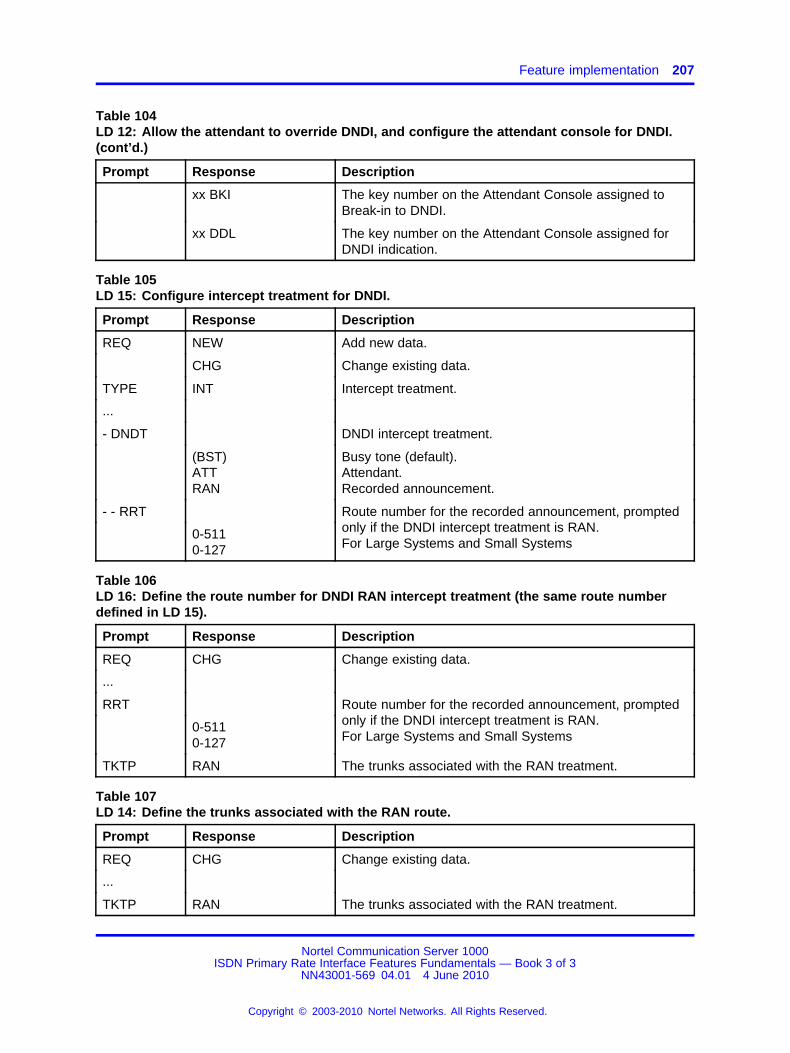
Feature implementation 207
Table 104LD 12: Allow the attendant to override DNDI, and configure the attendant console for DNDI.(cont’d.)
Prompt Response Description
xx BKI The key number on the Attendant Console assigned toBreak-in to DNDI.
xx DDL The key number on the Attendant Console assigned forDNDI indication.
Table 105LD 15: Configure intercept treatment for DNDI.
Prompt Response Description
REQ NEW Add new data.
CHG Change existing data.
TYPE INT Intercept treatment.
...
- DNDT DNDI intercept treatment.
(BST)ATTRAN
Busy tone (default).Attendant.Recorded announcement.
- - RRT
0-5110-127
Route number for the recorded announcement, promptedonly if the DNDI intercept treatment is RAN.For Large Systems and Small Systems
Table 106LD 16: Define the route number for DNDI RAN intercept treatment (the same route numberdefined in LD 15).
Prompt Response Description
REQ CHG Change existing data.
...
RRT
0-5110-127
Route number for the recorded announcement, promptedonly if the DNDI intercept treatment is RAN.For Large Systems and Small Systems
TKTP RAN The trunks associated with the RAN treatment.
Table 107LD 14: Define the trunks associated with the RAN route.
Prompt Response Description
REQ CHG Change existing data.
...
TKTP RAN The trunks associated with the RAN treatment.
Nortel Communication Server 1000ISDN Primary Rate Interface Features Fundamentals — Book 3 of 3
NN43001-569 04.01 4 June 2010
Copyright © 2003-2010 Nortel Networks. All Rights Reserved.
.
208 Network Individual Do Not Disturb
Feature operationSee the Do Not Disturb feature description in Features and Services(NN43001-506).
Nortel Communication Server 1000ISDN Primary Rate Interface Features Fundamentals — Book 3 of 3
NN43001-569 04.01 4 June 2010
Copyright © 2003-2010 Nortel Networks. All Rights Reserved.
.
209.
Network Intercom (Hot Type D and HotType I Enhancements)
ContentsThis section contains information on the following topics:
“Feature description” (page 209)
“Operating parameters” (page 210)
“Feature interactions” (page 211)
“Feature packaging” (page 214)
“Feature implementation” (page 214)
“Task summary list” (page 214)
“Feature operation” (page 216)
Feature descriptionHot Line enables a designated phone to place calls to a predetermineddestination that can be internal or external to the system. The calldoes not require attendant intervention. When the handset is lifted orwhen a preprogrammed key is activated, the system automatically dialsa preprogrammed DN. Hot Lines access a set of Terminal Numbersprogrammed by direct entry using LD 11, or by list entry such as SystemSpeed Call (SCC) using LD 18. Once a Hot Line call enters the ringingstate, it is the same as a normal call.
There were two types of Hot Line keys (DN-based Hot Type D and SpeedCall List-based Hot Type L). This enhancement introduces another type ofHot Line key, Hot Type I, while also providing improvements to the existingHot Type D. These two improvements function in both stand-alone andnetwork environments.
Hot Type IAn option is available with Hot Type I to provide a No Answer Indication,informing the called party that a Hot Line call was made during the calledparty’s absence. If a Hot Line call cannot be completed on the Hot Line
Nortel Communication Server 1000ISDN Primary Rate Interface Features Fundamentals — Book 3 of 3
NN43001-569 04.01 4 June 2010
Copyright © 2003-2010 Nortel Networks. All Rights Reserved.
.
210 Network Intercom (Hot Type D and Hot Type I Enhancements)
key, the calling party is informed through the phone’s display, and the callis completed over the network as a normally dialed call that attempts toterminate on the destination Prime DN.
Hot Type D EnhancementHot Type D provides the ability for Meridian digital phones to havetwo-way intercom calls on specially designated keys (not on the DNkeys) with other Meridian digital phones connected to PBXs across aMeridian Customer Defined Network (MCDN) Integrated Services DigitalNetwork (ISDN). A Hot Type D call can terminate in three different modes:Voice, Ringing, and Non-ringing. With the Voice mode, speech path isautomatically connected after a short ring. With Ringing and Non-ringingmodes, the call must be manually answered by the called party. Thedifference between the two modes is that for Non-ringing no audible toneis given, but the Hot Line key flashes to indicate the call.
Hot Type D allows more than one phone to have the same target DNdefined for the Hot Type D key. This enhancement includes Voice,Ringing, and Non-ringing termination modes, as well as the capabilityto leave a No Answer Indication in some situations (i.e., the Hot Linekey winks). A call terminating on an enhanced Hot Type D key operatesthe same as if it is terminating on a Hot Type I key (if the originating DNis the same as the target DN defined for the key). If it is not the same,but another Hot Line key exists on the phone that has a target DN thatmatches the originating DN, a No Answer Indication is left on that key.
Note: When configuring two-way Hot Type D keys in voice mode, thefact that the CLID does not transmit the originator’s Hot Type D DNbetween ISDN locations must be taken into account; it contains theprime DN of the originating phone, and not the originator’s Hot Type DDN. Therefore, ringing can occur on the Hot Type D key rather thanimmediate answer, since a match could not be found for the originator’sHot Type D DN. For this reason also, when the configured mode iseither voice, ringing, or non-ringing, a "No Answer Indication" is not lefton called phone of a two-way Hotline. It is, therefore, recommendedthat the Hot Type I be used for a two-way Hotline, since it relies only onthe prime DN.
Operating parametersHot Type I calls are not allowed on analog (500/2500-type) phones.
A Hot Line key should not be defined on a station without a Prime DN andlikewise should not be defined on the primary key. If this is not done, theimproved functionality will not work and the call is treated as a non-HotLine call.
Nortel Communication Server 1000ISDN Primary Rate Interface Features Fundamentals — Book 3 of 3
NN43001-569 04.01 4 June 2010
Copyright © 2003-2010 Nortel Networks. All Rights Reserved.
.
Feature interactions 211
The network DN for Hot Type I and Hot Type D (when the No AnswerIndication applies) must be either a Coordinated Dialing Plan or aUniversal Dialing Plan number that must terminate on a Prime DN of aMeridian digital phone; otherwise, the call is completed as a non-Hot Linecall.
The network-wide application of Hot Type I is only applicable to nodes in aPrimary Rate Interface (PRI), ISDN Signaling Link (ISL), Virtual NetworkServices (VNS), and Basic Rate Interface network.
If the termination mode is voice, the called party is idle, and the handsfreevoice call (HVA in LD 15) is active, there is no indication to the softwarethat the called party really answered the call. If any other key is pressed,the No Answer Indication is not left.
Hot Line keys must be defined with the same dialing plan.
Feature interactionsAttendant Blocking of DNA Hot Type I key cannot be blocked by the attendant because it has noDN.
Pressing a Hot Type D key that is attendant blocked establishes the callon the source side of the attendant.
Auto HoldIf a user who originated a Hot Type I call receives or makes another callon another DN, pressing that DN puts the established call on hold. Ifa user presses the Hot Type I key while a call is established on it, thecall is placed on hold. If the Hot Type I key is pressed while a call isestablished on another DN, the established call is put on hold. If a stationwith automatic hold allowed Class of Service receives a Hot Line call, theuser of that station can put the active call on hold by pressing the Hot TypeI key or by making or answering another call on another key.
Automatic Call Distribution (ACD)Hot Type I calls cannot terminate on an ACD DN. A call attemptingto terminate on an ACD DN receives an overflow tone. Hot Line callsinvolving ACD phones must use the Hot Type D option.
Busy Forward Status (BFS)In a Secretarial Filtering scenario, the secretary’s BFS lamp also will reflectthat the boss’s phone is busy if the boss is on a Hot Type I call.
Nortel Communication Server 1000ISDN Primary Rate Interface Features Fundamentals — Book 3 of 3
NN43001-569 04.01 4 June 2010
Copyright © 2003-2010 Nortel Networks. All Rights Reserved.
.
212 Network Intercom (Hot Type D and Hot Type I Enhancements)
Call ForwardHot Type I calls respect or override all kinds of Call Forward features(Busy, No Answer, All Calls, Internal, etc.) according to per-set definitions.If Call Forward is respected, the call becomes a normally dialed call, andthe originator will receive the appropriate indication on their display.
Call JoinHot Type I calls can be moved to the Conference key with the Call Joinfeature.
Call ParkHot Type I calls cannot be parked.
Call Party Name DisplayHot Type I calls display names the same way as a normal call.
Hot Type I calls that become a normal call indicate on the originatingstation’s display that the call is no longer a Hot Line call.
Call PickupHot Type I calls cannot be picked up. An attempt to pick up a Hot Type Icall results in an overflow tone.
Call TransferHot Type I calls can be transferred to another Hot Line key or to a normalDN key; likewise calls on a normal DN key can be transferred to a Hot Linekey.
ConferenceA Conference call can involve a mixture of intercom and regular DN keys.
Display KeyHot Type I calls are supported by the Display key feature; pressing theDisplay key and then the Hot Type I key will show the target DN on theoriginating station’s display.
Do Not Disturb (DND)Hot Type I calls ignore the Do Not Disturb feature. Hot Line calls arepresented to the defined target, even when DND is activated.
Flexible Feature Code (FFC) Boss Secretarial FilteringHot Type I calls override this feature (i.e., Hot Type I calls are not filteredby FFC Boss Secretarial filtering). The call terminates on the Boss’ phoneand is not forwarded to the secretary.
Nortel Communication Server 1000ISDN Primary Rate Interface Features Fundamentals — Book 3 of 3
NN43001-569 04.01 4 June 2010
Copyright © 2003-2010 Nortel Networks. All Rights Reserved.
.

Feature interactions 213
FFC Boss Secretarial Filtering takes precedence over enhanced HotType D calls. In this case, if FFC Boss Secretarial Filtering is active, callsterminate on the secretary’s phone.
Last Number RedialA Hot Line key cannot be redialed using the Last Number Redial feature.
Make Set BusyHot Type I calls terminating on a station in the Make Set Busy modeoverride Make Set Busy.
Multiple Appearance Redirection Prime (MARP)If more than one phone is allocated the same prime DN, the Hot Type Icall will terminate on the phone designated as the Multiple AppearanceRedirection Prime (MARP). If the MARP DN is not the prime DN on thephone, or if the phone designated as the MARP DN is not a Meridiandigital phone, the first Meridian digital phone with the prime DN will beused. If none of these conditions are met, the call will terminate as anon-Hot Line call, and the calling party will be notified on the display.
Hot Type D calls can have voice termination only on a MARP TerminalNumber (TN), or if there is no MARP TN, then on the first TN in the TN list.A No Answer Indication for Hot Type D can only be left on the MARP TN,or if there is no MARP TN, then on the first TN in the TN list.
OverrideAn internal Hot Type I call never returns busy, unless the call became anon-Hot Line call due to the Hot Line key being busy. In this case, the callbehaves like a normally dialed call, and Override can be used upon receiptof a busy signal.
Ring AgainHot Line calls terminating on a busy key become normal calls. Hence, theycan use the Ring Again feature under normal circumstances.
Ring Again - No AnswerIf Ring Again No Answer is activated for a Hot Type I call, it is activated asthough the call had been dialed normally.
Ringing Change KeyThe ringing/non-ringing mode of an enhanced Hot Type D or of a Hot TypeI key is not changeable by using the Ringing Change Key feature.
Vacant Number RoutingHot Type I keys and enhanced Hot Type D keys support Vacant NumberRouting.
Nortel Communication Server 1000ISDN Primary Rate Interface Features Fundamentals — Book 3 of 3
NN43001-569 04.01 4 June 2010
Copyright © 2003-2010 Nortel Networks. All Rights Reserved.
.
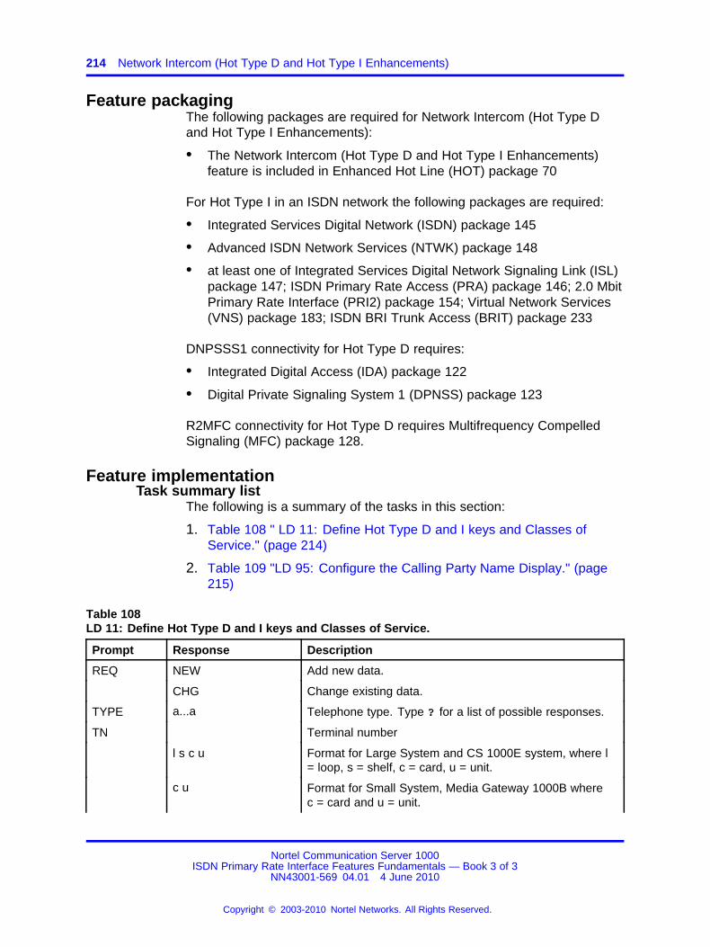
214 Network Intercom (Hot Type D and Hot Type I Enhancements)
Feature packagingThe following packages are required for Network Intercom (Hot Type Dand Hot Type I Enhancements):
• The Network Intercom (Hot Type D and Hot Type I Enhancements)feature is included in Enhanced Hot Line (HOT) package 70
For Hot Type I in an ISDN network the following packages are required:
• Integrated Services Digital Network (ISDN) package 145
• Advanced ISDN Network Services (NTWK) package 148
• at least one of Integrated Services Digital Network Signaling Link (ISL)package 147; ISDN Primary Rate Access (PRA) package 146; 2.0 MbitPrimary Rate Interface (PRI2) package 154; Virtual Network Services(VNS) package 183; ISDN BRI Trunk Access (BRIT) package 233
DNPSSS1 connectivity for Hot Type D requires:
• Integrated Digital Access (IDA) package 122
• Digital Private Signaling System 1 (DPNSS) package 123
R2MFC connectivity for Hot Type D requires Multifrequency CompelledSignaling (MFC) package 128.
Feature implementationTask summary list
The following is a summary of the tasks in this section:
1. Table 108 " LD 11: Define Hot Type D and I keys and Classes ofService." (page 214)
2. Table 109 "LD 95: Configure the Calling Party Name Display." (page215)
Table 108LD 11: Define Hot Type D and I keys and Classes of Service.
Prompt Response Description
REQ NEW Add new data.
CHG Change existing data.
TYPE a...a Telephone type. Type ? for a list of possible responses.
TN Terminal number
l s c u Format for Large System and CS 1000E system, where l= loop, s = shelf, c = card, u = unit.
c u Format for Small System, Media Gateway 1000B wherec = card and u = unit.
Nortel Communication Server 1000ISDN Primary Rate Interface Features Fundamentals — Book 3 of 3
NN43001-569 04.01 4 June 2010
Copyright © 2003-2010 Nortel Networks. All Rights Reserved.
.
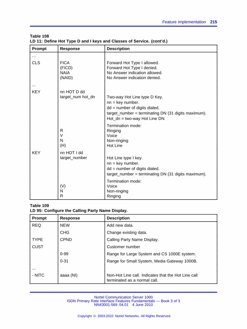
Feature implementation 215
Table 108LD 11: Define Hot Type D and I keys and Classes of Service. (cont’d.)
Prompt Response Description
...
CLS FICA(FICD)NAIA(NAID)
Forward Hot Type I allowed.Forward Hot Type I denied.No Answer indication allowed.No Answer indication denied.
...
KEY nn HOT D ddtarget_num hot_dn Two-way Hot Line type D Key.
nn = key number.dd = number of digits dialed.target_number = terminating DN (31 digits maximum).Hot_dn = two-way Hot Line DN.
RVN(H)
Termination mode:RingingVoiceNon-ringingHot Line
KEY nn HOT I ddtarget_number Hot Line type I key.
nn = key number.dd = number of digits dialed.target_number = terminating DN (31 digits maximum).
(V)NR
Termination mode:VoiceNon-ringingRinging
Table 109LD 95: Configure the Calling Party Name Display.
Prompt Response Description
REQ NEW Add new data.
CHG Change existing data.
TYPE CPND Calling Party Name Display.
CUST Customer number
0-99 Range for Large System and CS 1000E system.
0-31 Range for Small System, Media Gateway 1000B.
...
- NITC aaaa (NI) Non-Hot Line call. Indicates that the Hot Line callterminated as a normal call.
Nortel Communication Server 1000ISDN Primary Rate Interface Features Fundamentals — Book 3 of 3
NN43001-569 04.01 4 June 2010
Copyright © 2003-2010 Nortel Networks. All Rights Reserved.
.

216 Network Intercom (Hot Type D and Hot Type I Enhancements)
Feature operationPress the Hot Type I or D key to initiate a Hot Line call to a target DN (theDN can be an external DN in an MCDN ISDN network). The called partyanswers the call by pressing their Hot Type I or D key if configured. If thecalled party has no Hot Type I or D key configured, the call will behave asa normal call and is answered accordingly.
If the called party does not answer, and has No Answer Indication AllowedClass of Service, the Hot Type I or Hot Type D key winks as a form of NoAnswer Indication.
Nortel Communication Server 1000ISDN Primary Rate Interface Features Fundamentals — Book 3 of 3
NN43001-569 04.01 4 June 2010
Copyright © 2003-2010 Nortel Networks. All Rights Reserved.
.
217.
Network Message Services
ContentsThis section contains information on the following topics:
“Feature description” (page 217)
“Operating parameters” (page 220)
“Feature interactions” (page 221)
“Feature packaging” (page 222)
“Feature implementation” (page 232)
“Task summary list” (page 232)
Feature descriptionNetwork Message Services (NMS) uses ISDN signaling capabilitiesto provide messaging services across an ISDN network. Systemsinterconnected with PRI or ISL can extend supported message servicesto all users within that network on a customer basis from a single, centrallocation. Access to NMS and feature activation from the messagingsystem is transparent to the end user.
A second distinct application, NMS-Meridian Mail (NMS-MM), is introducedto provide end-user and calling party access to centralized Meridian Mailservices across the network.
NMS functions common to both applications are described here anddetails specific to each are described later in this module. Differencesbetween Message Center and Meridian Mail functions are described undertheir respective headings.
Nortel Communication Server 1000ISDN Primary Rate Interface Features Fundamentals — Book 3 of 3
NN43001-569 04.01 4 June 2010
Copyright © 2003-2010 Nortel Networks. All Rights Reserved.
.
218 Network Message Services
Within NMS operations, there are direct message calls and indirectmessage calls:
• Direct calls are initiated by the user accessing the Message Center toreceive messages. Access is allowed by dialing the message facilitydirectly or using the Message Waiting Key (MWK).
• Indirect calls occur when a redirection feature directs the call to aMessage Center so the caller can leave a message.
An NMS call has two components: basic PRI call signaling and transactionsignaling. The PRI portion of the call is supported by ISDN PRI or ISLand Network Call Redirection (NCRD)—subject to the requirements forPRI calls and the NCRD feature. NMS always uses non-call-associated,connectionless Transaction Signaling messages to turn on/off the user setMessage Waiting Indication (MWI) and to transport call information forcertain Meridian Mail features, including Call Sender (that is, the transportof connectionless signaling information across the ISDN network).
There are three types of network nodes supporting NMS:
• Originating node. For direct calls, the originating node is the PBXwhere the calling party resides. For indirect calls, the originating nodeis the node where the originally dialed party resides.
• Tandem node. This switch can pass transaction signaling messageson to the next PBX. Stations on a tandem node do not have access toNetwork Message Services functionality.
• Terminating node. This is the PBX where the Message Center orMeridian Mail server resides, and where the call terminates.
NMS supports Coordinated Dialing Plans (CDPs) and Uniform DialingPlans (UDPs). All nodes must conform uniformly to the adopted dialingplan. NMS does not support mixed CDP/UDP across a network and limitsCDP support to Distant Steering Codes.
Network Message Services - Message CenterNetwork Message Services-Message Center (NMS-MC) allows a callertransparent access to a centralized message center over an ISDN PRI/ISLnetwork.
These Message Center configurations are supported:
• ACD Message Center
• DN Message Center
• Attendant Message Center
Nortel Communication Server 1000ISDN Primary Rate Interface Features Fundamentals — Book 3 of 3
NN43001-569 04.01 4 June 2010
Copyright © 2003-2010 Nortel Networks. All Rights Reserved.
.
Feature description 219
For these types of Message Centers, the Message Indication Key (MIK) ona message taker’s phone is used to turn on Message Waiting Indication ata user phone. The Message Cancellation Key (MCK) is used to turn offMessage Waiting Indication.
The NMS-MC supports direct and indirect NMS-MC access across ISDN.Direct access is initiated by dialing the Message Center DN or pressingthe Message Waiting Key (MWK). Indirect access occurs when a call ispresented to the NMS-MC by any of the call redirection features supportedby Network Call Redirection (NCRD) including
• Network Call Forward All Calls
• Network Call Forward No Answer
• Network Call Forward Busy
• Network Hunting
See the NCRD module in this document for further details.
Network Message Services - Meridian MailNMS-MM provides transparent access to the Meridian Mail system acrossthe network. NMS-MM operates only between system machines supportedby a single Meridian Mail server facility. Users on remote nodes configuredas part of the NMS-MM server base have access to all the Meridian Mailfeatures available on the local switch.
See the NCRD module when you consider the redirections that applyto your particular environment. Since Message Center support is on acustomer-by-customer basis, configure your network accordingly. SeeHospitality Features Fundamentals (NN43001-553). In Meridian Mailapplications, different network PBXs (nodes) must be configured withthe same Meridian Mail server for proper messaging support. See theMeridian Mail suite of technical documents.
Direct calls for NMS-MM are initiated by dialing the message facilitydirectly or pressing MWK on a properly programmed phone. Functionalitymimics current operations, including Auto-login with a user’s password.See the appropriate technical documentation for a description of callfunctions.
Nortel Communication Server 1000ISDN Primary Rate Interface Features Fundamentals — Book 3 of 3
NN43001-569 04.01 4 June 2010
Copyright © 2003-2010 Nortel Networks. All Rights Reserved.
.
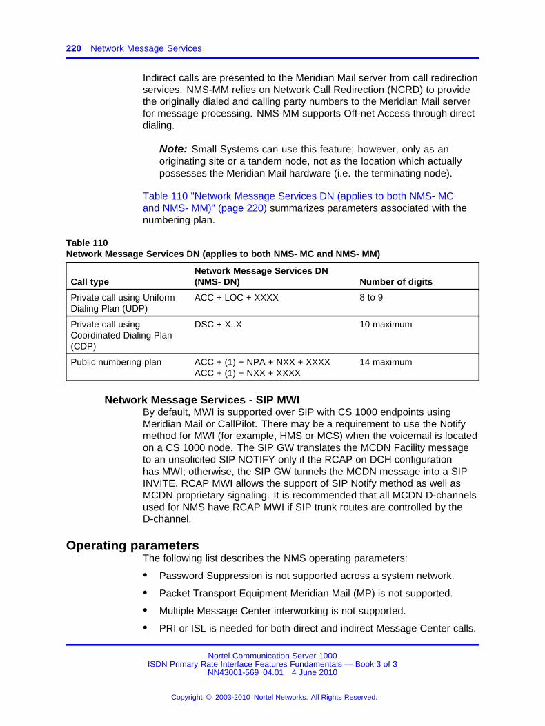
220 Network Message Services
Indirect calls are presented to the Meridian Mail server from call redirectionservices. NMS-MM relies on Network Call Redirection (NCRD) to providethe originally dialed and calling party numbers to the Meridian Mail serverfor message processing. NMS-MM supports Off-net Access through directdialing.
Note: Small Systems can use this feature; however, only as anoriginating site or a tandem node, not as the location which actuallypossesses the Meridian Mail hardware (i.e. the terminating node).
Table 110 "Network Message Services DN (applies to both NMS- MCand NMS- MM)" (page 220) summarizes parameters associated with thenumbering plan.
Table 110Network Message Services DN (applies to both NMS- MC and NMS- MM)
Call typeNetwork Message Services DN(NMS- DN) Number of digits
Private call using UniformDialing Plan (UDP)
ACC + LOC + XXXX 8 to 9
Private call usingCoordinated Dialing Plan(CDP)
DSC + X..X 10 maximum
Public numbering plan ACC + (1) + NPA + NXX + XXXXACC + (1) + NXX + XXXX
14 maximum
Network Message Services - SIP MWIBy default, MWI is supported over SIP with CS 1000 endpoints usingMeridian Mail or CallPilot. There may be a requirement to use the Notifymethod for MWI (for example, HMS or MCS) when the voicemail is locatedon a CS 1000 node. The SIP GW translates the MCDN Facility messageto an unsolicited SIP NOTIFY only if the RCAP on DCH configurationhas MWI; otherwise, the SIP GW tunnels the MCDN message into a SIPINVITE. RCAP MWI allows the support of SIP Notify method as well asMCDN proprietary signaling. It is recommended that all MCDN D-channelsused for NMS have RCAP MWI if SIP trunk routes are controlled by theD-channel.
Operating parametersThe following list describes the NMS operating parameters:
• Password Suppression is not supported across a system network.
• Packet Transport Equipment Meridian Mail (MP) is not supported.
• Multiple Message Center interworking is not supported.
• PRI or ISL is needed for both direct and indirect Message Center calls.
Nortel Communication Server 1000ISDN Primary Rate Interface Features Fundamentals — Book 3 of 3
NN43001-569 04.01 4 June 2010
Copyright © 2003-2010 Nortel Networks. All Rights Reserved.
.
Feature interactions 221
• The NMS DN must be unique and still be able to be reached by meansof PRI or ISL from all NMS users in the network, and vice versa.
• NMS supports system to system connections only.
• The local NMS-MM DN defined in each node must also be configuredin the Meridian Mail server database, in the VSDN table.
• In-band End-to-End Signaling (EES) is required for NMS-MM atterminating and originating nodes.
• NMS-MM requires the Meridian Hospitality Voice Services package toprovide link recovery enhancements for Meridian Link ISDN/AP.
• NMS-MM does not support international dialing.
• Only one Message Center DN can be defined for a phone. MultipleMessage Center types are not supported.
• The NMS does not support Trunk Steering Codes (TSCs).
The context sensitive keys on M2317, M3000, and M3900 telephones areupdated when CallPilot or Meridian Mail answers a call. Context sensitivekeys on M3900 telephones show the words "play, stop, next, delete", forexample, when a call is placed to the voice mail system over PRI TIEtrunks and is answered by a Meridian Mail or CallPilot Virtual Agent.
ATTENTIONThe NMS feature uses non-call associated ISDN Facility message. Therefore,digit manipulation through DMI or IDC tables can inhibit feature operation. TheORG6 and the DES6 in the FAC message must be directly translatable and theuser must be able to dial in both directions: the source and the target PBX.
Feature interactionsListed here are differences in networking applications, which can impactNetwork Message Services operations.
Password SuppressionPassword Suppression is not supported across a system network.
Network Call Redirection (NCRD)Indirect access to the NMS-Meridian Mail (NMS-MM) application is basedon the NCRD package, which is broken down into the following areas:
• Call Forward All Calls and Call Forward No Answer and Call ForwardBusy, Network Call Transfer, and Network Hunting provide the basefor NMS indirect access.
• Attendant Extended Call presents the same information to MeridianMail as Network Call Transfer except that the DN Update messageis sent to the NMS-MM when the attendant releases the call. The
Nortel Communication Server 1000ISDN Primary Rate Interface Features Fundamentals — Book 3 of 3
NN43001-569 04.01 4 June 2010
Copyright © 2003-2010 Nortel Networks. All Rights Reserved.
.
222 Network Message Services
connected party number is updated only when the attendant isreleased.
• NMS does not support incoming calls from CO Loop Start trunks.Calls that come into the switch from a CO Loop Start trunk cannot beredirected to another trunk by means of attendant extension or callredirection; these calls are blocked when redirection is activated.
Barge-in AttendantThe attendant can barge-into an NMS-MM call at the terminating PBX.During barge-in, the user cannot use features that require switch effort,such as the Call Sender feature.
TrunksWhen a call is presented to the NMS-MM by means of a non-PRI or ISLtrunk, the call is treated as an external call even if it is an on-network call.The external greeting is applied and the message is announced as froman external number.
Meridian Hospitality Voice ServicesNMS-MM requires the Meridian Hospitality Voice Services (MHVS)package to provide Meridian Link ISDN/AP protocol recovery treatment forlink applications. All calls to the ACD Night Call Forward (NCFW) DN areredirected to the Meridian Mail server when the ISDN/AP link fails. Calltreatment in NMS-MM is identical to the NCFW treatment.
ISDN requires that the network be equipped with either CoordinatedDialing Plan (CDP) or a Uniform Dialing Plan (UDP) throughout, but it doesnot support a mixture of both.
Feature packagingThe package requirements for Network Message Services-MessageCenter are different for each node.
The following packages are required for an NMS-Message Centeroriginating node:
• End-to-End Signaling (EES) package 10
• Basic Automatic Call Distribution (BACD) package 40
• Automatic Call Distribution Package A (ACDA) package 45
• Message Center (MWC) package 46
• ISDN Signaling (ISDN) package 145
Nortel Communication Server 1000ISDN Primary Rate Interface Features Fundamentals — Book 3 of 3
NN43001-569 04.01 4 June 2010
Copyright © 2003-2010 Nortel Networks. All Rights Reserved.
.
Feature packaging for SIP MWI 223
• ISDN Primary Rate Interface (PRI) package 146 or ISDN SignalingLink (ISL) package 147 or 2.0 Mbit Primary Rate Access (PRI2)package 154
• Advanced Network Services (NTWK) package 148
• Network Message Services (NMS) package 175
The following packages are required for an NMS-Message Center tandemnode:
• ISDN Signaling (ISDN) package 145
• ISDN Primary Rate Interface (PRI) package 146 or ISDN SignalingLink (ISL) package 147 or 2.0 Mbit Primary Rate Access (PRI2)package 154
• Network Message Services (NMS) package 175
The following packages are required for an NMS-Message Centerterminating node:
• End-to-End Signaling (EES) package 10
• Basic Automatic Call Distribution (BACD) package 40
• Automatic Call Distribution Package A (ACDA) package 45
• Message Center (MWC) package 46
• ISDN Signaling (ISDN) package 145
• ISDN Primary Rate Interface (PRI) package 146 or ISDN SignalingLink (ISL) package 147 or 2.0 Mbit Primary Rate Access (PRI2)package 154
• Advanced Network Services (NTWK) package 148
• Network Message Services (NMS) package 175
Note: BACD (package 40) and ACDA (package 45) are not necessarilyrequired for your particular Message Center application.
Feature packaging for SIP MWI• End-to-End Signaling (EES) package 10
• Basic ACD (BACD) package 40
• ACD package A (ACDA) package 45
• Message Center (MWC) package 46
• ISDN Signaling (ISDN) package 145
Nortel Communication Server 1000ISDN Primary Rate Interface Features Fundamentals — Book 3 of 3
NN43001-569 04.01 4 June 2010
Copyright © 2003-2010 Nortel Networks. All Rights Reserved.
.
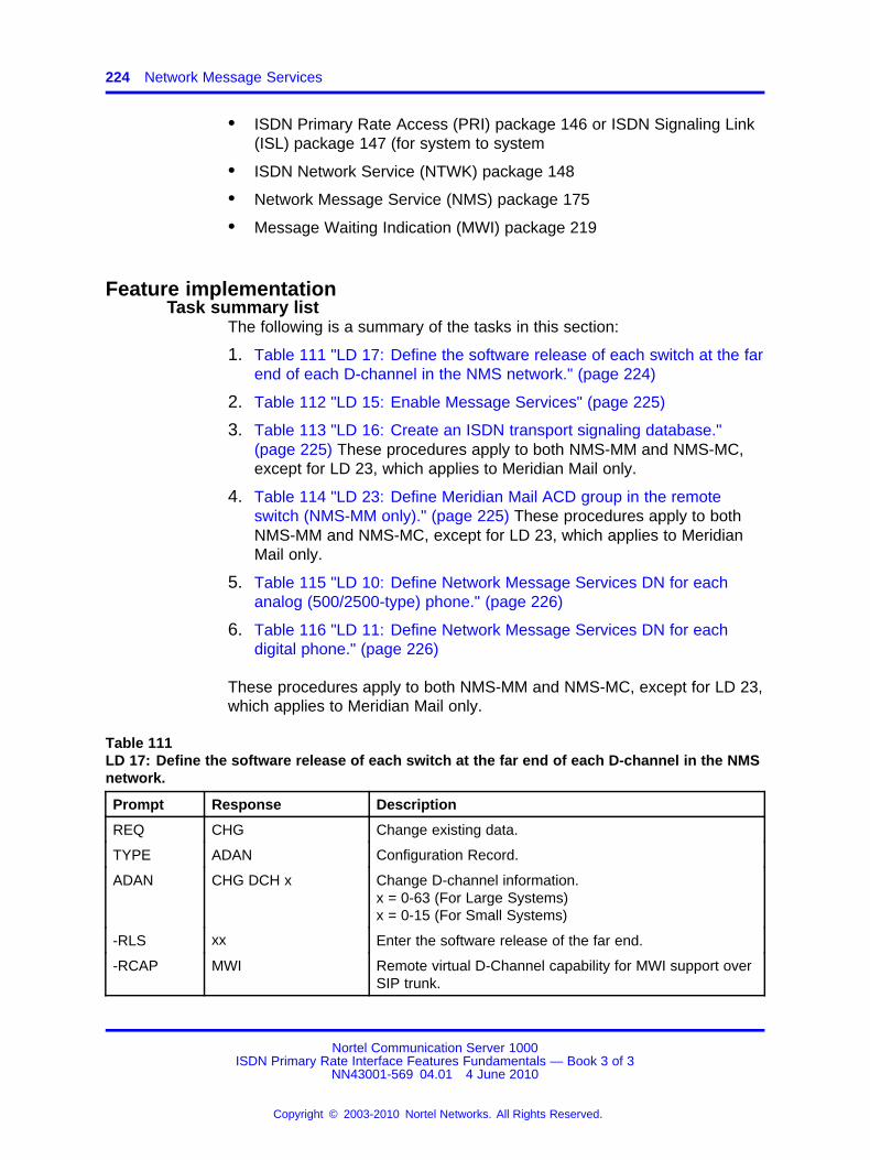
224 Network Message Services
• ISDN Primary Rate Access (PRI) package 146 or ISDN Signaling Link(ISL) package 147 (for system to system
• ISDN Network Service (NTWK) package 148
• Network Message Service (NMS) package 175
• Message Waiting Indication (MWI) package 219
Feature implementationTask summary list
The following is a summary of the tasks in this section:
1. Table 111 "LD 17: Define the software release of each switch at the farend of each D-channel in the NMS network." (page 224)
2. Table 112 "LD 15: Enable Message Services" (page 225)
3. Table 113 "LD 16: Create an ISDN transport signaling database."(page 225) These procedures apply to both NMS-MM and NMS-MC,except for LD 23, which applies to Meridian Mail only.
4. Table 114 "LD 23: Define Meridian Mail ACD group in the remoteswitch (NMS-MM only)." (page 225) These procedures apply to bothNMS-MM and NMS-MC, except for LD 23, which applies to MeridianMail only.
5. Table 115 "LD 10: Define Network Message Services DN for eachanalog (500/2500-type) phone." (page 226)
6. Table 116 "LD 11: Define Network Message Services DN for eachdigital phone." (page 226)
These procedures apply to both NMS-MM and NMS-MC, except for LD 23,which applies to Meridian Mail only.
Table 111LD 17: Define the software release of each switch at the far end of each D-channel in the NMSnetwork.
Prompt Response Description
REQ CHG Change existing data.
TYPE ADAN Configuration Record.
ADAN CHG DCH x Change D-channel information.x = 0-63 (For Large Systems)x = 0-15 (For Small Systems)
-RLS xx Enter the software release of the far end.
-RCAP MWI Remote virtual D-Channel capability for MWI support overSIP trunk.
Nortel Communication Server 1000ISDN Primary Rate Interface Features Fundamentals — Book 3 of 3
NN43001-569 04.01 4 June 2010
Copyright © 2003-2010 Nortel Networks. All Rights Reserved.
.

Feature implementation 225
Table 112LD 15: Enable Message Services
Prompt Response Description
REQ CHG Change existing data.
TYPE IMS Integrated Messaging Service.
CUST Customer number
0-99 Range for Large System and CS 1000E system.
0-31 Range for Small System, Media Gateway 1000B.
IMS YES Change Integrated Message System.
- IMA YES Enable Integrated Message System.
Table 113LD 16: Create an ISDN transport signaling database.
Prompt Response Description
REQ NEW Add new data.
CHG Change existing data.
TYPE RDB Route Data Block.
CUST Customer number
0-99 Range for Large System and CS 1000E system.
0-31 Range for Small System, Media Gateway 1000B.
ROUT Route number
0-511 Range for Large System and CS 1000E system.
0-127 Range for Small System, Media Gateway 1000B.
- ISDN YES ISDN option.
- - PNI 1-32700 Customer private identifier—unique to a customer. This isthe private identifier of the target switch and must be thesame number used for PNI in LD15 for remote customer.Matches PNI in LD16 at remote to PNI in LD15 at localsite.
- NCRD YES Network Call Redirection
- - TRO YES Trunk Route Optimization allowed (denied) on the route.
- INAC (NO) YES Insert Access Code. INAC = YES is required for ISDNnetwork features. This prompt only appears if the routetype is a TIE trunk.
Table 114LD 23: Define Meridian Mail ACD group in the remote switch (NMS-MM only).
Prompt Response Description
REQ NEW Add new data.
Nortel Communication Server 1000ISDN Primary Rate Interface Features Fundamentals — Book 3 of 3
NN43001-569 04.01 4 June 2010
Copyright © 2003-2010 Nortel Networks. All Rights Reserved.
.
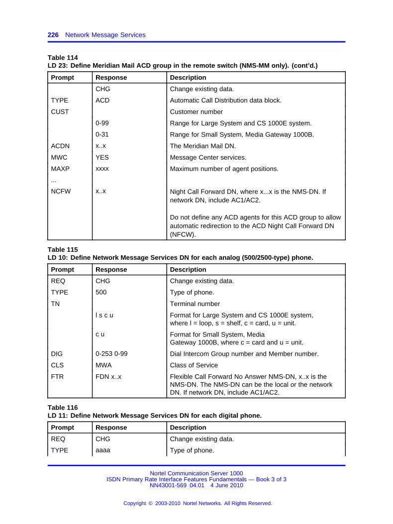
226 Network Message Services
Table 114LD 23: Define Meridian Mail ACD group in the remote switch (NMS-MM only). (cont’d.)
Prompt Response Description
CHG Change existing data.
TYPE ACD Automatic Call Distribution data block.
CUST Customer number
0-99 Range for Large System and CS 1000E system.
0-31 Range for Small System, Media Gateway 1000B.
ACDN x..x The Meridian Mail DN.
MWC YES Message Center services.
MAXP xxxx Maximum number of agent positions.
...
NCFW x..x Night Call Forward DN, where x...x is the NMS-DN. Ifnetwork DN, include AC1/AC2.
Do not define any ACD agents for this ACD group to allowautomatic redirection to the ACD Night Call Forward DN(NFCW).
Table 115LD 10: Define Network Message Services DN for each analog (500/2500-type) phone.
Prompt Response Description
REQ CHG Change existing data.
TYPE 500 Type of phone.
TN Terminal number
l s c u Format for Large System and CS 1000E system,where l = loop, s = shelf, c = card, u = unit.
c u Format for Small System, MediaGateway 1000B, where c = card and u = unit.
DIG 0-253 0-99 Dial Intercom Group number and Member number.
CLS MWA Class of Service
FTR FDN x..x Flexible Call Forward No Answer NMS-DN, x..x is theNMS-DN. The NMS-DN can be the local or the networkDN. If network DN, include AC1/AC2.
Table 116LD 11: Define Network Message Services DN for each digital phone.
Prompt Response Description
REQ CHG Change existing data.
TYPE aaaa Type of phone.
Nortel Communication Server 1000ISDN Primary Rate Interface Features Fundamentals — Book 3 of 3
NN43001-569 04.01 4 June 2010
Copyright © 2003-2010 Nortel Networks. All Rights Reserved.
.
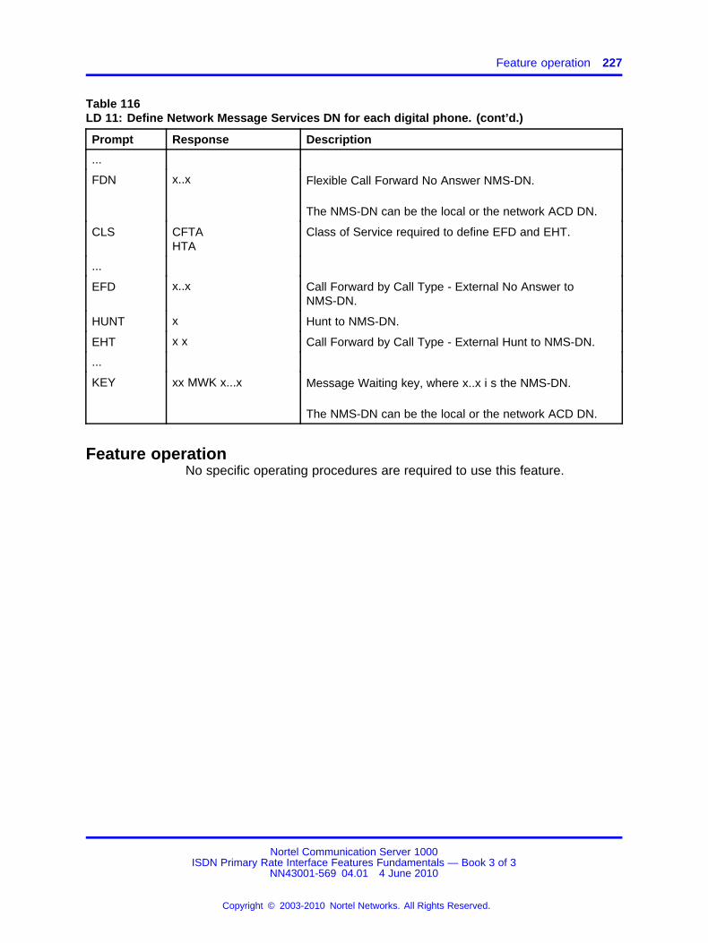
Feature operation 227
Table 116LD 11: Define Network Message Services DN for each digital phone. (cont’d.)
Prompt Response Description
...
FDN x..x Flexible Call Forward No Answer NMS-DN.
The NMS-DN can be the local or the network ACD DN.
CLS CFTAHTA
Class of Service required to define EFD and EHT.
...
EFD x..x Call Forward by Call Type - External No Answer toNMS-DN.
HUNT x Hunt to NMS-DN.
EHT x x Call Forward by Call Type - External Hunt to NMS-DN.
...
KEY xx MWK x...x Message Waiting key, where x..x i s the NMS-DN.
The NMS-DN can be the local or the network ACD DN.
Feature operationNo specific operating procedures are required to use this feature.
Nortel Communication Server 1000ISDN Primary Rate Interface Features Fundamentals — Book 3 of 3
NN43001-569 04.01 4 June 2010
Copyright © 2003-2010 Nortel Networks. All Rights Reserved.
.

228 Network Message Services
Nortel Communication Server 1000ISDN Primary Rate Interface Features Fundamentals — Book 3 of 3
NN43001-569 04.01 4 June 2010
Copyright © 2003-2010 Nortel Networks. All Rights Reserved.
.
229.
Network Ring Again
ContentsThis section contains information on the following topics:
“Feature description” (page 229)
“Operating parameters” (page 230)
“Feature interactions” (page 231)
“Feature packaging” (page 232)
“Feature implementation” (page 232)
“Task summary list” (page 232)
“Feature operation” (page 234)
Feature descriptionNetwork Ring Again (NRAG) provides ring again capability within anMCDN PRI/ISL network, or across an ECMA-QSIG or DPNSS1 gateway.NRAG allows a caller at one location to activate Ring Again against aterminating station that is busy at another location.
The NRAG feature operates in "free notification" mode. This means theterminating switch determines when the called party becomes idle andnotifies the originating switch.
Once the NRAG feature has been activated, the status of the called partyis observed until the line is idle and a new call set-up can be attempted,or until NRAG is deactivated by a timeout or manually disconnected bythe caller.
Nortel Communication Server 1000ISDN Primary Rate Interface Features Fundamentals — Book 3 of 3
NN43001-569 04.01 4 June 2010
Copyright © 2003-2010 Nortel Networks. All Rights Reserved.
.

230 Network Ring Again
NRAG operates as follows: station A makes a call across an MCDNnetwork, ECMA-QSIG, or DPNSS1 gateway to busy station B. Station Acan activate NRAG against station B. When station B becomes idle, freenotification is sent to phone A. Station A can then press the Ring Again(RGA) key to call station B.
Note: If station B has activated Call Forward All Calls to station C,and station C is busy, station A can activate NRAG against stationC, if station C is located in the same node as station B.If a MultipleAppearance Redirection Prime (MARP) is configured for station B,the MARP rules for redirection are applied, with the MARP TN beingused to check whether Call Forward All Calls is active. If MARP is notconfigured, but station B has a Multiple Appearance DN, the first TNfrom the DN block found to have Call Forward All Calls is used.
When more than one caller activates NRAG on a terminating station,the calls are queued on a first-come, first-served basis. When the calledstation becomes idle, only the first caller in the queue is signaled. Thesecond caller in the queue is signaled only after the Queue Advance Timer(four seconds) expires.
Operating parametersNRAG cannot be activated on an Automatic Call Distribution (ACD)termination, because ACD users are serviced by the ACD queue.
Only Call Forward All Calls is supported; any other type of redirection isnot supported (including Call Forward All Calls in two or more steps).
Call Forward All Calls is only supported to DNs on analog (500/2500-type)phone or digital phones.
If the terminating station presses the RGA key after receiving freenotification, and station B has deactivated Call Forward All Calls in themeantime, station B is rung.
NRAG requires a number of timers to control the feature functions on boththe originating and terminating switches. Originating Switch Timers andTerminating Switch Timers show the values defined and which timers areused by the system.
Nortel Communication Server 1000ISDN Primary Rate Interface Features Fundamentals — Book 3 of 3
NN43001-569 04.01 4 June 2010
Copyright © 2003-2010 Nortel Networks. All Rights Reserved.
.
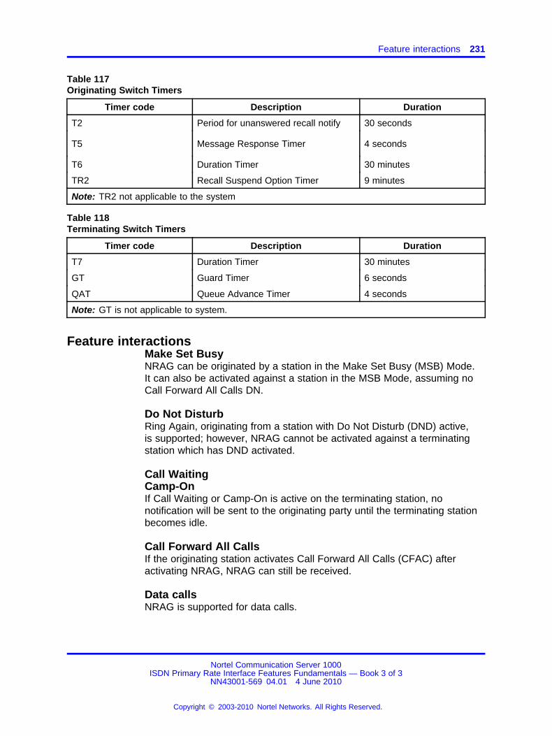
Feature interactions 231
Table 117Originating Switch Timers
Timer code Description Duration
T2 Period for unanswered recall notify 30 seconds
T5 Message Response Timer 4 seconds
T6 Duration Timer 30 minutes
TR2 Recall Suspend Option Timer 9 minutes
Note: TR2 not applicable to the system
Table 118Terminating Switch Timers
Timer code Description Duration
T7 Duration Timer 30 minutes
GT Guard Timer 6 seconds
QAT Queue Advance Timer 4 seconds
Note: GT is not applicable to system.
Feature interactionsMake Set BusyNRAG can be originated by a station in the Make Set Busy (MSB) Mode.It can also be activated against a station in the MSB Mode, assuming noCall Forward All Calls DN.
Do Not DisturbRing Again, originating from a station with Do Not Disturb (DND) active,is supported; however, NRAG cannot be activated against a terminatingstation which has DND activated.
Call WaitingCamp-OnIf Call Waiting or Camp-On is active on the terminating station, nonotification will be sent to the originating party until the terminating stationbecomes idle.
Call Forward All CallsIf the originating station activates Call Forward All Calls (CFAC) afteractivating NRAG, NRAG can still be received.
Data callsNRAG is supported for data calls.
Nortel Communication Server 1000ISDN Primary Rate Interface Features Fundamentals — Book 3 of 3
NN43001-569 04.01 4 June 2010
Copyright © 2003-2010 Nortel Networks. All Rights Reserved.
.

232 Network Ring Again
Calling Line IdentificationNRAG is supported only if the Calling Line Identification (CLID) uses theprime DN.
Incoming Digit ConversionIf there is any conversion done to the called DN, NRAG is not supported.
ISDN QSIG Basic CallNetwork Ring Again signaling is supported within the Meridian CustomerDefined Network only. Network Ring Again requests which go through theQSIG interface will not be supported.
CDP and NARSFor networks with CDP and NARS using the same route, turn off INAC andinsert a DMI when needed.
Feature packagingThis feature requires the following packages:
• Background Terminal (BGD) package 19
• ISDN signaling (ISDN) package 145
• Network Ring Again (NRAG) is package 148
This feature requires one the following packages:
• ISDN Primary Rate Interface (PRI) package 146 or
• 2.0 Mbit ISDN Primary Rate Interface (PRI) package 154 or
• ISDN Signaling Link (ISL) package 147; which, if ISL is over DTI/DTI2,requires:
— 1.5 Digital Trunk Interface (PBXI) package 75 or
— 2.0 Mbit Digital Trunk Interface (DTI2) package 129
Feature implementationTask summary list
The following is a summary of the tasks in this section:
1. Table 119 "LD 17: Define the software release ID." (page 233)
2. Table 120 "LD 15: Set up Private Network Identifier (PNI) mappingbetween call type translator HLOC, LSC, HNPA, or HNXX for properCLID construction." (page 233)
3. Table 121 "LD 16: Set up duration timer (NRAG), Private NetworkIdentifier (PNI), insertion of ESN Access Codes (INAC)." (page 234)
Nortel Communication Server 1000ISDN Primary Rate Interface Features Fundamentals — Book 3 of 3
NN43001-569 04.01 4 June 2010
Copyright © 2003-2010 Nortel Networks. All Rights Reserved.
.
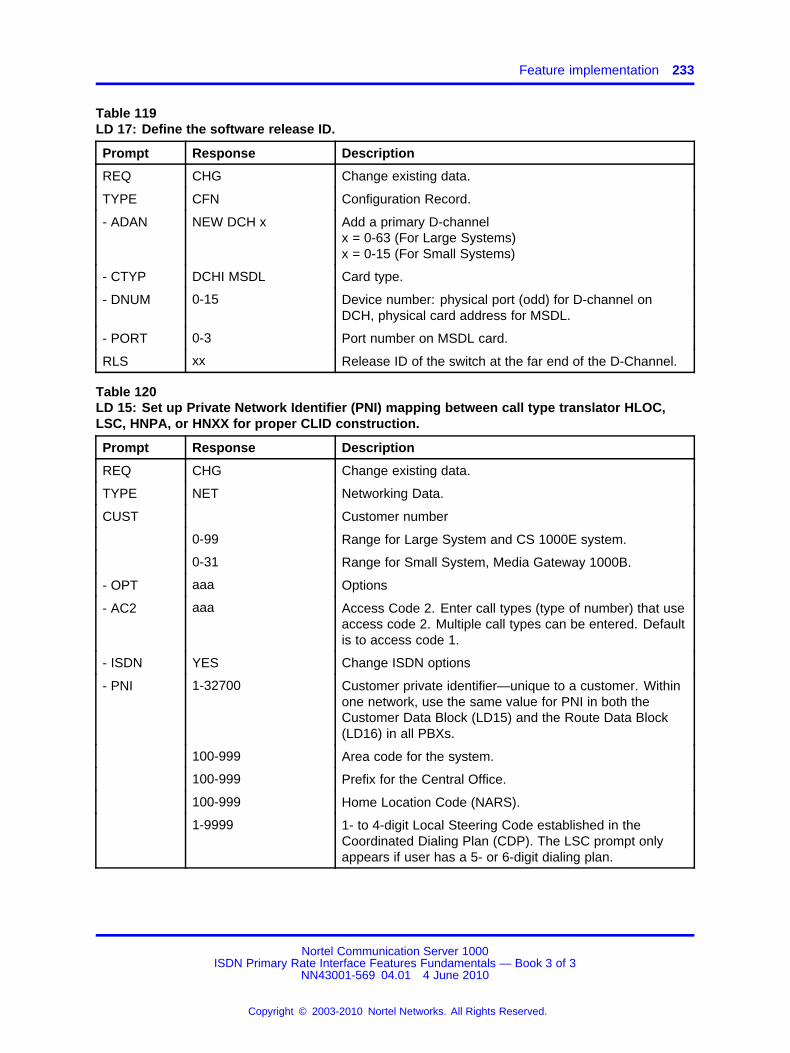
Feature implementation 233
Table 119LD 17: Define the software release ID.
Prompt Response Description
REQ CHG Change existing data.
TYPE CFN Configuration Record.
- ADAN NEW DCH x Add a primary D-channelx = 0-63 (For Large Systems)x = 0-15 (For Small Systems)
- CTYP DCHI MSDL Card type.
- DNUM 0-15 Device number: physical port (odd) for D-channel onDCH, physical card address for MSDL.
- PORT 0-3 Port number on MSDL card.
RLS xx Release ID of the switch at the far end of the D-Channel.
Table 120LD 15: Set up Private Network Identifier (PNI) mapping between call type translator HLOC,LSC, HNPA, or HNXX for proper CLID construction.
Prompt Response Description
REQ CHG Change existing data.
TYPE NET Networking Data.
CUST Customer number
0-99 Range for Large System and CS 1000E system.
0-31 Range for Small System, Media Gateway 1000B.
- OPT aaa Options
- AC2 aaa Access Code 2. Enter call types (type of number) that useaccess code 2. Multiple call types can be entered. Defaultis to access code 1.
- ISDN YES Change ISDN options
- PNI 1-32700 Customer private identifier—unique to a customer. Withinone network, use the same value for PNI in both theCustomer Data Block (LD15) and the Route Data Block(LD16) in all PBXs.
100-999 Area code for the system.
100-999 Prefix for the Central Office.
100-999 Home Location Code (NARS).
1-9999 1- to 4-digit Local Steering Code established in theCoordinated Dialing Plan (CDP). The LSC prompt onlyappears if user has a 5- or 6-digit dialing plan.
Nortel Communication Server 1000ISDN Primary Rate Interface Features Fundamentals — Book 3 of 3
NN43001-569 04.01 4 June 2010
Copyright © 2003-2010 Nortel Networks. All Rights Reserved.
.

234 Network Ring Again
Table 121LD 16: Set up duration timer (NRAG), Private Network Identifier (PNI), insertion of ESN AccessCodes (INAC).
Prompt Response Description
REQ NEW Add new data.
CHG Change existing data.
TYPE RDB Route Data Block.
...
CNTL (NO) YES Changes to controls or timers.
TIMR NRAG (30)-240 Network Ring Again duration timer (T6 and T7timers)—time is in minutes. Currently, only a value of 30minutes is supported.
Package 148, Advanced ISDN Features, is required.
...
INAC (NO) YES Insert Access Code. Permit an ESN access code tobe automatically added to an incoming ESN call from aprivate network. If INAC is YES, the digit insertion option(INST) is bypassed. This prompt only appears if the routetype is a TIE trunk.
PNI 1-32700 Customer private identifier—unique to a customer. Withinone network, use the same value for PNI in both theCustomer Data Block (LD15) and the Route Data Block(LD16) in all PBXs.
Feature operationNo specific operating procedures are required to use this feature.
Nortel Communication Server 1000ISDN Primary Rate Interface Features Fundamentals — Book 3 of 3
NN43001-569 04.01 4 June 2010
Copyright © 2003-2010 Nortel Networks. All Rights Reserved.
.
235.
Network Signaling on Virtual NetworkServices
ContentsThis section contains information on the following topics:
“Applicable regions” (page 235)
“Feature description” (page 235)
“Operating parameters” (page 239)
“Feature interactions” (page 240)
“Feature packaging” (page 240)
“Feature implementation” (page 240)
“Feature operation” (page 241)
Applicable regionsThe information presented in this section does not pertain to all regions.Contact your system supplier or your Nortel representative to verifysupport of this product in your area.
Feature descriptionThe Network Signaling on Virtual Network Services (NSIG on VNS) featureenhances the functionality of Virtual Network Services by supportingNetwork Signaling on the VNS D-Channel (VNS_DCH).
With VNS, the Public Switched Telephone Network (PSTN) trunk servesas a B-Channel. However, NSIG is not allowed over PSTN trunks;therefore, it is necessary to send NSIG over the D-Channel in order tomaintain the Network Class of Service (NCOS) information.
NCOS information is transported through Network Signaling over routes,depending on the value of the Signaling arrangement (SIGO) prompt inthe Route Data Block. When SIGO = STD, no NCOS information is senton the Bearer Channel (B-Channel).
Nortel Communication Server 1000ISDN Primary Rate Interface Features Fundamentals — Book 3 of 3
NN43001-569 04.01 4 June 2010
Copyright © 2003-2010 Nortel Networks. All Rights Reserved.
.
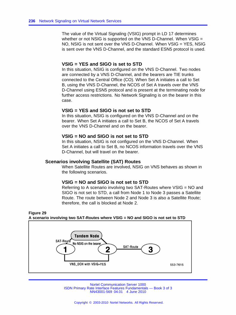
236 Network Signaling on Virtual Network Services
The value of the Virtual Signaling (VSIG) prompt in LD 17 determineswhether or not NSIG is supported on the VNS D-Channel. When VSIG =NO, NSIG is not sent over the VNS D-Channel. When VSIG = YES, NSIGis sent over the VNS D-Channel, and the standard ESN5 protocol is used.
VSIG = YES and SIGO is set to STDIn this situation, NSIG is configured on the VNS D-Channel. Two nodesare connected by a VNS D-Channel, and the bearers are TIE trunksconnected to the Central Office (CO). When Set A initiates a call to SetB, using the VNS D-Channel, the NCOS of Set A travels over the VNSD-Channel using ESN5 protocol and is present at the terminating node forfurther access restrictions. No Network Signaling is on the bearer in thiscase.
VSIG = YES and SIGO is not set to STDIn this situation, NSIG is configured on the VNS D-Channel and on thebearer. When Set A initiates a call to Set B, the NCOS of Set A travelsover the VNS D-Channel and on the bearer.
VSIG = NO and SIGO is not set to STDIn this situation, NSIG is not configured on the VNS D-Channel. WhenSet A initiates a call to Set B, no NCOS information travels over the VNSD-Channel, but will travel on the bearer.
Scenarios involving Satellite (SAT) RoutesWhen Satellite Routes are involved, NSIG on VNS behaves as shown inthe following scenarios.
VSIG = NO and SIGO is not set to STDReferring to A scenario involving two SAT-Routes where VSIG = NO andSIGO is not set to STD, a call from Node 1 to Node 3 passes a SatelliteRoute. The route between Node 2 and Node 3 is also a Satellite Route;therefore, the call is blocked at Node 2.
Figure 29A scenario involving two SAT-Routes where VSIG = NO and SIGO is not set to STD
Nortel Communication Server 1000ISDN Primary Rate Interface Features Fundamentals — Book 3 of 3
NN43001-569 04.01 4 June 2010
Copyright © 2003-2010 Nortel Networks. All Rights Reserved.
.
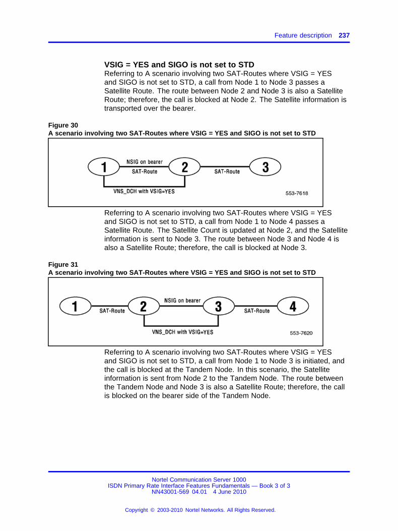
Feature description 237
VSIG = YES and SIGO is not set to STDReferring to A scenario involving two SAT-Routes where VSIG = YESand SIGO is not set to STD, a call from Node 1 to Node 3 passes aSatellite Route. The route between Node 2 and Node 3 is also a SatelliteRoute; therefore, the call is blocked at Node 2. The Satellite information istransported over the bearer.
Figure 30A scenario involving two SAT-Routes where VSIG = YES and SIGO is not set to STD
Referring to A scenario involving two SAT-Routes where VSIG = YESand SIGO is not set to STD, a call from Node 1 to Node 4 passes aSatellite Route. The Satellite Count is updated at Node 2, and the Satelliteinformation is sent to Node 3. The route between Node 3 and Node 4 isalso a Satellite Route; therefore, the call is blocked at Node 3.
Figure 31A scenario involving two SAT-Routes where VSIG = YES and SIGO is not set to STD
Referring to A scenario involving two SAT-Routes where VSIG = YESand SIGO is not set to STD, a call from Node 1 to Node 3 is initiated, andthe call is blocked at the Tandem Node. In this scenario, the Satelliteinformation is sent from Node 2 to the Tandem Node. The route betweenthe Tandem Node and Node 3 is also a Satellite Route; therefore, the callis blocked on the bearer side of the Tandem Node.
Nortel Communication Server 1000ISDN Primary Rate Interface Features Fundamentals — Book 3 of 3
NN43001-569 04.01 4 June 2010
Copyright © 2003-2010 Nortel Networks. All Rights Reserved.
.
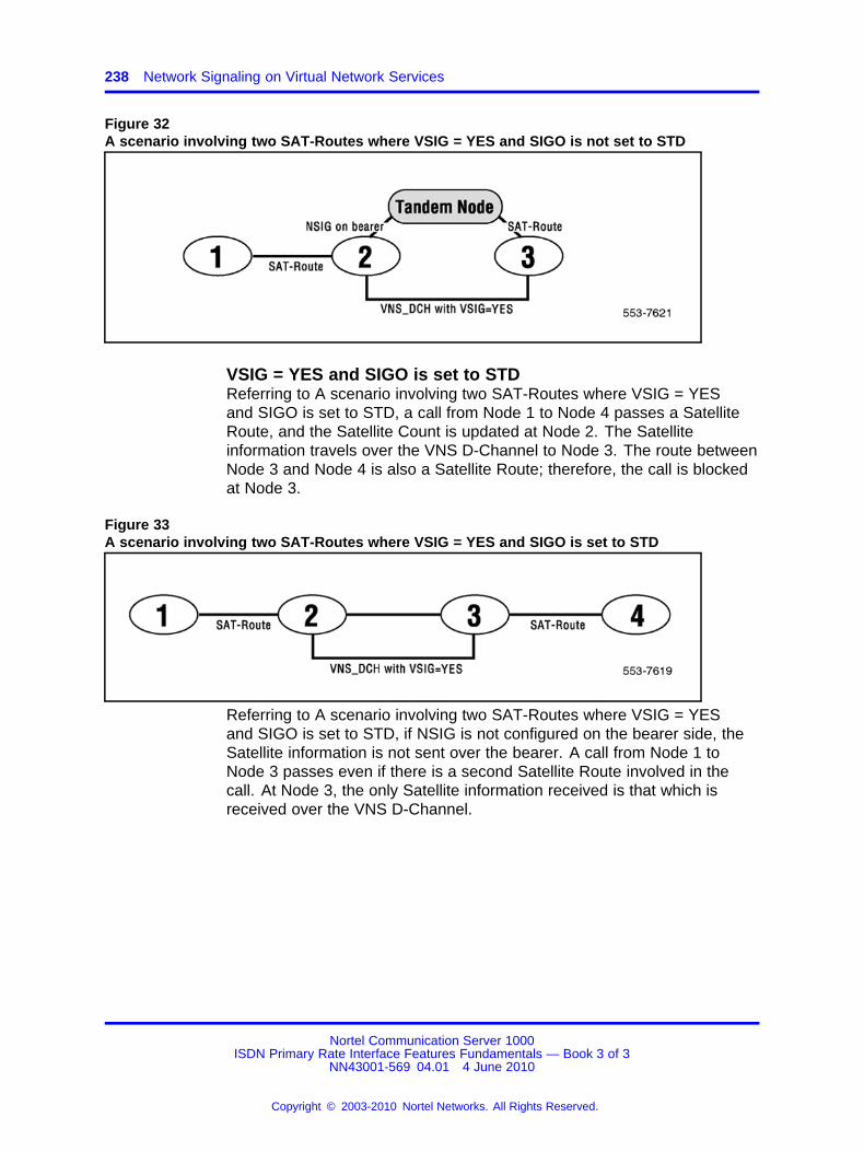
238 Network Signaling on Virtual Network Services
Figure 32A scenario involving two SAT-Routes where VSIG = YES and SIGO is not set to STD
VSIG = YES and SIGO is set to STDReferring to A scenario involving two SAT-Routes where VSIG = YESand SIGO is set to STD, a call from Node 1 to Node 4 passes a SatelliteRoute, and the Satellite Count is updated at Node 2. The Satelliteinformation travels over the VNS D-Channel to Node 3. The route betweenNode 3 and Node 4 is also a Satellite Route; therefore, the call is blockedat Node 3.
Figure 33A scenario involving two SAT-Routes where VSIG = YES and SIGO is set to STD
Referring to A scenario involving two SAT-Routes where VSIG = YESand SIGO is set to STD, if NSIG is not configured on the bearer side, theSatellite information is not sent over the bearer. A call from Node 1 toNode 3 passes even if there is a second Satellite Route involved in thecall. At Node 3, the only Satellite information received is that which isreceived over the VNS D-Channel.
Nortel Communication Server 1000ISDN Primary Rate Interface Features Fundamentals — Book 3 of 3
NN43001-569 04.01 4 June 2010
Copyright © 2003-2010 Nortel Networks. All Rights Reserved.
.
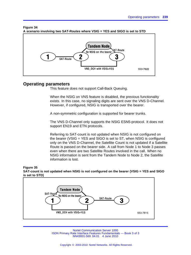
Operating parameters 239
Figure 34A scenario involving two SAT-Routes where VSIG = YES and SIGO is set to STD
Operating parametersThis feature does not support Call-Back Queuing.
When the NSIG on VNS feature is disabled, the previous functionalityexists. In this case, no signaling digits are sent over the VNS D-Channel.However, if configured, NSIG is transported over the bearer.
A non-symmetric configuration is supported for bearer trunks.
The VNS D-Channel only supports the NSIG ESN5-protocol. It does notsupport EN19 and ETN protocols.
Referring to SAT-count is not updated when NSIG is not configured onthe bearer (VSIG = YES and SIGO is set to ST, when NSIG is configuredonly on the VNS D-Channel, the Satellite Count is not updated if a SatelliteRoute is passed on the bearer side. A call from Node 1 to Node 3 passeseven when there are two Satellite Routes involved in the call. When noNSIG information is sent from the Tandem Node to Node 2, the Satelliteinformation is lost.
Figure 35SAT-count is not updated when NSIG is not configured on the bearer (VSIG = YES and SIGOis set to STD)
Nortel Communication Server 1000ISDN Primary Rate Interface Features Fundamentals — Book 3 of 3
NN43001-569 04.01 4 June 2010
Copyright © 2003-2010 Nortel Networks. All Rights Reserved.
.
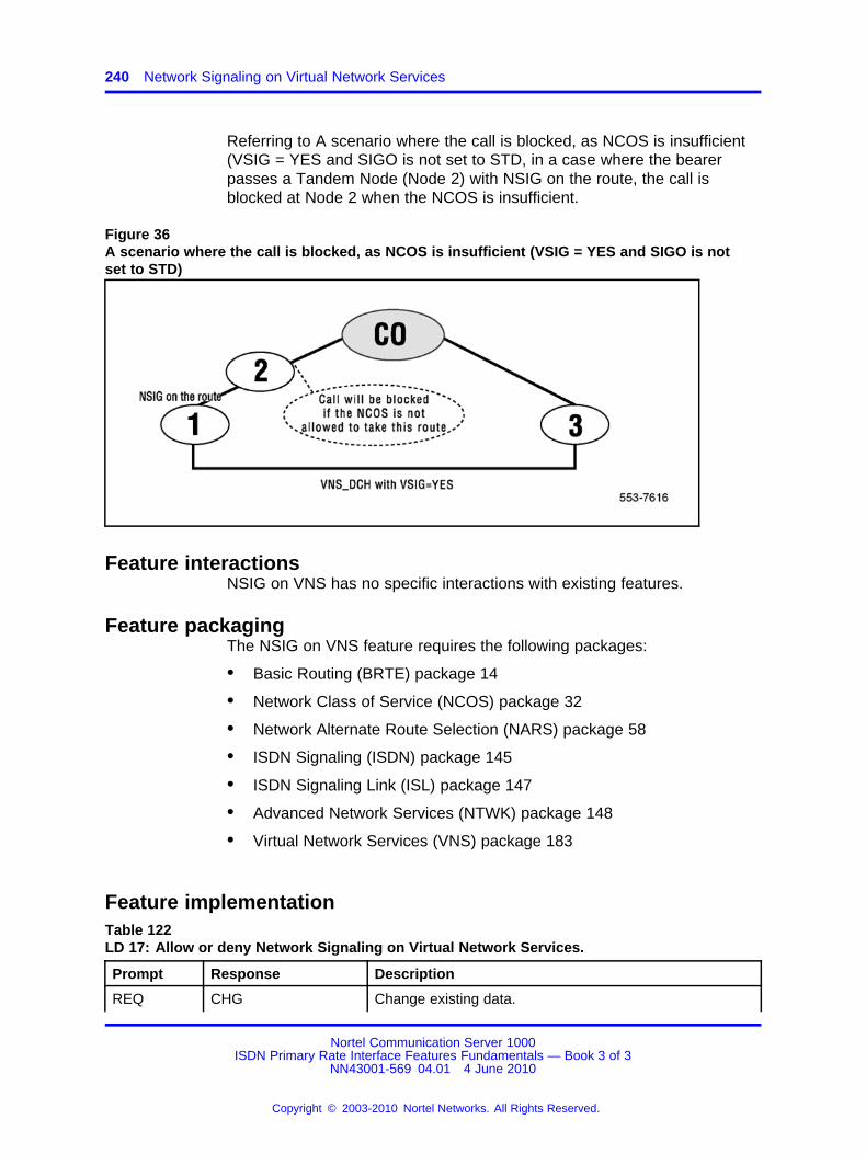
240 Network Signaling on Virtual Network Services
Referring to A scenario where the call is blocked, as NCOS is insufficient(VSIG = YES and SIGO is not set to STD, in a case where the bearerpasses a Tandem Node (Node 2) with NSIG on the route, the call isblocked at Node 2 when the NCOS is insufficient.
Figure 36A scenario where the call is blocked, as NCOS is insufficient (VSIG = YES and SIGO is notset to STD)
Feature interactionsNSIG on VNS has no specific interactions with existing features.
Feature packagingThe NSIG on VNS feature requires the following packages:
• Basic Routing (BRTE) package 14
• Network Class of Service (NCOS) package 32
• Network Alternate Route Selection (NARS) package 58
• ISDN Signaling (ISDN) package 145
• ISDN Signaling Link (ISL) package 147
• Advanced Network Services (NTWK) package 148
• Virtual Network Services (VNS) package 183
Feature implementationTable 122LD 17: Allow or deny Network Signaling on Virtual Network Services.
Prompt Response Description
REQ CHG Change existing data.
Nortel Communication Server 1000ISDN Primary Rate Interface Features Fundamentals — Book 3 of 3
NN43001-569 04.01 4 June 2010
Copyright © 2003-2010 Nortel Networks. All Rights Reserved.
.
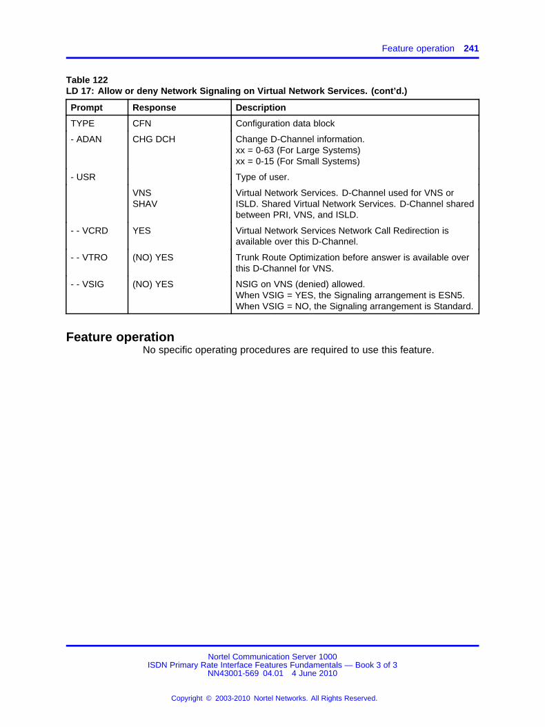
Feature operation 241
Table 122LD 17: Allow or deny Network Signaling on Virtual Network Services. (cont’d.)
Prompt Response Description
TYPE CFN Configuration data block
- ADAN CHG DCH Change D-Channel information.xx = 0-63 (For Large Systems)xx = 0-15 (For Small Systems)
- USR Type of user.
VNSSHAV
Virtual Network Services. D-Channel used for VNS orISLD. Shared Virtual Network Services. D-Channel sharedbetween PRI, VNS, and ISLD.
- - VCRD YES Virtual Network Services Network Call Redirection isavailable over this D-Channel.
- - VTRO (NO) YES Trunk Route Optimization before answer is available overthis D-Channel for VNS.
- - VSIG (NO) YES NSIG on VNS (denied) allowed.When VSIG = YES, the Signaling arrangement is ESN5.When VSIG = NO, the Signaling arrangement is Standard.
Feature operationNo specific operating procedures are required to use this feature.
Nortel Communication Server 1000ISDN Primary Rate Interface Features Fundamentals — Book 3 of 3
NN43001-569 04.01 4 June 2010
Copyright © 2003-2010 Nortel Networks. All Rights Reserved.
.

242 Network Signaling on Virtual Network Services
Nortel Communication Server 1000ISDN Primary Rate Interface Features Fundamentals — Book 3 of 3
NN43001-569 04.01 4 June 2010
Copyright © 2003-2010 Nortel Networks. All Rights Reserved.
.

243.
Network Tenant Service
ContentsThis section contains information on the following topics:
“Feature description” (page 243)
“Operating parameters” (page 244)
“Feature interactions” (page 245)
“Feature packaging” (page 245)
“Feature implementation” (page 245)
“Task summary list” (page 245)
“Feature operation” (page 248)
Feature descriptionThis feature provides the capability of Network Attendant Service (NAS)on a tenant basis, with network-wide tenant-to-tenant and tenant-to-trunkblocking.
The Multi-location Business Group (MBG) number is the grouping agentused to associate users belonging to a customer group or "sub-group".Network Tenant Service (NTS) uses MBG numbers to define therelationship between the Multi-location Business Group Subgroup (MBGS)number and the tenant number on a particular node. The tenant numberrelated to an outgoing call is translated into the corresponding MBGSnumber and then transmitted through the network. At the terminating node,the MBGS number is translated back into a meaningful tenant number.
Attendant routingNTS allows Console Presentation Groups (CPGs) and related attendantsto be defined at any node in the Integrated Services Digital Network(ISDN).
Nortel Communication Server 1000ISDN Primary Rate Interface Features Fundamentals — Book 3 of 3
NN43001-569 04.01 4 June 2010
Copyright © 2003-2010 Nortel Networks. All Rights Reserved.
.
244 Network Tenant Service
Calls can be directed to another node based upon:
• a time of day schedule defined at the CPG level
• overflow conditions
• status of local attendants in the CPG group
• status of trunks to other attendant locations
• status of the NAS key on a customer basis, and
• Night Service indicator of the CPG group
Each Attendant Console group (ACG) can have its own NAS routingtable defined. Calls not associated with a particular console group will bepresented to ACG 0.
Tenant-to-tenant blockingIt is possible to define tables which allow or deny calls between tenantgroups in the same customer group. Normal intercept treatment is given toa station attempting to dial into a denied access tenant.
Tenant to tenant blocking is maintained across the network. Access isallowed or denied according to information defined on the node whichcurrently processes the call.
It is possible with network-wide tenant-to-tenant blocking to define one-wayrestrictions ("A" cannot call "B", but "B" can call "A"), even though thisis not possible in standalone cases. If nodes do not have the sametenant-to-tenant restrictions defined, one-way blocking can result.
Timed Reminder RecallsTimed Reminder Recalls work in the same way as in NAS, but on a tenantbasis. The attendant is chosen based on the tenant number of the targetparty.
Operating parametersTo ensure correct call routing, all nodes in the ISDN must have theNetwork Tenant Service feature equipped.
Each ACG can have a NAS routing table, or several ACGs can sharethe same NAS routing table. However, the NAS key is defined only on acustomer basis – it is not a CPG-level parameter. When one AttendantConsole activates the NAS key, regardless of ACG, the entire system isin NAS service.
Nortel Communication Server 1000ISDN Primary Rate Interface Features Fundamentals — Book 3 of 3
NN43001-569 04.01 4 June 2010
Copyright © 2003-2010 Nortel Networks. All Rights Reserved.
.
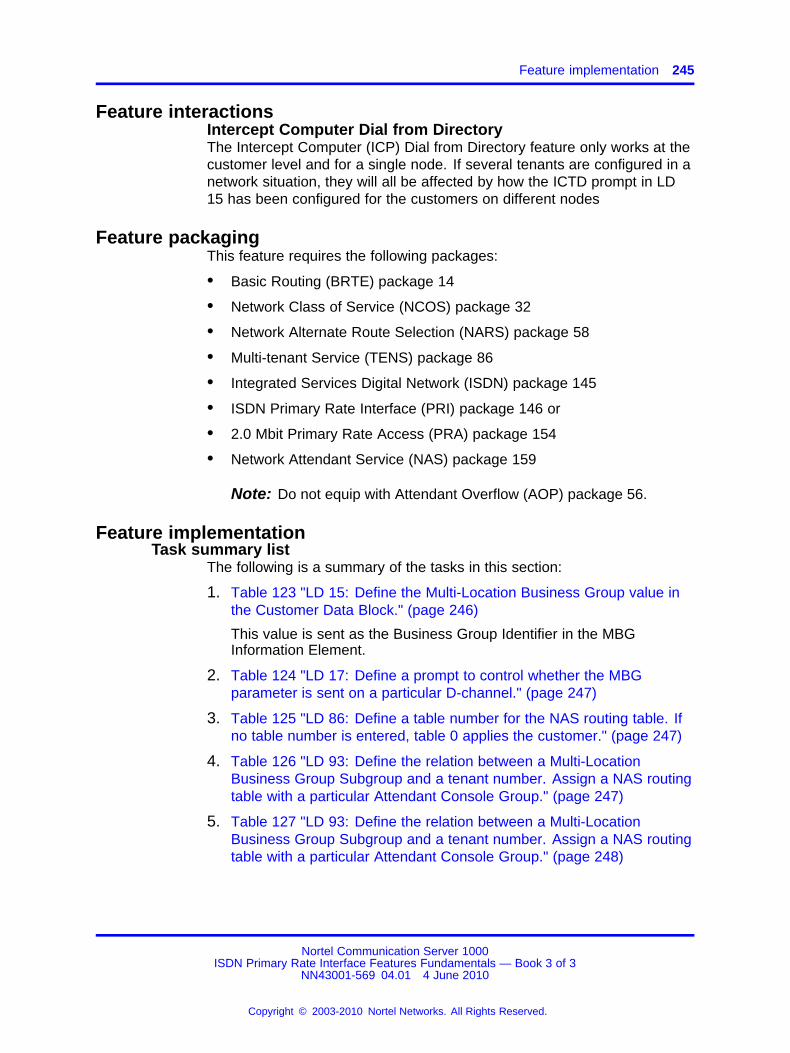
Feature implementation 245
Feature interactionsIntercept Computer Dial from DirectoryThe Intercept Computer (ICP) Dial from Directory feature only works at thecustomer level and for a single node. If several tenants are configured in anetwork situation, they will all be affected by how the ICTD prompt in LD15 has been configured for the customers on different nodes
Feature packagingThis feature requires the following packages:
• Basic Routing (BRTE) package 14
• Network Class of Service (NCOS) package 32
• Network Alternate Route Selection (NARS) package 58
• Multi-tenant Service (TENS) package 86
• Integrated Services Digital Network (ISDN) package 145
• ISDN Primary Rate Interface (PRI) package 146 or
• 2.0 Mbit Primary Rate Access (PRA) package 154
• Network Attendant Service (NAS) package 159
Note: Do not equip with Attendant Overflow (AOP) package 56.
Feature implementationTask summary list
The following is a summary of the tasks in this section:
1. Table 123 "LD 15: Define the Multi-Location Business Group value inthe Customer Data Block." (page 246)
This value is sent as the Business Group Identifier in the MBGInformation Element.
2. Table 124 "LD 17: Define a prompt to control whether the MBGparameter is sent on a particular D-channel." (page 247)
3. Table 125 "LD 86: Define a table number for the NAS routing table. Ifno table number is entered, table 0 applies the customer." (page 247)
4. Table 126 "LD 93: Define the relation between a Multi-LocationBusiness Group Subgroup and a tenant number. Assign a NAS routingtable with a particular Attendant Console Group." (page 247)
5. Table 127 "LD 93: Define the relation between a Multi-LocationBusiness Group Subgroup and a tenant number. Assign a NAS routingtable with a particular Attendant Console Group." (page 248)
Nortel Communication Server 1000ISDN Primary Rate Interface Features Fundamentals — Book 3 of 3
NN43001-569 04.01 4 June 2010
Copyright © 2003-2010 Nortel Networks. All Rights Reserved.
.

246 Network Tenant Service
Table 123LD 15: Define the Multi-Location Business Group value in the Customer Data Block.
Prompt Response Description
REQ NEW Add new data.
CHG Change existing data.
TYPE NET Networking data.
CUST Customer number
0-99 Range for Large System and CS 1000E system.
0-31 Range for Small System, Media Gateway 1000B.
…
- ISDN (NO) YES Integrated Services Digital Network (not) allowed for thiscustomer.
- PNI (0)-32700 Private Network Identifier. Prompted if ISDN = YES.
- MBG (0)-65535 Multi-Location Business Group.
This parameter is used to define the Multi-LocationBusiness Group.0 = no indication.1 = reserved for public network.2-65535 = Business Group Identifiers.
- BSGC (0)-65535 Business Sub Group Consult-only.
0 = no indication.1-65535 = Subgroup identifier.
This value is sent as the Multi-Location Business GroupSubgroup (MBGS) identifier or tenant number when anexisting call has more than two different MBGSs. Inthis case, a consultation connection will be allowed, butcompletion of a call modification, such as conference ortransfer, will be disallowed.
Note: If MBGA is set to YES, the MBG will be sent on the D-channelas required. If MBGA is set to NO, the MBG will not be sent on theD-channel. Note that the RLS value in the D-channel data block alsoprevents the sending of the MBG parameter to versions of the softwarethat do not support MBG.
Nortel Communication Server 1000ISDN Primary Rate Interface Features Fundamentals — Book 3 of 3
NN43001-569 04.01 4 June 2010
Copyright © 2003-2010 Nortel Networks. All Rights Reserved.
.

Feature implementation 247
Table 124LD 17: Define a prompt to control whether the MBG parameter is sent on a particularD-channel.
Prompt Response Description
REQ CHG Change existing data.
TYPE CFNADAN
Configuration Record.Gate opener.
ISDN (NO) YES Integrated Services Digital Network.
…
- NASA (NO) YES Network Attendant Service (disallowed) allowed.
- MBGA (NO) YES Multi-Location Business Group messages are allowed tobe sent on this D-channel.
Table 125LD 86: Define a table number for the NAS routing table. If no table number is entered, table 0applies the customer.
Prompt Response Description
REQ NEW Add new data.
CHG Change existing data.
CUST Customer number
0-99 Range for Large System and CS 1000E system.
0-31 Range for Small System, Media Gateway 1000B.
FEAT NAS Network Attendant Service.
TBL (0)-63 NAS routing table 0. 0 is the customer routing table. It isassociated with ACG 0. Prompted if FEAT = NAS.
ALT 1-7X1-X7
Alternative number to be defined.Precede with "X" to delete the alternative number.
Table 126LD 93: Define the relation between a Multi-Location Business Group Subgroup and a tenantnumber. Assign a NAS routing table with a particular Attendant Console Group.
Prompt Response Description
REQ CHG Change existing data.
TYPE TACC Tenant Access information.
CUST Customer number
0-99 Range for Large System and CS 1000E system.
0-31 Range for Small System, Media Gateway 1000B.
Nortel Communication Server 1000ISDN Primary Rate Interface Features Fundamentals — Book 3 of 3
NN43001-569 04.01 4 June 2010
Copyright © 2003-2010 Nortel Networks. All Rights Reserved.
.
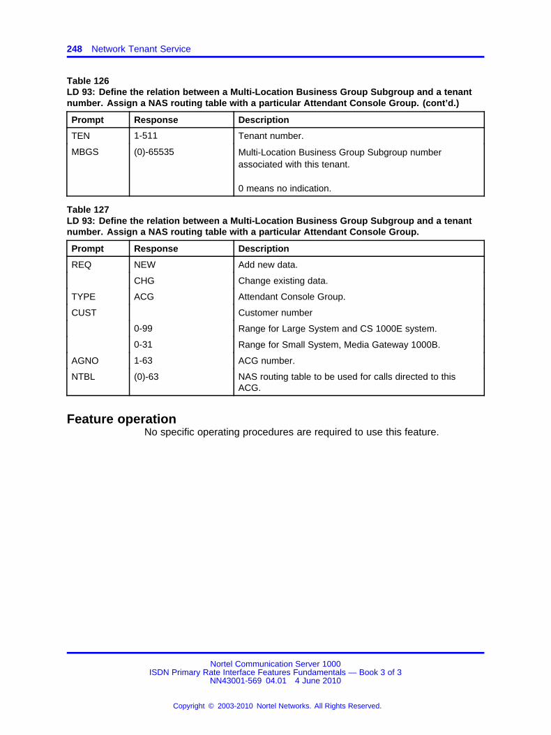
248 Network Tenant Service
Table 126LD 93: Define the relation between a Multi-Location Business Group Subgroup and a tenantnumber. Assign a NAS routing table with a particular Attendant Console Group. (cont’d.)
Prompt Response Description
TEN 1-511 Tenant number.
MBGS (0)-65535 Multi-Location Business Group Subgroup numberassociated with this tenant.
0 means no indication.
Table 127LD 93: Define the relation between a Multi-Location Business Group Subgroup and a tenantnumber. Assign a NAS routing table with a particular Attendant Console Group.
Prompt Response Description
REQ NEW Add new data.
CHG Change existing data.
TYPE ACG Attendant Console Group.
CUST Customer number
0-99 Range for Large System and CS 1000E system.
0-31 Range for Small System, Media Gateway 1000B.
AGNO 1-63 ACG number.
NTBL (0)-63 NAS routing table to be used for calls directed to thisACG.
Feature operationNo specific operating procedures are required to use this feature.
Nortel Communication Server 1000ISDN Primary Rate Interface Features Fundamentals — Book 3 of 3
NN43001-569 04.01 4 June 2010
Copyright © 2003-2010 Nortel Networks. All Rights Reserved.
.

249.
Network Time Synchronization
ContentsThis section contains information on the following topics:
“Description” (page 249)
“Operating parameters” (page 251)
“Feature interactions” (page 251)
“Feature packaging” (page 251)
“Feature implementation” (page 251)
“Task summary list” (page 252)
“Feature operation” (page 256)
DescriptionThe Network Time Synchronization feature is designed to ensure that alltime stamps in a network are synchronized from one source. One switchbecomes the master for this purpose.
In a private network environment, each switch in the network hasan individual system clock. These system clocks can, under certainconditions, lose or gain time, causing inaccurate time stamps for differentfeatures.
Also, in a private network, several switches can be located in different timezones. As features become more centralized in a network environment, itis useful to have time stamps based on one time zone.
To provide Time Synchronization on a network-wide basis, MeridianCustomer Defined Integrated Services Digital Network (ISDN) nodescan request Time Synchronization from another node, using D-channelmessages. Therefore, Slave switches can request the time from theMaster switch, while the Master switch can do the same to a Backup node.
Nortel Communication Server 1000ISDN Primary Rate Interface Features Fundamentals — Book 3 of 3
NN43001-569 04.01 4 June 2010
Copyright © 2003-2010 Nortel Networks. All Rights Reserved.
.

250 Network Time Synchronization
A time difference (or delta) is provided for every node, in order todistinguish time zones for time usage by local features (e.g., AutomaticWake-up) and centralized ones (e.g., Centralized Call Detail Recording).
The Time Synchronization request messages are composed of:
• the message identifier
• the requester’s ID
• the time
• the date
• the time-adjust factor
IDs are virtual DNs, and are used to route the messages.
On the Slaves, Time Synchronization requests are sent automaticallyunder the background routines (default setup) or with the daily routines(optional setup), every time a time change is performed (to accurately setthe seconds), and on every SYSLOAD and initialization.
On the Master, Time Synchronization requests are sent to a Backup nodeupon initialization and, therefore, after SYSLOAD. The Master will beforbidden to synchronize Slave switches during these backup periods. Inthe rare event where Master and Backup nodes would start requestingsynchronization at the same time, the real time will be considered to beon the Slave node, if it is not initializing. If both nodes are only initializing,the real time would be considered to be carried by the Master switch.If a SYSLOAD occurs at the Master and the Slave is initializing, thereal time would be considered to be carried by the Slave switch. Awarning message will be printed if both switches SYSLOAD, and all TimeSynchronization would be put to a halt until the Master’s clock is reset.
If no answer is received on the first time synchronization request (by theend of the request time-out), extra Time Synchronization requests will besent. If there is still no answer on the third time synchronization request,a warning message will be issued.
Note 1: Upon SYSLOAD, the clock starts on time zero, while uponinitialization, only the seconds are lost.
Note 2: Through service change (LD 2) or through an AttendantConsole, the clock can be reset to the correct time if desired. If theNetwork Time Synchronization feature is on, then the Master will berequested for synchronization upon these service changes (to permitfine synchronization).
Nortel Communication Server 1000ISDN Primary Rate Interface Features Fundamentals — Book 3 of 3
NN43001-569 04.01 4 June 2010
Copyright © 2003-2010 Nortel Networks. All Rights Reserved.
.
Feature implementation 251
Operating parametersThis feature uses D-channel messaging over a Meridian Customer DefinedIntegrated Services Digital Network (ISDN).
Feature interactionsTime-of-day AdjustmentEvery time LD 2 is used to change the system time, a request forsynchronization will be made of the Master to accurately set the seconds.
Time and Date (TAD) Attendant keyAs done with LD 2, every time the TAD key is used to change thesystem time, a request for synchronization will be made to the Master toaccurately set the seconds.
Call Detail Recording (CDR)Upon receipt of synchronization messages, Slave switches will issue CDRrecords (if so equipped) for monitoring the feature. These CDR records willbe identical to those issued by a time change performed in LD 2 or by anattendant’s TAD key.
Feature packagingThis feature is included with the Integrated Services Digital NetworkSupplementary Features (ISDNS) package 161.
Feature implementationThe following parameters are used to configure Network TimeSynchronization:
• Node Status: Can either be Master, Slave, or standard stand-alonenode (MAST, SLAV or STDA).
• Customer Number: Customer that will issue and receive the NetworkTime Synchronization messages. The default value is "0". For achange (only possible on switches with the multi-customer package)to be accepted, the customer should already exist. Furthermore, theLocal DN has to be reentered.
• Local DN: Virtual DN (access code included) dedicated forsynchronization services on the Local node; up to 16 digits. A call withthese routing digits should terminate on the previously designatedcustomer.
• Master or Backup DN: Virtual DN (access code included) dedicatedfor synchronization services on the Master or Backup node; up to 16digits.
Nortel Communication Server 1000ISDN Primary Rate Interface Features Fundamentals — Book 3 of 3
NN43001-569 04.01 4 June 2010
Copyright © 2003-2010 Nortel Networks. All Rights Reserved.
.
252 Network Time Synchronization
• Time Delta: Time difference added to the local time in order to get theMaster or Backup time. The entry is prefixed with the digit 1 for positiveand 0 for negative.
• Requesting mode: Operating mode used to request the timesynchronization messages (i.e., with the background routines (defaultsetup) or with the daily services (BKGD or DSVC)).
Note: The Node Status, Customer Number, Local DN, and Masteror Backup DN parameters must be configured for the Network TimeSynchronization feature to be operational.
Task summary listThe following is a summary of the tasks in this section:
1. “LD 2: Define entries for the Network Time Synchronization feature.”(page 252)
2. “LD 22: Print the DN type for the Network Time SynchronizationVirtual DN. The DN type is TIME.” (page 256)
LD 2: Define entries for the Network Time Synchronizationfeature.The following commands are Network Time Synchronization featurespecific:
Query Node Status (Type Time Synchronization Status).
The command format is:
INPUTOUTPUT
.TTSS.TTSS (STATUS)
Example:
.TTSS.TTSS MAST
Set Node Status (Set Time Synchronization Status).
The command format is:
Nortel Communication Server 1000ISDN Primary Rate Interface Features Fundamentals — Book 3 of 3
NN43001-569 04.01 4 June 2010
Copyright © 2003-2010 Nortel Networks. All Rights Reserved.
.
Feature implementation 253
.STSS (status)
where status can be:
STDA — stand-alone (default)
MAST — Master
SLAV — Slave
Example:
.STSS SLAV
Query Customer in charge (Type Time Synchronization Customer).
The command format is:
INPUTOUTPUT
.TTSC.TTSC (CUSTOMER NUMBER)
Example:
.TTSC.TTSC 5
Set Customer in charge (Set Time Synchronization Customer).
The command format is:
.STSC (customer number)
where customer can be:
0 - 99 — 0 is default.
Example:
.STSC 5
Query Local Virtual DN (Type Local DN).
The command format is:
INPUTOUTPUT
.TLDN.TLDN (DN)
Nortel Communication Server 1000ISDN Primary Rate Interface Features Fundamentals — Book 3 of 3
NN43001-569 04.01 4 June 2010
Copyright © 2003-2010 Nortel Networks. All Rights Reserved.
.
254 Network Time Synchronization
Example (for 6 = ESN access code, 613 = ESN location code, 5999 =DN):
.TLDN.TLDN 66135999
Set Local Virtual DN (Set Local DN).
The command format is:
.SLDN (dn)
Example:
.SLDN 66135999
Query Master or Backup Time Synchronization Number (Type MasterDN).
The command format is:
INPUTOUTPUT
.TMDN.TMDN (DN)
Example (for 6 = Outside line, 514 = ESN code, 3999 = DN):
.TMDN.TMDN 65143999
Set Master or Backup Time Synchronization Number (Set Master DN).
The command format is:
.SMDN (dn)
Example:
.SMDN 65143999
Query Time Delta.
The command format is:
INPUT OUTPUT
.TDEL.TDEL (SIGN) (HR) (MIN)
Example:
Nortel Communication Server 1000ISDN Primary Rate Interface Features Fundamentals — Book 3 of 3
NN43001-569 04.01 4 June 2010
Copyright © 2003-2010 Nortel Networks. All Rights Reserved.
.
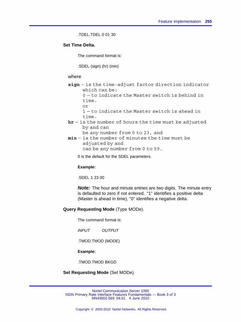
Feature implementation 255
.TDEL.TDEL 0 01 30
Set Time Delta.
The command format is:
.SDEL (sign) (hr) (min)
where
sign – is the time-adjust factor direction indicatorwhich can be:0 — to indicate the Master switch is behind intime.or1 — to indicate the Master switch is ahead intime.
hr – is the number of hours the time must be adjustedby and canbe any number from 0 to 23, and
min – is the number of minutes the time must beadjusted by andcan be any number from 0 to 59.
0 is the default for the SDEL parameters.
Example:
.SDEL 1 23 00
Note: The hour and minute entries are two digits. The minute entryis defaulted to zero if not entered. "1" identifies a positive delta(Master is ahead in time), "0" identifies a negative delta.
Query Requesting Mode (Type MODe).
The command format is:
INPUT OUTPUT
.TMOD.TMOD (MODE)
Example:
.TMOD.TMOD BKGD
Set Requesting Mode (Set MODe).
Nortel Communication Server 1000ISDN Primary Rate Interface Features Fundamentals — Book 3 of 3
NN43001-569 04.01 4 June 2010
Copyright © 2003-2010 Nortel Networks. All Rights Reserved.
.

256 Network Time Synchronization
The command format is:
.SMOD (mode)
where mode can be:BKGD — Background (default)orDSVC — Daily Service (midnight)
Example:
.SMOD DSVC
LD 22: Print the DN type for the Network Time SynchronizationVirtual DN. The DN type is TIME.
Feature operationEach node of the network that is to be synchronized sets its status (i.e.,Master, Slave, or Standard stand-alone (the feature is not used)). Thecraftsperson also sets the node’s customer in charge of synchronizing theswitch (that customer will request Time Synchronization and receive thetime from the Master or Backup switch). The customer must already exist,prior to referencing it, and then sets the local access codes with the virtualDN, the Master (or Backup) routing digits, the time difference betweenlocal and Master nodes, and the requesting mode (for example, performedunder the background routines (default) or the daily services. The timedelta and the requesting mode are optional entries).
The time synchronization feature is designed to work in a MeridianCustomer Defined Integrated Services Digital Network (ISDN)environment, using D-channel messages. The synchronization messagesare carried by TCAP facility messages on a Meridian Customer DefinedISDN, and routed according to the configuration defined in LD 2.
Once the configuration is defined in LD 2, the Slaves will automaticallystart requesting "time-stamps" from the Master periodically, upon initialize,and when the time and date is changed in LD 2. The message to besent is identified as being a time synchronization request. The storedMaster’s routing digits (access codes + virtual DN) are used to route thesynchronization requests. As part of the request, the requester’s accesscodes + virtual DN is sent to provide the Master with a way back to therequesting node.
Nortel Communication Server 1000ISDN Primary Rate Interface Features Fundamentals — Book 3 of 3
NN43001-569 04.01 4 June 2010
Copyright © 2003-2010 Nortel Networks. All Rights Reserved.
.
Feature operation 257
Upon receipt at the Master node, the terminating DN is recognizedas being a time synchronization virtual DN, and the request is thenprocessed. The processing consists of constructing a message, identifiedas being a time synchronization response and originating from that virtualDN, which includes:
• time
• date, and
• time-adjust factor (if used).
The message is then routed to the Slave using the access codes andvirtual DN provided with the request. The time-adjust factor is sent to allSlaves in order to have the whole network correct any inaccurate clocksettings in unison, if any slippage correction is necessary.
Up to three requests will be sent at one minute intervals, to allow thesystem to overcome possible temporary malfunctions. On receipt ofthe time message, the requester verifies the originator’s ID (its virtualDN), and updates its clock accordingly (i.e., equal to the time sent minusthe time delta between the two switches). If equipped with the CDRpackage, a time change record is provided with every time synchronizationoccurrence.
Nortel Communication Server 1000ISDN Primary Rate Interface Features Fundamentals — Book 3 of 3
NN43001-569 04.01 4 June 2010
Copyright © 2003-2010 Nortel Networks. All Rights Reserved.
.

258 Network Time Synchronization
Nortel Communication Server 1000ISDN Primary Rate Interface Features Fundamentals — Book 3 of 3
NN43001-569 04.01 4 June 2010
Copyright © 2003-2010 Nortel Networks. All Rights Reserved.
.
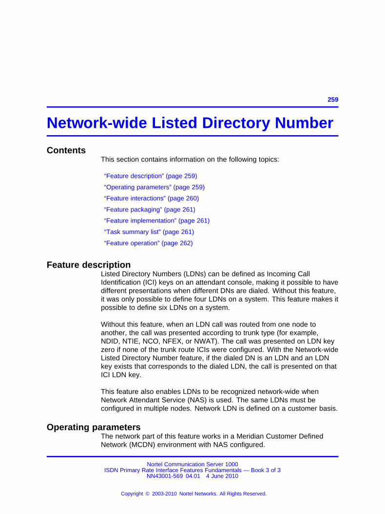
259.
Network-wide Listed Directory Number
ContentsThis section contains information on the following topics:
“Feature description” (page 259)
“Operating parameters” (page 259)
“Feature interactions” (page 260)
“Feature packaging” (page 261)
“Feature implementation” (page 261)
“Task summary list” (page 261)
“Feature operation” (page 262)
Feature descriptionListed Directory Numbers (LDNs) can be defined as Incoming CallIdentification (ICI) keys on an attendant console, making it possible to havedifferent presentations when different DNs are dialed. Without this feature,it was only possible to define four LDNs on a system. This feature makes itpossible to define six LDNs on a system.
Without this feature, when an LDN call was routed from one node toanother, the call was presented according to trunk type (for example,NDID, NTIE, NCO, NFEX, or NWAT). The call was presented on LDN keyzero if none of the trunk route ICIs were configured. With the Network-wideListed Directory Number feature, if the dialed DN is an LDN and an LDNkey exists that corresponds to the dialed LDN, the call is presented on thatICI LDN key.
This feature also enables LDNs to be recognized network-wide whenNetwork Attendant Service (NAS) is used. The same LDNs must beconfigured in multiple nodes. Network LDN is defined on a customer basis.
Operating parametersThe network part of this feature works in a Meridian Customer DefinedNetwork (MCDN) environment with NAS configured.
Nortel Communication Server 1000ISDN Primary Rate Interface Features Fundamentals — Book 3 of 3
NN43001-569 04.01 4 June 2010
Copyright © 2003-2010 Nortel Networks. All Rights Reserved.
.

260 Network-wide Listed Directory Number
The LDNs to be used network-wide cannot be used in conjunction withDistant Steering Codes.
Feature interactionsCall Forward No AnswerWith this feature, the LDN ICI has a higher priority than CFNA ICI. When acall is forwarded to an LDN through Flexible DN, the call will be presentedon the LDN ICI.
Departmental Listed Directory NumberDepartmental LDN is not supported over the network; however, this featuredoes provide two more LDNs for the DLDN feature.
Console Presentation GroupThis feature provides two more LDNs for each Console PresentationGroup.
Console Operation/Console PresentationConsole Operation makes it possible for each console to select which ICIcall types will be presented to the console. Network -wide LDN does notwork with the Console Presentation feature because it is not supported byNAS. Console Operation can, however, be configured with two new LDNs.
Network Message CenterWith this feature, the LDN ICI has a higher priority than MWC ICI. When acall is forwarded to an LDN over the network to a Message Center, the callwill be presented on the LDN ICI.
Network Attendant ServiceThe way the network LDN calls are presented in a NAS environmentis changed by this feature. The presentation on the NDID, NTIE, NCO,NFEX, or NWAT, and the LDN0 key is changed to the correct LDN key, ifit exists. Otherwise, it will be presented as it previously was on the NDIDor LDN0 key.
Console Operation/Queue ThermometerThe queue thermometer indicates how many calls are in the queue fora certain ICI key. An ICI key can correspond to more than one ICI type.Even though the ICI type of a call can be different with or without thisfeature active, it will not interact with queue thermometer operations.
Centralized Attendant ServiceCentralized Attendant Service (CAS) is mutually exclusive to the NASpackage. As the network wide LDN feature requires NAS for its networkingfunctions, the network part of this feature will not work with CAS, but thetwo extra LDNs can be used locally.
Nortel Communication Server 1000ISDN Primary Rate Interface Features Fundamentals — Book 3 of 3
NN43001-569 04.01 4 June 2010
Copyright © 2003-2010 Nortel Networks. All Rights Reserved.
.
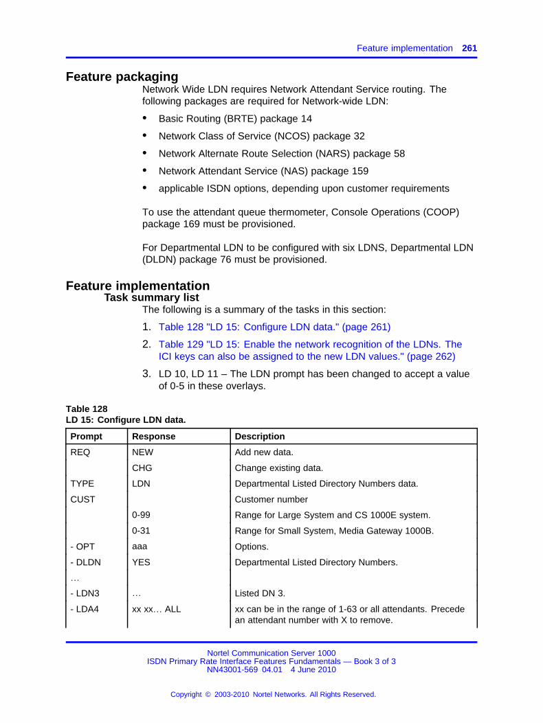
Feature implementation 261
Feature packagingNetwork Wide LDN requires Network Attendant Service routing. Thefollowing packages are required for Network-wide LDN:
• Basic Routing (BRTE) package 14
• Network Class of Service (NCOS) package 32
• Network Alternate Route Selection (NARS) package 58
• Network Attendant Service (NAS) package 159
• applicable ISDN options, depending upon customer requirements
To use the attendant queue thermometer, Console Operations (COOP)package 169 must be provisioned.
For Departmental LDN to be configured with six LDNS, Departmental LDN(DLDN) package 76 must be provisioned.
Feature implementationTask summary list
The following is a summary of the tasks in this section:
1. Table 128 "LD 15: Configure LDN data." (page 261)
2. Table 129 "LD 15: Enable the network recognition of the LDNs. TheICI keys can also be assigned to the new LDN values." (page 262)
3. LD 10, LD 11 – The LDN prompt has been changed to accept a valueof 0-5 in these overlays.
Table 128LD 15: Configure LDN data.
Prompt Response Description
REQ NEW Add new data.
CHG Change existing data.
TYPE LDN Departmental Listed Directory Numbers data.
CUST Customer number
0-99 Range for Large System and CS 1000E system.
0-31 Range for Small System, Media Gateway 1000B.
- OPT aaa Options.
- DLDN YES Departmental Listed Directory Numbers.
…
- LDN3 … Listed DN 3.
- LDA4 xx xx… ALL xx can be in the range of 1-63 or all attendants. Precedean attendant number with X to remove.
Nortel Communication Server 1000ISDN Primary Rate Interface Features Fundamentals — Book 3 of 3
NN43001-569 04.01 4 June 2010
Copyright © 2003-2010 Nortel Networks. All Rights Reserved.
.

262 Network-wide Listed Directory Number
Table 128LD 15: Configure LDN data. (cont’d.)
Prompt Response Description
- LDN4 x…x Listed Directory Number. If the DNXP package isequipped, up to seven digits are allowed; otherwise, onlyfour digits are allowed.
- LDA5 xx xx… ALL xx can be in the range of 1-63 or all attendants. Precedean attendant number with X to remove.
- LDN5 x…x Listed Directory Number. If the DNXP package isequipped, up to seven digits are allowed; otherwise, onlyfour digits are allowed.
Table 129LD 15: Enable the network recognition of the LDNs. The ICI keys can also be assigned tothe new LDN values.
Prompt Response Description
REQ NEW Add new data.
CHG Change existing data.
TYPE LDN Departmental Listed Directory Number data.
CUST Customer number
0-99 Range for Large System and CS 1000E system.
0-31 Range for Small System, Media Gateway 1000B.
- OPT NLDN Network-wide LDN allowed
…
- ICI xx LD4 New answer to existing prompt, where xx is the keynumber.
- ICI xx LD5 New answer to existing prompt, where xx is the keynumber.
Feature operationNo specific operating procedures are required to use this feature.
Nortel Communication Server 1000ISDN Primary Rate Interface Features Fundamentals — Book 3 of 3
NN43001-569 04.01 4 June 2010
Copyright © 2003-2010 Nortel Networks. All Rights Reserved.
.
263.
NI-2 B-channel Service Messaging
ContentsThis section contains information on the following topics:
“Applicable regions” (page 263)
“Feature description” (page 263)
“Differences between ISA, CBC, and NI-2 CBC” (page 275)
“Feature interactions” (page 267)
“Feature implementation” (page 268)
“Feature operation” (page 268)
Applicable regionsThis feature is only available in North America. Contact your systemsupplier or your Nortel representative to verify support of this product inyour area.
Feature descriptionThe NI-2 B-channel Service Messaging feature provides B-channelavailability control on the NI-2 interface. With this feature, servicemessages communicate B-channel status changes to the far-end. Thisfeature does the following:
• increases B-channel availability
• increases throughput on PRI service
• reduces line degradation
• reduces the number of lost calls
• minimizes the number of repeated calls on an out-of-service B-channel
When the status of a system B-channel changes, the system sendsa service message to the Central Office (CO). The CO replies with aservice acknowledgment and changes the status of the correspondingB-channel. When a CO sends a service message to a system, the system
Nortel Communication Server 1000ISDN Primary Rate Interface Features Fundamentals — Book 3 of 3
NN43001-569 04.01 4 June 2010
Copyright © 2003-2010 Nortel Networks. All Rights Reserved.
.

264 NI-2 B-channel Service Messaging
acknowledges the service message and changes the B-channel statuson the near-end.NI-2 B-channel Service messaging illustrates B-channelservice messaging on the NI-2 interface.
Figure 37NI-2 B-channel Service messaging
B-channel status categoriesThe following are the status categories associated with the NI-2 B-channelService Messaging feature:
• IS - Indicates that the B-channel is in service and available for outgoingand incoming calls.
• OOS-FE - indicates that the far-end B-channel is out-of-service.
• OOS-NE - indicates that the near-end B-channel is out-of-service.
When a B-channel at the near-end goes out-of-service, the systemsends a service message with OOS status to the far-end. The near-endB-channel status is OOS-NE. On receipt of this service message, thefar-end changes the corresponding B-channel to OOS-FE.
When the near-end B-channel becomes available, the system sends aservice message with IS status to the far-end. The near-end B-channelis temporarily placed in OOS-FE. On receipt of this service message,the far-end changes the channel status to IS and returns a serviceacknowledge message with the IS status to the system. On receipt ofthis service acknowledge message, the near-end B-channel is placed inservice.
Nortel Communication Server 1000ISDN Primary Rate Interface Features Fundamentals — Book 3 of 3
NN43001-569 04.01 4 June 2010
Copyright © 2003-2010 Nortel Networks. All Rights Reserved.
.
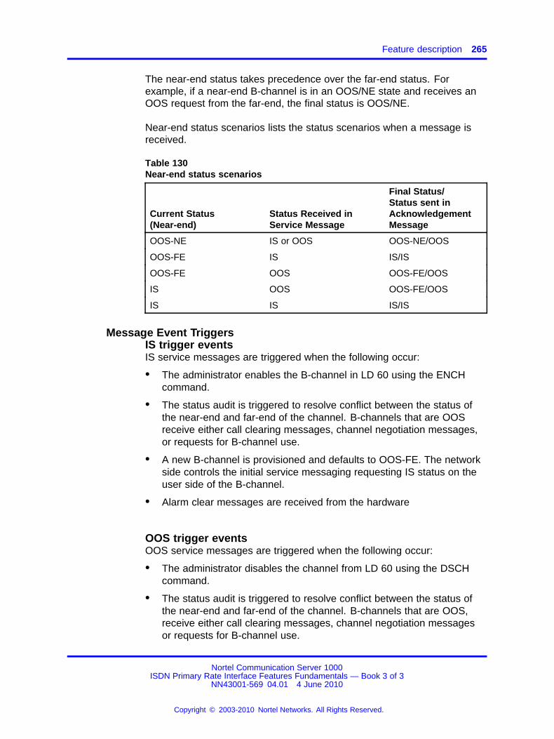
Feature description 265
The near-end status takes precedence over the far-end status. Forexample, if a near-end B-channel is in an OOS/NE state and receives anOOS request from the far-end, the final status is OOS/NE.
Near-end status scenarios lists the status scenarios when a message isreceived.
Table 130Near-end status scenarios
Current Status(Near-end)
Status Received inService Message
Final Status/Status sent inAcknowledgementMessage
OOS-NE IS or OOS OOS-NE/OOS
OOS-FE IS IS/IS
OOS-FE OOS OOS-FE/OOS
IS OOS OOS-FE/OOS
IS IS IS/IS
Message Event TriggersIS trigger eventsIS service messages are triggered when the following occur:
• The administrator enables the B-channel in LD 60 using the ENCHcommand.
• The status audit is triggered to resolve conflict between the status ofthe near-end and far-end of the channel. B-channels that are OOSreceive either call clearing messages, channel negotiation messages,or requests for B-channel use.
• A new B-channel is provisioned and defaults to OOS-FE. The networkside controls the initial service messaging requesting IS status on theuser side of the B-channel.
• Alarm clear messages are received from the hardware
OOS trigger eventsOOS service messages are triggered when the following occur:
• The administrator disables the channel from LD 60 using the DSCHcommand.
• The status audit is triggered to resolve conflict between the status ofthe near-end and far-end of the channel. B-channels that are OOS,receive either call clearing messages, channel negotiation messagesor requests for B-channel use.
Nortel Communication Server 1000ISDN Primary Rate Interface Features Fundamentals — Book 3 of 3
NN43001-569 04.01 4 June 2010
Copyright © 2003-2010 Nortel Networks. All Rights Reserved.
.

266 NI-2 B-channel Service Messaging
• An existing B-channel is removed from service.
• The administrator changes the channel ID in LD 14 using the MOVcommand.
• A PRI restart is sent or received for channels which are OOS.
• A channel is disabled for maintenance and an OOS message is sent.
• Alarm set messages are received from the hardware.
• A loop test is enabled in LD 60 for channels in a fault state.
Service message retransmissionService messaging retransmits the message when an acknowledgmentis not received within 120 seconds of the originating transmission. Thenumber of retransmissions, up to a maximum of four, is configured in LD17.
Service message collisionA message collision occurs when a service message is received betweenthe time when a service message is sent and its corresponding serviceacknowledgement is received from the same B-channel. A re-transmissionoccurs after 120 seconds if an acknowledgment is not received. Servicecollision outcome lists the possible service message collision outcomes.
Table 131Service collision outcome
Previous Near-endStatus
Status Sent inService Message
Colliding StatusReceived
Final Near-endStatus
OOS-NE IS IS IS
OOS-FE IS IS IS
OOS-NE IS OOS OOS-FE
OOS-FE IS OOS OOS-FE
OOS-NE OOS IS OOS-NE
OOS-FE OOS IS OOS-NE
OOS-NE OOS OOS OOS-NE
OOS-FE OOS OOS OOS-NE
IS IS IS IS
IS IS OOS OOS-FE
IS OOS IS OOS-NE
IS OOS OOS OOS-NE
Nortel Communication Server 1000ISDN Primary Rate Interface Features Fundamentals — Book 3 of 3
NN43001-569 04.01 4 June 2010
Copyright © 2003-2010 Nortel Networks. All Rights Reserved.
.

Feature interactions 267
Operating parametersThe NI-2 B-channel Service Messaging feature operates on any systemconfigured with a D-channel interface. The following PRI cards do notsupport the NI-2 B-channel Service Messaging feature:
• QPC757 Primary Rate Interface card
• NTAK93 D-Channel Handler Interface card
For the NI-2 B-channel Service Messaging feature, the far-end mustsupport B-channel service messaging.
On an outgoing call, if the far-end triggers channel negotiation, analternate channel is assigned. If the alternate B-channel has a near-endstatus of OOS-FE, the channel negotiation is accepted and the channel isplaced in IS status. Otherwise, a Release Complete message is sent or achannel negotiation is triggered again.
When a setup message is received requesting an OOS channel, aRelease Complete message is sent or a channel negotiation is performed.However, if the requested B-channel is OOS-FE, the status is changed toIS and the call is accepted.
With no existing call on the channel, B-channel Service messagingactivates the B-channel to IS status. When there is a call on theB-channel, B-channel restart messaging is used.
The B-channel is placed in a lockout state when a restart message issent. The lockout ends on receipt of a restart acknowledgement from thefar-end. Calls cannot be placed on B-channels in the lockout state.
The identity of B-channels in the OOS-NE state are included in the PRIrestart message.
To disable a PRI loop, corresponding D-channels are disabled. In thisstate, the B-channel service messaging is not active.
When a backup D-channel becomes active the restart procedure istriggered. Service messages containing B-channel status information aresent to all far-end B-channels in the OOS state.
If a colliding service message is received, the T323 timer stops and theoriginal message does not retransmit.
Feature interactionsThere are no feature interactions associated with this feature.
Nortel Communication Server 1000ISDN Primary Rate Interface Features Fundamentals — Book 3 of 3
NN43001-569 04.01 4 June 2010
Copyright © 2003-2010 Nortel Networks. All Rights Reserved.
.
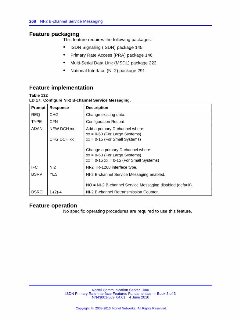
268 NI-2 B-channel Service Messaging
Feature packagingThis feature requires the following packages:
• ISDN Signaling (ISDN) package 145
• Primary Rate Access (PRA) package 146
• Multi-Serial Data Link (MSDL) package 222
• National Interface (NI-2) package 291
Feature implementationTable 132LD 17: Configure NI-2 B-channel Service Messaging.
Prompt Response Description
REQ CHG Change existing data.
TYPE CFN Configuration Record.
ADAN NEW DCH xx
CHG DCH xx
Add a primary D-channel where:xx = 0-63 (For Large Systems)xx = 0-15 (For Small Systems)
Change a primary D-channel where:xx = 0-63 (For Large Systems)xx = 0-15 xx = 0-15 (For Small Systems)
IFC NI2 NI-2 TR-1268 interface type.
BSRV YES NI-2 B-channel Service Messaging enabled.
NO = NI-2 B-channel Service Messaging disabled (default).
BSRC 1-(2)-4 NI-2 B-channel Retransmission Counter.
Feature operationNo specific operating procedures are required to use this feature.
Nortel Communication Server 1000ISDN Primary Rate Interface Features Fundamentals — Book 3 of 3
NN43001-569 04.01 4 June 2010
Copyright © 2003-2010 Nortel Networks. All Rights Reserved.
.

269.
NI-2 Call By Call Service Selection
ContentsThis section contains information on the following topics:
“Applicable regions” (page 269)
“Feature description” (page 269)
“Operating parameters” (page 279)
“Feature interactions” (page 279)
“Feature description” (page 269)
“Feature interactions” (page 267)
“Task summary list” (page 279)
“Feature operation” (page 285)
Applicable regionsThis feature is only available in North America. Contact your systemsupplier or your Nortel representative to verify support of this product inyour area.
Feature descriptionThe National ISDN-2 (NI-2) Call By Call (CBC) Service Selection featureprovides a standardized version of call by call service over an NI-2TR-1268 interface, as defined in the Bellcore Technical ReferenceSpecification TR-NWT-001270. It is intended that NI-2 CBC apply to allClass 5 type local exchanges complying with the NI-2 TR1270 standard.
Note: The NI-2 Call By Call service Selection feature provides all ofthe NI-2 TR-1268 Basic Call services. Please refer to the NationalISDN-2 TR-1268 PRI Interface feature module for a description of theservices that are offered.
Prior to the introduction of this feature, proprietary call by call capabilitieswere offered by Nortel’s Integrated Services Access feature (ISA) CallBy Call Type service for DMS switches (such as the DMS-100), and
Nortel Communication Server 1000ISDN Primary Rate Interface Features Fundamentals — Book 3 of 3
NN43001-569 04.01 4 June 2010
Copyright © 2003-2010 Nortel Networks. All Rights Reserved.
.

270 NI-2 Call By Call Service Selection
Lucent’s Call By Call Service Selection for 5ESS Local Exchange Carriers.“Differences between ISA, CBC, and NI-2 CBC” (page 275) provides asummary of the functional differences between the three offerings.
Note: The ISA Call By Call Type service and the NI-2 Call By CallService Selection feature can co-exist on the same PBX.
NI-2 Call By Call Service Selection allows multiple service routes to sharethe same common pool of B-channels, rather than using dedicated routesthat require each service route to have its own trunks. The channels areassigned to a service for each call.
Figure 38 "Dedicated facilities configuration" (page 270) depicts aconfiguration using dedicated facilities, while “NI-2 B-channel ServiceMessaging” (page 263) shows an NI-2 Call By Call Service Selectionconfiguration. “NI-2 CBC service route treatment” (page 274) provides agraphical representation of the NI-2 CBC master route and service routes.
Figure 38Dedicated facilities configuration
Nortel Communication Server 1000ISDN Primary Rate Interface Features Fundamentals — Book 3 of 3
NN43001-569 04.01 4 June 2010
Copyright © 2003-2010 Nortel Networks. All Rights Reserved.
.
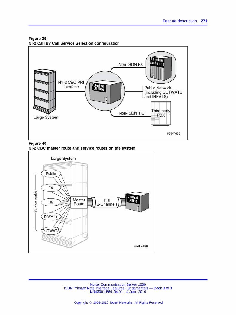
Feature description 271
Figure 39NI-2 Call By Call Service Selection configuration
Figure 40NI-2 CBC master route and service routes on the system
Nortel Communication Server 1000ISDN Primary Rate Interface Features Fundamentals — Book 3 of 3
NN43001-569 04.01 4 June 2010
Copyright © 2003-2010 Nortel Networks. All Rights Reserved.
.

272 NI-2 Call By Call Service Selection
Provisioning a master route and service routesNI-2 Call By Call Service Selection is provisioned by configuring atrunk route as an NI-2 Call By Call Service Selection master route, andassociated service routes. A master route contains a list of B-channels(trunks) to be shared by the different service routes. Service routes do nothave dedicated trunks. They are associated with the master route andshare trunks for different Call By Call services. Calls from the CentralOffice to the system are offered over the CBC master route.
The NI-2 CBC master route is defined in LD 16. The associated list ofB-channels (trunks) is defined using LD 14. Then, the service routes areconfigured, also using LD 16. When configuring the service routes, thetype of service to be carried over the B-channels for the NI-2 PRI interfaceis defined as a decimal value, as follows:
0 = Public call service (No Network Specific Facility IE is sent, sinceCOT/DID routes are used)
19 = FX (Foreign Exchange) service
20 = TIE service
17 = Inward Wide Area Telecommunication Service (INWATS) service
18 = Outward Wide Area Telecommunication Service (OUTWATS) service.Information pertaining to the band number and the Inter-Exchange Carrieris stored in the service route.
Three OUTWATS services can be accessed:
1. IntraLATA OUTWATS, provided by a local service provider
2. InterLATA OUTWATS, provided by a carrier other than that of the localservice provider and
3. Banded OUTWATS, using bands which each represents ageographical area to which a subscriber can place a call at a specialtariff level
Lucent proprietary call by call services are as follows (these values aredefined in the facility coding field in the NSF IE in order for the system torecognize the Lucent call by call services):
• 00001 = Access to Virtual Private Network (such as Lucent’s SoftwareDefined Network service)
• 00010 = MEGACOM 800
• 00011 = MEGACOM
Nortel Communication Server 1000ISDN Primary Rate Interface Features Fundamentals — Book 3 of 3
NN43001-569 04.01 4 June 2010
Copyright © 2003-2010 Nortel Networks. All Rights Reserved.
.

Feature description 273
• 00110 = ACCUNET switched digital service
• 00111 = International long distance service
• 01000 = International 800
• 01011 = Electronic Tandem Network
• 01101 = Private Virtual Network
• 10000 = DIAL IT and Lucent MultiQuest
For each FX and TIE trunk service, a Facility Number is assigned.
The maximum number of trunks limited by each service route is enteredwhen configuring the service routes. The maximum number of channelsfor each service (a maximum value is required by the Bellcore TechnicalReference Specification) is controlled by the Central Office, and assignedat the time of subscription. It is this value that must be entered in LD 16.
There is no minimum limit specified by the Bellcore Technical ReferenceSpecification, therefore no minimum value is assigned by the CentralOffice, or defined on the system.
Engineering consideration pertaining to service maximumsThe maximum value of trunks defined for any service type cannot exceedthe network maximum, but the total of all maximums combined can begreater than the network maximum.
For example, in a single 23B+D span, two service routes can beconfigured, each with a maximum of 15 trunks (B-channels). Even thoughthe combined number of B-channels (30) is greater than the networkmaximum (23), a minimum of 8 B-channels would be left available forother service routes.
For an incoming call to the system, if the maximum number of trunksdefined for a service has been reached, the system will return a "ReleaseComplete" message to the Central Office, with the "Cause" value set to"User Busy". This allows the Central Office to return a busy tone to thecaller.
Service routes for public network callsNI-2 Call By Call Service Selection uses the Network Specific Facility(NSF) Information Element (IE) to indicate the requested service in the callrequest. If no NSF IE is included, the call is treated as a TR-1268 publicnetwork call (CO or DID).
Multiple service routes can be configured on a master route to serveoutgoing public network calls, but only one service route can be specifiedin the master route to serve incoming public network calls (this is done
Nortel Communication Server 1000ISDN Primary Rate Interface Features Fundamentals — Book 3 of 3
NN43001-569 04.01 4 June 2010
Copyright © 2003-2010 Nortel Networks. All Rights Reserved.
.

274 NI-2 Call By Call Service Selection
using the IPUB prompt in LD 16). The route type for these service routescan be COT and DID. The result is that a system can be configured tohandle public network calls with one incoming route and multiple outgoingroutes, or one incoming and outgoing route with multiple outgoing routes.
NI-2 CBC service route treatmentEach service route stores the information, pertaining to a particularsubscribed service, required to initiate or terminate a call. The informationis transmitted to, or received from, the network by means of an NSF IEcontained in the outgoing or incoming SETUP message.
Originating treatment (system to Central Office)The system can designate the desired service to the Central Office, ona call-by-call basis. This is done by means of an NSF IE in the outgoingSETUP message. The NSF IE is built using the information configured inthe service route. The SETUP message is sent by seizing a B-channelfrom a pool of channels associated to the CBC master route.
Termination treatment (Central Office to the system)The Central Office, when offering a call to the system over the CBC masterroute, indicates in the NSF IE the type of service of the incoming call. TheNSF IE contains the information required to identify a service route and tohandle further call processing. The termination of NI-2 CBC service routesis based on the existing Nortel Network’s Integrated Services Accessfeature (ISA) call by call service treatment, and summarized in Table 133"Call termination for NI-2 CBC service route" (page 275).
Nortel Communication Server 1000ISDN Primary Rate Interface Features Fundamentals — Book 3 of 3
NN43001-569 04.01 4 June 2010
Copyright © 2003-2010 Nortel Networks. All Rights Reserved.
.
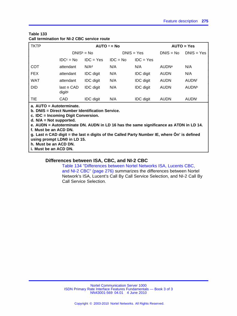
Feature description 275
Table 133Call termination for NI-2 CBC service route
TKTP AUTO a = No AUTO = Yes
DNISb = No DNIS = Yes DNIS = No DNIS = Yes
IDCc = No IDC = Yes IDC = No IDC = Yes
COT attendant N/Ad N/A N/A AUDNe N/A
FEX attendant IDC digit N/A IDC digit AUDN N/A
WAT attendant IDC digit N/A IDC digit AUDN AUDNf
DID last n CADdigitg
IDC digit N/A IDC digit AUDN AUDNh
TIE CAD IDC digit N/A IDC digit AUDN AUDNi
a. AUTO = Autoterminate.b. DNIS = Direct Number Identification Service.c. IDC = Incoming Digit Conversion.d. N/A = Not supported.e. AUDN = Autoterminate DN. AUDN in LD 16 has the same significance as ATDN in LD 14.f. Must be an ACD DN.g. Last n CAD digit = the last n digits of the Called Party Number IE, where Ôn’ is definedusing prompt LDN0 in LD 15.h. Must be an ACD DN.i. Must be an ACD DN.
Differences between ISA, CBC, and NI-2 CBCTable 134 "Differences between Nortel Networks ISA, Lucents CBC,and NI-2 CBC" (page 276) summarizes the differences between NortelNetwork’s ISA, Lucent’s Call By Call Service Selection, and NI-2 Call ByCall Service Selection.
Nortel Communication Server 1000ISDN Primary Rate Interface Features Fundamentals — Book 3 of 3
NN43001-569 04.01 4 June 2010
Copyright © 2003-2010 Nortel Networks. All Rights Reserved.
.

276 NI-2 Call By Call Service Selection
Table 134Differences between Nortel Networks ISA, Lucents CBC, and NI-2 CBC
Nortel ISA Lucent CBC NI-2 CBC
Proprietary (interface specificto DMS-100 and DMS-250).
Proprietary (interface specificto Lucent 5ESS LocalExchange Carriers).
Bellcore-based standard CBCservice (independent of switchtype).
Services:
— Public
— PRIVATE
— INWATS
— OUTWATS
— TIE
— FX
Services:
— ACCUNET
— SDN
— MEGACOM
— MEGACOM 800
— WATB
— WATM
— LDS
— IWAT
— I800
Standardized Services:
— TR-1268 Public (COor DID)
— FX
— TIE
— OUTWATS(IntraLATA, Bands,and InterLATA)
— INWATS
Non-standardized Services:
— e.g., Lucentproprietary services,as follows:
• Access to operator
• Access to ExchangeCarrier Services (call bycall services)
• Access to Virtual PrivateNetwork
Note 1: The maximum cannot be greater than 512 for all call types.
Note 2: Multiple service routes can be configured on a master route to serve outgoing publicnetwork calls, but only one service route can be specified in the master route to serve incomingpublic network calls. The route type for these service routes can be COT and DID. The result is thata system can be configured to handle public network calls with one incoming route and multipleoutgoing routes, or one incoming and outgoing route with multiple outgoing routes
Note 3: For a TIE trunk operating in send mode, the Central Office collects and screens the calleddigits before sending the digits to the Class II equipment or PBX at the end of the TIE trunk.
Note 4: For a TIE trunk operating in cut-through mode, the Central Office does not collect the calleddigits. The Class II equipment or the switch at the end of the TIE trunk are allowed to exchangein-band information, such as dial tone and address information.
Nortel Communication Server 1000ISDN Primary Rate Interface Features Fundamentals — Book 3 of 3
NN43001-569 04.01 4 June 2010
Copyright © 2003-2010 Nortel Networks. All Rights Reserved.
.
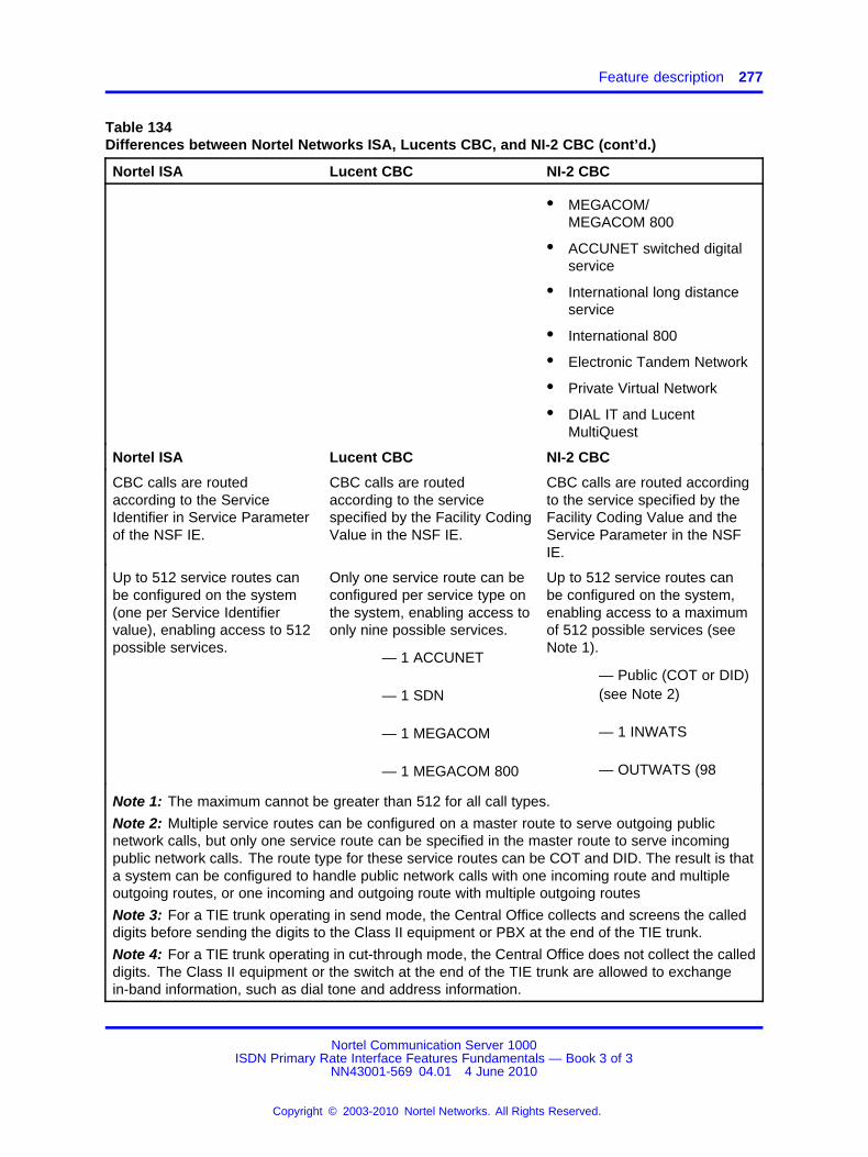
Feature description 277
Table 134Differences between Nortel Networks ISA, Lucents CBC, and NI-2 CBC (cont’d.)
Nortel ISA Lucent CBC NI-2 CBC
• MEGACOM/MEGACOM 800
• ACCUNET switched digitalservice
• International long distanceservice
• International 800
• Electronic Tandem Network
• Private Virtual Network
• DIAL IT and LucentMultiQuest
Nortel ISA Lucent CBC NI-2 CBC
CBC calls are routedaccording to the ServiceIdentifier in Service Parameterof the NSF IE.
CBC calls are routedaccording to the servicespecified by the Facility CodingValue in the NSF IE.
CBC calls are routed accordingto the service specified by theFacility Coding Value and theService Parameter in the NSFIE.
Up to 512 service routes canbe configured on the system(one per Service Identifiervalue), enabling access to 512possible services.
Only one service route can beconfigured per service type onthe system, enabling access toonly nine possible services.
— 1 ACCUNET
— 1 SDN
— 1 MEGACOM
— 1 MEGACOM 800
Up to 512 service routes canbe configured on the system,enabling access to a maximumof 512 possible services (seeNote 1).
— Public (COT or DID)(see Note 2)
— 1 INWATS
— OUTWATS (98
Note 1: The maximum cannot be greater than 512 for all call types.
Note 2: Multiple service routes can be configured on a master route to serve outgoing publicnetwork calls, but only one service route can be specified in the master route to serve incomingpublic network calls. The route type for these service routes can be COT and DID. The result is thata system can be configured to handle public network calls with one incoming route and multipleoutgoing routes, or one incoming and outgoing route with multiple outgoing routes
Note 3: For a TIE trunk operating in send mode, the Central Office collects and screens the calleddigits before sending the digits to the Class II equipment or PBX at the end of the TIE trunk.
Note 4: For a TIE trunk operating in cut-through mode, the Central Office does not collect the calleddigits. The Class II equipment or the switch at the end of the TIE trunk are allowed to exchangein-band information, such as dial tone and address information.
Nortel Communication Server 1000ISDN Primary Rate Interface Features Fundamentals — Book 3 of 3
NN43001-569 04.01 4 June 2010
Copyright © 2003-2010 Nortel Networks. All Rights Reserved.
.
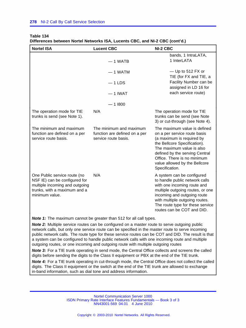
278 NI-2 Call By Call Service Selection
Table 134Differences between Nortel Networks ISA, Lucents CBC, and NI-2 CBC (cont’d.)
Nortel ISA Lucent CBC NI-2 CBC
— 1 WATB
— 1 WATM
— 1 LDS
— 1 IWAT
— 1 I800
bands, 1 IntraLATA,1 InterLATA
— Up to 512 FX orTIE (for FX and TIE, aFacility Number can beassigned in LD 16 foreach service route)
The operation mode for TIEtrunks is send (see Note 1).
N/A The operation mode for TIEtrunks can be send (see Note3) or cut-through (see Note 4).
The minimum and maximumfunction are defined on a perservice route basis.
The minimum and maximumfunction are defined on a perservice route basis.
The maximum value is definedon a per service route basis(a maximum is required bythe Bellcore Specification).The maximum value is alsodefined by the serving CentralOffice. There is no minimumvalue allowed by the BellcoreSpecification.
One Public service route (noNSF IE) can be configured formultiple incoming and outgoingtrunks, with a maximum and aminimum value.
N/A A system can be configuredto handle public network callswith one incoming route andmultiple outgoing routes, or oneincoming and outgoing routewith multiple outgoing routes.The route type for these serviceroutes can be COT and DID.
Note 1: The maximum cannot be greater than 512 for all call types.
Note 2: Multiple service routes can be configured on a master route to serve outgoing publicnetwork calls, but only one service route can be specified in the master route to serve incomingpublic network calls. The route type for these service routes can be COT and DID. The result is thata system can be configured to handle public network calls with one incoming route and multipleoutgoing routes, or one incoming and outgoing route with multiple outgoing routes
Note 3: For a TIE trunk operating in send mode, the Central Office collects and screens the calleddigits before sending the digits to the Class II equipment or PBX at the end of the TIE trunk.
Note 4: For a TIE trunk operating in cut-through mode, the Central Office does not collect the calleddigits. The Class II equipment or the switch at the end of the TIE trunk are allowed to exchangein-band information, such as dial tone and address information.
Nortel Communication Server 1000ISDN Primary Rate Interface Features Fundamentals — Book 3 of 3
NN43001-569 04.01 4 June 2010
Copyright © 2003-2010 Nortel Networks. All Rights Reserved.
.
Feature implementation 279
Operating parametersNI-2 Call By Call Service Selection does not support the TIE trunkcut-through mode.
The maximum number of NI-2 Call By Call Service Selection routes thatcan be configured on a system is 512.
The maximum number of trunks for each route is 254 for each masterroute.
Feature interactionsCalling Party PrivacyThe Calling Party Privacy feature allows a user the option of restrictingthe display of the calling number on the phone of the called party. TheINWATS service requires that the CLID always be displayed. Therefore,subscribers to INWATS cannot restrict the display of the calling number,even though they have the Calling Party Privacy feature active.
Feature packagingThe NI-2 Call By Call Service Selection feature requires the NI-2 Call ByCall (NI2 CBC) package 334.
The following packages are also required as dependencies:
• Integrated Services Digital Network (ISDN) package 145
• Primary Rate Access (PRA) package 146
• Multi-purpose Serial Data Link (MSDL) package 222
• National ISDN-2 (NI2) package 291
Feature implementationTask summary list
The following is a summary of the tasks in this section:
1. Table 135 "LD 17: Configure the primary D-channel for the NI-2 BasicCall Service." (page 280)
2. Table 136 "LD 16: Configure the NI-2 Call By Call Service masterroute." (page 280)
3. Table 137 "LD 14: Define the associated list of trunks (B-channels) thatare to be shared by the NI-2 CBC service routes." (page 281)
4. Table 138 "LD 16: Configure the NI-2 CBC service routes." (page 281)
Nortel Communication Server 1000ISDN Primary Rate Interface Features Fundamentals — Book 3 of 3
NN43001-569 04.01 4 June 2010
Copyright © 2003-2010 Nortel Networks. All Rights Reserved.
.
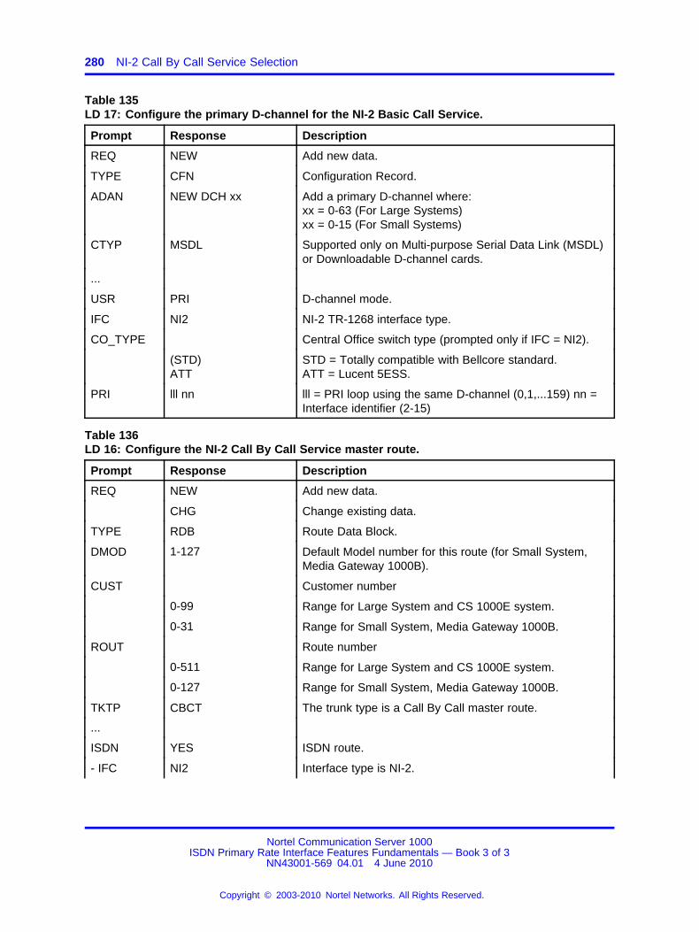
280 NI-2 Call By Call Service Selection
Table 135LD 17: Configure the primary D-channel for the NI-2 Basic Call Service.
Prompt Response Description
REQ NEW Add new data.
TYPE CFN Configuration Record.
ADAN NEW DCH xx Add a primary D-channel where:xx = 0-63 (For Large Systems)xx = 0-15 (For Small Systems)
CTYP MSDL Supported only on Multi-purpose Serial Data Link (MSDL)or Downloadable D-channel cards.
...
USR PRI D-channel mode.
IFC NI2 NI-2 TR-1268 interface type.
CO_TYPE Central Office switch type (prompted only if IFC = NI2).
(STD)ATT
STD = Totally compatible with Bellcore standard.ATT = Lucent 5ESS.
PRI lll nn lll = PRI loop using the same D-channel (0,1,...159) nn =Interface identifier (2-15)
Table 136LD 16: Configure the NI-2 Call By Call Service master route.
Prompt Response Description
REQ NEW Add new data.
CHG Change existing data.
TYPE RDB Route Data Block.
DMOD 1-127 Default Model number for this route (for Small System,Media Gateway 1000B).
CUST Customer number
0-99 Range for Large System and CS 1000E system.
0-31 Range for Small System, Media Gateway 1000B.
ROUT Route number
0-511 Range for Large System and CS 1000E system.
0-127 Range for Small System, Media Gateway 1000B.
TKTP CBCT The trunk type is a Call By Call master route.
...
ISDN YES ISDN route.
- IFC NI2 Interface type is NI-2.
Nortel Communication Server 1000ISDN Primary Rate Interface Features Fundamentals — Book 3 of 3
NN43001-569 04.01 4 June 2010
Copyright © 2003-2010 Nortel Networks. All Rights Reserved.
.

Feature implementation 281
Table 136LD 16: Configure the NI-2 Call By Call Service master route. (cont’d.)
Prompt Response Description
- IPUB0-5110-127
Service route to be used for incoming network calls.For Large SystemsFor Small Systems
...
- - PNI 1-32700 Private Network Identifier.
...
ICOG IAOICTOGT
IAO = The trunk is incoming and outgoing.ICT = The trunk is incoming only.OGT = The trunk is outgoing only.
Table 137LD 14: Define the associated list of trunks (B-channels) that are to be shared by the NI-2 CBCservice routes.
Prompt Response Description
REQ NEW Add new data.
CHG Change existing data.
TYPE CBCT Call By Call trunk.
TN Terminal Number.
l ch Loop and channel for digital trunks, where:l = Previously defined loop number (0-159).ch = channel (1-24).
CUST Customer number
0-99 Range for Large System and CS 1000E system.
0-31 Range for Small System, Media Gateway 1000B.
RTMB Route number and Member Number
0-511 1-4000 Range for Large System and CS 1000E system.
0-127 1-4000 Range for Small System, Media Gateway 1000B.
Note: Up to 512 service routes can be configured using this procedure.
Table 138LD 16: Configure the NI-2 CBC service routes.
Prompt Response Description
REQ NEW Add new data.
CHG Change existing data.
TYPE RDB Route Data Block.
CUST Customer number
Nortel Communication Server 1000ISDN Primary Rate Interface Features Fundamentals — Book 3 of 3
NN43001-569 04.01 4 June 2010
Copyright © 2003-2010 Nortel Networks. All Rights Reserved.
.

282 NI-2 Call By Call Service Selection
Table 138LD 16: Configure the NI-2 CBC service routes. (cont’d.)
Prompt Response Description
0-99 Range for Large System and CS 1000E system.
0-31 Range for Small System, Media Gateway 1000B.
ROUT Route number
Note: Service route number must be different than thevalue entered for the master route.
0-511 Range for Large System and CS 1000E system.
0-127 Range for Small System, Media Gateway 1000B.
...
TKTPTIECOTDIDWATFEX
Service trunk type.TIECentral OfficeDirect Inward DialWide Area Telecommunication ServiceForeign Exchange
...
ISDN YES ISDN route.
- IFC NI2 Interface type is NI-2.
- CBCR YES Service route indicator.
- - RTN0-5110-127
Master route number, as previously defined in LD 16.For Large SystemsFor Small Systems
- - SRVC (0)-31 Decimal value of the service provisioned for NI-2.Prompted only if IFC = NI2.
0 = Public call service19 = FX (Foreign Exchange) service20 = TIE service17 = Inward Wide Area Telecommunication Service(INWATS) service18 = Outward Wide Area Telecommunication Service(OUTWATS) service.
Lucent proprietary call by call services can also be definedhere. Refer to List for a list of these values.
- - FACN (0)-99999 TIE or FX facility number.Prompted only if IFC = NI2, and SRVC = 19 (FX) or 20(TIE).
Nortel Communication Server 1000ISDN Primary Rate Interface Features Fundamentals — Book 3 of 3
NN43001-569 04.01 4 June 2010
Copyright © 2003-2010 Nortel Networks. All Rights Reserved.
.

Sample configuration 283
Table 138LD 16: Configure the NI-2 CBC service routes. (cont’d.)
Prompt Response Description
- - BAND (0)-99 OUTWATS band number.Prompted only if IFC= NI2 and SRVC = 18 (OUTWATS).
- - IEC (0)-xxx(0)-xxxx
Inter-Exchange Carrier providing the service.Prompted if IFC = NI2 and SRVC = 0-16, 18, or 21-31.
- - MAX xxx Maximum number of trunks for the service route. Thisvalue must be the same as the value assigned by theCentral Office at the time of subscription.
Sample configurationThe following provides a sample configuration of the NI-2 CBC feature.
LD 17 provides a sample configuration of a primary D-channel for the NI-2Basic Call Service.
Table 139LD 17: Configure a primary D-channel for the NI-2 Basic Call Service.
Prompt Response Description
REQ NEW Add configuration information.
TYPE CFN Configuration Record.
ADAN NEW DCH 1 Add a primary D-channel for NI-2, where 1 is the primaryD-channel number.
CTYP MSDL Supported only on Multi-purpose Serial Data Link (MSDL)or Downloadable D-channel cards.
...
USR PRI D-channel mode.
IFC NI2 NI-2 TR-1268 interface type.
CO_TYPE STD Central Office switch type for the NI-2 interface.
STD = Totally compatible with Bellcore standard.
PRI 1 2 1 = PRI loop using the same D-channel (0,1,...159)2 = Interface identifier (2,3,...15)
LD 16 configures a trunk route as an NI-2 Call By Call Service Selectionmaster route.
Table 140LD 16: Configure a trunk route as an NI-2 Call By Call Service Selection master route.
Prompt Response Description
REQ CHG Change existing data.
Nortel Communication Server 1000ISDN Primary Rate Interface Features Fundamentals — Book 3 of 3
NN43001-569 04.01 4 June 2010
Copyright © 2003-2010 Nortel Networks. All Rights Reserved.
.

284 NI-2 Call By Call Service Selection
Table 140LD 16: Configure a trunk route as an NI-2 Call By Call Service Selection master route. (cont’d.)
Prompt Response Description
TYPE RDB Route Data Block.
DMOD 1-127 Default Model number for this route (for Small System,Media Gateway 1000B).
CUST Customer number
0-99 Range for Large System and CS 1000E system.
0-31 Range for Small System, Media Gateway 1000B.
ROUT 0 Master route number
TKTP CBCT The trunk type is a Call By Call master route.
DTRK YES Trunk route is digital.
DGTP PRI Trunk type is digital.
ISDN YES ISDN is used.
...
- IFC NI2 Interface type is NI-2.
- IPUB 1 Service route for incoming public network calls.
...
- - PNI 1 Customer’s Private Network Identifier.
...
ICOG IAO The trunk is incoming and outgoing.
LD 14 defines the associated list of trunks (B-channels) that are to beshared by the NI-2 CBC service routes.
Table 141LD 14: Define the associated list of trunks (B-channels) to be shared by NI-2 CBC serviceroutes.
Prompt Response Description
REQ CHG Change existing data.
TYPE CBCT Call By Call trunk.
TN Terminal Number
01
Loop and channel for digital trunks, where:0 = Previously defined loop number (0-159).1 = channel (1-24).
CUST Customer number
0-99 Range for Large System and CS 1000E system.
Nortel Communication Server 1000ISDN Primary Rate Interface Features Fundamentals — Book 3 of 3
NN43001-569 04.01 4 June 2010
Copyright © 2003-2010 Nortel Networks. All Rights Reserved.
.

Feature operation 285
Table 141LD 14: Define the associated list of trunks (B-channels) to be shared by NI-2 CBC serviceroutes. (cont’d.)
Prompt Response Description
0-31 Range for Small System, Media Gateway 1000B.
RTMB 0 1 CBC master route and member number.
LD 16 defines the NI-2 CBC service routes. Up to 512 service routes canbe configured using this procedure.
Table 142LD 16: Define the NI-2 CBC service routes.
Prompt Response Description
REQ NEW Add new data.
CHG Change existing data.
TYPE RDB Route Data Block.
CUST Customer number
0-99 Range for Large System and CS 1000E system.
0-31 Range for Small System, Media Gateway 1000B.
ROUT 1 Service Route number
...
TKTP TIE Service trunk type.
...
ISDN YES ISDN route.
- IFC NI2 Interface type is NI-2.
- CBCR YES Service route indicator.
- - RTN 0 Master route number, as previously defined in LD 16, withwhich the service routes are associated.
- - SRVC 20 Decimal value of for TIE service.
- - FACN 20 TIE Facility Number.
- - MAX 1 Maximum number of trunks for the service route. Thisvalue must be the same as the value assigned by theCentral Office at the time of subscription.
Feature operationNo specific operating procedures are required to use this feature.
Nortel Communication Server 1000ISDN Primary Rate Interface Features Fundamentals — Book 3 of 3
NN43001-569 04.01 4 June 2010
Copyright © 2003-2010 Nortel Networks. All Rights Reserved.
.

286 NI-2 Call By Call Service Selection
Nortel Communication Server 1000ISDN Primary Rate Interface Features Fundamentals — Book 3 of 3
NN43001-569 04.01 4 June 2010
Copyright © 2003-2010 Nortel Networks. All Rights Reserved.
.

287.
NI-2 Name Display SupplementaryService
ContentsThis section contains information on the following topics:
“Applicable regions” (page 287)
“Feature description” (page 287)
“Operating parameters” (page 289)
“Feature interactions” (page 289)
“Feature packaging” (page 293)
“Feature implementation” (page 293)
“Task summary list” (page 293)
“Feature operation” (page 296)
Applicable regionsThis feature applies only to North America. Contact your system supplieror your Nortel representative to verify support of this product in your area.
Feature descriptionThe NI-2 Name Display Supplementary Service extends the systemcapability to support name display on National ISDN-2 (NI-2) interfaces.This feature provides the following:
• calling name information on outgoing and incoming calls
• Connected/Alerting name information to incoming calls and fromoutgoing calls
The NDS feature retains the existing user interface for Meridian CustomerDefined Network (MCDN) name display capabilities.
Nortel Communication Server 1000ISDN Primary Rate Interface Features Fundamentals — Book 3 of 3
NN43001-569 04.01 4 June 2010
Copyright © 2003-2010 Nortel Networks. All Rights Reserved.
.
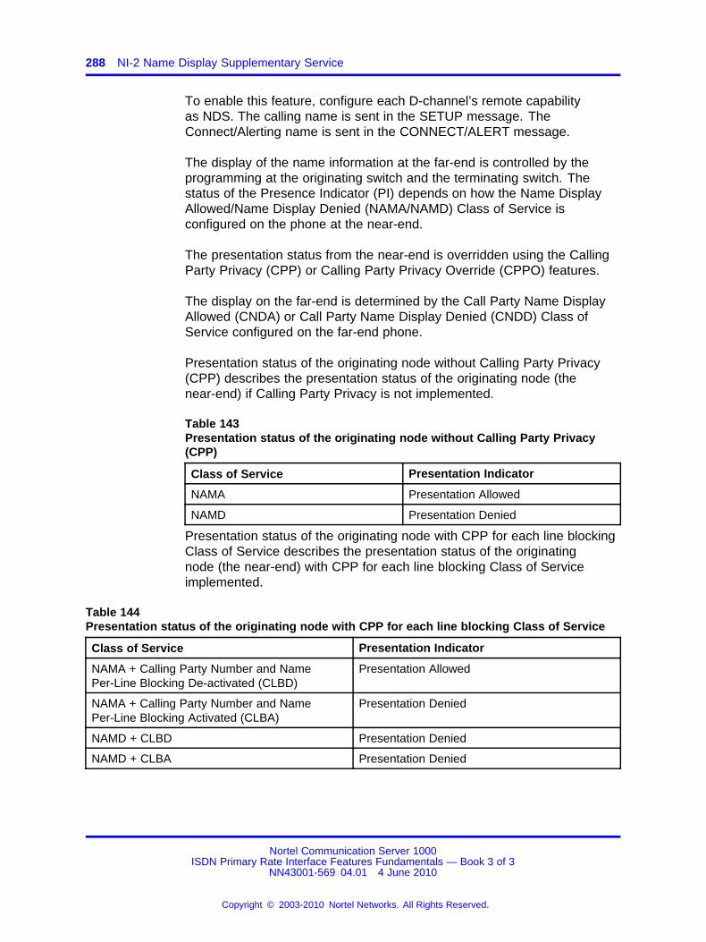
288 NI-2 Name Display Supplementary Service
To enable this feature, configure each D-channel’s remote capabilityas NDS. The calling name is sent in the SETUP message. TheConnect/Alerting name is sent in the CONNECT/ALERT message.
The display of the name information at the far-end is controlled by theprogramming at the originating switch and the terminating switch. Thestatus of the Presence Indicator (PI) depends on how the Name DisplayAllowed/Name Display Denied (NAMA/NAMD) Class of Service isconfigured on the phone at the near-end.
The presentation status from the near-end is overridden using the CallingParty Privacy (CPP) or Calling Party Privacy Override (CPPO) features.
The display on the far-end is determined by the Call Party Name DisplayAllowed (CNDA) or Call Party Name Display Denied (CNDD) Class ofService configured on the far-end phone.
Presentation status of the originating node without Calling Party Privacy(CPP) describes the presentation status of the originating node (thenear-end) if Calling Party Privacy is not implemented.
Table 143Presentation status of the originating node without Calling Party Privacy(CPP)
Class of Service Presentation Indicator
NAMA Presentation Allowed
NAMD Presentation Denied
Presentation status of the originating node with CPP for each line blockingClass of Service describes the presentation status of the originatingnode (the near-end) with CPP for each line blocking Class of Serviceimplemented.
Table 144Presentation status of the originating node with CPP for each line blocking Class of Service
Class of Service Presentation Indicator
NAMA + Calling Party Number and NamePer-Line Blocking De-activated (CLBD)
Presentation Allowed
NAMA + Calling Party Number and NamePer-Line Blocking Activated (CLBA)
Presentation Denied
NAMD + CLBD Presentation Denied
NAMD + CLBA Presentation Denied
Nortel Communication Server 1000ISDN Primary Rate Interface Features Fundamentals — Book 3 of 3
NN43001-569 04.01 4 June 2010
Copyright © 2003-2010 Nortel Networks. All Rights Reserved.
.
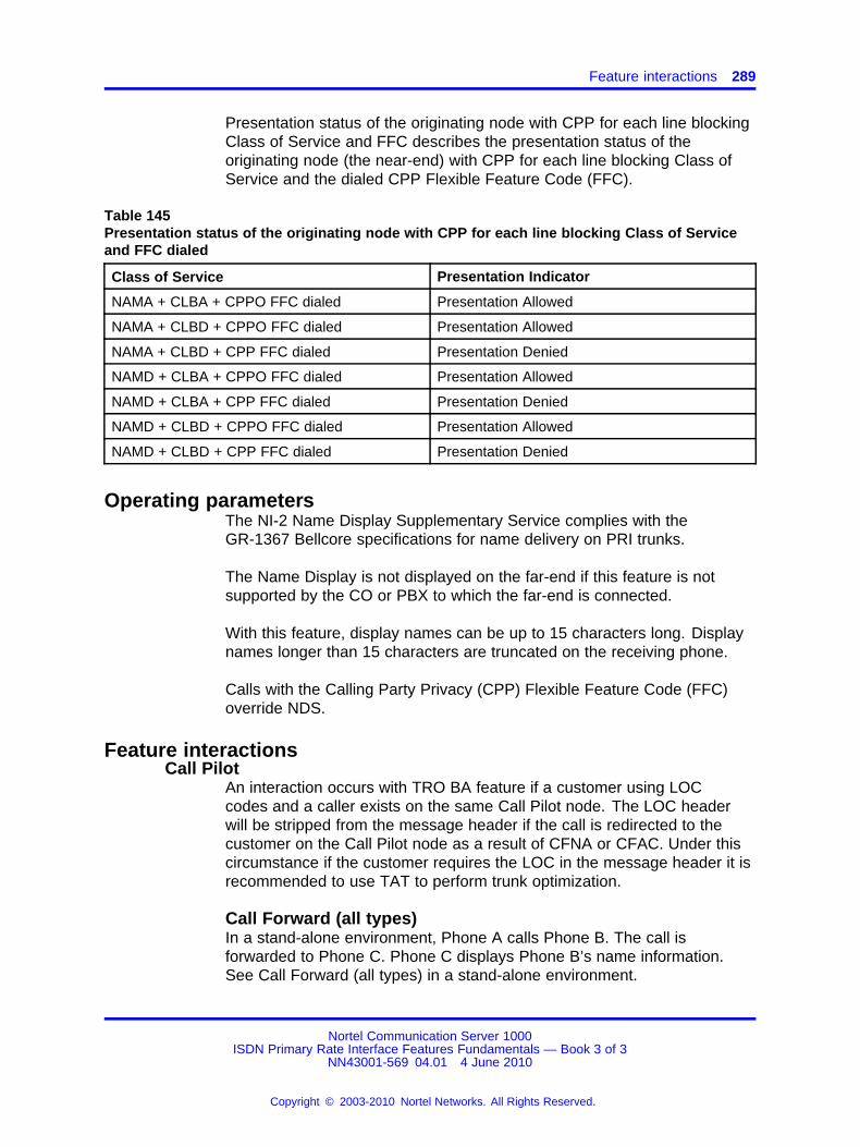
Feature interactions 289
Presentation status of the originating node with CPP for each line blockingClass of Service and FFC describes the presentation status of theoriginating node (the near-end) with CPP for each line blocking Class ofService and the dialed CPP Flexible Feature Code (FFC).
Table 145Presentation status of the originating node with CPP for each line blocking Class of Serviceand FFC dialed
Class of Service Presentation Indicator
NAMA + CLBA + CPPO FFC dialed Presentation Allowed
NAMA + CLBD + CPPO FFC dialed Presentation Allowed
NAMA + CLBD + CPP FFC dialed Presentation Denied
NAMD + CLBA + CPPO FFC dialed Presentation Allowed
NAMD + CLBA + CPP FFC dialed Presentation Denied
NAMD + CLBD + CPPO FFC dialed Presentation Allowed
NAMD + CLBD + CPP FFC dialed Presentation Denied
Operating parametersThe NI-2 Name Display Supplementary Service complies with theGR-1367 Bellcore specifications for name delivery on PRI trunks.
The Name Display is not displayed on the far-end if this feature is notsupported by the CO or PBX to which the far-end is connected.
With this feature, display names can be up to 15 characters long. Displaynames longer than 15 characters are truncated on the receiving phone.
Calls with the Calling Party Privacy (CPP) Flexible Feature Code (FFC)override NDS.
Feature interactionsCall Pilot
An interaction occurs with TRO BA feature if a customer using LOCcodes and a caller exists on the same Call Pilot node. The LOC headerwill be stripped from the message header if the call is redirected to thecustomer on the Call Pilot node as a result of CFNA or CFAC. Under thiscircumstance if the customer requires the LOC in the message header it isrecommended to use TAT to perform trunk optimization.
Call Forward (all types)In a stand-alone environment, Phone A calls Phone B. The call isforwarded to Phone C. Phone C displays Phone B’s name information.See Call Forward (all types) in a stand-alone environment.
Nortel Communication Server 1000ISDN Primary Rate Interface Features Fundamentals — Book 3 of 3
NN43001-569 04.01 4 June 2010
Copyright © 2003-2010 Nortel Networks. All Rights Reserved.
.
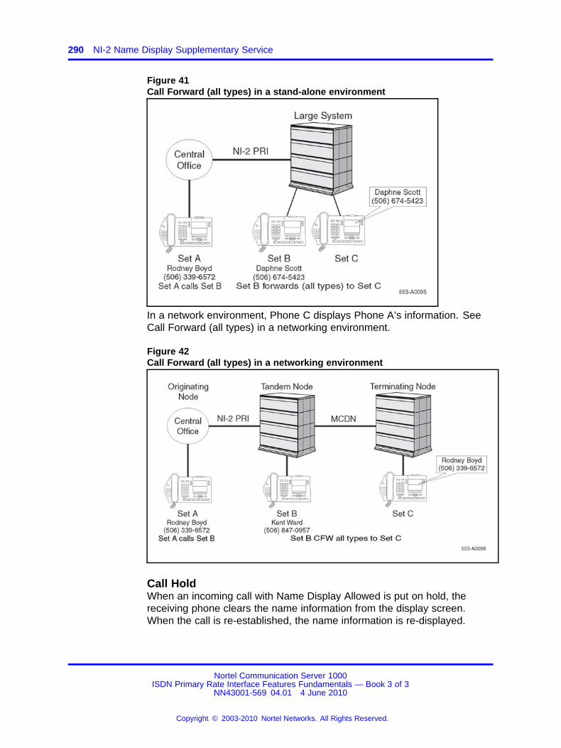
290 NI-2 Name Display Supplementary Service
Figure 41Call Forward (all types) in a stand-alone environment
In a network environment, Phone C displays Phone A’s information. SeeCall Forward (all types) in a networking environment.
Figure 42Call Forward (all types) in a networking environment
Call HoldWhen an incoming call with Name Display Allowed is put on hold, thereceiving phone clears the name information from the display screen.When the call is re-established, the name information is re-displayed.
Nortel Communication Server 1000ISDN Primary Rate Interface Features Fundamentals — Book 3 of 3
NN43001-569 04.01 4 June 2010
Copyright © 2003-2010 Nortel Networks. All Rights Reserved.
.
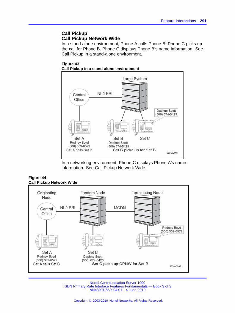
Feature interactions 291
Call PickupCall Pickup Network WideIn a stand-alone environment, Phone A calls Phone B. Phone C picks upthe call for Phone B. Phone C displays Phone B’s name information. SeeCall Pickup in a stand-alone environment.
Figure 43Call Pickup in a stand-alone environment
In a networking environment, Phone C displays Phone A’s nameinformation. See Call Pickup Network Wide.
Figure 44Call Pickup Network Wide
Nortel Communication Server 1000ISDN Primary Rate Interface Features Fundamentals — Book 3 of 3
NN43001-569 04.01 4 June 2010
Copyright © 2003-2010 Nortel Networks. All Rights Reserved.
.
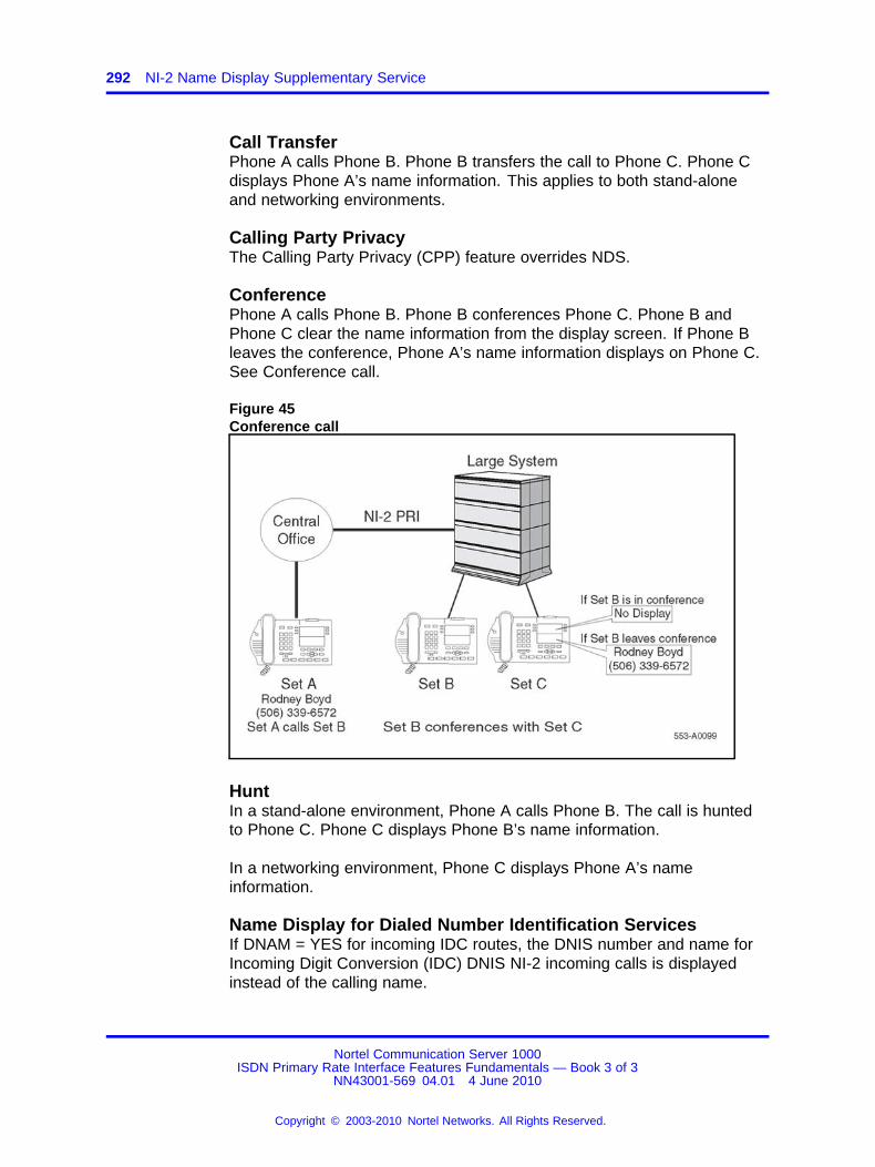
292 NI-2 Name Display Supplementary Service
Call TransferPhone A calls Phone B. Phone B transfers the call to Phone C. Phone Cdisplays Phone A’s name information. This applies to both stand-aloneand networking environments.
Calling Party PrivacyThe Calling Party Privacy (CPP) feature overrides NDS.
ConferencePhone A calls Phone B. Phone B conferences Phone C. Phone B andPhone C clear the name information from the display screen. If Phone Bleaves the conference, Phone A’s name information displays on Phone C.See Conference call.
Figure 45Conference call
HuntIn a stand-alone environment, Phone A calls Phone B. The call is huntedto Phone C. Phone C displays Phone B’s name information.
In a networking environment, Phone C displays Phone A’s nameinformation.
Name Display for Dialed Number Identification ServicesIf DNAM = YES for incoming IDC routes, the DNIS number and name forIncoming Digit Conversion (IDC) DNIS NI-2 incoming calls is displayedinstead of the calling name.
Nortel Communication Server 1000ISDN Primary Rate Interface Features Fundamentals — Book 3 of 3
NN43001-569 04.01 4 June 2010
Copyright © 2003-2010 Nortel Networks. All Rights Reserved.
.
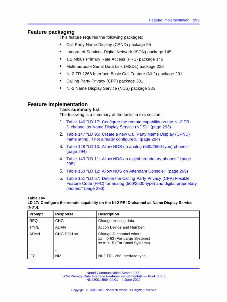
Feature implementation 293
Feature packagingThis feature requires the following packages:
• Call Party Name Display (CPND) package 95
• Integrated Services Digital Network (ISDN) package 145
• 1.5 Mbit/s Primary Rate Access (PRS) package 146
• Multi-purpose Serial Data Link (MSDL) package 222
• NI-2 TR-1268 Interface Basic Call Feature (NI-2) package 291
• Calling Party Privacy (CPP) package 301
• NI-2 Name Display Service (NDS) package 385
Feature implementationTask summary listThe following is a summary of the tasks in this section:
1. Table 146 "LD 17: Configure the remote capability on the NI-2 PRID-channel as Name Display Service (NDS)." (page 293)
2. Table 147 "LD 95: Create a new Call Party Name Display (CPND)name string, if not already configured." (page 294)
3. Table 148 "LD 10: Allow NDS on analog (500/2500-type) phones."(page 294)
4. Table 149 "LD 11: Allow NDS on digital proprietary phones." (page295)
5. Table 150 "LD 12: Allow NDS on Attendant Console." (page 295)
6. Table 151 "LD 57: Define the Calling Party Privacy (CPP) FlexibleFeature Code (FFC) for analog (500/2500-type) and digital proprietaryphones." (page 296)
Table 146LD 17: Configure the remote capability on the NI-2 PRI D-channel as Name Display Service(NDS).
Prompt Response Description
REQ CHG Change existing data.
TYPE ADAN Action Device and Number.
ADAN CHG DCH xx Change D-channel where:xx = 0-63 (For Large Systems)xx = 0-15 (For Small Systems)
.... ....
IFC NI2 NI-2 TR-1268 Interface type.
Nortel Communication Server 1000ISDN Primary Rate Interface Features Fundamentals — Book 3 of 3
NN43001-569 04.01 4 June 2010
Copyright © 2003-2010 Nortel Networks. All Rights Reserved.
.
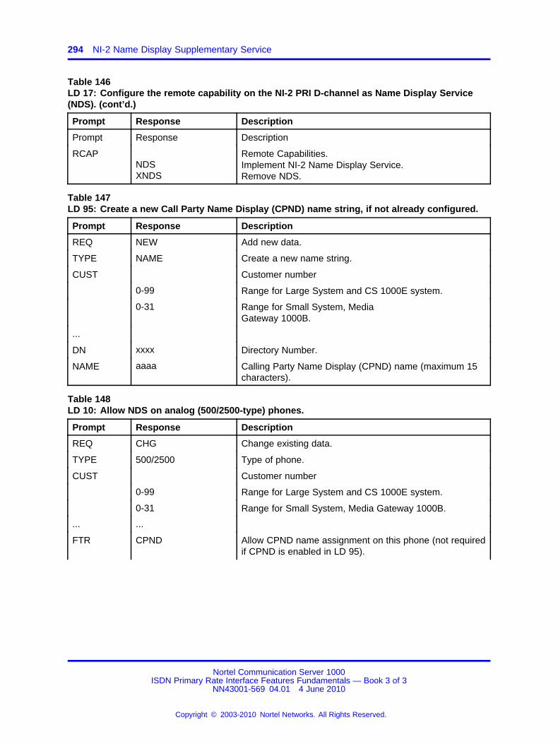
294 NI-2 Name Display Supplementary Service
Table 146LD 17: Configure the remote capability on the NI-2 PRI D-channel as Name Display Service(NDS). (cont’d.)
Prompt Response Description
Prompt Response Description
RCAPNDSXNDS
Remote Capabilities.Implement NI-2 Name Display Service.Remove NDS.
Table 147LD 95: Create a new Call Party Name Display (CPND) name string, if not already configured.
Prompt Response Description
REQ NEW Add new data.
TYPE NAME Create a new name string.
CUST Customer number
0-99 Range for Large System and CS 1000E system.
0-31 Range for Small System, MediaGateway 1000B.
...
DN xxxx Directory Number.
NAME aaaa Calling Party Name Display (CPND) name (maximum 15characters).
Table 148LD 10: Allow NDS on analog (500/2500-type) phones.
Prompt Response Description
REQ CHG Change existing data.
TYPE 500/2500 Type of phone.
CUST Customer number
0-99 Range for Large System and CS 1000E system.
0-31 Range for Small System, Media Gateway 1000B.
... ...
FTR CPND Allow CPND name assignment on this phone (not requiredif CPND is enabled in LD 95).
Nortel Communication Server 1000ISDN Primary Rate Interface Features Fundamentals — Book 3 of 3
NN43001-569 04.01 4 June 2010
Copyright © 2003-2010 Nortel Networks. All Rights Reserved.
.

Feature implementation 295
Table 148LD 10: Allow NDS on analog (500/2500-type) phones. (cont’d.)
Prompt Response Description
CLS (CNDD)
CNDA
Called Party Name Display denied.
Called Party Name Display allowed (applies only toportable, personal phones). Allowed if WRLS=Yes.
CLS (NAMD)
NAMA
Name Display Denied on the far-end.
Name Display Allowed on the far-end.
Table 149LD 11: Allow NDS on digital proprietary phones.
Prompt Response Description
REQ NEW Add new data.
CHG Change existing data.
TYPE a...a Telephone type. Type ? for a list of possible responses.
CUST Customer number
0-99 Range for Large System and CS 1000E system.
0-31 Range for Small System, Media Gateway 1000B.
...
CLS (CNDD)
CNDA
Call Party Name Display denied on this phone.
Call Party Name Display allowed on this phone.
CLS (NAMD)
NAMA
Name Display denied on the far-end.
Name Display allowed on the far-end.
Table 150LD 12: Allow NDS on Attendant Console.
Prompt Response Description
REQ NEW Add new data.
TYPE 2250 Attendant Console type.
CUST Customer number
0-99 Range for Large System and CS 1000E system.
0-31 Range for Small System, MediaGateway 1000B.
Nortel Communication Server 1000ISDN Primary Rate Interface Features Fundamentals — Book 3 of 3
NN43001-569 04.01 4 June 2010
Copyright © 2003-2010 Nortel Networks. All Rights Reserved.
.
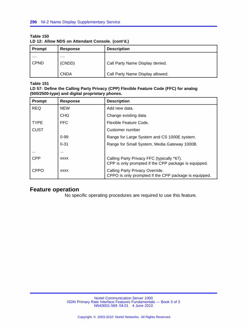
296 NI-2 Name Display Supplementary Service
Table 150LD 12: Allow NDS on Attendant Console. (cont’d.)
Prompt Response Description
.... ....
CPND (CNDD)
CNDA
Call Party Name Display denied.
Call Party Name Display allowed.
Table 151LD 57: Define the Calling Party Privacy (CPP) Flexible Feature Code (FFC) for analog(500/2500-type) and digital proprietary phones.
Prompt Response Description
REQ NEW Add new data.
CHG Change existing data.
TYPE FFC Flexible Feature Code.
CUST Customer number
0-99 Range for Large System and CS 1000E system.
0-31 Range for Small System, Media Gateway 1000B.
... ...
CPP xxxx Calling Party Privacy FFC (typically *67).CPP is only prompted if the CPP package is equipped.
CPPO xxxx Calling Party Privacy Override.CPPO is only prompted if the CPP package is equipped.
Feature operationNo specific operating procedures are required to use this feature.
Nortel Communication Server 1000ISDN Primary Rate Interface Features Fundamentals — Book 3 of 3
NN43001-569 04.01 4 June 2010
Copyright © 2003-2010 Nortel Networks. All Rights Reserved.
.
297.
NI-2/QSIG Compliance Update
ContentsThis section contains information on the following topics:
“Feature description” (page 297)
“Operating parameters” (page 298)
“Feature interactions” (page 298)
“Feature packaging” (page 298)
“Feature implementation” (page 299)
“Task summary list” (page 299)
“Feature operation” (page 300)
Feature descriptionThe NI-2/QSIG Compliance Update feature makes the NI-2 andQSIG interfaces compliant with the latest standards documents. Thisfeature applies to both Basic Rate Interface and Primary Rate Interfaceconnections.
Note: ISDN BRI trunking is not available in North America.
Compliancy with the standards has evolved as follows:
• ETSI QSIG basic call functionality now complies with the ETS 300-172,fourth edition (1997) standards document. Initially, support for theISDN ETSI QSIG interface and the basic call capability was introduced.This version of the interface was based on the ETS 300-172, firstedition (1990) document.
• ISO QSIG basic call functionality now complies with the NorthAmerican standards document, ISO/IEC 115172 second edition.Initially, support for the ISDN ISO QSIG interface and the basic call
Nortel Communication Server 1000ISDN Primary Rate Interface Features Fundamentals — Book 3 of 3
NN43001-569 04.01 4 June 2010
Copyright © 2003-2010 Nortel Networks. All Rights Reserved.
.
298 NI-2/QSIG Compliance Update
capability was introduced. This version of the interface was based onthe ISO/IEC 115172 first edition document.
• National ISDN-2 (NI-2) basic call functionality now complies with thelatest North American standards document, Bellcore TR-NWT-001268.
The NI-2/QSIG Compliance Update feature changes the way the systemhandles a recoverable error. Instead of sending incorrect call stateinformation, the system now sends a correct call state in the STATUSmessage.
The mandatory parts of the STATUS message are: CAUSE (indicatestype of error) and CALL STATE. Whenever the system encounters arecoverable error it sends a STATUS message. Recoverable errors can becases such as:
• the IE received is non-mandatory and unrecognized
• the IE is non-mandatory and has invalid contents
In cases such as these, the basic call can still be processed, withoutaffecting basic services, if the call state sent does not hinder this process.All the protocol must do is report the errors.
Before the protocol compliancy was updated, the system sent the callstate information as it existed before receiving the incoming call messagewith the recoverable error. This was not appropriate for other-vendorswitches which dropped the call when the incorrect call state informationwas received. Now, the system sends the call state information, adjustedafter the incoming call message was received. The adjusted call stateinformation allows the other vendor switch to proceed with the basic call.
Operating parametersFatal errors and errors in non-call-associated messages (such asmaintenance messages) are not affected by this feature. These errorscontinue to use the existing error reporting mechanism.
Feature interactionsThere are no feature interactions associated with this feature.
Feature packagingThe following packages are required for the ISDN PRI QSIG interface:
• ISDN Signaling (ISDN) package 145
• 2 Mbit PRI (PRI2) package 154
• International PRA (IPRA) package 202
Nortel Communication Server 1000ISDN Primary Rate Interface Features Fundamentals — Book 3 of 3
NN43001-569 04.01 4 June 2010
Copyright © 2003-2010 Nortel Networks. All Rights Reserved.
.
Feature implementation 299
• Multi-Purpose Serial Data Link (MSDL) package 222
• QSIG Interface (QSIG) package 263
The following packages are required for the ISL QSIG interface:
• ISDN Signaling (ISDN) package 145
• ISDN Signaling Link (ISL) package 147
• 2 Mbit PRI (PRI2) package 154
• Multi-Purpose Serial Data Link (MSDL) package 222 (for ISL on PRIonly)
• QSIG Interface (QSIG) package 263
The following packages are required for the ISDN BRIT QSIG interface:
• ISDN Signaling (ISDN) package 145
• ISDN Basic Rate Interface (BRI) package 216
• Multi-Purpose Serial Data Link (MSDL) package 222
• ISDN BRI Trunk Access (BRIT) package 233
• QSIG Interface (QSIG) package 263
The following packages are required for the PRI NI-2 interface:
• ISDN Signaling (ISDN) package 145
• Primary Rate Interface (PRA) package 146
• Multi-Purpose Serial Data Link (MSDL) package 222
• National ISDN-2 Interface (NI-2) package 291
Feature implementationTask summary list
The following is a summary of the tasks in this section:
1. Table 152 "LD 17: Assign the configuration record." (page 299)
2. Table 153 "LD 16: Use this overlay to define a route data block." (page300)
Table 152LD 17: Assign the configuration record.
Prompt Response Description
REQ NEW Add new data.
CHG Change existing data.
Nortel Communication Server 1000ISDN Primary Rate Interface Features Fundamentals — Book 3 of 3
NN43001-569 04.01 4 June 2010
Copyright © 2003-2010 Nortel Networks. All Rights Reserved.
.

300 NI-2/QSIG Compliance Update
Table 152LD 17: Assign the configuration record. (cont’d.)
Prompt Response Description
TYPE ADAN Action Device And Number
...
IFC ISIGESIG Interface ID for ISO QSIG.Interface ID for ETSI QSIG.
TIMR (NO) YES NO = skip timer prompt.YES = change timer value.
T310 10-(30)-60 10-60 seconds (one-second increments).30 seconds is the default value.
Table 153LD 16: Use this overlay to define a route data block.
Prompt Response Description
REQ NEW Add new data.
CHG Change existing data.
TYPE RDB Route data block.
...
DGTP PRIPRI2BRI
Digital route type.
IFC ISIGESIG
New DCH interface ID.
Feature operationNo specific operating procedures are required to use this feature.
Nortel Communication Server 1000ISDN Primary Rate Interface Features Fundamentals — Book 3 of 3
NN43001-569 04.01 4 June 2010
Copyright © 2003-2010 Nortel Networks. All Rights Reserved.
.

301.
NPI and TON in CDR
ContentsThis section contains information on the following topics:
“Feature description” (page 301)
“Operating parameters” (page 308)
“Feature interactions” (page 309)
“Feature packaging” (page 309)
“Feature implementation” (page 309)
“Feature operation” (page 309)
Feature descriptionThe Numbering Plan Identification (NPI) and Type Of Number (TON) inCall Detail Recording (CDR) feature allows NPI and TON informationto be optionally displayed on the third line of CDRs. NPI and TON areassociated with Calling Line Identification (CLID) information, and areuseful for billing incoming calls to the originating party.
The NPI and TON are only displayed for calls on an incoming ISDN trunk.Also, the New Format CDR (FCDR) prompt must be set to NEW and theCalling Line Identification (CLID) prompt must be set to YES in LD 17.Third line format for CDR ticket illustrates the format of the third line of aCDR ticket.
Nortel Communication Server 1000ISDN Primary Rate Interface Features Fundamentals — Book 3 of 3
NN43001-569 04.01 4 June 2010
Copyright © 2003-2010 Nortel Networks. All Rights Reserved.
.
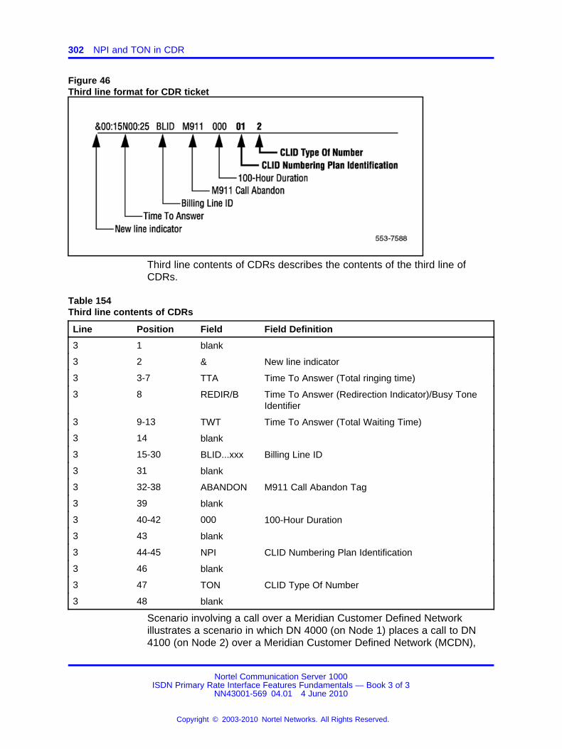
302 NPI and TON in CDR
Figure 46Third line format for CDR ticket
Third line contents of CDRs describes the contents of the third line ofCDRs.
Table 154Third line contents of CDRs
Line Position Field Field Definition
3 1 blank
3 2 & New line indicator
3 3-7 TTA Time To Answer (Total ringing time)
3 8 REDIR/B Time To Answer (Redirection Indicator)/Busy ToneIdentifier
3 9-13 TWT Time To Answer (Total Waiting Time)
3 14 blank
3 15-30 BLID...xxx Billing Line ID
3 31 blank
3 32-38 ABANDON M911 Call Abandon Tag
3 39 blank
3 40-42 000 100-Hour Duration
3 43 blank
3 44-45 NPI CLID Numbering Plan Identification
3 46 blank
3 47 TON CLID Type Of Number
3 48 blank
Scenario involving a call over a Meridian Customer Defined Networkillustrates a scenario in which DN 4000 (on Node 1) places a call to DN4100 (on Node 2) over a Meridian Customer Defined Network (MCDN),
Nortel Communication Server 1000ISDN Primary Rate Interface Features Fundamentals — Book 3 of 3
NN43001-569 04.01 4 June 2010
Copyright © 2003-2010 Nortel Networks. All Rights Reserved.
.
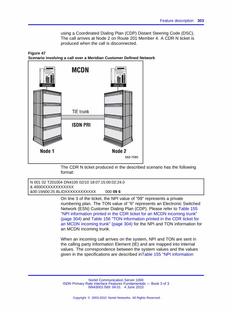
Feature description 303
using a Coordinated Dialing Plan (CDP) Distant Steering Code (DSC).The call arrives at Node 2 on Route 201 Member 4. A CDR N ticket isproduced when the call is disconnected.
Figure 47Scenario involving a call over a Meridian Customer Defined Network
The CDR N ticket produced in the described scenario has the followingformat:
N 001 02 T201004 DN4100 02/10 18:07:15:00:02:24.0& 4000XXXXXXXXXXXX&00:15N00:25 BLIDXXXXXXXXXXXX 000 09 6
On line 3 of the ticket, the NPI value of "09" represents a privatenumbering plan. The TON value of "6" represents an Electronic SwitchedNetwork (ESN) Customer Dialing Plan (CDP). Please refer to Table 155"NPI information printed in the CDR ticket for an MCDN incoming trunk"(page 304) and Table 156 "TON information printed in the CDR ticket foran MCDN incoming trunk" (page 304) for the NPI and TON information foran MCDN incoming trunk.
When an incoming call arrives on the system, NPI and TON are sent inthe calling party Information Element (IE) and are mapped into internalvalues. The correspondence between the system values and the valuesgiven in the specifications are described inTable 155 "NPI information
Nortel Communication Server 1000ISDN Primary Rate Interface Features Fundamentals — Book 3 of 3
NN43001-569 04.01 4 June 2010
Copyright © 2003-2010 Nortel Networks. All Rights Reserved.
.
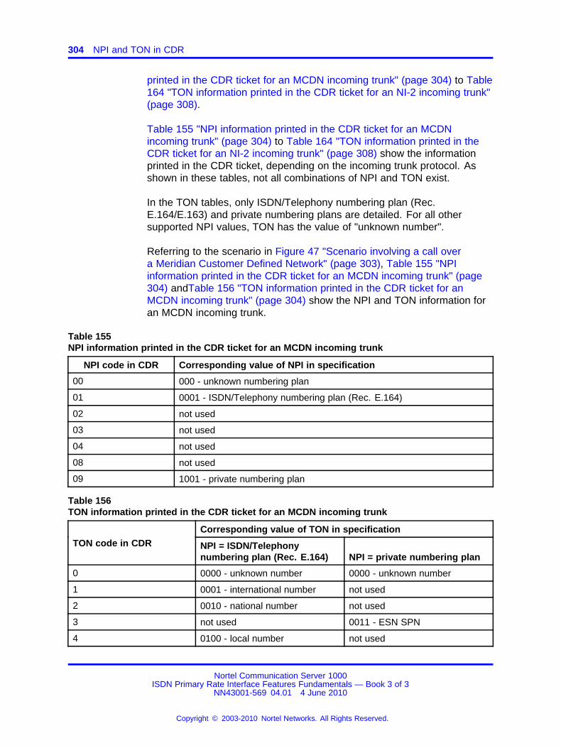
304 NPI and TON in CDR
printed in the CDR ticket for an MCDN incoming trunk" (page 304) to Table164 "TON information printed in the CDR ticket for an NI-2 incoming trunk"(page 308).
Table 155 "NPI information printed in the CDR ticket for an MCDNincoming trunk" (page 304) to Table 164 "TON information printed in theCDR ticket for an NI-2 incoming trunk" (page 308) show the informationprinted in the CDR ticket, depending on the incoming trunk protocol. Asshown in these tables, not all combinations of NPI and TON exist.
In the TON tables, only ISDN/Telephony numbering plan (Rec.E.164/E.163) and private numbering plans are detailed. For all othersupported NPI values, TON has the value of "unknown number".
Referring to the scenario in Figure 47 "Scenario involving a call overa Meridian Customer Defined Network" (page 303), Table 155 "NPIinformation printed in the CDR ticket for an MCDN incoming trunk" (page304) andTable 156 "TON information printed in the CDR ticket for anMCDN incoming trunk" (page 304) show the NPI and TON information foran MCDN incoming trunk.
Table 155NPI information printed in the CDR ticket for an MCDN incoming trunk
NPI code in CDR Corresponding value of NPI in specification
00 000 - unknown numbering plan
01 0001 - ISDN/Telephony numbering plan (Rec. E.164)
02 not used
03 not used
04 not used
08 not used
09 1001 - private numbering plan
Table 156TON information printed in the CDR ticket for an MCDN incoming trunk
Corresponding value of TON in specificationTON code in CDR NPI = ISDN/Telephony
numbering plan (Rec. E.164) NPI = private numbering plan
0 0000 - unknown number 0000 - unknown number
1 0001 - international number not used
2 0010 - national number not used
3 not used 0011 - ESN SPN
4 0100 - local number not used
Nortel Communication Server 1000ISDN Primary Rate Interface Features Fundamentals — Book 3 of 3
NN43001-569 04.01 4 June 2010
Copyright © 2003-2010 Nortel Networks. All Rights Reserved.
.
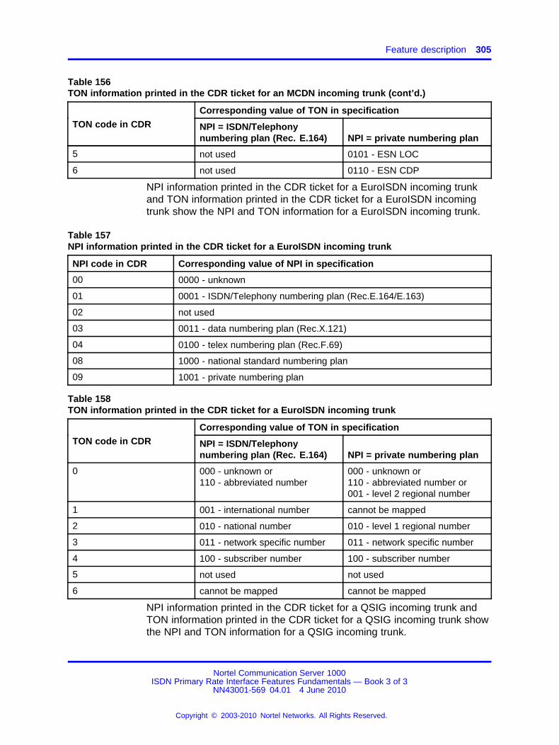
Feature description 305
Table 156TON information printed in the CDR ticket for an MCDN incoming trunk (cont’d.)
Corresponding value of TON in specificationTON code in CDR NPI = ISDN/Telephony
numbering plan (Rec. E.164) NPI = private numbering plan
5 not used 0101 - ESN LOC
6 not used 0110 - ESN CDP
NPI information printed in the CDR ticket for a EuroISDN incoming trunkand TON information printed in the CDR ticket for a EuroISDN incomingtrunk show the NPI and TON information for a EuroISDN incoming trunk.
Table 157NPI information printed in the CDR ticket for a EuroISDN incoming trunk
NPI code in CDR Corresponding value of NPI in specification
00 0000 - unknown
01 0001 - ISDN/Telephony numbering plan (Rec.E.164/E.163)
02 not used
03 0011 - data numbering plan (Rec.X.121)
04 0100 - telex numbering plan (Rec.F.69)
08 1000 - national standard numbering plan
09 1001 - private numbering plan
Table 158TON information printed in the CDR ticket for a EuroISDN incoming trunk
Corresponding value of TON in specificationTON code in CDR NPI = ISDN/Telephony
numbering plan (Rec. E.164) NPI = private numbering plan
0 000 - unknown or110 - abbreviated number
000 - unknown or110 - abbreviated number or001 - level 2 regional number
1 001 - international number cannot be mapped
2 010 - national number 010 - level 1 regional number
3 011 - network specific number 011 - network specific number
4 100 - subscriber number 100 - subscriber number
5 not used not used
6 cannot be mapped cannot be mapped
NPI information printed in the CDR ticket for a QSIG incoming trunk andTON information printed in the CDR ticket for a QSIG incoming trunk showthe NPI and TON information for a QSIG incoming trunk.
Nortel Communication Server 1000ISDN Primary Rate Interface Features Fundamentals — Book 3 of 3
NN43001-569 04.01 4 June 2010
Copyright © 2003-2010 Nortel Networks. All Rights Reserved.
.
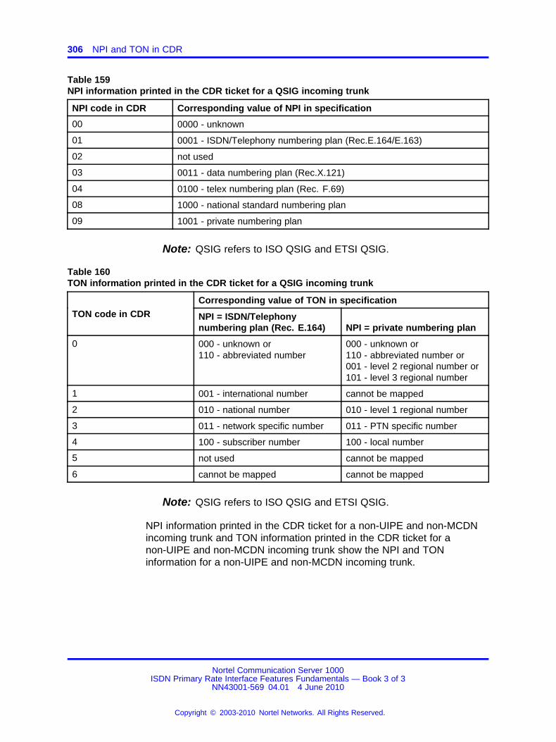
306 NPI and TON in CDR
Table 159NPI information printed in the CDR ticket for a QSIG incoming trunk
NPI code in CDR Corresponding value of NPI in specification
00 0000 - unknown
01 0001 - ISDN/Telephony numbering plan (Rec.E.164/E.163)
02 not used
03 0011 - data numbering plan (Rec.X.121)
04 0100 - telex numbering plan (Rec. F.69)
08 1000 - national standard numbering plan
09 1001 - private numbering plan
Note: QSIG refers to ISO QSIG and ETSI QSIG.
Table 160TON information printed in the CDR ticket for a QSIG incoming trunk
Corresponding value of TON in specificationTON code in CDR NPI = ISDN/Telephony
numbering plan (Rec. E.164) NPI = private numbering plan
0 000 - unknown or110 - abbreviated number
000 - unknown or110 - abbreviated number or001 - level 2 regional number or101 - level 3 regional number
1 001 - international number cannot be mapped
2 010 - national number 010 - level 1 regional number
3 011 - network specific number 011 - PTN specific number
4 100 - subscriber number 100 - local number
5 not used cannot be mapped
6 cannot be mapped cannot be mapped
Note: QSIG refers to ISO QSIG and ETSI QSIG.
NPI information printed in the CDR ticket for a non-UIPE and non-MCDNincoming trunk and TON information printed in the CDR ticket for anon-UIPE and non-MCDN incoming trunk show the NPI and TONinformation for a non-UIPE and non-MCDN incoming trunk.
Nortel Communication Server 1000ISDN Primary Rate Interface Features Fundamentals — Book 3 of 3
NN43001-569 04.01 4 June 2010
Copyright © 2003-2010 Nortel Networks. All Rights Reserved.
.
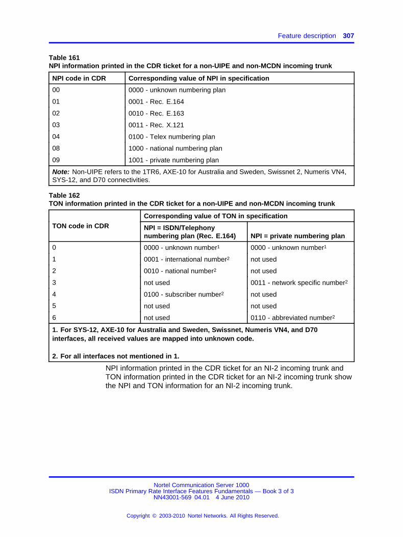
Feature description 307
Table 161NPI information printed in the CDR ticket for a non-UIPE and non-MCDN incoming trunk
NPI code in CDR Corresponding value of NPI in specification
00 0000 - unknown numbering plan
01 0001 - Rec. E.164
02 0010 - Rec. E.163
03 0011 - Rec. X.121
04 0100 - Telex numbering plan
08 1000 - national numbering plan
09 1001 - private numbering plan
Note: Non-UIPE refers to the 1TR6, AXE-10 for Australia and Sweden, Swissnet 2, Numeris VN4,SYS-12, and D70 connectivities.
Table 162TON information printed in the CDR ticket for a non-UIPE and non-MCDN incoming trunk
Corresponding value of TON in specificationTON code in CDR NPI = ISDN/Telephony
numbering plan (Rec. E.164) NPI = private numbering plan
0 0000 - unknown number1 0000 - unknown number1
1 0001 - international number2 not used
2 0010 - national number2 not used
3 not used 0011 - network specific number2
4 0100 - subscriber number2 not used
5 not used not used
6 not used 0110 - abbreviated number2
1. For SYS-12, AXE-10 for Australia and Sweden, Swissnet, Numeris VN4, and D70interfaces, all received values are mapped into unknown code.
2. For all interfaces not mentioned in 1.
NPI information printed in the CDR ticket for an NI-2 incoming trunk andTON information printed in the CDR ticket for an NI-2 incoming trunk showthe NPI and TON information for an NI-2 incoming trunk.
Nortel Communication Server 1000ISDN Primary Rate Interface Features Fundamentals — Book 3 of 3
NN43001-569 04.01 4 June 2010
Copyright © 2003-2010 Nortel Networks. All Rights Reserved.
.
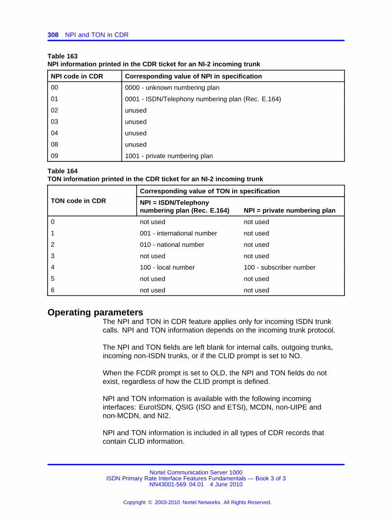
308 NPI and TON in CDR
Table 163NPI information printed in the CDR ticket for an NI-2 incoming trunk
NPI code in CDR Corresponding value of NPI in specification
00 0000 - unknown numbering plan
01 0001 - ISDN/Telephony numbering plan (Rec. E.164)
02 unused
03 unused
04 unused
08 unused
09 1001 - private numbering plan
Table 164TON information printed in the CDR ticket for an NI-2 incoming trunk
Corresponding value of TON in specificationTON code in CDR NPI = ISDN/Telephony
numbering plan (Rec. E.164) NPI = private numbering plan
0 not used not used
1 001 - international number not used
2 010 - national number not used
3 not used not used
4 100 - local number 100 - subscriber number
5 not used not used
6 not used not used
Operating parametersThe NPI and TON in CDR feature applies only for incoming ISDN trunkcalls. NPI and TON information depends on the incoming trunk protocol.
The NPI and TON fields are left blank for internal calls, outgoing trunks,incoming non-ISDN trunks, or if the CLID prompt is set to NO.
When the FCDR prompt is set to OLD, the NPI and TON fields do notexist, regardless of how the CLID prompt is defined.
NPI and TON information is available with the following incominginterfaces: EuroISDN, QSIG (ISO and ETSI), MCDN, non-UIPE andnon-MCDN, and NI2.
NPI and TON information is included in all types of CDR records thatcontain CLID information.
Nortel Communication Server 1000ISDN Primary Rate Interface Features Fundamentals — Book 3 of 3
NN43001-569 04.01 4 June 2010
Copyright © 2003-2010 Nortel Networks. All Rights Reserved.
.
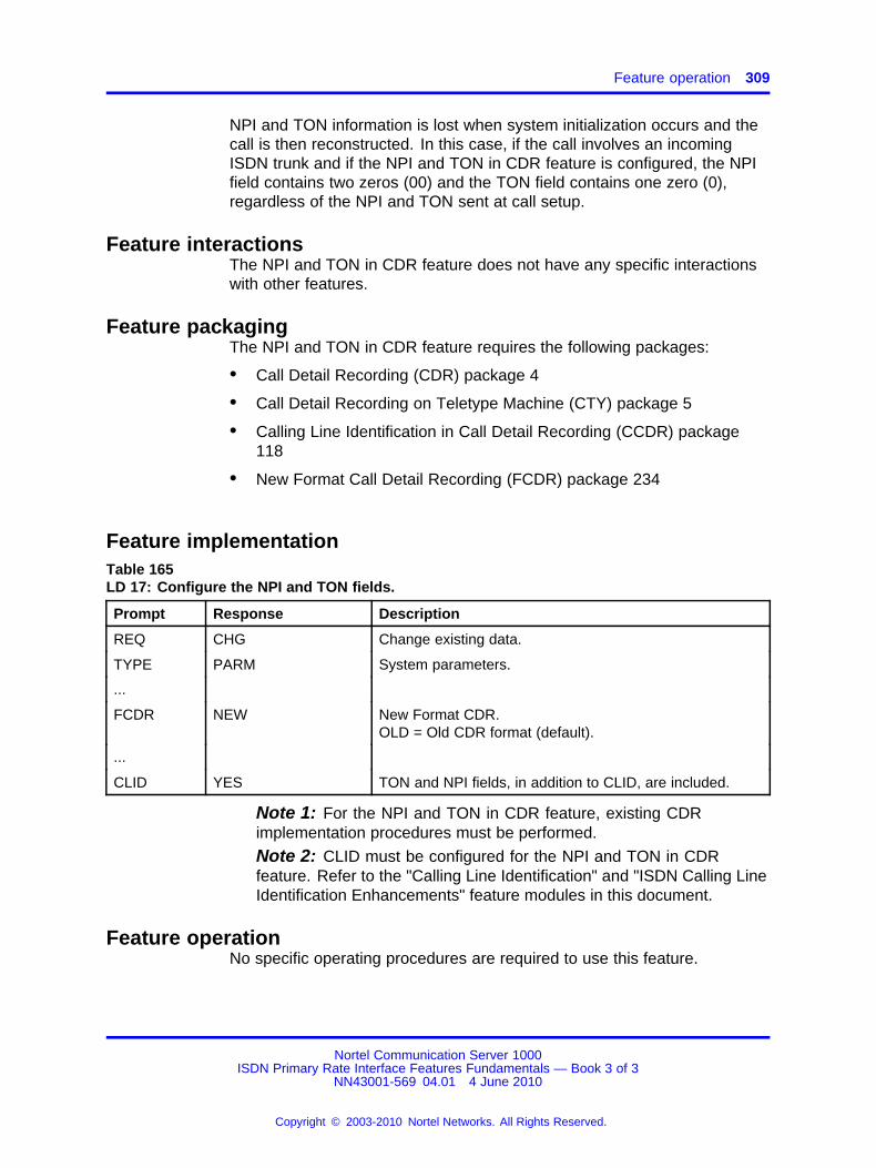
Feature operation 309
NPI and TON information is lost when system initialization occurs and thecall is then reconstructed. In this case, if the call involves an incomingISDN trunk and if the NPI and TON in CDR feature is configured, the NPIfield contains two zeros (00) and the TON field contains one zero (0),regardless of the NPI and TON sent at call setup.
Feature interactionsThe NPI and TON in CDR feature does not have any specific interactionswith other features.
Feature packagingThe NPI and TON in CDR feature requires the following packages:
• Call Detail Recording (CDR) package 4
• Call Detail Recording on Teletype Machine (CTY) package 5
• Calling Line Identification in Call Detail Recording (CCDR) package118
• New Format Call Detail Recording (FCDR) package 234
Feature implementationTable 165LD 17: Configure the NPI and TON fields.
Prompt Response Description
REQ CHG Change existing data.
TYPE PARM System parameters.
...
FCDR NEW New Format CDR.OLD = Old CDR format (default).
...
CLID YES TON and NPI fields, in addition to CLID, are included.
Note 1: For the NPI and TON in CDR feature, existing CDRimplementation procedures must be performed.
Note 2: CLID must be configured for the NPI and TON in CDRfeature. Refer to the "Calling Line Identification" and "ISDN Calling LineIdentification Enhancements" feature modules in this document.
Feature operationNo specific operating procedures are required to use this feature.
Nortel Communication Server 1000ISDN Primary Rate Interface Features Fundamentals — Book 3 of 3
NN43001-569 04.01 4 June 2010
Copyright © 2003-2010 Nortel Networks. All Rights Reserved.
.

310 NPI and TON in CDR
Nortel Communication Server 1000ISDN Primary Rate Interface Features Fundamentals — Book 3 of 3
NN43001-569 04.01 4 June 2010
Copyright © 2003-2010 Nortel Networks. All Rights Reserved.
.
311.
Overlap Signaling on ISDN Networks
ContentsThis section contains information on the following topics:
“Feature description” (page 311)
“Operating parameters” (page 314)
“Feature interactions” (page 314)
“Feature packaging” (page 315)
“Feature implementation” (page 315)
“Task summary list” (page 315)
“Feature operation” (page 317)
Feature descriptionOn ISDN, dialed digits are sent out and received in the following modes:
• Enbloc
• Overlap
Enbloc SignalingIn Enbloc mode, the switch waits for all the dialed digits from the user andthen sends all the digits in the SETUP message.
Overlap SignalingIn Overlap mode, the digits are sent out as they are dialed from the user,instead of waiting for an interdigit timer to timeout. This improves the callsetup time. The Overlap Signaling method is useful when a system cannotdetermine the completion of all the digits unless the originator terminatesdialing with an octothorpe "#". Examples of this are when a caller dials:
• international numbers
• private numbers where all the sub-DN digits are not known across thenetwork
Nortel Communication Server 1000ISDN Primary Rate Interface Features Fundamentals — Book 3 of 3
NN43001-569 04.01 4 June 2010
Copyright © 2003-2010 Nortel Networks. All Rights Reserved.
.

312 Overlap Signaling on ISDN Networks
Overlap Sending and Overlap Receiving are optional on each D-channelinterface for ISDN Trunks.
Overlap SendingOverlap Sending is applicable to the outgoing leg of the ISDN interfaceand if enabled on a ISDN interface, it is assumed that the far end supportsOverlap Signaling and Overlap Receiving.
Overlap ReceivingOverlap Receiving is applicable to the incoming leg of the ISDN interface.If the ISDN interface does not support Overlap Receiving, then INFOmessages received from the originating switch are ignored and the systemoperates only on the digits received in the SETUP message as if theoriginating switch used ENBLOC dialing.
ISDN Overlap support lists the ISDN interfaces on the system and whetherthey support or do not support Overlap Sending and Overlap Receiving.
Table 166ISDN Overlap support
ISDN interfaceOverlapSending
OverlapReceiving Notes
Australia ETSI Y N
AXE-10 (Sweden and Australia) Y N Overlap Receiving is possibleonly if the AXE-10 conformsto the guidelines containedin CCITT’s preliminary Q.931section 5.0
Swiss Net (Switzerland) Y N
NEAX-61 (New Zealand)(non-Asia Pacific ISDNConnectivity)
Y N
SYS-12 (Norway) Y N
Numeris VN3 (France) Y N
1TR6 (Germany) Y N
Japan D70 (non-Asia PacificISDN Connectivity)
N N
Euro ISDN ETS 300-102 basicprotocol
Y Y
Austria Y Y
Denmark Y N
Finland Y Y
Germany Y Y
Nortel Communication Server 1000ISDN Primary Rate Interface Features Fundamentals — Book 3 of 3
NN43001-569 04.01 4 June 2010
Copyright © 2003-2010 Nortel Networks. All Rights Reserved.
.

Feature description 313
Table 166ISDN Overlap support (cont’d.)
ISDN interfaceOverlapSending
OverlapReceiving Notes
Italy Y Y
Norway Y N
Portugal Y N
Sweden Y N
Ireland Y Y
Holland Y Y
Switzerland Y Y
Belgium Y Y
Spain Y Y
United Kingdom Y Y
France Y Y
Commonwealth of IndependentStates (Russia and the Ukraine).
Y Y
Asia Pacific
Australia Y N
China Y Y
Hong Kong Y N
India Y Y
Indonesia Y Y
Japan N N
Malaysia Y Y
Philippines N N
Singapore Y N
Taiwan Y N
New Zealand Y N
Thailand Y Y
QSIG Y Y
JTTC (Japan QSIG) N N
BRI Y Y
MCDN (only SL-1) Y Y
Nortel Communication Server 1000ISDN Primary Rate Interface Features Fundamentals — Book 3 of 3
NN43001-569 04.01 4 June 2010
Copyright © 2003-2010 Nortel Networks. All Rights Reserved.
.
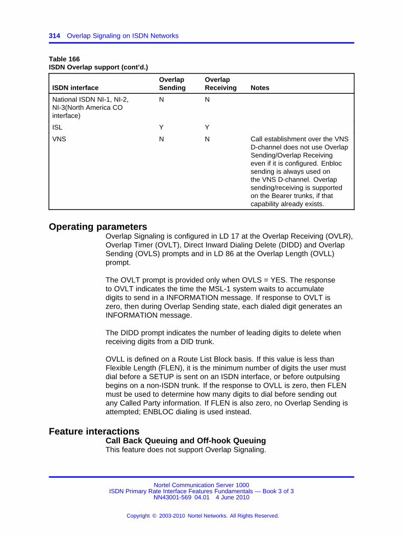
314 Overlap Signaling on ISDN Networks
Table 166ISDN Overlap support (cont’d.)
ISDN interfaceOverlapSending
OverlapReceiving Notes
National ISDN NI-1, NI-2,NI-3(North America COinterface)
N N
ISL Y Y
VNS N N Call establishment over the VNSD-channel does not use OverlapSending/Overlap Receivingeven if it is configured. Enblocsending is always used onthe VNS D-channel. Overlapsending/receiving is supportedon the Bearer trunks, if thatcapability already exists.
Operating parametersOverlap Signaling is configured in LD 17 at the Overlap Receiving (OVLR),Overlap Timer (OVLT), Direct Inward Dialing Delete (DIDD) and OverlapSending (OVLS) prompts and in LD 86 at the Overlap Length (OVLL)prompt.
The OVLT prompt is provided only when OVLS = YES. The responseto OVLT indicates the time the MSL-1 system waits to accumulatedigits to send in a INFORMATION message. If response to OVLT iszero, then during Overlap Sending state, each dialed digit generates anINFORMATION message.
The DIDD prompt indicates the number of leading digits to delete whenreceiving digits from a DID trunk.
OVLL is defined on a Route List Block basis. If this value is less thanFlexible Length (FLEN), it is the minimum number of digits the user mustdial before a SETUP is sent on an ISDN interface, or before outpulsingbegins on a non-ISDN trunk. If the response to OVLL is zero, then FLENmust be used to determine how many digits to dial before sending outany Called Party information. If FLEN is also zero, no Overlap Sending isattempted; ENBLOC dialing is used instead.
Feature interactionsCall Back Queuing and Off-hook QueuingThis feature does not support Overlap Signaling.
Nortel Communication Server 1000ISDN Primary Rate Interface Features Fundamentals — Book 3 of 3
NN43001-569 04.01 4 June 2010
Copyright © 2003-2010 Nortel Networks. All Rights Reserved.
.

Feature implementation 315
Flexible HotlineThis feature does not support Overlap Signaling.
VNSCalls established over the VNS D-channel do not use OverlapSending/Overlap Receiving, even if configured. The VNS D-channelalways uses Enbloc Sending. The Bearer trunks support Overlap Sendingand Overlap Receiving, if the capability already exists.
Feature packagingThis feature requires the following packages:
• Basic Routing (BRTE) package 14
• Basic Queuing (BQUE) package 28
• Network Class of Service (NCOS) package 32
• Basic Alternate Route Selection (BARS) package 57
• Network Alternate Route Selection (NARS) package 58 and/orCoordinated Dialing Plan (CDP) package 59
• Flexible Numbering Plan (FNP) package 160
• Overlap Signaling (OVLP) package 184
Feature implementationTask summary list
The following is a summary of the tasks in this section:
1. Table 167 "LD 17: Configure Overlap Receiving, Direct Inward DialingDelete, Overlay Sending, and Overlap Timer." (page 316)
Note: If the interfacing switch supports Overlap Receiving, set thevalue for the OVLR prompt as YES.
2. Table 167 "LD 17: Configure Overlap Receiving, Direct Inward DialingDelete, Overlay Sending, and Overlap Timer." (page 316)
Note: The recommended value for the DIDD prompt is 0. Butincase, some digits need to be deleted, then this value has to beagreed upon with the interfacing switch.
3. Table 167 "LD 17: Configure Overlap Receiving, Direct Inward DialingDelete, Overlay Sending, and Overlap Timer." (page 316)
Note: If the interfacing switch supports Overlap Sending, set thevalue for the OVLS prompt as YES.
Nortel Communication Server 1000ISDN Primary Rate Interface Features Fundamentals — Book 3 of 3
NN43001-569 04.01 4 June 2010
Copyright © 2003-2010 Nortel Networks. All Rights Reserved.
.
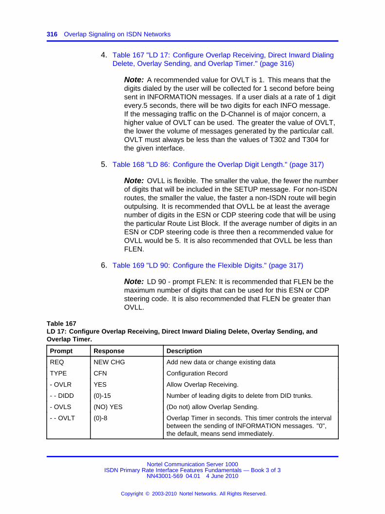
316 Overlap Signaling on ISDN Networks
4. Table 167 "LD 17: Configure Overlap Receiving, Direct Inward DialingDelete, Overlay Sending, and Overlap Timer." (page 316)
Note: A recommended value for OVLT is 1. This means that thedigits dialed by the user will be collected for 1 second before beingsent in INFORMATION messages. If a user dials at a rate of 1 digitevery.5 seconds, there will be two digits for each INFO message.If the messaging traffic on the D-Channel is of major concern, ahigher value of OVLT can be used. The greater the value of OVLT,the lower the volume of messages generated by the particular call.OVLT must always be less than the values of T302 and T304 forthe given interface.
5. Table 168 "LD 86: Configure the Overlap Digit Length." (page 317)
Note: OVLL is flexible. The smaller the value, the fewer the numberof digits that will be included in the SETUP message. For non-ISDNroutes, the smaller the value, the faster a non-ISDN route will beginoutpulsing. It is recommended that OVLL be at least the averagenumber of digits in the ESN or CDP steering code that will be usingthe particular Route List Block. If the average number of digits in anESN or CDP steering code is three then a recommended value forOVLL would be 5. It is also recommended that OVLL be less thanFLEN.
6. Table 169 "LD 90: Configure the Flexible Digits." (page 317)
Note: LD 90 - prompt FLEN: It is recommended that FLEN be themaximum number of digits that can be used for this ESN or CDPsteering code. It is also recommended that FLEN be greater thanOVLL.
Table 167LD 17: Configure Overlap Receiving, Direct Inward Dialing Delete, Overlay Sending, andOverlap Timer.
Prompt Response Description
REQ NEW CHG Add new data or change existing data
TYPE CFN Configuration Record
- OVLR YES Allow Overlap Receiving.
- - DIDD (0)-15 Number of leading digits to delete from DID trunks.
- OVLS (NO) YES (Do not) allow Overlap Sending.
- - OVLT (0)-8 Overlap Timer in seconds. This timer controls the intervalbetween the sending of INFORMATION messages. "0",the default, means send immediately.
Nortel Communication Server 1000ISDN Primary Rate Interface Features Fundamentals — Book 3 of 3
NN43001-569 04.01 4 June 2010
Copyright © 2003-2010 Nortel Networks. All Rights Reserved.
.

Feature operation 317
Table 168LD 86: Configure the Overlap Digit Length.
Prompt Response Description
REQ NEW CHG Add new data or change existing data
TYPE CFN Configuration Record
- OVLL (0)-24 Enter the minimum Overlap Length, pertaining to OverlapSending. If 0 (the default) is entered, then the FlexibleDigit Number Length (FLEN) determines whether OverlapSending takes place.
Table 169LD 90: Configure the Flexible Digits.
Prompt Response Description
REQ NEW CHG Add new data or change existing data
TYPE CFN Configuration Record
- FLEN (0)-24 Enter the number of Flexible Digits (the number of digits that thesystem expects to receive before accessing a trunk, and outpulsingthe digits).
Feature operationNo specific operating procedures are required to use this feature.
Nortel Communication Server 1000ISDN Primary Rate Interface Features Fundamentals — Book 3 of 3
NN43001-569 04.01 4 June 2010
Copyright © 2003-2010 Nortel Networks. All Rights Reserved.
.

318 Overlap Signaling on ISDN Networks
Nortel Communication Server 1000ISDN Primary Rate Interface Features Fundamentals — Book 3 of 3
NN43001-569 04.01 4 June 2010
Copyright © 2003-2010 Nortel Networks. All Rights Reserved.
.

319.
Private to Public CLID Conversion
ContentsThis section contains information on the following topics:
“Applicable regions” (page 319)
“Feature description” (page 319)
“Operating parameters” (page 329)
“Feature interactions” (page 331)
“Feature packaging” (page 333)
“Feature implementation” (page 333)
“Task summary list” (page 333)
“Feature operation” (page 335)
Applicable regionsThe information presented in this section does not pertain to all regions.Contact your system supplier or your Nortel representative to verifysupport of this product in your area.
Feature descriptionThe Private to Public Calling Line Identification (CLID) Conversion featurepermits the correct CLID to be sent to the CO when a call hops off theprivate network to the public network (the PSTN) at a tandem node.
On ISDN trunks, Calling Line Identification (CLID) information is sent inthe Calling Party Information Element (IE) of the setup message. Thisinformation is used to display the originating party’s number on theterminating phone. A Call Type indicator is also present, to indicate tothe switch at the other end what type of call it is receiving (International,National, Subscriber, UDP, CDP, SPN). This in turn affects how that switchhandles the call using the INAC prompt.
Nortel Communication Server 1000ISDN Primary Rate Interface Features Fundamentals — Book 3 of 3
NN43001-569 04.01 4 June 2010
Copyright © 2003-2010 Nortel Networks. All Rights Reserved.
.

320 Private to Public CLID Conversion
Originating nodes configure the format of the CLID using the followingcomponents:
• the dialing plan used to make the call
• the type of trunk used for the call
• the Customer Data Block option and Class of Service of the phonerelated to sending the Prime DN (PDN) or Listed Directory Number(LDN) of the phone
For example, a call dialed with a Location Code (private Uniform DialingPlan), that is sent out on a private network trunk (TIE trunk) has a CLIDin the private network format (LOC+DN). However, a Location Code callthat is sent out on a public network trunk (a COT trunk, for example) hasa CLID in the public network format [National (NPA+NXX+DN)]. Thepublic network number can be the LDN of the customer group for non-DIDphones or the NPA+NXX+DN for DID users.
If the default method for constructing Call Types is not suitable, theadministrator can program Digit Manipulation Indexes to apply to calls asthey leave the switch to change the Call Type indicator that travels witheach call.
Prior to this feature introduction, a tandem node that received CLIDs fromanother node on an ISDN TIE trunk passed the CLIDs along withoutchanging them. A system acting as a tandem node did not convert aprivate format CLID to a public format CLID when routing a call on aPSTN trunk. The private format CLID of the originating phone was sent tothe Central Office (CO). However, there are COs in North America thatmodify the CLID (adding an NPA and NXX) when less than ten digits arereceived. If the system sends seven digits in the CLID to the PSTN, theCO automatically inserts the NPA of the serving area. Therefore, the CLIDends up as: NPA+LOC+DN. Therefore, the terminating phone displayeda CLID that was sometimes a valid phone number in the area around thetandem node, but it was not the correct CLID of the originating user.
The scenario described above is illustrated inFigure 48 "Private network toPublic network hop off, prior functionality for UDP dialing" (page 321) onPrivate network to Public network hop off, prior functionality for UDPdialing.
Nortel Communication Server 1000ISDN Primary Rate Interface Features Fundamentals — Book 3 of 3
NN43001-569 04.01 4 June 2010
Copyright © 2003-2010 Nortel Networks. All Rights Reserved.
.
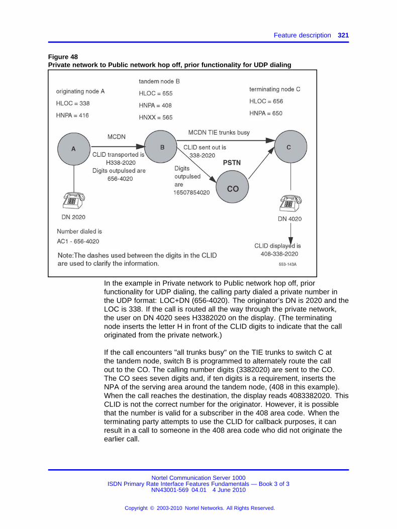
Feature description 321
Figure 48Private network to Public network hop off, prior functionality for UDP dialing
In the example in Private network to Public network hop off, priorfunctionality for UDP dialing, the calling party dialed a private number inthe UDP format: LOC+DN (656-4020). The originator’s DN is 2020 and theLOC is 338. If the call is routed all the way through the private network,the user on DN 4020 sees H3382020 on the display. (The terminatingnode inserts the letter H in front of the CLID digits to indicate that the calloriginated from the private network.)
If the call encounters "all trunks busy" on the TIE trunks to switch C atthe tandem node, switch B is programmed to alternately route the callout to the CO. The calling number digits (3382020) are sent to the CO.The CO sees seven digits and, if ten digits is a requirement, inserts theNPA of the serving area around the tandem node, (408 in this example).When the call reaches the destination, the display reads 4083382020. ThisCLID is not the correct number for the originator. However, it is possiblethat the number is valid for a subscriber in the 408 area code. When theterminating party attempts to use the CLID for callback purposes, it canresult in a call to someone in the 408 area code who did not originate theearlier call.
Nortel Communication Server 1000ISDN Primary Rate Interface Features Fundamentals — Book 3 of 3
NN43001-569 04.01 4 June 2010
Copyright © 2003-2010 Nortel Networks. All Rights Reserved.
.
322 Private to Public CLID Conversion
The Private to Public Calling Line Identification (CLID) Conversionfeature is applicable to Electronic Switched Networks (ESNs) that use thefollowing private network numbering plans and codes:
• Uniform Dialing Plan (UDP) and Location Codes (LOCs)
• Coordinated Dialing Plan (CDP) and Distant Steering Codes (DSCs)
A private format CLID can be in either of the following formats:
• LOC+DN
• DSC+X..X
The Private to Public CLID Conversion feature provides two differentoptions to send a public format CLID to the PSTN. The options are:
• CLID contains the NPA and NXX of the originating node. Foroutgoing calls from the tandem node you translate location codes(LOC) and/or Distant Steering Codes (DSC). For incoming calls fromthose switches and CLID conversion purposes, you program the NPAand NXX of each originating node to associate with its LOC or DSC atthe tandem node. The tandem node uses this NPA and NXX to build apublic format CLID for the originator when calls from that switch hop offto the public network from the tandem node.
• CLID contains the LDN of the tandem node. You can use the LDNof the tandem node for the public format CLID.
This feature introduces a prompt (CPUB) in the Route Data Block (LD 16).This prompt controls what option applies when the tandem node buildsthe public format CLID. Program the CPUB option on the outgoing PSTNroutes. The CPUB options are:
• ON
• OFF
• LDN
ON means the feature is enabled. The system uses the NPA and NXXprogrammed for the LOC or DSC of the caller to build the CLID.
OFF means the feature is disabled. The CLID is built as it was prior to theintroduction of this feature.
LDN The tandem node sends its LDN0 (from LD 15) to the CO as theCLID. The CLID is constructed by coupling the HNPA and HNXX in CLIDentry 0 in the Customer Data Block (LD 15) with the LDN0 from LD 15 atthe tandem node.
Nortel Communication Server 1000ISDN Primary Rate Interface Features Fundamentals — Book 3 of 3
NN43001-569 04.01 4 June 2010
Copyright © 2003-2010 Nortel Networks. All Rights Reserved.
.
Feature description 323
Uniform Dialing Plan (UDP)In LD 90 you program an NPA and NXX (to be used for CLIDs) for eachLOC you translate.
Figure 49 "Private network to Public network hopoff, NPA and NXXconversion functionality for UDP dialing" (page 324) on Private networkto Public network hopoff, NPA and NXX conversion functionality for UDPdialing illustrates the effect of the conversion capability when a userdials a private network call in the UDP format and the tandem node isprogrammed to send the CLID of the originator.
Figure 50 "Private network to Public network hopoff, LDN conversionfunctionality for UDP dialing" (page 325) on Private network to Publicnetwork hopoff, LDN conversion functionality for UDP dialing illustrates theeffect of the conversion capability when a user dials a private network callin the UDP format and the tandem node is programmed to send its LDNas the CLID.
Before sending the call to the CO, the system software checks the RouteData Block for the PSTN route. It checks the CPUB option and one of thefollowing results can occur:
• if it is "OFF", no manipulation of the digits occurs. The Private CLIDis sent to the CO. Figure 48 "Private network to Public network hopoff, prior functionality for UDP dialing" (page 321) on Private networkto Public network hop off, prior functionality for UDP dialing illustrateswhat happens when CPUB is OFF.
• if it is "ON" the software checks the CLID within the Calling Party IE ofthe outgoing setup message. UseFigure 49 "Private network to Publicnetwork hopoff, NPA and NXX conversion functionality for UDP dialing"(page 324) on Private network to Public network hopoff, NPA and NXXconversion functionality for UDP dialing as an example. The softwaredetects the leading digits (338) and checks LD 90 for translation ofLOC 338. If it is in the translation tables, the software checks for NPAand NXX entries for that location code. If these entries are there,the LOC 338 is replaced by the NPA and NXX. The changed CLIDnumber is sent to the CO. In this example, 3382020 is replaced by4162532020. This is a number which the terminating user can dial toreach the originator.
• if it is "LDN", the listed directory number of the tandem system is sent.The LDN0 of the tandem node is paired with the HNPA and HNXXassociated with CLID entry 0 in LD 15 to build the CLID that is sent tothe CO. Refer to Figure 50 "Private network to Public network hopoff,LDN conversion functionality for UDP dialing" (page 325) on Privatenetwork to Public network hopoff, LDN conversion functionality for UDPdialing.
Nortel Communication Server 1000ISDN Primary Rate Interface Features Fundamentals — Book 3 of 3
NN43001-569 04.01 4 June 2010
Copyright © 2003-2010 Nortel Networks. All Rights Reserved.
.
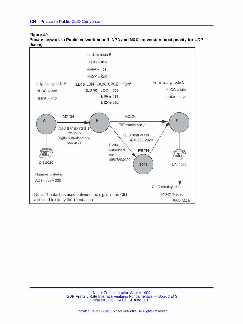
324 Private to Public CLID Conversion
Figure 49Private network to Public network hopoff, NPA and NXX conversion functionality for UDPdialing
Nortel Communication Server 1000ISDN Primary Rate Interface Features Fundamentals — Book 3 of 3
NN43001-569 04.01 4 June 2010
Copyright © 2003-2010 Nortel Networks. All Rights Reserved.
.
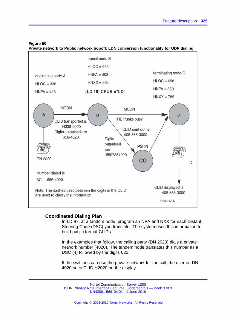
Feature description 325
Figure 50Private network to Public network hopoff, LDN conversion functionality for UDP dialing
Coordinated Dialing PlanIn LD 87, at a tandem node, program an NPA and NXX for each DistantSteering Code (DSC) you translate. The system uses this information tobuild public format CLIDs.
In the examples that follow, the calling party (DN 2020) dials a privatenetwork number (4020). The tandem node translates this number as aDSC (4) followed by the digits 020.
If the switches can use the private network for the call, the user on DN4020 sees CLID H2020 on the display.
Nortel Communication Server 1000ISDN Primary Rate Interface Features Fundamentals — Book 3 of 3
NN43001-569 04.01 4 June 2010
Copyright © 2003-2010 Nortel Networks. All Rights Reserved.
.
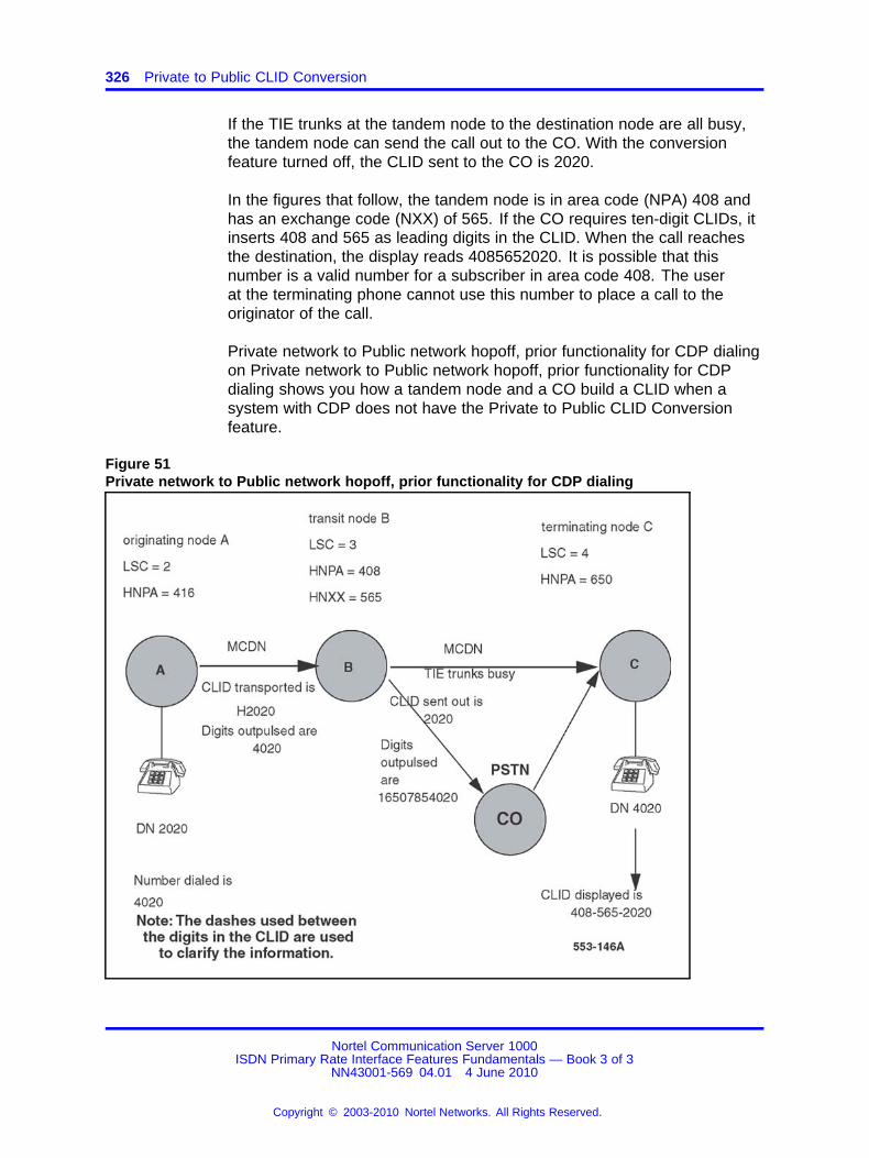
326 Private to Public CLID Conversion
If the TIE trunks at the tandem node to the destination node are all busy,the tandem node can send the call out to the CO. With the conversionfeature turned off, the CLID sent to the CO is 2020.
In the figures that follow, the tandem node is in area code (NPA) 408 andhas an exchange code (NXX) of 565. If the CO requires ten-digit CLIDs, itinserts 408 and 565 as leading digits in the CLID. When the call reachesthe destination, the display reads 4085652020. It is possible that thisnumber is a valid number for a subscriber in area code 408. The userat the terminating phone cannot use this number to place a call to theoriginator of the call.
Private network to Public network hopoff, prior functionality for CDP dialingon Private network to Public network hopoff, prior functionality for CDPdialing shows you how a tandem node and a CO build a CLID when asystem with CDP does not have the Private to Public CLID Conversionfeature.
Figure 51Private network to Public network hopoff, prior functionality for CDP dialing
Nortel Communication Server 1000ISDN Primary Rate Interface Features Fundamentals — Book 3 of 3
NN43001-569 04.01 4 June 2010
Copyright © 2003-2010 Nortel Networks. All Rights Reserved.
.
Feature description 327
Figure 52 "Private network to Public network hopoff, NPA and NXXconversion functionality for CDP dialing" (page 328) on Private networkto Public network hopoff, NPA and NXX conversion functionality for CDPdialing illustrates the effect of the conversion capability when a userdials a private network call in the CDP format and the tandem node isprogrammed to send the CLID of the originator.
Figure 53 "Private network to Public network hopoff, LDN conversionfunctionality for CDP dialing" (page 329) on Figure 53 "Private networkto Public network hopoff, LDN conversion functionality for CDP dialing"(page 329) illustrates the effect of the conversion capability when a userdials a private network call in the CDP format and the tandem node isprogrammed to send its LDN as the CLID.
Before sending the call to the CO, the system software checks the RouteData Block for the PSTN route. It checks the CPUB option and one of thefollowing results can occur:
• If it is "OFF", no manipulation of the CLID digits occurs. The tandemnode sends the Private CLID to the CO.Figure 51 "Private networkto Public network hopoff, prior functionality for CDP dialing" (page326) shows you the CLID format when the CPUB option is OFF.
• If it is "ON" the software checks the CLID within the Calling Party IE ofthe outgoing setup message. Use Figure 52 "Private network to Publicnetwork hopoff, NPA and NXX conversion functionality for CDP dialing"(page 328) on Figure 52 "Private network to Public network hopoff,NPA and NXX conversion functionality for CDP dialing" (page 328) asan example. The software detects the leading digits (2020). Thesystem checks for a DSC translation entry in LD 87 equal to 2, 20, 202,or 2020. (It uses the left-wise unique rule.) If there is an entry for theDSC, the software checks for NPA and NXX entries for that SteeringCode. The node adds the NPA and NXX as leading digits in the CLID.The software automatically deletes the DSC from the CLID. You mustinclude the removed DSC at the end of the NXX field to maintain theaccuracy of the CLID. The node sends the changed CLID to the CO.In this example, 4162532020 replaces 2020. The terminating user candial this number to reach the originator.
• If it is "LDN", the node sends its listed directory number as a CLID tothe CO. The node attaches the HNTN and HLCL from CLID entry 0 inLD 15 to the LDN0 in LD 15. It sends this CLID to the CO.
Nortel Communication Server 1000ISDN Primary Rate Interface Features Fundamentals — Book 3 of 3
NN43001-569 04.01 4 June 2010
Copyright © 2003-2010 Nortel Networks. All Rights Reserved.
.

328 Private to Public CLID Conversion
Figure 52Private network to Public network hopoff, NPA and NXX conversion functionality for CDPdialing
Nortel Communication Server 1000ISDN Primary Rate Interface Features Fundamentals — Book 3 of 3
NN43001-569 04.01 4 June 2010
Copyright © 2003-2010 Nortel Networks. All Rights Reserved.
.
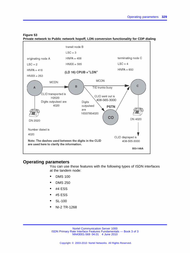
Operating parameters 329
Figure 53Private network to Public network hopoff, LDN conversion functionality for CDP dialing
Operating parametersYou can use these features with the following types of ISDN interfacesat the tandem node:
• DMS 100
• DMS 250
• #4 ESS
• #5 ESS
• SL-100
• NI-2 TR-1268
Nortel Communication Server 1000ISDN Primary Rate Interface Features Fundamentals — Book 3 of 3
NN43001-569 04.01 4 June 2010
Copyright © 2003-2010 Nortel Networks. All Rights Reserved.
.
330 Private to Public CLID Conversion
The conversion of the CLID also occurs when features such as CallForward All Calls, Forward No Answer, and Hunting divert calls to thepublic network.
Some COs use the CLID to perform billing. When a system tandemnode interfaces with one of these COs, set the CPUB option to "LDN" toallow correct billing. Or else, with the CPUB option on, the CO uses theoriginator’s CLID for billing purposes. The call used the private networkpart of the way; the bill for the call is not correct when it is based onthis CLID. If you use the Incoming Trunk Programmable Calling Line IDfeature, it takes priority over the Private to Public CLID conversion feature(refer to Feature interactions).
The software does not validate the NPA and NXX you input for each LOCand DSC. When you test the operation of this feature, check the CLIDshown on the display of the terminating phone. Make sure it is the calloriginator’s CLID.
When used with CDP, the software automatically deletes the DSC from theCLID. You must include the removed DSC at the end of the NXX field tomaintain the accuracy of the CLID. For example, if the DSC is 32 and theNXX is 658, program the NXX as 65832 in order to construct the correctCLID.
To activate the feature you must enable it in LD 16 on the outgoing PSTNroute. You must also program an NPA and NXX for each LOC in LD 90 oreach DSC in LD 87. If you do not program an NPA and NXX in LD 90 orLD 87, the system cannot build the public format CLID.
The feature does not work if CPUB = LDN but there is no LDN0 or CLIDentry 0 in LD 15.
The tandem node must receive the CLID in the LOC+DN or DSC+X..Xformat for the feature to operate.
This feature addresses only private to public CLID conversion and notpublic to private CLID conversion.
The Private to Public CLID Conversion feature provides one NPA andone NXX for each LOC or DSC. To support networks with switches thathave more than one NPA or NXX, assign one LOC or DSC for each NPAor NXX.
The feature does not operate if the originating CLID contains a DSCor LOC that the tandem node cannot translate. (One reason not totranslate an LOC or DSC is to block outgoing calls to that destinationfrom the tandem node.) Solution: Add the codes to the translation tables
Nortel Communication Server 1000ISDN Primary Rate Interface Features Fundamentals — Book 3 of 3
NN43001-569 04.01 4 June 2010
Copyright © 2003-2010 Nortel Networks. All Rights Reserved.
.
Feature interactions 331
at the tandem node so it can convert incoming CLIDs to the correctpublic network format. Block outgoing calls from the tandem node to thedestination with other forms of restriction. [For example, you can useSupplemental Digit Restriction (in LD 90) or Facility Restriction Levels (inLD 86)].
This feature only operates on the CLID and not on other informationelements such as the redirecting number, the connected name, or theconnected number.
The tandem node has limitations when it handles calls from an originatingswitch that has both DID and non-DID DNs. The tandem node converts allCLIDs from a switch with one LOC the same way. You can program thetandem node to send its LDN for non-DID DNs at the originating switch, ifthese DNs are associated with a different LOC than the DID DNs.
Feature interactionsAutomatic Call Distribution (ACD)When a private call is presented to an ACD DN, and the call flows to thePSTN due to the ACD Night Call Forward or the Interflow or the Overflowfeature, the Private to Public CLID Conversion feature operates.
Alternate RoutingThe Private to Public CLID Conversion feature applies to calls which arealternately routed by one of the following features: Network AlternateRouting (NARS), QSIG Alternate Routing, and MCDN Alternate Routing.
Call Redirection (External Calls)/HuntingCall Redirection includes the following redirections at the tandem node:
• Call Forward All Calls
• Call Forward Busy
• Call Forward by Call Type
• Call Forward External Deny
• Call Forward No Answer/Flexible Call Forward No Answer
• Call Forward No Answer, Second Level
• Call Redirection by Time of Day
• Call Redirection by Day
When a call forwards to an external phone, and if the call is sent out on aPSTN route, then the Private to Public Conversion feature configures apublic format CLID, if the option is configured at the node that is redirectingthe call. The same applies to Hunting, if the Hunt DN is an externalnumber.
Nortel Communication Server 1000ISDN Primary Rate Interface Features Fundamentals — Book 3 of 3
NN43001-569 04.01 4 June 2010
Copyright © 2003-2010 Nortel Networks. All Rights Reserved.
.
332 Private to Public CLID Conversion
Call TransferThe Private to Public Conversion feature has no interaction with CallTransfer. The prior functionality continues.
Calling Party Privacy (CPP) and Calling Party Privacy Override(CPPO)A call marked as a CPP or CPPO call can hopoff the private networkto the public network. Even though the Private to Public Conversionfeature modifies the private CLID to a public format CLID, the presentationindicators indicating whether this is CPP/CPPO call are not modified. Afterhopoff occurs, the call continues to be identified as a CPP or CPPO call.
Call Detail Recording (CDR)This feature has no interaction with CDR. After the CLID is converted, theinformation in the call record is the same as it was with no conversion.
Incoming Trunk Programmable Calling Line IDThe Incoming Trunk Programmable Calling Line ID feature allows you toprogram a CLID (or billing number) on an incoming route. This featuretakes precedence over the Private to Public CLID Conversion featurewhen they are both programmed at the tandem node.
Meridian MailIn a case where a call terminates on Meridian Mail with a convertedCLID, the private greeting is not given. Either an unknown origin or publicgreeting is given.
Call Sender feature This feature has no interaction with the Call Senderfeature of Meridian Mail. If a public format, converted CLID is received andthe Call Sender feature is configured in Meridian Mail, the user can useCall Sender to callback the caller.
Remote Virtual QueuingRemote Virtual Queuing continues to work normally. During a callreinitiation (when a public network trunk becomes available), if a hopoff tothe public network takes place, this feature converts the originating CLID toa public format.
Network feature interactionsCLID EnhancementsThe CLID Enhancements feature provides flexibility in the way the CLIDat the originating node is built. The Private to Public Conversion featureworks at the tandem node, and does not have any interaction with theCLID Enhancements feature. If the tandem node is configured to sendthe LDN of as the CLID, CLID entry Ô0" from LD 15 is used to build thetandem node LDN CLID.
Nortel Communication Server 1000ISDN Primary Rate Interface Features Fundamentals — Book 3 of 3
NN43001-569 04.01 4 June 2010
Copyright © 2003-2010 Nortel Networks. All Rights Reserved.
.
Feature implementation 333
Network ACDWhen Network ACD routes a call over a PSTN route, the Private to PublicCLID Conversion feature builds a public format CLID, if this option isconfigured at the node that diverted the call.
Network Ring AgainThe Network Ring Again feature continues to work normally. During acall reinitiation, if a hopoff to the public network takes place, this featureconverts the originating CLID to a public format.
Internet Telephony Gateway (ITG)ITG 2.0 implements ITG with ISDN as ITG ISL. When an ITG ISL trunk callhops off to the public network, the system builds a public network formatCLID, if this feature is configured.
Feature packagingThis feature requires the following packages:
• Network Alternate Route Selection (NARS) package 58 (and BasicAutomatic Route Selection (BARS) package 57 - optional) and/orCoordinated Dialing Plan (CDP) package 59
• Integrated Services Digital Network (ISDN) package 145
• Primary Rate Access (PRA) package 146 or 2.0 Mbit Primary RateInterface (PRI2) package 154
Feature implementationTask summary list
The following is a summary of the tasks in this section:
1. Table 170 "LD 16: Configure the PSTN route for Private to Public CLIDConversion." (page 333)
2. Table 171 "LD 87: Configure the NPA and NXX associated with eachDSC." (page 334)
3. Table 172 "LD 90: Configure the NPA and NXX associated with eachLOC." (page 335)
Table 170LD 16: Configure the PSTN route for Private to Public CLID Conversion.
Prompt Response Description
REQ NEW Add new data.
CHG Change existing data.
TYPE RDB Route Data Block.
CUST Customer number
Nortel Communication Server 1000ISDN Primary Rate Interface Features Fundamentals — Book 3 of 3
NN43001-569 04.01 4 June 2010
Copyright © 2003-2010 Nortel Networks. All Rights Reserved.
.

334 Private to Public CLID Conversion
Table 170LD 16: Configure the PSTN route for Private to Public CLID Conversion. (cont’d.)
Prompt Response Description
0-99 Range for Large System and CS 1000E system.
0-31 Range for Small System, MediaGateway 1000B.
... ...
ROUT Route number
0-511 Range for Large System and CS 1000E system.
0-127 Range for Small System, MediaGateway 1000B.
... ...
ISDN YES Integrated Services Digital Network.
- IFC a..a Interface type for route. IFC must be one of the followingfor the CPUB prompt to appear: S100, D100, D250,ESS4, ESS5, NI2.
... ...
CPFXS (YES) NO Customer-defined prefixes.
CPUB Conversion to public number feature.
(OFF)ON
No conversion; CLID remains in private number format.Send the NPA and NXX associated with LOC (in LD 90)or DSC (in LD 87).
LDN Send the LDN of this node.
Table 171LD 87: Configure the NPA and NXX associated with each DSC.
Prompt Response Description
REQ NEW Add new data.
CHG Change existing data.
CUST Customer number
0-99 Range for Large System and CS 1000E system.
0-31 Range for Small System, MediaGateway 1000B.
FEAT CDP Coordinated Dialing Plan.
TYPE DSC Distant Steering Code.
DSC x..x Distant Steering Code digits.
- RLI xxx Route List Index (used for outgoing calls).
... ...
Nortel Communication Server 1000ISDN Primary Rate Interface Features Fundamentals — Book 3 of 3
NN43001-569 04.01 4 June 2010
Copyright © 2003-2010 Nortel Networks. All Rights Reserved.
.

Feature operation 335
Table 171LD 87: Configure the NPA and NXX associated with each DSC. (cont’d.)
Prompt Response Description
-- NPA x..x NPA to be inserted in the outgoing public format CLIDwhen this DSC is received in the CLID of an incoming call(maximum seven digits).
-- NXX x..x NXX to be inserted in the outgoing public format CLIDwhen this DSC is received in the CLID of an incoming call(maximum seven digits).
Table 172LD 90: Configure the NPA and NXX associated with each LOC.
Prompt Response Description
REQ NEW Add new data.
CHG Change existing data.
CUST Customer number
0-99 Range for Large System and CS 1000E system.
0-31 Range for Small System, MediaGateway 1000B.
FEAT NET Network Translation.
TRAN AC1
AC2
Access code 1 translation table.
Access code 2 translation table.
TYPE LOC Location code.
LOC x..x Location code digits (maximum seven digits).
- RLI xxx Route List Index (used for outgoing calls).
-- NPA x..x NPA to be inserted in the outgoing public format CLIDwhen this LOC is received in the CLID of an incoming call(maximum seven digits).
-- NXX x..x NXX to be inserted in the outgoing public format CLIDwhen this LOC is received in the CLID of an incoming call(maximum seven digits).
Feature operationNo specific operating procedures are required to use this feature.
Nortel Communication Server 1000ISDN Primary Rate Interface Features Fundamentals — Book 3 of 3
NN43001-569 04.01 4 June 2010
Copyright © 2003-2010 Nortel Networks. All Rights Reserved.
.

336 Private to Public CLID Conversion
Nortel Communication Server 1000ISDN Primary Rate Interface Features Fundamentals — Book 3 of 3
NN43001-569 04.01 4 June 2010
Copyright © 2003-2010 Nortel Networks. All Rights Reserved.
.
337.
QSIG Message Waiting IndicationSupplementary Service
ContentsThis section contains information on the following topics:
“Feature description” (page 337)
“Operating parameters” (page 340)
“Feature interactions” (page 341)
“Feature packaging” (page 341)
“Feature implementation” (page 341)
“Task summary list” (page 341)
“Feature operation” (page 343)
Feature descriptionThe QSIG Message Waiting Indication Supplementary Service (QSIG MWISS) feature allows the transport of an MWI message between systemnetworks and multi-vendor networks, using the industry standard QSIGprotocol.
With this feature, the Served User (the person receiving the message)receives an MWI appropriate for their system when they have at leastone new VoiceMail message. For the system user, the red LED is lit, theMessage Waiting key lamp flashes or a stutter tone is heard to indicate anew VoiceMail message. When the system user retrieves the message,the MWI is deactivated.
The MWI is transported in the following manner:
1. A Meridian Message Center (for example, CallPilot) sends an MWImessage to the Meridian Message Center Private Integrated ServicesNetwork Exchange (PINX) that an unheard VoiceMail message existsfor a user. The user is located in a different multi-vendor PrivateIntegrated Services Network (PISN). See Figure 54 "MWI message
Nortel Communication Server 1000ISDN Primary Rate Interface Features Fundamentals — Book 3 of 3
NN43001-569 04.01 4 June 2010
Copyright © 2003-2010 Nortel Networks. All Rights Reserved.
.
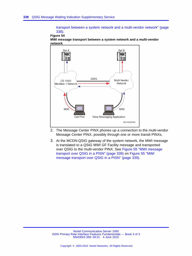
338 QSIG Message Waiting Indication Supplementary Service
transport between a system network and a multi-vendor network" (page338).
Figure 54MWI message transport between a system network and a multi-vendornetwork
2. The Message Center PINX phones up a connection to the multi-vendorMessage Center PINX, possibly through one or more transit PINXs.
3. At the MCDN-QSIG gateway of the system network, the MWI messageis translated to a QSIG MWI GF Facility message and transportedover QSIG to the multi-vendor PINX. See Figure 55 "MWI messagetransport over QSIG in a PISN" (page 339) on Figure 55 "MWImessage transport over QSIG in a PISN" (page 339).
Nortel Communication Server 1000ISDN Primary Rate Interface Features Fundamentals — Book 3 of 3
NN43001-569 04.01 4 June 2010
Copyright © 2003-2010 Nortel Networks. All Rights Reserved.
.
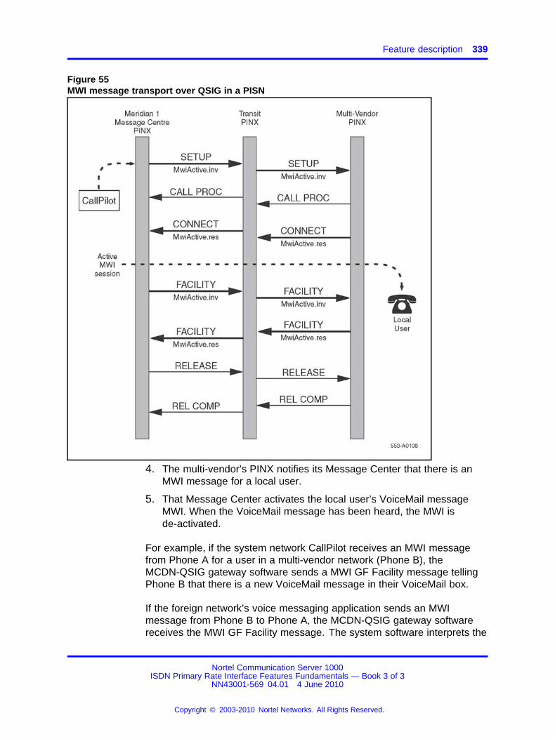
Feature description 339
Figure 55MWI message transport over QSIG in a PISN
4. The multi-vendor’s PINX notifies its Message Center that there is anMWI message for a local user.
5. That Message Center activates the local user’s VoiceMail messageMWI. When the VoiceMail message has been heard, the MWI isde-activated.
For example, if the system network CallPilot receives an MWI messagefrom Phone A for a user in a multi-vendor network (Phone B), theMCDN-QSIG gateway software sends a MWI GF Facility message tellingPhone B that there is a new VoiceMail message in their VoiceMail box.
If the foreign network’s voice messaging application sends an MWImessage from Phone B to Phone A, the MCDN-QSIG gateway softwarereceives the MWI GF Facility message. The system software interprets the
Nortel Communication Server 1000ISDN Primary Rate Interface Features Fundamentals — Book 3 of 3
NN43001-569 04.01 4 June 2010
Copyright © 2003-2010 Nortel Networks. All Rights Reserved.
.
340 QSIG Message Waiting Indication Supplementary Service
message and performs the same actions as if the MWI message had beenreceived from the local CallPilot. The system software activates Phone A’sMessage Waiting Indication key LED.
When an MWI message is received for a DN assigned to multiple phones,the Message Waiting Indication is activated on each of the phones. Whenall new messages are heard, the system cancels the MWI on all phones.
QSIG-MCDN GatewaysQSIG MWI Facility messages at QSIG-MCDN Gateway nodes aretranslated to MCDN MWI Facility messages. MCDN MWI Facilitymessages at QSIG-MCDN Gateway nodes are translated to QSIG MWIFacility messages.
Operating parametersThe QSIG Message Waiting Indication Supplementary Service featuresupports all Meridian phones that support Message Waiting Indication.
QSIG MWI SS requires a Coordinated Dialing Plan (CDP) or a UniformDialing Plan (UDP) between the networks using QSIG MWI SS.
ESIG and ISIG networks do not support QSIG MWI SS.
QSIG MWI SS does not support the Remote Call Sender feature.
The QSIG MWI SS feature does not support the QSIG-DPNSS Gateway.
The QSIG-MCDN interface does not support the transport of the MWIInterrogate facility message; however, it tandems MWI Interrogate facilitymessages to other multi-vendor switches that do support it.
On any system, either the Server User node or the Message Center nodemust have the QSIG Supplementary Services (QSIG-SS) package 316equipped in order to use the MWI service.
The QMWI feature is only supported with CallPilot and Meridian Mailas the local message centers hosted off a system running Succession3.0 software or later. It is not supported with CallPilot MINI or any othersystems (for example, Octel VM) that do not use a link for integration.QMWI cannot be used with phone integration or MIK MCK keys.
Nortel Communication Server 1000ISDN Primary Rate Interface Features Fundamentals — Book 3 of 3
NN43001-569 04.01 4 June 2010
Copyright © 2003-2010 Nortel Networks. All Rights Reserved.
.

Feature implementation 341
Feature interactionsMeridian End-to-End TransparencyThe system sends the proprietary QSIG MWI message between systemswitches over a QSIG interface, using Meridian End-to-End Transparency(MEET). MEET requires a Remote Capability (RCAP) of MCDN QSIGConversion as a Remote Capability (MQC) on the D-channel.
The QSIG MWI SS sends the QSIG MWI message between systemswitches and multi-vendor switches, using the industry-standard QSIGprotocol. QSIG MWI SS requires a RCAP of QSIG Message WaitingIndication using Integer Value (QMWI) or QSIG Message WaitingIndication using Object Identifier (QMWO).
Remove RCAP MQC, if implemented on a D-channel, before implementingRCAP QMWI/QMWO.
Feature packagingQSIG Message Waiting Indication Supplementary Service (QSIG MWI SS)is included in QSIG Supplementary Services (QSIG-SS) package 316.
Feature implementationTask summary list
The following is a summary of the tasks in this section:
1. Table 173 "LD 15: Configure a PINX DN for the customer." (page 341)
2. Table 174 "LD 16: Configure QSIG MWI for QSIG BRI trunks." (page342)
3. Table 175 "LD 17: Configure QSIG MWI for PRI trunks." (page 342)
Table 173LD 15: Configure a PINX DN for the customer.
Prompt Response Description
REQ CHG Change existing data.
TYPE NET Networking data.
CUST Customer number
0-99 Range for Large System and CS 1000E system.
0-31 Range for Small System, Media Gateway 1000B.
PINX_DN xx....x
Private Integrated Services Network Exchange DNNode DN (up to seven digits).
Nortel Communication Server 1000ISDN Primary Rate Interface Features Fundamentals — Book 3 of 3
NN43001-569 04.01 4 June 2010
Copyright © 2003-2010 Nortel Networks. All Rights Reserved.
.
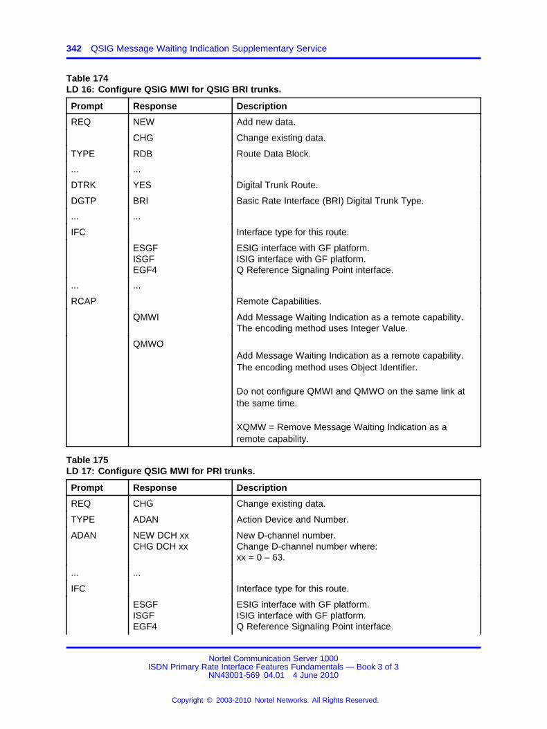
342 QSIG Message Waiting Indication Supplementary Service
Table 174LD 16: Configure QSIG MWI for QSIG BRI trunks.
Prompt Response Description
REQ NEW Add new data.
CHG Change existing data.
TYPE RDB Route Data Block.
... ...
DTRK YES Digital Trunk Route.
DGTP BRI Basic Rate Interface (BRI) Digital Trunk Type.
... ...
IFC Interface type for this route.
ESGFISGFEGF4
ESIG interface with GF platform.ISIG interface with GF platform.Q Reference Signaling Point interface.
... ...
RCAP Remote Capabilities.
QMWI Add Message Waiting Indication as a remote capability.The encoding method uses Integer Value.
QMWOAdd Message Waiting Indication as a remote capability.The encoding method uses Object Identifier.
Do not configure QMWI and QMWO on the same link atthe same time.
XQMW = Remove Message Waiting Indication as aremote capability.
Table 175LD 17: Configure QSIG MWI for PRI trunks.
Prompt Response Description
REQ CHG Change existing data.
TYPE ADAN Action Device and Number.
ADAN NEW DCH xxCHG DCH xx
New D-channel number.Change D-channel number where:xx = 0 – 63.
... ...
IFC Interface type for this route.
ESGFISGFEGF4
ESIG interface with GF platform.ISIG interface with GF platform.Q Reference Signaling Point interface.
Nortel Communication Server 1000ISDN Primary Rate Interface Features Fundamentals — Book 3 of 3
NN43001-569 04.01 4 June 2010
Copyright © 2003-2010 Nortel Networks. All Rights Reserved.
.

Feature operation 343
Table 175LD 17: Configure QSIG MWI for PRI trunks. (cont’d.)
Prompt Response Description
RCAP Remote Capabilities.
QMWI Add Message Waiting Indication as a remote capability.The encoding method uses Integer Value.
QMWOAdd Message Waiting Indication as a remote capability.The encoding method uses Object Identifier.
Do not configure QMWI and QMWO on the same link atthe same time.
Feature operationNo specific operating procedures are required to use this feature.
Nortel Communication Server 1000ISDN Primary Rate Interface Features Fundamentals — Book 3 of 3
NN43001-569 04.01 4 June 2010
Copyright © 2003-2010 Nortel Networks. All Rights Reserved.
.

344 QSIG Message Waiting Indication Supplementary Service
Nortel Communication Server 1000ISDN Primary Rate Interface Features Fundamentals — Book 3 of 3
NN43001-569 04.01 4 June 2010
Copyright © 2003-2010 Nortel Networks. All Rights Reserved.
.

345.
Recall with Priority during NightService Network Wide
ContentsThis section contains information on the following topics:
“Feature description” (page 345)
“Operating parameters” (page 346)
“Feature interactions” (page 346)
“Feature packaging” (page 346)
“Feature implementation” (page 346)
“Feature operation” (page 347)
Feature descriptionThis feature adds the Recall with Priority during Night Service (RPNS)functionality to a network-wide application. For this network application,RPNS is activated on a customer basis from an Attendant Console,according to the NITE service specifications defined in the NetworkAttendant Service feature description.
If NAS is not active, then conventional attendant service and Night Serviceare in effect.
Service is provided as follows when NAS is activated:
• If Night Service is not active (the NITE key is dark), calls are routedto a Local or Remote attendant.
• If Night Service is active at a local node (the NITE key is lit), the callis directed to a Remote attendant, queued to a route, or presented toa Night Station. If the NAS schedule does not define an alternativeattendant location for this period:
Nortel Communication Server 1000ISDN Primary Rate Interface Features Fundamentals — Book 3 of 3
NN43001-569 04.01 4 June 2010
Copyright © 2003-2010 Nortel Networks. All Rights Reserved.
.
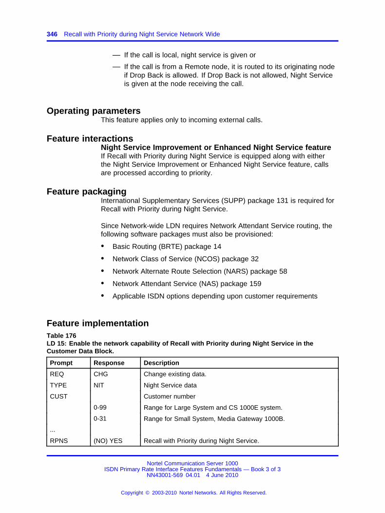
346 Recall with Priority during Night Service Network Wide
— If the call is local, night service is given or
— If the call is from a Remote node, it is routed to its originating nodeif Drop Back is allowed. If Drop Back is not allowed, Night Serviceis given at the node receiving the call.
Operating parametersThis feature applies only to incoming external calls.
Feature interactionsNight Service Improvement or Enhanced Night Service featureIf Recall with Priority during Night Service is equipped along with eitherthe Night Service Improvement or Enhanced Night Service feature, callsare processed according to priority.
Feature packagingInternational Supplementary Services (SUPP) package 131 is required forRecall with Priority during Night Service.
Since Network-wide LDN requires Network Attendant Service routing, thefollowing software packages must also be provisioned:
• Basic Routing (BRTE) package 14
• Network Class of Service (NCOS) package 32
• Network Alternate Route Selection (NARS) package 58
• Network Attendant Service (NAS) package 159
• Applicable ISDN options depending upon customer requirements
Feature implementationTable 176LD 15: Enable the network capability of Recall with Priority during Night Service in theCustomer Data Block.
Prompt Response Description
REQ CHG Change existing data.
TYPE NIT Night Service data
CUST Customer number
0-99 Range for Large System and CS 1000E system.
0-31 Range for Small System, Media Gateway 1000B.
...
RPNS (NO) YES Recall with Priority during Night Service.
Nortel Communication Server 1000ISDN Primary Rate Interface Features Fundamentals — Book 3 of 3
NN43001-569 04.01 4 June 2010
Copyright © 2003-2010 Nortel Networks. All Rights Reserved.
.

Feature operation 347
Feature operationNo specific operating procedures are required to use this feature.
Nortel Communication Server 1000ISDN Primary Rate Interface Features Fundamentals — Book 3 of 3
NN43001-569 04.01 4 June 2010
Copyright © 2003-2010 Nortel Networks. All Rights Reserved.
.

348 Recall with Priority during Night Service Network Wide
Nortel Communication Server 1000ISDN Primary Rate Interface Features Fundamentals — Book 3 of 3
NN43001-569 04.01 4 June 2010
Copyright © 2003-2010 Nortel Networks. All Rights Reserved.
.
349.
Recorded Announcement for CallsDiverted to External Trunks
ContentsThis section contains information on the following topics:
“Feature description” (page 349)
“Operating parameters” (page 350)
“Feature interactions” (page 350)
“Feature packaging” (page 351)
“Feature implementation” (page 351)
“Feature operation” (page 352)
Feature descriptionRecorded Announcement for Calls Diverted to External Trunks (RANX)provides an optional recorded announcement when the call is beingforwarded to the external Public Exchange through DTI, DTI2, PRI2, PRI,analog, and BRI trunks connected to AXE-10 or EuroISDN routes. Theannouncement notifies the calling party that call forwarding is taking placeand the call set-up can require more time than usual. The delay dependsupon the signaling that is required to reach the destination party.
Note: ISDN BRI trunking is not available in North America.
The message is given if the outgoing route is supported by the RANXfeature. The calling party receives RAN treatment until either themessage is finished or until an answer is received from the external PublicExchange trunk.
This feature operates on a route basis and is controlled by a the RANXprompt in LD 16, for calls diverted to external trunks.
Nortel Communication Server 1000ISDN Primary Rate Interface Features Fundamentals — Book 3 of 3
NN43001-569 04.01 4 June 2010
Copyright © 2003-2010 Nortel Networks. All Rights Reserved.
.
350 Recorded Announcement for Calls Diverted to External Trunks
Operating parametersThe RANX feature is supported only for external CO routes. Thecorresponding RANX prompt in LD 16 appears when the trunk type is:
• A Central Office Trunk (COT) and is not configured as a RadioPaging (RPA) trunk. The trunk has to be configured as an outgoingor outgoing/incoming trunk. The feature is not applicable for trunksconfigured solely for data traffic.
• A Direct Inward Dialing (DID) trunk configured as an outgoing oroutgoing/incoming trunk. The feature is not applicable for trunksconfigured solely for data traffic.
The RANX feature requires a Recorded Announcement (RAN) machine inthe same node as the outgoing route.
If the RAN trunk is configured with supervision, the calling party who isconnected to the RAN trunk will be charged from the time the answersignal is sent.
This feature is supported network wide in a Meridian Customer DefinedNetwork (MCDN) environment; no other private network protocols aresupported.
Since Digital Private Network Signaling System (DPNSS1) does notsupport any information concerning redirection, this feature is notsupported in a DPNSS1 network.
If a phone is forwarded to a trunk configured with the RANX feature andthe party that calls the extension is supposed to dial additional digits, thisis not always possible. If the calling party dials digits when being providedwith RAN, those digits will be lost since they are not buffered.
If the outgoing trunk, or the phone from which the call originated, times outduring the RAN, it is not possible to dial additional digits after the RAN isterminated.
If a DISA call is forwarded to a route with the RANX feature configured,and the RAN message that is provided to the calling party is longer thanthe duration of the EOD timer, the RAN will be interrupted when the EODtimer expires. When the EOD timer expires, the call is considered asestablished.
Feature interactionsCall Forward All Calls/Busy/No Answer/HuntRANX is activated if the call is forwarded to an outgoing external CO trunkwith the RANX feature active.
Nortel Communication Server 1000ISDN Primary Rate Interface Features Fundamentals — Book 3 of 3
NN43001-569 04.01 4 June 2010
Copyright © 2003-2010 Nortel Networks. All Rights Reserved.
.
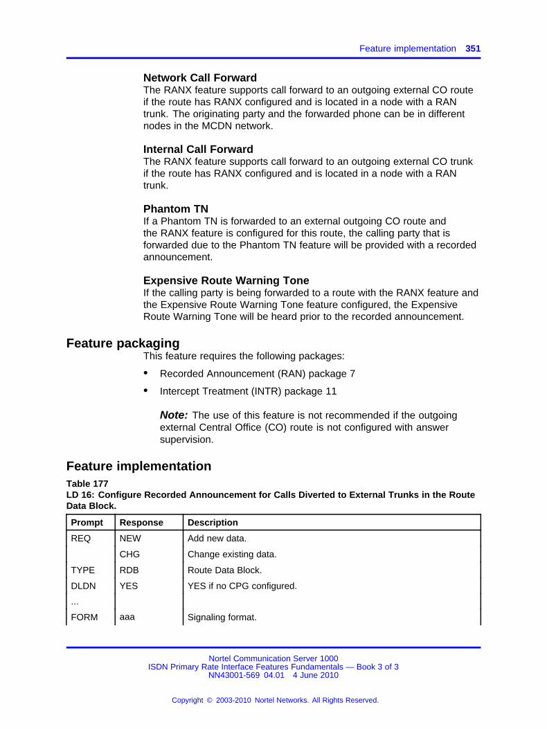
Feature implementation 351
Network Call ForwardThe RANX feature supports call forward to an outgoing external CO routeif the route has RANX configured and is located in a node with a RANtrunk. The originating party and the forwarded phone can be in differentnodes in the MCDN network.
Internal Call ForwardThe RANX feature supports call forward to an outgoing external CO trunkif the route has RANX configured and is located in a node with a RANtrunk.
Phantom TNIf a Phantom TN is forwarded to an external outgoing CO route andthe RANX feature is configured for this route, the calling party that isforwarded due to the Phantom TN feature will be provided with a recordedannouncement.
Expensive Route Warning ToneIf the calling party is being forwarded to a route with the RANX feature andthe Expensive Route Warning Tone feature configured, the ExpensiveRoute Warning Tone will be heard prior to the recorded announcement.
Feature packagingThis feature requires the following packages:
• Recorded Announcement (RAN) package 7
• Intercept Treatment (INTR) package 11
Note: The use of this feature is not recommended if the outgoingexternal Central Office (CO) route is not configured with answersupervision.
Feature implementationTable 177LD 16: Configure Recorded Announcement for Calls Diverted to External Trunks in the RouteData Block.
Prompt Response Description
REQ NEW Add new data.
CHG Change existing data.
TYPE RDB Route Data Block.
DLDN YES YES if no CPG configured.
...
FORM aaa Signaling format.
Nortel Communication Server 1000ISDN Primary Rate Interface Features Fundamentals — Book 3 of 3
NN43001-569 04.01 4 June 2010
Copyright © 2003-2010 Nortel Networks. All Rights Reserved.
.
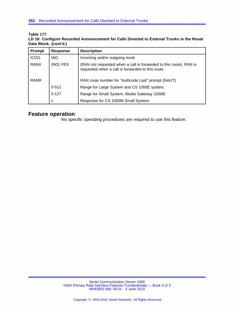
352 Recorded Announcement for Calls Diverted to External Trunks
Table 177LD 16: Configure Recorded Announcement for Calls Diverted to External Trunks in the RouteData Block. (cont’d.)
Prompt Response Description
ICOG IAO Incoming and/or outgoing trunk.
RANX (NO) YES (RAN not requested when a call is forwarded to this route), RAN isrequested when a call is forwarded to this route.
RANR RAN route number for "Authcode Last" prompt (NAUT)
0-511 Range for Large System and CS 1000E system.
0-127 Range for Small System, Media Gateway 1000B.
x Response for CS 1000M Small System.
Feature operationNo specific operating procedures are required to use this feature.
Nortel Communication Server 1000ISDN Primary Rate Interface Features Fundamentals — Book 3 of 3
NN43001-569 04.01 4 June 2010
Copyright © 2003-2010 Nortel Networks. All Rights Reserved.
.

353.
Redirecting Name DisplayEnhancement for QSIG Call Rerouting
ContentsThis section contains information on the following topics:
“Feature description” (page 353)
“Operating parameters” (page 353)
“Feature interactions” (page 353)
“Feature packaging” (page 354)
“Feature implementation” (page 354)
“Feature operation” (page 354)
Feature descriptionDialed Name Display Allowed and Dialed Name Display Denied(DNDA/DNDD) functionality is now supported for Call Rerouting when boththe originating and the diverted-to user are on the same node.
Call Diversion notification provides, for QSIG generic functional protocol(GF) interfaces, the capability of displaying the diverted-to user’s callingline identification (CLID) on the calling user’s phone when the diverted-touser’s phone is rung during QSIG call diversion.
When both the originating and the diverted-to user are on the samesystem node and call diversion is performed by the Rerouting method, theoriginating user’s subscription options have no impact on the diverted-touser’s notification. If the diverted-to user has Class of Service DNDA, thenthe diverted-to phone displays the redirecting name.
Operating parametersThere are no operating parameters associated with this feature.
Feature interactionsThere are no feature interactions associated with this feature.
Nortel Communication Server 1000ISDN Primary Rate Interface Features Fundamentals — Book 3 of 3
NN43001-569 04.01 4 June 2010
Copyright © 2003-2010 Nortel Networks. All Rights Reserved.
.
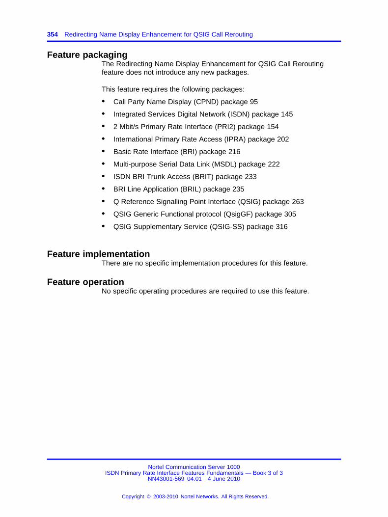
354 Redirecting Name Display Enhancement for QSIG Call Rerouting
Feature packagingThe Redirecting Name Display Enhancement for QSIG Call Reroutingfeature does not introduce any new packages.
This feature requires the following packages:
• Call Party Name Display (CPND) package 95
• Integrated Services Digital Network (ISDN) package 145
• 2 Mbit/s Primary Rate Interface (PRI2) package 154
• International Primary Rate Access (IPRA) package 202
• Basic Rate Interface (BRI) package 216
• Multi-purpose Serial Data Link (MSDL) package 222
• ISDN BRI Trunk Access (BRIT) package 233
• BRI Line Application (BRIL) package 235
• Q Reference Signalling Point Interface (QSIG) package 263
• QSIG Generic Functional protocol (QsigGF) package 305
• QSIG Supplementary Service (QSIG-SS) package 316
Feature implementationThere are no specific implementation procedures for this feature.
Feature operationNo specific operating procedures are required to use this feature.
Nortel Communication Server 1000ISDN Primary Rate Interface Features Fundamentals — Book 3 of 3
NN43001-569 04.01 4 June 2010
Copyright © 2003-2010 Nortel Networks. All Rights Reserved.
.
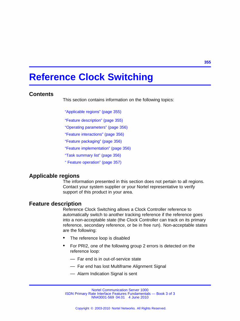
355.
Reference Clock Switching
ContentsThis section contains information on the following topics:
“Applicable regions” (page 355)
“Feature description” (page 355)
“Operating parameters” (page 356)
“Feature interactions” (page 356)
“Feature packaging” (page 356)
“Feature implementation” (page 356)
“Task summary list” (page 356)
“ Feature operation” (page 357)
Applicable regionsThe information presented in this section does not pertain to all regions.Contact your system supplier or your Nortel representative to verifysupport of this product in your area.
Feature descriptionReference Clock Switching allows a Clock Controller reference toautomatically switch to another tracking reference if the reference goesinto a non-acceptable state (the Clock Controller can track on its primaryreference, secondary reference, or be in free run). Non-acceptable statesare the following:
• The reference loop is disabled
• For PRI2, one of the following group 2 errors is detected on thereference loop:
— Far end is in out-of-service state
— Far end has lost Multiframe Alignment Signal
— Alarm Indication Signal is sent
Nortel Communication Server 1000ISDN Primary Rate Interface Features Fundamentals — Book 3 of 3
NN43001-569 04.01 4 June 2010
Copyright © 2003-2010 Nortel Networks. All Rights Reserved.
.

356 Reference Clock Switching
— Loss of Frame Alignment
— Loss of Multiframe Alignment
• For DTI2, if the reference loop is in out-of-service grade of service, or ifthe reference loop is in No New Call state (if the OOS is inhibited)
Clock Tracking RecoveryIf a repeating device loses the signal, it immediately begins sending anunframed all 1’s signal to the far-end to indicate an alarm condition. Thiscondition is called a Blue Alarm, or an Alarm Indication Signal (AIS). OnMeridian 1 PBX 11C Chassis and Meridian 1 PBX 11C Cabinet systemsan Alarm Indication Signal (AIS) on PRI loops puts the reference loopin an unacceptable state. Reference Clock Switching in such a case isimplemented using the CTRR (Clock Tracking Recovery) prompt in theDigital Data Block (DDB) in LD 73. The response to the CTRR prompt canbe YES or NO. (The default is NO.)
The CTRR option is prompted only for Meridian 1 PBX 11C Chassis andMeridian 1 PBX 11C Cabinet systems and only if at least one of CC0,CC2, CC3, or CC4 is configured.
Operating parametersThere are no operating parameters associated with this feature.
Feature interactionsThere are no feature interactions associated with this feature.
Feature packagingThis feature requires the following packages:
• International Supplementary Features (SUPP) package 131 and one orboth of:
— 2.0 Mbit Digital Trunk Interface (DTI2) package 129
— 2.0 Mbit Primary Rate Interface (PRI2) package 154
Feature implementationTask summary list
The following is a summary of the tasks in this section:
1. Table 178 "LD 73: Define the Grade of Service timers for the DTIcard." (page 357)
2. Table 179 "LD 73: Enable Clock Tracking Recovery on small systems."(page 357)
Nortel Communication Server 1000ISDN Primary Rate Interface Features Fundamentals — Book 3 of 3
NN43001-569 04.01 4 June 2010
Copyright © 2003-2010 Nortel Networks. All Rights Reserved.
.
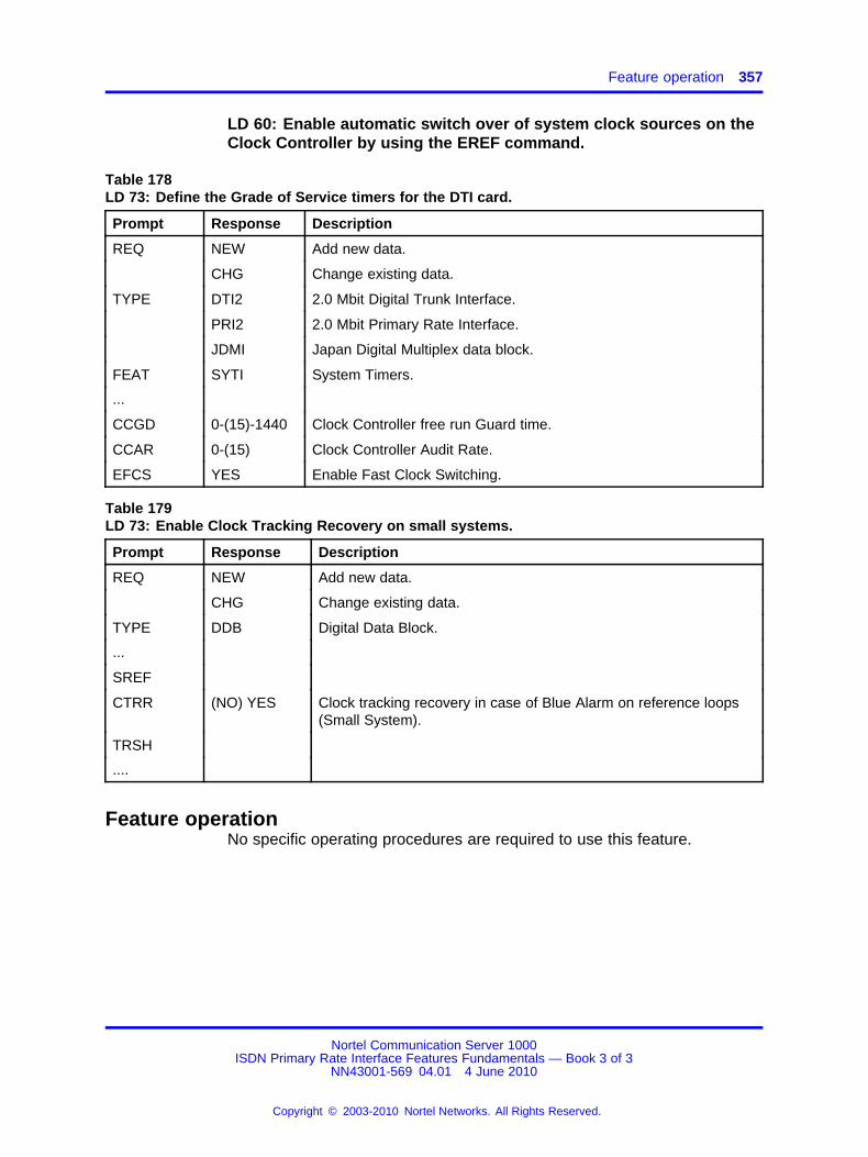
Feature operation 357
LD 60: Enable automatic switch over of system clock sources on theClock Controller by using the EREF command.
Table 178LD 73: Define the Grade of Service timers for the DTI card.
Prompt Response Description
REQ NEW Add new data.
CHG Change existing data.
TYPE DTI2 2.0 Mbit Digital Trunk Interface.
PRI2 2.0 Mbit Primary Rate Interface.
JDMI Japan Digital Multiplex data block.
FEAT SYTI System Timers.
...
CCGD 0-(15)-1440 Clock Controller free run Guard time.
CCAR 0-(15) Clock Controller Audit Rate.
EFCS YES Enable Fast Clock Switching.
Table 179LD 73: Enable Clock Tracking Recovery on small systems.
Prompt Response Description
REQ NEW Add new data.
CHG Change existing data.
TYPE DDB Digital Data Block.
...
SREF
CTRR (NO) YES Clock tracking recovery in case of Blue Alarm on reference loops(Small System).
TRSH
....
Feature operationNo specific operating procedures are required to use this feature.
Nortel Communication Server 1000ISDN Primary Rate Interface Features Fundamentals — Book 3 of 3
NN43001-569 04.01 4 June 2010
Copyright © 2003-2010 Nortel Networks. All Rights Reserved.
.

358 Reference Clock Switching
Nortel Communication Server 1000ISDN Primary Rate Interface Features Fundamentals — Book 3 of 3
NN43001-569 04.01 4 June 2010
Copyright © 2003-2010 Nortel Networks. All Rights Reserved.
.
359.
Remote Virtual Queuing
ContentsThis section contains information on the following topics:
“Feature description” (page 359)
“Operating parameters” (page 360)
“Feature interactions” (page 362)
“Feature packaging” (page 363)
“Feature implementation” (page 364)
“Task summary list” (page 364)
“Feature operation” (page 366)
Feature descriptionRemote Virtual Queuing (RVQ) allows a system to perform queuing- typefunctions on a busy trunk route (B-Channel) in an ISDN network. Thisfeature is similar to the ESN features Coordinated Call Back Queuing(CCBQ) and Call Back Queuing to a Conventional Main (CBQCM). Prior tooperating RVQ, you must have a working knowledge of the ESN features.
Remote Virtual Queuing (RVQ) is supported on a private ISDN PRI/ISLnetwork only.
When an outgoing network path is unavailable, Remote Virtual Queuing(RVQ) provides call back queuing. RVQ repeatedly scans ahead on theISDN trunk to be sure that the entire path, from origination to termination,is available. When a path becomes idle, you are notified and can ring thepath again to terminate the call.
Nortel Communication Server 1000ISDN Primary Rate Interface Features Fundamentals — Book 3 of 3
NN43001-569 04.01 4 June 2010
Copyright © 2003-2010 Nortel Networks. All Rights Reserved.
.
360 Remote Virtual Queuing
Operating parametersIn addition to the function offered by CCBQ and CBQCM, RVQ providesthe following:
• There is no limit to the number of nodes in the ISDN network that RVQsearches.
• The originating node has control of the call.
• Data terminals are supported.
• Attendants cannot activate RVQ.
• RVQ is activated only by phones with Ring Again allowed.
• AUTHCODE is supported on the first tandem node only.
• Trunk Access Codes are not supported.
• ACD DNs are supported as a terminating DN.
• Attendants are supported as terminating stations.
RVQ is supported in a private ISDN PRI/ISL network only. Any trunk otherthan an ISDN PRI or ISL trunk is considered a Non-RVQ Compatible(NRC) trunk. NRC trunks include analog trunks, T1 trunks, or publictrunks. NRC also includes trunks connecting to a non-system, ornon-ISDN.
Meridian Modular, analog (500/2500-type) and Meridian digital phones canactivate and receive RVQ calls.
The RVQ retry timer is set for each NCOS. Setting a specific NCOS with alow retry timer searches for more connections more often. The lower thetimer, the greater the chance to connect the call.
The maximum total amount of time RVQ searches for available paths is 30minutes. The countdown begins as soon as the originator activates theRing Again key.
Only one RVQ Ring Again attempt for each phone is allowed at one time.If Ring Again is pressed again, after activating it for RVQ, the most recentnumber dialed is the one attempted.
RVQ does not check the terminating phone’s status. The dialed DN canbe invalid or busy. Once the path is available, the RVQ call can reach thedialed DN. It is possible that the dialed phone is busy, and Network RingAgain can be used if enabled. The tone indicating that the trunks are busyis a fast busy tone. A busy DN is indicated by a standard busy tone.
RVQ searches throughout system networks only. Off-net trunk pathscannot be checked beyond the first NRC trunk.
Nortel Communication Server 1000ISDN Primary Rate Interface Features Fundamentals — Book 3 of 3
NN43001-569 04.01 4 June 2010
Copyright © 2003-2010 Nortel Networks. All Rights Reserved.
.
Operating parameters 361
RVQ is a virtual queuing feature. Each RVQ call is independent ofanother. It does not operate by first in first out policy. The first caller toinitiate RVQ is not necessarily the first person connected.
It can take up to 30 seconds for notification to reach the originator. Thenetwork path is reserved while RVQ notifies the caller. In a privatenetwork, the path is reserved from the originating node to the terminatingnode. Otherwise the path is reserved up to the first NRC trunk.
RVQ supports Uniform Dialing Plan (UDP) and Coordinated Dialing Plan(CDP). For NRC trunks, the E.164 public numbering plan is supported.
RVQ supports the following trunk types:
• Private network ISDN trunks
— TIE
— COT
— Direct Outgoing Dial (DOD)
— WATS
— ISA
— FEX
RVQ supports only system machines in a private ISDN PRI/ISL network.A non-system machine functioning in tandem with a system machine istreated as a Non-RVQ Compatible (NRC) trunk.
• NRC trunks
— COT
— Direct Outgoing Dial (DOD)
— WATS
— FEX
— ISA
— TIE
RVQ is cancelled if the originating node system initializes.
If the originating node performs a cold start, RVQ is cancelled.
RVQ from a Conventional Main (RVQCM) requires a special configuration.See the "Feature administration" section in this module.
With RVQ, callers cannot activate Ring Again to refuse expensive routesafter the Expensive Route Warning Tone (ERWT) is given.
Nortel Communication Server 1000ISDN Primary Rate Interface Features Fundamentals — Book 3 of 3
NN43001-569 04.01 4 June 2010
Copyright © 2003-2010 Nortel Networks. All Rights Reserved.
.

362 Remote Virtual Queuing
When using RVQ from a Conventional Main (RVQCM), the originatingnode seizes the same TIE trunk group that was used to initiateRVQCM for the callback. Thus, these trunk groups must be two-way(incoming/outgoing) and configured for far end disconnect.
Conventional mains must provide answer supervision on TIE trunksconnected to the originating node. The system must also permittransmission or repetition of phone dial pulses for RVQCM operation. Thisfeature cannot be used with systems that operate in senderized mode.Operation can require adjustment of the interdigit timeout on systems thatemploy simulated cut-through operation.
Multiple callback queues are allowed for each trunk group for theConventional main by dialing any digits (up to 7) based on the availabilityof system call registers.
When utilizing RVQCM, do not call forward the calling phone whenawaiting callback. If the phone is forwarded, it is possible that the TIEtrunk will not be released at the end of the call.
Feature interactionsDrop Back BusyDrop Back Busy (DBB) and Remote Virtual Queuing (RVQ) are bothpackaged under the Originating Routing Control/Remote Virtual Queuing(ORC-RVQ) package 192. If RVQ and DBB are both configured, DBB willtake precedence over RVQ. If the user wishes to activate RVQ, DBB mustbe disabled for a route entry in response to the IDBB prompt. If the userwishes to activate DBB, it must be enabled by entering DBI or DBA. Referto the "Feature administration" section for more information.
Coordinated Call Back QueuingCCBQ and RVQ can both be enabled on a single machine.
Call Back Queuing to a Conventional MainCBQCM and RVQ can both be enabled on a single machine.
Call Page Network WideRVQ is supported for an incoming call to a Paging trunk when all the trunkmembers of the dialed Paging route are busy.
Direct Inward System AccessDISA DNs are not supported by RVQ.
ISDN QSIG Basic CallRemote Virtual Queuing (RVQ) does not operate on the QSIG interface.The existing RVQ operation on unsupported interface applies on the QSIGinterface.
Nortel Communication Server 1000ISDN Primary Rate Interface Features Fundamentals — Book 3 of 3
NN43001-569 04.01 4 June 2010
Copyright © 2003-2010 Nortel Networks. All Rights Reserved.
.

Feature packaging 363
Make Set BusyRVQ can be originated by, and terminated on, an ACD DN in Make SetBusy Mode.
Network ACDIf a target agent is available on a Remote node, RVQ cannot be activatedif the busy trunk is found on its way to the target node.
Network Call RedirectionRVQ does not guarantee connection if the terminating phone call forwardsto a phone on another node. When a terminating phone call forwards toanother node, that node is a redirected node. RVQ cannot search betweenterminating and redirected nodes.
Network Ring AgainNetwork Ring Again (NRAG) is activated only when the terminating phoneor console is busy. If both the network path and the terminating phone arebusy, RVQ is activated first. When the path is available, but the phone isbusy, NRAG can be activated.
Off -Hook QueuingRVQ and Off- Hook Queuing (OHQ) are compatible in a system. If OHQis configured, it is implemented by leaving the handset off -hook. RVQ isimplemented by pressing the Ring Again key. Choosing one or the othermethod activates the specified feature.
Feature packagingThis feature requires the following packages:
• Main Network Queuing package 38
• Flexible Call Back Queuing package 61
• Digital Trunk Interface package 75
• ISDN signaling package 145
• ISDN PRI package 146 or ISL package 147 or 2.0 Mbit Primary RateAccess (PRI2) package 154
• Advanced Network Services package 148 (for NRAG capability)
• ISDN Supplementary (ISDNS) package 161
• Originating Routing Control/Remote Virtual Queuing (ORC-RVQ)package 192
Nortel Communication Server 1000ISDN Primary Rate Interface Features Fundamentals — Book 3 of 3
NN43001-569 04.01 4 June 2010
Copyright © 2003-2010 Nortel Networks. All Rights Reserved.
.
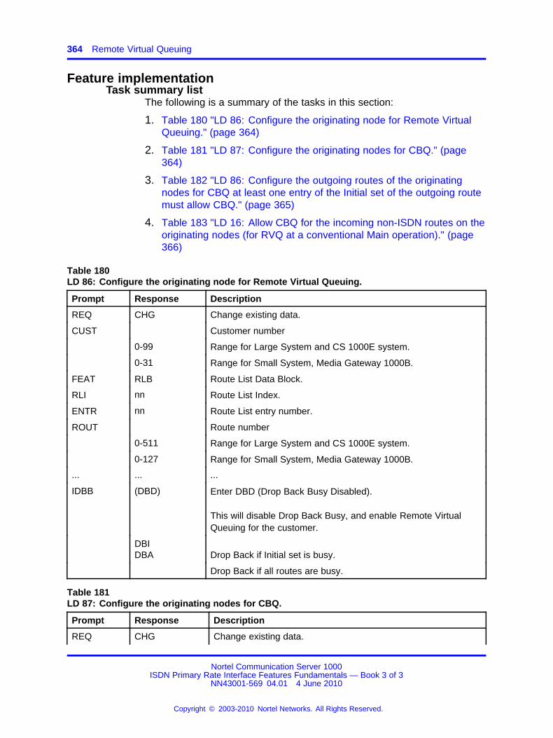
364 Remote Virtual Queuing
Feature implementationTask summary list
The following is a summary of the tasks in this section:
1. Table 180 "LD 86: Configure the originating node for Remote VirtualQueuing." (page 364)
2. Table 181 "LD 87: Configure the originating nodes for CBQ." (page364)
3. Table 182 "LD 86: Configure the outgoing routes of the originatingnodes for CBQ at least one entry of the Initial set of the outgoing routemust allow CBQ." (page 365)
4. Table 183 "LD 16: Allow CBQ for the incoming non-ISDN routes on theoriginating nodes (for RVQ at a conventional Main operation)." (page366)
Table 180LD 86: Configure the originating node for Remote Virtual Queuing.
Prompt Response Description
REQ CHG Change existing data.
CUST Customer number
0-99 Range for Large System and CS 1000E system.
0-31 Range for Small System, Media Gateway 1000B.
FEAT RLB Route List Data Block.
RLI nn Route List Index.
ENTR nn Route List entry number.
ROUT Route number
0-511 Range for Large System and CS 1000E system.
0-127 Range for Small System, Media Gateway 1000B.
... ... ...
IDBB (DBD) Enter DBD (Drop Back Busy Disabled).
This will disable Drop Back Busy, and enable Remote VirtualQueuing for the customer.
DBIDBA Drop Back if Initial set is busy.
Drop Back if all routes are busy.
Table 181LD 87: Configure the originating nodes for CBQ.
Prompt Response Description
REQ CHG Change existing data.
Nortel Communication Server 1000ISDN Primary Rate Interface Features Fundamentals — Book 3 of 3
NN43001-569 04.01 4 June 2010
Copyright © 2003-2010 Nortel Networks. All Rights Reserved.
.
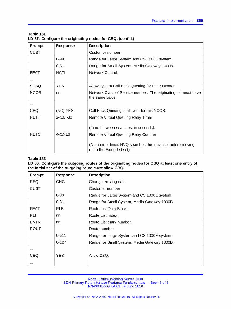
Feature implementation 365
Table 181LD 87: Configure the originating nodes for CBQ. (cont’d.)
Prompt Response Description
CUST Customer number
0-99 Range for Large System and CS 1000E system.
0-31 Range for Small System, Media Gateway 1000B.
FEAT NCTL Network Control.
...
SCBQ YES Allow system Call Back Queuing for the customer.
NCOS nn Network Class of Service number. The originating set must havethe same value.
...
CBQ (NO) YES Call Back Queuing is allowed for this NCOS.
RETT 2-(10)-30 Remote Virtual Queuing Retry Timer
(Time between searches, in seconds).
RETC 4-(5)-16 Remote Virtual Queuing Retry Counter
(Number of times RVQ searches the Initial set before movingon to the Extended set).
Table 182LD 86: Configure the outgoing routes of the originating nodes for CBQ at least one entry ofthe Initial set of the outgoing route must allow CBQ.
Prompt Response Description
REQ CHG Change existing data.
CUST Customer number
0-99 Range for Large System and CS 1000E system.
0-31 Range for Small System, Media Gateway 1000B.
FEAT RLB Route List Data Block.
RLI nn Route List Index.
ENTR nn Route List entry number.
ROUT Route number
0-511 Range for Large System and CS 1000E system.
0-127 Range for Small System, Media Gateway 1000B.
...
CBQ YES Allow CBQ.
...
Nortel Communication Server 1000ISDN Primary Rate Interface Features Fundamentals — Book 3 of 3
NN43001-569 04.01 4 June 2010
Copyright © 2003-2010 Nortel Networks. All Rights Reserved.
.

366 Remote Virtual Queuing
Table 182LD 86: Configure the outgoing routes of the originating nodes for CBQ at least one entry ofthe Initial set of the outgoing route must allow CBQ. (cont’d.)
Prompt Response Description
ENTR <CR>
ISET nn Size of the Initial set.
Table 183LD 16: Allow CBQ for the incoming non-ISDN routes on the originating nodes (for RVQ at aconventional Main operation).
Prompt Response Description
REQ CHG Change existing data.
TYPE RDB Route Data Block.
CUST Customer number
0-99 Range for Large System and CS 1000E system.
0-31 Range for Small System, Media Gateway 1000B.
ROUT Route number
0-511 Range for Large System and CS 1000E system.
0-127 Range for Small System, Media Gateway 1000B.
...
CBQ YES Allow Call Back Queuing.
...
Feature operationRVQ supports private ISDN PRI/ISL networks, non-RVQ compatible (NRC)blocked trunks, and conventional mains (RVQCM). RVQ supports systemmachines only. A non-system machine working in tandem with a system istreated as a Non-RVQ Compatible (NRC) trunk.
RVQ on a private networkRVQ follows this checklist before starting.
• The first tandem node must be a system node.
• The originating node’s Network Class of Service (NCOS) must allowCall Back Queuing (CBQ).
• At least one route in the Initial set of the route list must allow CBQ.
• The system has CBQ allowed at the Network Control Block.
When the checks are complete, activate RVQ by pressing the Ring Againkey. As soon as the key is pressed, the retry timer begins. When the retrytimer expires, RVQ checks the path again. When a blocked path occurs,
Nortel Communication Server 1000ISDN Primary Rate Interface Features Fundamentals — Book 3 of 3
NN43001-569 04.01 4 June 2010
Copyright © 2003-2010 Nortel Networks. All Rights Reserved.
.

Feature operation 367
RVQ searches the network to ensure that the entire path will be clear oncethe blockage disappears. The total amount of time RVQ will spend on asearch is 30 minutes.
The retry counter controls the number of times the Initial set is checkedbefore RVQ searches the extended set. The extended set search includesall of the trunks in both the Initial and Extended sets.
Tandem nodes must recognize the RVQ messages and pass them on toanother tandem or terminating node.
RVQ with NRC trunksRVQ searches the path until it reaches the firstNon-RVQ Compatible(NRC) trunk. RVQ notifies the originator when that trunk is available,but cannot search beyond it. It is possible that the path can be blockedbeyond the NRC trunk, and the call cannot go through.
Any trunk other than an ISDN PRI or ISL trunk is considered an NRCtrunk. NRC trunks include analog, T1, or public trunks, as well as trunksconnecting to a non-system, or non-ISDN node.
When an NRC trunk is busy, RVQ follows this checklist beforeimplementing RVQ.
• First tandem node must be a system node.
• Originating node’s NCOS must allow Call Back Queuing (CBQ).
• At least one route in the initial set of the route list must allow CBQ.
• The system has CBQ allowed at the Network Control Block.
When the checks are complete, activate RVQ by pressing the Ring Againkey. As soon as the key is pressed, the retry timer begins. When the retrytimer expires, RVQ checks the path again. The total amount of time RVQwill spend on a search is 30 minutes.
The retry counter controls the number of times the Initial set is checkedbefore RVQ searches the Extended set. The extended set search includesall the trunks in both the Initial and Extended sets. Only the first NRC trunkis checked. RVQ cannot search beyond that trunk, even if the subsequenttrunks are ISDN PRI/ISL.
RVQ on a conventional main (RVQCM)A conventional main call is one that comes from a third-party system intothe private network through a TIE trunk to a system node.
Nortel Communication Server 1000ISDN Primary Rate Interface Features Fundamentals — Book 3 of 3
NN43001-569 04.01 4 June 2010
Copyright © 2003-2010 Nortel Networks. All Rights Reserved.
.
368 Remote Virtual Queuing
When the conventional main call enters the network, the default NCOS isassigned to the TIE trunk to determine RVQCM eligibility. Use Authcodelast to upgrade the NCOS if necessary.
When a conventional main call is blocked, RVQ checks the following at thefirst system node to ensure RVQCM can be activated. The system node isconsidered the Originating node, and controls the call.
• The tandem and terminating nodes must be system nodes.
• The originating node’s Network Class of Service (NCOS) must allowCall Back Queuing (CBQ).
• At least one route in the Initial set of the route list must allow CBQ.
• The system has CBQ allowed at the Network Control Block.
• The incoming TIE trunk allows CBQ.
RVQCM is offered to the conventional main caller with a special offertone (3 beeps). To accept RVQ, enter the calling number. After the samespecial confirmation tone (3 beeps) is heard, hang up. The originatingnode begins the retry timer and search process. When the retry timerexpires, RVQ checks the path again. The maximum total amount of timeRVQ will spend on a search is 30 minutes. When the path is free, theoriginating node calls the caller back (at the number entered). The phonerings, the same special callback tone (3 beeps) is heard, and the call isconnected. RVQCM cannot be cancelled from the conventional main oncestarted.
If the calling phone is busy, or does not answer the callback, the RVQcallback is placed in a 5 minute suspense state. After 5 minutes havepassed, RVQ attempts the callback again. If the calling phone is still busy,or does not answer, RVQ is cancelled.
The retry counter controls the number of times the Initial set is checkedbefore RVQ searches the Extended set. The Extended set search includesall the trunks in both the Initial and Extended sets.
Note: The calling number is accepted only if the database hasbeen configured to accept the given number of digits. If not, or if thecaller does not hang up, an overflow tone is given, and the call isdisconnected. RVQCM does not verify that the dialed DN is valid or free.
Once started, RVQ cannot be cancelled from the convention main.Operating parameters relating to Call Back Queuing for ConventionalMains (CBQCM) also apply to RVQCM as follows.
Nortel Communication Server 1000ISDN Primary Rate Interface Features Fundamentals — Book 3 of 3
NN43001-569 04.01 4 June 2010
Copyright © 2003-2010 Nortel Networks. All Rights Reserved.
.

Feature operation 369
Users at Conventional Mains cannot activate Ring Again to refuseexpensive routes after the Expensive Route Warning Tone (ERWT) isgiven.
The node seizes the same TIE trunk group that was used to initiateRVQCM for the callback. These trunk groups must be two way(incoming/outgoing).
Conventional Mains must provide answer supervision on TIE trunksconnected to the node. These switches must also permit transmission,or repetition of phone dial pulses, for RVQCM operation. This featurecannot be used with systems that operate in senderized mode. Operationcan require adjustment of the interdigit timeout on systems that employsimulated cut-through operation.
Multiple callback queues are allowed for each trunk group for theConventional Main by dialing up to 7 digits (any digits are allowed) basedon the availability of system call registers.
ATTENTIONConventional Mains must not allow RVQCM callback calls to be modified by calltransfer or call forward to an outside line. These Call modifications can result inthe TIE trunk not being released at the end of the call.
Nortel Communication Server 1000ISDN Primary Rate Interface Features Fundamentals — Book 3 of 3
NN43001-569 04.01 4 June 2010
Copyright © 2003-2010 Nortel Networks. All Rights Reserved.
.

370 Remote Virtual Queuing
Nortel Communication Server 1000ISDN Primary Rate Interface Features Fundamentals — Book 3 of 3
NN43001-569 04.01 4 June 2010
Copyright © 2003-2010 Nortel Networks. All Rights Reserved.
.
371.
Ring Again on No Answer
ContentsThis section contains information on the following topics:
“Feature description” (page 371)
“Operating parameters” (page 371)
“Feature interactions” (page 372)
“Feature packaging” (page 372)
“Feature implementation” (page 372)
“Task summary list” (page 372)
“Feature operation” (page 373)
Feature descriptionThis feature extends the capabilities of Network Ring Again for ISDNapplications.
When the called station goes off-hook and then on-hook, the activatingstation is rung back in the same way that traditional Ring Again onBusy operates. Ring Again on Busy gives a caller the opportunity, afterencountering a busy Directory Number (DN), to ring the DN again when itbecomes free. If a dialed DN is busy, or if all the trunks are busy, pressingthe Ring Again key asks the system to monitor the dialed DN or trunk.When it becomes available, the system notifies the caller. The call isautomatically dialed again when the caller presses the Ring Again key asecond time.
Ring Again on No Answer is applied to the originally dialed DN only.
Operating parametersRing Again on No Answer cannot be applied:
• if the dialed DN is a Pilot DN
• to Attendant Consoles
Nortel Communication Server 1000ISDN Primary Rate Interface Features Fundamentals — Book 3 of 3
NN43001-569 04.01 4 June 2010
Copyright © 2003-2010 Nortel Networks. All Rights Reserved.
.
372 Ring Again on No Answer
• to a station which has been intercepted to the attendant
• to a station which is queued for an attendant
• to a station which has been recalled to an attendant due tomisoperation
• to Automatic Call Distribution (ACD) stations
• to a station with Radio Paging active
• to trunks
Meridian digital telephones must be equipped with a Ring Again (RGA)key/lamp combination.
Ring Again on No Answer is applied to the originally dialed DN only.
Feature interactionsCall Forward (All Calls)Call Forward No AnswerAutomatic Call ForwardIf an unanswered call is forwarded to another station by any of thesefeatures, RANA is applied to the originally dialed station.
HuntIf RANA has been applied to a station going through a Hunt sequence,Ring Again is applied to that station and not the ringing station.
ISDN QSIG/EuroISDN Call CompletionAnalog (500/2500 type) phones can have only one Call Completion toBusy Subscriber request at a given time. Meridian 1 Proprietary Phonescan make Ring Again requests based on the number of Ring Again keysprogrammed on a phone.
Feature packagingThis feature requires the following package:
• Advanced ISDN Network Services (NTWK) package 148.
Feature implementationTask summary list
The following is a summary of the tasks in this section:
1. Table 184 "LD 15: Allow or deny Ring Again on No Answer operation."(page 373)
2. Table 185 "LD 11: Define RGA keys against M2317 phones." (page373)
Nortel Communication Server 1000ISDN Primary Rate Interface Features Fundamentals — Book 3 of 3
NN43001-569 04.01 4 June 2010
Copyright © 2003-2010 Nortel Networks. All Rights Reserved.
.
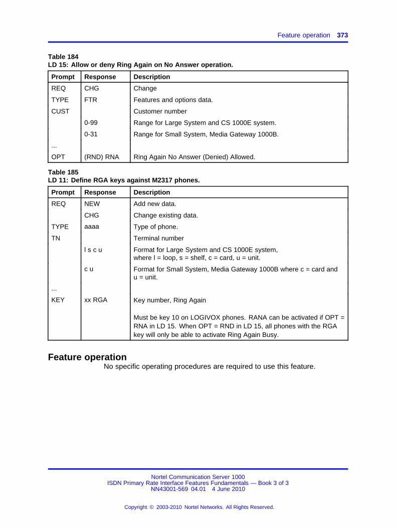
Feature operation 373
Table 184LD 15: Allow or deny Ring Again on No Answer operation.
Prompt Response Description
REQ CHG Change
TYPE FTR Features and options data.
CUST Customer number
0-99 Range for Large System and CS 1000E system.
0-31 Range for Small System, Media Gateway 1000B.
...
OPT (RND) RNA Ring Again No Answer (Denied) Allowed.
Table 185LD 11: Define RGA keys against M2317 phones.
Prompt Response Description
REQ NEW Add new data.
CHG Change existing data.
TYPE aaaa Type of phone.
TN Terminal number
l s c u Format for Large System and CS 1000E system,where l = loop, s = shelf, c = card, u = unit.
c u Format for Small System, Media Gateway 1000B where c = card andu = unit.
...
KEY xx RGA Key number, Ring Again
Must be key 10 on LOGIVOX phones. RANA can be activated if OPT =RNA in LD 15. When OPT = RND in LD 15, all phones with the RGAkey will only be able to activate Ring Again Busy.
Feature operationNo specific operating procedures are required to use this feature.
Nortel Communication Server 1000ISDN Primary Rate Interface Features Fundamentals — Book 3 of 3
NN43001-569 04.01 4 June 2010
Copyright © 2003-2010 Nortel Networks. All Rights Reserved.
.

374 Ring Again on No Answer
Nortel Communication Server 1000ISDN Primary Rate Interface Features Fundamentals — Book 3 of 3
NN43001-569 04.01 4 June 2010
Copyright © 2003-2010 Nortel Networks. All Rights Reserved.
.
375.
SDID Number as CLID for EuroISDNTrunks
ContentsThis section contains information on the following topics:
“Applicable regions” (page 375)
“Feature description” (page 375)
“Operating parameters” (page 376)
“Feature interactions” (page 377)
“Feature packaging” (page 377)
“Feature implementation” (page 378)
“Feature operation” (page 379)
Applicable regionsThe information presented in this section does not pertain to all regions.Contact your system supplier or your Nortel representative to verifysupport of this product in your area.
Feature descriptionThe following is a description of the SDID number as CLID for EuroISDNTrunks feature. SDID capability is available for EuroISDN calls that haveCLID OPT1 enabled. For BRIE interfaces, the OPT1 option is configuredat the CLID prompt in LD 16. For PRI2 interfaces, the OPT1 option isconfigured at the CLID prompt in LD 17.
The Send DID Number (SDID) feature sends the Direct Inward Dial(DID) number of a specific DN as Calling Line Identification (CLID) on anoutgoing trunk call. SDID replaces the internal DN of the phone with theDID (external DN) of the phone. The DID number is obtained from theIncoming Digit Conversion (IDC) table.
Nortel Communication Server 1000ISDN Primary Rate Interface Features Fundamentals — Book 3 of 3
NN43001-569 04.01 4 June 2010
Copyright © 2003-2010 Nortel Networks. All Rights Reserved.
.

376 SDID Number as CLID for EuroISDN Trunks
The IDC table converts the following:
• the internal DN of the phone to the external DN of the phone
• the external DN of the phone to the internal DN of the phone
Table 186Example of an IDC table
Incoming Digits (IDGT) Converted Digits (CDGT)
4322 (external DN) 726 (internal DN)
8741 (external DN) 12 (internal DN)
Phone A with an internal DN of 726 calls Phone B. The IDC table convertsPhone A’s internal DN 726 to its external DN 4322. The CLID of Phone Ais sent to Phone B as 4322. If the internal DN is not entered in the IDCtable, the internal DN is sent as the CLID.
Phone C calls Phone D by dialing Phone D’s external DN 8741. The IDCtable converts Phone D’s external DN 8741 (external DN) to its internal DN12. Phone D’s external DN is sent to Phone C as the Connected Number(CONN).
Type Of Number of Calling Party NumberThe SDID feature allows the Type of Number (TON) of the calling partynumber to be changed in the Route Data Block (RDB). The TON ischanged when the calling party number has an ISDN numbering plan.
Connected Number IdentificationThe SDID DN (the external DN) is sent to the CO as the ConnectedNumber for an incoming call.
Operating parametersThis feature is only available on EuroISDN routes.
The EuroISDN route must have an IDC table associated with it when SDIDis enabled.
This feature replaces the internal DN with the DID DN for the following:
• analog (500/250- type) phones
• Meridian Digital phones
• Basic Rate Interface (BRI) Line phones
• Attendant Consoles
This feature does not apply to trunks as the originator.
Nortel Communication Server 1000ISDN Primary Rate Interface Features Fundamentals — Book 3 of 3
NN43001-569 04.01 4 June 2010
Copyright © 2003-2010 Nortel Networks. All Rights Reserved.
.
Feature packaging 377
Feature interactionsAutomatic Call DistributionThe SDID number as CLID for EuroISDN trunks feature is not applicable toAutomatic Call Distribution (ACD), as calls cannot originate from an ACDkey.
If the ACD phone is equipped with an active Single Call Ringing (SCR)key, the DN is obtained from the active key. If the DN has been entered inthe IDC table, the external DID number is used. See "ISDN Calling LineIdentification Enhancement".
Business Network ExpressEven though the CLID is changed to the SDID DN, the private CLID orname is not changed.
Call Detail RecordingCall Detail Recording (CDR) is not affected by the SDID feature. Therecord’s Originating ID (ORIGID) and Terminating ID (TERID) remain asthe internal DN.
Call ForwardIf a forwarding DN on a EuroISDN trunk is used as CLID and is found inthe IDC table, the SDID DN is sent as the CLID.
Calling Party PrivacyThe Calling Party Privacy (CPP) feature is not affected by SDID.
Direct Inward System AccessDirect Inward System Access (DISA) numbers are not affected by theSDID feature.
EuroISDN Trunk: Network SideThe SDID number as CLID feature is supported on the network side ofthe EuroISDN trunk.
Feature packagingThis feature requires the following packages:
• Incoming Digit Conversion (IDC) package 113
• International Supplementary Features (SUPP) package 131
• Integrated Services Digital Network (ISDN) package 145
Nortel Communication Server 1000ISDN Primary Rate Interface Features Fundamentals — Book 3 of 3
NN43001-569 04.01 4 June 2010
Copyright © 2003-2010 Nortel Networks. All Rights Reserved.
.

378 SDID Number as CLID for EuroISDN Trunks
Feature implementationTask summary list
The following is a summary of the tasks in this section:
1. Table 187 "LD 49: Define the IDC table." (page 378)
2. Table 188 "LD 16: Define the Route Data Block (RDB) for ISDNtrunks." (page 378)
Table 187LD 49: Define the IDC table.
Prompt Response Description
REQ NEW Add new data.
CHG Change existing data.
TYPE IDC Incoming Digit Conversion.
CUST Customer number
0-99 Range for Large System and CS 1000E system.
0-31 Range for Small System, Media Gateway 1000B.
DCNO 0 – 254 Day IDC tree number.
FDID Flexible DID.
(NO)YES
SDID Send DID number instead of internal DN.
(NO)YES
IDGT xxxx xxxx Incoming Digit or range of digits where:xxxx = 0 – 9999.
xxxx yyyy Converted Digits (CDGT).
IDGT xxxx xxxx Incoming Digit or range of Digits where:xxxx = 0 – 9999.
xxxx yyyy Converted digits (CDGT).
Table 188LD 16: Define the Route Data Block (RDB) for ISDN trunks.
Prompt Response Description
REQ NEW Add new data.
CHG Change existing data.
TYPE RDB Type of data block = RDB (route data block).
ROUT Route number
0-511 Range for Large System and CS 1000E system.
0-127 Range for Small System, Media Gateway 1000B.
Nortel Communication Server 1000ISDN Primary Rate Interface Features Fundamentals — Book 3 of 3
NN43001-569 04.01 4 June 2010
Copyright © 2003-2010 Nortel Networks. All Rights Reserved.
.
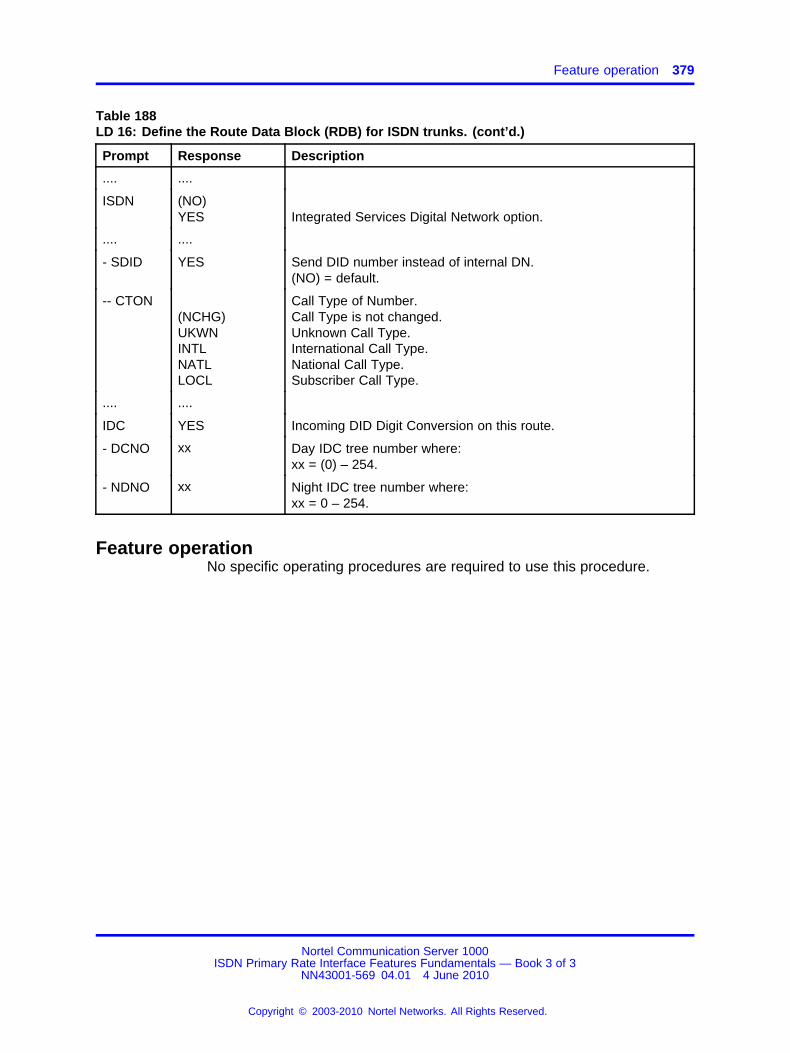
Feature operation 379
Table 188LD 16: Define the Route Data Block (RDB) for ISDN trunks. (cont’d.)
Prompt Response Description
.... ....
ISDN (NO)YES Integrated Services Digital Network option.
.... ....
- SDID YES Send DID number instead of internal DN.(NO) = default.
-- CTON(NCHG)UKWNINTLNATLLOCL
Call Type of Number.Call Type is not changed.Unknown Call Type.International Call Type.National Call Type.Subscriber Call Type.
.... ....
IDC YES Incoming DID Digit Conversion on this route.
- DCNO xx Day IDC tree number where:xx = (0) – 254.
- NDNO xx Night IDC tree number where:xx = 0 – 254.
Feature operationNo specific operating procedures are required to use this procedure.
Nortel Communication Server 1000ISDN Primary Rate Interface Features Fundamentals — Book 3 of 3
NN43001-569 04.01 4 June 2010
Copyright © 2003-2010 Nortel Networks. All Rights Reserved.
.

380 SDID Number as CLID for EuroISDN Trunks
Nortel Communication Server 1000ISDN Primary Rate Interface Features Fundamentals — Book 3 of 3
NN43001-569 04.01 4 June 2010
Copyright © 2003-2010 Nortel Networks. All Rights Reserved.
.

381.
Singapore ISDN Restart MessageEnhancement
ContentsThis section contains information on the following topics:
“Feature description” (page 381)
“Operating parameters” (page 382)
“Feature interactions” (page 382)
“Feature packaging” (page 382)
“Feature implementation” (page 382)
“Feature operation” (page 382)
Feature descriptionThe Singapore ISDN Restart Message Enhancement allows systemswith Asia Pacific- Singapore ISDN connectivity to recognize and processRestart Acknowledge messages sent from an Alternate Carrier’s NokiaCentral Office (CO) switch.
Note: The Alternate Carrier’s Nokia CO must be located in Singapore.
With the Singapore ISDN Restart Message Enhancement, the systemaccepts an Indicated Channels Restart Acknowledge message from theCO. The acknowledge message from the CO is in response to the SingleInterface Restart Message.
Restart messaging sequence for the Singapore ISDN Restart MessageEnhancement shows the Restart messaging sequence between a systemand a Nokia CO switch over the Asia-Pacific Singapore ISDN interface.
Nortel Communication Server 1000ISDN Primary Rate Interface Features Fundamentals — Book 3 of 3
NN43001-569 04.01 4 June 2010
Copyright © 2003-2010 Nortel Networks. All Rights Reserved.
.

382 Singapore ISDN Restart Message Enhancement
Figure 56Restart messaging sequence for the Singapore ISDN Restart Message Enhancement
Operating parametersThere are no operating parameters associated with this feature.
Feature interactionsThere are no feature interactions associated with this feature.
Feature packagingThere are no new packages associated with this feature.
Feature implementationThere are no specific implementation procedures associated with thisfeature.
Feature operationNo specific operating procedures are required to use this feature.
Nortel Communication Server 1000ISDN Primary Rate Interface Features Fundamentals — Book 3 of 3
NN43001-569 04.01 4 June 2010
Copyright © 2003-2010 Nortel Networks. All Rights Reserved.
.

383.
Software Defined Network Access
ContentsThis section contains information on the following topics:
“Applicable regions” (page 383)
“Feature description” (page 383)
“Operating parameters” (page 383)
“Feature interactions” (page 384)
“Feature packaging” (page 384)
“Feature implementation” (page 384)
“Task summary list” (page 384)
“Feature operation” (page 385)
Applicable regionsThe information presented in this section does not pertain to all regions.Contact your system supplier or your Nortel representative to verifysupport of this product in your area.
Feature descriptionAT&T’s Software Defined Network (SDN) provides the equivalent of aprivate network. The network is controlled by customized call-processingspecifications stored in the AT&T network, rather than at customer sites.To access SDN, the customer uses access lines from their location to theAT&T network.
SDN can transmit voice, data, or graphics. Analog transmission to 9600bit/s and 56 Kbit/s or 64 Kbit/s clear end-to-end digital data transmissionare supported.
Operating parametersThere are no operating parameters associated with this feature.
Nortel Communication Server 1000ISDN Primary Rate Interface Features Fundamentals — Book 3 of 3
NN43001-569 04.01 4 June 2010
Copyright © 2003-2010 Nortel Networks. All Rights Reserved.
.

384 Software Defined Network Access
Feature interactionsThere are no feature interactions associated with this feature.
Feature packagingThis feature is included in base System Software.
Feature implementationTask summary list
The following is a summary of the tasks in this section:
1. Table 189 "LD 17: Configure the AT and T interface type." (page 384)
2. Table 190 "LD 16: Configure a TIE route. Routes defined for accessto AT and T services, such as SDN, must be TIE trunk routes." (page384)
Table 189LD 17: Configure the AT and T interface type.
Prompt Response Description
REQ CHG Change existing data.
TYPE CFN Configuration Record
ADAN NEW DCH xx Add a primary D-channel
CTYP DCHIMSDL
Card type
DNUM xx Device number: physical port (odd) for D-channel on DCH, physicalcard address for MSDL or DDCH.
- PORT xx Port number on MSDL or card
USR PRIISLDSHA
D-channel mode
PRI xxx yy Additional PRI loops using the same D-channel, and interface ID
IFC ESS4ESS5
AT&T 4ESS or 5ESS
Table 190LD 16: Configure a TIE route. Routes defined for access to AT and T services, such as SDN,must be TIE trunk routes.
Prompt Response Description
REQ NEW Add new data.
CHG Change existing data.
TYPE RDB Route data block
Nortel Communication Server 1000ISDN Primary Rate Interface Features Fundamentals — Book 3 of 3
NN43001-569 04.01 4 June 2010
Copyright © 2003-2010 Nortel Networks. All Rights Reserved.
.
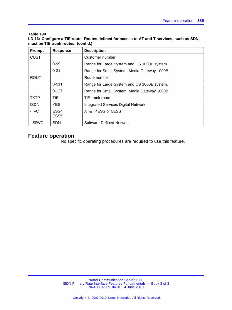
Feature operation 385
Table 190LD 16: Configure a TIE route. Routes defined for access to AT and T services, such as SDN,must be TIE trunk routes. (cont’d.)
Prompt Response Description
CUST Customer number
0-99 Range for Large System and CS 1000E system.
0-31 Range for Small System, Media Gateway 1000B.
ROUT Route number
0-511 Range for Large System and CS 1000E system.
0-127 Range for Small System, Media Gateway 1000B.
TKTP TIE TIE trunk route
ISDN YES Integrated Services Digital Network
- IFC ESS4ESS5
AT&T 4ESS or 5ESS
- SRVC SDN Software Defined Network
Feature operationNo specific operating procedures are required to use this feature.
Nortel Communication Server 1000ISDN Primary Rate Interface Features Fundamentals — Book 3 of 3
NN43001-569 04.01 4 June 2010
Copyright © 2003-2010 Nortel Networks. All Rights Reserved.
.

386 Software Defined Network Access
Nortel Communication Server 1000ISDN Primary Rate Interface Features Fundamentals — Book 3 of 3
NN43001-569 04.01 4 June 2010
Copyright © 2003-2010 Nortel Networks. All Rights Reserved.
.
387.
Software Release ID
ContentsThis section contains information on the following topics:
“Feature description” (page 387)
“Operating parameters” (page 388)
“Feature interactions” (page 388)
“Feature packaging” (page 388)
“Feature implementation” (page 388)
“Feature operation” (page 388)
Feature descriptionSoftware Release ID uses the D-channel connection of your switch toidentify the software release of an adjoining switch. This feature identifiesthe software release of the NRAG, NACD, NMS, and NCRD features.The software release ID can be requested for all direct connections tothe system. However, the Software Release ID cannot be obtained forswitches in a tandem configuration. The information provided by theSoftware Release ID depends on the interfacing switches. That is, asystem switch provides a release number and a DMS-100 switch providesa BCS number.
Note: If the interface is changed, the release ID is also changed. Therelease ID must then be reconfigured.
This feature prevents software incompatibility between two switches.Different applications are supported by different releases, and for mostof the ISDN applications, operations are invoked by sending messagesback and forth. To prevent software incompatibility, the following occurs.The release ID of the connecting D-channel is checked before data is sent
Nortel Communication Server 1000ISDN Primary Rate Interface Features Fundamentals — Book 3 of 3
NN43001-569 04.01 4 June 2010
Copyright © 2003-2010 Nortel Networks. All Rights Reserved.
.
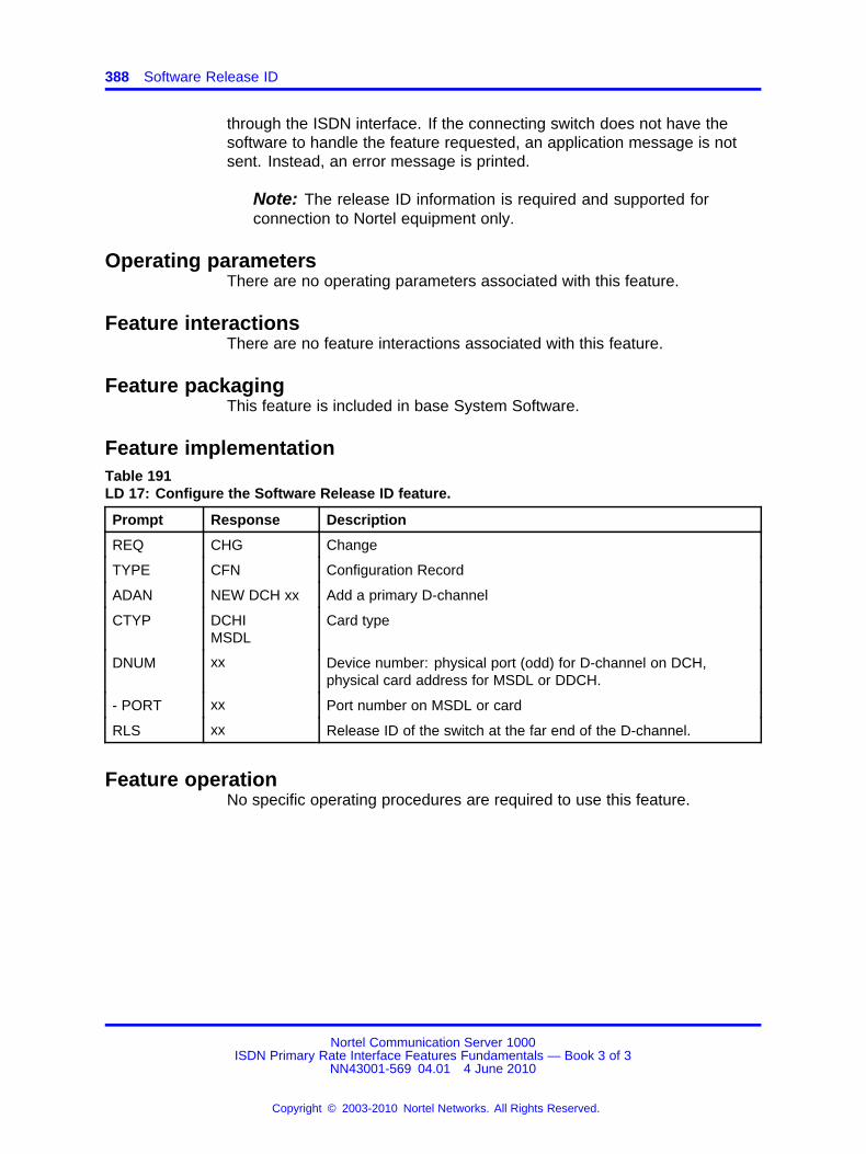
388 Software Release ID
through the ISDN interface. If the connecting switch does not have thesoftware to handle the feature requested, an application message is notsent. Instead, an error message is printed.
Note: The release ID information is required and supported forconnection to Nortel equipment only.
Operating parametersThere are no operating parameters associated with this feature.
Feature interactionsThere are no feature interactions associated with this feature.
Feature packagingThis feature is included in base System Software.
Feature implementationTable 191LD 17: Configure the Software Release ID feature.
Prompt Response Description
REQ CHG Change
TYPE CFN Configuration Record
ADAN NEW DCH xx Add a primary D-channel
CTYP DCHIMSDL
Card type
DNUM xx Device number: physical port (odd) for D-channel on DCH,physical card address for MSDL or DDCH.
- PORT xx Port number on MSDL or card
RLS xx Release ID of the switch at the far end of the D-channel.
Feature operationNo specific operating procedures are required to use this feature.
Nortel Communication Server 1000ISDN Primary Rate Interface Features Fundamentals — Book 3 of 3
NN43001-569 04.01 4 June 2010
Copyright © 2003-2010 Nortel Networks. All Rights Reserved.
.

389.
Trunk Route Optimization
ContentsThis section contains information on the following topics:
“Feature description” (page 389)
“Operating parameters” (page 406)
“Feature interactions” (page 425)
“Feature packaging” (page 453)
“Feature implementation” (page 454)
“Feature operation” (page 456)
Feature descriptionThe Trunk Anti-Tromboning (TAT), Trunk Route Optimization-BeforeAnswer (TRO-BA), and Trunk Route Optimization-Call Modification(TRO-CM) features work together in a Meridian Customer Defined Network(MCDN) to optimize trunk connections.
For maximum benefit, configure TAT, TRO-BA, and TRO-CM on all nodesin the MCDN.
These features apply to the following:
• IP Peer Virtual Trunks
• IP trunks
• Virtual Network Services (VNS) trunks
• ISDN Signaling Link (ISL) trunks
• Basic Rate Interface (BRI) and Primary Rate Interface (PRI) trunks
TAT, TRO-BA, and TRO-CM provide the following benefits:
Nortel Communication Server 1000ISDN Primary Rate Interface Features Fundamentals — Book 3 of 3
NN43001-569 04.01 4 June 2010
Copyright © 2003-2010 Nortel Networks. All Rights Reserved.
.
390 Trunk Route Optimization
• Optimize trunk resources to reduce operating costs for customers inTime Division Multiplexing (TDM) and hybrid networks (IP Trunk andIP Peer Networks).
• Reduce the number of physical Central Office trunks, TIE trunks, IPtrunk resources, Virtual Trunks, and Voice Gateway channels.
• Eliminate most of the voice quality degradation associated with multipletandem IP telephony voice paths, which results from network calltransfers in hybrid networks.
• Eliminate redundant tandem Virtual Trunk resources and VoiceGateway resources in an IP Peer network.
• Minimize service interruptions by eliminating unnecessary points offailure in the tandem nodes of established calls.
Configuring TRO-BA, TRO-CM, and TATConfigure TRO-BA and TRO-CM by setting TRO = YES in the Route DataBlock. Configure TAT by setting RCAP = TAT in the D-Channel data block.
Automatic call redirections and user-initiated call modifications in anMCDN require the correct configuration and operation of the TRO andTAT features at all Call Server nodes in order to optimize the routebetween the connected callers. TRO-BA and TRO-CM depend on thecorrect implementation of UPD and CDP at all CS 1000nodes andNRS-collaborated servers.
TAT interoperability with IP Trunk 3.01 requires CSE remote nodecapability. Otherwise, TAT depends on the called number of the first legof the call matching the calling number of the second leg of the call; thisrestriction severely inhibits TAT.
TAT interoperability with BCM 3.5 is subject to called/calling numbermatching on the first and second legs of tromboning. The upcoming BCMrelease will remove this restriction.
See “Feature implementation” (page 454).
Nortel Communication Server 1000ISDN Primary Rate Interface Features Fundamentals — Book 3 of 3
NN43001-569 04.01 4 June 2010
Copyright © 2003-2010 Nortel Networks. All Rights Reserved.
.

Feature description 391
Trunk Route Optimization-Before AnswerTRO-BA enhances routing on PRI and ISL routes for redirected calls (forexample, calls redirected by Call Forward All Calls, Call Forward Busy,Call Forward No Answer, and Hunt). TRO-BA occurs when a direct call ismade from the originating station to the redirected station, on Meridian 1 orCS 1000Msystems.
Note: TRO-BA does not optimize trunks for calls that have undergonea call modification (for example, calls that have been transferred orconferenced).
TRO-BA requires Network Call Redirection to be configured on the system.
TRO-BA applies to the following call redirections:
• Network Call Forward All Calls (NCFAC)
• Network Call Forward No Answer (NCFNA)
• Network Hunt (NHNT)
Example of TRO-BA when NCRD is enabled on each node shows anexample of TRO-BA when the NCRD feature is enabled on each node.
Figure 57Example of TRO-BA when NCRD is enabled on each node
Nortel Communication Server 1000ISDN Primary Rate Interface Features Fundamentals — Book 3 of 3
NN43001-569 04.01 4 June 2010
Copyright © 2003-2010 Nortel Networks. All Rights Reserved.
.
392 Trunk Route Optimization
Figure 57 "Example of TRO-BA when NCRD is enabled on each node"(page 391) illustrates the following:
• Station A calls remote Station B over PRI/ISL Route 1.
• Due to NCFAC, NCFNA, or NHNT, the call is forwarded to Station Cover Route 2.
• When TRO-BA is enabled at Node B, facility messages are sent fromthe redirecting Node B to the originating Node A with the followingredirection information:
— redirection number
— reason
— counter
• The system returns a facility message accepting TRO-BA, if thefollowing conditions are met:
— Node A has TRO-BA enabled.
— Node A has a first choice RLB entry route member available.
— The redirection counter does not exceed the limit.
If the originating node does not support TRO, the node sends amessage rejecting TRO-BA, and the call proceeds on the current route.The redirecting node then cancels TRO-BA routing.
• The redirecting node sends a message to release the connection.
• The originating node sends a message confirming that the originalconnection (1) is dropped.
• The originating node sets up a direct connection to Station C overRoute 3.
• Routes 1 and 2 are available for new calls.
Example 2 of TRO-BA when NCRD is enabled on each node showsanother example of TRO-BA when the NCRD feature is enabled on eachnode.
Nortel Communication Server 1000ISDN Primary Rate Interface Features Fundamentals — Book 3 of 3
NN43001-569 04.01 4 June 2010
Copyright © 2003-2010 Nortel Networks. All Rights Reserved.
.

Feature description 393
Figure 58Example 2 of TRO-BA when NCRD is enabled on each node
Figure 58 "Example 2 of TRO-BA when NCRD is enabled on each node"(page 393) illustrates the following:
• The originating Station A calls remote Station C over PRI/ISL routes3 and 5.
• Due to NCFAC, NCFNA, or NHNT, the call forwards to Station B overPRI/ISL route 5.
• When Node A accepts the TRO-BA request, Node A establishes adirect connection to Node B over route 3.
• TRO-BA clears both connections over route 5. Route 5 trunks are nowavailable for other calls.
Trunk Anti-TromboningTAT optimizes tromboned trunks for calls that are redirected or modifiedafter answer. Tromboning occurs when a call goes to another node and istransferred back on a second trunk, tying up two trunks (for example, callforward or call transfer).
TAT optimizes tromboned trunks under the following conditions:
• The trunks are associated with the same primary channel.
• Both trunks belong to the same customer.
Note: TAT also applies to calls entering a system network over aCentral Office (CO) trunk. TAT eliminates the tromboning of privatenetwork trunks that can occur if the call is redirected or modified.
Nortel Communication Server 1000ISDN Primary Rate Interface Features Fundamentals — Book 3 of 3
NN43001-569 04.01 4 June 2010
Copyright © 2003-2010 Nortel Networks. All Rights Reserved.
.

394 Trunk Route Optimization
Example of a trunk anti-tromboning operationThe following example is a demonstration of TAT working in a simplesystem-to-system interworking. Refer to Anti-Tromboning scenarios forother interworking scenarios.
Figure 59 "Prior to Trunk Anti-Tromboning operation" (page 394) illustratesthe following:
• Station B, (at the terminating node), receives an incoming call over aPRI trunk from Station A, (at the originating node), or an incoming COcall is tandemed from the originating node to the terminating node.
• Station B answers the call and transfers it to Station C, which residesat the originating node. A second PRI trunk is established to handlethe new call.
• Station B completes the call transfer, which leaves Station A connectedto Station C (which is in a ringing state) by using the two PRI trunks.The PRI trunks remain tromboned until Station C answers the call.
Figure 59Prior to Trunk Anti-Tromboning operation
Figure 60 "After Trunk Anti-Tromboning operation" (page 395) illustrateshow the TAT application eliminates the redundant ISDN PRI B-channelsforming the loop-back. After Station C answers the call, the originatingnode bridges Station A and Station C. If the trunks involved are associatedwith the same primary D-channel and the same customer, TAT releasesthe redundant trunks. The TAT operation eliminates the use of extranetwork trunking facilities for the duration of the call.
Nortel Communication Server 1000ISDN Primary Rate Interface Features Fundamentals — Book 3 of 3
NN43001-569 04.01 4 June 2010
Copyright © 2003-2010 Nortel Networks. All Rights Reserved.
.
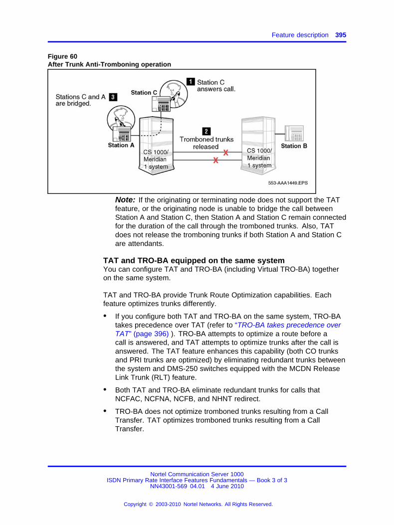
Feature description 395
Figure 60After Trunk Anti-Tromboning operation
Note: If the originating or terminating node does not support the TATfeature, or the originating node is unable to bridge the call betweenStation A and Station C, then Station A and Station C remain connectedfor the duration of the call through the tromboned trunks. Also, TATdoes not release the tromboning trunks if both Station A and Station Care attendants.
TAT and TRO-BA equipped on the same systemYou can configure TAT and TRO-BA (including Virtual TRO-BA) togetheron the same system.
TAT and TRO-BA provide Trunk Route Optimization capabilities. Eachfeature optimizes trunks differently.
• If you configure both TAT and TRO-BA on the same system, TRO-BAtakes precedence over TAT (refer to “TRO-BA takes precedence overTAT” (page 396) ). TRO-BA attempts to optimize a route before acall is answered, and TAT attempts to optimize trunks after the call isanswered. The TAT feature enhances this capability (both CO trunksand PRI trunks are optimized) by eliminating redundant trunks betweenthe system and DMS-250 switches equipped with the MCDN ReleaseLink Trunk (RLT) feature.
• Both TAT and TRO-BA eliminate redundant trunks for calls thatNCFAC, NCFNA, NCFB, and NHNT redirect.
• TRO-BA does not optimize tromboned trunks resulting from a CallTransfer. TAT optimizes tromboned trunks resulting from a CallTransfer.
Nortel Communication Server 1000ISDN Primary Rate Interface Features Fundamentals — Book 3 of 3
NN43001-569 04.01 4 June 2010
Copyright © 2003-2010 Nortel Networks. All Rights Reserved.
.
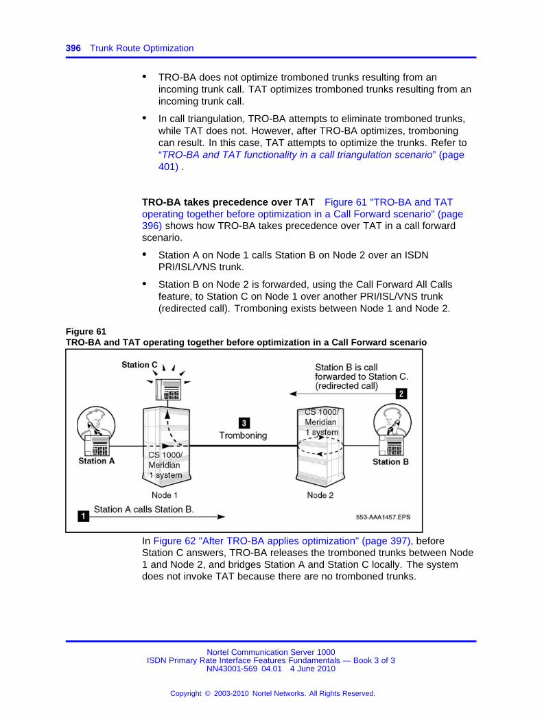
396 Trunk Route Optimization
• TRO-BA does not optimize tromboned trunks resulting from anincoming trunk call. TAT optimizes tromboned trunks resulting from anincoming trunk call.
• In call triangulation, TRO-BA attempts to eliminate tromboned trunks,while TAT does not. However, after TRO-BA optimizes, tromboningcan result. In this case, TAT attempts to optimize the trunks. Refer to“TRO-BA and TAT functionality in a call triangulation scenario” (page401) .
TRO-BA takes precedence over TAT Figure 61 "TRO-BA and TAToperating together before optimization in a Call Forward scenario" (page396) shows how TRO-BA takes precedence over TAT in a call forwardscenario.
• Station A on Node 1 calls Station B on Node 2 over an ISDNPRI/ISL/VNS trunk.
• Station B on Node 2 is forwarded, using the Call Forward All Callsfeature, to Station C on Node 1 over another PRI/ISL/VNS trunk(redirected call). Tromboning exists between Node 1 and Node 2.
Figure 61TRO-BA and TAT operating together before optimization in a Call Forward scenario
In Figure 62 "After TRO-BA applies optimization" (page 397), beforeStation C answers, TRO-BA releases the tromboned trunks between Node1 and Node 2, and bridges Station A and Station C locally. The systemdoes not invoke TAT because there are no tromboned trunks.
Nortel Communication Server 1000ISDN Primary Rate Interface Features Fundamentals — Book 3 of 3
NN43001-569 04.01 4 June 2010
Copyright © 2003-2010 Nortel Networks. All Rights Reserved.
.
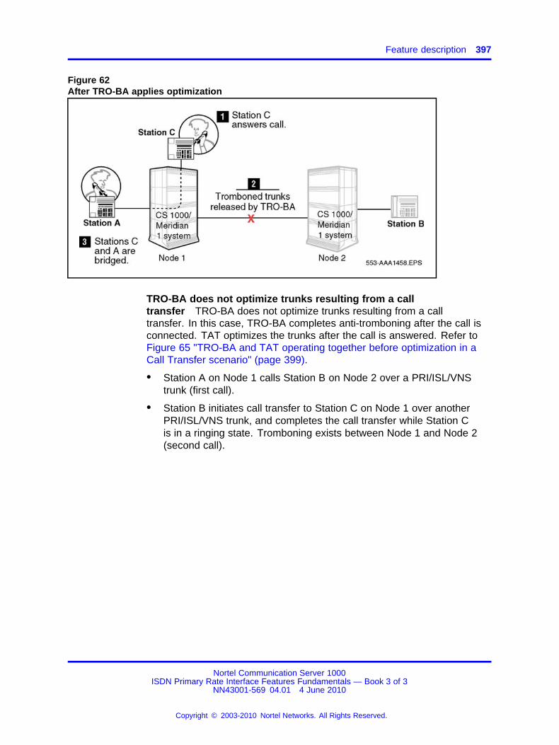
Feature description 397
Figure 62After TRO-BA applies optimization
TRO-BA does not optimize trunks resulting from a calltransfer TRO-BA does not optimize trunks resulting from a calltransfer. In this case, TRO-BA completes anti-tromboning after the call isconnected. TAT optimizes the trunks after the call is answered. Refer toFigure 65 "TRO-BA and TAT operating together before optimization in aCall Transfer scenario" (page 399).
• Station A on Node 1 calls Station B on Node 2 over a PRI/ISL/VNStrunk (first call).
• Station B initiates call transfer to Station C on Node 1 over anotherPRI/ISL/VNS trunk, and completes the call transfer while Station Cis in a ringing state. Tromboning exists between Node 1 and Node 2(second call).
Nortel Communication Server 1000ISDN Primary Rate Interface Features Fundamentals — Book 3 of 3
NN43001-569 04.01 4 June 2010
Copyright © 2003-2010 Nortel Networks. All Rights Reserved.
.
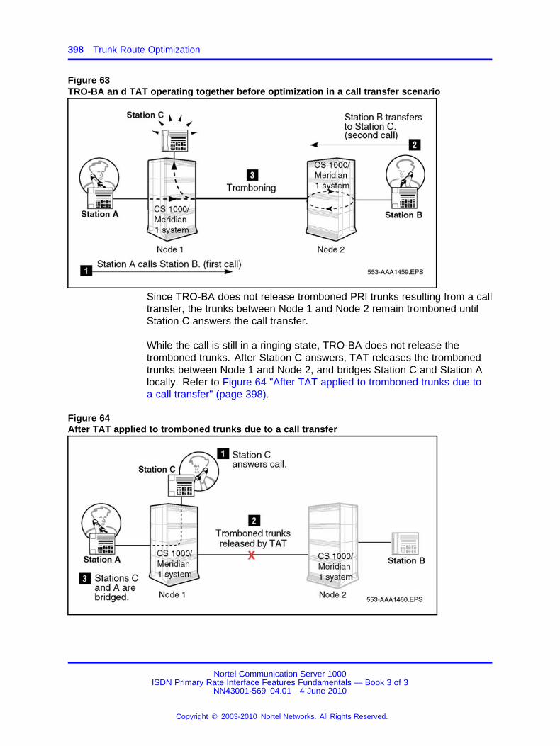
398 Trunk Route Optimization
Figure 63TRO-BA an d TAT operating together before optimization in a call transfer scenario
Since TRO-BA does not release tromboned PRI trunks resulting from a calltransfer, the trunks between Node 1 and Node 2 remain tromboned untilStation C answers the call transfer.
While the call is still in a ringing state, TRO-BA does not release thetromboned trunks. After Station C answers, TAT releases the trombonedtrunks between Node 1 and Node 2, and bridges Station C and Station Alocally. Refer to Figure 64 "After TAT applied to tromboned trunks due toa call transfer" (page 398).
Figure 64After TAT applied to tromboned trunks due to a call transfer
Nortel Communication Server 1000ISDN Primary Rate Interface Features Fundamentals — Book 3 of 3
NN43001-569 04.01 4 June 2010
Copyright © 2003-2010 Nortel Networks. All Rights Reserved.
.

Feature description 399
Trunk Route Optimization with call redirection resulting from a calltransfer Following is an example of TRO-BA and TAT interaction inthe case of a call redirection initiated on the transfer key. Refer to Figure65 "TRO-BA and TAT operating together before optimization in a CallTransfer scenario" (page 399):
• Station A on Node 1 calls Station B on Node 1.
• Station B initiates a call transfer to Station C on Node 2 over aPRI/ISL/VNS trunk (first B-channel).
• Station C forwards the call to Station D on Node 1, using Call ForwardNo Answer over another PRI/ISL/VNS trunk (second B-channel due tocall redirection). Trunk tromboning occurs between Node 1 and Node2.
Figure 65TRO-BA and TAT operating together before optimization in a Call Transfer scenario
Station B completes the call transfer while Station C is in A ringing state.The system (Node 1) software routes the call to Station D; then TRO-BAoptimizes the trunks, and locally bridges Station A and Station D. Refer toFigure 66 "Tromboned trunks released by TRO-BA" (page 400).
Nortel Communication Server 1000ISDN Primary Rate Interface Features Fundamentals — Book 3 of 3
NN43001-569 04.01 4 June 2010
Copyright © 2003-2010 Nortel Networks. All Rights Reserved.
.
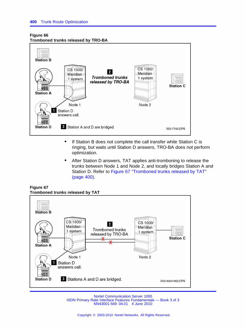
400 Trunk Route Optimization
Figure 66Tromboned trunks released by TRO-BA
• If Station B does not complete the call transfer while Station C isringing, but waits until Station D answers, TRO-BA does not performoptimization.
• After Station D answers, TAT applies anti-tromboning to release thetrunks between Node 1 and Node 2, and locally bridges Station A andStation D. Refer to Figure 67 "Tromboned trunks released by TAT"(page 400).
Figure 67Tromboned trunks released by TAT
Nortel Communication Server 1000ISDN Primary Rate Interface Features Fundamentals — Book 3 of 3
NN43001-569 04.01 4 June 2010
Copyright © 2003-2010 Nortel Networks. All Rights Reserved.
.

Feature description 401
TRO-BA and TAT functionality in a call triangulation scenario Ina call triangulation scenario, TRO-BA attempts to eliminate trombonedtrunks. TAT cannot perform this operation because a second D-channel isinvolved. Refer to Figure 68 "Call path before TRO-BA is applied" (page401):
• Station A on Node 1 calls Station B on Node 2 over a PRI/ISL/VNStrunk (first call).
• Station B on Node 2 is call forwarded or hunts to Station C on Node 3over another PRI/ISL/VNS trunk (redirected call). Two trunks are beingused to handle one call.
Figure 68Call path before TRO-BA is applied
Before Station C answers, TRO-BA releases the trunks between Node 1and Node 2, and between Node 2 and Node 3, and establishes a newPRI/ISL/VNS trunk connection between Node 1 and Node 3. Refer toFigure 69 "Call path after TRO-BA is applied" (page 402).
Note: The TAT feature cannot provide this functionality becausemultiple D-channels are used.
Nortel Communication Server 1000ISDN Primary Rate Interface Features Fundamentals — Book 3 of 3
NN43001-569 04.01 4 June 2010
Copyright © 2003-2010 Nortel Networks. All Rights Reserved.
.
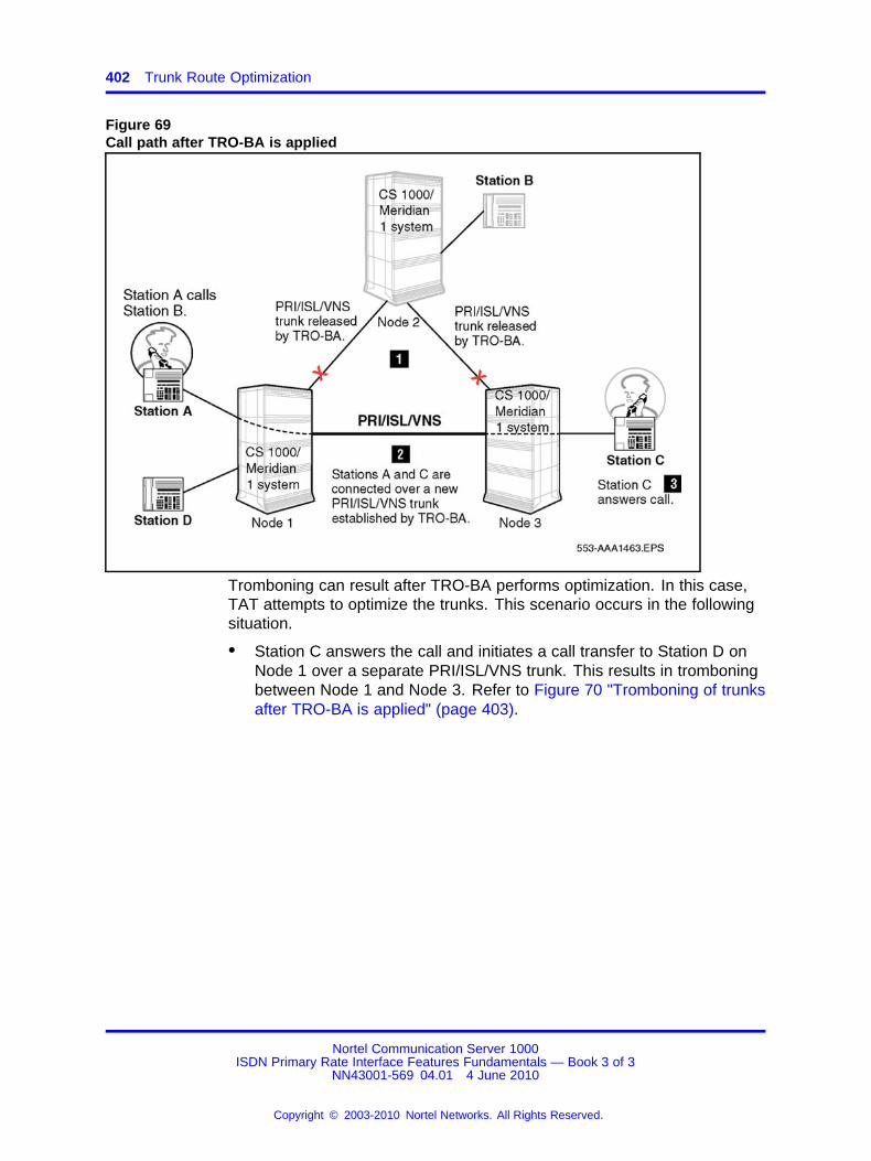
402 Trunk Route Optimization
Figure 69Call path after TRO-BA is applied
Tromboning can result after TRO-BA performs optimization. In this case,TAT attempts to optimize the trunks. This scenario occurs in the followingsituation.
• Station C answers the call and initiates a call transfer to Station D onNode 1 over a separate PRI/ISL/VNS trunk. This results in tromboningbetween Node 1 and Node 3. Refer to Figure 70 "Tromboning of trunksafter TRO-BA is applied" (page 403).
Nortel Communication Server 1000ISDN Primary Rate Interface Features Fundamentals — Book 3 of 3
NN43001-569 04.01 4 June 2010
Copyright © 2003-2010 Nortel Networks. All Rights Reserved.
.

Feature description 403
Figure 70Tromboning of trunks after TRO-BA is applied
• After Station D answers the call, and Station C completes the calltransfer, TAT releases the tromboned trunks between Node 3 andNode 1, and leaves Station D and Station A bridged locally. Refer toFigure 71 "Tromboned trunks released by TAT" (page 404).
Nortel Communication Server 1000ISDN Primary Rate Interface Features Fundamentals — Book 3 of 3
NN43001-569 04.01 4 June 2010
Copyright © 2003-2010 Nortel Networks. All Rights Reserved.
.
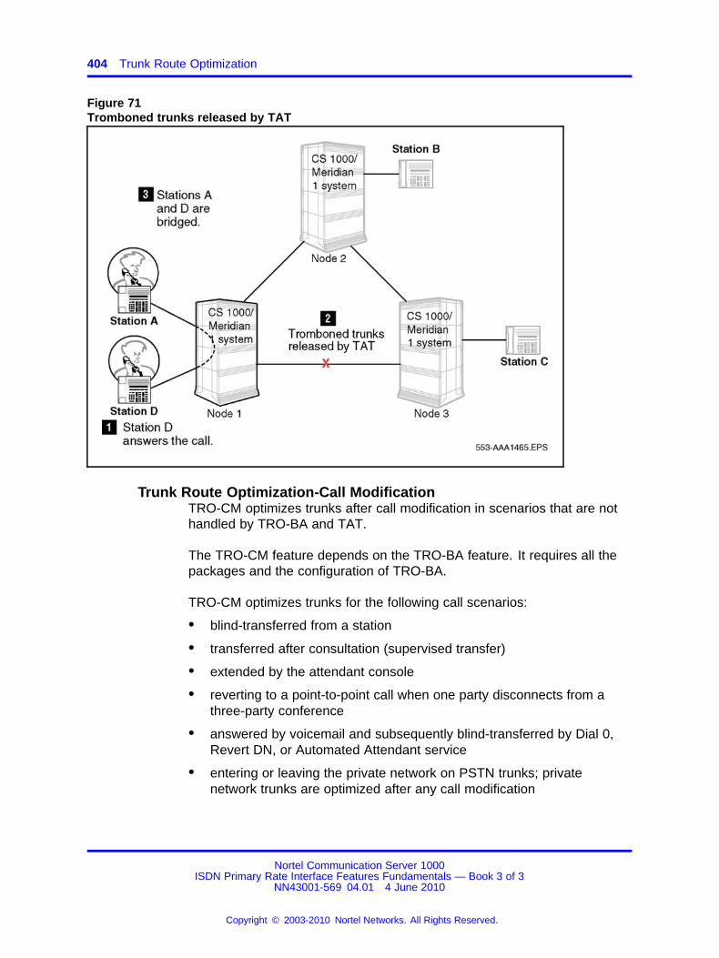
404 Trunk Route Optimization
Figure 71Tromboned trunks released by TAT
Trunk Route Optimization-Call ModificationTRO-CM optimizes trunks after call modification in scenarios that are nothandled by TRO-BA and TAT.
The TRO-CM feature depends on the TRO-BA feature. It requires all thepackages and the configuration of TRO-BA.
TRO-CM optimizes trunks for the following call scenarios:
• blind-transferred from a station
• transferred after consultation (supervised transfer)
• extended by the attendant console
• reverting to a point-to-point call when one party disconnects from athree-party conference
• answered by voicemail and subsequently blind-transferred by Dial 0,Revert DN, or Automated Attendant service
• entering or leaving the private network on PSTN trunks; privatenetwork trunks are optimized after any call modification
Nortel Communication Server 1000ISDN Primary Rate Interface Features Fundamentals — Book 3 of 3
NN43001-569 04.01 4 June 2010
Copyright © 2003-2010 Nortel Networks. All Rights Reserved.
.
Feature description 405
Events that trigger TRO-CMThe system triggers TRO-CM in the following scenarios:
• transfer triggerThe System invokes TRO-CM for calls transferred from a stationacross a network. The transfer can be blind or supervised.
— manual transferThe user can manually initiate call transfer from a phone. Forexample, Station A (on Node 1) calls Station B (on Node 2). StationB answers the call and initiates call transfer to Station C on adifferent node.
— automated transferThe System can also initiate call transfer using the Auto-attendant,Thru-dial or Call Sender features of CallPilot/Meridian Mail. Forexample, Station A (on Node 1) calls Station B (on Node 2). StationB activates Call Forward to voicemail. Station A is connectedto CallPilot/Meridian Mail. Station A activates the Dial 0 RevertDN feature. This invokes blind transfer to Station C at Node 3.CallPilot/Meridian Mail completes the transfer.
• attendant extending callThe System triggers TRO-CM when the attendant at the tandem nodeextends the call to a station on another node and drops out of the call.This occurs only when the station answers the call. The attendant isable to drop out of the call until the station answers the call.
• conference call on disconnectionThe System triggers TRO-CM when a conference call reverts to atwo-party call.
TRO-CM basic operationIn Figure 72 "TRO-CM basic operation" (page 406), Figure 72 "TRO-CMbasic operation" (page 406), Station A calls Station B. Station B answersthe call and transfers to Station C. Station C answers the call and StationB completes the transfer.
Nortel Communication Server 1000ISDN Primary Rate Interface Features Fundamentals — Book 3 of 3
NN43001-569 04.01 4 June 2010
Copyright © 2003-2010 Nortel Networks. All Rights Reserved.
.

406 Trunk Route Optimization
Figure 72TRO-CM basic operation
Operating parametersTRO-BA operating parameters
The system only supports TRO-BA if the originated call is not answered.
For TRO-BA to be supported on all nodes involved, you must set theTRO prompt to YES in the Route Data Block (LD 16). Also, each phoneredirecting the call must have a Call Forward/Hunt feature allowed. If theoriginating phone and the redirecting phone reside on the same node, thesystem does not support the TRO-BA operation.
Trunk routes targeted for optimization must be listed in the Route ListIndex (RLI entry 0).
The system only supports ISDN PRI/ISL trunks. If the system usesan analog or digital trunk (not controlled by a D-channel) between theoriginating and redirecting node, then TRO-BA does not operate. The callcontinues on the original path.
Trunk Route Optimization operates independently of the phone type usedfor a call. TRO-BA works for both voice and data calls between systems.
Only system-to-system connections are supported. If non-system switchescan send the TRO-BA messages, they can operate as tandem switches.
Nortel Communication Server 1000ISDN Primary Rate Interface Features Fundamentals — Book 3 of 3
NN43001-569 04.01 4 June 2010
Copyright © 2003-2010 Nortel Networks. All Rights Reserved.
.
Operating parameters 407
When the system redirects the call, the redirecting system beginsa two-second timer while waiting for a response message from theoriginating node. If the timer expires, the call continues along the originalpath, and TRO-BA does not operate.
Note: Carefully analyze traffic estimates for all routes targeted forTRO-BA. This ensures that enough trunks and routes are availablefor all routing possibilities.
The system does not support TRO-BA with mixed dialing plans. Usecaution when implementing TRO-BA on a network that uses a UniformDialing Plan (UDP) and a Coordinated Dialing Plan (CDP) at the sametime. TRO-BA can direct calls to the wrong location because locationcodes are not used between CDP locations. Duplicating CDP DirectoryNumbers (DNs) at other TRO-BA locations can cause TRO-BA to redirectthe call to the wrong DN.
TRO-BA does not support Trunk Route Optimization for the following calltypes:
• A Direct Inward Dialing (DID) trunk call at Node A goes to Station B,(on Node B), and NCFAC, NCFNA, or NHUNT to Station C. This is amixed dialing plan. Refer to Figure 73 "TRO-BA non-support" (page408).
• A DID trunk call from Node A to Station A (that has NCFAC, NCFNA,or NHUNT) to Station B (that has NFAC, NCFNA, or NHUNT) to PhoneC. Refer to Figure 73 "TRO-BA non-support" (page 408).
• Station D (at Node D) calls Station B (at Node B), which has NCFAC,NCFNA, or NHUNT, to Station C (at Node C), where Node D isconnected by non-ISDN link to Node C. Refer to Figure 73 "TRO-BAnon-support" (page 408).
• The attendant extends a DID or Incoming trunk call to Phone B (atNode B) and releases, and Phone B is CFNA to Phone C (at Node C).After three rings, the call is forwarded to Phone C, but not optimized.Refer to Figure 73 "TRO-BA non-support" (page 408).
If the attendant remains with the call, TRO-BA functions.
• Phone A uses Transfer or Conference to Phone B when Phone B hasNCFAC, NHUNT, or NCFNA to Phone C. Refer to Figure 73 "TRO-BAnon-support" (page 408).
• Calls to Meridian Mail auto attendant functions are not optimizedbecause the call is viewed as being answered.
• If the system exceeds the network redirection counter limits, TRO-BAdoes not initiate.
Nortel Communication Server 1000ISDN Primary Rate Interface Features Fundamentals — Book 3 of 3
NN43001-569 04.01 4 June 2010
Copyright © 2003-2010 Nortel Networks. All Rights Reserved.
.
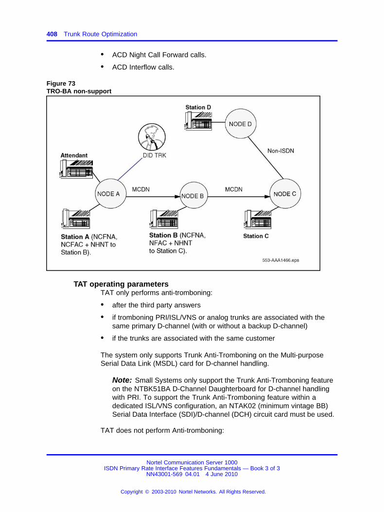
408 Trunk Route Optimization
• ACD Night Call Forward calls.
• ACD Interflow calls.
Figure 73TRO-BA non-support
TAT operating parametersTAT only performs anti-tromboning:
• after the third party answers
• if tromboning PRI/ISL/VNS or analog trunks are associated with thesame primary D-channel (with or without a backup D-channel)
• if the trunks are associated with the same customer
The system only supports Trunk Anti-Tromboning on the Multi-purposeSerial Data Link (MSDL) card for D-channel handling.
Note: Small Systems only support the Trunk Anti-Tromboning featureon the NTBK51BA D-Channel Daughterboard for D-channel handlingwith PRI. To support the Trunk Anti-Tromboning feature within adedicated ISL/VNS configuration, an NTAK02 (minimum vintage BB)Serial Data Interface (SDI)/D-channel (DCH) circuit card must be used.
TAT does not perform Anti-tromboning:
Nortel Communication Server 1000ISDN Primary Rate Interface Features Fundamentals — Book 3 of 3
NN43001-569 04.01 4 June 2010
Copyright © 2003-2010 Nortel Networks. All Rights Reserved.
.
Operating parameters 409
• if the tromboning trunks belong to different customers on the samenode (even though they are associated with the same primaryD-channel)
• for a tromboned call between two attendants on the same node
• if non-ISDN PRI trunks are involved in a call transfer call, and thereforeISDN signaling messages cannot be sent
• for tromboned trunks associated with a call originating on a phone androuted back to the same phone
• for BRI trunks, except if the trunks are VNS bearer trunks
TAT protocolsTAT operations use two types of protocols, depending on the interfacetype.
• system-to-system interface
• system to DMS-250 Sprint load equipped with the MCDN RLT feature
TAT can cause a momentary interruption in data transmission duringoptimization. When the system performs TAT operations at multipletandem nodes, the effect is cumulative (in the milliseconds range.)Therefore, the impact of this loss depends upon the terminals on bothends of the transmission and can be recovered through re-transmission.
Anti-Tromboning scenariosThe Anti-Tromboning scenarios in this section provide examples for asystem interworking with another system, and a system interworking with aDMS-250 Sprint load equipped with Release Link Trunk (RLT).
Trunk Anti-Tromboning scenario legend Figure 74 "Notation forillustrations" (page 410) shows the notations used for the graphics in theTAT section.
Nortel Communication Server 1000ISDN Primary Rate Interface Features Fundamentals — Book 3 of 3
NN43001-569 04.01 4 June 2010
Copyright © 2003-2010 Nortel Networks. All Rights Reserved.
.

410 Trunk Route Optimization
Figure 74Notation for illustrations
Note: In the scenarios that follow, the system does not have theTRO-BA feature configured.
Anti-Tromboning operation for NCRD (case 1) PBX interworking withDMS The following example shows TAT being applied in an NCRDscenario (in the example, Call Forward is used), with two system switchesinterworking with a DMS-250. Refer to Figure 75 "Anti-Tromboning forNCRD (case 1), PBX/DMS" (page 411).
• Station A, (located at the originating switch [CO or PBX] or a DMSnode), makes an internodal call through a DMS-250 and a tandemsystem node to Station B, (located at a terminating system node). Thisis the first call.
• Station B, located at the terminating system node, is call forwardedthrough the tandem system node and the DMS-250, to Station Clocated at the originating node (redirected call)
• Station C answers.
• Station A connects to Station C.
Nortel Communication Server 1000ISDN Primary Rate Interface Features Fundamentals — Book 3 of 3
NN43001-569 04.01 4 June 2010
Copyright © 2003-2010 Nortel Networks. All Rights Reserved.
.
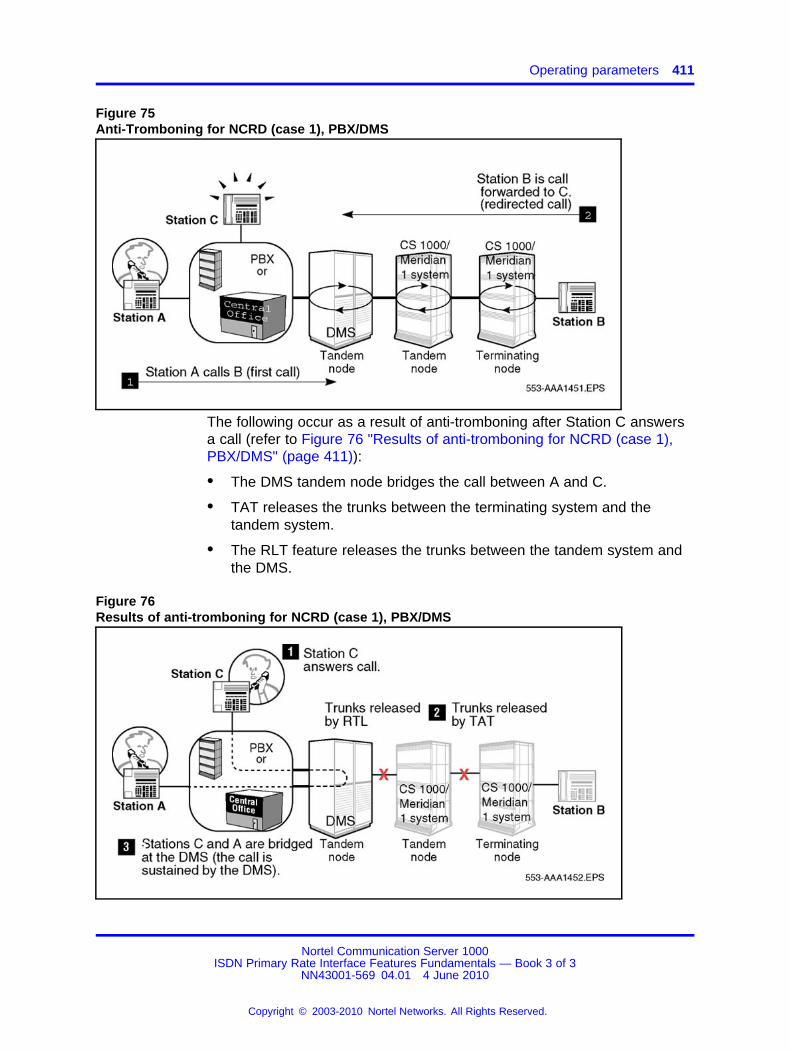
Operating parameters 411
Figure 75Anti-Tromboning for NCRD (case 1), PBX/DMS
The following occur as a result of anti-tromboning after Station C answersa call (refer to Figure 76 "Results of anti-tromboning for NCRD (case 1),PBX/DMS" (page 411)):
• The DMS tandem node bridges the call between A and C.
• TAT releases the trunks between the terminating system and thetandem system.
• The RLT feature releases the trunks between the tandem system andthe DMS.
Figure 76Results of anti-tromboning for NCRD (case 1), PBX/DMS
Nortel Communication Server 1000ISDN Primary Rate Interface Features Fundamentals — Book 3 of 3
NN43001-569 04.01 4 June 2010
Copyright © 2003-2010 Nortel Networks. All Rights Reserved.
.
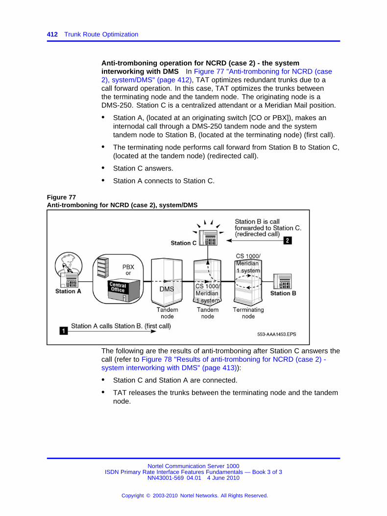
412 Trunk Route Optimization
Anti-tromboning operation for NCRD (case 2) - the systeminterworking with DMS In Figure 77 "Anti-tromboning for NCRD (case2), system/DMS" (page 412), TAT optimizes redundant trunks due to acall forward operation. In this case, TAT optimizes the trunks betweenthe terminating node and the tandem node. The originating node is aDMS-250. Station C is a centralized attendant or a Meridian Mail position.
• Station A, (located at an originating switch [CO or PBX]), makes aninternodal call through a DMS-250 tandem node and the systemtandem node to Station B, (located at the terminating node) (first call).
• The terminating node performs call forward from Station B to Station C,(located at the tandem node) (redirected call).
• Station C answers.
• Station A connects to Station C.
Figure 77Anti-tromboning for NCRD (case 2), system/DMS
The following are the results of anti-tromboning after Station C answers thecall (refer to Figure 78 "Results of anti-tromboning for NCRD (case 2) -system interworking with DMS" (page 413)):
• Station C and Station A are connected.
• TAT releases the trunks between the terminating node and the tandemnode.
Nortel Communication Server 1000ISDN Primary Rate Interface Features Fundamentals — Book 3 of 3
NN43001-569 04.01 4 June 2010
Copyright © 2003-2010 Nortel Networks. All Rights Reserved.
.
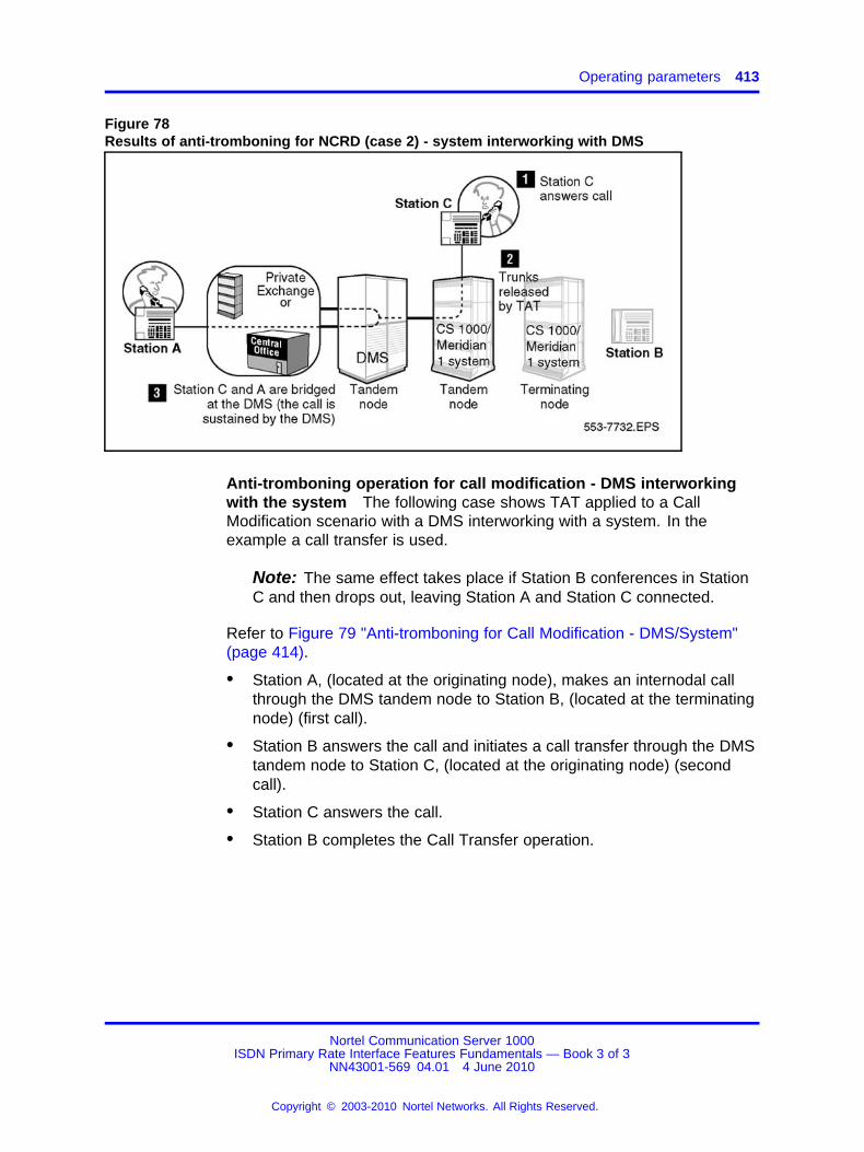
Operating parameters 413
Figure 78Results of anti-tromboning for NCRD (case 2) - system interworking with DMS
Anti-tromboning operation for call modification - DMS interworkingwith the system The following case shows TAT applied to a CallModification scenario with a DMS interworking with a system. In theexample a call transfer is used.
Note: The same effect takes place if Station B conferences in StationC and then drops out, leaving Station A and Station C connected.
Refer to Figure 79 "Anti-tromboning for Call Modification - DMS/System"(page 414).
• Station A, (located at the originating node), makes an internodal callthrough the DMS tandem node to Station B, (located at the terminatingnode) (first call).
• Station B answers the call and initiates a call transfer through the DMStandem node to Station C, (located at the originating node) (secondcall).
• Station C answers the call.
• Station B completes the Call Transfer operation.
Nortel Communication Server 1000ISDN Primary Rate Interface Features Fundamentals — Book 3 of 3
NN43001-569 04.01 4 June 2010
Copyright © 2003-2010 Nortel Networks. All Rights Reserved.
.
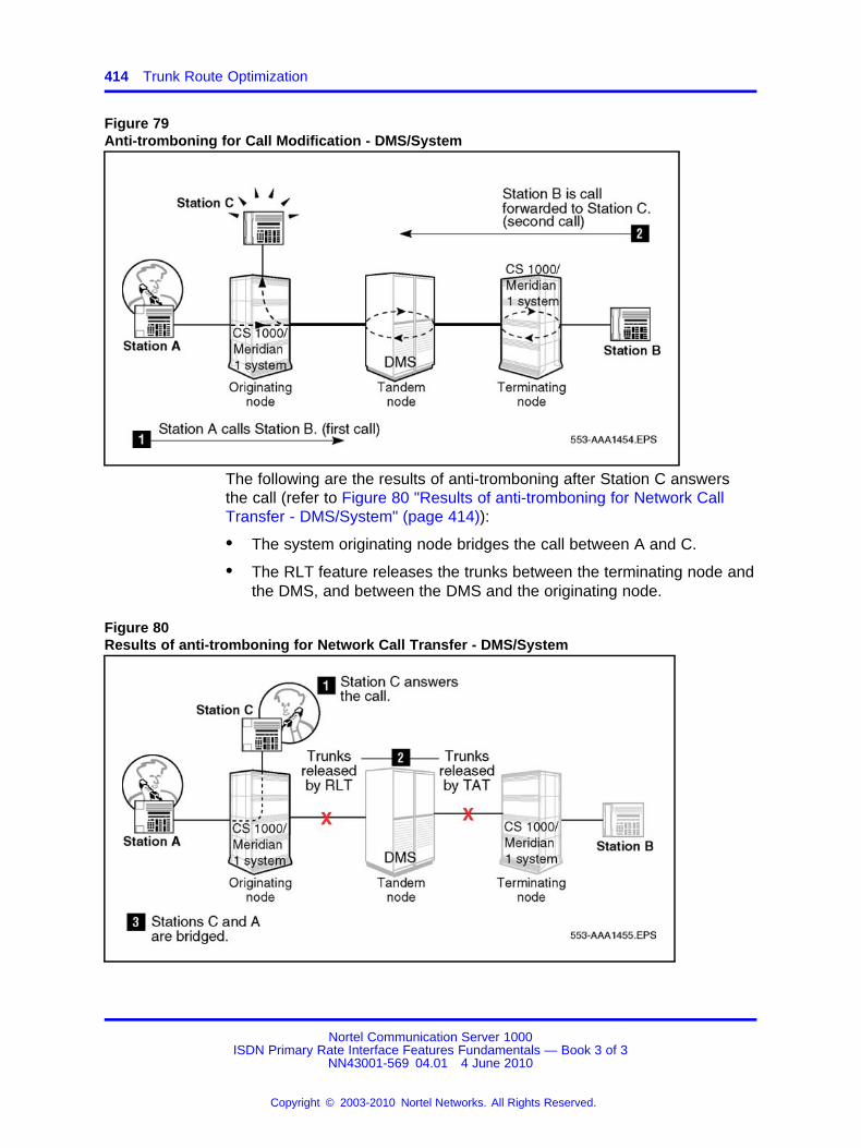
414 Trunk Route Optimization
Figure 79Anti-tromboning for Call Modification - DMS/System
The following are the results of anti-tromboning after Station C answersthe call (refer to Figure 80 "Results of anti-tromboning for Network CallTransfer - DMS/System" (page 414)):
• The system originating node bridges the call between A and C.
• The RLT feature releases the trunks between the terminating node andthe DMS, and between the DMS and the originating node.
Figure 80Results of anti-tromboning for Network Call Transfer - DMS/System
Nortel Communication Server 1000ISDN Primary Rate Interface Features Fundamentals — Book 3 of 3
NN43001-569 04.01 4 June 2010
Copyright © 2003-2010 Nortel Networks. All Rights Reserved.
.
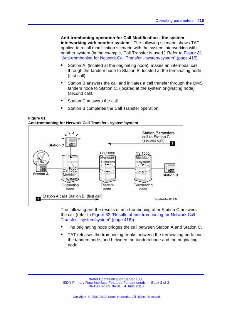
Operating parameters 415
Anti-tromboning operation for Call Modification - the systeminterworking with another system The following scenario shows TATapplied to a call modification scenario with the system interworking withanother system (in the example, Call Transfer is used.) Refer to Figure 81"Anti-tromboning for Network Call Transfer - system/system" (page 415).
• Station A, (located at the originating node), makes an internodal callthrough the tandem node to Station B, located at the terminating node(first call).
• Station B answers the call and initiates a call transfer through the DMStandem node to Station C, (located at the system originating node)(second call).
• Station C answers the call.
• Station B completes the Call Transfer operation.
Figure 81Anti-tromboning for Network Call Transfer - system/system
The following are the results of anti-tromboning after Station C answersthe call (refer to Figure 82 "Results of anti-tromboning for Network CallTransfer - system/system" (page 416)):
• The originating node bridges the call between Station A and Station C.
• TAT releases the tromboning trunks between the terminating node andthe tandem node, and between the tandem node and the originatingnode.
Nortel Communication Server 1000ISDN Primary Rate Interface Features Fundamentals — Book 3 of 3
NN43001-569 04.01 4 June 2010
Copyright © 2003-2010 Nortel Networks. All Rights Reserved.
.
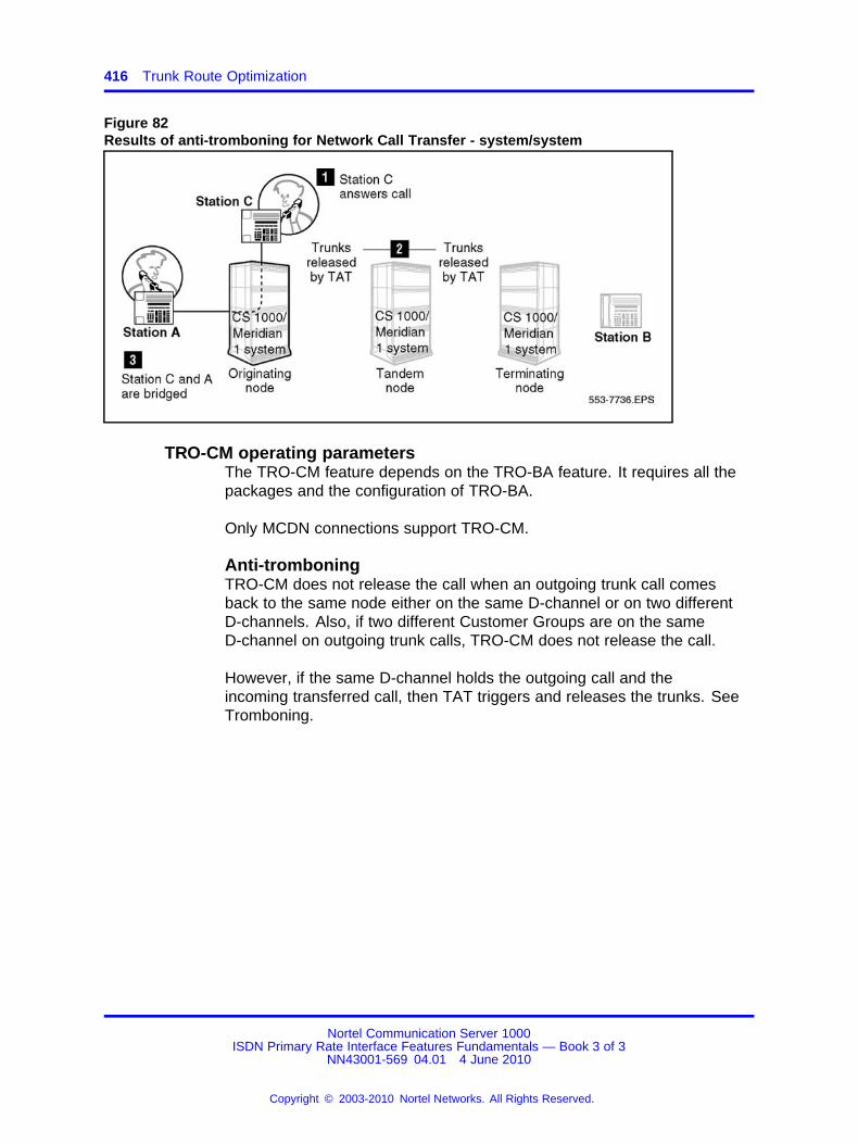
416 Trunk Route Optimization
Figure 82Results of anti-tromboning for Network Call Transfer - system/system
TRO-CM operating parametersThe TRO-CM feature depends on the TRO-BA feature. It requires all thepackages and the configuration of TRO-BA.
Only MCDN connections support TRO-CM.
Anti-tromboningTRO-CM does not release the call when an outgoing trunk call comesback to the same node either on the same D-channel or on two differentD-channels. Also, if two different Customer Groups are on the sameD-channel on outgoing trunk calls, TRO-CM does not release the call.
However, if the same D-channel holds the outgoing call and theincoming transferred call, then TAT triggers and releases the trunks. SeeTromboning.
Nortel Communication Server 1000ISDN Primary Rate Interface Features Fundamentals — Book 3 of 3
NN43001-569 04.01 4 June 2010
Copyright © 2003-2010 Nortel Networks. All Rights Reserved.
.

Operating parameters 417
Figure 83Tromboning
Attendant callsIf the originator of the call is an Attendant on the TRO-CM originatingnode, the system defers the TRO-CM request while the attendant is activeon the call. The system accepts TRO-CM when the attendant leaves thecall.
Call originator transfersTRO-CM does not optimize the call when the call originator transfers thecall to another node.
For example, in Originating party transfers the call, Station B calls StationA. Station A answers the call. Station B transfers the call to Station C.TRO-CM fails.
TRO-CM fails when the conference originator drops out of the conference.
For example, in Figure 84 "Originating party transfers the call" (page418), Station B calls Station A. Station A answers the call. StationB conferences Station C and Station B drops out of the conference.TRO-CM fails.
Nortel Communication Server 1000ISDN Primary Rate Interface Features Fundamentals — Book 3 of 3
NN43001-569 04.01 4 June 2010
Copyright © 2003-2010 Nortel Networks. All Rights Reserved.
.
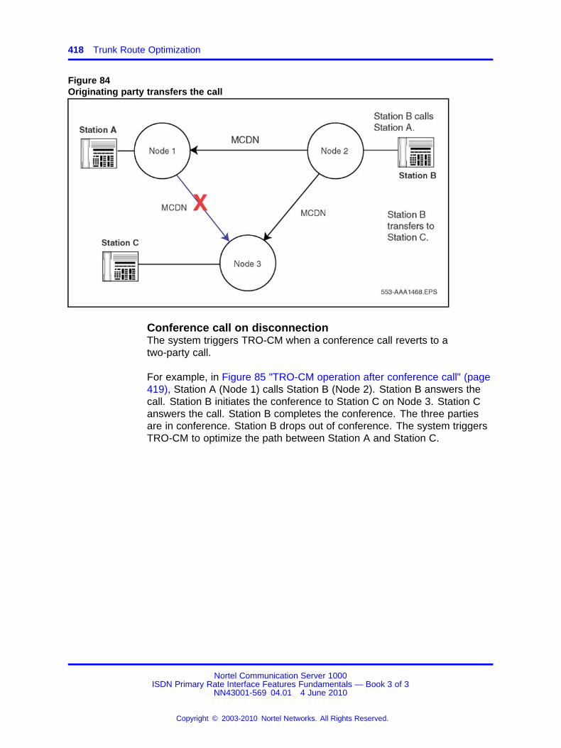
418 Trunk Route Optimization
Figure 84Originating party transfers the call
Conference call on disconnectionThe system triggers TRO-CM when a conference call reverts to atwo-party call.
For example, in Figure 85 "TRO-CM operation after conference call" (page419), Station A (Node 1) calls Station B (Node 2). Station B answers thecall. Station B initiates the conference to Station C on Node 3. Station Canswers the call. Station B completes the conference. The three partiesare in conference. Station B drops out of conference. The system triggersTRO-CM to optimize the path between Station A and Station C.
Nortel Communication Server 1000ISDN Primary Rate Interface Features Fundamentals — Book 3 of 3
NN43001-569 04.01 4 June 2010
Copyright © 2003-2010 Nortel Networks. All Rights Reserved.
.
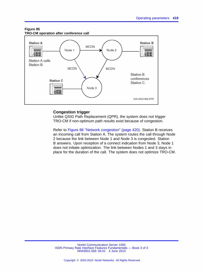
Operating parameters 419
Figure 85TRO-CM operation after conference call
Congestion triggerUnlike QSIG Path Replacement (QPR), the system does not triggerTRO-CM if non-optimum path results exist because of congestion.
Refer to Figure 86 "Network congestion" (page 420). Station B receivesan incoming call from Station A. The system routes the call through Node2 because the link between Node 1 and Node 3 is congested. StationB answers. Upon reception of a connect indication from Node 3, Node 1does not initiate optimization. The link between Nodes 1 and 3 stays inplace for the duration of the call. The system does not optimize TRO-CM.
Nortel Communication Server 1000ISDN Primary Rate Interface Features Fundamentals — Book 3 of 3
NN43001-569 04.01 4 June 2010
Copyright © 2003-2010 Nortel Networks. All Rights Reserved.
.
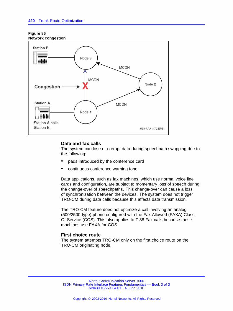
420 Trunk Route Optimization
Figure 86Network congestion
Data and fax callsThe system can lose or corrupt data during speechpath swapping due tothe following:
• pads introduced by the conference card
• continuous conference warning tone
Data applications, such as fax machines, which use normal voice linecards and configuration, are subject to momentary loss of speech duringthe change-over of speechpaths. This change-over can cause a lossof synchronization between the devices. The system does not triggerTRO-CM during data calls because this affects data transmission.
The TRO-CM feature does not optimize a call involving an analog(500/2500-type) phone configured with the Fax Allowed (FAXA) ClassOf Service (COS). This also applies to T.38 Fax calls because thesemachines use FAXA for COS.
First choice routeThe system attempts TRO-CM only on the first choice route on theTRO-CM originating node.
Nortel Communication Server 1000ISDN Primary Rate Interface Features Fundamentals — Book 3 of 3
NN43001-569 04.01 4 June 2010
Copyright © 2003-2010 Nortel Networks. All Rights Reserved.
.
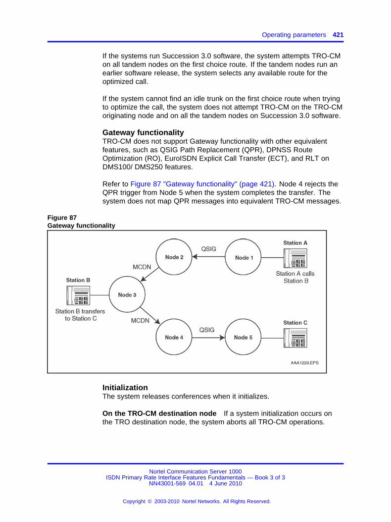
Operating parameters 421
If the systems run Succession 3.0 software, the system attempts TRO-CMon all tandem nodes on the first choice route. If the tandem nodes run anearlier software release, the system selects any available route for theoptimized call.
If the system cannot find an idle trunk on the first choice route when tryingto optimize the call, the system does not attempt TRO-CM on the TRO-CMoriginating node and on all the tandem nodes on Succession 3.0 software.
Gateway functionalityTRO-CM does not support Gateway functionality with other equivalentfeatures, such as QSIG Path Replacement (QPR), DPNSS RouteOptimization (RO), EuroISDN Explicit Call Transfer (ECT), and RLT onDMS100/ DMS250 features.
Refer to Figure 87 "Gateway functionality" (page 421). Node 4 rejects theQPR trigger from Node 5 when the system completes the transfer. Thesystem does not map QPR messages into equivalent TRO-CM messages.
Figure 87Gateway functionality
InitializationThe system releases conferences when it initializes.
On the TRO-CM destination node If a system initialization occurs onthe TRO destination node, the system aborts all TRO-CM operations.
Nortel Communication Server 1000ISDN Primary Rate Interface Features Fundamentals — Book 3 of 3
NN43001-569 04.01 4 June 2010
Copyright © 2003-2010 Nortel Networks. All Rights Reserved.
.
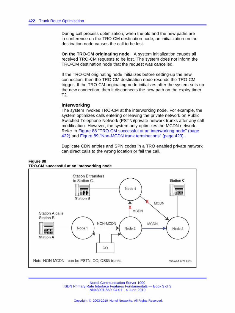
422 Trunk Route Optimization
During call process optimization, when the old and the new paths arein conference on the TRO-CM destination node, an initialization on thedestination node causes the call to be lost.
On the TRO-CM originating node A system initialization causes allreceived TRO-CM requests to be lost. The system does not inform theTRO-CM destination node that the request was cancelled.
If the TRO-CM originating node initializes before setting-up the newconnection, then the TRO-CM destination node resends the TRO-CMtrigger. If the TRO-CM originating node initializes after the system sets upthe new connection, then it disconnects the new path on the expiry timerT2.
InterworkingThe system invokes TRO-CM at the interworking node. For example, thesystem optimizes calls entering or leaving the private network on PublicSwitched Telephone Network (PSTN)/private network trunks after any callmodification. However, the system only optimizes the MCDN network.Refer to Figure 88 "TRO-CM successful at an interworking node" (page422) and Figure 89 "Non-MCDN trunk terminations" (page 423).
Duplicate CDN entries and SPN codes in a TRO enabled private networkcan direct calls to the wrong location or fail the call.
Figure 88TRO-CM successful at an interworking node
Nortel Communication Server 1000ISDN Primary Rate Interface Features Fundamentals — Book 3 of 3
NN43001-569 04.01 4 June 2010
Copyright © 2003-2010 Nortel Networks. All Rights Reserved.
.
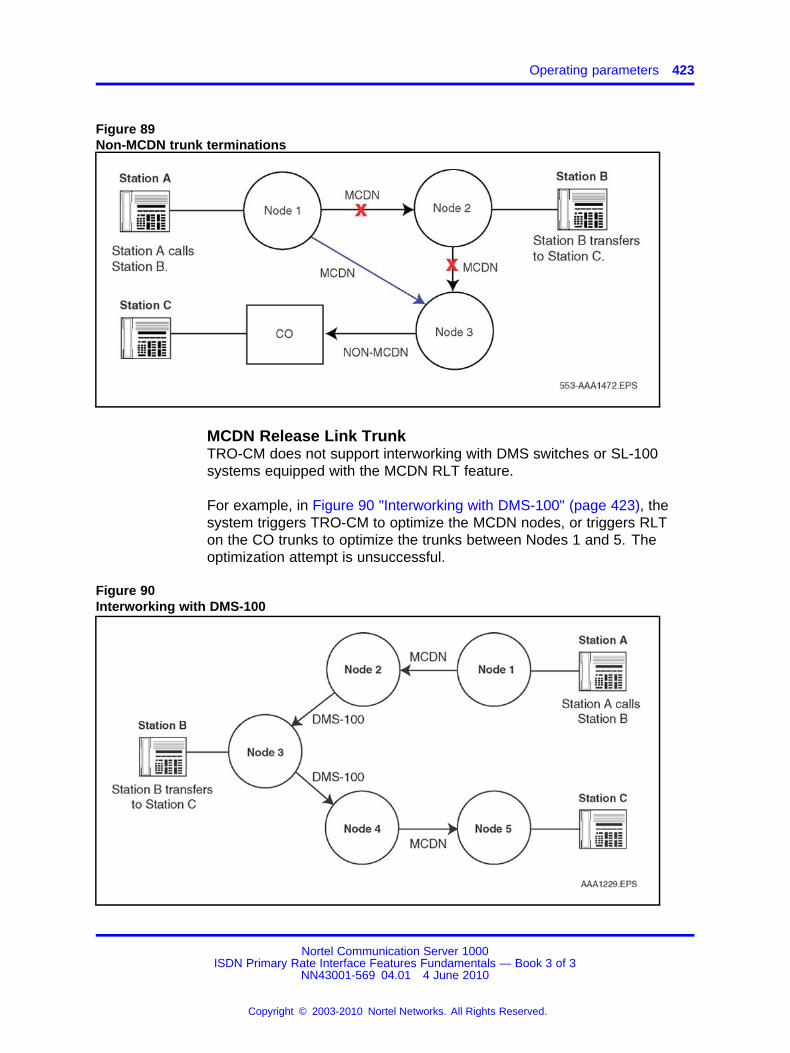
Operating parameters 423
Figure 89Non-MCDN trunk terminations
MCDN Release Link TrunkTRO-CM does not support interworking with DMS switches or SL-100systems equipped with the MCDN RLT feature.
For example, in Figure 90 "Interworking with DMS-100" (page 423), thesystem triggers TRO-CM to optimize the MCDN nodes, or triggers RLTon the CO trunks to optimize the trunks between Nodes 1 and 5. Theoptimization attempt is unsuccessful.
Figure 90Interworking with DMS-100
Nortel Communication Server 1000ISDN Primary Rate Interface Features Fundamentals — Book 3 of 3
NN43001-569 04.01 4 June 2010
Copyright © 2003-2010 Nortel Networks. All Rights Reserved.
.
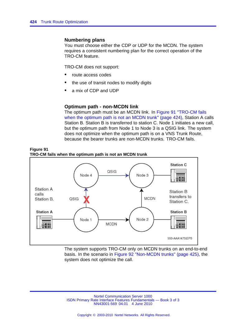
424 Trunk Route Optimization
Numbering plansYou must choose either the CDP or UDP for the MCDN. The systemrequires a consistent numbering plan for the correct operation of theTRO-CM feature.
TRO-CM does not support:
• route access codes
• the use of transit nodes to modify digits
• a mix of CDP and UDP
Optimum path - non-MCDN linkThe optimum path must be an MCDN link. In Figure 91 "TRO-CM failswhen the optimum path is not an MCDN trunk" (page 424), Station A callsStation B. Station B is transferred to station C. Node 1 initiates a new call,but the optimum path from Node 1 to Node 3 is a QSIG link. The systemdoes not optimize when the optimum path is on a VNS Trunk Route,because the bearer trunks are non-MCDN trunks. TRO-CM fails.
Figure 91TRO-CM fails when the optimum path is not an MCDN trunk
The system supports TRO-CM only on MCDN trunks on an end-to-endbasis. In the scenario in Figure 92 "Non-MCDN trunks" (page 425), thesystem does not optimize the call.
Nortel Communication Server 1000ISDN Primary Rate Interface Features Fundamentals — Book 3 of 3
NN43001-569 04.01 4 June 2010
Copyright © 2003-2010 Nortel Networks. All Rights Reserved.
.
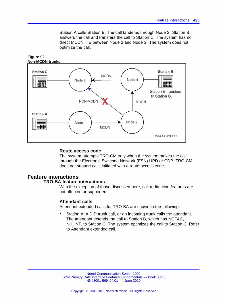
Feature interactions 425
Station A calls Station B. The call tandems through Node 2. Station Banswers the call and transfers the call to Station C. The system has nodirect MCDN TIE between Node 2 and Node 3. The system does notoptimize the call.
Figure 92Non-MCDN trunks
Route access codeThe system attempts TRO-CM only when the system makes the callthrough the Electronic Switched Network (ESN) UPD or CDP. TRO-CMdoes not support calls initiated with a route access code.
Feature interactionsTRO-BA feature interactions
With the exception of those discussed here, call redirection features arenot affected or supported.
Attendant callsAttendant extended calls for TRO-BA are shown in the following:
• Station A, a DID trunk call, or an incoming trunk calls the attendant.The attendant extends the call to Station B, which has NCFAC,NHUNT, to Station C. The system optimizes the call to Station C. Referto Attendant extended call.
Nortel Communication Server 1000ISDN Primary Rate Interface Features Fundamentals — Book 3 of 3
NN43001-569 04.01 4 June 2010
Copyright © 2003-2010 Nortel Networks. All Rights Reserved.
.
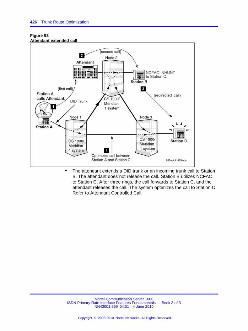
426 Trunk Route Optimization
Figure 93Attendant extended call
• The attendant extends a DID trunk or an incoming trunk call to StationB. The attendant does not release the call. Station B utilizes NCFACto Station C. After three rings, the call forwards to Station C, and theattendant releases the call. The system optimizes the call to Station C.Refer to Attendant Controlled Call.
Nortel Communication Server 1000ISDN Primary Rate Interface Features Fundamentals — Book 3 of 3
NN43001-569 04.01 4 June 2010
Copyright © 2003-2010 Nortel Networks. All Rights Reserved.
.
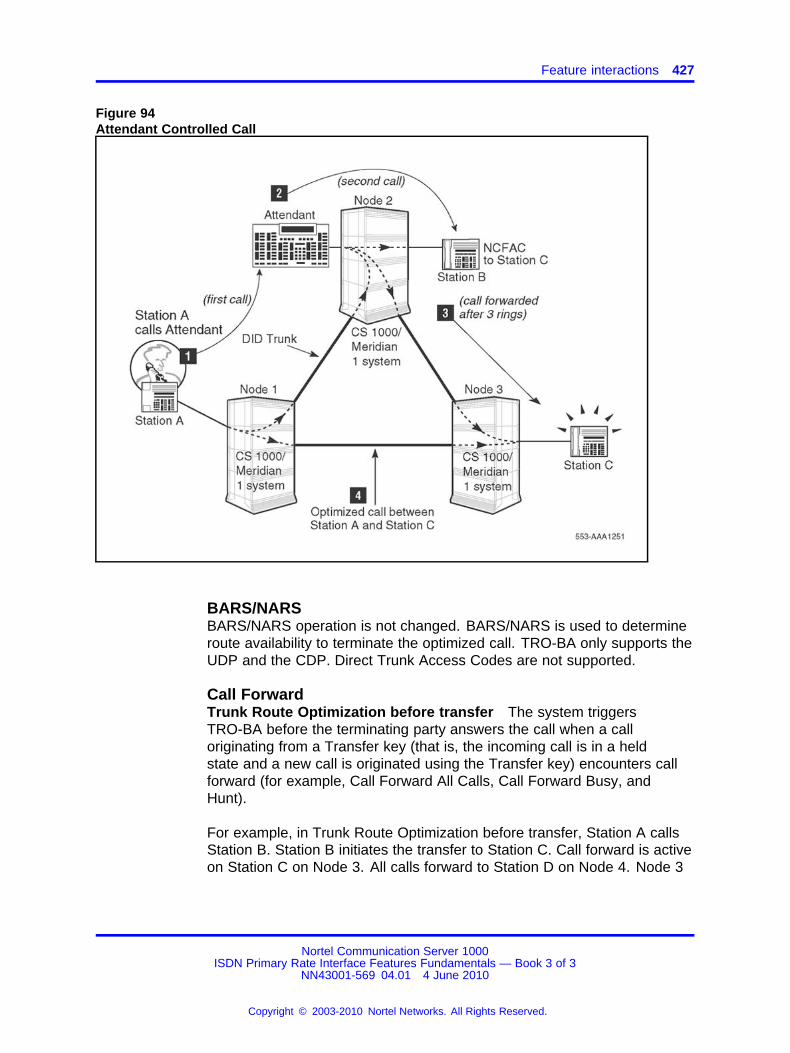
Feature interactions 427
Figure 94Attendant Controlled Call
BARS/NARSBARS/NARS operation is not changed. BARS/NARS is used to determineroute availability to terminate the optimized call. TRO-BA only supports theUDP and the CDP. Direct Trunk Access Codes are not supported.
Call ForwardTrunk Route Optimization before transfer The system triggersTRO-BA before the terminating party answers the call when a calloriginating from a Transfer key (that is, the incoming call is in a heldstate and a new call is originated using the Transfer key) encounters callforward (for example, Call Forward All Calls, Call Forward Busy, andHunt).
For example, in Trunk Route Optimization before transfer, Station A callsStation B. Station B initiates the transfer to Station C. Call forward is activeon Station C on Node 3. All calls forward to Station D on Node 4. Node 3
Nortel Communication Server 1000ISDN Primary Rate Interface Features Fundamentals — Book 3 of 3
NN43001-569 04.01 4 June 2010
Copyright © 2003-2010 Nortel Networks. All Rights Reserved.
.

428 Trunk Route Optimization
sends the TRO-BA offer to Node 2. Node 2 accepts the offer, drops theold connection, and sets up a new connection between Node 2 and Node4.
Figure 95Trunk Route Optimization before transfer
Call Forward ForwardingIf you configure the database to use the forwarding set Class of Servicewhen a call is redirected (OPT = CFF in OVL 15), the originating set Classof Service can restrict an optimized call to the redirection DN, and theredirecting Class of Service can allow the call to be completed.
Call Forward No AnswerTrunk Route Optimization before transfer
TRO-BA on Transfer (TRN) key TRO-BA optimizes calls originated fromthe TRN key.
For example, in TRO-BA on TRN key, Station A calls Station B. StationB initiates the transfer to Station C. Station C is Call Forward No Answer(CFNA) to Station D. Upon CFNA timer expiry, while Station A is still in aheld state, Node 3 sends the TRO-BA request to Node 2. Node 2 acceptsthe TRO-BA offer, drops the old connection and sets-up a new directconnection from Node 2 to Node 4 on the TRN key.
Nortel Communication Server 1000ISDN Primary Rate Interface Features Fundamentals — Book 3 of 3
NN43001-569 04.01 4 June 2010
Copyright © 2003-2010 Nortel Networks. All Rights Reserved.
.
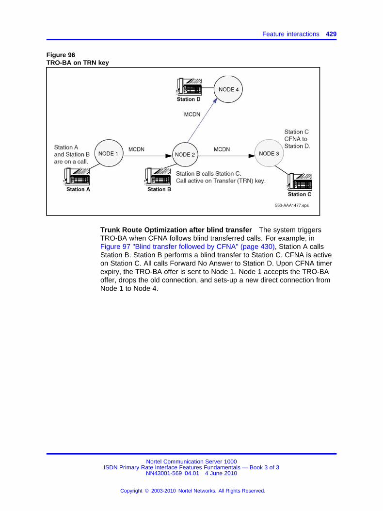
Feature interactions 429
Figure 96TRO-BA on TRN key
Trunk Route Optimization after blind transfer The system triggersTRO-BA when CFNA follows blind transferred calls. For example, inFigure 97 "Blind transfer followed by CFNA" (page 430), Station A callsStation B. Station B performs a blind transfer to Station C. CFNA is activeon Station C. All calls Forward No Answer to Station D. Upon CFNA timerexpiry, the TRO-BA offer is sent to Node 1. Node 1 accepts the TRO-BAoffer, drops the old connection, and sets-up a new direct connection fromNode 1 to Node 4.
Nortel Communication Server 1000ISDN Primary Rate Interface Features Fundamentals — Book 3 of 3
NN43001-569 04.01 4 June 2010
Copyright © 2003-2010 Nortel Networks. All Rights Reserved.
.
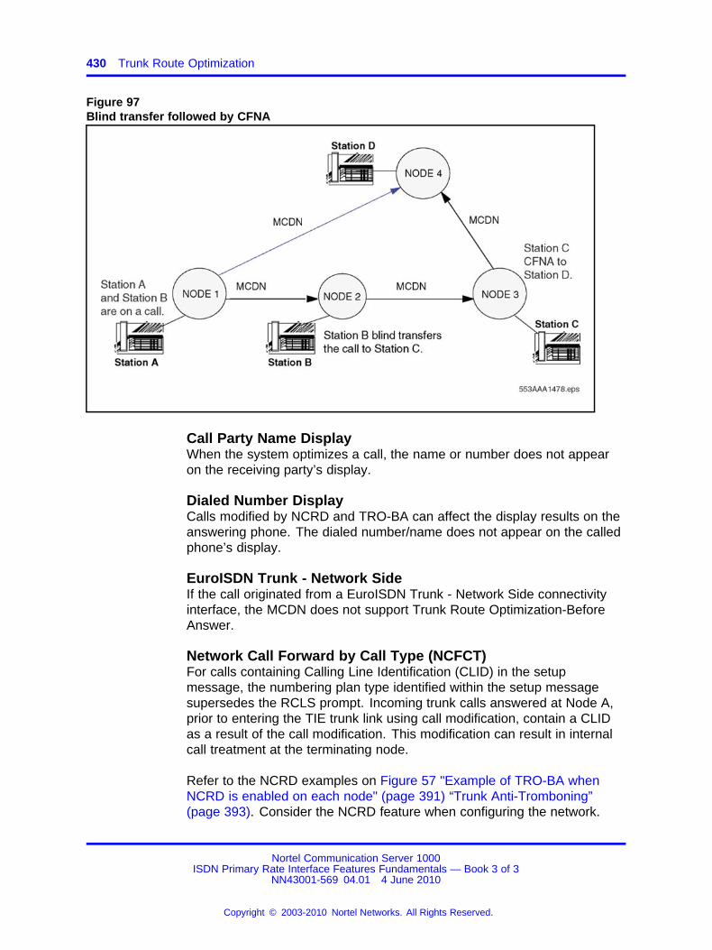
430 Trunk Route Optimization
Figure 97Blind transfer followed by CFNA
Call Party Name DisplayWhen the system optimizes a call, the name or number does not appearon the receiving party’s display.
Dialed Number DisplayCalls modified by NCRD and TRO-BA can affect the display results on theanswering phone. The dialed number/name does not appear on the calledphone’s display.
EuroISDN Trunk - Network SideIf the call originated from a EuroISDN Trunk - Network Side connectivityinterface, the MCDN does not support Trunk Route Optimization-BeforeAnswer.
Network Call Forward by Call Type (NCFCT)For calls containing Calling Line Identification (CLID) in the setupmessage, the numbering plan type identified within the setup messagesupersedes the RCLS prompt. Incoming trunk calls answered at Node A,prior to entering the TIE trunk link using call modification, contain a CLIDas a result of the call modification. This modification can result in internalcall treatment at the terminating node.
Refer to the NCRD examples on Figure 57 "Example of TRO-BA whenNCRD is enabled on each node" (page 391) “Trunk Anti-Tromboning”(page 393). Consider the NCRD feature when configuring the network.
Nortel Communication Server 1000ISDN Primary Rate Interface Features Fundamentals — Book 3 of 3
NN43001-569 04.01 4 June 2010
Copyright © 2003-2010 Nortel Networks. All Rights Reserved.
.
Feature interactions 431
Network Call Redirection (Network Call Forward All Calls[NCFAC], Network Call Forward No Answer [NCFNA], NetworkHunt (NHNT))TRO-BA depends on NCRD messages over the D-channel. Allow NCRDfor all routes targeted for TRO-BA calls. When TRO-BA redirects a call,the originating node receives the redirecting information. The originatingnode suspends the redirection, and establishes a direct connection. If aroute is not available when the call is placed, the call can be blocked.
Network Call TransferTrunk Route Optimization does not operate for Network Call Transferredcalls. Station and attendant extended calls do not utilize TRO-BA.
Network Message ServiceTRO-BA occurs when the node activates the Meridian Mail Call Sender.Through dialing or operator revert features do not provide the DN toMeridian Mail. Therefore, optimization does not take place. The originalcalled-party information included in the setup message determines whereMeridian Mail terminates the call.
Radio Paging (RPA) CallsTrunk Optimization does not occur when RPA is involved in the call.
TAT feature interactionsIf you configure TRO-BA and TAT on the same system, TRO-BA takesprecedence over TAT.
Note: For the TAT features described in this section, assume that youconfigured only the TAT feature (and not TRO-BA) on the system.
AttendantIf an attendant activates Busy Verify or Barge-in at the same time thatthe system receives a message to invoke TAT, the system aborts theAnti-tromboning operation.
Automatic Call Distribution (ACD)The Trunk Anti-Tromboning feature performs anti-tromboning operationsto eliminate the PRI trunks associated with the same D-channel due to thefollowing ACD operations:
• Enhanced Network Call Forward
• Network ACD
• Interflow Options
• Enhanced Interflow
Nortel Communication Server 1000ISDN Primary Rate Interface Features Fundamentals — Book 3 of 3
NN43001-569 04.01 4 June 2010
Copyright © 2003-2010 Nortel Networks. All Rights Reserved.
.
432 Trunk Route Optimization
If a supervisor attempts to observe an ACD agent at the same timethe system receives a message to invoke TAT, the system aborts theAnti-tromboning operation.
If a Recorded Announcement (RAN) answers an incoming PRI call in theACD queue, the system only performs the Anti-tromboning operation afteran ACD agent answers the call.
Call Park Network WideIf you program the feature at all the interim Private Branch Exchanges(PBXs) in the call, the system invokes the Trunk Anti-Tromboning feature.
ConferenceIf the system activates the Conference feature, the Trunk Anti-Tromboningfeature only performs the anti-tromboning operations when two parties:
• remain in the call
• use PRI trunks associated with the same D-channel
Figure 98 "Conference call before TAT" (page 433) shows a conferencecall before TAT:
• Station A or an incoming DID trunk call at the originating node isconnected to Station B at the terminating node over a PRI/ISL/VNSor analog trunk (first call).
• Station B conferences in Station C, also located at the originatingnode, over a second PRI/ISL/VNS or analog trunk that is associatedwith the same D-channel as the first call.
• For the duration of the three-party conference call, the two trunks aretromboned.
Nortel Communication Server 1000ISDN Primary Rate Interface Features Fundamentals — Book 3 of 3
NN43001-569 04.01 4 June 2010
Copyright © 2003-2010 Nortel Networks. All Rights Reserved.
.

Feature interactions 433
Figure 98Conference call before TAT
When Station B drops out of the conference, the system invokesanti-tromboning. The system does not invoke TAT as long as theconference call situation exists. The two tromboned trunks are released.The system software bridges Station A or the DID trunk, and Station C.Refer to Conference call after TAT.
Figure 99Conference call after TAT
Nortel Communication Server 1000ISDN Primary Rate Interface Features Fundamentals — Book 3 of 3
NN43001-569 04.01 4 June 2010
Copyright © 2003-2010 Nortel Networks. All Rights Reserved.
.
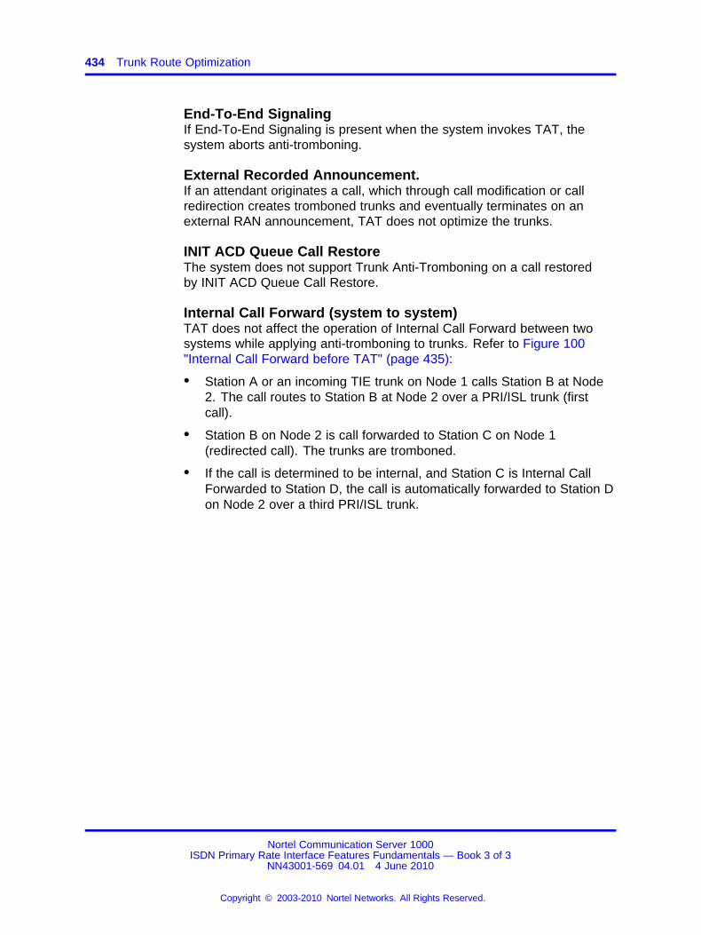
434 Trunk Route Optimization
End-To-End SignalingIf End-To-End Signaling is present when the system invokes TAT, thesystem aborts anti-tromboning.
External Recorded Announcement.If an attendant originates a call, which through call modification or callredirection creates tromboned trunks and eventually terminates on anexternal RAN announcement, TAT does not optimize the trunks.
INIT ACD Queue Call RestoreThe system does not support Trunk Anti-Tromboning on a call restoredby INIT ACD Queue Call Restore.
Internal Call Forward (system to system)TAT does not affect the operation of Internal Call Forward between twosystems while applying anti-tromboning to trunks. Refer to Figure 100"Internal Call Forward before TAT" (page 435):
• Station A or an incoming TIE trunk on Node 1 calls Station B at Node2. The call routes to Station B at Node 2 over a PRI/ISL trunk (firstcall).
• Station B on Node 2 is call forwarded to Station C on Node 1(redirected call). The trunks are tromboned.
• If the call is determined to be internal, and Station C is Internal CallForwarded to Station D, the call is automatically forwarded to Station Don Node 2 over a third PRI/ISL trunk.
Nortel Communication Server 1000ISDN Primary Rate Interface Features Fundamentals — Book 3 of 3
NN43001-569 04.01 4 June 2010
Copyright © 2003-2010 Nortel Networks. All Rights Reserved.
.
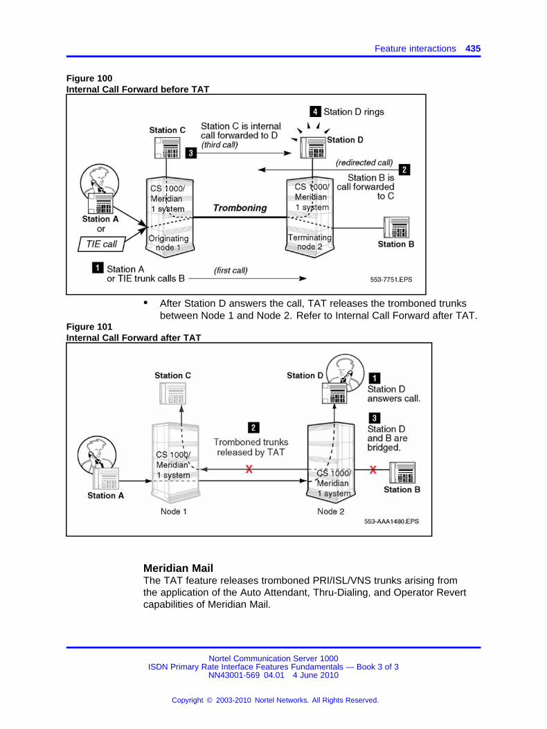
Feature interactions 435
Figure 100Internal Call Forward before TAT
• After Station D answers the call, TAT releases the tromboned trunksbetween Node 1 and Node 2. Refer to Internal Call Forward after TAT.
Figure 101Internal Call Forward after TAT
Meridian MailThe TAT feature releases tromboned PRI/ISL/VNS trunks arising fromthe application of the Auto Attendant, Thru-Dialing, and Operator Revertcapabilities of Meridian Mail.
Nortel Communication Server 1000ISDN Primary Rate Interface Features Fundamentals — Book 3 of 3
NN43001-569 04.01 4 June 2010
Copyright © 2003-2010 Nortel Networks. All Rights Reserved.
.
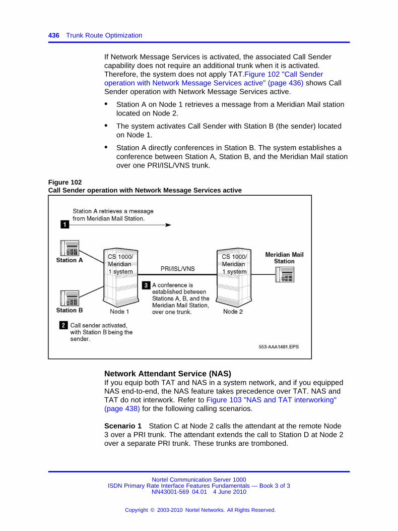
436 Trunk Route Optimization
If Network Message Services is activated, the associated Call Sendercapability does not require an additional trunk when it is activated.Therefore, the system does not apply TAT.Figure 102 "Call Senderoperation with Network Message Services active" (page 436) shows CallSender operation with Network Message Services active.
• Station A on Node 1 retrieves a message from a Meridian Mail stationlocated on Node 2.
• The system activates Call Sender with Station B (the sender) locatedon Node 1.
• Station A directly conferences in Station B. The system establishes aconference between Station A, Station B, and the Meridian Mail stationover one PRI/ISL/VNS trunk.
Figure 102Call Sender operation with Network Message Services active
Network Attendant Service (NAS)If you equip both TAT and NAS in a system network, and if you equippedNAS end-to-end, the NAS feature takes precedence over TAT. NAS andTAT do not interwork. Refer to Figure 103 "NAS and TAT interworking"(page 438) for the following calling scenarios.
Scenario 1 Station C at Node 2 calls the attendant at the remote Node3 over a PRI trunk. The attendant extends the call to Station D at Node 2over a separate PRI trunk. These trunks are tromboned.
Nortel Communication Server 1000ISDN Primary Rate Interface Features Fundamentals — Book 3 of 3
NN43001-569 04.01 4 June 2010
Copyright © 2003-2010 Nortel Networks. All Rights Reserved.
.
Feature interactions 437
Case 1 - TAT and NAS are equipped on all nodes The NASfunctionality drops the tromboned trunks, and the system bridges Station Cand Station D when Station D answers.
Case 2 - NAS is not equipped If you did not equip the systemwith NAS, TAT performs anti-tromboning operations by removing thetromboned trunks and bridging Station C and Station D.
Scenario 2 Station A at Node 1 calls the attendant at Node 3. Theattendant extends the call to Station B on Node 1.
Case 1 - TAT and NAS are equipped on all nodes If you equippedNAS and TAT between Node 1 and Node 2, and between Node 2 andNode 3, then NAS takes precedence over TAT to optimize the trombonedtrunks between Node 1 and Node 2, and between Node 2 and Node 3.
Case 2 - NAS is not equipped If you only equipped TAT between Node1 and Node 2, and between Node 2 and Node 3, then TAT releases thetromboned trunks between Node 1 and Node 2, and between Node 2 andNode 3.
Case 3 - NAS is equipped between Node 1 and Node 2, and TAT isequipped between Node 2 and Node 3 If you only equipped NASbetween Node 1 and Node 2, and equipped TAT between Node 2 andNode 3, then TAT releases the tromboned trunks between Node 2 andNode 3. The call is bridged at Node 2. NAS does not optimize thetromboned trunks between Node 1 and Node 2.
Case 4 - TAT is equipped between Node 1 and Node 2, and NASis equipped between Node 2 and Node 3 If you only equipped TATbetween Node 1 and Node 2, and only equipped NAS between Node 2and Node 3, the system does not perform anti-tromboning because you didnot equip NAS end-to-end.
Nortel Communication Server 1000ISDN Primary Rate Interface Features Fundamentals — Book 3 of 3
NN43001-569 04.01 4 June 2010
Copyright © 2003-2010 Nortel Networks. All Rights Reserved.
.
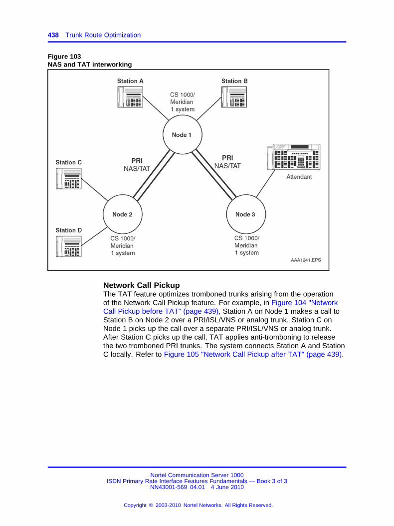
438 Trunk Route Optimization
Figure 103NAS and TAT interworking
Network Call PickupThe TAT feature optimizes tromboned trunks arising from the operationof the Network Call Pickup feature. For example, in Figure 104 "NetworkCall Pickup before TAT" (page 439), Station A on Node 1 makes a call toStation B on Node 2 over a PRI/ISL/VNS or analog trunk. Station C onNode 1 picks up the call over a separate PRI/ISL/VNS or analog trunk.After Station C picks up the call, TAT applies anti-tromboning to releasethe two tromboned PRI trunks. The system connects Station A and StationC locally. Refer to Figure 105 "Network Call Pickup after TAT" (page 439).
Nortel Communication Server 1000ISDN Primary Rate Interface Features Fundamentals — Book 3 of 3
NN43001-569 04.01 4 June 2010
Copyright © 2003-2010 Nortel Networks. All Rights Reserved.
.
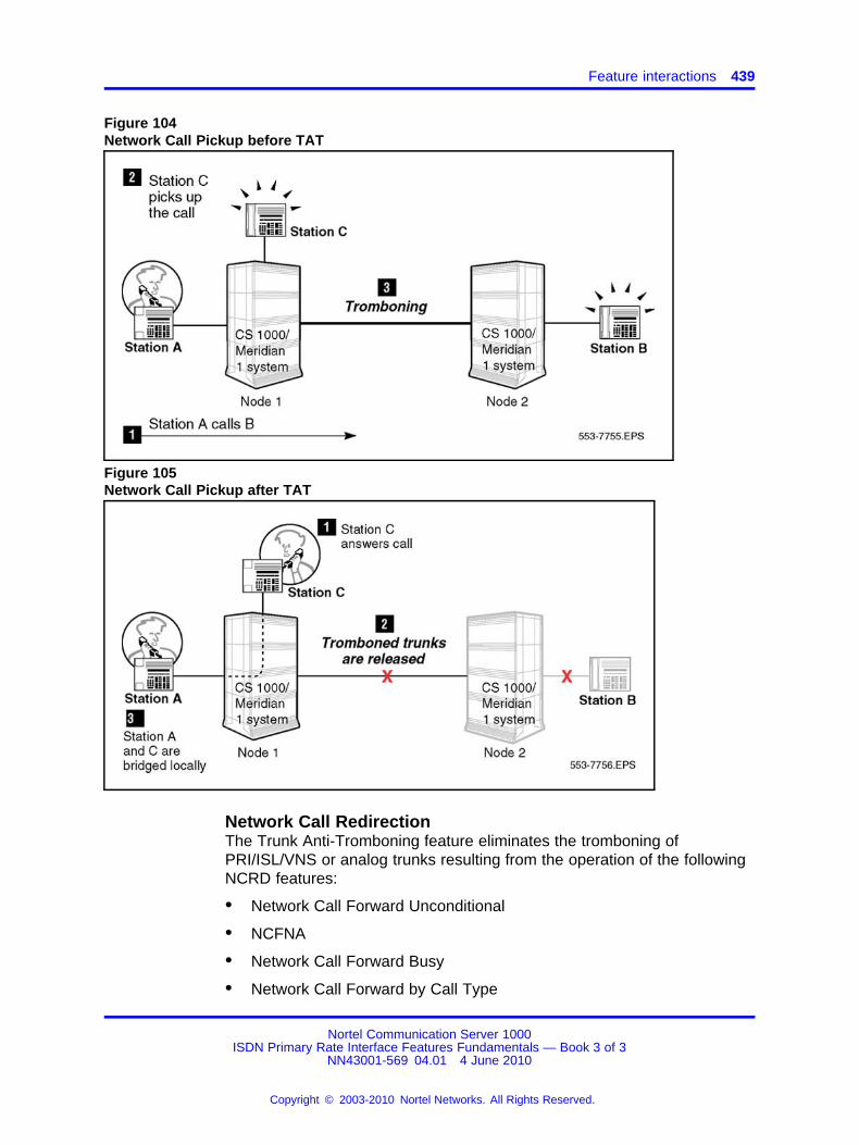
Feature interactions 439
Figure 104Network Call Pickup before TAT
Figure 105Network Call Pickup after TAT
Network Call RedirectionThe Trunk Anti-Tromboning feature eliminates the tromboning ofPRI/ISL/VNS or analog trunks resulting from the operation of the followingNCRD features:
• Network Call Forward Unconditional
• NCFNA
• Network Call Forward Busy
• Network Call Forward by Call Type
Nortel Communication Server 1000ISDN Primary Rate Interface Features Fundamentals — Book 3 of 3
NN43001-569 04.01 4 June 2010
Copyright © 2003-2010 Nortel Networks. All Rights Reserved.
.
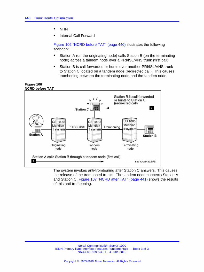
440 Trunk Route Optimization
• NHNT
• Internal Call Forward
Figure 106 "NCRD before TAT" (page 440) illustrates the followingscenario:
• Station A (on the originating node) calls Station B (on the terminatingnode) across a tandem node over a PRI/ISL/VNS trunk (first call).
• Station B is call forwarded or hunts over another PRI/ISL/VNS trunkto Station C located on a tandem node (redirected call). This causestromboning between the terminating node and the tandem node.
Figure 106NCRD before TAT
The system invokes anti-tromboning after Station C answers. This causesthe release of the tromboned trunks. The tandem node connects Station Aand Station C. Figure 107 "NCRD after TAT" (page 441) shows the resultsof this anti-tromboning.
Nortel Communication Server 1000ISDN Primary Rate Interface Features Fundamentals — Book 3 of 3
NN43001-569 04.01 4 June 2010
Copyright © 2003-2010 Nortel Networks. All Rights Reserved.
.

Feature interactions 441
Figure 107NCRD after TAT
Radio Paging SystemIf an attendant originates a call, which through call modification or callredirection, creates tromboned trunks, and eventually terminates on RadioPaging equipment, TAT does not optimize the trunks.
Trunk Route Optimization - Before AnswerSee “TAT and TRO-BA equipped on the same system” (page 395).
Virtual Network ServicesThe TAT feature performs anti-tromboning operations to eliminatetromboned trunks (physical B-channels) associated with the same VNSD-channel. In Figure 108 "VNS before TAT" (page 442), Station A, at theoriginating node, calls Station B, at the terminating node, over a VNSD-channel trunk. Station B transfers the call to Station C, at the originatingnode. The physical B-channel trunks associated with the D-channels aretromboned.
Nortel Communication Server 1000ISDN Primary Rate Interface Features Fundamentals — Book 3 of 3
NN43001-569 04.01 4 June 2010
Copyright © 2003-2010 Nortel Networks. All Rights Reserved.
.
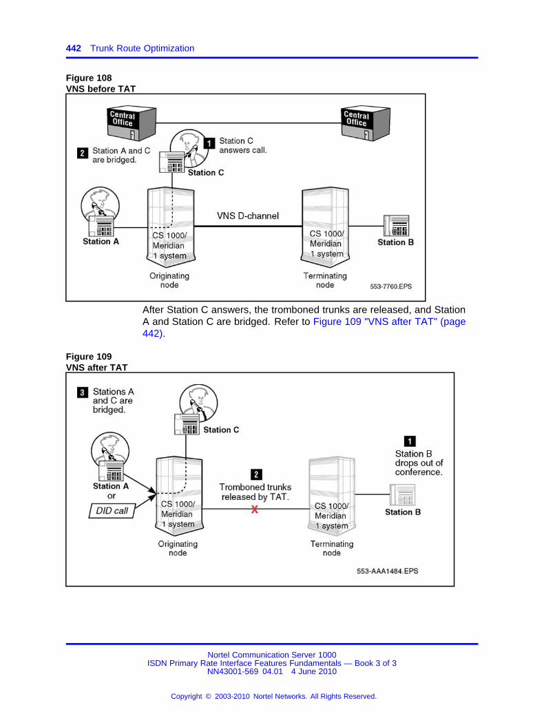
442 Trunk Route Optimization
Figure 108VNS before TAT
After Station C answers, the tromboned trunks are released, and StationA and Station C are bridged. Refer to Figure 109 "VNS after TAT" (page442).
Figure 109VNS after TAT
Nortel Communication Server 1000ISDN Primary Rate Interface Features Fundamentals — Book 3 of 3
NN43001-569 04.01 4 June 2010
Copyright © 2003-2010 Nortel Networks. All Rights Reserved.
.
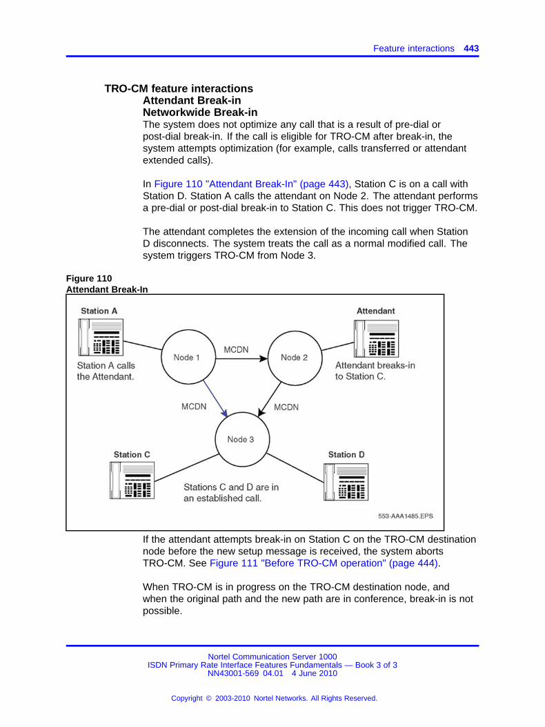
Feature interactions 443
TRO-CM feature interactionsAttendant Break-inNetworkwide Break-inThe system does not optimize any call that is a result of pre-dial orpost-dial break-in. If the call is eligible for TRO-CM after break-in, thesystem attempts optimization (for example, calls transferred or attendantextended calls).
In Figure 110 "Attendant Break-In" (page 443), Station C is on a call withStation D. Station A calls the attendant on Node 2. The attendant performsa pre-dial or post-dial break-in to Station C. This does not trigger TRO-CM.
The attendant completes the extension of the incoming call when StationD disconnects. The system treats the call as a normal modified call. Thesystem triggers TRO-CM from Node 3.
Figure 110Attendant Break-In
If the attendant attempts break-in on Station C on the TRO-CM destinationnode before the new setup message is received, the system abortsTRO-CM. See Figure 111 "Before TRO-CM operation" (page 444).
When TRO-CM is in progress on the TRO-CM destination node, andwhen the original path and the new path are in conference, break-in is notpossible.
Nortel Communication Server 1000ISDN Primary Rate Interface Features Fundamentals — Book 3 of 3
NN43001-569 04.01 4 June 2010
Copyright © 2003-2010 Nortel Networks. All Rights Reserved.
.

444 Trunk Route Optimization
When the system receives the TRO-CM Trigger on the originating nodeand Station A is broken-into, the system rejects TRO-CM due to theterminated status of the call. See Figure 111 "Before TRO-CM operation"(page 444).
Figure 111Before TRO-CM operation
Automatic Call Distribution (ACD)The system triggers the TRO-CM feature when the ACD agent at theTRO-CM destination node answers the call.
Barge-inBarge-in calls are attendant-originated. They do not optimize.
Call Detail RecordingIn Figure 112 "Triangulation" (page 445), Station A calls Station B. StationB transfers the call to Station C. Station C answers the call. Station Bcompletes the transfer. The system triggers TRO-CM, and sets-up a newconnection between Node 1 and Node 6 through Node 4.
Nortel Communication Server 1000ISDN Primary Rate Interface Features Fundamentals — Book 3 of 3
NN43001-569 04.01 4 June 2010
Copyright © 2003-2010 Nortel Networks. All Rights Reserved.
.
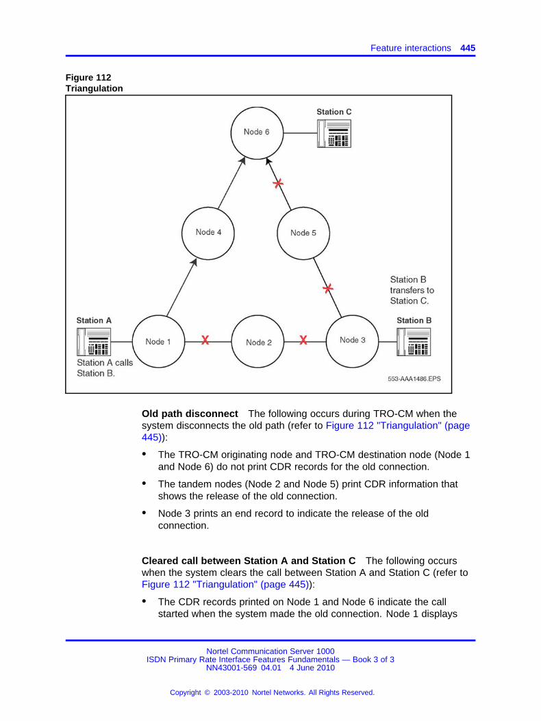
Feature interactions 445
Figure 112Triangulation
Old path disconnect The following occurs during TRO-CM when thesystem disconnects the old path (refer to Figure 112 "Triangulation" (page445)):
• The TRO-CM originating node and TRO-CM destination node (Node 1and Node 6) do not print CDR records for the old connection.
• The tandem nodes (Node 2 and Node 5) print CDR information thatshows the release of the old connection.
• Node 3 prints an end record to indicate the release of the oldconnection.
Cleared call between Station A and Station C The following occurswhen the system clears the call between Station A and Station C (refer toFigure 112 "Triangulation" (page 445)):
• The CDR records printed on Node 1 and Node 6 indicate the callstarted when the system made the old connection. Node 1 displays
Nortel Communication Server 1000ISDN Primary Rate Interface Features Fundamentals — Book 3 of 3
NN43001-569 04.01 4 June 2010
Copyright © 2003-2010 Nortel Networks. All Rights Reserved.
.
446 Trunk Route Optimization
Station A (the originator of the new connection) as the originator of theold connection. Node 6 displays Station C (the terminator of the newconnection) as the terminator of the old connection. See Figure 112"Triangulation" (page 445).
• Node 4 (tandem node) prints CDR information that shows the releaseof a connection, which started when the new connection was made.
Call ForwardCall Forward BusyCall Forward All CallsCall Forward HuntTrunk Route Optimization after transfer When Call Forward Busy,Call Forward All Calls, and Call Forward Hunt follow a blind or supervisedtransfer, the system only triggers TRO-CM after the terminating partyanswers the call.
For example, in Figure 113 "Trunk Route Optimization after transfer" (page447), Station A calls Station B. Station B initiates a transfer to StationC. CFNA is active on Station C. All calls Forward No Answer to StationD. Station D answers the call, then Station B completes the transfer.TRO-CM optimizes the call between Station A and Station D.
Nortel Communication Server 1000ISDN Primary Rate Interface Features Fundamentals — Book 3 of 3
NN43001-569 04.01 4 June 2010
Copyright © 2003-2010 Nortel Networks. All Rights Reserved.
.

Feature interactions 447
Figure 113Trunk Route Optimization after transfer
Supervised transfer The system triggers TRO-CM upon answer, onlyif CFNA follows a supervised transfer. The system optimizes CFNA callsonly on answer.
In Figure 114 "Supervised transfer followed by CFNA" (page 448), StationA calls Station B. Station B initiates a transfer to Station C. CFNA is activeon Station C. All calls Forward No Answer to Station D. Station D answersthe call. Station B completes the transfer. TRO-CM optimizes the callbetween Station A and Station D.
However, if Station B performs a blind transfer to Station C, the systemdoes not trigger TRO-CM.
Nortel Communication Server 1000ISDN Primary Rate Interface Features Fundamentals — Book 3 of 3
NN43001-569 04.01 4 June 2010
Copyright © 2003-2010 Nortel Networks. All Rights Reserved.
.
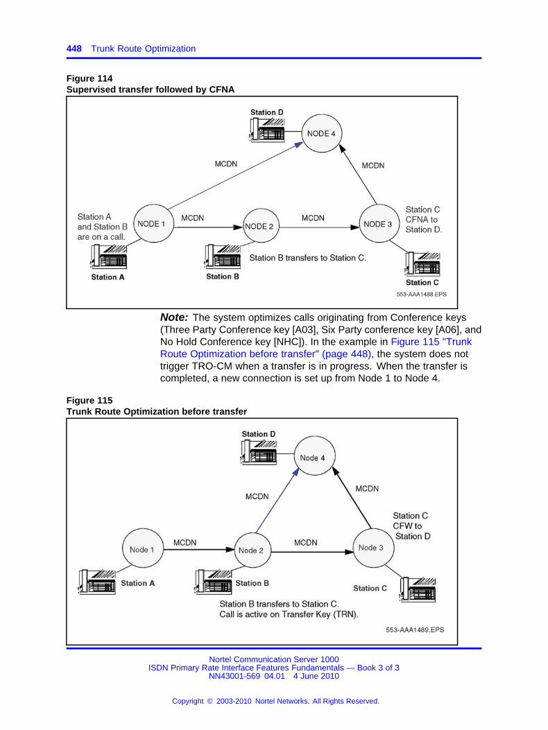
448 Trunk Route Optimization
Figure 114Supervised transfer followed by CFNA
Note: The system optimizes calls originating from Conference keys(Three Party Conference key [A03], Six Party conference key [A06], andNo Hold Conference key [NHC]). In the example in Figure 115 "TrunkRoute Optimization before transfer" (page 448), the system does nottrigger TRO-CM when a transfer is in progress. When the transfer iscompleted, a new connection is set up from Node 1 to Node 4.
Figure 115Trunk Route Optimization before transfer
Nortel Communication Server 1000ISDN Primary Rate Interface Features Fundamentals — Book 3 of 3
NN43001-569 04.01 4 June 2010
Copyright © 2003-2010 Nortel Networks. All Rights Reserved.
.
Feature interactions 449
Call HoldThe system aborts the TRO-CM operation when the terminating party ororiginating party attempts to put a call on hold.
If the call on the TRO-CM originating node is on hold when the TRO-CMTrigger is received, the system rejects TRO-CM due to the non-terminatedstatus of the call.
Call ParkThe system does not optimize Parked calls. For example, when Station Aon Node 1 calls Station B on Node 2, Station B transfers the call to StationC on Node 3. Station C parks the call. Station B completes the transfer.The system does not trigger TRO-CM.
When Station A on Node 1 calls Station B on Node 2, Station B initiatesa transfer to Station C on Node 3. Station B completes the transfer. Thesystem triggers TRO-CM. When Station C attempts to park the call, thesystem aborts the TRO-CM process.
If Station A parks the call on the TRO-CM originating node when theTRO-CM trigger is received, the request is rejected.
If station A parks the call on the TRO-CM originating node, the destinationnode rejects the request when the originating node receives the TRO-CMtrigger.
If Station A attempts to park the call when a TRO-CM setup facility hasbeen sent to the TRO-CM destination node, the system cancels theTRO-CM operations.
Call Pick-upNetwork Call Pick-upThe system does not optimize picked-up calls. For example, Station Aon Node 1 calls Station B on Node 2. Station B initiates a transfer toStation C on Node 3. While Station C is ringing, B completes the transfer.Station D (on the same node or on a different node) picks up Station C’scall. The system does not trigger TRO-CM. See Figure 115 "Trunk RouteOptimization before transfer" (page 448).
The system triggers TRO-CM if Station B does a supervised transfer.
Nortel Communication Server 1000ISDN Primary Rate Interface Features Fundamentals — Book 3 of 3
NN43001-569 04.01 4 June 2010
Copyright © 2003-2010 Nortel Networks. All Rights Reserved.
.
450 Trunk Route Optimization
Call TransferWhen the system sends the trigger from the TRO-CM destination nodeand before the originating node receives the new setup, if Station Cattempts to transfer the call, the system aborts TRO-CM operations. SeeFigure 111 "Before TRO-CM operation" (page 444). See Figure 111"Before TRO-CM operation" (page 444).
When TRO-CM is in progress on the TRO-CM destination node, and whenthe original path and the new path are in conference, a transfer is possible.
If Station A on the TRO-CM originating node performs a transfer when theTRO-CM trigger is received, or completes the transfer before the TRO-CMtrigger is received, the request is rejected.
When Station A attempts to transfer when a TRO-CM setup facilitymessage is sent to the TRO-CM destination node, the system abortsTRO-CM operations.
The system updates the display on the phones when the systemcompletes the transfer. The system invokes TRO-CM only after the systemupdates the display on the phones. TRO-CM does not alter the displayof the users.
A local Call Transfer does not trigger a TRO-CM request.
Call WaitingThe system does not invoke TRO-CM on a waiting call. However, thesystem invokes TRO-CM, if eligible, when the intended party answers thewaiting call.
For example, in Figure 111 "Before TRO-CM operation" (page 444),Station A calls Station B, if Station C is busy on another call. Station Battempts to transfer the call to Station C. Station B’s call is waiting onStation C. This does not trigger TRO-CM. However, when Station C picksup the waiting call, the system triggers TRO-CM.
Camp-OnThe system does not invoke TRO-CM on a camped-on call. However, thesystem invokes TRO-CM, if eligible, once the intended party answers thecamped-on call.
For example, in Figure 110 "Attendant Break-In" (page 443), Station Acalls the attendant on Node 2. Station C is busy on another call. Theattendant camps the call on Station C. This action does not triggerTRO-CM. However, once Station C is free and answers the camped-oncall, the system triggers TRO-CM.
Nortel Communication Server 1000ISDN Primary Rate Interface Features Fundamentals — Book 3 of 3
NN43001-569 04.01 4 June 2010
Copyright © 2003-2010 Nortel Networks. All Rights Reserved.
.
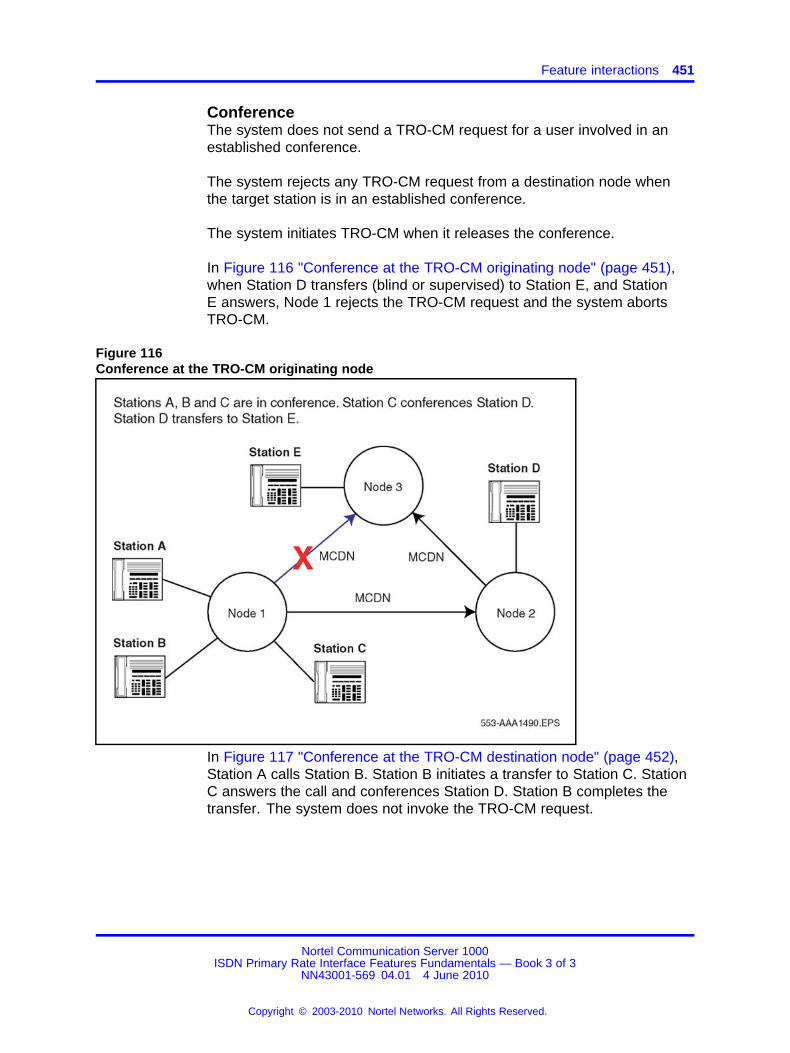
Feature interactions 451
ConferenceThe system does not send a TRO-CM request for a user involved in anestablished conference.
The system rejects any TRO-CM request from a destination node whenthe target station is in an established conference.
The system initiates TRO-CM when it releases the conference.
In Figure 116 "Conference at the TRO-CM originating node" (page 451),when Station D transfers (blind or supervised) to Station E, and StationE answers, Node 1 rejects the TRO-CM request and the system abortsTRO-CM.
Figure 116Conference at the TRO-CM originating node
In Figure 117 "Conference at the TRO-CM destination node" (page 452),Station A calls Station B. Station B initiates a transfer to Station C. StationC answers the call and conferences Station D. Station B completes thetransfer. The system does not invoke the TRO-CM request.
Nortel Communication Server 1000ISDN Primary Rate Interface Features Fundamentals — Book 3 of 3
NN43001-569 04.01 4 June 2010
Copyright © 2003-2010 Nortel Networks. All Rights Reserved.
.
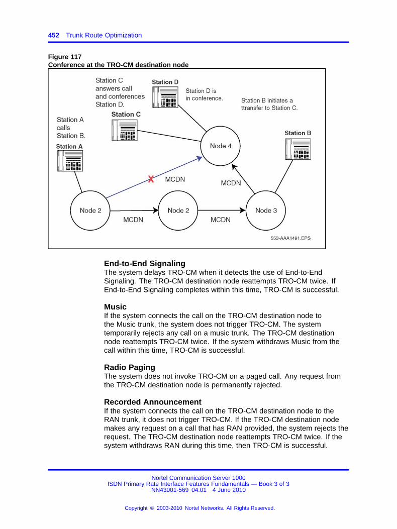
452 Trunk Route Optimization
Figure 117Conference at the TRO-CM destination node
End-to-End SignalingThe system delays TRO-CM when it detects the use of End-to-EndSignaling. The TRO-CM destination node reattempts TRO-CM twice. IfEnd-to-End Signaling completes within this time, TRO-CM is successful.
MusicIf the system connects the call on the TRO-CM destination node tothe Music trunk, the system does not trigger TRO-CM. The systemtemporarily rejects any call on a music trunk. The TRO-CM destinationnode reattempts TRO-CM twice. If the system withdraws Music from thecall within this time, TRO-CM is successful.
Radio PagingThe system does not invoke TRO-CM on a paged call. Any request fromthe TRO-CM destination node is permanently rejected.
Recorded AnnouncementIf the system connects the call on the TRO-CM destination node to theRAN trunk, it does not trigger TRO-CM. If the TRO-CM destination nodemakes any request on a call that has RAN provided, the system rejects therequest. The TRO-CM destination node reattempts TRO-CM twice. If thesystem withdraws RAN during this time, then TRO-CM is successful.
Nortel Communication Server 1000ISDN Primary Rate Interface Features Fundamentals — Book 3 of 3
NN43001-569 04.01 4 June 2010
Copyright © 2003-2010 Nortel Networks. All Rights Reserved.
.

Feature packaging 453
Feature packagingThe TRO-BA and TRO-CM features require Advanced Network Services(NTWK) package 148.
The Trunk Anti-Tromboning feature requires the following packages:
• Integrated Services Digital Network (ISDN) package 145
• Primary Rate Access (PRA) package 146 or Integrated Service DigitalNetwork Signaling Link (ISL) package 147 or 2.0 Mbit Primary RateInterface (PRI2) package 154 and optionally
• Advanced ISDN Network Services (NTWK) package 148
• Multi-purpose Serial Data Link (MSDL) package 222
• Trunk Anti-Tromboning (TATO) package 312
Example of TRO-BA in operation when ARDN = YES or NO shows anexample of TRO-BA in operation when the ARDN feature is set to YES orNO.
Figure 118Example of TRO-BA in operation when ARDN = YES or NO
Figure 118 "Example of TRO-BA in operation when ARDN = YES or NO"(page 453)illustrates the following:
• User A calls User D.
• User D sets Call Forward No Answer (CFNA) to User B.
• User B CFW to User C.
Nortel Communication Server 1000ISDN Primary Rate Interface Features Fundamentals — Book 3 of 3
NN43001-569 04.01 4 June 2010
Copyright © 2003-2010 Nortel Networks. All Rights Reserved.
.
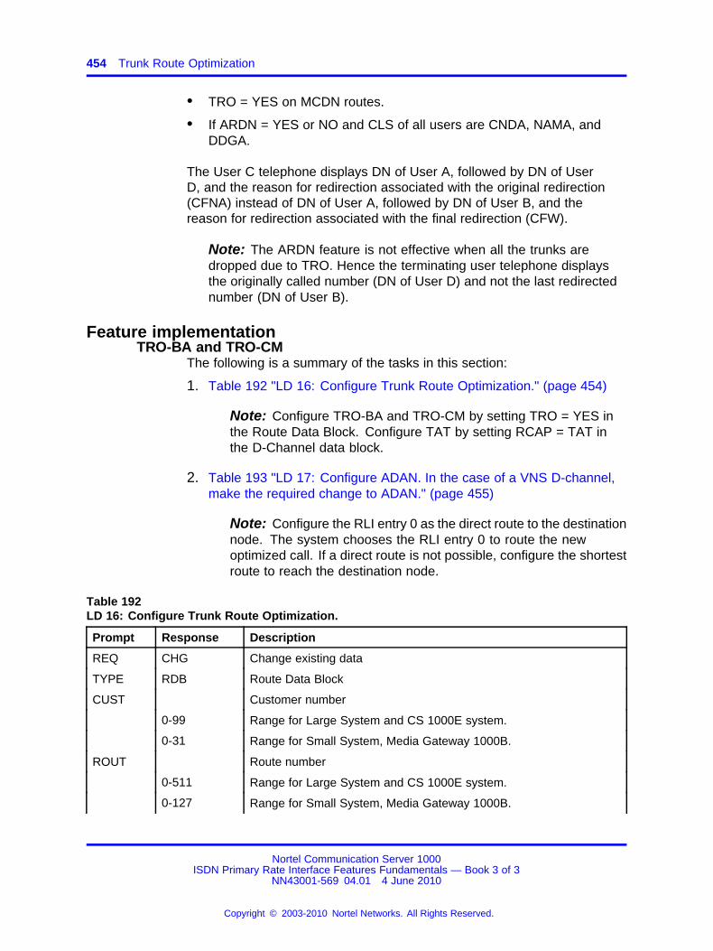
454 Trunk Route Optimization
• TRO = YES on MCDN routes.
• If ARDN = YES or NO and CLS of all users are CNDA, NAMA, andDDGA.
The User C telephone displays DN of User A, followed by DN of UserD, and the reason for redirection associated with the original redirection(CFNA) instead of DN of User A, followed by DN of User B, and thereason for redirection associated with the final redirection (CFW).
Note: The ARDN feature is not effective when all the trunks aredropped due to TRO. Hence the terminating user telephone displaysthe originally called number (DN of User D) and not the last redirectednumber (DN of User B).
Feature implementationTRO-BA and TRO-CM
The following is a summary of the tasks in this section:
1. Table 192 "LD 16: Configure Trunk Route Optimization." (page 454)
Note: Configure TRO-BA and TRO-CM by setting TRO = YES inthe Route Data Block. Configure TAT by setting RCAP = TAT inthe D-Channel data block.
2. Table 193 "LD 17: Configure ADAN. In the case of a VNS D-channel,make the required change to ADAN." (page 455)
Note: Configure the RLI entry 0 as the direct route to the destinationnode. The system chooses the RLI entry 0 to route the newoptimized call. If a direct route is not possible, configure the shortestroute to reach the destination node.
Table 192LD 16: Configure Trunk Route Optimization.
Prompt Response Description
REQ CHG Change existing data
TYPE RDB Route Data Block
CUST Customer number
0-99 Range for Large System and CS 1000E system.
0-31 Range for Small System, Media Gateway 1000B.
ROUT Route number
0-511 Range for Large System and CS 1000E system.
0-127 Range for Small System, Media Gateway 1000B.
Nortel Communication Server 1000ISDN Primary Rate Interface Features Fundamentals — Book 3 of 3
NN43001-569 04.01 4 June 2010
Copyright © 2003-2010 Nortel Networks. All Rights Reserved.
.
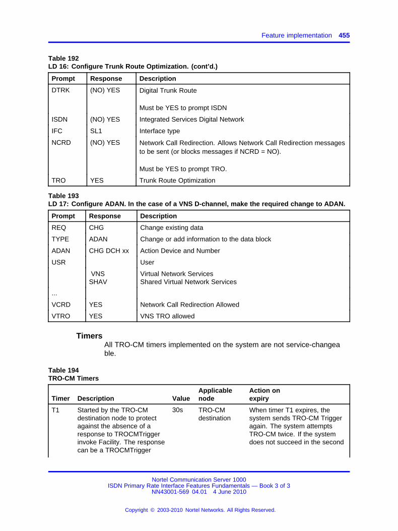
Feature implementation 455
Table 192LD 16: Configure Trunk Route Optimization. (cont’d.)
Prompt Response Description
DTRK (NO) YES Digital Trunk Route
Must be YES to prompt ISDN
ISDN (NO) YES Integrated Services Digital Network
IFC SL1 Interface type
NCRD (NO) YES Network Call Redirection. Allows Network Call Redirection messagesto be sent (or blocks messages if NCRD = NO).
Must be YES to prompt TRO.
TRO YES Trunk Route Optimization
Table 193LD 17: Configure ADAN. In the case of a VNS D-channel, make the required change to ADAN.
Prompt Response Description
REQ CHG Change existing data
TYPE ADAN Change or add information to the data block
ADAN CHG DCH xx Action Device and Number
USR User
VNSSHAV
Virtual Network ServicesShared Virtual Network Services
...
VCRD YES Network Call Redirection Allowed
VTRO YES VNS TRO allowed
TimersAll TRO-CM timers implemented on the system are not service-changeable.
Table 194TRO-CM Timers
Timer Description ValueApplicablenode
Action onexpiry
T1 Started by the TRO-CMdestination node to protectagainst the absence of aresponse to TROCMTriggerinvoke Facility. The responsecan be a TROCMTrigger
30s TRO-CMdestination
When timer T1 expires, thesystem sends TRO-CM Triggeragain. The system attemptsTRO-CM twice. If the systemdoes not succeed in the second
Nortel Communication Server 1000ISDN Primary Rate Interface Features Fundamentals — Book 3 of 3
NN43001-569 04.01 4 June 2010
Copyright © 2003-2010 Nortel Networks. All Rights Reserved.
.

456 Trunk Route Optimization
Timer Description ValueApplicablenode
Action onexpiry
return error IE or aTROCMSetup invoke IE.
attempt, all TRO-CM operationsare cancelled.
T2 Started by the TRO-CMdestination node to protectagainst failure to release theold connection.
20s TRO-CMdestination
The TRO-CM destination nodedisconnects the new connectionon expiry.
TAT
Table 195LD 17: Configure TAT functionality on the D-channel.
Prompt Response Description
REQ CHG Change existing data.
TYPE ADAN Action Device and Number.
- ADAN
NEW DCH xCHG DCH x
Add D-channel x.Change D-channel x.
- CTYP Card type.
MSDL Multi-purpose Serial Data Link. (For Large Systems)Downloadable D-channel (For Small Systems).
- CDNO 1-10 The Card number for the Downloadable D-channel. (For SmallSystemsonly)
- PORT 0-31
Port number on MSDL cards. (For Large Systems) Port number(For the Small Systems).
...
- IFC SL1S100D100D250
Interface type for D-channel.
...
- RLS xx Release ID of the switch at the far end of the D-channel.
- RCAP TAT Remote Capabilities.TAT must be entered to enable Trunk Anti-Tromboning.
Feature operationNo specific operating procedures are required to use this feature.
Nortel Communication Server 1000ISDN Primary Rate Interface Features Fundamentals — Book 3 of 3
NN43001-569 04.01 4 June 2010
Copyright © 2003-2010 Nortel Networks. All Rights Reserved.
.
457.
Trunk to Trunk ConnectionThe Trunk to Trunk Connection feature introduces the followingcapabilities:
• transfer on ringing of external trunks across the network
• transfer of one supervised outgoing external trunk to another
• conference of external trunks
• outgoing trunk to trunk charging
These capabilities are available on an analog (500/2500-type) phone,Meridian 1 Proprietary Phone, or an Attendant Console.
Refer to Features and Services Fundamentals (NN43001-106) forcomplete information.
Nortel Communication Server 1000ISDN Primary Rate Interface Features Fundamentals — Book 3 of 3
NN43001-569 04.01 4 June 2010
Copyright © 2003-2010 Nortel Networks. All Rights Reserved.
.

458 Trunk to Trunk Connection
Nortel Communication Server 1000ISDN Primary Rate Interface Features Fundamentals — Book 3 of 3
NN43001-569 04.01 4 June 2010
Copyright © 2003-2010 Nortel Networks. All Rights Reserved.
.

459.
UIPE D-channel Monitoring ToolEnhancement
ContentsThis section contains information on the following topics:
“Feature description” (page 459)
“Feature interactions” (page 463)
“Operating parameters” (page 463)
“Feature packaging” (page 463)
“Feature implementation” (page 463)
“Feature operation” (page 467)
Feature descriptionThe UIPE D-Channel Monitoring Tool Enhancement enables the Q.931message monitoring to support the decoded message format. Forenabled messages, it supports channel-based, message-based, and SETTN-based filtering.
The UIPE D-Channel Monitoring Enhancement modifies the monitor outputso the debug option prints in three formats. It also removes the existingpassword protection for the Q.931 monitor.
If the monitor is enabled and the number of Call Registers in the idlequeue drops below 10%, message monitoring is suspended. If the monitoris enabled and the number of idle call registers exceeds 10%, messageprinting starts again. For UIPE messages, the UIPE D-Channel MonitoringTool Enhancement includes a real-time clock stamp on all messagesprinted on the terminal.
LD 96 introduces commands to support message filtering based on theISDN TNs and the message type for Q.931 messages.
Nortel Communication Server 1000ISDN Primary Rate Interface Features Fundamentals — Book 3 of 3
NN43001-569 04.01 4 June 2010
Copyright © 2003-2010 Nortel Networks. All Rights Reserved.
.
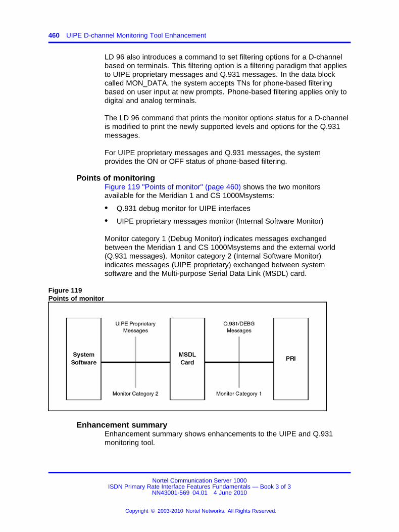
460 UIPE D-channel Monitoring Tool Enhancement
LD 96 also introduces a command to set filtering options for a D-channelbased on terminals. This filtering option is a filtering paradigm that appliesto UIPE proprietary messages and Q.931 messages. In the data blockcalled MON_DATA, the system accepts TNs for phone-based filteringbased on user input at new prompts. Phone-based filtering applies only todigital and analog terminals.
The LD 96 command that prints the monitor options status for a D-channelis modified to print the newly supported levels and options for the Q.931messages.
For UIPE proprietary messages and Q.931 messages, the systemprovides the ON or OFF status of phone-based filtering.
Points of monitoringFigure 119 "Points of monitor" (page 460) shows the two monitorsavailable for the Meridian 1 and CS 1000Msystems:
• Q.931 debug monitor for UIPE interfaces
• UIPE proprietary messages monitor (Internal Software Monitor)
Monitor category 1 (Debug Monitor) indicates messages exchangedbetween the Meridian 1 and CS 1000Msystems and the external world(Q.931 messages). Monitor category 2 (Internal Software Monitor)indicates messages (UIPE proprietary) exchanged between systemsoftware and the Multi-purpose Serial Data Link (MSDL) card.
Figure 119Points of monitor
Enhancement summaryEnhancement summary shows enhancements to the UIPE and Q.931monitoring tool.
Nortel Communication Server 1000ISDN Primary Rate Interface Features Fundamentals — Book 3 of 3
NN43001-569 04.01 4 June 2010
Copyright © 2003-2010 Nortel Networks. All Rights Reserved.
.
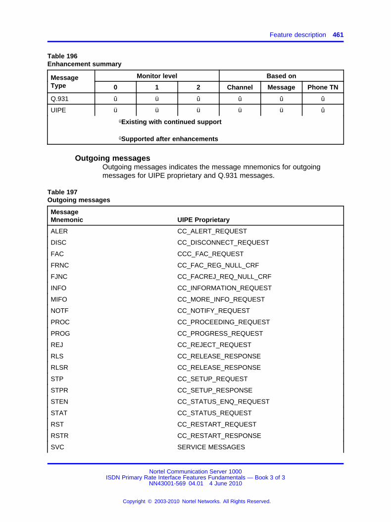
Feature description 461
Table 196Enhancement summary
Monitor level Based onMessageType 0 1 2 Channel Message Phone TN
Q.931 û ü û û û û
UIPE ü ü ü ü ü û
üExisting with continued support
ûSupported after enhancements
Outgoing messagesOutgoing messages indicates the message mnemonics for outgoingmessages for UIPE proprietary and Q.931 messages.
Table 197Outgoing messages
MessageMnemonic UIPE Proprietary
ALER CC_ALERT_REQUEST
DISC CC_DISCONNECT_REQUEST
FAC CCC_FAC_REQUEST
FRNC CC_FAC_REG_NULL_CRF
FJNC CC_FACREJ_REQ_NULL_CRF
INFO CC_INFORMATION_REQUEST
MIFO CC_MORE_INFO_REQUEST
NOTF CC_NOTIFY_REQUEST
PROC CC_PROCEEDING_REQUEST
PROG CC_PROGRESS_REQUEST
REJ CC_REJECT_REQUEST
RLS CC_RELEASE_RESPONSE
RLSR CC_RELEASE_RESPONSE
STP CC_SETUP_REQUEST
STPR CC_SETUP_RESPONSE
STEN CC_STATUS_ENQ_REQUEST
STAT CC_STATUS_REQUEST
RST CC_RESTART_REQUEST
RSTR CC_RESTART_RESPONSE
SVC SERVICE MESSAGES
Nortel Communication Server 1000ISDN Primary Rate Interface Features Fundamentals — Book 3 of 3
NN43001-569 04.01 4 June 2010
Copyright © 2003-2010 Nortel Networks. All Rights Reserved.
.

462 UIPE D-channel Monitoring Tool Enhancement
Table 197Outgoing messages (cont’d.)
MessageMnemonic UIPE Proprietary
SVCR SERVICE RESPONSE
RSTJ CC_RESTART_REJECT
Incoming messagesIncoming messages indicates the message mnemonics for incomingmessages for UIPE proprietary and Q.931 messages.
Table 198Incoming messages
MessageMnemonic UIPE Proprietary Q.931 Messages
Support onQ.931
ALER CC_ALERT_INDICATION ALERTING ü
DISC CC_DISCONNECT_INDICATION DISCONNECT ü
FAC CCC_FAC_INDICATION FACILITY ü
FIDC CC_FAC_IND_NULL_CRF FACILITY ü
FJDC CC_FACREJ_IND_NULL_CRF FACILITY REJECT ü
INFO CC_INFORMATION_INDICATION INFORMATION ü
MIFO CC_MORE_INFO_INDICATION SETUP ACK ü
NOTF CC_NOTIFY_INDICATION NOTIFY ü
PROC CC_PROCEEDING_INDICATION CALL PROCEEDING ü
PROG CC_PROGRESS_INDICATION PROGRESS ü
RLSC CC_RELEASE_CONFIRMATION RELEASE COMPLETE X
RLS CC_RELEASE_INDICATION RELEASE ü
REJ CC_REJECT_INDICATION RELEASE COMPLETE ü
STP CC_SETUP_INDICATION SETUP ü
STPC CC_SETUP_CONFIRMATION CONNECT ü
STEN CC_STATUS_ENQ_INDICATION STATUS ENQUIRY ü
STAT CC_STATUS_INDICATION STATUS ü
RST CC_RESTART_INDICATION RESTART X
RSTC CC_RESTART_CONFIRMATION RESTART ACK X
SVC SERVICE MESSAGES SERVICE ü
SVCR SERVICE RESPONSE SERVICE RESPONSE ü
Nortel Communication Server 1000ISDN Primary Rate Interface Features Fundamentals — Book 3 of 3
NN43001-569 04.01 4 June 2010
Copyright © 2003-2010 Nortel Networks. All Rights Reserved.
.

Feature implementation 463
Operating parametersUIPE D-channel Monitoring Tool Enhancement is not applicable for BRI,because the debug option is not supported for BRI.
For phone-based monitoring, attendant consoles and ISDN terminals arenot supported.
For phone-based filtering of messages, incoming calls to a phone are notsupported.
For channel-based monitoring, the messages that do not have channel IDIE or call reference in the call reference table are not supported. This isalso applicable for phone-based monitoring.
Note: Messages that do not have channel ID IE or valid call referencesin the call reference table always have the channel number printed asNCAL in the message header.
Feature interactionsThere are no feature interactions associated with this feature.
Feature packagingThis feature requires the following packages:
• Integrated Services Digital Network (ISDN) package 145
• Primary Rate Access (PRA) package 146
• International Primary Rate Access (IPRA) package 154
• Multi-purpose Serial Data Link (MSDL) package 222
The UIPE D-Channel Monitoring Tool Enhancement does not introducea software package.
Feature implementationTask summary list
The following is a summary of the tasks in this section:
1. LD 15 - Enter the TNs of the phones to be monitored (Set-BasedMonitoring).
2. LD 96 - Enable or disable the monitor.
3. LD 96 - Query the status of the monitor and the filtering options.
4. LD 96 - Set monitor level.
Nortel Communication Server 1000ISDN Primary Rate Interface Features Fundamentals — Book 3 of 3
NN43001-569 04.01 4 June 2010
Copyright © 2003-2010 Nortel Networks. All Rights Reserved.
.
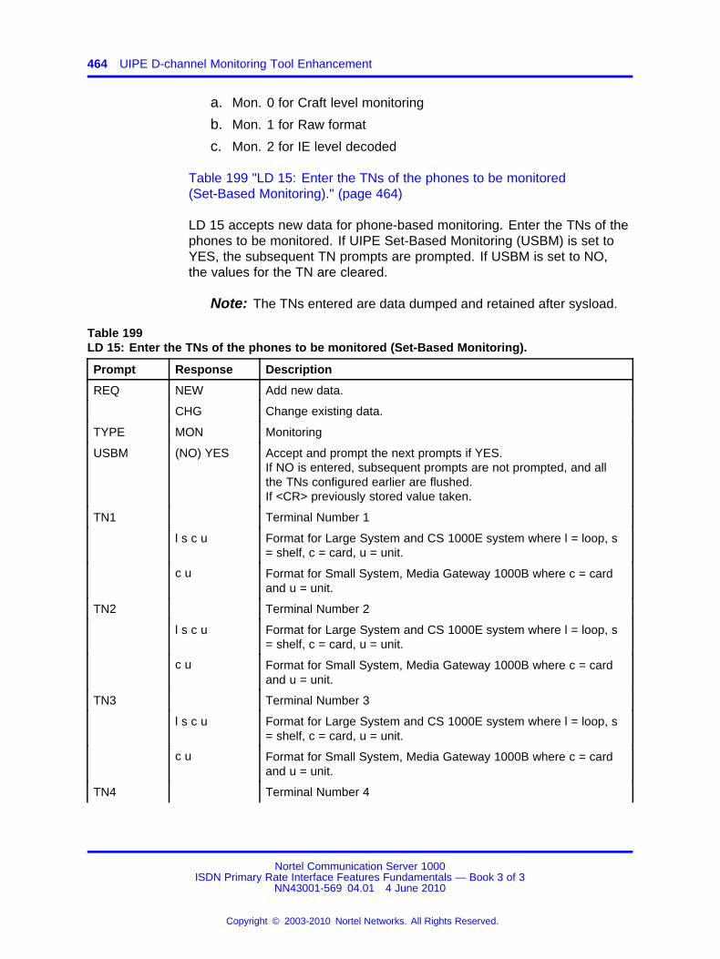
464 UIPE D-channel Monitoring Tool Enhancement
a. Mon. 0 for Craft level monitoring
b. Mon. 1 for Raw format
c. Mon. 2 for IE level decoded
Table 199 "LD 15: Enter the TNs of the phones to be monitored(Set-Based Monitoring)." (page 464)
LD 15 accepts new data for phone-based monitoring. Enter the TNs of thephones to be monitored. If UIPE Set-Based Monitoring (USBM) is set toYES, the subsequent TN prompts are prompted. If USBM is set to NO,the values for the TN are cleared.
Note: The TNs entered are data dumped and retained after sysload.
Table 199LD 15: Enter the TNs of the phones to be monitored (Set-Based Monitoring).
Prompt Response Description
REQ NEW Add new data.
CHG Change existing data.
TYPE MON Monitoring
USBM (NO) YES Accept and prompt the next prompts if YES.If NO is entered, subsequent prompts are not prompted, and allthe TNs configured earlier are flushed.If <CR> previously stored value taken.
TN1 Terminal Number 1
l s c u Format for Large System and CS 1000E system where l = loop, s= shelf, c = card, u = unit.
c u Format for Small System, Media Gateway 1000B where c = cardand u = unit.
TN2 Terminal Number 2
l s c u Format for Large System and CS 1000E system where l = loop, s= shelf, c = card, u = unit.
c u Format for Small System, Media Gateway 1000B where c = cardand u = unit.
TN3 Terminal Number 3
l s c u Format for Large System and CS 1000E system where l = loop, s= shelf, c = card, u = unit.
c u Format for Small System, Media Gateway 1000B where c = cardand u = unit.
TN4 Terminal Number 4
Nortel Communication Server 1000ISDN Primary Rate Interface Features Fundamentals — Book 3 of 3
NN43001-569 04.01 4 June 2010
Copyright © 2003-2010 Nortel Networks. All Rights Reserved.
.
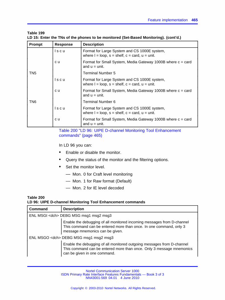
Feature implementation 465
Table 199LD 15: Enter the TNs of the phones to be monitored (Set-Based Monitoring). (cont’d.)
Prompt Response Description
l s c u Format for Large System and CS 1000E system,where l = loop, s = shelf, c = card, u = unit.
c u Format for Small System, Media Gateway 1000B where c = cardand u = unit.
TN5 Terminal Number 5
l s c u Format for Large System and CS 1000E system,where l = loop, s = shelf, c = card, u = unit.
c u Format for Small System, Media Gateway 1000B where c = cardand u = unit.
TN6 Terminal Number 6
l s c u Format for Large System and CS 1000E system,where l = loop, s = shelf, c = card, u = unit.
c u Format for Small System, Media Gateway 1000B where c = cardand u = unit.
Table 200 "LD 96: UIPE D-channel Monitoring Tool Enhancementcommands" (page 465)
In LD 96 you can:
• Enable or disable the monitor.
• Query the status of the monitor and the filtering options.
• Set the monitor level.
— Mon. 0 for Craft level monitoring
— Mon. 1 for Raw format (Default)
— Mon. 2 for IE level decoded
Table 200LD 96: UIPE D-channel Monitoring Tool Enhancement commands
Command Description
ENL MSGI <dch> DEBG MSG msg1 msg2 msg3
Enable the debugging of all monitored incoming messages from D-channelThis command can be entered more than once. In one command, only 3message mnemonics can be given.
ENL MSGO <dch> DEBG MSG msg1 msg2 msg3
Enable the debugging of all monitored outgoing messages from D-channelThis command can be entered more than once. Only 3 message mnemonicscan be given in one command.
Nortel Communication Server 1000ISDN Primary Rate Interface Features Fundamentals — Book 3 of 3
NN43001-569 04.01 4 June 2010
Copyright © 2003-2010 Nortel Networks. All Rights Reserved.
.
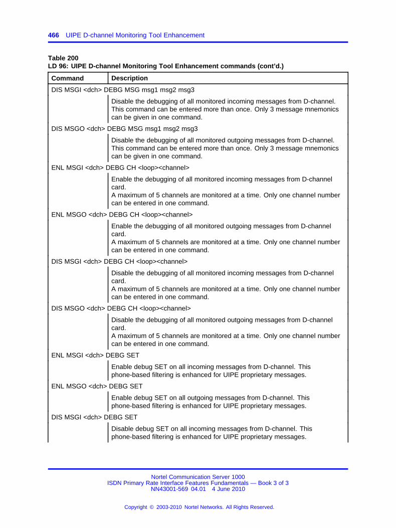
466 UIPE D-channel Monitoring Tool Enhancement
Table 200LD 96: UIPE D-channel Monitoring Tool Enhancement commands (cont’d.)
Command Description
DIS MSGI <dch> DEBG MSG msg1 msg2 msg3
Disable the debugging of all monitored incoming messages from D-channel.This command can be entered more than once. Only 3 message mnemonicscan be given in one command.
DIS MSGO <dch> DEBG MSG msg1 msg2 msg3
Disable the debugging of all monitored outgoing messages from D-channel.This command can be entered more than once. Only 3 message mnemonicscan be given in one command.
ENL MSGI <dch> DEBG CH <loop><channel>
Enable the debugging of all monitored incoming messages from D-channelcard.A maximum of 5 channels are monitored at a time. Only one channel numbercan be entered in one command.
ENL MSGO <dch> DEBG CH <loop><channel>
Enable the debugging of all monitored outgoing messages from D-channelcard.A maximum of 5 channels are monitored at a time. Only one channel numbercan be entered in one command.
DIS MSGI <dch> DEBG CH <loop><channel>
Disable the debugging of all monitored incoming messages from D-channelcard.A maximum of 5 channels are monitored at a time. Only one channel numbercan be entered in one command.
DIS MSGO <dch> DEBG CH <loop><channel>
Disable the debugging of all monitored outgoing messages from D-channelcard.A maximum of 5 channels are monitored at a time. Only one channel numbercan be entered in one command.
ENL MSGI <dch> DEBG SET
Enable debug SET on all incoming messages from D-channel. Thisphone-based filtering is enhanced for UIPE proprietary messages.
ENL MSGO <dch> DEBG SET
Enable debug SET on all outgoing messages from D-channel. Thisphone-based filtering is enhanced for UIPE proprietary messages.
DIS MSGI <dch> DEBG SET
Disable debug SET on all incoming messages from D-channel. Thisphone-based filtering is enhanced for UIPE proprietary messages.
Nortel Communication Server 1000ISDN Primary Rate Interface Features Fundamentals — Book 3 of 3
NN43001-569 04.01 4 June 2010
Copyright © 2003-2010 Nortel Networks. All Rights Reserved.
.
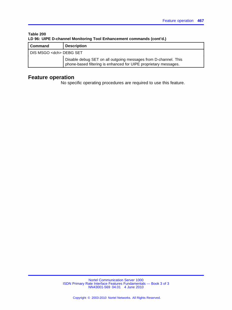
Feature operation 467
Table 200LD 96: UIPE D-channel Monitoring Tool Enhancement commands (cont’d.)
Command Description
DIS MSGO <dch> DEBG SET
Disable debug SET on all outgoing messages from D-channel. Thisphone-based filtering is enhanced for UIPE proprietary messages.
Feature operationNo specific operating procedures are required to use this feature.
Nortel Communication Server 1000ISDN Primary Rate Interface Features Fundamentals — Book 3 of 3
NN43001-569 04.01 4 June 2010
Copyright © 2003-2010 Nortel Networks. All Rights Reserved.
.

468 UIPE D-channel Monitoring Tool Enhancement
Nortel Communication Server 1000ISDN Primary Rate Interface Features Fundamentals — Book 3 of 3
NN43001-569 04.01 4 June 2010
Copyright © 2003-2010 Nortel Networks. All Rights Reserved.
.

469.
Virtual Network Services
ContentsThis section contains information on the following topics:
“Feature description” (page 469)
“Operating parameters” (page 475)
“Feature interactions” (page 481)
“Feature packaging” (page 491)
“Feature implementation” (page 491)
“Task summary list” (page 491)
“Feature operation” (page 497)
Feature descriptionThe Virtual Network Services (VNS) feature offers a means to useIntegrated Services Digital Network (ISDN) networking features whentwo systems are linked by a D-channel and an available Public SwitchedTelephone Network (PSTN) trunk exists. The PSTN trunks in thisconfiguration serve as the B-channel for the call’s duration.
VNS is an enhancement of the ISDN Signaling Link (ISL) interface. Theenhancement allows the voice and the signaling of a call to take differentphysical paths. In the case of an ISL call, the D-channel is used forsignaling, whereas the voice/data uses a TIE trunk (system to systemconnection only). The VNS feature extends the number of trunk typessupported for the voice path by including the possibility of using differentpublic trunks (for example, COT, DID, DOD).
Figure 120 "VNS Interface/ISL Interface Comparison" (page 470) depictsthe difference between two nodes linked by an ISL interface and twonodes linked using VNS.
Nortel Communication Server 1000ISDN Primary Rate Interface Features Fundamentals — Book 3 of 3
NN43001-569 04.01 4 June 2010
Copyright © 2003-2010 Nortel Networks. All Rights Reserved.
.
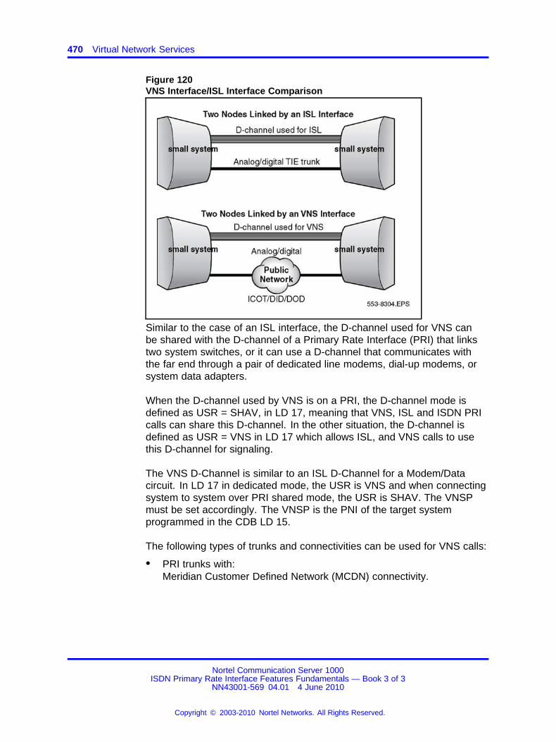
470 Virtual Network Services
Figure 120VNS Interface/ISL Interface Comparison
Similar to the case of an ISL interface, the D-channel used for VNS canbe shared with the D-channel of a Primary Rate Interface (PRI) that linkstwo system switches, or it can use a D-channel that communicates withthe far end through a pair of dedicated line modems, dial-up modems, orsystem data adapters.
When the D-channel used by VNS is on a PRI, the D-channel mode isdefined as USR = SHAV, in LD 17, meaning that VNS, ISL and ISDN PRIcalls can share this D-channel. In the other situation, the D-channel isdefined as USR = VNS in LD 17 which allows ISL, and VNS calls to usethis D-channel for signaling.
The VNS D-Channel is similar to an ISL D-Channel for a Modem/Datacircuit. In LD 17 in dedicated mode, the USR is VNS and when connectingsystem to system over PRI shared mode, the USR is SHAV. The VNSPmust be set accordingly. The VNSP is the PNI of the target systemprogrammed in the CDB LD 15.
The following types of trunks and connectivities can be used for VNS calls:
• PRI trunks with:Meridian Customer Defined Network (MCDN) connectivity.
Nortel Communication Server 1000ISDN Primary Rate Interface Features Fundamentals — Book 3 of 3
NN43001-569 04.01 4 June 2010
Copyright © 2003-2010 Nortel Networks. All Rights Reserved.
.
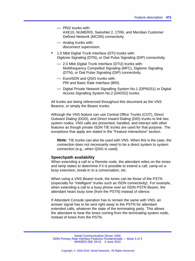
Feature description 471
— PRI2 trunks with:AXE10, NUMERIS, SwissNet 2, 1TR6, and Meridian CustomerDefined Network (MCDN) connectivity.
— Analog trunks with:disconnect supervision.
• 1.5 Mbit Digital Trunk Interface (DTI) trunks with:Digitone Signaling (DTN), or Dial Pulse Signaling (DIP) connectivity.
— 2.0 Mbit Digital Trunk Interface (DTI2) trunks with:Multifrequency Compelled Signaling (MFC), Digitone Signaling(DTN), or Dial Pulse Signaling (DIP) connectivity.
— EuroISDN and QSIG trunks with:PRI and Basic Rate Interface (BRI).
— Digital Private Network Signalling System No.1 (DPNSS1) or DigitalAccess Signalling System No.2 (DASS2) trunks.
All trunks are being referenced throughout this document as the VNSBearers, or simply the Bearer trunks.
Although the VNS feature can use Central Office Trunks (COT), DirectOutward Dialing (DOD), and Direct Inward Dialing (DID) trunks to link twosystem nodes, VNS calls are presented, handled, and interact with otherfeatures as though private ISDN TIE trunks are used for that purpose. Theexceptions that apply are stated in the "Feature interactions" section.
Note: TIE trunks can also be used with VNS. When this is the case, theconnection does not necessarily need to be a direct system to systemconnection (e.g., when QSIG is used).
Speechpath availabilityWhen extending a call to a Remote node, the attendant relies on the tonesand lamp states to determine if it is possible to extend a call, camp-on abusy extension, break-in to a conversation, etc.
When using a VNS Bearer trunk, the tones can be those of the PSTN(especially for "intelligent" trunks such as ISDN connectivity). For example,when extending a call to a busy phone over an ISDN PSTN Bearer, theattendant hears busy tone (from the PSTN) instead of silence.
If Attendant Console operation has to remain the same with VNS, ananswer signal has to be sent right away to the PSTN for attendantextended calls, whatever the state of the terminating party. This allowsthe attendant to hear the tones coming from the terminating system node,instead of tones from the PSTN.
Nortel Communication Server 1000ISDN Primary Rate Interface Features Fundamentals — Book 3 of 3
NN43001-569 04.01 4 June 2010
Copyright © 2003-2010 Nortel Networks. All Rights Reserved.
.

472 Virtual Network Services
The prompt VRAT exists for the incoming Bearer route (LD 16) to allow ordisallow automatic answering of attendant extended calls. The NetworkAttendant Service (NAS) feature must be configured to provide thisfunctionality.
When a route is configured with VRAT = YES, tones are similar to thoseprovided on a private ISDN PRI network; however, some unansweredcalls can be charged. If a route is configured with the default value (VRAT= NO), tones heard when extending a call from the attendant might bedifferent than the ones provided over a private ISDN network. Users arenot charged for unanswered calls.
PSTN clearing of unanswered callsIn some countries, a PSTN call left unanswered is disconnected after afew minutes, in order to reduce the usage of equipment that has not beenpaid for. This creates a major difference between private networks usingTIE lines and private networks using VNS. For example, with VNS a callleft in a camp-on state would be cleared by the public network after severalminutes.
The VNS Set Speechpath (VSS) timer of the incoming Bearer route (LD16) can be configured to avoid this situation. It defines the interval afterwhich an answer signal is sent from the terminating system node to thePublic Exchange/Central Office.
The configuration of the VSS timer has an impact on the cost of the calls,because the public network starts charging upon the reception of theanswer signal.
Numbering PlanA requirement of VNS is that customers have to configure VNS DNs(VDNs) as part of their numbering plan. The VNS VDN expansion featuresets a new limit on the number of VDNs at 4000. VDNs are configuredon LD 79.
The VDNs must be mapped onto the DID range of numbers for the PBXthey serve. Do not assign the VDN numbers to any station.
The VDNs are defined in sets of blocks. Each block can contain anynumber of contiguous VDNs, as long as the total number does not exceed4000. Within a block, it is possible to define a range of VDNs as well asindividual VDNs. For example, a customer can define the following VDNs(in this example, the customer is defining a total of 164 VDNs.)
Nortel Communication Server 1000ISDN Primary Rate Interface Features Fundamentals — Book 3 of 3
NN43001-569 04.01 4 June 2010
Copyright © 2003-2010 Nortel Networks. All Rights Reserved.
.

Feature description 473
7200-72997320-732573557400-74557676
A customer can remove a block of contiguous VDNs, as long as there isno VNS call using a VDN in the block. To remove a block of contiguousVDNs, the block has to be first disabled in LD 79 (by entering DIS againstthe REQ prompt), to prevent new VNS calls from using any of the VDNsin the block. Once the block has been disabled, the system administratorhas to wait until all the VNS calls, using any of the VDNs in the block, arecleared.
The system administrator can determine the number of VDNs usedby VNS calls, by printing VNS information using the PRT command inresponse to the REQ prompt in LD 79 (note that the block of VDNs mustbe first disabled.) Once all of the VDNs are free (unused), the block ofVDNs can be removed by using the OUT command.
An Electronic Switched Network (ESN) call is identified as being VNS oncea valid entry configured when the prompt VNS = YES has been found ina Route List Block (LD 86) used for the digits dialed. A SETUP messageis sent to the terminating node on the VNS D-channel. Manipulation of thedigits included in the SETUP message is performed, if needed, using thedigits dialed and according to the content of the Digit Manipulation Tablereferenced with the prompt VDMI.
In LD 86, the VDCH entry indicates the VNS D-channel used for callrouting. DMI indicates the Digit manipulation table index for VNSB-channel. VDMI indicates the digit manipulation table index for theD-channel. Usually, the DMI table inserts 1+NPA/NXX of the target switchand is usually the only DMI needed. The system automatically inserts theVDN returned from the target system.
On reception of the SETUP request, the terminating node sends one of itsVirtual DNs back to the originating node. The terminating node expectsto receive a call for that Directory Number (VDN) from one of its trunkslinked to the public network. The originating node, upon reception of theVDN, seizes a trunk and dials a number consisting of the VNS VirtualDN affected by the manipulations defined in the Digit Manipulation Tablereferenced by the prompt DMI. These manipulations are performed inorder to dial the Virtual DN through the public network to the destinationnode.
Nortel Communication Server 1000ISDN Primary Rate Interface Features Fundamentals — Book 3 of 3
NN43001-569 04.01 4 June 2010
Copyright © 2003-2010 Nortel Networks. All Rights Reserved.
.
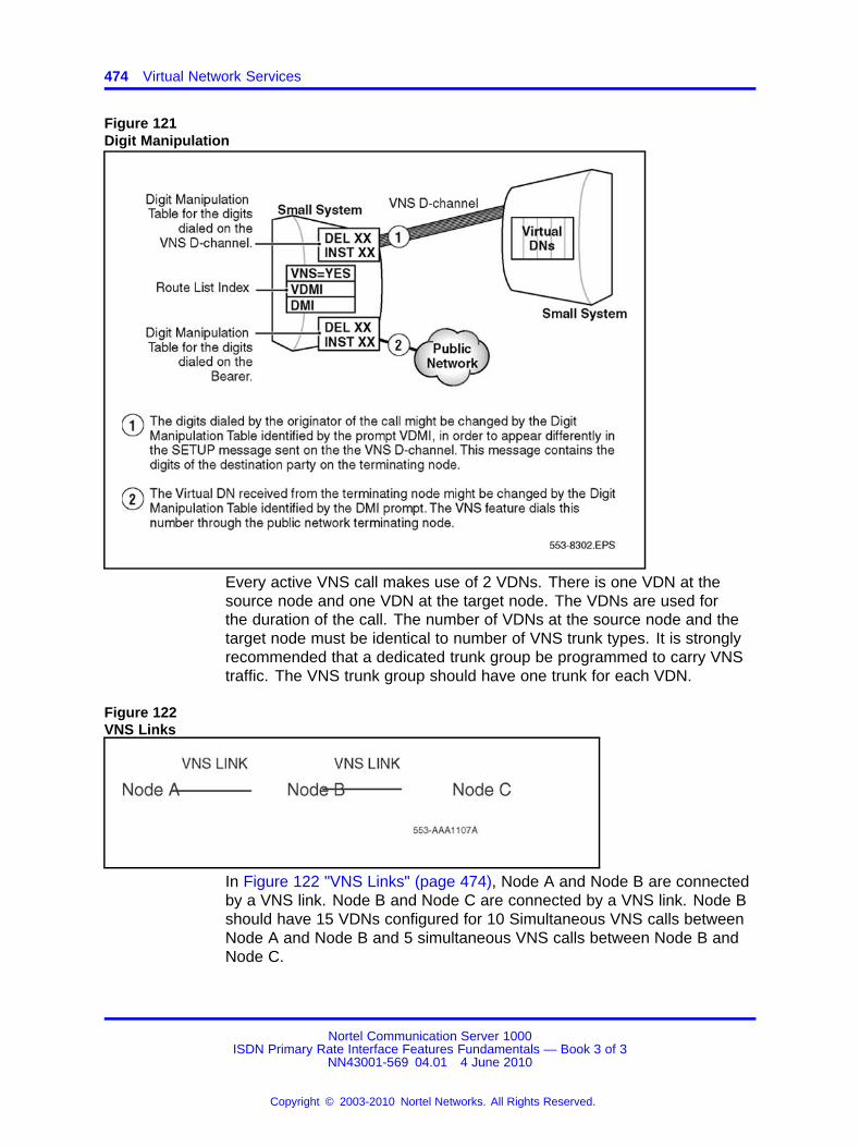
474 Virtual Network Services
Figure 121Digit Manipulation
Every active VNS call makes use of 2 VDNs. There is one VDN at thesource node and one VDN at the target node. The VDNs are used forthe duration of the call. The number of VDNs at the source node and thetarget node must be identical to number of VNS trunk types. It is stronglyrecommended that a dedicated trunk group be programmed to carry VNStraffic. The VNS trunk group should have one trunk for each VDN.
Figure 122VNS Links
In Figure 122 "VNS Links" (page 474), Node A and Node B are connectedby a VNS link. Node B and Node C are connected by a VNS link. Node Bshould have 15 VDNs configured for 10 Simultaneous VNS calls betweenNode A and Node B and 5 simultaneous VNS calls between Node B andNode C.
Nortel Communication Server 1000ISDN Primary Rate Interface Features Fundamentals — Book 3 of 3
NN43001-569 04.01 4 June 2010
Copyright © 2003-2010 Nortel Networks. All Rights Reserved.
.
Operating parameters 475
When using AUTH CODES at the CO level, the DMI in the RLB can insertthe AUTH CODE ahead of the public number. This configuration must benegotiated with the CO.
When programming network features in LD 15, such as NACD, the HLOCprogrammed in the target system’s NET DATA must match the dialed LOCat the source switch. The target switch can have more than one HLOCprogrammed, but the one in LD 15 is the only one used for network featureoperation. This HLOC is embedded in the facility messages that controlproprietary feature operation.
Failure of VNS D-channelIf the D-channel is not operable, the VNS route list entry is chosen, andthen this entry is bypassed. In a network VNS environment, calls willremain queued at the source node.
If the VNS D-channel fails when a call is established, the call remainsestablished. This is, however, without the ability to use the networkingfeatures normally supported by the VNS feature.
Failure of BearerFailure of the VNS Bearer trunk results in the VNS call being cleared.
Operating parametersVNS requires a contiguous block of existing unused DNs (virtual DNs) atboth the originating and the terminating nodes, which are a subset of theDID range of the customer. VNS virtual DNs can be up to seven digitslong. A maximum of 100 virtual DNs can be assigned for each customer.
VNS D-channelVNS requires an established D-channel between the originating andterminating nodes for signaling. No intermediate nodes are permitted.
A VNS D-channel belongs to only one customer and cannot be sharedby other customers for VNS calls.
VNS does not support Backup D-channels for VNS signaling.
D-channels provided by Basic Rate Interface (BRI) are not supported asVNS D-channels.
VNS reverts back to conventional signaling if the VNS D-channel fails.
VNS Bearer TrunksDisconnect supervision is mandatory for all trunks, while answersupervision is not. In cases when it is not available, VNS will assume thatthe Bearer is answered as soon as the "end-of-dialing" timer has expired.
Nortel Communication Server 1000ISDN Primary Rate Interface Features Fundamentals — Book 3 of 3
NN43001-569 04.01 4 June 2010
Copyright © 2003-2010 Nortel Networks. All Rights Reserved.
.
476 Virtual Network Services
The following trunks are not supported as VNS Bearer trunks:
• Autoterminate trunks;
• Analog Private Networking Signalling System (APNSS); and
• Basic Rate Interface trunks (used for NUMERIS, 1TR6 or MCDN).
The following signaling systems are not supported for VNS:
• Japan D70; and
• Multifrequency Extended Signaling for Socotel (MFE).
Any Incoming Digit Conversion on the incoming VNS Bearer trunk causesa VNS call to fail.
Data calls are supported only if the Bearer supports data calls.
Maximum number of VNS callsDifferent elements control the maximum number of simultaneous VNScalls that can be processed by a system. The number depends on theresources allocated for the VNS feature itself, the resources to be usedfor the voice path (Bearer trunks) and the resources available for VNSsignaling over the D-channel.
For each customerIt is not possible to perform more VNS calls (incoming and outgoing) thanthe number of Virtual DNs defined for the customer in LD 79.
The number of VNS calls is limited by the number of available Bearertrunks. When all Bearers defined to be usable with VNS are busy, no otherVNS calls can be made.
For each D-channel of the customerThe maximum number of VNS calls allowed to use a D-channel is limitedby the value defined to the D-channel by the VNSM prompt in LD 17.
For each entry in a Route List BlockThe maximum number of VNS calls that can be performed on a routelisted in an entry of a Route List Block in LD 86 is limited by the valueentered in response to the VTRK prompt.
On a network levelIn the case of a non-symmetrical configuration between originating andterminating VNS nodes, the call limitation imposed by the more restrictivenode applies.
Nortel Communication Server 1000ISDN Primary Rate Interface Features Fundamentals — Book 3 of 3
NN43001-569 04.01 4 June 2010
Copyright © 2003-2010 Nortel Networks. All Rights Reserved.
.

Operating parameters 477
Figure 123VNS Call Limitations
Troubleshooting failed VNS calls and useful tipsVNS uses PSTN facilities to provide "tie trunk-like connectivity". Only thesource system can determine the availability of an outgoing DOD/COTtrunk member. The status of the incoming DID trunk at the target systemis not known until the call is attempted. VNS attempts to complete the callregardless of All Trunks Busy for the DID trunk group at the Target node.VNS considers the non availability of the trunks as bearer failure. Thesystem outputs an error ERR5428 at the source node. ERR5428 indicatesa Failure on a bearer trunk used by VNS.
VNS can generate more than one error message for a single VNS callfailure. An on-site technician interprets this as a serious issue, but it is theexpected behavior of the feature. On-site technicians need to analyzethese messages to take appropriate action. The bearer failure could bedue to network blockage or an insufficient number of VDNs. If there aremultiple call failures, multiple bug messages are generated, which canhamper the normal TTY operation, which results in an INI.
The most common errors generated are the following:
• ERR5428 (refers to BEARER FAILURE)
• BUG5180 (refers to VNS call processing GENERAL ERRORMESSAGE)
• BUG5182 (refers to NO VNS DN FOUND corresponding to therequest)
Nortel Communication Server 1000ISDN Primary Rate Interface Features Fundamentals — Book 3 of 3
NN43001-569 04.01 4 June 2010
Copyright © 2003-2010 Nortel Networks. All Rights Reserved.
.
478 Virtual Network Services
The only alternative to the multiple bug messages generated because ofmultiple call failures is to use LD 17 to XBUG. If further BUG and ERRmonitoring is required, configure a 9600 BD modem on the Core with USRBUG. Only configure TTY for BUG in these extreme situations.
While using VNS over NACD, ensure enough Call Registers are availableto buffer the messaging by doing the following:
• Use MON 0.
• Use pdt to determine the number of call registers used in the printqueue. pdt > sl1Qshow
• If needed, use LD 48 to flush the buffers.
When troubleshooting a VNS problem, the dialed number is the key.Extract the dialed number from the Bug. Perform a Ras Trace on the Bugto determine the call flow. ISA B-channels left in MBSY state, as a result ofVNS call failures, can generate pages of bugs.
Typical VNS bugsThe following are typical VNS bugs:
• Bug 5180: Wait while the Virtual Network Service (VNS) performssome call processing.
• Bug 5181: A nil pointer is found during Virtual Network Service (VNS)call processing.
• Bug 5182: There is a PRA call reference mismatch affecting the VNSIndex pointer. Run an audit.
Note: This bug is generated if a DID call is made to a VDN through amisdial from the public network. If the only output is many 5182 bugs,then a PRA call reference mismatch affecting the VNS Index pointer isthe probable cause.
Troubleshooting tips to isolate VNS related issuesMany issues can arise when installing VNS for the first time.
The following are tips to find the cause of VNS issues:
• Verify the ESN programming when using CDP/LOC. This ensures theproper RLB is used.
• Verify that the VPNIs on the VNS D-Channels match.
• Verify that the VDMI and DMI entries in the VNS RLB are correct.
Examples of problems encountered while installing a VNS Network:
Nortel Communication Server 1000ISDN Primary Rate Interface Features Fundamentals — Book 3 of 3
NN43001-569 04.01 4 June 2010
Copyright © 2003-2010 Nortel Networks. All Rights Reserved.
.

Operating parameters 479
• The customer is using NACD over VNS and the target queues do notopen even though agents are available.
This problem can be related to LOC HLOC mismatch. Check that theLOC of the dialed queue matches the HLOC defined in LD 15 of thetarget system.
• VNS calls do not complete during test scenarios.
The problem can be related to the DMI. Verify that the DMI andVDMI for the VNS RLB is correct. The VDMI should not require Digitmanipulation as long as the CDP/UDP dialed number can be translatedat the target system. The DMI is critical, because it determinesthe PSTN portion of the call. The DMI must point to an outgoingCOT/DOD/TIE RLB and includes everything except the VDN. Thesystem automatically inserts the VDN.
Example: The target DID number is 4167432888. 2888 is a VDN atthe target system. The DMI should, in this case, be 61416743 usingNARS/BARS. The system negotiates the insert of the 2888 as it is aVDN at the target switch.
Also, verify the target trunks. It is possible that the target trunks are notset up as DID in the CO. Customers can try to configure VNS, becausethey do not know that the CO needs to translate the VDNs to a validDID range at the target.
• Outgoing trunks require an auth code.
Some customers use outgoing toll trunks that require an auth code atthe CO level. This can be overcome by inserting the auth code aheadof the DMI in the VNS RLB. This must also be negotiated with the CO.
• NACD calls are terminating to an ACD Queue that is NCFW to an ACDQueue that uses NACD over VNS.
This scenario is not supported as the design intended.
Typical VNS errorVNS Errors, as a rule, do not provide much useful information when tryingto isolate a VNS issue. Extract the dialed number for the Err message todetermine the call scenario.
When troubleshooting VNS Errors, insist that access to both source andtarget systems is available, and that trained technicians are present in bothswitch rooms to make test calls.
Err5428: Failure on a bearer trunk used by VNS. This is a common VNSErr and is generated for a VNS call that does not complete to the targetsystem.
Nortel Communication Server 1000ISDN Primary Rate Interface Features Fundamentals — Book 3 of 3
NN43001-569 04.01 4 June 2010
Copyright © 2003-2010 Nortel Networks. All Rights Reserved.
.

480 Virtual Network Services
Typical call scenarios causing this error are:
• All Trunks Busy at the target node
• NACD call reject due to the expiration of the RAGT
• target agent rejecting the call by MSBY/LOGOUT
• blockage at the CO of the source system
This message is output at each system at the time of call failure. Thedialed number from the VNS D- channel can be output in reverse format.Use this to determine the source of the call.
To isolate an ERR5428 use the following procedure:
Step Action
1 Determine the called number from the ERR.
For example: ERR5428 52 00002348 0029C261 0000100500008018 00001E4C 00000000 19 00223979 002E1D39 00_000000 0 2090 00000084 0000A9A2 00000000 0000000000000000 00000000 00000000 000
In this case 2348 is the packed TN of the outgoing trunk, and the2090 is a target NACD Queue. Note that the A9A2 is in reverseformat and A = 0.
For example: ERR5428 3 00001D90 00274031 0000060700008318 00001F18 00001D90 0 00000000 00000000 0000_ 0000 0 2090 00000108 00002225 00003A34 0000000000000000 00000000 00000000 00000
In this case 1D90 is the packed TN of the outgoing trunk, and2090 is the source Queue and 52224303 is a UDP target NACDQueue.
Note: Not all ERR5428s indicate the dialed number, but it isa good start.
2 Determine the calling pattern with personnel familiar with thenetwork.
3 If the calling pattern can be established, use the D-Channelmonitor to associate the ERR5428 with a specific call.
4 If the switch is busy, use monitor 0 only.
5 Turn on the outgoing setup only at the source and the incomingonly at the target for the D-Channels associated with the publicpart of the call.
6 Use monitor 0 on the VNS D-Channel in the same manner.
Nortel Communication Server 1000ISDN Primary Rate Interface Features Fundamentals — Book 3 of 3
NN43001-569 04.01 4 June 2010
Copyright © 2003-2010 Nortel Networks. All Rights Reserved.
.

Feature interactions 481
This reveals all the call information at the time of the ERR5428without causing a real time load on the network.
7 Use the collected information to establish the root cause of theERR.
--End--
Some causes are due to programming errors, such as:
• ESN Errors
• CO blockage due to translations
• faulty facilities (for example:)
— bad analog trunks
— all trunks busy at the target system
— call rejections from ACD Agents
Feature interactionsIn LD 17, set NASA to "yes" for the MCDN supplementary features to workacross the DCH.
The following features are supported over VNS routes:
• Attendant Barge-In
• Attendant Break-In
• Attendant Recall with Splitting
• Basic Authorization Code
• Basic Rate Interface/Primary Rate Interface Interworking
• Calling Party Number
• Call Party Name Display
• Call Selection (ICI + loop)
• Console Digit Display
• Control of Trunk Group Access
• Digit Display
• Display of Calling Party Denied
• Electronic Lock Network Wide/Electronic Lock on Private Lines
• Network Attendant Service
• Network Call Redirection
Nortel Communication Server 1000ISDN Primary Rate Interface Features Fundamentals — Book 3 of 3
NN43001-569 04.01 4 June 2010
Copyright © 2003-2010 Nortel Networks. All Rights Reserved.
.
482 Virtual Network Services
• Network Class of Service
• Network Flexible Feature Codes
• Network Message Center
• Network Message Service to Meridian Mail
• Network Ring Again
• Network Ring Again No Answer
• Originator Routing Calls
• Radio Paging
• Trunk Route Optimization Before Answer
In addition, VNS has interactions with the following features:
Access RestrictionWhen a user has trunk access barred, for example, through Trunk GroupAccess Restriction (TGAR), New Flexible Call Restriction (NFCR), or TollDenied Class of Service), the user will still be able to make a VNS call.
If a customer wants users to be toll restricted even for VNS calls, theMinimum Facility Restriction Level (FRL) in the Route List Block (i.e., LD86) can be used.
Analog Private Networking Signalling System (APNSS)APNSS trunks cannot function as VNS Bearer trunks.
Attendant CallWhen an attendant extends a call over a VNS network, it is not possible torelease the call before the status of the destination is known. This appliesregardless of Network Attendant Service (NAS) configuration.
AutoterminateAutotermination on VNS Bearer trunks is not supported, because a VNSVirtual DN is expected on a VNS Bearer exactly the way it was passedback on the VNS D-channel.
Call Detail Recording (CDR)Call Detail Recording is supported on VNS routes with the exception ofthe 911 CDR Improvement and Meridian 911 ANI in CDR features. TheCDR output is controlled by the Bearer trunk (i.e., CDR output defines thedetails of the call made on the Bearer, and not the VNS D-channel). TheCalling Line Identity will be output in the CDR record for incoming calls.
Nortel Communication Server 1000ISDN Primary Rate Interface Features Fundamentals — Book 3 of 3
NN43001-569 04.01 4 June 2010
Copyright © 2003-2010 Nortel Networks. All Rights Reserved.
.
Feature interactions 483
Call Pickup Network- WideThe Call Pickup Network Wide feature will not work in conjunction with theVirtual Network Services feature.
Calling Line IdentificationCalling Line Identification is supported on VNS routes. All displayinformation is taken from messages on the VNS D-channel. The VNSBearer does not drive the display of such information.
Charge Display at End of CallIn the case of VNS calls, no charge information is displayed.
Data CallsData calls are supported on DPNSS1 or DASS2 VNS Bearer trunks if theDPNSS1 or DASS2 VNS Bearer trunks are configured to support datacalls. Similarly, data calls are supported on DPNSS1 or DASS2 Bearertrunks in VNS to DPNNS1/DASS2 gateways, if the DPNSS1 or DASS2VNS Bearer trunks are configured to support data calls.
Digital Trunk Interface (DTI) - Commonwealth of IndependentStates (CIS)Virtual Network Services through CIS DTI2 is not supported.
Direct Inward Dialing (DID) TreatmentSince VNS is handling calls as though they were made using ISDN TIEtrunks even when VNS DID Bearer trunks are used, the VNS feature doesnot adhere to the special treatment given to regular DID trunks.
Distinctive RingingExcept in the case of Network Distinctive Ringing, the Distinctive Ringingfeature is not supported by VNS. An incoming call using VNS on a Bearertrunk defined with the prompt DRNG = YES will ignore this value and willperform the same treatment as though the value was DRNG = NO (i.e., nodistinctive ringing provided).
DPNSS1 Attendant Call OfferDPNSS1 Attendant Call Offer is not supported over VNS Bearer trunks(DPNSS1 Attendant Call Offer allows an attendant-extended call, routedover a DPNSS1 trunk, to be camped-on to a remote busy extension.)Standard ISDN Camp-on can be provided instead, if NAS is configuredover the VNS Bearer trunks.
Nortel Communication Server 1000ISDN Primary Rate Interface Features Fundamentals — Book 3 of 3
NN43001-569 04.01 4 June 2010
Copyright © 2003-2010 Nortel Networks. All Rights Reserved.
.

484 Virtual Network Services
DPNSS1 Attendant Timed Reminder Recall and AttendantThree-Party ServiceDPNSS1 Attendant Timed Reminder Recall and Attendant Three-PartyService are not supported over VNS Bearer trunks. If NAS is configuredover the VNS Bearer trunks, NAS call extension and Attendant Recall willbe offered instead.
DPNSS1 Call Back When Free and Call Back When Next UsedDPNSS1 Call Back When Free and Call Back When Next Used are notsupported over VNS Bearer trunks. Network Ring Again or Network RingAgain on No Answer can be provided instead, if Network Ring Again orNetwork Ring Again on No Answer are configured over the VNS Bearertrunks.
DPNSS1 DiversionDPNSS1 Diversion is not supported over VNS Bearer trunks. NetworkCall Redirection and Trunk Route Optimization can be provided instead, ifconfigured over the VNS D-Channel.
DPNSS1 Extension Three-Party ServiceDPNSS1 Extension Three-Party Service is not supported over VNS Bearertrunks. Network Call Redirection and Trunk Route Optimization can beprovided instead, if configured over the VNS D-Channels.
DPNSS1 Loop AvoidanceDPNSS1 Loop Avoidance is not supported over VNS Bearer trunks(DPNSS1 Loop Avoidance prevents a call from being looped through aDPNSS1 network by placing a limit on the number of channels that acall can use.) The ISDN Call Connection Limitation is provided, if it isconfigured over the VNS D-Channel.
DPNSS1 Route OptimizationDPNSS1 Route Optimization is not supported over VNS Bearer trunks.
DPNSS1 Route Optimization/ISDN Trunk Anti-TromboningInterworkingISDN Trunk Anti-Tromboning can be applied to the VNS part of the call, ifconfigured on the VNS D-Channel.
DPNSS1 Route Optimisation/MCDN Trunk Anti-TromboningInterworkingThe Route Optimisation/Trunk Anti-Tromboning Interworking feature isnot supported over VNS trunks, since VNS uses only MCDN signaling.DPNSS1 is not supported.
Nortel Communication Server 1000ISDN Primary Rate Interface Features Fundamentals — Book 3 of 3
NN43001-569 04.01 4 June 2010
Copyright © 2003-2010 Nortel Networks. All Rights Reserved.
.
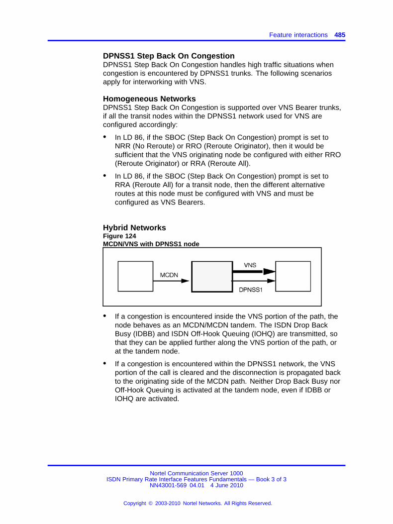
Feature interactions 485
DPNSS1 Step Back On CongestionDPNSS1 Step Back On Congestion handles high traffic situations whencongestion is encountered by DPNSS1 trunks. The following scenariosapply for interworking with VNS.
Homogeneous NetworksDPNSS1 Step Back On Congestion is supported over VNS Bearer trunks,if all the transit nodes within the DPNSS1 network used for VNS areconfigured accordingly:
• In LD 86, if the SBOC (Step Back On Congestion) prompt is set toNRR (No Reroute) or RRO (Reroute Originator), then it would besufficient that the VNS originating node be configured with either RRO(Reroute Originator) or RRA (Reroute All).
• In LD 86, if the SBOC (Step Back On Congestion) prompt is set toRRA (Reroute All) for a transit node, then the different alternativeroutes at this node must be configured with VNS and must beconfigured as VNS Bearers.
Hybrid NetworksFigure 124MCDN/VNS with DPNSS1 node
• If a congestion is encountered inside the VNS portion of the path, thenode behaves as an MCDN/MCDN tandem. The ISDN Drop BackBusy (IDBB) and ISDN Off-Hook Queuing (IOHQ) are transmitted, sothat they can be applied further along the VNS portion of the path, orat the tandem node.
• If a congestion is encountered within the DPNSS1 network, the VNSportion of the call is cleared and the disconnection is propagated backto the originating side of the MCDN path. Neither Drop Back Busy norOff-Hook Queuing is activated at the tandem node, even if IDBB orIOHQ are activated.
Nortel Communication Server 1000ISDN Primary Rate Interface Features Fundamentals — Book 3 of 3
NN43001-569 04.01 4 June 2010
Copyright © 2003-2010 Nortel Networks. All Rights Reserved.
.

486 Virtual Network Services
Figure 125VNS with DPNSS1/DPNSS1 node
This scenario is considered an MCDN/DPNSS1 gateway.
Figure 126DPNSS1/VNS with DPNSS1 node
• If a congestion is encountered inside the VNS portion of the path, theVNS portion of the call is cleared and the disconnection is propagatedback to the originating DPNSS1 side. The Step Back on Congestionfeature is invoked, if it is configured.
• If a congestion is encountered the within the DPNSS1 portion of thepath, with the DPNSS1 trunk being used as a VNS Bearer, the VNSportion of the call is cleared and a normal disconnection is propagatedback to the originating DPNSS1 side. The Step Back on Congestionfeature is not invoked, even if it is configured.
• Refer to Figure 127 "Network Attendant Service (NAS)" (page 487) forinformation on the interaction with NAS in a similar scenario.
DPNSS1 Executive IntrusionDPNSS1 Extension Three-Party Service is not supported over VNS Bearertrunks. Attendant Break-in can be provided instead, if NAS is configuredover the VNS Bearer trunks.
Nortel Communication Server 1000ISDN Primary Rate Interface Features Fundamentals — Book 3 of 3
NN43001-569 04.01 4 June 2010
Copyright © 2003-2010 Nortel Networks. All Rights Reserved.
.

Feature interactions 487
Figure 127Network Attendant Service (NAS)
• NAS calls being routed over the DPNSS1 network used as VNS Bearerwill get dropped if there is congestion in the bearer call setup. NASDBK (drop back) will not occur even if it is configured.
Stand-alone Meridian MailStand-alone Meridian Mail is not supported over VNS Bearer trunks. Amailbox user can access Meridian Mail, if the ISDN Network MessageServices is configured.
DPNSS1 Enhancements for ISDN InterworkingEnhancements allow DPNSS1 to interwork with QSIG and EuroISDN. Atan ISDN gateway, ISDN information can be carried into some DPNSS1messages, if DPNSS_189I package 284 is equipped.
DPNSS1/DASS2 to ISDN PRI GatewayA VNS call over a DPNSS1 or DASS2 Bearer trunk of an DPNSS1/DASS2to ISDN PRI Gateway acts as the ISDN leg of the Gateway.
Electronic Switched Network (ESN)The following ESN features are supported on VNS routes:
• ESN Basic Automatic Route Selection
• ESN Coordinated Dialing Plan Routing Enhancement
• ESN Coordinated Dialing Plan
• ESN (999 Loc.)
• ESN Flexible Numbering Plan
• ESN Free Calling Area Screening
• ESN Incoming Trunk Group Exclusion
• ESN Network Authorization Code
• ESN Network Automatic Route Selection
• ESN Network Routing Controls (Time-of-day Scheduling)
Nortel Communication Server 1000ISDN Primary Rate Interface Features Fundamentals — Book 3 of 3
NN43001-569 04.01 4 June 2010
Copyright © 2003-2010 Nortel Networks. All Rights Reserved.
.
488 Virtual Network Services
• ESN Network Speed Call
• ESN Tone Detection
• ESN Off-Hook Queuing
EuroISDN ContinuationA EuroISDN link can be used as a B-Channel for the Virtual NetworkServices feature.
EuroISDN Trunk - Network SideVirtual Network Services is supported on a EuroISDN Trunk - NetworkSide connectivity, meaning that a EuroISDN Trunk - Network Side trunkcan be used as a VNS bearer trunk.
Incoming Digit ConversionSince VNS Virtual DNs must be received on the incoming VNS Bearer(DID) trunks, as they are defined at the terminating node, the VNS featureis not supported for routes that perform digit conversion on the digits usedfor VNS Virtual DNs.
ISDN Call Connection Limitation (ICCL) ChecksThe VNS trunk from the external network looks exactly like an ISDN TIEtrunk and accordingly is subject to ICCL checks and call restrictionsapplied thereon.
ISDN PRI/BRI system to Asia Pacific ConnectivityIt is not possible to configure an Asia Pacific D-channel as a VNSD-channel. However, the voice connection through the Public Exchange ofa VNS call can use a PRI/BRI COT or DID as a virtual TIE trunk.
ISDN QSIG Basic CallA QSIG link can be used as a B-channel for the Virtual Network Service(VNS) over a private network. All VNS services are supported as normal.QSIG is only used as a speech bearer.
Intercept TreatmentIntercept treatment applied to VNS calls is configured as for TIE trunks.
Network ACDNetwork ACD (NACD) is supported by VNS. When a call queued at asource node receives notification that an agent is free and reserved at thetarget node, a VNS call is made to the target node. At that time, the callis removed from the queue at the source node. The call will continue toreceive ringback (or Recorded Announcement (RAN) if configured) whileit is waiting for the VNS call to be completed. When an alerting messageis received from the target node, the ringback or RAN is removed and
Nortel Communication Server 1000ISDN Primary Rate Interface Features Fundamentals — Book 3 of 3
NN43001-569 04.01 4 June 2010
Copyright © 2003-2010 Nortel Networks. All Rights Reserved.
.
Feature interactions 489
the speechpath with the Bearer is connected. The user will thus hearringback tone (given either by the PSTN or the system at the target node,depending on the Bearer type), until the agent answers the call.
If for some reason the ALERTING message is not received, the user isrequeued (at the top of the queue at the source node). Since ringbackor RAN were not removed in the first place, the user is unaware that anattempt to reach a remote agent has been made and has failed.
Since PSTN Bearer trunk call establishment can take longer than PRI2 TIEtrunk call establishment, it is necessary to allow more time for the call toarrive at the agent’s phone than provided by the regular NACD feature.The Agent Reservation Timer should be configured to accommodate alonger interval.
If an agent is reserved at the target node, but the call fails to reachthat node (e.g., all trunks are busy), the agent will stay reserved untilNACD Target Reservation Timer (RAGT) expires (the target node has noindication that the call has encountered a busy condition). This is morecritical when NACD is used with VNS, because (RAGT) must be set to agreater value.
NACD allows up to 20 remote target nodes to be defined in the routingtables. Since the maximum number of VNS Virtual DNs for each customeris 100, it is not realistic to configure 20 target nodes using VNS routing:this would only allow five Virtual DNs for each target node and thus amaximum of five simultaneous calls.
Set the RAGT to a minimum of 6, but ideally, it should be set to 12. Setthe CRQS and FCTH according to the D-Channel speed. Below 28800the settings should be a minimum. For example, 11 for CRQS and 10 forFCTH. For 28800 and greater, use 10 for FCTH and 20 for CRQS.
Note: These settings are critical for proper network operation.
Network Call Party Name DisplayNetwork Call Party Name Display is supported on VNS routes. All displayinformation is taken from messages on the VNS D-channel. The VNSBearer does not drive the display of such information.
Network Distinctive RingingFor an incoming DID call (without VNS) that tandems to another nodeusing VNS, the feature will be supported as it would have been if an ISDNTIE trunk had been used for the VNS call.
Nortel Communication Server 1000ISDN Primary Rate Interface Features Fundamentals — Book 3 of 3
NN43001-569 04.01 4 June 2010
Copyright © 2003-2010 Nortel Networks. All Rights Reserved.
.
490 Virtual Network Services
Overlap Sending and Overlap ReceivingCall establishment over the VNS D-channel will not use overlapsending/receiving even if configured. Enbloc sending will always be usedon the VNS D-channel. Overlap sending/receiving will be supported on theBearer trunks if that capability already exists.
Periodic Pulse MeteringPeriodic Pulse Metering is supported on the VNS Bearer trunks only.
R2 Multifrequency Compelled Signaling to DPNSS1 GatewayIf the call on the DPNSS1 (or R2MFC) trunk is tandeming to the R2MFCor (DPNSS1) trunk on a Virtual Network Services (VNS) call, the R2MFCto DPNSS1 Gateway feature does not apply. If a DPNSS1/R2MFCtandem is encountered during the routing of a VNS call, the R2MFC toDPNSS1 Gateway feature applies. The following figure illustrates how theR2MFC-DPNSS1 gateway can apply to a VNS call.
Three Wire Analog Trunk - Commonwealth of IndependentStates (CIS)Virtual Network Services is not supported on CIS trunks.
Trunk BarringThree cases apply for Trunk Barring:
1. When the second trunk involved in the call is used by VNS, no trunkbarring is applied regardless of the configuration of the first trunk. Thecall is always allowed to get through.
Note: This implementation completely overrides the Trunk Barringfeature.
2. When the first trunk involved in the call uses VNS, and the second oneis not used by VNS, trunk barring is performed according to the contentof the default Access Restriction Table (ART) for the TIE trunk.
3. When neither the first trunk nor the second trunk is involved in a VNScall, the usual rules for Trunk Barring apply.
Vacant Number RoutingCalls rerouted by the Vacant Number Routing feature are not allowedto have digit manipulation performed on the DN dialed. Thus, for nonVNS calls, no Digit Manipulation Index (DMI) can be associated in theRoute List Index (RLI) used by Vacant Number Routing. For VNS calls (inLD 86, the entries on this RLI are defined with the prompt VNS = YES),it is not allowed to associate any manipulation on the digits included inthe messages exchanged over the VNS D-channel. In these cases, theprompt VMDI is not displayed, but the prompt DMI is still displayed.
Nortel Communication Server 1000ISDN Primary Rate Interface Features Fundamentals — Book 3 of 3
NN43001-569 04.01 4 June 2010
Copyright © 2003-2010 Nortel Networks. All Rights Reserved.
.
Feature implementation 491
Advice of Charge for Euro ISDNFor a Virtual Network Service (VNS) simple call connectivity, receivedcharging information is stored against the Message Registration meter ofthe calling party’s phone.
On an outgoing trunk call on VNS connectivity, charging information isprocessed based on the Trunk to Trunk Connection feature.
Feature packagingThe Virtual Network Services (VNS) package is 183.
The following software packages are also required for VNS:
• Network Alternate Route Selection (NARS) package 58, which isdependent on Basic Routing (BRTE) package 14 and Network Class ofService (NCOS) package 32
• Integrated Services Digital Network (ISDN) package 145
• ISDN Signaling Link (ISL) package 147
• Advanced Network Services (NTWK) package 148
• Primary Rate Access (PRI) package 146, or 2.0 Mbit PRI (PRI2)package 154 is required if VNS uses the D-Channel of a PRI or PRI2trunk for its signaling (USR = SHAV)
• Integrated Services Digital Network Supplementary (ISDNS) package161
Feature implementationTask summary list
The following is a summary of the tasks in this section:
1. Table 201 "LD 17: Configure Virtual Network Services." (page 492)
2. Table 202 "LD 79: Add or create a new single VDN or a block ofcontiguous VDNs." (page 492)
3. Table 203 "LD 79: Remove a single VDN or a block of contiguousVDNs, or remove all existing VDN data blocks." (page 493)
4. Table 204 "LD 79: Disable or enable single VDN, or a block ofcontiguous VDNs." (page 493)
5. Table 205 "LD 79: Print VNS information for a customer." (page 494)
6. Table 206 "LD 86: Assign D-channel number and VNS digitmanipulation index to be used when signaling on the Bearer trunk andon the D-channel." (page 495)
7. Table 207 "LD 16: Configure VNS trunk route options." (page 496)
Nortel Communication Server 1000ISDN Primary Rate Interface Features Fundamentals — Book 3 of 3
NN43001-569 04.01 4 June 2010
Copyright © 2003-2010 Nortel Networks. All Rights Reserved.
.

492 Virtual Network Services
Table 201LD 17: Configure Virtual Network Services.
Prompt Response Description
REQ NEW Add new data.
CHG Change existing data.
TYPE ADAN aaa xx Action device and number.
...
- USR VNS To define a D-channel used for Virtual Network Services (or ISLD).
SHAV To define a D-channel shared between PRI and VNS (and ISLD).
- VNSM 0-100 Define the maximum number of VNS channels over the D-channel.
- VNSC xx Virtual Network Services Customer number.
- VNSP 0-32700 Private Network Identifier (PNI) of the far end customer.
- VNCA YES Network Call Party Name Display is available over this D-channelfor VNS.
- VCRD YES Network Call Redirection is available over this D-channel for VNS.
- VTRO YES Trunk Route Optimization before answer is available over thisD-channel for VNS. This prompt is optional and is not a prerequisitefor VNS.
Table 202LD 79: Add or create a new single VDN or a block of contiguous VDNs.
Prompt Response Description
REQ NEW Add or create a new single VDN or a block of contiguous VDNs.
Note: The CHG command is not supported; you must use the NEWcommand to enter information.
TYPE VNS Virtual Network Services.
CUST Customer number
0-99 Range for Large System and CS 1000E system.
0-31 Range for Small System, Media Gateway 1000B.
VNDN xx...x1-4000 xx...x
Individual VDN to be added.1-4000 = number of contiguous VDN to be addedxx...x = first VDN to be added.
<CR>You can add another single VDN or a block of contiguous VDNsby entering <CR> after the VNDN entry. VNDN is prompted until<CR> is entered. In this case, the REQ prompt will appear again.
Note: For the above entries, the VDNs must be part of thecustomer’s numbering plan.
Nortel Communication Server 1000ISDN Primary Rate Interface Features Fundamentals — Book 3 of 3
NN43001-569 04.01 4 June 2010
Copyright © 2003-2010 Nortel Networks. All Rights Reserved.
.

Feature implementation 493
Table 203LD 79: Remove a single VDN or a block of contiguous VDNs, or remove all existing VDN datablocks.
Prompt Response Description
REQ OUT Remove a single VDN or a block of contiguous VDNs, or remove allexisting VDN data blocks.
Note: You cannot remove only certain VDNs from a block; you haveto remove the entire block.
TYPE VNS Virtual Network Services.
CUST Customer number
Note: At least one D-Channel must be configured with USR = VNSor USR = SHAV and havingVNS = customer number.
0-99 Range for Large System and CS 1000E system.
0-31 Range for Small System, Media Gateway 1000B.
VNDN XALLVDNSxx...x
Remove all VNS data blocks.Remove an individual VDN, or the first VDN of a block ofcontiguous VDNs.
<CR>You can remove another single VDN, or a block of contiguousVDNs, by entering <CR> after the VNDN entry. VNDN is prompteduntil <CR> is entered. In this case, the REQ prompt will appearagain.
If XALLVDNS is entered, the message REMOVE ALL VDNBLOCKS? is then output, followed by the CONF prompt.
CONF YES To confirm the removal of all VDN blocks.
Table 204LD 79: Disable or enable single VDN, or a block of contiguous VDNs.
Prompt Response Description
REQ DIS Disable a single VDN or a block of contiguous VDNs
ENL Enable a single VDN or a block of contiguous VDNs
TYPE VNS Virtual Network Services.
CUST Customer number
Note: At least one D-Channel must be configured with USR = VNSor USR = SHAV and havingVNS = customer number.
0-99 Range for Large System and CS 1000E system.
Nortel Communication Server 1000ISDN Primary Rate Interface Features Fundamentals — Book 3 of 3
NN43001-569 04.01 4 June 2010
Copyright © 2003-2010 Nortel Networks. All Rights Reserved.
.
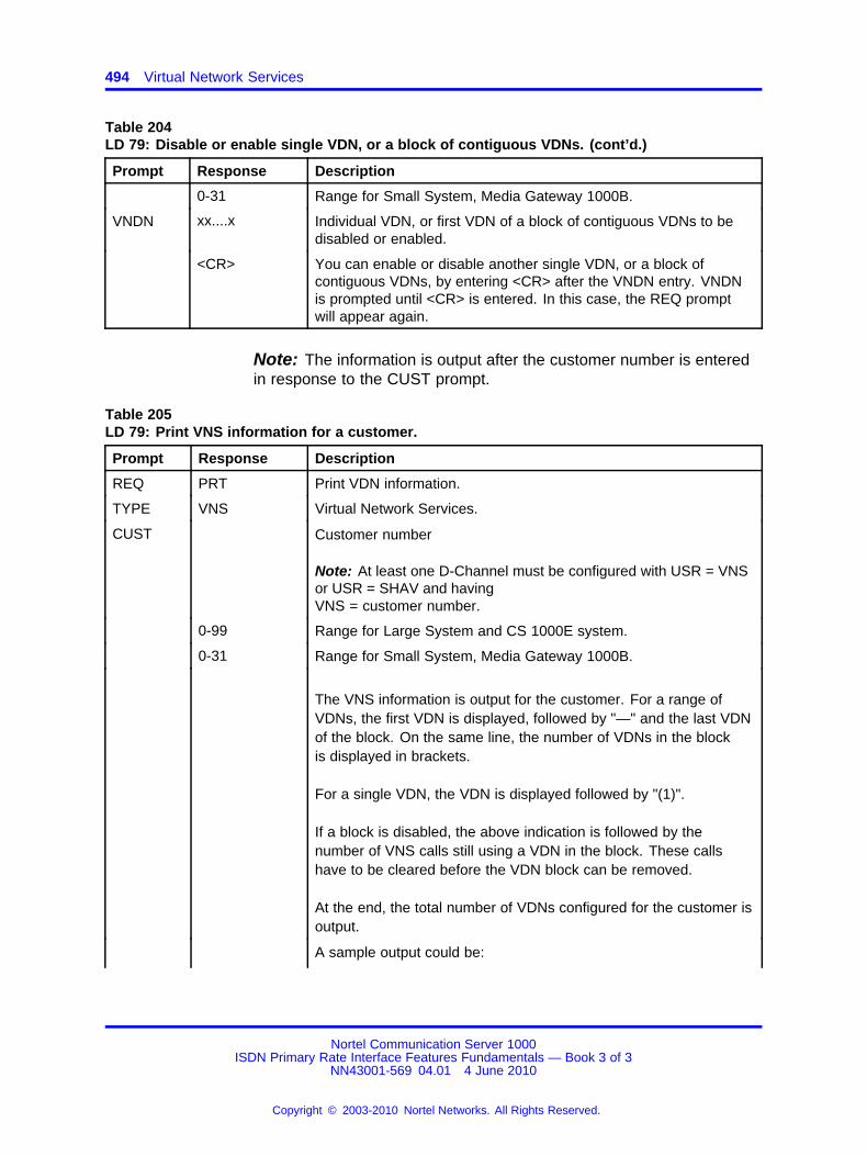
494 Virtual Network Services
Table 204LD 79: Disable or enable single VDN, or a block of contiguous VDNs. (cont’d.)
Prompt Response Description
0-31 Range for Small System, Media Gateway 1000B.
VNDN xx....x Individual VDN, or first VDN of a block of contiguous VDNs to bedisabled or enabled.
<CR> You can enable or disable another single VDN, or a block ofcontiguous VDNs, by entering <CR> after the VNDN entry. VNDNis prompted until <CR> is entered. In this case, the REQ promptwill appear again.
Note: The information is output after the customer number is enteredin response to the CUST prompt.
Table 205LD 79: Print VNS information for a customer.
Prompt Response Description
REQ PRT Print VDN information.
TYPE VNS Virtual Network Services.
CUST Customer number
Note: At least one D-Channel must be configured with USR = VNSor USR = SHAV and havingVNS = customer number.
0-99 Range for Large System and CS 1000E system.
0-31 Range for Small System, Media Gateway 1000B.
The VNS information is output for the customer. For a range ofVDNs, the first VDN is displayed, followed by "—" and the last VDNof the block. On the same line, the number of VDNs in the blockis displayed in brackets.
For a single VDN, the VDN is displayed followed by "(1)".
If a block is disabled, the above indication is followed by thenumber of VNS calls still using a VDN in the block. These callshave to be cleared before the VDN block can be removed.
At the end, the total number of VDNs configured for the customer isoutput.
A sample output could be:
Nortel Communication Server 1000ISDN Primary Rate Interface Features Fundamentals — Book 3 of 3
NN43001-569 04.01 4 June 2010
Copyright © 2003-2010 Nortel Networks. All Rights Reserved.
.
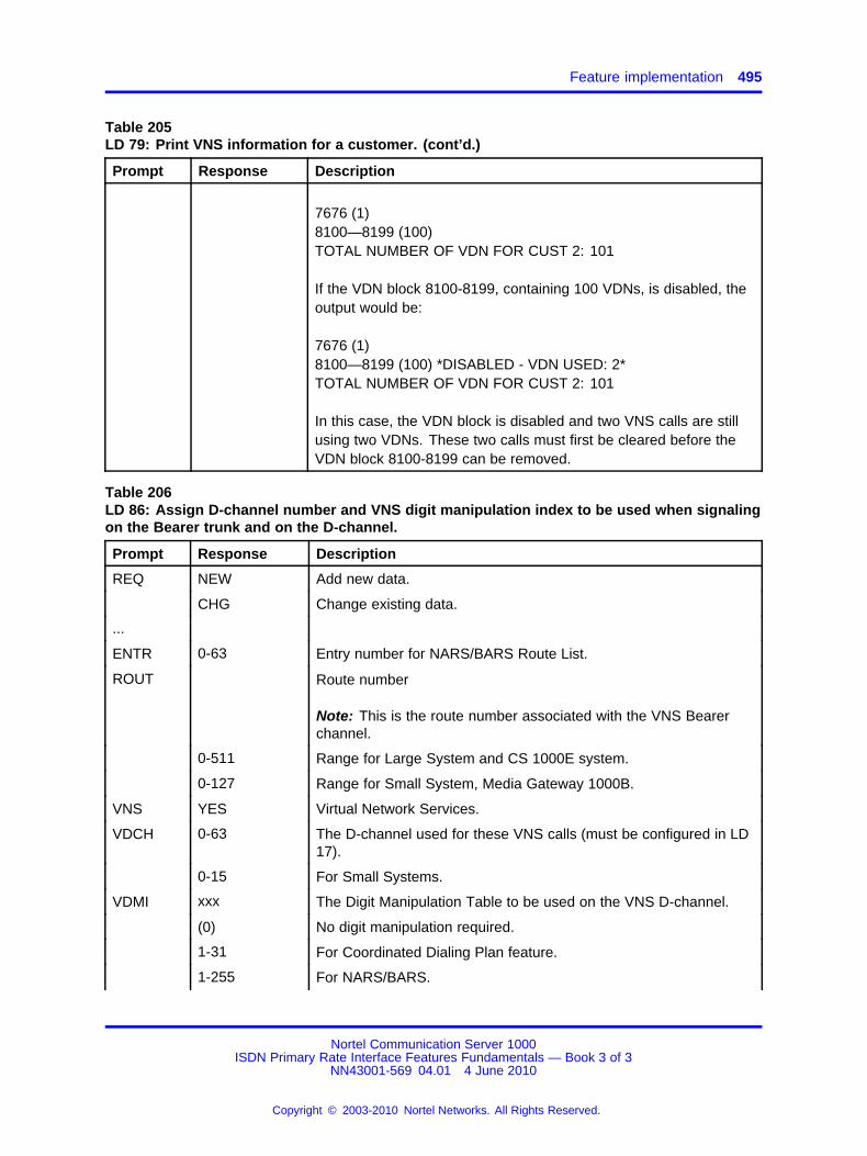
Feature implementation 495
Table 205LD 79: Print VNS information for a customer. (cont’d.)
Prompt Response Description
7676 (1)8100—8199 (100)TOTAL NUMBER OF VDN FOR CUST 2: 101
If the VDN block 8100-8199, containing 100 VDNs, is disabled, theoutput would be:
7676 (1)8100—8199 (100) *DISABLED - VDN USED: 2*TOTAL NUMBER OF VDN FOR CUST 2: 101
In this case, the VDN block is disabled and two VNS calls are stillusing two VDNs. These two calls must first be cleared before theVDN block 8100-8199 can be removed.
Table 206LD 86: Assign D-channel number and VNS digit manipulation index to be used when signalingon the Bearer trunk and on the D-channel.
Prompt Response Description
REQ NEW Add new data.
CHG Change existing data.
...
ENTR 0-63 Entry number for NARS/BARS Route List.
ROUT Route number
Note: This is the route number associated with the VNS Bearerchannel.
0-511 Range for Large System and CS 1000E system.
0-127 Range for Small System, Media Gateway 1000B.
VNS YES Virtual Network Services.
VDCH 0-63 The D-channel used for these VNS calls (must be configured in LD17).
0-15 For Small Systems.
VDMI xxx The Digit Manipulation Table to be used on the VNS D-channel.
(0) No digit manipulation required.
1-31 For Coordinated Dialing Plan feature.
1-255 For NARS/BARS.
Nortel Communication Server 1000ISDN Primary Rate Interface Features Fundamentals — Book 3 of 3
NN43001-569 04.01 4 June 2010
Copyright © 2003-2010 Nortel Networks. All Rights Reserved.
.
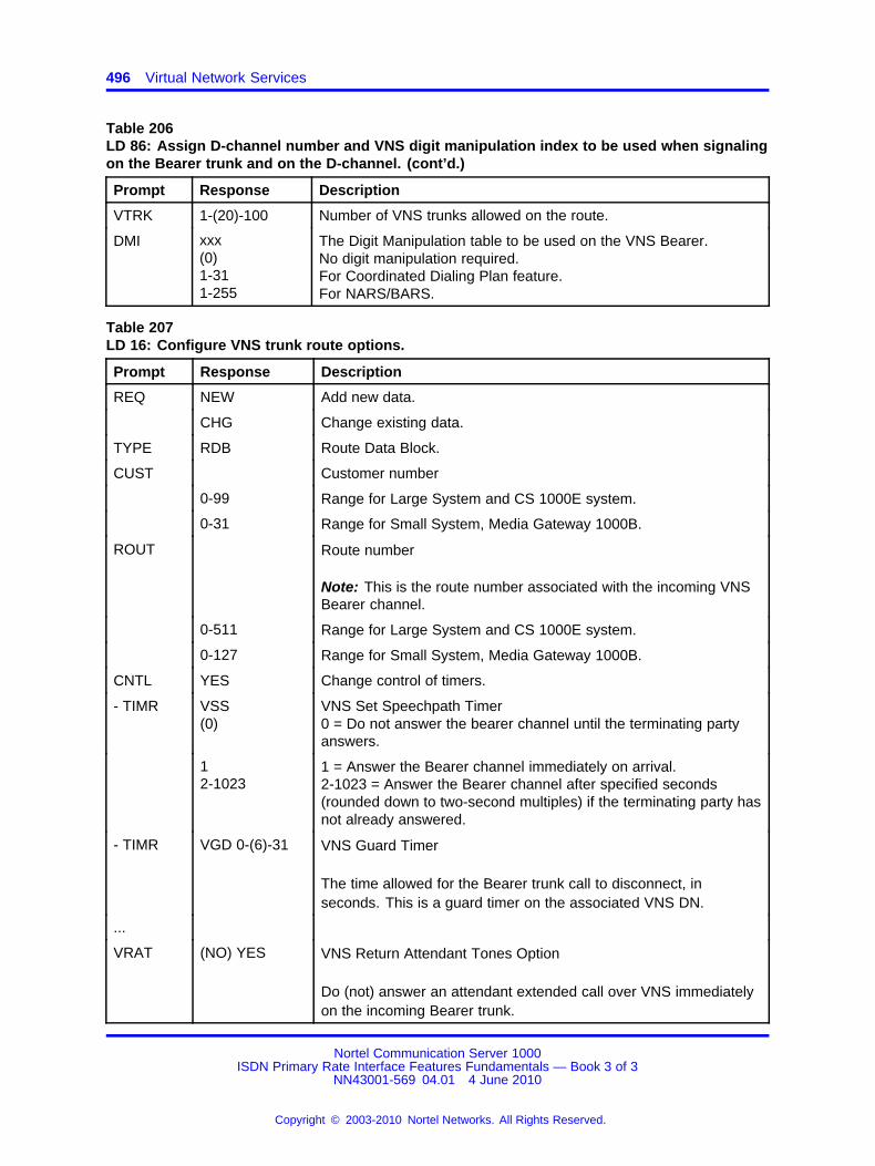
496 Virtual Network Services
Table 206LD 86: Assign D-channel number and VNS digit manipulation index to be used when signalingon the Bearer trunk and on the D-channel. (cont’d.)
Prompt Response Description
VTRK 1-(20)-100 Number of VNS trunks allowed on the route.
DMI xxx(0)1-311-255
The Digit Manipulation table to be used on the VNS Bearer.No digit manipulation required.For Coordinated Dialing Plan feature.For NARS/BARS.
Table 207LD 16: Configure VNS trunk route options.
Prompt Response Description
REQ NEW Add new data.
CHG Change existing data.
TYPE RDB Route Data Block.
CUST Customer number
0-99 Range for Large System and CS 1000E system.
0-31 Range for Small System, Media Gateway 1000B.
ROUT Route number
Note: This is the route number associated with the incoming VNSBearer channel.
0-511 Range for Large System and CS 1000E system.
0-127 Range for Small System, Media Gateway 1000B.
CNTL YES Change control of timers.
- TIMR VSS(0)
VNS Set Speechpath Timer0 = Do not answer the bearer channel until the terminating partyanswers.
12-1023
1 = Answer the Bearer channel immediately on arrival.2-1023 = Answer the Bearer channel after specified seconds(rounded down to two-second multiples) if the terminating party hasnot already answered.
- TIMR VGD 0-(6)-31 VNS Guard Timer
The time allowed for the Bearer trunk call to disconnect, inseconds. This is a guard timer on the associated VNS DN.
...
VRAT (NO) YES VNS Return Attendant Tones Option
Do (not) answer an attendant extended call over VNS immediatelyon the incoming Bearer trunk.
Nortel Communication Server 1000ISDN Primary Rate Interface Features Fundamentals — Book 3 of 3
NN43001-569 04.01 4 June 2010
Copyright © 2003-2010 Nortel Networks. All Rights Reserved.
.

Feature operation 497
Feature operationNo specific operating procedures are required to use this feature.
Nortel Communication Server 1000ISDN Primary Rate Interface Features Fundamentals — Book 3 of 3
NN43001-569 04.01 4 June 2010
Copyright © 2003-2010 Nortel Networks. All Rights Reserved.
.

498 Virtual Network Services
Nortel Communication Server 1000ISDN Primary Rate Interface Features Fundamentals — Book 3 of 3
NN43001-569 04.01 4 June 2010
Copyright © 2003-2010 Nortel Networks. All Rights Reserved.
.

499.
Virtual Network Services VirtualDirectory Number Expansion
ContentsThis section contains information on the following topics:
“Feature description” (page 499)
“Operating parameters” (page 500)
“Feature interactions” (page 500)
“Feature packaging” (page 500)
“Feature implementation” (page 501)
“Task summary list” (page 501)
“Feature operation” (page 505)
Feature descriptionVirtual Network Services (VNS) provides ISDN features to customerswhen no ISDN Primary Rate Interface (PRI) or ISDN Signaling Link (ISL)Bearer Channels are available between two system switches. (Refer tothe VNS feature description module in this technical document for detailedinformation on VNS).
You must configure VNS DNs (VDNs) as part of the numbering plan. TheVNS VDN expansion feature sets a new limit on the number of VDNs at4000. VDNs are configured on LD 79.
The VDNs are defined in sets of blocks. Each block can contain anynumber of contiguous VDNs, as long as the total number does not exceed4000. Within a block, it is possible to define a range of VDNs as well asindividual VDNs.
Nortel Communication Server 1000ISDN Primary Rate Interface Features Fundamentals — Book 3 of 3
NN43001-569 04.01 4 June 2010
Copyright © 2003-2010 Nortel Networks. All Rights Reserved.
.
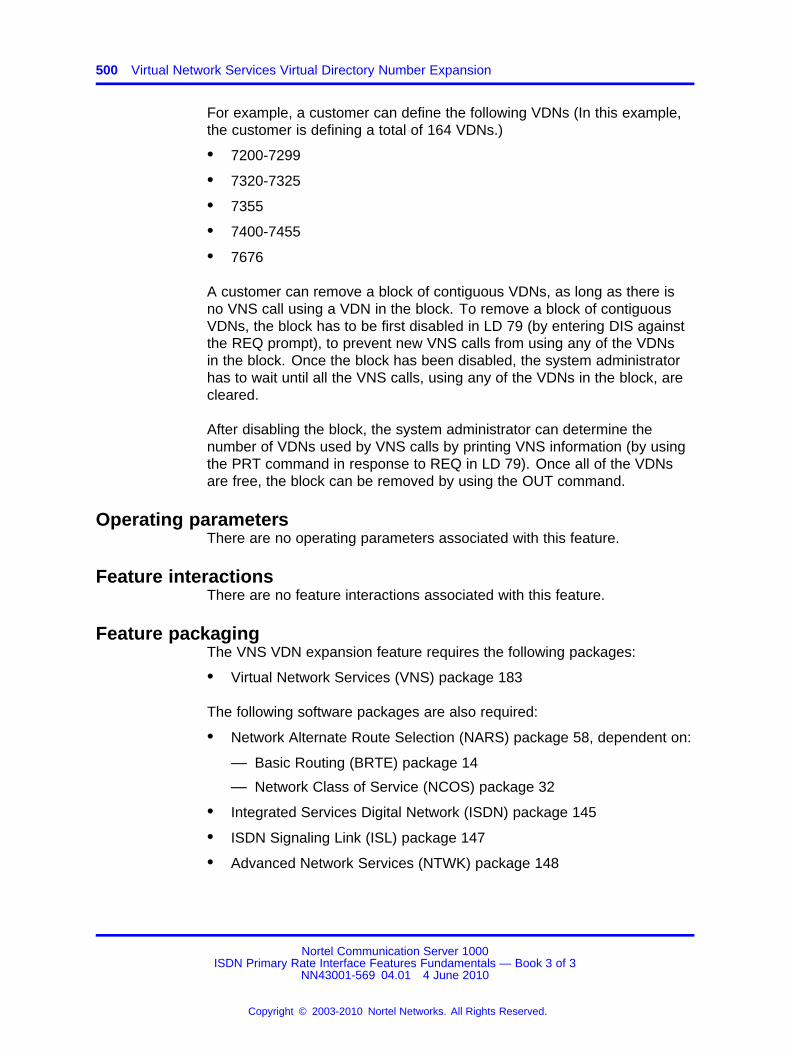
500 Virtual Network Services Virtual Directory Number Expansion
For example, a customer can define the following VDNs (In this example,the customer is defining a total of 164 VDNs.)
• 7200-7299
• 7320-7325
• 7355
• 7400-7455
• 7676
A customer can remove a block of contiguous VDNs, as long as there isno VNS call using a VDN in the block. To remove a block of contiguousVDNs, the block has to be first disabled in LD 79 (by entering DIS againstthe REQ prompt), to prevent new VNS calls from using any of the VDNsin the block. Once the block has been disabled, the system administratorhas to wait until all the VNS calls, using any of the VDNs in the block, arecleared.
After disabling the block, the system administrator can determine thenumber of VDNs used by VNS calls by printing VNS information (by usingthe PRT command in response to REQ in LD 79). Once all of the VDNsare free, the block can be removed by using the OUT command.
Operating parametersThere are no operating parameters associated with this feature.
Feature interactionsThere are no feature interactions associated with this feature.
Feature packagingThe VNS VDN expansion feature requires the following packages:
• Virtual Network Services (VNS) package 183
The following software packages are also required:
• Network Alternate Route Selection (NARS) package 58, dependent on:
— Basic Routing (BRTE) package 14
— Network Class of Service (NCOS) package 32
• Integrated Services Digital Network (ISDN) package 145
• ISDN Signaling Link (ISL) package 147
• Advanced Network Services (NTWK) package 148
Nortel Communication Server 1000ISDN Primary Rate Interface Features Fundamentals — Book 3 of 3
NN43001-569 04.01 4 June 2010
Copyright © 2003-2010 Nortel Networks. All Rights Reserved.
.
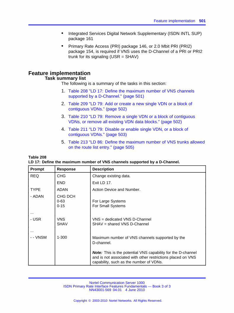
Feature implementation 501
• Integrated Services Digital Network Supplementary (ISDN INTL SUP)package 161
• Primary Rate Access (PRI) package 146, or 2.0 Mbit PRI (PRI2)package 154, is required if VNS uses the D-Channel of a PRI or PRI2trunk for its signaling (USR = SHAV)
Feature implementationTask summary list
The following is a summary of the tasks in this section:
1. Table 208 "LD 17: Define the maximum number of VNS channelssupported by a D-Channel." (page 501)
2. Table 209 "LD 79: Add or create a new single VDN or a block ofcontiguous VDNs." (page 502)
3. Table 210 "LD 79: Remove a single VDN or a block of contiguousVDNs, or remove all existing VDN data blocks." (page 502)
4. Table 211 "LD 79: Disable or enable single VDN, or a block ofcontiguous VDNs." (page 503)
5. Table 213 "LD 86: Define the maximum number of VNS trunks allowedon the route list entry." (page 505)
Table 208LD 17: Define the maximum number of VNS channels supported by a D-Channel.
Prompt Response Description
REQ CHG Change existing data.
END Exit LD 17.
TYPE ADAN Action Device and Number.
- ADAN CHG DCH0-630-15
For Large SystemsFor Small Systems
...
- USR VNSSHAV
VNS = dedicated VNS D-ChannelSHAV = shared VNS D-Channel
...
- - VNSM 1-300 Maximum number of VNS channels supported by theD-channel.
Note: This is the potential VNS capability for the D-channeland is not associated with other restrictions placed on VNScapability, such as the number of VDNs.
Nortel Communication Server 1000ISDN Primary Rate Interface Features Fundamentals — Book 3 of 3
NN43001-569 04.01 4 June 2010
Copyright © 2003-2010 Nortel Networks. All Rights Reserved.
.
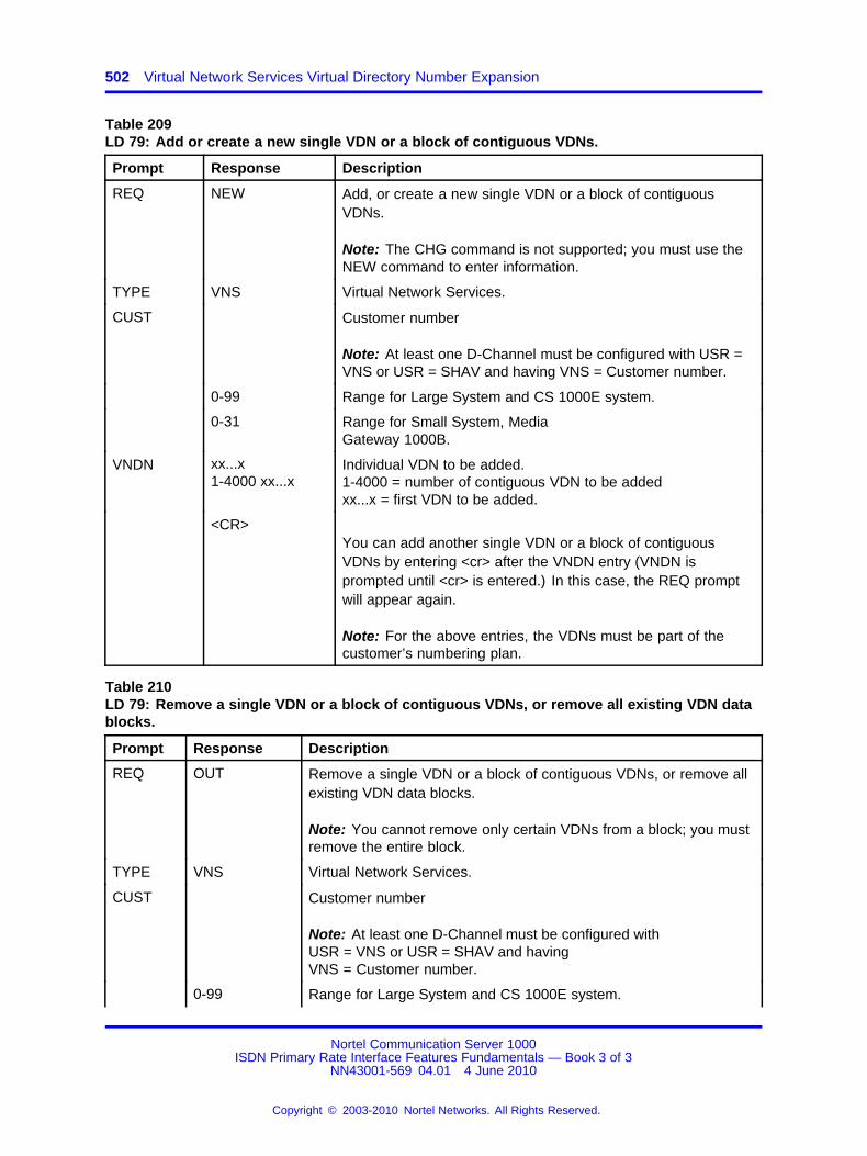
502 Virtual Network Services Virtual Directory Number Expansion
Table 209LD 79: Add or create a new single VDN or a block of contiguous VDNs.
Prompt Response Description
REQ NEW Add, or create a new single VDN or a block of contiguousVDNs.
Note: The CHG command is not supported; you must use theNEW command to enter information.
TYPE VNS Virtual Network Services.
CUST Customer number
Note: At least one D-Channel must be configured with USR =VNS or USR = SHAV and having VNS = Customer number.
0-99 Range for Large System and CS 1000E system.
0-31 Range for Small System, MediaGateway 1000B.
VNDN xx...x1-4000 xx...x
Individual VDN to be added.1-4000 = number of contiguous VDN to be addedxx...x = first VDN to be added.
<CR>You can add another single VDN or a block of contiguousVDNs by entering <cr> after the VNDN entry (VNDN isprompted until <cr> is entered.) In this case, the REQ promptwill appear again.
Note: For the above entries, the VDNs must be part of thecustomer’s numbering plan.
Table 210LD 79: Remove a single VDN or a block of contiguous VDNs, or remove all existing VDN datablocks.
Prompt Response Description
REQ OUT Remove a single VDN or a block of contiguous VDNs, or remove allexisting VDN data blocks.
Note: You cannot remove only certain VDNs from a block; you mustremove the entire block.
TYPE VNS Virtual Network Services.
CUST Customer number
Note: At least one D-Channel must be configured withUSR = VNS or USR = SHAV and havingVNS = Customer number.
0-99 Range for Large System and CS 1000E system.
Nortel Communication Server 1000ISDN Primary Rate Interface Features Fundamentals — Book 3 of 3
NN43001-569 04.01 4 June 2010
Copyright © 2003-2010 Nortel Networks. All Rights Reserved.
.
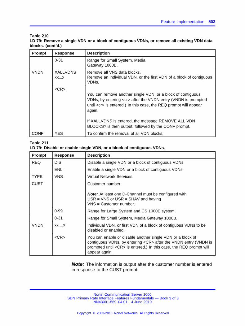
Feature implementation 503
Table 210LD 79: Remove a single VDN or a block of contiguous VDNs, or remove all existing VDN datablocks. (cont’d.)
Prompt Response Description
0-31 Range for Small System, MediaGateway 1000B.
VNDN XALLVDNSxx...x
Remove all VNS data blocks.Remove an individual VDN, or the first VDN of a block of contiguousVDNs.
<CR>You can remove another single VDN, or a block of contiguousVDNs, by entering <cr> after the VNDN entry (VNDN is prompteduntil <cr> is entered.) In this case, the REQ prompt will appearagain.
If XALLVDNS is entered, the message REMOVE ALL VDNBLOCKS? is then output, followed by the CONF prompt.
CONF YES To confirm the removal of all VDN blocks.
Table 211LD 79: Disable or enable single VDN, or a block of contiguous VDNs.
Prompt Response Description
REQ DIS Disable a single VDN or a block of contiguous VDNs
ENL Enable a single VDN or a block of contiguous VDNs
TYPE VNS Virtual Network Services.
CUST Customer number
Note: At least one D-Channel must be configured withUSR = VNS or USR = SHAV and havingVNS = Customer number.
0-99 Range for Large System and CS 1000E system.
0-31 Range for Small System, Media Gateway 1000B.
VNDN xx....x Individual VDN, or first VDN of a block of contiguous VDNs to bedisabled or enabled.
<CR> You can enable or disable another single VDN or a block ofcontiguous VDNs, by entering <CR> after the VNDN entry (VNDN isprompted until <CR> is entered.) In this case, the REQ prompt willappear again.
Note: The information is output after the customer number is enteredin response to the CUST prompt.
Nortel Communication Server 1000ISDN Primary Rate Interface Features Fundamentals — Book 3 of 3
NN43001-569 04.01 4 June 2010
Copyright © 2003-2010 Nortel Networks. All Rights Reserved.
.

504 Virtual Network Services Virtual Directory Number Expansion
Table 212LD 79: Print VNS information for a customer.
Prompt Response Description
REQ PRT Print VDN information.
TYPE VNS Virtual Network Services.
CUST Customer number
Note: At least one D-Channel must be configured withUSR = VNS or USR = SHAV and havingVNS = Customer number.
0-99 Range for Large System and CS 1000E system.
0-31 Range for Small System, MediaGateway 1000B.
The VNS information is output for the customer. For a range ofVDNs, the first VDN is displayed, followed by "—" and the last VDNof the block. On the same line, the number of VDNs in the blockis displayed in brackets.
For a single VDN, the VDN is displayed followed by "(1)".
If a block is disabled, the above indication is followed by the numberof VNS calls still using a VDN in the block. These calls have to becleared before the VDN block can be removed.
At the end, the total number of VDNs configured for the customer isoutput.
A sample output could be:
7676 (1)8100—8199 (100)TOTAL NUMBER OF VDN FOR CUST 2: 101
If the VDN block 8100-8199, containing 100 VDNs, is disabled, theoutput would be:
7676 (1)8100—8199 (100) *DISABLED - VDN USED: 2*TOTAL NUMBER OF VDN FOR CUST 2: 101
In this case, the VDN block is disabled and two VNS calls are stillusing two VDNs. These two calls must first be cleared before theVDN block 8100-8199 can be removed.
Nortel Communication Server 1000ISDN Primary Rate Interface Features Fundamentals — Book 3 of 3
NN43001-569 04.01 4 June 2010
Copyright © 2003-2010 Nortel Networks. All Rights Reserved.
.

Feature operation 505
Table 213LD 86: Define the maximum number of VNS trunks allowed on the route list entry.
Prompt Response Description
REQ NEW Add new data.
CHG Change existing data.
CUST Customer number
0-99 Range for Large System and CS 1000E system.
0-31 Range for Small System, Media Gateway1000B.
FEAT RLB Route list data block feature.
RLI 0-MXRL The Route List Index to be associated with the VNS BearerChannel.
ENTR 0-63 The entry within the Route List Index to be associated with the VNSBearer Channel.
ROUT Route number
Note: This is the route number associated with the incoming VNSBearer channel.
0-511 Range for Large System and CS 1000E system.
0-127 Range for Small System, Media Gateway1000B.
VNS YES Virtual Network Services.
...
VTRK 1-(20)-254 Number of VNS Trunks allowed on the route.
Feature operationNo specific operating procedures are required to use this feature.
Nortel Communication Server 1000ISDN Primary Rate Interface Features Fundamentals — Book 3 of 3
NN43001-569 04.01 4 June 2010
Copyright © 2003-2010 Nortel Networks. All Rights Reserved.
.

506 Virtual Network Services Virtual Directory Number Expansion
Nortel Communication Server 1000ISDN Primary Rate Interface Features Fundamentals — Book 3 of 3
NN43001-569 04.01 4 June 2010
Copyright © 2003-2010 Nortel Networks. All Rights Reserved.
.
507.
Zone Based Dialing
ContentsThis section contains the following topic:
“Feature description” (page 507)
Feature descriptionUse the Zone Based Dialing (ZBD) feature to replace a nodal PBX networkwith one or more high-capacity soft switches and branch gateways forPublic Switched Telephone Network (PSTN) access. New customers, whoplan to setup a private network in multiple locations, can deploy ZBD.
For more information about ZBD, see Dialing Plans Fundamentals(NN43001-283).
Nortel Communication Server 1000ISDN Primary Rate Interface Features Fundamentals — Book 3 of 3
NN43001-569 04.01 4 June 2010
Copyright © 2003-2010 Nortel Networks. All Rights Reserved.
.

508 Zone Based Dialing
Nortel Communication Server 1000ISDN Primary Rate Interface Features Fundamentals — Book 3 of 3
NN43001-569 04.01 4 June 2010
Copyright © 2003-2010 Nortel Networks. All Rights Reserved.
.

509.
Engineering and configurationguidelines
ContentsThis section contains information on the following topics:
“Description” (page 509)
“System compatibility” (page 510)
“Inter-system compatibility” (page 510)
“Primary Rate Interface (PRI) hardware requirements” (page 511)
“ISDN Signaling Link (ISL) hardware” (page 512)
“Cable and channel information” (page 514)
“Configuration parameters” (page 514)
“Data characteristics” (page 514)
“Transmission characteristics” (page 515)
“Loss and level plan” (page 515)
“Call connection limitations” (page 517)
“Software packages” (page 518)
“Software and hardware compatibility” (page 520)
“Cable information” (page 530)
DescriptionThis section contains the ISDN guidelines for compatible system softwareand hardware configurations. This includes:
• system compatibility information
• configuration parameters
• transmission characteristics
• software package requirements
• hardware requirements
Nortel Communication Server 1000ISDN Primary Rate Interface Features Fundamentals — Book 3 of 3
NN43001-569 04.01 4 June 2010
Copyright © 2003-2010 Nortel Networks. All Rights Reserved.
.

510 Engineering and configuration guidelines
• disk-drive upgrade requirements
• cable information
• data characteristics
• loss and level plan information
For detailed instructions on hardware installation, refer to ISDN PrimaryRate Interface Installation and Commissioning (NN43001-301).
For specific information on Small Systems refer to ISDN Primary RateInterface Installation and Commissioning (NN43001-301) and ISDNPrimary Rate Interface Maintenance (NN43001-717).
System compatibilityThe ISDN software supports the following system options:
• Large Systems
• Small Systems
Inter-system compatibilityPRI Transmission characteristics
There are five characteristics of transmission necessary for ISDN PRIcompatibility. These are:
• carrier-system compatibility
• synchronization
• signaling
• trunk-type support
• voice and data transmission compatibility
Carrier system compatibilityPRI is compatible with carrier systems which:
• use CEPT G.703 framing on repeater cables;
• use the CEPT G.703 interface (such as fiber optic, microwave, copper,satellite, and infrared transport);
• meet CCITT Q.921 and Q.931 recommendations; and
• use HDB3 line coding at 75-ohm coaxial or 120-ohm twisted-pairinterfaces.
Nortel Communication Server 1000ISDN Primary Rate Interface Features Fundamentals — Book 3 of 3
NN43001-569 04.01 4 June 2010
Copyright © 2003-2010 Nortel Networks. All Rights Reserved.
.
Primary Rate Interface (PRI) hardware requirements 511
SynchronizationPRI is Stratum 3 compatible (accuracy, jitter, pull-in range).
SignalingISDN D-channel signaling is used for Primary Rate Access.
Trunk type supportPRI supports the following trunk types:
• Tie (2-wire E&M, 4-wire E&M)
• Foreign Exchange (FX)
• WATS
• PBX-to-Public Exchange trunks; also known as Central Office (CO)trunks
• Direct Inward Dial (DID or DDI) trunks
Voice connectionsVoice transmission meets the CCITT standard for flexible loss-and-levelplan.
Data connectionsPRI supports the following Transmission modes:
• asynchronous 50 bit/s to 19.2 Kbit/s
• synchronous 1200 bit/s to 64 Kbit/s
• half or full duplex
Primary Rate Interface (PRI) hardware requirementsThe following hardware is required to equip ISDN PRI on Meridian 1 LargeSystems:
• NT6D11(AB/AE/AF) D-Channel Interface (DCH) card (for 2.0 Mbit PRI)
• QPC757 D-channel Interface (DCH) for (1.5 Mbit PRI)
• NT6D80 Multipurpose Serial Data Link (MSDL) card
• NTBK51 Downloadable D-Channel Daughterboard (DDCH), used asan option to the NT6D80 MSDL, the NT5D97 dual-port DTI2/PRI2 card,or the NT5D12 dual-port 1.5 Mbit DTI/PRI card
• NT8D72 (AB/BA) PRI2 card
• NT5D97 dual-port DTI2/PRI2 card
• QPC720 1.5 Mbit PRI card
Nortel Communication Server 1000ISDN Primary Rate Interface Features Fundamentals — Book 3 of 3
NN43001-569 04.01 4 June 2010
Copyright © 2003-2010 Nortel Networks. All Rights Reserved.
.
512 Engineering and configuration guidelines
• NT5D12 dual-port 1.5 DTI/PRI card
• QPC471 or NTRB53 Clock Controller
Note: The QPC471 and NTRB53 Clock Controllers cannot be mixed inone system. Vintages A through G of the QPC471 Clock Controller canbe used in one system; vintage H of QPC471 Clock Controllers cannotbe mixed with Clock Controllers of other vintages.
Additional hardware is also required for PRI capability and applications.Installation instructions are given in other Nortel publications, or suppliedby the manufacturer. This additional hardware includes:
• QPC414 Network card
• Channel Service Unit (CSU)
• Echo canceller
Note: Meridian 1 PBX 81Cor CS 1000M MGrequirements arefulfilled by the NT6D66 Call Processor (CP) card.
• QMT8 Asynchronous Data Module (ADM)
ISDN Signaling Link (ISL) hardwareThe following hardware is required for ISDN Signaling Link (ISL) capabilityand applications.
Equipment required for shared mode capability:
• NT6D11(AB/AE/AF) D-Channel (DCH) card (for 2.0 Mbit PRI)
• QPC757 D-channel (DCH) for (1.5 Mbit PRI)
• NT6D80 Multipurpose Serial Data Link (MSDL) card
• NTBK51 Downloadable D-Channel Daughterboard (DDCH), used asan option to the NT6D80 MSDL, the NT5D97 dual-port DTI2/PRI2 card,or the NT5D12 dual-port 1.5 Mbit DTI/PRI card
• NT8D72 (AB/BA) PRI2 card
• NT5D97 dual-port DTI2/PRI2 card
• QPC720 1.5 Mbit PRI card
• NT5D12 dual-port 1.5 DTI/PRI card
• QPC471 or QPC775 Clock Controller
Equipment required for dedicated mode using leased lines:
Nortel Communication Server 1000ISDN Primary Rate Interface Features Fundamentals — Book 3 of 3
NN43001-569 04.01 4 June 2010
Copyright © 2003-2010 Nortel Networks. All Rights Reserved.
.
ISDN Signaling Link (ISL) hardware 513
• NT6D11(AB/AE/AF) D-Channel (DCH) card (for 2.0 Mbit PRI)
• QPC757 D-channel (DCH) for (1.5 Mbit PRI)
• NT6D80 Multipurpose Serial Data Link (MSDL) card
• NTBK51 Downloadable D-Channel Daughterboard (DDCH), used asan option to the NT6D80 MSDL
• modem set in synchronous mode
Equipment required for dedicated mode using a dial-up modem:
• NT6D11(AB/AE/AF) D-Channel (DCH) card (for 2.0 Mbit PRI)
• QPC757 D-channel (DCH) for (1.5 Mbit PRI)
• NT6D80 Multipurpose Serial Data Link (MSDL) card
• NTBK51 Downloadable D-Channel Daughterboard (DDCH), used asan option to the NT6D80 MSDL
• modem with auto-dial capability
Note: This configuration is the least reliable due to lockup problemsinherent in Smart Modems from power spikes and noisy lines. Toincrease the reliability on this configuration, use a constant powersource when powering the modems. Also, verify that TIE lines meetdata grade specifications. Nortel takes no responsibility for ISLD-Channel outages due to modem lockup.
• 500 set line card
Equipment required for dedicated mode using a DTI/DTI2 trunk:
• NT6D11(AB/AE/AF) D-Channel (DCH) card (for 2.0 Mbit PRI)
• QPC757 D-channel (DCH) for (1.5 Mbit PRI)
• NT6D80 Multipurpose Serial Data Link (MSDL) card
• NTBK51 Downloadable D-Channel Daughterboard (DDCH), used asan option to the NT6D80 MSDL
• NT5D97 dual-port DTI2/PRI2 card
• QPC472 1.5 Mbit DTI card or NT5D12 dual-port 1.5 DTI/PRI card
• QMT8 Asynchronous Data Module (ADM), QMT11 Asynchronous/Synchronous Interface Module (ASIM) or QMT21 High Speed Data Module(HSDM)
• Data line card
Nortel Communication Server 1000ISDN Primary Rate Interface Features Fundamentals — Book 3 of 3
NN43001-569 04.01 4 June 2010
Copyright © 2003-2010 Nortel Networks. All Rights Reserved.
.
514 Engineering and configuration guidelines
Cable and channel informationThe following sections contain cable and channel information.
Cable distanceThe cable type used is a 2-pair twisted wire. Maximum cable distancesare:
• 200 m (655 ft) from the system to cross-connect point (using ARAMor ABAM equivalent cable)
• 229 m (750 ft) from the system to Office Repeater Bay
Configuration parametersThere are two types of configuration parameters:
• line rate
• T1 and E1 compatibility
The line rate is 1.544 Mbit for T1 and 2.048 Mbit for E1.
The integrated voice and data can use a single medium to transmit speechand data between locations.
There are three advantages to T1 or E1 compatibility:
• E-link or T-link version 2 supports system to system, system to SL-100,and system to Custom DMS-100 for 56 or 64 Kbit/s data, and systemto Central Office connectivity.
• includes capability to be configured as a standard T1 DS-1 link
• eliminates need for channel bank equipment when using digitalnetwork facilities
Data characteristicsPRI utilizes Nortel Network’s T-link Data Rate Adaptation protocol. Thereare three transmission modes:
• asynchronous 50 bit/s to 19.2 Kbit/s
• synchronous 1200 bit/s to 64 Kbit/s
• half or full duplex
Nortel Communication Server 1000ISDN Primary Rate Interface Features Fundamentals — Book 3 of 3
NN43001-569 04.01 4 June 2010
Copyright © 2003-2010 Nortel Networks. All Rights Reserved.
.
Loss and level plan 515
Transmission characteristicsThere are five types of transmission necessary for ISDN compatibility:
• carrier system compatibility
• synchronization
• signaling
• trunk types supported
• voice transmission
These transmission types are described in the lists that follow.
Carrier system compatibility:
• compatible with D2, D3, D4, B8ZS, and Extended superframe format(ESF) framing on T1 repeater cables
• compatible with systems that use a DS-1 interface, such as fiberoptics, microwave, copper, satellite, and infrared
• meets CCITT Q.921 and Q.931 recommendations
• complies with T1D1 minimal subset
Synchronization: stratum 3 compatible (accuracy, jitter, pull-in range)
Signaling:
• in PRI mode: ISDN D-channel signaling
• in DTI mode: loop start, ground start, E&M, DTMF, and dial pulse
• in ITA mode: PRI trunks use PRI mode and DTI trunks use DTI mode
Trunk types supported:
• CO, FX, WATS, DID, TIE (2-wire E&M, 4-wire E&M)
Voice transmission:
• meets EIA Digital PBX Draft Standard PN-1429 requirements such asloss and level, distortion, and delay
Note: ISDN meets the Radio Frequency Interference (RFI)requirements.
Loss and level planThe loss plan for PRI has been added to the existing system loss matrix(the EIA loss plan).
Nortel Communication Server 1000ISDN Primary Rate Interface Features Fundamentals — Book 3 of 3
NN43001-569 04.01 4 June 2010
Copyright © 2003-2010 Nortel Networks. All Rights Reserved.
.
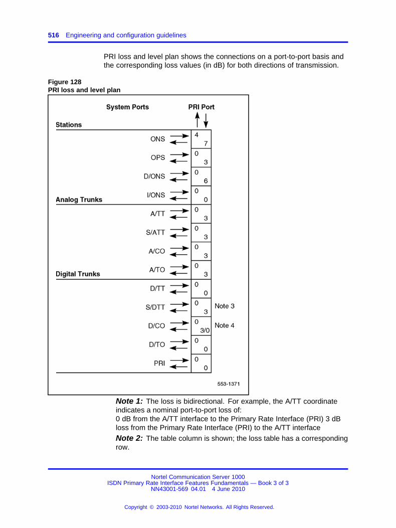
516 Engineering and configuration guidelines
PRI loss and level plan shows the connections on a port-to-port basis andthe corresponding loss values (in dB) for both directions of transmission.
Figure 128PRI loss and level plan
Note 1: The loss is bidirectional. For example, the A/TT coordinateindicates a nominal port-to-port loss of:0 dB from the A/TT interface to the Primary Rate Interface (PRI) 3 dBloss from the Primary Rate Interface (PRI) to the A/TT interface
Note 2: The table column is shown; the loss table has a correspondingrow.
Nortel Communication Server 1000ISDN Primary Rate Interface Features Fundamentals — Book 3 of 3
NN43001-569 04.01 4 June 2010
Copyright © 2003-2010 Nortel Networks. All Rights Reserved.
.

Call connection limitations 517
Note 3: For echo control reasons, this connection cannot be loss-less.
Note 4: The value of 0 dB in the PRI-D/CO direction is the long-termobjective. The value of 3 dB is to be used for connections to D/COsthat have not been programmed for inserting receive-side loss on PRIto local loop connections.
Legend:
ONS Line interface/on premise line
OPS Line interface/off premise line
D/ONS Digital line interface/on premise line
I/ONS ISDN terminal (on premise)
A/TT Analog trunk interface/analog TIE trunk
S/ATT Analog trunk interface/analog satellite PBX TIE trunk
A/CO Analog trunk interface/analog CO trunk
A/TO Analog trunk interface/analog toll office trunk
D/TT Digital trunk interface/digital or combination TIE trunk
S/DTT Digital trunk interface/digital satellite PBX TIE trunk
D/CO Digital trunk interface/digital or combination CO trunk
D/TO Digital trunk interface/digital or combination toll office trunk
PRI Primary Rate Interface
Call connection limitationsCall connection restrictions limit user access to networks and features byallowing users to set the following limits:
• number of tandem connections
• number of call redirections
• number of PSTNs; can be one or unlimited
• number of ?/A-law conversions
• number of satellite delays
These restrictions apply only within an ISDN environment. Limitationsalso prevent trunk lockup by allowing only one trunk without disconnectsupervision to participate in a call connection. (Trunks providingdisconnect supervision include CO/FX/WATS, CO, DID, TIE, CCSA, 2MBDTI trunks, and ISDN.) If multiple call transfers, conferences, or othersituations cause two or more unsupervised trunks to be connected, callconnection restrictions might not be effective.
Nortel Communication Server 1000ISDN Primary Rate Interface Features Fundamentals — Book 3 of 3
NN43001-569 04.01 4 June 2010
Copyright © 2003-2010 Nortel Networks. All Rights Reserved.
.
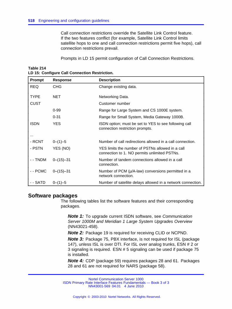
518 Engineering and configuration guidelines
Call connection restrictions override the Satellite Link Control feature.If the two features conflict (for example, Satellite Link Control limitssatellite hops to one and call connection restrictions permit five hops), callconnection restrictions prevail.
Prompts in LD 15 permit configuration of Call Connection Restrictions.
Table 214LD 15: Configure Call Connection Restriction.
Prompt Response Description
REQ CHG Change existing data.
TYPE NET Networking Data.
CUST Customer number
0-99 Range for Large System and CS 1000E system.
0-31 Range for Small System, Media Gateway 1000B.
ISDN YES ISDN option; must be set to YES to see following callconnection restriction prompts.
...
- RCNT 0–(1)–5 Number of call redirections allowed in a call connection.
- PSTN YES (NO) YES limits the number of PSTNs allowed in a callconnection to 1. NO permits unlimited PSTNs.
- - TNDM 0–(15)–31 Number of tandem connections allowed in a callconnection.
- - PCMC 0–(15)–31 Number of PCM (µ/A-law) conversions permitted in anetwork connection.
- - SATD 0–(1)–5 Number of satellite delays allowed in a network connection.
Software packagesThe following tables list the software features and their correspondingpackages.
Note 1: To upgrade current ISDN software, see CommunicationServer 1000M and Meridian 1 Large System Upgrades Overview(NN43021-458).
Note 2: Package 19 is required for receiving CLID or NCPND.
Note 3: Package 75, PBX interface, is not required for ISL (package147), unless ISL is over DTI. For ISL over analog trunks, ESN # 2 or3 signaling is required. ESN # 5 signaling can be used if package 75is installed.
Note 4: CDP (package 59) requires packages 28 and 61. Packages28 and 61 are not required for NARS (package 58).
Nortel Communication Server 1000ISDN Primary Rate Interface Features Fundamentals — Book 3 of 3
NN43001-569 04.01 4 June 2010
Copyright © 2003-2010 Nortel Networks. All Rights Reserved.
.
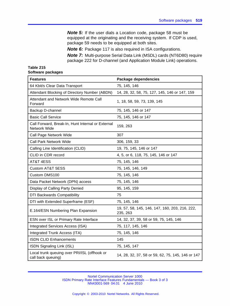
Software packages 519
Note 5: If the user dials a Location code, package 58 must beequipped at the originating and the receiving system. If CDP is used,package 59 needs to be equipped at both sites.
Note 6: Package 117 is also required in ISA configurations.
Note 7: Multi-purpose Serial Data Link (MSDL) cards (NT6D80) requirepackage 222 for D-channel (and Application Module Link) operations.
Table 215Software packages
Features Package dependencies
64 Kbit/s Clear Data Transport 75, 145, 146
Attendant Blocking of Directory Number (ABDN) 14, 28, 32, 58, 75, 127, 145, 146 or 147, 159
Attendant and Network Wide Remote CallForward
1, 18, 58, 59, 73, 139, 145
Backup D-channel 75, 145, 146 or 147
Basic Call Service 75, 145, 146 or 147
Call Forward, Break-In, Hunt Internal or ExternalNetwork Wide
159, 263
Call Page Network Wide 307
Call Park Network Wide 306, 159, 33
Calling Line Identification (CLID) 19, 75, 145, 146 or 147
CLID in CDR record 4, 5, or 6, 118, 75, 145, 146 or 147
AT&T 4ESS 75, 145, 146
Custom AT&T 5ESS 75, 145, 146, 149
Custom DMS100 75, 145, 146
Data Packet Network (DPN) access 75, 145, 146
Display of Calling Party Denied 95, 145, 159
DTI Backwards Compatibility 75
DTI with Extended Superframe (ESF) 75, 145, 146
E.164/ESN Numbering Plan Expansion19, 57, 58, 145, 146, 147, 160, 203, 216, 222,235, 263
ESN over ISL or Primary Rate Interface 14, 32, 37, 39, 58 or 59, 75, 145, 146
Integrated Services Access (ISA) 75, 117, 145, 146
Integrated Trunk Access (ITA) 75, 145, 146
ISDN CLID Enhancements 145
ISDN Signaling Link (ISL) 75, 145, 147
Local trunk queuing over PRI/ISL (offhook orcall back queuing)
14, 28, 32, 37, 58 or 59, 62, 75, 145, 146 or 147
Nortel Communication Server 1000ISDN Primary Rate Interface Features Fundamentals — Book 3 of 3
NN43001-569 04.01 4 June 2010
Copyright © 2003-2010 Nortel Networks. All Rights Reserved.
.
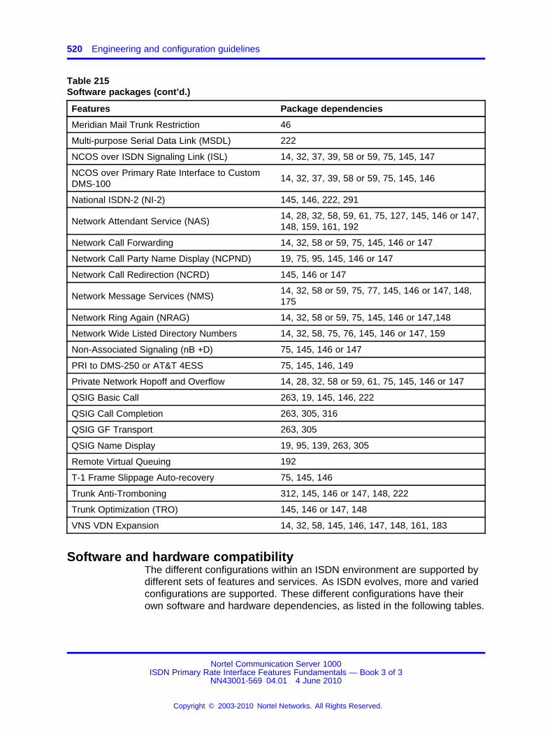
520 Engineering and configuration guidelines
Table 215Software packages (cont’d.)
Features Package dependencies
Meridian Mail Trunk Restriction 46
Multi-purpose Serial Data Link (MSDL) 222
NCOS over ISDN Signaling Link (ISL) 14, 32, 37, 39, 58 or 59, 75, 145, 147
NCOS over Primary Rate Interface to CustomDMS-100
14, 32, 37, 39, 58 or 59, 75, 145, 146
National ISDN-2 (NI-2) 145, 146, 222, 291
Network Attendant Service (NAS)14, 28, 32, 58, 59, 61, 75, 127, 145, 146 or 147,148, 159, 161, 192
Network Call Forwarding 14, 32, 58 or 59, 75, 145, 146 or 147
Network Call Party Name Display (NCPND) 19, 75, 95, 145, 146 or 147
Network Call Redirection (NCRD) 145, 146 or 147
Network Message Services (NMS)14, 32, 58 or 59, 75, 77, 145, 146 or 147, 148,175
Network Ring Again (NRAG) 14, 32, 58 or 59, 75, 145, 146 or 147,148
Network Wide Listed Directory Numbers 14, 32, 58, 75, 76, 145, 146 or 147, 159
Non-Associated Signaling (nB +D) 75, 145, 146 or 147
PRI to DMS-250 or AT&T 4ESS 75, 145, 146, 149
Private Network Hopoff and Overflow 14, 28, 32, 58 or 59, 61, 75, 145, 146 or 147
QSIG Basic Call 263, 19, 145, 146, 222
QSIG Call Completion 263, 305, 316
QSIG GF Transport 263, 305
QSIG Name Display 19, 95, 139, 263, 305
Remote Virtual Queuing 192
T-1 Frame Slippage Auto-recovery 75, 145, 146
Trunk Anti-Tromboning 312, 145, 146 or 147, 148, 222
Trunk Optimization (TRO) 145, 146 or 147, 148
VNS VDN Expansion 14, 32, 58, 145, 146, 147, 148, 161, 183
Software and hardware compatibilityThe different configurations within an ISDN environment are supported bydifferent sets of features and services. As ISDN evolves, more and variedconfigurations are supported. These different configurations have theirown software and hardware dependencies, as listed in the following tables.
Nortel Communication Server 1000ISDN Primary Rate Interface Features Fundamentals — Book 3 of 3
NN43001-569 04.01 4 June 2010
Copyright © 2003-2010 Nortel Networks. All Rights Reserved.
.
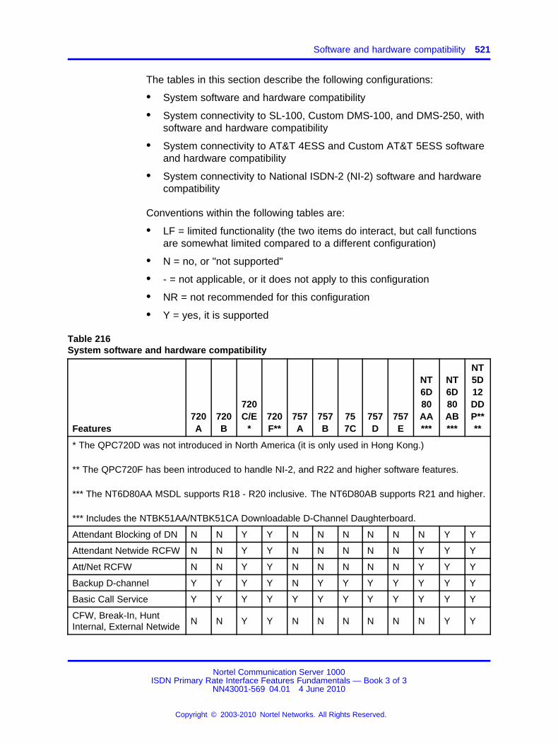
Software and hardware compatibility 521
The tables in this section describe the following configurations:
• System software and hardware compatibility
• System connectivity to SL-100, Custom DMS-100, and DMS-250, withsoftware and hardware compatibility
• System connectivity to AT&T 4ESS and Custom AT&T 5ESS softwareand hardware compatibility
• System connectivity to National ISDN-2 (NI-2) software and hardwarecompatibility
Conventions within the following tables are:
• LF = limited functionality (the two items do interact, but call functionsare somewhat limited compared to a different configuration)
• N = no, or "not supported"
• - = not applicable, or it does not apply to this configuration
• NR = not recommended for this configuration
• Y = yes, it is supported
Table 216System software and hardware compatibility
Features720A
720B
720C/E
*720F**
757A
757B
757C
757D
757E
NT6D80AA***
NT6D80AB***
NT5D12DDP****
* The QPC720D was not introduced in North America (it is only used in Hong Kong.)
** The QPC720F has been introduced to handle NI-2, and R22 and higher software features.
*** The NT6D80AA MSDL supports R18 - R20 inclusive. The NT6D80AB supports R21 and higher.
*** Includes the NTBK51AA/NTBK51CA Downloadable D-Channel Daughterboard.
Attendant Blocking of DN N N Y Y N N N N N N Y Y
Attendant Netwide RCFW N N Y Y N N N N N Y Y Y
Att/Net RCFW N N Y Y N N N N N Y Y Y
Backup D-channel Y Y Y Y N Y Y Y Y Y Y Y
Basic Call Service Y Y Y Y Y Y Y Y Y Y Y Y
CFW, Break-In, HuntInternal, External Netwide
N N Y Y N N N N N N Y Y
Nortel Communication Server 1000ISDN Primary Rate Interface Features Fundamentals — Book 3 of 3
NN43001-569 04.01 4 June 2010
Copyright © 2003-2010 Nortel Networks. All Rights Reserved.
.
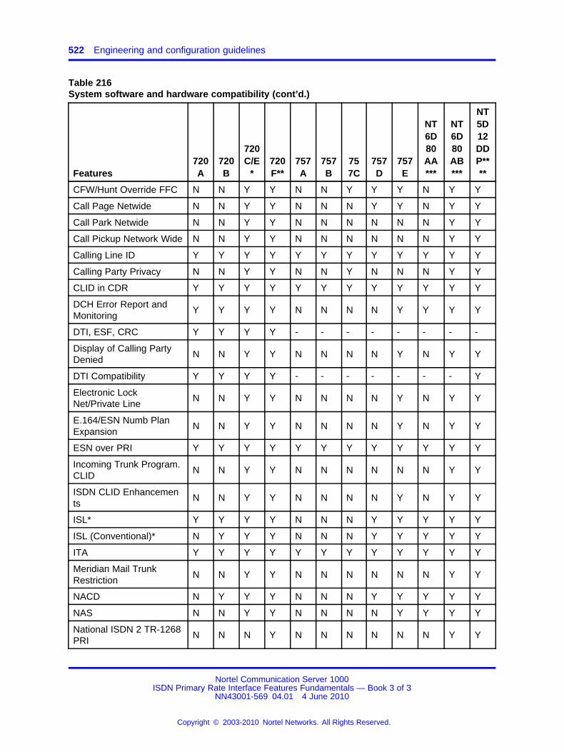
522 Engineering and configuration guidelines
Table 216System software and hardware compatibility (cont’d.)
Features720A
720B
720C/E
*720F**
757A
757B
757C
757D
757E
NT6D80AA***
NT6D80AB***
NT5D12DDP****
CFW/Hunt Override FFC N N Y Y N N Y Y Y N Y Y
Call Page Netwide N N Y Y N N N Y Y N Y Y
Call Park Netwide N N Y Y N N N N N N Y Y
Call Pickup Network Wide N N Y Y N N N N N N Y Y
Calling Line ID Y Y Y Y Y Y Y Y Y Y Y Y
Calling Party Privacy N N Y Y N N Y N N N Y Y
CLID in CDR Y Y Y Y Y Y Y Y Y Y Y Y
DCH Error Report andMonitoring
Y Y Y Y N N N N Y Y Y Y
DTI, ESF, CRC Y Y Y Y - - - - - - - -
Display of Calling PartyDenied
N N Y Y N N N N Y N Y Y
DTI Compatibility Y Y Y Y - - - - - - - Y
Electronic LockNet/Private Line
N N Y Y N N N N Y N Y Y
E.164/ESN Numb PlanExpansion
N N Y Y N N N N Y N Y Y
ESN over PRI Y Y Y Y Y Y Y Y Y Y Y Y
Incoming Trunk Program.CLID
N N Y Y N N N N N N Y Y
ISDN CLID Enhancements
N N Y Y N N N N Y N Y Y
ISL* Y Y Y Y N N N Y Y Y Y Y
ISL (Conventional)* N Y Y Y N N N Y Y Y Y Y
ITA Y Y Y Y Y Y Y Y Y Y Y Y
Meridian Mail TrunkRestriction
N N Y Y N N N N N N Y Y
NACD N Y Y Y N N N Y Y Y Y Y
NAS N N Y Y N N N N Y Y Y Y
National ISDN 2 TR-1268PRI
N N N Y N N N N N N Y Y
Nortel Communication Server 1000ISDN Primary Rate Interface Features Fundamentals — Book 3 of 3
NN43001-569 04.01 4 June 2010
Copyright © 2003-2010 Nortel Networks. All Rights Reserved.
.
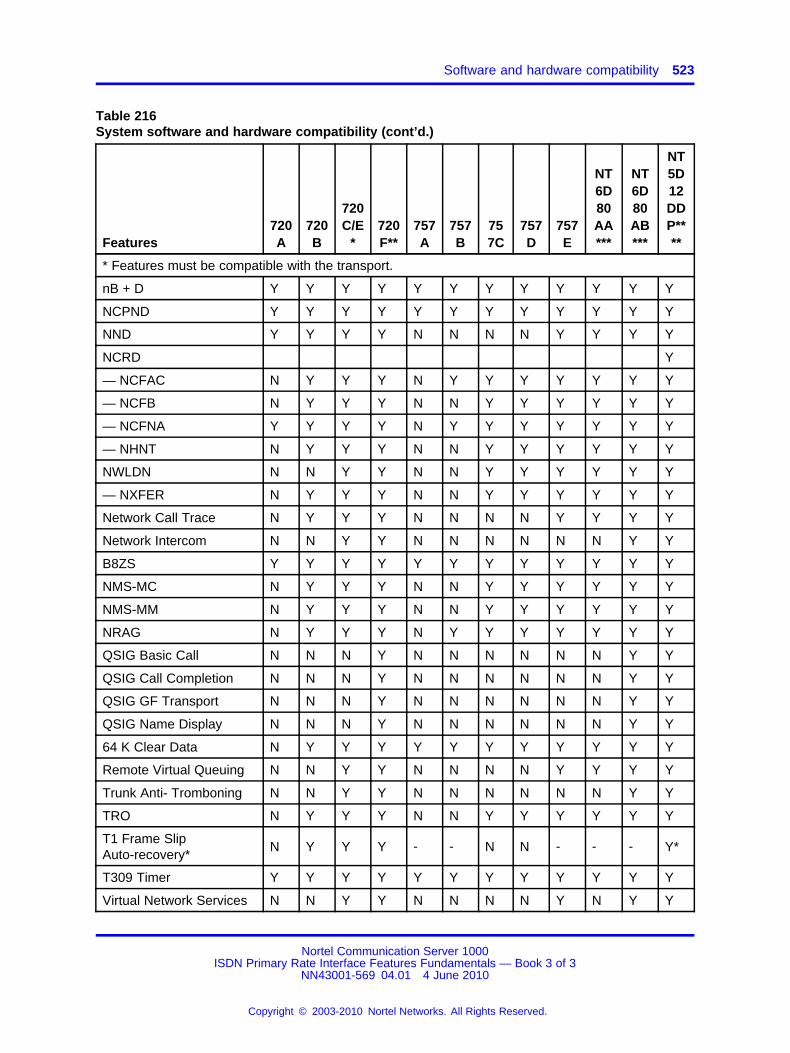
Software and hardware compatibility 523
Table 216System software and hardware compatibility (cont’d.)
Features720A
720B
720C/E
*720F**
757A
757B
757C
757D
757E
NT6D80AA***
NT6D80AB***
NT5D12DDP****
* Features must be compatible with the transport.
nB + D Y Y Y Y Y Y Y Y Y Y Y Y
NCPND Y Y Y Y Y Y Y Y Y Y Y Y
NND Y Y Y Y N N N N Y Y Y Y
NCRD Y
— NCFAC N Y Y Y N Y Y Y Y Y Y Y
— NCFB N Y Y Y N N Y Y Y Y Y Y
— NCFNA Y Y Y Y N Y Y Y Y Y Y Y
— NHNT N Y Y Y N N Y Y Y Y Y Y
NWLDN N N Y Y N N Y Y Y Y Y Y
— NXFER N Y Y Y N N Y Y Y Y Y Y
Network Call Trace N Y Y Y N N N N Y Y Y Y
Network Intercom N N Y Y N N N N N N Y Y
B8ZS Y Y Y Y Y Y Y Y Y Y Y Y
NMS-MC N Y Y Y N N Y Y Y Y Y Y
NMS-MM N Y Y Y N N Y Y Y Y Y Y
NRAG N Y Y Y N Y Y Y Y Y Y Y
QSIG Basic Call N N N Y N N N N N N Y Y
QSIG Call Completion N N N Y N N N N N N Y Y
QSIG GF Transport N N N Y N N N N N N Y Y
QSIG Name Display N N N Y N N N N N N Y Y
64 K Clear Data N Y Y Y Y Y Y Y Y Y Y Y
Remote Virtual Queuing N N Y Y N N N N Y Y Y Y
Trunk Anti- Tromboning N N Y Y N N N N N N Y Y
TRO N Y Y Y N N Y Y Y Y Y Y
T1 Frame SlipAuto-recovery*
N Y Y Y - - N N - - - Y*
T309 Timer Y Y Y Y Y Y Y Y Y Y Y Y
Virtual Network Services N N Y Y N N N N Y N Y Y
Nortel Communication Server 1000ISDN Primary Rate Interface Features Fundamentals — Book 3 of 3
NN43001-569 04.01 4 June 2010
Copyright © 2003-2010 Nortel Networks. All Rights Reserved.
.
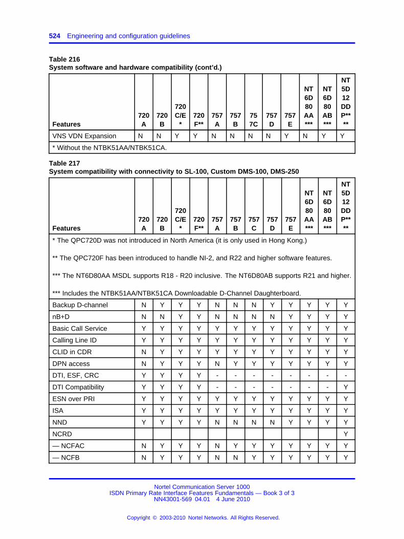
524 Engineering and configuration guidelines
Table 216System software and hardware compatibility (cont’d.)
Features720A
720B
720C/E
*720F**
757A
757B
757C
757D
757E
NT6D80AA***
NT6D80AB***
NT5D12DDP****
VNS VDN Expansion N N Y Y N N N N Y N Y Y
* Without the NTBK51AA/NTBK51CA.
Table 217System compatibility with connectivity to SL-100, Custom DMS-100, DMS-250
Features720A
720B
720C/E
*720F**
757A
757B
757C
757D
757E
NT6D80AA***
NT6D80AB***
NT5D12DDP****
* The QPC720D was not introduced in North America (it is only used in Hong Kong.)
** The QPC720F has been introduced to handle NI-2, and R22 and higher software features.
*** The NT6D80AA MSDL supports R18 - R20 inclusive. The NT6D80AB supports R21 and higher.
*** Includes the NTBK51AA/NTBK51CA Downloadable D-Channel Daughterboard.
Backup D-channel N Y Y Y N N N Y Y Y Y Y
nB+D N N Y Y N N N N Y Y Y Y
Basic Call Service Y Y Y Y Y Y Y Y Y Y Y Y
Calling Line ID Y Y Y Y Y Y Y Y Y Y Y Y
CLID in CDR N Y Y Y Y Y Y Y Y Y Y Y
DPN access N Y Y Y N Y Y Y Y Y Y Y
DTI, ESF, CRC Y Y Y Y - - - - - - - -
DTI Compatibility Y Y Y Y - - - - - - - Y
ESN over PRI Y Y Y Y Y Y Y Y Y Y Y Y
ISA Y Y Y Y Y Y Y Y Y Y Y Y
NND Y Y Y Y N N N N Y Y Y Y
NCRD Y
— NCFAC N Y Y Y N Y Y Y Y Y Y Y
— NCFB N Y Y Y N N Y Y Y Y Y Y
Nortel Communication Server 1000ISDN Primary Rate Interface Features Fundamentals — Book 3 of 3
NN43001-569 04.01 4 June 2010
Copyright © 2003-2010 Nortel Networks. All Rights Reserved.
.

Software and hardware compatibility 525
Table 217System compatibility with connectivity to SL-100, Custom DMS-100, DMS-250 (cont’d.)
Features720A
720B
720C/E
*720F**
757A
757B
757C
757D
757E
NT6D80AA***
NT6D80AB***
NT5D12DDP****
— NCFNA Y Y Y Y N Y Y Y Y Y Y Y
— NHNT N Y Y Y N N Y Y Y Y Y Y
NRAG (TIE) Y Y Y Y N N Y Y Y Y Y Y
B8ZS Y Y Y Y Y Y Y Y Y Y Y Y
NRAG N Y Y Y N Y Y Y Y Y Y Y
64 K Clear Data N Y Y Y Y Y Y Y Y Y Y Y
Private Network Hopoff Y Y Y Y Y Y Y Y Y Y Y Y
T1 Frame SlipAuto-recovery*
N Y Y Y - - - - - - - Y*
* Without the NTBK51AA/NTBK51CA.
Table 218System software and hardware compatibility with connectivity to AT and T 4ESS
Features720A
720B
720C/E
*720F**
757A
757B
757C
757D
757E
NT6D80AA***
NT6D80AB***
NT5D12DDP****
* The QPC720D was not introduced in North America (it is only used in Hong Kong.)
** The QPC720F has been introduced to handle NI-2, and R22 and higher software features.
*** The NT6D80AA MSDL supports R18 - R20 inclusive. The NT6D80AB supports R21 and higher.
*** Includes the NTBK51AA/NTBK51CA Downloadable D-Channel Daughterboard.
ANI in CDR N Y Y Y Y Y Y Y Y Y Y Y
ANI Station ID N Y Y Y Y Y Y Y Y Y Y Y
Backup D-channel N N Y Y N Y Y Y Y Y Y Y
Basic Call Service N Y Y Y Y Y Y Y Y Y Y Y
ISA/CBC N Y Y Y N N N Y Y Y Y Y
Nortel Communication Server 1000ISDN Primary Rate Interface Features Fundamentals — Book 3 of 3
NN43001-569 04.01 4 June 2010
Copyright © 2003-2010 Nortel Networks. All Rights Reserved.
.
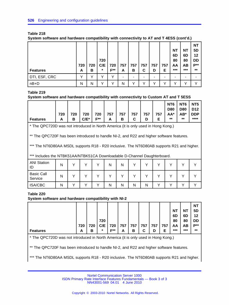
526 Engineering and configuration guidelines
Table 218System software and hardware compatibility with connectivity to AT and T 4ESS (cont’d.)
Features720A
720B
720C/E
*720F**
757A
757B
757C
757D
757E
NT6D80AA***
NT6D80AB***
NT5D12DDP****
DTI, ESF, CRC Y Y Y Y - - - - - - - -
nB+D N N Y Y N Y Y Y Y Y Y Y
Table 219System software and hardware compatibility with connectivity to Custom AT and T 5ESS
Features720A
720B
720C/E*
720F**
757A
757B
757C
757D
757E
NT6D80AA***
NT6D80AB***
NT5D12DDP****
* The QPC720D was not introduced in North America (it is only used in Hong Kong.)
** The QPC720F has been introduced to handle NI-2, and R22 and higher software features.
*** The NT6D80AA MSDL supports R18 - R20 inclusive. The NT6D80AB supports R21 and higher.
*** Includes the NTBK51AA/NTBK51CA Downloadable D-Channel Daughterboard.
ANI StationID
N Y Y Y N N Y Y Y Y Y Y
Basic CallService
N Y Y Y Y Y Y Y Y Y Y Y
ISA/CBC N Y Y Y N N N N Y Y Y Y
Table 220System software and hardware compatibility with NI-2
Features720A
720B
720C/E
*720F**
757A
757B
757C
757D
757E
NT6D80AA***
NT6D80AB***
NT5D12DDP****
* The QPC720D was not introduced in North America (it is only used in Hong Kong.)
** The QPC720F has been introduced to handle NI-2, and R22 and higher software features.
*** The NT6D80AA MSDL supports R18 - R20 inclusive. The NT6D80AB supports R21 and higher.
Nortel Communication Server 1000ISDN Primary Rate Interface Features Fundamentals — Book 3 of 3
NN43001-569 04.01 4 June 2010
Copyright © 2003-2010 Nortel Networks. All Rights Reserved.
.
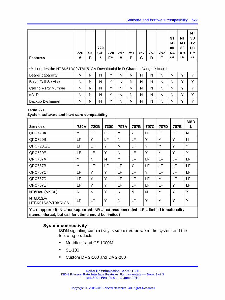
Software and hardware compatibility 527
Features720A
720B
720C/E
*720F**
757A
757B
757C
757D
757E
NT6D80AA***
NT6D80AB***
NT5D12DDP****
*** Includes the NTBK51AA/NTBK51CA Downloadable D-Channel Daughterboard.
Bearer capability N N N Y N N N N N N Y Y
Basic Call Service N N N Y N N N N N N Y Y
Calling Party Number N N N Y N N N N N N Y Y
nB+D N N N Y N N N N N N Y Y
Backup D-channel N N N Y N N N N N N Y Y
Table 221System software and hardware compatibility
Services 720A 720B 720C 757A 757B 757C 757D 757EMSD
L
QPC720A Y LF LF Y Y LF LF LF N
QPC720B LF Y LF N LF Y Y Y N
QPC720C/E LF LF Y N LF Y Y Y Y
QPC720F LF LF Y N LF Y Y Y Y
QPC757A Y N N Y LF LF LF LF LF
QPC757B Y LF LF LF Y LF LF LF LF
QPC757C LF Y Y LF LF Y LF LF LF
QPC757D LF Y Y LF LF LF Y LF LF
QPC757E LF Y Y LF LF LF LF Y LF
NT6D80 (MSDL) N N Y N N N Y Y Y
NT5D12/wNTBK51AA/NTBK51CA
LF LF Y N LF Y Y Y Y
Y = (supported); N = not supported; NR = not recommended; LF = limited functionality(items interact, but call functions could be limited)
System connectivityISDN signaling connectivity is supported between the system and thefollowing products:
• Meridian 1and CS 1000M
• SL-100
• Custom DMS-100 and DMS-250
Nortel Communication Server 1000ISDN Primary Rate Interface Features Fundamentals — Book 3 of 3
NN43001-569 04.01 4 June 2010
Copyright © 2003-2010 Nortel Networks. All Rights Reserved.
.
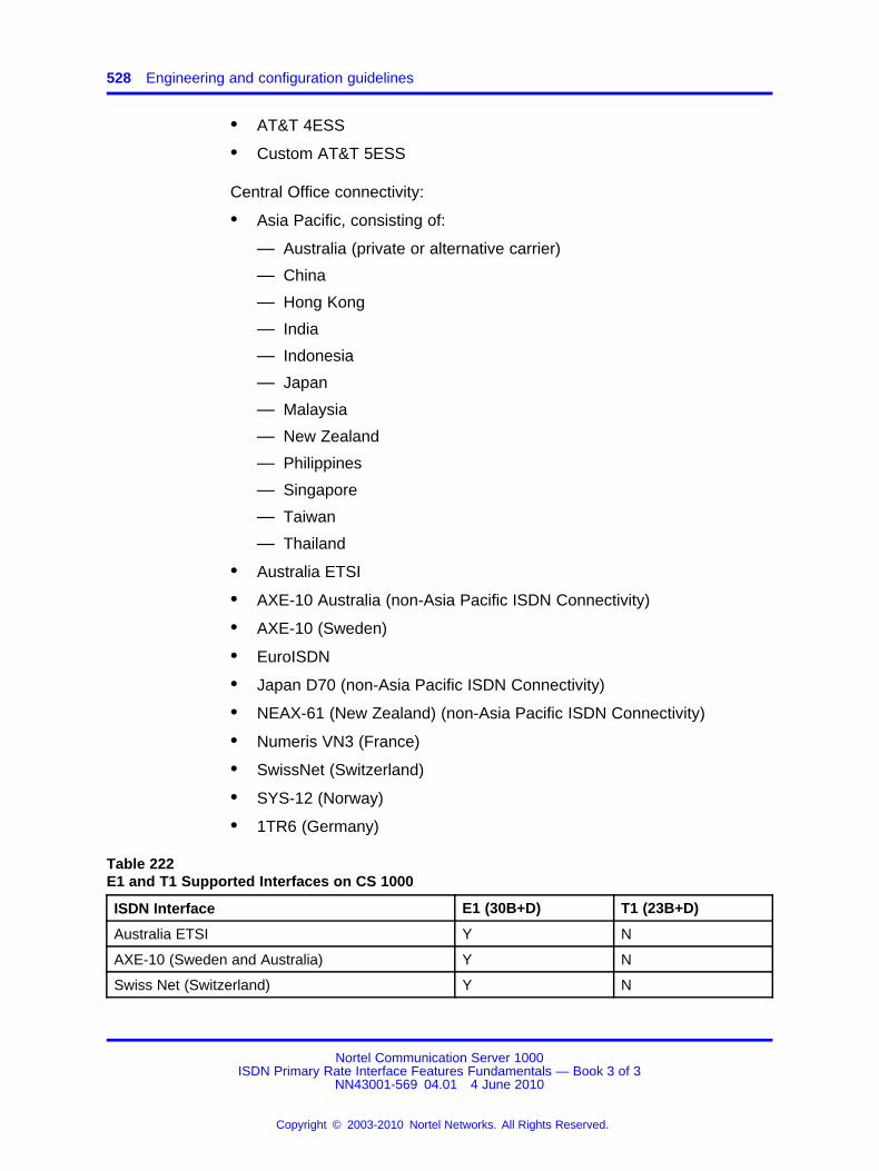
528 Engineering and configuration guidelines
• AT&T 4ESS
• Custom AT&T 5ESS
Central Office connectivity:
• Asia Pacific, consisting of:
— Australia (private or alternative carrier)
— China
— Hong Kong
— India
— Indonesia
— Japan
— Malaysia
— New Zealand
— Philippines
— Singapore
— Taiwan
— Thailand
• Australia ETSI
• AXE-10 Australia (non-Asia Pacific ISDN Connectivity)
• AXE-10 (Sweden)
• EuroISDN
• Japan D70 (non-Asia Pacific ISDN Connectivity)
• NEAX-61 (New Zealand) (non-Asia Pacific ISDN Connectivity)
• Numeris VN3 (France)
• SwissNet (Switzerland)
• SYS-12 (Norway)
• 1TR6 (Germany)
Table 222E1 and T1 Supported Interfaces on CS 1000
ISDN Interface E1 (30B+D) T1 (23B+D)
Australia ETSI Y N
AXE-10 (Sweden and Australia) Y N
Swiss Net (Switzerland) Y N
Nortel Communication Server 1000ISDN Primary Rate Interface Features Fundamentals — Book 3 of 3
NN43001-569 04.01 4 June 2010
Copyright © 2003-2010 Nortel Networks. All Rights Reserved.
.
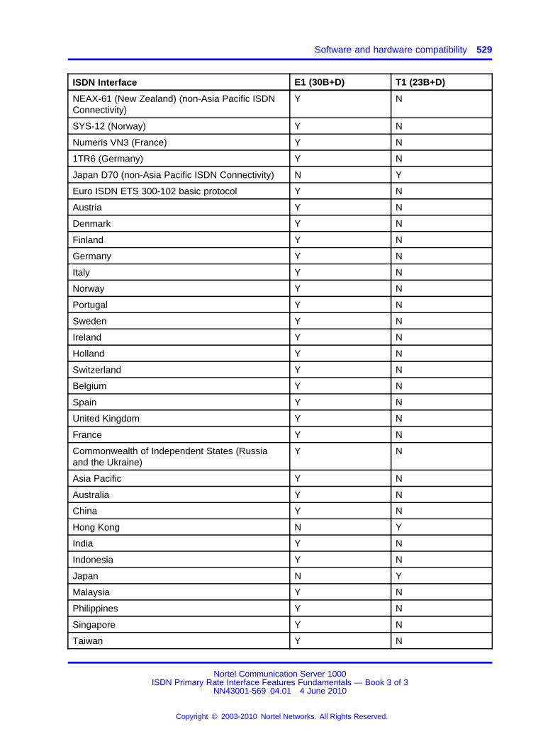
Software and hardware compatibility 529
ISDN Interface E1 (30B+D) T1 (23B+D)
NEAX-61 (New Zealand) (non-Asia Pacific ISDNConnectivity)
Y N
SYS-12 (Norway) Y N
Numeris VN3 (France) Y N
1TR6 (Germany) Y N
Japan D70 (non-Asia Pacific ISDN Connectivity) N Y
Euro ISDN ETS 300-102 basic protocol Y N
Austria Y N
Denmark Y N
Finland Y N
Germany Y N
Italy Y N
Norway Y N
Portugal Y N
Sweden Y N
Ireland Y N
Holland Y N
Switzerland Y N
Belgium Y N
Spain Y N
United Kingdom Y N
France Y N
Commonwealth of Independent States (Russiaand the Ukraine)
Y N
Asia Pacific Y N
Australia Y N
China Y N
Hong Kong N Y
India Y N
Indonesia Y N
Japan N Y
Malaysia Y N
Philippines Y N
Singapore Y N
Taiwan Y N
Nortel Communication Server 1000ISDN Primary Rate Interface Features Fundamentals — Book 3 of 3
NN43001-569 04.01 4 June 2010
Copyright © 2003-2010 Nortel Networks. All Rights Reserved.
.

530 Engineering and configuration guidelines
ISDN Interface E1 (30B+D) T1 (23B+D)
New Zealand Y N
Thailand Y N
QSIG Y Y
JTTC (Japan QSIG) N Y
SL-1 Y Y
D100 N Y
D250 N Y
SL100 N Y
National ISDN 2 (NI-2) N Y
ESS4 N Y
ESS5 N Y
DPNSS/DASS Y N
Cable informationThe following list contains cable and channel information. The cable typeused is a 2-pair twisted wire.
• 655 ft (200 m) maximum distance from the system to DSX-1cross-connect point (using ARAM or ABAM equivalent shielded cable)
• 750 ft (229 m) maximum distance from the system to Office RepeaterBay
Specific cables are detailed in ISDN Primary Rate Interface Installationand Commissioning (NN43001-301).
Nortel Communication Server 1000ISDN Primary Rate Interface Features Fundamentals — Book 3 of 3
NN43001-569 04.01 4 June 2010
Copyright © 2003-2010 Nortel Networks. All Rights Reserved.
.
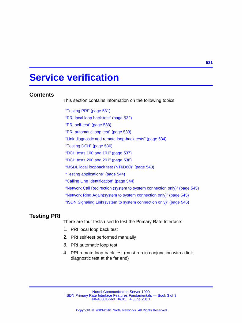
531.
Service verification
ContentsThis section contains information on the following topics:
“Testing PRI” (page 531)
“PRI local loop back test” (page 532)
“PRI self-test” (page 533)
“PRI automatic loop test” (page 533)
“Link diagnostic and remote loop-back tests” (page 534)
“Testing DCH” (page 536)
“DCH tests 100 and 101” (page 537)
“DCH tests 200 and 201” (page 538)
“MSDL local loopback test (NT6D80)” (page 540)
“Testing applications” (page 544)
“Calling Line Identification” (page 544)
“Network Call Redirection (system to system connection only)” (page 545)
“Network Ring Again(system to system connection only)” (page 545)
“ISDN Signaling Link(system to system connection only)” (page 546)
Testing PRIThere are four tests used to test the Primary Rate Interface:
1. PRI local loop back test
2. PRI self-test performed manually
3. PRI automatic loop test
4. PRI remote loop-back test (must run in conjunction with a linkdiagnostic test at the far end)
Nortel Communication Server 1000ISDN Primary Rate Interface Features Fundamentals — Book 3 of 3
NN43001-569 04.01 4 June 2010
Copyright © 2003-2010 Nortel Networks. All Rights Reserved.
.
532 Service verification
PRI local loop back testThis test checks the communication path between the QPC414 Networkcard and the PRI card. It also checks the leads for the J4. It is oftenperformed when the PRI cannot be enabled. The PRI card must beinstalled, and a cable connecting its J3 connector to a QPC414 Networkcard.
Step Action
1 Disable the D-channel.
LD 96DIS DCH x
2 Disable the PRI loop:
LD 60DISL loop
3 Disconnect the cable connector from the PRI J4 (if attached).Several LEDs will light on the faceplate.
4 Attach a female 15 pin connector loopback plug to J4. Theloopback plug must have pins 1 and 3, and pins 9 and 11shorted together.
5 Enable the PRI loop:
LD 60ENLL loop
The green ACT LED will light in a few seconds. If so, the testpassed. Continue with the following steps.
If the green ACT light does not come on, retest. Unseat the PRIcard between steps 2 and 3.
If the light still does not turn on, try replacing your QPC414 orPRI cards, or the connecting cable.
6 Remove the loopback plug from the J4 connector.
7 Replace cable connector to the PRI J4 (removed in step 3).
8 Enable the loop:
LD 60ENLL loop
9 Enable the DCH:
Nortel Communication Server 1000ISDN Primary Rate Interface Features Fundamentals — Book 3 of 3
NN43001-569 04.01 4 June 2010
Copyright © 2003-2010 Nortel Networks. All Rights Reserved.
.
Testing PRI 533
LD 96ENL DCH x
--End--
PRI self-testThe self-test checks speech path continuity, zero code suppression,remote alarm detection, and A&B bit signaling. This test is performedmanually, for each channel or for each frame (24 channels).
The DCH and PRI must be disabled before performing the self-test or callprocessing is disrupted. To perform the self-test on a specific loop:
Step Action
1 Disable DCH:
LD 96DIS DCH x
2 Disable the PRI loop and run the self-test:
LD60DISL loopSLFT loop
When the system returns OK, it indicates that the hardware isoperable.
3 Re-enable the PRI loop:
LD 60ENLL loop
The D-channel will re-enable automatically.
--End--
PRI automatic loop testThe automatic loop test checks the same functions as the self-test. Unlikethe self-test, it can be run automatically, as part of the midnight routines.
With the ATLP command set to one:
If all 23 channels are idle at midnight, the system disables the card andperforms a self-test on all channels.
Nortel Communication Server 1000ISDN Primary Rate Interface Features Fundamentals — Book 3 of 3
NN43001-569 04.01 4 June 2010
Copyright © 2003-2010 Nortel Networks. All Rights Reserved.
.
534 Service verification
If any of the 23 channels are busy at midnight, the system disables oneidle channel, chosen at random, and checks it while the card is enabled.
With the ATLP command set to zero, only one channel is tested. Thechannel tested is randomly selected by software; it cannot be specified.
To perform the remote loop-back test, use the following:
LD 60ATLP 1 or 0
When ATLP 1 is entered, the TTY prints out AUTO TEST ENBL. WhenATLP 0 is entered, the TTY prints out AUTO TEST DSBL.
Link diagnostic and remote loop-back testsThe remote loop-back test and the link diagnostic test are performedmanually for each channel or for each frame (23 channels).
Link diagnostic testThe link diagnostic test, also called the far end loop-back test, does nottest the system PRI. It puts the PRI in loop-back mode at the far end so aremote loop-back test can be performed on far end equipment. The PRIchannel, loop, or frame tested must be disabled.
Remote loop-back testThe remote loop-back test, also called the near end loop back test, checksthe integrity of the PRI from the system to the far end. The far end mustbe put into loop-back mode before this test can be performed. The PRIchannel, loop, or frame tested must be disabled.
Coordinating the testsWhen a technician at the far end asks for loop-back mode on the system,perform the following steps.
Step Action
1 Disable the D-channel.
LD 96DIS DCH x
2 Disable the PRI loop and activate loop-back mode.
LD 60DISL loopRLBK loop
Nortel Communication Server 1000ISDN Primary Rate Interface Features Fundamentals — Book 3 of 3
NN43001-569 04.01 4 June 2010
Copyright © 2003-2010 Nortel Networks. All Rights Reserved.
.

Testing PRI 535
The QPC720 LBK LED lights.
--End--
When a technician at the far end asks for loop-back mode on the systemto be disabled, perform this step.
Disable loopback mode.
LD 60DLBK loop
The LBK LED turns off.
When a technician at the far end asks for PRI and DCH to be re-enabled,perform this step.
Enable the PRI loop.
LD 60ENLL loop
OK will print out. The D-channel re-enables automatically.
To run the remote loop-back test on the system, call a technician at the farend and ask for loop-back mode at that facility.
When loop-back mode at the far end is confirmed, the technician at thefar end follows these steps.
Step Action
1 Disable the D-channel.
LD 96DIS DCH N
2 Disable the PRI loop and run the loop-back test using.
LD 60DISL LRMST L
SLFT OK prints out to indicate a successful test.
3 Call the far end technician to disable the loopback test, and tore-enable the PRI and DCH. The far end technician enables thePRI.
Nortel Communication Server 1000ISDN Primary Rate Interface Features Fundamentals — Book 3 of 3
NN43001-569 04.01 4 June 2010
Copyright © 2003-2010 Nortel Networks. All Rights Reserved.
.
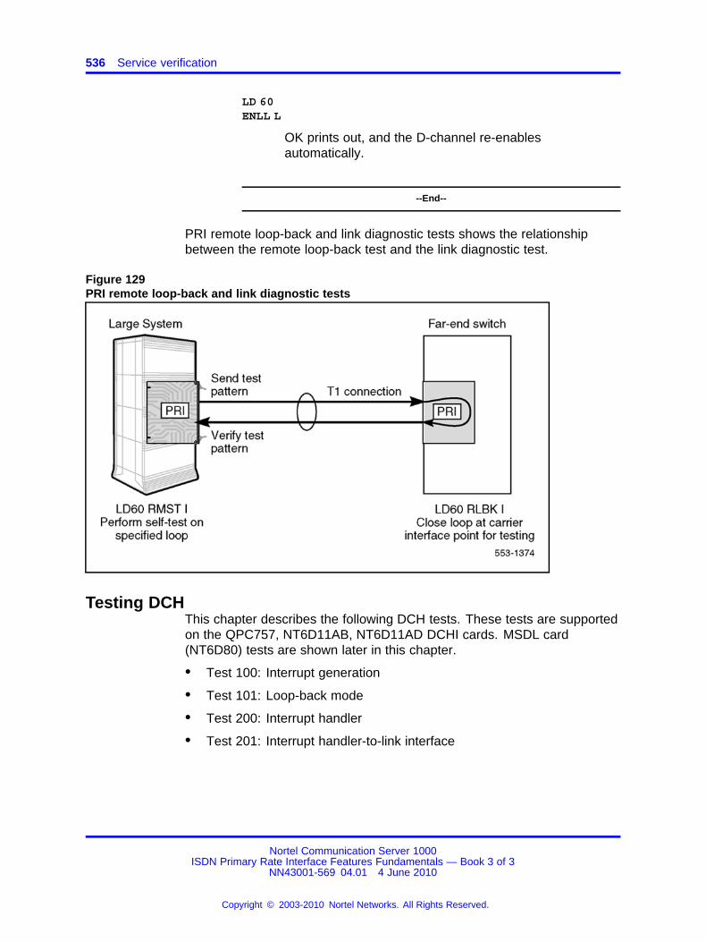
536 Service verification
LD 60ENLL L
OK prints out, and the D-channel re-enablesautomatically.
--End--
PRI remote loop-back and link diagnostic tests shows the relationshipbetween the remote loop-back test and the link diagnostic test.
Figure 129PRI remote loop-back and link diagnostic tests
Testing DCHThis chapter describes the following DCH tests. These tests are supportedon the QPC757, NT6D11AB, NT6D11AD DCHI cards. MSDL card(NT6D80) tests are shown later in this chapter.
• Test 100: Interrupt generation
• Test 101: Loop-back mode
• Test 200: Interrupt handler
• Test 201: Interrupt handler-to-link interface
Nortel Communication Server 1000ISDN Primary Rate Interface Features Fundamentals — Book 3 of 3
NN43001-569 04.01 4 June 2010
Copyright © 2003-2010 Nortel Networks. All Rights Reserved.
.

Testing DCH 537
DCH tests 100 and 101DCH tests 100 and 101 are isolated hardware tests. Test 100 checksinterrupt generation on the DCHI card. Test 101 checks the DCHIloop-back capability. If either test fails, either a faulty DCHI or a contentionproblem is indicated. A test failure initiates DCH error messages. SeeFigure 130 "DCH tests 100 and 101" (page 538).
Tests 100 and 101 must be run in sequential order (tests 200 and 201 canfollow). Established calls stay up, but new calls cannot be placed.
The DCH link must be in the reset state when these tests are run. Resetcan be accomplished when the status of the D-channel is established(EST) or released (RLS).
To reset:LD 96STAT DCH x (responds either EST or RLS)RST DCH x
If the DCHI is disabled, it must be enabled before reset can beestablished.
To enable the DCHI:
LD 96STAT DCH x (responds RST)ENL DCH x (if a problem caused the disabled state, RLS occurs; if thedisabled state is cleared, status is EST)
To run Test 100 and Test 101 after verifying that the DCH is reset:
TEST 100 xTEST 101 x
OK appears when test passes successfully.
Nortel Communication Server 1000ISDN Primary Rate Interface Features Fundamentals — Book 3 of 3
NN43001-569 04.01 4 June 2010
Copyright © 2003-2010 Nortel Networks. All Rights Reserved.
.

538 Service verification
Figure 130DCH tests 100 and 101
DCH tests 200 and 201DCH tests 200 and 201 are software tests. See Figure 131 "DCH tests200 and 201" (page 540). Test 200 monitors the DCHI interrupt handler.Test 201 checks the interrupt handler-to-link interface path. A failure ofeither test indicates software problems. A test failure initiates DCH errormessages.
Nortel Communication Server 1000ISDN Primary Rate Interface Features Fundamentals — Book 3 of 3
NN43001-569 04.01 4 June 2010
Copyright © 2003-2010 Nortel Networks. All Rights Reserved.
.
Testing DCH 539
Tests 200 and 201 must be run sequentially after tests 100 and 101.Established calls stay up, but new calls cannot be placed.
The DCH link must be in the reset state when these tests are run. Resetcan be established when the status of the D-channel is established (EST)or released (RLS).
To reset:
LD 96STAT DCH x (responds either EST or RLS)RST DCH x
If the DCHI is disabled, it must be enabled before reset can beestablished.
To enable the DCHI:
LD 96STAT DCH x (responds RST)ENL DCH x (if a problem caused the disabled state, RLS occurs; if thedisabled state is cleared, status is EST)
RST DCH x
To run Test 200 and Test 201 after verifying that the DCH is reset:
TEST 200 xTEST 201 x
OK appears when test passes successfully.
Nortel Communication Server 1000ISDN Primary Rate Interface Features Fundamentals — Book 3 of 3
NN43001-569 04.01 4 June 2010
Copyright © 2003-2010 Nortel Networks. All Rights Reserved.
.
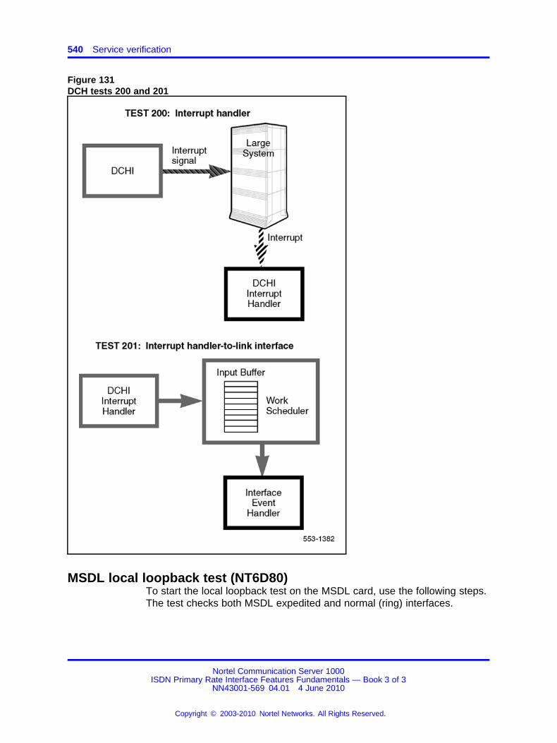
540 Service verification
Figure 131DCH tests 200 and 201
MSDL local loopback test (NT6D80)To start the local loopback test on the MSDL card, use the following steps.The test checks both MSDL expedited and normal (ring) interfaces.
Nortel Communication Server 1000ISDN Primary Rate Interface Features Fundamentals — Book 3 of 3
NN43001-569 04.01 4 June 2010
Copyright © 2003-2010 Nortel Networks. All Rights Reserved.
.
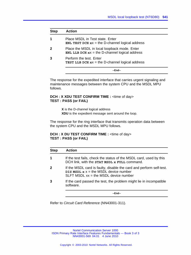
MSDL local loopback test (NT6D80) 541
Step Action
1 Place MSDL in Test state. EnterENL TEST DCH xx = the D-channel logical address
2 Place the MSDL in local loopback mode. EnterENL LLB DCH xx = the D-channel logical address
3 Perform the test. EnterTEST LLB DCH xx = the D-channel logical address
--End--
The response for the expedited interface that carries urgent signaling andmaintenance messages between the system CPU and the MSDL MPUfollows.
DCH : X XDU TEST CONFIRM TIME : <time of day>TEST : PASS (or FAIL)
X is the D-channel logical addressXDU is the expedient message sent around the loop.
The response for the ring interface that transmits operation data betweenthe system CPU and the MSDL MPU follows.
DCH : X DU TEST CONFIRM TIME : <time of day>TEST : PASS (or FAIL)
Step Action
1 If the test fails, check the status of the MSDL card, used by thisDCH link, with the STAT MSDL x FULL command.
2 If the MSDL card is faulty, disable the card and perform self-test.DIS MSDL x x = the MSDL device numberSLFT MSDL xx = the MSDL device number
3 If the card passed the test, the problem might lie in incompatiblesoftware.
--End--
Refer to Circuit Card Reference (NN43001-311).
Nortel Communication Server 1000ISDN Primary Rate Interface Features Fundamentals — Book 3 of 3
NN43001-569 04.01 4 June 2010
Copyright © 2003-2010 Nortel Networks. All Rights Reserved.
.
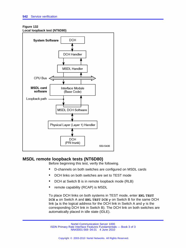
542 Service verification
Figure 132Local loopback test (NT6D80)
MSDL remote loopback tests (NT6D80)Before beginning this test, verify the following.
• D-channels on both switches are configured on MSDL cards
• DCH links on both switches are set to TEST mode
• DCH at Switch B is in remote loopback mode (RLB)
• remote capability (RCAP) is MSDL
To place DCH links on both systems in TEST mode, enter ENL TESTDCH x on Switch A and ENL TEST DCH y on Switch B for the same DCHlink (x is the logical address for the DCH link in Switch A and y is thecorresponding DCH link in Switch B). The DCH link on both switches areautomatically placed in idle state (IDLE).
Nortel Communication Server 1000ISDN Primary Rate Interface Features Fundamentals — Book 3 of 3
NN43001-569 04.01 4 June 2010
Copyright © 2003-2010 Nortel Networks. All Rights Reserved.
.

MSDL remote loopback tests (NT6D80) 543
Step Action
1 Place the Switch B DCH link in remote loopback state (RLB) withENL RLB DCH x. The DCH link in Switch A must stay in idle.
2 Perform the loopback test TESTRLB x from Switch A.
The result of the remote loopback test is displayed on Switch A’sconsole in the following format.
DCH : X RLB TEST CONFIRM TIME : <time of day>TEST : PASS
TEST : FAIL - NO DATA RCV FAR ENDTEST : FAIL - CORPT DATA RCV FAR ENDTEST : FAIL - REASON UNKNOWN
TEST : FAIL can indicate a problem in the physical link betweenthe two switches, or faulty equipment in either switch. Check theconnections, and verify the status of the MSDL and PRI trunkcards used for this link. Refer to ISDN Primary Rate InterfaceMaintenance (NN43001-717) for detailed troubleshootingprocedures.
3 Place the Switch B DCH link back to the idle state, with theDIS RLB y command.
4 If you think the MSDL card used in either switch has failed,check the status of the DCH link and the status of the MSDLcard by entering STAT MSDL x FULL.
5 If the MSDL card is faulty, disable the card and perform self-test.DIS MSDL xSLFT MSDL x
6 If the card passed the test, the problem might lie in incompatiblesoftware. Refer to Circuit Card Reference (NN43001-311).
--End--
Nortel Communication Server 1000ISDN Primary Rate Interface Features Fundamentals — Book 3 of 3
NN43001-569 04.01 4 June 2010
Copyright © 2003-2010 Nortel Networks. All Rights Reserved.
.

544 Service verification
Figure 133Remote loopback tests (NT6D80)
Testing applicationsCalling Line Identification
To verify Calling Line Identification (CLID), do the following:
Step Action
1 Place a call from the system over a PRI trunk to a terminal with adigit display at the far-end facility.
2 Verify that the call is terminated correctly.
3 Verify that the CLID number displayed on the far-end phone iscorrect.
4 Have the far end place a call to a system device with a digitdisplay.
5 Verify that the number displayed is the correct CLID number.
Nortel Communication Server 1000ISDN Primary Rate Interface Features Fundamentals — Book 3 of 3
NN43001-569 04.01 4 June 2010
Copyright © 2003-2010 Nortel Networks. All Rights Reserved.
.
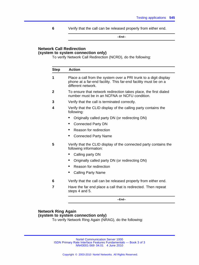
Testing applications 545
6 Verify that the call can be released properly from either end.
--End--
Network Call Redirection(system to system connection only)
To verify Network Call Redirection (NCRD), do the following:
Step Action
1 Place a call from the system over a PRI trunk to a digit displayphone at a far-end facility. This far-end facility must be on adifferent network.
2 To ensure that network redirection takes place, the first dialednumber must be in an NCFNA or NCFU condition.
3 Verify that the call is terminated correctly.
4 Verify that the CLID display of the calling party contains thefollowing:
• Originally called party DN (or redirecting DN)
• Connected Party DN
• Reason for redirection
• Connected Party Name
5 Verify that the CLID display of the connected party contains thefollowing information:
• Calling party DN
• Originally called party DN (or redirecting DN)
• Reason for redirection
• Calling Party Name
6 Verify that the call can be released properly from either end.
7 Have the far end place a call that is redirected. Then repeatsteps 4 and 5.
--End--
Network Ring Again(system to system connection only)
To verify Network Ring Again (NRAG), do the following:
Nortel Communication Server 1000ISDN Primary Rate Interface Features Fundamentals — Book 3 of 3
NN43001-569 04.01 4 June 2010
Copyright © 2003-2010 Nortel Networks. All Rights Reserved.
.
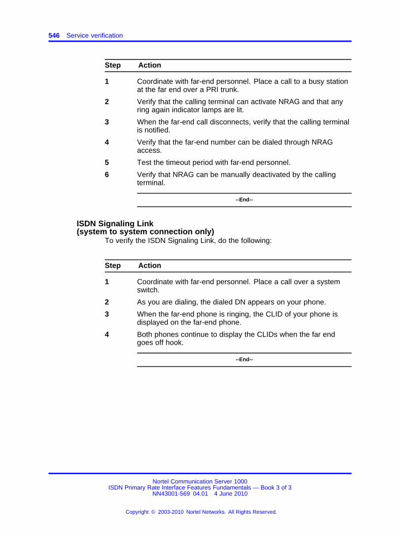
546 Service verification
Step Action
1 Coordinate with far-end personnel. Place a call to a busy stationat the far end over a PRI trunk.
2 Verify that the calling terminal can activate NRAG and that anyring again indicator lamps are lit.
3 When the far-end call disconnects, verify that the calling terminalis notified.
4 Verify that the far-end number can be dialed through NRAGaccess.
5 Test the timeout period with far-end personnel.
6 Verify that NRAG can be manually deactivated by the callingterminal.
--End--
ISDN Signaling Link(system to system connection only)
To verify the ISDN Signaling Link, do the following:
Step Action
1 Coordinate with far-end personnel. Place a call over a systemswitch.
2 As you are dialing, the dialed DN appears on your phone.
3 When the far-end phone is ringing, the CLID of your phone isdisplayed on the far-end phone.
4 Both phones continue to display the CLIDs when the far endgoes off hook.
--End--
Nortel Communication Server 1000ISDN Primary Rate Interface Features Fundamentals — Book 3 of 3
NN43001-569 04.01 4 June 2010
Copyright © 2003-2010 Nortel Networks. All Rights Reserved.
.
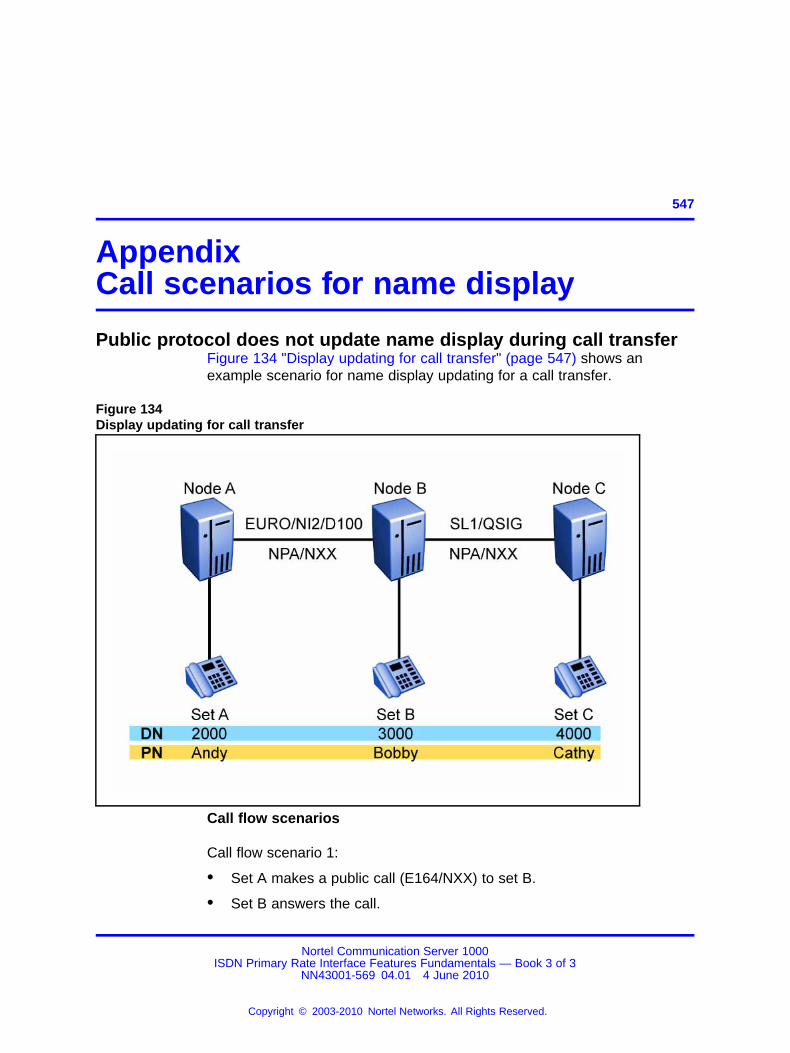
547.
AppendixCall scenarios for name display
Public protocol does not update name display during call transferFigure 134 "Display updating for call transfer" (page 547) shows anexample scenario for name display updating for a call transfer.
Figure 134Display updating for call transfer
Call flow scenarios
Call flow scenario 1:
• Set A makes a public call (E164/NXX) to set B.
• Set B answers the call.
Nortel Communication Server 1000ISDN Primary Rate Interface Features Fundamentals — Book 3 of 3
NN43001-569 04.01 4 June 2010
Copyright © 2003-2010 Nortel Networks. All Rights Reserved.
.
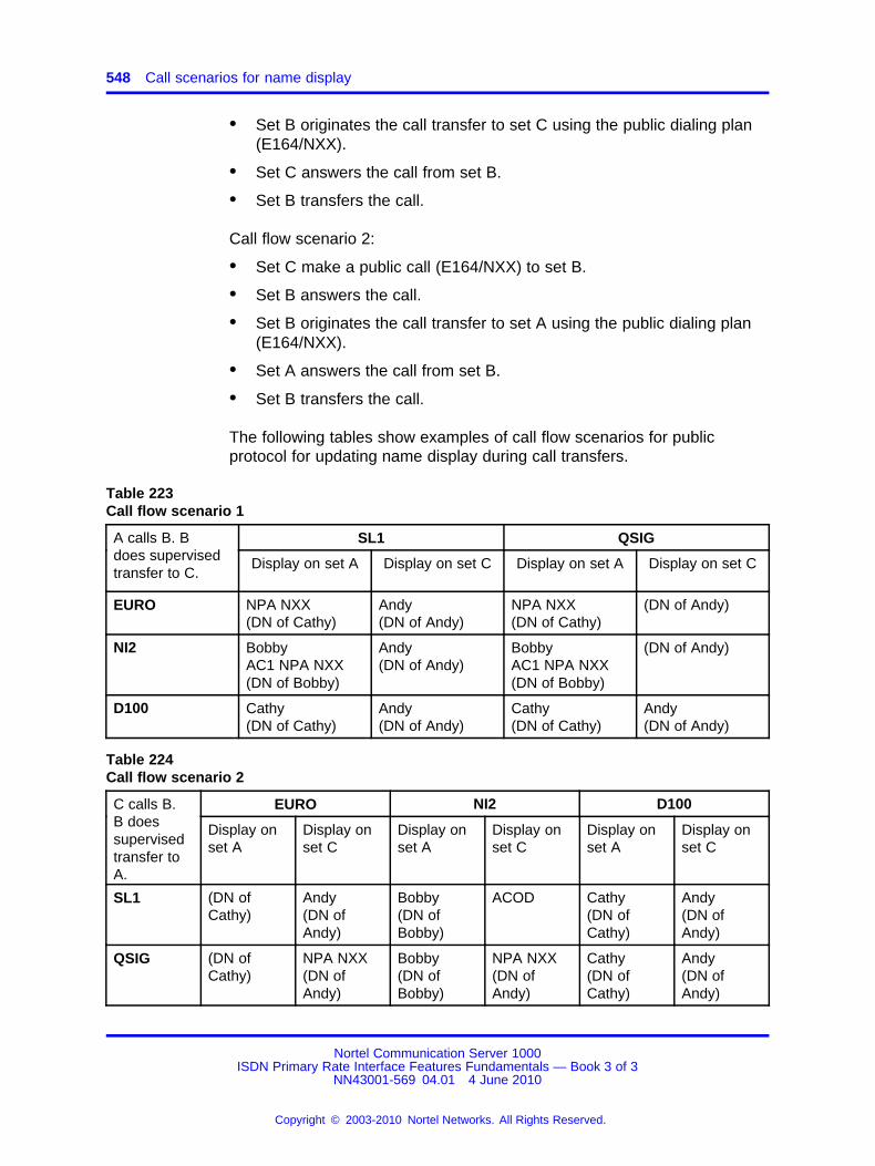
548 Call scenarios for name display
• Set B originates the call transfer to set C using the public dialing plan(E164/NXX).
• Set C answers the call from set B.
• Set B transfers the call.
Call flow scenario 2:
• Set C make a public call (E164/NXX) to set B.
• Set B answers the call.
• Set B originates the call transfer to set A using the public dialing plan(E164/NXX).
• Set A answers the call from set B.
• Set B transfers the call.
The following tables show examples of call flow scenarios for publicprotocol for updating name display during call transfers.
Table 223Call flow scenario 1
SL1 QSIGA calls B. Bdoes supervisedtransfer to C.
Display on set A Display on set C Display on set A Display on set C
EURO NPA NXX(DN of Cathy)
Andy(DN of Andy)
NPA NXX(DN of Cathy)
(DN of Andy)
NI2 BobbyAC1 NPA NXX(DN of Bobby)
Andy(DN of Andy)
BobbyAC1 NPA NXX(DN of Bobby)
(DN of Andy)
D100 Cathy(DN of Cathy)
Andy(DN of Andy)
Cathy(DN of Cathy)
Andy(DN of Andy)
Table 224Call flow scenario 2
EURO NI2 D100C calls B.B doessupervisedtransfer toA.
Display onset A
Display onset C
Display onset A
Display onset C
Display onset A
Display onset C
SL1 (DN ofCathy)
Andy(DN ofAndy)
Bobby(DN ofBobby)
ACOD Cathy(DN ofCathy)
Andy(DN ofAndy)
QSIG (DN ofCathy)
NPA NXX(DN ofAndy)
Bobby(DN ofBobby)
NPA NXX(DN ofAndy)
Cathy(DN ofCathy)
Andy(DN ofAndy)
Nortel Communication Server 1000ISDN Primary Rate Interface Features Fundamentals — Book 3 of 3
NN43001-569 04.01 4 June 2010
Copyright © 2003-2010 Nortel Networks. All Rights Reserved.
.
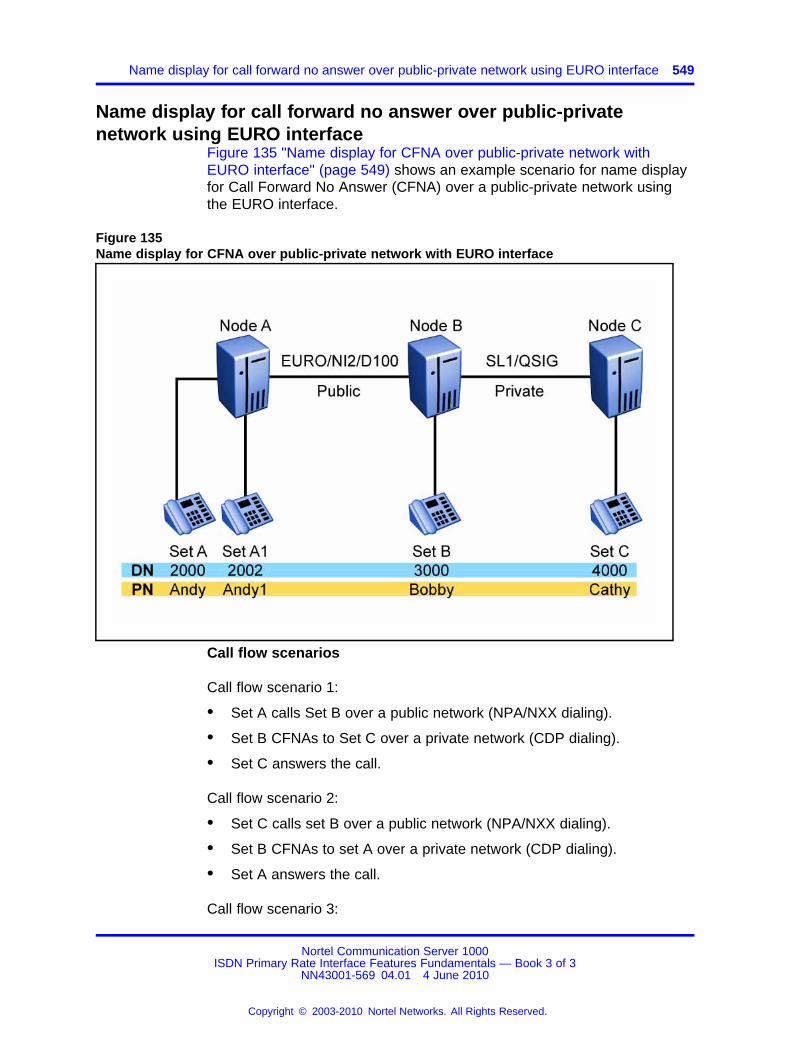
Name display for call forward no answer over public-private network using EURO interface 549
Name display for call forward no answer over public-privatenetwork using EURO interface
Figure 135 "Name display for CFNA over public-private network withEURO interface" (page 549) shows an example scenario for name displayfor Call Forward No Answer (CFNA) over a public-private network usingthe EURO interface.
Figure 135Name display for CFNA over public-private network with EURO interface
Call flow scenarios
Call flow scenario 1:
• Set A calls Set B over a public network (NPA/NXX dialing).
• Set B CFNAs to Set C over a private network (CDP dialing).
• Set C answers the call.
Call flow scenario 2:
• Set C calls set B over a public network (NPA/NXX dialing).
• Set B CFNAs to set A over a private network (CDP dialing).
• Set A answers the call.
Call flow scenario 3:
Nortel Communication Server 1000ISDN Primary Rate Interface Features Fundamentals — Book 3 of 3
NN43001-569 04.01 4 June 2010
Copyright © 2003-2010 Nortel Networks. All Rights Reserved.
.
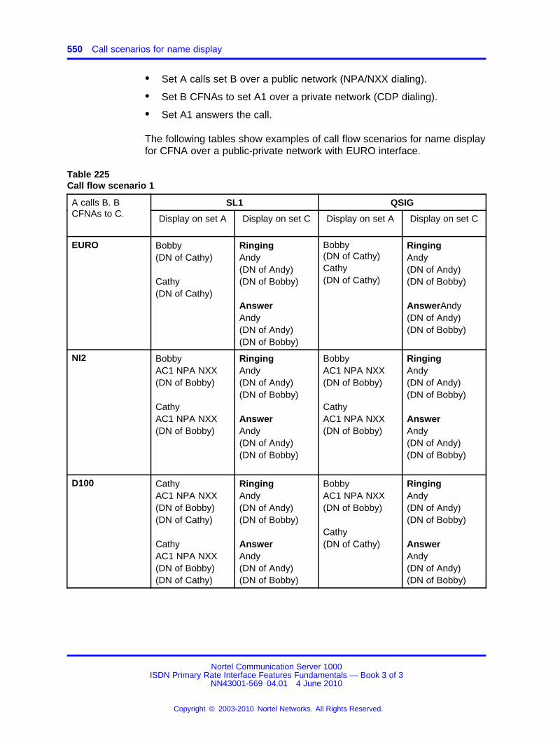
550 Call scenarios for name display
• Set A calls set B over a public network (NPA/NXX dialing).
• Set B CFNAs to set A1 over a private network (CDP dialing).
• Set A1 answers the call.
The following tables show examples of call flow scenarios for name displayfor CFNA over a public-private network with EURO interface.
Table 225Call flow scenario 1
SL1 QSIGA calls B. BCFNAs to C. Display on set A Display on set C Display on set A Display on set C
EURO Bobby(DN of Cathy)
Cathy(DN of Cathy)
RingingAndy(DN of Andy)(DN of Bobby)
AnswerAndy(DN of Andy)(DN of Bobby)
Bobby(DN of Cathy)Cathy(DN of Cathy)
RingingAndy(DN of Andy)(DN of Bobby)
AnswerAndy(DN of Andy)(DN of Bobby)
NI2 BobbyAC1 NPA NXX(DN of Bobby)
CathyAC1 NPA NXX(DN of Bobby)
RingingAndy(DN of Andy)(DN of Bobby)
AnswerAndy(DN of Andy)(DN of Bobby)
BobbyAC1 NPA NXX(DN of Bobby)
CathyAC1 NPA NXX(DN of Bobby)
RingingAndy(DN of Andy)(DN of Bobby)
AnswerAndy(DN of Andy)(DN of Bobby)
D100 CathyAC1 NPA NXX(DN of Bobby)(DN of Cathy)
CathyAC1 NPA NXX(DN of Bobby)(DN of Cathy)
RingingAndy(DN of Andy)(DN of Bobby)
AnswerAndy(DN of Andy)(DN of Bobby)
BobbyAC1 NPA NXX(DN of Bobby)
Cathy(DN of Cathy)
RingingAndy(DN of Andy)(DN of Bobby)
AnswerAndy(DN of Andy)(DN of Bobby)
Nortel Communication Server 1000ISDN Primary Rate Interface Features Fundamentals — Book 3 of 3
NN43001-569 04.01 4 June 2010
Copyright © 2003-2010 Nortel Networks. All Rights Reserved.
.

Name display for call forward no answer over public-private network using EURO interface 551
Table 226Call flow scenario 2
EURO NI2 D100C calls B. BCFNAs toA.
Display onset C
Display onset A
Display onset C
Display onset A
Display onset C
Display onset A
SL1 BobbyAC1 NPANXX(DN ofBobby)
AndyAC1 NPANXX(DN ofBobby)
RingingCathy(DN ofCathy)
AnswerCathy(DN ofCathy)
BobbyAC1 NPANXX(DN ofBobby)
Andy(DN ofAndy)
RingingCathy(DN ofCathy)(DN ofBobby)
AnswerCathy(DN ofCathy)(DN ofBobby)
ANDYAC1 NPANXX(DN ofBobby)(DN ofAndy)
ANDYAC1 NPANXX(DN ofBobby)(DN ofAndy)
RingingCathy(DN ofCathy)(DN ofBobby)
AnswerCathy(DN ofCathy)(DN ofBobby)
QSIG BobbyAC1 NPANXX(DN ofBobby)
AndyAC1 NPANXX(DN ofBobby)
RingingCathy(DN ofCathy)
AnswerCathy(DN ofCathy)
BobbyAC1 NPANXX(DN ofBobby)
AndyAC1 NPANXX(DN ofBobby)(DN OFAndy)
RingingCathy(DN ofCathy)(DN ofBobby)
AnswerCathy(DN ofCathy)(DN ofBobby)
BobbyAC1 NPANXX(DN ofBobby)
AndyAC1 NPANXX(DN ofBobby)(DN ofAndy)
RingingCathy(DN ofCathy)(DN ofBobby)
AnswerCathy(DN ofCathy)(DN ofBobby)
Nortel Communication Server 1000ISDN Primary Rate Interface Features Fundamentals — Book 3 of 3
NN43001-569 04.01 4 June 2010
Copyright © 2003-2010 Nortel Networks. All Rights Reserved.
.

552 Call scenarios for name display
Table 227Call flow scenario 3 for EURO
EUROA calls B. B CFNAs to A1.
Display on set A Display on set A1
EURO BobbyAC1 NPA NXX(DN of Bobby)
Andy 1(DN of Andy 1)
RingingAndy(DN of Andy)
AnswerAndy(DN of Andy)
Table 228Call flow scenario 3 for NI2
NI2A calls B. B CFNAs to A1.
Display on set A Display on set A1
NI2 BobbyAC1 NPA NXX(DN of Bobby)
AC1 NPA NXX(DN of Bobby)
RingingAndy(DN of Andy) )(DN of Bobby)
AnswerAndy(DN of Andy)(DN of Bobby)
Table 229Call flow scenario 3 for D100
D100A calls B. B CFNAs to A1.
Display on set A Display on set A1
D100 Andy1AC1 NPA NXX(DN Bobby)(DN of Andy1)
Andy1AC1 NPA NXX(DN of Bobby)(DN of Andy1)
RingingAndy(DN of Andy)(DN of Bobby)
AnswerAndy(DN of Andy)(DN of Bobby)
Nortel Communication Server 1000ISDN Primary Rate Interface Features Fundamentals — Book 3 of 3
NN43001-569 04.01 4 June 2010
Copyright © 2003-2010 Nortel Networks. All Rights Reserved.
.

Private name displayed for call originates locally and CFNA/CFW in public network 553
Table 230Call flow scenario 3 for SL1
SL1A calls B. B CFNAs to A1.
Display on set A Display on set A1
SL1 Andy1AC1 NPA NXX(DN Bobby)(DN of Andy1)
Andy1AC1 NPA NXX(DN of Bobby)(DN of Andy1)
RingingAndy(DN of Andy)(DN of Bobby)
AnswerAndy(DN of Andy)(DN of Bobby)
Table 231Call flow scenario 3 for QSIG
QSIGA calls B. B CFNAs to A1
Display on set A Display on set A1
QSIG Andy1AC1 NPA NXX(DN Bobby)(DN of Andy1)
Andy1AC1 NPA NXX(DN of Bobby)(DN of Andy1)
RingingAndy(DN of Andy)(DN of Bobby)
AnswerAndy(DN of Andy)(DN of Bobby)
Private name displayed for call originates locally and CFNA/CFW inpublic network
Figure 136 "Private name display" (page 554) shows an example scenariofor private name display for a call that originates locally and CFNA CallForward (CFW) in a public network.
Nortel Communication Server 1000ISDN Primary Rate Interface Features Fundamentals — Book 3 of 3
NN43001-569 04.01 4 June 2010
Copyright © 2003-2010 Nortel Networks. All Rights Reserved.
.
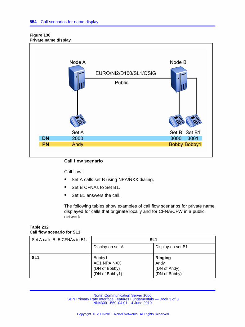
554 Call scenarios for name display
Figure 136Private name display
Call flow scenario
Call flow:
• Set A calls set B using NPA/NXX dialing.
• Set B CFNAs to Set B1.
• Set B1 answers the call.
The following tables show examples of call flow scenarios for private namedisplayed for calls that originate locally and for CFNA/CFW in a publicnetwork.
Table 232Call flow scenario for SL1
SL1Set A calls B. B CFNAs to B1.
Display on set A Display on set B1
SL1 Bobby1AC1 NPA NXX(DN of Bobby)(DN of Bobby1)
RingingAndy(DN of Andy)(DN of Bobby)
Nortel Communication Server 1000ISDN Primary Rate Interface Features Fundamentals — Book 3 of 3
NN43001-569 04.01 4 June 2010
Copyright © 2003-2010 Nortel Networks. All Rights Reserved.
.

Private name displayed for call originates locally and CFNA/CFW in public network 555
Bobby1AC1 NPA NXX(DN of Bobby)(DN of Bobby1)
AnswerAndy(DN of Andy)(DN of Bobby)
Table 233Call flow scenario for QSIG
QSIGSet A calls B. B CFNAs to B1.
Display on set A Display on set B1
QSIG Bobby1AC1 NPA NXX(DN of Bobby)(DN of Bobby1)
Bobby1AC1 NPA NXX(DN of Bobby)(DN of Bobby1)
RingingAndy(DN of Andy)(DN of Bobby)
AnswerAndy(DN of Andy)(DN of Bobby)
Table 234Call flow scenario for EURO
EUROSet A calls B. B CFNAs to B1.
Display on set A Display on set B1
EURO Bobby
(DN of Bobby1)
Bobby1(DN of Bobby1)
RingingAndy(DN of Andy)(DN of Bobby)
AnswerAndy(DN of Andy)(DN of Bobby)
Nortel Communication Server 1000ISDN Primary Rate Interface Features Fundamentals — Book 3 of 3
NN43001-569 04.01 4 June 2010
Copyright © 2003-2010 Nortel Networks. All Rights Reserved.
.
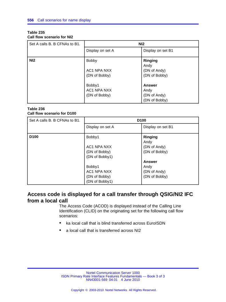
556 Call scenarios for name display
Table 235Call flow scenario for NI2
NI2Set A calls B. B CFNAs to B1.
Display on set A Display on set B1
NI2 Bobby
AC1 NPA NXX(DN of Bobby)
Bobby1AC1 NPA NXX(DN of Bobby)
RingingAndy(DN of Andy)(DN of Bobby)
AnswerAndy(DN of Andy)(DN of Bobby)
Table 236Call flow scenario for D100
D100Set A calls B. B CFNAs to B1.
Display on set A Display on set B1
D100 Bobby1
AC1 NPA NXX(DN of Bobby)(DN of Bobby1)
Bobby1AC1 NPA NXX(DN of Bobby)(DN of Bobby1)
RingingAndy(DN of Andy)(DN of Bobby)
AnswerAndy(DN of Andy)(DN of Bobby)
Access code is displayed for a call transfer through QSIG/NI2 IFCfrom a local call
The Access Code (ACOD) is displayed instead of the Calling LineIdentification (CLID) on the originating set for the following call flowscenarios:
• ka local call that is blind transferred across EuroISDN
• a local call that is transferred across NI2
Nortel Communication Server 1000ISDN Primary Rate Interface Features Fundamentals — Book 3 of 3
NN43001-569 04.01 4 June 2010
Copyright © 2003-2010 Nortel Networks. All Rights Reserved.
.

Nortel Communication Server 1000
ISDN Primary Rate Interface Features Fundamentals — Book 3of 3Release: 7.0Publication: NN43001-569Document revision: 04.01Document release date: 4 June 2010
Copyright © 2003-2010 Nortel Networks. All Rights Reserved.
While the information in this document is believed to be accurate and reliable, except as otherwise expressly agreed to in writingNORTEL PROVIDES THIS DOCUMENT "AS IS" WITHOUT WARRANTY OR CONDITION OF ANY KIND, EITHER EXPRESSOR IMPLIED. The information and/or products described in this document are subject to change without notice.
Nortel, Nortel Networks, the Nortel logo, and the Globemark are trademarks of Nortel Networks.
All other trademarks are the property of their respective owners.
To provide feedback or to report a problem in this document, go to www.nortel.com/documentfeedback.
www.nortel.com
Copyright © 2022 FDOKUMEN