Proline Promass E 100 EtherNet/IP - My Endress+Hauser ID
130
Products Solutions Services Operating Instructions Proline Promass E 100 EtherNet/IP Coriolis flowmeter BA01712D/06/EN/02.17 71381124 Valid as of version 01.02.zz (Device firmware)
-
Upload
khangminh22 -
Category
Documents
-
view
5 -
download
0
Transcript of Proline Promass E 100 EtherNet/IP - My Endress+Hauser ID

Products Solutions Services
Operating InstructionsProline Promass E 100EtherNet/IPCoriolis flowmeter
BA01712D/06/EN/02.1771381124
Valid as of version01.02.zz (Device firmware)

Proline Promass E 100 EtherNet/IP
2 Endress+Hauser
• Make sure the document is stored in a safe place such that it is always available whenworking on or with the device.
• To avoid danger to individuals or the facility, read the "Basic safety instructions" sectioncarefully, as well as all other safety instructions in the document that are specific toworking procedures.
• The manufacturer reserves the right to modify technical data without prior notice. YourEndress+Hauser Sales Center will supply you with current information and updates tothese instructions.

Proline Promass E 100 EtherNet/IP Table of contents
Endress+Hauser 3
Table of contents
1 About this document . . . . . . . . . . . . . . . . 61.1 Document function . . . . . . . . . . . . . . . . . . . . . 61.2 Symbols used . . . . . . . . . . . . . . . . . . . . . . . . . . 6
1.2.1 Safety symbols . . . . . . . . . . . . . . . . . . 61.2.2 Electrical symbols . . . . . . . . . . . . . . . . 61.2.3 Tool symbols . . . . . . . . . . . . . . . . . . . . 61.2.4 Symbols for
certain types of information . . . . . . . . . 71.2.5 Symbols in graphics . . . . . . . . . . . . . . . 7
1.3 Documentation . . . . . . . . . . . . . . . . . . . . . . . . 71.3.1 Standard documentation . . . . . . . . . . . 81.3.2 Supplementary device-dependent
documentation . . . . . . . . . . . . . . . . . . 81.4 Registered trademarks . . . . . . . . . . . . . . . . . . . 8
2 Basic safety instructions . . . . . . . . . . . . 92.1 Requirements for the personnel . . . . . . . . . . . . 92.2 Designated use . . . . . . . . . . . . . . . . . . . . . . . . 92.3 Workplace safety . . . . . . . . . . . . . . . . . . . . . . 102.4 Operational safety . . . . . . . . . . . . . . . . . . . . . 102.5 Product safety . . . . . . . . . . . . . . . . . . . . . . . . 102.6 IT security . . . . . . . . . . . . . . . . . . . . . . . . . . . 11
3 Product description . . . . . . . . . . . . . . . . 123.1 Product design . . . . . . . . . . . . . . . . . . . . . . . . 12
3.1.1 Device version with EtherNet/IPcommunication type . . . . . . . . . . . . . 12
4 Incoming acceptance and productidentification . . . . . . . . . . . . . . . . . . . . . 13
4.1 Incoming acceptance . . . . . . . . . . . . . . . . . . . 134.2 Product identification . . . . . . . . . . . . . . . . . . . 13
4.2.1 Transmitter nameplate . . . . . . . . . . . 144.2.2 Sensor nameplate . . . . . . . . . . . . . . . 144.2.3 Symbols on measuring device . . . . . . 15
5 Storage and transport . . . . . . . . . . . . . 165.1 Storage conditions . . . . . . . . . . . . . . . . . . . . . 165.2 Transporting the product . . . . . . . . . . . . . . . . 16
5.2.1 Measuring devices without liftinglugs . . . . . . . . . . . . . . . . . . . . . . . . . 16
5.2.2 Measuring devices with lifting lugs . . 175.2.3 Transporting with a fork lift . . . . . . . . 17
5.3 Packaging disposal . . . . . . . . . . . . . . . . . . . . . 17
6 Installation . . . . . . . . . . . . . . . . . . . . . . . 186.1 Installation conditions . . . . . . . . . . . . . . . . . . 18
6.1.1 Mounting position . . . . . . . . . . . . . . . 186.1.2 Requirements from environment and
process . . . . . . . . . . . . . . . . . . . . . . . 206.1.3 Special mounting instructions . . . . . . 22
6.2 Mounting the measuring device . . . . . . . . . . . 226.2.1 Required tools . . . . . . . . . . . . . . . . . . 226.2.2 Preparing the measuring device . . . . . 236.2.3 Mounting the measuring device . . . . . 23
6.3 Post-installation check . . . . . . . . . . . . . . . . . . 23
7 Electrical connection . . . . . . . . . . . . . . 247.1 Connection conditions . . . . . . . . . . . . . . . . . . 24
7.1.1 Required tools . . . . . . . . . . . . . . . . . . 247.1.2 Requirements for connecting cable . . . 247.1.3 Terminal assignment . . . . . . . . . . . . . 257.1.4 Pin assignment, device plug . . . . . . . . 267.1.5 Preparing the measuring device . . . . . 26
7.2 Connecting the measuring device . . . . . . . . . . 267.2.1 Connecting the transmitter . . . . . . . . 277.2.2 Ensure potential equalization . . . . . . 28
7.3 Special connection instructions . . . . . . . . . . . . 297.3.1 Connection examples . . . . . . . . . . . . . 29
7.4 Hardware settings . . . . . . . . . . . . . . . . . . . . . 297.4.1 Setting the device address . . . . . . . . . 29
7.5 Ensuring the degree of protection . . . . . . . . . . 307.6 Post-connection check . . . . . . . . . . . . . . . . . . 31
8 Operation options . . . . . . . . . . . . . . . . . 328.1 Overview of operating options . . . . . . . . . . . . 328.2 Structure and function of the operating
menu . . . . . . . . . . . . . . . . . . . . . . . . . . . . . . 338.2.1 Structure of the operating menu . . . . 338.2.2 Operating philosophy . . . . . . . . . . . . 34
8.3 Access to the operating menu via the webbrowser . . . . . . . . . . . . . . . . . . . . . . . . . . . . . 348.3.1 Function range . . . . . . . . . . . . . . . . . 348.3.2 Prerequisites . . . . . . . . . . . . . . . . . . . 358.3.3 Establishing a connection . . . . . . . . . 368.3.4 Logging on . . . . . . . . . . . . . . . . . . . . 378.3.5 User interface . . . . . . . . . . . . . . . . . . 388.3.6 Disabling the Web server . . . . . . . . . . 398.3.7 Logging out . . . . . . . . . . . . . . . . . . . . 39
8.4 Access to the operating menu via theoperating tool . . . . . . . . . . . . . . . . . . . . . . . . 408.4.1 Connecting the operating tool . . . . . . 408.4.2 FieldCare . . . . . . . . . . . . . . . . . . . . . 418.4.3 DeviceCare . . . . . . . . . . . . . . . . . . . . 43
9 System integration . . . . . . . . . . . . . . . . 449.1 Overview of device description files . . . . . . . . . 44
9.1.1 Current version data for the device . . . 449.1.2 Operating tools . . . . . . . . . . . . . . . . . 44
9.2 Overview of system files . . . . . . . . . . . . . . . . . 449.3 Integrating the measuring device in the
system . . . . . . . . . . . . . . . . . . . . . . . . . . . . . 459.4 Cyclic data transmission . . . . . . . . . . . . . . . . 45
9.4.1 Block model . . . . . . . . . . . . . . . . . . . 459.4.2 Input and output groups . . . . . . . . . . 45

Table of contents Proline Promass E 100 EtherNet/IP
4 Endress+Hauser
10 Commissioning . . . . . . . . . . . . . . . . . . . . 4910.1 Function check . . . . . . . . . . . . . . . . . . . . . . . 4910.2 Configuring the device address via software . . 49
10.2.1 Ethernet network and Web server . . . 4910.3 Setting the operating language . . . . . . . . . . . . 4910.4 Configuring the measuring device . . . . . . . . . . 49
10.4.1 Defining the tag name . . . . . . . . . . . . 5010.4.2 Setting the system units . . . . . . . . . . 5010.4.3 Selecting and setting the medium . . . 5310.4.4 Configuring the communication
interface . . . . . . . . . . . . . . . . . . . . . . 5410.4.5 Configuring the low flow cut off . . . . . 5610.4.6 Configuring the partial filled pipe
detection . . . . . . . . . . . . . . . . . . . . . 5710.5 Advanced settings . . . . . . . . . . . . . . . . . . . . . 58
10.5.1 Using the parameter to enter theaccess code . . . . . . . . . . . . . . . . . . . . 58
10.5.2 Calculated values . . . . . . . . . . . . . . . . 5810.5.3 Carrying out a sensor adjustment . . . . 6010.5.4 Configuring the totalizer . . . . . . . . . . 6010.5.5 Carrying out additional display
configurations . . . . . . . . . . . . . . . . . . 6210.5.6 Using parameters for device
administration . . . . . . . . . . . . . . . . . 6410.6 Simulation . . . . . . . . . . . . . . . . . . . . . . . . . . . 6510.7 Protecting settings from unauthorized
access . . . . . . . . . . . . . . . . . . . . . . . . . . . . . . 6610.7.1 Write protection via access code . . . . . 6610.7.2 Write protection via write protection
switch . . . . . . . . . . . . . . . . . . . . . . . . 67
11 Operation . . . . . . . . . . . . . . . . . . . . . . . . . 6911.1 Read out and modify current Ethernet
settings . . . . . . . . . . . . . . . . . . . . . . . . . . . . . 6911.2 Reading the device locking status . . . . . . . . . . 6911.3 Adjusting the operating language . . . . . . . . . . 7011.4 Configuring the display . . . . . . . . . . . . . . . . . 7011.5 Reading measured values . . . . . . . . . . . . . . . . 70
11.5.1 "Measured variables" submenu . . . . . . 7011.5.2 "Totalizer" submenu . . . . . . . . . . . . . . 72
11.6 Adapting the measuring device to the processconditions . . . . . . . . . . . . . . . . . . . . . . . . . . . 73
11.7 Performing a totalizer reset . . . . . . . . . . . . . . 7311.7.1 Function scope of the "Control
Totalizer" parameter . . . . . . . . . . . . . 7411.7.2 Function scope of the "Reset all
totalizers" parameter . . . . . . . . . . . . . 74
12 Diagnostics and troubleshooting . . . 7512.1 General troubleshooting . . . . . . . . . . . . . . . . . 7512.2 Diagnostic information via light emitting
diodes . . . . . . . . . . . . . . . . . . . . . . . . . . . . . . 7712.2.1 Transmitter . . . . . . . . . . . . . . . . . . . . 77
12.3 Diagnostic information in the Web browser . . 7712.3.1 Diagnostic options . . . . . . . . . . . . . . . 7712.3.2 Calling up remedy information . . . . . . 79
12.4 Diagnostic information in DeviceCare orFieldCare . . . . . . . . . . . . . . . . . . . . . . . . . . . . 7912.4.1 Diagnostic options . . . . . . . . . . . . . . . 7912.4.2 Calling up remedy information . . . . . . 80
12.5 Diagnostic information via communicationinterface . . . . . . . . . . . . . . . . . . . . . . . . . . . . 8012.5.1 Reading out diagnostic information . . 80
12.6 Adapting the diagnostic information . . . . . . . 8012.6.1 Adapting the diagnostic behavior . . . . 80
12.7 Overview of diagnostic information . . . . . . . . 8112.7.1 Diagnostic of sensor . . . . . . . . . . . . . 8112.7.2 Diagnostic of electronic . . . . . . . . . . . 8312.7.3 Diagnostic of configuration . . . . . . . . 8512.7.4 Diagnostic of process . . . . . . . . . . . . . 87
12.8 Pending diagnostic events . . . . . . . . . . . . . . . 9112.9 Diagnostic list . . . . . . . . . . . . . . . . . . . . . . . . 9212.10 Event logbook . . . . . . . . . . . . . . . . . . . . . . . . 92
12.10.1 Reading out the event logbook . . . . . . 9212.10.2 Filtering the event logbook . . . . . . . . 9312.10.3 Overview of information events . . . . . 93
12.11 Resetting the measuring device . . . . . . . . . . . 9412.11.1 Function scope of the "Device reset"
parameter . . . . . . . . . . . . . . . . . . . . . 9412.12 Device information . . . . . . . . . . . . . . . . . . . . 9412.13 Firmware history . . . . . . . . . . . . . . . . . . . . . . 97
13 Maintenance . . . . . . . . . . . . . . . . . . . . . . 9813.1 Maintenance tasks . . . . . . . . . . . . . . . . . . . . . 98
13.1.1 Exterior cleaning . . . . . . . . . . . . . . . . 9813.1.2 Interior cleaning . . . . . . . . . . . . . . . . 98
13.2 Measuring and test equipment . . . . . . . . . . . . 9813.3 Endress+Hauser services . . . . . . . . . . . . . . . . 98
14 Repairs . . . . . . . . . . . . . . . . . . . . . . . . . . . 9914.1 General notes . . . . . . . . . . . . . . . . . . . . . . . . 99
14.1.1 Repair and conversion concept . . . . . . 9914.1.2 Notes for repair and conversion . . . . . 99
14.2 Spare parts . . . . . . . . . . . . . . . . . . . . . . . . . . 9914.3 Endress+Hauser services . . . . . . . . . . . . . . . . 9914.4 Return . . . . . . . . . . . . . . . . . . . . . . . . . . . . . . 9914.5 Disposal . . . . . . . . . . . . . . . . . . . . . . . . . . . 100
14.5.1 Removing the measuring device . . . . 10014.5.2 Disposing of the measuring device . . 100
15 Accessories . . . . . . . . . . . . . . . . . . . . . . 10115.1 Device-specific accessories . . . . . . . . . . . . . . 101
15.1.1 For the sensor . . . . . . . . . . . . . . . . . 10115.2 Communication-specific accessories . . . . . . . 10115.3 Service-specific accessories . . . . . . . . . . . . . . 10115.4 System components . . . . . . . . . . . . . . . . . . . 102
16 Technical data . . . . . . . . . . . . . . . . . . . 10316.1 Application . . . . . . . . . . . . . . . . . . . . . . . . . 10316.2 Function and system design . . . . . . . . . . . . . 10316.3 Input . . . . . . . . . . . . . . . . . . . . . . . . . . . . . . 10416.4 Output . . . . . . . . . . . . . . . . . . . . . . . . . . . . 105

Proline Promass E 100 EtherNet/IP Table of contents
Endress+Hauser 5
16.5 Power supply . . . . . . . . . . . . . . . . . . . . . . . . 10916.6 Performance characteristics . . . . . . . . . . . . . 11016.7 Installation . . . . . . . . . . . . . . . . . . . . . . . . . 11316.8 Environment . . . . . . . . . . . . . . . . . . . . . . . . 11416.9 Process . . . . . . . . . . . . . . . . . . . . . . . . . . . . 11416.10 Mechanical construction . . . . . . . . . . . . . . . 11716.11 Operability . . . . . . . . . . . . . . . . . . . . . . . . . 11916.12 Certificates and approvals . . . . . . . . . . . . . . 12216.13 Application packages . . . . . . . . . . . . . . . . . . 12316.14 Accessories . . . . . . . . . . . . . . . . . . . . . . . . . 12416.15 Supplementary documentation . . . . . . . . . . . 124
Index . . . . . . . . . . . . . . . . . . . . . . . . . . . . . . . . . 126

About this document Proline Promass E 100 EtherNet/IP
6 Endress+Hauser
1 About this document
1.1 Document functionThese Operating Instructions contain all the information that is required in various phasesof the life cycle of the device: from product identification, incoming acceptance andstorage, to mounting, connection, operation and commissioning through totroubleshooting, maintenance and disposal.
1.2 Symbols used
1.2.1 Safety symbols
Symbol Meaning
DANGER
DANGER!This symbol alerts you to a dangerous situation. Failure to avoid this situation willresult in serious or fatal injury.
WARNING
WARNING!This symbol alerts you to a dangerous situation. Failure to avoid this situation canresult in serious or fatal injury.
CAUTION
CAUTION!This symbol alerts you to a dangerous situation. Failure to avoid this situation canresult in minor or medium injury.
NOTICE
NOTE!This symbol contains information on procedures and other facts which do not result inpersonal injury.
1.2.2 Electrical symbols
Symbol Meaning
Direct current
Alternating current
Direct current and alternating current
Ground connectionA grounded terminal which, as far as the operator is concerned, is grounded via agrounding system.
Protective Earth (PE)A terminal which must be connected to ground prior to establishing any otherconnections.
The ground terminals are situated inside and outside the device:• Inner ground terminal: Connects the protectiv earth to the mains supply.• Outer ground terminal: Connects the device to the plant grounding system.
1.2.3 Tool symbols
Symbol Meaning
Allen key
Open-ended wrench

Proline Promass E 100 EtherNet/IP About this document
Endress+Hauser 7
1.2.4 Symbols for certain types of information
Symbol Meaning
PermittedProcedures, processes or actions that are permitted.
PreferredProcedures, processes or actions that are preferred.
ForbiddenProcedures, processes or actions that are forbidden.
TipIndicates additional information.
Reference to documentation.
A Reference to page.
Reference to graphic.
Notice or individual step to be observed.
1. , 2. , 3.… Series of steps.
Result of a step.
Help in the event of a problem.
Visual inspection.
1.2.5 Symbols in graphics
Symbol Meaning
1, 2, 3, ... Item numbers
1. , 2. , 3. , … Series of steps
A, B, C, ... Views
A-A, B-B, C-C, ... Sections
-Hazardous area
.Safe area (non-hazardous area)
Flow direction
1.3 DocumentationFor an overview of the scope of the associated Technical Documentation, refer to thefollowing:• The W@M Device Viewer : Enter the serial number from the nameplate
(www.endress.com/deviceviewer)• The Endress+Hauser Operations App: Enter the serial number from the nameplate
or scan the 2-D matrix code (QR code) on the nameplate.
For a detailed list of the individual documents along with the documentation code→ 124

About this document Proline Promass E 100 EtherNet/IP
8 Endress+Hauser
1.3.1 Standard documentation
Document type Purpose and content of the document
Technical Information Planning aid for your deviceThe document contains all the technical data on the device and providesan overview of the accessories and other products that can be ordered forthe device.
Sensor Brief Operating Instructions Guides you quickly to the 1st measured value - Part 1The Sensor Brief Operating Instructions are aimed at specialists withresponsibility for installing the measuring device.
• Incoming acceptance and product identification• Storage and transport• Installation
Transmitter Brief OperatingInstructions
Guides you quickly to the 1st measured value - Part 2The Transmitter Brief Operating Instructions are aimed at specialists withresponsibility for commissioning, configuring and parameterizing themeasuring device (until the first measured value).
• Product description• Installation• Electrical connection• Operation options• System integration• Commissioning• Diagnostic information
Description of Device Parameters Reference for your parametersThe document provides a detailed explanation of each individualparameter in the Expert operating menu. The description is aimed atthose who work with the device over the entire life cycle and performspecific configurations.
1.3.2 Supplementary device-dependent documentationAdditional documents are supplied depending on the device version ordered: Alwayscomply strictly with the instructions in the supplementary documentation. Thesupplementary documentation is an integral part of the device documentation.
1.4 Registered trademarksEtherNet/IP™Trademark of ODVA, Inc.
Microsoft®Registered trademark of the Microsoft Corporation, Redmond, Washington, USA
TRI-CLAMP®Registered trademark of Ladish & Co., Inc., Kenosha, USA

Proline Promass E 100 EtherNet/IP Basic safety instructions
Endress+Hauser 9
2 Basic safety instructions
2.1 Requirements for the personnelThe personnel for installation, commissioning, diagnostics and maintenance must fulfillthe following requirements:‣ Trained, qualified specialists must have a relevant qualification for this specific function
and task.‣ Are authorized by the plant owner/operator.‣ Are familiar with federal/national regulations.‣ Before starting work, read and understand the instructions in the manual and
supplementary documentation as well as the certificates (depending on theapplication).
‣ Follow instructions and comply with basic conditions.
The operating personnel must fulfill the following requirements:‣ Are instructed and authorized according to the requirements of the task by the facility's
owner-operator.‣ Follow the instructions in this manual.
2.2 Designated useApplication and mediaThe measuring device described in these Brief Operating Instructions is intended only forflow measurement of liquids and gases.
Depending on the version ordered, the measuring device can also measure potentiallyexplosive, flammable, poisonous and oxidizing media.
Measuring devices for use in hazardous areas, in hygienic applications or where there is anincreased risk due to process pressure, are labeled accordingly on the nameplate.
To ensure that the measuring device remains in proper condition for the operation time:‣ Keep within the specified pressure and temperature range.‣ Only use the measuring device in full compliance with the data on the nameplate and
the general conditions listed in the Operating Instructions and supplementarydocumentation.
‣ Based on the nameplate, check whether the ordered device is permitted for theintended use in the hazardous area (e.g. explosion protection, pressure vessel safety).
‣ Use the measuring device only for media to which the process-wetted materials aresufficiently resistant.
‣ If the measuring device is not operated at atmospheric temperature, compliance withthe relevant basic conditions specified in the associated device documentation isabsolutely essential: "Documentation" section→ 7.
‣ Protect the measuring device permanently against corrosion from environmentalinfluences.
Incorrect useNon-designated use can compromise safety. The manufacturer is not liable for damagecaused by improper or non-designated use.
LWARNINGDanger of breakage due to corrosive or abrasive fluids!‣ Verify the compatibility of the process fluid with the sensor material.‣ Ensure the resistance of all fluid-wetted materials in the process.‣ Keep within the specified pressure and temperature range.

Basic safety instructions Proline Promass E 100 EtherNet/IP
10 Endress+Hauser
NOTICEVerification for borderline cases:‣ For special fluids and fluids for cleaning, Endress+Hauser is glad to provide assistance
in verifying the corrosion resistance of fluid-wetted materials, but does not accept anywarranty or liability as minute changes in the temperature, concentration or level ofcontamination in the process can alter the corrosion resistance properties.
Residual risks
LWARNINGThe electronics and the medium may cause the surfaces to heat up. This presents aburn hazard!‣ For elevated fluid temperatures, ensure protection against contact to prevent burns.
LWARNINGDanger of housing breaking due to measuring tube breakage!‣ In the event of a measuring tube breakage for a device version without rupture disk it is
possible for the pressure loading capacity of the sensor housing to be exceeded. Thiscan lead to rupture or failure of the sensor housing.
2.3 Workplace safetyFor work on and with the device:‣ Wear the required personal protective equipment according to federal/national
regulations.
For welding work on the piping:‣ Do not ground the welding unit via the measuring device.
If working on and with the device with wet hands:‣ Due to the increased risk of electric shock, gloves must be worn.
2.4 Operational safetyRisk of injury.‣ Operate the device in proper technical condition and fail-safe condition only.‣ The operator is responsible for interference-free operation of the device.
Conversions to the deviceUnauthorized modifications to the device are not permitted and can lead to unforeseeabledangers.‣ If, despite this, modifications are required, consult with Endress+Hauser.
RepairTo ensure continued operational safety and reliability,‣ Carry out repairs on the device only if they are expressly permitted.‣ Observe federal/national regulations pertaining to repair of an electrical device.‣ Use original spare parts and accessories from Endress+Hauser only.
2.5 Product safetyThis measuring device is designed in accordance with good engineering practice to meetstate-of-the-art safety requirements, has been tested, and left the factory in a condition inwhich it is safe to operate.

Proline Promass E 100 EtherNet/IP Basic safety instructions
Endress+Hauser 11
It meets general safety standards and legal requirements. It also complies with the EUdirectives listed in the device-specific EU Declaration of Conformity. Endress+Hauserconfirms this by affixing the CE mark to the device.
2.6 IT securityWe only provide a warranty if the device is installed and used as described in theOperating Instructions. The device is equipped with security mechanisms to protect itagainst any inadvertent changes to the device settings.
IT security measures in line with operators' security standards and designed to provideadditional protection for the device and device data transfer must be implemented by theoperators themselves.

Product description Proline Promass E 100 EtherNet/IP
12 Endress+Hauser
3 Product descriptionThe device consists of a transmitter and a sensor.
The device is available as a compact version:The transmitter and sensor form a mechanical unit.
3.1 Product design
3.1.1 Device version with EtherNet/IP communication type
3
2
1
4
5
6
7
A0023153
1 Important components of a measuring device
1 Sensor2 Transmitter housing3 Main electronics module4 Transmitter housing cover5 Transmitter housing cover (version for optional onsite display)6 Onsite display (optional)7 Main electronics module (with bracket for optional onsite display)

Proline Promass E 100 EtherNet/IP Incoming acceptance and product identification
Endress+Hauser 13
4 Incoming acceptance and productidentification
4.1 Incoming acceptance
A0028673
1
2
1
2
Are the order codes on thedelivery note (1) and theproduct sticker (2) identical?
A0028673
Are the goods undamaged?
A0028673Order code:
Ser. no.:
Ext. ord. cd.:
i i
Date:
Do the nameplate datamatch the orderinginformation on the deliverynote?
A0028673
Is the CD-ROM with theTechnical Documentation(depends on device version)and documents present?
• If one of the conditions is not satisfied, contact your Endress+Hauser Sales Center.• Depending on the device version, the CD-ROM might not be part of the delivery!
The Technical Documentation is available via the Internet or via the Endress+HauserOperations App, see the "Product identification" section → 14.
4.2 Product identificationThe following options are available for identification of the measuring device:• Nameplate specifications• Order code with breakdown of the device features on the delivery note• Enter serial numbers from nameplates in W@M Device Viewer
(www.endress.com/deviceviewer): All information about the measuring device isdisplayed.
• Enter the serial number from the nameplates into the Endress+Hauser Operations Appor scan the 2-D matrix code (QR code) on the nameplate with the Endress+HauserOperations App: all the information for the measuring device is displayed.

Incoming acceptance and product identification Proline Promass E 100 EtherNet/IP
14 Endress+Hauser
For an overview of the scope of the associated Technical Documentation, refer to thefollowing:• The chapters "Additional standard documentation on the device" → 8 and
"Supplementary device-dependent documentation" → 8• The W@M Device Viewer: Enter the serial number from the nameplate
(www.endress.com/deviceviewer)• The Endress+Hauser Operations App: Enter the serial number from the nameplate or
scan the 2-D matrix code (QR code) on the nameplate.
4.2.1 Transmitter nameplate
i
1
2
3
45
6
7
8
9
101112
Order code:
Ext. ord. cd.:
Ser. no.:
13
A0030222
2 Example of a transmitter nameplate
1 Manufacturing location2 Name of the transmitter3 Order code4 Serial number (ser. no.)5 Extended order code (Ext. ord. cd.)6 Electrical connection data, e.g. available inputs and outputs, supply voltage7 Permitted ambient temperature (Ta)8 Degree of protection9 2-D matrix code10 Document number of safety-related supplementary documentation → 12511 Manufacturing date: year-month12 CE mark, C-Tick13 Firmware version (FW)
4.2.2 Sensor nameplate
Order code:
Ser. no.:
Ext. ord. cd.:
1
678
2
3
5
4
A0029206
3 Example of a sensor nameplate, part 1
1 Name of the sensor2 Manufacturing location3 Nominal diameter of the sensor; flange nominal diameter/nominal pressure; sensor test pressure; medium
temperature range; material of measuring tube and manifold4 Sensor-specific information5 CE mark, C-Tick6 Order code7 Serial number (ser. no.)8 Extended order code (Ext. ord. cd.)

Proline Promass E 100 EtherNet/IP Incoming acceptance and product identification
Endress+Hauser 15
1
3
2
i i
Date:
4
56
A0029207
4 Example of a sensor nameplate, part 2
1 Approval information for explosion protection, Pressure Equipment Directive and degree of protection2 Permitted ambient temperature (Ta)3 Document number of safety-related supplementary documentation4 2-D matrix code5 Flow direction6 Manufacturing date: year-month
Order codeThe measuring device is reordered using the order code.
Extended order code• The device type (product root) and basic specifications (mandatory features) are
always listed.• Of the optional specifications (optional features), only the safety and approval-
related specifications are listed (e.g. LA). If other optional specifications are alsoordered, these are indicated collectively using the # placeholder symbol (e.g. #LA#).
• If the ordered optional specifications do not include any safety and approval-relatedspecifications, they are indicated by the + placeholder symbol (e.g. XXXXXX-ABCDE+).
4.2.3 Symbols on measuring device
Symbol Meaning
WARNING!This symbol alerts you to a dangerous situation. Failure to avoid this situation can result in seriousor fatal injury.
Reference to documentationRefers to the corresponding device documentation.
Protective ground connectionA terminal which must be connected to ground prior to establishing any other connections.

Storage and transport Proline Promass E 100 EtherNet/IP
16 Endress+Hauser
5 Storage and transport
5.1 Storage conditionsObserve the following notes for storage:‣ Store in the original packaging to ensure protection from shock.‣ Do not remove protective covers or protective caps installed on process connections.
They prevent mechanical damage to the sealing surfaces and contamination in themeasuring tube.
‣ Protect from direct sunlight to avoid unacceptably high surface temperatures.‣ Store in a dry and dust-free place.‣ Do not store outdoors.
Storage temperature→ 114
5.2 Transporting the productTransport the measuring device to the measuring point in the original packaging.
A0029252
Do not remove protective covers or caps installed on process connections. Theyprevent mechanical damage to the sealing surfaces and contamination in themeasuring tube.
5.2.1 Measuring devices without lifting lugsLWARNING
Center of gravity of the measuring device is higher than the suspension points of thewebbing slings.Risk of injury if the measuring device slips.‣ Secure the measuring device against slipping or turning.‣ Observe the weight specified on the packaging (stick-on label).
A0029214

Proline Promass E 100 EtherNet/IP Storage and transport
Endress+Hauser 17
5.2.2 Measuring devices with lifting lugsLCAUTION
Special transportation instructions for devices with lifting lugs‣ Only use the lifting lugs fitted on the device or flanges to transport the device.‣ The device must always be secured at two lifting lugs at least.
5.2.3 Transporting with a fork liftIf transporting in wood crates, the floor structure enables the crates to be lifted lengthwiseor at both sides using a forklift.
5.3 Packaging disposalAll packaging materials are environmentally friendly and 100% recyclable:• Measuring device secondary packaging: polymer stretch film that conforms to EC
Directive 2002/95/EC (RoHS).• Packaging:
– Wood crate, treated in accordance with ISPM 15 standard, which is confirmed by theaffixed IPPC logo.or
– Carton in accordance with European Packaging Directive 94/62EC; recyclability isconfirmed by the affixed RESY symbol.
• Seaworthy packaging (optional): Wood crate, treated in accordance with ISPM 15standard, which is confirmed by the affixed IPPC logo.
• Carrying and mounting hardware:– Disposable plastic pallet– Plastic straps– Plastic adhesive strips
• Dunnage: Paper cushion

Installation Proline Promass E 100 EtherNet/IP
18 Endress+Hauser
6 Installation
6.1 Installation conditionsNo special measures such as supports are necessary. External forces are absorbed by theconstruction of the device.
6.1.1 Mounting position
Mounting location
A0028772
To prevent measuring errors arising from accumulation of gas bubbles in the measuringtube, avoid the following mounting locations in the pipe:• Highest point of a pipeline.• Directly upstream of a free pipe outlet in a down pipe.
Installation in down pipes
However, the following installation suggestion allows for installation in an open verticalpipeline. Pipe restrictions or the use of an orifice with a smaller cross-section than thenominal diameter prevent the sensor running empty while measurement is in progress.
1
2
3
4
5
A0028773
5 Installation in a down pipe (e.g. for batching applications)
1 Supply tank2 Sensor3 Orifice plate, pipe restriction4 Valve5 Batching tank

Proline Promass E 100 EtherNet/IP Installation
Endress+Hauser 19
DN Ø orifice plate, pipe restriction
[mm] [in] [mm] [in]
8 ³⁄₈ 6 0.24
15 ½ 10 0.40
25 1 14 0.55
40 1½ 22 0.87
50 2 28 1.10
80 3 50 1.97
OrientationThe direction of the arrow on the sensor nameplate helps you to install the sensoraccording to the flow direction (direction of medium flow through the piping).
Orientation Recommendation
A Vertical orientation
A0015591
B Horizontal orientation, transmitter attop
A0015589
1)
Exceptions:→ 6, 19
C Horizontal orientation, transmitter atbottom
A0015590
2)
Exceptions:→ 6, 19
D Horizontal orientation, transmitter atside
A0015592
1) Applications with low process temperatures may decrease the ambient temperature. To maintain theminimum ambient temperature for the transmitter, this orientation is recommended.
2) Applications with high process temperatures may increase the ambient temperature. To maintain themaximum ambient temperature for the transmitter, this orientation is recommended.
If a sensor is installed horizontally with a curved measuring tube, match the position of thesensor to the fluid properties.
1 2
A0028774
6 Orientation of sensor with curved measuring tube
1 Avoid this orientation for fluids with entrained solids: Risk of solids accumulating.2 Avoid this orientation for outgassing fluids: Risk of gas accumulating.

Installation Proline Promass E 100 EtherNet/IP
20 Endress+Hauser
Inlet and outlet runsNo special precautions need to be taken for fittings which create turbulence, such asvalves, elbows or T-pieces, as long as no cavitation occurs → 20.
A0029322 A0029323
Installation dimensions
For the dimensions and installation lengths of the device, see the "TechnicalInformation" document, "Mechanical construction" section.
6.1.2 Requirements from environment and process
Ambient temperature range
Measuring device • –40 to +60 °C (–40 to +140 °F)• Order code for "Test, certificate", option JM:
–50 to +60 °C (–58 to +140 °F)
‣ If operating outdoors:Avoid direct sunlight, particularly in warm climatic regions.
System pressureIt is important that cavitation does not occur, or that gases entrained in the liquids do notoutgas.
Cavitation is caused if the pressure drops below the vapor pressure:• In liquids that have a low boiling point (e.g. hydrocarbons, solvents, liquefied gases)• In suction lines
‣ Ensure the system pressure is sufficiently high to prevent cavitation and outgassing.
For this reason, the following mounting locations are recommended:• At the lowest point in a vertical pipe• Downstream from pumps (no danger of vacuum)
A0028777
Thermal insulationIn the case of some fluids, it is important to keep the heat radiated from the sensor to thetransmitter to a low level. A wide range of materials can be used for the requiredinsulation.

Proline Promass E 100 EtherNet/IP Installation
Endress+Hauser 21
NOTICEElectronics overheating on account of thermal insulation!‣ Recommended orientation: horizontal orientation, transmitter housing pointing
downwards.‣ Do not insulate the transmitter housing .‣ Maximum permissible temperature at the lower end of the transmitter housing:
80 °C (176 °F)‣ Thermal insulation with extended neck free: the insulation is omitted around the
extended neck. We recommend that you do not insulate the extended neck in order toensure optimum dissipation of heat.
A0034391
7 Thermal insulation with extended neck free
HeatingNOTICE
Electronics can overheat due to elevated ambient temperature!‣ Observe maximum permitted ambient temperature for the transmitter .‣ Depending on the fluid temperature, take the device orientation requirements into
account .
NOTICEDanger of overheating when heating‣ Ensure that the temperature at the lower end of the transmitter housing does not
exceed 80 °C (176 °F).‣ Ensure that convection takes place on a sufficiently large scale at the transmitter neck.‣ Ensure that a sufficiently large area of the housing support remains exposed. The
uncovered part serves as a radiator and protects the electronics from overheating andexcessive cooling.
Heating options
If a fluid requires that no heat loss should occur at the sensor, users can avail of thefollowing heating options:• Electrical heating, e.g. with electric band heaters• Via pipes carrying hot water or steam• Via heating jackets
Using an electrical trace heating system
If heating is regulated via phase angle control or pulse packages, magnetic fields can affectthe measured values (= for values that are greater than the values permitted by the ENstandard (sine 30 A/m)).
For this reason, the sensor must be magnetically shielded: the housing can be shieldedwith tin plates or electric sheets without a privileged direction (e.g. V330-35A).
The sheet must have the following properties:• Relative magnetic permeability µr ≥ 300• Plate thickness d ≥ 0.35 mm (d ≥ 0.014 in)

Installation Proline Promass E 100 EtherNet/IP
22 Endress+Hauser
VibrationsThe high oscillation frequency of the measuring tubes ensures that the correct operation ofthe measuring system is not influenced by plant vibrations.
6.1.3 Special mounting instructions
Rupture diskInformation that is relevant to the process: → 115.
LWARNINGLimited functional reliability of the rupture disk.Danger to persons from escaping fluids!‣ Do not remove the rupture disk.‣ When using a rupture disk, do not use a heating jacket.‣ Make sure that the function and operation of the rupture disk is not impeded through
the installation of the device.‣ Take precautions to prevent damage and danger to persons if the rupture disk is
actuated.‣ Observe information on the rupture disk sticker.
‣ After the rupture disk is actuated, do not operate the measuring device any more.
The position of the rupture disk is indicated on a sticker applied over it. If the rupture diskis triggered, the sticker is destroyed. The disk can therefore be visually monitored.
RUPTURE DISK
i
1
DN 8 ( ")... ( ")!⁄# 50 2 DN ( ")80 3
A0029956
1 Rupture disk label
Zero point adjustmentAll measuring devices are calibrated in accordance with state-of-the-art technology.Calibration takes place under reference conditions→ 110. Therefore, a zero pointadjustment in the field is generally not required.
Experience shows that zero point adjustment is advisable only in special cases:• To achieve maximum measuring accuracy even with low flow rates.• Under extreme process or operating conditions (e.g. very high process temperatures or
very high-viscosity fluids).
6.2 Mounting the measuring device
6.2.1 Required tools
For sensorFor flanges and other process connections: Corresponding mounting tools

Proline Promass E 100 EtherNet/IP Installation
Endress+Hauser 23
6.2.2 Preparing the measuring device1. Remove all remaining transport packaging.
2. Remove any protective covers or protective caps present from the sensor.
3. If present, remove transport protection of the rupture disk.
4. Remove stick-on label on the electronics compartment cover.
6.2.3 Mounting the measuring deviceLWARNING
Danger due to improper process sealing!‣ Ensure that the inside diameters of the gaskets are greater than or equal to that of the
process connections and piping.‣ Ensure that the gaskets are clean and undamaged.‣ Install the gaskets correctly.
1. Ensure that the direction of the arrow on the nameplate of the sensor matches theflow direction of the fluid.
2. Install the measuring device or turn the transmitter housing so that the cable entriesdo not point upwards.
A0029263
6.3 Post-installation check
Is the device undamaged (visual inspection)?
Does the measuring device conform to the measuring point specifications?
For example:• Process temperature → 114• Process pressure (refer to the section on "Pressure-temperature ratings" in the "Technical
Information" document)• Ambient temperature• Measuring range
Has the correct orientation for the sensor been selected ?
• According to sensor type• According to medium temperature• According to medium properties (outgassing, with entrained solids)
Does the arrow on the sensor nameplate match the direction of flow of the fluid through thepiping → 19?
Are the measuring point identification and labeling correct (visual inspection)?
Is the device adequately protected from precipitation and direct sunlight?
Are the securing screw and securing clamp tightened securely?

Electrical connection Proline Promass E 100 EtherNet/IP
24 Endress+Hauser
7 Electrical connectionNOTICE
The measuring device does not have an internal circuit breaker.‣ For this reason, assign the measuring device a switch or power-circuit breaker so that
the power supply line can be easily disconnected from the mains.‣ Although the measuring device is equipped with a fuse, additional overcurrent
protection (maximum 16 A) should be integrated into the system installation.
7.1 Connection conditions
7.1.1 Required tools• For cable entries: Use corresponding tools• For securing clamp (on aluminum housing): Allen screw3 mm• For securing screw (for stainless steel housing): open-ended wrench 8 mm• Wire stripper• When using stranded cables: crimper for wire end ferrule
7.1.2 Requirements for connecting cableThe connecting cables provided by the customer must fulfill the following requirements.
Electrical safetyIn accordance with applicable federal/national regulations.
Permitted temperature range• The installation guidelines that apply in the country of installation must be observed.• The cables must be suitable for the minimum and maximum temperatures to be
expected.
Power supply cableStandard installation cable is sufficient.
Signal cableEtherNet/IP
The standard ANSI/TIA/EIA-568-B.2 Annex specifies CAT 5 as the minimum category fora cable used for EtherNet/IP. CAT 5e and CAT 6 are recommended.
For more information on planning and installing EtherNet/IP networks, please referto the "Media Planning and Installation Manual. EtherNet/IP" of ODVA Organization
Cable diameter• Cable glands supplied:
M20 × 1.5 with cable ⌀ 6 to 12 mm (0.24 to 0.47 in)• Spring terminals:
Wire cross-sections 0.5 to 2.5 mm2 (20 to 14 AWG)

Proline Promass E 100 EtherNet/IP Electrical connection
Endress+Hauser 25
7.1.3 Terminal assignment
TransmitterEtherNet/IP connection version
Order code for "Output", option NDepending on the housing version, the transmitters can be ordered with terminals ordevice plugs.
Order code"Housing"
Connection methods availablePossible options for order code
"Electrical connection"Output Powersupply
OptionsA, B
Device plugs→ 26
Terminals • Option L: plug M12x1 + thread NPT ½"• Option N: plug M12x1 + coupling M20• Option P: plug M12x1 + thread G ½"• Option U: plug M12x1 + thread M20
OptionsA, B, C
Device plugs→ 26
Device plugs→ 26
Option Q: 2 x plug M12x1
Order code for "Housing":• Option A: compact, coated aluminum• Option B: compact, hygienic, stainless• Option C ultra-compact, hygienic, stainless
L
L
1
2
+_ 1
2
A0017054
8 EtherNet/IP terminal assignment
1 Power supply: DC 24 V2 EtherNet/IP
Order code"Output"
Terminal number
Power supply Output
2 (L-) 1 (L+) Device plug M12x1
Option N DC 24 V EtherNet/IP
Order code for "Output":Option N: EtherNet/IP

Electrical connection Proline Promass E 100 EtherNet/IP
26 Endress+Hauser
7.1.4 Pin assignment, device plug
Supply voltage
1
2
4
3
5
A0016809
Pin Assignment
1 L+ DC 24 V
2 Not assigned
3 Not assigned
4 L- DC 24 V
5 Grounding/shielding
Coding Plug/socket
A Plug
Device plug for signal transmission (device side)
3
2
4
1
A0016812
Pin Assignment
1 + Tx
2 + Rx
3 - Tx
4 - Rx
Coding Plug/socket
D Socket
7.1.5 Preparing the measuring deviceNOTICE
Insufficient sealing of the housing!Operational reliability of the measuring device could be compromised.‣ Use suitable cable glands corresponding to the degree of protection.
1. Remove dummy plug if present.
2. If the measuring device is supplied without cable glands:Provide suitable cable gland for corresponding connecting cable.
3. If the measuring device is supplied with cable glands:Observe requirements for connecting cables → 24.
7.2 Connecting the measuring deviceNOTICE
Limitation of electrical safety due to incorrect connection!‣ Have electrical connection work carried out by appropriately trained specialists only.‣ Observe applicable federal/national installation codes and regulations.‣ Comply with local workplace safety regulations.‣ Always connect the protective ground cable before connecting additional cables.‣ For use in potentially explosive atmospheres, observe the information in the device-
specific Ex documentation.‣ The power unit must be tested to ensure it meets safety requirements (e.g. PELV,
SELV).

Proline Promass E 100 EtherNet/IP Electrical connection
Endress+Hauser 27
7.2.1 Connecting the transmitterThe connection of the transmitter depends on the following order codes:• Housing version: compact or ultra-compact• Connection version: device plug or terminals
1 2 1 2 3 4
A B C
A0016924
9 Housing versions and connection versions
A Compact, coated aluminumB Compact hygienic, stainless or compact, stainless1 Cable entry or device plug for signal transmission2 Cable entry or device plug for supply voltageC Ultra-compact hygienic, stainless or ultra-compact, stainless3 Device plug for signal transmission4 Device plug for supply voltage

Electrical connection Proline Promass E 100 EtherNet/IP
28 Endress+Hauser
10 (0.4)
mm (in)
1 2 3
2
1
21
23
8 mm
3 mm
8 mm
A0017844
10 Device versions with connection examples
1 Cable2 Device plug for signal transmission3 Device plug for supply voltage
Depending on the housing version disconnect the local display from the mainelectronics module: Operating Instructions for the device .
‣ Connect the cable in accordance with the terminal assignment or the device plug pinassignment .
7.2.2 Ensure potential equalization
RequirementsNo special measures for potential equalization are required.
For devices intended for use in hazardous locations, please observe the guidelines inthe Ex documentation (XA).

Proline Promass E 100 EtherNet/IP Electrical connection
Endress+Hauser 29
7.3 Special connection instructions
7.3.1 Connection examples
EtherNet/IP
1 2 43
5
5
A0028767
11 Connection example for EtherNet/IP
1 Control system (e.g. PLC)2 Ethernet switch3 Observe cable specifications4 Device plug5 Transmitter
7.4 Hardware settings
7.4.1 Setting the device address
EtherNet/IPThe IP address of the measuring device can be configured for the network via DIP switches.
Addressing data
IP address and configuration options
1st octet 2nd octet 3rd octet 4th octet192. 168. 1. XXX
↓ ↓Can only be configured via software addressing Can be configured via
software addressingand hardwareaddressing
IP address range 1 to 254 (4th octet)
IP address broadcast 255
Addressing mode exworks
Software addressing; all DIP switches for hardware addressing are set to OFF.
IP address ex works DHCP server active
For device addressing via software

Electrical connection Proline Promass E 100 EtherNet/IP
30 Endress+Hauser
Setting the address
OFF ON
1
2
3
4
5
6
7
8
9
10
1
2
4
8
16
32
64
128
- Write protection
- Default Ethernetnetwork settingsIP 192.168.1.212
IPA
ddre
ss s
ettin
g(last octe
t)
A0017913
1. Depending on the housing version, loosen the securing clamp or fixing screw of thehousing cover.
2. Depending on the housing version, unscrew or open the housing cover anddisconnect the local display from the main electronics module where necessary→ 120.
3. Set the desired IP address using the corresponding DIP switches on the I/Oelectronics module. Hardware addressing with the configured IP address is enabled after 10 s.
4. Reverse the removal procedure to reassemble the transmitter.
7.5 Ensuring the degree of protectionThe measuring device fulfills all the requirements for the IP66/67 degree of protection,Type 4X enclosure.
To guarantee IP66/67 degree of protection, Type 4X enclosure, carry out the followingsteps after the electrical connection:
1. Check that the housing seals are clean and fitted correctly.
2. Dry, clean or replace the seals if necessary.
3. Tighten all housing screws and screw covers.
4. Firmly tighten the cable glands.
5. To ensure that moisture does not enter the cable entry:Route the cable so that it loops down before the cable entry ("water trap").
A0029278
6. Insert dummy plugs into unused cable entries.

Proline Promass E 100 EtherNet/IP Electrical connection
Endress+Hauser 31
7.6 Post-connection check
Are cables or the device undamaged (visual inspection)?
Do the cables used meet the requirements→ 24?
Do the cables have adequate strain relief?
Are all the cable glands installed, firmly tightened and leak-tight? Cable run with "water trap"→ 30 ?
Depending on the device version: are all the device plugs firmly tightened ?
Does the supply voltage match the specifications on the transmitter nameplate → 109?
Is the terminal assignment → 25 or pin assignment of the connector → 26 correct?
If supply voltage is present, is the power LED on the electronics module of the transmitter lit green→ 12?
Depending on the device version, is the securing clamp or fixing screw firmly tightened?

Operation options Proline Promass E 100 EtherNet/IP
32 Endress+Hauser
8 Operation options
8.1 Overview of operating options
1 2
A0017760
1 Computer with Web browser (e.g. Internet Explorer) or with "FieldCare" operating tool2 Automation system, e.g. "RSLogix" (Rockwell Automation) and work station for measuring device operation
with Add-on Profile Level 3 for "RSLogix 5000" software (Rockwell Automation)

Proline Promass E 100 EtherNet/IP Operation options
Endress+Hauser 33
8.2 Structure and function of the operating menu
8.2.1 Structure of the operating menuFor an overview of the operating menu for experts: "Description of Device Parameters"document supplied with the device→ 124
!
Expert
System
Sensor
Communication
Application
Diagnostics
Access status display
Output
Operating menu for experts
Language
Operatation Language
Parameter 1
Setup
Submenu 1
Submenu n
Device tag
Advanced setup Enter access code
Parameter 1
Parameter n
Submenu 1
Submenu n
Diagnostics Parameter 1
Parameter n
Submenu 1
Submenu n
Operating menu for operators and maintenances
Parameter n
Op
era
tor
Ma
inte
na
nce
Ta
sk-o
rie
nte
dF
un
ctio
n-o
rie
nte
d
Ex
pe
rt
Wizard 1 / Parameter 1
Wizard n / Parameter n
Parameter n
Input
A0018237-EN
12 Schematic structure of the operating menu

Operation options Proline Promass E 100 EtherNet/IP
34 Endress+Hauser
8.2.2 Operating philosophyThe individual parts of the operating menu are assigned to certain user roles (operator,maintenance etc.). Each user role contains typical tasks within the device lifecycle.
Menu/parameter User role and tasks Content/meaning
Language task-oriented Role "Operator", "Maintenance"Tasks during operation:• Configuring the operational display• Reading measured values
• Defining the operating language• Defining the Web server operating language• Resetting and controlling totalizers
Operation • Configuring the operational display (e.g. display format, display contrast)• Resetting and controlling totalizers
Setup "Maintenance" roleCommissioning:• Configuration of the measurement• Configuration of the
communication interface
Submenus for fast commissioning:• Set the system units• Define the medium• Configuration of the digital communication interface• Configuring the operational display• Set the low flow cut off• Configure partial and empty pipe detection
Advanced setup• For more customized configuration of the measurement (adaptation to
special measuring conditions)• Configuration of totalizers• Configure the WLAN settings• Administration (define access code, reset measuring device)
Diagnostics "Maintenance" roleFault elimination:• Diagnostics and elimination of
process and device errors• Measured value simulation
Contains all parameters for error detection and analyzing process anddevice errors:• Diagnostic list
Contains up to 5 currently pending diagnostic messages.• Event logbook
Contains event messages that have occurred.• Device information
Contains information for identifying the device.• Measured values
Contains all current measured values.• Heartbeat
The functionality of the device is checked on demand and the verificationresults are documented.
• SimulationIs used to simulate measured values or output values.
Expert function-oriented Tasks that require detailed knowledgeof the function of the device:• Commissioning measurements
under difficult conditions• Optimal adaptation of the
measurement to difficult conditions• Detailed configuration of the
communication interface• Error diagnostics in difficult cases
Contains all the parameters of the device and makes it possible to accessthese parameters directly using an access code. The structure of this menuis based on the function blocks of the device:• System
Contains all higher-order device parameters which do not concern themeasurement or the communication interface.
• SensorConfiguration of the measurement.
• CommunicationConfiguration of the digital communication interface and the Webserver.
• ApplicationConfigure the functions that go beyond the actual measurement (e.g.totalizer).
• DiagnosticsError detection and analysis of process and device errors and for devicesimulation and Heartbeat Technology.
8.3 Access to the operating menu via the web browser
8.3.1 Function rangeThanks to the integrated Web server, the device can be operated and configured via a Webbrowser and via a service interface (CDI-RJ45) . In addition to the measured values, status

Proline Promass E 100 EtherNet/IP Operation options
Endress+Hauser 35
information on the device is also displayed and allows the user to monitor the status of thedevice. Furthermore the device data can be managed and the network parameters can beconfigured.
For additional information on the Web server, refer to the Special Documentation forthe device
8.3.2 Prerequisites
Computer hardware
Interface The computer must have an RJ45 interface.
Connection Standard Ethernet cable with RJ45 connector.
Screen Recommended size: ≥12" (depends on the screen resolution)
Computer software
Recommended operatingsystems
Microsoft Windows 7 or higher.
Microsoft Windows XP is supported.
Web browsers supported • Microsoft Internet Explorer 8 or higher• Microsoft Edge• Mozilla Firefox• Google Chrome• Safari
Computer settings
User rights Appropriate user rights (e.g. administrator rights) for TCP/IP and proxy serversettings are necessary (for adjusting the IP address, subnet mask etc.).
Proxy server settings of theWeb browser
The Web browser setting Use a Proxy Server for Your LAN must bedeselected .
JavaScript JavaScript must be enabled.
If JavaScript cannot be enabled:enter http://XXX.XXX.X.XXX/basic.html in the address line of the Webbrowser, e.g. http://192.168.1.212/basic.html. A fully functional butsimplified version of the operating menu structure starts in the Webbrowser.
Network connections Only the active network connections to the measuring device should be used.
Switch off all other network connections such as WLAN.
In the event of connection problems: → 75
Measuring device: Via CDI-RJ45 service interface
Device CDI-RJ45 service interface
Measuring device The measuring device has an RJ45 interface.
Web server Web server must be enabled; factory setting: ON
For information on enabling the Web server → 39
IP address If the IP address of the device is not known, communication with the Webserver can be established via the default IP address 192.168.1.212.The DHCP function is enabled in the device at the factory, i.e. the deviceexpects an IP address to be assigned by the network. This function can bedisabled and the device can be set to the default IP address 192.168.1.212:set DIP switch No. 10 from OFF → ON.

Operation options Proline Promass E 100 EtherNet/IP
36 Endress+Hauser
Device CDI-RJ45 service interface
OFF ON
1
2
3
4
5
6
7
8
9
10
1
2
4
8
16
32
64
128
- Write protection
- Default Ethernetnetwork settingsIP 192.168.1.212
IPA
ddre
ss s
ettin
g(last octe
t)
A0017965
• Once the DIP switch has been activated, the device must be restartedbefore the device uses the default IP address.
• If the default IP address is used (DIP switch No. 10 = ON), there is noconnection to the EtherNet/IP network.
8.3.3 Establishing a connection
Via service interface (CDI-RJ45)Preparing the measuring device
Configuring the Internet protocol of the computer
The IP address can be assigned to the measuring device in a variety of ways:• Dynamic Host Configuration Protocol (DHCP), factory setting:
The IP address is automatically assigned to the measuring device by the automationsystem (DHCP server).
• Hardware addressing:The IP address is set via DIP switches .
• Software addressing:The IP address is entered via the IP address parameter (→ 55) .
• DIP switch for "Default IP address":To establish the network connection via the service interface (CDI-RJ45): the fixed IPaddress 192.168.1.212 is used .
The measuring device works with the Dynamic Host Configuration Protocol (DHCP), onleaving the factory, i.e. the IP address of the measuring device is automatically assigned bythe automation system (DHCP server).
To establish a network connection via the service interface (CDI-RJ45): the "Default IPaddress" DIP switch must be set to ON. The measuring device then has the fixed IP address:192.168.1.212. This address can now be used to establish the network connection.
1. Via DIP switch 2, activate the default IP address 192.168.1.212: .
2. Switch on the measuring device.
3. Connect to the computer using a cable → 121.
4. If a 2nd network card is not used, close all the applications on the notebook. Applications requiring Internet or a network, such as e-mail, SAP applications,
Internet or Windows Explorer.
5. Close any open Internet browsers.
6. Configure the properties of the Internet protocol (TCP/IP) as defined in the table:

Proline Promass E 100 EtherNet/IP Operation options
Endress+Hauser 37
IP address 192.168.1.XXX; for XXX all numerical sequences except: 0, 212 and 255 → e.g.192.168.1.213
Subnet mask 255.255.255.0
Default gateway 192.168.1.212 or leave cells empty
Starting the Web browser1. Start the Web browser on the computer.
2. Enter the IP address of the Web server in the address line of the Web browser:192.168.1.212 The login page appears.
6
7
8
9
10
1 52 3 4
A0029417
1 Picture of device2 Device name3 Device tag4 Status signal5 Current measured values6 Operating language7 User role8 Access code9 Login10 Reset access code
If a login page does not appear, or if the page is incomplete → 75
8.3.4 Logging on1. Select the preferred operating language for the Web browser.
2. Enter the user-specific access code.
3. Press OK to confirm your entry.
Access code 0000 (factory setting); can be changed by customer
If no action is performed for 10 minutes, the Web browser automatically returns tothe login page.

Operation options Proline Promass E 100 EtherNet/IP
38 Endress+Hauser
8.3.5 User interface
6
1 2 3 4 5
7
A0032879
1 Picture of device2 Device name3 Device tag4 Status signal5 Current measured values6 Navigation area7 Local display language
HeaderThe following information appears in the header:• Device tag• Device status with status signal → 78• Current measured values
Function row
Functions Meaning
Measured values Displays the measured values of the measuring device
Menu
• Access to the operating menu from the measuring device• The structure of the operating menu is the same as for the operating tools
For detailed information on the structure of the operating menu, see the OperatingInstructions for the measuring device
Device status Displays the diagnostic messages currently pending, listed in order of priority
Datamanagement
Data exchange between PC and measuring device:• Device configuration:
– Load settings from the device(XML format, save configuration)
– Save settings to the device(XML format, restore configuration)
• Logbook - Export Event logbook (.csv file)• Documents - Export documents:
– Export backup data record(.csv file, create documentation of the measuring point configuration)
– Verification report(PDF file, only available with the "Heartbeat Verification" application package)
• File for system integration - If using fieldbuses, upload device drivers for systemintegration from the measuring device:EtherNet/IP: EDS file
Networkconfiguration
Configuration and checking of all the parameters required for establishing the connection tothe measuring device:• Network settings (e.g. IP address, MAC address)• Device information (e.g. serial number, firmware version)
Logout End the operation and call up the login page

Proline Promass E 100 EtherNet/IP Operation options
Endress+Hauser 39
Navigation areaIf a function is selected in the function bar, the submenus of the function open in thenavigation area. The user can now navigate through the menu structure.
Working areaDepending on the selected function and the related submenus, various actions can beperformed in this area:• Configuring parameters• Reading measured values• Calling up help text• Starting an upload/download
8.3.6 Disabling the Web serverThe Web server of the measuring device can be switched on and off as required using theWeb server functionality parameter.
Navigation"Expert" menu → Communication → Web server
Parameter overview with brief description
Parameter Description Selection Factory setting
Web server functionality Switch the Web server on and off. • Off• On
On
Function scope of the "Web server functionality" parameter
Option Description
Off • The web server is completely disabled.• Port 80 is locked.
On • The complete functionality of the web server is available.• JavaScript is used.• The password is transferred in an encrypted state.• Any change to the password is also transferred in an encrypted state.
Enabling the Web serverIf the Web server is disabled it can only be re-enabled with the Web server functionalityparameter via the following operating options:• Via Bedientool "FieldCare"• Via "DeviceCare" operating tool
8.3.7 Logging outBefore logging out, perform a data backup via the Data management function(upload configuration from device) if necessary.
1. Select the Logout entry in the function row. The home page with the Login box appears.
2. Close the Web browser.

Operation options Proline Promass E 100 EtherNet/IP
40 Endress+Hauser
3. If no longer needed:Reset modified properties of the Internet protocol (TCP/IP) → 36.
If communication with the Web server was established via the default IP address192.168.1.212, DIP switch No. 10 must be reset (from ON → OFF). Afterwards, the IPaddress of the device is active again for network communication.
8.4 Access to the operating menu via the operating tool
8.4.1 Connecting the operating tool
Via EtherNet/IP networkThis communication interface is available in device versions with EtherNet/IP.
Star topology
4
21 3
5 5 5
A0032078
13 Options for remote operation via EtherNet/IP network: star topology
1 Automation system, e.g. "RSLogix" (Rockwell Automation)2 Workstation for measuring device operation: with Custom Add-On Profile for "RSLogix 5000" (Rockwell
Automation) or with Electronic Data Sheet (EDS)3 Computer with Web browser (e.g. Internet Explorer) for accessing the integrated device Web server or
computer with operating tool (e.g. FieldCare, DeviceCare) with COM DTM "CDI Communication TCP/IP"4 Ethernet switch5 Measuring device

Proline Promass E 100 EtherNet/IP Operation options
Endress+Hauser 41
Via service interface (CDI)
+
E
–
12
3
A0014019
1 Service interface (CDI = Endress+Hauser Common Data Interface) of the measuring device2 Commubox FXA2913 Computer with FieldCare operating tool with COM DTM CDI Communication FXA291
Via service interface (CDI-RJ45)
EtherNet/IP
1
2
3
A0016940
14 Connection for order code for "Output", option N: EtherNet/IP
1 Service interface (CDI -RJ45) and EtherNet/IP interface of the measuring device with access to the integratedWeb server
2 Computer with Web browser (e.g. Internet Explorer) for accessing the integrated device Web server or with"FieldCare" operating tool with COM DTM "CDI Communication TCP/IP"
3 Standard Ethernet connecting cable with RJ45 plug
8.4.2 FieldCare
Function scopeFDT-based plant asset management tool from Endress+Hauser. It can configure all smartfield devices in a system and helps you manage them. By using the status information, it isalso a simple but effective way of checking their status and condition.
Access is via:CDI-RJ45 service interface

Operation options Proline Promass E 100 EtherNet/IP
42 Endress+Hauser
Typical functions:• Configuring parameters of transmitters• Loading and saving device data (upload/download)• Documentation of the measuring point• Visualization of the measured value memory (line recorder) and event logbook
For additional information about FieldCare, see Operating Instructions BA00027Sand BA00059S
Source for device description filesSee information → 44
Establishing a connection1. Start FieldCare and launch the project.
2. In the network: Add a device. The Add device window opens.
3. Select the CDI Communication TCP/IP option from the list and press OK to confirm.
4. Right-click CDI Communication TCP/IP and select the Add device option in thecontext menu that opens.
5. Select the desired device from the list and press OK to confirm. The CDI Communication TCP/IP (Configuration) window opens.
6. Enter the device address in the IP address field and press Enter to confirm:192.168.1.212 (factory setting); if the IP address is not known → 69.
7. Establish the online connection to the device.
For additional information, see Operating Instructions BA00027S and BA00059S

Proline Promass E 100 EtherNet/IP Operation options
Endress+Hauser 43
User interface
6532
1
Xxxxxx/…/…/
7
P
P
+
–
P
–
P
+
+
+
+
+
+
4
8 9
10 11
Xxxxxxx
GoodStatus:
Device tag:
XxxxxxxDevice name: Mass flow: 12.34 kg/h
Volume flow: 12.34 m /h³
Mass flow unit:
Volume flow unit:
kg/h
m /h³Access status tooling
Operation
Setup
Xxxxxx
Mass flow unitVolume flow unit
Select medium
Device tag
…
…
Advanced setup
Diagnostics
Expert
Maintenance
kg/hm /h³
Xxxxxx
System units
A0021051-EN
1 Header2 Picture of device3 Device name4 Tag name5 Status area with status signal→ 786 Display area for current measured values7 Edit toolbar with additional functions such as save/restore, event list and create documentation8 Navigation area with operating menu structure9 Working area10 Range of action11 Status area
8.4.3 DeviceCare
Function scopeTool to connect and configure Endress+Hauser field devices.
The fastest way to configure Endress+Hauser field devices is with the dedicated"DeviceCare" tool. Together with the device type managers (DTMs) it presents a convenient,comprehensive solution.
For details, see Innovation Brochure IN01047S
Source for device description filesSee information → 44

System integration Proline Promass E 100 EtherNet/IP
44 Endress+Hauser
9 System integration
9.1 Overview of device description files
9.1.1 Current version data for the device
Firmware version 01.02.zz • On the title page of the Operating Instructions• On the transmitter nameplate• Firmware version
Diagnostics → Device information → Firmwareversion
Release date of firmware version 10.2014 ---
Manufacturer ID 0x49E Manufacturer IDDiagnostics → Device information → Manufacturer ID
Device type ID 0x104A Device typeDiagnostics → Device information → Device type
Device revision • Major revision2
• Minorrevision 1
• On the transmitter nameplate• Device revision
Diagnostics → Device information → Device revision
Device profile Generic device (product type: 0x2B)
For an overview of the different firmware versions for the device
9.1.2 Operating toolsThe suitable device description file for the individual operating tools is listed in the tablebelow, along with information on where the file can be acquired.
Operating tool viaService interface (CDI)
Sources for obtaining device descriptions
FieldCare • www.endress.com → Download Area• CD–ROM (contact Endress+Hauser)• DVD (contact Endress+Hauser)
DeviceCare • www.endress.com → Download Area• CD–ROM (contact Endress+Hauser)• DVD (contact Endress+Hauser)
9.2 Overview of system files
System files Version Description How to acquire
Electronic DataSheet (EDSsystem file)
2.1 Certified in accordance with thefollowing ODVA guidelines:• Conformance test• Performance test• PlugFest
Embedded EDS Support (File Object0x37)
• www.endress.com → Download-Area
• EDS system file integrated in thedevice: can be downloaded viathe Web browser
Add-on ProfileLevel 3
• Majorrevision 2
• Minorrevision 1
System file for "Studio 5000"software (Rockwell Automation)
www.endress.com → Download-Area

Proline Promass E 100 EtherNet/IP System integration
Endress+Hauser 45
9.3 Integrating the measuring device in the systemA detailed description of how to integrate the device into an automation system (e.g.from Rockwell Automation) is available as a separate document: www.endress.com →Select country → Automation → Digital communication → Fieldbus deviceintegration → EtherNet/IP
Protocol-specific data → 106.
9.4 Cyclic data transmission Cyclic data transmission when using the device master file (GSD).
9.4.1 Block modelThe block model shows which input and output data the measuring device makes availablefor implicit messaging. Cyclical data exchange is performed using an EtherNet/IP scanner,e.g. a distributed control system etc.
Measuring device Control system
TransducerBlock
Input Assembly Fix(Assem100) 44 Byte → 46 Permanently assigned
input group→
EtherNet/IPOutput Assembly Fix(Assem102) 64 Byte → 47 Permanently assigned
output group←
Input AssemblyConfigurable(Assem101) 88 Byte
→ 47Configurableinput group
→
9.4.2 Input and output groups
Possible configurations
Configuration 1: Exclusive Owner Multicast
Input Assembly Fix Instance Size [byte] Min. RPI (ms)
Input Assembly Configurable Configuration 0 x 64 398 –
Output Assembly Fix O → T Configuration 0 x 66 64 5
Input Assembly Fix T → O Configuration 0 x 64 44 5
Configuration 2: Input Only Multicast
Input Assembly Fix Instance Size [byte] Min. RPI (ms)
Input Assembly Configurable Configuration 0 x 68 398 –
Output Assembly Fix O → T Configuration 0 x C7 – –
Input Assembly Fix T → O Configuration 0 x 64 44 5
Configuration 3: Exclusive Owner Multicast
Input Assembly Configurable Instance Size [byte] Min. RPI (ms)
Input Assembly Configurable Configuration 0 x 68 398 –
Output Assembly Fix O → T Configuration 0 x 66 64 5
Input Assembly Fix T → O Configuration 0 x 65 88 5

System integration Proline Promass E 100 EtherNet/IP
46 Endress+Hauser
Configuration 4: Input Only Multicast
Input Assembly Configurable Instance Size [byte] Min. RPI (ms)
Input Assembly Configurable Configuration 0 x 68 398 –
Output Assembly Fix O → T Configuration 0 x C7 – –
Input Assembly Fix T → O Configuration 0 x 64 88 5
Configuration 5: Exclusive Owner Multicast
Input Assembly Fix Instance Size [byte] Min. RPI (ms)
Input Assembly Configurable Configuration 0 x 69 – –
Output Assembly Fix O → T Configuration 0 x 66 64 5
Input Assembly Fix T → O Configuration 0 x 64 44 5
Configuration 6: Input Only Multicast
Input Assembly Fix Instance Size [byte] Min. RPI (ms)
Input Assembly Configurable Configuration 0 x 69 – –
Output Assembly Fix O → T Configuration 0 x C7 – –
Input Assembly Fix T → O Configuration 0 x 65 44 5
Configuration 7: Exclusive Owner Multicast
Input Assembly Configurable Instance Size [byte] Min. RPI (ms)
Input Assembly Configurable Configuration 0 x 69 – –
Output Assembly Fix O → T Configuration 0 x 66 64 5
Input Assembly Fix T → O Configuration 0 x 64 88 5
Configuration 8: Input Only Multicast
Input Assembly Configurable Instance Size [byte] Min. RPI (ms)
Input Assembly Configurable Configuration 0 x 69 – –
Output Assembly Fix O → T Configuration 0 x C7 – –
Input Assembly Fix T → O Configuration 0 x 65 88 5
Permanently assigned input groupInput Assembly Fix (Assem100) 44 Byte
Designation Description Byte
Input Assembly Fix 1. File header (not visible) 1-4
2. Current diagnosis 1) 5-8
3. Mass flow 9-12
4. Volume flow 13-16
5. Corrected volume flow 17-20
6. Temperature 21-24
7. Density 25-28
8. Reference density 29-32
9. Totalizer 1 33-36

Proline Promass E 100 EtherNet/IP System integration
Endress+Hauser 47
Designation Description Byte
10. Totalizer 2 37-40
11. Totalizer 3 41-44
1) Structure: Code, number, description (e.g.: 16777265 F882 input signal)
Detailed description:• Diagnostic information → 81• Information events → 93
Configurable input groupInput Assembly Configurable (Assem101) 88 byte
Designation Description Format
Input Assembly Configurable 1. - 10. Input values 1 to 10 Real
11. - 20. Input values 11 to 20 Double integer
Possible input values
Possible input values 1 to 10:
• Off• Mass flow• Volume flow• Corrected volume flow• Target mass flow 1)
• Carrier mass flow 1)
• Density• Reference density• Concentration 1)
• Temperature• Electronic temperature• Oscillation frequency 0• Oscillation amplitude 0• Oscillation frequency 0• Oscillation damping 0• Signal shift
• Tube damping fluctuation 0• Exciter current 0• Monitoring of exciter current 0• Totalizer 1• Totalizer 2• Totalizer 3
1) Only available with the Concentration application package
Possible input values 11 to 20:
• Off• Current diagnosis• Previous diagnosis• Mass flow unit• Volume flow unit• Corrected volume flow unit
• Temperature unit• Density unit• Reference density unit• Concentration unit• Current unit• Verification status
• Totalizer 1 unit• Totalizer 2 unit• Totalizer 3 unit• Verification result
Permanently assigned output groupOutput Assembly Fix (Assem102) 64 byte
Designation Description (format) Byte Bit Value
OutputAssembly Fix
1. Totalizer 1 1 1
• 0: Enable• 1: Disable
2. Totalizer 2 2
3. Totalizer 3 3
4. Pressure compensation 4
5. Reference density compensation 5
6. Temperature compensation 6
7. Verification 7
8. Not used 8 –

System integration Proline Promass E 100 EtherNet/IP
48 Endress+Hauser
Designation Description (format) Byte Bit Value
9. Not used 2-4 0-8 –
10. Control totalizer 1 (integer) 5-6 0-8 • 32226: Add• 32490: Reset and stop• 32228: Default value and stop• 198: Reset and add• 199: Default value and add
11. Not used 7-8 0-8 –
12. Control totalizer 2 (integer) 9-10 0-8 See totalizer 1
13. Not used 11-12 0-8 –
14. Control totalizer 3 (integer) 13-14 0-8 See totalizer 1
15. Not used 15-16 0-8 –
16. External pressure (real) 17-20 0-8 Data format:Byte 1 to 4: External pressureFloating-point number(IEEE754)
17. External pressure unit (integer) 21-22 0-8 • 2165: Pa a• 2116: kPa a• 2137: MPa a• 4871: bar a• 2166: Pa g• 2117: kPa a• 2138: MPa a• 2053: bar g• 2182: Psi a• 2183: Psi g• 2244: Customer-specific
18. Not used 23-24 0-8 –
19. External reference density (real) 25-28 0-8 Data format:Byte 1 to 4: External ref. densityFloating-point number(IEEE754)
20. External reference density unit(integer)
29-30 0-8 • 2112: kg/Nm3
• 2113: kg/Nl• 2092: g/Scm3
• 2114: kg/Scm3
• 2181: lb/Sft3
21. Not used 31-32 0-8 –
22. External temperature (real) 33-36 0-8 Data format:Byte 1 to 4: ExternaltemperatureFloating-point number(IEEE754)
23. External temperature unit(integer)
37-38 0-8 • 4608: °C• 4609: °F• 4610: K• 4611: °R
24. Not used 39-40 0-8 –
25. Start verification (integer) 41-42 0-8 • 32378: Start• 32713: Cancel
26. Not used 43-64 0-8 –

Proline Promass E 100 EtherNet/IP Commissioning
Endress+Hauser 49
10 Commissioning
10.1 Function checkBefore commissioning the measuring device:
‣ Make sure that the post-installation and post-connection checks have been performed.
• "Post-installation check" checklist→ 23• "Post-connection check" checklist → 31
10.2 Configuring the device address via softwareIn the "Communication" submenu the device address can be set.
Navigation"Setup" menu → Communication → Device address
10.2.1 Ethernet network and Web serverWhen delivered, the measuring device has the following factory settings:
IP address 192.168.1.212
Subnet mask 255.255.255.0
Default gateway 192.168.1.212
• If hardware addressing is active, software addressing is disabled.• If a switch is made to hardware addressing, the address configured via software
addressing is retained for the first 9 places (the first three octets).• If the IP address of the device is not known, the device address currently configured
can be read out → 69.
10.3 Setting the operating languageFactory setting: English or ordered local language
The operating language can be set in FieldCare, DeviceCare or via the Web server:Operation → Display language
10.4 Configuring the measuring deviceThe Setup menu with its submenus contains all the parameters needed for standardoperation.
Setup
Device tag → 50
‣ System units → 50
‣ Medium selection → 53

Commissioning Proline Promass E 100 EtherNet/IP
50 Endress+Hauser
‣ Communication → 54
‣ Low flow cut off → 56
‣ Partially filled pipe detection → 57
‣ Advanced setup → 58
10.4.1 Defining the tag nameTo enable fast identification of the measuring point within the system, you can enter aunique designation using the Device tag parameter and thus change the factory setting.
Enter the tag name in the "FieldCare" operating tool → 43
Navigation"Setup" menu → Device tag
Parameter overview with brief description
Parameter Description User entry Factory setting
Device tag Enter the name for the measuring point. Max. 32 characters, such asletters, numbers or specialcharacters (e.g. @, %, /).
Promass 100
10.4.2 Setting the system unitsIn the System units submenu the units of all the measured values can be set.
Depending on the device version, not all submenus and parameters are available inevery device. The selection can vary depending on the order code.
Navigation"Setup" menu → Advanced setup → System units
‣ System units
Mass flow unit → 51
Mass unit → 51
Volume flow unit → 51
Volume unit → 51
Corrected volume flow unit → 51
Corrected volume unit → 51
Density unit → 51

Proline Promass E 100 EtherNet/IP Commissioning
Endress+Hauser 51
Reference density unit → 51
Temperature unit → 52
Pressure unit → 52
Parameter overview with brief description
Parameter Description Selection Factory setting
Mass flow unit Select mass flow unit.
Result
The selected unit applies for:• Output• Low flow cut off• Simulation process variable
Unit choose list Country-specific:• kg/h• lb/min
Mass unit Select mass unit. Unit choose list Country-specific:• kg• lb
Volume flow unit Select volume flow unit.
Result
The selected unit applies for:• Output• Low flow cut off• Simulation process variable
Unit choose list Country-specific:• l/h• gal/min (us)
Volume unit Select volume unit. Unit choose list Country-specific:• l (DN > 150 (6"): m³)• gal (us)
Corrected volume flow unit Select corrected volume flow unit.
Result
The selected unit applies for:Corrected volume flow parameter(→ 71)
Unit choose list Country-specific:• Nl/h• Sft³/min
Corrected volume unit Select corrected volume unit. Unit choose list Country-specific:• Nl• Sft³
Density unit Select density unit.
Result
The selected unit applies for:• Output• Simulation process variable• Density adjustment (Expert menu)
Unit choose list Country-specific:• kg/l• lb/ft³
Reference density unit Select reference density unit. Unit choose list Country-dependent• kg/Nl• lb/Sft³

Commissioning Proline Promass E 100 EtherNet/IP
52 Endress+Hauser
Parameter Description Selection Factory setting
Temperature unit Select temperature unit.
Result
The selected unit applies for:• Electronic temperature parameter
(6053)• Maximum value parameter (6051)• Minimum value parameter (6052)• External temperature parameter (6080)• Maximum value parameter (6108)• Minimum value parameter (6109)• Maximum value parameter (6029)• Minimum value parameter (6030)• Reference temperature parameter
(1816)• Temperature parameter
Unit choose list Country-specific:• °C• °F
Pressure unit Select process pressure unit.
Result
The unit is taken from:• Pressure value parameter (→ 54)• External pressure parameter
(→ 54)• Pressure value
Unit choose list Country-specific:• bar a• psi a

Proline Promass E 100 EtherNet/IP Commissioning
Endress+Hauser 53
10.4.3 Selecting and setting the mediumThe Select medium wizard submenu contains parameters that must be configured inorder to select and set the medium.
Navigation"Setup" menu → Medium selection
‣ Medium selection
Select medium → 54
Select gas type → 54
Reference sound velocity → 54
Temperature coefficient sound velocity → 54
Pressure compensation → 54
Pressure value → 54
External pressure → 54

Commissioning Proline Promass E 100 EtherNet/IP
54 Endress+Hauser
Parameter overview with brief description
Parameter Prerequisite Description Selection / Userentry
Factory setting
Select medium – Select medium type. • Liquid• Gas
Liquid
Select gas type The Gas option is selected inthe Select medium parameter.
Select measured gas type. • Air• Ammonia NH3• Argon Ar• Sulfur hexafluoride
SF6• Oxygen O2• Ozone O3• Nitrogen oxide
NOx• Nitrogen N2• Nitrous oxide N2O• Methane CH4• Hydrogen H2• Helium He• Hydrogen chloride
HCl• Hydrogen sulfide
H2S• Ethylene C2H4• Carbon dioxide
CO2• Carbon monoxide
CO• Chlorine Cl2• Butane C4H10• Propane C3H8• Propylene C3H6• Ethane C2H6• Others
Methane CH4
Reference sound velocity In the Select gas typeparameter, the Others optionis selected.
Enter sound velocity of gas at0 °C (32 °F).
1 to 99 999.9999 m/s
415.0 m/s
Temperature coefficient soundvelocity
The Others option is selectedin the Select gas typeparameter.
Enter temperature coefficientfor the gas sound velocity.
Positive floating-point number
0 (m/s)/K
Pressure compensation – Select pressure compensationtype.
• Off• Fixed value• External value
Off
Pressure value The Fixed value option isselected in the Pressurecompensation parameter.
Enter process pressure to beused for pressure correction.
Positive floating-point number
0 bar
External pressure The External value option isselected in the Pressurecompensation parameter.
Positive floating-point number
0 bar
10.4.4 Configuring the communication interfaceThe Communication submenu guides you systematically through all the parameters thathave to be configured for selecting and setting the communication interface.

Proline Promass E 100 EtherNet/IP Commissioning
Endress+Hauser 55
Navigation"Setup" menu → Communication
‣ Communication
MAC address → 55
Default network settings → 55
DHCP client → 55
IP address → 55
Subnet mask → 55
Default gateway → 55
Parameter overview with brief description
Parameter Description User interface / Selection / User entry
Factory setting
MAC address Displays the MAC address of the measuringdevice.
MAC = Media Access Control
Unique 12-digit characterstring comprising letters andnumbers, e.g.:00:07:05:10:01:5F
Each measuring device is givenan individual address.
Default network settings Select whether to restore network settings. • Off• On
Off
DHCP client Select to activate/deactivate DHCP clientfunctionality.
ResultIf the DHCP client functionality of the Webserver is activated, the IP address, Subnetmask and Default gateway are setautomatically.
Identification is via the MAC addressof the measuring device.
• Off• On
Off
IP address Displays the IP address of the Web server ofthe measuring device.
4 octet: 0 to 255 (in theparticular octet)
192.168.1.212
Subnet mask Displays the subnet mask. 4 octet: 0 to 255 (in theparticular octet)
255.255.255.0
Default gateway Displays the default gateway. 4 octet: 0 to 255 (in theparticular octet)
0.0.0.0

Commissioning Proline Promass E 100 EtherNet/IP
56 Endress+Hauser
10.4.5 Configuring the low flow cut offThe Low flow cut off submenu contains the parameters that must be set in order toconfigure the low flow cut off.
Navigation"Setup" menu → Low flow cut off
‣ Low flow cut off
Assign process variable → 56
On value low flow cutoff → 56
Off value low flow cutoff → 56
Pressure shock suppression → 56
Parameter overview with brief description
Parameter Prerequisite Description Selection / Userentry
Factory setting
Assign process variable – Select process variable for lowflow cut off.
• Off• Mass flow• Volume flow• Corrected volume
flow
Mass flow
On value low flow cutoff One of the following options isselected in the Assign processvariable parameter (→ 56):• Mass flow• Volume flow• Corrected volume flow
Enter on value for low flow cutoff.
Positive floating-point number
Depends on countryand nominaldiameter
Off value low flow cutoff One of the following options isselected in the Assign processvariable parameter (→ 56):• Mass flow• Volume flow• Corrected volume flow
Enter off value for low flow cutoff.
0 to 100.0 % 50 %
Pressure shock suppression One of the following options isselected in the Assign processvariable parameter (→ 56):• Mass flow• Volume flow• Corrected volume flow
Enter time frame for signalsuppression (= active pressureshock suppression).
0 to 100 s 0 s

Proline Promass E 100 EtherNet/IP Commissioning
Endress+Hauser 57
10.4.6 Configuring the partial filled pipe detectionThe Partially filled pipe detection submenu contains parameters that have to be set forconfiguring empty pipe detection.
Navigation"Setup" menu → Partially filled pipe detection
‣ Partially filled pipe detection
Assign process variable → 57
Low value partial filled pipe detection → 57
High value partial filled pipe detection → 57
Response time part. filled pipe detect. → 57
Parameter overview with brief description
Parameter Prerequisite Description Selection / Userentry
Factory setting
Assign process variable – Select process variable forpartially filled pipe detection.
• Off• Density• Reference density
Off
Low value partial filled pipedetection
One of the following options isselected in the Assign processvariable parameter (→ 57):• Density• Reference density
Enter lower limit value fordeactivating partialy filled pipedetection.
Signed floating-pointnumber
200
High value partial filled pipedetection
One of the following options isselected in the Assign processvariable parameter (→ 57):• Density• Reference density
Enter upper limit value fordeactivating partialy filled pipedetection.
Signed floating-pointnumber
6 000
Response time part. filled pipedetect.
One of the following options isselected in the Assign processvariable parameter (→ 57):• Density• Reference density
Enter time before diagnosticmessage is displayed forpartially filled pipe detection.
0 to 100 s 1 s

Commissioning Proline Promass E 100 EtherNet/IP
58 Endress+Hauser
10.5 Advanced settingsThe Advanced setup submenu together with its submenus contains parameters forspecific settings.
The number of submenus can vary depending on the device version, e.g. viscosity isavailable only with the Promass I.
Navigation"Setup" menu → Advanced setup
‣ Advanced setup
Enter access code → 58
‣ Calculated values → 58
‣ Sensor adjustment → 60
‣ Totalizer 1 to n → 60
‣ Display → 62
‣ Viscosity
‣ Concentration
‣ Heartbeat setup
‣ Administration → 64
10.5.1 Using the parameter to enter the access code
Navigation"Setup" menu → Advanced setup
Parameter overview with brief description
Parameter Description User entry
Enter access code Enter access code to disable write protection of parameters. 0 to 9 999
10.5.2 Calculated valuesThe Calculated values submenu contains parameters for calculating the corrected volumeflow.

Proline Promass E 100 EtherNet/IP Commissioning
Endress+Hauser 59
Navigation"Setup" menu → Advanced setup → Calculated values
‣ Calculated values
‣ Corrected volume flow calculation
Corrected volume flow calculation → 59
External reference density → 59
Fixed reference density → 59
Reference temperature → 59
Linear expansion coefficient → 59
Square expansion coefficient → 59
Parameter overview with brief description
Parameter Prerequisite Description Selection / Userinterface / User
entry
Factory setting
Corrected volume flow calculation – Select reference density forcalculating the correctedvolume flow.
• Fixed referencedensity
• Calculatedreference density
• Reference densityby API table 53
• External referencedensity
Calculated referencedensity
External reference density In the Corrected volume flowcalculation parameter, theExternal reference densityoption is selected.
Shows external referencedensity.
Floating pointnumber with sign
–
Fixed reference density The Fixed reference densityoption is selected in theCorrected volume flowcalculation parameterparameter.
Enter fixed value for referencedensity.
Positive floating-point number
1 kg/Nl
Reference temperature The Calculated referencedensity option is selected inthe Corrected volume flowcalculation parameter.
Enter reference temperaturefor calculating the referencedensity.
–273.15 to 99 999 °C Country-specific:• +20 °C• +68 °F
Linear expansion coefficient The Calculated referencedensity option is selected inthe Corrected volume flowcalculation parameterparameter.
Enter linear, medium-specificexpansion coefficient forcalculating the referencedensity.
Signed floating-pointnumber
0.0
Square expansion coefficient The Calculated referencedensity option is selected inthe Corrected volume flowcalculation parameterparameter.
For media with a non-linearexpansion pattern: enter thequadratic, medium-specificexpansion coefficient forcalculating the referencedensity.
Signed floating-pointnumber
0.0

Commissioning Proline Promass E 100 EtherNet/IP
60 Endress+Hauser
10.5.3 Carrying out a sensor adjustmentThe Sensor adjustment submenu contains parameters that pertain to the functionality ofthe sensor.
Navigation"Setup" menu → Advanced setup → Sensor adjustment
‣ Sensor adjustment
Installation direction → 60
‣ Zero point adjustment → 60
Parameter overview with brief description
Parameter Description Selection Factory setting
Installation direction Set sign of flow direction to match thedirection of the arrow on the sensor.
• Flow in arrow direction• Flow against arrow direction
Flow in arrow direction
Zero point adjustment All measuring devices are calibrated in accordance with state-of-the-art technology.Calibration takes place under reference conditions→ 110. Therefore, a zero pointadjustment in the field is generally not required.
Experience shows that zero point adjustment is advisable only in special cases:• To achieve maximum measuring accuracy even with low flow rates.• Under extreme process or operating conditions (e.g. very high process temperatures or
very high-viscosity fluids).
Navigation"Setup" menu → Advanced setup → Sensor adjustment → Zero point adjustment
‣ Zero point adjustment
Zero point adjustment control → 60
Progress → 60
Parameter overview with brief description
Parameter Description Selection / User interface Factory setting
Zero point adjustment control Start zero point adjustment. • Cancel• Busy• Zero point adjust failure• Start
Cancel
Progress Shows the progress of the process. 0 to 100 % –
10.5.4 Configuring the totalizerIn the "Totalizer 1 to n" submenu the individual totalizer can be configured.

Proline Promass E 100 EtherNet/IP Commissioning
Endress+Hauser 61
Navigation"Setup" menu → Advanced setup → Totalizer 1 to n
‣ Totalizer 1 to n
Assign process variable → 61
Unit totalizer → 61
Totalizer operation mode → 61
Failure mode → 61
Parameter overview with brief description
Parameter Prerequisite Description Selection Factory setting
Assign process variable – Select process variable fortotalizer.
• Off• Volume flow• Mass flow• Corrected volume
flow• Target mass flow *
• Carrier mass flow *
Mass flow
Unit totalizer One of the following options isselected in the Assign processvariable parameter (→ 61)of the Totalizer 1 to nsubmenu:• Volume flow• Mass flow• Corrected volume flow• Target mass flow *
• Carrier mass flow *
Select process variable totalizerunit.
Unit choose list Country-specific:• kg• lb
Totalizer operation mode One of the following options isselected in the Assign processvariable parameter (→ 61)of the Totalizer 1 to nsubmenu:• Volume flow• Mass flow• Corrected volume flow• Target mass flow *
• Carrier mass flow *
Select totalizer calculationmode.
• Net flow total• Forward flow total• Reverse flow total
Net flow total
Failure mode One of the following options isselected in the Assign processvariable parameter (→ 61)of the Totalizer 1 to nsubmenu:• Volume flow• Mass flow• Corrected volume flow• Target mass flow *
• Carrier mass flow *
Define totalizer behavior inalarm condition.
• Stop• Actual value• Last valid value
Stop
* Visibility depends on order options or device settings

Commissioning Proline Promass E 100 EtherNet/IP
62 Endress+Hauser
10.5.5 Carrying out additional display configurationsIn the Display submenu you can set all the parameters associated with the configurationof the local display.
Navigation"Setup" menu → Advanced setup → Display
‣ Display
Format display → 63
Value 1 display → 63
0% bargraph value 1 → 63
100% bargraph value 1 → 63
Decimal places 1 → 63
Value 2 display → 63
Decimal places 2 → 63
Value 3 display → 63
0% bargraph value 3 → 64
100% bargraph value 3 → 64
Decimal places 3 → 64
Value 4 display → 64
Decimal places 4 → 64
Display language → 64
Display interval → 64
Display damping → 64
Header → 64
Header text → 64
Separator → 64
Backlight

Proline Promass E 100 EtherNet/IP Commissioning
Endress+Hauser 63
Parameter overview with brief description
Parameter Prerequisite Description Selection / Userentry
Factory setting
Format display A local display is provided. Select how measured valuesare shown on the display.
• 1 value, max. size• 1 bargraph + 1
value• 2 values• 1 value large + 2
values• 4 values
1 value, max. size
Value 1 display A local display is provided. Select the measured value thatis shown on the local display.
• Mass flow• Volume flow• Corrected volume
flow• Target mass flow *
• Carrier mass flow *
• Density• Reference density• Concentration *
• Temperature• Electronic
temperature• Oscillation
frequency 0• Oscillation
amplitude 0 *
• Frequencyfluctuation 0
• Oscillationdamping 0
• Tube dampingfluctuation 0
• Tube dampingfluctuation 1
• Signal asymmetry• Exciter current 0• None• Totalizer 1• Totalizer 2• Totalizer 3
Mass flow
0% bargraph value 1 A local display is provided. Enter 0% value for bar graphdisplay.
Signed floating-pointnumber
Country-specific:• 0 kg/h• 0 lb/min
100% bargraph value 1 A local display is provided. Enter 100% value for bargraph display.
Signed floating-pointnumber
Depends on countryand nominaldiameter
Decimal places 1 A measured value is specifiedin the Value 1 displayparameter.
Select the number of decimalplaces for the display value.
• x• x.x• x.xx• x.xxx• x.xxxx
x.xx
Value 2 display A local display is provided. Select the measured value thatis shown on the local display.
For the picklist, seethe Value 1 displayparameter
None
Decimal places 2 A measured value is specifiedin the Value 2 displayparameter.
Select the number of decimalplaces for the display value.
• x• x.x• x.xx• x.xxx• x.xxxx
x.xx
Value 3 display A local display is provided. Select the measured value thatis shown on the local display.
For the picklist, seethe Value 1 displayparameter (→ 63)
None

Commissioning Proline Promass E 100 EtherNet/IP
64 Endress+Hauser
Parameter Prerequisite Description Selection / Userentry
Factory setting
0% bargraph value 3 A selection was made in theValue 3 display parameter.
Enter 0% value for bar graphdisplay.
Signed floating-pointnumber
Country-specific:• 0 kg/h• 0 lb/min
100% bargraph value 3 A selection was made in theValue 3 display parameter.
Enter 100% value for bargraph display.
Signed floating-pointnumber
0
Decimal places 3 A measured value is specifiedin the Value 3 displayparameter.
Select the number of decimalplaces for the display value.
• x• x.x• x.xx• x.xxx• x.xxxx
x.xx
Value 4 display A local display is provided. Select the measured value thatis shown on the local display.
For the picklist, seethe Value 1 displayparameter (→ 63)
None
Decimal places 4 A measured value is specifiedin the Value 4 displayparameter.
Select the number of decimalplaces for the display value.
• x• x.x• x.xx• x.xxx• x.xxxx
x.xx
Display language A local display is provided. Set display language. • English• Deutsch *
• Français *
• Español *
• Italiano *
• Nederlands *
• Portuguesa *
• Polski *
• русский язык(Russian) *
• Svenska *
• Türkçe *
• 中文 (Chinese) *
• 日本語(Japanese) *
• 한국어 (Korean) *
• Bahasa Indonesia *
• tiếng Việt(Vietnamese) *
• čeština (Czech) *
English(alternatively, theordered language ispreset in the device)
Display interval A local display is provided. Set time measured values areshown on display if displayalternates between values.
1 to 10 s 5 s
Display damping A local display is provided. Set display reaction time tofluctuations in the measuredvalue.
0.0 to 999.9 s 0.0 s
Header A local display is provided. Select header contents on localdisplay.
• Device tag• Free text
Device tag
Header text In the Header parameter, theFree text option is selected.
Enter display header text. Max. 12 characterssuch as letters,numbers or specialcharacters (e.g. @,%, /)
------------
Separator A local display is provided. Select decimal separator fordisplaying numerical values.
• . (point)• , (comma)
. (point)
* Visibility depends on order options or device settings
10.5.6 Using parameters for device administrationThe Administration submenu systematically guides the user through all the parametersthat can be used for device administration purposes.

Proline Promass E 100 EtherNet/IP Commissioning
Endress+Hauser 65
Navigation"Setup" menu → Advanced setup → Administration
‣ Administration
Define access code → 65
Device reset → 65
Parameter overview with brief description
Parameter Description User entry / Selection Factory setting
Define access code Define release code for write access toparameters.
0 to 9 999 0
Device reset Reset the device configuration - eitherentirely or in part - to a defined state.
• Cancel• To delivery settings• Restart device
Cancel
10.6 SimulationThe Simulation submenu enables you to simulate, without a real flow situation, variousprocess variables in the process and the device alarm mode and to verify downstreamsignal chains (switching valves or closed-control loops).
Navigation"Diagnostics" menu → Simulation
‣ Simulation
Assign simulation process variable → 66
Value process variable → 66
Simulation device alarm → 66
Simulation diagnostic event → 66

Commissioning Proline Promass E 100 EtherNet/IP
66 Endress+Hauser
Parameter overview with brief description
Parameter Prerequisite Description Selection / Userentry
Factory setting
Assign simulation process variable – Select a process variable forthe simulation process that isactivated.
• Off• Mass flow• Volume flow• Corrected volume
flow• Density• Reference density• Temperature• Concentration *
• Target mass flow *
• Carrier mass flow *
Off
Value process variable One of the following options isselected in the Assignsimulation process variableparameter (→ 66):• Mass flow• Volume flow• Corrected volume flow• Density• Reference density• Temperature• Concentration *
• Target mass flow *
• Carrier mass flow *
Enter the simulation value forthe selected process variable.
Depends on theprocess variableselected
0
Simulation device alarm – Switch the device alarm on andoff.
• Off• On
Off
Diagnostic event category – Select a diagnostic eventcategory.
• Sensor• Electronics• Configuration• Process
Process
Simulation diagnostic event – Select a diagnostic event forthe simulation process that isactivated.
• Off• Diagnostic event
picklist (dependson the categoryselected)
Off
* Visibility depends on order options or device settings
10.7 Protecting settings from unauthorized accessThe following options exist for protecting the configuration of the measuring device fromunintentional modification after commissioning:• Write protection via access code for Web browser → 66• Write protection via write protection switch → 67
10.7.1 Write protection via access codeWith the customer-specific access code, access to the measuring device via the Webbrowser is protected, as are the parameters for the measuring device configuration.

Proline Promass E 100 EtherNet/IP Commissioning
Endress+Hauser 67
Navigation"Setup" menu → Advanced setup → Administration → Define access code
‣ Administration
Define access code → 65
Device reset → 65
Defining the access code via the Web browser1. Navigate to the Define access code parameter.
2. Define a max. 16-digit numeric code as an access code.
3. Enter the access code again in the to confirm the code. The Web browser switches to the login page.
If no action is performed for 10 minutes, the Web browser automatically returns tothe login page.
• If parameter write protection is activated via an access code, it can also only bedeactivated via this access code .
• The user role with which the user is currently logged on via Web browser isindicated by the Access status tooling parameter. Navigation path: Operation→ Access status tooling
10.7.2 Write protection via write protection switchThe write protection switch makes it possible to block write access to the entire operatingmenu with the exception of the following parameters:• External pressure• External temperature• Reference density• All parameters for configuring the totalizer
The parameter values are now read only and cannot be edited any more:• Via service interface (CDI-RJ45)• Via Ethernet network
1. Depending on the housing version, loosen the securing clamp or fixing screw of thehousing cover.
2. Depending on the housing version, unscrew or open the housing cover anddisconnect the local display from the main electronics module where necessary→ 120.

Commissioning Proline Promass E 100 EtherNet/IP
68 Endress+Hauser
3.OFF ON
1
2
3
4
5
6
7
8
9
10
1
2
4
8
16
32
64
128
- Write protection
- Default Ethernetnetwork settingsIP 192.168.1.212
IPA
ddre
ss s
ettin
g(last octe
t)
A0017915
Setting the write protection switch on the I/O electronics module to the ON positionenables the hardware write protection. Setting the write protection switch on the I/Oelectronics module to the OFF position (factory setting) disables the hardware writeprotection. If hardware write protection is enabled: the Locking status parameter displays
the Hardware locked option ; if disabled, the Locking status parameter does notdisplay any option .
4. Reverse the removal procedure to reassemble the transmitter.

Proline Promass E 100 EtherNet/IP Operation
Endress+Hauser 69
11 Operation
11.1 Read out and modify current Ethernet settingsIf the Ethernet settings such as the IP address of the measuring device are unknown, theycan be read out and modified as explained in the following example for an IP address.
OFF ON
1
2
3
4
5
6
7
8
9
10
1
2
4
8
16
32
64
128
- Write protection
- Default Ethernetnetwork settingsIP 192.168.1.212
IPA
ddre
ss s
ettin
g(last octe
t)
A0017965
Prerequisite• Software addressing is enabled: All the DIP switches for hardware addressing are set to
OFF.• Measuring device is switched on.
1. Set the DIP switch for "Default Ethernet network settings, IP 192.168.1.212" fromOFF → ON.
2. Restart the device. The device's Ethernet settings are reset to their factory settings:
IP address: 192.168.1.212; Subnet mask: 255.255.255.0; Default gateway:192.168.1.212
3. Enter the default setting for the IP address in the address line of the Web browser.
4. Navigate to IP address parameter in the operating menu: Setup → Communication→ IP address The parameter displays the configured IP address.
5. Change the IP address of the device if necessary.
6. Set the DIP switch for "Default Ethernet network settings, IP 192.168.1.212" from ON→ OFF.
7. Restart the device. The modified IP address of the device is now enabled.
11.2 Reading the device locking statusDevice active write protection: Locking status parameter

Operation Proline Promass E 100 EtherNet/IP
70 Endress+Hauser
Navigation"Operation" menu → Locking status
Function scope of "Locking status" parameter
Options Description
Hardware locked The write protection switch (DIP switch) for hardware locking is activated on theI/O electronic module. This prevents write access to the parameters .
Temporarily locked Write access to the parameters is temporarily locked on account of internalprocesses running in the device (e.g. data upload/download, reset etc.). Once theinternal processing has been completed, the parameters can be changed onceagain.
11.3 Adjusting the operating languageDetailed information:• To configure the operating language → 49• For information on the operating languages supported by the measuring device
→ 121
11.4 Configuring the displayDetailed information:On the advanced settings for the local display → 62
11.5 Reading measured valuesWith the Measured values submenu, it is possible to read all the measured values.
Navigation"Diagnostics" menu → Measured values
‣ Measured values
‣ Process variables → 70
‣ Totalizer → 72
11.5.1 "Measured variables" submenuThe Process variables submenu contains all the parameters needed to display the currentmeasured values for each process variable.
Navigation"Diagnostics" menu → Measured values → Measured variables
‣ Measured variables
Mass flow → 71
Volume flow → 71

Proline Promass E 100 EtherNet/IP Operation
Endress+Hauser 71
Corrected volume flow → 71
Density → 71
Reference density → 71
Temperature → 71
Pressure value → 72
Concentration → 72
Target mass flow → 72
Carrier mass flow → 72
Parameter overview with brief description
Parameter Prerequisite Description User interface
Mass flow – Displays the mass flow currentlymeasured.
DependencyThe unit is taken from the Mass flowunit parameter (→ 51).
Signed floating-pointnumber
Volume flow – Displays the volume flow currentlycalculated.
DependencyThe unit is taken from the Volume flowunit parameter (→ 51).
Signed floating-pointnumber
Corrected volume flow – Displays the corrected volume flowcurrently calculated.
DependencyThe unit is taken from the Correctedvolume flow unit parameter(→ 51).
Signed floating-pointnumber
Density – Shows the density currently measured.
DependencyThe unit is taken from the Density unitparameter (→ 51).
Signed floating-pointnumber
Reference density – Displays the reference density currentlycalculated.
DependencyThe unit is taken from the Referencedensity unit parameter (→ 51).
Signed floating-pointnumber
Temperature – Shows the medium temperaturecurrently measured.
DependencyThe unit is taken from theTemperature unit parameter(→ 52).
Signed floating-pointnumber

Operation Proline Promass E 100 EtherNet/IP
72 Endress+Hauser
Parameter Prerequisite Description User interface
Pressure value – Displays either a fixed or externalpressure value.
DependencyThe unit is taken from the Pressureunit parameter (→ 52).
Signed floating-pointnumber
Concentration For the following order code:"Application package", option ED"Concentration"
The software options currentlyenabled are displayed in theSoftware option overviewparameter.
Displays the concentration currentlycalculated.
DependencyThe unit is taken from theConcentration unit parameter.
Signed floating-pointnumber
Target mass flow With the following conditions:• Order code for "Application package",
option ED "Concentration"• The WT-% option or the User conc.
option is selected in theConcentration unit parameter.
The software options currentlyenabled are displayed in theSoftware option overviewparameter.
Displays the target fluid mass flowcurrently measured.
DependencyThe unit is taken from the Mass flowunit parameter (→ 51).
Signed floating-pointnumber
Carrier mass flow With the following conditions:• Order code for "Application package",
option ED "Concentration"• The WT-% option or the User conc.
option is selected in theConcentration unit parameter.
The software options currentlyenabled are displayed in theSoftware option overviewparameter.
Displays the carrier fluid mass flowcurrently measured.
DependencyThe unit is taken from the Mass flowunit parameter (→ 51).
Signed floating-pointnumber
11.5.2 "Totalizer" submenuThe Totalizer submenu contains all the parameters needed to display the currentmeasured values for every totalizer.
Navigation"Diagnostics" menu → Measured values → Totalizer
‣ Totalizer
Totalizer value 1 to n → 73
Totalizer overflow 1 to n → 73

Proline Promass E 100 EtherNet/IP Operation
Endress+Hauser 73
Parameter overview with brief description
Parameter Prerequisite Description User interface
Totalizer value 1 to n One of the following options is selectedin the Assign process variableparameter (→ 61)Totalizer 1 to nsubmenu:• Volume flow• Mass flow• Corrected volume flow• Target mass flow *
• Carrier mass flow *
Displays the current totalizer countervalue.
Signed floating-pointnumber
Totalizer overflow 1 to n One of the following options is selectedin the Assign process variableparameter (→ 61)Totalizer 1 to nsubmenu:• Volume flow• Mass flow• Corrected volume flow• Target mass flow *
• Carrier mass flow *
Displays the current totalizer overflow. Integer with sign
* Visibility depends on order options or device settings
11.6 Adapting the measuring device to the processconditions
The following are available for this purpose:• Basic settings using theSetup menu (→ 49)• Advanced settings using theAdvanced setup submenu (→ 58)
11.7 Performing a totalizer reset
Navigation"Operation" menu → Totalizer handling
‣ Totalizer handling
Control Totalizer 1 to n → 74
Preset value 1 to n → 74
Reset all totalizers → 74

Operation Proline Promass E 100 EtherNet/IP
74 Endress+Hauser
Parameter overview with brief description
Parameter Prerequisite Description Selection / Userentry
Factory setting
Control Totalizer 1 to n One of the following options isselected in the Assign processvariable parameter (→ 61)of the Totalizer 1 to nsubmenu:• Volume flow• Mass flow• Corrected volume flow• Target mass flow *
• Carrier mass flow *
Control totalizer value. • Totalize• Reset + hold• Preset + hold• Reset + totalize• Preset + totalize
Totalize
Preset value 1 to n One of the following options isselected in the Assign processvariable parameter (→ 61)of the Totalizer 1 to nsubmenu:• Volume flow• Mass flow• Corrected volume flow• Target mass flow *
• Carrier mass flow *
Specify start value for totalizer.
Dependency
The unit of the selectedprocess variable isspecified for the totalizerin the Unit totalizerparameter (→ 61).
Signed floating-pointnumber
Country-specific:• 0 kg• 0 lb
Reset all totalizers – Reset all totalizers to 0 andstart.
• Cancel• Reset + totalize
Cancel
* Visibility depends on order options or device settings
11.7.1 Function scope of the "Control Totalizer" parameter
Options Description
Totalize The totalizer is started or continues running.
Reset + hold The totaling process is stopped and the totalizer is reset to 0.
Preset + hold The totaling process is stopped and the totalizer is set to its defined start valuefrom the Preset value parameter.
Reset + totalize The totalizer is reset to 0 and the totaling process is restarted.
Preset + totalize The totalizer is set to the defined start value from the Preset value parameter andthe totaling process is restarted.
11.7.2 Function scope of the "Reset all totalizers" parameter
Options Description
Cancel No action is executed and the user exits the parameter.
Reset + totalize Resets all totalizers to 0 and restarts the totaling process. This deletes all the flowvalues previously totalized.

Proline Promass E 100 EtherNet/IP Diagnostics and troubleshooting
Endress+Hauser 75
12 Diagnostics and troubleshooting
12.1 General troubleshooting
For local display
Error Possible causes Solution
Local display dark and no outputsignals
Supply voltage does not match thevalue indicated on the nameplate.
Apply the correct supply voltage .
Local display dark and no outputsignals
The polarity of the supply voltage iswrong.
Correct the polarity.
Local display dark and no outputsignals
No contact between connectingcables and terminals.
Check the connection of the cablesand correct if necessary.
Local display dark and no outputsignals
Terminals are not plugged into theI/O electronics module correctly.
Check terminals.
Local display dark and no outputsignals
I/O electronics module is defective. Order spare part → 99.
Local display is dark, but signaloutput is within the valid range
Display is set too bright or too dark. • Set the display brighter bysimultaneously pressing + .
• Set the display darker bysimultaneously pressing + .
Local display is dark, but signaloutput is within the valid range
The cable of the display module isnot plugged in correctly.
Insert the plug correctly into themain electronics module anddisplay module.
Local display is dark, but signaloutput is within the valid range
Display module is defective. Order spare part → 99.
Backlighting of local display is red Diagnostic event with "Alarm"diagnostic behavior has occurred.
Take remedial measures
Message on local display:"Communication Error""Check Electronics"
Communication between thedisplay module and the electronicsis interrupted.
• Check the cable and theconnector between the mainelectronics module and displaymodule.
• Order spare part → 99.
For output signals
Error Possible causes Solution
Green power LED on the mainelectronics module of thetransmitter is dark
Supply voltage does not match thevalue indicated on the nameplate.
Apply the correct supply voltage .
Device measures incorrectly. Configuration error or device isoperated outside the application.
1. Check and correct parameterconfiguration.2. Observe limit values specified inthe "Technical Data".
For access
Error Possible causes Solution
No write access to parameters Hardware write protection enabled Set the write protection switch onmain electronics module to the OFFposition → 67.
No connection via EtherNet/IP Device plug connected incorrectly Check the pin assignment of theconnector .

Diagnostics and troubleshooting Proline Promass E 100 EtherNet/IP
76 Endress+Hauser
Error Possible causes Solution
Not connecting to Web server Web server disabled Using the "FieldCare" or "DeviceCare"operating tool, check whether theWeb server of the measuring deviceis enabled, and enable it ifnecessary→ 39 .
Incorrect setting for the Ethernetinterface of the computer
1. Check the properties of theInternet protocol (TCP/IP) → 36.2. Check the network settings withthe IT manager.
Not connecting to Web server • Incorrect IP address• IP address is not known
1. If addressing via hardware: openthe transmitter and check the IPaddress configured (last octet).2. Check the IP address of themeasuring device with the networkmanager.3. If the IP address is not known,set DIP switch no. 10 to ON, restartthe device and enter the factory IPaddress 192.168.1.212.
EtherNet/IP communicationis interrupted by enabling theDIP switch.
Web browser setting "Use a ProxyServer for Your LAN" is enabled
Disable the use of the proxy serverin the Web browser settings of thecomputer.Using the example of MS InternetExplorer:1. Under Control Panel openInternet options.2. Select the Connections tab andthen double-click LAN settings.3. In the LAN settings disable theuse of the proxy server and selectOK to confirm.
Apart from the active networkconnection to the measuring device,other network connections are alsobeing used.
• Make sure that no other networkconnections are established bythe computer (also no WLAN)and close other programs withnetwork access to the computer.
• If using a docking station fornotebooks, make sure that anetwork connection to anothernetwork is not active.
Web browser frozen and operationno longer possible
Data transfer active Wait until data transfer or currentaction is finished.
Connection lost 1. Check cable connection andpower supply.2. Refresh the Web browser andrestart if necessary.
Content of Web browserincomplete or difficult to read
Not using optimum version of Webserver.
1. Use the correct Web browserversion → 35.2. Clear the Web browser cache andrestart the Web browser.
Unsuitable view settings. Change the font size/display ratioof the Web browser.
No or incomplete display ofcontents in the Web browser
• JavaScript not enabled• JavaScript cannot be enabled
1. Enable JavaScript.2. Enter http://XXX.XXX.X.XXX/basic.html as the IP address.

Proline Promass E 100 EtherNet/IP Diagnostics and troubleshooting
Endress+Hauser 77
Error Possible causes Solution
Operation with FieldCare orDeviceCare via CDI-RJ45 serviceinterface (port 8000)
Firewall of computer or network ispreventing communication
Depending on the settings of thefirewall used on the computer or inthe network, the firewall must beadapted or disabled to allowFieldCare/DeviceCare access.
Flashing of firmware with FieldCareor DeviceCare via CDI-RJ45 serviceinterface (via port 8000 or TFTPports)
Firewall of computer or network ispreventing communication
Depending on the settings of thefirewall used on the computer or inthe network, the firewall must beadapted or disabled to allowFieldCare/DeviceCare access.
12.2 Diagnostic information via light emitting diodes
12.2.1 TransmitterDifferent LEDs in the transmitter provide information on the device status.
LED Color Meaning
Supply voltage Off Supply voltage is off or too low
Green Supply voltage is ok
Device status Green Device status is ok
Flashing red A device error of diagnostic behavior "Warning" has occurred
Red A device error of diagnostic behavior "Alarm" has occurred
Alternately flashing red/green
Boot loader is active
Network status Off Device has no EtherNet/IP address
Green Device's EtherNet/IP connection is active
Flashing green Device has EtherNet/IP address but no EtherNet/IP connection
Red EtherNet/IP address of the device has been assigned twice
Flashing red Device's EtherNet/IP connection is in timeout mode
Link/Activity Orange Link available but no activity
Flashing orange Activity present
12.3 Diagnostic information in the Web browser
12.3.1 Diagnostic optionsAny faults detected by the measuring device are displayed in the Web browser on thehome page once the user has logged on.

Diagnostics and troubleshooting Proline Promass E 100 EtherNet/IP
78 Endress+Hauser
1
2
A0032880
1 Status area with status signal2 Diagnostic information → 78 and remedial measures with Service ID
In addition, diagnostic events which have occurred can be shown in the Diagnosticsmenu:• Via parameter• Via submenu → 92
Status signalsThe status signals provide information on the state and reliability of the device bycategorizing the cause of the diagnostic information (diagnostic event).
Symbol Meaning
FailureA device error has occurred. The measured value is no longer valid.
Function checkThe device is in service mode (e.g. during a simulation).
Out of specificationThe device is operated:Outside its technical specification limits (e.g. outside the process temperature range)
Maintenance requiredMaintenance is required. The measured value is still valid.
The status signals are categorized in accordance with VDI/VDE 2650 and NAMURRecommendation NE 107.
Diagnostic informationThe fault can be identified using the diagnostic information. The short text helps you byproviding information about the fault.
Diagnostic information
Diagnostic code
Status signal Diagnostic number Short text
↓ ↓ ↓
Example A0013958
842 Process limit
3-digit number

Proline Promass E 100 EtherNet/IP Diagnostics and troubleshooting
Endress+Hauser 79
12.3.2 Calling up remedy informationRemedy information is provided for every diagnostic event to ensure that problems can berectified quickly. These measures are displayed in red along with the diagnostic event andthe related diagnostic information.
12.4 Diagnostic information in DeviceCare or FieldCare
12.4.1 Diagnostic optionsAny faults detected by the measuring device are displayed on the home page of theoperating tool once the connection has been established.
Xxxxxx/…/…/
Xxxxxx
P
P
P
+
+
+
+Diagnostics 1:
Remedy information:
Failure (F)
Function check (C)
Out of spezification (S)
Maintenance required (M)
C485 Simulation measured vari...
Deactivate Simulation (Service...
Diagnostics 1: C485 Simu...
Remedy information: Deactivate...
Access status tooling: Mainenance
Operation
Setup
Diagnostics
Expert
Function check (C)Status signal:
Device tag:
Device name: Mass flow:
Volume flow:Xxxxxxx
12.34 kg/h
12.34 m /h³
Xxxxxxx
1
2
3
A0021799-EN
1 Status area with status signal2 Diagnostic information→ 783 Remedy information with Service ID
In addition, diagnostic events which have occurred can be shown in the Diagnosticsmenu:• Via parameter• Via submenu → 92
Diagnostic informationThe fault can be identified using the diagnostic information. The short text helps you byproviding information about the fault.

Diagnostics and troubleshooting Proline Promass E 100 EtherNet/IP
80 Endress+Hauser
Diagnostic information
Diagnostic code
Status signal Diagnostic number Short text
↓ ↓ ↓
Example A0013958
842 Process limit
3-digit number
12.4.2 Calling up remedy informationRemedy information is provided for every diagnostic event to ensure that problems can berectified quickly:• On the home page
Remedy information is displayed in a separate field below the diagnostics information.• In the Diagnostics menu
Remedy information can be called up in the working area of the user interface.
The user is in the Diagnostics menu.
1. Call up the desired parameter.
2. On the right in the working area, mouse over the parameter. A tool tip with remedy information for the diagnostic event appears.
12.5 Diagnostic information via communication interface
12.5.1 Reading out diagnostic informationThe current diagnostic event and associated diagnostic information can be read out via theinput assembly (fix assembly):
Bytes 0 1 2 3 4 5 6 7
↓ ↓ ↓
Content "Empty" or "Reserved" "Empty" or "Paddingbytes"
Diagnostic numberof the diagnostic
event that isdisplayed in the
Actualdiagnostics
parameter , e.g.242
For the content of bytes 8 to 16
12.6 Adapting the diagnostic information
12.6.1 Adapting the diagnostic behaviorEach item of diagnostic information is assigned a specific diagnostic behavior at thefactory. The user can change this assignment for specific diagnostic information in theDiagnostic behavior submenu.

Proline Promass E 100 EtherNet/IP Diagnostics and troubleshooting
Endress+Hauser 81
Expert → System → Diagnostic handling → Diagnostic behavior
You can assign the following options to the diagnostic number as the diagnostic behavior:
Options Description
Alarm The device stops measurement. The totalizers assume the defined alarm condition. Adiagnostic message is generated.
Warning The device continues to measure. The totalizers are not affected. A diagnostic message isgenerated.
Logbook entry only The device continues to measure. The diagnostic message is entered only in the Eventlogbook submenu (Event list submenu) and is not displayed in alternation with themeasured value display.
Off The diagnostic event is ignored, and no diagnostic message is generated or entered.
12.7 Overview of diagnostic information The amount of diagnostic information and the number of measured variables affectedincrease if the measuring device has one or more application packages.
In the case of some items of diagnostic information, the diagnostic behavior can bechanged. Change the diagnostic information → 80
12.7.1 Diagnostic of sensor
Diagnostic information Remedy instructions Coding of diagnosticinformation (hex)
No. Short text
022 Sensor temperature 1. Change main electronic module2. Change sensor
• 0x10000BE• 0x10000BF• 0x10000D5• 0x10000D6
Status signal F
Diagnostic behavior Alarm
Diagnostic information Remedy instructions Coding of diagnosticinformation (hex)
No. Short text
046 Sensor limit exceeded 1. Inspect sensor2. Check process condition
• 0x80000C8• 0x80000CA
Status signal S
Diagnostic behavior Alarm
Diagnostic information Remedy instructions Coding of diagnosticinformation (hex)
No. Short text
062 Sensor connection 1. Change main electronic module2. Change sensor
• 0x10000DB• 0x10000DC• 0x1000113• 0x1000114
Status signal F
Diagnostic behavior Alarm
Diagnostic information Remedy instructions Coding of diagnosticinformation (hex)
No. Short text
082 Data storage 1. Check module connections2. Contact service
0x10000E7
Status signal F
Diagnostic behavior Alarm

Diagnostics and troubleshooting Proline Promass E 100 EtherNet/IP
82 Endress+Hauser
Diagnostic information Remedy instructions Coding of diagnosticinformation (hex)
No. Short text
083 Memory content 1. Restart device2. Contact service
0x10000A0
Status signal F
Diagnostic behavior Alarm
Diagnostic information Remedy instructions Coding of diagnosticinformation (hex)
No. Short text
140 Sensor signal 1. Check or change main electronics2. Change sensor
0x80000CC
Status signal S
Diagnostic behavior Alarm
Diagnostic information Remedy instructions Coding of diagnosticinformation (hex)
No. Short text
144 Measuring error too high 1. Check or change sensor2. Check process conditions
0x10001C7
Status signal F
Diagnostic behavior Alarm
Diagnostic information Remedy instructions Coding of diagnosticinformation (hex)
No. Short text
190 Special event 1 Contact service 0x10000EA
Status signal F
Diagnostic behavior Alarm
Diagnostic information Remedy instructions Coding of diagnosticinformation (hex)
No. Short text
191 Special event 5 Contact service 0x1000129
Status signal F
Diagnostic behavior Alarm
Diagnostic information Remedy instructions Coding of diagnosticinformation (hex)
No. Short text
192 Special event 9 Contact service 0x1000150
Status signal F
Diagnostic behavior [from thefactory] 1)
Alarm
1) Diagnostic behavior can be changed.

Proline Promass E 100 EtherNet/IP Diagnostics and troubleshooting
Endress+Hauser 83
12.7.2 Diagnostic of electronic
Diagnostic information Remedy instructions Coding of diagnosticinformation (hex)
No. Short text
201 Device failure 1. Restart device2. Contact service
0x100014B
Status signal F
Diagnostic behavior Alarm
Diagnostic information Remedy instructions Coding of diagnosticinformation (hex)
No. Short text
242 Software incompatible 1. Check software2. Flash or change main electronics
module
0x1000067
Status signal F
Diagnostic behavior Alarm
Diagnostic information Remedy instructions Coding of diagnosticinformation (hex)
No. Short text
252 Modules incompatible 1. Check electronic modules2. Change electronic modules
0x100006B
Status signal F
Diagnostic behavior Alarm
Diagnostic information Remedy instructions Coding of diagnosticinformation (hex)
No. Short text
262 Module connection 1. Check module connections2. Change main electronics
0x1000149
Status signal F
Diagnostic behavior Alarm
Diagnostic information Remedy instructions Coding of diagnosticinformation (hex)
No. Short text
270 Main electronic failure Change main electronic module • 0x100007C• 0x100007F• 0x1000080• 0x100009F• 0x10000A1• 0x10000D4
Status signal F
Diagnostic behavior Alarm
Diagnostic information Remedy instructions Coding of diagnosticinformation (hex)
No. Short text
271 Main electronic failure 1. Restart device2. Change main electronic module
0x100007D
Status signal F
Diagnostic behavior Alarm

Diagnostics and troubleshooting Proline Promass E 100 EtherNet/IP
84 Endress+Hauser
Diagnostic information Remedy instructions Coding of diagnosticinformation (hex)
No. Short text
272 Main electronic failure 1. Restart device2. Contact service
0x1000079
Status signal F
Diagnostic behavior Alarm
Diagnostic information Remedy instructions Coding of diagnosticinformation (hex)
No. Short text
273 Main electronic failure Change electronic • 0x1000098• 0x10000E5• 0x100010BStatus signal F
Diagnostic behavior Alarm
Diagnostic information Remedy instructions Coding of diagnosticinformation (hex)
No. Short text
274 Main electronic failure Change electronic • 0x80000CE• 0x80000CF
Status signal S
Diagnostic behavior Warning
Diagnostic information Remedy instructions Coding of diagnosticinformation (hex)
No. Short text
283 Memory content 1. Reset device2. Contact service
0x100016F
Status signal F
Diagnostic behavior Alarm
Diagnostic information Remedy instructions Coding of diagnosticinformation (hex)
No. Short text
311 Electronic failure 1. Reset device2. Contact service
0x10000E1
Status signal F
Diagnostic behavior Alarm
Diagnostic information Remedy instructions Coding of diagnosticinformation (hex)
No. Short text
311 Electronic failure 1. Do not reset device2. Contact service
0x40000E2
Status signal M
Diagnostic behavior Warning

Proline Promass E 100 EtherNet/IP Diagnostics and troubleshooting
Endress+Hauser 85
Diagnostic information Remedy instructions Coding of diagnosticinformation (hex)
No. Short text
382 Data storage 1. Insert DAT module2. Change DAT module
0x100016D
Status signal F
Diagnostic behavior Alarm
Diagnostic information Remedy instructions Coding of diagnosticinformation (hex)
No. Short text
383 Memory content 1. Restart device2. Check or change DAT module 3.
Contact service
0x100016E
Status signal F
Diagnostic behavior Alarm
Diagnostic information Remedy instructions Coding of diagnosticinformation (hex)
No. Short text
390 Special event 2 Contact service 0x1000112
Status signal F
Diagnostic behavior Alarm
Diagnostic information Remedy instructions Coding of diagnosticinformation (hex)
No. Short text
391 Special event 6 Contact service 0x1000128
Status signal F
Diagnostic behavior Alarm
Diagnostic information Remedy instructions Coding of diagnosticinformation (hex)
No. Short text
392 Special event 10 Contact service 0x1000151
Status signal F
Diagnostic behavior [from thefactory] 1)
Alarm
1) Diagnostic behavior can be changed.
12.7.3 Diagnostic of configuration
Diagnostic information Remedy instructions Coding of diagnosticinformation (hex)
No. Short text
410 Data transfer 1. Check connection2. Retry data transfer
0x100008B
Status signal F
Diagnostic behavior Alarm

Diagnostics and troubleshooting Proline Promass E 100 EtherNet/IP
86 Endress+Hauser
Diagnostic information Remedy instructions Coding of diagnosticinformation (hex)
No. Short text
411 Up-/download active Up-/download active, please wait • 0x2000068• 0x2000069• 0x200006CStatus signal C
Diagnostic behavior Warning
Diagnostic information Remedy instructions Coding of diagnosticinformation (hex)
No. Short text
437 Configuration incompatible 1. Restart device2. Contact service
0x1000060
Status signal F
Diagnostic behavior Alarm
Diagnostic information Remedy instructions Coding of diagnosticinformation (hex)
No. Short text
438 Dataset 1. Check data set file2. Check device configuration3. Up- and download new
configuration
0x400006A
Status signal M
Diagnostic behavior Warning
Diagnostic information Remedy instructions Coding of diagnosticinformation (hex)
No. Short text
453 Flow override Deactivate flow override 0x2000094
Status signal C
Diagnostic behavior Warning
Diagnostic information Remedy instructions Coding of diagnosticinformation (hex)
No. Short text
484 Simulation failure mode Deactivate simulation 0x2000090
Status signal C
Diagnostic behavior Alarm
Diagnostic information Remedy instructions Coding of diagnosticinformation (hex)
No. Short text
485 Simulation measured variable Deactivate simulation 0x2000093
Status signal C
Diagnostic behavior Warning

Proline Promass E 100 EtherNet/IP Diagnostics and troubleshooting
Endress+Hauser 87
Diagnostic information Remedy instructions Coding of diagnosticinformation (hex)
No. Short text
495 Simulation diagnostic event Deactivate simulation 0x200015E
Status signal C
Diagnostic behavior Warning
Diagnostic information Remedy instructions Coding of diagnosticinformation (hex)
No. Short text
537 Configuration 1. Check IP addresses in network2. Change IP address
0x100014A
Status signal F
Diagnostic behavior Warning
Diagnostic information Remedy instructions Coding of diagnosticinformation (hex)
No. Short text
590 Special event 3 Contact service 0x1000124
Status signal F
Diagnostic behavior Alarm
Diagnostic information Remedy instructions Coding of diagnosticinformation (hex)
No. Short text
591 Special event 7 Contact service 0x1000127
Status signal F
Diagnostic behavior Alarm
Diagnostic information Remedy instructions Coding of diagnosticinformation (hex)
No. Short text
592 Special event 11 Contact service 0x1000152
Status signal F
Diagnostic behavior [from thefactory] 1)
Alarm
1) Diagnostic behavior can be changed.
12.7.4 Diagnostic of process
Diagnostic information Remedy instructions Coding of diagnosticinformation (hex)
No. Short text
825 Operating temperature 1. Check ambient temperature2. Check process temperature
• 0x8000085• 0x8000087
Status signal S
Diagnostic behavior Warning

Diagnostics and troubleshooting Proline Promass E 100 EtherNet/IP
88 Endress+Hauser
Diagnostic information Remedy instructions Coding of diagnosticinformation (hex)
No. Short text
825 Operating temperature 1. Check ambient temperature2. Check process temperature
0x1000088
Status signal F
Diagnostic behavior Alarm
Diagnostic information Remedy instructions Coding of diagnosticinformation (hex)
No. Short text
830 Sensor temperature too high Reduce ambient temp. around thesensor housing
0x80000C0
Status signal S
Diagnostic behavior Warning
Diagnostic information Remedy instructions Coding of diagnosticinformation (hex)
No. Short text
831 Sensor temperature too low Increase ambient temp. around thesensor housing
0x80000C2
Status signal S
Diagnostic behavior Warning
Diagnostic information Remedy instructions Coding of diagnosticinformation (hex)
No. Short text
832 Electronic temperature too high Reduce ambient temperature 0x80000C3
Status signal S
Diagnostic behavior [from thefactory] 1)
Warning
1) Diagnostic behavior can be changed.
Diagnostic information Remedy instructions Coding of diagnosticinformation (hex)
No. Short text
833 Electronic temperature too low Increase ambient temperature 0x80000C1
Status signal S
Diagnostic behavior [from thefactory] 1)
Warning
1) Diagnostic behavior can be changed.
Diagnostic information Remedy instructions Coding of diagnosticinformation (hex)
No. Short text
834 Process temperature too high Reduce process temperature 0x80000C5
Status signal S
Diagnostic behavior [from thefactory] 1)
Warning
1) Diagnostic behavior can be changed.

Proline Promass E 100 EtherNet/IP Diagnostics and troubleshooting
Endress+Hauser 89
Diagnostic information Remedy instructions Coding of diagnosticinformation (hex)
No. Short text
835 Process temperature too low Increase process temperature 0x80000C6
Status signal S
Diagnostic behavior [from thefactory] 1)
Warning
1) Diagnostic behavior can be changed.
Diagnostic information Remedy instructions Coding of diagnosticinformation (hex)
No. Short text
842 Process limit Low flow cut off active!1. Check low flow cut off
configuration
0x8000091
Status signal S
Diagnostic behavior Warning
Diagnostic information Remedy instructions Coding of diagnosticinformation (hex)
No. Short text
843 Process limit Check process conditions 0x8000123
Status signal S
Diagnostic behavior Warning
Diagnostic information Remedy instructions Coding of diagnosticinformation (hex)
No. Short text
862 Partly filled pipe 1. Check for gas in process2. Adjust detection limits
0x8000092
Status signal S
Diagnostic behavior Warning
Diagnostic information Remedy instructions Coding of diagnosticinformation (hex)
No. Short text
882 Input signal 1. Check input configuration2. Check external device or process
conditions
• 0x1000031• 0x1000257
Status signal F
Diagnostic behavior Alarm
Diagnostic information Remedy instructions Coding of diagnosticinformation (hex)
No. Short text
910 Tubes not oscillating 1. Check electronic2. Inspect sensor
0x1000050
Status signal F
Diagnostic behavior Alarm

Diagnostics and troubleshooting Proline Promass E 100 EtherNet/IP
90 Endress+Hauser
Diagnostic information Remedy instructions Coding of diagnosticinformation (hex)
No. Short text
912 Medium inhomogeneous 1. Check process cond.2. Increase system pressure
• 0x80000C4• 0x80000DF
Status signal S
Diagnostic behavior Warning
Diagnostic information Remedy instructions Coding of diagnosticinformation (hex)
No. Short text
912 Inhomogeneous 1. Check process cond.2. Increase system pressure
• 0x8000115• 0x8000162
Status signal S
Diagnostic behavior Warning
Diagnostic information Remedy instructions Coding of diagnosticinformation (hex)
No. Short text
913 Medium unsuitable 1. Check process conditions2. Check electronic modules or
sensor
0x80000CD
Status signal S
Diagnostic behavior Alarm
Diagnostic information Remedy instructions Coding of diagnosticinformation (hex)
No. Short text
944 Monitoring failed Check process conditions forHeartbeat Monitoring
0x80001C6
Status signal S
Diagnostic behavior Warning
Diagnostic information Remedy instructions Coding of diagnosticinformation (hex)
No. Short text
948 Tube damping too high Check process conditions 0x8000168
Status signal S
Diagnostic behavior Warning
Diagnostic information Remedy instructions Coding of diagnosticinformation (hex)
No. Short text
990 Special event 4 Contact service 0x1000125
Status signal F
Diagnostic behavior Alarm

Proline Promass E 100 EtherNet/IP Diagnostics and troubleshooting
Endress+Hauser 91
Diagnostic information Remedy instructions Coding of diagnosticinformation (hex)
No. Short text
991 Special event 8 Contact service 0x1000126
Status signal F
Diagnostic behavior Alarm
Diagnostic information Remedy instructions Coding of diagnosticinformation (hex)
No. Short text
992 Special event 12 Contact service 0x100011F
Status signal F
Diagnostic behavior [from thefactory] 1)
Alarm
1) Diagnostic behavior can be changed.
12.8 Pending diagnostic eventsThe Diagnostics menu allows the user to view the current diagnostic event and theprevious diagnostic event separately.
To call up the measures to rectify a diagnostic event:• Via Web browser → 79• Via "FieldCare" operating tool → 80• Via "DeviceCare" operating tool → 80
Other pending diagnostic events can be displayed in the Diagnostic list submenu→ 92
Navigation"Diagnostics" menu
Diagnostics
Actual diagnostics → 92
Previous diagnostics → 92
Operating time from restart → 92
Operating time → 92

Diagnostics and troubleshooting Proline Promass E 100 EtherNet/IP
92 Endress+Hauser
Parameter overview with brief description
Parameter Prerequisite Description User interface
Actual diagnostics A diagnostic event has occurred. Shows the current occured diagnosticevent along with its diagnosticinformation.
If two or more messages occursimultaneously, the message withthe highest priority is shown onthe display.
Symbol for diagnosticbehavior, diagnostic codeand short message.
Previous diagnostics Two diagnostic events have alreadyoccurred.
Shows the diagnostic event thatoccurred prior to the current diagnosticevent along with its diagnosticinformation.
Symbol for diagnosticbehavior, diagnostic codeand short message.
Operating time from restart – Shows the time the device has been inoperation since the last device restart.
Days (d), hours (h),minutes (m) and seconds(s)
Operating time – Indicates how long the device has beenin operation.
Days (d), hours (h),minutes (m) and seconds(s)
12.9 Diagnostic listUp to 5 currently pending diagnostic events can be displayed in the Diagnostic listsubmenu along with the associated diagnostic information. If more than 5 diagnosticevents are pending, the events with the highest priority are shown on the display.
Navigation pathDiagnostics → Diagnostic list
To call up the measures to rectify a diagnostic event:• Via Web browser → 79• Via "FieldCare" operating tool → 80• Via "DeviceCare" operating tool → 80
12.10 Event logbook
12.10.1 Reading out the event logbookA chronological overview of the event messages that have occurred is provided in theEvents list submenu.
Navigation pathDiagnostics menu → Event logbook submenu → Event list
A maximum of 20 event messages can be displayed in chronological order.
The event history includes entries for:• Diagnostic events → 81• Information events → 93

Proline Promass E 100 EtherNet/IP Diagnostics and troubleshooting
Endress+Hauser 93
In addition to the operation time of its occurrence, each event is also assigned a symbolthat indicates whether the event has occurred or is ended:• Diagnostic event
– : Occurrence of the event– : End of the event
• Information event: Occurrence of the event
To call up the measures to rectify a diagnostic event:• Via Web browser → 79• Via "FieldCare" operating tool → 80• Via "DeviceCare" operating tool → 80
For filtering the displayed event messages → 93
12.10.2 Filtering the event logbookUsing the Filter options parameter you can define which category of event message isdisplayed in the Events list submenu.
Navigation pathDiagnostics → Event logbook → Filter options
Filter categories• All• Failure (F)• Function check (C)• Out of specification (S)• Maintenance required (M)• Information (I)
12.10.3 Overview of information eventsUnlike a diagnostic event, an information event is displayed in the event logbook only andnot in the diagnostic list.
Info number Info name
I1000 --------(Device ok)
I1089 Power on
I1090 Configuration reset
I1091 Configuration changed
I1110 Write protection switch changed
I1111 Density adjust failure
I1137 Electronic changed
I1151 History reset
I1155 Reset electronic temperature
I1157 Memory error event list
I1185 Display backup done
I1186 Restore via display done
I1187 Settings downloaded with display
I1188 Display data cleared
I1189 Backup compared
I1209 Density adjustment ok
I1221 Zero point adjust failure

Diagnostics and troubleshooting Proline Promass E 100 EtherNet/IP
94 Endress+Hauser
Info number Info name
I1222 Zero point adjustment ok
I1256 Display: access status changed
I1264 Safety sequence aborted
I1335 Firmware changed
I1361 Wrong web server login
I1397 Fieldbus: access status changed
I1398 CDI: access status changed
I1444 Device verification passed
I1445 Device verification failed
I1446 Device verification active
I1447 Record application reference data
I1448 Application reference data recorded
I1449 Recording application ref. data failed
I1450 Monitoring off
I1451 Monitoring on
I1457 Failed:Measured error verification
I1459 Failed: I/O module verification
I1460 Failed: Sensor integrity verification
I1461 Failed: Sensor verification
I1462 Failed:Sensor electronic module verific.
12.11 Resetting the measuring deviceUsing theDevice reset parameter (→ 65) it is possible to reset the entire deviceconfiguration or some of the configuration to a defined state.
12.11.1 Function scope of the "Device reset" parameter
Options Description
Cancel No action is executed and the user exits the parameter.
To delivery settings Every parameter for which a customer-specific default setting was ordered is resetto this customer-specific value. All other parameters are reset to the factorysetting.
This option is not visible if no customer-specific settings have been ordered.
Restart device The restart resets every parameter whose data are in the volatile memory (RAM)to the factory setting (e.g. measured value data). The device configuration remainsunchanged.
12.12 Device informationThe Device information submenu contains all parameters that display differentinformation for device identification.

Proline Promass E 100 EtherNet/IP Diagnostics and troubleshooting
Endress+Hauser 95
Navigation"Diagnostics" menu → Device information
‣ Device information
Device tag → 95
Serial number → 95
Firmware version → 95
Device name
Order code → 95
Extended order code 1 → 96
Extended order code 2 → 96
Extended order code 3 → 96
ENP version → 96
IP address → 96
Subnet mask → 96
Default gateway → 96
Parameter overview with brief description
Parameter Description User interface / User entry Factory setting
Device tag Shows name of measuring point. Max. 32 characters, such asletters, numbers or specialcharacters (e.g. @, %, /).
Promass 100
Serial number Shows the serial number of the measuringdevice.
A maximum of 11-digitcharacter string comprisingletters and numbers.
–
Firmware version Shows the device firmware version installed. Character string in the formatxx.yy.zz
–
Device name Shows the name of the transmitter.
The name can be found on thenameplate of the transmitter.
Promass300/500 –
Order code Shows the device order code.
The order code can be found on thenameplate of the sensor andtransmitter in the "Order code" field.
Character string composed ofletters, numbers and certainpunctuation marks (e.g. /).
–

Diagnostics and troubleshooting Proline Promass E 100 EtherNet/IP
96 Endress+Hauser
Parameter Description User interface / User entry Factory setting
Extended order code 1 Shows the 1st part of the extended ordercode.
The extended order code can also befound on the nameplate of the sensorand transmitter in the "Ext. ord. cd."field.
Character string –
Extended order code 2 Shows the 2nd part of the extended ordercode.
The extended order code can also befound on the nameplate of the sensorand transmitter in the "Ext. ord. cd."field.
Character string –
Extended order code 3 Shows the 3rd part of the extended ordercode.
The extended order code can also befound on the nameplate of the sensorand transmitter in the "Ext. ord. cd."field.
Character string –
ENP version Shows the version of the electronicnameplate (ENP).
Character string 2.02.00
IP address Displays the IP address of the Web server ofthe measuring device.
4 octet: 0 to 255 (in theparticular octet)
192.168.1.212
Subnet mask Displays the subnet mask. 4 octet: 0 to 255 (in theparticular octet)
255.255.255.0
Default gateway Displays the default gateway. 4 octet: 0 to 255 (in theparticular octet)
0.0.0.0

Proline Promass E 100 EtherNet/IP Diagnostics and troubleshooting
Endress+Hauser 97
12.13 Firmware history
Releasedate
Firmwareversion
Order codefor
"Firmwareversion"
Firmwarechanges
Documentationtype
Documentation
06.2012 01.00.00 Option 77 Original firmware OperatingInstructions
04.2013 01.01.zz Option 73 • Fieldbus accesslevel was changedfrom service tomaintenance
• Improvedcalculation:– Target mass flow– Carrier mass flow
• Option to accessapplicationpackages:– Heartbeat
Technology– Concentration
OperatingInstructions
10.2014 01.02.zz Option 71 • Integration ofoptional localdisplay
• Heartbeatfunctionality forRockwell AOP
• New unit "BeerBarrel (BBL)"
• Monitoring ofmeasuring tubedamping
• Simulation ofdiagnostic events
OperatingInstructions
It is possible to flash the firmware to the current version or the previous version usingthe service interface.
For the compatibility of the firmware version with the previous version, the installeddevice description files and operating tools, observe the information about the devicein the "Manufacturer's information" document.
The manufacturer's information is available:• In the Download Area of the Endress+Hauser web site: www.endress.com →
Downloads• Specify the following details:
– Product root, e.g. 8E1BThe product root is the first part of the order code: see the nameplate on thedevice.
– Text search: Manufacturer's information– Media type: Documentation – Technical Documentation

Maintenance Proline Promass E 100 EtherNet/IP
98 Endress+Hauser
13 Maintenance
13.1 Maintenance tasksNo special maintenance work is required.
13.1.1 Exterior cleaningWhen cleaning the exterior of measuring devices, always use cleaning agents that do notattack the surface of the housing or the seals.
13.1.2 Interior cleaningObserve the following points for CIP and SIP cleaning:• Use only cleaning agents to which the process-wetted materials are adequately resistant.• Observe the maximum permitted medium temperature for the measuring device
→ 114.
13.2 Measuring and test equipmentEndress+Hauser offers a wide variety of measuring and test equipment, such as W@M ordevice tests.
Your Endress+Hauser Sales Center can provide detailed information on the services.
List of some of the measuring and testing equipment: → 101
13.3 Endress+Hauser servicesEndress+Hauser offers a wide variety of services for maintenance such as recalibration,maintenance service or device tests.
Your Endress+Hauser Sales Center can provide detailed information on the services.

Proline Promass E 100 EtherNet/IP Repairs
Endress+Hauser 99
14 Repairs
14.1 General notes
14.1.1 Repair and conversion conceptThe Endress+Hauser repair and conversion concept provides for the following:• The measuring devices have a modular design.• Spare parts are grouped into logical kits with the associated Installation Instructions.• Repairs are carried out by Endress+Hauser Service or by appropriately trained customers.• Certified devices can only be converted to other certified devices by Endress+Hauser
Service or at the factory.
14.1.2 Notes for repair and conversionFor repair and modification of a measuring device, observe the following notes:‣ Use only original Endress+Hauser spare parts.‣ Carry out the repair according to the Installation Instructions.‣ Observe the applicable standards, federal/national regulations, Ex documentation (XA)
and certificates.‣ Document every repair and each conversion and enter them into the W@M life cycle
management database.
14.2 Spare partsW@M Device Viewer (www.endress.com/deviceviewer):All the spare parts for the measuring device, along with the order code, are listed here andcan be ordered. If available, users can also download the associated InstallationInstructions.
Measuring device serial number:• Is located on the nameplate of the device.• Can be read out via the Serial number parameter (→ 95) in the Device
information submenu.
14.3 Endress+Hauser servicesEndress+Hauser offers a wide range of services.
Your Endress+Hauser Sales Center can provide detailed information on the services.
14.4 ReturnThe measuring device must be returned if it is need of repair or a factory calibration, or ifthe wrong measuring device has been delivered or ordered. Legal specifications requireEndress+Hauser, as an ISO-certified company, to follow certain procedures when handlingproducts that are in contact with the medium.
To ensure safe, swift and professional device returns, please refer to the procedure andconditions for returning devices provided on the Endress+Hauser website athttp://www.endress.com/support/return-material

Repairs Proline Promass E 100 EtherNet/IP
100 Endress+Hauser
14.5 Disposal
14.5.1 Removing the measuring device1. Switch off the device.
LWARNINGDanger to persons from process conditions.‣ Beware of hazardous process conditions such as pressure in the measuring device, high
temperatures or aggressive fluids.
2. Carry out the mounting and connection steps from the "Mounting the measuringdevice" and "Connecting the measuring device" sections in reverse order. Observe thesafety instructions.
14.5.2 Disposing of the measuring deviceLWARNING
Danger to personnel and environment from fluids that are hazardous to health.‣ Ensure that the measuring device and all cavities are free of fluid residues that are
hazardous to health or the environment, e.g. substances that have permeated intocrevices or diffused through plastic.
Observe the following notes during disposal:‣ Observe valid federal/national regulations.‣ Ensure proper separation and reuse of the device components.

Proline Promass E 100 EtherNet/IP Accessories
Endress+Hauser 101
15 AccessoriesVarious accessories, which can be ordered with the device or subsequently from Endress+Hauser, are available for the device. Detailed information on the order code in question isavailable from your local Endress+Hauser sales center or on the product page of theEndress+Hauser website: www.endress.com.
15.1 Device-specific accessories
15.1.1 For the sensor
Accessories Description
Heating jacket Is used to stabilize the temperature of the fluids in the sensor.Water, water vapor and other non-corrosive liquids are permitted for use as fluids.If using oil as a heating medium, please consult with Endress+Hauser.Heating jackets cannot be used with sensors fitted with a rupture disk.
15.2 Communication-specific accessories
Accessories Description
Commubox FXA291 Connects Endress+Hauser field devices with a CDI interface (= Endress+HauserCommon Data Interface) and the USB port of a computer or laptop.
For details, see the "Technical Information" document TI405C/07
Field Xpert SFX350 Field Xpert SFX350 is a mobile computer for commissioning and maintenance. Itenables efficient device configuration and diagnostics for and can be used in non-hazardous areas.
For details, see Operating Instructions BA01202S
Field Xpert SFX370 Field Xpert SFX370 is a mobile computer for commissioning and maintenance. Itenables efficient device configuration and diagnostics for and can be used in thenon-hazardous area and in the hazardous area.
For details, see Operating Instructions BA01202S
15.3 Service-specific accessories
Accessories Description
Applicator Software for selecting and sizing Endress+Hauser measuring devices:• Choice of measuring devices for industrial requirements• Calculation of all the necessary data for identifying the optimum flowmeter: e.g.
nominal diameter, pressure loss, flow velocity and accuracy.• Graphic illustration of the calculation results• Determination of the partial order code, administration, documentation and
access to all project-related data and parameters over the entire life cycle of aproject.
Applicator is available:• Via the Internet: https://wapps.endress.com/applicator• As a downloadable DVD for local PC installation.

Accessories Proline Promass E 100 EtherNet/IP
102 Endress+Hauser
W@M W@M Life Cycle ManagementImproved productivity with information at your fingertips. Data relevant to a plantand its components is generated from the first stages of planning and during theasset’s complete life cycle.W@M Life Cycle Management is an open and flexible information platform withonline and on-site tools. Instant access for your staff to current, in-depth datashortens your plant’s engineering time, speeds up procurement processes andincreases plant uptime.Combined with the right services, W@M Life Cycle Management boostsproductivity in every phase. For more information, visitwww.endress.com/lifecyclemanagement
FieldCare FDT-based plant asset management tool from Endress+Hauser.It can configure all smart field units in your system and helps you manage them. Byusing the status information, it is also a simple but effective way of checking theirstatus and condition.
For details, see Operating Instructions BA00027S and BA00059S
DeviceCare Tool for connecting and configuring Endress+Hauser field devices.
For details, see Innovation brochure IN01047S
15.4 System components
Accessories Description
Memograph M graphicdata manager
The Memograph M graphic data manager provides information on all the relevantmeasured variables. Measured values are recorded correctly, limit values aremonitored and measuring points analyzed. The data are stored in the 256 MBinternal memory and also on a SD card or USB stick.
For details, see "Technical Information" TI00133R and Operating InstructionsBA00247R
iTEMP The temperature transmitters can be used in all applications and are suitable forthe measurement of gases, steam and liquids. They can be used to read in themedium temperature.
For details, see "Fields of Activity", FA00006T

Proline Promass E 100 EtherNet/IP Technical data
Endress+Hauser 103
16 Technical data
16.1 ApplicationThe measuring device is suitable for flow measurement of liquids and gases only.
Depending on the version ordered, the measuring device can also measure potentiallyexplosive, flammable, poisonous and oxidizing media.
To ensure that the device remains in proper operating condition for its service life, use themeasuring device only for media against which the process-wetted materials aresufficiently resistant.
16.2 Function and system design
Measuring principle Mass flow measurement based on the Coriolis measuring principle
Measuring system The device consists of a transmitter and a sensor.
The device is available as a compact version:The transmitter and sensor form a mechanical unit.
For information on the structure of the device → 12

Technical data Proline Promass E 100 EtherNet/IP
104 Endress+Hauser
16.3 Input
Measured variable Direct measured variables• Mass flow• Density• Temperature
Calculated measured variables• Volume flow• Corrected volume flow• Reference density
Measuring range Measuring ranges for liquids
DN Measuring range full scale values min(F) to max(F)
[mm] [in] [kg/h] [lb/min]
8 ³⁄₈ 0 to 2 000 0 to 73.50
15 ½ 0 to 6 500 0 to 238.9
25 1 0 to 18 000 0 to 661.5
40 1½ 0 to 45 000 0 to 1 654
50 2 0 to 70 000 0 to 2 573
80 3 0 to 180 000 0 to 6 615
Measuring ranges for gases The full scale values depend on the density of the gas and can be calculated with theformula below:max(G) = max(F) · ρG : x
max(G) Maximum full scale value for gas [kg/h]
max(F) Maximum full scale value for liquid [kg/h]
max(G) < max(F) max(G) can never be greater than max(F)
ρG Gas density in [kg/m³] at operating conditions
x Constant dependent on nominal diameter
DN x
[mm] [in] [kg/m3]
8 ³⁄₈ 85
15 ½ 110
25 1 125
40 1½ 125
50 2 125
80 3 155

Proline Promass E 100 EtherNet/IP Technical data
Endress+Hauser 105
Calculation example for gas• Sensor: Promass E, DN 50• Gas: Air with a density of 60.3 kg/m³ (at 20 °C and 50 bar)• Measuring range (liquid): 70 000 kg/h• x = 125 kg/m³ (for Promass E, DN 50)
Maximum possible full scale value: max(G) = max(F) · ρG : x = 70 000 kg/h · 60.3 kg/m³ : 125 kg/m³ = 33 800 kg/h
Recommended measuring range"Flow limit" section → 116
Operable flow range Over 1000 : 1.
Flow rates above the preset full scale value do not override the electronics unit, with theresult that the totalizer values are registered correctly.
16.4 Output
Output signal EtherNet/IP
Standards In accordance with IEEE 802.3
Signal on alarm Depending on the interface, failure information is displayed as follows:
Current output 4 to 20 mA
4 to 20 mA
Failure mode Choose from:• 4 to 20 mA in accordance with NAMUR recommendation NE 43• 4 to 20 mA in accordance with US• Min. value: 3.59 mA• Max. value: 22.5 mA• Freely definable value between: 3.59 to 22.5 mA• Actual value• Last valid value
Pulse/frequency/switch output
Pulse output
Failure mode Choose from:• Actual value• No pulses
Frequency output
Failure mode Choose from:• Actual value• 0 Hz• Defined value: 0 to 12 500 Hz
Switch output
Failure mode Choose from:• Current status• Open• Closed

Technical data Proline Promass E 100 EtherNet/IP
106 Endress+Hauser
EtherNet/IP
Device diagnostics Device condition can be read out in Input Assembly
Local display
Plain text display With information on cause and remedial measures
Backlight Red backlighting indicates a device error.
Status signal as per NAMUR recommendation NE 107
Interface/protocol• Via digital communication:
EtherNet/IP• Via service interface
CDI-RJ45 service interface
Plain text display With information on cause and remedial measures
Web server
Plain text display With information on cause and remedial measures
Light emitting diodes (LED)
Status information Status indicated by various light emitting diodes
The following information is displayed depending on the device version:• Supply voltage active• Data transmission active• Device alarm/error has occurred• EtherNet/IP network available• EtherNet/IP connection established
Diagnostic information via light emitting diodes
Low flow cut off The switch points for low flow cut off are user-selectable.
Galvanic isolation The following connections are galvanically isolated from each other:• Outputs• Power supply
Protocol-specific data Protocol-specific data
Protocol • The CIP Networks Library Volume 1: Common Industrial Protocol• The CIP Networks Library Volume 2: EtherNet/IP Adaptation of CIP
Communication type • 10Base-T• 100Base-TX
Device profile Generic device (product type: 0x2B)
Manufacturer ID 0x49E
Device type ID 0x104A

Proline Promass E 100 EtherNet/IP Technical data
Endress+Hauser 107
Baud rates Automatic ¹⁰⁄₁₀₀ Mbit with half-duplex and full-duplex detection
Polarity Auto-polarity for automatic correction of crossed TxD and RxD pairs
Supported CIP connections Max. 3 connections
Explicit connections Max. 6 connections
I/O connections Max. 6 connections (scanner)
Configuration options formeasuring device
• DIP switches on the electronics module for IP addressing• Manufacturer-specific software (FieldCare)• Add-on Profile Level 3 for Rockwell Automation control systems• Web browser• Electronic Data Sheet (EDS) integrated in the measuring device
Configuration of the EtherNetinterface
• Speed: 10 MBit, 100 MBit, auto (factory setting)• Duplex: half-duplex, full-duplex, auto (factory setting)
Configuration of the deviceaddress
• DIP switches on the electronics module for IP addressing (last octet)• DHCP• Manufacturer-specific software (FieldCare)• Add-on Profile Level 3 for Rockwell Automation control systems• Web browser• EtherNet/IP tools, e.g. RSLinx (Rockwell Automation)
Device Level Ring (DLR) No
Fix Input
RPI 5 ms to 10 s (factory setting: 20 ms)
Exclusive Owner Multicast Instance Size [byte]
Instance configuration: 0x68 398
O → T configuration: 0x66 64
T → O configuration: 0x64 44
Exclusive Owner Multicast Instance Size [byte]
Instance configuration: 0x69 -
O → T configuration: 0x66 64
T → O configuration: 0x64 44
Input only Multicast Instance Size [byte]
Instance configuration: 0x68 398
O → T configuration: 0xC7 -
T → O configuration: 0x64 44
Input only Multicast Instance Size [byte]
Instance configuration: 0x69 -
O → T configuration: 0xC7 -
T → O configuration: 0x64 44
Input Assembly • Current device diagnostics• Mass flow• Volume flow• Corrected volume flow• Density• Reference density• Temperature• Totalizer 1• Totalizer 2• Totalizer 3
Configurable Input
RPI 5 ms to 10 s (factory setting: 20 ms)
Exclusive Owner Multicast Instance Size [byte]
Instance configuration: 0x68 398

Technical data Proline Promass E 100 EtherNet/IP
108 Endress+Hauser
O → T configuration: 0x66 64
T → O configuration: 0x65 88
Exclusive Owner Multicast Instance Size [byte]
Instance configuration: 0x69 -
O → T configuration: 0x66 64
T → O configuration: 0x65 88
Input only Multicast Instance Size [byte]
Instance configuration: 0x68 398
O → T configuration: 0xC7 -
T → O configuration: 0x65 88
Input only Multicast Instance Size [byte]
Instance configuration: 0x69 -
O → T configuration: 0xC7 -
T → O configuration: 0x65 88
Configurable Input Assembly • Current device diagnostics• Mass flow• Volume flow• Corrected volume flow• Density• Reference density• Temperature• Totalizer 1• Totalizer 2• Totalizer 3
The range of options increases if the measuring device has one ormore application packages.
Fix Output
Output Assembly • Activation of reset totalizers 1-3• Activation of pressure compensation• Activation of reference density compensation• Activation of temperature compensation• Reset totalizers 1-3• External pressure value• Pressure unit• External reference density• Reference density unit• External temperature• Temperature unit
Configuration
Configuration Assembly Only the most common configurations are listed below.
• Software write protection• Mass flow unit• Mass unit• Volume flow unit• Volume unit• Corrected volume flow unit• Corrected volume unit• Density unit• Reference density unit• Temperature unit• Pressure unit• Length• Totalizer 1-3:
– Assignment– Unit– Operating mode– Failsafe mode
• Alarm delay

Proline Promass E 100 EtherNet/IP Technical data
Endress+Hauser 109
16.5 Power supply
Terminal assignment → 25
Pin assignment, device plug → 26
Supply voltage The power unit must be tested to ensure it meets safety requirements (e.g. PELV, SELV).
TransmitterDC 20 to 30 V
Power consumption Transmitter
Order code for "Output" MaximumPower consumption
Option N: EtherNet/IP 3.5 W
Current consumption Transmitter
Order code for "Output" MaximumCurrent consumption
Maximumswitch-on current
Option N: EtherNet/IP 145 mA 18 A (< 0.125 ms)
Power supply failure • Totalizers stop at the last value measured.• Depending on the device version, the configuration is retained in the device memory or
in the plug-in memory (HistoROM DAT).• Error messages (incl. total operated hours) are stored.
Electrical connection → 26
Potential equalization → 28
Terminals TransmitterSpring terminals for wire cross-sections0.5 to 2.5 mm2 (20 to 14 AWG)
Cable entries • Cable gland: M20 × 1.5 with cable 6 to 12 mm (0.24 to 0.47 in)• Thread for cable entry:
– M20– G ½"– NPT ½"
Cable specification → 24
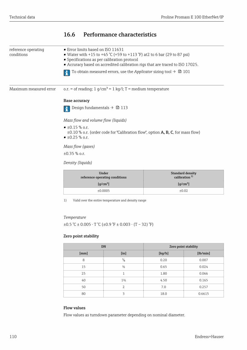
Technical data Proline Promass E 100 EtherNet/IP
110 Endress+Hauser
16.6 Performance characteristics
reference operatingconditions
• Error limits based on ISO 11631• Water with +15 to +45 °C (+59 to +113 °F) at2 to 6 bar (29 to 87 psi)• Specifications as per calibration protocol• Accuracy based on accredited calibration rigs that are traced to ISO 17025.
To obtain measured errors, use the Applicator sizing tool → 101
Maximum measured error o.r. = of reading; 1 g/cm³ = 1 kg/l; T = medium temperature
Base accuracyDesign fundamentals → 113
Mass flow and volume flow (liquids)
• ±0.15 % o.r.±0.10 % o.r. (order code for "Calibration flow", option A, B, C, for mass flow)
• ±0.25 % o.r.
Mass flow (gases)
±0.35 % o.r.
Density (liquids)
Underreference operating conditions
Standard densitycalibration 1)
[g/cm³] [g/cm³]
±0.0005 ±0.02
1) Valid over the entire temperature and density range
Temperature
±0.5 °C ± 0.005 · T °C (±0.9 °F ± 0.003 · (T – 32) °F)
Zero point stability
DN Zero point stability
[mm] [in] [kg/h] [lb/min]
8 ³⁄₈ 0.20 0.007
15 ½ 0.65 0.024
25 1 1.80 0.066
40 1½ 4.50 0.165
50 2 7.0 0.257
80 3 18.0 0.6615
Flow valuesFlow values as turndown parameter depending on nominal diameter.

Proline Promass E 100 EtherNet/IP Technical data
Endress+Hauser 111
SI units
DN 1:1 1:10 1:20 1:50 1:100 1:500
[mm] [kg/h] [kg/h] [kg/h] [kg/h] [kg/h] [kg/h]
8 2 000 200 100 40 20 4
15 6 500 650 325 130 65 13
25 18 000 1 800 900 360 180 36
40 45 000 4 500 2 250 900 450 90
50 70 000 7 000 3 500 1 400 700 140
80 180 000 18 000 9 000 3 600 1 800 360
US units
DN 1:1 1:10 1:20 1:50 1:100 1:500
[inch] [lb/min] [lb/min] [lb/min] [lb/min] [lb/min] [lb/min]
³⁄₈ 73.50 7.350 3.675 1.470 0.735 0.147
½ 238.9 23.89 11.95 4.778 2.389 0.478
1 661.5 66.15 33.08 13.23 6.615 1.323
1½ 1 654 165.4 82.70 33.08 16.54 3.308
2 2 573 257.3 128.7 51.46 25.73 5.146
3 6 615 661.5 330.8 132.3 66.15 13.23
Accuracy of outputsThe output accuracy must be factored into the measured error if analog outputs areused, but can be ignored for fieldbus outputs (e.g. Modbus RS485, EtherNet/IP).
The outputs have the following base accuracy specifications.
Repeatability o.r. = of reading; 1 g/cm3 = 1 kg/l; T = medium temperature
Base repeatabilityDesign fundamentals → 113
Mass flow and volume flow (liquids)
±0.075 % o.r.±0.05 % o.r. (calibration option, for mass flow)
Mass flow (gases)
±0.35 % o.r.
Density (liquids)
±0.00025 g/cm3
Temperature
±0.25 °C ± 0.0025 · T °C (±0.45 °F ± 0.0015 · (T–32) °F)
Response time The response time depends on the configuration (damping).

Technical data Proline Promass E 100 EtherNet/IP
112 Endress+Hauser
Influence of ambienttemperature
Current outputo.r. = of reading
Temperature coefficient Max. ±0.005 % o.r./°C
Pulse/frequency output
Temperature coefficient No additional effect. Included in accuracy.
Influence of mediumtemperature
Mass flow and volume flowo.f.s. = of full scale value
When there is a difference between the temperature for zero point adjustment and theprocess temperature, the additional measured error of the sensor is typically ±0.0002 %o.f.s./°C (±0.0001 % o. f.s./°F).
The effect is reduced if zero point adjustment is performed at process temperature.
DensityWhen there is a difference between the density calibration temperature and the processtemperature, the typical measured error of the sensor is±0.0001 g/cm3 /°C (±0.00005 g/cm3 /°F). Field density calibration is possible.
[kg/m ]3
[°C]
-40 0-80 40 80 120 160 200 240 280 320 [°F]
-40 0 50 100 1500
2
4
6
8
10
14
12
A0016609
15 Field density calibration, for example at +20 °C (+68 °F)
Temperature±0.005 · T °C (± 0.005 · (T – 32) °F)
Influence of mediumpressure
The table below shows the effect on accuracy of mass flow due to a difference betweencalibration pressure and process pressure.
o.r. = of reading
It is possible to compensate for the effect by:• Reading in the current pressure measured value via the current input.• Specifying a fixed value for the pressure in the device parameters.
Operating Instructions .

Proline Promass E 100 EtherNet/IP Technical data
Endress+Hauser 113
DN [% o.r./bar] [% o.r./psi]
[mm] [in]
8 ³⁄₈ no influence
15 ½ no influence
25 1 no influence
40 1½ no influence
50 2 –0.009 –0.0006
80 3 –0.020 –0.0014
Design fundamentals o.r. = of reading, o.f.s. = of full scale value
BaseAccu = base accuracy in % o.r., BaseRepeat = base repeatability in % o.r.
MeasValue = measured value; ZeroPoint = zero point stability
Calculation of the maximum measured error as a function of the flow rate
Flow rate Maximum measured error in % o.r.
ZeroPoint
BaseAccu⋅ 100³
A0021332
± BaseAccu
A0021339
ZeroPoint
BaseAccu⋅ 100<
A0021333
ZeroPoint
MeasValue⋅ 100±
A0021334
Calculation of the maximum repeatability as a function of the flow rate
Flow rate Maximum repeatability in % o.r.
½ ⋅ ZeroPointBaseRepeat ⋅ 100³
A0021335 A0021340
½ ⋅ ZeroPointBaseRepeat ⋅ 100<
A0021336
ZeroPoint
MeasValue⋅ 100½ ⋅±
A0021337
Example for maximum measured error
E [%]
Q [%]0 5 10 15 20 25 30 35 40 45 50 60 6555
0
0.5
1.0
1.5
2.0
2.5
70 75 80 85 90 95 100
A0030289
E Maximum measured error in % o.r. (example)Q Flow rate in % of maximum full scale value
16.7 Installation"Mounting requirements" → 18

Technical data Proline Promass E 100 EtherNet/IP
114 Endress+Hauser
16.8 Environment
Ambient temperaturerange
→ 20
Temperature tablesObserve the interdependencies between the permitted ambient and fluidtemperatures when operating the device in hazardous areas.
For detailed information on the temperature tables, see the separate documententitled "Safety Instructions" (XA) for the device.
Storage temperature –40 to +80 °C (–40 to +176 °F), preferably at +20 °C (+68 °F)
Climate class DIN EN 60068-2-38 (test Z/AD)
Degree of protection Transmitter and sensor• As standard: IP66/67, type 4X enclosure• With the order code for "Sensor options", option CM: IP69 can also be ordered• When housing is open: IP20, type 1 enclosure• Display module: IP20, type 1 enclosure
Vibration resistance • Vibration, sinusoidal according to IEC 60068-2-6– 2 to 8.4 Hz, 3.5 mm peak– 8.4 to 2 000 Hz, 1 g peak
• Vibration broad-band random, according to IEC 60068-2-64– 10 to 200 Hz, 0.003 g2/Hz– 200 to 2 000 Hz, 0.001 g2/Hz– Total: 1.54 g rms
Shock resistance Shock, half-sine according to IEC 60068-2-276 ms 30 g
Impact resistance Rough handling shocks according to IEC 60068-2-31
Electromagneticcompatibility (EMC)
• As per IEC/EN 61326 and NAMUR Recommendation 21 (NE 21)• Complies with emission limits for industry as per EN 55011 (Class A)
Details are provided in the Declaration of Conformity.
16.9 Process
Medium temperature range –40 to +150 °C (–40 to +302 °F)

Proline Promass E 100 EtherNet/IP Technical data
Endress+Hauser 115
Dependency of ambient temperature on medium temperature
Ta
Tm
B
A
A0031121
16 Exemplary representation, values in the table below.
Ta Ambient temperatureTm Medium temperatureA Maximum permitted medium temperature Tm at Ta max = 60 °C (140 °F); higher medium temperatures Tm
require a reduced ambient temperature Ta
B Maximum permitted ambient temperature Ta for the maximum specified medium temperature Tm of thesensor
Values for devices used in the hazardous area:Separate Ex documentation (XA) for the device .
Density 0 to 5 000 kg/m3 (0 to 312 lb/cf)
Pressure-temperatureratings
An overview of the pressure-temperature ratings for the process connections isprovided in the "Technical Information" document
Secondary containment The sensor housing is filled with dry nitrogen gas and protects the electronics andmechanics inside.
The secondary containment does not have a pressure rating classification.
Reference value for the pressure loading capacity of the sensor housing: 16 bar (232 psi)
If the device is fitted with a rupture disk (order code for "Sensor option", option CA "Rupturedisk"), the rupture disk trigger pressure is decisive for the maximum nominal pressure→ 115.
If a measuring tube fails (e.g. due to process characteristics like corrosive or abrasivefluids), the fluid will be contained by the secondary containment.
Rupture disk To increase the level of safety, a device version with a rupture disk with a trigger pressureof 10 to 15 bar (145 to 217.5 psi)can be used (order code for "Sensor option", option CA"rupture disk").
Rupture disks cannot be combined with the separately available heating jacket .
Special mounting instructions: → 22

Technical data Proline Promass E 100 EtherNet/IP
116 Endress+Hauser
Flow limit Select the nominal diameter by optimizing between the required flow range andpermissible pressure loss.
For an overview of the full scale values for the measuring range, see the "Measuringrange" section → 104
• The minimum recommended full scale value is approx. 1/20 of the maximum full scalevalue
• In most applications, 20 to 50 % of the maximum full scale value can be considered ideal• A low full scale value must be selected for abrasive media (such as liquids with entrained
solids): flow velocity < 1 m/s (< 3 ft/s).• For gas measurement the following rules apply:
– The flow velocity in the measuring tubes should not exceed half the sound velocity(0.5 Mach).
– The maximum mass flow depends on the density of the gas: formula → 104
To calculate the flow limit, use the Applicator sizing tool → 101
Pressure loss To calculate the pressure loss, use the Applicator sizing tool → 101
System pressure → 20

Proline Promass E 100 EtherNet/IP Technical data
Endress+Hauser 117
16.10 Mechanical construction
Design, dimensions For the dimensions and installation lengths of the device, see the "TechnicalInformation" document, "Mechanical construction" section.
Weight All values (weight exclusive of packaging material) refer to devices with EN/DINPN 40 flanges. Weight specifications including transmitter: order code for "Housing",option A "Compact, aluminum coated".
Different values due to different transmitter versions:
Weight in SI units
DN[mm]
Weight [kg]
8 4.5
15 4.8
25 6.4
40 10.4
50 15.5
80 29
Weight in US units
DN[in]
Weight [lbs]
3/8 10
½ 11
1 14
1 ½ 23
2 34
3 64
Materials Transmitter housing• Order code for "Housing", option A "Compact, aluminum coated":
Aluminum, AlSi10Mg, coated• Order code for "Housing", option B "Compact, hygienic, stainless":
Hygienic version, stainless steel 1.4301 (304)• Order code for "Housing", option C "Ultra-compact, hygienic, stainless":
Hygienic version, stainless steel 1.4301 (304)• Window material for optional local display (→ 119):
– For order code for "Housing", option A: glass– For order code for "Housing", option B and C: plastic

Technical data Proline Promass E 100 EtherNet/IP
118 Endress+Hauser
Cable entries/cable glands
1
2
3
A0020640
17 Possible cable entries/cable glands
1 Female thread M20 × 1.52 Cable gland M20 × 1.53 Adapter for cable entry with internal thread G ½" or NPT ½"
Order code for "Housing", option A "Compact, coated aluminum"
The various cable entries are suitable for hazardous and non-hazardous areas.
Cable entry/cable gland Material
Cable gland M20 × 1.5 Nickel-plated brass
Adapter for cable entry with internal thread G ½"
Adapter for cable entry with internal thread NPT ½"
Order code for "Housing", option B "Compact, hygienic, stainless"
The various cable entries are suitable for hazardous and non-hazardous areas.
Cable entry/cable gland Material
Cable gland M20 × 1.5 Stainless steel, 1.4404 (316L)
Adapter for cable entry with internal thread G ½"
Adapter for cable entry with internal thread NPT ½"
Device plug
Electrical connection Material
Plug M12x1 • Socket: Stainless steel, 1.4404 (316L)• Contact housing: Polyamide• Contacts: Gold-plated brass
Sensor housing• Acid and alkali-resistant outer surface• Stainless steel 1.4301 (304)
Measuring tubesStainless steel, 1.4539 (904L); manifold: stainless steel, 1.4404 (316L)

Proline Promass E 100 EtherNet/IP Technical data
Endress+Hauser 119
Process connections• Flanges according to EN 1092-1 (DIN2501) / according to ASME B 16.5 / as per JIS
B2220:Stainless steel, 1.4404 (F316/F316L)
• All other process connections:Stainless steel, 1.4404 (316/316L)
List of all available process connections → 119
SealsWelded process connections without internal seals
AccessoriesProtective cover
Stainless steel, 1.4404 (316L)
Safety Barrier Promass 100
Housing: Polyamide
Process connections • Fixed flange connections:– EN 1092-1 (DIN 2501) flange– EN 1092-1 (DIN 2512N) flange– Namur lengths in accordance with NE 132– ASME B16.5 flange– JIS B2220 flange– DIN 11864-2 Form A flange, DIN 11866 series A, flange with notch
• Clamp connectionsTri-Clamp (OD tubes), DIN 11866 series C
• Thread:– DIN 11851 thread, DIN 11866 series A– SMS 1145 thread– ISO 2853 thread, ISO 2037– DIN 11864-1 Form A thread, DIN 11866 series A
• VCO connections– 8-VCO-4– 12-VCO-4
For information on the different materials used in the process connections → 117
Surface roughness All data relate to parts in contact with fluid. The following surface roughness quality canbe ordered.• Not polished• Ramax = 0.8 µm (32 µin)• Ramax = 0.4 µm (16 µin)
16.11 Operability
Local display The local display is only available with the following device order code:Order code for "Display; operation", option B: 4-line; illuminated, via communication

Technical data Proline Promass E 100 EtherNet/IP
120 Endress+Hauser
Display element• 4-line liquid crystal display with 16 characters per line.• White background lighting; switches to red in event of device errors.• Format for displaying measured variables and status variables can be individually
configured.• Permitted ambient temperature for the display: –20 to +60 °C (–4 to +140 °F). The
readability of the display may be impaired at temperatures outside the temperaturerange.
Disconnecting the local display from the main electronics moduleIn the case of the "Compact, aluminum coated" housing version, the local display mustonly be disconnected manually from the main electronics module. In the case of the"Compact, hygienic, stainless" and "Ultra-compact, hygienic, stainless" housingversions, the local display is integrated in the housing cover and is disconnected fromthe main electronics module when the housing cover is opened.
"Compact, aluminum coated" housing version
The local display is plugged onto the main electronics module. The electronic connectionbetween the local display and main electronics module is established via a connectingcable.
For some work performed on the measuring device (e.g. electrical connection), it isadvisable to disconnect the local display from the main electronics module:
1. Press in the side latches of the local display.
2. Remove the local display from the main electronics module. Pay attention to thelength of the connecting cable when doing so.
Once the work is completed, plug the local display back on.
Remote operation Via EtherNet/IP networkThis communication interface is available in device versions with EtherNet/IP.

Proline Promass E 100 EtherNet/IP Technical data
Endress+Hauser 121
Star topology
4
21 3
5 5 5
A0032078
18 Options for remote operation via EtherNet/IP network: star topology
1 Automation system, e.g. "RSLogix" (Rockwell Automation)2 Workstation for measuring device operation: with Custom Add-On Profile for "RSLogix 5000" (Rockwell
Automation) or with Electronic Data Sheet (EDS)3 Computer with Web browser (e.g. Internet Explorer) for accessing the integrated device Web server or
computer with operating tool (e.g. FieldCare, DeviceCare) with COM DTM "CDI Communication TCP/IP"4 Ethernet switch5 Measuring device
Service interface Via service interface (CDI-RJ45)
EtherNet/IP
1
2
3
A0016940
19 Connection for order code for "Output", option N: EtherNet/IP
1 Service interface (CDI -RJ45) and EtherNet/IP interface of the measuring device with access to the integratedWeb server
2 Computer with Web browser (e.g. Internet Explorer) for accessing the integrated device Web server or with"FieldCare" operating tool with COM DTM "CDI Communication TCP/IP"
3 Standard Ethernet connecting cable with RJ45 plug
Languages Can be operated in the following languages:• Via "FieldCare" operating tool: English, German, French, Spanish, Italian, Chinese,
Japanese• Via Web browser
English, German, French, Spanish, Italian, Dutch, Portuguese, Polish, Russian, Turkish,Chinese, Japanese, Bahasa (Indonesian), Vietnamese, Czech, Swedish, Korean

Technical data Proline Promass E 100 EtherNet/IP
122 Endress+Hauser
16.12 Certificates and approvals
CE mark The measuring system is in conformity with the statutory requirements of the applicableEU Directives. These are listed in the corresponding EU Declaration of Conformity alongwith the standards applied.
Endress+Hauser confirms successful testing of the device by affixing to it the CE mark.
C-Tick symbol The measuring system meets the EMC requirements of the "Australian Communicationsand Media Authority (ACMA)".
Ex approval The devices are certified for use in hazardous areas and the relevant safety instructions areprovided in the separate "Safety Instructions" (XA) document. Reference is made to thisdocument on the nameplate.
Sanitary compatibility • 3-A approvalOnly devices with the order code for "Additional approval", option LP "3A" have3-A approval.
• EHEDG-testedOnly devices with the order code for "Additional approval", option LT "EHEDG" have beentested and meet the requirements of the EHEDG.To meet the requirements for EHEDG certification, the device must be used with processconnections in accordance with the EHEDG position paper entitled "Easy Cleanable PipeCouplings and Process Connections" (www.ehedg.org).
EtherNet/IP certification The measuring device is certified and registered by the ODVA (Open Device VendorAssociation). The measuring system meets all the requirements of the followingspecifications:• Certified in accordance with the ODVA Conformance Test• EtherNet/IP Performance Test• EtherNet/IP PlugFest compliance• The device can also be operated with certified devices of other manufacturers
(interoperability)
Pressure EquipmentDirective
• With the identification PED/G1/x (x = category) on the sensor nameplate,Endress+Hauser confirms conformity with the "Essential Safety Requirements" specifiedin Appendix I of the Pressure Equipment Directive 2014/68/EC.
• Devices not bearing this marking (PED) are designed and manufactured according togood engineering practice. They meet the requirements of Art. 4, Par. 3 of the PressureEquipment Directive 2014/68/EU. The range of application is indicated in tables 6 to 9in Annex II of the Pressure Equipment Directive 2014/68/EC.
Other standards andguidelines
• EN 60529Degrees of protection provided by enclosures (IP code)
• IEC/EN 60068-2-6Environmental influences: Test procedure - Test Fc: vibrate (sinusoidal).
• IEC/EN 60068-2-31Environmental influences: Test procedure - Test Ec: shocks due to rough handling,primarily for devices.
• EN 61010-1Safety requirements for electrical equipment for measurement, control and laboratoryuse - general requirements

Proline Promass E 100 EtherNet/IP Technical data
Endress+Hauser 123
• IEC/EN 61326Emission in accordance with Class A requirements. Electromagnetic compatibility (EMCrequirements).
• NAMUR NE 21Electromagnetic compatibility (EMC) of industrial process and laboratory controlequipment
• NAMUR NE 32Data retention in the event of a power failure in field and control instruments withmicroprocessors
• NAMUR NE 43Standardization of the signal level for the breakdown information of digital transmitterswith analog output signal.
• NAMUR NE 53Software of field devices and signal-processing devices with digital electronics
• NAMUR NE 80The application of the pressure equipment directive to process control devices
• NAMUR NE 105Specifications for integrating fieldbus devices in engineering tools for field devices
• NAMUR NE 107Self-monitoring and diagnosis of field devices
• NAMUR NE 131Requirements for field devices for standard applications
• NAMUR NE 132Coriolis mass meter
16.13 Application packagesMany different application packages are available to enhance the functionality of thedevice. Such packages might be needed to address safety aspects or specific applicationrequirements.
The application packages can be ordered with the device or subsequently fromEndress+Hauser. Detailed information on the order code in question is available from yourlocal Endress+Hauser sales center or on the product page of the Endress+Hauser website:www.endress.com.
Detailed information on the application packages:Special Documentation for the device → 125
Heartbeat Technology Package Description
Heartbeat Verification+Monitoring
Heartbeat VerificationMeets the requirement for traceable verification to DIN ISO 9001:2008 Chapter7.6 a) "Control of monitoring and measuring equipment".• Functional testing in the installed state without interrupting the process.• Traceable verification results on request, including a report.• Simple testing process via local operation or other operating interfaces.• Clear measuring point assessment (pass/fail) with high test coverage within the
framework of manufacturer specifications.• Extension of calibration intervals according to operator's risk assessment.
Heartbeat MonitoringContinuously supplies data, which are characteristic of the measuring principle, toan external condition monitoring system for the purpose of preventivemaintenance or process analysis. These data enable the operator to:• Draw conclusions - using these data and other information - about the impact
process influences (such as corrosion, abrasion, buildup etc.) have on themeasuring performance over time.
• Schedule servicing in time.• Monitor the process or product quality, e.g. gas pockets.

Technical data Proline Promass E 100 EtherNet/IP
124 Endress+Hauser
Concentration Package Description
Concentrationmeasurement
Calculation and outputting of fluid concentrationsMany applications use density as a key measured value for monitoring quality orcontrolling processes. The device measures the density of the fluid as standard andmakes this value available to the control system.
The observed density is converted to the concentration of a substance of a binarymixture using the "Concentration Measurement" application package:• Choice of predefined fluids (e.g. various sugar solutions, acids, alkalis, salts,
ethanol etc.)• Common or user-defined units (°Brix, °Plato, % mass, % volume, mol/l etc.) for
standard applications.• Concentration calculation from user-defined tables.
The measured values are output via the digital and analog outputs of the device.
16.14 AccessoriesOverview of accessories available for order → 101
16.15 Supplementary documentationFor an overview of the scope of the associated Technical Documentation, refer to thefollowing:• The W@M Device Viewer : Enter the serial number from the nameplate
(www.endress.com/deviceviewer)• The Endress+Hauser Operations App: Enter the serial number from the nameplate
or scan the 2-D matrix code (QR code) on the nameplate.
Standard documentation Brief Operating Instructions
Brief Operating Instructions for the sensor
Measuring device Documentation code
Proline Promass E KA01260D
Transmitter Brief Operating Instructions
Measuring device Documentation code
Proline Promass 100 KA01332D
Technical Information
Measuring device Documentation code
Proline Promass E 100 TI01351D
Description of Device Parameters
Measuring device Documentation code
Proline Promass 100 GP01036D

Proline Promass E 100 EtherNet/IP Technical data
Endress+Hauser 125
Supplementary device-dependent documentation
Safety Instructions
Content Documentation code
ATEX/IECEx Ex i XA00159D
ATEX/IECEx Ex nA XA01029D
cCSAus IS XA00160D
INMETRO Ex i XA01219D
INMETRO Ex nA XA01220D
Special Documentation
Content Documentation code
Information on the Pressure Equipment Directive SD00142D
Concentration measurement SD01152D
Heartbeat Technology SD01153D
Web server SD01822D
Installation Instructions
Contents Comment
Installation instructions for spare part sets and accessories • Access the overview of all the available spare part sets viaW@M Device Viewer → 99
• Accessories available for order with Installation Instructions → 101

Index Proline Promass E 100 EtherNet/IP
126 Endress+Hauser
Index
0 … 93-A approval . . . . . . . . . . . . . . . . . . . . . . . . . . . . . . 122
AAccuracy . . . . . . . . . . . . . . . . . . . . . . . . . . . . . . . . . 110Adapting the diagnostic behavior . . . . . . . . . . . . . . . . 80Ambient temperature
Influence . . . . . . . . . . . . . . . . . . . . . . . . . . . . . . 112Application . . . . . . . . . . . . . . . . . . . . . . . . . . . . . . . 103Application packages . . . . . . . . . . . . . . . . . . . . . . . . 123Applicator . . . . . . . . . . . . . . . . . . . . . . . . . . . . . . . . 104Approvals . . . . . . . . . . . . . . . . . . . . . . . . . . . . . . . . 122
CC-Tick symbol . . . . . . . . . . . . . . . . . . . . . . . . . . . . . 122Cable entries
Technical data . . . . . . . . . . . . . . . . . . . . . . . . . . 109Cable entry
Degree of protection . . . . . . . . . . . . . . . . . . . . . . . 30CE mark . . . . . . . . . . . . . . . . . . . . . . . . . . . . . . 10, 122Certificates . . . . . . . . . . . . . . . . . . . . . . . . . . . . . . . 122Check
Installation . . . . . . . . . . . . . . . . . . . . . . . . . . . . . 23Checklist
Post-connection check . . . . . . . . . . . . . . . . . . . . . 31Post-installation check . . . . . . . . . . . . . . . . . . . . . 23
CleaningCleaning in place (CIP) . . . . . . . . . . . . . . . . . . . . . 98Exterior cleaning . . . . . . . . . . . . . . . . . . . . . . . . . 98Interior cleaning . . . . . . . . . . . . . . . . . . . . . . . . . . 98Sterilization in place (SIP) . . . . . . . . . . . . . . . . . . . 98
Climate class . . . . . . . . . . . . . . . . . . . . . . . . . . . . . . 114Commissioning . . . . . . . . . . . . . . . . . . . . . . . . . . . . . 49
Advanced settings . . . . . . . . . . . . . . . . . . . . . . . . 58Configuring the measuring device . . . . . . . . . . . . . 49
Connecting cable . . . . . . . . . . . . . . . . . . . . . . . . . . . . 24Connecting the measuring device . . . . . . . . . . . . . . . . 26Connection
see Electrical connectionConnection preparations . . . . . . . . . . . . . . . . . . . . . . 26Connection tools . . . . . . . . . . . . . . . . . . . . . . . . . . . . 24Current consumption . . . . . . . . . . . . . . . . . . . . . . . . 109Cyclic data transmission . . . . . . . . . . . . . . . . . . . . . . 45
DDeclaration of Conformity . . . . . . . . . . . . . . . . . . . . . 10Define access code . . . . . . . . . . . . . . . . . . . . . . . . . . . 67Degree of protection . . . . . . . . . . . . . . . . . . . . . 30, 114Density . . . . . . . . . . . . . . . . . . . . . . . . . . . . . . . . . . 115Design
Measuring device . . . . . . . . . . . . . . . . . . . . . . . . . 12Design fundamentals
Maximum measured error . . . . . . . . . . . . . . . . . 113Repeatability . . . . . . . . . . . . . . . . . . . . . . . . . . . 113
Designated use . . . . . . . . . . . . . . . . . . . . . . . . . . . . . . 9Device components . . . . . . . . . . . . . . . . . . . . . . . . . . 12
Device description files . . . . . . . . . . . . . . . . . . . . . . . 44Device documentation
Supplementary documentation . . . . . . . . . . . . . . . . 8Device locking, status . . . . . . . . . . . . . . . . . . . . . . . . 69Device name
Sensor . . . . . . . . . . . . . . . . . . . . . . . . . . . . . . . . . 14Transmitter . . . . . . . . . . . . . . . . . . . . . . . . . . . . . 14
Device repair . . . . . . . . . . . . . . . . . . . . . . . . . . . . . . . 99Device revision . . . . . . . . . . . . . . . . . . . . . . . . . . . . . 44Device type ID . . . . . . . . . . . . . . . . . . . . . . . . . . . . . . 44DeviceCare . . . . . . . . . . . . . . . . . . . . . . . . . . . . . . . . 43
Device description file . . . . . . . . . . . . . . . . . . . . . . 44Diagnostic information
Communication interface . . . . . . . . . . . . . . . . . . . 80Design, description . . . . . . . . . . . . . . . . . . . . . 78, 79DeviceCare . . . . . . . . . . . . . . . . . . . . . . . . . . . . . . 79FieldCare . . . . . . . . . . . . . . . . . . . . . . . . . . . . . . . 79Light emitting diodes . . . . . . . . . . . . . . . . . . . . . . 77Overview . . . . . . . . . . . . . . . . . . . . . . . . . . . . . . . 81Remedial measures . . . . . . . . . . . . . . . . . . . . . . . 81Web browser . . . . . . . . . . . . . . . . . . . . . . . . . . . . 77
Diagnostic list . . . . . . . . . . . . . . . . . . . . . . . . . . . . . . 92DIP switches
see Write protection switchDisabling write protection . . . . . . . . . . . . . . . . . . . . . 66Display values
For locking status . . . . . . . . . . . . . . . . . . . . . . . . . 69Disposal . . . . . . . . . . . . . . . . . . . . . . . . . . . . . . . . . 100Document
Function . . . . . . . . . . . . . . . . . . . . . . . . . . . . . . . . 6Symbols used . . . . . . . . . . . . . . . . . . . . . . . . . . . . . 6
Document function . . . . . . . . . . . . . . . . . . . . . . . . . . . 6Down pipe . . . . . . . . . . . . . . . . . . . . . . . . . . . . . . . . . 18
EEHDEG-certified . . . . . . . . . . . . . . . . . . . . . . . . . . . 122Electrical connection
Commubox FXA291 . . . . . . . . . . . . . . . . . . . . . . . 41Degree of protection . . . . . . . . . . . . . . . . . . . . . . . 30Measuring device . . . . . . . . . . . . . . . . . . . . . . . . . 24Operating tools
Via Ethernet network . . . . . . . . . . . . . . . 40, 120Via service interface (CDI-RJ45) . . . . . . . . 41, 121Via service interface (CDI) . . . . . . . . . . . . . . . . 41
RSLogix 5000 . . . . . . . . . . . . . . . . . . . . . . . . 40, 120Web server . . . . . . . . . . . . . . . . . . . . . . . . . . 41, 121
Electromagnetic compatibility . . . . . . . . . . . . . . . . . 114Enabling write protection . . . . . . . . . . . . . . . . . . . . . 66Endress+Hauser services
Maintenance . . . . . . . . . . . . . . . . . . . . . . . . . . . . 98Repair . . . . . . . . . . . . . . . . . . . . . . . . . . . . . . . . . 99
EnvironmentImpact resistance . . . . . . . . . . . . . . . . . . . . . . . . 114Shock resistance . . . . . . . . . . . . . . . . . . . . . . . . . 114Storage temperature . . . . . . . . . . . . . . . . . . . . . . 114Vibration resistance . . . . . . . . . . . . . . . . . . . . . . 114

Proline Promass E 100 EtherNet/IP Index
Endress+Hauser 127
Error messagessee Diagnostic messages
EtherNet/IPDiagnostic information . . . . . . . . . . . . . . . . . . . . . 80
EtherNet/IP certification . . . . . . . . . . . . . . . . . . . . . 122Event list . . . . . . . . . . . . . . . . . . . . . . . . . . . . . . . . . . 92Event logbook . . . . . . . . . . . . . . . . . . . . . . . . . . . . . . 92Ex approval . . . . . . . . . . . . . . . . . . . . . . . . . . . . . . . 122Extended order code
Sensor . . . . . . . . . . . . . . . . . . . . . . . . . . . . . . . . . 14Transmitter . . . . . . . . . . . . . . . . . . . . . . . . . . . . . 14
Exterior cleaning . . . . . . . . . . . . . . . . . . . . . . . . . . . . 98
FFDA . . . . . . . . . . . . . . . . . . . . . . . . . . . . . . . . . . . . 122Field of application
Residual risks . . . . . . . . . . . . . . . . . . . . . . . . . . . . 10FieldCare . . . . . . . . . . . . . . . . . . . . . . . . . . . . . . . . . 41
Device description file . . . . . . . . . . . . . . . . . . . . . . 44Establishing a connection . . . . . . . . . . . . . . . . . . . 42Function . . . . . . . . . . . . . . . . . . . . . . . . . . . . . . . 41User interface . . . . . . . . . . . . . . . . . . . . . . . . . . . 43
Filtering the event logbook . . . . . . . . . . . . . . . . . . . . 93Firmware
Release date . . . . . . . . . . . . . . . . . . . . . . . . . . . . . 44Version . . . . . . . . . . . . . . . . . . . . . . . . . . . . . . . . 44
Firmware history . . . . . . . . . . . . . . . . . . . . . . . . . . . . 97Fix assembly . . . . . . . . . . . . . . . . . . . . . . . . . . . . . . . 80Flow direction . . . . . . . . . . . . . . . . . . . . . . . . . . . 19, 23Flow limit . . . . . . . . . . . . . . . . . . . . . . . . . . . . . . . . 116Food Contact Materials Regulation . . . . . . . . . . . . . . 122Function check . . . . . . . . . . . . . . . . . . . . . . . . . . . . . 49Functions
see Parameter
GGalvanic isolation . . . . . . . . . . . . . . . . . . . . . . . . . . 106
HHardware write protection . . . . . . . . . . . . . . . . . . . . . 67
II/O electronics module . . . . . . . . . . . . . . . . . . . . . 12, 27Identifying the measuring device . . . . . . . . . . . . . . . . 13Impact resistance . . . . . . . . . . . . . . . . . . . . . . . . . . 114Incoming acceptance . . . . . . . . . . . . . . . . . . . . . . . . . 13Influence
Ambient temperature . . . . . . . . . . . . . . . . . . . . . 112Medium pressure . . . . . . . . . . . . . . . . . . . . . . . . 112Medium temperature . . . . . . . . . . . . . . . . . . . . . 112
Information on the document . . . . . . . . . . . . . . . . . . . 6Inlet runs . . . . . . . . . . . . . . . . . . . . . . . . . . . . . . . . . 20Input . . . . . . . . . . . . . . . . . . . . . . . . . . . . . . . . . . . 104Inspection
Received goods . . . . . . . . . . . . . . . . . . . . . . . . . . . 13Inspection check
Connection . . . . . . . . . . . . . . . . . . . . . . . . . . . . . . 31Installation . . . . . . . . . . . . . . . . . . . . . . . . . . . . . . . . 18Installation conditions
Down pipe . . . . . . . . . . . . . . . . . . . . . . . . . . . . . . 18
Inlet and outlet runs . . . . . . . . . . . . . . . . . . . . . . . 20Installation dimensions . . . . . . . . . . . . . . . . . . . . 20Mounting location . . . . . . . . . . . . . . . . . . . . . . . . 18Orientation . . . . . . . . . . . . . . . . . . . . . . . . . . . . . 19Rupture disk . . . . . . . . . . . . . . . . . . . . . . . . . . . . . 22Sensor heating . . . . . . . . . . . . . . . . . . . . . . . . . . . 21System pressure . . . . . . . . . . . . . . . . . . . . . . . . . . 20Thermal insulation . . . . . . . . . . . . . . . . . . . . . . . . 20Vibrations . . . . . . . . . . . . . . . . . . . . . . . . . . . . . . 22
Installation dimensions . . . . . . . . . . . . . . . . . . . . . . . 20Interior cleaning . . . . . . . . . . . . . . . . . . . . . . . . . . . . 98
LLanguages, operation options . . . . . . . . . . . . . . . . . 121Low flow cut off . . . . . . . . . . . . . . . . . . . . . . . . . . . 106
MMain electronics module . . . . . . . . . . . . . . . . . . . . . . 12Maintenance tasks . . . . . . . . . . . . . . . . . . . . . . . . . . 98Manufacturer ID . . . . . . . . . . . . . . . . . . . . . . . . . . . . 44Manufacturing date . . . . . . . . . . . . . . . . . . . . . . . . . . 14Materials . . . . . . . . . . . . . . . . . . . . . . . . . . . . . . . . 117Maximum measured error . . . . . . . . . . . . . . . . . . . . 110Measured values
see Process variablesMeasuring and test equipment . . . . . . . . . . . . . . . . . 98Measuring device
Configuration . . . . . . . . . . . . . . . . . . . . . . . . . . . . 49Conversion . . . . . . . . . . . . . . . . . . . . . . . . . . . . . . 99Design . . . . . . . . . . . . . . . . . . . . . . . . . . . . . . . . . 12Disposal . . . . . . . . . . . . . . . . . . . . . . . . . . . . . . . 100Mounting the sensor . . . . . . . . . . . . . . . . . . . . . . 23Preparing for electrical connection . . . . . . . . . . . . 26Preparing for mounting . . . . . . . . . . . . . . . . . . . . 23Removing . . . . . . . . . . . . . . . . . . . . . . . . . . . . . . 100Repairs . . . . . . . . . . . . . . . . . . . . . . . . . . . . . . . . 99
Measuring principle . . . . . . . . . . . . . . . . . . . . . . . . 103Measuring range
Calculation example for gas . . . . . . . . . . . . . . . . 105For gases . . . . . . . . . . . . . . . . . . . . . . . . . . . . . . 104For liquids . . . . . . . . . . . . . . . . . . . . . . . . . . . . . 104
Measuring range, recommended . . . . . . . . . . . . . . . 116Measuring system . . . . . . . . . . . . . . . . . . . . . . . . . . 103Medium pressure
Influence . . . . . . . . . . . . . . . . . . . . . . . . . . . . . . 112Medium temperature
Influence . . . . . . . . . . . . . . . . . . . . . . . . . . . . . . 112Menu
Diagnostics . . . . . . . . . . . . . . . . . . . . . . . . . . . . . 91Operation . . . . . . . . . . . . . . . . . . . . . . . . . . . . . . 69Setup . . . . . . . . . . . . . . . . . . . . . . . . . . . . . . . . . . 50
MenusFor measuring device configuration . . . . . . . . . . . . 49For specific settings . . . . . . . . . . . . . . . . . . . . . . . 58
Mounting dimensionssee Installation dimensions
Mounting location . . . . . . . . . . . . . . . . . . . . . . . . . . . 18Mounting preparations . . . . . . . . . . . . . . . . . . . . . . . 23Mounting tools . . . . . . . . . . . . . . . . . . . . . . . . . . . . . 22
Index Proline Promass E 100 EtherNet/IP
128 Endress+Hauser
NNameplate
Sensor . . . . . . . . . . . . . . . . . . . . . . . . . . . . . . . . . 14Transmitter . . . . . . . . . . . . . . . . . . . . . . . . . . . . . 14
OOperable flow range . . . . . . . . . . . . . . . . . . . . . . . . 105Operating menu
Menus, submenus . . . . . . . . . . . . . . . . . . . . . . . . 33Structure . . . . . . . . . . . . . . . . . . . . . . . . . . . . . . . 33Submenus and user roles . . . . . . . . . . . . . . . . . . . 34
Operating philosophy . . . . . . . . . . . . . . . . . . . . . . . . 34Operation . . . . . . . . . . . . . . . . . . . . . . . . . . . . . . . . . 69Operation options . . . . . . . . . . . . . . . . . . . . . . . . . . . 32Operational safety . . . . . . . . . . . . . . . . . . . . . . . . . . . 10Order code . . . . . . . . . . . . . . . . . . . . . . . . . . . . . . . . 14Orientation (vertical, horizontal) . . . . . . . . . . . . . . . . 19Outlet runs . . . . . . . . . . . . . . . . . . . . . . . . . . . . . . . . 20Output . . . . . . . . . . . . . . . . . . . . . . . . . . . . . . . . . . 105Output signal . . . . . . . . . . . . . . . . . . . . . . . . . . . . . 105
PPackaging disposal . . . . . . . . . . . . . . . . . . . . . . . . . . 17Parameter settings
Administration (Submenu) . . . . . . . . . . . . . . . . . . 64Advanced setup (Submenu) . . . . . . . . . . . . . . . . . 58Calculated values (Submenu) . . . . . . . . . . . . . . . . 58Communication (Submenu) . . . . . . . . . . . . . . . . . 54Device information (Submenu) . . . . . . . . . . . . . . . 94Diagnostics (Menu) . . . . . . . . . . . . . . . . . . . . . . . 91Display (Submenu) . . . . . . . . . . . . . . . . . . . . . . . . 62Low flow cut off (Wizard) . . . . . . . . . . . . . . . . . . . 56Measured variables (Submenu) . . . . . . . . . . . . . . . 70Medium selection (Submenu) . . . . . . . . . . . . . . . . 53Partially filled pipe detection (Wizard) . . . . . . . . . 57Sensor adjustment (Submenu) . . . . . . . . . . . . . . . 60Setup (Menu) . . . . . . . . . . . . . . . . . . . . . . . . . . . . 50Simulation (Submenu) . . . . . . . . . . . . . . . . . . . . . 65System units (Submenu) . . . . . . . . . . . . . . . . . . . . 50Totalizer (Submenu) . . . . . . . . . . . . . . . . . . . . . . . 72Totalizer 1 to n (Submenu) . . . . . . . . . . . . . . . . . . 60Totalizer handling (Submenu) . . . . . . . . . . . . . . . . 73Web server (Submenu) . . . . . . . . . . . . . . . . . . . . . 39Zero point adjustment (Submenu) . . . . . . . . . . . . . 60
Performance characteristics . . . . . . . . . . . . . . . . . . . 110Post-connection check (checklist) . . . . . . . . . . . . . . . 31Post-installation check . . . . . . . . . . . . . . . . . . . . . . . 49Post-installation check (checklist) . . . . . . . . . . . . . . . 23Potential equalization . . . . . . . . . . . . . . . . . . . . . . . . 28Power consumption . . . . . . . . . . . . . . . . . . . . . . . . . 109Power supply failure . . . . . . . . . . . . . . . . . . . . . . . . 109Pressure Equipment Directive . . . . . . . . . . . . . . . . . 122Pressure loss . . . . . . . . . . . . . . . . . . . . . . . . . . . . . . 116Pressure-temperature ratings . . . . . . . . . . . . . . . . . 115Process connections . . . . . . . . . . . . . . . . . . . . . . . . 119Process variables
Calculated . . . . . . . . . . . . . . . . . . . . . . . . . . . . . 104Measured . . . . . . . . . . . . . . . . . . . . . . . . . . . . . . 104
Product safety . . . . . . . . . . . . . . . . . . . . . . . . . . . . . . 10
Protecting parameter settings . . . . . . . . . . . . . . . . . . 66
RReading measured values . . . . . . . . . . . . . . . . . . . . . . 70Reading out diagnostic information, EtherNet/IP . . . . 80Recalibration . . . . . . . . . . . . . . . . . . . . . . . . . . . . . . . 98reference operating conditions . . . . . . . . . . . . . . . . . 110Registered trademarks . . . . . . . . . . . . . . . . . . . . . . . . . 8Remote operation . . . . . . . . . . . . . . . . . . . . . . . . . . 120Repair of a device . . . . . . . . . . . . . . . . . . . . . . . . . . . 99Repairs . . . . . . . . . . . . . . . . . . . . . . . . . . . . . . . . . . . 99
Notes . . . . . . . . . . . . . . . . . . . . . . . . . . . . . . . . . . 99Repeatability . . . . . . . . . . . . . . . . . . . . . . . . . . . . . . 111Replacement
Device components . . . . . . . . . . . . . . . . . . . . . . . . 99Requirements for personnel . . . . . . . . . . . . . . . . . . . . . 9Response time . . . . . . . . . . . . . . . . . . . . . . . . . . . . . 111Return . . . . . . . . . . . . . . . . . . . . . . . . . . . . . . . . . . . 99Rupture disk
Safety instructions . . . . . . . . . . . . . . . . . . . . . . . . 22Triggering pressure . . . . . . . . . . . . . . . . . . . . . . 115
SSafety . . . . . . . . . . . . . . . . . . . . . . . . . . . . . . . . . . . . . 9Sanitary compatibility . . . . . . . . . . . . . . . . . . . . . . . 122Secondary containment . . . . . . . . . . . . . . . . . . . . . . 115Sensor
Mounting . . . . . . . . . . . . . . . . . . . . . . . . . . . . . . . 23Sensor heating . . . . . . . . . . . . . . . . . . . . . . . . . . . . . 21Serial number . . . . . . . . . . . . . . . . . . . . . . . . . . . . . . 14Setting the operating language . . . . . . . . . . . . . . . . . 49Settings
Adapting the measuring device to the processconditions . . . . . . . . . . . . . . . . . . . . . . . . . . . . . . 73Administration . . . . . . . . . . . . . . . . . . . . . . . . . . . 64Advanced display configurations . . . . . . . . . . . . . . 62Communication interface . . . . . . . . . . . . . . . . . . . 54Device reset . . . . . . . . . . . . . . . . . . . . . . . . . . . . . 94Device tag . . . . . . . . . . . . . . . . . . . . . . . . . . . . . . 50Low flow cut off . . . . . . . . . . . . . . . . . . . . . . . . . . 56Medium . . . . . . . . . . . . . . . . . . . . . . . . . . . . . . . . 53Operating language . . . . . . . . . . . . . . . . . . . . . . . 49Partial filled pipe detection . . . . . . . . . . . . . . . . . . 57Resetting the totalizer . . . . . . . . . . . . . . . . . . . . . 73Sensor adjustment . . . . . . . . . . . . . . . . . . . . . . . . 60Simulation . . . . . . . . . . . . . . . . . . . . . . . . . . . . . . 65System units . . . . . . . . . . . . . . . . . . . . . . . . . . . . 50Totalizer . . . . . . . . . . . . . . . . . . . . . . . . . . . . . . . 60Totalizer reset . . . . . . . . . . . . . . . . . . . . . . . . . . . 73
Shock resistance . . . . . . . . . . . . . . . . . . . . . . . . . . . 114Signal on alarm . . . . . . . . . . . . . . . . . . . . . . . . . . . . 105Software release . . . . . . . . . . . . . . . . . . . . . . . . . . . . 44Spare part . . . . . . . . . . . . . . . . . . . . . . . . . . . . . . . . . 99Spare parts . . . . . . . . . . . . . . . . . . . . . . . . . . . . . . . . 99Special connection instructions . . . . . . . . . . . . . . . . . 29Standards and guidelines . . . . . . . . . . . . . . . . . . . . . 122Status signals . . . . . . . . . . . . . . . . . . . . . . . . . . . . . . 78Storage conditions . . . . . . . . . . . . . . . . . . . . . . . . . . . 16Storage temperature . . . . . . . . . . . . . . . . . . . . . . . . . 16

Proline Promass E 100 EtherNet/IP Index
Endress+Hauser 129
Storage temperature range . . . . . . . . . . . . . . . . . . . 114Structure
Operating menu . . . . . . . . . . . . . . . . . . . . . . . . . . 33Submenu
Administration . . . . . . . . . . . . . . . . . . . . . . . . . . . 64Advanced setup . . . . . . . . . . . . . . . . . . . . . . . . . . 58Calculated values . . . . . . . . . . . . . . . . . . . . . . . . . 58Communication . . . . . . . . . . . . . . . . . . . . . . . 49, 54Device information . . . . . . . . . . . . . . . . . . . . . . . . 94Display . . . . . . . . . . . . . . . . . . . . . . . . . . . . . . . . . 62Event list . . . . . . . . . . . . . . . . . . . . . . . . . . . . . . . 92Measured values . . . . . . . . . . . . . . . . . . . . . . . . . 70Measured variables . . . . . . . . . . . . . . . . . . . . . . . 70Medium selection . . . . . . . . . . . . . . . . . . . . . . . . . 53Overview . . . . . . . . . . . . . . . . . . . . . . . . . . . . . . . 34Process variables . . . . . . . . . . . . . . . . . . . . . . . . . 58Sensor adjustment . . . . . . . . . . . . . . . . . . . . . . . . 60Simulation . . . . . . . . . . . . . . . . . . . . . . . . . . . . . . 65System units . . . . . . . . . . . . . . . . . . . . . . . . . . . . 50Totalizer . . . . . . . . . . . . . . . . . . . . . . . . . . . . . . . 72Totalizer 1 to n . . . . . . . . . . . . . . . . . . . . . . . . . . . 60Totalizer handling . . . . . . . . . . . . . . . . . . . . . . . . 73Web server . . . . . . . . . . . . . . . . . . . . . . . . . . . . . 39Zero point adjustment . . . . . . . . . . . . . . . . . . . . . 60
Supply voltage . . . . . . . . . . . . . . . . . . . . . . . . . . . . . 109Surface roughness . . . . . . . . . . . . . . . . . . . . . . . . . . 119System design
Measuring system . . . . . . . . . . . . . . . . . . . . . . . 103see Measuring device design
System fileRelease date . . . . . . . . . . . . . . . . . . . . . . . . . . . . . 44Source . . . . . . . . . . . . . . . . . . . . . . . . . . . . . . . . . 44Version . . . . . . . . . . . . . . . . . . . . . . . . . . . . . . . . 44
System integration . . . . . . . . . . . . . . . . . . . . . . . . . . 44System pressure . . . . . . . . . . . . . . . . . . . . . . . . . . . . 20
TTechnical data, overview . . . . . . . . . . . . . . . . . . . . . 103Temperature range
Medium temperature . . . . . . . . . . . . . . . . . . . . . 114Storage temperature . . . . . . . . . . . . . . . . . . . . . . . 16
Terminal assignment . . . . . . . . . . . . . . . . . . . . . . 25, 27Terminals . . . . . . . . . . . . . . . . . . . . . . . . . . . . . . . . 109Thermal insulation . . . . . . . . . . . . . . . . . . . . . . . . . . 20Tools
Electrical connection . . . . . . . . . . . . . . . . . . . . . . 24For mounting . . . . . . . . . . . . . . . . . . . . . . . . . . . . 22Transport . . . . . . . . . . . . . . . . . . . . . . . . . . . . . . . 16
TotalizerConfiguration . . . . . . . . . . . . . . . . . . . . . . . . . . . . 60
TransmitterConnecting the signal cables . . . . . . . . . . . . . . . . . 27
Transporting the measuring device . . . . . . . . . . . . . . 16Troubleshooting
General . . . . . . . . . . . . . . . . . . . . . . . . . . . . . . . . 75
UUse of the measuring device
Borderline cases . . . . . . . . . . . . . . . . . . . . . . . . . . . 9
Incorrect use . . . . . . . . . . . . . . . . . . . . . . . . . . . . . 9see Designated use
User interfaceCurrent diagnostic event . . . . . . . . . . . . . . . . . . . . 91Previous diagnostic event . . . . . . . . . . . . . . . . . . . 91
User roles . . . . . . . . . . . . . . . . . . . . . . . . . . . . . . . . . 34
VVersion data for the device . . . . . . . . . . . . . . . . . . . . 44Vibration resistance . . . . . . . . . . . . . . . . . . . . . . . . 114Vibrations . . . . . . . . . . . . . . . . . . . . . . . . . . . . . . . . . 22
WW@M . . . . . . . . . . . . . . . . . . . . . . . . . . . . . . . . 98, 99W@M Device Viewer . . . . . . . . . . . . . . . . . . . . . 13, 99Weight
SI units . . . . . . . . . . . . . . . . . . . . . . . . . . . . . . . 117Transport (notes) . . . . . . . . . . . . . . . . . . . . . . . . . 16US units . . . . . . . . . . . . . . . . . . . . . . . . . . . . . . . 117
WizardDefine access code . . . . . . . . . . . . . . . . . . . . . . . . 66Low flow cut off . . . . . . . . . . . . . . . . . . . . . . . . . . 56Partially filled pipe detection . . . . . . . . . . . . . . . . . 57
Workplace safety . . . . . . . . . . . . . . . . . . . . . . . . . . . 10Write protection
Via access code . . . . . . . . . . . . . . . . . . . . . . . . . . . 66Via write protection switch . . . . . . . . . . . . . . . . . . 67
Write protection switch . . . . . . . . . . . . . . . . . . . . . . . 67

www.addresses.endress.com