The Maintenance Guide - My Endress+Hauser ID
118
The Maintenance Guide Tips and reference information to keep your installed base up and running
-
Upload
khangminh22 -
Category
Documents
-
view
0 -
download
0
Transcript of The Maintenance Guide - My Endress+Hauser ID

The Maintenance GuideTips and reference information to keep your installed base up and running
The
Mai
nten
ance
Gui
deEn
dres
s+H
ause
r

The Endress+Hauser Maintenance Guide
Because your success is important to us…
As a shift of Endress+Hauser’s ‘Instrument Express’ concept, this fully revised ‘Maintenance Guide’ aims at providing reference information to your production, metrology and maintenance teams. Elaborated on by our experts, it contains some reminders of the measuring principles and gives answers to frequently asked questions. And we have included lots of tips to help you make better use of your installed base!Keep a copy on your desk all year round!
Tips & Advice 7
Level measurement 9 - 26Flow metering 27 - 44Liquid analysis 45 - 66Pressure measurement 67 - 76Temperature measurement 77 - 82Recorders 83 - 86Field communication 87 - 93
How to deal with Endress+Hauser 3
Support 4
At your service 95
W@M - Life Cycle Management for process automation 96Commissioning 100FieldCare® 101Field Xpert 102Calibration services 104CompuCal™ 107Maintenance services 108Installed Base Audit 111Training 114
How to get consumables, tools and spare parts?In addition to the Maintenance Guide, Endress+Hauser issues ‘The Maintenance Store’ on an annual basis.
This small catalog contains the price lists of electrodes, cables and various other consumables, hardware, and software tools and of the most frequently ordered spare parts.

The Endress+Hauser Maintenance Guide
Contacts list and links at a glance
How to deal with Endress+Hauser
Our support
• Helpdesk Tel.: 800-642-877 Option #
• Application support Tel.: 800-642-877 Option #4
• Field service Tel.: 800-642-877 Option #2
• Factory repairs Tel.: 800-642-877 Option #1To request a Return Authorization or download a Declaration of decontamination:www.us.endress.com/factoryrepair
• Schedule training Tel.: 800-642-877 Option #5
• Finding and ordering a spare partRefer to ‘The Maintenance Store’ or W@M Portal
• Finding and ordering consumablesRefer to ‘The Maintenance Store’ or Online Shop:www.us.endress.com/e-business
Details on pages 4 and 5and on www.us.endress.com/services
Our service offering (call 800-642-8737)
• The W@M portal www.us.endress.com/W@M Details on page 96
• Commissioning www.us.endress.com/start-up Details on page 100
• Plant Asset Management www.us.endress.com/fieldcare Details on page 101
• Device configuration www.us.endress.com Details on page 102
• On-site or factory Calibration www.us.endress.com/calibration Details on page 104
• Calibration Management www.us.endress.com/CompuCal Details on page 107
• Maintenance services www.us.endress.com/contracts Details on page 108
• Installed Base Audit www.us.endress.com/IBA Details on page 111
• Training www.us.endress.com/training Details on page 114
‘The Maintenance Store’: the easy way to find the right spare part See page 5
Documentation management with W@M See page 96

4 The Endress+Hauser Maintenance Guide
Total support throughout your plant life cycle
Our Hotline - Real technical support
Our team of product specialists can help you put your sensors into operation and suggest the best solution in case of problems with an application. Having analyzed the situation, they will provide advice designed to:• facilitate the diagnostic process• avoid the need for on-site visits wherever possible• ensure your instruments and software are correctly installed• improve your maintenance
You can contact us:*By telephoneMonday through Friday, from 8:00 AM - 6:00 PM EST800-642-877
Emergency support provided 24 hrs/day, 7 days a week.
Our whole organization is geared towards helping you keep your plant up and running. This is of particular importance when troubleshooting or having an urgent need for a spare part.
You can count on our experts to answer your requests for assistance - our helpdesk, field service engineers and factory services are all there to help, with different levels of support and response times to match your needs.
Behind each local organization is also a logistical infrastructure designed to support all regions with a flow of parts and consumables, ensuring that all customers are served as their situation demands.
By e-mail To send us your request by e-mail, send to:[email protected], or complete the online form at:www.us.endress.com/us_helpticket For contact information and service information in other countriesVisit www.endress.com/worldwide
*for customers in the USA. If in Canada or Mexico, see back cover.
Information is periodically updated on www.us.endress.com/services

5The Endress+Hauser Maintenance Guide
The Maintenance Store - consumables, spare parts and tools always at hand
Quick delivery - an essential asset of our worldwide support.Behind each local organization is a logistical infrastructure designed to support all regions with a constant flow of parts and consumables, ensuring that all customers are served as their situation demands.
As a complement to this Maintenance Guide, please refer to ‘The Maintenance Store’. This configurator gives you a fast access to the most frequently ordered consumables and tools for maintenance. It also includes a copy of the ‘Spare Part Finding Tool’ CD. This offline tool allows you to select any Endress+Hauser spare part from your computer.
You can also use our online tool: www.us.endress.com
Field Service - Always local, and available to helpOur team of dedicated troubleshooters are always on hand in emergency situations for fast and efficient diagnosis and repair.
To arrange an on-site visitBy telephoneOur service coordinators will be happy to help you arrange an on-site visit. Call them Mon. - Fri. 8:00 to 5:00 at 800-642-877 Option #2.
By e-mailTo send us your request by e-mail, please complete and return the form to: [email protected]
Factory Repair & Calibration -Please provide the ‘Declaration of Decontamination’ with the returned productsWe always aim at keeping turn-around times as short as possible by handling your repairs in a professional and safe manner. As a certified company and, due to legal regulations, Endress+Hauser is obliged to deal with all returned products which were in contact with the medium, in a prescribed manner. When receiving returned products, we require certain information from the ‘Declaration of Decontamination’ (Return Policy available as download at www.us.endress.com/factoryrepair). You may also send an e-mail to [email protected]. Please note that we can begin repairing or calibrating returned products only upon receipt of the fully completed form. Once the ‘Declaration of Decontamination’ is complete, please place it in a prominent place on the outside of the package. Ensure that all goods are well packed in order to protect the equipment during transport. Thank you in advance for actively supporting us in protecting our personnel and the environment by following the above procedure. We are convinced that this will help us to maintain our technical equipment in good condition and guarantee our high standards of quality and safety.

6 The Endress+Hauser Maintenance Guide
Maintenance Actions
A handy collection of information sheets dealing with a specific subject of direct relevance to your day-to-day operationsEach sheet spells out your options(s) for immediate action. We publish several sheets each year.
Maintenance Today
A magazine for all instrument users and anyone with responsibility for quality issuesPrinted once or twice a year, it contains a selection of in-depth articles, case studies and useful information. ‘Maintenance Today’ provides guidance on handling the challenges and developments you are likely to meet, and on choosing the tools and services best adapted to your needs.
e-Talkline subscription
Keep yourself informed of the latest developments in process instrumentation. We offer an electronic version, e-TALKLINE, which is tailored to the interests that you have selected. You can view or download a copy of Talkline direct from our site.www.us.endress.com/etalkline
Documentation online (download area)
This application is available on our website, enables you to access a wide range of documents (technical information, operating instructions, certificates, application sheets, safety instructions, multimedia files) and you can access all of the installation and update files required for Endress+Hauser software.• Searching is easy and the results are very accurate• Access the desired documentation at any time
Online shop
The online shop is available round the clock and offers you the opportunity to order standard products, services, consumables and spare parts with a personalized access point and in accordance with your conditions.
An intuitive navigation system allows you to directly compare the products suitable for your application and with the help of the configurator, you can select the options for the product, and then add them to your shopping cart. If you have standardized devices, you can store them in personal product lists.• Constant access ensures a high level of flexibility• Your price and delivery date available onlinewww.us.endress.com/e-business
Order tracking
Accurate and up to date - delivery statusTrack your order every step of the way.If you want to install a device you have ordered or if you want to perform maintenance on devices already installed, you will require the delivery date of the material in order to plan these tasks. On our Internet site you can trace the delivery of your orders around the clock.
Together with our logistics provider, we supply you with tracking information about the status of your shipment.• Direct access to the delivery date• Planning of installation and start-up/commissioningwww.us.endress.com/ordertracking

Tips & adviceHelping you to obtain even higher availability from installed instrumentation
Contents
Useful definitions 8
Level measurement 9
Flow metering 27
Liquid analysis 45
Pressure measurement 67
Temperature measurement 77
Recorders 83
Field communication 87
7The Endress+Hauser Maintenance Guide
Our contribution to your success goes far beyond the sale of instrumentationEvery day our experts help you to solve installation, commissioning, operations, migration or re-engineering related problems.
In this ‘Tips & advice’ section, we have gathered various useful information that will help you anticipate the most frequent situations thus increasing instrumentation availability.
Installation Commissioning Operations Migration Re-engineering
Time spent reading the chapters that cover the measurement principles you are using in your plant will not be wasted time!
And please keep in mind that we are happy to help you reach your objectives.
Feel free to call on our service organization. We are at your service!

8 The Endress+Hauser Maintenance Guide
Useful definitions
Accuracy of a measurementCloseness of the agreement between the result of measurement and a true value of the reference.
AdjustmentThe adjustment is the operation of bringing a measuring instrument into a state of performance suitable for its use.
Note: adjustment may be automatic, semiautomatic or manual.
CalibrationCalibration is the process of comparing values displayed by the unit under test with corresponding reference values (standards) and does not include adjustment unless specifically requested by the
customer. The result of this operation is documented in a calibration certificate.
CheckFor the purposes of this document, we will define a check as an act of conditional maintenance. Conditional maintenance is preventive maintenance based on monitoring of the proper functioning of the device and/or the critical parameters associated with its functioning, including any action which may be required as a result.The results of this operation allow the user to confirm the conformity of the instrument at the various control points in the procedure. The results are documented in a certificate of proper functioning.
Down timeTime interval during which an item is in a down state.
InspectionCheck for conformity by measuring, observing, testing or gauging the relevant characteristics of an item.
Note: Generally inspection can be carried out before, during or after other maintenance activity.
Life cycleTime interval that commences with the initiation of the concept and terminates with the disposal of the item.
Preventive maintenanceMaintenance carried out at predetermined intervals or according to prescribed criteria
and intended to reduce the probability of failure or the degradation of the functioning of an item.
Routine maintenanceRegular or repeated elementary maintenance activities which usually do not require special qualifications, authorization(s) or tools.
Note: Routine maintenance may include, for example, cleaning, tightening of connections, checking liquid level, lubrication, etc.
Metrology Maintenance
The Endress+Hauser Maintenance Guide
Level measurement
Contents
Basics 10The chapter ‘Basics’ includes information which is valid for all level measurement principles described hereafter. Thus you should read it before any other chapter.
Level-radar 12
Guided level-radar 16
Ultrasonic level measurement 19
Capacitive level measurement 22
FAQ 25
For service on your gamma products, please consult Endress+Hauser at 317-642-8737
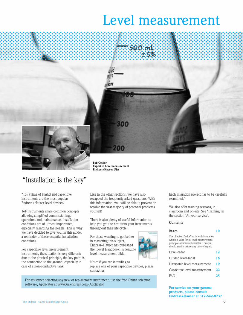
“ToF (Time of Flight) and capacitive instruments are the most popular Endress+Hauser level devices.
ToF instruments share common concepts allowing simplified commissioning, operation, and maintenance. Installation conditions are of utmost importance, especially regarding the nozzle. This is why we have decided to give you, in this guide, a reminder of these essential installation conditions.
For capacitive level measurement instruments, the situation is very different: due to the physical principle, the key point is the connection to the ground, especially in case of a non-conductive tank.
Like in the other sections, we have also recapped the frequently asked questions. With this information, you will be able to prevent or resolve the vast majority of potential problems yourself!
There is also plenty of useful information to help you get the best from your instruments throughout their life cycle.
For those wanting to go further in mastering this subject, Endress+Hauser has published the ‘Level Handbook’, a genuine level measurement bible.
Note: if you are intending to replace one of your capacitive devices, please contact us.
Bob CollierExpert in Level measurementEndress+Hauser USA
“Installation is the key”
For assistance selecting any new or replacement instrument, use the free Online selection software, Applicator at www.us.endress.com/Applicator
Each migration project has to be carefully examined.”
We also offer training sessions, in classroom and on-site. See ‘Training’ in the section ‘At your service’.

10 The Endress+Hauser Maintenance Guide
BasicsInformation common to all types of level measurement devices
The Time of Flight (ToF) principle
• Emission of ultrasound- or microwave-pulses
• Reflection of the pulses from the product surface
• Reception of the reflected pulses
• Measurement of the Time of Flight: calculation of the distance between the device and the product surface by d = (c x t)/2
Setup - Configuration of level instruments
General note: The respect of installation conditions are of key importance for level measurement. Once this is correctly done, the unit will work. Nevertheless it is always necessary to configure the measuring point to achieve correct measurement.
All Endress+Hauser ToF level measurement devices have the same display. The display of the process value and the configuration of the device occur locally by means of a large 4-line alphanumeric display with plain text information. The guided menu system with integrated help text ensures quick and safe commissioning (see Fig. ).To access the display, the cover of the electronic compartment may be removed even in hazardous areas (IS and XP).
The VU1 LC-Display can be removed to ease operation by simply pressing the snap-fit (see Fig. 2). It is connected to the device by means of a 1.7” (500 mm) cable.
The LC-Display VU1 allows configuration via keys directly at the instrument. All device functions can be set through a menu system. The menu consists of function groups and functions. Within a function, application parameters can be read or adjusted. The user is guided through a complete configuration procedure.
You can also configure your ToF instruments from your PC. Remote commissioning, including documentation of the measuring point and in-depth analysis functions, is supported via FieldCare Setup. See presentation of FieldCare on page 101.
Operation and Maintenance
Routine maintenanceToF devices include no wear parts thus require very little maintenance. However, according to its criticality to the quality, some instruments need to be inspected and/or calibrated periodically.
Defining the right maintenance frequency taking several parameters into account is an expert’s job. Endress+Hauser can also help you with this task!
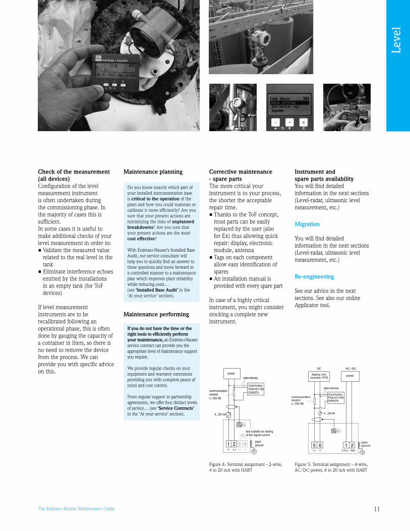
To test the 4 to 20 mA loop (see Fig. 4 and 5):• The 2-wire, 4 to 20 mA with
HART® version includes test sockets for testing of the signal current
• On the 4-wire versions (Levelflex and Prosonic), there are two terminals situated at the front of the electronic module
Calibration (all devices)Intrinsically our instruments offer long-term stability and repeatability of your measurements. Nevertheless we recommend periodic calibration for the measurement points which are critical to the process and thus are important to control the quality of your product. From on-site to accredited services, you can be sure to find the right method by reaching the right balance between the device downtime and the calibration uncertainty.
L00-FMxxxxxx-07-00-00-en-001
ENDRESS + HAUSER
E+–
ENDRESS+HAUSER
MICROPILOT II
IP 65
Order Code:Ser.-No.:
MessbereichMeasuring rangeU 16...36 V DC
4...20 mA
max. 20 m
Mad
ein
Ger
man
yM
aulb
urg
T>70°C :
A
t >85°C
LCD(liquid crystal display)
Symbols
3 keys
snap-fit
L00-FMRxxxxx-07-00-00-en-002
XX
X
XS
S
OO FF
F
F
HOME
FG00 F000 F001 F002 F003 F004 ...
FG01FG02FG03FG04FG05FG06FG07
...
ENDRESS + HAUSER
E+–
Headline Position indicator
Main value UnitSymbol
Selection list
Function groups -> Functions
Help text
Envelopecurve
Bargraph
Figure 2: On-site operation with VU1
Calibration can be performed by Endress+Hauser either on-site or in our accredited laboratories (see ‘Calibration’ in the ‘At your service’ section).
Figure 1: The principle - Time of Flight
Figure : The ‘Basic Setup’ covers 5% of the situations
Our service team can set up any Endress+Hauser level measurement device for you and thus ensure you immediately get the best from your instrument. (see ‘Commissioning’ in the ‘At your service’ section)
Leve
l
11The Endress+Hauser Maintenance Guide
Check of the measurement (all devices)Configuration of the level measurement instrument is often undertaken during the commissioning phase. In the majority of cases this is sufficient. In some cases it is useful to make additional checks of your level measurement in order to:• Validate the measured value
related to the real level in the tank
• Eliminate interference echoes emitted by the installations in an empty tank (for ToF devices)
If level measurement instruments are to be recalibrated following an operational phase, this is often done by gauging the capacity of a container in liters, so there is no need to remove the device from the process. We can provide you with specific advice on this.
Maintenance planning
Maintenance performing
Corrective maintenance - spare parts The more critical your instrument is to your process, the shorter the acceptable repair time. • Thanks to the ToF concept,
most parts can be easily replaced by the user (also for Ex) thus allowing quick repair: display, electronic module, antenna
• Tags on each component allow easy identification of spares
• An installation manual is provided with every spare part
In case of a highly critical instrument, you might consider stocking a complete new instrument.
Instrument and spare parts availabilityYou will find detailed information in the next sections (Level-radar, ultrasonic level measurement, etc.)
Migration
You will find detailed information in the next sections (Level-radar, ultrasonic level measurement, etc.)
Re-engineering
See our advice in the next sections. See also our online Applicator tool.
If you do not have the time or the right tools to efficiently perform your maintenance, an Endress+Hauser service contract can provide you the appropriate level of maintenance support you require.
We provide regular checks on your equipment and warranty extensions providing you with complete peace of mind and cost control.
From regular support to partnership agreements, we offer four distinct levels of service… (see ‘Service Contracts’ in the ‘At your service’ section).
Do you know exactly which part of your installed instrumentation base is critical to the operation of the plant and how you could maintain or calibrate it more efficiently? Are you sure that your present actions are minimizing the risks of unplanned breakdowns? Are you sure that your present actions are the most cost effective?
With Endress+Hauser’s Installed Base Audit, our service consultant will help you to quickly find an answer to these questions and move forward in a controlled manner to a maintenance plan which improves plant reliability while reducing costs… (see ‘Installed Base Audit’ in the ‘At your service’ section).
L00-FMxxxxxx-04-00-00-en-015 L00-FMxxxxxx-04-00-00-en-011
3 4I+ I-
1 2L- L+
4...20 mA
CommuboxFXA191/195DXR375communication
resistor(> 250 )W
alternatively
plantground
test sockets for testingof the signal current
power
5 6I+ I-
1 2L1/L+ N/L-
4...20mA
CommuboxFXA191/195DXR375
communicationresistor(> 250 )W
alternatively
powerdisplay unit,recorder, PCS
AC / DCDC
plantground
Figure 4: Terminal assignment - 2-wire, 4 to 20 mA with HART
Figure 5: Terminal assignment - 4-wire, AC/DC power, 4 to 20 mA with HART
Leve
l
12 The Endress+Hauser Maintenance Guide
Level-radarMicropilot series
For several years, Micropilot M instrumentation has been the product of choice for level-radar measurement. FMR20 (horn antenna) and 21 (rod antenna) instruments use 6 GHz waves, while FMR240 (horn antenna), 244 (horn antenna encapsulated in PTFE), 245 (flat antenna) and 250 (level-radar measurement on solids) use 26 GHz waves.
In this section, you will find essential information and advice that will help you to perform the optimum follow-up of your Micropilot M instruments throughout their life cycle.
“0% of the success of the setup depends on proper installation”
Measuring principle
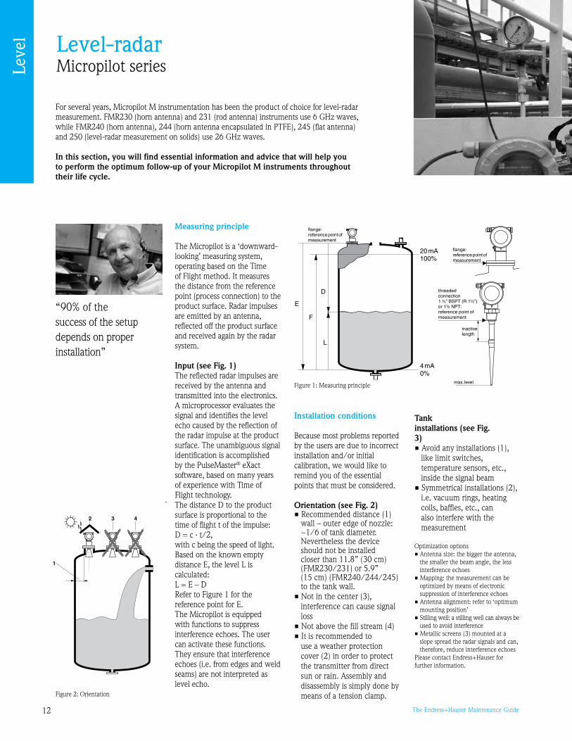
The Micropilot is a ‘downward-looking’ measuring system, operating based on the Time of Flight method. It measures the distance from the reference point (process connection) to the product surface. Radar impulses are emitted by an antenna, reflected off the product surface and received again by the radar system.
Input (see Fig. 1)The reflected radar impulses are received by the antenna and transmitted into the electronics. A microprocessor evaluates the signal and identifies the level echo caused by the reflection of the radar impulse at the product surface. The unambiguous signal identification is accomplished by the PulseMaster® eXact software, based on many years of experience with Time of Flight technology. The distance D to the product surface is proportional to the time of flight t of the impulse:D = c · t/2,with c being the speed of light.Based on the known empty distance E, the level L is calculated:L = E – DRefer to Figure 1 for the reference point for E.The Micropilot is equipped with functions to suppress interference echoes. The user can activate these functions. They ensure that interference echoes (i.e. from edges and weld seams) are not interpreted as level echo.
L00-FMR2xxxx-17-00-00-xx-001
Figure 2: Orientation
L00-FMR2xxxx-15-00-00-en-001
20 mA100%
4mA0%
D
L
F
E
flange:referencepointofmeasurement
flange:referencepointofmeasurement
inactivelength
max.level
threadedconnection1 ½” (R 1
:reference point ofmeasurement
BSPT ½”)or 1½ NPT
Figure 1: Measuring principle
Installation conditions
Because most problems reported by the users are due to incorrect installation and/or initial calibration, we would like to remind you of the essential points that must be considered.
Orientation (see Fig. 2)• Recommended distance (1)
wall – outer edge of nozzle: ~1/6 of tank diameter. Nevertheless the device should not be installed closer than 11.8” (0 cm) (FMR20/21) or 5.” (15 cm) (FMR240/244/245) to the tank wall.
• Not in the center (), interference can cause signal loss
• Not above the fill stream (4)• It is recommended to
use a weather protection cover (2) in order to protect the transmitter from direct sun or rain. Assembly and disassembly is simply done by means of a tension clamp.
Tank installations (see Fig. 3)• Avoid any installations (1),
like limit switches, temperature sensors, etc., inside the signal beam
• Symmetrical installations (2), i.e. vacuum rings, heating coils, baffles, etc., can also interfere with the measurement
Optimization options• Antenna size: the bigger the antenna,
the smaller the beam angle, the less interference echoes
• Mapping: the measurement can be optimized by means of electronic suppression of interference echoes
• Antenna alignment: refer to ‘optimum mounting position’
• Stilling well: a stilling well can always be used to avoid interference
• Metallic screens () mounted at a slope spread the radar signals and can, therefore, reduce interference echoes
Please contact Endress+Hauser for further information.
Leve
l
1The Endress+Hauser Maintenance Guide
Commissioning of two Micropilot M
L00-FMR2xxxx-17-00-00-xx-002
Figure : Tank installations
L00-FMR230xx-17-00-00-en-001
Figure 4: Optimum mounting position FMR20
L00-FMR230xx-17-00-00-en-002
H
Ø D
nozzle
Figure 5: Optimum mounting position FMR21
L00-FMR231xx-17-00-00-en-001
L00-FMR231xx-17-00-00-en-002
HH
1
beam launchedhere
beam launchedhere
inactive length
inactive length
spring washers
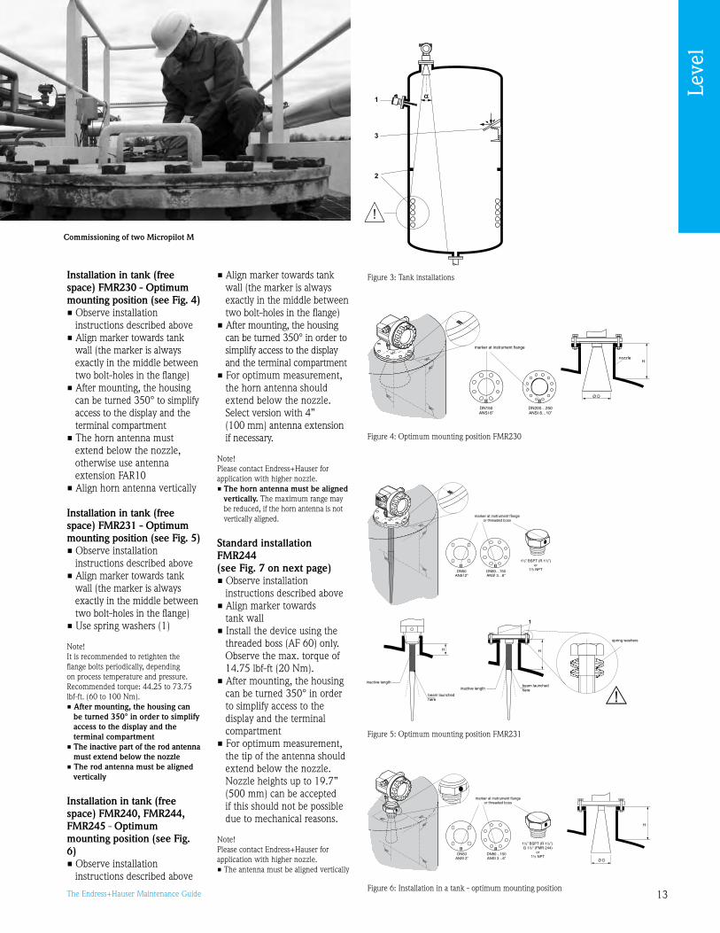
Installation in tank (free space) FMR230 - Optimum mounting position (see Fig. 4)• Observe installation
instructions described above• Align marker towards tank
wall (the marker is always exactly in the middle between two bolt-holes in the flange)
• After mounting, the housing can be turned 50° to simplify access to the display and the terminal compartment
• The horn antenna must extend below the nozzle, otherwise use antenna extension FAR10
• Align horn antenna vertically
Installation in tank (free space) FMR231 - Optimum mounting position (see Fig. 5)• Observe installation
instructions described above• Align marker towards tank
wall (the marker is always exactly in the middle between two bolt-holes in the flange)
• Use spring washers (1)
Note!It is recommended to retighten the flange bolts periodically, depending on process temperature and pressure. Recommended torque: 44.25 to 7.75 lbf-ft. (60 to 100 Nm).• After mounting, the housing can
be turned 350° in order to simplify access to the display and the terminal compartment
• The inactive part of the rod antenna must extend below the nozzle
• The rod antenna must be aligned vertically
Installation in tank (free space) FMR240, FMR244, FMR245 - Optimum mounting position (see Fig. 6)• Observe installation
instructions described above
• Align marker towards tank wall (the marker is always exactly in the middle between two bolt-holes in the flange)
• After mounting, the housing can be turned 50° in order to simplify access to the display and the terminal compartment
• For optimum measurement, the horn antenna should extend below the nozzle. Select version with 4” (100 mm) antenna extension if necessary.
Note!Please contact Endress+Hauser for application with higher nozzle.• The horn antenna must be aligned
vertically. The maximum range may be reduced, if the horn antenna is not vertically aligned.
Standard installation FMR244 (see Fig. 7 on next page)• Observe installation
instructions described above• Align marker towards
tank wall• Install the device using the
threaded boss (AF 60) only. Observe the max. torque of 14.75 lbf-ft (20 Nm).
• After mounting, the housing can be turned 50° in order to simplify access to the display and the terminal compartment
• For optimum measurement, the tip of the antenna should extend below the nozzle. Nozzle heights up to 1.7” (500 mm) can be accepted if this should not be possible due to mechanical reasons.
Note!Please contact Endress+Hauser for application with higher nozzle.• The antenna must be aligned vertically
Figure 6: Installation in a tank - optimum mounting positionL00-FMR240xx-17-00-00-en-001
90°
90°
90°
90°
90°
90°
90°
90°
9
DN80…150ANSI 3…6”
DN50ANSI 2”
90°
1½” BSPT (R 1½”),G 1½" (FMR 244)
or1½ NPT
marker at instrument flangeor threaded boss
L00-FMR240xx-17-00-00-de-002
H
Ø D
Leve
l

14 The Endress+Hauser Maintenance Guide
L00-FMR245xx-17-00-00-de-002
H
1
Ø D
spring washers
Figure : Installation in stilling well - optimum mounting positionL00-FMR230xx-17-00-00-en-006
90°
DN80…150ANSI 3…6”
DN50ANSI 2”
BSPT (R 1½”),G 1½" (FMR 244)
or1½ NPT
1½”
marker at instrument flangeor threaded boss
Figure 10: Installation in bypass - optimum mounting position L00-FMR230xx-17-00-00-en-007
Standard installation FMR245 (see Fig. 8)• Observe installation
instructions described above• Align marker towards
tank wall• The marker is always exactly
in the middle between two bolt-holes in the flange
• Use spring washers (1)
Note!It is recommended to retighten the flange bolts periodically, depending on process temperature and pressure. Recommended torque: 44.25 to 7.75 lbs-ft. (60 to 100 Nm).• After mounting, the housing can
be turned 350° in order to simplify access to the display and the terminal compartment
• The antenna must be aligned verticallyCaution! The maximum range may be reduced, if the antenna is not vertically aligned.Note! Please contact Endress+Hauser for application with higher nozzle.
Installation in stilling well FMR230, FMR240, FMR244, FMR245 (see Fig. 9) • Align marker toward slots • The marker is always exactly
in the middle between two bolt-holes in the flange
• After mounting, the housing can be turned 50° in order to simplify access to the display and the terminal compartment
• Measurements can be performed through an open full bore ball valve without any problems
• Additional installation instructions on page 20
Recommendations for the stilling well • Metal (no enamel coating, plastic on
request) • Constant diameter • Diameter of stilling well not larger
than antenna diameter • Weld seam as smooth as possible and
on the same axis as the slots • Slots offset 180° (not 0°) • Slot width respectively diameter of
holes max. 1/10 of pipe diameter, de-burred. Length and number do not have any influence on the measurement.
• Select horn antenna as big as possible. For intermediate sizes (i.e. 7”/180 mm) select next larger antenna and adapt it mechanically (FMR20/FMR240 only).
• At any transition (i.e. when using a ball valve or mending pipe segments), no gap may be created exceeding 1 mm (0.04”)
• The stilling well must be smooth on the inside (average roughness Rz ≤ 6.3 μm). Use extruded or parallel welded stainless steel pipe. An extension of the pipe is possible with welded flanges or pipe sleeves. Flange and pipe have to be properly aligned at the inside.
• Do not weld through the pipe wall. The inside of the stilling well must remain smooth. In case of unintentional welding through the pipe, the weld seam and any unevenness on the inside needs to be carefully removed and smoothed. Otherwise, strong interference echoes will be generated and material buildup will be promoted.
• Particularly on smaller nominal widths it needs to be observed that flanges are welded to the pipe such that they allow for correct orientation (marker aligned toward slots)
Installation in bypass FMR230, FMR240, FMR245 (see Fig. 10)• Align marker perpendicular (0°)
to tank connectors• The marker is always exactly in
the middle between two bolt-holes in the flange
• After mounting, the housing can be turned 50° in order to simplify access to the display and the terminal compartment
• The horn must be aligned vertically
• Measurements can be performed through an open full bore ball valve without any problems
• Additional installation instructions described above
Recommendations for the bypass pipe• Metal (no plastic or enamel coating)• Constant diameter• Select horn antenna as big as possible. For
intermediate sizes (i.e. .74”/5 mm) select next larger antenna and adapt it mechanically (FMR20/FMR240 only).
• At any transition (i.e. when using a ball valve or mending pipe segments), no gap may be created exceeding 0.04” (1 mm)
• In the area of the tank connections (~ ±20 cm / 7.87”) a reduced accuracy of the measurement has to be expected
Installation in vessel FMR250 with horn antenna (see Fig. 11)• Observe installation instructions
described above • Align marker towards vessel wall
(the marker is always exactly in the middle between two bolt-holes in the flange)
• After mounting, the housing can be turned 50° in order to simplify access to the display and the terminal compartment
• The horn antenna should protrude from the nozzle. If this is not possible for mechanical reasons, larger nozzle heights can be accepted.
L00-FMR250xx-17-00-00-en-004
H
Ø D
L00-FMR250xx-17-00-00-en-009
90°
90°
90°
90°
90°
90°
90°
90°
9
DN80…200ANSI 3…8”
90°
1½” BSPT (R 1½”)or
1½ NPT
marker at instrumentflange or threaded boss 1)
1) at version with top target positioner, the marker is at the housing adapter(opposite the air purge connection)
L00-FMR244xx-17-00-00-de-002
H
Ø D
Figure 8: Standard installation FMR245 Figure 7: Standard installation FMR244
Figure 11 (above and right): Installation in vessel FMR250 - optimum mounting position
Leve
l
15The Endress+Hauser Maintenance Guide
Note! • Please contact Endress+Hauser for
application with higher nozzle • Ideally, the horn antenna should
be installed vertically. To avoid interference reflections or for optimum alignment within the vessel, the FMR250 with optional top target positioner can be swiveled by 15° in all directions.
Setup - Configuration
See ‘Basics’.
The ‘Basic setup’ menu enables a quick and simple commissioning. The software helps the user to enter the main parameters which cover 5% of the cases. By entering the data carefully, you will avoid many problems.
Note for FMR244/245: Please take a blocking distance of 7.87” (0.2 m) into account. (See details on the blocking distance in chapter Ultrasonic level measurement - page 1).
Operation and Maintenance
See ‘Basics’ (page 10).
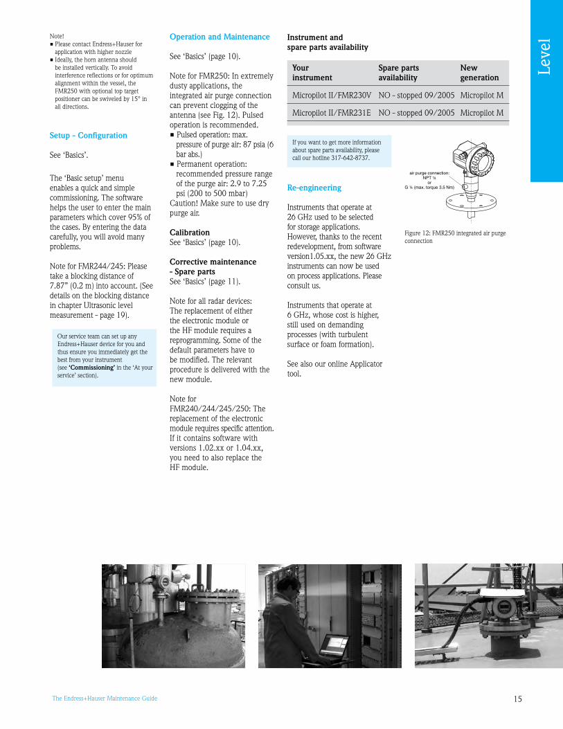
Note for FMR250: In extremely dusty applications, the integrated air purge connection can prevent clogging of the antenna (see Fig. 12). Pulsed operation is recommended.• Pulsed operation: max.
pressure of purge air: 87 psia (6 bar abs.)
• Permanent operation: recommended pressure range of the purge air: 2. to 7.25 psi (200 to 500 mbar)
Caution! Make sure to use dry purge air.
CalibrationSee ‘Basics’ (page 10).
Corrective maintenance - Spare partsSee ‘Basics’ (page 11).
Note for all radar devices: The replacement of either the electronic module or the HF module requires a reprogramming. Some of the default parameters have to be modified. The relevant procedure is delivered with the new module.
Note for FMR240/244/245/250: The replacement of the electronic module requires specific attention. If it contains software with versions 1.02.xx or 1.04.xx, you need to also replace the HF module.
Instrument and spare parts availability
Re-engineering
Instruments that operate at 26 GHz used to be selected for storage applications. However, thanks to the recent redevelopment, from software version1.05.xx, the new 26 GHz instruments can now be used on process applications. Please consult us.
Instruments that operate at 6 GHz, whose cost is higher, still used on demanding processes (with turbulent surface or foam formation).
See also our online Applicator tool.
Your Spare parts New instrument availability generation
Micropilot II/FMR20V NO - stopped 0/2005 Micropilot M
Micropilot II/FMR21E NO - stopped 0/2005 Micropilot M
If you want to get more information about spare parts availability, please call our hotline 17-642-877.
Our service team can set up any Endress+Hauser device for you and thus ensure you immediately get the best from your instrument (see ‘Commissioning’ in the ‘At your service’ section).
L00-FMR250xx-17-00-00-en-010
air purge connection:NPT
orG (max. torque 3.5 Nm)
¼
¼
Figure 12: FMR250 integrated air purge connection
Leve
l

16 The Endress+Hauser Maintenance Guide
Guided level-radarLevelflex series
The current guided level-radar range includes Levelflex M:• FMP40 for general applications in liquids and solids• FMP41C for corrosive liquids and for high hygienic requirements• FMP45 mainly in liquids with pressures up to 5801.5 psi (400 bar) and
temperatures from -328 to +752°F (-200 to +400°C)• New FMP43 (from 01/07/07) for pharma requirements
With this section we aim at providing efficient help to Levelflex M users throughout the life cycle.
L00-FMP4xxxx-15-00-00-en-002
20mA100%
4mA0%
D
probe lengthLN
L
F
E
flange:referencepointofmeasurement
Measuring principle
The Levelflex is a ‘downward-looking’ measuring system that functions according to the ToF method (ToF = Time of Flight). The distance from the reference point (process connection of the measuring device) to the product surface is measured. High-frequency pulses are injected to a probe and led along the probe. The pulses are reflected by the product surface, received by the electronic evaluation unit and converted into level information.This method is also known as TDR (Time Domain Reflectometry).
Figure 1: Measuring principle
Figure 2: Upper blocking distanceF = measuring spanE = empty distance (= zero)UB = upper blocking distanceLN = probe lengthB = minimum distance of the probe to the container wall
L00-FMP4xxxx-17-00-00-en-006
100%
0%
F
E
UB
B
LN
referencepointofmeasurement
max. 20 m /67 ft
remote displayFHX 40
“Consider blocking distances and pay attention to the nozzle”
Input (see Fig. 1)The reflected pulses are transmitted from the probe to the electronics. There, a microprocessor analyzes thesignals and identifies the level echo, which was generated by the reflection of the high-frequency pulses at the product surface. This clear signal finding benefits from the more than 0 years of experience with pulse Time of Flight procedures that have been integrated into the development of the PulseMaster® Software.
Distance D to the product surface is proportional to the Time of Flight t of the impulse:D = c · t/2,with c being the speed of light.Based on the known empty distance E, level L is calculated:L = E – DReference point for E see Fig. 1.
The Levelflex comes with functions to suppress interference echoes (e.g. internals and struts).
Installation conditions
Upper blocking distance (see Fig. 2)The upper blocking distance (UB) is the minimum distance from the reference point of the measurement (mounting flange) to the maximum level. Within the blocking distance, a reliable measurement can not be guaranteed (see table p.17).
Lower blocking distanceAt the lowest part of the probe an exact measurement is not possible. The following measuring error is present in the vicinity of the probe end: (see Fig. )
Leve
l

17The Endress+Hauser Maintenance Guide
Check of a Levelflex at a chemical plant
If εr (dielectric coefficient) value is less than 7 for cable probes, then measurement is not possible in the area of the straining weight (0 to .84”/0 to 250 mm from end of probe; lower blocking distance) (see table).
General installation instructions (for bulk solids + fluids)Let’s review some very important instructions (see Fig. 4):• Do not mount rod or cable
probes in the filling curtain (2) • Mount rod and cable probes
away from the wall (B) at such a distance that, in the event of buildup on the wall, there is still a minimum distance of .4” (100 mm) between the probe and the buildup
• In the case of bulk solids in concrete silos, a large distance (B) should be observed between the probe and the concrete wall, if possible ≥ 3.28 ft (1 m), but at least 1.64 ft. (0.5 m)
• In metal and plastic silos, the probe can be mounted very close to the wall (0.66 ft/0.2m), but ensure that the probe does not touch the wall
• Minimum distance of probe end to the container floor (C):– Cable probe: 5.” (150 mm)– Rod probe: 1.7” (50 mm)– Coax probe: 0.” (10 mm)
• If the product becomes highly electrostatically charged during processing, a grounding chain should be mounted in the filling curtain or the end of the probe should be grounded
FMP40 LN ft (m) UB inches (mm)
min max
Cable probe . (1) 115 (5) (1) 7. (8) (2)
6 mm rod probe 1.0 (0.) 6.5 (2) 7. (8) (2)
16 mm rod robe 1.0 (0.) 1 (4) 7. (8) (2)
Coax probe 1.0 (0.) 1 (4) 0 / 0(1) Larger measuring range available on request.(2) The indicated blocking distances are predetermined. Media with DK > 7, the upper blocking distance UB can be reduced for rod and cable probes to 4” (100 mm). The upper blocking distance UB can be entered manually.
LBD [m] if DC>7 if DC<7
Cable probe 0.02 0.25
Rod or coax probe 0.02 0.05
Rod probe and coax probe
Distance from probe end in inches (mm) Distance from probe end in inches (mm)
DC = 2
DC > 7
Cable probe
-3.15 (-80) -3.15 (-80)
-2.36 (-60) -2.36 (-60)
-1.57 (-40) -1.57 (-40)
-0.79 (-20) -0.79 (-20)
0 0
0.79 (20) 0.79 (20)
1.57 (40) 1.57 (40)
2.36 (60) 2.36 (60)
3.15 (80) 3.15 (80)
00
DC = Dielectric Constant
DC > 7
Sum of non-linearity,non-repeatability, andhysteresis in inches (mm)
Sum of non-linearity,non-repeatability, andhysteresis in inches (mm)
1.97(50)
1.97(50)
3.94(100)
3.94(100)
5.91(150)
5.91(150)
7.87(200)
7.87(200)
9.84(250)
9.84(250)
11.8(300)
11.8(300)
Figure : Measuring error in the vicinity of the probe end
L00-FMP4xxxx-17-00-00-xx-003
B
C
1 2
Figure 4: General installation conditions1 = correct installation
L00-FMP4xxxx-17-00-00-en-017
diameter nozzle:< DN150 ( 6”)<
<<
150 mm( 4")
elzzon ni noitallatsnissob gnidlew htiw noitallatsni
Figure 5: Type of probe installation
Type of probe installation (see Fig. 5)• Probes are mounted to the
process connection with threaded connections or flanges and are usually also secured with these. If during this installation there is the danger that the probe end moves so much that it touches the tank floor or cone at times, the probe must, if necessary, be shortened and secured. The easiest way to fix the cable probes is to screw them to the internal thread on the lower end of the weight.
• The ideal installation is mounting in a screwed joint / screw-in sleeve which is internally flush with the container ceiling
• If installation takes place in a nozzle, the nozzle should be 1.7” to 5.” (50 to 150 mm) in diameter and should not be more than 5.” (150 mm) high. Installation adapters are available for other dimensions.
• Installation with welding boss is strongly recommended when the product εr (dielectric coefficient) is low. “0% of the problems encountered in case of a low εr are due to a bad nozzle”
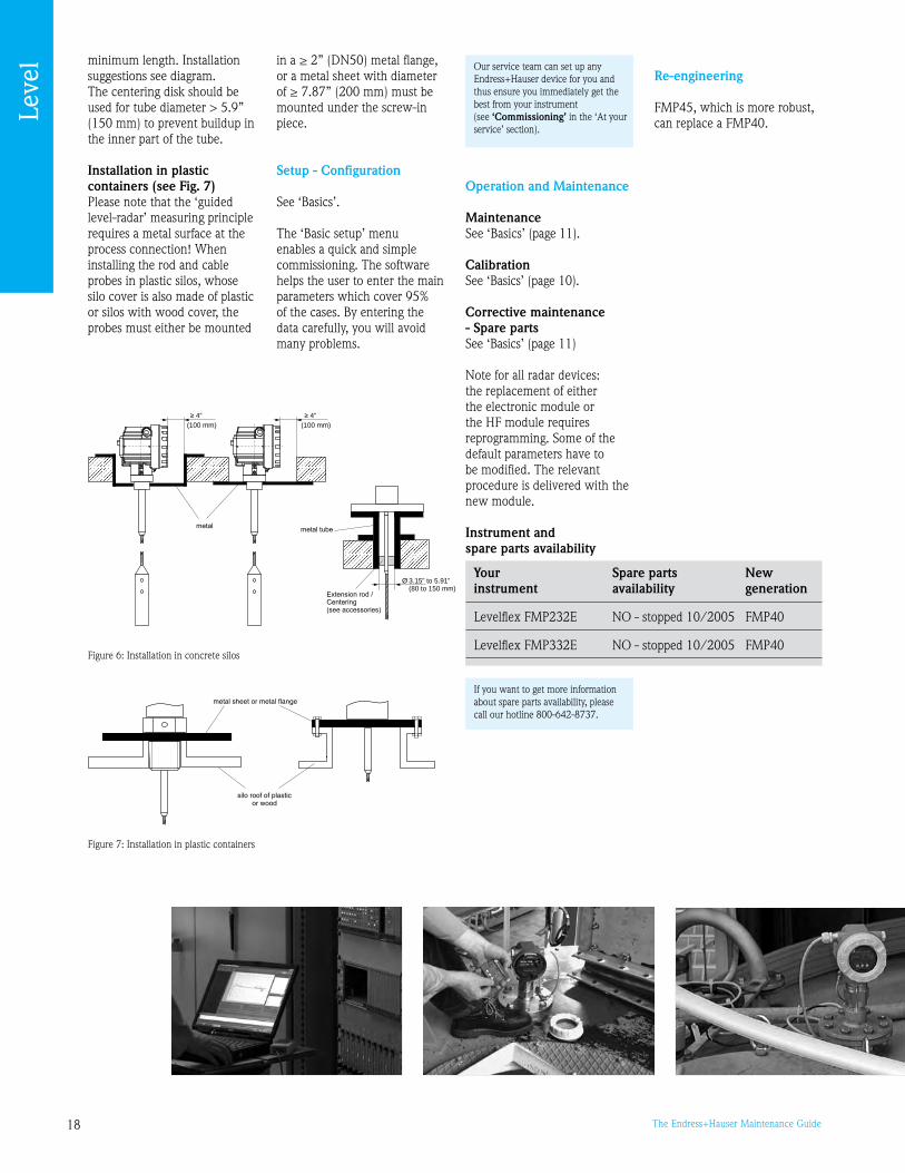
Installation in concrete silos (see Fig. 6)Installation, for example, into a thick concrete ceiling should be made flush with the lower edge. Alternatively, the probe can also be installed into a pipe that must not protrude over the lower edge of the silo ceiling. The pipe should be kept at a
Leve
lBlocking distance and measuring range:
18 The Endress+Hauser Maintenance Guide
4”
(100 mm)
4”
(100 mm)
3.15” to 5.91”(80 to 150 mm)
Figure 6: Installation in concrete silos
L00-FMP4xxxx-17-00-00-en-018
metal sheet or metal flange
silo roof of plasticor wood
Wall thickness for GFK/PP< 15 mm
metal sheet or metal flange
Figure 7: Installation in plastic containers
Your Spare parts New instrument availability generation
Levelflex FMP232E NO - stopped 10/2005 FMP40
Levelflex FMP332E NO - stopped 10/2005 FMP40
minimum length. Installation suggestions see diagram.The centering disk should be used for tube diameter > 5.” (150 mm) to prevent buildup in the inner part of the tube.
Installation in plastic containers (see Fig. 7)Please note that the ‘guided level-radar’ measuring principle requires a metal surface at the process connection! When installing the rod and cable probes in plastic silos, whose silo cover is also made of plastic or silos with wood cover, the probes must either be mounted
in a ≥ 2” (DN50) metal flange, or a metal sheet with diameter of ≥ 7.87” (200 mm) must be mounted under the screw-in piece.
Setup - Configuration
See ‘Basics’.
The ‘Basic setup’ menu enables a quick and simple commissioning. The software helps the user to enter the main parameters which cover 5% of the cases. By entering the data carefully, you will avoid many problems.
Operation and Maintenance
MaintenanceSee ‘Basics’ (page 11).
CalibrationSee ‘Basics’ (page 10).
Corrective maintenance - Spare partsSee ‘Basics’ (page 11)
Note for all radar devices: the replacement of either the electronic module or the HF module requires reprogramming. Some of the default parameters have to be modified. The relevant procedure is delivered with the new module.
Instrument and spare parts availability
Re-engineering
FMP45, which is more robust, can replace a FMP40.
If you want to get more information about spare parts availability, please call our hotline 800-642-877.
Leve
l Our service team can set up any Endress+Hauser device for you and thus ensure you immediately get the best from your instrument (see ‘Commissioning’ in the ‘At your service’ section).

1The Endress+Hauser Maintenance Guide
Ultrasonic level measurementProsonic series
The current ultrasonic range of transmitters includes the Prosonic M FMU40/41/42/43/44 and Prosonic S FMU90.
With this section we aim to:• provide efficient help to Prosonic M users throughout the life cycle• answer the most frequently asked questions by the users of Prosonic S FMU86x,
and give key information to successfully migrate to FMU90
L00-FMU4x-15-00-00-de-001
20mA100%
4mA0%
D
L
FE
BD
Measuring principle
Time of Flight method The Prosonic M sensor emits ultrasonic pulses in the direction of the product surface. There, they are reflected back and received by the sensor. The Prosonic M measures the time t between pulse emission and reception. The instrument uses time t (and the velocity of sound c) to calculate distance D between the sensor membrane and the product surface: D = c · t/2 As the device knows the empty distance E from a user entry, it can calculate the level as follows: L = E - D An integrated temperature sensor compensates changes in the velocity of sound caused by temperature changes.
Figure 1: Measuring principleF = span (full distance)E = empty distanceD = distance from sensor membrane to the product surfaceBD = blocking distanceL = level
“The installation of the sensor and the presence of foam or bubbles have a strong impact on the measurement”
Interference echo suppression The interference echo suppression feature of Prosonic M
ensures that interference echoes (e.g. from edges, welded joints and installations) are not interpreted as level echoes.
Tip: why is there a blocking distance?
Waves are emitted at the surface of the sensor membrane. The device is either emitting or receiving but cannot do both at the same time. In case of an obstacle located within the area between positions 1 and 2, the resulting echo would be surrounded by the residual vibration and could not be differentiated.As it is impossible to differentiate the echo within this area, the levelto be measured must not approach the membrane.This distance is named blocking distance.
Figure 2T0: Start of the emitted impulsion. An alternating current which frequencycorresponds to the system’s resonance, makes crystals oscillate.T1: End of the emitted impulsion. Membrane continues to vibrate during 1msand then switches to the receiving position.
T2: the residual membrane vibration is weakened enough to reflect an echoand to differentiate it.T: the echo comes back after 6 ms meaning the total distance represents2 m. Therefore the product surface is located . ft. (1m) under the probe.T4: Double reflection echo or numerous reflections can sometimes be observed.
1.6’(0.5)
3.3’(1)
4.9’(1.5)
3 6 9
Distance in ft (m)
Duration (ms)
432
1
0
Leve
l
20 The Endress+Hauser Maintenance Guide
Adjustment Enter the empty distance E and the span F to adjust the device (see Fig. 1).
Blocking distance Span F may not extend into blocking distance BD. Level echoes from the blocking distance cannot be evaluated due to the transient characteristics of the sensor.
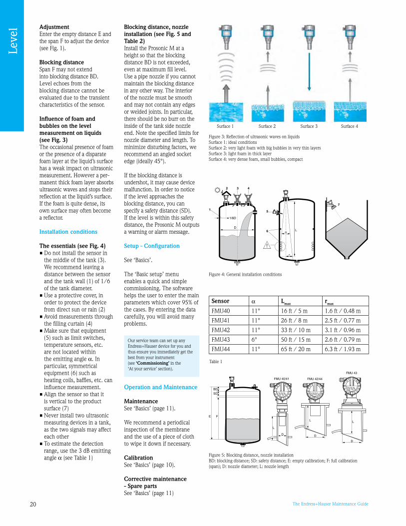
Influence of foam and bubbles on the level measurement on liquids (see Fig. 3) The occasional presence of foam or the presence of a disparate foam layer at the liquid’s surface has a weak impact on ultrasonic measurement. However a per-manent thick foam layer absorbs ultrasonic waves and stops their reflection at the liquid’s surface. If the foam is quite dense, its own surface may often become a reflector.
Installation conditions
The essentials (see Fig. 4)• Do not install the sensor in
the middle of the tank (). We recommend leaving a distance between the sensor and the tank wall (1) of 1/6 of the tank diameter.
• Use a protective cover, in order to protect the device from direct sun or rain (2)
• Avoid measurements through the filling curtain (4)
• Make sure that equipment (5) such as limit switches, temperature sensors, etc. are not located within the emitting angle a. In particular, symmetrical equipment (6) such as heating coils, baffles, etc. can influence measurement.
• Align the sensor so that it is vertical to the product surface (7)
• Never install two ultrasonic measuring devices in a tank, as the two signals may affect each other
• To estimate the detection range, use the dB emitting angle a (see Table 1)
Figure : Reflection of ultrasonic waves on liquidsSurface 1: ideal conditionsSurface 2: very light foam with big bubbles in very thin layersSurface : light foam in thick layerSurface 4: very dense foam, small bubbles, compact
L00-FMU4xxxx-17-00-00-de-005
1
2 3 4
5
6
1/6D
7
D
r
α L
Figure 4: General installation conditions
Sensor a Lmax rmax
FMU40 11° 16 ft / 5 m 1.6 ft / 0.48 m
FMU41 11° 26 ft / 8 m 2.5 ft / 0.77 m
FMU42 11° ft / 10 m .1 ft / 0.6 m
FMU4 6° 50 ft / 15 m 2.6 ft / 0.7 m
FMU44 11° 65 ft / 20 m 6. ft / 1. m
Blocking distance, nozzle installation (see Fig. 5 and Table 2)Install the Prosonic M at a height so that the blocking distance BD is not exceeded, even at maximum fill level. Use a pipe nozzle if you cannot maintain the blocking distance in any other way. The interior of the nozzle must be smooth and may not contain any edges or welded joints. In particular, there should be no burr on the inside of the tank side nozzle end. Note the specified limits for nozzle diameter and length. To minimize disturbing factors, we recommend an angled socket edge (ideally 45°).
If the blocking distance is undershot, it may cause device malfunction. In order to notice if the level approaches the blocking distance, you can specify a safety distance (SD). If the level is within this safety distance, the Prosonic M outputs a warning or alarm message.
Setup - Configuration
See ‘Basics’.
The ‘Basic setup’ menu enables a quick and simple commissioning. The software helps the user to enter the main parameters which cover 5% of the cases. By entering the data carefully, you will avoid many problems.
Operation and Maintenance
MaintenanceSee ‘Basics’ (page 11).
We recommend a periodical inspection of the membrane and the use of a piece of cloth to wipe it down if necessary.
CalibrationSee ‘Basics’ (page 10).
Corrective maintenance - Spare partsSee ‘Basics’ (page 11)
Table 1
L00-FMU4xxxx-17-00-00-en-004
FE
BDSD
L
D
FMU 40/41
L
D
FMU 43
L
D
FMU 42/44
Figure 5: Blocking distance, nozzle installationBD: blocking distance; SD: safety distance; E: empty calibration; F: full calibration (span); D: nozzle diameter; L: nozzle length
Leve
l
Surface 1 Surface 2 Surface Surface 4
Our service team can set up any Endress+Hauser device for you and thus ensure you immediately get the best from your instrument (see ‘Commissioning’ in the ‘At your service’ section).

21The Endress+Hauser Maintenance Guide
Instrument and spare parts availability
See table to the right.
Migration
S range: FMU860 (1-channel level measurement), 861 (flow measurement) and 862 (2 -channel level measurement) have been phased-out.The new FMU0 transmitters associated with FDUX sensors replace FMU86x transmitters and FDU8x sensors.The new FMU0 transmitter is fully compatible with the FDU8x transmitters and can be used in association with FDU8x sensors.Warning: The sensors FDU8/84/85/86 with an ATEX, FM or CSA certificate are not certified for connection to the FMU0 transmitter.On the other hand, the new FDUx sensors cannot be used with FMU86x transmitters.
Advantages• FMU0 offers full
compatibility with the equivalent FMU86x version e.g. the 1-channel level measurement FMU0 is 100% compatible with FMU860
Prosonic M family
BD Max. range liquids
Max. range bulk materials
Nozzle diameter
Max. nozzle length
FMU40 0.8 ft /0.25 m
16 ft / 5 m 6.5 ft / 2 m
2” / 50 mm ~ .15”/80 mm
” / 80 mm ~ .45”/240 mm
4” / 100 mm ~ 11.8”/00 mm
FMU41 1.1 ft / 0.5 m
26 ft / 8 m
11.5 ft/ .5 m
” / 80 mm ~ .45”/240 mm
4” / 100 mm ~ 11.8”/00 mm
FMU42 1. ft / 0.4 m
ft / 10 m 16 ft / 5 m
” / 80 mm ~ .8”/250 mm
4” / 100 mm ~ 11.8”/00 mm
FMU4 2 ft / 0.6 m
50 ft / 15 m
2 ft / 7 m min. 4” / 100 mm
~ 11.8”/00 mm
FMU44 1.6 ft / 0.5 m
66 ft / 20 m
ft / 10 m
min. 6” / 150 mm
~ 15.7”/400 mm
Your Spare parts New instrument availability generation
FMU280 NO - stopped 12/2002 FMU4x*
FMU2480 NO - stopped 12/2002 FMU4x*
FMU2680 NO - stopped 12/2002 FMU4x*
FMU280 NO - stopped 12/2002 FMU4x*
FMU10E/A NO - stopped 10/2005 FMU4x*
FMU11E/A NO - stopped 10/2005 FMU4x*
FMU22 YES - until 11/2008 FMU4x*
FMU2780 NO - stopped 12/2002 FMU0
FMU86x YES - until 0/2012 FMU0
FDU8x YES - until 12/201 FDUx
FDU41C YES - until 12/2010 FMU44
FDU60Z NO - stopped 10/2006 FMU44
FDU61Z NO - stopped 10/2006 FMU44
* Partly compatible
Table 2
• An installation on a mast can be reused. On the contrary, you will need to drill again in case of wall mounting.
• FMU0 transmitters are available as field housing or cabinet housing (mounting on DIN rail)
• Because ISO Venturi channels were not preconfigured in the FMU861 (ISO415 to ISO480), many users have asked us about the curves and about the way to program them in the device. These channels are not preconfigured in the FMU0.
• Matrix programming has been replaced by a simplified and user-friendly program-ming concept on the new Prosonic S FMU0
• The maximum distance between the transmitter and the sensor is 54 ft. (00 m) as was the case with the old generation
Re-engineering
The 2-channel version of FMU0 is quite polyvalent:each channel can be affected either to flow measurement or to level measurement thus allowing three combinations: level + level, level + flow and flow + flow.
Leve
l
If you want to get more information about spare parts availability, please call our hotline 800-642-877.
22 The Endress+Hauser Maintenance Guide
Capacitive level measurementLiquicap series
The current Endress+Hauser range of capacitive sensors includes 70 instruments. In the future, this range will be shortened to:• Level detection for liquids: Liquicap M FTI51/52 and probe 11500Z• Level detection for solids: Solicap M FTI55/56, Nivector FTC968, Minicap
FTC260/262 and probes T12892 and T12894• Level measurement for liquids: Liquicap T FMI21 and Liquicap M FMI51/52
With this section we aim to: • provide a concise reminder of the main guidelines for optimal use of capacitive
sensors• provide efficient help to Liquicap M users throughout the life cycle
L00-FMI5xxxx-15-05-xx-xx-001
CA
R
C
CE
1 2 3
CA
∆C
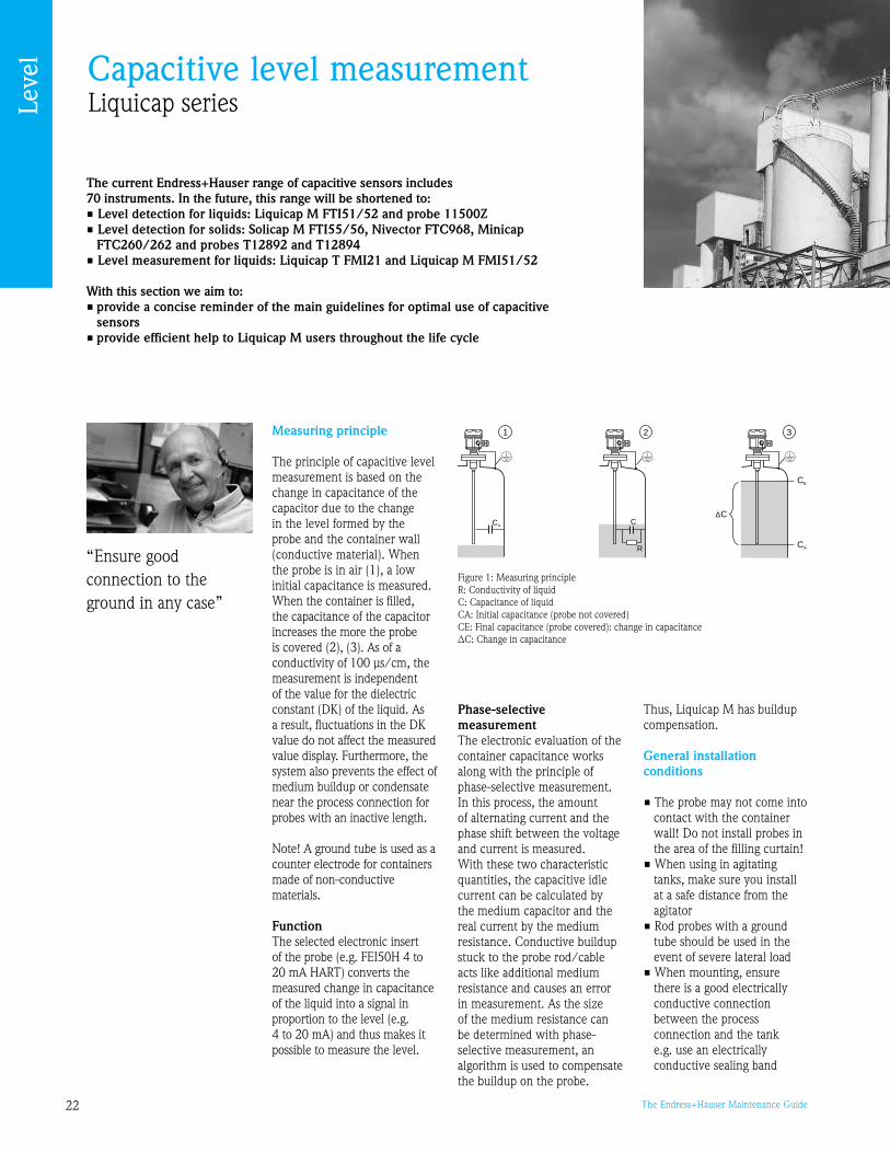
Measuring principle
The principle of capacitive level measurement is based on the change in capacitance of the capacitor due to the change in the level formed by the probe and the container wall (conductive material). When the probe is in air (1), a low initial capacitance is measured. When the container is filled, the capacitance of the capacitor increases the more the probe is covered (2), (). As of a conductivity of 100 μs/cm, the measurement is independent of the value for the dielectric constant (DK) of the liquid. As a result, fluctuations in the DK value do not affect the measured value display. Furthermore, the system also prevents the effect of medium buildup or condensate near the process connection for probes with an inactive length.
Note! A ground tube is used as a counter electrode for containers made of non-conductive materials.
Function The selected electronic insert of the probe (e.g. FEI50H 4 to 20 mA HART) converts the measured change in capacitance of the liquid into a signal in proportion to the level (e.g. 4 to 20 mA) and thus makes it possible to measure the level.
Figure 1: Measuring principleR: Conductivity of liquid C: Capacitance of liquid CA: Initial capacitance (probe not covered) CE: Final capacitance (probe covered): change in capacitance ΔC: Change in capacitance
Phase-selective measurement The electronic evaluation of the container capacitance works along with the principle of phase-selective measurement. In this process, the amount of alternating current and the phase shift between the voltage and current is measured. With these two characteristic quantities, the capacitive idle current can be calculated by the medium capacitor and the real current by the medium resistance. Conductive buildup stuck to the probe rod/cable acts like additional medium resistance and causes an error in measurement. As the size of the medium resistance can be determined with phase-selective measurement, an algorithm is used to compensate the buildup on the probe.
“Ensure good connection to the ground in any case”
Thus, Liquicap M has buildup compensation.
General installation conditions
• The probe may not come into contact with the container wall! Do not install probes in the area of the filling curtain!
• When using in agitating tanks, make sure you install at a safe distance from the agitator
• Rod probes with a ground tube should be used in the event of severe lateral load
• When mounting, ensure there is a good electrically conductive connection between the process connection and the tank e.g. use an electrically conductive sealing band
Leve
l

2The Endress+Hauser Maintenance Guide
Figure 2: Installation on containers that conduct electricity
L00-FMI5xxxx-11-06-xx-xx-001
L00-FMI5xxxx-11-06-xx-xx-007
Figure 4: Installation in a nozzleL00-FMI5xxxx-11-06-xx-xx-004
Figure 7: Tensioning weight
L00-FMI5xxxx-11-06-xx-xx-002
Figure : Installation on containers that do not conduct electricity
Figure 5: Installation of rod probes on conductive tanks
L00-FMI5xxxx-11-06-xx-xx-005
Figure 6: Installation of rod probes on non-conductive tanks
For containers that conduct electricity e.g. steel tanks, see Fig. 2.For containers that do not conduct electricity e.g. plastic tanks, use a probe with ground tube and ensure proper grounding (see Fig. ).
When installing in a nozzle, use a rod probe with ground tube and inactive length (see Fig. 4).
As a general rule, the probe should neither be shortened nor lengthened. Only on Liquicap T FMI21, Liquicap M FMI52 / FTI52 and Minicap FTC262 the probe may be shortened by means of a special kit.
Specific installation conditions for rod probes
The probes are ‘plug and play’ where the conductivity is higher than 100 μS/cm.Reported measurement errors are generally due to:• A bad connection to the
ground• The absence of a counter
electrode or a ground tube in case of containers made of non-conductive material
• Customer’s specific constraints
On conductive tanks (metal tanks) If the process connection of the probe is insulated from the metal tank (e.g. through seal material), the ground connection at the probe housing must be connected to the tank by means of a short cable. (see Fig. 5)
Note! A fully insulated rod probe may neither be shortened nor extended.Damaged insulation probe results in an incorrect measurement result.
On non-conductive tanks (plastic tanks) Always use a probe with ground tube (see Fig. 6).
Tensioning weight (see Fig. 7)The end of the probe needs to be secured when the probe could touch the silo wall or another part in the tank. This is what the internal thread in the probe weight is intended for.The bracing can be conductive or insulating to the tank wall.We strongly recommend to secure the end of the probe in case of high tank or silo and also in case of agitated liquid.To minimize the pull force on a cable that is tied down, leave a small amount of slack on the cable. The maximum tensile load may not exceed 14.75 lbf-ft (200 Nm).
Setup - Configuration
Calibration is necessary only at startup. There will be no drift afterwards.
Liquicap M FMIxxFor conductive liquids (>100 μS/cm), the probe is calibrated at the factory to the probe length ordered (0% to 100%). For non-conductive liquids (<1 μS/cm), 0% calibration is performed at the factory. Only the 100%
Leve
l
24 The Endress+Hauser Maintenance Guide
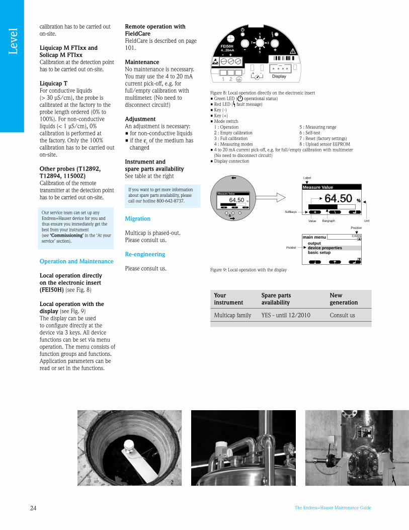
Figure : Local operation with the display
L00-FMI5xxxx-07-05-xx-xx-000
Label
Position
Bargraph
Softkeys
64.50 %
+
Value Unit
Picklist
main menuoutputdevice propertiesbasic setup
64.50 %
Measure Value
CX001
Measure Value
calibration has to be carried out on-site.
Liquicap M FTIxx and Solicap M FTIxxCalibration at the detection point has to be carried out on-site.
Liquicap T For conductive liquids (> 0 μS/cm), the probe is calibrated at the factory to the probe length ordered (0% to 100%). For non-conductive liquids (< 1 μS/cm), 0% calibration is performed at the factory. Only the 100% calibration has to be carried out on-site.
Other probes (T12892, T12894, 11500Z)Calibration of the remote transmitter at the detection point has to be carried out on-site.
Minicap and NivectorNothing to be carried out.
Operation and Maintenance
Local operation directly on the electronic insert (FEI50H) (see Fig. 8)
Local operation with the display (see Fig. )The display can be used to configure directly at the device via keys. All device functions can be set via menu operation. The menu consists of function groups and functions. Application parameters can be read or set in the functions.
Remote operation with FieldCareFieldCare is described on page 101.
MaintenanceNo maintenance is necessary.You may use the 4 to 20 mA current pick-off, e.g. for full/empty calibration with multimeter. (No need to disconnect circuit!)
AdjustmentAn adjustment is necessary: • for non-conductive liquids • if the εr of the medium has
changed
Instrument and spare parts availabilitySee table at the right
Migration
Multicap is phased-out. Please consult us.
Re-engineering
Please consult us.
Your Spare parts New instrument availability generation
Multicap family YES - until 12/2010 Consult us
Figure 8: Local operation directly on the electronic insert• Green LED ( operational status)• Red LED ( fault message)• Key (-)• Key (+)• Mode switch
• 4 to 20 mA current pick-off, e.g. for full/empty calibration with multimeter (No need to disconnect circuit!)
• Display connection
1 : Operation2 : Empty calibration : Full calibration4 : Measuring modes
5 : Measuring range6 : Self-test7 : Reset (factory settings)8 : Upload sensor EEPROM
Leve
l
If you want to get more information about spare parts availability, please call our hotline 800-642-877.
Our service team can set up any Endress+Hauser device for you and thus ensure you immediately get the best from your instrument (see ‘Commissioning’ in the ‘At your service’ section).

25The Endress+Hauser Maintenance Guide
Frequently asked questions
Micropilot: How can I adjust the LCD contrast?Press ‘+ ‘ and ‘E’ or ‘-’ and ‘E’ simultaneously.
Micropilot: How can I unlock the hardware?No configuration is possible if the device is locked. To unlock the hardware via the Display, enter the following code: Press ‘+’, ‘-’ and ‘E’ simultaneously.
Levelflex M: The filling level indicated by the device is too high. What can be done?• Check the setting of the medium property and correct,
if necessary• Carry out mapping
(Cable probes: mapping range 6.6 ft (2 m), Rod probes: Define the total probe length as mapping range) Attention: During mapping, the filling level must be below the
mapping range.
Prosonic S/M and Micropilot M: The level indicated by the device is too high. What can be done?Carry out mapping. Attention: During mapping, the filling level must be below the mapping range.
Levelflex M, Prosonic S/M and Micropilot M: The device indicates the correct value on-site, but keeps on showing 4 mA at the output. What can be done?Presumably a HART address was assigned and the device works in the Multidrop mode. Set the HART address to 0!
Prosonic FMU86X: Alignment values cannot be entered, the values keep going back to alignment empty 32.8 ft (10 m) and alignment full 29.5 ft (9 m).No sensor has been selected yet. Select sensor and confirm with ‘E’!
Prosonic FMU86X: Although a different endpoint of the scaling has been entered in V2H7, the device keeps indicating in the former units in VOHO.After changing the endpoint in V2H7, the value entered in V2HO must be confirmed with ‘E’.
Prosonic FMU86X: How to shift the decimal dot?Press ‘+’ and ‘->’ simultaneously.
Prosonic FMU86X: Error E641 “Echo lost”. Is there a troubleshooting?Remove the sensor and cable it directly to the transmitter. Then aim at the ground so that the membrane is approximately . ft (1 m) above the ground. If E641 disappears, it means the device is OK.
Prosonic: How can I adjust the 0% level of the tank?As the tank is empty, read the value displayed in V0H8 and type the same value in V0H1.
Prosonic: Is there any equivalence between the parameters for FMU86X and for FMU90?No. The approach is different.
Prosonic FMU90: the sensor is not recognized…Check which type of sensor is connected. In case this is the old FDU8x sensor, the sensor has to be selected manually.
Capacitive measurement: I get an incorrect measured value at commissioning…Ensure the grounding is correct. In case of a non-metal tank, ensure the installation conditions are met (see previous pages).
Leve
l

26 The Endress+Hauser Maintenance Guide
Endress+Hauser, Inc250 Endress PlaceGreenwood, IN [email protected]
Sales: 888-ENDRESSService: 800-642-877Fax: 17-55-848
Your instruments tuned to perfection.
Just as a piano needs to be tuned to ensure a perfect pitch so do critical process measurement instruments. Calibration services from Endress+Hauser deliver the skills and tools necessary to ensure your quality, safety, or environmental measurement devices are tuned to perfection. Calibration from Endress+Hauser – let us help you stay in tune.www.us.endress.com/calibration

27The Endress+Hauser Maintenance Guide
Flow metering
Contents
Basics 28The chapter ‘Basics’ includes information which is valid for all flow metering principles described hereafter. Thus you should read it before any other chapter.
Maintenance of ‘Proline’ flowmeters 30
Electromagnetic flowmeters 32
Mass flowmeters 35
Vortex flowmeters 38
Ultrasonic flowmeters 40
Thermal mass flowmeters 42
FAQ 44
“Flowmeters are so reliable that users refer to us primarily during installation and commissioning; very often it is not for several years that users come back to us. It is true that there are certain problems due to aging, but others can be resolved by recalibration. From time to time we also find that the flowmeter has been used for an application other than that for which it had been selected, at the risk of it being unsuited to this application, and creating a long term reliability problem… Finally, we observe that many apparently maintenance-related problems prove to be installation and setup problems.
That is why we have decided to give you in this guide a reminder of the few operating constraints and installation conditions for flowmeters. We have also recapped the
main questions that you ask us. With this information, you will be able to prevent or resolve the vast majority of potential problems yourself!
There is also plenty of useful information to help you get the best from your instruments throughout their life cycle… and prepare for renewing your equipment gradually.”
For those wanting to go further in mastering this subject, Endress+Hauser has published the ‘Flow Handbook’, a genuine flow measurement bible.
We also offer training sessions, in classroom and on-site. See ‘Training’ in the section ‘At your service’.
Kyle ShippsExpert in Flow meteringEndress+Hauser USA
“Installation and setup require particular care”
For assistance selecting any new or replacement instrument, use the free Online selection software, Applicator at www.us.endress.com/Applicator

28 The Endress+Hauser Maintenance Guide
BasicsInformation common to any type of flowmeter
Installation requirements overview
The specification of ANY flowmeter is based on an ideal installation. Installation guidelines for all technologies exist. They should be viewed as MINIMUM requirements:
The flowmeter must remain completely full at all times. This is of utmost importance for filling or dosing applications, since many flowmeters (except mass flowmeters) measure the fluid’s velocity, assuming that the whole section is full of liquid. Measuring errors might be particularly important if this is not the case. Please note that this rule applies even to mass flowmeters.
Installation at the highest point of pipe work • Installation at the top of a
piping system causes a risk that air will collect and negatively influence the performance (Fig.1)
• Avoid installing directly upstream of a free pipe outlet in a vertical pipe as air is potentially rising up through the flowmeter causing measuring errors
• The flowmeter should be installed in a lower part of the pipe work. This ensures enough head pressure to avoid cavitation and the meter will always remain full.
“Compliance with installation requirements would avoid most reported errors!”
F06-5xxxxxxx-11-00-00-xx-002
Installation in a siphon It sometimes can’t be ensured that the pipe is always full (i.e. wastewater pipes). This could lead to measuring errors or situations where the flowmeter will not work at all. • The flowmeter should then be
installed in a siphon (Fig. 2) • If solids are carried with the
fluid it is recommended to plan a cleaning access. A U-tube or a sloping pipe might be simple solutions.
Advice: the ideal mount for a flowmeter is in a fluid riser vertical pipe (Fig. )• The meter must be installed
with sufficient straight pipe upstream
• See technology-specific installation conditions for further details (mainly vortex, ultrasonic and thermal mass flowmeter)
WiringTake care with the instrument wiring, especially when the transmitter is mounted remotely.
Ensure correct tightening of the wires and cable glands. In case of humid atmosphere, check that no water drop may get into the flowmeter.
Further requirements may apply for one particular technology. Please check specific installation conditions for EMF*, mass flowmeters, etc. in the next sections.
F06-5xxxxxxx-11-00-00-xx-004
Figure 1
Figure 2: Installation in a siphon
Figure : Ideal mount for a flowmeter
*EMF: Electromagnetic flowmeter
Setup - Configuration
General note: If the installation and wiring conditions have been observed initially, you can be certain of getting correct measurements from the instrument’s first activation. Configuration will only serve to optimize the operating parameters of the quantities measured (current output setup, etc.)
Since 2007, all Endress+Hauser flowmeters belong to the Proline family and thus offer a QUICK SETUP. QUICK SETUP enables quick and easy configuration of the device’s main functions (units, outputs…).
You can also configure your flowmeters from your PC. See presentation of FieldCare on page 101.
Our service organization can set up any Endress+Hauser flowmeter for you and thus ensure you immediately get the best from your instrument (see ‘Commissioning’ in the ‘At your service’ section).
Electromagnetic flowmetersSpecific information p. 2
Mass flowmetersSpecific information p. 5
Vortex flowmetersSpecific information p. 8
Ultrasonic flowmetersSpecific information p. 40
…
Thermal mass flowmetersSpecific information p. 42
flow direction
flow
dire
ctio
n
F06-5xxxxxxx-11-00-00-xx-000
Flow

2The Endress+Hauser Maintenance Guide
Operation and Maintenance
In most applications, when correctly selected and installed, Endress+Hauser flowmeters (except mechanical) require very little maintenance as they are designed without any moving mechanical parts. Nevertheless, according to its criticality to the quality, some flowmeters need to be inspected and/or calibrated periodically.Defining the right maintenance frequency taking several parameters into account is an expert’s job. Endress+Hauser can also help you with this task!
Periodic inspection to assure reliability of the applicationAfter a flowmeter has been operating for a period of time, the user may think that just because the flowmeter signal is stable it is correct – but this might not be the case. Even an indicated flow that appears to be within acceptable limits may be inaccurate and may then affect the quality of the final product.
Pipeline inspections• Deposits in the pipe can cause
a slow drift of measured values at meter output that is not detected and rectified
• According to the type of flowmeter, anything that alters the shape or diameter of a pipeline upstream of the measurement point will cause errors in the readings
Due to the effects of sedimenta-tion or deposition, a periodical cleaning of the flowmeter pipe might be necessary.
CalibrationIntrinsically our flowmeters offer long-term stability and repeatability of your measurements. Nevertheless we recommend periodic calibration for the measurement points which are critical to the process and thus are important to control the quality of your product. From on-site to accredited services, you can be sure to find the right method by finding the right balance between the flowmeter downtime and the calibration uncertainty.
Inspection of seals and gaskets In some processes, operational needs necessitate the use of frequent cleaning or sterilization in place (CIP or SIP). The flowmeter seals and gaskets should then be carefully chosen and frequently replaced to avoid risks of leakage, contamination and even process failure.
Routine maintenanceThe need for routine maintenance is defined according to the importance of the flowmeter in the process.
Flowmeters can be checked in a variety of ways:• The most common
maintenance seems to be the use of electrical devices for simple checking of the input
and output function of the transmitter
• They may be checked using a flow simulator in the field so that problems can be identified. For any flowmeter belonging to the Proline family (see next page) we recommend the use of our FieldCheck® smart signal simulator which facilitates on-site verification.
The user may effect either a manual simulation of the flowmeter functions or a full check of the flowmeter, of its electronics only or of its sensor only. The tool incorporates procedures for automatically checking all the electronic operations (linearity of the amplifier, the analog outputs and frequency) on the one hand, and all the sensor operations on the other (magnetic field and measuring electrode integrity). With FieldCare software, the user can upload the test results to a PC, incorporate them in a certificate, print them or archive them, thus meeting the requirements of quality procedures.
Moreover, this solution combined with calibration could allow to reduce the calibration frequencies and by this way reduce your maintenance costs.
Maintenance planning
Maintenance
Corrective maintenance The more critical your instrument is to your process, the shorter the acceptable time for repairing is. Thanks to the Proline concept (see next page), flowmeters offer a modular design; one of the outcomes is that most parts can be easily replaced thus allowing quick repair.
Inspection of the flowmeter pipe
Functional check of a flowmeter using the FieldCare software associated with the FieldCheck tool (small right picture)
Flowmeters mounted in a fluid riser vertical pipe
If you do not have the time or the right tools to efficiently perform your maintenance, an Endress+Hauser service contract can provide you the appropriate level of maintenance support you require. We provide regular checks on your equipment and warranty extensions providing you with complete peace of mind and cost control.
From regular support to partnership agreements, we offer four distinct levels of service… (see ‘Service Contracts’ in the ‘At your service’ section).
Calibration can be performed by Endress+Hauser either on-site or in our accredited laboratories (see ‘Calibration’ in the ‘At your service’ section).
Do you know exactly which part of your installed instrumentation base is critical to the operation of the plant and how you could maintain or calibrate it more efficiently? Are you sure that your present actions are minimizing the risks of unplanned breakdowns? Are you sure that your present actions are the most cost effective?
With Endress+Hauser’s Installed Base Audit, our service consultant will help you to quickly find an answer to these three questions and move forward in a controlled manner to a maintenance plan which improves plant reliability while reducing costs… (see ‘Installed Base Audit’ in the ‘At your service’ section).
…
FieldCheck is presented on page 1.
Flow
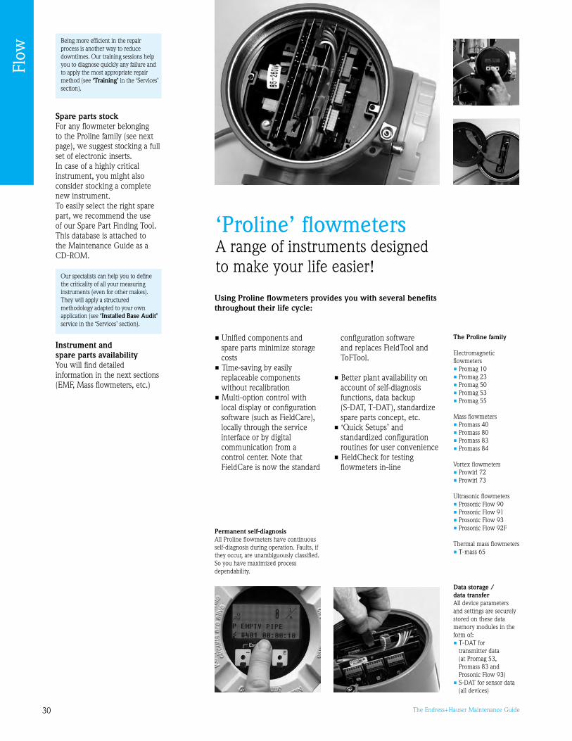
0 The Endress+Hauser Maintenance Guide
The Proline family
Electromagnetic flowmeters• Promag 10• Promag 2• Promag 50• Promag 5• Promag 55
Mass flowmeters• Promass 40• Promass 80• Promass 8• Promass 84
Vortex flowmeters• Prowirl 72• Prowirl 7
Ultrasonic flowmeters• Prosonic Flow 0• Prosonic Flow 1• Prosonic Flow • Prosonic Flow 2F
Thermal mass flowmeters• T-mass 65
‘Proline’ flowmetersA range of instruments designed to make your life easier!
Spare parts stockFor any flowmeter belonging to the Proline family (see next page), we suggest stocking a full set of electronic inserts.In case of a highly critical instrument, you might also consider stocking a complete new instrument. To easily select the right spare part, we recommend the use of our Spare Part Finding Tool. This database is attached to the Maintenance Guide as a CD-ROM.
Instrument and spare parts availabilityYou will find detailed information in the next sections (EMF, Mass flowmeters, etc.)
Using Proline flowmeters provides you with several benefits throughout their life cycle:
• Unified components and spare parts minimize storage costs
• Time-saving by easily replaceable components without recalibration
• Multi-option control with local display or configuration software (such as FieldCare), locally through the service
interface or by digital communication from a control center. Note that FieldCare is now the standard
configuration software and replaces FieldTool and ToFTool.
• Better plant availability on account of self-diagnosis functions, data backup
(S-DAT, T-DAT), standardize spare parts concept, etc.
• ‘Quick Setups’ and standardized configuration routines for user convenience
• FieldCheck for testing flowmeters in-line
Permanent self-diagnosisAll Proline flowmeters have continuous self-diagnosis during operation. Faults, if they occur, are unambiguously classified. So you have maximized process dependability.
Data storage / data transfer All device parameters and settings are securely stored on these data memory modules in the form of:• T-DAT for
transmitter data (at Promag 5, Promass 8 and Prosonic Flow )
• S-DAT for sensor data (all devices)
Our specialists can help you to define the criticality of all your measuring instruments (even for other makes). They will apply a structured methodology adapted to your own application (see ‘Installed Base Audit’ service in the ‘Services’ section).
Being more efficient in the repair process is another way to reduce downtimes. Our training sessions help you to diagnose quickly any failure and to apply the most appropriate repair method (see ‘Training’ in the ‘Services’ section).
Flow

1The Endress+Hauser Maintenance Guide
Outputs
Service interface
Simubox
On-site connectionsWorkshop connection
FieldCare is presented on page 101.
FieldCheck® Smart signal simulator
With FieldCheck®, meter verification can be carried out without the removal of the Proline flowmeter from the pipe. Where ISO 9000 requires frequent test cycles, FieldCheck® is an economical alternative to calibration.
Designed especially for flowmeter verification*, FieldCheck® simulates sensor signals to test and evaluate the behavior of a piece of equipment. It can also, thanks to its checking procedures, test proper flowmeter functioning – be it to meet in-house criteria or regulatory requirements. The check and test results obtained with FieldCheck® can then be stored in a database and printed out for subsequent use, e.g. in connection with certification by audit organizations.
Main advantages• All Endress+Hauser PROline
flowmeters can be tested directly on-site, without removal of the instrument
• Simultaneous verification of process outputs (current, frequency)
• Large, clear, multivariable displays
• Expanded functionality with the FieldCare® software program: reading and printing of test results (verification certificates)
How does it work?FieldCheck® includes a signal generator, connector cables and ‘Simubox’ adapters for connection to the various types of flowmeters (see picture).
The user may affect:• A manual simulation of the flowmeter functions. The generator simulates a flow based on several freely programmable profiles. This allows the user to check the behavior of the outs towards the device, or the supervision system, without any actual flow in the pipe.or• A full check of the flowmeter, of its electronics only, or of its sensor only (see photo). The tool incorporates procedures for automatically checking all the electronic operations (linearity of the amplifier, the analog outputs and frequency) on the one hand, and all the sensor operations on the other (magnetic field and measuring electrode integrity).
We can provide checks on your Proline flowmeters as on-site service for your installed devices. Our specialist staff will carry out all the test functions directly in the installation.
Your benefits:• Cost savings by providing the
inspection equipment• No familiarization required by
operating personnel• Test certificate as record and proof
of the simulation and verification
The suitcase includes FieldCheck® signal simulator and Simubox interfaces
Modular concept
All Endress+Hauser flowmeters are based on unified electronics and operating concepts. The modular Proline device concept provides the user with obvious advantages, e.g. in service situations: • Minimization of spare parts
costs through standardized components
• Time-saving with easily replaceable meter electronics, without the need of recalibration
• Individual retrofitting of flowmeters for application-specific modifications
Time-saving ‘Quick Setups’
The Quick Setup menus make commissioning fast and straightforward. It guides you step by step through all the operation-relevant parameters. Quick Setups are availableas follows:
• For standard commissioning• For metering pulsating flow• For metering gas flow (Coriolis)• For filling and dosing
applications• For sensor installation and
wall thickness measurement (ultrasonic)• For configuring the Fieldbus
interface
On-site functional check of a flowmeter using FieldCheck®
Flow
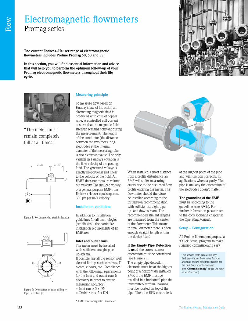
2 The Endress+Hauser Maintenance Guide
Electromagnetic flowmetersPromag series
The current Endress+Hauser range of electromagnetic flowmeters includes Proline Promag 50, 53 and 55.
In this section, you will find essential information and advice that will help you to perform the optimum follow-up of your Promag electromagnetic flowmeters throughout their life cycle.
“The meter must remain completely full at all times.”
Measuring principle
To measure flow based on Faraday’s law of induction an alternating magnetic field is produced with coils of copper wire. A controlled coil current ensures that the magnetic field strength remains constant during the measurement. The length of the conductor (the distance between the two measuring electrodes at the internal diameter of the measuring tube) is also a constant value. The only variable in Faraday’s equation is the flow velocity of the passing fluid. The generated voltage is exactly proportional and linear to the velocity of the fluid. An EMF* does not measure volume but velocity. The induced voltage of a general purpose EMF from Endress+Hauser equals approx. 00 μV per m/s velocity.
Installation conditions
In addition to installation guidelines for all technologies (see ‘Basics’), the particular installation requirements of an EMF are:
Inlet and outlet runsThe meter must be installed with sufficient straight pipe up-stream. If possible, install the sensor well clear of fittings such as valves, T-pieces, elbows, etc. Compliance with the following requirements for the inlet and outlet runs is necessary in order to ensure measuring accuracy :• Inlet run ≥ 5 x DN• Outlet run ≥ 2 x DN
When installed a short distance from a profile disturbance an EMF will suffer measuring errors due to the disturbed flow profile entering the meter. The flowmeter should therefore be installed according to the installation recommendation with sufficient straight pipe up- and downstream. The recommended straight lengths are measured from the center of the flowmeter. This means in small diameter there is often enough straight length within the device itself.
If the Empty Pipe Detection is used the correct sensor orientation must be considered (see Figure 2).The empty pipe detection electrode must be at the highest point of a horizontally installed EMF. If the EMF must be installed in a horizontal pipe the transmitter/terminal housing must be located on top of the pipe. Then the EPD electrode is
at the highest point of the pipe and will function correctly. In applications where a partly filled pipe is unlikely the orientation of the electrodes doesn’t matter.
The grounding of the EMF must be according to the guidelines (see FAQs). For further information please refer to the corresponding chapter in the Operating Manual.
Setup - Configuration
All Proline flowmeters propose a ‘Quick Setup’ program to make standard commissioning easy.
F06-5xxxxxxx-11-00-00-xx-005
Figure 1: Recommended straight lengths
Our service team can set up any Endress+Hauser flowmeter for you and thus ensure you immediately get the best from your instrument (see ‘Commissioning’ in the ‘At your service’ section).
Figure 2: Orientation in case of Empty Pipe Detection (1)
* EMF: Electromagnetic Flowmeter
F06-5xxxxxxx-11-00-xx-xx-000
F06-5xxxxxxx-11-00-xx-xx-000
Flow

The Endress+Hauser Maintenance Guide
EMF mounted horizontally
EMF mounted in a siphon
EMF with remote electronicsEMF mounted vertically
Operation and Maintenance
Preventive maintenanceHow can you minimize the risks of failure or drift of your measurement point?Having no moving parts, EMFs require very little preventive maintenance. Process conditions may affect your flowmeters’ lifetime or accuracy: abrasive products, soiling of the electrodes, effects from high temperatures or high temperature cycles (e.g. CIP), vibration, aggressive chemical products, etc.If you face one of those situations, you can drastically decrease the risk of process downtime by planning periodical checks and calibrations. Another topic requires particular attention: the seals on H sensors (hygienic or small diameter) which are exposed to repeated cleaning or sterilization (CIP/SIP) may quickly deteriorate. Ensure that they are regularly replaced.
To control the functional integrity of the Promag we use special tools which provide very complete checks of the internal parameters of the electronics including elements of the sensor (See full description of FieldCheck® on page 1).
Note: a measurement consistency check may
be obtained by means of comparison with an ultrasound device. This is in no way a calibration.
CalibrationCalibration frequency should be in line with the operating conditions. Device calibration procedures and intervals depend on:• the precision required for
leakage flow monitoring,• its criticality to the process,
the legislative constraints imposed.
So it is important to define the calibration intervals and the maximum permissible error of a measurement point.The main factors influencing flowmeter drift are:• the process conditions (fluid
type, product temperature, etc.)• the ambient conditions in
which the sensors are fitted (ambient temperature, moisture).
In knowing that calibration frequencies should be optimized over time in line with the operating histories, you need to set an initial frequency. Hereafter you will find a table of recommendations to help you define this frequency, taking into account the process conditions and ambient conditions:
Note: • For abrasive or corrosive
fluids, the calibration frequency must be lowered according to the wear
• These calibration recommen-dations are no substitute for the maintenance operations required to keep the device in perfect working condition
Instrument and spare parts availability
Spare parts stockFor any flowmeter belonging to the Proline family, we suggest stocking a full set of electronic inserts.
Our service contracts can include such verifications – once a year is recommended (see ‘Service Contracts’ in the ‘At your service’ section).
Calibration of flowmeters can be performed by Endress+Hauser either on-site or in our accredited laboratories (see ‘Calibration’ in the ‘At your service’ section).
Your Spare parts New instrument availability generation
Promag 0/ YES - until 12/2007 Promag 50/5
Promag F/H NO - stopped 0/2007 Promag 50/5
Dosimag A YES - until 12/2010 Dosimag 5BH
Promag 5S YES - until 12/2010 Promag 55S
If you want to get more information about spare parts availability, please call our hotline 800-642-877.
Flow

4 The Endress+Hauser Maintenance Guide
Migration
Promag 5X series is Endress+Hauser’s new generation of electromagnetic flowmeters. These new instruments offer new ways to carry out preventive verification (see FieldCheck on page 1). They can replace all Endress+Hauser’s previous instruments.
The old generation included primarily the Promag 0, Promag and Promag 5. As of December 2007, the parts for the Promag 0 and are no longer available.
• With which device should you replace your Promag 0? For identical applications, with the Promag 10, which is much more user-friendly and easy to use. In addition, you will only need to stock a single electronics board.
• With which device should you replace your Promag ? For standard applications: with its designated successor, which is the Promag 50. For special applications: the Promag 5 offers a broader range of options and better measurement uncertainty. Promag 5 also includes passive or active pulse output, like Promag .
• With which device should you replace your Promag 5? With the Promag 55, typically for applications involving high-load fluids (paper mill, mining extraction, etc.)
Please call our sales force (888-ENDRESS) for more information about replacement.
Re-engineering
You wish to apply an EMF to a different application than the one for which it had been selected? Please take the following advice into account.
No or low conductivityIf a fluid has a rather low conductivity, an EMF cannot be used. The following liquids can NOT be measured because their conductivity is too low: vegetable or mineral oil, de-mineralized water, hydrocarbons/solvents, etc. (see graphics)However, if these liquids are mixed with even a low quantity of a conductive liquid, an EMF might be used.To apply an EMF successfully the fluid must have a minimum conductivity of: >5 μS/cm for Promag 50/5/55 (55 also for water) >20 μS/cm for water applications in general >50μS/cm for Promag 2/10.
Solid Content in a fluid Since the influence of solids is very much dependent on concentration, mixture, particle characteristics and other parameters, expert knowledge is required to select and size the best fitting model and options. Two typical influences must be considered: • Excessive signal noise due
to solids requires a high performing transmitter (Promag 55)
• For abrasive slurries suitable liners and electrode designs/materials must be chosen
Temperature range All available liner materials are isolating plastics or rubbers with a limited operating temperature. This is the limiting factor for the applicability of EMF’s.
Buildup / ECCWhile an EMF is very tolerant regarding buildup on the measuring tube, there are limitations. A layer on the electrodes will eventually lead to a reduced flow signal and the device might stop functioning.
If the buildup is conductive (e.g. magnetic in heating water systems), it is possible to use an electronic solution: ECC (electrode clean circuit) keeps the measuring electrodes clean and free from buildup.
The effect of buildup on the electrodes
For a more in-depth analysis of your current installed base, we can help you with our ‘Installed Base Audit’ service (see the ‘Services’ section).
Measuring rangeYou also need to check that the flowmeter’s measuring range is adequate for the application. In case of a different pipe diameter, a certain flow rate is required at minimum flow so that the flowmeter operates with the expected accuracy. The Applicator software allows you to check the device’s accuracy over the measuring range.
Again consider proper installation and setup.
Oil, Hydrocarbons
Ultra pure water
Pure water
Industrial water
Potable water
BeerMilkOrange juiceApple juiceTomato juice
Phosphoric acidSulphuric acidHydrochloric acidCaustic soda
Water
Food
Process
Min. Conductivityfor EMFs
0.05 μS/cm
1 μS/cm
10 μS/cm
100 μS/cm
1 mS/cm
10 mS/cm
100 mS/cm
1000 mS/cm
Flow

5The Endress+Hauser Maintenance Guide
Mass flowmetersPromass series
The current Endress+Hauser range of mass flowmeters includes Proline Promass 80, 83 and 40.
In this section, you will find essential information and advice that will help you to perform the optimum follow-up of your Promass flowmeters throughout their life cycle.
“Ensure that cavitation does not occur!”
Measuring principle
The measuring principle is based on the controlled generation of Coriolis forces. These forces are always present when both translational and rotational movements are superimposed.
FC = 2 Δm (v w)
FC = Coriolis force Δm = moving mass w = rotational velocity v = radial velocity in rotating or
oscillating system
The amplitude of the Coriolis force depends on the moving mass Δm, its velocity v in the system, and thus on the mass flow. Instead of a constant angular velocity w, the Promass sensor uses oscillation.
In the Promass F and M sensors, two parallel measuring tubes containing flowing fluid oscillate in antiphase, acting like a tuning fork. The Coriolis forces produced at the measuring tubes cause a phase shift in the tube oscillations (see illustration):
• At zero flow, in other words when the fluid is at a standstill, the two tubes oscillate in phase (1).
• Mass flow causes deceleration of the oscillation at the inlet of the tubes (2) and acceleration at the outlet ().
The phase difference (A-B) increases with increasing mass
flow. Electrodynamic sensors register the tube oscillations at the inlet and outlet.
System balance is ensured by the antiphase oscillation of the two measuring tubes. The measuring principle operates independently of temperature, pressure, viscosity, conductivity and flow profile.
Note: For Promass I, S and P, the system balance required for proper measurement is created by exciting an eccentrically arranged swinging mass to antiphase oscillation. This patented TMB system (Torsion Mode Balanced System) guarantees perfect measurements, even in changing process and environmental conditions. The measuring tube is continuously excited at its resonance frequency. A change in the mass and thus the
density of the oscillating system (consisting of the measuring tube and fluid) results in a corresponding, automatic adjustment in the oscillation frequency. Resonance frequency is thus a function of fluid density. The microprocessor utilizes this relationship to obtain a density signal. The temperature of the measuring tube is determined in order to calculate the compensation factor due to temperature effects. This signal corresponds to the process temperature and is also available as an output.
…
Flow

6 The Endress+Hauser Maintenance Guide
Installation conditions
In addition to installation guidelines for all technologies (see ‘Basics’), here are the specific installation requirements for a mass flowmeter:
When using a bent measuring tube and horizontal installation, the position of the sensor has to be matched to the fluid properties!
Horizontal installation for sensors with a bent measuring tube1 Not suitable for fluids with entrained solids. Risk of solids accumulating.2 Not suitable for outgassing fluids. Risk of air accumulating.
System pressure It is important to ensure that cavitation does not occur, because it would influence the oscillation of the measuring tube. No special measures need to be taken for fluids which have properties similar to water under normal conditions.In the case of liquids with a low boiling point (hydrocarbons, solvents, liquified gases) or in suction lines, it is important to ensure that pressure does not drop below the vapor pressure and that the liquid does not start to boil. It is also important to ensure that the gases that occur naturally in many liquids do not outgas. Such effects can be prevented when system pressure is sufficiently high.Therefore, the following locations should be preferred for installation:• Downstream from pumps (no danger of vacuum)• At the lowest point in a vertical pipe
Recommended measuring ranges: Limiting flow Please refer to the ‘Measuring range’ section of the ‘Technical Information’ documentation.Select nominal diameter by optimizing between required flow range and permissible pressure loss. See the ‘Measuring range’ section for a list of maximum possible full scale values.• The minimum recommended full scale value is approx. 1/20 of the
max. full scale value• In most applications, 20 to 50% of the maximum full scale value
can be considered ideal• Select a lower full scale value for abrasive substances such as fluids
with entrained solids (flow velocity <1 m/s).
• For gas measurement the following rules apply: – Flow velocity in the measuring tubes should not be more than
half the sonic velocity (0.5 Mach) – The maximum mass flow depends on the density of the gas:
formula shown below
Measuring ranges for gases The full scale values depend on the density of the gas. Use the formula below to calculate the full scale values: mmax(G) = mmax(F) rG) / 160 [kg/m] mmax(G) = max. full scale value for gas [kg/h] mmax(F) = max. full scale value for liquid [kg/h] r(G) = Gas density in [kg/m] at operating conditionsHere, mmax(G) can never be greater than mmax(F).
Mounting locationNo special precautions need to be taken for fittings which create turbulence (valves, elbows, T-pieces, etc.), as long as no cavitation occurs. Entrained air or gas bubbles in the measuring tube can result in an increase in measuring errors. Therefore, avoid the following mounting locations in the pipe installation:• Highest point of a pipeline. Risk of air accumulating• Directly upstream of a free pipe outlet in a vertical pipeline
Note: We recommended the vertical orientation with upward direction of flow. When fluid is not flowing, entrained solids will sink down and gases will rise away from the measuring tube. The measuring tubes can be completely drained and protected against solids buildup.
Setup - Configuration
All Proline flowmeters propose a ‘Quick Setup’ program for straightforward commissioning. Promass 8 proposes an application-specific Quick Setup program.
F06-xxxxxxxx-11-00-00-xx-003
F06-xxxxxxxx-11-00-00-xx-004
F06-xxxxxxxx-11-00-00-xx-008
Mobile flow rig for on-site calibration
Mass flowmeters mounted vertically
Commissioning and configuration with FieldCareFl
ow
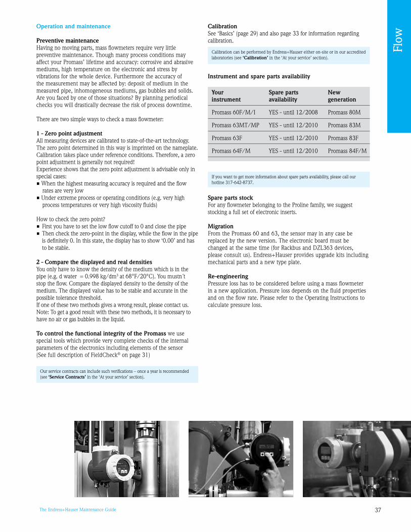
7The Endress+Hauser Maintenance Guide
CalibrationSee ‘Basics’ (page 2) and also page for information regarding calibration.
Instrument and spare parts availability
Spare parts stockFor any flowmeter belonging to the Proline family, we suggest stocking a full set of electronic inserts.
MigrationFrom the Promass 60 and 6, the sensor may in any case be replaced by the new version. The electronic board must be changed at the same time (for Rackbus and DZL6 devices, please consult us). Endress+Hauser provides upgrade kits including mechanical parts and a new type plate.
Re-engineeringPressure loss has to be considered before using a mass flowmeter in a new application. Pressure loss depends on the fluid properties and on the flow rate. Please refer to the Operating Instructions to calculate pressure loss.
Operation and maintenance
Preventive maintenanceHaving no moving parts, mass flowmeters require very little preventive maintenance. Though many process conditions may affect your Promass’ lifetime and accuracy: corrosive and abrasive mediums, high temperature on the electronic and stress by vibrations for the whole device. Furthermore the accuracy of the measurement may be affected by: deposit of medium in the measured pipe, inhomogeneous mediums, gas bubbles and solids.Are you faced by one of those situations? By planning periodical checks you will drastically decrease the risk of process downtime.
There are two simple ways to check a mass flowmeter:
1 - Zero point adjustmentAll measuring devices are calibrated to state-of-the-art technology. The zero point determined in this way is imprinted on the nameplate.Calibration takes place under reference conditions. Therefore, a zero point adjustment is generally not required!Experience shows that the zero point adjustment is advisable only in special cases:• When the highest measuring accuracy is required and the flow
rates are very low• Under extreme process or operating conditions (e.g. very high
process temperatures or very high viscosity fluids)
How to check the zero point?• First you have to set the low flow cutoff to 0 and close the pipe• Then check the zero-point in the display, while the flow in the pipe
is definitely 0. In this state, the display has to show ‘0.00’ and has to be stable.
2 - Compare the displayed and real densitiesYou only have to know the density of the medium which is in the pipe (e.g. d water = 0.8 kg/dm at 68°F/20°C). You mustn´t stop the flow. Compare the displayed density to the density of the medium. The displayed value has to be stable and accurate in the possible tolerance threshold.If one of these two methods gives a wrong result, please contact us.Note: To get a good result with these two methods, it is necessary to have no air or gas bubbles in the liquid.
To control the functional integrity of the Promass we use special tools which provide very complete checks of the internal parameters of the electronics including elements of the sensor (See full description of FieldCheck® on page 1)
Our service contracts can include such verifications – once a year is recommended (see ‘Service Contracts’ in the ‘At your service’ section).
If you want to get more information about spare parts availability, please call our hotline 17-642-877.
Calibration can be performed by Endress+Hauser either on-site or in our accredited laboratories (see ‘Calibration’ in the ‘At your service’ section).
Your Spare parts New instrument availability generation
Promass 60F/M/I YES - until 12/2008 Promass 80M
Promass 6MT/MP YES - until 12/2010 Promass 8M
Promass 6F YES - until 12/2010 Promass 8F
Promass 64F/M YES - until 12/2010 Promass 84F/M
Flow
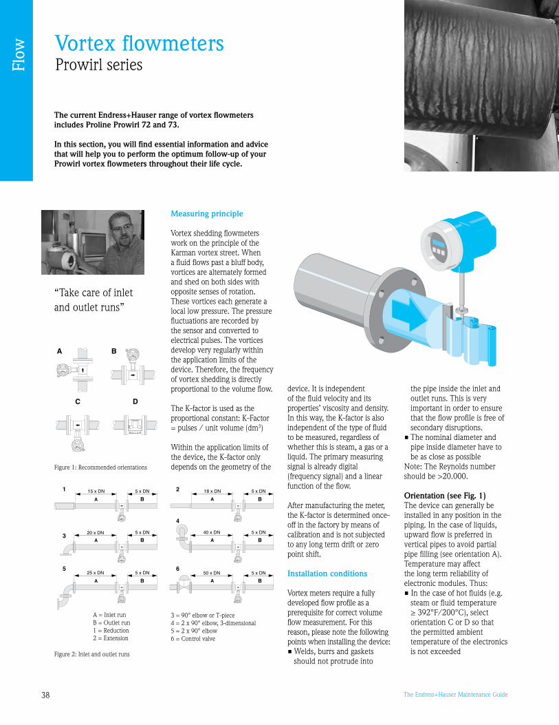
8 The Endress+Hauser Maintenance Guide
Vortex flowmetersProwirl series
The current Endress+Hauser range of vortex flowmeters includes Proline Prowirl 72 and 73.
In this section, you will find essential information and advice that will help you to perform the optimum follow-up of your Prowirl vortex flowmeters throughout their life cycle.
“Take care of inlet and outlet runs”
Measuring principle
Vortex shedding flowmeters work on the principle of the Karman vortex street. When a fluid flows past a bluff body, vortices are alternately formed and shed on both sides with opposite senses of rotation. These vortices each generate a local low pressure. The pressure fluctuations are recorded by the sensor and converted to electrical pulses. The vortices develop very regularly within the application limits of the device. Therefore, the frequency of vortex shedding is directly proportional to the volume flow.
The K-factor is used as the proportional constant: K-Factor = pulses / unit volume (dm)
Within the application limits of the device, the K-factor only depends on the geometry of the
device. It is independent of the fluid velocity and its properties’ viscosity and density. In this way, the K-factor is also independent of the type of fluid to be measured, regardless of whether this is steam, a gas or a liquid. The primary measuring signal is already digital (frequency signal) and a linear function of the flow.
After manufacturing the meter, the K-factor is determined once-off in the factory by means ofcalibration and is not subjected to any long term drift or zero point shift.
Installation conditions
Vortex meters require a fully developed flow profile as a prerequisite for correct volume flow measurement. For this reason, please note the following points when installing the device:• Welds, burrs and gaskets
should not protrude into
the pipe inside the inlet and outlet runs. This is very important in order to ensure that the flow profile is free of secondary disruptions.
• The nominal diameter and pipe inside diameter have to be as close as possible
Note: The Reynolds number should be >20.000.
Orientation (see Fig. 1)The device can generally be installed in any position in the piping. In the case of liquids, upward flow is preferred in vertical pipes to avoid partial pipe filling (see orientation A).Temperature may affect the long term reliability of electronic modules. Thus:• In the case of hot fluids (e.g.
steam or fluid temperature ≥ 392°F/200°C), select orientation C or D so that the permitted ambient temperature of the electronics is not exceeded
Figure 1: Recommended orientations
Figure 2: Inlet and outlet runs
A = Inlet runB = Outlet run1 = Reduction2 = Extension
= 0° elbow or T-piece4 = 2 x 0° elbow, -dimensional5 = 2 x 0° elbow6 = Control valve
Flow
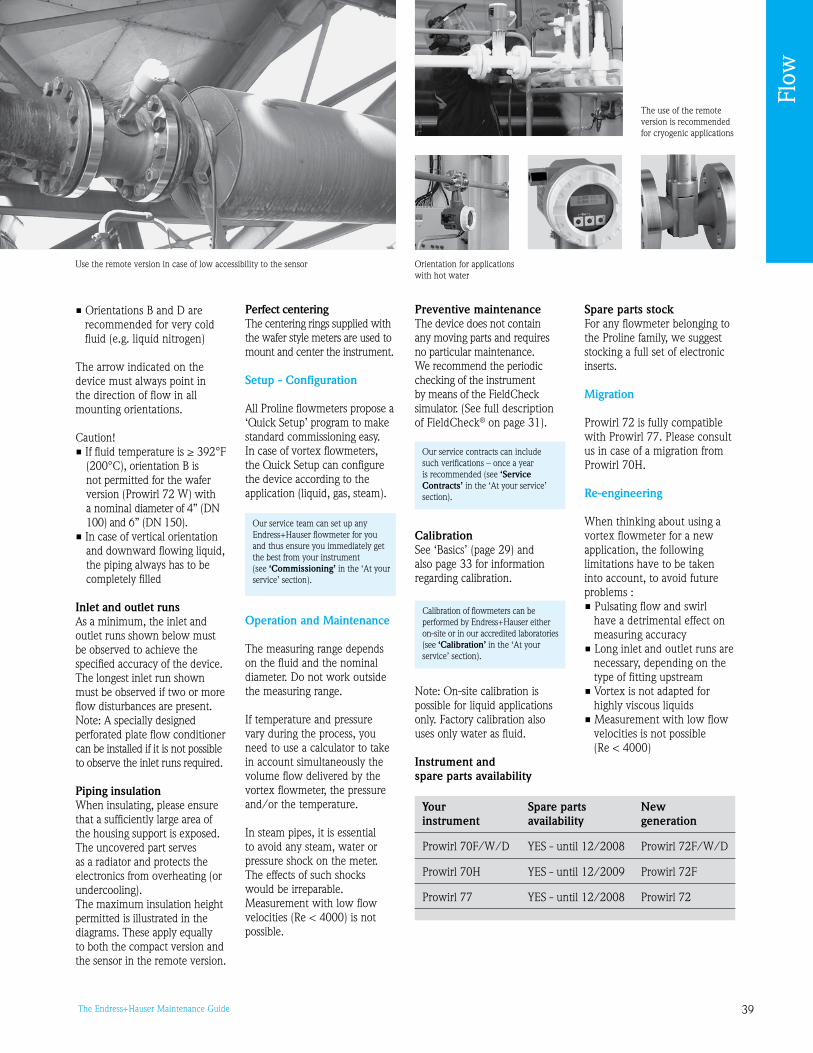
The Endress+Hauser Maintenance Guide
The use of the remote version is recommended for cryogenic applications
Orientation for applications with hot water
Use the remote version in case of low accessibility to the sensor
• Orientations B and D are recommended for very cold fluid (e.g. liquid nitrogen)
The arrow indicated on the device must always point in the direction of flow in all mounting orientations.
Caution!• If fluid temperature is ≥ 392°F
(200°C), orientation B is not permitted for the wafer version (Prowirl 72 W) with a nominal diameter of 4” (DN 100) and 6” (DN 150).
• In case of vertical orientation and downward flowing liquid, the piping always has to be completely filled
Inlet and outlet runsAs a minimum, the inlet and outlet runs shown below must be observed to achieve the specified accuracy of the device. The longest inlet run shown must be observed if two or more flow disturbances are present.Note: A specially designed perforated plate flow conditioner can be installed if it is not possible to observe the inlet runs required.
Piping insulationWhen insulating, please ensure that a sufficiently large area of the housing support is exposed.The uncovered part serves as a radiator and protects the electronics from overheating (orundercooling).The maximum insulation height permitted is illustrated in the diagrams. These apply equally to both the compact version and the sensor in the remote version.
Perfect centeringThe centering rings supplied with the wafer style meters are used to mount and center the instrument.
Setup - Configuration
All Proline flowmeters propose a ‘Quick Setup’ program to make standard commissioning easy. In case of vortex flowmeters, the Quick Setup can configure the device according to the application (liquid, gas, steam).
Operation and Maintenance
The measuring range depends on the fluid and the nominal diameter. Do not work outside the measuring range.
If temperature and pressure vary during the process, you need to use a calculator to take in account simultaneously the volume flow delivered by the vortex flowmeter, the pressure and/or the temperature.
In steam pipes, it is essential to avoid any steam, water or pressure shock on the meter. The effects of such shocks would be irreparable.Measurement with low flow velocities (Re < 4000) is not possible.
Preventive maintenanceThe device does not contain any moving parts and requires no particular maintenance. We recommend the periodic checking of the instrument by means of the FieldCheck simulator. (See full description of FieldCheck® on page 1).
CalibrationSee ‘Basics’ (page 2) and also page for information regarding calibration.
Note: On-site calibration is possible for liquid applications only. Factory calibration also uses only water as fluid.
Instrument and spare parts availability
Spare parts stockFor any flowmeter belonging to the Proline family, we suggest stocking a full set of electronic inserts.
Migration
Prowirl 72 is fully compatible with Prowirl 77. Please consult us in case of a migration from Prowirl 70H.
Re-engineering
When thinking about using a vortex flowmeter for a new application, the following limitations have to be taken into account, to avoid future problems :• Pulsating flow and swirl
have a detrimental effect on measuring accuracy
• Long inlet and outlet runs are necessary, depending on the type of fitting upstream
• Vortex is not adapted for highly viscous liquids
• Measurement with low flow velocities is not possible (Re < 4000)
Our service team can set up any Endress+Hauser flowmeter for you and thus ensure you immediately get the best from your instrument (see ‘Commissioning’ in the ‘At your service’ section).
Our service contracts can include such verifications – once a year is recommended (see ‘Service Contracts’ in the ‘At your service’ section).
Calibration of flowmeters can be performed by Endress+Hauser either on-site or in our accredited laboratories (see ‘Calibration’ in the ‘At your service’ section).
Your Spare parts New instrument availability generation
Prowirl 70F/W/D YES - until 12/2008 Prowirl 72F/W/D
Prowirl 70H YES - until 12/200 Prowirl 72F
Prowirl 77 YES - until 12/2008 Prowirl 72
Flow

40 The Endress+Hauser Maintenance Guide
Ultrasonic flowmetersProsonic Flow series
Measuring principle
Prosonic Flow operates on the principle of transit time difference.An acoustic (ultrasonic) signal is transmitted in both directions from one measuring sensor to the other. As the signal propagation velocity of the waves is less when the waves travel against the direction of flow than along the direction of flow, a transit time difference occurs. This difference is directly proportional to the flow velocity.Prosonic Flow calculates the flow from the pipe cross-sectional area and the measured transit time difference.
v ~ Δt Q = v A
v = flow velocity Δt = transit time difference v = volume flowA = pipe cross-sectional area In addition to the volume flow, the system measures the sound velocity in the liquid. The sound velocity can be used to distinguish different liquids or as a measure of product quality.
Limitations:• Pipes from ½” to 16” (DN 15
to 4000)• Liquids should not be heavily
contaminated with solids or gas
Installation conditions
Pipe materialThe pipe material should be as homogeneous as possible, either metallic or synthetic, and must conduct sound waves.
Recommended materials:• Cast iron, with or without
cement coating• Stainless steel• Carbon steel• PVC• PE• GRP (composite material)• FibrocementNote: If the pipe material does not conduct sound waves (e.g. granular concrete), use insertion sensors instead of clamp on sensors.
Mounting locationCorrect measurement is possible only if the pipe is full. Avoid the following locations (see Fig. 1) :• Highest point of a pipeline.
Risk of air accumulating.• Directly upstream of a free
pipe outlet in a vertical pipe
Inlet and outlet runsIf possible, install the sensor well clear of fittings such as valves, T-pieces, elbows, etc.
Compliance with the following requirements for the inlet and outlet runs is recommended in order to ensure measuring accuracy (see Figure 2).
OrientationSee Figure .
Coupling mediumA coupling medium is required to ensure the acoustic coupling between the sensor and the piping. This is applied to the sensor surface during commissioning. Periodic replacement of the coupling medium is usually not required.Prosonic Flow offers a coupling medium monitoring function as part of its ‘Extended Diagnostics’ software package. This function outputs the signal strength as a limit value.
Note: with proper mounting, uncertainty will be less than 2%.
Figure 1: Mounting location
Figure 2: Inlet and outlet runs1 = Valve, 2 = Pump, = Two pipe bends in different directions
F06
-9xx
xxxx
x-11
-05-
00-x
x-01
0
F06
-5xx
xxxx
x-11
-00-
00-x
x-0
06
The current Endress+Hauser range of ultrasonic flowmeters includes:• Proline Prosonic Flow 90 and 93 in both ‘clamp on’ (non-contact measurement technique)
and insertion versions • New Prosonic Flow 92 Inline whose installation requirements are similar to those of the
electromagnetic flowmeters• Prosonic Flow 92 portable ‘clamp on’ flowmeters
In this section, you will find essential information and advice to obtain the best from ‘clamp on’ ultrasonic devices throughout their life cycle.
“Note the type of fluid and the pipe material”
flow direction
Flow

41The Endress+Hauser Maintenance Guide
Prosonic Flow 92 used for the measurement consistency check of an electromagnetic flowmeter (see page 27)
Installation of coated pipesStandard horizontal installation
Setup - Configuration
All Proline flowmeters propose a ‘Quick Setup’ program to make standard commissioning easy. In case of ultrasonic flowmeters, you need to know precisely the pipe material, the pipe external diameter, the pipe thickness and the type of fluid.
Some fluids have already been programmed. For others, the sound velocity in the fluid is requested. The Quick Setup will then help you configure the transmitter and will give you the exact positioning of the sensors.
Operation and Maintenance
Take care of the sensor cable: if it gets twisted or wounded, the measurement will be impacted and the replacement is relatively expensive.
Preventive maintenance• Check periodically the correct
tightening of the connectors• Ensure that the sensors’ posi-
tion is kept constant• Coupling medium should be
periodically changed in the following situations:- important variation of
temperature- ambient moisture or
streaming on the pipe- outside application exposed
to wind, sand or dust
On-site verification is possible with the FieldCheck simulator (described on page 1). The ‘service’ test block offers a simple way to test the function
of both sensors as well as the electronic functionality.
CalibrationSee ‘Basics’ (page 2) and also page for information regarding calibration.
According to quality constraints, you may wish to periodically calibrate your instrument.Ultrasonic flowmeters can be calibrated on a flow rig. Please note that the conditions are different from the process conditions.
Instrument and spare parts availabilitySee table to the right.
Spare parts stockFor any flowmeter belonging to the Proline family, we suggest stocking a full set of electronic inserts and sensors.Note: changing the sensor does not affect the electronics; no recalibration is necessary.
Sensor replacement in the insertion version (see Fig. 4)The active part of the sensor can be exchanged without interrupting the process.
Our service contracts can include such verifications – once a year is recommended (see ‘Service Contracts’ in the ‘At your service’ section).
Calibration of flowmeters can be performed by Endress+Hauser either on-site or in our accredited laboratories (see ‘Calibration’ in the ‘At your service’ section).
Installation in highly corrosive environment
F06
-9xx
xxxx
x-11
-05-
00-x
x-00
4
F06
-9xx
xxxx
x-11
-00-
05-x
x-00
8
Figure 4: Sensor replacement in the insertion version1 = Sensor section in contact with fluid (screwed in), 2 = Sensor element (active sec-tion), = Connector holder, 4 = Sensor cover, 5 = Sensor connector
Figure : OrientationView A shows the recommended orientation with upward direction of flow.View B shows the recommended installation range (C ≤ 120°) in a horizontal installation position
Your Spare parts New instrument availability generation
DMU NO - stopped 12/2007 DMU0/1/
Flow

42 The Endress+Hauser Maintenance Guide
Thermal mass flowmeterst-mass series
The current Endress+Hauser range of thermal mass flowmeters includes Proline t-mass 65.
In this section, you will find essential information and advice that will help you to perform the optimum follow-up of your thermal mass flowmeters throughout their life cycle.
t-mass insertion version mounted on a low pressure air pipe
“Ensure the sensor is mounted at 0 degrees to the flow direction and avoid condensation”
Measuring principle
The thermal principle operates by monitoring the cooling effect of a gas stream as it passes over a heated transducer (Pt100).Gas flowing through the sensing section passes over two Pt100 RTD transducers one of which is used conventionally as a temperature sensing device, while the other is used as a heater. The temperature sensor monitors the actual process values while the heater is maintained at a constant
differential temperature above this by varying the power consumed by the sensor. The greater the mass flow, the greater the cooling effect and power required to maintain the differential temperature. The measured heater power is therefore a measure of the gas mass flow rate.
These devices need to be programmed for a certain gas or gas mixture. In the factory, calibration is performed on air, using a highly accurate and repeatable flow rig, and a dynamic sensor and gas property calculator model ‘Gas Engine’ determines mass flow for the application gas.
Installation conditions
Like Vortex flowmeters, thermal mass flowmeters require a fully developed flow profile as a prerequisite for correct volume flow measurement.
Pipework requirementsGood installation practice should be followed at all times:• Clean pipe and flange welded
joints• Correctly sized gaskets• Correctly aligned flanges and
gaskets• The use of seamless pipe
immediately upstream of the flowmeter
• The use of pipe work with a matching internal diameter to that of the flowmeter to ensure that no step disturbance greater than 0.04” (1 mm) can occur at the meter inlet or outlet, 0.12” ( mm) for diameters > 8” (DN 200).
As a general comment, anything that disturbs the smoothness of the internal pipe wall should be eliminated; the goal should be a smooth uninterrupted internal surface. For further information please refer to ISO 14511.
a0005113Figure 1: Minimum inlet and outlet runs
A = Inlet runB = Outlet run1 = Reduction2 = Extension
= 0° elbow or T-piece4 = 2 x 0° elbow, -dimensional5 = 2 x 0° elbow6 = Control valve
Flow

4The Endress+Hauser Maintenance Guide
Inlet and outlet runsIf possible, install the sensor well clear of fittings such as valves, T-pieces, elbows, etc. Compliance with the following requirements for the inlet and outlet runs is recommended in order to ensure measuring accuracy (see Figure 1). It is recommended to install a perforated plate flow conditioner if the recommended inlet runs are not available.
OrientationThe device can generally be installed in any position in the piping. In the case of wet/dirty gases, upward flow is preferred in vertical pipes to minimize condensation/contamination on or around the sensing element. In particular, where free condensation can occur (e.g. Biogas) the sensor should be mounted to prevent water collecting on or around the sensing elements (e.g. do not install the sensor at a low point in the installation without adequate drainage). Make sure that the direction arrow on the sensor matches the direction of flow (direction of fluid flow through the pipe). Note: The best accuracy is obtained only if the gas is dry and clean.
Setup - Configuration
The sensor is provided fully calibrated with an S-DAT.Each meter is programmed to individual requirements, i.e. in particular the gas type or gas composition and calibrated with air. The necessary information is
requested before delivery. Thus commissioning is quite simple.
Requested information:• Gas type if not air
(composition if more than one gas in % Mole)
• Gas pressure• Gas temperature• Line size - internal diameter• 20 mA range required• Flow engineering units
(kg/h etc.)
‘DELIVERY SETTINGS’ are the programmed parameters (factory settings plus customer specific settings) originally delivered with the device.
The Quick Setup menu contains the default settings that are adequate for commissioning. You may use the Quick Setup in order to change parameters or to use the device on another application.
Operation and Maintenance
Preventive maintenanceFull compatibility with FieldCheck® (see page 1) will allow on-site checking (when the specific SimuBox will be available).
CalibrationSee ‘Basics’.
The sensor’s aging directly impacts the measurement. Aging may be sped up in case of buildup due to solids deposit, of shock on any of the transducers or of abrasion due to the presence of impurities in the gas.
Calibration of flowmeters can be performed by Endress+Hauser either on-site or in our accredited laboratories (see ‘Calibration’ in the ‘At your service’ section).
In practice, a certain drift can also be noted when the process temperature is higher than 122°F (50°C). In that case, we recommend to have the device calibrated once a year.
The t-mass flowmeters are designed to support in-situ calibration using a reference meter signal (mobile rig), thus saving time and cost by reducing the need for factory re-calibration. An adjustment may complete the calibration work.Please discuss your specific requirements with your Endress+Hauser service representative.
For higher precision, t-mass 65 flowmeters can be calibrated with an ISO/IEC 17025 accredited specific gas flow rig.
Corrective maintenanceSee ‘Basics’ (page 2).You can change the sensor and the transmitter on-site. Thanks to S-DAT and T-DAT, no further programming is necessary.
Instrument and spare parts availability
Spare parts stockFor any flowmeter belonging to the Proline family, we suggest stocking a full set of electronic inserts.
Migration
Thermal mass flowmeter t-mass AT70 is no longer sold. With brand new 65F/I series, Endress+Hauser offers full interchangeability.What about the interchangeability with existing sensors?From the mechanical side:• The t-mass 65I available
process connections are G 1” and NPT 1”
• The t-mass 65F flange length is identical to the AT70
From the electrical side: the 65F/I series can be supplied with 24 VDC, allowing total interchangeability with AT70.
Re-engineering
Besides the utilities, t-mass 65F/I series is ideally suited for the air injection regulation in the pond of aeration of a wastewater treatment plant.See Installation conditions before you decide to change the device’s application.Use Gas Engine software to change the gas mixture.
t-mass being calibrated on a gas calibration flow rig
Endress+Hauser‘s new gas calibration flow rig
t-mass measuring N2 consumption
Air injection regulation in the pond of aeration (wastewater)
Your Spare parts New instrument availability generation
t-mass AT70 YES t-mass 65
Flow

44 The Endress+Hauser Maintenance Guide
Frequently asked questions
How to achieve proper potential equalization?Perfect measurement requires the medium and the sensor have the same electrical potential. Most Promag sensors have a standard installed reference electrode which guarantees the required connection and makes additional potential matching measures unnecessary.Special cases are mentioned in the Operating Manual. In particular the case of plastic pipes and isolating lined pipes.In exceptional cases it is possible that, due to the grounding plan of a system, large matching currents flow over the reference electrodes. This can lead to destruction of the sensor. In such cases, e.g. for fiberglass or PVC piping, it is recommended that you use additional ground disks for potential matching.
Grounding should be ensured at first installation; nevertheless in some cases it may be corrected later.
How to connect a flowmeter to an automaton (PLC) and then make them talk to each other?• Correct electrical wiring. Use a specific cable to connect the
sensor to the transmitter (Please read carefully ‘4.1 Wiring – Connecting the remote version’ in the Promag 50 Operation Manual).
• Ensure full compatibility between the emitter and the receiver by a proper parametrization of the Pulse/Frequency output according to your automaton’s settings.
Go to the program matrix at level ‘(4207) Output signal‘ and select:
0 = PASSIVE - POSITIVE 1 = PASSIVE - NEGATIVE 2 = ACTIVE - POSITIVE = ACTIVE - NEGATIVE Factory setting: PASSIVE-POSITIVE See also the Proline Promag 5 operating manual, p.68 for more
explanation.
What is the unlocking code for my instrument?Name of device: e.g. ‘0050’ or ‘50’ for Promag 50
How do I set the end of the 4-20 mA output scale?• Go to the ‘current output’ menu • Go to the ‘20 mA end of scale’ box
How do I set the Pulse output?• Go to the ‘pulse output/frequency’ menu • Go to the ‘pulse value’ box
How do I wire the pulse output on a Promag 50?• Connect the 24 V DC to the + terminal of the pulse output • Retrieve the signal on terminal 25 (Input/Output terminal
numbers)
What to do when faced with measurement drift over time?• Remove the measuring tube and clean it• Return it to the factory so that it can undergo the calibration
bench procedure
Coil current fault?• Make sure that all the connectors are correctly clipped onto the
electronics boards• If so: Return the complete device to the factoryThe instrument counts at zero flow. What should I do?• Probable cause: air transit• Calibrate DPP with tube empty and tube full• Activate ‘product presence detection’ function. Note: See ‘Process Parameters Menu’ in the Operating Instructions.
The measurement exhibits peaks or fluctuating values. The measurement is unstable. What should I do?• Check the installation conditions• Make sure that the pipe is completely filled (no air in the unit)• High or low fluid load?• Make sure there are no air bubbles• Electrical connection: if electronics separate: ground connection?
Synthetic pipe?
With the Profibus® version, are different values displayed on the display and the automaton?• Go to the communication menu• Validate the ‘set unit to bus’ box. Note: this is also valid after any programming alteration.
How do I test the pulse output?• For the test, set a pulse period of 1 second • Connect a diode mode multimeter to the unwired (+) and (-)
terminals• The value changes can be seen on the multimeter
(one step = 1 s): Equipment OK
How do I test the current output?• Connect a milliammeter to the unwired terminals 26 (+)
and 27 (-)• Go to the ‘current output’ menu• Activate the ‘current simulation’ box• Define the current to be simulated in the ‘sim. curr. value’ box
There is a high measurement error. What should I do?• Check the installation conditions• Make sure that the pipe is completely filled (no air in the unit)• Is the setup correct?
The Promass shows Error#587 but the tubes do not oscillate. What is the reason for that?Perhaps the pipe is only partly filled or there is a too low pressure and gas bubbles are in the medium. Please check:• Is the pipe completely filled?• Are there gas bubbles in the medium?
F06-5xxxxxxx-04-xx-xx-xx-004
Flow

45The Endress+Hauser Maintenance Guide
Liquid analysis
Contents
pH and ORP measurement 46
Conductivity measurement 51
Turbidity measurement 54
Chlorine measurement 57
Oxygen measurement 60
Analyzers 63
FAQ 66
“Analysis devices typically require more maintenance than the other measurement principles. As a consequence, the maintenance staff that takes care of a plant generally knows exactly what has to be done.
Another consequence is that most reported questions concern either the use of an Endress+Hauser device itself or troubleshooting (generally due to the application).
That is why we have decided to give you in this guide a reminder of the different principles used in liquid analysis.
You will also find some recommendations related to maintenance intervals to help you keep your instruments fit! In addition to this, we have included expert approaches to diagnosis and frequently asked questions to help you make the right diagnosis and actions in case of trouble.
As experts, we also offer training sessions, in classroom and on-site. We would be glad to meet with you and help you go one step further. See ‘Training’ in the section ‘At your service’.”
Don SpriggsExpert in Liquid AnalysisEndress+Hauser USA
“We help you in all situations!”
For assistance selecting any new or replacement instrument, use the free Online selection software, Applicator at www.us.endress.com/Applicator
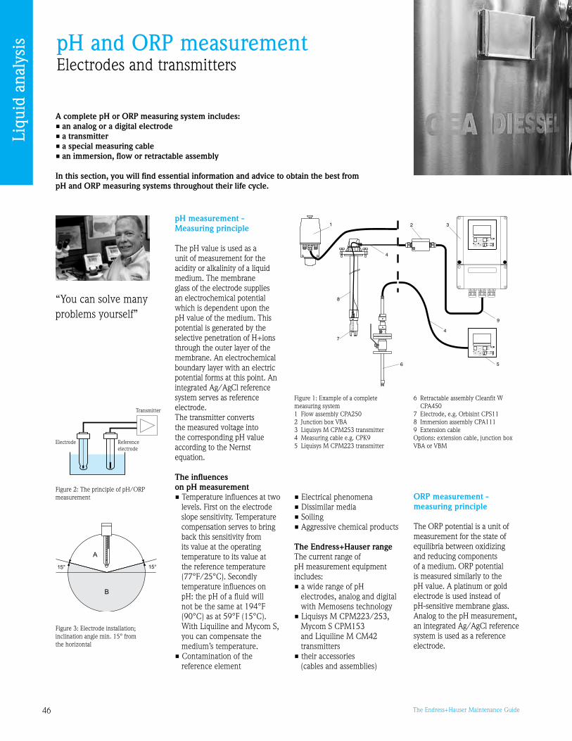
46 The Endress+Hauser Maintenance Guide
pH and ORP measurementElectrodes and transmitters
A complete pH or ORP measuring system includes:• an analog or a digital electrode• a transmitter• a special measuring cable• an immersion, flow or retractable assembly
In this section, you will find essential information and advice to obtain the best from pH and ORP measuring systems throughout their life cycle.
“You can solve many problems yourself”
pH measurement -Measuring principle
The pH value is used as a unit of measurement for the acidity or alkalinity of a liquid medium. The membrane glass of the electrode supplies an electrochemical potential which is dependent upon the pH value of the medium. This potential is generated by the selective penetration of H+ions through the outer layer of the membrane. An electrochemical boundary layer with an electric potential forms at this point. An integrated Ag/AgCl reference system serves as reference electrode. The transmitter converts the measured voltage into the corresponding pH value according to the Nernst equation.
The influences on pH measurement• Temperature influences at two
levels. First on the electrode slope sensitivity. Temperature compensation serves to bring back this sensitivity from its value at the operating temperature to its value at the reference temperature (77°F/25°C). Secondly temperature influences on pH: the pH of a fluid will not be the same at 14°F (0°C) as at 5°F (15°C). With Liquiline and Mycom S, you can compensate the medium’s temperature.
• Contamination of the reference element
Figure : Electrode installation; inclination angle min. 15° from the horizontal
C07-CPM2x3xx-14-06-00-xx-001.eps
Figure 1: Example of a complete measuring system 1 Flow assembly CPA2502 Junction box VBA Liquisys M CPM25 transmitter 4 Measuring cable e.g. CPK5 Liquisys M CPM22 transmitter
• Electrical phenomena• Dissimilar media• Soiling• Aggressive chemical products
The Endress+Hauser rangeThe current range of pH measurement equipment includes:• a wide range of pH
electrodes, analog and digital with Memosens technology
• Liquisys M CPM22/25, Mycom S CPM15 and Liquiline M CM42 transmitters
• their accessories (cables and assemblies)
ORP measurement -measuring principle
The ORP potential is a unit of measurement for the state of equilibria between oxidizing and reducing components of a medium. ORP potential is measured similarly to the pH value. A platinum or gold electrode is used instead of pH-sensitive membrane glass. Analog to the pH measurement, an integrated Ag/AgCl reference system is used as a reference electrode.
6 Retractable assembly Cleanfit W CPA450
7 Electrode, e.g. Orbisint CPS118 Immersion assembly CPA111 Extension cable Options: extension cable, junction box VBA or VBM
a0003686
Electrode Referenceelectrode
Transmitter
Figure 2: The principle of pH/ORP measurement
Liqu
id a
naly
sis

47The Endress+Hauser Maintenance Guide
Figure 4A: Asymmetrical connection
The Endress+Hauser rangeThe current range of ORP measurement equipment includes:• a wide range of ORP
electrodes, analog and digital with Memosens technology
• Liquisys M CPM22/25, Mycom S CPM15 and Liquiline M CM42 transmitters
• their accessories (cables and mounting assemblies)
Installation conditions
Do not install the electrode upside down (see Fig. ). The inclination angle must be at least 15° from the horizontal. A smaller inclination angle is not permitted as such an inclination results in air cushion forming. This might impair the contact of reference and metal lead. Caution! • Make sure that the assembly’s
threaded connection for the electrode is clean and working properly before installing the electrode
• Hand tighten the electrode (2.2 lbf-ft/ Nm)! (Given value only applies to installation in Endress+Hauser assemblies.)
• Make sure to follow the installation instructions in the operating instructions of the used assembly
Cabling• Cable should be no longer
than 164 ft/50 m (CPK7, CPK, CYK71); for higher distances use an electrode fitted with a preamplifier (CPF81 for pH, CPF82 for
ORP) or use Memosens technology
• The cabling should not be interrupted (avoid any temporary connection). If an extension is necessary, use a High Impedance junction box (VBM).
Connecting pH and ORP sensors (see Fig. 4A and 4B)The pH and ORP analog sensors can be connected both symmetrically and asymmetrically.
Advantages of symmetrical measurement: • No leakage current since both
the reference and pH/ORP measuring electrodes are connected with a high impedance amplifier
• Safe measurement under difficult process conditions (strong flowing and/or highly resistant media, partially soiled reference diaphragm)
Advantages of asymmetrical measurement: • Use of assemblies without
potential matching possible
Caution! In the case of a symmetrical connection, the potential matching pin (solution ground) must be connected and always immersed in the medium (even during calibration).
Operation and Maintenance
Maintenance work at the transmitter includes: • Cleaning of assembly
and sensor
Figure 4B: Symmetrical connection
• Cable and connection check• Calibration and adjustment
Cleaning glass pH and ORP electrodes There are 5 levels of cleaning:• Level 1: use water + sponge • Level 2: use water + soap
(presence of grease)• Level (ORP only): carefully
clean the metal pins or surfaces mechanically (polish under water using ultra fine abrasive paper or grit free polishing compound)
• Level 4: use diluted hydrochloric acid HCl ( to 5%) and rinse with clean water
Note! After chemical cleaning, the ORP sensor can require several hours conditioning time. Therefore check the calibration after a day.
• Level 5: use specific products to clean contamination (see list below)
• Oily and greasy films: Clean with detergent and water or
any grease dissolvers such as alcohol, acetone.
• Inorganic layers: Immerse the electrode for 15 min in
diluted hydrochloric acid or sodium hydroxide (max 5%).
• Lime and metal hydroxide layers: Dissolve layers with diluted
hydrochloric or acetic acid (vinegar) (max 10%).
• Layers containing sulphide: Use mixture of hydrochloric acid (max
10%) saturated with urea.• Layers containing proteins: Immerse the electrode in a mixture of
hydrochloric acid (max 10%) saturated with pepsin (8500 units) at 8.6°F (7°C).
Note! Always rinse carefully with plenty of clear water and wipe with a soft cloth.
Cable and connection check• Check cables and connections
for moisture, cuts or kinks• Check electrical continuity:
establish a short-circuit between 2 wires at one end of the cable (e.g. between ‘Measure’ and ‘Ref’). Measure the resistance with an ohmmeter at the other end (should be 0.1Ω/m).
• Detection of insulation default: disconnect both ends of the cable and measure the impedance between the different wires with an insulation meter that measures with 1000 V (should be R = ∞)
…
Liqu
id a
naly
sis
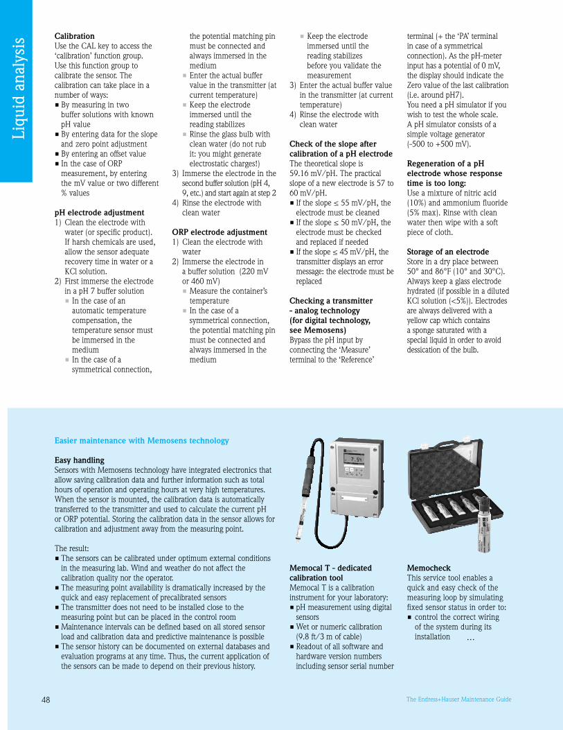
48 The Endress+Hauser Maintenance Guide
CalibrationUse the CAL key to access the ‘calibration’ function group. Use this function group to calibrate the sensor. The calibration can take place in a number of ways: • By measuring in two
buffer solutions with known pH value
• By entering data for the slope and zero point adjustment
• By entering an offset value• In the case of ORP
measurement, by entering the mV value or two different % values
pH electrode adjustment 1) Clean the electrode with
water (or specific product). If harsh chemicals are used, allow the sensor adequate recovery time in water or a KCl solution.
2) First immerse the electrode in a pH 7 buffer solution • In the case of an
automatic temperature compensation, the temperature sensor must be immersed in the medium
• In the case of a symmetrical connection,
terminal (+ the ‘PA’ terminal in case of a symmetrical connection). As the pH-meter input has a potential of 0 mV, the display should indicate the Zero value of the last calibration (i.e. around pH7).You need a pH simulator if you wish to test the whole scale. A pH simulator consists of a simple voltage generator (-500 to +500 mV).
Regeneration of a pH electrode whose response time is too long: Use a mixture of nitric acid (10%) and ammonium fluoride (5% max). Rinse with clean water then wipe with a soft piece of cloth.
Storage of an electrode Store in a dry place between 50° and 86°F (10° and 0°C). Always keep a glass electrode hydrated (if possible in a diluted KCl solution (<5%)). Electrodes are always delivered with a yellow cap which contains a sponge saturated with a special liquid in order to avoid dessication of the bulb.
the potential matching pin must be connected and always immersed in the medium
• Enter the actual buffer value in the transmitter (at current temperature)
• Keep the electrode immersed until the reading stabilizes
• Rinse the glass bulb with clean water (do not rub it: you might generate electrostatic charges!)
) Immerse the electrode in the second buffer solution (pH 4, , etc.) and start again at step 24) Rinse the electrode with clean water
ORP electrode adjustment1) Clean the electrode with water 2) Immerse the electrode in a buffer solution (220 mV or 460 mV) • Measure the container’s
temperature • In the case of a
symmetrical connection, the potential matching pin must be connected and always immersed in the medium
• Keep the electrode immersed until the reading stabilizes before you validate the measurement
) Enter the actual buffer value in the transmitter (at current temperature) 4) Rinse the electrode with clean water
Check of the slope after calibration of a pH electrodeThe theoretical slope is 5.16 mV/pH. The practical slope of a new electrode is 57 to 60 mV/pH.• If the slope ≤ 55 mV/pH, the
electrode must be cleaned• If the slope ≤ 50 mV/pH, the
electrode must be checked and replaced if needed
• If the slope ≤ 45 mV/pH, the transmitter displays an error message: the electrode must be replaced
Checking a transmitter - analog technology (for digital technology, see Memosens)Bypass the pH input by connecting the ‘Measure’ terminal to the ‘Reference’
Easier maintenance with Memosens technology
Easy handling Sensors with Memosens technology have integrated electronics that allow saving calibration data and further information such as total hours of operation and operating hours at very high temperatures. When the sensor is mounted, the calibration data is automatically transferred to the transmitter and used to calculate the current pH or ORP potential. Storing the calibration data in the sensor allows for calibration and adjustment away from the measuring point.
The result: • The sensors can be calibrated under optimum external conditions
in the measuring lab. Wind and weather do not affect the calibration quality nor the operator.
• The measuring point availability is dramatically increased by the quick and easy replacement of precalibrated sensors
• The transmitter does not need to be installed close to the measuring point but can be placed in the control room
• Maintenance intervals can be defined based on all stored sensor load and calibration data and predictive maintenance is possible
• The sensor history can be documented on external databases and evaluation programs at any time. Thus, the current application of the sensors can be made to depend on their previous history.
Memocal T - dedicated calibration toolMemocal T is a calibration instrument for your laboratory:• pH measurement using digital
sensors• Wet or numeric calibration
(.8 ft/ m of cable)• Readout of all software and
hardware version numbers including sensor serial number
MemocheckThis service tool enables a quick and easy check of the measuring loop by simulating fixed sensor status in order to: • control the correct wiring
of the system during its installation …
Liqu
id a
naly
sis
…

4The Endress+Hauser Maintenance Guide
Corrective maintenance Diagnosis of common troubleshooting: See Table 1
Generic approach to diagnose troubleshooting
We suggest five steps:1) Check that the sensor
fully corresponds to the application
2) Check the installation (cabling), the configuration and the hydraulic mounting
) Take the environment (electromagnetic, electrical, moisture, sun) into account
4) Consider the metrological level
5) Find out which component is out of order
1) Installation• Configuration of analog (non-
Memosens) systems to be symmetrical or asymmetrical must be the same as the cabling connection
• Review the programming matrix
• Consider the installation conditions of the electrode
2) Environment• Is the sensor installed inside
or outside? Is it protected from sunlight?
• check the digital data transfer during commissioning
• solve troubleshooting in the running process
Memocheck PlusThis tool enables qualification of the measuring loop in pharmaceutical and biotechnology industries • with 5 plug-in heads each
simulating a fixed, defined sensor status for a dedicated type of sensor
• reading of all relevant calibration and process data after simulation at predefined pH and temperature value
• each plug-in head has passed a stringent test on computerized inspection unit and a quality certificate is issued
Problem / Possible cause Action
Calibration is impossible
Bulb and/or diaphragm soiled Clean it
Bulb broken Replace electrode
Cabling error or defective cable Check and replace if needed
Buffer solution out-of-date Change buffer solution
Measurement is unstable
Incorrect connection Check cable and connections
Interference Use double shielded cable; check connection of the shield to ground; change cable path (away from AC and high voltage lines)
Current or parasitic potential in the product (for analog systems only)
In case of asymmetrical measurement, connect the product to the ground; switch to symmetrical measurement
Sensor responds slowly
Electrode soiled Clean it
Sensor aging Test the measurement chain with a simulator; replace the electrode
Display blocked on a fixed value
Insulation default and/or short-circuit on the cable
Test with a pH simulator or an insulation meter
Moisture on the connectors Check and dry
Crack on the inside tube (short-circuit between measurement and reference)
Replace electrode
Reduction of the reference element (current circulation)
Insulation default and/or short-circuit on the cable
Test with a pH simulator or an insulation meter
Moisture on the connectors Check and dry
Inconsistency between configuration and connection (Symmetrical/Asymmetrical) (for analog, non-Memosens systems only)
Check
Table 1: Diagnosis of common troubleshooting
…
Liqu
id a
naly
sis
…

50 The Endress+Hauser Maintenance Guide
List of consumables
Buffer solutions for pH electrodesTechnical buffer solutions, accuracy 0.02pH, acc. to NIST/DIN • pH 4.0 red, 250 ml, order no. CPY20-C02A1 • pH 4.0 red, 1000 ml, order no. CPY20-C10A1 • pH 7.0 green, 250 ml, order no. CPY20-E02A1 • pH 7.0 green, 1000 ml, order no. CPY20-E10A1 Technical buffer solutions for single use, accuracy 0.02pH, acc. to NIST/DIN • pH 4.0 red, 20 x 18 ml, order no. CPY 20-C01A1 • pH 7.0 green, 20 x 18 ml, order no. CPY 20-E01A1
ORP solutions • +220 mV, pH 7.0, 0.026 US gal. (100 ml); order no. CPY-0 • +468 mV, pH 0.1, 0.026 US gal. (100 ml); order no. CPY-1
KCl-electrolyte solutions for liquid filled electrodes • .0 mol, T= 14 to 212°F (-10 to 100°C), oz (100 ml), order no. CPY4-1 • .0 mol, T= 14 to 212°F (-10 to 100°C), 0 oz (1000 ml), order no. CPY4-2 • 1.5 mol, T= -22 to 266°F (-0 to 100°C), oz (100 ml), order no. CPY4- • 1.5 mol, T= -22 to 266°F (-0 to 100°C), 0 oz (1000 ml), order no. CPY4-4
List of accessories
Special cables• CPK1 special measuring cable for pH/ORP electrodes with GSA plug-in head • CPK special measuring cable for sensors with TOP68 plug-in head, for high-
temperature and high-pressure applications, IP 68 • CYK10 Memosens data cable for digital pH sensors with Memosens technology
(CPSxxD) • CPK12 special measuring cable for pH/ORP glass electrodes and ISFET sensors with
TOP68 plug-in head
• Take the electrode out of its environment and check it in another environment
• Electromagnetic phenomena: check the cables and the connection to ground
• Does temperature vary alot? If yes, check that temperature compensation is active
• Moisture: visual check of the junction boxes’ watertightness, look for moisture or oxidation on the connectors, etc.
) Metrological levelIs there a drift, is the measurement unstable or incorrect?• Is the electrode soiled?
Then clean the electrode (see page 47)
• Check the electrode in a well known medium with the actual configuration data of the transmitter. If there is a drift, come back to the factory configuration. If this is not sufficient, apply the procedure to adjust an electrode manually (see page 48). Read the slope and the Zero point. According to the value of the slope you may need to clean or replace the electrode.
4) Which component is out of order?
Electrode check: • Visual check of the outside
condition (damaged, cracked, bulb broken, corrosion, abrasion, oxidation or moisture on the connector, etc.)
• Visual check of the inside condition (Is KCl still transparent? Is the reference electrolyte level significantly reduced? Is the inside glass tube damaged?)
Cable check: see page 47Transmitter check: see page 48
Instrument and spare parts availabilitySee table at the right.
Spare parts stock We recommend that you always keep a new electrode in stock.
How to select and order electrodes and tools: See the selection guide and prices in ‘The Maintenance Store’.
How to select and order buffer solutions and cables: Select the right order code from the list hereafter; then refer to the price list in The Maintenance Store.
Migration
Want to use a Memosens electrode with your current pH transmitter?A special kit exists to upgrade any Liquisys M CPM22/25 from version 2.5 onwards and Mycom S CPM15. This upgrade can be done either by a service engineer on-site or you can send it back to the Endress+Hauser repair facility.
Your Spare parts New instrument availability generation
CPM220/240 NO - stopped 01/2004 CPM22/25
CPM221/252 NO - stopped 01/2005 CPM22/25
MyPro CPM41 YES - until 10/2010 Liquiline CM42
MyPro CLM41 YES - until 10/2010 Liquiline CM42
Mycom CPM152 YES - until 06/2011 CPM15
If you want to get more information about spare parts availability, please call our hotline 800-642-877.
Liqu
id a
naly
sis

51The Endress+Hauser Maintenance Guide
Conductivity measurementSensors and transmitters
A complete conductivity measuring system includes:• a conductivity sensor• a transmitter• a special measuring cable
In this section, you will find essential information and advice to obtain the best from conductivity measuring systems throughout their life cycle.
Conductive measurement of conductivity -measuring principle
The conductivity of liquids is measured with a measuring system that has two coaxially arranged electrodes like a capacitor. The electric resistance or its reciprocal value, the conductance G, is measured according to Ohm’s law. The specific conductivity is determined using the cell constant k that is dependent on the sensor geometry.
Inductive conductivity measurement -measuring principle
A generator (1) generates an alternating magnetic field in the primary coil (2) which induces a current in the medium (). The strength of the induced current depends on the conductivity and thus the ion concentration of the medium. The current flow in the medium generates another magnetic field in the secondary coil (4). The resulting current induced in the coil is measured by the receiver (5) and processed to determine the conductivity.
Benefits of inductive conductivity measurement• No electrodes, therefore no
polarization • Accurate measurement in
media or solutions with a high soiling degree and a tendency to deposition
• Complete galvanic separation of measurement and medium
“Always be aware of the effect of temperature!”
Figure 2: Inductive conductivity measurement 1 Generator 2 Primary coil Current flow in the medium 4 Secondary coil 5 Receiver
C07-CLXixxxx-15-0x-00-xx-001.eps
a0003416Figure 1: The principle of conductive measurement of conductivityAC Power supply I Current meter U Voltage meter
Installation conditions for inductive conductivity measurement
For CLS50/52/54, the medium should flow through the conical measuring channel in the indicated direction. Installation of the sensor in pipes with horizontal (middle) and vertical (right) flow directions. (see Fig. 4)• In narrow installation
conditions, the electrical field in the medium is affected by the pipe walls. This effect is compensated by the so-called installation factor.
• The installation factor can be entered in the transmitter or the cell constant can be
corrected by multiplication with the installation factor to ensure correct measurement. The value of the installation factor depends on the diameter and the conductivity of the pipe as well as the sensor distance from the wall. If the distance from the wall is sufficient (a > 0.5”/15 mm, from 2.5”/DN 65), it is not necessary to consider the installation factor (f = 1.00). If the distance from the wall is smaller, the installation factor increases in case of electrically insulating pipes (f > 1) and decreases in case of electrically conductive pipes (f < 1). The installation
C07-CLM2x3xx-14-06-00-xx-001.epsFigure : Example of a complete measuring system 1 Conductive sensor CLS15 2 Liquisys M CLM25 transmitter Liquisys M CPM22 transmitter 4 Inductive sensor CLS52
5 Inductive sensor CLS50 6 Conductive sensor CLS217 Immersion assembly CLA111 Options: extension cable, junction box VBA or VBM
Liqu
id a
naly
sis

52 The Endress+Hauser Maintenance Guide
Figure 5: Dependence of installation factor f on wall distance a 1 Conductive pipe 2 Insulating pipe
factor can be measured using calibration solutions or be approximately determined from a diagram (see Fig. 5).
• To compensate residual coupling in the cable and between the two sensor coils, perform a zero calibration in air («air set») before installing the sensor. For further information, refer to the Operating Instructions of your transmitter.
• Choose immersion depth b of the sensor in the medium such that the coil body is completely immersed (see Fig. 6). The pipe has to be completely filled with water. Gas bubbles will have an influence on the displayed value (avoid installation in down flowing pipes where flow can be affected by gravity).
Operation and Maintenance
Maintenance work includes: • Cleaning of assembly
and sensor • Cable and connection check
(see ‘pH’ section)• Calibration
Cleaning the conductivity sensors Please clean contamination on the sensor as follows: carefully clean with a synthetic brush and, if needed, with diluted hydrochloric acid (5%). Then rinse carefully with plenty of clear water.
Calibration of conductive measurement systemsThree different types are possible:
• Calibration by measurement in a calibration solution with a known conductivity
• Calibration by entering the exact cell constant of the conductivity sensor (included with the sensor’s quality certificate)
• Calibration by comparison to a reference device (e.g. CONCAL)
Calibration of inductive measurement systemsTwo different types are possible: • Calibration by measurement
in a calibration solution with a known conductivity
• Calibration by comparison to a reference device
Check of inductive sensorsTest sending and receiving coils: Ohmic resistance should be approx. 5 to 7 Ω. and inductivity approx. 260 to 450 mH (at 2 kHz).Shorts between sensor coils is not allowed. The measured resistance should be > 20 MΩ. Test with ohmmeter between red coaxial cable and white coaxial cable.
Check of transmitter (inductive sensors)• Conductivity can be checked
with standard resistors, e.g. with decade resistors. For conductivity simulation, pull a cable through the cleaned sensor opening and check the
display versus the table printed in the Operating Instructions of your transmitter.
• For temperature simulation, connect the decade resistor instead of the temperature sensor Pt100, using a three-wire arrangement, i.e. connection to terminals 11 and 12, with a bridge from 12 to 1. Check the temperature display versus the table printed in the Operating Instructions of your transmitter.
To check a transmitter with conductive sensors, please refer to your Operating Instructions.
Instrument and spare parts availabilitySee table below
Consumables stock The calibration solutions must be stored in a dry place and used within a year.
Figure 4: Installation of a CLS52 inductive sensor in pipes with horizontal (middle) and vertical (right) flow directions b Indicator arrow for the flow direction c Flow direction 1 Welding neck 2 Pipe
C07-CLS52xxx-11-05-00-xx-001.eps
If you want to get more information about spare parts availability, please call our hotline 800-642-877.
Your Spare parts New instrument availability generation
CLD10 NO - stopped 01/2005 CLD12/14
CLD41 YES - until 10/2010 Liquiline CM42
CLM221/252 NO - stopped 01/2005 CLM22/25
Mycom CLM152 YES - until 06/2011 CLM15
Figure 6: Consider the immersion depth
Liqu
id a
naly
sis
Our service team can perform such verifications (see ‘Service contracts’ in the ‘At your service’ section).
If removing your conductivity transmitter from process for 1 to 2 weeks is acceptable, the best method is to send the instrument to one of our calibration facilities. We provide calibration certificates (see ‘Calibration’ in the ‘At your service’ section).

5The Endress+Hauser Maintenance Guide
List of consumables
Calibration solutionsPrecision solutions, traceable to SRM (standard reference material) by NIST, for qualified calibration of conductivity measuring systems according to ISO, with temperature table, • CLY11-A, 74 μS/cm (reference temperature 77°F
/25°C), 16. fl.oz (500 ml), order no. 5008102 • CLY11-B, 14.6 μS/cm (reference temperature 77°F
/25°C), 16. fl.oz (500 ml), order no. 500810 • CLY11-C, 1.406 mS/cm (reference temperature 77°F
/25°C), 0.1 US.gal. (500 ml), order no. 5008104 • CLY11-D, 12.64 mS/cm (reference temperature 77°F
/25°C), 0.1 US.gal. (500 ml), order no. 5008105 • CLY11-E, 107.0 mS/cm (reference temperature 77°F
/25°C), 0.1 US.gal. (500 ml), order no. 5008106
List of accessories
Measuring cables (for conductive sensors)• CYK71 measuring cable: non-terminated cable for the
connection of sensors (e.g. conductivity sensors) or the extension of sensor cables - sold by the meter, order numbers:
non-Ex version, black: 50085 Ex version, blue: 51506616
Measuring cables (for inductive sensors)• CLK5 measuring cable: Extension cable for
connecting CLS50/52/54 and transmitter via the VBM junction box - sold by the meter, order no. 5008547
sterile
P ARA M
MEAS C AL
DIAG
P ARA M
MEAS CA L
DIAG
3m max. Sampling valveSampling outlet
Concal reference toolConductivimeter
CONCAL calibration set
How to select and order calibration solutions and cables: select the right order
code from the list hereafter; then refer to the price lists in the ‘The Maintenance Store’.
Liqu
id a
naly
sis
Using CONCAL, our service team can perform the periodic recalibration of ultrapure conductivity measurement systems. Please contact us.
CONCAL is a conductivity calibration set for ultrapure water applications, factory-calibrated with certificate, traceable to SRM of NIST and DKD. CONCAL is suitable for comparative measurement in ultrapure water applications up to 20 μS/cm and temperature < 212°F (100°C).

54 The Endress+Hauser Maintenance Guide
Turbidity measurementSensors and transmitters
A complete turbidity measuring system includes:• a turbidity sensor with a special measuring cable• a transmitter• an immersion, flow or retractable assembly
In this section, you will find essential information and advice to obtain the best from turbidity measuring systems throughout their life cycle.
“Be careful when cleaning the optics”
Measuring principle
Nephelometric measuring principle 90° NIR scattered light according to EN 27027 The 0° scattered light method with a wavelength in the near-infrared range (880 nm) according to ISO 7027 / EN 27027 records turbidity values under standardized, comparable conditions. A temperature signal is also recorded and transmitted in addition to the turbidity signal. The excitation radiation of an infrared transmitter (Fig. 2, Item 1) strikes the medium at a defined angle of beam. The different refractions of light between the entrance window and the medium (water) are taken into account. Particles in the medium (Item 5) create a scattered radiation which strikes the scattered light receivers (Items , 4) at a defined angle of beam. The measurement in the medium is constantly compared with the values of a reference receiver (Item 2). Digital filter functions with excellent interference signal suppression and sensor self-monitoring ensure additional measurement reliability.
The standard reference particle is formazine (C2H4N2) which is carcinogenic and unstable (short life time).Various units are used:• FNU (Formazine
Nephelometric Unit)• NTU (Nephelometric
Turbidity Unit)• FTU (Formazine Turbidity Unit)• JTU (Jackson Turbidity Unit)
a0003125
Figure 1: Example of a complete measuring system 1 Immersion assembly CYA611 2 Retractable assembly CUA451
• TE/F (Trübungseinheiten Formazin)
1 FNU = 1 NTU = 1 FTU = 1 TE/FFormazine mother solution’s turbidity is 4000 FNU which is equivalent to 10000ppm SiO2 (1FNU = 2.5 ppm SiO2)
Note : • There is no direct
relationship between FNU and the suspended particles concentration.
• The norm applies up to 10000 FNU; beyond this value, the particles disrupt each other and so absorb more than they diffuse.
Thanks to a second scattered light receiver, Endress+Hauser sensors cover a much broader measuring range (up to
00 g/l). Since the norm doesn’t apply any more, you need to periodically perform calibration and adjustment of the measuring system with your process water. The -point calibration is achieved after comparison to laboratory measurements.
There are two different sensors:CUS1: for drinking water and process water0.000 to FNU0.00 to 000 ppmto 200.0%0.00 to g/l
CUS41: for wastewater and sludge0.000 to FNU0.00 to 100 to 00 g/l0.0 to 200.0%
Assembly with gas bubble trap 4 Liquisys CUM25 5 Liquisys CUM22
Figure 2: Turbidity measurement according to ISO 7027 / EN 27027 A Side view of the sensor (cutaway scheme) 1 Infrared transmitter 2 Reference diode Scattered light receiver 14 Scattered light receiver 25 Particles in the medium B Top view of the sensor surface with optical windows
Liqu
id a
naly
sis

55The Endress+Hauser Maintenance Guide
Figure : Tube implantation
The influences on turbidity measurementThe measurement is altered by:• Change of sludge type• Flow variation• Presence of air or foam
bubbles, suspended particles deposit
• Back scatter (which results in a higher signal) due to the installation of the sensor in piping or very close to a wall
• Deposits on the sensor optics
Installation conditions
Pipe installation (see Fig. 3)• The pipeline diameter must
be at least 4” (DN 100) if reflective materials (e.g. stainless steel) are used
• Install the sensor in places with uniform flow conditions and not in places where air may collect or foam bubbles form or where suspended particles may settle
• The best installation location is in the ascending pipe. Installation is also possible in a horizontal pipe, but should be avoided in a down flowing pipe (where flow can be affected by gravity).
• Position the sensor surface against the medium flow (“self-cleaning effect”)
Installation in flow assemblies • If possible, install the flow
assembly vertically so that the medium flows to the sensor from below. Alternatively, the assembly can also be installed horizontally.
• Two sensor orientations are possible for horizontal installation (Fig. 4): • parallel to the medium flow • against the medium flow
• Orientation parallel to the medium flow is required when using the CUR spray head
• Orientation against the medium flow is used to increase the self-cleaning effect in heavily-soiled media (> 15 FNU). The wall reflection is negligible here due to the high absorption tendency.
We recommend the CUS1-xxE or CUS1-xxS sensor version be used for turbidities < 5 FNU.
Operation and Maintenance
Maintenance work includes: • Cleaning of assembly
and sensor • Cable and connection check• Calibration
Cleaning the turbidity sensors Deposits on the sensor optics may result in inaccurate measurement. Therefore the sensor must be cleaned at regular intervals. The intervals are specific to each installation and must be determined during operation. Clean the optics with the following agents depending on the type of soiling:
• Limestone deposits: Short treatment with commercial
deliming agent • Oily and greasy soiling: Cleaning agents based on
water-soluble surfactants (e.g. household dish detergents)
• Other types of soiling: With water and brush Warning: • Do not touch the optics with
sharp-edged objects• Do not scratch the optics
Clean the sensor mechanically using a soft brush. Then rinse thoroughly with water.
Calibration and adjustment Note: The sensor contains all the calibration data.• In the FNU operating
mode, the sensor is factory calibrated with formazine traceable to ISO7027
• In the ppm operating mode, the calibration data records for Kaolin and SiO2 are derived from the FNU data records
• In the % operating mode, the calibration data records are set to the average of various residual concrete waters. They are preset in such a way that correct values are displayed for average clarity. However the settings do not follow a currently applicable standard as none exist.
• In the g/l operating mode also, the sensor is not calibrated to a fixed value as no standard is directly applicable. You must carry out a calibration because the media of the various applications differ too greatly here.
The calibration data is saved in an EEPROM directly in the sensor. Therefore:• Recalibration is not required in
the event of a power failure
• Recalibration is not required when the transmitter is replaced
• Customer-specific recalibration is required, however, when the sensor is replaced
Three calibration data records are saved in the sensor for each of the four main operating modes.
When do you need to calibrate?Three-point sensor calibration is the standard calibration. It is absolutely essential: • When commissioning the
sensor in sludge applications • When changing to another
sludge type
Figure 4: Installation in flow assembliesParallel sensor orientation Sensor orientation against the medium flow
Liqu
id a
naly
sis

56 The Endress+Hauser Maintenance Guide
Three-point sensor calibration is not necessary: • When commissioning the
sensor in the drinking water area (sensor has been calibrated for drinking water applications in the factory)
• For residual concrete water. Density measurement for determining the concentration of residual concrete water is based on %–data records. They are preset in such a way that correct values are displayed for average clarity. One-point calibration is often sufficient to adjust the system in the event of deviating values.
• When recalibrating with the same sludge type. One-point calibration suffices here if the degrees of lightness and clarity, for example, do not differ too greatly.
Performing three-point calibration (on-site)You should perform the calibration in the turbidity/solids concentration range in which you plan to measure. The overall calibration characteristic of the measuring chain is determined using three samples of known turbidity or known solids content. Calibration with a very dark, high-absorption medium returns small slopes while light, clear media returns big slopes. You can create the requisite samples by diluting a sample of the process medium. In general, very good calibration results are achieved with a concentration gradation of 10%, % and 100%. The following condition must be met for the calibration: Sample A > 1.1 x sample B > 1.1 x sample C (see Fig. 5)
Installation adjustment In installation adjustment, back scatter from the immediate sensor environment is compensated. Installation adjustment must be performed with a medium whose turbidity is lower than 2FNU or 5 ppm.
Checking the measuring point The sensors CUS1 and CUS41 cannot be simulated as they contain the complete data processing and all the measured values are transmitted to CUM22/25 using an RS485 digital interface. Therefore a functional sensor is required for the measuring point test. Method for testing a measuring point: • Check that device is operable
and that the display reacts appropriately, e.g. by pressing the PLUS key
• Check the current outputs by carrying out a current simulation (Field O(2))
• Measure the sensor operating voltage: approx. 10 to 16 V at terminals 87 (+) and 88 (–)
• The cause for an incorrect voltage may be present either at the device or at the sensor
– Replace the sensor – If the sensor operating
voltage is still too low replace the power supply module LSGA/LSGD (make sure to use the appropriate version)
• Sensor operating voltage is OK but no measured turbidity value even with a new sensor. Replace the transmitter module MKT1.
Instrument and spare parts availabilitySee table below.
How to select and order accessories: Select the right order code from the list hereafter; then refer to the price lists in ‘The Maintenance Store’.
Your Spare parts New instrument availability generation
CUM221/252 NO - stopped 01/2005 CUM22/25
Mycom CUM151 NO - stopped 12/2005 CUM22/25
List of accessories
Measuring cables• CYK81 measuring cable: non-terminated measuring cable for extension of sensor
cables of e.g. Memosens, CUS1/CUS41 - 2 wires, twisted pair with shield and PVC-sheath (minimum 20 AWG) - sold by the meter, order no. 5150254
Other accessories• CUY22 check unit for CUS1 and CUS41
for checking the stability of the sensor, order no. 51504477
• CUY1 service kit spare wiper arms for CUS1-Wxx: The CUS1-W sensor is equipped with a rubber wiper for removing deposits from the sensor carrier plate. The cleaning times and intervals are controlled by means of the transmitter (Liquisys M CUM22/25). Order no. 5008252
• Flow assembly Flowfit CUA250 for CUS1/CUS41 Please contact us
a0006961
Figure 5: Making the samples for a three-point calibration A Original sample B 1 part sample A + 2 parts water C 1 part sample A + parts water
Liqu
id a
naly
sis
If you want to get more information about spare parts availability, please call our hotline 800-642-877.
Our service team can perform such verifications (see ‘Service contracts’ in the ‘At your service’ section).
You can send us the sensor and flow assembly for adjustment on a calibration bench according to ISO70027. You will be given a quality certificate.
Our service team can perform such adjustments by means of a reference tool named TURBICAL (see ‘Service contracts’ in the ‘At your service’ section).
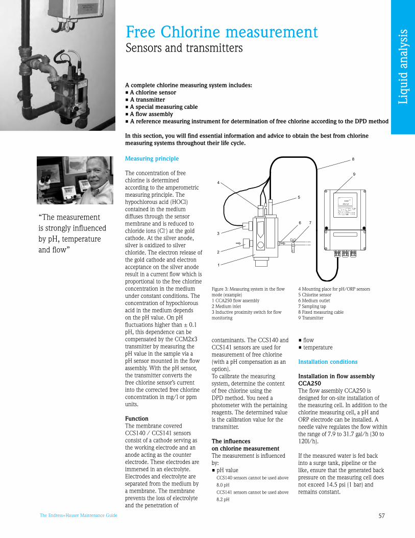
57The Endress+Hauser Maintenance Guide
Free Chlorine measurementSensors and transmitters
A complete chlorine measuring system includes:• A chlorine sensor • A transmitter • A special measuring cable • A flow assembly • A reference measuring instrument for determination of free chlorine according to the DPD method
In this section, you will find essential information and advice to obtain the best from chlorine measuring systems throughout their life cycle.
Measuring principle
The concentration of free chlorine is determined according to the amperometric measuring principle. The hypochlorous acid (HOCl) contained in the medium diffuses through the sensor membrane and is reduced to chloride ions (Cl-) at the gold cathode. At the silver anode, silver is oxidized to silver chloride. The electron release of the gold cathode and electron acceptance on the silver anode result in a current flow which is proportional to the free chlorine concentration in the medium under constant conditions. The concentration of hypochlorous acid in the medium depends on the pH value. On pH fluctuations higher than ± 0.1 pH, this dependence can be compensated by the CCM2x transmitter by measuring the pH value in the sample via a pH sensor mounted in the flow assembly. With the pH sensor, the transmitter converts the free chlorine sensor’s current into the corrected free chlorine concentration in mg/l or ppm units.
Function The membrane covered CCS140 / CCS141 sensors consist of a cathode serving as the working electrode and an anode acting as the counter electrode. These electrodes are immersed in an electrolyte. Electrodes and electrolyte are separated from the medium by a membrane. The membrane prevents the loss of electrolyte and the penetration of
“The measurement is strongly influenced by pH, temperature and flow”
contaminants. The CCS140 and CCS141 sensors are used for measurement of free chlorine (with a pH compensation as an option).To calibrate the measuring system, determine the content of free chlorine using the DPD method. You need a photometer with the pertaining reagents. The determined value is the calibration value for the transmitter.
The influences on chlorine measurementThe measurement is influenced by:• pH value CCS140 sensors cannot be used above
8.0 pH CCS141 sensors cannot be used above
8.2 pH
• flow• temperature
Installation conditions
Installation in flow assembly CCA250 The flow assembly CCA250 is designed for on-site installation of the measuring cell. In addition to the chlorine measuring cell, a pH and ORP electrode can be installed. A needle valve regulates the flow within the range of 7. to 1.7 gal/h (0 to 120l/h).
If the measured water is fed back into a surge tank, pipeline or the like, ensure that the generated back pressure on the measuring cell does not exceed 14.5 psi (1 bar) and remains constant.
a0001691
Figure : Measuring system in the flow mode (example) 1 CCA250 flow assembly 2 Medium inlet Inductive proximity switch for flow monitoring
4 Mounting place for pH/ORP sensors5 Chlorine sensor6 Medium outlet7 Sampling tap 8 Fixed measuring cable Transmitter
Liqu
id a
naly
sis

58 The Endress+Hauser Maintenance Guide
Negative pressure at the measuring cell, e.g. by feedback of measured water to the suction side of a pump, must be avoided.
Operation and Maintenance
Maintenance work at the transmitter includes: • Calibration• Cleaning of assembly and
sensor • Cable and connection check
Reference measurement according to the DPD method The calibration of the measuring system requires a colorimetric reference measurement according to the DPD method. Free chlorine reacts with diethyl-p-phenylenediamine(DPD) by producing a red dye, the intensity of the red color being proportional to the chlorine concentration. Simple visual methods using comparators are inaccurate and depend on the considerably varying subjective evaluation by the operator. Today, the chlorine concentration can be determined objectively and accurately using low-cost microprocessor photometers (order code CCM182).
An important fact must be kept in mind: The DPD method is not a selective measuring method for free chlorine alone, but other oxidants present in the medium can also be registered (see DIN8408, part 5, section 4). Moreover, the measuring range of the photometers has a lower limit and does not permit measurements in the very low trace range. In addition to the chlorinated probe, a sample of the medium without added chlorine should be checked by a DPD measurement if possible. The measured value must lie near zero and differ significantly from the chlorinated sample. The measured water is always buffered to a pH value of 6. with the DPD method, so the measurement is independent of
the pH value of the measured water. Caution: The DPD method cannot be applied if organic chlorination agents are used. In this case it causes a higher measured value compared to the actual free active chlorine value (also note in DIN8408, part 4, section 5).
Calibration (CCS140/141) The calibration of a chlorine measuring unit is performed by means of a colorimetric comparative measurement according to the DPD method. DPD no. 1 pills fit for the measurement of free chlorine.
Calibration according to the pH valueWhen pH is between 4 and 6, only active chlorine exists in water, so the active chlorine measured value = the free chlorine measured value. According to DPD no. 1 method, the analyzed water is buffered at a pH value of 6., thus the measurement is independent from the pH and no compensation is necessary.
When pH is between 6 and 8, the quantity of active chlorine (HClO) decreases, while the quantity of hypochlorite (ClO-) ions increases. Without any pH compensation, the displayed value (active chlorine) would be lower than the value obtained with the DPD no. 1 method (free chlorine).To display the value of free chlorine, a pH compensation is necessary if the pH varies.To display active chlorine, do not compensate the pH but measure it and use a conversion table with DPD no. 1 method.
Maintenance of chlorine sensors Corrective maintenance for chlorine sensors and assemblies is described in the operating instructions. Use and refer to the operating instructions relating to your measuring system:
CCS140/141 BA058C/07/en CCS240/241 BA114C/07/en
Routine check for CCS140/141• Check the measurement at
regular intervals, dependent on the respective conditions, at least once a month
• Perform recalibration if required
• If the membrane is visibly soiled, remove the measuring cell from the flow assembly. Only clean the membrane mechanically with a gentle water jet or for several minutes in 1 to 10% hydrochloric acid (observe safety regulations!) without chemical additives. Chemicals reducing the surface tension must not be used.
• Replace a heavily soiled or damaged membrane (see chapter 5.2).
• Refill the measuring cell with electrolyte once per season or every 12 months. Depending on the chlorine content on site, this period can be reduced or extended (procedure see BA058C/07/en chapter 5.).
Maintenance of pH/ORP sensors (version EP)See pH/ORP section
Maintenance pH connecting lines and junction boxes (EP) Check the cables and connections for moisture. Moisture is indicated by a sensor slope that is too small. If no more display is possible or if the display is fixed at pH7, please check the following components: • Sensor head • Sensor connector • pH measuring cable • Junction box, if fitted • Extension cable Caution! If there is moisture in the measuring cable, the cable must be replaced!
A short in the cable > 20 MΩ cannot be measured with normal multimeters but is damaging for the pH measurement. A reliable test can be carried out with a usual commercial insulation meter: • Make sure to disconnect the
pH measuring cable from the sensor and device!
• If you are using a junction box, check the infeed and outfeed measuring cable separately
• Check the cable with 1000 VDC (at least with 500 VDC) testing voltage
• If the cable is intact, the insulation resistance > 100 GΩ
• If the cable is defective (moist), there is flashover. The cable must be replaced.
Test and simulation Chlorine sensors Chlorine sensors work according to the amperometric principle and supply very small direct current as measuring signals. A chlorine sensor can be simulated by a DC source. Due to the small currents, however, the simulation is highly sensitive. Lines should be screened and the simulator grounded. You will find typical slope values in the table below.
Temperature measurement The transmitter uses the NTC sensor of the chlorine sensor to measure the temperature. Due to the relatively high sensor resistance, a two-wire connection is sufficient. Simulation can take place with a normal decade resistor. The table hereafter contains some simulation values.
Sensor Typical slope value
CCS140 ≈ 25 nA per mg Cl/l
CCS141 ≈ 80 nA per mg Cl/l
CCS240 ≈ 100 nA per mg ClO2/l
CCS241 ≈ 350 nA per mg ClO2/l
Liqu
id a
naly
sis

5The Endress+Hauser Maintenance Guide
List of accessories
Calibration accessories• Photometer CCM182; microprocessor-controlled photometer for chlorine, pH value,
cyanuric acid; Chlorine measuring range: 0.05 to 6 mg/l pH measuring range: 6.5 to 8.4
Measuring cables• CMK measuring cable: cable for the CCS140, 141, 240 and 241, order no. CMK• CYK71 measuring cable: non-terminated cable for the connection of sensors
(e.g. conductivity sensors) or the extension of sensor cables -sold by the meter, order numbers:
non-Ex version, black: 50085
pH/ORP measurement Simulation takes place with a pH/mV simulator or an mV voltage source (see pH/ORP section).
Flow monitoringThe CCA250 flow assembly has an optional proximity switch to alarm for low flow conditions. Refer to the operating instructions relating to your measuring system for details.
Instrument and spare parts availability
How to select and order accessories: Select the right order code from the list below; then refer to the price lists in ‘The Maintenance Store’.
Your Spare parts New instrument availability generation
CCM221/252 NO - stopped 01/2005 CCM22/25
T° NTC simulation value
2°F (0°C) 29.490 kΩ
50°F (10°C) 18.787 kΩ
68°F (20°C) 12.268 kΩ
77°F (25°C) 10.000 kΩ
86°F (0°C) 8.197 kΩ
104°F (40°C) 5.594 kΩ
Liqu
id a
naly
sis
If you want to get more information about spare parts availability, please call our hotline 800-642-877.
Our service team can perform such verifications (see ‘Service contracts’ in the ‘At your service’ section).

60 The Endress+Hauser Maintenance Guide
Oxygen measurementSensors and transmitters for dissolved oxygen
There are four variants of measuring systems:• The transmitter Liquisys M COM223 or COM253 – DX or DS with oxygen sensor COS41 • The transmitter Liquisys M COM223 or COM253 – WX or WS with oxygen sensor COS31,
COS61 or COS71• The transmitter Liquisys M COM223 or COM253 – HX or HS with oxygen sensor COS21• The transmitter Liquiline CM42 with oxygen sensor COS21DEach of them can include an immersion, flow or retractable assembly. In this section, you will find essential information and advice to obtain the best from oxygen measuring systems throughout their life cycle.
“Periodically clean and check the system.”
Measuring principle
Amperometric principle The oxygen molecules diffuse through the membrane and are reduced to hydroxide ions (OH-) at the cathode. Silver is oxidized to silver ions (Ag+) at the anode (this forms a silver bromide layer, AgBr). A current flows due to the electron release at the cathode and electron acceptance at the anode. In equilibrium, this flow is proportional to the oxygen content of the medium. This current is converted in the measuring instrument and indicated on the display as an oxygen concentration in ppm, mg/l, as a saturation index in % SAT or as an oxygen partial pressure in hPa.
Fluorescence quenching principle• Sensor design: – Oxygen-sensitive molecules
(markers) are integrated in an optically active layer (fluorescence layer) of the sensor ‘cap’
– The surface of the fluorescence layer is in contact with the medium
– The sensor optics are directed at the underside of the fluorescence layer
• There is an equilibrium between the oxygen partial pressure in the medium and that in the fluorescence layer:
C07-COM2x3xx-14-06-00-xx-002.epsFigure 1: Examples of complete measuring systems 1 Oxygen sensor 2 Immersion assembly CYA611 Universal hanging assembly holder
CYH101
– If the sensor is immersed in the medium, the equilibrium is established very quickly
• Measuring process: – The sensor optics send
green light pulses to the fluorescence layer
– The markers ‘answer’ (fluoresce) with red light pulses
– The duration and intensity of the response signals are directly dependent on the oxygen contents and the partial pressure
– If the medium is free from oxygen, the response signals are long and very intense
– Oxygen molecules ‘quench’ the marker molecules. As a result, the response signals are shorter and less intense.
• Measurement result: – The sensor returns a signal
that is in proportion to the oxygen concentration in the medium
– The fluid temperature and air pressure are already calculated in the sensor
4 Weather protection cover CYY101 5 Liquisys M COM25 transmitter6 Liquisys M COM22 transmitter7 Retractable assembly COA451
C07-COS41xxx-16-05-07-xx-001.epsFigure 2: Sensor head - Amperometric principle 1 Thread for protection guard 2 Sealing ring Thread for membrane cap 4 Electrolyte 5 Gold cathode 6 Membrane 7 Membrane cap 8 Anode
Figure : Sensor design - Optical principle1 Sensor cable 2 Sensor shaft O-ring 4 Protection guard 5 Threaded connection 6 Detector 7 Emitter diode 8 Fluorescence cap
a0004151
Liqu
id a
naly
sis

61The Endress+Hauser Maintenance Guide
Operation and Maintenance
Maintenance work includes: • Cleaning of assembly
and sensor • Cable and connection check• Calibration and adjustment
Cleaning the sensorTo ensure reliable measurement, the sensor must be cleaned at regular intervals. Depending on the type of soiling, proceed as follows:
• Salt deposits Immerse the sensor in drinking water
or in 1-5% hydrochloric acid for a few minutes. Afterwards, rinse it with large amounts of water.
• Dirt particles on the sensor body (not on the membrane!)
Clean the sensor body mechanically with water and a suitable brush.
• Dirt particles on the membrane cap or the membrane
Clean the membrane with water and a soft sponge.
After cleaning, rinse the sensor with large amounts of clean water.
COS61, Cleaning the optics The optics only need to be cleaned if medium has penetrated through a defective fluorescence cap. To clean it, proceed as follows: 1. Unscrew the protection guard and fluorescence cap from the sensor head. 2. Carefully clean the optical surface with a soft cloth until the buildup is fully removed. . Clean the optics with drinking or distilled water. 4. Clean the optics and screw on a new fluorescence cap. Caution! The optical surface may not be scratched or damaged in any way!
Calibration and adjustmentTo access the ‘Calibration’ function group, press the CAL key on your transmitter. This function group is used to calibrate and adjust the measuring point. The sensor is calibrated in air or in the medium. Note! • At first start-up, sensor
calibration of amperometric sensors is absolutely required in order for the measuring system to be able to generate accurate measuring values
• The optical oxygen sensor COS61 does not need a calibration at first start-up. It is pre-calibrated.
Calibration and adjustment of amperometric systemsCalibration is a means of adapting the transmitter to the characteristic values of the sensor. As no zero calibration is required for the sensor, a single-point calibration is carried out in the presence of oxygen. The sensor requires calibration after: • first commissioning • replacing a membrane or
electrolyte • cleaning the cathode • long breaks in operation
without power supply • typical time intervals dependent
on operating experience
Three different types of calibration are possible: • Calibration in water • Calibration in air• Calibration by comparison to a
reference device
Calibration in air is the easiest method of calibration.
Calibration and adjustment in air1. Remove the sensor from the medium. 2. Clean the outside of the sensor with a damp cloth. Then dry the sensor membrane e.g. by using a tissue. . If the sensor is removed from a closed pressure system with a process pressure greater than atmospheric pressure: – Open the membrane cap to
balance the pressure and clean the cap if necessary
– Replace the electrolyte filling and close the membrane cap again
– Wait for the polarization time to end
4. Then wait while the sensor adjusts to the temperature of the ambient air. This takes about 20 minutes. Check that the sensor is not in direct sunlight during this time. 5. If the measured value display on the transmitter is stable, carry out the calibration in accordance with the Operating Instructions of the transmitter. 6. Place the sensor in the medium again.
Note: Calibration and adjustment in air is only possible if air temperature ≥ 2°F (–5°C). Make sure you comply with the instructions for calibration in the Operating Instructions of the transmitter.
The calibration intervals depend heavily on: • The application and • The installation position of the
sensor The following methods help you determine how long the calibration intervals should be: 1. Check the sensor one month after being put into operation by taking it out of the fluid, drying it and then measuring the oxygen saturation index at air after 10 minutes. Decide using the results: a. If the measured value is not between 8 and 102% SAT for an amperometric system or between .4 and 100.6% SAT for an optical system, you have to calibrate the sensor. b. Otherwise, double the length of time to the next inspection. 2. Proceed as per Point 1 after two, four and/or eight months. In this way, you can determine the optimum calibration interval for your sensor.
Calibration and adjustment of optical systems Calibration is a means of adapting the transmitter to the characteristic values of the sensor. Normally, sensor calibration is seldom necessary. It is necessary after changing the fluorescence cap.
The slope calibration of the oxygen sensor COS61 will be performed in air or in air saturated water. The calibration of the zero point will be performed in nitrogen or in oxygen-free water (water enriched with zero solution).
Liqu
id a
naly
sis
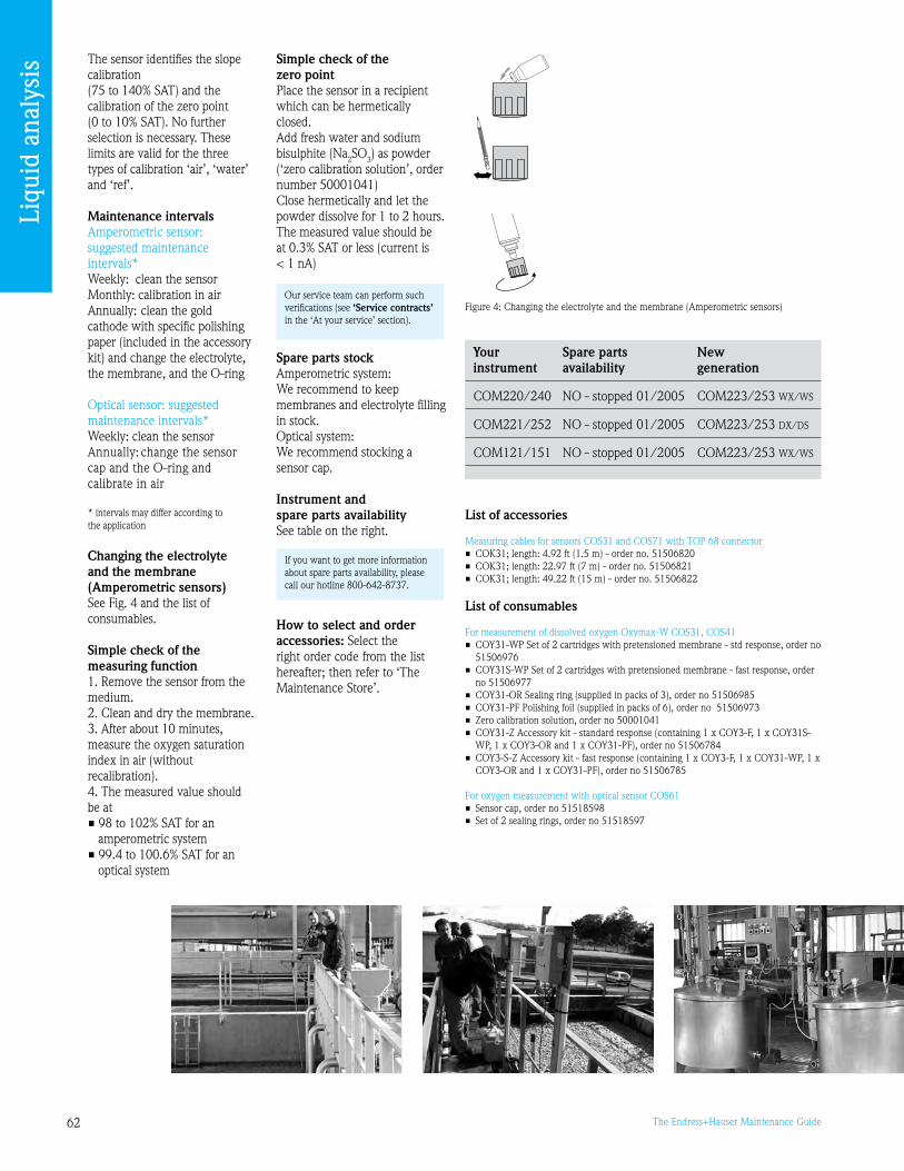
62 The Endress+Hauser Maintenance Guide
The sensor identifies the slope calibration (75 to 140% SAT) and the calibration of the zero point (0 to 10% SAT). No further selection is necessary. These limits are valid for the three types of calibration ‘air’, ‘water’ and ‘ref’.
Maintenance intervalsAmperometric sensor: suggested maintenance intervals*Weekly: clean the sensorMonthly: calibration in airAnnually: clean the gold cathode with specific polishing paper (included in the accessory kit) and change the electrolyte, the membrane, and the O-ring Optical sensor: suggested maintenance intervals*Weekly: clean the sensorAnnually: change the sensor cap and the O-ring and calibrate in air
* intervals may differ according to the application
Changing the electrolyte and the membrane (Amperometric sensors)See Fig. 4 and the list of consumables.
Simple check of the measuring function1. Remove the sensor from the medium. 2. Clean and dry the membrane. . After about 10 minutes, measure the oxygen saturation index in air (without recalibration). 4. The measured value should be at• 8 to 102% SAT for an
amperometric system • .4 to 100.6% SAT for an
optical system
Simple check of the zero pointPlace the sensor in a recipient which can be hermetically closed.Add fresh water and sodium bisulphite (Na2SO) as powder (‘zero calibration solution’, order number 50001041)Close hermetically and let the powder dissolve for 1 to 2 hours.The measured value should be at 0.% SAT or less (current is < 1 nA)
Spare parts stock Amperometric system: We recommend to keep membranes and electrolyte filling in stock.Optical system: We recommend stocking a sensor cap.
Instrument and spare parts availabilitySee table on the right.
How to select and order accessories: Select the right order code from the list hereafter; then refer to ‘The Maintenance Store’.
C07
-CO
S 41x
xx-1
7-0 5
-00-
xx-0
01.E
PS
Figure 4: Changing the electrolyte and the membrane (Amperometric sensors)
List of accessories
Measuring cables for sensors COS1 and COS71 with TOP 68 connector• COK1; length: 4.2 ft (1.5 m) - order no. 51506820 • COK1; length: 22.7 ft (7 m) - order no. 51506821 • COK1; length: 4.22 ft (15 m) - order no. 51506822
List of consumables
For measurement of dissolved oxygen Oxymax-W COS1, COS41• COY1-WP Set of 2 cartridges with pretensioned membrane - std response, order no
5150676• COY1S-WP Set of 2 cartridges with pretensioned membrane - fast response, order
no 5150677• COY1-OR Sealing ring (supplied in packs of ), order no 5150685• COY1-PF Polishing foil (supplied in packs of 6), order no 515067• Zero calibration solution, order no 50001041• COY1-Z Accessory kit - standard response (containing 1 x COY-F, 1 x COY1S-
WP, 1 x COY-OR and 1 x COY1-PF), order no 51506784 • COY-S-Z Accessory kit - fast response (containing 1 x COY-F, 1 x COY1-WP, 1 x
COY-OR and 1 x COY1-PF), order no 51506785
For oxygen measurement with optical sensor COS61• Sensor cap, order no 5151858• Set of 2 sealing rings, order no 5151857
Your Spare parts New instrument availability generation
COM220/240 NO - stopped 01/2005 COM22/25 WX/WS
COM221/252 NO - stopped 01/2005 COM22/25 DX/DS
COM121/151 NO - stopped 01/2005 COM22/25 WX/WS
If you want to get more information about spare parts availability, please call our hotline 800-642-877.
Our service team can perform such verifications (see ‘Service contracts’ in the ‘At your service’ section).
Liqu
id a
naly
sis

6The Endress+Hauser Maintenance Guide
Online analyzers
The current Endress+Hauser range of analyzers includes: • The Stamolys range of colorimetric analyzers for ammonium, iron, manganese,
chlorine, silica, etc.• The Stamosens range of UV analyzers• The STIP analyzers for BOD (biological oxygen demand), TOC (total organic
carbon), COD (chemical oxygen demand), toxicity and multiparameter UV analyzers
In this section, you will find essential information and advice that will help you to perform the optimum follow-up of your Stamolys analyzers throughout their life cycle.
Photometry measuring principle
Light is shone through the aqueous sample. The light intensity is absorbed by the coloration of the constituent substances. Every substance has a characteristic coloration. The more there is of this substance in the water, the more these light beams are absorbed. Detectors measure the absorption of light at a coloration typical for this substance. A reference measurement (sample without chemicals) is performed before every measurement so that interferences caused by inherent color, turbidity or contamination can be compensated for. The concentration of the substance is determined using this information.
When using colorimetric analyzers, a reagent is added to the water sample to chemically ‘dye’ the substance that is to be analyzed.
Stamolys analyzers design After sample conditioning, the analyzer sample pump conveys a part of the filtrate to a mixing vessel. The reagent pump adds reagent at a specific ratio. As a result of the reaction, the sample turns a characteristic color. The photometer determines the sample’s absorption of an emitted light at a specific wavelength.The wavelength is parameter specific. The absorbance
“Periodic maintenance is essential.”
is proportional to the concentration of the specified parameter in the sample. Additionally, the absorption of a reference light is determined to receive a genuine measuring result. The reference signal is subtracted from the measuring signal to prevent any effects due to turbidity, contamination and aging of the LEDs.The temperature in the photometer is controlled automatically so that the reaction is reproducible and
takes place within a short period of time.
Installation conditions • Ambient temperature :
41°F to 104°F (5°C to 40°C)• Below the condensation limit,
the device must be installed in usual, clean rooms
• The device is IP4 and must be protected from rain and frost
• Outdoor installation is only possible with protective devices (customer supplied)
Figure 1: Typical Stamolys analyzer (housing version, without hoses) 1 Reagents pump, inlet from canister2 Display Serial interface RS 224 Photometer optical cell5 Static mixer (acc. to version)6 Valve V4 (version with sample outlet
right side only)
7 Dosage loop (with CA71SI only)8 Valve V2 Sample or reagents mix outlet (left or
right acc. to version)10 Valve V111 Channel switch12 Sample pump
a0001352
Figure 2: Photometry measuring principle
Figure : Stamolys analyzers design1 Reference LED2 Emitter LED Sample4 Reference detector5 Measuring detector
Liqu
id a
naly
sis
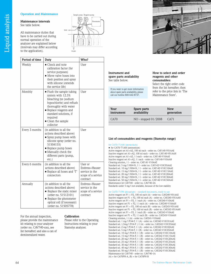
64 The Endress+Hauser Maintenance Guide
Operation and Maintenance
Maintenance intervalsSee table below.
All maintenance duties that have to be carried out during normal operation of the analyzer are explained below (intervals may differ according to the application).
For the annual inspection, please provide the maintenance kit relating to your analyzer (order no. CAV740-xxx, see list hereafter) and also a can of demineralized water.
List of consumables and reagents (Stamolys range)
for CA70/71AM (ammonium)• for CA70/71AM (ammonium) Active reagent set A1+A2, 100 ml each - order no. CAY140-V01AAEInactive reagent set A1+A2, 100 ml each - order no. CAY140-V01AAHActive reagent set A1+A2, 1 l each - order no. CAY140-V10AAEInactive reagent set A1+A2, 1 l each - order no. CAY140-V10AAHCleaning solution, 1 l - order no. CAY141-V10AAE Standard sol. 5 mg/l NH4-N, 1 l - order no. CAY142-V10C05AAEStandard sol. 10 mg/l NH4-N, 1 l - order no. CAY142-V10C10AAEStandard sol. 15 mg/l NH4-N, 1 l - order no. CAY142-V10C15AAEStandard sol. 20 mg/l NH4-N, 1 l - order no. CAY142-V10C20AAEStandard sol. 0 mg/l NH4-N, 1 l - order no. CAY142-V10C0AAEStandard sol. 50 mg/l NH4-N, 1 l - order no. CAY142-V10C50AAEMaintenance kit CAV740 - order no. CAV740-2AStandards under 5 mg/l not available, because of the low stability
for CA70/71PH (phosphate) - standard documents, ready to use Active reagent set P1 + P2, 100 ml each (A) - order no. CAY240-V01AAEInactive reagent set P1 + P2, 100 ml each (A) - order no. CAY240-V01AAHActive reagent set P1 + P2, 1 l each (A) - order no. CAY240-V10AAEInactive reagent set P1 + P2, 1 l each (A) - order no. CAY240-V10AAHActive reagent set P1 + P2, 100 ml each (B) - order no. CAY24-V01AAEInactive reagent set P1 + P2, 100 ml each (B) - order no. CAY24-V01AAHActive reagent set P1 + P2, 1 l each (B) - order no. CAY24-V10AAEInactive reagent set P1 + P2, 1 l each (B) - order no. CAY24-V10AAHCleaning solution, 1 l (A) - order no. CAY241-V10AAEStandard sol. 1 mg/l PO4-P, 1 l (A) - order no. CAY242-V10C01AAEStandard sol. 1,5mg/l PO4-P ,1 l (A) - order no. CAY242-V10C0AAEStandard sol. 2 mg/l PO4-P, 1 l (A) - order no. CAY242-V10C02AAEStandard sol. 5 mg/l PO4-P, 1 l (B) - order no. CAY242-V10C05AAEStandard sol. 10 mg/l PO4-P, 1 l (B) - order no. CAY242-V10C10AAEStandard sol. 15 mg/l PO4-P, 1 l (B) - order no. CAY242-V10C15AAEStandard sol. 20 mg/l PO4-P, 1 l (B) - order no. CAY242-V10C20AAEStandard sol. 25 mg/l PO4-P, 1 l (B) - order no. CAY242-V10C25AAEStandard sol. 0 mg/l PO4-P, 1 l (B) - order no. CAY242-V10C0AAEStandard sol. 40 mg/l PO4-P, 1 l (B) - order no. CAY242-V10C40AAEStandard sol. 50 mg/l PO4-P, 1 l (B) - order no. CAY242-V10C50AAEMaintenance kit CAV740 - order no. CAV740-1A(A) = for CA70PH-A, (B) = for CA70PH-B
Period of time Duty Who?
Weekly • Check and note calibration factor (for service purposes)
• Move valve hoses into their position and spray with silicone (extends the service life)
User
Monthly • Flush the sample tubing system with 12.5% bleaching lye (sodium hypochlorite) and reflush thoroughly with water
• Replace reagents and standard solutions, if required
• Clean the sample collector
User
Every months (in addition to all the actions described above)• Spray pump hoses with
silicone spray (order no. 51504155)
• Replace pump hoses• Manually check the
different parts (pump, etc.)
User
Every 6 months (in addition to all the actions described above)• Replace all hoses and ‘T’
connectors
User or Endress+Hauser service in the scope of a service contract
Annually (in addition to all the actions described above)• Replace the static mixer
(order no. 51512101)• Replace the photometer
optical cell (if necessary) (order no. 51505778)
Endress+Hauser service in the scope of a service contract
If you want to get more information about spare parts availability, please call our hotline 800-642-877.
Your Spare parts New instrument availability generation
CA70 NO - stopped 01/2008 CA71
Calibration Please refer to the Operating Instructions relating to your Stamolys analyzer.
Instrument and spare parts availabilitySee table below.
How to select and order reagents and other consumables: Select the right order code from the list hereafter; then refer to the price lists in ‘The Maintenance Store’.
Reagents pumpSample pump
Photometer
Valves
Inlet
Outlet
Cle
anin
g
Stan
dard
Reag
ent 1
Reag
ent 2
Reag
ent
Liqu
id a
naly
sis

65The Endress+Hauser Maintenance Guide
for CA70/71NO (nitrite) Reagent, 1 l - order no. CAY4-V10AAECleaning solution, 1 l - order no. CAY44-V10AAEStandard sol. 250 mg/l NO2-N, 0,5 l (821.5 mg/l NO2) - order no. CAY45-V05C25AAEMaintenance kit CAV740 - order no. CAV740-1A
for CA70/71CR (chromate) Reagent set CR1 + CR2, 1 l each - order no. CAY846-V10AAEStandard sol. 1.00 mg/l CrVI, 1 l - order no. CAY848-V10C10AAEStandard sol. 2.00 mg/l CrVI, 1 l - order no. CAY848-V10C20AAEMaintenance kit CAV740 - order no. CAV740-1A
for CA70/71SI (silicate) Reagent set SI1 + SI2 + SI, 1 l each - order no. CAY640-V10AAECleaning solution, 1 l - order no. CAY641-V10AAEStandard sol. 500 ppb, 1 l - order no. CAY642-V10C50AAEMaintenance kit CAV740 - order no. CAV740-4A
for CA70/71AL (aluminium) - standard documents, ready to use Active reagent set AL1 + AL2 + AL, 1 l each - order no. CAY40-V10AAEInactive reagent set AL1 + AL2 + AL, 1 l each - order no. CAY40-V10AAHStandard sol.100 μg/l Al, 1 l - order no. CAY42-V10C10AAEStandard sol. 250 μg/l Al, 1 l - order no. CAY42-V10C25AAEStandard sol. 500 μg/l Al, 1 l - order no. CAY42-V10C50AAEMaintenance kit CAV740 - order no. CAV740-1A
for CA70/71FE (iron) Reagent set FE1, 1 l - order no. CAY840-V10AAEStandard sol. 500 μg/l Fe, 1 l - order no. CAY842-V10C05AAEStandard sol. 2 mg/l Fe, 1 l - order no. CAY842-V10C20AAEMaintenance kit CAV740 - order no. CAV740-1A
for CA70/71MN (manganese) Reagent set MN1 + MN2 + MN, 1 l each - order no. CAY84-V10AAECleaning solution, 1 l - order no. CAY844-V10AAEStandard solution 100 μg/l Mn, 1 l - order no. CAY845-V10C10AAEStandard solution 500 μg/l Mn, 1 l - order no. CAY845-V10C50AAEMaintenance kit CAV740 - order no. CAV740-1A
for CA70/71CU (copper) Reagent set CU1 + CU2, 1 l each - order no. CAY850-V10AAEStandard sol. 1.00 mg/l Cu, 1 l - order no. CAY852-V10C10AAEStandard sol. 2.00 mg/l Cu, 1 l - order no. CAY852-V10C20AAEMaintenance kit CAV740 - order no. CAV740-1A
for CA70/71HA (hardness) Reagent set HA1 + HA2, 1 l each - order no. CAY74-V10AAEStandard sol. 10 mg/l CaCO, 1 l - order no. CAY745-V10C10AAEStandard sol. 20 mg/l CaCO, 1 l - order no. CAY745-V10C20AAEStandard sol. 50 mg/l CaCO, 1 l - order no. CAY745-V10C50AAEMaintenance kit CAV740 - order no. CAV740-2A
for CA70/71CL (chlorine) Reagent set CL1 + CL2 (free), 1 l each - order no. CAY54-V10AAEReagent set CL1 + CL2 (total), 1 l each - order no. CAY546-V10AAE Cleaning solution, 1 l - order no. CAY544-V10AAEMaintenance kit CAV740 - order no. CAV740-1AMaintenance kit CAV740 - order no. CAV740-4A
for the maintenance Silicon spray - order no. 51504155
for other analyzers Filter element for CAT40/41 - order no. 515026Hose set for CAT40 - order no. 5150225Filter membrane (2 pcs.) for CAT411 - order no. 51511288
For STIP analyzers: see ‘The Maintenance Store’
Liqu
id a
naly
sis
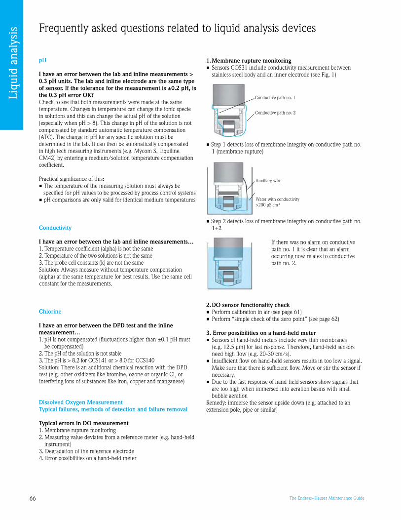
66 The Endress+Hauser Maintenance Guide
Frequently asked questions related to liquid analysis devices
pH
I have an error between the lab and inline measurements > 0.3 pH units. The lab and inline electrode are the same type of sensor. If the tolerance for the measurement is ±0.2 pH, is the 0.3 pH error OK?Check to see that both measurements were made at the same temperature. Changes in temperature can change the ionic specie in solutions and this can change the actual pH of the solution (especially when pH > 8). This change in pH of the solution is not compensated by standard automatic temperature compensation (ATC). The change in pH for any specific solution must be determined in the lab. It can then be automatically compensated in high tech measuring instruments (e.g. Mycom S, Liquiline CM42) by entering a medium/solution temperature compensation coefficient.
Practical significance of this:• The temperature of the measuring solution must always be
specified for pH values to be processed by process control systems• pH comparisons are only valid for identical medium temperatures
Conductivity
I have an error between the lab and inline measurements…1. Temperature coefficient (alpha) is not the same2. Temperature of the two solutions is not the same. The probe cell constants (k) are not the sameSolution: Always measure without temperature compensation (alpha) at the same temperature for best results. Use the same cell constant for the measurements.
Chlorine
I have an error between the DPD test and the inline measurement…1. pH is not compensated (fluctuations higher than ±0.1 pH must
be compensated)2. The pH of the solution is not stable. The pH is > 8.2 for CCS141 or > 8.0 for CCS140Solution: There is an additional chemical reaction with the DPD test (e.g. other oxidizers like bromine, ozone or organic Cl2 or interfering ions of substances like iron, copper and manganese)
Dissolved Oxygen MeasurementTypical failures, methods of detection and failure removal
Typical errors in DO measurement1. Membrane rupture monitoring2. Measuring value deviates from a reference meter (e.g. hand-held
instrument). Degradation of the reference electrode4. Error possibilities on a hand-held meter
1. Membrane rupture monitoring• Sensors COS1 include conductivity measurement between
stainless steel body and an inner electrode (see Fig. 1)
• Step 1 detects loss of membrane integrity on conductive path no. 1 (membrane rupture)
• Step 2 detects loss of membrane integrity on conductive path no. 1+2
If there was no alarm on conductive path no. 1 it is clear that an alarm occurring now relates to conductive path no. 2.
2. DO sensor functionality check• Perform calibration in air (see page 61)• Perform “simple check of the zero point” (see page 62)
3. Error possibilities on a hand-held meter• Sensors of hand-held meters include very thin membranes
(e.g. 12.5 μm) for fast response. Therefore, hand-held sensors need high flow (e.g. 20-0 cm/s).
• Insufficient flow on hand-held sensors results in too low a signal. Make sure that there is sufficient flow. Move or stir the sensor if necessary.
• Due to the fast response of hand-held sensors show signals that are too high when immersed into aeration basins with small bubble aeration
Remedy: immerse the sensor upside down (e.g. attached to an extension pole, pipe or similar)
Conductive path no. 1
Conductive path no. 2
Auxiliary wire
Water with conductivity >200 μS cm-1
Liqu
id a
naly
sis

67The Endress+Hauser Maintenance Guide
Pressure measurement
Duane MuirExpert in Pressure measurementEndress+Hauser USA
Contents
Basics 68The chapter ‘Basics’ includes information which is valid for all pressure measurement devices principles described hereafter. Thus you should read it before any other chapter.
Absolute/relative pressure transmitters 70
Differential pressure measurement 73
Hydrostatic pressure measurement 75
FAQ 76
“Pressure measurement uses various principles and can, according to the application, serve to calculate a flow rate or a level. Thus these devices are used frequently in a broad scope of applications.
No wonder most of the reported questions occur during commissioning. Therefore, we have decided to focus on this in the following pages. However with proper installation and cabling, immediate operation will be achieved.
You will also find plenty of useful information to help you get the best from your instruments throughout their life cycle… and prepare for renewing your equipment gradually.”
“Proper commissioning ensures peace of mind”
For assistance selecting any new or replacement instrument, use the free Online selection software, Applicator at www.us.endress.com/Applicator

68 The Endress+Hauser Maintenance Guide
BasicsInformation common to any type of pressure sensors
Installation instructions - general notes
Seal for flange mountingWarning! The seal is not allowed to press on the diaphragm as this could affect the measurement result (see Fig.1).
The device specific instructions are described in the next pages.
“It’s even easier with the new ‘Evolution’ generation!”
Setup - Configuration
• General note: If the installation and wiring
conditions have been observed initially, you can be certain of receiving correct measurements from the instrument’s first activation. Configuration will only serve to optimize the operating parameters of the quantities measured (current output setup, etc.)
• Cerabar S, Deltabar S and Deltapilot S offer a QUICK SETUP Instead of the matrix programming present on the first generation of Cerabar S, Deltabar S and on the Deltapilot S DB5x, the new ‘Evolution’ generation offers a QUICK SETUP.
QUICK SETUP enables quick and easy configuration of the device’s main functions (units, outputs…).
• You can also configure your flowmeters from your PC
See presentation of FieldCare on page 107.
Our service organization can set up any Endress+Hauser device for you and thus ensure you immediately get the best from your instrument (see ‘Commissioning’ in the ‘At your service’ section).
Operation and Maintenance
Pressure measurement instruments contain no wear
parts. Furthermore they are insensitive to the medium. Thus they require very little maintenance.
We recommend to periodically perform a visual check of the devices:• check the cap and housing’s
condition• check the diaphragm’s
condition• check the cable gland’s
watertightness• ensure there is no
condensation inside the housing
• check the connections to the electronic module
Taking 4 to 20 mA test signal - Cerabar S, Deltabar S, Deltapilot SA 4 to 20 mA signal may be measured via the positive and test terminal without interrupting the measurement. The minimum supply voltage of the device can be reduced by simply changing the position of the jumper. As a result, operation is also possible with lower voltage sources. Observe the position of the jumper in accordance with the following table. (see Fig. )
CalibrationHydrostatic pressure measurement sensors need calibration at start-up.All pressure sensors require periodic calibration; the calibration’s frequency depends on the expected precision. Calibration can be performed either on-site or
The current Endress+Hauser range of pressure measurement devices includes:• The Cerabar S and M absolute/relative pressure
transmitters• The Deltabar S differential pressure transmitters • The Deltapilot S hydrostatic pressure transmitters
P01-FMD7xxxx-11-xx-xx-xx-002
Fig. 11: Mounting the versions with flange or diaphragm seal
1 Diaphragm 2 Seal
1 2
Figure 1: Mounting the versions with flange or diaphragm seal 1 Diaphragm 2 Seal
Configuration with operating keys situated either on the exterior of the device (see photo) or below the 4-line display. Data is stored in a HistoROM / M-DAT allowing easy duplication from a device to another.
P01-xxxxxxxx-19-xx-xx-xx-104
Electronic insert HART
1 Operating keys 2 Slot for optional display3 Slot for optional HistoROM ®/M-DAT4 DIP-switch for locking/unlocking
measured-value-relevant parameters5 DIP-switch for damping on/off6 Green LED to indicate value being accepted
Figure 2: Cerabar S, Deltabar S and Deltapilot S:Operating keys and elements located internally on the electronic insert (HART)1 Operating keys 2 Slot for optional display Slot for optional HistoROM®/M-DAT 4 DIP-switch for locking/unlocking
measured- value-relevant parameters 5 DIP-switch for damping on/off 6 Green LED to indicate value being
accepted
Pres
sure

6The Endress+Hauser Maintenance Guide
in the laboratory (for greater precision and/or for accredited calibration).
Endress+Hauser can help you calculate the right calibration frequency and perform calibration either on-site or in accredited laboratories (see ‘Calibration’ in the ‘At your service’ section).
Maintenance planning
Do you know exactly which part of your installed instrumentation base is critical to the operation of the plant and how you could maintain or calibrate it more efficiently? Are you sure that your present actions are minimizing the risks of unplanned breakdowns? Are you sure that your present actions are the most cost effective?
With Endress+Hauser’s Installed Base Audit, our service consultant will help you to quickly find an answer to these three questions and move forward in a controlled manner to a maintenance plan which improves plant reliability while reducing costs… (see ‘Installed Base Audit’ in the ‘At your service’ section).
Maintenance performing
If you do not have the time or the right tools to efficiently perform your maintenance, an Endress+Hauser service contract can provide you the appropriate level of maintenance support you require.
We provide regular checks on your equipment and warranty extensions providing you with complete peace of mind and cost control.
From regular support to partnership agreements, we offer four distinct levels of service… (see ‘Service Contracts’ in the ‘At your service’ section).
Corrective maintenance The more critical your instru-ment is to your process, the shorter the acceptable time for repair is. Thanks to the Endress+Hauser’s spare part concept (see hereafter), most parts can be easily replaced by the user thus allowing quick repair.
Being more efficient in the repair process is another way to reduce downtimes. Our training sessions help you to quickly diagnose any failure and to apply the most appropriate repair method (see ‘Training’ in the ‘At your service’ section).
Spare parts stockAs members of the Evolution range, Cerabar S, Deltabar S and Deltapilot S use the same electronic modules (for HART output, for Profibus output, etc.), the same housings, caps, display, terminal compartment, mounting set, and Histo-ROM. Only the sensor and its electronic board vary from one device to another. This allows a consistent spare parts stock reduction.
For each device type, we suggest stocking a full set of electronic inserts.
On each part you will find a sticker with the part number, for easy spare parts ordering.
In case of a highly critical instrument, you might also consider stocking a complete new instrument.
Our specialists can help you to define the criticality of all your measuring instruments (even for other makes). They will apply a structured methodology adapted to your own application (see ‘Installed Base Audit’ service in the ‘At your service’ section).
Instrument and spare parts availabilityYou will find detailed information in the pages to follow.
Migration
You will find detailed information in the pages to follow.
Re-engineering
You wish to use an instrument for a new application? We can help you check the relevant parameters. See our online Applicator tool.
P01-xMx7xxxx-04-xx-xx-xx-001
Electrical connection 4 to 20 mA HART, here shown with aluminum housing (T14)
1 Housing2 Jumper for 4 to 20 mA test signal
See also Page 19, "Taking 4 to 20 mA test signal".3 Internal ground terminal4 External ground terminal5 4 to 20 mA test signal between positive and test terminal6 Minimum supply voltage 10.5 V DC, if the jumper is inserted in accordance with the illustration.7 Minimum supply voltage 11.5 V DC, if the jumper is inserted in "Test" position.8 Devices with integrated overvoltage protection are labelled OVP (overvoltage protection) here ( see also Page 25).
Jumper position for test signal Description
– Taking 4 to 20 mA test signal via plus and test terminal: possible. (Thus, the output current can be measured without interruption via the diode.)
– Delivery status – minimum supply voltage: 11.5 V DC
– Taking 4 to 20 mA test signal via plus and test terminal: not possible.
– minimum supply voltage: 10.5 V DC
Figure : Taking test signal
Pres
sure

70 The Endress+Hauser Maintenance Guide
Absolute/relative pressure transmittersCerabar series
The current Endress+Hauser range of absolute/relative pressure transmitters includes Cerabar M and S series.
In this section, you will find essential information and advice that will help you to perform the optimum follow-up of your Cerabar M and S transmitters throughout their life cycle.
Measuring principle
Ceramic measuring diaphragm (PMCxx devices)The ceramic sensor is a dry sensor, i.e. the process pressure acts directly on the robust ceramic diaphragm and deflects it. A pressure-dependent change in capacitance is measured at the electrodes of the ceramic carrier and the diaphragm. The measuring range is determined by the thickness of the ceramic diaphragm. (See Figure 1)
Metallic measuring diaphragm (See Figure 2)For PMP71 The operating pressure deflects the separating diaphragm and a fill fluid transfers the pressure to a resistance measuring bridge (semi-conductor technology). The pressure-dependent change of the bridge output voltage is measured and processed further.
For PMP75 The operating pressure acts on the diaphragm of the diaphragm seal and is transferred to the separating diaphragm of the sensor by a diaphragm seal fill fluid. The separating diaphragm is deflected and a fill fluid transfers the pressure to a resistance measuring bridge. The pressure-dependent change of the bridge output voltage is measured and processed further.
Level measurement (level, volume and mass) Design and operation mode is shown on Figure .
P01-PMC71xxx-03-xx-xx-xx-000
Ceramic sensor
1 Atmospheric vent (gauge pressure only)2 Ceramic substrate3 Electrodes4 Ceramic diaphragm
P01-PMP7xxxx-03-xx-xx-xx-000
Metal sensor
1 Measuring element2 Measuring diaphragm with Wheatstone bridge3 Channel with fill fluid4 Process diaphragm, Metal separating diaphragm
p p
Figure 1: Ceramic sensor 1 Atmospheric vent
(gauge pressure only) 2 Ceramic substrate Electrodes 4 Ceramic diaphragm
Figure 2: Metal sensor 1 Measuring element 2 Measuring diaphragm with
Wheatstone bridge Channel with fill fluid 4 Process diaphragm, Metal
separating diaphragm
P01-PMx7xxxx-15-xx-xx-xx-000
Level measurement with Cerabar S
h Height (level)p Pressureρ Density of the mediumg Gravitation constant
h =pg
h
Figure : Level measurement with Cerabar S h Height (level) p Pressure r Density of the medium g Gravitation constant
P01-PMx7xxxx-11-xx-xx-xx-001
Fig. 5: Measuring arrangement for pressure measurement in gasesFigure 4: Measuring arrangement for pressure measurement in gases 1 Cerabar S 2 Shut-off device
Cerabar S specific informationPressure measurement in liquidsMount Cerabar S with shut-off device below or at the same level as the tapping point. (see Fig. 6)
Level measurement • Mount Cerabar S below the
lowest measuring point (see Fig. 7)
• Do not mount the device at the following positions: In the fill flow, in the tank outlet or at a point in the container which could be affected by pressure pulses from the agitator
• The calibration and functional test can be carried out more easily if you mount the device after a shut-off device
Installation instructions for devices without diaphragm seals – PMP71, PMC71
Pressure measurement in gasesMount Cerabar S with shut-off device above the tapping point so that the condensate can flow into the process. (see Fig. 4)
Pressure measurement in steams• Mount Cerabar S with
siphon below the tapping point. The siphon reduces the temperature to almost ambient temperature. (see Fig. 5)
• Fill the siphon with fill fluid before commissioning
P01-PMC71xxx-03-xx-xx-xx-000
Ceramic sensor
1 Atmospheric vent (gauge pressure only)2 Ceramic substrate3 Electrodes4 Ceramic diaphragm
P01-PMP7xxxx-03-xx-xx-xx-000
Metal sensor
1 Measuring element2 Measuring diaphragm with Wheatstone bridge3 Channel with fill fluid4 Process diaphragm, Metal separating diaphragm
p p
Pres
sure

71The Endress+Hauser Maintenance Guide
Figure 5: Measuring arrangement for pressure measurement in steams 1 Cerabar S 2 Shut-off device U-shaped siphon 4 Circular siphon
P01-PMx7xxxx-11-xx-xx-xx-002
Fig. 6: Measuring arrangement for pressure measurement in steams
1 Cerabar S2 Shut-off device3 U-shaped siphon4 Circular siphon
P01-PMx7xxxx-11-xx-xx-xx-003
Fig. 7: Measuring arrangement for pressure measurement in liquids
1 Cerabar S2 Shut-off device
Figure 6: Measuring arrangement for pressure measurement in liquids 1 Cerabar S 2 Shut-off device
Figure 7: Measuring arrangement for level P01-PMP75xxx-11-xx-xx-xx-000
Fig. 8: Measuring arrangement for level
302010.5 U[V]
40 45
1282
1500
847
413
[ ]RLmax
302011.5 U[V]
40 45
1239
1456
804
369
[ ]RLmax
TestTest
U – 10.5 VRLmax 23 mA≤ U – 11.5 V
RLmax 23 mA≤
391
U – 11 VRLmax 23 mA≤
3020 U[V]
40 45
1260
1478
826
[ ]RLmax
11 302012 U[V]
40 45
1217
1434
782
347
[ ]RLmax
U – 12 VRLmax 23 mA≤
Figure 8: Load diagram1 Jumper for the 4 to 20 mA test signal inserted in «Non-test» position 2 Jumper for the 4 to 20 mA test signal inserted in «Test» position Supply voltage 10.5 (11.5) to 0 V DC for 1/2 G, 1 GD, 1/2 GD, FM IS, CSA
IS, IECEx ia, NEPSI Ex ia and TIIS Ex ia 4 Supply voltage 10.5 (11.5) to 45 V DC for devices for non-hazardous areas, 1/2
D, 1/ D, 2 G EEx d, G EEx nA, FM XP, FM DIP, FM NI, CSA XP, CSA Dust-Ex, NEPSI Ex d, TIIS Ex d
5 Supply voltage 11 (12) to 45 V DC for PMC71, EEx d[ia], NEPSI Ex d[ia] and TIIS Ex d[ia]
RLmax Maximum load resistance U Supply voltage
Operations and Maintenance
Taking 4 to 20 mA test signalA 4 to 20 mA signal may be measured via the positive and test terminal without interrupting the measurement.(see page 68)
Load – 4 to 20 mA and 4 to 20 mA HARTLoad diagram, observe the position of the jumper
(see ‘Basics’) and the explosion protection. (see Fig. 8)
CalibrationSee ‘Basics’.
Instrument and spare parts availability(see table below)
If you want to get more information about spare parts availability, please call our hotline 800-642-877.
Your Spare parts New instrument availability generation
PMC71 YES - until 12/2010 PMC71
PMP71 YES - until 12/2010 PMP71
PMP65 YES - until 12/2010 PMP75
PMC61 YES - until 12/2010 PMP75
Pres
sure

72 The Endress+Hauser Maintenance Guide
P01-PMx4xxxx-05-xx-xx-xx-000
0
1522
1295
840
386
11.5 30 4520 U[V]
U – 11.5 VRLmax 22 mA≤
[ ]ΩRLmax
40
Operations and Maintenance
Taking 4 to 20 mA test signalA 4 to 20 mA signal may be measured via the positive and test terminal without interrupting the measurement.(see Figures 1 and 2)
Load – 4 to 20 mA and 4 to 20 mA HARTLoad diagram, observe explosion protection. (see Fig. )
P01-PMx4xxxx-04-xx-xx-xx-000
Analog electronic insertP01-PMx4xxxx-04-xx-xx-xx-001
4 to 20 mA HART electronic insert
P01-PMx4xxxx-04-xx-xx-xx-000
Analog electronic insertP01-PMx4xxxx-04-xx-xx-xx-001
4 to 20 mA HART electronic insertFigure 1: Analog electronic insert• Remove the sensor from the
process and take the display off• Connect a multimeter to the
terminal lugs• Generate the pressure that
corresponds to the lower range value
• Check that I = 4 mA• Use ‘Zero’ potentiometer to
correct the value• Generate the pressure that
corresponds to the upper range value
• Check that I = 20 mA• Use ‘Span’ potentiometer to
correct the value
Figure 2: 4 to 20 mA HART electronic insert• Remove the sensor from the
process and take the display off• Connect a multimeter to the
terminal lugs• Generate the pressure that
corresponds to the lower range value
• Check that I = 4 mA• To correct the value, please press
twice the ‘Zero’ button or confirm the value in the matrix
• Generate the pressure that corresponds to the upper range value
• Check that I = 20 mA• To correct the value, please press
twice the ‘Span’ button or confirm the value in the matrix
Figure : Load diagram1 Power supply 11.5 to 45 V DC for
devices for non-hazardous areas, 1/ D, EEx d, EEx nA, FM XP, FM DIP, CSA XP and CSA Dust-Ex
2 Power supply 11.5 to 0 V DC for EEx ia, 1 D, 1/2 D1/2G, FM IS and CSA IS
RLmax Maximum load resistance U Supply voltage
Cerabar M specific informationPr
essu
re

7The Endress+Hauser Maintenance Guide
Differential pressure measurementDeltabar series
The current Endress+Hauser range of differential pressure measurement includes Deltabar S series.
In this section, you will find essential information and advice that will help you to perform the optimum follow-up of your Deltabar S devices throughout their life cycle.
Measuring principle
Ceramic measuring diaphragms used for PMD70 and FMD76 The ceramic measuring cell is based on the principle of a plate capacitor with an electrode on (1) and a movable electrode on the interior of the diaphragm (). Standard silicone oil or mineral oil filling oils for this measuring cell. A differential pressure (p1 ≠ p2) causes a corresponding deflection of both diaphragms. Both capacitance values are converted and are fed to the microprocessor of the transmitter as a digital signal.
Metallic measuring diaphragms used for PMD75, FMD77 and FMD78 The separating diaphragms (/) are deflected on both sides by the acting pressures. A filling oil (4/8) transfers the pressure to a resistance circuit bridge (semi-conductor technology). The differential-pressure-dependent change of the bridge output voltage is measured and further processed.
P01-PMD75xxx-11-xx-xx-xx-005
Fig. 13: Measuring layout for level measurement in a container with superimposed steam with PMD75
1 Condensate trap2 Shut-off valves3 Deltabar S, here PMD754 Separator5 Drain valves6 Three-valve manifold
P01-PMD75xxx-11-xx-xx-xx-001
Fig. 6: Measuring layout for flow measurement in steam with PMD75
1 Condensate traps2 Orifice plate or pitot tube3 Shut-off valves4 Deltabar S, here PMD755 Separator6 Drain valves7 Three-valve manifold
Figure 1: Measuring layout for flow measurement in steam with PMD75 1 Condensate traps 2 Orifice plate or pitot tube Shut-off valves 4 Deltabar S, PMD75 shown here 5 Separator 6 Drain valves 7 Three-valve manifold
Figure 2: Measuring layout for level measurement in a container with superimposed steam with PMD75 1 Condensate trap 2 Shut-off valves Deltabar S, PMD75 shown here 4 Separator 5 Drain valves 6 Three-valve manifold
Specific installation conditions
We remind you hereafter the main installation requirements regarding the most frequently used applications.
Flow measurement in steam with PMD70/PMD75• Mount the Deltabar S below
the measuring point (see Fig. 1)
• Mount the condensate traps at the same level as the tapping points and at the same distance to the Deltabar S
• Prior to commissioning, fill the impulse piping to the height of the condensate traps
Level measurement in a closed container with superimposed steam with PMD70/ PMD75
• Mount the Deltabar S below the lower measuring connection so that the impulse piping is always filled with liquid (see Fig. 2)
• Always connect the negative side above the maximum level
• A condensate trap ensures constant pressure on the negative side
• When measuring in media with solid parts, such as dirty liquids, installing separators and drain valves is useful for capturing and removing sediment
P01-FMD78xxx-11-xx-xx-xx-000
Fig. 12: Measuring layout for level measurem ent in a closed container with FMD78
1 Deltabar S, here FMD78
Figure : Measuring layout for level measurement in a closed container with FMD78 1 Deltabar S, FMD78 shown here
P01-FMD76xxx-11-xx-xx-xx-003
Fig. 9: Measuring layout for level measurement in open containers with FMD76
1 Deltabar S, here FMD762 The negative side is op en to atmospheric pressure
Figure 4: Measuring layout for level measurement in open containers with FMD76 1 Deltabar S, FMD76 shown here 2 The negative side is open to
atmospheric pressure
Pres
sure
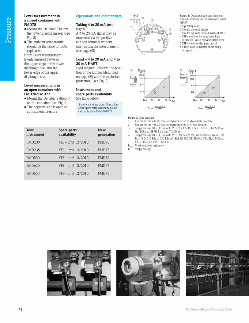
74 The Endress+Hauser Maintenance Guide
P01-xMD7xxxx-05-xx-xx-xx-005
Fig. 31: Load diagram, observe the position of the jumper and the explosion protection ( ? See also page 25, "Taking 4...20 mA test signal" part.)
1 Jumper for 4...20 mA test signal inserted in "Non-Test" position2 Jumper for 4...20 mA test signal inserted in "Test" position3 Supply voltage 10.5 (11.5)...30 V DC for 1/2 G, 1GD, 1/2 GD, FM IS, CSA IS, IECEx ia, NEPSI Ex ia and TIIS Ex ia4 Supply voltage 10.5 (11.5)...45 V DC for device for non-hazardous areas, 1/2 D, 1/3 D, 2 G EEx d,
3 G EEx nA, FM XP, FM DIP, FM NI, CSA XP, CSA Dust Ex, NEPSI Ex d und TIIS Ex dRLmax Maximum load resistanceU Supply voltage
U – 10.5 VRLmax 23 mA≤
302010.5 U[V]
40 45
1282
1500
847
413
[ ]RLmax
302011.5 U[V]
40 45
1239
1456
804
369
[ ]RLmax
TestTest
U – 11.5 VRLmax 23 mA≤
P01-xxxxxxxx-19-xx-xx-xx-104
Electronic insert HART
1 Operating keys 2 Slot for optional display3 Slot for optional HistoROM ®/M-DAT4 DIP-switch for locking/unlocking
measured-value-relevant parameters5 DIP-switch for damping on/off6 Green LED to indicate value being accepted
Figure 1: Operating keys and elements located internally on the electronic insert (HART)1 Operating keys 2 Slot for optional display Slot for optional HistoROM®/M-DAT 4 DIP-switch for locking/unlocking
measured- value-relevant parameters 5 DIP-switch for damping on/off 6 Green LED to indicate value being
accepted
Figure 2: Load diagram1 Jumper for the 4 to 20 mA test signal inserted in «Non-test» position 2 Jumper for the 4 to 20 mA test signal inserted in «Test» position Supply voltage 10.5 (11.5) to 0 V DC for 1/2 D, 1 GD, 1/2 GD, FM IS, CSA
IS, IECEx ia, NEPSI Ex ia and TIIS Ex ia 4 Supply voltage 10.5 (11.5) to 45 V DC for device for non-hazardous areas, 1/2
D, 1/ D, 2 G EEx d, G EEx nA, FM XP, FM DIP, FM NI, CSA XP, CSA Dust-Ex, NEPSI Ex d and TIIS Ex d
RLmax Maximum load resistance U Supply voltage
Level measurement in a closed container with FMD78• Mount the Deltabar S below
the lower diaphragm seal (see Fig. )
• The ambient temperature should be the same for both capillaries
Note! Level measurement is only ensured between the upper edge of the lower diaphragm seal and the lower edge of the upper diaphragm seal.
Level measurement in an open container with FMD76/FMD77 • Mount the Deltabar S directly
on the container (see Fig. 4) • The negative side is open to
atmospheric pressure
Operations and Maintenance
Taking 4 to 20 mA test signalA 4 to 20 mA signal may be measured via the positive and test terminal without interrupting the measurement.(see page 68)
Load – 4 to 20 mA and 4 to 20 mA HARTLoad diagram, observe the posi-tion of the jumper (described on page 6) and the explosion protection. (see Fig. 2)
Instrument and spare parts availabilitySee table below.
If you want to get more information about spare parts availability, please call our hotline 800-642-877.
Your Spare parts New instrument availability generation
PMD20 YES - until 12/2010 PMD70
PMD25 YES - until 12/2010 PMD75
FMD20 YES - until 12/2010 FMD76
FMD60 YES - until 12/2010 FMD77
FMD6 YES - until 12/2010 FMD78
Pres
sure

75The Endress+Hauser Maintenance Guide
P01-FMB70xxx-11-xx-xx-xx-000
P01-FMB70xxx-11-xx-xx-xx-001
6 Endress+Hauser
P01-FMB70xxx-15-xx-xx-xx-000
Deltapilot S hydrostatic level meas urement and measuring principle
1 Measuring diaphragm2 Measuring element3 Process diaphragm (separating diaphragm)
g Gravitational accelerationh Level heightp tot Total pressure = hydrostatic pr essure + atmospheric pressurep atm Atmospheric pressurep hydr. Hydrostatic pressurep meas Measured pressure in the meas uring cell = hydrostatic pressure
Density of fluid
Figure 1: Deltapilot S hydrostatic level measurement and measuring principle 1 Measuring diaphragm 2 Measuring element Process diaphragm (separating
diaphragm) g Gravitational acceleration h Level height
Hydrostatic pressure measurementDeltapilot series
The current Endress+Hauser range of differential pressure measurement includes Deltapilot S series.
In this section, you will find essential information and advice that will help you to perform the optimum follow-up of your Deltapilot S devices throughout their life cycle.
Measuring principle
(See Figure 1)Due to its weight, a liquid column creates hydrostatic pressure. If the density is constant, the hydrostatic pressure depends solely on the height h of the liquid column. The CONTITE™ measuring cell which works on the principle of the gauge pressure sensor constitutes the core of Deltapilot S. In contrast to conventional gauge pressure sensors, the precision measuring element (2) in the CONTITE™ measuring cell is absolutely protected between the process diaphragm () and the measuring diaphragm (1). Thanks to this hermetic sealing of the measuring element, the CONTITE™ measuring cell is absolutely insensitive to condensate, condensation and aggressive gases. The pressure applied is transferred from the process diaphragm to the measuring element by means of an oil without any loss in pressure.
Two temperature sensors are arranged between the process diaphragm and measuring element which measure the distribution of temperature in the cell. The electronics can compensate any measuring errors resulting from fluctuations in temperature with these measured temperature values.
Specific installation conditions
Note! • Do not clean or touch
diaphragm seals with hard or pointed objects
• Always install the device under the lowest measuring point
• Do not install the device at the following positions: – in the filling curtain – in the tank outlet – or at a point in the tank
that can be reached by pressure pulses from agitator
The calibration and functional test can be carried out more easily if you mount the device after a shut-off device.
Deltapilot S must be included in the insulation for media that can harden when cold.
Operations and Maintenance
Taking 4 to 20 mA test signalA 4 to 20 mA signal may be measured via the positive and test terminal without interrupting the measurement.(see Fig. 2)
Load – 4 to 20 mA and 4 to 20 mA HARTLoad diagram, observe the posi-tion of the jumper (described on page 6) and the explosion protection. (see Fig. )
p tot Total pressure = hydrostatic pressure + atmospheric pressure
p atm Atmospheric pressure p hydr. Hydrostatic pressure p meas Measured pressure in the measuring
cell = hydrostatic pressure r Density of fluid
Pres
sure

76 The Endress+Hauser Maintenance Guide
P01-xMD7xxxx-05-xx-xx-xx-005
Load diagram, observe the position of the jumper and the explosion protection. ( ? See also page 19, section "Taking 4...20 mA test signal" .)
1 Jumper for the 4...20 mA test signal inserted in "Non-test" position2 Jumper for the 4...20 mA test signal inserted in "Test" position3 Supply voltage 10.5 (11.5) to 30 V DC for 1/2 G, 1 GD, 1/2 GD, FM IS, CSA IS, TIIS Ex ia and IEC Ex ia4 Supply voltage10.5 (11.5) to 45 V DC for devices for no n-hazardous areas, 1/2 D, 1/3 D, 3 G EEx nA, FM DIP,
FM NI, CSA Dust-ExRLmax Maximum load resistanceU Supply voltage
P01-xxxxxxxx-19-xx-xx-xx-104
Electronic insert HART
1 Operating keys 2 Slot for optional display3 Slot for optional HistoROM ®/M-DAT4 DIP-switch for locking/unlocking
measured-value-relevant parameters5 DIP-switch for damping on/off6 Green LED to indicate value being accepted
Figure 2: Operating keys and elements located internally on the electronic insert (HART)1 Operating keys 2 Slot for optional display Slot for optional HistoROM®/M-DAT 4 DIP-switch for locking/unlocking
measured- value-relevant parameters 5 DIP-switch for damping on/off 6 Green LED to indicate value being
accepted
Figure : Load diagram1 Jumper for the 4 to 20 mA test signal inserted in «Non-test» position 2 Jumper for the 4 to 20 mA test signal inserted in «Test» position Supply voltage 10.5 (11.5) to 0 V DC for 1/2 G, 1 GD, 1/2 GD, FM IS, CSA IS
and TIIS Ex ia 4 Supply voltage 10.5 (11.5) to 45 V DC for devices for non-hazardous areas, 1/2
D, 1/ D, G EEx nA, FM DIP, FM NI, CSA Dust-Ex RLmax Maximum load resistance U Supply voltage
Your Spare parts New instrument availability generation
DB50L YES - until 10/2011 FMB70
DB50S YES - until 10/2011 FMB70
DB50A YES - until 10/2011 FMB70
Corrective maintenanceChanging the sensor’s electronic module Deltabar S FMB70x requires no calibration.
Instrument and spare parts availability• The FMB70 compact version
was launched in 2006• DB50 and 50L will be phased
out 10/2008• Spare parts: See table below
Migration
The Deltapilot S FMB70 is fully compatible with DB50 and 50L.
Frequently asked questions
What to do in case of warning or alarm in the display?See error codes listed in documentation/operating instructions.
The local display is dark – why?• With analog output: Only the display is defective.• With current = 0 mA: Check terminal voltage or plug to the E-board
• If there is no voltage on the plug, but on the terminals: defective terminal module (filter/interlock diode)
• If there is a voltage on the plug: defective electronics
Display/current does not show 0% value upon start-up…Perform additional position alignment (position, temperature) as described in the manual.
The current is too low…The sensor is not connected in 2-wire technique, but probably in 4-wire technique by testing terminals, which is forbidden!
The pressure is about 14.5 psi (1 bar) too high!An absolute cell is built in instead of a relative cell.
Current permanently at 20.5 mA and possibly display flashing!Measuring cell selected too small, possibly confused relative with absolute!
If you want to get more information about spare parts availability, please call our hotline 800-642-877.
Tanks with a conical outlet - entry of the linearization tablePlease refer to the Operating Instructions of your device.
P01-PMP75xxx-19-xx-xx-xx-002
Pres
sure

77The Endress+Hauser Maintenance Guide
Temperature measurement
Duane MuirExpert in Temperature measurementEndress+Hauser USA
Contents
Basics 78
FAQ 82
Temperature is the most frequently measured parameter in the process industry.
Maintenance of temperature measurement consists mostly of periodic calibration. This is why we have focused on calibration in the next pages.
Please note that new transmitters like TMT162 include advanced diagnostics functions (like drift or corrosion detection) which can increase the system’s performance and availability.
You will also find plenty of useful information to help you get the best from your instruments throughout their life cycle… and prepare for renewing your equipment gradually.
As experts, we also offer training sessions, in classroom and on-site. We would be glad to meet with you and help you to go one step further. See ‘Training’ in the section ‘At your service’.”
“Finding the right balance in calibration”
For assistance selecting any new or replacement instrument, use the free Online selection software, Applicator at www.us.endress.com/Applicator
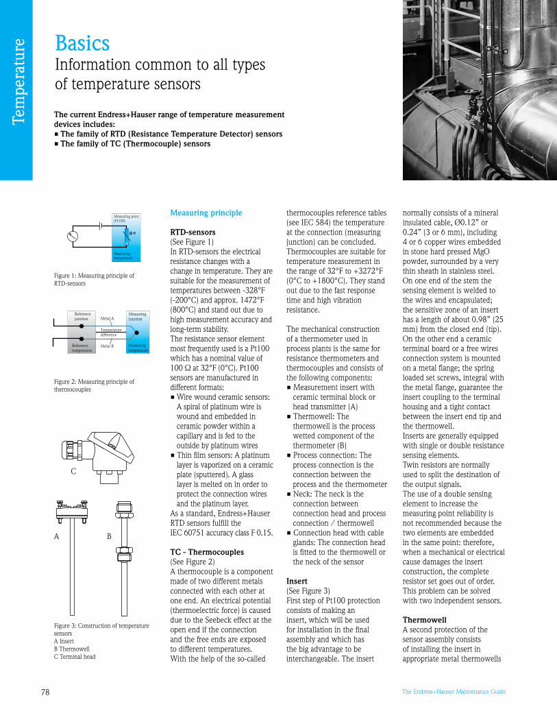
78 The Endress+Hauser Maintenance Guide
BasicsInformation common to all types of temperature sensors
The current Endress+Hauser range of temperature measurement devices includes:• The family of RTD (Resistance Temperature Detector) sensors• The family of TC (Thermocouple) sensors
Measuring principle
RTD-sensors(See Figure 1)In RTD-sensors the electrical resistance changes with a change in temperature. They are suitable for the measurement of temperatures between -28°F (-200°C) and approx. 1472°F (800°C) and stand out due to high measurement accuracy and long-term stability. The resistance sensor element most frequently used is a Pt100 which has a nominal value of 100 Ω at 32°F (0°C). Pt100 sensors are manufactured in different formats: • Wire wound ceramic sensors:
A spiral of platinum wire is wound and embedded in ceramic powder within a capillary and is fed to the outside by platinum wires
• Thin film sensors: A platinum layer is vaporized on a ceramic plate (sputtered). A glass layer is melted on in order to protect the connection wires and the platinum layer.
As a standard, Endress+Hauser RTD sensors fulfill the IEC 60751 accuracy class F 0.15.
TC - Thermocouples (See Figure 2) A thermocouple is a component made of two different metals connected with each other at one end. An electrical potential (thermoelectric force) is caused due to the Seebeck effect at the open end if the connection and the free ends are exposed to different temperatures. With the help of the so-called
Figure 1: Measuring principle of RTD-sensors
Figure 2: Measuring principle of thermocouples
thermocouples reference tables (see IEC 584) the temperature at the connection (measuring junction) can be concluded. Thermocouples are suitable for temperature measurement in the range of 2°F to +272°F (0°C to +1800°C). They stand out due to the fast response time and high vibration resistance.
The mechanical construction of a thermometer used in process plants is the same for resistance thermometers and thermocouples and consists of the following components: • Measurement insert with
ceramic terminal block or head transmitter (A)
• Thermowell: The thermowell is the process wetted component of the thermometer (B)
• Process connection: The process connection is the connection between the process and the thermometer
• Neck: The neck is the connection between connection head and process connection / thermowell
• Connection head with cable glands: The connection head is fitted to the thermowell or the neck of the sensor
Insert(See Figure )First step of Pt100 protection consists of making an insert, which will be used for installation in the final assembly and which has the big advantage to be interchangeable. The insert
normally consists of a mineral insulated cable, Ø0.12” or 0.24” ( or 6 mm), including 4 or 6 copper wires embedded in stone hard pressed MgO powder, surrounded by a very thin sheath in stainless steel. On one end of the stem the sensing element is welded to the wires and encapsulated; the sensitive zone of an insert has a length of about 0.8” (25 mm) from the closed end (tip). On the other end a ceramic terminal board or a free wires connection system is mounted on a metal flange; the spring loaded set screws, integral with the metal flange, guarantee the insert coupling to the terminal housing and a tight contact between the insert end tip and the thermowell. Inserts are generally equipped with single or double resistance sensing elements. Twin resistors are normally used to split the destination of the output signals. The use of a double sensing element to increase the measuring point reliability is not recommended because the two elements are embedded in the same point: therefore, when a mechanical or electrical cause damages the insert construction, the complete resistor set goes out of order. This problem can be solved with two independent sensors.
Thermowell A second protection of the sensor assembly consists of installing the insert in appropriate metal thermowells
Figure : Construction of temperature sensors A InsertB ThermowellC Terminal head
C
A B
Tem
pera
ture

7The Endress+Hauser Maintenance Guide
(i.e. thermowells or pockets). This component is normally required for medium and heavy duty applications but it can be employed also for light duty services whenever the insert replacement must be allowed without any plant shut-down. In order to reduce the sensor response time lag due to thermowells, tapered end constructions are available. The sensor thermowell can be mounted in tanks or pipes by means of threaded, flanged or welded connections. Since the thermowell is the component that comes into contact with the process, exact specification is most important as it determines the lifetime of assembly. The appropriate selection depends upon the chosen method of mounting, the space available, the pressure, the temperature, the flow speed and the nature of the product. Among different international and corporate standards, the DIN 476 defines a series of standard thermowell designs including: • threaded thermowells type B
or C • flanged thermowells type F • weld-in thermowells type D
Terminal headA terminal head is recommended to protect the connections between the insert and the external circuit wires. The heads are normally provided with two connections, one for the thermowell and one for the electrical output
wiring. This component can provide a protective housing for built-in transmitters or can act as a junction box if remote mounted transmitters/receivers are used. The head also permits the complete sensor assembling and facilitates the insert replacement. A wide choice of terminal heads covers general purposes, heavy duty, explosion proof and sanitary applications. A widely used version of connection heads is constructed in light metal alloy, usually aluminum, and conforms to DIN standard 472 type B. The Endress+Hauser metallic heads are delivered with gaskets to withstand a temperature of 266°F (10°C). Some connection heads can include a built-in transmitter and/or an indicator: in this case the temperature has to be checked considering the electronic device limits.
Installation instructions
Immersion length The sensors should insert in the medium where the temperature has to be measured at such a depth that a good compromise among different measuring problems is obtained. • The heat conducted into
sensors from ambient may alter the temperature of the sensing tip: for this reason a short sensor is preferable
• The sensor/thermowell process connection may introduce a thermal drift, due to heat dissipation
through the connection mass, that can affect the correct measurement: this problem can be solved with a longer immersion length
• Process requirements should also be considered to guarantee a representative measuring point for sensing and for control efficiency
• For a correct temperature measurement the thermowell/sensor immersion length must be at least 20 times its diameter (0 times for non M.I. cable type). Shorter immersion lengths can be specified but the sensor requires an external (process connection, neck and connection head) thermal insulation.
• Furthermore, if a calibration certificate is requested, the probe design (length and diameter) has to be defined also according to the certification lab size requirements
Pipe installations (See Figure 4 and 5)In small diameter pipes the most suitable immersion length can often be achieved only by installing the assembly at an angle to the pipe axis or in bends. In this case the inserted assembly must be mounted against the flow.
Figure 4: Pipe installations: a) at elbows, against the flow b) in smaller pipes, against the flow c) perpendicular to the flow
Figure 5: Thermal insulation examples: a) insulating material b) pipe c) thermowell with insert d) external plate
…
Tem
pera
ture

80 The Endress+Hauser Maintenance Guide
Internal wiring of Pt100 insertsAccording to IEC751, three configurations are possible:
• ‘2 wires’ configuration This configuration generates
an error which equals to 2 times the resistance of the wire. This configuration is recommended only when no high precision is required.
• ‘ wires’ configuration This configuration introduces
a compensation which reduces the error to approx. zero. This configuration is commonly used in industry today.
• ‘4 wires’ configuration Provided as a standard
connection for the single Pt100’s, this configuration excludes additional errors in every condition. Generally in the ‘4 wires’ configuration there is a higher guarantee of accuracy.
The TPR insert series is available in two basic versions (see Fig. 6). The connections of the first one, with free wires for mounting of in-head transmitters, are shown in the left side of the figure, while the connections of the second one, with ceramic terminal block, are shown in the right side of the figure. On the left side, the internal wiring of Pt100 is shown.
Resistances and tolerances IEC 751 standard Nominal resistance is the specified resistance value at a given temperature. Sensors of 100Ω nominal resistance value at 2°F (0°C) shall be classified according to degree of conformity with the values of the complete reference table of temperature vs. Ω for Pt100 resistance elements.
Class A and B tolerances are given in the following table. Class A tolerances shall not be applied to Pt100 resistance sensors at temperatures above 1202°F (650°C) and it is valid only for and 4 wire sensors.
Notes: ltl = modulus of temperature in °C without regard to sign. Tolerance value for each temperature point can be calculated with the above formula. Example: class A tolerance value at -50°C = 0.15 + 0.002 x 50 = 0.25°C
Tolerance values vary with the temperature.
We recommend the use of the ‘4 wires’ configuration combined with class A tolerance for high measurement precision.
Device configuration (see Fig. 7)PCP (PC-programmable): Online configuration with TXU10 SETUP connector, socket and ReadWin® 2000 operating software. HART®: HART® signal for on-site or centralized device setup using a hand-held terminal (DXR75) or PC. Operation, visualization and maintenance at the PC using FieldCare, AMS, PDM or ReadWin® 2000 software (valid for TMT184 and TMT85).
Operations and Maintenance
Maintenance mostly consists of periodic calibration. We also recommend that you periodically check (visually) the installation’s watertightness.
Thermometer calibrationA calibration means the determination of a deviation compared to a reference that shows a known uncertainty. So when calibrating, the ‘right’ value of the measurement is predefined by a reference with which the measurement to be calibrated is compared. In the case of sensors this happens either at the defined fixed points of the international temperature scale (ITS0) or by the comparison with a normal sensor.So a redundant sensor cannot replace any calibration, because both measurements may drift and neither of the two sensors are a traceable reference.
1xP t100
3 w ires
R edR ed
W hite
R ed
R ed
W hite
R edR ed
R ed
R ed
W hiteW h ite W h ite
W hite
1xP t100
4 w ires
Figure 6: Internal wiring of Pt100 inserts
Class Tolerance (°C)
A 0.15+0.002 ltl
B 0. +0.005 ltl
Figure 7: Device configuration
Tem
pera
ture

81The Endress+Hauser Maintenance Guide
An accredited calibration is carried out under a strict compliance with national or international norms and guidelines. The normals and gauges used as well as the calibration process and algorithms of the evaluation and measuring accuracy calculation were checked and approved and confirmed in the accreditation authority approval. The compliance is regularly supervised by an accreditation authority by audits and tests. In Europe the national accreditation authorities have united themselves within the EU (e.g. DKD: Germany, SIT: Italy; SCS: Switzerland) to the EA (European Cooperation of Accreditation).
The factory calibration is carried out depending on production norms and sets of rules or according to requirements of the customer. The results are documented in a calibration certificate. Of course all test equipment used are traceable to national/international standards. The measurement accuracy of a device is not influenced by a calibration.Just the opposite, during an adjustment (defined on page 8) a measurement device is adjusted and calibrated in such a way that the measurement deviation does not exceed predetermined error limits (defined by the user). The following are part of any adjustment: Trim, offset and sensor-transmitter matching.
How often must a sensor be calibrated? At which intervals is recalibration required?How often a sensor should be recalibrated depends on:• the user’s requirements
regarding precision• which thermic (maximum
temperature, possible thermo shocks, frequent changes of temperature, etc.) or mechanical strains (vibrations, jolts, etc.) the thermometer will be exposed to
• legal requirements
As we know, RTD are affected by aging, i.e. their characteristic
curve drifts slightly. This drifting is usually particularly marked with new devices, while later on a certain stabilization is observed. Therefore, calibration should be performed somewhat more often in the beginning (about every –6 months). Later on, having gained experience with the drifting behavior of one special thermometer, the recalibration intervals may certainly be prolonged (about every -12 months).
Thermocouples: The user might be recommended (if a particularly high precision of measurement is required), to buy only a TC calibrated by us and to recalibrate it himself, in the beginning maybe every 2- months.
If the TC turns out to be stable, after some time the calibration cycles may certainly be prolonged to -12 months.It absolutely depends on the individual case. After all, drifting is different with every TC, therefore general recommendations regarding calibration cycles can hardly be made. If precision is of major importance to him, the customer will have to monitor the drift himself and decide then, how often he will have the TC recalibrated - or not.
Note: With nearly all transmitters you can compensate the drift via ReadWin® 2000 (‘sensor matching’).
Spare parts
The insert, the thermowell, the terminal head and the transmitter can be exchanged if necessary.
Migration
You will find detailed information regarding the new generations of temperature sensors in the following table.
Re-engineering
You wish to use an instrument for a new application? We can help you check the relevant parameters. See our online Applicator tool.
Old generation New Description Spare parts availability
TST10/TST111/TST221 TR10 RTD-sensor until 10/2010
TST42 TR24 RTD-sensor until 10/2011
TST425 TR25 RTD-sensor NO
TST11/TST211 TR11 RTD-sensor until 10/2010
TST12/TST221 TR12 RTD-sensor until 10/2010
TST1/TST11 TR1 RTD-sensor until 10/2010
TST140/TST141 TR15 RTD-sensor until 10/2010
TST288 TR88 RTD-sensor until 01/201
TST44N TR44 RTD-sensor until 10/200
TST14 TR45 RTD-sensor until 10/200
TST74 TR47 RTD-sensor NO
TST76 TR48 RTD-sensor NO
TST262TR62 RTD-sensor
until 10/200
TST264 until 01/201
TST266 TR66 RTD-sensor until 10/201
TET100
TPR100 RTD-sensor, measurement insert
NO
TET102 NO
TET105 NO
TSC110S TC10 Thermocouple until 10/2010
TSC10S TC1 Thermocouple until 10/2010
TSC140T TC15 Thermocouple until 10/2010
TSC288 TC88 Thermocouple until 10/2011
TSC262/TSC264 TC62 Thermocouple until 10/2012
TSC266 TC66 Thermocouple until 10/2012
TEC100/TEC105 TPC100 Thermocouple, measurement insert
NO
TMT16/TMT17 TMT180 Head transmitter NO
TMD81 TMT181 Head transmitter NO
TMD82 TMT182 Head transmitter NO
TMD84 TMT184 Head transmitter NO
TMD842 TMT112 TMT122
TransmitterDIN-rail transmitter
NO
TMD8 TMT162 Field transmitter NO
TMT165 TMT162 Field transmitter until 10/2010
TMT165 TMT85 Head transmitter until 10/2010
TMD8T TMT162R Compact thermometer, RTD-sensor and Field transmitter
NO
TMD8C TMT162C Compact sensor, Thermocouple and Field transmitter
NO
TA10 TW10 Thermowell NO
TA11 TW11 Thermowell NO
TA12 TW12 Thermowell NO
TA1 TW1 Thermowell NO
TA57/TA574 TW15 Thermowell NO
TA250 TW251 Thermowell NO
Note: these dates are periodically updated on www.endress.com (to be confirmed)
Tem
pera
ture

82 The Endress+Hauser Maintenance Guide
Frequently asked questions
The PLC doesn’t display the right temperature value…• Check the Pt100 signal by means of an ohmmeter• Thermocouple:
• Is the right thermocouple selected?• Is the right temperature for the reference junction used?
• Ensure that both 4-20 mA ranges of the transmitter and the PLC correspond
• Check or calibrate the sensor• Check the installation (see Fig. 4 and 5 on the previous pages)
I have no communication to the transmitter from Readwin® 2000…• Ensure that your transmitter can communicate• Is the latest version of Readwin® 2000 installed on the PC?
You can download it from www.readwin2000.com• Ensure that the power supply is min. V for TMT181 and
TMT121• For TMT182 (HART) and TMT122 (HART), switch off the ‘FIFO
active’ setting. In order to do this proceed as follows: • Windows NT® Version 4.0: Using the menu ‘START’/‘SETTINGS’/‘SYSTEM CONTROL’/
‘CONNECTIONS’ select the menu point ‘COM-Port’. Switch off the ’FIFO active’ command off using the menu path ‘SETTINGS’/’EXPANDED’.
• Windows® 2000: Select ‘Advanced settings for COM1’ from the ‘START’/
‘SETTINGS’/‘SYSTEM CONTROL’/‘SYSTEM’/‘HARDWARE’/‘DEVICE MANAGER’/‘CONNECTIONS (COM and LPT)’/‘COMMUNICATION CONNECTION (COM1)’/‘CONNECTION SETTINGS’/‘ADVANCED’ menu. Deactivate ‘Use FIFO buffer’.
• Windows® XP: Select ‘Port settings’ from connections Port (Com 1)/’START’/
’SETTING’/’SYSTEM’/‘HARDWARE’/‘DEVICE MANAGER’/’PORTS (COM and LPT)’/‘COMMUNICATION PORT (COM1)’/‘PORT SETTING’/‘ADVANCED’ menu. Deactivate ‘Use FIFO buffer’.
• For TMT122/142/182 (HART products) and TMT162 (HART version only), ensure that the load resistance at the Commubox’s terminals equals 250 Ω. If the loop is overloaded (due to the PLC’s impedance or the presence of a recorder) the load resistance can be much higher thus reducing the signal’s intensity.
• You are using TXU10:• Is the USB driver installed on the PC? The driver is stored on
the Readwin® 2000 CD-ROM. You can download the latest version from www.readwin2000.com
• To install the driver you need ‘admin’ rights on your PC• Also take care of the selected communication port: From
Windows®, ‘START’/’CONTROL PANEL’/’SYSTEM’/‘HARDWARE/’DEVICE MANAGER’/’PORTS’
From this window, use the port number that corresponds to the connected communication interface (FXA15 if you are using a HART modem).
Tem
pera
ture

8The Endress+Hauser Maintenance Guide
Recorders
Contents
Basics 84
FAQ 86
“Today, maintenance of strip chart recorders is considered (too) high. The need for many consumables (paper and pens) and the fact that data isn’t stored electronically are big inconveniences in the process world.
This is why electronic (paperless) recorders have rapidly become very ‘popular’. Whereas the first generation stored the data on diskettes, the new range uses Compact Flash or Secure Digital cards for even more reliability and storage capacity.
These devices are maintenance free. So in the next pages we focus on advice for better operation.
Nevertheless paper recorders still constitute a pretty big part of the market. Endress+Hauser will keep providing consumables for its recorders.
As experts, we also offer training sessions, in classroom and on-site. We would be glad to meet with you and help you go one step further. See ‘Training’ in the section ‘At your service’.”
“The advantages of switching to paperless recorders”
For assistance selecting any new or replacement instrument, use the free Online selection software, Applicator at www.us.endress.com/Applicator
Duane MuirExpert in RecordersEndress+Hauser USA

84 The Endress+Hauser Maintenance Guide
BasicsInformation common to any type of modern recorders
The current Endress+Hauser range of recorders includes:• Ecograph RSG20/22/24 and Ecograph T RSG30 multi-channel
electronic (paperless) recorders• Memograph S RSG10/12 and Memograph M RSG40, system
compatible data managers with a unique safety concept for critical applications. Compliant to the high FDA requirements laid down in the 21 CFR Part 11
Measuring principle and main features
The electronic recorders carry out the electronic acquisition, display, recording, analysis, remote transmission and archiving of analog and digital input signals.
Communication• Communication interfaces
available: USB, RS22, RS485, Ethernet, Profibus DP and MODBUS (RSG40)
Inputs/Outputs• Galvanically isolated universal
inputs (U, I, TC, RTD, and frequency)
• Digital input (high/low) • Digital output
(relay/open collector)• Mathematic channels for
calculations
Display of measured values• Electronic recorders are easy
to program via the ‘Set up’ window or from a PC
• Display of historical data on-site
• Display of statistics• Various display modes
Memory (Fig. 1)• Redundant memory
ensures safe data recording: internal Flash memory + CF (CompactFlash) or SD (Secure Digital) cards and USB stick + data transfer to a PC
Note: Please use the original memory cards from Endress+Hauser, because these are industry proven.
Analysis/archiving• Long-term archiving is carried
out at the PC, whereby the data is transferred to the database, via Ethernet or serially to the PC
• Using the supplied PC software package, the devices can be operated, read-out and the measurement data can be archived and visualized
21 CFR 11• Memograph M and S together
with ReadWin® 2000 fulfill the requirements of 21 CFR 11 concerning electronic documents and electronic signature
Installation instructions
Outside installation The front side seal should be correctly positioned to ensure watertightness and avoid any problem due to condensation. And the backside should also be protected against humidity.
Cabling• Please cable the unit
with care. Many reported problems come from wrong connections. We remind you that the cabling synopsis is printed on the rear side of the recorder.
• Please use shielded cables
Surge arresterWe recommend the use of surge arrester(s) (HAW56x family) to protect the instrumentation against overvoltage.
Setup
Setup can be performed at the unit by using the ‘Set up’ window at main menu. Nevertheless setting up using a PC is much more comfortable.
Setup using PCYou can use the PC software ReadWin® 2000 provided with
the device to put the device into service/configure it via PC. You can also download the latest software version directly from the internet under the following address: www.readwin2000.com For further information on ReadWin®2000, refer to the operating manual of the software (BA17R/0).
Advantages of configuration via PC: • The device data is saved in a
database and can be accessed again at any time
• Text entries can be carried out more quickly and efficiently by keyboard
• Measured values can also be read out, archived and displayed on the PC with this program
Operations and Maintenance
Electronic recorders are maintenance free.If your unit includes a floppy disk drive, we recommend that you clean the disk drive once a year with a cleaning disk (several times a year in dusty areas).
Using the ‘screensaver’ mode increases the display’s lifetime.
Tips for safe and comfortable operation• Use Readwin® 2000 to
analyze and print the recorded data.
Note: The operating instructions documentation related to Readwin® 2000 is available on the delivered CD.
Data transferusing CF
or SD card
Copy saved on Compact Flashor SD card
Figure 1: Measuring system on new generation recorders
Reco
rder
s
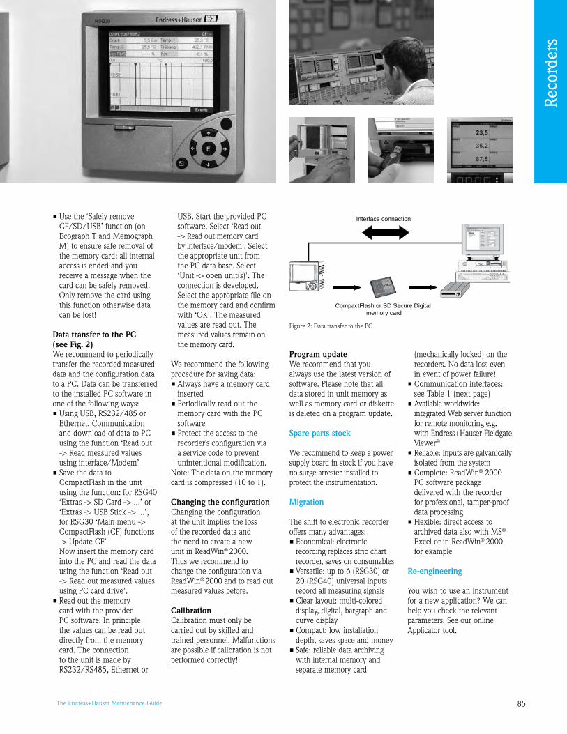
85The Endress+Hauser Maintenance Guide
• Use the ‘Safely remove CF/SD/USB’ function (on Ecograph T and Memograph M) to ensure safe removal of the memory card: all internal access is ended and you receive a message when the card can be safely removed.
Only remove the card using this function otherwise data can be lost!
Data transfer to the PC (see Fig. 2)We recommend to periodically transfer the recorded measured data and the configuration data to a PC. Data can be transferred to the installed PC software in one of the following ways: • Using USB, RS22/485 or
Ethernet. Communication and download of data to PC using the function ‘Read out -> Read measured values using interface/Modem’
• Save the data to CompactFlash in the unit using the function: for RSG40 ‘Extras -> SD Card -> ...’ or ‘Extras -> USB Stick -> ...’, for RSG0 ‘Main menu -> CompactFlash (CF) functions -> Update CF’
Now insert the memory card into the PC and read the data using the function ‘Read out -> Read out measured values using PC card drive’.
• Read out the memory card with the provided PC software: In principle the values can be read out directly from the memory card. The connection to the unit is made by RS22/RS485, Ethernet or
Figure 2: Data transfer to the PC
CompactFlash or SD Secure Digital memory card
Interface connectionUSB. Start the provided PC software. Select ‘Read out -> Read out memory card by interface/modem’. Select the appropriate unit from the PC data base. Select ‘Unit -> open unit(s)’. The connection is developed. Select the appropriate file on the memory card and confirm with ‘OK’. The measured values are read out. The measured values remain on the memory card.
We recommend the following procedure for saving data: • Always have a memory card
inserted• Periodically read out the
memory card with the PC software
• Protect the access to the recorder’s configuration via a service code to prevent unintentional modification.
Note: The data on the memory card is compressed (10 to 1).
Changing the configuration Changing the configuration at the unit implies the loss of the recorded data and the need to create a new unit in ReadWin® 2000. Thus we recommend to change the configuration via ReadWin® 2000 and to read out measured values before.
Calibration Calibration must only be carried out by skilled and trained personnel. Malfunctions are possible if calibration is not performed correctly!
Program updateWe recommend that you always use the latest version of software. Please note that all data stored in unit memory as well as memory card or diskette is deleted on a program update.
Spare parts stock
We recommend to keep a power supply board in stock if you have no surge arrester installed to protect the instrumentation.
Migration
The shift to electronic recorder offers many advantages:• Economical: electronic
recording replaces strip chart recorder, saves on consumables
• Versatile: up to 6 (RSG0) or 20 (RSG40) universal inputs record all measuring signals
• Clear layout: multi-colored display, digital, bargraph and curve display
• Compact: low installation depth, saves space and money
• Safe: reliable data archiving with internal memory and separate memory card
(mechanically locked) on the recorders. No data loss even in event of power failure!
• Communication interfaces: see Table 1 (next page)
• Available worldwide: integrated Web server function for remote monitoring e.g. with Endress+Hauser Fieldgate Viewer®
• Reliable: inputs are galvanically isolated from the system
• Complete: ReadWin® 2000 PC software package delivered with the recorder for professional, tamper-proof data processing
• Flexible: direct access to archived data also with MS® Excel or in ReadWin® 2000 for example
Re-engineering
You wish to use an instrument for a new application? We can help you check the relevant parameters. See our online Applicator tool.
Reco
rder
sRe
cord
ers

86 The Endress+Hauser Maintenance Guide
…
Frequently asked questions
How to start with Readwin® 2000? (see also BA137R)• Create a unit ‘Group/plant’• ‘Unit\Display/Change unit setup/Add new unit\Unit group plant’
How to insert and configure the unit? (see also BA137R)• ‘Unit\Display/Change unit setup/Add new unit\Unit\
Add new unit’
How to store and display measured values on the PC?There are two ways to read out data:• Via the Compact Flash card Click ‘Read out/Read out measured values using PC card drive’
then ‘New unit’ and give it a name. Data will then be transferred.• Via the interface Click ‘Read out/Read out measured values using interface/modem’
then ‘New unit’ and give it a name. Data will then be transferred.
To display the data, click ‘Display/Display measured values from database’Choose the unit to be displayed, then the data timescale, etc.
How to export data from Readwin® 2000 to Excel®?• To display the data, click ‘Display/Display measured values from
database’ Choose the unit to be displayed, then the data timescale, etc.• Click ‘Tabular’ at the bottom left of the screen then click on the
‘Display’ tag at the top left then choose ‘Save table’ (choose .txt or .xls file format)
How long can we store measured values on the external and internal memories?Please refer to the Operating Instructions of your device.
Recorder
USB
RS23
2
RS48
5
Ethe
rnet
Prof
ibus
D
P
MO
DBU
S RT
U
MO
DBU
S TC
P
Ecograph RSG20 • • •
Ecograph RSG22 • • •
Ecograph RSG24 • • •
Ecograph T RSG0 • • • •
Memograph RSG10 • • • •
Memograph S RSG12 • • • •
Memograph M RSG40 • • • • • • •
Table 1: Communication interfaces available
The display of the % of external memory is not correct after read out to a PC…The displayed percentage will be refreshed after the first new memory block is sent to the external memory.
I have no communication via USB to the recorder…• Is the USB driver installed on the PC? You can download the lat-
est version from www.readwin2000.com• To install the driver you need ‘admin’ rights on your PC• Also take care of the selected communication port: From Windows®,
‘START’/’CONTROL PANEL’/’SYSTEM’/‘HARDWARE/’DEVICE MANAGER’/’PORTS’
From this window, use the port number that corresponds to the connected communication interface (FXA15 if you are using a HART modem).
Will the database of measured values be deleted after an update of Readwin® 2000?No.
Will the configuration and the measured values be deleted after a software update?Yes. Please read out and save data before.
Can the language be changed on the recorder?Yes. Please ask the helpdesk for the right software.
Can I define different levels of user rights in Readwin® 2000?Yes: ‘Extras\Program options\Set-up\Security\Password protection’ must be activated
The terminals on the back side of the unit are missing…Only the terminals that correspond to the options you have ordered are delivered.
Reco
rder
s

87The Endress+Hauser Maintenance Guide
Field communication
Brian HowsareExpert in Digital CommunicationEndress+Hauser USA
Contents
Basics 88
FAQ 90
Tip: hardware tools for the maintenance of fieldbus networks 92
“The use of digital communication and fieldbus networks provides lots of advantages in terms of maintenance.
Digital instrumentation can simultaneously exchange data with PLC’s and computers.
Once the instruments have been installed, their parametrization can be performed remotely, from technical premises, a control room, or at any point of the network with a laptop - which is nice in case of hazardous environments or difficult access.
In case of troubleshooting, the diagnosis can also be performed in the same way, even at a long distance, thanks to gateways or modems.
We have issued ‘Guidelines for planning and commissioning’ for both Profibus and Foundation Fieldbus networks. For further details, please refer to BA04S (Profibus) and to BA01S (Foundation Fieldbus). You can download these documents from our web site.
As experts, we also offer training sessions, in classroom and on-site. We would be glad to meet with you and help you go one step further. See ‘Training’ in the section ‘At your service’.
“An introduction to the maintenance of fieldbus networks”
For assistance selecting any new or replacement instrument, use the free Online selection software, Applicator at www.us.endress.com/Applicator

88 The Endress+Hauser Maintenance Guide
BasicsHelping you to maintain fieldbus networks
Endress+Hauser’s instrumentation is involved in networks that may combine:• the HART® protocol• Profibus® DP/PA architectures• Foundation™ Fieldbus architectures
HART is a point to point protocol (see Fig. 1): a PC talks to a single instrument (or to several instruments via a multiplexer).
Conversely, Foundation Fieldbus and Profibus fit for the data exchange to a programmable logic controller (PLC) or a process control system (PCS).
Since Foundation Fieldbus and Profibus use the same electric signal and encoding - only the
protocol differs -, the ‘low level’ maintenance is identical in both networks.
Profibus DP/PA typical architecture (Fig. 2)
The process is controlled by a process control system or a programmable logic controller (PLC). The control system or PLC serves as a Class 1 master. It uses the cyclic services to acquire measurements and
output control commands. The asset management program, e.g. FieldCare, serves as a Class 2 master. It uses the acyclic services and serves to parameterize the bus participants during installation and normal operation.
The PROFIBUS DP system is used to handle the communication at the control level. Drives, remote I/Os, etc. may all be found upon the bus. It is also possible to connect externally powered field devices to this level, e.g. the flowmeters Promass and Promag. PROFIBUS DP ensures that data is quickly exchanged, whereby in mixed PROFIBUS DP/PA systems the baud rate supported by the segment coupler is often the limiting factor.
PROFIBUS PA is used at field level. The segment coupler serves both as interface to the PROFIBUS-DP system and as power supply for the PROFIBUS PA field devices. Depending upon the type of segment coupler, the PROFIBUS PA segment can be installed in safe or hazardous areas.
Foundation Fieldbus typical architecture (Fig. )
The Foundation Fieldbus system architecture has been designed to promote interoperability between and among devices of different manufacturers. Since Foundation Fieldbus supports both a high speed and low speed (H1) network, two architectures exist. These provide the same basic functionality but differ in
Figure 1: Typical HART architecture
Figure 2: Typical architecture of a Profibus DP/PA network Figure : Standard Foundation Fieldbus architecture
Visualization and Monitoring e.g. P View
Network engineering e.g. ControlCare Configurator
High Speed Ethernet
Field Controller/Gateway
Field Controller
FOUNDATION Fieldbus H1FOUNDATION Fieldbus H14x 4x
Process operation and visualization with P ViewPlant Asset Management with FieldCare
PROFIBUS master for cyclic process data communication (I/O)Ethernet
PROFIBUS master for acyclic communication
PROFIBUS DP
e.g. AS-Interface
Devices from third-party vendors (Remote I/O, drives, pumps, etc.)
PROFIBUS PA
Safe Area
Hazardous AreaPROFIBUS PA
PLC PLC
4-20 mA HART
4-20 mA HART
4-20 mA HART
e.g. PROFIBUS DP
e.g. PROFIBUS DP
4-20 mA HART
PLC + HART interface
Remote I/O
Ethernet
HART Multidrop (up to 15 devices)
Fiel
d co
mm
unic
atio
n
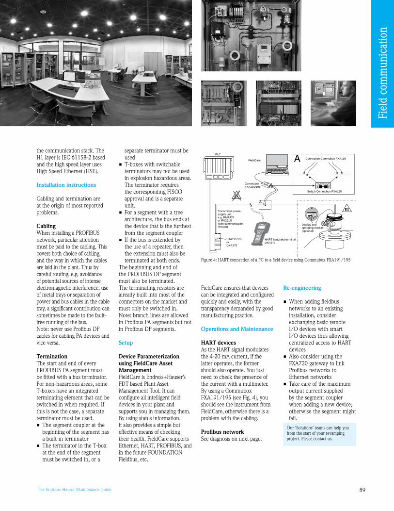
8The Endress+Hauser Maintenance Guide
the communication stack. The H1 layer is IEC 61158-2 based and the high speed layer uses High Speed Ethernet (HSE).
Installation instructions
Cabling and termination are at the origin of most reported problems.
Cabling When installing a PROFIBUS network, particular attention must be paid to the cabling. This covers both choice of cabling, and the way in which the cables are laid in the plant. Thus by careful routing, e.g. avoidance of potential sources of intense electromagnetic interference, use of metal trays or separation of power and bus cables in the cable tray, a significant contribution can sometimes be made to the fault-free running of the bus. Note: never use Profibus DP cables for cabling PA devices and vice versa.
TerminationThe start and end of every PROFIBUS PA segment must be fitted with a bus terminator. For non-hazardous areas, some T-boxes have an integrated terminating element that can be switched in when required. If this is not the case, a separate terminator must be used. • The segment coupler at the
beginning of the segment has a built-in terminator
• The terminator in the T-box at the end of the segment must be switched in, or a
separate terminator must be used
• T-boxes with switchable terminators may not be used in explosion hazardous areas. The terminator requires the corresponding FISCO approval and is a separate unit.
• For a segment with a tree architecture, the bus ends at the device that is the furthest from the segment coupler
• If the bus is extended by the use of a repeater, then the extension must also be terminated at both ends.
The beginning and end of the PROFIBUS DP segment must also be terminated. The terminating resistors are already built into most of the connectors on the market and must only be switched in.Note: branch lines are allowed in Profibus PA segments but not in Profibus DP segments.
Setup
Device Parameterization using FieldCare Asset Management FieldCare is Endress+Hauser’s FDT based Plant Asset Management Tool. It can configure all intelligent field devices in your plant and supports you in managing them. By using status information, it also provides a simple but effective means of checking their health. FieldCare supports Ethernet, HART, PROFIBUS, and in the future FOUNDATION Fieldbus, etc.
FieldCare ensures that devices can be integrated and configured quickly and easily, with the transparency demanded by good manufacturing practice.
Operations and Maintenance
HART devicesAs the HART signal modulates the 4-20 mA current, if the latter operates, the former should also operate. You just need to check the presence of the current with a multimeter.By using a Commubox FXA11/15 (see Fig. 4), you should see the instrument from FieldCare, otherwise there is a problem with the cabling.
Profibus networkSee diagnosis on next page.
Re-engineering
• When adding fieldbus networks to an existing installation, consider exchanging basic remote I/O devices with smart I/O devices thus allowing centralized access to HART devices
• Also consider using the FXA720 gateway to link Profibus networks to Ethernet networks
• Take care of the maximum output current supplied by the segment coupler when adding a new device; otherwise the segment might fail.
ENDRESS + HAUSERRMA 422
1# % &
Copy
G H I
P Q R S
, ( ) ‘
A B C
Paste
PageOn
PageUp
DeleteBksp
Insert
J K L
T U V
_ < >
D E F
Hot Key
+ Hot Key
M N O
W X Y Z
+ * /
4
7
.
2
5
8
0
375FIELD COMMUNICATOR
3
6
9
-
DELTABAR: * * * * * * * *ONLINE
1 QUICK SETUP2 OPERATING MENU
C°0VS4rabm253VP3
HELP SAVE
dsdmdmdf das.asdas faasas la.
EX
EX
64.50 %
Measured Value
A
A
270
ffO O
n
HART handheld terminalDXR375
PLC
CommuboxFXA191/195
Displayperating
ando module(optional)
FieldCare
FXA191/195orDXR375
Transmitter power-supply unit,e.g. RMA422or RN221N(with communicationresistor)
Switch Commubox FXA195
Connection Commubox FXA195
Figure 4: HART connection of a PC to a field device using Commubox FXA11/15
Our ‘Solutions’ teams can help you from the start of your revamping project. Please contact us.
Fiel
d co
mm
unic
atio
n
0 The Endress+Hauser Maintenance Guide
Frequently asked questions
HART protocol
I have no communication to the device from the PC…• Ensure that the load resistance at the Commubox’s terminals
equals 250 Ω. If the loop is overloaded (due to the PLC’s impedance or the presence of a recorder) the load resistance can be much higher thus reducing the signal’s intensity.
• Switch off the ‘FIFO active’ setting. In order to do this proceed as follows: • Windows NT® Version 4.0: Using the menu ‘START’/‘SETTINGS’/‘SYSTEM CONTROL’/
‘CONNECTIONS’ select the menu point ‘COM-Port’. Switch off the ’FIFO active’ command using the menu path ‘SETTINGS’/’EXPANDED’.
• Windows® 2000: Select ‘Advanced settings for COM1’ from the ‘START’/
‘SETTINGS’/‘SYSTEM CONTROL’/‘SYSTEM’/‘HARDWARE’/‘DEVICE MANAGER’/‘CONNECTIONS (COM and LPT)’/‘COMMUNICATION CONNECTION (COM1)’/‘CONNECTION SETTINGS’/‘ADVANCED’ menu. Deactivate ‘Use FIFO buffer’.
• Windows® XP: Select ‘Port settings’ from connections Port (Com 1)/’START’/
’SETTING’/’SYSTEM’/‘HARDWARE’/‘DEVICE MANAGER’/’PORTS (COM and LPT)’/‘COMMUNICATION PORT (COM1)’/‘PORT SETTING’/‘ADVANCED’ menu. Deactivate ‘Use FIFO buffer’.
• Also take care of the selected communication port: From Windows®, ‘START’/’CONTROL PANEL’/’SYSTEM’/‘HARDWARE’/’DEVICE MANAGER’/’PORTS’
From this window, use the port number that corresponds to the connected communication interface (FXA15 if you are using a HART modem).
• Check the minimum voltage required for your HART communicating transmitter(s); the voltage is related to the device
Commissioning of Profibus networks
How can I assign an address to a device? • With the exception of the analysis device Mypro, all
Endress+Hauser devices have an address switch that allows hard-ware or software addressing
• Software address changes can be made via the PROFIdtmDPV1 CommDTM of FieldCare, the DPV1-DDE server of Commuwin II or any other PROFIBUS operating tool. See also Chapter 6.6 of BA04S.
Where is the device termination switch? PROFIBUS PA: • There is no termination switch on the device itself
• The bus is terminated by using a separate terminator or a T-piece/junction box with a switchable terminating element
PROFIBUS DP: • Termination switches are located in the devices. We recommend
the use of PROFIBUS connectors with integrated terminators (in cabinet).
When a device is added to the bus, the segment fails The segment coupler supplies a defined maximum output current to the segment. Every device requires a particular basic current (see Chapter 5. of BA04S). If the sum of the basic currents exceeds the output current of the coupler, the bus becomes unstable. • Diagnosis: Measure the current consumption of the devices with
an amperemeter • Remedy: Reduce the electrical load on the segment concerned,
i.e. one or more devices must be disconnected
PROFIBUS-PA slave with address 2 cannot be found • If a Siemens DP/PA-link Type IM 15/157 is used, the internal
address must be taken into consideration. On the PROFIBUS-PA side, the link has the fixed internal address 2. For this reason, the address 2 may not be assigned to any of the PROFIBUS PA slaves connected to the link.
• Two devices (slave or master) have the same address. Disconnect the slave with address 2 from the bus and check whether there are others on the bus with the same address (e.g. with FieldCare or Commuwin II). Readdress as appropriate. Check the settings of the PROFIBUS master as to whether the address 2 has been allocated twice.
PLC planning on Profibus networks The measured value in Siemens S7 PLCs is always zero • The function module SFC 14 must be used. The SFC 14 ensures
that e.g. 5 bytes can be consistently loaded into the SPS. If the SFC 14 is not used, only 4 bytes can be consistently loaded into the Siemens S7.
• Newer versions of the S7 series can access the I/O buffer directly. The SFC 14 is no longer required.
The measured value at the device display is not the same as that in the PLC The parameters PV_SCALE and OUT_SCALE are not set correctly. OUT_SCALE_Min. = PV-Min. OUT_SCALE_Max. = PV-Max. Instructions on how to adjust the parameters PV_SCALE and OUT_SCALE in the function block can be taken from the device operating instructions. Note: we recommend to use FieldCare for this adjustment.
Diagnosis of Profibus networksIf you are facing a problem (be it during commissioning or be it a troubleshooting) with a device installed in a Profibus network:• First search for addressing errors• Then search for connection problems• Then check the correct integration of the device in the system
(how data is transferred to the PLC):
• Did I use the correct GSD* file? • Enable ‘Set unit to bus’ at the device to ensure correct scaling • Is the decoding correct at the PLC?
* The PROFIBUS system requires a description of the device parameters, e.g. output data, input data, data format and supported transmission rate, so that it can inte-grate the field devices into the bus system. This data is contained in a PROFIBUS device description file (GSD file) which is placed at the disposal of the PROFIBUS-DP master when the communication system is being commissioned. Device bitmaps, which appear as symbols in the network tree, can also be integrated. See Chapter 7-2 of BA04S
Fiel
d co
mm
unic
atio
n

1The Endress+Hauser Maintenance Guide
No connection between the PLC and the PROFIBUS PA network • The bus parameters and baud rate were not set when the PLC
was configured. The baud rate to be set depends upon the seg-ment coupler used (Chapter 7-5 of BA04S).
- Pepperl+Fuchs SK1: ,75 kBit/s - Siemens: 45.45 kBit/s - PA-link (Siemens IM 15/157): freely selectable - Pepperl+Fuchs SK1: .75 kBit/s - Pepperl+Fuchs SK2 and SK: freely selectable • For Pepperl+Fuchs SK2 and SK, the PROFIBUS PA GSD has not
been converted • The bus parameters require adjustment • The polarity of the PROFIBUS-DP line is reversed (A and B)? • PROFIBUS-DP bus not terminated? • Both the beginning and the end of the bus must be terminated
Data transmission on Profibus networks
How is data transferred to the PLC? • The measured values are transmitted in 5 byte long data blocks.
4 bytes are used to transmit the measured value. The fifth byte contains standardized status information. Error codes for Endress+Hauser device faults, e.g. E 641, are not transmitted with the status.
• For limit switches, the information is transmitted in two bytes: Signal condition and status information.
How can the PLC switch on the positive zero return of the Promag 53? Via the output word of the cyclic services.
How can the totalizer of the Promag 53 / Promass 83 be reset? Via the output word of the cyclic services for the totalizer in question, see corresponding operating manual.
How can I suppress a measured value in cyclic communication? By using the placeholder «EMPTY_MODULE» or «FREE_PLACE» during configuration.
How can I write a value to the local display? By using the Display_Value model from the GSD (if supported).
General note: You can refer to Chapters 7.2 and 7. of BA04S (Profibus) for more details.
FieldCare
FieldCare cannot open connection to the PROFIBUS PA devices… FieldCare is a Class 2 master that allows the transmission of acyclic values. The PROFIBUS-DP baud rate to be set depends upon the segment coupler used.
The connection to the devices cannot be opened • If the PLC and FieldCare are used in parallel, the bus parameters
must be mutually compatible. The bus parameters must be identical for all connected masters.
If FieldCare is used, the Token Rotation Time (TTR) calculated by the PLC configuration tool must be increased by 20,000 bit times and the corresponding value entered in the FieldCare Profibus configuration and in the PLC.
• The HSA parameter (Highest Station Address) must permit the FieldCare address. The HSA specifies the highest address permitted for active participants (masters) on the bus. Slaves can have a higher address.
• Is the FieldCare address free or is it being used by another device? • Is the correct baud rate set? • Have the drivers and cards been correctly installed? Is the green
LED on the TAP of the Proficard or Profiboard lit? • Is the GAP update too high (the result is longer waiting times)?
A device does not appear in the live list • Device is not connected to segment • Address used twice
Device cannot be fully operated • The device version is not supported by FieldCare. An appropriate
DTM is necessary. The default parameters of the PROFIBUS-PA profile are offered.
A change of unit at the device has no effect on the value on the bus If the measured value at the device display is to be the same as that transmitted to the PLC, the parameters PV_SCALE and OUT_SCALE must be matched. - OUT_SCALE_MIN = PV_SCALE_MIN - OUT_SCALE_MAX = PV_SCALE_MAX See the device operating instructions.
Fiel
d co
mm
unic
atio
n
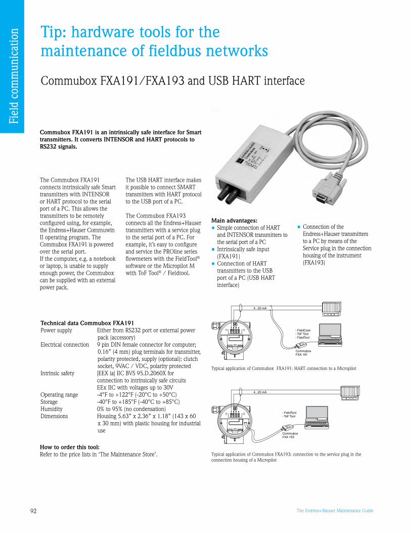
2 The Endress+Hauser Maintenance Guide
Tip: hardware tools for the maintenance of fieldbus networks
Commubox FXA11/FXA1 and USB HART interface
Commubox FXA191 is an intrinsically safe interface for Smart transmitters. It converts INTENSOR and HART protocols to RS232 signals.
Main advantages:• Simple connection of HART
and INTENSOR transmitters to the serial port of a PC
• Intrinsically safe input (FXA11)
• Connection of HART transmitters to the USB port of a PC (USB HART interface)
Typical application of Commubox FXA11: HART connection to a Micropilot
The Commubox FXA11 connects intrinsically safe Smart transmitters with INTENSOR or HART protocol to the serial port of a PC. This allows the transmitters to be remotely configured using, for example, the Endress+Hauser Commuwin II operating program. The Commubox FXA11 is powered over the serial port. If the computer, e.g. a notebook or laptop, is unable to supply enough power, the Commubox can be supplied with an external power pack.
Typical application of Commubox FXA1: connection to the service plug in the connection housing of a Micropilot
Technical data Commubox FXA191Power supply Either from RS22 port or external power
pack (accessory)Electrical connection pin DIN female connector for computer;
0.16” (4 mm) plug terminals for transmitter, polarity protected, supply (optional): clutch socket, VAC / VDC, polarity protected
Intrinsic safety [EEX ia] IIC BVS 5.D.2060X for connection to intrinsically safe circuits EEx IIC with voltages up to 0VOperating range -4°F to +122°F (-20°C to +50°C)Storage -40°F to +185°F (-40°C to +85°C)Humidity 0% to 5% (no condensation)Dimensions Housing 5.6” x 2.6” x 1.18” (14 x 60
x 0 mm) with plastic housing for industrial use
The USB HART interface makes it possible to connect SMART transmitters with HART protocol to the USB port of a PC.
The Commubox FXA1 connects all the Endress+Hauser transmitters with a service plug to the serial port of a PC. For example, it’s easy to configure and service the PROline series flowmeters with the FieldTool®
software or the Micropilot M with ToF Tool® / Fieldtool.
• Connection of the Endress+Hauser transmitters to a PC by means of the Service plug in the connection housing of the instrument (FXA1)
How to order this tool: Refer to the price lists in ‘The Maintenance Store’.
Fiel
d co
mm
unic
atio
n

The Endress+Hauser Maintenance Guide
Fieldgate FXA520 - Modem for remote maintenance
Fieldgate FXA520 enables remote monitoring, diagnosis and configuration of connected HART field instruments (sensors/actuators) by telephone lines (analog), Ethernet TCP/IP or mobile communications (GSM). The measured data is web-compatible (http, html) and can therefore be displayed in your web browser without additional software. Fieldgate FXA520 has many possibilities from remote maintenance to inventory management (VMI).
Main advantages• Worldwide access to
measuring points with HART protocol via the Internet
• Simple configuration with web browsers without additional software
• Visualization of all sensor data• Remote monitoring, diagnosis
and configuration• Uses standard Internet
protocols (http, html)• Event message via e-mail and
SMS
• Efficient employment of standby and maintenance staff
• The Fieldgate FXA520 has standard two channels for HART devices and two chan-nels for analog inputs 4 to 20 mA (use of multiplexers is possible up to 0 channels)
• DAT module for configuration data backup
Avoid on-site service operations by using remote monitoring, diagnosis and configuration:
GSM antenna on a solar panel
How to order this tool: Refer to the price lists in ‘The Maintenance Store’.
Fiel
d co
mm
unic
atio
n

4 The Endress+Hauser Maintenance Guide

At your serviceAn extended set of tools and services to efficiently manage your assets
5The Endress+Hauser Maintenance Guide
Contents
W@M - Life Cycle Management for process automation 96
Commissioning 100
FieldCare® 101
Field Xpert 102
Calibration services 104
CompuCal™ 107
Maintenance services 108
Installed Base Audit 111
Training 114

6 The Endress+Hauser Maintenance Guide
W@MLife Cycle Management for process automation
Knowledge is a critical factor in driving productivity and competitiveness - and full knowledge of your plant status allows for good maintenance planning. W@M – Life Cycle
www.us.endress.com/W@M
At y
our
serv
ice
What is W@M – Life Cycle Management?W@M – Life Cycle Management, is an open information management system providing data flow and archiving for the
technical and operational management of your plant completely, conveniently, and at any time or place. From engineering, procurement, and commissioning through operation, maintenance, and the
replacement of individual components, W@M is an open and flexible information platform with on-site tools and services supporting you throughout your plant’s life cycle.
Engineering
Management from Endress+Hauser provides up-to-date and complete information on all your assets, including products from other suppliers.
Selection
Configuration
Buying
Procurement
Order tracking
Installation
Configuration
CommissioningOperation
Condition monitoring
Spare part planning
Maintenance
Calibration
Documentation management
Replacing spare parts
Reorder

7The Endress+Hauser Maintenance Guide
Operations• Up-to-date information:
65 days a year / 24 hours a day• Effectively service, maintain and
optimize your installed base• Constant planning reliability
Engineering• Fast and safe selection and sizing of
the correct measuring instrument for your application
• Documentation and administration of projects
Procurement• Reduce procurement costs• Optimize the quality and speed
of your procurement processes• Your price and delivery data is
always available on-line
Installation• Product documentation is available in
different languages• Software versions are always up-to-date
Commissioning• Simplified remote commissioning• Increased safety of your personnel• Eliminate the need for time
consuming testing
At y
our
serv
ice
During the procurement phase, W@M helps you check availability and prices quickly and efficiently – simply place the configured instrument in the shopping cart and place your order. Immediately, the status of the order or shipment can be monitored online. What’s more, the preparation of catalogs and spare parts files makes ordering as easy as possible. Your orders can be prepared and fully completed in the Endress+Hauser e-shop.
In the commissioning phase, W@M – Life Cycle Management provides all the information you need for safe installation and commissioning. You can quickly download documentation, software, or certificates in a variety of different languages.
During the operations phase, W@M provides updated and quickly available information: be it on spare parts, the verification of software versions, tracing instrument history records or viewing the plant database with its installed instruments. Using tools such as FieldCare, CompuCal, and the Installed Base Assistant, data can be freely exchanged with the equipment record within W@M. So, you can safely comply with continually increasing quality requirements through traceable and certified calibration and documentation.
How does W@M support your internal processes?

8 The Endress+Hauser Maintenance Guide
Integration into CMMS systemsThe information content of W@M can be integrated into existing CMMS (Computerized Maintenance Management Systems) installations such as SAP PM, Maximo from IBM, Datastream7i from Infor or any other system.Users do not have to learn how to use a new system: they keep working in their familiar environment but gain access to much more information about their assets.
Integration into Endress+Hauser toolsYou already use FieldCare or CompuCal, Endress+Hauser’s device configuration and calibration tools? With your W@M application, you may access detailed device information directly from those tools with one single click. Of course this also works for rd party instruments managed in the W@M environment.
SAP PM module recognizes an Endress+Hauser device and offers a link to the W@M Portal. Login details and serial number are automatically transferred allowing information about the current asset to be displayed in a browser window.
FieldCare using its device-in-web functionality connects to your W@M application and shows device related information with its integrated web browser.
Easy integration into your existing tools
With the help of tree view navigation, any combination of location or sub-locations, applications, loops and bus systems can be mapped, allowing W@M to reproduce the exact structure of your plant.
Spare parts lists for Endress+Hauser instruments are made available automatically. Exploded view drawings help to easily identify the right parts.
Live data and great functionalityWhat makes the W@M concept so very special is the unique combination of a software tool with great features and functionality, and the ability to connect to a supplier’s database to display up-to-date data.
This means that you automatically benefit from the information recorded and stored by Endress+Hauser about your instruments, e.g. product availability, original calibration certificates, operating manual, etc.
In addition to this, you can archive your own information and documentation related to your assets. Therefore, W@M is centrally organized information management for you and your colleagues.
At y
our
serv
ice
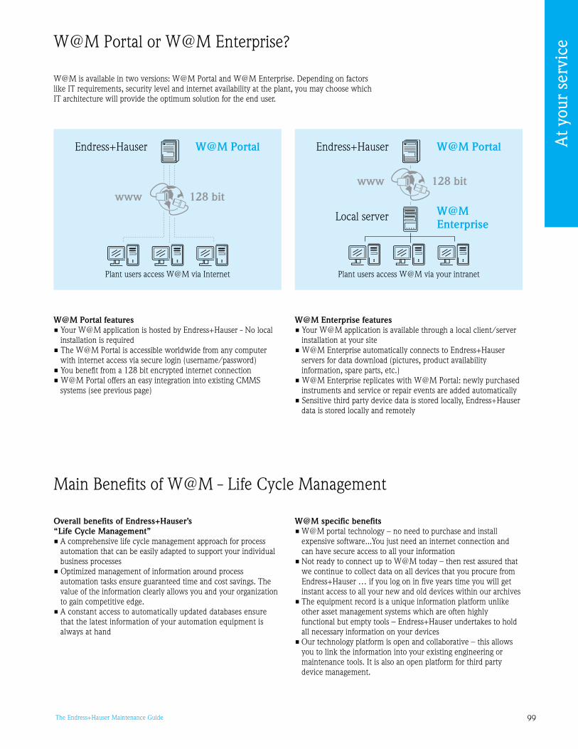
The Endress+Hauser Maintenance Guide
W@M is available in two versions: W@M Portal and W@M Enterprise. Depending on factors like IT requirements, security level and internet availability at the plant, you may choose which IT architecture will provide the optimum solution for the end user.
W@M Portal features• Your W@M application is hosted by Endress+Hauser - No local
installation is required• The W@M Portal is accessible worldwide from any computer
with internet access via secure login (username/password)• You benefit from a 128 bit encrypted internet connection• W@M Portal offers an easy integration into existing CMMS
systems (see previous page)
W@M Enterprise features• Your W@M application is available through a local client/server
installation at your site• W@M Enterprise automatically connects to Endress+Hauser
servers for data download (pictures, product availability information, spare parts, etc.)
• W@M Enterprise replicates with W@M Portal: newly purchased instruments and service or repair events are added automatically
• Sensitive third party device data is stored locally, Endress+Hauser data is stored locally and remotely
Endress+HauserW@M Portal W@M Portal
www 128 bitwww 128 bit
Local server W@M Enterprise
Endress+Hauser
Plant users access W@M via Internet Plant users access W@M via your intranet
W@M Portal or W@M Enterprise?
Overall benefits of Endress+Hauser’s “Life Cycle Management”• A comprehensive life cycle management approach for process
automation that can be easily adapted to support your individual business processes
• Optimized management of information around process automation tasks ensure guaranteed time and cost savings. The value of the information clearly allows you and your organization to gain competitive edge.
• A constant access to automatically updated databases ensure that the latest information of your automation equipment is always at hand
Main Benefits of W@M - Life Cycle Management
W@M specific benefits• W@M portal technology – no need to purchase and install
expensive software...You just need an internet connection and can have secure access to all your information
• Not ready to connect up to W@M today – then rest assured that we continue to collect data on all devices that you procure from Endress+Hauser … if you log on in five years time you will get instant access to all your new and old devices within our archives
• The equipment record is a unique information platform unlike other asset management systems which are often highly functional but empty tools – Endress+Hauser undertakes to hold all necessary information on your devices
• Our technology platform is open and collaborative – this allows you to link the information into your existing engineering or maintenance tools. It is also an open platform for third party device management.
At y
our
serv
ice

100 The Endress+Hauser Maintenance Guide
Your main benefits• Short start-up times performed by experienced
Service staff• Cost-efficient packages focused on your start-up
requirements• Device performance guaranteed from the beginning of
start-up• Briefing and documentation by Endress+Hauser• All test equipment and special tools provided
Start-up and commissioningOptimize your instruments’ performance right from the start
The demands on your engineering and maintenance staff are higher than ever before. They are expected to be able to maintain existing equipment yet still be able to accommodate the start-up of new plants often faced with the latest technology and equipment that they are not familiar with.
This is where Endress+Hauser can help - our experienced Service staff can reduce the time to commission to the essential minimum. That saves time and money.
Not only a start-up - we offer more …
• The installation is checked to confirm optimum location of the measuring instrument – ensuring best product performance
• The application is reassessed to define exact instrument settings and confirm instrument choice
• All electrical connections are tested to verify operational safety of the system and compliance to EMC regulations
• Hands-on training is carried out for your operators and technicians
• A final report / certificate is issued detailing equipment setup and advising future maintenance requirements.
You decide about the scope of commissioning services required. Beside the standard components each start-up contains, we offer optional services to you for special measuring instruments or customized solutions, for example the start-up of complete communication or fieldbus network.
Installationcheck
Functionalchecks
Configuration
Verification ofmeasurement
Servicereport
Shortintroduction
Extendedhands-on training
Measuring pointcertificate
Linearisation ofmeasuring points
Extended on-siteservice*
Sophisticatedmeasurementequipment**
Loop check
Customized
Standard
Optional
Commissioning ofcommunicationnetworks***
Custody transfermeteringapplication****
Commissioning of non Endress+Hauser products
* Extended Warranty with repair service on-site, 1 year after commissioning
** e.g. for radioactive level and density systems to comply with local laws and regulations
*** Fieldbus instruments incl. Profibus PA/DP, Rackbus, FF devices
**** For witness testing of a system in conjunction with outside officials
www.us.endress.com/start-up
At y
our
serv
ice

101The Endress+Hauser Maintenance Guide
Commissioning in the regulated industries demands a high level of experience and documentation to ensure that your IQ/OQ requirements are fulfilled. Our Service Engineers are trained in accordance with GMP and we can offer full validation services as required.
Other example demands a high level of experience and documentation to ensure that your IQ/OQ requirements are fulfilled.
Other example demands a high level of experience and documentation to ensure that your IQ/OQ requirements are fulfilled. Our service Engineers are trained in accordance to GMP and we can offer full validation services as required.
FieldCare®
From device configuration to plant asset management
FieldCare can be used in direct connection to W@M in order to enhance the management of your assets.
www.us.endress.com/fieldcare
FieldCare is Endress+Hauser’s ‘FDT based Configuration and Plant Asset Management Tool’ that will gradually replace all Endress+Hauser device operation tools. It is an open platform that enables third party device operation (via DTM) because it is based on an open standard.
Fit to your own needsFieldCare starts from a simple device configuration and parameterization tool (FieldCare Device Setup) that can be up-graded to offer advanced device operation and management functionalities (FieldCare Standard) as well as Plant Asset Management functionalities (FieldCare Professional).
Main advantages• Supports Ethernet, HART and PROFIBUS
(Foundation Fieldbus in preparation)• Operates all E+H devices (please contact
your local Endress+Hauser Service department)
• Operates all third party sensors, actuators, remote I/Os, drives delivering FDT standard compliant DTMs
• Ensures full functionality for all devices via their DTMs
• Offers Generic HART and Profibus Profile operation for any third party fieldbus devices that do not have a vendor DTM
FieldCare (free version) available for download from www.us.endress.com/fieldcare
At y
our
serv
ice

102 The Endress+Hauser Maintenance Guide
Field XpertHigh performance device configurator that meets the needs and requirements of the process industry
Field Xpert Field Xpert is a compact, flexible, ergonomic and robust industrial PDA adapted to your needs for high productivity. The Field Xpert package includes:• Field Xpert device• Device Xpert configuration software for all registered HART devices• HART/BluetoothTM modem for device connection
Field Xpert offers functions to reduce your instrument setup and diagnosis time. It operates with HART/BluetoothTM modem and WLAN supported networks.
Device Xpert Device Xpert configuration software makes Field Xpert the complete HART communicator for industrial applications.Device Xpert is designed for project commissioning and maintenance. It is designed to support the daily requirements of field technicians.
By supporting special device functions, e.g. envelope curves from Endress+Hauser time-of-flight level transmitters and automatic distribution of Device Descriptions (DD) via Internet or WLAN, Device Xpert ensures quick and flexible operation.
Device Xpert supports Endress+Hauser‘s Fieldgate FXA520, allowing Ethernet communication to your remote HART field devices. Support for other communication protocols is in development.
Flexible architectureThe Windows MobileTM operating system makes it possible to install other software applications for Plant Asset Management activities such as maintenance and documentation.
The Endress+Hauser software packages of the Xpert series run well on Field Xpert. This makes Field Xpert a real all-rounder for tough industrial applications.
Connection
Field Xpert with Bluetooth™ connection Field Xpert with WLAN (WiFi™) connection
Existingcontroller
4 to 20 mA
Ethernet TCP/IP
FieldgateFXA520 HART
Multiplexer
4 to 20 mA

10The Endress+Hauser Maintenance Guide
• Connections Device Xpert supports the use of multiple connections. The user can configure a specific serial port and address scan range appropriate to one scenario and then configure another connection to address a different requirement. Each device is shown in a group view, so that the correct parameter is easily found.
• Device configuration Every parameter is easy to find and to configure. If the location of a specific function is unknown, the integrated Function Finder locates it in all HART devices. This is especially useful with complex devices with many parameters.
• Device diagnosis Device Xpert offers the range of diagnosis supported by the Device Description (DD). Basic information such as device status can be seen at a glance, making diagnosis easy.
Device Xpert
• Device extensions Device Xpert interprets DD extensions, allowing access to custom functionality that is normally not available in a handheld terminal. Such functions include envelope curves for Endress+Hauser level transmitters, valve signatures for positioner actuators and custom calibration routines.
Display• .5” transreflective TFT color• 64k, QVGA, 240 x 20 pixel• Portrait and landscape mode• Protected by a Makrolon panel Power Supply Rechargeable lithium ion battery• Non-Ex version: 2880 mAh• Ex version: 600 mAh
Housing• Protection class IP 65 (immersion for brief periods)• Antistatic• Non-corroding
Dimensions L x W x D• 7” x .” x 1.5” (178 x 85 x mm)
Weight• Non-Ex version: 1.2 lbs. (550 gram)• Ex version: 1.5 lbs. (700 gram)
Temperature ranges • Storage: 14°F up to 140°F (-10°C up to +60°C)• Charging: 2°F up to 11°F (0°C up to +45°C)• Working, non-Ex version: 14°F up to 140°F (-10°C up to +60°C)• Working, Ex version: 14°F up to 122°F (-10°C up to +50°C)
Relative humidity• Storage and operation: up to 0% r.h.
Accessories• Leather carrying case: 7106688• USB data transmission set: 71066841• Viator Bluetooth interface for HART: 71066844• Charger LG10: 71066847• Spare stylus (2 pcs/pk) 71066850
Field Xpert

104 The Endress+Hauser Maintenance Guide
Does the instrumentation that controls your quality critical processes need regular checking, validation and calibration? Do you need a cost-effective service that is fast, of high quality, traceable and accredited? Do you need clear and concise calibration certificates?
Endress+Hauser covers all these critical aspects, and can perform and advise on all aspects of calibration from in-situ testing to fully accredited factory calibration. We calibrate your equipment at just the right time. This ensures optimal process performance at minimum cost.
Calibration servicesA complete range of calibration services to suit your requirements
www.us.endress.com/calibration
Parameter Equipment type Calibration location
Temperature
• Resistance sensor• Probe + temperature
transmitter• Probe + display
On-site
In the laboratory
Pressure• Manometers• Pressure sensors• Pressure transmitters
On-site
In the laboratory
Flow
• Electromagnetic flowmeters
• Vortex flowmeters• Coriolis flowmeters• Ultrasonic flowmeters• Thermal flowmeters• Mechanical flowmeters
On-site
In the laboratory
ConductivityConductivity measuring chain including cell, transmitter and cable
On-site
pHpH measuring chain including cell, transmitter and cable
On-site
Other parameters
On request, we can calibrate other parameters. Please contact your local Endress+Hauser partner for further information.
Endress+Hauser performs instrument calibrations across a variety of measuring principles. We even extend our calibration service to third party equipment to reduce time, effort and cost in terms of coordination and documentation.
Accredited facilitiesThanks to accredited laboratories installed in our factories and our Service organization, we can offer the accredited calibration of:
On-site calibrationHaving also invested in mobile reference tools and in the deployment of a powerful Service organization in many countries, Endress+Hauser can also perform on-site calibration of the following parameters:
We suggest that you ask your local Sales Center about any particular request.
• flow (SCS accreditation), • pressure (DKD accreditation) • temperature (SIT accredita-
tion) measurement devices
• moisture• voltage, current
• flow• pressure• temperature• weight• viscosity
• time• length• speed• conductivity• voltage, current
At y
our
serv
ice

105The Endress+Hauser Maintenance Guide
1Calibration specificationEndress+Hauser will help you to establish your metrology plan by fixing your calibration specifications per parameter (maximum permissible errors, periodicities) or by defining the right reference tools according to their uncertainty.Together, we will work out which parameters have to be calibrated on site and, in the case of high accuracy requirements, which need calibrating in the laboratory.
Calibration SOPsWe offer a full range of Standard Operating Procedures to support our on-site work. SOPs ensure that our work is repeatable all over the world. We also provide site specific SOP’s noting which measuring parameters have to be calibrated on-site and in case of high accuracy requirements, which need calibrating in the laboratory.
Test equipmentLocal service centers provide a one-stop calibration and repair service to a wide range of test, measurement and process control instrumentation. So whether you need pressure, analytical, temperature or flow calibration, look no further.All of our facilities are traceable to national and international standards. This means you are guaranteed the highest level of service compliant with the ISO 17025 standard.
Trained employeesOn-site calibration is performed by special, highly trained staff. This relieves your in-house maintenance staff from routine time consuming tasks and allows them to focus on improving plant availability. For you this means reliable advice, optimum performance of your instruments and true cost-effectiveness. Our Service technicians are trained in accordance with GMP.
2
3
Calibrationspecification
CalibrationSOPs
TestEquipment
Trained Employees
1 2
3
4
4
Endress+Hauser has carried out more than one million calibrations.Above all we see our calibration service as part of your repair and maintenance planning. Our aim is to provide you with complete calibration management solutions. At the forefront of this is the tuning of calibration cycles, planning dates for carrying out calibration work, the coordination of personnel and certified calibration equipment.
Calibrationspecification
CalibrationSOPs
TestEquipment
Trained Employees
CalibrationWork
CalibrationDocumentation
Calibrationsoftware
1 2
3
45
6
7 Circle of quality calibration
Discussion around the metrology plan SOPs, calibration certificates, labels and electronic recordings
At y
our
serv
ice

106 The Endress+Hauser Maintenance Guide
CalibrationWork
CalibrationDocumentation
Calibrationsoftware
56
7Calibration workAll of our primary calibration facilities operate and are accredited to ISO 17025 and are located around the world. We own and operate more calibration laboratories than any other instrumentation supplier.As a leading supplier of field instrumentation we not only can calibrate, but also quickly and efficiently adjust, repair or replace equipment that is failing to meet the specified criteria. Our specialists have the necessary skills and equipment to calibrate all makes of instruments.
5
Calibration documentationWe support our service with certified and traceable documentation.A calibration certificate compliant with the ISO 17025 standard is issued. It details all required data in a way that is easy to understand. Importantly, it also satisfies all relevant authorities.
Calibration management softwareCompuCal™ is a high performance scheduling and electronic software tool that helps to control the scheduling activity around your installed base, providing traceable and auditable records. 6
7
On-site calibration of temperature instruments
On-site calibration of pressure devices Laboratory calibration of level instruments On-site calibration of analysis devices
Oil & gas industries• On-site flow calibration rigs up to 6”
(DN150)• Calibration of all kinds of custody transfer
devices• Calibration of flowmeters up to 80”
(DN2000)
Environmental industry• Calibration of all kinds of measurement
equipment• Verification of flowmeters• Calibration of custody transfer instruments• Calibration of flowmeters up to 80”
(DN2000)
Life sciences industryAs a compliant partner, we:• Perform calibration of any kind of process
measuring point according to cGMP regulations and universal guidelines
• Document any service provided• Prove traceability by ensuring the
conformity to Standard Operating Procedures
• Keep Service staff trained to GxPs.
Food & beverage industries• Calibration within HACCP requirements• Calibration management strategies to
support production costs concepts
Chemical industries• On-site flow calibration rigs up to 6”
(DN150)• Calibration of all kinds of safety relevant
measuring points• Calibration of flowmeters up to 80”
(DN2000)
Renewable fuels industry• On-site flow calibration rigs up to 6”
(DN150)
We fulfill the needs of all industries:
At y
our
serv
ice
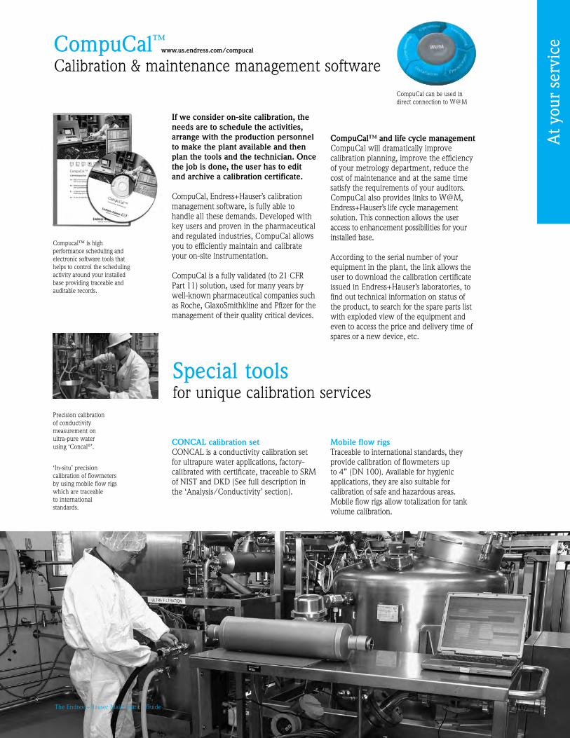
107The Endress+Hauser Maintenance Guide
CompuCal™Calibration & maintenance management software
www.us.endress.com/compucal
If we consider on-site calibration, the needs are to schedule the activities, arrange with the production personnel to make the plant available and then plan the tools and the technician. Once the job is done, the user has to edit and archive a calibration certificate.
CompuCal, Endress+Hauser’s calibration management software, is fully able to handle all these demands. Developed with key users and proven in the pharmaceutical and regulated industries, CompuCal allows you to efficiently maintain and calibrate your on-site instrumentation.
CompuCal is a fully validated (to 21 CFR Part 11) solution, used for many years by well-known pharmaceutical companies such as Roche, GlaxoSmithkline and Pfizer for the management of their quality critical devices.
CompuCal™ and life cycle managementCompuCal will dramatically improve calibration planning, improve the efficiency of your metrology department, reduce the cost of maintenance and at the same time satisfy the requirements of your auditors. CompuCal also provides links to W@M, Endress+Hauser’s life cycle management solution. This connection allows the user access to enhancement possibilities for your installed base.
According to the serial number of your equipment in the plant, the link allows the user to download the calibration certificate issued in Endress+Hauser’s laboratories, to find out technical information on status of the product, to search for the spare parts list with exploded view of the equipment and even to access the price and delivery time of spares or a new device, etc.
CompuCal can be used in direct connection to W@M
Precision calibration of conductivity measurement on ultra-pure water using ‘Concal®’.
‘In-situ’ precision calibration of flowmeters by using mobile flow rigs which are traceable to international standards.
Compucal™ is high performance scheduling and electronic software tools that helps to control the scheduling activity around your installed base providing traceable and auditable records.
Special toolsfor unique calibration services
CONCAL calibration setCONCAL is a conductivity calibration set for ultrapure water applications, factory-calibrated with certificate, traceable to SRM of NIST and DKD (See full description in the ‘Analysis/Conductivity’ section).
Mobile flow rigsTraceable to international standards, they provide calibration of flowmeters up to 4” (DN 100). Available for hygienic applications, they are also suitable for calibration of safe and hazardous areas. Mobile flow rigs allow totalization for tank volume calibration.
At y
our
serv
ice

108 The Endress+Hauser Maintenance Guide
Maintenance servicesThe right maintenance support for all your measuring points
Preventive serviceWe test and certify the operating integrity of the equipment to ensure optimum performance and full compliance to specific regulatory requirements.Periodic checks according to our Standard Operating Procedures (SOP) can be combined with annual replacement of wear parts or consumables, telephone support during non-opening hours. An independent report confirms the instrument’s performance and reliability.
Your benefits• The necessary maintenance
tasks to ensure an optimal instrument performance
• The delivery of documented reports to ensure you comply with audited quality procedures
With Endress+Hauser service contracts, you decide the right level of maintenance support you require. We provide regular checks on your equipment and warranty extensions providing you with complete peace of mind and cost control.
Extended serviceIn addition to the features of the preventive service, we guarantee to support all contracted instruments. This covers any callout costs for travel and time on-site. Furthermore, commissioning costs for new instruments under contract agreement will be covered by Endress+Hauser.
Your additional benefits• Reliable back-up and
instrument operation between preventive maintenance visits
• Any pre-arranged extra visits for the commissioning of newly contracted equipment are included in the costs
From regular support to partnership agreements, we offer four distinct levels of service:
Total serviceIn addition to the features of the extended contract, we cover any costs for spare parts in the event of equipment failure. As an option, we can support all the contracted instruments for on-site repairs within a quick response time to be defined by both parties.
Your additional benefits• Commissioning spares callout
covered• Complete control of your
maintenance budget
Tailor-made servicePeace of mind, reliability and security of your installed base - we can help you to achieve all these with a tailor-made service agreement. In consultation with you, we define and agree on a scheduled package of services and guarantees to ensure we meet all your maintenance needs and provide a customized service solution. For example, this kind of contract can include calibration activities, remote services, maintenance of software updates, etc.
Your additional benefits• Endress+Hauser Support
Services perfectly complement your internal resources
www.us.endress.com/contracts
At y
our
serv
ice
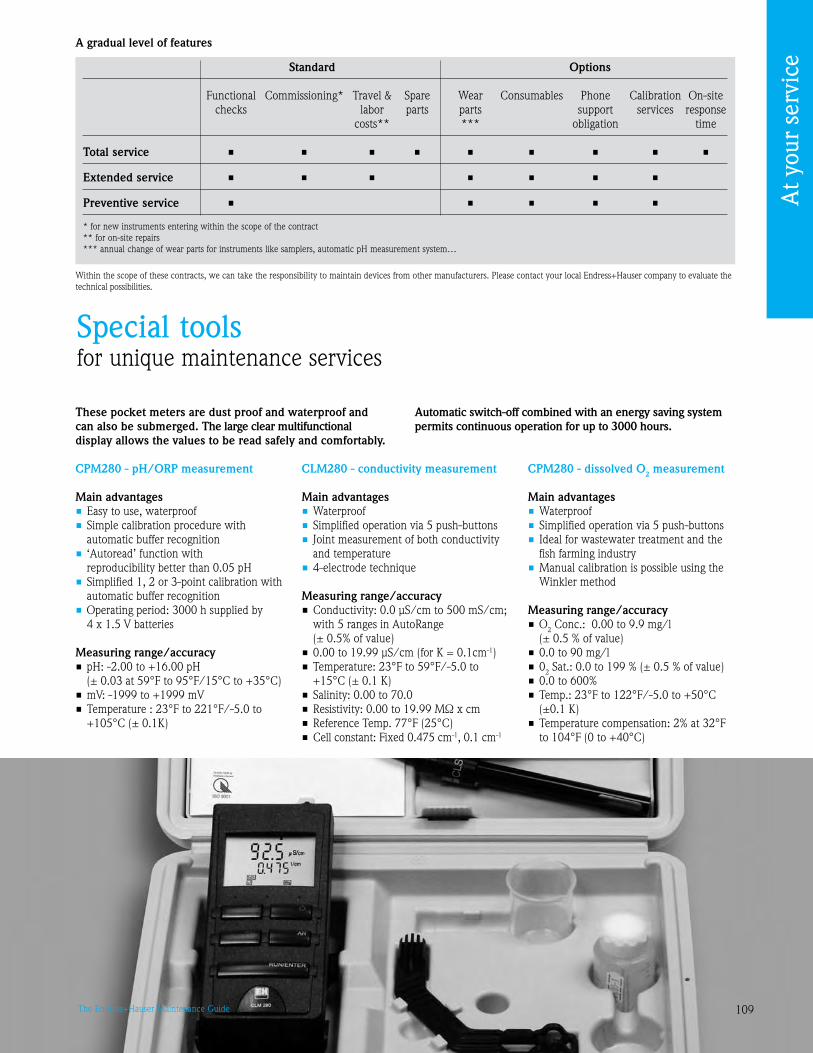
10The Endress+Hauser Maintenance Guide
Standard Options
Functional Commissioning* Travel & Spare Wear Consumables Phone Calibration On-site checks labor parts parts support services response costs** *** obligation time
Total service • • • • • • • • •
Extended service • • • • • • •
Preventive service • • • • •
* for new instruments entering within the scope of the contract** for on-site repairs*** annual change of wear parts for instruments like samplers, automatic pH measurement system…
A gradual level of features
Within the scope of these contracts, we can take the responsibility to maintain devices from other manufacturers. Please contact your local Endress+Hauser company to evaluate the technical possibilities.
These pocket meters are dust proof and waterproof and can also be submerged. The large clear multifunctional display allows the values to be read safely and comfortably.
CPM280 - pH/ORP measurement
Main advantages• Easy to use, waterproof• Simple calibration procedure with
automatic buffer recognition• ‘Autoread’ function with
reproducibility better than 0.05 pH• Simplified 1, 2 or -point calibration with
automatic buffer recognition • Operating period: 000 h supplied by
4 x 1.5 V batteries
Measuring range/accuracy• pH: -2.00 to +16.00 pH
(± 0.0 at 5°F to 5°F/15°C to +5°C)• mV: -1 to +1 mV• Temperature : 2°F to 221°F/-5.0 to
+105°C (± 0.1K)
CLM280 - conductivity measurement
Main advantages• Waterproof• Simplified operation via 5 push-buttons• Joint measurement of both conductivity
and temperature• 4-electrode technique
Measuring range/accuracy• Conductivity: 0.0 μS/cm to 500 mS/cm;
with 5 ranges in AutoRange (± 0.5% of value)
• 0.00 to 1. μS/cm (for K = 0.1cm-1)• Temperature: 2°F to 5°F/-5.0 to
+15°C (± 0.1 K)• Salinity: 0.00 to 70.0• Resistivity: 0.00 to 19.99 MΩ x cm• Reference Temp. 77°F (25°C)• Cell constant: Fixed 0.475 cm-1, 0.1 cm-1
CPM280 - dissolved O2 measurement
Main advantages• Waterproof• Simplified operation via 5 push-buttons• Ideal for wastewater treatment and the
fish farming industry• Manual calibration is possible using the
Winkler method
Measuring range/accuracy• O2 Conc.: 0.00 to . mg/l
(± 0.5 % of value)• 0.0 to 0 mg/l• 02 Sat.: 0.0 to 1 % (± 0.5 % of value)• 0.0 to 600%• Temp.: 2°F to 122°F/-5.0 to +50°C
(±0.1 K)• Temperature compensation: 2% at 2°F
to 104°F (0 to +40°C)
Automatic switch-off combined with an energy saving system permits continuous operation for up to 3000 hours.
Special toolsfor unique maintenance services
At y
our
serv
ice

110 The Endress+Hauser Maintenance Guide
Prosonic Flow 92 portable ultrasonic flowmeter
The Prosonic Flow 2 gives you the possibility to efficiently verify and optimize your process, wherever and whenever you want, without interrupting the process.This portable ultrasonic flowmeter convinces because of its sophisticated ‘clamp on’ sensor technology and allows you to take temporary measurements from outside anytime you like.
Main advantages• Ideally suited for bidirectional measurements
of pure and slightly soiled liquids (gas content <1% or solids content < 5%)
• Portable transmitter battery operated• Built-in datalogger with a capacity of
40,000 measuring values• Simultaneous logging of volume flow,
flow velocity, totalizer and one external value (4 to 20mA)
• Site setup operating menus for straightforward of up to 20 measurement sites
• Clamp on sensors, non-contact measurement technique
• Very wide range of nominal diameters ½” to 160” (DN15 to DN4000), temperature range -4°F to +176°F (-20°C to +80°C)
• Data readout software for use with personal computer
• Current inputs and outputs (4 to 20mA)
Special tools for unique maintenance services (cont’d)
FieldCheck® smart signal simulator
Designed especially for flowmeter verification*, FieldCheck® simulates sensor signals to test and evaluate the behavior of a piece of equipment. It can also, thanks to its
*With FieldCheck®, meter verification can be carried out without the removal of the Proline flowmeter from the pipe. Where ISO 000 requires frequent test cycles, FieldCheck® is an economical alternative to calibration.
checking procedures, test proper flowmeter functioning – be it to meet in-house criteria or regulatory requirements.
FieldCheck smart signal simulator is presented on page 1 (‘Flow/Basics’).
W sensor• 4” to 160” (DN100 to DN4000)• -4°F to +176°F (-20°C to +80°C)• Stainless steel sensor holders• Protection: Sensor NEMA 4X/IP67 BNC adaptor IP52
U sensor• ½” to 4” (DN15 to DN100)• -4°F to +176°F (-20°C to +80°C)• Plastic/aluminum sensor assembly• Protection: IP52
Available for short-term rental. See www.us.endress.com/rental
At y
our
serv
ice

111The Endress+Hauser Maintenance Guide
Installed Base AuditAuditing and analyzing your installed base of process instrumentation
www.us.endress.com/IBA
Installed Base Audit allows you:• To make the right decisions
in terms of focusing the needed maintenance efforts according to your available resources and production requirements
• To help you to decrease the high complexity of your older plant with different brands of equipment and large variety of instrument types
Ask yourself three simple questions:
• Do you know exactly which part of your installed instrumentation base is critical to the operation of the plant and how you could maintain it more efficiently?
• Are you completely sure that your present actions are minimizing the risks of unplanned breakdowns?
• Are you sure that your present preventive actions are the most cost effective?
With Endress+Hauser’s Installed Base Audit, you will quickly find an answer to these three questions and move forward in a controlled manner to a maintenance plan which improves plant reliability while reducing costs.
Finding the right balance Our objective is to help you reach the optimum point where the overall costs are at their minimum level. We understand that too little maintenance and no back-up can result in costly downtime, but on the other hand, too much maintenance is unnecessary and leads to additional expense.
• To point out your out-of-date plant documentation not reflecting the actual status
• To define the necessary actions to handle higher demands on production quality and availability
• To fulfill the highest safety requirements
% T
otal
equ
ipm
ent c
osts
Initialcosts
Maintenance and operation costs
Time
ARC studies point out new ways to optimize maintenance costsAsset Management can reduce unplanned equipment related incidents. People and process related incidents could be reduced by better decision support tools found in Asset Management
Degree of preventative maintenance
Tota
l cos
t
Target zone:Optimized relationship,
minimum cost
Nomaintenance
Too much maintenance
Companies are looking for lower Total Cost of Ownership (TCO)Optimizing maintenance costs and increasing equipment life cycles are priorities today.
The targets
At y
our
serv
ice

112 The Endress+Hauser Maintenance Guide
How we work with you
Step 4 - Analysis and recommendations definitionConsists of: a detailed analysis of your installed base focused on the maintenance activities you choose in step
Involves: the Endress+Hauser consultant
• Based on your wishes expressed in step , the Endress+Hauser Consultant realizes a thorough study of the activities to improve
• The Endress+Hauser consultant then defines the recommendations and proposes one or more possibilities
Step 2 - Revealing process critical instrumentsConsists of: definition of the critical measuring points, the maintainability of all your instruments
Involves: typically the Endress+Hauser consultant and the Production, Quality and Maintenance Departments’ representatives
• During a meeting, the Endress+Hauser Advisor has the moderator role asking the relevant questions to define the critical point
• Each measuring point is assigned with the criticality level (High, Medium, Low)
Step 1 - Collecting data in the plantConsists of: on-site inventory of the main technical data issued from your installed instrumentation (all manufacturers)
Involves: an Endress+Hauser Audit Technician and one of your technicians who knows the assets’ location and the applications
Equipped with a dedicated Personal Digital Assistant, the Endress+Hauser Audit Technician collects and records: • Instrument data (serial number, tag, order code, manufacturer,
type and model, location, age, measuring principle, process conditions)
• Application data (pressure, temperature, medium)
At y
our
serv
ice

11The Endress+Hauser Maintenance Guide
Step 5 - Presentation of the results and action planInvolves: the Endress+Hauser Consultant and the interested representatives of your company
• Presentation of the detailed analysis and the different possibilities for each topic to optimize
• Decision points and action plan definition • Delivery of the final Installed Base Audit report covering all the
detailed analysis and recommendations
Step - Highlighting potential improvements Consists of: assessment of the status report giving you an overview of the status of your installed base with global improvement recommendations
Involves: the Endress+Hauser Consultant and all the representatives the Endress+Hauser Advisor and all the representatives of your company who participated in the first steps.
• The Endress+Hauser Consultant studies the data collected during steps 1 and 2
Installed Base Audit gives you an access to the W@M Portal. The data collected during the on-site inventory are presented here in a structured format. The W@M portal also includes additional information linked to the serial number of the instrument.
At the conclusion of step 5, you are delivered the final Installed Base Report allowing you to implement an action plan.
• He defines and presents the global improvement you could bring to the different areas of your maintenance activities (preventive and corrective maintenance, standardization, migration)
• He opens your W@M portal (see picture below) - there you will find the status report and the collected data presented in a structured manner
Concerned about constantly improving the quality of our services, we periodically form and audit our staff according to Endress+Hauser’s standards. We do our best to satisfy your expectations.
At y
our
serv
ice

114 The Endress+Hauser Maintenance Guide
TrainingInvesting in people
Have you recently purchased new instrumentation that is operated using unfamiliar principles? Do you want to improve your response times in case of possible measurement failure? If the answer is ‘yes’, why not improve your technical knowledge and apply to your maintenance schedule.
Your main benefits• Learn how to operate and maintain your equipment
efficiently and effectively• Discover methods for preventive and corrective
planned maintenance• Increased plant efficiency
Our specialists can provide your maintenance staff with the techni-cal product knowledge they require to run the plant efficiently and cost-effectively.
Training can be performed in-house or on-site. Your maintenance personnel will benefit from professional, up-to-date and hands-on training, using a range of working instruments.
The training program will be pre-defined according to your require-ments and participants will receive supplementaryliterature and a certificate of attendance.
We provide training for:• Engineers and technicians• Plant operators• Maintenance engineers• New recruits, apprentices,
refresher courses
Training topics include:• Theoretical and hands-on
knowledge• Installation advice• Start-up and maintenance
diagnostics• Troubleshooting tips• Practical exercises using a
range of working instruments
www.us.endress.com/training
At y
our
serv
ice

115The Endress+Hauser Maintenance Guide
Endress+Hauser, Inc250 Endress PlaceGreenwood, IN [email protected]
Sales: 888-ENDRESSService: 800-642-877Fax: 17-55-848
Services: reaping the benefits of balance.
In the world of measurement and automation, striking the right services balance is critical. Too little service can lead to costly breakdowns; too much service results in unnecessary overhead. That’s why Endress+Hauser provides carefully balanced services to suit your individual needs. Let us help you to find the right balance. www.us.endress.com/services

116 The Endress+Hauser Maintenance Guide
Notes...____________________________________________________________________________________________________________________
____________________________________________________________________________________________________________________
____________________________________________________________________________________________________________________
____________________________________________________________________________________________________________________
____________________________________________________________________________________________________________________
____________________________________________________________________________________________________________________
____________________________________________________________________________________________________________________
____________________________________________________________________________________________________________________
____________________________________________________________________________________________________________________
____________________________________________________________________________________________________________________
____________________________________________________________________________________________________________________
____________________________________________________________________________________________________________________
____________________________________________________________________________________________________________________
____________________________________________________________________________________________________________________
____________________________________________________________________________________________________________________
____________________________________________________________________________________________________________________
____________________________________________________________________________________________________________________
____________________________________________________________________________________________________________________
____________________________________________________________________________________________________________________

Endress+Hauser, Inc350 Endress PlaceGreenwood, IN [email protected]
Sales: 888-ENDRESSService: 800-64-8737Fax: 317-535-8498
The information you need at your fingertips.
Information at your fingertips in seconds! Whether you’re planning, procuring, installing and commissioning or operating a plant, W@M – Life Cycle Management from Endress+Hauser keeps you up to date on the complete installed base of process automation equipment, even for non-Endress+Hauser products. W@M is designed as an open and flexible information platform with software applications and services that reduce equipment failure and plant downtime, and minimize repair and maintenance costs, cutting total life cycle costs. Talk to us today. We’ll be glad to tell you more about how W@M can help improve your business. www.us.endress.com/W@M

EC 003H/4/ae/07.08
US/INDD CS
Three complementary tools to help with everyday problems
• The Maintenance Guide: this fully revised manual is the reference text for your production, metrology and maintenance teams. Keep a copy on your desk all year round.
• “Maintenance Today” is a magazine for all instrument users and anyone with responsibility for quality issues. Printed once or twice a year, it contains a selection of in-depth articles, case studies and useful information. Provides guidance on handling the challenges and developments you are likely to meet, and on choosing the tools and services best adapted to your needs.
• “Maintenance Actions” is a handy collection of information sheets dealing with a specific subject of direct relevance to your day-to-day operations. Each sheet identifies your option(s) for immediate action. We publish several sheets each year.
Coming soon: dedicated web pages!
To receive the next issues …
You have this copy already but would like to receive the electronic version (PDF)? A colleague told you about “Maintenance Today” or “Maintenance Actions”? You’d like a subscription for a colleague? Fax the coupon below to 317-535-171.
Company: . . . . . . . . . . . . . . . . . . . . . . . . . . . . . . . . . . . . . . . . . .
Name: . . . . . . . . . . . . . . . . . . . . . . . . . . . . . . . . . . . . . . . . . . . . .
Title: . . . . . . . . . . . . . . . . . . . . . . . . . . . . . . . . . . . . . . . . . . . . . .
Department: . . . . . . . . . . . . . . . . . . . . . . . . . . . . . . . . . . . . . . . .
Mailing Address: . . . . . . . . . . . . . . . . . . . . . . . . . . . . . . . . . . . . .
. . . . . . . . . . . . . . . . . . . . . . . . . . . . . . . . . . . . . . . . . . . . . . . . . .
City, State, Zip: . . . . . . . . . . . . . . . . . . . . . . . . . . . . . . . . . . . . . .
Tel: . . . . . . . . . . . . . . . . . . . . . . . . . . . . . . . . . . . . . . . . . . . . . . .
E-mail:. . . . . . . . . . . . . . . . . . . . . . . . . . . . . . . . . . . . . . . . . . . . .
Please send me:
the electronic version (PDF) of Maintenance Today
the paper version Maintenance Actions
both The Maintenance Guide
11.07/SCUSA
USA
Endress+Hauser, Inc.350 Endress PlaceGreenwood, IN 46143Tel: 317-535-7138Sales: 888-ENDRESSService: 800-64-8737Fax: [email protected]
International
For international locations visit: www.endress.com/worldwide
ISO 9001:000 Certified
Mexico
Endress+Hauser México S.A. de C.V.Fernando Montes de Oca 1 Edificio A Piso 3Fracc. Industrial San Nicolás 54030 Tlalnepantla de BazEstado de MéxicoMéxicoTel: +5 55 531 080Fax: +5 55 531 [email protected]
Canada
Endress+Hauser Canada1075 Sutton DriveBurlington, ON L7L 5Z8Tel: 905-681-99800-668-3199Fax: [email protected]