
7210 SAS D, E OS OAM and Diagnostics Guide - Nokia ...
193
7210 SAS D, E OS OAM and Diagnostics Guide Software Version: 7210 SAS OS 6.0 Rev.02 August 2013 Document Part Number: 93-0499-01-02 93-0499-01-02
-
Upload
khangminh22 -
Category
Documents
-
view
4 -
download
0
Transcript of 7210 SAS D, E OS OAM and Diagnostics Guide - Nokia ...

7210 SAS D, E OSOAM and Diagnostics Guide
Software Version: 7210 SAS OS 6.0 Rev.02August 2013Document Part Number: 93-0499-01-02
93-0499-01-02

This document is protected by copyright. Except as specifically permitted herein, no portion of the provided information can be reproduced in any form, or by any means, without prior written permission from Alcatel-Lucent.Alcatel, Lucent, Alcatel-Lucent and the Alcatel-Lucent logo are trademarks of Alcatel-Lucent. All other trademarks are the property of their respective owners.The information presented is subject to change without notice.Alcatel-Lucent assumes no responsibility for inaccuracies contained herein.
Copyright 2013 Alcatel-Lucent. All rights reserved.

Table of Contents
Preface. . . . . . . . . . . . . . . . . . . . . . . . . . . . . . . . . . . . . . . . . . . . . . . . . . . . . . . . . . . . . . . . . . . . . . . . . . . . . . .7
Getting StartedAlcatel-Lucent 7210 SAS-Series Services Configuration Process . . . . . . . . . . . . . . . . . . . . . . . . . . . . . . .11
Mirror ServicesService Mirroring. . . . . . . . . . . . . . . . . . . . . . . . . . . . . . . . . . . . . . . . . . . . . . . . . . . . . . . . . . . . . . . . . . . . .14Mirror Implementation. . . . . . . . . . . . . . . . . . . . . . . . . . . . . . . . . . . . . . . . . . . . . . . . . . . . . . . . . . . . . . . . .15
Mirror Source and Destinations . . . . . . . . . . . . . . . . . . . . . . . . . . . . . . . . . . . . . . . . . . . . . . . . . . . . . . .16Mirroring Performance. . . . . . . . . . . . . . . . . . . . . . . . . . . . . . . . . . . . . . . . . . . . . . . . . . . . . . . . . . . . . .18Mirroring Configuration . . . . . . . . . . . . . . . . . . . . . . . . . . . . . . . . . . . . . . . . . . . . . . . . . . . . . . . . . . . . .19
Configuration Process Overview . . . . . . . . . . . . . . . . . . . . . . . . . . . . . . . . . . . . . . . . . . . . . . . . . . . . . . . .20Configuration Notes . . . . . . . . . . . . . . . . . . . . . . . . . . . . . . . . . . . . . . . . . . . . . . . . . . . . . . . . . . . . . . . . . .21Configuring Service Mirroring with CLI . . . . . . . . . . . . . . . . . . . . . . . . . . . . . . . . . . . . . . . . . . . . . . . . . . . .23
Mirror Configuration Overview. . . . . . . . . . . . . . . . . . . . . . . . . . . . . . . . . . . . . . . . . . . . . . . . . . . . . . . .24Defining Mirrored Traffic . . . . . . . . . . . . . . . . . . . . . . . . . . . . . . . . . . . . . . . . . . . . . . . . . . . . . . . . . .24
Basic Mirroring Configuration . . . . . . . . . . . . . . . . . . . . . . . . . . . . . . . . . . . . . . . . . . . . . . . . . . . . . . . . . . .25Mirror Classification Rules. . . . . . . . . . . . . . . . . . . . . . . . . . . . . . . . . . . . . . . . . . . . . . . . . . . . . . . . . . .26
Common Configuration Tasks . . . . . . . . . . . . . . . . . . . . . . . . . . . . . . . . . . . . . . . . . . . . . . . . . . . . . . . . . .28Configuring a Local Mirror Service . . . . . . . . . . . . . . . . . . . . . . . . . . . . . . . . . . . . . . . . . . . . . . . . . . . .29
Service Management Tasks . . . . . . . . . . . . . . . . . . . . . . . . . . . . . . . . . . . . . . . . . . . . . . . . . . . . . . . . . . . .32Modifying a Local Mirrored Service . . . . . . . . . . . . . . . . . . . . . . . . . . . . . . . . . . . . . . . . . . . . . . . . . . . .33Deleting a Local Mirrored Service . . . . . . . . . . . . . . . . . . . . . . . . . . . . . . . . . . . . . . . . . . . . . . . . . . . . .34
Mirror Service Command Reference . . . . . . . . . . . . . . . . . . . . . . . . . . . . . . . . . . . . . . . . . . . . . . . . . . . . .37Configuration Commands . . . . . . . . . . . . . . . . . . . . . . . . . . . . . . . . . . . . . . . . . . . . . . . . . . . . . . . . . . . . . .39
OAM and SAAOAM Overview . . . . . . . . . . . . . . . . . . . . . . . . . . . . . . . . . . . . . . . . . . . . . . . . . . . . . . . . . . . . . . . . . . . . . .56
Two-Way Active Measurement Protocol . . . . . . . . . . . . . . . . . . . . . . . . . . . . . . . . . . . . . . . . . . . . . . . .56Configuration Notes . . . . . . . . . . . . . . . . . . . . . . . . . . . . . . . . . . . . . . . . . . . . . . . . . . . . . . . . . . . . .57
Ethernet Connectivity Fault Management (ETH-CFM) . . . . . . . . . . . . . . . . . . . . . . . . . . . . . . . . . . . . . . . .58ETH-CFM Building Blocks . . . . . . . . . . . . . . . . . . . . . . . . . . . . . . . . . . . . . . . . . . . . . . . . . . . . . . . . . . .60
Loopback . . . . . . . . . . . . . . . . . . . . . . . . . . . . . . . . . . . . . . . . . . . . . . . . . . . . . . . . . . . . . . . . . . . . .65Linktrace. . . . . . . . . . . . . . . . . . . . . . . . . . . . . . . . . . . . . . . . . . . . . . . . . . . . . . . . . . . . . . . . . . . . . .66Continuity Check (CC) . . . . . . . . . . . . . . . . . . . . . . . . . . . . . . . . . . . . . . . . . . . . . . . . . . . . . . . . . . .68Alarm Indication Signal (ETH-AIS Y.1731). . . . . . . . . . . . . . . . . . . . . . . . . . . . . . . . . . . . . . . . . . . .70Test (ETH-TST Y.1731) . . . . . . . . . . . . . . . . . . . . . . . . . . . . . . . . . . . . . . . . . . . . . . . . . . . . . . . . . .70
Time Stamp Capability . . . . . . . . . . . . . . . . . . . . . . . . . . . . . . . . . . . . . . . . . . . . . . . . . . . . . . . . . . . . .71One-Way Delay Measurement (ETH-1DM Y.1731) . . . . . . . . . . . . . . . . . . . . . . . . . . . . . . . . . . . . .71Two-Way Delay Measurement (ETH-DMM Y.1731) . . . . . . . . . . . . . . . . . . . . . . . . . . . . . . . . . . . .71CFM Connectivity Fault Conditions . . . . . . . . . . . . . . . . . . . . . . . . . . . . . . . . . . . . . . . . . . . . . . . . .72CFM Fault Propagation Methods . . . . . . . . . . . . . . . . . . . . . . . . . . . . . . . . . . . . . . . . . . . . . . . . . . .73VPLS Service . . . . . . . . . . . . . . . . . . . . . . . . . . . . . . . . . . . . . . . . . . . . . . . . . . . . . . . . . . . . . . . . . .74
802.3ah EFM OAM Mapping and Interaction with Service Manager. . . . . . . . . . . . . . . . . . . . . . . . . . .75Port Loopback for Ethernet ports. . . . . . . . . . . . . . . . . . . . . . . . . . . . . . . . . . . . . . . . . . . . . . . . . . . . . .75
7210 SAS D, E OS OAM and Diagnostic Guide Page 3

Table of Contents
Synthetic Loss Measurement (ETH-SL) . . . . . . . . . . . . . . . . . . . . . . . . . . . . . . . . . . . . . . . . . . . . . . . . . . .76Configuration Example . . . . . . . . . . . . . . . . . . . . . . . . . . . . . . . . . . . . . . . . . . . . . . . . . . . . . . . . . . . . .78
OAM Mapping. . . . . . . . . . . . . . . . . . . . . . . . . . . . . . . . . . . . . . . . . . . . . . . . . . . . . . . . . . . . . . . . . . . . . . .82CFM Connectivity Fault Conditions . . . . . . . . . . . . . . . . . . . . . . . . . . . . . . . . . . . . . . . . . . . . . . . . .82CFM Fault Propagation Methods . . . . . . . . . . . . . . . . . . . . . . . . . . . . . . . . . . . . . . . . . . . . . . . . . . .83Epipe Services . . . . . . . . . . . . . . . . . . . . . . . . . . . . . . . . . . . . . . . . . . . . . . . . . . . . . . . . . . . . . . . . .84
Service Assurance Agent Overview . . . . . . . . . . . . . . . . . . . . . . . . . . . . . . . . . . . . . . . . . . . . . . . . . . . . . .86Traceroute Implementation . . . . . . . . . . . . . . . . . . . . . . . . . . . . . . . . . . . . . . . . . . . . . . . . . . . . . . .86NTP . . . . . . . . . . . . . . . . . . . . . . . . . . . . . . . . . . . . . . . . . . . . . . . . . . . . . . . . . . . . . . . . . . . . . . . . .86Ethernet CFM . . . . . . . . . . . . . . . . . . . . . . . . . . . . . . . . . . . . . . . . . . . . . . . . . . . . . . . . . . . . . . . . . .87Writing SAA Results to Accounting Files . . . . . . . . . . . . . . . . . . . . . . . . . . . . . . . . . . . . . . . . . . . . .87
Configuring SAA Test Parameters . . . . . . . . . . . . . . . . . . . . . . . . . . . . . . . . . . . . . . . . . . . . . . . . . . . .88Y.1564 Testhead OAM tool . . . . . . . . . . . . . . . . . . . . . . . . . . . . . . . . . . . . . . . . . . . . . . . . . . . . . . . . . . . .89
Pre-requisites for using the Testhead Tool . . . . . . . . . . . . . . . . . . . . . . . . . . . . . . . . . . . . . . . . . . . . . .92Configuration Guidelines . . . . . . . . . . . . . . . . . . . . . . . . . . . . . . . . . . . . . . . . . . . . . . . . . . . . . . . . . . . .94Configuring testhead tool parameters . . . . . . . . . . . . . . . . . . . . . . . . . . . . . . . . . . . . . . . . . . . . . . . . . .97
Diagnostics Command Reference . . . . . . . . . . . . . . . . . . . . . . . . . . . . . . . . . . . . . . . . . . . . . . . . . . . . . . .99Tools Command Reference . . . . . . . . . . . . . . . . . . . . . . . . . . . . . . . . . . . . . . . . . . . . . . . . . . . . . . . . . . .167
Common CLI Command DescriptionsCommon Service Commands. . . . . . . . . . . . . . . . . . . . . . . . . . . . . . . . . . . . . . . . . . . . . . . . . . . . . . . . . .186
Standards and Protocol Support (7210 SAS D) . . . . . . . . . . . . . . . . . . . . . . . . . . . . . . . . . . . . . . . .187
Standards and Protocol Support (7210 SAS E). . . . . . . . . . . . . . . . . . . . . . . . . . . . . . . . . . . . . . . . .191
Page 4 7210 SAS D, E OS OAM and Diagnostic Guide

List of Tables
Preface . . . . . . . . . . . . . . . . . . . . . . . . . . . . . . . . . . . . . . . . . . . . . . . . . . . . . . . . . . . . . . . . . . . . . . . . . . . . . .7
Getting StartedTable 1: Configuration Process. . . . . . . . . . . . . . . . . . . . . . . . . . . . . . . . . . . . . . . . . . . . . . . . . . . . . . . . .11
Mirror ServicesTable 2: Mirror Source Port Requirements . . . . . . . . . . . . . . . . . . . . . . . . . . . . . . . . . . . . . . . . . . . . . . . .26
OAM and SAATable 3: ETH-CFM Support Matrix for 7210 SAS-D . . . . . . . . . . . . . . . . . . . . . . . . . . . . . . . . . . . . . . . . .62Table 4: ETH-CFM Support Matrix for 7210 SAS-E . . . . . . . . . . . . . . . . . . . . . . . . . . . . . . . . . . . . . . . . .62Table 5: . . . . . . . . . . . . . . . . . . . . . . . . . . . . . . . . . . . . . . . . . . . . . . . . . . . . . . . . . . . . . . . . . . . . . . . . . .62Table 6: SAP Encapsulations supported for testhead. . . . . . . . . . . . . . . . . . . . . . . . . . . . . . . . . . . . . . . .98Table 7: Output fieldstools dump system-resource sap-ingress-qos . . . . . . . . . . . . . . . . . . . . . . . . . . .173
Common CLI Command Descriptions
7210 SAS D, E OS OAM and Diagnostic Guide Page 5

List of Figures
Mirror ServicesFigure 1: Service Mirroring . . . . . . . . . . . . . . . . . . . . . . . . . . . . . . . . . . . . . . . . . . . . . . . . . . . . . . . . . . . .14Figure 2: Local Mirroring Example . . . . . . . . . . . . . . . . . . . . . . . . . . . . . . . . . . . . . . . . . . . . . . . . . . . . . .19Figure 3: Mirror Configuration and Implementation Flow . . . . . . . . . . . . . . . . . . . . . . . . . . . . . . . . . . . . .20Figure 4: Local Mirrored Service Tasks. . . . . . . . . . . . . . . . . . . . . . . . . . . . . . . . . . . . . . . . . . . . . . . . . . .28
OAM and SAAFigure 5: MEP and MIP . . . . . . . . . . . . . . . . . . . . . . . . . . . . . . . . . . . . . . . . . . . . . . . . . . . . . . . . . . . . . . .63Figure 6: MEP, MIP and MD Levels . . . . . . . . . . . . . . . . . . . . . . . . . . . . . . . . . . . . . . . . . . . . . . . . . . . . .64Figure 7: CFM Loopback. . . . . . . . . . . . . . . . . . . . . . . . . . . . . . . . . . . . . . . . . . . . . . . . . . . . . . . . . . . . . .65Figure 8: CFM Linktrace . . . . . . . . . . . . . . . . . . . . . . . . . . . . . . . . . . . . . . . . . . . . . . . . . . . . . . . . . . . . . .66Figure 9: CFM Continuity Check . . . . . . . . . . . . . . . . . . . . . . . . . . . . . . . . . . . . . . . . . . . . . . . . . . . . . . . .68Figure 10: CFM CC Failure Scenario . . . . . . . . . . . . . . . . . . . . . . . . . . . . . . . . . . . . . . . . . . . . . . . . . . . . .68Figure 11: SLM Example. . . . . . . . . . . . . . . . . . . . . . . . . . . . . . . . . . . . . . . . . . . . . . . . . . . . . . . . . . . . . . .78Figure 12: 7210 acting as traffic generator and traffic analyzer . . . . . . . . . . . . . . . . . . . . . . . . . . . . . . . . .89
Common CLI Command Descriptions
Page 6 7210 SAS D, E OS OAM and Diagnostic Guide

Preface
About This Guide
This guide describes service mirroring and Operations, Administration and Management (OAM) and diagnostic tools provided by the 7210 SAS D and E platforms and presents examples to configure and implement various tests.
This document is organized into functional chapters and provides concepts and descriptions of the implementation flow, as well as Command Line Interface (CLI) syntax and command usage.
Audience
This manual is intended for network administrators who are responsible for configuring the 7210 SAS routers. It is assumed that the network administrators have an understanding of networking principles and configurations. Protocols, standards, and services described in this manual include the following:
• CLI concepts• Subscriber services• Service mirroring• Operation, Administration and Maintenance (OAM) operations
7210 SAS D, E OS OAM and Diagnostics Guide Page 7

Preface
List of Technical Publications
The 7210-SAS D, E OS documentation set is composed of the following books:
• 7210-SAS D, E OS Basic System Configuration GuideThis guide describes basic system configurations and operations.
• 7210-SAS D, E OS System Management GuideThis guide describes system security and access configurations as well as event logging and accounting logs.
• 7210-SAS D, E OS Interface Configuration GuideThis guide describes card, Media Dependent Adapter (MDA), and port provisioning.
• 7210-SAS D, E OS Router Configuration GuideThis guide describes logical IP routing interfaces and associated attributes such as an IP address, port, link aggregation group (LAG) as well as IP and MAC-based filtering.
• 7210-SAS D, E OS Routing Protocols GuideThis guide provides an overview of routing concepts and provides configuration examples for protocols and route policies.
• 7210-SAS D, E OSServices GuideThis guide describes how to configure service parameters such as, customer information and user services.
• 7210-SAS D, E OS OAM and Diagnostic GuideThis guide describes how to configure features such as service mirroring and Operations, Administration and Management (OAM) tools.
• 7210-SAS D, E OS Quality of Service GuideThis guide describes how to configure Quality of Service (QoS) policy management.
Page 8 7210 SAS D, E OS OAM and Diagnostics Guide

Preface
Technical Support
If you purchased a service agreement for your 7210 SAS and related products from a distributor or authorized reseller, contact the technical support staff for that distributor or reseller for assistance. If you purchased an Alcatel-Lucent service agreement, contact your welcome center.
Web: http://www1.alcatel-lucent.com/comps/pages/carrier_support.jhtml
7210 SAS D, E OS OAM and Diagnostics Guide Page 9

Preface
Page 10 7210 SAS D, E OS OAM and Diagnostics Guide

Getting Started
In This Chapter
This book provides process flow information to configure service mirroring and Operations, Administration and Management (OAM) tools.
Alcatel-Lucent 7210 SAS-Series Services Configuration Process
Table 1 lists the tasks necessary to configure mirroring, and perform tools monitoring functions.This guide is presented in an overall logical configuration flow. Each section describes a software area and provides CLI syntax and command usage to configure parameters for a functional area.
Table 1: Configuration Process
Area Task Chapter
Diagnostics/Service verification
Mirroring Mirror Services on page 13
OAM OAM and SAA on page 55
Reference List of IEEE, IETF, and other proprietary entities.
Standards and Protocol Support on page 131
7210 SAS D, E OS OAM and Diagnostics Guide Page 11

Getting Started
Page 12 7210 SAS D, E OS OAM and Diagnostics Guide

Mirror Services
In This Chapter
This chapter provides information to configure mirroring.
Topics in this chapter include:
• Service Mirroring on page 14• Mirror Implementation on page 15
→ Mirror Source and Destinations on page 16− Local Mirroring on page 17
→ Mirroring Performance on page 18→ Mirroring Configuration on page 19
• Configuration Process Overview on page 20• Configuration Notes on page 21• Configuring Service Mirroring with CLI on page 23• Basic Mirroring Configuration on page 25• Common Configuration Tasks on page 28• Service Management Tasks on page 32• Mirror Service Command Reference on page 37• Configuration Commands on page 39
7210 SAS D, E OS OAM and Diagnostics Guide Page 13

Service Mirroring
Service Mirroring
When troubleshooting complex operational problems, customer packets can be examined as they traverse the network. Alcatel-Lucent’s service mirroring provides the capability to mirror customer packets to allow for trouble shooting and offline analysis.
This capability also extends beyond troubleshooting services. Telephone companies have the ability to obtain itemized calling records and wire-taps where legally required by investigating authorities. The process can be very complex and costly to carry out on data networks. Service Mirroring greatly simplifies these tasks, as well as reduces costs through centralization of analysis tools and skilled technicians.
Only local mirroring is supported on the 7210 SAS D and E platforms. Additionally, only a NULL SAP or a dot1q SAP or a Q1.* SAP can be provisioned as a mirror destination.
Original packets are forwarded while a copy is sent out the mirrored port to the mirroring (destination) port. Service mirroring allows an operator to see the actual traffic on a customer’s service with a sniffer sitting in a central location. In many cases, this reduces the need for a separate, costly overlay sniffer network.
7210 SAS-D and 7210 SAS-E platforms supports use of NULL SAP or a dot1q SAP or a Q1.* SAP as a mirror destination. Use of Dot1q SAP or a Q1.* SAP as the mirror destination allows the mirrored traffic to share the same uplink as the service traffic (when the uplinks are L2 based). 7210 SAS-X and 7210 SAS-M network mode also supports remote mirroring using MPLS SDPs. When using Dot1q SAP or a Q1.* SAP or MPLS SDP as the mirror destination user needs to dedicate the resources of a port for use with mirror application (For more information, see below).
Figure 1: Service Mirroring
OSSG025
IP/MPLS Core
Customer Traffic Customer Traffic
Mirrored
Traffic
Sniffer
VL
AN
ID
100 Byte Slice
of Customer Packet
DLC
Header
VC
Label
Control
WordCustomer Packet
MPLS
Tunnel
Label
Page 14 7210 SAS D, E OS OAM and Diagnostics Guide

Mirror Services
Mirror Implementation
Mirroring can be implemented on ingress service access points (SAPs) or ingress network interfaces as well as on ingress ports. Egress mirroring is supported only on the port. Egress mirroring is not supported for SAPs and filters.
Alcatel-Lucent’s implementation of packet mirroring is based on the following assumptions:
• Ingress packets are mirrored as they appear on the wire. This is important for troubleshooting encapsulation and protocol issues.
When mirroring at ingress the 7210 SAS node sends an exact copy of the original ingress packet to the mirror destination while normal forwarding proceeds on the original packet.
• When mirroring at egress, the packets are not an exact copy of the forwarded packet. Specifically it does not contain the SAP tags that the forwarded copy of the packet carries, but carries an internal VLAN tag.In the 7210 SAS node, mirroring at egress takes place before the packet is processed by egress QoS. Therefore, there exists a possibility that a packet is dropped by egress QoS mechanisms (because of RED mechanisms and so on) and thus not forwarded but it is still mirrored.
7210 SAS D, E OS OAM and Diagnostics Guide Page 15

Mirror Implementation
Mirror Source and Destinations
Mirror sources and destinations have the following characteristics:
• Each mirror destination should terminate on a distinct port carrying only null encapsulation or a Dot1q SAP or a Q1.* SAP.
• They can only be on the same 7210 SAS node (local mirroring).• A mirror destination can terminate on only one port (NULL SAP or dot1q SAP or a Q1.*
SAP).• Packets ingressing a port can have a mirror destination separate from packets egressing
another or the same port.• A total of four mirror destinations are supported (local only) per node.• •
Page 16 7210 SAS D, E OS OAM and Diagnostics Guide

Mirror Services
Local Mirroring
Mirrored frames can be copied and sent to a specific local destination mirror service on 7210 SAS node .
The 7210 SAS devices allows multiple concurrent mirroring sessions so traffic from more than one ingress mirror source can be mirrored to the same or different mirror destinations. In case of port egress mirroring, only a maximum of 4 egress mirror sources are allowed and one egress mirror source can be configured to only one mirror destination.
7210 SAS D, E OS OAM and Diagnostics Guide Page 17

Mirror Implementation
Mirroring Performance
Replication of mirrored packets can, typically, affect performance and should be used carefully.
Mirroring can be performed based on the following criteria:
• Port (ingress and egress)• SAP (ingress only)• MAC filter (ingress only)• IP filter (ingress only)
Page 18 7210 SAS D, E OS OAM and Diagnostics Guide

Mirror Services
Mirroring Configuration
Configuring mirroring is similar to creating a uni-direction service. Mirroring requires the configuration of:
• Mirror source — The traffic on a specific point(s) to mirror.• Mirror destination — The location to send the mirrored traffic, where the sniffer will be
located.
Figure 2 depicts a local mirror service configured on ALA-A.
• Port 1/1/2 is specified as the source. Mirrored traffic ingressing and egressing this port will be sent to port 1/1/3.
• SAP 1/1/3 is specified as the destination. The sniffer is physically connected to this port. Mirrored traffic ingressing and egressing port 1/1/2 is sent here. SAP, encapsulation requirements, and mirror classification parameters are configured.
Figure 2: Local Mirroring Example
1/1/1 1/1/2 1/1/3
Sniffer
Configure a mirror service specifying
source and destination parameters
ALA-A
7210 SAS D, E OS OAM and Diagnostics Guide Page 19
Configuration Process Overview
Configuration Process Overview
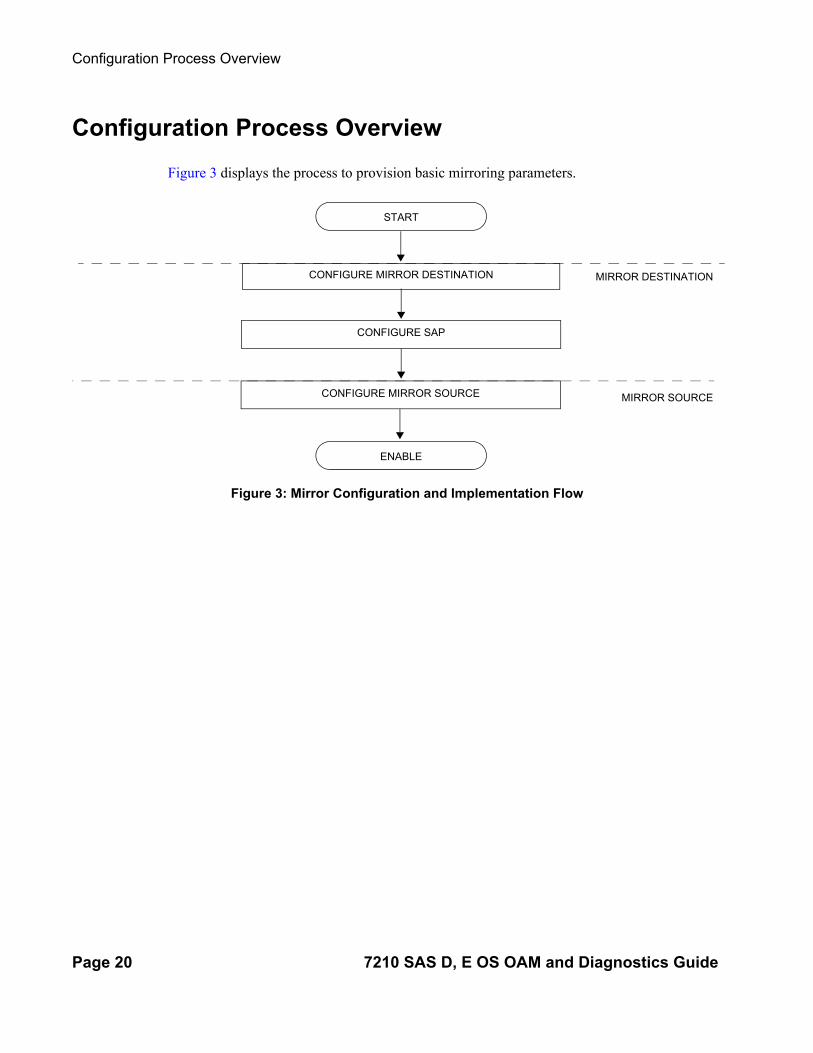
Figure 3 displays the process to provision basic mirroring parameters.
Figure 3: Mirror Configuration and Implementation Flow
ENABLE
START
CONFIGURE MIRROR DESTINATION
CONFIGURE SAP
CONFIGURE MIRROR SOURCE
MIRROR DESTINATION
MIRROR SOURCE
Page 20 7210 SAS D, E OS OAM and Diagnostics Guide

Mirror Services
Configuration Notes
This section describes mirroring configuration caveats.
• Multiple mirroring service IDs (mirror destinations) may be created within a single system.
• A mirrored source can only have one destination.• On 7210 SAS-E, before using a Dot1q SAP or Q1.* SAP as a mirror destination, the user
must configure a port for use with this feature using the command config> system> loopback-no-svc-port mirror. No services can be configured on this port. More details of this command can be found in the 7210 Interfaces Guide. On 7210 SAS-D, the software uses the resources associated with an internal port for mirror application.
• The destination mirroring service IDs and service parameters are persistent between router (re)boots and are included in the configuration saves.
Mirror source criteria configuration (defined in debug>mirror>mirror-source) is not preserved in a configuration save (admin save). Debug mirror source configuration can be saved using admin>debug-save.
• Physical layer problems such as collisions, jabbers, etc., are not mirrored. Typically, only complete packets are mirrored.
• Starting and shutting down mirroring:
Mirror destinations:→ The default state for a mirror destination service ID is shutdown. You must issue a no
shutdown command to enable the feature.→ When a mirror destination service ID is shutdown, mirrored packets associated with
the service ID are not accepted from its mirror source. The associated mirror source is put into an operationally down mode. Mirrored packets are not transmitted out the SAP. Each mirrored packet is silently discarded.
→ Issuing the shutdown command causes the mirror destination service or its mirror source to be put into an administratively down state. Mirror destination service IDs must be shut down first in order to delete a service ID, or SAP association from the system.
Mirror sources:→ The default state for a mirror source for a given mirror-dest service ID is no
shutdown. Enter a shutdown command to deactivate (disable) mirroring from that mirror-source.
→ Mirror sources do not need to be shutdown to remove them from the system. When a mirror source is shutdown, mirroring is terminated for all sources defined locally for the mirror destination service ID.
7210 SAS D, E OS OAM and Diagnostics Guide Page 21

Configuration Notes
Page 22 7210 SAS D, E OS OAM and Diagnostics Guide

Mirror Services
Configuring Service Mirroring with CLI
This section provides information about service mirroring
Topics in this section include:
• Mirror Configuration Overview on page 24• Basic Mirroring Configuration on page 25
→ Mirror Classification Rules on page 26• Common Configuration Tasks on page 28
→ Configuring a Local Mirror Service on page 29• Service Management Tasks on page 32
→ Modifying a Local Mirrored Service on page 33→ Deleting a Local Mirrored Service on page 34
7210 SAS D, E OS OAM and Diagnostics Guide Page 23

Configuring Service Mirroring with CLI
Mirror Configuration Overview
7210 SAS node mirroring can be organized in the following logical entities:
• The mirror source is defined as the location where ingress traffic specific to a port, SAP, MAC or IP filter, is to be mirrored (copied). The original frames are not altered or affected in any way. The egress traffic specific to a port can be mirrored.
• A SAP is defined in local mirror services as the mirror destination to where the mirrored packets are sent.
Defining Mirrored Traffic
In some scenarios, or when multiple services are configured on the same port, specifying the port does not provide sufficient resolution to separate traffic. In Alcatel-Lucent’s implementation of mirroring, multiple source mirroring parameters can be specified to further identify traffic.
Mirroring of packets matching specific filter entries in an IP or MAC filter can be applied to refine what traffic is mirrored to flows of traffic within a service. The IP criteria can be combinations of:
• Source IP address/mask• Destination IP address/mask• IP Protocol value• Source port value (for example, UDP or TCP port)• Destination port value (for example, UDP or TCP port)• DiffServ Code Point (DSCP) value• ICMP code• ICMP type• IP fragments• TCP ACK set/reset• TCP SYN set/reset
The MAC criteria can be combinations of:
• IEEE 802.1p value/mask• Source MAC address/mask• Destination MAC address/mask• Ethernet Type II Ethernet type value
Page 24 7210 SAS D, E OS OAM and Diagnostics Guide

Mirror Services
Basic Mirroring Configuration
Destination mirroring parameters must include at least:
• A mirror destination ID (same as the mirror source service ID).• A mirror destination SAP.
Mirror source parameters must include at least:
• A mirror service ID (same as the mirror destination service ID).• At least one source type (port, SAP, IP filter or MAC filter) specified.
The following example displays a sample configuration of a local mirrored service (ALA-A).
*A:ALA-A>config>mirror# info---------------------------------------------- mirror-dest 103 create exit no shutdown exit----------------------------------------------*A:ALA-A>config>mirror#
The following displays the mirror source configuration:
*A:ALA-A>debug>mirror-source# show debug mirrordebug mirror-source 103
no shutdown exitexit*A:ALA-A>debug>mirror-source# exit
7210 SAS D, E OS OAM and Diagnostics Guide Page 25

Basic Mirroring Configuration
Mirror Classification Rules
Alcatel-Lucent’s implementation of mirroring can be performed by configuring parameters to select network traffic according to any of the following entities:
• Port• SAP• MAC filter• IP filter
Port The port command associates a port to a mirror source. The port is identified by the port ID. The defined port can be Ethernet or a Link Aggregation Group (LAG) ID. When a LAG ID is given as the port ID, mirroring is enabled on all ports making up the LAG.
Mirror sources can be ports in either access or access uplink mode. Port mirroring is supported in the following combinations:
CLI Syntax: debug>mirror-source# port {port-id|lag lag-id} {[egress][in-gress]}
Example: *A:ALA-A>debug>mirror-source# port 1/1/2 ingress egress
SAP More than one SAP can be associated within a single mirror-source. Each SAP has its own ingress parameter keyword to define which packets are mirrored to the mirror-dest service ID. A SAP that is defined within a mirror destination cannot be used in a mirror source.
CLI Syntax: debug>mirror-source# sap sap-id {[ingress]}
Example: *A:ALA-A>debug>mirror-source# sap 1/1/4:100 ingress
Table 2: Mirror Source Port Requirements
Port Type Port Mode Port Encap Type
faste/gige access dot1q, null
faste/gige access uplink qinq
Page 26 7210 SAS D, E OS OAM and Diagnostics Guide

Mirror Services
MAC filter MAC filters are configured in the config>filter>mac-filter context. The mac-filter command causes all the packets matching the explicitly defined list of entry IDs to be mirrored to the mirror destination specified by the service-id of the mirror source.
CLI Syntax: debug>mirror-source# mac-filter mac-filter-id entry entry-id [entry-id …]
Example: *A:ALA-2>debug>mirror-source# mac-filter 12 entry 15 20 25
IP filter IP filters are configured in the config>filter>ip-filter context. The ip-filter command causes all the packets matching the explicitly defined list of entry IDs to be mirrored to the mirror destination specified by the service-id of the mirror source.
Ingress mirrored packets are mirrored to the mirror destination prior to any ingress packet modifications.
CLI Syntax: debug>mirror-source# ip-filter ip-filter-id entry entry-id [entry-id …]
Example: *A:ALA-A>debug>mirror-source# ip-filter 1 entry 20
NOTES:
− An IP filter cannot be applied to a mirror destination SAP.− Ingress mirroring for IPv6 ACL entries are supported.
7210 SAS D, E OS OAM and Diagnostics Guide Page 27

Common Configuration Tasks
Common Configuration Tasks
This section provides a brief overview of the tasks that must be performed to configure local mirror services and provides CLI command syntax. Note that the local mirror source and mirror destination components must be configured under the same service ID context.
Each local mirrored service (Figure 4) (within the same router) requires the following configurations:
1. Specify mirror destination (SAP).
2. Specify mirror source (port, SAP, IP filter, MAC filter).
Figure 4: Local Mirrored Service Tasks
OSSG028A
1/1/1 1/1/2 1/1/3
Mirror Destination
1/1/3
Mirror Source
1/1/2
Sniffer
ALA-A
Page 28 7210 SAS D, E OS OAM and Diagnostics Guide

Mirror Services
Configuring a Local Mirror Service
To configure a local mirror service, the source and destinations must be located on the same router. Note that local mirror source and mirror destination components must be configured under the same service ID context.
The mirror-source commands are used as traffic selection criteria to identify traffic to be mirrored at the source. Each of these criteria are independent. For example, use the debug>mirror-source>port {port-id | lag lag-id} {[egress] [ingress]} command and debug>mirror-source ip-filter ip-filter-id entry entry-id [entry-id…] command to capture (mirror) traffic that matches a specific IP filter entry and traffic ingressing and egressing a specific port. A filter must be applied to the SAP or interface if only specific packets are to be mirrored.
Use the CLI syntax to configure one or more mirror source parameters:
The mirror-dest commands are used to specify where the mirrored traffic is to be sent. Use the following CLI syntax to configure mirror destination parameters:
CLI Syntax: config>mirror mirror-dest service-id [type {ether}] [create]description stringsap sap-id [create]no shutdown
CLI Syntax: debug# mirror-source service-idip-filter ip-filter-id entry entry-id [entry-id …]mac-filter mac-filter-id entry entry-id [entry-id …]port {port-id|lag lag-id} {[egress][ingress]}sap sap-id {[ingress]}no shutdown
The following output displays an example of a local mirrored service using a NULL SAP. On ALA-A, mirror service 103 is mirroring traffic matching IP filter 2, entry 1 as well as egress and ingress traffic on port 1/1/23 and sending the mirrored packets to SAP 1/1/24
*A:ALA-A>config>mirror# info---------------------------------------------- mirror-dest 103 create sap 1/1/24 create exit no shutdown exit----------------------------------------------*A:ALA-A>config>mirror#
The following output displays an example of local mirrored service using a dot1q SAP. User needs to configure a front-panel port for use with the mirroring application when the mirror destination is a Dot1q SAP or a Q1.* SAP, as shown below.
7210 SAS D, E OS OAM and Diagnostics Guide Page 29

Common Configuration Tasks
NOTE: On 7210 SAS-D, the loopback-no-svc-port is not needed. The software uses the resources associated with an internal port for mirroring application.
*A:ALA-A>config>system> ------------------------------------------------------
loopback-no-svc-port mirror 1/1/14-------------------------------------------------------
*A:ALA-A>config>mirror# info----------------------------------------------
mirror-dest 103 createsap 1/1/10:100 createexitno shutdown
exit----------------------------------------------*A:ALA-A>config>mirror#
The following displays the debug mirroring information:
*A:ALA-A>debug>mirror-source# show debug mirrordebug mirror-source 103
no shutdown port 1/1/23 ingress
ip-filter 2 entry 1 exitexit*A:ALA-A>debug>mirror-source# exit
Page 30 7210 SAS D, E OS OAM and Diagnostics Guide

Mirror Services
The source and destination are configured on different routers for remote mirroring[create] [type <mirror-type>] [mirror-source-type <mirror-source-type>][profile <profile>]
7210 SAS D, E OS OAM and Diagnostics Guide Page 31

Service Management Tasks
Service Management Tasks
This section discusses the following service management tasks:
• Modifying a Local Mirrored Service on page 33• Deleting a Local Mirrored Service on page 34
Use the following command syntax to modify an existing mirrored service:
CLI Syntax: config>mirror# mirror-dest service-id [type {ether}]
description description-stringno description sap sap-id no sap[no] shutdown
CLI Syntax: debug[no] mirror-source service-id
ip-filter ip-filter-id entry entry-id [entry-id...]no ip-filter ip-filter-idno ip-filter entry entry-id [entry-id...]mac-filter mac-filter-id entry entry-id [entry-id...]no mac-filter mac-filter-idno mac-filter mac-filter-id entry entry-id [entry-id...][no] port {port-id|lag lag-id} {[egress][ingress]}[no] sap sap-id {[ingress]}[no] shutdown
Page 32 7210 SAS D, E OS OAM and Diagnostics Guide

Mirror Services
Modifying a Local Mirrored Service
Existing mirroring parameters can be modified in the CLI. The changes are applied immediately. The service must be shut down if changes to the SAP are made.
The following example displays commands to modify parameters for a basic local mirroring service.
Example: config>mirror# mirror-dest 103config>mirror>mirror-dest# shutdownconfig>mirror>mirror-dest# no sapconfig>mirror>mirror-dest# sap 1/1/5 createconfig>mirror>mirror-dest>sap$ exitconfig>mirror>mirror-dest# no shutdowndebug# mirror-source 103debug>mirror-source# no port 1/1/23 debug>mirror-source# port 1/1/7 ingress egress
The following displays the local mirrored service modifications:
*A:ALA-A>config>mirror# info----------------------------------------------mirror-dest 103 create no shutdown sap 1/1/5 create exit
*A:ALA-A>debug>mirror-source# show debug mirrordebug mirror-source 103 no shutdown port 1/1/7 egress ingress exit*A:ALA-A>debug>mirror-source#
7210 SAS D, E OS OAM and Diagnostics Guide Page 33

Service Management Tasks
Deleting a Local Mirrored Service
Existing mirroring parameters can be deleted in the CLI. A shutdown must be issued on a service level in order to delete the service. It is not necessary to shut down or remove SAP or port references to delete a local mirrored service.
The following example displays commands to delete a local mirrored service.
Example:ALA-A>config>mirror# mirror-dest 103config>mirror>mirror-dest# shutdownconfig>mirror>mirror-dest# exitconfig>mirror# no mirror-dest 103config>mirror# exit
Page 34 7210 SAS D, E OS OAM and Diagnostics Guide

Mirror Services
7210 SAS D, E OS OAM and Diagnostics Guide Page 35

Service Management Tasks
Page 36 7210 SAS D, E OS OAM and Diagnostics Guide

Mirror Services
Mirror Service Command Reference
Command Hierarchies•
•
• Mirror Configuration Commands on page 37
• Show Commands on page 38
• Debug Commands on page 38
—
Mirror Configuration Commandsconfig
— mirror— mirror-dest service-id [type encap-type] [create]— no mirror-dest service-id
— description description-string— no description— [no] fc [fc-name] [profile profile]— sap sap-id [create] — service-name service-name— [no] service-name— [no] shutdown
7210 SAS D, E OS OAM and Diagnostics Guide Page 37

Mirror Service Command Reference
Show Commandsshow
— debug [application]— mirror mirror-dest [service-id]— service
— service-using mirror
Debug Commandsdebug
— [no] mirror-source service-id— ip-filter ip-filter-id entry entry-id [entry-id …]— no ip-filter ip-filter-id [entry entry-id]— mac-filter mac-filter-id entry entry-id [entry-id …]— no mac-filter mac-filter-id [entry entry-id...]— port {port-id | lag lag-id} {[egress] [ingress]}— no port {port-id | lag lag-id} [egress] [ingress]— sap sap-id {[ingress]}— no sap sap-id [ingress]— [no] shutdown
Page 38 7210 SAS D, E OS OAM and Diagnostics Guide

Mirror Services
Configuration Commands
Generic Commands
description
Syntax description description-stringno description
Context config>mirror>mirror-dest
Description This command creates a text description stored in the configuration file for a configuration context to help the administrator identify the content of the file.
The no form of the command removes the description string.
Default There is no default description associated with the configuration context.
Parameters description-string — The description character string. Allowed values are any string up to 80 characters long composed of printable, 7-bit ASCII characters. If the string contains special characters (#, $, spaces, etc.), the entire string must be enclosed within double quotes.
shutdown
Syntax [no] shutdown
Context config>mirror>mirror-destdebug>mirror-source
Description The shutdown command administratively disables an entity. When disabled, an entity does not change, reset, or remove any configuration settings or statistics. Many entities must be explicitly enabled using the no shutdown command.
The shutdown command administratively disables an entity. The operational state of the entity is disabled as well as the operational state of any entities contained within. Many objects must be shut down before they may be deleted.
Unlike other commands and parameters where the default state is not indicated in the configuration file, shutdown and no shutdown are always indicated in system generated configuration files.
The no form of the command puts an entity into the administratively enabled state.
Default See Special Cases below.Special Cases Mirror Destination — When a mirror destination service ID is shutdown, mirrored packets associated
with the service ID are not accepted from the mirror source device. The associated mirror source is put into an operationally down mode. Mirrored packets are not transmitted out of the SAP. Each mirrored packet is silently discarded. If the mirror destination is a SAP, the SAP’s discard counters are incremented.
7210 SAS D, E OS OAM and Diagnostics Guide Page 39

Generic Commands
The shutdown command places the mirror destination service or mirror source into an administratively down state. The mirror-dest service ID must be shut down in order to delete the service ID, SAP associa-tion from the system.
The default state for a mirror destination service ID is shutdown. A no shutdown command is required to enable the service.
Mirror Source — Mirror sources do not need to be shutdown in order to remove them from the system.
When a mirror source is shutdown, mirroring is terminated for all sources defined locally for the mirror-dest service ID.
The default state for a mirror source for a given mirror-dest service ID is no shutdown. A shutdown com-mand is required to disable mirroring from that mirror-source.
Page 40 7210 SAS D, E OS OAM and Diagnostics Guide

Mirror Services
Mirror Destination Configuration Commands
mirror-dest
Syntax mirror-dest service-id [type encap-type] [mirror-source-type mirror-source-type][create]no mirror-dest
Context config>mirror
Description This command creates a context to set up a service that is intended for packet mirroring. It is configured as a service to allow mirrored packets to be directed locally (within the same device), over the core of the net-work and have a far end device decode the mirror encapsulation.
The mirror-dest service is comprised of destination parameters that define where the mirrored packets are to be sent. It also specifies whether the defined service-id will receive mirrored packets from far end devices over the network core.
The mirror-dest service IDs are persistent between boots of the router and are included in the configuration backups. The local sources of mirrored packets for the service ID are defined within the debug mirror mir-ror-source command that references the same service-id.
The mirror-dest command is used to create or edit a service ID for mirroring purposes. If the service-id does not exist within the context of all defined services, the mirror-dest service is created and the context of the CLI is changed to that service ID. If the service-id exists within the context of defined mirror-dest ser-vices, the CLI context is changed for editing parameters on that service ID. If the service-id exists within the context of another service type, an error message is returned and CLI context is not changed from the cur-rent context.
The no form of the command removes a mirror destination from the system. The mirror-source associa-tions with the mirror-dest service-id do not need to be removed or shutdown first. The mirror-dest service-id must be shutdown before the service ID can be removed. When the service ID is removed, all mirror-source commands that have the service ID defined will also be removed from the system.
Default No packet mirroring services are defined.
Parameters service-id — The service id identifies the service in the service domain. This ID is unique to this service and cannot be used by any other service, regardless of service type. The same service ID must be configured on every device that this particular service is defined on.
service-id
If a particular service ID already exists for a service, then the same value cannot be used to create a mir-ror destination service ID with the same value.
For example:
If an Epipe service-ID 11 exists, then a mirror destination service-ID 11 cannot be created. If a VPLS service-ID 12 exists, then a mirror destination service-ID 12 cannot be created.If an IES service-ID 13 exists, then a mirror destination service-ID 13 cannot be created.
Values service-id: 1 — 2147483647
7210 SAS D, E OS OAM and Diagnostics Guide Page 41

Mirror Destination Configuration Commands
type encap-type — The type describes the encapsulation supported by the mirror service.
Values ether
fc
Syntax fc fc-name profile { profile }no fc
Context config>mirror>mirror-dest
Description This command specifies a forwarding class for all mirrored copy of the packets transmitted to the destina-tion SAP overriding the default (be) forwarding class. All packets are sent with the same class of service to minimize out of sequence issues. The mirrored copy of the packet does not inherit the forwarding class of the original packet.
When the destination is on a SAP, it pulls buffers from the queue associated with the fc-name and the shap-ing and scheduling treatment given to the packet is as per the user configuration for that queue.
On 7210 SAS-D , all SAPs configured on a port use the port-based egress queues. If the mirror destination SAP (that is, dot1q SAP or a Q1.* SAP) is configured to share an uplink with service traffic, mirrored copy of the traffic sent out of the Dot1q or Q1.* SAP will share the port-based egress queues with the other ser-vice traffic. User is provided an option to assign the profile mirrored copy to the packet, so that during con-gestion mirrored copy of thepackets marked as out-of-profile is dropped before in-profile service traffic (and possibly in-profile mirrored traffic, if user has configured mirrored traffic to be in-profile). The profile is used to determine the slope policy to use for the packet and determines the packet's drop precedence. Addi-tionally, if marking is enabled, it determines the marking value to be used in the packet header.
The no form of the command returns the mirror-dest service ID forwarding class to the default forwarding class.
Default The best effort (be) forwarding class is associated with the mirror-dest service ID and profile is out.
Parameters fc-name — The name of the forwarding class with which to associate mirrored service traffic. The forwarding class name must already be defined within the system. If the fc-name does not exist, an error will be returned and the fc command will have no effect. If the fc-name does exist, the forwarding class associated with fc-name will override the default forwarding class.
Values be, l2, af, l1, h2, ef, h1, nc
profile — The profile to assign to mirrored copy of the service traffic. The profile is used to determine the slope policy to use for the packet and determines the packet's drop precedence. Additionally, if marking is enabled, it determines the marking value to be used in the packet header. A value of in marks the traffic as in-profile traffic and results in use of high slope parameters. A value of out marks the traffic as out-of-profile and results in use of low slope parameters.
Values in, out
Default out
Page 42 7210 SAS D, E OS OAM and Diagnostics Guide

Mirror Services
sap
Syntax sap sap-id [create]no sap
Context config>mirror>mirror-dest
Description This command creates a service access point (SAP) within a mirror destination service. The SAP is owned by the mirror destination service ID.
The SAP is defined with port and encapsulation parameters to uniquely identify the (mirror) SAP on the interface and within the box. The specified SAP must define an Ethernet port with a null SAP or a Dot1q SAP or a Q1.* SAP. A Q1.Q2 SAP cannot be used when the port encapsulation is set to QinQ or on an access-uplink port.
NOTE: Before using a Dot1q SAP or a Q1.* SAP, user will need to dedicate a port for use with mirroring application using the command config> system> loopback-no-svc-port. This is required only for 7210 SAS-E. For more information about this command can be found in the 7210 Interfaces Guide.
Only one SAP can be created within a mirror-dest service ID. If the defined SAP has not been created on any service within the system, the SAP is created and the context of the CLI will change to the newly cre-ated SAP. In addition, the port cannot be a member of a multi-link bundle, LAG, APS group or IMA bundle.
If the defined SAP exists in the context of another service ID, mirror-dest or any other type, an error is gen-erated.
Mirror destination SAPs can be created on Ethernet interfaces that have been defined as an access port or access-uplink port. If the interface is defined as network, the SAP creation returns an error.
When the no form of this command is used on a SAP created by a mirror destination service ID, the SAP with the specified port and encapsulation parameters is deleted.
Default No default SAP for the mirror destination service defined.
Parameters sap-id — Specifies the physical port identifier portion of the SAP definition. See Common CLI Command Descriptions on page 185 for command syntax.
service-name
Syntax service-name service-nameno service-name
Context config>mirror>mirror-dest
Description This command configures an optional service name, up to 64 characters in length, which adds a name identifier to a given service to then use that service name in configuration references as well as display and use service names in show commands throughout the system. This helps the service provider/administrator to identify and manage services within the 7750 SR, 7450 ESS and 7710 SR platforms.
7210 SAS D, E OS OAM and Diagnostics Guide Page 43

Mirror Destination Configuration Commands
All services are required to assign a service ID to initially create a service. However, either the service ID or the service name can be used o identify and reference a given service once it is initially created.
Parameters service-name — Specifies a unique service name to identify the service. Service names may not begin with an integer (0-9).
Page 44 7210 SAS D, E OS OAM and Diagnostics Guide

Mirror Services
Mirror Source Configuration Commands
mirror-source
Syntax [no] mirror-source service-id
Context debug
Description This command configures mirror source parameters for a mirrored service.
The mirror-source command is used to enable mirroring of packets specified by the association of the mir-ror-source to sources of packets defined within the context of the mirror-dest-service-id. The mirror desti-nation service must already exist within the system.
A mirrored packet cannot be mirrored to multiple destinations. If a mirrored packet is properly referenced by multiple mirror sources (for example, a SAP on one mirror-source and a port on another mirror-source), then the packet is mirrored to a single mirror-dest-service-id based on the following hierarchy:
1. Filter entry
2. Service access port (SAP)
3. Physical port
The hierarchy is structured so the most specific match criteria has precedence over a less specific match. For example, if a mirror-source defines a port and a SAP on that port, then the SAP mirror-source is accepted and the mirror-source for the port is ignored because of the hierarchical order of precedence.
The mirror-source configuration is not saved when a configuration is saved. A mirror-source manually configured within an ASCII configuration file will not be preserved if that file is overwritten by a save com-mand. Define the mirror-source within a file associated with a config exec command to make a mirror-source persistent between system reboots.
By default, all mirror-dest service IDs have a mirror-source associated with them. The mirror-source is not technically created with this command. Instead the service ID provides a contextual node for storing the current mirroring sources for the associated mirror-dest service ID. The mirror-source is created for the mirror service when the operator enters the debug>mirror-source svcId for the first time. The mirror-source is also automatically removed when the mirror-dest service ID is deleted from the system.
The no form of the command deletes all related source commands within the context of the mirror-source service-id. The command does not remove the service ID from the system.
Default No mirror source match criteria is defined for the mirror destination service.
Parameters service-id — The mirror destination service ID for which match criteria will be defined. The service-id must already exist within the system.
Values service-id: 1 — 2147483647
7210 SAS D, E OS OAM and Diagnostics Guide Page 45
Mirror Source Configuration Commands
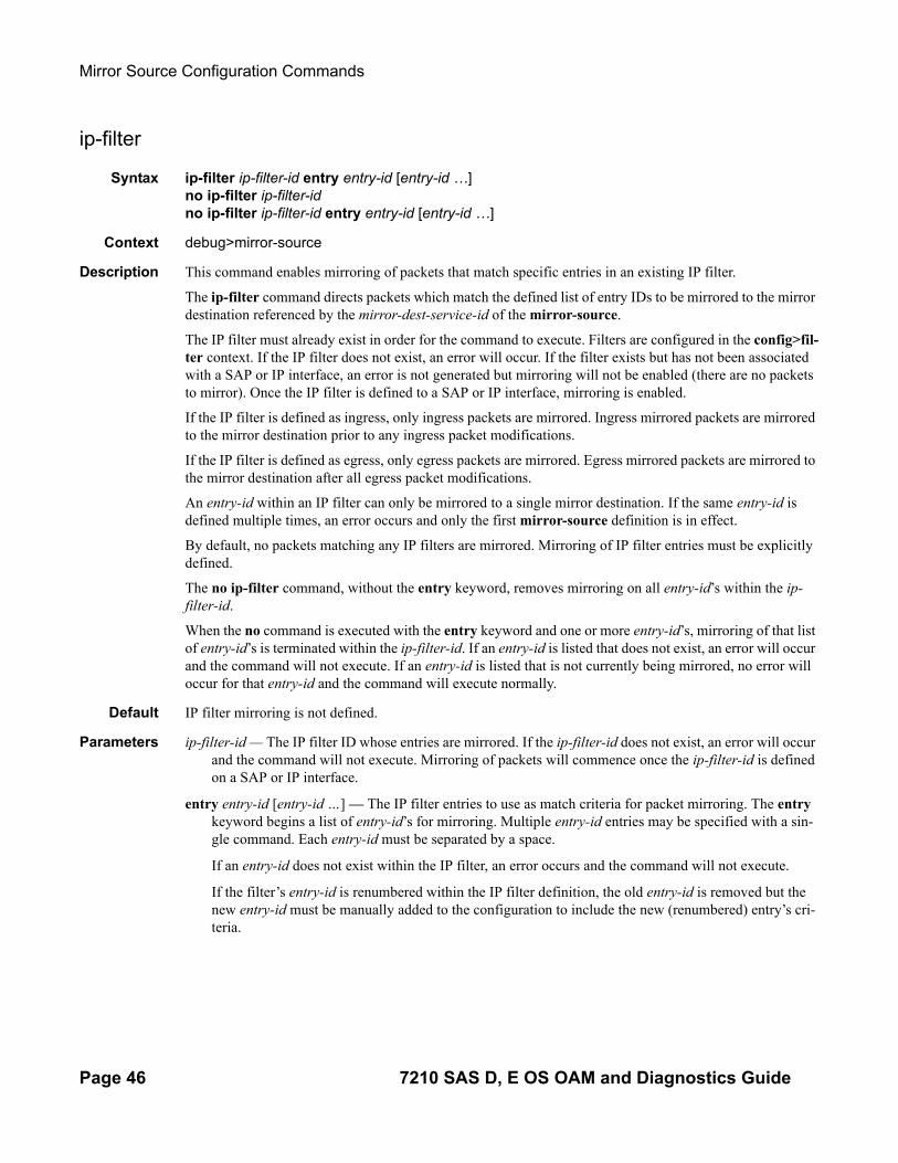
ip-filter
Syntax ip-filter ip-filter-id entry entry-id [entry-id …]no ip-filter ip-filter-idno ip-filter ip-filter-id entry entry-id [entry-id …]
Context debug>mirror-source
Description This command enables mirroring of packets that match specific entries in an existing IP filter.
The ip-filter command directs packets which match the defined list of entry IDs to be mirrored to the mirror destination referenced by the mirror-dest-service-id of the mirror-source.
The IP filter must already exist in order for the command to execute. Filters are configured in the config>fil-ter context. If the IP filter does not exist, an error will occur. If the filter exists but has not been associated with a SAP or IP interface, an error is not generated but mirroring will not be enabled (there are no packets to mirror). Once the IP filter is defined to a SAP or IP interface, mirroring is enabled.
If the IP filter is defined as ingress, only ingress packets are mirrored. Ingress mirrored packets are mirrored to the mirror destination prior to any ingress packet modifications.
If the IP filter is defined as egress, only egress packets are mirrored. Egress mirrored packets are mirrored to the mirror destination after all egress packet modifications.
An entry-id within an IP filter can only be mirrored to a single mirror destination. If the same entry-id is defined multiple times, an error occurs and only the first mirror-source definition is in effect.
By default, no packets matching any IP filters are mirrored. Mirroring of IP filter entries must be explicitly defined.
The no ip-filter command, without the entry keyword, removes mirroring on all entry-id’s within the ip-filter-id.
When the no command is executed with the entry keyword and one or more entry-id’s, mirroring of that list of entry-id’s is terminated within the ip-filter-id. If an entry-id is listed that does not exist, an error will occur and the command will not execute. If an entry-id is listed that is not currently being mirrored, no error will occur for that entry-id and the command will execute normally.
Default IP filter mirroring is not defined.
Parameters ip-filter-id — The IP filter ID whose entries are mirrored. If the ip-filter-id does not exist, an error will occur and the command will not execute. Mirroring of packets will commence once the ip-filter-id is defined on a SAP or IP interface.
entry entry-id [entry-id …] — The IP filter entries to use as match criteria for packet mirroring. The entry keyword begins a list of entry-id’s for mirroring. Multiple entry-id entries may be specified with a sin-gle command. Each entry-id must be separated by a space.
If an entry-id does not exist within the IP filter, an error occurs and the command will not execute.
If the filter’s entry-id is renumbered within the IP filter definition, the old entry-id is removed but the new entry-id must be manually added to the configuration to include the new (renumbered) entry’s cri-teria.
Page 46 7210 SAS D, E OS OAM and Diagnostics Guide

Mirror Services
mac-filter
Syntax mac-filter mac-filter-id entry entry-id [entry-id …]no mac-filter mac-filter-idno mac-filter mac-filter-id entry entry-id [entry-id …]
Context debug>mirror-source
Description This command enables mirroring of packets that match specific entries in an existing MAC filter.
The mac-filter command directs packets which match the defined list of entry IDs to be mirrored to the mir-ror destination referenced by the mirror-dest-service-id of the mirror-source.
The MAC filter must already exist in order for the command to execute. Filters are configured in the con-fig>filter context. If the MAC filter does not exist, an error will occur. If the filter exists but has not been associated with a SAP or IP interface, an error is not be generated but mirroring will not be enabled (there are no packets to mirror). Once the filter is defined to a SAP or MAC interface, mirroring is enabled.
If the MAC filter is defined as ingress, only ingress packets are mirrored. Ingress mirrored packets are mir-rored to the mirror destination prior to any ingress packet modifications.
The no mac-filter command, without the entry keyword, removes mirroring on all entry-id’s within the mac-filter-id.
When the no command is executed with the entry keyword and one or more entry-id’s, mirroring of that list of entry-id’s is terminated within the mac-filter-id. If an entry-id is listed that does not exist, an error will occur and the command will not execute. If an entry-id is listed that is not currently being mirrored, no error will occur for that entry-id and the command will execute normally.
Default No MAC filter mirroring defined.
Parameters mac-filter-id — The MAC filter ID whose entries are mirrored. If the mac-filter-id does not exist, an error will occur and the command will not execute. Mirroring of packets will commence once the mac-filter-id is defined on a SAP.
entry entry-id [entry-id …] — The MAC filter entries to use as match criteria for packet mirroring. The entry keyword begins a list of entry-id’s for mirroring. Multiple entry-id entries may be specified with a single command. Each entry-id must be separated by a space. Up to 8 entry IDs may be specified in a single command.
Each entry-id must exist within the mac-filter-id. If the entry-id is renumbered within the MAC filter definition, the old entry-id is removed from the list and the new entry-id will need to be manually added to the list if mirroring is still desired.
If no entry-id entries are specified in the command, mirroring will not occur for that MAC filter ID. The command will have no effect.
7210 SAS D, E OS OAM and Diagnostics Guide Page 47

Mirror Source Configuration Commands
port
Syntax port {port-id | lag lag-id} {[egress] [ingress]}no port {port-id | lag lag-id} [egress] [ingress]
Context debug>mirror-source
Description This command enables mirroring of traffic ingressing or egressing a port (Ethernet port, or Link Aggrega-tion Group (LAG)).
The port command associates a port or LAG to a mirror source. The port is identified by the port-id. The defined port may be Ethernet, access or access uplink. access. A port may be a single port or a Link Aggre-gation Group (LAG) ID. When a LAG ID is given as the port-id, mirroring is enabled on all ports making up the LAG. Either a LAG port member or the LAG port can be mirrored.
The port is only referenced in the mirror source for mirroring purposes. If the port is removed from the sys-tem, the mirroring association will be removed from the mirror source.
The same port may not be associated with multiple mirror source definitions with the ingress parameter defined. The same port may not be associated with multiple mirror source definitions with the egress param-eter defined.
If a SAP is mirrored on an access port, the SAP mirroring will have precedence over the access port mirror-ing when a packet matches the SAP mirroring criteria. Filter and label mirroring destinations will also pre-cedence over a port-mirroring destination.
If the port is not associated with a mirror-source, packets on that port will not be mirrored. Mirroring may still be defined for a SAP or filter entry, which will mirror based on a more specific criteria.
The no port command disables port mirroring for the specified port. Mirroring of packets on the port may continue due to more specific mirror criteria. If the egress or ingress parameter keywords are specified in the no command, only the ingress or egress mirroring condition will be removed.
Default No ports are defined.
Parameters port-id — Specifies the port ID.
lag-id — The LAG identifier, expressed as a decimal integer.
egress — Specifies that packets egressing the port should be mirrored. Egress packets are mirrored to the mirror destination after egress packet modification.
ingress — Specifies that packets ingressing the port should be mirrored. Ingress packets are mirrored to the mirror destination prior to ingress packet modification.
sap
Syntax sap sap-id {[ingress]}no sap sap-id[ingress]
Context debug>mirror-source
Description This command enables mirroring of traffic ingressing a service access port (SAP). A SAP that is defined within a mirror destination cannot be used in a mirror source. The mirror source SAP referenced by the sap-
Page 48 7210 SAS D, E OS OAM and Diagnostics Guide

Mirror Services
id is owned by the service ID of the service in which it was created. The SAP is only referenced in the mirror source name for mirroring purposes. The mirror source association does not need to be removed before deleting the SAP from its service ID. If the SAP is deleted from its service ID, the mirror association is removed from the mirror source.
More than one SAP can be associated within a single mirror-source. Each SAP has its own ingress param-eter keyword to define which packets are mirrored to the mirror destination.
The SAP must be valid and properly configured. If the associated SAP does not exist, an error occurs and the command will not execute.
The same SAP cannot be associated with multiple mirror source definitions for ingress packets.
If a particular SAP is not associated with a mirror source name, then that SAP will not have mirroring enabled for that mirror source.
The no form of the command disables mirroring for the specified SAP. All mirroring for that SAP on ingress is terminated. Mirroring of packets on the SAP can continue if more specific mirror criteria is configured. If the ingress parameter keyword are specified in the no command, only the ingress mirroring condition is removed.
Default No SAPs are defined by default.
Parameters sap-id — Specifies the physical port identifier portion of the SAP definition. See Common CLI Command Descriptions on page 185 for command syntax.
ingress — Specifies that packets ingressing the SAP should be mirrored. Ingress packets are mirrored to the mirror destination prior to ingress packet modification.
7210 SAS D, E OS OAM and Diagnostics Guide Page 49

Mirror Source Configuration Commands
Page 50 7210 SAS D, E OS OAM and Diagnostics Guide
Mirror Services
Show Commands
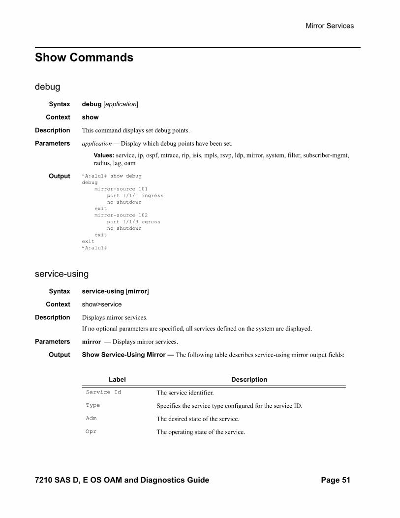
debug
Syntax debug [application]
Context show
Description This command displays set debug points.
Parameters application — Display which debug points have been set.
Values: service, ip, ospf, mtrace, rip, isis, mpls, rsvp, ldp, mirror, system, filter, subscriber-mgmt, radius, lag, oam
Output *A:alu1# show debug debug mirror-source 101 port 1/1/1 ingress no shutdown exit mirror-source 102 port 1/1/3 egress no shutdown exitexit*A:alu1#
service-using
Syntax service-using [mirror]
Context show>service
Description Displays mirror services.
If no optional parameters are specified, all services defined on the system are displayed.
Parameters mirror — Displays mirror services.
Output Show Service-Using Mirror — The following table describes service-using mirror output fields:
Label Description
Service Id The service identifier.
Type Specifies the service type configured for the service ID.
Adm The desired state of the service.
Opr The operating state of the service.
7210 SAS D, E OS OAM and Diagnostics Guide Page 51

Show Commands
Sample Output
A:ALA-48# show service service-using mirror===============================================================================Services [mirror]===============================================================================ServiceId Type Adm Opr CustomerId Last Mgmt Change-------------------------------------------------------------------------------218 Mirror Up Down 1 04/08/2007 13:49:57318 Mirror Down Down 1 04/08/2007 13:49:57319 Mirror Up Down 1 04/08/2007 13:49:57320 Mirror Up Down 1 04/08/2007 13:49:571000 Mirror Down Down 1 04/08/2007 13:49:571216 Mirror Up Down 1 04/08/2007 13:49:571412412 Mirror Down Down 1 04/08/2007 13:49:57-------------------------------------------------------------------------------Matching Services : 7===============================================================================A:ALA-48#
CustomerID The ID of the customer who owns this service.
Last Mgmt Change The date and time of the most recent management-initiated change to this service.
Label Description (Continued)
Page 52 7210 SAS D, E OS OAM and Diagnostics Guide
Mirror Services
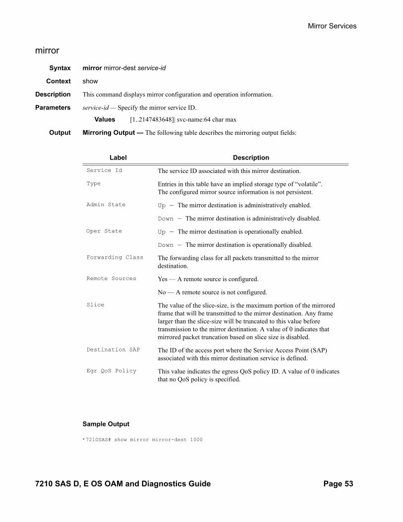
mirror
Syntax mirror mirror-dest service-id
Context show
Description This command displays mirror configuration and operation information.
Parameters service-id — Specify the mirror service ID.
Values [1..2147483648]| svc-name:64 char max
Output Mirroring Output — The following table describes the mirroring output fields:
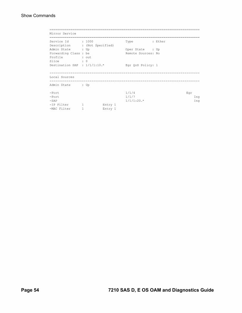
Sample Output
*7210SAS# show mirror mirror-dest 1000
Label Description
Service Id The service ID associated with this mirror destination.
Type Entries in this table have an implied storage type of “volatile”.The configured mirror source information is not persistent.
Admin State Up — The mirror destination is administratively enabled.
Down — The mirror destination is administratively disabled.
Oper State Up — The mirror destination is operationally enabled.
Down — The mirror destination is operationally disabled.
Forwarding Class The forwarding class for all packets transmitted to the mirror destination.
Remote Sources Yes — A remote source is configured.
No — A remote source is not configured.
Slice The value of the slice-size, is the maximum portion of the mirrored frame that will be transmitted to the mirror destination. Any frame larger than the slice-size will be truncated to this value before transmission to the mirror destination. A value of 0 indicates that mirrored packet truncation based on slice size is disabled.
Destination SAP The ID of the access port where the Service Access Point (SAP)associated with this mirror destination service is defined.
Egr QoS Policy This value indicates the egress QoS policy ID. A value of 0 indicates that no QoS policy is specified.
7210 SAS D, E OS OAM and Diagnostics Guide Page 53
Show Commands
===============================================================================Mirror Service===============================================================================Service Id : 1000 Type : EtherDescription : (Not Specified)Admin State : Up Oper State : UpForwarding Class : be Remote Sources: NoProfile : outSlice : 0 Destination SAP : 1/1/1:10.* Egr QoS Policy: 1 -------------------------------------------------------------------------------Local Sources-------------------------------------------------------------------------------Admin State : Up -Port 1/1/4 Egr -Port 1/1/7 Ing-SAP 1/1/1:20.* Ing-IP Filter 1 Entry 1 -MAC Filter 1 Entry 1
Page 54 7210 SAS D, E OS OAM and Diagnostics Guide

OAM and SAA
In This Chapter
This chapter provides information about the Operations, Administration and Management (OAM) and Service Assurance Agent (SAA) commands available in the CLI for troubleshooting services.
Topics in this chapter include:
• OAM Overview on page 56• Ethernet Connectivity Fault Management (ETH-CFM) on page 58• Synthetic Loss Measurement (ETH-SL) on page 76• Service Assurance Agent Overview on page 83
→ SAA Application on page 144
7210 SAS D, E OS OAM and Diagnostics Guide Page 55

OAM Overview
OAM Overview
Delivery of services requires a number of operations occur properly and at different levels in the service delivery model. For example, operations such as the association of packets to a service, must be performed properly in the forwarding plane for the service to function properly. In order to verify that a service is operational, a set of in-band, packet-based Operation, Administration, and Maintenance (OAM) tools is required, with the ability to test each of the individual packet operations.
For in-band testing, the OAM packets closely resemble customer packets to effectively test the customer's forwarding path, but they are distinguishable from customer packets so they are kept within the service provider's network and not forwarded to the customer.
• The suite of OAM diagnostics supplement the basic IP ping and traceroute operations with diagnostics specialized for the different levels in the service delivery model. There are diagnostics for services.
•
Two-Way Active Measurement Protocol
Two-Way Active Measurement Protocol (TWAMP) provides a standards-based method for measuring the round-trip IP performance (packet loss, delay and jitter) between two devices. TWAMP uses the methodology and architecture of One-Way Active Measurement Protocol (OWAMP) to define a way to measure two-way or round-trip metrics.
There are four logical entities in TWAMP:
• The control-client• The session-sender• The server• The session-reflector.
The control-client and session-sender are typically implemented in one physical device (the “client”) and the server and session-reflector in a second physical device (the “server”) with which the two-way measurements are being performed. The 7210 SAS acts as the server. The control-client and server establishes a TCP connection and exchange TWAMP-Control messages over this connection. When the control-client requires to start testing, the client communicates the test parameters to the server. If the server corresponds to conduct the described tests, the test begins as soon as the client sends a Start-Sessions message. As part of a test, the sessionsender sends a stream of UDP-based test packets to the session-reflector, and the session reflector responds to each received packet with a response UDP-based test packet. When the session-sender receives the
Page 56 7210 SAS D, E OS OAM and Diagnostics Guide
OAM and SAA
response packets from the session-reflector, the information is used to calculate two-way delay, packet loss, and packet delay variation between the two devices.
Configuration Notes
The following are the configuration notes:
• Unauthenticated mode is supported. Encrypted and Authenticated modes are not supported.
• TWAMP is supported only in the base router instance. • By default, 7210 uses TCP port number 862 to listen for TWAMP control connectins and
this is not user configurable.
7210 SAS D, E OS OAM and Diagnostics Guide Page 57

Ethernet Connectivity Fault Management (ETH-CFM)
Ethernet Connectivity Fault Management (ETH-CFM)
The IEEE and the ITU-T have cooperated to define the protocols, procedures and managed objects to support service based fault management. Both IEEE 802.1ag standard and the ITU-T Y.1731recommendation support a common set of tools that allow operators to deploy the necessary administrative constructs, management entities and functionality, Ethernet Connectivity Fault Management (ETH-CFM). The ITU-T has also implemented a set of advanced ETH-CFM and performance management functions and features that build on the proactive and on demand troubleshooting tools.
CFM uses Ethernet frames and is distinguishable by ether-type 0x8902. In certain cases the different functions will use a reserved multicast address that could also be used to identify specific functions at the MAC layer. However, the multicast MAC addressing is not used for every function or in every case. The Operational Code (OpCode) in the common CFM header is used to identify the type of function carried in the CFM packet. CFM frames are only processed by IEEE MAC bridges. With CFM, interoperability can be achieved between different vendor equipment in the service provider network up to and including customer premises bridges. The following table lists CFM-related acronyms used in this section.
IEEE 802.1ag and ITU-T Y.1731 functions that are implemented are available on the 7210 SAS platforms.
Acronym Callout
1DM One way Delay Measurement (Y.1731)
AIS Alarm Indication Signal
CCM Continuity check message
CFM Connectivity fault management
DMM Delay Measurement Message (Y.1731)
DMR Delay Measurement Reply (Y.1731)
LBM Loopback message
LBR Loopback reply
LTM Linktrace message
LTR Linktrace reply
ME Maintenance entity
MA Maintenance association
Page 58 7210 SAS D, E OS OAM and Diagnostics Guide

OAM and SAA
MA-ID Maintenance association identifier
MD Maintenance domain
MEP Maintenance association end point
MEP-ID Maintenance association end point identifier
MHF MIP half function
MIP Maintenance domain intermediate point
OpCode Operational Code
RDI Remote Defect Indication
TST Ethernet Test (Y.1731)
Acronym Callout (Continued)
7210 SAS D, E OS OAM and Diagnostics Guide Page 59

Ethernet Connectivity Fault Management (ETH-CFM)
ETH-CFM Building Blocks
The IEEE and the ITU-T use their own nomenclature when describing administrative contexts and functions. This introduces a level of complexity to configuration, discussion and different vendors naming conventions. The 7210 SAS OS CLI has chosen to standardize on the IEEE 802.1ag naming where overlap exists. ITU-T naming is used when no equivalent is available in the IEEE standard. In the following definitions, both the IEEE name and ITU-T names are provided for completeness, using the format IEEE Name/ITU-T Name.
Maintenance Domain (MD)/Maintenance Entity (ME) is the administrative container that defines the scope, reach and boundary for faults. It is typically the area of ownership and management responsibility. The IEEE allows for various formats to name the domain, allowing up to 45 characters, depending on the format selected. ITU-T supports only a format of “none” and does not accept the IEEE naming conventions.
0 — Undefined and reserved by the IEEE.
1 — No domain name. It is the only format supported by Y.1731 as the ITU-T specification does not use the domain name. This is supported in the IEEE 802.1ag standard but not in currently implemented for 802.1ag defined contexts.
2,3,4 — Provides the ability to input various different textual formats, up to 45 characters. The string format (2) is the default and therefore the keyword is not shown when looking at the configuration.
Maintenance Association (MA)/Maintenance Entity Group (MEG) is the construct where the different management entities will be contained. Each MA is uniquely identified by its MA-ID. The MA-ID is comprised of the by the MD level and MA name and associated format. This is another administrative context where the linkage is made between the domain and the service using the bridging-identifier configuration option. The IEEE and the ITU-T use their own specific formats. The MA short name formats (0-255) have been divided between the IEEE (0-31, 64-255) and the ITU-T (32-63), with five currently defined (1-4, 32). Even though the different standards bodies do not have specific support for the others formats a Y.1731 context can be configured using the IEEE format options.
1 (Primary VID) — Values 0 — 4094
2 (String) — Raw ASCII, excluding 0-31 decimal/0-1F hex (which are control characters) form the ASCII table
3 (2-octet integer) — 0 — 65535
4 (VPN ID) — Hex value as described in RFC 2685, Virtual Private Networks Identifier
32 (icc-format) — Exactly 13 characters from the ITU-T recommendation T.50.
Note: When a VID is used as the short MA name, 802.1ag will not support VLAN translation because the MA-ID must match all the MEPs. The default format for a short MA name is an
Page 60 7210 SAS D, E OS OAM and Diagnostics Guide

OAM and SAA
integer. Integer value 0 means the MA is not attached to a VID. This is useful for VPLS services on 7210 SAS platforms because the VID is locally significant.
Maintenance Domain Level (MD Level)/Maintenance Entity Group Level (MEG Level) is the numerical value (0-7) representing the width of the domain. The wider the domain, higher the numerical value, the farther the ETH-CFM packets can travel. It is important to understand that the level establishes the processing boundary for the packets. Strict rules control the flow of ETH-CFM packets and are used to ensure proper handling, forwarding, processing and dropping of these packets. To keep it simple ETH-CFM packets with higher numerical level values will flow through MEPs on MIPs on SAPs configured with lower level values. This allows the operator to implement different areas of responsibility and nest domains within each other. Maintenance association (MA) includes a set of MEPs, each configured with the same MA-ID and MD level used verify the integrity of a single service instance.
Maintenance Endpoint (MEP)/MEG Endpoint (MEP) are the workhorses of ETH-CFM. A MEP is the unique identification within the association (0-8191). Each MEP is uniquely identified by the MA-ID, MEPID tuple. This management entity is responsible for initiating, processing and terminating ETH-CFM functions, following the nesting rules. MEPs form the boundaries which prevent the ETH-CFM packets from flowing beyond the specific scope of responsibility. A MEP has direction, up or down. Each indicates the directions packets will be generated; UP toward the switch fabric, down toward the SAP away from the fabric. Each MEP has an active and passive side. Packets that enter the active point of the MEP will be compared to the existing level and processed accordingly. Packets that enter the passive side of the MEP are passed transparently through the MEP. Each MEP contained within the same maintenance association and with the same level (MA-ID) represents points within a single service. MEP creation on a SAP is allowed only for Ethernet ports with NULL, q-tags, q-in-q encapsulations. MEPs may also be created on SDP bindings. 7210 SAS supports only Down MEPs.
To achieve better scaling on the 7210 SAS-E devices, it is recommended that the MEPs are configured at particular levels. The recommended levels are 0, 1, 3 and 7.
Maintenance Intermediate Point (MIP)/MEG Intermediate Point (MIP) are management entities between the terminating MEPs along the service path. These provide insight into the service path connecting the MEPs. MIPs only respond to Loopback Messages (LBM) and Linktrace Messages (LTM). All other CFM functions are transparent to these entities. Only one MIP is allowed per SAP or SDP. The creation of the MIPs can be done when the lower level domain is created (explicit). This is controlled by the use of the mhf-creation mode within the association under the bridge-identifier. MIP creation is supported on a SAP and SDP, not including Mesh SDP bindings. By default, no MIPs are created. Only Ingress MIPs are supported on 7210.
There are two locations in the configuration where ETH-CFM is defined. The domains, associations (including linkage to the service id), MIP creation method, common ETH-CFM functions and remote MEPs are defined under the top level eth-cfm command. It is important to note, when Y.1731 functions are required the context under which the MEPs are configured must follow the Y.1731 specific formats (domain format of none, MA format icc-format). Once these
7210 SAS D, E OS OAM and Diagnostics Guide Page 61

Ethernet Connectivity Fault Management (ETH-CFM)
parameters have been entered, the MEP and possibly the MIP can be defined within the service under the SAP or SDP.
This is a general table that indicates the ETH-CFM support for the different services and endpoints. It is not meant to indicate the services that are supported or the requirements for those services on the individual platforms.
Table 3: ETH-CFM Support Matrix for 7210 SAS-D
Table 4: ETH-CFM Support Matrix for 7210 SAS-E
Notes:
• Ethernet-Rings are not configurable under all service types. Any service restrictions for MEP direction or MIP support will override the generic capability of the Ethernet-Tunnel or Ethernet-Ring MPs. Refer to the 7210 SAS Services Guide for more information on G.8032 Ethernet-rings.
Service Description MEP/MIP Support
Epipe (Ethernet Access SAP) Ethernet Point to Point Down MEP, UP MEP
VPLS (Ethernet SAP) Multipoint Ethernet Down MEP, UP MEP, Ingress MIPs
RVPLS (Ethernet Access SAP and Access-uplink SAP)
Routed VPLS service None
RVPLS (IES Interface) Routed VPLS service(IP interface)
None
IES (Ethernet Access SAP and Access-uplink SAP)
Internet Enhanced Service None
Service Description MEP/MIP Support
Epipe (Ethernet Access SAP and Access-uplink SAP)
Ethernet Point to Point Down MEP
VPLS (Ethernet SAP) Multipoint Ethernet Down MEP, Ingress MIPs
IES (Ethernet Access SAP and Access-uplink SAP)
Internet Enhanced Service None
Page 62 7210 SAS D, E OS OAM and Diagnostics Guide

OAM and SAA
• 100ms timer value is supported only for service Down MEPs and G8032 Down MEPs on 7210 SAS-D. The minimum timer for service UP MEPs on 7210 SAS-D is 1 second. On 7210 SAS-E, the minimum timer value supported for Down MEPs (including G8032 Down MEPs) is 1 second.
Figure 5: MEP and MIP
Figure 6 shows the detailed IEEE representation of MEPs, MIPs, levels and associations, using the standards defined icons.
MEP1
MIP1
MA1
MA2
MIP3MIP2 MIP5
MIP11
MIP4 MIP7
BridgePortMIPMEP
MIP6 MIP8
MIP10 MEP3
MEP2 MIP12
MEP4
7210 SAS D, E OS OAM and Diagnostics Guide Page 63

Ethernet Connectivity Fault Management (ETH-CFM)
Figure 6: MEP, MIP and MD Levels
CE
p b d e g q
CEOperator A Provider Bridges
Customer MD Level
MD Physical Level
Bridge with two
Bridge PortsDown MEP
MIP Maintenance
Asscociation
Operator MD level
Operator B Provider Bridges21 63 4 5
Service Provider MD Level
5
5 Up MEP
Logical path
of CFM PDUs
55 5
5 5
3 33
3
2
0 00 0
22
2
2
2
2
2
2
2
22
2
2
2
3
3
Page 64 7210 SAS D, E OS OAM and Diagnostics Guide

OAM and SAA
Loopback
A loopback message is generated by an MEP to its peer MEP (Figure 7). The functions are similar to an IP ping to verify Ethernet connectivity between the nodes.
Figure 7: CFM Loopback
The following loopback-related functions are supported:
• Loopback message functionality on an MEP or MIP can be enabled or disabled.• MEP — Supports generating loopback messages and responding to loopback messages
with loopback reply messages. • MIP — Supports responding to loopback messages with loopback reply messages when
loopback messages are targeted to self.• Displays the loopback test results on the originating MEP. There is a limit of ten
outstanding tests per node.
MEP1
MIP1 MIP3MIP2 MIP5
MIP11
Loopback
Messages
Loopback
Reply Messages
MIP4 MIP7
Bridge
Port
MIP
MEP
MIP6
MIP10 MEP3
MEP2 MIP12
MEP4
MIP8
7210 SAS D, E OS OAM and Diagnostics Guide Page 65

Ethernet Connectivity Fault Management (ETH-CFM)
Linktrace
A linktrace message is originated by an MEP and targeted to a peer MEP in the same MA and within the same MD level (Figure 8). Its function is similar to IP traceroute. Traces a specific MAC address through the service. The peer MEP responds with a linktrace reply message after successful inspection of the linktrace message. The MIPs along the path also process the linktrace message and respond with linktrace replies to the originating MEP if the received linktrace message that has a TTL greater than 1 and forward the linktrace message if a look up of the target MAC address in the Layer 2 FIB is successful. The originating MEP shall expect to receive multiple linktrace replies and from processing the linktrace replies, it can put together the route to the target bridge.
A traced MAC address is carried in the payload of the linktrace message, the target MAC. Each MIP and MEP receiving the linktrace message checks whether it has learned the target MAC address. In order to use linktrace the target MAC address must have been learned by the nodes in the network. If so, a linktrace message is sent back to the originating MEP. Also, a MIP forwards the linktrace message out of the port where the target MAC address was learned.
The linktrace message itself has a multicast destination address. On a broadcast LAN, it can be received by multiple nodes connected to that LAN. But, at most, one node will send a reply.
Figure 8: CFM Linktrace
The following linktrace related functions are supported:
• Enable or disables linktrace functions on an MEP.
Fig_13
MEP1
MEP1 MIP3MIP2
MEP11
Linktrace ReplyMessages to
MIP1
Linktrace RequestMessages
MIP4 MIP7
BridgePortMIPMEP
MIP8
MIP10
MEP2 MIP12
MEP4
MEP3
MIP6MIP5
Page 66 7210 SAS D, E OS OAM and Diagnostics Guide

OAM and SAA
• MEP — Supports generating linktrace messages and responding with linktrace reply messages.
• Displays linktrace test results on the originating MEP. There is a limit of ten outstanding tests per node. Storage is provided for up to ten MEPs and for the last ten responses. If more than ten responses are received older entries will be overwritten.
7210 SAS D, E OS OAM and Diagnostics Guide Page 67

Ethernet Connectivity Fault Management (ETH-CFM)
Continuity Check (CC)
A Continuity Check Message (CCM) is a multicast frame that is generated by a MEP and multicast to all other MEPs in the same MA. The CCM does not require a reply message. To identify faults, the receiving MEP maintains an internal list of remote MEPs it should be receiving CCM messages from.
This list is based off of the remote-mepid configuration within the association the MEP is created in. When the local MEP does not receive a CCM from one of the configured remote MEPs within a pre-configured period, the local MEP raises an alarm.
Figure 9: CFM Continuity Check
Figure 10: CFM CC Failure Scenario
MEP1
MIP1 MIP3MIP2 MIP5
MIP12
MIP4 MIP7
BridgePortMIPMEP
MIP6 MIP8
MIP10 MEP3
MEP2 MIP12
MEP4
MEP1
MIP1
NMS Fault
MIP3MIP2 MIP5
MIP11
MIP4 MIP7
Bridge
Port
MIP
MEP
MIP6 MIP8
MIP10 MEP3
MEP2 MIP12
MEP4
NMS
Page 68 7210 SAS D, E OS OAM and Diagnostics Guide

OAM and SAA
The following functions are supported:
• Enable and disable CC for an MEP• Configure and delete the MEP entries in the CC MEP monitoring database manually. It is
only required to provision remote MEPs. Local MEPs shall be automatically put into the database when they are created.
• CCM transmit interval: 100ms (Supported only on 7210 SAS-D),1s,10s,60s and 600s.Default: 10s.
When configuring MEPs with sub-second CCM intervals bandwidth consumption must be taken into consideration. Each CCM PDU is 100 bytes (800 bits). Taken individually this is a small value. However, the bandwidth consumption increases rapidly as multiple MEPs are configured with 10ms timers, 100 packets per second. Sub-second enabled MEPs are supported on the following:
→ Down MEPs configured on Ethernet SAPs.→ Lowest MD-level, when multiple MEPs exist on same Ethernet SAP.→ Individual Ethernet tunnel paths requiring EAPs but not on the Ethernet tunnel itself.
This requires a the MEPs to be part of the Y.1731 context because of the EAPS.• CCM will declare a fault, when:
→ The CCM stops hearing from one of the remote MEPs for 3.5 times CC interval→ Hears from a MEP with a LOWER MD level→ Hears from a MEP that is not part of the local MEPs MA→ Hears from a MEP that is in the same MA but not in the configured MEP list→ Hears from a MEP in the same MA with the same MEP id as the receiving MEP→ The CC interval of the remote MEP does not match the local configured CC interval→ The remote MEP is declaring a fault
• An alarm is raised and a trap is sent if the defect is greater than or equal to the configured low-priority-defect value.
• Remote Defect Indication (RDI) is supported but by default is not recognized as a defect condition because the low-priority-defect setting default does not include RDI.
7210 SAS D, E OS OAM and Diagnostics Guide Page 69

Ethernet Connectivity Fault Management (ETH-CFM)
Alarm Indication Signal (ETH-AIS Y.1731)
Alarm Indication Signal (AIS) provides an Y.1731 capable MEP the ability to signal a fault condition in the reverse direction of the MEP, out the passive side. When a fault condition is detected the MEP will generate AIS packets at the configured client levels and at the specified AIS interval until the condition is cleared. Currently a MEP configured to generate AIS must do so at a level higher than its own. The MEP configured on the service receiving the AIS packets is required to have the active side facing the receipt of the AIS packet and must be at the same level the AIS, The absence of an AIS packet for 3.5 times the AIS interval set by the sending node will clear the condition on the receiving MEP.
It is important to note that AIS generation is not supported to an explicitly configured endpoint. An explicitly configured endpoint is an object that contains multiple individual endpoints, as in PW redundancy.
Test (ETH-TST Y.1731)
Ethernet test affords operators an Y.1731 capable MEP the ability to send an in service on demand function to test connectivity between two MEPs. The test is generated on the local MEP and the results are verified on the destination MEP. Any ETH-TST packet generated that exceeds the MTU will be silently dropped by the lower level processing of the node.
Page 70 7210 SAS D, E OS OAM and Diagnostics Guide

OAM and SAA
Time Stamp Capability
Accurate results for one-way and two-way delay measurement tests are obtained if the nodes are capable of time stamping packets in hardware. 7210 SAS-E devices support only software based time stamping for one-way and two-way delay measurement tests. Network elements that do not support hardware time stamping like 7210 SAS-E, display different results than hardware timestamp capable devices.
For one-way delay measurement tests, for both UP and Down MEP, 7210 SAS-D devices support hardware based time stamping in the Rx direction and software based time stamping in the Tx direction.
For two-way delay measurement tests the 7210 SAS-D devices support hardware time stamping in both Rx and Tx directions only when the test is invoked for Down MEPs. For two-way delay measurement tests the 7210 SAS-D devices support hardware time stamping in both Rx and software based time stamping in Tx direction only when the test is invoked for an UP MEPs.
One-Way Delay Measurement (ETH-1DM Y.1731)
One-way delay measurement allows the operator the ability to check unidirectional delay between MEPs. An ETH-1DM packet is time stamped by the generating MEP and sent to the remote node. The remote node time stamps the packet on receipt and generates the results. The results, available from the receiving MEP, will indicate the delay and jitter. Jitter, or delay variation, is the difference in delay between tests. This means the delay variation on the first test will not be valid. It is important to ensure that the clocks are synchronized on both nodes to ensure the results are accurate. NTP can be used to achieve a level of wall clock synchronization between the nodes.
Two-Way Delay Measurement (ETH-DMM Y.1731)
Two-way delay measurement is similar to one way delay measurement except it measures the round trip delay from the generating MEP. In this case wall clock synchronization issues will not influence the test results because four timestamps are used. This allows the remote nodes time to be removed from the calculation and as a result clock variances are not included in the results. The same consideration for first test and hardware based time stamping stated for one way delay measurement are applicable to two-way delay measurement.
Delay can be measured using one-way and two-way on demand functions. The two-way test results are available single-ended, test initiated, calculation and results viewed on the same node. There is no specific configuration under the MEP on the SAP in order to enabled this function. An example of an on demand test and results are below. The latest test result is stored for viewing. Further tests will overwrite the previous results. Delay Variation is only valid if more than one test has been executed.
7210 SAS D, E OS OAM and Diagnostics Guide Page 71

Ethernet Connectivity Fault Management (ETH-CFM)
oam eth-cfm two-way-delay-test d0:0d:1e:00:01:02 mep 101 domain 4 association 1
Two-Way-Delay-Test Response:Delay 2955 microseconds Variation 111 microseconds
# show eth-cfm mep 101 domain 4 association 1 two-way-delay-test===================================================================Eth CFM Two-way Delay Test Result Table===================================================================Peer Mac Addr Delay (us) Delay Variation (us)-------------------------------------------------------------------d0:0d:1e:00:01:02 2955 111
===================================================================
CFM Connectivity Fault Conditions
CFM MEP declares a connectivity fault when its defect flag is equal to or higher than its configured lowest defect priority. The defect can be any of the following depending on configuration:
• DefRDICCM• DefMACstatus• DefRemoteCCM• DefErrorCCM• DefXconCCM
The following additional fault condition applies to Y.1731 MEPs:
• Reception of AIS for the local MEP level
Setting the lowest defect priority to allDef may cause problems when fault propagation is enabled in the MEP. In this scenario, when MEP A sends CCM to MEP B with interface status down, MEP B will respond with a CCM with RDI set. If MEP A is configured to accept RDI as a fault, then it gets into a dead lock state, where both MEPs will declare fault and never be able to recover. The default lowest defect priority is DefMACstatus, which will not be a problem when interface status TLV is used. It is also very important that different Ethernet OAM strategies should not overlap the span of each other. In some cases, independent functions attempting to perform their normal fault handling can negatively impact the other. This interaction can lead to fault propagation in the direction toward the original fault, a false positive, or worse, a deadlock condition that may require the operator to modify the configuration to escape the condition. For example, overlapping Link Loss Forwarding (LLF) and ETH-CFM fault propagation could cause these issues.
For the DefRemoteCCM fault, it is raised when any remote MEP is down. So whenever a remote MEP fails and fault propagation is enabled, a fault is propagated to SMGR.
Page 72 7210 SAS D, E OS OAM and Diagnostics Guide

OAM and SAA
CFM Fault Propagation Methods
When CFM is the OAM module at the other end, it is required to use the following method (depending on local configuration) to notify the remote peer:
• Generating AIS for certain MEP levels
For using AIS for fault propagation, AIS must be enabled for the MEP. The AIS configuration needs to be updated to support the MD level of the MEP (currently it only supports the levels above the local MD level).
In 7210 SAS-E and 7210 SAS-D devices, users can enable AIS messages to be sent out of client MEP when a failure is detected on the port on which the server MEP (Down MEP) is configured by executing the command config>service>epipe>sap>eth-cfm>mep>ais-enable>send-ais-on-port-down. This allows notification of failure associated with the server MEP without the use of CFM CCM messages. On enabling this feature, when the system detects a port failure, AIS messages are sent out of access or access-uplink SAPs at the configured level to peer devices. The peer devices take appropriate action on receiving the AIS message. With this capability down MEPs are used to detect failures on ports and propagate the failure using AIS messages. CCM can be disabled on these Down MEPs.
From release 4.0R2, to allow for higher scaling of server MEPs (Down MEP) in conjunction with use of send-ais-on-port-down, MEPs can be created using pre-defined levels 0, 1, 3, and 7. Higher scaling for Down MEP is supported only in 7210 SAS-E (there is no change in scaling for 7210 SAS-D). When using this capability, it is recommended to disable CFM CCM messages on all the MEPs in use. Additionally, users must exercise care to limit the number of AIS messages that the system generates. The number of AIS messages generated per given interval is directly proportional to the number of services with ‘send-ais-on-port-down’ feature turned on in the system, the number of client MEPs configured in each of the service (that is, the numbers of SAPs in the services), and the number of levels that the AIS messages need to be sent out on.
The example below provides an example on how to use the command send-ais-on-port-down:
epipe 815 customer 1 svc-sap-type dot1q createdescription "Default epipe description for service id 815"sap 1/1/4:815 create
description "Default sap description for service id 815"eth-cfm
mep 5 domain 2000 association 1081517 direction downais-enable
client-meg-level 6send-ais-on-port-down
exitno shutdown
exitexitno shutdown
exit
7210 SAS D, E OS OAM and Diagnostics Guide Page 73

Ethernet Connectivity Fault Management (ETH-CFM)
exit
VPLS Service
For VPLS services, on down MEPs are supported for fault propagation.
Page 74 7210 SAS D, E OS OAM and Diagnostics Guide

OAM and SAA
802.3ah EFM OAM Mapping and Interaction with Service Manager
802.3ah EFM OAM declares a link fault when any of the following occurs:
• Loss of OAMPDU for a certain period of time• Receiving OAMPDU with link fault flags from the peer
When 802.3ah EFM OAM declares a fault, the port goes into operation state down. The SMGR communicates the fault to CFM MEPs in the service.
OAM fault propagation in the opposite direction (SMGR to EFM OAM) is not supported.
Port Loopback for Ethernet ports
Note :Port loopback with mac-swap is not supported on 7210 SAS-E devices.7210 devices support port loopback for ethernet ports. There are two flavors of port loopback commands - port loopback without mac-swap and port loopback with mac-swap. Both these commands are helpful for testing the service configuration and measuring performance parameters such as throughput, delay, and jitter on service turn-up. Typically, a third-party external test device is used to inject packets at desired rate into the service at a central office location.
For detailed information on port loop back functionality see 7210 SAS D,E Interfaces guide.
7210 SAS D, E OS OAM and Diagnostics Guide Page 75

Synthetic Loss Measurement (ETH-SL)
Synthetic Loss Measurement (ETH-SL)
Alcatel-Lucent applied pre-standard OpCodes 53 (Synthetic Loss Reply) and 54 (Synthetic Loss Message) for the purpose of measuring loss using synthetic packets.
Notes: These will be changes to the assigned standard values in a future release. This means that the Release 4.0R6 is pre-standard and will not interoperate with future releases of SLM or SLR that supports the standard OpCode values.
This synthetic loss measurement approach is a single-ended feature that allows the operator to run on-demand and proactive tests to determine “in”, “out” loss and “unacknowledged” packets. This approach can be used between peer MEPs in both point to point and multipoint services. Only remote MEP peers within the association and matching the unicast destination will respond to the SLM packet.
The specification uses various sequence numbers in order to determine in which direction the loss occurred. Alcatel-Lucent has implemented the required counters to determine loss in each direction. In order to properly use the information that is gathered the following terms are defined;
• Count — The number of probes that are sent when the last frame is not lost. When the last frame(s) is or are lost, the count and unacknowledged equals the number of probes sent.
• Out-Loss (Far-end) — Packets lost on the way to the remote node, from test initiator to the test destination.
• In-Loss (Near-end) — Packet loss on the way back from the remote node to the test initiator.
• Unacknowledged — Number of packets at the end of the test that were not responded to.
The per probe specific loss indicators are available when looking at the on-demand test runs, or the individual probe information stored in the MIB. When tests are scheduled by Service Assurance Application (SAA) the per probe data is summarized and per probe information is not maintained. Any “unacknowledged” packets will be recorded as “in-loss” when summarized.
The on-demand function can be executed from CLI or SNMP. The on demand tests are meant to provide the carrier a way to perform on the spot testing. However, this approach is not meant as a method for storing archived data for later processing. The probe count for on demand SLM has a range of one to 100 with configurable probe spacing between one second and ten seconds. This means it is possible that a single test run can be up to 1000 seconds in length. Although possible, it is more likely the majority of on demand case can increase to 100 probes or less at a one second interval. A node may only initiate and maintain a single active on demand SLM test at any given time. A maximum of one storage entry per remote MEP is maintained in the results table. Subsequent runs to the same peer can overwrite the results for that peer. This means, when using on demand testing the test should be run and the results checked prior to starting another test.
The proactive measurement functions are linked to SAA. This backend provides the scheduling,storage and summarization capabilities. Scheduling may be either continuous or
Page 76 7210 SAS D, E OS OAM and Diagnostics Guide

OAM and SAA
periodic. It also allows for the interpretation and representation of data that may enhance the specification. As an example, an optional TVL has been included to allow for the measurement of both loss and delay or jitter with a single test. The implementation does not cause any interoperability because the optional TVL is ignored by equipment that does not support this. In mixed vendor environments loss measurement continues to be tracked but delay and jitter can only report round trip times. It is important to point out that the round trip times in this mixed vendor environments include the remote nodes processing time because only two time stamps will be included in the packet. In an environment where both nodes support the optional TLV to include time stamps unidirectional and round trip times is reported. Since all four time stamps are included in the packet the round trip time in this case does not include remote node processing time. Of course, those operators that wish to run delay measurement and loss measurement at different frequencies are free to run both ETH-SL and ETH-DM functions. ETH-SL is not replacing ETH-DM. Service Assurance is only briefly discussed here to provide some background on the basic functionality. To know more about SAA functions see Service Assurance Agent Overview on page 86.
The ETH-SL packet format contains a test-id that is internally generated and not configurable. The test-id is visible for the on demand test in the display summary. It is possible for a remote node processing the SLM frames receives overlapping test-ids as a result of multiple MEPs measuring loss between the same remote MEP. For this reason, the uniqueness of the test is based on remote MEP-ID, test-id and Source MAC of the packet.
ETH-SL is applicable to up and down MEPs and as per the recommendation transparent to MIPs. There is no coordination between various fault conditions that could impact loss measurement. This is also true for conditions where MEPs are placed in shutdown state as a result of linkage to a redundancy scheme like MC-LAG. Loss measurement is based on the ETH-SL and not coordinated across different functional aspects on the network element. ETH-SL is supported on service based MEPs.
It is possible that two MEPs may be configured with the same MAC on different remote nodes. This causes various issues in the FDB for multipoint services and is considered a misconfiguration for most services. It is possible to have a valid configuration where multiple MEPs on the same remote node have the same MAC. In fact, this is likely to happen. In this release, only the first responder is used to measure packet loss. The second responder is dropped. Since the same MAC for multiple MEPs is only truly valid on the same remote node this should is an acceptable approach
There is no way for the responding node to understand when a test is completed. For this reason a configurable “inactivity-timer” determines the length of time a test is valid. The timer will maintain an active test as long as it is receiving packets for that specific test, defined by the test-id, remote MEP Id and source MAC. When there is a gap between the packets that exceeds the inactivity-timer the responding node responds with a sequence number of one regardless of what the sequence number was the instantiating node sent. This means the remote MEP accepts that the previous test has expired and these probes are part of a new test. The default for the inactivity timer is 100 second and has a range of 10 to 100 seconds.
7210 SAS D, E OS OAM and Diagnostics Guide Page 77

Synthetic Loss Measurement (ETH-SL)
The responding node is limited to a fixed number of SLM tests per platform. Any test that attempts to involve a node that is already actively processing more than the system limit of the SLM tests shows up as “out loss” or “unacknowledged” packets on the node that instantiated the test because the packets are silently discarded at the responder. It is important for the operator to understand this is silent and no log entries or alarms is raised. It is also important to keep in mind that these packets are ETH-CFM based and the different platforms stated receive rate for ETH-CFM must not be exceeded.
ETH-SL provides a mechanism for operators to proactively trend packet loss for service based MEPs.Note: On 7210 SAS-E, Rx and Tx timestamps is in CPU and on 7210 SAS-D, the Tx timestamp is CPU based and Rx is hardware based.
Configuration Example
The following illustration, , shows the configuration required for proactive SLM test using SAA.
Figure 11: SLM Example
The output from the MIB is shown below as an example of an on-demand test. Node1 is tested for this example. The SAA configuration does not include the accounting policy required to collect the statistics before they are overwritten. NODE2 does not have an SAA configuration. NODE2 includes the configuration to build the MEP in the VPLS service context.
config>eth-cfm# info----------------------------------------------
domain 3 format none level 3association 1 format icc-based name "03-0000000100"
bridge-identifier 100exitccm-interval 1remote-mepid 101
exit
Page 78 7210 SAS D, E OS OAM and Diagnostics Guide

OAM and SAA
exit----------------------------------------------config>service>vpls# info----------------------------------------------
stpshutdown
exitsap 1/1/3:100.100 createexitsap lag-1:100.100 create
eth-cfmmep 100 domain 3 association 1 direction down
ccm-enablemac-address d0:0d:1e:00:01:00no shutdown
exitexit
exitno shutdown----------------------------------------------*A:7210SAS>config>service>vpls*A:7210SAS>config>saa# info detail---------------------------------------------- test "SLM" owner "TiMOS CLI" no description type eth-cfm-two-way-slm 00:01:22:22:33:34 mep 1 domain 1 association 1 size 0 fc "nc" count 100 timeout 1 interval 1 exit trap-gen no probe-fail-enable probe-fail-threshold 1 no test-completion-enable no test-fail-enable test-fail-threshold 1
exitcontinuousno shutdownexit
----------------------------------------------*A:7210SAS>config>saa#
The following sample output is meant to demonstrate the different loss conditions that anoperator may see. The total number of attempts is “100” is because the final probe inthe test was not acknowledged.
*A:7210SAS# show saa SLM42
===============================================================================SAA Test Information===============================================================================Test name : SLM42Owner name : TiMOS CLIDescription : N/AAccounting policy : NoneContinuous : YesAdministrative status : EnabledTest type : eth-cfm-two-way-slm 00:25:ba:02:a6:50 mep 4 domain 1 association 1 fc "h1" count 100
7210 SAS D, E OS OAM and Diagnostics Guide Page 79

Synthetic Loss Measurement (ETH-SL)
timeout 1 interval 1Trap generation : NoneTest runs since last clear : 117Number of failed test runs : 1Last test result : Success-------------------------------------------------------------------------------ThresholdType Direction Threshold Value Last Event Run #-------------------------------------------------------------------------------Jitter-in Rising None None Never None Falling None None Never None Jitter-out Rising None None Never None Falling None None Never None Jitter-rt Rising None None Never None Falling None None Never None Latency-in Rising None None Never None Falling None None Never None Latency-out Rising None None Never None Falling None None Never None Latency-rt Rising None None Never None Falling None None Never None Loss-in Rising None None Never None Falling None None Never None Loss-out Rising None None Never None Falling None None Never None Loss-rt Rising None None Never None Falling None None Never None ===============================================================================Test Run: 116Total number of attempts: 100Number of requests that failed to be sent out: 0Number of responses that were received: 100Number of requests that did not receive any response: 0Total number of failures: 0, Percentage: 0 (in ms) Min Max Average JitterOutbound : 8.07 8.18 8.10 0.014Inbound : -7.84 -5.46 -7.77 0.016Roundtrip : 0.245 2.65 0.334 0.025Per test packet: Sequence Outbound Inbound RoundTrip Result 1 8.12 -7.82 0.306 Response Received 2 8.09 -7.81 0.272 Response Received 3 8.08 -7.81 0.266 Response Received 4 8.09 -7.82 0.270 Response Received 5 8.10 -7.82 0.286 Response Received 6 8.09 -7.81 0.275 Response Received 7 8.09 -7.81 0.271 Response Received 8 8.09 -7.82 0.277 Response Received 9 8.11 -7.81 0.293 Response Received 10 8.10 -7.82 0.280 Response Received 11 8.11 -7.82 0.293 Response Received 12 8.10 -7.82 0.287 Response Received 13 8.10 -7.82 0.286 Response Received 14 8.09 -7.82 0.276 Response Received 15 8.10 -7.82 0.284 Response Received 16 8.09 -7.82 0.271 Response Received 17 8.11 -7.81 0.292 Response Received===============================================================================
Page 80 7210 SAS D, E OS OAM and Diagnostics Guide

OAM and SAA
The following is an example of an on demand tests that and the associated output. Onlysingle test runs are stored and can be viewed after the fact.#oam eth-cfm two-way-slm-test 00:25:ba:04:39:0c mep 4 domain 1 association 1 send-count10 interval 1 timeout 1Sending 10 packets to 00:25:ba:04:39:0c from MEP 4/1/1 (Test-id: 143Sent 10 packets, 10 packets received from MEP ID 3, (Test-id: 143)(0 out-loss, 0 in-loss, 0 unacknowledged)
*A:7210SAS>show# eth-cfm mep 4 domain 1 association 1 two-way-slm-test
===============================================================================Eth CFM Two-way SLM Test Result Table (Test-id: 143)===============================================================================Peer Mac Addr Remote MEP Count In Loss Out Loss Unack-------------------------------------------------------------------------------00:25:ba:04:39:0c 3 10 0 0 0===============================================================================*A:7210SAS>show#
7210 SAS D, E OS OAM and Diagnostics Guide Page 81

OAM Mapping
OAM Mapping
NOTE: Fault Propagation and OAM Mapping is not supported on 7210 SAS-E.
OAM mapping is a mechanism that enables a way of deploying OAM end-to-end in a network where different OAM tools are used in different segments. For instance, an Epipe service could span across the network using Ethernet access (CFM used for OAM), and Ethernet access (CFM used for OAM).
In the 7210 SAS implementation, the Service Manager (SMGR) is used as the central point of OAM mapping. It receives and processes the events from different OAM components, then decides the actions to take, including triggering OAM events to remote peers.
Fault propagation for CFM is by default disabled at the MEP level to maintain backward compatibility. When required, it can be explicitly enabled by configuration.
Fault propagation for a MEP can only be enabled when the MA is comprised of no more than two MEPs (point-to-point).
CFM Connectivity Fault Conditions
CFM MEP declares a connectivity fault when its defect flag is equal to or higher than its configured lowest defect priority. The defect can be any of the following depending on configuration:
• DefRDICCM• DefMACstatus• DefRemoteCCM• DefErrorCCM• DefXconCCM
The following additional fault condition applies to Y.1731 MEPs:
• Reception of AIS for the local MEP level
Setting the lowest defect priority to allDef may cause problems when fault propagation is enabled in the MEP. In this scenario, when MEP A sends CCM to MEP B with interface status down, MEP B will respond with a CCM with RDI set. If MEP A is configured to accept RDI as a fault, then it gets into a dead lock state, where both MEPs will declare fault and never be able to recover. The default lowest defect priority is DefMACstatus, which will not be a problem when interface status
Page 82 7210 SAS D, E OS OAM and Diagnostics Guide

OAM and SAA
TLV is used. It is also very important that different Ethernet OAM strategies should not overlap the span of each other. In some cases, independent functions attempting to perform their normal fault handling can negatively impact the other. This interaction can lead to fault propagation in the direction toward the original fault, a false positive, or worse, a deadlock condition that may require the operator to modify the configuration to escape the condition. For example, overlapping Link Loss Forwarding (LLF) and ETH-CFM fault propagation could cause these issues.
For the DefRemoteCCM fault, it is raised when any remote MEP is down. So whenever a remote MEP fails and fault propagation is enabled, a fault is propagated to SMGR.
CFM Fault Propagation Methods
When CFM is the OAM module at the other end, it is required to use any of the following methods (depending on local configuration) to notify the remote peer:
• Generating AIS for certain MEP levels • Sending CCM with interface status TLV “down”• Stopping CCM transmission
NOTE: 7210 platforms expect that the fault notified using interface status TLV, is cleared explicitly by the remote MEP when the fault is no longer present on the remote node. On 7210 SAS- D,use of CCM with interface status TLV Down is not recommended to be configured with a Down MEP, unless it is known that the remote MEP clears the fault explicitly.
User can configure UP MEPs to use Interface Status TLV with fault propagation. Special considerations apply only to Down MEPs.
When a fault is propagated by the service manager, if AIS is enabled on the SAP/SDP-binding, then AIS messages are generated for all the MEPs configured on the SAP/SDP-binding using the configured levels.
Note that the existing AIS procedure still applies even when fault propagation is disabled for the service or the MEP. For example, when a MEP loses connectivity to a configured remote MEP, it generates AIS if it is enabled. The new procedure that is defined in this document introduces a new fault condition for AIS generation, fault propagated from SMGR, that is used when fault propagation is enabled for the service and the MEP.
The transmission of CCM with interface status TLV must be done instantly without waiting for the next CCM transmit interval. This rule applies to CFM fault notification for all services.
7210 SAS D, E OS OAM and Diagnostics Guide Page 83

OAM Mapping
Notifications from SMGR to the CFM MEPs for fault propagation should include a direction for the propagation (up or down: up means in the direction of coming into the SAP/SDP-binding; down means in the direction of going out of the SAP/SDP-binding), so that the MEP knows what method to use. For instance, an up fault propagation notification to a down MEP will trigger an AIS, while a down fault propagation to the same MEP can trigger a CCM with interface TLV with status down.
For a specific SAP/SDP-binding, CFM and SMGR can only propagate one single fault to each other for each direction (up or down).
When there are multiple MEPs (at different levels) on a single SAP/SDP-binding, the fault reported from CFM to SMGR will be the logical OR of results from all MEPs. Basically, the first fault from any MEP will be reported, and the fault will not be cleared as long as there is a fault in any local MEP on the SAP/SDP-binding.
Epipe Services
Down and up MEPs are supported for Epipe services as well as fault propagation. When there are both up and down MEPs configured in the same SAP/SDP-binding and both MEPs have fault propagation enabled, a fault detected by one of them will be propagated to the other, which in turn will propagate fault in its own direction.
CFM Detected Fault
When a MEP detects a fault and fault propagation is enabled for the MEP, CFM needs to communicate the fault to SMGR, so SMGR will mark the SAP/SDP-binding faulty but still oper-up. CFM traffic can still be transmitted to or received from the SAP/SDP-binding to ensure when the fault is cleared, the SAP will go back to normal operational state. Since the operational status of the SAP/SDP-binding is not affected by the fault, no fault handling is performed. For example, applications relying on the operational status are not affected.
If the MEP is an up MEP, the fault is propagated to the OAM components on the same SAP/SDP-binding; if the MEP is a down MEP, the fault is propagated to the OAM components on the mate SAP/SDP-binding at the other side of the service.
Service Down
This section describes procedures for the scenario where an Epipe service is down due to the following:
• Service is administratively shutdown. When service is administratively shutdown, the fault is propagated to the SAP/SDP-bindings in the service.
•
Page 84 7210 SAS D, E OS OAM and Diagnostics Guide

OAM and SAA
LLF and CFM Fault Propagation
LLF and CFM fault propagation are mutually exclusive. CLI protection is in place to prevent enabling both LLF and CFM fault propagation in the same service, on the same node and at the same time. However, there are still instances where irresolvable fault loops can occur when the two schemes are deployed within the same service on different nodes. This is not preventable by the CLI. At no time should these two fault propagation schemes be enabled within the same service.
802.3ah EFM OAM Mapping and Interaction with Service Manager
802.3ah EFM OAM declares a link fault when any of the following occurs:
• Loss of OAMPDU for a certain period of time• Receiving OAMPDU with link fault flags from the peer
When 802.3ah EFM OAM declares a fault, the port goes into operation state down. The SMGR communicates the fault to CFM MEPs in the service. OAM fault propagation in the opposite direction (SMGR to EFM OAM) is not supported.
7210 SAS D, E OS OAM and Diagnostics Guide Page 85

Service Assurance Agent Overview
Service Assurance Agent Overview
In the last few years, service delivery to customers has drastically changed. Services such as are offered. The introduction of Broadband Service Termination Architecture (BSTA) applications such as Voice over IP (VoIP), TV delivery, video and high speed Internet services force carriers to produce services where the health and quality of Service Level Agreement (SLA) commitments are verifiable to the customer and internally within the carrier.
SAA is a feature that monitors network operations using statistics such as jitter, latency, response time, and packet loss. The information can be used to troubleshoot network problems, problem prevention, and network topology planning.
The results are saved in SNMP tables are queried by either the CLI or a management system. Threshold monitors allow for both rising and falling threshold events to alert the provider if SLA performance statistics deviate from the required parameters.
SAA allows two-way timing for several applications. This provides the carrier and their customers with data to verify that the SLA agreements are being properly enforced.
Traceroute Implementation
In the 7210 SAS, for various applications, such as IP traceroute, control CPU inserts the timestamp in software.
When interpreting these timestamps care must be taken that some nodes are not capable of providing timestamps, as such timestamps must be associated with the same IP-address that is being returned to the originator to indicate what hop is being measured.
NTP
Because NTP precision can vary (+/- 1.5ms between nodes even under best case conditions), SAA one-way latency measurements might display negative values, especially when testing network segments with very low latencies. The one-way time measurement relies on the accuracy of NTP between the sending and responding nodes.
Page 86 7210 SAS D, E OS OAM and Diagnostics Guide

OAM and SAA
Ethernet CFM
Loopback (LBM), linktrace (LTR) and two-way-delay measurements (Y.1731 ETH-DMM) can be scheduled using SAA. Additional timestamping is required for non Y.1731 delay-measurement tests, to be specific, loopback and linktrace tests. An organization-specific TLV is used on both sender and receiver nodes to carry the timestamp information. Currently, timestamps are only applied by the sender node. This means any time measurements resulting from loopback and linktrace tests includes the packet processing time of the remote node. Since Y.1731 ETH-DMM uses a four time stamp approach to remove the remote processing time it should be used for accurate delay measurements.
The SAA versions of the CFM loopback, linktrace and ETH-DMM tests support send-count, interval, timeout, and FC. The existing CFM OAM commands have not been extended to support send-count and interval natively. The summary of the test results are stored in an accounting file that is specified in the SAA accounting-policy.
Writing SAA Results to Accounting Files
SAA statistics enables writing statistics to an accounting file. When results are calculated an accounting record is generated.
In order to write the SAA results to an accounting file in a compressed XML format at the termination of every test, the results must be collected, and, in addition to creating the entry in the appropriate MIB table for this SAA test, a record must be generated in the appropriate accounting file.
Accounting File Management
Because the SAA accounting files have a similar role to existing accounting files that are used for billing purposes, existing file management information is leveraged for these accounting (billing) files.
Assigning SAA to an Accounting File ID
Once an accounting file has been created, accounting information can be specified and will be collected by the config>log>acct-policy> to file log-file-id context.
Continuous TestingWhen you configure a test, use the config>saa>test>continuous command to make the test runcontinuously. Use the no continuous command to disable continuous testing and shutdown to
7210 SAS D, E OS OAM and Diagnostics Guide Page 87

Service Assurance Agent Overview
disable the test completely. Once you have configured a test as continuous, you cannot start or stop it by using the saa test-name [owner test-owner] {start | stop} [no-accounting] command.
Configuring SAA Test Parameters
The following example displays an SAA configuration:
*A:7210 SAS>config>saa# info---------------------------------------------- test "abc" shutdown description "test" jitter-event rising-threshold 100 falling-threshold 10 loss-event rising-threshold 300 falling-threshold 30 latency-event rising-threshold 100 falling-threshold 20 exit----------------------------------------------*A:7210 SAS>config>saa#
Page 88 7210 SAS D, E OS OAM and Diagnostics Guide

OAM and SAA
Y.1564 Testhead OAM tool
ITU-T Y.1564 defines the out-of-service test methodology to be used and parameters to be measured to test service SLA conformance during service turn up. It primarily defines 2 test phases. The first test phase defines service configuration test, which consists of validating whether the service is configured properly. As part of this test the throughput, Frame Delay, Frame Delay Variation (FDV), and Frame Loss Ratio (FLR) is measured for each service. This test is typically run for a short duration. The second test phase consists of validating the quality of services delivered to the end customer and is referred to as the service performance test. These tests are typically run for a longer duration and all traffic is generated up to the configured CIR for all the services simultaneously and the service performance parameters are measured for each the service.
7210 SAS supports service configuration test for user configured rate and measurement of delay, delay variation and frame loss ratio with the testhead OAM tool. 7210 testhead OAM tool supports bi-directional measurement and it can generate test traffic for only one service at a given time. It can validate if the user specified rate (only CIR support is available in this release) is available and compute the delay, delay variation and frame loss ratio for the service under test at the specified rate. It is capable of generating traffic up to 1G rate. User needs to dedicate the resources of a front-panel port for use with testhead feature. Additionally, port loopback with mac-swap must be used at both ends and all services/SAPs on the test port will need to be shutdown before using the testhead. The frames generated by the testhead tool will egress the access SAP and ingress back on the same port, using the resources of the 2 loopback ports ( one configured for testhead and another configured for mac-swap functionality), before being sent out to the network side (typically an access-uplink SAP) to the remote end. At the remote end, it is expected that the frames will egress the SAP under test and ingress back in again through the same port, going through another loopback (with mac-swap) before being sent back to the local node where the testhead application is running. Figure 12 illustrates the remote loopback required and the flow of the frame through the network generated by the testhead tool.
Figure 12: 7210 acting as traffic generator and traffic analyzer
7210 SAS D, E OS OAM and Diagnostics Guide Page 89

Y.1564 Testhead OAM tool
The tool allows the user to specify the frame payload header parameters independent of the test SAP configuration parameters to allow the user flexibility to test for different possible frame header encapsulations. This allows user to specify the appropriate VLAN tags, ethertype, and dot1p’s, independent of the SAP configuration like with actual service testing. In other words, the software does not use the parameters (For example: SAP ID, Source MAC, and Destination MAC) during the invocation of the testhead tool to build the test frames. Instead it uses the parameters specified using the frame-payload CLI command tree. The software does not verify that the parameters specified match the service configuration used for testing, for example, software does not match if the VLAN tags specified matches the SAP tags, the ethertype specified matches the user configured port ethertype, and so on. It is expected that the user configures the frame-payload appropriately so that the traffic matches the SAP configuration.
Following is the functionality supported by the testhead OAM tool:
• Supports configuration of only access SAPs as the test measurement point. • Supports all port encapsulation supported on the platforms and all svc-sap-types. • Supported is available for both VPLS and Epipe service.• Supports two-way measurement of service performance metrics. The tests must measure
throughput, frame delay, frame delay variation, and frame loss ratio.• For two-way measurement of the service performance metrics, such as frame delay and
frame delay variation, test frames are injected at a low rate at periodic intervals. Frame delay and Frame delay variation is computed for these frames and used to display the results. Hardware based timestamps is used for delay computation.
• User is provided with an option to configure the CIR rate and the testhead application will generate traffic up to the configured CIR rate to be used for service performance measurements.
Page 90 7210 SAS D, E OS OAM and Diagnostics Guide

OAM and SAA
• Testhead tool can generate traffic up to about 1G rate. Only CIR rate can be specified by the user and is rounded off the nearest rate the hardware supports by using the adaptation rule configured by the user.
• Allows user to specify the different frame-sizes up to about 1522. User can configure the following frame payload types- L2 payload, IP payload, and IP/TCP/UDP payload. Testhead tool will use the configured values for the IP header fields and TCP header fields based on the payload type configured. User is provided with an option to specify the data pattern to used in the payload field of the frame/packet.
• Allow user to configure the duration of the test up to a maximum of 24 hours. The test performance measurements by are done after the specified rate is achieved. At any time user can probe the system to know the current status and progress of the test.
• Support configuration of the Forwarding Class (FC). The FC specified is used to determine the queue to enqueue the packets generated by testhead application on the egress of the test SAP on the local node. It is expected that user will define consistent QoS classification policies to map the packet header fields to the FC specified on the test SAP ingress on the local node, in the network on the nodes through which the service transits, and on the SAP ingress in the remote node.
• Allow the user to configure a test-profile, a.k.a. a policy template that defines the test configuration parameters. User can invoke a test using a preconfigured test policy for a specific SAP and service. The test profile allows the user to configure the acceptance criteria. The acceptance criteria allows user to configure the thresholds that indicate the acceptable range for the service performance metrics. An event is raised if the test results exceed the configured thresholds. See CLI section below for more details. At the end of the test, the measured values for FD, FDV, and FLR is compared against the configured thresholds to determine the PASS/FAIL criteria and to raise a trap to the management station. If the acceptance criteria is not configured, the test result is declared to be PASS, if the throughput is achieved and frame-loss is 0 (zero).
• ITU-T Y.1564 specifies five different test procedures. Only CIR configuration test is supported by the testhead tool.
7210 SAS D, E OS OAM and Diagnostics Guide Page 91

Y.1564 Testhead OAM tool
Pre-requisites for using the Testhead Tool
This section describes some pre-requisites to use the testhead tool.
• The configuration guidelines and pre-requisites that are to be followed when the port loopback with mac-swap feature is used standalone, applies to its use along with testhead tool. For more information, see the description in the “7210 SAS-DE Interfaces User Guide”.
• User must configure resources for ACL MAC criteria in ingress-internal-tcam using the command config>system> resource-profile> ingress-internal-tcam> acl-sap-ingress> mac-match-enable. Additionally they must allocate resources to egress ACL MAC or IPv4 or IPv6 64-bit criteria (using the command config>system> resource-profile> egress-internal-tcam> acl-sap-egress> mac-ipv4-match-enable or mac-ipv6-64bit-enable or mac-ipv4-match-enable). Testhead tool uses resources from these resource pools. If no resources are allocated to these pools or no resources are available for use in these pools, then testhead will fail to function. Testhead needs a minimum of about 4 entries from the ingress-internal-tcam pool and 2 entries from the egress-internal-tcam pool. If user allocates resources to egress ACLs IPv6 128-bit match criteria (using the command config> system> resource-profile> egress-internal-tcam> acl-sap-egress> ipv6-128bit-match-enable), then testhead fails to function.
• For both Epipe and VPLS service, the test can be used to perform only a point-to-point test between the given source and destination MAC address. Port loopback mac-swap functionality must be used for both Epipe and VPLS services. The configured source and destination MAC address is associated with the two SAPs configured in the service and used as the two endpoints. In other words, the user configured source MAC and destination MAC addresses are used by the testhead tool on the local node to identify the packets as belonging to testhead application and are processed appropriately at the local end and at the remote end these packets are processed by the port loopback with mac-swap application.
• Port loopback must be in use on both the endpoints (that is, the local node, the port on which the test SAP is configured and the remote node, the port on which the remote SAP is configured for both Epipe and VPLS services. Port loopback with mac-swap must be setup by the user on both the local end and the remote end before invoking the testhead tool. These must match appropriately for traffic to flow, else there will be no traffic flow and the testhead tool reports a failure at the end of the completion of the test run.
• Use of port loopback is service affecting. It affects all the services configured on the port. Its not recommended to use configure a SAP, if the port on which they are configured, is used to transport the service packets towards the core. As, a port loopback is required for the testhead to function correctly, doing so might result in loss of connectivity to the node when in-band management is in use. Additionally, all services being transported to the core will be affected.
Page 92 7210 SAS D, E OS OAM and Diagnostics Guide

OAM and SAA
• It is expected that the user will configure the appropriate ACL and QoS policies to ensure that the testhead traffic is processed as desired by the local and remote node/SAP. In particular, QoS policies in use must ensure that the rate in use for the SAP ingress meters exceed or are equal to the user configured rate for testhead tests and the classification policies map the testhead packets to the appropriate FCs/queues (the FC classification must match the FC specified in the CLI command testhead-test) using the packet header fields configured in the frame-payload. Similarly, ACL policies must ensure that testhead traffic is not blocked.
• Testhead tool uses marker packets with special header values. The QoS policies and ACL policies need to ensure that same treatment as accorded to testhead traffic is given to marker packets. In this release, Marker packets are IPv4 packet with IP option set and IP protocol set to 252. It uses the src and dst MAC addresses, Dot1p, IP ToS, IP DSCP, IP TTL, IP source address and destination address as configured in the frame-payload. It does not use the IP protocol and TCP/UDP port numbers from the frame-payload configured. If the payload-type is “l2”, IP addresses are set to 0.0.0.0, IP TTL is set to 0, IP TOS is set to 0 and DSCP is set to be, if these values are not explicitly configured in the frame-payload. Ethertype configured in the frame-payload is not used for marker packets, it is always set to ethertype = 0x0800 (ethertype for IPv4) as marker packets are IPv4 packets. QoS policies applied in the network needs to configured such that the classification for marker packets is similar to service packets. An easy way to do this is by using the header fields that are common across marker packets and service packets, such as MAC (src and dst) addresses, VLAN ID, Dot1p, IPv4 (src and dst) addresses, IP DSCP, and IP ToS. Use of other fields which are different for marker packets and service packets is not recommended. ACL policies in the network must ensure that marker packets are not dropped.
• The testhead software does not check the state of the service or the SAPs on the local endpoint before initiating the tests. The operator must ensure that the service and SAPs used for the test are UP before the tests are started. If they are not, the testhead tool will report a failure.
• The mac-swap loopback port, the testhead loopback port and the uplink port must not be modified after the testhead tool is invoked. Any modifications can be made only when the testhead tool is not running.
• Testhead tool can be used to test only unicast traffic flows. It must not be used to test BUM traffic flows.
• Link-level protocols (For example: LLDP, EFM, and other protocols) must not be enabled on the port on which the test SAP is configured. In general, no other traffic must be sent out of the test SAP when the testhead tool is running.
• The frame payload must be configured such that number of tags match the number of SAP tags. For example: For 0.* SAP, the frame payload must be untagged or priority tagged and it cannot contain another tag following the priority tag.
7210 SAS D, E OS OAM and Diagnostics Guide Page 93

Y.1564 Testhead OAM tool
Configuration Guidelines
This section describes the configuration guidelines for Testhead.
• SAPs configured on LAG cannot be configured for testing with testhead tool. Other than the test SAP, other service endpoints (For example: SAPs/SDP-Bindings) configured in the service can be over a LAG.
• User must configure a front-panel port for use with testhead OAM tool on 7210 SAS-D. The port configured for testhead tool use cannot be shared with other applications that need the loopback port. The resources of the loopback port are used by the testhead tool for traffic generation.
• ITU-T Y.1564 recommends to provide an option to configure the CIR step-size and the step-duration for the service configuration tests. This is not supported directly in 7210. It can be achieved by SAM or a third-party NMS system or an application with configuration of the desired rate and duration to correspond to the CIR step-size and step duration and repeating the test a second time, with a different value of the rate (that is, CIR step size) and duration (that is, step duration) and so on.
• Testhead waits for about 5 seconds at the end of the configured test duration before collecting statistics. This allows for all in-flight packets to be received by the node and accounted for in the test measurements. User cannot start another test during this period.
• When using testhead to test bandwidth available between SAPs configured in a VPLS service, operators must ensure that no other SAPs in the VPLS service are exchanging any traffic, particularly BUM traffic and unicast traffic destined to either the local test SAP or the remote SAP. BUM traffic eats into the network resources which is also used by testhead traffic.
• It is possible that test packets (both data and marker packets) remain in the loop created for testing when the tests are killed. This is highly probably when using QoS policies with very less shaper rates resulting in high latency for packets flowing through the network loop. User must remove the loop at both ends once the test is complete or when the test is stopped and wait for a suitable time before starting the next test for the same service, to ensure that packets drain out of the network for that service. If this is not done, then the subsequent tests might process and account these stale packets, resulting in incorrect results. Software cannot detect stale packets in the loop as it does not associate or check each and every packet with a test session
• Traffic received from the remote node and looped back into the test port (where the test SAP is configured) on the local end (that is, the end where the testhead tool is invoked) is dropped by hardware after processing (and is not sent back to the remote end). The SAP ingress QoS policies and SAP ingress filter policies must match the packet header fields specified by the user in the testhead profile, except that the source/destination MAC addresses are swapped.
• Latency is not be computed if marker packets are not received by the local node where the test is invoked and will be printed as 0 (zero), in such cases. If jitter = 0 and latency > 0, it
Page 94 7210 SAS D, E OS OAM and Diagnostics Guide

OAM and SAA
means that jitter calculated is less than the precision used for measurement. There is also a small chance that jitter was not actually calculated, that is, only one value of latency has been computed. This typically indicates a network issue rather than a testhead issue.
• When the throughput is not met, FLR will not be calculated. If the measured throughput is approximately +/-10% of the user configured rate, FLR value is displayed; else software prints “Not Applicable”. The percentage of variance of measured bandwidth depends on the packet size in use and the configured rate.
• User must not use the CLI command to clear statistics of the test SAP port, testhead loopback port and MAC swap loopback port when the testhead tool is running. The port statistics are used by the tool to determine the Tx/Rx frame count.
• Testhead tool generates traffic at a rate slightly above the CIR. The additional bandwidth is attributable to the marker packets used for latency measurements. This is not expected to affect the latency measurement or the test results in a significant way.
• If the operational throughput is 1kbps and is achieved in the test loop, the throughput computed could still be printed as 0 if it is < 1Kbps (0.99 kbps, for example). Under such cases, if FLR is PASS, the tool indicates that the throughput has been achieved.
• The testhead tool displays a failure result if the received count of frames is less than the injected count of frames, even though the FLR might be displayed as 0. This happens due to truncation of FLR results to 6 decimal places and can happen when the loss is very less.
• As the rate approaches 1Gbps or the maximum bandwidth achievable in the loop, user needs to account for the marker packet rate and the meter behavior while configuring the CIR rate. In other words, if the user wants to test 1Gbps for 512 bytes frame size, then they will need to configure about 962396Kbps, instead of 962406Kbps, the maximum rate that can be achieved for this frame-size. In general, they would need to configure about 98%-99% (based on packet size) of the maximum possible rate to account for marker packets when they need to test at rates which are closer to bandwidth available in the network. The reason for this is that at the maximum rate, injection of marker packets by CPU will result in drops of either the injected data traffic or the marker packets themselves, as the net rate exceeds the capacity. These drops cause the testhead to always report a failure, unless the rate is marginally reduced.
• Testhead works with L2 rate, that is, the rate after subtracting the L1 overhead. The L1 overhead is due to IFG and Preamble added to every Ethernet frame and is typically about 20 bytes (IFG = 12 bytes and Preamble = 8 bytes). Depending on the frame size configured by the user, testhead tool computes the L2 rate and does not allow the user to configure a value greater than it. For 512 bytes Ethernet frame, L2 rate is 962406Kbps and L1 rate is 1Gbps.
• It is not expected that the operator will use the testhead tool to measure the throughput or other performance parameters of the network during the course of network event. The network events could be affecting the other SAP/SDP-Binding/PW configured in the service. Examples are transition of a SAP due to G8032 ring failure, transition of active/ standby SDP-Binding/PW due to link or node failures.
7210 SAS D, E OS OAM and Diagnostics Guide Page 95

Y.1564 Testhead OAM tool
• The 2-way delay (also known as “latency”) values measured by Testhead tool is more accurate than obtained using OAM tools, as the timestamps are generated in hardware.
Page 96 7210 SAS D, E OS OAM and Diagnostics Guide

OAM and SAA
Configuring testhead tool parameters
NOTE: Please note that the 7210 SAS-D node “mac swap” and “testhead loopback port” are internally configured.
The following example displays a port loopback mac-swap using the service and SAP:
configure> system> loopback-no-svc-port testhead <port-id>*A:7210SAS>config>system# info ----------------------------------------------.............resource-profile ingress-internal-tcam qos-sap-ingress-resource 5 exit acl-sap-ingress 5 exit exit egress-internal-tcam exit exit loopback-no-svc-port mac-swap 1/1/8 testhead 1/1/11..............
The following example displays a port loopback with mac-swap on the remote end:
*A:7210SAS# configure system loopback-no-svc-port mac-swap 1/1/8 testhead 1/1/11 *A:7210SAS# configure system *A:7210SAS>config>system# info ---------------------------------------------- alarm-contact-input 1 shutdown exit alarm-contact-input 2 shutdown exit alarm-contact-input 3 shutdown exit alarm-contact-input 4 shutdown exit resource-profile ingress-internal-tcam qos-sap-ingress-resource 5 exit acl-sap-ingress 5 exit exit egress-internal-tcam exit exit loopback-no-svc-port mac-swap 1/1/8 testhead 1/1/11.................
7210 SAS D, E OS OAM and Diagnostics Guide Page 97

Y.1564 Testhead OAM tool
The following example displays a test profile:
config> test-oam> testhead-profile 1 createconfig>test-oam>testhd-prof# info---------------------------------------------- rate cir 7 cir-adaptation-rule max----------------------------------------------
*A:7210SAS# oam testhead testhead-profile 1 frame-payload 1 sap 1/1/5 test-me owner owner-me *A:7210SAS# configure test-oam testhead-profile 1 *A:7210SAS>config>test-oam>testhd-prof# info ---------------------------------------------- description "test-profile" rate cir 7 cir-adaptation-rule max frame-payload 1 payload-type tcp-ipv4 create description "frame-payload-1" data-pattern "12ldsknakidbga" dscp "af11" dst-mac 00:00:00:00:00:02 src-mac 00:00:00:00:00:01 ip-proto 6 exit----------------------------------------------*A:7210SAS>config>test-oam>testhd-prof#
SAP Encapsulations
The following table provides details of SAP encapsulation that are supported for Testhead.
Table 6: SAP Encapsulations supported for testhead
Epipe service configured with svc-sap-type
Test SAP Encapsu-lations
null-star Null, :* , 0.* , Q.*
Any Null , :0 , :Q , :Q1.Q2
dot1q-preserve :Q
Page 98 7210 SAS D, E OS OAM and Diagnostics Guide

OAM and SAA Command Reference
Diagnostics Command Reference
• OAM Commands on page 99• SAA Commands on page 104
OAM CommandsBase Operational Commands
GLOBAL— ping [ip-address | dns-name] [rapid | detail] [ttl time-to-live] [tos type-of-service] [size bytes] [pattern
pattern] [source ip-address ] [interval seconds] [{next-hop ip-address} | {interface interface-name} | bypass-routing] [count requests] [do-not-fragment] [router router-instance| service- name service- name] [timeout timeout] [fc fc-name]
— traceroute [ip-address | dns-name] [ttl ttl] [wait milli-seconds] [no-dns][source ip-address] [tos type-of-service] [router [router-instance | service- name service- name]
— oam— dns target-addr dns-name name-server ip-address [source ip-address] [count send-count]
[timeout timeout] [interval interval] [record-type {ipv4-a-record|ipv6-aaaa-record}]— saa test-name [owner test-owner] {start | stop} [no-accounting]
TWAMP (applicable only to 7210 SAS-D)GLOBAL
—— oam-test
— twamp— server
— [no] prefix {ip-prefix | mask}— [no] description description string— [no] max-conn-prefix count— [no] max-sess-prefix count— [no] shutdown
— [no] inactivity-timeout seconds— [no] max-conn-server count— [no] max-sess-servercount— [no] port number— [no] shutdown
Ethernet in the First Mile (EFM) CommandsGLOBAL
— oam— efm port-id local-loopback {start | stop}— efm port-id remote-loopback {start | stop}
7210 SAS D, E OS OAM and Diagnostics Guide Page 99

Diagnostics Command Reference
ETH-CFM OAM Commandsoam
— eth-cfm eth-test mac-address mep mep-id domain md-index association ma-index [priority priority] [data-length data-length]
— eth-cfm linktrace mac-address mep mep-id domain md-index association ma-index [ttl ttl-value]— eth-cfm loopback mac-address mep mep-id domain md-index association ma-index [send-count
send-count] [size data-size] [priority priority] — eth-cfm one-way-delay-test mac-address mep mep-id domain md-index association ma-index [prior-
ity priority]— eth-cfm two-way-delay-test mac-address mep mep-id domain md-index association ma-index [prior-
ity priority]
Page 100 7210 SAS D, E OS OAM and Diagnostics Guide

OAM and SAA Command Reference
eth-cfm-two-way-slm-test mac-address mep mep-id domain md-index association ma-index [fc {fc-name} [profile {in|out}]] [count send-count] [size data-size] [timeout timeout] [interval interval]
Testhead commandsconfig
— test-oam — testhead-profile profile-id create
— [no] acceptance-criteria acceptance-criteria-id create— [no] jitter-rising-threshold threshold— [no] latency-rising-threshold threshold— [no] loss-rising-threshold threshold
— [no] description description-string— no frame-payload payload-id [payload-type [l2|tcp-ipv4|udp-ipv4|ipv4] create— no frame-payload payload
— [no] data-pattern data-pattern— [no] description description-string— [no] dscp dscp-name— [no] dst-ip ipv4 ipv4-address— [no] dst-mac ieee-address [ieee-address-mask]— [no] dst-port dst-port-number— [no] ethertype 0x0600..0xffff— [no] ip-proto ip-protocol-number— [no] ip-tos type-of-service— [no] ip-ttl ttl-value— [no] src-ip ipv4 ipv4-address— [no] src-mac ieee-address [ieee-address-mask]— [no] src-port src-port-number— [no] vlan-tag-1 vlan-id vlan-id [tpid tpid] [dot1p dot1p-value]— [no] vlan-tag-2 vlan-id vlan-id [tpid tpid] [dot1p dot1p-value]
— [no] frame-size frame-size— [no] rate cir cir-rate-in-kbps [cir-adaptation-rule adaptation-rule] — [no] rate cir— [no] test-completion-trap-enable— [no] test-duration [hours hours| minutes minutes| seconds seconds]— [no] test-duration
OAM Testhead Commandsoam
— testhead test-name owner owner-name testhead-profile profile-id [frame-payload frame-payload-id] sap sap-id [fc fc-name] [acceptance-criteria acceptance-criteria-id]
— testhead test-name owner owner-name stop
7210 SAS D, E OS OAM and Diagnostics Guide Page 101

Diagnostics Command Reference
Show commandsshow
— test-oam— testhead-profile profile-id
show— testhead [test-name owner owner-name] [detail]
Page 102 7210 SAS D, E OS OAM and Diagnostics Guide

OAM and SAA Command Reference
Clear commandsclear
— testhead [ test-name ] [owner test-owner]
7210 SAS D, E OS OAM and Diagnostics Guide Page 103

Diagnostics Command Reference
SAA Commands
config— saa
— [no] test test-name [owner test-owner] — accounting-policy acct-policy-id— no accounting-policy— [no] continuous— description description-string— no description— [no] jitter-event rising-threshold threshold [falling-threshold threshold] [direc-
tion] — [no] latency-event rising-threshold threshold [falling-threshold threshold]
[direction]— [no] loss-event rising-threshold threshold [falling-threshold threshold] [direction]— [no] shutdown— trap-gen
— [no] probe-fail-enable — [no] probe-fail-threshold 0..15— [no] test-completion-enable— [no] test-fail-enable— [no] test-fail-threshold 0..15
— [no] type— dns target-addr dns-name name-server ip-address [source ip-address]
[send-count send-count] [timeout timeout] [interval interval]— eth-cfm-linktrace mac-address mep mep-id domain md-index associa-
tion ma-index [ttl ttl-value] [fc {fc-name} ] [count send-count] [timeout timeout] [interval interval] [record-type {ipv4-a-record|ipv6-aaaa-record}]
— eth-cfm-loopback mac-address mep mep-id domain md-index associa-tion ma-index [size data-size] [fc {fc-name} ] [count send-count ][time-out timeout] [interval interval]
— eth-cfm-two-way-delay mac-address mep mep-id domain md-index association ma-index [fc {fc-name} ][count send-count ][timeout time-out] [interval interval]
— eth-cfm-two-way-slm mac-address mep mep-id domain md-index asso-ciation ma-index [fc {fc-name} [profile {in|out}]] [count send-count] [size data-size] [timeout timeout] [interval interval]
— icmp-ping [ip-address | dns-name] [rapid | detail] [ttl time-to-live] [tos type-of-service] [size bytes] [pattern pattern] [source ip-address] [inter-val seconds] [{next-hop ip-address}|{interface interface-name}|bypass-routing] [count requests] [do-not-fragment] [router-instance | service- name service- name] [timeout timeout]fc {fc-name}
— icmp-trace [ip-address | dns-name] [ttl time-to-live] [wait milli-seconds] [source ip-address] [tos type-of-service][router-instance | service- name service- name]
Page 104 7210 SAS D, E OS OAM and Diagnostics Guide

OAM and SAA Command Reference
Show Commandsshow
— eth-cfm— association [ma-index] [detail]— cfm-stack-table [port [port-id [vlan qtag[.qtag]][level 0..7] [direction up | down]— cfm-stack-table— cfm-stack-table port [{all-ports}][level <0..7>][direction up | down]— cfm-stack-table <port-id> [vlan <qtag[.qtag]>] [level <0..7>] [direction up | down]— domain [md-index] [association ma-index | all-associations] [detail]— mep mep-id domain md-index association ma-index [loopback] [linktrace]— mep mep-id domain md-index association ma-index [remote-mepid mep-id | all-remote-
mepids]— mep mep-id domain md-index association ma-index eth-test-results [remote-peer mac-
address]— mep mep-id domain md-index association ma-index one-way-delay-test [remote-peer mac-
address]— mep mep-id domain md-index association ma-index two-way-delay-test [remote-peer mac-
address]— mep mep-id domain md-index association ma-index two-way-slm-test [remote-peer mac-
address]— saa [test-name [owner test-owner]]— test-oam (applicable only to 7210 SAS-D)
— twamp server— server all— server prefix ip-prefix/mask— server
Clear Commandsclear
— saa [test-name [owner test-owner]]— test-oam (applicable only to 7210 SAS-D)
— twamp server— server
7210 SAS D, E OS OAM and Diagnostics Guide Page 105

Diagnostics Command Reference
Page 106 7210 SAS D, E OS OAM and Diagnostics Guide

OAM and SAA Command Reference
OAM and SAA Command Hierarchies
Operational Commands
shutdown
Syntax [no] shutdown
Context config>saa>test
Description In order to modify an existing test it must first be shut down. When a test is created it will be in shutdown mode until a no shutdown command is executed.
A shutdown can only be performed if a test is not executing at the time the command is entered.
Use the no form of the command to set the state of the test to operational.
shutdown
Syntax [no] shutdown
Context config>test-oam>ldp-treetraceconfig>test-oam>twamp>serverconfig>test-oam>twamp>server>prefix
Description This command suspends the background process running the LDP ECMP OAM tree discovery and path probing features. The configuration is not deleted.
Use the no form of the command to enable the background process.
dns
Syntax dns target-addr dns-name name-server ip-address [source ip-address] [count send-count] [timeout timeout] [interval interval]
Context oam
Description This command performs DNS name resolution. If ipv4-a-record is specified, dns-names are queried for A-records only.
Parameters ip-address — The IP address of the primary DNS server.
Values ipv4-address - a.b.c.dipv6-address - x:x:x:x:x:x:x:x (eight 16-bit pieces)
x:x:x:x:x:x:d.d.d.d
7210 SAS D, E OS OAM and Diagnostics Guide Page 107

Operational Commands
x - [0..FFFF]Hd - [0..255]D
timeout timeout — The timeout parameter in seconds, expressed as a decimal integer. This value is used to override the default timeout value and is the amount of time that the router will wait for a message reply after sending the message request. Upon the expiration of message timeout, the requesting router assumes that the message response will not be received. Any response received after the request times out will be silently discarded.
Default 5
Values 1 — 120
interval interval — The interval parameter in seconds, expressed as a decimal integer. This parameter is used to override the default request message send interval and defines the minimum amount of time that must expire before the next message request is sent.
If the interval is set to 1 second, and the timeout value is set to 10 seconds, then the maximum time between message requests is 10 seconds and the minimum is 1 second. This depends upon the receipt of a message reply corresponding to the outstanding message request.
Default 1
Values 1 — 10
ping
Syntax ping [ip-address | dns-name] [rapid | detail] [ttl time-to-live] [tos type-of-service] [size bytes] [pattern pattern] [source ip-address | dns-name] [interval seconds] [{next-hop ip-address} | {interface interface-name} | bypass-routing] [count requests] [do-not-fragment] [router router-instance | service-name service-name] [timeout timeout]
Context <GLOBAL>
Description This command verifies the reachability of a remote host.
Parameters ip-address — The far-end IP address to which to send the icmp-ping request message in dotted decimal notation.
Note: IPv6 is supported only for "Management" instance of the router.
Values ipv4-address: a.b.c.dipv6-address: x:x:x:x:x:x:x:x (eight 16-bit pieces)
x:x:x:x:x:x:d.d.d.dx: [0 .. FFFF]Hd: [0 .. 255]D
dns-name — The DNS name of the far-end device to which to send the icmp-ping request message, expressed as a character string.
rapid — Packets will be generated as fast as possible instead of the default 1 per second.
detail — Displays detailed information.
Page 108 7210 SAS D, E OS OAM and Diagnostics Guide

OAM and SAA Command Reference
ttl time-to-live — The TTL value for the IP TTL, expressed as a decimal integer.
Values 1 — 128
tos type-of-service — Specifies the service type.
Values 0 — 255
size bytes — The request packet size in bytes, expressed as a decimal integer.
Values 0 — 16384
pattern pattern — The date portion in a ping packet will be filled with the pattern value specified. If not specified, position info will be filled instead.
Values 0 — 65535
source ip-address — Specifies the IP address to be used.
Note: IPv6 is supported only for "Management" instance of the router.
Values ipv4-address: a.b.c.dipv6-address: x:x:x:x:x:x:x:x (eight 16-bit pieces)
x:x:x:x:x:x:d.d.d.dx: [0 .. FFFF]Hd: [0 .. 255]D
router router-instance — Specifies the router name or service ID.
Values router-name: Base
Default Base
service-name service-name - Specifies the service name as an integer or string.
bypass-routing — Specifies whether to send the ping request to a host on a directly attached network bypassing the routing table.
interface interface-name — Specifies the name of an IP interface. The name must already exist in the con-fig>router>interface context.
next-hop ip-address — Only displays static routes with the specified next hop IP address.
Note: IPv6 is supported only for "Management" instance of the router.
Values ipv4-address: a.b.c.d (host bits must be 0)ipv6-address: x:x:x:x:x:x:x:x (eight 16-bit pieces)
x:x:x:x:x:x:d.d.d.dx: [0 — FFFF]Hd: [0 — 255]
count requests — Specifies the number of times to perform an OAM ping probe operation. Each OAM echo message request must either timeout or receive a reply before the next message request is sent.
Values 1 — 100000
Default 5
do-not-fragment — Sets the DF (Do Not Fragment) bit in the ICMP ping packet.
timeout seconds — Overrides the default timeout value and is the amount of time that the router will wait
7210 SAS D, E OS OAM and Diagnostics Guide Page 109

Operational Commands
for a message reply after sending the message request. Upon the expiration of message timeout, the requesting router assumes that the message response will not be received. A ‘request timeout’ message is displayed by the CLI for each message request sent that expires. Any response received after the request times out will be silently discarded.
Default 5
Values 1 — 10
traceroute
Syntax traceroute [ip-address |dns-name] [ttl ttl] [wait milli-seconds] [no-dns] [source ip-address] [tos type-of-service] [router router-instance | service- name service- name]
Context Global
Description The TCP/IP traceroute utility determines the route to a destination address. DNS lookups of the responding hosts is enabled by default.*A:ALA-1# traceroute 192.168.xx.xx4traceroute to 192.168.xx.xx4, 30 hops max, 40 byte packets 1 192.168.xx.xx4 0.000 ms 0.000 ms 0.000 ms*A:ALA-1#
Parameters ip-address — The far-end IP address to which to send the traceroute request message in dotted decimal nota-tion.
Note: IPv6 is supported only for "Management" instance of the router.
Values ipv4-address: a.b.c.dipv6-address: x:x:x:x:x:x:x:x (eight 16-bit pieces)
x:x:x:x:x:x:d.d.d.dx: [0 .. FFFF]Hd: [0 .. 255]D
dns-name — The DNS name of the far-end device to which to send the traceroute request message, expressed as a character string.
ttl ttl — The maximum Time-To-Live (TTL) value to include in the traceroute request, expressed as a deci-mal integer.
Values 1 — 255
wait milliseconds — The time in milliseconds to wait for a response to a probe, expressed as a decimal inte-ger.
Default 5000
Values 10 — 60000
no-dns — When the no-dns keyword is specified, DNS lookups of the responding hosts will not be per-formed, only the IP addresses will be printed.
Default DNS lookups are performed
source ip-address — The source IP address to use as the source of the probe packets in dotted decimal nota-
Page 110 7210 SAS D, E OS OAM and Diagnostics Guide

OAM and SAA Command Reference
tion. If the IP address is not one of the device’s interfaces, an error is returned.
tos type-of-service — The type-of-service (TOS) bits in the IP header of the probe packets, expressed as a decimal integer.
Values 0 — 255
router router-name — Specify the alphanumeric character string up to 32 characters.
Values Base, Management
Values service-name service-name - Specifies the service name as an integer or string.
7210 SAS D, E OS OAM and Diagnostics Guide Page 111

Operational Commands
EFM Commands
efm
Syntax port-id
Context oam>efm
Description This command enables Ethernet in the First Mile (EFM) OAM tests loopback tests on the specified port. The EFM OAM remote loopback OAMPDU will be sent to the peering device to trigger remote loopback.
Parameters port-id — Specify the port ID in the slot/mda/port format.
local-loopback
Syntax local-loopback {start | stop}
Context oam>efm
Description This command enables local loopback tests on the specified port.
remote-loopback
Syntax remote-loopback {start | stop}
Context oam>efm
Description This command enables remote Ethernet in the First Mile (EFM) OAM loopback tests on the specified port. The EFM OAM remote loopback OAMPDU will be sent to the peering device to trigger remote loopback.
Page 112 7210 SAS D, E OS OAM and Diagnostics Guide

OAM and SAA Command Reference
ETH-CFM OAM Commands
linktrace
Syntax linktrace mac-address mep mep-id domain md-index association ma-index [ttl ttl-value]
Context oam>eth-cfm
Default The command specifies to initiate a linktrace test.
Parameters mac-address — Specifies a unicast destination MAC address.
mep mep-id — Specifies the target MAC address.
Values 1 — 8191
domain md-index — Specifies the MD index.
Values 1 — 4294967295
association ma-index — Specifies the MA index.
Values 1 — 4294967295
ttl ttl-value — Specifies the TTL for a returned linktrace.
Values 0 — 255
Default 64
loopback
Syntax loopback mac-address mep mep-id domain md-index association ma-index [send-count send-count] [size data-size] [priority priority]
Context oam>eth-cfm
Default The command specifies to initiate a loopback test.
Parameters mac-address — Specifies a unicast MAC address.
mep mep-id — Specifies target MAC address.
Values 1 — 8191
domain md-index — Specifies the MD index.
Values 1 — 4294967295
association ma-index — Specifies the MA index.
Values 1 — 4294967295
send-count send-count — Specifies the number of messages to send, expressed as a decimal integer. Loop-back messages are sent back to back, with no delay between the transmissions.
7210 SAS D, E OS OAM and Diagnostics Guide Page 113

Operational Commands
Default 1
Values 1 — 5
size data-size — This is the size of the data portion of the data TLV. If 0 is specified no data TLV is added to the packet.
Values 0 — 1500
priority priority — Specifies a 3-bit value to be used in the VLAN tag, if present, in the transmitted frame.
Values 0 — 7
eth-test
Syntax mac-address mep mep-id domain md-index association ma-index [priority priority] [data-length data-length]
Context oam>eth-cfm
Description This command issues an ETH-CFM test.
Parameters mac-address — Specifies a unicast MAC address.
mep mep-id — Specifies target MAC address.
Values 1 — 8191
domain md-index — Specifies the MD index.
Values 1 — 4294967295
association ma-index — Specifies the MA index.
Values 1 — 4294967295
data-length data-length — Indicates the UDP data length of the echo reply, the length starting after the IP header of the echo reply.
Values 64 — 1500
Default 64
priority priority — Specifies the priority.
Values 0— 7
Default The CCM and LTM priority of the MEP
Page 114 7210 SAS D, E OS OAM and Diagnostics Guide

OAM and SAA Command Reference
one-way-delay-test
Syntax one-way-delay-test mac-address mep mep-id domain md-index association ma-index [priority priority]
Context oam>eth-cfm
Description This command issues an ETH-CFM one-way delay test.
Parameters mac-address — Specifies a unicast MAC address.
mep mep-id — Specifies target MAC address.
Values 1 — 8191
domain md-index — Specifies the MD index.
Values 1 — 4294967295
association ma-index — Specifies the MA index.
Values 1 — 4294967295
priority priority — Specifies the priority.
Values 0 — 7
Default The CCM and LTM priority of the MEP.
two-way-delay-test
Syntax two-way-delay-test mac-address mep mep-id domain md-index association ma-index [priority priority]
Context oam>eth-cfm
Description This command issues an ETH-CFM two-way delay test.
Parameters mac-address — Specifies a unicast MAC address.
mep mep-id — Specifies target MAC address.
Values 1 — 8191
domain md-index — Specifies the MD index.
Values 1 — 4294967295
association ma-index — Specifies the MA index.
Values 1 — 4294967295
priority priority — Specifies the priority.
Values 0 — 7
Default The CCM and LTM priority of the MEP.
7210 SAS D, E OS OAM and Diagnostics Guide Page 115

Operational Commands
two-way-slm-test
Syntax two-way-slm-test mac-address mep mep-id domain md-index association ma-index [fc {fc-name} [profile {in|out}]] [send-count send-count] [size data-size] [timeout timeout] [interval interval]
Context oam>eth-cfm
Description This command configures an Ethernet CFM two-way SLM test in SAA.
mac-address — Specifies a unicast destination MAC address.
mep mep-id — Specifies the target MAC address.
Values 1 — 8191
domain md-index — Specifies the MD index.
Values 1 — 4294967295
association ma-index — Specifies the MA index.
Values 1 — 4294967295
fc fc-name — Specifies the forwarding class of the MPLS echo request packets.
Values be, l2, af, l1, h2, ef, h1, nc
Default nc
profile {in | out} — Specifies the profile value to be used with the forwarding class specified in the fc-name parameter.
Default in
send-count send-count — The number of messages to send, expressed as a decimal integer. The count parameter is used to override the default number of message requests sent. Each message request must either timeout or receive a reply before the next message request is sent. The message interval value must be expired before the next message request is sent.
Default 1
Values 1 — 100
size data-size — This is the size of the data portion of the data TLV. If 0 is specified no data TLV is added to the packet.
Default 0
Values 0 — 1500
timeout timeout — The timeout parameter in seconds, expressed as a decimal integer. This value is used to override the default timeout value and is the amount of time that the router waits for a reply message after sending the message request. Upon the expiration of message timeout, the requesting router assumes that the message response is not received. Any response received after the request times out is silently discarded. The timeout value must be less than the interval.
Page 116 7210 SAS D, E OS OAM and Diagnostics Guide

OAM and SAA Command Reference
Default 5
Values 1 — 10
interval interval — The interval parameter in seconds, expressed as a decimal integer. This parameter is used to override the default request message send interval and defines the minimum amount of time that must expire before the next message request is sent.
If the interval is set to 1 second, and the timeout value is set to 10 seconds, then the maximum time between message requests is 10 seconds and the minimum is 1 second. This depends upon the receipt of a message reply corresponding to the outstanding message request. The timeout value must be less than the interval.
Default 5
Values 1 — 10
7210 SAS D, E OS OAM and Diagnostics Guide Page 117

Operational Commands
Testhead Commands
testhead-profile
Syntax testhead-profile profile-id create
Context config> test-oam
Description Provides the context to the create service testhead profiles which is used by the Y.1564/RFC 2544 testhead (also known as, traffic generator) OAM tool. A service testhead profile allows user to configure the parme-ters such as contents of the frame payload that is generated by traffic generator, the size of the frame, test duration, test acceptance criteria, and other criteria to be used by the testhead tool.
The profile is used the testhead OAM tool to generate the appropriate frame at the configured rate and mea-sure the performance parameters (FD, FDV, and loss). At the end of the test run, the tool compares the mea-sured values against the test acceptance criteria that is configured in the profile to determine if the service is within bounds of the acceptance criteria or not.
The no form the command removes user created profile from the system.
Default none
Parameters profile-id — Identifies the profile.
Values 1-10
description
Syntax description profile-description
Context config> test-oam>testhead-profile
Description Allows user to associate a description with profile.
The no form the command removes description.
Default none
Parameters profile-description — Provides a way to add a description to the profile based on it use or as per user choice.
Values ASCII string
Page 118 7210 SAS D, E OS OAM and Diagnostics Guide

OAM and SAA Command Reference
rate cir
Syntax rate cir cir-rate [cir-adaptation-rule [closest | max | min]]
Context config> test-oam>testhead-profile
Description The testhead tool generates traffic up to the configured CIR rate. In other words, CIR rate specifies the band-width or throughput the user needs to validate.
The cir-adaptation-rule parameter can be specified to let the system derive the operational hardware rate. This allows the software to find the best operational rate based on the user specified constraint and the hard-ware based rate steps supported on the platform. For more information about the hardware rate steps sup-ported for meters on different platforms, see the “7210 SAS QoS User Guide”.
The no form of the command set the cir to zero.
Default rate cir 1000kbps cir-adaptation-rule closest
Parameters cir-rate — The cir parameter overrides the default administrative CIR to use. When the rate command has not been executed or the cir parameter is not explicitly specified, the default CIR (0) is assumed. Fractional values are not allowed and must be given as a positive integer. The actual CIR rate is dependent on the meter’s adaptation-rule parameters and the hardware. It is specified in kilo-bits per second (kbps).
Values 0 — 10000000, max
cir-adaptation-rule — Defines the constraints enforced when adapting the CIR rate defined with the rate command to the hardware rates supported by the platform. This parameter requires a qualifier that defines the constraint used when deriving the operational CIR value. If this parameter is not specified then the default adaptation-rule closest is applied.
Valuesmax - The max (maximum) option is mutually exclusive with the min and closest options. When max is defined, the operational CIR will be the next multiple of the hardware step-size that is equal to or lesser than the specified rate. The hardware step-size is determined by the configured administrative CIR and varies based on the platform.
min - The min (minimum) option is mutually exclusive with the max and closest options. When min is defined, the operational PIR/CIR will be the next multiple of the hardware step-size that is equal to or lesser than the specified rate. The hardware step-size is determined by the configured administrative CIR and varies based on the platform.
closest - The closest parameter is mutually exclusive with the min and max parameter. When closest is defined, the operational PIR/CIR will be the next multiple of the hardware step-size that is equal to or lesser than the specified rate. The hardware step-size is determined by the configured administrative CIR and varies based on the platform.
7210 SAS D, E OS OAM and Diagnostics Guide Page 119

Operational Commands
test-duration
Syntax test-duration [hours <0 - 24>] [minutes <0 — 60>] [seconds <0 — 60>]
Context config> test-oam>testhead-profile
Description This command allows the user to specify the total test duration to be used for throughput measurement. The CLI parameters, hours, minutes, and seconds, allows the user to specify the number of hours, number of minutes and number of seconds to used for throughput measurement. User can specify all the parameters together. If all the parameters are specified together then the total test duration is set to the sum of the values specified for hours, minutes and seconds.
The no form of the command sets the value to the default value
Default no test-duration; which sets the test duration for 3 minutes.
Parameters hours — The total number of hours to run the test. The total test duration is determined by the sum of the hours, minutes and seconds specified by the user.
Values 0 - 24
minutes — The total number of minutes to run the test. The total test duration is determined by the sum of the hours, minutes and seconds specified by the user.
Values 0 — 60
seconds — The total number of seconds to run the test. The total test duration is determined by the sum of the hours, minutes and seconds specified by the user.
Values 0 — 60
frame-size
Syntax [no] frame-size [64..1522]
Context config> test-oam>testhead-profile
Description This command allows the user to specify the frame size of the packets generated by the testhead tool. Any frame size in the given range can be specified.
The no form of the command sets the value to the default value
Default no frame-size - set to a default value of 1514 bytes.
Parameters frame-size — The size of the frame generated by the testhead tool. Choose from among the value allowed in the available range.
Values 64 … 1522
NOTE: In a subsequent 5.0 maintenance release, the maximum value for frame-size will be increased to 9212.
Page 120 7210 SAS D, E OS OAM and Diagnostics Guide

OAM and SAA Command Reference
acceptance-criteria
Syntax [no] acceptance-criteria acceptance-criteria-id create
Context configure> test-oam> testhead-profile
Description This command provides the context to specify the test acceptance criteria to be used by the testhead OAM tool to declare the PASS/FAIL result at the completion of the test.
User can create upto 4 different acceptance criteria per profile to measure different SLA needs. User has an option to specify only one of the acceptance criteria to be specified with the testhead OAM tool during the invocation of the test.
The no form of the command removes the test acceptance criteria.
Default no defaults
Parameters acceptance-criteria-id — A number to identify the test acceptance criteria. Its an decimal used to identify the test acceptance criteria and to use when starting the throughput test.
Values 1- 4
latency-rising-threshold
Syntax [no] latency-rising-threshold threshold
Context configure> test-oam> testhead-profile> acceptance-criteria
Description The specified value for the latency is compared with the measured latency at the end of the test to declare the test result. If the measured value is greater than the specified value the test is declared as ‘FAIL’, else its con-sidered to be ‘PASS’.
The no form of the command disables the comparision of this parameter with the measured value at the end of the test. Essentially, the threshold value is ignored and not considered for declaring the test result.
Default no latency-rising-threshold
Parameters threshold — Specifies the value for comparision with measured value.
Values 1 – 1000, Specified in microseconds.
jitter-rising-threshold
Syntax [no] jitter-rising-threshold threshold
Context configure> test-oam> testhead-profile> acceptance-criteria
Description The specified value for the jitter is compared with the measured jitter at the end of the test to declare the test result. If the measured value is greater than the specified value the test is declared as ‘FAIL’, else its consid-ered to be ‘PASS’.
7210 SAS D, E OS OAM and Diagnostics Guide Page 121

Operational Commands
The no form of the command disables the comparision of this parameter with the measured value at the end of the test. Essentially, the threshold value is ignored and not considered for declaring the test result.
Default no jitter-rising-threshold
Parameters threshold — Specifies the value for comparision with measured value.
Values 1 – 1000, Specified in microseconds.
loss-rising-threshold
Syntax [no] loss-rising-threshold threshold
Context configure> test-oam> testhead-profile> acceptance-criteria
Description The specified value for the frame loss ratio (FLR) is compared with the measured FLR at the end of the test to declare the test result. If the measured value is greater than the specified value the test is declared as ‘FAIL’, else its considered to be ‘PASS’.
Frame Loss ratio is computed as a ratio of the difference of number of received frames to number of injected/sent frames divided by the number of sent frames.
The no form of the command disables the comparision of this parameter with the measured value at the end of the test. Essentially, the threshold value is ignored and not considered for declaring the test result.
Default no loss-rising-threshold
Parameters threshold — Specifies the value for comparision with measured value.
Values 1 – 1000000, Loss-rising-threshold is specified as a number which denotes one ten-thousandth (1/10000) of a percent. For example specifying a value of 1 is equivalent to 0.0001%, and specifying a value of 10000 is equivalent to 1%.
test-completion-trap-enable
Syntax [no] test-completion-trap-enable
Context configure> test-oam> testhead-profile
Description Executing this command allows the user to specify that the test completion trap needs to be generated after the completion of the test or if the test is stopped. The trap contains the details of test configuration, the mea-sured values, test completion status and PASS/FAIL result.
The no form of the command disables the generation of the event/log/trap after test completion.
Default no test-completion-trap-enable – that is, trap is not generated on completion of the test.
Page 122 7210 SAS D, E OS OAM and Diagnostics Guide

OAM and SAA Command Reference
frame-payload
Syntax [no] frame-payload frame-payload-id [payload-type [l2|tcp-ipv4|udp-ipv4|ipv4] create
Context configure> test-oam> testhead-profile
Description This command provides the context to specify the packet header values to be used in frames generated by testhead tool.
User can create up to 4 different types of frame payload representing different kinds of traffic, within a pro-file. User chooses one among these when starting the throughput test.
The parameter payload-type determines the packet header fields that are used to populate the frame gener-ated by the testhead OAM tool. The packet header fields use the value from the parameters configured under the frame-payload. For example, when the pauload-type is configured as “l2”, software uses the parameters src-mac, dst-mac, vlan-tag-1 (if configured), vlan-tag-2 (if configured), ethertype, and data-pattern. See below for parameters used when other values are specified with payload-type.
The no form of the command removes the frame payload context.
Default no defaults – no frame payload is created by default.
Parameters frame-payload-id — A number to identify the frame-payload. Its an integer used to identify the frame type to use when starting the throughput test.
Values 1-4
frame-payload-type — IIdentifies whether the frame payload is L2 traffic, IP traffic, TCP/IP traffic or UDP/IP traffic and uses appropriate parameters to build the frame to be generated by the testhead OAM tool. It defaults to tcp-ipv4, if the user does not specify the value during creation of the new frame-payload.
Values l2, ipv4, tcp-ipv4, udp-ipv4If l2 is specified, use src-mac+dst-mac+vlan-tag-1(if available)+vlan-tag-2 (if available)+ethertype+data-pattern. If tcp-ipv4 or udp-ipv4 is specified, use src-mac+dst-mac+vlan-tag-1(if available)+vlan-tag-2 (if available)+ethertype=0x0800+src-ipv4+dst-ipv4+ip-ttl+ip-dscp or ip-tos+TCP/UDP Protocol Number+src-port+dst-port+data-pattern.If ipv4 is specified, use src-mac+dst-mac+vlan-tag-1(if available)+vlan-tag-2 (if available)+ethertype=0x0800+src-ipv4+dst-ipv4+ip-ttl+ip-dscp or ip-tos+ip-proto+data-pattern.
description
Syntax [no] description frame-description
Context configure> test-oam> testhead-profile> frame-payload
Description This command allows user to add some description to the frame type created to describe the purpose or iden-tify its usage or any other such purpose.
The no form of the command removes the description.
7210 SAS D, E OS OAM and Diagnostics Guide Page 123

Operational Commands
Default no description
Parameters frame-description — Its an ASCII string used to describe the frame.
Values ASCII string
src-mac
Syntax [no] src-mac mac-address
Context configure> test-oam> testhead-profile> frame-payload
Description Specify the value of source MAC address to use in the frame generated by the testhead OAM tool. Only uni-cast MAC address must be specified.
This value must be specified for all possible values of payload-type.
The no form of the command indicates that the field is not to be used in the frame generated by the tool.
Default no src-mac
Parameters mac-address — Specify the unicast source MAC address.
Values It is specified as a hexadecimal string using the notation xx:xx:xx:xx:xx:xx. The values for xx can be in the range 0-9 and a-f.
dst-mac
Syntax [no] dst-mac mac-address
Context configure> test-oam> testhead-profile> frame-payload
Description Specify the value of source MAC address to use in the frame generated by the testhead OAM tool. Only uni-cast MAC address must be specified.
This value must be specified for all possible values of payload-type.
The no form of the command indicates that the field is not to be used in the frame generated by the tool.
Default no dst-mac
Parameters mac-address — Specify the unicast source MAC address.
Values It is specified as a hexadecimal string using the notation xx:xx:xx:xx:xx:xx. The values for xx can be in the range 0-9 and a-f.
Page 124 7210 SAS D, E OS OAM and Diagnostics Guide

OAM and SAA Command Reference
vlan-tag-1
Syntax [no] vlan-tag-1 vlan-id vlan-id-value [tpid tpid value] [dot1p dot1p-value]
Context configure> test-oam> testhead-profile> frame-payload
Description This command allows the user to specify the values to be used for the outermost vlan-tag (often called the outer vlan) in the frame generated by the testhead OAM tool. The tool uses the values specified for VLAN ID, dot1p bits and TPID in populating the outermost VLAN tag in the frame generated.
Configuration of this parameter is optional and it is used for all possible values of payload-type, if config-ured.
The no form of the command indicates that the field is not to be used in the frame generated by the tool.
NOTES:
• User must ensure that TPID/ethertype configured with this command matches the QinQ ethertype value in use on the port on which the test SAP is configured or must match 0x8100 if the test SAP is configured on a Dot1q encapsulation port, for the frame generated by the tool to be processed successfully on SAP ingress. If this value does not match the one configured under the port, frames generated by the testhead will be dropped by the node on SAP ingress due to ethertype mismatch.
• User must ensure that VLAN ID configured with this command matches the outermost VLAN tag of the QinQ SAP or the Dot1q SAP used for the test SAP for the frame generated by the tool to be processed successfully on SAP ingress. If this value does not match the one configured for the SAP, frames generated by the testhead will be dropped by the node on SAP ingress due to VLAN ID mismatch.
• The Dot1p bits specified for the outermost tag can be used for SAP ingress QoS classification.
Default no vlan-tag-1
Parameters vlan-id-value — Specify the VLAN ID to use to populate the VLAN ID value of the VLAN tag. No defaults are chosen and user has to specify a value to use, if they configure this command.
Values Values can be in the range 0-4094.
tpid-value — Specify the TPID (also known as, ethertype) to use for the VLAN tag addition. It defaults to 0x8100 if user does not specify it.
Values Values can be any of the valid ethertype values allowed for use with VLAN tags in the range 0x0600..0xffff.
Dot1p-value — Specify the Dot1p value to use to populate the Dot1p bits in the VLAN tag. It defaults to 0, if the user does not specify it.
Values Values can be in the range of 0 – 7.
7210 SAS D, E OS OAM and Diagnostics Guide Page 125

Operational Commands
vlan-tag-2
Syntax [no] vlan-tag-2 vlan-id vlan-id-value [tpid tpid value] [dot1p dot1p-value]
Context configure> test-oam> testhead-profile> frame-payload
Description This command allows the user to specify the values to be used for the second vlan-tag (often called the inner vlan or the C-vlan) in the frame generated by the testhead OAM tool. The tool uses the values specified for VLAN ID, dot1p bits and TPID in populating the second VLAN tag in the frame generated.
Configuration of this parameter is optional and it is used for all possible values of payload-type, if config-ured.
The no form of the command indicates that the field is not to be used in the frame generated by the tool.
NOTES:
• User must ensure that TPID/ethertype configured with this command is 0x8100 for the frame generated by the tool to be processed successfully on SAP ingress. If this value does not match 0x8100, frames generated by the testhead will be dropped by the node on SAP ingress due to ethertype mismatch (7210 supports only 0x8100 as the ethertype value for the inner vlan tag).
• User must ensure that VLAN ID configured with this command matches the outermost VLAN tag of the QinQ SAP or the Dot1q SAP used for the test SAP for the frame generated by the tool to be processed successfully on SAP ingress. If this value does not match the one configured for the SAP, frames generated by the testhead will be dropped by the node on SAP ingress due to VLAN ID mismatch.
• The Dot1p bits specified for the outermost tag can be used for SAP ingress QoS classification.
Default no vlan-tag-2
Parameters vlan-id-value — Specify the VLAN ID to use to populate the VLAN ID value of the VLAN tag. No defaults are chosen and user has to specify a value to use, if they configure this command.
Values Values can be in the range 0-4094.
tpid-value — Specify the TPID (also knows as, ethertype) to use for the VLAN tag addition. It defaults to 0x8100 if user does not specify it.
Values Values can be any of the valid ethertype values allowed for use with VLAN tags in the range 0x0600..0xffff.
Dot1p-value — Specify the Dot1p value to use to populate the Dot1p bits in the VLAN tag. It defaults to 0, if the user does not specify it.
Values Values can be in the range of 0 – 7
ethertype
Syntax [no] ethertype ethertype-value
Context configure> test-oam> testhead-profile> frame-payload
Description This command allows the user to specify the ethertype of the frame generated by the testhead tool.
Page 126 7210 SAS D, E OS OAM and Diagnostics Guide

OAM and SAA Command Reference
This value must be specified if the payload-type is “l2”. The testhead tool uses the value specified with this command only if the payload-type is “l2”. For all other values of payload-type, the ethertype value used in the frame generated by the testhead tool uses specific value based on the payload-type. See the frame-pay-load CLI description for more information.
The no form of the command indicates that the field is not to be used in the frame generated by the tool.
Default no ethertype, if the payload-type is set to l2, else the values used depends on the payload-type specified.
Parameters ethertype-value — Specify the frame payload ethertype value.
Values Valid ethertype values specified in the range 0x0600..0xffff, as hexadecimal string.
src-ip
Syntax [no] src-ip ipv4 ipv4-address
Context configure> test-oam> testhead-profile> frame-payload
Description This command allows the user to specify the source IPv4 address to use in the IP header for the frame gener-ated by the testhead tool.
This value must be specified if the payload-type is configured as ipv4 or tcp-ipv4 or udp-ipv4. The testhead tool does not use the value specified with this command if the payload-type is “l2”.
The no form of the command indicates that the field is not to be used in the frame generated by the tool.
Default no src-ip, if the payload-type is set to ipv4, tcp-ipv4, udp-ipv4.
Parameters ipv4-address — Specify the IPv4 source IP address to use in the IP header
Values Valid IPv4 address specified in dotted decimal format (that is, a.b.c.d) where a, b, c, d are decimal values in the range1-255
dst-ip
Syntax [no] dst-ip ipv4 ipv4-address
Context configure> test-oam> testhead-profile> frame-payload
Description This command allows the user to specify the destination IPv4 address to use in the IP header for the frame generated by the testhead tool.
This value must be specified if the payload-type is configured as ipv4 or tcp-ipv4 or udp-ipv4. The testhead tool does not use the value specified with this command if the payload-type is “l2”.
The no form of the command indicates that the field is not to be used in the frame generated by the tool.
Default no dst-ip, if the payload-type is set to ipv4, tcp-ipv4, udp-ipv4.
7210 SAS D, E OS OAM and Diagnostics Guide Page 127

Operational Commands
Parameters ipv4-address — Specify the IPv4 destination IP address to use in the IP header
Values Valid IPv4 address specified in dotted decimal format (that is, a.b.c.d) where a, b, c, d are decimal values in the range1-255.
ip-proto
Syntax [no] ip-proto ip-protocol-number
Context configure> test-oam> testhead-profile> frame-payload
Description This command allows the user to specify the IP protocol value to use in the IP header for the frame payload generated by the testhead tool.
This value must be specified if the payload-type is configured as ipv4. If the payload-type is specified as tcp-ipv4 or udp-ipv4, the appropriate standard defined values are used. The testhead tool does not use the value specified with this command if the payload-type is “l2”.
The no form of the command indicates that the field is not to be used in the frame generated by the tool.
Default no ip-proto
Parameters ip-protocol-number — Specify the IP-protocol number to use in the IP header.
Values Valid IP protocol number specified as a decimal number in the range 0-255.
dscp
Syntax [no] dscp dscp-name
Context configure> test-oam> testhead-profile> frame-payload
Description This command allows the user to specify the IP DSCP value to use in the IP header for the frame generated by the testhead tool.
This value can be specified if the payload-type is configured as ipv4 or tcp-ipv4 or udp-ipv4 and if config-ured is used by the testhead tool to populate the IP DSCP field of the IP header. If it is not specified it defaults to 0 when the payload type is ipv4, tcp-ipv4, and udp-ipv4. The testhead tool does not use the value specified with this command if the payload-type is “l2”.
The no form of the command indicates that the field is not to be used in the frame generated by the tool.
Default no dscp
Parameters dscp-name — Specify the IPv4 DSCP value to use in the IP header.
Values Valid values from the list of DSCP names.be|ef|cp1|cp2|cp3|cp4|cp5|cp6|cp7|cp9|cs1|cs2|cs3|cs4|cs5|nc1|nc2|af11|af12|af13|af21|af22|af23|af31|af32|af33|af41|af42|af43|cp11|cp13|cp15|cp17|cp19|cp21|cp23|cp25|cp27|cp29|cp31|cp33|cp35|cp37|cp39|cp41|cp42|cp43|cp44|cp45|cp47|cp49|cp50|cp51|cp52|cp53|cp54|cp55|cp57|cp58|cp59|cp60|cp61|cp62|cp63
Page 128 7210 SAS D, E OS OAM and Diagnostics Guide
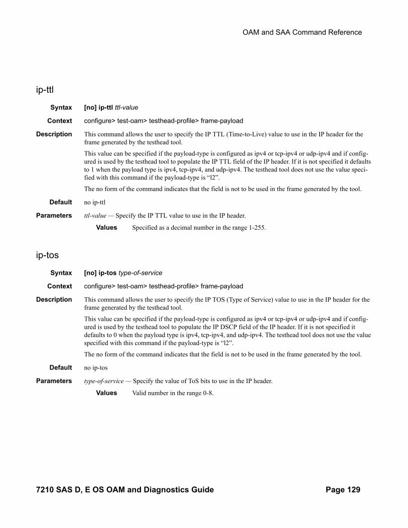
OAM and SAA Command Reference
ip-ttl
Syntax [no] ip-ttl ttl-value
Context configure> test-oam> testhead-profile> frame-payload
Description This command allows the user to specify the IP TTL (Time-to-Live) value to use in the IP header for the frame generated by the testhead tool.
This value can be specified if the payload-type is configured as ipv4 or tcp-ipv4 or udp-ipv4 and if config-ured is used by the testhead tool to populate the IP TTL field of the IP header. If it is not specified it defaults to 1 when the payload type is ipv4, tcp-ipv4, and udp-ipv4. The testhead tool does not use the value speci-fied with this command if the payload-type is “l2”.
The no form of the command indicates that the field is not to be used in the frame generated by the tool.
Default no ip-ttl
Parameters ttl-value — Specify the IP TTL value to use in the IP header.
Values Specified as a decimal number in the range 1-255.
ip-tos
Syntax [no] ip-tos type-of-service
Context configure> test-oam> testhead-profile> frame-payload
Description This command allows the user to specify the IP TOS (Type of Service) value to use in the IP header for the frame generated by the testhead tool.
This value can be specified if the payload-type is configured as ipv4 or tcp-ipv4 or udp-ipv4 and if config-ured is used by the testhead tool to populate the IP DSCP field of the IP header. If it is not specified it defaults to 0 when the payload type is ipv4, tcp-ipv4, and udp-ipv4. The testhead tool does not use the value specified with this command if the payload-type is “l2”.
The no form of the command indicates that the field is not to be used in the frame generated by the tool.
Default no ip-tos
Parameters type-of-service — Specify the value of ToS bits to use in the IP header.
Values Valid number in the range 0-8.
7210 SAS D, E OS OAM and Diagnostics Guide Page 129
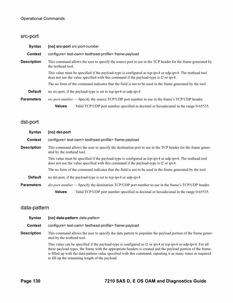
Operational Commands
src-port
Syntax [no] src-port src-port-number
Context configure> test-oam> testhead-profile> frame-payload
Description This command allows the user to specify the source port to use in the TCP header for the frame generated by the testhead tool.
This value must be specified if the payload-type is configured as tcp-ipv4 or udp-ipv4. The testhead tool does not use the value specified with this command if the payload-type is l2 or ipv4.
The no form of the command indicates that the field is not to be used in the frame generated by the tool.
Default no src-port, if the payload-type is set to tcp-ipv4 or udp-ipv4
Parameters src-port-number — Specify the source TCP/UDP port number to use in the frame’s TCP/UDP header.
Values Valid TCP/UDP port number specified in decimal or hexadecimal in the range 0-65535.
dst-port
Syntax [no] dst-port
Context configure> test-oam> testhead-profile> frame-payload
Description This command allows the user to specify the destination port to use in the TCP header for the frame gener-ated by the testhead tool.
This value must be specified if the payload-type is configured as tcp-ipv4 or udp-ipv4. The testhead tool does not use the value specified with this command if the payload-type is l2 or ipv4.
The no form of the command indicates that the field is not to be used in the frame generated by the tool.
Default no dst-port, if the payload-type is set to tcp-ipv4 or udp-ipv4
Parameters dst-port-number — Specify the destination TCP/UDP port number to use in the frame’s TCP/UDP header.
Values Valid TCP/UDP port number specified in decimal or hexadecimal in the range 0-65535.
data-pattern
Syntax [no] data-pattern data-pattern
Context configure> test-oam> testhead-profile> frame-payload
Description This command allows the user to specify the data pattern to populate the payload portion of the frame gener-ated by the testhead tool.
This value can be specified if the payload-type is configured as l2 or ipv4 or tcp-ipv4 or udp-ipv4. For all these payload types, the frame with the appropriate headers is created and the payload portion of the frame, is filled up with the data-pattern-value specified with this command, repeating it as many times as required to fill up the remaining length of the payload.
Page 130 7210 SAS D, E OS OAM and Diagnostics Guide

OAM and SAA Command Reference
The no form of the command uses the default data-pattern value of 0xa1b2c3d4e5f6.
Default no data-pattern
Parameters data-pattern — Used to specify the data-pattern to fill the payload data.
Values A string of decimal or hexadecimal numbers of length in the range 1-64.
7210 SAS D, E OS OAM and Diagnostics Guide Page 131

OAM testhead commands
OAM testhead commands
testhead
Syntax testhead test-name owner owner-name testhead-profile profile-id [frame-payload frame-payload-id] [acceptance-criteria acceptance-criteria-id] sap sap-id [fc fc-name]
Context oam
Description This command allows the user to execute the throughput test by generating the traffic upto the configured rate and measures the delay, delay-variation and frame-loss ratio. At the end of the test run the testhead com-mand compares the measured values against the test acceptance criteria that is specified to determine if the service is within bounds of the acceptance criteria or not. It declares the test to have PASSED if the through-put is achieved and the measured values are lesser than the thresholds configured in the acceptance criteria or else it reports a FAILURE if any of the measured values exceeds the thresholds configured in the accep-tance criteria.
If the acceptance parameter is not specified, the by default software will display the test result as “PASS”, if the frame loss is zero and desired rate is achieved. Measured value of latency and delay variation will not be compared.
User must specify the testhead-profile parameter to use. This parameter determines the rate at which traffic is generated and the content of the frames used for traffic generation.
The test-name and owner-name together identify a particular testhead invocation/session uniquely. The results of the testhead session are associated with the test-name and owner-name. These parameters must be used if the user needs to display the results of the testhead tool and to clear the results of a completed run. Multiple invocations of the testhead tool with the same test-name and owner-name is not allowed if the results of the old run using the same pair of test-name and owner-name are present. In other words, the results are not overwritten when the testhead is invoked again with the same values for test-name and owner-name. The results needs to be cleared explicitly using the clear command before invoking the testhead tool with the same test-name and owner-name. Results for up to 100 unique sessions each using a different test-name and owner-name is saved in memory (in other words, the results are not available for use after a reboot).
NOTE: This command is not saved in the configuration file across a reboot.
Following are some of the pre-requisites before the testhead tool can be used:
• The user needs to setup the port loopback with the mac-swap on the local node using the sap-id used with this command and the src-mac & dst-mac used in the frame-payload. Port loopback with mac-swap on remote node needs to be setup by user to match the local configuration.
• User must configure resources for ACL MAC criteria in ingress-internal-tcam using the command config>system> resource-profile> ingress-internal-tcam> acl-sap-ingress> mac-match-enable. Additionally they must allocate resources to egress ACL MAC or IPv4 or IPv6 64-bit criteria (using the command config>system> resource-profile> egress-internal-tcam> acl-sap-egress> mac-ipv4-match-enable or mac-ipv6-64bit-enable or mac-ipv4-match-enable). Testhead tool uses resources from these resource pools. If no resources are allocated to these pools or no resources are available for use in these pools, then testhead will fail to function. Testhead needs a minimum of about 4 entries from the ingress-internal-tcam pool and 2 entries from the egress-internal-tcam
Page 132 7210 SAS D, E OS OAM and Diagnostics Guide

OAM and SAA Command Reference
pool. If user allocates resources to egress ACLs IPv6 128-bit match criteria (using the command config> system> resource-profile> egress-internal-tcam> acl-sap-egress> ipv6-128bit-match-enable), then testhead will fail to function.
• The MAC addresses must be learnt on the appropriate SAPs before the test can be started. It is recommended to configure static-mac etnry for the source MAC address configured with the port-loopback command (or the source MAC address configured in the frame-payload in the testhead profile). The source MAC address must be learnt on a SAP/SDP which carries traffic towards the core network.
• While the test is running user must not modify the SAP configuration. If need be, they must stop the test, remove the port loopback with mac-swap configuration, modify the SAP configuration and SAP parameters and then add back the port loopback with mac-swap configuration and run the test.
Default no defaults
Parameters test-name — Name of the test
Values ASCII string upto 32 characters in length
owner test-owner — Specifies the owner of an testhead operation.
Values ASCII string upto 32 characters in length
testhead-profile profile-id — Specifies the testhead profile ID to use with this run/session of testhead invoca-tion. Testhead profile must be configure beforehand using the commands under config> test-oam> testhead-profile>.
Values 1- 10
frame-payload frame-payload-id — Optional parameter used to specify the frame payload ID to use for this run. It identifies the parameters used to construct the frame generated by the testhead tool.
Values 1 – 4, if this parameter is not specified, then by default parameters configured under frame-payload-id 1 is used by this run.
acceptance-criteria acceptance-criteria-id — Optional parameter used to specify the test acceptance criteria parameters to use. for this run. It identifies the parameters used to compare the measured performance values against the configured thresholds configured in the acceptance criteria.
Values 1 – 4. If this parameter is not specified then the run is declared pass if the throughput configured in the testhead-profile is achieved without any loss.
sap sap-id — Identifies the test SAP. Must be specified by the user.
Values null - <port-id|lag-id>dot1q - <port-id|lag-id>:qtag1qinq - <port-id|lag-id>:qtag1.qtag2port-id - slot/mda/portlag-id - lag-<id>lag - keywordid - [1..200]qtag1 - [0..4094]qtag2 - [*|1..4094]
For more information, see “SAP configuration guidelines”.
7210 SAS D, E OS OAM and Diagnostics Guide Page 133

OAM testhead commands
fc fc-name — Optional parameter that specifies the forwarding class (FC) to use to send the frames gener-ated by the testhead tool.
Values be, l2, af, l1, h2, ef, h1, nc
testhead
Syntax testhead test-name owner owner-name stop
Context oam
Description The currently running test, if any will be stopped. All performance results based on the data available upto the time the test is stopped is used determine the pass/fail criteria. Additionally, the test-status will display “Stopped” and Test completion status will be marked “Incomplete or No”.
Parameters test-name — Name of the test
Values ASCII string upto 32 characters in length
owner test-owner — Specifies the owner of an testhead operation.
Values ASCII string upto 32 characters in length
Page 134 7210 SAS D, E OS OAM and Diagnostics Guide

OAM and SAA Command Reference
Service Assurance Agent (SAA) Commands
saa
Syntax saa
Context config
Description This command creates the context to configure the Service Assurance Agent (SAA) tests.
test
Syntax test name [owner test-owner]no test name
Context config>saa
Description This command identifies a test and create/modify the context to provide the test parameters for the named test. Subsequent to the creation of the test instance the test can be started in the OAM context.
A test can only be modified while it is shut down.
The no form of this command removes the test from the configuration. In order to remove a test it can not be active at the time.
Parameters name — Identify the saa test name to be created or edited.
owner test-owner — Specifies the owner of an SAA operation upto 32 characters in length.
Values If a test-owner value is not specified, tests created by the CLI have a default owner “TiMOS CLI”.
accounting-policy
Syntax accounting-policy acct-policy-idno accounting-policy
Context config>saa>test
Description This command associates an accounting policy to the SAA test. The accounting policy must already be defined before it can be associated else an error message is generated.
A notification (trap) when a test is completed is issued whenever a test terminates.
The no form of this command removes the accounting policy association.
Default none
7210 SAS D, E OS OAM and Diagnostics Guide Page 135

OAM testhead commands
Parameters acct-policy-id — Enter the accounting policy-id as configured in the config>log>accounting-policy context.
Values 1 — 99
description
Syntax description description-stringno description
Context config>saa>test
Description This command creates a text description stored in the configuration file for a configuration context.
The description command associates a text string with a configuration context to help identify the content in the configuration file.
The no form of this command removes the string from the configuration.
Default No description associated with the configuration context.
Parameters string — The description character string. Allowed values are any string up to 80 characters long composed of printable, 7-bit ASCII characters. If the string contains special characters (#, $, spaces, etc.), the entire string must be enclosed within double quotes.
continuous
Syntax [no] continuous
Context config>saa>test
Description This command specifies whether the SAA test is continuous. Once the test is configured as continuous, it cannot be started or stopped by using the saa command.The no form of the command disables the continuous running of the test. Use the shutdown command todisable the test.
jitter-event
Syntax jitter-event rising-threshold threshold [falling-threshold threshold] [direction]no jitter-event
Context config>saa>test
Description Specifies that at the termination of an SAA test probe, the calculated jitter value is evaluated against the con-figured rising and falling jitter thresholds. SAA threshold events are generated as required.
Once the threshold (rising/falling) is crossed, it is disabled from generating additional events until the oppo-site threshold is crossed. If a falling-threshold is not supplied, the rising threshold will be re-enabled when it falls below the threshold after the initial crossing that generate the event.
Page 136 7210 SAS D, E OS OAM and Diagnostics Guide

OAM and SAA Command Reference
The configuration of jitter event thresholds is optional.
Parameters rising-threshold threshold — Specifies a rising threshold jitter value. When the test run is completed, the calculated jitter value is compared to the configured jitter rising threshold. If the test run jitter value is greater than the configured rising threshold value then an SAA threshold event is generated. The SAA threshold event is tmnxOamSaaThreshold, logger application OAM, event #2101.
Default 0
Values 0 — 2147483 milliseconds
falling-threshold threshold — Specifies a falling threshold jitter value. When the test run is completed, the calculated jitter value is compared to the configured jitter falling threshold. If the test run jitter value is greater than the configured falling threshold value then an SAA threshold event is generated. The SAA threshold event is tmnxOamSaaThreshold, logger application OAM, event #2101.
Default 0
Values 0 — 2147483 milliseconds
direction — Specifies the direction for OAM ping responses received for an OAM ping test run.
Values inbound — Monitor the value of jitter calculated for the inbound, one-way, OAM ping responses received for an OAM ping test run.outbound — Monitor the value of jitter calculated for the outbound, one-way, OAM ping requests sent for an OAM ping test run.roundtrip — Monitor the value of jitter calculated for the round trip, two-way, OAM ping requests and replies for an OAM ping test run.
Default roundtrip
latency-event
Syntax latency-event rising-threshold threshold [falling-threshold threshold] [direction]no latency-event
Context config>saa>test
Description Specifies that at the termination of an SAA test probe, the calculated latency event value is evaluated against the configured rising and falling latency event thresholds. SAA threshold events are generated as required.
Once the threshold (rising/falling) is crossed, it is disabled from generating additional events until the oppo-site threshold is crossed. If a falling-threshold is not supplied, the rising threshold will be re-enabled when it falls below the threshold after the initial crossing that generate the event.
The configuration of latency event thresholds is optional.
Parameters rising-threshold threshold — Specifies a rising threshold latency value. When the test run is completed, the calculated latency value is compared to the configured latency rising threshold. If the test run latency value is greater than the configured rising threshold value then an SAA threshold event is generated. The SAA threshold event is tmnxOamSaaThreshold, logger application OAM, event #2101.
Default 0
Values 0 — 2147483 milliseconds
7210 SAS D, E OS OAM and Diagnostics Guide Page 137

OAM testhead commands
falling-threshold threshold — Specifies a falling threshold latency value. When the test run is completed, the calculated latency value is compared to the configured latency falling threshold. If the test run latency value is greater than the configured falling threshold value then an SAA threshold event is gen-erated. The SAA threshold event is tmnxOamSaaThreshold, logger application OAM, event #2101.
Default 0
Values 0 — 2147483 milliseconds
direction — Specifies the direction for OAM ping responses received for an OAM ping test run.
Values inbound — Monitor the value of jitter calculated for the inbound, one-way, OAM ping responses received for an OAM ping test run.outbound — Monitor the value of jitter calculated for the outbound, one-way, OAM ping requests sent for an OAM ping test run.roundtrip — Monitor the value of jitter calculated for the round trip, two-way, OAM ping requests and replies for an OAM ping test run.
Default roundtrip
loss-event
Syntax loss-event rising-threshold threshold [falling-threshold threshold] [direction]no loss-event
Context config>saa>test
Description Specifies that at the termination of an SAA testrun, the calculated loss event value is evaluated against the configured rising and falling loss event thresholds. SAA threshold events are generated as required.
The configuration of loss event thresholds is optional.
Parameters rising-threshold threshold — Specifies a rising threshold loss event value. When the test run is completed, the calculated loss event value is compared to the configured loss event rising threshold. If the test run loss event value is greater than the configured rising threshold value then an SAA threshold event is generated. The SAA threshold event is tmnxOamSaaThreshold, logger application OAM, event #2101.
Default 0
Values 0 — 2147483647 packets
falling-threshold threshold — Specifies a falling threshold loss event value. When the test run is com-pleted, the calculated loss event value is compared to the configured loss event falling threshold. If the test run loss event value is greater than the configured falling threshold value then an SAA threshold event is generated. The SAA threshold event is tmnxOamSaaThreshold, logger application OAM, event #2101.
Default 0
Values 0 — 2147483647 packets
direction — Specifies the direction for OAM ping responses received for an OAM ping test run.
Values inbound — Monitor the value of jitter calculated for the inbound, one-way, OAM ping responses received for an OAM ping test run.
Page 138 7210 SAS D, E OS OAM and Diagnostics Guide

OAM and SAA Command Reference
outbound — Monitor the value of jitter calculated for the outbound, one-way, OAM ping requests sent for an OAM ping test run.roundtrip — Monitor the value of jitter calculated for the round trip, two-way, OAM ping requests and replies for an OAM ping test run.
Default roundtrip
trap-gen
Syntax trap-gen
Context config>saa>test
Description This command enables the context to configure trap generation for the SAA test.
probe-fail-enable
Syntax [no] probe-fail-enable
Context config>saa>test>trap-gen
Description This command enables the generation of an SNMP trap when probe-fail-threshold consecutive probes fail during the execution of the SAA ping test. This command is not applicable to SAA trace route tests.
The no form of the command disables the generation of an SNMP trap.
probe-fail-threshold
Syntax [no] probe-fail-threshold 0..15
Context config>saa>test>trap-gen
Description This command has no effect when probe-fail-enable is disabled. This command is not applicable to SAA trace route tests.
The probe-fail-enable command enables the generation of an SNMP trap when the probe-fail-threshold consecutive probes fail during the execution of the SAA ping test. This command is not applicable to SAA trace route tests.
The no form of the command returns the threshold value to the default.
Default 1
7210 SAS D, E OS OAM and Diagnostics Guide Page 139

OAM testhead commands
test-completion-enable
Syntax [no] test-completion-enable
Context config>saa>test>trap-gen
Description This command enables the generation of a trap when an SAA test completes.
The no form of the command disables the trap generation.
test-fail-enable
Syntax [no] test-fail-enable
Context config>saa>test>trap-gen
Description This command enables the generation of a trap when a test fails. In the case of a ping test, the test is consid-ered failed (for the purpose of trap generation) if the number of failed probes is at least the value of the test-fail-threshold parameter.
The no form of the command disables the trap generation.
test-fail-threshold
Syntax [no] test-fail-threshold 0..15
Context config>saa>test>trap-gen
Description This command configures the threshold for trap generation on test failure.
This command has no effect when test-fail-enable is disabled. This command is not applicable to SAA trace route tests.
The no form of the command returns the threshold value to the default.
Default 1
type
Syntax typeno type
Context config>saa>test
Description This command creates the context to provide the test type for the named test. Only a single test type can be configured.
A test can only be modified while the test is in shut down mode.
Page 140 7210 SAS D, E OS OAM and Diagnostics Guide

OAM and SAA Command Reference
Once a test type has been configured the command can be modified by re-entering the command, the test type must be the same as the previously entered test type.
To change the test type, the old command must be removed using the config>saa>test>no type command.
dns
Syntax dns target-addr dns-name name-server ip-address [source ip-address] [count send-count] [timeout timeout] [interval interval] [record-type {ipv4-a-record | ipv6-aaaa-record}]
Context <GLOBAL>config>saa>test>type
Description This command configures a DNS name resolution test.
Parameters target-addr — Is a keyword to specify the domain name or IP address to be looked up.
dns-name — Specifies the domain name or IP address to be looked up.
name-server ip-address — Specifies the server connected to a network that resolves network names into network addresses.
Values ipv4-address - a.b.c.dipv6-address - x:x:x:x:x:x:x:x (eight 16-bit pieces)
x:x:x:x:x:x:d.d.d.dx - [0..FFFF]Hd - [0..255]D
source ip-address — Specifies the IP address to be used as the source for performing an OAM ping opera-tion.
Values ipv4-address - a.b.c.dipv6-address - x:x:x:x:x:x:x:x (eight 16-bit pieces)
x:x:x:x:x:x:d.d.d.dx - [0..FFFF]H d - [0..255]D
send-count send-count — The number of messages to send, expressed as a decimal integer. The send-count parameter is used to override the default number of message requests sent. Each message request must either timeout or receive a reply before the next message request is sent. The message interval value must be expired before the next message request is sent.
Default 1
Values 1 — 100
timeout timeout — The timeout parameter in seconds, expressed as a decimal integer. This value is used to override the default timeout value and is the amount of time that the router will wait for a message reply after sending the message request. Upon the expiration of message timeout, the requesting router assumes that the message response will not be received. Any response received after the request times out will be silently discarded.
Default 5
Values 1 — 120
7210 SAS D, E OS OAM and Diagnostics Guide Page 141

OAM testhead commands
interval interval — The interval parameter in seconds, expressed as a decimal integer. This parameter is used to override the default request message send interval and defines the minimum amount of time that must expire before the next message request is sent.
If the interval is set to 1 second, and the timeout value is set to 10 seconds, then the maximum time between message requests is 10 seconds and the minimum is 1 second. This depends upon the receipt of a message reply corresponding to the outstanding message request.
Default 1
Values 1 — 10
record-type — Specifies a record type.
Values ipv4-a-record - A record specific mapping a host name to an IPv4 address.
ipv6-aaaa-record - A record specific to the Internet class that stores a single IPv6 address.
eth-cfm-linktrace
Syntax eth-cfm-linktrace mac-address mep mep-id domain md-index association ma-index [ttl ttlvalue][fc {fc-name} ] [count send-count] [timeout timeout] [interval interval]
Context config>saa>test>type
Description This command configures a CFM linktrace test in SAA.
Parameters- mac-address — Specifies a unicast destination MAC address.
mep mep-id — Specifies the target MAC address.
Values 1 — 8191
domain md-index — Specifies the MD index.
Values 1 — 4294967295
association ma-index — Specifies the MA index.
Values 1 — 4294967295
ttl ttl-value — Specifies the maximum number of hops traversed in the linktrace.
Default 64
Values 1— 255
fc fc-name — The fc parameter is used to indicate the forwarding class of the CFM Linktrace request messages.The actual forwarding class encoding is controlled by the network egress mappings.
Default nc
Values be, l2, af, l1, h2, ef, h1, nc
count send-count — The number of messages to send, expressed as a decimal integer. The count parameteris used to override the default number of message requests sent. Each message request must either timeout
Page 142 7210 SAS D, E OS OAM and Diagnostics Guide

OAM and SAA Command Reference
or receive a reply before the next message request is sent. The message interval value must be expired before the next message request is sent.
Default 1
Values 1 — 10
timeout timeout — The timeout parameter in seconds, expressed as a decimal integer. This value is used tooverride the default timeout value and is the amount of time that the router will wait for a message reply after sending the message request. Upon the expiration of message timeout, the requesting router assumes that the message response will not be received. Any response received after the request times out will be silently discarded. The timeout value must be less than the interval.
Default 5
Values 1 — 10
interval interval — The interval parameter in seconds, expressed as a decimal integer. This parameter isused to override the default request message send interval and defines the minimum amount of time that must expire before the next message request is sent.If the interval is set to “1” second, and the timeout value is set to “10” seconds, then the maximum timebetween message requests is “10” seconds and the minimum is “1” second. This depends upon the receipt ofa message reply corresponding to the outstanding message request. The timeout value must be less thanthe interval.
Default 5
Values 1 — 10
eth-cfm-loopback
Syntax eth-cfm-loopback mac-address mep mep-id domain md-index association ma-index [size datasize] [fc {fc-name} ] [count send-count ][timeout timeout] [interval interval]
Context config>saa>test>type
Description This command configures an Ethernet CFM loopback test in SAA.
mac-address — Specifies a unicast destination MAC address.
mep mep-id — Specifies the target MAC address.
Values 1 — 8191
domain md-index — Specifies the MD index.
Values 1 — 4294967295
association ma-index — Specifies the MA index.
Values 1 — 4294967295
size data-size — The packet size in bytes, expressed as a decimal integer.
7210 SAS D, E OS OAM and Diagnostics Guide Page 143

OAM testhead commands
Default 0
Values 0 — 1500
fc fc-name — The fc parameter is used to indicate the forwarding class of the CFM Loopback request messages.The actual forwarding class encoding is controlled by the network egress mappings.
Default nc
Values be, l2, af, l1, h2, ef, h1, nc
count send-count — The number of messages to send, expressed as a decimal integer. The count parameteris used to override the default number of message requests sent. Each message request must either timeoutor receive a reply before the next message request is sent. The message interval value must be expired before the next message request is sent.
Default 1
Values 1 — 100
timeout timeout — The timeout parameter in seconds, expressed as a decimal integer. This value is used tooverride the default timeout value and is the amount of time that the router will wait for a message reply after sending the message request. Upon the expiration of message timeout, the requesting router assumes that the message response will not be received. Any response received after the request times out will be silently discarded. The timeout value must be less than the interval.
Default 5
Values 1 — 10
interval interval — The interval parameter in seconds, expressed as a decimal integer. This parameter isused to override the default request message send interval and defines the minimum amount of time that must expire before the next message request is sent.If the interval is set to “1” second, and the timeout value is set to “10” seconds, then the maximum timebetween message requests is “10” seconds and the minimum is “1” second. This depends upon the receipt ofa message reply corresponding to the outstanding message request. The timeout value must be less thanthe interval.
Default 5
Values 1 — 10
eth-cfm-two-way-delay
Syntax eth-cfm-two-way-delay mac-address mep mep-id domain md-index association ma-index [fc {fc-name} ] [count send-count] [timeout timeout] [interval interval]
Context config>saa>test>type
Description- This command configures an Ethernet CFM two-way delay test in SAA.
mac-address — Specifies a unicast destination MAC address.
Page 144 7210 SAS D, E OS OAM and Diagnostics Guide

OAM and SAA Command Reference
mep mep-id — Specifies the target MAC address.
Values 1 — 8191
domain md-index — Specifies the MD index.
Values 1 — 4294967295
association ma-index — Specifies the MA index.
Values 1 — 4294967295
ttl ttl-value — Specifies the maximum number of hops traversed in the linktrace.
Default 64
Values 1— 255
fc fc-name — The fc parameter is used to indicate the forwarding class of the CFM two-delay request messages.The actual forwarding class encoding is controlled by the network egress mappings.
Default nc
Values be, l2, af, l1, h2, ef, h1, nc
count send-count — The number of messages to send, expressed as a decimal integer. The count parameteris used to override the default number of message requests sent. Each message request must either timeoutor receive a reply before the next message request is sent. The message interval value must be expired before the next message request is sent.
Default 1
Values 1 — 100
timeout timeout — The timeout parameter in seconds, expressed as a decimal integer. This value is used tooverride the default timeout value and is the amount of time that the router will wait for a message reply after sending the message request. Upon the expiration of message timeout, the requesting router assumes that the message response will not be received. Any response received after the request times out will be silently discarded. The timeout value must be less than the interval.
Default 5
Values 1 — 10
interval interval — The interval parameter in seconds, expressed as a decimal integer. This parameter isused to override the default request message send interval and defines the minimum amount of time that must expire before the next message request is sent.If the interval is set to “1” second, and the timeout value is set to “10” seconds, then the maximum timebetween message requests is “10” seconds and the minimum is “1” second. This depends upon the receipt ofa message reply corresponding to the outstanding message request. The timeout value must be less thanthe interval.
Default 5
Values 1 — 10
7210 SAS D, E OS OAM and Diagnostics Guide Page 145

OAM testhead commands
eth-cfm-two-way-slm
Syntax eth-cfm-two-way-delay mac-address mep mep-id domain md-index association ma-index [fc {fc-name}] [send-count send-count] [size data-size] [timeout timeout] [interval interval]
Context config>saa>test>type
Description This command configures an Ethernet CFM two-way SLM test in SAA.
mac-address — Specifies a unicast destination MAC address.
mep mep-id — Specifies the target MAC address.
Values 1 — 8191
domain md-index — Specifies the MD index.
Values 1 — 4294967295
association ma-index — Specifies the MA index.
Values 1 — 4294967295
fc fc-name — The fc parameter is used to indicate the forwarding class of the CFM SLM request messages. The actual forwarding class encoding is controlled by the network egress mappings.
Default nc
Values be, l2, af, l1, h2, ef, h1, nc
profile {in | out} — The profile state of the CFM SLM request messages.
Default in
send-count send-count — The number of messages to send, expressed as a decimal integer. The count parameter is used to override the default number of message requests sent. Each message request must either timeout or receive a reply before the next message request is sent. The message interval value must be expired before the next message request is sent.
Default 1
Values 1 — 100
size data-size — This is the size of the data portion of the data TLV. If 0 is specified no data TLV is added to
the packet.
Default 0
Values 0 — 1500
timeout timeout — The timeout parameter in seconds, expressed as a decimal integer. This value is used to override the default timeout value and is the amount of time that the router waits for a message reply after sending the message request. Upon the expiration of message timeout, the requesting router assumes that the message response is not received. Any response received after the request times out is silently discarded. The timeout value must be less than the interval.
Default 5
Values 1 — 10
Page 146 7210 SAS D, E OS OAM and Diagnostics Guide

OAM and SAA Command Reference
interval interval — The interval parameter in seconds, expressed as a decimal integer. This parameter is used to override the default request message send interval and defines the minimum amount of time that must expire before the next message request is sent. If the interval is set to 1 second, and the timeout value is set to 10 seconds, then the maximum time between message requests is 10 seconds and the minimum is 1 sec-ond. This depends upon the receipt of a message reply corresponding to the outstanding message request. The timeout value must be less than the interval.
Default 5
Values 1 — 10
icmp-ping
Syntax icmp-ping [ip-address | dns-name] [rapid | detail] [ttl time-to-live] [tos type-of-service] [size bytes] [pattern pattern] [source ip-address] [interval seconds] [{next-hop ip-address} | {interface interface-name} | bypass-routing] [count requests] [do-not-fragment] [router router-instance | service-name service-name] [timeout timeout]
Context config>saa>test>type
Description This command configures an ICMP ping test.
Parameters ip-address — The far-end IP address to which to send the icmp-ping request message in dotted decimal notation.
Values ipv4-address: a.b.c.dipv6-address: x:x:x:x:x:x:x:x (eight 16-bit pieces)
x:x:x:x:x:x:d.d.d.dx: [0 .. FFFF]Hd: [0 .. 255]D
dns-name — The DNS name of the far-end device to which to send the icmp-ping request message, expressed as a character string up to 63 characters maximum.
rapid — Packets will be generated as fast as possible instead of the default 1 per second.
detail — Displays detailed information.
ttl time-to-live — The TTL value for the IP packet, expressed as a decimal integer.
Values 1 — 128
tos type-of-service — Specifies the service type.
Values 0 — 255
size bytes — The request packet size in bytes, expressed as a decimal integer.
Values 0 — 16384
pattern pattern — The date portion in a ping packet will be filled with the pattern value specified. If not specified, position info will be filled instead.
Values 0 — 65535
7210 SAS D, E OS OAM and Diagnostics Guide Page 147

OAM testhead commands
source ip-address — Specifies the IP address to be used.
Values ipv4-address: a.b.c.d
interval seconds — This parameter is used to override the default request message send interval and defines the minimum amount of time that must expire before the next message request is sent.
If the interval is set to 1 second, and the timeout value is set to 10 seconds, then the maximum time between message requests is 10 seconds and the minimum is 1 second. This depends upon the receipt of a message reply corresponding to the outstanding message request.
Default 1
Values 1 — 10
next-hop ip-address — Only displays static routes with the specified next hop IP address.
Values ipv4-address: a.b.c.d (host bits must be 0)
interface interface-name — The name used to refer to the interface. The name must already exist in the config>router>interface context.
bypass-routing — Specifies whether to send the ping request to a host on a directly attached network bypassing the routing table.
count requests — Specifies the number of times to perform an OAM ping probe operation. Each OAM echo message request must either timeout or receive a reply before the next message request is sent.
Values 1 — 100000
Default 5
do-not-fragment — Sets the DF (Do Not Fragment) bit in the ICMP ping packet.
router router-instance — Specifies the router name or service ID.
Values router-name: Base , management service-id: 1 — 2147483647
Default Base
service-name service-name — Specifies the service name as an integer.
Values service-id: 1 — 2147483647
timeout timeout — Overrides the default timeout value and is the amount of time that the router will wait for a message reply after sending the message request. Upon the expiration of message timeout, the requesting router assumes that the message response will not be received. Any response received after the request times out will be silently discarded.
Default 5
Values 1 — 10
Page 148 7210 SAS D, E OS OAM and Diagnostics Guide

OAM and SAA Command Reference
icmp-trace
Syntax icmp-trace [ip-address | dns-name] [ttl time-to-live] [wait milli-seconds] [tos type-of-service] [source ip-address] [tos type-of-service] [router router-instance | service-name service-name]
Context config>saa>test>type
Description This command configures an ICMP traceroute test.
Parameters ip-address — The far-end IP address to which to send the icmp-ping request message in dotted decimal notation.
Values ipv4-address: a.b.c.dipv6-address: x:x:x:x:x:x:x:x (eight 16-bit pieces)
x:x:x:x:x:x:d.d.d.dx: [0 .. FFFF]Hd: [0 .. 255]D
dns-name — The DNS name of the far-end device to which to send the icmp-ping request message, expressed as a character string to 63 characters maximum.
ttl time-to-live — The TTL value for the IP TTL, expressed as a decimal integer.
Values 1 — 255
wait milliseconds — The time in milliseconds to wait for a response to a probe, expressed as a decimal inte-ger.
Default 5000
Values 1 — 60000
tos type-of-service — Specifies the service type.
Values 0 — 255
source ip-address — Specifies the IP address to be used.
Values ipv4-address: a.b.c.dipv6-address: x:x:x:x:x:x:x:x (eight 16-bit pieces)
x:x:x:x:x:x:d.d.d.dx: [0 .. FFFF]Hd: [0 .. 255]D
router router-instance — Specifies the router name or service ID.
Values router-name: 7210 SAS E supports: Base, management 7210 SAS D supports: Base
service-id: 1 — 2147483647
Default Base
Multiple Response Connectivity Tests — When the connectivity test count is greater than one (1), a single line is displayed per SDP echo request send attempt.
The request number is a sequential number starting with 1 and ending with the last request sent, increment-ing by one (1) for each request. This should not be confused with the message-id contained in each request and reply message.
7210 SAS D, E OS OAM and Diagnostics Guide Page 149
OAM testhead commands
A response message indicates the result of the message request. Following the response message is the round trip time value. If any reply is received, the round trip time is displayed.
After the last reply has been received or response timed out, a total is displayed for all messages sent and all replies received. A maximum, minimum and average round trip time is also displayed. Error response and timed out requests do not apply towards the average round trip time.
Page 150 7210 SAS D, E OS OAM and Diagnostics Guide

OAM and SAA Command Reference
OAM SAA Commands
saa
Syntax saa test-name [owner test-owner] {start | stop} [no-accounting]
Context oam
Description Use this command to start or stop an SAA test.
test-name — Name of the SAA test. The test name must already be configured in the config>saa>test con-text.
owner test-owner — Specifies the owner of an SAA operation up to 32 characters in length.
Values If a test-owner value is not specified, tests created by the CLI have a default owner “TiMOS CLI”.
start — This keyword starts the test. A test cannot be started if the same test is still running.
A test cannot be started if it is in a shut-down state. An error message and log event will be generated to indicate a failed attempt to start an SAA test run. A test cannot be started if it is in a continous state.
stop — This keyword stops a test in progress. A test cannot be stopped if it is not in progress. A log message will be generated to indicate that an SAA test run has been aborted. A test cannot be stopped if it is in a continous state.
no-accounting — This parameter disables the recording results in the accounting policy. If no-accounting is specified, the MIB record produced at the end of the test will not be added to the accounting file. It will however use up one of the three MIB rows available for the accounting module to be collected.
7210 SAS D, E OS OAM and Diagnostics Guide Page 151

OAM testhead commands
Twamp commands
twamp
Syntax twamp
Context config>oam-test
Description This command enables TWAMP functionality.
Default TWAMP is disabled.
server
Syntax retry-count retry-count
Context config>test-oam>twamp
Description This command configures the node for TWAMP server functionality.
Default TWAMP is disabled.
prefix
Syntax prefix {ip-prefix | mask}no prefix
Context config>test-oam>twamp>server
Description This command configures an IP address prefix containing one or more TWAMP clients. In order for a
TWAMP client to connect to the TWAMP server (and subsequently conduct tests) it must establish the con-trol connection using an IP address that is part of a configured prefix.
Default no prefix
Parameters prefix ip-prefix/mask — Specifies the address prefix and subnet mask of the destination node.ip-prefix — An IPv4 address in dotted decimal notation.
Values a.b.c.d
Default none
mask — The prefix length.
Values 0—32
Default none
Page 152 7210 SAS D, E OS OAM and Diagnostics Guide

OAM and SAA Command Reference
max-conn-prefix
Syntax max-conn-prefix countno max-conn-prefix
Context config>test-oam>twamp>server>prefix
Description This command configures the maximum number of TWAMP control connections by clients with an IP address in a specific prefix. A new control connection is rejected if accepting it would cause either the prefix limit defined by this command or the server limit (max-conn-server) to be exceeded.
The no form of the command sets the default value.
Default no max-conn-prefix
Parameters count — The maximum number of control connections.
Values 0—48
Default 24
max-conn-server
Syntax max-conn-server countno max-conn-server
Context config>test-oam>twamp>server
Description This command configures the maximum number of TWAMP control connections from all TWAMP clients.
A new control connection is rejected if accepting it would cause either this limit or a prefix limit (max-conn-prefix) to be exceeded.
The no form of the command sets the default value.
Default no max-conn-server
Parameters count — The maximum number of control connections.
Values 0—8
Default 4
inactivity-timeout
Syntax inactivity-timeout secondsno inactivity-timeout
Context config>test-oam>twamp>server
Description This command configures the inactivity timeout for all TWAMP-control connections. If no TWAMP control message is exchanged over the TCP connection for this duration of time the connection is closed and all inprogress tests are terminated.
7210 SAS D, E OS OAM and Diagnostics Guide Page 153

OAM testhead commands
The no form of the command instructs the system to go with the default value.
Default no inactivity-timeout
Parameters retry-count — The duration of the inactivity timeout.
Values 60— 3600
Default 900
max-sess-prefix
Syntax max-sess-prefix countno max-sess-prefix
Context config>test-oam>twamp>server>prefix
Description This command configures the maximum number of concurrent TWAMP-Test sessions by clients with an IP address in a specific prefix. A new test session (described by a Request-TW-Session message) is rejected if accepting it would cause either the limit defined by this command or the server limit (max-sess-server) to be exceeded.
The no form of the command instructs the system to go with the default value.
Default no max-sess-prefix
Parameters count — The maximum number of concurrent test sessions.
Values 0—48
Default 24
max-sess-server
Syntax max-sess-server countno max-sess-server
Context config>test-oam>twamp>server
Description This command configures the maximum number of concurrent TWAMP-Test sessions across all allowed cli-ents.
A new test session (described by a Request-TW-Session message) is rejected if accepting it would cause either the limit defined by this command or a prefix limit (max-sess-prefix) to be exceeded.
The no form of the command instructs the system to go with the default value.
Default no max-sessions
Parameters count — The maximum number of concurrent test sessions.
Values 0— 8
Default 4
Page 154 7210 SAS D, E OS OAM and Diagnostics Guide

OAM and SAA Command Reference
port
Syntax port numberno port
Context config>test-oam>twamp>server
Description This command configures the TCP port number used by the TWAMP server to listen for incoming connec-tion requests from TWAMP clients.
The port number can be changed only when the server has been shutdown.
The no form of this command means to go with the default of 862.
Default no port
Parameters number — The TCP port number.
Values 1 — 65535
Default 862
7210 SAS D, E OS OAM and Diagnostics Guide Page 155

OAM testhead commands
Show Commands
saa
Syntax saa [test-name] [owner test-owner]
Context show>saa
Description Use this command to display information about the SAA test.
If no specific test is specified a summary of all configured tests is displayed.
If a specific test is specified then detailed test results for that test are displayed for the last three occurrences that this test has been executed, or since the last time the counters have been reset via a system reboot or clear command.
Parameters test-name — Enter the name of the SAA test for which the information needs to be displayed. The test name must already be configured in the config>saa>test context.
This is an optional parameter.
owner test-owner — Specifies the owner of an SAA operation up to 32 characters in length.
Values 32 characters maximum.
Default If a test-owner value is not specified, tests created by the CLI have a default owner “TiMOS CLI”.
Output SAA Output — The following table provides SAA field descriptions.
Label Description
Test Name Specifies the name of the test.
Owner Name Specifies the owner of the test.
Description Specifies the description for the test type.
Accounting pol-icy
Specifies the associated accounting policy ID.
Administrative status
Specifies whether the administrative status is enabled or disabled.
Test type Specifies the type of test configured.
Trap generation Specifies the trap generation for the SAA test.
Test runs since last clear
Specifies the total number of tests performed since the last time the tests were cleared.
Number of failed tests run
Specifies the total number of tests that failed.
Page 156 7210 SAS D, E OS OAM and Diagnostics Guide

OAM and SAA Command Reference
*A:7210 SAS>show# saa
===============================================================================SAA Test Information===============================================================================Test name : abcOwner name : TiMOS CLIDescription : testAccounting policy : NoneAdministrative status : DisabledTest type : Not configuredTrap generation : NoneTest runs since last clear : 0Number of failed test runs : 0Last test result : Undetermined-------------------------------------------------------------------------------ThresholdType Direction Threshold Value Last Event Run #-------------------------------------------------------------------------------Jitter-in Rising None None Never None Falling None None Never NoneJitter-out Rising None None Never None Falling None None Never NoneJitter-rt Rising 100 None Never None Falling 10.0 None Never NoneLatency-in Rising None None Never None Falling None None Never NoneLatency-out Rising None None Never None Falling None None Never NoneLatency-rt Rising 100 None Never None Falling 20.0 None Never NoneLoss-in Rising None None Never None Falling None None Never NoneLoss-out Rising None None Never None Falling None None Never None
Last test run Specifies the last time a test was run.
Threshold type Indicates the type of threshold event being tested, jitter-event, latency-event, or loss-event, and the direction of the test responses received for a test run:in — inboundout — outboundrt — roundtrip
Direction Indicates the direction of the event threshold, rising or falling.
Threshold Displays the configured threshold value.
Value Displays the measured crossing value that triggered the threshold crossing event.
Last event Indicates the time that the threshold crossing event occurred.
Run # Indicates what test run produced the specified values.
Label Description (Continued)
7210 SAS D, E OS OAM and Diagnostics Guide Page 157

OAM testhead commands
Loss-rt Rising 300 None Never None Falling 30 None Never None
===============================================================================
===============================================================================*A:7210 SAS>show#
eth-cfm
Syntax eth-cfm
Context show
Description This command enables the context to display CFM information.
association
Syntax association [ma-index] [detail]
Context show>eth-cfm
Description This command displays eth-cfm association information.
Parameters ma-index — Specifies the MA index.
Values 1— 4294967295
detail — Displays detailed information for the eth-cfm association.
Sample Output
ALU-IPD# show eth-cfm association
===============================================================================CFM Association Table===============================================================================Md-index Ma-index Name CCM-intrvl Hold-time Bridge-id-------------------------------------------------------------------------------3 1 03-0000000100 1 n/a 10010 1 FacilityPrt01 1 n/a none===============================================================================ALU-IPD#
Page 158 7210 SAS D, E OS OAM and Diagnostics Guide

OAM and SAA Command Reference
cfm-stack-table
Syntax cfm-stack-table [port [port-id [vlan vlan-id]][level 0..7] [direction up | down]
Contextup |down
show>eth-cfm
Description This command displays stack-table information. This stack-table is used to display the various management points MEPs and MIPs that are configured on the system. These can be Service based or facility based. The various option allow the operator to be specific. If no parameters are include then the entire stack-table will be displayed.
Parameters port port-id — Displays the bridge port or aggregated port on which MEPs or MHFs are configured.
vlan vlan-id — Displays the associated VLAN ID.
Values 0 — 4094
level — Display the MD level of the maintenance point.
Values 0 — 7
direction up | down — Displays the direction in which the MP faces on the bridge port.
Sample Output
*ALU-IPD# show eth-cfm cfm-stack-table ========================================================================CFM SAP Stack Table========================================================================Sap Level Dir Md-index Ma-index Mep-id Mac-address ------------------------------------------------------------------------lag-1:1.1 0 Down 2 1 10 00:f3:f0:98:97:1blag-1:1.1 6 Down 1 1 1 00:f3:f0:98:97:1blag-1:2.2 0 Down 2 2 20 00:f3:f0:98:97:1blag-1:2.2 6 Down 1 2 2 00:f3:f0:98:97:1b========================================================================*ALU-IPD#
domain
Syntax domain [md-index] [association ma-index | all-associations] [detail]
Context show>eth-cfm
Description This command displays domain information.
Parameters md-index — Displays the index of the MD to which the MP is associated, or 0, if none.
association ma-index — Displays the index to which the MP is associated, or 0, if none.
all-associations — Displays all associations to the MD.
detail — Displays detailed domain information.
7210 SAS D, E OS OAM and Diagnostics Guide Page 159
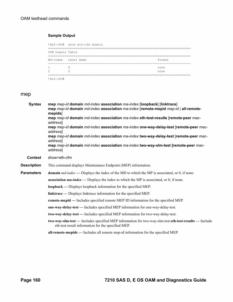
OAM testhead commands
Sample Output
*ALU-IPD# show eth-cfm domain ==============================================================================CFM Domain Table==============================================================================Md-index Level Name Format ------------------------------------------------------------------------------1 6 none 2 0 none ==============================================================================*ALU-IPD#
mep
Syntax mep mep-id domain md-index association ma-index [loopback] [linktrace]mep mep-id domain md-index association ma-index [remote-mepid mep-id | all-remote-mepids]mep mep-id domain md-index association ma-index eth-test-results [remote-peer mac-address]mep mep-id domain md-index association ma-index one-way-delay-test [remote-peer mac-address]mep mep-id domain md-index association ma-index two-way-delay-test [remote-peer mac-address]mep mep-id domain md-index association ma-index two-way-slm-test [remote-peer mac-address]
Context show>eth-cfm
Description This command displays Maintenance Endpoint (MEP) information.
Parameters domain md-index — Displays the index of the MD to which the MP is associated, or 0, if none.
association ma-index — Displays the index to which the MP is associated, or 0, if none.
loopback — Displays loopback information for the specified MEP.
linktrace — Displays linktrace information for the specified MEP.
remote-mepid — Includes specified remote MEP ID information for the specified MEP.
one-way-delay-test — Includes specified MEP information for one-way-delay-test.
two-way-delay-test — Includes specified MEP information for two-way-delay-test.
two-way-slm-test — Includes specified MEP information for two-way-slm-test.eth-test-results — Include eth-test-result information for the specified MEP.
all-remote-mepids — Includes all remote mep-id information for the specified MEP.
Page 160 7210 SAS D, E OS OAM and Diagnostics Guide

OAM and SAA Command Reference
twamp server
Syntax twamp server
Context show>test-oam
Description Used to obtain information about the TWAMP server. It displays summary information for the ip-prefix in use.
Sample Output
*A:Dut-G>show>test-oam# twamp server
===============================================================================TWAMP Server===============================================================================Admin State : Down Operational State : DownUp Time : 0d 00:00:00Current Connections : 0 Max Connections : 8Connections Rejected : 0 Inactivity Time Out : 900 secondsCurrent Sessions : 0 Max Sessions : 8Sessions Rejected : 0 Sessions Aborted : 0Sessions Completed : 0Test Packets Rx : 0 Test Packets Tx : 0===============================================================================
===============================================================================TWAMP Server Prefix Summary===============================================================================Prefix Current Current Description Connections Sessions--------------------------------------------------------------------------------------------------------------------------------------------------------------No. of TWAMP Server Prefixes: 0===============================================================================*A:Dut-G>show>test-oam#
server all
Syntax server all
Context show>test-oam twamp server
Description Used to display detailed information about the TWAMP server and TWAMP clients using different IP pre-fix.
Sample Output
7210SASM# show test-oam twamp server all
===============================================================================
7210 SAS D, E OS OAM and Diagnostics Guide Page 161

OAM testhead commands
TWAMP Server===============================================================================Admin State : Up Operational State : UpUp Time : 0d 08:17:34Current Connections : 0 Max Connections : 16Connections Rejected : 0 Inactivity Time Out : 900 secondsCurrent Sessions : 0 Max Sessions : 16Sessions Rejected : 0 Sessions Aborted : 0Sessions Completed : 0Test Packets Rx : 0 Test Packets Tx : 0===============================================================================
===============================================================================TWAMP Server Prefix 30.1.1.0/24===============================================================================Description : (Not Specified)Current Connections : 0 Max Connections : 16Connections Rejected : 0Current Sessions : 0 Max Sessions : 16Sessions Rejected : 0 Sessions Aborted : 0Sessions Completed : 0Test Packets Rx : 0 Test Packets Tx : 0===============================================================================
===============================================================================Connection information for TWAMP server prefix 30.1.1.0/24===============================================================================Client State Curr Sessions Sessions Rejected Sessions Completed Idle Time (s) Test Packets Rx Test Packets Tx--------------------------------------------------------------------------------------------------------------------------------------------------------------No. of TWAMP Server Connections for Prefix 30.1.1.0/24: 0===============================================================================
===============================================================================TWAMP Server Prefix 60.1.1.0/24===============================================================================Description : (Not Specified)Current Connections : 0 Max Connections : 16Connections Rejected : 0Current Sessions : 0 Max Sessions : 16Sessions Rejected : 0 Sessions Aborted : 0Sessions Completed : 0Test Packets Rx : 0 Test Packets Tx : 0===============================================================================
===============================================================================Connection information for TWAMP server prefix 60.1.1.0/24===============================================================================Client State Curr Sessions Sessions Rejected Sessions Completed Idle Time (s) Test Packets Rx Test Packets Tx--------------------------------------------------------------------------------------------------------------------------------------------------------------No. of TWAMP Server Connections for Prefix 60.1.1.0/24: 0==============================================================================================================================================================No. of TWAMP Server Prefixes: 2===============================================================================
Page 162 7210 SAS D, E OS OAM and Diagnostics Guide

OAM and SAA Command Reference
server prefix
Syntax server prefix ip-prefix/mask
Context show>test-oam twamp server
Description Display information about the TWAMP clients using the specified prefix.
Sample output
*A:7210SAS# show test-oam twamp server prefix 60.1.1.0/24
===============================================================================TWAMP Server Prefix 60.1.1.0/24===============================================================================Description : (Not Specified)Current Connections : 0 Max Connections : 16Connections Rejected : 0Current Sessions : 0 Max Sessions : 16Sessions Rejected : 0 Sessions Aborted : 0Sessions Completed : 0Test Packets Rx : 0 Test Packets Tx : 0===============================================================================
===============================================================================Connection information for TWAMP server prefix 60.1.1.0/24===============================================================================Client State Curr Sessions Sessions Rejected Sessions Completed Idle Time (s) Test Packets Rx Test Packets Tx--------------------------------------------------------------------------------------------------------------------------------------------------------------No. of TWAMP Server Connections for Prefix 60.1.1.0/24: 0===============================================================================
Parameters ip-prefix — The destination address of the static route.
Values [18 chars max]
mask — The prefix length.
testhead-profile
Syntax testhead-profile profile-id
Context show>test-oam
Description Specifies the testhead profile ID to use with this run/session of testhead invocation. Testhead profile must be configure beforehand using the commands under config> test-oam> testhead-profile>.
Sample Output
A:7210SAS>show>test-oam# testhead-profile 1
7210 SAS D, E OS OAM and Diagnostics Guide Page 163
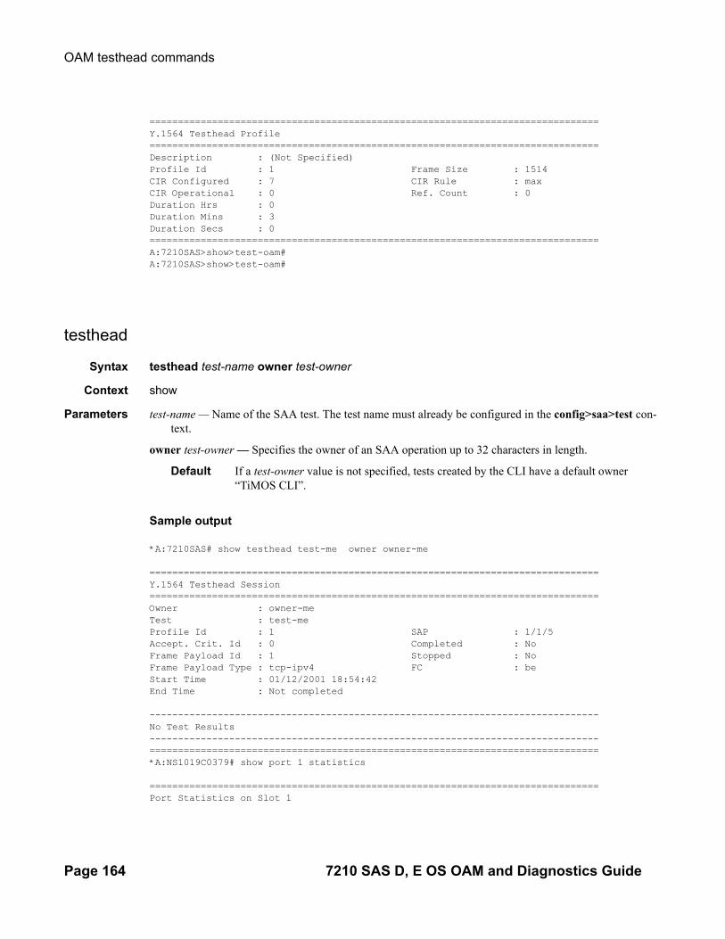
OAM testhead commands
===============================================================================Y.1564 Testhead Profile===============================================================================Description : (Not Specified)Profile Id : 1 Frame Size : 1514CIR Configured : 7 CIR Rule : maxCIR Operational : 0 Ref. Count : 0Duration Hrs : 0 Duration Mins : 3 Duration Secs : 0 ===============================================================================A:7210SAS>show>test-oam# A:7210SAS>show>test-oam#
testhead
Syntax testhead test-name owner test-owner
Context show
Parameters test-name — Name of the SAA test. The test name must already be configured in the config>saa>test con-text.
owner test-owner — Specifies the owner of an SAA operation up to 32 characters in length.
Default If a test-owner value is not specified, tests created by the CLI have a default owner “TiMOS CLI”.
Sample output
*A:7210SAS# show testhead test-me owner owner-me
===============================================================================Y.1564 Testhead Session===============================================================================Owner : owner-meTest : test-meProfile Id : 1 SAP : 1/1/5Accept. Crit. Id : 0 Completed : NoFrame Payload Id : 1 Stopped : NoFrame Payload Type : tcp-ipv4 FC : beStart Time : 01/12/2001 18:54:42 End Time : Not completed
-------------------------------------------------------------------------------No Test Results-------------------------------------------------------------------------------===============================================================================*A:NS1019C0379# show port 1 statistics
===============================================================================Port Statistics on Slot 1
Page 164 7210 SAS D, E OS OAM and Diagnostics Guide

OAM and SAA Command Reference
===============================================================================Port Ingress Ingress Egress EgressId Packets Octets Packets Octets-------------------------------------------------------------------------------1/1/7 0 0 1718 26010521/1/8 1718 2601052 1718 26010521/1/11 1689854 2558437442 1689856 2558441984===============================================================================*A:7210SAS# show testhead test-me owner owner-me
7210 SAS D, E OS OAM and Diagnostics Guide Page 165

OAM testhead commands
Clear Commands
saa
Syntax saa-test [test-name [owner test-owner]]
Context clear
Description Clear the SAA results for the latest and the history for this test. If the test name is omitted, all the results for all tests are cleared.
Parameters test-name — Name of the SAA test. The test name must already be configured in the config>saa>test con-text.
owner test-owner — Specifies the owner of an SAA operation up to 32 characters in length.
Default If a test-owner value is not specified, tests created by the CLI have a default owner “TiMOS CLI”.
twamp server
Syntax twamp server
Context clear>test-oam
Description Clear TWAMP server statistics.
testhead
Syntax testhead [ test-name ] [owner test-owner]
Context oam>clear
Description Clear the testhead results identified by the test-name and test-owner.
Parameters test-name — Name of the test
Values ASCII string upto 32 characters in length
owner test-owner — Specifies the owner of an testhead operation.
Values ASCII string upto 32 characters in length
Page 166 7210 SAS D, E OS OAM and Diagnostics Guide

Tools
Tools Command Reference
Command Hierarchies• Tools Dump Commands on page 167
• Tools Perform Commands on page 168
Configuration Commands
Tools Dump Commandstools
—Tools Dump Commands — dump— accounting-policy acct-policy-id flash-write-count [clear]— eth-ring ring-index [clear] — lag lag-id lag-id— persistence
— summary— mc-endpoint peer ip-address
— router router-instance— dintf [ip-address]— filter-info [verbose]— l3-info— l3-stats [clear]— service-name service-name
— service— base-stats [clear]— dpipe service-id— dtls service-id— iom-stats [clear]— l2pt-diags— l2pt-diags clear— l2pt-diags detail— vpls-fdb-stats [clear]— vpls-mfib-stats [clear]
— system— cpu-pkt-stats
— system-resources slot-number— system-resources sap-ingress-qos
7210 SAS D, E OS OAM and Diagnostics Guide Page 167

Tools Command Reference
Tools Perform Commandstools
—Tools Perform Commands — perform — cron
— action— stop [action-name] [owner action-owner] [all]
— tod— re-evaluate
— customer customer-id [site customer-site-name]— filter ip-filter [filter-id]— filter ipv6-filter [filter-id]— filter mac-filter [filter-id]— service id service-id [sap sap-id]— tod-suite tod-suite-name
— eth-cfm— lag
— clear-force lag-id lag-id [sub-group sub-group-id]— force lag-id lag-id [sub-group sub-group-id] {active | standby}
— log— test-event
Page 168 7210 SAS D, E OS OAM and Diagnostics Guide

Tools
Tools Configuration Commands
Generic Commands
tools
Syntax tools
Context root
Description This command enables the context to enable useful tools for debugging purposes.
Default none
Parameters dump — Enables dump tools for the various protocols.
perform — Enables tools to perform specific tasks.
7210 SAS D, E OS OAM and Diagnostics Guide Page 169

Dump Commands
Dump Commands
dump
Syntax dump router-name
Context tools
Description The context to display information for debugging purposes.
Default none
Parameters router-name — Specify a router name, up to 32 characters in length.
Default Base
accounting-policy
Syntax accounting-policy acct-policy-id flash-write-count [clear]
Context tools>dump
Description The above command dumps the total count of flash writes for the accounting policy specified by the user. The 'clear' option allows the user to clear the count maintained per accounting policy and starts the counter afresh.
Parameters flash-write-count — This is a keyword used to dump the total number of flash writes up to the present for the accounting policy specified by accounting-policy 'id'.
acct-policy-id — Identifies the Accounting policy.
Values 1 - 99
clear — This keyword clears statistics.
eth-ring
Syntax eth-ring ring-index [clear]eth-ring control-sap-tag port-id [list-in-use|next-available]
Context tools>dump
Description The command displays Ethernet-ring information.
Parameters ring-index — Specify ring index.
Values 1 —128
clear — This keyword clears statistics.
Page 170 7210 SAS D, E OS OAM and Diagnostics Guide

Tools
lag
Syntax lag lag-id lag-id
Context tools>dump
Description This tool displays LAG information.
Parameters lag-id — Specify an existing LAG id.
Values 1 — 12
*A:7210 SAS>tools>dump# lag lag-id 1 Port state : UpSelected subgrp : 1NumActivePorts : 2ThresholdRising : 2ThresholdFalling: 0IOM bitmask : 2Config MTU : 1522Oper. MTU : 1522Bandwidth : 200000
multi-chassis : NO
------------------------------------------------------------------------------------Indx PortId RX pkts TX pkts State Active Port Cfg Oper Speed BW AP CS Pri Mtu Mtu ------------------------------------------------------------------------------------ 0 1/1/1 1 1 Up yes 32768 1522 1522 1000 100000 0 2 1 1/1/2 0 0 Up yes 32768 1522 1522 1000 100000 0 2
persistence
Syntax persistence
Context tools>dump
Description This command enables the context to display persistence information for debugging purposes.
summary
Syntax summary
Context tools>dump>persistence
Description The context to display persistence summary information for debugging purposes.
Sample Output
A:ALA-B# tools dump persistence summary =====================================================================
7210 SAS D, E OS OAM and Diagnostics Guide Page 171

Dump Commands
Persistence Summary on Slot A=====================================================================Client Location Entries in use Status---------------------------------------------------------------------xxxxxx cf1:\l2_dhcp.pst 200 ACTIVE---------------------------------------------------------------------Persistence Summary on Slot B=====================================================================Client Location Entries in use Status---------------------------------------------------------------------xxxxxx cf1:\l2_dhcp.pst 200 ACTIVE---------------------------------------------------------------------A:ALA-B#
system
Syntax cpu-pkt-stats
Context tools>dump>system
Description This command dumps tools for system information.
cpu-pkt-stats
Syntax cpu-pkt-stats
Context tools>dump>system
Description This command dumps statistics for CPU traffic.
system-resources
Syntax system-resources slot-numbersystem-resources sap-ingress-qos
Context tools>dump
Description This command displays system resource information.
Default none
Parameters slot-number — Specify a specific slot to view system resources information.
Values
sap-ingress-qos — This command provides details on usage of resources allocated for QoS classification and different match criteria under QoS classification.
Page 172 7210 SAS D, E OS OAM and Diagnostics Guide

Tools
tools dump system-resources sap-ingress-qos — The following table describes tools dump sys-tem-resource sap-ingress-qos output fields:
Table 7: Output fieldstools dump system-resource sap-ingress-qos
Labels Descriptions
Total Chunks Configured Displays the total number of chunks configured for use by SAP ingress QoS classification across all the match criteria.
Total Chunks Available Displays the total number of chunks alloted by software for use by SAP ingress QoS classification across all the match criteria.
Number of Chunks in Use Displays the total number of chunks in use by SAP for SAP ingress QoS classification.
Number of Free Chunks Displays the total number of chunks available for use by SAP for SAP ingress QoS classification.
Number of Chunks in use for IP match
Displays the total number of chunks in use for by SAP that use IP classification match criteria in the SAP ingress QoS policy.
Number of Chunks in use for IPv6 match
Displays the total number of chunks in use for by SAP that use IPv6 classification match criteria in the SAP ingress QoS policy.
Number of Chunks in use for MAC match
Displays the total number of chunks in use for by SAP that use MAC classification match criteria in the SAP ingress QoS policy.
Classification Entries The total number of Classification entries that are available/allocated/free per chunk. Information is displayed only for chunks that are in use.Meters - The total number of Meters that are available/allocated/free per chunk. Information is displayed only for chunks that are in use.
7210 SAS D, E OS OAM and Diagnostics Guide Page 173
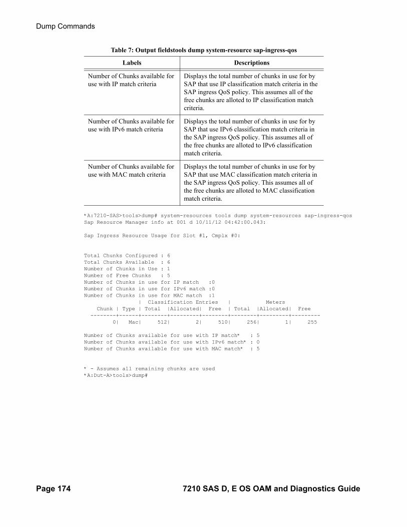
Dump Commands
*A:7210-SAS>tools>dump# system-resources tools dump system-resources sap-ingress-qosSap Resource Manager info at 001 d 10/11/12 04:42:00.043:
Sap Ingress Resource Usage for Slot #1, Cmplx #0:
Total Chunks Configured : 6Total Chunks Available : 6Number of Chunks in Use : 1Number of Free Chunks : 5Number of Chunks in use for IP match :0Number of Chunks in use for IPv6 match :0Number of Chunks in use for MAC match :1 | Classification Entries | Meters Chunk | Type | Total |Allocated| Free | Total |Allocated| Free --------+------+--------+---------+--------+--------+---------+--------- 0| Mac| 512| 2| 510| 256| 1| 255
Number of Chunks available for use with IP match* : 5Number of Chunks available for use with IPv6 match* : 0Number of Chunks available for use with MAC match* : 5
* - Assumes all remaining chunks are used*A:Dut-A>tools>dump#
Number of Chunks available for use with IP match criteria
Displays the total number of chunks in use for by SAP that use IP classification match criteria in the SAP ingress QoS policy. This assumes all of the free chunks are alloted to IP classification match criteria.
Number of Chunks available for use with IPv6 match criteria
Displays the total number of chunks in use for by SAP that use IPv6 classification match criteria in the SAP ingress QoS policy. This assumes all of the free chunks are alloted to IPv6 classification match criteria.
Number of Chunks available for use with MAC match criteria
Displays the total number of chunks in use for by SAP that use MAC classification match criteria in the SAP ingress QoS policy. This assumes all of the free chunks are alloted to MAC classification match criteria.
Table 7: Output fieldstools dump system-resource sap-ingress-qos
Labels Descriptions
Page 174 7210 SAS D, E OS OAM and Diagnostics Guide

Tools
Service Commands
service
Syntax service
Context tools>dump
Description Use this command to configure tools to display service dump information.
base-stats
Syntax base-stats [clear]
Context tools>dump>service
Description Use this command to display internal service statistics.
Default none
Parameters clear — Clears stats after reading.
dpipe
Syntax dpipe service-id
Context tools>dump>service
Description This command displays debug information for specified service.
Parameters service-id — Displays specified service ID details.
dtls
Syntax dtls service-id
Context tools>dump>service
Description Use this command to display TLS service statistics.
Default none
Parameters service-id — Displays specified service ID details.
7210 SAS D, E OS OAM and Diagnostics Guide Page 175

Service Commands
iom-stats
Syntax iom-stats [clear]
Context tools>dump>service
Description Use this command to display IOM message statistics.
Default none
Parameters clear — Clears stats after reading.
l2pt-diags
Syntax l2pt-diagsl2pt-diags clearl2pt-diags detail
Context tools>dump>service
Description Use this command to display L2pt diagnostics.
Default none
Parameters clear — Clears the diags after reading.
detail — Displays detailed information.
Sample Output
A:ALA-48>tools>dump>service# l2pt-diags[ l2pt/bpdu error diagnostics ] Error Name | Occurence | Event log -----------------+-------------+-----------------------------[ l2pt/bpdu forwarding diagnostics ]
Rx Frames | Tx Frames | Frame Type ------------+-------------+----------------------------------A:ALA-48>tools>dump>service#
A:ALA-48>tools>dump>service# l2pt-diags detail[ l2pt/bpdu error diagnostics ] Error Name | Occurence | Event log -----------------+-------------+-----------------------------[ l2pt/bpdu forwarding diagnostics ]
Rx Frames | Tx Frames | Frame Type ------------+-------------+----------------------------------[ l2pt/bpdu config diagnostics ] WARNING - service 700 has l2pt termination enabled on all access points : consider translating further down the chain or turning it off. WARNING - service 800 has l2pt termination enabled on all access points : consider translating further down the chain or turning it off. WARNING - service 9000 has l2pt termination enabled on all access points : consider translating further down the chain or turning it off. WARNING - service 32806 has l2pt termination enabled on all access points :
Page 176 7210 SAS D, E OS OAM and Diagnostics Guide

Tools
consider translating further down the chain or turning it off. WARNING - service 90001 has l2pt termination enabled on all access points : consider translating further down the chain or turning it off.A:ALA-48>tools>dump>service#
vpls-fdb-stats
Syntax vpls-fdb-stats [clear]
Context tools>dump>service
Description Use this command to display VPLS FDB statistics.
Default none
Parameters clear — Clears stats after reading.
vpls-mfib-stats
Syntax vpls-mfib-stats [clear]
Context tools>dump>service
Description Use this command to display VPLS MFIB statistics.
Default none
Parameters clear — Clears stats after reading.
7210 SAS D, E OS OAM and Diagnostics Guide Page 177

Router Commands
Router Commands
router
Syntax router router-instance
Context tools>dump
Description This command enables tools for the router instance.
Default none
Parameters router router-instance — Specifies the router name or service ID.
Values router-name: Baseservice-id: 1 — 2147483647
Default Base
dintf
Syntax dintf [ip-address]
Context tools>dump
Description This command displays the internal IP interface details.
This command dumps hardware-specific information related to the active IP interfaces configured. By default, hardware information for all active IP interfaces is dumped.
Default Dumps hardware-specific information for all the active IP interfaces present within the system.
Parameters ip-address — Only displays the hardware information associated with the specified IP address.
Sample Output
A:STU# /tools dump router dintf 5.1.1.2 [************* SLOT 1 ****************][IP interfaces] Table Usage: 5/263 [L3 SAP interface 1/1/7:360137680] Interface index 54 (Svc) cpmtag 2 primary IPv4 5.1.1.2/24 VRF 0 primary MAC 00:14:25:36:f7:f0 no VRRP MAC addresses Local Subnet 0 5.1.1.2/24 index=62 admin ip_mtu 1500 Intf Port 1/1/7 No agg port
Page 178 7210 SAS D, E OS OAM and Diagnostics Guide

Tools
uRPF mode None Ingress uRPF stats Drop=0/0 [Host IP Map 1 entries] [IP Entry v4 5.1.1.1 interface=54 L3 Egress HDL=100003 Ref Cnt=0] [Nexthop 5.1.1.1 idx=7] ref count 1 # mpls nhlfes 0 # nexthop groups 1 # SDP bindings 0 p2mp_arp_index 0 Subscriber ifIndex 0 Subscriber red ifIndex 0 [Subscriber Red Group 54] Subscriber red ifIndex 0 Subscriber use SRRP src mac no Use inter-dest Id no SRRP Disabled ref count 1 [Inter-dest group 0] Locally reachable no Subscriber red ifIndex In-use=no Subscriber hosts unreachable no cpmtag 15 cpmtag 15 L3 SAP idx=1 1/1/7:0.* SVLAN 54 svlan_interface_index 54 Encap Type q-in-q HW IF Index 1024 L2 USER ENTRY cindex 1 VFP EID 181 L3 BCAST EID 182 ARP REPLY EID 183 ARP REQST EID 184 VFP0 EID 185 L3 BCAST0 EID 186 ARP REPLY0 EID 187 ARP REQST0 EID 188 L3 BCAST IFP 189 ARP IFP 190 IP EXT MtcH IFP 288 HW Port Number 17A:STU#A:ALA-A#
filter-info
Syntax filter-info [verbose]
Context tools>dump>router
Description This command dumps the hardware-specific filter information.
Parameters verbose — Displays the hardware information of the filter.
7210 SAS D, E OS OAM and Diagnostics Guide Page 179
Router Commands
l3-info
Syntax lag
Context tools>dump>router
Description This command dumps the hardware-specific L3 information.
l3-stats
Syntax l3-stats [clear]
Context tools>dump>router
Description This command dumps the hardware-specific L3 statistics.
Parameters clear — Clears the hardware information of the filter.
eth-cfm
Syntax eth-cfm
Context tools>perform
Description This command configures performance tools for eth-cfm.
eth-cfm
Syntax eth-cfm
Context tools>perform
Description This command configures performance tools for eth-cfm.
lag
Syntax lag
Context tools>perform
Description This command configures tools to control LAG.
Page 180 7210 SAS D, E OS OAM and Diagnostics Guide

Tools
log
Syntax log
Context tools>perform
Description Tools for event logging.
test-event
Syntax test-event
Context tools>perform>log
Description This command causes a test event to be generated. The test event is LOGGER event #2011 and maps to the tmnxEventSNMP trap in the TIMETRA-LOG-MIB.
ip-prefix/mask — Specifies the IP prefix and host bits.
ospf3
Syntax ospf3
Context tools>dump>router
Description This command enables the context to display tools information for OSPF3.
Default none
7210 SAS D, E OS OAM and Diagnostics Guide Page 181

Performance Tools
Performance Tools
perform
Syntax perform
Context tools
Description This command enables the context to enable tools to perform specific tasks.
Default none
cron
Syntax cron
Context tools>perform
Description This command enables the context to perform CRON (scheduling) control operations.
Default none
action
Syntax action
Context tools>perform>cron
Description This command enables the context to stop the execution of a script started by CRON action. See the stop command.
stop
Syntax stop [action-name] [owner action-owner] [all]
Context tools>perform>cron>action
Description This command stops execution of a script started by CRON action.
Parameters action-name — Specifies the action name.
Values Maximum 32 characters.
owner action-owner — Specifies the owner name.
Default TiMOS CLI
all — Specifies to stop all CRON scripts.
Page 182 7210 SAS D, E OS OAM and Diagnostics Guide

Tools
tod
Syntax tod
Context tools>perform>cron
Description This command enables the context for tools for controlling time-of-day actions.
Default none
re-evaluate
Syntax re-evaluate
Context tools>perform>cron>tod
Description This command enables the context to re-evaluate the time-of-day state.
Default none
customer
Syntax customer customer-id [site customer-site-name]
Context tools>perform>cron>tod>re-eval
Description This command re-evaluates the time-of-day state of a multi-service site.
Parameters customer-id — Specify an existing customer ID.
Values 1 — 2147483647
site customer-site-name — Specify an existing customer site name.
filter
Syntax filter ip-filter [filter-id]filter ipv6-filter [filter-id]filter mac-filter [filter-id]
Context tools>perform>cron>tod>re-eval
Description This command re-evaluates the time-of-day state of a filter entry.
Parameters filter-type — Specify the filter type.
Values ip-filter, mac-filter
filter-id — Specify an existing filter ID.
Values 1 — 65535
7210 SAS D, E OS OAM and Diagnostics Guide Page 183

Performance Tools
service
Syntax service id service-id [sap sap-id]
Context tools>perform>cron>tod>re-eval
Description This command re-evaluates the time-of-day state of a SAP.
Parameters r service-id — Specify the an existing service ID.
Values 1 — 2147483647
sap sap-id — Specifies the physical port identifier portion of the SAP definition. See Common CLI Com-mand Descriptions on page 185 for CLI command syntax.
tod-suite
Syntax tod-suite tod-suite-name
Context tools>perform>cron>tod>re-eval
Description This command re-evaluates the time-of-day state for the objects referring to a tod-suite.
Parameters tod-suite-name — Specify an existing TOD nfame.
Page 184 7210 SAS D, E OS OAM and Diagnostics Guide

Common CLI CommandDescriptions
In This Chapter
This chapter provides CLI syntax and command descriptions for SAP and port commands.
Topics in this chapter include:
• SAP Syntax on page 186• Port Syntax on page 202
7210 SAS D, E OS OAM and Diagnostics Guide Page 185

Common Service Commands
Common Service CommandsSAP Syntax
sap
Syntax [no] sap sap-id
Description This command specifies the physical port identifier portion of the SAP definition.
Parameters sap-id — Specifies the physical port identifier portion of the SAP definition.
The sap-id can be configured in one of the following formats:
port
Syntax port port-id
Description This command specifies a port identifier.
Parameters port-id — The port-id can be configured in one of the following formats.
port-id slot/mda/port
Type Syntax Example
port-id slot/mda/port[.channel] 1/1/5
null [port-id lag-id] port-id: 1/1/3lag-id: lag-3
dot1q [port-id |lag-id]:qtag1 port-id:qtag1: 1/1/3:100lag-id:qtag1:lag-3:102
qinq [port-id | lag-id]:qtag1.qtag2 port-id:qtag1.qtag2: 1/1/3:100.10lag-id:qtag1.qtag2: lag-10
Page 186 7210 SAS D, E OS OAM and Diagnostics Guide
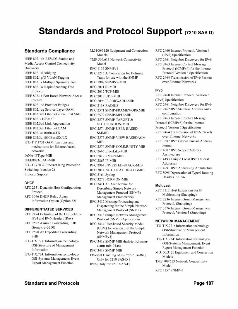
Standards and Protocol Support (7210 SAS D)
Standards ComplianceIEEE 802.1ab-REV/D3 Station andMedia Access Control ConnectivityDiscoveryIEEE 802.1d BridgingIEEE 802.1p/Q VLAN TaggingIEEE 802.1s Multiple Spanning TreeIEEE 802.1w Rapid Spanning Tree
ProtocolIEEE 802.1x Port Based Network Access
ControlIEEE 802.1ad Provider BridgesIEEE 802.1ag Service Layer OAMIEEE 802.3ah Ethernet in the First MileIEEE 802.3 10BaseTIEEE 802.3ad Link AggregationIEEE 802.3ah Ethernet OAMIEEE 802.3u 100BaseTXIEEE 802.3z 1000BaseSX/LXITU-T Y.1731 OAM functions and
mechanisms for Ethernet based networks
IANA-IFType-MIBIEEE8023-LAG-MIBITU-T G.8032 Ethernet Ring ProtectionSwitching (version 2)Protocol Support
DHCPRFC 2131 Dynamic Host Configuration
ProtocolRFC 3046 DHCP Relay Agent
Information Option (Option 82)
DIFFERENTIATED SERVICESRFC 2474 Definition of the DS Field the
IPv4 and IPv6 Headers (Rev)RFC 2597 Assured Forwarding PHB
Group (rev3260)RFC 2598 An Expedited Forwarding
PHBITU-T X.721: Information technology-
OSI-Structure of Management Information
ITU-T X.734: Information technology-OSI-Systems Management: Event Report Management Function
M.3100/3120 Equipment and Connection Models
TMF 509/613 Network Connectivity Model
RFC 1157 SNMPv1RFC 1215 A Convention for Defining
Traps for use with the SNMPRFC 1907 SNMPv2-MIBRFC 2011 IP-MIBRFC 2012 TCP-MIBRFC 2013 UDP-MIBRFC 2096 IP-FORWARD-MIBRFC 2138 RADIUSRFC 2571 SNMP-FRAMEWORKMIBRFC 2572 SNMP-MPD-MIBRFC 2573 SNMP-TARGET-&-
NOTIFICATION-MIBRFC 2574 SNMP-USER-BASED-
SMMIBRFC 2575 SNMP-VIEW-BASEDACM-
MIBRFC 2576 SNMP-COMMUNITY-MIBRFC 2665 EtherLike-MIBRFC 2819 RMON-MIBRFC 2863 IF-MIBRFC 2864 INVERTED-STACK-MIBRFC 3014 NOTIFICATION-LOGMIBRFC 3164 SyslogRFC 3273 HCRMON-MIBRFC 3411 An Architecture for
Describing Simple Network Management Protocol (SNMP) Management Frameworks
RFC 3412 Message Processing and Dispatching for the Simple Network Management Protocol (SNMP)
RFC 3413 Simple Network Management Protocol (SNMP) Applications
RFC 3414 User-based Security Model (USM) for version 3 of the Simple Network Management Protocol (SNMPv3)
RFC 3418 SNMP MIB draft-ietf-disman-alarm-mib-04.txt
RFC 3418 SNMP MIBEfficient Handling of in-Profile Traffic [
Only for 7210 SAS-D ]IPv6 [Only for 7210 SAS-E]
RFC 2460 Internet Protocol, Version 6 (IPv6) Specification
RFC 2461 Neighbor Discovery for IPv6RFC 2463 Internet Control Message
Protocol (ICMPv6) for the Internet Protocol Version 6 Specification
RFC 2464 Transmission of IPv6 Packets over Ethernet Networks
IPv6RFC 2460 Internet Protocol, Version 6(IPv6) SpecificationRFC 2461 Neighbor Discovery for IPv6RFC 2462 IPv6 Stateless Address Auto
configurationRFC 2463 Internet Control MessageProtocol (ICMPv6) for the InternetProtocol Version 6 SpecificationRFC 2464 Transmission of IPv6 Packets
over Ethernet NetworksRFC 3587 IPv6 Global Unicast Address
FormatRFC 4007 IPv6 Scoped Address
ArchitectureRFC 4193 Unique Local IPv6 Unicast
AddressesRFC 4291 IPv6 Addressing ArchitectureRFC 5095 Deprecation of Type 0 Routing
Headers in IPv6
MulticastRFC 1112 Host Extensions for IP
Multicasting (Snooping) RFC 2236 Internet Group Management
Protocol, (Snooping) RFC 3376 Internet Group Management
Protocol, Version 3 (Snooping)
NETWORK MANAGEMENTITU-T X.721: Information technology-
OSI-Structure of Management Information
ITU-T X.734: Information technology-OSI-Systems Management: Event Report Management Function
M.3100/3120 Equipment and Connection Models
TMF 509/613 Network Connectivity Model
RFC 1157 SNMPv1
Standards and Protocols Page 187
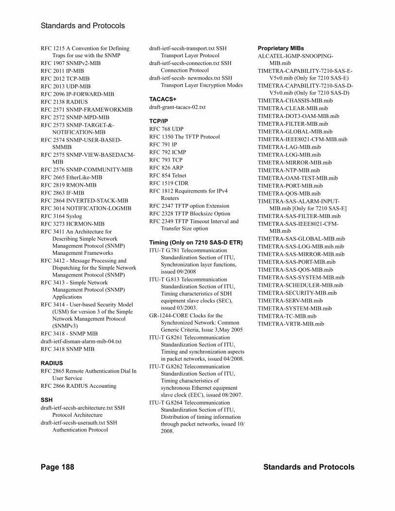
Standards and Protocols
RFC 1215 A Convention for Defining Traps for use with the SNMP
RFC 1907 SNMPv2-MIBRFC 2011 IP-MIBRFC 2012 TCP-MIBRFC 2013 UDP-MIBRFC 2096 IP-FORWARD-MIBRFC 2138 RADIUSRFC 2571 SNMP-FRAMEWORKMIBRFC 2572 SNMP-MPD-MIBRFC 2573 SNMP-TARGET-&-
NOTIFICATION-MIBRFC 2574 SNMP-USER-BASED-
SMMIBRFC 2575 SNMP-VIEW-BASEDACM-
MIBRFC 2576 SNMP-COMMUNITY-MIBRFC 2665 EtherLike-MIBRFC 2819 RMON-MIBRFC 2863 IF-MIBRFC 2864 INVERTED-STACK-MIBRFC 3014 NOTIFICATION-LOGMIBRFC 3164 SyslogRFC 3273 HCRMON-MIBRFC 3411 An Architecture for
Describing Simple Network Management Protocol (SNMP) Management Frameworks
RFC 3412 - Message Processing and Dispatching for the Simple Network Management Protocol (SNMP)
RFC 3413 - Simple Network Management Protocol (SNMP) Applications
RFC 3414 - User-based Security Model (USM) for version 3 of the Simple Network Management Protocol (SNMPv3)
RFC 3418 - SNMP MIBdraft-ietf-disman-alarm-mib-04.txtRFC 3418 SNMP MIB
RADIUSRFC 2865 Remote Authentication Dial In
User ServiceRFC 2866 RADIUS Accounting
SSHdraft-ietf-secsh-architecture.txt SSH
Protocol Architecturedraft-ietf-secsh-userauth.txt SSH
Authentication Protocol
draft-ietf-secsh-transport.txt SSH Transport Layer Protocol
draft-ietf-secsh-connection.txt SSH Connection Protocol
draft-ietf-secsh- newmodes.txt SSH Transport Layer Encryption Modes
TACACS+draft-grant-tacacs-02.txt
TCP/IPRFC 768 UDPRFC 1350 The TFTP ProtocolRFC 791 IPRFC 792 ICMPRFC 793 TCPRFC 826 ARPRFC 854 TelnetRFC 1519 CIDRRFC 1812 Requirements for IPv4
RoutersRFC 2347 TFTP option ExtensionRFC 2328 TFTP Blocksize OptionRFC 2349 TFTP Timeout Interval and
Transfer Size option
Timing (Only on 7210 SAS-D ETR)ITU-T G.781 Telecommunication
Standardization Section of ITU, Synchronization layer functions, issued 09/2008
ITU-T G.813 Telecommunication Standardization Section of ITU, Timing characteristics of SDH equipment slave clocks (SEC), issued 03/2003.
GR-1244-CORE Clocks for the Synchronized Network: Common Generic Criteria, Issue 3,May 2005
ITU-T G.8261 Telecommunication Standardization Section of ITU, Timing and synchronization aspects in packet networks, issued 04/2008.
ITU-T G.8262 Telecommunication Standardization Section of ITU, Timing characteristics of synchronous Ethernet equipment slave clock (EEC), issued 08/2007.
ITU-T G.8264 Telecommunication Standardization Section of ITU, Distribution of timing information through packet networks, issued 10/2008.
Proprietary MIBsALCATEL-IGMP-SNOOPING-
MIB.mib TIMETRA-CAPABILITY-7210-SAS-E-
V5v0.mib (Only for 7210 SAS-E)TIMETRA-CAPABILITY-7210-SAS-D-
V5v0.mib (Only for 7210 SAS-D)TIMETRA-CHASSIS-MIB.mibTIMETRA-CLEAR-MIB.mibTIMETRA-DOT3-OAM-MIB.mibTIMETRA-FILTER-MIB.mibTIMETRA-GLOBAL-MIB.mibTIMETRA-IEEE8021-CFM-MIB.mibTIMETRA-LAG-MIB.mibTIMETRA-LOG-MIB.mibTIMETRA-MIRROR-MIB.mibTIMETRA-NTP-MIB.mibTIMETRA-OAM-TEST-MIB.mibTIMETRA-PORT-MIB.mibTIMETRA-QOS-MIB.mibTIMETRA-SAS-ALARM-INPUT-
MIB.mib [Only for 7210 SAS-E]TIMETRA-SAS-FILTER-MIB.mibTIMETRA-SAS-IEEE8021-CFM-
MIB.mibTIMETRA-SAS-GLOBAL-MIB.mibTIMETRA-SAS-LOG-MIB.mib.mibTIMETRA-SAS-MIRROR-MIB.mibTIMETRA-SAS-PORT-MIB.mibTIMETRA-SAS-QOS-MIB.mibTIMETRA-SAS-SYSTEM-MIB.mibTIMETRA-SCHEDULER-MIB.mibTIMETRA-SECURITY-MIB.mibTIMETRA-SERV-MIB.mibTIMETRA-SYSTEM-MIB.mibTIMETRA-TC-MIB.mibTIMETRA-VRTR-MIB.mib
Page 188 Standards and Protocols

Standards and Protocols
Standards and Protocols Page 189

Standards and Protocols
Page 190 Standards and Protocols

Standards and Protocol Support (7210 SAS E)
Standards ComplianceIEEE 802.1ab-REV/D3 Station And
Media Access Control Connectivity Discovery
IEEE 802.1d BridgingIEEE 802.1p/Q VLAN TaggingIEEE 802.1w Rapid Spanning Tree
ProtocolIEEE 802.1x Port Based Network Access
ControlIEEE 802.1ad Provider BridgesIEEE 802.1ag Service Layer OAMIEEE 802.3ah Ethernet in the First MileIEEE 802.3 10BaseTIEEE 802.3ad Link AggregationIEEE 802.3ah Ethernet OAMIEEE 802.3u 100BaseTXIEEE 802.3z 1000BaseSX/LXITU-T Y.1731 OAM functions and
mechanisms for Ethernet based networks
IANA-IFType-MIBIEEE8023-LAG-MIBITU-T G.8032 Ethernet Ring Protection
Switching (version 1)
Protocol Support
DIFFERENTIATED SERVICESRFC 2474 Definition of the DS Field the
IPv4 and IPv6 Headers (Rev)RFC 2597 Assured Forwarding PHB
Group (rev3260)RFC 2598 An Expedited Forwarding
PHBITU-T X.721: Information technology-
OSI-Structure of Management Information
ITU-T X.734: Information technology-OSI-Systems Management: Event Report Management Function
M.3100/3120 Equipment and Connection Models
TMF 509/613 Network Connectivity Model
RFC 1157 SNMPv1RFC 1215 A Convention for Defining
Traps for use with the SNMP
RFC 1907 SNMPv2-MIBRFC 2011 IP-MIBRFC 2012 TCP-MIBRFC 2013 UDP-MIBRFC 2096 IP-FORWARD-MIBRFC 2138 RADIUSRFC 2571 SNMP-FRAMEWORKMIBRFC 2572 SNMP-MPD-MIBRFC 2573 SNMP-TARGET-&-
NOTIFICATION-MIBRFC 2574 SNMP-USER-BASED-
SMMIBRFC 2575 SNMP-VIEW-BASEDACM-
MIBRFC 2576 SNMP-COMMUNITY-MIBRFC 2665 EtherLike-MIBRFC 2819 RMON-MIBRFC 2863 IF-MIBRFC 2864 INVERTED-STACK-MIBRFC 3014 NOTIFICATION-LOGMIBRFC 3164 SyslogRFC 3273 HCRMON-MIBRFC 3411 An Architecture for
Describing Simple Network Management Protocol (SNMP) Management Frameworks
RFC 3412 Message Processing and Dispatching for the Simple Network Management Protocol (SNMP)
RFC 3413 Simple Network Management Protocol (SNMP) Applications
RFC 3414 User-based Security Model (USM) for version 3 of the Simple Network Management Protocol (SNMPv3)
RFC 3418 SNMP MIB draft-ietf-disman-alarm-mib-04.txt
RFC 3418 SNMP MIB
IPv6RFC 2460 Internet Protocol, Version 6(IPv6) SpecificationRFC 2461 Neighbor Discovery for IPv6RFC 2462 IPv6 Stateless Address Auto
configurationRFC 2463 Internet Control MessageProtocol (ICMPv6) for the InternetProtocol Version 6 Specification
RFC 2464 Transmission of IPv6 Packets over Ethernet Networks
RFC 3587 IPv6 Global Unicast Address Format
RFC 4007 IPv6 Scoped Address Architecture
RFC 4193 Unique Local IPv6 Unicast Addresses
RFC 4291 IPv6 Addressing ArchitectureRFC 5095 Deprecation of Type 0 Routing
Headers in IPv6
MULTICASTRFC 1112 Host Extensions for IP
Multicasting (Snooping)RFC 2236 Internet Group Management
Protocol, (Snooping)RFC 3376 Internet Group Management
Protocol, Version 3 (Snooping)
TCP/IPRFC 768 UDPRFC 1350 The TFTP Protocol (Rev.RFC 791 IPRFC 792 ICMPRFC 793 TCPRFC 826 ARPRFC 854 TelnetRFC 1519 CIDRRFC 1812 Requirements for IPv4
RoutersRFC 2347 TFTP option ExtensionRFC 2328 TFTP Blocksize OptionRFC 2349 TFTP Timeout Intervaland
Transfer Size option
RADIUSRFC 2865 Remote Authentication Dial In
User ServiceRFC 2866 RADIUS Accounting
SSHdraft-ietf-secsh-architecture.txt SSH
Protocol Architecturedraft-ietf-secsh-userauth.txt SSH
Authentication Protocoldraft-ietf-secsh-transport.txt SSH
Transport Layer Protocol
Standards and Protocols Page 191

Standards and Protocols
draft-ietf-secsh-connection.txt SSH Connection Protocol
draft-ietf-secsh- newmodes.txt SSH Transport Layer Encryption Modes
TACACS+draft-grant-tacacs-02.txt
NETWORK MANAGEMENTITU-T X.721: Information technology-
OSI-Structure of Management Information
ITU-T X.734: Information technology-OSI-Systems Management: Event Report Management Function
M.3100/3120 Equipment and Connection Models
TMF 509/613 Network Connectivity Model
RFC 1157 SNMPv1RFC 1215 A Convention for Defining
Traps for use with the SNMPRFC 1907 SNMPv2-MIBRFC 2011 IP-MIBRFC 2012 TCP-MIBRFC 2013 UDP-MIBRFC 2096 IP-FORWARD-MIBRFC 2138 RADIUSRFC 2571 SNMP-FRAMEWORKMIBRFC 2572 SNMP-MPD-MIBRFC 2573 SNMP-TARGET-&-
NOTIFICATION-MIBRFC 2574 SNMP-USER-BASED-
SMMIBRFC 2575 SNMP-VIEW-BASEDACM-
MIBRFC 2576 SNMP-COMMUNITY-MIBRFC 2665 EtherLike-MIBRFC 2819 RMON-MIBRFC 2863 IF-MIBRFC 2864 INVERTED-STACK-MIBRFC 3014 NOTIFICATION-LOGMIBRFC 3164 SyslogRFC 3273 HCRMON-MIBRFC 3411 An Architecture for
Describing Simple Network Management Protocol (SNMP) Management Frameworks
RFC 3412 - Message Processing and Dispatching for the Simple Network Management Protocol (SNMP)
RFC 3413 - Simple Network Management Protocol (SNMP) Applications
RFC 3414 - User-based Security Model (USM) for version 3 of the Simple Network Management Protocol (SNMPv3)
RFC 3418 - SNMP MIBdraft-ietf-disman-alarm-mib-04.txt
PROPRIETARY MIBsALCATEL-IGMP-SNOOPING-
MIB.mib TIMETRA-CAPABILITY-7210-SAS-E-
V5v0.mib (Only for 7210 SAS-E)TIMETRA-CHASSIS-MIB.mibTIMETRA-CLEAR-MIB.mibTIMETRA-DOT3-OAM-MIB.mibTIMETRA-FILTER-MIB.mibTIMETRA-GLOBAL-MIB.mibTIMETRA-IEEE8021-CFM-MIB.mibTIMETRA-LAG-MIB.mibTIMETRA-LOG-MIB.mibTIMETRA-MIRROR-MIB.mibTIMETRA-NTP-MIB.mibTIMETRA-OAM-TEST-MIB.mibTIMETRA-PORT-MIB.mibTIMETRA-QOS-MIB.mibTIMETRA-SAS-ALARM-INPUT-
MIB.mib [Only for 7210 SAS-E]TIMETRA-SAS-FILTER-MIB.mibTIMETRA-SAS-IEEE8021-CFM-
MIB.mibTIMETRA-SAS-GLOBAL-MIB.mibTIMETRA-SAS-LOG-MIB.mib.mibTIMETRA-SAS-MIRROR-MIB.mibTIMETRA-SAS-PORT-MIB.mibTIMETRA-SAS-QOS-MIB.mibTIMETRA-SAS-SYSTEM-MIB.mibTIMETRA-SCHEDULER-MIB.mibTIMETRA-SECURITY-MIB.mibTIMETRA-SERV-MIB.mibTIMETRA-SYSTEM-MIB.mibTIMETRA-TC-MIB.mibTIMETRA-VRTR-MIB.mib
Page 192 Standards and Protocols

Index
Ccontinuity check 68
EEthernet CFM 58
Llinktrace 66loopback 65
MMirror
overview 14implementation 15source and destination 16
configuringbasic 25classification rules 26
IP filter 27MAC filter 27port 26SAP 26
37local mirror service 29management tasks 32overview 24
OOAM 56
overview 56configuring
command reference 99
SSAA test parameters 88service assurance agent 86, 89
TTools 167
7210 SAS D, E OS OAM and Diagnostic Guide Page 193