
Comparative Energy Analysis of VRF and VAV Systems Under ...
8
ASME ES2009 ES2009-90450 Comparative Energy Analysis of VRF and VAV Systems under Cooling Mode Jaeyoon Koh † †A/C Laboratory, LG Electronics, Changwon, Korea.120-700 John Z. Zhai*, Jessica A Rivas* *Department of Civil, Environmental and Architectural Engineering at University of Colorado at Boulder, CO, 80309, USA VRF systems are larger capacity more complex versions of ductless multi-split or mini-split heat pump systems. Their design differs from unitary air conditioner systems, which distribute cooled air through ductwork, or chiller systems, which distribute cold water through pipes. Generally, a single compact air-cooled condensing unit located outdoor consists of a variable-speed and a constant-speed compressor, and it is able to link to several numbers of indoor evaporator units. Modular design allows for flexible installation and connection of multiple indoor units of varying configurations and capacities. The VRF system is able to control the refrigerant flow rate to the indoor units individually according to the cooling or heating load of the zone served by each indoor unit. A typical VRF outdoor condensing unit has a cooling capacity of 72,000-192,000 Btu/h, however for buildings that require larger cooling capacities, the VRF system is able to integrate multiple condensing units to serve large air-conditioning loads. Abstract Variable refrigerant flow (VRF) or variable refrigerant volume (VRV) systems provide many benefits over traditional air- conditioning systems, with great potential to decrease energy cost and increase thermal comfort in buildings. This paper presents a method to size and select VRF systems and to compute its annual energy consumption. The study compares the cooling energy usage of a VRF system against a conventional chiller-based variable-air-volume (VAV) system and a packaged VAV (PVAV) system for a typical light commercial building. The results reveal that the peak electrical demand of the VRF system for the cooling season is about 60% of the chiller-based VAV system and 70% of the packaged VAV systems, and the operating energy usage is about 53% of the chiller-based VAV system and 60% of the packaged VAV system for the building studied. 1. Introduction VRF systems provide many benefits over traditional air- conditioning systems, including: Increased awareness and concern regarding energy consumption, carbon emissions and the corollary environmental impact have led to an increase in the development and adoption of efficient technologies. Specifically, new space conditioning technologies offer the potential for decreased energy consumption and increased thermal comfort in commercial buildings. One technology from Asia offers an innovative approach to condition buildings. Variable refrigerant flow (VRF) or variable refrigerant volume (VRV) heat pumps are multi-zone air conditioning systems that vary refrigerant flow rates in order to provide adjustable levels of cooling and/or heating. These systems have been cooling buildings in Asia and Europe for nearly twenty years and are just now making their entrance into North America markets [1-3]. • Eliminating duct losses. Energy loss occurs through air leakage at duct joints as well as via conduction, convection, and radiation through the duct materials. These losses are estimated to be between 10 to 20% of total airflow, and they become particularly important where ducts are run through unconditioned spaces [4]. • Improved zone control. Each individual indoor evaporator unit is able to control the temperature, pressure, volume and direction of refrigerant that passes through its pipe [5]. This allows the individual room or zone demand to be met precisely. Traditional systems do not provide individual space control. Instead air movement is controlled via dampers or variable air volume blowers. Additionally, 1 Copyright © 2009 by ASME Proceedings of the ASME 2009 3rd International Conference of Energy Sustainability ES2009 July 19-23, 2009, San Francisco, California, USA ES2009-90450 Copyright © 2009 by ASME Proceedings of the ASME 2009 3rd International Conference of Energy Sustainability ES2009 July 19-23, 2009, San Francisco, California, USA ES2009- Downloaded From: https://proceedings.asmedigitalcollection.asme.org on 07/01/2019 Terms of Use: http://www.asme.org/about-asme/terms-of-use
-
Upload
khangminh22 -
Category
Documents
-
view
2 -
download
0
Transcript of Comparative Energy Analysis of VRF and VAV Systems Under ...
ASME ES2009
ES2009-90450
Comparative Energy Analysis of VRF and VAV Systems under Cooling Mode
Jaeyoon Koh †
†A/C Laboratory, LG Elect ron ics ,
Changwon, Korea.120-700
John Z. Zhai*, Jessica A Rivas*
*Depar tment o f Civ i l , Env i ronmenta l and
Arch i tectural Engineer ing at Univers i ty o f
Colorado at Boulder, CO, 80309, USA
VRF systems are larger capacity more complex versions of ductless multi-split or mini-split heat pump systems. Their design differs from unitary air conditioner systems, which distribute cooled air through ductwork, or chiller systems, which distribute cold water through pipes. Generally, a single compact air-cooled condensing unit located outdoor consists of a variable-speed and a constant-speed compressor, and it is able to link to several numbers of indoor evaporator units. Modular design allows for flexible installation and connection of multiple indoor units of varying configurations and capacities. The VRF system is able to control the refrigerant flow rate to the indoor units individually according to the cooling or heating load of the zone served by each indoor unit. A typical VRF outdoor condensing unit has a cooling capacity of 72,000-192,000 Btu/h, however for buildings that require larger cooling capacities, the VRF system is able to integrate multiple condensing units to serve large air-conditioning loads.
Abstract
Variable refrigerant flow (VRF) or variable refrigerant volume (VRV) systems provide many benefits over traditional air-conditioning systems, with great potential to decrease energy cost and increase thermal comfort in buildings. This paper presents a method to size and select VRF systems and to compute its annual energy consumption. The study compares the cooling energy usage of a VRF system against a conventional chiller-based variable-air-volume (VAV) system and a packaged VAV (PVAV) system for a typical light commercial building. The results reveal that the peak electrical demand of the VRF system for the cooling season is about 60% of the chiller-based VAV system and 70% of the packaged VAV systems, and the operating energy usage is about 53% of the chiller-based VAV system and 60% of the packaged VAV system for the building studied.
1. Introduction VRF systems provide many benefits over traditional air-conditioning systems, including:
Increased awareness and concern regarding energy consumption, carbon emissions and the corollary environmental impact have led to an increase in the development and adoption of efficient technologies. Specifically, new space conditioning technologies offer the potential for decreased energy consumption and increased thermal comfort in commercial buildings. One technology from Asia offers an innovative approach to condition buildings. Variable refrigerant flow (VRF) or variable refrigerant volume (VRV) heat pumps are multi-zone air conditioning systems that vary refrigerant flow rates in order to provide adjustable levels of cooling and/or heating. These systems have been cooling buildings in Asia and Europe for nearly twenty years and are just now making their entrance into North America markets [1-3].
• Eliminating duct losses. Energy loss occurs through air leakage at duct joints as well as via conduction, convection, and radiation through the duct materials. These losses are estimated to be between 10 to 20% of total airflow, and they become particularly important where ducts are run through unconditioned spaces [4].
• Improved zone control. Each individual indoor evaporator unit is able to control the temperature, pressure, volume and direction of refrigerant that passes through its pipe [5]. This allows the individual room or zone demand to be met precisely. Traditional systems do not provide individual space control. Instead air movement is controlled via dampers or variable air volume blowers. Additionally,
1
Copyright © 2009 by ASME
Proceedings of the ASME 2009 3rd International Conference of Energy Sustainability ES2009
July 19-23, 2009, San Francisco, California, USA
ES2009-90450
Copyright © 2009 by ASME
Proceedings of the ASME 2009 3rd International Conference of Energy Sustainability ES2009
July 19-23, 2009, San Francisco, California, USA
ES2009-90450
Downloaded From: https://proceedings.asmedigitalcollection.asme.org on 07/01/2019 Terms of Use: http://www.asme.org/about-asme/terms-of-use
indoor units can be turned off in spaces that do not required air-conditioning, saving energy.
• Flexible design and installation. The VRF system’s modular, lightweight and small indoor components can usually be transported in a standard elevator, eliminating the use of expensive installation equipment such as cranes. [2] The condensing unit can be located outside of the building, which reduces the space requirements for a mechanical room. The ductwork of a dedicated ventilation system is generally smaller than a unitary system’s ductwork, which can also increase the amount of lease-able building space in new construction, by reducing plenum space requirements. This makes VRV systems ideal for use in rooms that lack the space required for ducts or historical buildings where duct installation is difficult and expensive.
• Simultaneous heating and cooling. VRV systems can use a heat recovery or 3-pipe design to circulate refrigerant from zones needing cooling directly to zones calling for heating, and vice versa. This reduces the compressor run time and increases overall system efficiency in terms of total power consumption per combined heating and cooling load.
Perhaps most important, the VRF system offers high part-load efficiency. Typical HVAC systems spend the majority of their operating hours at part load, utilizing only 20 to 80% of their maximum capacity. With multiple compressors, including a variable speed compressor, the VRF system can operate at 10~130% of its total capacity by 70~90 steps. This allows the system to operate more efficiently over a wide range of capacities [6].
The major barrier to the widespread adoption of the VRF system is the lack of a definitive way to calculate its energy consumption, and thus its potential energy savings. The limited number of field tests combined with the changeability of the VRF system configuration has eliminated any rule-of-thumb estimates. Instead, the complexity of the system design requires computer simulation to size, design and estimate annual consumption. In the past seven years since the introduction of the first VRF system marketed in North America, manufacturers and consultants have used an array of tools, from spreadsheets to proprietary software, to perform these analyses [12]. However, these tools have not been experimentally validated. As such, an evaluation of the energy use characteristics of the VRF system from a dynamic
building energy simulation perspective is the focus of this research.
This paper presents a method to size VRF systems and calculate the corresponding energy usage. This method is then used to compare the cooling energy consumption of a VRF system to a conventional chiller-based VAV system and a packaged VAV system in a typical light commercial/office building [8].
2. Energy Modeling of an Office Building
2.1 Building Descriptions
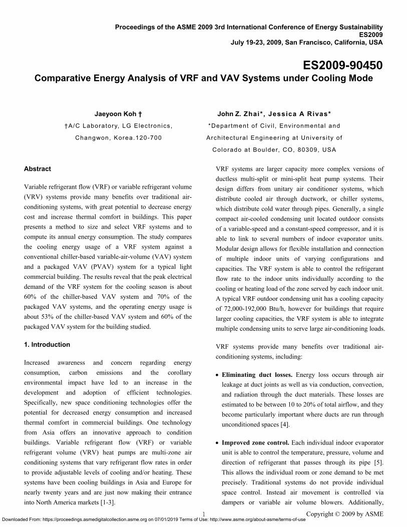
Figure 1 shows the layout of the single-story multi-zone office building considered in this study. The building has a ground-to-ceiling height of 4 meters and is divided into six conditioned thermal zones: Each of the small zones 1–4 are 66.67 ㎡, and each of the two relatively large zones 5 and 6 are 100 m2. The internal loads for each zone including occupants, lights, and electronic equipment are provided in Table 1. The building is designed with a typical VRF system, a conventional chiller-based variable-air-volume (VAV) system and a packaged variable-air-volume (PVAV) system.
Figure 1 Schematic building plan and VRF system assignments
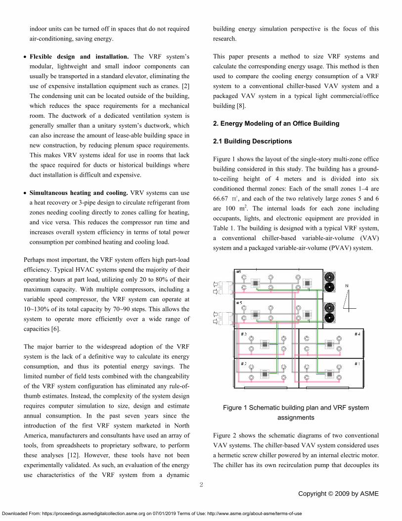
Figure 2 shows the schematic diagrams of two conventional VAV systems. The chiller-based VAV system considered uses a hermetic screw chiller powered by an internal electric motor. The chiller has its own recirculation pump that decouples its
2
Copyright © 2009 by ASME
Downloaded From: https://proceedings.asmedigitalcollection.asme.org on 07/01/2019 Terms of Use: http://www.asme.org/about-asme/terms-of-use
flow from the loop flow. As such, flow through the chiller varies with the coil flow and the chiller operating status.
(a) Chiller-based VAV system
(b) Packaged VAV system
Figure 2 Schematic VAV system configurations
Table 1 Building design parameters
Items Description
General
information
Incheon, Korea (Latitude 37°29'N, Longitude 126°38'E,
Altitude 70 m)
One story office building with floor area of 467 m2
Running period: July and August, 2008
Design
values
Max occupants: 28 (18.6 m2/person), Lighting: 50 W/ m2,
EQUIP: 30 W/ m2, Infiltration: 0.19ACH, Ventilation:
0.7ACH
Construction
Average U-
value
Roof: 0.153 [W/ m2K]
Wall Construction: 0.460 [W/ m2K]
Glass: 3.35 [W/ m2K]
The PVAV system is a variable-air-volume DX system that uses direct expansion of a refrigerant to provide cool air to the zones. This system can use natural gas, hot-water or electric resistance heaters to provide heat to the zones. In the cooling
mode, the supply air temperature is usually constant and the supply air volume is varied to meet individual zone requirements. In its most basic configuration, the PVAV consists of a compressor, an air-cooled condenser with a fan discharging heat to the outdoors, an evaporator with a fan supplying cooled air to the indoors, reheat coils in the zone, a filter, variable-volume control boxes, and thermostats. PVAV units can also be specified with outside ventilation air, exhaust fan, return air fan, and economizer control. The supply fan may be either a blow-through or draw-through design, with the fan motor inside or outside the air stream. The thermostat may be specified with night setback and night cycle control.
2.2 Modeling Method for VRF Systems
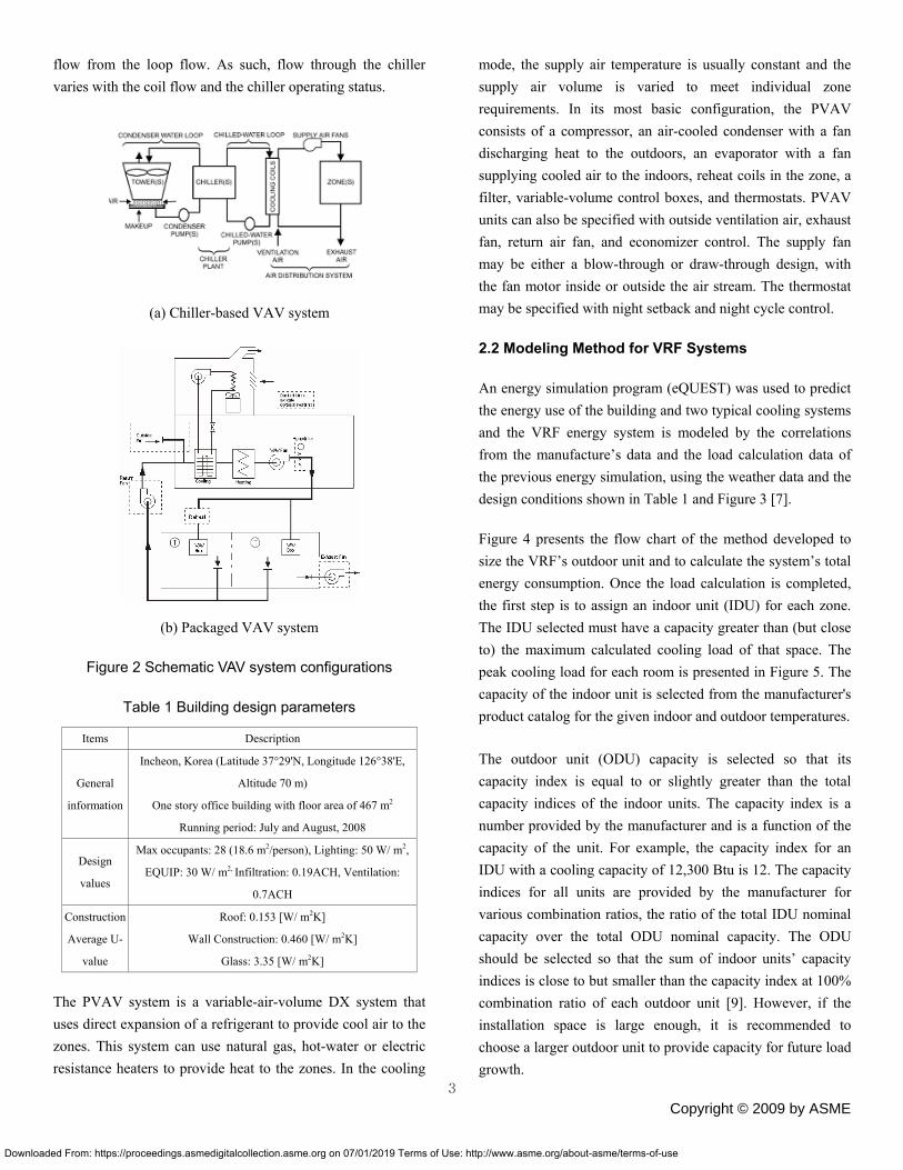
An energy simulation program (eQUEST) was used to predict the energy use of the building and two typical cooling systems and the VRF energy system is modeled by the correlations from the manufacture’s data and the load calculation data of the previous energy simulation, using the weather data and the design conditions shown in Table 1 and Figure 3 [7].
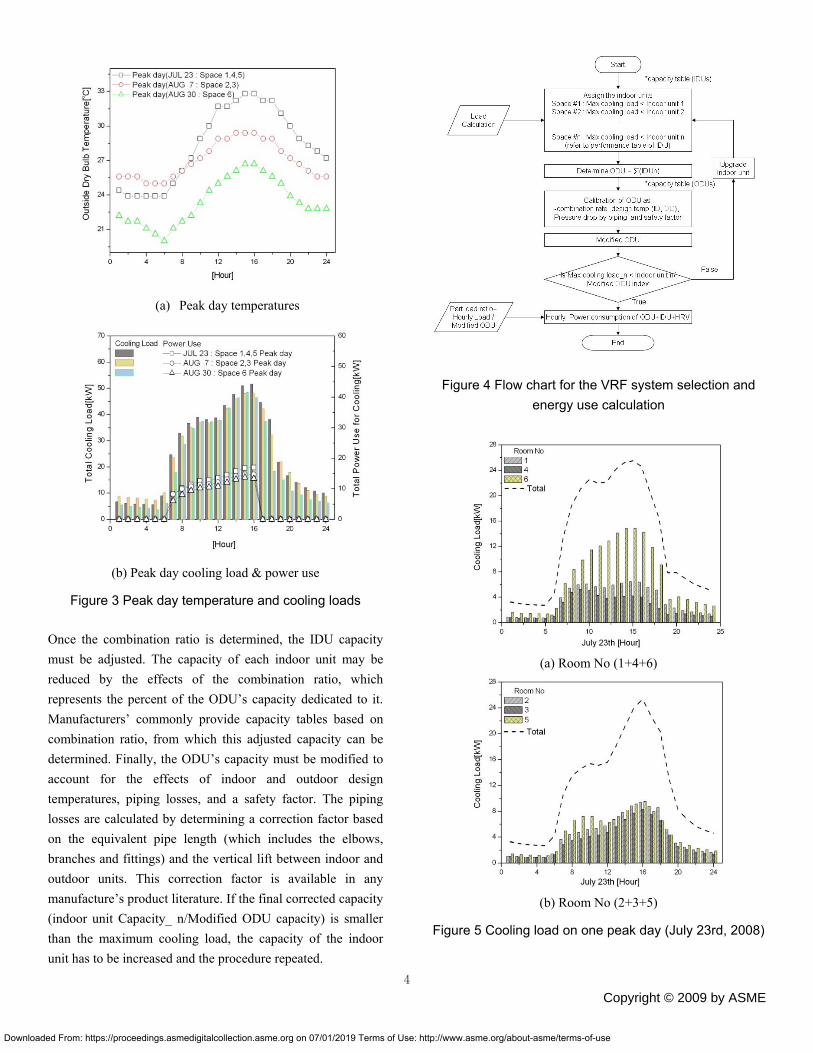
Figure 4 presents the flow chart of the method developed to size the VRF’s outdoor unit and to calculate the system’s total energy consumption. Once the load calculation is completed, the first step is to assign an indoor unit (IDU) for each zone. The IDU selected must have a capacity greater than (but close to) the maximum calculated cooling load of that space. The peak cooling load for each room is presented in Figure 5. The capacity of the indoor unit is selected from the manufacturer's product catalog for the given indoor and outdoor temperatures.
The outdoor unit (ODU) capacity is selected so that its capacity index is equal to or slightly greater than the total capacity indices of the indoor units. The capacity index is a number provided by the manufacturer and is a function of the capacity of the unit. For example, the capacity index for an IDU with a cooling capacity of 12,300 Btu is 12. The capacity indices for all units are provided by the manufacturer for various combination ratios, the ratio of the total IDU nominal capacity over the total ODU nominal capacity. The ODU should be selected so that the sum of indoor units’ capacity indices is close to but smaller than the capacity index at 100% combination ratio of each outdoor unit [9]. However, if the installation space is large enough, it is recommended to choose a larger outdoor unit to provide capacity for future load growth.
3
Copyright © 2009 by ASME
Downloaded From: https://proceedings.asmedigitalcollection.asme.org on 07/01/2019 Terms of Use: http://www.asme.org/about-asme/terms-of-use
(a) Peak day temperatures
Figure 4 Flow chart for the VRF system selection and energy use calculation
(b) Peak day cooling load & power use
Figure 3 Peak day temperature and cooling loads
Once the combination ratio is determined, the IDU capacity must be adjusted. The capacity of each indoor unit may be reduced by the effects of the combination ratio, which represents the percent of the ODU’s capacity dedicated to it. Manufacturers’ commonly provide capacity tables based on combination ratio, from which this adjusted capacity can be determined. Finally, the ODU’s capacity must be modified to account for the effects of indoor and outdoor design temperatures, piping losses, and a safety factor. The piping losses are calculated by determining a correction factor based on the equivalent pipe length (which includes the elbows, branches and fittings) and the vertical lift between indoor and outdoor units. This correction factor is available in any manufacture’s product literature. If the final corrected capacity (indoor unit Capacity_ n/Modified ODU capacity) is smaller than the maximum cooling load, the capacity of the indoor unit has to be increased and the procedure repeated.
(a) Room No (1+4+6)
(b) Room No (2+3+5)
Figure 5 Cooling load on one peak day (July 23rd, 2008)
4
Copyright © 2009 by ASME
Downloaded From: https://proceedings.asmedigitalcollection.asme.org on 07/01/2019 Terms of Use: http://www.asme.org/about-asme/terms-of-use
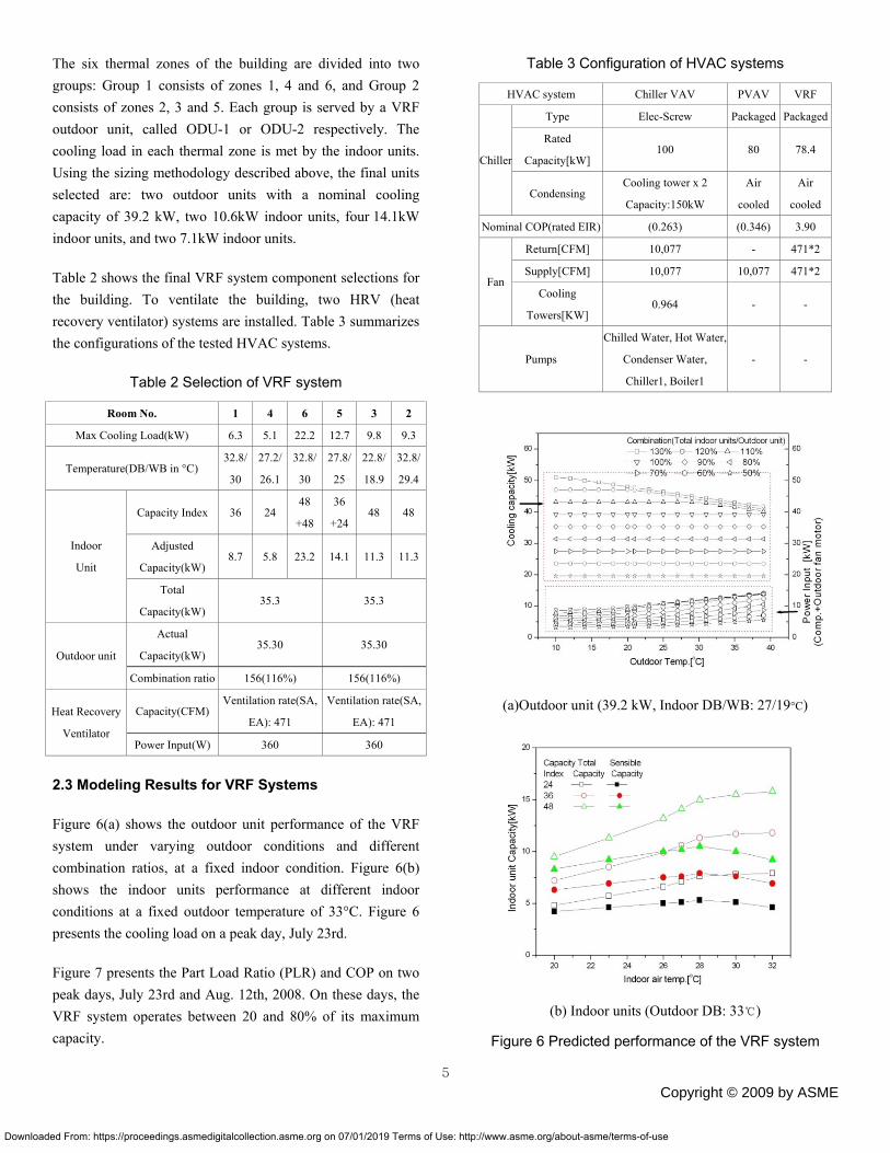
Table 3 Configuration of HVAC systems The six thermal zones of the building are divided into two groups: Group 1 consists of zones 1, 4 and 6, and Group 2 consists of zones 2, 3 and 5. Each group is served by a VRF outdoor unit, called ODU-1 or ODU-2 respectively. The cooling load in each thermal zone is met by the indoor units. Using the sizing methodology described above, the final units selected are: two outdoor units with a nominal cooling capacity of 39.2 kW, two 10.6kW indoor units, four 14.1kW indoor units, and two 7.1kW indoor units.
HVAC system Chiller VAV PVAV VRF
Type Elec-Screw Packaged Packaged
Rated
Capacity[kW] 100 80 78.4
Chiller
Condensing Cooling tower x 2
Capacity:150kW
Air
cooled
Air
cooled
Nominal COP(rated EIR) (0.263) (0.346) 3.90
Return[CFM] 10,077 - 471*2
Supply[CFM] 10,077 10,077 471*2 Fan
Cooling
Towers[KW] 0.964 - -
Pumps
Chilled Water, Hot Water,
Condenser Water,
Chiller1, Boiler1
- -
Table 2 shows the final VRF system component selections for the building. To ventilate the building, two HRV (heat recovery ventilator) systems are installed. Table 3 summarizes the configurations of the tested HVAC systems.
Table 2 Selection of VRF system
Room No. 1 4 6 5 3 2
Max Cooling Load(kW) 6.3 5.1 22.2 12.7 9.8 9.3
Temperature(DB/WB in °C) 32.8/
30
27.2/
26.1
32.8/
30
27.8/
25
22.8/
18.9
32.8/
29.4
Capacity Index 36 24 48
+48
36
+24 48 48
Adjusted
Capacity(kW) 8.7 5.8 23.2 14.1 11.3 11.3
Indoor
Unit
Total
Capacity(kW) 35.3 35.3
Actual
Capacity(kW) 35.30 35.30
Outdoor unit
Combination ratio 156(116%) 156(116%)
Capacity(CFM) Ventilation rate(SA,
EA): 471
Ventilation rate(SA,
EA): 471 Heat Recovery
Ventilator Power Input(W) 360 360
(a)Outdoor unit (39.2 kW, Indoor DB/WB: 27/19°C)
2.3 Modeling Results for VRF Systems
Figure 6(a) shows the outdoor unit performance of the VRF system under varying outdoor conditions and different combination ratios, at a fixed indoor condition. Figure 6(b) shows the indoor units performance at different indoor conditions at a fixed outdoor temperature of 33°C. Figure 6 presents the cooling load on a peak day, July 23rd.
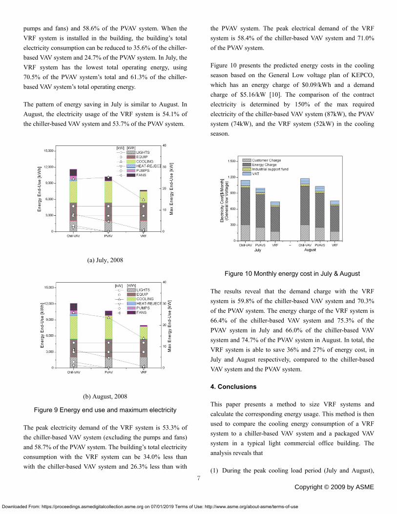
Figure 7 presents the Part Load Ratio (PLR) and COP on two peak days, July 23rd and Aug. 12th, 2008. On these days, the VRF system operates between 20 and 80% of its maximum capacity.
(b) Indoor units (Outdoor DB: 33℃)
Figure 6 Predicted performance of the VRF system
5
Copyright © 2009 by ASME
Downloaded From: https://proceedings.asmedigitalcollection.asme.org on 07/01/2019 Terms of Use: http://www.asme.org/about-asme/terms-of-use
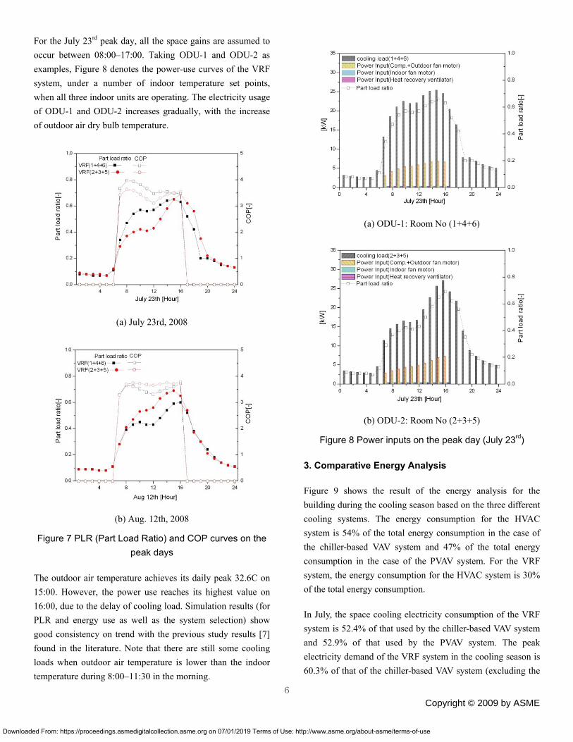
For the July 23rd peak day, all the space gains are assumed to occur between 08:00–17:00. Taking ODU-1 and ODU-2 as examples, Figure 8 denotes the power-use curves of the VRF system, under a number of indoor temperature set points, when all three indoor units are operating. The electricity usage of ODU-1 and ODU-2 increases gradually, with the increase of outdoor air dry bulb temperature.
(a) ODU-1: Room No (1+4+6)
(a) July 23rd, 2008
(b) ODU-2: Room No (2+3+5)
Figure 8 Power inputs on the peak day (July 23rd)
3. Comparative Energy Analysis
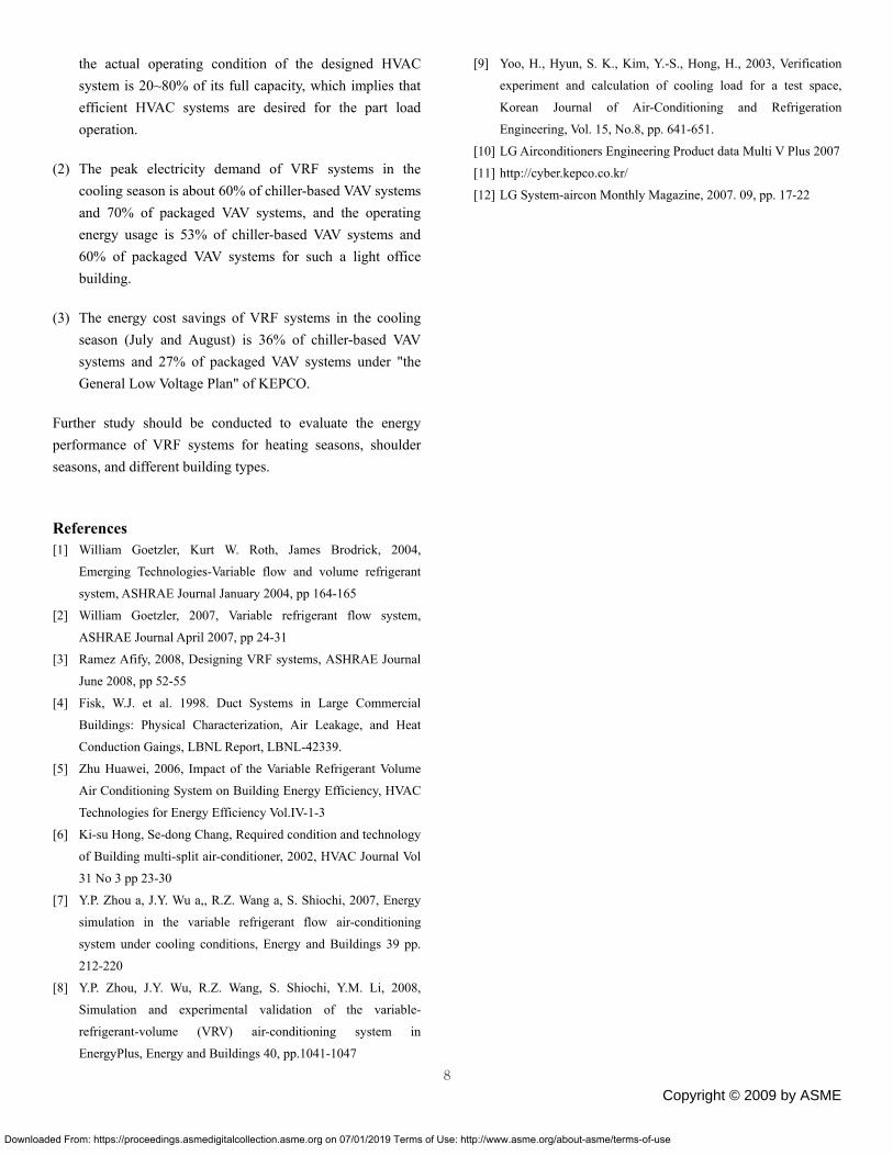
Figure 9 shows the result of the energy analysis for the building during the cooling season based on the three different cooling systems. The energy consumption for the HVAC system is 54% of the total energy consumption in the case of the chiller-based VAV system and 47% of the total energy consumption in the case of the PVAV system. For the VRF system, the energy consumption for the HVAC system is 30% of the total energy consumption.
(b) Aug. 12th, 2008
Figure 7 PLR (Part Load Ratio) and COP curves on the peak days
The outdoor air temperature achieves its daily peak 32.6C on 15:00. However, the power use reaches its highest value on 16:00, due to the delay of cooling load. Simulation results (for PLR and energy use as well as the system selection) show good consistency on trend with the previous study results [7] found in the literature. Note that there are still some cooling loads when outdoor air temperature is lower than the indoor temperature during 8:00–11:30 in the morning.
In July, the space cooling electricity consumption of the VRF system is 52.4% of that used by the chiller-based VAV system and 52.9% of that used by the PVAV system. The peak electricity demand of the VRF system in the cooling season is 60.3% of that of the chiller-based VAV system (excluding the
6
Copyright © 2009 by ASME
Downloaded From: https://proceedings.asmedigitalcollection.asme.org on 07/01/2019 Terms of Use: http://www.asme.org/about-asme/terms-of-use
pumps and fans) and 58.6% of the PVAV system. When the VRF system is installed in the building, the building’s total electricity consumption can be reduced to 35.6% of the chiller-based VAV system and 24.7% of the PVAV system. In July, the VRF system has the lowest total operating energy, using 70.5% of the PVAV system’s total and 61.3% of the chiller-based VAV system’s total operating energy.
The pattern of energy saving in July is similar to August. In August, the electricity usage of the VRF system is 54.1% of the chiller-based VAV system and 53.7% of the PVAV system.
(a) July, 2008
(b) August, 2008
Figure 9 Energy end use and maximum electricity
The peak electricity demand of the VRF system is 53.3% of the chiller-based VAV system (excluding the pumps and fans) and 58.7% of the PVAV system. The building’s total electricity consumption with the VRF system can be 34.0% less than with the chiller-based VAV system and 26.3% less than with
the PVAV system. The peak electrical demand of the VRF system is 58.4% of the chiller-based VAV system and 71.0% of the PVAV system.
Figure 10 presents the predicted energy costs in the cooling season based on the General Low voltage plan of KEPCO, which has an energy charge of $0.09/kWh and a demand charge of $5.16/kW [10]. The comparison of the contract electricity is determined by 150% of the max required electricity of the chiller-based VAV system (87kW), the PVAV system (74kW), and the VRF system (52kW) in the cooling season.
Figure 10 Monthly energy cost in July & August
The results reveal that the demand charge with the VRF system is 59.8% of the chiller-based VAV system and 70.3% of the PVAV system. The energy charge of the VRF system is 66.4% of the chiller-based VAV system and 75.3% of the PVAV system in July and 66.0% of the chiller-based VAV system and 74.7% of the PVAV system in August. In total, the VRF system is able to save 36% and 27% of energy cost, in July and August respectively, compared to the chiller-based VAV system and the PVAV system.
4. Conclusions
This paper presents a method to size VRF systems and calculate the corresponding energy usage. This method is then used to compare the cooling energy consumption of a VRF system to a chiller-based VAV system and a packaged VAV system in a typical light commercial office building. The analysis reveals that
(1) During the peak cooling load period (July and August), 7
Copyright © 2009 by ASME
Downloaded From: https://proceedings.asmedigitalcollection.asme.org on 07/01/2019 Terms of Use: http://www.asme.org/about-asme/terms-of-use
8
the actual operating condition of the designed HVAC system is 20~80% of its full capacity, which implies that efficient HVAC systems are desired for the part load operation.
(2) The peak electricity demand of VRF systems in the cooling season is about 60% of chiller-based VAV systems and 70% of packaged VAV systems, and the operating energy usage is 53% of chiller-based VAV systems and 60% of packaged VAV systems for such a light office building.
(3) The energy cost savings of VRF systems in the cooling season (July and August) is 36% of chiller-based VAV systems and 27% of packaged VAV systems under "the General Low Voltage Plan" of KEPCO.
Further study should be conducted to evaluate the energy performance of VRF systems for heating seasons, shoulder seasons, and different building types.
References [1] William Goetzler, Kurt W. Roth, James Brodrick, 2004,
Emerging Technologies-Variable flow and volume refrigerant
system, ASHRAE Journal January 2004, pp 164-165
[2] William Goetzler, 2007, Variable refrigerant flow system,
ASHRAE Journal April 2007, pp 24-31
[3] Ramez Afify, 2008, Designing VRF systems, ASHRAE Journal
June 2008, pp 52-55
[4] Fisk, W.J. et al. 1998. Duct Systems in Large Commercial
Buildings: Physical Characterization, Air Leakage, and Heat
Conduction Gaings, LBNL Report, LBNL-42339.
[5] Zhu Huawei, 2006, Impact of the Variable Refrigerant Volume
Air Conditioning System on Building Energy Efficiency, HVAC
Technologies for Energy Efficiency Vol.IV-1-3
[6] Ki-su Hong, Se-dong Chang, Required condition and technology
of Building multi-split air-conditioner, 2002, HVAC Journal Vol
31 No 3 pp 23-30
[7] Y.P. Zhou a, J.Y. Wu a,, R.Z. Wang a, S. Shiochi, 2007, Energy
simulation in the variable refrigerant flow air-conditioning
system under cooling conditions, Energy and Buildings 39 pp.
212-220
[8] Y.P. Zhou, J.Y. Wu, R.Z. Wang, S. Shiochi, Y.M. Li, 2008,
Simulation and experimental validation of the variable-
refrigerant-volume (VRV) air-conditioning system in
EnergyPlus, Energy and Buildings 40, pp.1041-1047
[9] Yoo, H., Hyun, S. K., Kim, Y.-S., Hong, H., 2003, Verification
experiment and calculation of cooling load for a test space,
Korean Journal of Air-Conditioning and Refrigeration
Engineering, Vol. 15, No.8, pp. 641-651.
[10] LG Airconditioners Engineering Product data Multi V Plus 2007
[11] http://cyber.kepco.co.kr/
[12] LG System-aircon Monthly Magazine, 2007. 09, pp. 17-22
Copyright © 2009 by ASME
Downloaded From: https://proceedings.asmedigitalcollection.asme.org on 07/01/2019 Terms of Use: http://www.asme.org/about-asme/terms-of-use