
Advanced Standard Drive - OPIS Engineering
52
INDUSTRY PROCESS AND AUTOMATION SOLUTIONS Agile Advanced Standard Drive
-
Upload
khangminh22 -
Category
Documents
-
view
8 -
download
0
Transcript of Advanced Standard Drive - OPIS Engineering

INDUSTRY PROCESSAND AUTOMATION SOLUTIONS
Agile
Advanced Standard Drive
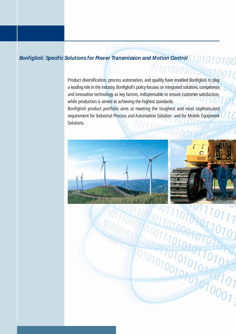
Bonfiglioli: Specific Solutions for Power Transmission and Motion Control
Product diversification, process automation, and quality have enabled Bonfiglioli to play
a leading role in the industry. Bonfiglioli’s policy focuses on integrated solutions, competence
and innovative technology as key factors, indispensable to ensure customer satisfaction,
while production is aimed at achieving the highest standards.
Bonfiglioli product portfolio aims at meeting the toughest and most sophisticated
requirement for Industrial Process and Automation Solution and for Mobile Equipment
Solutions.
1
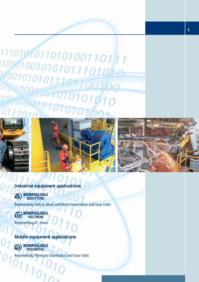
Mobile equipment applications
Representing Planetary Gearmotors and Gear Units
Industrial equipment applications
Representing AC drives
Representing Helical, Bevel and Worm Gearmotors and Gear Units
Contents
Introduction
4
Overview
5
Areas of application
7
Designation
8
Innovation at the service of people
10
Synergy with Bonfiglioli motors
13
VPlus engineering software
14
Sensorless control of permanent magnet synchronous motors
17
Energy saving
18
A drive with a PLC built in
20
Integrated safety thanks to Safe Torque Off
22
2
Selective Multi-Motor Control (SMMC)
24

3Contents
Braking Resistors
45
Resource pack
26
Functional layout
27
General technical data
28
AGL402 series - Technical data
31
Dimensions
35
Standards and Regulations
38
Optional modules
39
Mounting
40
Line choke
47
Worldwide
48
ASK-USB serial connection kit
44
INDUSTRY PROCESSAND AUTOMATION SOLUTIONS
Agile Introduction
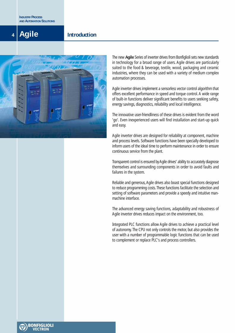
The new Agile Series of inverter drives from Bonfiglioli sets new standardsin technology for a broad range of users. Agile drives are particularlysuited to the food & beverage, textile, wood, packaging and ceramicindustries, where they can be used with a variety of medium complexautomation processes.
Agile inverter drives implement a sensorless vector control algorithm thatoffers excellent performance in speed and torque control. A wide rangeof built-in functions deliver significant benefits to users seeking safety,energy savings, diagnostics, reliability and local intelligence.
The innovative user-friendliness of these drives is evident from the word'go'. Even inexperienced users will find installation and start-up quickand easy.
Agile inverter drives are designed for reliability at component, machineand process levels. Software functions have been specially developed toinform users of the ideal time to perform maintenance in order to ensurecontinuous service from the plant.
Transparent control is ensured by Agile drives' ability to accurately diagnosethemselves and surrounding components in order to avoid faults andfailures in the system.
Reliable and generous, Agile drives also boast special functions designedto reduce programming costs. These functions facilitate the selection andsetting of software parameters and provide a speedy and intuitive man-machine interface.
The advanced energy saving functions, adaptability and robustness ofAgile inverter drives reduces impact on the environment, too.
Integrated PLC functions allow Agile drives to achieve a practical levelof autonomy. The CPU not only controls the motor, but also provides theuser with a number of programmable logic functions that can be usedto complement or replace PLC's and process controllers.
4
5
INDUSTRY PROCESSAND AUTOMATION SOLUTIONS
Overview Agile
Performance
Func
tions
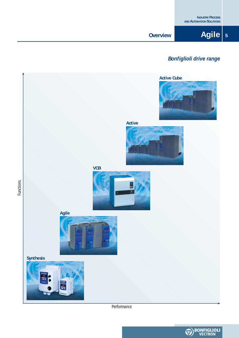
Bonfiglioli drive range
Synthesis
Agile
Active
Active Cube
VCB
INDUSTRY PROCESSAND AUTOMATION SOLUTIONS
Agile Overview6
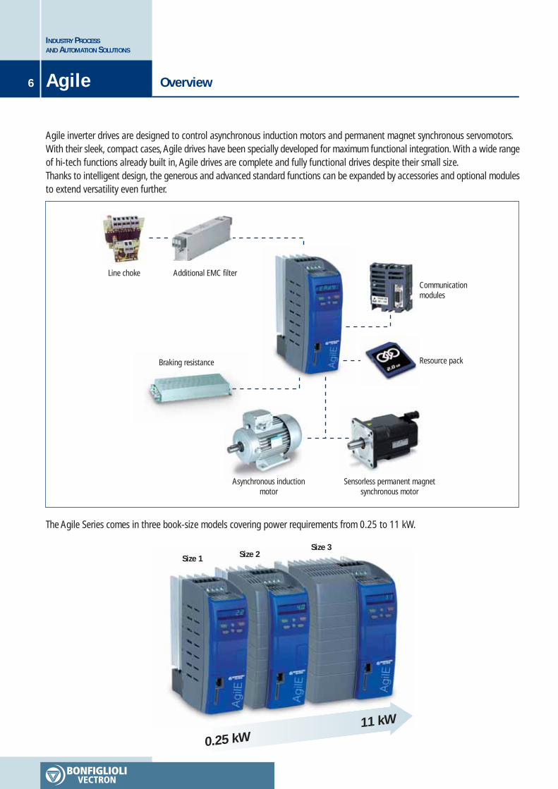
Agile inverter drives are designed to control asynchronous induction motors and permanent magnet synchronous servomotors.With their sleek, compact cases, Agile drives have been specially developed for maximum functional integration. With a wide rangeof hi-tech functions already built in, Agile drives are complete and fully functional drives despite their small size.Thanks to intelligent design, the generous and advanced standard functions can be expanded by accessories and optional modulesto extend versatility even further.
Line choke Additional EMC filterCommunicationmodules
Braking resistance
Asynchronous inductionmotor
Sensorless permanent magnetsynchronous motor
The Agile Series comes in three book-size models covering power requirements from 0.25 to 11 kW.
Size 1 Size 2Size 3
0.25 kW11 kW
Resource pack
7
INDUSTRY PROCESSAND AUTOMATION SOLUTIONS
Areas of application Agile
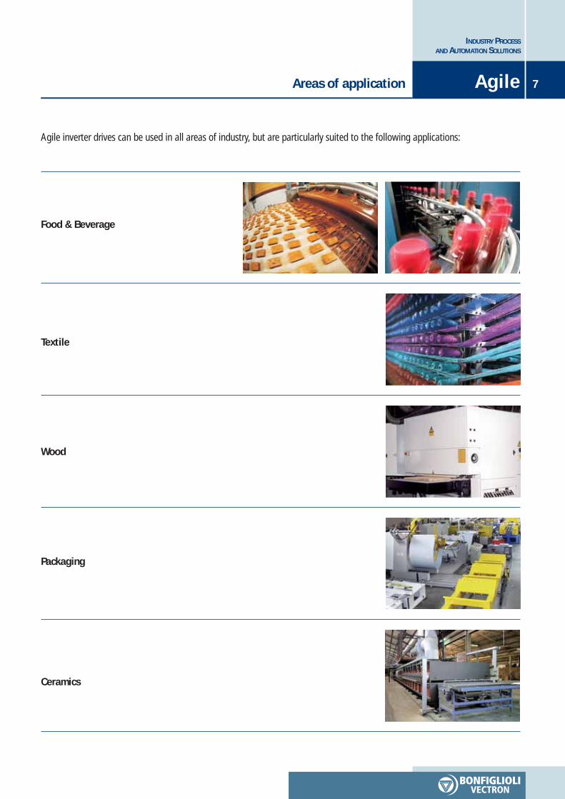
Agile inverter drives can be used in all areas of industry, but are particularly suited to the following applications:
Food & Beverage
Textile
Wood
Packaging
Ceramics
INDUSTRY PROCESSAND AUTOMATION SOLUTIONS
Agile Designation8
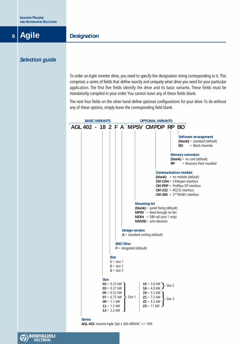
To order an Agile inverter drive, you need to specify the designation string corresponding to it. Thiscomprises a series of fields that define exactly and uniquely what drive you need for your particularapplication. The first five fields identify the drive and its basic variants. These fields must bemandatorily compiled in your order. You cannot leave any of these fields blank.
The next four fields on the other hand define optional configurations for your drive. To do withoutany of these options, simply leave the corresponding field blank.
Selection guide
AGL 402 - 18 2 F ABASIC VARIANTS
MPSV CMPDP RP BOOPTIONAL VARIANTS
Memory extension(blank) = no card (default)RP = Resource Pack installed
Communication module(blank) = no module (default)CM-CAN = CANopen interfaceCM-PDP = Profibus DP interfaceCM-232 = RS232 interfaceCM-485 = 2nd RS485 interface
Mounting kit(blank) = panel fixing (default)MPSV = feed-through no fanMDIN = DIN rail (size 1 only)MNVIB = anti-vibration
Design versionA = standard cooling (default)
SeriesAGL 402: inverter Agile 3ph x 360-480VAC +/- 10%
Size1 = size 12 = size 23 = size 3
EMC filterF = integrated (default)
Size02 = 0.25 kW03 = 0.37 kW05 = 0.55 kW07 = 0.75 kW09 = 1.1 kW11 = 1.5 kW13 = 2.2 kW
15 = 3.0 kW18 = 4.0 kW19 = 5.5 kW21 = 7.5 kW22 = 9.2 kW23 = 11 kW
Size 3
Size 2
Size 1
Software arrangement(blank) = standard (default)BO = Block-Override
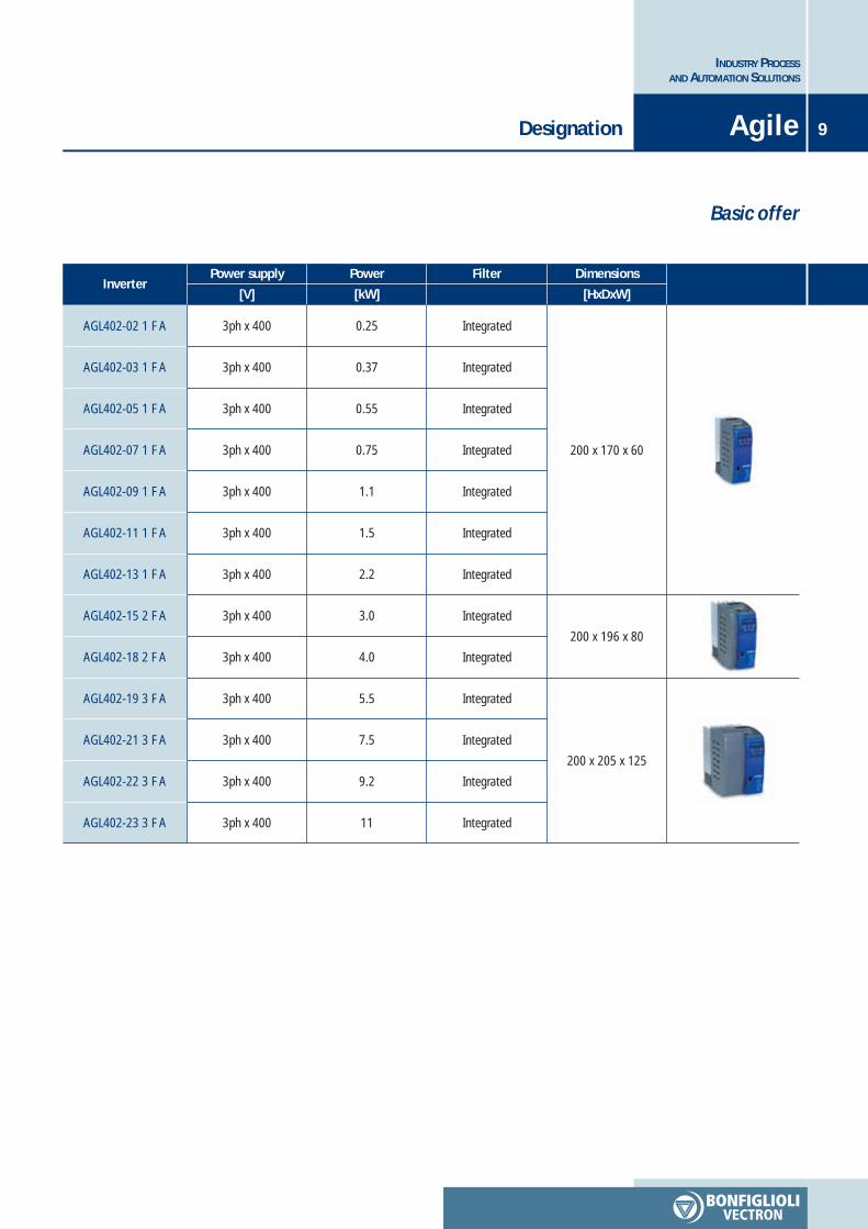
PowerInverter
Power supply Filter Dimensions
[kW] [HxDxW]
0.25
0.37
0.55
0.75
1.1
1.5
2.2
3.0
4.0
5.5
7.5
9.2
11
Integrated
Integrated
Integrated
Integrated
Integrated
Integrated
Integrated
Integrated
Integrated
Integrated
Integrated
Integrated
Integrated
200 x 170 x 60
200 x 196 x 80
200 x 205 x 125
AGL402-02 1 F A
AGL402-03 1 F A
AGL402-05 1 F A
AGL402-07 1 F A
AGL402-09 1 F A
AGL402-11 1 F A
AGL402-13 1 F A
AGL402-15 2 F A
AGL402-18 2 F A
AGL402-19 3 F A
AGL402-21 3 F A
AGL402-22 3 F A
AGL402-23 3 F A
[V]
3ph x 400
3ph x 400
3ph x 400
3ph x 400
3ph x 400
3ph x 400
3ph x 400
3ph x 400
3ph x 400
3ph x 400
3ph x 400
3ph x 400
3ph x 400
9
INDUSTRY PROCESSAND AUTOMATION SOLUTIONS
Designation Agile
Basic offer

INDUSTRY PROCESSAND AUTOMATION SOLUTIONS
10 Innovation at the service of peopleAgile
Agile inverter drives help bridge the gap between user and process by providing software andhardware functions that simplify the management of complete systems.
Agile inverter process drives provide accurate sensorless vector control of asynchronous inductionmotors and permanent magnet synchronous motors, and also help manage the complete automationsystem by contributing to energy saving, safety, maintenance and logic control.
Agile drives are Bonfiglioli's solution to the needs of the standard drive market, and boast a special“all-in-one” formula that delivers exceptional versatility.
USER PROCESS
Easy start up mode
Energy stand-by
Safety inside
Diagnostic fault scanner
Downtime suppressor
Leader in room saving
Integrated automation
Sensorless brushless control
Resource pack
E-served
Innovation at the service of people 11
INDUSTRY PROCESSAND AUTOMATION SOLUTIONS
Agile
Failure preventionAgile drives keep themselves and the system they are installed in under control, and make a generous contribution tomaintenance efficiency by preventing unexpected machine stoppages.
• Estimation of capacitor maintenance intervals• Estimation of cooling fan maintenance intervals
Energy savingAgile helps reduce system energy requirements by minimising its own losses and those of the motor.
• Sensorless control of permanent magnet synchronous motors• Automatic suspension of power stage with motor stopped• Adaptation of voltage to suit the load applied to the motor shaft• Minimum earth leakage
Functional safetyAgile drives respect all the safety standards applicable to electronic variable speed control.In particular, Agile drives provide functional safety according to EN61508 SIL2 and electrical safety according to EN954-1 Cat. 3, in conformity to EN61800-5-2 product standards for torque elimination through the physical disconnectionof the motor inside the inverter.
• Safe Torque Off• Foolproof wiring
Diagnostic analysisAgile drives provide valuable support for the analysis of critical events affecting the drive itself and the system in whichit is installed. They also incorporate a tool for monitoring, reconstructing and interpreting system dynamics
• Alarm log• Drive and motor status recovery• Autodiagnostics after critical events• Built-in multi-trace oscilloscope
RapidityIt only takes a few minutes to install and set up an Agile drive. Users will find everything quick and easy, from controlrack installation to software configuration, and will have the motor up and running in next to no time.
• Drilling template• DIN rail mounting• Clearly identified power terminals• Pre-calibrated for Bonfiglioli motors
• Automatic and permanent adaptive tuning• Pre-selection of application masks• Customisable units of measure• On-line help
INDUSTRY PROCESSAND AUTOMATION SOLUTIONS
12 Innovation at the service of peopleAgile
Space savingThe compact book size of Agile drives means significant space saving and great manoeuvrability inside the controlcabinet.
• High power concentration• Space saving in the control panel• Book size• Side by side installation• Same height for all sizes
E-served managementAgile can be fully managed through Bonfiglioli's MOSAICO e-business platform that lets you select drives, order themand monitor delivery over the internet.Technical training is also available through Bonfiglioli's HUB e-learning system. There is even a dedicated website forthe distribution of newsletters.
Resource packAgile drives can be fitted with an MMC standard non-volatile flash memory expansion.
• MMC standard memory expansion card• Any capacity cards supported• Parameter copy function• Integrated application documentation• Integrated application software
Sensorless brushlessAgile vector drives can control even sensorless permanent magnet synchronous motors thanks to an innovative algorithmwhich provides full starting torque.
Built-in PLCAgile drives can perform simple and complex programmable logic operations on physical signals to their terminals andon internal software variables, and can combine these operations to create a functional program that can complementor replace a control panel PLC.
• Programmable logic functions• Graphic block programming• Cyclical operating system
• Accessible drive variables• Input/output buffers
Synergy with Bonfiglioli motors 13
INDUSTRY PROCESSAND AUTOMATION SOLUTIONS
Agile
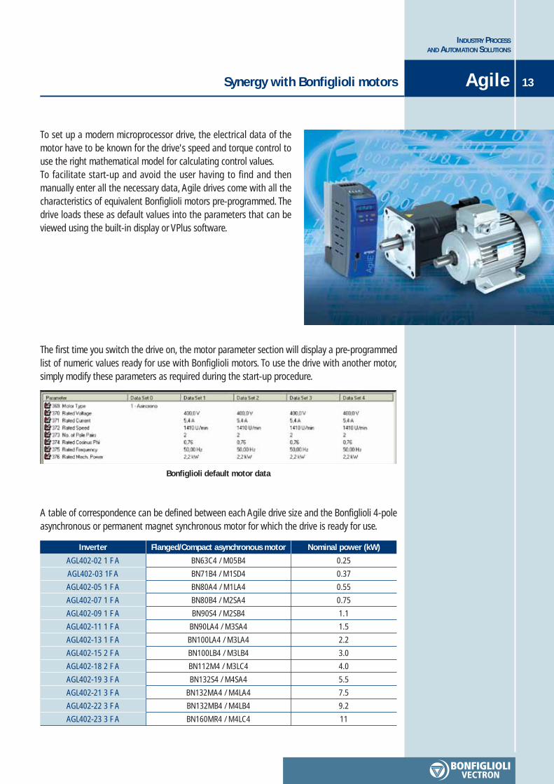
To set up a modern microprocessor drive, the electrical data of themotor have to be known for the drive's speed and torque control touse the right mathematical model for calculating control values.To facilitate start-up and avoid the user having to find and thenmanually enter all the necessary data, Agile drives come with all thecharacteristics of equivalent Bonfiglioli motors pre-programmed. Thedrive loads these as default values into the parameters that can beviewed using the built-in display or VPlus software.
The first time you switch the drive on, the motor parameter section will display a pre-programmedlist of numeric values ready for use with Bonfiglioli motors. To use the drive with another motor,simply modify these parameters as required during the start-up procedure.
Bonfiglioli default motor data
A table of correspondence can be defined between each Agile drive size and the Bonfiglioli 4-poleasynchronous or permanent magnet synchronous motor for which the drive is ready for use.
Inverter Flanged/Compact asynchronous motor
AGL402-02 1 F A
AGL402-03 1F A
AGL402-05 1 F A
AGL402-07 1 F A
AGL402-09 1 F A
AGL402-11 1 F A
AGL402-13 1 F A
AGL402-15 2 F A
AGL402-18 2 F A
AGL402-19 3 F A
AGL402-21 3 F A
AGL402-22 3 F A
AGL402-23 3 F A
BN63C4 / M05B4
BN71B4 / M1SD4
BN80A4 / M1LA4
BN80B4 / M2SA4
BN90S4 / M2SB4
BN90LA4 / M3SA4
BN100LA4 / M3LA4
BN100LB4 / M3LB4
BN112M4 / M3LC4
BN132S4 / M4SA4
BN132MA4 / M4LA4
BN132MB4 / M4LB4
BN160MR4 / M4LC4
Nominal power (kW)
0.25
0.37
0.55
0.75
1.1
1.5
2.2
3.0
4.0
5.5
7.5
9.2
11
INDUSTRY PROCESSAND AUTOMATION SOLUTIONS
14 VPlus engineering softwareAgile
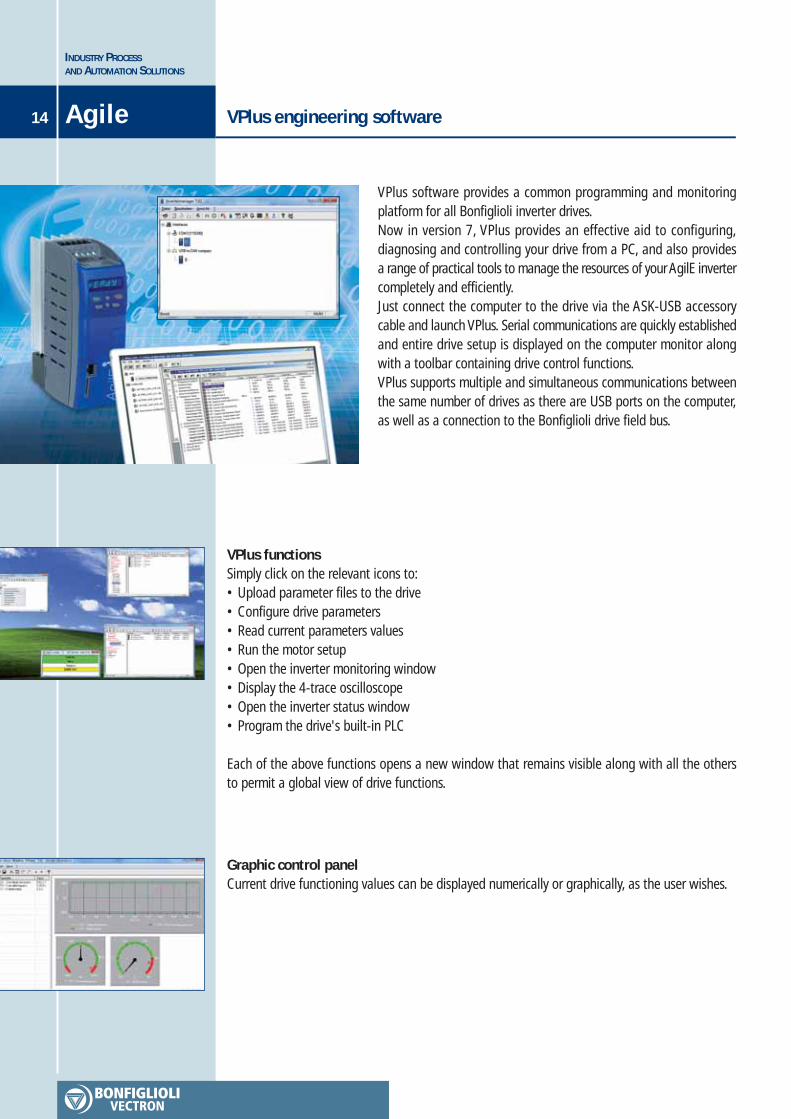
VPlus software provides a common programming and monitoringplatform for all Bonfiglioli inverter drives.Now in version 7, VPlus provides an effective aid to configuring,diagnosing and controlling your drive from a PC, and also providesa range of practical tools to manage the resources of your AgilE invertercompletely and efficiently.Just connect the computer to the drive via the ASK-USB accessorycable and launch VPlus. Serial communications are quickly establishedand entire drive setup is displayed on the computer monitor alongwith a toolbar containing drive control functions.VPlus supports multiple and simultaneous communications betweenthe same number of drives as there are USB ports on the computer,as well as a connection to the Bonfiglioli drive field bus.
VPlus functionsSimply click on the relevant icons to:• Upload parameter files to the drive• Configure drive parameters• Read current parameters values• Run the motor setup• Open the inverter monitoring window• Display the 4-trace oscilloscope• Open the inverter status window• Program the drive's built-in PLC
Each of the above functions opens a new window that remains visible along with all the othersto permit a global view of drive functions.
Graphic control panelCurrent drive functioning values can be displayed numerically or graphically, as the user wishes.
VPlus engineering software 15
INDUSTRY PROCESSAND AUTOMATION SOLUTIONS
Agile
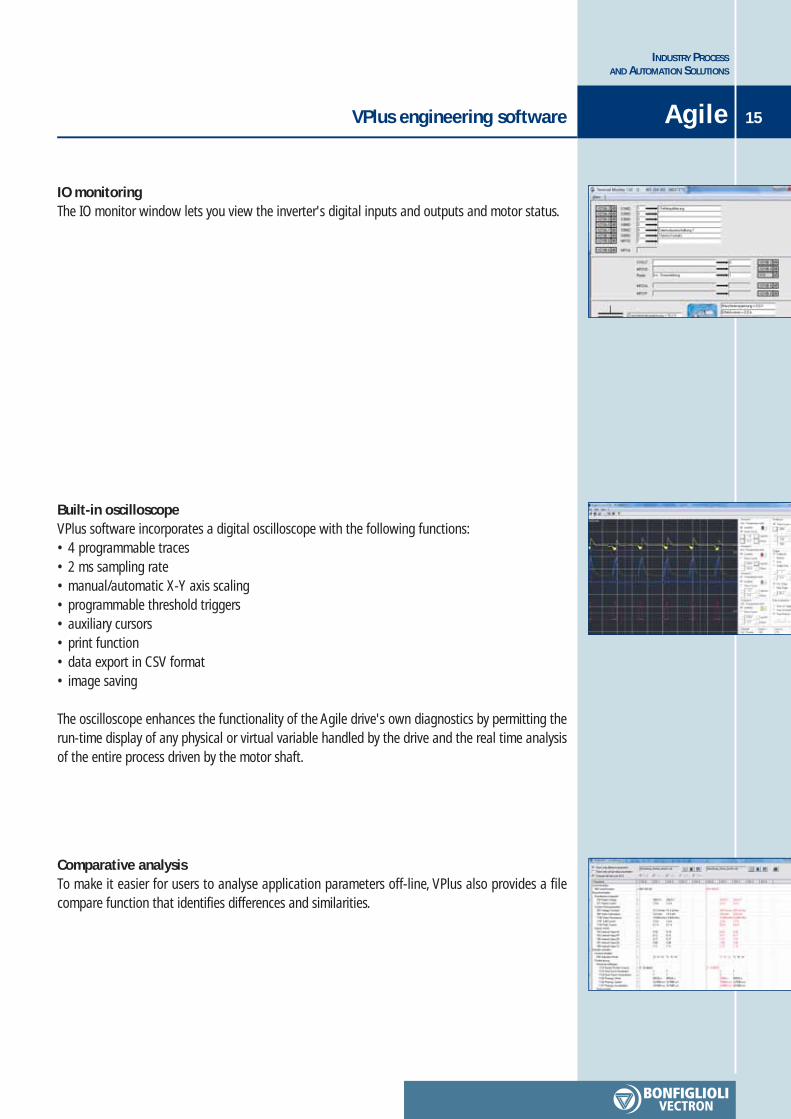
IO monitoringThe IO monitor window lets you view the inverter's digital inputs and outputs and motor status.
Built-in oscilloscopeVPlus software incorporates a digital oscilloscope with the following functions:• 4 programmable traces• 2 ms sampling rate• manual/automatic X-Y axis scaling• programmable threshold triggers• auxiliary cursors• print function• data export in CSV format• image saving
The oscilloscope enhances the functionality of the Agile drive's own diagnostics by permitting therun-time display of any physical or virtual variable handled by the drive and the real time analysisof the entire process driven by the motor shaft.
Comparative analysisTo make it easier for users to analyse application parameters off-line, VPlus also provides a filecompare function that identifies differences and similarities.
INDUSTRY PROCESSAND AUTOMATION SOLUTIONS
16 VPlus engineering softwareAgile
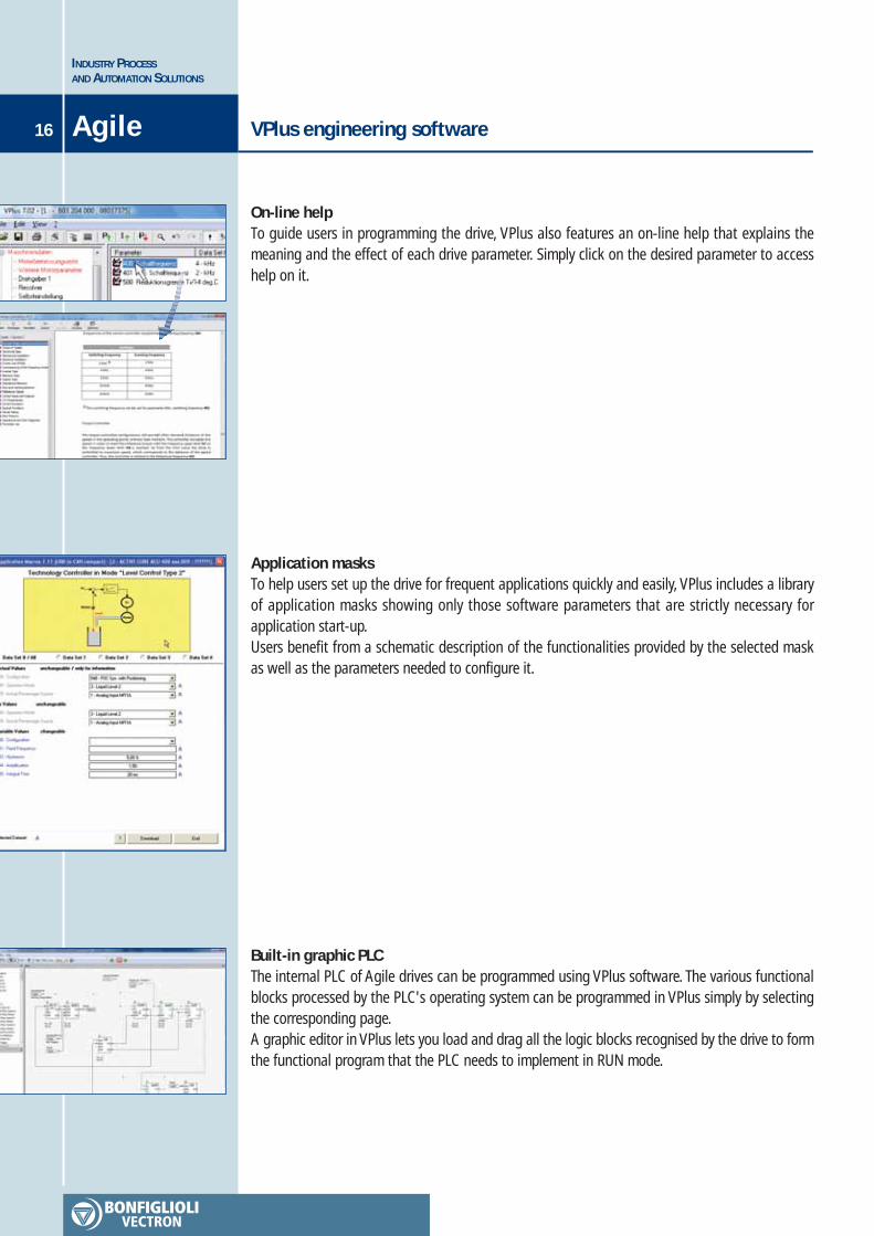
Built-in graphic PLCThe internal PLC of Agile drives can be programmed using VPlus software. The various functionalblocks processed by the PLC's operating system can be programmed in VPlus simply by selectingthe corresponding page.A graphic editor in VPlus lets you load and drag all the logic blocks recognised by the drive to formthe functional program that the PLC needs to implement in RUN mode.
On-line helpTo guide users in programming the drive, VPlus also features an on-line help that explains themeaning and the effect of each drive parameter. Simply click on the desired parameter to accesshelp on it.
Application masksTo help users set up the drive for frequent applications quickly and easily, VPlus includes a libraryof application masks showing only those software parameters that are strictly necessary forapplication start-up.Users benefit from a schematic description of the functionalities provided by the selected maskas well as the parameters needed to configure it.
Sensorless control of permanent magnet synchronous motors 17
INDUSTRY PROCESSAND AUTOMATION SOLUTIONS
Agile
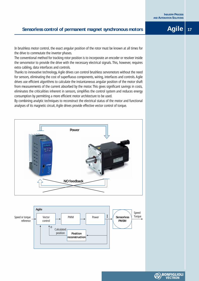
In brushless motor control, the exact angular position of the rotor must be known at all times forthe drive to commutate the inverter phases.The conventional method for tracking rotor position is to incorporate an encoder or resolver insidethe servomotor to provide the drive with the necessary electrical signals. This, however, requiresextra cabling, data interfaces and controls.Thanks to innovative technology, Agile drives can control brushless servomotors without the needfor sensors, eliminating the cost of superfluous components, wiring, interfaces and controls. Agiledrives use efficient algorithms to calculate the instantaneous angular position of the motor shaftfrom measurements of the current absorbed by the motor. This gives significant savings in costs,eliminates the criticalities inherent in sensors, simplifies the control system and reduces energyconsumption by permitting a more efficient motor architecture to be used.By combining analytic techniques to reconstruct the electrical status of the motor and functionalanalyses of its magnetic circuit, Agile drives provide effective vector control of torque.
Power
NO feedback
Speed or torquereference
Agile
Vectorcontrol
PWM Power
Positionreconstruction
SensorlessPMSM
SpeedTorque
Calculatedposition
I
ϑ
INDUSTRY PROCESSAND AUTOMATION SOLUTIONS
18 Energy savingAgile
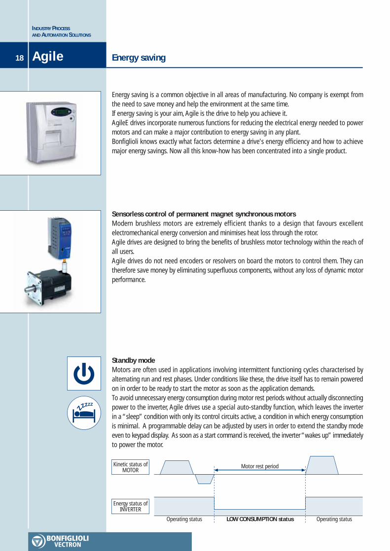
Energy saving is a common objective in all areas of manufacturing. No company is exempt fromthe need to save money and help the environment at the same time.If energy saving is your aim, Agile is the drive to help you achieve it.AgileE drives incorporate numerous functions for reducing the electrical energy needed to powermotors and can make a major contribution to energy saving in any plant.Bonfiglioli knows exactly what factors determine a drive's energy efficiency and how to achievemajor energy savings. Now all this know-how has been concentrated into a single product.
Sensorless control of permanent magnet synchronous motorsModern brushless motors are extremely efficient thanks to a design that favours excellentelectromechanical energy conversion and minimises heat loss through the rotor.Agile drives are designed to bring the benefits of brushless motor technology within the reach ofall users.Agile drives do not need encoders or resolvers on board the motors to control them. They cantherefore save money by eliminating superfluous components, without any loss of dynamic motorperformance.
Standby modeMotors are often used in applications involving intermittent functioning cycles characterised byalternating run and rest phases. Under conditions like these, the drive itself has to remain poweredon in order to be ready to start the motor as soon as the application demands.To avoid unnecessary energy consumption during motor rest periods without actually disconnectingpower to the inverter, Agile drives use a special auto-standby function, which leaves the inverterin a “sleep” condition with only its control circuits active, a condition in which energy consumptionis minimal. A programmable delay can be adjusted by users in order to extend the standby modeeven to keypad display. As soon as a start command is received, the inverter “wakes up” immediatelyto power the motor.
Energy status ofINVERTER
Operating status LOW CONSUMPTION status Operating status
Kinetic status ofMOTOR
Motor rest period

Energy saving 19
INDUSTRY PROCESSAND AUTOMATION SOLUTIONS
Agile
Power managingMotor efficiency is significantly conditioned by the quality of the power supply.Agile drives use control to reduce motor voltage to suit applied loads without compromisingperformance. This reduces motor losses, consumption and maintenance requirements and helpsextend motor life. For example, if the motor is run up to rated speed at zero load, there is no needto apply full rated voltage. The minimum voltage compatible with the needs of motor magnetisationis all that is needed.
Torque requiredby motor shaft Motor at zero load Motor at zero load
Voltage appliedto motor
Minimum voltage Minimum voltage
Minimum earth leakageAgile drives are equipped with a built-in, low leakage current EMC filter that conforms to allapplicable standards. By significantly reducing earth leakage, this filter also maximises energysavings under all operating conditions.

INDUSTRY PROCESSAND AUTOMATION SOLUTIONS
20 A drive with a PLC built inAgile
Modern PLCs are extremely evolved devices with high calculation and interface capacities. Theproblem is that they need qualified, expert personnel to convert the needs of the machine intosequences of PLC instructions. These may even have to be encoded according to different proprietaryprogramming standards.The inverter is becoming one type of actuator to which PLCs can delegate the dynamic control ofan axis in synchronisation with other parts of the machine.
Agile drives guarantee efficient motor control and incorporate a programmable logic controllerthat can be used to complement or replace a conventional control panel PLC.In the heart of every Agile drive is a PLC capable of performing multiple logic operations (AND,OR, XOR) and functions (counters, timers, comparators, multiplexers, decoders, oscillators, etc.).These can be combined using a graphic editor to create complex functions. The result is anintelligent local controller capable of handling the drive's own internal variables (currents,frequencies, machine statuses, etc.), I/O signals to and from the terminals, and multiplexed dataexchanged over a field bus.The intuitive graphic editor allows even non-expert users to program the PLC of an Agile drivewithout having to learn complicated programming languages that very few can master. Agile usersdo not have to rely on others to program their drives.Agile drives are powerful and intelligent and, by relieving the main control panel PLC of localtasks, conform perfectly to the concept of distributed logic.
The Agile PLC recognises and handles 120 different functions, which can be used within 32programmable functional modules (indexes).
Each module has a maximum of 4 inputs, 2 outputs and 2 configuration parameters. When thedrive is switched on, its operating system indexes all the active modules in sequence, taking only1 ms per module. Each module is implemented by running all its instructions in sequence. Whenone module has been completed, the OS moves on to the next, and so on.
Internal PLC
Function Block
RoutineSoftware
OutputsInputs
Functionselector
Parameters

A drive with a PLC built in 21
INDUSTRY PROCESSAND AUTOMATION SOLUTIONS
Agile
Input Latches & Output Latches
Active function blocks
Inactive functionblocks
Instructions
Functionblock 1
I = 1
Functionblock 2
I = 2
Functionblock 3
I = 3 I = 4
P1343 = 0
Writeoutput buffer
Updateinput buffer
24xx25xx
20xx23xx
1. ms5. ms
...
2. ms6. ms
...
3. ms7. ms
...
4. ms8. ms
...
(Return)
CYCLE
The OS scans input and output buffers, samples input signals and executes output signals beforeit indexes the sequence of active modules.
As in any control panel PLC, cycle management is entrusted to the operating system and isindependent of all other processes managed by the CPU.The program is therefore deterministic and scan time proportional to the number of active functionblocks.In any automation process, the cycle period can be calculated by summing the 1-ms delaysintroduced by each function block.Agile PLC functions can be programmed using VPlus software, which graphically displays theprogram to which the drive's memory corresponds in real time.VPlus software also provides a page that can be used to load graphic function blocks and linkthem together to create complex logic networks for use by the drive.
The Agile PLC supports and processes all the variables used by the drive software, including I/Ovariables, strings exchanged over the field bus and numeric motor control values. The PLC istherefore perfectly able to exchange signals with external devices like sensors, actuators, inverters,PLCs, PC's, etc.) as well as with the drive itself.
Externaldevices
Motorcontrolroutine
Agile
I/O PLC area Field bus Externaldevices
INDUSTRY PROCESSAND AUTOMATION SOLUTIONS
22 Integrated safety thanks to Safe Torque OffAgile
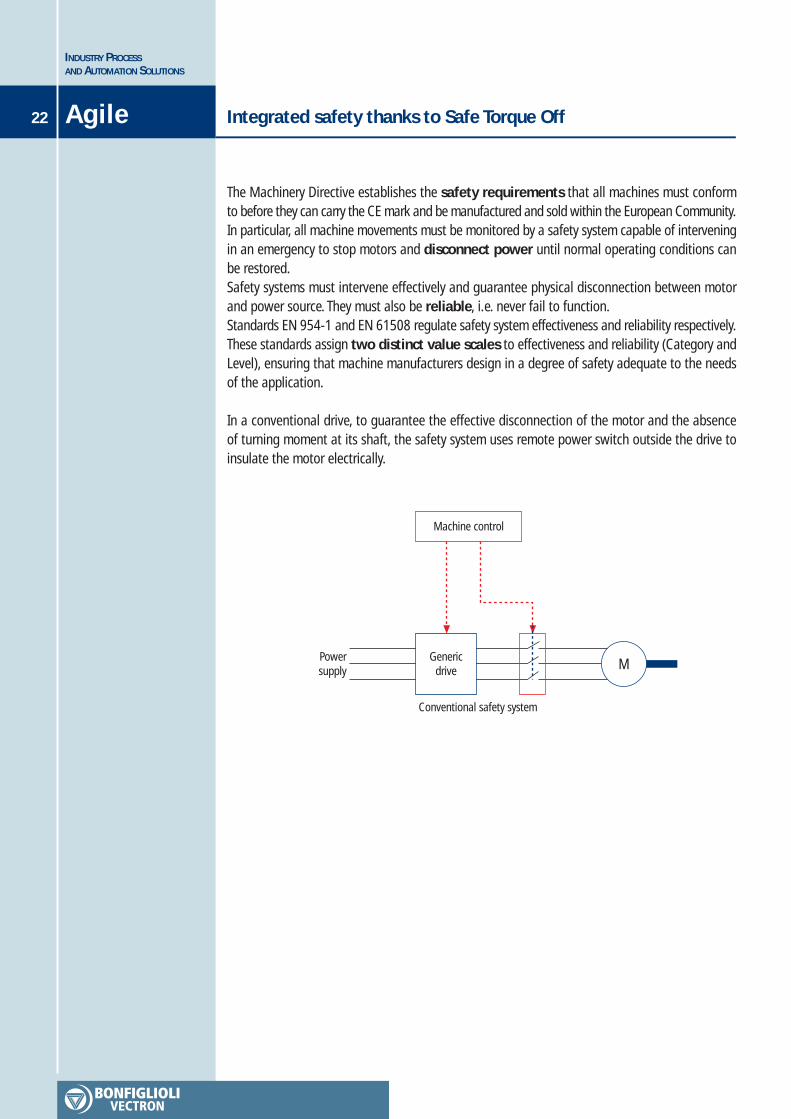
The Machinery Directive establishes the safety requirements that all machines must conformto before they can carry the CE mark and be manufactured and sold within the European Community.In particular, all machine movements must be monitored by a safety system capable of interveningin an emergency to stop motors and disconnect power until normal operating conditions canbe restored.Safety systems must intervene effectively and guarantee physical disconnection between motorand power source. They must also be reliable, i.e. never fail to function.Standards EN 954-1 and EN 61508 regulate safety system effectiveness and reliability respectively.These standards assign two distinct value scales to effectiveness and reliability (Category andLevel), ensuring that machine manufacturers design in a degree of safety adequate to the needsof the application.
In a conventional drive, to guarantee the effective disconnection of the motor and the absenceof turning moment at its shaft, the safety system uses remote power switch outside the drive toinsulate the motor electrically.
Genericdrive
Powersupply M
Conventional safety system
Machine control
Integrated safety thanks to Safe Torque Off 23
INDUSTRY PROCESSAND AUTOMATION SOLUTIONS
Agile
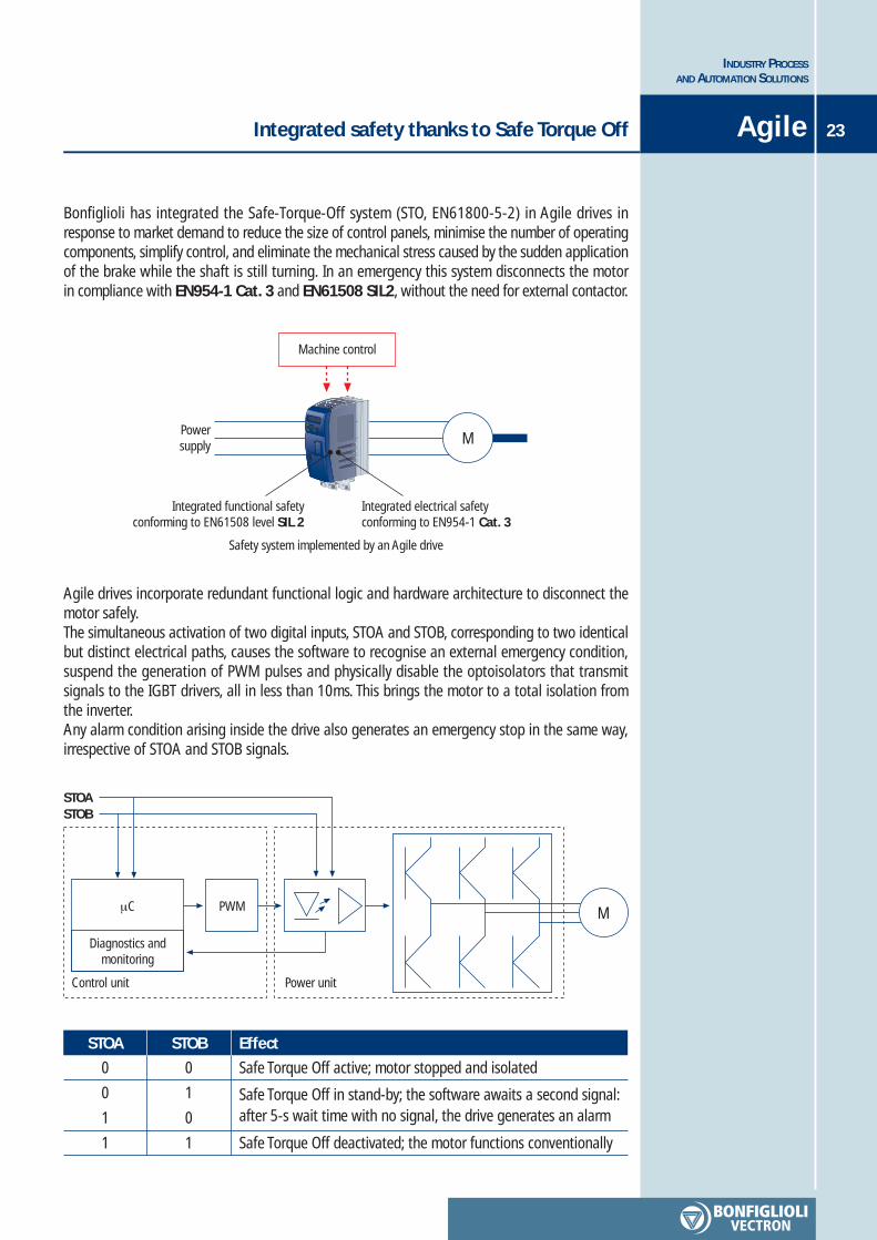
Bonfiglioli has integrated the Safe-Torque-Off system (STO, EN61800-5-2) in Agile drives inresponse to market demand to reduce the size of control panels, minimise the number of operatingcomponents, simplify control, and eliminate the mechanical stress caused by the sudden applicationof the brake while the shaft is still turning. In an emergency this system disconnects the motorin compliance with EN954-1 Cat. 3 and EN61508 SIL2, without the need for external contactor.
STOASTOB
M
Diagnostics andmonitoring
Control unit Power unit
PWMμC
Safety system implemented by an Agile drive
Powersupply M
Machine control
Integrated functional safetyconforming to EN61508 level SIL 2
Integrated electrical safetyconforming to EN954-1 Cat. 3
0
0
1
1
STOA Effect
Safe Torque Off active; motor stopped and isolated
Safe Torque Off deactivated; the motor functions conventionally
0
1
0
1
STOB
Safe Torque Off in stand-by; the software awaits a second signal:after 5-s wait time with no signal, the drive generates an alarm
Agile drives incorporate redundant functional logic and hardware architecture to disconnect themotor safely.The simultaneous activation of two digital inputs, STOA and STOB, corresponding to two identicalbut distinct electrical paths, causes the software to recognise an external emergency condition,suspend the generation of PWM pulses and physically disable the optoisolators that transmitsignals to the IGBT drivers, all in less than 10ms. This brings the motor to a total isolation fromthe inverter.Any alarm condition arising inside the drive also generates an emergency stop in the same way,irrespective of STOA and STOB signals.
INDUSTRY PROCESSAND AUTOMATION SOLUTIONS
24 Agile
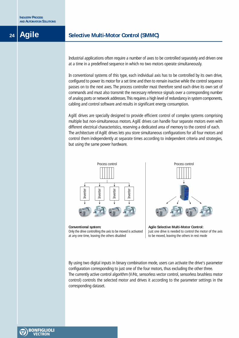
Industrial applications often require a number of axes to be controlled separately and driven oneat a time in a predefined sequence in which no two motors operate simultaneously.
In conventional systems of this type, each individual axis has to be controlled by its own drive,configured to power its motor for a set time and then to remain inactive while the control sequencepasses on to the next axes. The process controller must therefore send each drive its own set ofcommands and must also transmit the necessary reference signals over a corresponding numberof analog ports or network addresses. This requires a high level of redundancy in system components,cabling and control software and results in significant energy consumption.
AgilE drives are specially designed to provide efficient control of complex systems comprisingmultiple but non-simultaneous motors. AgilE drives can handle four separate motors even withdifferent electrical characteristics, reserving a dedicated area of memory to the control of each.The architecture of AgilE drives lets you store simultaneous configurations for all four motors andcontrol them independently at separate times according to independent criteria and strategies,but using the same power hardware.
Selective Multi-Motor Control (SMMC)
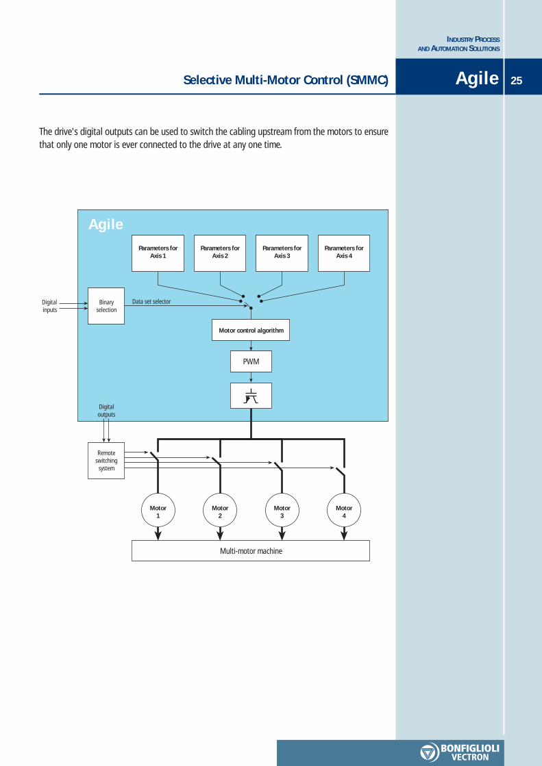
By using two digital inputs in binary combination mode, users can activate the drive's parameterconfiguration corresponding to just one of the four motors, thus excluding the other three.The currently active control algorithm (V/Hz, sensorless vector control, sensorless brushless motorcontrol) controls the selected motor and drives it according to the parameter settings in thecorresponding dataset.
Conventional system:Only the drive controlling the axis to be moved is activatedat any one time, leaving the others disabled
Agile Selective Multi-Motor Control:Just one drive is needed to control the motor of the axisto be moved, leaving the others in rest mode
Inve
rter
Inve
rter
Inve
rter
Inve
rter
Process control Process control
Selective Multi-Motor Control (SMMC) 25
INDUSTRY PROCESSAND AUTOMATION SOLUTIONS
Agile
The drive's digital outputs can be used to switch the cabling upstream from the motors to ensurethat only one motor is ever connected to the drive at any one time.
Remoteswitching
system
Digitalinputs
Parameters forAxis 1
Parameters forAxis 2
Parameters forAxis 3
Parameters forAxis 4
Data set selector
Motor control algorithm
Binaryselection
PWM
Multi-motor machine
Motor1
Motor2
Motor3
Motor4
Digitaloutputs
Agile
INDUSTRY PROCESSAND AUTOMATION SOLUTIONS
26 Agile
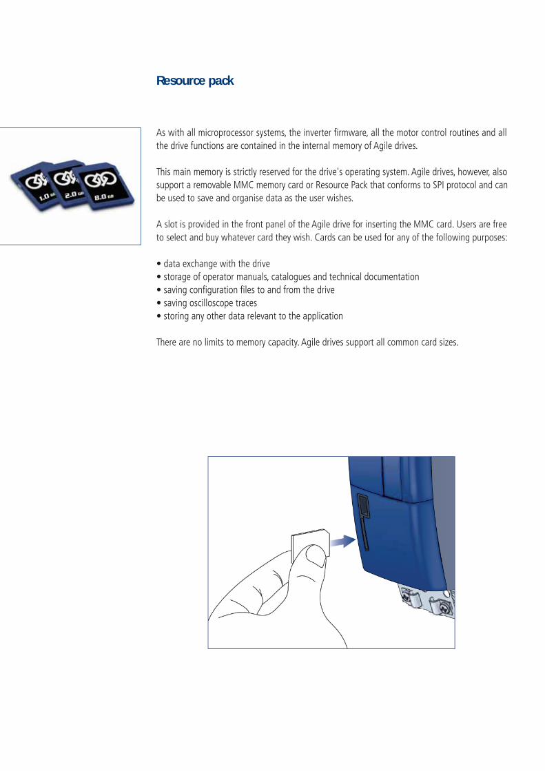
As with all microprocessor systems, the inverter firmware, all the motor control routines and allthe drive functions are contained in the internal memory of Agile drives.
This main memory is strictly reserved for the drive's operating system. Agile drives, however, alsosupport a removable MMC memory card or Resource Pack that conforms to SPI protocol and canbe used to save and organise data as the user wishes.
A slot is provided in the front panel of the Agile drive for inserting the MMC card. Users are freeto select and buy whatever card they wish. Cards can be used for any of the following purposes:
• data exchange with the drive• storage of operator manuals, catalogues and technical documentation• saving configuration files to and from the drive• saving oscilloscope traces• storing any other data relevant to the application
There are no limits to memory capacity. Agile drives support all common card sizes.
Resource pack
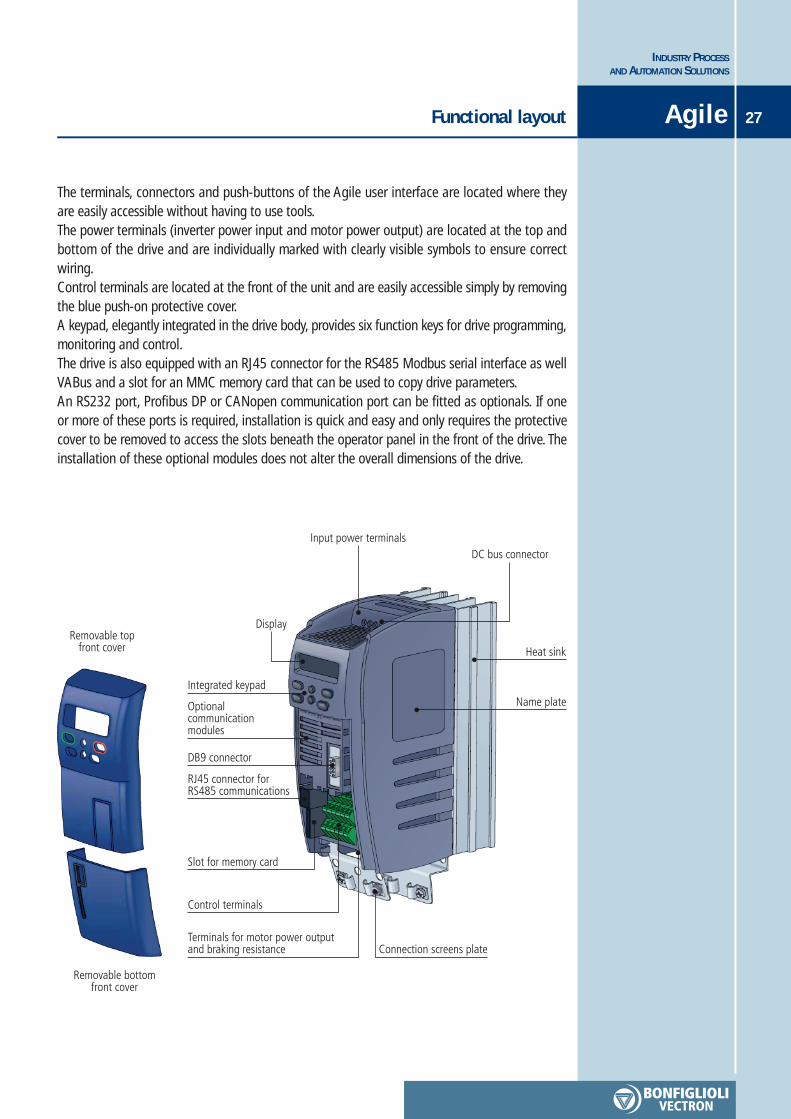
Removable topfront cover
Removable bottomfront cover
Display
Input power terminalsDC bus connector
Heat sink
Name plate
Connection screens plateTerminals for motor power outputand braking resistance
Control terminals
Slot for memory card
RJ45 connector forRS485 communications
DB9 connector
Optionalcommunicationmodules
Integrated keypad
Functional layout 27
INDUSTRY PROCESSAND AUTOMATION SOLUTIONS
Agile
The terminals, connectors and push-buttons of the Agile user interface are located where theyare easily accessible without having to use tools.The power terminals (inverter power input and motor power output) are located at the top andbottom of the drive and are individually marked with clearly visible symbols to ensure correctwiring.Control terminals are located at the front of the unit and are easily accessible simply by removingthe blue push-on protective cover.A keypad, elegantly integrated in the drive body, provides six function keys for drive programming,monitoring and control.The drive is also equipped with an RJ45 connector for the RS485 Modbus serial interface as wellVABus and a slot for an MMC memory card that can be used to copy drive parameters.An RS232 port, Profibus DP or CANopen communication port can be fitted as optionals. If oneor more of these ports is required, installation is quick and easy and only requires the protectivecover to be removed to access the slots beneath the operator panel in the front of the drive. Theinstallation of these optional modules does not alter the overall dimensions of the drive.

INDUSTRY PROCESSAND AUTOMATION SOLUTIONS
28 General technical dataAgile
EnvironmentTransport and storage temperature -25°C … 55°COperation temperature: 0°C - 40°C (40°C-55°C with derating)Environment class: 3K3 (EN60721-3-3)Relative humidity 5%...95%, no condensationAltitude of installation: up to 3000m (over 1000m with derating)Storage conditions: according to EN50178Degree of protection: IP20
ElectricalRated mains voltage: in the range 323 …. 528 VRated mains frequency: in the range 45 … 69 HzOverload current: 150% nominal currentPeak current: 200% nominal currentElectric protections: short circuit / earthBraking transistor: built-in on standard device
StandardsCE conformity: Low voltage directive 2006/95/EC and EN50178 / DIN VDE 0160 and EN61800Interference immunity: according to EN61800-3UL approval: according to UL508c
ConnectionsThe Agile drive is fitted with power input terminals for connection to the mains, power outputterminals for driving the motor and signal terminals for inverter control, subdivided into foursections.
Power terminalsThe power terminals are located at the top and bottom of the unit.Mains input power is connected to the top of the drive where a DC-bus connection is also provided.The power output cables to the motor are connected to the bottom of the drive where there isalso a connection for a braking resistance if required.Just as on ACT and ACU drives, this effective separation of input and output power terminals helpsprevent mis-wiring through human error.

29
INDUSTRY PROCESSAND AUTOMATION SOLUTIONS
General technical data Agile
Control terminalsControl signals are distributed over four separate terminal strips, located under the drive's removablefront cover. Terminals include:
• 6 digital inputs• 1 configurable digital I/O port• 2 configurable multifunctional A/D inputs• 1 digital output• 1 configurable multifunctional A/D/pulse output• 1 auxiliary voltage supply input• 2 voltage supply outputs• 1 Systembus/CAN communication interface
1 2 3 4 5 6X13
24V
in
GN
D
STO
B
10V
out
Digi
tal O
utpu
t
Anal
og O
utpu
t
1 2 3 4 5 6X12
Digi
tal I
nput
Digi
tal I
nput
Anal
og In
put
Digi
tal I
nput
CAN
_H
CAN
_L
1 2 3 4 5 6X11
24V
out
GN
D
STO
A
Digi
tal I
nput
Digi
tal I
nput
Digi
tal P
ort
32
1
X10
Alarm relay
X13.1
X13.2
X13.3
X13.4
X13.5
X13.6
X12.1
X12.2
X12.3
X12.4
X12.5
X12.6
X11.1
X11.2
X11.3
X11.4
X11.5
X11.6
X10.1
X10.2
X10.3
Terminal Default function
Auxiliary 24 VDC input
GND for X13.1
Digital input for Safe Torque Off B
10 VDC output
Multifunction Digital Output (default = RUN state)
Multifunction Analog Output (default = Actual speed)
Multifunction Digital Input (default = data set change-over bit 1)
Multifunction Digital Input (default = fixed frequency change-over)
Voltage Configurable Analog/Digital Multifunction Input
(default = frequency reference)
Voltage Configurable Analog/Digital Multifunction Input
(default = motor thermal contact)
Systembus/CAN signal +
Systembus/CAN signal -
24VDC output
GND for X11.1
Digital input for Safe Torque Off A
Multifunction Digital Input (default = start clockwise)
Multifunction Digital Input (default = start anticlockwise)
Digital Configurable Input/Output
(default = data set change-over bit 2)
Normally closed Alarm Relay contact
Alarm relay switching contact
Normally open Alarm Relay contact

INDUSTRY PROCESSAND AUTOMATION SOLUTIONS
30 General technical dataAgile
The Agile Series covers a power range of 0.25 to 11 kW, divided into three sub-ranges, eachcovered by one physical drive size. Each drive size can therefore satisfy the needs of differentpower ratings to offer a suitable solution for all applications.The three physical drive sizes are identical in height and depth but differ in width because of thedifferent power modules combined with them. The sizes are easily identifiable for the same reason.The AGL402 three phase 400 V configuration soon will be partnered by single phase 230 V version.
3ph 400VAGL 402
Power supplySeries
Rating
AGL402- … 1 F A
Size 2 Size 3Size 1
AGL402- … 2 F A AGL402- … 3 F A
0.25 kW
0.37 kW
0.55 kW
0.75 kW
1.1 kW
1.5 kW
2.2 kW
3.0 kW
4.0 kW
-
-
-
-
-
5.5 kW
7.5 kW
9.2 kW
11 kW
-
-
-
31
INDUSTRY PROCESSAND AUTOMATION SOLUTIONS
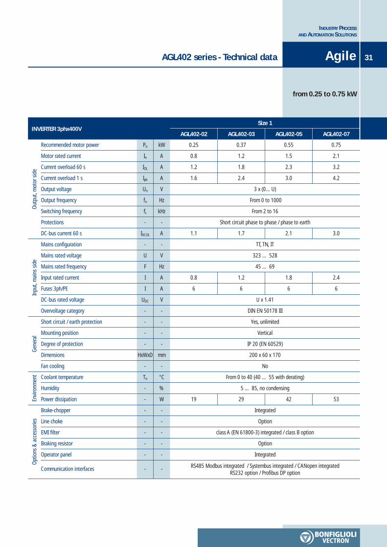
AGL402 series - Technical data Agile
from 0.25 to 0.75 kW
Out
put,
mot
or s
ide
INVERTER 3phx400VSize 1
AGL402-02 AGL402-03 AGL402-05 AGL402-07
Inpu
t, m
ains
sid
eG
ener
alEn
viro
nmen
tO
ptio
ns &
acc
esso
ries
Recommended motor power
Motor rated current
Current overload 60 s
Current overload 1 s
Output voltage
Output frequency
Switching frequency
Protections
DC-bus current 60 s
Mains configuration
Mains rated voltage
Mains rated frequency
Input rated current
Fuses 3ph/PE
DC-bus rated voltage
Overvoltage category
Short circuit / earth protection
Mounting position
Degree of protection
Dimensions
Fan cooling
Coolant temperature
Humidity
Power dissipation
Brake-chopper
Line choke
EMI filter
Braking resistor
Operator panel
Communication interfaces
Pn
In
IOL
Ipk
Un
fn
fc
-
IDCOL
-
U
F
I
I
UDC
-
-
-
-
HxWxD
-
Tn
-
-
-
-
-
-
-
-
kW
A
A
A
V
Hz
kHz
-
A
-
V
Hz
A
A
V
-
-
-
-
mm
-
°C
%
W
-
-
-
-
-
-
0.25
0.8
1.2
1.6
0.37
1.2
1.8
2.4
0.55
1.5
2.3
3.0
0.75
2.1
3.2
4.2
3 x (0…U)
From 0 to 1000
From 2 to 16
Short circuit phase to phase / phase to earth
TT, TN, IT
323 … 528
45 … 69
1.1 1.7 2.1 3.0
0.8
6
1.2
6
1.8
6
2.4
6
U x 1.41
DIN EN 50178 III
Yes, unlimited
Vertical
IP 20 (EN 60529)
200 x 60 x 170
No
From 0 to 40 (40 … 55 with derating)
5 … 85, no condensing
19 29 42 53
Integrated
Option
class A (EN 61800-3) integrated / class B option
Option
Integrated
RS485 Modbus integrated / Systembus integrated / CANopen integratedRS232 option / Profibus DP option

INVERTER 3phx400VSize 1
Pn
In
IOL
Ipk
Un
fn
fc
-
IDCOL
-
U
F
I
I
UDC
-
-
-
-
HxWxD
-
Tn
-
-
-
-
-
-
-
-
kW
A
A
A
V
Hz
kHz
-
A
-
V
Hz
A
A
V
-
-
-
-
mm
-
°C
%
W
-
-
-
-
-
-
3 x (0…U)
From 0 to 1000
From 2 to 16
Short circuit phase to phase / phase to earth
TT, TN, IT
323 … 528
45 … 69
4.8 6.4 8.7
2.8
6
3.3
6
5.8
10
U x 1.41
DIN EN 50178 III
Yes, unlimited
Vertical
IP 20 (EN 60529)
200 x 60 x 170
Yes
From 0 to 40 (40 … 55 with derating)
5 … 85, no condensing
70 89 122
Integrated
Option
class A (EN 61800-3) integrated / class B option
Option
Integrated
RS485 Modbus integrated / Systembus integrated / CANopen integratedRS232 option / Profibus DP option
AGL402 series - Technical data
from 1.1 to 2.2 kW
INDUSTRY PROCESSAND AUTOMATION SOLUTIONS
32 Agile
AGL402-09 AGL402-11 AGL402-13
1.1
3.0
4.5
6.0
1.5
4.0
6.0
8.0
2.2
5.5
8.2
11.0
Out
put,
mot
or s
ide
Inpu
t, m
ains
sid
eG
ener
alEn
viro
nmen
tO
ptio
ns &
acc
esso
ries
Recommended motor power
Motor rated current
Current overload 60 s
Current overload 1 s
Output voltage
Output frequency
Switching frequency
Protections
DC-bus current 60 s
Mains configuration
Mains rated voltage
Mains rated frequency
Input rated current
Fuses 3ph/PE
DC-bus rated voltage
Overvoltage category
Short circuit / earth protection
Mounting position
PDegree of protection
Dimensions
Fan cooling
Coolant temperature
Humidity
Power dissipation
Brake-chopper
Line choke
EMI filter
Braking resistor
Operator panel
Communication interfaces
INVERTER 3phx400VSize 2
Pn
In
IOL
Ipk
Un
fn
fc
-
IDCOL
-
U
F
I
I
UDC
-
-
-
-
HxWxD
-
Tn
-
-
-
-
-
-
-
-
kW
A
A
A
V
Hz
kHz
-
A
-
V
Hz
A
A
V
-
-
-
-
mm
-
°C
%
W
-
-
-
-
-
-
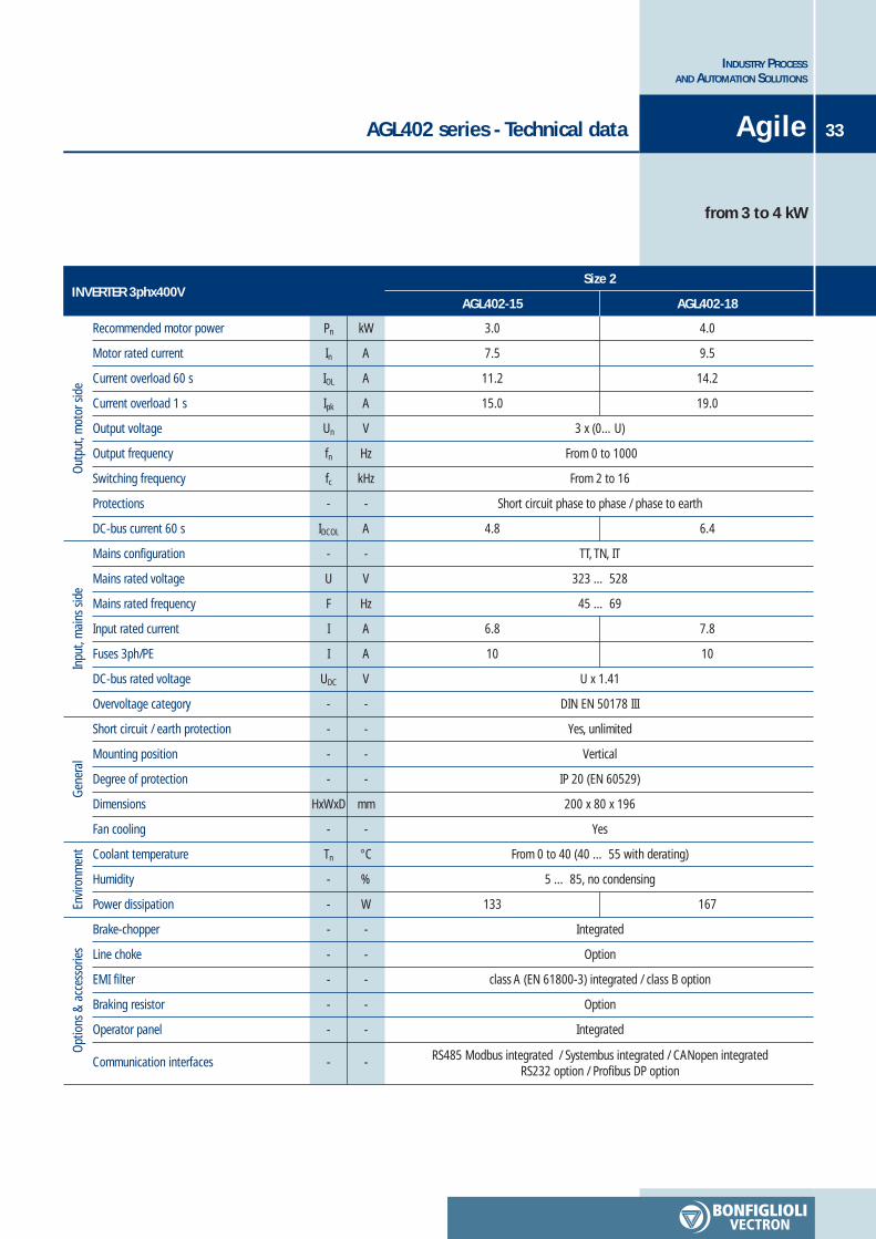
3.0
7.5
11.2
15.0
4.0
9.5
14.2
19.0
3 x (0…U)
From 0 to 1000
From 2 to 16
Short circuit phase to phase / phase to earth
TT, TN, IT
323 … 528
45 … 69
4.8 6.4
6.8
10
7.8
10
U x 1.41
DIN EN 50178 III
Yes, unlimited
Vertical
IP 20 (EN 60529)
200 x 80 x 196
Yes
From 0 to 40 (40 … 55 with derating)
5 … 85, no condensing
133 167
Integrated
Option
class A (EN 61800-3) integrated / class B option
Option
Integrated
RS485 Modbus integrated / Systembus integrated / CANopen integratedRS232 option / Profibus DP option
AGL402 series - Technical data
from 3 to 4 kW
33
INDUSTRY PROCESSAND AUTOMATION SOLUTIONS
Agile
AGL402-15 AGL402-18
Out
put,
mot
or s
ide
Inpu
t, m
ains
sid
eG
ener
alEn
viro
nmen
tO
ptio
ns &
acc
esso
ries
Recommended motor power
Motor rated current
Current overload 60 s
Current overload 1 s
Output voltage
Output frequency
Switching frequency
Protections
DC-bus current 60 s
Mains configuration
Mains rated voltage
Mains rated frequency
Input rated current
Fuses 3ph/PE
DC-bus rated voltage
Overvoltage category
Short circuit / earth protection
Mounting position
Degree of protection
Dimensions
Fan cooling
Coolant temperature
Humidity
Power dissipation
Brake-chopper
Line choke
EMI filter
Braking resistor
Operator panel
Communication interfaces
INVERTER 3phx400VSize 3
Pn
In
IOL
Ipk
Un
fn
fc
-
IDCOL
-
U
F
I
I
UDC
-
-
-
-
HxWxD
-
Tn
-
-
-
-
-
-
-
-
kW
A
A
A
V
Hz
kHz
-
A
-
V
Hz
A
A
V
-
-
-
-
mm
-
°C
%
W
-
-
-
-
-
-
3 x (0…U)
From 0 to 1000
From 2 to 16
Short circuit phase to phase / phase to earth
TT, TN, IT
323 … 528
45 … 69
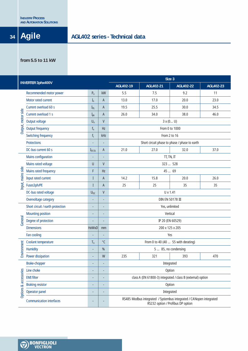
21.0 27.0 32.0
14.2
25
15.8
25
20.0
35
U x 1.41
DIN EN 50178 III
Yes, unlimited
Vertical
IP 20 (EN 60529)
200 x 125 x 205
Yes
From 0 to 40 (40 … 55 with derating)
5 … 85, no condensing
235 321 393
Integrated
Option
class A (EN 61800-3) integrated / class B (external) option
Option
Integrated
RS485 Modbus integrated / Systembus integrated / CANopen integratedRS232 option / Profibus DP option
5.5
13.0
19.5
26.0
7.5
17.0
25.5
34.0
9.2
20.0
30.0
38.0
AGL402 series - Technical data
from 5.5 to 11 kW
INDUSTRY PROCESSAND AUTOMATION SOLUTIONS
34 Agile
AGL402-21 AGL402-22 AGL402-23AGL402-19
37.0
26.0
35
470
11
23.0
34.5
46.0
Out
put,
mot
or s
ide
Inpu
t, m
ains
sid
eG
ener
alEn
viro
nmen
tO
ptio
ns &
acc
esso
ries
Recommended motor power
Motor rated current
Current overload 60 s
Current overload 1 s
Output voltage
Output frequency
Switching frequency
Protections
DC-bus current 60 s
Mains configuration
Mains rated voltage
Mains rated frequency
Input rated current
Fuses3ph/PE
DC-bus rated voltage
Overvoltage category
Short circuit / earth protection
Mounting position
Degree of protection
Dimensions
Fan cooling
Coolant temperature
Humidity
Power dissipation
Brake-chopper
Line choke
EMI filter
Braking resistor
Operator panel
Communication interfaces
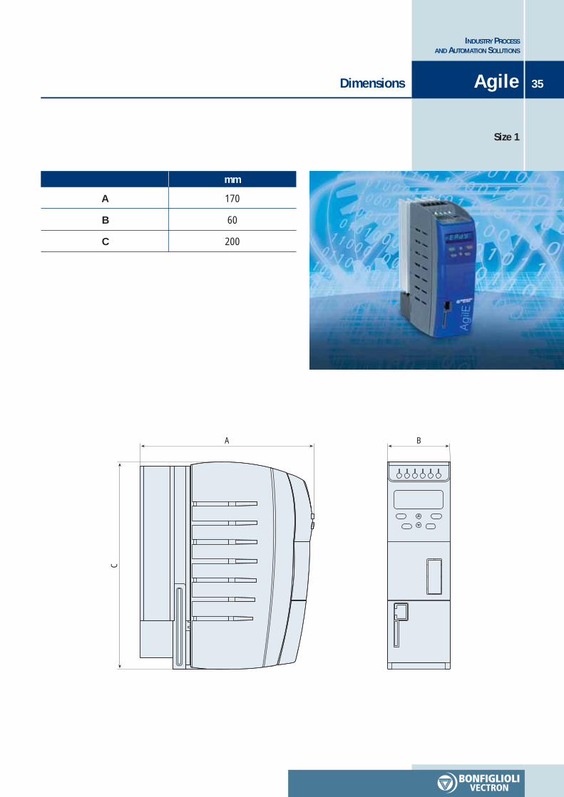
Dimensions 35
INDUSTRY PROCESSAND AUTOMATION SOLUTIONS
Agile
Size 1
C
A B
A
B
C
mm
170
60
200
INDUSTRY PROCESSAND AUTOMATION SOLUTIONS
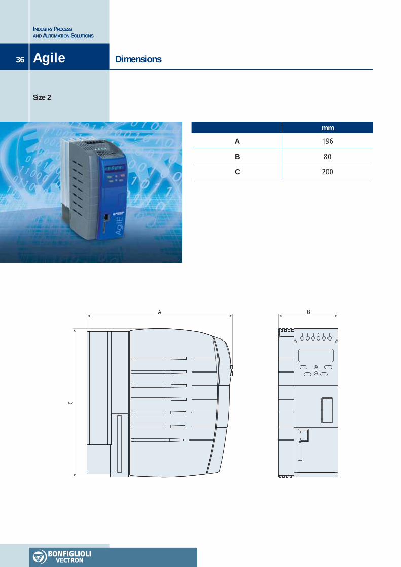
36 Agile
Size 2
DimensionsC
A B
A
B
C
mm
196
80
200
37
INDUSTRY PROCESSAND AUTOMATION SOLUTIONS
Dimensions Agile
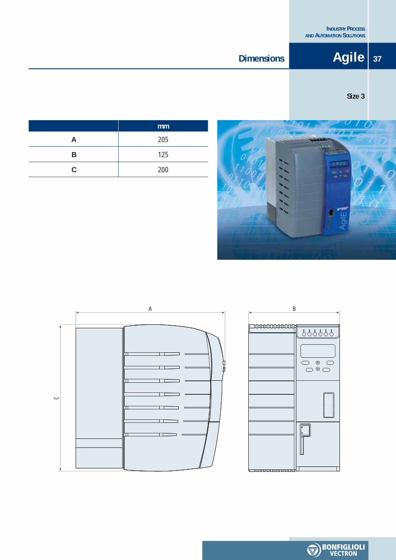
Size 3
C
A B
A
B
C
mm
205
125
200
38 Agile
INDUSTRY PROCESSAND AUTOMATION SOLUTIONS
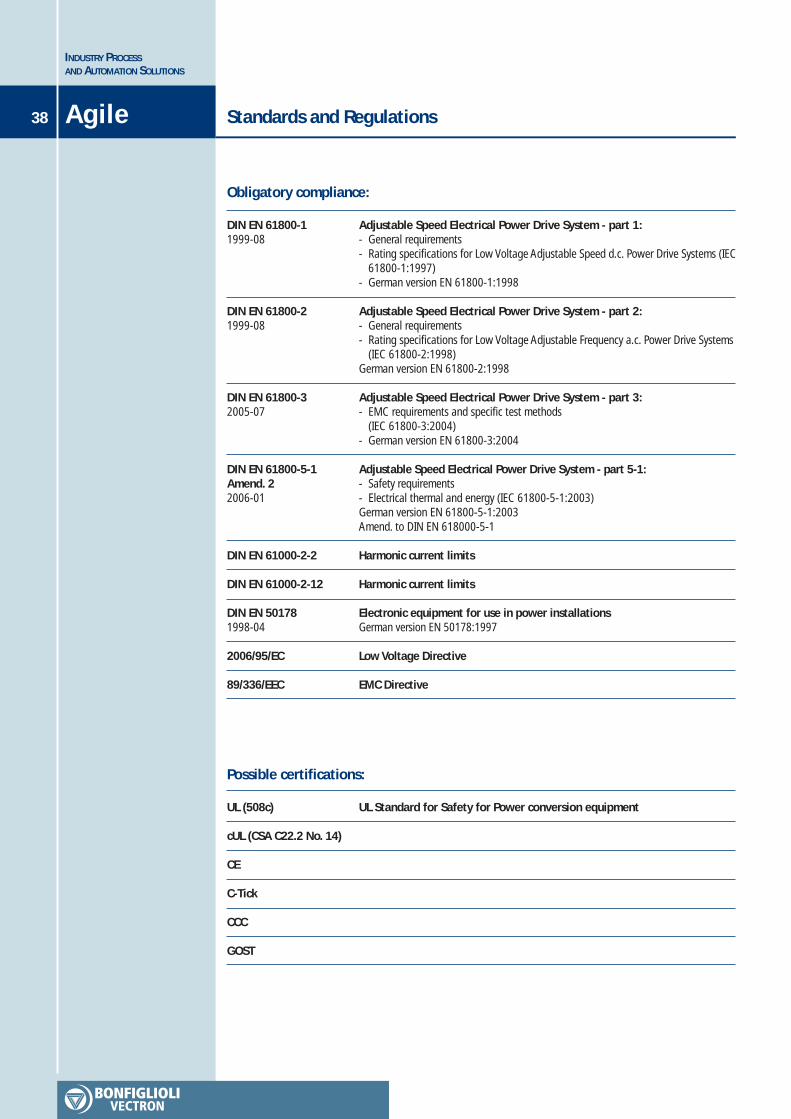
Standards and Regulations
Adjustable Speed Electrical Power Drive System - part 1:- General requirements- Rating specifications for Low Voltage Adjustable Speed d.c. Power Drive Systems (IEC
61800-1:1997)- German version EN 61800-1:1998
Adjustable Speed Electrical Power Drive System - part 2:- General requirements- Rating specifications for Low Voltage Adjustable Frequency a.c. Power Drive Systems
(IEC 61800-2:1998)German version EN 61800-2:1998
Adjustable Speed Electrical Power Drive System - part 3:- EMC requirements and specific test methods
(IEC 61800-3:2004)- German version EN 61800-3:2004
Adjustable Speed Electrical Power Drive System - part 5-1:- Safety requirements- Electrical thermal and energy (IEC 61800-5-1:2003)German version EN 61800-5-1:2003Amend. to DIN EN 618000-5-1
Harmonic current limits
Harmonic current limits
Electronic equipment for use in power installationsGerman version EN 50178:1997
Low Voltage Directive
EMC Directive
DIN EN 61800-11999-08
DIN EN 61800-21999-08
DIN EN 61800-32005-07
DIN EN 61800-5-1Amend. 22006-01
DIN EN 61000-2-2
DIN EN 61000-2-12
DIN EN 501781998-04
2006/95/EC
89/336/EEC
UL Standard for Safety for Power conversion equipmentUL (508c)
cUL (CSA C22.2 No. 14)
CE
C-Tick
CCC
GOST
Obligatory compliance:
Possible certifications:
39AgileOptional modules
INDUSTRY PROCESSAND AUTOMATION SOLUTIONS
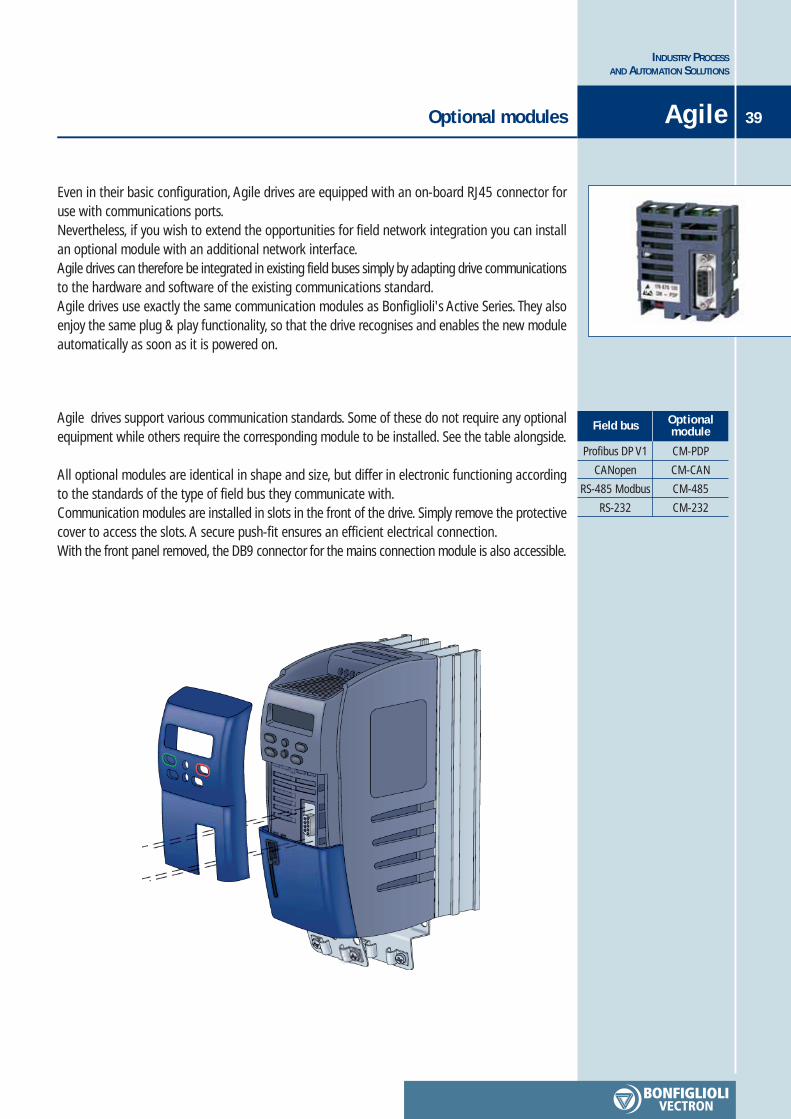
Even in their basic configuration, Agile drives are equipped with an on-board RJ45 connector foruse with communications ports.Nevertheless, if you wish to extend the opportunities for field network integration you can installan optional module with an additional network interface.Agile drives can therefore be integrated in existing field buses simply by adapting drive communicationsto the hardware and software of the existing communications standard.Agile drives use exactly the same communication modules as Bonfiglioli's Active Series. They alsoenjoy the same plug & play functionality, so that the drive recognises and enables the new moduleautomatically as soon as it is powered on.
Agile drives support various communication standards. Some of these do not require any optionalequipment while others require the corresponding module to be installed. See the table alongside.
All optional modules are identical in shape and size, but differ in electronic functioning accordingto the standards of the type of field bus they communicate with.Communication modules are installed in slots in the front of the drive. Simply remove the protectivecover to access the slots. A secure push-fit ensures an efficient electrical connection.With the front panel removed, the DB9 connector for the mains connection module is also accessible.
CM-PDP
CM-CAN
CM-485
CM-232
Profibus DP V1
CANopen
RS-485 Modbus
RS-232
OptionalmoduleField bus
INDUSTRY PROCESSAND AUTOMATION SOLUTIONS
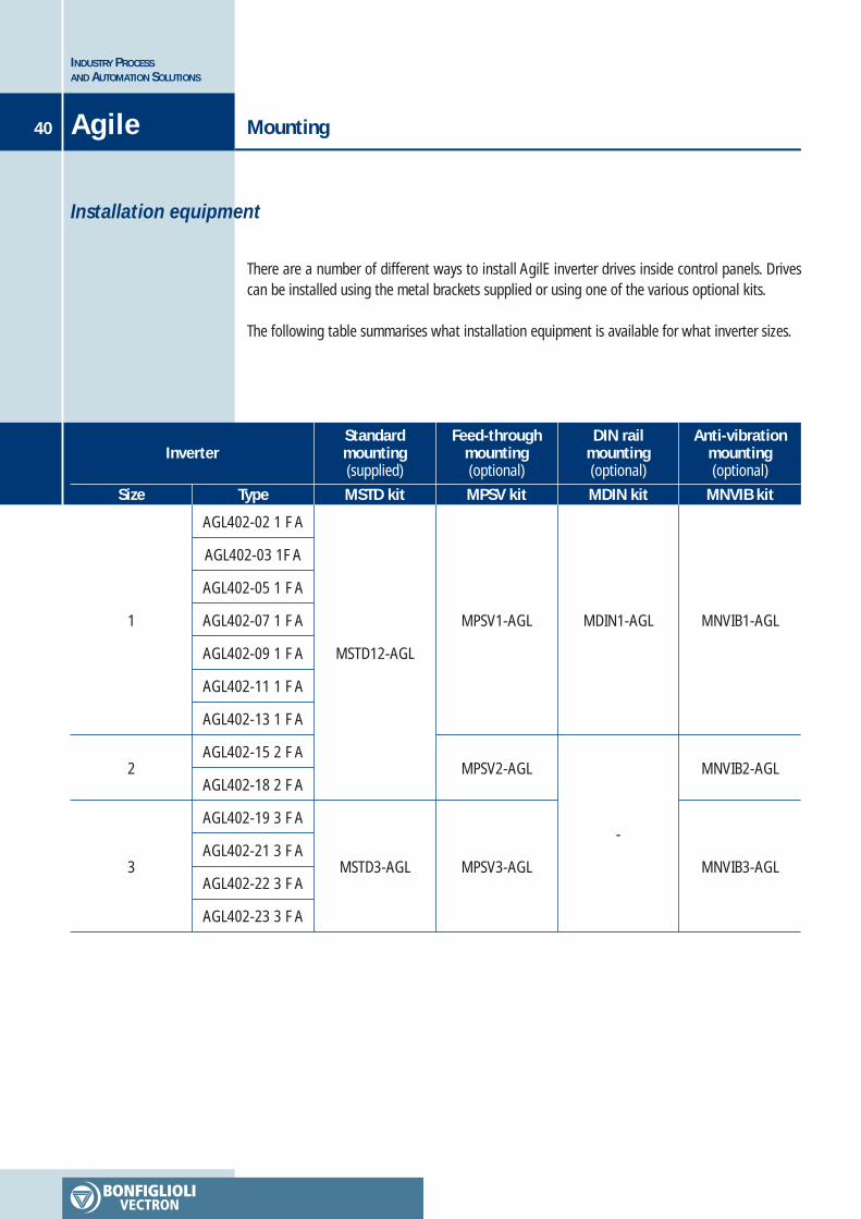
40 Agile Mounting
There are a number of different ways to install AgilE inverter drives inside control panels. Drivescan be installed using the metal brackets supplied or using one of the various optional kits.
The following table summarises what installation equipment is available for what inverter sizes.
Installation equipment
Size Type MSTD kit
Feed-throughmounting(optional)
DIN railmounting(optional)
Anti-vibrationmounting(optional)
1
2
3
AGL402-02 1 F A
AGL402-03 1F A
AGL402-05 1 F A
AGL402-07 1 F A
AGL402-09 1 F A
AGL402-11 1 F A
AGL402-13 1 F A
AGL402-15 2 F A
AGL402-18 2 F A
AGL402-19 3 F A
AGL402-21 3 F A
AGL402-22 3 F A
AGL402-23 3 F A
MSTD12-AGL
MSTD3-AGL
MPSV1-AGL
MPSV2-AGL
MPSV3-AGL
MDIN1-AGL
-
MNVIB1-AGL
MNVIB2-AGL
MNVIB3-AGL
Inverter
MPSV kit MDIN kit MNVIB kit
Standardmounting(supplied)
41
INDUSTRY PROCESSAND AUTOMATION SOLUTIONS
AgileMounting
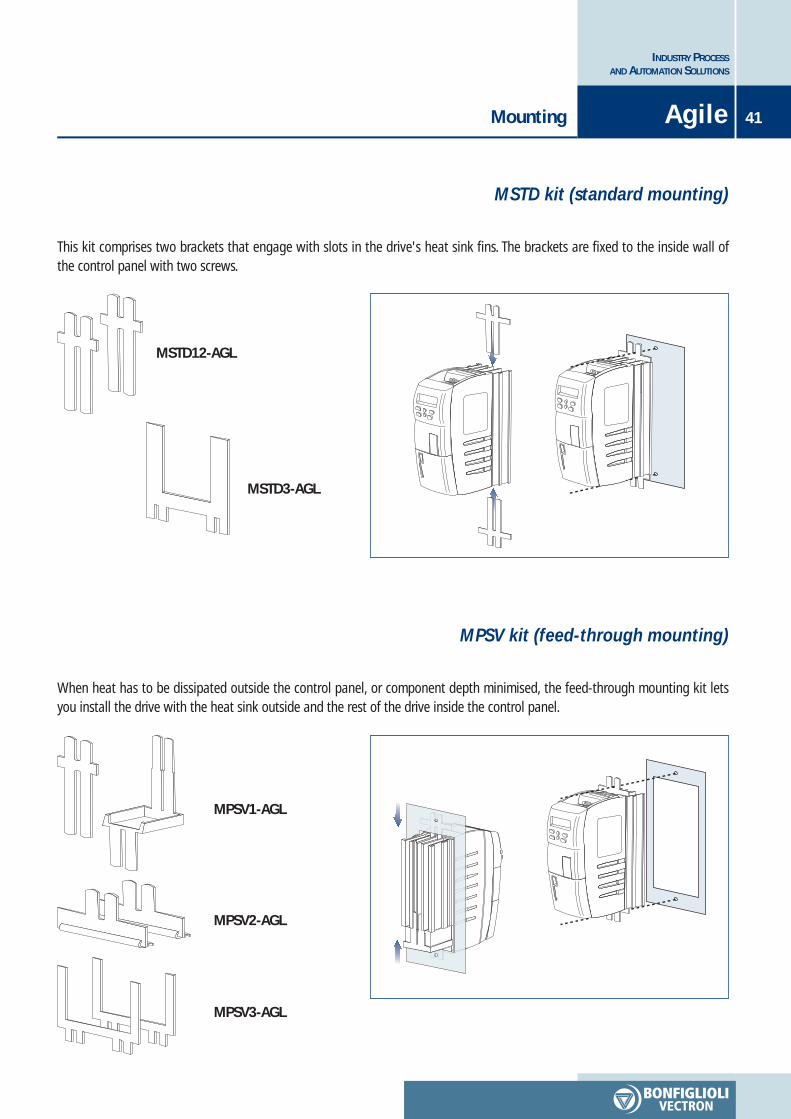
This kit comprises two brackets that engage with slots in the drive's heat sink fins. The brackets are fixed to the inside wall ofthe control panel with two screws.
MSTD kit (standard mounting)
MSTD12-AGL
MSTD3-AGL
When heat has to be dissipated outside the control panel, or component depth minimised, the feed-through mounting kit letsyou install the drive with the heat sink outside and the rest of the drive inside the control panel.
MPSV kit (feed-through mounting)
MPSV1-AGL
MPSV2-AGL
MPSV3-AGL
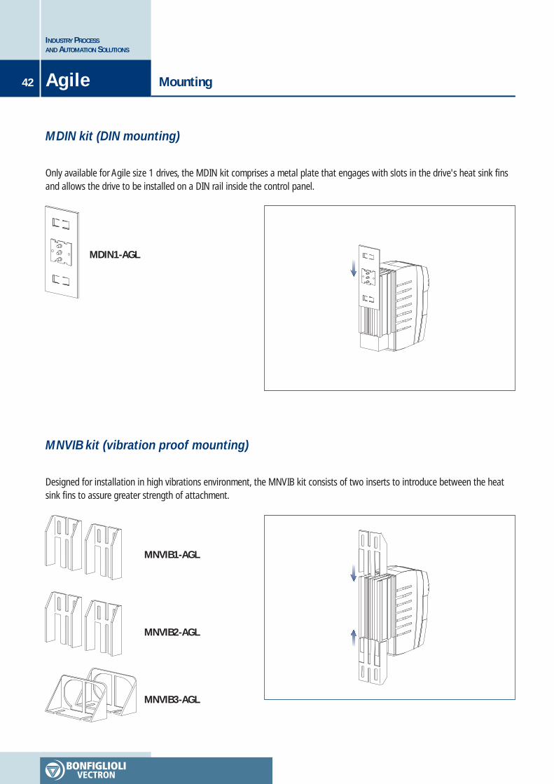
Only available for Agile size 1 drives, the MDIN kit comprises a metal plate that engages with slots in the drive's heat sink finsand allows the drive to be installed on a DIN rail inside the control panel.
MDIN kit (DIN mounting)
INDUSTRY PROCESSAND AUTOMATION SOLUTIONS
42 Agile Mounting
Designed for installation in high vibrations environment, the MNVIB kit consists of two inserts to introduce between the heatsink fins to assure greater strength of attachment.
MNVIB kit (vibration proof mounting)
MDIN1-AGL
MNVIB1-AGL
MNVIB2-AGL
MNVIB3-AGL

43
INDUSTRY PROCESSAND AUTOMATION SOLUTIONS
AgileMounting
The Agile' s standard version is executed with integrated heat-sink which contributes to define the inverter overall dimensionsallowing optimal performances by means of suitable heat disposal.
For special applications requiring space saving or compliance with heavy environmental regimes, Agile offers an alternative designform, cold plate version, on demand during purchase order emission.
The cold plate version is realized without built-in cooling ribs which instead must be prepared by the user according to parametersreported on the relevant technical manual.In that configuration the drive backside ends with smooth metal plate able to be fixed to an auxiliary heat-sink by means ofspecific mounting kit.
Cold Plate design form
MCP-AGL
Control panel heat sink
Agile standard version Agile Cold Plate version
INDUSTRY PROCESSAND AUTOMATION SOLUTIONS
44 Agile ASK-USB serial connection kit
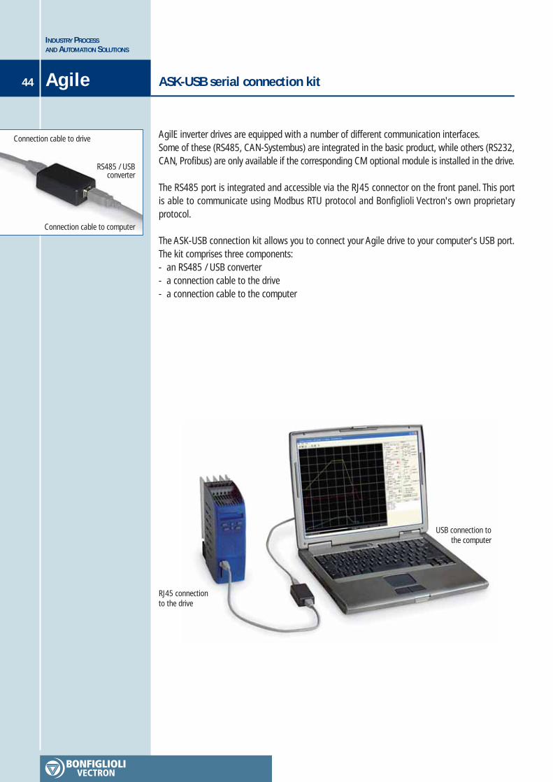
AgilE inverter drives are equipped with a number of different communication interfaces.Some of these (RS485, CAN-Systembus) are integrated in the basic product, while others (RS232,CAN, Profibus) are only available if the corresponding CM optional module is installed in the drive.
The RS485 port is integrated and accessible via the RJ45 connector on the front panel. This portis able to communicate using Modbus RTU protocol and Bonfiglioli Vectron's own proprietaryprotocol.
The ASK-USB connection kit allows you to connect your Agile drive to your computer's USB port.The kit comprises three components:- an RS485 / USB converter- a connection cable to the drive- a connection cable to the computer
Connection cable to drive
RS485 / USBconverter
Connection cable to computer
RJ45 connectionto the drive
USB connection tothe computer
45
INDUSTRY PROCESSAND AUTOMATION SOLUTIONS
AgileBraking resistors
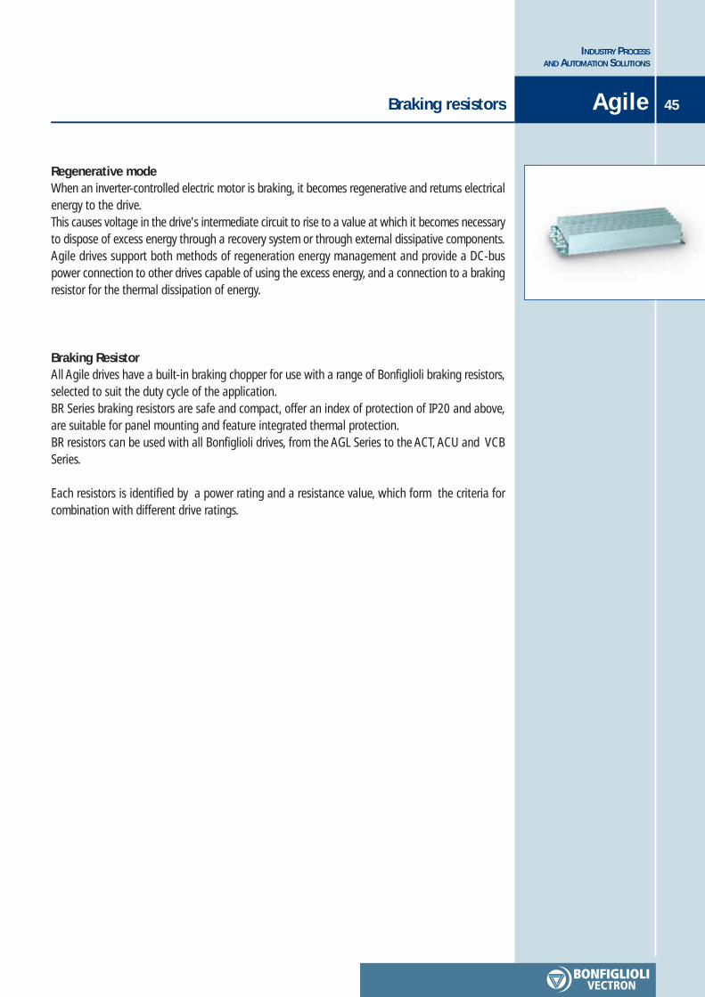
Regenerative modeWhen an inverter-controlled electric motor is braking, it becomes regenerative and returns electricalenergy to the drive.This causes voltage in the drive's intermediate circuit to rise to a value at which it becomes necessaryto dispose of excess energy through a recovery system or through external dissipative components.Agile drives support both methods of regeneration energy management and provide a DC-buspower connection to other drives capable of using the excess energy, and a connection to a brakingresistor for the thermal dissipation of energy.
Braking ResistorAll Agile drives have a built-in braking chopper for use with a range of Bonfiglioli braking resistors,selected to suit the duty cycle of the application.BR Series braking resistors are safe and compact, offer an index of protection of IP20 and above,are suitable for panel mounting and feature integrated thermal protection.BR resistors can be used with all Bonfiglioli drives, from the AGL Series to the ACT, ACU and VCBSeries.
Each resistors is identified by a power rating and a resistance value, which form the criteria forcombination with different drive ratings.

TypeRated power
Pn (kW)Type
Continuouspower
(W)
Resistance **
(Ω)
DissipatedpowerPR (kW)
Duty cycle
δR (%)
Inverter Recommended Bonfiglioli resistor Reference cycle *
AGL 402-02AGL 402-03AGL 402-05AGL 402-07AGL 402-09AGL 402-11AGL 402-13AGL 402-15AGL 402-18AGL 402-19AGL 402-21AGL 402-22AGL 402-23
0.250.370.550.751.11.52.23.04.05.57.59.211
BR 213/300BR 213/300BR 213/300BR 213/300BR 213/300BR 213/300BR 471/136BR 471/136BR 696/92BR 1330/48BR 1330/48BR 1330/48BR 2000/32
2132132132132132134714716961330133013302000
3003003003003003001361369248484832
0.250.370.550.751.11.52.23.04.05.57.59.211
84563828191421161724181418
* referred to a period of 120 seconds** Don’t apply resistance values lower than displayed
INDUSTRY PROCESSAND AUTOMATION SOLUTIONS
46 Agile
To help identify the most suitable braking resistors for different drives and applications, the followingtable suggests pairings that allow drives to dissipate their full rated power to the resistor for alimited by cyclically repeatable time.
Energy dissipatedto resistor
P rateddrive
T
TFmax = T 1.2 δRδR
100
Braking cycle
Braking resistors
Since each resistor has a lower continuous rated power value than the corresponding drive, it is important to respect the specifieddissipation cycle. Though the component will heat up, this cycle permits adequate cooling.The purpose of the reference cycle is to inform users that over a period of 120 seconds, braking time must not exceed 1.2 δR
seconds, or the resistor will overheat.The reference cycle is therefore a limit cycle and must not be exceeded.
Given an application with a user-defined period T, during which the drive's full rated power is deviated to the resistor, brakingtime must not exceed the value of TFmax calculated on the basis of the reference cycle.
TF

Mains harmonicsSometimes the Mains can be site of floating current harmonics generated by other user equipmentswhich can attenuate our system’s active power.
Line chokeThe best solution to protect our inverter against Mains harmonics is to install line-choke in serieswith each input phase, filtering the current before reaching the drive.
The mains power supply has its own intrinsic inductance. The addition of line chokes boosts thisto offer ever greater impedance to higher harmonic components and act effectively as a low-passfilter.
Line chokes should have a short circuit rating some 20 to 40 times greater than the rated powerof the drive and should produce voltage drops no greater than 4%.Bonfiglioli can provide a range of line chokes satisfying these criteria for use with different drivesizes according to the table below.
47
INDUSTRY PROCESSAND AUTOMATION SOLUTIONS
AgileLine choke
Powerfeeding line
AGL402-02
AGL402-03
AGL402-05
AGL402-07
AGL402-09
AGL402-11
AGL402-13
AGL402-15
AGL402-18
AGL402-19
AGL402-21
AGL402-22
AGL402-23
Inverter Recommended Bonfiglioli line choke
LCVT004
LCVT004
LCVT004
LCVT004
LCVT004
LCVT004
LCVT006
LCVT008
LCVT010
LCVT015
LCVT018
LCVT025
LCVT034

48
The ever-growing export share has led Bonfiglioli into the most far away Countries. With expansion plans entailing a further growth of the sales network Bonfiglioli aims at improvingboth the competitiveness of its products and the effectiveness of the Customer service.In every market place Bonfiglioli is committed to improve the Customer satisfaction by offeringstate-of-the-art technology and shorter deliveries. Nowadays branch companies and BEST Partnersbearing the Bonfiglioli name are operating in seventeen Countries outside Italy, with sales andservice in the other countries managed by appointed dealers.The domestic network is made up of 30 sales office and representatives and 100 dealers operatingwith their own warehouse and supporting Customers locally. Throughout the World Bonfiglioli’sreputed know-how and Service guarantee effective and timely assistance.
INDUSTRY PROCESSAND AUTOMATION SOLUTIONS
Worldwide
Worldwide
INDUSTRY PROCESSAND AUTOMATION SOLUTIONS
HEADQUARTERSBONFIGLIOLI RIDUTTORI S.p.A.
Via Giovanni XXIII, 7/A40012 Lippo di Calderara di Reno
Bologna (ITALY)Tel. (+39) 051 6473111Fax (+39) 051 6473126
SPARE PARTS BONFIGLIOLIB.R.T.
Via Castagnini, 2-4Z.I. Bargellino - 40012
Calderara di Reno - Bologna (ITALY)Tel. (+39) 051 727844Fax (+39) 051 727066
INDIABONFIGLIOLI TRANSMISSIONS PVT Ltd.PLOT AC7-AC11 Sidco Industrial EstateThirumudivakkam - Chennai 600 044Tel. +91(0) 44 24781035 / 24781036 / 24781037Fax +91(0) 44 24780091 / 24781904www.bonfiglioliindia.com - [email protected]
INDONESIA PT. ANEKAMAKMUR TEKNIK NUSAJAYAPertokoan Glodok Makmur No. 32 - Jakarta BaratTel. (+62) 21 624 8828 - Fax (+62) 21 624 2405www.anekamakmur.com - [email protected]
ITALYBONFIGLIOLI ITALIA S.p.A.Via Sandro Pertini lotto 7b - 20080 Carpiano (Milano)Tel. (+39) 02 985081 - Fax (+39) 02 985085817www.bonfiglioli.it - [email protected]
NEW ZEALAND SAECO BEARINGS TRANSMISSION36 Hastie Avenue, Mangere Po Box 22256, Otahuhu - AucklandTel. (+64) 9 634 7540 - Fax (+64) 9 634 7552 - [email protected]
POLAND POLPACK Sp. z o.o. - Ul. Polna 129 - 87100 TorunTel. (+48) 56 6559235 to 37 - Fax (+48) 56 6559238www.polpack.com.pl - [email protected]
PORTUGAL BT BONFITEC Equipamentos Industriais, Lda.Largo do Colegio de Ermesinde, 70 - Formiga 4445-382 ErmesindeTel. (+351) 229759634/5/6 - Fax (+351) 229752211www.bonfitec.pt - [email protected]
RUSSIA FAM57, Maly prospekt, V.O. - 199048, St. PetersburgTel. (+7) 812 3319333 - Fax (+7) 812 3271454www.fam-drive.ru - [email protected]
SPAINTECNOTRANS BONFIGLIOLI S.A.Pol. Ind. Zona Franca sector C, calle F, n°6 08040 BarcelonaTel. (+34) 93 4478400 - Fax (+34) 93 3360402www.tecnotrans.com - [email protected]
SOUTH AFRICABONFIGLIOLI POWER TRANSMISSION Pty Ltd.55 Galaxy Avenue, Linbro Business Park - SandtonTel. (+27) 11 608 2030 OR - Fax (+27) 11 608 2631www.bonfiglioli.co.za - [email protected]
SOUTH KOREA YOUN HO INDUSTRIALRoom B1, World Plaza Bldg. - 1262 Guro-Dong, Gurd-Gu, SeoulTel. (+82) 2 626 43201 - Fax (+82) 2 263 23202www.younho.com - [email protected]
SWEDEN BONFIGLIOLI SKANDINAVIEN ABKoppargatan 8 - 234 35 Lomma (Sweden)Tel. (+46) 40418230 - Fax (+46) 40414508www.bonfiglioli.se - [email protected]
THAILAND K.P.T MACHINERY (1993) CO.LTD.259/83 Soi Phiboonves, Sukhumvit 71 Rd. Phrakanong-nur,Wattana, Bangkok 10110Tel. (+66) 2 3913030/7111998 - Fax (+66) 2 7112852/3811308/3814905www.kpt-group.com - [email protected]
TURKEYBONFIGLIOLI TURKIYEAtatürk Organíze Sanayi Bölgesi, 10015 Sk. No: 17, Çigli - IzmirTel. +90 (0) 232 328 22 77 (pbx) - Fax +90 (0) 232 328 04 14www.bonfiglioli.com.tr - [email protected]
USABONFIGLIOLI USA, INC.3541 Hargrave Drive Hebron, Kentucky 41048Tel. (+1) 859 334 3333 - Fax (+1) 859 334 [email protected] - [email protected]
VENEZUELA MAICA SOLUCIONES TECNICAS C.A.Calle 3B - Edif. Comindu - Planta Baja - Local B - La Urbina - Caracas 1070Tel. (+58) 212 2413570 / 2425268 / 2418263Fax (+58) 212 2424552 - Tlx 24780 Maica V - [email protected]
VIETNAMBONFIGLIOLI VIETNAM LTD.Lot C-9D-CN My Phuoc Industrial Park 3Ben Cat - Binh Duong Province - VietnamTel. (+84) 650 3577411 - Fax (+84) 650 [email protected] - www.bonfiglioli.vn
AUSTRALIABONFIGLIOLI TRANSMISSION (Aust) Pty Ltd.2, Cox Place Glendenning NSW 2761 (Australia)Locked Bag 1000 Plumpton NSW 2761Tel. (+ 61) 2 8811 8000 - Fax (+ 61) 2 9675 6605www.bonfiglioli.com.au - [email protected]
AUSTRIABONFIGLIOLI ÖSTERREICH GmbHMolkereistr 4 - A-2700 Wiener NeustadtTel. (+43) 02622 22400 - Fax (+43) 02622 22386www.bonfiglioli.at - [email protected]
MOLL MOTOR GmbH Industriestrasse 8 - 2000 StockerauTel. (+43) 2266 634210 - Fax (+43) 2266 6342180www.mollmotor.at - [email protected]
BELGIUM ESCO TRANSMISSION N.V./S.A.Culliganlaan 3 - 1831 Machelem DiegemTel. (+32) 2 7176460 - Fax (+32) 2 7176461www.esco-transmissions.be - [email protected]
BRASILBONFIGLIOLI REDUTORES DO BRASIL INDÚSTRIA E COMÉRCIO LTDA.Travessa Cláudio Armando 171 - Bloco 3 - CEP 09861-730Bairro Assunção - São Bernardo do Campo - São Paulo (Brasil)Tel. (+55) 11 4344 1900 - Fax (+55) 11 4344 1906www.bonfigliolidobrasil.com.br - [email protected]
CANADABONFIGLIOLI CANADA INC.2-7941 Jane Street - Concord, Ontario L4K 4L6Tel. (+1) 905 7384466 - Fax (+1) 905 7389833www.bonfigliolicanada.com - [email protected]
CHILE IMATESA S.A.Santa Rosa 5699 - San Miguel - SantiagoTel. (+56) 2 5264702 - Fax (+56) 2 5265878www.imatesa.cl - [email protected]
CHINABONFIGLIOLI DRIVES (SHANGHAI) CO. LTD.19D, No. 360 Pudong Road (S)New Shanghai International Tower - 200120 Shanghai (P.R. China)Tel. (+86) 21 69225500 - Fax (+86) 21 69225511www.bonfiglioli.cn - [email protected]
DENMARK BRD. KLEEGadagervej 11 Denmark - 2620 AlbertslundTel. (+45) 43 868333 - Fax (+45) 868388www.brd-klee.dk - [email protected]
FRANCEBONFIGLIOLI TRANSMISSIONS S.A.14 Rue Eugène Pottier BP 19Zone Industrielle de Moimont II - 95670 Marly la VilleTel. (+33) 1 34474510 - Fax (+33) 1 34688800www.bonfiglioli.fr - [email protected]
GERMANYBONFIGLIOLI DEUTSCHLAND GmbhSperberweg 12 - 41468 NeussTel. (+49) 02131 2988-0 - Fax (+49) 02131 2988-100www.bonfiglioli.de - [email protected]
GREAT BRITAINBONFIGLIOLI UK LtdIndustrial Equipment - Unit 7, Colemeadow RoadNorth Moons Moat - Redditch, Worcestershire B98 9PBTel. (+44) 1527 65022 - Fax (+44) 1527 61995www.bonfiglioli.co.uk - [email protected]
Mobile Equipment3 - 7 Grosvenor Grange, Woolston, Warrington - Cheshire WA1 4SFTel. (+44) 1925 852667 - Fax (+44) 1925 852668www.bonfiglioli.co.uk - [email protected]
GREECE B.E.S.T. HELLAS S.A.O.T. 48A T.O. 230 - C.P. 570 22, Industrial Area - ThessalonikiTel. (+30) 2310 796456 - Fax (+30) 2310 795903www.bonfiglioli.gr - [email protected]
HOLLAND ELSTO AANDRIJFTECHNIEKLoosterweg, 7 - 2215 TL VoorhoutTel. (+31) 252 219 123 - Fax (+31) 252 231 660www.elsto.nl - [email protected]
HUNGARY AGISYS AGITATORS & TRANSMISSIONS Ltd2045 Törökbálint, Tö u.2. (Hungary)Tel. (+36) 23 50 11 50 - Fax (+36) 23 50 11 59www.agisys.hu - [email protected]
INDUSTRY PROCESSAND AUTOMATION SOLUTIONS
w w w . b o n f i g l i o l i . c o m
COD. VEC 631 R2
Agile