HARD DRIVE EXPANSION BAY - eANIXTER
22
Copyright © 2009 Digimerge Technology Inc. www.digimerge.com Right For Business ™ INSTRUCTION MANUAL English Version 1.0 HARD DRIVE EXPANSION BAY DESIGNED FOR THE DIGIMERGE BLADE™ VBAY3HD
-
Upload
khangminh22 -
Category
Documents
-
view
3 -
download
0
Transcript of HARD DRIVE EXPANSION BAY - eANIXTER

Copyright © 2009 Digimerge Technology Inc.
www.digimerge.com
Right For Business™
INSTRUCTION MANUALEnglish Version 1.0
HARD DRIVE EXPANSION BAYDESIGNED FOR THE DIGIMERGE BLADE™
VBAY3HD

Thank you for purchasing this product. Digimerge is committed to providing our customers with a high quality, reliable security solution.This manual refers to the following models:
• VBAY3HD• VB300 Digimerge Blade™ (Not Included)
For more information on this product, firmware updates, and accessory products, please visit us at:
www.digimerge.com
CAUTION
RISK OF ELECTRIC SHOCKDO NOT OPEN
CAUTION: TO REDUCE THE RISK OF ELECTRIC SHOCK DO NOT REMOVE COVER. NO USER SERVICABLE PARTS INSIDE.
REFER SERVICING TO QUALIFIED SERVICE PERSONNEL.
The lightning flash symbol within an equilateral triangle is intended to alert the user to the presence of uninsulated "dangerous voltage" within the products ' enclosure that may be of sufficient magnitude to constitute a risk of electric shock.The exclamation point within an equilateral triangle is intended to alert the user to the presence of important operating and maintenance (servicing) instructions in the literature accompanying the appliance.
WARNING: TO PREVENT FIRE OR SHOCK HAZARD, DO NOT EXPOSE THIS UNIT TO RAIN OR MOISTURE.
CAUTION: TO PREVENT ELECTRIC SHOCK, MATCH WIDE BLADE OF THE PLUG TO THE WIDE SLOT AND FULLY INSERT.

Important Safeguards
In addition to the careful attention devoted to quality standards in the manufacturing process of your video product, safety is a major factor in the design of every instrument. However, safety is your responsibility too. This sheet lists important information that will help to assure your enjoyment and proper use of the video product and accessory equipment. Please read them carefully before operating and using your video product.
Installation1. Read and Follow Instructions - All the safety and
operating instructions should be read before the video product is operated. Follow all operating instructions.
2. Retain Instructions - The safety and operating instructions should be retained for future reference.
3. Heed Warnings - Comply with all warnings on the video product and in the operating instructions.
4. Polarization - Do not defeat the safety purpose of the polarized or grounding-type plug.A polarized plug has two blades with one wider than the other.A grounding type plug has two blades and a third grounding prong.The wide blade or the third prong are provided for your safety.If the provided plug does not fit into your outlet, consult an electrician for replacement of the obsolete outlet.
5. Power Sources - This video product should be operated only from the type of power source indicated on the marking label. If you are not sure of the type of power supply to your location, consult your video dealer or local power company. For video products intended to operate from battery power, or other sources, refer to the operating instructions.
6. Overloading - Do not overload wall outlets of extension cords as this can result in the risk of fire or electric shock. Overloaded AC outlets, extension cords, frayed power cords, damaged or cracked wire insulation, and broken plugs are dangerous. They may result in a shock or fire hazard. Periodically examine the cord, and if its appearance indicates damage or deteriorated insulation, have it replaced by your service technician.
7. Power Cord Protection - Power supply cords should be routed so that they are not likely to be walked on or pinched by items placed upon or against them, paying particular attention to cords at plugs, convenience receptacles, and the point where they exit from the video product.
8. Ventilation - Slots and openings in the case are provided for ventilation to ensure reliable operation of the video product and to protect it from overheating. These openings must not be blocked or covered. The openings should never be blocked by placing the video equipment on a bed, sofa, rug, or other similar surface. This video product should never be placed near or over a radiator or heat register. This video product should not be placed in a built-in installation such as a bookcase or rack unless proper ventilation is provided or the video product manufacturer’s instructions have been followed.
9. Attachments - Do not use attachments unless recommended by the video product manufacturer as they may cause a hazard.
10. Camera Extension Cables – Check the rating of your extension cable(s) to verify compliance with your local authority regulations prior to installation.
11. Water and Moisture - Do not use this video product near water. For example, near a bath tub, wash bowl, kitchen sink or laundry tub, in a wet basement, near a swimming pool and the like. Caution: Maintain electrical safety. Powerline operated equipment or accessories connected to this unit should bear the UL listing mark of CSA certification mark on the accessory itself and should not be modified so as to defeat the safety features. This will help avoid any potential hazard from electrical shock or fire. If in doubt, contact qualified service personnel.
12. Accessories - Do not place this video equipment on an unstable cart, stand, tripod, or table. The video equipment may fall, causing serious damage to the video product. Use this video product only with a cart, stand, tripod, bracket, or table recommended by the manufacturer or sold with the video product. Any mounting of the product should follow the manufacturer’s instructions and use a mounting accessory recommended by the manufacturer.
iii

General Precautions
Service13. Servicing - Do not attempt to service this video
equipment yourself as opening or removing covers may expose you to dangerous voltage or other hazards. Refer all servicing to qualified service personnel.
14. Conditions Requiring Service - Unplug this video product from the wall outlet and refer servicing to qualified service personnel under the following conditions:• When the power supply cord or plug is damaged.
• If liquid has been spilled or objects have fallen into the video product.
• If the video product has been exposed to rain or water.
• If the video product does not operate normally by following the operating instructions. Adjust only those controls that are covered by the operating instructions. Improper adjustment of other controls may result in damage and will often require extensive work by a qualified technician to restore the video product to its normal operation.
• If the video product has been dropped or the cabinet has been damaged.
• When the video product exhibits a distinct change in performance. This indicates a need for service.
15. Replacement Parts - When replacement parts are required, have the service technician verify that the replacements used have the same safety characteristics as the original parts. Use of replacements specified by the video product manufacturer can prevent fire, electric shock or other hazards.
16. Safety Check - Upon completion of any service or repairs to this video product, ask the service technician to perform safety checks recommended by the manufacturer to determine that the video product is in safe operating condition.
17. Wall or Ceiling Mounting - The cameras provided with this system should be mounted to a wall or ceiling only as instructed in this guide, using the provided mounting brackets.
18. Heat - The product should be situated away from heat sources such as radiators, heat registers, stoves, or other products (including amplifiers) that produce heat.
Use19. Cleaning - Unplug the video product from the wall
outlet before cleaning. Do not use liquid cleaners or aerosol cleaners. Use a damp cloth for cleaning.
20. Product and Cart Combination - Video and cart combination should be moved with care. Quick stops, excessive force, and uneven surfaces may cause the video product and car combination to overturn.
21. Object and Liquid Entry - Never push objects for any kind into this video product through openings as they may touch dangerous voltage points or “short-out” parts that could result in a fire or electric shock. Never spill liquid of any kind on the video product.
22. Lightning - For added protection for this video product during a lightning storm, or when it is left unattended and unused for long periods of time, unplug it from the wall outlet and disconnect the antenna or cable system. This will prevent damage to the video product due to lightning and power line surges.
iv

General Precautions1. All warnings and instructions in this manual should be followed.2. Remove the plug from the outlet before cleaning. Do not use liquid aerosol detergents. Use a
water dampened cloth for cleaning.3. Do not use this unit in humid or wet places.4. Keep enough space around the unit for ventilation. Slots and openings in the storage cabinet
should not be blocked.5. During lightning storms, or when the unit is not used for a long time, disconnect the power
supply, antenna, and cables to protect the unit from electrical surge.
This equipment has been certified and found to comply with the limits regulated by FCC, EMC, and LVD. Therefore, it is designated to provide reasonable protection against interference and will not cause interference with other appliance usage.
However, it is imperative that the user follows the guidelines in this manual to avoid improper usage which may result in damage to the unit, electrical shock and fire hazard injury.
In order to improve the feature functions and quality of this product, the specifications are subject to change without notice from time to time.
FCC CLASS A NOTICE
NOTE
This equipment has been tested and found to comply with the limits for a Class A digital device pursuant to Part 15 of the FCC Rules. These limits are designed to provide reasonable protection against harmful interference when the equipment is operated in a commercial environment. This equipment generates, uses, and can radiate radio frequency energy and, if not installed and used in accordance with the manufacturer’s instruction manual, may cause harmful interference with radio communications. Operation of this equipment in a residential area is likely to cause harmful interference, in which case you will be required to correct the interference at your own expense.
www.digimerge.com
v

Features
• 3 hard drive expansion capability (total of 3 hard drives; not included)• Mirroring capability - duplicates data on your Blade, providing secure data redundancy• Ultra-slim, stackable design• Rugged metal enclosure• Dual exhaust fans for optimal cooling
vi

TABLE OF CONTENTS
Getting Started . . . . . . . . . . . . . . . . . . . . . . . . . . . . . . . . . . . . . . . . . . . . . . . . . 1Basic Setup . . . . . . . . . . . . . . . . . . . . . . . . . . . . . . . . . . . . . . . . . . . . . . . . . . . . .2Front and Rear Panel . . . . . . . . . . . . . . . . . . . . . . . . . . . . . . . . . . . . . . . . . . . . 3
Stacking The Expansion Bay . . . . . . . . . . . . . . . . . . . . . . . . . . . . . . . . . . . . . . . . . . . . . . . . . . . . . . . . . . . . 3Upgrading The Firmware . . . . . . . . . . . . . . . . . . . . . . . . . . . . . . . . . . . . . . . . .4
Setting Up The Expansion Bay . . . . . . . . . . . . . . . . . . . . . . . . . . . . . . . . . . . . .5Setting The Expansion Bay As A Standalone Hard Drive . . . . . . . . . . . . . . . . . . . . . . . . 5Setting The Expansion Bay to Record Events . . . . . . . . . . . . . . . . . . . . . . . . . . . . . . . . . 6Setting Up The Expansion Bay In Mirror Mode . . . . . . . . . . . . . . . . . . . . . . . . . . . . . . . 7
How the Mirroring Sequence Works . . . . . . . . . . . . . . . . . . . . . . . . . . . . . . . . . . . . . . . . . . . . . . . . . . . . . . . . . . . . . . 7Error Messages . . . . . . . . . . . . . . . . . . . . . . . . . . . . . . . . . . . . . . . . . . . . . . . . . . . . . . . . . . . . . . . . . . . . . . . . . . . . . . 8
Restarting The Expansion Bay . . . . . . . . . . . . . . . . . . . . . . . . . . . . . . . . . . . . . . . . . . . . . 8
Upgrading The Hard Drive . . . . . . . . . . . . . . . . . . . . . . . . . . . . . . . . . . . . . . . . . . . . . . . . 8Remove The Casing . . . . . . . . . . . . . . . . . . . . . . . . . . . . . . . . . . . . . . . . . . . . . . . . . . . . . . . . . . . . . . . . . . . . . . . . . . . 8Adding A Hard Drive In Bay #1 . . . . . . . . . . . . . . . . . . . . . . . . . . . . . . . . . . . . . . . . . . . . . . . . . . . . . . . . . . . . . . . . . . 9Removing A Hard Drive In Bay #1 . . . . . . . . . . . . . . . . . . . . . . . . . . . . . . . . . . . . . . . . . . . . . . . . . . . . . . . . . . . . . . . 11Adding A Hard Drive To Bay #2 & 3 . . . . . . . . . . . . . . . . . . . . . . . . . . . . . . . . . . . . . . . . . . . . . . . . . . . . . . . . . . . . . .12Removing A Hard Drive from Bay #2 & 3 . . . . . . . . . . . . . . . . . . . . . . . . . . . . . . . . . . . . . . . . . . . . . . . . . . . . . . . . . 12
SATA CONNECTORS . . . . . . . . . . . . . . . . . . . . . . . . . . . . . . . . . . . . . . . . . . . . . . . . . . 12Hard Drive Rotation Speeds . . . . . . . . . . . . . . . . . . . . . . . . . . . . . . . . . . . . . . . . . . . . . . . . . . . . . . . . . . . . . . . . . . . 12
Setup Tips . . . . . . . . . . . . . . . . . . . . . . . . . . . . . . . . . . . . . . . . . . . . . . . . . . . . . . . . . . . . . . . 12
Appendix A: VBAY3HD Specifications 13
vii

viii

1
Getting Started
GETTING STARTEDThe system comes with the following components:
EXPANSION BAY POWER ADAPTER
INSTRUCTION MANUAL
USB CABLE
GROUNDING CABLEHDD SCREWS X12
HARD DRIVE SIZE, HARD DRIVE CONFIGURATION MAY VARYBY MODEL. PLEASE REFER TO YOUR PACKAGE FOR SPECIFIC CONTENT DETAILS.CHECK YOUR PACKAGE TO CONFIRM THAT YOU HAVE RECEIVED THE COMPLETE SYSTEM, INCLUDING ALL COMPONENTS SHOWN ABOVE.

Basic Setup
BASIC SETUP1. UPGRADE THE FIRMWARE
a. Upgrade the Blade with the included firmware. See “Upgrading The Firmware” on page 4. The Blade requires a firmware upgrade in order to detect the expansion bay.
2. CONNECT THE GROUNDING CABLE
a. Connect the grounding cable from the rear panel of the expansion bay to the rear panel of the Blade. Screw the grounding cable into the Ground port to secure (Figure 1.0).
3. CONNECT THE USB CABLEa. Connect the included USB cable from the
rear panel of the expansion bay to the rear panel USB port on the Blade.
TIP: The bottom USB port on the rear panel of the Blade offers faster transfer rates.
NOTE: It is highly recommended to use the included USB cable for the expansion bay to function properly.
4. POWER ON THE EXPANSION BAY
a. Connect the power cable to the DC 12V port on the rear panel of the expansion bay (Figure 1.2).
5. POWER ON THE BLADE a. Turn on the Blade to start configuring the
expansion bay.
Figure 1.0 Connect the grounding cable from the expansion bay to the Blade.
Figure 1.1 Connect the USB cable to the Blade and expansion bay.
Figure 1.2 Connect the power cable
2

Front and Rear Panel
FRONT AND REAR PANEL
1. POWER LED: Glows red when unit powers on.
2. HDD LED Indicators: Flickers green during hard drive activity.
3. Exhaust Fan: Draws hot air out of the expansion bay. Keep the exhaust vents clear.
4. USB Port: Plug in the included USB cable only. The unit will not function properly with longer USB cables.
5. Ground Port: Grounds the unit from electric shock. Always ground the unit to prevent damage. 6. DC12V Power Port: Port for 12V power supply (included).
STACKING THE EXPANSION BAY The expansion bay is designed to stack on top or under the Blade. Always check that the stacking surface is level. Never place heavy objects on top of the units. Keep exhaust vents on the Blade and the expansion bay clear at all times to prevent overheating.
1
3
Figure 1.3 Front and rear panel.
Front Panel
Rear Panel
2
4 5 6
3

Upgrading The Firmware
UPGRADING THE FIRMWAREYou must install the latest firmware on the Blade before you can use the expansion bay (version 2.88D38F_B or higher). The firmware can be found *online. Copy the firmware onto your USB memory stick before upgrading.
To upgrade the firmware on the Blade:1. Insert USB memory key with the
downloaded firmware into the Blade.2. Press (Menu) on the remote. The
System Menu opens.
3. Select System and press ENTER on the remote.The Setup menu opens.
4. Select FIRMWARE UPGRADE. Press the ENTER button on the remote. The system prompts you with the message: FIRMWARE UPGRADE FROM USB?
5. Select YES and press ENTER on the remote to start the firmware upgrade. Once the firmware upgrade is complete, the system prompts you with the message: PLEASE RECYCLE DVR POWER.
6. Turn off the Blade for five seconds, then turn it back on. The system flashes a blue prompt screen. This is normal.
7. Wait until the system returns to the setup menu to complete the firmware upgrade process.
Figure 1.4 Select the System icon to enter the system setup screen.
Figure 1.5 Firmware upgrade screen.
Figure 1.6 Power off the Blade for several seconds and power back on after the prompt appears.
*Downloading Firmware Updates1. Go to www.lorexcctv.com; search and
download the latest firmware upgrade for the Blade.
2. Extract the zipped file onto a USB memory key. The firmware ends in a .dvi extension
NOTE: The firmware file should be the only file on the USB memory key.
NOTE: It is highly recommended to upgrade Digi-Client to the latest version for improved compatibility.
4

Setting Up The Expansion Bay
SETTING UP THE EXPANSION BAYAfter you upgrade the Blade to the latest firmware, the expansion bay is ready to configure.
The expansion bay offers three modes:
1. As a standalone external hard drive that extends the Blade’s storage capacity.2. As an event-only storage hard drive that records and stores motion-based and event- based
recordings.3. As a mirroring hard drive that duplicates data from the Blade for data redundancy.
Setting The Expansion Bay As A Standalone Hard DriveYou can configure the expansion bay so that it acts as an standalone hard drive that extends your storage capacity. When the expansion bay is set as a standalone hard drive it does not mirror your primary drives in the Blade.
For example, you may want to record a longer duration of video, without the need of mirroring the Blade’s primary hard drive.
To set up the expansion bay as a standalone hard drive: Configure the expansion hard drives
1. Press (Menu) on the remote to open the main menu.
2. Select SYSTEM. Press ENTER on the remote. 3. Select HDD. Press ENTER on the remote. 4. Select HDD CONFIGURATION. Press ENTER
on the remote. A window opens with a list of hard drives (Figure 1.9).
• Hard drives labeled FIXED-00 and FIXED-01 refer to the hard drives in the Blade.
• Hard drives labeled FIXED-02 , FIXED-03 and FIXED-04 refer to the hard drives in the expansion bay.
5. Select FIXED-02. Change the setting to REC (default) by pressing the f(-) or f(+) button on the remote. Repeat for FIXED-03 and FIXED-04 if desired.
6. Press the ESC button on the remote until you reach the main menu.
Figure 1.8 Select HDD CONFIGURATION in HD setup menu.
Figure 1.9 A list of hard drives detected by the Blade.
5

Setting Up The Expansion Bay
Select Recording Mode
1. Select RECORD from the main menu. Press ENTER on the remote. The Record menu opens.
2. Select BACK UP MODE. Change the value to OFF. Press f(-) or f(+) on the remote to change the values.
3. Press the ESC button on the remote until a window prompts you to save. Select SAVE AND EXIT. Press ENTER on the remote.
NOTE: The overwrite option must be enabled so that the system records on a continual loop.
Setting The Expansion Bay to Record Events You can set the expansion bay to store events only. For example, you can set the expansion bay to store all Motion events. This allows you to save hard drive space.
To configure your expansion bay to record events: Configure the expansion hard drives
1. Press (Menu) on the remote to open the main menu.
2. Select SYSTEM. Press ENTER on the remote. 3. Select HDD. Press ENTER on the remote. 4. Select HDD CONFIGURATION. Press ENTER
on the remote. A window opens with a list of hard drives (Figure 2.1).
• Hard drives labeled FIXED-00 and FIXED-01 refer to the hard drives in the Blade.
• Hard drives labeled FIXED-02, FIXED-03 and FIXED-04 refer to the hard drives in the expansion bay.
5. Select FIXED-02. Change the setting to BACKUP by pressing the f(-) or f(+) button on the remote. Repeat for FIXED-03 and FIXED-04 if desired.
6. Press the ESC button on the remote until you reach the main menu.
Select Recording Mode
1. Select RECORD from the main menu. Press ENTER on the remote. The Record menu opens.2. Select BACK UP MODE. Change the value to EVENT. Press f(-) or f(+) on the remote to change
the values.3. Press the ESC button on the remote until a window prompts you to save. Select SAVE AND
EXIT. Press ENTER on the remote.
Figure 2.0 Record setup menu. Select OFF under BACKUP MODE.
Figure 2.1 HDD Configuration menu.
Figure 2.2 Record menu. Select EVENT under BACKUP MODE.
6

Setting Up The Expansion Bay
Setting Up The Expansion Bay In Mirror ModeYou can set the expansion bay to run in Mirror Mode for data redundancy. Running your expansion bay in Mirror Mode means that you will always have a backup of the Blade’s hard drive data.
How the Mirroring Sequence Works
Mirroring allows data from a primary hard drive to simultaneously copy to a secondary hard drive. If the primary hard drive fails, the secondary hard drive serves as a temporary replacement.
For example, when the Blade’s internal hard drive begins to record, the data simultaneously copies into the first hard drive in the expansion bay (HD1 in illustration). When the Blade’s hard drive fills up, it overwrites itself, and records from the beginning.
Then, the second hard drive in the expansion bay (HD2 in illustration) begins to copy data from the Blade. When the Blade’s hard drive fills up again, the third hard drive (HD3 in illustration) copies data from the Blade.
When the third hard drive (HD3) in the expansion bay is full, the first hard drive (HD1) begins to copy data from the Blade. This process repeats in a loop.
To set up the expansion bay in Mirror Mode:Configure the expansion hard drives
1. Press (Menu) on the remote to open the main menu.2. Select SYSTEM. Press ENTER on the remote. 3. Select HDD. Press ENTER on the remote. 4. Select HDD CONFIGURATION. Press ENTER on the
remote. A window opens with a list of hard drives.• Hard drives labeled FIXED-00 and FIXED-01 refer to the hard drives in the Blade.• Hard drives labeled FIXED-02, FIXED-03 and FIXED-04 refer to the hard drives in the expansion
bay. 5. Select FIXED-02. Change the setting to BACKUP by pressing the f(-) or f(+) button on the
remote. Repeat for FIXED-03 and FIXED-04 if desired.
6. Press the ESC button on the remote until you reach the main menu.
Blade DVR
HD 1 HD 2 HD 3
Expansion Bay
Figure 2.3 The mirroring sequence. When the third hard drive (HD3) is full , the first hard drive (HD1) begins to record.
Figure 2.4 HDD Configuration menu.
7

Setting Up The Expansion Bay
Select Recording Mode
1. Select RECORD from the main menu. Press ENTER on the remote. The Record menu opens.
2. Select BACK UP MODE. Change the value to MIRROR. Press f(-) or f(+) on the remote to change the values.
3. Press the ESC button on the remote until a window prompts you to save. Select SAVE AND EXIT. Press ENTER on the remote.
Error MessagesYou may encounter an error message that reads: "BACKUP HDD NOT CONFIGURED"if you do not set the HDD CONFIGURATION properly.
The hard drive(s) must be set in BACKUP mode in order for the mirroring function to work (Figure 2.4).
NOTE: At least ONE hard drive needs to be set to BACKUP mode for Mirror mode to function. Do not set all the hard drives to BACKUP mode. See figure 2.4 as an example.
Restarting The Expansion BayIf you need to power off the expansion bay, you must restart the Blade in order to detect the expansion bay hard drives. To restart the expansion bay, unplug the power cord from the rear panel. Wait five seconds before powering back on.
Always set up the expansion bay in an area where you will not accidently trip or unplug the power cord. If this happens, you must restart the Blade in order for the expansion bay hard drives to function.
Upgrading The Hard DriveYou may need to upgrade the hard drive on the expansion bay to increase storage capacity or for future maintenance.
Remove The Casing1. Unscrew the four black screws on the sides of
the casing.2. Slide the casing off of the unit.
NOTE: The two vent slots on the casing face toward the two internal hard drives.
Figure 2.5 Record setup menu. Select MIRROR under BACKUP MODE.
Figure 2.6 Error message during Recording configuration. Double-check and make sure that you correctly set the HDD CONFIGURATION menu. The hard drives must be set to BACKUP mode.
Figure 2.7 Unscrew the four black screws on the sides of the casing.
8

Setting Up The Expansion Bay
Adding A Hard Drive In Bay #1 Note that the hard drive in Bay #1 is installed upside down, with the underside of the hard drive exposed.
To install a hard drive in Bay # 1:1. Remove the two metal brackets by unscrewing the four silver screws underneath the unit.
Bay # 1
Bay # 2
Bay # 3
Figure 2.8 Internal layout of expansion bay with three hard drives installed. Note that the hard drive in Bay #1 is upside down. This is the correct way of installing the hard drive.
Note!
A hard drive may be installed in any bay. There is no "Primary" hard drive bay.
The bays are labeled Bays #1~3 for description purposes.
Hard drive mounting brackets. Silver screws
Figure 2.9 Remove the two hard drive mounting brackets by removing the four silver screws.
9

Setting Up The Expansion Bay
2. With the hard drive upside down, screw the metal bracket on both sides of the hard drive with the included hard drive screws.
3. With the hard drive upside down, connect the SATA power and SATA data cables. The cables only connect one way. Do not force in the cables.
4. Gently lower the hard drive into the bay. With your hand clasping the hard drive, flip the unit over. Tighten the four bracket screws to secure mounting bracket in place.
Figure 3.0 Install the two mounting brackets on the side of the hard drive.
NOTE: The screws that mount the hard drive to the bracket are larger. The screws that mount the bracket onto the base of the unit are smaller.
Bracket screwHard Drive screw
Figure 3.1 Connect the SATA power cable and SATA data cable. Make sure connections are in all the way.
Figure 3.2 With the hard drive in place, flip the unit over with your hand clasping the hard drive so that it does not fall out. Tighten the four screws underneath the unit to secure hard drive.
10
Setting Up The Expansion Bay
Removing A Hard Drive In Bay #11. Unscrew the four silver screws on the bottom of the unit.
2. Gently lift the hard drive out of the bay, and disconnect the SATA power and SATA data cable from the hard drive.
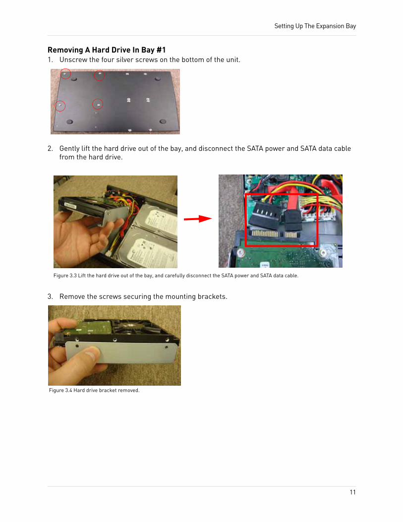
3. Remove the screws securing the mounting brackets.
Figure 3.3 Lift the hard drive out of the bay, and carefully disconnect the SATA power and SATA data cable.
Figure 3.4 Hard drive bracket removed.
11

Setting Up The Expansion Bay
Adding A Hard Drive To Bay #2 & 31. Plug in the SATA power connector and SATA data
connector into the hard drive (Figure 3.5). Do not force in the connectors. The connectors are designed to go in one way only.
2. Lower the hard drive into the bay.3. Clasp your hand on the hard drive and the casing
(Figure 3.6).4. Flip the unit upside down while clasping the hard
drive with your hands (Figure 3.7).5. Screw in the four corresponding hard drive screws
underneath the unit to secure.
Removing A Hard Drive from Bay #2 & 31. Flip the unit upside down with the silver screws
facing up.2. Clasp your hand on the hard drive and the casing.
This prevents the hard drive from falling when you unscrew it from the case.
3. Remove the four corresponding silver screws.4. With your hands still clasping the hard drive, flip the
unit upright.5. Unplug the SATA power cord and SATA data cord.
SATA ConnectorsSata connectors are designed to connect one way only. The connector with the flat, red cable is the data connector. The wider connector with the red and black wires is the power connector.
Hard Drive Rotation SpeedsIf you are setting up the expansion bay in Mirror mode, the hard drives must be at least 7200 RPM. Hard drives slower than 7200 RPM are not recommended.
Setup Tips
• Ground yourself from static electricity before handling the hard drive. Static electricity may damage hard drives and electronic components.
• Keep the exhaust vents clear. The exhaust fans draw hot air out of the casing and cools the hard drive.
• Add a UPS (Uninterruptible Power Supply) (Optional) to ensure that power outtages do not shut off your main system. A UPS can reduce or prevent damage to your equipment from sudden power surges.
Figure 3.5 Plug in the SATA power and data cables.
Figure 3.6 Clasp your hands on the hard drive and flip over.
Figure 3.7 While holding the hard drive, screw in the four screws to secure the hard drive in place.
Figure 3.8 SATA connectors. Data connector shown on the left; power connector on the right.
12

Appendix A: VBAY3HD Specifications
APPENDIX A: VBAY3HD SPECIFICATIONS
Display
LED Display Red (Power), Green (HDD 1 - 3)
Hard Drive
Maximum Capacity Three 3.5‘‘ SATA HDD
Minimum Rotational Speed 7200 RPM
Seek Time Faster than 10ms (average)
Connections
USB 2.0
Electrical
Power Source 12 V/ 5A
Power Consumption with 1 HD installed
Start 12V @ 1.7A (peak)
Read/Write 12V @ 0.8A (typical)
Power Consumption with 2 HDs installed
Start 12V @ 3.0A (peak)
Read/Write 12V @ 1.2A (typical)
Power Consumption with 3 HDs installed
Start 12V @ 4.4A (peak)
Read/Write 12V @ 1.8A (typical)
Maximum Supply Current for HD 12V/2.3A, 5V/4A
Operational Temperatures
Operating Temperature 0°C to 40°C
Storage Temperature -10°C to 60°C
Humidity 30 to 90%
Physical Dimensions
Dimensions 280mm (W) X 221mm (D) X 32.3mm (H)
Weight Approximately 1.1kg (with no HDD inside)
Interface
USB 2.0 EHCI (Enhanced Host Controller Interface)
13

Appendix A: VBAY3HD Specifications
Appendix A (cont’d)
Accessories
Ground Conductor (Grounding Cable)
AC Adaptor (12/5A) with AC Cord
Screws (5W/32-32) for HDD Installation
USB 2.0 Cable
14