CDHD2 Servo Drive Operator Panel (HMI) - ELDAR.biz
44
CDHD2 Servo Drive Operator Panel (HMI) Revision: 1.0 Firmware Version 2.15.x
-
Upload
khangminh22 -
Category
Documents
-
view
3 -
download
0
Transcript of CDHD2 Servo Drive Operator Panel (HMI) - ELDAR.biz

CDHD2 Servo Drive
Operator Panel (HMI) Revision: 1.0 Firmware Version 2.15.x


CDHD2
Operator Panel (HMI) 3
Copyright Notice
© 2018 Servotronix Motion Control Ltd.
All rights reserved. No part of this work may be reproduced or transmitted in any form or by any means without prior written permission of Servotronix Motion Control Ltd.
Disclaimer
This product documentation was accurate and reliable at the time of its release. Servotronix Motion Control Ltd. reserves the right to change the specifications of the product described in this manual without notice at any time.
Trademarks
All marks in this manual are the property of their respective owners.
Contact Information
Servotronix Motion Control Ltd. 21C Yagia Kapayim Street Petach Tikva 49130, Israel Tel: +972 (3) 927 3800 Fax: +972 (3) 922 8075 Website: www.servotronix.com
Technical Support
If you need assistance with the installation and configuration of the CDHD2 drive, contact Servotronix technical support: [email protected]

CDHD2
4 Operator Panel (HMI)
CDHD2
Operator Panel (HMI) 5
Contents
1 Operator Panel (HMI) Overview ________________________________________________ 7
2 Operator Panel – Parameter Mode ____________________________________________ 12
3 Operator Panel – Command Mode ____________________________________________ 23
4 Operator Panel – Monitoring Mode ___________________________________________ 32
5 Operator Panel – Faults & Info Mode _________________________________________ 39

CDHD2
6 Operator Panel (HMI)

CDHD2
Operator Panel (HMI) 7
1 Operator Panel (HMI) Overview
The CDHD2 operator panel is an HMI (human-machine interface) that allows you to monitor and edit parameter values, execute commands, and perform drive diagnostics and troubleshooting.
While COMMODE 0 is in effect, the drive can be fully controlled (enabled, motor movement, parameter modification) by both the operator panel and ServoStudio. Neither the operator panel nor ServoStudio takes precedence.
Functions performed in the operator panel and in ServoStudio are recognized by each other, but modifications to certain values, states and mode are not automatically displayed in the other. Changes made from the panel might not appear in a ServoStudio task screen until the screen in refreshed (exited and reopened).
When COMMODE 1 is in effect, the drive cannot be enabled and the motor cannot be moved through the operator panel or ServoStudio. The operator panel can only be used to manipulate parameters that do not interfere with fieldbus operation. If you attempt to set a parameter that interferes with fieldbus operation, the drive will issue an error code in the operator panel and/or an error message in ServoStudio.
The operator panel has a 5-digit 7-segment LED display, and four control keys.
Digit 5 DP5 Digit 4 DP4 Digit 3 DP3 Digit 2 DP2 Digit 1 DP1
Figure 1-1. Five Digit 7-Segment Display and Keypad

CDHD2
8 Operator Panel (HMI)
Table 1-2. Operator Panel Control Keys
Key Name Function
Mode Switches to next panel display mode (Status >
Parameter > Command > Monitor > Fault > Status).
While editing, cancels the edited value and returns to mode menu.
Shift | Enter Moves the cursor one digit to the left.
Press short: Shows the value of the currently selected parameter, and enables editing and setting of the parameter value.
Press long: Applies parameter number or value
Up Parameter:
Press once: Navigates up to next parameter. Press continuously: Quickly scrolls through
ascending parameter indices. Speed of scrolling increases the longer the key is pressed.
Value: Increases value by one increment
Down Parameter:
Press once: Navigates down to next parameter. Press continuously: Quickly scrolls through
descending parameter indices. Speed of scrolling increases the longer the key is pressed.
Value: Decreases value by one increment
Mode Scrolls to next panel display mode.
While editing, cancels the edited value and moves to next panel mode.
Shift + Mode Long press (>0.5 second)
Applies parameter value and executes CONFIG. >> done
Shift + Mode Very long press (>2 seconds)
Executes CONFIG after one second, then executes SAVE after two seconds. >> done
CDHD2
Operator Panel (HMI) 9
Operator Panel Modes
Use the Mode button to scroll through the five digital display modes.
The operator panel has five modes.
Table 1-3. Operator Panel Modes
Status (S) S Mode for displaying drive status, operating mode, warnings and motor movement. Refer to Operator Panel – Status Mode. Also refer to Digital Display – Warning Codes in the CDHD2 User Manual.
Parameters P Mode for reading and writing values of drive parameters. Refer to the VarCom Reference Manual.
Command C Mode for executing drive commands. Refer to Operator Panel – Command Mode.
Monitoring d Mode for displaying drive and system variables, such as actual speed, position, input and output states. Refer to Operator Panel – Monitoring Mode.
Faults & Info F Mode for displaying fault codes and system information. Refer to Operator Panel – Faults & Info Mode.
The drive remembers the last selected setting or value in each mode.
If one or more faults occurs while in Status, Commands or Monitoring mode, the digital display automatically switches to Faults mode, and the most recent fault number is displayed. To resume working, a different display mode must be selected.
While in Parameters mode, an incorrect value will cause an error code to be displayed, but the digital display will not switch modes.
Operator Panel – Status Mode
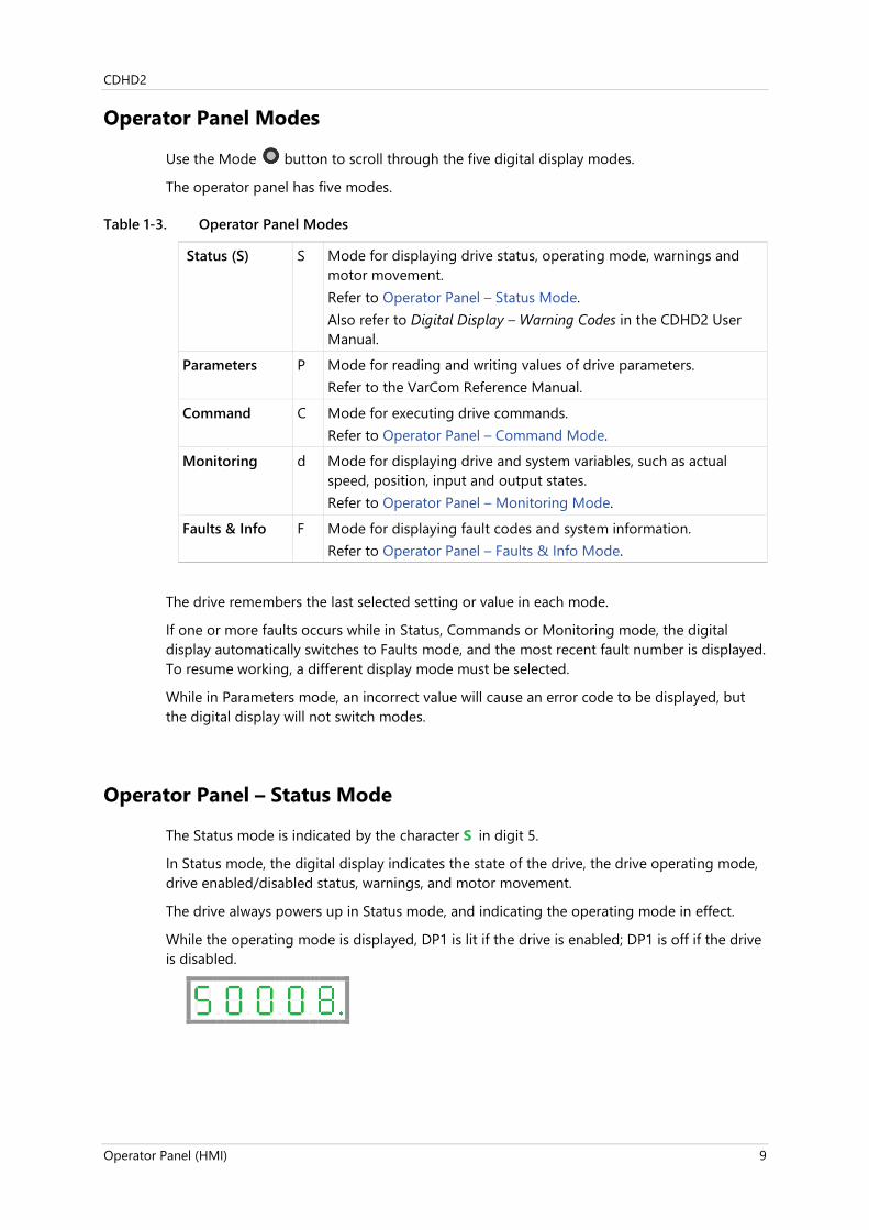
The Status mode is indicated by the character S in digit 5.
In Status mode, the digital display indicates the state of the drive, the drive operating mode, drive enabled/disabled status, warnings, and motor movement.
The drive always powers up in Status mode, and indicating the operating mode in effect.
While the operating mode is displayed, DP1 is lit if the drive is enabled; DP1 is off if the drive is disabled.

CDHD2
10 Operator Panel (HMI)
HMI Status Codes
Status codes are shown in the table below. Also refer to Digital Display – Warning Codes in the CDHD2 User Manual.
Table 1-4. Digital Display Status Codes
Digit or DP Display Description
DP 1 . Drive enabled
. Drive disabled
Digits 1 and 2 Operating mode, depending on COMMODE.
If COMMODE 0: Analog/P&D/Serial (OPMODE)
0 0 0 = Velocity control, using serial commands
0 1 1 = Velocity control, using analog input
0 2 2 = Current control, using serial commands
0 3 3 = Current control, using analog input
0 4 4 = Position control, using gearing input
0 8 8 = Position control, using serial commands
If COMMODE 1: (Object 6061)
P P 1 = Profile Position mode
P S 3 = Profile Velocity mode
P t 4 = Profile Torque mode
H H 6 = Homing mode
S P 8 = Cyclic Synchronous Position mode
S S 9 = Cyclic Synchronous Velocity mode
S t 10 = Cyclic Synchronous Torque mode
DP 2 . EtherCAT/CANopen OP mode active
. EtherCAT/CANopen INIT mode
Digit 3 r Motor is moving
. Motor is not moving
Digit 4 # First character of a warning code.
. No faults or warnings
Digit 5 S Status mode. Displays the codes shown in this table.
P Parameter mode. Refer to Operator Panel – Parameter Mode and to the VarCom Reference Manual.
C Command mode. Refer to Operator Panel – Command Mode.
d Monitoring mode. Refer to Operator Panel – Monitoring Mode.
F Faults & Information mode Refer to Operator Panel – Faults & Info Mode.
CDHD2
Operator Panel (HMI) 11
HMI Special Status Codes
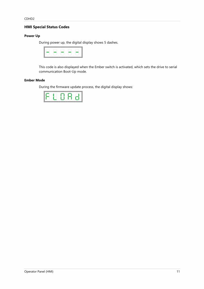
Power Up
During power up, the digital display shows 5 dashes.
This code is also displayed when the Ember switch is activated, which sets the drive to serial communication Boot-Up mode.
Ember Mode
During the firmware update process, the digital display shows:
CDHD2
12 Operator Panel (HMI)
2 Operator Panel – Parameter Mode
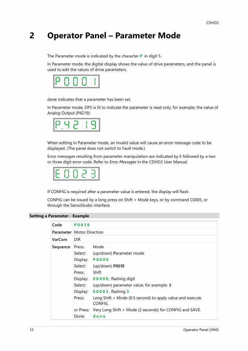
The Parameter mode is indicated by the character P in digit 5.
In Parameter mode, the digital display shows the value of drive parameters, and the panel is used to edit the values of drive parameters.
done indicates that a parameter has been set.
In Parameter mode, DP5 is lit to indicate the parameter is read only; for example, the value of Analog Output (P4219):
When editing in Parameter mode, an invalid value will cause an error message code to be displayed. (The panel does not switch to Fault mode.)
Error messages resulting from parameter manipulation are indicated by E followed by a two or three digit error code. Refer to Error Messages in the CDHD2 User Manual.
If CONFIG is required after a parameter value is entered, the display will flash.
CONFIG can be issued by a long press on Shift + Mode keys, or by command C0005, or through the ServoStudio interface.
Setting a Parameter - Example
Code P 0 0 1 8
Parameter Motor Direction
VarCom DIR
Sequence Press: Mode Select: (up/down) Parameter mode Display: P 0 0 0 0 Select: (up/down) P0018 Press: Shift Display: 0 0 0 0 0 , flashing digit Select: (up/down) parameter value; for example: 3 Display: 0 0 0 0 3 , flashing 3 Press: Long Shift + Mode (0.5 second) to apply value and execute
CONFIG. or Press: Very Long Shift + Mode (2 seconds) for CONFIG and SAVE. Done: d o n e

CDHD2
Operator Panel (HMI) 13
HMI Parameter Value Manipulation
The digital display can present parameter values up to ±9,223,372,036,854,775,807.000
The first string is displayed by default. To view the second, third and fourth strings, press the Shift key repeatedly, until the display shows the next string.
The string can be recognized by the DPs that are lit:
DP1: first string (integer value)
DP1 + DP4: first string (value with 3 decimal places)
DP1 + DP2: second string
DP1 + DP2+ DP3: third string
DP1 + DP2+ DP3 + DP4: fourth string
First string integers up to 99999
Second string numerals in values up to 9,999,999.xxx
Third string numerals in values up to 999,999,999,999.xxx
Fourth string numerals in values up to 99,999,999,999,999,999.xxx
or values up to 99.999
Note that the first string might show 00.000. while the value of the parameter is shown and set in the second string; for example, if acceleration parameter (ACC/P0014) = 40000.000 [rpm/s]:
First string:
Shift to second string:
HMI Parameter Codes
Table 2-1. Parameter Groups
Parameter Group Description
Basic - most frequently used Starting at index 0000
Gains and Filters Starting at index 1000
Shaping Filters Starting at index 1100
Linear Loop Gains Starting at index 1200

CDHD2
14 Operator Panel (HMI)
Parameter Group Description
Current Loop Gains Starting at index 1300
Feedback Starting at index 2000
Secondary Feedback Starting at index 2100
Motor Starting at index 3000
Digital I/Os Starting at index 4000
Analog I/Os Starting at index 4100
Limits Starting at index 5000
Communication/Fieldbus Starting at index 6000
Drive Parameters and Foldback Starting at index 7000
Emergency stop Starting at index 7100
Homing Starting at index 7200
Faults Modes and Thresholds Starting at index 7300
Table 2-2. Parameter Codes
Parameter Description Code
Basic - most frequently used Starting at index 0000
COMMODE Communication Mode P 0 0 0 0
OPMODE Drive Operation Mode P 0 0 0 1
GEARMODE Gearing Operation Mode P 0 0 0 2
ADDR Drive Communication Address P 0 0 0 3
XENCRES External Encoder Resolution P 0 0 0 4
GEARIN Gear Ratio Numerator P 0 0 0 5
GEAROUT Gear Ratio Divider P 0 0 0 6
ENCOUTRES Encoder Simulation Line Resolution P 0 0 0 7
ENCOUTMODE Encoder Simulation Mode P 0 0 0 8
ANIN1VSCALE Analog Input 1 Velocity Scaling P 0 0 0 9
ANIN1ISCALE Analog Input 1 Current Scaling P 0 0 1 0
ILIM User Current Limit P 0 0 1 1
VLIM User Velocity Limit P 0 0 1 2
VBUS Bus Voltage (DC) P 0 0 1 3
ACC Acceleration P 0 0 1 4
DEC Deceleration P 0 0 1 5
DISMODE Disable Mode P 0 0 1 6
DECSTOP Active Disable Deceleration P 0 0 1 7
DIR Feedback Direction P 0 0 1 8
MFBDIR Motor and Feedback Direction P 0 0 1 9
MPHASE Commutation Offset P 0 0 2 0
PFBOFFSET Position Offset P 0 0 2 1
UNITSROTPOS Units Rotary Position P 0 0 2 2

CDHD2
Operator Panel (HMI) 15
Parameter Description Code
UNITSROTACC Units Rotary Acc/Dec P 0 0 2 3
UNITSROTVEL Units Rotary Velocity P 0 0 2 4
UNITSLINPOS Units Linear Position P 0 0 2 5
UNITSLINACC Units Linear Acc/Dec P 0 0 2 6
UNITSLINVEL Units Linear Velocity P 0 0 2 7
Gains and Filters Starting at index 1000
POSCONTROLMODE Position Loop Controller Mode P 1 0 0 0
VELCONTROLMODE Velocity Loop Controller P 1 0 0 1
KNLUSERGAIN HD Global Gain P 1 0 0 2
KNLD HD Derivative Gain P 1 0 0 3
KNLP HD Proportional Gain P 1 0 0 4
KNLIV HD Derivative-Integral Gain P 1 0 0 5
KNLI HD Integral Gain P 1 0 0 6
KNLAFRC HD Acceleration Feedforward P 1 0 0 7
NLPEAFF HD Flexibility Compensation P 1 0 0 8
NLAFFLPFHZ HD Spring Filter P 1 0 0 9
NLFILTT1 HD Current Filter Low Pass Rise Time P 1 0 1 0
NLFILTDAMPING HD Current Filter Damping P 1 0 1 1
NLMAXGAIN HD Maximum Adaptive Gain P 1 0 1 2
NLNOTCHCENTER HD Current Filter Notch Center P 1 0 1 3
NLNOTCHBW HD Current Filter Notch Bandwidth P 1 0 1 4
NLNOTCH2CENTER HD Current Filter 2nd Notch Center P 1 0 1 5
NLANTIVIBSHARP HD AV 1 Filter Sharpness P 1 0 1 6
NLANTIVIBGAIN2 HD Anti-Vibration 2 Filter ? Gain P 1 0 1 7
NLANTIVIBHZ2 HD AV 2 Filter Center Frequency P 1 0 1 8
NLANTIVIBSHARP2 HD AV 2 Filter Sharpness P 1 0 1 9
NLANTIVIBGAIN3 HD Anti-Vibration 3 Filter ? Gain P 1 0 2 0
NLANTIVIBHZ3 HD AV 3 Filter Center Frequency P 1 0 2 1
NLANTIVIBSHARP3 HD AV 3 Filter Sharpness P 1 0 2 2
Shaping Filters Starting at index 1100
MOVESMOOTHMODE Position Command Smoothing Mode P 1 1 0 0
MOVESMOOTHSRC Position Command Smoothing Source P 1 1 0 1
MOVESMOOTHAVG Position Command Moving Avg Filter P 1 1 0 2
MOVESMOOTHLPFHZ Position Command Move Low Pass Filter P 1 1 0 3
GEARFILTMODE Gear Filter Mode P 1 1 0 4
GEARFILTT1 Gear Filter Depth P 1 1 0 5
GEARFILTT2 Gear Filter Vel and Acc Depth P 1 1 0 6
GEARACCTHRESH Gear Acceleration Threshold P 1 1 0 7

CDHD2
16 Operator Panel (HMI)
Parameter Description Code
GEARFILTVELFF Gear Filter Velocity Feedforward P 1 1 0 8
GEARFILTAFF Gear Filter Acceleration FF P 1 1 0 9
Linear Loop Gains Starting at index 1200
KVP Velocity Proportional Gain P 1 2 0 0
KVI Velocity Integral Gain P 1 2 0 1
KVFR Velocity Feedforward Ratio P 1 2 0 2
FILTMODE Velocity Loop Output Filter Mode P 1 2 0 3
FILTHZ1 Velocity Loop Output Filter Param 1 P 1 2 0 4
FILTHZ2 Velocity Loop Output Filter Param 2 P 1 2 0 5
VELFILTMODE Velocity Filter Mode P 1 2 0 6
KPP Position Proportional Gain P 1 2 0 7
KPI Position Integral Gain P 1 2 0 8
KPISATIN Position Integral Saturation Input P 1 2 0 9
KPISATOUT Position Integral Saturation Output P 1 2 1 0
KPD Position Derivative Gain P 1 2 1 1
KPE Position Adaptive Proportional Gain P 1 2 1 2
KPVFR Position Velocity Feedforward P 1 2 1 3
KPAFRC Position Acc FF to Current Loop P 1 2 1 4
KPAFRV Position Acceleration Feedforward P 1 2 1 5
Current Loop Gains Starting at index 1300
KCP Current KP Gain P 1 3 0 0
KCI Current KI Gain P 1 3 0 1
KCD Dead Time Compensation Min Level P 1 3 0 2
KCFF Current KFF Gain P 1 3 0 3
KCBEMF Current BEMF Compensation Gain P 1 3 0 4
KCMODE Current Loop Compatibility Mode P 1 3 0 5
MLGAINP Adaptive Gain at Peak Motor Current P 1 3 0 7
MLGAINC Adapt Gain at Continuous Motor Current P 1 3 0 8
MTANGLC Torque Angle at Motor Continuous Current P 1 3 0 8
MTANGLP Torque Angle at Motor Peak Current P 1 3 0 9
FRICINEG Friction Compens Negative Current P 1 3 1 0
FRICIPOS Friction Compens Positive Current P 1 3 1 1
FRICNVHYST Friction Compens Neg Vel Hysteresis P 1 3 1 2
FRICPVHYST Friction Compens Neg Vel Hysteresis P 1 3 1 3
I Motor Current P 1 3 1 4
ICMD Current Command P 1 3 1 5
ID Current D Axis P 1 3 1 6
IFFLPFHZ Current Feedforward Low Pass Filter P 1 3 1 7

CDHD2
Operator Panel (HMI) 17
Parameter Description Code
IGRAV Gravity Compensation P 1 3 1 8
IMAX Drive Current Limit P 1 3 1 9
IQ Current Q Axis P 1 3 2 0
IU Phase U Actual Current P 1 3 2 1
IUOFFSET Phase U Current Offset P 1 3 2 2
IV Phase V Actual Current P 1 3 2 3
IVOFFSET Phase V Current Offset P 1 3 2 4
Feedback Starting at index 2000
FEEDBACKTYPE Feedback Type P 2 0 0 0
MENCRES Motor Encoder Resolution P 2 0 0 1
MENCTYPE Motor Encoder Type P 2 0 0 2
MSININT Motor Sine Interpolation P 2 0 0 3
BISSCFIELDS (argument 1) Multi-turn Data (bits) P 2 0 0 4
BISSCFIELDS (argument 2) Effective Multi-turn Data (bits) P 2 0 0 5
BISSCFIELDS (argument 3) Single Turn Data (bits) P 2 0 0 6
BISSCFIELDS (argument 4) Effective Single Turn Data (bits) P 2 0 0 7
RESBW Resolver Conversion Bandwidth P 2 0 0 8
HALLSINV Hall Signals Inversion P 2 0 0 9
HALLSTYPE Hall Signals Type P 2 0 1 0
PHASEFINDMODE Phase Find Mode P 2 0 1 1
PHASEFINDI Phase Find Current P 2 0 1 2
PHASEFINDTIME Phase Find Duration P 2 0 1 3
PHASEFINDGAIN Phase Find Gain P 2 0 1 4
HALLSCOMMTHRESH Halls-Only Commutation Source Switch P 2 0 1 5
HALLSONLYCOMM Halls-Only Commutation Source P 2 0 1 6
HALLSFILTAFF Halls-Only MSQ Filter Acc FF P 2 0 1 7
HALLSFILTT1 Halls-Only MSQ Filter Depth P 2 0 1 8
HALLSFILTT2 Halls-Only MSQ Filter Vel and Acc P 2 0 1 9
HALLSFILTVELFF Halls-Only MSQ Filter Velocity FF P 2 0 2 0
HWPOS Hardware Position P 2 0 2 1
MECHANGLE Motor Angle P 2 0 2 3
MENCAQBFILT Motor Encoder A/B Quadrature Filter P 2 0 2 4
MENCZPOS Motor Encoder Index Position P 2 0 2 5
MFBMODE Motor Feedback Mode P 2 0 2 6
MRESPOLES Motor Resolver Poles P 2 0 2 7
RESAMPLRANGE Resolver Amplitude Range P 2 0 2 8
SININITMODE Sine/Cosine Calibration Mode P 2 0 2 9
TMTEMP Tamagawa Temperature P 2 0 3 0

CDHD2
18 Operator Panel (HMI)
Parameter Description Code
INDEXDURATE Simulated Encoder Index Pulse Duration P 2 0 3 2
Secondary Feedback Starting at index 2100
HWPEXT Hardware Position External P 2 1 0 0
HWPEXTCNTRLR Hardware Position External (FPGA) P 2 1 0 1
HWPEXTMACHN Hardware Position External (DSP) P 2 1 0 2
SFB Secondary Feedback P 2 1 0 3
SFBMODE Secondary Feedback Mode P 2 1 0 7
SFBOFFSET Secondary Feedback Offset P 2 1 0 8
SFBTYPE Secondary Feedback Type P 2 1 1 3
LMUNITSDEN Motor to Load Scaling Denominator P 2 1 1 4
LMUNITSNUM Motor to Load Scaling Numerator P 2 1 1 5
Motor Starting at index 3000
MOTORNAME Motor Name P 3 0 0 0
MOTORTYPE Motor Type P 3 0 0 1
MICONT Motor Continuous Current P 3 0 0 2
MIPEAK Motor Peak Current P 3 0 0 3
MSPEED Motor Maximum Speed P 3 0 0 4
MPOLES Motor Poles P 3 0 0 5
MPITCH Motor Pitch P 3 0 0 6
MKT Torque Constant P 3 0 0 7
MKF Torque Constant for Linear Motor P 3 0 0 8
ML Motor Inductance P 3 0 0 9
MR Motor Resistance P 3 0 1 0
MOTORCOMMTYPE Motor Commutation Type P 3 0 1 1
MFOLD Motor Foldback Status P 3 0 1 2
MFOLDD Motor Foldback Delay Time P 3 0 1 3
MFOLDDIS Motor Foldback Disable P 3 0 1 4
MFOLDF Motor Foldback Factor P 3 0 1 5
MFOLDR Motor Foldback Recovery Time P 3 0 1 6
MFOLDT Motor Foldback Time Constant P 3 0 1 7
MIFOLD Motor Foldback Current P 3 0 1 8
MIFOLDFTHRESH Motor Foldback Fault Threshold P 3 0 1 9
MTPMODE Electronic Motor Nameplate Mode P 3 0 2 0
Digital I/Os Starting at index 4000
INMODE 1 Input Mode (input 1) P 4 0 0 0
INMODE 2 Input Mode (input 2) P 4 0 0 1
INMODE 3 Input Mode (input 3) P 4 0 0 2
INMODE 4 Input Mode (input 4) P 4 0 0 3

CDHD2
Operator Panel (HMI) 19
Parameter Description Code
INMODE 5 Input Mode (input 5) P 4 0 0 4
INMODE 6 Input Mode (input 6) P 4 0 0 5
INMODE 7 Input Mode (input 7) P 4 0 0 6
INMODE 8 Input Mode (input 8) P 4 0 0 7
INMODE 9 Input Mode (input 9) P 4 0 0 8
INMODE 10 Input Mode (input 10) P 4 0 0 9
INMODE 11 Input Mode (input 11) P 4 0 1 0
ININV 1 Input Inversion (input 1) P 4 0 1 1
ININV 2 Input Inversion (input 2) P 4 0 1 2
ININV 3 Input Inversion (input 3) P 4 0 1 3
ININV 4 Input Inversion (input 4) P 4 0 1 4
ININV 5 Input Inversion (input 5) P 4 0 1 5
ININV 6 Input Inversion (input 6) P 4 0 1 6
ININV 7 Input Inversion (input 7) P 4 0 1 7
ININV 8 Input Inversion (input 8) P 4 0 1 8
ININV 9 Input Inversion (input 9) P 4 0 1 9
ININV 10 Input Inversion (input 10) P 4 0 2 0
ININV 11 Input Inversion (input 11) P 4 0 2 1
OUTMODE 1 Output Mode (output 1) P 4 0 2 2
OUTMODE 2 Output Mode (output 2) P 4 0 2 3
OUTMODE 3 Output Mode (output 3) P 4 0 2 4
OUTMODE 4 Output Mode (output 4) P 4 0 2 5
OUTMODE 5 Output Mode (output 5) P 4 0 2 6
OUTMODE 6 Output Mode (output 6) P 4 0 2 7
OUTMODE 7 Output Mode (output 7) P 4 0 2 8
OUTINV 1 Output Inversion (output 1) P 4 0 2 9
OUTINV 2 Output Inversion (output 2) P 4 0 3 0
OUTINV 3 Output Inversion (output 3) P 4 0 3 1
OUTINV 4 Output Inversion (output 4) P 4 0 3 2
OUTINV 5 Output Inversion (output 5) P 4 0 3 3
OUTINV 6 Output Inversion (output 6) P 4 0 3 4
OUTINV 7 Output Inversion (output 7) P 4 0 3 5
ENCOUTZPOS Encoder Simulation Index Position P 4 0 3 6
IN32OPMODES Operation Mode Change Input Level P 4 0 3 7
IN32SWITCH Operation Mode Change Resume Motion P 4 0 3 8
JOGSPD1 Jog Speed 1 Triggered by Input P 4 0 3 9
JOGSPD2 Jog Speed 2 Triggered by Input P 4 0 4 0
OUTBRAKE Manual Brake by Output P 4 0 4 1

CDHD2
20 Operator Panel (HMI)
Parameter Description Code
OUTBRAKEINV Manual Brake by Output Inverse P 4 0 4 2
OUTBRAKEMODE Manual Brake by Output Mode P 4 0 4 3
OUTFLTLVL Force Digital Output State on Fault P 4 0 4 4
OUTILVL1 Current 1 Digital Output Definition P 4 0 4 5
OUTILVL2 Current 2 Digital Output Definition P 4 0 4 6
OUTINV Position 1 Digital Output Definition P 4 0 4 7
OUTPLVL2 Position 2 Digital Output Definition P 4 0 4 8
OUTVLVL1 Velocity 1 Digital Output Definition P 4 0 4 9
OUTVLVL2 Velocity 2 Digital Output Definition P 4 0 5 0
RELAY Fault Relay Status P 4 0 5 1
RELAYMODE Fault Relay Mode P 4 0 5 2
Analog I/Os Starting at index 4200
ANIN1DB Analog Input 1 Deadband P 4 2 0 0
ANIN1FILTAFF Analog Input 1 MSQ 2nd Deriv FF P 4 2 0 1
ANIN1FILTIN Analog Input 1 Before MSQ Filter P 4 2 0 2
ANIN1FILTMODE Analog Input 1 MSQ Filter P 4 2 0 3
ANIN1FILTT1 Analog Input 1 MSQ Filter Depth P 4 2 0 4
ANIN1FILTT2 Analog Input 1 MSQ 1st 2nd Deriv P 4 2 0 5
ANIN1FILTVELFF Analog Input 1 MSQ 1st Deriv FF P 4 2 0 6
ANIN1LPFHZ Analog Input 1 Filter P 4 2 0 7
ANIN1OFFSET Analog Input 1 Offset P 4 2 0 8
ANIN2DB Analog Input 2 Deadband P 4 2 0 9
ANIN2ISCALE Analog Input 2 Current Scaling P 4 2 1 0
ANIN2LPFHZ Analog Input 2 Filter P 4 2 1 1
ANIN2MODE Analog Input 2 Mode P 4 2 1 2
ANIN2OFFSET Analog Input 2 Offset P 4 2 1 3
ANIN2USER Analog Input 2 Voltage User Units P 4 2 1 4
ANIN2USERDEN ANIN2USER Conversion Denominator P 4 2 1 5
ANIN2USERNUM ANIN2USER Conversion Numerator P 4 2 1 6
ANIN2USEROFFSET ANIN2USER Conversion Offset P 4 2 1 7
ANIN2ZERO Analog Input 2 Zero Command P 4 2 1 8
ANOUT Analog Output Value P 4 2 1 9
ANOUTCMD Analog Output Command P 4 2 2 0
ANOUTISCALE Analog Output Current Scaling P 4 2 2 1
ANOUTLIM Analog Output Voltage Limit P 4 2 2 2
ANOUTMODE Analog Output Mode P 4 2 2 3
ANOUTVSCALE Analog Output Velocity Scaling P 4 2 2 4

CDHD2
Operator Panel (HMI) 21
Parameter Description Code
Limits Starting at index 5000
LIMSWITCHNEG Limit Switch Negative Status P 5 0 0 0
LIMSWITCHPOS Limit Switch Positive Status P 5 0 0 1
GEARLIMITSMODE Electronic Gearing Mode P 5 0 0 2
POSLIMHYST SW Position LS Hysteresis Value P 5 0 0 3
POSLIMMODE Position Limiting Mode P 5 0 0 4
POSLIMNEG Minimum Software Position Limit P 5 0 0 5
POSLIMPOS Maximum Software Position Limit P 5 0 0 6
ILIMACT Drive Actual Current Limit P 5 0 0 7
Communication/Fieldbus Starting at index 6000
BAUDRATE Serial Baud Rate P 6 0 0 0
CANBITRATE CAN Bus Bit Rate P 6 0 0 1
CHECKSUM Checksum P 6 0 0 2
ECHO Serial Communication Character Echo P 6 0 0 3
PNUM Feed Constant Scaling Numerator P 6 0 0 4
FBGDS Fieldbus Gear Driving Shaft Scaling P 6 0 0 6
FBGMS Fieldbus Gear Motor Shaft Scaling P 6 0 0 7
FBITIDX Fieldbus Interpolation Time Index P 6 0 0 8
FBITPRD Fieldbus Interpolation Time P 6 0 0 9
FBPLIGNORE Fieldbus Ignore Packet Loss Fault P 6 0 1 0
FBSCALE Fieldbus Unit Scaling P 6 0 1 1
MSGPROMPT Drive Messages and Prompts P 6 0 1 2 Drive Parameters and Foldback
Starting at index 7000
DICONT Drive Continuous Current P 7 0 0 0
DIPEAK Drive Peak Current P 7 0 0 1
FOLD Drive Foldback Status P 7 0 0 2
IFOLD Drive Foldback Current Limit P 7 0 0 3
IFOLDFTHRESH Drive Foldback Fault Threshold P 7 0 0 4
IFOLDWTHRESH Drive Foldback Warning Threshold P 7 0 0 5
IZERO Zero Procedure Current P 7 0 0 6
Emergency Stop Starting at index 7100
DECSTOPTIME Active Disable Deceleration Time P 7 1 0 2
DISSPEED Active Disable Speed Threshold P 7 1 0 3
DISTIME Active Disable Time P 7 1 0 4
ESTOPILIM Current Limit During Emergency P 7 1 0 5
HOLD Hold Position Command P 7 1 0 6
ISTOP Dynamic Braking Current P 7 1 0 7
COMMERRMAXCNT Commutation Error Counter P 7 1 0 8

CDHD2
22 Operator Panel (HMI)
Parameter Description Code
COMMERRTTHRESH Commutation Error Threshold P 7 1 0 9
COMMERRVTHRESH Commutation Velocity Deviation P 7 1 1 0
STALLTIME Stall Time P 7 1 1 1
STALLVEL Stall Velocity P 7 1 1 2
Homing Starting at index 7200
HOMETYPE Homing Type P 7 2 0 0
HOMECMDST Homing Process Status P 7 2 0 2
HOMEIHARDSTOP Current for Homing on Hard Stop P 7 2 0 3
HOMEOFFSET Home Offset P 7 2 0 4
HOMEOFSTMOVE Home Offset Move P 7 2 0 5
HOMESPEED1 Homing Speed 1 - Switch Search P 7 2 0 6
HOMESPEED2 Homing Speed 2 - Index Search P 7 2 0 7
HOMESTATE Homing Status P 7 2 0 8
Faults Modes and Thresholds Starting at index 7300
UVMODE Under-Voltage Mode P 7 3 0 0
UVRECOVER Under-Voltage Recovery Mode P 7 3 0 1
UVTHRESH Under-Voltage Threshold P 7 3 0 2
UVTIME Under-Voltage Time P 7 3 0 3
IGNOREBRKFLT Ignore Power Brake Fault P 7 3 0 4
LINELOSSMODE Bus AC Supply Line Disconnect Mode P 7 3 0 5
LINELOSSRECOVER Bus AC Disconnect Recovery Mode P 7 3 0 6
LINELOSSTYPE Bus AC Supply Line Disconnect Type P 7 3 0 7
OVTHRESH Over-Voltage Threshold P 7 3 0 8
PWMFRQ PWM Frequency P 7 3 0 9
REGENFLTMODE Regeneration Resistor Fault Mode P 7 3 1 0
REGENMAXONTIME Regeneration Resistor Max On Time P 7 3 1 1
REGENMAXPOW Regeneration Resistor Maximum Power P 7 3 1 2
REGENPOW Regeneration Resistor Power P 7 3 1 3
REGENRES Regeneration Resistor Resistance P 7 3 1 4

CDHD2
Operator Panel (HMI) 23
3 Operator Panel – Command Mode
The Command mode is indicated by the character C in digit 5.
In Command mode, the panel is used to issue commands to the drive.
If an invalid command argument is entered, an error message code will be displayed. Error messages resulting from parameter manipulation are indicated by E r followed by a two or three digit error code.
For the full list of error message codes, refer to Error Messages in the CDHD2 User Manual.
HMI Command Codes
Command codes are shown in the table below.
The sequences for entering the commands are presented in the sections that follow.
When selecting/entering a command, 0 often flashes once in digit 1. This is standard behavior of the panel, indicating a value can be entered.
Table 3-1. Command Codes
Command - VarCom Description Code
HDTUNE Initiate Drive-based Autotuning C 0 0 0 0
MOTORSETUP Motor Setup Command C 0 0 0 1
CLEARFAULTS Clear Faults C 0 0 0 2
EN / K Enable/Disable C 0 0 0 3
J Jog Command C 0 0 0 4
CONFIG Configure Drive C 0 0 0 5
SAVE Save Parameters C 0 0 0 6
MTTURNRESET Encoder Multi-Turn Reset C 0 0 0 7
FACTORYRESTORE Restore Factory Settings C 0 0 0 8
ANIN1ZERO Analog Input 1 Zero Command C 0 0 0 9
MOVEABS Move Absolute Command C 0 0 1 0
MOVEINC Move Incremental Command C 0 0 1 1
HOMECMD Homing Command C 0 0 1 2
PHASEFIND Phase Find Command C 0 0 1 3
SININIT Sine/Cosine Calibration Command C 0 0 1 4

CDHD2
24 Operator Panel (HMI)
Autotuning
Code C 0 0 0 0
Command Initiate Drive-based Autotuning
VarCom HDTUNE
Sequence Make sure the drive is disabled, and has no faults Select: C0000 Press: Shift Display: A t u n e
Press: Shift Display: Flashing 0 . in digit 1 Insert a value that represents the autotuning options:
0 Internal Motion Generator – Express, drive-based
1 Internal Motion Generator – Advanced, drive-based
2 Internal Motion Generator – Advanced, for vertical applications, drive-based
10 External Motion Generator – Express, controller-based
11 External Motion Generator – Advanced, controller-based
12 External Motion Generator – Advanced, for vertical application, controller-based
13 External Motion Generator – Advanced, with command smoothing, controller-based
14 External Motion Generator – Advanced, with command smoothing for vertical application, controller-based
Press: Long Shift Display: Autotuning progress in % number (DP1 is lit) Done: d o n e (or an error code)
Note During autotuning: A warning will be displayed as S# A fault will be displayed as F# flashing

CDHD2
Operator Panel (HMI) 25
Motor Setup
Code C 0 0 0 1
Command Motor Setup
VarCom MOTORSETUP
Sequence Make sure the drive is disabled, and has no faults Select: C0001 Press: Shift Display: n n s e t
Press: Long Shift Display: Motor setup progress in % number Done: d o n e (or an error code)
Clear Faults OK
Code C 0 0 0 2
Command Clear Faults
VarCom CLEARFAULTS
Sequence Select: C0002 Press: Shift Display: 0 0 0 0 0 . Press: Shift Display: Flashing 0 . in digit 1 Press: Long Shift Display: 0 0 0 0 0 . or will continue to show the fault code

CDHD2
26 Operator Panel (HMI)
Enable / Disable
Code C 0 0 0 3
Command Enable/Disable (Toggle)
VarCom EN / K
Sequence Select: C 0 0 0 3 Press: Shift Display: 00.000. Press: Long Shift Done: 0 0 . 0 0 0 .
Sequence Select: C0003 Press: Shift Display: 0 0 . 0 0 0 . Press: Shift Display: Flashing 0 . in digit 1 Press: Long Shift Done: 0 0 . 0 0 0 .
Note The ServoStudio toolbar/status bar might not accurately reflect change in Enable/Disable state. Use the ST command in Terminal to verify.
Jog
Code C 0 0 0 4
Command Jog
VarCom J
Note Jog speed range: 1 rpm to VLIM The jog command from the panel functions in both 0 and 8 modes
Sequence Make sure drive is in appropriate operating mode. Make sure drive is Enabled. Select: C0004 Press: Shift Display: j o G 8 8
Press: Shift Display: 0 0 . 0 0 0 . Press: Shift Display: flashing 0 . in digit 1

CDHD2
Operator Panel (HMI) 27
For example, set a speed of 300 rpm First string = values up to 99.999. Nothing to set.
Press: Shift until you reach the first digit in the second string. Second string = values up to 9999,9nn.nnn. Press: Up to reach 3
Press: Long Shift Display: joG8S (jog motion stopped)
Press and hold Up key move motor at defined speed in positive direction. Press and hold Down key to move motor at defined speed in negative direction. Display: jog8r (rotating, during motion)
Config
Code C 0 0 0 5
Command Configure Drive
VarCom CONFIG
Sequence Select: C0005 Show: c o n f g
Press: Shift Display: Flashing 0 . in digit 1 Press: Long Shift Done: d o n e (momentarily), and then 0 0 0 0 0 . (or an error code)
CDHD2
28 Operator Panel (HMI)
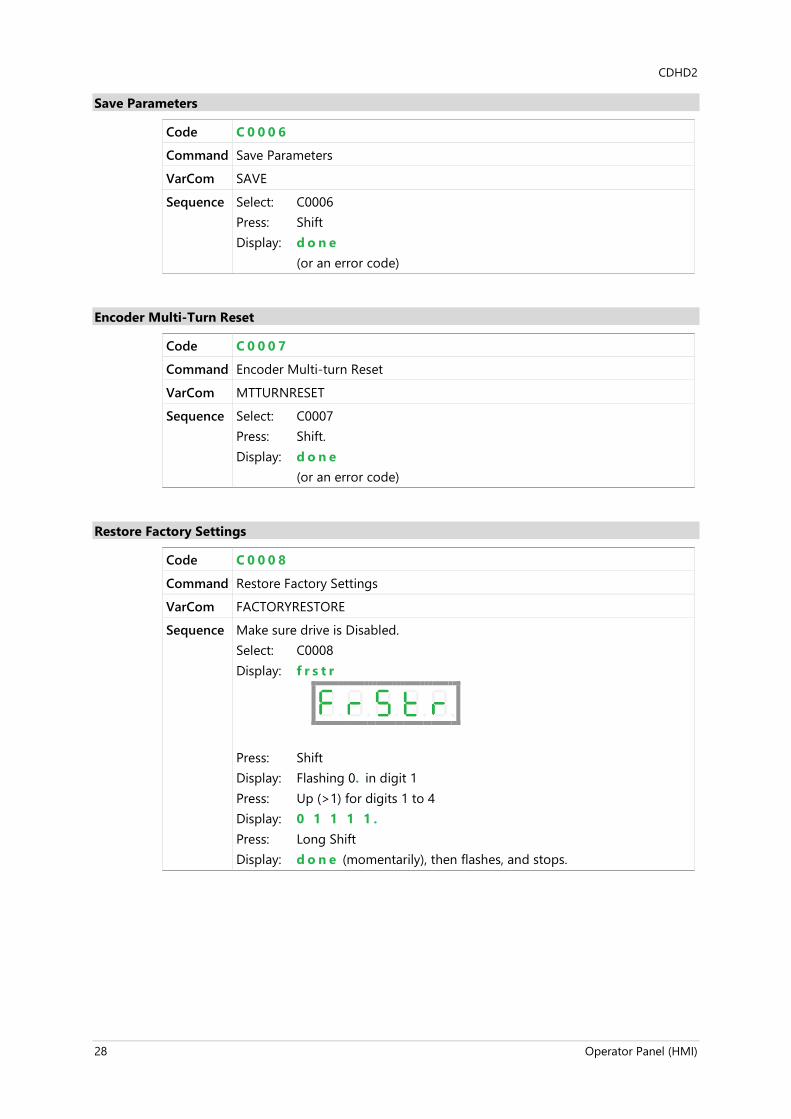
Save Parameters
Code C 0 0 0 6
Command Save Parameters
VarCom SAVE
Sequence Select: C0006 Press: Shift Display: d o n e (or an error code)
Encoder Multi-Turn Reset
Code C 0 0 0 7
Command Encoder Multi-turn Reset
VarCom MTTURNRESET
Sequence Select: C0007 Press: Shift. Display: d o n e (or an error code)
Restore Factory Settings
Code C 0 0 0 8
Command Restore Factory Settings
VarCom FACTORYRESTORE
Sequence Make sure drive is Disabled. Select: C0008 Display: f r s t r
Press: Shift Display: Flashing 0. in digit 1 Press: Up (>1) for digits 1 to 4 Display: 0 1 1 1 1 . Press: Long Shift Display: d o n e (momentarily), then flashes, and stops.

CDHD2
Operator Panel (HMI) 29
Analog Input 1 Zero
Code C 0 0 0 9
Command Analog Input 1 Zero Command
VarCom ANIN1ZERO
Sequence Make sure drive is Disabled. Select: C0008 Press: Shift Display: Flashing 0 . in digit 1 Press: Long Shift Display: d o n e (or an error code)
Move Absolute - Distance
Code C 0 0 1 0
Command Move Absolute - distance
VarCom MOVEABS {distance} {velocity} Sets the distance argument. Command uses velocity value set by JOGSPD1.
Sequence Make sure drive is Enabled. Select: C0010 Display: a b s n n
Press: Long Shift Display: Flashing 0 . in digit 1 Press: (for example) Set a value of 15 (revolutions) Press: Long Shift (motor rotates) Display: a b S n n (during motor movement) Display: d o n e (or an error code)

CDHD2
30 Operator Panel (HMI)
Move Incremental - Distance
Code C 0 0 1 1
Command Move Incremental - distance
VarCom MOVEINC {distance} {velocity} Sets the distance argument. Command uses velocity value set by JOGSPD1.
Sequence Select: C0011 Display: i n c n n
Press: Long Shift Display: flashing 0 Press: (for example) Set a value of 2 (revolutions) Press: Long Shift Display: i n c n n (during movement) Display: d o n e (or an error code) Note value of movement = revolution, counts, degrees Sets distance for movement. Speed is set according JOGSPD1
Home
Code C 0 0 1 2
Command Home
VarCom HOMECMD
Sequence Select: C0012 Display: h o n n e
Press: Shift Display: Flashing 0 . in digit 1 Press: Set the value of a homing type Press: Long Shift Press: Long Shift Display: (indicates homing progress in a % number) Display: d o n e (or an error code)

CDHD2
Operator Panel (HMI) 31
Phase Find
Code C 0 0 1 3
Command Phase Find
VarCom PHASEFIND
Sequence Select: C0013 Press: Shift. Display: P h a S e
Press: Shift Display: Flashing 0 . in digit 1 Press: Long Shift Display: d o n e (or an error code)
Sine/Cosine Calibration
Code C 0 0 1 4
Command Sine/Cosine Calibration
VarCom SININIT
Sequence Select: C0014 Display: s i n i n
Press: Shift Display: Flashing 0 . in digit 1 Press: Long Shift Display: d o n e (or an error code)

CDHD2
32 Operator Panel (HMI)
4 Operator Panel – Monitoring Mode
The Monitoring mode is indicated by the character d in digit 5.
In Monitoring mode, the panel is used to read drive variables, such as speed, position, and current, inputs and outputs.
HMI Monitor Codes
Table 4-1. Monitor Codes
Command - VarCom Description Code
V Actual speed, in rpm d 0 0 0 0
PFB Actual position, in degrees d 0 0 0 1
PFB Actual position, in revolutions d 0 0 0 2
I Current, in amperes d 0 0 0 3
IN Digital inputs 1 through 10 d 0 0 0 4
IN Digital input 11 d 0 0 0 5
OUT Digital outputs 1 through 7 d 0 0 0 6
Not Applicable CAN statusword d 0 0 0 7
Not Applicable CAN controlword d 0 0 0 8
ANIN1 Analog input 1 d 0 0 0 9
ANIN2 Analog input 2 d 0 0 1 0
HWPEXT Hardware position-external d 0 0 1 1

CDHD2
Operator Panel (HMI) 33
Actual Speed
Code d 0 0 0 0
Command Velocity
Description Shows the actual speed of the motor, as measured by the primary feedback, in rpm. Speed is shown in digits 4 3 2 1 If motion is in a negative direction, DP5 is lit.
VarCom V
Sequence Select: d0000 Press: Shift Display: 0 0 0 0 0 Press: Shift (repeatedly), until only DP1 is lit. Start motion.
Examples 0 0 2 5 0 . = positive motion 250 rpm 0 0 0 2 0 . = positive motion 20 rpm 0 . 0 2 5 0 . = negative motion 250 rpm 0 . 0 0 2 0 . = negative motion 20 rpm
Actual Position (degrees)
Code d 0 0 0 1
Command Actual Position, in degrees
Description Shows the actual position of the motor, as measured by the primary feedback, in degrees. If the position is a negative value, DP5 is lit.
VarCom PFB
Sequence Select: d0001 Press: Shift (repeatedly) until only DP2 and DP1 are lit. Start motion. Press the Shift key to view the next string.
Examples Examples of display: 0 0 2 5 . 0 . during motion 0 0 3 6 . 0 . (move absolute 36,000 degrees position: 100 revs.) 0 3 6 0 . 0 . (move absolute 360,000 degrees position: 1000 revs.) 1 8 0 0 . 0 . (move absolute 1,080,000 degrees position: 3000 revs.) 0 . 0 0 3 . 6 . (move absolute -3,600 degree position: -10)

CDHD2
34 Operator Panel (HMI)
Actual Position (rev)
Code d 0 0 0 2
Command Actual Position, in revolutions
Description Shows the actual position of the motor, as measured by the primary feedback, in revolutions. If the position is a negative value, DP5 is lit.
VarCom PFB
Sequence Select: d0002 Press: Shift Start motion.
If number of revolutions = 1000 – 9999: digits 4 3 2 1 = integer value
If number of revolutions <1000: digits 4 3 2 = integer value, digit 1 = decimal value DP1 is lit
If number of revolutions <100 digits 4 3 = integer value digits 2 1 = decimal value DP2 and DP1 are lit
If number of revolutions <10 digit 4 = integer value digit 3 2 1 = decimal value DP3, DP2 and DP1 are lit
If number of revolutions > 10,000, press Shift to view the next string.
Examples Examples of display: If position = 00.000 to 99.999: String 1: 7 8 . 1 2 3 . 78.123 revolutions 9 7 . 3 4 5 97.345 revolutions If position = 100.000 to 999.999: String 1: 0 1 . 7 8 9 . = 101.789 revolutions 0 4 . 3 6 7 . = 104.367 revolutions Press Shift
String 2: 0 0 0 0 . 1 . = 101.789 0 0 0 0 . 1 . = 104.367

CDHD2
Operator Panel (HMI) 35
Actual Current
Code d 0 0 0 3
Command Motor Current
Description Shows the motor current, in amperes. If the current is a negative value, DP5 is lit.
VarCom I
Sequence Select: d0003 Press: Shift Display: 0 0 . # # # .
Examples During motion, values change continuously. 0 0 . 1 7 8 . 0 0 . 1 8 8 . 0 0 . 1 9 2 . 0 0 . 2 0 4 .
Digital Inputs 1 through 10
Code d 0 0 0 4
Command Digital Inputs State
Description Indicates the state of digital inputs 1 through 10. Double height line = on Single height line = off Read from left to right.
VarCom IN
Sequence Select: d0004 Press: Shift
Examples Digital input 1 on. Digital inputs 2 through 10 off.
Digital input 2 on. Digital inputs 1, 3 through 10 off.
Digital 1 though 10 are all on.
Digital inputs 1 though 10 are all off.

CDHD2
36 Operator Panel (HMI)
Digital Input 11
Code d 0 0 0 5
Command Digital Input 11 Status
Description Indicates the state of digital input 11. Double height line = on Single height line = off
VarCom IN
Sequence Press: d0005 Press: Shift
Examples Digital input 11 is on.
Digital input 11 is off.
Digital Outputs 1 through 7
Code d 0 0 0 6
Command Digital Outputs State
Description Indicates the state of digital outputs 1 through 7. Double height line = on Single height line = off Read from left to right.
VarCom OUT
Sequence Press: d0006 Press: Shift
Examples Digital outputs 1 though 7 are all on.
Digital outputs 1 though 7 are all off.
CDHD2
Operator Panel (HMI) 37
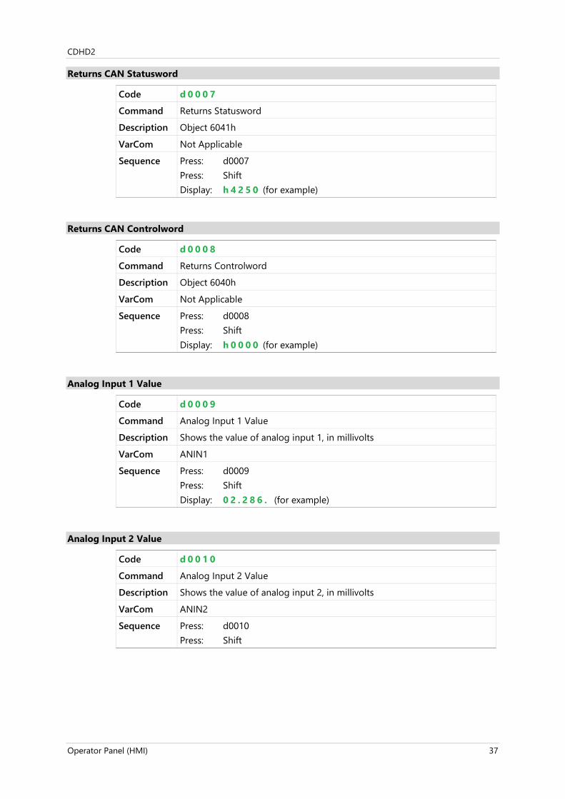
Returns CAN Statusword
Code d 0 0 0 7
Command Returns Statusword
Description Object 6041h
VarCom Not Applicable
Sequence Press: d0007 Press: Shift Display: h 4 2 5 0 (for example)
Returns CAN Controlword
Code d 0 0 0 8
Command Returns Controlword
Description Object 6040h
VarCom Not Applicable
Sequence Press: d0008 Press: Shift Display: h 0 0 0 0 (for example)
Analog Input 1 Value
Code d 0 0 0 9
Command Analog Input 1 Value
Description Shows the value of analog input 1, in millivolts
VarCom ANIN1
Sequence Press: d0009 Press: Shift Display: 0 2 . 2 8 6 . (for example)
Analog Input 2 Value
Code d 0 0 1 0
Command Analog Input 2 Value
Description Shows the value of analog input 2, in millivolts
VarCom ANIN2
Sequence Press: d0010 Press: Shift

CDHD2
38 Operator Panel (HMI)
Hardware Position External (counts)
Code d 0 0 1 1
Command Hardware Position External
Description Shows the position as measured by an external feedback device, in counts
VarCom HWPEXT
Sequence Press: d0011 Press: Shift Display: 0 0 0 3 2 . (for example)
Examples -16 counts 0 . 0 0 1 6 .

CDHD2
Operator Panel (HMI) 39
5 Operator Panel – Faults & Info Mode
The Faults & Info mode is indicated by the character F in digit 5.
HMI Fault Codes
If one or more faults occurs while the digital display is in Status, Commands or Monitoring mode, the Faults mode “hijacks” the display, and the code of the most recent fault is displayed.
When faults occur simultaneously, the display shows the code of the fault with the highest priority.
To resume work, after clearing the fault/s, you must select a different display mode.
When the digital display is in Fault mode, the fault codes are displayed as a string, in digits 4, 3, 2 and 1 as needed, and do not flash.
If a fault remains in effect, and a different display mode is selected, the fault code characters will be displayed sequentially in digit 4, with flashing.
For the full list of Fault codes, refer to Digital Display – Fault Codes in the CDHD2 User Manual.
HMI Info Codes
The Faults & Info mode is also used to display faults history, warning history, and drive information.
Info codes are shown in the table below.
The sequences for entering codes and viewing information are presented in the sections that follow.
Table 5-1. Info Codes
Command - VarCom Description Code
FLTHIST Faults History F 0 0 0 1
VER Firmware Version F 0 0 0 2
VER FPGA Version F 0 0 0 3
Not Applicable Warnings History F 0 0 0 4
CDHD2
40 Operator Panel (HMI)
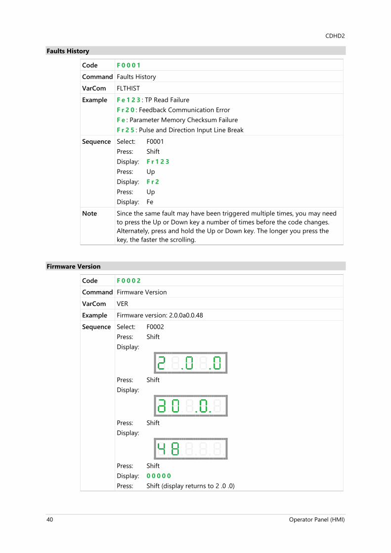
Faults History
Code F 0 0 0 1
Command Faults History
VarCom FLTHIST
Example F e 1 2 3 : TP Read Failure F r 2 0 : Feedback Communication Error F e : Parameter Memory Checksum Failure F r 2 5 : Pulse and Direction Input Line Break
Sequence Select: F0001 Press: Shift Display: F r 1 2 3 Press: Up Display: F r 2 Press: Up Display: Fe
Note Since the same fault may have been triggered multiple times, you may need to press the Up or Down key a number of times before the code changes. Alternately, press and hold the Up or Down key. The longer you press the key, the faster the scrolling.
Firmware Version
Code F 0 0 0 2
Command Firmware Version
VarCom VER
Example Firmware version: 2.0.0a0.0.48
Sequence Select: F0002 Press: Shift Display:
Press: Shift Display:
Press: Shift Display:
Press: Shift Display: 0 0 0 0 0 Press: Shift (display returns to 2 .0 .0)

CDHD2
Operator Panel (HMI) 41
FPGA Version
Code F 0 0 0 2
Command Firmware Version
VarCom VER
Example FPGA Version: 4.08 March 16 2017
Sequence Select: F0002 Press: Shift Display:
Press: Shift Display:
Press: Shift Display:
Press: Shift Display:

CDHD2
42 Operator Panel (HMI)
Warnings History
Code F 0 0 0 4
Command Warnings History
VarCom Not Applicable
Example F : Foldback Warning n : STO Warning L 6 : Software Limit Switches are Tripped
Sequence Select: F0001 Press: Shift Display: F Press: Up Display: n Press: Up Display: L6
Notes When displayed in Status mode, multi-character warning codes are displayed in sequence, in digit 4 only. When displayed in Faults & Info mode, multi-character codes are displayed as strings. Since the same warning may have been triggered multiple times, you may need to press the Up or Down key a number of times before the code changes. Alternately, press and hold the Up or Down key. The longer you press the key, the faster the scrolling.


CDHD2 Servo Drive – Operator Panel (HMI)
Servotronix - 21C Yagia Kapayim St. POB 3919 Petach Tikva 49130, Israel Tel: 972-3-927-3800 [email protected] www.servotronix.com