Industrial small servo drive system - WITTENSTEIN SE
53
cyber motor Industrial small servo drive system connective dynamic compact The second generation
-
Upload
khangminh22 -
Category
Documents
-
view
2 -
download
0
Transcript of Industrial small servo drive system - WITTENSTEIN SE

cyber motor
Industrial small servo drive system
connectivedynamiccompact
The second generation
cyber motor
Content
The Group ...........................................................................................................................04
WITTENSTEIN cyber motor ...............................................................................................06 Small servo drive system ...............................................................................................08 A plus in performance ..............................................................................................08 Nearly endless possibilities ......................................................................................10 Connective at all levels ............................................................................................12 Software MotionGUI 2 .............................................................................................14 Solutions for complex motion tasks ............................................................... 16 Applications in practice ................................................................................. 18
cyber® simco® line - Servo drives ................................................................................24 Technical data ..........................................................................................................26
cyber® dynamic line - Brushless servo motors .........................................................32 Technical data ..........................................................................................................34
cyber® dynamic line - Linear actuators ......................................................................42 Technical data ..........................................................................................................44 Options ........................................................................................................ 48
cyber® dynamic system - Servo motors and actuators ...........................................50 Technical data ..........................................................................................................52 Options ........................................................................................................ 60
cyber® power supply - DIN rail power supplies ........................................................62 Technical data ..........................................................................................................64
Cables .................................................................................................................................66
Accessories ........................................................................................................................78
Information .......................................................................................................................80 Order codes .............................................................................................................80 Service concept .......................................................................................................90 Drive selection and sizing ........................................................................................92 Commissioning and maintenance ...........................................................................93 Glossary ....................................................................................................................94https://cyber-motor.wittenstein.de/en-en/download/
Catalogs, CAD files and instruction manuals can be found in our download center on
alpha motion contro lcyber motorgalax ie
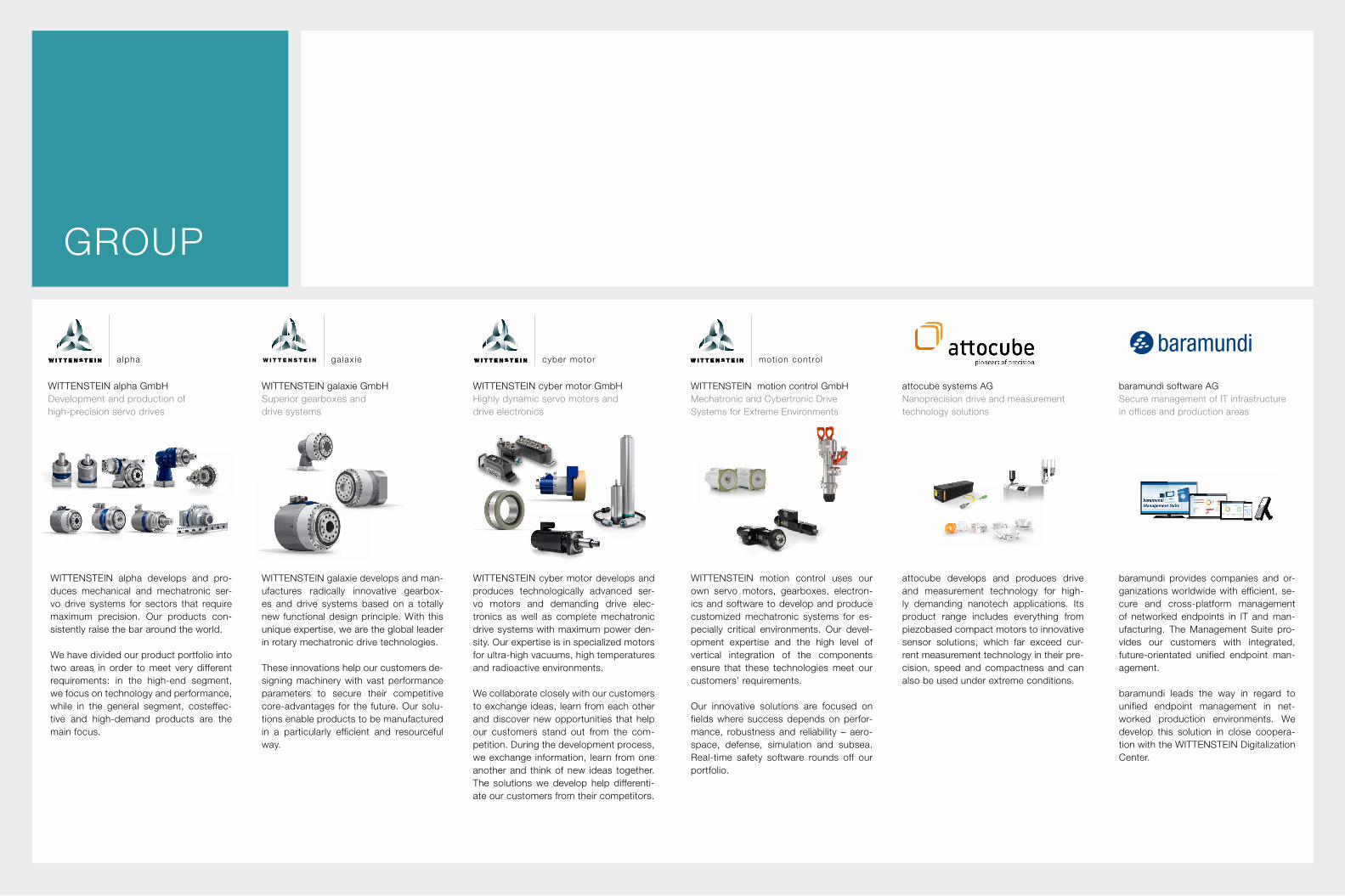
GROUP
WITTENSTEIN motion control GmbH Mechatronic and Cybertronic Drive Systems for Extreme Environments
WITTENSTEIN alpha develops and pro-duces mechanical and mechatronic ser-vo drive systems for sectors that require maximum precision. Our products con-sistently raise the bar around the world.
We have divided our product portfolio into two areas in order to meet very different requirements: in the high-end segment, we focus on technology and performance, while in the general segment, costeffec-tive and high-demand products are the main focus.
WITTENSTEIN galaxie develops and man-ufactures radically innovative gearbox-es and drive systems based on a totally new functional design principle. With this unique expertise, we are the global leader in rotary mechatronic drive technologies.
These innovations help our customers de-signing machinery with vast performance parameters to secure their competitive core-advantages for the future. Our solu-tions enable products to be manufacturedin a particularly efficient and resourceful way.
WITTENSTEIN alpha GmbH Development and production of high-precision servo drives
WITTENSTEIN galaxie GmbH Superior gearboxes and drive systems
WITTENSTEIN cyber motor GmbHHighly dynamic servo motors and drive electronics
WITTENSTEIN motion control uses our own servo motors, gearboxes, electron-ics and software to develop and produce customized mechatronic systems for es-pecially critical environments. Our devel-opment expertise and the high level of vertical integration of the components ensure that these technologies meet our customers’ requirements.
Our innovative solutions are focused on fields where success depends on perfor-mance, robustness and reliability – aero-space, defense, simulation and subsea. Real-time safety software rounds off our portfolio.
WITTENSTEIN cyber motor develops and produces technologically advanced ser-vo motors and demanding drive elec-tronics as well as complete mechatronic drive systems with maximum power den-sity. Our expertise is in specialized motors for ultra-high vacuums, high temperatures and radioactive environments.
We collaborate closely with our customers to exchange ideas, learn from each other and discover new opportunities that help our customers stand out from the com-petition. During the development process, we exchange information, learn from one another and think of new ideas together. The solutions we develop help differenti-ate our customers from their competitors.
attocube develops and produces drive and measurement technology for high-ly demanding nanotech applications. Its product range includes everything from piezobased compact motors to innovative sensor solutions, which far exceed cur-rent measurement technology in their pre-cision, speed and compactness and can also be used under extreme conditions.
baramundi provides companies and or-ganizations worldwide with efficient, se-cure and cross-platform management of networked endpoints in IT and man-ufacturing. The Management Suite pro-vides our customers with integrated, future-orientated unified endpoint man-agement. baramundi leads the way in regard to unified endpoint management in net-worked production environments. We develop this solution in close coopera-tion with the WITTENSTEIN Digitalization Center.
attocube systems AGNanoprecision drive and measurement technology solutions
baramundi software AGSecure management of IT infrastructure in offices and production areas
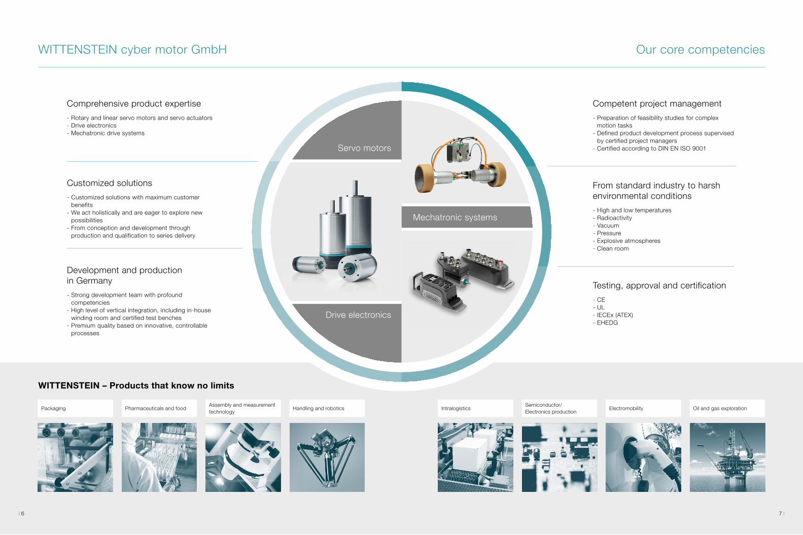
Our core competencies
Packaging Pharmaceuticals and foodAssembly and measurement technology
Handling and robotics IntralogisticsSemiconductor/ Electronics production
Electromobility Oil and gas exploration
Servo motors
Drive electronics
Mechatronic systems
WITTENSTEIN cyber motor GmbH
Comprehensive product expertise
- Rotary and linear servo motors and servo actuators- Drive electronics- Mechatronic drive systems
Customized solutions
- Customized solutions with maximum customer benefits
- We act holistically and are eager to explore new possibilities
- From conception and development through production and qualification to series delivery
Development and production in Germany
- Strong development team with profound competencies
- High level of vertical integration, including in-house winding room and certified test benches
- Premium quality based on innovative, controllable processes
WITTENSTEIN – Products that know no limits
Competent project management
- Preparation of feasibility studies for complex motion tasks
- Defined product development process supervised by certified project managers
- Certified according to DIN EN ISO 9001
From standard industry to harsh environmental conditions
- High and low temperatures- Radioactivity- Vacuum- Pressure- Explosive atmospheres- Clean room
Testing, approval and certification
- CE- UL- IECEx (ATEX)- EHEDG
7 6
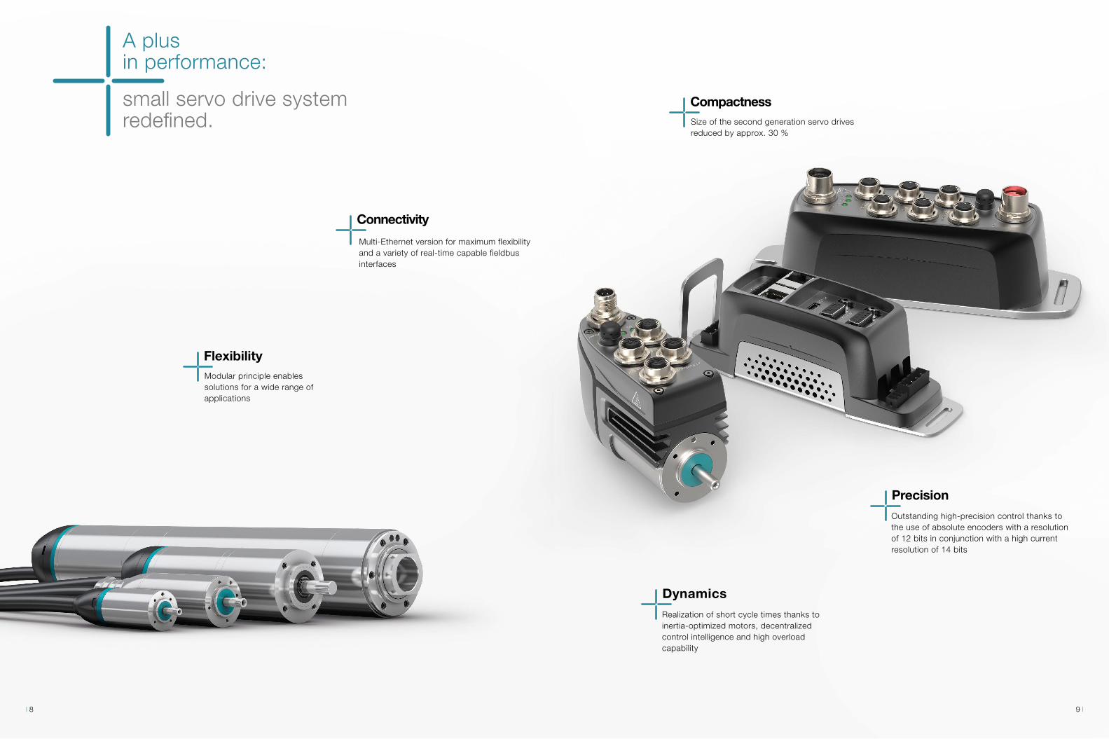
Flexibility
A plusin performance:
small servo drive systemredefined.
Connectivity
Multi-Ethernet version for maximum flexibility and a variety of real-time capable fieldbus interfaces
Modular principle enables solutions for a wide range of applications
Compactness
Dynamics Realization of short cycle times thanks to inertia-optimized motors, decentralized control intelligence and high overload capability
PrecisionOutstanding high-precision control thanks to the use of absolute encoders with a resolution of 12 bits in conjunction with a high current resolution of 14 bits
Size of the second generation servo drives reduced by approx. 30 %
9 8

connective
Flexible interfaces, intelligent soft-ware and technology functions and connection options to a wide rangeof control systems make the small drive system a multitalent in pro-cess design.
dynamic
Mass inertia-optimized motors, a high current resolution and coor-dinated control parameters permit high-precision and dynamic control of the system.
compact
Miniaturization is an integral part in the product and development strat-egy of WITTENSTEIN cyber motor. Servo motors with high torque den-sity, a diameter of 17 mm and the option of decentralized use of the electronics for space savings in the switch cabinet are just a few as-pects of the system.
Thanks to the numerous interfaces, the
small servo drive system offers maxi-
mum flexibility for the most demanding
tasks in modular machine construction.
The second generation of WITTENSTEIN cyber motor‘s industrial small servo drive system guaran-tees a plus in performance in terms of connectivity, compactness and configurability:
The small servo drive system at a glance:The system is convincing in every respect.
The cyber® simco® drive 2 servo drives are up to 30 % more compact than their predecessors and offer max-imum connectivity with their Multi-Ethernet-Interface. They also feature real-time CIP Sync functionality, de-centralized intelligence and a STO safety function. The new servo drives have also made it possible to realize the cyber® dynamic system. The motor-integrated de-sign convinces through the decentralized intelligence directly on the axis and saves space in the cabinet. The servo motors of the cyber® dynamic line and the cyber® dynamic system are now optionally available with a multiturn encoder (size 32/40), holding brake (size 40), gearbox or ball screw drive.
This creates new freedom in your machine design.
Servo drive - cyber® simco® drive 2The servo drives feature a Multi-Ethernet-Interface, CIP Sync real-time functionality, decentralized intelligence and STO safety func-tion. They are either available with protection class IP20 or IP65 in a very compact design.
Drive system - cyber® dynamic systemThe motor-integrated version offers a Multi-Ethernet-Interface and convinces with decentralized intelligence directly on the axis. The system is optionally available with different encoder variants and plan-etary gearboxes, ball screw drive or holding brake.
Servo motors and actuators - cyber® dynamic lineThe industrial servo motors are the professional choice for dynamic applications with limited installation space. With high-quality stain-less steel housing and absolute encoder (singleturn or multiturn), the motor series offers the highest reliability and precision. Optionally the servo motors can be equipped with a holding brake, planetary gear-box or ball screw drive.
Small servo drive system Nearly endless possibilities
11 10
Interface performance
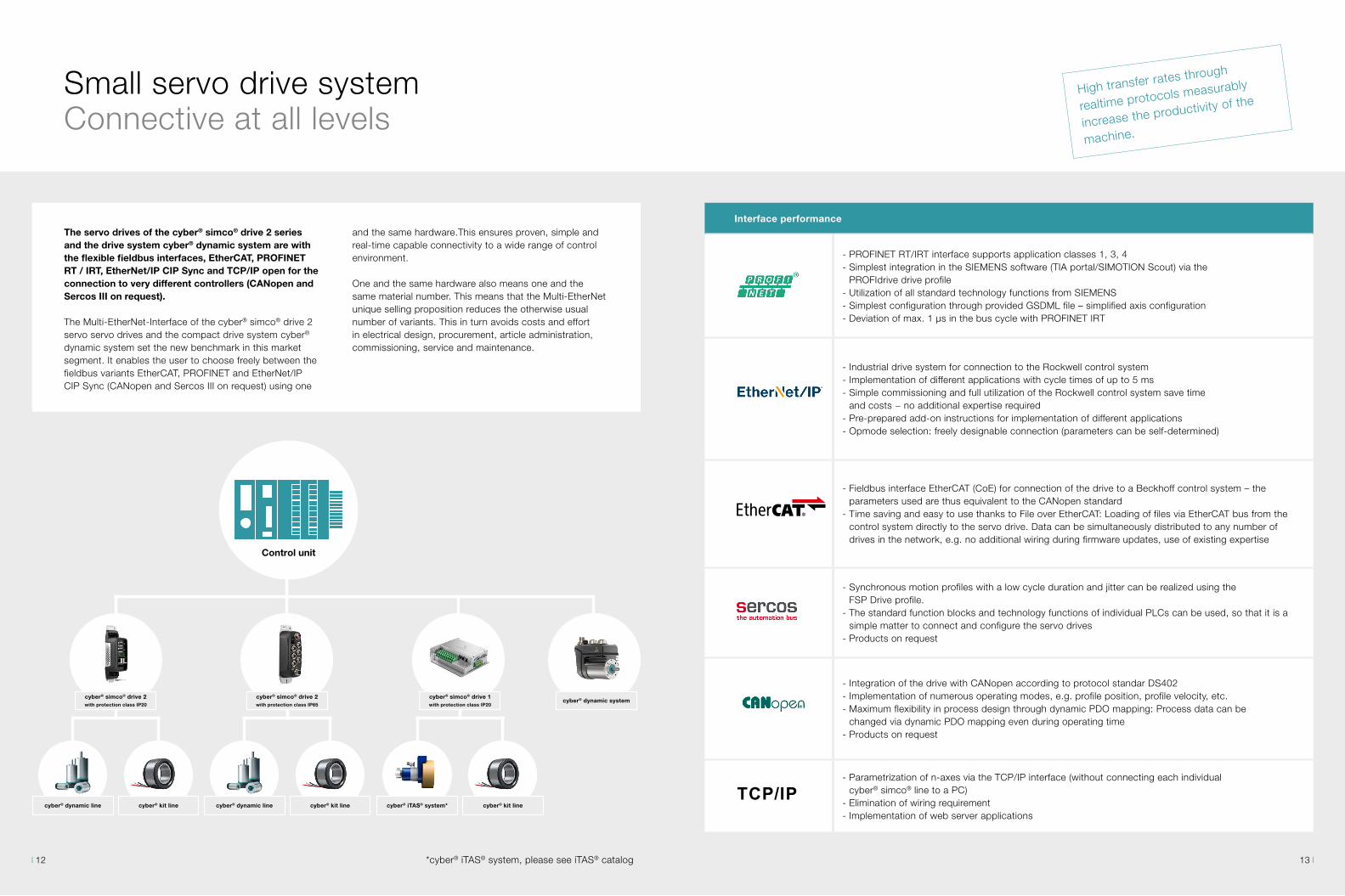
- PROFINET RT/IRT interface supports application classes 1, 3, 4- Simplest integration in the SIEMENS software (TIA portal/SIMOTION Scout) via the
PROFIdrive drive profile- Utilization of all standard technology functions from SIEMENS- Simplest configuration through provided GSDML file – simplified axis configuration- Deviation of max. 1 μs in the bus cycle with PROFINET IRT
- Industrial drive system for connection to the Rockwell control system- Implementation of different applications with cycle times of up to 5 ms- Simple commissioning and full utilization of the Rockwell control system save time
and costs − no additional expertise required- Pre-prepared add-on instructions for implementation of different applications- Opmode selection: freely designable connection (parameters can be self-determined)
- Fieldbus interface EtherCAT (CoE) for connection of the drive to a Beckhoff control system – the parameters used are thus equivalent to the CANopen standard
- Time saving and easy to use thanks to File over EtherCAT: Loading of files via EtherCAT bus from the control system directly to the servo drive. Data can be simultaneously distributed to any number of drives in the network, e.g. no additional wiring during firmware updates, use of existing expertise
- Synchronous motion profiles with a low cycle duration and jitter can be realized using the FSP Drive profile.
- The standard function blocks and technology functions of individual PLCs can be used, so that it is a simple matter to connect and configure the servo drives
- Products on request
- Integration of the drive with CANopen according to protocol standar DS402- Implementation of numerous operating modes, e.g. profile position, profile velocity, etc.- Maximum flexibility in process design through dynamic PDO mapping: Process data can be
changed via dynamic PDO mapping even during operating time- Products on request
- Parametrization of n-axes via the TCP/IP interface (without connecting each individual cyber® simco® line to a PC)
- Elimination of wiring requirement- Implementation of web server applications
TCP/IP
The servo drives of the cyber® simco® drive 2 series and the drive system cyber® dynamic system are with the flexible fieldbus interfaces, EtherCAT, PROFINET RT / IRT, EtherNet/IP CIP Sync and TCP/IP open for the connection to very different controllers (CANopen and Sercos III on request).
The Multi-EtherNet-Interface of the cyber® simco® drive 2 servo servo drives and the compact drive system cyber® dynamic system set the new benchmark in this market segment. It enables the user to choose freely between the fieldbus variants EtherCAT, PROFINET and EtherNet/IP CIP Sync (CANopen and Sercos III on request) using one
and the same hardware.This ensures proven, simple and real-time capable connectivity to a wide range of control environment.
One and the same hardware also means one and the same material number. This means that the Multi-EtherNet unique selling proposition reduces the otherwise usual number of variants. This in turn avoids costs and effort in electrical design, procurement, article administration, commissioning, service and maintenance.
High transfer rates through
realtime protocols measurably
increase the productivity of the
machine.
Small servo drive system Connective at all levels
Control unit
cyber® simco® drive 2 with protection class IP20
cyber® simco® drive 2 with protection class IP65
cyber® simco® drive 1 with protection class IP20
cyber® dynamic line cyber® dynamic line cyber® iTAS® system*cyber® kit line cyber® kit line
cyber® dynamic system
cyber® kit line
*cyber® iTAS® system, please see iTAS® catalog 13 12

The MotionGUI 2 graphical user interface guides the user intuitively during commissioning and operation of the drive system. Diagnoses, optimizations and parametrization of the drive can be performed via a number of functions. Diagnostic
routines and event logging are implemented by means of a time stamp. Condition monitoring as well as integration and maintenance work can be carried out in an efficient and time-saving way – visible at any time in MotionGUI 2 software.
- Extended motion block table with „decentralized intelligence“ for individual modification and flexible programming of the application
- Simple creation of motion tasks with reduced programming effort for the machine manufacturer
- Complex single-axis movements, such as clamping processes or actuation of lifting modules can also be generated and executed decentrally
- In the case of several synchronized axes: movements can be started simultaneously via a synchroniza-tion signal from the control system
- Realization of stand-alone solutions by omitting the control system
- Oscilloscope function Analysis of applications and move-ment sequences via the oscillo-scope function – also possible in offline mode
- Errors and warnings Logging of errors and warnings for fast troubleshooting – storage of errors in error history
Diagnostic functions
Motion tasks
Remote maintenance via MotionGUI 2
- MotionGUI 2 can be used for remote maintenance via TCP / IP communication
- Performance of analyses and diagnoses in the installed state (e.g. during machine break-downs)
Intuitive control during commissioning and operation
Small servo drive system Software MotionGUI 2
15 14
Small servo drive systemSolutions for complex motion tasks
Precise.
Cost-effective.
Flexible.
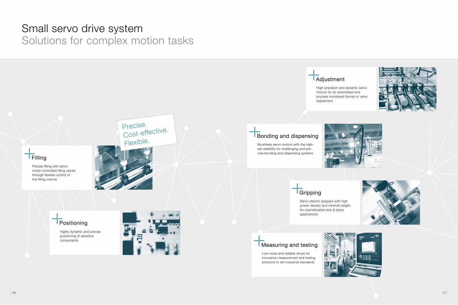
AdjustmentHigh-precision and dynamic servo motors for an automated and process monitored format or valve adjustment
Bonding and dispensingBrushless servo motors with the high-est reliability for challenging and pre-cise bonding and dispensing systems
FillingPrecise filling with servo motor-controlled filling valves through flexible control of the filling volume
Positioning
Highly dynamic and precise positioning of sensitive components
GrippingServo electric grippers with high power density and minimal weight for sophisticated pick & place applications
Measuring and testingLow-noise and reliable drives for innovative measurement and testing solutions to set industrial standards
17 16
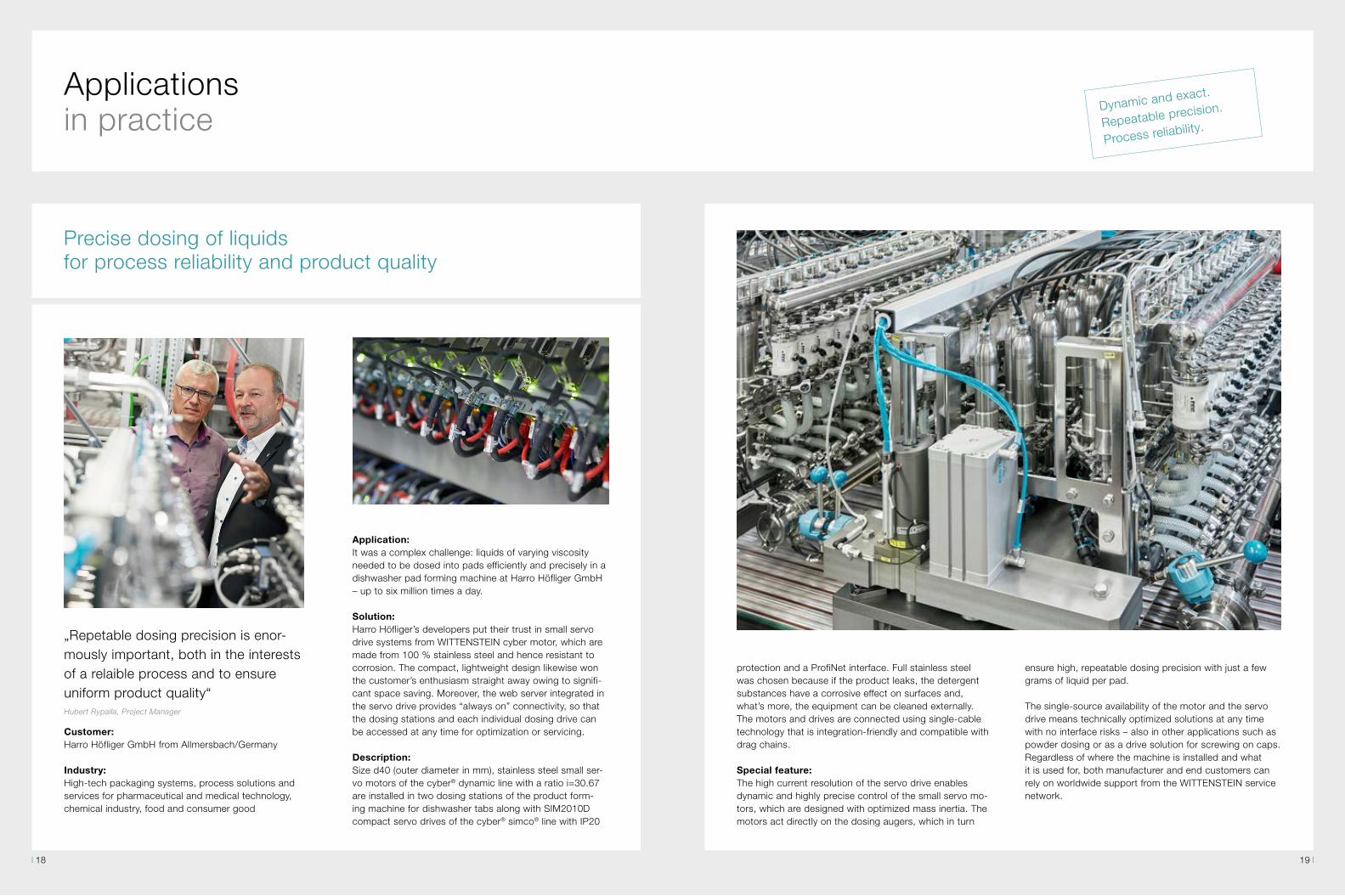
Application:It was a complex challenge: liquids of varying viscosity needed to be dosed into pads efficiently and precisely in a dishwasher pad forming machine at Harro Höfliger GmbH – up to six million times a day.
Solution:Harro Höfliger’s developers put their trust in small servo drive systems from WITTENSTEIN cyber motor, which are made from 100 % stainless steel and hence resistant to corrosion. The compact, lightweight design likewise won the customer’s enthusiasm straight away owing to signifi-cant space saving. Moreover, the web server integrated in the servo drive provides “always on” connectivity, so that the dosing stations and each individual dosing drive can be accessed at any time for optimization or servicing.
Description:Size d40 (outer diameter in mm), stainless steel small ser-vo motors of the cyber® dynamic line with a ratio i=30.67 are installed in two dosing stations of the product form-ing machine for dishwasher tabs along with SIM2010D compact servo drives of the cyber® simco® line with IP20
protection and a ProfiNet interface. Full stainless steel was chosen because if the product leaks, the detergent substances have a corrosive effect on surfaces and, what’s more, the equipment can be cleaned externally. The motors and drives are connected using single-cable technology that is integration-friendly and compatible with drag chains.
Special feature:The high current resolution of the servo drive enables dynamic and highly precise control of the small servo mo-tors, which are designed with optimized mass inertia. The motors act directly on the dosing augers, which in turn
Precise dosing of liquids for process reliability and product quality
„Repetable dosing precision is enor-mously important, both in the interests of a relaible process and to ensure uniform product quality“Hubert Rypalla, Project Manager
Customer:Harro Höfliger GmbH from Allmersbach/Germany
Industry:High-tech packaging systems, process solutions and services for pharmaceutical and medical technology, chemical industry, food and consumer good
ensure high, repeatable dosing precision with just a few grams of liquid per pad.
The single-source availability of the motor and the servo drive means technically optimized solutions at any time with no interface risks – also in other applications such as powder dosing or as a drive solution for screwing on caps. Regardless of where the machine is installed and what it is used for, both manufacturer and end customers can rely on worldwide support from the WITTENSTEIN service network.
Dynamic and exact.
Repeatable precision.
Process reliability.
Applications in practice
19 18
Compact design.
Low weight.
Easy integration.
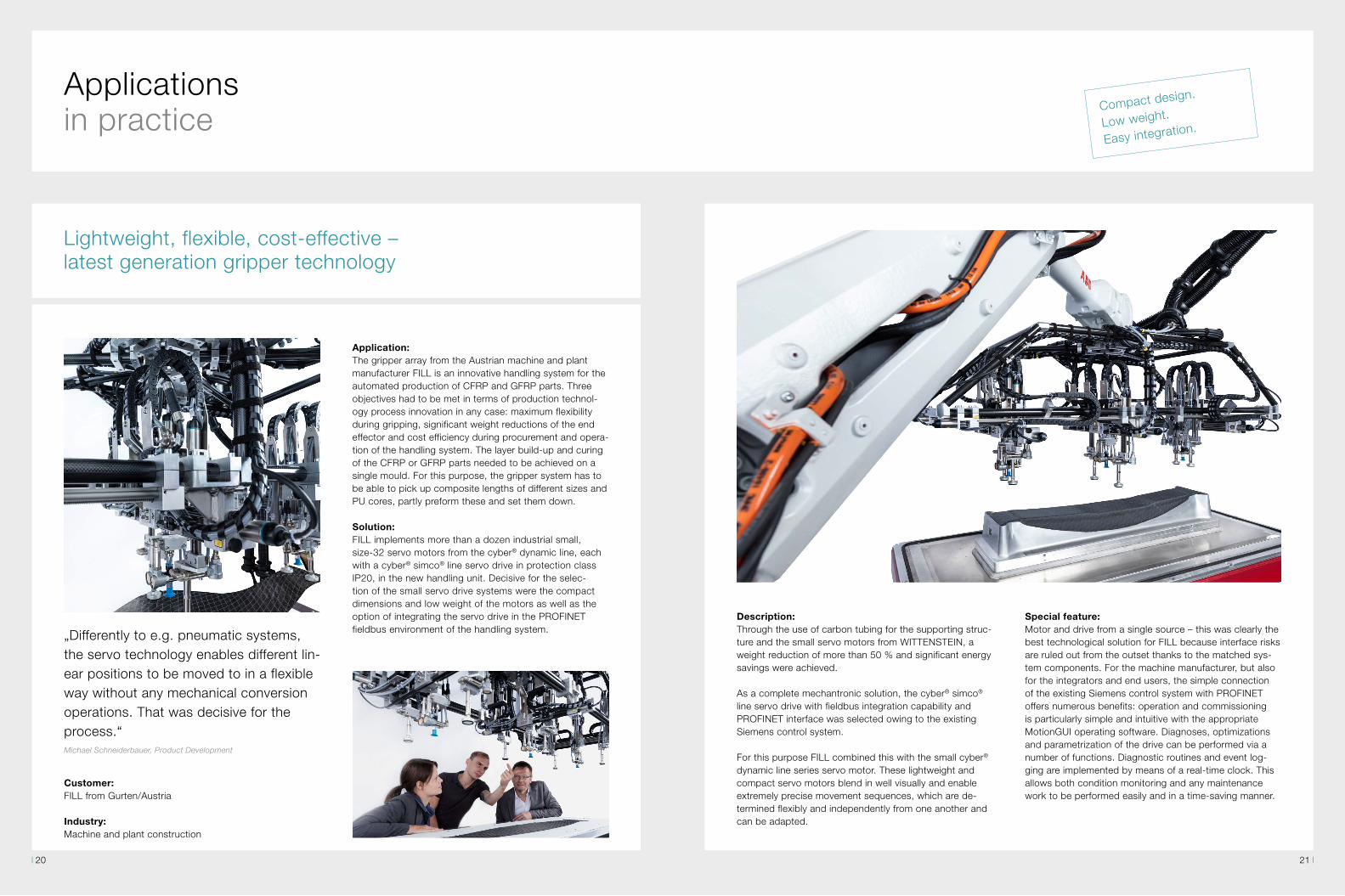
Application:The gripper array from the Austrian machine and plant manufacturer FILL is an innovative handling system for theautomated production of CFRP and GFRP parts. Three objectives had to be met in terms of production technol-ogy process innovation in any case: maximum flexibility during gripping, significant weight reductions of the endeffector and cost efficiency during procurement and opera-tion of the handling system. The layer build-up and curingof the CFRP or GFRP parts needed to be achieved on a single mould. For this purpose, the gripper system has tobe able to pick up composite lengths of different sizes and PU cores, partly preform these and set them down.
Solution:FILL implements more than a dozen industrial small, size-32 servo motors from the cyber® dynamic line, each with a cyber® simco® line servo drive in protection class IP20, in the new handling unit. Decisive for the selec-tion of the small servo drive systems were the compact dimensions and low weight of the motors as well as the option of integrating the servo drive in the PROFINET fieldbus environment of the handling system.
Description:Through the use of carbon tubing for the supporting struc-ture and the small servo motors from WITTENSTEIN, a weight reduction of more than 50 % and significant energy savings were achieved.
As a complete mechantronic solution, the cyber® simco® line servo drive with fieldbus integration capability and PROFINET interface was selected owing to the existing Siemens control system.
For this purpose FILL combined this with the small cyber® dynamic line series servo motor. These lightweight and compact servo motors blend in well visually and enable extremely precise movement sequences, which are de-termined flexibly and independently from one another and can be adapted.
Applications in practice
Lightweight, flexible, cost-effective –latest generation gripper technology
„Differently to e.g. pneumatic systems,the servo technology enables different lin-ear positions to be moved to in a flexibleway without any mechanical conversionoperations. That was decisive for theprocess.“Michael Schneiderbauer, Product Development
Customer:FILL from Gurten/Austria
Industry:Machine and plant construction
Special feature:Motor and drive from a single source – this was clearly the best technological solution for FILL because interface risks are ruled out from the outset thanks to the matched sys-tem components. For the machine manufacturer, but also for the integrators and end users, the simple connection of the existing Siemens control system with PROFINET offers numerous benefits: operation and commissioning is particularly simple and intuitive with the appropriate MotionGUI operating software. Diagnoses, optimizations and parametrization of the drive can be performed via a number of functions. Diagnostic routines and event log-ging are implemented by means of a real-time clock. This allows both condition monitoring and any maintenance work to be performed easily and in a time-saving manner.
21 20

Application:For the processing of reactive casting resins, a small servo drive system with special performance focuses was being sought: The requirement was for a complete drive solution guaranteeing the highest dispensing and repeat accuracywith completely different material properties during pro-cessing.
Solution:The performance package consisting of cyber® simco® line drive and cyber® dynamic actuator R can reliably cope with the extremely heterogeneous influencing factors.
Description:The complete solution from WITTENSTEIN optimally ex-ploitsthe performance potential of the drive solution: The cyber® dynamic line size 40 servo motors work with inte-grated planetary gearheads and drive the eccentric screw pumps so that even the tiniest quantities in the microliter range can be dispensed with precision. Precise control via the cyber® simco® line servo drive makes it possible to individually regulate the dispensing quantities and to min-imize the quantity tolerances. In this way, the dispensing results can be optimized in a reproducible manner – under full process control, at all times.
Special feature:The cyber® simco® line servo drive is characterized by very high-resolution current regulation and fast current meas-urement. This enables the delivery of the tiniest quantities with great accuracy, even in the case of variable movement speeds.
„The market places ever higher demandson dispensing and repeat accuracy“Markus Rieger, Sales Director Germany
Customer:bdtronic GmbH from Weikersheim
Industry:Plant systems and process solutions for dispensing technology and other special applications
Process accuracy for positioning anddosing of smallest quantities
Optimal system solution with decentralized control unit
Applications in practice
„The consulting from a single source ensures reliable project planning.“Joachim Walter, Managing Director at BeeWaTec AG
Customer:BeeWaTec AG from Pfullingen near Reutlingen
Industry:Mini AGV for production and warehouse logistics
Application:The manufacturer of automated guided vehicles was looking for a tailor-made drive solution for use in a modular mini-vehicle for transporting stacked goods containers.
Solution:iTAS® system with TAS 004 plus cyber® simco® line IP20 and, as a "perfect match", cyber® dynamic actuator R size 40 with cyber® simco® line IP20.
Description:Through individual selection of the motor/gearhead unit in conjunction with the appropriate cyber® simco® line electronics, extremely diverse performance ranges can be covered. At BeeWaTec, the cyber® simco® line is also used as a decentralized control unit for the handling equipment on the vehicles and is adapted to the small high-torque drives of the cyber® dynamic line. Procuring both drive solutions from a single source was a decisive argument for BeeWaTec.
Special feature:A special requirement for the BeeWaTec Mini vehicle is transporting overall weights of up to 150 kg, which not only have to be pulled, but also clamped to the vehicle. This is made possible by the innovative solution for the clamping actuator in the vehicle: the clamping is controlled decentrally via the cyber® simco® line. Digital inputs and outputs connect this to the vehicle computer; there is no need for a complicated fieldbus interface. BeeWaTec cre-ated a motion task for the clamping. This is part of the in-tuitive MotionGUI user interface and is stored in the cyber® simco® line. The motion task contains all the necessary parameters for the clamping in the form of a list.
23 22

cyber® simco® line Servo drives
connective · intelligent · safecyber® simco® line · Servo drives
Space saving installationStackability and user-friendly pin assignment
Saving installation spaceup to 30 %
Numerous fieldbus interfaces and decentral intelligence - Multi-Ethernet version - Real-time capable
fieldbus interfaces - Various encoder interfaces - PLC functionality
Wide range input12-60 VDC
Integrated safety functionSTO according to SIL3 / PL e
Electronic name plateAutomatic and safe parametrization of the motor
Torque controlHigh precision and dynamic
Protection class IP20 / IP65
In combination with various servo motors and servo actua-tors, cyber® simco® drive 2 is the ideal solution for fast and precise moving and positioning tasks. With a continuous output of up to 750 W and a short-term peak output of 1.5 kW, the servo drive is suitable for high-precision appli-
cations, e.g. in the machine-tool, electronics or packaging industries – as a switch cabinet version with protection class IP20 or decentralized version with protection class IP65.
The cyber® simco® drive 2 servo drive is equipped with a Multi-Ethernet-Interface and allows with one and the same hardware – free selection between the Fieldbus variants EtherCat, PROFINET, EtherNet/IP CIP Sync (CANopen and Sercos III on request).This feature ensures proven, simple and real-time connectivity to a wide variety of control environments. The Multi-Ethernet version also reduces the usual number of variants and avoids high effort in the elec-trical construction, in procurement, article administration and commissioning, service and maintenance.
Connectivity
Flexibility
Dynamics and precision
Safety and robustness
Compactness and simplicity
Intelligencecyber® simco® line "thinks" ahead and for you. Integration, commissioning, operability, expansion, configuration, communication: with cyber® simco® line, everything is designed for simplicity, intuition and efficiency. This saves time and money – and is more than clever.
Suitable for industrial use - this term can be used to describe the combination of robust design and integrat-ed safety. With the integrated safety function STO (Safe Torque Off) all servo drive variants fulfill safety requirements according to SIL3 / PL e. In addition, the servo drives are equipped with a 12 to 60 VDC wide range input, which allows compensation for any fluctuations in the voltage source. The servo drives are also available with protection class up to IP65 and are suitable for demanding operation condi-tions.
The Multi-Ethernet version of the simco® drive 2 series offers a wide range of flexibility in selecting the required interfaces. In addition, various performance classes are available, which can be selected precisely according to the application. The flexible programming of motion tasks and the portfolio of IP20 and IP65 variants allows enormous freedom in machine design for control cabinet or decen-tralized applications.
The cyber® simco® drive 2 servo drives convince with their compact design. This series is 30 % more compact than the previous version and allow with the forward arranged mounting brackets user friendly pin assignments. This also allows stackability of the servo drives in the switch cabi-net, which saves space or offers solutions for the tightest installation conditions.
Dynamics and precision are two further features that characterize the cyber® simco® drive servo drives. The real-time-capable and clock-synchronous Ethernet communication, the high current resolution of 14 bits and a switching frequency of 16 kHz enable highly accurate torque control in complex motion control applications.
25 24

cyber motor
cyber® simco® drive 2 IP20
Performance version SIM2007 SIM2015
Supply voltage (Power / Logic / STO)
VDC + 12 ... 60
Rated current Aeff 7.5 15
Maximum current Aeff 15 30
Rated power (at 48 VDC)
W 375 750
Maximum power (at 48 VDC)
W 750 1500
Communication - EtherCat, PROFINET RT/IRT, EtherNet/IP CIP Sync, Sercos III*, CANopen*
Encoder interface - EnDat 2.2, BiSS-C, Resolver, Sin/Cos-Encoder
Commissioning - USB
Digital inputs - 4
Digital outputs - 2
Safety function - STO according to SIL 3
Brake control - yes
Brake chopper - integrated, connection of a braking resistor possible
Technology functions - Motion Task
Weight kg 0.36
Ambient temperature °C 0 ... 45
Protection class IP 20
Approval - NRTL, CE, STO according to SIL3 / PL e
Number Function Connector on the device
X1 Power supply Dinkle 5EHDVC-04PL (is supplied)
X2 Optional auxiliary voltage logic and STO Dinkle ECH350V-03PL (is supplied)
X3 Resolver- / Sin/Cos-Encoder interface SUB-D 9-pole socket
X4 Encoder interface SUB-D 15-pole socket
X5 Diagnostic interface USB Mini USB-B socket
X6 Fieldbus interface Input RJ45 socket
X7 Fieldbus interface Output RJ45 socket
X8 Digital inputs and -outputs Dinkle 0225 (is supplied)
X9 Connection of motor temperature sensor and brake Dinkle 0159 (is supplied)
X10 Motor (U, V, W, PE) Dinkle 5EHDVC-04PL coded (is supplied)
* Sercos III and CANopen on request
Shield clamp available as accessory (see page 78)
27 26

cyber motor
cyber® simco® drive 2 IP65
Performance version SIM2007 SIM2015
Supply voltage (Power / Logic / STO)
VDC +12 ... 60
Rated current Aeff 7.5 15
Maximum current Aeff 15 30
Rated power (at 48 VDC)
W 375 750
Maximum power (at 48 VDC)
W 750 1500
Communication - EtherCat, PROFINET RT/IRT, EtherNet/IP CIP Sync, Sercos III*, CANopen*
Encoder interface - EnDat 2.2, BiSS-C, Resolver, Sin/Cos-Encoder
Commissioning - USB
Digital inputs - 4
Digital outputs - 2
Safety function - STO according to SIL 3
Brake control - yes
Brake chopper - integrated, connection of a braking resistor possible
Technology functions - Motion Task
Weight kg 0.62
Ambient temperature °C 0 ... 55
Protection class IP 65
Approval - NRTL, CE, STO according to SIL3 / PL e
Number Function Connector on the device
X1 Power supply (optional auxiliary voltage logic and STO) Intercontec, itec 915, 9-pole, connector
X2 Fieldbus interface OutputCAN: M12 5-pole socket A-coded
Ethernet-based: M12 4-pole socket D-coded
X3 Fieldbus interface InputCAN: M12 5-pole connector A-coded
Ethernet-based: M12 4-pole socket D-coded
X4 Diagnostic interface USB M12 4-pole socket A-coded
X5 Digital inputs and -outputs M12 8-pole connector A-coded
X6 Resolver- / Sin/Cos-Encoder interface M12 8-pole socket, A-coded
X7 Encoder interface M12 12-pole socket, A-coded
X8 Motor (U, V, W, PE, connection of motor temperature sensor and brake) Intercontec, itec 915, 15-pole, socket
* Sercos III and CANopen on request
29 28

cyber motor
Performance version SIM2050D-C
Supply voltage (Power)
UDC VDC
+12 … +60 (unregulated)
Supply voltage (Logic)
Ulog VDC
+12 … +60 (unregulated)
Rated current IN Aeff 50
Maximum current Imax Aeff 100 (for 5s)
Rated power(at 48 VDC)
PN W 2500
Maximum power(at 48 VDC)
Pmax W 5000
Switchung frequency fPWM kHz 8 … 32
Current control resolution - Bit 14
Communication - - CANopen, EtherCAT, PROFINET RT / IRT, EtherNet / IP, Sercos III
Encoder interface - - BISS C, EnDat 2.2*, Hall sensors, Resolver
Commissioning - - RS232
Digital inputs - - 4, opto-decoupled, freely programmable function
Digital outputs - - 2, opto-decoupled, freely programmable function
Safety function - -STO (Safe Torque off) according to SIL3 / PL e
certified
Brake control - - yes
Brake chopper - - Not integrated
Technology functions - - Disk cam, Motion Tasks
Weight m kg 1.03
Event logging with real-time clock - - yes
Ambient temperature ϑA °C 0 … 45
Protection class - IP 20
Approval - - CE, STO according to SIL 3 / PL e
Heat sink available as accessory (see page 78)
Number Function Connector on the device
X1 Fieldbus interface Input RJ45 socket
X2 Fieldbus interface Output RJ45 socket
X3 Diagnostic interface RS232 RJ12 socket
X4 Encoder interface SUB-D 15-pole socket
X5 Resolver interface SUB-D 9-pole socket
X6 Digital inputs and -outputs SUB-D 9-pole connector
X7 Motor connection Phoenix Contact ZFKDS 10-10.00
X8 Power supply Phoenix Contact MC 1.5 / 10-GF-3.5
cyber® simco® drive 1 IP20
* not in combination with Sercos III
31 30
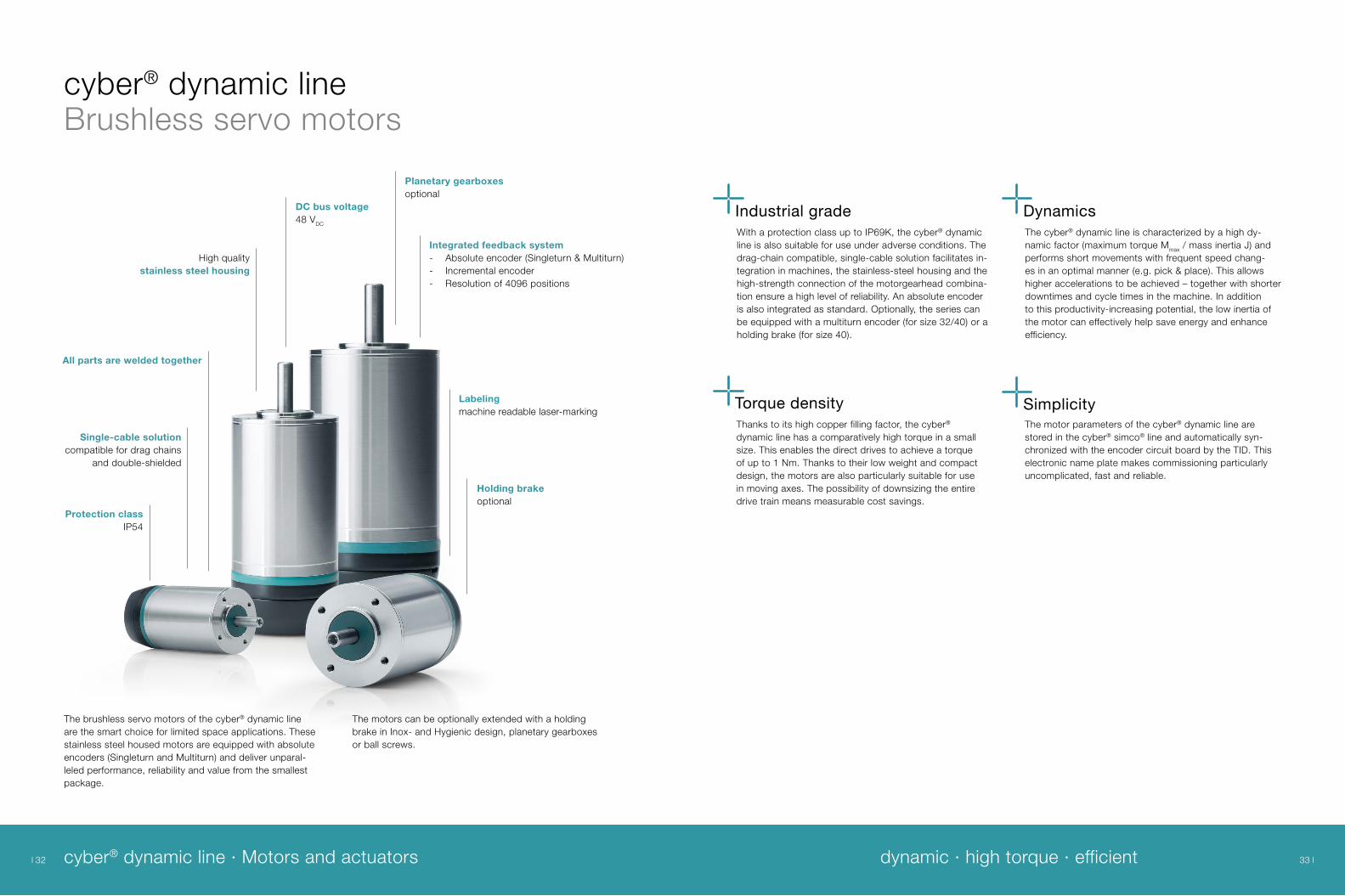
cyber® dynamic lineBrushless servo motors
cyber® dynamic line · Motors and actuators dynamic · high torque · efficient
DC bus voltage 48 VDC
Planetary gearboxesoptional
Single-cable solutioncompatible for drag chains
and double-shielded
All parts are welded together
Labelingmachine readable laser-marking
Protection classIP54
High qualitystainless steel housing
Integrated feedback system - Absolute encoder (Singleturn & Multiturn) - Incremental encoder - Resolution of 4096 positions
Holding brakeoptional
The brushless servo motors of the cyber® dynamic line are the smart choice for limited space applications. These stainless steel housed motors are equipped with absolute encoders (Singleturn and Multiturn) and deliver unparal-leled performance, reliability and value from the smallest package.
The motors can be optionally extended with a holding brake in Inox- and Hygienic design, planetary gearboxes or ball screws.
With a protection class up to IP69K, the cyber® dynamic line is also suitable for use under adverse conditions. The drag-chain compatible, single-cable solution facilitates in-tegration in machines, the stainless-steel housing and the high-strength connection of the motorgearhead combina-tion ensure a high level of reliability. An absolute encoder is also integrated as standard. Optionally, the series can be equipped with a multiturn encoder (for size 32/40) or a holding brake (for size 40).
Industrial grade
SimplicityTorque density
DynamicsThe cyber® dynamic line is characterized by a high dy-namic factor (maximum torque Mmax / mass inertia J) and performs short movements with frequent speed chang-es in an optimal manner (e.g. pick & place). This allows higher accelerations to be achieved – together with shorter downtimes and cycle times in the machine. In addition to this productivity-increasing potential, the low inertia of the motor can effectively help save energy and enhance efficiency.
Thanks to its high copper filling factor, the cyber® dynamic line has a comparatively high torque in a small size. This enables the direct drives to achieve a torque of up to 1 Nm. Thanks to their low weight and compact design, the motors are also particularly suitable for use in moving axes. The possibility of downsizing the entire drive train means measurable cost savings.
The motor parameters of the cyber® dynamic line are stored in the cyber® simco® line and automatically syn-chronized with the encoder circuit board by the TID. This electronic name plate makes commissioning particularly uncomplicated, fast and reliable.
33 32
cyber motor
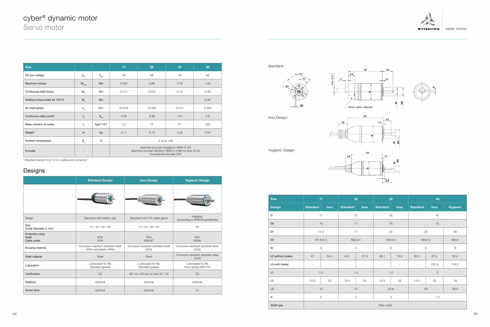
Size 17 22 32 40
DC bus voltage UDc VDC 48 48 48 48
Maximum torque Mmax Nm 0.035 0.08 0.33 1.02
Continuous stall torque M0 Nm 0.012 0.034 0.14 0.38
Holding torque brake (at 120°C) M4 Nm - - - 0.36
No-load speed n0 min-1 22.918 14.324 9.513 5.590
Continuous stall current I0 Aeff 0.52 0.96 2.6 3.9
Mass moment of inertia J1 kgm2*10-8 5.2 12 57 250
Weight* m kg 0.11 0.15 0.33 0.54
Ambient temperature ϑU °C 0 up to +40
Encoder - -Absolute encoder Singleturn BISS-C (HI)
Absolute encoder Multiturn BISS-C (HM) for size 32/40Incremental encoder (HF)
Designs
Size 17 22 32 40
Design Standard Inox Standard Inox Standard Inox Standard Inox Hygienic
D 17 22 32 40
D0 10 13 16 22
D1 12.5 17 22 32 30
D2 M1.6x2.5 M2x3.5 M3x4.5 M3x4.5 M3x4
W 3 4 6 6 8
L0 (without brake) 47 54.4 49.1 57.9 66.1 74.6 80.3 87.4 90.4
L0 (with brake) - - - - - - - 130.5 133.5
L1 1.2 1.5 1.5 2
L2 13.3 20 12.4 20 12.5 22 14.5 22 18
L3 10 12 20.6 20 28.5
H 0 0 3 7.5
Shaft type Plain shaft
L3
cyber® dynamic motor Servo motor
L3
L3
H
WW
W
D0
D0
D0
L0
L0
L0
L2
L2
L2
L1
L1
L1
4 x 90 °
45 °
Motor cable, separate
max
. Ø
9.7
6
D1
D2
DD
D
Inox Design:
Standard:
Hygienic Design:
* Standard version incl. 0.5 m cable and connector
Standard Design Inox Design Hygienic Design
Design Standard with plastic cap Standard with PG-cable glandHygienic
(according to EHEDG guidelines)
Size(Outer diameter in mm)
17 / 22 / 32 / 40 17 / 22 / 32 / 40 40
Protection classShaftCable outlet
IP20IP54
IP20IP66/67
IP67IP69K
Housing materialCorrosion-resistant stainless steel
(V2A) and plastic (PA6)Corrosion-resistant stainless steel
(V2A)Corrosion-resistant stainless steel
(V2A)
Shaft material Steel SteelCorrosion-resistant stainless steel
(V2A)
LubricationLubricated for lifeStandard grease
Lubricated for lifeStandard grease
Lubricated for lifeFood grade (NSF/H1)
Certification CE CE, UL (cRUus) for size 32 / 40 CE
Gearbox optional optional optional
Screw drive optional optional no
35 34
cyber motor
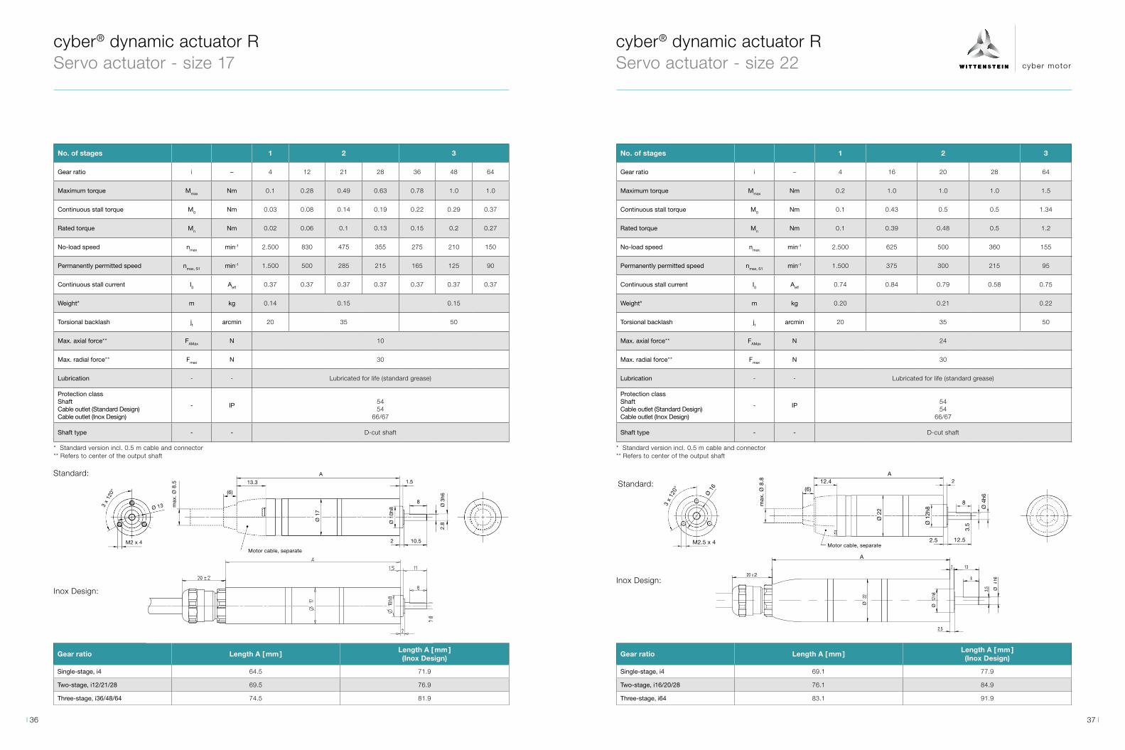
No. of stages 1 2 3
Gear ratio i – 4 12 21 28 36 48 64
Maximum torque Mmax Nm 0.1 0.28 0.49 0.63 0.78 1.0 1.0
Continuous stall torque M0 Nm 0.03 0.08 0.14 0.19 0.22 0.29 0.37
Rated torque Mn Nm 0.02 0.06 0.1 0.13 0.15 0.2 0.27
No-load speed nmax min-1 2.500 830 475 355 275 210 150
Permanently permitted speed nmax, S1 min-1 1.500 500 285 215 165 125 90
Continuous stall current I0 Aeff 0.37 0.37 0.37 0.37 0.37 0.37 0.37
Weight* m kg 0.14 0.15 0.15
Torsional backlash jt arcmin 20 35 50
Max. axial force** FAMax N 10
Max. radial force** Fmax N 30
Lubrication - - Lubricated for life (standard grease)
Protection class ShaftCable outlet (Standard Design)Cable outlet (Inox Design)
- IP5454
66/67
Shaft type - - D-cut shaft
Gear ratio Length A [ mm ]Length A [ mm ] (Inox Design)
Single-stage, i4 64.5 71.9
Two-stage, i12/21/28 69.5 76.9
Three-stage, i36/48/64 74.5 81.9
cyber® dynamic actuator R Servo actuator - size 17
3 x
120°
M2 x 4
Ø 13 max
. Ø
8.5 13.3
(6)
Ø 1
7
Ø 1
0h8
2 10.5
8
1.5
2.8
Ø 3
h6
Motor cable, separate
AStandard:
Inox Design:
Gear ratio Length A [ mm ]Length A [ mm ] (Inox Design)
Single-stage, i4 69.1 77.9
Two-stage, i16/20/28 76.1 84.9
Three-stage, i64 83.1 91.9
cyber® dynamic actuator R Servo actuator - size 22
No. of stages 1 2 3
Gear ratio i – 4 16 20 28 64
Maximum torque Mmax Nm 0.2 1.0 1.0 1.0 1.5
Continuous stall torque M0 Nm 0.1 0.43 0.5 0.5 1.34
Rated torque Mn Nm 0.1 0.39 0.48 0.5 1.2
No-load speed nmax min-1 2.500 625 500 360 155
Permanently permitted speed nmax, S1 min-1 1.500 375 300 215 95
Continuous stall current I0 Aeff 0.74 0.84 0.79 0.58 0.75
Weight* m kg 0.20 0.21 0.22
Torsional backlash jt arcmin 20 35 50
Max. axial force** FAMax N 24
Max. radial force** Fmax N 30
Lubrication - - Lubricated for life (standard grease)
Protection class ShaftCable outlet (Standard Design)Cable outlet (Inox Design)
- IP5454
66/67
Shaft type - - D-cut shaft
* Standard version incl. 0.5 m cable and connector** Refers to center of the output shaft
* Standard version incl. 0.5 m cable and connector** Refers to center of the output shaft
3 x
120°
M2.5 x 4
Ø 1
6
max
. Ø
8.8 12.4
(6)
Ø 1
2h8
12.5
Ø 4
h6
Motor cable, separate2.5
2
8
A
3.5
Ø 2
2
SLO+/DATA+
MA+/CLOCK+
weiss AWG20
SLO-/DATA-
Mot.Ph.WGND
Mot.Ph.U
blau AWG28
5V
MA-/CLOCK-
schwarz AWG20
rot AWG20
weiss AWG28
blau AWG24
Mot.Ph.V
n.c.
grau AWG28
braun AWG28
gelb AWG28
Anschlussschema
rosa AWG28
n.c.n.c.
braun AWG28
gelb AWG28
grün AWG28
orange AWG28
grau AWG28
grün AWG24
grün AWG28M 1:1
n.c.
n.c.
n.c.
n.c.
n.c.
M 2,5 x4
15 ā 2
22Ø
15 ā 2
50 ā 5
500 +10
2,5
13
8
3x120Ā
91,9
20 x 2
16Ă
2
4h6
Ø3,5
12h8
Ø
A
Inox Design:
Standard:
37 36
cyber motor
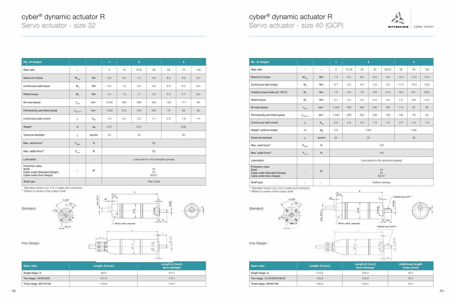
No. of stages 1 2 3
Gear ratio i – 4 16 20.8 25 64 72 100
Maximum torque Mmax Nm 0.8 4.0 4.0 4.0 6.0 6.0 6.0
Continuous stall torque M0 Nm 0.4 1.5 2.0 2.0 6.0 6.0 6.0
Rated torque Mn Nm 0.4 1.3 1.7 2.0 5.0 5.7 6.0
No-load speed nmax min-1 2.000 500 385 320 125 111 80
Permanently permitted speed nmax, S1 min-1 1.250 313 240 200 78 69 50
Continuous stall current I0 Aeff 1.9 2.0 2.0 1.7 2.0 1.8 1.4
Weight* m kg 0.47 0.51 0.56
Torsional backlash jt arcmin 20 35 50
Max. axial force** FAMax N 65
Max. radial force** Fmax N 80
Lubrication - - Lubricated for life (standard grease)
Protection class ShaftCable outlet (Standard Design)Cable outlet (Inox Design)
- IP5454
66/67
Shaft type - - Plain shaft
cyber® dynamic actuator R Servo actuator - size 32
Gear ratio Length A [ mm ]Length A [ mm ] (Inox Design)
Single-stage, i4 92.6 101.1
Two-stage, i16/20.8/25 101.6 110.1
Three-stage, i64/72/100 110.6 119.1
(6)
max
. Ø
9.7 12.5
Ø 2
0h8
Motor cable, separate
A
Ø 3
2
3
4 16
Ø 6
h6
4 x 90°
45°
Ø 26
M3 x 5
3Standard:
Inox Design:
No. of stages 1 2 3
Gear ratio i – 4 12.25 20 25 30.67 49 64 100
Maximum torque Mmax Nm 1.4 8.0 8.0 8.0 8.0 12.0 12.0 12.0
Continuous stall torque M0 Nm 0.7 3.2 4.0 4.0 4.0 11.4 12.0 12.0
Holding torque brake (at 120°C) M4 Nm 1.6 4.8 7.8 9.8 12.0 19.2 25.1 39.2
Rated torque Mn Nm 0.7 2.4 4.0 4.0 4.0 7.5 9.8 12.0
No-load speed nmax min-1 1.400 455 280 220 182 114 87 56
Permanently permitted speed nmax, S1 min-1 1.250 408 250 200 160 100 78 50
Continuous stall current I0 Aeff 2.0 2.9 2.3 1.9 1.6 2.9 2.5 1.8
Weight* (without brake) m kg 0.8 0.89 0.95
Torsional backlash jt arcmin 20 35 50
Max. axial force** FAMax N 120
Max. radial force** Fmax N 150
Lubrication - - Lubricated for life (standard grease)
Protection class ShaftCable outlet (Standard Design)Cable outlet (Inox Design)
- IP5454
66/67
Shaft type - - Feather keyway
cyber® dynamic actuator R Servo actuator - size 40 (GCP)
Gear ratio Length A [ mm ]Length A [ mm ] (Inox Design)
Additional lengthbrake [mm]
Single-stage, i4 113.3 120.4 43.1
Two-stage, i12.25/20/25/30.67 125.8 132.9 43.1
Three-stage, i49/64/100 138.3 145.4 43.1
* Standard version incl. 0.5 m cable and connector** Refers to center of the output shaft
Motor cable, separate4 18.5
(6)
max
. Ø
9.7
14.5A
Ø 4
0
Ø 2
5h8
Ø 8
h6
3Feather key 3x3x14
7.5
M4 x 8
4 x 90°45°
Ø 32
Standard:
Inox Design:
Feather key 3x3x14
* Standard version incl. 0.5 m cable and connector** Refers to center of the output shaft
39 38

cyber motor
M 4x6
45°
4x 90°
32Ø
18 ± 1
Passfeder 3x3x18
h726
Ø
j710
Ø
40Ø
140,1
2
M 4x6
45°
4x 90°
32Ø
18 ± 1
Passfeder 3x3x18
h726
Ø
j710
Ø
40Ø
140,1
2
cyber® dynamic actuator R Servo actuator - size 40 (NP)
No. of stages 1 2
Gear ratio i – 5 10 25
Maximum torque Mmax Nm 4.9 9.9 22.0
Continuous stall torque M0 Nm 1.6 3.4 6.5
Holding torque brake (at 120°C) M4 Nm 2.2 4.1 10.5
No-load speed nmax min-1 1.118 559 224
Permanently permitted speed nmax, S1 min-1 800 460 160
Rated current In Aeff 3.7 3.7 2.9
Maximum current Imax Aeff 11.4 11.4 10.0
Maximum torsional backlash jt arcmin ≤ 10 ≤ 13
Max. axial force** FAMax N 700
Max. radial force** Frmax N 800
Weight* (without brake) m kg 1.1 1.1 1.3
Lubrication - -Lubricated for life (standard grease)
Optional: Food grade (NSF/H1) – Reduction of the output torque by 20%
Protection class ShaftCable outlet (Standard Design)Cable outlet (Inox Design)
- IP6454
66/67
Shaft type - - Feather keyway
* Standard version incl. 0.5 m cable and connector** Refers to center of the output shaft
Standard:
Inox Design:
Gear ratio Length A [ mm ]Length A [ mm ] (Inox Design)
Additional lengthbrake [mm]
Single-stage, i5, 10 148 155.1 43.1
Two-stage, i25 163.5 170.6 43.1
No. of stages 1 2
Gear ratio i – 4 5 16 50
Maximum torque Mmax Nm 3.2 4.0 8.4 8.4
Continuous stall torque M0 Nm 1.1 1.0 4.2 4.2
Holding torque brake (at 120°C) M4 Nm 1.6 2.1 6.6 20.5
Rated torque Mn Nm 0.91 0.76 3.65 4.2
No-load speed nmax min-1 1400 1120 350 110
Permanently permitted speed nmax, S1 min-1 1000 800 250 80
Continuous stall current I0 Aeff 3.1 2.4 3.0 1.05
Weight* (without brake) m kg 0.92 1.13
Torsional backlash jt arcmin 20 25
Max. axial force** FAMax N 230
Max. radial force** Fmax N 200
Lubrication - -Lubricated for life
Food grade (NSF/H1)
Protection class ShaftCable outlet
- IP 6769K
Shaft type - - feather keyway
Gear ratio Length A [ mm ] Additional length brake [mm]
Single-stage, i4/5 124.6 43.1
Two-stage, i16/50 140.1 43.1
A
* Standard version incl. 0.5 m cable and connector** Refers to center of the output shaft
cyber® dynamic actuator R Servo actuator – Hygienic Design
41 40
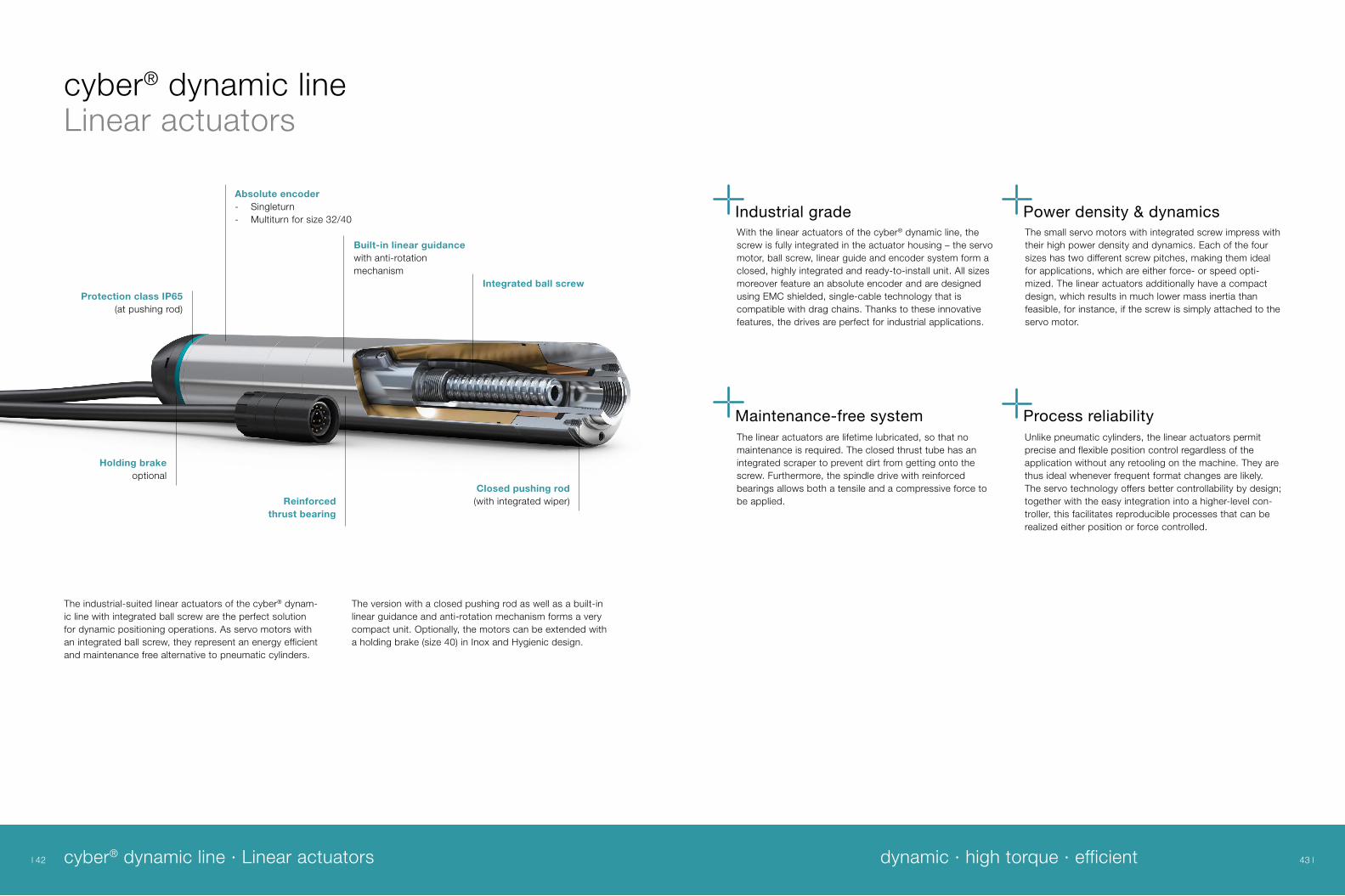
cyber® dynamic lineLinear actuators
The industrial-suited linear actuators of the cyber® dynam-ic line with integrated ball screw are the perfect solution for dynamic positioning operations. As servo motors with an integrated ball screw, they represent an energy efficient and maintenance free alternative to pneumatic cylinders.
The version with a closed pushing rod as well as a built-in linear guidance and anti-rotation mechanism forms a very compact unit. Optionally, the motors can be extended with a holding brake (size 40) in Inox and Hygienic design.
Protection class IP65(at pushing rod)
Absolute encoder- Singleturn - Multiturn for size 32/40
Reinforced thrust bearing
Closed pushing rod(with integrated wiper)
Built-in linear guidance with anti-rotation mechanism
Integrated ball screw
Holding brakeoptional
With the linear actuators of the cyber® dynamic line, the screw is fully integrated in the actuator housing – the servo motor, ball screw, linear guide and encoder system form a closed, highly integrated and ready-to-install unit. All sizes moreover feature an absolute encoder and are designed using EMC shielded, single-cable technology that is compatible with drag chains. Thanks to these innovative features, the drives are perfect for industrial applications.
Industrial grade
Maintenance-free system Process reliability
Power density & dynamicsThe small servo motors with integrated screw impress with their high power density and dynamics. Each of the four sizes has two different screw pitches, making them ideal for applications, which are either force- or speed opti-mized. The linear actuators additionally have a compact design, which results in much lower mass inertia than feasible, for instance, if the screw is simply attached to the servo motor.
Unlike pneumatic cylinders, the linear actuators permit precise and flexible position control regardless of the application without any retooling on the machine. They are thus ideal whenever frequent format changes are likely. The servo technology offers better controllability by design; together with the easy integration into a higher-level con-troller, this facilitates reproducible processes that can be realized either position or force controlled.
The linear actuators are lifetime lubricated, so that no maintenance is required. The closed thrust tube has an integrated scraper to prevent dirt from getting onto the screw. Furthermore, the spindle drive with reinforced bearings allows both a tensile and a compressive force to be applied.
cyber® dynamic line · Linear actuators dynamic · high torque · efficient 43 42
cyber motor
M 1,6 x3
Elektrische Zuleitung, separatfeed cable separately
X
X ( 2:1 )
Stöß
eldu
rchm
esse
r
M 1:1
2
13,5Ø
9SW
8M
x0,75 11
-0,0
4Ă
13,3
Hub 5,2-35,2 (=30mm)
10f7
Ă
16Ø
17Ø
66x60°
146
8
60°
1,2
+0,0
65+0
,045
M 2 x4
X ( 2:1 )M 1:1
Stöß
eldu
rchm
esse
r
Elektrische Zuleitung, separatfeed cable separately
10M
x0,75
2,5
1,5
11SW
5,5Hub -40,5 (=35mm)
8
15-0
,04
Ø
22Ø
612,4
21+0
,065
+0,0
45Ø
170,5
18Ø 6x
60°60°
12f7
Ø
M 2 x4
X ( 2:1 )M 1:1
Stöß
eldu
rchm
esse
r
Elektrische Zuleitung, separatfeed cable separately
10M
x0,75
2,5
1,5
11SW
5,5Hub -40,5 (=35mm)
8
15-0
,04
Ø
22Ø
612,4
21+0
,065
+0,0
45Ø
170,5
18Ø 6x
60°60°
12f7
Ø
M 1,6 x3
Elektrische Zuleitung, separatfeed cable separately
X
X ( 2:1 )
Stöß
eldu
rchm
esse
r
M 1:1
2
13,5Ø
9SW
8M
x0,75 11
-0,0
4Ă
13,3
Hub 5,2-35,2 (=30mm)
10f7
Ă
16Ø
17Ø
66x60°
146
8
60°
1,2
+0,0
65+0
,045
Motor cable, seperateMotor cable, seperate
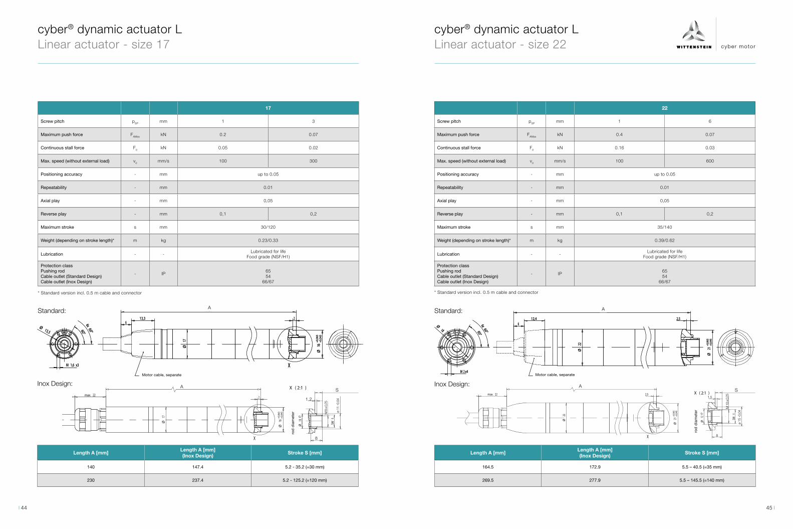
cyber® dynamic actuator L Linear actuator - size 22
cyber® dynamic actuator L Linear actuator - size 17
Standard:
Inox Design:
17
Screw pitch pSP mm 1 3
Maximum push force FAMax kN 0.2 0.07
Continuous stall force F0 kN 0.05 0.02
Max. speed (without external load) v0 mm/s 100 300
Positioning accuracy - mm up to 0.05
Repeatability - mm 0.01
Axial play - mm 0,05
Reverse play - mm 0,1 0,2
Maximum stroke s mm 30/120
Weight (depending on stroke length)* m kg 0.23/0.33
Lubrication - -Lubricated for life
Food grade (NSF/H1)
Protection class Pushing rodCable outlet (Standard Design)Cable outlet (Inox Design)
- IP6554
66/67
22
Screw pitch pSP mm 1 6
Maximum push force FAMax kN 0.4 0.07
Continuous stall force F0 kN 0.16 0.03
Max. speed (without external load) v0 mm/s 100 600
Positioning accuracy - mm up to 0.05
Repeatability - mm 0.01
Axial play - mm 0,05
Reverse play - mm 0,1 0,2
Maximum stroke s mm 35/140
Weight (depending on stroke length)* m kg 0.39/0.62
Lubrication - -Lubricated for life
Food grade (NSF/H1)
Protection class Pushing rodCable outlet (Standard Design)Cable outlet (Inox Design)
- IP6554
66/67
M 2 x4
X ( 2:1 )M 1:1
Stöß
eldu
rchm
esse
r
Elektrische Zuleitung, separatfeed cable separately
10M
x0,75
2,5
1,5
11SW
5,5Hub -40,5 (=35mm)
8
15-0
,04
Ø
22Ø
612,4
21+0
,065
+0,0
45Ø
170,5
18Ø 6x
60°60°
12f7
Ø
M 2 x4
X ( 2:1 )M 1:1
Stöß
eldu
rchm
esse
r
Elektrische Zuleitung, separatfeed cable separately
10M
x0,75
2,5
1,5
11SW
5,5Hub -40,5 (=35mm)
8
15-0
,04
Ø
22Ø
612,4
21+0
,065
+0,0
45Ø
170,5
18Ø 6x
60°60°
12f7
Ø
Motor cable, seperate
A
cyber motor GmbHRIgersheim . Germany
A2Urspr.-Zeichnung / Basic drawing :
Schutzvermerk/ Protection notice
ausgegeben / Issued Spr./ Lang.
Schriftfeld gemäß / Data block according to : ISO 7200:2004; Zeichnungsvordruck gemäß / Drawing sheet according to : ISO 5457:1999
9
H
11
H
10763 4 5 821
zusätzlicher Titel / Supplementary title von/ fr.
AC
Bl./ Sh.
Title
vertraulich
cyber dynamic 22
15.08.2017 1
5 01
-007 D046471
11
10
12
M 1:1
Stöß
eldu
rchm
esse
r
X ( 2:1 )
X
11SW
10M
x0,75
8
2,5
1,5
22max.
15-0
,04
Ø
21+0
,065
+0,0
45Ø
12f7
Ø
22Ø
Rod
dia
met
er
A
ø 15
-0,0
4
8
1,5
M 1
0 x
0.75
S
Length A [mm]Length A [mm] (Inox Design)
Stroke S [mm]
140 147.4 5.2 - 35.2 (=30 mm)
230 237.4 5.2 - 125.2 (=120 mm)
Length A [mm]Length A [mm] (Inox Design)
Stroke S [mm]
164.5 172.9 5.5 – 40.5 (=35 mm)
269.5 277.9 5.5 – 145.5 (=140 mm)
* Standard version incl. 0.5 m cable and connector * Standard version incl. 0.5 m cable and connector
Motor cable, separate
M 1,6 x3
Elektrische Zuleitung, separatfeed cable separately
X
X ( 2:1 )
Stöß
eldu
rchm
esse
r
M 1:1
2
13,5Ø
9SW
8M
x0,75 11
-0,0
4Ă
13,3
Hub 5,2-35,2 (=30mm)
10f7
Ă
16Ø
17Ø
66x60°
146
8
60°
1,2
+0,0
65+0
,045
Standard:
M 1,6 x3
Elektrische Zuleitung, separatfeed cable separately
X
X ( 2:1 )
Stöß
eldu
rchm
esse
r
M 1:1
2
13,5Ø
9SW
8M
x0,75 11
-0,0
4Ă
13,3
Hub 5,2-35,2 (=30mm)
10f7
Ă
16Ø
17Ø
66x60°
146
8
60°
1,2
+0,0
65+0
,045
Motor cable, seperate
A
Motor cable, separate
ro
d d
iam
eter
Inox Design:
M 1,6 x3 X
17Ø 16
+0,0
65+0
,045
Ø
60Ā6x
60Ā
22max.
13,5Ă
X ( 2:1 )
Stöß
eldu
rchm
esse
r
AnschlussschemaAnsicht X (3:1)
1,2
8
10f7
Ø
9SW
8M
x0,75
2
11-0
,04
Ø
M 1:1
SLO- / DATA-
Mot.Ph.V
MA+ / CLOCK+
SLO+ / DATA+
Mot.Ph.W
Mot.Ph.U
MA- / CLOCK-
5V
Schirm
GND
AWG26
AWG26
C
5
AWG24
AWG26
1
AWG26
3
B
AWG242
Schirm
6
4
10
12
8
AWG24
7
AAWG24AWG24
11
9
C
10
6
1
5
9
11 2
4A B
E
8
3
7
12
A
M 1,6 x3 X
17Ø 16
+0,0
65+0
,045
Ø
60Ā6x
60Ā
22max.
13,5Ă
X ( 2:1 )
Stöß
eldu
rchm
esse
r
AnschlussschemaAnsicht X (3:1)
1,2
8
10f7
Ø
9SW
8M
x0,75
2
11-0
,04
Ø
M 1:1
SLO- / DATA-
Mot.Ph.V
MA+ / CLOCK+
SLO+ / DATA+
Mot.Ph.W
Mot.Ph.U
MA- / CLOCK-
5V
Schirm
GND
AWG26
AWG26
C
5
AWG24
AWG26
1
AWG26
3
B
AWG242
Schirm
6
4
10
12
8
AWG24
7
AAWG24AWG24
11
9
C
10
6
1
5
9
11 2
4A B
E
8
3
7
12
Rod
dia
met
er
S
8
M 8
x 0
,75
ø 11
-0.0
41.2
ro
d d
iam
eter
45 44

cyber motor
cyber® dynamic actuator L Linear actuator - size 32
Standard:
Standard:
Inox Design:
32
Screw pitch pSP mm 2 8
Maximum push force FAMax kN 0.94 0.2
Continuous stall force F0 kN 0.35 0.09
Max. speed (without external load) v0 mm/s 200 800
Positioning accuracy - mm up to 0.05
Repeatability - mm 0.01
Axial play - mm 0,05
Reverse play - mm 0,1 0,2
Maximum stroke s mm 40/160
Weight (depending on stroke length)* m kg 1.0/1.6
Lubrication - -Lubricated for life
Food grade (NSF/H1)
Protection class Pushing rodCable outlet (Standard Design)Cable outlet (Inox Design)
- IP6554
66/67
40
Screw pitch pSP mm 3 10
Maximum push force FAMax kN 1.92 1.92 1.28 0.58 0.58 0.58
Continuous stall force F0 kN 0.64 0.64 0.6 0.17 0.17 0.19
Holding force brake (at 120°C) F4 kN 0.83 0.83 0.83 0.25 0.25 0.25
Max. speed (without external load) v0 mm/s 279 279 140 932 932 467
Positioning accuracy - mm up to 0.05
Repeatability - mm 0.01
Axial play - mm 0,05
Reverse play - mm 0,1 0,2
Maximum stroke s mm 50 200 300 50 200 300
Weight (depending on stroke length)* m kg 1.8 3.2 3.0 1.8 3.2 3.0
Lubrication - -Lubricated for life
Food grade (NSF/H1)
Protection class Pushing rodCable outlet (Standard Design)Cable outlet (Inox Design)
- IP6554
66/67
M 1:1
X ( 2:1 )
Stöß
eldu
rchm
esse
r
6,5Hub -46,5 (=40mm)
1,5
20-0
,04
Ă
10
12x1
M
14SW
16f7
Ă
M 3 x6Elektrische Zuleitung, separatfeed cable separately
X
25Ø
12,5
205,1
6
30,1
-0,0
3-0
,05
Ø
32Ø
3
60°6x
60°
3
Motor cable, seperate
M 1:1
X ( 2:1 )
Stöß
eldu
rchm
esse
r
6,5Hub -46,5 (=40mm)
1,5
20-0
,04
Ă
10
12x1
M
14SW
16f7
Ă
M 3 x6Elektrische Zuleitung, separatfeed cable separately
X
25Ø
12,5
205,1
6
30,1
-0,0
3-0
,05
Ø
32Ø
3
60°6x
60°
3
A
Stöß
eldu
rchm
esse
r
M 1:1
X ( 2:1 )
22f7
Ă
16x1
M
19SW
12
7Hub -57 (=50mm)
2
26-0
,04
Ă
M 3 x6
Elektrische Zuleitung, separatfeed cable separately
X
245,3
6
3
40Ø 38
,2-0
,03
-0,0
5Ø
32Ø
1560°
6x 60°
7,5
Motor cable, seperate
A
B
11
CMot.Ph.V
MA- / CLOCK-
10
3
AWG26
8
Mot.Ph.U A
C
AWG16
GND
AWG16
12
Mot.Ph.W
SLO- / DATA-
1 AWG242
AWG16
SLO+ / DATA+
4
7
AWG26
AWG26
MA+ / CLOCK+AWG26
56
9
Schirm
Anschlussschema
95V
Schirm
AWG24
1112
5
2
A
7 6
3
1
4
Ansicht X (3:1)
10
M 1:2
8
EB
M 3 x6
Stöß
eldu
rchm
esse
r
X
X ( 1:1 )1,5
3
10
30,1
-0,0
3-0
,05
Ø
6x60Ā60Ā
20-0
,04
Ø
32Ø
25Ă
26max.
f716
Ø
x112
M
SW14
B
11
CMot.Ph.V
MA- / CLOCK-
10
3
AWG26
8
Mot.Ph.U A
C
AWG16
GND
AWG16
12
Mot.Ph.W
SLO- / DATA-
1 AWG242
AWG16
SLO+ / DATA+
4
7
AWG26
AWG26
MA+ / CLOCK+AWG26
56
9
Schirm
Anschlussschema
95V
Schirm
AWG24
1112
5
2
A
7 6
3
1
4
Ansicht X (3:1)
10
M 1:2
8
EB
M 3 x6
Stöß
eldu
rchm
esse
r
X
X ( 1:1 )1,5
3
10
30,1
-0,0
3-0
,05
Ø
6x60Ā60Ā
20-0
,04
Ø
32Ø
25Ă
26max.f7
16Ø
x112
M
SW14
Rod
dia
met
er
AS
9
A
AWG26
Ansicht X (3:1)
5VAWG26
AWG26
Anschlussschema
11
AWG16
1
Mot.Ph.V AWG16
11
Schirm
AWG24
A
C
2
7
56
C
2
12
MA+ / CLOCK+
B
4
8
M 1:2
AWG26
9
SLO- / DATA-
45
SLO+ / DATA+
E
10
AWG16
3
3
12
Schirm
Mot.Ph.W
AWG24 10
MA- / CLOCK-
87 6
Mot.Ph.U
1
BGND
M 3 x6 X
6x 60Ā
60Ā 26max.
38,2
-0,0
3-0
,05
Ø
40Ø
32Ă
3
SW19x1
16M
f722
Ø
26-0
,04
Ø
12
X ( 1:1 )
Stöß
eldu
rchm
esse
r
2
9
A
AWG26
Ansicht X (3:1)
5VAWG26
AWG26
Anschlussschema
11
AWG16
1
Mot.Ph.V AWG16
11
Schirm
AWG24
A
C
2
7
56
C
2
12
MA+ / CLOCK+
B
4
8
M 1:2
AWG26
9
SLO- / DATA-
45
SLO+ / DATA+
E
10
AWG16
3
3
12
Schirm
Mot.Ph.W
AWG24 10
MA- / CLOCK-
87 6
Mot.Ph.U
1
BGND
M 3 x6 X
6x 60Ā
60Ā 26max.
38,2
-0,0
3-0
,05
Ø
40Ø
32Ă
3
SW19x1
16M
f722
Ø
26-0
,04
Ø
12
X ( 1:1 )
Stöß
eldu
rchm
esse
r
2
Rod
dia
met
er
A
S
Length A [mm]Length A [mm] (Inox Design)
Stroke S [mm]
199.1 205.6 6.5 – 46.5 (=40 mm)
319.1 325.6 6.5 – 166.5 (=160 mm)
Length A [mm]Length A [mm] (Inox Design)
Stroke S [mm] Additional length brake [mm]
239.3 246.4 7 – 57 (=50 mm) 43.1
389.3 396.4 7 – 207 (=200 mm) 43.1
489.3 496.4 7 – 307 (=300 mm) 43.1
cyber® dynamic actuator L Linear actuator - size 40
* Standard version incl. 0.5 m cable and connector
* Standard version incl. 0.5 m cable and connector
Motor cable, separateMotor cable, separate
ro
d d
iam
eter
ro
d d
iam
eter
Inox Design:
47 46

cyber motor
cyber® dynamic line Options
Size 40
Holding torque static at 120 °C Nm 0.36
Supply voltage VDC 24
Current at rated voltage and 20 °C ADC 0.42
Engaging time ms up to 0.05
Release time ms 0.01
Weight kg 0.18
A compact permanent magnet brake is fitted to secure the motor shaft when the motor or actuator is disconnected from the power. Characteristics include holding without torsional backlash, no residual torque when the brake is released and unlimit-ed power-on time at zero speed.
The holding brakes used in the motors and actuators are subject to various factors, e.g. oxidation of abraded parti-cles, flattening of friction surfaces due to frequent applica-tion of the brakes in the same position or air gap changes due to wear. This may result in a reduction of available holding torques. The specified holding torques apply under optimal conditions without detrimental influences. For critical applications we recommend dimensioning for an adequately large holding torque to take account of these factors of uncertainty.
Depending on the ratio configured for the event of an emergency stop, the brakes used in the motors and actu-ators can generate a dynamic braking torque at the output which exceeds the maximum permissible torque Mmax act of the gearbox. In this case, it must be ensured in the application that such an exceeding of the maximum torque is prevented, otherwise the gearbox may be damaged. For linear drives, the same behaviour results from external force effects.
Note: The holding brake is available for the cyber® dynamic system and for the cyber® dynamic line in size 40 in combination with an absolute encoder (HI/HM) and Inox/Hygiene Design. Variants with incremental encoder (HF) or in standard design cannot be equipped with a holding brake.
Holding brake
Encoder HI HM HF
Interface BiSS-Interface C-Mode BiSS-Interface C-Mode TTL
Power supply 5 V ± 10 %
Operating power consumption (no load)
50 mA 150 mA 50 mA
Max. power consumption (no load) 275 mW 825 mW 275 mW
Resolution 4.096 positions per revolution4.096 positions per revolution (12
Bit) / 65.536 revolutions(16 Bit)
1.024 Increments per revolution
System accuracy ± 1°
Repeatability ± 0.2°
A selection of encoder systems is available for position and speed measurement:
- BISS-C, Absolute encoder Singleturn (HI): universally usable
- BISS-C, Absolute encoder Multiturn (HM): Available for the cyber® dynamic system and the cyber® dynamic line in size 32/40 and Inox/Hygienic Design
- Incremental encoder (HF): Available for cyber® dynamic line
Encoder
49 48

cyber® dynamic system Servo motors and actuators
The industrial drive system cyber® dynamic system offers maximum connectivity thanks to its Multi-Ethernet-Interface and scores with decentralized intel-ligence. The inertia-optimized motors and high current resolution also ensure highly dynamic and precise movements. The system is the professional choice for decentralized applications in demanding environmental conditions with limited installation space. In addition,
the CDS is equipped with the integrated safety function STO (Safe Torque Off) and meets the safety require-ments according to SIL3 / PL e.
This system is optionally available with various encoder variants as well as planetary gearboxes, ball screw and holding brake.
Numerous fieldbus interfaces and decentral intelligence
Ideal for the tightest installation spaces
Ball screw(integrated)
Closed pushing rod(with integrated wiper)
High precision planetary gearbox
1-3 stages Protection class IP65(mounted)
Holding brake optional
Absolute encoder - Singleturn
- Multiturn
Ultra-compact unitof motor and controller
Cabling effort minimized
cyber® dynamic system · Drive system connective · compact · dynamic
The cyber® dynamic system (CDS) is equipped with a Multi-EtherNet-Interface and allows with one and the same hardware free selection between the fieldbus variants EtherCat, PROFINET, EtherNet/IP CIP Sync (CANopen and Sercos III on request). This feature ensures proven, simple and real-time connectivity to a wide variety of control environments. The Multi-Ethernet version also reduces the usual number of variants. Thanks to an electronic name plate, automatic motor parameterization is also possible. In addition, quick commissioning and connection to the PLC is ensured.
Connectivity
Dynamics
Robustness and safety
Precision
CompactnessA 40 mm size motor together with a special housing de-sign forms an ultra-compact unit that fits into the tightest of installation conditions. Furthermore, it eliminates the need for cabling except for the power supply and fieldbus communication without compromising on industrial suita-bility, connectivity, dynamics and precision. As a decentra-lized solution, the CDS therefore saves valuable space in the control cabinet.
The motor-integrated variant cyber® dynamic system is equipped with an absolute encoder with an encoder resolution of 12 bits. In addition, the high current resoluti-on of 14 bits ensures highly accurate torque control. This enables low cycle times to be achieved for highly dynamic and precise applications.
The low mass inertia of the CDS motors ensures maximum acceleration and contributes to high dynamics. The real-ti-me capable and clock-synchronous Ethernet communica-tion supports this. The cyber® dynamic system also offers a decentralized PLC functionality for autonomous positi-oning operations and thus also provides for a relief of the automation system. In addition, synchronous and dynamic driving profiles can be realized with the CDS.
FlexibilityThe modular principle of the small servo drive system enables optimum solutions for a wide range of applica-tions. This also includes the optional integration of abso-lute encoders such as singleturn or multiturn, a holding brake as well as planetary gearboxes (GCP or NP) or a ball screw. All this creates new freedom in machine design.
Suitable for industrial use − this term best describes the combination of robust design and integrated safety. With the integrated safety function STO (Safe Torque Off), the cyber® dynamic system meets the safety requirements according to SIL3 / PL e. In addition, the CDS has a 12 to 60 VDC wide-range input on the supply side, which enables compensations for fluctuations in the voltage source. In addition, the motor-integrated version is available with IP65 protection and is therefore suitable for decentralized use in demanding environmental conditions with limited installation space.
51 50
cyber motor
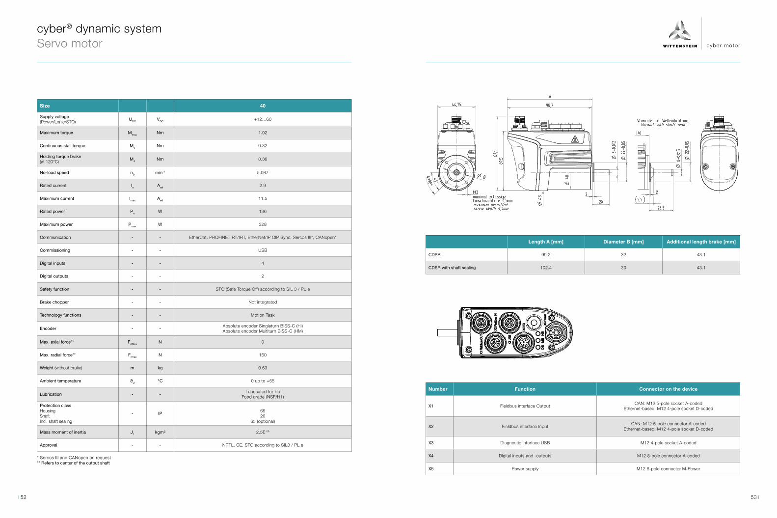
cyber® dynamic system Servo motor
Size 40
Supply voltage (Power/Logic/STO)
UDC VDC +12…60
Maximum torque Mmax Nm 1.02
Continuous stall torque M0 Nm 0.32
Holding torque brake (at 120°C)
M4 Nm 0.36
No-load speed n0 min-1 5.087
Rated current In Aeff 2.9
Maximum current Imax Aeff 11.5
Rated power Pn W 136
Maximum power Pmax W 328
Communication - - EtherCat, PROFINET RT/IRT, EtherNet/IP CIP Sync, Sercos III*, CANopen*
Commissioning - - USB
Digital inputs - - 4
Digital outputs - - 2
Safety function - - STO (Safe Torque Off) according to SIL 3 / PL e
Brake chopper - - Not integrated
Technology functions - - Motion Task
Encoder - -Absolute encoder Singleturn BISS-C (HI)Absolute encoder Multiturn BISS-C (HM)
Max. axial force** FAMax N 0
Max. radial force** Frmax N 150
Weight (without brake) m kg 0.63
Ambient temperature ϑU °C 0 up to +55
Lubrication - -Lubricated for life
Food grade (NSF/H1)
Protection classHousing ShaftIncl. shaft sealing
- IP6520
65 (optional)
Mass moment of inertia J1 kgm² 2.5E-06
Approval - - NRTL, CE, STO according to SIL3 / PL e
* Sercos III and CANopen on request** Refers to center of the output shaft
Length A [mm] Diameter B [mm] Additional length brake [mm]
CDSR 99.2 32 43.1
CDSR with shaft sealing 102.4 30 43.1
Number Function Connector on the device
X1 Fieldbus interface OutputCAN: M12 5-pole socket A-coded
Ethernet-based: M12 4-pole socket D-coded
X2 Fieldbus interface InputCAN: M12 5-pole connector A-coded
Ethernet-based: M12 4-pole socket D-coded
X3 Diagnostic interface USB M12 4-pole socket A-coded
X4 Digital inputs and -outputs M12 8-pole connector A-coded
X5 Power supply M12 6-pole connector M-Power
53 52

cyber motor
cyber® dynamic system Servo actuator − GCP
No. of stages 1 2 3
Gear ratio i - 4 12.25 20 25 30.67 49 64 100
Supply voltage (Power / Logic / STO) UDC VDC +12…60
Maximum torque Mmax Nm 1.4 8.0 8.0 8.0 8.0 12.0 12.0 12.0
Continuous stall torque M0 Nm 0.7 2.6 4.0 4.0 4.0 9.9 12.0 12.0
Holding torque brake (at 120°C)
M4 Nm 1.6 4.8 7.8 9.8 12.0 19.2 25.1 39.2
No-load speed n0 min-1 1.272 415 254 203 166 104 79 51
Permanently permitted speed nmax,S1 min-1 1.250 408 250 200 163 102 78 50
Rated current In Aeff 2.0 2.0 2.0 2.0 1.7 1.9 1.9 1.8
Maximum current Imax Aeff 3.9 7.3 4.4 3.6 2.9 3.1 2.5 1.8
Rated power Pn W 82 82 82 81 66 59 59 51
Maximum power Pmax W 164 262 183 152 126 119 93 61
Communication - - EtherCat, PROFINET RT/IRT, EtherNet/IP CIP Sync, Sercos III*, CANopen*
Commissioning - - USB
Digital inputs - - 4
Digital outputs - - 2
Safety function - - STO according to SIL 3
Brake chopper - - Not integrated
Technology functions - - Motion Task
Encoder - -Absolute encoder Singleturn BISS-C (HI)Absolute encoder Multiturn BISS-C (HM)
Max. torsional backlash jt arcmin ≤ 20 ≤ 35 ≤ 50
Max. axial force** FAMax N 120
Max. radial force** Frmax N 150
Weight (without brake) m kg 0.9 1.0 1.1
Ambient temperature ϑU °C 0 up to + 55
No. of stages 1 2 3
Gear ratio i - 4 12.25 20 25 30.67 49 64 100
Lubrication - - Lubricated für life (standard grease)
Protection classHousing Shaft
- IP 6554
Mass moment of inertia J1 kgm² 4.48E-05 4.43E-04 1.18E-03 1.84E-03 2.77E-03 7.44E-03 1.27E-02 3.10E-02
Approval - - NRTL, CE, STO according to SIL3 / PL e
Length A [mm] Additional length brake [mm]
Single-stage, i4 132.2 43.1
Two-stage, i12.25/20/25/30.67 144.7 43.1
Three-stage, i49/64/100 157.2 43.1
* Sercos III and CANopen on request** Refers to center of the output shaft
55 54
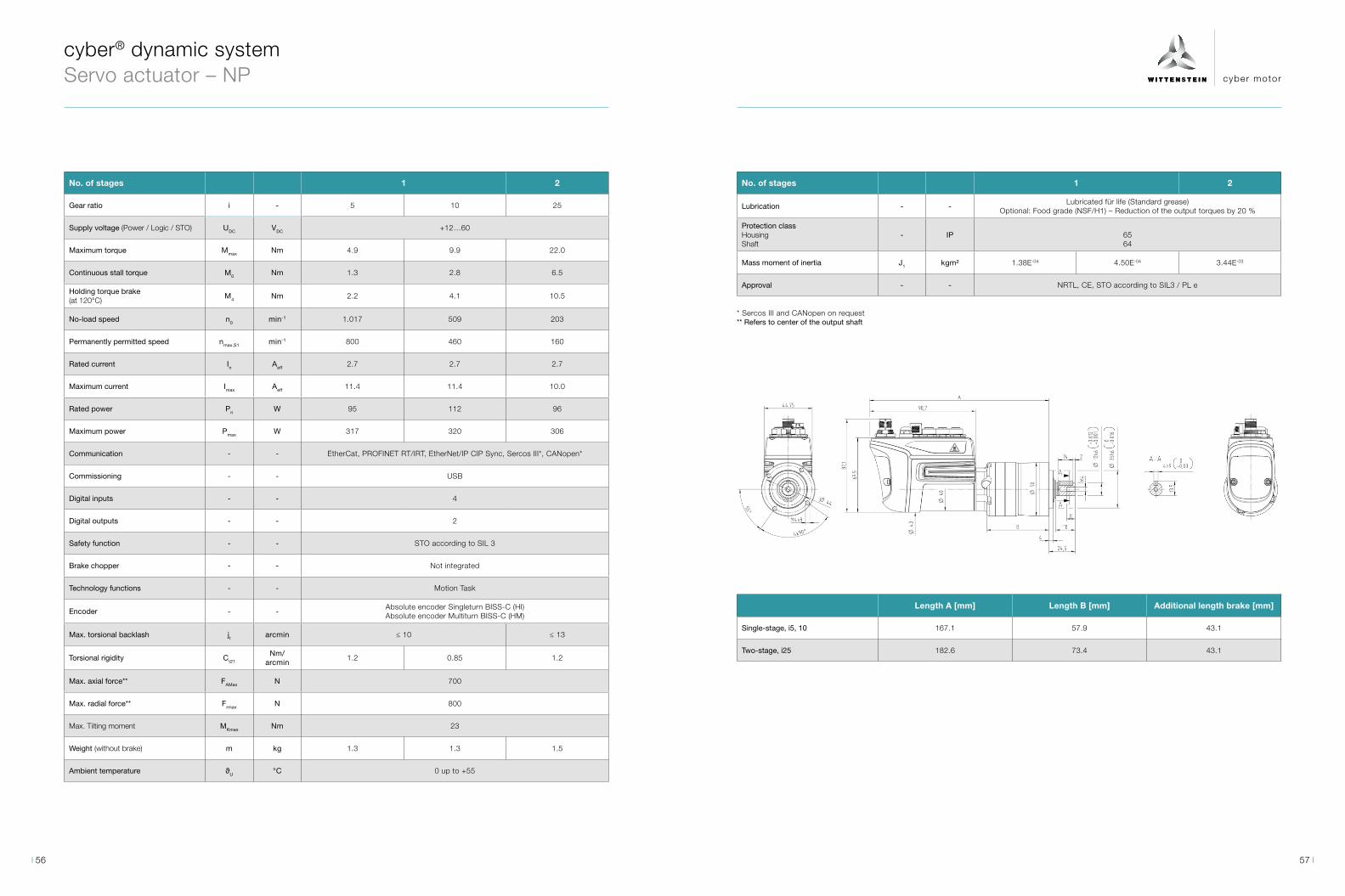
cyber motor
cyber® dynamic system Servo actuator – NP
No. of stages 1 2
Gear ratio i - 5 10 25
Supply voltage (Power / Logic / STO) UDC VDC +12…60
Maximum torque Mmax Nm 4.9 9.9 22.0
Continuous stall torque M0 Nm 1.3 2.8 6.5
Holding torque brake (at 120°C)
M4 Nm 2.2 4.1 10.5
No-load speed n0 min-1 1.017 509 203
Permanently permitted speed nmax,S1 min-1 800 460 160
Rated current In Aeff 2.7 2.7 2.7
Maximum current Imax Aeff 11.4 11.4 10.0
Rated power Pn W 95 112 96
Maximum power Pmax W 317 320 306
Communication - - EtherCat, PROFINET RT/IRT, EtherNet/IP CIP Sync, Sercos III*, CANopen*
Commissioning - - USB
Digital inputs - - 4
Digital outputs - - 2
Safety function - - STO according to SIL 3
Brake chopper - - Not integrated
Technology functions - - Motion Task
Encoder - -Absolute encoder Singleturn BISS-C (HI)Absolute encoder Multiturn BISS-C (HM)
Max. torsional backlash jt arcmin ≤ 10 ≤ 13
Torsional rigidity Ct21
Nm/ arcmin
1.2 0.85 1.2
Max. axial force** FAMax N 700
Max. radial force** Frmax N 800
Max. Tilting moment MKmax Nm 23
Weight (without brake) m kg 1.3 1.3 1.5
Ambient temperature ϑU °C 0 up to +55
No. of stages 1 2
Lubrication - -Lubricated für life (Standard grease)
Optional: Food grade (NSF/H1) – Reduction of the output torques by 20 %
Protection classHousing Shaft
- IP 6564
Mass moment of inertia J1 kgm² 1.38E-04 4.50E-04 3.44E-03
Approval - - NRTL, CE, STO according to SIL3 / PL e
Length A [mm] Length B [mm] Additional length brake [mm]
Single-stage, i5, 10 167.1 57.9 43.1
Two-stage, i25 182.6 73.4 43.1
* Sercos III and CANopen on request** Refers to center of the output shaft
57 56
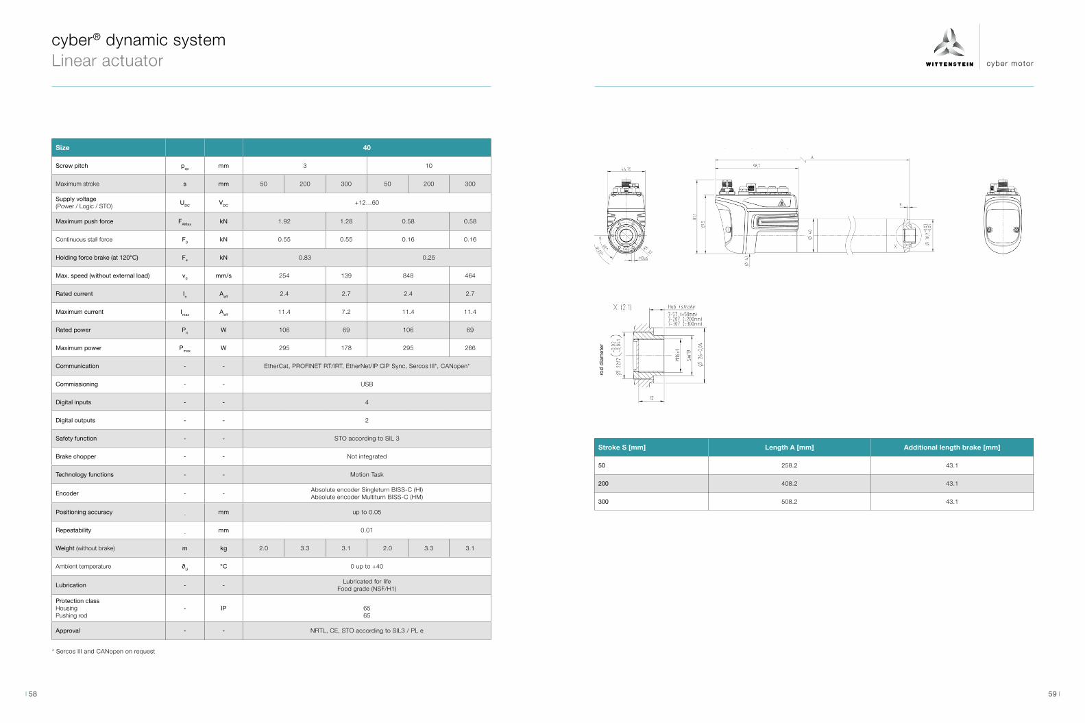
cyber motor
cyber® dynamic system Linear actuator
Size 40
Screw pitch psp mm 3 10
Maximum stroke s mm 50 200 300 50 200 300
Supply voltage (Power / Logic / STO)
UDC VDC +12…60
Maximum push force FAMax kN 1.92 1.28 0.58 0.58
Continuous stall force F0 kN 0.55 0.55 0.16 0.16
Holding force brake (at 120°C) F4 kN 0.83 0.25
Max. speed (without external load) v0 mm/s 254 139 848 464
Rated current In Aeff 2.4 2.7 2.4 2.7
Maximum current Imax Aeff 11.4 7.2 11.4 11.4
Rated power Pn W 106 69 106 69
Maximum power Pmax W 295 178 295 266
Communication - - EtherCat, PROFINET RT/IRT, EtherNet/IP CIP Sync, Sercos III*, CANopen*
Commissioning - - USB
Digital inputs - - 4
Digital outputs - - 2
Safety function - - STO according to SIL 3
Brake chopper - - Not integrated
Technology functions - - Motion Task
Encoder - -Absolute encoder Singleturn BISS-C (HI)Absolute encoder Multiturn BISS-C (HM)
Positioning accuracy - mm up to 0.05
Repeatability - mm 0.01
Weight (without brake) m kg 2.0 3.3 3.1 2.0 3.3 3.1
Ambient temperature ϑU °C 0 up to +40
Lubrication - -Lubricated for life
Food grade (NSF/H1)
Protection classHousing Pushing rod
- IP 6565
Approval - - NRTL, CE, STO according to SIL3 / PL e
* Sercos III and CANopen on request
Stroke S [mm] Length A [mm] Additional length brake [mm]
50 258.2 43.1
200 408.2 43.1
300 508.2 43.1
ro
d d
iam
eter
59 58
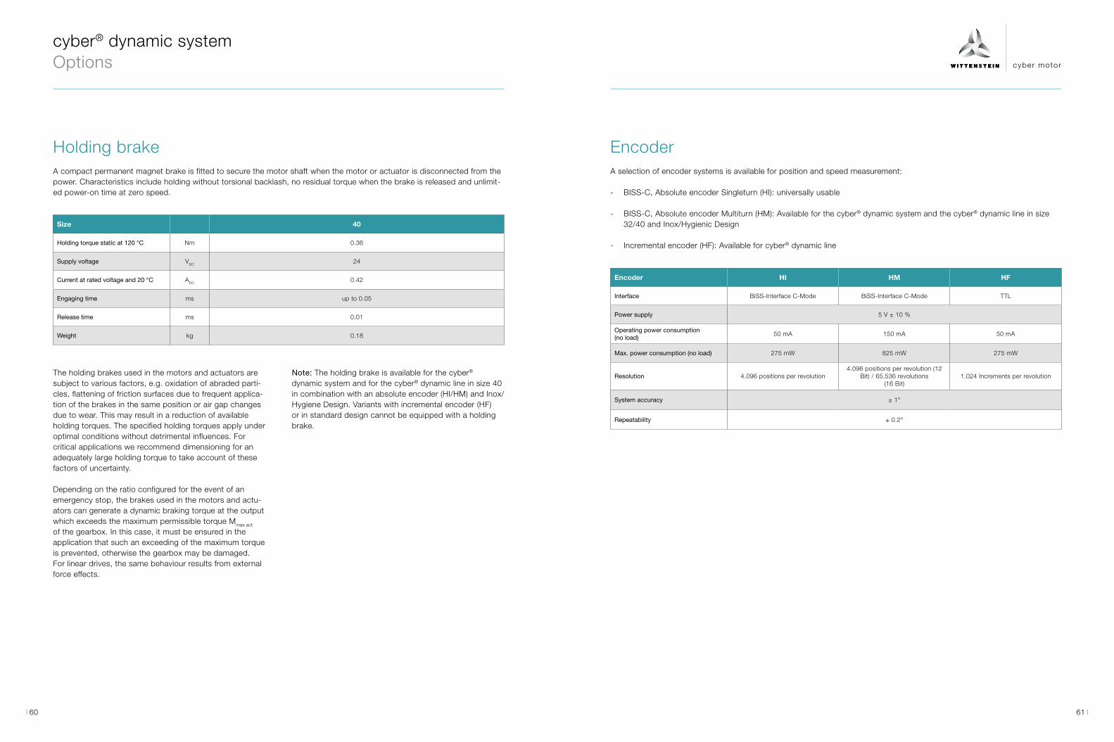
cyber motor
cyber® dynamic system Options
Size 40
Holding torque static at 120 °C Nm 0.36
Supply voltage VDC 24
Current at rated voltage and 20 °C ADC 0.42
Engaging time ms up to 0.05
Release time ms 0.01
Weight kg 0.18
Holding brake
Encoder HI HM HF
Interface BiSS-Interface C-Mode BiSS-Interface C-Mode TTL
Power supply 5 V ± 10 %
Operating power consumption (no load)
50 mA 150 mA 50 mA
Max. power consumption (no load) 275 mW 825 mW 275 mW
Resolution 4.096 positions per revolution4.096 positions per revolution (12
Bit) / 65.536 revolutions (16 Bit)
1.024 Increments per revolution
System accuracy ± 1°
Repeatability ± 0.2°
EncoderA compact permanent magnet brake is fitted to secure the motor shaft when the motor or actuator is disconnected from the power. Characteristics include holding without torsional backlash, no residual torque when the brake is released and unlimit-ed power-on time at zero speed.
The holding brakes used in the motors and actuators are subject to various factors, e.g. oxidation of abraded parti-cles, flattening of friction surfaces due to frequent applica-tion of the brakes in the same position or air gap changes due to wear. This may result in a reduction of available holding torques. The specified holding torques apply under optimal conditions without detrimental influences. For critical applications we recommend dimensioning for an adequately large holding torque to take account of these factors of uncertainty.
Depending on the ratio configured for the event of an emergency stop, the brakes used in the motors and actu-ators can generate a dynamic braking torque at the output which exceeds the maximum permissible torque Mmax act of the gearbox. In this case, it must be ensured in the application that such an exceeding of the maximum torque is prevented, otherwise the gearbox may be damaged. For linear drives, the same behaviour results from external force effects.
Note: The holding brake is available for the cyber® dynamic system and for the cyber® dynamic line in size 40 in combination with an absolute encoder (HI/HM) and Inox/Hygiene Design. Variants with incremental encoder (HF) or in standard design cannot be equipped with a holding brake.
A selection of encoder systems is available for position and speed measurement:
- BISS-C, Absolute encoder Singleturn (HI): universally usable
- BISS-C, Absolute encoder Multiturn (HM): Available for the cyber® dynamic system and the cyber® dynamic line in size 32/40 and Inox/Hygienic Design
- Incremental encoder (HF): Available for cyber® dynamic line
61 60

cyber® power supply DIN rail power supplies
The DIN rail power supplies of the cyber® power sup-ply range perfectly complement the small servo drive system. Thanks to an innovative circuit design and high-quality components, the power supplies have an efficiency of more than 95% and thus reduce heat ge-
neration in the overall system. In addition, an overload range that perfectly fits with our servo drives enables an optimum utilization of the available power.
1- and 3-phase Design
Simple installation due to DIN rail mounting
Compact design
Optimized overload range (short term overload of up to 150%)
Long life span
Robust wide range input and small inrush current
High Efficiency (Efficiency up to 95%)
cyber® power supply · DIN rail power supplies efficient · compact · reliable
Thanks to an innovative circuit design and high-quality components, the power supplies have an efficiency of more than 95% and thus reduce heat generation in the overall system.
Efficiency
ReliabilityCompactness
SimplicityThe installation of the power supplies is very simple and fast thanks to their top-hat rail design. The devices are plugged onto the DIN rail and then wired. For this pur-pose, all connections are located on the front side of the devices.
Thanks to the high efficiency of the power supplies, they have a high degree of compactness, because the less heat generated in the power supply, the more compact the de-vices can be built. This ensures significant space savings in the control cabinet.
The power supplies are developed according to the Cool Design principle. This means that the life-determining components, such as electrolytic capacitors, are positi-oned at the coolest points of the device. Combined with the robust circuit design, wide range input and excellent efficiencies, this results in high reliability and long device life. In addition, the power supplies feature an optimized overload behavior, which, in conjunction with our servo controllers, enables optimum utilization of power.
63 62
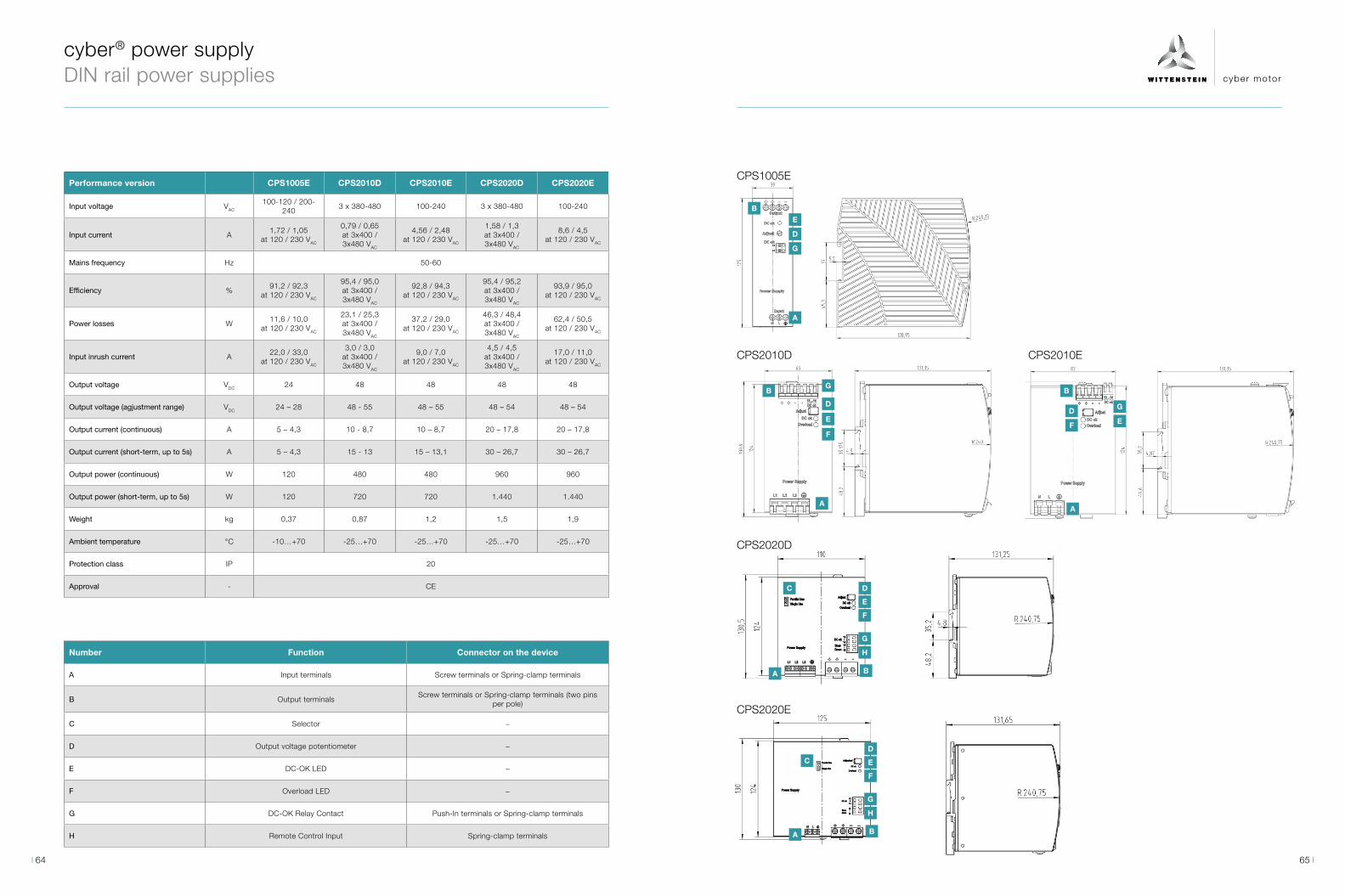
cyber motor
A
A
A
AA
B
B
B
B B
D
C
C
G
G
E
D
D
DD
G
E
E
E E
F
F
FF
G
G
H
H
Performance version CPS1005E CPS2010D CPS2010E CPS2020D CPS2020E
Input voltage VAC
100-120 / 200-240
3 x 380-480 100-240 3 x 380-480 100-240
Input current A1,72 / 1,05
at 120 / 230 VAC
0,79 / 0,65 at 3x400 / 3x480 VAC
4,56 / 2,48 at 120 / 230 VAC
1,58 / 1,3 at 3x400 / 3x480 VAC
8,6 / 4,5 at 120 / 230 VAC
Mains frequency Hz 50-60
Efficiency %91,2 / 92,3
at 120 / 230 VAC
95,4 / 95,0 at 3x400 / 3x480 VAC
92,8 / 94,3 at 120 / 230 VAC
95,4 / 95,2 at 3x400 / 3x480 VAC
93,9 / 95,0 at 120 / 230 VAC
Power losses W11,6 / 10,0
at 120 / 230 VAC
23,1 / 25,3 at 3x400 / 3x480 VAC
37,2 / 29,0 at 120 / 230 VAC
46,3 / 48,4 at 3x400 / 3x480 VAC
62,4 / 50,5 at 120 / 230 VAC
Input inrush current A22,0 / 33,0
at 120 / 230 VAC
3,0 / 3,0 at 3x400 / 3x480 VAC
9,0 / 7,0 at 120 / 230 VAC
4,5 / 4,5 at 3x400 / 3x480 VAC
17,0 / 11,0 at 120 / 230 VAC
Output voltage VDC 24 48 48 48 48
Output voltage (agjustment range) VDC 24 – 28 48 - 55 48 – 55 48 – 54 48 – 54
Output current (continuous) A 5 – 4,3 10 - 8,7 10 – 8,7 20 – 17,8 20 – 17,8
Output current (short-term, up to 5s) A 5 – 4,3 15 - 13 15 – 13,1 30 – 26,7 30 – 26,7
Output power (continuous) W 120 480 480 960 960
Output power (short-term, up to 5s) W 120 720 720 1.440 1.440
Weight kg 0,37 0,87 1,2 1,5 1,9
Ambient temperature °C -10…+70 -25…+70 -25…+70 -25…+70 -25…+70
Protection class IP 20
Approval - CE
Number Function Connector on the device
A Input terminals Screw terminals or Spring-clamp terminals
B Output terminals Screw terminals or Spring-clamp terminals (two pins
per pole)
C Selector −
D Output voltage potentiometer −
E DC-OK LED −
F Overload LED −
G DC-OK Relay Contact Push-In terminals or Spring-clamp terminals
H Remote Control Input Spring-clamp terminals
CPS1005E
CPS2010D
CPS2020D
CPS2020E
CPS2010E
cyber® power supply DIN rail power supplies
65 64
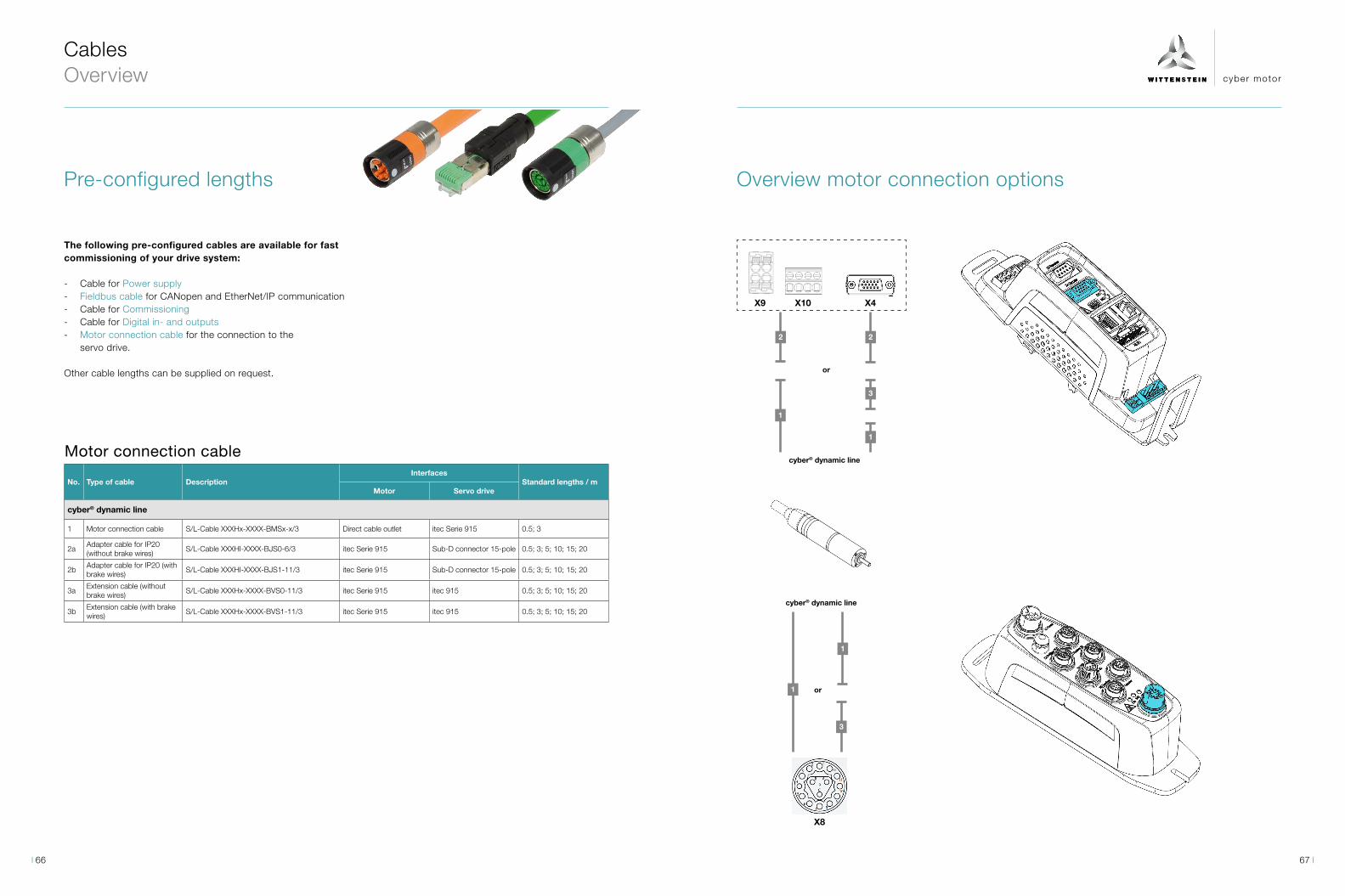
cyber motor
2 2
1
1
3
3
1
1
Pre-configured lengths
The following pre-configured cables are available for fast commissioning of your drive system:
- Cable for Power supply - Fieldbus cable for CANopen and EtherNet/IP communication - Cable for Commissioning - Cable for Digital in- and outputs - Motor connection cable for the connection to the
servo drive.
Other cable lengths can be supplied on request.
Motor connection cable
No. Type of cable DescriptionInterfaces
Standard lengths / mMotor Servo drive
cyber® dynamic line
1 Motor connection cable S/L-Cable XXXHx-XXXX-BMSx-x/3 Direct cable outlet itec Serie 915 0.5; 3
2aAdapter cable for IP20 (without brake wires)
S/L-Cable XXXHI-XXXX-BJS0-6/3 itec Serie 915 Sub-D connector 15-pole 0.5; 3; 5; 10; 15; 20
2bAdapter cable for IP20 (with brake wires)
S/L-Cable XXXHI-XXXX-BJS1-11/3 itec Serie 915 Sub-D connector 15-pole 0.5; 3; 5; 10; 15; 20
3aExtension cable (without brake wires)
S/L-Cable XXXHx-XXXX-BVS0-11/3 itec Serie 915 itec 915 0.5; 3; 5; 10; 15; 20
3bExtension cable (with brake wires)
S/L-Cable XXXHx-XXXX-BVS1-11/3 itec Serie 915 itec 915 0.5; 3; 5; 10; 15; 20
Cables Overview
Overview motor connection options
cyber® dynamic line
or
or
cyber® dynamic line
X8
X9 X10 X4
67 66
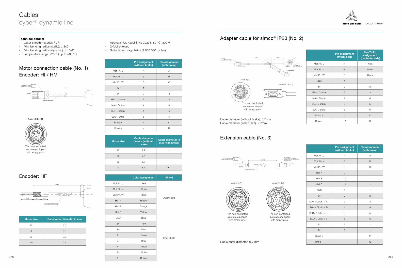
cyber motor
Leistungskennzeichnung
15 ± 215 ± 2
500+10 6 15
50 ± 5
Ansicht X (3:1)
Die nicht kontaktiertenSteckplätze sind mit
Leerpins bestückt.
4
1
BC
12
68
9A
7
E 3
5
11 2
10
INTERCONTECE ST A 204 MR xx 33 0003 xxx
Stecker Serie 915, 12+3 polig, mitKontaktstiften
Leitungskennzeichnung
Ansicht X
156A
Ansicht X (3:1)
Die nicht kontaktiertenSteckplätze sind mit
Leerpins bestückt.
4
1
BC
12
68
9A
7
E 3
5
11 2
10
INTERCONTECE ST A 204 MR xx 33 0003 xxx
Stecker Serie 915, 12+3 polig, mitKontaktstiften
Leitungskennzeichnung
Ansicht X
156A
Ansicht Y ⥀ (2:1)
51
1110
X2: Sub-D Steckerabgewinkelt, 3-reihig,15-polig, mit Kontaktstiften
A
CB
Abbildung ähnlich.
Aderendhülse (3x)+10150170+10
Y
Schirm
min. 300mm Nur statisch verlegen!
150+10
Leitungskennzeichnung
X1: INTERCONTECE KU A 205 FR xx 33 0003 xxxKupplung Serie 915, 12+3-polig, mitKontaktbuchsen
500+10
Ansicht X (3:1)
Die nicht kontaktiertenSteckplätze sind mitLeerpins bestückt.
3
B C
1
11P
7
106
412
8
2
9
A5
X
INTERCONTECE ST A 204 MR xx 33 0003 xxx
Stecker Serie 915, 12+3 polig, mitKontaktstiften
INTERCONTECE KU A 205 FR xx 33 0003 xxxKupplung Serie 915, 12+3 polig, mitKontaktbuchsen
Ansicht X
Leitungskennzeichnung
Ansicht Y
Ansicht Y (3:1)Ansicht X (3:1)
Die nicht kontaktiertenSteckplätze sind mit
Leerpins bestückt.
Die nicht kontaktiertenSteckplätze sind mit
Leerpins bestückt.
5000 +100
A
12
7
9
1
4
2
B3
65
E10C
11
8
12
10
11
1
97
5
86
23
B ACP4
Cables cyber® dynamic line
Technical details:
Motor connection cable (No. 1)Encoder: HI / HM
- Outer sheath material: PUR - Min. bending radius (static): ≥ 3xD - Min. bending radius (dynamic): ≥ 10xD - Temperature range: -20 °C up to +80 °C
Pin assignment (without brake)
Pin assignment (with brake)
Mot.Ph. U A A
Mot.Ph. V B B
Mot.Ph. W C C
GND 1 1
5V 2 2
MA+ / Clock+ 3 3
MA- / Clock- 4 4
SLO+ / Data+ 5 5
SLO- / Data- 6 6
Brake + - 11
Brake - - 12
Motor sizeCable diameter in mm (without
brake)
Cable diameter in mm (with brake)
17 7.2 -
22 7.6 -
32 8.7 -
40 8.7 9.7
Encoder: HF Color assignment Shield
Mot.Ph. U Red
Outer shield
Mot.Ph. V White
Mot.Ph. W Black
Hall A Brown
Hall B Orange
Hall C Yellow
GND Blue
Inner Shield
5V Red
A+ Pink
A- Green
B+ Grey
B- Yellow
Z+ White
Z- Brown
Motor size Cabel outer diameter in mm
17 8.5
22 8.8
32 9.7
40 9.7
Adapter cable for simco® IP20 (No. 2)
Extension cable (No. 3)
Pin assignment (motor side)
Pin-/Color assignment
(controller side)
Mot.Ph. U A Red
Mot.Ph. V B White
Mot.Ph. W C Black
GND 1 1
5V 2 2
MA+ / Clock+ 3 3
MA- / Clock- 4 4
SLO+ / Data+ 5 5
SLO- / Data- 6 6
Brake + 11 11
Brake - 12 12
Pin assignment (without brake)
Pin assignment (with brake)
Mot.Ph. U A A
Mot.Ph. V B B
Mot.Ph. W C C
Hall A 9 -
Hall B 10 -
Hall C 11 -
GND 1 1
5V 2 2
MA+ / Clock+ / A+ 3 3
MA- / Clock- / A- 4 4
SLO+ / Data+ / B+ 5 5
SLO- / Data- / B- 6 6
Z+ 7 -
Z- 8 -
Brake + - 11
Brake - - 12
Cable diameter (without brake): 8.7mmCable diameter (with brake): 9.7mm
The non-contacted slots are equipped with empty pins.
The non-contacted slots are equipped with empty pins.
The non-contacted slots are equipped with empty pins.
The non-contacted slots are equipped with empty pins.
Cable outer diameter: 9.7 mm
- Approval: UL AWM Style 20233, 80 °C, 300 V - 2-fold shielded - Suitable for drag chains (1.000.000 cycles)
69 68

cyber motor
4 4
2
3
3
5
2. cyber® simco® drive1. cyber® simco® drive
X5 X6X6 X7X7 X5
1. cyber® simco® drive 2. cyber® simco® drive
88
5
7 7
2
3
6
4
1 1
X5
X1
X2X4 X3X3 X4X2 X5
X1 X1
1,2
X1
Cables cyber® simco® line
No. Type of accessory Description
Interfaces
Description Standard lengths1. simco® drive
PLC / PC / 2. simco® drive
Fieldbus control cabinet / Suitable for drag chains (UL)
1 Fieldbus cableCAB-BUS-CAN-RJ45-FL-LXXXX
RJ45 connector flying leadsNetwork connection to PLC; plug can be assembled
1.5; 5 m
2 Fieldbus cableCAB-BUS-UN2-RJ45-RJ45-LXXXX
RJ45 connector RJ45 connectorNetwork connection to PLC; second simco® drive
0.3; 1; 2; 3 m
Fieldbus control cabinet (not UL)
3 Fieldbus cable CAB-BUS-UN1-RJ45-RJ45-LXXXX
RJ45 connector RJ45 connectorNetwork connection to PLC; second simco® drive
0.3; 1; 2; 3 m
Commissioning
4 USB connection cableCASIGN-USB/A-M/USB/B-L0300
Mini USB B USB A connector
Connection cable for diagnostic purposes, commissioning with MotionGUI 2
3 m
Miscellaneous
5Terminating resistor CANopen
CAB-BUS-CAN-RJ45-TERMINAT
- RJ45 connectorOnly necessary for CAN communication
-
IP20
Fieldbus IN Fieldbus INFieldbus OUT Fieldbus OUT
USB
Commissioning / Diagnostic PC
Higher-level control system
Commissioning / Diagnostic PC
USB
Fieldbus (UL listed) Fieldbus (not UL listed) Commissioning
No. Type of accessory Description
Interfaces
Description Standard lengths1. simco® drive
PLC / PC / 2. simco® drive
Power supply
1 Power supply cableCAB-POW-E-S915-FL__-LXXXX
y tec 915 flying leadsDC - Power supply cable
1; 2; 5; 10; 15 m
Fieldbus CANopen
2 Fieldbus cable PLCCAB-BUS-CAN-M12M-FL__-LXXXX
M12 socket 5-pole A-coded
flying leadsNetwork connection to PLC; plug can be assembled
1; 2; 5; 10; 15 m
3Fieldbus cable extension
CASIGN-CAN-M12F-SA-M12MSA-LXXXX
M12 connector 5-pole A-coded
M12 socket 5-pole A-coded
Network connection between simco® drives
1; 2; 5; 10; 15 m
4Terminating resistor CANopen
CAB-BUS-CAN-M12M-TERMINAT
-M12 connector 5-pole A-coded
Only necessary for CAN communication
-
Industrial Ethernet (EtherCAT / PROFINET / EtherNet/IP / Sercos III)
5 Network cable PLCTCC 002-025-XXXR-PUR
M12 connector 4-pole D-coded
RJ45 connectorNetwork connection to PLC
1; 2; 5; 10; 15 m
6Network cable extension
TCC 002-026-XXXR-PUR
M12 connector 4-pole D-coded
M12 connector 4-pole D-coded
Network connection between simco® drives
1; 2; 5; 10; 15 m
Commissioning
7 USB connection cableCASIGN M12-4p USB-A 2.0m PVC
M12 connector 4-pole A-coded (straight)
USB A connector
Connection cable for diagnostic purposes, commissioning with MotionGUI 2
2 m
Digital in- and outputs
8 Cable for Digital IOCASIGN-I/O-M12FSA-M12FSA-L0500
M12 socket 8-pole A-coded (straight)
M12 socket 8-pole A-coded (straight)
Connection cable to I/O-Box
5 m
IP65
Digital I/ODigital I/O
Commissioning / Diagnostic PC Commissioning / Diagnostic PC Digital I/O CANopen Ethernet based Commissioning
DC power supply DC power supply
Higher-level control system
XXXX = Cable length in cm (Example: 5 m = 0500)
XXXX = Cable length in cm (Example: 5 m = 0500)XXX = Cable length in dm (Example: 5 m = 050)
71 70
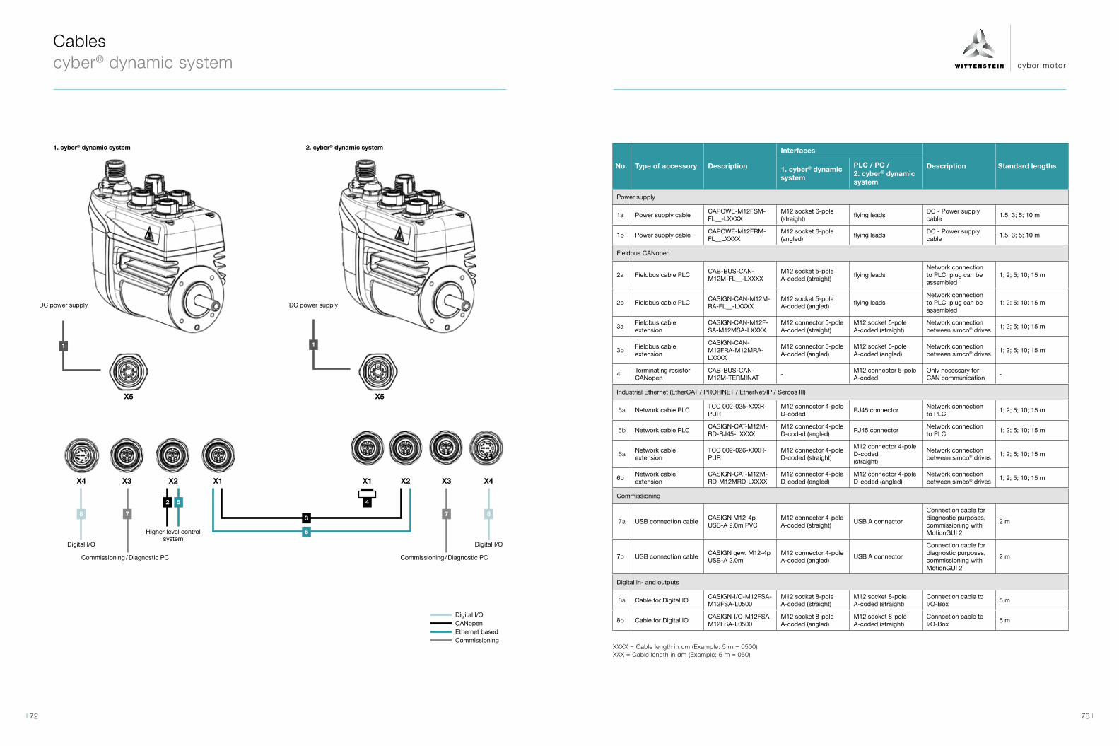
cyber motor
Cables cyber® dynamic system
No. Type of accessory Description
Interfaces
Description Standard lengths1. cyber® dynamic system
PLC / PC / 2. cyber® dynamic system
Power supply
1a Power supply cableCAPOWE-M12FSM-FL__-LXXXX
M12 socket 6-pole (straight)
flying leadsDC - Power supply cable
1.5; 3; 5; 10 m
1b Power supply cableCAPOWE-M12FRM-FL__LXXXX
M12 socket 6-pole (angled)
flying leadsDC - Power supply cable
1.5; 3; 5; 10 m
Fieldbus CANopen
2a Fieldbus cable PLCCAB-BUS-CAN-M12M-FL__-LXXXX
M12 socket 5-pole A-coded (straight)
flying leadsNetwork connection to PLC; plug can be assembled
1; 2; 5; 10; 15 m
2b Fieldbus cable PLCCASIGN-CAN-M12M-RA-FL__-LXXXX
M12 socket 5-pole A-coded (angled)
flying leadsNetwork connection to PLC; plug can be assembled
1; 2; 5; 10; 15 m
3aFieldbus cable extension
CASIGN-CAN-M12F-SA-M12MSA-LXXXX
M12 connector 5-pole A-coded (straight)
M12 socket 5-pole A-coded (straight)
Network connection between simco® drives
1; 2; 5; 10; 15 m
3bFieldbus cable extension
CASIGN-CAN-M12FRA-M12MRA-LXXXX
M12 connector 5-pole A-coded (angled)
M12 socket 5-pole A-coded (angled)
Network connection between simco® drives
1; 2; 5; 10; 15 m
4Terminating resistor CANopen
CAB-BUS-CAN-M12M-TERMINAT
-M12 connector 5-pole A-coded
Only necessary for CAN communication
-
Industrial Ethernet (EtherCAT / PROFINET / EtherNet/IP / Sercos III)
5a Network cable PLCTCC 002-025-XXXR-PUR
M12 connector 4-pole D-coded
RJ45 connectorNetwork connection to PLC
1; 2; 5; 10; 15 m
5b Network cable PLCCASIGN-CAT-M12M-RD-RJ45-LXXXX
M12 connector 4-pole D-coded (angled)
RJ45 connectorNetwork connection to PLC
1; 2; 5; 10; 15 m
6aNetwork cable extension
TCC 002-026-XXXR-PUR
M12 connector 4-pole D-coded (straight)
M12 connector 4-pole D-coded(straight)
Network connection between simco® drives
1; 2; 5; 10; 15 m
6bNetwork cable extension
CASIGN-CAT-M12M-RD-M12MRD-LXXXX
M12 connector 4-pole D-coded (angled)
M12 connector 4-pole D-coded (angled)
Network connection between simco® drives
1; 2; 5; 10; 15 m
Commissioning
7a USB connection cableCASIGN M12-4p USB-A 2.0m PVC
M12 connector 4-pole A-coded (straight)
USB A connector
Connection cable for diagnostic purposes, commissioning with MotionGUI 2
2 m
7b USB connection cableCASIGN gew. M12-4p USB-A 2.0m
M12 connector 4-pole A-coded (angled)
USB A connector
Connection cable for diagnostic purposes, commissioning with MotionGUI 2
2 m
Digital in- and outputs
8a Cable for Digital IOCASIGN-I/O-M12FSA-M12FSA-L0500
M12 socket 8-pole A-coded (straight)
M12 socket 8-pole A-coded (straight)
Connection cable to I/O-Box
5 m
8b Cable for Digital IOCASIGN-I/O-M12FSA-M12FSA-L0500
M12 socket 8-pole A-coded (angled)
M12 socket 8-pole A-coded (straight)
Connection cable to I/O-Box
5 m
1. cyber® dynamic system 2. cyber® dynamic system
88
5
7 7
2
3
6
4
1 1
X4 X4X1X3 X2X2 X3X1
X4
X5 X5
Digital I/ODigital I/O
Commissioning / Diagnostic PC Commissioning / Diagnostic PC
Digital I/O CANopen Ethernet based Commissioning
DC power supply DC power supply
Higher-level control system
XXXX = Cable length in cm (Example: 5 m = 0500)XXX = Cable length in dm (Example: 5 m = 050)
73 72
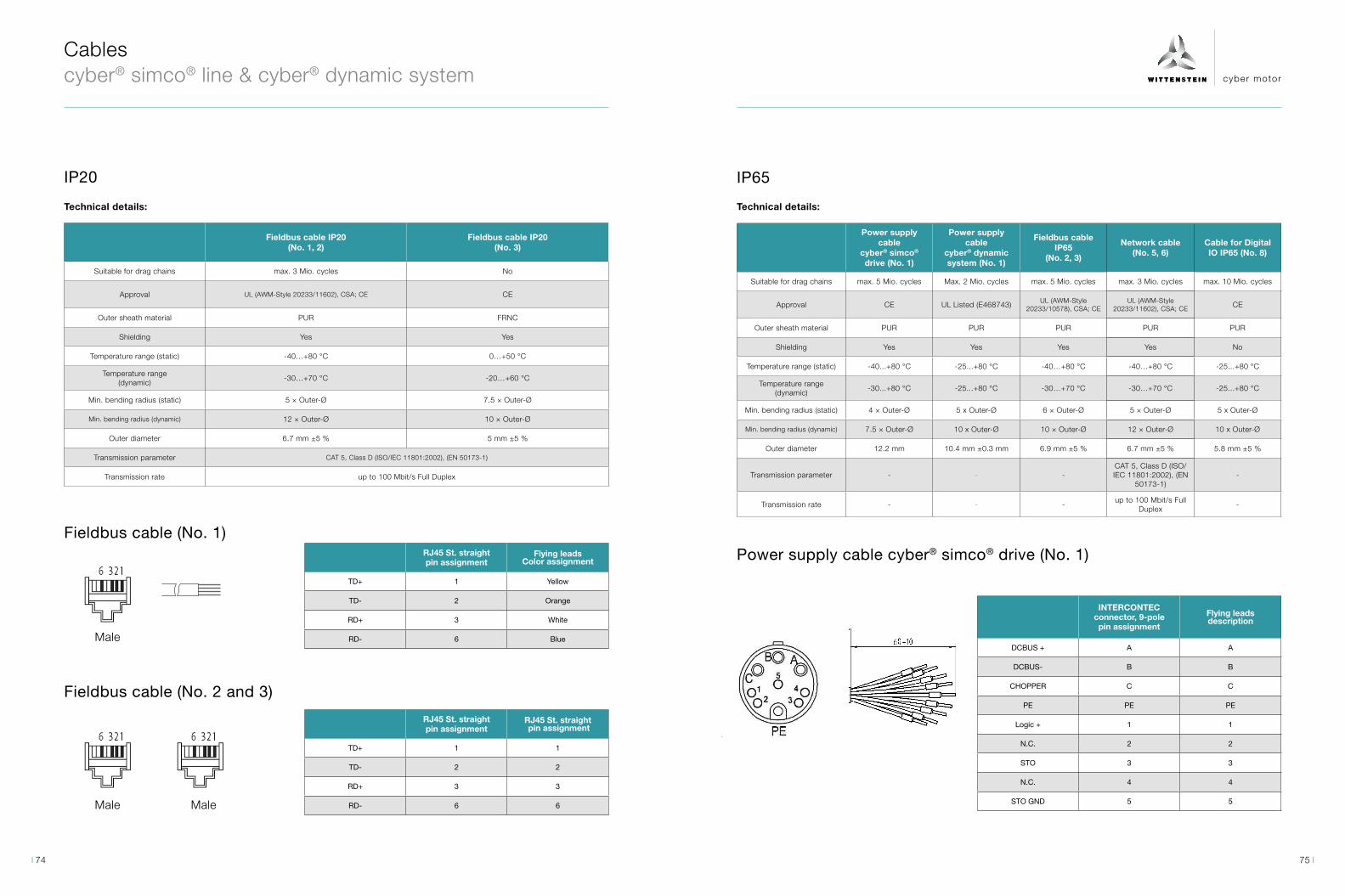
cyber motor
Cables cyber® simco® line & cyber® dynamic system
Fieldbus cable IP20 (No. 1, 2)
Fieldbus cable IP20 (No. 3)
Suitable for drag chains max. 3 Mio. cycles No
Approval UL (AWM-Style 20233/11602), CSA; CE CE
Outer sheath material PUR FRNC
Shielding Yes Yes
Temperature range (static) -40…+80 °C 0…+50 °C
Temperature range (dynamic)
-30…+70 °C -20…+60 °C
Min. bending radius (static) 5 × Outer-Ø 7.5 × Outer-Ø
Min. bending radius (dynamic) 12 × Outer-Ø 10 × Outer-Ø
Outer diameter 6.7 mm ±5 % 5 mm ±5 %
Transmission parameter CAT 5, Class D (ISO/IEC 11801:2002), (EN 50173-1)
Transmission rate up to 100 Mbit/s Full Duplex
Fieldbus cable (No. 1)
IP20
Fieldbus cable (No. 2 and 3)
Male
Male Male
RJ45 St. straightpin assignment
Flying leadsColor assignment
TD+ 1 Yellow
TD- 2 Orange
RD+ 3 White
RD- 6 Blue
RJ45 St. straightpin assignment
RJ45 St. straight pin assignment
TD+ 1 1
TD- 2 2
RD+ 3 3
RD- 6 6
Technical details:
IP65
Technical details:
Power supply cable
cyber® simco® drive (No. 1)
Power supply cable
cyber® dynamic system (No. 1)
Fieldbus cable IP65
(No. 2, 3)
Network cable (No. 5, 6)
Cable for Digital IO IP65 (No. 8)
Suitable for drag chains max. 5 Mio. cycles Max. 2 Mio. cycles max. 5 Mio. cycles max. 3 Mio. cycles max. 10 Mio. cycles
Approval CE UL Listed (E468743) UL (AWM-Style 20233/10578), CSA; CE
UL (AWM-Style 20233/11602), CSA; CE CE
Outer sheath material PUR PUR PUR PUR PUR
Shielding Yes Yes Yes Yes No
Temperature range (static) -40...+80 °C -25...+80 °C -40…+80 °C -40…+80 °C -25...+80 °C
Temperature range (dynamic)
-30...+80 °C -25...+80 °C -30…+70 °C -30…+70 °C -25...+80 °C
Min. bending radius (static) 4 × Outer-Ø 5 x Outer-Ø 6 × Outer-Ø 5 × Outer-Ø 5 x Outer-Ø
Min. bending radius (dynamic) 7.5 × Outer-Ø 10 x Outer-Ø 10 × Outer-Ø 12 × Outer-Ø 10 x Outer-Ø
Outer diameter 12.2 mm 10.4 mm ±0.3 mm 6.9 mm ±5 % 6.7 mm ±5 % 5.8 mm ±5 %
Transmission parameter - - -CAT 5, Class D (ISO/IEC 11801:2002), (EN
50173-1)-
Transmission rate - - -up to 100 Mbit/s Full
Duplex-
Power supply cable cyber® simco® drive (No. 1)
INTERCONTEC connector, 9-polepin assignment
Flying leadsdescription
DCBUS + A A
DCBUS- B B
CHOPPER C C
PE PE PE
Logic + 1 1
N.C. 2 2
STO 3 3
N.C. 4 4
STO GND 5 5
75 74

cyber motor
4 35
1 2
4 3
1 2
4 3
1 2
4 3
1 2
Cables cyber® simco® line & cyber® dynamic system
Fieldbus cable CANopen (No. 2)
Power supply cable cyber® dynamic system (No. 1)
Female, A-coded
Female, M-coded
M12 St. straight
pin assignment
Flying leadscolor assignment
Shield 1 -
+ 2 Red
- 3 Black
CAN-H 4 White
CAN-L 5 Blue
M12 socket, straight
pin assignment
Flying leadsdescription
DCBUS+ 1 BK1
DCBUS- 2 BK2
Logic+ 3 BK3
STO 4 BK4
STO GND 5 BK5
FE 6 GN/YE
Fieldbus cable CANopen (No. 3)
Male, A-coded
Female, A-coded
M12 St. straightpin assignment
M12 St. straightpin assignment
Shield 1 1
+ 2 2
- 3 3
CAN-H 4 4
CAN-L 5 5
Network cable Ethernet (No. 5)
Male, D-coded
Male
M12 St. straightpin assignment
RJ45 St. straightpin assignment
TD+ 1 1
TD- 3 2
RD+ 2 3
RD- 4 6
Network cable Ethernet (No. 6)
Cable for Digital IO (No. 8)
Male, D-coded
Female, A-coded
Male, D-coded
Female, A-coded
M12 St. straightpin assignment
M12 St. straightpin assignment
TD+ 1 1
TD- 3 3
RD+ 2 2
RD- 4 4
M12 socket, straight
pin assignment
M12 socket, straight
pin assignment
DIN 2 1 1
DIN 4 2 2
DOUT 1 3 3
DOUT 2 4 4
VCC24 5 5
DIN 1 6 6
GND 7 7
DIN 3 8 8
77 76

cyber motor
WITTENSTEIN – eins sein mit der Zukunft www.wittenstein-cyber-motor.de WITTENSTEIN cyber motor GmbH · Walter-Wittenstein-Straße 1 · 97999 Igersheim · Germany Tel. +49 7931 493-15800 · [email protected]
Schirmklemme IP20
Shield clamp IP20
cyber® simco line
Technische Daten Technical Data
Allgemeine Informationen General information Typenbezeichnung Type code Schirmanschlussklemme SK 14 shield connection clamp SK 14 Anzahl der Etagen Number of floors 1 Anzahl der Anschlüsse number of connections 1 Kabeldurchmesser Cable diameter 3…14 mm Farbe colour Silberfarben silver Mechanische Eigenschaften Mechanical data Länge length 19,5 mm Breite width 17 mm Höhe hight 59,3 mm Anschlussart connection type Schraubanschluss screw connection Schraubengewinde screw thread M4 Anzugsdrehmoment tightening torque max 0,8 Nm Elektrische Eigenschaften Electrical data Übergangswiderstand Contact resistance < 1 mΩ Environmental Product Compliance REACh SVHC Lead 7439-92-1 China RoHS Zeitraum für bestimmungsgemäße Verwendung: unbegrenzt = EFUP-e
Period for intended use: unlimited = EFUP-e
CDSR CDSL
Accessories
Heat sink kit SIM2050D
Shield clamp IP20
- Heat sink for simco® drive version SIM2050 - Delivery: Heat sink incl. M4x14 screws for fixing to the
servo drive - Different mounting holes for rotation of the heat sink
- Possibility of mounting the servo drive with heat sink via four M4 threads located on the heat sink (D-D).
- Order reference: Kuehlkoerperkit SIM2050D flex
- Shield clamp for shield diameter 3-14 mm - Connection of the outer shield of the motor cable
with a screw cap
- When ordering a servo drive of the cyber® simco® line in IP20 with shield clamp, the servo drive is supplied with the shield clamp fitted
- Order reference: Schirmanschlussklemme SK 14
Mounting adapters
Attachment parts to the pushing rod
Mounting adapters are available for the cyber® dynamic system to realize an installation compatible solution to our Ternary drive system.
Order reference: Adapter CDSR or Adapter CDSL
For the linear actuators of the cyber® dynamic line in size 40 as well as the cyber® dynamic system, four different attach-ment parts for the pushing rod are available.
Order reference: cyber® dynamic Anbauteil Tip X
A B C D
Outer thread M16 x 1.5Outer thread M16 x 1.5 with double D-profile
Inner thread M10 x 1.25 with double D-profile
Outer thread M12 x 1.25 with double D-profile
79 78
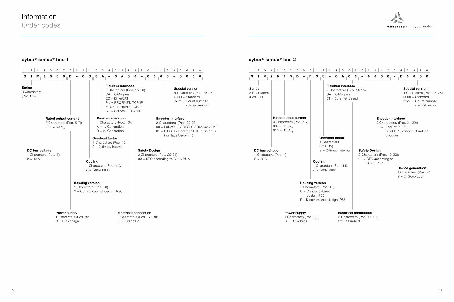
cyber motor
1 2 3 4 5 6 7 8 9 0 1 2 3 4 5 6 7 8 9 0 1 2 3 4 5 6 7 8
S I M 2 0 5 0 D – C C S A – C A 0 0 – 0 0 0 0 – 0 0 0 0
1 2 3 4 5 6 7 8 9 0 1 2 3 4 5 6 7 8 9 0 1 2 3 4 5 6 7 8
S I M 2 0 1 5 D – F C S – C A 0 0 – 0 0 0 0 – B 0 0 0 0
cyber® simco® line 1
Series3 Characters (Pos.1-3)
Series3 Characters (Pos.1-3)
DC bus voltage 1 Characters (Pos. 4):2 = 48 V
DC bus voltage 1 Characters (Pos. 4):2 = 48 V
Rated output current3 Characters (Pos. 5-7):050 = 50 Aeff
Rated output current3 Characters (Pos. 5-7):007 = 7.5 Aeff 015 = 15 Aeff
Power supply1 Characters (Pos. 8):D = DC voltage
Power supply1 Characters (Pos. 8):D = DC voltage
Housing version1 Characters (Pos. 10):C = Control cabinet design IP20
Housing version1 Characters (Pos. 10):C = Control cabinet
design IP20F = Decentralized design IP65
Cooling1 Characters (Pos. 11):C = Convection
Cooling1 Characters (Pos. 11):C = Convection
Overload factor1 Characters (Pos. 12):S = 2-times, internal
Overload factor1 Characters (Pos. 12):S = 2-times, internal
Device generation1 Characters (Pos. 24):B = 2. Generation
Device generation1 Characters (Pos. 13):A = 1. GenerationB = 2. Generation
Fieldbus interface2 Characters (Pos. 15-16):CA = CANopenEC = EtherCATPN = PROFINET, TCP/IPEI = EtherNet/IP, TCP/IPSC = Sercos III, TCP/IP
Fieldbus interface2 Characters (Pos. 14-15):CA = CANopenET = Ethernet-based
Electrical connection2 Characters (Pos. 17-18):00 = Standard
Electrical connection2 Characters (Pos. 17-18):00 = Standard
Safety Design2 Characters (Pos. 20-21):00 = STO according to SIL3 / PL e
Safety Design2 Characters (Pos. 19-20):00 = STO according to
SIL3 / PL e
Encoder interface2 Characters, (Pos. 22-23):00 = EnDat 2.2 / BISS C / Reolver / Hall01 = BISS C / Reolver / Hall (if Fieldbus
interface Sercos III)
Encoder interface2 Characters, (Pos. 21-22):00 = EndDat 2.2 /
BiSS-C / Resolver / Sin/Cos-Encoder
Special version4 Characters (Pos. 25-28):0000 = Standardxxxx = Count number
special version
Special version4 Characters (Pos. 25-28):0000 = Standardxxxx = Count number
special version
Information Order codes
cyber® simco® line 2
81 80
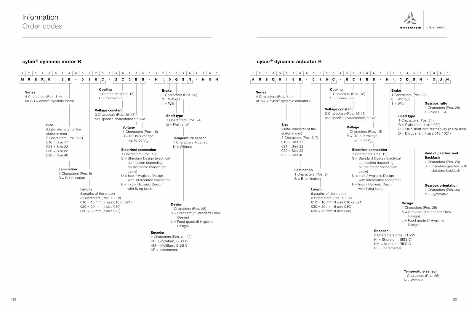
cyber motor
1 2 3 4 5 6 7 8 9 0 1 2 3 4 5 6 7 8 9 0 1 2 3 4 5 6 7 8 9 0
M R S R 0 1 6 B - 0 1 0 C - 2 C 0 B S - H I 0 G S N - N N N
1 2 3 4 5 6 7 8 9 0 1 2 3 4 5 6 7 8 9 0 1 2 3 4 5 6 7 8 9 0
A R S Q 0 1 6 B - 0 1 0 C - 8 C 1 B S - H I 0 D S N - X U N
cyber® dynamic motor R cyber® dynamic actuator R
Series4 Characters (Pos. 1-4)MRSR = cyber® dynamic motor
Series4 Characters (Pos. 1-4)ARSQ = cyber® dynamic actuator R
Electrical connection1 Characters (Pos. 19)S = Standard Design (electrical
connection depending on the motor connection cable)
U = Inox / Hygienic Design with intercontec connector
F = Inox / Hygienic Design with flying leads
Electrical connection1 Characters (Pos. 19)S = Standard Design (electrical
connection depending on the motor connection cable)
U = Inox / Hygienic Design with intercontec connector
F = Inox / Hygienic Design with flying leads
Encoder2 Characters (Pos. 21-22)HI = Singleturn, BISS CHM = Multiturn, BISS CHF = Incremental
Encoder2 Characters (Pos. 21-22)HI = Singleturn, BISS CHM = Multiturn, BISS CHF = Incremental
Size(Outer diameter of the stator in mm)3 Characters (Pos. 5-7)016 = Size 17021 = Size 22030 = Size 32038 = Size 40
Size(Outer diameter of the stator in mm)3 Characters (Pos. 5-7)016 = Size 17021 = Size 22030 = Size 32038 = Size 40
Length(Lengths of the stator)3 Characters (Pos. 10-12)010 = 10 mm (if size 016 or 021)020 = 20 mm (if size 030)030 = 30 mm (if size 038)
Length(Lengths of the stator)3 Characters (Pos. 10-12)010 = 10 mm (if size 016 or 021)020 = 20 mm (if size 030)030 = 30 mm (if size 038)
Lamination1 Characters (Pos. 8)B = B-lamination
Lamination1 Characters (Pos. 8)B = B-lamination
Cooling1 Characters (Pos. 13)C = Convection
Cooling1 Characters (Pos. 13)C = Convection
Voltage1 Characters (Pos. 18)B = DC bus voltage
up to 60 VDC
Voltage1 Characters (Pos. 18)B = DC bus voltage
up to 60 VDC
Voltage constant3 Characters (Pos. 15-17)see specific characteristic curve
Voltage constant3 Characters (Pos. 15-17)see specific characteristic curve
Brake1 Characters (Pos. 23)0 = Without1 = With
Brake1 Characters (Pos. 23)0 = Without1 = With
Shaft type1 Characters (Pos. 24)G = Plain shaft
Shaft type1 Characters (Pos. 24)G = Plain shaft (if size 030)P = Plain shaft with feather key (if size 038) D = D-cut shaft (if size 016 / 021)
Temperature sensor1 Characters (Pos. 26)N = Without
Temperature sensor1 Characters (Pos. 26)N = Without
Gearbox ratio1 Characters (Pos. 28)X = See S. 84
Kind of gearbox and Backlash1 Characters (Pos. 29)U = Planetary gearbox with
standard backlash
Gearbox orientation1 Characters (Pos. 30)N = Symmetric
Design1 Characters (Pos. 25)S = Standard (if Standard / Inox
Design) L = Food grade (if Hygienic
Design)
Design1 Characters (Pos. 25)S = Standard (if Standard / Inox
Design) L = Food grade (if Hygienic
Design)
Information Order codes
83 82
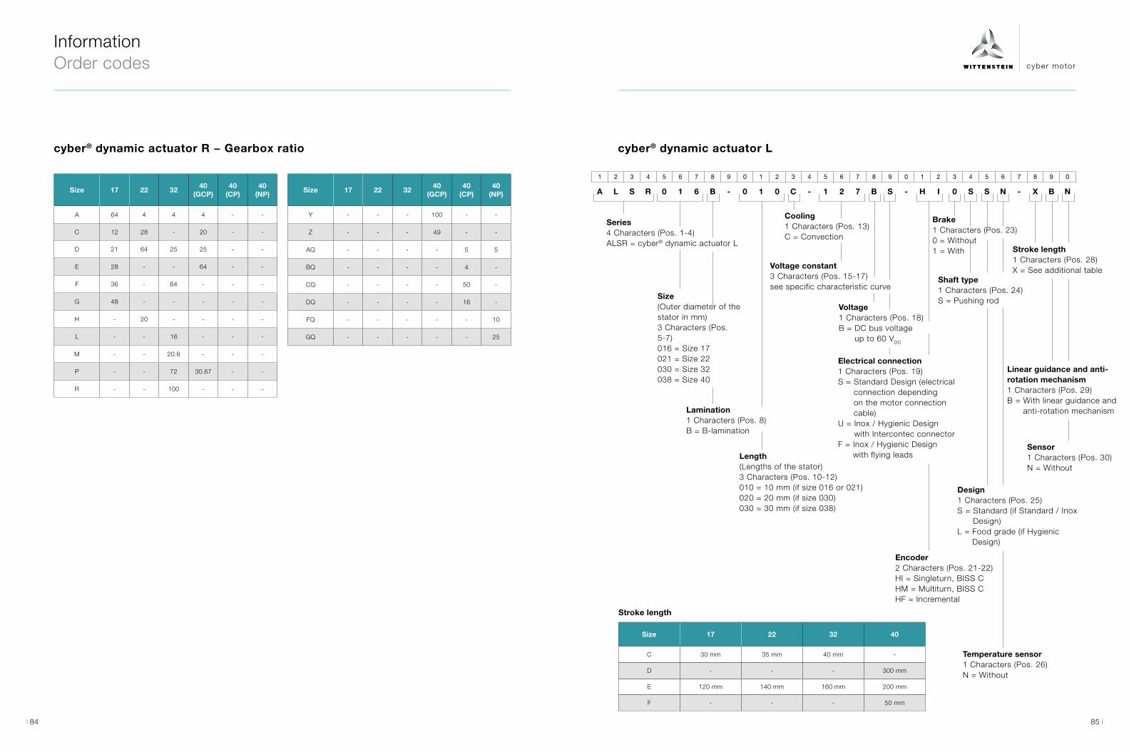
cyber motor
1 2 3 4 5 6 7 8 9 0 1 2 3 4 5 6 7 8 9 0 1 2 3 4 5 6 7 8 9 0
A L S R 0 1 6 B - 0 1 0 C - 1 2 7 B S - H I 0 S S N - X B N
cyber® dynamic actuator L
Information Order codes
Series4 Characters (Pos. 1-4)ALSR = cyber® dynamic actuator L
Electrical connection1 Characters (Pos. 19)S = Standard Design (electrical
connection depending on the motor connection cable)
U = Inox / Hygienic Design with Intercontec connector
F = Inox / Hygienic Design with flying leads
Encoder2 Characters (Pos. 21-22)HI = Singleturn, BISS CHM = Multiturn, BISS CHF = Incremental
Size(Outer diameter of the stator in mm)3 Characters (Pos. 5-7)016 = Size 17021 = Size 22030 = Size 32038 = Size 40
Length(Lengths of the stator)3 Characters (Pos. 10-12)010 = 10 mm (if size 016 or 021)020 = 20 mm (if size 030)030 = 30 mm (if size 038)
Lamination1 Characters (Pos. 8)B = B-lamination
Cooling1 Characters (Pos. 13)C = Convection
Voltage1 Characters (Pos. 18)B = DC bus voltage
up to 60 VDC
Voltage constant3 Characters (Pos. 15-17)see specific characteristic curve
Brake1 Characters (Pos. 23)0 = Without1 = With
Shaft type1 Characters (Pos. 24)S = Pushing rod
Temperature sensor1 Characters (Pos. 26)N = Without
Stroke length1 Characters (Pos. 28)X = See additional table
Linear guidance and anti-rotation mechanism1 Characters (Pos. 29)B = With linear guidance and
anti-rotation mechanism
Sensor1 Characters (Pos. 30)N = Without
Design1 Characters (Pos. 25)S = Standard (if Standard / Inox
Design) L = Food grade (if Hygienic
Design)
Size 17 22 32 40
C 30 mm 35 mm 40 mm -
D - - - 300 mm
E 120 mm 140 mm 160 mm 200 mm
F - - - 50 mm
Stroke length
Size 17 22 3240
(GCP)40
(CP)40
(NP)
A 64 4 4 4 - -
C 12 28 - 20 - -
D 21 64 25 25 - -
E 28 - - 64 - -
F 36 - 64 - - -
G 48 - - - - -
H - 20 - - - -
L - - 16 - - -
M - - 20.8 - - -
P - - 72 30.67 - -
R - - 100 - - -
Size 17 22 3240
(GCP)40
(CP)40
(NP)
Y - - - 100 - -
Z - - - 49 - -
AQ - - - - 5 5
BQ - - - - 4 -
CQ - - - - 50 -
DQ - - - - 16 -
FQ - - - - - 10
GQ - - - - - 25
cyber® dynamic actuator R − Gearbox ratio
85 84
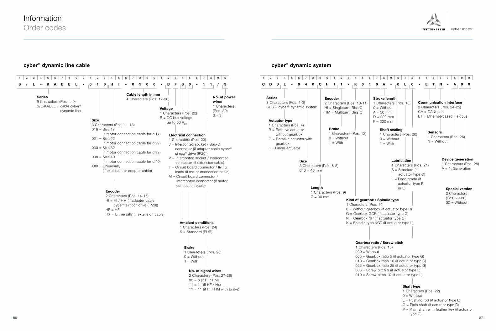
cyber motor
1 2 3 4 5 6 7 8 9 0 1 2 3 4 5 6 7 8 9 0 1 2 3 4 5 6 7 8 9 0
C D S L - 0 4 0 C H I 1 - K 0 1 0 A - 0 L 0 - E T N - A 0 0
1 2 3 4 5 6 7 8 9 0 1 2 3 4 5 6 7 8 9 0 1 2 3 4 5 6 7 8 9 0
S / L - K A B E L - 0 1 6 H I - 0 5 0 0 - B F S 0 - 1 1 / 3
Information Order codes
Series3 Characters (Pos. 1-3)CDS = cyber® dynamic system
Actuator type1 Characters (Pos. 4)R = Rotative actuator
without gearboxG = Rotative actuator with
gearboxL = Linear actuator
Kind of gearbox / Spindle type1 Characters (Pos. 14)0 = Without gearbox (if actuator type R) G = Gearbox GCP (if actuator type G) N = Gearbox NP (if actuator type G) K = Spindle type KGT (if actuator type L)
Shaft type1 Characters (Pos. 22)0 = Without L = Pushing rod (if actuator type L) G = Plain shaft (if actuator type R) P = Plain shaft with feather key (if actuator
type G)
Gearbox ratio / Screw pitch1 Characters (Pos. 15)000 = Without 005 = Gearbox ratio 5 (if actuator type G)010 = Gearbox ratio 10 (if actuator type G)025 = Gearbox ratio 25 (if actuator type G) 003 = Screw pitch 3 (if actuator type L)010 = Screw pitch 10 (if actuator type L)
Encoder2 Characters (Pos. 10-11)HI = Singleturn, Biss CHM = Multiturn, Biss C
Stroke length1 Characters (Pos. 18)0 = Without A = 50 mmD = 200 mmF = 300 mm
Shaft sealing1 Characters (Pos. 20)0 = Without 1 = With
Communication interface2 Characters (Pos. 24-25)CA = CANopen ET = Ethernet-based Fieldbus
Lubrication1 Characters (Pos. 21)S = Standard (if
actuator type G) L = Food grade (if
actuator type R or L)
Size3 Characters (Pos. 6-8)040 = 40 mm
Length1 Characters (Pos. 9)C = 30 mm
Sensors1 Characters (Pos. 26)N = Without
Device generation1 Characters (Pos. 28)A = 1. Generation
Special version2 Characters (Pos. 29-30)00 = Without
Brake1 Characters (Pos. 12)0 = Without1 = With
cyber® dynamic systemcyber® dynamic line cable
Series9 Characters (Pos. 1-9)S/L-KABEL = cable cyber®
dynamic line
Electrical connection1 Characters (Pos. 23)J = Intercontec socket / Sub-D
connector (if adapter cable cyber® simco® drive (IP20))
V = Intercontec socket / Intercontec connector (if extension cable)
F = Circuit board connector / flying leads (if motor connection cable)
M = Circuit board connector / Intercontec connector (if motor connection cable)
Encoder2 Characters (Pos. 14-15)HI = HI / HM (if adapter cable
cyber® simco® drive (IP20))HF = HFHX = Universally (if extension cable)
Size3 Characters (Pos. 11-13)016 = Size 17
(if motor connection cable for dl17)021 = Size 22
(if motor connection cable for dl22)030 = Size 32
(if motor connection cable for dl32)038 = Size 40
(if motor connection cable for dl40)XXX = Universally
(if extension or adapter cable)
Brake1 Characters (Pos. 25)0 = Without1 = With
No. of signal wires2 Characters (Pos. 27-28)06 = 6 (if HI / HM)11 = 11 (if HF / Hx) 11 = 11 (if HI / HM with brake)
Ambient conditions1 Characters (Pos. 24)S = Standard (PUR)
Cable length in mm4 Characters (Pos. 17-20) No. of power
wires1 Characters (Pos. 30)3 = 3
Voltage1 Characters (Pos. 22)B = DC bus voltage
up to 60 VDC
87 86

cyber motor
1 2 3 4 5 6 7 8 9 0 1 2 3 4 5 6
C P S 2 0 1 0 D - C C N - A 0 0
1 2 3 4 5 6 7 8 9 0 1 2 3 4 5 6 7
C Y D F W - C A - 0 2 - 0 1 - 0 1
cyber® power supply
Series3 Characters (Pos. 1-3)CPS = cyber® power supply
Nominal output voltage1 Characters (Pos. 4)1 = 24 V2 = 48 V
Nominal output current3 Characters (Pos. 5-7)005 = 5 A010 = 10 A020 = 20 A
Input voltage1 Characters (Pos. 8)E = 1-phaseD = 3-phase
Housing version1 Characters (Pos. 10)C = Control cabinet design IP20
Cooling1 Characters (Pos. 11)C = Convection
Overload factor1 Characters (Pos. 12)A = 0-timesN = 1.5-times
Device Generation1 Characters (Pos. 14)A = 1. Generation
Special version2 Characters (Pos. 15-16)00 = Standardxx = Count number special version
Information Order codes
cyber® simco® line / cyber® dynamic system software
Series3 Characters (Pos.1-3)CYD = cyber® drive
Generation2 Characters (Pos.10-11)02 = 2. Generation
Software type2 Characters (Pos.4-5)FW = Firmware
Version2 Characters (Pos.13-14)XX = Latest version01 = Version 102 = Version 2
Subversion2 Characters (Pos.16-17)XX = Latest subversion00 = Subversion 001 = Subversion 1
Fieldbus interface 2 Characters (Pos.7-8)CA = CANopenEC = EtherCATPN = ProfinetEI = EtherNet/IPSC = SERCOS IIIME = Multi-Ethernet
89 88

cyber motor
∙ Engineering
∙ Consultation and trainings
∙ Sizing software cymex®
∙ CAD POINT
For reliable and expert dimensioning.
Tel: +49 7931 493-15800
Fax: +49 7931 493-10905
E-Mail: [email protected]
For any questions on installation, commissioning and optimization.
Tel: +49 7931 493-14800
E-Mail: [email protected]
For detailed information, please visit www.wittenstein-cyber-motor.de
For fast and unbureaucratic assistance with repairs and questions about supplied products.
Tel: +49 7931 493-15900
Fax: +49 7931 493-10903
E-Mail: [email protected]
∙ Service Portal
∙ Installation on-site
∙ Operating & installation instruc-tions
∙ Pick-up & return service
∙ Service Portal
∙ Modernization
∙ 24 h service hotline
∙ Maintenance and inspection
∙ Repair
∙ cymex® statistics
∙ Product training
∙ Sizing training
∙ Installation training
∙ Service training
PRE-SALES PRE-SALESAFTER-SALES AFTER-SALES
Our service concept continues to raise
the bar for service quality. We are there for
you, starting from the initial concept and
throughout the entire life cycle of your
application.
Information Service concept
Our services at a glance Contact information
Design Support hotline
Technical Support
Installation TrainingMaintenance Service hotline
91 90

cyber motor
Information Drive selection and sizing
Information Commissioning and maintenance
Our software portfolio helps you to choose the right driveYou can conveniently download dimension sheets and CAD data, select the best product quickly and easily design complex kinematic sequences in detail – our software solutions offer various methods of selecting the best, most reliable drive on all axes.
The basic idea of the WITTENSTEIN Service Portal The new web-based WITTENSTEIN Service Portal supports you throughout the entire life cycle of your WITTENSTEIN product – from installation over commissioning to service and/or drive replacement. Here you will find relevant and current information about your product, covering explanations, technical data, tutorial videos on assembly & commissioning, docu-mentation, firmware files and the details of your contact. The WITTENSTEIN Service Portal also makes it quick and easy to request replacement products and register returns for inspection or repair.
CAD POINT Your Smart Catalog
- Performance data, dimension sheets and CAD data to all products
- Available online, without login - Clear documentation of the selection
www.wittenstein-cad-point.com
cymex® 5Calculate on the Best
- Detailed calculation of complete drive trains - Precise simulation of motion and
load variables - Desktop software for complex designs
www.wittenstein-cymex.com
WITTENSTEIN Sizing Tools – several ways to reach your objectives WITTENSTEIN Service Portal - One gate. All support.
Your advantages
- Fast: You will receive clear information about the present pro-duct without any time spent waiting or researching.
- Simple access: You can access the WITTENSTEIN Service Portal via desktop PC and mobile devices and navigate intuitively.
- Up-to-date: You will improve security because data, documentation and software are up to date.
- Personal: For further support, you can directly get in touch with the competent contact responsible.
- Understandable: You receive access to the version of the firmware as of delivery as well as to the latest version.
- International: The Service Portal is available in six languages (EN, DE, ES, IT, FR, TR).
www.wittenstein.de/service-portal-en
You can access the WITTENSTEIN Service Portal both from your desktop PC by entering the serial number of your drives or, even more conveniently, via your mobile devices (tablet or smartphone) by scanning the DataMatrix code attached to the product.
Discover the WITTENSTEIN Service Portal
93 92
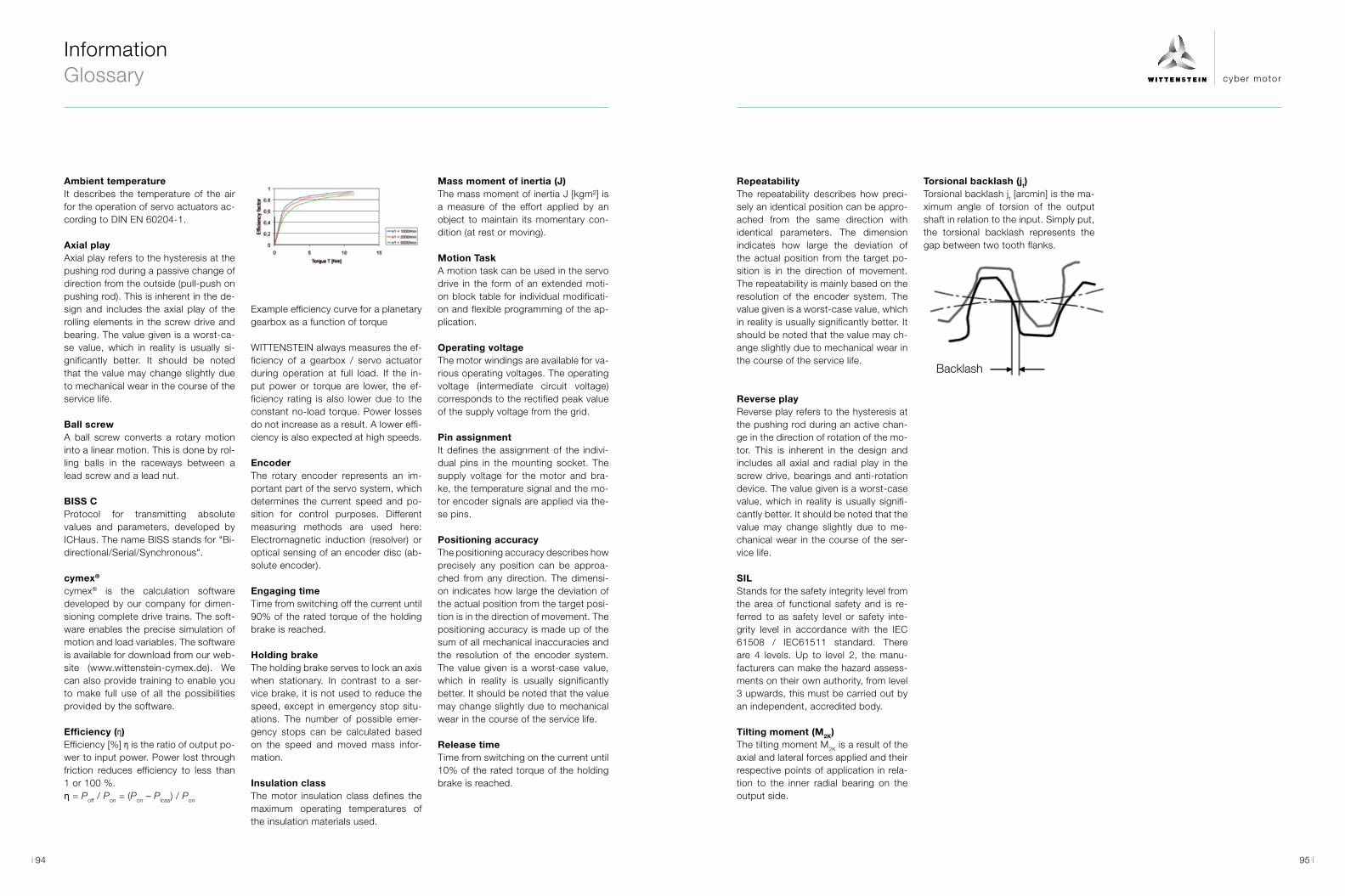
cyber motor
Information Glossary
Ambient temperature It describes the temperature of the air for the operation of servo actuators ac-cording to DIN EN 60204-1.
Axial playAxial play refers to the hysteresis at the pushing rod during a passive change of direction from the outside (pull-push on pushing rod). This is inherent in the de-sign and includes the axial play of the rolling elements in the screw drive and bearing. The value given is a worst-ca-se value, which in reality is usually si-gnificantly better. It should be noted that the value may change slightly due to mechanical wear in the course of the service life.
Ball screwA ball screw converts a rotary motion into a linear motion. This is done by rol-ling balls in the raceways between a lead screw and a lead nut.
BISS CProtocol for transmitting absolute values and parameters, developed by ICHaus. The name BISS stands for "Bi-directional/Serial/Synchronous".
cymex®
cymex® is the calculation software developed by our company for dimen-sioning complete drive trains. The soft-ware enables the precise simulation of motion and load variables. The software is available for download from our web-site (www.wittenstein-cymex.de). We can also provide training to enable you to make full use of all the possibilities provided by the software.
Efficiency (η) Efficiency [%] η is the ratio of output po-wer to input power. Power lost through friction reduces efficiency to less than 1 or 100 %.η = Poff / Pon = (Pon – Ploss) / Pon
Example efficiency curve for a planetary gearbox as a function of torque
WITTENSTEIN always measures the ef-ficiency of a gearbox / servo actuator during operation at full load. If the in-put power or torque are lower, the ef-ficiency rating is also lower due to the constant no-load torque. Power losses do not increase as a result. A lower effi-ciency is also expected at high speeds.
EncoderThe rotary encoder represents an im-portant part of the servo system, which determines the current speed and po-sition for control purposes. Different measuring methods are used here: Electromagnetic induction (resolver) or optical sensing of an encoder disc (ab-solute encoder).
Engaging timeTime from switching off the current until 90% of the rated torque of the holding brake is reached.
Holding brakeThe holding brake serves to lock an axis when stationary. In contrast to a ser-vice brake, it is not used to reduce the speed, except in emergency stop situ-ations. The number of possible emer-gency stops can be calculated based on the speed and moved mass infor-mation.
Insulation class The motor insulation class defines the maximum operating temperatures of the insulation materials used.
Mass moment of inertia (J)The mass moment of inertia J [kgm²] is a measure of the effort applied by an object to maintain its momentary con-dition (at rest or moving).
Motion TaskA motion task can be used in the servo drive in the form of an extended moti-on block table for individual modificati-on and flexible programming of the ap-plication.
Operating voltageThe motor windings are available for va-rious operating voltages. The operating voltage (intermediate circuit voltage) corresponds to the rectified peak value of the supply voltage from the grid.
Pin assignment It defines the assignment of the indivi-dual pins in the mounting socket. The supply voltage for the motor and bra-ke, the temperature signal and the mo-tor encoder signals are applied via the-se pins.
Positioning accuracyThe positioning accuracy describes how precisely any position can be approa-ched from any direction. The dimensi-on indicates how large the deviation of the actual position from the target posi-tion is in the direction of movement. The positioning accuracy is made up of the sum of all mechanical inaccuracies and the resolution of the encoder system. The value given is a worst-case value, which in reality is usually significantly better. It should be noted that the value may change slightly due to mechanical wear in the course of the service life.
Release timeTime from switching on the current until 10% of the rated torque of the holding brake is reached.
RepeatabilityThe repeatability describes how preci-sely an identical position can be appro-ached from the same direction with identical parameters. The dimension indicates how large the deviation of the actual position from the target po-sition is in the direction of movement. The repeatability is mainly based on the resolution of the encoder system. The value given is a worst-case value, which in reality is usually significantly better. It should be noted that the value may ch-ange slightly due to mechanical wear in the course of the service life.
Reverse playReverse play refers to the hysteresis at the pushing rod during an active chan-ge in the direction of rotation of the mo-tor. This is inherent in the design and includes all axial and radial play in the screw drive, bearings and anti-rotation device. The value given is a worst-case value, which in reality is usually signifi-cantly better. It should be noted that the value may change slightly due to me-chanical wear in the course of the ser-vice life.
SIL Stands for the safety integrity level from the area of functional safety and is re-ferred to as safety level or safety inte-grity level in accordance with the IEC 61508 / IEC61511 standard. There are 4 levels. Up to level 2, the manu-facturers can make the hazard assess-ments on their own authority, from level 3 upwards, this must be carried out by an independent, accredited body.
Tilting moment (M2K)The tilting moment M2K is a result of the axial and lateral forces applied and their respective points of application in rela-tion to the inner radial bearing on the output side.
Torsional backlash (jt) Torsional backlash jt [arcmin] is the ma-ximum angle of torsion of the output shaft in relation to the input. Simply put, the torsional backlash represents the gap between two tooth flanks.
Backlash
95 94
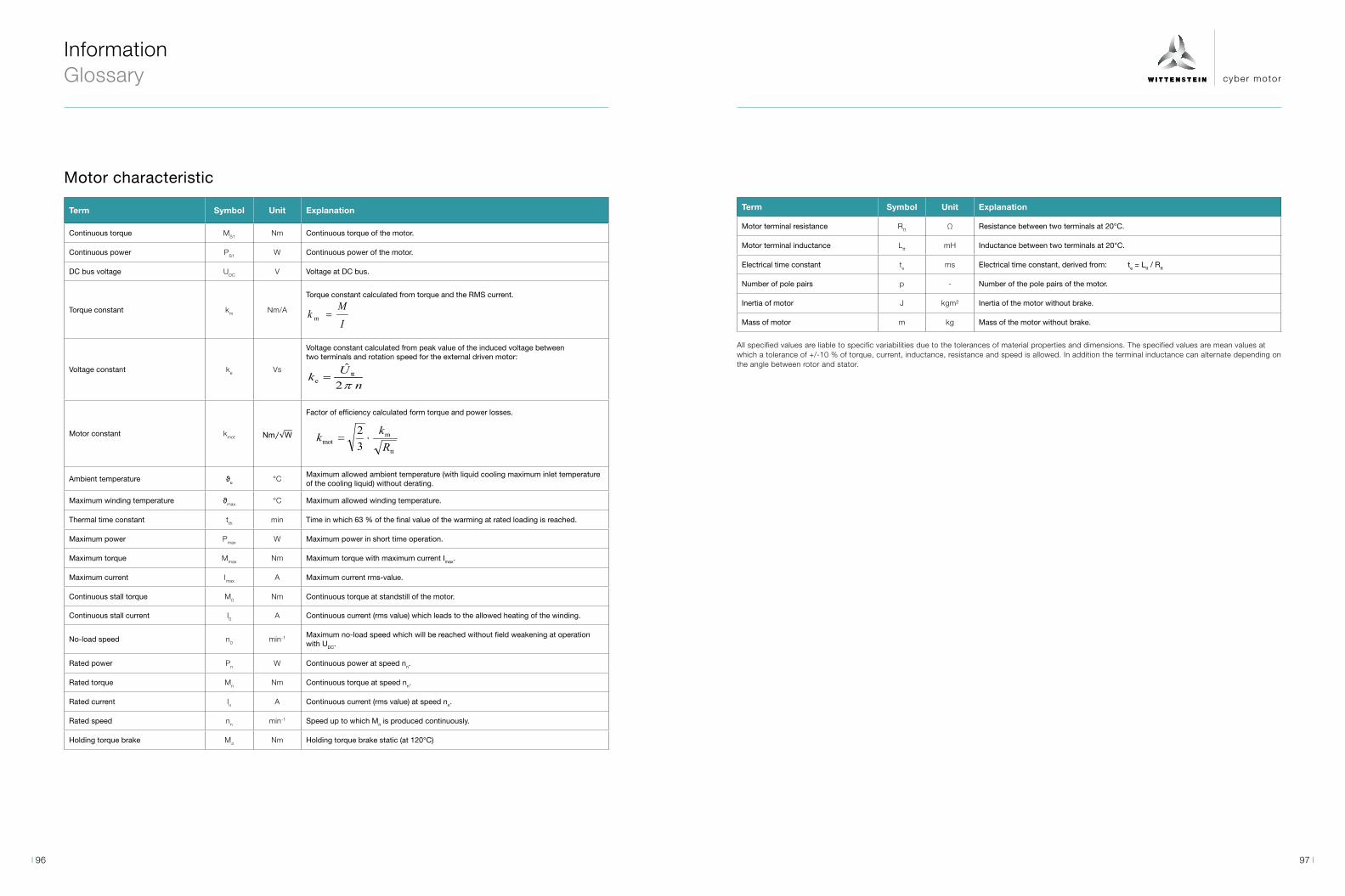
cyber motor
Motor characteristic
Term Symbol Unit Explanation
Continuous torque MS1 Nm Continuous torque of the motor.
Continuous power PS1 W Continuous power of the motor.
DC bus voltage UDC V Voltage at DC bus.
Torque constant km Nm/A
Torque constant calculated from torque and the RMS current.
IM
k =m
Voltage constant ke Vs
Voltage constant calculated from peak value of the induced voltage betweentwo terminals and rotation speed for the external driven motor:
nUkπ2
ˆtt
e =
Motor constant kmot
Factor of efficiency calculated form torque and power losses.
tt
mmot 3
2R
kk ⋅=
Ambient temperature ϑu °CMaximum allowed ambient temperature (with liquid cooling maximum inlet temperature of the cooling liquid) without derating.
Maximum winding temperature ϑmax °C Maximum allowed winding temperature.
Thermal time constant tth min Time in which 63 % of the final value of the warming at rated loading is reached.
Maximum power Pmax W Maximum power in short time operation.
Maximum torque Mmax Nm Maximum torque with maximum current Imax.
Maximum current Imax A Maximum current rms-value.
Continuous stall torque M0 Nm Continuous torque at standstill of the motor.
Continuous stall current I0 A Continuous current (rms value) which leads to the allowed heating of the winding.
No-load speed n0 min-1 Maximum no-load speed which will be reached without field weakening at operation with UDC.
Rated power Pn W Continuous power at speed nn.
Rated torque Mn Nm Continuous torque at speed nn.
Rated current In A Continuous current (rms value) at speed nn.
Rated speed nn min-1 Speed up to which Mn is produced continuously.
Holding torque brake M4 Nm Holding torque brake static (at 120°C)
Term Symbol Unit Explanation
Motor terminal resistance Rtt Ω Resistance between two terminals at 20°C.
Motor terminal inductance Ltt mH Inductance between two terminals at 20°C.
Electrical time constant te ms Electrical time constant, derived from: te = Ltt / Rtt
Number of pole pairs p - Number of the pole pairs of the motor.
Inertia of motor J kgm² Inertia of the motor without brake.
Mass of motor m kg Mass of the motor without brake.
All specified values are liable to specific variabilities due to the tolerances of material properties and dimensions. The specified values are mean values at which a tolerance of +/-10 % of torque, current, inductance, resistance and speed is allowed. In addition the terminal inductance can alternate depending on the angle between rotor and stator.
Information Glossary
97 96

cyber motor
Information Glossary
Term Symbol Unit Explanation
Electrical time constant te ms Electrical time constant, derived from: te = Ltt / Rtt
Number of pole pairs p - Number of the pole pairs of the motor.
Inertia of actuator Jact kgm² Inertia of the actuator without brake on application side.
Mass of actuator mact kg Mass of the actuator.
Gear ratio iG - Ratio of the gear.
Gear efficiency ηG % Efficiency of the gear.
Mechanical speed limit S1 ηlimit,S1min-1 Maximum speed for continuous operation due to mechanical limits.
Mechanical speed limit Max ηlimit,Maxmin-1 Maximum speed for maximum operation due to mechanical limits.
All specified values are liable to specific variabilities due to the tolerances of material properties and dimensions. The specified values are mean values at which a tolerance of +/-10 % of torque, current and speed is allowed.
The actuator characteristic is calculated with a constant gear efficiency. The operating range is restricted in case of mechanical load limitations. No longer admissible areas of the maximum characteristic curves defined by the electric motor are shown as dotted lines.
Term Symbol Unit Explanation
Continuous torque MS1 Nm Continuous torque of the actuator.
Continuous power PS1 W Continuous power of the actuator.
DC bus voltage UDC V Voltage at DC bus.
Torque constant km act Nm/A
Torque constant calculated from torque and RMS value of the current.
IM
k =m
Voltage constant ke act Vs
Voltage constant calculated from peak value of the induced voltage betweentwo terminals and rotation speed for the external driven actuator:
nUkπ2
ˆtt
e =
Actuator constant kact
Factor of efficiency calculated from torque and power losses.
tt
mmot 3
2R
kk ⋅=
Ambient temperature ϑu °CMaximum allowed ambient temperature (with liquid cooling maximum inlet temperature of the cooling liquid) without derating.
Maximum winding temperature Jmax °C Maximum allowed winding temperature.
Thermal time constant Tth min Time in which 63 % of the final value of the warming at rated loading is reached.
Maximum power Pmax act W Maximum power in short time operation.
Maximum torque Mmax act Nm Maximum torque with maximum current Imax.
Maximum current Imax A Maximum current (rms-value).
Continuous stall torque M0 act Nm Continuous torque at standstill of the actuator.
Continuous stall current I0 A Continuous current (rms value), which leads to the allowed heating of the winding.
No-load speed n0 act min-1 Maximum no-load speed which will be reached without field weakening at operation with UDC.
Rated power Pn act W Continuous power at speed nn act.
Rated torque Mn act Nm Continuous torque at speed nn act.
Rated current In A Continuous current (rms value) at speed nn act.
Rated speed nn act min-1 Speed up to which Mn act is produced continuously.
Holding torque brake M4 Nm Holding torque brake static (at 120°C)
Motor terminal resistance Rtt Ω Resistance between two terminals at 20°C.
Motor terminal inductance Ltt mH Inductance between two terminals at 20°C.
Actuator characteristic (rotative)
99 98
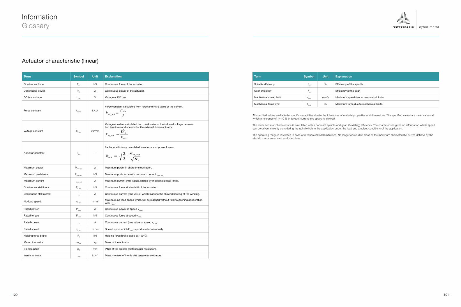
cyber motor
Information Glossary
Term Symbol Unit Explanation
Spindle efficiency ηS% Efficiency of the spindle.
Gear efficiency ηG− Efficiency of the gear.
Mechanical speed limit vlimit mm/s Maximum speed due to mechanical limits.
Mechanical force limit Flimit kN Maximum force due to mechanical limits.
All specified values are liable to specific variabilities due to the tolerances of material properties and dimensions. The specified values are mean values at which a tolerance of +/-10 % of torque, current and speed is allowed.
The linear actuator characteristic is calculated with a constant spindle and gear (if existing) efficiency. The characteristic gives no information which speed can be driven in reality considering the spindle hub in the application under the load and ambient conditions of the application.
The operating range is restricted in case of mechanical load limitations. No longer admissible areas of the maximum characteristic curves defined by the electric motor are shown as dotted lines.
Term Symbol Unit Explanation
Continuous force FS1 kN Continuous force of the actuator.
Continuous power PS1 W Continuous power of the actuator.
DC bus voltage UDC V Voltage at DC bus.
Force constant km act kN/A
Force constant calculated from force and RMS value of the current.
IF
k actm_act =
Voltage constant ke act Vs/mm
Voltage constant calculated from peak value of the induced voltage between two terminals and speed v for the external driven actuator:
act
tte_act
ˆ
vU
k =
Actuator constant kact −
Factor of efficiency calculated from force and power losses.
tt
m_actact 3
2R
kk ⋅=
Maximum power Pmax act W Maximum power in short time operation.
Maximum push force Fmax act kN Maximum push force with maximum current Imax act.
Maximum current Imax act A Maximum current (rms-value), limited by mechanical load limits.
Continuous stall force F0 act kN Continuous force at standstill of the actuator.
Continuous stall current I0 A Continuous current (rms value), which leads to the allowed heating of the winding.
No-load speed v0 act mm/sMaximum no-load speed which will be reached without field weakening at operation with UDC.
Rated power Pn act W Continuous power at speed vn act.
Rated torque Fn act kN Continuous force at speed vn act.
Rated current In A Continuous current (rms value) at speed vn act.
Rated speed vn act mm/s Speed, up to which Fn act is produced continuously.
Holding force brake F4 kN Holding force brake static (at 120°C)
Mass of actuator mact kg Mass of the actuator.
Spindle pitch pS mm Pitch of the spindle (distance per revolution).
Inertia actuator Jact kgm² Mass moment of inertia des gesamten Aktuators.
Actuator characteristic (linear)
101 100

cyber motor
Notes
103 102

cyber motor
WITTENSTEIN cyber motor GmbH · Walter-Wittenstein-Straße 1 · 97999 Igersheim · GermanyTel. +49 7931 493-15800 · [email protected]
WITTENSTEIN Inc. · 1249 Humbracht Circle · Bartlett, IL 60103 · USATel. +1 630 540 5300 · [email protected]
WITTENSTEIN Co., Ltd. · 2-6-6 Shibadaimon Minato-ku · 105-0012 Tokyo · JapanTel. +81 3 6680 2835 · [email protected]
WITTENSTEIN (Hangzhou) Co., Ltd. · No. 355 Tianmushan West Road · 311122 Hangzhou · ChinaTel. +86 571 8869 5852 / 5851 · [email protected]
WITTENSTEIN S.P.A. · Via Giosuè Carducci 125 · 20099 Sesto San Giovanni MI · ItalyTel. +39 02 241357-1 · [email protected]
WITTENSTEIN – one with the future
www.wittenstein-cyber-motor.de Cat
alo
g_s
mal
l_se
rvo
_driv
e_sy
stem
__en
_20
21
_II S
ubje
ct t
o c
hang
e