SINAMICS S210 servo drive system - Digital Asset Management
278
Catalog D 32 Edition February 2022 MOTION CONTROL DRIVES SINAMICS S210 Servo Drive System siemens.com/d32 © Siemens 2022
-
Upload
khangminh22 -
Category
Documents
-
view
1 -
download
0
Transcript of SINAMICS S210 servo drive system - Digital Asset Management

Catalog D 32
Edition February 2022
MOTION CONTROL DRIVES
SINAMICS S210 Servo Drive System
siemens.com/d32
© Siemens 2022

Related catalogs
Motion Control Drives D 31.1SINAMICS Converters for Single-Axis Drives Built-In Units
PDF (E86060-K5531-A111-A2-7600)
Motion Control Drives D 31.2SINAMICS Converters for Single-Axis Drives Distributed Converters
PDF (E86060-K5531-A121-A2-7600)
Motion Control Drives D 31.5SINAMICS Converters for Single-Axis DrivesSINAMICS G120X infrastructure converters for HVAC/Water/Wastewater
PDF (E86060-K5531-A151-A3-7600)
Motion Control Drives D 34SIMATIC MICRO-DRIVEServo Drive System
PDF (E86060-K5534-A101-A2-7600)
SINAMICS S120 D 21.3Chassis Format Converter UnitsChassis-2 Format Converter UnitsCabinet Modules, Cabinet Modules-2SINAMICS S150Converter Cabinet UnitsE86060-K5521-A131-A7-7600
Motion Control Drives D 21.4SINAMICS S120 and SIMOTICS
E86060-K5521-A141-A1-7600
SIMOTICS S-1FG1 D 41Servo geared motorsHelical, Parallel shaft, Bevel and Helical worm geared motors
PDF (E86060-K5541-A101-A5-7600)
SIMOTICS GP, SD, XP, DP D 81.1Low-Voltage MotorsType series 1FP1, 1LE1, 1LE5, 1MB1, 1MB5, 1PC1Frame sizes 63 to 450Power range 0.09 to 1000 kWPDF (E86060-K5581-A111-B5-7600)
SIMOGEAR D 50.1Geared MotorsHelical, parallel shaft, bevel, helical wormand worm geared motors
PDF (E86060-K5250-A111-A8-7600)
Motion Control System PM 21SIMOTIONEquipment for Production Machines
E86060-K4921-A101-A4-7600
Industrial Controls IC 10SIRIUS
PDF (E86060-K1010-A101-B3-7600)
Industrial Controls IC 10 AOSIRIUS Classic
PDF (E86060-K1010-A191-A5-7600)
Low-Voltage Power Distribution and LV 10Electrical Installation Technology SENTRON • SIVACON • ALPHAProtection, Switching, Measuring and Monitoring Devices, Switchboards and Distribution Systems
PDF (E86060-K8280-A101-B4-7600)
SIMATIC ST 70Products forTotally Integrated Automation
PDF (E86060-K4670-A101-B8-7600)
SIMATIC HMI / ST 80/ST PCPC-based Automation Human Machine Interface SystemsPC-based Automation
PDF (E86060-K4680-A101-C9-7600)
Industrial Communication IK PISIMATIC NET
E86060-K6710-A101-B8-7600
Industry Mall Information and Ordering Platformon the internet:
www.siemens.com/industrymall
U2_D32_EN.fm Seite 1 Freitag, 18. Februar 2022 8:51 08
© Siemens 2022

MOTION CONTROL DRIVES
SINAMICS S210Servo Drive System
siemens.com/d32
Dear Customer,
We are pleased to present you with the new Catalog D 32 · February 2022. The catalog provides a comprehensive overview of the SINAMICS S210 servo drive system. The SINAMICS S210 servo drive system consists of a SINAMICS S210 servo converter, a SIMOTICS S servomotor and a matching One Cable Connection (OCC).The single-axis AC/AC servo converter system stands out due to its high performance and dynamic response for mid-range Motion Control applications. In addition to updates and technical modifications, the new edition of the catalog has also been supplemented with the SIMOTICS S-1FT2 servo planetary geared motors, individual variants of the SIMOTICS S-1FK2 and S-1FT2 servomotors and with the SIMOTICS S-1FS2 servomotors shaft height 80.The products listed in this catalog are also included in the Industry Mall. Please contact your local Siemens office for additional information.Up-to-date information about SINAMICS S210 is available on the internet at: www.siemens.com/sinamics-s210You can access our Industry Mall online at: www.siemens.com/industrymallYour personal contact will be happy to receive your suggestions and recommendations for improvement. You can find your representative in our Personal Contact database at: www.siemens.com/automation-contactWe hope that you will often enjoy using Catalog D 32 · February 2022 as a selection and ordering reference document and wish you every success with our products and solutions.
With kind regards
Frank GolükeVice PresidentGeneral Motion ControlSiemens AG, Digital Industries, Motion Control
CatalogD 32
EditionFebruary2022
© Siemens 2022

© Siemens 2022

6SL3070-0AA00-0AG06SL3072-0AA00-0AG0
Article No.
www.siemens.com/product?6SL3070-0AA00-0AG0 Or directly on the Internet, e.g.
Click on an Article No. in the catalog PDF to call it up in the Industry Mall and to obtain all the information.
System overview 1
SINAMICS S210 servo drive 2
SIMOTICS S servomotors and servo planetary geared motors for SINAMICS S210
3
MOTION-CONNECT connection systems 4
Engineering tools 5
Services and documentation 6
Appendix 7
SINAMICS S210 Servo Drive SystemMotion Control Drives
Catalog D 32 · February 2022
Supersedes: Catalog D 32 · July 2021
Refer to the Industry Mall for current updates of this catalog:www.siemens.com/industrymall
Please contact your local Siemens branch.
© Siemens 2022
The products and systems described in this catalog are manufactured/distributed under application of a certified quality management system in accordance with EN ISO 9001. The certificate is recognized by all IQNet countries.
© Siemens 2022

2 Siemens D 32 · February 2022
www.siemens.com/ids
With Integrated Drive Systems you can reduce your main tenance costs by up to
15 %
You can boost the avail ability of your application or plant to up to
99 %**e.g., conveyor application
With TIA Portal you can cut your engineering time by up to
30 %
Integrated Drive SystemsFaster on the market and in the black with Integrated Drive Systems
Integrated Drive Systems are Siemens’ trendsetting answer to the high degree of complexity that characterizes drive and automation technology today. The world’s only true one-stop solution for entire drive systems is characterized in particular by its threefold integration: Horizontal, vertical, and lifecycle integration ensure that every drive system component fits seamlessly into the whole system, into any automation environment, and even into the entire lifecycle of a plant.
The outcome is an optimal workflow – from engineering all the way to service that entails more productivity, increased efficiency, and better availability. That’s how Integrated Drive Systems reduce time to market and time to profit.
Horizontal integrationIntegrated drive portfolio: The core elements of a fully integrated drive portfolio are frequency converters, motors, couplings, and gear units. At Siemens, they‘re all available from a single source. Perfectly integrated, perfectly interacting. For all power and performance classes. As standard solutions or fully customized. No other player in the market can offer a comparable portfolio. Moreover, all Siemens drive components are perfectly matched, so they are optimally interacting.
Vertical integrationThanks to vertical integration, the complete drive train is seamlessly integrated in the entire automation environment – an important prerequisite for production with maximum value added. Integrated Drive Systems are part of Totally Integrated Automation (TIA), which means that they are perfectly embedded into the system architecture of the entire industrial production process. This enables optimal processes through maximum communication and control.
Lifecycle integrationLifecycle integration adds the factor of time: Software and service are available for the entire lifecycle of an Integrated Drive System. That way, important optimization potential for maximum productivity, increased efficiency, and highest availability can be leveraged throughout the system’s lifecycle – from planning, design, and engineering to operation, maintenance, and all the way even to modernization.
With Integrated Drive Systems, assets become important success factors. They ensure shorter time to market, maximum productivity and efficiency in operation, and shorter time to profit.
© Siemens 2022

Siemens D 32 · February 2022
11/2 The SINAMICS converter family
1/6 Drive selection
1/7 SINAMICS S210 servo drive system1/13 Order overview1/13 with SIMOTICS S-1FK2 servomotors 1/18 with SIMOTICS S-1FT2 servomotors 1/23 with SIMOTICS S-1FS2 servomotors1/24 with SIMOTICS S-1FK2 and 1FT2
servo planetary geared motors1/25 Accessories
1/28 SINAMICS S210 starter kit
System overview
© Siemens 2022

1/2 Siemens D 32 · February 2022
1
System overview
The SINAMICS converter family
■ Overview
Integration in automation
Totally Integrated Automation and communication
SINAMICS is an integral component of the Siemens "Totally Integrated Automation" concept. Integrated SINAMICS systems covering configuration, data storage, and communication at automation level ensure low-maintenance solutions with the SIMATIC, SIMOTION and SINUMERIK control systems.
Depending on the application, the appropriate variable frequency drives can be selected and incorporated in the auto-mation concept. With this in mind, the drives are clearly subdi-vided into their different applications. A wide range of communi-cation options (depending on the drive type) are available for establishing a communication link to the automation system:• PROFINET• PROFIBUS• EtherNet/IP• Modbus TCP• Modbus RTU• AS-Interface• BACnet MS/TP
Applications
SINAMICS is the comprehensive converter family from Siemens designed for machine and plant engineering applications. SINAMICS offers solutions for all drive tasks:• Simple pump and fan applications in the process industry• Demanding single drives in centrifuges, presses, extruders,
elevators, as well as conveyor and transport systems• Drive line-ups in textile, plastic film, and paper machines as
well as in rolling mill plants• Highly dynamic servo drives for machine tools, as well as
packaging and printing machines
Management level
Process control level Control center / control system:SIMATIC PCS 7 / WINCC
Automation systems / HMI:SIMATIC / SIMOTION / SINUMERIK
pumpingventilating
compressing moving processing machining G_D
011_
EN_0
0337
d
Office environment: SIMATIC IT / COMOS...
Control level
Fieldbus
SINAMICS VSINAMICS G
SINAMICS VSINAMICS GSINAMICS S
SINAMICS VSINAMICS GSINAMICS S SINAMICS S
© Siemens 2022

1/3Siemens D 32 · February 2022
1
System overview
The SINAMICS converter family
■ Overview
SINAMICS as part of the Siemens modular automation system
Innovative, energy-efficient and reliable drive systems and applications as well as services for the entire drive train
The solutions for drive technology place great emphasis on the highest productivity, energy efficiency and reliability for all torque ranges, performance and voltage classes.
Siemens offers not only the right innovative variable frequency drive for every drive application, but also a wide range of energy-efficient low-voltage motors, geared motors, explosion-protected motors and high-voltage motors for combination with SINAMICS.
Furthermore, Siemens supports its customers with global pre-sales and after-sales services, with over 295 service points in 130 countries – and with special services e.g. application consulting or motion control solutions.
Energy efficiency
Energy management process
Efficient energy management consultancy identifies the energy flows, determines the potential for making savings and imple-ments them with focused activities.
Almost two thirds of the industrial power requirement is from electric motors. This makes it all the more important to use drive technology permitting energy consumption to be reduced effec-tively even in the configuration phase, and consequently to optimize plant availability and process stability. With SINAMICS, Siemens offers powerful energy efficient solutions which, depending on the application, enable a significant reduction in electricity costs.
SIMOTICSSIMOGEAR
G_D
011_
XX_0
0515
b
SIMATICSIMOTION SINUMERIK
SINAMICS
© Siemens 2022

1/4 Siemens D 32 · February 2022
1
System overview
The SINAMICS converter family
■ Overview
Up to 70 % potential for savings using variable-speed operation
SINAMICS enables great potential for savings to be realized by controlling the motor speed. In particular, huge potential savings can be recovered from pumps, fans and compressors which are operated with mechanical throttle and valves. Here, changing to variable-speed drives brings enormous economic advantages. In contrast to mechanical control systems, the power consump-tion at partial load operation is always immediately adjusted to the demand at that time. So energy is no longer wasted, permitting savings of up to 60 % – in exceptional cases even up to 70 %. Variable-speed drives also offer clear advantages over mechanical control systems when it comes to maintenance and repair. Current spikes when starting up the motor and strong torque surges become things of the past – and the same goes for pressure waves in pipelines, cavitation or vibrations which cause sustainable damage to the plant. Smooth starting and ramp-down relieve the load on the mechanical system, ensuring a significantly longer service life of the entire drive train.
Regenerative feedback of braking energy
In conventional drive systems, the energy produced during braking is converted to heat using braking resistors. Energy produced during braking is efficiently recovered to the supply system by versions of SINAMICS G and SINAMICS S drives with regenerative feedback capability and these devices do not therefore need a braking resistor. This permits up to 60 % of the energy requirement to be saved, e.g. in lifting applications. Energy which can be reused at other locations on a machine. Furthermore, this reduced power loss simplifies the cooling of the system, enabling a more compact design.
Energy transparency in all configuration phases
Early on, in the configuration phase, the SIZER for Siemens Drives engineering tool (integrated into TIA Selection Tool) provides information on the specific energy requirement. The energy consumption across the entire drive train is visualized and compared with different plant concepts.
SINAMICS in combination with energy-saving motors
Engineering integration stretches beyond the SINAMICS converter family to higher-level automation systems, and to a broad spectrum of energy-efficient motors with a wide range of performance classes, which, compared to previous motors, are able to demonstrate up to 10 % greater efficiency.
Variants
Depending on the application, the SINAMICS converter family offers the ideal variant for any drive task.
SINAMICS V drives focus on the essentials both in terms of hardware and functionality. This results in a high degree of ruggedness combined with lower investment costs.
SINAMICS G drives function perfectly for low and medium demands on the dynamic response of the control system.
SINAMICS S drives are predestined for demanding single - and multi-axis applications in machine and plant engineeringas well as for numerous motion control tasks.
PriceG
_D01
1_EN
_004
49b
Performance
SINAMICS SSINAMICS GSINAMICS V
© Siemens 2022

1/5Siemens D 32 · February 2022
1
System overview
The SINAMICS converter family
■ Overview
Platform concept
All SINAMICS variants are based on a platform concept. Joint hardware and software components, as well as standardized tools for dimensioning, configuration, and commissioning tasks ensure high-level integration across all components. SINAMICS handles a wide variety of drive tasks with no system gaps. The different SINAMICS variants can be easily combined with each other.
Quality management according to EN ISO 9001
SINAMICS conforms to the most exacting quality requirements. Comprehensive quality assurance measures in all development and production processes ensure a consistently high level of quality.
Of course, our quality management system is certified by an independent authority in accordance with EN ISO 9001.
IDS – Integration at its very best
The Siemens Integrated Drive Systems (IDS) solution offers perfectly matched drive components with which you can meet your requirements. The drive components reveal their true strengths as an Integrated Drive System over the full range from engineering and commissioning through to operation: Integrated system configuration is performed using the Drive Technology Configurator: Just select a motor and a converter and design them with the SIZER for Siemens Drives engineering tool (integrated into TIA Selection Tool). The STARTER and SINAMICS Startdrive commissioning tools integrate the motor data and at the same time simplify efficient commissioning. Integrated Drive Systems are incorporated in the TIA Portal – this simplifies engineering, commissioning and diagnostics.
Engineering tools (e.g. Drive Technology Configurator, SIZER for Siemens Drives, STARTER and SINAMICS Startdrive)
G_D011_EN_00450r
Pumps, fans,
compressors, conveyor
belts, mixers, mills,
spinning machines,
textile machines,
refrigerated display
counters, fitness
equipment, ventilation systems,
single-axis positioning
applications in machine and
plant engineering
Handling machines, packaging machines, automatic assembly machines,
metal forming machines,
printing machines,
winding and unwinding
units
0.12 kW to 250 kW
0.05 kW to 7 kW
Conveyor technology, single-axis positioning applications
(G120D)
Pumps, fans,
compressors, building
management systems, process industry, HVAC,
water/waste water
industries
0.37 kW to 7.5 kW
0.75 kW to 630 kW
D 31.5Catalog
D 31.1Catalog
D 33CatalogCatalog
D 31.2
Pumps, fans,
compressors, conveyor
belts, extruders,
mixers, mills,
kneaders, centrifuges, separators
Pumps, fans,
compressors, conveyor
belts, mixers, mills,
extruders
2.2 kW to 6600 kW
75 kW to 2700 kW
Catalog CatalogD 11 D 18.1
Single-axis positioning
applications in machine and
plant engineering
0.55 kW to 132 kW
Catalog CatalogD 31.1 D 32
0.55 kW to 5700 kW
0.05 kW to 7 kW
CatalogsD 21.3, D 21.4
NC 62
Test bays, cross cutters, centrifuges
75 kW to 1200 kW
CatalogD 21.3
Rolling mill drives,
wire-drawing machines,
extruders and kneaders, cableways and lifts,
test bay drives
6 kW to 30 MW
CatalogD 23.1,
Industry Mall
0.15 MW to 85 MW
Converters for applications
with high outputs
High performance frequency converters
Industry-specific frequency converters
Distributed frequency converters
Standard performance frequency converters
Servo drives
Medium voltageLow voltage
Packaging machines, handling
equipment, feed and
withdrawal devices,
stacking units, automatic assembly machines, laboratory
automation, wood, glass
and ceramics industry,
digital printing machines
Production machines
(packaging, textile and
printing machines,
paper machines,
plastic processing machines), machine
tools, plants,
process lines and rolling
mills, marine drives,
test bays
Pumps, fans,
compressors, mixers,
extruders, mills,
crushers, rolling mills,
conveyor technology, excavators, test bays,
marine drives, blast furnace
fans, retrofit
DC converters
Direct voltage
Internet 2)
1) DC/DC controllers, see Industry Mall.2) www.siemens.com/medium-voltage-converter
GH150GH180GM150SM150GL150SL150SH150
V20G120CG120
SINAMICS SINAMICSSINAMICSSINAMICS
SIMATIC ET 200pro FC-2
SINAMICS SINAMICS SINAMICS SINAMICS SINAMICS SINAMICS SINAMICSV90G115D
G120D G180G130
G150S110
SINAMICSS210 S120
S120MS150 DCM
DCP 1) G120X
© Siemens 2022

1/6 Siemens D 32 · February 2022
1
System overview
Drive selection
■ Overview
SINAMICS selection guide – typical applications
Using the SINAMICS selection guide
The varying range of demands on modern variable frequency drives requires a large number of different types. Selecting the optimum drive has become a significantly more complex pro-cess. The application matrix shown simplifies this selection pro-cess considerably, by suggesting the ideal SINAMICS drive for examples of typical applications and requirements.
• The application type is selected from the vertical column- Pumping, ventilating, compressing- Moving- Processing- Machining
• The quality of the motion type is selected from the horizontal row- Basic- Medium- High
■ More Information
Further information about SINAMICS is available on the internet atwww.siemens.com/sinamics
Practical application examples and descriptions are available on the internet atwww.siemens.com/sinamics-applications
Use Requirements for torque accuracy/speed accuracy/position accuracy/coordination of axes/functionality
Continuous motion Non-continuous motion
Basic Medium High Basic Medium High
Pumping, ventilating, compressing
Centrifugal pumpsRadial / axial fansCompressors
Centrifugal pumpsRadial / axial fansCompressors
Eccentric screw pumps
Hydraulic pumpsMetering pumps
Hydraulic pumpsMetering pumps
Descaling pumpsHydraulic pumps
V20G120CG120X
G120XG130/G150G180 1)
DCM
S120 G120 S110 S120
Moving Conveyor belts Roller conveyors Chain conveyors
Conveyor beltsRoller conveyorsChain conveyorsLifting/lowering devicesElevatorsEscalators/moving walkwaysIndoor cranesMarine drivesCable railways
ElevatorsContainer cranesMining hoistsExcavators for open-cast miningTest bays
Acceleration conveyorsStorage and retrieval machines
Acceleration conveyorsStorage and retrieval machinesCross cuttersReel changers
Storage and retrieval machinesRoboticsPick & placeRotary indexing tablesCross cuttersRoll feedsEngagers/disengagers
V20G115DG120CET 200pro FC-2 2)
G120G120DG130/G150G180 1)
S120S150DCM
V90G120G120D
S110S210DCM
S120S210DCM
Processing MillsMixersKneadersCrushersAgitatorsCentrifuges
Mills MixersKneadersCrushersAgitatorsCentrifugesExtrudersRotary furnaces
ExtrudersWinders/unwindersLead/follower drivesCalendersMain press drivesPrinting machines
Tubular bagging machinesSingle-axis motion controlsuch as• Position profiles• Path profiles
Tubular bagging machinesSingle-axis motion controlsuch as• Position profiles• Path profiles
Servo pressesRolling mill drivesMulti-axis motion controlsuch as• Multi-axis positioning• Cams• Interpolations
V20G120C
G120G130/G150G180 1)
S120S150DCM
V90G120
S110S210
S120S210DCM
Machining Main drives for• Turning• Milling• Drilling
Main drives for• Drilling• Sawing
Main drives for• Turning• Milling• Drilling• Gear cutting• Grinding
Axis drives for• Turning• Milling• Drilling
Axis drives for• Drilling• Sawing
Axis drives for• Turning• Milling• Drilling• Lasering• Gear cutting• Grinding• Nibbling and
punching
S110 S110S120
S120 S110 S110S120
S120
1) Industry-specific converters. 2) Information on the SIMATIC ET 200pro FC-2 frequency converter is available in Catalog D 31.2 and at: www.siemens.com/et200pro-fc
© Siemens 2022

1/7Siemens D 32 · February 2022
1
System overview
SINAMICS S210 servo drive system
■ Overview
Example: SINAMICS S210 converter frame size FSB, 200 V 1 AC, with SIMOTICS S-1FK2 servomotor shaft height 30
Example: SINAMICS S210 converter frame size FSB, 400 V 3 AC, with SIMOTICS S-1FK2 servomotor shaft height 63
The servo drive system comprises a SINAMICS S210 servo converter, a SIMOTICS S-1FK2, S-1FT2 or S-1FS2 servomotor and a matching One Cable Connection (OCC) for connecting the motor to the converter. SINAMICS S210 is a single-axis AC/AC servo converter system with high performance and dy-namic response for mid-range Motion Control applications.
SINAMICS S210 servo converters are available for the following line voltages:• 200 V to 240 V 1 AC (1 AC series)• 200 V to 480 V 3 AC (3 AC series)
Flexible in application
The SINAMICS S210 is a flexible, versatile system. SIMOTICS S-1FK2, S-1FT2 or S-1FS2 series synchronous servo-motors are installed in rotary and linear axes. The integrated One Cable Connection (OCC) interface allows user-friendly connection of a SIMOTICS S-1FK2, S-1FT2 or S-1FS2 motor with just one cable. The electronic motor type plate data can be read out, which eliminates the need to parameterize the converter with the motor data. This significantly simplifies and shortens commissioning.
In conjunction with the technological functions of the higher-level controller, there are many possibilities of motion – from continu-ous operation through positioning and synchronous operation, to coordinated motion of multiple axes via cyclic cams or interpolation – everything is possible.
The SINAMICS S210 converter has an integrated PROFINET communications interface for connecting to a control system.
The data exchange with the higher-level controllers takes place via standardized protocols – the PROFIdrive profile for position-ing mode and the PROFIsafe profile for safety-related communi-cation.
Thus, operation is optimally ensured with the SIMATIC S7 automation system. The drive axis is connected via technology objects and Motion Control blocks in the SIMATIC S7 or a SIMOTION controller.
High performance for fast and precise control
The high performance of the SINAMICS S210 servo drive system in conjunction with a SIMOTICS S-1FK2, S-1FT2 or S-1FS2 servomotor derives from the following features:• Low moment of inertia and high overload capability of the
motor• High-resolution encoder with fast scanning• Current controller clock cycle of 62.5 s and a pulse
frequency of 8 kHz of the servo converter
This enables short cycle times on the machine even with complex motion control.
DC link coupling (only 3 AC series)
For devices of the 3 AC series, the DC links of up to six convert-ers can be coupled. Thus, energy balancing between the axes is possible and energy produced during braking can be used by other axes for accelerating. This is not only efficient but also reduces the dissipated heat in the control cabinet, because the energy that is produced no longer has to be converted to heat in the braking resistor.
© Siemens 2022

1/8 Siemens D 32 · February 2022
1
System overview
SINAMICS S210 servo drive system
■ Overview
The SIMOTICS S-1FK2, S-1FT2 and S-1FS2 servomotors differ as follows:
Optimized connection technology with One Cable Connection (OCC)
Example: SINAMICS S210 M12 OCC connecting cable
Motor and converter are simply connected to one another by one instead of the usual two or three cables. With this One Cable Technology, energy supply, encoder signals and braking signal
are brought together in a single cable. This results in the follow-ing advantages:• Time-saving by laying only one cable• Smaller installation space and space requirement in cable
collars, tight bending radii• Only one cable has to be cleaned. This is advantageous, e.g.
in the pharmaceutical industry and where higher requirements are placed upon hygiene
• Can be ordered to the decimeter• Compact connection system• Rotatable connector on the motor side• Motor with very low interfering contour for restricted installa-
tion space.
Cables are available in two different qualities:• MOTION-CONNECT 500• MOTION-CONNECT 800PLUS• MOTION-CONNECT 400 (only for SIMOTICS S-1FS2)
In addition to the pre-assembled cable, individual components (connectors and products sold by the meter) can be ordered for self-assembly.
SIMOTICS S servomotors for SINAMICS S210
1FK2 1FT2 1FS2
High Dynamic (HD) / Compact (CT) High Dynamic (HD) / Compact (CT) High Dynamic (HD) / Compact (CT)
Shaft heights• SH20 HD (1FK2102) HD (1FT2102) –• SH30 HD (1FK2103) / CT (1FK2203) HD (1FT2103) / CT (1FT2203) –• SH40 HD (1FK2104) / CT (1FK2204) HD (1FT2104) / CT (1FT2204) HD (1FS2104)• SH48 CT (1FK2205) CT (1FT2205) –• SH52 HD (1FK2105) HD (1FT2105) HD (1FS2105)• SH63 HD (1FK2106) / CT (1FK2206) HD (1FT2106) / CT (1FT2206) HD (1FS2106)• SH80 CT (1FK2208) CT (1FT2208) CT (1FS2208)• SH100 CT (1FK2210) CT (1FT2210) –
Static torque M0 0.16 ... 40 Nm (0.12 ... 29.50 lbf-ft) 0.16 ... 40 Nm (0.12 ... 29.50 lbf-ft) 3.1 ... 23.5 Nm (2.29 ... 17.30 lbf-ft)
Rated power PN Up to 6.4 kW Up to 6.4 kW Up to 2.51 kW
Applications • Packaging machines • Handling equipment • Feed and withdrawal devices • Stacking units • Automatic assembly machines • Laboratory automation • Woodworking, glass and ceramic
industries • Digital printing machines
• Packaging machines • Handling equipment • Feed and withdrawal devices • Stacking units • Automatic assembly machines • Laboratory automation • Woodworking, glass and ceramic
industries • Digital printing machines
• Food and beverage industries• Pharmaceutical industry• Packaging machines • Handling equipment • Feed and withdrawal devices
Housing/paint finish Aluminum/anthracite gray Aluminum/anthracite gray
Optionally other colors possible
Stainless steel
Degree of protection IP64IP65 optional or retrofittable
IP64IP65 optional or retrofittable, IP67 optional
IP66/IP67, IP69K (30 bars)
Encoder systems• Absolute encoder 22-bit singleturn ✓ ✓ –• Absolute encoder 22-bit + 12-bit multiturn ✓ ✓ ✓
• Absolute encoder 26-bit singleturn – ✓ –• Absolute encoder 26-bit + 12-bit multiturn – ✓ –
Notes • Also available as servo planetary geared motor
• Versions with increased rated and maximum speed
• Options:- Increased detergent resistance - Pressure balance - Metal rating plate - Coating color
• Also available as servo planetary geared motor
• Very high detergent resistance • Certification according to EHEDG • With connection cable (cable end
and cable length up to 11 m can be selected)
© Siemens 2022

1/9Siemens D 32 · February 2022
1
System overview
SINAMICS S210 servo drive system
■ Overview
Easy commissioning via web server, One Button Tuning and SINAMICS Startdrive/TIA Portal (V15.1 or higher)
One Button Tuning
The web server of the converter offers a simple means of parameter assignment. The web server allows commissioning purely oriented on the functionality of the drive. With the web server, the SINAMICS S210 servo drive system can be brought into operation with a few clicks.
As a result of reading the electronic type plate of the connected SIMOTICS S-1FK2, S-1FT2 or S-1FS2 servomotor, only a few op-erator actions, such as automatic controller optimization with One Button Tuning, are necessary, as the motor and encoder are automatically detected. The controller parameters are automati-cally optimized. The three selectable dynamic levels of the con-troller can optimally take into account the desired behavior of the connected mechanics.
A motion of the axis can take place directly via the control panel during commissioning.
The customer benefits from the web server in many ways:• Commissioning can also be easily done in places difficult to
access, as the web server in the converter can also be accessed directly via PROFINET from the controller.
• The web server provides full diagnostic capability without the need for additional software.
• Commissioning and diagnostics can also be done without a cable via mobile devices, such as laptops, smart phones and tablets (an additional WLAN access point is necessary).
• Intuitive user interface
In addition to easy commissioning directly via the web server of the converter, engineering is also possible with SINAMICS Startdrive and TIA Portal (V15.1 or higher). The tool for configu-ration, commissioning and diagnostics has been optimized with regard to the consistent utilization of the TIA Portal advantages – one shared work environment for PLC, HMI and drives. SINAMICS firmware V5.2 or higher is required for SINAMICS S210 devices.
For more information, see the Engineering tools selection.
Diagnostics
Faults and warnings are shown on the display located under the front cover, and they can be acknowledged with the Acknowl-edge button. Extensive diagnostics with plain text messages for cause and remedy information is possible via the web server.
Safety Integrated
The integrated safety functions provide highly effective, applica-tion-oriented protection for personnel and machinery (terms as defined in IEC 61800-5-2).
The following Safety Integrated Basic Functions are included as standard:• Safe Torque Off (STO)• Safe Brake Control (SBC)• Safe Stop 1 time controlled (SS1-t)
The following Safety Integrated Extended Functions 1) are available as options:• Safe Stop 1 (SS1)• Safe Stop 2 (SS2)• Safe Operating Stop (SOS)• Safely-Limited Speed (SLS)• Safe Speed Monitor (SSM)• Safe Direction (SDI)• Safely-Limited Acceleration (SLA)• Safe Brake Test (SBT) diagnostic function
The Safety Integrated Functions are fully integrated into the drive system. They can be activated via fail-safe digital inputs on the converter (only STO and SS1-t) or via PROFINET with PROFIsafe.
The Safety Integrated Functions are implemented electronically and therefore require no additional installation effort or space in the control cabinet. Furthermore, the costs are considerably lower than for externally implemented monitoring functions.
The Safety Integrated Functions can be easily commissioned using the web server of the converter or SINAMICS Startdrive/ TIA Portal V15.1 or higher.
Perfect combination with SIMATIC S7-1500, SIMATIC S7-1500 T-CPU, SIMATIC ET 200SP Open Controller, and PROFINET
It communicates with the higher-level control via PROFINET IRT. For optimal interaction between the controller and the SINAMICS S210 servo drive system, SIMATIC S7-1500, SIMATIC S7-1500 T-CPU, SIMATIC ET 200SP Open Controller, and SIMOTION can be used as the control system.
The SINAMICS S210 servo converter has an integrated PROFINET communications interface with a cycle of up to 250 s for connecting to a control system.
Standardized protocols for linking to a higher-level control with RT and IRT are supported – the PROFIdrive profile with DSC for positioning mode and the PROFIsafe profile for safety-related communication. Functions, such as Shared Device, ring redun-dancy and PROFIenergy, are also possible.
1) Available in SINAMICS V5.1 SP1 and higher. The Extended Functions require a Safety license.
© Siemens 2022

1/10 Siemens D 32 · February 2022
1
System overview
SINAMICS S210 servo drive system
■ Overview
Everything from one source: Through the use of Motion Control functionalities in the controller, the combination of converter and SIMATIC S7 automation system or a SIMOTION controller allows ideally harmonized engineering. As a result, commissioning times are shortened.
Via technology objects and Motion Control blocks of the higher-level controller, there are many possibilities of motion, such as continuous operation, positioning and synchronous operation, and coordinated motion of multiple axes via cyclic cams or interpolation.
Siemens offers tested SIMATIC PLC/HMI application examples for connection of the servo drive system to a SIMATIC controller:www.siemens.com/sinamics-applications
Further information on the SIMATIC S7-1500, SIMATIC S7-1500 T-CPU and SIMATIC ET 200SP Open Control-ler is available in the ST 70 Catalog and on the internet under www.siemens.com/simatic-s7-1500
Example: Communication via PROFINET
Ruggedness
The SINAMICS S210 is equipped as standard with varnished or partially varnished modules. The painting on the modules pro-tects the sensitive SMD components against corrosive gases, chemically active dust and moisture.
Can be used worldwide
In addition to the usual approvals, the SINAMICS S210 drive system also has UL approval for the North American market. This means that the drive system, comprising SINAMICS S210 and SIMOTICS S-1FK2, S-1FT2 or S-1FS2, including the One Cable Connection (OCC), can be used worldwide.
More information
A Quick Installation Guide is supplied in hard copy form in English with every SINAMICS S210. Further documentation, such as the operating instructions, is available free on the inter-net at: www.siemens.com/sinamics-s210/documentation
Detailed information on the SINAMICS S210 drive system, including the latest technical documentation (brochures, tutorials, dimensional drawings, certificates, manuals and operating instructions), is available on the internet at: www.siemens.com/sinamics-s210
and is also available via the Drive Technology Configurator (DT Configurator) on the internet.The DT Configurator can be found in the Siemens Industry Mall at the following address: www.siemens.com/sinamics-s210/configuration
OCC (One Cable Connection for motor, motor holding brake and encoder)
SIMOTICS S-1FK2*) S-1FT2*) S-1FS2
servomotors
G_D
211_
EN_0
0392
b
SINAMICS S210 servo drive
Also available as servo planetary geared motor.*)
SIMATIC S7-1515T PN SIMATIC Basic Panel
PROFINET IRT
PROFINET
© Siemens 2022

1/11Siemens D 32 · February 2022
1
System overview
SINAMICS S210 servo drive system
■ Overview
Example for the 1 AC series
To further PROFINET devices (e.g. further SINAMICS S210)
OCC (One Cable Connection for motor, motor holding brake and encoder)
SIMOTICS S-1FK2*) S-1FT2*) S-1FS2
servomotor
Shaft sealing ring (optional)
Shield plate
Shield connection clamp
G_D
211_
EN_0
0368
c
SD memory card (optional)
F-DI measuring probe
Controller (e.g. SIMATIC S7-1500)
Commissioning device
SINAMICS S210 converter 1 AC series
Power supply 24 V DC
External braking resistor(optional)
Line filter (optional)
Line contactor (optional)
Fuse or circuit-breaker
Also available as servo planetary geared motor.*)
X107
X100
X150 P2
X150 P1
X130
X127
X2
X1
X124
D32_01-04.fm Seite 11 Mittwoch, 16. Februar 2022 1:42 13
© Siemens 2022

1/12 Siemens D 32 · February 2022
1
System overview
SINAMICS S210 servo drive system
■ Overview
Example for the 3 AC series
To further PROFINET devices (e.g. further SINAMICS S210)
OCC (One Cable Connection for motor, motor holding brake and encoder)
SIMOTICS S-1FK2*) S-1FT2*) S-1FS2
servomotor
Shaft sealing ring (optional)
Shield connection clamp
G_D
211_
EN_0
0391
b
SD memory card (optional)
F-DI measuring probe
Controller (e.g. SIMATIC S7-1500)
Commissioning device
SINAMICS S210 converter 3 AC series
Power supply 24 V DC
External braking resistor (optional)
DC link coupling (optional)
Line contactor (optional)
Line filter(optional)
Fuse or circuit-breaker
Also available as servo planetary geared motor.*)
X107
X100
X150 P2
X150 P1
X130
X127
X2
X3
X1
X4
X124
D32_01-04.fm Seite 12 Mittwoch, 16. Februar 2022 1:42 13
© Siemens 2022

1/13Siemens D 32 · February 2022
1
System overview
SINAMICS S210 servo drive system with SIMOTICS S-1FK2 servomotors
■ Order overview
SINAMICS S210 drive system with SIMOTICS S-1FK2 servomotors for line connection 200 ... 240 V 1 ACSIMOTICS S-1FK2 servomotor SINAMICS S210 servo converter
(1 AC series)Supply voltage 200 ... 240 V 1 AC
MOTION-CONNECT motor connection cable
Static torque
Maxi-mum torque
Maxi-mum speed
Rated power 230 V
Rated torque
Rotor moment of inertia
Rated power 230 V
Frame size
M0 Mmax nmax PN MN JMot PNNm (lbf-ft)
Nm (lbf-ft) rpm
kW (hp)
Nm (lbf-ft)
kg cm2
(lbf-in2) Article No.
kWArticle No. Article No.
High Dynamic for highly dynamic applications SINAMICS S210 servo converter One Cable ConnectionShaft height 20 – rated speed nN 3000 rpm0.16 (0.12)
0.56 (0.41)
8000 0.05 (0.07)
0.16 (0.12)
0.025 (0.009)
1FK2102-0AG■■-■■A0 0.1 FSA 6SL3210-5HB10-1UF0 6FX■002-8QN04-1■■■
0.32 (0.24)
1.11 (0.82)
8000 0.1 (0.13)
0.32 (0.24)
0.036 (0.012)
1FK2102-1AG■■-■■A0 0.1 FSA 6SL3210-5HB10-1UF0 6FX■002-8QN04-1■■■
Shaft height 30 – rated speed nN 3000 rpm0.64 (0.47)
1.95 (1.44)
8000 0.2 (0.27)
0.64 (0.47)
0.093 (0.032)
1FK2103-2AG■■-■■A0 0.2 FSA 6SL3210-5HB10-2UF0 6FX■002-8QN04-1■■■
1.27 (0.94)
4.05 (2.99)
7300 0.4 (0.54)
1.27 (0.94)
0.14 (0.048)
1FK2103-4AG■■-■■A0 0.4 FSB 6SL3210-5HB10-4UF0 6FX■002-8QN04-1■■■
Shaft height 40 – rated speed nN 1500 rpm1.27 (0.94)
3.75 (2.77)
3600 0.2 (0.27)
1.27 (0.94)
0.35 (0.120)
1FK2104-4AF■■-■■A0 0.2 FSA 6SL3210-5HB10-2UF0 6FX■002-8QN08-1■■■
2.4 (1.77)
7.5 (5.53)
3300 0.375 (0.50)
2.4 (1.77)
0.56 (0.191)
1FK2104-5AF■■-■■A0 0.4 FSB 6SL3210-5HB10-4UF0 6FX■002-8QN08-1■■■
3.2 (2.36)
10 (7.38)
3600 0.5 (0.67)
3.2 (2.36)
0.76 (0.260)
1FK2104-6AF■■-■■A0 0.75 FSC 6SL3210-5HB10-8UF0 6FX■002-8QN08-1■■■
Shaft height 40 – rated speed nN 3000 rpm1.27 (0.94)
3.85 (2.84)
7500 0.4 (0.54)
1.27 (0.94)
0.35 (0.120)
1FK2104-4AK■■-■■A0 0.4 FSB 6SL3210-5HB10-4UF0 6FX■002-8QN08-1■■■
2.4 (1.77)
7.6 (5.61)
7100 0.75 (1.01)
2.4 (1.77)
0.56 (0.191)
1FK2104-5AK■■-■■A0 0.75 FSC 6SL3210-5HB10-8UF0 6FX■002-8QN08-1■■■
Compact for high precision applications SINAMICS S210 servo converter One Cable ConnectionShaft height 30 – rated speed nN 3000 rpm0.64 (0.47)
1.85 (1.36)
8000 0.2 (0.27)
0.64 (0.47)
0.20 (0.068)
1FK2203-2AG■■-■■A0 0.2 FSA 6SL3210-5HB10-2UF0 6FX■002-8QN04-1■■■
1.27 (0.94)
3.75 (2.77)
7800 0.4 (0.54)
1.27 (0.94)
0.35 (0.120)
1FK2203-4AG■■-■■A0 0.4 FSB 6SL3210-5HB10-4UF0 6FX■002-8QN04-1■■■
Shaft height 40 – rated speed nN 1500 rpm2.4 (1.77)
7.1 (5.24)
3700 0.375 (0.50)
2.4 (1.77)
1.2 (0.410)
1FK2204-5AF■■-■■A0 0.4 FSB 6SL3210-5HB10-4UF0 6FX■002-8QN08-1■■■
3.2 (2.36)
9.5 (7.01)
3800 0.5 (0.67)
3.2 (2.36)
1.6 (0.547)
1FK2204-6AF■■-■■A0 0.75 FSC 6SL3210-5HB10-8UF0 6FX■002-8QN08-1■■■
Shaft height 40 – rated speed nN 3000 rpm2.4 (1.77)
7.1 (5.24)
7500 0.75 (1.01)
2.4 (1.77)
1.2 (0.410)
1FK2204-5AK■■-■■A0 0.75 FSC 6SL3210-5HB10-8UF0 6FX■002-8QN08-1■■■
Shaft height 48 – rated speed nN 1500 rpm3.6 (2.66)
10.8 (7.97)
3200 0.53 (0.71)
3.4 (2.51)
3.2 (1.093)
1FK2205-2AF■■-■■A0 0.75 FSC 6SL3210-5HB10-8UF0 6FX■002-8QN08-1■■■
Article No. supplementsHolding brake Pre-assembled MOTION-CONNECT cableWithout brake 0 MOTION-CONNECT 500 5With brake 1 MOTION-CONNECT 800PLUS 8
Degree of protection Length code (max. 50 m (164 ft))IP64 (without shaft sealing ring) 0 0 m (0 ft) AIP65 (with shaft sealing ring) 1 10 m (32.8 ft) B
... ...Shaft extension / feather key 50 m (164 ft) FPlain shaft 0Shaft with feather key 1 0 m (0 ft) APlain shaft, reduced shaft diameter 0 2 1 m (3.28 ft) B• 11 × 23 mm (0.43 × 0.91 in) (only for 1FK2.03 and IP64) 2 m (6.56 ft) C
• 14 × 30 mm (0.55 × 1.18 in) (only for 1FK2.04 and IP64) 3 m (9.84 ft) D4 m (13.1 ft) E
Encoder 5 m (16.4 ft) FAS22DQC (absolute encoder 22-bit singleturn) S 6 m (19.7 ft) GAM22DQC (absolute encoder 22-bit + 12-bit multiturn) M 7 m (23.0 ft) H
8 m (26.2 ft) J9 m (29.5 ft) K
0 m (0 ft) 00.1 m (0.33 ft) 1... ...0.8 m (2.62 ft) 8
Clicking to the Industry Mall
6SL3255-0AA00-5AA0
© Siemens 2022

1/14 Siemens D 32 · February 2022
1
System overview
SINAMICS S210 servo drive system with SIMOTICS S-1FK2 servomotors
■ Order overview
SINAMICS S210 drive system with SIMOTICS S-1FK2 servomotors for line connection 200 ... 240 V 3 ACSIMOTICS S-1FK2 servomotor SINAMICS S210 servo converter
(3 AC series)Supply voltage 200 ... 240 V 3 AC
MOTION-CONNECT motor connection cable
Static torque
Maxi-mum torque
Maxi-mum speed
Rated power 240 V
Rated torque
Rotor moment of inertia
Rated power 240 V
Frame size
M0 Mmax nmax PN MN JMot PNNm (lbf-ft)
Nm (lbf-ft) rpm
kW (hp)
Nm (lbf-ft)
kg cm2
(lbf-in2) Article No.
kWArticle No. Article No.
High Dynamic for highly dynamic applications SINAMICS S210 servo converter One Cable Connection
Shaft height 20 – rated speed nN 3000 rpm0.16 (0.12)
0.56 (0.41)
8000 0.05 (0.07)
0.16 (0.12)
0.025 (0.009)
1FK2102-0AG■■-■■A0 0.24 FSA 6SL3210-5HE10-4UF0 6FX■002-8QN04-1■■■
0.32 (0.24)
1.11 (0.82)
8000 0.1 (0.13)
0.32 (0.24)
0.036 (0.012)
1FK2102-1AG■■-■■A0 0.24 FSA 6SL3210-5HE10-4UF0 6FX■002-8QN04-1■■■
Shaft height 30 – rated speed nN 3000 rpm0.64 (0.47)
1.95 (1.44)
8000 0.2 (0.27)
0.64 (0.47)
0.093 (0.032)
1FK2103-2AG■■-■■A0 0.45 FSA 6SL3210-5HE10-8UF0 6FX■002-8QN04-1■■■
1.27 (0.94)
4.05 (2.99)
8000 0.4 (0.54)
1.27 (0.94)
0.14 (0.048)
1FK2103-4AG■■-■■A0 0.6 FSA 6SL3210-5HE11-0UF0 6FX■002-8QN04-1■■■
Shaft height 40 – rated speed nN 1500 rpm1.27 (0.94)
3.75 (2.77)
7200 0.2 (0.27)
1.27 (0.94)
0.35 (0.120)
1FK2104-4AF■■-■■A0 0.24 FSA 6SL3210-5HE10-4UF0 6FX■002-8QN08-1■■■
2.4 (1.77)
7.5 (5.53)
6700 0.375 (0.50)
2.4 (1.77)
0.56 (0.191)
1FK2104-5AF■■-■■A0 0.45 FSA 6SL3210-5HE10-8UF0 6FX■002-8QN08-1■■■
3.2 (2.36)
10 (7.38)
7200 0.5 (0.67)
3.2 (2.36)
0.76 (0.260)
1FK2104-6AF■■-■■A0 0.6 FSA 6SL3210-5HE11-0UF0 6FX■002-8QN08-1■■■
Shaft height 40 – rated speed nN 3000 rpm1.27 (0.94)
3.85 (2.84)
8000 0.4 (0.54)
1.27 (0.94)
0.35 (0.120)
1FK2104-4AK■■-■■A0 0.6 FSA 6SL3210-5HE11-0UF0 6FX■002-8QN08-1■■■
2.4 (1.77)
7.6 (5.61)
8000 0.75 (1.01)
2.4 (1.77)
0.56 (0.191)
1FK2104-5AK■■-■■A0 0.9 FSB 6SL3210-5HE11-5UF0 6FX■002-8QN08-1■■■
Shaft height 52 – rated speed nN 1500 rpm5 (3.69)
15 (11.06)
6000 0.79 (1.06)
5 (3.69)
1.7 (0.581)
1FK2105-4AF■■-■■A0 0.9 FSB 6SL3210-5HE11-5UF0 6FX■002-8QN08-1■■■
8 (5.90)
24 (17.70)
6000 1.26 (1.69)
8 (5.90)
2.7 (0.923)
1FK2105-6AF■■-■■A0 1.2 FSB 6SL3210-5HE12-0UF0 6FX■002-8QN08-1■■■
Shaft height 63 – rated speed nN 1500 rpm9 (6.64)
26(19.18)
6000 1.3 (1.74)
8.3 (6.12)
4.6 (1.572)
1FK2106-3AF■■-■■A0 3 FSC 6SL3210-5HE15-0UF0 6FX■002-8QN11-1■■■
12 (8.85)
33(24.34)
6000 1.64 (2.20)
10.5 (7.74)
6.0 (2.050)
1FK2106-4AF■■-■■A0 3 FSC 6SL3210-5HE15-0UF0 6FX■002-8QN11-1■■■
16 (11.80)
45.5(33.56)
6000 2.15 (2.88)
13.8 (10.18)
8.7 (2.973)
1FK2106-6AF■■-■■A0 4.2 FSC 6SL3210-5HE17-0UF0 6FX■002-8QN11-1■■■
Article No. supplementsHolding brake Pre-assembled MOTION-CONNECT cableWithout brake 0 MOTION-CONNECT 500 5With brake 1 MOTION-CONNECT 800PLUS 8
Degree of protection Length code (max. 50 m (164 ft))IP64 (without shaft sealing ring) 0 0 m (0 ft) AIP65 (with shaft sealing ring) 1 10 m (32.8 ft) B
... ...Shaft extension / feather key 50 m (164 ft) FPlain shaft 0Shaft with feather key 1 0 m (0 ft) APlain shaft, reduced shaft diameter 0 2 1 m (3.28 ft) B
• 11 × 23 mm (0.43 × 0.91 in) (only for 1FK2.03 and IP64) 2 m (6.56 ft) C
• 14 × 30 mm (0.55 × 1.18 in) (only for 1FK2.04 and IP64) 3 m (9.84 ft) D
4 m (13.1 ft) EEncoder 5 m (16.4 ft) F
AS22DQC (absolute encoder 22-bit singleturn) S 6 m (19.7 ft) GAM22DQC (absolute encoder 22-bit + 12-bit multiturn) M 7 m (23.0 ft) H
8 m (26.2 ft) J9 m (29.5 ft) K
0 m (0 ft) 0
When operating a SINAMICS S210 servo converter with a supply voltage of 200 V to 240 V 3 AC, an external, intrinsically safe braking resistor is always required.
0.1 m (0.33 ft) 1
... ...0.8 m (2.62 ft) 8
Clicking to the Industry Mall
6SL3255-0AA00-5AA0
© Siemens 2022

1/15Siemens D 32 · February 2022
1
System overview
SINAMICS S210 servo drive system with SIMOTICS S-1FK2 servomotors
■ Order overview
SINAMICS S210 drive system with SIMOTICS S-1FK2 servomotors for line connection 200 ... 240 V 3 AC (continued)SIMOTICS S-1FK2 servomotor SINAMICS S210 servo converter
(3 AC series)Supply voltage 200 ... 240 V 3 AC
MOTION-CONNECT motor connection cable
Static torque
Maxi-mum torque
Maxi-mum speed
Rated power 240 V
Rated torque
Rotor moment of inertia
Rated power 240 V
Frame size
M0 Mmax nmax PN MN JMot PNNm (lbf-ft)
Nm (lbf-ft) rpm
kW (hp)
Nm (lbf-ft)
kg cm2
(lbf-in2) Article No.
kWArticle No. Article No.
Compact for high precision applications SINAMICS S210 servo converter One Cable ConnectionShaft height 30 – rated speed nN 3000 rpm0.64 (0.47)
1.85 (1.36)
8000 0.2 (0.27)
0.64 (0.47)
0.20 (0.068)
1FK2203-2AG■■-■■A0 0.45 FSA 6SL3210-5HE10-8UF0 6FX■002-8QN04-1■■■
1.27 (0.94)
3.75 (2.77)
8000 0.4 (0.54)
1.27 (0.94)
0.35 (0.120)
1FK2203-4AG■■-■■A0 0.6 FSA 6SL3210-5HE11-0UF0 6FX■002-8QN04-1■■■
Shaft height 40 – rated speed nN 1500 rpm2.4 (1.77)
7.1 (5.24)
7500 0.375 (0.50)
2.4 (1.77)
1.2 (0.410)
1FK2204-5AF■■-■■A0 0.45 FSA 6SL3210-5HE10-8UF0 6FX■002-8QN08-1■■■
3.2 (2.36)
9.5 (7.01)
7600 0.5 (0.67)
3.2 (2.36)
1.6 (0.547)
1FK2204-6AF■■-■■A0 0.6 FSA 6SL3210-5HE11-0UF0 6FX■002-8QN08-1■■■
Shaft height 40 – rated speed nN 3000 rpm2.4 (1.77)
7.1 (5.24)
8000 0.75 (1.01)
2.4 (1.77)
1.2 (0.410)
1FK2204-5AK■■-■■A0 0.9 FSB 6SL3210-5HE11-5UF0 6FX■002-8QN08-1■■■
Shaft height 48 – rated speed nN 1500 rpm3.6 (2.66)
10.8 (7.97)
6000 0.53 (0.71)
3.4 (2.51)
3.2 (1.093)
1FK2205-2AF■■-■■A0 0.6 FSA 6SL3210-5HE11-0UF0 6FX■002-8QN08-1■■■
6 (4.43)
18 (13.28)
6000 0.86 (1.15)
5.5 (4.06)
5.1 (1.743)
1FK2205-4AF■■-■■A0 0.9 FSB 6SL3210-5HE11-5UF0 6FX■002-8QN08-1■■■
Shaft height 63 – rated speed nN 1500 rpm6.5 (4.79)
18 (13.28)
6000 0.97 (1.30)
6.1 (4.50)
7.8 (2.665)
1FK2206-2AF■■-■■A0 0.9 FSB 6SL3210-5HE11-5UF0 6FX■002-8QN11-1■■■
12 (8.85)
36 (26.55)
5800 1.72 (2.31)
10.9 (8.04)
15 (5.126)
1FK2206-4AF■■-■■A0 2.1 FSC 6SL3210-5HE13-5UF0 6FX■002-8QN11-1■■■
Shaft height 80 – rated speed nN 1000 rpm18 (13.28)
51 (37.62)
4100 1.74 (2.33)
16.6 (12.24)
30 (10.251)
1FK2208-3AC■■-■■A0 2.1 FSC 6SL3210-5HE13-5UF0 6FX■002-8QN11-1■■■
22 (16.23)
66 (48.68)
4600 2.15 (2.88)
20 (14.75)
39 (13.326)
1FK2208-4AC■■-■■A0 3 FSC 6SL3210-5HE15-0UF0 6FX■002-8QN11-1■■■
27 (19.92)
80 (59.01)
4700 2.5 (3.35)
23.5 (17.33)
48 (16.402)
1FK2208-5AC■■-■■A0 4.2 FSC 6SL3210-5HE17-0UF0 6FX■002-8QN11-1■■■
Shaft height 100 – rated speed nN 750 rpm30 (22.13)
90 (66.38)
2500 2.5 (3.35)
30 (22.13)
89 (30.411)
1FK2210-3AB■■-■■A0 2.1 FSC 6SL3210-5HE13-5UF0 6FX■002-8QN11-1■■■
40 (29.50)
120 (88.51)
2500 3.05 (4.09)
39 (28.77)
120 (41.004)
1FK2210-4AB■■-■■A0 3 FSC 6SL3210-5HE15-0UF0 6FX■002-8QN11-1■■■
Shaft height 100 – rated speed nN 1000 rpm30 (22.13)
90 (66.38)
4400 3.2 (4.29)
30 (22.13)
89 (30.411)
1FK2210-3AC■■-■■A0 4.2 FSC 6SL3210-5HE17-0UF0 6FX■002-8QN11-1■■■
40 (29.50)
120 (88.51)
3300 3.9 (5.23)
37 (27.29)
120 (41.004)
1FK2210-4AC■■-■■A0 4.2 FSC 6SL3210-5HE17-0UF0 6FX■002-8QN11-1■■■
Article No. supplementsHolding brake Pre-assembled MOTION-CONNECT cableWithout brake 0 MOTION-CONNECT 500 5With brake 1 MOTION-CONNECT 800PLUS 8
Degree of protection Length code (max. 50 m (164 ft))IP64 (without shaft sealing ring) 0 0 m (0 ft) AIP65 (with shaft sealing ring) 1 10 m (32.8 ft) B
... ...Shaft extension / feather key 50 m (164 ft) FPlain shaft 0Shaft with feather key 1 0 m (0 ft) APlain shaft, reduced shaft diameter 0 2 1 m (3.28 ft) B• 11 × 23 mm (0.43 × 0.91 in) (only for 1FK2.03 and IP64) 2 m (6.56 ft) C
• 14 × 30 mm (0.55 × 1.18 in) (only for 1FK2.04 and IP64) 3 m (9.84 ft) D4 m (13.1 ft) E
Encoder 5 m (16.4 ft) FAS22DQC (absolute encoder 22-bit singleturn) S 6 m (19.7 ft) GAM22DQC (absolute encoder 22-bit + 12-bit multiturn) M 7 m (23.0 ft) H
8 m (26.2 ft) J9 m (29.5 ft) K
0 m (0 ft) 0When operating a SINAMICS S210 servo converter with a supply voltage of 200 V to 240 V 3 AC, an external, intrinsically safe braking resistor is always required.
0.1 m (0.33 ft) 1... ...0.8 m (2.62 ft) 8
Clicking to the Industry Mall
6SL3255-0AA00-5AA0
© Siemens 2022

1/16 Siemens D 32 · February 2022
1
System overview
SINAMICS S210 servo drive system with SIMOTICS S-1FK2 servomotors
■ Order overview
SINAMICS S210 drive system with SIMOTICS S-1FK2 servomotors for line connection 380 ... 480 V 3 ACSIMOTICS S-1FK2 servomotor SINAMICS S210 servo converter
(3 AC series)Supply voltage 380 ... 480 V 3 AC
MOTION-CONNECT motor connection cable
Static torque
Maxi-mum torque
Maxi-mum speed
Rated power 400 V
Rated torque
Rotor moment of inertia
Rated power 400 V
Frame size
M0 Mmax nmax PN MN JMot PN
Nm (lbf-ft)
Nm (lbf-ft) rpm
kW (hp)
Nm (lbf-ft)
kg cm2
(lbf-in2) Article No.
kWArticle No. Article No.
High Dynamic for highly dynamic applications SINAMICS S210 servo converter One Cable Connection
Shaft height 30 – rated speed nN 4500 rpm
0.64(0.47)
1.95(1.44)
8000 0.28(0.38)
0.59(0.44)
0.093(0.032)
1FK2103-2AH■■-■■A0 0.4 FSA 6SL3210-5HE10-4UF0 6FX■002-8QN08-1■■■
1.27 (0.94)
4.05(2.99)
8000 0.48(0.64)
1.01(0.74)
0.14(0.048)
1FK2103-4AH■■-■■A0 0.75 FSA 6SL3210-5HE10-8UF0 6FX■002-8QN08-1■■■
Shaft height 40 – rated speed nN 3000 rpm
1.27 (0.94)
3.75 (2.77)
7200 0.4 (0.54)
1.27 (0.94)
0.35 (0.120)
1FK2104-4AF■■-■■A0 0.4 FSA 6SL3210-5HE10-4UF0 6FX■002-8QN08-1■■■
2.4 (1.77)
7.5 (5.53)
6700 0.75 (1.01)
2.4 (1.77)
0.56(0.191)
1FK2104-5AF■■-■■A0 0.75 FSA 6SL3210-5HE10-8UF0 6FX■002-8QN08-1■■■
3.2 (2.36)
10 (7.38)
7200 1 (1.34)
3.2 (2.36)
0.76(0.260)
1FK2104-6AF■■-■■A0 1 FSA 6SL3210-5HE11-0UF0 6FX■002-8QN08-1■■■
Shaft height 40 – rated speed nN 6000 rpm
1.27(0.94)
3.85(2.84)
8000 0.6(0.80)
0.95(0.70)
0.35 (0.120)
1FK2104-4AK■■-■■A0 1 FSA 6SL3210-5HE11-0UF0 6FX■002-8QN08-1■■■
2.4(1.77)
7.6(5.61)
8000 1.07(1.43)
1.7(1.25)
0.56(0.191)
1FK2104-5AK■■-■■A0 1.5 FSB 6SL3210-5HE11-5UF0 6FX■002-8QN08-1■■■
Shaft height 52 – rated speed nN 3000 rpm
5 (3.69)
15 (11.06)
6000 1.45 (1.94)
4.6 (3.39)
1.7 (0.581)
1FK2105-4AF■■-■■A0 1.5 FSB 6SL3210-5HE11-5UF0 6FX■002-8QN08-1■■■
8 (5.90)
24 (17.70)
6000 2.1 (2.82)
6.6 (4.87)
2.7 (0.923)
1FK2105-6AF■■-■■A0 2 FSB 6SL3210-5HE12-0UF0 6FX■002-8QN08-1■■■
Shaft height 63 – rated speed nN 3000 rpm
9 (6.64)
26(19.18)
6000 2.3 (3.08)
7.3 (5.38)
4.6 (1.572)
1FK2106-3AF■■-■■A0 5 FSC 6SL3210-5HE15-0UF0 6FX■002-8QN11-1■■■
12 (8.85)
33(24.34)
6000 2.7 (3.62)
8.6 (6.34)
6.0 (2.050)
1FK2106-4AF■■-■■A0 5 FSC 6SL3210-5HE15-0UF0 6FX■002-8QN11-1■■■
16 (11.80)
45.5(33.56)
6000 3.3 (4.43)
10.6 (7.82)
8.7 (2.973)
1FK2106-6AF■■-■■A0 7 FSC 6SL3210-5HE17-0UF0 6FX■002-8QN11-1■■■
Article No. supplementsHolding brake Pre-assembled MOTION-CONNECT cableWithout brake 0 MOTION-CONNECT 500 5With brake 1 MOTION-CONNECT 800PLUS 8
Degree of protection Length code (max. 50 m (164 ft))IP64 (without shaft sealing ring) 0 0 m (0 ft) AIP65 (with shaft sealing ring) 1 10 m (32.8 ft) B
... ...Shaft extension / feather key 50 m (164 ft) FPlain shaft 0Shaft with feather key 1 0 m (0 ft) APlain shaft, reduced shaft diameter 0 2 1 m (3.28 ft) B• 11 × 23 mm (0.43 × 0.91 in) (only for 1FK2.03 and IP64) 2 m (6.56 ft) C
• 14 × 30 mm (0.55 × 1.18 in) (only for 1FK2.04 and IP64) 3 m (9.84 ft) D4 m (13.1 ft) E
Encoder 5 m (16.4 ft) FAS22DQC (absolute encoder 22-bit singleturn) S 6 m (19.7 ft) GAM22DQC (absolute encoder 22-bit + 12-bit multiturn) M 7 m (23.0 ft) H
8 m (26.2 ft) J9 m (29.5 ft) K
0 m (0 ft) 00.1 m (0.33 ft) 1... ...0.8 m (2.62 ft) 8
Clicking to the Industry Mall
6SL3255-0AA00-5AA0
© Siemens 2022

1/17Siemens D 32 · February 2022
1
System overview
SINAMICS S210 servo drive system with SIMOTICS S-1FK2 servomotors
■ Order overview
SINAMICS S210 drive system with SIMOTICS S-1FK2 servomotors for line connection 380 ... 480 V 3 AC (continued)SIMOTICS S-1FK2 servomotor SINAMICS S210 servo converter
(3 AC series)Supply voltage 380 ... 480 V 3 AC
MOTION-CONNECT motor connection cable
Static torque
Maxi-mum torque
Maxi-mum speed
Rated power 400 V
Rated torque
Rotor moment of inertia
Rated power 400 V
Frame size
M0 Mmax nmax PN MN JMot PNNm (lbf-ft)
Nm (lbf-ft) rpm
kW (hp)
Nm (lbf-ft)
kg cm2
(lbf-in2) Article No.
kWArticle No. Article No.
Compact for high precision applications SINAMICS S210 servo converter One Cable ConnectionShaft height 30 – rated speed nN 6000 rpm0.64(0.47)
1.85(1.36)
8000 0.255(0.342)
0.405(0.299)
0.2(0.068)
1FK2203-2AK■■-■■A0 0.4 FSA 6SL3210-5HE10-4UF0 6FX■002-8QN08-1■■■
1.27 (0.94)
3.75(2.77)
8000 0.43(0.58)
0.68(0.50)
0.35(0.120)
1FK2203-4AK■■-■■A0 0.75 FSA 6SL3210-5HE10-8UF0 6FX■002-8QN08-1■■■
Shaft height 40 – rated speed nN 3000 rpm2.4 (1.77)
7.1 (5.24)
7500 0.75 (1.01)
2.4 (1.77)
1.2 (0.410)
1FK2204-5AF■■-■■A0 0.75 FSA 6SL3210-5HE10-8UF0 6FX■002-8QN08-1■■■
3.2 (2.36)
9.5 (7.01)
7600 1 (1.34)
3.2 (2.36)
1.6 (0.547)
1FK2204-6AF■■-■■A0 1 FSA 6SL3210-5HE11-0UF0 6FX■002-8QN08-1■■■
Shaft height 40 – rated speed nN 6000 rpm2.4 (1.77)
7.1 (5.24)
8000 0.57 (0.76)
0.9 (0.66)
1.2 (0.410)
1FK2204-5AK■■-■■A0 1.5 FSB 6SL3210-5HE11-5UF0 6FX■002-8QN08-1■■■
Shaft height 48 – rated speed nN 3000 rpm3.6 (2.66)
10.8 (7.97)
6000 0.94 (1.26)
3 (2.21)
3.2 (1.093)
1FK2205-2AF■■-■■A0 1 FSA 6SL3210-5HE11-0UF0 6FX■002-8QN08-1■■■
6 (4.43)
18 (13.28)
6000 1.45 (1.94)
4.6 (3.39)
5.1 (1.743)
1FK2205-4AF■■-■■A0 1.5 FSB 6SL3210-5HE11-5UF0 6FX■002-8QN08-1■■■
Shaft height 63 – rated speed nN 3000 rpm6.5 (4.79)
18 (13.28)
6000 1.71 (2.29)
5.4 (3.98)
7.8 (2.665)
1FK2206-2AF■■-■■A0 1.5 FSB 6SL3210-5HE11-5UF0 6FX■002-8QN11-1■■■
12 (8.85)
36 (26.55)
5800 2.85 (3.82)
9.1 (6.71)
15 (5.126)
1FK2206-4AF■■-■■A0 3.5 FSC 6SL3210-5HE13-5UF0 6FX■002-8QN11-1■■■
Shaft height 80 – rated speed nN 2000 rpm18 (13.28)
51 (37.62)
4100 3.05 (4.09)
14.5 (10.70)
30 (10.251)
1FK2208-3AC■■-■■A0 3.5 FSC 6SL3210-5HE13-5UF0 6FX■002-8QN11-1■■■
22 (16.23)
66 (48.68)
4600 3.55 (4.76)
17 (12.54)
39 (13.326)
1FK2208-4AC■■-■■A0 5 FSC 6SL3210-5HE15-0UF0 6FX■002-8QN11-1■■■
27 (19.92)
80 (59.01)
4700 4 (5.36)
19.1 (14.09)
48 (16.402)
1FK2208-5AC■■-■■A0 7 FSC 6SL3210-5HE17-0UF0 6FX■002-8QN11-1■■■
Shaft height 100 – rated speed nN 1500 rpm30 (22.13)
90 (66.38)
2500 4.5 (6.03)
28.5 (21.02)
89 (30.411)
1FK2210-3AB■■-■■A0 3.5 FSC 6SL3210-5HE13-5UF0 6FX■002-8QN11-1■■■
40 (29.50)
120 (88.51)
2500 5.4 (7.24)
34.5 (25.45)
120 (41.004)
1FK2210-4AB■■-■■A0 5 FSC 6SL3210-5HE15-0UF0 6FX■002-8QN11-1■■■
Shaft height 100 – rated speed nN 2000 rpm30 (22.13)
90 (66.38)
4400 5.5 (7.38)
26 (19.18)
89 (30.411)
1FK2210-3AC■■-■■A0 7 FSC 6SL3210-5HE17-0UF0 6FX■002-8QN11-1■■■
40 (29.50)
120 (88.51)
3300 6.4 (8.58)
30.5 (22.50)
120 (41.004)
1FK2210-4AC■■-■■A0 7 FSC 6SL3210-5HE17-0UF0 6FX■002-8QN11-1■■■
Article No. supplementsHolding brake Pre-assembled MOTION-CONNECT cableWithout brake 0 MOTION-CONNECT 500 5With brake 1 MOTION-CONNECT 800PLUS 8
Degree of protection Length code (max. 50 m (164 ft))IP64 (without shaft sealing ring) 0 0 m (0 ft) AIP65 (with shaft sealing ring) 1 10 m (32.8 ft) B
... ...Shaft extension / feather key 50 m (164 ft) FPlain shaft 0Shaft with feather key 1 0 m (0 ft) APlain shaft, reduced shaft diameter 0 2 1 m (3.28 ft) B
• 11 × 23 mm (0.43 × 0.91 in) (only for 1FK2.03 and IP64) 2 m (6.56 ft) C
• 14 × 30 mm (0.55 × 1.18 in) (only for 1FK2.04 and IP64) 3 m (9.84 ft) D
4 m (13.1 ft) EEncoder 5 m (16.4 ft) F
AS22DQC (absolute encoder 22-bit singleturn) S 6 m (19.7 ft) GAM22DQC (absolute encoder 22-bit + 12-bit multiturn) M 7 m (23.0 ft) H
8 m (26.2 ft) J9 m (29.5 ft) K
0 m (0 ft) 00.1 m (0.33 ft) 1
... ...0.8 m (2.62 ft) 8
Clicking to the Industry Mall
6SL3255-0AA00-5AA0
© Siemens 2022

1/18 Siemens D 32 · February 2022
1
System overview
SINAMICS S210 servo drive system with SIMOTICS S-1FT2 servomotors
■ Order overview
SINAMICS S210 drive system with SIMOTICS S-1FT2 servomotors for line connection 200 ... 240 V 1 ACSIMOTICS S-1FT2 servomotor SINAMICS S210 servo converter
(1 AC series)Supply voltage 200 ... 240 V 1 AC
MOTION-CONNECT motor connection cable
Static torque
Maxi-mum torque
Maxi-mum speed
Rated power 230 V
Rated torque
Rotor moment of inertia
Rated power 230 V
Frame size
M0 Mmax nmax PN MN JMot PNNm (lbf-ft)
Nm (lbf-ft) rpm
kW (hp)
Nm (lbf-ft)
kg cm2
(lbf-in2) Article No.
kWArticle No. Article No.
High Dynamic for highly dynamic applications SINAMICS S210 servo converter One Cable ConnectionShaft height 20 – rated speed nN 3000 rpm0.16 (0.12)
0.56 (0.41)
8000 0.05 (0.07)
0.16 (0.12)
0.025 (0.009)
1FT2102-0AG■■-■■A0 0.1 FSA 6SL3210-5HB10-1UF0 6FX■002-8QN04-1■■■
0.32 (0.24)
1.11(0.82)
8000 0.1(0.13)
0.32 (0.24)
0.036 (0.012)
1FT2102-1AG■■-■■A0 0.1 FSA 6SL3210-5HB10-1UF0 6FX■002-8QN04-1■■■
Shaft height 30 – rated speed nN 3000 rpm0.64 (0.47)
1.95(1.44)
8000 0.2(0.27)
0.64 (0.47)
0.093 (0.032)
1FT2103-2AG■■-■■A0 0.2 FSA 6SL3210-5HB10-2UF0 6FX■002-8QN04-1■■■
1.27 (0.94)
4.05(2.99)
7300 0.4(0.54)
1.27 (0.94)
0.14 (0.048)
1FT2103-4AG■■-■■A0 0.4 FSB 6SL3210-5HB10-4UF0 6FX■002-8QN04-1■■■
Shaft height 40 – rated speed nN 1500 rpm1.27(0.94)
3.75(2.77)
3600 0.2(0.27)
1.27 (0.94)
0.35 (0.120)
1FT2104-4AF■■-■■A0 0.2 FSA 6SL3210-5HB10-2UF0 6FX■002-8QN08-1■■■
2.4 (1.77)
7.5 (5.53)
3300 0.375 (0.50)
2.4 (1.77)
0.56 (0.191)
1FT2104-5AF■■-■■A0 0.4 FSB 6SL3210-5HB10-4UF0 6FX■002-8QN08-1■■■
3.2 (2.36)
10 (7.38)
3600 0.5 (0.67)
3.2 (2.36)
0.76 (0.260)
1FT2104-6AF■■-■■A0 0.75 FSC 6SL3210-5HB10-8UF0 6FX■002-8QN08-1■■■
Shaft height 40 – rated speed nN 3000 rpm1.27(0.94)
3.85(2.84)
7500 0.4(0.54)
1.27 (0.94)
0.35 (0.120)
1FT2104-4AK■■-■■A0 0.4 FSB 6SL3210-5HB10-4UF0 6FX■002-8QN08-1■■■
2.4 (1.77)
7.6 (5.61)
7100 0.75 (1.01)
2.4 (1.77)
0.56 (0.191)
1FT2104-5AK■■-■■A0 0.75 FSC 6SL3210-5HB10-8UF0 6FX■002-8QN08-1■■■
Compact for high precision applications SINAMICS S210 servo converter One Cable ConnectionShaft height 30 – rated speed nN 3000 rpm0.64 (0.47)
1.85 (1.36)
8000 0.2(0.27)
0.64 (0.47)
0.20 (0.068)
1FT2203-2AG■■-■■A0 0.2 FSA 6SL3210-5HB10-2UF0 6FX■002-8QN04-1■■■
1.27 (0.94)
3.75 (2.77)
7800 0.4(0.54)
1.27 (0.94)
0.35 (0.120)
1FT2203-4AG■■-■■A0 0.4 FSB 6SL3210-5HB10-4UF0 6FX■002-8QN04-1■■■
Shaft height 40 – rated speed nN 1500 rpm2.4 (1.77)
7.1 (5.24)
3700 0.375 (0.50)
2.4 (1.77)
1.2 (0.410)
1FT2204-5AF■■-■■A0 0.4 FSB 6SL3210-5HB10-4UF0 6FX■002-8QN08-1■■■
3.2 (2.36)
9.5 (7.01)
3800 0.5 (0.67)
3.2 (2.36)
1.6 (0.547)
1FT2204-6AF■■-■■A0 0.75 FSC 6SL3210-5HB10-8UF0 6FX■002-8QN08-1■■■
Shaft height 40 – rated speed nN 3000 rpm2.4 (1.77)
7.1 (5.24)
7500 0.75 (1.01)
2.4 (1.77)
1.2 (0.410)
1FT2204-5AK■■-■■A0 0.75 FSC 6SL3210-5HB10-8UF0 6FX■002-8QN08-1■■■
Shaft height 48 – rated speed nN 1500 rpm3.6 (2.66)
10.8 (7.97)
3200 0.53 (0.71)
3.4 (2.51)
3.2 (1.093)
1FT2205-2AF■■-■■A0 0.75 FSC 6SL3210-5HB10-8UF0 6FX■002-8QN08-1■■■
Article No. supplementsHolding brake Pre-assembled MOTION-CONNECT cableWithout brake 0 MOTION-CONNECT 500 5With brake 1 MOTION-CONNECT 800PLUS 8
Degree of protection Length code (max. 50 m (164 ft))IP64 (without shaft sealing ring) 0 0 m (0 ft) AIP65 (with shaft sealing ring) 1 10 m (32.8 ft) BIP67 (with shaft sealing ring) 2 ... ...
50 m (164 ft) FShaft extension / feather keyPlain shaft 0 0 m (0 ft) AShaft with feather key 1 1 m (3.28 ft) BPlain shaft, reduced shaft diameter 0 2 2 m (6.56 ft) C• 11 × 23 mm (0.43 × 0.91 in) (only for 1FT2.03 and IP64) 3 m (9.84 ft) D
• 14 × 30 mm (0.55 × 1.18 in) (only for 1FT2.04 and IP64) 4 m (13.1 ft) E5 m (16.4 ft) F
Encoder 6 m (19.7 ft) GAS22DQC (absolute encoder 22-bit singleturn) S 7 m (23.0 ft) HAM22DQC (absolute encoder 22-bit + 12-bit multiturn) M 8 m (26.2 ft) JAS26DQC (absolute encoder 26-bit singleturn) B 9 m (29.5 ft) KAM26DQC (absolute encoder 26-bit + 12-bit multiturn) C
0 m (0 ft) 00.1 m (0.33 ft) 1... ...0.8 m (2.62 ft) 8
Clicking to the Industry Mall
6SL3255-0AA00-5AA0
© Siemens 2022

1/19Siemens D 32 · February 2022
1
System overview
SINAMICS S210 servo drive system with SIMOTICS S-1FT2 servomotors
■ Order overview
SINAMICS S210 drive system with SIMOTICS S-1FT2 servomotors for line connection 200 ... 240 V 3 ACSIMOTICS S-1FT2 servomotor SINAMICS S210 servo converter
(3 AC series)Supply voltage 200 ... 240 V 3 AC
MOTION-CONNECT motor connection cable
Static torque
Maxi-mum torque
Maxi-mum speed
Rated power 240 V
Rated torque
Rotor moment of inertia
Rated power 240 V
Frame size
M0 Mmax nmax PN MN JMot PNNm (lbf-ft)
Nm (lbf-ft) rpm
kW (hp)
Nm (lbf-ft)
kg cm2
(lbf-in2) Article No.
kWArticle No. Article No.
High Dynamic for highly dynamic applications SINAMICS S210 servo converter One Cable ConnectionShaft height 20 – rated speed nN 3000 rpm0.16 (0.12)
0.56 (0.41)
8000 0.05 (0.07)
0.16 (0.12)
0.025 (0.009)
1FT2102-0AG■■-■■A0 0.24 FSA 6SL3210-5HE10-4UF0 6FX■002-8QN04-1■■■
0.32 (0.24)
1.11(0.82)
8000 0.1 (0.13)
0.32 (0.24)
0.036 (0.012)
1FT2102-1AG■■-■■A0 0.24 FSA 6SL3210-5HE10-4UF0 6FX■002-8QN04-1■■■
Shaft height 30 – rated speed nN 3000 rpm0.64 (0.47)
1.95 (1.44)
8000 0.2 (0.27)
0.64 (0.47)
0.093 (0.032)
1FT2103-2AG■■-■■A0 0.45 FSA 6SL3210-5HE10-8UF0 6FX■002-8QN04-1■■■
1.27 (0.94)
4.05 (2.99)
8000 0.4 (0.54)
1.27 (0.94)
0.14 (0.048)
1FT2103-4AG■■-■■A0 0.6 FSA 6SL3210-5HE11-0UF0 6FX■002-8QN04-1■■■
Shaft height 40 – rated speed nN 1500 rpm1.27(0.94)
3.75(2.77)
7200 0.2 (0.27)
1.27 (0.94)
0.35 (0.120)
1FT2104-4AF■■-■■A0 0.24 FSA 6SL3210-5HE10-4UF0 6FX■002-8QN08-1■■■
2.4 (1.77)
7.5 (5.53)
6700 0.375 (0.50)
2.4 (1.77)
0.56 (0.191)
1FT2104-5AF■■-■■A0 0.45 FSA 6SL3210-5HE10-8UF0 6FX■002-8QN08-1■■■
3.2 (2.36)
10 (7.38)
7200 0.5 (0.67)
3.2 (2.36)
0.76 (0.260)
1FT2104-6AF■■-■■A0 0.6 FSA 6SL3210-5HE11-0UF0 6FX■002-8QN08-1■■■
Shaft height 40 – rated speed nN 3000 rpm1.27(0.94)
3.85(2.84)
8000 0.4 (0.54)
1.27 (0.94)
0.35 (0.120)
1FT2104-4AK■■-■■A0 0.6 FSA 6SL3210-5HE11-0UF0 6FX■002-8QN08-1■■■
2.4 (1.77)
7.6 (5.61)
8000 0.75 (1.01)
2.4 (1.77)
0.56 (0.191)
1FT2104-5AK■■-■■A0 0.9 FSB 6SL3210-5HE11-5UF0 6FX■002-8QN08-1■■■
Shaft height 52 – rated speed nN 1500 rpm5(3.69)
15 (11.06)
7400 0.79(1.06)
5(3.69)
1.7(0.581)
1FT2105-4AF■■-■■A0 0.9 FSB 6SL3210-5HE11-5UF0 6FX■002-8QN08-1■■■
8(5.90)
24 (17.70)
6600 1.26(1.69)
8(5.90)
2.7(0.923)
1FT2105-6AF■■-■■A0 1.2 FSB 6SL3210-5HE12-0UF0 6FX■002-8QN08-1■■■
Shaft height 52 – rated speed nN 2500 rpm5(3.69)
15 (11.06)
9000 1.27(1,70)
4.85(3.60)
1.7(0.581)
1FT2105-4AH■■-■■A0 2.1 FSC 6SL3210-5HE13-5UF0 6FX■002-8QN08-1■■■
Shaft height 63 – rated speed nN 1500 rpm9(6.64)
26(19.18)
8000 1.3 (1.74)
8.3 (6.12)
4.6 (1.572)
1FT2106-3AF■■-■■A0 3 FSC 6SL3210-5HE15-0UF0 6FX■002-8QN11-1■■■
12(8.85)
33(24.34)
7800 1.64(2.20)
10.5 (7.74)
6.0(2.050)
1FT2106-4AF■■-■■A0 3 FSC 6SL3210-5HE15-0UF0 6FX■002-8QN11-1■■■
16(11.80)
45.5(33.56)
7600 2.15(2.88)
13.8 (10.18)
8.7 (2.973)
1FT2106-6AF■■-■■A0 3 FSC 6SL3210-5HE15-0UF0 6FX■002-8QN11-1■■■
Article No. supplementsHolding brake Pre-assembled MOTION-CONNECT cableWithout brake 0 MOTION-CONNECT 500 5With brake 1 MOTION-CONNECT 800PLUS 8
Degree of protection Length code (max. 50 m (164 ft))IP64 (without shaft sealing ring) 0 0 m (0 ft) AIP65 (with shaft sealing ring) 1 10 m (32.8 ft) BIP67 (with shaft sealing ring) 2 ... ...
50 m (164 ft) FShaft extension / feather keyPlain shaft 0 0 m (0 ft) AShaft with feather key 1 1 m (3.28 ft) BPlain shaft, reduced shaft diameter 0 2 2 m (6.56 ft) C• 11 × 23 mm (0.43 × 0.91 in) (only for 1FT2.03 and IP64) 3 m (9.84 ft) D
• 14 × 30 mm (0.55 × 1.18 in) (only for 1FT2.04 and IP64) 4 m (13.1 ft) E5 m (16.4 ft) F
Encoder 6 m (19.7 ft) GAS22DQC (absolute encoder 22-bit singleturn) S 7 m (23.0 ft) HAM22DQC (absolute encoder 22-bit + 12-bit multiturn) M 8 m (26.2 ft) JAS26DQC (absolute encoder 26-bit singleturn) B 9 m (29.5 ft) KAM26DQC (absolute encoder 26-bit + 12-bit multiturn) C
0 m (0 ft) 0When operating a SINAMICS S210 servo converter with a supply voltage of 200 V to 240 V 3 AC, an external, intrinsically safe braking resistor is always required.
0.1 m (0.33 ft) 1... ...0.8 m (2.62 ft) 8
Clicking to the Industry Mall
6SL3255-0AA00-5AA0
© Siemens 2022

1/20 Siemens D 32 · February 2022
1
System overview
SINAMICS S210 servo drive system with SIMOTICS S-1FT2 servomotors
■ Order overview
SINAMICS S210 drive system with SIMOTICS S-1FT2 servomotors for line connection 200 ... 240 V 3 AC (continued)SIMOTICS S-1FT2 servomotor SINAMICS S210 servo converter
(3 AC series)Supply voltage 200 ... 240 V 3 AC
MOTION-CONNECT motor connection cable
Static torque
Maxi-mum torque
Maxi-mum speed
Rated power 240 V
Rated torque
Rotor moment of inertia
Rated power 240 V
Frame size
M0 Mmax nmax PN MN JMot PNNm (lbf-ft)
Nm (lbf-ft) rpm
kW (hp)
Nm (lbf-ft)
kg cm2
(lbf-in2) Article No.
kWArticle No. Article No.
Compact for high precision applications SINAMICS S210 servo converter One Cable ConnectionShaft height 30 – rated speed nN 3000 rpm0.64 (0.47)
1.85(1.36)
8000 0.2 (0.27)
0.64 (0.47)
0.20 (0.068)
1FT2203-2AG■■-■■A0 0.45 FSA 6SL3210-5HE10-8UF0 6FX■002-8QN04-1■■■
1.27 (0.94)
3.75(2.77)
8000 0.4 (0.54)
1.27 (0.94)
0.35 (0.120)
1FT2203-4AG■■-■■A0 0.6 FSA 6SL3210-5HE11-0UF0 6FX■002-8QN04-1■■■
Shaft height 40 – rated speed nN 1500 rpm2.4 (1.77)
7.1 (5.24)
7500 0.375 (0.50)
2.4 (1.77)
1.2 (0.410)
1FT2204-5AF■■-■■A0 0.45 FSA 6SL3210-5HE10-8UF0 6FX■002-8QN08-1■■■
3.2 (2.36)
9.5 (7.01)
7600 0.5 (0.67)
3.2 (2.36)
1.6 (0.547)
1FT2204-6AF■■-■■A0 0.6 FSA 6SL3210-5HE11-0UF0 6FX■002-8QN08-1■■■
Shaft height 40 – rated speed nN 3000 rpm2.4 (1.77)
7.1 (5.24)
8000 0.75(1.01)
2.4 (1.77)
1.2 (0.410)
1FT2204-5AK■■-■■A0 0.9 FSB 6SL3210-5HE11-5UF0 6FX■002-8QN08-1■■■
Shaft height 48 – rated speed nN 1500 rpm3.6 (2.66)
10.8(7.97)
6500 0.53(0.71)
3.4 (2.51)
3.2 (1.093)
1FT2205-2AF■■-■■A0 0.6 FSA 6SL3210-5HE11-0UF0 6FX■002-8QN08-1■■■
6(4.43)
18 (13.28)
6200 0.86(1.15)
5.5 (4.06)
5.1 (1.743)
1FT2205-4AF■■-■■A0 0.9 FSB 6SL3210-5HE11-5UF0 6FX■002-8QN08-1■■■
Shaft height 48 – rated speed nN 2500 rpm3.6 (2.66)
10.8(7.97)
8300 0.82(1,10)
3.15(2.30)
3.2 (1.093)
1FT2205-2AH■■-■■A0 0.9 FSB 6SL3210-5HE11-5UF0 6FX■002-8QN08-1■■■
Shaft height 63 – rated speed nN 1500 rpm6.5 (4.79)
18 (13.28)
6800 0.97(1.30)
6.1 (4.50)
7.8 (2.665)
1FT2206-2AF■■-■■A0 0.9 FSB 6SL3210-5HE11-5UF0 6FX■002-8QN11-1■■■
12 (8.85)
36 (26.55)
5800 1.72(2.31)
10.9(8.04)
15(5.126)
1FT2206-4AF■■-■■A0 2.1 FSC 6SL3210-5HE13-5UF0 6FX■002-8QN11-1■■■
Shaft height 63 – rated speed nN 2500 rpm6.5 (4.79)
18 (13.28)
8000 1.45(1.94)
5.5 (4.06)
7.8 (2.665)
1FT2206-2AH■■-■■A0 0.9 FSB 6SL3210-5HE11-5UF0 6FX■002-8QN11-1■■■
12(8.85)
36 (26.55)
8000 2.4(3.22)
9.3(6.90)
15(5.126)
1FT2206-4AH■■-■■A0 3 FSC 6SL3210-5HE15-0UF0 6FX■002-8QN11-1■■■
Shaft height 80 – rated speed nN 1000 rpm18 (13.28)
51 (37.62)
4100 1.74(2.33)
16.6(12.24)
30(10.251)
1FT2208-3AC■■-■■A0 2.1 FSC 6SL3210-5HE13-5UF0 6FX■002-8QN11-1■■■
22 (16.23)
66 (48.68)
4600 2.15(2.88)
20 (14.75)
39(13.326)
1FT2208-4AC■■-■■A0 3 FSC 6SL3210-5HE15-0UF0 6FX■002-8QN11-1■■■
27 (19.92)
80 (59.01)
4700 2.5 (3.35)
23.5(17.33)
48(16.402)
1FT2208-5AC■■-■■A0 4.2 FSC 6SL3210-5HE17-0UF0 6FX■002-8QN11-1■■■
Shaft height 80 – rated speed nN 1500 rpm18 (13.28)
51 (37.62)
5600 2.4(3.22)
15(11.1)
30(10.251)
1FT2208-3AF■■-■■A0 3 FSC 6SL3210-5HE15-0UF0 6FX■002-8QN11-1■■■
22 (16.23)
66 (48.68)
5900 2.75(3.69
18(13.3)
39(13.326)
1FT2208-4AF■■-■■A0 4.2 FSC 6SL3210-5HE17-0UF0 6FX■002-8QN11-1■■■
Shaft height 100 – rated speed nN 750 rpm30 (22.13)
90 (66.38)
2500 2.5 (3.35)
30 (22.13)
89(30.411)
1FT2210-3AB■■-■■A0 2.1 FSC 6SL3210-5HE13-5UF0 6FX■002-8QN11-1■■■
40 (29.50)
120 (88.51)
2500 3.05(4.09)
39 (28.77)
120(41.004)
1FT2210-4AB■■-■■A0 3 FSC 6SL3210-5HE15-0UF0 6FX■002-8QN11-1■■■
Shaft height 100 – rated speed nN 1000 rpm30 (22.13)
90 (66.38)
4400 3.2 (4.29)
30 (22.13)
89(30.411)
1FT2210-3AC■■-■■A0 4.2 FSC 6SL3210-5HE17-0UF0 6FX■002-8QN11-1■■■
40 (29.50)
120 (88.51)
3300 3.9 (5.23)
37 (27.29)
120(41.004)
1FT2210-4AC■■-■■A0 4.2 FSC 6SL3210-5HE17-0UF0 6FX■002-8QN11-1■■■
Article No. supplementsHolding brake Pre-assembled MOTION-CONNECT cableWithout brake 0 MOTION-CONNECT 500 5With brake 1 MOTION-CONNECT 800PLUS 8
Degree of protection Length code (max. 50 m (164 ft))IP64 (without shaft sealing ring) 0 0 m (0 ft) AIP65 (with shaft sealing ring) 1 10 m (32.8 ft) BIP67 (with shaft sealing ring) 2 ... ...
50 m (164 ft) FShaft extension / feather keyPlain shaft 0 0 m (0 ft) AShaft with feather key 1 1 m (3.28 ft) BPlain shaft, reduced shaft diameter 0 2 2 m (6.56 ft) C• 11 × 23 mm (0.43 × 0.91 in) (only for 1FT2.03 and IP64) 3 m (9.84 ft) D• 14 × 30 mm (0.55 × 1.18 in) (only for 1FT2.04 and IP64) 4 m (13.1 ft) E
5 m (16.4 ft) FEncoder 6 m (19.7 ft) GAS22DQC (absolute encoder 22-bit singleturn) S 7 m (23.0 ft) HAM22DQC (absolute encoder 22-bit + 12-bit multiturn) M 8 m (26.2 ft) JAS26DQC (absolute encoder 26-bit singleturn) B 9 m (29.5 ft) KAM26DQC (absolute encoder 26-bit + 12-bit multiturn) C
0 m (0 ft) 0When operating a SINAMICS S210 servo converter with a supply voltage of 200 V to 240 V 3 AC, an external, intrinsically safe braking resistor is always required.
0.1 m (0.33 ft) 1... ...0.8 m (2.62 ft) 8
Clicking to the Industry Mall
6SL3255-0AA00-5AA0
© Siemens 2022

1/21Siemens D 32 · February 2022
1
System overview
SINAMICS S210 servo drive system with SIMOTICS S-1FT2 servomotors
■ Order overview
SINAMICS S210 drive system with SIMOTICS S-1FT2 servomotors for line connection 380 ... 480 V 3 ACSIMOTICS S-1FT2 servomotor SINAMICS S210 servo converter
(3 AC series)Supply voltage 380 ... 480 V 3 AC
MOTION-CONNECT motor connection cable
Static torque
Maxi-mum torque
Maxi-mum speed
Rated power 400 V
Rated torque
Rotor moment of inertia
Rated power 400 V
Frame size
M0 Mmax nmax PN MN JMot PNNm (lbf-ft)
Nm (lbf-ft) rpm
kW (hp)
Nm (lbf-ft)
kg cm2
(lbf-in2) Article No.
kWArticle No. Article No.
High Dynamic for highly dynamic applications SINAMICS S210 servo converter One Cable Connection
Shaft height 30 – rated speed nN 4500 rpm
0.64(0.47)
1.95(1.44)
8000 0.28(0.38)
0.59(0.44)
0.093(0.032)
1FT2103-2AH■■-■■A0 0.4 FSA 6SL3210-5HE10-4UF0 6FX■002-8QN08-1■■■
1.27 (0.94)
4.05(2.99)
8000 0.48(0.64)
1.01(0.74)
0.14(0.048)
1FT2103-4AH■■-■■A0 0.75 FSA 6SL3210-5HE10-8UF0 6FX■002-8QN08-1■■■
Shaft height 40 – rated speed nN 3000 rpm
1.27(0.94)
3.75(2.77)
7200 0.4(0.54)
1.27 (0.94)
0.35 (0.120)
1FT2104-4AF■■-■■A0 0.4 FSA 6SL3210-5HE10-4UF0 6FX■002-8QN08-1■■■
2.4 (1.77)
7.5 (5.53)
6700 0.75 (1.01)
2.4 (1.77)
0.56(0.191)
1FT2104-5AF■■-■■A0 0.75 FSA 6SL3210-5HE10-8UF0 6FX■002-8QN08-1■■■
3.2 (2.36)
10 (7.38)
7200 1(1.34)
3.2 (2.36)
0.76(0.260)
1FT2104-6AF■■-■■A0 1 FSA 6SL3210-5HE11-0UF0 6FX■002-8QN08-1■■■
Shaft height 40 – rated speed nN 6000 rpm
1.27(0.94)
3.85(2.84)
8000 0.6(0.80)
0.95(0.70)
0.35 (0.120)
1FT2104-4AK■■-■■A0 1 FSA 6SL3210-5HE11-0UF0 6FX■002-8QN08-1■■■
2.4(1.77)
7.6(5.61)
8000 1.07(1.43)
1.7(1.25)
0.56(0.191)
1FT2104-5AK■■-■■A0 1.5 FSB 6SL3210-5HE11-5UF0 6FX■002-8QN08-1■■■
Shaft height 52 – rated speed nN 3000 rpm
5 (3.69)
15(11.06)
7400 1.45(1.94)
4.6 (3.39)
1.7(0.581)
1FT2105-4AF■■-■■A0 1.5 FSB 6SL3210-5HE11-5UF0 6FX■002-8QN08-1■■■
8 (5.90)
24(17.70)
6600 2.1 (2.82)
6.6 (4.87)
2.7(0.923)
1FT2105-6AF■■-■■A0 2 FSB 6SL3210-5HE12-0UF0 6FX■002-8QN08-1■■■
Shaft height 52 – rated speed nN 4500 rpm
5 (3.69)
15(11.06)
9000 1.74(2.28)
3.7(2.70)
1.7(0.581)
1FT2105-4AH■■-■■A0 3.5 FSC 6SL3210-5HE13-5UF0 6FX■002-8QN08-1■■■
Shaft height 63 – rated speed nN 3000 rpm
9 (6.64)
26(19.18)
8000 2.3 (3.08)
7.3 (5.38)
4.6 (1.572)
1FT2106-3AF■■-■■A0 5 FSC 6SL3210-5HE15-0UF0 6FX■002-8QN11-1■■■
12 (8.85)
33(24.34)
7800 2.7 (3.62)
8.6 (6.34)
6.0 (2.050)
1FT2106-4AF■■-■■A0 5 FSC 6SL3210-5HE15-0UF0 6FX■002-8QN11-1■■■
16 (11.80)
45.5(33.56)
7600 3.3 (4.43)
10.6(7.82)
8.7 (2.973)
1FT2106-6AF■■-■■A0 7 FSC 6SL3210-5HE17-0UF0 6FX■002-8QN11-1■■■
Article No. supplementsHolding brake Pre-assembled MOTION-CONNECT cableWithout brake 0 MOTION-CONNECT 500 5With brake 1 MOTION-CONNECT 800PLUS 8
Degree of protection Length code (max. 50 m (164 ft))IP64 (without shaft sealing ring) 0 0 m (0 ft) AIP65 (with shaft sealing ring) 1 10 m (32.8 ft) BIP67 (with shaft sealing ring) 2 ... ...
50 m (164 ft) FShaft extension / feather keyPlain shaft 0 0 m (0 ft) AShaft with feather key 1 1 m (3.28 ft) BPlain shaft, reduced shaft diameter 0 2 2 m (6.56 ft) C
• 11 × 23 mm (0.43 × 0.91 in) (only for 1FT2.03 and IP64) 3 m (9.84 ft) D
• 14 × 30 mm (0.55 × 1.18 in) (only for 1FT2.04 and IP64) 4 m (13.1 ft) E
5 m (16.4 ft) FEncoder 6 m (19.7 ft) G
AS22DQC (absolute encoder 22-bit singleturn) S 7 m (23.0 ft) HAM22DQC (absolute encoder 22-bit + 12-bit multiturn) M 8 m (26.2 ft) JAS26DQC (absolute encoder 26-bit singleturn) B 9 m (29.5 ft) KAM26DQC (absolute encoder 26-bit + 12-bit multiturn) C
0 m (0 ft) 00.1 m (0.33 ft) 1
... ...0.8 m (2.62 ft) 8
Clicking to the Industry Mall
6SL3255-0AA00-5AA0
© Siemens 2022

1/22 Siemens D 32 · February 2022
1
System overview
SINAMICS S210 servo drive system with SIMOTICS S-1FT2 servomotors
■ Order overview
SINAMICS S210 drive system with SIMOTICS S-1FT2 servomotors for line connection 380 ... 480 V 3 AC (continued)SIMOTICS S-1FT2 servomotor SINAMICS S210 servo converter
(3 AC series)Supply voltage 380 ... 480 V 3 AC
MOTION-CONNECT motor connection cable
Static torque
Maxi-mum torque
Maxi-mum speed
Rated power 400 V
Rated torque
Rotor moment of inertia
Rated power 400 V
Frame size
M0 Mmax nmax PN MN JMot PNNm (lbf-ft)
Nm (lbf-ft) rpm
kW (hp)
Nm (lbf-ft)
kg cm2
(lbf-in2) Article No.
kWArticle No. Article No.
Compact for high precision applications SINAMICS S210 servo converter One Cable ConnectionShaft height 30 – rated speed nN 6000 rpm0.64(0.47)
1.85(1.36)
8000 0.255(0.342)
0.405(0.299)
0.2(0.068)
1FT2203-2AK■■-■■A0 0.4 FSA 6SL3210-5HE10-4UF0 6FX■002-8QN08-1■■■
1.27 (0.94)
3.75(2.77)
8000 0.43(0.58)
0.68(0.50)
0.35(0.120)
1FT2203-4AK■■-■■A0 0.75 FSA 6SL3210-5HE10-8UF0 6FX■002-8QN08-1■■■
Shaft height 40 – rated speed nN 3000 rpm2.4 (1.77)
7.1 (5.24)
7500 0.75(1.01)
2.4 (1.77)
1.2(0.410)
1FT2204-5AF■■-■■A0 0.75 FSA 6SL3210-5HE10-8UF0 6FX■002-8QN08-1■■■
3.2 (2.36)
9.5 (7.01)
7600 1(1.34)
3.2 (2.36)
1.6(0.547)
1FT2204-6AF■■-■■A0 1 FSA 6SL3210-5HE11-0UF0 6FX■002-8QN08-1■■■
Shaft height 40 – rated speed nN 6000 rpm2.4(1.77)
7.1 (5.24)
8000 0.57 (0.76)
0.9 (0.66)
1.2(0.410)
1FT2204-5AK■■-■■A0 1.5 FSB 6SL3210-5HE11-5UF0 6FX■002-8QN08-1■■■
Shaft height 48 – rated speed nN 3000 rpm3.6 (2.66)
10.8(7.97)
6500 0.94(1.26)
3(2.21)
3.2(1.093)
1FT2205-2AF■■-■■A0 1 FSA 6SL3210-5HE11-0UF0 6FX■002-8QN08-1■■■
6(4.43)
18 (13.28)
6200 1.45(1.94)
4.6 (3.39)
5.1 (1.743)
1FT2205-4AF■■-■■A0 1.5 FSB 6SL3210-5HE11-5UF0 6FX■002-8QN08-1■■■
Shaft height 48 – rated speed nN 4500 rpm3.6 (2.66)
10.8(7.97)
8300 1.1(1.48)
2.3(1.7)
3.2(1.093)
1FT2205-2AH■■-■■A0 1.5 FSB 6SL3210-5HE11-5UF0 6FX■002-8QN08-1■■■
Shaft height 63 – rated speed nN 3000 rpm6.5 (4.79)
18 (13.28)
6800 1.71(2.29)
5.4 (3.98)
7.8 (2.665)
1FT2206-2AF■■-■■A0 1.5 FSB 6SL3210-5HE11-5UF0 6FX■002-8QN11-1■■■
12 (8.85)
36 (26.55)
5800 2.85(3.82)
9.1 (6.71)
15(5.126)
1FT2206-4AF■■-■■A0 3.5 FSC 6SL3210-5HE13-5UF0 6FX■002-8QN11-1■■■
Shaft height 63 – rated speed nN 4500 rpm6.5 (4.79)
18 (13.28)
8000 1.8(2.41)
3.9(2.9)
7.8 (2.665)
1FT2206-2AH■■-■■A0 2 FSB 6SL3210-5HE12-0UF0 6FX■002-8QN11-1■■■
12 (8.85)
36 (26.55)
8000 2.2(2.95)
4.7(3.47)
15(5.126)
1FT2206-4AH■■-■■A0 5 FSC 6SL3210-5HE15-0UF0 6FX■002-8QN11-1■■■
Shaft height 80 – rated speed nN 2000 rpm18 (13.28)
51 (37.62)
4100 3.05(4.09)
14.5(10.70)
30 (10.251)
1FT2208-3AC■■-■■A0 3.5 FSC 6SL3210-5HE13-5UF0 6FX■002-8QN11-1■■■
22 (16.23)
66 (48.68)
4600 3.55(4.76)
17 (12.54)
39 (13.326)
1FT2208-4AC■■-■■A0 5 FSC 6SL3210-5HE15-0UF0 6FX■002-8QN11-1■■■
27 (19.92)
80 (59.01)
4700 4(5.36)
19.1 (14.09)
48 (16.402)
1FT2208-5AC■■-■■A0 7 FSC 6SL3210-5HE17-0UF0 6FX■002-8QN11-1■■■
Shaft height 80 – rated speed nN 3000 rpm18 (13.28)
51 (37.62)
5600 3.5(4.69)
11(8.0)
30 (10.251)
1FT2208-3AF■■-■■A0 5 FSC 6SL3210-5HE15-0UF0 6FX■002-8QN11-1■■■
22 (16.23)
66 (48.68)
5900 3.7(4.96)
12(9.0)
39(13.326)
1FT2208-4AF■■-■■A0 7 FSC 6SL3210-5HE17-0UF0 6FX■002-8QN11-1■■■
Shaft height 100 – rated speed nN 1500 rpm30 (22.13)
90 (66.38)
2500 4.5 (6.03)
28.5(21.02)
89 (30.411)
1FT2210-3AB■■-■■A0 3.5 FSC 6SL3210-5HE13-5UF0 6FX■002-8QN11-1■■■
40 (29.50)
120 (88.51)
2500 5.4 (7.24)
34.5(25.45)
120(41.004)
1FT2210-4AB■■-■■A0 5 FSC 6SL3210-5HE15-0UF0 6FX■002-8QN11-1■■■
Shaft height 100 – rated speed nN 2000 rpm30 (22.13)
90 (66.38)
4400 5.5 (7.38)
26 (19.18)
89 (30.411)
1FT2210-3AC■■-■■A0 7 FSC 6SL3210-5HE17-0UF0 6FX■002-8QN11-1■■■
40 (29.50)
120 (88.51)
3300 6.4 (8.58)
30.5(22.50)
120(41.004)
1FT2210-4AC■■-■■A0 7 FSC 6SL3210-5HE17-0UF0 6FX■002-8QN11-1■■■
Article No. supplementsHolding brake Pre-assembled MOTION-CONNECT cableWithout brake 0 MOTION-CONNECT 500 5With brake 1 MOTION-CONNECT 800PLUS 8
Degree of protection Length code (max. 50 m (164 ft))IP64 (without shaft sealing ring) 0 0 m (0 ft) AIP65 (with shaft sealing ring) 1 10 m (32.8 ft) BIP67 (with shaft sealing ring) 2 ... ...
50 m (164 ft) FShaft extension / feather keyPlain shaft 0 0 m (0 ft) AShaft with feather key 1 1 m (3.28 ft) BPlain shaft, reduced shaft diameter 0 2 2 m (6.56 ft) C• 11 × 23 mm (0.43 × 0.91 in) (only for 1FT2.03 and IP64) 3 m (9.84 ft) D• 14 × 30 mm (0.55 × 1.18 in) (only for 1FT2.04 and IP64) 4 m (13.1 ft) E
5 m (16.4 ft) FEncoder 6 m (19.7 ft) GAS22DQC (absolute encoder 22-bit singleturn) S 7 m (23.0 ft) HAM22DQC (absolute encoder 22-bit + 12-bit multiturn) M 8 m (26.2 ft) JAS26DQC (absolute encoder 26-bit singleturn) B 9 m (29.5 ft) KAM26DQC (absolute encoder 26-bit + 12-bit multiturn) C
0 m (0 ft) 00.1 m (0.33 ft) 1... ...0.8 m (2.62 ft) 8
Clicking to the Industry Mall
6SL3255-0AA00-5AA0
© Siemens 2022

1/23Siemens D 32 · February 2022
1
System overview
SINAMICS S210 servo drive system with SIMOTICS S-1FS2 servomotors
■ Order overview
SINAMICS S210 drive system with SIMOTICS S-1FS2 servomotorsSIMOTICS S-1FS2 servomotor SINAMICS S210 servo converterStatic torque
Maxi-mum torque
Maxi-mum speed
Rated power
Rated torque
Rotor moment of inertiawithout/with brake
Additional order code for cable end and cable length
Supply voltage 200 ... 240 V 1 AC
Supply voltage 200 ... 240 V 3 AC and400 ... 480 V 3 AC
for 380 ... 480 V 3 AC 1)
M0 Mmax nmax PN MN JMot
Nm (lbf-ft)
Nm (lbf-ft) rpm
kW (hp)
Nm (lbf-ft)
kg cm2
(lbf-in2)
Article No. Order code Article No. Article No.
Shaft height 40 – rated speed nN 3000 rpm
3.1(2.29)
10(7.38)
7200 0.8(1.07)
2.55(1.88)
0.72/0.8(0.246/0.273)
1FS2104-6AF■7-■MZ0 Q■■ 6SL3210-5HB10-8UF0 6SL3210-5HE11-0UF0
Shaft height 52 – rated speed nN 3000 rpm
7.6(5.61)
24(17.7)
6000 1.29(1.73)
4.1(3.02)
2.8/3.6(0.957/1.230)
1FS2105-6AF■7-■MZ0 Q■■ – 6SL3210-5HE12-0UF0
Shaft height 63 – rated speed nN 2500 rpm
14(10.3)
42(31)
6000 1.81(2.43)
6.9(5.09)
–/11(–/3.759)
1FS2106-6AE■7-■MZ0 Q■■ – 6SL3210-5HE15-0UF0
Shaft height 63 – rated speed nN 3000 rpm
14(10.3)
42(31)
6000 1.95(2.61)
6.2(4.57)
9/–(3.075/–)
1FS2106-6AF■7-■MZ0 Q■■ – 6SL3210-5HE15-0UF0
Shaft height 80 – rated speed nN 2000 rpm
23.5(21.39)
80(59.1)
4750 2.51(3.37)
12(8.85)
49/55(16.743/18.794)
1FS2208-5AC■7-■MZ0 Q■■ – 6SL3210-5HE17-0UF0
Article No. supplementsHolding brakeWithout brake 0With brake 1
Shaft extension / feather keyPlain shaft 0Shaft with feather key 1
Supplements for the additional order code Cable endFree cable ends for direct connection to the converter 0Cable end with SPEED-CONNECT coupling M17 (1FS2104 and 1FS2105) or M23 (1FS2106 and 1FS2208)
1
Cable length0.5 m (1.64 ft) A
1 m (3.28 ft) B
1.5 m (4.92 ft) C
2 m (6.56 ft) D
2.5 m (8.20 ft) E
3 m (9.84 ft) F
3.5 m (11.48 ft) G
4 m (13.12 ft) H
4.5 m (14.76 ft) J
5 m (16.41 ft) K
5.5 m (18.05 ft) L
6 m (19.69 ft) M
6.5 m (21.33 ft) N
7 m (22.97 ft) P
7.5 m (24.61 ft) Q
8 m (26.25 ft) R
8.5 m (27.89 ft) S
9 m (29.53 ft) T
9.5 m (31.17 ft) U
10 m (32.81 ft) V
10.5 m (34.45 ft) W
11 m (36.09 ft) X
1) Values for operation at 200 ... 240 V 1/3 AC, see chapter 3.3 "SIMOTICS S-1FS2 servomotors for SINAMICS S210".
Clicking to the Industry Mall
6SL3255-0AA00-5AA0
D32_01-04.fm Seite 23 Freitag, 18. Februar 2022 7:02 07
© Siemens 2022

1/24 Siemens D 32 · February 2022
1
System overview
SINAMICS S210 servo drive system with SIMOTICS S-1FK2 and 1FT2 servo planetary geared motors
■ Order overview
SIMOTICS S-1FK2 and 1FT2 servo planetary geared motors
Notes:• The geared motor can only be delivered as a unit – motor plus gearbox – (no individual gearboxes).• Not all combinations are possible.• For shaft design with feather key, the gearbox data only applies to pulsating loads. With alternating load / reversal of direction of
rotation, limitation of the torque as a function of the number of load cycles is required (see Configuration Manual).
SIMOTICS S-1FK2 and S-1FT2 servo planetary geared motorsBasic motor Planetary gearboxArticle No. Order codes1F 7 2 . 0 . - . A . 7 7 - . 7 7 0 -Z 7 7 7 + 7 7 7 + 7 7 7
Basic servomotor KT
Holding brake Without brake 0With brake 1
Degree of protec-tion motor
IP64 0IP65 1
Motor shaft Assignment depending on the gearbox sizeEncoder Absolute encoder 22-bit singleturn (AS22DQC) S
Absolute encoder 22-bit + 12-bit multiturn (AM22DQC) MAbsolute encoder Singleturn 26-bit (AS26DQC) T (Only for 1FT2) BAbsolute encoder 26-bit + 12-bit Multiturn (AM26DQC) T (Only for 1FT2) C
Connection tech-nology
One-cable technology for SINAMICS S210 servo converter ATwo-cable technology for SINAMICS S120 servo converter B
Gearbox type, gearbox size, number of gearbox stages, transmission ratio, lubrication and gearbox shaft1. Order code – gearbox type, gearbox size and number of gearbox stages• Gearbox type
Planetary gearbox NRB APlanetary gearbox NRK BPlanetary gearbox NLC C
• Gearbox size040/050 1060/070 2080/090 3120 4155/160 5
• Number of gearbox stages1-stage 12-stage 23-stage 3
2. Order code – transmission ratio• Transmission ratio i
1-stage 2-stage 3-stagei Order code i Order code i Order code3 R 0 3 9 R 0 9 60 R 6 04 R 0 4 12 R 1 2 80 R 8 05 R 0 5 15 R 1 5 100 R 0 17 R 0 7 16 R 1 6 120 R 2 18 R 0 8 20 R 2 0 160 R 6 110 R 1 0 25 R 2 5 200 R 0 2
32 R 3 2 256 R 5 240 R 4 0 320 R 2 364 R 6 4 512 R 5 1100 R 0 0
3. Order code – gearbox lubrication and shaft design• Gearbox lubrication + shaft design
Standard lubrication + Smooth solid shaft M 0 0Standard lubrication + Solid shaft with feather key M 0 1Food-grade lubricant + Smooth solid shaft M 1 0Food-grade lubricant + Solid shaft with feather key M 1 1
© Siemens 2022

1/25Siemens D 32 · February 2022
1
System overview
SINAMICS S210 servo drive system
■ Order overview
Accessories for SINAMICS S210 servo converters Accessories for SIMOTICS S-1FK2 and S-1FT2 servomotors
Starter kit
Training case
Description Article No.
SINAMICS SD card (optional)512 MB
The parameter assignment, firmware and licenses for a converter can be stored on this memory card.
Firmware V5.2 or higher is required for the 3 AC series.• Empty 6SL3054-4AG00-2AA0• With firmware V5.1 6SL3054-4FB00-2BA0• With firmware V5.1 SP1 6SL3054-4FB10-2BA0• With firmware V5.1 SP1 and
Safety license (Extended Functions)6SL3054-4FB10-2BA0-ZF01
• With firmware V5.2 6SL3054-4FC00-2BA0• With firmware V5.2 and
Safety license (Extended Functions)6SL3054-4FC00-2BA0-ZF01
• With firmware V5.2 SP3 6SL3054-4FC30-2BA0• With firmware V5.2 SP3 and
Safety license (Extended Functions)6SL3054-4FC30-2BA0-ZF01
Safety license(Extended Functions) 1)
• CoL in paper form 6SL3074-0AA10-0AA0• CoL in electronic form 6SL3074-0AA10-0AH0
PROFINET patch cableFor the networking of concatenated converters• 0.3 m 6XV1870-3QE30• 0.5 m 6XV1870-3QE50
Only for the 1 AC series
Line filter
With this line filter, Category C2 for cable lengths up to 25 m (82 ft), Category C3 for cable lengths up to 50 m (164 ft) acc. to IEC 61800-3 can be achieved.• 18 A 6SL3203-0BB21-8VA1
Only for the 3 AC series
Line filterWith these line filters, Category C2 for cable lengths up to 25 m (82 ft), Category C3 for cable lengths up to 50 m (164 ft) acc. to IEC 61800-3 can be achieved.When connected via a DC link, a total cable length of up to 100 m (328 ft) with Category C2 and up to 250 m (820 ft) with Category C3 is possible 2)
• 35 A 6SL3203-0BE23-5HA0• 65 A 6SL3203-0BE26-5HA0
Connector set AC bus and DC link
For coupling the DC link and the line infeed
Scope of delivery: 1 AC bus connector, 1 DC link connector, 2 cover caps
The AC bus connector replaces the push-in connector included in the scope of deliv-ery of the converter. Wiring is performed with conventional 16 mm2 cable (not included in scope of delivery) 3)
6SL3260-2DC00-0AA0
Connector set AC bus individual
For coupling the line infeed
Scope of delivery: 1 AC bus connector, 1 cover cap
This connector replaces the push-in connector included in the scope of delivery of the converter. Wiring is performed with conventional 16 mm2 cable (not included in scope of delivery) 3)
6SL3260-2DC10-0AA0
External braking resistors for 200 … 240 V 3 AC
For a supply voltage of 200 V to 240 V 3 AC, an external, intrinsically safe braking resistor is always required for each converter 4)
• 100 W, 47 for FSA and FSB GXK:BWG250047TS-190• 240 W, 14 for FSC GXK:BWG600014TS-190
Description For motor Article No.
Shaft sealing ring (optional)To achieve degree of pro-tection IP65 for retrofitting or as spare part
1FK21021FT2102
1FY2902-0GC00
1FK2.031FT2.03
1FY2903-0GC00
1FK2.041FT2.04
1FY2904-0GC00
Description Article No.
SINAMICS S210 starter kit with Extended Safety
6SL3200-0AE61-0AA0
Scope of delivery:
• SINAMICS S210 servo converter, 230 V 1 AC, 400 W
• SIMOTICS S-1FK2 servomotor, High Dynamic, shaft height 30, 400 W, without brake, shaft with feather key, with absolute encoder multiturn
• One Cable Connection (OCC) motor connection cables, 3 m (9.84 ft)
• Memory card with firmware V5.2 SP3 and Safety license (Extended Functions)
The delivery quantity is limited to three units per customer.
Description Article No.
SINAMICS S210 training case 6AG1067-1AA33-0AA0
Scope of delivery:
• 2 × SINAMICS S210 servo converters, 0.1 kW, 230 V 1 AC
• 2 × SIMOTICS S-1FK2 servomotors, High Dynamic
• 2 × One Cable Connection (OCC) motor connection cables
• Rail, prepared for installation of a controller, e.g. SIMATIC S7-1500 (controller not included in scope of delivery)
The SINAMICS S210 training case is supplied as a trolley with a hood.
1) Extended function for an existing memory card (firmware V5.1 SP1 or higher). The memory card is not included in the scope of delivery. The Safety license can also be ordered together with a memory card (see above). With a CoL in electronic form, the license is supplied as a PDF file. Notification of this with a download link is received by email. For further information, see section Supplementary system components > Memory cards.
2) The data is applicable for the complete cable length of the motors, whose associated converters are coupled with one another via an AC coupling or through the DC link.The maximum cable length per motor is 25 m using the internal filters or an external filter to achieve EMC category C2. If an external filter is used to achieve EMC category C3, the maximum cable length per motor is 50 m.
3) Permissible cables:- 16 mm2, Class 5 (finely stranded, PVC-insulated) H07V-K + H07V2-K
according to EN 50525-2-31- HELUTHERM 145: 16 mm2, Class 5 (finely stranded, crosslinked
polyolefin-copolymer, halogen-free) www.helukabel.com- External diameter 6.7 mm to 8.1 mm
Permissible cables (UL approval):- AWG 6, copper cable with PVC insulation, with or without nylon jacket,
19 strands- Types: MTW, THHW, THW, THW-2, THHN, THWN-2, TW, TWN- CSA types: TW, TWU, TWN75, TW75, TWU75, T90, no compressed
conductors4) The prefix "GXK:" is part of a Siemens internal order code that does not
belong to the product number of the original manufacturer Michael Koch GmbH.
Clicking to the Industry Mall
6SL3255-0AA00-5AA0
© Siemens 2022

1/26 Siemens D 32 · February 2022
1
System overview
SINAMICS S210 servo drive system
■ Order overview
Pre-assembled OCC cables MOTION-CONNECT 500 and 800PLUS
Pre-assembled OCC cables MOTION-CONNECT 400 Length code for pre-assembled cables (max. 50 m (164 ft))
The maximum permissible cable length must be observed.
Cross-section
Connector size
For SIMOTICS S motor MOTION-CONNECT 500 and 800PLUS OCC motor connection and extension cables incl. shield clamp
mm2 1FK2 1FT2 1FS2 Article No.
0.38 M12 1FK2102, 1FK2.03-..G 1FT2102, 1FT2.03-..G – 6FX ■ 0 ■ 2-8Q ■ 04-1 ■■■
0.75 M17 1FK2103-..H, 1FK2203-..K, 1FK2.04, 1FK2.05
1FT2103-..H, 1FT2203-..K, 1FT2.04, 1FT2.05
11FS2104, 1FS2105 6FX ■ 0 ■ 2-8Q ■ 08-1 ■■■
1.5 M23 1FK2.06, 1FK2208, 1FK2210 1FT2.06, 1FT2208, 1FT2210 1FS2106, 1FS2208 6FX ■ 0 ■ 2-8Q ■ 11-1 ■■■
2.5 1) M23 1FK2.06, 1FK2208, 1FK2210 1FT2.06, 1FT2208, 1FT2210 – 6FX ■ 0 ■ 2-8Q ■ 21-1 ■■■
Article No. supplement
Type of cable
• MOTION-CONNECT 500 – for predominantly fixed routing 5
• MOTION-CONNECT 800PLUS – for use with cable carriers 8
Type of assembly
• Completely pre-assembled 0
• Connector for the converter side enclosed 2) 1
Type of cable
• Motor connection cable N
• Extension cable E
Length code
See table "Length code for pre-assembled cables (max. 50 m (164 ft))" ■■■
Cross-section
Connector size
For SIMOTICS S motor MOTION-CONNECT 400 *)OCC cablesincl. shield clamp
mm2 1FS2 Article No.
0.75 M17 1FS2104, 1FS2105 6FX40 ■ 2-8QN08-1 ■■■
1.5 M23 1FS2106, 1FS2208 6FX40 ■ 2-8QN11-1 ■■■
Article No. supplement
Type of assembly
• Completely pre-assembled 0
• Converter-side Siemens IX signal connector enclosed 1
Length code
See table "Length code for pre-assembled cables (max. 50 m (164 ft))" ■■■
*) Available soon.1) For increased requirement regarding routing type and ambient
temperature. See tables on page 4/4.
2) For the extension cable (10th position of the Article No. "E"), special tools for assembling are required. For more information, refer to the installation instructions.
Description Article No. supplement
MOTION-CONNECT cable 6FX . 0 . 2-8Q . 0 . -1 ■ ■ ■
0 m (0 ft) A
10 m (32.8 ft) B
20 m (65.6 ft) C
30 m (98.4 ft) D
40 m (131 ft) E
50 m (164 ft) F
0 m (0 ft) A
1 m (3.28 ft) B
2 m (6.56 ft) C
3 m (9.84 ft) D
4 m (13.1 ft) E
5 m (16.4 ft) F
6 m (19.7 ft) G
7 m (23.0 ft) H
8 m (26.2 ft) J
9 m (29.5 ft) K
0 m (0 ft) 0
0.1 m (0.33 ft) 1
0.2 m (0.66 ft) 2
0.3 m (0.98 ft) 3
0.4 m (1.31 ft) 4
0.5 m (1.64 ft) 5
0.6 m (1.97 ft) 6
0.7 m (2.30 ft) 7
0.8 m (2.62 ft) 8
Clicking to the Industry Mall
6SL3255-0AA00-5AA0
© Siemens 2022

1/27Siemens D 32 · February 2022
1
System overview
SINAMICS S210 servo drive system
■ Order overview
OCC components for customer assembly
Sold by the meter OCC cables MOTION-CONNECT Length code for cables sold by the meter (max. 500 m (1640 ft))
The maximum permissible cable length must be observed.
Control cabinet bushing
Recommended SIMATIC S7 controller
More information about SIMATIC S7-1500 and SIMATIC S7-1500 T-CPU controllers is available in Catalog ST 70 and on theinternet atwww.siemens.com/simatic-s7-1500
Description Cross-section For SIMOTICS S motor OCC component
mm2 1FK2 1FT2 1FS2 Article No.
Siemens IX signal connector on the converter side
– – – – 6FX2003-0DE01
Shield clamp(Packing unit: 10 items)
• For pre-assembled cables with M12 and M17 plugs
0.38 and 0.75 – – – 6FX2003-7EX10
• For pre-assembled cables with M23 plugs 1.5 and 2.5 – – – 6FX2003-7EX11
SPEED-CONNECT plug
• M12 0.38 1FK2102, 1FK2.03-..G
1FT2102, 1FT2.03-..G
– 6FX2003-0L■ 64
• M17 0.75 1FK2103-..H, 1FK2203-..K, 1FK2.04, 1FK2.05
1FT2103-..H, 1FT2203-..K, 1FT2.04, 1FT2.05
1FS2104, 1FS2105 6FX2003-0L■ 54
• M23 1.5 and 2.5 1FK2.06, 1FK2208, 1FK2210
1FT2.06, 1FT2208, 1FT2210
1FS2106, 1FS2208 6FX2003-0L■ 34
Article No. supplement
• Motor-side plug U
• Plug with male thread for extension cable A
Cross-section For SIMOTICS S motor MOTION-CONNECT 500 and 800PLUSsold by the meter OCC cables
mm2 1FK2 1FT2 Article No.
0.38 1FK2102, 1FK2.03-..G
1FT2102, 1FT2.03-..G
6FX■ 008-1BE04-■■A0
0.75 1FK2103-..H, 1FK2203-..K, 1FK2.04, 1FK2.05
1FT2103-..H, 1FT2203-..K, 1FT2.04, 1FT2.05
6FX■ 008-1BE08-■■A0
1.5 1FK2.06, 1FK2208, 1FK2210
1FT2.06, 1FT2208, 1FT2210
6FX■ 008-1BE11-■■A0
2.5 1) 1FK2.06, 1FK2208, 1FK2210
1FT2.06, 1FT2208, 1FT2210
6FX■ 008-1BE21-■■A0
Article No. supplement
Type of cable
• MOTION-CONNECT 500for predominantly fixed routing
5
• MOTION-CONNECT 800PLUSfor use with cable carriers
8
Length code
See table "Length code for cables sold by the meter (max. 500 m (1640 ft))"
■■
Cross-section For SIMOTICS S motor MOTION-CONNECT 400 *)sold by the meter OCC cables
mm2 1FS2 Article No.
0.75 1FS2104, 1FS2105 6FX4008-1BE08- ■■A0
1.5 1FS2106, 1FS2208 6FX4008-1BE11- ■■A0
Article No. supplement
Length code
See table "Length code for cables sold by the meter (max. 500 m (1640 ft))"
■■
Description Article No. supplement
MOTION-CONNECT cable 6FX . 008-1BE . . - ■ ■A0
50 m (164 ft) 1 F
100 m (328 ft) 2 A
200 m (656 ft) 3 A
300 m (984 ft) 4 A
400 m (1312 ft) 5 A
500 m (1640 ft) 6 A
Description Article No.
Mounting flange
for cabinet bushing
• For connector size M12 6FX2003-7JX00
• For connector size M17 6FX2003-7HX00
• For connector size M23 6FX2003-7BX00
*) Available soon. 1) For increased requirement regarding routing type and ambient temperature. See tables on page 4/4.
Clicking to the Industry Mall
6SL3255-0AA00-5AA0
© Siemens 2022

1/28 Siemens D 32 · February 2022
1
System overview
SINAMICS S210 starter kit
■ Overview
The SINAMICS S210 starter kit with Extended Safety with Article No. 6SL3200-0AE61-0AA0 comprises• a SINAMICS S210 servo converter, 230 V 1 AC, 400 W
(Article No. 6SL3210-5HB10-4UF0)• a SIMOTICS S-1FK2 servomotor, High Dynamic, shaft height 30,
400 W, without brake, shaft with feather key, with absolute encoder multiturn (Article No. 1FK2103-4AG00-1MA0)
• a corresponding One Cable Connection cable (OCC), 3 m (9.84 ft) (Article No. 6FX5002-8QN04-1AD0)
• a memory card with firmware V5.2 SP3 and Safety license (Extended Functions) (Article No. 6SL3054-4FC30-2BA0-Z F01)
The delivery quantity is limited to three per customer.
The SINAMICS S210 starter kit can be perfectly combined with the SIMATIC S7-1500 starter kit. In this way, Motion Control applications can be quickly and easily implemented.
For more information on SIMATIC S7-1500 starter kits, see: www.siemens.com/s7-1500-starterkits
■ Selection and ordering data
Description Article No.
SINAMICS S210 starter kit with Extended Safety
With SINAMICS S210 servo converter, SIMOTICS S-1FK2 servomotor (power rating 400 W), OCC cable (3 m (9.84 ft)) and memory card with Safety license (Extended Functions)
6SL3200-0AE61-0AA0
Clicking to the Industry Mall
6SL3255-0AA00-5AA0
© Siemens 2022

Siemens D 32 · February 2022
22/2 SINAMICS S210 servo drive2/2 Overview2/4 Design2/5 Function2/5 Configuration2/6 Integration2/8 Selection and ordering data2/10 Technical specifications2/13 Dimensional drawings2/14 Accessories
2/15 Line-side components2/15 Line filters2/16 Recommended line-side overcurrent
protection devices
2/17 DC link components2/17 External braking resistors
2/18 Supplementary system components2/18 Memory cards
Detailed technical information on the SINAMICS S210 servo drive system is available on the internet at www.siemens.com/sinamics-s210/documentation
In addition, the Drive Technology Configurator (DT Configurator) can be used on the internet at the following address: www.siemens.com/sinamics-s210/configuration
SINAMICS S210 servo drive
© Siemens 2022

2/2 Siemens D 32 · February 2022
2
SINAMICS S210 servo drive0.1 kW to 7 kW
SINAMICS S210 servo drive
■ Overview
SINAMICS S210 – the single-axis servo drive for highly dynamic applications
SINAMICS S210, 1 AC series, frame sizes FSA to FSC
SINAMICS S210, 3 AC series, frame sizes FSA to FSC
The SINAMICS S210 servo converter is designed for connection to SIMOTICS S-1FK2, S-1FT2 or S-1FS2 synchro-nous servomotors. PROFINET RT/IRT is available for connection to a higher-level control system. That allows, above all, SIMATIC S7 and SIMOTION to be used as controllers.
SINAMICS S210 is optimized for operation with SIMATIC S7-1500 and SIMATIC S7-1500T, which have their own positioning functionality. Therefore, no additional basic positioner is integrated into the converter.
The converter works with a servo controller with or without Dynamic Servo Control (DSC) and has a torque setpoint limitation. A wide range of internal protection functions are included to protect the converter.
The status of the converter is indicated by two multi-color LEDs and a 7-segment display. Pending faults can be acknowledged with a button under the front cover.
The converter has a web server, which can be called via the service interface or via PROFINET from a web browser on a PC. Both commissioning and diagnostics can be performed through this. With the web server, the converter can be brought into operation in a few steps. As the motor data from the converter is read from the electronic type plate, they do not need to be parameterized. The PROFIdrive telegram is automatically accepted by the controller; so only the controller parameters have to be adjusted. This is simply done with the One Button Tuning function, which automatically determines the parame-ters.
In addition to easy commissioning directly via the web server of the converter, engineering is also possible with SINAMICS Startdrive and TIA Portal (as of V15.1). The tool for configuration, commissioning and diagnostics has been optimized with regard to user friendliness and the consistent utilization of the TIA Portal advantages of a shared work environment for PLC, HMI and drives (requires SINAMICS S210 firmware V5.2 or higher).
SIMOTICS S-1FK2, S-1FT2 or S-1FS2 servomotors can be con-nected and operated via a One Cable Connection (OCC) line. Third-party motors cannot be connected because the converter requires the type plate data of the motor.
No additional components are required for controlling the motor holding brake as all the required components are integrated into the converter. In addition, no special power supply is required because the converter optimally sets the voltage for the brake internally. Thus, in combination with the SIMOTICS S-1FK2, S-1FT2 or S-1FS2 servomotors, shortened opening and closing times of the brakes are also possible.
The converter can be operated optionally with a memory card. The card is inserted in the card slot behind the front cover. Firm-ware and drive parameters can be stored on the memory card, so that the converter can easily be replaced without any other aids. This memory card can also be used to perform series com-missioning on multiple drives of identical type.
The card is available as an empty memory card or containing the latest drive firmware version. The memory card also contains the licenses for chargeable functions, such as the safety license for the Extended Safety Functions. To use these functions, a memory card containing the corresponding safety license must be permanently inserted.
If necessary, the converter contains an integrated braking resis-tor. As a result of the generous dimensioning of the resistor and the DC link capacities, an external braking resistor is only necessary to meet very high requirements. When operating a SINAMICS S210 servo converter with a supply voltage of 200 V to 240 V 3 AC, an external, intrinsically safe braking resistor is always required.
For the 3 AC series, DC link coupling of up to six devices is pos-sible. Thus, the energy that is generated when braking axes can be used for accelerating other axes. This conserves energy and reduces the amount of heat dissipated via the braking resistors.
The converter also features an integrated line filter. For the 1 AC series, it satisfies category C2 for cable lengths up to 10 m and category C3 for cable lengths up to 25 m. With an optional external line filter, cable lengths of up to 25 m are also possible with category C2 and up to 50 m with category C3. For the 3 AC series, category C3 is achieved for cable lengths up to 25 m. For requirements that go beyond this, an external line filter is required.
© Siemens 2022

2/3Siemens D 32 · February 2022
2
SINAMICS S210 servo drive0.1 kW to 7 kW
SINAMICS S210 servo drive
■ Overview
SINAMICS S210 drive system, 1 AC series with optional components
SINAMICS S210 drive system, 3 AC series with optional components
To further PROFINET devices (e.g. further SINAMICS S210)
OCC (One Cable Connection for motor, motor holding brake and encoder)
SIMOTICS S-1FK2*) S-1FT2*) S-1FS2
servomotor
Controller (e.g. SIMATIC S7-1500)
Commissioning device
G_D
211_
EN_0
0370
c
SINAMICS S210 converter 1 AC series
Power supply 24 V DC
Braking resistor (optional)
Line filter (optional)
Fuse or circuit-breaker
PROFINET
Also available as servo planetary geared motor.*)
To further PROFINET devices (e.g. further SINAMICS S210)
OCC (One Cable Connection for motor, motor holding brake and encoder)
SIMOTICS S-1FK2*) S-1FT2*) S-1FS2
servomotor
DC link coupling (optional)
Controller (e.g. SIMATIC S7-1500)
Commissioning device
G_D
211_
EN_0
0388
b
SINAMICS S210 converter 3 AC seriesPower supply
24 V DC
Braking resistor (optional)
Line filter (optional)
Fuse or circuit-breaker
Also available as servo planetary geared motor.*)
PROFINET
© Siemens 2022

2/4 Siemens D 32 · February 2022
2
SINAMICS S210 servo drive0.1 kW to 7 kW
SINAMICS S210 servo drive
■ Design
The single-axis AC/AC converter contains a power unit and a Control Unit for the powerful communication, open and closed-loop control functions.
The SINAMICS S210 servo converter features the following connections and interfaces as standard:• Fieldbus interface
- 1 PROFINET interface with two ports (RJ45 sockets) with PROFIdrive V4 profile
• 1 service interface for Ethernet communications with a service PC
• One Cable Connection (OCC)- 1 communications connector for communication with the
encoder of the SIMOTICS S-1FK2, S-1FT2 or S-1FS2 motors- 1 motor power connector for the power conductors of the
SIMOTICS S-1FK2, S-1FT2 or S-1FS2 motors- 1 brake connection for the conductors of the motor holding
brake of the SIMOTICS S-1FK2, S-1FT2 or S-1FS2 motors• 1 connection for the electronic power supply via the 24 V DC
supply connector (supply can be looped through connectors for several SINAMICS S210)
• 1 connection for the line voltage and an external braking resistor (braking resistor optional, for the 3 AC series via a separate connector). When connecting to 200 V to 240 V 3 AC, an external, intrinsically safe braking resistor is always required.
• 1 connection for the DC link coupling (optional, only for the 3 AC series)
• Digital inputs- 1 fail-safe digital input (isolated) for controlling STO and
SS1-t via terminals- 2 high-speed digital inputs for measuring probe or reference
marks- 1 digital input for monitoring the temperature of an external
braking resistor• 1 slot for a memory card on which the firmware, parameters
and licenses can be stored• 1 display with 3-digit, 7-segment display for indicating faults
and two status LEDs• 1 button for acknowledging errors
DC link coupling (only 3 AC series)
For devices of the 3 AC series, the DC links of up to six convert-ers can be coupled. Thus, energy balancing between the axes is possible and energy produced during braking can be used by other axes for accelerating. This is not only efficient but also reduces the dissipated heat in the control cabinet, because the energy that is produced no longer has to be converted to heat in the braking resistor. For DC link coupling, the line side must also be coupled (AC bus).
SINAMICS S210, 3 AC series, one line filter plus five servo converters, AC coupling and DC link coupling
G_D211_XX_00462
© Siemens 2022

2/5Siemens D 32 · February 2022
2
SINAMICS S210 servo drive0.1 kW to 7 kW
SINAMICS S210 servo drive
■ Function
■ Configuration
The following electronic configuring aids and engineering tools are available for the SINAMICS S210 servo converters:
SINAMICS SELECTOR app
Frequency converter selection guide for on the move
Siemens has developed the SINAMICS SELECTOR app as a practical tool for finding article numbers for your SINAMICS converter in the power range from 0.1 kW to 630 kW quickly and easily. Whether for SINAMICS V20, SINAMICS G120C, SINAMICS G120P, SINAMICS G120X, SINAMICS G120 or SINAMICS S210: The app will provide you with the correct article numbers conveniently.
How does it work? Simply select your application, the frequency converter you require, the rated power and device options as well as the necessary accessories.
Then you can save your selection and send it by email. The preselection serves as the basis for an order specification with the dealer/Siemens.
You will find free downloads for Android and iOS here: www.siemens.com/sinamics-selector
Drive Technology Configurator (DT Configurator)
The Drive Technology Configurator (DT Configurator) helps you to configure the optimum drive technology products for a number of applications – starting with gearboxes, motors, converters as well as the associated options and components and ending with controllers, software licenses and connection systems.
The DT Configurator can be used on the internet without requir-ing any installation. The DT Configurator can be found in the Siemens Industry Mall at the following address:www.siemens.com/dt-configurator
Drive dimensioning of the SINAMICS S210 servo drive system with the TIA Selection Tool
The SINAMICS S210 servo drive system is easily configured with the TIA Selection Tool under the Drive Dimensioning plug-in. It provides support when selecting the hardware and firmware components necessary to implement a drive task. The plug-in encompasses the configuration of the entire drive system and allows the handling of individual drives.• Intuitive user interface, menu-based operation and help• Configuration of the SINAMICS S210 servo drive system• Adjustable traversing cycles and various mechanical systems
integrated for single-axis applications• Interface to the TIA Portal and Industry Mall
The TIA Selection Tool is available for free on the internet atwww.siemens.com/tia-selection-tool-standalone
SINAMICS web server for SINAMICS S210
The converter can be brought easily and quickly into operation and optimized with the web server. Additional software does not need to be installed as access comes directly from a web browser.
You can find further information about the web server for SINAMICS S210 in the Engineering tools section.
SINAMICS Startdrive commissioning tool (TIA Portal)
SINAMICS Startdrive is a tool for configuring, commissioning and diagnosing the SINAMICS converter family that is integrated into TIA Portal (V15.1 or higher).
The SINAMICS Startdrive has been optimized with regard to user friendliness and consistent use of the TIA Portal benefits of a common working environment for PLC, HMI and drives. SINAMICS firmware V5.2 or higher is required for SINAMICS S210.
The SINAMICS Startdrive Advanced license is required for the Safety Integrated acceptance test.
The SINAMICS Startdrive commissioning tool is available free on the internet at www.siemens.com/startdrive
You can find further information on the SINAMICS Startdrive commissioning tool in the section Engineering tools.
Closed-loop control Servo control with DSC
Control functions Speed control with encoder
Dynamic Servo Control (DSC)
Torque setpoint limitation
Current controller and current controller adapta-tion suitably adjusted for SIMOTICS S-1FK2,S-1FT2 or S-1FS2 servomotors
One Button Tuning with moment of inertia estimator and reference model
Local measuring probe
Simple brake control
Direction reversal without changing the setpoint channel
Travel to fixed stop
Vertical axis
Speed controller adaptation
Thermal monitoring for power unit and servomotor
High-performance brake control
Protective functions Undervoltage DC link voltage
Overvoltage DC link voltage
Overcurrent power unit
Overcurrent motor
Overload power unit (I2t)
Short-circuit
Ground fault
Temperature rise servomotor
Temperature rise power unit
Safety Integrated Safe Torque OFF (STO)
Safe Brake Control (SBC)
Safe Stop 1 time controlled (SS1-t)
Safe Stop 1 (SS1) 1)
Safe Stop 2 (SS2) 1)
Safe Operating Stop (SOS) 1)
Safely-Limited Speed (SLS) 1)
Safe Speed Monitor (SSM) 1)
Safe Direction (SDI) 1)
Safely-Limited Acceleration (SLA) 1)
Safe Brake Test (SBT) diagnostic function 1)
Commissioning Identification of the SIMOTICS S-1FK2, S-1FT2 or S-1FS2 motors via the electronic type plate
Automatic controller optimization
1) Available in firmware V5.1 SP1 and higher. The Extended Functions require a Safety license.
© Siemens 2022
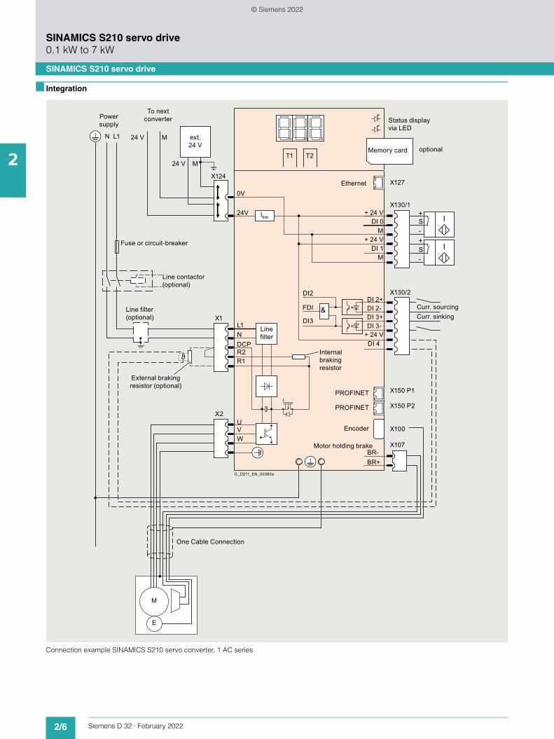
2/6 Siemens D 32 · February 2022
2
SINAMICS S210 servo drive0.1 kW to 7 kW
SINAMICS S210 servo drive
■ Integration
Connection example SINAMICS S210 servo converter, 1 AC series
Power supply
N L1 24 V
24 V
+
+-
-
S
S
+ 24 V
+ 24 V
+ 24 V
DI 0
DI 1
L1 N
U V W
DCP R2 R1
DI 2-
DI 3-
DI 4
DI 3+
DI 2+
BR-BR+
M
M
ext. 24 V
M
MT1 T2
llim
To next converter Status display
via LED
Memory card optional
Ethernet
Curr. sourcingCurr. sinking
Fuse or circuit-breaker
Internal braking resistor
PROFINET
PROFINET
Encoder
Motor holding brake
G_D211_EN_00380a
External braking resistor (optional)
One Cable Connection
Line contactor (optional)
Line filter (optional)
Line filter
0V
24V
X127
X130/1
X130/2
X150 P1
X150 P2
X100
X107
DI2
DI3
FDI
X124
X1
X2
M
E
© Siemens 2022

2/7Siemens D 32 · February 2022
2
SINAMICS S210 servo drive0.1 kW to 7 kW
SINAMICS S210 servo drive
■ Integration
Connection example SINAMICS S210 servo converter, 3 AC series
Power supply
24 V
24 V
24 V
M
+
+-
-
S
S
+ 24 V
+ 24 V
+ 24 V
DI 0
DI 1
L1
L1 L2 L3
L2 L3
N
U V W
DCP
DCP
DCN
R2 R1
DI 2-
DI 3-
DI 4
DI 3+
DI 2+
BR-BR+
M
M
ext. 24 V
M
MT1 T2
llim
To next converter Status display
via LED
Memory card optional
Ethernet
Curr. sourcingCurr. sinking
Fuse or circuit-breaker
Internal braking resistor
PROFINET
PROFINET
Encoder
Motor holding brake
Relay
G_D211_EN_00393a
External braking resistor (optional)
One Cable Connection
Line contactor (optional)
To next converter
To next converter (optional)
Line filter (optional)
DC
Lin
k
0V
24V
Line filter
X127
X130/1
X130/2
X150 P1
X150 P2
X100
X107
DI2
DI3
FDI
X124
X1
X4
X2
X3
M
E
© Siemens 2022

2/8 Siemens D 32 · February 2022
2
SINAMICS S210 servo drive0.1 kW to 7 kW
SINAMICS S210 servo drive
■ Selection and ordering data
When operating a SINAMICS S210 servo converter with a supply voltage of 200 V to 240 V 3 AC, an external, intrinsi-cally safe braking resistor is always required.
Description Frame size
Article No.
200 ... 240 V 1 AC
SINAMICS S210 servo converterswith shield plate and push-in connectors without memory card
The shield clamp is included in the scope of delivery of the MOTION-CONNECT cable.
• 0.1 kW FSA 6SL3210-5HB10-1UF0
• 0.2 kW FSA 6SL3210-5HB10-2UF0
• 0.4 kW FSB 6SL3210-5HB10-4UF0
• 0.75 kW FSC 6SL3210-5HB10-8UF0
200 ... 480 V 3 AC
SINAMICS S210 servo converterswith shield plate (for FSA only) and push-in connectors without memory card
The shield clamp is included in the scope of delivery of the MOTION-CONNECT cable.
• 0.4 kW FSA 6SL3210-5HE10-4UF0
• 0.75 kW FSA 6SL3210-5HE10-8UF0
• 1 kW FSA 6SL3210-5HE11-0UF0
• 1.5 kW FSB 6SL3210-5HE11-5UF0
• 2 kW FSB 6SL3210-5HE12-0UF0
• 3.5 kW FSC 6SL3210-5HE13-5UF0
• 5 kW FSC 6SL3210-5HE15-0UF0
• 7 kW FSC 6SL3210-5HE17-0UF0
Description Frame size
Article No.
© Siemens 2022

2/9Siemens D 32 · February 2022
2
SINAMICS S210 servo drive0.1 kW to 7 kW
SINAMICS S210 servo drive
■ Selection and ordering data
Accessories
Description Article No.SINAMICS SD card (optional)512 MB
The parameter assignment, firmware and licenses for a converter can be stored on this memory card.
Firmware V5.2 or higher is required for the 3 AC series.• Empty 6SL3054-4AG00-2AA0• With firmware V5.1 6SL3054-4FB00-2BA0• With firmware V5.1 SP1 6SL3054-4FB10-2BA0• With firmware V5.1 SP1
and Safety license (Extended Functions)
6SL3054-4FB10-2BA0-ZF01
• With firmware V5.2 6SL3054-4FC00-2BA0• With firmware V5.2
and Safety license (Extended Functions)
6SL3054-4FC00-2BA0-ZF01
• With firmware V5.2 SP3
6SL3054-4FC30-2BA0
• With firmware V5.2 SP3 and Safety license (Extended Functions)
6SL3054-4FC30-2BA0-ZF01
Safety license(Extended Functions) 1)
• CoL in paper form 6SL3074-0AA10-0AA0• CoL in electronic
form6SL3074-0AA10-0AH0
PROFINET patch cableFor the networking of concatenated converters
Industrial Ethernet TP cord, CAT 6 A, twisted pair line 4 × 2 cores, pre-assembled with two RJ45 connectors• 0.3 m (0.98 ft) 6XV1870-3QE30• 0.5 m (1.64 ft) 6XV1870-3QE50
Only for the 1 AC seriesLine filterWith this line filter, Category C2 for cable lengths up to 25 m (82 ft), Category C3 for cable lengths up to 50 m (164 ft) acc. to EN 61800-3 can be achieved.
• 18 A 6SL3203-0BB21-8VA1
Replacement connector setFor frame sizes FSA, FSB and FSCWith a connector set, as in the scope of delivery, and two shield plates
6SL3260-2DB00-0AA0
1) Extended function for an existing memory card (firmware V5.1 SP1 or higher). The memory card is not included in the scope of delivery. The Safety license can also be ordered together with a memory card (see above). With a CoL in electronic form, the license is supplied as a PDF file. Notification of this with a download link is received by email. For further information, see section Supplementary system components > Memory cards.
2) The data is applicable for the complete cable length of the motors, whose associated converters are coupled with one another via an AC coupling or through the DC link.The maximum cable length per motor is 25 m using the internal filters or an external filter to achieve EMC category C2. If an external filter is used to achieve EMC category C3, the maximum cable length per motor is 50 m.
Description Article No.Only for the 3 AC series
Line filter
With these line filters, Cate-gory C2 for cable lengths up to 25 m (82 ft), Category C3 for cable lengths up to 50 m (164 ft) acc. to IEC 61800-3 can be achieved.When connected via a DC link, a total cable length of up to 100 m (328 ft) with Category C2 and up to 250 m (820 ft) with Category C3 is possible 2)
• 35 A 6SL3203-0BE23-5HA0• 65 A 6SL3203-0BE26-5HA0Connector set AC bus and DC link
6SL3260-2DC00-0AA0
For coupling the DC link and the line infeed
Scope of delivery: 1 AC bus connector, 1 DC link connector, 2 cover caps
The AC bus connector replaces the push-in connector included in the scope of delivery of the converter.Wiring is performed with conventional 16 mm2 cable (not included in scope of delivery) 3)
Connector set AC bus individual
6SL3260-2DC10-0AA0
For coupling the line infeed
Scope of delivery: 1 AC bus connector, 1 cover cap
This connector replaces the push-in connector included in the scope of delivery of the converter. Wiring is per-formed with conventional 16 mm2 cable (not included in scope of delivery) 3)
External braking resistors for 200 … 240 V 3 ACFor a supply voltage of 200 V to 240 V 3 AC, an external, intrinsically safe braking resistor is always required for each converter• 100 W, 47 for
FSA and FSBGXK:BWG250047TS-190
• 240 W, 14 for FSC GXK:BWG600014TS-190Replacement connector set 6SL3260-2DB10-0AA0For frame sizes FSA, FSB and FSCWith a connector set, as in the scope of delivery, and one shield plate (for FSA)
Replacement fan
Incl. support• Frame size FSA 6SL3260-0AA00-0AA0• Frame size FSB 6SL3260-0AB00-0AA0• Frame size FSC 6SL3260-0AC00-0AA0
3) Permissible cables:- 16 mm2, Class 5 (finely stranded, PVC-insulated) H07V-K + H07V2-K
according to EN 50525-2-31- HELUTHERM 145: 16 mm2, Class 5 (finely stranded, crosslinked
polyolefin-copolymer, halogen-free) www.helukabel.com- External diameter 6.7 mm to 8.1 mm
Permissible cables (UL approval):- AWG 6, copper cable with PVC insulation, with or without nylon jacket,
19 strands- Types: MTW, THHW, THW, THW-2, THHN, THWN-2, TW, TWN- CSA types: TW, TWU, TWN75, TW75, TWU75, T90, no compressed
conductors
© Siemens 2022

2/10 Siemens D 32 · February 2022
2
SINAMICS S210 servo drive0.1 kW to 7 kW
SINAMICS S210 servo drive
■ Technical specifications
Unless explicitly specified otherwise, the following technical specifications are valid for all SINAMICS S210 servo converters.
General technical specifications
Mechanical specifications
Vibratory load• Transport 1) acc. to IEC 60721-3-2: 1997 Class 2M3• Operation acc. to IEC 60721-3-3: 2002 Class 3M2
- Test values according to IEC/EN 60068-2-6 Test Fc (sinusoidal)• 2 ... 9 Hz: 1.5 mm deflection amplitude• 9 ... 200 Hz: 0.5 × g acceleration amplitude• 10 frequency cycles per axis
Shock load• Transport 1) acc. to IEC 60721-3-2: 1997 Class 2M3• Operation acc. to IEC 60721-3-3: 2002 Class 3M2
- Test values according to IEC/EN 60068-2-27 Test Ea (semisinusoidal)• 5 × g peak acceleration• 30 ms duration• 3 shocks in all three axes in both directions
Environmental conditions
Protection classAccording to IEC/EN 61800-5-1
Class I (with protective bonding circuit) and class III (PELV or SELV)
Degree of protectionAccording to IEC/EN 60529
IP20Mounting in control cabinet necessary
Permissible ambient temperature (air) in operation 0 ... 50 °C (32 ... 122 °F)
Installation altitude Up to max. 4000 m (13123 ft) (IEC/EN/UL), up to max. 2000 m (6562 ft) (CSA)• Up to 1000 m (3281 ft) above sea level without derating• As from 1000 m (3281 ft) derating 10 % of current or 5 K per 1000 m (3281 ft)• For 1 AC devices, an isolating transformer is required from 2000 m (6562 ft)
Climatic environmental conditions• Storage 2) acc. to IEC 60721-3-1: 1997 Class 1K4
-25 ... +55 °C (-13 ... +131 °F)• Transport 1) acc. to IEC 60721-3-2: 1997 Class 2K4
-40 ... +70 °C (-40 ... +158 °F)Max. air humidity: 95 % at 40 °C (104 °F)
• Operation acc. to IEC 60721-3-3: 2002 Better than class 3K3
0 ... 50 °C (32 ... 122 °F)Relative air humidity: 5 ... 95 %Condensation, splashwater, and ice formation not permitted (IEC/EN 60204, Part 1)
Environmental class/harmful chemical substances• Storage 2) acc. to IEC 60721-3-1: 1997 Class 1C2• Transport 1) acc. to IEC 60721-3-2: 1997 Class 2C2• Operation acc. to IEC 60721-3-3: 2002 Class 3C2
Organic/biological influences• Storage 2) acc. to IEC 60721-3-1: 1997 Class 1B2• Transport 1) acc. to IEC 60721-3-2: 1997 Class 2B2• Operation acc. to IEC 60721-3-3: 2002 Class 3B2
Degree of pollution
According to IEC/EN 61800-5-1
2
Standards
Certificates of suitability CE, UKCA, cULus (UL File No. E355661 for 1 AC series, E192450 for 3 AC series), RCM, EAC, KC
Functional safety • SIL 2 according to IEC 61508 parts 1 to 3 (2010) and IEC 61800-5-2 (2016)• PL d according to ISO 13849 part 1 (2015)• Category 3 according to ISO 13849 part 1 (2015)
1) In transport packaging.2) In product packaging.
© Siemens 2022

2/11Siemens D 32 · February 2022
2
SINAMICS S210 servo drive0.1 kW to 7 kW
SINAMICS S210 servo drive
■ Technical specifications
Line voltage 200 ... 240 V 1 AC SINAMICS S210 servo converters, 1 AC series
6SL3210-5HB10-1UF0 6SL3210-5HB10-2UF0 6SL3210-5HB10-4UF0 6SL3210-5HB10-8UF0
Line supply connection• Supply voltage 200 ... 240 V 1 AC ±10 %• Line frequency Hz 50/60• Conductor cross-section, max. mm2 2.5• Line system configuration Grounded TN/TT networks and ungrounded IT networks
Rated current A 1.4 2.7 5 9.3
Inrush current A 8 8 8 8
Power loss W 15.7 23.2 38.5 71.1
Electronic power supply• Voltage 24 V -15 % ... +20 %• Power requirement, max. A 0.8 without brake
For current consumption of the brake, see section SIMOTICS S-1FK2 servomotors > Technical specifications > Holding brake, page 3.1/10
• Conductor cross-section, max. mm2 2.5
Output• Rated power 230 V kW 0.1 0.2 0.4 0.75• Rated current A 0.8 1.4 2.4 4.4• Output current, max. A 3.1 4.8 8.7 16
Pulse frequency power unit kHz 8
Output frequency Hz 0 ... 550
Line filter Integrated, category C2 (up to 10 m (32.8 ft) cable length), category C3 (up to 25 m (82.0 ft) cable length)
Braking resistor Without 1) Integrated Integrated Integrated
Digital inputs 2)
• Fast inputs for measuring probes, reference marks, tem-perature monitoring, external braking resistor
3
- Low level -30 V ... +5 V and 2 mA- High level 15 V ... 30 V- Current consumption mA 6- Delay time, typ., L H s 5- Delay time, typ., H L s 50- Galvanic isolation No
• Fail-safe input 1- Low level -30 V ... +5 V and 2 mA- High level 15 V ... 30 V- Current consumption mA 5- Delay time, typ., L H s 50- Delay time, typ., H L s 100- Galvanic isolation Yes
• Conductor cross-section, max. mm2 1.5
Cooling Convection (without fan)
Frame size FSA FSB FSC
Dimensions• Width mm (in) 45 (1.77) 55 (2.17) 74.5 (2.93)• Height mm (in) 170 (6.69) 170 (6.69) 170 (6.69)• Depth mm (in) 170 (6.69) 170 (6.69) 195 (7.68)
Weight, approx. kg (lb) 1.1 (2.43) 1.2 (2.65) 1.9 (4.19)
1) An internal braking resistor is not required for normal operation on account of the available DC link capacity.
2) The specified delay times refer to the hardware. The actual reaction time depends on the time slot in which the digital input is processed.
© Siemens 2022

2/12 Siemens D 32 · February 2022
2
SINAMICS S210 servo drive0.1 kW to 7 kW
SINAMICS S210 servo drive
■ Technical specifications
Line voltage 200 ... 480 V 3 AC SINAMICS S210 servo converters, 3 AC series
6SL3210-5HE10-4UF0
6SL3210-5HE10-8UF0
6SL3210-5HE11-0UF0
6SL3210-5HE11-5UF0
6SL3210-5HE12-0UF0
6SL3210-5HE13-5UF0
6SL3210-5HE15-0UF0
6SL3210-5HE17-0UF0
Line supply connection• Supply voltage 200 ... 480 V 3 AC ±10 %• Line frequency Hz 50/60• Conductor cross-section, max. mm2 6• Line system configuration Grounded TN/TT networks, ungrounded IT networks and networks with grounded line conductor only with an
isolating transformer
Rated current A 1.6 2.8 3.8 6 7.5 12.5 15 17.9
Inrush current A 4.3 4.3 4.3 8.6 8.6 27.8 27.8 27.8
Power loss W 69 81 94 114 131 167 191 204
Electronic power supply• Voltage 24 V -15 % ... +20 %• Power requirement, max. A 1.2 without brake
For current consumption of the brake, see section SIMOTICS S-1FK2 servomotors > Technical specifications > Holding brake, page 3.1/10
• Conductor cross-section, max. mm2 2.5
Output• Rated power
- 400 V kW 0.4 0.75 1 1.5 2 3.5 5 7- 240 V kW 0.24 0.45 0.6 0.9 1.2 2.1 3 4.2
• Rated current A 1.2 2.3 3 5 7 9 12 15• Output current, max. A 4.2 7.6 10.9 19 24 33 44 55
Pulse frequency power unit kHz 8
Output frequency Hz 0 ... 550
Line filter Category C3 (up to 25 m (82.0 ft) cable length for a single axis, for DC link coupling see Accessories/line filters)
Braking resistor Integrated, when connecting to 200 V ... 240 V 3 AC, an external, intrinsically safe braking resistor is always required.
Digital inputs 1)
• Fast inputs for measuring probes, reference marks, tem-perature monitoring, external braking resistor
3
- Low level -30 V ... +5 V and 2 mA- High level 15 V ... 30 V- Current consumption mA 6- Delay time, typ., L H s 5- Delay time, typ., H L s 50- Galvanic isolation No
• Fail-safe input 1- Low level -30 V ... +5 V and 2 mA- High level 15 V ... 30 V- Current consumption mA 5- Delay time, typ., L H s 50- Delay time, typ., H L s 100- Galvanic isolation Yes
• Conductor cross-section, max. mm2 1.5
Cooling Air cooling with integrated fan
Frame size FSA FSB FSC
Dimensions• Width mm (in) 50 (1.97) 70 (2.76) 105 (4.13)• Height mm (in) 231 (9.09) 280 (11.0) 280 (11.0)• Depth mm (in) 223 (8.78) 223 (8.78) 223 (8.78)
Weight, approx. kg (lb) 2.1 (4.63) 3.3 (7.28) 5 (11.03)
1) The specified delay times refer to the hardware. The actual reaction time depends on the time slot in which the digital input is processed.
© Siemens 2022

2/13Siemens D 32 · February 2022
2
SINAMICS S210 servo drive0.1 kW to 7 kW
SINAMICS S210 servo drive
■ Dimensional drawings
Dimensional drawing SINAMICS S210, frame size FSA, 1 AC series
Dimensional drawing SINAMICS S210, frame size FSB, 1 AC series
Dimensional drawing SINAMICS S210, frame size FSC, 1 AC series
All dimensions in mm (values in brackets are in inches).
With the OCC motor connection cable connected, the overall depth increases by 57 mm (2.24 inches).
Dimensional drawing SINAMICS S210, frame size FSA, 3 AC series
Dimensional drawing SINAMICS S210, frame size FSB, 3 AC series
Dimensional drawing SINAMICS S210, frame size FSC, 3 AC series
172.4 (6.79)
2 × Ø 5.6 (0.22)
(1.77)45
Drill pattern
G_D
011_
EN
_005
49
(0.2
4)6
(6.2
2)15
8(8.6
2)21
9
(6.6
9)17
0
(0.33)
(1.1)28
8.5
172.4 (6.79) (2.17)55
G_D
011_
EN
_005
50
(0.2
4)6
(6.2
2)15
8(8.6
2)21
9
(6.6
9)17
0
(0.33)
(1.5)38
8.5
2 × Ø 5.6 (0.22)Drill pattern
197.4 (7.77) (2.93) (0.33)(0.2
4)(6
.22)
(8.6
2)(6.6
9)
(2.26)
74.5
57.5
G_D
011_
EN
_005
48a
615
8
21917
0
8.5
3 × Ø 5.6 (0.22)Drill pattern
G_D
011_
EN
_005
85
(8.77) (1.18)
(0.24)
222.8
(11.
8)29
9.6(9
.09)
231
(10.
24)
260
(0.2
9)7.
2
(1.97)50 30
6
(0.23)5.9
G_D
011_
EN
_005
86a
(8.77)222.8
(12.
68)
322(11.
02)
280
(12.
17)
309
(0.2
8)7.
2
(2.76)70 (1.97)50
(1.97)50
(0.4)10.1
(0.24)6
G_D
011_
EN
_005
87
(11.
02)
280 (1
2.68
)32
2
(12.
17)
309
(0.2
9)7.
3(8.77)222.8
(0.22)
5.5
(4.13)105 (3.15)80
(3.15)80
(0.49)12.45
© Siemens 2022

2/14 Siemens D 32 · February 2022
2
SINAMICS S210 servo drive0.1 kW to 7 kW
SINAMICS S210 servo drive
■ Accessories
Line filters
1 AC series
Filters are already integrated in order to achieve category C2 (for motor cable lengths up to 10 m) or category C3 (for motor cable lengths up to 25 m). Further requirements can be achieved using an external line filter.
3 AC series
Filters for achieving category C3 are already integrated (for motor cable lengths up to 25 m). Further requirements can be achieved using an external line filter.
Example: SINAMICS S210, 3 AC line filter with servo converter, frame size FSB
Recommended line-side overcurrent protection devices
Overcurrent protection devices are absolutely necessary for the operation of the converters. The table listed in the section "Recommended line-side overcurrent protection devices" provides recommendations according to IEC and UL regula-tions, depending on the area of application. Recommendations on further overcurrent protection devices are available at:https://support.industry.siemens.com/cs/document/109748999
Additional information about the listed Siemens fuses is available in Catalog LV 10 as well as in the Industry Mall.
Braking resistors
As far as necessary, braking resistors are integrated into the converters. Together with the generously dimensioned DC link capacities, an external braking resistor is not necessary in the normal case.
If the internal braking resistor is inadequate for applications with very high requirements, an external braking resistor can be connected as an alternative. When operating a SINAMICS S210 servo converter with a supply voltage of 200 V to 240 V 3 AC, an external, intrinsically safe braking resistor is always required.
Memory cards
A memory card (SINAMICS SD card) can be optionally used with SINAMICS S210. The associated slot is located under the front cover of the converter. Not only the firmware but also the device parameterization of a SINAMICS S210 servo converter can be stored on the memory card.
When service is required, e.g. after the converter has been replaced and the data have been downloaded from the memory card, the drive system is immediately ready for use again.
A memory card is only absolutely necessary if functions requir-ing license, such as the Extended Safety Functions, are used. The necessary license is saved on the memory card.
1 AC series Maximum motor cable length
for converters without additional line filter
for converters with external line filter
EMC category C2 10 m (32.8 ft) 25 m (82.0 ft)
EMC category C3 25 m (82.0 ft) 50 m (164 ft)
3 AC series Line/DC link coupling
Maximum motor cable length
for converters with integrated line filter
for converters with external line filter
EMC category C2 Without line/DC link coupling
– 25 m (82 ft)
With line/DC link coupling 6 converters 1)
– 100 m (328 ft)
EMC category C3 Without line/DC link coupling
25 m (82 ft) 50 m (164 ft)
With line/DC link coupling 6 converters 1)
100 m (328 ft) 250 m (820 ft)
1) The data is applicable for the complete cable length of the motors, whose associated converters are coupled with one another via an AC coupling or through the DC link.The maximum cable length per motor is 25 m using the internal filters or an external filter to achieve EMC category C2. If an external filter is used to achieve EMC category C3, the maximum cable length per motor is 50 m.
© Siemens 2022

2/15Siemens D 32 · February 2022
2
SINAMICS S210 servo drive0.1 kW to 7 kW
Line-side components > Line filters
■ Overview
1 AC line filter, 18 A
3 AC line filter, 35 A and 65 A
The 3 AC line filters are connected via the AC coupling of the converters.The total of the rated currents of the converters on an AC bus must not exceed the rated current of the line filter.
■ Selection and ordering data
■ Technical specifications
Rated current of the servo converter
Suitable for SINAMICS S210
Line filter
A Article No.
Line voltage 200 ... 240 V 1 AC
1.4 6SL3210-5HB10-1UF02.7 6SL3210-5HB10-2UF05 6SL3210-5HB10-4UF09.3 6SL3210-5HB10-8UF0• Total of the currents 18 A 6SL3203-0BB21-8VA1
Line voltage 200 ... 480 V 3 AC
1.6 6SL3210-5HE10-4UF02.8 6SL3210-5HE10-8UF03.8 6SL3210-5HE11-0UF06 6SL3210-5HE11-5UF07.5 6SL3210-5HE12-0UF012.5 6SL3210-5HE13-5UF015 6SL3210-5HE15-0UF017.9 6SL3210-5HE17-0UF0• Total of the currents 35 A 6SL3203-0BE23-5HA0• Total of the currents 65 A 6SL3203-0BE26-5HA0
Line voltage 200 ... 240 V 1 AC
Line filter
6SL3203-0BB21-8VA1
Rated current A 18
Power loss W < 1.2
Line/load connection
Screw terminals
• Conductor cross-section- For single-
conductor connection
mm2 0.25 ... 6AWG 24 ... 10
- For flexible cables
mm2 0.25 ... 4AWG 24 ... 12
PE connection M5 screw stud
Degree of protection
IP20
Dimensions• Width mm (in) 62 (2.44)• Height mm (in) 155 (6.10)• Depth mm (in) 53 (2.09)
Weight, approx. kg (lb) 0.7 (1.54)
Suitable for SINAMICS S210 servo converter
Type 6SL3210-5HB10-1UF0 (1.4 A)6SL3210-5HB10-2UF0 (2.7 A)6SL3210-5HB10-4UF0 (5 A)6SL3210-5HB10-8UF0 (9.3 A)
Line voltage 200 ... 480 V 3 AC
Line filter
6SL3203-0BE23-5HA0 6SL3203-0BE26-5HA0
Rated current A 35 65
Power loss W 12 18
Line supply connection
Screw terminals Screw terminals
• Conductor cross-section
mm2 0.5 ... 10AWG 24 ... 6
4 ... 25AWG 10 ... 3
Load connection Screw terminals Screw terminals• Conductor
cross-sectionmm2 16
AWG 616AWG 6
PE connection M4 screw stud M5 screw stud
Degree of protection
IP20 IP20
Dimensions• Width mm (in) 50 (1.97) 70 (2.76)• Height mm (in) 296.2 (11.66) 348.8 (13.73)• Depth mm (in) 220 (8.66) 220 (8.66)
Weight, approx. kg (lb) 2.3 (5.07) 3.5 (7.72)
Suitable for SINAMICS S210 servo converter
Type 6SL3210-5HE10-4UF0 (1.6 A)6SL3210-5HE10-8UF0 (2.8 A)6SL3210-5HE11-0UF0 (3.8 A)6SL3210-5HE11-5UF0 (6 A)6SL3210-5HE12-0UF0 (7.5 A)6SL3210-5HE13-5UF0 (12.5 A)6SL3210-5HE15-0UF0 (15 A)6SL3210-5HE17-0UF0 (17.9 A)
© Siemens 2022

2/16 Siemens D 32 · February 2022
2
SINAMICS S210 servo drive0.1 kW to 7 kW
Line-side components > Recommended line-side overcurrent protection devices
■ Selection and ordering data
Overcurrent protection devices are absolutely necessary for the operation of the converters. The following table lists recommen-dations for fuses.
• Siemens fuses of type 3NA3 for use in the area of validity of IEC
• UL-listed fuses Class J for use in USA and Canada
Recommendations on further overcurrent protection devices are available at: https://support.industry.siemens.com/cs/document/109748999
The Short Circuit Current Rating (SCCR) according to UL for industrial control cabinet installations to NEC Article 409 or UL 508A/508C or UL 61800-5-1 is as follows for Class J fuses for
• SINAMICS S210: 65 kA
SCCR and ICC values for combination with further overcurrent protection devices are available at: https://support.industry.siemens.com/cs/document/109748999
Notes for installations in Canada:
The converters are intended for line supply systems with overvoltage category III.More information is available in the technical documentation on the internet at: www.siemens.com/sinamics-s210/documentation
Additional information about the listed Siemens fuses is avail-able in Catalog LV 10 as well as in the Industry Mall.
Group protection of multiple converters
Further information is available in the technical documentation on the internet at:www.siemens.com/sinamics-s210/documentationhttps://support.industry.siemens.com/cs/document/109748999
Rated power SINAMICS S210 IEC-compliant UL/cUL-compliant
Fuse Fuse typeRated voltage 600 V AC
Current 3NA3 Current
kW Type A Article No. Class A
Line voltage 200 ... 240 V 1 AC
0.1 6SL3210-5HB10-1UF0 6 3NA3801 J 6
0.2 6SL3210-5HB10-2UF0 6 3NA3801 J 6
0.4 6SL3210-5HB10-4UF0 10 3NA3803 J 10
0.75 6SL3210-5HB10-8UF0 16 3NA3805 J 20
Line voltage 200 ... 480 V 3 AC
0.4 6SL3210-5HE10-4UF0 16 3NA3805 J 15
0.75 6SL3210-5HE10-8UF0 16 3NA3805 J 15
1 6SL3210-5HE11-0UF0 16 3NA3805 J 15
1.5 6SL3210-5HE11-5UF0 32 3NA3812 J 30
2 6SL3210-5HE12-0UF0 32 3NA3812 J 30
3.5 6SL3210-5HE13-5UF0 63 3NA3822 J 70
5 6SL3210-5HE15-0UF0 63 3NA3822 J 70
7 6SL3210-5HE17-0UF0 63 3NA3822 J 70
© Siemens 2022

2/17Siemens D 32 · February 2022
2
SINAMICS S210 servo drive0.1 kW to 7 kW
DC link components > External braking resistors
■ Overview
As far as necessary, braking resistors are integrated into the converters. Together with the generously dimensioned DC link capacities, another external braking resistor is not necessary in the normal case.
If the internal braking resistor is inadequate for applications with very high requirements, an external braking resistor can be con-nected as an alternative.
Only intrinsically safe braking resistors with temperature moni-toring may be used in order to minimize the risk of an explosion, the outbreak of fire or melting of the enclosure in the event of a continuous overload, e.g. due to a defect.
External braking resistors for 200 V to 240 V 3 AC
For operation with a supply voltage of 200 V to 240 V 3 AC, an external, intrinsically safe braking resistor is always required for each converter. Use of braking resistors integrated in the con-verter is not permissible with this supply voltage.
The following resistors are recommended as a substitute for the internal braking resistors. If these are not sufficient, the resistors from Michael Koch GmbH listed in the table can be used.• 100 W, 47 for frame sizes FSA and FSB:
GXK:BWG250047TS-190• 240 W, 14 for frame size FSC:
GXK:BWG600014TS-190
These resistors have approvals for the North American market (cURus and CSA).
If the temperature sensor of the resistor is connected to the input DI4 of the converter, the converter switches off when the braking resistor is overloaded.
■ More Information
Further information is available from the "Siemens Product Partner for Drives Options": www.siemens.com/drives-options-partner
■ Technical specifications
Requirements placed on an external braking resistor
Examples of braking resistors from Michael Koch GmbH
Converter Braking resistor
Article No. Rated power
Min. resistance
Max. continuous power
Max. peak power
Max. braking energy
6SL3210-... kW W W kJ
Line voltage 200 ... 240 V 1 AC
5HB10-1UF0 0.1 300 50 350 0.7
5HB10-2UF0 0.2 150 100 600 1.3
5HB10-4UF0 0.4 100 200 1300 2.3
5HB10-8UF0 0.75 50 380 2400 3.8
Line voltage 200 ... 240 V 3 AC
5HE10-4UF0 0.4 100 200 600 1
5HE10-8UF0 0.75 100 380 1200 1
5HE11-0UF0 1 100 500 1700 1
5HE11-5UF0 1.5 50 880 2900 20
5HE12-0UF0 2 50 1000 3800 20
5HE13-5UF0 3.5 15 1750 7500 25
5HE15-0UF0 5 15 2500 9500 25
5HE17-0UF0 7 15 3250 12500 25
Line voltage 380 ... 480 V 3 AC
5HE10-4UF0 0.4 200 200 1200 8
5HE10-8UF0 0.75 200 380 2400 8
5HE11-0UF0 1 200 500 3400 8
5HE11-5UF0 1.5 100 880 5700 80
5HE12-0UF0 2 100 1000 7600 80
5HE13-5UF0 3.5 30 1750 15000 100
5HE15-0UF0 5 30 2500 19000 100
5HE17-0UF0 7 30 3250 25000 100
Converter Braking resistors from Michael Koch GmbH
Article No. Order designation with temperature sensor 190 °C (Can only be obtained directly from Michael Koch GmbH)
Continuous power
Max. peak power
Max. braking energyfor CE for UL
6SL3210-... W W W kJ
Line voltage 200 ... 240 V 1 AC
5HB10-1UF0 BWG250047TS-190 50 50 350 0.7
5HB10-2UF0 BWG250047TS-190 100 100 600 1.1
5HB10-4UF0 BWG250047TS-190 100 100 1300 1.8
5HB10-8UF0 BWG500027TS-190 200 200 2400 2.7
Line voltage 200 ... 240 V 3 AC
5HE10-4UF0 BWG500027TS-190 200 200 600 0.9
5HE10-8UF0 BWG600014TS-190 380 240 1200 0.8
5HE11-0UF0 BWG600014TS-190 400 240 1700 0.8
5HE11-5UF0 BWD500027K03LIP65IS 600 600 2900 14.5
5HE12-0UF0 BWD500027K03LIP65IS 600 600 3800 13.9
5HE13-5UF0 BWD600014K03LIP65IS 1200 720 7500 18.7
5HE15-0UF0 BWD600014K03LIP65IS 1200 720 9500 17.8
5HE17-0UF0 BWD600014K03LIP65IS 1200 720 12500 18.2
Line voltage 380 ... 480 V 3 AC
5HE10-4UF0 BWG500100TS-190 200 200 1200 5.2
5HE10-8UF0 BWG600047TS-190 380 240 2400 6.2
5HE11-0UF0 BWG600047TS-190 400 240 3400 6.1
5HE11-5UF0 BWD500100K03LIP65IS 600 600 5700 30.4
5HE12-0UF0 BWD500100K03LIP65IS 600 600 7600 30.4
5HE13-5UF0 BWD600047K03LIP65IS 1200 720 15000 50
5HE15-0UF0 BWD600047K03LIP65IS 1200 720 19000 47.5
5HE17-0UF0 BWD600047K03LIP65IS 1200 720 25000 41.7
© Siemens 2022

2/18 Siemens D 32 · February 2022
2
SINAMICS S210 servo drive0.1 kW to 7 kW
Supplementary system components > Memory cards
■ Overview
SINAMICS memory card (SD card)
The parameter assignment, firmware and licenses for a con-verter can be stored on the SINAMICS memory card (SD card). When service is required, e.g. after the converter has been replaced and the data have been downloaded from the memory card the drive system is immediately ready for use again.
The memory card has the following functions:• Parameter settings can be written from the memory card to the
converter or saved from the converter to the memory card• The memory card supports series commissioning without the
use of a commissioning tool• If firmware is stored on the memory card, the firmware can be
upgraded/downgraded during startup• It is used for storing licenses when using functions under
license, e.g. the license for enabling the Extended SafetyFunctions- Safe Stop 1 (SS1) 1)
- Safe Stop 2 (SS2)- Safe Operating Stop (SOS)- Safely-Limited Speed (SLS)- Safe Speed Monitor (SSM)- Safe Direction (SDI)- Safely-Limited Acceleration (SLA)- Safe Brake Test (SBT) diagnostic function
Notes:
In general, the converter can be operated without a memory card. However, it is necessary if licenses, such as the Extended Safety license, are required. The card must then remain perma-nently inserted.
Firmware V5.2 or higher is required for the 3 AC series or when using the SINAMICS Startdrive commissioning tool.
■ Selection and ordering data
Description Article No.
SINAMICS SD card512 MB
Firmware V5.2 or higher is required for the3 AC series.
• Empty 6SL3054-4AG00-2AA0
• With firmware V5.1 6SL3054-4FB00-2BA0
• With firmware V5.1 SP1 6SL3054-4FB10-2BA0
• With firmware V5.1 SP1 and Safety license (Extended Functions)
6SL3054-4FB10-2BA0-ZF01
• With firmware V5.2 6SL3054-4FC00-2BA0
• With firmware V5.2 and Safety license (Extended Functions)
6SL3054-4FC00-2BA0-ZF01
• With firmware V5.2 SP3 6SL3054-4FC30-2BA0
• With firmware V5.2 SP3 and Safety license (Extended Functions)
6SL3054-4FC30-2BA0-ZF01
Safety license(Extended Functions) 2)
• CoL in paper form 6SL3074-0AA10-0AA0
• CoL in electronic form 6SL3074-0AA10-0AH0
1) Safe Stop 1 time controlled (SS1-t) is also included in the Safety Integrated Basic functions.
2) Extended function for an existing memory card (firmware V5.1 SP1 or higher). The memory card is not included in the scope of delivery. The Safety license can also be ordered together with a memory card (see above). With a CoL in electronic form, the license is supplied as aPDF file. Notification of this with a download link is received by email. For further information to CoL in electronic form, see next page. For further information to CoL, see section Software licenses.
© Siemens 2022

2/19Siemens D 32 · February 2022
2
SINAMICS S210 servo drive0.1 kW to 7 kW
Supplementary system components > Memory cards
■ More information
Certificate of License (CoL)
The CoL is the licensee's proof that the use of the software has been licensed by Siemens. A CoL must be assigned to each use and must be kept in a safe place.
Electronic Certificate of LicenseThe electronic Certificate of License is the paperless delivery form for runtime options for SINAMICS, SIMOTION, and SINUMERIK.
Like the previous paper Certificate of License CoL, the elec-tronic Certificate of License contains information about the type of rights of use purchased for the software. The electronic Certificate of License is supplied as a PDF file via the Online Software Delivery Portal (OSD). This enables quick notification with a download link to the email address to be stated in the order.
The electronic Certificate of License can then be downloaded from the OSD. The Web License Manager can also be called from the OSD to assign the runtime license to a memory card. In this case, the data of the electronic Certificate of License are automatically transferred to the Web License Manager and do not have to be entered manually.This ensures quick availability of the license key and simple and secure handling and management of the license certificates.
You will find information on the OSD at: https://support.industry.siemens.com/cs/document/109759444
Electronic Certificate of License: Procedure for order licenses
In the future, the pre-licensed memory cards will also be deliv-ered with the corresponding electronic Certificates of License on the memory card. The Certificates of License are stored in direc-tory "KEYS". The pre-licensed memory cards will successively make the transition from paper CoLs to electronic CoLs. The CoL on paper will then no longer be contained in the delivery.
Electronic Certificate of License: Storage location on data medium
„CoL“ PDF
OSDLog In
Direct link
Automatic Log In
„Key“
G_D
011_
EN_0
0601
Within a few hours
Siemens Mall
Online Software Delivery
Web License Manager
G_D
011_
EN_0
0602
[Product name]
keys.txt
eCoL
identifiereCoL_ .pdf
identifiereCoL_ .pdf
Product name = SINAMICS, SINUMERIK or SIMOTION
Memory Card
SIEMENS
OEM
ADDON
USER
KEYS
© Siemens 2022

2/20 Siemens D 32 · February 2022
2
SINAMICS S210 servo drive
Notes
© Siemens 2022

Siemens D 32 · February 2022
33/2 Overview
3.1/1 SIMOTICS S-1FK2 servomotors
3.2/1 SIMOTICS S-1FT2 servomotors
3.3/1 SIMOTICS S-1FS2 servomotors
3.4/1 SIMOTICS S-1FK2 and S-1FT2 servo planetary geared motors
Detailed technical information on the SINAMICS S210 servo drive system is available on the internet at:www.siemens.com/sinamics-s210/documentation
In addition, the Drive Technology Configurator (DT Configurator) can be used on the internet at the following address: www.siemens.com/sinamics-s210/configuration
SIMOTICS S servomotors and servo planetary geared motors for SINAMICS S210
© Siemens 2022

3/2 Siemens D 32 · February 2022
3
SIMOTICS S servomotors and servo planetary geared motors for SINAMICS S210
■ Overview
SIMOTICS S servomotors for SINAMICS S210
1FK2 1FT2 1FS2
High Dynamic (HD) / Compact (CT) High Dynamic (HD) / Compact (CT) High Dynamic (HD) / Compact (CT)
Shaft heights• SH20 HD (1FK2102) HD (1FT2102) –• SH30 HD (1FK2103) / CT (1FK2203) HD (1FT2103) / CT (1FT2203) –• SH40 HD (1FK2104) / CT (1FK2204) HD (1FT2104) / CT (1FT2204) HD (1FS2104)• SH48 CT (1FK2205) CT (1FT2205) –• SH52 HD (1FK2105) HD (1FT2105) HD (1FS2105)• SH63 HD (1FK2106) / CT (1FK2206) HD (1FT2106) / CT (1FT2206) HD (1FS2106)• SH80 CT (1FK2208) CT (1FT2208) CT (1FS2208)• SH100 CT (1FK2210) CT (1FT2210) –
Static torque M0 0.16 ... 40 Nm (0.12 ... 29.50 lbf-ft) 0.16 ... 40 Nm (0.12 ... 29.50 lbf-ft) 3.1 ... 23.5 Nm (2.29 ... 17.33 lbf-ft)
Rated power PN Up to 6.4 kW Up to 6.4 kW Up to 2.51 kW
Applications • Packaging machines • Handling equipment • Feed and withdrawal devices • Stacking units • Automatic assembly machines • Laboratory automation • Woodworking, glass and ceramic in-
dustries • Digital printing machines
• Packaging machines • Handling equipment • Feed and withdrawal devices • Stacking units • Automatic assembly machines • Laboratory automation • Woodworking, glass and ceramic in-
dustries • Digital printing machines
• Food and beverage industries• Pharmaceutical industry• Packaging machines • Handling equipment • Feed and withdrawal devices
Housing/paint finish Aluminum/anthracite gray Aluminum/anthracite gray
Optionally other colors possible
Stainless steel
Degree of protection IP64IP65 optional or retrofittable
IP64IP65 optional or retrofittable, IP67 optional
IP66/IP67, IP69K (30 bars)
Encoder systems• Absolute encoder 22-bit
singleturn✓ ✓ –
• Absolute encoder 22-bit + 12-bit multiturn
✓ ✓ ✓
• Absolute encoder 26-bit singleturn
– ✓ –
• Absolute encoder 26-bit + 12-bit multiturn
– ✓ –
Notes • Also available as servo planetary geared motor
• Versions with increased rated and max-imum speed
• Options:- Increased detergent resistance - Pressure balance - Metal rating plate - Coating color
• Also available as servo planetary geared motor
• Very high detergent resistance • Certification according to EHEDG • With connection cable (cable end
and cable length up to 11 m can be selected)
© Siemens 2022

Siemens D 32 · February 2022
3.13.1/2 Overview3.1/2 Benefits3.1/2 Application3.1/3 Selection and ordering data3.1/6 Technical specifications3.1/6 General technical specifications3.1/11 Shaft height 203.1/13 Shaft height 303.1/16 Shaft height 403.1/20 Shaft height 483.1/22 Shaft height 523.1/24 Shaft height 633.1/27 Shaft height 803.1/30 Shaft height 100
Detailed technical information on the SINAMICS S210 servo drive system is available on the internet at:www.siemens.com/sinamics-s210/documentation
In addition, the Drive Technology Configurator (DT Configurator) can be used on the internet at the following address: www.siemens.com/sinamics-s210/configuration
SIMOTICS S-1FK2 servomotors for SINAMICS S210
© Siemens 2022

3.1/2 Siemens D 32 · February 2022
31
SIMOTICS S-1FK2 servomotors for SINAMICS S210
■ Overview
The SIMOTICS S-1FK2 servomotors are compact and highly dynamic synchronous motors for a wide range of uses in an industrial environment. They are characterized by high power density, degree of protection and overload capability.
SIMOTICS S-1FK2 High Dynamic motors
Highest dynamic response through low inertia for highly dynamic applications with low moved masses.
SIMOTICS S-1FK2 Compact motors
Precise, stable control with medium to high masses to be moved with medium moment of inertia.
■ Benefits
The SIMOTICS S-1FK2 servomotors fully exploit their strengths in the system with the SINAMICS S210 converter:• Short adjustment and positioning times• Quick and precise compensation of disturbances• Stable closed loop control with high dynamic response
This is achieved by:• Rapid control cycle• High pulse frequency• Complex rule algorithms• High-resolution optical encoder with fast scanning• Low moment of inertia of the motors• High overload capability
■ Application
• Packaging machines• Handling equipment• Feed and withdrawal devices• Stacking units• Automatic assembly machines• Laboratory automation• Woodworking, glass and ceramic industries• Digital printing machines
© Siemens 2022

3.1/3Siemens D 32 · February 2022
31
SIMOTICS S-1FK2 servomotors for SINAMICS S210
■ Selection and ordering data
Static torque
Maximum torque
Maximum speed
Rated speed for 200 ... 240 V 1 AC / 3 AC
Rated speed for 380 ... 480 V 3 AC
Rotor moment of inertia
SIMOTICS S-1FK2 servomotor
M0 Mmax nmax nN nN JMot
Nm (lbf-ft)
Nm (lbf-ft) rpm rpm rpm
kg cm2 (lbf-in
2) Article No.
High Dynamic for highly dynamic applications
Shaft height 20
0.16 (0.12)
0.56 (0.41)
8000 3000 – 0.025 (0.009)
1FK2102-0AG■■-■■A0
0.32(0.24)
1.11 (0.82)
8000 3000 – 0.036 (0.012)
1FK2102-1AG■■-■■A0
Shaft height 30
0.64 (0.47)
1.95 (1.44)
8000 3000 – 0.093 (0.032)
1FK2103-2AG■■-■■A0
0.64 (0.47)
1.95 (1.44)
8000 – 4500 0.093 (0.032)
1FK2103-2AH■■-■■A0
1.27 (0.94)
4.05 (2.99)
8000 3000 – 0.14 (0.048)
1FK2103-4AG■■-■■A0
1.27 (0.94)
4.05 (2.99)
8000 – 4500 0.14 (0.048)
1FK2103-4AH■■-■■A0
Shaft height 40
1.27 (0.94)
3.75 (2.77)
7200 1500 3000 0.35 (0.120)
1FK2104-4AF■■-■■A0
1.27 (0.94)
3.85 (2.84)
8000 3000 6000 0.35 (0.120)
1FK2104-4AK■■-■■A0
2.4 (1.77)
7.5 (5.53)
6700 1500 3000 0.56 (0.191)
1FK2104-5AF■■-■■A0
2.4 (1.77)
7.6 (5.61)
8000 3000 6000 0.56 (0.191)
1FK2104-5AK■■-■■A0
3.2 (2.36)
10 (7.38)
7200 1500 3000 0.76 (0.260)
1FK2104-6AF■■-■■A0
Shaft height 52
5 (3.69)
15 (11.06)
6000 1500 3000 1.7 (0.581)
1FK2105-4AF■■-■■A0
8 (5.90)
24 (17.70)
6000 1500 3000 2.7 (0.923)
1FK2105-6AF■■-■■A0
Shaft height 63
9 (6.64)
26 (19.18)
6000 1500 3000 4.6 (1.572)
1FK2106-3AF■■-■■A0
12 (8.85)
33(24.34)
6000 1500 3000 6.0 (2.050)
1FK2106-4AF■■-■■A0
16 (11.80)
45.5 (33.56)
6000 1500 3000 8.7 (2.973)
1FK2106-6AF■■-■■A0
Article No. supplements
Holding brake
Without brake 0
With brake 1
Degree of protection
IP64 (without shaft sealing ring) 0
IP65 (with shaft sealing ring) 1
Shaft extension, feather key
Plain shaft 0
Shaft with feather key 1
Plain shaft, reduced shaft diameter, 11 × 23 mm (0.43 × 0.91 in) (only for 1FK2.03 and IP64), 14 × 30 mm (0.55 × 1.18 in) (only for 1FK2.04 and IP64) 0 2
Encoder
Absolute encoder 22-bit singleturn S
Absolute encoder 22-bit + 12-bit multiturn M
© Siemens 2022

3.1/4 Siemens D 32 · February 2022
31
SIMOTICS S-1FK2 servomotors for SINAMICS S210
■ Selection and ordering data
Static torque
Maximum torque
Maximum speed
Rated speed for 200 ... 240 V 1 AC / 3 AC
Rated speed for 380 ... 480 V 3 AC
Rotor moment of inertia
SIMOTICS S-1FK2 servomotor
M0 Mmax nmax nN nN JMotNm (lbf-ft)
Nm (lbf-ft) rpm rpm rpm
kg cm2 (lbf-in
2) Article No.Compact for high precision applicationsShaft height 30
0.64 (0.47)
1.85 (1.36)
8000 3000 – 0.20 (0.068)
1FK2203-2AG■■-■■A0
0.64 (0.47)
1.85 (1.36) 8000 – 6000 0.20 (0.068)
1FK2203-2AK■■-■■A0
1.27 (0.94)
3.75 (2.77)
8000 3000 – 0.35 (0.120)
1FK2203-4AG■■-■■A0
1.27 (0.94)
3.75 (2.77)
8000 – 6000 0.35 (0.120)
1FK2203-4AK■■-■■A0
Shaft height 402.4 (1.77)
7.1 (5.24)
7500 1500 3000 1.2 (0.410)
1FK2204-5AF■■-■■A0
2.4 (1.77)
7.1 (5.24)
8000 3000 6000 1.2 (0.410)
1FK2204-5AK■■-■■A0
3.2 (2.36)
9.5 (7.01)
7600 1500 3000 1.6 (0.547)
1FK2204-6AF■■-■■A0
Shaft height 483.6 (2.66)
10.8 (7.97)
6000 1500 3000 3.2 (1.093)
1FK2205-2AF■■-■■A0
6 (4.43)
18 (13.28)
6000 1500 3000 5.1 (1.743)
1FK2205-4AF■■-■■A0
Shaft height 636.5 (4.79)
18 (13.28)
6000 1500 3000 7.8 (2.665)
1FK2206-2AF■■-■■A0
12 (8.85)
36 (26.55)
5800 1500 3000 15 (5.126)
1FK2206-4AF■■-■■A0
Shaft height 8018 (13.28)
51 (37.62)
4100 1000 2000 30 (10.251)
1FK2208-3AC■■-■■A0
22 (16.23)
66 (48.68)
4600 1000 2000 39 (13.326)
1FK2208-4AC■■-■■A0
27 (19.92)
80 (59.01)
4700 1000 2000 48 (16.402)
1FK2208-5AC■■-■■A0
Shaft height 10030 (22.13)
90 (66.38)
2500 750 1500 89 (30.411)
1FK2210-3AB■■-■■A0
30 (22.13)
90 (66.38)
4400 1000 2000 89 (30.411)
1FK2210-3AC■■-■■A0
40 (29.50)
120 (88.51)
2500 750 1500 120 (41.004)
1FK2210-4AB■■-■■A0
40 (29.50)
120 (88.51)
3300 1000 2000 120 (41.004)
1FK2210-4AC■■-■■A0
Article No. supplements
Holding brake
Without brake 0
With brake 1
Degree of protection
IP64 (without shaft sealing ring) 0
IP65 (with shaft sealing ring) 1
Shaft extension, feather key
Plain shaft 0
Shaft with feather key 1
Plain shaft, reduced shaft diameter, 11 × 23 mm (0.43 × 0.91 in) (only for 1FK2.03 and IP64), 14 × 30 mm (0.55 × 1.18 in) (only for 1FK2.04 and IP64) 0 2
Encoder
Absolute encoder 22-bit singleturn S
Absolute encoder 22-bit + 12-bit multiturn M
© Siemens 2022

3.1/5Siemens D 32 · February 2022
31
SIMOTICS S-1FK2 servomotors for SINAMICS S210
■ Selection and ordering data
Accessories
Structure of the Article No. of the SIMOTICS S-1FK2 servomotors
Description For motor Article No.
Shaft sealing ring
To achieve degree of protection IP65
Degree of protection kit for mounting on the motor for retrofitting or as spare part
1FK2.02 1FY2902-0GC00
1FK2.03 1FY2903-0GC00
1FK2.04 1FY2904-0GC00
Data position in Article No. 1 2 3 4 5 6 7 8 9 10 11 12 13 14 15 16
1 F K 2 ■ ■ ■ - ■ A ■ ■ ■ - ■ ■ A 0
1st to 4th position:digit, letter, letter, digit
Motor 1 F K 2
5th position:digit
Moment of inertia
High Dynamic 1
Compact 2
6th and 7thpositions:digit, digit
Shaft height
20 0 2
30 0 3
40 0 4
52 1 0 5
48 2 0 5
63 0 6
80 0 8
100 1 0
8th position:digit
Overall length
See specific technical specifications 0 ... 8
9th position:letter
Reserved A
10th position:letter
Winding/rated speed
For converters connected to max. 240 V
For converters connected to max. 480 V
750 rpm at 230 V 1500 rpm at 400 V B
1000 rpm at 240 V 2000 rpm at 400 V C
1500 rpm at 230 V 3000 rpm at 400 V F
3000 rpm at 230 V Not permissible G
2500 rpm at 230 V 4500 rpm at 400 V H
3000 rpm at 230 V 6000 rpm at 400 V K
11th position:digit
Brake
None 0
Holding brake 1
12th position:digit
Degree of protection
IP64 (without shaft sealing ring) 0
IP65 (with shaft sealing ring) 1
13th position:digit
Shaft extension, feather key
Plain shaft 0
Shaft with feather key 1
Plain shaft, reduced shaft diameter11 × 23 mm (0.43 × 0.91 in) (only for 1FK2.03 and IP64), 14 × 30 mm (0.55 × 1.18 in) (only for 1FK2.04 and IP64)
0 2
14th position:letter
Encoder
Absolute encoder 22-bit singleturn (AS22DQC) S
Absolute encoder 22-bit + 12-bit multiturn (AM22DQC) M
15th position:
letter
One Cable Connection A
16th position:digit
Reserved 0
© Siemens 2022

3.1/6 Siemens D 32 · February 2022
31
SIMOTICS S-1FK2 servomotors for SINAMICS S210
■ Technical specifications
General technical specifications
SIMOTICS S-1FK2 High Dynamic/Compact motors
Motor type Permanent-magnet synchronous motor
Permissible operating conditions without derating• Ambient temperature -15 ... +40 °C (5 ... 104 °F)• Installation altitude, max. 1000 m (3281 ft)
Degree of protection
According to EN 60034-5 (IEC 60034-5)
IP64IP65 optional or retrofittable
Cooling
According to EN 60034-6
Natural cooling (IC410)
Type of construction
According to EN 60034-7 (IEC 60034-7)
IM B5 (IM V1, IM V3)
Shaft extension
According to DIN 748-3 (IEC 60072-1)
Plain shaftOptional shaft with feather key (half-key balancing)
Shaft and flange accuracy
According to DIN 42955 (IEC 60072-1)
Tolerance NIn each case for radial eccentricity of the shaft extension, concentricity of the centering ring, and axial eccentricity of the mounting flange to the axis of the shaft extension.
Vibration severity grade
According to EN 60034-14 (IEC 60034-14)
Grade Ais maintained up to rated speed
Stator winding insulation
According to EN 60034-1 (IEC 60034-1)• 1FK2102, 1FK2.03 Thermal class 130 (B)
for a winding overtemperature of T = 80 K• 1FK2.04, 1FK2.05, 1FK2.06, 1FK2.08, 1FK2.10 Thermal class 155 (F)
for a winding overtemperature of T = 100 K
Sound pressure level LpA (1 m), max.
According to ISO 1680• 1FK2102, 1FK2.03, 1FK2.04 55 dB(A) + 3 dB(A) tolerance• 1FK2.05 and 1FK2.06 65 dB(A) + 3 dB(A) tolerance• 1FK2.08 and 1FK2.10 70 dB(A) + 3 dB(A) tolerance
Encoder system • AS22DQC (absolute encoder 22-bit singleturn)• AM22DQC (absolute encoder 22-bit + 12-bit multiturn)
Holding brake Optional integrated holding brake
Connection One Cable Connection (OCC) for signals and power
Rotatable connector
Paint finish RAL 7016 (anthracite gray)
Certificates of suitability cURus, CE
© Siemens 2022

3.1/7Siemens D 32 · February 2022
31
SIMOTICS S-1FK2 servomotors for SINAMICS S210
■ Technical specifications
Regulations, standards, specifications
The motors comply with the appropriate standards and regula-tions, see table below.
As a result of the fact that in many countries the national regula-tions have been completely harmonized with the international IEC 60034-1 recommendation, there are no longer any differ-ences with respect to coolant temperatures, temperature classes and temperature rise limits.
SIMOTICS S-1FK2 motors have UL approval from Underwriters Laboratories Inc. and are marked with the "UL Recognized Component" test symbol. This is used for components which are part of a larger product or system. This confirmed compliance with the corresponding US American and Canadian regulations, and allowed access to the North American market.
For SIMOTICS S-1FK2 motors, conformity with the relevant EC directives 2006/95/EC and 2014/35/EU and the relevant standards EN 60034-1:2010 and EN 60204-1:2006 is confirmed. By applying the CE mark to the product, Siemens AG confirms this for the product, and secures the free movement of goods within the European Union.
Degree of protection acc. to IEC 60034-5
A suitable degree of protection must be selected according to the operating and environmental conditions to protect the machine against damage caused by the ingress of water and other liquids, as well as dust and foreign bodies.
SIMOTICS S-1FK2 motors have degree of protection IP64 as standard.
The motor can be optionally supplied with a radial shaft seal ring in degree of protection IP65. This increases the protection against the ingress of liquids.
The degree of protection designation is composed from the code IP (for International Protection) and two code numbers for the protection against touching and penetration of foreign bodies, and the degree of protection against the ingress of water.
First code number
6: Protection against dust ingress and complete protection against touching
Second code number
4: Protection against splashwater from any direction
5: Protection against jet water from any direction
Recommended degrees of protection for AC motors
When cooling lubricants are used, protection against water alone is inadequate. The IP rating should only be considered as a guide value in this case. The motors may have to be protected by suitable covers. Attention must be paid to providing suitable sealing of the motor shaft for the selected degree of protection for the motor.
The following table can serve as a decision aid for selecting the proper degree of protection for motors. A permanent covering of liquid on the flange must be avoided when the motor is mounted with the shaft extension facing upwards (IM V3).
General specifications for rotating electrical machines
IEC 60034-1
Terminal designations and direction of rotation for electrical machines
IEC 60034-8
Types of construction of rotating electrical machines
IEC 60034-7
Cooling methods of rotating electrical machines IEC 60034-6
Degrees of protection of rotating electrical machines
IEC 60034-5
Vibration severity of rotating electrical machines IEC 60034-14
Noise limit values for rotating electrical machines IEC 60034-9
Cylindrical shaft extensions for electrical machines
DIN 748-3/IEC 60072-1
Effect General workshop environment
Water/general cooling lubricant (95 % water, 5 % oil)
Dry IP64 –
Water-enriched environment
– IP64
Mist – IP65
Spray – IP65
© Siemens 2022

3.1/8 Siemens D 32 · February 2022
31
SIMOTICS S-1FK2 servomotors for SINAMICS S210
■ Technical specifications
Type of construction, mounting position according to IEC 60034-7
SIMOTICS S-1FK2 motors are designed in type of construction IM B5. It can also be used in mounting positions IM V1 and IM V3.
Shaft and flange accuracy in accordance with IEC 60072-1
Radial eccentricity tolerance of shaft in relation to housing axis
(referred to cylindrical shaft extensions)
Concentricity and axial eccentricity tolerance of the flangesurface for the shaft axis
(referred to the centering diameter of the mounting flange)
Code 1 IM B5 IM V1 IM V3
Code 2 IM 3001 IM 3011 IM 3031
Horizontal flange mounting Flange mounting, output shaft pointing vertically downwards
Flange mounting, output shaft pointing vertically upwards
Motor Shaft extensionsD × L
Radial eccentricity Tolerance N
mm (in) µm
1FK2102 8 × 25 (0.31 × 0.98) 30
1FK2.03 14 × 30 (0.55 × 1.18) 35
11 × 23 (0.43 × 0.91) 35
1FK2.04 19 × 40 (0.75 × 1.57) 40
14 × 30 (0.55 × 1.18) 35
1FK2.05 19 × 40 (0.75 × 1.57) 40
1FK2.06 24 × 50 (0.94 × 1.97) 40
1FK2208 32 × 58 (1.26 × 2.28) 50
1FK2210 38 × 80 (1.50 × 3.15) 50
G_DA65_EN_00063c
Test: runout
Dial gauge
Motor shaft
MotorL
L/2
Motor Centering diameter Concentricity and axial eccentricityTolerance N
mm (in) µm
1FK2102 30 (1.18) 80
1FK2.03 50 (1.97)
1FK2.04 70 (2.76)
1FK2205 80 (3.15)
1FK2105 95 (3.74)
1FK2.06 110 (4.33) 100
1FK2208 130 (5.12)
1FK2210 130 (5.12)
(0.39 in)
(0.39 in)
G_DA65_EN_00064d
Test: concentricity
Test: perpendicularity
Motor
Dial gauge
Dial gauge
Motor
Motor shaft
Motor shaft
10 mm
10 mm
© Siemens 2022

3.1/9Siemens D 32 · February 2022
31
SIMOTICS S-1FK2 servomotors for SINAMICS S210
■ Technical specifications
Vibration severity and vibration severity grade A according to IEC 60034-14
The vibration severity is the RMS value of the vibration velocity (frequency range from 10 Hz to 1000 Hz). The vibration severity is measured using electrical measuring devices according to DIN 45666.
The specified values refer only to the motor. These values can increase as a result of the overall system vibrational behavior due to installation.
Vibration severity limit values
The speeds of 1800 rpm and 3600 rpm and the associated limit values are specified according to IEC 60034-14.The speeds of 4500 rpm and 6000 rpm and the specified values are defined by the motor manufacturer.
The motors maintain vibration severity grade A up to the rated speed.
Balancing according to ISO 21940-32
Apart from the balance quality of the motor, the vibrational quality of motors with attached pulleys is mainly determined by the balance state of the mounted component. If the motor and the mounted component are balanced separately before being joined, the balancing process of the pulley is to be adapted to the motor's balancing type.
SIMOTICS S-1FK2 motors with feather keys are always half-key balanced. In general, motors with a plain shaft are recom-mended for systems with the most stringent vibrational quality requirements.
Vibration stress, immitted vibration values
The requirements of environmental class 3M8 (according to EN 60721-3-3 Table 6) must be maintained for proper function and safeguard the bearing life. The following limits are valid for (immitted) vibration values introduced into the motor from outside:• Vibration velocity Vrms according to ISO 10816,
max. 4.5 mm/s (0.18 in/s)• Vibration acceleration apeak axial and radial 50 m/s2 (164 ft/s2)
During transport, the motors withstand single shocks (6 ms) of up to 250 m/s2 (820 ft/s2).
Ambient temperature and installation altitude
Operating range without restrictions:
Temperature range from -15 °C to +40 °C (5.0 °F to 104 °F), installation altitude up to 1000 m (3281 ft).
If deviating conditions are encountered, the S1 characteristic of the motor must be adapted with regard to speed and torque.
Use the following equation to calculate the reduced S1 characteristic:S1red (n) = xD × S140°C; 1000m (n/xD)
Encoder systems
In motors with integrated OCC/DRIVE-CLiQ interface, the sensor signal is already digitally prepared in the motor, and then trans-ferred quickly and without loss to the drive system. Motors with an OCC/DRIVE-CLiQ interface simplify commissioning and diagnostics, as the motor parameters and encoder system are identified automatically.
Single-turn absolute encoder
This encoder outputs an absolute angular position between 0° and 360° in the specified resolution. In contrast to the multi-turn absolute encoder, it does not have a revolution counter, and can therefore only supply the position value within one revolution. It does not have a traversing range.
Multi-turn absolute encoder
This encoder outputs an absolute angular position between 0° and 360° in the specified resolution. It can also count 4096 revolutions. So with a ball screw, for example, the absolute position of the slide can be determined over a longer distance.
G_D
011_
EN_0
0547
rpmDrive speed nDomain of definition
(Rated speeds)
Vibr
atio
n ve
loci
ty V
rms
Grade R
Grade N
Grade A
Grade B0.5
1.5
2.5
3.5mm/s
4 000 6 0002 000 8 000 10 00000
1
2
3
4 Installation altitude above sea level
Derating factor xDat an ambient temperature of
m (ft) 5 °C (41 °F)
10 °C(50 °F)
20 °C(68 °F)
30 °C (86 °F)
40 °C(104 °F)
50 °C(122 °F)
1000 (3281) 1.16 1.14 1.1 1.05 1 0.91
2000 (6562) 1.12 1.1 1.05 1 0.95 0.84
14th position in the Article No. of the motor
Designation
1FK2...-.....-.S.. AS22DQC Absolute encoder 22-bit singleturn (resolution 4194304)
1FK2...-.....-.M.. AM22DQC Absolute encoder 22-bit + 12-bit multiturn (resolution 4194304, traversing range 4096 revolutions)
D32_03-02_3-1.fm Seite 9 Montag, 21. Februar 2022 11:57 11
© Siemens 2022

3.1/10 Siemens D 32 · February 2022
31
SIMOTICS S-1FK2 servomotors for SINAMICS S210
■ Technical specifications
Holding brake
Many drives need a holding brake with an EMERGENCY STOP function for safety reasons or to meet process requirements. The brakes used on the SIMOTICS S-1FK2 motors function accord-ing to the closed-circuit principle. A spring or permanent magnet exerts a tensile force on the brake armature disk, i.e. in a state of zero current, the brake is closed and the motor shaft thereby stopped.
An electric current that flows through a coil generates an opposing field that counteracts the force effect of the spring or permanent magnet and releases or holds open the brake. Only a limited number of braking operations can be performed for an EMERGENCY STOP or power failure without causing excessive wear on the holding brake. The holding brake is not an opera-tional brake. Regular dynamic braking leads to increased wear and premature brake failure. In order to ensure the functionality
and specification of the brake, neither the total operating energy nor the maximum switching energy per braking operation may be exceeded.
The braking signal is already fully integrated into the SINAMICS S210 converter system, so that an external circuit is not necessary.
After an EMERGENCY STOP sequence with the maximum single switching energy, a cooling time of at least 5 minutes must be allowed.
The following table shows the technical specifications of the holding brakes for operation with SINAMICS S210 (for 1 AC devices, hardware version 2 or higher) and firmware V5.2 or higher.
Motor Shaft height
Holding torque
Average dynamic braking torque
Maximum dynamic braking torque
Opening time
Closing time
Maximum permissible single switching energy
Total operating energy(service life)
Holding current
Break-induced current, typ. 1) for 500 ms
Nm (lbf-ft)
Nm (lbf-ft) Nm (lbf-ft) ms ms J kJ A A
1FK2102 20 0.32 (0.24)
0.32(0.24)
1 (0.74)
25 20 7.4 1.75 0.1 0.6
1FK2.03 30 1.3 (0.96)
1.3 (0.96)
3.9 (2.88)
40 30 62 17.5 0.15 0.8
1FK2.04 40 3.3 (2.43)
3.3 (2.43)
9 (6.64)
50 40 270 120 0.2 1.2
1FK2.05 48/52 8 (5.90)
5 (3.69)
18 (13.28)
35 20 570 284 0.3 1.1
1FK2106 63 16 (11.80)
9 (6.64)
35 (25.82)
70 35 1065 774 0.35 1.1
1FK2206 63 13 (9.59)
6.5 (4.79)
35 (25.82)
70 35 1550 774 0.35 1.1
1FK2208-3 80 19 (14.0)
12 (8.85)
37 (27.29)
70 35 2000 1800 0.4 1.2
1FK2208-4 80 32 (23.60)
17 (12.54)
70 (51.63)
120 40 4800 2400 0.5 1.4
1FK2208-5 80 32 (23.60)
17 (12.54)
70 (51.63)
120 40 4800 2400 0.5 1.4
1FK2210-3 100 32 (23.60)
17 (12.54)
70 (51.63)
120 40 6600 2400 0.5 1.4
1FK2210-4 100 55 (40.57)
26 (19.18)
100 (73.76)
130 65 8700 3800 0.5 1.5
1FK2210-5 100 55 (40.57)
26 (19.18)
100 (73.76)
130 65 8700 3800 0.5 1.5
1) Typical values at an ambient temperature of 20 °C (68° F). At -15 °C (5 °F), the break-induced currents can increase by up to 30 %.
© Siemens 2022

3.1/11Siemens D 32 · February 2022
31
SIMOTICS S-1FK2 servomotors for SINAMICS S210
■ Technical specifications
SIMOTICS S-1FK2 shaft height 20
Specific technical specifications
SIMOTICS S-1FK2 servomotors High Dynamic
Shaft height 20 1FK2102-0AG 1FK2102-1AG
Static torque M0 Nm (lbf-ft) 0.16 (0.12) 0.32 (0.24)
Stall current I0 A 0.75 0.76
Maximum torque Mmax Nm (lbf-ft) 0.56 (0.41) 1.11 (0.82)
Maximum current Imax A 3.1 2.95
Maximum speed nmax rpm 8000 8000
Rotor moment of inertia JMot kg cm2 (lbf-in2) 0.025 (0.009) 0.036 (0.012)
Moment of inertia (with brake) JMot Br kg cm2 (lbf-in2) 0.029 (0.010) 0.040 (0.014)
Weight mMot kg (lb) 0.47 (1.04) 0.60 (1.32)
Weight (with brake) mMot Br kg (lb) 0.73 (1.61) 0.86 (1.90)
200 ... 240 V 1 AC / 3 AC
Rated speed nN rpm 3000 3000
Rated torque MN Nm (lbf-ft) 0.16 (0.12) 0.32 (0.24)
Rated current IN A 0.75 0.76
Rated power PN W 50 100
Suitable for SINAMICS S210 servo converter
• 200 ... 240 V 1 AC 6SL3210-5HB10-1UF0 6SL3210-5HB10-1UF0
• 200 ... 240 V 3 AC 6SL3210-5HE10-4UF0 6SL3210-5HE10-4UF0
© Siemens 2022

3.1/12 Siemens D 32 · February 2022
31
SIMOTICS S-1FK2 servomotors for SINAMICS S210
■ Technical specifications
Dimensional drawing
All dimensions in mm (values in brackets are in inches).
Speed/torque characteristics
High Dynamic
With shaft sealing ring(IP65)
With feather key
(2.0
1)
(0.7
9)
(Ø 0.17)
(1.3)(0.98)
(Ø 0
.31
)
(Ø 1
.18
)
(0.39) (0.24)(0.1)(0.08)(0.28)
(0.08)
(0.3
5)
(3.54)(4.17)
(4.76)(5.39)
Ø 4.4
2.5
h6 j6
Without brake With brake
G_D
211_
EN_0
0383
Shaft height 20DINIEC
(□ 1.57)
(Ø 1.81)(□ 2.12)
90106
121137
33
□ 40
□ 54Ø 46
51
20
k/k125
6
2
2
710
9
j6Ø
30 h
6Ø
8 DIN 332-DR M3
M12
A
A-A
A
1FK2102-0A...1FK2102-1A...
kLB
k1LB1
Nm MmaxM
rpmn
S1
G_D
211_
EN
_003
72a
1FK2102-0AG servomotor with SINAMICS S210
230 V 1 AC 240 V 3 AC
0.6
0.5
0.4
0.3
0.2
0.1
0 2000 4000 6000 80000
MmaxM
rpm
n
S1
G_D
211_
EN
_003
73a
1FK2102-1AG servomotor with SINAMICS S210
230 V 1 AC 240 V 3 AC
1.2
1Nm
0.8
0.6
0.4
0.2
0 2000 4000 6000 80000
© Siemens 2022

3.1/13Siemens D 32 · February 2022
31
SIMOTICS S-1FK2 servomotors for SINAMICS S210
■ Technical specifications
SIMOTICS S-1FK2 shaft height 30
Specific technical specifications
SIMOTICS S-1FK2 servomotors High Dynamic Compact
Shaft height 30 1FK2103-2AG
1FK2103-2AH
1FK2103-4AG
1FK2103-4AH
1FK2203-2AG
1FK2203-2AK
1FK2203-4AG
1FK2203-4AK
Static torque M0 Nm (lbf-ft) 0.64 (0.47) 0.64 (0.47) 1.27 (0.94) 1.27 (0.94) 0.64 (0.47) 0.64 (0.47) 1.27 (0.94) 1.27 (0.94)
Stall current I0 A 1.36 1.06 2.4 1.87 1.38 1.05 2.52 2.05
Maximum torque Mmax Nm (lbf-ft) 1.95 (1.44) 1.95 (1.44) 4.05 (2.99) 4.05 (2.99) 1.85 (1.36) 1.85 (1.36) 3.75 (2.77) 3.75 (2.77)
Maximum current Imax A 4.8 3.95 8.7 7.1 4.2 3.4 7.8 6.7
Maximum speed nmax rpm 8000 8000 7300 8000 8000 8000 7800 8000
Rotor moment of inertia JMot kg cm2 (lbf-in2) 0.093 (0.032) 0.093 (0.032) 0.14 (0.048) 0.14 (0.048) 0.20 (0.068) 0.20 (0.068) 0.35 (0.120) 0.35 (0.120)
Moment of inertia (with brake) JMot Br
kg cm2 (lbf-in2) 0.11 (0.038) 0.11 (0.038) 0.16 (0.055) 0.16 (0.055) 0.22 (0.075) 0.22 (0.075) 0.37 (0.126) 0.37 (0.126)
Weight mMot kg (lb) 1.17 (2.58) 1.18 (2.60) 1.64 (3.62) 1.65 (3.64) 1.15 (2.54) 1.16 (2.56) 1.48 (3.26) 1.49 (3.29)
Weight (with brake) mMot Br kg (lb) 1.54 (3.40) 1.55 (3.42) 1.98 (4.37) 1.99 (4.39) 1.52 (3.35) 1.53 (3.37) 1.96 (4.32) 1.97 (4.34)
200 ... 240 V 1 AC / 3 AC
Rated speed nN rpm 3000 – 3000 – 3000 – 3000 –
Rated torque MN Nm (lbf-ft) 0.64 (0.47) – 1.27 (0.94) – 0.64 (0.47) – 1.27 (0.94) –
Rated current IN A 1.36 – 2.4 – 1.38 – 2.52 –
Rated power PN W 200 – 400 – 200 – 400 –
380 ... 480 V 3 AC
Rated speed nN rpm – 4500 – 4500 – 6000 – 6000
Rated torque MN Nm (lbf-ft) – 0.59 (0.44) – 1.01 (0.74) – 0.405 (0.299) – 0.68 (0.50)
Rated current IN A – 1.05 – 1.56 – 0.75 – 1.24
Rated power PN W – 280 – 480 – 255 – 430
Suitable for SINAMICS S210 servo converter
• 200 ... 240 V 1 AC 6SL3210-5HB10-2UF0
6SL3210-5HB10-4UF0
6SL3210-5HB10-2UF0
6SL3210-5HB10-4UF0
• 200 ... 240 V 3 AC 6SL3210-5HE10-8UF0
6SL3210-5HE11-0UF0
6SL3210-5HE10-8UF0
6SL3210-5HE11-0UF0
• 380 ... 480 V 3 AC – 6SL3210-5HE10-4UF0
– 6SL3210-5HE10-8UF0
– 6SL3210-5HE10-4UF0
– 6SL3210-5HE10-8UF0
© Siemens 2022

3.1/14 Siemens D 32 · February 2022
31
SIMOTICS S-1FK2 servomotors for SINAMICS S210
■ Technical specifications
Dimensional drawing
All dimensions in mm (values in brackets are in inches).
Speed/torque characteristics
High Dynamic
G_D
211_
EN_0
0571
Without brake With brake With shaft Ø 14 With shaft Ø 11 Plug
(Ø 0.55h6)
(Ø 0.55h6)
(1.18)
(1.18)
(Ø 0.43k6)
(Ø 0.43k6)
(0.91)
(0.91)
(2.17)
(2.17)
(2.36)
(2.36)
Shaft height 30
(Ø 2.76)(□ 3.19)
(□ 2.36)
(Ø 0.21)Ø 5.4
(0.91)
(0.31)
(0.1)2.5
(1.1
8)
With shaft sealing ring(IP65)
(0.33)8.5
With feather key
(0.2)
(0.6
3)
(0.63)(0.08)
(Ø 1
.97
) j6
DIN 332-DR M4 (for Ø 11) DIN 332-DR M5 (for Ø 14)
DINIEC
(3.9) (5.16)
(6.1)(4.84)
Ø 14h6
Ø 14h6
30
30
Ø 11k6
Ø 11k6
23
23
55M12
55M12
60M17
60M17
□ 81
Ø 70
□ 60
g2
23
k/k1
8
30g1
d
52
16
16
j6Ø
50
1FK2.03-2AG 1FK2.03-2AH 1FK2.03-2AK 1FK2.03-4AG 1FK2.03-4AH 1FK2.03-4AK
99
123
131
155
kLB
k1LB1
dD
lL
dD
lL G1
g1 g2G2
l
A
A
A-A
MmaxM
rpm
n
S1
G_D
211_
EN
_003
74a
1FK2103-2AG servomotor with SINAMICS S210
230 V 1 AC 240 V 3 AC
Nm2
1.5
2.5
1
0.5
0 2000 4000 6000 80000
Mmax
M
rpm
n
S1
G_D
211_
EN
_003
75b
1FK2103-4AG servomotor with SINAMICS S210
230 V 1 AC 240 V 3 AC
Nm
0 2000 4000 6000 80000
5
4
3
2
1
NmM
rpm
n
G_D
211_
EN
_005
80
1FK2103-2AH servomotor with SINAMICS S210
400 V 3 AC
Mmax
S1
480 V 3 AC
0 1000 2000 3000 80004000 5000 60000
0,5
1
2,5
2
1,5
NmM
rpm
n
G_D
211_
EN
_005
81
1FK2103-4AH servomotor with SINAMICS S210
400 V 3 AC
Mmax
S1
480 V 3 AC
0 1000 2000 3000 80004000 5000 60000
1
2
5
4
3
© Siemens 2022

3.1/15Siemens D 32 · February 2022
31
SIMOTICS S-1FK2 servomotors for SINAMICS S210
■ Technical specifications
Compact
Mmax
M
rpm
n
S1
G_D
211_
EN
_003
76a
1FK2203-2AG servomotor with SINAMICS S210
230 V 1 AC 240 V 3 AC
Nm2
1.5
2.5
1
0.5
0 2000 4000 6000 80000
M
rpmn
G_D
211_
EN
_003
77b
1FK2203-4AG servomotor with SINAMICS S210
230 V 1 AC 240 V 3 AC
Nm
Mmax
S1
0 2000 4000 6000 80000
5
4
3
2
1
NmM
rpm
n
G_D
211_
EN
_005
82
1FK2203-2AK servomotor with SINAMICS S210
400 V 3 AC
Mmax
S1
480 V 3 AC
0 1000 2000 3000 80004000 5000 60000
0,5
1
2,5
2
1,5
NmM
rpm
n
G_D
211_
EN
_005
83
1FK2203-4AK servomotor with SINAMICS S210
400 V 3 AC
Mmax
S1
480 V 3 AC
0 1000 2000 3000 80004000 5000 60000
1
2
5
4
3
© Siemens 2022

3.1/16 Siemens D 32 · February 2022
31
SIMOTICS S-1FK2 servomotors for SINAMICS S210
■ Technical specifications
SIMOTICS S-1FK2 shaft height 40
Specific technical specifications
SIMOTICS S-1FK2 servomotors High Dynamic Compact
Shaft height 40 1FK2104-4AF
1FK2104-4AK
1FK2104-5AF
1FK2104-5AK
1FK2104-6AF
1FK2204-5AF
1FK2204-5AK
1FK2204-6AF
Static torque M0 Nm (lbf-ft) 1.27 (0.94) 1.27 (0.94) 2.4 (1.77) 2.4 (1.77) 3.2 (2.36) 2.4 (1.77) 2.4 (1.77) 3.2 (2.36)
Stall current I0 A 1.19 2.4 2.1 4.4 3 2.25 4.4 3
Maximum torque Mmax Nm (lbf-ft) 3.75 (2.77) 3.85 (2.84) 7.5 (5.53) 7.6 (5.61) 10 (7.38) 7.1 (5.24) 7.1 (5.24) 9.5 (7.01)
Maximum current Imax A 4.2 8.7 7.6 16 10.9 7.1 14.2 9.9
Maximum speed nmax rpm 7200 8000 6700 8000 7200 7500 8000 7600
Rotor moment of inertia JMot kg cm2 (lbf-in2) 0.35 (0.120) 0.35 (0.120) 0.56 (0.191) 0.56 (0.191) 0.76 (0.260) 1.2 (0.410) 1.2 (0.410) 1.6 (0.547)
Moment of inertia (with brake) JMot Br
kg cm2 (lbf-in2) 0.43 (0.147) 0.43 (0.147) 0.65 (0.222) 0.65 (0.222) 0.84 (0.287) 1.3 (0.444) 1.3 (0.444) 1.7 (0.581)
Weight mMot kg (lb) 2.05 (4.52) 2.05 (4.52) 2.85 (6.28) 2.85 (6.28) 3.4 (7.50) 2.9 (6.39) 2.9 (6.39) 3.5 (7.72)
Weight (with brake) mMot Br kg (lb) 2.9 (6.39) 2.9 (6.39) 3.7 (8.16) 3.7 (8.16) 4.25 (9.37) 3.75 (8.27) 3.75 (8.27) 4.4 (9.70)
200 ... 240 V 1 AC / 3 AC
Rated speed nN rpm 1500 3000 1500 3000 1500 1500 3000 1500
Rated torque MN Nm (lbf-ft) 1.27 (0.94) 1.27 (0.94) 2.4 (1.77) 2.4 (1.77) 3.2 (2.36) 2.4 (1.77) 2.4 (1.77) 3.2 (2.36)
Rated current IN A 1.19 2.4 2.1 4.4 3 2.25 4.4 3
Rated power PN W 200 400 375 750 500 375 750 500
380 ... 480 V 3 AC
Rated speed nN rpm 3000 6000 3000 6000 3000 3000 6000 3000
Rated torque MN Nm (lbf-ft) 1.27 (0.94) 0.95 (0.70) 2.4 (1.77) 1.7 (1.25) 3.2 (2.36) 2.4 (1.77) 0.9 (0.66) 3.2 (2.36)
Rated current IN A 1.19 1.88 2.1 3.20 3 2.25 1.95 3
Rated power PN W 400 600 750 1070 1000 750 570 1000
Suitable for SINAMICS S210 servo converter
• 200 ... 240 V 1 AC 6SL3210-5HB10-2UF0
6SL3210-5HB10-4UF0
6SL3210-5HB10-4UF0
6SL3210-5HB10-8UF0
6SL3210-5HB10-8UF0
6SL3210-5HB10-4UF0
6SL3210-5HB10-8UF0
6SL3210-5HB10-8UF0
• 200 ... 240 V 3 AC 6SL3210-5HE10-4UF0
6SL3210-5HE11-0UF0
6SL3210-5HE10-8UF0
6SL3210-5HE11-5UF0
6SL3210-5HE11-0UF0
6SL3210-5HE10-8UF0
6SL3210-5HE11-5UF0
6SL3210-5HE11-0UF0
• 380 ... 480 V 3 AC 6SL3210-5HE10-4UF0
6SL3210-5HE11-0UF0
6SL3210-5HE10-8UF0
6SL3210-5HE11-5UF0
6SL3210-5HE11-0UF0
6SL3210-5HE10-8UF0
6SL3210-5HE11-5UF0
6SL3210-5HE11-0UF0
© Siemens 2022

3.1/17Siemens D 32 · February 2022
31
SIMOTICS S-1FK2 servomotors for SINAMICS S210
■ Technical specifications
Dimensional drawing
All dimensions in mm (values in brackets are in inches).
Speed/torque characteristics
High Dynamic
With shaft sealing ring(IP65)
With feather key
G_D
211_
EN_0
0385
a
(3.86)(4.96)(5.67)
(5.59)(6.69)(7.4)
Without brake With brake
(1.57) (1.18)
With shaft Ø 19 × 40Shaft height 40
(Ø 0.26)Ø 6.5
(2.8
)
(1.02)
(0.26)(0.12)
6.5(0.87)
(0.24)
(0.8
5)
(0.12)3(0.31)
21.5
(1.5
7)
(Ø 2
.76
) j6
(Ø 0.75 ) k6
With plain shaft Ø 14 × 30 (for IP64 only and without feather key)
(Ø 0.55 ) k6
DINIEC
26 (Ø 3.54)(□ 4.13)
(□ 3.15)
DIN 332-DR M5 (for Ø 14) DIN 332-DR M6 (for Ø 19)
40 □ 105
Ø 90
□ 80
71
k/k1
322
6
8
M17
d
I j6
Ø 7
0
k6Ø 19
A
A
98126
142170
1FK2.04-4A... 1FK2.04-5A...
144 1881FK2.04-6A...
kLB
k1LB1
40 30
dD
k6Ø 14
dD
IL
IL
A-A
Nm
Mmax
M
rpmn
S1
G_D
211_
EN
_004
04
1FK2104-4AF servomotor with SINAMICS S210
230 V 1 AC 240 V 3 AC0 2000 4000 6000 8000
0
5
4
3
2
1
Mmax
M
rpmn
S1
G_D
211_
EN
_003
78a
1FK2104-4AK servomotor with SINAMICS S210
230 V 1 AC 240 V 3 AC
Nm
0 2000 4000 6000 80000
5
4
3
2
1
Nm
Mmax
M
rpmn
S1
G_D
211_
EN
_003
95
1FK2104-4AF servomotor with SINAMICS S210
400 V 3 AC 480 V 3 AC0 2000 4000 6000 8000
0
5
4
3
2
1
NmMmax
M
rpmn
S1
G_D
211_
EN
_004
05a
1FK2104-4AK servomotor with SINAMICS S210
400 V 3 AC 480 V 3 AC0 2000 4000 6000 8000
0
5
4
3
2
1
© Siemens 2022

3.1/18 Siemens D 32 · February 2022
31
SIMOTICS S-1FK2 servomotors for SINAMICS S210
■ Technical specifications
Speed/torque characteristics (continued)
High Dynamic (continued)
MmaxM
rpmn
S1
G_D
211_
EN
_004
06
1FK2104-5AF servomotor with SINAMICS S210
230 V 1 AC 240 V 3 AC
Nm
0 2000 4000 6000 80000
8
6
4
2
M
rpmn
G_D
211_
EN
_003
79a
1FK2104-5AK servomotor with SINAMICS S210
230 V 1 AC 240 V 3 AC
Mmax
S1
Nm
0 2000 4000 6000 80000
8
6
4
2
Nm MmaxM
rpmn
S1
G_D
211_
EN
_004
08
1FK2104-6AF servomotor with SINAMICS S210
230 V 1 AC 240 V 3 AC0 2000 4000 6000 8000
0
12
10
8
6
4
2
M
rpmn
G_D
211_
EN
_003
96
1FK2104-5AF servomotor with SINAMICS S210
400 V 3 AC 480 V 3 AC
Nm Mmax
S1
0 2000 4000 6000 80000
8
6
4
2
Nm Mmax
M
rpmn
S1
G_D
211_
EN
_004
07a
1FK2104-5AK servomotor with SINAMICS S210
400 V 3 AC 480 V 3 AC
8
10
6
4
2
0 2000 4000 6000 80000
Nm
MmaxM
rpmn
S1
G_D
211_
EN
_003
97
1FK2104-6AF servomotor with SINAMICS S210
400 V 3 AC 480 V 3 AC0 2000 4000 6000 8000
0
12
10
8
6
4
2
© Siemens 2022

3.1/19Siemens D 32 · February 2022
31
SIMOTICS S-1FK2 servomotors for SINAMICS S210
■ Technical specifications
Speed/torque characteristics (continued)
Compact
NmMmaxM
8
6
4
2
rpmn
S1
G_D
211_
EN
_004
13
1FK2204-5AF servomotor with SINAMICS S210
230 V 1 AC 240 V 3 AC0 2000 4000 6000 8000
0
NmMmaxM
rpmn
S1
G_D
211_
EN
_003
98
1FK2204-5AK servomotor with SINAMICS S210
230 V 1 AC 240 V 3 AC0 2000 4000 6000 8000
0
8
6
4
2
12
10Nm
Mmax
M
8
6
4
2
rpmn
S1
G_D
211_
EN
_004
15
1FK2204-6AF servomotor with SINAMICS S210
230 V 1 AC 240 V 3 AC
0 2000 4000 6000 80000
MmaxM
rpmn
S1
G_D
211_
EN
_003
99a
1FK2204-5AF servomotor with SINAMICS S210
400 V 3 AC 480 V 3 AC
Nm
0 2000 4000 6000 80000
8
6
4
2
NmMmaxM
8
6
4
2
rpmn
S1
G_D
211_
EN
_004
14
1FK2204-5AK servomotor with SINAMICS S210
400 V 3 AC 480 V 3 AC0 2000 4000 6000 8000
0
M
rpmn
G_D
211_
EN
_004
00
1FK2204-6AF servomotor with SINAMICS S210
400 V 3 AC 480 V 3 AC
Mmax
S1
Nm
0 2000 4000 6000 80000
12
10
8
6
4
2
© Siemens 2022

3.1/20 Siemens D 32 · February 2022
31
SIMOTICS S-1FK2 servomotors for SINAMICS S210
■ Technical specifications
SIMOTICS S-1FK2 shaft height 48
Specific technical specifications
SIMOTICS S-1FK2 servomotors Compact
Shaft height 48 1FK2205-2AF 1FK2205-4AF
Static torque M0 Nm (lbf-ft) 3.6 (2.66) 6 (4.43)
Stall current I0 A 2.9 4.7
Maximum torque Mmax Nm (lbf-ft) 10.8 (7.97) 18 (13.28)
Maximum current Imax A 9.5 15.1
Maximum speed nmax rpm 6000 6000
Rotor moment of inertia JMot kg cm2 (lbf-in2) 3.2 (1.093) 5.1 (1.743)
Moment of inertia (with brake) JMot Br kg cm2 (lbf-in2) 4.0 (1.367) 6.0 (2.050)
Weight mMot kg (lb) 3.75 (8.27) 5.2 (11.47)
Weight (with brake) mMot Br kg (lb) 4.75 (10.47) 6.2 (13.67)
200 ... 240 V 1 AC / 3 AC
Rated speed nN rpm 1500 1500
Rated torque MN Nm (lbf-ft) 3.4 (2.51) 5.5 (4.06)
Rated current IN A 2.8 4.35
Rated power PN W 530 860
380 ... 480 V 3 AC
Rated speed nN rpm 3000 3000
Rated torque MN Nm (lbf-ft) 3 (2.21) 4.6 (3.39)
Rated current IN A 2.5 3.75
Rated power PN W 940 1450
Suitable for SINAMICS S210 servo converter
• 200 ... 240 V 1 AC 6SL3210-5HB10-8UF0 –
• 200 ... 240 V 3 AC 6SL3210-5HE11-0UF0 6SL3210-5HE11-5UF0
• 380 ... 480 V 3 AC 6SL3210-5HE11-0UF0 6SL3210-5HE11-5UF0
© Siemens 2022

3.1/21Siemens D 32 · February 2022
31
SIMOTICS S-1FK2 servomotors for SINAMICS S210
■ Technical specifications
Dimensional drawing
All dimensions in mm (values in brackets are in inches).
Speed/torque characteristics
Compact
With feather key
G_D
211_
EN_0
0427
(Ø 0.26)Ø 6.5
(3.1
5)
(0.35)
(0.12)
9
(1.26)32
(0.16)4(0.24)6
(0.8
5)21
.5
(1.8
7)
(Ø 0
.75
) k6
(Ø 3
.15
) j6
(1.57)
(Ø 3.94)(□ 4.72)
(□ 3.74)
(5.71)(6.97)
(7.4)(8.66)
Without brake With brake
(1.1) (1.34)
Without brake With brakeShaft height 48DINIEC
□ 120
Ø 100
□ 95
80
DIN 332-DR M6
3
47.5
M17
k/k140
k6
Ø 1
9 j6Ø
80
A-A
A
A
o/o1
145177
188220
1FK2205-2A… 1FK2205-4A…
kLB
k1LB1
28 34
o–
o1–
12
10Nm Mmax
M
8
6
4
2
rpmn
S1
G_D
211_
EN
_004
16
1FK2205-2AF servomotor with SINAMICS S210
230 V 1 AC 240 V 3 AC0 1500 3000 4500 6000
0
Nm MmaxM
rpmn
S1
G_D
211_
EN
_004
18
1FK2205-4AF servomotor with SINAMICS S210
240 V 3 AC0 1500 3000 4500 6000
0
21
15
18
12
6
9
3
Nm Mmax
M
rpmn
S1
G_D
211_
EN
_004
17
1FK2205-2AF servomotor with SINAMICS S210
400 V 3 AC 480 V 3 AC0 1500 3000 4500 6000
0
12
10
8
6
4
2
21
18
15
Nm MmaxM
12
9
6
3
rpmn
S1
G_D
211_
EN
_004
19
1FK2205-4AF servomotor with SINAMICS S210
400 V 3 AC 480 V 3 AC0 1500 3000 4500 6000
0
© Siemens 2022

3.1/22 Siemens D 32 · February 2022
31
SIMOTICS S-1FK2 servomotors for SINAMICS S210
■ Technical specifications
SIMOTICS S-1FK2 shaft height 52
Specific technical specifications
SIMOTICS S-1FK2 servomotors High Dynamic
Shaft height 52 1FK2105-4AF 1FK2105-6AF
Static torque M0 Nm (lbf-ft) 5 (3.69) 8 (5.90)
Stall current I0 A 4.65 6.7
Maximum torque Mmax Nm (lbf-ft) 15 (11.06) 24 (17.70)
Maximum current Imax A 18 24
Maximum speed nmax rpm 6000 6000
Rotor moment of inertia JMot kg cm2 (lbf-in2) 1.7 (0.581) 2.7 (0.923)
Moment of inertia (with brake) JMot Br kg cm2 (lbf-in2) 2.6 (0.888) 3.5 (1.196)
Weight mMot kg (lb) 5.6 (12.35) 7.7 (16.98)
Weight (with brake) mMot Br kg (lb) 6.6 (14.55) 8.7 (19.18)
200 ... 240 V 3 AC
Rated speed nN rpm 1500 1500
Rated torque MN Nm (lbf-ft) 5 (3.69) 8 (5.90)
Rated current IN A 4.65 6.7
Rated power PN W 790 1260
380 ... 480 V 3 AC
Rated speed nN rpm 3000 3000
Rated torque MN Nm (lbf-ft) 4.6 (3.39) 6.6 (4.87)
Rated current IN A 4.35 5.6
Rated power PN W 1450 2100
Suitable for SINAMICS S210 servo converter
• 200 ... 240 V 3 AC 6SL3210-5HE11-5UF0 6SL3210-5HE12-0UF0
• 380 ... 480 V 3 AC 6SL3210-5HE11-5UF0 6SL3210-5HE12-0UF0
© Siemens 2022

3.1/23Siemens D 32 · February 2022
31
SIMOTICS S-1FK2 servomotors for SINAMICS S210
■ Technical specifications
Dimensional drawing
All dimensions in mm (values in brackets are in inches).
Speed/torque characteristics
High Dynamic
With feather key
G_D
211_
EN_0
0428
a
(Ø 0.36)Ø 9
(3.3
1)
(0.41)
(0.12)(1.26)
(0.16)(0.24)
(0.8
5)21
.5
(2.0
1)
(Ø 0
.75
) k6
(Ø 3
.74
) j6
(1.57)
(Ø 4.53)(□ 5.31)
(□ 4.13)
Without brake With brakeShaft height 52DINIEC
(6.81)(8.46)
(7.87)(9.53)
(1.34)
52.5
10.5
□ 135
Ø 115
□ 105
84
DIN 332-DR M6
3
M17
k/k140
k6
Ø 1
9 j6Ø
95
A-A
A
A
32
46
1FK2105-4A…1FK2105-6A…
kLB
k1LB1
173215
200242
34
Nm MmaxM
12.5
17.5
7.5
2.5
rpmn
S1
G_D
211_
EN
_004
09
1FK2105-4AF servomotor with SINAMICS S210
240 V 3 AC0 1500 3000 4500 6000
0
15
10
5
Nm MmaxM
rpmn
S1
G_D
211_
EN
_004
11
1FK2105-6AF servomotor with SINAMICS S210
240 V 3 AC0 1500 3000 4500 6000
0
28
24
16
20
12
8
4
17.5
12.5
Nm MmaxM
7.5
2.5
rpmn
S1
G_D
211_
EN
_004
10
1FK2105-4AF servomotor with SINAMICS S210
400 V 3 AC 480 V 3 AC0 1500 3000 4500 6000
0
15
10
5
MmaxM
rpmn
S1
G_D
211_
EN
_004
12
1FK2105-6AF servomotor with SINAMICS S210
400 V 3 AC 480 V 3 AC0 1500 3000 4500 6000
0
28
24
16
20
12
8
4
© Siemens 2022

3.1/24 Siemens D 32 · February 2022
31
SIMOTICS S-1FK2 servomotors for SINAMICS S210
■ Technical specifications
SIMOTICS S-1FK2 shaft height 63
Specific technical specifications
SIMOTICS S-1FK2 servomotors High Dynamic Compact
Shaft height 63 1FK2106-3AF 1FK2106-4AF 1FK2106-6AF 1FK2206-2AF 1FK2206-4AF
Static torque M0 Nm (lbf-ft) 9 (6.64) 12 (8.85) 16 (11.80) 6.5 (4.79) 12 (8.85)
Stall current I0 A 9.2 10.7 14.3 5 7.9
Maximum torque Mmax Nm (lbf-ft) 26 (19.18) 33 (24.34) 45.5 (33.56) 18 (13.28) 36 (26.55)
Maximum current Imax A 43 42 49 17.8 29.5
Maximum speed nmax rpm 6000 6000 6000 6000 5800
Rotor moment of inertia JMot kg cm2 (lbf-in2) 4.6 (1.572) 6.0 (2.050) 8.7 (2.973) 7.8 (2.665) 15 (5.126)
Moment of inertia (with brake) JMot Br kg cm2 (lbf-in2) 6.3 (2.153) 7.6 (2.597) 10 (3.417) 9.4 (3.212) 17 (5.809)
Weight mMot kg (lb) 7.4 (16.32) 9 (19.85) 11.8 (26.02) 6.3 (13.89) 8.9 (19.62)
Weight (with brake) mMot Br kg (lb) 9 (19.85) 10.6 (23.37) 13.4 (29.55) 7.9 (17.42) 10.6 (23.37)
200 ... 240 V 3 AC
Rated speed nN rpm 1500 1500 1500 1500 1500
Rated torque MN Nm (lbf-ft) 8.3 (6.12) 10.5 (7.74) 13.8 (10.18) 6.1 (4.50) 10.9 (8.04)
Rated current IN A 8.7 9.6 12.5 4.8 7.3
Rated power PN W 1300 1640 2150 970 1720
380 ... 480 V 3 AC
Rated speed nN rpm 3000 3000 3000 3000 3000
Rated torque MN Nm (lbf-ft) 7.3 (5.38) 8.6 (6.34) 10.6 (7.82) 5.4 (3.98) 9.1 (6.71)
Rated current IN A 7.9 8.1 9.7 4.35 6.2
Rated power PN W 2300 2700 3300 1710 2850
Suitable for SINAMICS S210 servo converter
• 200 ... 240 V 3 AC 6SL3210-5HE15-0UF0
6SL3210-5HE15-0UF0
6SL3210-5HE17-0UF0
6SL3210-5HE11-5UF0
6SL3210-5HE13-5UF0
• 380 ... 480 V 3 AC 6SL3210-5HE15-0UF0
6SL3210-5HE15-0UF0
6SL3210-5HE17-0UF0
6SL3210-5HE11-5UF0
6SL3210-5HE13-5UF0
© Siemens 2022

3.1/25Siemens D 32 · February 2022
31
SIMOTICS S-1FK2 servomotors for SINAMICS S210
■ Technical specifications
Dimensional drawing
All dimensions in mm (values in brackets are in inches).
Speed/torque characteristics
High Dynamic
With feather key
(Ø 0.35)
G_D
211_
EN_0
0429
(4.0
9)
(0.39)
(0.14)(1.57)
(0.2)(0.31)
(1.0
6)27
(2.4
6)
(Ø 0
.94
) k6
(Ø 4
.33
) j6
o/o1(1.97)
(Ø 5.12)(□ 6.22)
(□ 4.92)
(6.06)(6.85)
(8.07)(8.86)
(7.6)(9.13)
(9.61)(11.14)
Without brake With brake
(1.61) (2.09)
Without brake With brakeShaft height 63DINIEC
62.5
3.5
□ 158
Ø 130
□ 125
104
DIN 332-DR M8
M23
k/k150
k6
Ø 2
4
j6Ø
110
A-A10
40
A
A
58
Ø 9
154174193232
205225
1FK2206-2A…1FK2106-3A…
244283
1FK2.06-4A…1FK2106-6A…
kLB
k1LB1
41 53
o–
o1–
Nm
MmaxM
rpm
n
S1
G_D
211_
EN
_004
47a
1FK2106-3AF servomotor with SINAMICS S210
240 V 3 AC
0 1000 2000 3000 600040000
10
20
30
NmMmax
M
rpm
n
S1
G_D
211_
EN
_004
49a
1FK2106-4AF servomotor with SINAMICS S210
240 V 3 AC
0 1000 2000 3000 600040000
10
20
40
30
Nm
MmaxM
rpm
n
S1
G_D
211_
EN
_004
48a
1FK2106-3AF servomotor with SINAMICS S210
400 V 3 AC 480 V 3 AC
0 1000 2000 3000 600040000
10
20
30
NmMmax
M
rpmn
S1
G_D
211_
EN
_004
50a
1FK2106-4AF servomotor with SINAMICS S210
400 V 3 AC 480 V 3 AC0 1000 2000 3000 60004000
0
10
20
40
30
© Siemens 2022

3.1/26 Siemens D 32 · February 2022
31
SIMOTICS S-1FK2 servomotors for SINAMICS S210
■ Technical specifications
Speed/torque characteristics (continued)
High Dynamic (continued)
Compact
Nm MmaxM
rpm
n
S1
G_D
211_
EN
_004
51a
1FK2106-6AF servomotor with SINAMICS S210
240 V 3 AC
0 1000 2000 3000 600040000
10
20
50
40
30
Nm MmaxM
rpm
n
S1
G_D
211_
EN
_004
52a
1FK2106-6AF servomotor with SINAMICS S210
400 V 3 AC 480 V 3 AC
0 1000 2000 3000 600040000
10
20
50
40
30
18
15
21Nm Mmax
M
12
9
6
3
rpmn
S1
G_D
211_
EN
_004
37
1FK2206-2AF servomotor with SINAMICS S210
240 V 3 AC0 1500 3000 4500 6000
0
42
30
36Nm Mmax
M
24
18
12
6
rpmn
S1
G_D
211_
EN
_004
38
1FK2206-4AF servomotor with SINAMICS S210
240 V 3 AC0 1500 3000 4500 6000
0
Nm MmaxM
rpmn
S1
G_D
211_
EN
_004
20
1FK2206-2AF servomotor with SINAMICS S210
400 V 3 AC 480 V 3 AC0 1500 3000 4500 6000
0
18
15
21
12
9
6
3
42
30
36Nm Mmax
M
24
18
12
6
rpmn
S1
G_D
211_
EN
_004
21
1FK2206-4AF servomotor with SINAMICS S210
400 V 3 AC 480 V 3 AC0 1500 3000 4500 6000
0
© Siemens 2022

3.1/27Siemens D 32 · February 2022
31
SIMOTICS S-1FK2 servomotors for SINAMICS S210
■ Technical specifications
SIMOTICS S-1FK2 shaft height 80
Specific technical specifications
SIMOTICS S-1FK2 servomotors Compact
Shaft height 80 1FK2208-3AC 1FK2208-4AC 1FK2208-5AC
Static torque M0 Nm (lbf-ft) 18 (13.28) 22 (16.23) 27 (19.92)
Stall current I0 A 8.4 11.7 14.6
Maximum torque Mmax Nm (lbf-ft) 51 (37.62) 66 (48.68) 80 (59.01)
Maximum current Imax A 29.5 43.5 51.5
Maximum speed nmax rpm 4100 4600 4700
Rotor moment of inertia JMot kg cm2 (lbf-in2) 30 (10.251) 39 (13.326) 48 (16.402)
Moment of inertia (with brake) JMot Br kg cm2 (lbf-in2) 33 (11.276) 44 (15.035) 54 (18.452)
Weight mMot kg (lb) 12.6 (27.78) 14.6 (32.19) 16.6 (36.60)
Weight (with brake) mMot Br kg (lb) 14.6 (32.19) 17.3 (38.15) 19.3 (42.56)
200 ... 240 V 3 AC
Rated speed nN rpm 1000 1000 1000
Rated torque MN Nm (lbf-ft) 16.6 (12.24) 20 (14.75) 23.5 (17.33)
Rated current IN A 7.9 10.9 13.2
Rated power PN W 1740 2150 2500
380 ... 480 V 3 AC
Rated speed nN rpm 2000 2000 2000
Rated torque MN Nm (lbf-ft) 14.5 (10.70) 17 (12.54) 19.1 (14.09)
Rated current IN A 7 9.3 10.8
Rated power PN W 3050 3550 4000
Suitable for SINAMICS S210 servo converter
• 200 ... 240 V 3 AC 6SL3210-5HE13-5UF0 6SL3210-5HE15-0UF0 6SL3210-5HE17-0UF0
• 380 ... 480 V 3 AC 6SL3210-5HE13-5UF0 6SL3210-5HE15-0UF0 6SL3210-5HE17-0UF0
© Siemens 2022

3.1/28 Siemens D 32 · February 2022
31
SIMOTICS S-1FK2 servomotors for SINAMICS S210
■ Technical specifications
Dimensional drawing
All dimensions in mm (values in brackets are in inches).
With feather key
(Ø 0.43)
G_D
211_
EN_0
0430
(4.6
9)
(0.45)(1.77) (0.14)
(0.2)(0.39)
(1.3
8)35
(3.0
5)
(Ø 1
.26
) k6
(Ø 5
.12
) j6
(2.28)(1.54)
(Ø 6.5)
(□ 6.1)
(7.2)(7.99)
(9.29)(10.08)
(8.78) (10.87)
Without brake With brakeShaft height 80DINIEC
(□ 7.64)
□ 194
Ø 165
□ 155
119
DIN 332-DR M12
77.5
M23
k/k158
39
k6
Ø 3
2
j6Ø
130
3.511.5
45
510
Ø 11A-A
A
A
183203223
236256
1FK2208-3A…1FK2208-4A…
2761FK2208-5A…
kLB
k1LB1
© Siemens 2022

3.1/29Siemens D 32 · February 2022
31
SIMOTICS S-1FK2 servomotors for SINAMICS S210
■ Technical specifications
Speed/torque characteristics
Compact
48
54
36
42
Nm MmaxM
30
2418
6
12
rpmn
S1
G_D
211_
EN
_004
39
1FK2208-3AC servomotor with SINAMICS S210
240 V 3 AC0 1000 2000 3000 4000
0
60
80
40
Nm MmaxM
20
rpmn
S1
G_D
211_
EN
_004
40
1FK2208-4AC servomotor with SINAMICS S210
240 V 3 AC0 1000 2000 3000 4000 5000
0
60
80
100
40
NmMmaxM
20
rpmn
S1
G_D
211_
EN
_004
41
1FK2208-5AC servomotor with SINAMICS S210
240 V 3 AC0 20001000 3000 4000 5000
0
48
54
36
42
Nm MmaxM
30
24
18
6
12
rpmn
S1
G_D
211_
EN
_004
22
1FK2208-3AC servomotor with SINAMICS S210
400 V 3 AC 480 V 3 AC0 1000 2000 3000 4000
0
60
80
40
Nm MmaxM
20
rpmn
S1
G_D
211_
EN
_004
23
1FK2208-4AC servomotor with SINAMICS S210
400 V 3 AC 480 V 3 AC0 1000 2000 3000 4000 5000
0
60
80
100
40
NmMmaxM
20
rpmn
S1
G_D
211_
EN
_004
24
1FK2208-5AC servomotor with SINAMICS S210
400 V 3 AC 480 V 3 AC0 20001000 3000 4000 5000
0
© Siemens 2022

3.1/30 Siemens D 32 · February 2022
31
SIMOTICS S-1FK2 servomotors for SINAMICS S210
■ Technical specifications
SIMOTICS S-1FK2 shaft height 100
Specific technical specifications
SIMOTICS S-1FK2 servomotors Compact
Shaft height 100 1FK2210-3AB 1FK2210-3AC 1FK2210-4AB 1FK2210-4AC
Static torque M0 Nm (lbf-ft) 30 (22.13) 30 (22.13) 40 (29.50) 40 (29.50)
Stall current I0 A 8.5 15 11.8 15
Maximum torque Mmax Nm (lbf-ft) 90 (66.38) 90 (66.38) 120 (88.51) 120 (88.51)
Maximum current Imax A 31.5 55 43.5 55
Maximum speed nmax rpm 2500 4400 2500 3300
Rotor moment of inertia JMot kg cm2 (lbf-in2) 89 (30.411) 89 (30.411) 120 (41.004) 120 (41.004)
Moment of inertia (with brake) JMot Br kg cm2 (lbf-in2) 95 (32.462) 95 (32.462) 130 (44.421) 130 (44.421)
Weight mMot kg (lb) 22 (48.51) 22 (48.51) 27 (59.54) 27 (59.54)
Weight (with brake) mMot Br kg (lb) 25 (55.13) 25 (55.13) 31 (68.36) 31 (68.36)
200 ... 240 V 3 AC
Rated speed nN rpm 750 1000 750 1000
Rated torque MN Nm (lbf-ft) 30 (22.13) 30 (22.13) 39 (28.77) 37 (27.29)
Rated current IN A 8.6 15.5 11.6 14.3
Rated power PN W 2500 3200 3050 3900
380 ... 480 V 3 AC
Rated speed nN rpm 1500 2000 1500 2000
Rated torque MN Nm (lbf-ft) 28.5 (21.02) 26 (19.18) 34.5 (25.45) 30.5 (22.50)
Rated current IN A 8.3 13.5 10.4 11.8
Rated power PN W 4500 5500 5400 6400
Suitable for SINAMICS S210 servo converter
• 200 ... 240 V 3 AC 6SL3210-5HE13-5UF0 6SL3210-5HE17-0UF0 6SL3210-5HE15-0UF0 6SL3210-5HE17-0UF0
• 380 ... 480 V 3 AC 6SL3210-5HE13-5UF0 6SL3210-5HE17-0UF0 6SL3210-5HE15-0UF0 6SL3210-5HE17-0UF0
© Siemens 2022

3.1/31Siemens D 32 · February 2022
31
SIMOTICS S-1FK2 servomotors for SINAMICS S210
■ Technical specifications
Dimensional drawing
All dimensions in mm (values in brackets are in inches).
(Ø 0.55)
G_D
211_
EN_0
0431
(5.4
5)
(0.51)(0.16)
With feather key
(2.76)
(0.2)(0.39)
(1.6
1)
(3.7
8) (Ø 1
.5
) k
6
(Ø 7
.09
) j6
(3.15)(1.69)
(Ø 8.46)(□ 9.61)
(□ 7.56)
138.
5
(7.8)(8.78)
(10.12)(11.1)
Without brake With brakeShaft height 100DINIEC
□ 244
Ø 215
□ 192
DIN 332-DR M12
96M
23
k/k180
43
k6
Ø 3
8 j6Ø
180
413
510
Ø 14
70
A-A
A
A41
198223
257282
1FK2210-3A…1FK2210-4A…
kLB
k1LB1
© Siemens 2022

3.1/32 Siemens D 32 · February 2022
31
SIMOTICS S-1FK2 servomotors for SINAMICS S210
■ Technical specifications
Speed/torque characteristics
Compact
60
80
100
40
NmMmax
M
20
rpmn
S1
G_D
211_
EN
_004
42
1FK2210-3AB servomotor with SINAMICS S210
240 V 3 AC0 500 1000 1500 2000 2500
0
Nm Mmax
M
rpmn
S1
G_D
211_
EN
_004
43
1FK2210-3AC servomotor with SINAMICS S210
240 V 3 AC0 1000 2000 3000 4000
0
60
80
100
40
20
60
80
100
40
NmMmax
M
20
rpmn
S1
G_D
211_
EN
_004
33
1FK2210-3AB servomotor with SINAMICS S210
400 V 3 AC 480 V 3 AC0 500 1000 1500 2000 2500
0
60
80
100
40
Nm Mmax
M
20
rpmn
S1
G_D
211_
EN
_004
25
1FK2210-3AC servomotor with SINAMICS S210
400 V 3 AC 480 V 3 AC0 1000 2000 3000 4000
0
© Siemens 2022

3.1/33Siemens D 32 · February 2022
31
SIMOTICS S-1FK2 servomotors for SINAMICS S210
■ Technical specifications
Speed/torque characteristics (continued)
Compact (continued)
Nm MmaxM
rpmn
S1
G_D
211_
EN
_004
44
1FK2210-4AB servomotor with SINAMICS S210
240 V 3 AC0 500 1000 1500 2000 2500
0
60
80
140
100
120
40
20
Nm MmaxM
rpmn
S1
G_D
211_
EN
_004
45
1FK2210-4AC servomotor with SINAMICS S210
240 V 3 AC0 1000 2000 3000
0
60
80
140
100
120
40
20
Nm MmaxM
rpmn
S1
G_D
211_
EN
_004
34
1FK2210-4AB servomotor with SINAMICS S210
400 V 3 AC 480 V 3 AC0 500 1000 1500 2000 2500
0
60
80
140
100
120
40
20
Nm MmaxM
rpmn
S1
G_D
211_
EN
_004
26
1FK2210-4AC servomotor with SINAMICS S210
400 V 3 AC 480 V 3 AC0 1000 2000 3000
0
60
80
140
100
120
40
20
© Siemens 2022

3.1/34 Siemens D 32 · February 2022
31
SIMOTICS S-1FK2 servomotors for SINAMICS S210
Notes
© Siemens 2022

Siemens D 32 · February 2022
3.23.2/2 Overview3.2/2 Benefits3.2/2 Application3.2/3 Selection and ordering data3.2/6 Options3.2/7 Technical specifications3.2/7 General technical specifications3.2/12 Shaft height 203.2/14 Shaft height 303.2/17 Shaft height 403.2/21 Shaft height 483.2/24 Shaft height 523.2/27 Shaft height 633.2/31 Shaft height 803.2/35 Shaft height 100
Detailed technical information on the SINAMICS S210 servo drive system is available on the internet at:www.siemens.com/sinamics-s210/documentation
In addition, the Drive Technology Configurator (DT Configurator) can be used on the internet at the following address: www.siemens.com/sinamics-s210/configuration
SIMOTICS S-1FT2 servomotors for SINAMICS S210
© Siemens 2022

3.2/2 Siemens D 32 · February 2022
32
SIMOTICS S-1FT2 servomotors for SINAMICS S210
■ Overview
The SIMOTICS S-1FT2 servomotors are compact and highly dynamic synchronous motors for a wide range of uses in an industrial environment. They are characterized by high power density, degree of protection and overload capability.
SIMOTICS S-1FT2 High Dynamic motors
Highest dynamic response through low inertia for highly dynamic applications with low moved masses.
SIMOTICS S-1FT2 Compact motors
Precise, stable control with medium to high masses to be moved with medium moment of inertia.
■ Benefits
The SIMOTICS S-1FT2 servomotors fully exploit their strengths in the system with the SINAMICS S210 converter:• Short adjustment and positioning times• Quick and precise compensation of disturbances• Stable closed loop control with high dynamic response• Highest flexibility during selection• More rugged• Best accuracy
This is achieved by:• Rapid control cycle• High pulse frequency• Complex rule algorithms• Highest resolution optical encoder• Low moment of inertia of the motors• High overload capability
■ Application
• Packaging machines• Handling equipment• Feed and withdrawal devices• Stacking units• Automatic assembly machines• Laboratory automation• Woodworking, glass and ceramic industries• Digital printing machines
© Siemens 2022

3.2/3Siemens D 32 · February 2022
32
SIMOTICS S-1FT2 servomotors for SINAMICS S210
■ Selection and ordering data
Static torque
Maximum torque
Maximum speed
Rated speed for 200 ... 240 V 1/3 AC
Rated speed for 380 ... 480 V 3 AC
Rotor moment of inertia
SIMOTICS S-1FT2 servomotor
M0 Mmax nmax nN nN JMot
Nm (lbf-ft) Nm (lbf-ft) rpm rpm rpm kg cm2 (lbf-in2) Article No.
High Dynamic for highly dynamic applications
Shaft height 200.16 (0.12) 0.56 (0.41) 8000 3000 – 0.025 (0.009) 1FT2102-0AG■■-■■A0
0.32 (0.24) 1.11 (0.82) 8000 3000 – 0.036 (0.012) 1FT2102-1AG■■-■■A0
Shaft height 300.64 (0.47) 1.95 (1.44) 8000 3000 – 0.093 (0.032) 1FT2103-2AG■■-■■A0
0.64 (0.47) 1.95 (1.44) 8000 – 4500 0.093 (0.032) 1FT2103-2AH■■-■■A01.27 (0.94) 4.05 (2.99) 8000 3000 – 0.14 (0.048) 1FT2103-4AG■■-■■A0
1.27 (0.94) 4.05 (2.99) 8000 – 4500 0.14 (0.048) 1FT2103-4AH■■-■■A0Shaft height 40
1.27 (0.94) 3.75 (2.77) 7200 1500 3000 0.35 (0.120) 1FT2104-4AF■■-■■A01.27 (0.94) 3.85 (2.84) 8000 3000 6000 0.35 (0.120) 1FT2104-4AK■■-■■A0
2.4 (1.77) 7.5 (5.53) 6700 1500 3000 0.56 (0.191) 1FT2104-5AF■■-■■A02.4 (1.77) 7.6 (5.61) 8000 3000 6000 0.56 (0.191) 1FT2104-5AK■■-■■A0
3.2 (2.36) 10 (7.38) 7200 1500 3000 0.76 (0.260) 1FT2104-6AF■■-■■A0Shaft height 52
5 (3.69) 15 (11.06) 7400 1500 3000 1.7 (0.581) 1FT2105-4AF■■-■■A05 (3.69) 15 (11.06) 9000 2500 4500 1.7 (0.581) 1FT2105-4AH■■-■■A0
8 (5.90) 24 (17.70) 6600 1500 3000 2.7 (0.923) 1FT2105-6AF■■-■■A0
Shaft height 639 (6.64) 26 (19.18) 8000 1500 3000 4.6 (1.572) 1FT2106-3AF■■-■■A0
12 (8.85) 33 (24.34) 7800 1500 3000 6.0 (2.050) 1FT2106-4AF■■-■■A016 (11.80) 45.5 (33.56) 7600 1500 3000 8.7 (2.973) 1FT2106-6AF■■-■■A0
Article No. supplementsHolding brake
Without brake 0With brake 1
Degree of protection
IP64 (without shaft sealing ring) 0IP65 (with shaft sealing ring) 1
IP67 (with shaft sealing ring and spring lock washer) 1) 2
Shaft extension, feather keyPlain shaft 0
Shaft with feather key 1Plain shaft, reduced shaft diameter 11 × 23 mm (0.43 × 0.91 in) (only for 1FT2.03 and IP64), 14 × 30 mm (0.55 × 1.18 in) (only for 1FT2.04 and IP64) 0 2
Encoder
Absolute encoder 22-bit singleturn SAbsolute encoder 22-bit + 12-bit multiturn M
Absolute encoder 26-bit singleturn BAbsolute encoder 26-bit + 12-bit multiturn C
1) Not available in shaft height 20.
© Siemens 2022

3.2/4 Siemens D 32 · February 2022
32
SIMOTICS S-1FT2 servomotors for SINAMICS S210
■ Selection and ordering data
Static torque
Maximum torque
Maximum speed
Rated speed for 200 ... 240 V 1/3 AC
Rated speed for 380 ... 480 V 3 AC
Rotor moment of inertia
SIMOTICS S-1FT2 servomotor
M0 Mmax nmax nN nN JMot
Nm (lbf-ft) Nm (lbf-ft) rpm rpm rpm kg cm2 (lbf-in2) Article No.
Compact for high precision applications
Shaft height 30
0.64 (0.47) 1.85 (1.36) 8000 3000 – 0.20 (0.068) 1FT2203-2AG■■-■■A00.64 (0.47) 1.85 (1.36) 8000 – 6000 0.20 (0.068) 1FT2203-2AK■■-■■A0
1.27 (0.94) 3.75 (2.77) 8000 3000 – 0.35 (0.120) 1FT2203-4AG■■-■■A01.27 (0.94) 3.75 (2.77) 8000 – 6000 0.35 (0.120) 1FT2203-4AK■■-■■A0
Shaft height 402.4 (1.77) 7.1 (5.24) 7500 1500 3000 1.2 (0.410) 1FT2204-5AF■■-■■A0
2.4 (1.77) 7.1 (5.24) 8000 3000 6000 1.2 (0.410) 1FT2204-5AK■■-■■A03.2 (2.36) 9.5 (7.01) 7600 1500 3000 1.6 (0.547) 1FT2204-6AF■■-■■A0
Shaft height 483.6 (2.66) 10.8 (7.97) 6500 1500 3000 3.2 (1.093) 1FT2205-2AF■■-■■A0
3.6 (2.66) 10.8 (7.97) 8300 2500 4500 3.2 (1.093) 1FT2205-2AH■■-■■A06 (4.43) 18 (13.28) 6200 1500 3000 5.1 (1.743) 1FT2205-4AF■■-■■A0
Shaft height 636.5 (4.79) 18 (13.28) 6800 1500 3000 7.8 (2.665) 1FT2206-2AF■■-■■A0
6.5 (4.79) 18 (13.28) 8000 2500 4500 7.8 (2.665) 1FT2206-2AH■■-■■A012 (8.85) 36 (26.55) 5800 1500 3000 15 (5.126) 1FT2206-4AF■■-■■A0
12 (8.85) 36 (26.55) 8000 2500 4500 15 (5.126) 1FT2206-4AH■■-■■A0
Shaft height 8018 (13.28) 51 (37.62) 4100 1000 2000 30 (10.251) 1FT2208-3AC■■-■■A0
18 (13.28) 51 (37.62) 5600 1500 3000 30 (10.251) 1FT2208-3AF■■-■■A022 (16.23) 66 (48.68) 4600 1000 2000 39 (13.326) 1FT2208-4AC■■-■■A0
22 (16.23) 66 (48.68) 5900 1500 3000 39 (13.326) 1FT2208-4AF■■-■■A027 (19.92) 80 (59.01) 4700 1000 2000 48 (16.402) 1FT2208-5AC■■-■■A0
Shaft height 100
30 (22.13) 90 (66.38) 2500 750 1500 89 (30.411) 1FT2210-3AB■■-■■A030 (22.13) 90 (66.38) 4400 1000 2000 89 (30.411) 1FT2210-3AC■■-■■A0
40 (29.50) 120 (88.51) 2500 750 1500 120 (41.004) 1FT2210-4AB■■-■■A040 (29.50) 120 (88.51) 3300 1000 2000 120 (41.004) 1FT2210-4AC■■-■■A0
Article No. supplements
Holding brakeWithout brake 0
With brake 1
Degree of protectionIP64 (without shaft sealing ring) 0
IP65 (with shaft sealing ring) 1IP67 (with shaft sealing ring and spring lock washer) 1) 2
Shaft extension, feather key
Plain shaft 0Shaft with feather key 1
Plain shaft, reduced shaft diameter 11 × 23 mm (0.43 × 0.91 in) (only for 1FT2.03 and IP64), 14 × 30 mm (0.55 × 1.18 in) (only for 1FT2.04 and IP64) 0 2
EncoderAbsolute encoder 22-bit singleturn S
Absolute encoder 22-bit + 12-bit multiturn MAbsolute encoder 26-bit singleturn B
Absolute encoder 26-bit + 12-bit multiturn C
1) Not available in shaft height 20.
© Siemens 2022

3.2/5Siemens D 32 · February 2022
32
SIMOTICS S-1FT2 servomotors for SINAMICS S210
■ Selection and ordering data
Accessories
Structure of the Article No. of the SIMOTICS S-1FT2 servomotors
Description For motor Article No.
Shaft sealing ring
To achieve degree of protection IP65
Degree of protection kit for mounting on the motor for retrofitting or as spare part
1FT2102 1FY2902-0GC00
1FT2.03 1FY2903-0GC00
1FT2.04 1FY2904-0GC00
Data position in Article No. 1 2 3 4 5 6 7 8 9 10 11 12 13 14 15 16
1 F T 2 ■ ■ ■ - ■ A ■ ■ ■ - ■ ■ A ■
1st to 4th positions:digit, letter, letter, digit
Motor 1 F T 2
5th position:digit
Moment of inertia
High Dynamic 1
Compact 2
6th and 7th positions:digit, digit
Shaft height
20 0 2
30 0 3
40 0 4
52 1 0 5
48 2 0 5
63 0 6
80 0 8
100 1 0
8th position:digit
Overall length
See specific technical specifications 0 ... 8
9th position:letter
Reserved A
10th position:letter
Winding/rated speed
For converters connected to max. 240 V
For converters connected to max. 480 V
750 rpm at 230 V 1500 rpm at 400 V B
1000 rpm at 230 V 2000 rpm at 400 V C
1500 rpm at 230 V 3000 rpm at 400 V F
3000 rpm at 230 V Not permissible G
2500 rpm at 230 V 4500 rpm at 400 V H
3000 rpm at 230 V 6000 rpm at 400 V K
11th position:digit
Brake
Without 0
Holding brake 1
12th position:digit
Degree of protection
IP64 (without shaft sealing ring) 0
IP65 (with shaft sealing ring) 1
IP67 (with shaft sealing ring and spring lock washer) 1) 2
13th position:digit
Shaft extension, feather key
Plain shaft 0
Shaft with feather key 1
Plain shaft, reduced shaft diameter• 11 × 23 mm (0.43 × 0.91 in) (for 1FT2.03 and IP64)• 14 × 30 mm (0.55 × 1.18 in) (for 1FT2.04 and IP64)
0 2
14th position:letter
Encoder
Absolute encoder 22-bit singleturn (AS22DQC) S
Absolute encoder 22-bit + 12-bit multiturn (AM22DQC) M
Absolute encoder 26-bit singleturn (AS26DQC) B
Absolute encoder 26-bit + 12-bit multiturn (AM26DQC) C
15th position:letter
One Cable Connection A
16th position:digit
Reserved 0
1) Not available in shaft height 20.
© Siemens 2022

3.2/6 Siemens D 32 · February 2022
32
SIMOTICS S-1FT2 servomotors for SINAMICS S210
■ Options
For one or more options, the Article No. of the motor must be supplemented with “-Z” and the order code.
Example:
1FT2104-4AF00-1SA0-ZN16+Q31+X03
Increased detergent resistance
1FT2 motors are available with increased chemical resistance with order code N16. The standard color is anthracite gray – can be combined with the colors according to order codes X01 to X08.Additional properties:• 4-layer paint system (PS Premium paint system)• Nickel-plated plug connectors
Motor applications:
Plants and systems in the foodstuff industry are typical appli-cations for these types of versions. The paint system for these motors is resistant to a wide range of common cleaning and disinfecting agents.
Note:
More information on the resistance to the cleaning and disinfecting agents is available at:https://support.industry.siemens.com/cs/document/58657336
Pressure balance 1)
Motors are provided with a connection to the pressure balance with order code Q20.
Metal rating plate instead of adhesive label 2)
The regular rating plate of the motor is a plastic adhesive label.A metal rating plate of aluminum can be ordered using order code Q31. The labeling is lasered on. This ensures legibility for a long time even under poor environmental conditions.
Coating color
If a color other than RAL 7016 (anthracite gray) is desired, this must be indicated by specifying the following order codes.
Customer-specific text on rating plate 3)
Supplementary data (maximum of 20 characters) can be indicated on the rating plate and on the packaging label using order code Y84.
Article No. of the motor Article No. supplement
1FT2 . . . - . A . . . - . . A . -Z Order code
Increased detergent resistance N16
Pressure balance 1) Q20
Metal rating plate instead of adhesive label 2)
Q31
Paint system with primer K23
Color• Jet black, mat X01• Cream white X02• Reseda green X03• Pebble gray X04• Sky blue X05• Light ivory X06• White aluminum X08
Customer-specific text on rating plate 3)
Y84
Color RAL Order code
Jet black, mat 9005 X01
Cream white 9001 X02
Reseda green 6011 X03
Pebble gray 7032 X04
Sky blue 5015 X05
Light ivory 1015 X06
White aluminum 9006 X08
1) Not available for shaft heights 20 and 30.2) Not available for shaft height 20.
3) Order code Y84 requires a plain text with the order.
© Siemens 2022

3.2/7Siemens D 32 · February 2022
32
SIMOTICS S-1FT2 servomotors for SINAMICS S210
■ Technical specifications
General technical specifications
SIMOTICS S-1FT2 High Dynamic/Compact motors
Motor type Permanent-magnet synchronous motor
Permissible operating conditions without derating
• Ambient temperature -15 ... +40 °C (5 ... 104 °F)
• Installation altitude, max. 1000 m (3281 ft)
Degree of protection
According to EN 60034-5 (IEC 60034-5)
IP64IP65 optional or retrofittableoptional IP67
Cooling
According to EN 60034-6
Natural cooling (IC410)
Type of construction
According to EN 60034-7 (IEC 60034-7)
IM B5 (IM V1, IM V3)
Shaft extension
According to DIN 748-3 (IEC 60072-1)
Plain shaftOptional shaft with feather key (half-key balancing)
Shaft and flange accuracy
According to DIN 42955 (IEC 60072-1)
Tolerance NIn each case for radial eccentricity of the shaft extension, concentricity of the centering ring, and axial eccentricity of the mounting flange to the axis of the shaft extension.
Vibration severity grade
According to EN 60034-14 (IEC 60034-14)
Grade Ais maintained up to rated speed
Stator winding insulation
According to EN 60034-1 (IEC 60034-1)
• 1FT2102, 1FT2.03 Thermal class 130 (B)for a winding overtemperature of T = 80 K
• 1FT2.04, 1FT2.05, 1FT2.06, 1FT2208, 1FT2210 Thermal class 155 (F)for a winding overtemperature of T = 100 K
Sound pressure level LpA (1 m), max.
According to ISO 1680
• 1FT2102, 1FT2.03, 1FT2.04 55 dB(A) + 3 dB(A) tolerance
• 1FT2.05 and 1FT2.06 65 dB(A) + 3 dB(A) tolerance
• 1FT2208 and 1FT2210 70 dB(A) + 3 dB(A) tolerance
Encoder system • AS22DQC (absolute encoder 22-bit singleturn)• AM22DQC (absolute encoder 22-bit + 12-bit multiturn)• AS26DQC (absolute encoder 26-bit singleturn)• AM26DQC (absolute encoder 26-bit + 12-bit multiturn)
Holding brake Optional integrated holding brake
Connection One Cable Connection (OCC) for signals and power
Rotatable connector
Coating color RAL 7016 (anthracite gray)See Options for more colors
Certificates of suitability cURus, CE, EAC, CEL
© Siemens 2022

3.2/8 Siemens D 32 · February 2022
32
SIMOTICS S-1FT2 servomotors for SINAMICS S210
■ Technical specifications
Regulations, standards, specifications
The motors comply with the appropriate standards and regula-tions, see table below.
As a result of the fact that in many countries the national regula-tions have been completely harmonized with the international IEC 60034-1 recommendation, there are no longer any differ-ences with respect to coolant temperatures, temperature classes and temperature rise limits.
SIMOTICS S-1FT2 motors have UL approval from Underwriters Laboratories Inc. and are marked with the "UL Recognized Component" test symbol. This is used for components which are part of a larger product or system. This confirmed compliance with the corresponding US American and Canadian regulations, and allowed access to the North American market.
For SIMOTICS S-1FT2 motors, conformity with the relevant EC directives 2006/95/EC and 2014/35/EU and the relevant standards EN 60034-1:2010 and EN 60204-1:2006 is confirmed. By applying the CE mark to the product, Siemens AG confirms this for the product, and secures the free movement of goods within the European Union.
Degree of protection acc. to IEC 60034-5
A suitable degree of protection must be selected according to the operating and environmental conditions to protect the motor against damage caused by the ingress of water and other liquids, as well as dust and foreign bodies.
SIMOTICS S-1FT2 motors have degree of protection IP64 as standard.
The motor can be optionally supplied with a radial shaft seal ring with degree of protection IP65. This increases the protection against the ingress of liquids.
Contrary to degree of protection IP65, degree of protection IP67 has increased protection against jet and splashing water as well as brief immersion. The mounting position of the motor must be chosen so that the stagnant water at the shaft exit is avoided.
The degree of protection designation is composed from the code IP (for International Protection) and two code numbers for the protection against touching and penetration of foreign bodies, and the degree of protection against the ingress of water.
First code number
6: Protection against dust ingress and complete protection against touching
Second code number
4: Protection against splashwater from any direction
5: Protection against jet water from any direction
7: Protection against brief immersion
Recommended degrees of protection for three-phase motors
When cooling lubricants are used, protection against water alone is inadequate. The IP rating should only be considered as a guide value in this case. The motors may have to be protected by suitable covers. Attention must be paid to providing suitable sealing of the motor shaft for the selected degree of protection for the motor.
The following table can serve as a decision aid for selecting the proper degree of protection for motors. A permanent covering of liquid on the flange must be avoided when the motor is mounted with the shaft extension facing upwards (IM V3).
General specifications for rotating electrical machines
IEC 60034-1
Terminal designations and direction of rotation for electrical machines
IEC 60034-8
Types of construction of rotating electrical machines
IEC 60034-7
Cooling methods of rotating electrical machines IEC 60034-6
Degrees of protection of rotating electrical machines
IEC 60034-5
Vibration severity of rotating electrical machines IEC 60034-14
Noise limit values for rotating electrical machines IEC 60034-9
Cylindrical shaft extensions for electrical machines
DIN 748-3/IEC 60072-1
Effect General workshop envi-ronment
Water/ general cooling lubricant (95 % water, 5 % oil)
Dry IP64 –
Water-enriched environment
– IP64
Mist – IP65
Spraying water – IP65
Water jet – IP67
Splash/brief immersion/constant inundation
– IP67
© Siemens 2022

3.2/9Siemens D 32 · February 2022
32
SIMOTICS S-1FT2 servomotors for SINAMICS S210
■ Technical specifications
Design format, mounting position according to IEC 60034-7
SIMOTICS S-1FT2 motors are designed in type of construction IM B5. It can also be used in mounting positions IM V1 and IM V3.
Shaft and flange accuracy in accordance with IEC 60072-1
Radial eccentricity tolerance of shaft in relation to housing axis
(referred to cylindrical shaft extensions)
Concentricity and axial eccentricity tolerance of the flangesurface for the shaft axis
(referred to the centering diameter of the mounting flange)
Code 1 IM B5 IM V1 IM V3
Code 2 IM 3001 IM 3011 IM 3031
Horizontal flange mounting Flange mounting, output shaft pointing vertically downwards
Flange mounting, output shaft pointing vertically upwards
Motor Shaft extensionsD × L
Radial eccentricity Tolerance N
mm (in) µm
1FT2102 8 × 25 (0.31 × 0.98) 30
1FT2.03 14 × 30 (0.55 × 1.18) 35
11 × 23 (0.43 × 0.91) 35
1FT2.04 19 × 40 (0.75 × 1.57) 40
14 × 30 (0.55 × 1.18) 35
1FT2.05 19 × 40 (0.75 × 1.57) 40
1FT2.06 24 × 50 (0.94 × 1.97) 40
1FT2208 32 × 58 (1.26 × 2.28) 50
1FT2210 38 × 80 (1.50 × 3.15) 50
G_DA65_EN_00063c
Test: runout
Dial gauge
Motor shaft
MotorL
L/2
Motor Centering diameter Concentricity and axial eccentricityTolerance N
mm (in) µm
1FT2102 30 (1.18) 80
1FT2.03 50 (1.97)
1FT2.04 70 (2.76)
1FT2205 80 (3.15)
1FT2105 95 (3.74)
1FT2.06 110 (4.33) 100
1FT2208 130 (5.12)
1FT2210 130 (5.12)
(0.39 in)
(0.39 in)
G_DA65_EN_00064d
Test: concentricity
Test: perpendicularity
Motor
Dial gauge
Dial gauge
Motor
Motor shaft
Motor shaft
10 mm
10 mm
© Siemens 2022

3.2/10 Siemens D 32 · February 2022
32
SIMOTICS S-1FT2 servomotors for SINAMICS S210
■ Technical specifications
Vibration severity and vibration severity grade A according to IEC 60034-14
The vibration severity is the RMS value of the vibration velocity (frequency range from 10 Hz to 1000 Hz). The vibration severity is measured using electrical measuring devices according to DIN 45666.
The specified values refer only to the motor. These values can increase as a result of the overall system vibrational behavior due to installation.
Vibration severity limit values
The speeds of 1800 rpm and 3600 rpm and the associated limit values are specified according to IEC 60034-14.The speeds of 4500 rpm and 6000 rpm and the specified values are defined by the motor manufacturer.
The motors maintain vibration severity grade A up to the rated speed.
Balancing according to ISO 21940-32
Apart from the balance quality of the motor, the vibrational quality of motors with attached pulleys is mainly determined by the balance state of the mounted component. If the motor and the mounted component are balanced separately before being joined, the balancing process of the pulley is to be adapted to the motor's balancing type.
SIMOTICS S-1FT2 motors with feather keys are always half-key balanced. In general, motors with a plain shaft are recom-mended for systems with the most stringent vibrational quality requirements.
Vibration stress, immitted vibration values
The requirements of environmental class 3M8 (according to EN 60721-3-3 Table 6) must be maintained for proper function and safeguard the bearing life. The following limits are valid for (immitted) vibration values introduced into the motor from outside:• Vibration velocity Vrms according to ISO 10816,
max. 4.5 mm/s (0.18 in/s)• Vibration acceleration apeak axial and radial 50 m/s2 (164 ft/s2)
During transport, the motors withstand single shocks (6 ms) of up to 250 m/s2 (820 ft/s2).
Ambient temperature and installation altitude
Operating range without restrictions:
Temperature range from -15 °C to +40 °C (5.0 °F to 104 °F), installation altitude up to 1000 m (3281 ft).
If deviating conditions are encountered, the S1 characteristic of the motor must be adapted with regard to speed and torque.
Use the following equation to calculate the reduced S1 characteristic:S1red (n) = xD × S140°C; 1000m (n/xD)
Encoder systems
In motors with integrated OCC/DRIVE-CLiQ interface, the sensor signal is already digitally prepared in the motor, and then trans-ferred quickly and without loss to the drive system. Motors with an OCC/DRIVE-CLiQ interface simplify commissioning and diagnostics, as the motor parameters and encoder system are identified automatically.
Singleturn absolute encoder
This encoder outputs an absolute angular position between 0° and 360° in the specified resolution. In contrast to the multi-turn absolute encoder, it does not have a revolution counter, and can therefore only supply the position value within one revolution. It does not have a traversing range.
Multiturn absolute encoder
This encoder outputs an absolute angular position between 0° and 360° in the specified resolution. It can also count 4096 revolutions. So with a ball screw, for example, the absolute position of the slide can be determined over a longer distance.
G_D
011_
EN_0
0547
rpmDrive speed nDomain of definition
(Rated speeds)
Vibr
atio
n ve
loci
ty V
rms
Grade R
Grade N
Grade A
Grade B0.5
1.5
2.5
3.5mm/s
4 000 6 0002 000 8 000 10 00000
1
2
3
4 Installation altitude above sea level
Derating factor xDat an ambient temperature of
m (ft) 5 °C (41 °F)
10 °C(50 °F)
20 °C(68 °F)
30 °C (86 °F)
40 °C(104 °F)
50 °C(122 °F)
1000 (3281) 1.16 1.14 1.1 1.05 1 0.91
2000 (6562) 1.12 1.1 1.05 1 0.95 0.84
14th position in the Article No. of the motor
Designation
1FT2 ...-.....-.S.. AS22DQC Absolute encoder 22-bit singleturn (resolution 4194304)
1FT2 ...-.....-.M.. AM22DQC Absolute encoder 22-bit + 12-bit multiturn (resolution 4194304, traversing range 4096 revolutions)
1FT2 ...-.....-.B.. AS26DQC Absolute encoder 26-bit singleturn (resolution 67108864)
1FT2 ...-.....-.C.. AM26DQC Absolute encoder 26-bit + 12-bit multiturn (resolution 67108864, traversing range 4096 revolutions)
D32_03-04_3-2.fm Seite 10 Montag, 21. Februar 2022 11:58 11
© Siemens 2022

3.2/11Siemens D 32 · February 2022
32
SIMOTICS S-1FT2 servomotors for SINAMICS S210
■ Technical specifications
Holding brake
Many drives need a holding brake with an EMERGENCY STOP function for safety reasons or to meet process requirements. The brakes used on the SIMOTICS S-1FT2 motors function accord-ing to the closed-circuit principle. A spring or permanent magnet exerts a tensile force on the brake armature disk, i.e. in a state of zero current, the brake is closed and the motor shaft thereby stopped.
An electric current that flows through a coil generates an opposing field that counteracts the force effect of the spring or permanent magnet and releases or holds open the brake. Only a limited number of braking operations can be performed for an EMERGENCY STOP or power failure without causing excessive wear on the holding brake. The holding brake is not an opera-tional brake. Regular dynamic braking leads to increased wear
and premature brake failure. In order to ensure the functionality and specification of the brake, neither the total operating energy nor the maximum switching energy per braking operation may be exceeded.
The brake control is already fully integrated into the SINAMICS S210 converter system, so that an external circuit is not necessary.
After an EMERGENCY STOP sequence with the maximum single switching energy, a cooling time of at least 5 minutes must be allowed.
The following table contains technical specifications of the holding brakes for operating on a SINAMICS S210 (for 1-AC devices as of hardware version 2) and from firmware V5.2.
Motor Shaft height
Holding torque
Average dynamic braking torque
Maximum dynamic braking torque
Opening time
Closing time
Maximum permissible single switching energy
Total operating energy(service life)
Holding current
Break-induced current, typ. 1) for 500 ms
Nm (lbf-ft)
Nm (lbf-ft) Nm (lbf-ft) ms ms J kJ A A
1FT2102 20 0.32 (0.24)
0.32(0.24)
1 (0.74)
25 20 7.4 1.75 0.1 0.6
1FT2.03 30 1.3 (0.96)
1.3 (0.96)
3.9 (2.88)
40 30 62 17.5 0.15 0.8
1FT2.04 40 3.3 (2.43)
3.3 (2.43)
9 (6.64)
50 40 270 120 0.2 1.2
1FT2.05 48/52 8 (5.90)
5 (3.69)
18 (13.28)
35 20 570 284 0.3 1.1
1FT2106 63 16 (11.80)
9 (6.64)
35 (25.82)
70 35 1065 774 0.35 1.1
1FT2206 63 13 (9.59)
6.5 (4.79)
35 (25.82)
70 35 1550 774 0.35 1.1
1FT2208-3 80 19 (14.0)
12 (8.85)
37 (27.29)
70 35 2000 1800 0.4 1.2
1FT2208-4 80 32 (23.60)
17 (12.54)
70 (51.63)
120 40 4800 2400 0.5 1.4
1FT2208-5 80 32 (23.60)
17 (12.54)
70 (51.63)
120 40 4800 2400 0.5 1.4
1FT2210-3 100 32 (23.60)
17 (12.54)
70 (51.63)
120 40 6500 2400 0.5 1.4
1FT2210-4 100 55 (40.57)
26 (19.18)
100 (73.76)
130 65 8700 3800 0.5 1.5
1FT2210-5 100 55 (40.57)
26 (19.18)
100 (73.76)
130 65 8700 3800 0.5 1.5
1) Typical values at an ambient temperature of 20 °C (68° F). At -15 °C (5 °F), the break-induced currents can increase by up to 30 %.
© Siemens 2022

3.2/12 Siemens D 32 · February 2022
32
SIMOTICS S-1FT2 servomotors for SINAMICS S210
■ Technical specifications
SIMOTICS S-1FT2 shaft height 20
Specific technical specifications
SIMOTICS S-1FT2 servomotors High Dynamic
Shaft height 20 1FT2102-0AG 1FT2102-1AG
Static torque M0 Nm (lbf-ft) 0.16 (0.12) 0.32 (0.24)
Stall current I0 A 0.75 0.76
Maximum torque Mmax Nm (lbf-ft) 0.56 (0.41) 1.11 (0.82)
Maximum current Imax A 3.1 2.95
Maximum speed nmax rpm 8000 8000
Rotor moment of inertia JMot kg cm2 (lbf-in2) 0.025 (0.009) 0.036 (0.012)
Moment of inertia (with brake) JMot Br kg cm2 (lbf-in2) 0.029 (0.010) 0.040 (0.014)
Weight mMot kg (lb) 0.47 (1.04) 0.60 (1.32)
Weight (with brake) mMot Br kg (lb) 0.73 (1.61) 0.86 (1.90)
200 ... 240 V 1 AC / 3 AC
Rated speed nN rpm 3000 3000
Rated torque MN Nm (lbf-ft) 0.16 (0.12) 0.32 (0.24)
Rated current IN A 0.75 0.76
Rated power PN W 50 100
Suitable for SINAMICS S210 servo converter
• 200 ... 240 V 1 AC 6SL3210-5HB10-1UF0 6SL3210-5HB10-1UF0
• 200 ... 240 V 3 AC 6SL3210-5HE10-4UF0 6SL3210-5HE10-4UF0
© Siemens 2022

3.2/13Siemens D 32 · February 2022
32
SIMOTICS S-1FT2 servomotors for SINAMICS S210
■ Technical specifications
Dimensional drawing
All dimensions in mm (values in brackets are in inches).
Speed/torque characteristics
High Dynamic
With shaft sealing ring(IP65)
With feather key
(2.0
1)
(0.7
9)
(Ø 0.17)
(1.3)(0.98)
(Ø 0
.31
)
(Ø 1
.18
)
(0.39) (0.24)(0.1)(0.08)(0.28)
(0.08)
(0.3
5)
(3.54)(4.17)
(4.76)(5.39)
Ø 4.4
2.5
h6 j6
Without brake With brake
G_D
211_
EN_0
0466
Shaft height 20DINIEC
(□ 1.57)
(Ø 1.81)(□ 2.12)
90106
121137
33
□ 40
□ 54Ø 46
51
20
k/k125
6
2
2
710
9
j6Ø
30 h
6Ø
8 DIN 332-DR M3
M12
A
A-A
A
1FT2102-0A...1FT2102-1A...
kLB
k1LB1
Nm MmaxM
rpmn
S1
G_D
211_
EN
_004
74
1FT2102-0AG servomotor with SINAMICS S210
230 V 1 AC 240 V 3 AC
0.6
0.5
0.4
0.3
0.2
0.1
0 2000 4000 6000 80000
MmaxM
rpm
n
S1
G_D
211_
EN
_004
75
1FT2102-1AG servomotor with SINAMICS S210
230 V 1 AC 240 V 3 AC
1.2
1Nm
0.8
0.6
0.4
0.2
0 2000 4000 6000 80000
© Siemens 2022

3.2/14 Siemens D 32 · February 2022
32
SIMOTICS S-1FT2 servomotors for SINAMICS S210
■ Technical specifications
SIMOTICS S-1FT2 shaft height 30
Specific technical specifications
SIMOTICS S-1FT2 servomotors High Dynamic Compact
Shaft height 30 1FT2103-2AG
1FT2103-2AH
1FT2103-4AG
1FT2103-4AH
1FT2203-2AG
1FT2203-2AK
1FT2203-4AG
1FT2203-4AK
Static torque M0 Nm (lbf-ft) 0.64 (0.47) 0.64 (0.47) 1.27 (0.94) 1.27 (0.94) 0.64 (0.47) 0.64 (0.47) 1.27 (0.94) 1.27 (0.94)
Stall current I0 A 1.36 1.06 2.4 1.87 1.38 1.05 2.52 2.05
Maximum torque Mmax Nm (lbf-ft) 1.95 (1.44) 1.95 (1.44) 4.05 (2.99) 4.05 (2.99) 1.85 (1.36) 1.85 (1.36) 3.75 (2.77) 3.75 (2.77)
Maximum current Imax A 4.8 3.95 8.7 7.1 4.2 3.4 7.8 6.7
Maximum speed nmax rpm 8000 8000 8000 8000 8000 8000 8000 8000
Rotor moment of inertia JMot kg cm2 (lbf-in2) 0.093 (0.032) 0.093 (0.032) 0.14 (0.048) 0.14 (0.048) 0.20 (0.068) 0.20 (0.068) 0.35 (0.120) 0.35 (0.120)
Moment of inertia (with brake) JMot Br
kg cm2 (lbf-in2) 0.11 (0.038) 0.11 (0.038) 0.16 (0.055) 0.16 (0.055) 0.22 (0.075) 0.22 (0.075) 0.37 (0.126) 0.37 (0.126)
Weight mMot kg (lb) 1.17 (2.58) 1.18 (2.60) 1.64 (3.62) 1.65 (3.64) 1.15 (2.54) 1.16 (2.56) 1.48 (3.26) 1.49 (3.29)
Weight (with brake) mMot Br kg (lb) 1.54 (3.40) 1.55 (3.42) 1.98 (4.37) 1.99 (4.39) 1.52 (3.35) 1.53 (3.37) 1.96 (4.32) 1.97 (4.34)
200 ... 240 V 1 AC / 3 AC
Rated speed nN rpm 3000 – 3000 – 3000 – 3000 –
Rated torque MN Nm (lbf-ft) 0.64 (0.47) – 1.27 (0.94) – 0.64 (0.47) – 1.27 (0.94) –
Rated current IN A 1.36 – 2.4 – 1.38 – 2.52 –
Rated power PN W 200 – 400 – 200 – 400 –
380 ... 480 V 3 AC
Rated speed nN rpm – 4500 – 4500 – 6000 – 6000
Rated torque MN Nm (lbf-ft) – 0.59 (0.44) – 1.01 (0.74) – 0.405 (0.299) – 0.68 (0.50)
Rated current IN A – 1.05 – 1.56 – 0.75 – 1.24
Rated power PN W – 280 – 480 – 255 – 430
Suitable for SINAMICS S210 servo converter
• 200 ... 240 V 1 AC 6SL3210-5HB10-2UF0
6SL3210-5HB10-4UF0
6SL3210-5HB10-2UF0
6SL3210-5HB10-4UF0
• 200 ... 240 V 3 AC 6SL3210-5HE10-8UF0
6SL3210-5HE11-0UF0
6SL3210-5HE10-8UF0
6SL3210-5HE11-0UF0
• 380 ... 480 V 3 AC – 6SL3210-5HE10-4UF0
– 6SL3210-5HE10-8UF0
– 6SL3210-5HE10-4UF0
– 6SL3210-5HE10-8UF0
© Siemens 2022

3.2/15Siemens D 32 · February 2022
32
SIMOTICS S-1FT2 servomotors for SINAMICS S210
■ Technical specifications
Dimensional drawing
All dimensions in mm (values in brackets are in inches).
Speed/torque characteristics
High Dynamic
G_D
211_
EN_0
0570
Without brake With brake With shaft Ø 14 With shaft Ø 11 Plug
(Ø 0.55h6)
(Ø 0.55h6)
(1.18)
(1.18)
(Ø 0.43k6)
(Ø 0.43k6)
(0.91)
(0.91)
(2.17)
(2.17)
(2.36)
(2.36)
Shaft height 30
(Ø 2.76)(□ 3.19)
(□ 2.36)
(Ø 0.21)Ø 5.4
(0.91)
(0.31)
(0.1)2.5
(1.1
8)
With shaft sealing ring(IP65/IP67)
(0.33)8.5
With feather key
(0.2)
(0.6
3)
(0.63)(0.08)
(Ø 1
.97
) j6
DIN 332-DR M4 (for Ø 11) DIN 332-DR M5 (for Ø 14)
DINIEC
(3.9) (5.16)
(6.1)(4.84)
Ø 14h6
Ø 14h6
30
30
Ø 11k6
Ø 11k6
23
23
55M12
55M12
60M17
60M17
□ 81
Ø 70
□ 60
g2
23
k/k1
8
30g1
d
52
16
16
j6Ø
50
1FT2.03-2AG 1FT2.03-2AH 1FT2.03-2AK 1FT2.03-4AG 1FT2.03-4AH 1FT2.03-4AK
99
123
131
155
kLB
k1LB1
dD
lL
dD
lL G1
g1 g2G2
l
A
A
A-A
Mmax
M
rpm
n
S1
G_D
211_
EN
_004
76
1FT2103-2AG servomotor with SINAMICS S210
230 V 1 AC 240 V 3 AC
Nm2
1.5
2.5
1
0.5
0 2000 4000 6000 80000
Mmax
M
rpm
n
S1
G_D
211_
EN
_004
77
1FT2103-4AG servomotor with SINAMICS S210
230 V 1 AC 240 V 3 AC
Nm
0 2000 4000 6000 80000
5
4
3
2
1
NmM
rpm
n
G_D
211_
EN
_005
84
1FT2103-2AH servomotor with SINAMICS S210
400 V 3 AC
Mmax
S1
480 V 3 AC
0 1000 2000 3000 80004000 5000 60000
0,5
1
2,5
2
1,5
NmM
rpm
n
G_D
211_
EN
_005
85
1FT2103-4AH servomotor with SINAMICS S210
400 V 3 AC
Mmax
S1
480 V 3 AC
0 1000 2000 3000 80004000 5000 60000
1
2
5
4
3
© Siemens 2022

3.2/16 Siemens D 32 · February 2022
32
SIMOTICS S-1FT2 servomotors for SINAMICS S210
■ Technical specifications
Compact
Mmax
M
rpm
n
S1
G_D
211_
EN
_004
78
1FT2203-2AG servomotor with SINAMICS S210
230 V 1 AC 240 V 3 AC
Nm2
1.5
2.5
1
0.5
0 2000 4000 6000 80000
M
rpmn
G_D
211_
EN
_004
79
1FT2203-4AG servomotor with SINAMICS S210
230 V 1 AC 240 V 3 AC
Nm
Mmax
S1
0 2000 4000 6000 80000
5
4
3
2
1
NmM
rpm
n
G_D
211_
EN
_005
86
1FT2203-2AK servomotor with SINAMICS S210
400 V 3 AC
Mmax
S1
480 V 3 AC
0 1000 2000 3000 80004000 5000 60000
0,5
1
2,5
2
1,5
NmM
rpm
n
G_D
211_
EN
_005
87
1FT2203-4AK servomotor with SINAMICS S210
400 V 3 AC
Mmax
S1
480 V 3 AC
0 1000 2000 3000 80004000 5000 60000
1
2
5
4
3
© Siemens 2022

3.2/17Siemens D 32 · February 2022
32
SIMOTICS S-1FT2 servomotors for SINAMICS S210
■ Technical specifications
SIMOTICS S-1FT2 shaft height 40
Specific technical specifications
SIMOTICS S-1FT2 servomotors High Dynamic Compact
Shaft height 40 1FT2104-4AF
1FT2104-4AK
1FT2104-5AF
1FT2104-5AK
1FT2104-6AF
1FT2204-5AF
1FT2204-5AK
1FT2204-6AF
Static torque M0 Nm (lbf-ft) 1.27 (0.94) 1.27 (0.94) 2.4 (1.77) 2.4 (1.77) 3.2 (2.36) 2.4 (1.77) 2.4 (1.77) 3.2 (2.36)
Stall current I0 A 1.19 2.4 2.1 4.4 3 2.25 4.4 3
Maximum torque Mmax Nm (lbf-ft) 3.75 (2.77) 3.85 (2.84) 7.5 (5.53) 7.6 (5.61) 10 (7.38) 7.1 (5.24) 7.1 (5.24) 9.5 (7.01)
Maximum current Imax A 4.2 8.7 7.6 16 10.9 7.1 14.2 9.9
Maximum speed nmax rpm 7200 8000 6700 8000 7200 7500 8000 7600
Rotor moment of inertia JMot kg cm2 (lbf-in2) 0.35 (0.120) 0.35 (0.120) 0.56 (0.191) 0.56 (0.191) 0.76 (0.260) 1.2 (0.410) 1.2 (0.410) 1.6 (0.547)
Moment of inertia (with brake) JMot Br
kg cm2 (lbf-in2) 0.43 (0.147) 0.43 (0.147) 0.65 (0.222) 0.65 (0.222) 0.84 (0.287) 1.3 (0.444) 1.3 (0.444) 1.7 (0.581)
Weight mMot kg (lb) 2.1 (4.63) 2.1 (4.63) 2.9 (6.39) 2.9 (6.39) 3.4 (7.50) 2.9 (6.39) 2.9 (6.39) 3.5 (7.72)
Weight (with brake) mMot Br kg (lb) 2.9 (6.39) 2.9 (6.39) 3.7 (8.16) 3.7 (8.16) 4.3 (9.48) 3.8 (8.38) 3.8 (8.38) 4.4 (9.70)
200 ... 240 V 1 AC / 3 AC
Rated speed nN rpm 1500 3000 1500 3000 1500 1500 3000 1500
Rated torque MN Nm (lbf-ft) 1.27 (0.94) 1.27 (0.94) 2.4 (1.77) 2.4 (1.77) 3.2 (2.36) 2.4 (1.77) 2.4 (1.77) 3.2 (2.36)
Rated current IN A 1.19 2.4 2.1 4.4 3 2.25 4.4 3
Rated power PN W 200 400 375 750 500 375 750 500
380 ... 480 V 3 AC
Rated speed nN rpm 3000 6000 3000 6000 3000 3000 6000 3000
Rated torque MN Nm (lbf-ft) 1.27 (0.94) 0.95 (0.70) 2.4 (1.77) 1.7 (1.25) 3.2 (2.36) 2.4 (1.77) 0.9 (0.66) 3.2 (2.36)
Rated current IN A 1.19 1.88 2.1 3.20 3 2.25 1.95 3
Rated power PN W 400 600 750 1070 1000 750 570 1000
Suitable for SINAMICS S210 servo converter
• 200 ... 240 V 1 AC 6SL3210-5HB10-2UF0
6SL3210-5HB10-4UF0
6SL3210-5HB10-4UF0
6SL3210-5HB10-8UF0
6SL3210-5HB10-8UF0
6SL3210-5HB10-4UF0
6SL3210-5HB10-8UF0
6SL3210-5HB10-8UF0
• 200 ... 240 V 3 AC 6SL3210-5HE10-4UF0
6SL3210-5HE11-0UF0
6SL3210-5HE10-8UF0
6SL3210-5HE11-5UF0
6SL3210-5HE11-0UF0
6SL3210-5HE10-8UF0
6SL3210-5HE11-5UF0
6SL3210-5HE11-0UF0
• 380 ... 480 V 3 AC 6SL3210-5HE10-4UF0
6SL3210-5HE11-0UF0
6SL3210-5HE10-8UF0
6SL3210-5HE11-5UF0
6SL3210-5HE11-0UF0
6SL3210-5HE10-8UF0
6SL3210-5HE11-5UF0
6SL3210-5HE11-0UF0
© Siemens 2022

3.2/18 Siemens D 32 · February 2022
32
SIMOTICS S-1FT2 servomotors for SINAMICS S210
■ Technical specifications
Dimensional drawing
All dimensions in mm (values in brackets are in inches).
Speed/torque characteristics
High Dynamic
With shaft sealing ring(IP65/IP67)
With feather key
G_D
211_
EN_0
0468
(3.86)(4.96)(5.67)
(5.59)(6.69)(7.4)
Without brake With brake
(1.57) (1.18)
With shaft Ø 19 × 40Shaft height 40
(Ø 0.26)Ø 6.5
(2.8
)
(1.02)
(0.26)(0.12)
6.5(0.87)
(0.24)
(0.8
5)
(0.12)3(0.31)
21.5
(1.5
7)
(Ø 2
.76
) j6
(Ø 0.75 ) k6
With plain shaft Ø 14 × 30 (for IP64 only and without feather key)
(Ø 0.55 ) k6
DINIEC
26 (Ø 3.54)(□ 4.13)
(□ 3.15)
DIN 332-DR M5 (for Ø 14) DIN 332-DR M6 (for Ø 19)
40 □ 105
Ø 90
□ 80
71
k/k1
322
6
8
M17
d
I j6
Ø 7
0
k6Ø 19
A
A
98126
142170
1FT2.04-4A... 1FT2.04-5A...
144 1881FT2.04-6A...
kLB
k1LB1
40 30
dD
k6Ø 14
dD
IL
IL
A-A
Nm
Mmax
M
rpmn
S1
G_D
211_
EN
_004
88
1FT2104-4AF servomotor with SINAMICS S210
230 V 1 AC 240 V 3 AC0 2000 4000 6000 8000
0
5
4
3
2
1
Mmax
M
rpmn
S1
G_D
211_
EN
_004
80
1FT2104-4AK servomotor with SINAMICS S210
230 V 1 AC 240 V 3 AC
Nm
0 2000 4000 6000 80000
5
4
3
2
1
Nm
Mmax
M
rpmn
S1
G_D
211_
EN
_004
82
1FT2104-4AF servomotor with SINAMICS S210
400 V 3 AC 480 V 3 AC0 2000 4000 6000 8000
0
5
4
3
2
1
NmM
rpm
n
G_D
211_
EN
_005
88
1FT2104-4AK servomotor with SINAMICS S210
400 V 3 AC
Mmax
S1
480 V 3 AC
0 1000 2000 3000 80004000 5000 60000
1
2
5
4
3
© Siemens 2022

3.2/19Siemens D 32 · February 2022
32
SIMOTICS S-1FT2 servomotors for SINAMICS S210
■ Technical specifications
Speed/torque characteristics (continued)
High Dynamic (continued)
MmaxM
rpmn
S1
G_D
211_
EN
_004
89
1FT2104-5AF servomotor with SINAMICS S210
230 V 1 AC 240 V 3 AC
Nm
0 2000 4000 6000 80000
8
6
4
2
M
rpmn
G_D
211_
EN
_004
81
1FT2104-5AK servomotor with SINAMICS S210
230 V 1 AC 240 V 3 AC
Mmax
S1
Nm
0 2000 4000 6000 80000
8
6
4
2
Nm
MmaxM
rpmn
S1
G_D
211_
EN
_004
90
1FT2104-6AF servomotor with SINAMICS S210
230 V 1 AC 240 V 3 AC0 2000 4000 6000 8000
0
12
10
8
6
4
2
M
rpmn
G_D
211_
EN
_004
83
1FT2104-5AF servomotor with SINAMICS S210
400 V 3 AC 480 V 3 AC
Nm Mmax
S1
0 2000 4000 6000 80000
8
6
4
2
NmM
rpm
n
G_D
211_
EN
_005
89
1FT2104-5AK servomotor with SINAMICS S210
400 V 3 AC
Mmax
S1
480 V 3 AC
0 1000 2000 3000 80004000 5000 60000
2
4
10
8
6
Nm
MmaxM
rpmn
S1
G_D
211_
EN
_004
84
1FT2104-6AF servomotor with SINAMICS S210
400 V 3 AC 480 V 3 AC0 2000 4000 6000 8000
0
12
10
8
6
4
2
© Siemens 2022

3.2/20 Siemens D 32 · February 2022
32
SIMOTICS S-1FT2 servomotors for SINAMICS S210
■ Technical specifications
Speed/torque characteristics (continued)
Compact
NmMmaxM
8
6
4
2
rpmn
S1
G_D
211_
EN
_004
95
1FT2204-5AF servomotor with SINAMICS S210
230 V 1 AC 240 V 3 AC0 2000 4000 6000 8000
0
MmaxM
rpmn
S1
G_D
211_
EN
_004
86
1FT2204-5AF servomotor with SINAMICS S210
400 V 3 AC 480 V 3 AC
Nm
0 2000 4000 6000 80000
8
6
4
2
NmMmaxM
rpmn
S1
G_D
211_
EN
_004
85
1FT2204-5AK servomotor with SINAMICS S210
230 V 1 AC 240 V 3 AC0 2000 4000 6000 8000
0
8
6
4
2
NmMmaxM
8
6
4
2
rpmn
S1
G_D
211_
EN
_004
96
1FT2204-5AK servomotor with SINAMICS S210
400 V 3 AC 480 V 3 AC0 2000 4000 6000 8000
0
12
10Nm
Mmax
M
8
6
4
2
rpmn
S1
G_D
211_
EN
_004
97
1FT2204-6AF servomotor with SINAMICS S210
230 V 1 AC 240 V 3 AC
0 2000 4000 6000 80000
M
rpmn
G_D
211_
EN
_004
87
1FT2204-6AF servomotor with SINAMICS S210
400 V 3 AC 480 V 3 AC
Mmax
S1
Nm
0 2000 4000 6000 80000
12
10
8
6
4
2
© Siemens 2022

3.2/21Siemens D 32 · February 2022
32
SIMOTICS S-1FT2 servomotors for SINAMICS S210
■ Technical specifications
SIMOTICS S-1FT2 shaft height 48
Specific technical specifications
SIMOTICS S-1FT2 servomotors Compact
Shaft height 48 1FT2205-2AF 1FT2205-2AH 1FT2205-4AF
Static torque M0 Nm (lbf-ft) 3.6 (2.66) 3.6 (2.66) 6 (4.43)
Stall current I0 A 2.9 3.8 4.7
Maximum torque Mmax Nm (lbf-ft) 10.8 (7.97) 10.8 (7.97) 18 (13.28)
Maximum current Imax A 9.5 12.1 15.1
Maximum speed nmax rpm 6500 8300 6200
Rotor moment of inertia JMot kg cm2 (lbf-in2) 3.2 (1.093) 3.2 (1.093) 5.1 (1.743)
Moment of inertia (with brake) JMot Br kg cm2 (lbf-in2) 4.1 (1.401) 4.1 (1.401) 6.0 (2.050)
Weight mMot kg (lb) 3.8 (8.38) 3.8 (8.38) 5.2 (11.47)
Weight (with brake) mMot Br kg (lb) 4.8 (10.58) 4.8 (10.58) 6.2 (13.67)
200 ... 240 V 1 AC / 3 AC
Rated speed nN rpm 1500 2500 1500
Rated torque MN Nm (lbf-ft) 3.4 (2.51) 3.15 (2.33) 5.5 (4.06)
Rated current IN A 2.8 3.45 4.35
Rated power PN W 530 820 860
380 ... 480 V 3 AC
Rated speed nN rpm 3000 4500 3000
Rated torque MN Nm (lbf-ft) 3 (2.21) 2.3 (1.70) 4.6 (3.39)
Rated current IN A 2.5 2.55 3.75
Rated power PN W 940 1100 1450
Suitable for SINAMICS S210 servo converter
• 200 ... 240 V 1 AC 6SL3210-5HB10-8UF0 – –
• 200 ... 240 V 3 AC 6SL3210-5HE11-0UF0 6SL3210-5HE11-5UF0 6SL3210-5HE11-5UF0
• 380 ... 480 V 3 AC 6SL3210-5HE11-0UF0 6SL3210-5HE11-5UF0 6SL3210-5HE11-5UF0
© Siemens 2022

3.2/22 Siemens D 32 · February 2022
32
SIMOTICS S-1FT2 servomotors for SINAMICS S210
■ Technical specifications
Dimensional drawing
All dimensions in mm (values in brackets are in inches).
Speed/torque characteristics
Compact
With feather key
G_D
211_
EN_0
0469
(Ø 0.26)Ø 6.5
(3.1
5)
(0.35)
(0.12)
9
(1.26)32
(0.16)4(0.24)6
(0.8
5)21
.5
(1.8
7)
(Ø 0
.75
) k6
(Ø 3
.15
) j6
(1.57)
(Ø 3.94)(□ 4.72)
(□ 3.74)
(5.71)(6.97)
(7.4)(8.66)
Without brake With brake
(1.1) (1.34)
Without brake With brakeShaft height 48DINIEC
□ 120
Ø 100
□ 95
80
DIN 332-DR M6
3
47.5
M17
k/k140
k6
Ø 1
9 j6Ø
80
A-A
A
A
o/o1
145177
188220
1FT2205-2A… 1FT2205-4A…
kLB
k1LB1
28 34
o–
o1–
12
10Nm Mmax
M
8
6
4
2
rpmn
S1
G_D
211_
EN
_004
98a
1FT2205-2AF servomotor with SINAMICS S210
230 V 1 AC 240 V 3 AC0 2000 30001000 4000 5000 7000
0
Nm Mmax
M
rpmn
S1
G_D
211_
EN
_004
99a
1FT2205-2AF servomotor with SINAMICS S210
400 V 3 AC 480 V 3 AC0 20001000 3000 4000 5000 7000
0
12
10
8
6
4
2
Nm Mmax
M
rpmn
S1
G_D
211_
EN
_004
63
1FT2205-2AH servomotor with SINAMICS S210
400 V 3 AC 480 V 3 AC0 2000 4000 6000 8000
0
12
10
8
6
4
2
Nm Mmax
M
rpmn
S1
G_D
211_
EN
_005
64
1FT2205-2AH servomotor with SINAMICS S210
400 V 3 AC 480 V 3 AC0 2000 4000 6000 8000
0
12
10
8
6
4
2
© Siemens 2022

3.2/23Siemens D 32 · February 2022
32
SIMOTICS S-1FT2 servomotors for SINAMICS S210
■ Technical specifications
Speed/torque characteristics (continued)
Compact (continued)
Nm Mmax
M
rpmn
S1
G_D
211_
EN
_005
00a
1FT2205-4AF servomotor with SINAMICS S210
240 V 3 AC 0 2000 30001000 4000
0
20
12
16
8
4
5000 7000
NmMmax
M
rpmn
S1
G_D
211_
EN
_005
01a
1FT2205-4AF servomotor with SINAMICS S210
400 V 3 AC 480 V 3 AC 0 2000 30001000 4000
0
20
12
16
8
4
5000 7000
© Siemens 2022

3.2/24 Siemens D 32 · February 2022
32
SIMOTICS S-1FT2 servomotors for SINAMICS S210
■ Technical specifications
SIMOTICS S-1FT2 shaft height 52
Specific technical specifications
SIMOTICS S-1FT2 servomotors High Dynamic
Shaft height 52 1FT2105-4AF 1FT2105-4AH 1FT2105-6AF
Static torque M0 Nm (lbf-ft) 5 (3.69) 5 (3.69) 8 (5.90)
Stall current I0 A 4.65 6.9 6.7
Maximum torque Mmax Nm (lbf-ft) 15 (11.06) 15 (11.06) 24 (17.70)
Maximum current Imax A 18 27 24
Maximum speed nmax rpm 7400 9000 6600
Rotor moment of inertia JMot kg cm2 (lbf-in2) 1.7 (0.581) 1.7 (0.581) 2.7 (0.923)
Moment of inertia (with brake) JMot Br kg cm2 (lbf-in2) 2.6 (0.888) 2.6 (0.888) 3.5 (1.196)
Weight mMot kg (lb) 5.6 (12.35) 5.6 (12.35) 7.7 (16.98)
Weight (with brake) mMot Br kg (lb) 6.6 (14.55) 6.6 (14.55) 8.7 (19.18)
200 ... 240 V 3 AC
Rated speed nN rpm 1500 2500 1500
Rated torque MN Nm (lbf-ft) 5 (3.69) 4.85 (3.58) 8 (5.90)
Rated current IN A 4.65 6.9 6.7
Rated power PN W 790 1270 1260
380 ... 480 V 3 AC
Rated speed nN rpm 3000 4500 3000
Rated torque MN Nm (lbf-ft) 4.6 (3.39) 3.7 (2.73) 6.6 (4.87)
Rated current IN A 4.35 5.4 5.6
Rated power PN W 1450 1740 2100
Suitable for SINAMICS S210 servo converter
• 200 ... 240 V 3 AC 6SL3210-5HE11-5UF0 6SL3210-5HE13-5UF0 6SL3210-5HE12-0UF0
• 380 ... 480 V 3 AC 6SL3210-5HE11-5UF0 6SL3210-5HE13-5UF0 6SL3210-5HE12-0UF0
© Siemens 2022

3.2/25Siemens D 32 · February 2022
32
SIMOTICS S-1FT2 servomotors for SINAMICS S210
■ Technical specifications
Dimensional drawing
All dimensions in mm (values in brackets are in inches).
Speed/torque characteristics
High Dynamic
With feather key
G_D
211_
EN_0
0470
a
(Ø 0.36)Ø 9
(3.3
1)
(0.41)
(0.12)(1.26)
(0.16)(0.24)
(0.8
5)21
.5
(2.0
1)
(Ø 0
.75
) k6
(Ø 3
.74
) j6
(1.57)
(Ø 4.53)(□ 5.31)
(□ 4.13)
Without brake With brakeShaft height 52DINIEC
10.5
52.5
(1.34)
(6.81)(8.46)
(7.87)(9.53)
□ 135
Ø 115
□ 105
84
DIN 332-DR M6
3
M17
k/k140
k6
Ø 1
9 j6Ø
95
A-A
A
A
32
46
34
173215
200242
1FT2105-4A…1FT2105-6A…
kLB
k1LB1
Nm
MmaxM
rpmn
S1
G_D
211_
EN
_004
91
1FT2105-4AF servomotor with SINAMICS S210
240 V 3 AC 0 2000 30001000 4000
0
20
12
16
8
4
60005000 8000 9000
Nm
MmaxM
rpmn
S1
G_D
211_
EN
_004
92
1FT2105-4AF servomotor with SINAMICS S210
400 V 3 AC 480 V 3 AC 0 2000 30001000 4000
0
20
12
16
8
4
60005000 8000 9000
NmM
rpm
n
G_D
211_
EN
_005
26
1FT2105-4AH servomotor with SINAMICS S210
240 V 3 AC
Mmax
S1
0
4
8
12
16
20
0 1000 2000 3000 4000 5000 6000 7000 9000
NmM
rpm
n
G_D
211_
EN
_005
27
1FT2105-4AH servomotor with SINAMICS S210
3 AC 480 V 3 AC
Mmax
S1
0
4
8
12
16
20
0 1000 2000 3000 4000 5000 6000 7000 9000
© Siemens 2022

3.2/26 Siemens D 32 · February 2022
32
SIMOTICS S-1FT2 servomotors for SINAMICS S210
■ Technical specifications
Speed/torque characteristics (continued)
High Dynamic (continued)
NmMmaxM
rpmn
S1
G_D
211_
EN
_004
93a
1FT2105-6AF servomotor with SINAMICS S210
240 V 3 AC
00 2000 30001000 4000
30
15
25
20
10
5
5000 7000
NmMmaxM
rpmn
S1
G_D
211_
EN
_004
94a
1FT2105-6AF servomotor with SINAMICS S210
400 V 3 AC 480 V 3 AC
00 2000 30001000 4000
30
15
25
20
10
5
5000 7000
© Siemens 2022

3.2/27Siemens D 32 · February 2022
32
SIMOTICS S-1FT2 servomotors for SINAMICS S210
■ Technical specifications
SIMOTICS S-1FT2 shaft height 63
Specific technical specifications
SIMOTICS S-1FT2 servomotors High Dynamic Compact
Shaft height 63 1FT2106-3AF 1FT2106-4AF 1FT2106-6AF 1FT2206-2AF 1FT2206-2AH 1FT2206-4AF 1FT2206-4AH
Static torque M0 Nm (lbf-ft) 9 (6.64) 12 (8.85) 16 (11.80) 6.5 (4.79) 6.5 (4.79) 12 (8.85) 12 (8.85)
Stall current I0 A 9.2 10.7 14.3 5 6.5 7.9 12
Maximum torque Mmax Nm (lbf-ft) 26 (19.18) 33 (24.34) 45.5 (33.56) 18 (13.28) 18 (13.28) 36 (26.55) 36 (26.55)
Maximum current Imax A 43 42 49 17.8 22.5 29.5 44
Maximum speed nmax rpm 8000 7800 7600 6800 8000 5800 8000
Rotor moment of inertia JMot kg cm2 (lbf-in2) 4.6 (1.572) 6.0 (2.050) 8.7 (2.973) 7.8 (2.665) 7.8 (2.665) 15 (5.126) 15 (5.126)
Moment of inertia (with brake) JMot Br
kg cm2 (lbf-in2) 6.3 (2.153) 7.6 (2.597) 10 (3.417) 9.4 (3.212) 9.4 (3.212) 17 (5.809) 17 (5.809)
Weight mMot kg (lb) 7.4 (16.32) 9,0 (19.85) 12 (26.46) 6.3 (13.89) 6.3 (13.89) 8.9 (19.62) 8.9 (19.62)
Weight (with brake) mMot Br kg (lb) 9,0 (19.85) 11 (24.26) 13 (28.67) 7.9 (17.42) 7.9 (17.42) 11 (24.26) 11 (24.26)
200 ... 240 V 3 AC
Rated speed nN rpm 1500 1500 1500 1500 2500 1500 2500
Rated torque MN Nm (lbf-ft) 8.3 (6.12) 10.5 (7.74) 13.8 (10.18) 6.1 (4.50) 5.5 (4.06) 10.9 (8.04) 9.3 (6.86)
Rated current IN A 8.7 9.6 12.5 4.8 5.7 7.3 9.8
Rated power PN W 1300 1640 2150 970 1450 1720 2400
380 ... 480 V 3 AC
Rated speed nN rpm 3000 3000 3000 3000 4500 3000 4500
Rated torque MN Nm (lbf-ft) 7.3 (5.38) 8.6 (6.34) 10.6 (7.82) 5.4 (3.98) 3.9 (2.90) 9.1 (6.71) 4.7 (3.47)
Rated current IN A 7.9 8.1 9.7 4.35 4.1 6.2 5.2
Rated power PN W 2300 2700 3300 1710 1800 2850 2200
Suitable for SINAMICS S210 servo converter
• 200 ... 240 V 3 AC 6SL3210-5HE15-0UF0
6SL3210-5HE15-0UF0
6SL3210-5HE15-0UF0
6SL3210-5HE11-5UF0
6SL3210-5HE11-5UF0
6SL3210-5HE13-5UF0
6SL3210-5HE15-0UF0
• 380 ... 480 V 3 AC 6SL3210-5HE15-0UF0
6SL3210-5HE15-0UF0
6SL3210-5HE17-0UF0
6SL3210-5HE11-5UF0
6SL3210-5HE12-0UF0
6SL3210-5HE13-5UF0
6SL3210-5HE15-0UF0
© Siemens 2022

3.2/28 Siemens D 32 · February 2022
32
SIMOTICS S-1FT2 servomotors for SINAMICS S210
■ Technical specifications
Dimensional drawing
All dimensions in mm (values in brackets are in inches).
Speed/torque characteristics
High Dynamic
With feather key
(Ø 0.35)
G_D
211_
EN_0
0471
(4.0
9)
(0.39)
(0.14)(1.57)
(0.2)(0.31)
(1.0
6)27
(2.4
6)
(Ø 0
.94
) k6
(Ø 4
.33
) j6
o/o1(1.97)
(Ø 5.12)(□ 6.22)
(□ 4.92)
(6.06)(6.85)
(8.07)(8.86)
(7.6)(9.13)
(9.61)(11.14)
Without brake With brake
(1.61) (2.09)
Without brake With brakeShaft height 63DINIEC
62.5
3.5
□ 158
Ø 130
□ 125
104
DIN 332-DR M8
M23
k/k150
k6
Ø 2
4
j6Ø
110
A-A10
40
A
A
58
Ø 9
154174193232
205225
1FT2206-2A…1FT2106-3A…
244283
1FT2.06-4A…1FT2106-6A…
kLB
k1LB1
41 53
o–
o1–
Nm Mmax
M
rpm
n
S1
G_D
211_
EN
_005
20a
1FT2106-3AF servomotor with SINAMICS S210
240 V 3 AC
0 1000 2000 3000 80004000 5000 60000
10
20
30Nm
Mmax
M
rpm
n
S1
G_D
211_
EN
_005
21a
1FT2106-3AF servomotor with SINAMICS S210
400 V 3 AC 480 V 3 AC
0 1000 2000 3000 80004000 5000 60000
10
20
30
Nm MmaxM
rpm
n
S1
G_D
211_
EN
_005
22a
1FT2106-4AF servomotor with SINAMICS S210
240 V 3 AC
0 1000 2000 3000 80004000 5000 60000
10
20
40
30
Nm MmaxM
rpm
n
S1
G_D
211_
EN
_005
23a
1FT2106-4AF servomotor with SINAMICS S210
400 V 3 AC 480 V 3 AC
0 1000 2000 3000 80004000 5000 60000
10
20
40
30
© Siemens 2022

3.2/29Siemens D 32 · February 2022
32
SIMOTICS S-1FT2 servomotors for SINAMICS S210
■ Technical specifications
Speed/torque characteristics (continued)
High Dynamic (continued)
Compact
NmM
rpm
nG
_D21
1_E
N_0
0524
a
1FT2106-6AF servomotor with SINAMICS S210
240 V 3 AC
Mmax
S1
0 1000 2000 3000 80004000 5000 60000
10
20
50
40
30
NmM
rpm
n
G_D
211_
EN
_005
25a
1FT2106-6AF servomotor with SINAMICS S210
400 V 3 AC
Mmax
S1
480 V 3 AC
0 1000 2000 3000 80004000 5000 60000
10
20
50
40
30
NmMmaxM
rpm
n
S1
G_D
211_
EN
_005
11
1FT2206-2AF servomotor with SINAMICS S210
240 V 3 AC 0 1000 2000 3000 4000 5000 6000 8000
0
1816
22
12
8
4
18
15
21Nm
MmaxM
12
9
6
3
rpmn
S1
G_D
211_
EN
_005
02
1FT2206-2AF servomotor with SINAMICS S210
400 V 3 AC 480 V 3 AC0 1000 2000 3000 4000 5000 6000 8000
0
Nm MmaxM
n
S1
G_D
211_
EN
_005
28
1FT2206-2AH servomotor with SINAMICS S210
240 V 3 AC
rpm02468
1012141618
22
0 1000 2000 3000 4000 5000 6000 8000
Nm MmaxM
n
S1
G_D
211_
EN
_005
29
1FT2206-2AH servomotor with SINAMICS S210
400 V 3 AC 480 V 3 AC
rpm02468
1012141618
22
0 1000 2000 3000 4000 5000 6000 8000
© Siemens 2022

3.2/30 Siemens D 32 · February 2022
32
SIMOTICS S-1FT2 servomotors for SINAMICS S210
■ Technical specifications
Speed/torque characteristics (continued)
Compact (continued)
42
30
36Nm Mmax
M
24
18
12
6
rpmn
S1
G_D
211_
EN
_005
12
1FT2206-4AF servomotor with SINAMICS S210
240 V 3 AC0 1500 3000 4500 6000
0
42
30
36Nm Mmax
M
24
18
12
6
rpmn
S1
G_D
211_
EN
_005
03
1FT2206-4AF servomotor with SINAMICS S210
400 V 3 AC 480 V 3 AC0 1500 3000 4500 6000
0
Nm Mmax
M
n
S1
G_D
211_
EN
_005
30
1FT2206-4AH servomotor with SINAMICS S210
240 V 3 AC
rpm0 1000 2000 3000 4000 5000 6000 80000
5
10
15
20
25
30
35
40Nm Mmax
M
n
S1
G_D
211_
EN
_005
31
1FT2206-4AH servomotor with SINAMICS S210
400 V 3 AC 480 V 3 ACrpm0 1000 2000 3000 4000 5000 6000 8000
0
5
10
15
20
25
30
35
40
© Siemens 2022

3.2/31Siemens D 32 · February 2022
32
SIMOTICS S-1FT2 servomotors for SINAMICS S210
■ Technical specifications
SIMOTICS S-1FT2 shaft height 80
Specific technical specifications
SIMOTICS S-1FT2 servomotors Compact
Shaft height 80 1FT2208-3AC 1FT2208-3AF 1FT2208-4AC 1FT2208-4AF 1FT2208-5AC
Static torque M0 Nm (lbf-ft) 18 (13.28) 18 (13.28) 22 (16.23) 22 (16.23) 27 (19.92)
Stall current I0 A 8.4 11.9 11.7 15 15
Maximum torque Mmax Nm (lbf-ft) 51 (37.62) 51 (37.62) 66 (48.68) 66 (48.68) 80 (59.01)
Maximum current Imax A 29.5 40 43.5 55 51.5
Maximum speed nmax rpm 4100 5600 4600 5900 4700
Rotor moment of inertia JMot kg cm2 (lbf-in2) 30 (10.251) 30 (10.251) 39 (13.326) 39 (13.326) 48 (16.402)
Moment of inertia (with brake) JMot Br kg cm2 (lbf-in2) 33 (11.276) 33 (11.276) 44 (15.035) 44 (15.035) 54 (18.452)
Weight mMot kg (lb) 13 (28.6) 13 (28.6) 15 (33.08) 15 (33.08) 17 (37.49)
Weight (with brake) mMot Br kg (lb) 15 (33.08) 15 (33.08) 17 (37.49) 17 (37.49) 19 (41.90)
200 ... 240 V 3 AC
Rated speed nN rpm 1000 1500 1000 1500 1000
Rated torque MN Nm (lbf-ft) 16.6 (12.24) 15 (11.10) 20 (14.75) 18 (13.30) 23.5 (17.33)
Rated current IN A 7.9 10.4 10.9 12.4 13.2
Rated power PN W 1740 2400 2150 2750 2500
380 ... 480 V 3 AC
Rated speed nN rpm 2000 3000 2000 3000 2000
Rated torque MN Nm (lbf-ft) 14.5 (10.70) 11 (8.10) 17 (12.54) 12 (8.90) 19.1 (14.09)
Rated current IN A 7 7.7 9.3 8.5 10.8
Rated power PN W 3050 3500 3550 3700 4000
Suitable for SINAMICS S210 servo converter
• 200 ... 240 V 3 AC 6SL3210-5HE13-5UF0
6SL3210-5HE15-0UF0
6SL3210-5HE15-0UF0
6SL3210-5HE17-0UF0
6SL3210-5HE17-0UF0
• 380 ... 480 V 3 AC 6SL3210-5HE13-5UF0
6SL3210-5HE15-0UF0
6SL3210-5HE15-0UF0
6SL3210-5HE17-0UF0
6SL3210-5HE17-0UF0
© Siemens 2022

3.2/32 Siemens D 32 · February 2022
32
SIMOTICS S-1FT2 servomotors for SINAMICS S210
■ Technical specifications
Dimensional drawing
All dimensions in mm (values in brackets are in inches).
With feather key
(Ø 0.43)
G_D
211_
EN_0
0472
(4.6
9)
(0.45)(1.77) (0.14)
(0.2)(0.39)
(1.3
8)35
(3.0
5)
(Ø 1
.26
) k6
(Ø 5
.12
) j6
(2.28)(1.54)
(Ø 6.5)
(□ 6.1)
(7.2)(7.99)
(9.29)(10.08)
(8.78) (10.87)
Without brake With brakeShaft height 80DINIEC
(□ 7.64)
□ 194
Ø 165
□ 155
119
DIN 332-DR M12
77.5
M23
k/k158
39
k6
Ø 3
2
j6Ø
130
3.511.5
45
510
Ø 11A-A
A
A
183203223
236256
1FT2208-3A…1FT2208-4A…
2761FT2208-5A…
kLB
k1LB1
© Siemens 2022

3.2/33Siemens D 32 · February 2022
32
SIMOTICS S-1FT2 servomotors for SINAMICS S210
■ Technical specifications
Speed/torque characteristics
Compact
48
54
36
42
Nm MmaxM
30
2418
6
12
rpmn
S1
G_D
211_
EN
_005
13
1FT2208-3AC servomotor with SINAMICS S210
240 V 3 AC0 1000 2000 3000 4000
0
48
54
36
42
Nm MmaxM
30
24
18
6
12
rpmn
S1
G_D
211_
EN
_005
04
1FT2208-3AC servomotor with SINAMICS S210
400 V 3 AC 480 V 3 AC0 1000 2000 3000 4000
0
Nm MmaxM
n
S1
G_D
211_
EN
_005
32
1FT2208-3AF servomotor with SINAMICS S210
240 V 3 AC
rpm05
101520253035404550
60
0 1000 2000 3000 4000 5000 6000 0
Nm MmaxM
rpm
S1
G_D
211_
EN
_005
33
1FT2208-3AF servomotor with SINAMICS S210
400 V 3 AC 480 V 3 AC n
05
101520253035404550
60
0 1000 2000 3000 4000 5000 6000
60
80
40
Nm MmaxM
20
rpmn
S1
G_D
211_
EN
_005
14
1FT2208-4AC servomotor with SINAMICS S210
240 V 3 AC0 1000 2000 3000 4000 5000
0
60
80
40
Nm MmaxM
20
rpmn
S1
G_D
211_
EN
_005
05
1FT2208-4AC servomotor with SINAMICS S210
400 V 3 AC 480 V 3 AC0 1000 2000 3000 4000 5000
0
© Siemens 2022

3.2/34 Siemens D 32 · February 2022
32
SIMOTICS S-1FT2 servomotors for SINAMICS S210
■ Technical specifications
Speed/torque characteristics (continued)
Compact (continued)
NmMmaxM
n
S1
G_D
211_
EN
_005
34
1FT2208-4AF servomotor with SINAMICS S210
240 V 3 AC
rpm0
10
20
30
40
50
60
70
80
0 1000 2000 3000 4000 5000 6000
NmMmaxM
S1
G_D
211_
EN
_005
35
1FT2208-4AF servomotor with SINAMICS S210
n400 V 3 AC 480 V 3 AC
rpm0
10
20
30
40
50
60
70
80
0 1000 2000 3000 4000 5000 6000
60
80
100
40
NmMmaxM
20
rpmn
S1
G_D
211_
EN
_005
15
1FT2208-5AC servomotor with SINAMICS S210
240 V 3 AC0 20001000 3000 4000 5000
0
60
80
100
40
NmMmaxM
20
rpmn
S1
G_D
211_
EN
_005
06
1FT2208-5AC servomotor with SINAMICS S210
400 V 3 AC 480 V 3 AC0 20001000 3000 4000 5000
0
© Siemens 2022

3.2/35Siemens D 32 · February 2022
32
SIMOTICS S-1FT2 servomotors for SINAMICS S210
■ Technical specifications
SIMOTICS S-1FT2 shaft height 100
Specific technical specifications
SIMOTICS S-1FT2 servomotors Compact
Shaft height 100 1FT2210-3AB 1FT2210-3AC 1FT2210-4AB 1FT2210-4AC
Static torque M0 Nm (lbf-ft) 30 (22.13) 30 (22.13) 40 (29.50) 40 (29.50)
Stall current I0 A 8.5 15 12 15
Maximum torque Mmax Nm (lbf-ft) 90 (66.38) 90 (66.38) 120 (88.51) 120 (88.51)
Maximum current Imax A 31.5 55 43.5 55
Maximum speed nmax rpm 2500 4400 2500 3300
Rotor moment of inertia JMot kg cm2 (lbf-in2) 89 (30.411) 89 (30.411) 120 (41.004) 120 (41.004)
Moment of inertia (with brake) JMot Br
kg cm2 (lbf-in2) 95 (32.462) 95 (32.462) 130 (44.421) 130 (44.421)
Weight mMot kg (lb) 22 (48.51) 22 (48.51) 27 (59.54) 27 (59.54)
Weight (with brake) mMot Br kg (lb) 25 (55.13) 25 (55.13) 31 (68.36) 31 (68.36)
200 ... 240 V 3 AC
Rated speed nN rpm 750 1000 750 1000
Rated torque MN Nm (lbf-ft) 30 (22.13) 30 (22.13) 39 (28.77) 37 (27.29)
Rated current IN A 8.6 15.5 11.6 14.3
Rated power PN W 2500 3200 3050 3900
380 ... 480 V 3 AC
Rated speed nN rpm 1500 2000 1500 2000
Rated torque MN Nm (lbf-ft) 28.5 (21.02) 26 (19.18) 34.5 (25.45) 30.5 (22.50)
Rated current IN A 8.3 13.5 10.4 11.8
Rated power PN W 4500 5500 5400 6400
Suitable for SINAMICS S210 servo converter
• 200 ... 240 V 3 AC 6SL3210-5HE13-5UF0 6SL3210-5HE17-0UF0 6SL3210-5HE15-0UF0 6SL3210-5HE17-0UF0
• 380 ... 480 V 3 AC 6SL3210-5HE13-5UF0 6SL3210-5HE17-0UF0 6SL3210-5HE15-0UF0 6SL3210-5HE17-0UF0
© Siemens 2022

3.2/36 Siemens D 32 · February 2022
32
SIMOTICS S-1FT2 servomotors for SINAMICS S210
■ Technical specifications
Dimensional drawing
All dimensions in mm (values in brackets are in inches).
(Ø 0.55)
G_D
211_
EN_0
0473
(5.4
5)
(0.51)(0.16)
With feather key
(2.76)
(0.2)(0.39)
(1.6
1)
(3.7
8) (Ø 1
.5
) k
6
(Ø 7
.09
) j6
(3.15)(1.69)
(Ø 8.46)(□ 9.61)
(□ 7.56)
138.
5
(7.8)(8.78)
(10.12)(11.1)
Without brake With brakeShaft height 100DINIEC
□ 244
Ø 215
□ 192
DIN 332-DR M12
96M
23
k/k180
43
k6
Ø 3
8 j6Ø
180
413
510
Ø 14
70
A-A
A
A41
198223
257282
1FT2210-3A…1FT2210-4A…
kLB
k1LB1
© Siemens 2022

3.2/37Siemens D 32 · February 2022
32
SIMOTICS S-1FT2 servomotors for SINAMICS S210
■ Technical specifications
Speed/torque characteristics
Compact
60
80
100
40
NmMmax
M
20
rpmn
S1
G_D
211_
EN
_005
16
1FT2210-3AB servomotor with SINAMICS S210
240 V 3 AC0 500 1000 1500 2000 2500
0
60
80
100
40
NmMmax
M
20
rpmn
S1
G_D
211_
EN
_005
09
1FT2210-3AB servomotor with SINAMICS S210
400 V 3 AC 480 V 3 AC0 500 1000 1500 2000 2500
0
Nm Mmax
M
rpmn
S1
G_D
211_
EN
_005
17
1FT2210-3AC servomotor with SINAMICS S210
240 V 3 AC0 1000 2000 3000 4000
0
60
80
100
40
20
60
80
100
40
Nm Mmax
M
20
rpmn
S1
G_D
211_
EN
_005
07
1FT2210-3AC servomotor with SINAMICS S210
400 V 3 AC 480 V 3 AC0 1000 2000 3000 4000
0
© Siemens 2022

3.2/38 Siemens D 32 · February 2022
32
SIMOTICS S-1FT2 servomotors for SINAMICS S210
■ Technical specifications
Speed/torque characteristics (continued)
Compact (continued)
Nm MmaxM
rpmn
S1
G_D
211_
EN
_005
18
1FT2210-4AB servomotor with SINAMICS S210
240 V 3 AC0 500 1000 1500 2000 2500
0
60
80
140
100
120
40
20
Nm MmaxM
rpmn
S1
G_D
211_
EN
_005
10
1FT2210-4AB servomotor with SINAMICS S210
400 V 3 AC 480 V 3 AC0 500 1000 1500 2000 2500
0
60
80
140
100
120
40
20
Nm MmaxM
rpmn
S1
G_D
211_
EN
_005
19
1FT2210-4AC servomotor with SINAMICS S210
240 V 3 AC0 1000 2000 3000
0
60
80
140
100
120
40
20
Nm MmaxM
rpmn
S1
G_D
211_
EN
_005
08
1FT2210-4AC servomotor with SINAMICS S210
400 V 3 AC 480 V 3 AC0 1000 2000 3000
0
60
80
140
100
120
40
20
© Siemens 2022

Siemens D 32 · February 2022
3.33.3/2 Overview3.3/2 Benefits3.3/2 Application3.3/3 Selection and ordering data3.3/4 Technical specifications3.3/4 General technical specifications3.3/8 Shaft height 403.3/10 Shaft height 523.3/12 Shaft height 633.3/14 Shaft height 80
Detailed technical information on the SINAMICS S210 servo drive system is available on the internet at:www.siemens.com/sinamics-s210/documentation
In addition, the Drive Technology Configurator (DT Configurator) can be used on the internet at the following address: www.siemens.com/sinamics-s210/configuration
SIMOTICS S-1FS2 servomotors for SINAMICS S210
© Siemens 2022

33
© Siemens 2022
SIMOTICS S-1FS2 servomotors for SINAMICS S210
■ Overview
The SIMOTICS S-1FS2 servomotors are compact and highly dynamic synchronous motors, especially designed for use in food and pharmaceutical environments with the most stringent requirements for hygiene and cleanliness. They are character-ized by high power density, degree of protection and overload capability, a design suitable for cleaning and the use of materials that are approved to be used in food processing.
■ Benefits
The SIMOTICS S-1FS2 servomotors fully exploit their strengths in the system with the SINAMICS S210 converter:• Short adjustment and positioning times• Quick and precise compensation of disturbances• Stable closed loop control with high dynamic response• Maximum flexibility in the selection• Increased ruggedness• Simplified cleaning
This is achieved by:• Rapid control cycle• High pulse frequency• Complex rule algorithms• Highest resolution optical encoders• Low moment of inertia of the motors• High overload capability• One cable connection system
■ Application
• Food and beverage industry• Pharmaceutical industry• Packaging machines• Handling equipment• Feed and withdrawal devices
3.3/2 Siemens D 32 · February 2022

33
© Siemens 2022
SIMOTICS S-1FS2 servomotors for SINAMICS S210
■ Selection and ordering data
The connection cable of the SIMOTICS S-1FS2 servomotors can be extended with additional cables up to a total cable length of 50 m (164 ft). This applies to motors with the additional order code Q1. (Cable end with SPEED-CONNECT coupling).For further information see section MOTION-CONNECT connection systems from page 4/1.
Static torque
Maximum torque
Maximum speed
Rated speed for 200 ... 240 V 1/3 AC
Rated speed for 380 ... 480 V 3 AC
Rotor moment of inertia without/with brake
SIMOTICS S-1FS2 servomotor with connection cable
Additional order code for cable end and cable length
M0 Mmax nmax nN nN JMotNm (lbf-ft) Nm (lbf-ft) rpm rpm rpm kg cm2 (lbf-in
2) Article No. Order code
Shaft height 40
3.1 (2.29) 10 (7.38) 7200 1500 3000 0.72/0.8(0.246/0.273)
1FS2104-6AF ■ 7- ■ MZ0 Q■ ■
Shaft height 52
7.6 (5.61) 24 (17.7) 6000 1500 3000 2.8/3.6(0.957/1.230)
1FS2105-6AF ■ 7- ■ MZ0 Q■ ■
Shaft height 63
14 (10.3) 42 (31) 6000 1250 2500 –/11(–/3.759)
1FS2106-6AE 1 7- ■ MZ0 Q■ ■
14 (10.3) 42 (31) 6000 1500 3000 9/–(3.075/–)
1FS2106-6AF 0 7- ■ MZ0 Q■ ■
Shaft height 80
23.5 (17.33) 80 (59.01) 4750 1000 2000 49/55(16.743/18.794)
1FS2208-5AC ■ 7- ■ MZ0 Q■ ■
Article No. supplements
Holding brake
Without brake 0
With brake 1
Shaft extension, feather key
Plain shaft 0
Shaft with feather key 1
Supplements for the additional order code
Cable end
Free cable ends for direct connection to the converter 0
Cable end with SPEED-CONNECT coupling M17 (1FS2104 and 1FS2105) or M23 (1FS2106 and 1FS2208) 1
Cable length
0.5 m (1.64 ft) A 6 m (19.69 ft) M
1 m (3.28 ft) B 6.5 m (21.33 ft) N
1.5 m (4.92 ft) C 7 m (22.97 ft) P
2 m (6.56 ft) D 7.5 m (24.61 ft) Q
2.5 m (8.20 ft) E 8 m (26.25 ft) R
3 m (9.84 ft) F 8.5 m (27.89 ft) S
3.5 m (11.48 ft) G 9 m (29.53 ft) T
4 m (13.12 ft) H 9.5 m (31.17 ft) U
4.5 m (14.76 ft) J 10 m (32.81 ft) V
5 m (16.41 ft) K 10.5 m (34.45 ft) W
5.5 m (18.05 ft) L 11 m (36.09 ft) X
3.3/3Siemens D 32 · February 2022

33
© Siemens 2022
SIMOTICS S-1FS2 servomotors for SINAMICS S210
■ Technical specifications
General technical specifications
Regulations, standards, specifications
The motors comply with the appropriate standards and regula-tions, see table below.
As a result of the fact that in many countries the national regula-tions have been completely harmonized with the international IEC 60034-1 recommendation, there are no longer any differ-ences with respect to coolant temperatures, temperature classes and temperature rise limits.
Component" test symbol. This is used for components which are a part of a larger product or system. This confirmed compliance with the corresponding US American and Canadian regulations, and allowed access to the North American market.
For SIMOTICS S-1FS2 motors, conformity with the relevant EC directives 2006/95/EC and 2014/35/EU and the relevant standards EN 60034-1:2010 and EN 60204-1:2006 is confirmed. By applying the CE mark to the product, Siemens AG confirms this for the product, and secures the free movement of goods within the European Union.
Specific standards for the food industry
The SIMOTICS S-1FS2 motors meet the EHEDG directives for "Class I EL AUX". FDA-listed plastic materials are used in the rel-evant exterior areas. The bearing grease is approved in accor-dance with NSF H1.
EHEDG certificate: https://support.industry.siemens.com/cs/document/109805184
SIMOTICS S-1FS2 motors
Motor type Permanent-magnet synchronous motor
Permissible operating conditions without derating • Ambient temperature -15 ... +40 °C (5 ... 104 °F)• Installation altitude, max. 1000 m (3281 ft)
Degree of protectionAccording to EN 60034-5 (IEC 60034-5), ISO 20653
IP66, IP67IP69K (does not apply to the shaft outlet)
CoolingAccording to EN 60034-6
Natural cooling (IC410)
Type of constructionAccording to EN 60034-7 (IEC 60034-7)
IM B5 (IM V1, IM V3)
Shaft extensionAccording to DIN 748-3 (IEC 60072-1)
Plain shaftOptional shaft with feather key (half-key balancing)
Shaft and flange accuracyAccording to DIN 42955 (IEC 60072-1)
Tolerance NIn each case for radial eccentricity of the shaft extension, concentricity of the centering edge, and axial eccentricity of the mounting flange to the axis of the shaft extension
Vibration severity gradeAccording to EN 60034-14 (IEC 60034-14)
Grade Ais maintained up to rated speed
Stator winding insulationAccording to EN 60034-1 (IEC 60034-1)
Thermal class 155 (F)for a winding overtemperature of T = 100 K
Sound pressure level LpA (1 m), max.According to ISO 1680
• 1FS2104 55 dB(A) + 3 dB(A) tolerance• 1FS2105 and 1FS2106 65 dB(A) + 3 dB(A) tolerance• 1FS2208 70 dB(A) + 3 dB(A) tolerance
Encoder system AM22DQC (absolute encoder 22-bit + 12-bit multiturn)
Holding brake Optional integrated holding brake
Connection One Cable Connection (OCC) for signals and power, open cable end for direct connection to SINAMICS converter or cable end with plug connector to connect a MOTION-CONNECT basic line
Surface Stainless steel 1.4404, roughness < 0.8 µm
Certificates of suitability cURus, CE, EAC, CEL, EHEDG
General specifications for rotating electrical machines
IEC 60034-1
Terminal designations and direction of rotation for electrical machines
IEC 60034-8
Types of construction of rotating electrical machines
IEC 60034-7
Cooling methods of rotating electrical machines IEC 60034-6
Degrees of protection of rotating electrical machines
IEC 60034-5
Vibration severity of rotating electrical machines IEC 60034-14
Noise limit values for rotating electrical machines IEC 60034-9
Cylindrical shaft extensions for electrical machines
DIN 748-3/IEC 60072-1
3.3/4 Siemens D 32 · February 2022
SIMOTICS S-1FS2 motors have UL approval from Underwriters Laboratories Inc. and are marked with the "UL Recognized

33
© Siemens 2022
SIMOTICS S-1FS2 servomotors for SINAMICS S210
■ Technical specifications
Degree of protection according to IEC 60034-5
A suitable degree of protection must be selected according to the operating and environmental conditions to protect the motor against damage caused by the ingress of water and other liquids, as well as dust and foreign bodies.
SIMOTICS S-1FS2 motors have degree of protection IP66/IP67 as standard.
In contrast to the degree of protection IP65, the degree of protection IP67 provides increased protection against water jets and splashing water as well as brief immersion. The mounting position of the motor must be chosen so that the stagnant water at the shaft exit is avoided.
The degree of protection designation is composed from the code IP (for International Protection) and two code numbers for the protection against touching and penetration of foreign bodies, and the degree of protection against the ingress of water.
First code number
6 Protection against dust ingress and complete protection against touching
Second code number
4: Protection against splashwater from any direction
5: Protection against jet water from any direction
6: Increased protection against powerful water jets from any direction
7: Protection against brief immersion
Degree of protection according to ISO 20653
The motor meets the IP69K requirements of the ISO 20653 standard. Deviating, the test pressure here is 3 MPa (30 bars). Using a much higher pressure for cleaning is generally not advisable in the food sector, as there is a risk of re-contaminating already cleaned system parts with the spray mist.
Chemical resistance and cleaning agents
The SIMOTICS S-1FS2 motor is resistant to a wide range of cleaning agents and processes used in the food industry.
For detailed information, such as admissible cleaning agents, see operating instructions "SINAMICS servo drive system with 1FS2":https://support.industry.siemens.com/cs/document/109796333
Type of construction, mounting position according to IEC 60034-7
SIMOTICS S-1FS2 motors are designed in type of construction IM B5. They may also be used in the mounting positions IM V1 and IM V3.
Note:
An EHEDG-compliant V3 mounting position requires additional measures, such as a cover for the motor flange.
Code 1 IM B5 IM V1 IM V3
Code 2 IM 3001 IM 3011 IM 3031
Horizontal flange mounting Flange mounting, output shaft pointing vertically downwards
Flange mounting, output shaft pointing vertically upwards
3.3/5Siemens D 32 · February 2022

33
© Siemens 2022
SIMOTICS S-1FS2 servomotors for SINAMICS S210
■ Technical specifications
Shaft and flange accuracy in accordance with IEC 60072-1
Radial eccentricity tolerance of shaft in relation to housing axis(referred to cylindrical shaft extensions)
Concentricity and axial eccentricity tolerance of the flange surface for the shaft axis(referred to the centering diameter of the mounting flange)
Vibration severity and vibration severity grade A according to IEC 60034-14
The vibration severity is the RMS value of the vibration velocity (frequency range from 10 Hz to 1000 Hz). The vibration severity is measured using electrical measuring devices according to DIN 45666.
The specified values refer only to the motor. These values can in-crease as a result of the overall system vibrational behavior due to installation.
Vibration severity limit values
The speeds of 1800 rpm and 3600 rpm and the associated limit values are specified according to IEC 60034-14.The speeds of 4500 rpm and 6000 rpm and the specified values are defined by the motor manufacturer.
The motors maintain vibration severity grade A up to the rated speed.
Balancing according to ISO 21940-32
Apart from the balance quality of the motor, the vibrational quality of motors with attached belt pulleys is mainly determined by the balance state of the mounted component. If the motor and the mounted component are balanced separately before being joined, the balancing process of the belt pulley is to be adapted to the motor's balancing type.
SIMOTICS S-1FS2 motors with feather keys are always half-key balanced. In general, motors with a plain shaft are recommended for systems with the most stringent vibrational quality require-ments.
Motor Shaft extensionD × L
Radial eccentricity Tolerance N
mm (in) m
1FS2104 19 × 40 (0.75 × 1.57) 40
1FS2105
1FS2106 24 × 50 (0.94 × 1.97)
G_DA65_EN_00063c
Test: runout
Dial gauge
Motor shaft
MotorL
L/2
Motor Centering diameter Concentricity and axial eccentricity Tolerance N
mm (in) m
1FS2104 70 (2.76) 80
1FS2105 95 (3.74)
1FS2106 110 (4.33) 100
1FS2208 130 (5.12)
(0.39 in)
(0.39 in)
G_DA65_EN_00064d
Test: concentricity
Test: perpendicularity
Motor
Dial gauge
Dial gauge
Motor
Motor shaft
Motor shaft
10 mm
10 mm
G_D
011_
EN_0
0547
Vibr
atio
n ve
loci
ty V
rms
Grade R
Grade N
Grade A
Grade B0.5
1.5
2.5
3.5mm/s
0
1
2
3
4
3.3/6 Siemens D 32 · February 2022
rpmDrive speed nDomain of definition
(Rated speeds)
4 000 6 0002 000 8 000 10 0000

33
D32_03-06_3-3.fm Seite 7 Montag, 21. Februar 2022 11:58 11
© Siemens 2022
SIMOTICS S-1FS2 servomotors for SINAMICS S210
■ Technical specifications
Vibration stress, immitted vibration values
The requirements of environmental class 3M8 (according to EN 60721-3-3 Table 6) must be maintained for proper function and safeguard the bearing life. The following limits are valid for (immitted) vibration values introduced into the motor from outside:• Vibration velocity Vrms according to ISO 10816,
max. 4.5 mm/s (0.18 in/s)• Vibration acceleration apeak axial and radial 50 m/s2 (164 ft/s2)
During transport, the motors withstand single shocks (6 ms) of up to 250 m/s2 (820 ft/s2).
Ambient temperature and installation altitude
Operating range without restrictions:
Temperature range from -15 °C to +40 °C (5.0 °F to 104 °F), installation altitude up to 1000 m (3281 ft).
If deviating conditions are encountered, the S1 characteristic of the motor must be adapted with regard to speed and torque.
Use the following equation to calculate the reduced S1 characteristic:S1red (n) = xD × S140°C; 1000m (n/xD)
Encoder system
In motors with integrated OCC/DRIVE-CLiQ interface, the sensor signal is already digitally prepared in the motor, and then transferred quickly and without loss to the drive system. Motors with an OCC/DRIVE-CLiQ interface simplify commissioning and diagnostics, as the motor parameters and encoder system are identified automatically.
Multiturn absolute encoder
AM22DQC: absolute encoder 22-bit + 12-bit multiturn
This encoder outputs an absolute angular position between 0° and 360° in the specified resolution. It can also count 4096 revolutions. The absolute position is also sensed in the de-energized state. With a ball screw, for example, the absolute position of the slide can be determined over a longer distance.
Holding brake
Many drives need a holding brake with an EMERGENCY STOP function for safety reasons or to meet process requirements. The brakes used on the SIMOTICS S-1FS2 motors operate on the quiescent current principle. A spring or permanent magnet exerts a tensile force on the brake armature disk. This means that the brake is closed and the motor shaft thereby stopped in a state of zero current.
An electric current that flows through a coil generates an opposing field that counteracts the force effect of the spring or permanent magnet and releases or holds open the brake. Only a limited number of braking operations can be performed for an EMERGENCY STOP or voltage failure without causing excessive wear on the holding brake. The holding brake is not an operational brake. Regular dynamic braking leads to increased wear and premature brake failure. In order to ensure the functionality and specification of the brake, neither the total operating energy nor the maximum switching energy per braking operation may be exceeded.
The brake control is already fully integrated into the SINAMICS S210 converter system, so that an external circuit is not necessary.
After an EMERGENCY STOP at the maximum single switching energy, a cooling time of at least 5 minutes is required.
The following table contains technical specifications of the holding brakes for operating on a SINAMICS S210.
Installation altitude above sea level
Derating factor xDat an ambient temperature of
m (ft) 5 °C (41 °F)
10 °C(50 °F)
20 °C(68 °F)
30 °C (86 °F)
40 °C(104 °F)
50 °C(122 °F)
1000 (3281) 1.16 1.14 1.1 1.05 1 0.91
2000 (6562) 1.12 1.1 1.05 1 0.95 0.84
Motor Shaft height
Holding torque
Average dynamic braking torque
Maximum dynamic braking torque
Opening time
Closing time
Maximum permissible single switching energy
Total operating energy(service life)
Holding current
Break-induced current, typ. 1) for 500 ms
Nm (lbf-ft)
Nm (lbf-ft) Nm (lbf-ft) ms ms J kJ A A
1FS2104 40 3.3 (2.43)
3.3 (2.43)
9 (6.64)
50 40 270 120 0.2 1.2
1FS2105 52 8 (5.90)
5 (3.69)
18 (13.28)
35 20 570 284 0.3 1.1
1FS2106 63 16 9 35 70 35 1065 774 0.35 1.1
3.3/7Siemens D 32 · February 2022
(11.80) (6.64) (25.82)
1FS2208 80 32(23.60)
17 (12.54)
70 (51.63)
120 40 4800 2400 0,5 1,4
1) Typical values at an ambient temperature of 20 °C (68 °F). At -15 °C (5 °F), the break-induced currents can increase by up to 30 %.

33
© Siemens 2022
SIMOTICS S-1FS2 servomotors for SINAMICS S210
■ Technical specifications
SIMOTICS S-1FS2 shaft height 40
Specific technical specifications
SIMOTICS S-1FS2 servomotors
Shaft height 40 1FS2104-6AF
Static torque M0 Nm (lbf-ft) 3.1 (2.29)
Stall current I0 A 2.75
Maximum torque Mmax Nm (lbf-ft) 10 (7.38)
Maximum current Imax A 10.9
Maximum speed nmax rpm 7200
Rotor moment of inertia JMot kg cm2 (lbf-in2) 0.72 (0.246)
Moment of inertia (with brake) JMot Br kg cm2 (lbf-in2) 0.8 (0.273)
Weight mMot kg (lb) 7.2 (15.88)
Weight (with brake) mMot Br kg (lb) 8.7 (19.18)
200 ... 240 V 1 AC / 3 AC
Rated speed nN rpm 1500
Rated torque MN Nm (lbf-ft) 2.85 (2.10)
Rated current IN A 2.7
Rated power PN W 450
380 ... 480 V 3 AC
Rated speed nN rpm 3000
Rated torque MN Nm (lbf-ft) 2.55 (1.88)
Rated current IN A 2.4
Rated power PN W 800
Suitable for SINAMICS S210 servo converter
200 ... 240 V 1 AC 6SL3210-5HB10-8UF0
200 ... 240 V 3 AC 6SL3210-5HE11-0UF0
380 ... 480 V 3 AC 6SL3210-5HE11-0UF0
3.3/8 Siemens D 32 · February 2022

33
© Siemens 2022
SIMOTICS S-1FS2 servomotors for SINAMICS S210
■ Technical specifications
Dimensional drawing
All dimensions in mm (values in brackets are in inches).
Speed/torque characteristics
(1.97)50 (Ø 4.33)Ø 110
20°(Ø 0.26)Ø 6.5
(Ø 3.54)Ø 90
(0.26)6.5DIN 332-DR M6
(0.85)21.5
(0.2
4)6
(2.8
3)72
G_D
211_
EN_0
0554
(Ø 4
.17)
Ø 1
06
(0.12)3
(1.57)40
(0.12)3
(1.26)32 (0.31)8
(Ø 2
.76
) j6 j6
(Ø 0
.75
) k6 k6
(8.46) (10.2) (7.2) (8.9)
Without brake With brake Without brake With brakeShaft height 40DINIEC
o/o1
k/k1
Ø 7
0
Ø 1
9
215 259 183 2261FS2104-6
kLB
k1LB1
o–
o1–
NmM
n
G_D
211_
EN
_005
55
1FS2104-6AF servomotor with SINAMICS S210
240 V 3 AC
Mmax
S1
rpm0
2
4
6
8
10
12
0 1000 2000 3000 4000 5000 6000 8000
NmM
G_D
211_
EN
_005
56
1FS2104-6AF servomotor with SINAMICS S210
Mmax
S1
rpm0
2
4
6
8
10
12
0 1000 2000 3000 4000 5000 6000 8000
3.3/9Siemens D 32 · February 2022
n480 V

33
© Siemens 2022
SIMOTICS S-1FS2 servomotors for SINAMICS S210
■ Technical specifications
SIMOTICS S-1FS2 shaft height 52
Specific technical specifications
SIMOTICS S-1FS2 servomotors
Shaft height 52 1FS2105-4AF
Static torque M0 Nm (lbf-ft) 7.6 (5.61)
Stall current I0 A 6.2
Maximum torque Mmax Nm (lbf-ft) 24 (17.70)
Maximum current Imax A 24
Maximum speed nmax rpm 6000
Rotor moment of inertia JMot kg cm2 (lbf-in2) 2.8 (0.957)
Moment of inertia (with brake) JMot Br kg cm2 (lbf-in2) 3.6 (1.230)
Weight mMot kg (lb) 13.3 (29.33)
Weight (with brake) mMot Br kg (lb) 14.6 (32.19)
200 ... 240 V 3 AC
Rated speed nN rpm 1500
Rated torque MN Nm (lbf-ft) 6.2 (4.57)
Rated current IN A 5.5
Rated power PN W 980
380 ... 480 V 3 AC
Rated speed nN rpm 3000
Rated torque MN Nm (lbf-ft) 4.1 (3.02)
Rated current IN A 3.7
Rated power PN W 1290
Suitable for SINAMICS S210 servo converter
200 ... 240 V 3 AC 6SL3210-5HE12-0UF0
380 ... 480 V 3 AC 6SL3210-5HE12-0UF0
3.3/10 Siemens D 32 · February 2022

33
© Siemens 2022
SIMOTICS S-1FS2 servomotors for SINAMICS S210
■ Technical specifications
Dimensional drawing
All dimensions in mm (values in brackets are in inches).
Speed/torque characteristics
(1.97)50 (Ø 5.31)Ø 135
20°(Ø 0.35)Ø 9
(Ø 4.53)Ø 115
(0.26)6.5DIN 332-DR M6
(0.85)21.5
(0.2
4)6
(3.3
1)84
(Ø 5
.04)
Ø 1
28
(0.12)3
(1.57)40
(0.16)4
(1.26)32 (0.31)8
(Ø 3
.74
) j6 j6
(Ø 0
.75
) k6 k6
(10.71) (11.77) (9.21) (10.28)
Without brake With brake Without brake With brakeShaft height 52DINIEC
G_D
211_
EN_0
0553
o/o1
k/k1
Ø 9
5
Ø 1
9
272 299 234 2611FS2105-6
kLB
k1LB1
o–
o1–
Nm MmaxM
n
S1
G_D
211_
EN
_005
57
1FS2105-6AF servomotor with SINAMICS S210
240 V 3 AC
rpm0
4
8
12
16
20
24
28
0 1000 2000 3000 4000 6000
Nm MmaxM
S1
G_D
211_
EN
_005
58
1FS2105-6AF servomotor with SINAMICS S210
rpm0
4
8
12
16
20
24
28
0 1000 2000 3000 4000 6000
3.3/11Siemens D 32 · February 2022
n400 V 3 AC 480 V 3 AC

33
© Siemens 2022
SIMOTICS S-1FS2 servomotors for SINAMICS S210
■ Technical specifications
SIMOTICS S-1FS2 shaft height 63
Specific technical specifications
SIMOTICS S-1FS2 servomotors
Shaft height 63 1FS2106-6AE1 1FS2106-6AF0
Static torque M0 Nm (lbf-ft) 14 (10.33) 14 (10.33)
Stall current I0 A 12.4 12.4
Maximum torque Mmax Nm (lbf-ft) 42 (30.98) 42 (30.98)
Maximum current Imax A 44 44
Maximum speed nmax rpm 6000 6000
Rotor moment of inertia JMot kg cm2 (lbf-in2) – 9 (3.075)
Moment of inertia (with brake) JMot Br kg cm2 (lbf-in2) 11 (3.759) –
Weight mMot kg (lb) – 18.6 (41.01)
Weight (with brake) mMot Br kg (lb) 21 (46.31) –
200 ... 240 V 3 AC
Rated speed nN rpm 1250 1500
Rated torque MN Nm (lbf-ft) 11.2 (8.26) 11 (8.11)
Rated current IN A 10 10.3
Rated power PN W 1470 1730
380 ... 480 V 3 AC
Rated speed nN rpm 2500 3000
Rated torque MN Nm (lbf-ft) 6.9 (5.09) 6.2 (4.57)
Rated current IN A 6.5 6
Rated power PN W 1810 1950
Suitable for SINAMICS S210 servo converter
200 ... 240 V 3 AC 6SL3210-5HE15-0UF0 6SL3210-5HE15-0UF0
380 ... 480 V 3 AC 6SL3210-5HE15-0UF0 6SL3210-5HE15-0UF0
3.3/12 Siemens D 32 · February 2022

33
© Siemens 2022
SIMOTICS S-1FS2 servomotors for SINAMICS S210
■ Technical specifications
Dimensional drawing
All dimensions in mm (values in brackets are in inches).
Speed/torque characteristics
Motor with holding brake Motor without holding brake
(2.36)60 (Ø 6.22)Ø 158
20°(Ø 0.35)Ø 9
(Ø 5.12)Ø 130
(0.28)7DIN 332-DR M8
(1.06)27
(0.3
1)8
(3.7
)94
(Ø 5
.83)
Ø 1
48
(0.14)3.5
(1.97)50
(0.2)5
(1.57)40 (0.39)10
(Ø 4
.33
) j6
(Ø 0
.94
) k6
(10.43)(12.48)
(9.06)(11.1)
Without brake With brake Without brake With brakeShaft height 63DINIEC
G_D
211_
EN_0
0552
o/o1
k/k1
j6Ø
110
k6
Ø 2
4
A
A
265-
-317
230-
-282
1FS2106-6AF07 1FS2106-6AE17
kLB
k1LB1
o–
o1–
Nm MmaxM
n
S1
G_D
211_
EN
_005
59
1FS2106-6AE1 servomotor with SINAMICS S210
240 V 3 AC
rpm0 1000 2000 3000 4000 600005
10152025303540
50
Nm MmaxM
S1
211_
EN
_005
60
1FS2106-6AE1 servomotor with SINAMICS S210
510152025303540
50
Nm MmaxM
n
S1
G_D
211_
EN
_005
61
1FS2106-6AF0 servomotor with SINAMICS S210
240 V 3 AC
rpm0 1000 2000 3000 4000 600005
10152025303540
50
Nm MmaxM
S1
211_
EN
_005
62
1FS2106-6AF0 servomotor with SINAMICS S210
510152025303540
50
3.3/13Siemens D 32 · February 2022
n
G_D
400 V 3 AC
rpm
480 V 3 AC
0 1000 2000 3000 4000 60000
n
G_D
400 V 3 AC
rpm
480 V 3 AC
0 1000 2000 3000 4000 60000

33
© Siemens 2022
SIMOTICS S-1FS2 servomotors for SINAMICS S210
■ Technical specifications
SIMOTICS S-1FS2 shaft height 80
Specific technical specifications
SIMOTICS S-1FS2 servomotors
Shaft height 80 1FS2208-5AC
Static torque M0 Nm (lbf-ft) 23.5 (17.33)
Stall current I0 A 12.8
Maximum torque Mmax Nm (lbf-ft) 80 (59.01)
Maximum current Imax A 51.5
Maximum speed nmax rpm 4750
Rotor moment of inertia JMot kg cm2 (lbf-in2) 49.1 (16.777)
Moment of inertia (with brake) JMot Br kg cm2 (lbf-in2) 54.7 (18.691)
Weight mMot kg (lb) 28 (61.74)
Weight (with brake) mMot Br kg (lb) 32 (70.56)
200 ... 240 V 3 AC
Rated speed nN rpm 1000
Rated torque MN Nm (lbf-ft) 19.5 (14.38)
Rated current IN A 11.1
Rated power PN W 2040
380 ... 480 V 3 AC
Rated speed nN rpm 2000
Rated torque MN Nm (lbf-ft) 12 (8.85)
Rated current IN A 7.1
Rated power PN W 2510
Suitable for SINAMICS S210 servo converter
200 ... 240 V 3 AC 6SL3210-5HE17-0UF0
380 ... 480 V 3 AC 6SL3210-5HE17-0UF0
3.3/14 Siemens D 32 · February 2022

3.3/15Siemens D 32 · February 2022
33
SIMOTICS S-1FS2 servomotors for SINAMICS S210
■ Technical specifications
Dimensional drawing
All dimensions in mm (values in brackets are in inches).
Speed/torque characteristics
11.5 7.5
(Ø 6.5)
(Ø 0.43)
39.5
(2.68)
(2.28)
3.5 (0.14)
(10.43)(12.52)
(9.06)(11.14)
Without brake With brake Without brake With brakeShaft height 80DINIEC
G_D
211_
EN_0
0576
(1.56)
(1.4)
(0.2) (1.77) (0.45) (0.3)
(Ø 7.44)
(0.3
9) (7.2
)
(4.3
7)
(Ø 1
.26
)
(Ø 5
.12
) j6Ø
130
j6
k6 k6
Ø 3
2
Ø 1
83
111
265-
-318
230-
-283
1FS2208-5AC07 1FS2208-5AC17
kLB
k1LB1
o–
o1–
10
35
5 45
58
6820° Ø 11
Ø 165
Ø 189
DIN 332-DR M12
A
A
o/o1
k/k1
010203040506070
90
0 1000 2000 3000 5000
Nm Mmax
M
n
S1
G_D
211_
EN
_005
74
1FS2208-5AC servomotor with SINAMICS S210
240 V 3 AC
rpm
Nm Mmax
M
n
S1G
_D21
1_E
N_0
0575
1FS2208-5AC servomotor with SINAMICS S210
rpm
400 V 3 AC 480 V 3 AC
010203040506070
90
0 1000 2000 3000 5000
© Siemens 2022

3.3/16 Siemens D 32 · February 2022
33
SIMOTICS S-1FS2 servomotors for SINAMICS S210
Notes
© Siemens 2022

Siemens D 32 · February 2022
3.43.4/2 Overview3.4/6 Technical specifications3.4/6 General technical specifications
for NRB, NRK and NLC gearboxes3.4/7 Gearbox type NRB3.4/13 Gearbox type NRK3.4/17 Gearbox type NLC3.4/21 Selection and ordering data3.4/21 Notes on the selection3.4/25 for servo converters with line connection
230 V 1 AC / 240 V 3 AC
3.4/26 Gearbox type NRB0403.4/28 Gearbox type NRB0603.4/32 Gearbox type NRB0803.4/37 Gearbox type NRB1203.4/42 Gearbox type NRB160
3.4/44 Gearbox type NRK0503.4/45 Gearbox type NRK0703.4/48 Gearbox type NRK0903.4/51 Gearbox type NRK1203.4/54 Gearbox type NRK155
3.4/56 Gearbox type NLC0603.4/59 Gearbox type NLC0803.4/62 Gearbox type NLC1203.4/65 for servo converters with line connection
400 V 3 AC
3.4/66 Gearbox type NRB0603.4/68 Gearbox type NRB0803.4/71 Gearbox type NRB1203.4/75 Gearbox type NRB160
3.4/77 Gearbox type NRK0703.4/79 Gearbox type NRK0903.4/81 Gearbox type NRK1203.4/84 Gearbox type NRK155
3.4/86 Gearbox type NLC0603.4/88 Gearbox type NLC0803.4/90 Gearbox type NLC120
Detailed technical information on the SINAMICS S210 servo drive system is available on the internet at: www.siemens.com/sinamics-s210/documentation
In addition, the Drive Technology Configurator (DT Configurator) can be used on the internet at the following address: www.siemens.com/sinamics-s210/configuration
SIMOTICS S-1FK2 and S-1FT2 servo planetary geared motorsNEW NEU
© Siemens 2022

34
© Siemens 2022
SIMOTICS S-1FK2 and S-1FT2 servo planetary geared motors
■ Overview
SIMOTICS S-1FK2 and S-1FT2 servo planetary geared motors with the NRB, NRK and NLC gearboxes are highly dynamic, compact and cost-effective drive units. The combinations, each composed of a servomotor with a high-performance planetary gearbox, are suitable for a wide range of applications in an industrial environment. These planetary geared motors are specified and delivered completely as a unit. All outstanding performance data are matched to the motor-gearbox combination.
Motors
High Dynamic
Wherever small masses have to be moved with maximum dynamics and precision, the 1FK2 and 1FT2 High Dynamic servomotors with low inertia really come into their own.The lightweight and low-friction gearboxes in conjunction with inertia-optimized clamping systems allow the highest cycle rates in the application.
Compact
If larger loads need to be moved with precision and dynamically, a motor version with higher inertia is unavoidable for controllable operations. The 1FK2 and 1FT2 Compact servomotors with me-dium inertia and planetary gearboxes with higher transmission ratios enable even difficult inertia conditions to be mastered in terms of the control technology.
Gearboxes
The three planetary gearboxes NRB, NRK, and NLC can be mounted in all spatial positions without restriction and are main-tenance-free thanks to their life-long lubrication.
NRB
NRB is the lightest gearbox with the highest power density. Thanks to its low friction bearing design it is suitable for high speeds and only generates a slight amount of heat.
Application areas:• Packaging• Food industry• Pharmaceutical and medical systems• Auxiliary axes in machine tools
NRK
The NRK series gearbox is suitable for higher radial and axial forces due to the large output bearing. This gearbox is also suit-able for higher speeds thanks to low internal friction.
Application areas:• Automation and mounting technology• Packaging• Auxiliary axes in machine tools
NLC
Thanks to the preloaded tapered roller bearing, the NLC gear-box has a high degree of rigidity and is perfectly suited for high radial and axial loads. The IP65 cover provides protection against dust and water.
Application areas:• Automation and mounting technology• Packaging• Food industry• Printing industry• Auxiliary axes in machine tools
SIMOTICS S-1FK2 and S-1FT2 servo planetary geared motors
• Gearbox type NRB
• Gearbox type NRK
• Gearbox type NLC
G_D
211_
EN
_005
77
3.4/2 Siemens D 32 · February 2022

34
© Siemens 2022
SIMOTICS S-1FK2 and S-1FT2 servo planetary geared motors
■ Overview
Gearbox typeNRB NRK NLC
SIMOTICS S-1FK2 and S-1FT2 servo planetary geared motors
Transmission ratio i 3 ... 320 3 ... 100 3 ... 100
Gearbox stages z 1, 2 and 3-stage 1 and 2-stage 1 and 2-stage
Torsional backlash 2 ’ 6 ... 22 8 ... 20 7 ... 10
Gearbox type• Eco planetary gearbox• Straight gearing• Life-long grease lubrication• Average torsional backlash
IM B14IP64High input speeds thanks to low-friction bearing design
IM B14IP64Large ball bearing, opti-mized for high radial and axial forces
IM B5IP65Preloaded tapered roller bearing for best rigidity at highest loads
Geared motor data for 200 ... 240 V 1/3 ACMaximum torque M2max Nm (lbf-ft) 1.6 ... 630 (1.18 ... 465) 1.6 ... 510 (1.18 ... 376) 3 ... 368 (2.21 ... 271)
Rated torque M2N Nm (lbf-ft) 0.2 ... 127 (0.15 ... 93.7) 0.2 ... 210 (0.15 ... 155) 0.14 ... 120 (0.10 ... 88.5)
Rated speed n2N rpm 5 ... 1000 15 ... 1000 15 ... 500
Geared motor data for 380 ... 480 V 3 ACMaximum torque M2max Nm (lbf-ft) 10.4 ... 1280 (7.67 ... 944) 10.2 ... 736 (7.52 ... 543) 9.4 ... 416 (6.93 ... 307)
Rated torque M2N Nm (lbf-ft) 2.2 ... 650 (1.62 ... 479) 2.25 ... 450 (1.66 ... 332) 1.51 ... 240 (1.11 ... 177)
Rated speed n2N rpm 10 ... 1000 25 ... 750 30 ... 500
SuitabilityPower density +++ ++ ++
Bearing loading capacity + ++ +++
Suitable for high speeds ++ ++ +
Degree of protection + + ++
OptionsPlain shaft / solid shaft with feather key ✓ / ✓ ✓ / ✓ ✓ / ✓
Standard lubrication / food-grade lubricant ✓ / ✓ ✓ / ✓ ✓ / ✓
3.4/3Siemens D 32 · February 2022

34
© Siemens 2022
SIMOTICS S-1FK2 and S-1FT2 servo planetary geared motors
■ Overview
Structure of the Article No.
Notes:• The geared motor can only be delivered as a unit – motor plus gearbox – (no individual gearboxes).
SIMOTICS S-1FK2 and S-1FT2 servo planetary geared motorsBasic motor Planetary gearboxArticle No. Order codes1F 7 2 . 0 . - . A . 7 7 - . 7 7 0 -Z 7 7 7 + 7 7 7 + 7 7 7
Basic servomotor KT
Holding brake Without brake 0With brake 1
Degree of protec-tion motor
IP64 0IP65 1
Motor shaft Assignment depending on the gearbox sizeEncoder Absolute encoder 22-bit singleturn (AS22DQC) S
Absolute encoder 22-bit + 12-bit multiturn (AM22DQC) MAbsolute encoder Singleturn 26 bit (AS26DQC) T (Only for 1FT2) BAbsolute encoder 26 bit + 12 bit Multiturn (AM26DQC) T (Only for 1FT2) C
Connection tech-nology
One-cable technology for SINAMICS S210 servo converter ATwo-cable technology for SINAMICS S120 servo converter B
Gearbox type, gearbox size, number of gearbox stages, transmission ratio, lubrication and gearbox shaft1. Order code – gearbox type, gearbox size and number of gearbox stages• Gearbox type
Planetary gearbox NRB APlanetary gearbox NRK BPlanetary gearbox NLC C
• Gearbox size040/050 1060/070 2080/090 3120 4155/160 5
• Number of gearbox stages1-stage 12-stage 23-stage 3
2. Order code – transmission ratio• Transmission ratio i
1-stage 2-stage 3-stagei Order code i Order code i Order code3 R 0 3 9 R 0 9 60 R 6 04 R 0 4 12 R 1 2 80 R 8 05 R 0 5 15 R 1 5 100 R 0 17 R 0 7 16 R 1 6 120 R 2 18 R 0 8 20 R 2 0 160 R 6 110 R 1 0 25 R 2 5 200 R 0 2
32 R 3 2 256 R 5 240 R 4 0 320 R 2 364 R 6 4 512 R 5 1100 R 0 0
3. Order code – gearbox lubrication and shaft design• Gearbox lubrication + shaft design
Standard lubrication + Smooth solid shaft M 0 0Standard lubrication + Solid shaft with feather key M 0 1Food-grade lubricant + Smooth solid shaft M 1 0Food-grade lubricant + Solid shaft with feather key M 1 1
3.4/4 Siemens D 32 · February 2022
• Not all combinations are possible.• For shaft design with feather key, the gearbox data only applies to pulsating loads. With alternating load / reversal of direction of
rotation, limitation of the torque as a function of the number of load cycles is required (see Configuration Manual).

34
© Siemens 2022
SIMOTICS S-1FK2 and S-1FT2 servo planetary geared motors
■ Overview
Possible motor-gearbox combinations
Gearbox ratio Option for shaft
The output shaft of the planetary gearbox can be ordered as a plain shaft for a friction-locked connection or optionally with a feather key for positive transmission. A friction-locked connection free of backlash (plain shaft) is recommended for dynamic loads, particularly during reversals in operation. For pulsating loads without reversals, a positive feather key connection is also suitable as an alternative.
Limitation of output torques for gearbox shaft with feather key
It must be ensured that the following torques are not exceeded at the output shaft for gearboxes with feather key and changing application loads. Regardless of this, other limitations such as maximum torque M2max,G or the rated torque M2N,G of the gear-box components are maintained.
Option for lubrication
Planetary gearboxes can be optionally ordered with a food-grade lubricant. This lubricant was developed for the food and pharmaceutical
Gearbox type
Gearbox size
Motor Order code1FK2102 1FK2 . 03 1FK2 . 04 1FK2 . 05 1FK2 . 06 1FK2208 1FK22101FT2102 1FT2 . 03 1FT2 . 04 1FT2 . 05 1FT2 . 06 1FT2208 1FT2210 Number of gearbox stagesFor servo converters connected to 200 ... 240 V
For servo converters connected to200 ... 240 V and 400 ... 480 V
1-stage 2-stage 3-stage
NRB 040 ✓ ✓ – – – – – A11 A12 A13060 ✓ ✓ ✓ ✓ – – – A21 A22 A23080 – ✓ ✓ ✓ ✓ – – A31 A32 A33120 – ✓ ✓ ✓ ✓ ✓ – A41 A42 A43160 – – – ✓ ✓ ✓ – A51 A52 A53
NRK 050 ✓ ✓ – – – – – B11 B12 –070 ✓ ✓ ✓ ✓ – – – B21 B22 –090 – ✓ ✓ ✓ ✓ – – B31 B32 –120 – ✓ ✓ ✓ ✓ ✓ – B41 B42 –155 – – – ✓ ✓ ✓ ✓ B51 B52 –
NLC 060 ✓ ✓ ✓ ✓ – – – C21 C22 –080 – ✓ ✓ ✓ ✓ – – C31 C32 –120 – ✓ ✓ ✓ ✓ ✓ – C41 C42 –
Number of gearbox stages
Transmission ratio i Order code
1-stage 3 R034 R045 R057 R078 R0810 R10
2-stage 9 R0912 R1215 R1516 R1620 R2025 R2532 R3240 R4064 R64100 R00
3-stage 60 R6080 R80100 R01120 R21160 R61200 R02256 R52320 R23512 R51
Gearbox Max. application torque M2 in feather key design in Nmup to 10 million load changes
up to 100 million load changes
NRB040 9 7NRB060 31 25NRB080 68 54NRB120 132 105NRB160 401 319NRK050 12 9NRK070 No restriction 29NRK090 84 67NRK120 No restriction 190NRK155 389 309NLC060 37 29NLC080 76 60NLC120 239 190
3.4/5Siemens D 32 · February 2022
industries for unpredictable contact with products and packag-ing in the food, cosmetics, pharmaceutical and animal feed industries. NSF H1 registration ensures that the lubricant is compliant with FDA 21 CFR §178.3570.

34
© Siemens 2022
SIMOTICS S-1FK2 and S-1FT2 servo planetary geared motors
General technical specifications for NRB, NRK and NLC gearboxes
■ Technical specifications
General technical specifications for NRB, NRK and NLC gearboxes
Largest average input speed n1av,G and maximum input speed n1max,G
n1av,G – largest average input speed: In each time window of 15 minutes, the average input speed must be below n1av,G
n1max,G – maximum input speed: The maximum input speed n1max,G must never be exceeded.
The maximum speeds of the mounted motor can be found in the data sheet resulting from the configuration on the DT Configurator.
Gearbox Motor Largest average input speed n1av,G in rpm Maximum input speed n1max,G in rpmNRB040NRK050
1FK2102, 1FT2102 5000 180001FK2. 03, 1FT2. 03 4500 18000
NRB060NRK070NLC060
1FK2102, 1FT21021FK2. 03, 1FT2. 031FK2. 04, 1FT2. 04
4500 13000
1FK2. 05, 1FT2. 05 4000 13000NRB080NRK090NLC080
1FK2. 03, 1FT2. 031FK2. 04, 1FT2. 041FK2. 05, 1FT2. 05
4000 7000
1FK2. 06, 1FT2. 06 3500NRB120NRK120NLC120
1FK2. 03, 1FT2. 031FK2. 04, 1FT2. 041FK2. 05, 1FT2. 051FK2. 06, 1FT2. 06
3500 6500
1FK2208, 1FT22081FK2210, 1FT2210
3000 6500
NRB160 1FK2. 05, 1FT2. 051FK2. 06, 1FT2. 061FK2208, 1FT22081FK2210, 1FT2210
3000 6500NRK155 5500
3.4/6 Siemens D 32 · February 2022

34
© Siemens 2022
SIMOTICS S-1FK2 and S-1FT2 servo planetary geared motors
Gearbox type NRB
■ Technical specifications
Technical specifications for NRB gearbox
M2N,G – Rated torque for gearbox components
An endurance strength calculation becomes necessary if this torque is exceeded (see Configuration Manual). For the feather key version, the gearbox nominal torque is only permissible as a pulsating load or a reduction must be carried out depending on the number of load changes (see Components and Options).
Transmission ratio i M2N,G – Rated torque for gearbox components in NmGearboxNRB040 NRB060 NRB080 NRB120 NRB160
1-stage3 11 28 85 115 4004 15 38 115 155 4505 14 40 110 195 4507 8.5 25 65 135 –8 6 18 50 120 45010 5 15 38 95 –2-stage9 16.5 44 130 210 –12 20 44 120 260 80015 18 44 110 230 70016 20 44 120 260 80020 20 44 120 260 80025 18 40 110 230 70032 20 44 120 260 80040 18 40 110 230 70064 7.5 18 50 120 4503-stage60 20 44 110 260 –80 20 44 120 260 –100 20 44 120 260 –120 18 44 110 230 –160 20 44 120 260 –200 18 40 110 230 –256 20 44 120 260 –320 18 40 110 230 –512 7.5 18 50 120 –
3.4/7Siemens D 32 · February 2022

34
© Siemens 2022
SIMOTICS S-1FK2 and S-1FT2 servo planetary geared motors
Gearbox type NRB
■ Technical specifications
M2max,G – Maximum output torque of the gearbox components
This torque must not be exceeded during operation. It is permissible for a maximum of 30000 revolutions of the output shaft. An endurance strength configuration of the gearbox becomes necessary, if the output torques up to M2max,G are used (see Configuration Manual).
Transmission ratio i M2max,G – Maximum output torque of the gearbox components in NmGearboxNRB040 NRB060 NRB080 NRB120 NRB160
1-stage3 17.5 45 136 184 6404 24 61 184 248 7205 22 64 176 312 7207 13.5 40 104 216 –8 10 29 80 192 72010 8 24 61 152 –2-stage9 26 70 208 336 –12 32 70 192 416 128015 29 70 176 368 112016 32 70 192 416 128020 32 70 192 416 128025 29 64 176 368 112032 32 70 192 416 128040 29 64 176 368 112064 12 29 80 192 7203-stage60 32 70 176 416 –80 32 70 192 416 –100 32 70 192 416 –120 29 70 176 368 –160 32 70 192 416 –200 29 64 176 368 –256 32 70 192 416 –320 29 64 176 368 –512 12 29 80 192 –
3.4/8 Siemens D 32 · February 2022

34
© Siemens 2022
SIMOTICS S-1FK2 and S-1FT2 servo planetary geared motors
Gearbox type NRB
■ Technical specifications
M2Em.Off – Emergency Off output torque of the gearbox components
The Emergency Off torque can be tolerated a maximum of 1000 times within the gearbox service life without causing unacceptable damage to the gearbox. This code can be used to check whether the torques, caused by very rare operating faults, can damage the gearbox.
Transmission ratio i M2Em.Off – Emergency Off output torque of the gearbox components in NmGearboxNRB040 NRB060 NRB080 NRB120 NRB160
1-stage3 22.5 66 180 390 8004 30 88 240 520 9005 36 80 220 500 9007 26 80 178 340 –8 27 80 190 380 90010 27 80 200 480 –2-stage9 33 88 260 500 –12 40 88 240 520 160015 36 88 220 500 140016 40 88 240 520 160020 40 88 240 520 160025 36 80 220 500 140032 40 88 240 520 160040 36 80 220 500 140064 27 80 190 380 9003-stage60 40 88 220 520 –80 40 88 240 520 –100 40 88 240 520 –120 36 88 220 500 –160 40 88 240 520 –200 36 80 220 500 –256 40 88 240 520 –320 36 80 220 500 –512 27 80 190 380 –
3.4/9Siemens D 32 · February 2022

34
© Siemens 2022
SIMOTICS S-1FK2 and S-1FT2 servo planetary geared motors
Gearbox type NRB
■ Technical specifications
G – Efficiency of the gearbox components under full load
The exact values for the efficiency are, to some extent, dependent on the frame size of the mounted motor and can be found in the data sheet resulting from the configuration on the DT Configurator. In the partial load range, especially when the gearbox is cold, the efficiency of the gearbox is always lower than at operating speed. The gear losses are already taken into account in the characteristic curves and in the following characteristic data of the geared motor or its components: M2,0, M2,max, M0,M, Mmax,M. A reduction of this characteristic curve and the characteristics on efficiency is not necessary.
Transmission ratio i G – Efficiency of the gearbox components under full load in %GearboxNRB040 NRB060 NRB080 NRB120 NRB160
1-stage3 98 98 98 98 984 98 98 98 98 985 97 ... 98 98 98 98 987 96 ... 97 96 ... 97 97 97 –8 94 ... 96 95 ... 97 96 ... 97 97 9710 92 ... 95 94 ... 96 94 ... 96 97 –2-stage9 96 ... 97 96 ... 97 96 ... 97 97 –12 95 ... 96 95 ... 96 96 ... 97 96 9615 95 ... 96 95 ... 96 95 ... 96 96 9616 95 ... 96 95 ... 96 95 ... 96 96 9620 94 ... 96 94 ... 96 95 ... 96 96 9625 93 ... 95 93 ... 95 94 ... 95 95 9532 92 ... 95 92 ... 95 93 ... 95 95 9540 91 ... 94 91 ... 94 92 ... 94 94 9464 76 ... 86 78 ... 87 81 ... 89 89 903-stage60 88 ... 92 88 ... 92 88 ... 92 92 –80 85 ... 90 86 ... 91 87 ... 91 91 –100 83 ... 89 83 ... 89 85 ... 90 90 –120 79 ... 87 81 ... 88 82 ... 89 88 –160 77 ... 86 77 ... 86 80 ... 88 87 –200 71 ... 82 72 ... 83 75 ... 85 84 –256 69 ... 81 69 ... 81 73 ... 84 83 –320 62 ... 76 63 ... 77 67 ... 80 79 –512 31 ... 48 34 ... 51 38 ... 57 58 –
3.4/10 Siemens D 32 · February 2022

34
© Siemens 2022
SIMOTICS S-1FK2 and S-1FT2 servo planetary geared motors
Gearbox type NRB
■ Technical specifications
CT2 – Torsional rigidity of the gearbox (related to the output)
The exact values for the torsional rigidity are dependent on the motor-gearbox combination and can be found in the data sheet resulting from the configuration on the DT Configurator.
2 – Torsional backlash of the gearbox on the gearbox output
Permissible shaft loading capacity
The limit values shown for the bearing load refer to equivalent forces to be determined mathematically, whose effect is equivalent to the forces occurring in the load profile. They only apply to radial and axial loads. Axial forces up to maximum FA = 0.24 × FR are permissible in case of superimposition. They apply to the output speed of 100 rpm and in case of radial force for a force application point in the center of the shaft or for centrally applied axial force. For other speeds or force application points, the permissible radial forces must be obtained from the radial force diagrams of the Configuration Manual.
Transmission ratio i CT2 – Torsional rigidity of the gearbox in Nm/ ’GearboxNRB040 NRB060 NRB080 NRB120 NRB160
1-stage3 0.65 ... 0.75 2.2 ... 2.6 7.2 ... 7.9 17.5 ... 18.5 57.5 ... 59.54 0.85 ... 0.95 2.4 ... 2.8 9.2 ... 10.1 19 ... 20.5 65 ... 685 0.9 ... 0.95 2.5 ... 2.8 9.4 ... 10.2 19.5 ... 21 66 ... 697 0.8 ... 0.85 2.3 ... 2.5 8.1 ... 8.7 17.5 ... 18.5 –8 0.8 ... 0.85 2.2 ... 2.5 8 ... 8.4 17 ... 18 60 ... 6210 0.75 2 ... 2.2 7.5 ... 7.9 15.5 ... 16.4 –2-stage9 0.75 ... 0.8 2.4 ... 2.7 7.9 ... 8.4 19 ... 20 –12 0.9 ... 1 2.5 ... 2.8 9.6 ... 10.3 20.5 ... 22 70 ... 7315 0.9 ... 1 2.4 ... 2.7 9.5 ... 10.2 20 ... 21.5 69 ... 7316 0.95 ... 1 2.5 ... 2.8 9.8 ... 10.5 20.5 ... 22 72 ... 7520 0.95 ... 1 2.5 ... 2.8 9.8 ... 10.4 20.5 ... 22 72 ... 7525 0.95 ... 1 2.5 ... 2.8 9.7 ... 10.3 20 ... 21.5 70 ... 7432 0.95 ... 1 2.5 ... 2.8 9.7 ... 10.3 20.5 ... 22 71 ... 7540 0.95 ... 1 2.5 ... 2.8 9.6 ... 10.2 20 ... 21.5 70 ... 7364 0.8 ... 0.85 2.3 ... 2.5 7.9 ... 8.3 17.5 ... 18.5 61 ... 633-stage60 0.95 ... 1 2.5 ... 2.8 9.7 ... 10.3 20.5 ... 22 –80 0.95 ... 1 2.5 ... 2.8 9.8 ... 10.5 20.5 ... 22 –100 0.95 ... 1 2.5 ... 2.8 9.8 ... 10.4 20.5 ... 22 –120 0.95 ... 1 2.4 ... 2.7 9.6 ... 10.2 20 ... 21.5 –160 0.95 ... 1 2.5 ... 2.8 9.8 ... 10.4 20.5 ... 22 –200 0.95 ... 1 2.5 ... 2.8 9.7 ... 10.3 20 ... 21.5 –256 0.95 ... 1 2.5 ... 2.8 9.7 ... 10.3 20.5 ... 22 –320 0.95 ... 1 2.5 ... 2.8 9.6 ... 10.2 20 ... 21.5 –512 0.8 ... 0.85 2.3 ... 2.5 7.9 ... 8.3 17.5 ... 18.5 –
Gearbox stages z 2 – Torsional backlash of the gearbox on the gearbox output in ’GearboxNRB040 NRB060 NRB080 NRB120 NRB160
1-stage 15 10 7 7 62-stage 19 12 9 9 103-stage 22 15 11 11 –
Permissible shaft loading capacity, radial and axial forces in NmGearboxNRB040 NRB060 NRB080 NRB120 NRB160
Average radial force FR eq• for L10h = 20000 h 200 400 750 1750 5000• for L10h = 30000 h 160 340 650 1500 4200Maximum radial force FR max 200 700 1250 2000 5000
3.4/11Siemens D 32 · February 2022
Average axial force FA eq• for L10h = 20000 h 200 500 1000 2500 7000• for L10h = 30000 h 160 450 900 2100 6000Maximum axial force FA max 240 800 1600 3800 11000

34
© Siemens 2022
SIMOTICS S-1FK2 and S-1FT2 servo planetary geared motors
Gearbox type NRB
■ Technical specifications
mG – Weight of the gearbox components
The weight of the assigned motors and the total weight of the geared motors are in the data sheet resulting from the configuration of the motor or the geared motor in the DT Configurator.
Transmission ratio i
mG – Weight of the gearbox components in kgGearboxNRB040 NRB060 NRB080 NRB120 NRB160Motor1FK21021FT2102
1FK2 . 031FT2 . 03
1FK21021FT21021FK2 . 031FT2 . 03
1FK2 . 041FT2 . 04
1FK2 . 051FT2 . 05
1FK2 . 031FT2 . 031FK2 . 041FT2 . 041FK2 . 051FT2 . 05
1FK2 . 061FT2 . 06
1FK2 . 031FT2 . 031FK2 . 041FT2 . 04
1FK2 . 051FT2 . 051FK2 . 061FT2 . 06
1FK22081FT2208
1FK2 . 051FT2 . 051FK2 . 061FT2 . 061FK22081FT2208
1-stage3 0.34 0.56 0.87 0.88 1.56 2.14 3.09 5.81 5.69 7.4 17.124 0.35 0.58 0.88 0.88 1.41 2.14 3.1 5.65 5.75 7.77 17.045 0.35 0.57 0.89 0.89 1.3 2.16 3.11 5.7 5.81 7.82 16.967 0.35 0.57 0.88 0.88 1.3 2.14 3.27 5.65 5.75 7.77 –8 0.35 0.65 0.88 0.88 1.3 2.14 3.09 5.66 5.76 7.02 17.0710 0.35 0.58 0.89 0.89 – 2.16 3.3 5.89 5.77 7.79 –2-stage9 0.43 0.67 1.06 1.06 1.86 2.64 3.78 7.32 7.43 9.14 –12 0.43 0.66 1.07 1.07 1.76 2.62 3.57 7.61 7.48 9.2 23.0815 0.43 0.65 1.06 1.06 1.48 2.64 3.59 7.44 7.54 9.25 23.0416 0.44 0.66 1.07 1.07 1.48 2.61 3.56 7.39 7.49 9.51 23.0320 0.44 0.66 1.07 1.08 1.6 2.63 3.58 7.65 7.52 9.54 23.0425 0.44 0.66 1.08 1.08 – 2.65 3.6 7.71 7.58 9.6 23.0132 0.44 0.75 1.08 1.08 – 2.65 3.6 7.7 7.57 – 23.1340 0.44 0.75 1.09 1.09 – 2.67 – 7.76 7.63 – 23.0364 0.44 – 1.08 – – 2.66 – 7.48 7.59 – 23.233-stage60 0.52 0.74 1.26 1.27 – 3.1 – 9.15 9.25 – –80 0.53 – 1.27 – – 3.09 – 9.38 9.26 – –100 0.53 – 1.27 – – 3.12 – 9.42 9.29 – –120 0.53 – 1.27 – – 3.16 – 9.26 9.36 – –160 0.53 – 1.28 – – 3.13 – 9.24 – – –200 0.53 – 1.29 – – 3.15 – 9.29 – – –256 – – 1.29 – – 3.17 – 9.52 – – –320 – – 1.3 – – 3.18 – 9.58 – – –
3.4/12 Siemens D 32 · February 2022

34
© Siemens 2022
SIMOTICS S-1FK2 and S-1FT2 servo planetary geared motors
Gearbox type NRK
■ Technical specifications
Technical specifications for NRK gearbox
M2N,G – Rated torque for gearbox components
An endurance strength calculation becomes necessary if this torque is exceeded (see Configuration Manual). For the feather key version, the gearbox nominal torque is only permissible as a pulsating load or a reduction must be carried out depending on the number of load changes (see Components and Options).
M2max,G – Maximum output torque of the gearbox components
This torque must not be exceeded during operation. It is permissible for a maximum of 30000 revolutions of the output shaft. An endurance strength configuration of the gearbox becomes necessary, if the output torques up to M2max,G are used (see Configuration Manual).
Transmission ratio i M2N,G – Rated torque for gearbox components in NmGearboxNRK050 NRK070 NRK090 NRK120 NRK155
1-stage3 11 28 85 115 –4 15 33 90 155 4605 13 30 82 172 4457 8.5 25 65 135 –8 6 18 50 120 –10 5 15 38 95 2102-stage9 12 33 97 157 –12 15 33 90 195 –15 13 33 82 172 –16 15 33 90 195 46020 15 33 90 195 46025 13 30 82 172 44532 15 33 90 195 –40 13 30 82 172 46050 – – – – 44564 7.5 18 50 120 –100 5 15 38 95 210
Transmission ratio i M2max,G – Maximum output torque of the gearbox components in NmGearboxNRK050 NRK070 NRK090 NRK120 NRK155
1-stage3 17.5 45 136 184 –4 24 53 144 248 7365 21 48 131 275 7127 13.5 40 104 216 –8 9.5 29 80 192 –10 8 24 61 152 3362-stage9 19 53 155 251 –12 24 53 144 312 –15 21 53 131 275 –16 24 53 144 312 73620 24 53 144 312 73625 21 48 131 275 71232 24 53 144 312 –40 21 48 131 275 73650 – – – – 71264 12 29 80 192 –100 8 24 61 152 336
3.4/13Siemens D 32 · February 2022

34
© Siemens 2022
SIMOTICS S-1FK2 and S-1FT2 servo planetary geared motors
Gearbox type NRK
■ Technical specifications
M2Em.Off – Emergency Off output torque of the gearbox components
The Emergency Off torque can be tolerated a maximum of 1000 times within the gearbox service life without causing unacceptable damage to the gearbox. This code can be used to check whether the torques, caused by very rare operating faults, can damage the gearbox.
G – Efficiency of the gearbox components under full load
The exact values for the efficiency are, to some extent, dependent on the frame size of the mounted motor and can be found in the data sheet resulting from the configuration on the DT Configurator. In the partial load range, especially when the gearbox is cold, the efficiency of the gearbox is always lower than at operating speed. The gear losses are already taken into account in the characteristic curves and in the following characteristic data of the geared motor or its components: M2,0, M2,max, M0,M, Mmax,M. A reduction of this characteristic curve and the characteristics on efficiency is not necessary.
Transmission ratio i M2Em.Off – Emergency Off output torque of the gearbox components in NmGearboxNRK050 NRK070 NRK090 NRK120 NRK155
1-stage3 22.5 66 180 390 –4 30 88 240 520 9205 36 80 220 500 8907 26 80 178 340 –8 27 80 190 380 –10 27 80 200 480 4202-stage9 33 88 260 500 –12 40 88 240 520 –15 36 88 220 500 –16 40 88 240 520 92020 40 88 240 520 92025 36 80 220 500 89032 40 88 240 520 –40 36 80 220 500 92050 – – – – 89064 27 80 190 380 –100 27 80 200 480 420
Transmission ratio i G – Efficiency of the gearbox components under full load in %GearboxNRK050 NRK070 NRK090 NRK120 NRK155
1-stage3 97 ... 98 97 ... 98 98 98 –4 97 ... 98 97 ... 98 98 98 985 97 ... 98 97 97 ... 98 98 987 95 ... 97 96 ... 97 96 ... 97 97 –8 94 ... 96 95 ... 96 96 ... 97 97 –10 92 ... 95 93 ... 95 94 ... 96 96 972-stage9 95 ... 96 95 ... 96 96 ... 97 96 –12 95 ... 96 95 ... 96 95 ... 96 96 –15 94 ... 95 94 ... 95 94 ... 96 96 –16 94 ... 95 94 ... 95 94 ... 96 96 9620 93 ... 95 93 ... 95 94 ... 95 95 9625 91 ... 94 92 ... 94 92 ... 95 95 95 ... 9632 91 ... 94 91 ... 94 92 ... 94 94 –40 88 ... 92 89 ... 93 90 ... 94 93 94 ... 9550 – – – – 94 ... 9564 76 ... 86 78 ... 86 81 ... 89 89 –100 60 ... 75 67 ... 80 69 ... 82 83 84 ... 88
3.4/14 Siemens D 32 · February 2022

34
© Siemens 2022
SIMOTICS S-1FK2 and S-1FT2 servo planetary geared motors
Gearbox type NRK
■ Technical specifications
CT2 – Torsional rigidity of the gearbox (related to the output)
The exact values for the torsional rigidity are dependent on the motor-gearbox combination and can be found in the data sheet resulting from the configuration on the DT Configurator.
2 – Torsional backlash of the gearbox on the gearbox output
Permissible shaft loading capacity
The limit values shown for the bearing load refer to equivalent forces to be determined mathematically, whose effect is equivalent to the forces occurring in the load profile. They only apply to radial and axial loads. Axial forces up to maximum FA = 0.24 × FR are permissible in case of superimposition. They apply to the output speed of 100 rpm and in case of radial force for a force application point in the center of the shaft or for centrally applied axial force. For other speeds or force application points, the permissible radial forces must be obtained from the radial force diagrams of the Configuration Manual.
Transmission ratio i CT2 – Torsional rigidity of the gearbox in Nm/ ’GearboxNRK050 NRK070 NRK090 NRK120 NRK155
1-stage3 0.7 ... 0.75 4 ... 5.1 9.7 ... 10.8 29.5 ... 31.5 –4 0.9 ... 1 4.7 ... 5.7 13.6 ... 15.3 35.5 ... 38.5 65 ... 705 0.95 ... 1 5 ... 5.9 14 ... 15.5 36.5 ... 39.5 68 ... 727 0.85 4.2 ... 4.6 11.4 ... 12.2 29.5 ... 31 –8 0.85 4.1 ... 4.5 11.1 ... 11.8 28.5 ... 30.5 –10 0.75 ... 0.8 3.5 ... 3.8 10.1 ... 10.6 24.5 ... 25.5 54.5 ... 56.52-stage9 0.8 ... 0.85 4.7 ... 5.2 11 ... 11.7 34 ... 36.5 –12 1 ... 1.05 5.1 ... 5.7 14.6 ... 15.7 39.5 ... 43 –15 1 ... 1.05 4.8 ... 5.3 14.4 ... 15.5 37.5 ... 40.5 –16 1 ... 1.05 5.2 ... 5.8 15 ... 16.1 40 ... 43.5 69 ... 7320 1 ... 1.05 5.2 ... 5.7 15 ... 16.1 40 ... 43.5 70 ... 7325 1 ... 1.05 5.3 ... 5.8 14.7 ... 15.8 37.5 ... 41 70 ... 7332 1 ... 1.05 5.1 ... 5.6 14.8 ... 15.8 39.5 ... 43 –40 1 ... 1.05 5.2 ... 5.8 14.6 ... 15.6 37.5 ... 40.5 69 ... 7250 – – – – 69 ... 7364 0.85 ... 0.9 4.2 ... 4.6 11 ... 11.5 30 ... 31.5 –100 0.7 3.3 ... 3.6 9.7 ... 10.1 21 ... 22 55 ... 57
Gearbox stages z 2 – Torsional backlash of the gearbox on the gearbox output in ’GearboxNRK050 NRK070 NRK090 NRK120 NRK155
1-stage 15 10 7 7 62-stage 19 12 9 9 9
Permissible shaft loading capacity, radial and axial forces in NmGearboxNRK050 NRK070 NRK090 NRK120 NRK155
Average radial force FR eq• for L10h = 20000 h 800 1050 1900 2500 5200• for L10h = 30000 h 700 900 1700 2150 4600Maximum radial force FR max 1300 1650 3100 4000 8400Average axial force FA eq• for L10h = 20000 h 1000 1350 2000 4000 7000• for L10h = 30000 h 800 1000 1500 3000 6000Maximum axial force FA max 1000 2100 3800 5900 11000
3.4/15Siemens D 32 · February 2022

34
© Siemens 2022
SIMOTICS S-1FK2 and S-1FT2 servo planetary geared motors
Gearbox type NRK
■ Technical specifications
mG – Weight of the gearbox components
The weight of the assigned motors and the total weight of the geared motors are in the data sheet resulting from the configuration of the motor or the geared motor in the DT Configurator.
Transmission ratio i
mG – Weight of the gearbox components in kgGearboxNRK050 NRK070 NRK090 NRK120 NRK155Motor1FK21021FT2102
1FK2 . 031FT2 . 03
1FK21021FT21021FK2 . 031FT2 . 03
1FK2 . 041FT2 . 04
1FK2 . 051FT2 . 05
1FK2 . 031FT2 . 031FK2 . 041FT2 . 041FK2 . 051FT2 . 05
1FK2 . 061FT2 . 06
1FK2 . 031FT2 . 031FK2 . 041FT2 . 04
1FK2 . 051FT2 . 051FK2 . 061FT2 . 06
1FK22081FT2208
1FK2 . 051FT2 . 051FK2 . 061FT2 . 061FK22081FT2208
1FK22101FT2210
1-stage3 0.61 0.83 1.41 1.41 2.1 3.27 4.4 7.62 7.5 9.21 – –4 0.61 0.83 1.41 1.42 1.94 3.27 4.41 7.4 7.51 9.53 16.71 22.15 0.61 0.84 1.42 1.42 1.95 3.28 4.23 7.67 7.55 9.56 16.74 22.137 0.62 0.85 1.42 1.42 1.84 3.27 4.41 7.47 7.57 9.6 – –8 0.61 0.92 1.42 1.43 1.96 3.3 4.28 7.71 7.58 8.85 – –10 0.63 0.86 1.43 1.44 – 3.33 – 7.51 7.62 9.64 16.69 22.082-stage9 0.77 0.99 1.7 1.7 2.39 3.94 5.08 9.32 9.42 11.13 – –12 0.77 0.99 1.71 1.71 2.51 3.93 4.88 9.55 9.42 11.14 – –15 0.77 0.99 1.7 1.7 2.12 3.94 4.89 9.36 9.46 11.17 – –16 0.77 1 1.7 1.71 2.12 3.92 5.06 9.56 9.43 11.45 22.04 27.4320 0.77 0.99 1.71 1.71 – 3.94 5.08 9.59 9.46 11.48 22.13 27.5225 0.77 1 1.71 1.72 – 3.95 4.9 9.63 9.5 – 22.17 27.5632 0.77 1.08 1.72 1.72 – 3.96 – 9.41 9.51 – – –40 0.78 1.08 1.72 1.72 – 3.97 – 9.68 9.55 – 22.1 –50 – – – – – – – – – – 22.42 –64 0.78 – 1.73 – – 4 – 9.49 9.59 – – –100 – – 1.88 – – 4.06 – 9.64 – – 22.41 –
3.4/16 Siemens D 32 · February 2022

34
© Siemens 2022
SIMOTICS S-1FK2 and S-1FT2 servo planetary geared motors
Gearbox type NLC
■ Technical specifications
Technical specifications for NLC gearbox
M2N,G – Rated torque for gearbox components
An endurance strength calculation becomes necessary if this torque is exceeded (see Configuration Manual). For the feather key version, the gearbox nominal torque is only permissible as a pulsating load or a reduction must be carried out depending on the number of load changes (see Components and Options).
M2max,G – Maximum output torque of the gearbox components
This torque must not be exceeded during operation. It is permissible for a maximum of 30000 revolutions of the output shaft. An endurance strength configuration of the gearbox becomes necessary, if the output torques up to M2max,G are used (see Configuration Manual).
Transmission ratio i M2N,G – Rated torque for gearbox components in NmGearboxNLC060 NLC080 NLC120
1-stage3 28 85 1154 38 115 1555 40 110 1957 25 65 1358 18 50 12010 15 38 952-stage9 44 130 21012 44 120 26015 44 110 23016 44 120 26020 44 120 26025 40 110 23032 44 120 26040 40 110 23064 18 50 120100 15 38 95
Transmission ratio i M2max,G – Maximum output torque of the gearbox components in NmGearboxNLC060 NLC080 NLC120
1-stage3 45 136 1844 61 148 2485 64 176 3127 40 104 2168 29 80 19210 24 61 1522-stage9 70 208 33612 70 192 41615 70 176 36816 70 192 41620 70 192 41625 64 176 36832 70 192 41640 64 176 36864 29 80 192100 24 61 152
3.4/17Siemens D 32 · February 2022

34
© Siemens 2022
SIMOTICS S-1FK2 and S-1FT2 servo planetary geared motors
Gearbox type NLC
■ Technical specifications
M2Em.Off – Emergency Off output torque of the gearbox components
The Emergency Off torque can be tolerated a maximum of 1000 times within the gearbox service life without causing unacceptable damage to the gearbox. This code can be used to check whether the torques, caused by very rare operating faults, can damage the gearbox.
G – Efficiency of the gearbox components under full load
The exact values for the efficiency are, to some extent, dependent on the frame size of the mounted motor and can be found in the data sheet resulting from the configuration on the DT Configurator. In the partial load range, especially when the gearbox is cold, the efficiency of the gearbox is always lower than at operating speed. The gear losses are already taken into account in the characteristic curves and in the following characteristic data of the geared motor or its components: M2,0, M2,max, M0,M, Mmax,M. A reduction of this characteristic curve and the characteristics on efficiency is not necessary.
Transmission ratio i M2Em.Off – Emergency Off output torque of the gearbox components in NmGearboxNLC060 NLC080 NLC120
1-stage3 66 180 3904 88 240 5205 80 220 5007 80 178 3408 80 190 38010 80 200 4802-stage9 88 260 50012 88 240 52015 88 220 50016 88 240 52020 88 240 52025 80 220 50032 88 240 52040 80 220 50064 80 190 380100 80 200 480
Transmission ratio i G – Efficiency of the gearbox components under full load in %GearboxNLC060 NLC080 NLC120
1-stage3 96 97 974 96 ... 97 97 975 96 ... 97 97 977 94 ... 95 95 ... 96 968 93 ... 94 94 ... 96 9610 91 ... 93 92 ... 94 962-stage9 95 ... 96 96 9612 94 ... 95 95 ... 96 9615 94 ... 95 94 ... 95 9616 94 ... 95 94 ... 96 9620 93 ... 95 94 ... 95 9525 92 ... 94 93 ... 95 9532 91 ... 94 93 ... 95 9540 90 ... 93 91 ... 94 9464 77 ... 85 80 ... 88 89100 66 ... 78 68 ... 81 83
3.4/18 Siemens D 32 · February 2022

34
© Siemens 2022
SIMOTICS S-1FK2 and S-1FT2 servo planetary geared motors
Gearbox type NLC
■ Technical specifications
CT2 – Torsional rigidity of the gearbox (related to the output)
The exact values for the torsional rigidity are dependent on the motor-gearbox combination and can be found in the data sheet resulting from the configuration on the DT Configurator.
2 – Torsional backlash of the gearbox on the gearbox output
Permissible shaft loading capacity
The limit values shown for the bearing load refer to equivalent forces to be determined mathematically, whose effect is equivalent to the forces occurring in the load profile. They only apply to radial and axial loads. Axial forces up to maximum FA = 0.24 × FR are permissible in case of superimposition. They apply to the output speed of 100 rpm and in case of radial force for a force application point in the center of the shaft or for centrally applied axial force. For other speeds or force application points, the permissible radial forces must be obtained from the radial force diagrams of the Configuration Manual.
Transmission ratio i CT2 – Torsional rigidity of the gearbox in Nm/ ’GearboxNLC060 NLC080 NLC120
1-stage3 3.4 ... 4.1 8.2 ... 8.9 21.5 ... 224 3.9 ... 4.5 10.9 ... 11.8 24.5 ... 25.55 4 ... 4.6 11.2 ... 11.9 25 ... 267 3.5 ... 3.8 9.4 ... 9.9 21.5 ... 228 3.4 ... 3.7 9.2 ... 9.6 21 ... 2210 3 ... 3.2 8.5 ... 8.9 18.5 ... 19.52-stage9 3.8 ... 4.2 9.2 ... 9.6 23.5 ... 24.512 4.1 ... 4.5 11.5 ... 12.1 26 ... 27.515 3.9 ... 4.2 11.4 ... 12 25.5 ... 26.516 4.2 ... 4.6 11.8 ... 12.3 26.5 ... 27.520 4.1 ... 4.5 11.8 ... 12.3 26.5 ... 27.525 4.2 ... 4.6 11.6 ... 12.1 25.5 ... 26.532 4.1 ... 4.5 11.5 ... 12.2 26 ... 27.540 4.2 ... 4.5 11.5 ... 12 25.5 ... 26.564 3.5 ... 3.8 9.2 ... 9.5 21.5 ... 22.5100 2.9 ... 3.1 8.2 ... 8.5 16.7 ... 17
Gearbox stages z 2 – Torsional backlash of the gearbox on the gearbox output in ’GearboxNLC060 NLC080 NLC120
1-stage 10 7 72-stage 12 9 9
Permissible shaft loading capacity, radial and axial forces in NmGearboxNLC060 NLC080 NLC120
Average radial force FR eq• for L10h = 20000 h 3200 5500 6000• for L10h = 30000 h 3200 4800 5400Maximum radial force FR max 3200 5500 6000Average axial force FA eq• for L10h = 20000 h 4400 6400 8000• for L10h = 30000 h 3900 5700 7000Maximum axial force FA max 4400 6400 8000
3.4/19Siemens D 32 · February 2022

34
© Siemens 2022
SIMOTICS S-1FK2 and S-1FT2 servo planetary geared motors
Gearbox type NLC
■ Technical specifications
mG – Weight of the gearbox components
The weight of the assigned motors and the total weight of the geared motors are in the data sheet resulting from the configuration of the motor or the geared motor in the DT Configurator.
Transmission ratio i
mG – Weight of the gearbox components in kgGearboxNLC060 NLC080 NLC120Motor1FK21021FT21021FK2 . 031FT2 . 03
1FK2 . 041FT2 . 04
1FK2 . 051FT2 . 05
1FK2 . 031FT2 . 031FK2 . 041FT2 . 041FK2 . 051FT2 . 05
1FK2 . 061FT2 . 06
1FK2 . 031FT2 . 031FK2 . 041FT2 . 04
1FK2 . 051FT2 . 051FK2 . 061FT2 . 06
1FK22081FT2208
1-stage3 1.55 1.56 2.24 3.04 4.18 7.09 6.96 8.684 1.56 1.57 2.09 3.04 4 6.87 6.97 8.995 1.56 1.57 1.98 3.06 4.19 7.18 7.06 9.087 1.56 1.56 1.98 3.04 3.99 7.14 7.01 9.038 1.56 1.56 2.09 3.04 4 6.84 6.95 8.2110 1.57 1.57 – 3.06 4.2 7.14 7.01 9.042-stage9 1.74 1.74 2.54 3.55 4.68 8.75 8.62 10.3312 1.76 1.76 2.56 3.52 4.47 8.56 8.66 10.3715 1.74 1.75 2.16 3.54 4.49 8.84 8.71 10.4216 1.75 1.76 2.28 3.51 4.65 8.79 8.66 10.6820 1.76 1.76 2.29 3.53 4.67 8.6 8.7 10.7225 1.76 1.76 – 3.55 4.5 8.88 8.75 10.7732 1.76 1.77 – 3.55 4.51 8.87 8.75 –40 1.77 1.77 – 3.57 – 8.93 8.8 –64 1.77 – – 4.03 – 8.82 8.7 –100 1.75 – – 3.61 – 8.83 – –
3.4/20 Siemens D 32 · February 2022

34
© Siemens 2022
SIMOTICS S-1FK2 and S-1FT2 servo planetary geared motorsNotes on the selection
■ Selection and ordering data
Selection of holding brake, degree of protection motor, encoder, connection technology, gearbox lubrication and shaft design
Notes:• The geared motor can only be delivered as a unit – motor plus gearbox (no individual gearboxes).
SIMOTICS S-1FK2 and S-1FT2 servo planetary geared motorsBasic motor Planetary gearboxArticle No. Order codes1F 7 2 . 0 . - . A . 7 7 - . 7 7 0 -Z 7 7 7 + 7 7 7 + 7 7 7
Basic servomotor – See selection and ordering data tables KT
Holding brake Without brake 0With brake 1
Degree of protec-tion motor
IP64 0IP65 1
Motor shaft – Assignment depending on the gearbox size, see selection and ordering data tablesEncoder Absolute encoder 22-bit singleturn (AS22DQC) S
Absolute encoder 22-bit + 12-bit multiturn (AM22DQC) MAbsolute encoder Singleturn 26 bit (AS26DQC) T (Only for 1FT2) BAbsolute encoder 26 bit + 12 bit Multiturn (AM26DQC) T (Only for 1FT2) C
Connection tech-nology
One-cable technology for SINAMICS S210 servo converter ATwo-cable technology for SINAMICS S120 servo converter B
Gearbox type, gearbox size, number of gearbox stages, transmission ratio, lubrication and gearbox shaft1. Order code – gearbox type, gearbox size and number of gearbox stages• Gearbox type – Order codes see selection and ordering data tables
Planetary gearbox NRB APlanetary gearbox NRK BPlanetary gearbox NLC C
• Gearbox size – Order codes see selection and ordering data tables040/050 1060/070 2080/090 3120 4155/160 5
• Number of gearbox stages – Order codes see selection and ordering data tables1-stage 12-stage 23-stage 3
2. Order code – transmission ratio• Transmission ratio i – Order codes see selection and ordering data tables
1-stage 2-stage 3-stagei Order code i Order code i Order code3 R 0 3 9 R 0 9 60 R 6 04 R 0 4 12 R 1 2 80 R 8 05 R 0 5 15 R 1 5 100 R 0 17 R 0 7 16 R 1 6 120 R 2 18 R 0 8 20 R 2 0 160 R 6 110 R 1 0 25 R 2 5 200 R 0 2
32 R 3 2 256 R 5 240 R 4 0 320 R 2 364 R 6 4 512 R 5 1100 R 0 0
3. Order code – gearbox lubrication and shaft design• Gearbox lubrication + shaft design
Standard lubrication + Smooth solid shaft M 0 0Standard lubrication + Solid shaft with feather key M 0 1Food-grade lubricant + Smooth solid shaft M 1 0Food-grade lubricant + Solid shaft with feather key M 1 1
3.4/21Siemens D 32 · February 2022
• Not all combinations are possible – See selection and ordering data tables.• For shaft design with feather key, the gearbox data only applies to pulsating loads. With alternating load/reversal of direction of
rotation, limitation of the torque as a function of the number of load cycles is required (see Configuration Manual).

34
© Siemens 2022
SIMOTICS S-1FK2 and S-1FT2 servo planetary geared motorsNotes on the selection
■ Selection and ordering data
Characteristic curves of the geared motor (available via the DT Configurator)
$ MS1,M – Characteristic of the largest thermally permissible effective torque of the motor component minus the gear friction and with consideration of the thermal interactions of the gearbox attachment. The effective operating point must be below this line to avoid thermal overload of the geared motor.
% Mmax,M – Characteristic of the largest torque that can be generated by the motor component for a short time minus the gear friction.
MS1,M and Mmax,M may exceed the mechanically permissible limits of the gearbox, depending on the selection of the motor-gearbox combination 1).
Important gearbox component data in this catalog:
& M2N,G – The rated torque of the gearbox component at the output. This represents the fatigue strength limit of the gear teeth (independently of the motor). If exceeded, the gearbox is partially damaged and a service life calculation is required.
( M2max,G – Maximum torque of the gearbox component. This is the limit of the time strength range (can be tolerated for 30000 revolutions of the output shaft). There is a risk of breakage if the limit is exceeded.
) n1av,G – Greatest average input speed. In each time window of 15 minutes, the average input speed must be below n1av,G.
Important motor component data in this catalog:
* M0,M – The motor component can deliver this torque thermally on a sustained basis at standstill and near standstill. It may exceed the mechanical limits of the gearbox component if necessary 1).
+ Mmax,M – The motor component can deliver this torque for a short time. It may exceed the mechanical limits of the gearbox component if necessary 1).
Important geared motor system data in this catalog:
, Rated operating point: M2N – Rated torque and n2N – rated speed. This rated point can be permanently driven thermally and mechanically. If the S1 characteristic MS1,M at n2N is greater than M2N,G, M2N is reduced accordingly. At the rated point, the geared motor has approximately its maximum power.
- M2.0 – The geared motor can deliver this torque thermally on a sustained basis at standstill and near standstill. It is reduced to M2N,G if necessary.
. M2max – The geared motor can deliver this torque for a short time. It may be within the time strength range of the gearbox.
M2
Mmax,M
M2max,G
M2N,G
M1
MS1,M
Servomotor 1FK2104-5AF… with gearbox NRK 090, i = 25
G_D
211_
EN
_005
49
n2
n1
2
7
6 9 1
8
5
4
3
2
10150
0
50
100
200
1
0
3
4
5
6
7
8
0 50 100 150 200 250
0 1000 2000 3000 4000 5000 6000 7000
M2
Mmax,M
M2max,G
M2N,G
M1
MS1,M
Servomotor 1FK2104-5AF… with gearbox NRK 070, i = 40
G_D
211_
EN
_005
50
n2
n1
1
2
7
6 1
85
4
2
103 9
200
150
0
50
100
300
250
0
3
4
5
6
7
8
0 25 50 12510075 150 175
0 1000 2000 3000 4000 5000 6000 7000
3.4/22 Siemens D 32 · February 2022
1) In this case, it must be ensured that the torque effective at the gearbox output does not exceed the permissible limits (consideration of the load-to-motor inertia ratio during acceleration processes). More information is provided in the Configuration Manual.

34
© Siemens 2022
SIMOTICS S-1FK2 and S-1FT2 servo planetary geared motorsNotes on the selection
■ Selection and ordering data
Glossary
Formula sym-bols
Unit Designation Explanation
i Transmission ratio Input-to-output speed transmission ratioCT2 Nm/ ‘ Torsional stiffness of the gearbox Torsional stiffness of the gearbox related to the outputJ1 kg cm2 Mass moment of inertia of the geared
motorTotal mass moment of inertia of the geared motor related to the input or the motor shaft
J1,G kg cm2 Mass moment of inertia of the gearbox component
Mass moment of inertia of the gearbox component of a geared motor related to the input of the gearbox
JM kg cm2 Mass moment of inertia of the motor component without brake
Mass moment of inertia of the motor component of a geared motor
JM,Br kg cm2 Mass moment of inertia of the motor component with brake
Mass moment of inertia of the motor component of a geared motor including motor holding brake
m kg Mass of the geared motor Total mass of the geared motormG kg Mass of the gearbox component Mass of the gearbox component of a geared motormM kg Mass of the motor component Mass of the motor component of a geared motormM,Br kg Mass of the motor component with
brakeMass of the motor component with motor holding brake
M0,M Nm Static torque of the motor component on the geared motor
Torque of the motor component at standstill and near standstill that can be gener-ated permanently electrically or on average. If this is above M2max,G, it must be ensured that a maximum of M2max,G/ i is applied to the gearbox input (observe the gearbox inertia to load inertia ratio). If necessary, limit the acceleration, torque or current accordingly on the application side.
M2.0 Nm Geared motor static torque The geared motor can deliver this torque thermally on a sustained basis at standstill and near standstill. It is within the fatigue strength range of the gearbox.
M2N Nm Rated torque of the geared motor The geared motor can deliver this torque thermally on a sustained basis at its rated speed. It is within the fatigue strength range of the gearbox.
M2N,G Nm Rated torque of the gearbox component
Rated torque of the gearbox component at the output.This represents the fatigue strength limit of the gear teeth (independently of the motor). If exceeded, the gearbox is partially damaged and a service life calculation is required.
Mmax Nm Maximum torque of the motor Maximum torque of the motor that can be generated for a short time.M2max Nm Maximum torque of the geared motor Maximum possible short-term and permissible torque at the output of the geared
motor. Mmax,M Nm Maximum torque of the motor
componentElectrically generated maximum torque of the motor component. If this is above M2max,G, it must be ensured that a maximum of M2max,G/ i is applied to the gearbox input (observe the gearbox inertia to load inertia ratio). If necessary, limit the accel-eration, torque or current accordingly on the application side.
M2max,G Nm Maximum torque of the gearbox component
Maximum (very rare) permissible torque at the output of the gearbox. This is the limit of the time strength range. There is a risk of breakage if the limit is exceeded.
M2Em.Off Nm Emergency Off torque M2Em.Off can be tolerated a maximum of 1000 times during the gearbox service life without causing unacceptable damage to the gearbox. This code can be used to check whether high torques, caused by very rare operating faults, can damage the gearbox.
n1av,G rpm Largest average input speed of the gearbox component
In each time window of 15 minutes, the average input speed must be below n1av,G.
n1max,G rpm Maximum input peed of the gearbox component
Maximum permissible short-term input speed of the gearbox component on a geared motor
nmax,M rpm Maximum speed of the motor component
Maximum achievable and maximum permissible speed of the motor component on a geared motor
n2B,G rpm Reference speed of the gearbox Reference speed relative to the rated torque M2N,G of the gearbox component. This is required to perform a service life calculation of the gearbox output bearings.
n2max rpm Maximum speed of the geared motor Maximum achievable and maximum permissible speed at the gearbox output of a geared motor
n2N rpm Rated speed of the geared motor The rated torque of the geared motor is specified at this speedFR N Radial force Radial force perpendicular to the shaft axisFR eq N Average radial force Radial force averaged over the cycle, perpendicular to the shaft axis.
For ball bearings, use the cubic mean. For roller bearings, use the exponent 3.33 instead of the exponent 3.
FR max N Maximum radial force Maximum statically permissible radial forceFA N Axial force Axial forceFA eq N Average axial force Axial force averaged over the cycle.
For ball bearings, use the cubic mean. For roller bearings, use the exponent 3.33 instead of the exponent 3.
3.4/23Siemens D 32 · February 2022
FA max N Maximum axial force Maximum statically permissible axial forceMb Nm Maximum permissible bending
momentMaximum permissible bending moment at the motor flange to gearbox adapter sep-aration point
2 ’ Torsional backlash of the gearbox Torsional backlash of the gearbox related to the output

34
© Siemens 2022
SIMOTICS S-1FK2 and S-1FT2 servo planetary geared motorsNotes on the selection
■ Selection and ordering data
Selection of servomotors with planetary gearbox• Select gearbox type and gearbox size, e.g. on the basis of the
required torque or the required shaft loads - Table Permissible output shaft loads.
• Select a suitable servomotor-gearbox combination from the Selection data servomotors with planetary gearbox, the Servo-motor data and the Planetary gearbox data, e.g. on the basis of the rated speed of the servomotor with planetary gearbox, the associated transmission ratio and the rated torque. The fatigue strength of the motor and gearbox combination must be taken into account – see color background of the Selection data servomotors with planetary gearbox with associated color legend.
Structure of the tables for selection and ordering data
All combinations of servomotors with planetary gearbox includ-ing the transmission ratios available in each case can be found in the selection tables for SIMOTICS S-1FK2 and S-1FT2 servo planetary geared motors.
The selection tables are sorted according to the following criteria:• Line supply voltage of the converter• Gearbox type and size
The following views contain legends with explanations of the formula symbols and units specified in the selection and order tables.
Legend for "Servomotor data":
Legend for "Selection data servomotors with planetary gearbox":
Legend for "Planetary gearbox data":
Color legend for the fatigue strength of the motor and gearbox combination:
Servomotor data Selection data servomotors with planetary gearbox Servomotors with planetary gearboxM0,M Mmax,M JM
(JM,Br)Nm Nm kg cm²
1F.2102-0AG..-0...-ZRotor moment of inertia of the motor component (with holding brake) 1)
777 + 777 + . . .Maximum possible short-term torque of the motor component 2)
Maximum thermally permissible effective torque of the motor component at standstill or near standstill 2)
Servomotor data Selection data servomotors with planetary gearbox Servomotors with planetary gearboxM0,M Mmax,M JM
(JM,Br)Nm Nm kg cm²
... ... ... n2N rpm Rated speed of the servo planetary geared motor 1F.2102-0AG..-0...-ZM2N Nm Rated torque of the servo planetary geared motor 777 + 777 + . . .M2,0 Nm Static torque of the servo planetary geared motorM2max Nm Max. permissible short-term output torque of the servo planetary geared motor
Servomotor data Selection data servomotors with planetary gearbox Servomotors with planetary gearboxM0,M Mmax,M JM
(JM,Br)Nm Nm kg cm²
Planetary gearbox data 1F.2102-0AG..-0...-ZGearbox type, gearbox stages: Gearbox type and number of gearbox stages 777 + 777 + . . .1. Order code 1. Order code for gearbox type, gearbox size and number of gearbox stages
i Transmission ratio2. Order code 2. Order code for transmission ratio
M2N,G Nm Rated torque of the gearbox component (fatigue strength)M2max,G Nm Maximum permissible short-term output torque of the gearbox
(fatigue strength, max. 30000 revolutions of the output shaft)M2Em.Off Nm Emergency Off output torque of the gearbox (max. 1000 times)J1,G kg cm² Moment of inertia of the gearbox related to the input 1)
2,G ’ Torsional backlash of the gearbox related to the output
Color legend: Mmax,M × i < M2N,G The motor and gearbox combination is fatigue-proof
M2N,G < Mmax,M × i < M2max,G Check acceleration and inertias, perform service life calculation if necessary
Mmax,M × i > M2max,G The motor can destroy the gearbox, check acceleration and inertias, perform service life calculation if necessary
3.4/24 Siemens D 32 · February 2022
1) The total mass inertia is the sum of the motor and gearbox mass inertia. On some motors, the inertia of the gearbox clamping system is attributed to the motor.
2) Exact values can be found in the data sheet of the motor-gearbox combination, available via the DT Configurator.

34
© Siemens 2022
SIMOTICS S-1FK2 and S-1FT2 servo planetary geared motorsfor servo converters with line connection 230 V 1 AC / 240 V 3 AC
■ Selection and ordering data
SIMOTICS S-1FK2 and S-1FT2 servo planetary geared motors
SINAMICS S210 servo converter with SIMOTICS S-1FK2 and S-1FT2 servo planetary geared motors
The following servo planetary geared motors are suitable for servo converters with line connection 200 V to 240 V 1 AC as well as 200 V to 240 V 3 AC, especially for SINAMICS S210 servo converters.
The rated points of the geared motors are adapted to this voltage.
3.4/25Siemens D 32 · February 2022

34
© Siemens 2022
SIMOTICS S-1FK2 and S-1FT2 servo planetary geared motorsfor servo converters with line connection 230 V 1 AC / 240 V 3 AC
Gearbox type NRB040
■ Selection and ordering data
23
Ø 1
0Ø
26
34G_D211_XX_00536
Ø 40
Permissible output shaft loads
Average radial force for 20000 h FR,eq 200 N
Average axial force for 20000 h FA,eq 200 N
Average radial force for 30000 h FR,eq 160 N
Average axial force for 30000 h FA,eq 160 N
Maximum radial force FR,max 200 N
Maximum axial force FA,max 240 N
Servomotor data Selection data servomotors with planetary gearbox Servomotors with planetary gearboxM0,M Mmax,M JM
(JM,Br)Nm Nm kg cm²SIMOTICS S-1FK2 and S-1FT2 High Dynamic servomotors with planetary gearbox NRB040 1 and 2-stage0.117...0.124
0.517...0.53
0.0245(0.0285)
n2N rpm 1000 750 600 500 375 300 375 250 200 200 150 125 100 75 50 1F.2102-0AG..-0..0-ZM2N Nm 0.25 0.35 0.465 0.64 0.78 0.99 0.78 1.11 1.4 1.46 1.92 2.35 3.05 3.9 6.2 777 + 777 + . . .M2, 0 Nm 0.35 0.48 0.6 0.85 0.98 1.23 1.07 1.43 1.8 1.92 2.4 3 3.85 4.8 7.5M2max Nm 1.57 2.1 2.6 3.7 4.2 5.2 4.7 6.2 7.8 8.3 10.4 13.1 16.7 20.5 12
0.248...0.264
1.04...1.07
0.036(0.04)
n2N rpm 1000 750 600 500 375 300 375 250 200 200 150 125 100 75 – 1F.2102-1AG..-0..0-ZM2N Nm 0.62 0.84 1.07 1.47 1.77 2.2 1.82 2.5 3.15 3.3 4.25 5.2 6.8 8.6 – 777 + 777 + . . .M2, 0 Nm 0.77 1.04 1.31 1.84 2.1 2.6 2.25 3.05 3.8 4.05 5.1 6.4 8.1 10.2 –M2max Nm 3.15 4.25 5.3 7.4 8.5 8 9.5 12.6 15.8 16.8 21 26 32 29 –
0.468...0.496
1.83...1.87
0.1396(0.1586)
n2N rpm 1000 750 600 500 375 300 375 250 200 200 150 125 100 75 – 1F.2103-2AG..-2..0-ZM2N Nm 1.03 1.4 1.78 2.3 2.9 3.65 2.9 4.15 5.2 5.4 7 8.6 11 14.2 – 777 + 777 + . . .M2, 0 Nm 1.47 1.97 2.45 3.45 3.95 4.95 4.3 5.7 7.2 7.7 9.6 12 15.4 18 –M2max Nm 5.6 7.4 9.3 13 10 8 16.6 22 27.5 29.5 32 29 32 29 –
1.01...1.04
3.87...3.93
0.1856(0.2046)
n2N rpm 750 600 500 375 375 – 300 250 200 150 150 125 – – – 1F.2103-4AG..-2..0-ZM2N Nm 2.3 3 3.7 5 5.1 – 6.5 7.7 9.7 12.6 13 15.5 – – – 777 + 777 + . . .M2, 0 Nm 3.1 4.1 5.1 7.2 6 – 9 12 15.1 16.1 20 18 – – –M2max Nm 11.7 15.7 19.6 13.5 10 – 26 32 29 32 32 29 – – –
SIMOTICS S-1FK2 and S-1FT2 Compact servomotors with planetary gearbox NRB040 1 and 2-stage0.532...0.566
1.73...1.77
0.2466(0.2666)
n2N rpm 1000 750 600 500 375 300 375 250 200 200 150 125 100 75 – 1F.2203-2AG..-2..0-ZM2N Nm 0.99 1.35 1.73 2.05 2.8 3.55 2.65 4.05 5 5 6.8 8.2 10.4 13.8 – 777 + 777 + . . .M2, 0 Nm 1.68 2.25 2.8 3.95 4.5 5 4.9 6.5 8.2 8.7 10.9 13.7 17.5 18 –M2max Nm 5.3 7 8.8 12.3 10 8 15.7 21 26 27.5 32 29 32 29 –
1.17...1.2
3.59...3.64
0.3966(0.4166)
n2N rpm 1000 750 600 375 375 – 300 250 200 200 150 125 – – – 1F.2203-4AG..-2..0-ZM2N Nm 2.3 3.15 4.05 6.5 6 – 7.9 9.8 12.2 11.9 16.4 18 – – – 777 + 777 + . . .M2, 0 Nm 3.55 4.75 5.9 8.3 6 – 10.5 14 17.5 18.6 20 18 – – –M2max Nm 10.9 14.5 18.1 13.5 10 – 26 32 29 32 32 29 – – –
Planetary gearbox dataGearbox type: NRB040, 1-stage NRB040, 2-stage1. Order code A11 A12
i 3 4 5 7 8 10 9 12 15 16 20 25 32 40 642. Order code R03 R04 R05 R07 R08 R10 R09 R12 R15 R16 R20 R25 R32 R40 R64
M2N,G Nm 11 15 14 8.5 6 5 16.5 20 18 20 20 18 20 18 7.5M2max,G Nm 17.5 24 22 13.5 10 8 26 32 29 32 32 29 32 29 12M2Em.Off Nm 22.5 30 36 26 27 27 33 40 36 40 40 36 40 36 27J1,G kg cm² 0.027 0.021 0.019 0.015 0.015 0.014 0.026 0.025 0.025 0.02 0.018 0.018 0.015 0.015 0.0152,G ’ 15 19
Color legend: Mmax,M × i < M2N,G The motor and gearbox combination is fatigue-proof
M2N,G < Mmax,M × i < M2max,G Check acceleration and inertias, perform service life calculation if necessary
Mmax,M × i > M2max,G The motor can destroy the gearbox, check acceleration and inertias, perform service life calculation if necessary
3.4/26 Siemens D 32 · February 2022

34
© Siemens 2022
SIMOTICS S-1FK2 and S-1FT2 servo planetary geared motorsfor servo converters with line connection 230 V 1 AC / 240 V 3 AC
Gearbox type NRB040
Servomotor data Selection data servomotors with planetary gearbox Servomotors with planetary gearboxM0,M Mmax,M JM
(JM,Br)Nm Nm kg cm²SIMOTICS S-1FK2 and S-1FT2 High Dynamic servomotors with planetary gearbox NRB040 3-stage0.117...0.124
0.517...0.53
0.0245(0.0285)
n2N rpm 50 37.5 30 25 20 15 1F.2102-0AG..-0..0-ZM2N Nm 5.5 7.5 9.3 11 15 18 777 + 777 + . . .M2, 0 Nm 7 9.3 11.6 14 18.6 18M2max Nm 31 32 32 29 32 29
0.248...0.264
1.04...1.07
0.036(0.04)
n2N rpm 50 37.5 30 – – – 1F.2102-1AG..-0..0-ZM2N Nm 12.2 16.5 20 – – – 777 + 777 + . . .M2, 0 Nm 14.8 19.8 20 – – –M2max Nm 32 32 32 – – –
0.468...0.496
1.83...1.87
0.1396(0.1586)
n2N rpm 50 – – – – – 1F.2103-2AG..-2..0-ZM2N Nm 20 – – – – – 777 + 777 + . . .M2, 0 Nm 20 – – – – –M2max Nm 32 – – – – –
SIMOTICS S-1FK2 and S-1FT2 Compact servomotors with planetary gearbox NRB040 3-stage0.532...0.566
1.73...1.77
0.2466(0.2666)
n2N rpm 50 – – – – – 1F.2203-2AG..-2..0-ZM2N Nm 19.6 – – – – – 777 + 777 + . . .M2, 0 Nm 20 – – – – –M2max Nm 32 – – – – –
Planetary gearbox dataGearbox type: NRB040, 3-stage1. Order code A13
i 60 80 100 120 160 2002. Order code R60 R80 R01 R21 R61 R02
M2N,G Nm 20 20 20 18 20 18M2max,G Nm 32 32 32 29 32 29M2Em.Off Nm 40 40 40 36 40 36J1,G kg cm² 0.025 0.018 0.018 0.025 0.015 0.0152,G ’ 22
Color legend: Mmax,M × i < M2N,G The motor and gearbox combination is fatigue-proof
M2N,G < Mmax,M × i < M2max,G Check acceleration and inertias, perform service life calculation if necessary
Mmax,M × i > M2max,G The motor can destroy the gearbox, check acceleration and inertias, perform service life calculation if necessary
3.4/27Siemens D 32 · February 2022

34
© Siemens 2022
SIMOTICS S-1FK2 and S-1FT2 servo planetary geared motorsfor servo converters with line connection 230 V 1 AC / 240 V 3 AC
Gearbox type NRB060
■ Selection and ordering data
30
Ø 1
4Ø
40
52G_D211_XX_00537
Ø 60
Permissible output shaft loads
Average radial force for 20000 h FR,eq 400 N
Average axial force for 20000 h FA,eq 500 N
Average radial force for 30000 h FR,eq 340 N
Average axial force for 30000 h FA,eq 450 N
Maximum radial force FR,max 700 N
Maximum axial force FA,max 800 N
Servomotor data Selection data servomotors with planetary gearbox Servomotors with planetary gearboxM0,M Mmax,M JM
(JM,Br)Nm Nm kg cm²SIMOTICS S-1FK2 and S-1FT2 High Dynamic servomotors with planetary gearbox NRB060 1 and 2-stage0.106...0.122
0.501...0.512
0.0245(0.0285)
n2N rpm 750 750 600 500 375 300 375 250 200 200 150 125 100 75 50 1F.2102-0AG..-0..0-ZM2N Nm 0.19 0.26 0.365 0.52 0.67 0.87 0.54 0.85 1.25 1.25 1.7 2.1 2.8 3.6 5.7 777 + 777 + . . .M2, 0 Nm 0.32 0.44 0.56 0.81 0.93 1.18 1.05 1.41 1.78 1.91 2.4 3 3.85 4.8 7.7M2max Nm 1.5 2 2.5 3.55 4.05 5.1 4.55 6 7.6 8.1 10.1 12.7 16.2 20 29
0.258...0.271
1.02...1.05
0.036(0.04)
n2N rpm 1000 750 600 500 375 300 375 250 200 200 150 125 100 75 50 1F.2102-1AG..-0..0-ZM2N Nm 0.55 0.81 1.07 1.48 1.8 2.25 1.73 2.45 3.3 3.4 4.4 5.5 7.1 9 14.3 777 + 777 + . . .M2, 0 Nm 0.77 1.05 1.32 1.87 2.15 2.7 2.4 3.2 4 4.3 5.4 6.7 8.6 10.8 17.3M2max Nm 3.1 4.15 5.2 7.3 8.3 10.4 9.3 12.4 15.5 16.6 20.5 25.5 33 41.5 29
0.526...0.554
1.82...1.87
0.093(0.112)
n2N rpm 1000 750 600 500 375 300 375 250 200 200 150 125 100 75 – 1F.2103-2AG..-2..0-ZM2N Nm 1.13 1.61 2.05 2.8 3.45 4.35 3.35 4.8 6.2 6.4 8.4 10.3 13.3 17 – 777 + 777 + . . .M2, 0 Nm 1.62 2.15 2.7 3.85 4.4 5.5 4.85 6.4 8.1 8.6 10.8 13.5 17.3 21.5 –M2max Nm 5.5 7.4 9.3 13 14.9 18.6 16.6 22 27.5 29.5 36.5 46 59 64 –
1.1...1.16
3.83...3.92
0.139(0.158)
n2N rpm 1000 750 600 500 375 300 375 250 200 200 150 125 100 75 – 1F.2103-4AG..-2..0-ZM2N Nm 2.1 3.05 4 5.1 6.7 8.5 6.4 9.8 12.9 12.9 17.2 20.5 26.5 35 – 777 + 777 + . . .M2, 0 Nm 3.45 4.6 5.7 8.1 9.2 11.6 10.1 13.5 16.9 18 22.5 28 36 40 –M2max Nm 11.7 15.6 19.5 27 29 24 34.5 46.5 58 62 70 64 70 64 –
1.18...1.2
3.55...3.63
0.371(0.451)
n2N rpm 500 375 300 250 200 150 200 125 100 100 75 60 50 37.5 – 1F.2104-4AF..-2..0-ZM2N Nm 3.35 4.5 5.7 7.9 9.1 11.5 9.7 13.3 16.8 17.7 22 28 35.5 40 – 777 + 777 + . . .M2, 0 Nm 3.55 4.75 5.9 8.3 9.5 11.9 10.6 14.2 17.8 19 23.5 29.5 37.5 40 –M2max Nm 10.8 14.5 18.1 25 29 24 32 43 53 57 70 64 70 64 –
1.17...1.19
3.64...3.73
0.371(0.451)
n2N rpm 1000 750 600 500 375 300 375 250 200 200 150 125 100 75 – 1F.2104-4AK..-2..0-ZM2N Nm 3.1 4.25 5.4 7.3 8.8 11 8.9 12.5 16 16.6 21 26 33.5 40 – 777 + 777 + . . .M2, 0 Nm 3.55 4.7 5.9 8.3 9.5 11.9 10.6 14.1 17.7 18.8 23.5 29.5 37.5 40 –M2max Nm 11.1 14.9 18.6 26 29 24 33 44 55 59 70 64 70 64 –
2.27...2.3
7.21...7.32
0.581(0.671)
n2N rpm 500 375 300 250 200 150 200 125 100 100 75 60 50 – – 1F.2104-5AF..-2..0-ZM2N Nm 6.5 8.8 11 15.2 17.6 15 18.8 25.5 32 34 42.5 40 44 – – 777 + 777 + . . .M2, 0 Nm 6.8 9.1 11.4 16 18 15 20.5 27 34 36 44 40 44 – –M2max Nm 21.5 29 36.5 40 29 24 65 70 70 70 70 64 70 – –
➥ Continued on the next page
Planetary gearbox dataGearbox type: NRB060, 1-stage NRB060, 2-stage1. Order code A21 A22
i 3 4 5 7 8 10 9 12 15 16 20 25 32 40 642. Order code R03 R04 R05 R07 R08 R10 R09 R12 R15 R16 R20 R25 R32 R40 R64
M2N,G Nm 28 38 40 25 18 15 44 44 44 44 44 40 44 40 18M2max,G Nm 45 61 64 40 29 24 70 70 70 70 70 64 70 64 29M2Em.Off Nm 66 88 80 80 80 80 88 88 88 88 88 80 88 80 80J1,G kg cm² 0.128 0.092 0.08 0.069 0.067 0.065 0.121 0.118 0.076 0.085 0.075 0.075 0.066 0.066 0.0662,G ’ 10 12
Color legend: Mmax,M × i < M2N,G The motor and gearbox combination is fatigue-proof
3.4/28 Siemens D 32 · February 2022
M2N,G < Mmax,M × i < M2max,G Check acceleration and inertias, perform service life calculation if necessary
Mmax,M × i > M2max,G The motor can destroy the gearbox, check acceleration and inertias, perform service life calculation if necessary

34
© Siemens 2022
SIMOTICS S-1FK2 and S-1FT2 servo planetary geared motorsfor servo converters with line connection 230 V 1 AC / 240 V 3 AC
Gearbox type NRB060
SIMOTICS S-1FK2 and S-1FT2 High Dynamic servomotors with planetary gearbox NRB060 1 and 2-stage (continued)2.26...2.28
7.3...7.41
0.581(0.671)
n2N rpm 1000 750 600 500 375 300 300 250 200 200 150 125 100 – – 1F.2104-5AK..-2..0-ZM2N Nm 4.55 6.5 8.4 10.4 13.8 15 15.8 19.3 25 24.5 33.5 40 44 – – 777 + 777 + . . .M2, 0 Nm 6.8 9.1 11.4 15.9 18 15 20 27 33.5 36 44 40 44 – –M2max Nm 22 29.5 37 40 29 24 66 70 70 70 70 64 70 – –
3.01...3.05
9.63...9.78
0.781(0.861)
n2N rpm 500 375 300 250 200 – 200 125 100 100 75 60 – – – 1F.2104-6AF..-2..0-ZM2N Nm 8.2 11.1 14 18.8 18 – 23.5 33.5 42 43.5 44 40 – – – 777 + 777 + . . .M2, 0 Nm 9.1 12.1 15.2 21 18 – 27 36 44 44 44 40 – – –M2max Nm 29 39 48.5 40 29 – 70 70 70 70 70 64 – – –
4.7...4.75
14.4...14.6
1.98(2.82)
n2N rpm 500 375 300 250 – – 200 125 100 100 – – – – – 1F.2105-4AF..-0..0-ZM2N Nm 12.3 16.4 20.5 25 – – 32.5 44 44 44 – – – – – 777 + 777 + . . .M2, 0 Nm 14.2 18.9 23.5 25 – – 42 44 44 44 – – – – –M2max Nm 43.5 58 64 40 – – 70 70 70 70 – – – – –
7.13...7.25
23.2...23.5
2.92(3.77)
n2N rpm 500 375 300 – – – 200 – – – – – – – – 1F.2105-6AF..-0..0-ZM2N Nm 16.5 22 27.5 – – – 38.5 – – – – – – – – 777 + 777 + . . .M2, 0 Nm 21.5 28.5 36 – – – 44 – – – – – – – –M2max Nm 45 61 64 – – – 70 – – – – – – – –
SIMOTICS S-1FK2 and S-1FT2 Compact servomotors with planetary gearbox NRB060 1 and 2-stage0.562...0.573
1.73...1.77
0.2(0.22)
n2N rpm 1000 750 600 500 375 300 375 250 200 200 150 125 100 75 – 1F.2203-2AG..-2..0-ZM2N Nm 1.14 1.64 2.1 2.75 3.55 4.5 3.25 4.9 6.4 6.5 8.6 10.5 13.5 17.5 – 777 + 777 + . . .M2, 0 Nm 1.68 2.25 2.8 3.95 4.55 5.7 5.1 6.8 8.5 9 11.3 14.2 18.2 22.5 –M2max Nm 5.2 7 8.8 12.3 14.1 17.6 15.7 20.5 26 27.5 34.5 43.5 55 64 –
1.17...1.19
3.55...3.63
0.35(0.37)
n2N rpm 1000 750 600 500 375 300 375 250 200 200 150 125 100 75 – 1F.2203-4AG..-2..0-ZM2N Nm 2.8 3.95 5 6.6 8.2 10.3 8.1 11.5 14.7 15.2 19.7 24 30.5 39.5 – 777 + 777 + . . .M2, 0 Nm 3.55 4.75 5.9 8.3 9.5 11.9 10.6 14.1 17.7 18.9 23.5 29.5 37.5 40 –M2max Nm 10.8 14.5 18.1 25 29 24 32 43 53 57 70 64 70 64 –
2.23...2.26
6.81...6.91
1.251(1.331)
n2N rpm 500 375 300 250 200 150 200 125 100 100 75 60 50 – – 1F.2204-5AF..-2..0-ZM2N Nm 6.2 8.4 10.5 14.4 16.7 15 17.8 24.5 30.5 32 41 40 44 – – 777 + 777 + . . .M2, 0 Nm 6.7 9 11.2 15.7 18 15 20 26.5 33.5 35.5 44 40 44 – –M2max Nm 20.5 27.5 34.5 40 29 24 61 70 70 70 70 64 70 – –
2.25...2.27
6.81...6.91
1.251(1.331)
n2N rpm 750 600 600 375 375 300 300 200 200 150 150 125 100 – – 1F.2204-5AK..-2..0-ZM2N Nm 5.5 7.3 7.5 12.4 12.6 15 14.8 22 23 29.5 30.5 36.5 44 – – 777 + 777 + . . .M2, 0 Nm 6.8 9 11.3 15.8 18 15 20 27 33.5 35.5 44 40 44 – –M2max Nm 20.5 27.5 34.5 40 29 24 61 70 70 70 70 64 70 – –
3...3.03
9.14...9.27
1.631(1.711)
n2N rpm 500 375 300 250 200 – 200 125 100 100 75 60 – – – 1F.2204-6AF..-2..0-ZM2N Nm 8.7 11.8 14.8 19.7 18 – 24.5 34.5 43.5 44 44 40 – – – 777 + 777 + . . .M2, 0 Nm 9 12.1 15.1 21 18 – 27 36 44 44 44 40 – – –M2max Nm 27.5 37 46 40 29 – 70 70 70 70 70 64 – – –
2.85...2.9
10.4...10.5
3.42(4.32)
n2N rpm 500 375 300 250 200 – 200 125 100 100 75 – – – – 1F.2205-2AF..-0..0-ZM2N Nm 7.7 10.3 12.9 17.6 18 – 21.5 30 37.5 39.5 44 – – – – 777 + 777 + . . .M2, 0 Nm 8.7 11.6 14.5 20 18 – 25.5 34 42.5 44 44 – – – –M2max Nm 31.5 41.5 52 40 29 – 70 70 70 70 70 – – – –
➥ Continued on the next page
Servomotor data Selection data servomotors with planetary gearbox Servomotors with planetary gearboxM0,M Mmax,M JM
(JM,Br)Nm Nm kg cm²
Planetary gearbox dataGearbox type: NRB060, 1-stage NRB060, 2-stage1. Order code A21 A22
i 3 4 5 7 8 10 9 12 15 16 20 25 32 40 642. Order code R03 R04 R05 R07 R08 R10 R09 R12 R15 R16 R20 R25 R32 R40 R64
M2N,G Nm 28 38 40 25 18 15 44 44 44 44 44 40 44 40 18M2max,G Nm 45 61 64 40 29 24 70 70 70 70 70 64 70 64 29M2Em.Off Nm 66 88 80 80 80 80 88 88 88 88 88 80 88 80 80J1,G kg cm² 0.128 0.092 0.08 0.069 0.067 0.065 0.121 0.118 0.076 0.085 0.075 0.075 0.066 0.066 0.0662,G ’ 10 12
Color legend: Mmax,M × i < M2N,G The motor and gearbox combination is fatigue-proof
M2N,G < Mmax,M × i < M2max,G Check acceleration and inertias, perform service life calculation if necessary
3.4/29Siemens D 32 · February 2022
Mmax,M × i > M2max,G The motor can destroy the gearbox, check acceleration and inertias, perform service life calculation if necessary

34
© Siemens 2022
SIMOTICS S-1FK2 and S-1FT2 servo planetary geared motorsfor servo converters with line connection 230 V 1 AC / 240 V 3 AC
Gearbox type NRB060
SIMOTICS S-1FK2 and S-1FT2 Compact servomotors with planetary gearbox NRB060 1 and 2-stage (continued)4.86...4.95
17.3...17.6
5.37(6.27)
n2N rpm 500 375 300 250 – – 200 125 – – – – – – – 1F.2205-4AF..-0..0-ZM2N Nm 11.2 15.1 19 23.5 – – 28 43.5 – – – – – – – 777 + 777 + . . .M2, 0 Nm 14.8 19.8 24.5 25 – – 43.5 44 – – – – – – –M2max Nm 45 61 64 40 – – 70 70 – – – – – – –
Servomotor data Selection data servomotors with planetary gearbox Servomotors with planetary gearboxM0,M Mmax,M JM
(JM,Br)Nm Nm kg cm²
Planetary gearbox dataGearbox type: NRB060, 1-stage NRB060, 2-stage1. Order code A21 A22
i 3 4 5 7 8 10 9 12 15 16 20 25 32 40 642. Order code R03 R04 R05 R07 R08 R10 R09 R12 R15 R16 R20 R25 R32 R40 R64
M2N,G Nm 28 38 40 25 18 15 44 44 44 44 44 40 44 40 18M2max,G Nm 45 61 64 40 29 24 70 70 70 70 70 64 70 64 29M2Em.Off Nm 66 88 80 80 80 80 88 88 88 88 88 80 88 80 80J1,G kg cm² 0.128 0.092 0.08 0.069 0.067 0.065 0.121 0.118 0.076 0.085 0.075 0.075 0.066 0.066 0.0662,G ’ 10 12
Color legend: Mmax,M × i < M2N,G The motor and gearbox combination is fatigue-proof
M2N,G < Mmax,M × i < M2max,G Check acceleration and inertias, perform service life calculation if necessary
Mmax,M × i > M2max,G The motor can destroy the gearbox, check acceleration and inertias, perform service life calculation if necessary
3.4/30 Siemens D 32 · February 2022

34
© Siemens 2022
SIMOTICS S-1FK2 and S-1FT2 servo planetary geared motorsfor servo converters with line connection 230 V 1 AC / 240 V 3 AC
Gearbox type NRB060
Servomotor data Selection data servomotors with planetary gearbox Servomotors with planetary gearboxM0,M Mmax,M JM
(JM,Br)Nm Nm kg cm²SIMOTICS S-1FK2 and S-1FT2 High Dynamic servomotors with planetary gearbox NRB060 3-stage0.106...0.122
0.501...0.512
0.0245(0.0285)
n2N rpm 50 37.5 30 25 20 15 12.5 10 1F.2102-0AG..-0..0-ZM2N Nm 5.1 6.8 8.6 10.7 13.9 17.8 22 27.5 777 + 777 + . . .M2, 0 Nm 7.1 9.5 11.9 14.3 19.1 23.5 30.5 38M2max Nm 30 40 50 60 70 64 70 64
0.258...0.271
1.02...1.05
0.036(0.04)
n2N rpm 50 37.5 30 25 20 15 12.5 – 1F.2102-1AG..-0..0-ZM2N Nm 13 17.3 21.5 26 34.5 40 44 – 777 + 777 + . . .M2, 0 Nm 16.1 21 26.5 32 42.5 40 44 –M2max Nm 61 70 70 70 70 64 70 –
0.526...0.554
1.82...1.87
0.093(0.112)
n2N rpm 50 37.5 30 25 – – – – 1F.2103-2AG..-2..0-ZM2N Nm 24.5 32.5 40.5 44 – – – – 777 + 777 + . . .M2, 0 Nm 31.5 42 44 44 – – – –M2max Nm 70 70 70 70 – – – –
1.1...1.16
3.83...3.92
0.139(0.158)
n2N rpm 50 – – – – – – – 1F.2103-4AG..-2..0-ZM2N Nm 44 – – – – – – – 777 + 777 + . . .M2, 0 Nm 44 – – – – – – –M2max Nm 70 – – – – – – –
1.18...1.2
3.55...3.63
0.371(0.451)
n2N rpm 25 – – – – – – – 1F.2104-4AF..-2..0-ZM2N Nm 44 – – – – – – – 777 + 777 + . . .M2, 0 Nm 44 – – – – – – –M2max Nm 70 – – – – – – –
1.17...1.19
3.64...3.73
0.371(0.451)
n2N rpm 50 – – – – – – – 1F.2104-4AK..-2..0-ZM2N Nm 44 – – – – – – – 777 + 777 + . . .M2, 0 Nm 44 – – – – – – –M2max Nm 70 – – – – – – –
SIMOTICS S-1FK2 and S-1FT2 Compact servomotors with planetary gearbox NRB060 3-stage0.562...0.573
1.73...1.77
0.2(0.22)
n2N rpm 50 37.5 30 25 – – – – 1F.2203-2AG..-2..0-ZM2N Nm 25 33 41.5 44 – – – – 777 + 777 + . . .M2, 0 Nm 33.5 44 44 44 – – – –M2max Nm 70 70 70 70 – – – –
1.17...1.19
3.55...3.63
0.35(0.37)
n2N rpm 50 – – – – – – – 1F.2203-4AG..-2..0-ZM2N Nm 44 – – – – – – – 777 + 777 + . . .M2, 0 Nm 44 – – – – – – –M2max Nm 70 – – – – – – –
Planetary gearbox dataGearbox type: NRB060, 3-stage1. Order code A23
i 60 80 100 120 160 200 256 3202. Order code R60 R80 R01 R21 R61 R02 R52 R23
M2N,G Nm 44 44 44 44 44 40 44 40M2max,G Nm 70 70 70 70 70 64 70 64M2Em.Off Nm 88 88 88 88 88 80 88 80J1,G kg cm² 0.076 0.075 0.074 0.066 0.066 0.066 0.066 0.0662,G ’ 15
Color legend: Mmax,M × i < M2N,G The motor and gearbox combination is fatigue-proof
M2N,G < Mmax,M × i < M2max,G Check acceleration and inertias, perform service life calculation if necessary
Mmax,M × i > M2max,G The motor can destroy the gearbox, check acceleration and inertias, perform service life calculation if necessary
3.4/31Siemens D 32 · February 2022

34
© Siemens 2022
SIMOTICS S-1FK2 and S-1FT2 servo planetary geared motorsfor servo converters with line connection 230 V 1 AC / 240 V 3 AC
Gearbox type NRB080
■ Selection and ordering data
36
Ø 2
0Ø
60
70G_D211_XX_00538
Ø 80
Permissible output shaft loads
Average radial force for 20000 h FR,eq 750 N
Average axial force for 20000 h FA,eq 1000 N
Average radial force for 30000 h FR,eq 650 N
Average axial force for 30000 h FA,eq 900 N
Maximum radial force FR,max 1250 N
Maximum axial force FA,max 1600 N
Servomotor data Selection data servomotors with planetary gearbox Servomotors with planetary gearboxM0,M Mmax,M JM
(JM,Br)Nm Nm kg cm²SIMOTICS S-1FK2 and S-1FT2 High Dynamic servomotors with planetary gearbox NRB080 1 and 2-stage0.517...0.544
1.79...1.83
0.093(0.112)
n2N rpm 1000 750 600 500 375 300 375 250 200 200 150 125 100 75 50 1F.2103-2AG..-0..0-ZM2N Nm 0.85 1.25 1.73 2.4 3.1 3.95 2.8 4.2 5.3 5.4 7.5 9.2 12.3 15.9 24.5 777 + 777 + . . .M2, 0 Nm 1.55 2.1 2.65 3.75 4.3 5.4 4.8 6.4 8.1 8.6 10.8 13.5 17.3 21.5 34.5M2max Nm 5.4 7.2 9.1 12.7 14.6 18.3 16.3 21.5 27 29 36 45 58 72 80
1.13...1.15
3.78...3.88
0.139(0.158)
n2N rpm 750 600 500 375 375 300 300 250 200 200 150 125 100 75 50 1F.2103-4AG..-0..0-ZM2N Nm 2.6 3.45 4.45 6.5 6.8 8.7 7.9 9.8 12.4 12.1 17.3 21 27.5 35.5 50 777 + 777 + . . .M2, 0 Nm 3.35 4.5 5.6 8 9.1 11.4 10.2 13.6 17.1 18.2 22.5 28.5 36.5 45.5 50M2max Nm 11.6 15.4 19.3 27 31 38.5 34.5 46 57 61 76 95 122 153 80
1.14...1.16
3.5...3.59
0.35(0.43)
n2N rpm 500 375 300 250 200 150 200 125 100 100 75 60 50 37.5 25 1F.2104-4AF..-2..0-ZM2N Nm 3.25 4.4 5.6 7.8 9.1 11.4 9.7 13.3 16.7 17.6 22 28 35.5 45 50 777 + 777 + . . .M2, 0 Nm 3.4 4.55 5.7 8.1 9.2 11.6 10.3 13.8 17.3 18.4 23 28.5 36.5 46 50M2max Nm 10.7 14.3 17.9 25 28.5 35.5 32 42.5 53 56 71 88 113 141 80
1.13...1.16
3.6...3.69
0.35(0.43)
n2N rpm 1000 750 600 500 375 300 375 250 200 200 150 125 100 75 50 1F.2104-4AK..-2..0-ZM2N Nm 2.65 3.9 5.1 7 8.6 10.8 8.6 12.1 15.2 15.8 20.5 25.5 33 42.5 50 777 + 777 + . . .M2, 0 Nm 3.4 4.55 5.7 8 9.2 11.5 10.3 13.7 17.2 18.3 22.5 28.5 36.5 45.5 50M2max Nm 11 14.7 18.4 25.5 29.5 36.5 32.5 43.5 54 58 72 91 116 145 80
2.21...2.26
7.08...7.27
0.56(0.65)
n2N rpm 500 375 300 250 200 150 200 125 100 100 75 60 50 37.5 – 1F.2104-5AF..-2..0-ZM2N Nm 6.6 8.8 11.1 15.5 17.8 22 19.1 26 32.5 34.5 43.5 54 69 88 – 777 + 777 + . . .M2, 0 Nm 6.7 9 11.2 15.8 18 22.5 20 26.5 33.5 35.5 44.5 55 71 89 –M2max Nm 21.5 29 36 50 58 61 64 86 107 114 143 176 192 176 –
2.2...2.25
7.17...7.36
0.56(0.65)
n2N rpm 750 600 600 375 375 300 300 250 200 150 150 125 100 75 – 1F.2104-5AK..-2..0-ZM2N Nm 5.8 7.6 8 13.8 14.3 18.3 16.8 20 25 32.5 35 41.5 55 73 – 777 + 777 + . . .M2, 0 Nm 6.6 8.9 11.1 15.7 17.9 22 20 26.5 33 35.5 44 55 71 88 –M2max Nm 22 29 36.5 51 58 61 65 87 109 116 145 176 192 176 –
2.95...3.01
9.49...9.73
0.76(0.84)
n2N rpm 500 375 300 250 200 150 200 125 100 100 75 60 50 37.5 – 1F.2104-6AF..-2..0-ZM2N Nm 8.8 11.8 14.8 20.5 23.5 29.5 26 35 44 46.5 58 73 94 110 – 777 + 777 + . . .M2, 0 Nm 8.9 12 15 21 24 30 26.5 35.5 44.5 47.5 59 74 95 110 –M2max Nm 29 38.5 48.5 68 77 61 86 115 144 153 192 176 192 176 –
➥ Continued on the next page
Planetary gearbox dataGearbox type: NRB080, 1-stage NRB080, 2-stage1. Order code A31 A32
i 3 4 5 7 8 10 9 12 15 16 20 25 32 40 642. Order code R03 R04 R05 R07 R08 R10 R09 R12 R15 R16 R20 R25 R32 R40 R64
M2N,G Nm 85 115 110 65 50 38 130 120 110 120 120 110 120 110 50M2max,G Nm 136 184 176 104 80 61 208 192 176 192 192 176 192 176 80M2Em.Off Nm 180 240 220 178 190 200 260 240 220 240 240 220 240 220 190J1,G kg cm² 0.654 0.455 0.423 0.379 0.37 0.359 0.613 0.589 0.586 0.446 0.406 0.404 0.366 0.365 0.3662,G ’ 7 9
Color legend: Mmax,M × i < M2N,G The motor and gearbox combination is fatigue-proof
3.4/32 Siemens D 32 · February 2022
M2N,G < Mmax,M × i < M2max,G Check acceleration and inertias, perform service life calculation if necessary
Mmax,M × i > M2max,G The motor can destroy the gearbox, check acceleration and inertias, perform service life calculation if necessary

34
© Siemens 2022
SIMOTICS S-1FK2 and S-1FT2 servo planetary geared motorsfor servo converters with line connection 230 V 1 AC / 240 V 3 AC
Gearbox type NRB080
SIMOTICS S-1FK2 and S-1FT2 High Dynamic servomotors with planetary gearbox NRB080 1 and 2-stage (continued)4.68...4.74
14.4...14.6
1.71(2.55)
n2N rpm 500 375 300 250 200 150 200 125 100 100 75 60 50 37.5 – 1F.2105-4AF..-0..0-ZM2N Nm 12.8 17.2 21.5 29.5 34 38 36 50 63 66 83 104 120 110 – 777 + 777 + . . .M2, 0 Nm 14.1 18.9 23.5 33 37.5 38 42 56 70 74 93 110 120 110 –M2max Nm 43.5 58 73 102 80 61 130 173 176 192 192 176 192 176 –
7.32...7.5
23.1...23.5
2.65(3.5)
n2N rpm 500 375 300 250 200 – 200 125 100 100 75 60 – – – 1F.2105-6AF..-0..0-ZM2N Nm 19.2 25.5 32 42.5 50 – 51 74 93 96 120 110 – – – 777 + 777 + . . .M2, 0 Nm 22.5 29.5 37 52 50 – 66 88 110 117 120 110 – – –M2max Nm 70 93 117 104 80 – 208 192 176 192 192 176 – – –
7.41...7.57
23.5...23.8
5.472(7.172)
n2N rpm 500 375 300 250 200 – 150 125 100 100 75 – – – – 1F.2106-3AF..-0..0-ZM2N Nm 17.2 23 29 35.5 45 – 56 68 84 83 111 – – – – 777 + 777 + . . .M2, 0 Nm 22.5 30 37.5 52 50 – 66 89 110 119 120 – – – –M2max Nm 71 95 118 104 80 – 208 192 176 192 192 – – – –
9.59...9.81
31.2...31.7
6.872(8.472)
n2N rpm 500 375 300 200 200 – 150 125 100 100 75 – – – – 1F.2106-4AF..-0..0-ZM2N Nm 20.5 27 34.5 52 50 – 66 78 96 93 120 – – – – 777 + 777 + . . .M2, 0 Nm 29 39 49 65 50 – 86 115 110 120 120 – – – –M2max Nm 95 126 157 104 79 – 208 192 176 192 191 – – – –
SIMOTICS S-1FK2 and S-1FT2 Compact servomotors with planetary gearbox NRB080 1 and 2-stage0.511...0.537
1.69...1.73
0.2(0.22)
n2N rpm 750 600 600 500 375 300 300 250 200 200 150 125 100 75 50 1F.2203-2AG..-0..0-ZM2N Nm 1.16 1.57 1.75 2.3 3.2 4.1 3.45 4.25 5.4 5.4 7.7 9.3 12.5 16.4 25 777 + 777 + . . .M2, 0 Nm 1.53 2.05 2.6 3.7 4.25 5.3 4.75 6.3 8 8.5 10.6 13.3 17.1 21 34M2max Nm 5.1 6.8 8.6 12 13.8 17.2 15.4 20.5 25.5 27 34 42.5 54 68 80
1.13...1.16
3.5...3.59
0.35(0.37)
n2N rpm 1000 750 600 500 375 300 375 250 200 200 150 125 100 75 50 1F.2203-4AG..-0..0-ZM2N Nm 2.35 3.5 4.75 6.3 8 10.2 7.7 11.2 14.1 14.5 19.3 23.5 30.5 39.5 50 777 + 777 + . . .M2, 0 Nm 3.4 4.55 5.7 8 9.2 11.5 10.3 13.7 17.2 18.3 22.5 28.5 36.5 45.5 50M2max Nm 10.7 14.3 17.9 25 28.5 35.5 32 42.5 53 56 71 88 113 141 80
2.17...2.22
6.68...6.86
1.23(1.31)
n2N rpm 500 375 300 250 200 150 200 125 100 100 75 60 50 37.5 – 1F.2204-5AF..-2..0-ZM2N Nm 6.3 8.4 10.7 14.7 17.1 21.5 18.1 25 31 33 41.5 52 66 84 – 777 + 777 + . . .M2, 0 Nm 6.6 8.8 11 15.5 17.7 22 19.8 26 33 35 43.5 54 70 87 –M2max Nm 20.5 27 34 47.5 54 61 61 81 101 108 135 169 192 176 –
2.18...2.23
6.68...6.86
1.23(1.31)
n2N rpm 750 600 500 375 375 300 300 200 200 150 150 100 100 75 – 1F.2204-5AK..-2..0-ZM2N Nm 5.6 7.3 9.3 13.2 13.2 16.9 15.9 23 23 30.5 32.5 47.5 50 68 – 777 + 777 + . . .M2, 0 Nm 6.6 8.8 11.1 15.6 17.8 22 19.9 26.5 33 35 44 55 70 88 –M2max Nm 20.5 27 34 47.5 54 61 61 81 101 108 135 169 192 176 –
2.93...3
9...9.22
1.61(1.69)
n2N rpm 500 375 300 250 200 150 200 125 100 100 75 60 50 37.5 – 1F.2204-6AF..-2..0-ZM2N Nm 8.7 11.7 14.7 20.5 23.5 29.5 25.5 35 43.5 46.5 58 73 93 110 – 777 + 777 + . . .M2, 0 Nm 8.9 11.9 14.9 20.5 23.5 29.5 26.5 35.5 44.5 47 59 74 94 110 –M2max Nm 27.5 36.5 46 64 73 61 82 109 136 145 181 176 192 176 –
2.89...3.02
10.2...10.5
3.15(4.05)
n2N rpm 500 375 300 250 200 150 200 125 100 100 75 60 50 37.5 – 1F.2205-2AF..-0..0-ZM2N Nm 8 10.7 13.5 18.6 21.5 27 23 31.5 39.5 41.5 52 66 84 106 – 777 + 777 + . . .M2, 0 Nm 9 12 15 21 24 30 26.5 35 44 47 59 73 94 110 –M2max Nm 31 41.5 52 73 80 61 93 124 155 165 192 176 192 176 –
➥ Continued on the next page
Servomotor data Selection data servomotors with planetary gearbox Servomotors with planetary gearboxM0,M Mmax,M JM
(JM,Br)Nm Nm kg cm²
Planetary gearbox dataGearbox type: NRB080, 1-stage NRB080, 2-stage1. Order code A31 A32
i 3 4 5 7 8 10 9 12 15 16 20 25 32 40 642. Order code R03 R04 R05 R07 R08 R10 R09 R12 R15 R16 R20 R25 R32 R40 R64
M2N,G Nm 85 115 110 65 50 38 130 120 110 120 120 110 120 110 50M2max,G Nm 136 184 176 104 80 61 208 192 176 192 192 176 192 176 80M2Em.Off Nm 180 240 220 178 190 200 260 240 220 240 240 220 240 220 190J1,G kg cm² 0.654 0.455 0.423 0.379 0.37 0.359 0.613 0.589 0.586 0.446 0.406 0.404 0.366 0.365 0.3662,G ’ 7 9
Color legend: Mmax,M × i < M2N,G The motor and gearbox combination is fatigue-proof
M2N,G < Mmax,M × i < M2max,G Check acceleration and inertias, perform service life calculation if necessary
3.4/33Siemens D 32 · February 2022
Mmax,M × i > M2max,G The motor can destroy the gearbox, check acceleration and inertias, perform service life calculation if necessary

34
© Siemens 2022
SIMOTICS S-1FK2 and S-1FT2 servo planetary geared motorsfor servo converters with line connection 230 V 1 AC / 240 V 3 AC
Gearbox type NRB080
SIMOTICS S-1FK2 and S-1FT2 Compact servomotors with planetary gearbox NRB080 1 and 2-stage (continued)5.01...5.12
17.3...17.5
5.1(6)
n2N rpm 500 375 300 250 200 150 200 125 100 100 75 60 50 – – 1F.2205-4AF..-0..0-ZM2N Nm 13.1 17.6 22 29.5 35 38 37 51 64 67 85 107 120 – – 777 + 777 + . . .M2, 0 Nm 15.3 20 25.5 35.5 40.5 38 45 60 75 80 100 110 120 – –M2max Nm 52 70 87 104 80 61 156 192 176 192 192 176 192 – –
5.15...5.26
17.2...17.5
8.672(10.272)
n2N rpm 500 375 300 250 200 – 200 125 100 100 75 – – – – 1F.2206-2AF..-0..0-ZM2N Nm 12.9 17.3 21.5 27.5 34 – 33.5 51 63 66 84 – – – – 777 + 777 + . . .M2, 0 Nm 15.7 21 26 36.5 42 – 46.5 61 77 82 103 – – – –M2max Nm 52 69 87 104 80 – 155 192 176 192 192 – – – –
10...10.3
34.6...35.2
15.972(17.672)
n2N rpm 500 375 300 200 200 – 150 125 100 100 75 – – – – 1F.2206-4AF..-0..0-ZM2N Nm 21 28 35.5 53 50 – 67 79 98 95 120 – – – – 777 + 777 + . . .M2, 0 Nm 30.5 41 51 65 50 – 90 120 110 120 120 – – – –M2max Nm 105 140 175 104 79 – 208 192 176 192 191 – – – –
Servomotor data Selection data servomotors with planetary gearbox Servomotors with planetary gearboxM0,M Mmax,M JM
(JM,Br)Nm Nm kg cm²
Planetary gearbox dataGearbox type: NRB080, 1-stage NRB080, 2-stage1. Order code A31 A32
i 3 4 5 7 8 10 9 12 15 16 20 25 32 40 642. Order code R03 R04 R05 R07 R08 R10 R09 R12 R15 R16 R20 R25 R32 R40 R64
M2N,G Nm 85 115 110 65 50 38 130 120 110 120 120 110 120 110 50M2max,G Nm 136 184 176 104 80 61 208 192 176 192 192 176 192 176 80M2Em.Off Nm 180 240 220 178 190 200 260 240 220 240 240 220 240 220 190J1,G kg cm² 0.654 0.455 0.423 0.379 0.37 0.359 0.613 0.589 0.586 0.446 0.406 0.404 0.366 0.365 0.3662,G ’ 7 9
Color legend: Mmax,M × i < M2N,G The motor and gearbox combination is fatigue-proof
M2N,G < Mmax,M × i < M2max,G Check acceleration and inertias, perform service life calculation if necessary
Mmax,M × i > M2max,G The motor can destroy the gearbox, check acceleration and inertias, perform service life calculation if necessary
3.4/34 Siemens D 32 · February 2022

34
© Siemens 2022
SIMOTICS S-1FK2 and S-1FT2 servo planetary geared motorsfor servo converters with line connection 230 V 1 AC / 240 V 3 AC
Gearbox type NRB080
Servomotor data Selection data servomotors with planetary gearbox Servomotors with planetary gearboxM0,M Mmax,M JM
(JM,Br)Nm Nm kg cm²SIMOTICS S-1FK2 and S-1FT2 High Dynamic servomotors with planetary gearbox NRB080 3-stage0.517...0.544
1.79...1.83
0.093(0.112)
n2N rpm 50 37.5 30 25 20 15 12.5 10 1F.2103-2AG..-0..0-ZM2N Nm 21 29.5 37 42.5 60 77 96 110 777 + 777 + . . .M2, 0 Nm 31.5 42 52 63 84 105 120 110M2max Nm 107 143 179 176 192 176 192 176
1.13...1.15
3.78...3.88
0.139(0.158)
n2N rpm 50 37.5 30 25 20 – – – 1F.2103-4AG..-0..0-ZM2N Nm 49 66 83 98 120 – – – 777 + 777 + . . .M2, 0 Nm 67 90 112 110 120 – – –M2max Nm 176 192 192 176 192 – – –
1.14...1.16
3.5...3.59
0.35(0.43)
n2N rpm 25 20 15 12.5 10 – – – 1F.2104-4AF..-2..0-ZM2N Nm 65 86 109 110 120 – – – 777 + 777 + . . .M2, 0 Nm 68 91 114 110 120 – – –M2max Nm 176 192 192 176 192 – – –
1.13...1.16
3.6...3.69
0.35(0.43)
n2N rpm 50 37.5 30 25 20 – – – 1F.2104-4AK..-2..0-ZM2N Nm 59 81 101 110 120 – – – 777 + 777 + . . .M2, 0 Nm 68 90 113 110 120 – – –M2max Nm 176 192 192 176 192 – – –
2.21...2.26
7.08...7.27
0.56(0.65)
n2N rpm 25 20 15 – – – – – 1F.2104-5AF..-2..0-ZM2N Nm 110 120 120 – – – – – 777 + 777 + . . .M2, 0 Nm 110 120 120 – – – – –M2max Nm 176 192 192 – – – – –
2.2...2.25
7.17...7.36
0.56(0.65)
n2N rpm 50 37.5 30 – – – – – 1F.2104-5AK..-2..0-ZM2N Nm 99 120 120 – – – – – 777 + 777 + . . .M2, 0 Nm 110 120 120 – – – – –M2max Nm 176 192 192 – – – – –
2.95...3.01
9.49...9.73
0.76(0.84)
n2N rpm 25 – – – – – – – 1F.2104-6AF..-2..0-ZM2N Nm 110 – – – – – – – 777 + 777 + . . .M2, 0 Nm 110 – – – – – – –M2max Nm 176 – – – – – – –
Planetary gearbox dataGearbox type: NRB080, 3-stage1. Order code A33
i 60 80 100 120 160 200 256 3202. Order code R60 R80 R01 R21 R61 R02 R52 R23
M2N,G Nm 110 120 120 110 120 110 120 110M2max,G Nm 176 192 192 176 192 176 192 176M2Em.Off Nm 220 240 240 220 240 220 240 220J1,G kg cm² 0.584 0.405 0.404 0.59 0.365 0.365 0.366 0.3662,G ’ 11
Color legend: Mmax,M × i < M2N,G The motor and gearbox combination is fatigue-proof
M2N,G < Mmax,M × i < M2max,G Check acceleration and inertias, perform service life calculation if necessary
Mmax,M × i > M2max,G The motor can destroy the gearbox, check acceleration and inertias, perform service life calculation if necessary
3.4/35Siemens D 32 · February 2022

34
© Siemens 2022
SIMOTICS S-1FK2 and S-1FT2 servo planetary geared motorsfor servo converters with line connection 230 V 1 AC / 240 V 3 AC
Gearbox type NRB080
SIMOTICS S-1FK2 and S-1FT2 Compact servomotors with planetary gearbox NRB080 3-stage0.511...0.537
1.69...1.73
0.2(0.22)
n2N rpm 50 37.5 30 25 20 15 12.5 10 1F.2203-2AG..-0..0-ZM2N Nm 21.5 30 38 43.5 60 79 97 110 777 + 777 + . . .M2, 0 Nm 31.5 42.5 53 63 85 106 120 110M2max Nm 101 135 169 176 192 176 192 176
1.13...1.16
3.5...3.59
0.35(0.37)
n2N rpm 50 37.5 30 25 20 – – – 1F.2203-4AG..-0..0-ZM2N Nm 55 75 93 110 120 – – – 777 + 777 + . . .M2, 0 Nm 68 91 113 110 120 – – –M2max Nm 176 192 192 176 192 – – –
2.17...2.22
6.68...6.86
1.23(1.31)
n2N rpm 25 20 15 – – – – – 1F.2204-5AF..-2..0-ZM2N Nm 110 120 120 – – – – – 777 + 777 + . . .M2, 0 Nm 110 120 120 – – – – –M2max Nm 176 192 192 – – – – –
2.18...2.23
6.68...6.86
1.23(1.31)
n2N rpm 50 37.5 30 – – – – – 1F.2204-5AK..-2..0-ZM2N Nm 93 120 120 – – – – – 777 + 777 + . . .M2, 0 Nm 110 120 120 – – – – –M2max Nm 176 192 192 – – – – –
2.93...3
9...9.22
1.61(1.69)
n2N rpm 25 – – – – – – – 1F.2204-6AF..-2..0-ZM2N Nm 110 – – – – – – – 777 + 777 + . . .M2, 0 Nm 110 – – – – – – –M2max Nm 176 – – – – – – –
2.89...3.02
10.2...10.5
3.15(4.05)
n2N rpm 25 – – – – – – – 1F.2205-2AF..-0..0-ZM2N Nm 110 – – – – – – – 777 + 777 + . . .M2, 0 Nm 110 – – – – – – –M2max Nm 176 – – – – – – –
Servomotor data Selection data servomotors with planetary gearbox Servomotors with planetary gearboxM0,M Mmax,M JM
(JM,Br)Nm Nm kg cm²
Planetary gearbox dataGearbox type: NRB080, 3-stage1. Order code A33
i 60 80 100 120 160 200 256 3202. Order code R60 R80 R01 R21 R61 R02 R52 R23
M2N,G Nm 110 120 120 110 120 110 120 110M2max,G Nm 176 192 192 176 192 176 192 176M2Em.Off Nm 220 240 240 220 240 220 240 220J1,G kg cm² 0.584 0.405 0.404 0.59 0.365 0.365 0.366 0.3662,G ’ 11
Color legend: Mmax,M × i < M2N,G The motor and gearbox combination is fatigue-proof
M2N,G < Mmax,M × i < M2max,G Check acceleration and inertias, perform service life calculation if necessary
Mmax,M × i > M2max,G The motor can destroy the gearbox, check acceleration and inertias, perform service life calculation if necessary
3.4/36 Siemens D 32 · February 2022

34
© Siemens 2022
SIMOTICS S-1FK2 and S-1FT2 servo planetary geared motorsfor servo converters with line connection 230 V 1 AC / 240 V 3 AC
Gearbox type NRB120
■ Selection and ordering data
50
Ø 2
5Ø
80
100G_D211_XX_00539
Ø 115
Permissible output shaft loads
Average radial force for 20000 h FR,eq 1750 N
Average axial force for 20000 h FA,eq 2500 N
Average radial force for 30000 h FR,eq 1500 N
Average axial force for 30000 h FA,eq 2100 N
Maximum radial force FR,max 2000 N
Maximum axial force FA,max 3800 N
Servomotor data Selection data servomotors with planetary gearbox Servomotors with planetary gearboxM0,M Mmax,M JM
(JM,Br)Nm Nm kg cm²SIMOTICS S-1FK2 and S-1FT2 High Dynamic servomotors with planetary gearbox NRB120 1 and 2-stage0.408...0.478
1.7...1.75
0.093(0.112)
n2N rpm 500 500 375 375 300 300 200 150 150 150 125 100 100 75 50 1F.2103-2AG..-0..0-ZM2N Nm 0.81 0.96 1.59 2 2.6 2.85 2.9 4 4.15 4.4 6.1 7.9 9.3 12.6 19.3 777 + 777 + . . .M2, 0 Nm 1.22 1.71 2.2 3.15 3.65 4.6 4.1 5.5 7 7.4 9.4 11.8 15.1 19 30.5M2max Nm 5.1 6.8 8.6 12.2 13.9 17.5 15.6 20.5 26 27.5 34.5 43.5 55 69 111
1.02...1.07
3.71...3.8
0.139(0.158)
n2N rpm 600 500 375 300 300 250 250 200 150 150 125 100 75 75 37.5 1F.2103-4AG..-0..0-ZM2N Nm 2.35 3.15 4.75 6.8 7.2 9.1 7.3 9.1 13 13.3 17.8 22.5 32 32.5 64 777 + 777 + . . .M2, 0 Nm 3 4.1 5.2 7.4 8.5 10.7 9.5 12.7 15.9 17 21 26.5 34 42.5 68M2max Nm 11.2 15 18.9 26.5 30 38 33.5 45 56 60 75 94 120 150 192
1.03...1.09
3.43...3.51
0.35(0.43)
n2N rpm 500 375 300 250 200 150 200 125 100 100 75 60 50 37.5 25 1F.2104-4AF..-0..0-ZM2N Nm 2.75 3.8 4.9 7 8.2 10.3 8.6 11.8 14.8 15.9 20 25.5 33 41.5 66 777 + 777 + . . .M2, 0 Nm 3.05 4.15 5.3 7.5 8.6 10.8 9.6 12.9 16.2 17.2 21.5 27 34.5 43 69M2max Nm 10.4 13.9 17.4 24.5 28 35 31 41.5 52 55 69 86 111 139 192
1.02...1.08
3.53...3.61
0.35(0.43)
n2N rpm 750 600 500 375 375 300 300 200 150 150 150 125 100 75 50 1F.2104-4AK..-0..0-ZM2N Nm 2.35 3.45 4.7 6.8 7.8 9.9 7.5 11.2 14.2 15.2 18.9 22.5 31.5 40 63 777 + 777 + . . .M2, 0 Nm 3.05 4.15 5.2 7.4 8.5 10.7 9.5 12.8 16 17.1 21.5 26.5 34.5 43 69M2max Nm 10.7 14.3 17.9 25 28.5 36 32 42.5 53 57 71 89 114 143 192
2.13...2.18
7.01...7.19
0.56(0.65)
n2N rpm 500 375 300 250 200 150 200 125 100 100 75 60 50 37.5 25 1F.2104-5AF..-0..0-ZM2N Nm 6 8.2 10.4 14.7 16.9 21 18.4 24.5 31 33 41.5 52 67 84 120 777 + 777 + . . .M2, 0 Nm 6.4 8.6 10.8 15.2 17.4 21.5 19.4 25.5 32.5 34.5 43 54 69 86 120M2max Nm 21 28.5 35.5 50 57 71 64 85 106 113 142 177 225 280 192
2.12...2.17
7.1...7.28
0.56(0.65)
n2N rpm 600 500 500 375 300 250 250 200 150 150 125 100 75 75 50 1F.2104-5AK..-0..0-ZM2N Nm 5.8 7.6 8 12.4 16.1 20 16.8 20.5 28.5 29 38 48 66 68 100 777 + 777 + . . .M2, 0 Nm 6.3 8.5 10.7 15.1 17.3 21.5 19.3 25.5 32 34 43 53 68 86 120M2max Nm 21.5 29 36 50 58 72 64 86 108 115 144 179 230 285 192
2.87...2.93
9.39...9.64
0.76(0.84)
n2N rpm 500 375 300 250 200 150 200 125 100 100 75 60 50 37.5 25 1F.2104-6AF..-0..0-ZM2N Nm 8.3 11.2 14.1 19.9 22.5 28.5 25 33.5 42 45 56 70 91 114 120 777 + 777 + . . .M2, 0 Nm 8.6 11.6 14.5 20 23 29 26 34.5 43.5 46.5 58 72 93 116 120M2max Nm 28.5 38 48 67 77 96 85 114 143 152 190 235 300 368 192
➥ Continued on the next page
Planetary gearbox dataGearbox type: NRB120, 1-stage NRB120, 2-stage1. Order code A41 A42
i 3 4 5 7 8 10 9 12 15 16 20 25 32 40 642. Order code R03 R04 R05 R07 R08 R10 R09 R12 R15 R16 R20 R25 R32 R40 R64
M2N,G Nm 115 155 195 135 120 95 210 260 230 260 260 230 260 230 120M2max,G Nm 184 248 312 216 192 152 336 416 368 416 416 368 416 368 192M2Em.Off Nm 390 520 500 340 380 480 500 520 500 520 520 500 520 500 380J1,G kg cm² 2.36 1.84 1.63 1.46 1.43 1.38 2.29 2.22 2.2 1.75 1.57 1.57 1.42 1.42 1.412,G ’ 7 9
Color legend: Mmax,M × i < M2N,G The motor and gearbox combination is fatigue-proof
3.4/37Siemens D 32 · February 2022
M2N,G < Mmax,M × i < M2max,G Check acceleration and inertias, perform service life calculation if necessary
Mmax,M × i > M2max,G The motor can destroy the gearbox, check acceleration and inertias, perform service life calculation if necessary

34
© Siemens 2022
SIMOTICS S-1FK2 and S-1FT2 servo planetary geared motorsfor servo converters with line connection 230 V 1 AC / 240 V 3 AC
Gearbox type NRB120
SIMOTICS S-1FK2 and S-1FT2 High Dynamic servomotors with planetary gearbox NRB120 1 and 2-stage (continued)4.56...4.66
14.1...14.5
1.71(2.55)
n2N rpm 500 375 300 250 200 150 200 125 100 100 75 60 50 37.5 – 1F.2105-4AF..-0..0-ZM2N Nm 13 17.7 22 30.5 36 45.5 37.5 52 66 69 89 111 141 179 – 777 + 777 + . . .M2, 0 Nm 13.8 18.5 23 32.5 37 46.5 41.5 55 69 73 92 115 147 184 –M2max Nm 43.5 58 72 101 116 145 129 172 215 225 285 355 416 368 –
7.46...7.62
22.8...23.4
2.65(3.5)
n2N rpm 500 375 300 250 200 150 200 125 100 100 75 60 50 37.5 – 1F.2105-6AF..-0..0-ZM2N Nm 18.8 25.5 33 43.5 53 68 51 78 98 101 131 164 205 230 – 777 + 777 + . . .M2, 0 Nm 22.5 30 38 53 60 76 68 90 113 120 150 188 240 230 –M2max Nm 70 93 116 163 186 152 205 275 345 365 416 368 416 368 –
7.95...8.1
23.4...23.8
4.6(6.3)
n2N rpm 500 375 300 250 200 150 200 125 100 100 75 60 50 37.5 – 1F.2106-3AF..-0..0-ZM2N Nm 19.4 26.5 34 45 54 69 52 79 99 103 133 166 210 230 – 777 + 777 + . . .M2, 0 Nm 24 32 40 56 64 81 71 95 119 127 159 198 255 230 –M2max Nm 71 95 118 166 189 152 210 280 350 375 416 368 416 365 –
10.3...10.5
31.1...31.6
6(7.6)
n2N rpm 500 375 300 250 200 150 200 125 100 100 75 60 50 – – 1F.2106-4AF..-0..0-ZM2N Nm 23.5 32.5 41.5 53 66 85 60 97 121 123 163 200 255 – – 777 + 777 + . . .M2, 0 Nm 31.5 42 52 73 84 95 93 124 155 165 205 230 260 – –M2max Nm 94 126 157 216 192 152 280 370 368 416 416 368 416 – –
14.6...14.9
40.3...41
8.7(10.4)
n2N rpm 500 375 300 250 200 150 150 125 100 100 75 60 50 – – 1F.2106-6AF..-0..0-ZM2N Nm 31 42 54 69 85 95 101 122 151 152 200 230 260 – – 777 + 777 + . . .M2, 0 Nm 44.5 59 74 104 119 95 131 175 215 230 260 230 260 – –M2max Nm 122 163 200 216 192 152 336 416 368 416 416 368 416 – –
SIMOTICS S-1FK2 and S-1FT2 Compact servomotors with planetary gearbox NRB120 1 and 2-stage0.401...0.471
1.6...1.65
0.2(0.22)
n2N rpm 600 500 375 375 300 250 250 150 150 150 125 100 75 75 50 1F.2203-2AG..-0..0-ZM2N Nm 0.75 1.09 1.73 2.15 2.85 3.7 2.5 4.2 4.6 4.75 6.7 8.5 12.8 13.2 19.6 777 + 777 + . . .M2, 0 Nm 1.2 1.68 2.15 3.1 3.6 4.55 4.05 5.4 6.9 7.3 9.2 11.6 14.9 18.7 30M2max Nm 4.75 6.4 8.1 11.4 13.1 16.5 14.7 19.6 24.5 26 32.5 41 52 65 105
1.02...1.08
3.43...3.52
0.35(0.37)
n2N rpm 600 600 500 375 375 300 250 200 150 150 150 125 100 75 50 1F.2203-4AG..-0..0-ZM2N Nm 2.65 3.1 4.6 6.8 7.1 9.6 8.4 11.2 14.2 15.2 17.8 20.5 29.5 39 60 777 + 777 + . . .M2, 0 Nm 3.05 4.15 5.2 7.4 8.5 10.7 9.5 12.8 16.1 17.2 21.5 26.5 34.5 43 69M2max Nm 10.4 13.9 17.4 24.5 28 35 31 41.5 52 55 69 87 111 139 192
2.09...2.14
6.61...6.78
1.23(1.31)
n2N rpm 500 375 300 250 200 150 200 125 100 100 75 60 50 37.5 25 1F.2204-5AF..-0..0-ZM2N Nm 5.9 8 10.1 14.3 16.5 20.5 17.9 24 30 32 40.5 51 66 82 120 777 + 777 + . . .M2, 0 Nm 6.2 8.4 10.6 14.9 17 21 19 25 31.5 34 42.5 53 68 85 120M2max Nm 20 27 33.5 47 54 67 60 80 100 107 134 167 210 265 192
2.11...2.16
6.61...6.78
1.23(1.31)
n2N rpm 600 500 375 375 300 250 250 200 150 150 125 100 75 60 37.5 1F.2204-5AK..-0..0-ZM2N Nm 5.7 7.4 10.1 11.7 15.6 19.4 16.3 20 28 28 36.5 46 65 82 120 777 + 777 + . . .M2, 0 Nm 6.3 8.4 10.6 15 17.2 21.5 19.2 25.5 32 34 42.5 53 68 85 120M2max Nm 20 27 33.5 47 54 67 60 80 100 107 134 167 210 265 192
2.86...2.92
8.9...9.13
1.61(1.69)
n2N rpm 500 375 300 250 200 150 200 125 100 100 75 60 50 37.5 25 1F.2204-6AF..-0..0-ZM2N Nm 8.2 11.1 14 19.7 22.5 28.5 24.5 33 41.5 44.5 56 70 90 113 120 777 + 777 + . . .M2, 0 Nm 8.6 11.5 14.4 20 23 29 26 34.5 43 46 57 72 92 115 120M2max Nm 27 36 45.5 63 73 91 81 108 135 144 180 225 285 360 192
➥ Continued on the next page
Servomotor data Selection data servomotors with planetary gearbox Servomotors with planetary gearboxM0,M Mmax,M JM
(JM,Br)Nm Nm kg cm²
Planetary gearbox dataGearbox type: NRB120, 1-stage NRB120, 2-stage1. Order code A41 A42
i 3 4 5 7 8 10 9 12 15 16 20 25 32 40 642. Order code R03 R04 R05 R07 R08 R10 R09 R12 R15 R16 R20 R25 R32 R40 R64
M2N,G Nm 115 155 195 135 120 95 210 260 230 260 260 230 260 230 120M2max,G Nm 184 248 312 216 192 152 336 416 368 416 416 368 416 368 192M2Em.Off Nm 390 520 500 340 380 480 500 520 500 520 520 500 520 500 380J1,G kg cm² 2.36 1.84 1.63 1.46 1.43 1.38 2.29 2.22 2.2 1.75 1.57 1.57 1.42 1.42 1.412,G ’ 7 9
Color legend: Mmax,M × i < M2N,G The motor and gearbox combination is fatigue-proof
M2N,G < Mmax,M × i < M2max,G Check acceleration and inertias, perform service life calculation if necessary
3.4/38 Siemens D 32 · February 2022
Mmax,M × i > M2max,G The motor can destroy the gearbox, check acceleration and inertias, perform service life calculation if necessary

34
© Siemens 2022
SIMOTICS S-1FK2 and S-1FT2 servo planetary geared motorsfor servo converters with line connection 230 V 1 AC / 240 V 3 AC
Gearbox type NRB120
SIMOTICS S-1FK2 and S-1FT2 Compact servomotors with planetary gearbox NRB120 1 and 2-stage (continued)3.12...3.23
10.1...10.4
3.15(4.05)
n2N rpm 500 375 300 250 200 150 200 125 100 100 75 60 50 37.5 25 1F.2205-2AF..-0..0-ZM2N Nm 7.9 10.8 13.8 19.2 22 28.5 23 32.5 40.5 43 55 69 88 112 120 777 + 777 + . . .M2, 0 Nm 9.5 12.7 16 22.5 25.5 32 28.5 38 47.5 50 63 79 101 127 120M2max Nm 31 41.5 51 72 83 103 92 123 154 164 205 255 325 368 192
5.27...5.46
17...17.4
5.1(6)
n2N rpm 500 375 300 250 200 150 200 125 100 100 75 60 50 37.5 – 1F.2205-4AF..-0..0-ZM2N Nm 12.6 17.5 22.5 30 36.5 46.5 35.5 54 67 70 91 113 144 183 – 777 + 777 + . . .M2, 0 Nm 16.2 21.5 27 38 43.5 54 48 64 80 85 107 134 171 210 –M2max Nm 52 69 87 121 139 152 155 205 255 275 340 368 416 368 –
5.52...5.62
17.2...17.4
7.8(9.4)
n2N rpm 500 375 300 250 200 150 200 125 100 100 75 60 50 37.5 – 1F.2206-2AF..-0..0-ZM2N Nm 13.6 18.4 23 31.5 37.5 47.5 39 55 68 72 92 115 147 186 – 777 + 777 + . . .M2, 0 Nm 16.7 22 27.5 39 44.5 56 49.5 66 82 88 110 138 176 220 –M2max Nm 52 69 87 121 139 152 155 205 255 275 340 368 416 368 –
10.8...11
34.6...35.2
15.1(16.8)
n2N rpm 500 375 300 250 200 150 200 125 100 100 75 60 50 – – 1F.2206-4AF..-0..0-ZM2N Nm 24 33 42.5 54 67 89 62 99 123 125 167 205 255 – – 777 + 777 + . . .M2, 0 Nm 32.5 43.5 54 76 87 95 97 129 162 172 215 230 260 – –M2max Nm 105 140 175 216 192 152 310 416 368 416 416 368 416 – –
15.5...15.8
49...49.8
31.96(35.36)
n2N rpm 375 250 200 150 125 100 100 100 75 75 50 50 – – – 1F.2208-3AC..-0..0-ZM2N Nm 34.5 50 63 87 103 95 119 130 170 172 245 230 – – – 777 + 777 + . . .M2, 0 Nm 47 63 79 110 120 95 140 186 230 245 260 230 – – –M2max Nm 149 198 245 216 192 152 336 416 368 416 416 368 – – –
19.3...19.7
63.5...64.5
41.16(46.76)
n2N rpm 375 250 200 150 125 – 100 100 75 75 50 – – – – 1F.2208-4AC..-0..0-ZM2N Nm 39.5 58 73 101 118 – 138 142 190 189 260 – – – – 777 + 777 + . . .M2, 0 Nm 58 78 98 135 120 – 174 230 230 260 260 – – – –M2max Nm 184 248 312 216 192 – 336 416 368 416 416 – – – –
23.1...23.5
77.1...78.2
50.46(55.96)
n2N rpm 375 250 200 150 125 – 100 75 75 60 – – – – – 1F.2208-5AC..-0..0-ZM2N Nm 42.5 64 81 110 120 – 152 200 200 250 – – – – – 777 + 777 + . . .M2, 0 Nm 70 94 117 135 120 – 205 260 230 260 – – – – –M2max Nm 184 248 312 216 192 – 336 416 368 415 – – – – –
Servomotor data Selection data servomotors with planetary gearbox Servomotors with planetary gearboxM0,M Mmax,M JM
(JM,Br)Nm Nm kg cm²
Planetary gearbox dataGearbox type: NRB120, 1-stage NRB120, 2-stage1. Order code A41 A42
i 3 4 5 7 8 10 9 12 15 16 20 25 32 40 642. Order code R03 R04 R05 R07 R08 R10 R09 R12 R15 R16 R20 R25 R32 R40 R64
M2N,G Nm 115 155 195 135 120 95 210 260 230 260 260 230 260 230 120M2max,G Nm 184 248 312 216 192 152 336 416 368 416 416 368 416 368 192M2Em.Off Nm 390 520 500 340 380 480 500 520 500 520 520 500 520 500 380J1,G kg cm² 2.36 1.84 1.63 1.46 1.43 1.38 2.29 2.22 2.2 1.75 1.57 1.57 1.42 1.42 1.412,G ’ 7 9
Color legend: Mmax,M × i < M2N,G The motor and gearbox combination is fatigue-proof
M2N,G < Mmax,M × i < M2max,G Check acceleration and inertias, perform service life calculation if necessary
Mmax,M × i > M2max,G The motor can destroy the gearbox, check acceleration and inertias, perform service life calculation if necessary
3.4/39Siemens D 32 · February 2022

34
© Siemens 2022
SIMOTICS S-1FK2 and S-1FT2 servo planetary geared motorsfor servo converters with line connection 230 V 1 AC / 240 V 3 AC
Gearbox type NRB120
Servomotor data Selection data servomotors with planetary gearbox Servomotors with planetary gearboxM0,M Mmax,M JM
(JM,Br)Nm Nm kg cm²SIMOTICS S-1FK2 and S-1FT2 High Dynamic servomotors with planetary gearbox NRB120 3-stage0.408...0.478
1.7...1.75
0.093(0.112)
n2N rpm 37.5 30 25 20 20 15 12.5 10 1F.2103-2AG..-0..0-ZM2N Nm 17.8 26.5 32 34 48 64 77 97 777 + 777 + . . .M2, 0 Nm 28 37.5 47 56 75 94 121 151M2max Nm 103 138 172 205 275 340 416 368
1.02...1.07
3.71...3.8
0.139(0.158)
n2N rpm 37.5 30 25 20 20 15 10 10 1F.2103-4AG..-0..0-ZM2N Nm 54 75 92 105 126 172 245 230 777 + 777 + . . .M2, 0 Nm 63 85 106 127 170 210 260 230M2max Nm 220 295 370 368 416 368 416 368
1.03...1.09
3.43...3.51
0.35(0.43)
n2N rpm 25 20 15 12.5 10 7.5 6 5 1F.2104-4AF..-0..0-ZM2N Nm 59 80 101 119 164 205 260 230 777 + 777 + . . .M2, 0 Nm 64 86 107 129 172 215 260 230M2max Nm 205 275 340 368 416 368 416 368
1.02...1.08
3.53...3.61
0.35(0.43)
n2N rpm 50 37.5 30 25 20 15 12.5 10 1F.2104-4AK..-0..0-ZM2N Nm 47.5 76 95 98 157 198 250 230 777 + 777 + . . .M2, 0 Nm 64 85 107 128 171 210 260 230M2max Nm 210 280 350 368 416 368 416 368
2.13...2.18
7.01...7.19
0.56(0.65)
n2N rpm 25 20 15 12.5 10 – – – 1F.2104-5AF..-0..0-ZM2N Nm 123 166 205 230 260 – – – 777 + 777 + . . .M2, 0 Nm 129 171 210 230 260 – – –M2max Nm 416 416 416 368 416 – – –
2.12...2.17
7.1...7.28
0.56(0.65)
n2N rpm 37.5 30 25 20 20 – – – 1F.2104-5AK..-0..0-ZM2N Nm 118 161 194 220 245 – – – 777 + 777 + . . .M2, 0 Nm 128 170 210 230 260 – – –M2max Nm 416 416 416 368 416 – – –
2.87...2.93
9.39...9.64
0.76(0.84)
n2N rpm 25 20 15 12.5 10 – – – 1F.2104-6AF..-0..0-ZM2N Nm 167 220 260 230 260 – – – 777 + 777 + . . .M2, 0 Nm 172 230 260 230 260 – – –M2max Nm 416 416 416 368 416 – – –
4.56...4.66
14.1...14.5
1.71(2.55)
n2N rpm 25 20 15 – – – – – 1F.2105-4AF..-0..0-ZM2N Nm 255 260 260 – – – – – 777 + 777 + . . .M2, 0 Nm 260 260 260 – – – – –M2max Nm 416 416 415 – – – – –
7.46...7.62
22.8...23.4
2.65(3.5)
n2N rpm 25 – – – – – – – 1F.2105-6AF..-0..0-ZM2N Nm 260 – – – – – – – 777 + 777 + . . .M2, 0 Nm 260 – – – – – – –M2max Nm 416 – – – – – – –
Planetary gearbox dataGearbox type: NRB120, 3-stage1. Order code A43
i 60 80 100 120 160 200 256 3202. Order code R60 R80 R01 R21 R61 R02 R52 R23
M2N,G Nm 260 260 260 230 260 230 260 230M2max,G Nm 416 416 416 368 416 368 416 368M2Em.Off Nm 520 520 520 500 520 500 520 500J1,G kg cm² 2.2 1.57 1.56 2.18 1.42 1.42 1.41 1.412,G ’ 11
Color legend: Mmax,M × i < M2N,G The motor and gearbox combination is fatigue-proof
M2N,G < Mmax,M × i < M2max,G Check acceleration and inertias, perform service life calculation if necessary
Mmax,M × i > M2max,G The motor can destroy the gearbox, check acceleration and inertias, perform service life calculation if necessary
3.4/40 Siemens D 32 · February 2022

34
© Siemens 2022
SIMOTICS S-1FK2 and S-1FT2 servo planetary geared motorsfor servo converters with line connection 230 V 1 AC / 240 V 3 AC
Gearbox type NRB120
SIMOTICS S-1FK2 and S-1FT2 Compact servomotors with planetary gearbox NRB120 3-stage0.401...0.471
1.6...1.65
0.2(0.22)
n2N rpm 37.5 30 25 20 20 15 10 10 1F.2203-2AG..-0..0-ZM2N Nm 19.7 29 35 37 49.5 67 100 99 777 + 777 + . . .M2, 0 Nm 27.5 37 46.5 56 74 93 119 149M2max Nm 97 130 162 195 260 325 416 368
1.02...1.08
3.43...3.52
0.35(0.37)
n2N rpm 50 37.5 30 20 20 15 12.5 10 1F.2203-4AG..-0..0-ZM2N Nm 42.5 71 89 113 148 192 235 230 777 + 777 + . . .M2, 0 Nm 64 85 107 128 171 210 260 230M2max Nm 205 275 340 368 416 368 416 368
2.09...2.14
6.61...6.78
1.23(1.31)
n2N rpm 25 20 15 12.5 10 – – – 1F.2204-5AF..-0..0-ZM2N Nm 120 162 200 230 260 – – – 777 + 777 + . . .M2, 0 Nm 126 168 210 230 260 – – –M2max Nm 395 416 416 368 416 – – –
2.11...2.16
6.61...6.78
1.23(1.31)
n2N rpm 37.5 30 25 20 20 – – – 1F.2204-5AK..-0..0-ZM2N Nm 116 157 188 215 225 – – – 777 + 777 + . . .M2, 0 Nm 127 169 210 230 260 – – –M2max Nm 395 416 416 368 416 – – –
2.86...2.92
8.9...9.13
1.61(1.69)
n2N rpm 25 20 15 12.5 10 – – – 1F.2204-6AF..-0..0-ZM2N Nm 165 220 260 230 260 – – – 777 + 777 + . . .M2, 0 Nm 172 225 260 230 260 – – –M2max Nm 416 416 416 368 416 – – –
3.12...3.23
10.1...10.4
3.15(4.05)
n2N rpm 25 20 15 12.5 – – – – 1F.2205-2AF..-0..0-ZM2N Nm 160 210 260 230 – – – – 777 + 777 + . . .M2, 0 Nm 187 245 260 230 – – – –M2max Nm 416 416 416 368 – – – –
5.27...5.46
17...17.4
5.1(6)
n2N rpm 25 20 – – – – – – 1F.2205-4AF..-0..0-ZM2N Nm 260 260 – – – – – – 777 + 777 + . . .M2, 0 Nm 260 260 – – – – – –M2max Nm 416 416 – – – – – –
Servomotor data Selection data servomotors with planetary gearbox Servomotors with planetary gearboxM0,M Mmax,M JM
(JM,Br)Nm Nm kg cm²
Planetary gearbox dataGearbox type: NRB120, 3-stage1. Order code A43
i 60 80 100 120 160 200 256 3202. Order code R60 R80 R01 R21 R61 R02 R52 R23
M2N,G Nm 260 260 260 230 260 230 260 230M2max,G Nm 416 416 416 368 416 368 416 368M2Em.Off Nm 520 520 520 500 520 500 520 500J1,G kg cm² 2.2 1.57 1.56 2.18 1.42 1.42 1.41 1.412,G ’ 11
Color legend: Mmax,M × i < M2N,G The motor and gearbox combination is fatigue-proof
M2N,G < Mmax,M × i < M2max,G Check acceleration and inertias, perform service life calculation if necessary
Mmax,M × i > M2max,G The motor can destroy the gearbox, check acceleration and inertias, perform service life calculation if necessary
3.4/41Siemens D 32 · February 2022

34
© Siemens 2022
SIMOTICS S-1FK2 and S-1FT2 servo planetary geared motorsfor servo converters with line connection 230 V 1 AC / 240 V 3 AC
Gearbox type NRB160
■ Selection and ordering data
80
Ø 4
0Ø
130
145G_D211_XX_00540
Ø 160
Permissible output shaft loads
Average radial force for 20000 h FR,eq 5000 N
Average axial force for 20000 h FA,eq 7000 N
Average radial force for 30000 h FR,eq 4200 N
Average axial force for 30000 h FA,eq 6000 N
Maximum radial force FR,max 5000 N
Maximum axial force FA,max 11000 N
Servomotor data Selection data servomotors with planetary gearbox Servomotors with planetary gearboxM0,M Mmax,M JM
(JM,Br)Nm Nm kg cm²SIMOTICS S-1FK2 and S-1FT2 High Dynamic servomotors with planetary gearbox NRB160 1 and 2-stage4.16...4.28
14...14.1
1.71(2.55)
n2N rpm 300 250 200 150 100 75 75 60 50 50 37.5 20 1F.2105-4AF..-0..0-ZM2N Nm 11.2 14.8 19.5 31 44 57 60 76 95 96 136 245 777 + 777 + . . .M2, 0 Nm 12.4 16.8 21 34 51 63 68 85 106 136 170 270M2max Nm 42 56 70 113 168 210 220 275 345 445 550 720
7.13...7.24
22.6...22.9
2.65(3.5)
n2N rpm 300 250 200 150 100 75 75 60 50 37.5 30 20 1F.2105-6AF..-0..0-ZM2N Nm 16.5 21 29 43 60 83 82 110 132 187 230 350 777 + 777 + . . .M2, 0 Nm 21 28.5 36 57 86 107 114 143 179 230 285 450M2max Nm 68 91 114 183 270 340 360 450 560 720 900 720
7.5...7.65
23.1...23.4
4.6(6.3)
n2N rpm 300 250 200 150 100 75 75 60 50 37.5 30 20 1F.2106-3AF..-0..0-ZM2N Nm 17.5 22.5 30.5 45.5 63 88 86 115 139 195 240 365 777 + 777 + . . .M2, 0 Nm 22.5 30 38 61 90 112 120 150 187 240 300 450M2max Nm 69 93 116 186 275 345 365 460 570 730 920 720
9.84...10
30.8...31.2
6(7.6)
n2N rpm 300 250 200 150 100 75 75 60 50 37.5 30 20 1F.2106-4AF..-0..0-ZM2N Nm 22.5 28.5 39 56 76 108 104 140 167 235 295 435 777 + 777 + . . .M2, 0 Nm 29.5 39.5 50 80 118 147 157 196 245 310 390 450M2max Nm 93 124 155 245 370 460 490 610 770 980 1120 720
14.1...14.4
40...40.5
8.7(10.4)
n2N rpm 300 200 200 125 75 60 60 50 37.5 37.5 25 – 1F.2106-6AF..-0..0-ZM2N Nm 30 47 51 88 137 172 173 215 285 290 440 – 777 + 777 + . . .M2, 0 Nm 42.5 57 71 114 168 210 225 280 350 450 560 –M2max Nm 121 162 200 320 480 600 640 800 1000 1280 1120 –
Planetary gearbox dataGearbox type: NRB160, 1-stage NRB160, 2-stage1. Order code A51 A52
i 3 4 5 8 12 15 16 20 25 32 40 642. Order code R03 R04 R05 R08 R12 R15 R16 R20 R25 R32 R40 R64
M2N,G Nm 400 450 450 450 800 700 800 800 700 800 700 450M2max,G Nm 640 720 720 720 1280 1120 1280 1280 1120 1280 1120 720M2Em.Off Nm 800 900 900 900 1600 1400 1600 1600 1400 1600 1400 900J1,G kg cm² 12 6.91 5.19 3.73 10.1 9.91 6.06 4.7 4.63 3.55 3.52 3.52,G ’ 6 9
Color legend: Mmax,M × i < M2N,G The motor and gearbox combination is fatigue-proof
M2N,G < Mmax,M × i < M2max,G Check acceleration and inertias, perform service life calculation if necessary
Mmax,M × i > M2max,G The motor can destroy the gearbox, check acceleration and inertias, perform service life calculation if necessary
3.4/42 Siemens D 32 · February 2022

34
© Siemens 2022
SIMOTICS S-1FK2 and S-1FT2 servo planetary geared motorsfor servo converters with line connection 230 V 1 AC / 240 V 3 AC
Gearbox type NRB160
SIMOTICS S-1FK2 and S-1FT2 Compact servomotors with planetary gearbox NRB160 1 and 2-stage2.68...2.81
9.91...10
3.15(4.05)
n2N rpm 300 250 250 150 100 75 75 75 60 50 37.5 25 1F.2205-2AF..-0..0-ZM2N Nm 5.9 8.1 8.9 17.6 25 32 33.5 36.5 47 61 85 127 777 + 777 + . . .M2, 0 Nm 8 10.9 13.8 22 33 41 44 55 69 88 111 178M2max Nm 29.5 39.5 49.5 80 119 148 158 198 245 315 395 630
4.91...5.02
16.8...17
5.1(6)
n2N rpm 300 250 200 150 100 75 75 60 50 37.5 30 20 1F.2205-4AF..-0..0-ZM2N Nm 10.4 13.4 18.8 28 40 56 55 74 89 127 160 240 777 + 777 + . . .M2, 0 Nm 14.7 19.8 24.5 40 59 74 78 98 123 158 197 315M2max Nm 50 67 85 136 200 250 265 335 420 530 670 720
5.07...5.18
16.9...17.1
7.8(9.4)
n2N rpm 300 250 200 150 100 75 75 60 50 37.5 37.5 20 1F.2206-2AF..-0..0-ZM2N Nm 12.1 16.1 21 33 47.5 61 64 82 102 134 143 260 777 + 777 + . . .M2, 0 Nm 15.2 20 25.5 41 61 76 81 102 127 163 200 325M2max Nm 50 68 85 136 200 250 270 335 420 530 670 720
10.3...10.5
34.2...34.7
15.1(16.8)
n2N rpm 300 250 200 150 75 75 60 60 50 37.5 30 20 1F.2206-4AF..-0..0-ZM2N Nm 23 29 39.5 57 106 110 137 143 170 240 300 445 777 + 777 + . . .M2, 0 Nm 31 41.5 52 84 123 154 164 205 255 325 410 450M2max Nm 104 138 173 275 410 510 540 680 850 1090 1120 720
15...15.3
48.7...49.4
29.6(33)
n2N rpm 250 200 200 125 75 60 60 50 37.5 30 25 – 1F.2208-3AC..-0..0-ZM2N Nm 35 46 48.5 85 134 169 167 205 275 355 425 – 777 + 777 + . . .M2, 0 Nm 45.5 61 76 122 180 225 240 300 375 480 590 –M2max Nm 148 197 245 390 580 730 780 970 1120 1280 1120 –
18.7...19.1
63.1...64.1
38.8(44.4)
n2N rpm 250 200 150 125 75 60 50 50 37.5 30 25 – 1F.2208-4AC..-0..0-ZM2N Nm 42 54 75 97 154 194 230 230 315 400 480 – 777 + 777 + . . .M2, 0 Nm 57 76 95 153 220 280 295 370 465 590 700 –M2max Nm 192 255 320 510 760 940 1010 1260 1120 1280 1120 –
22.5...23
76.6...77.8
48.1(53.6)
n2N rpm 250 200 150 100 60 50 50 37.5 30 25 20 – 1F.2208-5AC..-0..0-ZM2N Nm 47.5 61 85 135 210 255 250 340 425 520 650 – 777 + 777 + . . .M2, 0 Nm 68 91 114 183 270 335 355 445 560 710 700 –M2max Nm 230 310 385 620 920 1120 1220 1280 1120 1280 1120 –
Servomotor data Selection data servomotors with planetary gearbox Servomotors with planetary gearboxM0,M Mmax,M JM
(JM,Br)Nm Nm kg cm²
Planetary gearbox dataGearbox type: NRB160, 1-stage NRB160, 2-stage1. Order code A51 A52
i 3 4 5 8 12 15 16 20 25 32 40 642. Order code R03 R04 R05 R08 R12 R15 R16 R20 R25 R32 R40 R64
M2N,G Nm 400 450 450 450 800 700 800 800 700 800 700 450M2max,G Nm 640 720 720 720 1280 1120 1280 1280 1120 1280 1120 720M2Em.Off Nm 800 900 900 900 1600 1400 1600 1600 1400 1600 1400 900J1,G kg cm² 12 6.91 5.19 3.73 10.1 9.91 6.06 4.7 4.63 3.55 3.52 3.52,G ’ 6 9
Color legend: Mmax,M × i < M2N,G The motor and gearbox combination is fatigue-proof
M2N,G < Mmax,M × i < M2max,G Check acceleration and inertias, perform service life calculation if necessary
Mmax,M × i > M2max,G The motor can destroy the gearbox, check acceleration and inertias, perform service life calculation if necessary
3.4/43Siemens D 32 · February 2022

34
© Siemens 2022
SIMOTICS S-1FK2 and S-1FT2 servo planetary geared motorsfor servo converters with line connection 230 V 1 AC / 240 V 3 AC
Gearbox type NRK050
■ Selection and ordering data
18
Ø 1
2Ø
35
44G_D211_XX_00541
Ø 50
Permissible output shaft loads
Average radial force for 20000 h FR,eq 800 N
Average axial force for 20000 h FA,eq 1000 N
Average radial force for 30000 h FR,eq 700 N
Average axial force for 30000 h FA,eq 800 N
Maximum radial force FR,max 1300 N
Maximum axial force FA,max 1000 N
Servomotor data Selection data servomotors with planetary gearbox Servomotors with planetary gearboxM0,M Mmax,M JM
(JM,Br)Nm Nm kg cm²SIMOTICS S-1FK2 and S-1FT2 High Dynamic servomotors with planetary gearbox NRK050 1 and 2-stage0.12...0.131
0.52...0.528
0.0245(0.0285)
n2N rpm 1000 750 600 500 375 300 375 250 200 200 150 125 100 75 50 1F.2102-0AG..-0..0-ZM2N Nm 0.24 0.36 0.47 0.66 0.81 1.04 0.84 1.21 1.53 1.62 2.1 2.6 3.35 4.3 6.8 777 + 777 + . . .M2, 0 Nm 0.36 0.49 0.62 0.89 1.02 1.29 1.14 1.54 1.93 2.05 2.55 3.25 4.15 5.2 7.5M2max Nm 1.56 2.05 2.6 3.65 4.2 5.2 4.7 6.2 7.8 8.3 10.4 13 16.7 20.5 12
0.27...0.28
1.05...1.06
0.036(0.04)
n2N rpm 1000 750 600 500 375 300 375 250 200 200 150 125 100 75 – 1F.2102-1AG..-0..0-ZM2N Nm 0.63 0.88 1.13 1.56 1.87 2.35 1.98 2.75 3.45 3.65 4.65 5.8 7.4 9.5 – 777 + 777 + . . .M2, 0 Nm 0.81 1.09 1.37 1.94 2.2 2.75 2.45 3.3 4.15 4.4 5.5 6.9 8.8 11.1 –M2max Nm 3.15 4.2 5.3 7.4 8.5 8 9.4 12.6 15.8 16.8 21 21 24 21 –
0.515...0.524
1.85...1.87
0.1396(0.1586)
n2N rpm 1000 750 600 500 375 300 375 250 200 200 150 125 100 75 – 1F.2103-2AG..-2..0-ZM2N Nm 1.05 1.46 1.87 2.45 3.05 3.85 3.15 4.55 5.7 5.9 7.7 9.4 12 13 – 777 + 777 + . . .M2, 0 Nm 1.54 2.05 2.55 3.65 4.15 5 4.65 6.2 7.7 8.2 10.3 12.9 15 13 –M2max Nm 5.5 7.4 9.3 13 9.5 8 16.6 22 21 24 24 21 24 21 –
1.08...1.09
3.87...3.92
0.1856(0.2046)
n2N rpm 750 600 600 375 375 – – 250 200 200 150 – – – – 1F.2103-4AG..-2..0-ZM2N Nm 2.2 2.9 3 5 5 – – 7.6 9.6 9.5 13 – – – – 777 + 777 + . . .M2, 0 Nm 3.25 4.35 5.4 7.6 6 – – 12.9 13 15 15 – – – –M2max Nm 11.7 15.6 19.6 13.5 9.5 – – 24 21 24 24 – – – –
SIMOTICS S-1FK2 and S-1FT2 Compact servomotors with planetary gearbox NRK050 1 and 2-stage0.566...0.574
1.74...1.77
0.2466(0.2666)
n2N rpm 1000 750 600 500 375 300 375 250 200 200 150 125 100 75 – 1F.2203-2AG..-2..0-ZM2N Nm 1.02 1.43 1.84 2.25 3.05 3.85 3 4.5 5.6 5.7 7.6 9.3 11.7 13 – 777 + 777 + . . .M2, 0 Nm 1.69 2.25 2.85 4 4.55 5 5.1 6.8 8.5 9 11.3 13 15 13 –M2max Nm 5.2 7 8.8 12.3 9.5 8 15.7 21 21 24 24 21 24 21 –
1.18...1.19
3.59...3.64
0.3966(0.4166)
n2N rpm 1000 750 600 375 375 – – 250 200 200 150 – – – – 1F.2203-4AG..-2..0-ZM2N Nm 2.2 3.1 4.05 6.5 6 – – 9.9 12.5 12.4 15 – – – – 777 + 777 + . . .M2, 0 Nm 3.55 4.75 5.9 8.3 6 – – 14.2 13 15 15 – – – –M2max Nm 10.9 14.5 18.1 13.5 9.5 – – 24 21 24 24 – – – –
Planetary gearbox dataGearbox type: NRK050, 1-stage NRK050, 2-stage1. Order code B11 B12
i 3 4 5 7 8 10 9 12 15 16 20 25 32 40 642. Order code R03 R04 R05 R07 R08 R10 R09 R12 R15 R16 R20 R25 R32 R40 R64
M2N,G Nm 11 15 13 8.5 6 5 12 15 13 15 15 13 15 13 7.5M2max,G Nm 17.5 24 21 13.5 9.5 8 19 24 21 24 24 21 24 21 12M2Em.Off Nm 22.5 30 36 26 27 27 33 40 36 40 40 36 40 36 27J1,G kg cm² 0.03 0.022 0.02 0.016 0.015 0.015 0.026 0.026 0.025 0.02 0.018 0.018 0.015 0.015 0.0152,G ’ 15 19
Color legend: Mmax,M × i < M2N,G The motor and gearbox combination is fatigue-proof
M2N,G < Mmax,M × i < M2max,G Check acceleration and inertias, perform service life calculation if necessary
Mmax,M × i > M2max,G The motor can destroy the gearbox, check acceleration and inertias, perform service life calculation if necessary
3.4/44 Siemens D 32 · February 2022

34
© Siemens 2022
SIMOTICS S-1FK2 and S-1FT2 servo planetary geared motorsfor servo converters with line connection 230 V 1 AC / 240 V 3 AC
Gearbox type NRK070
■ Selection and ordering data
28
Ø 1
6Ø
52
62G_D211_XX_00542
Ø 70
Permissible output shaft loads
Average radial force for 20000 h FR,eq 1050 N
Average axial force for 20000 h FA,eq 1350 N
Average radial force for 30000 h FR,eq 900 N
Average axial force for 30000 h FA,eq 1000 N
Maximum radial force FR,max 1650 N
Maximum axial force FA,max 2100 N
Servomotor data Selection data servomotors with planetary gearbox Servomotors with planetary gearboxM0,M Mmax,M JM
(JM,Br)Nm Nm kg cm²SIMOTICS S-1FK2 and S-1FT2 High Dynamic servomotors with planetary gearbox NRK070 1 and 2-stage0.0821...0.121
0.477...0.508
0.0245(0.0285)
n2N rpm – 375 375 375 375 300 300 250 200 200 150 125 100 75 50 30 1F.2102-0AG..-0..0-ZM2N Nm – 0.2 0.28 0.42 0.47 0.68 0.53 0.75 1.14 1.14 1.62 2.05 2.75 3.6 5.7 9.4 777 + 777 + . . .M2, 0 Nm – 0.33 0.45 0.7 0.82 1.07 0.94 1.31 1.68 1.8 2.25 2.9 3.75 4.7 7.6 12M2max Nm – 1.9 2.4 3.45 3.95 5 4.45 5.9 7.5 8 10 12.6 16.1 20 29 24
0.221...0.269
1...1.04
0.036(0.04)
n2N rpm 750 600 600 500 375 300 375 250 200 200 150 125 100 75 50 – 1F.2102-1AG..-0..0-ZM2N Nm 0.42 0.67 0.84 1.25 1.61 2.1 1.62 2.4 3.25 3.35 4.45 5.5 7.2 9.3 14.7 – 777 + 777 + . . .M2, 0 Nm 0.66 0.93 1.21 1.76 2 2.55 2.25 3.1 3.9 4.2 5.2 6.6 8.5 10.7 17.2 –M2max Nm 3 4.05 5.1 7.2 8.2 10.3 9.2 12.3 15.4 16.5 20.5 25.5 33 41 29 –
0.515...0.557
1.82...1.86
0.093(0.112)
n2N rpm 750 750 600 500 375 300 375 250 200 200 150 125 100 75 – – 1F.2103-2AG..-2..0-ZM2N Nm 1 1.28 1.77 2.45 3.15 4.1 3.2 4.75 6.2 6.4 8.5 10.5 13.6 17.4 – – 777 + 777 + . . .M2, 0 Nm 1.54 2.1 2.65 3.8 4.35 5.5 4.9 6.5 8.2 8.8 11 13.8 17.7 22 – –M2max Nm 5.4 7.3 9.2 12.9 14.8 18.5 16.5 22 27.5 29 36.5 46 53 48 – –
1.14...1.17
3.86...3.91
0.139(0.158)
n2N rpm 750 600 500 375 375 300 300 250 200 200 150 125 100 75 – – 1F.2103-4AG..-2..0-ZM2N Nm 1.91 2.8 3.7 5.4 5.7 7.5 7 8.8 11.8 11.8 16 19.6 25 30 – – 777 + 777 + . . .M2, 0 Nm 3.4 4.55 5.7 8.1 9.3 11.7 10.4 13.9 17.4 18.6 23 29 33 30 – –M2max Nm 11.6 15.5 19.4 27 29 24 34.5 46 53 53 53 48 53 48 – –
1.15...1.19
3.58...3.62
0.371(0.451)
n2N rpm 500 375 300 250 200 150 200 125 100 100 75 60 50 37.5 – – 1F.2104-4AF..-2..0-ZM2N Nm 3.1 4.3 5.5 7.7 9 11.4 9.8 13.5 17 18 22.5 28.5 33 30 – – 777 + 777 + . . .M2, 0 Nm 3.45 4.65 5.8 8.2 9.4 11.8 10.5 14.1 17.7 18.9 23.5 29.5 33 30 – –M2max Nm 10.7 14.4 18 25 28.5 24 32 43 53 53 53 48 53 48 – –
1.15...1.18
3.68...3.72
0.371(0.451)
n2N rpm 750 600 600 500 375 300 375 250 200 200 150 125 100 75 – – 1F.2104-4AK..-2..0-ZM2N Nm 2.85 4.1 4.6 6.1 8.3 10.8 8.1 12.5 16 16.7 21.5 26.5 33 30 – – 777 + 777 + . . .M2, 0 Nm 3.4 4.6 5.8 8.2 9.4 11.8 10.5 14 17.6 18.7 23.5 29 33 30 – –M2max Nm 11 14.8 18.5 25.5 29 24 33 44 53 53 53 48 53 48 – –
2.26...2.29
7.21...7.29
0.581(0.671)
n2N rpm 500 375 300 250 200 150 200 125 100 100 75 60 – – – – 1F.2104-5AF..-2..0-ZM2N Nm 5.9 8.3 10.7 14.6 17.3 15 18.6 26 32.5 33 33 30 – – – – 777 + 777 + . . .M2, 0 Nm 6.7 9 11.3 15.9 18 15 20 27 33 33 33 30 – – – –M2max Nm 21.5 29 36 40 29 24 53 53 53 53 53 48 – – – –
➥ Continued on the next page
Planetary gearbox dataGearbox type: NRK070, 1-stage NRK070, 2-stage1. Order code B21 B22
i 3 4 5 7 8 10 9 12 15 16 20 25 32 40 64 1002. Order code R03 R04 R05 R07 R08 R10 R09 R12 R15 R16 R20 R25 R32 R40 R64 R00
M2N,G Nm 28 33 30 25 18 15 33 33 33 33 33 30 33 30 18 15M2max,G Nm 45 53 48 40 29 24 53 53 53 53 53 48 53 48 29 24M2Em.Off Nm 66 88 80 80 80 80 88 88 88 88 88 80 88 80 80 80J1,G kg cm² 0.174 0.117 0.095 0.078 0.074 0.069 0.126 0.121 0.078 0.087 0.076 0.075 0.067 0.066 0.066 0.0642,G ’ 10 12
Color legend: Mmax,M × i < M2N,G The motor and gearbox combination is fatigue-proof
3.4/45Siemens D 32 · February 2022
M2N,G < Mmax,M × i < M2max,G Check acceleration and inertias, perform service life calculation if necessary
Mmax,M × i > M2max,G The motor can destroy the gearbox, check acceleration and inertias, perform service life calculation if necessary

34
© Siemens 2022
SIMOTICS S-1FK2 and S-1FT2 servo planetary geared motorsfor servo converters with line connection 230 V 1 AC / 240 V 3 AC
Gearbox type NRK070
SIMOTICS S-1FK2 and S-1FT2 High Dynamic servomotors with planetary gearbox NRK070 1 and 2-stage (continued)2.24...2.27
7.31...7.39
0.581(0.671)
n2N rpm 750 600 500 375 375 300 300 250 200 200 150 125 – – – – 1F.2104-5AK..-2..0-ZM2N Nm 4.45 6.3 8.1 11.6 12 15 14.4 17.7 23 23 31 30 – – – – 777 + 777 + . . .M2, 0 Nm 6.7 9 11.3 15.8 18 15 20 27 33 33 33 30 – – – –M2max Nm 22 29.5 36.5 40 29 24 53 53 53 53 53 48 – – – –
3.01...3.03
9.63...9.74
0.781(0.861)
n2N rpm 500 375 300 250 200 – 200 125 100 – – – – – – – 1F.2104-6AF..-2..0-ZM2N Nm 7.2 10.1 12.9 17.6 18 – 22 31.5 33 – – – – – – – 777 + 777 + . . .M2, 0 Nm 9 12 15.1 21 18 – 27 33 33 – – – – – – –M2max Nm 29 38.5 48 40 29 – 53 53 53 – – – – – – –
4.69...4.73
14.4...14.6
1.98(2.82)
n2N rpm 500 375 300 250 – – 200 125 – – – – – – – – 1F.2105-4AF..-0..0-ZM2N Nm 10.8 15.1 19.3 24.5 – – 30 33 – – – – – – – – 777 + 777 + . . .M2, 0 Nm 14.1 18.8 23.5 25 – – 33 33 – – – – – – – –M2max Nm 43.5 53 48 40 – – 53 53 – – – – – – – –
7.29...7.3
23.4...23.4
2.92(3.77)
n2N rpm 500 375 300 – – – – – – – – – – – – – 1F.2105-6AF..-0..0-ZM2N Nm 14 19.5 25 – – – – – – – – – – – – – 777 + 777 + . . .M2, 0 Nm 21.5 29 30 – – – – – – – – – – – – –M2max Nm 45 53 48 – – – – – – – – – – – – –
SIMOTICS S-1FK2 and S-1FT2 Compact servomotors with planetary gearbox NRK070 1 and 2-stage0.524...0.566
1.72...1.75
0.2(0.22)
n2N rpm 750 600 600 500 375 300 375 250 200 200 150 125 100 75 – – 1F.2203-2AG..-2..0-ZM2N Nm 1.04 1.55 1.75 2.35 3.2 4.2 3.1 4.85 6.4 6.5 8.7 10.7 13.8 18 – – 777 + 777 + . . .M2, 0 Nm 1.57 2.1 2.7 3.85 4.45 5.6 4.95 6.7 8.4 8.9 11.2 14.1 18 22.5 – –M2max Nm 5.1 6.9 8.7 12.2 14 17.5 15.6 20.5 26 27.5 34.5 43.5 53 48 – –
1.15...1.18
3.58...3.62
0.35(0.37)
n2N rpm 750 600 500 375 375 300 300 250 200 200 150 125 100 75 – – 1F.2203-4AG..-2..0-ZM2N Nm 2.55 3.75 4.9 7.1 7.6 9.9 9 11.5 14.9 15.3 20 24.5 31.5 30 – – 777 + 777 + . . .M2, 0 Nm 3.4 4.6 5.8 8.2 9.4 11.8 10.5 14 17.6 18.8 23.5 29 33 30 – –M2max Nm 10.7 14.4 18 25 28.5 24 32 43 53 53 53 48 53 48 – –
2.22...2.25
6.81...6.88
1.251(1.331)
n2N rpm 500 375 300 250 200 150 200 125 100 100 75 60 – – – – 1F.2204-5AF..-2..0-ZM2N Nm 5.7 8 10.2 13.8 16.5 15 17.7 24.5 31 32.5 33 30 – – – – 777 + 777 + . . .M2, 0 Nm 6.6 8.9 11.1 15.6 17.9 15 20 26.5 33 33 33 30 – – – –M2max Nm 20.5 27.5 34 40 29 24 53 53 53 53 53 48 – – – –
2.23...2.26
6.81...6.88
1.251(1.331)
n2N rpm 600 600 500 375 300 300 300 200 200 150 150 125 – – – – 1F.2204-5AK..-2..0-ZM2N Nm 5.2 5.8 7.5 10.7 13.6 13.8 13.2 20 21 27.5 28 30 – – – – 777 + 777 + . . .M2, 0 Nm 6.6 8.9 11.2 15.7 18 15 20 26.5 33 33 33 30 – – – –M2max Nm 20.5 27.5 34 40 29 24 53 53 53 53 53 48 – – – –
2.99...3.02
9.13...9.24
1.631(1.711)
n2N rpm 500 375 300 250 200 – 200 125 100 – 75 – – – – – 1F.2204-6AF..-2..0-ZM2N Nm 7.6 10.6 13.6 18.4 18 – 23 33 33 – 33 – – – – – 777 + 777 + . . .M2, 0 Nm 8.9 12 15 21 18 – 26.5 33 33 – 33 – – – – –M2max Nm 27.5 36.5 46 40 29 – 53 53 53 – 53 – – – – –
2.9...2.92
10.4...10.5
3.42(4.32)
n2N rpm 500 375 300 250 200 – 200 125 100 100 – – – – – – 1F.2205-2AF..-0..0-ZM2N Nm 7 9.9 12.6 16.6 18 – 20.5 30 33 33 – – – – – – 777 + 777 + . . .M2, 0 Nm 8.6 11.6 14.5 20 18 – 26 33 33 33 – – – – – –M2max Nm 31 41.5 48 40 29 – 53 53 53 53 – – – – – –
➥ Continued on the next page
Servomotor data Selection data servomotors with planetary gearbox Servomotors with planetary gearboxM0,M Mmax,M JM
(JM,Br)Nm Nm kg cm²
Planetary gearbox dataGearbox type: NRK070, 1-stage NRK070, 2-stage1. Order code B21 B22
i 3 4 5 7 8 10 9 12 15 16 20 25 32 40 64 1002. Order code R03 R04 R05 R07 R08 R10 R09 R12 R15 R16 R20 R25 R32 R40 R64 R00
M2N,G Nm 28 33 30 25 18 15 33 33 33 33 33 30 33 30 18 15M2max,G Nm 45 53 48 40 29 24 53 53 53 53 53 48 53 48 29 24M2Em.Off Nm 66 88 80 80 80 80 88 88 88 88 88 80 88 80 80 80J1,G kg cm² 0.174 0.117 0.095 0.078 0.074 0.069 0.126 0.121 0.078 0.087 0.076 0.075 0.067 0.066 0.066 0.0642,G ’ 10 12
Color legend: Mmax,M × i < M2N,G The motor and gearbox combination is fatigue-proof
M2N,G < Mmax,M × i < M2max,G Check acceleration and inertias, perform service life calculation if necessary
3.4/46 Siemens D 32 · February 2022
Mmax,M × i > M2max,G The motor can destroy the gearbox, check acceleration and inertias, perform service life calculation if necessary

34
© Siemens 2022
SIMOTICS S-1FK2 and S-1FT2 servo planetary geared motorsfor servo converters with line connection 230 V 1 AC / 240 V 3 AC
Gearbox type NRK070
SIMOTICS S-1FK2 and S-1FT2 Compact servomotors with planetary gearbox NRK070 1 and 2-stage (continued)4.94...4.98
17.3...17.5
5.37(6.27)
n2N rpm 500 375 300 250 – – 200 – – – – – – – – – 1F.2205-4AF..-0..0-ZM2N Nm 9.3 13.1 16.9 21 – – 25.5 – – – – – – – – – 777 + 777 + . . .M2, 0 Nm 14.9 19.9 24.5 25 – – 33 – – – – – – – – –M2max Nm 45 53 48 40 – – 53 – – – – – – – – –
Servomotor data Selection data servomotors with planetary gearbox Servomotors with planetary gearboxM0,M Mmax,M JM
(JM,Br)Nm Nm kg cm²
Planetary gearbox dataGearbox type: NRK070, 1-stage NRK070, 2-stage1. Order code B21 B22
i 3 4 5 7 8 10 9 12 15 16 20 25 32 40 64 1002. Order code R03 R04 R05 R07 R08 R10 R09 R12 R15 R16 R20 R25 R32 R40 R64 R00
M2N,G Nm 28 33 30 25 18 15 33 33 33 33 33 30 33 30 18 15M2max,G Nm 45 53 48 40 29 24 53 53 53 53 53 48 53 48 29 24M2Em.Off Nm 66 88 80 80 80 80 88 88 88 88 88 80 88 80 80 80J1,G kg cm² 0.174 0.117 0.095 0.078 0.074 0.069 0.126 0.121 0.078 0.087 0.076 0.075 0.067 0.066 0.066 0.0642,G ’ 10 12
Color legend: Mmax,M × i < M2N,G The motor and gearbox combination is fatigue-proof
M2N,G < Mmax,M × i < M2max,G Check acceleration and inertias, perform service life calculation if necessary
Mmax,M × i > M2max,G The motor can destroy the gearbox, check acceleration and inertias, perform service life calculation if necessary
3.4/47Siemens D 32 · February 2022

34
© Siemens 2022
SIMOTICS S-1FK2 and S-1FT2 servo planetary geared motorsfor servo converters with line connection 230 V 1 AC / 240 V 3 AC
Gearbox type NRK090
■ Selection and ordering data
36
Ø 2
2Ø
68
80G_D211_XX_00543
Ø 90
Permissible output shaft loads
Average radial force for 20000 h FR,eq 1900 N
Average axial force for 20000 h FA,eq 2000 N
Average radial force for 30000 h FR,eq 1700 N
Average axial force for 30000 h FA,eq 1500 N
Maximum radial force FR,max 3100 N
Maximum axial force FA,max 3800 N
Servomotor data Selection data servomotors with planetary gearbox Servomotors with planetary gearboxM0,M Mmax,M JM
(JM,Br)Nm Nm kg cm²SIMOTICS S-1FK2 and S-1FT2 High Dynamic servomotors with planetary gearbox NRK090 1 and 2-stage0.473...0.543
1.77...1.82
0.093(0.112)
n2N rpm 600 600 600 500 375 300 375 250 200 200 150 125 100 75 50 30 1F.2103-2AG..-0..0-ZM2N Nm 0.88 1.13 1.33 1.94 2.7 3.6 2.45 3.95 5.1 5.4 7.4 9.2 12.2 15.9 25 38 777 + 777 + . . .M2, 0 Nm 1.42 1.97 2.5 3.6 4.15 5.2 4.7 6.3 7.9 8.5 10.7 13.4 17.2 21.5 34.5 38M2max Nm 5.3 7.1 8.9 12.6 14.5 18.1 16.2 21.5 27 28.5 36 45 57 72 80 61
1.08...1.14
3.83...3.87
0.139(0.158)
n2N rpm 600 500 500 375 300 300 300 200 200 150 150 125 100 75 50 – 1F.2103-4AG..-0..0-ZM2N Nm 2.2 3.1 3.45 5.4 6.9 7.4 6.8 10.7 10.8 14.9 16 19.5 25.5 34.5 50 – 777 + 777 + . . .M2, 0 Nm 3.2 4.4 5.5 7.8 9 11.3 10.1 13.5 16.9 18.1 22.5 28 36 45.5 50 –M2max Nm 11.4 15.3 19.2 27 30.5 38.5 34 45.5 57 61 76 95 122 131 80 –
1.1...1.15
3.54...3.58
0.35(0.43)
n2N rpm 500 375 300 250 200 150 200 125 100 100 75 60 50 37.5 25 – 1F.2104-4AF..-2..0-ZM2N Nm 2.95 4.15 5.3 7.5 8.8 11.2 9.5 13.3 16.7 17.7 22 28 36 45 50 – 777 + 777 + . . .M2, 0 Nm 3.25 4.45 5.6 7.9 9.1 11.4 10.2 13.7 17.1 18.3 22.5 28.5 36.5 46 50 –M2max Nm 10.6 14.2 17.7 24.5 28.5 35.5 31.5 42.5 53 56 70 88 113 131 80 –
1.09...1.15
3.63...3.68
0.35(0.43)
n2N rpm 600 600 500 375 375 300 300 250 200 200 150 125 100 75 50 – 1F.2104-4AK..-2..0-ZM2N Nm 3.05 3.7 5 7.4 8.1 10.4 9.2 11.9 15.1 15.8 20.5 25.5 33 42.5 50 – 777 + 777 + . . .M2, 0 Nm 3.25 4.4 5.6 7.9 9.1 11.4 10.1 13.6 17 18.2 22.5 28.5 36.5 45.5 50 –M2max Nm 10.9 14.5 18.2 25.5 29 36.5 32.5 43.5 54 58 72 91 116 131 80 –
2.2...2.25
7.16...7.25
0.56(0.65)
n2N rpm 500 375 300 250 200 150 200 125 100 100 75 60 50 37.5 – – 1F.2104-5AF..-2..0-ZM2N Nm 6.1 8.5 10.9 15.2 17.7 22 19.1 26 32.5 35 44 55 70 82 – – 777 + 777 + . . .M2, 0 Nm 6.6 8.8 11.1 15.6 17.9 22 20 26.5 33 35.5 44.5 55 71 82 – –M2max Nm 21.5 28.5 36 50 57 61 64 86 107 114 143 131 144 131 – –
2.19...2.23
7.26...7.35
0.56(0.65)
n2N rpm 600 500 500 375 300 300 300 200 150 150 150 125 100 75 – – 1F.2104-5AK..-2..0-ZM2N Nm 5.3 7.2 7.8 11.8 15 15.8 14.4 22 29.5 30.5 32 38.5 50 68 – – 777 + 777 + . . .M2, 0 Nm 6.5 8.8 11 15.5 17.8 22 19.9 26.5 33 35 44 55 71 82 – –M2max Nm 21.5 29 36.5 51 58 61 65 87 109 116 144 131 144 131 – –
2.95...3
9.58...9.7
0.76(0.84)
n2N rpm 500 375 300 250 200 150 200 125 100 100 75 60 50 37.5 – – 1F.2104-6AF..-2..0-ZM2N Nm 7.5 10.7 13.8 18.9 22.5 29 24 34.5 43.5 45.5 58 73 90 82 – – 777 + 777 + . . .M2, 0 Nm 8.8 11.8 14.8 20.5 23.5 29.5 26.5 35.5 44.5 47.5 59 74 90 82 – –M2max Nm 29 38.5 48 67 77 61 86 115 131 144 144 131 144 131 – –
➥ Continued on the next page
Planetary gearbox dataGearbox type: NRK090, 1-stage NRK090, 2-stage1. Order code B31 B32
i 3 4 5 7 8 10 9 12 15 16 20 25 32 40 64 1002. Order code R03 R04 R05 R07 R08 R10 R09 R12 R15 R16 R20 R25 R32 R40 R64 R00
M2N,G Nm 85 90 82 65 50 38 97 90 82 90 90 82 90 82 50 38M2max,G Nm 136 144 131 104 80 61 155 144 131 144 144 131 144 131 80 61M2Em.Off Nm 180 240 220 178 190 200 260 240 220 240 240 220 240 220 190 200J1,G kg cm² 0.789 0.557 0.476 0.409 0.394 0.374 0.625 0.601 0.592 0.453 0.41 0.406 0.368 0.366 0.367 0.3562,G ’ 7 9
Color legend: Mmax,M × i < M2N,G The motor and gearbox combination is fatigue-proof
3.4/48 Siemens D 32 · February 2022
M2N,G < Mmax,M × i < M2max,G Check acceleration and inertias, perform service life calculation if necessary
Mmax,M × i > M2max,G The motor can destroy the gearbox, check acceleration and inertias, perform service life calculation if necessary

34
© Siemens 2022
SIMOTICS S-1FK2 and S-1FT2 servo planetary geared motorsfor servo converters with line connection 230 V 1 AC / 240 V 3 AC
Gearbox type NRK090
SIMOTICS S-1FK2 and S-1FT2 High Dynamic servomotors with planetary gearbox NRK090 1 and 2-stage (continued)4.67...4.72
14.4...14.6
1.71(2.55)
n2N rpm 500 375 300 250 200 150 200 125 100 100 75 60 50 – – – 1F.2105-4AF..-0..0-ZM2N Nm 12.3 16.8 21 29 34 38 36 50 63 66 84 82 90 – – – 777 + 777 + . . .M2, 0 Nm 14 18.7 23.5 33 37.5 38 42 56 70 74 90 82 90 – – –M2max Nm 43.5 58 72 102 80 61 130 144 131 144 144 131 144 – – –
7.41...7.51
23.1...23.4
2.65(3.5)
n2N rpm 500 375 300 250 200 – 200 125 100 100 75 – – – – – 1F.2105-6AF..-0..0-ZM2N Nm 16.5 23 29.5 38.5 47.5 – 46 71 82 89 90 – – – – – 777 + 777 + . . .M2, 0 Nm 22 29.5 37.5 52 50 – 66 89 82 90 90 – – – – –M2max Nm 70 93 116 104 80 – 155 144 131 144 144 – – – – –
7.48...7.58
23.4...23.8
5.472(7.172)
n2N rpm 375 375 300 200 200 – 150 125 100 100 75 – – – – – 1F.2106-3AF..-0..0-ZM2N Nm 18.6 19.9 25.5 40 40.5 – 51 62 78 77 90 – – – – – 777 + 777 + . . .M2, 0 Nm 22.5 30 37.5 53 50 – 67 90 82 90 90 – – – – –M2max Nm 71 95 118 104 80 – 155 144 131 144 144 – – – – –
9.7...9.82
31.2...31.6
6.872(8.472)
n2N rpm 375 300 250 200 200 – 150 125 – – – – – – – – 1F.2106-4AF..-0..0-ZM2N Nm 23 30 36.5 48 47 – 61 71 – – – – – – – – 777 + 777 + . . .M2, 0 Nm 29 39 49 65 50 – 87 90 – – – – – – – –M2max Nm 94 126 131 104 79 – 155 144 – – – – – – – –
SIMOTICS S-1FK2 and S-1FT2 Compact servomotors with planetary gearbox NRK090 1 and 2-stage0.467...0.537
1.67...1.72
0.2(0.22)
n2N rpm 600 500 500 375 375 300 300 250 200 200 150 125 100 75 50 30 1F.2203-2AG..-0..0-ZM2N Nm 0.96 1.42 1.65 2.6 2.7 3.65 3.15 3.95 5.1 5.3 7.6 9.3 12.4 16.5 25.5 38 777 + 777 + . . .M2, 0 Nm 1.4 1.94 2.45 3.55 4.1 5.2 4.6 6.2 7.8 8.4 10.5 13.2 17 21 34 38M2max Nm 4.95 6.7 8.4 11.9 13.6 17.1 15.2 20 25.5 27 34 42.5 54 68 80 61
1.09...1.15
3.54...3.58
0.35(0.37)
n2N rpm 600 600 500 375 375 300 300 250 200 200 150 125 100 75 50 – 1F.2203-4AG..-0..0-ZM2N Nm 2.9 3.35 4.65 6.9 7.3 9.7 8.6 10.9 14 14.4 19.4 23.5 31 40 50 – 777 + 777 + . . .M2, 0 Nm 3.25 4.4 5.6 7.9 9.1 11.4 10.1 13.6 17.1 18.2 22.5 28.5 36.5 45.5 50 –M2max Nm 10.6 14.2 17.8 25 28.5 35.5 31.5 42.5 53 56 70 88 113 131 80 –
2.16...2.21
6.76...6.84
1.23(1.31)
n2N rpm 500 375 300 250 200 150 200 125 100 100 75 60 50 37.5 – – 1F.2204-5AF..-2..0-ZM2N Nm 5.9 8.1 10.4 14.4 16.8 21.5 18.1 25 31.5 33 42 52 67 82 – – 777 + 777 + . . .M2, 0 Nm 6.4 8.7 10.9 15.4 17.6 22 19.6 26 32.5 35 43.5 54 70 82 – –M2max Nm 20 27 34 47.5 54 61 61 81 101 108 135 131 144 131 – –
2.17...2.22
6.76...6.84
1.23(1.31)
n2N rpm 600 500 375 300 300 250 250 200 150 150 125 100 75 75 – – 1F.2204-5AK..-2..0-ZM2N Nm 5.2 7 9.9 13.7 14.4 18 16.8 21.5 28.5 29.5 36.5 46 62 62 – – 777 + 777 + . . .M2, 0 Nm 6.5 8.7 10.9 15.4 17.7 22 19.7 26 33 35 44 55 70 82 – –M2max Nm 20 27 34 47.5 54 61 61 81 101 108 135 131 144 131 – –
2.94...2.98
9.08...9.2
1.61(1.69)
n2N rpm 500 375 300 250 200 150 200 125 100 100 75 60 50 37.5 – – 1F.2204-6AF..-2..0-ZM2N Nm 8 11.4 14.5 20 23 29 25 34.5 43.5 46.5 58 72 90 82 – – 777 + 777 + . . .M2, 0 Nm 8.8 11.8 14.8 20.5 23.5 29.5 26.5 35 44 47 59 73 90 82 – –M2max Nm 27.5 36.5 45.5 64 73 61 82 109 131 144 144 131 144 131 – –
2.98...3.02
10.3...10.5
3.15(4.05)
n2N rpm 500 375 300 250 200 150 200 125 100 100 75 60 50 37.5 – – 1F.2205-2AF..-0..0-ZM2N Nm 7.6 10.4 13.2 18.3 21 27 22.5 31.5 39.5 42 53 66 84 82 – – 777 + 777 + . . .M2, 0 Nm 8.9 11.9 15 21 24 30 26.5 35.5 44.5 47.5 59 74 90 82 – –M2max Nm 31 41.5 52 73 80 61 93 124 131 144 144 131 144 131 – –
➥ Continued on the next page
Servomotor data Selection data servomotors with planetary gearbox Servomotors with planetary gearboxM0,M Mmax,M JM
(JM,Br)Nm Nm kg cm²
Planetary gearbox dataGearbox type: NRK090, 1-stage NRK090, 2-stage1. Order code B31 B32
i 3 4 5 7 8 10 9 12 15 16 20 25 32 40 64 1002. Order code R03 R04 R05 R07 R08 R10 R09 R12 R15 R16 R20 R25 R32 R40 R64 R00
M2N,G Nm 85 90 82 65 50 38 97 90 82 90 90 82 90 82 50 38M2max,G Nm 136 144 131 104 80 61 155 144 131 144 144 131 144 131 80 61M2Em.Off Nm 180 240 220 178 190 200 260 240 220 240 240 220 240 220 190 200J1,G kg cm² 0.789 0.557 0.476 0.409 0.394 0.374 0.625 0.601 0.592 0.453 0.41 0.406 0.368 0.366 0.367 0.3562,G ’ 7 9
Color legend: Mmax,M × i < M2N,G The motor and gearbox combination is fatigue-proof
M2N,G < Mmax,M × i < M2max,G Check acceleration and inertias, perform service life calculation if necessary
3.4/49Siemens D 32 · February 2022
Mmax,M × i > M2max,G The motor can destroy the gearbox, check acceleration and inertias, perform service life calculation if necessary

34
© Siemens 2022
SIMOTICS S-1FK2 and S-1FT2 servo planetary geared motorsfor servo converters with line connection 230 V 1 AC / 240 V 3 AC
Gearbox type NRK090
SIMOTICS S-1FK2 and S-1FT2 Compact servomotors with planetary gearbox NRK090 1 and 2-stage (continued)5.06...5.13
17.3...17.5
5.1(6)
n2N rpm 500 375 300 250 200 150 200 125 100 100 75 60 – – – – 1F.2205-4AF..-0..0-ZM2N Nm 11.1 15.7 20 26.5 32.5 38 33 50 63 65 84 82 – – – – 777 + 777 + . . .M2, 0 Nm 15.2 20 25.5 35.5 41 38 45.5 60 76 81 90 82 – – – –M2max Nm 52 69 87 104 80 61 155 144 131 144 144 131 – – – –
5.2...5.26
17.2...17.4
8.672(10.272)
n2N rpm 500 375 300 200 200 – 200 125 100 100 75 – – – – – 1F.2206-2AF..-0..0-ZM2N Nm 10.6 15.3 20 30.5 31.5 – 29 49.5 62 62 84 – – – – – 777 + 777 + . . .M2, 0 Nm 15.6 20.5 26 36.5 42 – 46.5 62 78 83 90 – – – – –M2max Nm 52 69 87 104 80 – 155 144 131 144 144 – – – – –
10.2...10.3
34.7...35.2
15.972(17.672)
n2N rpm 375 300 250 200 200 – 150 125 – – – – – – – – 1F.2206-4AF..-0..0-ZM2N Nm 23.5 30.5 37.5 49 48.5 – 62 73 – – – – – – – – 777 + 777 + . . .M2, 0 Nm 30.5 41 51 65 50 – 91 90 – – – – – – – –M2max Nm 105 140 131 104 79 – 155 144 – – – – – – – –
Servomotor data Selection data servomotors with planetary gearbox Servomotors with planetary gearboxM0,M Mmax,M JM
(JM,Br)Nm Nm kg cm²
Planetary gearbox dataGearbox type: NRK090, 1-stage NRK090, 2-stage1. Order code B31 B32
i 3 4 5 7 8 10 9 12 15 16 20 25 32 40 64 1002. Order code R03 R04 R05 R07 R08 R10 R09 R12 R15 R16 R20 R25 R32 R40 R64 R00
M2N,G Nm 85 90 82 65 50 38 97 90 82 90 90 82 90 82 50 38M2max,G Nm 136 144 131 104 80 61 155 144 131 144 144 131 144 131 80 61M2Em.Off Nm 180 240 220 178 190 200 260 240 220 240 240 220 240 220 190 200J1,G kg cm² 0.789 0.557 0.476 0.409 0.394 0.374 0.625 0.601 0.592 0.453 0.41 0.406 0.368 0.366 0.367 0.3562,G ’ 7 9
Color legend: Mmax,M × i < M2N,G The motor and gearbox combination is fatigue-proof
M2N,G < Mmax,M × i < M2max,G Check acceleration and inertias, perform service life calculation if necessary
Mmax,M × i > M2max,G The motor can destroy the gearbox, check acceleration and inertias, perform service life calculation if necessary
3.4/50 Siemens D 32 · February 2022

34
© Siemens 2022
SIMOTICS S-1FK2 and S-1FT2 servo planetary geared motorsfor servo converters with line connection 230 V 1 AC / 240 V 3 AC
Gearbox type NRK120
■ Selection and ordering data
58
Ø 3
2Ø
90
108G_D211_XX_00544
Ø 120
Permissible output shaft loads
Average radial force for 20000 h FR,eq 2500 N
Average axial force for 20000 h FA,eq 4000 N
Average radial force for 30000 h FR,eq 2150 N
Average axial force for 30000 h FA,eq 3000 N
Maximum radial force FR,max 4000 N
Maximum axial force FA,max 5900 N
Servomotor data Selection data servomotors with planetary gearbox Servomotors with planetary gearboxM0,M Mmax,M JM
(JM,Br)Nm Nm kg cm²SIMOTICS S-1FK2 and S-1FT2 High Dynamic servomotors with planetary gearbox NRK120 1 and 2-stage0.346...0.477
1.64...1.74
0.093(0.112)
n2N rpm 300 300 300 300 250 250 200 150 125 125 125 100 75 75 50 30 1F.2103-2AG..-0..0-ZM2N Nm 0.7 0.99 1.3 1.71 2.25 2.5 2.35 3.45 4.4 4.6 5.2 6.8 10.2 10.5 16 28.5 777 + 777 + . . .M2, 0 Nm 1.03 1.52 2 2.95 3.45 4.45 3.9 5.3 6.8 7.3 9.2 11.6 15 18.8 30 47.5M2max Nm 4.9 6.6 8.4 12 13.7 17.3 15.4 20.5 25.5 27.5 34.5 43 55 69 111 152
0.955...1.07
3.7...3.78
0.139(0.158)
n2N rpm 375 375 300 250 250 200 200 150 125 125 100 100 75 60 37.5 25 1F.2103-4AG..-0..0-ZM2N Nm 2.45 2.95 4.3 6.1 6.4 8.7 7.7 10.8 13.5 13.8 18.7 18.5 27.5 35 57 87 777 + 777 + . . .M2, 0 Nm 2.85 3.95 5 7.2 8.3 10.5 9.3 12.5 15.8 16.8 21 26.5 34 42.5 68 95M2max Nm 11 14.9 18.7 26 30 37.5 33.5 45 56 60 75 93 120 150 192 152
0.969...1.09
3.41...3.5
0.35(0.43)
n2N rpm 500 375 300 250 200 150 200 125 100 100 75 60 50 37.5 25 15 1F.2104-4AF..-0..0-ZM2N Nm 2.25 3.45 4.65 6.7 7.9 10.1 8.2 11.7 14.8 15.8 20 25 32.5 41 66 95 777 + 777 + . . .M2, 0 Nm 2.9 4 5.1 7.3 8.4 10.6 9.4 12.7 16 17.1 21 26.5 34.5 43 69 95M2max Nm 10.2 13.7 17.2 24 27.5 34.5 31 41.5 52 55 69 86 111 138 192 152
0.963...1.08
3.51...3.59
0.35(0.43)
n2N rpm 500 500 375 300 300 250 250 200 150 150 125 100 100 75 50 30 1F.2104-4AK..-0..0-ZM2N Nm 2.45 2.65 4.55 6.7 7.4 9.7 8.1 10.5 14.2 15 19.4 24.5 25 37 53 95 777 + 777 + . . .M2, 0 Nm 2.85 3.95 5 7.2 8.3 10.6 9.4 12.6 15.9 17 21 26.5 34 43 69 95M2max Nm 10.5 14.1 17.7 25 28.5 35.5 32 42.5 53 57 71 89 114 142 192 152
2.07...2.17
7.09...7.17
0.56(0.65)
n2N rpm 500 375 300 250 200 150 200 125 100 100 75 60 50 37.5 25 – 1F.2104-5AF..-0..0-ZM2N Nm 4.9 7.6 10.1 14.4 16.7 21 18.1 24.5 31 33 41.5 52 67 84 120 – 777 + 777 + . . .M2, 0 Nm 6.2 8.4 10.6 15 17.2 21.5 19.2 25.5 32 34.5 43 54 69 86 120 –M2max Nm 21 28 35.5 50 57 71 63 85 106 113 141 177 225 275 192 –
2.06...2.15
7.18...7.27
0.56(0.65)
n2N rpm 500 375 375 300 250 200 200 150 125 125 100 100 75 60 37.5 – 1F.2104-5AK..-0..0-ZM2N Nm 4.8 7.5 8.3 12 15.1 19.8 17.7 24 30 30.5 40.5 40.5 59 74 119 – 777 + 777 + . . .M2, 0 Nm 6.1 8.3 10.5 14.9 17.1 21 19.1 25.5 32 34 42.5 53 68 85 120 –M2max Nm 21.5 28.5 36 50 58 72 64 86 107 115 143 179 230 275 192 –
2.82...2.92
9.5...9.62
0.76(0.84)
n2N rpm 500 375 300 250 200 150 200 125 100 100 75 60 50 37.5 25 – 1F.2104-6AF..-0..0-ZM2N Nm 6.2 9.5 12.9 17.7 21.5 28.5 22 33.5 42 44.5 56 70 91 113 120 – 777 + 777 + . . .M2, 0 Nm 8.4 11.4 14.3 20 23 29 25.5 34.5 43 46 57 72 92 116 120 –M2max Nm 28.5 38 47.5 67 76 96 85 114 142 152 190 235 300 275 192 –
➥ Continued on the next page
Planetary gearbox dataGearbox type: NRK120, 1-stage NRK120, 2-stage1. Order code B41 B42
i 3 4 5 7 8 10 9 12 15 16 20 25 32 40 64 1002. Order code R03 R04 R05 R07 R08 R10 R09 R12 R15 R16 R20 R25 R32 R40 R64 R00
M2N,G Nm 115 155 172 135 120 95 157 195 172 195 195 172 195 172 120 95M2max,G Nm 184 248 275 216 192 152 251 312 275 312 312 275 312 275 192 152M2Em.Off Nm 390 520 500 340 380 480 500 520 500 520 520 500 520 500 380 480J1,G kg cm² 2.76 2.05 1.77 1.55 1.5 1.42 2.33 2.25 2.22 1.76 1.58 1.57 1.42 1.42 1.42 1.382,G ’ 7 9
Color legend: Mmax,M × i < M2N,G The motor and gearbox combination is fatigue-proof
3.4/51Siemens D 32 · February 2022
M2N,G < Mmax,M × i < M2max,G Check acceleration and inertias, perform service life calculation if necessary
Mmax,M × i > M2max,G The motor can destroy the gearbox, check acceleration and inertias, perform service life calculation if necessary

34
© Siemens 2022
SIMOTICS S-1FK2 and S-1FT2 servo planetary geared motorsfor servo converters with line connection 230 V 1 AC / 240 V 3 AC
Gearbox type NRK120
SIMOTICS S-1FK2 and S-1FT2 High Dynamic servomotors with planetary gearbox NRK120 1 and 2-stage (continued)4.56...4.64
14.3...14.5
1.71(2.55)
n2N rpm 500 375 300 250 200 150 200 125 100 100 75 60 50 37.5 – – 1F.2105-4AF..-0..0-ZM2N Nm 10.5 15.8 20.5 28 33.5 43.5 34.5 50 63 66 85 106 135 171 – – 777 + 777 + . . .M2, 0 Nm 13.6 18.3 23 32 37 46 41 55 69 73 92 115 147 172 – –M2max Nm 43 57 72 101 115 144 129 172 215 225 285 275 312 275 – –
7.52...7.6
23...23.3
2.65(3.5)
n2N rpm 375 375 300 250 200 150 200 125 100 100 75 60 50 37.5 – – 1F.2105-6AF..-0..0-ZM2N Nm 18.8 21 28 36.5 46.5 62 43 71 89 90 121 152 190 172 – – 777 + 777 + . . .M2, 0 Nm 22.5 30 37.5 53 60 76 67 90 112 120 150 172 195 172 – –M2max Nm 69 93 116 163 186 152 205 275 275 312 312 275 312 275 – –
7.77...7.88
23.4...23.7
4.6(6.3)
n2N rpm 500 375 300 250 200 150 200 125 100 100 75 60 50 – – – 1F.2106-3AF..-0..0-ZM2N Nm 14.8 22 29.5 38 48.5 65 45 73 93 94 126 157 194 – – – 777 + 777 + . . .M2, 0 Nm 23 31 39 55 62 78 70 93 116 124 155 172 195 – – –M2max Nm 71 94 118 165 189 152 210 280 275 312 312 275 312 – – –
10.1...10.2
31.1...31.6
6(7.6)
n2N rpm 375 375 300 200 200 150 150 125 100 100 75 60 50 – – – 1F.2106-4AF..-0..0-ZM2N Nm 24.5 26 35.5 56 58 79 71 87 109 109 148 172 195 – – – 777 + 777 + . . .M2, 0 Nm 30.5 40.5 50 71 81 95 90 121 151 161 195 172 195 – – –M2max Nm 94 126 157 216 192 152 251 312 275 312 312 275 310 – – –
14.3...14.5
40.3...40.9
8.7(10.4)
n2N rpm 375 300 300 200 200 150 150 125 100 100 75 – – – – – 1F.2106-6AF..-0..0-ZM2N Nm 32 43 45 72 73 95 89 106 134 132 181 – – – – – 777 + 777 + . . .M2, 0 Nm 43 57 72 101 116 95 128 171 172 195 195 – – – – –M2max Nm 122 163 200 216 192 152 251 312 275 312 312 – – – – –
SIMOTICS S-1FK2 and S-1FT2 Compact servomotors with planetary gearbox NRK120 1 and 2-stage0.34...0.471
1.54...1.64
0.2(0.22)
n2N rpm 375 375 300 250 250 200 200 150 125 125 100 100 75 60 37.5 25 1F.2203-2AG..-0..0-ZM2N Nm 0.69 0.92 1.51 2.3 2.45 3.4 2.7 3.9 4.95 5.1 7.2 7.2 11.1 14.1 23 35.5 777 + 777 + . . .M2, 0 Nm 1.01 1.5 1.98 2.9 3.4 4.35 3.85 5.3 6.7 7.2 9.1 11.4 14.8 18.5 29.5 47M2max Nm 4.6 6.2 7.9 11.3 12.9 16.3 14.5 19.4 24 26 32.5 40.5 52 65 105 152
0.963...1.08
3.41...3.5
0.35(0.37)
n2N rpm 500 375 375 300 300 250 250 200 150 150 125 100 75 75 37.5 30 1F.2203-4AG..-0..0-ZM2N Nm 2.45 3.55 4.5 6.6 6.7 8.9 7.5 9.5 13.7 14.2 18.4 23 31.5 33.5 64 90 777 + 777 + . . .M2, 0 Nm 2.85 3.95 5 7.2 8.4 10.6 9.4 12.6 15.9 17 21 26.5 34 43 69 95M2max Nm 10.2 13.7 17.2 24 27.5 34.5 31 41.5 52 55 69 86 111 139 192 152
2.03...2.13
6.69...6.76
1.23(1.31)
n2N rpm 500 375 300 250 200 150 200 125 100 100 75 60 50 37.5 25 – 1F.2204-5AF..-0..0-ZM2N Nm 4.65 7.3 9.9 13.7 16.3 20.5 17.1 24 30 32 40.5 51 65 82 120 – 777 + 777 + . . .M2, 0 Nm 6 8.2 10.4 14.7 16.9 21 18.9 25 31.5 33.5 42 53 67 84 120 –M2max Nm 20 26.5 33.5 47 54 67 60 80 100 107 133 167 210 265 192 –
2.05...2.14
6.69...6.76
1.23(1.31)
n2N rpm 500 375 375 250 250 200 200 150 125 125 100 100 75 60 37.5 – 1F.2204-5AK..-0..0-ZM2N Nm 4.8 7.5 8.1 14 14.8 19.4 17.6 24 29.5 30 40 38 57 71 116 – 777 + 777 + . . .M2, 0 Nm 6.1 8.3 10.4 14.8 17 21 19 25 31.5 34 42.5 53 68 85 120 –M2max Nm 20 26.5 33.5 47 54 67 60 80 100 107 133 167 210 265 192 –
2.81...2.9
9...9.11
1.61(1.69)
n2N rpm 500 375 300 250 200 150 200 125 100 100 75 60 50 37.5 25 – 1F.2204-6AF..-0..0-ZM2N Nm 6.5 10.1 13.7 18.8 22 28 23 33 41.5 44.5 56 70 90 112 120 – 777 + 777 + . . .M2, 0 Nm 8.4 11.3 14.3 20 23 29 25.5 34.5 43 46 57 72 92 115 120 –M2max Nm 27 36 45 63 72 91 81 108 135 144 180 225 285 275 192 –
➥ Continued on the next page
Servomotor data Selection data servomotors with planetary gearbox Servomotors with planetary gearboxM0,M Mmax,M JM
(JM,Br)Nm Nm kg cm²
Planetary gearbox dataGearbox type: NRK120, 1-stage NRK120, 2-stage1. Order code B41 B42
i 3 4 5 7 8 10 9 12 15 16 20 25 32 40 64 1002. Order code R03 R04 R05 R07 R08 R10 R09 R12 R15 R16 R20 R25 R32 R40 R64 R00
M2N,G Nm 115 155 172 135 120 95 157 195 172 195 195 172 195 172 120 95M2max,G Nm 184 248 275 216 192 152 251 312 275 312 312 275 312 275 192 152M2Em.Off Nm 390 520 500 340 380 480 500 520 500 520 520 500 520 500 380 480J1,G kg cm² 2.76 2.05 1.77 1.55 1.5 1.42 2.33 2.25 2.22 1.76 1.58 1.57 1.42 1.42 1.42 1.382,G ’ 7 9
Color legend: Mmax,M × i < M2N,G The motor and gearbox combination is fatigue-proof
M2N,G < Mmax,M × i < M2max,G Check acceleration and inertias, perform service life calculation if necessary
3.4/52 Siemens D 32 · February 2022
Mmax,M × i > M2max,G The motor can destroy the gearbox, check acceleration and inertias, perform service life calculation if necessary

34
© Siemens 2022
SIMOTICS S-1FK2 and S-1FT2 servo planetary geared motorsfor servo converters with line connection 230 V 1 AC / 240 V 3 AC
Gearbox type NRK120
SIMOTICS S-1FK2 and S-1FT2 Compact servomotors with planetary gearbox NRK120 1 and 2-stage (continued)3.02...3.11
10.2...10.4
3.15(4.05)
n2N rpm 500 375 300 250 200 150 200 125 100 100 75 60 50 37.5 25 – 1F.2205-2AF..-0..0-ZM2N Nm 6.5 9.8 12.6 17.7 20.5 26.5 22 31 39 41 52 66 84 107 120 – 777 + 777 + . . .M2, 0 Nm 9 12.1 15.3 21.5 24.5 31 27.5 36.5 46 49 61 76 98 123 120 –M2max Nm 30.5 41 51 72 82 103 92 123 154 164 205 255 312 275 192 –
5.21...5.29
17.2...17.4
5.1(6)
n2N rpm 375 375 300 250 200 150 200 125 100 100 75 60 50 37.5 – – 1F.2205-4AF..-0..0-ZM2N Nm 12.5 14 19.1 25 31.5 43 30 49.5 62 64 86 108 135 172 – – 777 + 777 + . . .M2, 0 Nm 15.6 20.5 26 36.5 42 52 46.5 62 78 83 104 130 167 172 – –M2max Nm 52 69 86 121 139 152 155 205 255 275 312 275 312 275 – –
5.38...5.46
17.2...17.4
7.8(9.4)
n2N rpm 500 375 300 250 200 150 200 125 100 100 75 60 50 – – – 1F.2206-2AF..-0..0-ZM2N Nm 11.2 16.8 22 29.5 35.5 45.5 35.5 53 66 69 89 111 141 – – – 777 + 777 + . . .M2, 0 Nm 16.1 21.5 27 38 43.5 54 48.5 64 80 86 107 134 172 – – –M2max Nm 52 69 86 121 139 152 155 205 255 275 312 275 312 – – –
10.5...10.7
34.6...35.1
15.1(16.8)
n2N rpm 375 375 300 200 200 150 150 125 100 100 75 60 50 – – – 1F.2206-4AF..-0..0-ZM2N Nm 25 27 36 57 59 80 73 88 111 111 151 172 195 – – – 777 + 777 + . . .M2, 0 Nm 31.5 42.5 53 74 85 95 95 126 158 168 195 172 195 – – –M2max Nm 105 140 175 216 192 152 251 312 275 312 312 275 310 – – –
15.1...15.4
49...49.7
31.96(35.36)
n2N rpm 375 250 200 150 125 100 100 100 75 75 50 – – – – – 1F.2208-3AC..-0..0-ZM2N Nm 28 44 57 79 94 95 110 115 154 153 195 – – – – – 777 + 777 + . . .M2, 0 Nm 45.5 61 76 107 120 95 136 181 172 195 195 – – – – –M2max Nm 149 198 245 216 192 152 251 312 275 312 312 – – – – –
18.8...19.1
63.6...64.5
41.16(46.76)
n2N rpm 300 250 200 150 125 – 100 75 75 75 – – – – – – 1F.2208-4AC..-0..0-ZM2N Nm 40.5 51 65 90 108 – 126 167 168 165 – – – – – – 777 + 777 + . . .M2, 0 Nm 57 76 95 134 120 – 157 195 172 195 – – – – – –M2max Nm 184 248 275 216 192 – 251 312 270 310 – – – – – –
22.6...22.9
77.2...78.2
50.46(55.96)
n2N rpm 300 250 200 150 125 – 100 75 – – – – – – – – 1F.2208-5AC..-0..0-ZM2N Nm 45 55 71 98 118 – 138 183 – – – – – – – – 777 + 777 + . . .M2, 0 Nm 68 91 114 135 120 – 157 195 – – – – – – – –M2max Nm 184 248 275 216 192 – 251 310 – – – – – – – –
Servomotor data Selection data servomotors with planetary gearbox Servomotors with planetary gearboxM0,M Mmax,M JM
(JM,Br)Nm Nm kg cm²
Planetary gearbox dataGearbox type: NRK120, 1-stage NRK120, 2-stage1. Order code B41 B42
i 3 4 5 7 8 10 9 12 15 16 20 25 32 40 64 1002. Order code R03 R04 R05 R07 R08 R10 R09 R12 R15 R16 R20 R25 R32 R40 R64 R00
M2N,G Nm 115 155 172 135 120 95 157 195 172 195 195 172 195 172 120 95M2max,G Nm 184 248 275 216 192 152 251 312 275 312 312 275 312 275 192 152M2Em.Off Nm 390 520 500 340 380 480 500 520 500 520 520 500 520 500 380 480J1,G kg cm² 2.76 2.05 1.77 1.55 1.5 1.42 2.33 2.25 2.22 1.76 1.58 1.57 1.42 1.42 1.42 1.382,G ’ 7 9
Color legend: Mmax,M × i < M2N,G The motor and gearbox combination is fatigue-proof
M2N,G < Mmax,M × i < M2max,G Check acceleration and inertias, perform service life calculation if necessary
Mmax,M × i > M2max,G The motor can destroy the gearbox, check acceleration and inertias, perform service life calculation if necessary
3.4/53Siemens D 32 · February 2022

34
© Siemens 2022
SIMOTICS S-1FK2 and S-1FT2 servo planetary geared motorsfor servo converters with line connection 230 V 1 AC / 240 V 3 AC
Gearbox type NRK155
■ Selection and ordering data
82
Ø 4
0Ø
120
140G_D211_XX_00545
Ø 155
Permissible output shaft loads
Average radial force for 20000 h FR,eq 5200 N
Average axial force for 20000 h FA,eq 7000 N
Average radial force for 30000 h FR,eq 4600 N
Average axial force for 30000 h FA,eq 6000 N
Maximum radial force FR,max 8400 N
Maximum axial force FA,max 11000 N
Servomotor data Selection data servomotors with planetary gearbox Servomotors with planetary gearboxM0,M Mmax,M JM
(JM,Br)Nm Nm kg cm²SIMOTICS S-1FK2 and S-1FT2 High Dynamic servomotors with planetary gearbox NRK155 1 and 2-stage4.5...4.58
14.3...14.4
1.71(2.55)
n2N rpm 375 300 150 100 75 60 37.5 30 – 1F.2105-4AF..-0..0-ZM2N Nm 15.1 20.5 44 65 84 106 174 215 – 777 + 777 + . . .M2, 0 Nm 18 22.5 45.5 72 91 113 182 225 –M2max Nm 57 71 144 225 285 355 570 712 –
7.47...7.54
22.9...23.2
2.65(3.5)
n2N rpm 300 300 150 100 75 60 37.5 30 – 1F.2105-6AF..-0..0-ZM2N Nm 25.5 28.5 66 87 124 156 260 325 – 777 + 777 + . . .M2, 0 Nm 29.5 37 75 119 149 187 295 370 –M2max Nm 92 116 230 365 455 570 736 712 –
7.9...8.04
23.4...23.7
4.6(6.3)
n2N rpm 375 300 150 100 75 60 37.5 30 – 1F.2106-3AF..-0..0-ZM2N Nm 21 29.5 67 91 128 161 260 325 – 777 + 777 + . . .M2, 0 Nm 31.5 39.5 80 126 158 197 315 395 –M2max Nm 94 118 235 370 465 580 736 712 –
10.3...10.5
31.1...31.5
6(7.6)
n2N rpm 300 300 150 100 75 60 37.5 30 – 1F.2106-4AF..-0..0-ZM2N Nm 33 36 82 106 153 192 320 400 – 777 + 777 + . . .M2, 0 Nm 41.5 52 104 164 205 255 410 445 –M2max Nm 125 157 310 495 620 712 736 712 –
14.5...14.8
40.2...40.8
8.7(10.4)
n2N rpm 300 250 150 75 75 60 37.5 30 – 1F.2106-6AF..-0..0-ZM2N Nm 43.5 56 107 179 189 235 400 445 – 777 + 777 + . . .M2, 0 Nm 59 73 148 230 290 360 460 445 –M2max Nm 163 200 336 640 736 712 736 712 –
SIMOTICS S-1FK2 and S-1FT2 Compact servomotors with planetary gearbox NRK155 1 and 2-stage3.07...3.15
10.2...10.3
3.15(4.05)
n2N rpm 375 300 150 100 75 60 37.5 30 15 1F.2205-2AF..-0..0-ZM2N Nm 9.2 12.3 26.5 39 51 65 107 135 210 777 + 777 + . . .M2, 0 Nm 12.2 15.4 31.5 49.5 62 77 124 156 210M2max Nm 40.5 51 103 163 200 255 405 510 336
5.3...5.39
17.1...17.3
5.1(6)
n2N rpm 300 300 150 100 75 60 37.5 30 – 1F.2205-4AF..-0..0-ZM2N Nm 17.1 19.2 45 61 87 109 179 220 – 777 + 777 + . . .M2, 0 Nm 21 26.5 53 84 106 132 210 265 –M2max Nm 69 86 173 270 340 425 680 712 –
➥ Continued on the next page
Planetary gearbox dataGearbox type: NRK155, 1-stage NRK155, 2-stage1. Order code B51 B52
i 4 5 10 16 20 25 40 50 1002. Order code R04 R05 R10 R16 R20 R25 R40 R50 R00
M2N,G Nm 460 445 210 460 460 445 460 445 210M2max,G Nm 736 712 336 736 736 712 736 712 336M2Em.Off Nm 920 890 420 920 920 890 920 890 420J1,G kg cm² 7.61 6.48 4.93 7.11 6.17 6.12 5.11 4.77 4.762,G ’ 6 9
3.4/54 Siemens D 32 · February 2022
Color legend: Mmax,M × i < M2N,G The motor and gearbox combination is fatigue-proof
M2N,G < Mmax,M × i < M2max,G Check acceleration and inertias, perform service life calculation if necessary
Mmax,M × i > M2max,G The motor can destroy the gearbox, check acceleration and inertias, perform service life calculation if necessary

34
© Siemens 2022
SIMOTICS S-1FK2 and S-1FT2 servo planetary geared motorsfor servo converters with line connection 230 V 1 AC / 240 V 3 AC
Gearbox type NRK155
SIMOTICS S-1FK2 and S-1FT2 Compact servomotors with planetary gearbox NRK155 1 and 2-stage (continued)5.46...5.54
17.1...17.3
7.8(9.4)
n2N rpm 375 300 150 100 75 60 37.5 30 – 1F.2206-2AF..-0..0-ZM2N Nm 16 21.5 45.5 68 88 111 182 225 – 777 + 777 + . . .M2, 0 Nm 21.5 27 55 87 109 136 215 270 –M2max Nm 69 86 173 270 340 425 680 712 –
10.7...10.9
34.5...35
15.1(16.8)
n2N rpm 300 300 150 100 75 60 37.5 30 – 1F.2206-4AF..-0..0-ZM2N Nm 34 37 84 108 155 195 325 405 – 777 + 777 + . . .M2, 0 Nm 43 54 109 171 210 265 425 445 –M2max Nm 139 174 336 550 690 712 736 712 –
15.5...15.8
49...49.7
29.6(33)
n2N rpm 250 200 100 75 50 50 25 – – 1F.2208-3AC..-0..0-ZM2N Nm 48 63 132 169 250 260 460 – – 777 + 777 + . . .M2, 0 Nm 63 78 158 245 310 385 460 – –M2max Nm 198 245 336 736 736 712 736 – –
19.3...19.6
63.4...64.3
38.8(44.4)
n2N rpm 250 200 100 75 50 50 25 – – 1F.2208-4AC..-0..0-ZM2N Nm 56 73 154 186 285 285 460 – – 777 + 777 + . . .M2, 0 Nm 78 98 196 305 385 445 460 – –M2max Nm 255 320 336 736 736 712 730 – –
23.1...23.5
77...78
48.1(53.6)
n2N rpm 250 200 100 60 50 37.5 – – – 1F.2208-5AC..-0..0-ZM2N Nm 61 80 170 250 310 405 – – – 777 + 777 + . . .M2, 0 Nm 94 117 210 365 455 445 – – –M2max Nm 310 390 336 736 736 712 – – –
28.3...28.7
86.5...87.8
93.8(99.8)
n2N rpm 200 150 75 50 37.5 30 – – – 1F.2210-3AB..-0..0-ZM2N Nm 90 119 210 340 450 445 – – – 777 + 777 + . . .M2, 0 Nm 114 143 210 450 460 445 – – –M2max Nm 350 435 336 736 736 712 – – –
28.3...28.7
86.5...87.8
93.8(99.8)
n2N rpm 250 200 100 60 50 37.5 – – – 1F.2210-3AC..-0..0-ZM2N Nm 73 95 200 285 350 445 – – – 777 + 777 + . . .M2, 0 Nm 114 143 210 450 460 445 – – –M2max Nm 350 435 336 736 736 710 – – –
37.7...38.5
116...117
122(138)
n2N rpm 200 150 75 50 37.5 – – – – 1F.2210-4AB..-0..0-ZM2N Nm 105 140 210 385 460 – – – – 777 + 777 + . . .M2, 0 Nm 153 192 210 460 460 – – – –M2max Nm 465 580 335 736 736 – – – –
37.1...37.8
116...117
122(138)
n2N rpm 200 200 100 50 50 – – – – 1F.2210-4AC..-0..0-ZM2N Nm 104 106 210 380 375 – – – – 777 + 777 + . . .M2, 0 Nm 151 188 210 460 460 – – – –M2max Nm 465 580 335 736 736 – – – –
44...44.9
145...147
150(166)
n2N rpm 200 150 – 50 – – – – – 1F.2210-5AC..-0..0-ZM2N Nm 114 154 – 410 – – – – – 777 + 777 + . . .M2, 0 Nm 179 220 – 460 – – – – –M2max Nm 580 712 – 736 – – – – –
Servomotor data Selection data servomotors with planetary gearbox Servomotors with planetary gearboxM0,M Mmax,M JM
(JM,Br)Nm Nm kg cm²
Planetary gearbox dataGearbox type: NRK155, 1-stage NRK155, 2-stage1. Order code B51 B52
i 4 5 10 16 20 25 40 50 1002. Order code R04 R05 R10 R16 R20 R25 R40 R50 R00
M2N,G Nm 460 445 210 460 460 445 460 445 210M2max,G Nm 736 712 336 736 736 712 736 712 336M2Em.Off Nm 920 890 420 920 920 890 920 890 420J1,G kg cm² 7.61 6.48 4.93 7.11 6.17 6.12 5.11 4.77 4.762,G ’ 6 9
Color legend: Mmax,M × i < M2N,G The motor and gearbox combination is fatigue-proof
M2N,G < Mmax,M × i < M2max,G Check acceleration and inertias, perform service life calculation if necessary
Mmax,M × i > M2max,G The motor can destroy the gearbox, check acceleration and inertias, perform service life calculation if necessary
3.4/55Siemens D 32 · February 2022

34
© Siemens 2022
SIMOTICS S-1FK2 and S-1FT2 servo planetary geared motorsfor servo converters with line connection 230 V 1 AC / 240 V 3 AC
Gearbox type NLC060
■ Selection and ordering data
28
Ø 1
6
68 ... 75G_D211_XX_00546
Ø 60
Permissible output shaft loads
Average radial force for 20000 h FR,eq 3200 N
Average axial force for 20000 h FA,eq 4400 N
Average radial force for 30000 h FR,eq 3200 N
Average axial force for 30000 h FA,eq 3900 N
Maximum radial force FR,max 3200 N
Maximum axial force FA,max 4400 N
Servomotor data Selection data servomotors with planetary gearbox Servomotors with planetary gearboxM0,M Mmax,M JM
(JM,Br)Nm Nm kg cm²SIMOTICS S-1FK2 and S-1FT2 High Dynamic servomotors with planetary gearbox NLC060 1 and 2-stage0.0485...0.112
0.444...0.504
0.0245(0.0285)
n2N rpm – – – – 150 150 125 150 150 150 150 125 100 75 50 30 1F.2102-0AG..-0..0-ZM2N Nm – – – – 0.18 0.34 0.25 0.4 0.65 0.68 0.89 1.29 1.96 2.75 4.75 8.1 777 + 777 + . . .M2, 0 Nm – – – – 0.39 0.63 0.49 0.84 1.19 1.31 1.79 2.35 3.2 4.15 6.9 11.2M2max Nm – – – – 3.55 4.55 4 5.5 7.1 7.6 9.6 12.2 15.7 19.8 29 24
0.157...0.257
0.938...1.03
0.036(0.04)
n2N rpm – – 375 375 300 300 300 250 200 200 150 125 100 75 50 – 1F.2102-1AG..-0..0-ZM2N Nm – – 0.38 0.7 1.01 1.31 1.03 1.56 2.35 2.4 3.45 4.45 6 7.9 12.9 – 777 + 777 + . . .M2, 0 Nm – – 0.78 1.33 1.61 2.15 1.82 2.6 3.4 3.65 4.75 6.1 7.9 10 16.4 –M2max Nm – – 4.65 6.7 7.8 9.9 8.8 11.9 15 16 20 25 32.5 41 29 –
0.39...0.507
1.73...1.83
0.093(0.112)
n2N rpm – 375 375 375 375 300 300 250 200 200 150 125 100 75 – – 1F.2103-2AG..-2..0-ZM2N Nm – 1.01 1.35 1.93 2.15 3 2.6 3.6 5 5.1 7.1 9 11.8 15.5 – – 777 + 777 + . . .M2, 0 Nm – 1.55 2.05 3.15 3.7 4.75 4.1 5.7 7.2 7.7 9.8 12.4 16.1 20 – –M2max Nm – 6.9 8.7 12.5 14.4 18.1 16.1 21.5 27 29 36 45.5 58 64 – –
0.922...1.07
3.74...3.86
0.139(0.158)
n2N rpm 375 375 375 300 300 250 250 200 200 200 150 125 100 75 – – 1F.2103-4AG..-2..0-ZM2N Nm 2.05 2.7 3.25 5.2 5.6 7.6 7 9.6 11.3 11.1 15.6 19.5 25 32.5 – – 777 + 777 + . . .M2, 0 Nm 2.75 3.85 4.95 7.2 8.3 10.5 9.2 12.4 15.7 16.8 21 26.5 34 40 – –M2max Nm 11.2 15.1 19 26.5 29 24 34 46 57 61 70 64 70 64 – –
1.01...1.17
3.45...3.58
0.371(0.451)
n2N rpm 500 375 300 250 200 150 200 125 100 100 75 60 50 37.5 – – 1F.2104-4AF..-2..0-ZM2N Nm 2 3.45 4.6 6.7 7.9 10.3 8.6 12.2 15.5 16.5 21 26.5 34 40 – – 777 + 777 + . . .M2, 0 Nm 3 4.2 5.4 7.8 9 11.4 10.1 13.7 17.3 18.4 23 29 37 40 – –M2max Nm 10.3 13.9 17.6 24.5 28 24 31.5 42.5 53 56 70 64 70 64 – –
1.01...1.17
3.55...3.67
0.371(0.451)
n2N rpm 500 375 375 375 300 300 300 250 200 200 150 125 100 75 – – 1F.2104-4AK..-2..0-ZM2N Nm 2.15 3.75 4.75 5.8 7.8 9.1 8.2 11 14.4 15 19.7 24.5 31.5 40 – – 777 + 777 + . . .M2, 0 Nm 3 4.2 5.4 7.8 9 11.3 10.1 13.6 17.1 18.3 23 28.5 37 40 – –M2max Nm 10.6 14.3 18.1 25.5 29 24 32.5 43.5 54 58 70 64 70 64 – –
2.12...2.26
7.14...7.25
0.581(0.671)
n2N rpm 375 375 300 250 200 150 200 125 100 100 75 60 50 – – – 1F.2104-5AF..-2..0-ZM2N Nm 5.4 6.8 9.6 13.6 16 15 17.3 24 30.5 32 41 40 44 – – – 777 + 777 + . . .M2, 0 Nm 6.3 8.6 10.9 15.5 17.8 15 19.9 26.5 33.5 35.5 44 40 44 – – –M2max Nm 21 28.5 36 40 29 24 64 70 70 70 70 64 70 – – –
➥ Continued on the next page
Planetary gearbox dataGearbox type: NLC060, 1-stage NLC060, 2-stage1. Order code C21 C22
i 3 4 5 7 8 10 9 12 15 16 20 25 32 40 64 1002. Order code R03 R04 R05 R07 R08 R10 R09 R12 R15 R16 R20 R25 R32 R40 R64 R00
M2N,G Nm 28 38 40 25 18 15 44 44 44 44 44 40 44 40 18 15M2max,G Nm 45 61 64 40 29 24 70 70 70 70 70 64 70 64 29 24M2Em.Off Nm 66 88 80 80 80 80 88 88 88 88 88 80 88 80 80 80J1,G kg cm² 0.178 0.12 0.097 0.078 0.074 0.069 0.135 0.129 0.081 0.091 0.079 0.078 0.068 0.067 0.067 0.0642,G ’ 10 12
Color legend: Mmax,M × i < M2N,G The motor and gearbox combination is fatigue-proof
3.4/56 Siemens D 32 · February 2022
M2N,G < Mmax,M × i < M2max,G Check acceleration and inertias, perform service life calculation if necessary
Mmax,M × i > M2max,G The motor can destroy the gearbox, check acceleration and inertias, perform service life calculation if necessary

34
© Siemens 2022
SIMOTICS S-1FK2 and S-1FT2 servo planetary geared motorsfor servo converters with line connection 230 V 1 AC / 240 V 3 AC
Gearbox type NLC060
SIMOTICS S-1FK2 and S-1FT2 High Dynamic servomotors with planetary gearbox NLC060 1 and 2-stage (continued)2.1...2.24
7.24...7.35
0.581(0.671)
n2N rpm 375 375 375 300 300 300 250 200 200 150 150 125 100 – – – 1F.2104-5AK..-2..0-ZM2N Nm 5.3 6.7 7.8 11.8 12.6 12.9 15.2 20.5 22.5 30 32 39.5 44 – – – 777 + 777 + . . .M2, 0 Nm 6.3 8.5 10.8 15.4 17.7 15 19.8 26.5 33 35.5 44 40 44 – – –M2max Nm 21.5 29 36.5 40 29 24 65 70 70 70 70 64 70 – – –
2.87...2.99
9.6...9.69
0.781(0.861)
n2N rpm 375 375 300 250 200 – 200 125 100 100 75 60 – – – – 1F.2104-6AF..-2..0-ZM2N Nm 6.7 8.4 11.8 16.8 18 – 22 33 41.5 44 44 40 – – – – 777 + 777 + . . .M2, 0 Nm 8.6 11.6 14.7 20.5 18 – 26.5 35.5 44 44 44 40 – – – –M2max Nm 28.5 38.5 48 40 29 – 70 70 70 70 70 64 – – – –
4.51...4.61
14.4...14.5
1.98(2.82)
n2N rpm 375 300 300 250 – – 200 125 100 100 – – – – – – 1F.2105-4AF..-0..0-ZM2N Nm 10.6 15.4 17.1 22.5 – – 28.5 44 44 44 – – – – – – 777 + 777 + . . .M2, 0 Nm 13.5 18.2 22.5 25 – – 41 44 44 44 – – – – – –M2max Nm 43 57 64 40 – – 70 70 70 70 – – – – – –
6.96...7.02
23.1...23.3
2.92(3.77)
n2N rpm 300 300 250 – – – 150 – – – – – – – – – 1F.2105-6AF..-0..0-ZM2N Nm 17.8 20.5 26.5 – – – 44 – – – – – – – – – 777 + 777 + . . .M2, 0 Nm 20.5 27.5 35 – – – 44 – – – – – – – – –M2max Nm 45 61 64 – – – 70 – – – – – – – – –
SIMOTICS S-1FK2 and S-1FT2 Compact servomotors with planetary gearbox NLC060 1 and 2-stage0.383...0.555
1.58...1.73
0.2(0.22)
n2N rpm 375 375 375 375 300 300 300 250 200 200 150 125 100 75 – – 1F.2203-2AG..-2..0-ZM2N Nm 0.73 1.11 1.43 1.87 2.55 2.9 2.55 3.45 4.95 4.95 7 8.9 11.7 15.7 – – 777 + 777 + . . .M2, 0 Nm 1.14 1.72 2.3 3.45 4 5.1 4.55 6.2 7.9 8.5 10.8 13.6 17.6 22 – –M2max Nm 4.7 6.5 8.2 11.8 13.5 17.1 15.2 20 25.5 27 34 43 55 64 – –
1.01...1.17
3.45...3.58
0.35(0.37)
n2N rpm 375 375 375 300 300 300 300 250 200 200 150 125 100 75 – – 1F.2203-4AG..-2..0-ZM2N Nm 2.55 3.5 4.3 6.4 7.1 7.9 7.3 9.7 13 13.3 17.8 22 28.5 37 – – 777 + 777 + . . .M2, 0 Nm 3 4.2 5.4 7.8 9 11.4 10.1 13.6 17.2 18.3 23 29 37 40 – –M2max Nm 10.3 13.9 17.6 24.5 28.5 24 31.5 42.5 53 56 70 64 70 64 – –
2.08...2.21
6.73...6.84
1.251(1.331)
n2N rpm 375 375 300 250 200 150 200 125 100 100 75 60 50 – – – 1F.2204-5AF..-2..0-ZM2N Nm 5.2 6.5 9.1 12.9 15.2 15 16.4 23 29 30.5 39 40 44 – – – 777 + 777 + . . .M2, 0 Nm 6.2 8.4 10.7 15.2 17.5 15 19.6 26 33 35 44 40 44 – – –M2max Nm 20 27 33.5 40 29 24 60 70 70 70 70 64 70 – – –
2.09...2.23
6.73...6.84
1.251(1.331)
n2N rpm 375 375 300 300 250 250 250 200 150 150 125 125 100 – – – 1F.2204-5AK..-2..0-ZM2N Nm 5.3 6.6 9.4 11.4 14.5 15 14.6 19.9 27.5 28.5 35.5 36 44 – – – 777 + 777 + . . .M2, 0 Nm 6.2 8.5 10.8 15.3 17.6 15 19.7 26 33 35 44 40 44 – – –M2max Nm 20 27 33.5 40 29 24 60 70 70 70 70 64 70 – – –
2.85...2.98
9.09...9.18
1.631(1.711)
n2N rpm 375 375 300 250 200 – 200 125 100 100 75 60 – – – – 1F.2204-6AF..-2..0-ZM2N Nm 7.1 8.7 12.4 17.5 18 – 22.5 33 41.5 43.5 44 40 – – – – 777 + 777 + . . .M2, 0 Nm 8.5 11.5 14.6 20.5 18 – 26.5 35.5 44 44 44 40 – – – –M2max Nm 27 36.5 45.5 40 29 – 70 70 70 70 70 64 – – – –
2.66...2.78
10.3...10.4
3.42(4.32)
n2N rpm 375 375 300 250 200 – 200 125 100 100 75 – – – – – 1F.2205-2AF..-0..0-ZM2N Nm 6.7 7.6 11.3 15.5 18 – 20.5 28.5 36 38 44 – – – – – 777 + 777 + . . .M2, 0 Nm 7.9 10.8 13.6 19.3 18 – 24.5 33 41.5 43.5 44 – – – – –M2max Nm 30.5 41 51 40 29 – 70 70 70 70 70 – – – – –
➥ Continued on the next page
Servomotor data Selection data servomotors with planetary gearbox Servomotors with planetary gearboxM0,M Mmax,M JM
(JM,Br)Nm Nm kg cm²
Planetary gearbox dataGearbox type: NLC060, 1-stage NLC060, 2-stage1. Order code C21 C22
i 3 4 5 7 8 10 9 12 15 16 20 25 32 40 64 1002. Order code R03 R04 R05 R07 R08 R10 R09 R12 R15 R16 R20 R25 R32 R40 R64 R00
M2N,G Nm 28 38 40 25 18 15 44 44 44 44 44 40 44 40 18 15M2max,G Nm 45 61 64 40 29 24 70 70 70 70 70 64 70 64 29 24M2Em.Off Nm 66 88 80 80 80 80 88 88 88 88 88 80 88 80 80 80J1,G kg cm² 0.178 0.12 0.097 0.078 0.074 0.069 0.135 0.129 0.081 0.091 0.079 0.078 0.068 0.067 0.067 0.0642,G ’ 10 12
Color legend: Mmax,M × i < M2N,G The motor and gearbox combination is fatigue-proof
M2N,G < Mmax,M × i < M2max,G Check acceleration and inertias, perform service life calculation if necessary
3.4/57Siemens D 32 · February 2022
Mmax,M × i > M2max,G The motor can destroy the gearbox, check acceleration and inertias, perform service life calculation if necessary

34
© Siemens 2022
SIMOTICS S-1FK2 and S-1FT2 servo planetary geared motorsfor servo converters with line connection 230 V 1 AC / 240 V 3 AC
Gearbox type NLC060
SIMOTICS S-1FK2 and S-1FT2 Compact servomotors with planetary gearbox NLC060 1 and 2-stage (continued)4.69...4.79
17.3...17.4
5.37(6.27)
n2N rpm 300 300 250 200 – – 150 125 – – – – – – – – 1F.2205-4AF..-0..0-ZM2N Nm 11.9 13.9 18.4 24.5 – – 35 43.5 – – – – – – – – 777 + 777 + . . .M2, 0 Nm 14 18.9 23.5 25 – – 42.5 44 – – – – – – – –M2max Nm 45 61 64 40 – – 70 70 – – – – – – – –
Servomotor data Selection data servomotors with planetary gearbox Servomotors with planetary gearboxM0,M Mmax,M JM
(JM,Br)Nm Nm kg cm²
Planetary gearbox dataGearbox type: NLC060, 1-stage NLC060, 2-stage1. Order code C21 C22
i 3 4 5 7 8 10 9 12 15 16 20 25 32 40 64 1002. Order code R03 R04 R05 R07 R08 R10 R09 R12 R15 R16 R20 R25 R32 R40 R64 R00
M2N,G Nm 28 38 40 25 18 15 44 44 44 44 44 40 44 40 18 15M2max,G Nm 45 61 64 40 29 24 70 70 70 70 70 64 70 64 29 24M2Em.Off Nm 66 88 80 80 80 80 88 88 88 88 88 80 88 80 80 80J1,G kg cm² 0.178 0.12 0.097 0.078 0.074 0.069 0.135 0.129 0.081 0.091 0.079 0.078 0.068 0.067 0.067 0.0642,G ’ 10 12
Color legend: Mmax,M × i < M2N,G The motor and gearbox combination is fatigue-proof
M2N,G < Mmax,M × i < M2max,G Check acceleration and inertias, perform service life calculation if necessary
Mmax,M × i > M2max,G The motor can destroy the gearbox, check acceleration and inertias, perform service life calculation if necessary
3.4/58 Siemens D 32 · February 2022

34
© Siemens 2022
SIMOTICS S-1FK2 and S-1FT2 servo planetary geared motorsfor servo converters with line connection 230 V 1 AC / 240 V 3 AC
Gearbox type NLC080
■ Selection and ordering data
36
Ø 2
2
85G_D211_XX_00547
Ø 70
Permissible output shaft loads
Average radial force for 20000 h FR,eq 5500 N
Average axial force for 20000 h FA,eq 6400 N
Average radial force for 30000 h FR,eq 4800 N
Average axial force for 30000 h FA,eq 5700 N
Maximum radial force FR,max 5500 N
Maximum axial force FA,max 6400 N
Servomotor data Selection data servomotors with planetary gearbox Servomotors with planetary gearboxM0,M Mmax,M JM
(JM,Br)Nm Nm kg cm²SIMOTICS S-1FK2 and S-1FT2 High Dynamic servomotors with planetary gearbox NLC080 1 and 2-stage0.318...0.517
1.62...1.8
0.093(0.112)
n2N rpm – 300 300 300 300 300 250 250 200 200 150 125 100 75 50 30 1F.2103-2AG..-0..0-ZM2N Nm – 0.66 1.02 1.65 1.91 2.3 2.25 2.65 3.8 3.85 5.9 7.6 10.6 14.1 22.5 37.5 777 + 777 + . . .M2, 0 Nm – 1.27 1.81 2.9 3.45 4.5 3.85 5.4 7 7.5 9.6 12.2 15.9 20 32.5 38M2max Nm – 6.4 8.3 11.9 13.8 17.5 15.5 20.5 26 28 35 44.5 57 71 80 61
0.862...1.11
3.6...3.82
0.139(0.158)
n2N rpm 375 375 300 300 250 250 250 200 200 150 150 125 100 75 50 – 1F.2103-4AG..-0..0-ZM2N Nm 1.82 2.35 3.7 5 6.4 7.5 6.7 9.2 10 12.8 15.1 18.9 25 32.5 50 – 777 + 777 + . . .M2, 0 Nm 2.55 3.7 4.9 7.2 8.3 10.7 9.3 12.6 16 17.1 21.5 27 35 44 50 –M2max Nm 10.8 14.6 18.5 26 30 38 33.5 45 56 60 75 95 121 152 80 –
0.875...1.14
3.31...3.53
0.35(0.43)
n2N rpm 375 375 300 250 200 150 200 125 100 100 75 60 50 37.5 25 – 1F.2104-4AF..-2..0-ZM2N Nm 2.1 3 4.15 6.2 7.5 10 8.2 11.8 15.1 16 20.5 26 33.5 43 50 – 777 + 777 + . . .M2, 0 Nm 2.6 3.75 4.95 7.3 8.4 10.8 9.5 13 16.5 17.6 22 28 36 45 50 –M2max Nm 9.9 13.5 17.1 24 27.5 35 31 41.5 52 56 70 87 112 141 80 –
0.869...1.14
3.41...3.63
0.35(0.43)
n2N rpm 375 375 375 300 300 300 300 250 200 200 150 125 100 75 50 – 1F.2104-4AK..-2..0-ZM2N Nm 2.35 3.3 4.25 6.5 7.3 8.2 7.6 10.1 13.4 13.9 18.9 23.5 31 40 50 – 777 + 777 + . . .M2, 0 Nm 2.6 3.75 4.9 7.2 8.4 10.7 9.5 12.9 16.4 17.5 22 27.5 35.5 45 50 –M2max Nm 10.2 13.9 17.6 25 28.5 36 32 43 54 57 72 90 115 145 80 –
1.98...2.22
7...7.18
0.56(0.65)
n2N rpm 375 375 300 250 200 150 200 125 100 100 75 60 50 37.5 – – 1F.2104-5AF..-2..0-ZM2N Nm 5.3 6.6 9.4 13.5 16 20.5 17.3 24 30.5 32.5 41.5 52 67 84 – – 777 + 777 + . . .M2, 0 Nm 5.9 8.2 10.4 15 17.2 21.5 19.3 26 32.5 35 44 55 70 88 – –M2max Nm 21 28 35.5 50 57 61 64 85 107 114 142 176 192 176 – –
1.96...2.2
7.1...7.28
0.56(0.65)
n2N rpm 375 375 300 300 250 250 250 200 150 150 150 100 100 75 – – 1F.2104-5AK..-2..0-ZM2N Nm 5.3 6.5 9.7 12 15.5 17.1 16 22 29.5 31 33 49.5 56 77 – – 777 + 777 + . . .M2, 0 Nm 5.8 8.1 10.4 14.9 17.1 21.5 19.2 25.5 32.5 34.5 43.5 54 70 88 – –M2max Nm 21 28.5 36 50 58 61 64 86 108 115 144 176 192 176 – –
2.73...2.96
9.46...9.63
0.76(0.84)
n2N rpm 375 375 300 250 200 150 200 125 100 100 75 60 50 37.5 – – 1F.2104-6AF..-2..0-ZM2N Nm 6.8 8.3 12.2 17.8 22 28.5 24 33.5 42 44.5 56 71 91 110 – – 777 + 777 + . . .M2, 0 Nm 8.1 11.2 14.2 20 23 29 26 35 43.5 46.5 58 73 94 110 – –M2max Nm 28 38 47.5 67 76 61 85 114 143 152 191 176 192 176 – –
➥ Continued on the next page
Planetary gearbox dataGearbox type: NLC080, 1-stage NLC080, 2-stage1. Order code C31 C32
i 3 4 5 7 8 10 9 12 15 16 20 25 32 40 64 1002. Order code R03 R04 R05 R07 R08 R10 R09 R12 R15 R16 R20 R25 R32 R40 R64 R00
M2N,G Nm 85 115 110 65 50 38 130 120 110 120 120 110 120 110 50 38M2max,G Nm 136 184 176 104 80 61 208 192 176 192 192 176 192 176 80 61M2Em.Off Nm 180 240 220 178 190 200 260 240 220 240 240 220 240 220 190 200J1,G kg cm² 0.775 0.54 0.466 0.401 0.387 0.37 0.641 0.615 0.607 0.46 0.415 0.412 0.37 0.368 0.369 0.3572,G ’ 7 9
Color legend: Mmax,M × i < M2N,G The motor and gearbox combination is fatigue-proof
3.4/59Siemens D 32 · February 2022
M2N,G < Mmax,M × i < M2max,G Check acceleration and inertias, perform service life calculation if necessary
Mmax,M × i > M2max,G The motor can destroy the gearbox, check acceleration and inertias, perform service life calculation if necessary

34
© Siemens 2022
SIMOTICS S-1FK2 and S-1FT2 servo planetary geared motorsfor servo converters with line connection 230 V 1 AC / 240 V 3 AC
Gearbox type NLC080
SIMOTICS S-1FK2 and S-1FT2 High Dynamic servomotors with planetary gearbox NLC080 1 and 2-stage (continued)4.47...4.66
14.4...14.5
1.71(2.55)
n2N rpm 375 375 300 250 200 150 200 125 100 100 75 60 50 37.5 – – 1F.2105-4AF..-0..0-ZM2N Nm 11.5 14 19.3 27 31.5 38 34 48 60 63 81 102 120 110 – – 777 + 777 + . . .M2, 0 Nm 13.4 18.1 22.5 32 37 38 41 55 69 74 92 110 120 110 – –M2max Nm 43 57 72 101 80 61 129 172 176 192 192 176 192 176 – –
7.08...7.25
23...23.3
2.65(3.5)
n2N rpm 375 300 300 250 200 – 200 125 100 100 75 60 – – – – 1F.2105-6AF..-0..0-ZM2N Nm 16.7 24 26.5 37 48 – 47 72 90 95 120 110 – – – – 777 + 777 + . . .M2, 0 Nm 21 28.5 35.5 50 50 – 64 85 107 114 120 110 – – – –M2max Nm 69 92 116 104 80 – 208 192 176 192 192 176 – – – –
7.18...7.34
23.4...23.7
5.472(7.172)
n2N rpm 300 300 250 200 200 – 150 125 100 100 75 – – – – – 1F.2106-3AF..-0..0-ZM2N Nm 18.7 21 28.5 39.5 39.5 – 54 67 86 85 118 – – – – – 777 + 777 + . . .M2, 0 Nm 21.5 28.5 36 51 50 – 65 87 109 116 120 – – – – –M2max Nm 70 94 118 104 80 – 208 192 176 192 192 – – – – –
9.37...9.53
31.1...31.5
6.872(8.472)
n2N rpm 300 250 250 200 200 – 150 125 100 100 75 – – – – – 1F.2106-4AF..-0..0-ZM2N Nm 23.5 31.5 34 47 45 – 64 76 98 94 120 – – – – – 777 + 777 + . . .M2, 0 Nm 28 37.5 47 65 50 – 84 112 110 120 120 – – – – –M2max Nm 94 125 157 104 79 – 208 192 176 192 191 – – – – –
SIMOTICS S-1FK2 and S-1FT2 Compact servomotors with planetary gearbox NLC080 1 and 2-stage0.321...0.53
1.52...1.7
0.2(0.22)
n2N rpm – 300 300 300 250 250 250 200 150 150 150 125 100 75 50 30 1F.2203-2AG..-0..0-ZM2N Nm – 0.82 1.18 1.76 2.35 2.8 2.35 3.5 5.1 5.2 5.9 7.5 10.5 14.4 23 38 777 + 777 + . . .M2, 0 Nm – 1.28 1.83 2.9 3.45 4.55 3.95 5.6 7.2 7.7 9.9 12.6 16.4 20.5 33.5 38M2max Nm – 6 7.8 11.2 13 16.5 14.6 19.7 24.5 26.5 33 42 54 67 80 61
0.87...1.14
3.32...3.53
0.35(0.37)
n2N rpm 375 375 375 300 300 250 300 250 200 200 150 125 100 75 50 – 1F.2203-4AG..-0..0-ZM2N Nm 2.2 3.1 3.9 6 6.7 8.8 6.7 8.9 12 12.3 17.1 21 28 37 50 – 777 + 777 + . . .M2, 0 Nm 2.6 3.75 4.9 7.2 8.4 10.7 9.5 12.9 16.4 17.5 22 27.5 36 45 50 –M2max Nm 9.9 13.5 17.1 24 27.5 35 31 41.5 52 56 70 87 112 141 80 –
1.94...2.18
6.59...6.78
1.23(1.31)
n2N rpm 375 375 300 250 200 150 200 125 100 100 75 60 50 37.5 – – 1F.2204-5AF..-2..0-ZM2N Nm 5 6.3 8.9 12.7 15.2 19.7 16.3 23 29 30.5 39.5 49.5 63 80 – – 777 + 777 + . . .M2, 0 Nm 5.8 8 10.2 14.7 16.9 21 19 25.5 32 34 43 54 69 87 – –M2max Nm 19.7 26.5 33 47 54 61 60 80 100 107 134 168 192 176 – –
1.95...2.19
6.59...6.78
1.23(1.31)
n2N rpm 375 375 300 300 250 250 250 200 150 150 150 125 100 75 – – 1F.2204-5AK..-2..0-ZM2N Nm 5.2 6.4 9.2 11.6 14.8 16.2 15.4 20.5 27 28.5 30.5 37.5 52 68 – – 777 + 777 + . . .M2, 0 Nm 5.8 8 10.3 14.8 17 21.5 19.1 25.5 32 34.5 43 54 70 87 – –M2max Nm 19.7 26.5 33 47 54 61 60 80 100 107 134 168 192 176 – –
2.72...2.94
8.96...9.13
1.61(1.69)
n2N rpm 375 375 300 250 200 150 200 125 100 100 75 60 50 37.5 – – 1F.2204-6AF..-2..0-ZM2N Nm 7.3 8.7 12.9 18.6 22 28.5 23.5 33.5 42 44.5 56 71 91 110 – – 777 + 777 + . . .M2, 0 Nm 8.1 11.1 14.1 20 23 29 25.5 34.5 43.5 46.5 58 73 94 110 – –M2max Nm 26.5 36 45 63 72 61 81 108 135 144 181 176 192 176 – –
2.67...2.87
10.2...10.4
3.15(4.05)
n2N rpm 375 375 300 250 200 150 200 125 100 100 75 60 50 37.5 – – 1F.2205-2AF..-0..0-ZM2N Nm 6.7 8.8 11.7 16.6 19.6 25 21 29.5 37.5 39.5 50 63 81 103 – – 777 + 777 + . . .M2, 0 Nm 8 10.9 13.9 19.8 22.5 28.5 25 33.5 42.5 45 57 71 91 110 – –M2max Nm 30.5 41 51 72 80 61 92 123 154 164 192 176 192 176 – –
➥ Continued on the next page
Servomotor data Selection data servomotors with planetary gearbox Servomotors with planetary gearboxM0,M Mmax,M JM
(JM,Br)Nm Nm kg cm²
Planetary gearbox dataGearbox type: NLC080, 1-stage NLC080, 2-stage1. Order code C31 C32
i 3 4 5 7 8 10 9 12 15 16 20 25 32 40 64 1002. Order code R03 R04 R05 R07 R08 R10 R09 R12 R15 R16 R20 R25 R32 R40 R64 R00
M2N,G Nm 85 115 110 65 50 38 130 120 110 120 120 110 120 110 50 38M2max,G Nm 136 184 176 104 80 61 208 192 176 192 192 176 192 176 80 61M2Em.Off Nm 180 240 220 178 190 200 260 240 220 240 240 220 240 220 190 200J1,G kg cm² 0.775 0.54 0.466 0.401 0.387 0.37 0.641 0.615 0.607 0.46 0.415 0.412 0.37 0.368 0.369 0.3572,G ’ 7 9
Color legend: Mmax,M × i < M2N,G The motor and gearbox combination is fatigue-proof
M2N,G < Mmax,M × i < M2max,G Check acceleration and inertias, perform service life calculation if necessary
3.4/60 Siemens D 32 · February 2022
Mmax,M × i > M2max,G The motor can destroy the gearbox, check acceleration and inertias, perform service life calculation if necessary

34
© Siemens 2022
SIMOTICS S-1FK2 and S-1FT2 servo planetary geared motorsfor servo converters with line connection 230 V 1 AC / 240 V 3 AC
Gearbox type NLC080
SIMOTICS S-1FK2 and S-1FT2 Compact servomotors with planetary gearbox NLC080 1 and 2-stage (continued)4.75...4.94
17.2...17.4
5.1(6)
n2N rpm 375 300 300 250 200 150 200 125 100 100 75 60 50 – – – 1F.2205-4AF..-0..0-ZM2N Nm 11 16.2 18.3 25.5 32.5 38 34 49 62 65 83 104 120 – – – 777 + 777 + . . .M2, 0 Nm 14.2 19.2 24 34 39 38 43.5 58 73 77 97 110 120 – – –M2max Nm 51 69 86 104 80 61 155 192 176 192 192 176 192 – – –
4.9...5.07
17.2...17.3
8.672(10.272)
n2N rpm 375 300 250 200 200 – 150 125 100 100 75 – – – – – 1F.2206-2AF..-0..0-ZM2N Nm 10.9 16.2 20.5 29 31 – 37.5 49 62 64 83 – – – – – 777 + 777 + . . .M2, 0 Nm 14.7 19.8 25 35 40.5 – 45 60 75 80 100 – – – – –M2max Nm 51 69 86 104 80 – 154 192 176 192 192 – – – – –
9.84...9.99
34.6...35
15.972(17.672)
n2N rpm 300 250 250 200 200 – 150 100 100 100 75 – – – – – 1F.2206-4AF..-0..0-ZM2N Nm 24.5 33 35 48 46 – 65 100 100 96 120 – – – – – 777 + 777 + . . .M2, 0 Nm 29.5 39.5 49.5 65 50 – 88 118 110 120 120 – – – – –M2max Nm 104 139 174 104 79 – 208 192 176 192 191 – – – – –
Servomotor data Selection data servomotors with planetary gearbox Servomotors with planetary gearboxM0,M Mmax,M JM
(JM,Br)Nm Nm kg cm²
Planetary gearbox dataGearbox type: NLC080, 1-stage NLC080, 2-stage1. Order code C31 C32
i 3 4 5 7 8 10 9 12 15 16 20 25 32 40 64 1002. Order code R03 R04 R05 R07 R08 R10 R09 R12 R15 R16 R20 R25 R32 R40 R64 R00
M2N,G Nm 85 115 110 65 50 38 130 120 110 120 120 110 120 110 50 38M2max,G Nm 136 184 176 104 80 61 208 192 176 192 192 176 192 176 80 61M2Em.Off Nm 180 240 220 178 190 200 260 240 220 240 240 220 240 220 190 200J1,G kg cm² 0.775 0.54 0.466 0.401 0.387 0.37 0.641 0.615 0.607 0.46 0.415 0.412 0.37 0.368 0.369 0.3572,G ’ 7 9
Color legend: Mmax,M × i < M2N,G The motor and gearbox combination is fatigue-proof
M2N,G < Mmax,M × i < M2max,G Check acceleration and inertias, perform service life calculation if necessary
Mmax,M × i > M2max,G The motor can destroy the gearbox, check acceleration and inertias, perform service life calculation if necessary
3.4/61Siemens D 32 · February 2022

34
© Siemens 2022
SIMOTICS S-1FK2 and S-1FT2 servo planetary geared motorsfor servo converters with line connection 230 V 1 AC / 240 V 3 AC
Gearbox type NLC120
■ Selection and ordering data
58
Ø 3
2
120G_D211_XX_00548
Ø 90
Permissible output shaft loads
Average radial force for 20000 h FR,eq 6000 N
Average axial force for 20000 h FA,eq 8000 N
Average radial force for 30000 h FR,eq 5400 N
Average axial force for 30000 h FA,eq 7000 N
Maximum radial force FR,max 6000 N
Maximum axial force FA,max 8000 N
Servomotor data Selection data servomotors with planetary gearbox Servomotors with planetary gearboxM0,M Mmax,M JM
(JM,Br)Nm Nm kg cm²SIMOTICS S-1FK2 and S-1FT2 High Dynamic servomotors with planetary gearbox NLC120 1 and 2-stage0.239...0.468
1.53...1.74
0.093(0.112)
n2N rpm – – 200 200 200 200 150 125 100 100 100 75 75 60 50 30 1F.2103-2AG..-0..0-ZM2N Nm – – 0.7 1.37 1.64 2.05 1.94 2.85 4.1 4.35 5.4 7.7 9.6 12.6 16.2 29.5 777 + 777 + . . .M2, 0 Nm – – 1.19 2.15 2.65 3.6 3.1 4.55 6 6.4 8.4 10.8 14.1 18 29.5 46.5M2max Nm – – 7.6 11.1 12.9 16.5 14.6 19.8 25 26.5 33.5 42.5 54 68 110 152
0.681...1.07
3.42...3.75
0.139(0.158)
n2N rpm 300 250 250 200 200 200 150 150 125 100 100 75 75 60 37.5 25 1F.2103-4AG..-0..0-ZM2N Nm 1.51 2.65 3.35 5.7 6.2 6.9 7.7 9 11.8 14.6 17.5 23.5 27.5 35.5 59 94 777 + 777 + . . .M2, 0 Nm 2 3.1 4.2 6.4 7.5 9.7 8.5 11.7 15 16 20 25.5 33 41.5 67 95M2max Nm 10.2 14 17.9 25.5 29 37 32.5 44 55 59 74 93 119 149 192 152
0.695...1.08
3.13...3.47
0.35(0.43)
n2N rpm 375 300 300 250 200 150 200 125 100 100 75 60 50 37.5 25 15 1F.2104-4AF..-0..0-ZM2N Nm 1.51 2.6 3.5 5.5 7 9.3 7 10.8 13.8 14.8 19.3 24.5 32 40.5 65 95 777 + 777 + . . .M2, 0 Nm 2.05 3.15 4.3 6.5 7.6 9.8 8.6 11.9 15.2 16.3 20.5 26 33.5 42 68 95M2max Nm 9.4 12.9 16.4 23.5 27 34 30 40.5 51 54 68 85 110 138 192 152
0.688...1.07
3.23...3.57
0.35(0.43)
n2N rpm 375 300 300 250 250 200 200 150 150 150 125 100 100 75 50 30 1F.2104-4AK..-0..0-ZM2N Nm 1.69 2.75 3.8 5.9 7 9.1 7.5 10.5 12.7 12.7 18.2 23.5 24.5 37.5 57 95 777 + 777 + . . .M2, 0 Nm 2.05 3.15 4.25 6.4 7.5 9.7 8.5 11.8 15.1 16.1 20.5 25.5 33.5 42 68 95M2max Nm 9.6 13.3 16.9 24 27.5 35 31 41.5 52 56 70 88 113 142 192 152
1.8...2.16
6.82...7.09
0.56(0.65)
n2N rpm 300 300 250 250 200 150 200 125 100 100 75 60 50 37.5 25 – 1F.2104-5AF..-0..0-ZM2N Nm 5.1 6.6 9.3 11.8 15.7 20 15.2 23.5 30 32 40.5 51 66 83 120 – 777 + 777 + . . .M2, 0 Nm 5.3 7.6 9.8 14.2 16.4 20.5 18.4 25 31.5 33.5 42 53 68 85 120 –M2max Nm 20 27.5 34.5 49 56 70 63 84 105 112 141 176 225 280 192 –
1.78...2.14
6.92...7.18
0.56(0.65)
n2N rpm 300 300 250 250 200 200 200 150 125 125 100 100 75 60 37.5 – 1F.2104-5AK..-0..0-ZM2N Nm 5 6.5 9.2 11.5 15.5 17.2 14.9 21.5 27.5 28 39 38.5 60 76 120 – 777 + 777 + . . .M2, 0 Nm 5.3 7.5 9.7 14.1 16.3 20.5 18.3 24.5 31 33 42 52 68 85 120 –M2max Nm 20.5 28 35 49.5 57 71 63 85 107 114 143 178 225 285 192 –
2.55...2.89
9.28...9.54
0.76(0.84)
n2N rpm 300 300 250 250 200 150 200 125 100 100 75 60 50 37.5 25 – 1F.2104-6AF..-0..0-ZM2N Nm 6.8 8.4 11.8 14.6 19.5 27 18.6 32 41 43 55 69 90 113 120 – 777 + 777 + . . .M2, 0 Nm 7.6 10.6 13.5 19.4 22 28 25 33.5 42.5 45.5 57 71 92 115 120 –M2max Nm 27.5 37 47 66 76 95 84 113 142 151 189 235 300 368 192 –
➥ Continued on the next page
Planetary gearbox dataGearbox type: NLC120, 1-stage NLC120, 2-stage1. Order code C41 C42
i 3 4 5 7 8 10 9 12 15 16 20 25 32 40 64 1002. Order code R03 R04 R05 R07 R08 R10 R09 R12 R15 R16 R20 R25 R32 R40 R64 R00
M2N,G Nm 115 155 195 135 120 95 210 260 230 260 260 230 260 230 120 95M2max,G Nm 184 248 312 216 192 152 336 416 368 416 416 368 416 368 192 152M2Em.Off Nm 390 520 500 340 380 480 500 520 500 520 520 500 520 500 380 480J1,G kg cm² 2.49 1.91 1.76 1.49 1.43 1.39 2.33 2.26 2.23 1.77 1.59 1.58 1.42 1.42 1.42 1.382,G ’ 7 9
Color legend: Mmax,M × i < M2N,G The motor and gearbox combination is fatigue-proof
3.4/62 Siemens D 32 · February 2022
M2N,G < Mmax,M × i < M2max,G Check acceleration and inertias, perform service life calculation if necessary
Mmax,M × i > M2max,G The motor can destroy the gearbox, check acceleration and inertias, perform service life calculation if necessary

34
© Siemens 2022
SIMOTICS S-1FK2 and S-1FT2 servo planetary geared motorsfor servo converters with line connection 230 V 1 AC / 240 V 3 AC
Gearbox type NLC120
SIMOTICS S-1FK2 and S-1FT2 High Dynamic servomotors with planetary gearbox NLC120 1 and 2-stage (continued)4.29...4.59
14.2...14.4
1.71(2.55)
n2N rpm 375 300 250 250 200 150 200 125 100 100 75 60 50 37.5 – – 1F.2105-4AF..-0..0-ZM2N Nm 9.8 15 20 23.5 32 42.5 29.5 49 62 65 84 106 136 173 – – 777 + 777 + . . .M2, 0 Nm 12.8 17.5 22 31.5 36 45.5 40.5 54 68 72 91 114 146 183 – –M2max Nm 42.5 57 71 100 115 144 128 171 210 225 285 355 416 368 – –
7.26...7.52
23...23.2
2.65(3.5)
n2N rpm 300 300 250 200 200 150 150 125 100 100 75 60 50 37.5 – – 1F.2105-6AF..-0..0-ZM2N Nm 17.6 20.5 27.5 40 42 59 53 67 87 88 122 154 195 230 – – 777 + 777 + . . .M2, 0 Nm 21.5 29 37 52 59 75 66 89 112 119 149 187 240 230 – –M2max Nm 69 92 115 162 185 152 205 275 340 365 416 368 416 368 – –
7.64...7.9
23.4...23.6
4.6(6.3)
n2N rpm 300 300 250 200 200 150 150 125 100 100 75 60 50 37.5 – – 1F.2106-3AF..-0..0-ZM2N Nm 18.6 21.5 29 42 43.5 62 56 70 90 91 126 159 200 230 – – 777 + 777 + . . .M2, 0 Nm 22.5 30.5 38.5 54 62 78 70 93 117 125 156 195 250 230 – –M2max Nm 70 94 117 165 188 152 210 280 350 370 416 368 416 365 – –
10...10.3
31.1...31.5
6(7.6)
n2N rpm 300 250 250 200 200 150 150 125 100 100 75 60 50 – – – 1F.2106-4AF..-0..0-ZM2N Nm 23.5 32.5 36 51 52 75 67 83 107 106 149 189 235 – – – 777 + 777 + . . .M2, 0 Nm 30 40 50 71 81 95 91 121 152 162 200 230 260 – – –M2max Nm 93 125 156 216 192 152 280 370 368 416 416 368 416 – – –
14.3...14.6
40.3...40.8
8.7(10.4)
n2N rpm 300 250 250 200 150 150 150 100 100 75 75 60 50 – – – 1F.2106-6AF..-0..0-ZM2N Nm 31.5 42.5 46.5 65 88 95 84 128 131 174 183 230 260 – – – 777 + 777 + . . .M2, 0 Nm 43 57 72 101 116 95 129 172 215 230 260 230 260 – – –M2max Nm 121 162 200 216 192 152 336 416 368 416 416 368 416 – – –
SIMOTICS S-1FK2 and S-1FT2 Compact servomotors with planetary gearbox NLC120 1 and 2-stage0.232...0.462
1.43...1.64
0.2(0.22)
n2N rpm – – 200 200 200 150 150 125 100 100 100 75 75 60 37.5 25 1F.2203-2AG..-0..0-ZM2N Nm – – 0.84 1.67 1.93 3.05 2.25 3.35 4.55 4.95 6.1 8.6 10.5 13.7 23 37 777 + 777 + . . .M2, 0 Nm – – 1.16 2.1 2.6 3.55 3.05 4.45 5.9 6.3 8.2 10.6 13.9 17.7 29 46M2max Nm – – 7.1 10.4 12.1 15.5 13.7 18.6 23.5 25 31.5 40 51 64 104 152
0.689...1.07
3.13...3.47
0.35(0.37)
n2N rpm 375 300 300 250 250 200 200 150 150 125 125 100 75 75 50 30 1F.2203-4AG..-0..0-ZM2N Nm 1.51 2.75 3.7 5.9 6.3 9.1 7.5 10.5 11.6 14.4 17.1 22 31 34.5 52 93 777 + 777 + . . .M2, 0 Nm 2.05 3.15 4.25 6.4 7.5 9.7 8.6 11.8 15.1 16.2 20.5 25.5 33.5 42 68 95M2max Nm 9.4 12.9 16.4 23.5 27 34 30 40.5 51 54 68 86 110 138 192 152
1.76...2.11
6.41...6.68
1.23(1.31)
n2N rpm 300 300 250 250 200 150 200 125 100 100 75 60 50 37.5 25 – 1F.2204-5AF..-0..0-ZM2N Nm 4.95 6.3 9 11 15.1 19.7 14.3 23 29 31 39.5 50 65 81 120 – 777 + 777 + . . .M2, 0 Nm 5.2 7.4 9.5 13.9 16 20 18 24.5 30.5 33 41.5 52 67 84 120 –M2max Nm 19.2 26 32.5 46 53 66 59 79 99 106 133 166 210 265 192 –
1.77...2.13
6.41...6.68
1.23(1.31)
n2N rpm 300 300 250 250 200 200 200 150 125 125 100 75 75 60 37.5 – 1F.2204-5AK..-0..0-ZM2N Nm 5 6.5 9.1 11.3 15.4 16.7 14.6 21.5 27.5 27.5 38.5 50 58 74 120 – 777 + 777 + . . .M2, 0 Nm 5.3 7.4 9.6 14 16.2 20.5 18.2 24.5 31 33 41.5 52 67 84 120 –M2max Nm 19.2 26 32.5 46 53 66 59 79 99 106 133 166 210 265 192 –
2.54...2.88
8.77...9.03
1.61(1.69)
n2N rpm 300 300 250 250 200 150 200 125 100 100 75 60 50 37.5 25 – 1F.2204-6AF..-0..0-ZM2N Nm 7.2 9.1 12.8 15.3 20.5 27.5 19.4 32 40.5 43.5 55 69 89 112 120 – 777 + 777 + . . .M2, 0 Nm 7.6 10.5 13.4 19.3 22 28 25 33.5 42 45 56 71 91 114 120 –M2max Nm 26 35 44.5 62 72 90 80 107 134 143 179 220 285 355 192 –
➥ Continued on the next page
Servomotor data Selection data servomotors with planetary gearbox Servomotors with planetary gearboxM0,M Mmax,M JM
(JM,Br)Nm Nm kg cm²
Planetary gearbox dataGearbox type: NLC120, 1-stage NLC120, 2-stage1. Order code C41 C42
i 3 4 5 7 8 10 9 12 15 16 20 25 32 40 64 1002. Order code R03 R04 R05 R07 R08 R10 R09 R12 R15 R16 R20 R25 R32 R40 R64 R00
M2N,G Nm 115 155 195 135 120 95 210 260 230 260 260 230 260 230 120 95M2max,G Nm 184 248 312 216 192 152 336 416 368 416 416 368 416 368 192 152M2Em.Off Nm 390 520 500 340 380 480 500 520 500 520 520 500 520 500 380 480J1,G kg cm² 2.49 1.91 1.76 1.49 1.43 1.39 2.33 2.26 2.23 1.77 1.59 1.58 1.42 1.42 1.42 1.382,G ’ 7 9
Color legend: Mmax,M × i < M2N,G The motor and gearbox combination is fatigue-proof
M2N,G < Mmax,M × i < M2max,G Check acceleration and inertias, perform service life calculation if necessary
3.4/63Siemens D 32 · February 2022
Mmax,M × i > M2max,G The motor can destroy the gearbox, check acceleration and inertias, perform service life calculation if necessary

34
© Siemens 2022
SIMOTICS S-1FK2 and S-1FT2 servo planetary geared motorsfor servo converters with line connection 230 V 1 AC / 240 V 3 AC
Gearbox type NLC120
SIMOTICS S-1FK2 and S-1FT2 Compact servomotors with planetary gearbox NLC120 1 and 2-stage (continued)2.79...3.11
10...10.3
3.15(4.05)
n2N rpm 375 300 300 250 200 150 200 125 100 100 75 60 50 37.5 25 – 1F.2205-2AF..-0..0-ZM2N Nm 5.7 9 10.3 15.1 19.7 25.5 19.3 30 38 40 52 66 85 108 120 – 777 + 777 + . . .M2, 0 Nm 8.3 11.5 14.7 21 24 30.5 27 36.5 45.5 49 61 77 99 124 120 –M2max Nm 30 40.5 50 71 82 102 91 122 153 163 200 255 325 368 192 –
5.01...5.28
17.1...17.3
5.1(6)
n2N rpm 300 250 250 200 200 150 150 125 100 100 75 60 50 37.5 – – 1F.2205-4AF..-0..0-ZM2N Nm 11.4 16 18.4 27 28 40.5 37 47 61 62 86 109 139 178 – – 777 + 777 + . . .M2, 0 Nm 15 20 25.5 36.5 42 52 46.5 62 78 83 104 131 168 210 – –M2max Nm 51 68 86 120 138 152 154 205 255 270 340 368 416 368 – –
5.18...5.45
17.1...17.3
7.8(9.4)
n2N rpm 375 300 250 200 200 150 200 125 100 100 75 60 50 37.5 – – 1F.2206-2AF..-0..0-ZM2N Nm 10.9 16.3 21.5 30.5 33.5 44.5 30 51 65 68 88 111 142 181 – – 777 + 777 + . . .M2, 0 Nm 15.5 21 26.5 37.5 43 54 48 64 81 86 108 135 173 215 – –M2max Nm 51 68 86 120 138 152 154 205 255 270 340 368 416 368 – –
10.5...10.7
34.6...35
15.1(16.8)
n2N rpm 300 300 250 200 200 150 150 125 100 100 75 60 50 – – – 1F.2206-4AF..-0..0-ZM2N Nm 24 27.5 36.5 52 53 76 68 84 109 108 152 191 240 – – – 777 + 777 + . . .M2, 0 Nm 31 42 53 74 85 95 95 127 159 169 210 230 260 – – –M2max Nm 104 139 174 216 192 152 310 415 368 416 416 368 416 – – –
15.3...15.5
48.9...49.6
31.96(35.36)
n2N rpm 300 250 200 150 125 100 100 100 75 75 50 50 – – – – 1F.2208-3AC..-0..0-ZM2N Nm 28.5 38 51 75 91 95 108 113 154 154 230 230 – – – – 777 + 777 + . . .M2, 0 Nm 45.5 61 76 108 120 95 137 183 225 240 260 230 – – – –M2max Nm 148 197 245 216 192 152 336 416 368 416 416 368 – – – –
19...19.2
63.4...64.2
41.16(46.76)
n2N rpm 250 200 200 150 125 – 100 75 75 60 50 – – – – – 1F.2208-4AC..-0..0-ZM2N Nm 40.5 55 59 85 105 – 124 168 170 210 255 – – – – – 777 + 777 + . . .M2, 0 Nm 57 76 95 134 120 – 170 225 230 260 260 – – – – –M2max Nm 184 248 312 216 192 – 336 416 368 416 416 – – – – –
22.8...23.1
77...77.9
50.46(55.96)
n2N rpm 250 200 200 125 125 – 100 75 60 60 – – – – – – 1F.2208-5AC..-0..0-ZM2N Nm 46 62 63 111 114 – 136 183 225 230 – – – – – – 777 + 777 + . . .M2, 0 Nm 68 91 115 135 120 – 205 260 230 260 – – – – – –M2max Nm 184 248 312 216 192 – 336 416 368 415 – – – – – –
Servomotor data Selection data servomotors with planetary gearbox Servomotors with planetary gearboxM0,M Mmax,M JM
(JM,Br)Nm Nm kg cm²
Planetary gearbox dataGearbox type: NLC120, 1-stage NLC120, 2-stage1. Order code C41 C42
i 3 4 5 7 8 10 9 12 15 16 20 25 32 40 64 1002. Order code R03 R04 R05 R07 R08 R10 R09 R12 R15 R16 R20 R25 R32 R40 R64 R00
M2N,G Nm 115 155 195 135 120 95 210 260 230 260 260 230 260 230 120 95M2max,G Nm 184 248 312 216 192 152 336 416 368 416 416 368 416 368 192 152M2Em.Off Nm 390 520 500 340 380 480 500 520 500 520 520 500 520 500 380 480J1,G kg cm² 2.49 1.91 1.76 1.49 1.43 1.39 2.33 2.26 2.23 1.77 1.59 1.58 1.42 1.42 1.42 1.382,G ’ 7 9
Color legend: Mmax,M × i < M2N,G The motor and gearbox combination is fatigue-proof
M2N,G < Mmax,M × i < M2max,G Check acceleration and inertias, perform service life calculation if necessary
Mmax,M × i > M2max,G The motor can destroy the gearbox, check acceleration and inertias, perform service life calculation if necessary
3.4/64 Siemens D 32 · February 2022

34
© Siemens 2022
SIMOTICS S-1FK2 and S-1FT2 servo planetary geared motorsfor servo converters with line connection 400 V 3 AC
■ Selection and ordering data
SIMOTICS S-1FK2 and S-1FT2 servo planetary geared motors
SINAMICS S210 servo converter with SIMOTICS S-1FK2 and S-1FT2 servo planetary geared motors
The following servo planetary geared motors are suitable for servo converters with line connection 380 V to 480 V 3 AC, especially for SINAMICS S120 and SINAMICS S210 servo converters.
The rated points of the geared motors are adapted to this voltage.
3.4/65Siemens D 32 · February 2022
SINAMICS S120 servo converter

34
© Siemens 2022
SIMOTICS S-1FK2 and S-1FT2 servo planetary geared motorsfor servo converters with line connection 400 V 3 AC
Gearbox type NRB060
■ Selection and ordering data
30
Ø 1
4Ø
40
52G_D211_XX_00537
Ø 60
Permissible output shaft loads
Average radial force for 20000 h FR,eq 400 N
Average axial force for 20000 h FA,eq 500 N
Average radial force for 30000 h FR,eq 340 N
Average axial force for 30000 h FA,eq 450 N
Maximum radial force FR,max 700 N
Maximum axial force FA,max 800 N
Servomotor data Selection data servomotors with planetary gearbox Servomotors with planetary gearboxM0,M Mmax,M JM
(JM,Br)Nm Nm kg cm²SIMOTICS S-1FK2 and S-1FT2 High Dynamic servomotors with planetary gearbox NRB060 1 and 2-stage1.18...1.2
3.55...3.63
0.371(0.451)
n2N rpm 1000 750 600 500 375 300 375 250 200 200 150 125 100 75 50 1F.2104-4AF..-2..0-ZM2N Nm 2.85 3.95 5 6.7 8.1 10.2 8.3 11.6 14.8 15.4 19.7 24 31 39.5 44 777 + 777 + . . .M2, 0 Nm 3.55 4.75 5.9 8.3 9.5 11.9 10.6 14.2 17.8 19 23.5 29.5 37.5 40 44M2max Nm 10.8 14.5 18.1 25 29 24 32 43 53 57 70 64 70 64 70
2.27...2.3
7.21...7.32
0.581(0.671)
n2N rpm 1000 750 600 500 375 300 300 250 200 200 150 125 100 – – 1F.2104-5AF..-2..0-ZM2N Nm 4.6 6.6 8.5 10.6 14 15 16 19.5 25.5 25 33.5 40 44 – – 777 + 777 + . . .M2, 0 Nm 6.8 9.1 11.4 16 18 15 20.5 27 34 36 44 40 44 – –M2max Nm 21.5 29 36.5 40 29 24 65 70 70 70 70 64 70 – –
3.01...3.05
9.63...9.78
0.781(0.861)
n2N rpm 1000 750 600 500 375 – 300 250 200 200 150 125 – – – 1F.2104-6AF..-2..0-ZM2N Nm 5.5 7.8 10.1 12.3 16.5 – 18.8 22.5 29.5 28.5 39 40 – – – 777 + 777 + . . .M2, 0 Nm 9.1 12.1 15.2 21 18 – 27 36 44 44 44 40 – – –M2max Nm 29 39 48.5 40 29 – 70 70 70 70 70 64 – – –
4.7...4.75
14.4...14.6
1.98(2.82)
n2N rpm 600 500 375 300 – – 200 150 150 150 – – – – – 1F.2105-4AF..-0..0-ZM2N Nm 11.3 14 18.6 23.5 – – 32.5 43 43 41 – – – – – 777 + 777 + . . .M2, 0 Nm 14.2 18.9 23.5 25 – – 42 44 44 44 – – – – –M2max Nm 43.5 58 64 40 – – 70 70 70 70 – – – – –
7.13...7.25
23.2...23.5
2.92(3.77)
n2N rpm 600 500 375 – – – – – – – – – – – – 1F.2105-6AF..-0..0-ZM2N Nm 14.1 16.8 23 – – – – – – – – – – – – 777 + 777 + . . .M2, 0 Nm 21.5 28.5 36 – – – – – – – – – – – –M2max Nm 45 61 64 – – – – – – – – – – – –
Planetary gearbox dataGearbox type: NRB060, 1-stage NRB060, 2-stage NRB060,
3-stage1. Order code A21 A22 A23
i 3 4 5 7 8 10 9 12 15 16 20 25 32 40 602. Order code R03 R04 R05 R07 R08 R10 R09 R12 R15 R16 R20 R25 R32 R40 R60
M2N,G Nm 28 38 40 25 18 15 44 44 44 44 44 40 44 40 44M2max,G Nm 45 61 64 40 29 24 70 70 70 70 70 64 70 64 70M2Em.Off Nm 66 88 80 80 80 80 88 88 88 88 88 80 88 80 88J1,G kg cm² 0.128 0.092 0.08 0.069 0.067 0.065 0.121 0.118 0.076 0.085 0.075 0.075 0.066 0.066 0.0762,G ’ 10 12 15
Color legend: Mmax,M × i < M2N,G The motor and gearbox combination is fatigue-proof
M2N,G < Mmax,M × i < M2max,G Check acceleration and inertias, perform service life calculation if necessary
Mmax,M × i > M2max,G The motor can destroy the gearbox, check acceleration and inertias, perform service life calculation if necessary
3.4/66 Siemens D 32 · February 2022

34
© Siemens 2022
SIMOTICS S-1FK2 and S-1FT2 servo planetary geared motorsfor servo converters with line connection 400 V 3 AC
Gearbox type NRB060
SIMOTICS S-1FK2 and S-1FT2 Compact servomotors with planetary gearbox NRB060 1 and 2-stage2.23...2.26
6.81...6.91
1.251(1.331)
n2N rpm 750 600 600 375 375 300 300 200 200 150 150 125 100 – – 1F.2204-5AF..-2..0-ZM2N Nm 5.4 7.1 7.4 12.2 12.3 15 14.6 21.5 22.5 29 30 35.5 44 – – 777 + 777 + . . .M2, 0 Nm 6.7 9 11.2 15.7 18 15 20 26.5 33.5 35.5 44 40 44 – –M2max Nm 20.5 27.5 34.5 40 29 24 61 70 70 70 70 64 70 – –
2.25...2.27
6.81...6.91
1.251(1.331)
n2N rpm 750 600 600 375 375 300 300 200 200 150 150 125 100 – – 1F.2204-5AK..-2..0-ZM2N Nm 5.5 7.3 7.5 12.4 12.6 15 14.8 22 23 29.5 30.5 36.5 44 – – 777 + 777 + . . .M2, 0 Nm 6.8 9 11.3 15.8 18 15 20 27 33.5 35.5 44 40 44 – –M2max Nm 20.5 27.5 34.5 40 29 24 61 70 70 70 70 64 70 – –
3...3.03
9.14...9.27
1.631(1.711)
n2N rpm 750 600 500 375 375 – 300 200 200 150 150 125 – – – 1F.2204-6AF..-2..0-ZM2N Nm 7.1 9.4 11.6 15.8 15.8 – 18.3 27 28 37 37 40 – – – 777 + 777 + . . .M2, 0 Nm 9 12.1 15.1 21 18 – 27 36 44 44 44 40 – – –M2max Nm 27.5 37 46 40 29 – 70 70 70 70 70 64 – – –
2.85...2.9
10.4...10.5
3.42(4.32)
n2N rpm 600 500 375 300 300 – 250 200 150 125 100 – – – – 1F.2205-2AF..-0..0-ZM2N Nm 7.4 9.3 12.4 16 15.8 – 18.2 22 31 37 44 – – – – 777 + 777 + . . .M2, 0 Nm 8.7 11.6 14.5 20 18 – 25.5 34 42.5 44 44 – – – –M2max Nm 31.5 41.5 52 40 29 – 70 70 70 70 70 – – – –
4.86...4.95
17.3...17.6
5.37(6.27)
n2N rpm 600 500 375 250 – – 200 150 – – – – – – – 1F.2205-4AF..-0..0-ZM2N Nm 9.6 11.5 15.8 23.5 – – 28 37.5 – – – – – – – 777 + 777 + . . .M2, 0 Nm 14.8 19.8 24.5 25 – – 43.5 44 – – – – – – –M2max Nm 45 61 64 40 – – 70 70 – – – – – – –
Servomotor data Selection data servomotors with planetary gearbox Servomotors with planetary gearboxM0,M Mmax,M JM
(JM,Br)Nm Nm kg cm²
Planetary gearbox dataGearbox type: NRB060, 1-stage NRB060, 2-stage NRB060,
3-stage1. Order code A21 A22 A23
i 3 4 5 7 8 10 9 12 15 16 20 25 32 40 602. Order code R03 R04 R05 R07 R08 R10 R09 R12 R15 R16 R20 R25 R32 R40 R60
M2N,G Nm 28 38 40 25 18 15 44 44 44 44 44 40 44 40 44M2max,G Nm 45 61 64 40 29 24 70 70 70 70 70 64 70 64 70M2Em.Off Nm 66 88 80 80 80 80 88 88 88 88 88 80 88 80 88J1,G kg cm² 0.128 0.092 0.08 0.069 0.067 0.065 0.121 0.118 0.076 0.085 0.075 0.075 0.066 0.066 0.0762,G ’ 10 12 15
Color legend: Mmax,M × i < M2N,G The motor and gearbox combination is fatigue-proof
M2N,G < Mmax,M × i < M2max,G Check acceleration and inertias, perform service life calculation if necessary
Mmax,M × i > M2max,G The motor can destroy the gearbox, check acceleration and inertias, perform service life calculation if necessary
3.4/67Siemens D 32 · February 2022

34
© Siemens 2022
SIMOTICS S-1FK2 and S-1FT2 servo planetary geared motorsfor servo converters with line connection 400 V 3 AC
Gearbox type NRB080
■ Selection and ordering data
36
Ø 2
0Ø
60
70G_D211_XX_00538
Ø 80
Permissible output shaft loads
Average radial force for 20000 h FR,eq 750 N
Average axial force for 20000 h FA,eq 1000 N
Average radial force for 30000 h FR,eq 650 N
Average axial force for 30000 h FA,eq 900 N
Maximum radial force FR,max 1250 N
Maximum axial force FA,max 1600 N
Servomotor data Selection data servomotors with planetary gearbox Servomotors with planetary gearboxM0,M Mmax,M JM
(JM,Br)Nm Nm kg cm²SIMOTICS S-1FK2 and S-1FT2 High Dynamic servomotors with planetary gearbox NRB080 1 and 2-stage1.14...1.16
3.5...3.59
0.35(0.43)
n2N rpm 1000 750 600 500 375 300 375 250 200 200 150 125 100 75 50 1F.2104-4AF..-2..0-ZM2N Nm 2.55 3.6 4.7 6.4 7.9 10 7.8 11.2 14 14.5 19.1 23.5 30.5 39 50 777 + 777 + . . .M2, 0 Nm 3.4 4.55 5.7 8.1 9.2 11.6 10.3 13.8 17.3 18.4 23 28.5 36.5 46 50M2max Nm 10.7 14.3 17.9 25 28.5 35.5 32 42.5 53 56 71 88 113 141 80
2.21...2.26
7.08...7.27
0.56(0.65)
n2N rpm 750 600 500 375 375 300 300 250 200 200 150 125 100 75 – 1F.2104-5AF..-2..0-ZM2N Nm 5.9 7.7 9.8 14 14.6 18.6 17 20 25.5 24.5 35.5 42 56 74 – 777 + 777 + . . .M2, 0 Nm 6.7 9 11.2 15.8 18 22.5 20 26.5 33.5 35.5 44.5 55 71 89 –M2max Nm 21.5 29 36 50 58 61 64 86 107 114 143 176 192 176 –
2.95...3.01
9.49...9.73
0.76(0.84)
n2N rpm 750 600 500 375 375 300 300 200 200 150 150 125 100 75 – 1F.2104-6AF..-2..0-ZM2N Nm 7.1 9.3 11.8 16.8 17.3 22 20 29.5 29.5 39.5 41 48.5 64 86 – 777 + 777 + . . .M2, 0 Nm 8.9 12 15 21 24 30 26.5 35.5 44.5 47.5 59 74 95 110 –M2max Nm 29 38.5 48.5 68 77 61 86 115 144 153 192 176 192 176 –
4.68...4.74
14.4...14.6
1.71(2.55)
n2N rpm 750 600 500 375 300 250 250 200 150 150 125 100 75 75 – 1F.2105-4AF..-0..0-ZM2N Nm 11 14 17.4 24 30.5 37 33.5 42.5 56 56 68 85 117 108 – 777 + 777 + . . .M2, 0 Nm 14.1 18.9 23.5 33 37.5 38 42 56 70 74 93 110 120 110 –M2max Nm 43.5 58 73 102 80 61 130 173 176 192 192 176 192 176 –
7.32...7.5
23.1...23.5
2.65(3.5)
n2N rpm 600 500 375 300 250 – 200 150 125 125 100 100 – – – 1F.2105-6AF..-0..0-ZM2N Nm 17.3 21 28 37 44 – 51 67 81 80 101 94 – – – 777 + 777 + . . .M2, 0 Nm 22.5 29.5 37 52 50 – 66 88 110 117 120 110 – – –M2max Nm 70 93 117 104 80 – 208 192 176 192 192 176 – – –
7.41...7.57
23.5...23.8
5.472(7.172)
n2N rpm 500 375 300 250 200 – 150 125 100 100 75 – – – – 1F.2106-3AF..-0..0-ZM2N Nm 17.2 23 29 35.5 45 – 56 68 84 83 111 – – – – 777 + 777 + . . .M2, 0 Nm 22.5 30 37.5 52 50 – 66 89 110 119 120 – – – –M2max Nm 71 95 118 104 80 – 208 192 176 192 192 – – – –
Planetary gearbox dataGearbox type: NRB080, 1-stage NRB080, 2-stage1. Order code A31 A32
i 3 4 5 7 8 10 9 12 15 16 20 25 32 40 642. Order code R03 R04 R05 R07 R08 R10 R09 R12 R15 R16 R20 R25 R32 R40 R64
M2N,G Nm 85 115 110 65 50 38 130 120 110 120 120 110 120 110 50M2max,G Nm 136 184 176 104 80 61 208 192 176 192 192 176 192 176 80M2Em.Off Nm 180 240 220 178 190 200 260 240 220 240 240 220 240 220 190J1,G kg cm² 0.654 0.455 0.423 0.379 0.37 0.359 0.613 0.589 0.586 0.446 0.406 0.404 0.366 0.365 0.3662,G ’ 7 9
Color legend: Mmax,M × i < M2N,G The motor and gearbox combination is fatigue-proof
M2N,G < Mmax,M × i < M2max,G Check acceleration and inertias, perform service life calculation if necessary
Mmax,M × i > M2max,G The motor can destroy the gearbox, check acceleration and inertias, perform service life calculation if necessary
3.4/68 Siemens D 32 · February 2022

34
© Siemens 2022
SIMOTICS S-1FK2 and S-1FT2 servo planetary geared motorsfor servo converters with line connection 400 V 3 AC
Gearbox type NRB080
SIMOTICS S-1FK2 and S-1FT2 Compact servomotors with planetary gearbox NRB080 1 and 2-stage2.17...2.22
6.68...6.86
1.23(1.31)
n2N rpm 750 600 500 375 375 300 300 250 200 150 150 100 100 75 – 1F.2204-5AF..-2..0-ZM2N Nm 5.5 7.1 9.1 12.9 12.9 16.6 15.7 18 22.5 29.5 32 46 50 67 – 777 + 777 + . . .M2, 0 Nm 6.6 8.8 11 15.5 17.7 22 19.8 26 33 35 43.5 54 70 87 –M2max Nm 20.5 27 34 47.5 54 61 61 81 101 108 135 169 192 176 –
2.18...2.23
6.68...6.86
1.23(1.31)
n2N rpm 750 600 500 375 375 300 300 200 200 150 150 100 100 75 – 1F.2204-5AK..-2..0-ZM2N Nm 5.6 7.3 9.3 13.2 13.2 16.9 15.9 23 23 30.5 32.5 47.5 50 68 – 777 + 777 + . . .M2, 0 Nm 6.6 8.8 11.1 15.6 17.8 22 19.9 26.5 33 35 44 55 70 88 –M2max Nm 20.5 27 34 47.5 54 61 61 81 101 108 135 169 192 176 –
2.93...3
9...9.22
1.61(1.69)
n2N rpm 750 600 500 375 300 250 250 200 150 150 125 100 75 75 – 1F.2204-6AF..-2..0-ZM2N Nm 7.3 9.5 12 17 21 25.5 24 30 40 40 49.5 61 84 84 – 777 + 777 + . . .M2, 0 Nm 8.9 11.9 14.9 20.5 23.5 29.5 26.5 35.5 44.5 47 59 74 94 110 –M2max Nm 27.5 36.5 46 64 73 61 82 109 136 145 181 176 192 176 –
2.89...3.02
10.2...10.5
3.15(4.05)
n2N rpm 750 600 500 375 375 250 300 200 200 150 125 100 100 75 – 1F.2205-2AF..-0..0-ZM2N Nm 7.2 9.3 11.7 16.6 15.9 24.5 19.7 28.5 27 38 47 59 59 81 – 777 + 777 + . . .M2, 0 Nm 9 12 15 21 24 30 26.5 35 44 47 59 73 94 110 –M2max Nm 31 41.5 52 73 80 61 93 124 155 165 192 176 192 176 –
5.01...5.12
17.3...17.5
5.1(6)
n2N rpm 600 500 375 300 250 250 250 150 125 125 100 75 75 – – 1F.2205-4AF..-0..0-ZM2N Nm 11.7 14.4 19.7 25.5 31 30.5 29.5 49 59 59 75 98 100 – – 777 + 777 + . . .M2, 0 Nm 15.3 20 25.5 35.5 40.5 38 45 60 75 80 100 110 120 – –M2max Nm 52 70 87 104 80 61 156 192 176 192 192 176 192 – –
5.15...5.26
17.2...17.5
8.672(10.272)
n2N rpm 500 375 300 250 200 – 200 150 100 100 75 – – – – 1F.2206-2AF..-0..0-ZM2N Nm 12.9 17.3 21.5 27.5 34 – 33.5 44 63 66 84 – – – – 777 + 777 + . . .M2, 0 Nm 15.7 21 26 36.5 42 – 46.5 61 77 82 103 – – – –M2max Nm 52 69 87 104 80 – 155 192 176 192 192 – – – –
10...10.3
34.6...35.2
15.972(17.672)
n2N rpm 500 375 300 200 200 – 150 125 100 100 75 – – – – 1F.2206-4AF..-0..0-ZM2N Nm 21 28 35.5 53 50 – 67 79 98 95 120 – – – – 777 + 777 + . . .M2, 0 Nm 30.5 41 51 65 50 – 90 120 110 120 120 – – – –M2max Nm 105 140 175 104 79 – 208 192 176 192 191 – – – –
Servomotor data Selection data servomotors with planetary gearbox Servomotors with planetary gearboxM0,M Mmax,M JM
(JM,Br)Nm Nm kg cm²
Planetary gearbox dataGearbox type: NRB080, 1-stage NRB080, 2-stage1. Order code A31 A32
i 3 4 5 7 8 10 9 12 15 16 20 25 32 40 642. Order code R03 R04 R05 R07 R08 R10 R09 R12 R15 R16 R20 R25 R32 R40 R64
M2N,G Nm 85 115 110 65 50 38 130 120 110 120 120 110 120 110 50M2max,G Nm 136 184 176 104 80 61 208 192 176 192 192 176 192 176 80M2Em.Off Nm 180 240 220 178 190 200 260 240 220 240 240 220 240 220 190J1,G kg cm² 0.654 0.455 0.423 0.379 0.37 0.359 0.613 0.589 0.586 0.446 0.406 0.404 0.366 0.365 0.3662,G ’ 7 9
Color legend: Mmax,M × i < M2N,G The motor and gearbox combination is fatigue-proof
M2N,G < Mmax,M × i < M2max,G Check acceleration and inertias, perform service life calculation if necessary
Mmax,M × i > M2max,G The motor can destroy the gearbox, check acceleration and inertias, perform service life calculation if necessary
3.4/69Siemens D 32 · February 2022

34
© Siemens 2022
SIMOTICS S-1FK2 and S-1FT2 servo planetary geared motorsfor servo converters with line connection 400 V 3 AC
Gearbox type NRB080
Servomotor data Selection data servomotors with planetary gearbox Servomotors with planetary gearboxM0,M Mmax,M JM
(JM,Br)Nm Nm kg cm²SIMOTICS S-1FK2 and S-1FT2 High Dynamic servomotors with planetary gearbox NRB080 3-stage1.14...1.16
3.5...3.59
0.35(0.43)
n2N rpm 50 37.5 30 25 20 1F.2104-4AF..-2..0-ZM2N Nm 55 74 93 110 120 777 + 777 + . . .M2, 0 Nm 68 91 114 110 120M2max Nm 176 192 192 176 192
2.21...2.26
7.08...7.27
0.56(0.65)
n2N rpm 50 37.5 30 – – 1F.2104-5AF..-2..0-ZM2N Nm 101 120 120 – – 777 + 777 + . . .M2, 0 Nm 110 120 120 – –M2max Nm 176 192 192 – –
2.95...3.01
9.49...9.73
0.76(0.84)
n2N rpm 50 – – – – 1F.2104-6AF..-2..0-ZM2N Nm 110 – – – – 777 + 777 + . . .M2, 0 Nm 110 – – – –M2max Nm 176 – – – –
SIMOTICS S-1FK2 and S-1FT2 Compact servomotors with planetary gearbox NRB080 3-stage2.17...2.22
6.68...6.86
1.23(1.31)
n2N rpm 50 37.5 30 – – 1F.2204-5AF..-2..0-ZM2N Nm 91 120 120 – – 777 + 777 + . . .M2, 0 Nm 110 120 120 – –M2max Nm 176 192 192 – –
2.18...2.23
6.68...6.86
1.23(1.31)
n2N rpm 50 37.5 37.5 – – 1F.2204-5AK..-2..0-ZM2N Nm 93 120 100 – – 777 + 777 + . . .M2, 0 Nm 110 120 120 – –M2max Nm 176 192 192 – –
2.93...3
9...9.22
1.61(1.69)
n2N rpm 50 – – – – 1F.2204-6AF..-2..0-ZM2N Nm 109 – – – – 777 + 777 + . . .M2, 0 Nm 110 – – – –M2max Nm 176 – – – –
2.89...3.02
10.2...10.5
3.15(4.05)
n2N rpm 50 – – – – 1F.2205-2AF..-0..0-ZM2N Nm 107 – – – – 777 + 777 + . . .M2, 0 Nm 110 – – – –M2max Nm 176 – – – –
Planetary gearbox dataGearbox type: NRB080, 3-stage1. Order code A33
i 60 80 100 120 1602. Order code R60 R80 R01 R21 R61
M2N,G Nm 110 120 120 110 120M2max,G Nm 176 192 192 176 192M2Em.Off Nm 220 240 240 220 240J1,G kg cm² 0.584 0.405 0.404 0.59 0.3652,G ’ 11
Color legend: Mmax,M × i < M2N,G The motor and gearbox combination is fatigue-proof
M2N,G < Mmax,M × i < M2max,G Check acceleration and inertias, perform service life calculation if necessary
Mmax,M × i > M2max,G The motor can destroy the gearbox, check acceleration and inertias, perform service life calculation if necessary
3.4/70 Siemens D 32 · February 2022

34
© Siemens 2022
SIMOTICS S-1FK2 and S-1FT2 servo planetary geared motorsfor servo converters with line connection 400 V 3 AC
Gearbox type NRB120
■ Selection and ordering data
50
Ø 2
5Ø
80
100G_D211_XX_00539
Ø 115
Permissible output shaft loads
Average radial force for 20000 h FR,eq 1750 N
Average axial force for 20000 h FA,eq 2500 N
Average radial force for 30000 h FR,eq 1500 N
Average axial force for 30000 h FA,eq 2100 N
Maximum radial force FR,max 2000 N
Maximum axial force FA,max 3800 N
Servomotor data Selection data servomotors with planetary gearbox Servomotors with planetary gearboxM0,M Mmax,M JM
(JM,Br)Nm Nm kg cm²SIMOTICS S-1FK2 and S-1FT2 High Dynamic servomotors with planetary gearbox NRB120 1 and 2-stage1.03...1.09
3.43...3.51
0.35(0.43)
n2N rpm 750 600 500 375 375 300 300 200 150 150 150 125 100 75 50 1F.2104-4AF..-0..0-ZM2N Nm 2.2 3.2 4.35 6.5 7.1 9.2 7 10.6 13.9 14.7 17.1 21 28.5 37.5 58 777 + 777 + . . .M2, 0 Nm 3.05 4.15 5.3 7.5 8.6 10.8 9.6 12.9 16.2 17.2 21.5 27 34.5 43 69M2max Nm 10.4 13.9 17.4 24.5 28 35 31 41.5 52 55 69 86 111 139 192
2.13...2.18
7.01...7.19
0.56(0.65)
n2N rpm 600 500 500 375 300 250 250 200 150 150 125 100 75 75 50 1F.2104-5AF..-0..0-ZM2N Nm 5.9 7.7 8.2 12.6 16.4 20.5 17.1 21 29.5 30 38.5 49 67 69 101 777 + 777 + . . .M2, 0 Nm 6.4 8.6 10.8 15.2 17.4 21.5 19.4 25.5 32.5 34.5 43 54 69 86 120M2max Nm 21 28.5 35.5 50 57 71 64 85 106 113 142 177 225 280 192
2.87...2.93
9.39...9.64
0.76(0.84)
n2N rpm 600 500 375 375 300 250 250 200 150 150 125 100 75 60 50 1F.2104-6AF..-0..0-ZM2N Nm 7.3 9.5 13.6 15.3 19.8 24.5 20.5 25.5 35 35.5 46 58 83 104 117 777 + 777 + . . .M2, 0 Nm 8.6 11.6 14.5 20 23 29 26 34.5 43.5 46.5 58 72 93 116 120M2max Nm 28.5 38 48 67 77 96 85 114 143 152 190 235 300 368 192
4.56...4.66
14.1...14.5
1.71(2.55)
n2N rpm 600 500 375 300 300 250 250 150 150 125 100 100 75 60 – 1F.2105-4AF..-0..0-ZM2N Nm 11.9 15 21 29 29.5 36.5 30.5 50 52 64 82 82 120 150 – 777 + 777 + . . .M2, 0 Nm 13.8 18.5 23 32.5 37 46.5 41.5 55 69 73 92 115 147 184 –M2max Nm 43.5 58 72 101 116 145 129 172 215 225 285 355 416 368 –
7.46...7.62
22.8...23.4
2.65(3.5)
n2N rpm 500 375 375 300 250 200 200 150 125 125 100 75 60 50 – 1F.2105-6AF..-0..0-ZM2N Nm 18.8 25.5 27.5 37 45 57 51 68 81 81 106 141 184 220 – 777 + 777 + . . .M2, 0 Nm 22.5 30 38 53 60 76 68 90 113 120 150 188 240 230 –M2max Nm 70 93 116 163 186 152 205 275 345 365 416 368 416 368 –
7.95...8.1
23.4...23.8
4.6(6.3)
n2N rpm 500 375 375 300 250 200 200 150 125 100 100 75 60 50 – 1F.2106-3AF..-0..0-ZM2N Nm 19.4 26.5 28.5 38 46.5 59 52 70 84 103 109 145 189 225 – 777 + 777 + . . .M2, 0 Nm 24 32 40 56 64 81 71 95 119 127 159 198 255 230 –M2max Nm 71 95 118 166 189 152 210 280 350 375 416 368 416 365 –
10.3...10.5
31.1...31.6
6(7.6)
n2N rpm 500 375 375 250 250 200 200 125 100 100 75 75 60 – – 1F.2106-4AF..-0..0-ZM2N Nm 23.5 32.5 33.5 53 53 68 60 97 121 123 163 165 210 – – 777 + 777 + . . .M2, 0 Nm 31.5 42 52 73 84 95 93 124 155 165 205 230 260 – –M2max Nm 94 126 157 216 192 152 280 370 368 416 416 368 416 – –
➥ Continued on the next page
Planetary gearbox dataGearbox type: NRB120, 1-stage NRB120, 2-stage1. Order code A41 A42
i 3 4 5 7 8 10 9 12 15 16 20 25 32 40 642. Order code R03 R04 R05 R07 R08 R10 R09 R12 R15 R16 R20 R25 R32 R40 R64
M2N,G Nm 115 155 195 135 120 95 210 260 230 260 260 230 260 230 120M2max,G Nm 184 248 312 216 192 152 336 416 368 416 416 368 416 368 192M2Em.Off Nm 390 520 500 340 380 480 500 520 500 520 520 500 520 500 380J1,G kg cm² 2.36 1.84 1.63 1.46 1.43 1.38 2.29 2.22 2.2 1.75 1.57 1.57 1.42 1.42 1.412,G ’ 7 9
Color legend: Mmax,M × i < M2N,G The motor and gearbox combination is fatigue-proof
3.4/71Siemens D 32 · February 2022
M2N,G < Mmax,M × i < M2max,G Check acceleration and inertias, perform service life calculation if necessary
Mmax,M × i > M2max,G The motor can destroy the gearbox, check acceleration and inertias, perform service life calculation if necessary

34
© Siemens 2022
SIMOTICS S-1FK2 and S-1FT2 servo planetary geared motorsfor servo converters with line connection 400 V 3 AC
Gearbox type NRB120
SIMOTICS S-1FK2 and S-1FT2 High Dynamic servomotors with planetary gearbox NRB120 1 and 2-stage (continued)14.6...14.9
40.3...41
8.7(10.4)
n2N rpm 500 375 300 250 200 200 150 125 100 100 75 75 60 – – 1F.2106-6AF..-0..0-ZM2N Nm 31 42 54 69 85 87 101 122 151 152 200 199 255 – – 777 + 777 + . . .M2, 0 Nm 44.5 59 74 104 119 95 131 175 215 230 260 230 260 – –M2max Nm 122 163 200 216 192 152 336 416 368 416 416 368 416 – –
SIMOTICS S-1FK2 and S-1FT2 Compact servomotors with planetary gearbox NRB120 1 and 2-stage2.09...2.14
6.61...6.78
1.23(1.31)
n2N rpm 600 500 375 375 300 250 250 200 150 150 125 100 75 60 37.5 1F.2204-5AF..-0..0-ZM2N Nm 5.6 7.3 10 11.4 15.2 18.9 15.9 19.5 27.5 27.5 36 45 63 79 120 777 + 777 + . . .M2, 0 Nm 6.2 8.4 10.6 14.9 17 21 19 25 31.5 34 42.5 53 68 85 120M2max Nm 20 27 33.5 47 54 67 60 80 100 107 134 167 210 265 192
2.11...2.16
6.61...6.78
1.23(1.31)
n2N rpm 600 500 375 375 300 250 250 200 150 150 125 100 75 60 37.5 1F.2204-5AK..-0..0-ZM2N Nm 5.7 7.4 10.1 11.7 15.6 19.4 16.3 20 28 28 36.5 46 65 82 120 777 + 777 + . . .M2, 0 Nm 6.3 8.4 10.6 15 17.2 21.5 19.2 25.5 32 34 42.5 53 68 85 120M2max Nm 20 27 33.5 47 54 67 60 80 100 107 134 167 210 265 192
2.86...2.92
8.9...9.13
1.61(1.69)
n2N rpm 600 500 375 300 300 250 250 200 150 125 100 100 75 60 50 1F.2204-6AF..-0..0-ZM2N Nm 7.8 10 13.9 19.7 20.5 25 21 25.5 36.5 44 55 59 86 108 111 777 + 777 + . . .M2, 0 Nm 8.6 11.5 14.4 20 23 29 26 34.5 43 46 57 72 92 115 120M2max Nm 27 36 45.5 63 73 91 81 108 135 144 180 225 285 360 192
3.12...3.23
10.1...10.4
3.15(4.05)
n2N rpm 600 500 375 300 300 250 250 200 150 150 125 100 75 60 50 1F.2205-2AF..-0..0-ZM2N Nm 7.4 9.7 13.1 18.3 19.6 24 20.5 24.5 35.5 35 45 57 80 101 100 777 + 777 + . . .M2, 0 Nm 9.5 12.7 16 22.5 25.5 32 28.5 38 47.5 50 63 79 101 127 120M2max Nm 31 41.5 51 72 83 103 92 123 154 164 205 255 325 368 192
5.27...5.46
17...17.4
5.1(6)
n2N rpm 500 375 375 300 250 200 200 150 125 125 100 75 60 50 – 1F.2205-4AF..-0..0-ZM2N Nm 12.6 17.5 19.1 25.5 31 40 35.5 48 57 58 76 101 132 159 – 777 + 777 + . . .M2, 0 Nm 16.2 21.5 27 38 43.5 54 48 64 80 85 107 134 171 210 –M2max Nm 52 69 87 121 139 152 155 205 255 275 340 368 416 368 –
5.52...5.62
17.2...17.4
7.8(9.4)
n2N rpm 600 500 375 300 250 200 200 150 125 125 100 75 75 60 – 1F.2206-2AF..-0..0-ZM2N Nm 12.2 15 21.5 29 35 44 39 52 64 66 84 108 115 143 – 777 + 777 + . . .M2, 0 Nm 16.7 22 27.5 39 44.5 56 49.5 66 82 88 110 138 176 220 –M2max Nm 52 69 87 121 139 152 155 205 255 275 340 368 416 368 –
10.8...11
34.6...35.2
15.1(16.8)
n2N rpm 500 375 375 250 250 200 200 125 100 100 75 75 60 – – 1F.2206-4AF..-0..0-ZM2N Nm 24 33 34 54 54 70 62 99 123 125 167 168 215 – – 777 + 777 + . . .M2, 0 Nm 32.5 43.5 54 76 87 95 97 129 162 172 215 230 260 – –M2max Nm 105 140 175 216 192 152 310 416 368 416 416 368 416 – –
15.5...15.8
49...49.8
31.96(35.36)
n2N rpm 375 300 250 200 150 150 150 100 75 75 60 60 – – – 1F.2208-3AC..-0..0-ZM2N Nm 34.5 44 54 70 92 93 87 130 170 172 215 205 – – – 777 + 777 + . . .M2, 0 Nm 47 63 79 110 120 95 140 186 230 245 260 230 – – –M2max Nm 149 198 245 216 192 152 336 416 368 416 416 368 – – –
19.3...19.7
63.5...64.5
41.16(46.76)
n2N rpm 375 300 250 150 150 – 125 100 75 75 60 – – – – 1F.2208-4AC..-0..0-ZM2N Nm 39.5 49.5 60 101 104 – 116 142 190 189 235 – – – – 777 + 777 + . . .M2, 0 Nm 58 78 98 135 120 – 174 230 230 260 260 – – – –M2max Nm 184 248 312 216 192 – 336 416 368 416 416 – – – –
➥ Continued on the next page
Servomotor data Selection data servomotors with planetary gearbox Servomotors with planetary gearboxM0,M Mmax,M JM
(JM,Br)Nm Nm kg cm²
Planetary gearbox dataGearbox type: NRB120, 1-stage NRB120, 2-stage1. Order code A41 A42
i 3 4 5 7 8 10 9 12 15 16 20 25 32 40 642. Order code R03 R04 R05 R07 R08 R10 R09 R12 R15 R16 R20 R25 R32 R40 R64
M2N,G Nm 115 155 195 135 120 95 210 260 230 260 260 230 260 230 120M2max,G Nm 184 248 312 216 192 152 336 416 368 416 416 368 416 368 192M2Em.Off Nm 390 520 500 340 380 480 500 520 500 520 520 500 520 500 380J1,G kg cm² 2.36 1.84 1.63 1.46 1.43 1.38 2.29 2.22 2.2 1.75 1.57 1.57 1.42 1.42 1.412,G ’ 7 9
Color legend: Mmax,M × i < M2N,G The motor and gearbox combination is fatigue-proof
M2N,G < Mmax,M × i < M2max,G Check acceleration and inertias, perform service life calculation if necessary
3.4/72 Siemens D 32 · February 2022
Mmax,M × i > M2max,G The motor can destroy the gearbox, check acceleration and inertias, perform service life calculation if necessary

34
© Siemens 2022
SIMOTICS S-1FK2 and S-1FT2 servo planetary geared motorsfor servo converters with line connection 400 V 3 AC
Gearbox type NRB120
SIMOTICS S-1FK2 and S-1FT2 Compact servomotors with planetary gearbox NRB120 1 and 2-stage (continued)23.1...23.5
77.1...78.2
50.46(55.96)
n2N rpm 375 250 200 150 150 – 125 75 75 60 – – – – – 1F.2208-5AC..-0..0-ZM2N Nm 42.5 64 81 110 111 – 124 200 200 250 – – – – – 777 + 777 + . . .M2, 0 Nm 70 94 117 135 120 – 205 260 230 260 – – – – –M2max Nm 184 248 312 216 192 – 336 416 368 415 – – – – –
Servomotor data Selection data servomotors with planetary gearbox Servomotors with planetary gearboxM0,M Mmax,M JM
(JM,Br)Nm Nm kg cm²
Planetary gearbox dataGearbox type: NRB120, 1-stage NRB120, 2-stage1. Order code A41 A42
i 3 4 5 7 8 10 9 12 15 16 20 25 32 40 642. Order code R03 R04 R05 R07 R08 R10 R09 R12 R15 R16 R20 R25 R32 R40 R64
M2N,G Nm 115 155 195 135 120 95 210 260 230 260 260 230 260 230 120M2max,G Nm 184 248 312 216 192 152 336 416 368 416 416 368 416 368 192M2Em.Off Nm 390 520 500 340 380 480 500 520 500 520 520 500 520 500 380J1,G kg cm² 2.36 1.84 1.63 1.46 1.43 1.38 2.29 2.22 2.2 1.75 1.57 1.57 1.42 1.42 1.412,G ’ 7 9
Color legend: Mmax,M × i < M2N,G The motor and gearbox combination is fatigue-proof
M2N,G < Mmax,M × i < M2max,G Check acceleration and inertias, perform service life calculation if necessary
Mmax,M × i > M2max,G The motor can destroy the gearbox, check acceleration and inertias, perform service life calculation if necessary
3.4/73Siemens D 32 · February 2022

34
© Siemens 2022
SIMOTICS S-1FK2 and S-1FT2 servo planetary geared motorsfor servo converters with line connection 400 V 3 AC
Gearbox type NRB120
Servomotor data Selection data servomotors with planetary gearbox Servomotors with planetary gearboxM0,M Mmax,M JM
(JM,Br)Nm Nm kg cm²SIMOTICS S-1FK2 and S-1FT2 High Dynamic servomotors with planetary gearbox NRB120 3-stage1.03...1.09
3.43...3.51
0.35(0.43)
n2N rpm 50 37.5 30 25 20 15 12.5 10 1F.2104-4AF..-0..0-ZM2N Nm 45 69 86 93 143 185 225 225 777 + 777 + . . .M2, 0 Nm 64 86 107 129 172 215 260 230M2max Nm 205 275 340 368 416 368 416 368
2.13...2.18
7.01...7.19
0.56(0.65)
n2N rpm 37.5 30 25 20 20 – – – 1F.2104-5AF..-0..0-ZM2N Nm 120 162 197 225 250 – – – 777 + 777 + . . .M2, 0 Nm 129 171 210 230 260 – – –M2max Nm 416 416 416 368 416 – – –
2.87...2.93
9.39...9.64
0.76(0.84)
n2N rpm 37.5 30 25 20 20 – – – 1F.2104-6AF..-0..0-ZM2N Nm 143 194 230 230 260 – – – 777 + 777 + . . .M2, 0 Nm 172 230 260 230 260 – – –M2max Nm 416 416 416 368 416 – – –
4.56...4.66
14.1...14.5
1.71(2.55)
n2N rpm 37.5 30 25 – – – – – 1F.2105-4AF..-0..0-ZM2N Nm 205 260 260 – – – – – 777 + 777 + . . .M2, 0 Nm 260 260 260 – – – – –M2max Nm 416 416 415 – – – – –
7.46...7.62
22.8...23.4
2.65(3.5)
n2N rpm 37.5 – – – – – – – 1F.2105-6AF..-0..0-ZM2N Nm 235 – – – – – – – 777 + 777 + . . .M2, 0 Nm 260 – – – – – – –M2max Nm 416 – – – – – – –
SIMOTICS S-1FK2 and S-1FT2 Compact servomotors with planetary gearbox NRB120 3-stage2.09...2.14
6.61...6.78
1.23(1.31)
n2N rpm 37.5 30 25 20 20 – – – 1F.2204-5AF..-0..0-ZM2N Nm 112 151 184 210 220 – – – 777 + 777 + . . .M2, 0 Nm 126 168 210 230 260 – – –M2max Nm 395 416 416 368 416 – – –
2.11...2.16
6.61...6.78
1.23(1.31)
n2N rpm 37.5 30 25 20 20 – – – 1F.2204-5AK..-0..0-ZM2N Nm 116 157 188 215 225 – – – 777 + 777 + . . .M2, 0 Nm 127 169 210 230 260 – – –M2max Nm 395 416 416 368 416 – – –
2.86...2.92
8.9...9.13
1.61(1.69)
n2N rpm 37.5 30 25 20 20 – – – 1F.2204-6AF..-0..0-ZM2N Nm 148 200 235 230 260 – – – 777 + 777 + . . .M2, 0 Nm 172 225 260 230 260 – – –M2max Nm 416 416 416 368 416 – – –
3.12...3.23
10.1...10.4
3.15(4.05)
n2N rpm 37.5 30 25 20 – – – – 1F.2205-2AF..-0..0-ZM2N Nm 143 192 230 230 – – – – 777 + 777 + . . .M2, 0 Nm 187 245 260 230 – – – –M2max Nm 416 416 416 368 – – – –
5.27...5.46
17...17.4
5.1(6)
n2N rpm 30 30 – – – – – – 1F.2205-4AF..-0..0-ZM2N Nm 240 230 – – – – – – 777 + 777 + . . .M2, 0 Nm 260 260 – – – – – –M2max Nm 416 416 – – – – – –
Planetary gearbox dataGearbox type: NRB120, 3-stage1. Order code A43
i 60 80 100 120 160 200 256 3202. Order code R60 R80 R01 R21 R61 R02 R52 R23
M2N,G Nm 260 260 260 230 260 230 260 230M2max,G Nm 416 416 416 368 416 368 416 368M2Em.Off Nm 520 520 520 500 520 500 520 500J1,G kg cm² 2.2 1.57 1.56 2.18 1.42 1.42 1.41 1.412,G ’ 11
Color legend: Mmax,M × i < M2N,G The motor and gearbox combination is fatigue-proof
M2N,G < Mmax,M × i < M2max,G Check acceleration and inertias, perform service life calculation if necessary
M × i > M The motor can destroy the gearbox,
3.4/74 Siemens D 32 · February 2022
max,M 2max,Gcheck acceleration and inertias, perform service life calculation if necessary

34
© Siemens 2022
SIMOTICS S-1FK2 and S-1FT2 servo planetary geared motorsfor servo converters with line connection 400 V 3 AC
Gearbox type NRB160
■ Selection and ordering data
80
Ø 4
0Ø
130
145G_D211_XX_00540
Ø 160
Permissible output shaft loads
Average radial force for 20000 h FR,eq 5000 N
Average axial force for 20000 h FA,eq 7000 N
Average radial force for 30000 h FR,eq 4200 N
Average axial force for 30000 h FA,eq 6000 N
Maximum radial force FR,max 5000 N
Maximum axial force FA,max 11000 N
Servomotor data Selection data servomotors with planetary gearbox Servomotors with planetary gearboxM0,M Mmax,M JM
(JM,Br)Nm Nm kg cm²SIMOTICS S-1FK2 and S-1FT2 High Dynamic servomotors with planetary gearbox NRB160 1 and 2-stage4.16...4.28
14...14.1
1.71(2.55)
n2N rpm 300 250 200 150 100 75 75 60 50 50 37.5 20 1F.2105-4AF..-0..0-ZM2N Nm 11.2 14.8 19.5 31 44 57 60 76 95 96 136 245 777 + 777 + . . .M2, 0 Nm 12.4 16.8 21 34 51 63 68 85 106 136 170 270M2max Nm 42 56 70 113 168 210 220 275 345 445 550 720
7.13...7.24
22.6...22.9
2.65(3.5)
n2N rpm 300 250 200 150 100 75 75 60 50 37.5 30 20 1F.2105-6AF..-0..0-ZM2N Nm 16.5 21 29 43 60 83 82 110 132 187 230 350 777 + 777 + . . .M2, 0 Nm 21 28.5 36 57 86 107 114 143 179 230 285 450M2max Nm 68 91 114 183 270 340 360 450 560 720 900 720
7.5...7.65
23.1...23.4
4.6(6.3)
n2N rpm 300 250 200 150 100 75 75 60 50 37.5 30 20 1F.2106-3AF..-0..0-ZM2N Nm 17.5 22.5 30.5 45.5 63 88 86 115 139 195 240 365 777 + 777 + . . .M2, 0 Nm 22.5 30 38 61 90 112 120 150 187 240 300 450M2max Nm 69 93 116 186 275 345 365 460 570 730 920 720
9.84...10
30.8...31.2
6(7.6)
n2N rpm 300 250 200 150 100 75 75 60 50 37.5 30 20 1F.2106-4AF..-0..0-ZM2N Nm 22.5 28.5 39 56 76 108 104 140 167 235 295 435 777 + 777 + . . .M2, 0 Nm 29.5 39.5 50 80 118 147 157 196 245 310 390 450M2max Nm 93 124 155 245 370 460 490 610 770 980 1120 720
14.1...14.4
40...40.5
8.7(10.4)
n2N rpm 300 200 200 125 75 60 60 50 37.5 37.5 25 – 1F.2106-6AF..-0..0-ZM2N Nm 30 47 51 88 137 172 173 215 285 290 440 – 777 + 777 + . . .M2, 0 Nm 42.5 57 71 114 168 210 225 280 350 450 560 –M2max Nm 121 162 200 320 480 600 640 800 1000 1280 1120 –
Planetary gearbox dataGearbox type: NRB160, 1-stage NRB160, 2-stage1. Order code A51 A52
i 3 4 5 8 12 15 16 20 25 32 40 642. Order code R03 R04 R05 R08 R12 R15 R16 R20 R25 R32 R40 R64
M2N,G Nm 400 450 450 450 800 700 800 800 700 800 700 450M2max,G Nm 640 720 720 720 1280 1120 1280 1280 1120 1280 1120 720M2Em.Off Nm 800 900 900 900 1600 1400 1600 1600 1400 1600 1400 900J1,G kg cm² 12 6.91 5.19 3.73 10.1 9.91 6.06 4.7 4.63 3.55 3.52 3.52,G ’ 6 9
Color legend: Mmax,M × i < M2N,G The motor and gearbox combination is fatigue-proof
M2N,G < Mmax,M × i < M2max,G Check acceleration and inertias, perform service life calculation if necessary
Mmax,M × i > M2max,G The motor can destroy the gearbox, check acceleration and inertias, perform service life calculation if necessary
3.4/75Siemens D 32 · February 2022

34
© Siemens 2022
SIMOTICS S-1FK2 and S-1FT2 servo planetary geared motorsfor servo converters with line connection 400 V 3 AC
Gearbox type NRB160
SIMOTICS S-1FK2 and S-1FT2 Compact servomotors with planetary gearbox NRB160 1 and 2-stage2.68...2.81
9.91...10
3.15(4.05)
n2N rpm 300 250 250 150 100 75 75 75 60 50 37.5 25 1F.2205-2AF..-0..0-ZM2N Nm 5.9 8.1 8.9 17.6 25 32 33.5 36.5 47 61 85 127 777 + 777 + . . .M2, 0 Nm 8 10.9 13.8 22 33 41 44 55 69 88 111 178M2max Nm 29.5 39.5 49.5 80 119 148 158 198 245 315 395 630
4.91...5.02
16.8...17
5.1(6)
n2N rpm 300 250 200 150 100 75 75 60 50 37.5 30 20 1F.2205-4AF..-0..0-ZM2N Nm 10.4 13.4 18.8 28 40 56 55 74 89 127 160 240 777 + 777 + . . .M2, 0 Nm 14.7 19.8 24.5 40 59 74 78 98 123 158 197 315M2max Nm 50 67 85 136 200 250 265 335 420 530 670 720
5.07...5.18
16.9...17.1
7.8(9.4)
n2N rpm 300 250 200 150 100 75 75 60 50 37.5 37.5 20 1F.2206-2AF..-0..0-ZM2N Nm 12.1 16.1 21 33 47.5 61 64 82 102 134 143 260 777 + 777 + . . .M2, 0 Nm 15.2 20 25.5 41 61 76 81 102 127 163 200 325M2max Nm 50 68 85 136 200 250 270 335 420 530 670 720
10.3...10.5
34.2...34.7
15.1(16.8)
n2N rpm 300 250 200 150 75 75 60 60 50 37.5 30 20 1F.2206-4AF..-0..0-ZM2N Nm 23 29 39.5 57 106 110 137 143 170 240 300 445 777 + 777 + . . .M2, 0 Nm 31 41.5 52 84 123 154 164 205 255 325 410 450M2max Nm 104 138 173 275 410 510 540 680 850 1090 1120 720
15...15.3
48.7...49.4
29.6(33)
n2N rpm 250 200 200 125 75 60 60 50 37.5 30 25 – 1F.2208-3AC..-0..0-ZM2N Nm 35 46 48.5 85 134 169 167 205 275 355 425 – 777 + 777 + . . .M2, 0 Nm 45.5 61 76 122 180 225 240 300 375 480 590 –M2max Nm 148 197 245 390 580 730 780 970 1120 1280 1120 –
18.7...19.1
63.1...64.1
38.8(44.4)
n2N rpm 250 200 150 125 75 60 50 50 37.5 30 25 – 1F.2208-4AC..-0..0-ZM2N Nm 42 54 75 97 154 194 230 230 315 400 480 – 777 + 777 + . . .M2, 0 Nm 57 76 95 153 220 280 295 370 465 590 700 –M2max Nm 192 255 320 510 760 940 1010 1260 1120 1280 1120 –
22.5...23
76.6...77.8
48.1(53.6)
n2N rpm 250 200 150 100 60 50 50 37.5 30 25 20 – 1F.2208-5AC..-0..0-ZM2N Nm 47.5 61 85 135 210 255 250 340 425 520 650 – 777 + 777 + . . .M2, 0 Nm 68 91 114 183 270 335 355 445 560 710 700 –M2max Nm 230 310 385 620 920 1120 1220 1280 1120 1280 1120 –
Servomotor data Selection data servomotors with planetary gearbox Servomotors with planetary gearboxM0,M Mmax,M JM
(JM,Br)Nm Nm kg cm²
Planetary gearbox dataGearbox type: NRB160, 1-stage NRB160, 2-stage1. Order code A51 A52
i 3 4 5 8 12 15 16 20 25 32 40 642. Order code R03 R04 R05 R08 R12 R15 R16 R20 R25 R32 R40 R64
M2N,G Nm 400 450 450 450 800 700 800 800 700 800 700 450M2max,G Nm 640 720 720 720 1280 1120 1280 1280 1120 1280 1120 720M2Em.Off Nm 800 900 900 900 1600 1400 1600 1600 1400 1600 1400 900J1,G kg cm² 12 6.91 5.19 3.73 10.1 9.91 6.06 4.7 4.63 3.55 3.52 3.52,G ’ 6 9
Color legend: Mmax,M × i < M2N,G The motor and gearbox combination is fatigue-proof
M2N,G < Mmax,M × i < M2max,G Check acceleration and inertias, perform service life calculation if necessary
Mmax,M × i > M2max,G The motor can destroy the gearbox, check acceleration and inertias, perform service life calculation if necessary
3.4/76 Siemens D 32 · February 2022

34
© Siemens 2022
SIMOTICS S-1FK2 and S-1FT2 servo planetary geared motorsfor servo converters with line connection 400 V 3 AC
Gearbox type NRK070
■ Selection and ordering data
28
Ø 1
6Ø
52
62G_D211_XX_00542
Ø 70
Permissible output shaft loads
Average radial force for 20000 h FR,eq 1050 N
Average axial force for 20000 h FA,eq 1350 N
Average radial force for 30000 h FR,eq 900 N
Average axial force for 30000 h FA,eq 1000 N
Maximum radial force FR,max 1650 N
Maximum axial force FA,max 2100 N
Servomotor data Selection data servomotors with planetary gearbox Servomotors with planetary gearboxM0,M Mmax,M JM
(JM,Br)Nm Nm kg cm²SIMOTICS S-1FK2 and S-1FT2 High Dynamic servomotors with planetary gearbox NRK070 1 and 2-stage1.15...1.19
3.58...3.62
0.371(0.451)
n2N rpm 750 600 600 500 375 300 375 250 200 200 150 125 100 75 1F.2104-4AF..-2..0-ZM2N Nm 2.7 3.9 4.4 5.8 7.8 10 7.8 11.6 14.9 15.5 19.9 24.5 31.5 30 777 + 777 + . . .M2, 0 Nm 3.45 4.65 5.8 8.2 9.4 11.8 10.5 14.1 17.7 18.9 23.5 29.5 33 30M2max Nm 10.7 14.4 18 25 28.5 24 32 43 53 53 53 48 53 48
2.26...2.29
7.21...7.29
0.581(0.671)
n2N rpm 750 600 500 375 375 300 300 250 200 200 150 125 – – 1F.2104-5AF..-2..0-ZM2N Nm 4.5 6.4 8.2 11.8 12.2 15 14.6 17.9 23.5 23 31.5 30 – – 777 + 777 + . . .M2, 0 Nm 6.7 9 11.3 15.9 18 15 20 27 33 33 33 30 – –M2max Nm 21.5 29 36 40 29 24 53 53 53 53 53 48 – –
3.01...3.03
9.63...9.74
0.781(0.861)
n2N rpm 750 600 500 375 375 – 300 250 200 – – – – – 1F.2104-6AF..-2..0-ZM2N Nm 5.4 7.7 9.8 14.1 14.5 – 17 20.5 27 – – – – – 777 + 777 + . . .M2, 0 Nm 9 12 15.1 21 18 – 27 33 33 – – – – –M2max Nm 29 38.5 48 40 29 – 53 53 53 – – – – –
4.69...4.73
14.4...14.6
1.98(2.82)
n2N rpm 600 500 375 300 – – – – – – – – – – 1F.2105-4AF..-0..0-ZM2N Nm 9.1 11.4 16.3 21 – – – – – – – – – – 777 + 777 + . . .M2, 0 Nm 14.1 18.8 23.5 25 – – – – – – – – – –M2max Nm 43.5 53 48 40 – – – – – – – – – –
7.29...7.3
23.4...23.4
2.92(3.77)
n2N rpm 500 375 – – – – – – – – – – – – 1F.2105-6AF..-0..0-ZM2N Nm 14 19.5 – – – – – – – – – – – – 777 + 777 + . . .M2, 0 Nm 21.5 29 – – – – – – – – – – – –M2max Nm 45 53 – – – – – – – – – – – –
Planetary gearbox dataGearbox type: NRK070, 1-stage NRK070, 2-stage1. Order code B21 B22
i 3 4 5 7 8 10 9 12 15 16 20 25 32 402. Order code R03 R04 R05 R07 R08 R10 R09 R12 R15 R16 R20 R25 R32 R40
M2N,G Nm 28 33 30 25 18 15 33 33 33 33 33 30 33 30M2max,G Nm 45 53 48 40 29 24 53 53 53 53 53 48 53 48M2Em.Off Nm 66 88 80 80 80 80 88 88 88 88 88 80 88 80J1,G kg cm² 0.174 0.117 0.095 0.078 0.074 0.069 0.126 0.121 0.078 0.087 0.076 0.075 0.067 0.0662,G ’ 10 12
Color legend: Mmax,M × i < M2N,G The motor and gearbox combination is fatigue-proof
M2N,G < Mmax,M × i < M2max,G Check acceleration and inertias, perform service life calculation if necessary
Mmax,M × i > M2max,G The motor can destroy the gearbox, check acceleration and inertias, perform service life calculation if necessary
3.4/77Siemens D 32 · February 2022

34
© Siemens 2022
SIMOTICS S-1FK2 and S-1FT2 servo planetary geared motorsfor servo converters with line connection 400 V 3 AC
Gearbox type NRK070
SIMOTICS S-1FK2 and S-1FT2 Compact servomotors with planetary gearbox NRK070 1 and 2-stage2.22...2.25
6.81...6.88
1.251(1.331)
n2N rpm 600 600 500 375 300 300 300 200 200 150 150 125 – – 1F.2204-5AF..-2..0-ZM2N Nm 5.1 5.7 7.3 10.5 13.4 13.5 12.9 20 20.5 27 27.5 30 – – 777 + 777 + . . .M2, 0 Nm 6.6 8.9 11.1 15.6 17.9 15 20 26.5 33 33 33 30 – –M2max Nm 20.5 27.5 34 40 29 24 53 53 53 53 53 48 – –
2.23...2.26
6.81...6.88
1.251(1.331)
n2N rpm 600 600 500 375 300 300 300 200 200 150 150 125 – – 1F.2204-5AK..-2..0-ZM2N Nm 5.2 5.8 7.5 10.7 13.6 13.8 13.2 20 21 27.5 28 30 – – 777 + 777 + . . .M2, 0 Nm 6.6 8.9 11.2 15.7 18 15 20 26.5 33 33 33 30 – –M2max Nm 20.5 27.5 34 40 29 24 53 53 53 53 53 48 – –
2.99...3.02
9.13...9.24
1.631(1.711)
n2N rpm 600 500 500 375 300 – 250 200 200 – – – – – 1F.2204-6AF..-2..0-ZM2N Nm 6.8 9 9.6 13.6 17.4 – 19.9 25.5 25.5 – – – – – 777 + 777 + . . .M2, 0 Nm 8.9 12 15 21 18 – 26.5 33 33 – – – – –M2max Nm 27.5 36.5 46 40 29 – 53 53 53 – – – – –
2.9...2.92
10.4...10.5
3.42(4.32)
n2N rpm 500 500 375 300 250 – 200 150 150 125 – – – – 1F.2205-2AF..-0..0-ZM2N Nm 7 7.5 10.8 14 17.1 – 20.5 28 28.5 33 – – – – 777 + 777 + . . .M2, 0 Nm 8.6 11.6 14.5 20 18 – 26 33 33 33 – – – –M2max Nm 31 41.5 48 40 29 – 53 53 53 53 – – – –
4.94...4.98
17.3...17.5
5.37(6.27)
n2N rpm 500 375 300 250 – – 200 – – – – – – – 1F.2205-4AF..-0..0-ZM2N Nm 9.3 13.1 16.9 21 – – 25.5 – – – – – – – 777 + 777 + . . .M2, 0 Nm 14.9 19.9 24.5 25 – – 33 – – – – – – –M2max Nm 45 53 48 40 – – 53 – – – – – – –
Servomotor data Selection data servomotors with planetary gearbox Servomotors with planetary gearboxM0,M Mmax,M JM
(JM,Br)Nm Nm kg cm²
Planetary gearbox dataGearbox type: NRK070, 1-stage NRK070, 2-stage1. Order code B21 B22
i 3 4 5 7 8 10 9 12 15 16 20 25 32 402. Order code R03 R04 R05 R07 R08 R10 R09 R12 R15 R16 R20 R25 R32 R40
M2N,G Nm 28 33 30 25 18 15 33 33 33 33 33 30 33 30M2max,G Nm 45 53 48 40 29 24 53 53 53 53 53 48 53 48M2Em.Off Nm 66 88 80 80 80 80 88 88 88 88 88 80 88 80J1,G kg cm² 0.174 0.117 0.095 0.078 0.074 0.069 0.126 0.121 0.078 0.087 0.076 0.075 0.067 0.0662,G ’ 10 12
Color legend: Mmax,M × i < M2N,G The motor and gearbox combination is fatigue-proof
M2N,G < Mmax,M × i < M2max,G Check acceleration and inertias, perform service life calculation if necessary
Mmax,M × i > M2max,G The motor can destroy the gearbox, check acceleration and inertias, perform service life calculation if necessary
3.4/78 Siemens D 32 · February 2022

34
© Siemens 2022
SIMOTICS S-1FK2 and S-1FT2 servo planetary geared motorsfor servo converters with line connection 400 V 3 AC
Gearbox type NRK090
■ Selection and ordering data
36
Ø 2
2Ø
68
80G_D211_XX_00543
Ø 90
Permissible output shaft loads
Average radial force for 20000 h FR,eq 1900 N
Average axial force for 20000 h FA,eq 2000 N
Average radial force for 30000 h FR,eq 1700 N
Average axial force for 30000 h FA,eq 1500 N
Maximum radial force FR,max 3100 N
Maximum axial force FA,max 3800 N
Servomotor data Selection data servomotors with planetary gearbox Servomotors with planetary gearboxM0,M Mmax,M JM
(JM,Br)Nm Nm kg cm²SIMOTICS S-1FK2 and S-1FT2 High Dynamic servomotors with planetary gearbox NRK090 1 and 2-stage1.1...1.15
3.54...3.58
0.35(0.43)
n2N rpm 750 600 500 375 375 300 300 250 200 200 150 125 100 75 50 1F.2104-4AF..-2..0-ZM2N Nm 2.3 3.5 4.65 6.8 7.5 9.6 8.4 10.9 13.8 14.5 19.2 23.5 30.5 39.5 50 777 + 777 + . . .M2, 0 Nm 3.25 4.45 5.6 7.9 9.1 11.4 10.2 13.7 17.1 18.3 22.5 28.5 36.5 46 50M2max Nm 10.6 14.2 17.7 24.5 28.5 35.5 31.5 42.5 53 56 70 88 113 131 80
2.2...2.25
7.16...7.25
0.56(0.65)
n2N rpm 600 500 500 375 300 300 300 200 150 150 150 125 100 75 – 1F.2104-5AF..-2..0-ZM2N Nm 5.4 7.3 8 12 15.3 16.1 14.7 22.5 30 31 32.5 39 51 69 – 777 + 777 + . . .M2, 0 Nm 6.6 8.8 11.1 15.6 17.9 22 20 26.5 33 35.5 44.5 55 71 82 –M2max Nm 21.5 28.5 36 50 57 61 64 86 107 114 143 131 144 131 –
2.95...3
9.58...9.7
0.76(0.84)
n2N rpm 600 500 500 375 300 250 250 200 150 150 125 100 100 75 – 1F.2104-6AF..-2..0-ZM2N Nm 6.6 8.9 9.6 14.3 18.3 22.5 20.5 27 35.5 36.5 45.5 57 59 80 – 777 + 777 + . . .M2, 0 Nm 8.8 11.8 14.8 20.5 23.5 29.5 26.5 35.5 44.5 47.5 59 74 90 82 –M2max Nm 29 38.5 48 67 77 61 86 115 131 144 144 131 144 131 –
4.67...4.72
14.4...14.6
1.71(2.55)
n2N rpm 600 500 375 300 300 250 250 200 150 125 125 100 100 – – 1F.2105-4AF..-0..0-ZM2N Nm 10.7 13.9 19.6 26.5 27 33 30.5 38 51 62 63 78 69 – – 777 + 777 + . . .M2, 0 Nm 14 18.7 23.5 33 37.5 38 42 56 70 74 90 82 90 – –M2max Nm 43.5 58 72 102 80 61 130 144 131 144 144 131 144 – –
7.41...7.51
23.1...23.4
2.65(3.5)
n2N rpm 500 375 375 300 250 – 200 150 125 125 100 – – – – 1F.2105-6AF..-0..0-ZM2N Nm 16.5 23 24.5 32.5 39.5 – 46 62 74 74 90 – – – – 777 + 777 + . . .M2, 0 Nm 22 29.5 37.5 52 50 – 66 89 82 90 90 – – – –M2max Nm 70 93 116 104 80 – 155 144 131 144 144 – – – –
7.48...7.58
23.4...23.8
5.472(7.172)
n2N rpm 375 375 300 200 200 – 150 125 100 100 100 – – – – 1F.2106-3AF..-0..0-ZM2N Nm 18.6 19.9 25.5 40 40.5 – 51 62 78 77 68 – – – – 777 + 777 + . . .M2, 0 Nm 22.5 30 37.5 53 50 – 67 90 82 90 90 – – – –M2max Nm 71 95 118 104 80 – 155 144 131 144 144 – – – –
9.7...9.82
31.2...31.6
6.872(8.472)
n2N rpm 375 300 250 200 200 – – 125 – – – – – – – 1F.2106-4AF..-0..0-ZM2N Nm 23 30 36.5 48 47 – – 71 – – – – – – – 777 + 777 + . . .M2, 0 Nm 29 39 49 65 50 – – 90 – – – – – – –M2max Nm 94 126 131 104 79 – – 144 – – – – – – –
Planetary gearbox dataGearbox type: NRK090, 1-stage NRK090, 2-stage1. Order code B31 B32
i 3 4 5 7 8 10 9 12 15 16 20 25 32 40 642. Order code R03 R04 R05 R07 R08 R10 R09 R12 R15 R16 R20 R25 R32 R40 R64
M2N,G Nm 85 90 82 65 50 38 97 90 82 90 90 82 90 82 50M2max,G Nm 136 144 131 104 80 61 155 144 131 144 144 131 144 131 80M2Em.Off Nm 180 240 220 178 190 200 260 240 220 240 240 220 240 220 190J1,G kg cm² 0.789 0.557 0.476 0.409 0.394 0.374 0.625 0.601 0.592 0.453 0.41 0.406 0.368 0.366 0.3672,G ’ 7 9
Color legend: Mmax,M × i < M2N,G The motor and gearbox combination is fatigue-proof
M2N,G < Mmax,M × i < M2max,G Check acceleration and inertias, perform service life calculation if necessary
3.4/79Siemens D 32 · February 2022
Mmax,M × i > M2max,G The motor can destroy the gearbox, check acceleration and inertias, perform service life calculation if necessary

34
© Siemens 2022
SIMOTICS S-1FK2 and S-1FT2 servo planetary geared motorsfor servo converters with line connection 400 V 3 AC
Gearbox type NRK090
SIMOTICS S-1FK2 and S-1FT2 Compact servomotors with planetary gearbox NRK090 1 and 2-stage2.16...2.21
6.76...6.84
1.23(1.31)
n2N rpm 600 500 375 375 300 250 250 200 150 150 125 100 75 75 – 1F.2204-5AF..-2..0-ZM2N Nm 5.1 6.8 9.7 10.7 14.1 17.6 16.4 21 28 29 36 45 61 61 – 777 + 777 + . . .M2, 0 Nm 6.4 8.7 10.9 15.4 17.6 22 19.6 26 32.5 35 43.5 54 70 82 –M2max Nm 20 27 34 47.5 54 61 61 81 101 108 135 131 144 131 –
2.17...2.22
6.76...6.84
1.23(1.31)
n2N rpm 600 500 375 300 300 250 250 200 150 150 125 100 75 75 – 1F.2204-5AK..-2..0-ZM2N Nm 5.2 7 9.9 13.7 14.4 18 16.8 21.5 28.5 29.5 36.5 46 62 62 – 777 + 777 + . . .M2, 0 Nm 6.5 8.7 10.9 15.4 17.7 22 19.7 26 33 35 44 55 70 82 –M2max Nm 20 27 34 47.5 54 61 61 81 101 108 135 131 144 131 –
2.94...2.98
9.08...9.2
1.61(1.69)
n2N rpm 600 500 375 300 300 250 250 200 150 150 125 100 75 75 – 1F.2204-6AF..-2..0-ZM2N Nm 6.9 9.2 13 17.9 18.6 23 21 27 36.5 37 46 57 78 76 – 777 + 777 + . . .M2, 0 Nm 8.8 11.8 14.8 20.5 23.5 29.5 26.5 35 44 47 59 73 90 82 –M2max Nm 27.5 36.5 45.5 64 73 61 82 109 131 144 144 131 144 131 –
2.98...3.02
10.3...10.5
3.15(4.05)
n2N rpm 600 500 375 300 300 250 250 200 150 150 125 100 75 75 – 1F.2205-2AF..-0..0-ZM2N Nm 6.9 9.1 12.6 17.5 18.2 22.5 21 26.5 36 36.5 45 56 77 73 – 777 + 777 + . . .M2, 0 Nm 8.9 11.9 15 21 24 30 26.5 35.5 44.5 47.5 59 74 90 82 –M2max Nm 31 41.5 52 73 80 61 93 124 131 144 144 131 144 131 –
5.06...5.13
17.3...17.5
5.1(6)
n2N rpm 500 375 375 300 250 200 200 150 125 125 100 100 – – – 1F.2205-4AF..-0..0-ZM2N Nm 11.1 15.7 16.9 22 27.5 35 33 44.5 54 54 68 63 – – – 777 + 777 + . . .M2, 0 Nm 15.2 20 25.5 35.5 41 38 45.5 60 76 81 90 82 – – –M2max Nm 52 69 87 104 80 61 155 144 131 144 144 131 – – –
5.2...5.26
17.2...17.4
8.672(10.272)
n2N rpm 500 375 300 200 200 – 200 125 100 100 75 – – – – 1F.2206-2AF..-0..0-ZM2N Nm 10.6 15.3 20 30.5 31.5 – 29 49.5 62 62 84 – – – – 777 + 777 + . . .M2, 0 Nm 15.6 20.5 26 36.5 42 – 46.5 62 78 83 90 – – – –M2max Nm 52 69 87 104 80 – 155 144 131 144 144 – – – –
10.2...10.3
34.7...35.2
15.972(17.672)
n2N rpm 375 300 250 200 200 – – 125 – – – – – – – 1F.2206-4AF..-0..0-ZM2N Nm 23.5 30.5 37.5 49 48.5 – – 73 – – – – – – – 777 + 777 + . . .M2, 0 Nm 30.5 41 51 65 50 – – 90 – – – – – – –M2max Nm 105 140 131 104 79 – – 144 – – – – – – –
Servomotor data Selection data servomotors with planetary gearbox Servomotors with planetary gearboxM0,M Mmax,M JM
(JM,Br)Nm Nm kg cm²
Planetary gearbox dataGearbox type: NRK090, 1-stage NRK090, 2-stage1. Order code B31 B32
i 3 4 5 7 8 10 9 12 15 16 20 25 32 40 642. Order code R03 R04 R05 R07 R08 R10 R09 R12 R15 R16 R20 R25 R32 R40 R64
M2N,G Nm 85 90 82 65 50 38 97 90 82 90 90 82 90 82 50M2max,G Nm 136 144 131 104 80 61 155 144 131 144 144 131 144 131 80M2Em.Off Nm 180 240 220 178 190 200 260 240 220 240 240 220 240 220 190J1,G kg cm² 0.789 0.557 0.476 0.409 0.394 0.374 0.625 0.601 0.592 0.453 0.41 0.406 0.368 0.366 0.3672,G ’ 7 9
Color legend: Mmax,M × i < M2N,G The motor and gearbox combination is fatigue-proof
M2N,G < Mmax,M × i < M2max,G Check acceleration and inertias, perform service life calculation if necessary
Mmax,M × i > M2max,G The motor can destroy the gearbox, check acceleration and inertias, perform service life calculation if necessary
3.4/80 Siemens D 32 · February 2022

34
© Siemens 2022
SIMOTICS S-1FK2 and S-1FT2 servo planetary geared motorsfor servo converters with line connection 400 V 3 AC
Gearbox type NRK120
■ Selection and ordering data
58
Ø 3
2Ø
90
108G_D211_XX_00544
Ø 120
Permissible output shaft loads
Average radial force for 20000 h FR,eq 2500 N
Average axial force for 20000 h FA,eq 4000 N
Average radial force for 30000 h FR,eq 2150 N
Average axial force for 30000 h FA,eq 3000 N
Maximum radial force FR,max 4000 N
Maximum axial force FA,max 5900 N
Servomotor data Selection data servomotors with planetary gearbox Servomotors with planetary gearboxM0,M Mmax,M JM
(JM,Br)Nm Nm kg cm²SIMOTICS S-1FK2 and S-1FT2 High Dynamic servomotors with planetary gearbox NRK120 1 and 2-stage0.969...1.09
3.41...3.5
0.35(0.43)
n2N rpm 500 375 375 300 300 250 250 200 150 150 125 100 100 75 50 30 1F.2104-4AF..-0..0-ZM2N Nm 2.25 3.45 4.25 6.2 6.8 8.8 7.3 9.7 13 13.6 17.6 22 24 34 51 88 777 + 777 + . . .M2, 0 Nm 2.9 4 5.1 7.3 8.4 10.6 9.4 12.7 16 17.1 21 26.5 34.5 43 69 95M2max Nm 10.2 13.7 17.2 24 27.5 34.5 31 41.5 52 55 69 86 111 138 192 152
2.07...2.17
7.09...7.17
0.56(0.65)
n2N rpm 500 375 375 300 250 200 200 150 125 125 100 100 75 60 37.5 – 1F.2104-5AF..-0..0-ZM2N Nm 4.9 7.6 8.5 12.2 15.3 20 18.1 24.5 30.5 31.5 41 41 60 75 120 – 777 + 777 + . . .M2, 0 Nm 6.2 8.4 10.6 15 17.2 21.5 19.2 25.5 32 34.5 43 54 69 86 120 –M2max Nm 21 28 35.5 50 57 71 63 85 106 113 141 177 225 275 192 –
2.82...2.92
9.5...9.62
0.76(0.84)
n2N rpm 500 375 375 300 250 200 200 150 125 125 100 75 75 60 37.5 – 1F.2104-6AF..-0..0-ZM2N Nm 6.2 9.5 10.5 14.9 18.7 24.5 22 30 37 37.5 49.5 65 71 89 120 – 777 + 777 + . . .M2, 0 Nm 8.4 11.4 14.3 20 23 29 25.5 34.5 43 46 57 72 92 116 120 –M2max Nm 28.5 38 47.5 67 76 96 85 114 142 152 190 235 300 275 192 –
4.56...4.64
14.3...14.5
1.71(2.55)
n2N rpm 500 375 375 250 250 200 200 150 125 125 100 75 60 50 – – 1F.2105-4AF..-0..0-ZM2N Nm 10.5 15.8 16.8 28 29 38 34.5 47 57 57 75 100 128 157 – – 777 + 777 + . . .M2, 0 Nm 13.6 18.3 23 32 37 46 41 55 69 73 92 115 147 172 – –M2max Nm 43 57 72 101 115 144 129 172 215 225 285 275 312 275 – –
7.52...7.6
23...23.3
2.65(3.5)
n2N rpm 375 375 300 250 200 200 200 125 100 100 75 75 60 50 – – 1F.2105-6AF..-0..0-ZM2N Nm 18.8 21 28 36.5 46.5 47.5 43 71 89 90 121 124 161 172 – – 777 + 777 + . . .M2, 0 Nm 22.5 30 37.5 53 60 76 67 90 112 120 150 172 195 172 – –M2max Nm 69 93 116 163 186 152 205 275 275 312 312 275 312 275 – –
7.77...7.88
23.4...23.7
4.6(6.3)
n2N rpm 500 375 300 250 200 200 200 125 100 100 75 75 60 – – – 1F.2106-3AF..-0..0-ZM2N Nm 14.8 22 29.5 38 48.5 50 45 73 93 94 126 128 166 – – – 777 + 777 + . . .M2, 0 Nm 23 31 39 55 62 78 70 93 116 124 155 172 195 – – –M2max Nm 71 94 118 165 189 152 210 280 275 312 312 275 312 – – –
10.1...10.2
31.1...31.6
6(7.6)
n2N rpm 375 375 300 200 200 150 150 125 100 100 75 75 60 – – – 1F.2106-4AF..-0..0-ZM2N Nm 24.5 26 35.5 56 58 79 71 87 109 109 148 142 184 – – – 777 + 777 + . . .M2, 0 Nm 30.5 40.5 50 71 81 95 90 121 151 161 195 172 195 – – –M2max Nm 94 126 157 216 192 152 251 312 275 312 312 275 310 – – –
➥ Continued on the next page
Planetary gearbox dataGearbox type: NRK120, 1-stage NRK120, 2-stage1. Order code B41 B42
i 3 4 5 7 8 10 9 12 15 16 20 25 32 40 64 1002. Order code R03 R04 R05 R07 R08 R10 R09 R12 R15 R16 R20 R25 R32 R40 R64 R00
M2N,G Nm 115 155 172 135 120 95 157 195 172 195 195 172 195 172 120 95M2max,G Nm 184 248 275 216 192 152 251 312 275 312 312 275 312 275 192 152M2Em.Off Nm 390 520 500 340 380 480 500 520 500 520 520 500 520 500 380 480J1,G kg cm² 2.76 2.05 1.77 1.55 1.5 1.42 2.33 2.25 2.22 1.76 1.58 1.57 1.42 1.42 1.42 1.382,G ’ 7 9
Color legend: Mmax,M × i < M2N,G The motor and gearbox combination is fatigue-proof
3.4/81Siemens D 32 · February 2022
M2N,G < Mmax,M × i < M2max,G Check acceleration and inertias, perform service life calculation if necessary
Mmax,M × i > M2max,G The motor can destroy the gearbox, check acceleration and inertias, perform service life calculation if necessary

34
© Siemens 2022
SIMOTICS S-1FK2 and S-1FT2 servo planetary geared motorsfor servo converters with line connection 400 V 3 AC
Gearbox type NRK120
SIMOTICS S-1FK2 and S-1FT2 High Dynamic servomotors with planetary gearbox NRK120 1 and 2-stage (continued)14.3...14.5
40.3...40.9
8.7(10.4)
n2N rpm 375 300 300 200 200 150 150 125 100 100 75 – – – – – 1F.2106-6AF..-0..0-ZM2N Nm 32 43 45 72 73 95 89 106 134 132 181 – – – – – 777 + 777 + . . .M2, 0 Nm 43 57 72 101 116 95 128 171 172 195 195 – – – – –M2max Nm 122 163 200 216 192 152 251 312 275 312 312 – – – – –
SIMOTICS S-1FK2 and S-1FT2 Compact servomotors with planetary gearbox NRK120 1 and 2-stage2.03...2.13
6.69...6.76
1.23(1.31)
n2N rpm 500 375 375 250 250 200 200 150 125 125 100 100 75 60 37.5 – 1F.2204-5AF..-0..0-ZM2N Nm 4.65 7.3 7.9 13.7 14.4 19 17.1 23 28.5 29.5 38.5 37.5 55 70 113 – 777 + 777 + . . .M2, 0 Nm 6 8.2 10.4 14.7 16.9 21 18.9 25 31.5 33.5 42 53 67 84 120 –M2max Nm 20 26.5 33.5 47 54 67 60 80 100 107 133 167 210 265 192 –
2.05...2.14
6.69...6.76
1.23(1.31)
n2N rpm 500 375 375 250 250 200 200 150 125 125 100 100 75 60 37.5 – 1F.2204-5AK..-0..0-ZM2N Nm 4.8 7.5 8.1 14 14.8 19.4 17.6 24 29.5 30 40 38 57 71 116 – 777 + 777 + . . .M2, 0 Nm 6.1 8.3 10.4 14.8 17 21 19 25 31.5 34 42.5 53 68 85 120 –M2max Nm 20 26.5 33.5 47 54 67 60 80 100 107 133 167 210 265 192 –
2.81...2.9
9...9.11
1.61(1.69)
n2N rpm 500 375 300 250 250 200 200 150 125 125 100 75 75 50 37.5 – 1F.2204-6AF..-0..0-ZM2N Nm 6.5 10.1 13.7 18.8 19.5 25.5 23 31.5 39 39.5 52 69 72 110 120 – 777 + 777 + . . .M2, 0 Nm 8.4 11.3 14.3 20 23 29 25.5 34.5 43 46 57 72 92 115 120 –M2max Nm 27 36 45 63 72 91 81 108 135 144 180 225 285 275 192 –
3.02...3.11
10.2...10.4
3.15(4.05)
n2N rpm 500 375 375 300 250 200 200 150 125 125 100 75 75 60 37.5 – 1F.2205-2AF..-0..0-ZM2N Nm 6.5 9.8 10.7 14.9 19.1 25 22 29.5 36.5 38.5 49 63 70 89 120 – 777 + 777 + . . .M2, 0 Nm 9 12.1 15.3 21.5 24.5 31 27.5 36.5 46 49 61 76 98 123 120 –M2max Nm 30.5 41 51 72 82 103 92 123 154 164 205 255 312 275 192 –
5.21...5.29
17.2...17.4
5.1(6)
n2N rpm 375 375 300 250 200 200 200 125 100 100 100 75 60 50 – – 1F.2205-4AF..-0..0-ZM2N Nm 12.5 14 19.1 25 31.5 32.5 30 49.5 62 64 65 89 116 138 – – 777 + 777 + . . .M2, 0 Nm 15.6 20.5 26 36.5 42 52 46.5 62 78 83 104 130 167 172 – –M2max Nm 52 69 86 121 139 152 155 205 255 275 312 275 312 275 – –
5.38...5.46
17.2...17.4
7.8(9.4)
n2N rpm 500 375 300 250 250 200 200 150 125 100 100 75 60 – – – 1F.2206-2AF..-0..0-ZM2N Nm 11.2 16.8 22 29.5 29 38.5 35.5 48 58 69 75 102 133 – – – 777 + 777 + . . .M2, 0 Nm 16.1 21.5 27 38 43.5 54 48.5 64 80 86 107 134 172 – – –M2max Nm 52 69 86 121 139 152 155 205 255 275 312 275 312 – – –
10.5...10.7
34.6...35.1
15.1(16.8)
n2N rpm 375 375 300 200 200 150 150 125 100 100 75 75 60 – – – 1F.2206-4AF..-0..0-ZM2N Nm 25 27 36 57 59 80 73 88 111 111 151 145 186 – – – 777 + 777 + . . .M2, 0 Nm 31.5 42.5 53 74 85 95 95 126 158 168 195 172 195 – – –M2max Nm 105 140 175 216 192 152 251 312 275 312 312 275 310 – – –
15.1...15.4
49...49.7
31.96(35.36)
n2N rpm 375 250 250 150 150 125 125 100 75 75 60 – – – – – 1F.2208-3AC..-0..0-ZM2N Nm 28 44 45.5 79 81 95 92 115 154 153 192 – – – – – 777 + 777 + . . .M2, 0 Nm 45.5 61 76 107 120 95 136 181 172 195 195 – – – – –M2max Nm 149 198 245 216 192 152 251 312 275 312 312 – – – – –
18.8...19.1
63.6...64.5
41.16(46.76)
n2N rpm 300 250 200 150 125 – 125 75 75 75 – – – – – – 1F.2208-4AC..-0..0-ZM2N Nm 40.5 51 65 90 108 – 102 167 168 165 – – – – – – 777 + 777 + . . .M2, 0 Nm 57 76 95 134 120 – 157 195 172 195 – – – – – –M2max Nm 184 248 275 216 192 – 251 312 270 310 – – – – – –
➥ Continued on the next page
Servomotor data Selection data servomotors with planetary gearbox Servomotors with planetary gearboxM0,M Mmax,M JM
(JM,Br)Nm Nm kg cm²
Planetary gearbox dataGearbox type: NRK120, 1-stage NRK120, 2-stage1. Order code B41 B42
i 3 4 5 7 8 10 9 12 15 16 20 25 32 40 64 1002. Order code R03 R04 R05 R07 R08 R10 R09 R12 R15 R16 R20 R25 R32 R40 R64 R00
M2N,G Nm 115 155 172 135 120 95 157 195 172 195 195 172 195 172 120 95M2max,G Nm 184 248 275 216 192 152 251 312 275 312 312 275 312 275 192 152M2Em.Off Nm 390 520 500 340 380 480 500 520 500 520 520 500 520 500 380 480J1,G kg cm² 2.76 2.05 1.77 1.55 1.5 1.42 2.33 2.25 2.22 1.76 1.58 1.57 1.42 1.42 1.42 1.382,G ’ 7 9
Color legend: Mmax,M × i < M2N,G The motor and gearbox combination is fatigue-proof
M2N,G < Mmax,M × i < M2max,G Check acceleration and inertias, perform service life calculation if necessary
3.4/82 Siemens D 32 · February 2022
Mmax,M × i > M2max,G The motor can destroy the gearbox, check acceleration and inertias, perform service life calculation if necessary

34
© Siemens 2022
SIMOTICS S-1FK2 and S-1FT2 servo planetary geared motorsfor servo converters with line connection 400 V 3 AC
Gearbox type NRK120
SIMOTICS S-1FK2 and S-1FT2 Compact servomotors with planetary gearbox NRK120 1 and 2-stage (continued)22.6...22.9
77.2...78.2
50.46(55.96)
n2N rpm 300 250 200 150 125 – 100 75 – – – – – – – – 1F.2208-5AC..-0..0-ZM2N Nm 45 55 71 98 118 – 138 183 – – – – – – – – 777 + 777 + . . .M2, 0 Nm 68 91 114 135 120 – 157 195 – – – – – – – –M2max Nm 184 248 275 216 192 – 251 310 – – – – – – – –
Servomotor data Selection data servomotors with planetary gearbox Servomotors with planetary gearboxM0,M Mmax,M JM
(JM,Br)Nm Nm kg cm²
Planetary gearbox dataGearbox type: NRK120, 1-stage NRK120, 2-stage1. Order code B41 B42
i 3 4 5 7 8 10 9 12 15 16 20 25 32 40 64 1002. Order code R03 R04 R05 R07 R08 R10 R09 R12 R15 R16 R20 R25 R32 R40 R64 R00
M2N,G Nm 115 155 172 135 120 95 157 195 172 195 195 172 195 172 120 95M2max,G Nm 184 248 275 216 192 152 251 312 275 312 312 275 312 275 192 152M2Em.Off Nm 390 520 500 340 380 480 500 520 500 520 520 500 520 500 380 480J1,G kg cm² 2.76 2.05 1.77 1.55 1.5 1.42 2.33 2.25 2.22 1.76 1.58 1.57 1.42 1.42 1.42 1.382,G ’ 7 9
Color legend: Mmax,M × i < M2N,G The motor and gearbox combination is fatigue-proof
M2N,G < Mmax,M × i < M2max,G Check acceleration and inertias, perform service life calculation if necessary
Mmax,M × i > M2max,G The motor can destroy the gearbox, check acceleration and inertias, perform service life calculation if necessary
3.4/83Siemens D 32 · February 2022

34
© Siemens 2022
SIMOTICS S-1FK2 and S-1FT2 servo planetary geared motorsfor servo converters with line connection 400 V 3 AC
Gearbox type NRK155
■ Selection and ordering data
82
Ø 4
0Ø
120
140G_D211_XX_00545
Ø 155
Permissible output shaft loads
Average radial force for 20000 h FR,eq 5200 N
Average axial force for 20000 h FA,eq 7000 N
Average radial force for 30000 h FR,eq 4600 N
Average axial force for 30000 h FA,eq 6000 N
Maximum radial force FR,max 8400 N
Maximum axial force FA,max 11000 N
Servomotor data Selection data servomotors with planetary gearbox Servomotors with planetary gearboxM0,M Mmax,M JM
(JM,Br)Nm Nm kg cm²SIMOTICS S-1FK2 and S-1FT2 High Dynamic servomotors with planetary gearbox NRK155 1 and 2-stage4.5...4.58
14.3...14.4
1.71(2.55)
n2N rpm 375 300 200 100 100 75 50 37.5 – 1F.2105-4AF..-0..0-ZM2N Nm 15.1 20.5 39.5 65 71 98 161 205 – 777 + 777 + . . .M2, 0 Nm 18 22.5 45.5 72 91 113 182 225 –M2max Nm 57 71 144 225 285 355 570 712 –
7.47...7.54
22.9...23.2
2.65(3.5)
n2N rpm 300 300 200 100 75 60 50 37.5 – 1F.2105-6AF..-0..0-ZM2N Nm 25.5 28.5 50 87 124 156 200 270 – 777 + 777 + . . .M2, 0 Nm 29.5 37 75 119 149 187 295 370 –M2max Nm 92 116 230 365 455 570 736 712 –
7.9...8.04
23.4...23.7
4.6(6.3)
n2N rpm 375 300 200 100 75 60 50 37.5 – 1F.2106-3AF..-0..0-ZM2N Nm 21 29.5 52 91 128 161 205 280 – 777 + 777 + . . .M2, 0 Nm 31.5 39.5 80 126 158 197 315 395 –M2max Nm 94 118 235 370 465 580 736 712 –
10.3...10.5
31.1...31.5
6(7.6)
n2N rpm 300 300 150 100 75 60 37.5 30 – 1F.2106-4AF..-0..0-ZM2N Nm 33 36 82 106 153 192 320 400 – 777 + 777 + . . .M2, 0 Nm 41.5 52 104 164 205 255 410 445 –M2max Nm 125 157 310 495 620 712 736 712 –
14.5...14.8
40.2...40.8
8.7(10.4)
n2N rpm 300 250 150 75 75 60 37.5 37.5 – 1F.2106-6AF..-0..0-ZM2N Nm 43.5 56 107 179 189 235 400 380 – 777 + 777 + . . .M2, 0 Nm 59 73 148 230 290 360 460 445 –M2max Nm 163 200 336 640 736 712 736 712 –
SIMOTICS S-1FK2 and S-1FT2 Compact servomotors with planetary gearbox NRK155 1 and 2-stage3.07...3.15
10.2...10.3
3.15(4.05)
n2N rpm 375 375 200 125 100 75 60 50 25 1F.2205-2AF..-0..0-ZM2N Nm 9.2 9.8 24.5 32.5 47.5 61 90 106 210 777 + 777 + . . .M2, 0 Nm 12.2 15.4 31.5 49.5 62 77 124 156 210M2max Nm 40.5 51 103 163 200 255 405 510 336
5.3...5.39
17.1...17.3
5.1(6)
n2N rpm 300 300 200 100 75 60 50 37.5 – 1F.2205-4AF..-0..0-ZM2N Nm 17.1 19.2 34 61 87 109 146 196 – 777 + 777 + . . .M2, 0 Nm 21 26.5 53 84 106 132 210 265 –M2max Nm 69 86 173 270 340 425 680 712 –
➥ Continued on the next page
Planetary gearbox dataGearbox type: NRK155, 1-stage NRK155, 2-stage1. Order code B51 B52
i 4 5 10 16 20 25 40 50 1002. Order code R04 R05 R10 R16 R20 R25 R40 R50 R00
M2N,G Nm 460 445 210 460 460 445 460 445 210M2max,G Nm 736 712 336 736 736 712 736 712 336M2Em.Off Nm 920 890 420 920 920 890 920 890 420J1,G kg cm² 7.61 6.48 4.93 7.11 6.17 6.12 5.11 4.77 4.762,G ’ 6 9
3.4/84 Siemens D 32 · February 2022
Color legend: Mmax,M × i < M2N,G The motor and gearbox combination is fatigue-proof
M2N,G < Mmax,M × i < M2max,G Check acceleration and inertias, perform service life calculation if necessary
Mmax,M × i > M2max,G The motor can destroy the gearbox, check acceleration and inertias, perform service life calculation if necessary

34
© Siemens 2022
SIMOTICS S-1FK2 and S-1FT2 servo planetary geared motorsfor servo converters with line connection 400 V 3 AC
Gearbox type NRK155
SIMOTICS S-1FK2 and S-1FT2 Compact servomotors with planetary gearbox NRK155 1 and 2-stage (continued)5.46...5.54
17.1...17.3
7.8(9.4)
n2N rpm 375 300 200 100 100 75 50 37.5 – 1F.2206-2AF..-0..0-ZM2N Nm 16 21.5 39.5 68 71 100 165 210 – 777 + 777 + . . .M2, 0 Nm 21.5 27 55 87 109 136 215 270 –M2max Nm 69 86 173 270 340 425 680 712 –
10.7...10.9
34.5...35
15.1(16.8)
n2N rpm 300 300 150 100 75 60 37.5 30 – 1F.2206-4AF..-0..0-ZM2N Nm 34 37 84 108 155 195 325 405 – 777 + 777 + . . .M2, 0 Nm 43 54 109 171 210 265 425 445 –M2max Nm 139 174 336 550 690 712 736 712 –
15.5...15.8
49...49.7
29.6(33)
n2N rpm 300 250 125 75 60 50 30 – – 1F.2208-3AC..-0..0-ZM2N Nm 40.5 52 115 169 215 260 450 – – 777 + 777 + . . .M2, 0 Nm 63 78 158 245 310 385 460 – –M2max Nm 198 245 336 736 736 712 736 – –
19.3...19.6
63.4...64.3
38.8(44.4)
n2N rpm 250 200 125 75 60 50 37.5 – – 1F.2208-4AC..-0..0-ZM2N Nm 56 73 129 186 240 285 365 – – 777 + 777 + . . .M2, 0 Nm 78 98 196 305 385 445 460 – –M2max Nm 255 320 336 736 736 712 730 – –
23.1...23.5
77...78
48.1(53.6)
n2N rpm 250 200 125 60 50 37.5 – – – 1F.2208-5AC..-0..0-ZM2N Nm 61 80 137 250 310 405 – – – 777 + 777 + . . .M2, 0 Nm 94 117 210 365 455 445 – – –M2max Nm 310 390 336 736 736 712 – – –
28.3...28.7
86.5...87.8
93.8(99.8)
n2N rpm 250 200 100 60 50 37.5 – – – 1F.2210-3AB..-0..0-ZM2N Nm 73 96 200 290 355 445 – – – 777 + 777 + . . .M2, 0 Nm 114 143 210 450 460 445 – – –M2max Nm 350 435 336 736 736 712 – – –
28.3...28.7
86.5...87.8
93.8(99.8)
n2N rpm 250 200 100 60 50 37.5 – – – 1F.2210-3AC..-0..0-ZM2N Nm 73 95 200 285 350 445 – – – 777 + 777 + . . .M2, 0 Nm 114 143 210 450 460 445 – – –M2max Nm 350 435 336 736 736 710 – – –
37.7...38.5
116...117
122(138)
n2N rpm 200 200 100 50 50 – – – – 1F.2210-4AB..-0..0-ZM2N Nm 105 107 210 385 380 – – – – 777 + 777 + . . .M2, 0 Nm 153 192 210 460 460 – – – –M2max Nm 465 580 335 736 736 – – – –
37.1...37.8
116...117
122(138)
n2N rpm 200 200 100 50 50 – – – – 1F.2210-4AC..-0..0-ZM2N Nm 104 106 210 380 375 – – – – 777 + 777 + . . .M2, 0 Nm 151 188 210 460 460 – – – –M2max Nm 465 580 335 736 736 – – – –
44...44.9
145...147
150(166)
n2N rpm 200 150 – 50 – – – – – 1F.2210-5AC..-0..0-ZM2N Nm 114 154 – 410 – – – – – 777 + 777 + . . .M2, 0 Nm 179 220 – 460 – – – – –M2max Nm 580 712 – 736 – – – – –
Servomotor data Selection data servomotors with planetary gearbox Servomotors with planetary gearboxM0,M Mmax,M JM
(JM,Br)Nm Nm kg cm²
Planetary gearbox dataGearbox type: NRK155, 1-stage NRK155, 2-stage1. Order code B51 B52
i 4 5 10 16 20 25 40 50 1002. Order code R04 R05 R10 R16 R20 R25 R40 R50 R00
M2N,G Nm 460 445 210 460 460 445 460 445 210M2max,G Nm 736 712 336 736 736 712 736 712 336M2Em.Off Nm 920 890 420 920 920 890 920 890 420J1,G kg cm² 7.61 6.48 4.93 7.11 6.17 6.12 5.11 4.77 4.762,G ’ 6 9
Color legend: Mmax,M × i < M2N,G The motor and gearbox combination is fatigue-proof
M2N,G < Mmax,M × i < M2max,G Check acceleration and inertias, perform service life calculation if necessary
Mmax,M × i > M2max,G The motor can destroy the gearbox, check acceleration and inertias, perform service life calculation if necessary
3.4/85Siemens D 32 · February 2022

34
© Siemens 2022
SIMOTICS S-1FK2 and S-1FT2 servo planetary geared motorsfor servo converters with line connection 400 V 3 AC
Gearbox type NLC060
■ Selection and ordering data
28
Ø 1
6
68 ... 75G_D211_XX_00546
Ø 60
Permissible output shaft loads
Average radial force for 20000 h FR,eq 3200 N
Average axial force for 20000 h FA,eq 4400 N
Average radial force for 30000 h FR,eq 3200 N
Average axial force for 30000 h FA,eq 3900 N
Maximum radial force FR,max 3200 N
Maximum axial force FA,max 4400 N
Servomotor data Selection data servomotors with planetary gearbox Servomotors with planetary gearboxM0,M Mmax,M JM
(JM,Br)Nm Nm kg cm²SIMOTICS S-1FK2 and S-1FT2 High Dynamic servomotors with planetary gearbox NLC060 1 and 2-stage1.01...1.17
3.45...3.58
0.371(0.451)
n2N rpm 500 375 375 375 300 300 300 250 200 200 150 125 100 75 1F.2104-4AF..-2..0-ZM2N Nm 2 3.45 4.35 5.5 7.2 8.6 7.6 10.2 13.3 13.8 18.2 22.5 29 37.5 777 + 777 + . . .M2, 0 Nm 3 4.2 5.4 7.8 9 11.4 10.1 13.7 17.3 18.4 23 29 37 40M2max Nm 10.3 13.9 17.6 24.5 28 24 31.5 42.5 53 56 70 64 70 64
2.12...2.26
7.14...7.25
0.581(0.671)
n2N rpm 375 375 375 300 300 300 250 200 200 150 150 125 100 – 1F.2104-5AF..-2..0-ZM2N Nm 5.4 6.8 7.9 12 12.7 13.1 15.5 21 22.5 29.5 32 40 44 – 777 + 777 + . . .M2, 0 Nm 6.3 8.6 10.9 15.5 17.8 15 19.9 26.5 33.5 35.5 44 40 44 –M2max Nm 21 28.5 36 40 29 24 64 70 70 70 70 64 70 –
2.87...2.99
9.6...9.69
0.781(0.861)
n2N rpm 375 375 375 300 300 – 250 200 150 150 150 125 – – 1F.2104-6AF..-2..0-ZM2N Nm 6.7 8.4 9.6 14.5 15.2 – 18.2 24.5 35 35.5 37 40 – – 777 + 777 + . . .M2, 0 Nm 8.6 11.6 14.7 20.5 18 – 26.5 35.5 44 44 44 40 – –M2max Nm 28.5 38.5 48 40 29 – 70 70 70 70 70 64 – –
4.51...4.61
14.4...14.5
1.98(2.82)
n2N rpm 375 300 300 250 – – 200 150 150 125 – – – – 1F.2105-4AF..-0..0-ZM2N Nm 10.6 15.4 17.1 22.5 – – 28.5 40.5 39 44 – – – – 777 + 777 + . . .M2, 0 Nm 13.5 18.2 22.5 25 – – 41 44 44 44 – – – –M2max Nm 43 57 64 40 – – 70 70 70 70 – – – –
6.96...7.02
23.1...23.3
2.92(3.77)
n2N rpm 300 300 250 – – – 150 – – – – – – – 1F.2105-6AF..-0..0-ZM2N Nm 17.8 20.5 26.5 – – – 44 – – – – – – – 777 + 777 + . . .M2, 0 Nm 20.5 27.5 35 – – – 44 – – – – – – –M2max Nm 45 61 64 – – – 70 – – – – – – –
Planetary gearbox dataGearbox type: NLC060, 1-stage NLC060, 2-stage1. Order code C21 C22
i 3 4 5 7 8 10 9 12 15 16 20 25 32 402. Order code R03 R04 R05 R07 R08 R10 R09 R12 R15 R16 R20 R25 R32 R40
M2N,G Nm 28 38 40 25 18 15 44 44 44 44 44 40 44 40M2max,G Nm 45 61 64 40 29 24 70 70 70 70 70 64 70 64M2Em.Off Nm 66 88 80 80 80 80 88 88 88 88 88 80 88 80J1,G kg cm² 0.178 0.12 0.097 0.078 0.074 0.069 0.135 0.129 0.081 0.091 0.079 0.078 0.068 0.0672,G ’ 10 12
Color legend: Mmax,M × i < M2N,G The motor and gearbox combination is fatigue-proof
M2N,G < Mmax,M × i < M2max,G Check acceleration and inertias, perform service life calculation if necessary
Mmax,M × i > M2max,G The motor can destroy the gearbox, check acceleration and inertias, perform service life calculation if necessary
3.4/86 Siemens D 32 · February 2022

34
© Siemens 2022
SIMOTICS S-1FK2 and S-1FT2 servo planetary geared motorsfor servo converters with line connection 400 V 3 AC
Gearbox type NLC060
SIMOTICS S-1FK2 and S-1FT2 Compact servomotors with planetary gearbox NLC060 1 and 2-stage2.08...2.21
6.73...6.84
1.251(1.331)
n2N rpm 375 375 375 300 250 250 250 200 200 150 150 125 100 – 1F.2204-5AF..-2..0-ZM2N Nm 5.2 6.5 7.3 11.2 14.2 14.9 14.3 19.5 19.9 27.5 28.5 35.5 44 – 777 + 777 + . . .M2, 0 Nm 6.2 8.4 10.7 15.2 17.5 15 19.6 26 33 35 44 40 44 –M2max Nm 20 27 33.5 40 29 24 60 70 70 70 70 64 70 –
2.09...2.23
6.73...6.84
1.251(1.331)
n2N rpm 375 375 300 300 250 250 250 200 150 150 125 125 100 – 1F.2204-5AK..-2..0-ZM2N Nm 5.3 6.6 9.4 11.4 14.5 15 14.6 19.9 27.5 28.5 35.5 36 44 – 777 + 777 + . . .M2, 0 Nm 6.2 8.5 10.8 15.3 17.6 15 19.7 26 33 35 44 40 44 –M2max Nm 20 27 33.5 40 29 24 60 70 70 70 70 64 70 –
2.85...2.98
9.09...9.18
1.631(1.711)
n2N rpm 375 375 300 250 250 – 200 200 150 150 125 125 – – 1F.2204-6AF..-2..0-ZM2N Nm 7.1 8.7 12.4 17.5 18 – 22.5 24 35.5 35.5 43.5 40 – – 777 + 777 + . . .M2, 0 Nm 8.5 11.5 14.6 20.5 18 – 26.5 35.5 44 44 44 40 – –M2max Nm 27 36.5 45.5 40 29 – 70 70 70 70 70 64 – –
2.66...2.78
10.3...10.4
3.42(4.32)
n2N rpm 375 375 300 250 250 – 200 150 150 125 100 – – – 1F.2205-2AF..-0..0-ZM2N Nm 6.7 7.6 11.3 15.5 15.4 – 20.5 27.5 29 36 44 – – – 777 + 777 + . . .M2, 0 Nm 7.9 10.8 13.6 19.3 18 – 24.5 33 41.5 43.5 44 – – –M2max Nm 30.5 41 51 40 29 – 70 70 70 70 70 – – –
4.69...4.79
17.3...17.4
5.37(6.27)
n2N rpm 300 300 250 200 – – 150 125 – – – – – – 1F.2205-4AF..-0..0-ZM2N Nm 11.9 13.9 18.4 24.5 – – 35 43.5 – – – – – – 777 + 777 + . . .M2, 0 Nm 14 18.9 23.5 25 – – 42.5 44 – – – – – –M2max Nm 45 61 64 40 – – 70 70 – – – – – –
Servomotor data Selection data servomotors with planetary gearbox Servomotors with planetary gearboxM0,M Mmax,M JM
(JM,Br)Nm Nm kg cm²
Planetary gearbox dataGearbox type: NLC060, 1-stage NLC060, 2-stage1. Order code C21 C22
i 3 4 5 7 8 10 9 12 15 16 20 25 32 402. Order code R03 R04 R05 R07 R08 R10 R09 R12 R15 R16 R20 R25 R32 R40
M2N,G Nm 28 38 40 25 18 15 44 44 44 44 44 40 44 40M2max,G Nm 45 61 64 40 29 24 70 70 70 70 70 64 70 64M2Em.Off Nm 66 88 80 80 80 80 88 88 88 88 88 80 88 80J1,G kg cm² 0.178 0.12 0.097 0.078 0.074 0.069 0.135 0.129 0.081 0.091 0.079 0.078 0.068 0.0672,G ’ 10 12
Color legend: Mmax,M × i < M2N,G The motor and gearbox combination is fatigue-proof
M2N,G < Mmax,M × i < M2max,G Check acceleration and inertias, perform service life calculation if necessary
Mmax,M × i > M2max,G The motor can destroy the gearbox, check acceleration and inertias, perform service life calculation if necessary
3.4/87Siemens D 32 · February 2022

34
© Siemens 2022
SIMOTICS S-1FK2 and S-1FT2 servo planetary geared motorsfor servo converters with line connection 400 V 3 AC
Gearbox type NLC080
■ Selection and ordering data
36
Ø 2
2
85G_D211_XX_00547
Ø 70
Permissible output shaft loads
Average radial force for 20000 h FR,eq 5500 N
Average axial force for 20000 h FA,eq 6400 N
Average radial force for 30000 h FR,eq 4800 N
Average axial force for 30000 h FA,eq 5700 N
Maximum radial force FR,max 5500 N
Maximum axial force FA,max 6400 N
Servomotor data Selection data servomotors with planetary gearbox Servomotors with planetary gearboxM0,M Mmax,M JM
(JM,Br)Nm Nm kg cm²SIMOTICS S-1FK2 and S-1FT2 High Dynamic servomotors with planetary gearbox NLC080 1 and 2-stage0.875...1.14
3.31...3.53
0.35(0.43)
n2N rpm 375 375 375 300 300 300 300 250 200 200 150 125 100 75 50 1F.2104-4AF..-2..0-ZM2N Nm 2.1 3 3.85 5.9 6.7 7.8 7 9.4 12.2 12.7 17.3 21.5 28.5 37 50 777 + 777 + . . .M2, 0 Nm 2.6 3.75 4.95 7.3 8.4 10.8 9.5 13 16.5 17.6 22 28 36 45 50M2max Nm 9.9 13.5 17.1 24 27.5 35 31 41.5 52 56 70 87 112 141 80
1.98...2.22
7...7.18
0.56(0.65)
n2N rpm 375 375 375 300 300 250 250 200 200 150 150 125 100 75 – 1F.2104-5AF..-2..0-ZM2N Nm 5.3 6.6 7.5 12.2 12.7 17.4 16.1 21.5 21 29.5 33.5 41 56 73 – 777 + 777 + . . .M2, 0 Nm 5.9 8.2 10.4 15 17.2 21.5 19.3 26 32.5 35 44 55 70 88 –M2max Nm 21 28 35.5 50 57 61 64 85 107 114 142 176 192 176 –
2.73...2.96
9.46...9.63
0.76(0.84)
n2N rpm 375 375 300 300 250 250 250 200 150 150 125 100 100 75 – 1F.2104-6AF..-2..0-ZM2N Nm 6.8 8.3 12.2 14.9 19.3 20.5 19.4 26.5 37.5 37.5 48.5 62 66 91 – 777 + 777 + . . .M2, 0 Nm 8.1 11.2 14.2 20 23 29 26 35 43.5 46.5 58 73 94 110 –M2max Nm 28 38 47.5 67 76 61 85 114 143 152 191 176 192 176 –
4.47...4.66
14.4...14.5
1.71(2.55)
n2N rpm 375 375 300 300 250 250 250 200 150 150 125 100 75 75 – 1F.2105-4AF..-0..0-ZM2N Nm 11.5 14 19.3 23 29.5 30 28 37 53 53 68 87 115 110 – 777 + 777 + . . .M2, 0 Nm 13.4 18.1 22.5 32 37 38 41 55 69 74 92 110 120 110 –M2max Nm 43 57 72 101 80 61 129 172 176 192 192 176 192 176 –
7.08...7.25
23...23.3
2.65(3.5)
n2N rpm 375 300 300 250 200 – 200 150 125 100 100 100 – – – 1F.2105-6AF..-0..0-ZM2N Nm 16.7 24 26.5 37 48 – 47 65 81 95 104 96 – – – 777 + 777 + . . .M2, 0 Nm 21 28.5 35.5 50 50 – 64 85 107 114 120 110 – – –M2max Nm 69 92 116 104 80 – 208 192 176 192 192 176 – – –
7.18...7.34
23.4...23.7
5.472(7.172)
n2N rpm 300 300 250 200 200 – 150 125 100 100 75 – – – – 1F.2106-3AF..-0..0-ZM2N Nm 18.7 21 28.5 39.5 39.5 – 54 67 86 85 118 – – – – 777 + 777 + . . .M2, 0 Nm 21.5 28.5 36 51 50 – 65 87 109 116 120 – – – –M2max Nm 70 94 118 104 80 – 208 192 176 192 192 – – – –
9.37...9.53
31.1...31.5
6.872(8.472)
n2N rpm 300 250 250 200 200 – 150 125 100 100 75 – – – – 1F.2106-4AF..-0..0-ZM2N Nm 23.5 31.5 34 47 45 – 64 76 98 94 120 – – – – 777 + 777 + . . .M2, 0 Nm 28 37.5 47 65 50 – 84 112 110 120 120 – – – –M2max Nm 94 125 157 104 79 – 208 192 176 192 191 – – – –
Planetary gearbox dataGearbox type: NLC080, 1-stage NLC080, 2-stage1. Order code C31 C32
i 3 4 5 7 8 10 9 12 15 16 20 25 32 40 642. Order code R03 R04 R05 R07 R08 R10 R09 R12 R15 R16 R20 R25 R32 R40 R64
M2N,G Nm 85 115 110 65 50 38 130 120 110 120 120 110 120 110 50M2max,G Nm 136 184 176 104 80 61 208 192 176 192 192 176 192 176 80M2Em.Off Nm 180 240 220 178 190 200 260 240 220 240 240 220 240 220 190J1,G kg cm² 0.775 0.54 0.466 0.401 0.387 0.37 0.641 0.615 0.607 0.46 0.415 0.412 0.37 0.368 0.3692,G ’ 7 9
Color legend: Mmax,M × i < M2N,G The motor and gearbox combination is fatigue-proof
M2N,G < Mmax,M × i < M2max,G Check acceleration and inertias, perform service life calculation if necessary
3.4/88 Siemens D 32 · February 2022
Mmax,M × i > M2max,G The motor can destroy the gearbox, check acceleration and inertias, perform service life calculation if necessary

34
© Siemens 2022
SIMOTICS S-1FK2 and S-1FT2 servo planetary geared motorsfor servo converters with line connection 400 V 3 AC
Gearbox type NLC080
SIMOTICS S-1FK2 and S-1FT2 Compact servomotors with planetary gearbox NLC080 1 and 2-stage1.94...2.18
6.59...6.78
1.23(1.31)
n2N rpm 375 375 300 300 250 250 250 200 150 150 150 125 100 75 – 1F.2204-5AF..-2..0-ZM2N Nm 5 6.3 8.9 11.3 14.3 15.9 15 20 26 27.5 30 37 50 66 – 777 + 777 + . . .M2, 0 Nm 5.8 8 10.2 14.7 16.9 21 19 25.5 32 34 43 54 69 87 –M2max Nm 19.7 26.5 33 47 54 61 60 80 100 107 134 168 192 176 –
1.95...2.19
6.59...6.78
1.23(1.31)
n2N rpm 375 375 300 300 250 250 250 200 150 150 150 125 100 75 – 1F.2204-5AK..-2..0-ZM2N Nm 5.2 6.4 9.2 11.6 14.8 16.2 15.4 20.5 27 28.5 30.5 37.5 52 68 – 777 + 777 + . . .M2, 0 Nm 5.8 8 10.3 14.8 17 21.5 19.1 25.5 32 34.5 43 54 70 87 –M2max Nm 19.7 26.5 33 47 54 61 60 80 100 107 134 168 192 176 –
2.72...2.94
8.96...9.13
1.61(1.69)
n2N rpm 375 375 300 250 250 200 250 200 150 150 125 100 100 75 – 1F.2204-6AF..-2..0-ZM2N Nm 7.3 8.7 12.9 18.6 20 26.5 19.6 26.5 38 38.5 49 63 63 89 – 777 + 777 + . . .M2, 0 Nm 8.1 11.1 14.1 20 23 29 25.5 34.5 43.5 46.5 58 73 94 110 –M2max Nm 26.5 36 45 63 72 61 81 108 135 144 181 176 192 176 –
2.67...2.87
10.2...10.4
3.15(4.05)
n2N rpm 375 375 375 300 250 250 250 200 150 150 125 100 100 75 – 1F.2205-2AF..-0..0-ZM2N Nm 6.7 8.8 9.6 15.3 18.6 20.5 19.7 26 34 35.5 45 56 62 86 – 777 + 777 + . . .M2, 0 Nm 8 10.9 13.9 19.8 22.5 28.5 25 33.5 42.5 45 57 71 91 110 –M2max Nm 30.5 41 51 72 80 61 92 123 154 164 192 176 192 176 –
4.75...4.94
17.2...17.4
5.1(6)
n2N rpm 375 300 300 250 200 200 200 150 125 125 100 100 75 – – 1F.2205-4AF..-0..0-ZM2N Nm 11 16.2 18.3 25.5 32.5 36 34 47 58 60 77 75 110 – – 777 + 777 + . . .M2, 0 Nm 14.2 19.2 24 34 39 38 43.5 58 73 77 97 110 120 – –M2max Nm 51 69 86 104 80 61 155 192 176 192 192 176 192 – –
4.9...5.07
17.2...17.3
8.672(10.272)
n2N rpm 375 300 250 200 200 – 150 150 125 100 100 – – – – 1F.2206-2AF..-0..0-ZM2N Nm 10.9 16.2 20.5 29 31 – 37.5 41 50 64 62 – – – – 777 + 777 + . . .M2, 0 Nm 14.7 19.8 25 35 40.5 – 45 60 75 80 100 – – – –M2max Nm 51 69 86 104 80 – 154 192 176 192 192 – – – –
9.84...9.99
34.6...35
15.972(17.672)
n2N rpm 300 250 250 200 200 – 150 100 100 100 75 – – – – 1F.2206-4AF..-0..0-ZM2N Nm 24.5 33 35 48 46 – 65 100 100 96 120 – – – – 777 + 777 + . . .M2, 0 Nm 29.5 39.5 49.5 65 50 – 88 118 110 120 120 – – – –M2max Nm 104 139 174 104 79 – 208 192 176 192 191 – – – –
Servomotor data Selection data servomotors with planetary gearbox Servomotors with planetary gearboxM0,M Mmax,M JM
(JM,Br)Nm Nm kg cm²
Planetary gearbox dataGearbox type: NLC080, 1-stage NLC080, 2-stage1. Order code C31 C32
i 3 4 5 7 8 10 9 12 15 16 20 25 32 40 642. Order code R03 R04 R05 R07 R08 R10 R09 R12 R15 R16 R20 R25 R32 R40 R64
M2N,G Nm 85 115 110 65 50 38 130 120 110 120 120 110 120 110 50M2max,G Nm 136 184 176 104 80 61 208 192 176 192 192 176 192 176 80M2Em.Off Nm 180 240 220 178 190 200 260 240 220 240 240 220 240 220 190J1,G kg cm² 0.775 0.54 0.466 0.401 0.387 0.37 0.641 0.615 0.607 0.46 0.415 0.412 0.37 0.368 0.3692,G ’ 7 9
Color legend: Mmax,M × i < M2N,G The motor and gearbox combination is fatigue-proof
M2N,G < Mmax,M × i < M2max,G Check acceleration and inertias, perform service life calculation if necessary
Mmax,M × i > M2max,G The motor can destroy the gearbox, check acceleration and inertias, perform service life calculation if necessary
3.4/89Siemens D 32 · February 2022

34
© Siemens 2022
SIMOTICS S-1FK2 and S-1FT2 servo planetary geared motorsfor servo converters with line connection 400 V 3 AC
Gearbox type NLC120
■ Selection and ordering data
58
Ø 3
2
120G_D211_XX_00548
Ø 90
Permissible output shaft loads
Average radial force for 20000 h FR,eq 6000 N
Average axial force for 20000 h FA,eq 8000 N
Average radial force for 30000 h FR,eq 5400 N
Average axial force for 30000 h FA,eq 7000 N
Maximum radial force FR,max 6000 N
Maximum axial force FA,max 8000 N
Servomotor data Selection data servomotors with planetary gearbox Servomotors with planetary gearboxM0,M Mmax,M JM
(JM,Br)Nm Nm kg cm²SIMOTICS S-1FK2 and S-1FT2 High Dynamic servomotors with planetary gearbox NLC120 1 and 2-stage0.695...1.08
3.13...3.47
0.35(0.43)
n2N rpm 375 300 300 250 250 200 200 150 150 150 125 100 100 75 50 30 1F.2104-4AF..-0..0-ZM2N Nm 1.51 2.6 3.5 5.5 6.3 8.6 7 10.1 11.6 11.9 16.4 21 23.5 34 54 90 777 + 777 + . . .M2, 0 Nm 2.05 3.15 4.3 6.5 7.6 9.8 8.6 11.9 15.2 16.3 20.5 26 33.5 42 68 95M2max Nm 9.4 12.9 16.4 23.5 27 34 30 40.5 51 54 68 85 110 138 192 152
1.8...2.16
6.82...7.09
0.56(0.65)
n2N rpm 300 300 250 250 200 200 200 150 125 125 100 100 75 60 37.5 – 1F.2104-5AF..-0..0-ZM2N Nm 5.1 6.6 9.3 11.8 15.7 17.6 15.2 22 28 29 40 39 61 77 120 – 777 + 777 + . . .M2, 0 Nm 5.3 7.6 9.8 14.2 16.4 20.5 18.4 25 31.5 33.5 42 53 68 85 120 –M2max Nm 20 27.5 34.5 49 56 70 63 84 105 112 141 176 225 280 192 –
2.55...2.89
9.28...9.54
0.76(0.84)
n2N rpm 300 300 250 250 200 200 200 150 125 125 100 75 75 60 50 – 1F.2104-6AF..-0..0-ZM2N Nm 6.8 8.4 11.8 14.6 19.5 21.5 18.6 27 34.5 35 48 65 72 92 97 – 777 + 777 + . . .M2, 0 Nm 7.6 10.6 13.5 19.4 22 28 25 33.5 42.5 45.5 57 71 92 115 120 –M2max Nm 27.5 37 47 66 76 95 84 113 142 151 189 235 300 368 192 –
4.29...4.59
14.2...14.4
1.71(2.55)
n2N rpm 375 300 250 250 200 200 200 150 125 100 100 75 75 50 – – 1F.2105-4AF..-0..0-ZM2N Nm 9.8 15 20 23.5 32 33.5 29.5 42.5 53 65 73 99 104 160 – – 777 + 777 + . . .M2, 0 Nm 12.8 17.5 22 31.5 36 45.5 40.5 54 68 72 91 114 146 183 – –M2max Nm 42.5 57 71 100 115 144 128 171 210 225 285 355 416 368 – –
7.26...7.52
23...23.2
2.65(3.5)
n2N rpm 300 300 250 200 200 150 150 125 100 100 75 75 60 50 – – 1F.2105-6AF..-0..0-ZM2N Nm 17.6 20.5 27.5 40 42 59 53 67 87 88 122 124 165 199 – – 777 + 777 + . . .M2, 0 Nm 21.5 29 37 52 59 75 66 89 112 119 149 187 240 230 – –M2max Nm 69 92 115 162 185 152 205 275 340 365 416 368 416 368 – –
7.64...7.9
23.4...23.6
4.6(6.3)
n2N rpm 300 300 250 200 200 150 150 125 100 100 75 75 60 50 – – 1F.2106-3AF..-0..0-ZM2N Nm 18.6 21.5 29 42 43.5 62 56 70 90 91 126 129 171 205 – – 777 + 777 + . . .M2, 0 Nm 22.5 30.5 38.5 54 62 78 70 93 117 125 156 195 250 230 – –M2max Nm 70 94 117 165 188 152 210 280 350 370 416 368 416 365 – –
10...10.3
31.1...31.5
6(7.6)
n2N rpm 300 250 250 200 200 150 150 125 100 100 75 60 50 – – – 1F.2106-4AF..-0..0-ZM2N Nm 23.5 32.5 36 51 52 75 67 83 107 106 149 189 235 – – – 777 + 777 + . . .M2, 0 Nm 30 40 50 71 81 95 91 121 152 162 200 230 260 – – –M2max Nm 93 125 156 216 192 152 280 370 368 416 416 368 416 – – –
➥ Continued on the next page
Planetary gearbox dataGearbox type: NLC120, 1-stage NLC120, 2-stage1. Order code C41 C42
i 3 4 5 7 8 10 9 12 15 16 20 25 32 40 64 1002. Order code R03 R04 R05 R07 R08 R10 R09 R12 R15 R16 R20 R25 R32 R40 R64 R00
M2N,G Nm 115 155 195 135 120 95 210 260 230 260 260 230 260 230 120 95M2max,G Nm 184 248 312 216 192 152 336 416 368 416 416 368 416 368 192 152M2Em.Off Nm 390 520 500 340 380 480 500 520 500 520 520 500 520 500 380 480J1,G kg cm² 2.49 1.91 1.76 1.49 1.43 1.39 2.33 2.26 2.23 1.77 1.59 1.58 1.42 1.42 1.42 1.382,G ’ 7 9
Color legend: Mmax,M × i < M2N,G The motor and gearbox combination is fatigue-proof
3.4/90 Siemens D 32 · February 2022
M2N,G < Mmax,M × i < M2max,G Check acceleration and inertias, perform service life calculation if necessary
Mmax,M × i > M2max,G The motor can destroy the gearbox, check acceleration and inertias, perform service life calculation if necessary

34
© Siemens 2022
SIMOTICS S-1FK2 and S-1FT2 servo planetary geared motorsfor servo converters with line connection 400 V 3 AC
Gearbox type NLC120
SIMOTICS S-1FK2 and S-1FT2 High Dynamic servomotors with planetary gearbox NLC120 1 and 2-stage (continued)14.3...14.6
40.3...40.8
8.7(10.4)
n2N rpm 300 250 250 200 150 150 150 100 100 75 75 60 60 – – – 1F.2106-6AF..-0..0-ZM2N Nm 31.5 42.5 46.5 65 88 95 84 128 131 174 183 230 225 – – – 777 + 777 + . . .M2, 0 Nm 43 57 72 101 116 95 129 172 215 230 260 230 260 – – –M2max Nm 121 162 200 216 192 152 336 416 368 416 416 368 416 – – –
SIMOTICS S-1FK2 and S-1FT2 Compact servomotors with planetary gearbox NLC120 1 and 2-stage1.76...2.11
6.41...6.68
1.23(1.31)
n2N rpm 300 300 250 250 200 200 200 150 125 125 100 75 75 60 37.5 – 1F.2204-5AF..-0..0-ZM2N Nm 4.95 6.3 9 11 15.1 16.3 14.3 21 26.5 27 37.5 49 56 72 119 – 777 + 777 + . . .M2, 0 Nm 5.2 7.4 9.5 13.9 16 20 18 24.5 30.5 33 41.5 52 67 84 120 –M2max Nm 19.2 26 32.5 46 53 66 59 79 99 106 133 166 210 265 192 –
1.77...2.13
6.41...6.68
1.23(1.31)
n2N rpm 300 300 250 250 200 200 200 150 125 125 100 75 75 60 37.5 – 1F.2204-5AK..-0..0-ZM2N Nm 5 6.5 9.1 11.3 15.4 16.7 14.6 21.5 27.5 27.5 38.5 50 58 74 120 – 777 + 777 + . . .M2, 0 Nm 5.3 7.4 9.6 14 16.2 20.5 18.2 24.5 31 33 41.5 52 67 84 120 –M2max Nm 19.2 26 32.5 46 53 66 59 79 99 106 133 166 210 265 192 –
2.54...2.88
8.77...9.03
1.61(1.69)
n2N rpm 300 300 250 250 200 200 200 150 125 100 100 75 75 60 37.5 – 1F.2204-6AF..-0..0-ZM2N Nm 7.2 9.1 12.8 15.3 20.5 22 19.4 28.5 36 43.5 50 68 74 95 120 – 777 + 777 + . . .M2, 0 Nm 7.6 10.5 13.4 19.3 22 28 25 33.5 42 45 56 71 91 114 120 –M2max Nm 26 35 44.5 62 72 90 80 107 134 143 179 220 285 355 192 –
2.79...3.11
10...10.3
3.15(4.05)
n2N rpm 375 300 300 250 200 200 200 150 125 125 100 75 75 60 37.5 – 1F.2205-2AF..-0..0-ZM2N Nm 5.7 9 10.3 15.1 19.7 21.5 19.3 28 35 35.5 48.5 62 72 92 120 – 777 + 777 + . . .M2, 0 Nm 8.3 11.5 14.7 21 24 30.5 27 36.5 45.5 49 61 77 99 124 120 –M2max Nm 30 40.5 50 71 82 102 91 122 153 163 200 255 325 368 192 –
5.01...5.28
17.1...17.3
5.1(6)
n2N rpm 300 250 250 200 200 150 150 125 100 100 75 75 60 50 – – 1F.2205-4AF..-0..0-ZM2N Nm 11.4 16 18.4 27 28 40.5 37 47 61 62 86 89 119 144 – – 777 + 777 + . . .M2, 0 Nm 15 20 25.5 36.5 42 52 46.5 62 78 83 104 131 168 210 – –M2max Nm 51 68 86 120 138 152 154 205 255 270 340 368 416 368 – –
5.18...5.45
17.1...17.3
7.8(9.4)
n2N rpm 375 300 250 200 200 150 200 150 125 100 100 75 60 50 – – 1F.2206-2AF..-0..0-ZM2N Nm 10.9 16.3 21.5 30.5 33.5 44.5 30 43.5 54 68 73 102 134 164 – – 777 + 777 + . . .M2, 0 Nm 15.5 21 26.5 37.5 43 54 48 64 81 86 108 135 173 215 – –M2max Nm 51 68 86 120 138 152 154 205 255 270 340 368 416 368 – –
10.5...10.7
34.6...35
15.1(16.8)
n2N rpm 300 300 250 200 200 150 150 125 100 100 75 60 50 – – – 1F.2206-4AF..-0..0-ZM2N Nm 24 27.5 36.5 52 53 76 68 84 109 108 152 191 240 – – – 777 + 777 + . . .M2, 0 Nm 31 42 53 74 85 95 95 127 159 169 210 230 260 – – –M2max Nm 104 139 174 216 192 152 310 415 368 416 416 368 416 – – –
15.3...15.5
48.9...49.6
31.96(35.36)
n2N rpm 300 250 200 150 150 125 125 100 75 75 60 50 – – – – 1F.2208-3AC..-0..0-ZM2N Nm 28.5 38 51 75 77 94 89 113 154 154 198 230 – – – – 777 + 777 + . . .M2, 0 Nm 45.5 61 76 108 120 95 137 183 225 240 260 230 – – – –M2max Nm 148 197 245 216 192 152 336 416 368 416 416 368 – – – –
19...19.2
63.4...64.2
41.16(46.76)
n2N rpm 250 200 200 150 125 – 100 75 75 60 60 – – – – – 1F.2208-4AC..-0..0-ZM2N Nm 40.5 55 59 85 105 – 124 168 170 210 210 – – – – – 777 + 777 + . . .M2, 0 Nm 57 76 95 134 120 – 170 225 230 260 260 – – – – –M2max Nm 184 248 312 216 192 – 336 416 368 416 416 – – – – –
➥ Continued on the next page
Servomotor data Selection data servomotors with planetary gearbox Servomotors with planetary gearboxM0,M Mmax,M JM
(JM,Br)Nm Nm kg cm²
Planetary gearbox dataGearbox type: NLC120, 1-stage NLC120, 2-stage1. Order code C41 C42
i 3 4 5 7 8 10 9 12 15 16 20 25 32 40 64 1002. Order code R03 R04 R05 R07 R08 R10 R09 R12 R15 R16 R20 R25 R32 R40 R64 R00
M2N,G Nm 115 155 195 135 120 95 210 260 230 260 260 230 260 230 120 95M2max,G Nm 184 248 312 216 192 152 336 416 368 416 416 368 416 368 192 152M2Em.Off Nm 390 520 500 340 380 480 500 520 500 520 520 500 520 500 380 480J1,G kg cm² 2.49 1.91 1.76 1.49 1.43 1.39 2.33 2.26 2.23 1.77 1.59 1.58 1.42 1.42 1.42 1.382,G ’ 7 9
Color legend: Mmax,M × i < M2N,G The motor and gearbox combination is fatigue-proof
M2N,G < Mmax,M × i < M2max,G Check acceleration and inertias, perform service life calculation if necessary
3.4/91Siemens D 32 · February 2022
Mmax,M × i > M2max,G The motor can destroy the gearbox, check acceleration and inertias, perform service life calculation if necessary

34
© Siemens 2022
SIMOTICS S-1FK2 and S-1FT2 servo planetary geared motorsfor servo converters with line connection 400 V 3 AC
Gearbox type NLC120
SIMOTICS S-1FK2 and S-1FT2 Compact servomotors with planetary gearbox NLC120 1 and 2-stage (continued)22.8...23.1
77...77.9
50.46(55.96)
n2N rpm 250 200 200 125 125 – 100 75 60 60 – – – – – – 1F.2208-5AC..-0..0-ZM2N Nm 46 62 63 111 114 – 136 183 225 230 – – – – – – 777 + 777 + . . .M2, 0 Nm 68 91 115 135 120 – 205 260 230 260 – – – – – –M2max Nm 184 248 312 216 192 – 336 416 368 415 – – – – – –
Servomotor data Selection data servomotors with planetary gearbox Servomotors with planetary gearboxM0,M Mmax,M JM
(JM,Br)Nm Nm kg cm²
Planetary gearbox dataGearbox type: NLC120, 1-stage NLC120, 2-stage1. Order code C41 C42
i 3 4 5 7 8 10 9 12 15 16 20 25 32 40 64 1002. Order code R03 R04 R05 R07 R08 R10 R09 R12 R15 R16 R20 R25 R32 R40 R64 R00
M2N,G Nm 115 155 195 135 120 95 210 260 230 260 260 230 260 230 120 95M2max,G Nm 184 248 312 216 192 152 336 416 368 416 416 368 416 368 192 152M2Em.Off Nm 390 520 500 340 380 480 500 520 500 520 520 500 520 500 380 480J1,G kg cm² 2.49 1.91 1.76 1.49 1.43 1.39 2.33 2.26 2.23 1.77 1.59 1.58 1.42 1.42 1.42 1.382,G ’ 7 9
Color legend: Mmax,M × i < M2N,G The motor and gearbox combination is fatigue-proof
M2N,G < Mmax,M × i < M2max,G Check acceleration and inertias, perform service life calculation if necessary
Mmax,M × i > M2max,G The motor can destroy the gearbox, check acceleration and inertias, perform service life calculation if necessary
3.4/92 Siemens D 32 · February 2022

Siemens D 32 · February 2022
44/2 MOTION-CONNECT connection systems4/2 Overview4/2 Benefits4/2 Application4/2 Function4/3 Characteristic curves4/4 More information
4/5 One Cable Connection (OCC) technology for SINAMICS S210
4/5 Overview4/5 Technical specifications4/6 Selection and ordering data4/10 More information
Detailed technical information on the SINAMICS S210 servo drive system is available on the internet at: www.siemens.com/sinamics-s210/documentation
In addition, the Drive Technology Configurator (DT Configurator) can be used on the internet at the following address: www.siemens.com/sinamics-s210/configuration
MOTION-CONNECT connection systems
© Siemens 2022

4/2 Siemens D 32 · February 2022
4
MOTION-CONNECT connection systems
MOTION-CONNECT connection systems
■ Overview
MOTION-CONNECT cables are suitable for use with many different types of machine tools and production machinery.
The following variants of MOTION-CONNECT cable are avail-able as fully-assembled power and signal cables or sold by the meter:• MOTION-CONNECT 500
- Cost-effective solution for predominantly fixed installation- Suitable for low mechanical loading- Tested for traversing paths up to 5 m (16.4 ft)
• MOTION-CONNECT 800PLUS- Meets requirements for use in cable carriers- Suitable for high mechanical loading- Oil resistance- Tested for traversing paths of up to 50 m (164 ft)
• MOTION-CONNECT 400 (only for SIMOTICS S-1FS2 motors)- Extremely chemically resistant FEP jacket (especially
against common cleaning agents and disinfectants used in the F&B industry)
- With integrated pressure compensation tube- Not suitable for repeated bending stress!
■ Benefits
Pre-assembled MOTION-CONNECT cables provide high quality and impeccable system-tested functionality.
SPEED-CONNECT
Connectors with SPEED-CONNECT quick-release locks enable fast, stable and reliable connection. All that is required to attain stable interlocking and a secure connection is less than a quar-ter turn of the lock nut of the connector. Tools are not required.
Cables with SPEED-CONNECT connectors supplement the previous offering of MOTION-CONNECT cables with full-thread connectors.
■ Application
MOTION-CONNECT cables are designed for machinery use. They are not suitable for building technology applications or outdoor installation.
MOTION-CONNECT cables have been tested in a cable carrier with horizontal traversing path and have also been designed for this type of application. They are not self-supporting.
The pre-assembled cables can be ordered in length units of 10 cm (3.94 in) and can be extended, if necessary.
When cable lengths (basic cables and extensions) are deter-mined for the systems and applications described in this catalog, the technically permissible maximum cable lengths (e.g. 25 m (82 ft)) specified in the catalog must be observed. Malfunctions can occur if longer cables are used. Siemens assumes no liability for correct transmission of signals or power in this case.
■ Function
The cables must be removed from the drum without twisting, i.e., the cables must be unwound and must never be lifted over the drum flange in loops.
To maximize the service life of the cable carrier and cables, cables in the carrier made from different materials must be separated by spacers in the cable carrier. The spacers must be filled evenly to ensure that the position of the cables does not change during operation. The cables should be distributed as symmetrically as possible according to their weights and dimen-sions. Cables with very different outer diameters should also be separated by spacers.
When inserting pre-assembled cables into the cable carrier, do not pull at the connector, as this may damage the strain relief or cable clamping.
The cables must not be fixed in the cable carrier. They must be freely movable.
The cables must be able to be moved without applying force in particular in the bending radii of the carrier. The specified mini-mum bending radius must be adhered to.
G_N
C01
_XX_
0028
9
G_NC01_XX_00291
G_NC01_XX_00290
© Siemens 2022

4/3Siemens D 32 · February 2022
4
MOTION-CONNECT connection systems
MOTION-CONNECT connection systems
■ Function
The cable fixings must be attached at both ends at an appropri-ate distance away from the end points of the moving parts in a dead zone.
MOTION-CONNECT cables are tested in a cable carrier. The cables are attached at one end by means of strain relief to the moving ends of the cable carrier. Strain relief is applied over a wide area of the cable jacket surface without crimping the cable.
Cables must be installed in accordance with the instructions supplied by the cable carrier manufacturer.
Note:
If, for example, pre-assembled cables are installed in a cable carrier in such a way that the connector would inhibit assembly, pre-assembled cables without assembled connector can also be supplied (power and signal cables 1)). Depending on the ver-sion, the contacts of the cables are crimped and the connector is supplied separately. After installing the cables, the customer assembles the connector.
In case of vibration load and with horizontal or vertical cable en-tries, we recommend that the cable is additionally fixed if be-tween the cable strain relief on the cable carrier and the terminal at the motor part of the cable is hanging loose or is not routed. To prevent machine vibrations being transmitted to the connec-tors, the cable should be fixed at the moving part where the mo-tor is mounted.
■ Characteristic curves
Characteristic curve for MOTION-CONNECT 800PLUS
The blue area beneath the characteristic curve represents the potential range of use for the cables. The characteristic curve represents the tested operating points.
Permissible acceleration for MOTION-CONNECT 800PLUS signal and power cables up to 16 mm2
G_N
C01
_XX_
0029
2
Traversing path
MOTION-CONNECT 800PLUS
Acce
lera
tion
G_NC01_EN_00456
v = 300 m/min
m
m/s²
30
50
40
20
10
05550454035302520151050
1) Not for DRIVE-CLiQ signal cables.
© Siemens 2022

4/4 Siemens D 32 · February 2022
4
MOTION-CONNECT connection systems
MOTION-CONNECT connection systems
■ More information
Current carrying capacity for power and signal cables
The current carrying capacity of PVC/PUR-insulated copper cables is specified in the table for installation types B1, B2, C, and E under continuous operating conditions with reference to
an ambient air temperature of 40 °C (104 °F). For other ambient temperatures, the values must be corrected by the derating factors from the table.
Derating factors for PVC/PUR-insulated power and signal cables
Note:
Derating for MOTION-CONNECT 400 analog acc. to EN 60204-1.
Cross-section Current carrying capacityrms AC 50/60 Hz or DC in amps for installation type
B1 B2 C E
mm2
Single-core cables in conduits or installation ducts
Multi-core cablesin conduits or installation ducts
Multi-core cables, vertically or horizontally on walls/open, without conduits and installation ducts/with contact
Multi-core cables, horizontally or vertically on perforated cable racks/open, without conduits and installation ducts/with contact
Electronics 1)
0.2 – 4.3 4.4 4.4
0.5 – 7.5 7.5 7.8
0.75 – 9 9.5 10
Power 2)
0.38 6.2 6.1 7.1 7.4
0.75 8.6 8.5 9.8 10.4
1 10.3 10.1 11.7 12.4
1.5 13.5 13.1 15.2 16.1
2.5 18.3 17.4 21 22
4 24 23 28 30
6 31 30 36 37
10 44 40 50 52
16 59 54 66 70
Ambient air temperature°C (°F)
Derating factoracc. to EN 60204-1, Table D.1
30 (86) 1.15
35 (95) 1.08
40 (104) 1
45 (113) 0.91
50 (122) 0.82
55 (131) 0.71
60 (140) 0.58
1) One control circuit pair.2) One symmetrically loaded three-phase AC cable.
© Siemens 2022

4/5Siemens D 32 · February 2022
4
MOTION-CONNECT connection systems
One Cable Connection (OCC) technology for SINAMICS S210
■ Overview
Motor and converter are simply connected to one another by one cable instead of the usual two or three cables. With this One Cable Technology, energy supply, encoder signals and braking signal are brought together in a single cable.
This results in the following advantages:• Time-saving by laying only one cable• Smaller installation space and space requirement in cable
collars• Only one cable has to be cleaned. This is advantageous, e.g.
in the pharmaceutical industry and where higher requirements are placed upon hygiene
• Can be ordered to the decimeter• Compact connection system• Rotatable connectors on the motor side• Motor with very low interfering contour for restricted
installation space• Bending radius optimized to 2.5 × cable diameter static or
4 × cable diameter dynamic for MOTION-CONNECT 800PLUS
■ Technical specifications
MOTION-CONNECT 500 6FX5002-8QN04-1... 6FX5002-8QN08-1... 6FX5002-8QN11-1... 6FX5002-8QN21-1...
Cable jacket material PVC PVC PVC PVC
Connector• Converter side Siemens IX Siemens IX Siemens IX Siemens IX• Motor side M12 (SPEED-CONNECT) M17 (SPEED-CONNECT) M23 (SPEED-CONNECT) M23 (SPEED-CONNECT)
Number of cores 10 10 10 10
Cross-section 0.38 mm2 0.75 mm2 1.5 mm2 2.5 mm2
Cable length, max. 50 m (164 ft) 50 m (164 ft) 50 m (164 ft) 50 m (164 ft)
Cable structure 4G0.38+1Q0.2+1P0.38 4G0.75+1Q0.2+1P0.5 4G1.5+1Q0.2+1P1.5 4G2.5+1Q0.2+1P1.5
Max. number of bends 100000 100000 100000 100000
Number of disconnection points, max.
3 in 50 m (3 in 164 ft) 3 in 50 m (3 in 164 ft) 3 in 50 m (3 in 164 ft) 3 in 50 m (3 in 164 ft)
Degree of protection• Converter side IP20 IP20 IP20 IP20• Motor side IP67 IP67 IP67 IP67
Certificates of suitability RoHS, cURus, CE RoHS, cURus, CE RoHS, cURus, CE RoHS, cURus, CE
Suitable for SIMOTICS S-1FK2/S-1FT2/S-1FS2 servomotors
1F.2102, 1F.2 . 03 1F.2 . 04, 1F.2 . 05 1F.2 . 06, 1F.2208, 1F.2210 1F.2 . 06, 1F.2208, 1F.2210
MOTION-CONNECT 800PLUS 6FX8002-8QN04-1... 6FX8002-8QN08-1... 6FX8002-8QN11-1... 6FX8002-8QN21-1...
Cable jacket material PUR PUR PUR PUR
Connector• Converter side Siemens IX Siemens IX Siemens IX Siemens IX• Motor side M12 (SPEED-CONNECT) M17 (SPEED-CONNECT) M23 (SPEED-CONNECT) M23 (SPEED-CONNECT)
Number of cores 10 10 10 10
Cross-section 0.38 mm2 0.75 mm2 1.5 mm2 2.5 mm2
Cable length, max. 50 m (164 ft) 50 m (164 ft) 50 m (164 ft) 50 m (164 ft)
Cable structure 4G0.38+1Q0.2+1P0.38 4G0.75+1Q0.2+1P0.5 4G1.5+1Q0.2+1P1.5 4G2.5+1Q0.2+1P1.5
Max. number of bends 10 million 10 million 10 million 10 million
Number of disconnection points, max.
3 in 50 m (3 in 164 ft) 3 in 50 m (3 in 164 ft) 3 in 50 m (3 in 164 ft) 3 in 50 m (3 in 164 ft)
Degree of protection• Converter side IP20 IP20 IP20 IP20• Motor side IP67 IP67 IP67 IP67
Certificates of suitability RoHS, cURus, CE RoHS, cURus, CE RoHS, cURus, CE RoHS, cURus, CE
Suitable for SIMOTICS S-1FK2/S-1FT2/S-1FS2 servomotors
1F.2102, 1F.2 . 03 1F.2 . 04, 1F.2 . 05 1F.2 . 06, 1F.2208, 1F.2210 1F.2 . 06, 1F.2208, 1F.2210
© Siemens 2022

4/6 Siemens D 32 · February 2022
4
MOTION-CONNECT connection systems
One Cable Connection (OCC) technology for SINAMICS S210
■ Technical specifications
■ Selection and ordering data
Motor connection cable
MOTION-CONNECT 400 6FX4002-8QN08-1... 6FX4002-8QN11-1...
Cable jacket material FEP FEP
Connector• Converter side Siemens IX Siemens IX• Motor side M17 (SPEED-CONNECT) M23 (SPEED-CONNECT)
Number of cores 10 10
Cross-section 0.75 mm2 1.5 mm2
Cable length, max. 50 m (164 ft) 50 m (164 ft)
Cable structure 4x0.75+4x0.34+2x0.5C C 4x1.5+4x0.34+2x0.5C C
Max. number of bends Not suitable for bending loads Not suitable for bending loads
Number of disconnection points, max.
3 in 50 m (3 in 164 ft) 3 in 50 m (3 in 164 ft)
Degree of protection• Converter side IP20 IP20• Motor side IP67 IP67
Certificates of suitability RoHS, cURus, CE RoHS, cURus, CE
Suitable for SIMOTICS S-1FS2 servomotors
1FS2104, 1FS2105 1FS2106, 1FS2208
Version Description Connec-tor size
Cross-section
Dmax rstatic rdynamic For motor(Possible for 1FS2 with Q1x)
Article No.
mm2 mm (in) mm (in) mm (in) (Length code see table)
Pre-assembled OCC motor connection cable MOTION-CONNECT 500 for predominantly fixed routingwith SPEED-CONNECT connector on the motor side and Siemens IX pre-assembled signal connector for the converter side (shield clamp included in the scope of delivery)
M12 0.38 9.7 (0.38)
23.5 (0.93)
195 (7.68)
1FK2102, 1FK2.03-..G1FT2102, 1FT2.03-..G
6FX5002-8QN04-1■■■
M17 0.75 10.5 (0.41)
25.5 (1.00)
195 (7.68)
1FK2103-..H, 1FK2203-..K, 1FK2.04, 1FK2.051FT2103-..H, 1FT2203-..K, 1FT2.04, 1FT2.051FS2104, 1FS2105
6FX5002-8QN08-1■■■
M23 1.5 12.7 (0.50)
30.7 (1.21)
195 (7.68)
1FK2.06, 1FK2208, 1FK22101FT2.06, 1FT2208, 1FT22101FS2106, 1FS2208
6FX5002-8QN11-1■■■
M23 2.5 1) 13.7 (0.54)
30.7 (1.21)
195 (7.68)
1FK2.06, 1FK2208, 1FK22101FT2.06, 1FT2208, 1FT2210
6FX5002-8QN21-1■■■
Pre-assembled OCC motor connection cable MOTION-CONNECT 800PLUS for use with cable carrierswith SPEED-CONNECT connector on the motor side and Siemens IX pre-assembled signal connector for the converter side (shield clamp included in the scope of delivery)
M12 0.38 9.7 (0.38)
28.2 (1.11)
38 (1.50)
1FK2102, 1FK2.03-..G1FT2102, 1FT2.03-..G
6FX8002-8QN04-1■■■
M17 0.75 10.5 (0.41)
30.6 (1.20)
38 (1.50)
1FK2103-..H, 1FK2203-..K, 1FK2.04, 1FK2.051FT2103-..H, 1FT2203-..K, 1FT2.04, 1FT2.051FS2104, 1FS2105
6FX8002-8QN08-1■■■
M23 1.5 12.7 (0.50)
36.9 (1.45)
92.2 (3.63)
1FK2.06, 1FK2208, 1FK22101FT2.06, 1FT2208, 1FT22101FS2106, 1FS2208
6FX8002-8QN11-1■■■
M23 2.5 1) 13.7 (0.54)
39.9 (1.57)
99.7 (3.93)
1FK2.06, 1FK2208, 1FK22101FT2.06, 1FT2208, 1FT2210
6FX8002-8QN21-1■■■
Pre-assembled OCC motor connection cable MOTION-CONNECT 400 *)for fixed routingwith SPEED-CONNECT connector on the motor side and Siemens IX pre-assembled signal connector for the converter side (shield clamp included in the scope of delivery)
M17 0.75 10.1(0.40)
97(3.82)
– 1FS2104, 1FS2105 6FX4002-8QN08-1■■■
M23 1.5 11.8(0.46)
114(4.49)
– 1FS2106, 1FS2208 6FX4002-8QN11-1■■■
*) Available soon. 1) For increased requirement regarding routing type and ambient temperature. See tables on page 4/4.
© Siemens 2022

4/7Siemens D 32 · February 2022
4
MOTION-CONNECT connection systems
One Cable Connection (OCC) technology for SINAMICS S210
■ Selection and ordering data
Version Description Connec-tor size
Cross-section
Dmax rstatic rdynamic For motor(Possible for 1FS2 with Q1x)
Article No.
mm2mm (in)
mm (in)
mm (in) (Length code see table)
Partially assembled OCC motor connection cable MOTION-CONNECT 500 for predominantly fixed routing
With SPEED-CONNECT connector on the motor side and Siemens IX signal connector for the converter side enclosed separately (shield clamp included in the scope of delivery)
M12 0.38 9.7 (0.38)
23.5 (0.93)
195 (7.68)
1FK2102, 1FK2.03-..G1FT2102, 1FT2.03-..G
6FX5012-8QN04-1■■■
M17 0.75 10.5 (0.41)
25.5 (1.00)
195 (7.68)
1FK2103-..H, 1FK2203-..K, 1FK2.04, 1FK2.051FT2103-..H, 1FT2203-..K, 1FT2.04, 1FT2.051FS2104, 1FS2105
6FX5012-8QN08-1■■■
M23 1.5 12.7 (0.50)
30.7 (1.21)
195 (7.68)
1FK2.06, 1FK2208, 1FK22101FT2.06, 1FT2208, 1FT22101FS2106, 1FS2208
6FX5012-8QN11-1■■■
M23 2.5 1) 13.7 (0.54)
30.7 (1.21)
195 (7.68)
1FK2.06, 1FK2208, 1FK22101FT2.06, 1FT2208, 1FT2210
6FX5012-8QN21-1■■■
OCC motor connection cable MOTION-CONNECT 800PLUS for use with cable carriers
With SPEED-CONNECT connector on the motor side and Siemens IX signal connector for the converter side enclosed separately (shield clamp included in the scope of delivery)
M12 0.38 9.7 (0.38)
28.2 (1.11)
38 (1.50)
1FK2102, 1FK2.03-..G1FT2102, 1FT2.03-..G
6FX8012-8QN04-1■■■
M17 0.75 10.5 (0.41)
30.6 (1.20)
38 (1.50)
1FK2103-..H, 1FK2203-..K, 1FK2.04, 1FK2.051FT2103-..H, 1FT2203-..K, 1FT2.04, 1FT2.051FS2104, 1FS2105
6FX8012-8QN08-1■■■
M23 1.5 12.7 (0.50)
36.9 (1.45)
92.2 (3.63)
1FK2.06, 1FK2208, 1FK22101FT2.06, 1FT2208, 1FT22101FS2106, 1FS2208
6FX8012-8QN11-1■■■
M23 2.5 1) 13.7 (0.54)
39.9 (1.57)
99.7 (3.93)
1FK2.06, 1FK2208, 1FK22101FT2.06, 1FT2208, 1FT2210
6FX8012-8QN21-1■■■
OCC motor connection cable MOTION-CONNECT 400 *)for fixed routing
With SPEED-CONNECT connector on the motor side and Siemens IX signal connector for the converter side enclosed separately (shield clamp included in the scope of delivery)
M17 0.75 10.1(0.40)
97(3.82)
– 1FS2104, 1FS2105 6FX4012-8QN08-1■■■
M23 1.5 11.8(0.46)
114(4.49)
– 1FS2106, 1FS2208 6FX4012-8QN11-1■■■
*) Available soon. 1) For increased requirement regarding routing type and ambient temperature. See tables on page 4/4.
© Siemens 2022

4/8 Siemens D 32 · February 2022
4
MOTION-CONNECT connection systems
One Cable Connection (OCC) technology for SINAMICS S210
■ Selection and ordering data
Extension cable
Version Description Connec-tor size
Cross-section
Dmax rstatic rdynamic For motor(Possible for 1FS2 with Q1x)
Article No.
mm2mm (in)
mm (in)
mm (in) (Length code see table)
Pre-assembled OCC extension cable MOTION-CONNECT 500 for predominantly fixed routingwith SPEED-CONNECT connectors
M12 0.38 9.7 (0.38)
23.5 (0.93)
195 (7.68)
1FK2102, 1FK2.03-..G1FT2102, 1FT2.03-..G
6FX5002-8QE04-1■■■
M17 0.75 10.5 (0.41)
25.5 (1.00)
195 (7.68)
1FK2103-..H, 1FK2203-..K, 1FK2.04, 1FK2.051FT2103-..H, 1FT2203-..K, 1FT2.04, 1FT2.051FS2104, 1FS2105
6FX5002-8QE08-1■■■
M23 1.5 12.7 (0.50)
30.7 (1.21)
195 (7.68)
1FK2.06, 1FK2208, 1FK22101FT2.06, 1FT2208, 1FT22101FS2106, 1FS2208
6FX5002-8QE11-1■■■
M23 2.5 1) 13.7 (0.54)
30.7 (1.21)
195 (7.68)
1FK2.06, 1FK2208, 1FK22101FT2.06, 1FT2208, 1FT2210
6FX5002-8QE21-1■■■
Pre-assembled OCC extension cable MOTION-CONNECT 800PLUS for use with cable carrierswith SPEED-CONNECT connectors
M12 0.38 9.7 (0.38)
28.2 (1.11)
38 (1.50)
1FK2102, 1FK2.03-..G1FT2102, 1FT2.03-..G
6FX8002-8QE04-1■■■
M17 0.75 10.5 (0.41)
30.6 (1.20)
38 (1.50)
1FK2103-..H, 1FK2203-..K, 1FK2.04, 1FK2.051FT2103-..H, 1FT2203-..K, 1FT2.04, 1FT2.051FS2104, 1FS2105
6FX8002-8QE08-1■■■
M23 1.5 12.7 (0.50)
36.9 (1.45)
92.2 (3.63)
1FK2.06, 1FK2208, 1FK22101FT2.06, 1FT2208, 1FT22101FS2106, 1FS2208
6FX8002-8QE11-1■■■
M23 2.5 1) 13.7 (0.54)
39.9 (1.57)
99.7 (3.93)
1FK2.06, 1FK2208, 1FK22101FT2.06, 1FT2208, 1FT2210
6FX8002-8QE21-1■■■
Partially assembled OCC extension cable MOTION-CONNECT 500 for predominantly fixed routingwith SPEED-CONNECT connectors (male contacts inserted on the converter side, insulator and connector housing enclosed separately) 2)
M12 0.38 9.7 (0.38)
23.5 (0.93)
195 (7.68)
1FK2102, 1FK2.03-..G1FT2102, 1FT2.03-..G
6FX5012-8QE04-1■■■
M17 0.75 10.5 (0.41)
25.5 (1.00)
195 (7.68)
1FK2103-..H, 1FK2203-..K, 1FK2.04, 1FK2.051FT2103-..H, 1FT2203-..K, 1FT2.04, 1FT2.051FS2104, 1FS2105
6FX5012-8QE08-1■■■
M23 1.5 12.7 (0.50)
30.7 (1.21)
195 (7.68)
1FK2.06, 1FK2208, 1FK22101FT2.06, 1FT2208, 1FT22101FS2106, 1FS2208
6FX5012-8QE11-1■■■
M23 2.5 1) 13.7 (0.54)
30.7 (1.21)
195 (7.68)
1FK2.06, 1FK2208, 1FK22101FT2.06, 1FT2208, 1FT2210
6FX5012-8QE21-1■■■
Partially assembled OCC extension cable MOTION-CONNECT 800PLUS for use with cable carrierswith SPEED-CONNECT connectors (male contacts inserted on the converter side, insulator and connector housing enclosed separately) 2)
M12 0.38 9.7 (0.38)
28.2 (1.11)
38 (1.50)
1FK2102, 1FK2.03-..G1FT2102, 1FT2.03-..G
6FX8012-8QE04-1■■■
M17 0.75 10.5 (0.41)
30.6 (1.20)
38 (1.50)
1FK2103-..H, 1FK2203-..K, 1FK2.04, 1FK2.051FT2103-..H, 1FT2203-..K, 1FT2.04, 1FT2.051FS2104, 1FS2105
6FX8012-8QE08-1■■■
M23 1.5 12.7 (0.50)
36.9 (1.45)
92.2 (3.63)
1FK2.06, 1FK2208, 1FK22101FT2.06, 1FT2208, 1FT22101FS2106, 1FS2208
6FX8012-8QE11-1■■■
M23 2.5 1) 13.7 (0.54)
39.9 (1.57)
99.7 (3.93)
1FK2.06, 1FK2208, 1FK22101FT2.06, 1FT2208, 1FT2210
6FX8012-8QE21-1■■■
1) For increased requirement regarding routing type and ambient temperature. See tables on page 4/4.
2) For the extension cable, special tools for assembling are required. For more information, refer to the installation instructions.
© Siemens 2022

4/9Siemens D 32 · February 2022
4
MOTION-CONNECT connection systems
One Cable Connection (OCC) technology for SINAMICS S210
■ Selection and ordering data
Accessories
OCC components for customer assembly
Version Description Cross-section For motor(Possible for 1FS2 with Q1x)
Article No.mm2 (Length code see table)
Sold by the meter, OCC cable MOTION-CONNECT 500
For the self assembly of motor connection or extension cables MOTION-CONNECT 500 for predominantly fixed routing(see table for length codes)
0.38 1FK2102, 1FK2.03-..G1FT2102, 1FT2.03-..G
6FX5008-1BE04-■■A0
0.75 1FK2103-..H, 1FK2203-..K, 1FK2.04, 1FK2.051FT2103-..H, 1FT2203-..K, 1FT2.04, 1FT2.051FS2104, 1FS2105
6FX5008-1BE08-■■A0
1.5 1FK2.06, 1FK2208, 1FK22101FT2.06, 1FT2208, 1FT22101FS2106, 1FS2208
6FX5008-1BE11-■■A0
2.5 1) 1FK2.06, 1FK2208, 1FK22101FT2.06, 1FT2208, 1FT2210
6FX5008-1BE21-■■A0
Sold by the meter, OCC cable MOTION-CONNECT 800PLUS
For the self assembly of motor connection or extension cables MOTION-CONNECT 800PLUS for use with cable carriers(see table for length codes)
0.38 1FK2102, 1FK2.03-..G1FT2102, 1FT2.03-..G
6FX8008-1BE04-■■A0
0.75 1FK2103-..H, 1FK2203-..K, 1FK2.04, 1FK2.051FT2103-..H, 1FT2203-..K, 1FT2.04, 1FT2.051FS2104, 1FS2105
6FX8008-1BE08-■■A0
1.5 1FK2.06, 1FK2208, 1FK22101FT2.06, 1FT2208, 1FT22101FS2106, 1FS2208
6FX8008-1BE11-■■A0
2.5 1) 1FK2.06, 1FK2208, 1FK22101FT2.06, 1FT2208, 1FT2210
6FX8008-1BE21-■■A0
Sold by the meter, OCC cable MOTION-CONNECT 400 *)
For the self assembly of motor connection or extension cables MOTION-CONNECT 400 for fixed routing(see table for length codes)
0.75 1FS2104, 1FS2105 6FX4008-1BE08-■■A0
1.5 1FS2106, 1FS2208 6FX4008-1BE11-■■A0
Motor-side M12 SPEED-CONNECT connector
10-pole, including all socket contacts
0.38 1FK2102, 1FK2.03-..G1FT2102, 1FT2.03-..G
6FX2003-0LU64
Motor-side M17 SPEED-CONNECT connector
10-pole, including all socket contacts
0.75 1FK2103-..H, 1FK2203-..K, 1FK2.04, 1FK2.051FT2103-..H, 1FT2203-..K, 1FT2.04, 1FT2.051FS2104, 1FS2105
6FX2003-0LU54
Motor-side M23 SPEED-CONNECT connector
10-pole, including all socket contacts
1.5 and 2.5 1FK2.06, 1FK2208, 1FK22101FT2.06, 1FT2208, 1FT22101FS2106, 1FS2208
6FX2003-0LU34
M12 SPEED-CONNECT connector with male thread for extension cable
10-pole, including all pin contacts
0.38 1FK2102, 1FK2.03-..G1FT2102, 1FT2.03-..G
6FX2003-0LA64
*) Available soon. 1) For increased requirement regarding routing type and ambient temperature. See tables on page 4/4.
© Siemens 2022

4/10 Siemens D 32 · February 2022
4
MOTION-CONNECT connection systems
One Cable Connection (OCC) technology for SINAMICS S210
■ Selection and ordering data
Control cabinet bushing
Length codes for pre-assembled cables (max. 50 m (164 ft)) Length code for cables sold by the meter
The maximum permissible cable length must be observed.
■ More information
Arrangement of mounting flange and plug in a control cabinet panel
More information, particularly on grounding, is available in the technical documentation on the internet at:www.siemens.com/sinamics-s210/documentation
Version Description Cross-section For motor(Possible for 1FS2 with Q1x)
Article No.mm2 (Length code see table)
M17 SPEED-CONNECT connector with male thread for extension cable
10-pole, including all pin contacts
0.75 1FK2103-..H, 1FK2203-..K, 1FK2.04, 1FK2.051FT2103-..H, 1FT2203-..K, 1FT2.04, 1FT2.051FS2104, 1FS2105
6FX2003-0LA54
M23 SPEED-CONNECT connector with male thread for extension cable
10-pole, including all pin contacts
1.5 and 2.5 1FK2.06, 1FK2208, 1FK22101FT2.06, 1FT2208, 1FT22101FS2106, 1FS2208
6FX2003-0LA34
Siemens IX signal connector on the converter side
Device version in insulation displacement method for field assembly
– 6FX2003-0DE01
Shield clamp
For attaching the connection cables to the shield plate of the converter (packing unit 10 items)• For pre-assembled cables with M12 and M17 plugs – 6FX2003-7EX10• For pre-assembled cables with M23 plugs – 6FX2003-7EX11
Version Description Article No.
Mounting flangeFor cabinet bushing• For connector size M12 6FX2003-7JX00• For connector size M17 6FX2003-7HX00• For connector size M23 6FX2003-7BX00
Description Article No. supplement
MOTION-CONNECT cable 6FX . 0 . 2-8Q . 0 . -1 ■ ■ ■
0 m (0 ft) A
10 m (32.8 ft) B
20 m (65.6 ft) C
30 m (98.4 ft) D
40 m (131 ft) E
50 m (164 ft) F
0 m (0 ft) A
1 m (3.28 ft) B
2 m (6.56 ft) C
3 m (9.84 ft) D
4 m (13.1 ft) E
5 m (16.4 ft) F
6 m (19.7 ft) G
7 m (23.0 ft) H
8 m (26.2 ft) J
9 m (29.5 ft) K
0 m (0 ft) 0
0.1 m (0.33 ft) 1
0.2 m (0.66 ft) 2
0.3 m (0.98 ft) 3
0.4 m (1.31 ft) 4
0.5 m (1.64 ft) 5
0.6 m (1.97 ft) 6
0.7 m (2.30 ft) 7
0.8 m (2.62 ft) 8
Description Article No. supplement
MOTION-CONNECT cable 6FX . 008-1BE . . - ■ ■ A0
50 m (164 ft) 1 F
100 m (328 ft) 2 A
200 m (656 ft) 3 A
500 m (1640 ft) 6 A
Control cabinet
Mounting flange
G_D211_EN_00432
Plug
© Siemens 2022

Siemens D 32 · February 2022
55/2 Drive Technology Configurator
5/3 TIA Selection Tool
5/4 SINAMICS web server for SINAMICS S210
5/5 SINAMICS Startdrive commissioning tool
Security informationSiemens provides products and solutions with industrial security functions that support the secure operation of plants, systems, machines and networks.In order to protect plants, systems, ma-chines and networks against cyber threats, it is necessary to implement – and continu-ously maintain – a holistic, state-of-the-art industrial security concept. Siemens’ products and solutions constitute one element of such a concept.Customers are responsible for preventing unauthorized access to their plants, systems, machines and networks. Such systems, machines and components should only be connected to an enterprise network or the internet if and to the extent such a connection is necessary and only when appropriate security measures (e.g. firewalls and/or network segmenta-tion) are in place.For additional information on industrial security measures that may be imple-mented, please visit https://www.siemens.com/industrialsecurity
Siemens’ products and solutions undergo continuous development to make them more secure. Siemens strongly recom-mends that product updates are applied as soon as they are available and that the latest product versions are used. Use of product versions that are no longer sup-ported, and failure to apply the latest up-dates may increase customer’s exposure to cyber threats.To stay informed about product updates, subscribe to the Siemens Industrial Security RSS Feed under https://www.siemens.com/cert
Engineering tools
SINAMICS SELECTOR AppMobile selection guide for frequency converters
Siemens has developed the SINAMICS SELECTOR app as a practical tool for finding article numbers for your SINAMICS converter in the power range from 0.1 kW to 630 kW quickly and easily. Whether for SINAMICS V20, SINAMICS G120C, SINAMICS G120P, SINAMICS G120X, SINAMICS G120 or SINAMICS S210: The app will provide you with the correct article numbers conve-niently.How does it work? Simply select your ap-plication, the frequency converter you re-quire, the rated power and device options as well as the necessary accessories.Then you can save your selection and send it by email. The preselection serves as the basis for an order specification with the dealer/Siemens.You will find free downloads for Android and iOS here: www.siemens.com/sinamics-selector
© Siemens 2022

5/2 Siemens D 32 · February 2022
5
Engineering tools
Drive Technology Configurator
■ Overview
The Drive Technology Configurator (DT Configurator) helps you to configure the optimum drive technology products for your application – starting with gearboxes, motors, converters as well as the associated options and components and ending with controllers, software licenses and connection systems. Whether with little or detailed knowledge of products: preselected prod-uct groups, deliberate navigation through selection menus and direct product selection through entry of the article number support quick, efficient and convenient configuration.
In addition, comprehensive documentation comprising techni-cal data sheets, 2D dimensional drawings/3D CAD models, operating instructions, certificates, etc. can be selected in the DT Configurator. Immediate ordering is possible by simply trans-ferring a parts list to the shopping cart of the Industry Mall.
Drive Technology Configurator for efficient drive configuration with the following functions• Quick and easy configuration of drive products and
associated components – gearboxes, motors, converters, controllers, connection systems
• Configuration of drive systems for pump, fan and compressor applications from 1 kW to 2.6 MW
• Retrievable documentation for configured products and components, such as- Data sheets in up to 9 languages in PDF or RTF format- 2D dimensional drawings/3D CAD models in various formats- Terminal box drawing and terminal connection diagram- Operating instructions- Certificates- Start-up calculation for SIMOTICS motors- EPLAN macros
• Support with retrofitting in conjunction with Spares On Web www.siemens.com/sow
• Ability to order products directly through the Siemens Industry Mall
Access to the Drive Technology Configurator
The Drive Technology Configurator can be called up without registration and without a login: www.siemens.com/dt-configurator
© Siemens 2022

5/3Siemens D 32 · February 2022
5
Engineering tools
TIA Selection Tool
■ Overview
Selection guide and configurator for automation technology
Error-free configuration without expert knowledge through intelligent configurators and selection wizards. Desktop and cloud versions enable cross-team collaboration with maximum flexibility.
There are two versions of the TIA Selection Tool:• One for downloading and execution on Windows PCs
(from Microsoft Windows 10)• One for running from the cloud, which is launched from mobile
devices directly in the browser (we recommend Safari, Chrome and Firefox)
Projects stored in the cloud can be edited with both tools. This makes it possible to work on-the-go using a tablet, at home on a PC – and vice versa, or together with colleagues and customers.
In order to use the full functionality, we recommended setting up a Siemens Industry Mall account for both cases. This gives you access to prices and enables you to save your projects to our cloud.
You can find additional information about the TIA Selection Tool at: www.siemens.com/tia-selection-tool
Drive dimensioning in the TIA Selection Tool
Application-specific requirements can be determined using drive technology dimensioning in the TIA Selection Tool. This can include motors, gearboxes and converters. The tool sup-ports the configuration and dimensioning of control functions with an open and closed control loop. The technical documen-tation with features of the technical drive system, as well as a product list for ordering via the Industry Mall can also be com-piled.
You can find more information on the SIZER for Siemens Drives engineering tool at https://support.industry.siemens.com/cs/ww/en/ps/13434/dl
© Siemens 2022

5/4 Siemens D 32 · February 2022
5
Engineering tools
SINAMICS web server for SINAMICS S210
■ Overview
Web server for efficient commissioning, diagnostics and maintenance – available anywhere, anytime
Thanks to the web server, the SINAMICS S210 drive system offers efficient commissioning, diagnostics and maintenance options. The web server provides access to a multi-faceted range of new options for parameter assignment, drive diagnos-tics and remote maintenance for any networked PC with a web browser or for tablets and smartphones (via a separate WLAN access point), including:• Simple and fast commissioning• Drive traversing via the control panel• Downloading/uploading a configuration• Providing a status overview of the drive• Evaluating warnings and fault messages• Monitoring and adapting parameter setting
Integration of the SINAMICS web server as shown by the example of SINAMICS S120, SINAMICS S210 and PROFINET communication
The SINAMICS web server is available as of SINAMICS S210 firmware V5.1.
■ Benefits
Simple and fast commissioning• No installation of additional commissioning software• Simple controller optimization with One Button Tuning• Easy parameterization of Safety Integrated Functions• Standard pages for limit values and settings• Comprehensive fault diagnosis• Firmware update
Shorter machine downtimes• Efficient diagnostics and maintenance
Direct language selection• English, French, German, Italian, Spanish, Chinese Simplified
Accessibility• Via all LAN or PROFINET interfaces• Tablet and smartphone access via WLAN with separate
access point
Two users with different rights profiles• e.g. for operators and service personnel
Diagnostic functions• Quick overview of the current configuration and the state of
the drive• Understandable diagnostic information and messages,
including the causes of issues and possible remedies, are displayed in plain text in multiple languages
Freely configurable parameter lists• Monitoring parameters for diagnostic purposes, for example
for operating personnel• Adjustment of the parameter lists using filters, parameter
groups and the configuration of personal lists
Access security• Protection against unauthorized access to the drive
information
■ Application
The web server is ideal for applications in which special com-missioning software or version dependencies are not desired. Easy commissioning, diagnostics and maintenance are possible both locally and remotely, provided appropriate security measures are applied.
Webbrowser Remote
maintenance
Internet
G_D
211_
EN
_003
69
Intranet
Machine
Webbrowser Local
maintenance
SINAMICS S120 with CU320-2 PN
PROFINET
VPN
Industrial Ethernet
SINAMICS S210
© Siemens 2022

5/5Siemens D 32 · February 2022
5
Engineering tools
SINAMICS Startdrive commissioning tool
■ Overview
SINAMICS Startdrive is integrated in the TIA Portal and is a tool for the configuration, commissioning and diagnostics of the SINAMICS family of converters.
The SINAMICS Startdrive commissioning tool has been optimized with regard to user friendliness and consistent use of the TIA Portal benefits of a common working environment for PLC, HMI and drives. Time-saving and guided step-by-step commis-sioning with maximum flexibility is complemented by user-friendly graphic function views for all drive functions, including functional safety (Safety Integrated) and drive-based technology functions (e.g. EPos). The automatic message display, the powerful real-time trace and the context-sensitive online help make converter diagnostics very easy.
The software packages based on the TIA Portal are harmonized with each other and offer important benefits, the main advantage being a shared project storage. The TIA Portal enables simple integration of SINAMICS converters in your automation solution. Thanks to the standardization of operator actions and the integra-tion in general TIA Portal operating concepts (e.g. UMAC, Open-ness) as well as standard TIA Portal functions (e.g. Undo/Redo), familiarization is easy both for drive experts as well as SIMATIC users. Special focus is placed on the interaction between SIMATIC and SINAMICS, especially when connecting the SINAMICS drives to SIMATIC technology objects.
■ Integration
Supported frequency converters
SINAMICS Startdrive Basic enables complete commissioning, diagnostics, parameterization, optimization and connection to the PLC for the following SINAMICS converters integrated in SINAMICS Startdrive:• SINAMICS G120, G120C, G120D, G120P• SINAMICS G115D• SINAMICS G130, G150• SINAMICS S120, S150• SINAMICS S210• SINAMICS MV
SINAMICS Startdrive Advanced
With SINAMICS Startdrive Advanced (available as of V15) you benefit from powerful engineering functions that save you considerable time and ultimately costs.• Advanced functions for SINAMICS Startdrive: Safety
acceptance test for SINAMICS G120, SINAMICS S120 and SINAMICS S210- Safety Activation Test- Improved optimization options in the drive for
CU320-2 PN/DP and CU310-2 PN-based drive units: Extended measuring functions (available as of V5.2 SP3)
- Prompted acceptance test wizard for all drive-based Safety Integrated functions (Basic and Extended Safety)
- Automatic and safety function-specific generation of traces to analyze the machine behavior
- Generation of an acceptance report as Excel file (xlsx format, can also be used with OpenOffice)
- Available for SINAMICS G120, G120C, G115D, G120D, G120P, S120 and S210
• Also contains all Startdrive Basic functions• License key only required, no additional installation
New in V17
Startdrive Basic V17• Extension for UMAC: Additional function right for drive
parameter changes including DCC• Extension of the SINAMICS S210 family: Support of the
SINAMICS firmware V5.2 SP3• Extension of the SINAMICS S120 family: Support of CU320-2
DP (in V4.8 or higher) for SINAMICS S120 Booksize and Chassis
• Extension of the SINAMICS MV family: Support of the SINAMICS firmware V5.2 SP2
• Extensions for CU320-2 PN/DP and CU310-2 PN-based drive units- Support of the SINAMICS firmware V5.2 SP3- User-defined parameter list- Data set switchover (drive, motor, encoder and command
data sets)- Improved optimization option in the drive (Bode diagram)- Extensions for CU320-2 Integrated in SIMATIC Drive Controller- EPOS (basic positioner)- DCC (Drive Control Chart)- Improved interaction between drives and SIMATIC technology
objects- Transfer of optimization parameters from One Button Tuning
(OBT) of the drive to the technology object- Display of drive configuration status in the technology object- Support of new SINAMICS Technology Extensions (TEC)
function, seehttps://support.industry.siemens.com/cs/ww/en/view/109771648
• Extension of the SINAMICS G120 family:- Support of the SINAMICS G115D distributed drive- Improved AS-i connection for SINAMICS G115D AS-i
(in combination with SIMATIC ET200SP AS-i Master)• Extension of technology object "BasicPosControl"
- Physical units- Entry of mechanical data
• Extension of Openness for drive units- Support of the SINAMICS G115D distributed drive- More information on Startdrive Openness can be found at
https://support.industry.siemens.com/cs/ww/en/view/109763491
© Siemens 2022

5/6 Siemens D 32 · February 2022
5
Engineering tools
SINAMICS Startdrive commissioning tool
■ Integration
Startdrive Advanced V17• Extension of safety acceptance test
- Safety Activation Test- Support of the SINAMICS G115D distributed drive
• Extension for CU320-2 PN/DP and CU310-2 PN-based drive units: Improved optimization options in the drive: Extended measuring functions (available as of V5.2 SP3)
Installation versions
SINAMICS Startdrive can be installed as an optional package to SIMATIC STEP 7 or as a stand-alone application (without SIMATIC STEP 7).
System requirements
The following table shows the recommended hardware and system equipment for the operation of SINAMICS Startdrive.
Compatibility with other products• SINAMICS Startdrive V17 operates with STEP 7, WinCC and
Scout TIA V17 in one framework• SINAMICS Startdrive V17 can be installed on the same com-
puter as other versions of SINAMICS Startdrive V12 to V16• SINAMICS Startdrive can be installed on the same computer
as SINAMICS MICROMASTER STARTER
Supported virtualization platforms
SINAMICS Startdrive can be installed in a virtual machine. For this purpose, one of the following virtualization platforms in the specified version or a newer version can be used:• Windows 10 Professional Version 1909, 2004, 2009/20H2• Windows 10 Enterprise 1909, 2004, 2009/20H2• Windows 10 IoT Enterprise 2016 LTSB• Windows 10 IoT Enterprise 2019 LTSC
Supported security programs
The following security programs have been tested with SINAMICS Startdrive V17:• Virus scanners:
- Symantec Endpoint Protection 14.2- Trend Micro OfficeScan 12.0- McAfee Endpoint Security (ENS) 10.6- Kaspersky Endpoint Security 11.3- Windows Defender- Qihoo 360 "Safe Guard 12.1" + "Virus Scanner"
• Encryption software:- Microsoft Bitlocker
• Host-based Intrusion Detection System- McAfee Application Control 8.2
■ Selection and ordering data
■ More information
The SINAMICS Startdrive Basic commissioning tool is available free on the internet atwww.siemens.com/startdrive
Hardware Recommendation
Computer As of SIMATIC FIELD PG M5 Advanced (or comparable PC)
Processor Intel Core i5-8400H (2.5 ... 4.2 GHz; 4 cores + hyper-threading; 8 MB Smart Cache)
RAM 16 GB or more (32 GB for large projects)
Hard disk SSD with at least 50 GB available memory
Screen resolution
15.6"' Full HD display (1920 × 1080 or larger)
Operating systems
• Windows 10 (64 bit)- Windows 10 Professional Version 1909, 2004, 2009/20H2- Windows 10 Enterprise 1909, 2004, 2009/20H2- Windows 10 IoT Enterprise 2016 LTSB- Windows 10 IoT Enterprise 2019 LTSC
• Windows Server (64 bit)- Windows 10 Professional Version 1909, 2004, 2009/20H2- Windows 10 Enterprise 1909, 2004, 2009/20H2- Windows 10 IoT Enterprise 2016 LTSB- Windows 10 IoT Enterprise 2019 LTSC
Description Article No.
SINAMICS Startdrive Basic V17 commissioning toolSingle license and certificate of licenseEnglish, French, German, Italian, Spanish, Chinese Simplified
• On DVD-ROM 6SL3072-4HA02-0XA0
• Software download(email address required for delivery)
6SL3072-4HA02-0XG0
SINAMICS Startdrive Advanced V17 commissioning toolLicense key (floating license)English, French, German, Italian, Spanish, Chinese Simplified
• On DVD-ROM with license key on USB flash drive
6SL3072-4HA02-0XA5
• Software download incl. license key(email address required for delivery)
6SL3072-4HA02-0XG5
Upgrade SINAMICS Startdrive Advanced V15 ... V16 to V17
• On DVD-ROM with license key on USB flash drive
6SL3072-4HA02-0XE5
• Software download incl. license key(email address required for delivery)
6SL3072-4HA02-0XK5
Software Update Service with SINAMICS Startdrive Advanced in the TIA PortalDelivery is performed according to the number of ordered SUS products (e.g. 10 upgrade license keys (floating license) with 10 DVD-ROMs, 10 USB flash drives, etc.)
• On DVD-ROM with upgrade license key on USB flash drive
6SL3072-4AA02-0XL8
• Software download incl. license key(email address required for delivery)
6SL3072-4AA02-0XY8
© Siemens 2022

Siemens D 32 · February 2022
66/2 Partner
6/3 Industry Services6/4 Industry Services – Portfolio overview6/5 Online Support
6/6 Training6/6 SITRAIN – Digital Industry Academy6/7 SINAMICS S210 training case
6/8 Applications
6/9 Drives Options Partner
6/10 mySupport documentation
6/11 Documentation6/12 General documentation6/12 SINAMICS S210 documentation
Services and documentation
© Siemens 2022

6/2 Siemens D 32 · February 2022
6
Services and documentationPartner
Partner at Siemens
At your service locally, around the globe for consulting, sales, training, service, support, spare parts on the entire portfolio of Siemens.
Your partner can be found in our Personal Contacts Database at:www.siemens.com/automation-contact
You start by selecting • the required competence, • products and branches, • a country and a city
or by a• location search or free text search.
© Siemens 2022

6/3Siemens D 32 · February 2022
6
Services and documentationIndustry Services
■ Overview
Keep your business running and shaping your digital future – with Industry Services
Optimizing the productivity of your equipment and operations can be a challenge, especially with constantly changing market conditions. Working with our service experts makes it easier. We understand your industry's unique processes and provide the services needed so that you can better achieve your busi-ness goals.
You can count on us to maximize your uptime and minimize your downtime, increasing your operations' productivity and reliabil-ity. When your operations have to be changed quickly to meet a new demand or business opportunity, our services give you the flexibility to adapt. Of course, we take care that your production is protected against cyber threats. We assist in keeping your operations as energy and resource efficient as possible and re-ducing your total cost of ownership. As a trendsetter, we ensure that you can capitalize on the opportunities of digitalization and by applying data analytics to enhance decision making: You can be sure that your plant reaches its full potential and retains this over the longer lifespan.
You can rely on our highly dedicated team of engineers, techni-cians and specialists to deliver the services you need – safely, professionally and in compliance with all regulations. We are there for you, where you need us, when you need us.
www.siemens.com/industryservices
TrainingServices
ServicePrograms andAgreements
Retrofit andModernizationServices
G_DA65_XX_00272b
RepairServices
Field andMaintenanceServices
Spare PartsServices
Digital IndustryServices
Support andConsultingServices
© Siemens 2022

6/4 Siemens D 32 · February 2022
6
Services and documentationIndustry Services
Industry Services – Portfolio overview
■ Overview
Digital Industry Services
Digital Industry Services make your industrial processes transparent to gain improvements in productivity, asset availability, and energy efficiency.
Production data is generated, filtered and translated with intelligent analytics to enhance decision-making.
This is done whilst taking data security into consideration and with continuous protection against cyber-attack threats.www.siemens.com/global/en/products/services/industry/digital-industry-services.html
Training Services
From the basics and advanced to specialist skills, SITRAIN courses provide expertise right from the manufacturer – and encompass the entire spectrum of Siemens products and systems for the industry.
Worldwide, SITRAIN courses are available wherever you need a training course in more than 170 locations in over 60 countries.https://support.industry.siemens.com/cs/ww/en/sc/2226
Support and Consulting Services
Industry Online Support site for comprehen-sive information, application examples, FAQs and support requests.
Technical and Engineering Support for ad-vice and answers for all inquiries about func-
tionality, handling, and fault clearance. The Service Card as prepaid support for value added services such as Priority Call Back or Extended Support offers the clear advantage of quick and easy purchasing.
Information & Consulting Services, e.g. SIMATIC System Audit; clarity about the state and service capability of your auto-mation system or Lifecycle Information Services; transparency on the lifecycle of the products in your plants.https://support.industry.siemens.com/cs/ww/en/sc/2235
Spare Parts
Spare Parts Services are available worldwide for smooth and fast supply of spare parts – and thus optimal plant availability. Genuine spare parts are available for up to ten years. Logistic experts take care of procurement, transport, custom clearance, storage and order manage-
ment. Reliable logistics processes ensure that components reach their destination as needed.
Since not all spare parts can be kept in stock at all times, Siemens offers a preventive measure for spare parts provision-ing on the customer's premises with optimized Spare Parts Packages for individual products, custom-assembled drive components and entire integrated drive trains – including risk consulting.
Asset Optimization Services help you design a strategy for parts supply where your investment and carrying costs are reduced and the risk of obsolescence is avoided.https://support.industry.siemens.com/cs/ww/en/sc/2110
Repair Services
Repair Services are offered on-site and in re-gional repair centers for fast restoration of faulty devices’ functionality.
Also available are extended repair services, which include additional diagnostic and repair
measures, as well as emergency services.https://support.industry.siemens.com/cs/ww/en/sc/2154
Field and Maintenance Services
Siemens specialists are available globally to provide expert field and maintenance services, including commissioning, functional testing, preventive maintenance and fault clearance.
All services can be included in customized ser-vice agreements with defined reaction times or fixed mainte-nance intervals.https://support.industry.siemens.com/cs/ww/en/sc/2265
Retrofit and Modernization Services
Provide a cost-effective solution for the expan-sion of entire plants, optimization of systems or upgrading existing products to the latest tech-nology and software, e.g. migration services for automation systems.
Service experts support projects from planning through commis-sioning and, if desired over the entire extended lifespan, e.g. Retrofit for Integrated Drive Systems for an extended lifetime of your machines and plants.https://support.industry.siemens.com/cs/ww/en/sc/2286
Service Programs and Agreements
A technical Service Program or Agreement enables you to easily bundle a wide range of services into a single annual or multi-year agreement.
You pick the services you need to match your unique requirements or fill gaps in your organization’s mainte-nance capabilities.
Programs and agreements can be customized as KPI-based and/or performance-based contracts.https://support.industry.siemens.com/cs/ww/en/sc/2275
Digital IndustryServices
TrainingServices
Support andConsultingServices
Spare PartsServices
RepairServices
Field andMaintenanceServices
Retrofit andModernizationServices
ServicePrograms andAgreements
© Siemens 2022

6/5Siemens D 32 · February 2022
6
Services and documentationIndustry Services
Online Support
■ Overview
Siemens Industry and Online Support with some 1.7 million visi-tors per month is one of the most popular web services provided by Siemens. It is the central access point for comprehensive technical know-how about products, systems and services for automation and drives applications as well as for process industries.
In connection with the challenges and opportunities related to digitalization you can look forward to continued support with innovative offerings.
Online Support – fast, intuitive, whenever you want, wherever you need
Online Support for Siemens Industry Products
Exchange information and experience with other users and experts
Forum
Videos, documentation, manuals, updates, product notes, compatibility tool, certificates, planning data such as dimensional drawings, product data, 3D models
Technical information
Information about industrial products, programming and configuration as well as application examples
FAQ / Application examples
App
support.industry.siemens.com
Web
Scan the QR code for information on our Online Support app.
© Siemens 2022

6/6 Siemens D 32 · February 2022
6
Services and documentationTraining
SITRAIN – Digital Industry Academy
Time for learning
Today’s demands on our knowledge are every bit as diverse and dynamic as our profession itself. We keep learning more and longer – for our work, for our career and for ourselves. Advancing digitalization entails new topics and is also changing the way we absorb and process knowledge. SITRAIN – Digital Industry Academy offers the right source of knowledge here, which we can use anytime in just the way we need it. The time for learning is now.
Knowledge for every need
With its three areas – SITRAIN open, SITRAIN access and SITRAIN personal – SITRAIN offers you an all-encompassing range of options for an ongoing expansion of your knowledge and skills, suited for every type of learner. And SITRAIN uses advancing digitalization to continuously expand content and offer new training methods.
SITRAIN – Digital Industry Academy Customer Support Germany
Tel.: +49 911 895-7575Email: [email protected]
Knowledge you can always find
SITRAIN open bundles useful information, worthwhile data and up-to-date expert knowledge about Siemens products for indus-try. Search it anytime, find anything – and always the right stuff.
Knowledge that gets you ahead
SITRAIN access is learning in the digital age. It offers you indi-vidualized ways to build your knowledge and access to exclu-sive digital training courses. Take advantage of sustainable learning success with a wide range of learning methods. Improve your skills – whether working in groups with others, or by yourself. Whenever, wherever and however you need to.
Knowledge you can experience
We all want to learn from the best. And SITRAIN personal’s train-ing courses let you benefit from our well-practiced trainers’ ex-pert knowledge, along with direct access to our training equip-ment. That’s the best way to convey knowledge – whether at your company or in our training classrooms.
Findyour localoffer here
SITRAIN – Digital Industry Academy
www.siemens.com/sitrain• SITRAIN open:
www.siemens.com/sitrain-open• SITRAIN access:
www.siemens.com/sitrain-access• SITRAIN personal:
www.siemens.com/sitrain-personal
© Siemens 2022

6/7Siemens D 32 · February 2022
6
Services and documentationTraining
SINAMICS S210 training case
■ Overview
SINAMICS S210 training case
The SINAMICS S210 training case (version with 2 axes and PROFINET) is a convincing demonstration system thanks to its compact design. It is suitable for direct presentations as well as for tests in technical departments. The training case enables the functions of SINAMICS S210 servo drive system to be demon-strated and tested quickly and easily.
It contains the following components:• 2 × SINAMICS S210 servo converters, 0.1 kW, 230 V 1 AC• 2 × SIMOTICS S-1FK2 servomotors, High Dynamic
(1 × singleturn, 1 × multiturn, without break)• 2 × One Cable Connection (OCC) motor connection cable• Rail, prepared for installation of a controller, e.g.
SIMATIC S7-1500 (controller not included in scope of delivery)
The SINAMICS S210 training case is supplied as a trolley with a hood.
■ Technical specifications
■ Selection and ordering data
SINAMICS S210 training case 6AG1067-1AA33-0AA0
Supply voltage 230 V 1 AC
Dimensions• Width 420 mm (16.54 in)• Height 580 mm (22.83 in)• Depth 340 mm (13.39 in)
Weight, approx. 21 kg (46.3 lb)
Description Article No.
SINAMICS S210 training case
6AG1067-1AA33-0AA0
© Siemens 2022

6/8 Siemens D 32 · February 2022
6
Services and documentationApplications
■ Overview
Our understanding of an application is the customer-specific solution of an automation task based on standard hardware and software components. In this respect, industry knowledge and technological expertise are just as important as expert knowledge about how our products and systems work. We are setting ourselves this challenge with more than 280 application engineers in 20 countries.
Application centers
We currently have application centers in:• Germany:
Head Office in Erlangen and in other German regions, e.g. in Munich, Nuremberg, Stuttgart, Mannheim, Frankfurt, Chemnitz, Cologne, Bielefeld, Bremen, Hanover, Hamburg
• Belgium: Brussels• Brazil: Sao Paulo• China: Beijing and 12 regions• Denmark: Ballerup• France: Paris• Great Britain: Manchester• India: Mumbai• Italy: Bologna, Milan• Japan: Tokyo, Osaka• The Netherlands: The Hague• Austria: Vienna• Poland: Warsaw• Sweden: Göteborg• Switzerland: Zurich, Lausanne• Spain: Madrid• South Korea: Seoul• Taiwan: Taipei• Turkey: Istanbul• USA: Atlanta
These application centers specialize in the use of SIMATIC/ SIMOTION/SINAMICS. You therefore can rely on automation and drive specialists for implementing successful applications. By involving your personnel at an early stage in the process, we can provide a solid basis for rapid knowledge transfer, maintenance and further development of your automation solution.
Advice on applications and implementation
We offer a variety of consultation services to help you find the optimum solution for the SIMATIC/SIMOTION/SINAMICS appli-cation you want to implement:
The quotation phase includes• clarification of technical questions,• discussion of machine concepts and customer-specific
solutions,• selection of suitable technology and• suggestions for implementation.
A technical feasibility study is also performed at the outset. In this way, difficult points of the application can be identified and solved early on. We can also configure and implement your application as a complete solution from a single source.
A large number of proven standard applications are available for use during the implementation phase. This saves engineering costs.
The system can be commissioned by experienced, competent personnel, if required. This saves time and trouble.
If servicing is required, we can support you on site or remotely. For further information about servicing, please see the section "Industry Services".
On-site application training
Training for the implemented applications can also be organized and carried out on site. This training for machine manufacturers and their customers does not deal with individual products, but the entire hardware and software system (for example, automa-tion, drives and visualization).
From an initial concept to successful installation and commissioning: We provide complete support for SIMATIC/ SIMOTION/SINAMICS! Contact your Siemens representative.
You can find further information atwww.siemens.com/machinebuilding
© Siemens 2022

6/9Siemens D 32 · February 2022
6
Services and documentationDrives Options Partner
■ Overview
Siemens Product Partners for Drives Options
Individual options for our drives
In order to meet as many customer requirements as possible in the field of drive technology, in addition to its own products, Siemens also relies on the individual and complementary services of selected partners.
We are increasingly focusing on the standard drive options, and our Siemens Product Partners for Drives Options supplement our drives with individual drive options.
This gives Siemens a unique flexibility to meet all application requirements. Naturally, we support our Siemens Product Partners for Drives Options in tailoring their options perfectly to our drives.
For you as our customer, there are multiple benefits:• The Siemens Product Partners for Drives Options meet the
same high standards of quality and performance that we place on our own products
• Drive options can be adapted to individual requirements/ designs
• The Siemens Product Partners for Drives Options know our Siemens converter portfolio and can advise you individually and quickly
Schematic circuit diagram
■ More information
You can find more information on the internet atwww.siemens.com/drives-options-partner
Line filters
Converter
G_D
011_
EN_0
0529
a
Motor
Line reactors/ line reactors as base
components
Braking resistors/ braking resistors as base components
Options that can be supplied from Siemens as well as from Product Partners for Drives Options.
Sine-wave filters dv/dt filters
Output reactors
1)
1)
1)
1)
1)
© Siemens 2022

6/10 Siemens D 32 · February 2022
6
Services and documentationmySupport documentation
■ Overview
mySupport documentation – Compiling personal documents
mySupport documentation is a web-based system for generat-ing personalized documentation based on standard documents and is part of the Siemens Industry Online Support portal.
In mySupport, a personal document library can be created in the "Documentation" category. This library can be accessed online in mySupport or also be generated in various formats for offline use.
Previously, this functionality was available in the My Documenta-tion Manager for configurable manuals. Due to the integration in mySupport, all entries of the Industry Online Support can now be imported into the personal document library, including FAQs or product notifications.
If you have already worked with the My Documentation Manager, all of the previously created libraries will continue to be available without restrictions in mySupport.
In addition, the personal library in mySupport can be shared with other mySupport users. In this way, a collection of relevant documents can be created very effectively and used together with other mySupport users all over the world.
You must register/log in for configuring and generating/ managing.
■ Benefits
• DisplayView, print or download standard documents or personalized documents
• ConfigureTransfer standard documents or parts of them to personalized documents
• Generate/ManageGenerate and manage personalized documents in the formats PDF, RTF or XML in all available languages
■ Function
Opening mySupport documentation in the Industry OnlineSupport portal• Via the product support, entry type "Manual":
https://support.industry.siemens.com/cs/ww/en/ps/manBy clicking on the required version of the manual and then "Show and configure", the manual opens in a modular view, where you can navigate from topic to topic. Here the direct link to a topic can be used and made available to other users. The selected document can be added to the personal library via "mySupport Cockpit" > "Add to mySupport documentation".
• Via the direct linkhttps://support.industry.siemens.com/my/ww/en/documentation/advancedAfter logon/registration, the online help is displayed as the current document.
■ More information
You can find additional information on the internet at• https://support.industry.siemens.com/my/ww/en/
documentation• https://support.industry.siemens.com/cs/helpcenter/en/
index.htm?#persoenliche_bibliothek_aufbauen.htm
© Siemens 2022

6/11Siemens D 32 · February 2022
6
Services and documentationDocumentation
■ Overview
A high-quality programmable control or drive system can be used to maximum effect only if the user is aware of the perfor-mance of the products used as a result of intensive training and good technical documentation.
This is becoming more important due to the shorter innovation cycles of modern automation products and the convergence of electronics and mechanical engineering.
A comprehensive range of documentation is available which includes a Getting Started guide, operating instructions, installation manuals and a list manual.
The documents are available in hardcopy form or as a PDF file for downloading from the internet.
Information and documentation relating to SINUMERIK, SINAMICS, SIMOTION and SIMOTICS are available on the inter-net athttps://support.industry.siemens.com/cs/document/109476679
■ Application
Explanations of the manuals:• Operating Instructions
contain all the information needed to install the device and make electrical connections, information about commission-ing and a description of the converter functions.Phases of use: Control cabinet construction, commissioning, operation, maintenance and servicing.
• Hardware Installation Manual contains all relevant information about the intended use of the components of a system (technical specifications, interfaces, dimensional drawings, characteristics, or possible applica-tions), information about installation and electrical connec-tions and information about maintenance and servicing.Phases of use: Control cabinet configuration/construction, maintenance and servicing.
• Operating and Installation Instructions (for converter and accessories) contain all relevant information about the intended use of the components, such as technical specifications, interfaces, dimensional drawings, characteristics, or possible applications.Phases of use: Control cabinet configuration/construction.
• Manual/Configuration Manualcontains all necessary information about the intended use of the components of a system, e.g. technical specifications, interfaces, dimensional drawings, characteristics, or possible applications.Phases of use: Cabinet configuration/setup, circuit diagram configuration/drawing.
• Commissioning Manualcontains all information relevant to commissioning after instal-lation and wiring. It also contains all safety and warning notices relevant to commissioning in addition to overview drawings.Phases of use: Commissioning of components that have already been connected, configuration of system functions.
• List Manualcontains all parameters, function diagrams, and faults/alarms for the product/system as well as their meanings and setting options. It contains parameter data and fault/alarm descrip-tions with functional correlations.Phases of use: Commissioning of components that have already been connected, configuration of system functions, fault cause/diagnosis.
• Getting Startedprovides information about getting started for the first-time user as well as references to additional information. It contains information about the basic steps to be taken during commis-sioning. The information in the other documentation should be carefully observed for all of the other work required.Phases of use: Commissioning of components that have already been connected.
• Function Manual Drive Functionscontains all the relevant information about individual drive functions: Description, commissioning and integration in the drive system.Phases of use: Commissioning of components that have already been connected, configuration of system functions.
© Siemens 2022

6/12 Siemens D 32 · February 2022
6
Services and documentationDocumentation
General documentation
■ Overview
■ Overview
A Quick Installation Guide is supplied in hard copy form in English with every SINAMICS S210. Further documentation, such as the operating instructions, is available free on the inter-net at:www.siemens.com/sinamics-s210/documentation
Detailed information on the SINAMICS S210 drive system, including the latest technical documentation (brochures, tutori-als, dimensional drawings, certificates, manuals and operating instructions), is available on the internet at:www.siemens.com/sinamics-s210
and is also available via the Drive Technology Configurator (DT Configurator) on the internet.The DT Configurator can be found in the Siemens Industry Mall at the following address:www.siemens.com/sinamics-s210/configuration
Description Article No.
Decentralization with PROFIBUS DP/DPV1
Via bookstore
• German ISBN 978-3-89578-189-6• English ISBN 978-3-89578-218-3
Automating with PROFINET: Industrial Communication Based on Industrial Ethernet
Via bookstore
• German ISBN 978-3-89578-293-0• English ISBN 978-3-89578-294-7
SINAMICS S210 documentation
© Siemens 2022

Siemens D 32 · February 2022
77/2 Certificates of suitability (approvals)
7/4 Software licenses
7/6 Conversion tables
7/8 Metal surcharges
7/11 Conditions of sale and delivery
Appendix
© Siemens 2022

7/2 Siemens D 32 · February 2022
7
Appendix
Certificates of suitability (approvals)
■ Overview
Many of the products in this catalog fulfill requirements, e.g. for UL, CSA or FM and are labeled with the corresponding approval designation.
All of the certificates of suitability, approvals, certificates, declarations of conformity, test certificates, e.g. CE, UL, Safety Integrated etc. have been performed with the associated system components as they are described in the Catalogs and Configuration Manuals.
The certificates are only valid if the products are used with the described system components, are installed according to the Installation Guidelines and used for their intended purpose.
In other cases, the vendor of these products is responsible for arranging for the issue of new certificates.
Test code Tested by Device series/Component
Test standard Product category/File-No.
UL: Underwriters LaboratoriesIndependent public testing body in North America
UL according to UL standard
UL according to CSA standard
UL according to UL and CSA standards
UL according to UL standard
UL according to CSA standard
UL according to UL and CSA standards
SINUMERIK Standard UL 508, CSA C22.2 No. 142 NRAQ/7.E164110
NRAQ/7.E217227
SIMOTION Standard UL 508, CSA C22.2 No. 142 NRAQ/7.E164110
SINAMICS Standard UL 508, 508C, 61800-5-1CSA C22.2 No. 142, 274
NRAQ/7.E164110, NMMS/2/7/8.E192450, NMMS/2/7/8.E203250, NMMS/7.E214113, NMMS/7.E253831
NMMS/2/7/8.E121068
NMMS/7.E355661
NMMS/7.E323473
SIMODRIVE Standard UL 508C, CSA C22.2 No. 274 NMMS/2/7/8.E192450
NMMS/7.E214113
SIMOTICS Standard UL 1004-1, 1004-6, 1004-8, CSA C22.2 No. 100
PRGY2/8.E227215
PRHZ2/8.E93429
PRHJ2/8.E342747
PRGY2/8.E253922
PRHZ2/8.E342746
Line/motor reactors Standard UL 508, 506, 5085-1, 5085-2, 1561, CSA C22.2 No. 14, 47, 66.1-06, 66.2-06
XQNX2/8.E257859
NMTR2/8.E219022
NMMS2/8.E333628
XPTQ2/8.E257852
XPTQ2/8.E103521
NMMS2/8.E224872
XPTQ2/8.E354316
XPTQ2/8.E198309
XQNX2/8.E475972
Line filters, dv/dt filters, sine-wave filters
UL 1283, CSA C22.2 No. 8 FOKY2/8.E70122
Resistors UL 508, 508C, CSA C22.2 No. 14, 274 NMTR2/8.E224314
NMMS2/8.E192450
NMTR2/8.E221095
NMTR2/8.E226619
TUV: TUV Rheinland of North America Inc.Independent public testing body in North America, Nationally Recognized Testing Laboratory (NRTL)
TÜV: TÜV SÜD Product ServiceIndependent public testing body in Germany, Nationally Recognized Testing Laboratory (NRTL) for North America
TUV according to UL and CSA standards
SINAMICS NRTL listing according to standard UL 508C U7V 12 06 20078 013
U7 11 04 20078 009
U7 11 04 20078 010
U7 11 04 20078 011
SIMOTION NRTL listing according to standard UL 508 U7V 13 03 20078 01
SIMODRIVE NRTL listing according to standard UL 508C, CSA C22.2. No. 14
CU 72090702
Motion Control Encoder NRTL listing according to UL 61010-1 CSA C22.2 No. 61010-1
U8V 10 06 20196 024
© Siemens 2022

7/3Siemens D 32 · February 2022
7
Appendix
Certificates of suitability (approvals)
■ Overview
More information about certificates can be found online at:https://support.industry.siemens.com/cs/ww/en/ps/cert
Test code Tested by Device series/Component
Test standard Product category/File-No.
CSA: Canadian Standards AssociationIndependent public testing body in Canada
CSA according to CSA standard SINUMERIK Standard CSA C22.2 No. 142 2252-01 : LR 102527
FMRC: Factory Mutual Research CorporationIndependent public testing body in North America
FM according to FM standard SINUMERIK Standard FMRC 3600, FMRC 3611, FMRC 3810, ANSI/ISA S82.02.1
–
EAC: Ivanovo-CertificateIndependent public testing body in the Russian Federation
EAC in accordance with the EAC Directive
SINAMICS
SINUMERIK
SIMOTION
Standard IEC 61800-5-1/-2, IEC 61800-3 –
RCM: Australian Communications and Media AuthorityIndependent public testing body in Australia
RCM according to EMC standard SINAMICS
SINUMERIK
SIMOTION
Standard IEC AS 61800-3, EN 61800-3 –
KC: National Radio Research AgencyIndependent public testing body in South Korea
KC according to EMC standard SINAMICS
SINUMERIK
SIMOTION
Standard KN 11 –
BIAFederal Institute for Occupational Safety
– Functional safety SINAMICS
SINUMERIK
SIMOTION
Standard EN 61800-5-2 –
TÜV SÜD Rail
– Functional safety SINAMICS
SINUMERIK
SIMOTION
Standard EN 61800-5-2 –
© Siemens 2022

7/4 Siemens D 32 · February 2022
7
Appendix
Software licenses
■ Overview
Software typesSoftware requiring a license is categorized into types.The following software types have been defined:• Engineering software• Runtime software
Engineering softwareThis includes all software products for creating (engineering) user software, e.g. for configuring, programming, parameteriz-ing, testing, commissioning or servicing. Data generated with engineering software and executable programs can be duplicated for your own use or for use by third-parties free-of-charge.
Runtime softwareThis includes all software products required for plant/machine operation, e.g. operating system, basic system, system expan-sions, drivers, etc.The duplication of the runtime software and executable pro-grams created with the runtime software for your own use or for use by third-parties is subject to a charge. You can find information about license fees according to use in the ordering data (e.g. in the catalog). Examples of categories of use include per CPU, per installation, per channel, per instance, per axis, per control loop, per variable, etc.Information about extended rights of use for parameteriza-tion/configuration tools supplied as integral components of the scope of supply can be found in the readme file supplied with the relevant product(s).
License typesSiemens Industry Automation & Drive Technologies offers vari-ous types of software license:• Floating license• Single license• Rental license• Rental floating license• Trial license• Demo license• Demo floating license
Floating licenseThe software may be installed for internal use on any number of devices by the licensee. Only the concurrent user is licensed. The concurrent user is the person using the program. Use be-gins when the software is started. A license is required for each concurrent user.
Single licenseUnlike the floating license, a single license permits only one in-stallation of the software per license. The type of use licensed is specified in the ordering data and in the Certificate of License (CoL). Types of use include for ex-ample per instance, per axis, per channel, etc. One single license is required for each type of use defined.
Rental licenseA rental license supports the "sporadic use" of engineering software. Once the license key has been installed, the software can be used for a specific period of time (the operating hours do not have to be consecutive). One license is required for each installation of the software.
Rental floating licenseThe rental floating license corresponds to the rental license, ex-cept that a license is not required for each installation of the soft-ware. Rather, one license is required per object (for example, user or device).
Trial licenseA trial license supports "short-term use" of the software in a non-productive context, e.g. for testing and evaluation purposes. It can be transferred to another license.
Demo licenseThe demo license supports the "sporadic use" of engineering soft-ware in a non-productive context, for example, use for testing and evaluation purposes. It can be transferred to another li-cense. After the installation of the license key, the software can be operated for a specific period of time, whereby usage can be interrupted as often as required.One license is required per installation of the software.
Demo floating licenseThe demo floating license corresponds to the demo license, ex-cept that a license is not required for each installation of the soft-ware. Rather, one license is required per object (for example, user or device).
Certificate of License (CoL)The CoL is the licensee's proof that the use of the software has been licensed by Siemens. A CoL is required for every type of use and must be kept in a safe place.
DowngradingThe licensee is permitted to use the software or an earlier ver-sion/release of the software, provided that the licensee owns such a version/release and its use is technically feasible.
Delivery versionsSoftware is constantly being updated.The following delivery versions• PowerPack• Upgradecan be used to access updates.Existing bug fixes are supplied with the ServicePack version.
PowerPackPowerPacks can be used to upgrade to more powerful software.The licensee receives a new license agreement and CoL (Certificate of License) with the PowerPack. This CoL, together with the CoL for the original product, proves that the new soft-ware is licensed. A separate PowerPack must be purchased for each original license of the software to be replaced.
UpgradeAn upgrade permits the use of a new version of the software on the condition that a license for a previous version of the product is already held.The licensee receives a new license agreement and CoL with the upgrade. This CoL, together with the CoL for the previous product, proves that the new version is licensed.A separate upgrade must be purchased for each original license of the software to be upgraded.
© Siemens 2022

7/5Siemens D 32 · February 2022
7
Appendix
Software licenses
■ Overview
ServicePackServicePacks are used to debug existing products. ServicePacks may be duplicated for use as prescribed accord-ing to the number of existing original licenses.
License keySiemens Industry Automation & Drive Technologies supplies software products with and without license keys.The license key serves as an electronic license stamp and is also the "switch" for activating the software (floating license, rental license, etc.).The complete installation of software products requiring license keys includes the program to be licensed (the software) and the license key (which represents the license).
Software Update Service (SUS)As part of the SUS contract, all software updates for the respec-tive product are made available to you free of charge for a period of one year from the invoice date. The contract will automatically be extended for one year if it is not canceled three months be-fore it expires.The possession of the current version of the respective software is a basic condition for entering into an SUS contract.
You can download explanations concerning license conditions fromhttps://mall.industry.siemens.com/legal/ww/en/terms_of_trade_en.pdf
© Siemens 2022

7/6 Siemens D 32 · February 2022
7
Appendix
Conversion tables
■ Rotary inertia (to convert from A to B, multiply by entry in table)
■ Torque (to convert from A to B, multiply by entry in table)
■ Length (to convert from A to B, multiply by entry in table)
■ Power (to convert from A to B, multiply by entry in table)
■ Force (to convert from A to B, multiply by entry in table)
■ Mass (to convert from A to B, multiply by entry in table)
■ Rotation (to convert from A to B, multiply by entry in table)
B
A
lb-in2 lb-ft2 lb-in-s2 lb-ft-s2
slug-ft2kg-cm2 kg-cm-s2 gm-cm2 gm-cm-s2 oz-in2 oz-in-s2
lb-in2 1 6.94 × 10⁻³ 2.59 × 10⁻³ 2.15 × 10⁻⁴ 2.926 2.98 × 10⁻³ 2.92 × 10³ 2.984 16 4.14 × 10⁻²
lb-ft2 144 1 0.3729 3.10 × 10⁻² 421.40 0.4297 4.21 × 10⁵ 429.71 2304 5.967
lb-in-s2 386.08 2.681 1 8.33 × 10⁻² 1.129 × 10³ 1.152 1.129 × 10⁶ 1.152 × 10³ 6.177 × 10³ 16
lb-ft-s2
slug-ft24.63 × 103 32.17 12 1 1.35 × 10⁴ 13.825 1.355 × 10⁷ 1.38 × 10⁴ 7.41 × 10⁴ 192
kg-cm2 0.3417 2.37 × 10⁻³ 8.85 × 10⁻⁴ 7.37 × 10⁻⁵ 1 1.019 × 10⁻³ 1000 1.019 5.46 1.41 × 10⁻²
kg-cm-s2 335.1 2.327 0.8679 7.23 × 10⁻² 980.66 1 9.8 × 10⁵ 1000 5.36 × 10³ 13.887
gm-cm2 3.417 × 10⁻⁴ 2.37 × 10⁻⁶ 8.85 × 10⁻⁷ 7.37 × 10⁻⁸ 1 × 10⁻³ 1.01 × 10⁻⁶ 1 1.01 × 10⁻³ 5.46 × 10⁻³ 1.41 × 10⁻⁵
gm-cm-s2 0.335 2.32 × 10⁻³ 8.67 × 10⁻⁴ 7.23 × 10⁻⁵ 0.9806 1 × 10⁻³ 980.6 1 5.36 1.38 × 10⁻²
oz-in2 0.0625 4.34 × 10⁻⁴ 1.61 × 10⁻⁴ 1.34 × 10⁻⁵ 0.182 1.86 × 10⁻⁴ 182.9 0.186 1 2.59 × 10⁻³
oz-in-s2 24.13 0.1675 6.25 × 10⁻² 5.20 × 10⁻³ 70.615 7.20 × 10⁻² 7.09 × 10⁴ 72.0 386.08 1
B
A
lb-in lb-ft oz-in N-m kg-cm kg-m gm-cm dyne-cm
lb-in 1 8.333 × 10⁻² 16 0.113 1.152 1.152 × 10⁻² 1.152 × 10³ 1.129 × 10⁶
lb-ft 12 1 192 1.355 13.825 0.138 1.382 × 10⁴ 1.355 × 10⁷
oz-in 6.25 × 10⁻² 5.208 × 10⁻³ 1 7.061 × 10⁻³ 7.200 × 10⁻² 7.200 × 10⁻⁴ 72.007 7.061 × 10⁴
N-m 8.850 0.737 141.612 1 10.197 0.102 1.019 × 10⁴ 1 × 10⁷
kg-cm 0.8679 7.233 × 10⁻² 13.877 9.806 × 10⁻² 1 10–2 1000 9.806 × 10⁵
kg-m 86.796 7.233 1.388 × 10³ 9.806 100 1 1 × 10⁵ 9.806 × 10⁷
gm-cm 8.679 × 10⁻⁴ 7.233 × 10⁻⁵ 1.388 × 10⁻² 9.806 × 10⁻⁵ 1 × 10⁻³ 1 × 10⁻⁵ 1 980.665
dyne-cm 8.850 × 10⁻⁷ 7.375 × 10⁻⁸ 1.416 × 10⁻⁵ 10–7 1.0197 × 10⁻⁶ 1.019 × 10⁻⁸ 1.019 × 10⁻³ 1
B
A
inches feet cm yd mm m
inches 1 0.0833 2.54 0.028 25.4 0.0254
feet 12 1 30.48 0.333 304.8 0.3048
cm 0.3937 0.03281 1 1.09 × 10⁻² 10 0.01
yd 36 3 91.44 1 914.4 0.914
mm 0.03937 0.00328 0.1 1.09 × 10⁻³ 1 0.001
m 39.37 3.281 100 1.09 1000 1
B
A
hp Watts
hp (English) 1 745.7
(lb-in) (deg./s) 2.645 × 10⁻⁶ 1.972 × 10⁻³
(lb-in) (rpm) 1.587 × 10⁻⁵ 1.183 × 10⁻²
(lb-ft) (deg./s) 3.173 × 10⁻⁵ 2.366 × 10⁻²
(lb-ft) (rpm) 1.904 × 10⁻⁴ 0.1420
Watts 1.341 × 10⁻³ 1
B
A
lb oz gm dyne N
lb 1 16 453.6 4.448 × 10⁵ 4.4482
oz 0.0625 1 28.35 2.780 × 10⁴ 0.27801
gm 2.205 × 10⁻³ 0.03527 1 1.02 × 10⁻³ N.A.
dyne 2.248 × 10⁻⁶ 3.59 × 10⁻⁵ 980.7 1 0.00001
N 0.22481 3.5967 N.A. 100000 1
B
A
lb oz gm kg slug
lb 1 16 453.6 0.4536 0.0311
oz 6.25 × 10⁻² 1 28.35 0.02835 1.93 × 10⁻³
gm 2.205 × 10⁻³ 3.527 × 10⁻² 1 10–3 6.852 × 10⁻⁵
kg 2.205 35.27 103 1 6.852 × 10⁻²
slug 32.17 514.8 1.459 × 10⁴ 14.59 1
B
A
rpm rad/s degrees/s
rpm 1 0.105 6.0
rad/s 9.55 1 57.30
degrees/s 0.167 1.745 × 10⁻² 1
© Siemens 2022

7/7Siemens D 32 · February 2022
7
Appendix
Conversion tables
■ Temperature Conversion
■ Mechanism Efficiencies
■ Friction Coefficients
1) The table shows approximate SWG/AWG sizes nearest to standard metric sizes; the cross-sections do not match exactly.
■ Material Densities
■ Wire Gauges1)
°F °C °C °F
0 –17.8 –10 14
32 0 0 32
50 10 10 50
70 21.1 20 68
90 32.2 30 86
98.4 37 37 98.4
212 100 100 212
subtract 32 and multiply by 5/9 multiply by 9/5 and add 32
Acme-screw with brass nut ~0.35–0.65
Acme-screw with plastic nut ~0.50–0.85
Ball-screw ~0.85–0.95
Chain and sprocket ~0.95–0.98
Preloaded ball-screw ~0.75–0.85
Spur or bevel-gears ~0.90
Timing belts ~0.96–0.98
Worm gears ~0.45–0.85
Helical gear (1 reduction) ~0.92
Materials
Steel on steel (greased) ~0.15
Plastic on steel ~0.15–0.25
Copper on steel ~0.30
Brass on steel ~0.35
Aluminum on steel ~0.45
Steel on steel ~0.58
Mechanism
Ball bushings <0.001
Linear bearings <0.001
Dove-tail slides ~0.2++
Gibb ways ~0.5++
Material lb-in3 gm-cm3
Aluminum 0.096 2.66
Brass 0.299 8.30
Bronze 0.295 8.17
Copper 0.322 8.91
Hard wood 0.029 0.80
Soft wood 0.018 0.48
Plastic 0.040 1.11
Glass 0.079–0.090 2.2–2.5
Titanium 0.163 4.51
Paper 0.025–0.043 0.7–1.2
Polyvinyl chloride 0.047–0.050 1.3–1.4
Rubber 0.033–0.036 0.92–0.99
Silicone rubber, without filler 0.043 1.2
Cast iron, gray 0.274 7.6
Steel 0.280 7.75
Cross-sectionmm2
Standard WireGauge (SWG)
American WireGauge (AWG)
0.2 25 24
0.3 23 22
0.5 21 20
0.75 20 19
1.0 19 18
1.5 17 16
2.5 15 13
4 13 11
6 12 9
10 9 7
16 7 6
25 5 3
35 3 2
50 0 1/0
70 000 2/0
95 00000 3/0
120 0000000 4/0
150 – 6/0
185 – 7/0
© Siemens 2022

7/8 Siemens D 32 · February 2022
7
Appendix
Metal surcharges
■ Explanation of the raw material/metal surcharges 1) 2) 3) 4)
Surcharge calculationTo compensate for variations in the price of the raw materials silver, copper, aluminum, lead, gold, dysprosium2) and/or neodym2), surcharges are calculated on a daily basis using the so-called metal factor for products containing these raw materials. A surcharge for the respective raw material is calcu-lated as a supplement to the price of a product if the basic official price of the raw material in question is exceeded.The surcharges are calculated in accordance with the following criteria:• Basic official price of the raw material
Basic official price from the day prior to receipt of the order or prior to release order (daily price) for3)
- Silver (sales price, processed) - Gold (sales price, processed)
and for4)
- Copper (lower DEL notation + 1 %)- Aluminum (aluminum in cables) - Lead (lead in cables)
• Metal factor of the productsCertain products are displayed with a metal factor. The metal factor determines the official price (for those raw materials concerned) as of which the metal surcharges are applied and the calculation method used (weight or percentage method). An exact explanation is given below.
Structure of the metal factor
The metal factor consists of several digits; the first digit indicates whether the percentage method of calculation refers to the list price or a possible discounted price (customer net price) (L = list price / N = customer net price).
The remaining digits indicate the method of calculation used for the respective raw material. If no surcharge is added for a raw material, a "-" is used.
Weight method
The weight method uses the basic official price, the daily price and the raw material weight. In order to calculate the surcharge, the basic official price must be subtracted from the daily price. The difference is then multiplied by the raw material weight.
The basic official price can be found in the table below using the number (1 to 9) of the respective digit of the metal factor. The raw material weight can be found in the respective product descrip-tions.
Percentage method
Use of the percentage method is indicated by the letters A-Z at the respective digit of the metal factor.
The surcharge is increased - dependent on the deviation of the daily price compared with the basic official price - using the per-centage method in "steps" and consequently offers surcharges that remain constant within the framework of this "step range". A higher percentage rate is charged for each new step. The re-spective percentage level can be found in the table below.
Metal factor examples
1) Refer to the separate explanation on the next page regarding the raw materials dysprosium and neodym (= rare earths).2) For a different method of calculation, refer to the separate explanation for these raw materials on the next page.3) Source: Umicore, Hanau (www.metalsmanagement.umicore.com).4) Source: Schutzvereinigung DEL-Notiz e.V. (www.del-notiz.org).
1st digit List or customer net price using the percentage method
2nd digit for silver (AG)
3rd digit for copper (CU)
4th digit for aluminum (AL)
5th digit for lead (PB)
6th digit for gold (AU)
7th digit for dysprosium (Dy)2)
8th digit for neodym (Nd)2)
L E A – – – – –
Basis for % surcharge: List price
Silver Basis 150 €, Step 50 €, 0.5 %
Copper Basis 150 €, Step 50 €, 0.1 %
No surcharge for aluminum
No surcharge for lead
No surcharge for gold
No surcharge for dysprosium
No surcharge for neodym
N – A 6 – – – –
Basis for % surcharge: Customer net price
No surcharge for silver
Copper Basis 150 €, Step 50 €, 0.1 %
Aluminum acc. to weight, basic offic. price 225 €
No surcharge for lead
No surcharge for gold
No surcharge for dysprosium
No surcharge for neodym
– – 3 – – – – –
No basis necessary
No surcharge for silver
Copper acc. to weight, basic official price 150 €
No surcharge for aluminum
No surcharge for lead
No surcharge for gold
No surcharge for dysprosium
No surcharge for neodym
© Siemens 2022

7/9Siemens D 32 · February 2022
7
Appendix
Metal surcharges
■ Explanation of the raw material/metal surcharges for dysprosium and neodym (rare earths)1) 2)
Surcharge calculationTo compensate for variations in the price of the raw materials silver1), copper1), aluminum1), lead1), gold1), dysprosium and/or neodym, surcharges are calculated on a daily basis using the so-called metal factor for products containing these raw materials. The surcharge for dysprosium and neodym is calcu-lated as a supplement to the price of a product if the basic official price of the raw material in question is exceeded.The surcharge is calculated in accordance with the following criteria:• Basic official price of the raw material2)
Three-month basic average price (see below) in the period before the quarter in which the order was received or the re-lease order took place (= average official price) for- dysprosium (Dy metal, 99 % min. FOB China; USD/kg)- neodym (Nd metal, 99 % min. FOB China; USD/kg)
• Metal factor of the productsCertain products are displayed with a metal factor. The metal factor indicates (for those raw materials concerned) the basic official price as of which the surcharges for dysprosium and neodym are calculated using the weight method. An exact ex-planation of the metal factor is given below.
Three-month average price
The prices of rare earths vary according to the foreign currency, and there is no freely accessible stock exchange listing. This makes it more difficult for all parties involved to monitor changes in price. In order to avoid continuous adjustment of the sur-charges, but to still ensure fair, transparent pricing, an average price is calculated over a three-month period using the average monthly foreign exchange rate from USD to EUR (source: Euro-pean Central Bank). Since not all facts are immediately available at the start of each month, a one-month buffer is allowed before the new average price applies.
Examples of calculation of the average official price:
Structure of the metal factor
The metal factor consists of several digits; the first digit is not rel-evant to the calculation of dysprosium and neodym.
The remaining digits indicate the method of calculation used for the respective raw material. If no surcharge is added for a raw material, a "-" is used.
Weight method
The weight method uses the basic official price, the average price and the raw material weight. In order to calculate the sur-charge, the basic official price must be subtracted from the av-erage price. The difference is then multiplied by the raw material weight.
The basic official price can be found in the table below using the number (1 to 9) of the respective digit of the metal factor. Your Sales contact can inform you of the raw material weight.
Metal factor examples
1) For a different method of calculation, refer to the separate explanation for these raw materials on the previous page.2) Source: Asian Metal Ltd (www.asianmetal.com)
Period for calculation of the average price:
Period during which the order/release order is effected and the average price applies:
Sep 2012 - Nov 2012 Q1 in 2013 (Jan - Mar)
Dec 2012 - Feb 2013 Q2 in 2013 (Apr - Jun)
Mar 2013 - May 2013 Q3 in 2013 (Jul - Sep)
Jun 2013 - Aug 2013 Q4 in 2013 (Oct - Dec)
1st digit List or customer net price using the percentage method
2nd digit for silver (AG)1)
3rd digit for copper (CU)1)
4th digit for aluminum (AL)1)
5th digit for lead (PB)1)
6th digit for gold (AU)1)
7th digit for dysprosium (Dy)
8th digit for neodym (Nd)
– – – – – – 7 1
No basis necessary
No surcharge for silver
No surcharge for copper
No surcharge for aluminum
No surcharge for lead
No surcharge for gold
Dysprosium acc. to weight, basic official price 300 €
Neodym acc. to weight, basic official price 50 €
© Siemens 2022

7/10 Siemens D 32 · February 2022
7
Appendix
Metal surcharges
■ Values of the metal factor
Percentage method
Basic official pricein €
Step range in €
% surcharge1st step
% surcharge2nd step
% surcharge3rd step
% surcharge4th step
% sur-charge
per addi-tional stepPrice in € Price in € Price in € Price in €
150.01 - 200.00 200.01 - 250.00 250.01 - 300.00 300.01 - 350.00
A 150 50 0.1 0.2 0.3 0.4 0.1
B 150 50 0.2 0.4 0.6 0.8 0.2
C 150 50 0.3 0.6 0.9 1.2 0.3
D 150 50 0.4 0.8 1.2 1.6 0.4
E 150 50 0.5 1.0 1.5 2.0 0.5
F 150 50 0.6 1.2 1.8 2.4 0.6
G 150 50 1.0 2.0 3.0 4.0 1.0
H 150 50 1.2 2.4 3.6 4.8 1.2
I 150 50 1.6 3.2 4.8 6.4 1.6
J 150 50 1.8 3.6 5.4 7.2 1.8
175.01 - 225.00 225.01 - 275.00 275.01 - 325.00 325.01 - 375.00
O 175 50 0.1 0.2 0.3 0.4 0.1
P 175 50 0.2 0.4 0.6 0.8 0.2
R 175 50 0.5 1.0 1.5 2.0 0.5
225.01 - 275.00 275.01 - 325.00 325.01 - 375.00 375.01 - 425.00
S 225 50 0.2 0.4 0.6 0.8 0.2
U 225 50 1.0 2.0 3.0 4.0 1.0
V 225 50 1.0 1.5 2.0 3.0 1.0
W 225 50 1.2 2.5 3.5 4.5 1.0
150.01 - 175.00 175.01 - 200.00 200.01 - 225.00 225.01 - 250.00
Y 150 25 0.3 0.6 0.9 1.2 0.3
400.01 - 425.00 425.01 - 450.00 450.01 - 475.00 475.01 - 500.00
Z 400 25 0.1 0.2 0.3 0.4 0.1
Price basis (1st digit)
L Calculation based on the list price
N Calculation based on the customer net price (discounted list price)
Weight method
Basic official price in €
1 50
Calculation based on raw material weight
2 100
3 150
4 175
5 200
6 225
7 300
8 400
9 555
Miscella-neous
- No metal surcharge
© Siemens 2022

7/11Siemens D 32 · February 2022
7
Appendix
Conditions of sale and delivery
■ 1. General Provisions
By using this catalog you can purchase products (hardware, software and services) described therein from Siemens Aktien-gesellschaft subject to the following Terms and Conditions of Sale and Delivery (hereinafter referred to as "T&C"). Please note that the scope, the quality and the conditions for supplies and services, including software products, by any Siemens entity having a registered office outside Germany, shall be subject exclusively to the General Terms and Conditions of the respective Siemens entity. The following T&C apply exclusively for orders placed with Siemens Aktiengesellschaft, Germany.
1.1 For customers with a seat or registered office in European UnionFor customers with a seat or registered office in European Union, the following terms and conditions apply subordinate to T&C:• for products, which include specific terms and conditions in
the description text, these specific terms and conditions shall apply and subordinate thereto,
• for stand-alone software products and software products forming a part of a product or project, the "General License Conditions for Software Products for Automation and Drives for Customers with a Seat or registered Office in Germany"1) and/or
• for consulting services the “Allgemeine Geschäftsbedin-gungen für Beratungsleistungen der Division DF – Deutschland” (available only in German) and/or
• for other services, the „Supplementary Terms and Conditions for Services (“BL”)1) and/or
• for other supplies the "General Conditions for the Supply of Products and Services of the Electrical and Electronics Industry"1). In case such supplies should contain Open Source Software, the conditions of which shall prevail over the "General Condi-tions for the Supply of Products and Services of the Electrical and Electronics Industry"1), a notice will be contained in the scope of delivery in which the applicable conditions for Open Source Software are specified. This shall apply mutatis mutandis for notices referring to other third party software components.
1.2 For customers with a seat or registered office outside European UnionFor customers with a seat or registered office outside European Union, the following terms and conditions apply subordinate to T&C:• for products, which include specific terms and conditions in
the description text, these specific terms and conditions shall apply and subordinate thereto,
• for consulting services the "Standard Terms and Conditions for Consulting Services of the Division DF for Customers with a Seat or Registered Office Outside of Germany"1 ) and/or
• for other services the "International Terms & Conditions for Services"1) supplemented by "Software Licensing Conditions"1) and/or
• for other supplies of hard- and software the "International Terms & Conditions for Products"1) supplemented by "Software Licensing Conditions"1)
1.3 For customers with master or framework agreementTo the extent our supplies and/or services offered are covered by an existing master or framework agreement, the terms and conditions of that agreement shall apply instead of T&C.
■ 2. Prices
The prices are in € (Euro) ex point of delivery, exclusive of packaging.The sales tax (value added tax) is not included in the prices. It shall be charged separately at the respective rate according to the applicable statutory legal regulations.Prices are subject to change without prior notice. We will charge the prices valid at the time of delivery.To compensate for variations in the price of raw materials (e.g. silver, copper, aluminum, lead, gold, dysprosium and neodym), surcharges are calculated on a daily basis using the so-called metal factor for products containing these raw materials. A surcharge for the respective raw material is calculated as a supplement to the price of a product if the basic official price of the raw material in question is exceeded.The metal factor of a product indicates the basic official price (for those raw materials concerned) as of which the surcharges on the price of the product are applied, and with what method of calculation. You will find a detailed explanation of the metal factor on the page headed "Metal surcharges".To calculate the surcharge (except in the cases of dysprosium and neodym), the official price from the day prior to that on which the order was received or the release order was effected is used.To calculate the surcharge applicable to dysprosium and neodym ("rare earths"), the corresponding three-month basic average price in the quarter prior to that in which the order was received or the release order was effected is used with a one-month buffer (details on the calculation can be found in the explanation of the metal factor).
■ 3. Additional Terms and Conditions
The dimensions are in mm. In Germany, according to the German law on units in measuring technology, data in inches apply only to devices for export.Illustrations are not binding.Insofar as there are no remarks on the individual pages of this catalog – especially with regard to data, dimensions and weights given – these are subject to change without prior notice.
1) The text of the Terms and Conditions of Siemens AG can be downloaded athttps://mall.industry.siemens.com/legal/ww/en/terms_of_trade_en.pdf
© Siemens 2022

7/12 Siemens D 32 · February 2022
7
Appendix
Conditions of sale and delivery
■ 4. Export Regulations
We shall not be obligated to fulfill any agreement if such fulfillment is prevented by any impediments arising out of national or international foreign trade or customs requirements or any embargoes and/or other sanctions.Export may be subject to license. We shall indicate in the delivery details whether licenses are required under German, European and US export lists.Our products are controlled by the U.S. Government (when labeled with "ECCN" unequal "N") and authorized for export only to the country of ultimate destination for use by the ultimate consignee or end-user(s) herein identified. They may not be resold, transferred, or otherwise disposed of, to any other country or to any person other than the authorized ultimate consignee or end-user(s), either in their original form or after being incorporated into other items, without first obtaining approval from the U.S. Government or as otherwise authorized by U.S. law and regulations. Products labeled with "AL" unequal "N" are subject to European / national export authorization. The export indications can be viewed in advance in the description of the respective goods on the Industry Mall, our online catalog system. Only the export labels "AL" and "ECCN" indicated on order confirmations, delivery notes and invoices are authoritative.Products without label, with label "AL:N" / "ECCN:N", or label "AL:9X9999" / "ECCN: 9X9999" may require authorization from responsible authorities depending on the final end-use, or the destination.
If you transfer goods (hardware and/or software and/or technology as well as corresponding documentation, regardless of the mode of provision) delivered by us or works and services (including all kinds of technical support) performed by us to a third party worldwide, you shall comply with all applicable national and international (re-)export control regulations. In any event of such transfer of goods, works and services you shall comply with the (re-) export control regulations of the Federal Republic of Germany, of the European Union and of the United States of America.
Prior to any transfer of goods, works and services provided by us to a third party you shall in particular check and guarantee by appropriate measures that• there will be no infringement of an embargo imposed by the
European Union, by the United States of America and/ or by the United Nations by such transfer, by brokering of contracts concerning those goods, works and services or by provision of other economic resources in connection with those goods, works and services, also considering the limitations of domes-tic business and prohibitions of by-passing those embargos;
• such goods, works and services are not intended for use in connection with armaments, nuclear technology or weapons, if and to the extent such use is subject to prohibition or autho-rization, unless required authorization is provided;
• the regulations of all applicable Sanctioned Party Lists of the European Union and the United States of America concerning the trading with entities, persons and organizations listed therein are considered.
If required to enable authorities or us to conduct export control checks, you, upon request by us, shall promptly provide us with all information pertaining to the particular end customer, the particular destination and the particular intended use of goods, works and services provided by us, as well as any export control restrictions existing.You acknowledge that under the EU embargo regulations against Iran, Syria and Russia respectively the sale of certain listed goods and related services is subject to authorization by the competent export control authorities of the European Union. If (i) the goods or services ordered by you are destined for Iran, Syria or Russia, and (ii) the contract for our supplies and/or services is subject to prior authorization of the competent export control authorities of the European Union, the contract between you and us shall come into force in this respect only upon granting of such authorization.The products listed in this catalog may be subject to European/German and/or US export regulations. Any export requiring approval is therefore subject to authorization by the relevant authorities.Errors excepted and subject to change without prior notice.
© Siemens 2022

Selection and ordering at SiemensIndustry Mall, downloading and ordering catalogs
Easy product selection and ordering: Industry Mall
Industry Mall
The Industry Mall is a Siemens AG internet ordering platform. It provides you with online access to a comprehensive product spectrum that is presented in an informative, well-organized way.
Powerful search functions help you select the required products, while configurators enable you to configure complex product and system components quickly and easily. CAx data are also available for you to use.
Data transfer allows the entire procedure, from selection through ordering to tracking and tracing, to be carried out online. Availability checks, individual customer discounting, and quotation preparation are also possible.
www.siemens.com/industrymall
Downloading catalogsSiemens Industry Online Support
You can download catalogs and brochures in PDF format from Siemens Industry Online Support without having to register.
The filter box makes it possible to perform targeted searches.
www.siemens.com/industry-catalogs
Ordering printed catalogs
Please contact your local Siemens branch if you are interested in ordering printed catalogs. Addresses can be found at www.siemens.com/automation-contact
© Siemens 2022

Security information
Siemens provides products and solutions with industrial security functions that support the secure operation of plants, systems, machines and networks.
In order to protect plants, systems, machines and networks against cyber threats, it is necessary to implement – and continuously maintain – a holistic, state-of-the-art industrial security concept. Siemens’ products and solutions constitute one element of such a concept.
Customers are responsible for preventing unautho-rized access to their plants, systems, machines and networks. Such systems, machines and components should only be connected to an enterprise network or the internet if and to the extent such a connection is necessary and only when appropriate security measures (e.g. firewalls and/or network segmentation) are in place.
For additional information on industrial security measures that may be implemented, please visit https://www.siemens.com/industrialsecurity
Siemens’ products and solutions undergo contin-uous development to make them more secure. Siemens strongly recommends that product updates are applied as soon as they are available and that the latest product versions are used. Use of product versions that are no longer supported, and failure to apply the latest updates may increase customer’s exposure to cyber threats.
To stay informed about product updates, subscribe to the Siemens Industrial Security RSS Feed under https://www.siemens.com/cert
Get more information
SINAMICS S210 servo drive system: www.siemens.com/sinamics-s210
SIMOTICS electric motors: www.siemens.com/simotics
Motion Control Systems and Solutions for production machine and machine tool equipment: www.siemens.com/motioncontrol
Local partners worldwide: www.siemens.com/automation-contact
Published by Siemens AG Digital Industries Motion Control Postfach 31 80 91050 Erlangen, Germany
For the U.S. published by Siemens Industry Inc.
100 Technology Drive Alpharetta, GA 30005 United States
PDF (Article No. E86060-K5532-A101-A7-7600) V6.MKKATA.GMC.170 KG 0222 272 En Produced in Germany © Siemens 2022
Subject to changes and errors. The information given in this document only contains general descriptions and/or performance features which may not always specifically reflect those described, or which may undergo modification in the course of further development of the products. The requested performance features are binding only when they are expressly agreed upon in the concluded contract.
All product designations may be trademarks or other rights of Siemens AG, its affiliated companies or other companies whose use by third parties for their own purposes could violate the rights of the respective owner.
© Siemens 2022