Cube-m Field Software User Manual - Africatec
200
Cube-m Field Software User Manual www.stonex.it SUITE Stonex Software Cube-m – User Manual Vers. 3.0 m
-
Upload
khangminh22 -
Category
Documents
-
view
1 -
download
0
Transcript of Cube-m Field Software User Manual - Africatec
Cube-m Field Software User Manual
www.stonex.it
SUITE
Stonex Software Cube-m – User Manual Vers. 3.0
m
Stonex Software Cube-m – User Manual Vers. 3.0 1
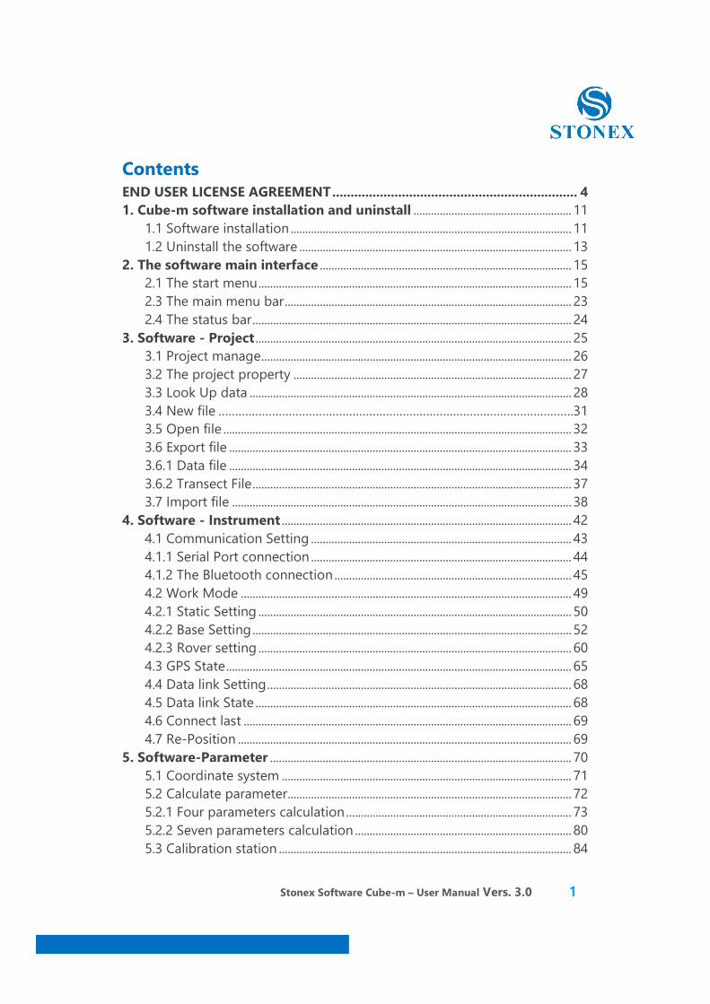
Contents END USER LICENSE AGREEMENT ................................................................... 4 1. Cube-m software installation and uninstall ...................................................... 11
1.1 Software installation ................................................................................................ 11 1.2 Uninstall the software ............................................................................................. 13
2. The software main interface ...................................................................................... 15 2.1 The start menu ........................................................................................................... 15 2.3 The main menu bar .................................................................................................. 23 2.4 The status bar ............................................................................................................. 24
3. Software - Project ............................................................................................................ 25 3.1 Project manage .......................................................................................................... 26 3.2 The project property ............................................................................................... 27 3.3 Look Up data .............................................................................................................. 28 3.4 New file …………………………………………………………………………………………….31 3.5 Open file ....................................................................................................................... 32 3.6 Export file ..................................................................................................................... 33 3.6.1 Data file ..................................................................................................................... 34 3.6.2 Transect File ............................................................................................................. 37 3.7 Import file .................................................................................................................... 38
4. Software - Instrument ................................................................................................... 42 4.1 Communication Setting ......................................................................................... 43 4.1.1 Serial Port connection ......................................................................................... 44 4.1.2 The Bluetooth connection ................................................................................. 45 4.2 Work Mode ................................................................................................................. 49 4.2.1 Static Setting ........................................................................................................... 50 4.2.2 Base Setting ............................................................................................................. 52 4.2.3 Rover setting ........................................................................................................... 60 4.3 GPS State ...................................................................................................................... 65 4.4 Data link Setting ........................................................................................................ 68 4.5 Data link State ............................................................................................................ 68 4.6 Connect last ................................................................................................................ 69 4.7 Re-Position .................................................................................................................. 69
5. Software-Parameter ....................................................................................................... 70 5.1 Coordinate system ................................................................................................... 71 5.2 Calculate parameter................................................................................................. 72 5.2.1 Four parameters calculation ............................................................................. 73 5.2.2 Seven parameters calculation .......................................................................... 80 5.3 Calibration station .................................................................................................... 84
Stonex Software Cube-m – User Manual Vers. 3.0 2
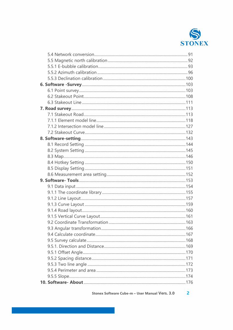
5.4 Network conversion ................................................................................................. 91 5.5 Magnetic north calibration ................................................................................... 92 5.5.1 E-bubble calibration ............................................................................................. 93 5.5.2 Azimuth calibration .............................................................................................. 96 5.5.3 Declination calibration ...................................................................................... 100
6. Software -Survey ............................................................................................................ 103 6.1 Point survey ............................................................................................................... 103 6.2 Stakeout Point .......................................................................................................... 108 6.3 Stakeout Line ............................................................................................................ 111
7. Road survey ....................................................................................................................... 113 7.1 Stakeout Road .......................................................................................................... 113 7.1.1 Element model line ............................................................................................. 118 7.1.2 Intersection model line ..................................................................................... 127 7.2 Stakeout Curve......................................................................................................... 132
8. Software-setting ............................................................................................................. 143 8.1 Record Setting ......................................................................................................... 144 8.2 System Setting ......................................................................................................... 145 8.3 Map…………………………………………………………………………………………………146 8.4 Hotkey Setting ......................................................................................................... 150 8.5 Display Setting ......................................................................................................... 151 8.6 Measurement area setting .................................................................................. 152
9. Software- Tools ............................................................................................................... 153 9.1 Data input .................................................................................................................. 154 9.1.1 The coordinate library ....................................................................................... 155 9.1.2 Line Layout ............................................................................................................. 157 9.1.3 Curve Layout ......................................................................................................... 159 9.1.4 Road layout ............................................................................................................ 160 9.1.5 Vertical Curve Layout ......................................................................................... 161 9.2 Coordinate Transformation ................................................................................ 163 9.3 Angular transformation ........................................................................................ 166 9.4 Calculate coordinate .............................................................................................. 167 9.5 Survey calculate ....................................................................................................... 168 9.5.1. Direction and Distance..................................................................................... 169 9.5.1 Offset Angle ........................................................................................................... 170 9.5.2 Spacing distance .................................................................................................. 171 9.5.3 Two line angle ...................................................................................................... 172 9.5.4 Perimeter and area ............................................................................................. 173 9.5.5 Slope…………………………………………………………………………………………….174
10. Software- About .......................................................................................................... 176
Stonex Software Cube-m – User Manual Vers. 3.0 3
10.1 Registered instrument ........................................................................................ 177 10.2 Battery Level ........................................................................................................... 178 10.3 About instrument ................................................................................................. 179 10.4 About software ...................................................................................................... 180
11. The simple operating procedures of RTK Field Surveying ................... 181 11.1 Set up the base station ...................................................................................... 182 11.2 Connect the handset and the mainframe .................................................. 184 11.3 Set up base station .............................................................................................. 190 11.4 Connecting the mobile station ....................................................................... 194 11.5 Calculating Transformation Parameter ....................................................... 195
Stonex Software Cube-m – User Manual Vers. 3.0 4
Stonex Cube-m Copyright (c) 2014-2017 Stonex Srl
END USER LICENSE AGREEMENT
IMPORTANT: PLEASE READ THIS LICENSE CAREFULLY BEFORE USING THIS SOFTWARE.
1. LICENSE
By receiving, opening the file package containing Stonex Cube-m ("Software"), and/or using this Software, you agree that this End User License Agreement (EULA) is a legally binding and valid contract and agree to be bound by it. You agree to abide by the intellectual property laws and all of the terms and conditions of this Agreement.
Stonex Srl reserves the right to amend this EULA at any time: your continued use of the Software after notification of such amendment will constitute acceptance of such amendments.
Unless you have a different license agreement signed by Stonex Srl your use of Stonex Cube-m indicates your unconditional acceptance of the terms and conditions of this agreement and warranty.
Subject to the terms of this Agreement, Stonex Srl grants to you a limited, non-exclusive, non-transferable license, without right to sub-license, to use Stonex Cube-m in accordance with this Agreement and any other written agreement with Stonex Srl. Stonex Srl does not transfer the title of Stonex Cube-m to you; the license granted to you is not a sale. This agreement is a binding legal agreement between Stonex Srl and the purchasers or users of Stonex Cube-m.
Stonex Software Cube-m – User Manual Vers. 3.0 5
If you do not agree to be bound by this agreement, remove Stonex Cube-m from your computer now and, if applicable, promptly return to Stonex Srl by mail any copies of Stonex Cube-m and related documentation and packaging in your possession.
2. DISTRIBUTION
Stonex Cube-m and the license herein granted shall not be copied, shared, distributed, re-sold, offered for re-sale, transferred or sub-licensed in whole or in part except that you may make one copy for archive purposes only. For information about redistribution of Stonex Cube-m contact Stonex Srl.
3. USER AGREEMENT
3.1 Use
Your license to use Stonex Cube-m is limited to the number of licenses purchased by you. You shall not allow others to use, copy or evaluate copies of Stonex Cube-m.
3.2 Use Restrictions
You shall use Stonex Cube-m in compliance with all applicable laws and not for any unlawful purpose. Without limiting the foregoing, use, display or distribution of Stonex Cube-m together with material that is racist, vulgar, defamatory, libelous, abusive, promoting hatred, discriminating or displaying prejudice based on religion, ethnic heritage, race, sexual orientation or age is strictly prohibited.
Each licensed copy of Stonex Cube-m may be used on one single computer
Stonex Software Cube-m – User Manual Vers. 3.0 6
location by one user. Use of Stonex Cube-m means that you have loaded, installed, or run Stonex Cube-m on a computer or similar device. If you install Stonex Cube-m onto a multi-user platform, server or network, each and every individual user of Stonex Cube-m must be licensed separately. You may make one copy of Stonex Cube-m for backup purposes, providing you only have one copy installed on one computer being used by one person. Other users may not use your copy of Stonex Cube-m . The assignment, sub-license, networking, sale, or distribution of copies of Stonex Cube-m are strictly forbidden without the prior written consent of Stonex Srl. It is a violation of this agreement to assign, sell, share, loan, rent, lease, borrow, network or transfer the use of Stonex Cube-m. If any person other than yourself uses Stonex Cube-m registered in your name, regardless of whether it is at the same time or different times, then this agreement is being violated and you are responsible for that violation!
3.3 Copyright Restriction This Software contains copyrighted material, trade secrets and other proprietary material. You shall not, and shall not attempt to, modify, reverse engineer, disassemble or decompile Stonex Cube-m. Nor can you create any derivative works or other works that are based upon or derived from Stonex Cube-m in whole or in part. Stonex Srl's name, logo and graphics file that represents Stonex Cube-m shall not be used in any way to promote products developed with Stonex Cube-m . Stonex Srl retains sole and exclusive ownership of all right, title and interest in and to Stonex Cube-m and all Intellectual Property rights relating thereto. Copyright law and international copyright treaty provisions protect all parts of Stonex Cube-m , products and services. No program, code, part, image, audio sample, or text may be copied or used in any way by the user except as intended within the bounds of the single user program. All rights not expressly granted here-under are reserved for Stonex Srl.
Stonex Software Cube-m – User Manual Vers. 3.0 7
3.4 Limitation of Responsibility
You will indemnify, hold harmless, and defend Stonex Srl , its employees, agents and distributors against any and all claims, proceedings, demand and costs resulting from or in any way connected with your use of Stonex Srl's Software. In no event (including, without limitation, in the event of negligence) will Stonex Srl , its employees, agents or distributors be liable for any consequential, incidental, indirect, special or punitive damages whatsoever (including, without limitation, damages for loss of profits, loss of use, business interruption, loss of information or data, or pecuniary loss), in connection with or arising out of or related to this Agreement, Stonex Cube-m or the use or inability to use Stonex Cube-m or the furnishing, performance or use of any other matters here-under whether based upon contract, tort or any other theory including negligence. Stonex Srl's entire liability, without exception, is limited to the customers' reimbursement of the purchase price of the Software (maximum being the lesser of the amount paid by you and the suggested retail price as listed by Stonex Srl) in exchange for the return of the product, all copies, registration papers and manuals, and all materials that constitute a transfer of license from the customer back to Stonex Srl.
3.5 Warranties
Except as expressly stated in writing, Stonex Srl makes no representation or warranties in respect of this Software and expressly excludes all other warranties, expressed or implied, oral or written, including, without limitation, any implied warranties of merchantable quality or fitness for a particular purpose.

Stonex Software Cube-m – User Manual Vers. 3.0 8
3.6 Governing Law
This Agreement shall be governed by the law of Italy applicable therein. You hereby irrevocably attorn and submit to the non-exclusive jurisdiction of the courts of Italy therefrom. If any provision shall be considered unlawful, void or otherwise unenforceable, then that provision shall be deemed severable from this License and not affect the validity and enforceability of any other provisions.
3.7 Termination
Any failure to comply with the terms and conditions of this Agreement will result in automatic and immediate termination of this license. Upon termination of this license granted herein for any reason, you agree to immediately cease use of Stonex Cube-m and destroy all copies of Stonex Cube-m supplied under this Agreement. The financial obligations incurred by you shall survive the expiration or termination of this license.
4. DISCLAIMER OF WARRANTY
THIS SOFTWARE AND THE ACCOMPANYING FILES ARE SOLD "AS IS" AND WITHOUT WARRANTIES AS TO PERFORMANCE OR MERCHANTABILITY OR ANY OTHER WARRANTIES WHETHER EXPRESSED OR IMPLIED. THIS DISCLAIMER CONCERNS ALL FILES GENERATED AND EDITED BY Stonex Cube-m AS WELL.
5. CONSENT OF USE OF DATA You agree that Stonex Srl may collect and use information gathered in any manner as part of the product registration, activation or support services provided to you, if any, related to Stonex Cube-m.

Stonex Software Cube-m – User Manual Vers. 3.0 9
Pursuant to art. 13 of Italian Legislative Decree No. 196 dated 30.6.2003, the sole company Stonex Srl, in its capacity as personal data holder, in the person of its legal representative, hereby informs you that: - The providing of some personal data may be mandatory in order to process your requests. If so, mandatory fields will be marked with an asterisk (*) or any equivalent. - The personal data you will provide may be processed directly or through third parties, to fulfil the contractual obligations and requirements under the laws, regulations, and EU standards. - Stonex Srl may also use this information to provide notices to you which may be of use or interest to you. - Personal data collected can, as expressly agreed upon, be shared with legal entities of Stonex Srl, as well as to its partners and dealers to the extent necessary for the fulfillment of the agreement or for direct marketing purposes. - Stonex Srl takes all physical, technical and organisational measures needed to ensure the security and confidentiality of personal data, particularly in view of protecting it against non authorised access.
STONEX® srl Part of UniStrong
Via Cimabue 39 - 20851 Lissone (MB) - Italy
Phone +39 039 278 300 8 - +39 039 278 557 5
Fax +39 039 278 957 6
For info and support (Cube-suite applications only)
Stonex Software Cube-m – User Manual Vers. 3.0 10
Preface Cube-m is a GNSS surveying and mapping software which is developed by Stonex company. Based on years of accumulating market experience, in combination with the international mainstream of surveying and mapping data acquisition function of the software, integrating RTK control, GIS data collection and road design and layout into one role. The main feature of the software is very outstanding graphic interaction, very powerful function and humanizes operation process. This manual mainly introduces all the menu functions and the field operation procedure of the Cube-m software.
Stonex Software Cube-m – User Manual Vers. 3.0 11
1. Cube-m software installation and uninstall
1.1 Software installation
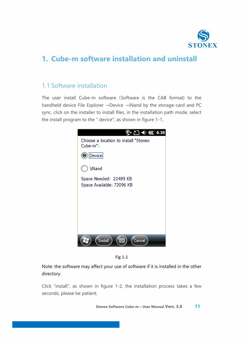
The user install Cube-m software(Software is the CAB format) to the handheld device File Explorer →Device →iNand by the storage-card and PC sync, click on the installer to install files, in the installation path mode, select the install program to the " device", as shown in figure 1-1.
Fig 1-1 Note: the software may affect your use of software if it is installed in the other directory.
Click "install", as shown in figure 1-2, the installation process takes a few seconds, please be patient.

Stonex Software Cube-m – User Manual Vers. 3.0 12
Fig 1-2
Stonex Software Cube-m – User Manual Vers. 3.0 13
1.2 Uninstall the software
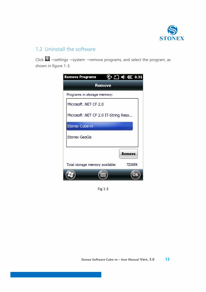
Click →settings →system →remove programs, and select the program, as shown in figure 1-3.
Fig 1-3
Stonex Software Cube-m – User Manual Vers. 3.0 14
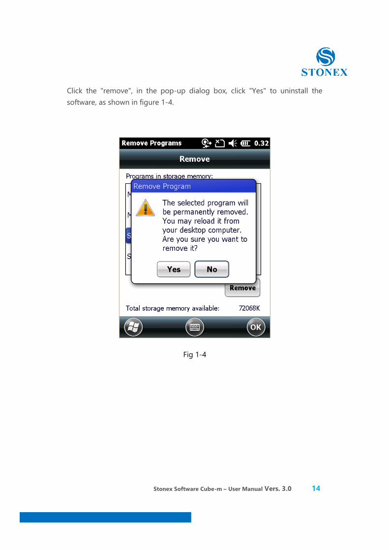
Click the "remove", in the pop-up dialog box, click "Yes" to uninstall the software, as shown in figure 1-4.
Fig 1-4
Stonex Software Cube-m – User Manual Vers. 3.0 15
2. The software main interface
2.1 The start menu
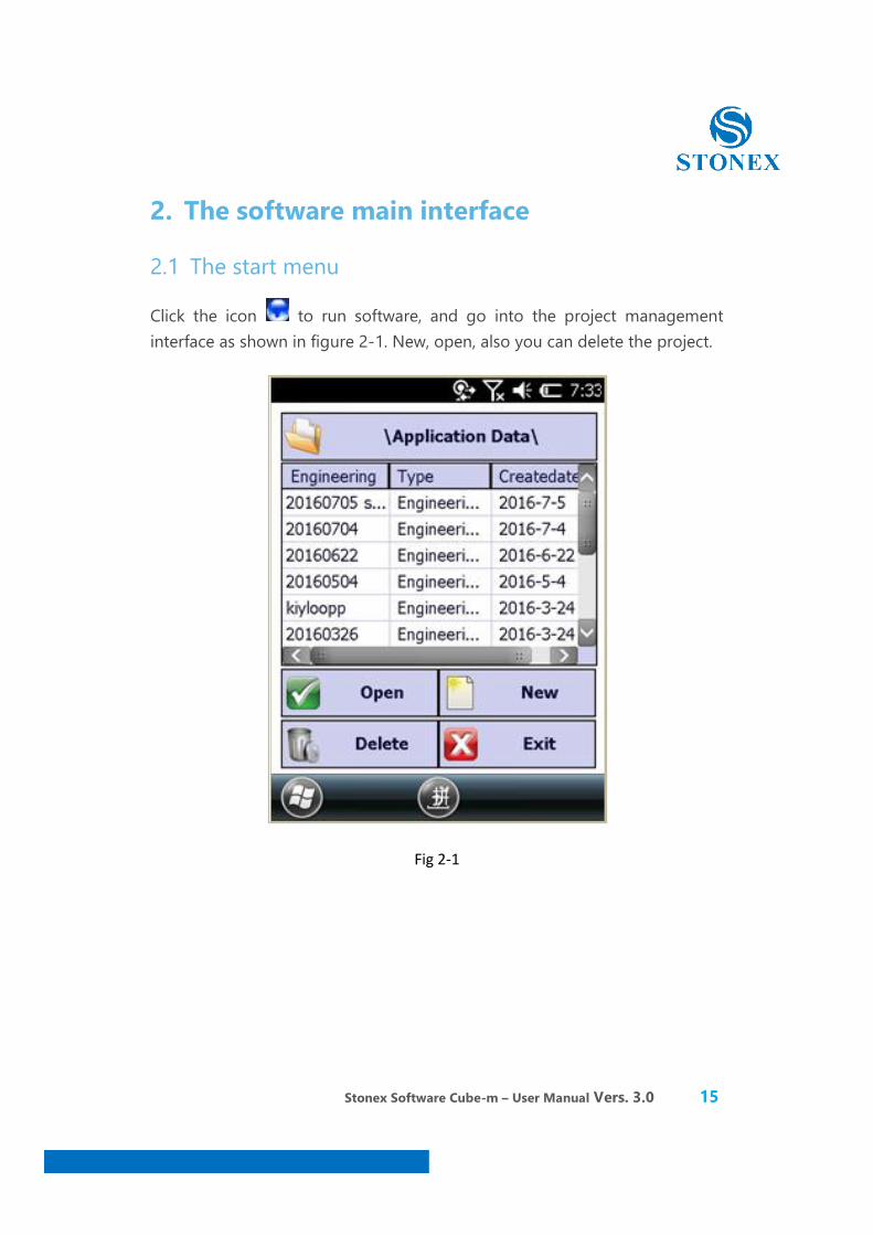
Click the icon to run software, and go into the project management interface as shown in figure 2-1. New, open, also you can delete the project.
Fig 2-1
Stonex Software Cube-m – User Manual Vers. 3.0 16
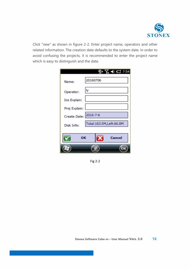
Click "new" as shown in figure 2-2. Enter project name, operators and other related information. The creation date defaults to the system date. In order to avoid confusing the projects, it is recommended to enter the project name which is easy to distinguish and the date.
Fig 2-2

Stonex Software Cube-m – User Manual Vers. 3.0 17
After filling out project information,click "ok" to enter the communication settings interface in figure 2-3.
Fig 2-3
Stonex Software Cube-m – User Manual Vers. 3.0 18
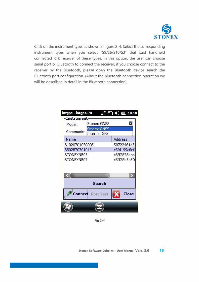
Click on the instrument type, as shown in figure 2-4. Select the corresponding instrument type, when you select “S9/S6/S10/S3” that said handheld connected RTK receiver of these types, in this option, the user can choose serial port or Bluetooth to connect the receiver, if you choose connect to the receiver by the Bluetooth, please open the Bluetooth device search the Bluetooth port configuration. (About the Bluetooth connection operation we will be described in detail in the Bluetooth connection).
Fig 2-4
Stonex Software Cube-m – User Manual Vers. 3.0 19
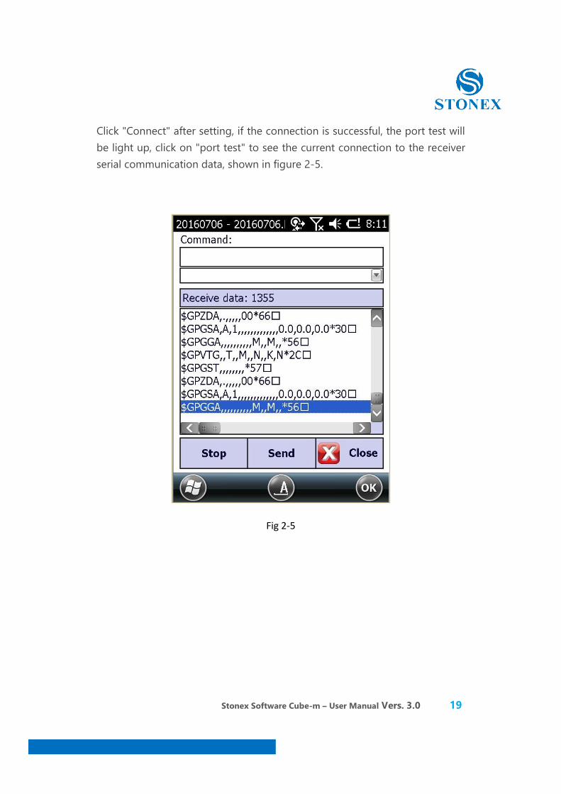
Click "Connect" after setting, if the connection is successful, the port test will be light up, click on "port test" to see the current connection to the receiver serial communication data, shown in figure 2-5.
Fig 2-5

Stonex Software Cube-m – User Manual Vers. 3.0 20
Click the "close" to return to the instrument connection interface, in the interface, click [export] to enter into the parameter settings interface, as shown in figure 2-6.
Fig 2-6

Stonex Software Cube-m – User Manual Vers. 3.0 21
You can set the related parameters. If you click “import”, there will be a page as the figure 2-7 below.
Fig 2-7
The coordinate system of the before projects and storaged in other places both could be applied to the new project. But the files format must be(*.SP,*.EP).
If you click “Encryption”, there will be a page as the figure 2-8 below.

Stonex Software Cube-m – User Manual Vers. 3.0 22
Fig 2-8
Cube-m software can be divided into three functional blocks.
When you choose a different function module in the menu bar, the five parts (project, instrument, parameter and setting, tool) are basic consistent, we will be unified introduction later. Measurement part due to the different functional modules of your choice, the measurement of content will be different.
Engineering measurement functions include: point measurement, point stakeout and line stakeout. Road measurement functions include: road stakeout, curve stakeout.

Stonex Software Cube-m – User Manual Vers. 3.0 23
About two functional modules corresponding to different measurement functions, we will be in detailed description of the following measuring chapters.
Note: a project can only correspond to one function module, according to the measure information, you can choose respectively engineering surveying, road surveying. Click the "close" into the main interface.
2.3 The main menu bar
Figure 2-9 shows the main interface.
Fig 2-9 Main interface show us the menu bar, status, about and exit.
Stonex Software Cube-m – User Manual Vers. 3.0 24
The main menu bar has all menu instructions, the content is divided into nine parts: project, instrument, parameter, survey, road, electric, rail way, configure, tool (The electricity and railway functions only be applied to the specified customers).
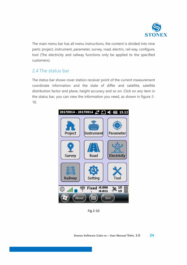
2.4 The status bar
The status bar shows rover station receiver point of the current measurement coordinate information and the state of differ and satellite, satellite distribution factor and plane, height accuracy and so on. Click on any item in the status bar, you can view the information you need, as shown in figure 2-10.
Fig 2-10
Stonex Software Cube-m – User Manual Vers. 3.0 25
3. Software - Project
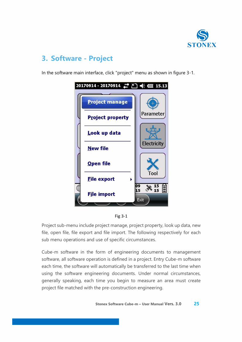
In the software main interface, click "project" menu as shown in figure 3-1.
Fig 3-1
Project sub-menu include project manage, project property, look up data, new file, open file, file export and file import. The following respectively for each sub menu operations and use of specific circumstances.
Cube-m software in the form of engineering documents to management software, all software operation is defined in a project. Entry Cube-m software each time, the software will automatically be transferred to the last time when using the software engineering documents. Under normal circumstances, generally speaking, each time you begin to measure an area must create project file matched with the pre-construction engineering.
Stonex Software Cube-m – User Manual Vers. 3.0 26
3.1 Project manage
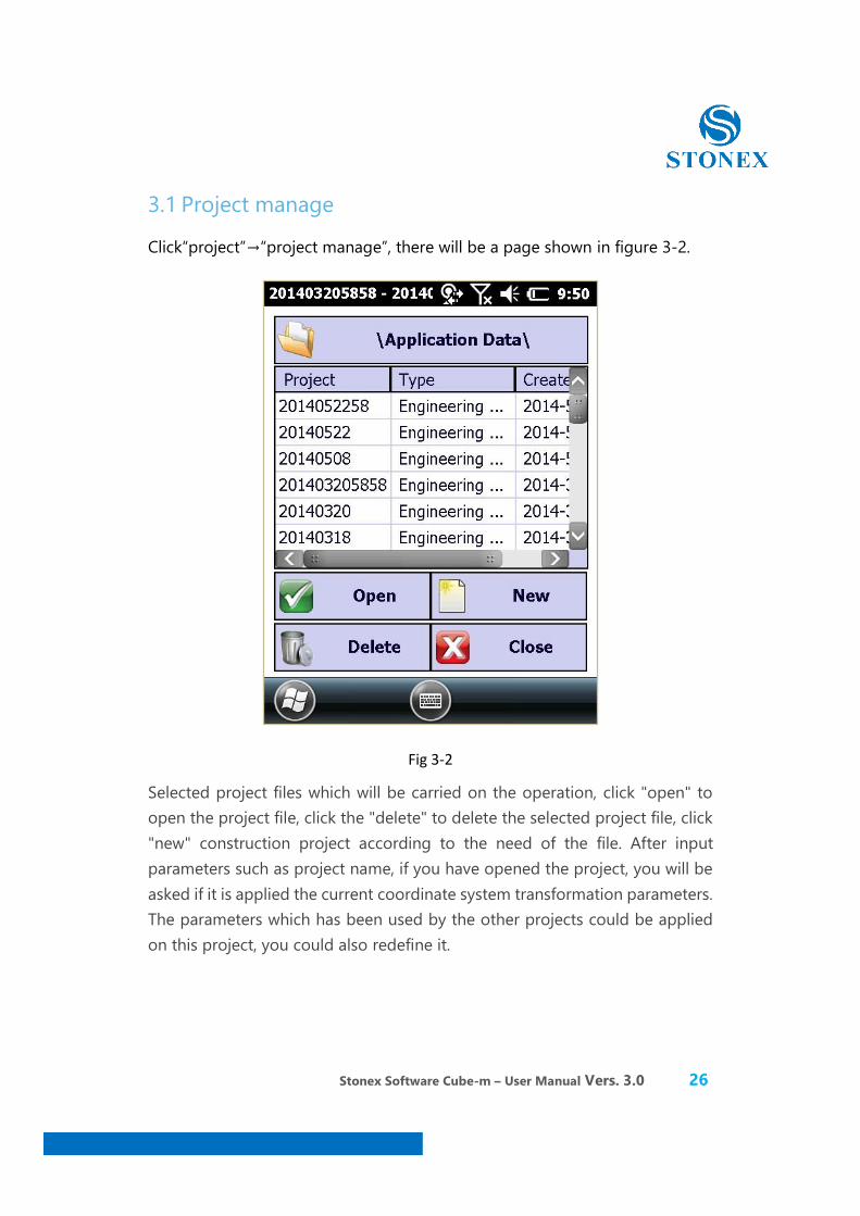
Click“project”→“project manage”, there will be a page shown in figure 3-2.
Fig 3-2
Selected project files which will be carried on the operation, click "open" to open the project file, click the "delete" to delete the selected project file, click "new" construction project according to the need of the file. After input parameters such as project name, if you have opened the project, you will be asked if it is applied the current coordinate system transformation parameters. The parameters which has been used by the other projects could be applied on this project, you could also redefine it.
Stonex Software Cube-m – User Manual Vers. 3.0 27
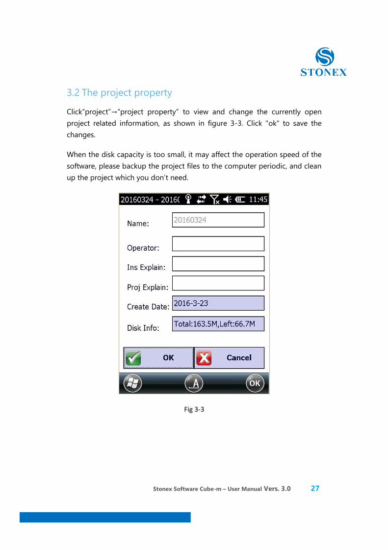
3.2 The project property
Click“project”→“project property” to view and change the currently open project related information, as shown in figure 3-3. Click "ok" to save the changes.
When the disk capacity is too small, it may affect the operation speed of the software, please backup the project files to the computer periodic, and clean up the project which you don’t need.
Fig 3-3

Stonex Software Cube-m – User Manual Vers. 3.0 28
3.3 Look Up data
Click on the [project] → [Look up data] to view coordinate data in the library, shown in figure 3-4.
Fig 3-4
Stonex Software Cube-m – User Manual Vers. 3.0 29
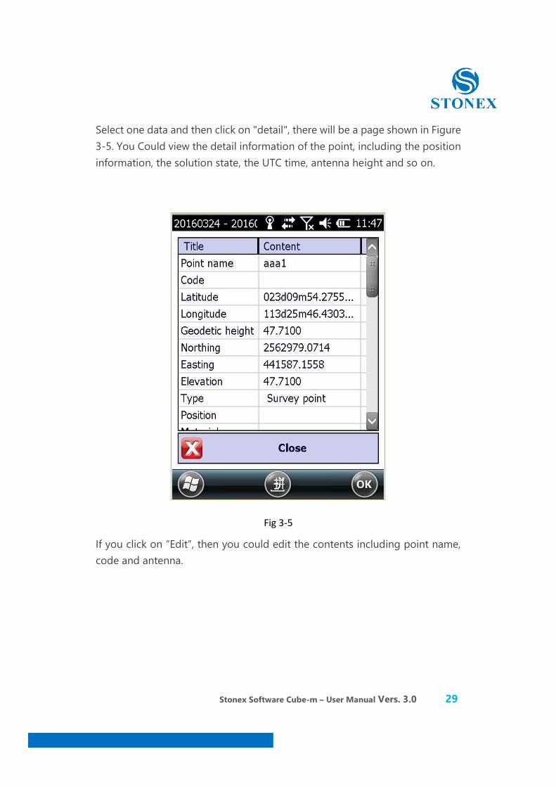
Select one data and then click on "detail", there will be a page shown in Figure 3-5. You Could view the detail information of the point, including the position information, the solution state, the UTC time, antenna height and so on.
Fig 3-5
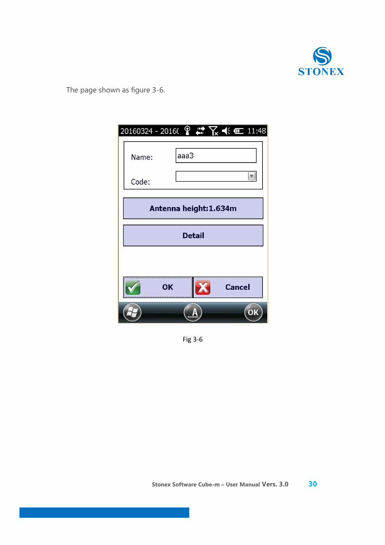
If you click on “Edit”, then you could edit the contents including point name, code and antenna.
Stonex Software Cube-m – User Manual Vers. 3.0 30
The page shown as figure 3-6.
Fig 3-6
Stonex Software Cube-m – User Manual Vers. 3.0 31
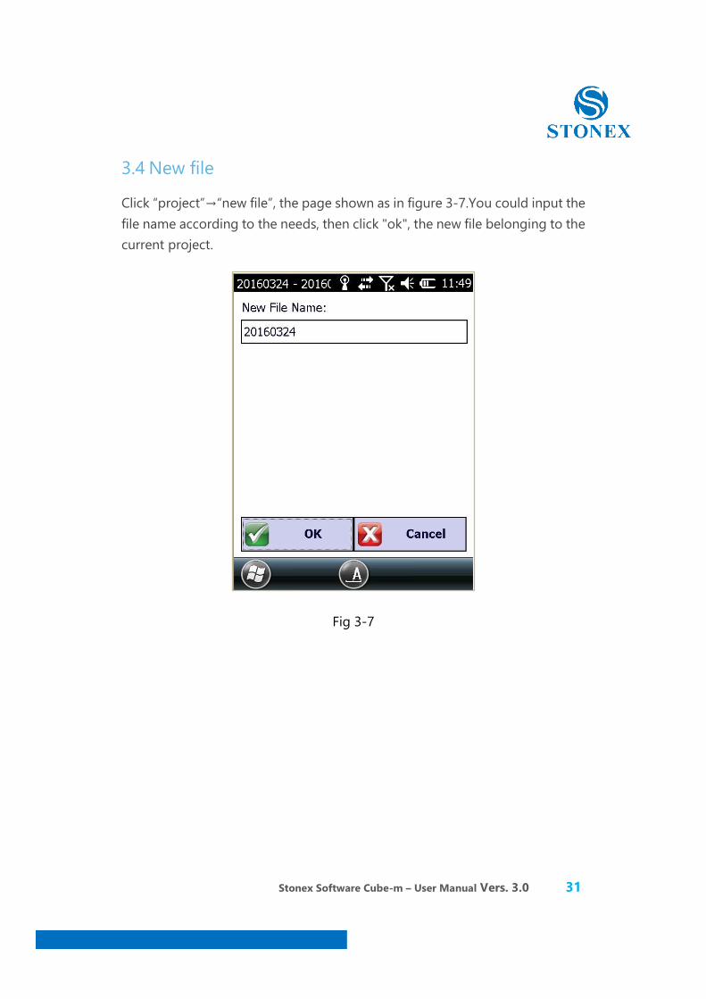
3.4 New file
Click “project”→“new file”, the page shown as in figure 3-7.You could input the file name according to the needs, then click "ok", the new file belonging to the current project.
Fig 3-7
Stonex Software Cube-m – User Manual Vers. 3.0 32
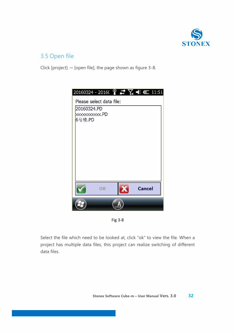
3.5 Open file
Click [project] → [open file], the page shown as figure 3-8.
Fig 3-8
Select the file which need to be looked at, click "ok" to view the file. When a project has multiple data files, this project can realize switching of different data files.
Stonex Software Cube-m – User Manual Vers. 3.0 33
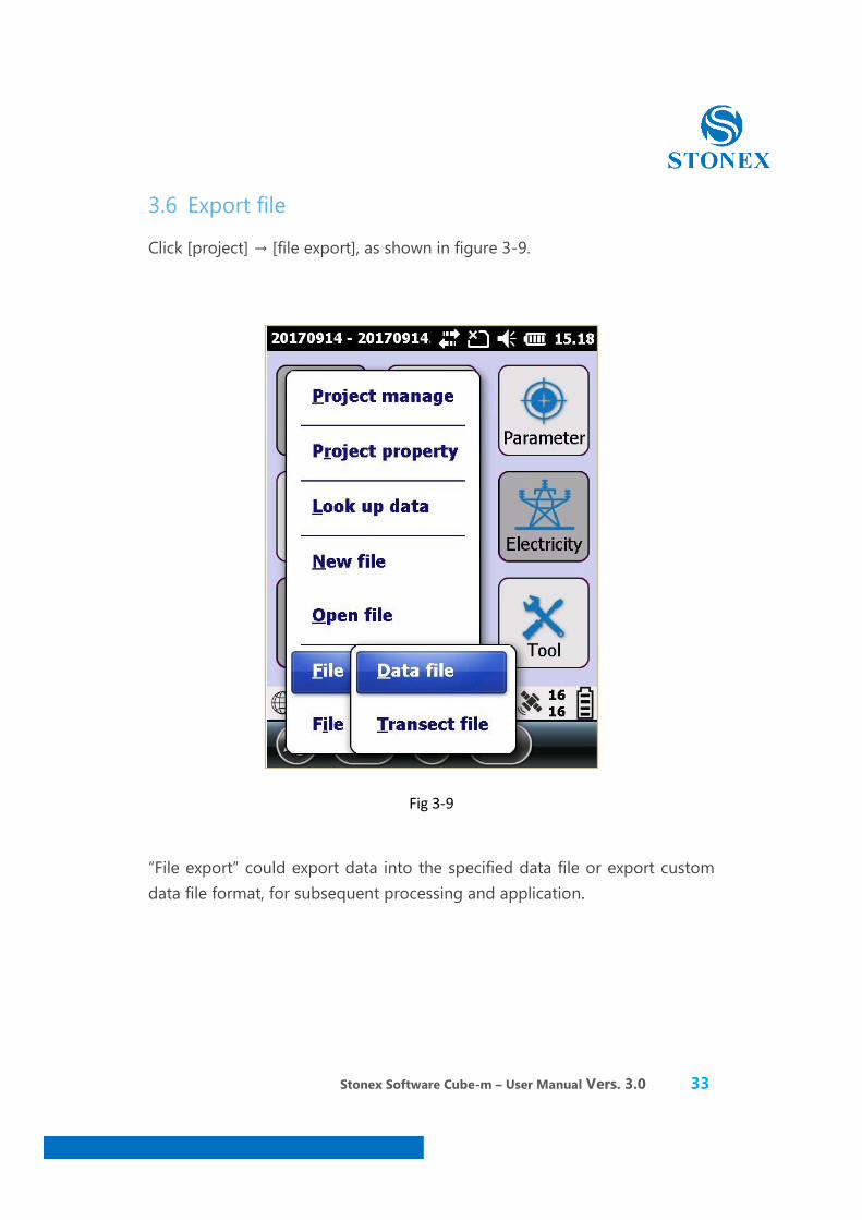
3.6 Export file
Click [project] → [file export], as shown in figure 3-9.
Fig 3-9
“File export” could export data into the specified data file or export custom data file format, for subsequent processing and application.
Stonex Software Cube-m – User Manual Vers. 3.0 34
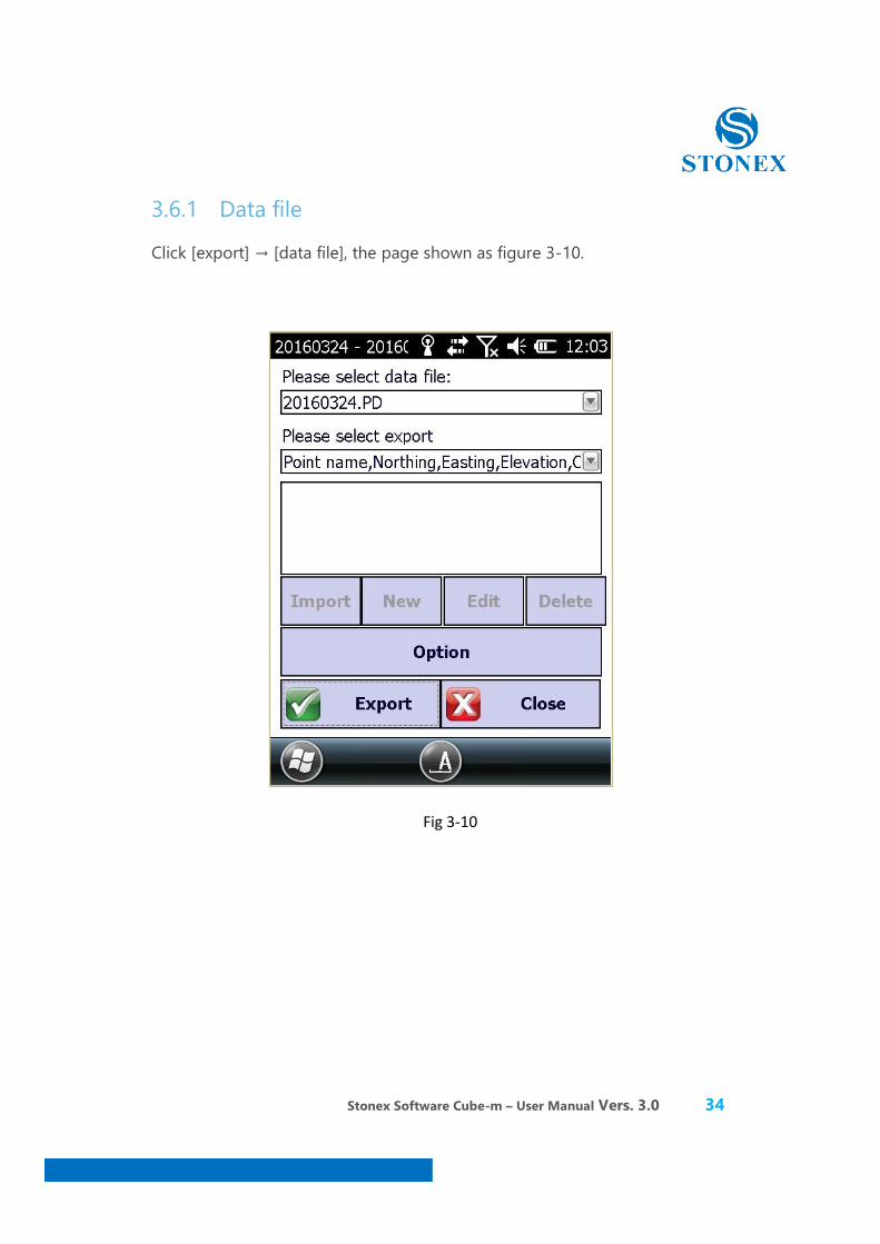
3.6.1 Data file
Click [export] → [data file], the page shown as figure 3-10.
Fig 3-10
Stonex Software Cube-m – User Manual Vers. 3.0 35
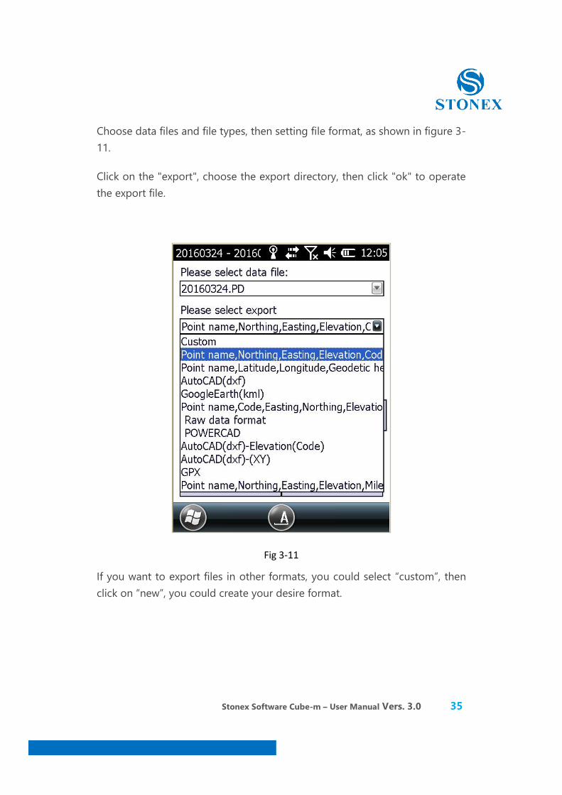
Choose data files and file types, then setting file format, as shown in figure 3-11.
Click on the "export", choose the export directory, then click "ok" to operate the export file.
Fig 3-11
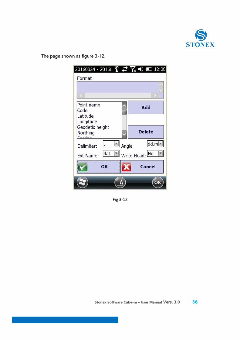
If you want to export files in other formats, you could select “custom”, then click on “new”, you could create your desire format.
Stonex Software Cube-m – User Manual Vers. 3.0 36
The page shown as figure 3-12.
Fig 3-12
Stonex Software Cube-m – User Manual Vers. 3.0 37
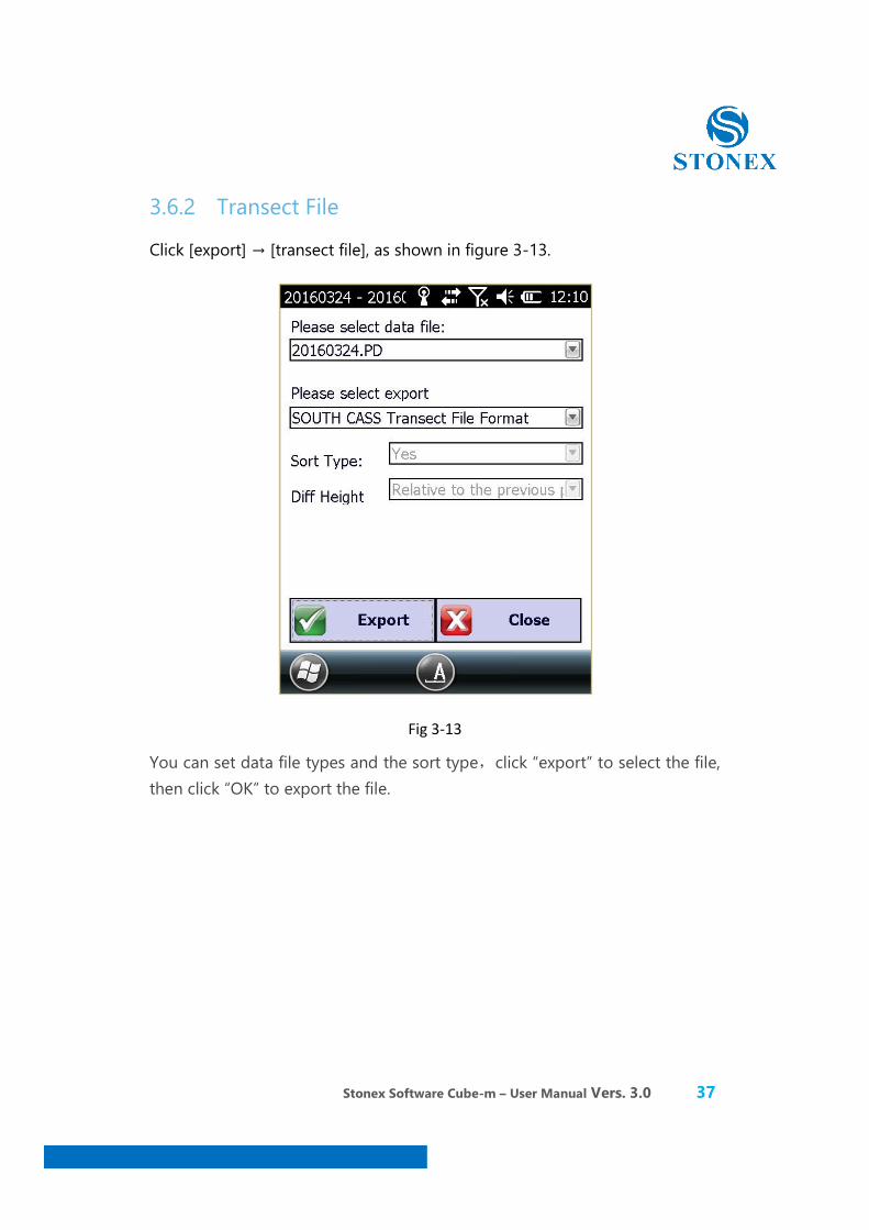
3.6.2 Transect File
Click [export] → [transect file], as shown in figure 3-13.
Fig 3-13
You can set data file types and the sort type,click “export” to select the file, then click “OK” to export the file.

Stonex Software Cube-m – User Manual Vers. 3.0 38
3.7 Import file
Click [project] → [Import File], as shown in figure 3-14.
Fig 3-14
Stonex Software Cube-m – User Manual Vers. 3.0 39
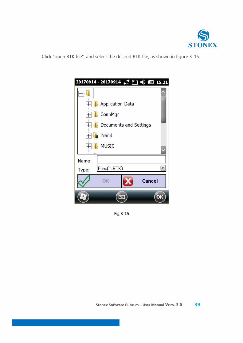
Click "open RTK file", and select the desired RTK file, as shown in figure 3-15.
Fig 3-15
Stonex Software Cube-m – User Manual Vers. 3.0 40
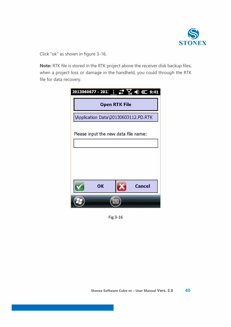
Click "ok" as shown in figure 3-16.
Note: RTK file is stored in the RTK project above the receiver disk backup files, when a project loss or damage in the handheld, you could through the RTK file for data recovery.
Fig 3-16
Stonex Software Cube-m – User Manual Vers. 3.0 41
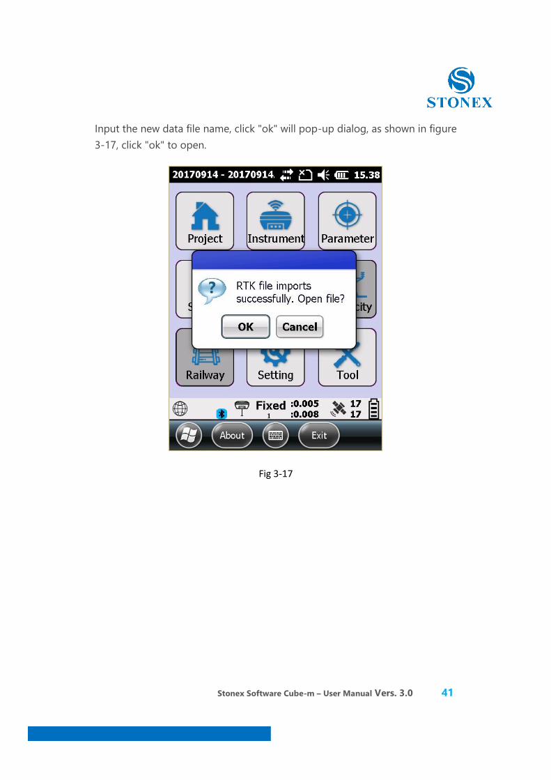
Input the new data file name, click "ok" will pop-up dialog, as shown in figure 3-17, click "ok" to open.
Fig 3-17
Stonex Software Cube-m – User Manual Vers. 3.0 42
4. Software - Instrument
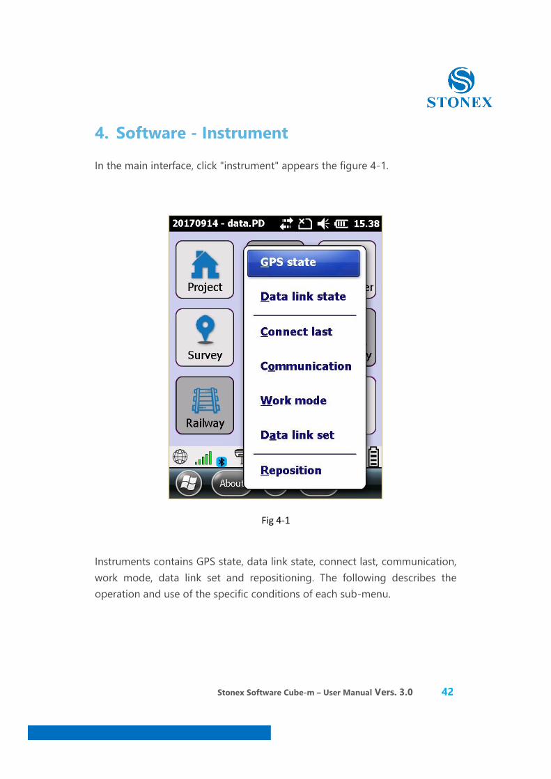
In the main interface, click "instrument" appears the figure 4-1.
Fig 4-1
Instruments contains GPS state, data link state, connect last, communication, work mode, data link set and repositioning. The following describes the operation and use of the specific conditions of each sub-menu.

Stonex Software Cube-m – User Manual Vers. 3.0 43
4.1 Communication Setting
Click [instrument] [communication settings], as shown in figure 4-2.
Fig 4-2
Stonex Software Cube-m – User Manual Vers. 3.0 44
4.1.1 Serial Port connection
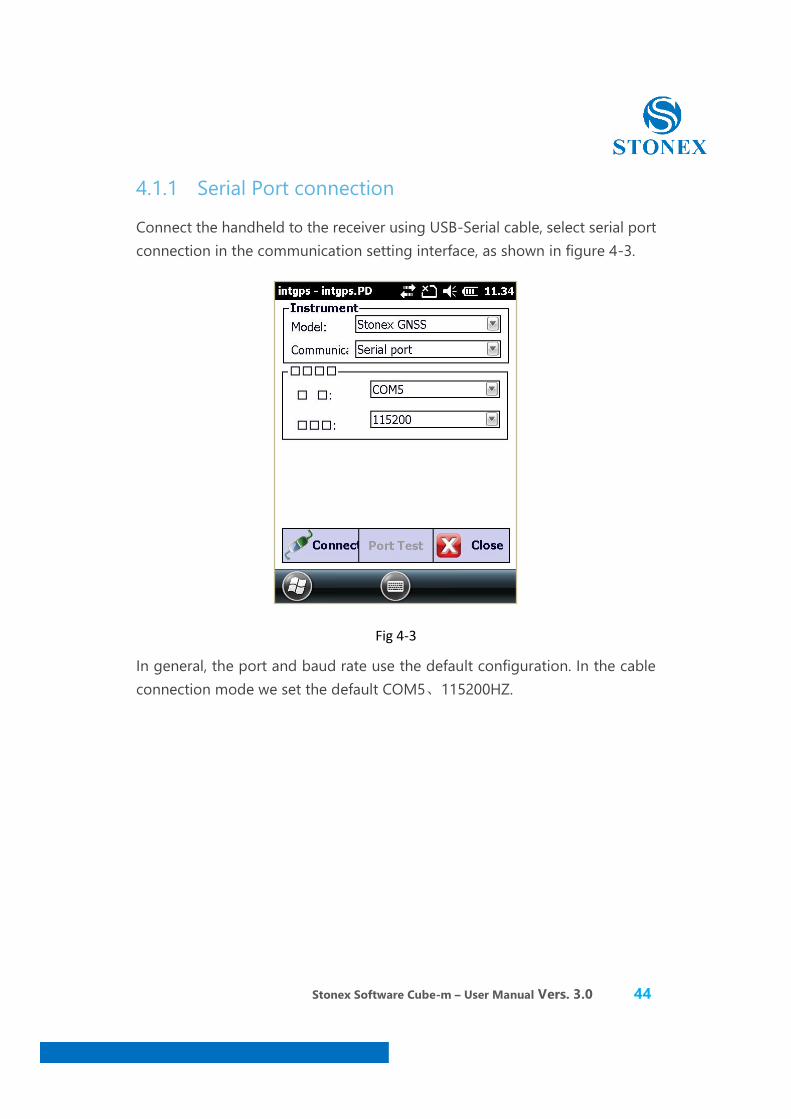
Connect the handheld to the receiver using USB-Serial cable, select serial port connection in the communication setting interface, as shown in figure 4-3.
Fig 4-3
In general, the port and baud rate use the default configuration. In the cable connection mode we set the default COM5、115200HZ.
Stonex Software Cube-m – User Manual Vers. 3.0 45
4.1.2 The Bluetooth connection
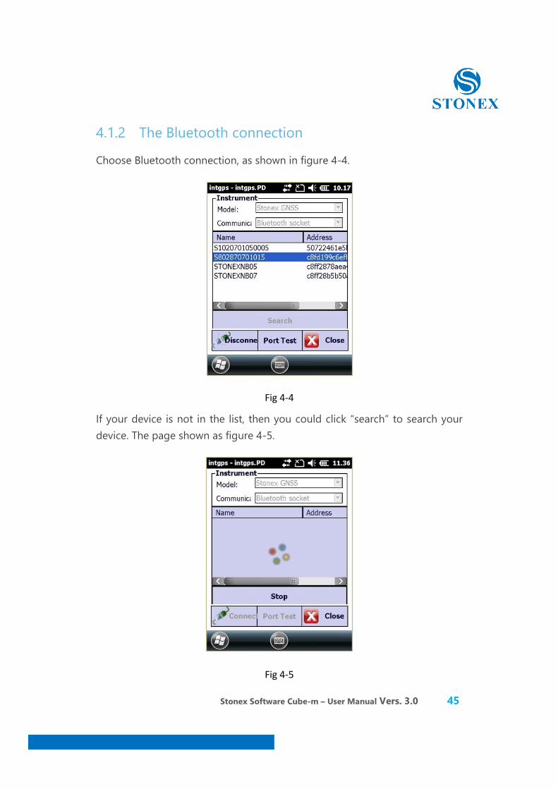
Choose Bluetooth connection, as shown in figure 4-4.
Fig 4-4
If your device is not in the list, then you could click “search” to search your device. The page shown as figure 4-5.
Fig 4-5
Stonex Software Cube-m – User Manual Vers. 3.0 46
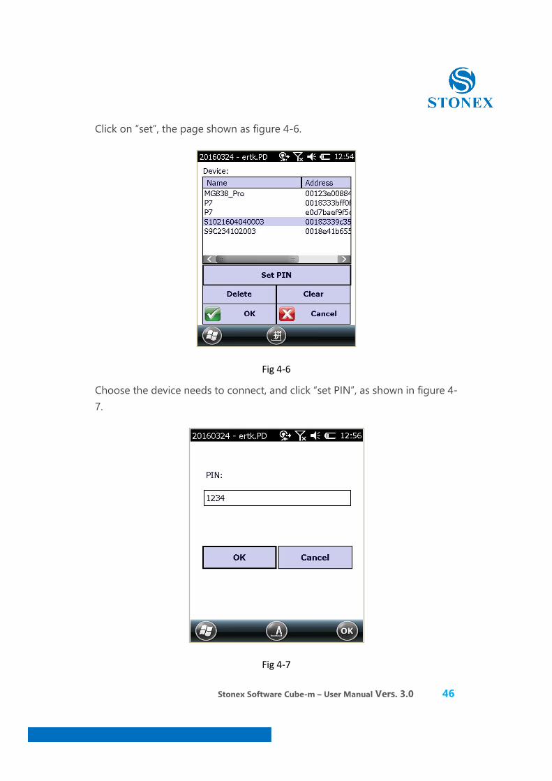
Click on “set”, the page shown as figure 4-6.
Fig 4-6
Choose the device needs to connect, and click “set PIN”, as shown in figure 4-7.
Fig 4-7
Stonex Software Cube-m – User Manual Vers. 3.0 47
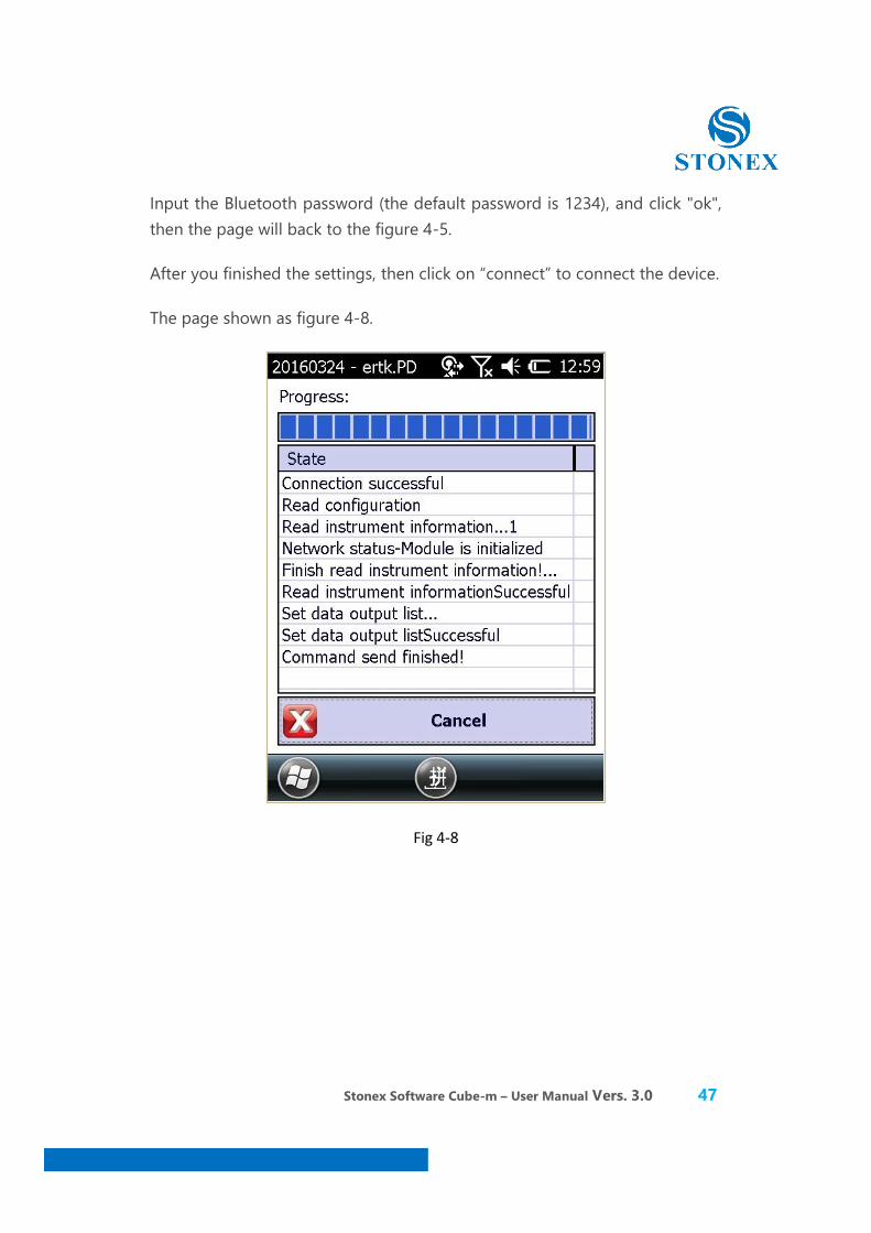
Input the Bluetooth password (the default password is 1234), and click "ok", then the page will back to the figure 4-5.
After you finished the settings, then click on “connect” to connect the device.
The page shown as figure 4-8.
Fig 4-8
Stonex Software Cube-m – User Manual Vers. 3.0 48
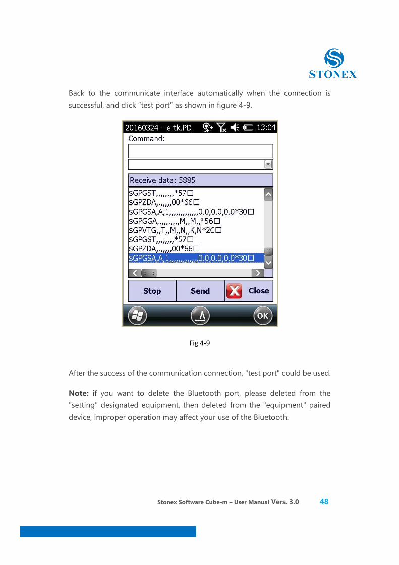
Back to the communicate interface automatically when the connection is successful, and click “test port” as shown in figure 4-9.
Fig 4-9
After the success of the communication connection, "test port" could be used.
Note: if you want to delete the Bluetooth port, please deleted from the "setting" designated equipment, then deleted from the "equipment" paired device, improper operation may affect your use of the Bluetooth.
Stonex Software Cube-m – User Manual Vers. 3.0 49
4.2 Work Mode
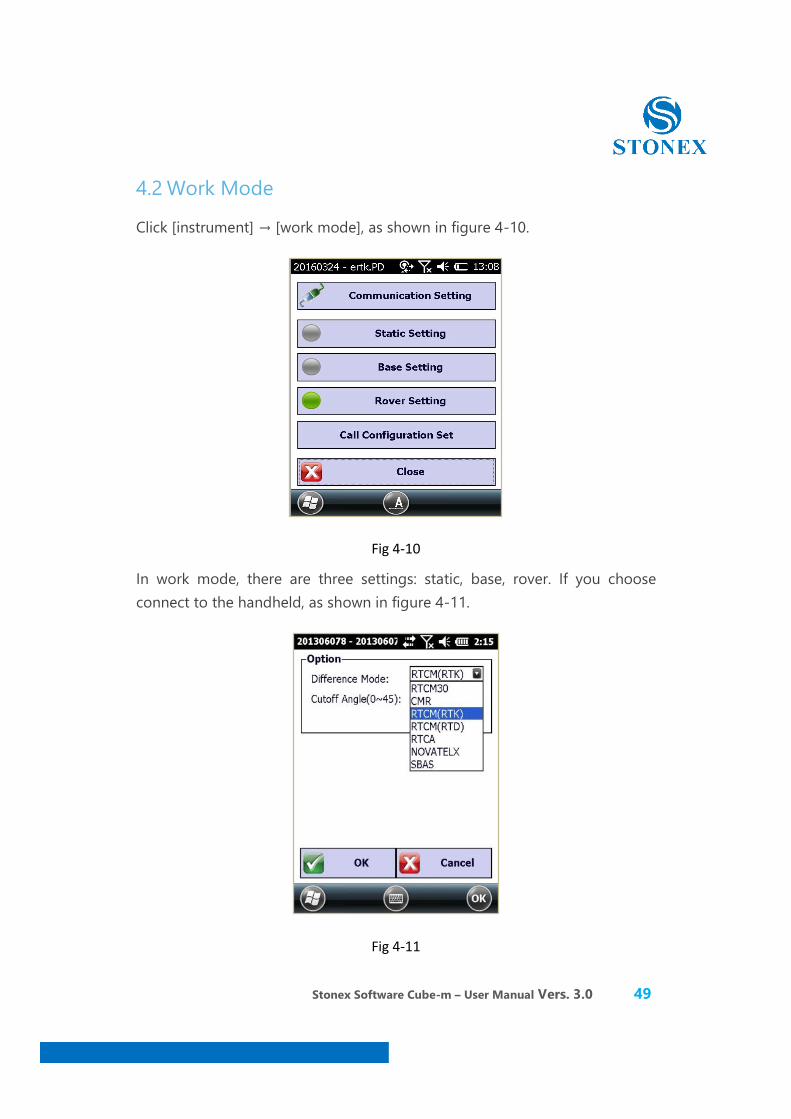
Click [instrument] → [work mode], as shown in figure 4-10.
Fig 4-10
In work mode, there are three settings: static, base, rover. If you choose connect to the handheld, as shown in figure 4-11.
Fig 4-11
Stonex Software Cube-m – User Manual Vers. 3.0 50
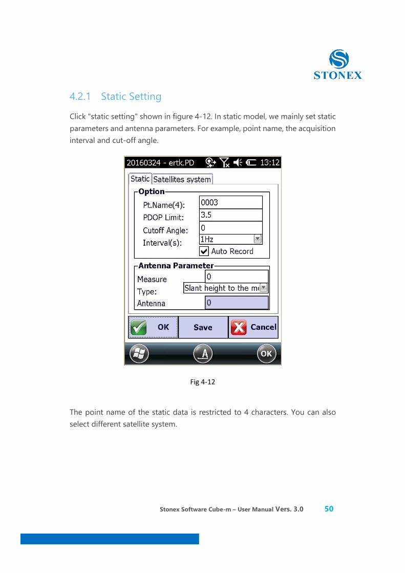
4.2.1 Static Setting
Click "static setting" shown in figure 4-12. In static model, we mainly set static parameters and antenna parameters. For example, point name, the acquisition interval and cut-off angle.
Fig 4-12
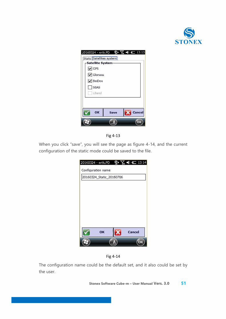
The point name of the static data is restricted to 4 characters. You can also select different satellite system.
Stonex Software Cube-m – User Manual Vers. 3.0 51
Fig 4-13
When you click “save”, you will see the page as figure 4-14, and the current configuration of the static mode could be saved to the file.
Fig 4-14
The configuration name could be the default set, and it also could be set by the user.
Stonex Software Cube-m – User Manual Vers. 3.0 52
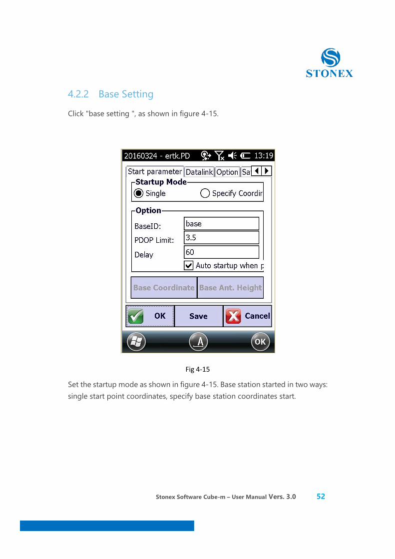
4.2.2 Base Setting
Click "base setting ", as shown in figure 4-15.
Fig 4-15
Set the startup mode as shown in figure 4-15. Base station started in two ways: single start point coordinates, specify base station coordinates start.
Stonex Software Cube-m – User Manual Vers. 3.0 53
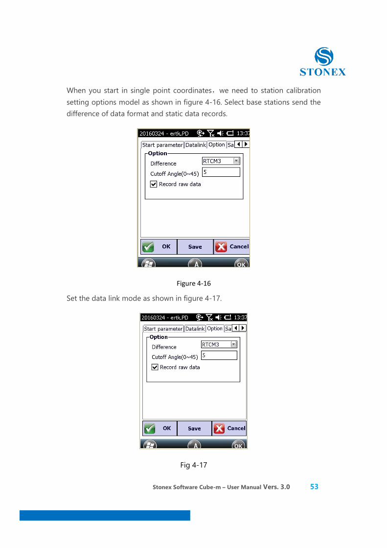
When you start in single point coordinates,we need to station calibration setting options model as shown in figure 4-16. Select base stations send the difference of data format and static data records.
Figure 4-16
Set the data link mode as shown in figure 4-17.
Fig 4-17
Stonex Software Cube-m – User Manual Vers. 3.0 54
We have five kinds of patterns in the data link can choose: network, internal radio, external radio, double link, according to the chain. Radio is set to the rover station radio, the rover station via the radio module to receive the radio signal sent from the base station, the base station is no such set.
Module, the operating mode of the network, the rover station is to the Internet through the network module network accepted the differential signal, the base station, then the base station through the network module Internet to transmit differential signal, the base station transferred to this mode, some machine is a twin-mode network and external radio twin.
External receiver external components, base station is the main application of external radio, and rover station external rover phones or other instrument model.
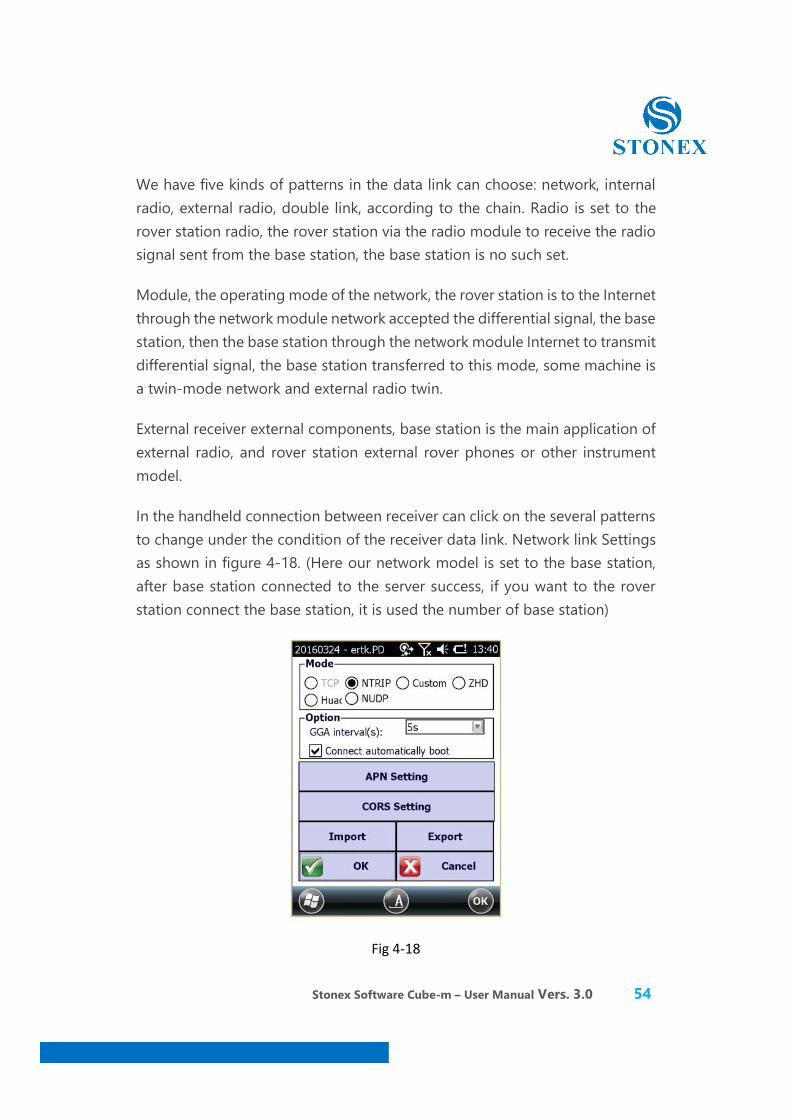
In the handheld connection between receiver can click on the several patterns to change under the condition of the receiver data link. Network link Settings as shown in figure 4-18. (Here our network model is set to the base station, after base station connected to the server success, if you want to the rover station connect the base station, it is used the number of base station)
Fig 4-18
Stonex Software Cube-m – User Manual Vers. 3.0 55
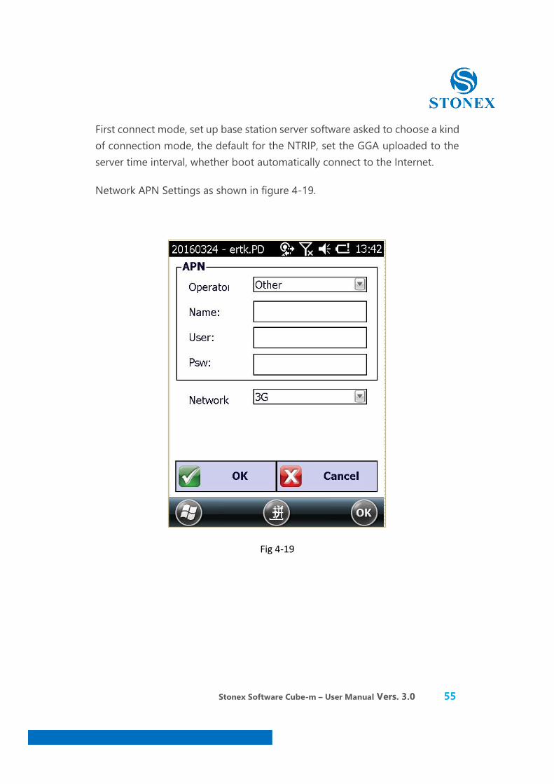
First connect mode, set up base station server software asked to choose a kind of connection mode, the default for the NTRIP, set the GGA uploaded to the server time interval, whether boot automatically connect to the Internet.
Network APN Settings as shown in figure 4-19.
Fig 4-19

Stonex Software Cube-m – User Manual Vers. 3.0 56
CROS Settings display in the figure 4-20.
This interface is a set of base set up the server IP address and port number.
Fig 4-20
Stonex Software Cube-m – User Manual Vers. 3.0 57
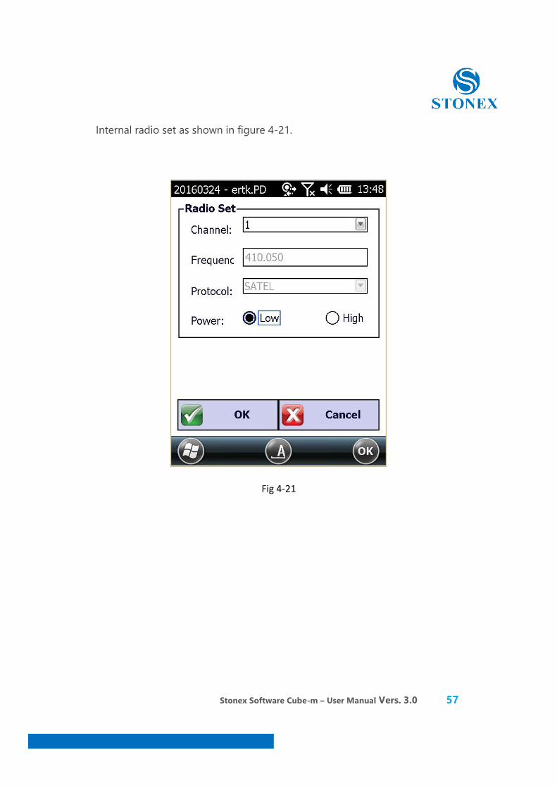
Internal radio set as shown in figure 4-21.
Fig 4-21
Stonex Software Cube-m – User Manual Vers. 3.0 58
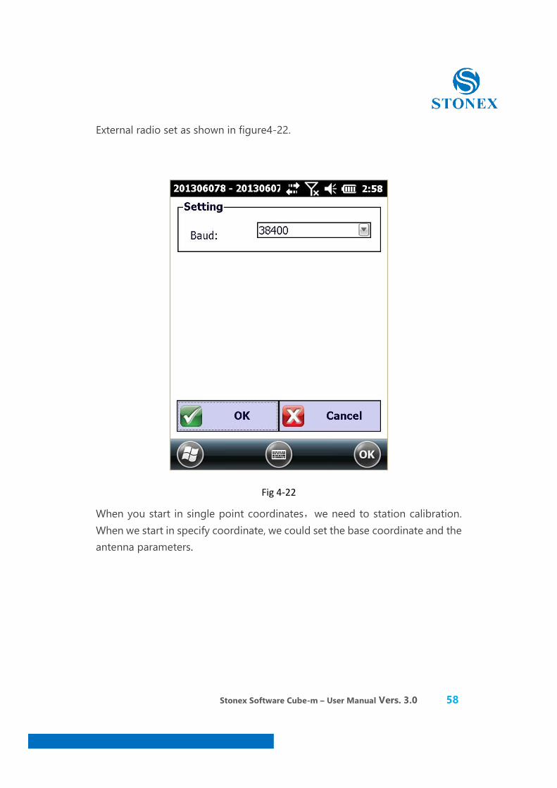
External radio set as shown in figure4-22.
Fig 4-22
When you start in single point coordinates,we need to station calibration. When we start in specify coordinate, we could set the base coordinate and the antenna parameters.

Stonex Software Cube-m – User Manual Vers. 3.0 59
The page about the base coordinate setting shown as figure 4-23.
Fig 4-23
The page about the antenna parameters setting shown as figure 4-24.
Fig 4-24
Stonex Software Cube-m – User Manual Vers. 3.0 60
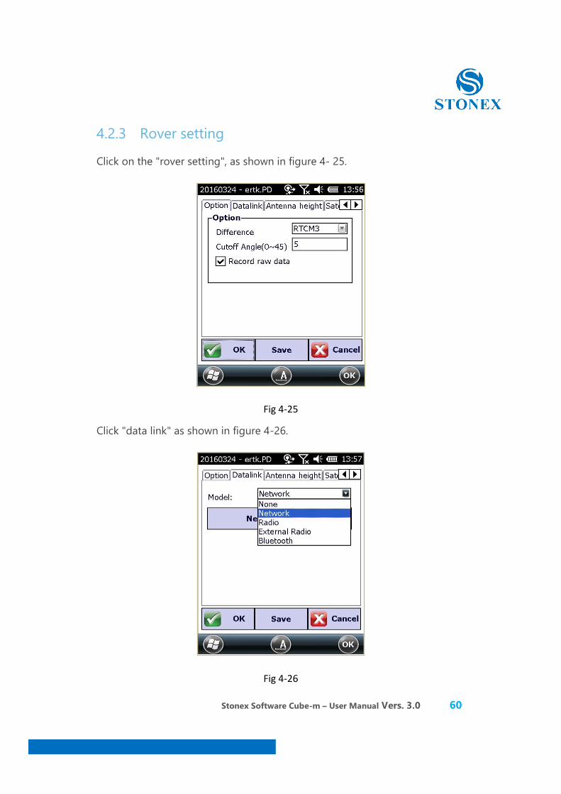
4.2.3 Rover setting
Click on the "rover setting", as shown in figure 4- 25.
Fig 4-25
Click "data link" as shown in figure 4-26.
Fig 4-26
Stonex Software Cube-m – User Manual Vers. 3.0 61
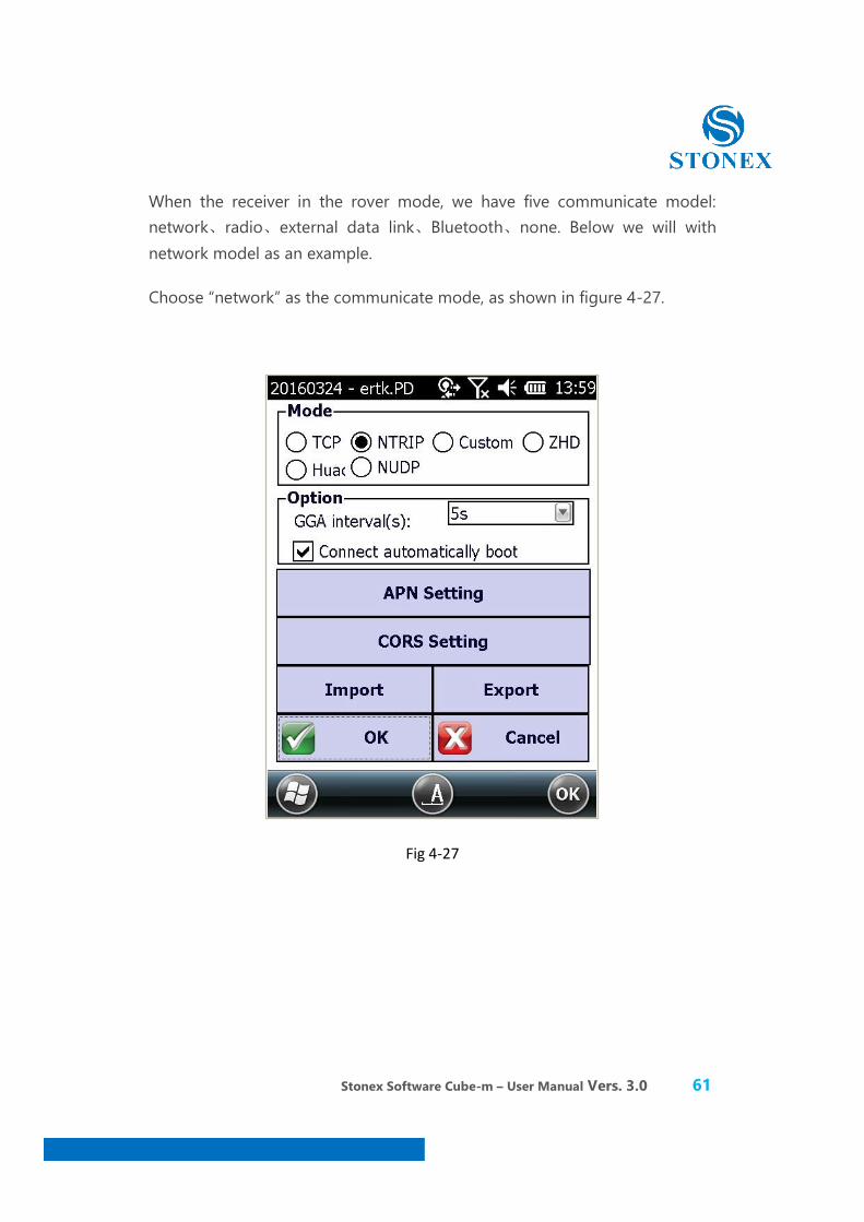
When the receiver in the rover mode, we have five communicate model: network、radio、external data link、Bluetooth、none. Below we will with network model as an example.
Choose “network” as the communicate mode, as shown in figure 4-27.
Fig 4-27
Stonex Software Cube-m – User Manual Vers. 3.0 62
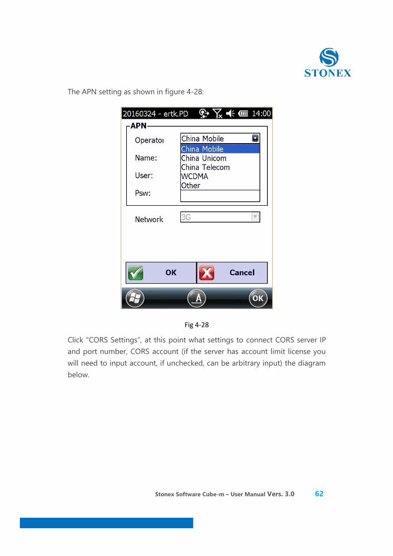
The APN setting as shown in figure 4-28:
Fig 4-28
Click "CORS Settings", at this point what settings to connect CORS server IP and port number, CORS account (if the server has account limit license you will need to input account, if unchecked, can be arbitrary input) the diagram below.

Stonex Software Cube-m – User Manual Vers. 3.0 63
Fig 4-29
If know the access point can choose to automatically or manually enter, click on the "get access point" can automatically access, then select designated access point. Click "ok" as below:
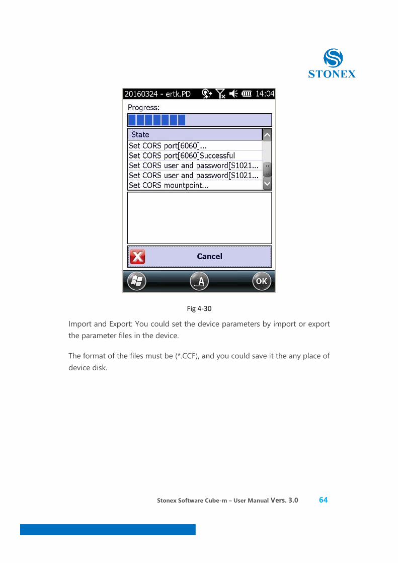
Stonex Software Cube-m – User Manual Vers. 3.0 64
Fig 4-30
Import and Export: You could set the device parameters by import or export the parameter files in the device.
The format of the files must be (*.CCF), and you could save it the any place of device disk.

Stonex Software Cube-m – User Manual Vers. 3.0 65
Fig 4-31
4.3 GPS State
Click [instrument] →[GPS status], the page as shown in figure 4-32.
Fig 4-32
Stonex Software Cube-m – User Manual Vers. 3.0 66
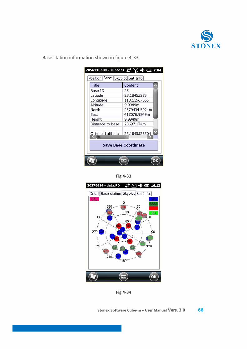
Base station information shown in figure 4-33.
Fig 4-33
Fig 4-34
Stonex Software Cube-m – User Manual Vers. 3.0 67
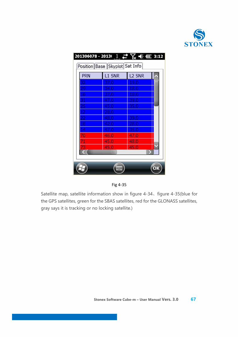
Fig 4-35
Satellite map, satellite information show in figure 4-34、figure 4-35(blue for the GPS satellites, green for the SBAS satellites, red for the GLONASS satellites, gray says it is tracking or no locking satellite.)
Stonex Software Cube-m – User Manual Vers. 3.0 68
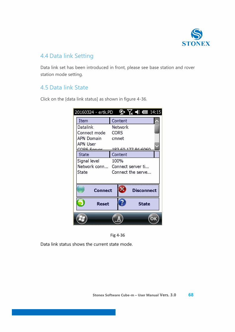
4.4 Data link Setting
Data link set has been introduced in front, please see base station and rover station mode setting.
4.5 Data link State
Click on the [data link status] as shown in figure 4-36.
Fig 4-36
Data link status shows the current state mode.
Stonex Software Cube-m – User Manual Vers. 3.0 69
4.6 Connect last
This function means that the handset could connect the last receiver by Bluetooth automatic, and you don’t need to configure the parameters again.
4.7 Re-Position
It makes the receiver to reposition and makes the GPS board initialization.
Stonex Software Cube-m – User Manual Vers. 3.0 70
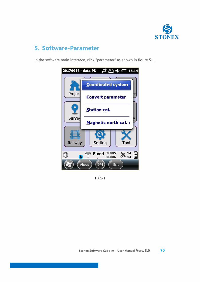
5. Software-Parameter
In the software main interface, click "parameter" as shown in figure 5-1.
Fig 5-1
Stonex Software Cube-m – User Manual Vers. 3.0 71
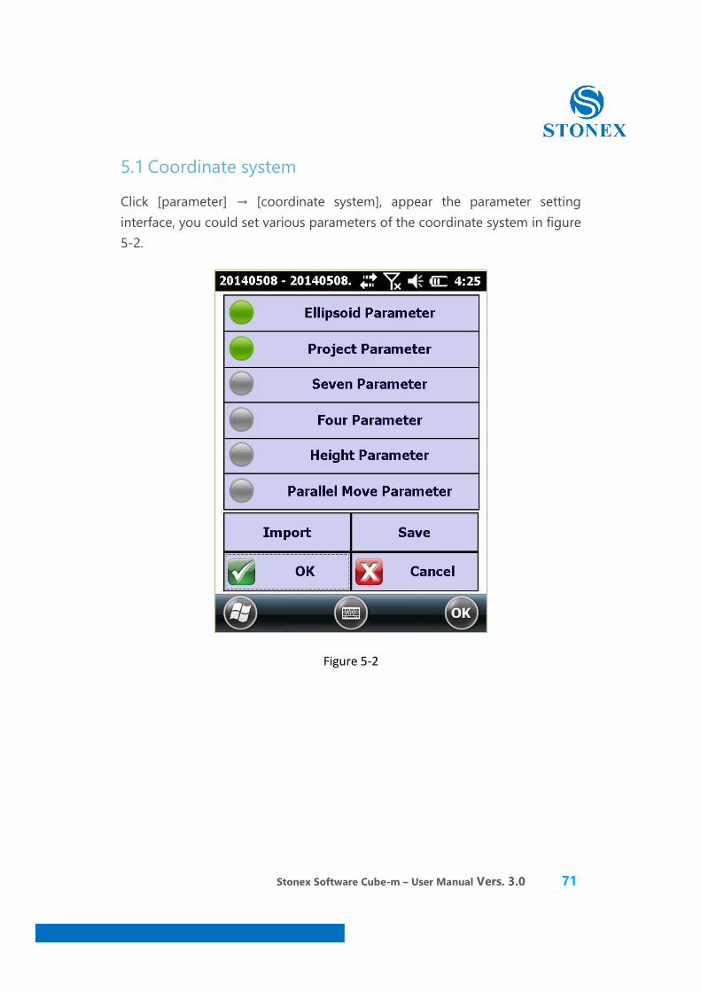
5.1 Coordinate system
Click [parameter] → [coordinate system], appear the parameter setting interface, you could set various parameters of the coordinate system in figure 5-2.
Figure 5-2
Stonex Software Cube-m – User Manual Vers. 3.0 72
5.2 Calculate parameter
GPS receiver output data is WGS-84 latitude and longitude coordinates, the coordinates need to be converted to the construction measure, which requires coordinate conversion parameters are calculated and set the conversion parameters of software, it is the main tool to complete this work. Seeking transformation parameters calculated four parameters or seven parameters and elevation fitting parameter, you can easily just edit, view, four parameters and fitting parameters of correction control point. When calculation four parameters, it need at least two control points of two sets of coordinate system coordinate calculation the minimum control requirements. We use the three points for calculating the elevation,its type as the weighted average; We use the 4-6 point elevation calculations, its parameter type plane fitting;Using seven more points of elevation, the type is surface fitting. Selection of control point and plane, it have close and direct relation elevation fitting, these are related to the stakeout of a large number of classic measurement control network knowledge, where there are many ways to do the introduction. Strives for the transformation parameters it looks something like this: suppose we use A and B the two known points to evaluate transformation parameters, you should first have A, B two GPS coordinate measuring hunger construction coordinate of original records. A and B two points of GPS coordinates of original records for there are two ways: one is static control network stakeout, using post-processing software when the GPS static control network is the original record coordinates; Another kind is the GPS rover station without any correction parameters play a role of Fixed audience record GPS coordinates. Second before operation, the coordinates are in the library input the known coordinates of A point after the software will be prompted to input the original coordinates of point A, and then input the known coordinates of point B and the original coordinates of point B after completion of entry and save (save the file as *. Cot file) four or seven parameters automatically calculated and elevation fitting parameters.
The following specific examples to demonstrate how to calculate the transformation parameters.

Stonex Software Cube-m – User Manual Vers. 3.0 73
5.2.1 Four parameters calculation
Four parameters: it is the same between different coordinate systems of ellipsoid transformation parameters. Need special attention is involved in the calculation of control points in principle at least use two or more than two points, the control point distribution directly determines the level of high and low and four parameters to control. Experience on the four parameters of the ideal control is generally within 20-30 square kilometres.
Transformation parameters into the interface as shown in figure 5-3.
Fig 5-3
Stonex Software Cube-m – User Manual Vers. 3.0 74
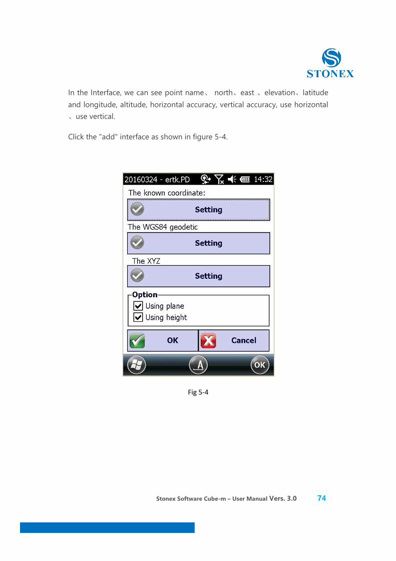
In the Interface, we can see point name、 north、east 、elevation、latitude and longitude, altitude, horizontal accuracy, vertical accuracy, use horizontal 、use vertical.
Click the "add" interface as shown in figure 5-4.
Fig 5-4
Stonex Software Cube-m – User Manual Vers. 3.0 75
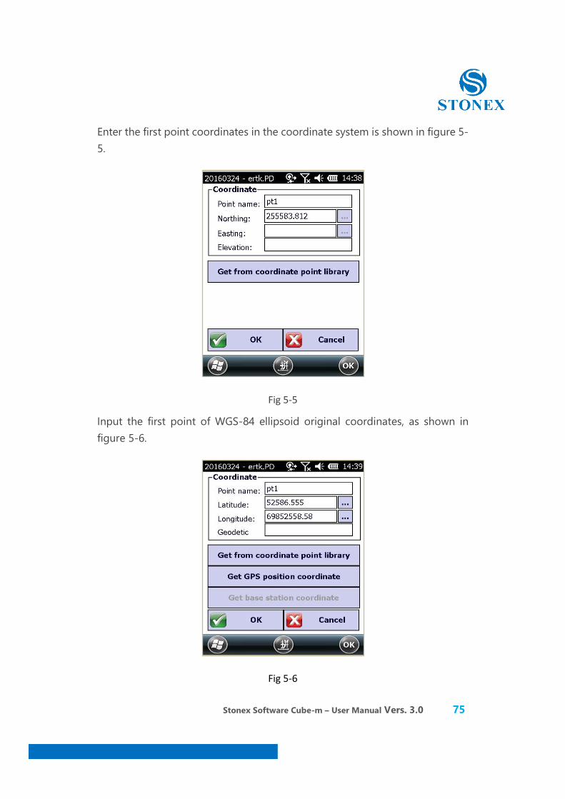
Enter the first point coordinates in the coordinate system is shown in figure 5-5.
Fig 5-5
Input the first point of WGS-84 ellipsoid original coordinates, as shown in figure 5-6.
Fig 5-6
Stonex Software Cube-m – User Manual Vers. 3.0 76
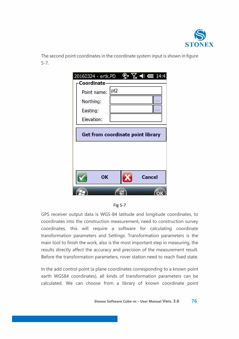
The second point coordinates in the coordinate system input is shown in figure 5-7.
Fig 5-7
GPS receiver output data is WGS-84 latitude and longitude coordinates, to coordinates into the construction measurement, need to construction survey coordinates, this will require a software for calculating coordinate transformation parameters and Settings. Transformation parameters is the main tool to finish the work, also is the most important step in measuring, the results directly affect the accuracy and precision of the measurement result. Before the transformation parameters, rover station need to reach fixed state.
In the add control point (a plane coordinates corresponding to a known point earth WGS84 coordinates), all kinds of transformation parameters can be calculated. We can choose from a library of known coordinate point
Stonex Software Cube-m – User Manual Vers. 3.0 77
coordinates, but also from the original coordinates WGS84 ellipsoid set selected coordinate point.
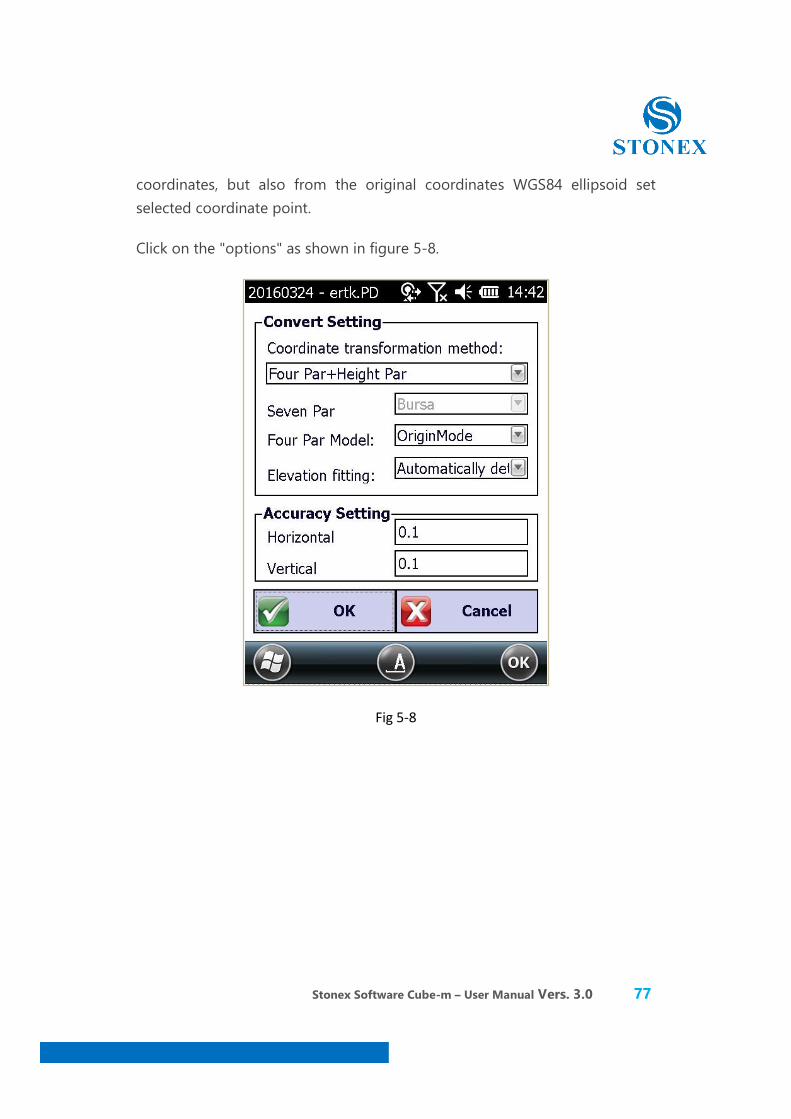
Click on the "options" as shown in figure 5-8.
Fig 5-8
Stonex Software Cube-m – User Manual Vers. 3.0 78
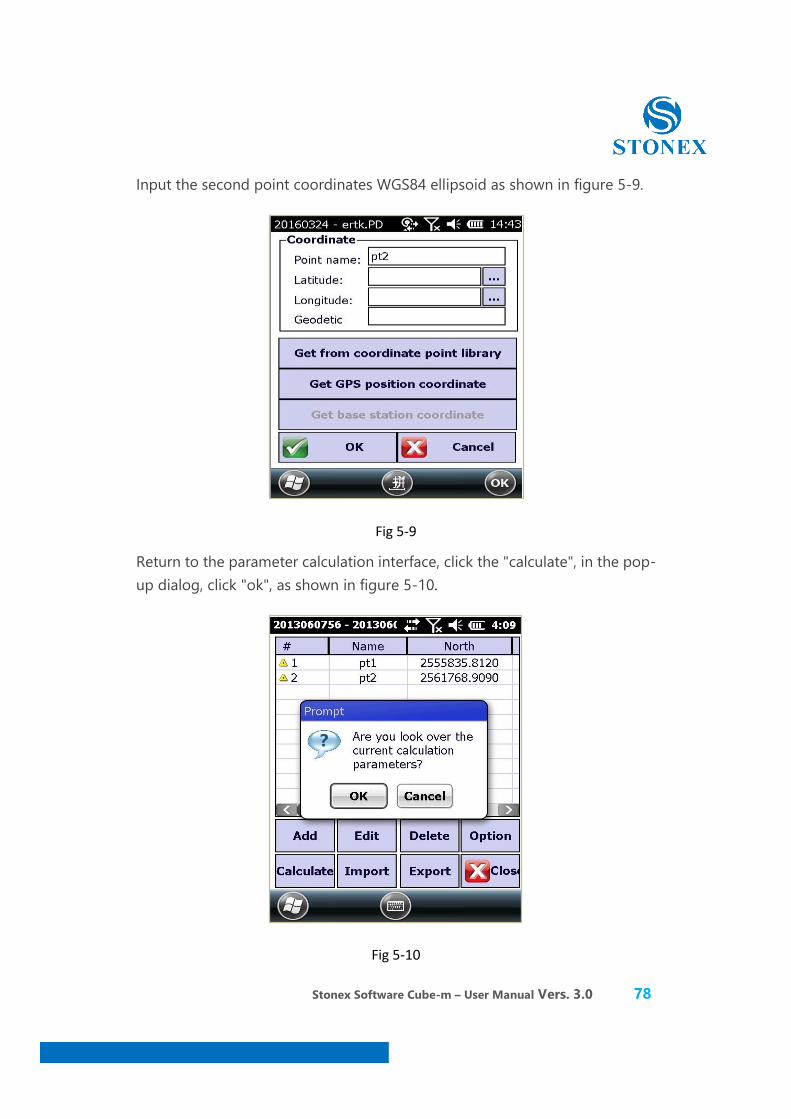
Input the second point coordinates WGS84 ellipsoid as shown in figure 5-9.
Fig 5-9
Return to the parameter calculation interface, click the "calculate", in the pop-up dialog, click "ok", as shown in figure 5-10.
Fig 5-10
Stonex Software Cube-m – User Manual Vers. 3.0 79
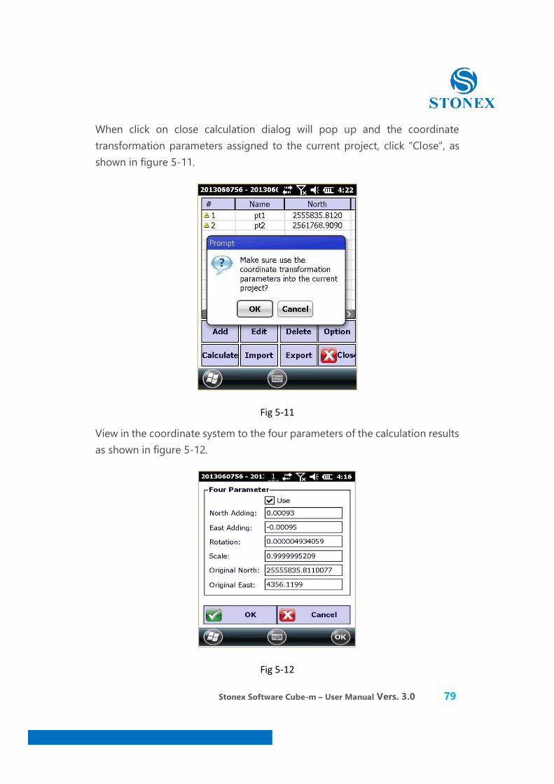
When click on close calculation dialog will pop up and the coordinate transformation parameters assigned to the current project, click "Close", as shown in figure 5-11.
Fig 5-11
View in the coordinate system to the four parameters of the calculation results as shown in figure 5-12.
Fig 5-12

Stonex Software Cube-m – User Manual Vers. 3.0 80
Methods: Four Par + Height Par, Seven Par+ Four Par+ Height Par, Seven Par.
Seven parameter calculation model, Bursa, Bursa tight algorithm (below) will be given.
Elevation simulation method has: automatically judgment, weighted average, plane fitting and surface fitting.
We through the import and export input point.
5.2.2 Seven parameters calculation
Seven parameters: it is located within the two ellipsoid transformation parameters between two coordinate systems. Seven-parameter calculation operation is basically the same four parameters, see the previous one related operations. Seven parameters are relatively large range of applications (generally more than 50 square kilometres),User need to know 3 points local coordinates and WGS-84 coordinates before calculating, namely the 7 transformation for transforming WGS-84 to local coordinate 。
Note: three dots area which could cover the whole test area, the effect is better. Using four parameters for RTK measurement method can be in a small range (20-30 square kilometres), make the measurement point in plane coordinate and cooperate between the precision of elevation control net with known very well, as long as the coordinate point collection of two or more than two places. But in a wide range of measure (for example, dozens of hundreds of square kilometres), transformation parameters often can't play for increasing accuracy of plane and elevation in part of the scope, seven parameters method should be used at this moment.
You first need to make measurements and levelling control, in the area known control point coordinates do static control, and then the network adjustment prior to the survey area is selected as a control point A static net adjustment WGS84 reference station. Use A static instrument at A fixed point measure
Stonex Software Cube-m – User Manual Vers. 3.0 81
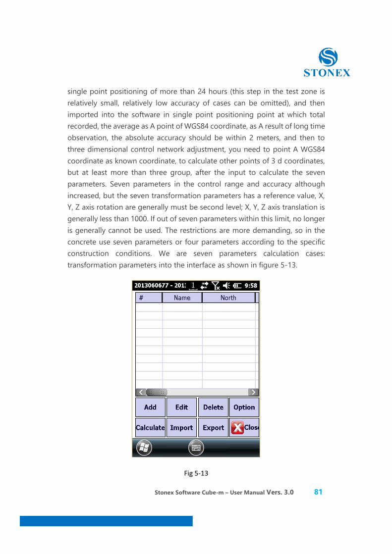
single point positioning of more than 24 hours (this step in the test zone is relatively small, relatively low accuracy of cases can be omitted), and then imported into the software in single point positioning point at which total recorded, the average as A point of WGS84 coordinate, as A result of long time observation, the absolute accuracy should be within 2 meters, and then to three dimensional control network adjustment, you need to point A WGS84 coordinate as known coordinate, to calculate other points of 3 d coordinates, but at least more than three group, after the input to calculate the seven parameters. Seven parameters in the control range and accuracy although increased, but the seven transformation parameters has a reference value, X, Y, Z axis rotation are generally must be second level; X, Y, Z axis translation is generally less than 1000. If out of seven parameters within this limit, no longer is generally cannot be used. The restrictions are more demanding, so in the concrete use seven parameters or four parameters according to the specific construction conditions. We are seven parameters calculation cases: transformation parameters into the interface as shown in figure 5-13.
Fig 5-13

Stonex Software Cube-m – User Manual Vers. 3.0 82
Set name, coordinates, elevation, latitude and longitude. We need to set up three points, in the current coordinate system is set as shown in figure 5-14.
Fig 5-14
We set up three points as an example shown in Figure 5-15.
Fig 5-15
Stonex Software Cube-m – User Manual Vers. 3.0 83
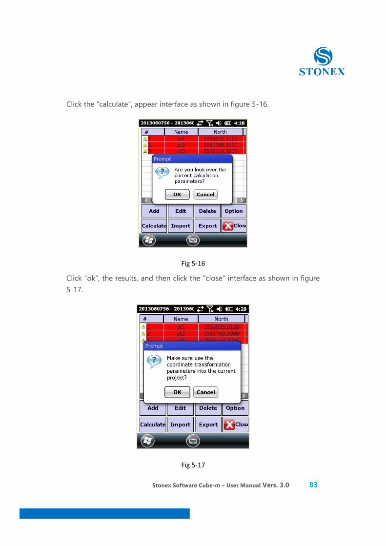
Click the "calculate", appear interface as shown in figure 5-16.
Fig 5-16
Click "ok", the results, and then click the "close" interface as shown in figure 5-17.
Fig 5-17
Stonex Software Cube-m – User Manual Vers. 3.0 84
Click "ok", and finally our current project which is now the coordinates of the parameters.
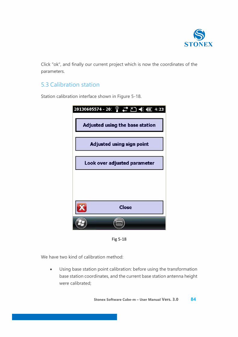
5.3 Calibration station
Station calibration interface shown in Figure 5-18.
Fig 5-18
We have two kind of calibration method:
x Using base station point calibration: before using the transformation base station coordinates, and the current base station antenna height were calibrated;
Stonex Software Cube-m – User Manual Vers. 3.0 85
x Use sign point calibration: use in station calibration has already collected the coordinates of the point;
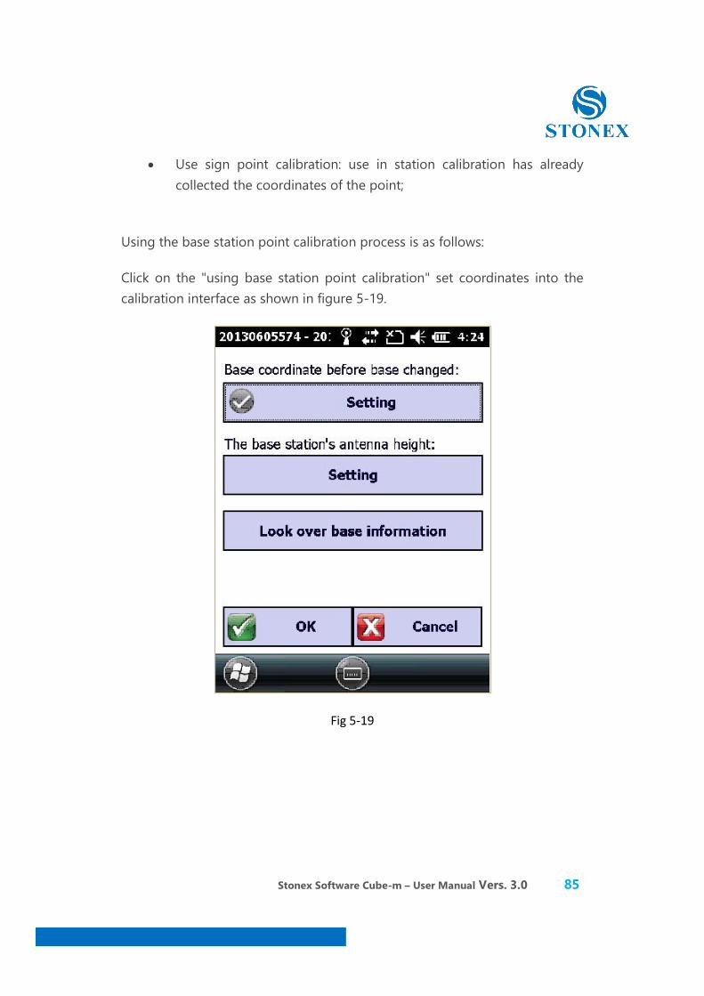
Using the base station point calibration process is as follows:
Click on the "using base station point calibration" set coordinates into the calibration interface as shown in figure 5-19.
Fig 5-19

Stonex Software Cube-m – User Manual Vers. 3.0 86
In the "base station before the transformation point coordinates" click :”Settings” then enter the base station coordinates before the transformation shown in figure 5-20.
Fig 5-20
Choose the previously saved base point in the coordinate library as shown in figure 5-21.
Fig 5-21
Stonex Software Cube-m – User Manual Vers. 3.0 87
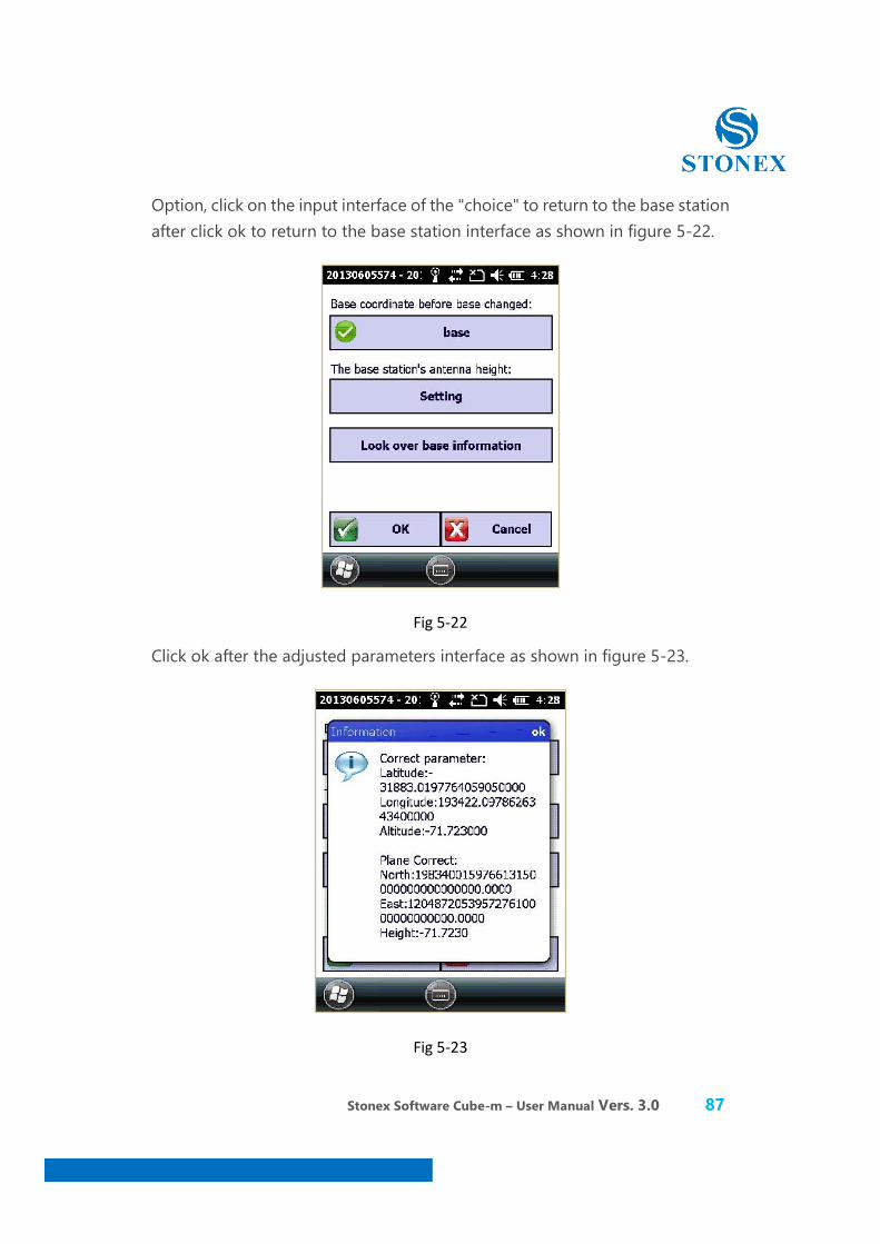
Option, click on the input interface of the "choice" to return to the base station after click ok to return to the base station interface as shown in figure 5-22.
Fig 5-22
Click ok after the adjusted parameters interface as shown in figure 5-23.
Fig 5-23
Stonex Software Cube-m – User Manual Vers. 3.0 88
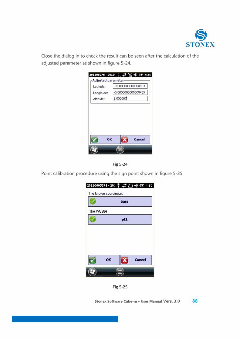
Close the dialog in to check the result can be seen after the calculation of the adjusted parameter as shown in figure 5-24.
Fig 5-24
Point calibration procedure using the sign point shown in figure 5-25.
Fig 5-25
Stonex Software Cube-m – User Manual Vers. 3.0 89
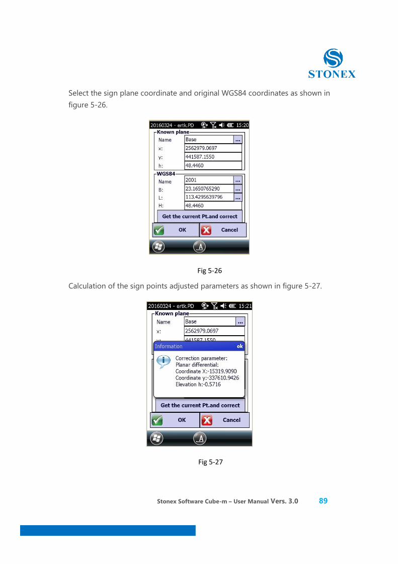
Select the sign plane coordinate and original WGS84 coordinates as shown in figure 5-26.
Fig 5-26
Calculation of the sign points adjusted parameters as shown in figure 5-27.
Fig 5-27
Stonex Software Cube-m – User Manual Vers. 3.0 90
Tip:
1. The station calibration parameters will not refresh the current calculation by the point coordinates in the library;
2. Transformation parameters by calculating the parameters of the library will refresh the current coordinates of the point;
We need to determine the correct latitude and longitude corrections, ellipsoidal corrections for station adjusted parameters. Station conversion parameter calibration is utilized as a tool. Since the output is WGS84 coordinates GPS and RTK base station can only recognize input coordinates WGS84 coordinates, so most GPS transformation parameters using a popular way to set up the base station at a known point, directly or indirectly, in the base station input WGS84 coordinates start base. Disadvantage is that this way must use every time controller connected to the base station after start the base station, the model in the measurement field job comes with some trouble. Avoid the use calibration wizard starts with the base station controller, you can choose to set up the base station at any point start automatically, greatly improving the flexibility of use.
Station calibration need to be done on the basis of the already open transformation parameters. Correction parameter is commonly used in the transformation parameters switch machine operations have been carried out and the base station, or a work area of transformation parameters, can be directly input and correction of calibration parameters is, in fact, the use of a common point calculation of two different coordinates "three parameters", referred to as the calibration parameter in software.
Stonex Software Cube-m – User Manual Vers. 3.0 91
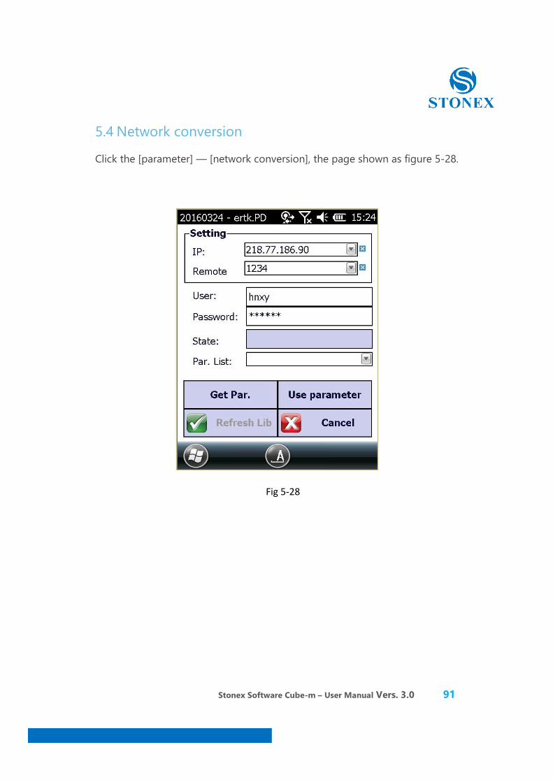
5.4 Network conversion
Click the [parameter] — [network conversion], the page shown as figure 5-28.
Fig 5-28
Stonex Software Cube-m – User Manual Vers. 3.0 92
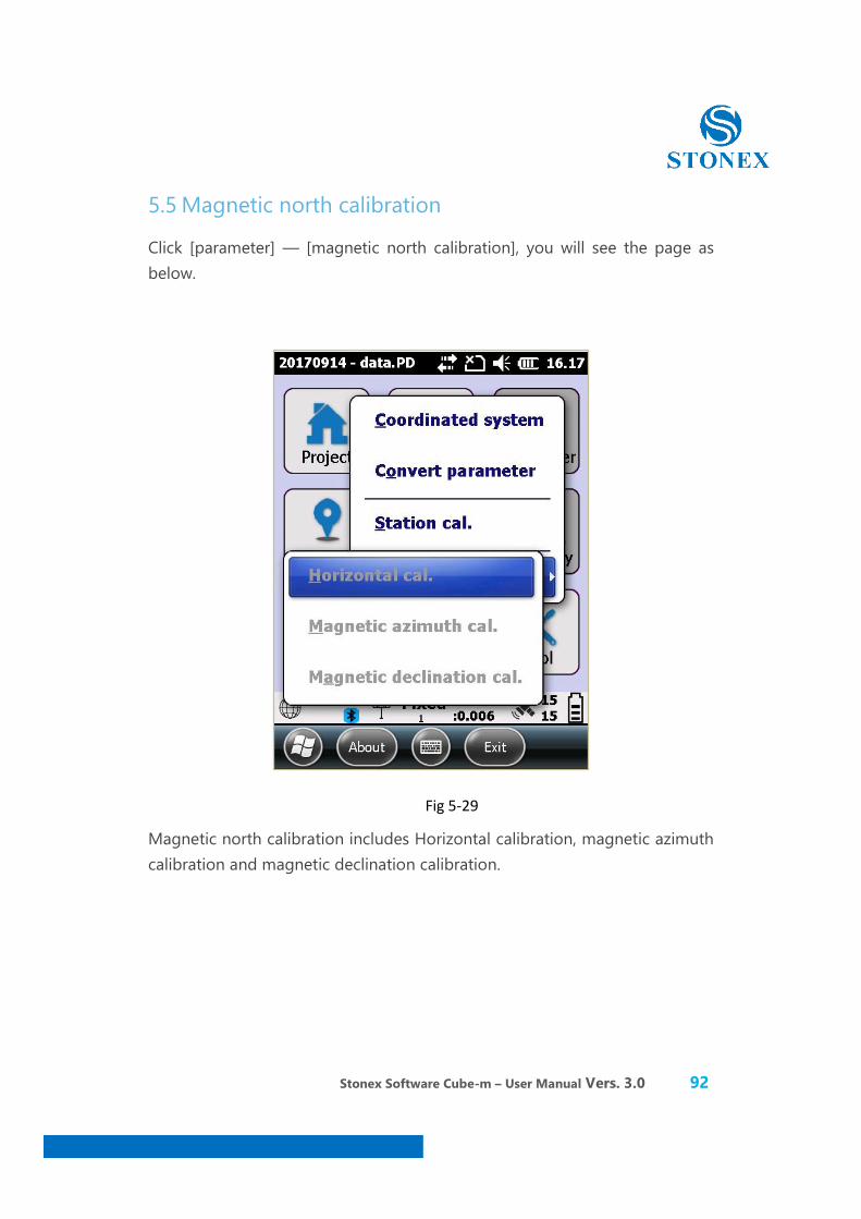
5.5 Magnetic north calibration
Click [parameter] — [magnetic north calibration], you will see the page as below.
Fig 5-29
Magnetic north calibration includes Horizontal calibration, magnetic azimuth calibration and magnetic declination calibration.

Stonex Software Cube-m – User Manual Vers. 3.0 93
5.5.1 E-bubble calibration
① Open the option of the E-bubble: Click “Setting”→“System”. Select the function of the E-bubble,as shown in the figure 5-30, then click “OK”.
Fig 5-30
Stonex Software Cube-m – User Manual Vers. 3.0 94
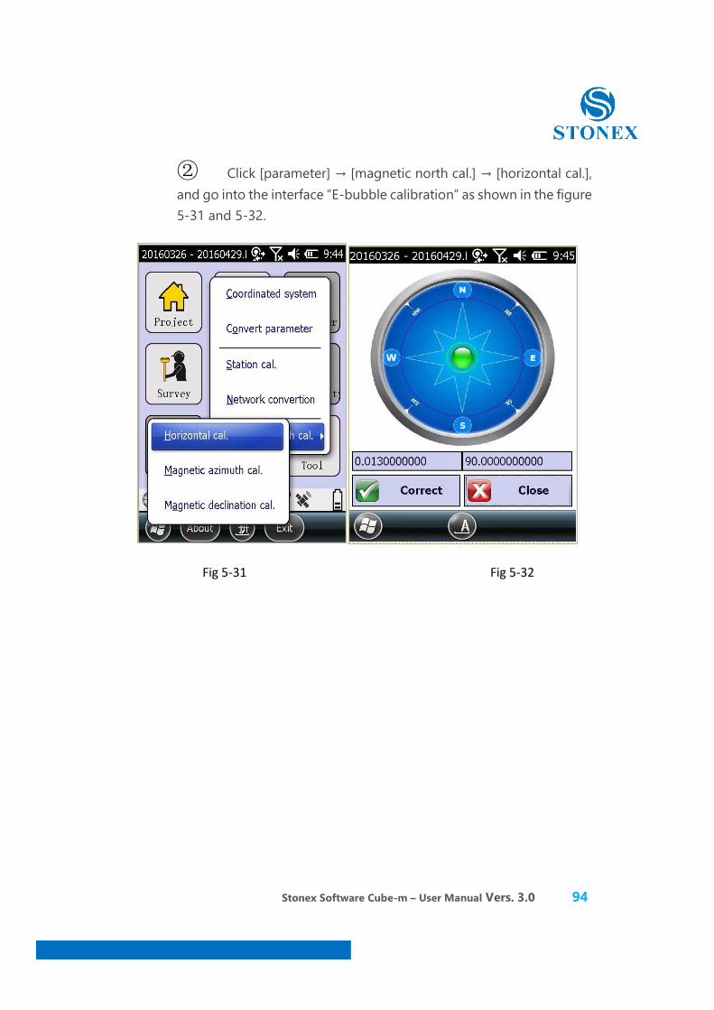
② Click [parameter] → [magnetic north cal.] → [horizontal cal.], and go into the interface “E-bubble calibration” as shown in the figure 5-31 and 5-32.
Fig 5-31 Fig 5-32
Stonex Software Cube-m – User Manual Vers. 3.0 95
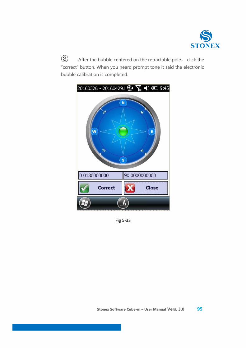
③ After the bubble centered on the retractable pole, click the “ccrrect” button. When you heard prompt tone it said the electronic bubble calibration is completed.
Fig 5-33
Stonex Software Cube-m – User Manual Vers. 3.0 96
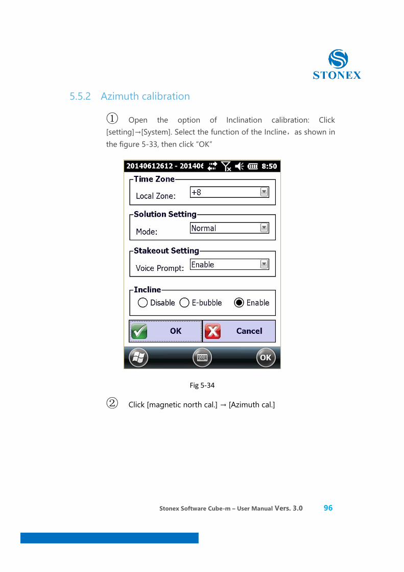
5.5.2 Azimuth calibration
① Open the option of Inclination calibration: Click [setting]→[System]. Select the function of the Incline,as shown in the figure 5-33, then click “OK”
Fig 5-34
② Click [magnetic north cal.] → [Azimuth cal.]
Stonex Software Cube-m – User Manual Vers. 3.0 97
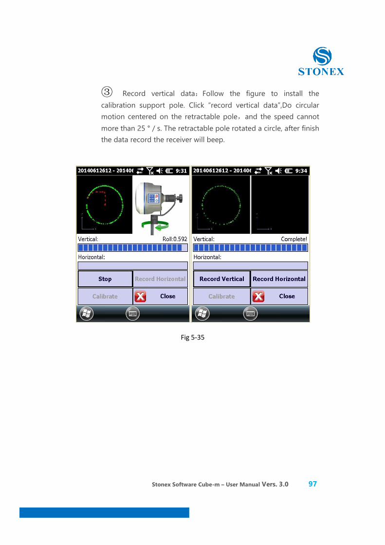
③ Record vertical data:Follow the figure to install the calibration support pole. Click “record vertical data”,Do circular motion centered on the retractable pole,and the speed cannot more than 25 ° / s. The retractable pole rotated a circle, after finish the data record the receiver will beep.
Fig 5-35

Stonex Software Cube-m – User Manual Vers. 3.0 98
④ Record Horizontal data: Follow the figure to install the calibration support pole. Click “calibration XY axis”, Do circular motion centered on the retractable pole,and the speed cannot more than 25 ° / s. Theretractable pole rotated a circle, after finish the data record the receiver will beep.
Fig 5-36
Stonex Software Cube-m – User Manual Vers. 3.0 99
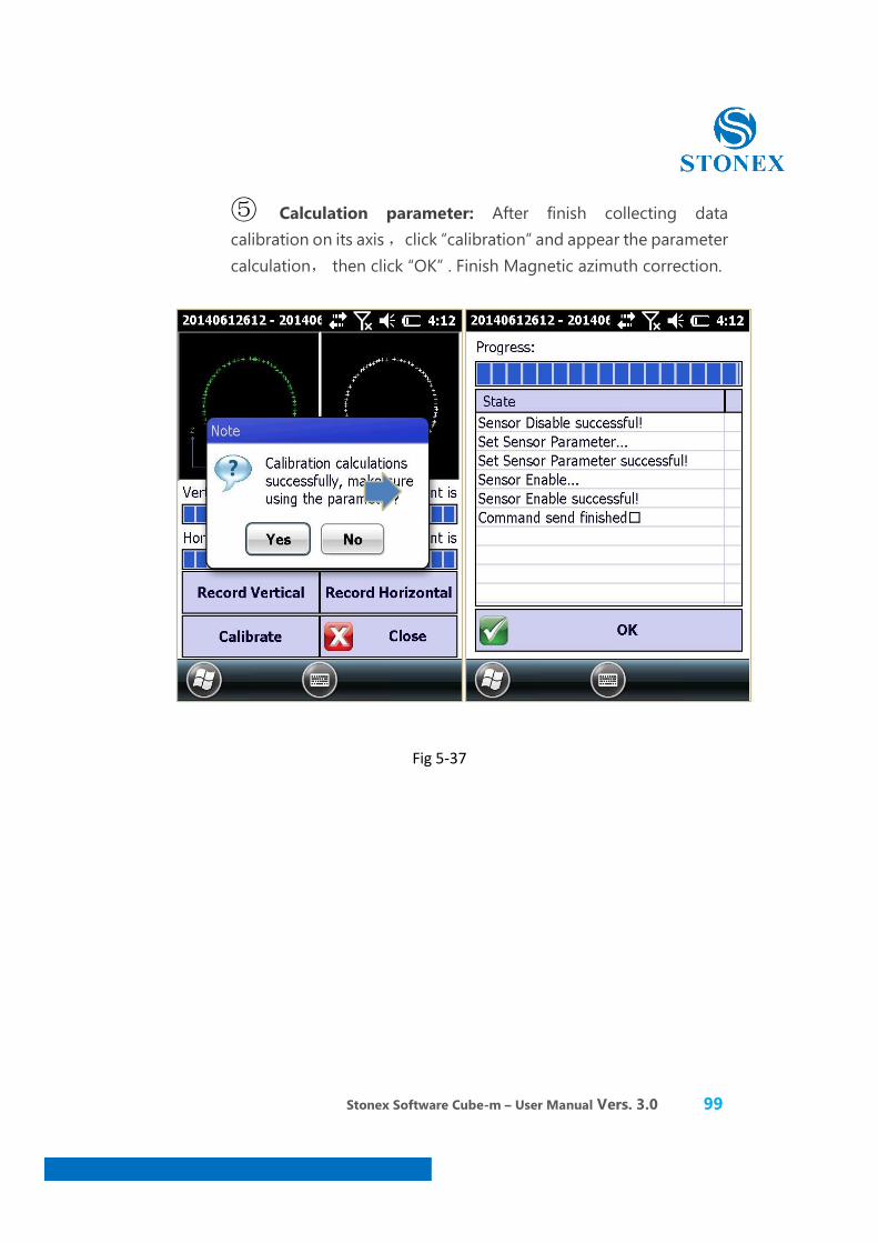
⑤ Calculation parameter: After finish collecting data calibration on its axis ,click “calibration” and appear the parameter calculation, then click “OK” . Finish Magnetic azimuth correction.
Fig 5-37
Stonex Software Cube-m – User Manual Vers. 3.0 100
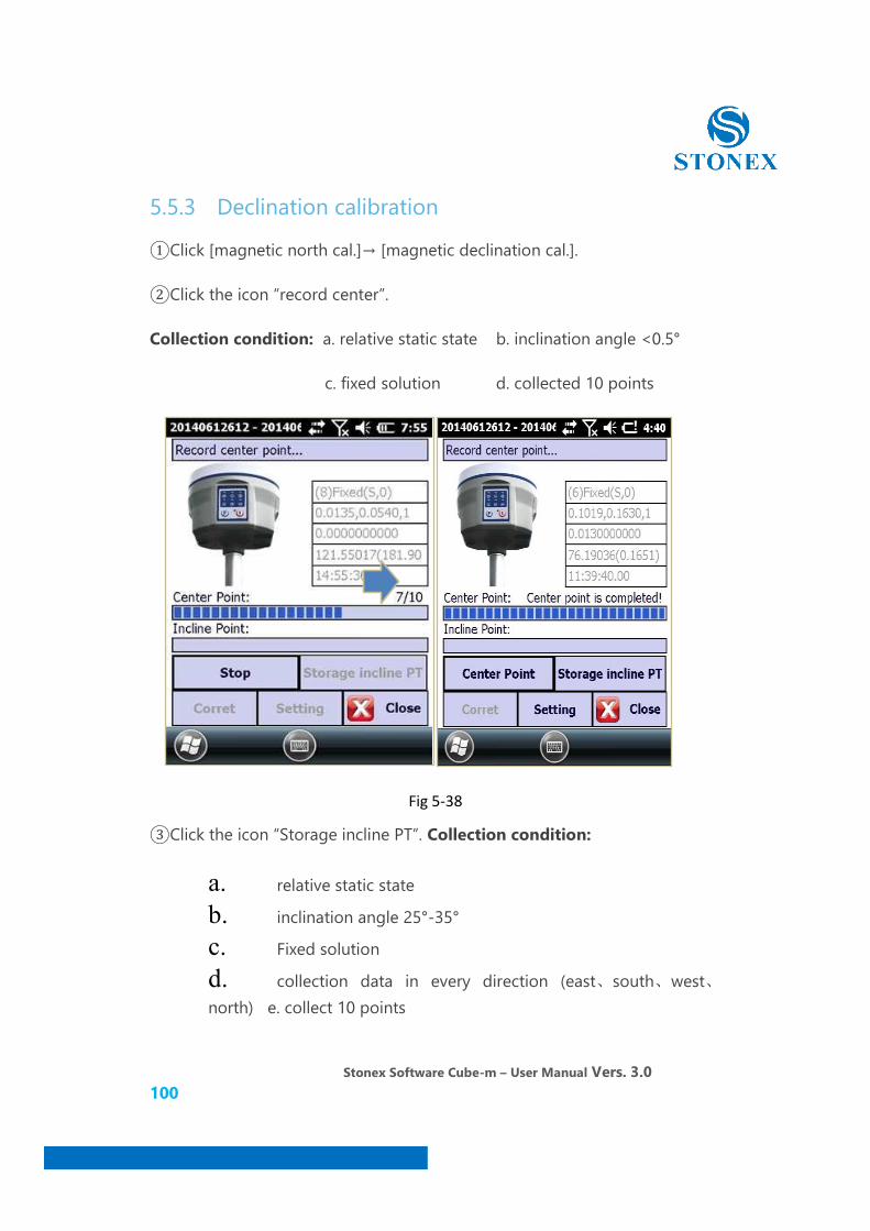
5.5.3 Declination calibration
①Click [magnetic north cal.]→ [magnetic declination cal.].
②Click the icon “record center”.
Collection condition: a. relative static state b. inclination angle <0.5°
c. fixed solution d. collected 10 points
Fig 5-38
③Click the icon “Storage incline PT”. Collection condition:
a. relative static state
b. inclination angle 25°-35°
c. Fixed solution
d. collection data in every direction (east、south、west、north) e. collect 10 points

Stonex Software Cube-m – User Manual Vers. 3.0 101
Fig 5-39
East South
West North

Stonex Software Cube-m – User Manual Vers. 3.0 102
So the centre point and the incline point have finished recorded, click “calibration” to calculate Magnetic declination parameters.
④Calculation parameter: Please input antenna parameter (The quick release adapter height 0.04m+measure height 1.8m), and then click “OK”.
Fig 5-40
Stonex Software Cube-m – User Manual Vers. 3.0 103
6. Software -Survey
Three are two parts in the survey: Point surveying, point stakeout and line stakeout.
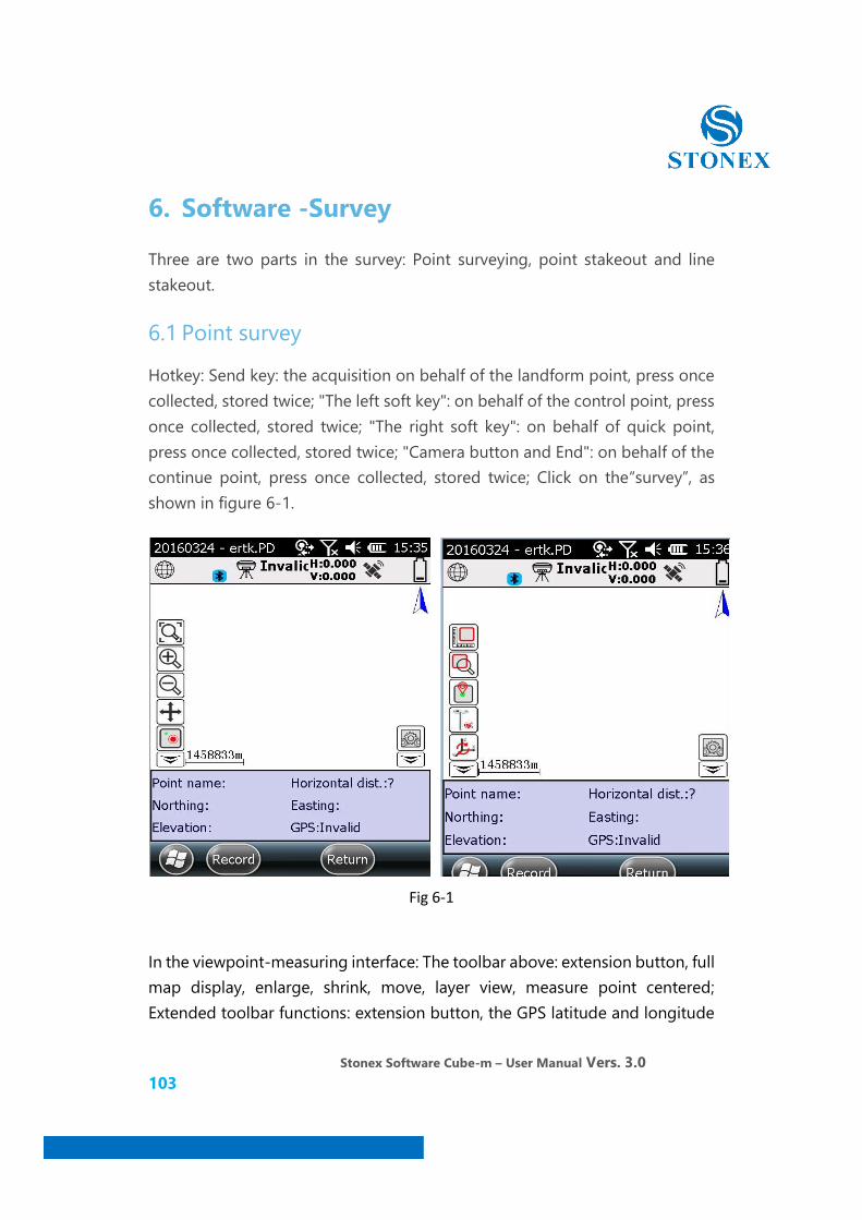
6.1 Point survey
Hotkey: Send key: the acquisition on behalf of the landform point, press once collected, stored twice; "The left soft key": on behalf of the control point, press once collected, stored twice; "The right soft key": on behalf of quick point, press once collected, stored twice; "Camera button and End": on behalf of the continue point, press once collected, stored twice; Click on the“survey”, as shown in figure 6-1.
Fig 6-1
In the viewpoint-measuring interface: The toolbar above: extension button, full map display, enlarge, shrink, move, layer view, measure point centered; Extended toolbar functions: extension button, the GPS latitude and longitude
Stonex Software Cube-m – User Manual Vers. 3.0 104
and the plane coordinate view, information view, instrument set, the layer set, take the screen, the screen measurement.
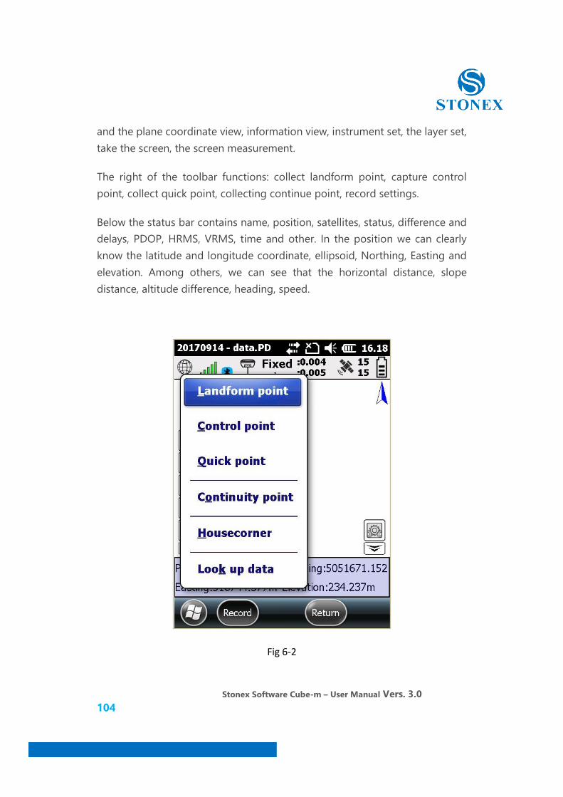
The right of the toolbar functions: collect landform point, capture control point, collect quick point, collecting continue point, record settings.
Below the status bar contains name, position, satellites, status, difference and delays, PDOP, HRMS, VRMS, time and other. In the position we can clearly know the latitude and longitude coordinate, ellipsoid, Northing, Easting and elevation. Among others, we can see that the horizontal distance, slope distance, altitude difference, heading, speed.
Fig 6-2
Stonex Software Cube-m – User Manual Vers. 3.0 105
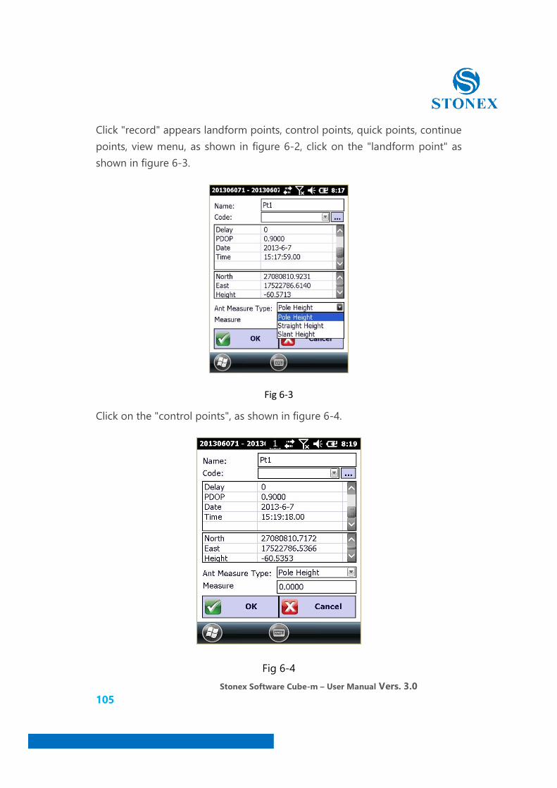
Click "record" appears landform points, control points, quick points, continue points, view menu, as shown in figure 6-2, click on the "landform point" as shown in figure 6-3.
Fig 6-3
Click on the "control points", as shown in figure 6-4.
Fig 6-4
Stonex Software Cube-m – User Manual Vers. 3.0 106
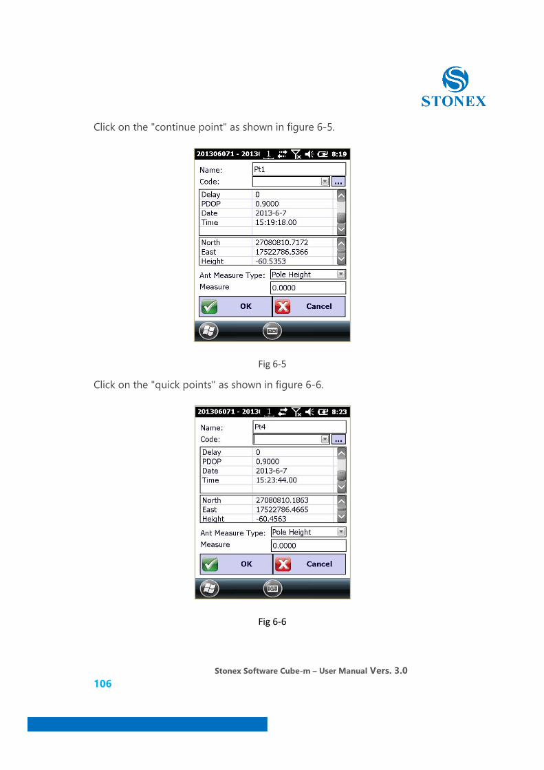
Click on the "continue point" as shown in figure 6-5.
Fig 6-5
Click on the "quick points" as shown in figure 6-6.
Fig 6-6
Stonex Software Cube-m – User Manual Vers. 3.0 107
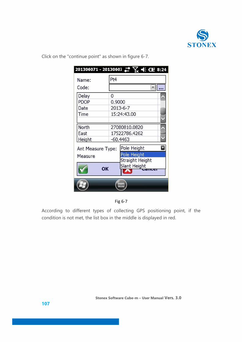
Click on the "continue point" as shown in figure 6-7.
Fig 6-7
According to different types of collecting GPS positioning point, if the condition is not met, the list box in the middle is displayed in red.
Stonex Software Cube-m – User Manual Vers. 3.0 108
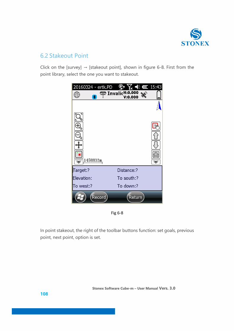
6.2 Stakeout Point
Click on the [survey] → [stakeout point], shown in figure 6-8. First from the point library, select the one you want to stakeout.
Fig 6-8
In point stakeout, the right of the toolbar buttons function: set goals, previous point, next point, option is set.
Stonex Software Cube-m – User Manual Vers. 3.0 109
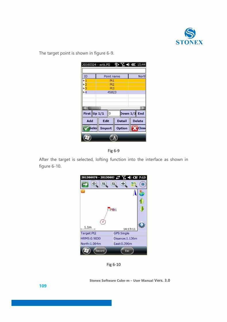
The target point is shown in figure 6-9.
Fig 6-9
After the target is selected, lofting function into the interface as shown in figure 6-10.
Fig 6-10

Stonex Software Cube-m – User Manual Vers. 3.0 110
You can set the lofting options as shown in figure 6-11.
Fig 6-11
Stonex Software Cube-m – User Manual Vers. 3.0 111
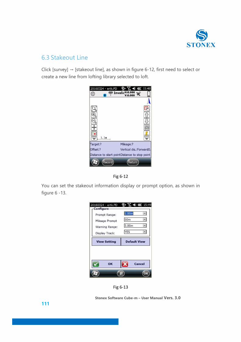
6.3 Stakeout Line
Click [survey] → [stakeout line], as shown in figure 6-12, first need to select or create a new line from lofting library selected to loft.
Fig 6-12
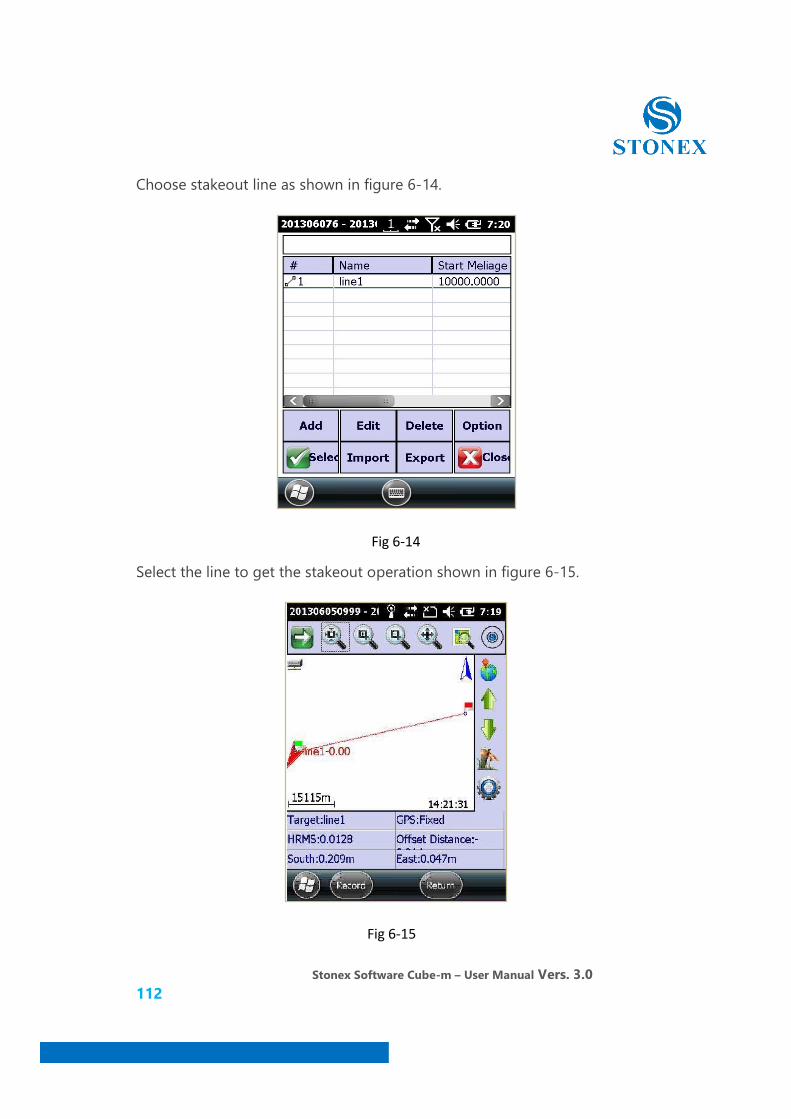
You can set the stakeout information display or prompt option, as shown in figure 6 -13.
Fig 6-13
Stonex Software Cube-m – User Manual Vers. 3.0 112
Choose stakeout line as shown in figure 6-14.
Fig 6-14
Select the line to get the stakeout operation shown in figure 6-15.
Fig 6-15
Stonex Software Cube-m – User Manual Vers. 3.0 113
7. Road survey
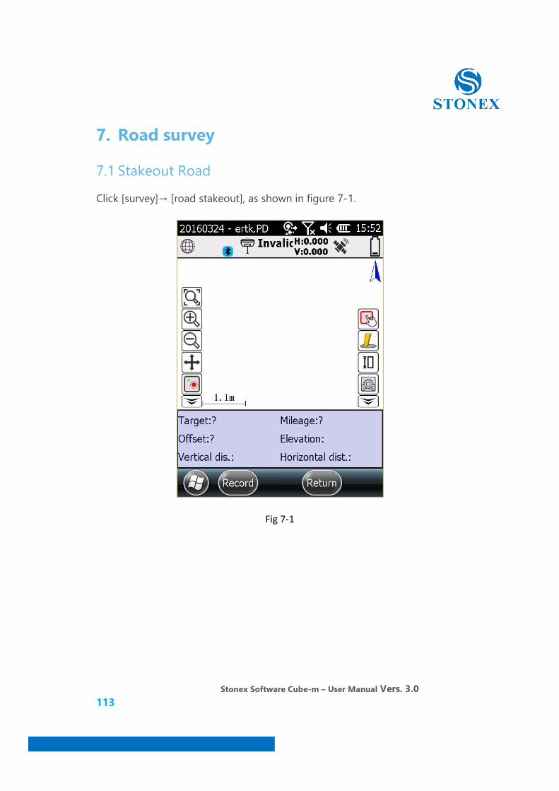
7.1 Stakeout Road
Click [survey]→ [road stakeout], as shown in figure 7-1.
Fig 7-1
Stonex Software Cube-m – User Manual Vers. 3.0 114
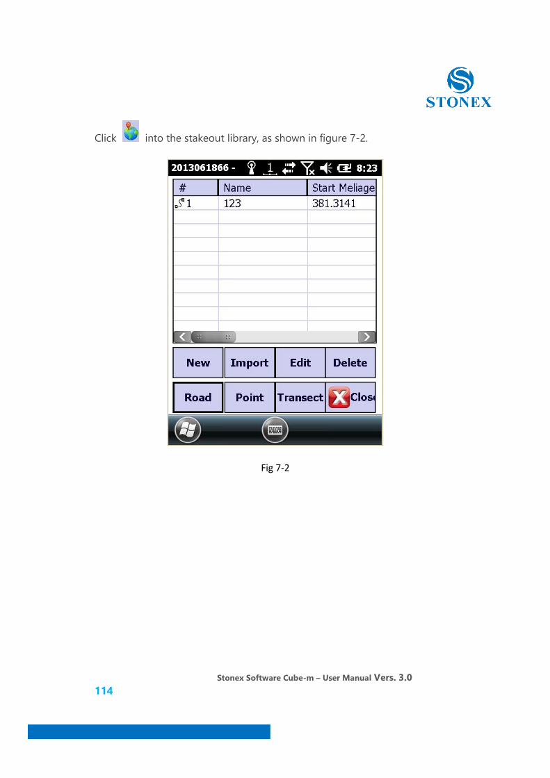
Click into the stakeout library, as shown in figure 7-2.
Fig 7-2

Stonex Software Cube-m – User Manual Vers. 3.0 115
You can select an existing line or create stakeout line, click on "New", shown in figure 7-3.
Fig 7-3

Stonex Software Cube-m – User Manual Vers. 3.0 116
You can select element mode or cross point mode. Click to design elevation,
click , set add peg can be as shown in figure 7-4.
Fig 7-4
Stonex Software Cube-m – User Manual Vers. 3.0 117
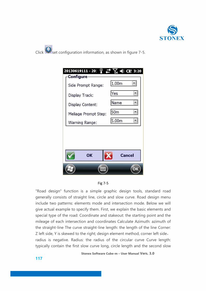
Click set configuration information, as shown in figure 7-5.
Fig 7-5
"Road design" function is a simple graphic design tools, standard road generally consists of straight line, circle and slow curve. Road design menu include two patterns: elements mode and intersection mode. Below we will give actual example to specify them. First, we explain the basic elements and special type of the road: Coordinate and stakeout: the starting point and the mileage of each intersection and coordinates Calculate Azimuth: azimuth of the straight-line The curve straight-line length: the length of the line Corner: Z left side, Y is skewed to the right; design element method, corner left side,radius is negative. Radius: the radius of the circular curve Curve length: typically contain the first slow curve long, circle length and the second slow

Stonex Software Cube-m – User Manual Vers. 3.0 118
curve long. The curve total length: the first curve long + circle length + second curve long.
Chain scission: rerouted due to local sub-measure or the amount of margin of error will cause mileage Stakeout does not match with the actual distance, this discontinuity in the middle of the mileage called the "chain scission".
Long chain: Stakeout overlapping said long chain Short-chain: Stakeout intermittent short chain. For the chain scission processing, must be segmented processing, to generate two road design files.
The oval curve: means at two radius ranging from the same to the circular curve insert a transition curve. Slow circle round; That is: the oval curve itself is a period of transition curve, just inserted to remove a section of near infinite radius general direction, rather than a complete transition curve. We are simple to understand, a round slow circle, the oval curve use element method. Oval curve are used in general highway.
Return curve: curve total deflection angle is greater than or close to 180 °, also known as pallial line. Return curve design element method,it is very common in the mountainous highway construction.
7.1.1 Element model line
"Element mode" is the usual mode of road design, it is the road line is split into a variety of road elements (point, line, curve, circle), and each of these basic elements added according to certain rules combined into the line, so as to achieve the purpose of the design of the entire section of the road.
The rules of the input element method: point - straight line - the first transition curve - circular curve - the second transition curve - straight line - the first transition curve - circular curve - the second transition curve ……Click a loop.
Stonex Software Cube-m – User Manual Vers. 3.0 119
Enter the elements have the following requirement:
1. The first element must be a point, and in addition to the first element,the element cannot be followed for the point.
2. The second element must be a straight line, the length may be zero, but it must be input azimuth.
3. Not the second element in a straight line, do not know the azimuth cannot lose, the software will automatically calculate.
4. Recommended at the input end of the straight-line elements, enter zero straight line, the software will automatically add a zero line to the end.
5. Oval curve and return curve, must use the element method
6. Road design, does not allow "round".
7. If have with zero curve between the linear case, have the following 3 analysis, based on easement curve
(1) If the line is a curve with the curve with a combination of form the round slow circle, so the middle of the zero line can't enter.
(2) If it is a standard form of lines, each node are standard slow circle under the slow situation, in the middle of the zero line to lose don't lose.
(3) Return curve, in the middle of the zero line must be input (do not enter there will be "round and round and error conditions).

Stonex Software Cube-m – User Manual Vers. 3.0 120
Click "element model line", as shown in figure 7-6, input line name.
Fig 7-6
Input rules according to the previously described, starting straight song data table to add elements, point feature only need to enter the X and Y coordinates, the straight-line elements only need to enter the azimuth and length.
Stonex Software Cube-m – User Manual Vers. 3.0 121
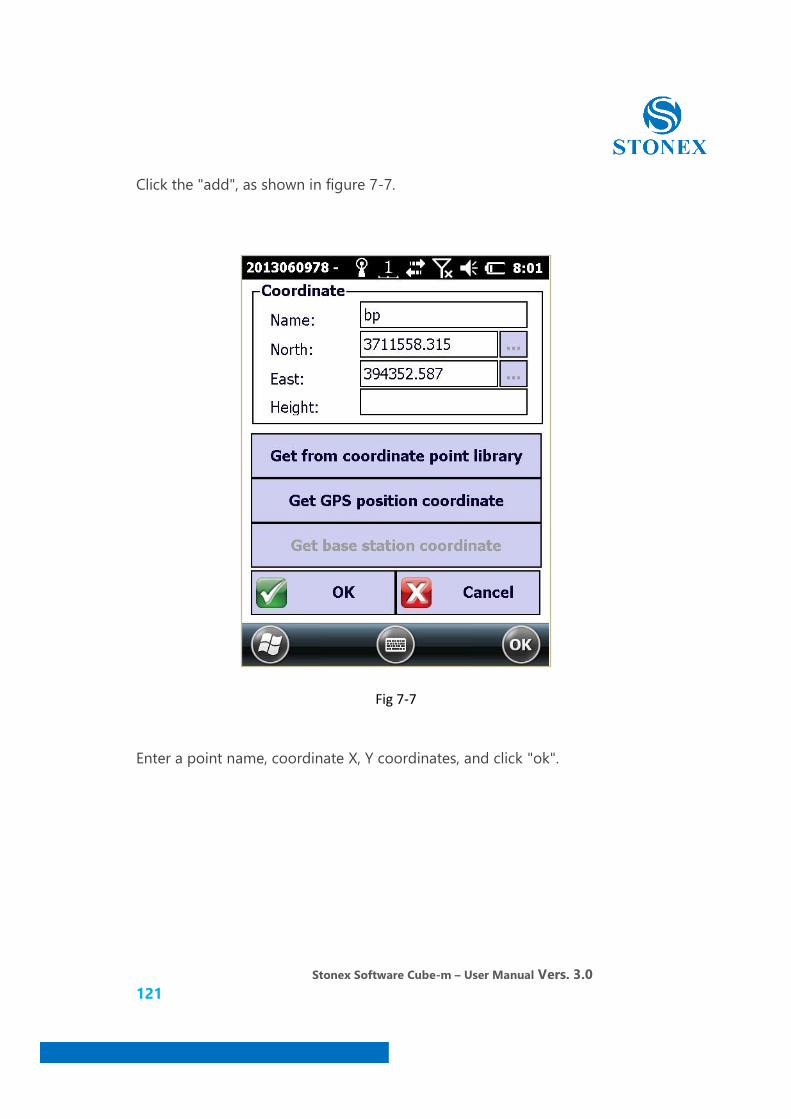
Click the "add", as shown in figure 7-7.
Fig 7-7
Enter a point name, coordinate X, Y coordinates, and click "ok".
Stonex Software Cube-m – User Manual Vers. 3.0 122
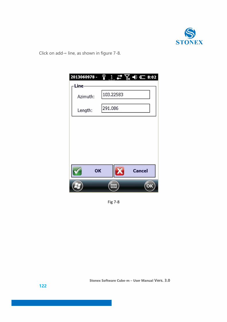
Click on add→ line, as shown in figure 7-8.
Fig 7-8
Stonex Software Cube-m – User Manual Vers. 3.0 123
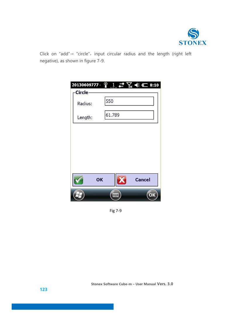
Click on “add”→ “circle”,input circular radius and the length (right left negative), as shown in figure 7-9.
Fig 7-9
Stonex Software Cube-m – User Manual Vers. 3.0 124
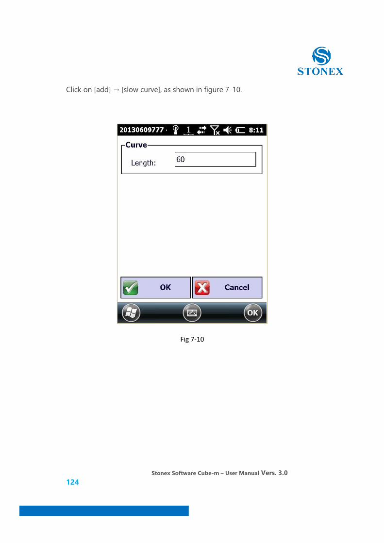
Click on [add] → [slow curve], as shown in figure 7-10.
Fig 7-10
Stonex Software Cube-m – User Manual Vers. 3.0 125
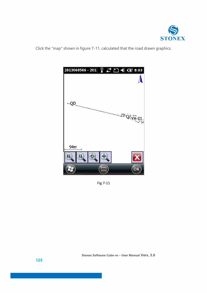
Click the "map" shown in figure 7-11, calculated that the road drawn graphics.
Fig 7-11

Stonex Software Cube-m – User Manual Vers. 3.0 126
Click , as shown in figure 7-12.
Fig 7-12
After successful calculation,First "Export Line Files" and then enter the file name, click OK, prompting the line to save the file successfully. We chose the design documents, contrast "coordinates Stakeouts," or enter plus pile interface for add-piles, to compare the check is correct, you can road stakeout after you confirm the correct.
Stonex Software Cube-m – User Manual Vers. 3.0 127
7.1.2 Intersection model line
Relative to the element method, Intersection method is more simple to understand and input; Straight piece table, are based on the intersection as a unit, each node corresponds to a cell line, every line is straight line, circle, curve these basic elements. Only when the intersection method input in order input parameter data value of each is ok, but note that the oval curve and return curve intersection method input should not be used. We input each parameter data of the intersection in order according to the method of intersection point, but we note that enter oval curve and return curve cannot use that.
Intersection method input rule
1. Starting and ending only enter north and east coordinates. Starting point must be at a point on the line.
2. Others need to enter the intersection coordinates, left and right curve length, radius and mileage. If the intersection of the cell line is only the circular curve, the left and right curve length without entering.
3. The first and the second curve is not necessarily symmetrical, the length can be different.
4. If the fragmentation process, the starting point after a period of mileage, you need to use that section of the HZ first intersection point mileage Less second tangent length obtained using the first point of intersection ZH mileage plus second tangent length wrong.

Stonex Software Cube-m – User Manual Vers. 3.0 128
Click “new”→ “intersection mode line”, as shown in figure 7-13.
Fig 7-13
Input line name, and click add to the intersection point. Starting and ending only enter coordinates; others need to enter the intersection coordinate, left and right curve length, radius and mileage.
Stonex Software Cube-m – User Manual Vers. 3.0 129
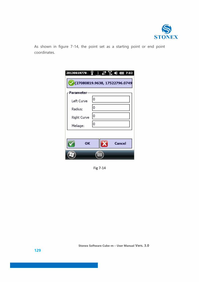
As shown in figure 7-14, the point set as a starting point or end point coordinates.
Fig 7-14
Stonex Software Cube-m – User Manual Vers. 3.0 130
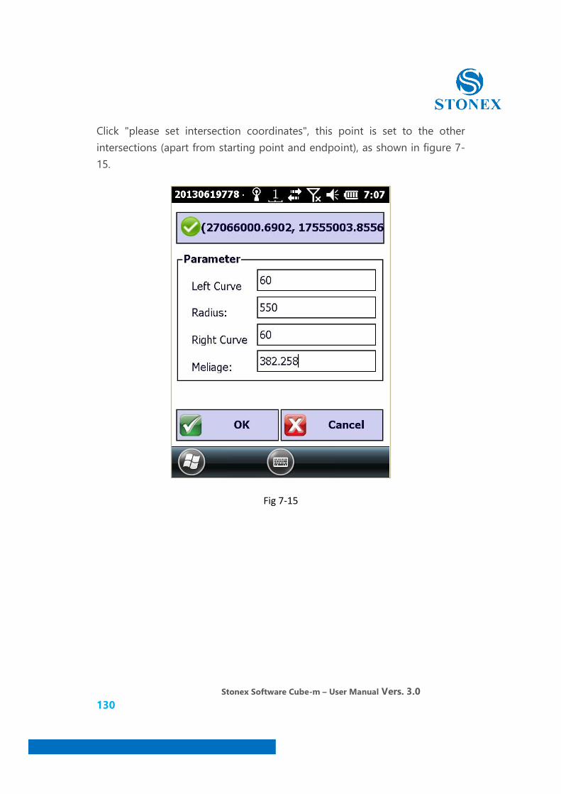
Click "please set intersection coordinates", this point is set to the other intersections (apart from starting point and endpoint), as shown in figure 7-15.
Fig 7-15

Stonex Software Cube-m – User Manual Vers. 3.0 131
We set at least three intersections, increase is completed, click on the "map" as shown in figure 7-16.
Fig 7-16

Stonex Software Cube-m – User Manual Vers. 3.0 132
7.2 Stakeout Curve
Click [survey] → [curve stakeout], as shown in figure 7-17. Must first select or new curve in the lofting library.
Fig 7-17
Stonex Software Cube-m – User Manual Vers. 3.0 133
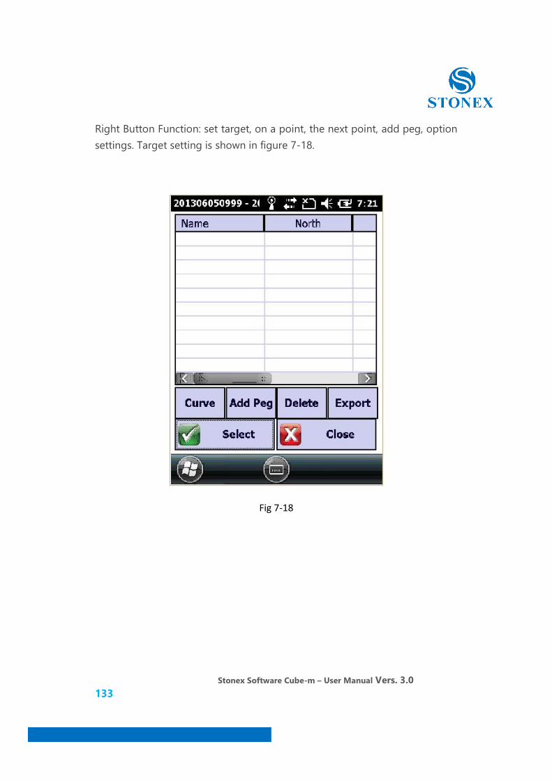
Right Button Function: set target, on a point, the next point, add peg, option settings. Target setting is shown in figure 7-18.
Fig 7-18

Stonex Software Cube-m – User Manual Vers. 3.0 134
Add curve as shown in figure 7-19.
Fig 7-19
We can choose line, circle, slow curve. The straight line set the name, mileage, start and end point. Circle set the name, radius, mileage, deflection angle, intersection point, reference. Slow curve set the name、radius、mileage、deflection angle, intersection point、reference.
Stonex Software Cube-m – User Manual Vers. 3.0 135
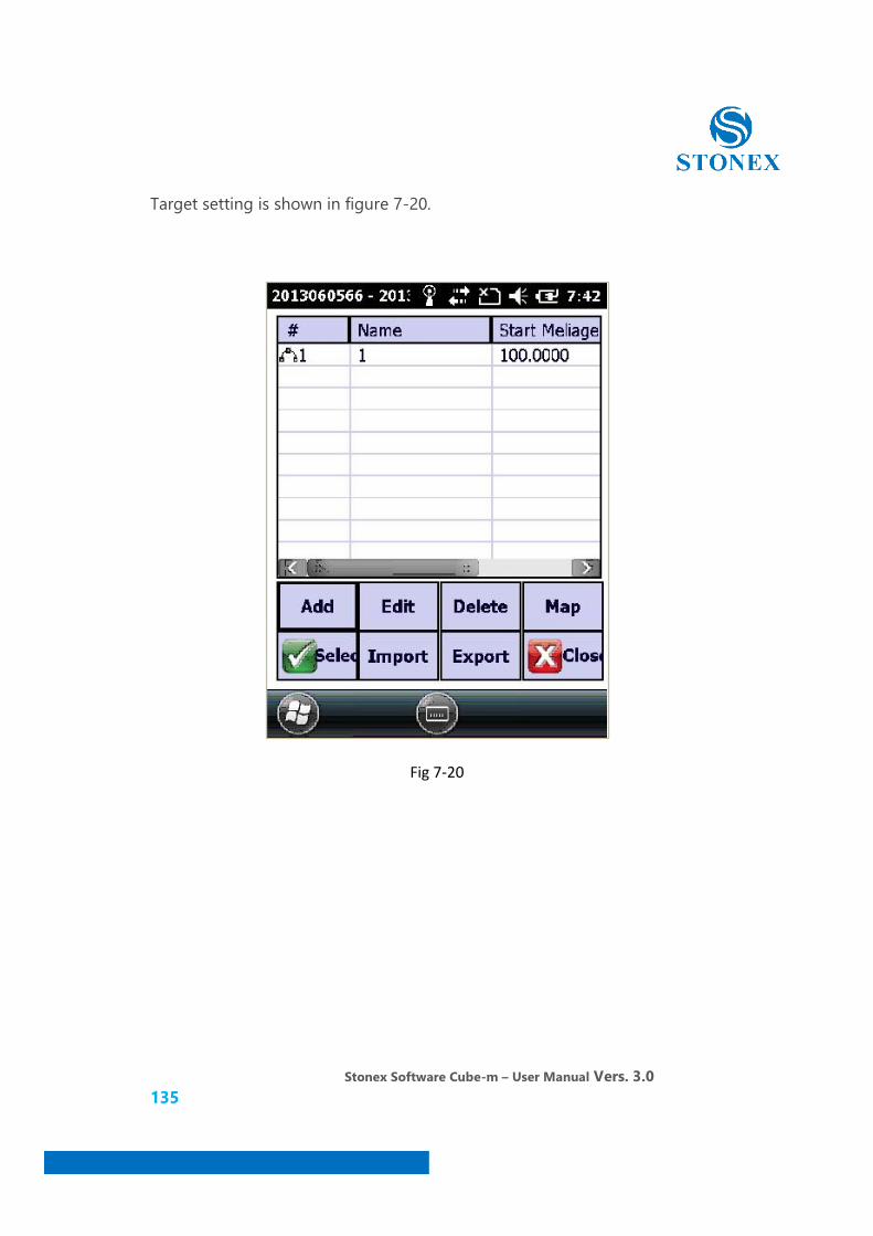
Target setting is shown in figure 7-20.
Fig 7-20

Stonex Software Cube-m – User Manual Vers. 3.0 136
Select curve after actual lofting display as shown in figure 7-21.
Fig 7-21
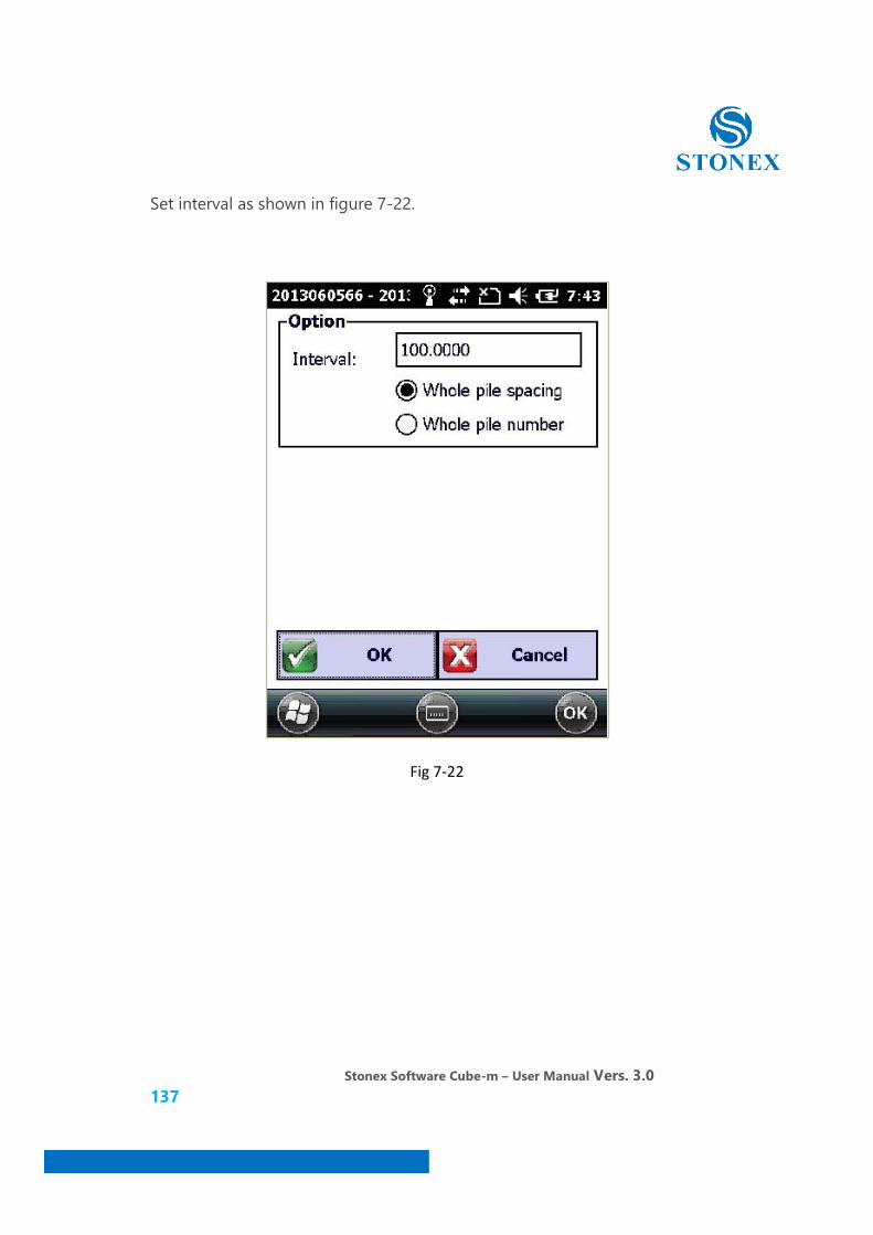
Stonex Software Cube-m – User Manual Vers. 3.0 137
Set interval as shown in figure 7-22.
Fig 7-22

Stonex Software Cube-m – User Manual Vers. 3.0 138
Click "ok" as shown in figure 7-23.
Fig 7-23
Stonex Software Cube-m – User Manual Vers. 3.0 139
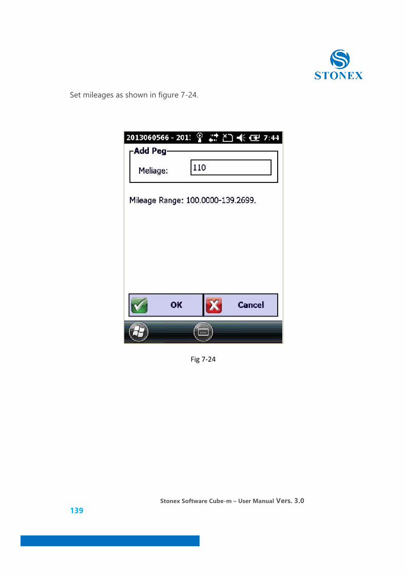
Set mileages as shown in figure 7-24.
Fig 7-24
Stonex Software Cube-m – User Manual Vers. 3.0 140
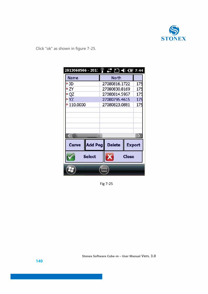
Click "ok" as shown in figure 7-25.
Fig 7-25

Stonex Software Cube-m – User Manual Vers. 3.0 141
"Selected" goal line, so that you can into the curve-lofting interface as shown in figure 7-26.
Fig 7-26
Stonex Software Cube-m – User Manual Vers. 3.0 142
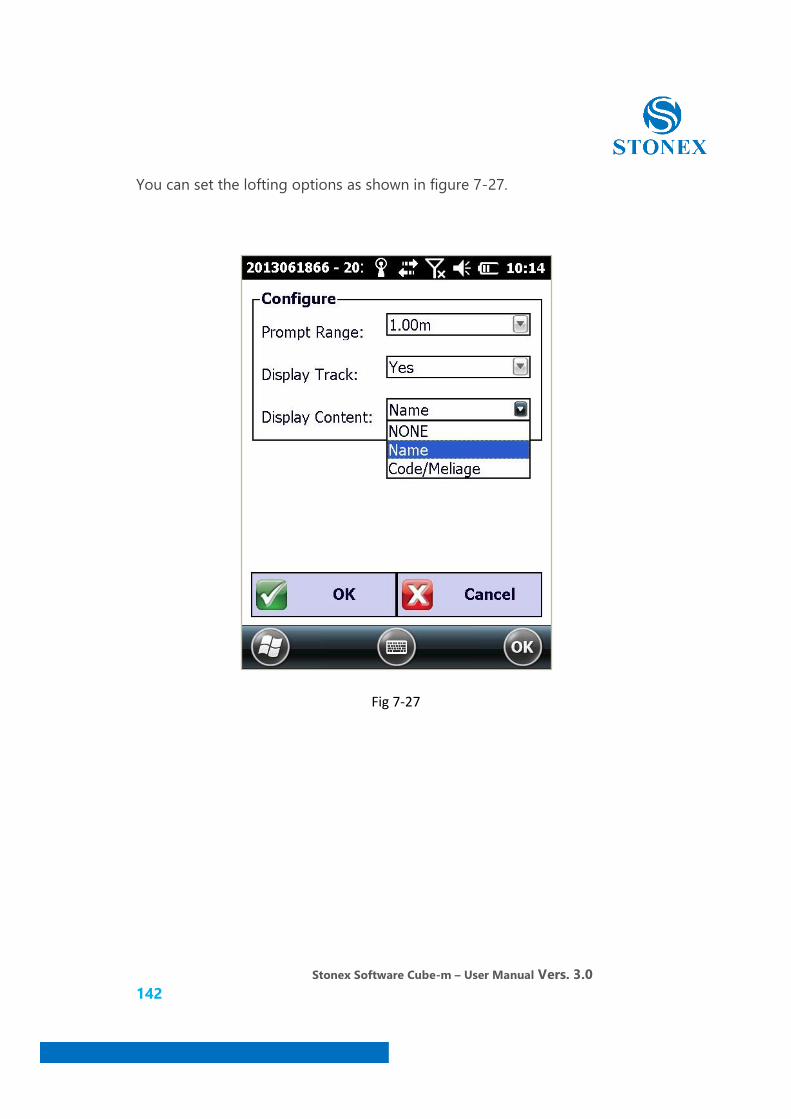
You can set the lofting options as shown in figure 7-27.
Fig 7-27

Stonex Software Cube-m – User Manual Vers. 3.0 143
8. Software-setting
Click "setting" as shown in figure 8-1.
Fig 8-1
There are six sub-menus:record, system, map, hotkey, show and measurement area.
Stonex Software Cube-m – User Manual Vers. 3.0 144
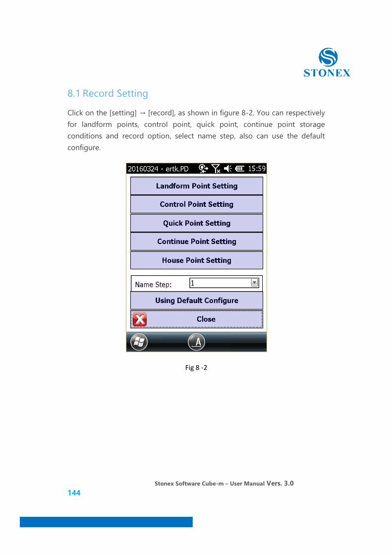
8.1 Record Setting
Click on the [setting] → [record], as shown in figure 8-2. You can respectively for landform points, control point, quick point, continue point storage conditions and record option, select name step, also can use the default configure.
Fig 8 -2

Stonex Software Cube-m – User Manual Vers. 3.0 145
8.2 System Setting
Click [setting]→[system], as shown in figure 8-3. You can set zone, solution setting, voice prompt.
Fig 8-3
Stonex Software Cube-m – User Manual Vers. 3.0 146
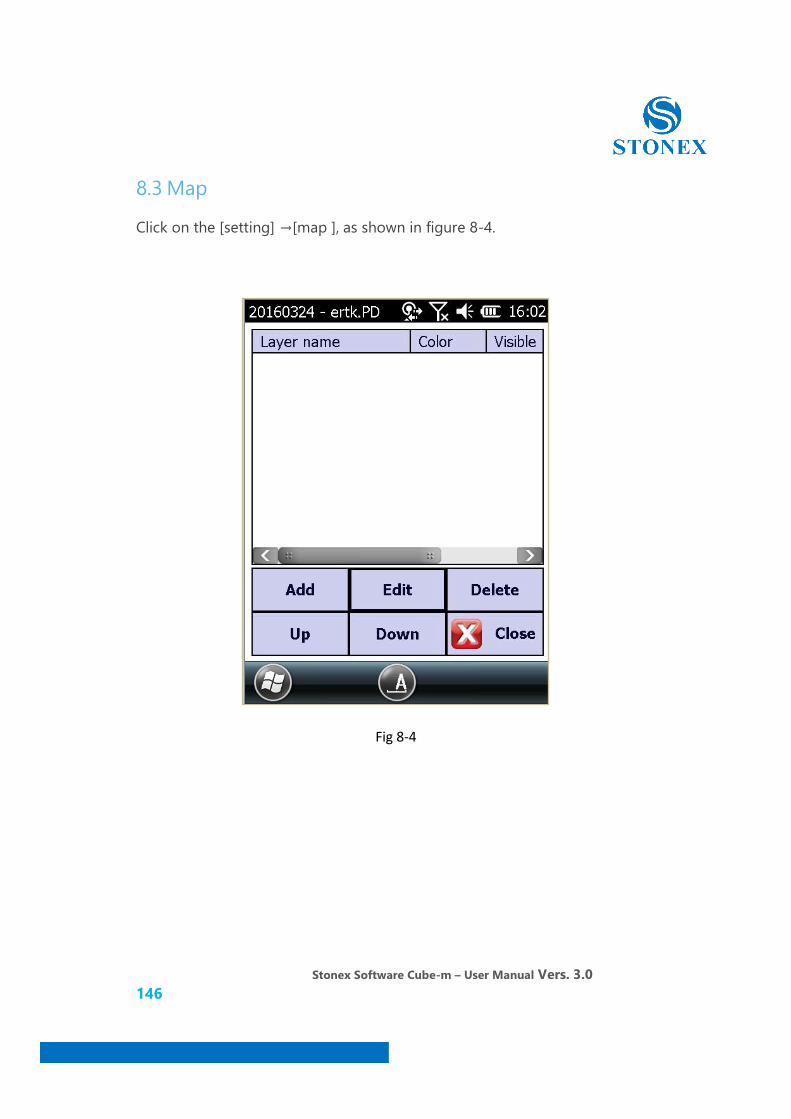
8.3 Map
Click on the [setting] →[map ], as shown in figure 8-4.
Fig 8-4
Stonex Software Cube-m – User Manual Vers. 3.0 147
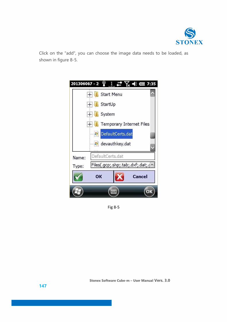
Click on the "add", you can choose the image data needs to be loaded, as shown in figure 8-5.
Fig 8-5

Stonex Software Cube-m – User Manual Vers. 3.0 148
Click "ok", as shown in figure 8-6.
Fig 8-6
Stonex Software Cube-m – User Manual Vers. 3.0 149
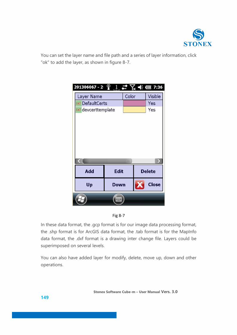
You can set the layer name and file path and a series of layer information, click "ok" to add the layer, as shown in figure 8-7.
Fig 8-7
In these data format, the .gcp format is for our image data processing format, the .shp format is for ArcGIS data format, the .tab format is for the MapInfo data format, the .dxf format is a drawing inter change file. Layers could be superimposed on several levels.
You can also have added layer for modify, delete, move up, down and other operations.
Stonex Software Cube-m – User Manual Vers. 3.0 150
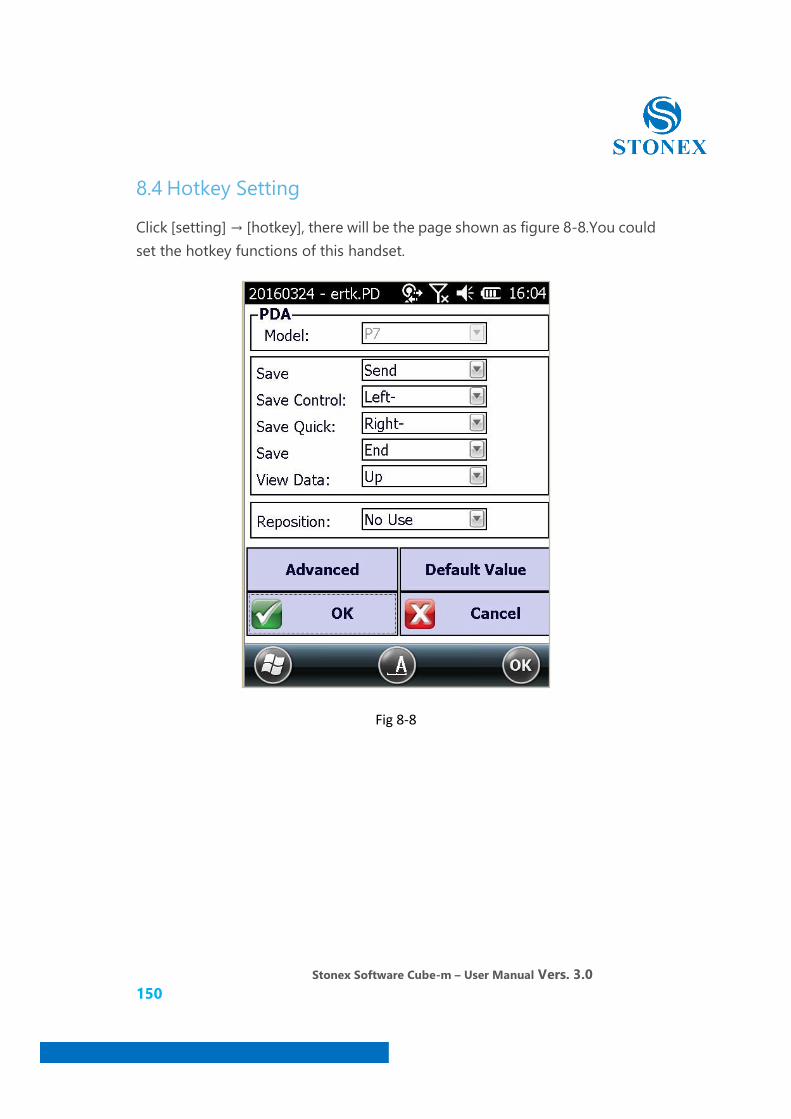
8.4 Hotkey Setting
Click [setting] → [hotkey], there will be the page shown as figure 8-8.You could set the hotkey functions of this handset.
Fig 8-8
Stonex Software Cube-m – User Manual Vers. 3.0 151
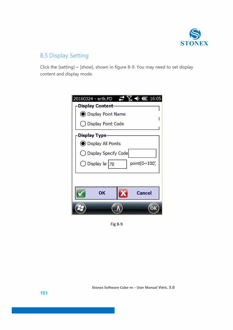
8.5 Display Setting
Click the [setting]→ [show], shown in figure 8-9. You may need to set display content and display mode.
Fig 8-9
Stonex Software Cube-m – User Manual Vers. 3.0 152
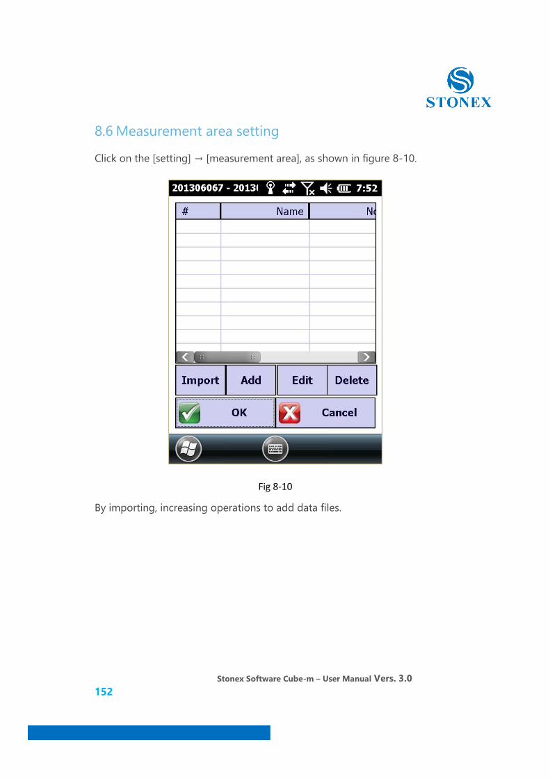
8.6 Measurement area setting
Click on the [setting] → [measurement area], as shown in figure 8-10.
Fig 8-10
By importing, increasing operations to add data files.

Stonex Software Cube-m – User Manual Vers. 3.0 153
9. Software- Tools
Click on the "tool" menu as shown in figure 9-1.
Fig 9-1

Stonex Software Cube-m – User Manual Vers. 3.0 154
9.1 Data input
Fig 9-2
There are the coordinate library, line layout, curve layout, Road layout, Vertical curve layout in the data input menu.
Stonex Software Cube-m – User Manual Vers. 3.0 155
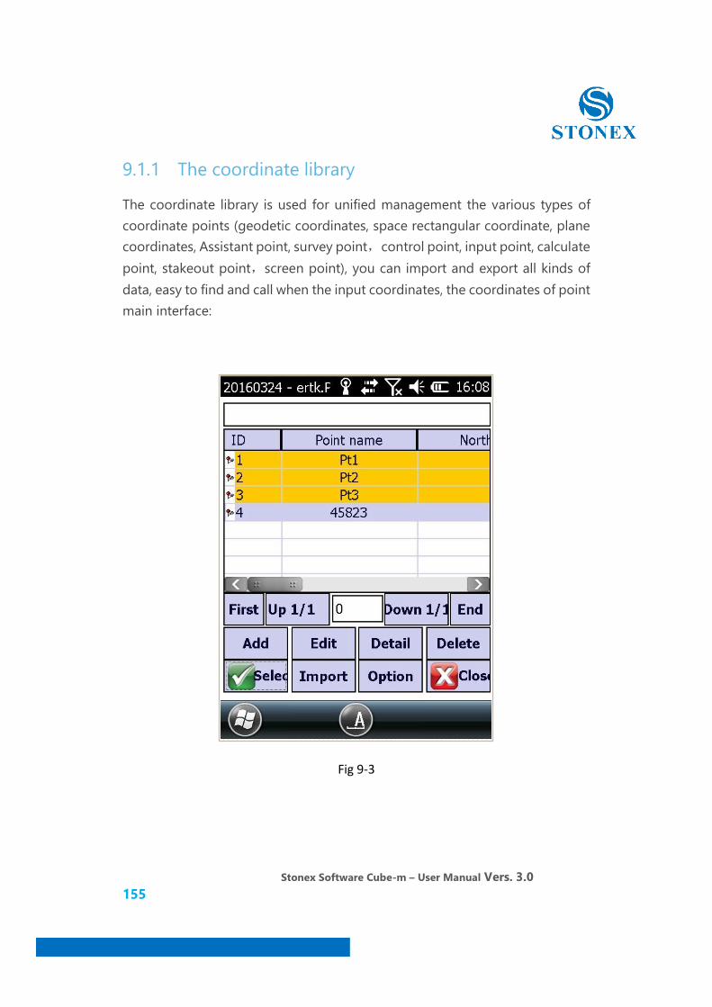
9.1.1 The coordinate library
The coordinate library is used for unified management the various types of coordinate points (geodetic coordinates, space rectangular coordinate, plane coordinates, Assistant point, survey point,control point, input point, calculate point, stakeout point,screen point), you can import and export all kinds of data, easy to find and call when the input coordinates, the coordinates of point main interface:
Fig 9-3
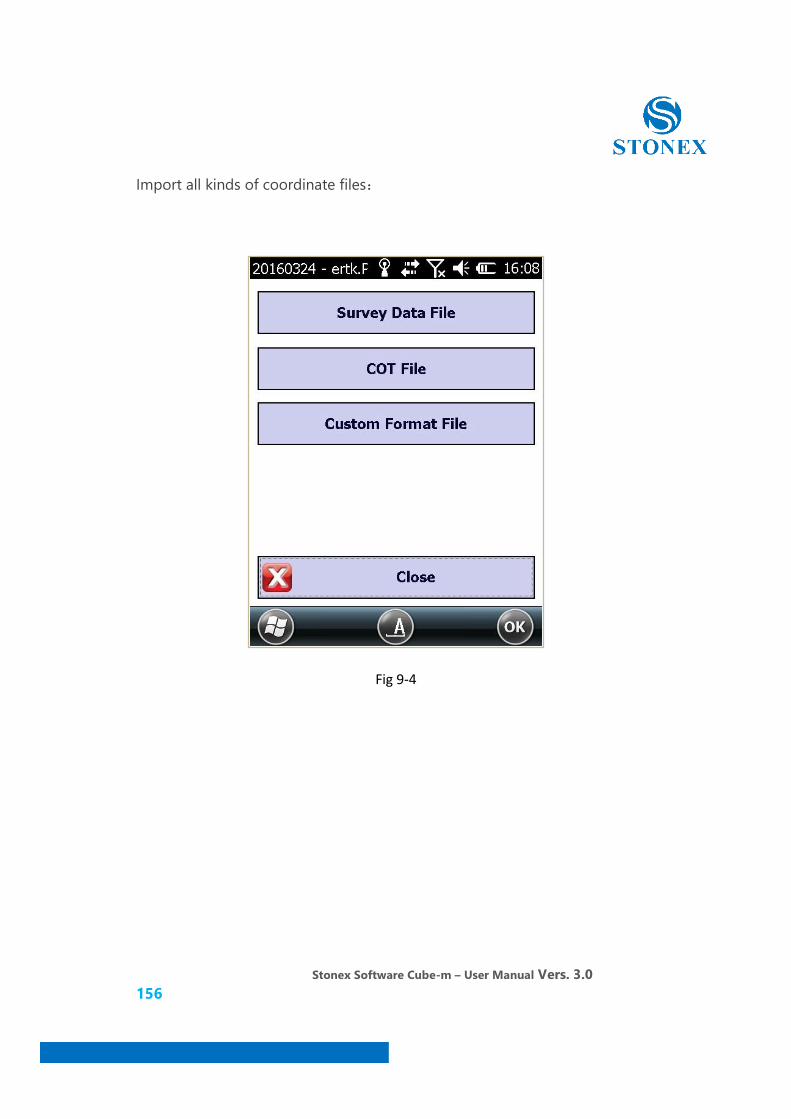
Stonex Software Cube-m – User Manual Vers. 3.0 156
Import all kinds of coordinate files:
Fig 9-4
Stonex Software Cube-m – User Manual Vers. 3.0 157
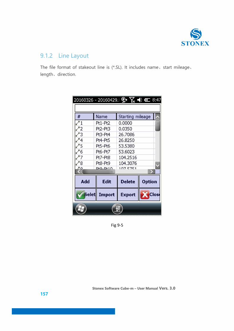
9.1.2 Line Layout
The file format of stakeout line is (*.SL). It includes name、start mileage、length、direction.
Fig 9-5

Stonex Software Cube-m – User Manual Vers. 3.0 158
Click [Import], you could import stakeout line file (* .SQL) and the coordinate point file (* .dat).
Fig 9-6
Stonex Software Cube-m – User Manual Vers. 3.0 159
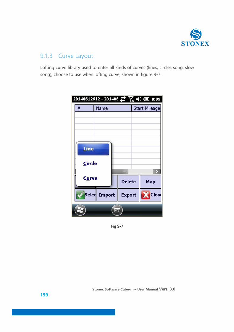
9.1.3 Curve Layout
Lofting curve library used to enter all kinds of curves (lines, circles song, slow song), choose to use when lofting curve, shown in figure 9-7.
Fig 9-7
Stonex Software Cube-m – User Manual Vers. 3.0 160
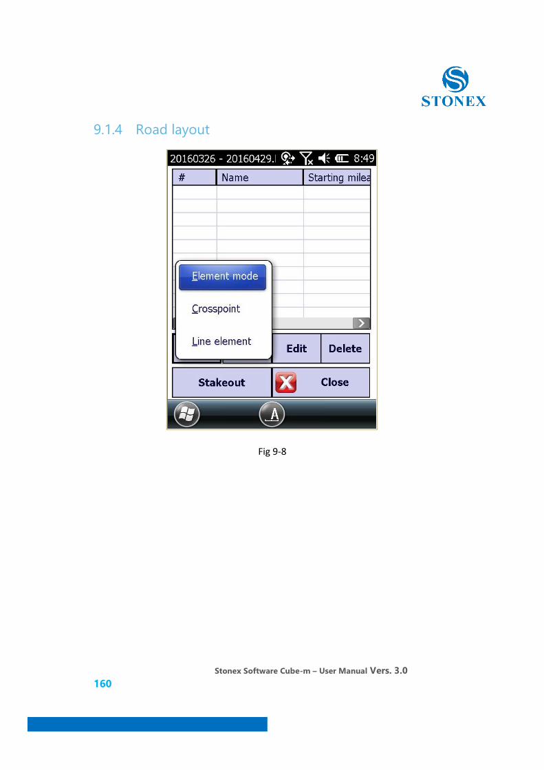
9.1.4 Road layout
Fig 9-8

Stonex Software Cube-m – User Manual Vers. 3.0 161
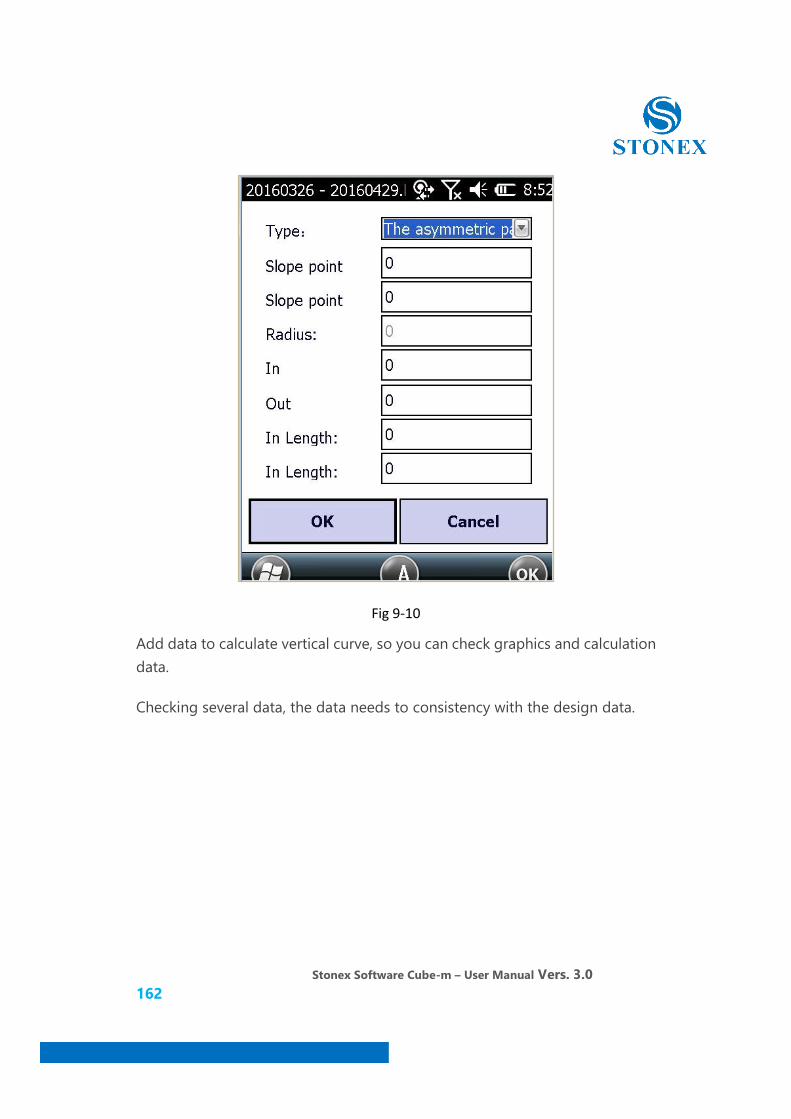
9.1.5 Vertical Curve Layout
Vertical curve: In order to ease the sudden change in the slope of the profile, it sets in the grade change point, smooth connection of two adjacent slope section of the vertical curve.
Vertical curve have two type: asymmetric parabola and parabola.
Fig 9-9
Based on data provided by the design paper, input the necessary data to calculate vertical curve, and depending on the type of curve to calculate element will change slightly.
Stonex Software Cube-m – User Manual Vers. 3.0 162
Fig 9-10
Add data to calculate vertical curve, so you can check graphics and calculation data.
Checking several data, the data needs to consistency with the design data.
Stonex Software Cube-m – User Manual Vers. 3.0 163
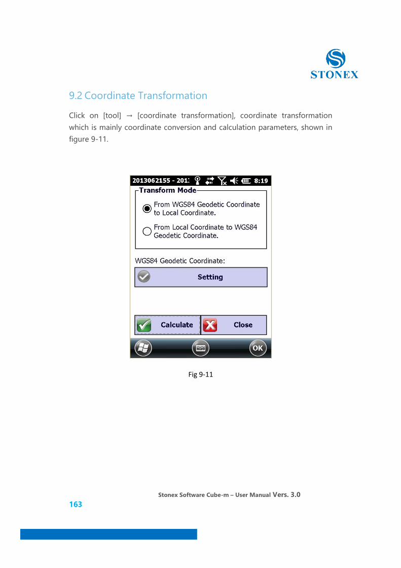
9.2 Coordinate Transformation
Click on [tool] → [coordinate transformation], coordinate transformation which is mainly coordinate conversion and calculation parameters, shown in figure 9-11.
Fig 9-11
Stonex Software Cube-m – User Manual Vers. 3.0 164
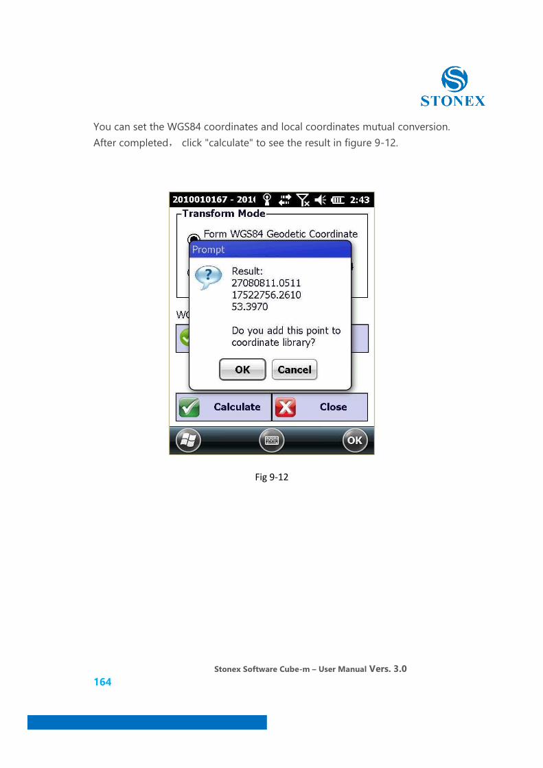
You can set the WGS84 coordinates and local coordinates mutual conversion. After completed, click "calculate" to see the result in figure 9-12.
Fig 9-12
Stonex Software Cube-m – User Manual Vers. 3.0 165
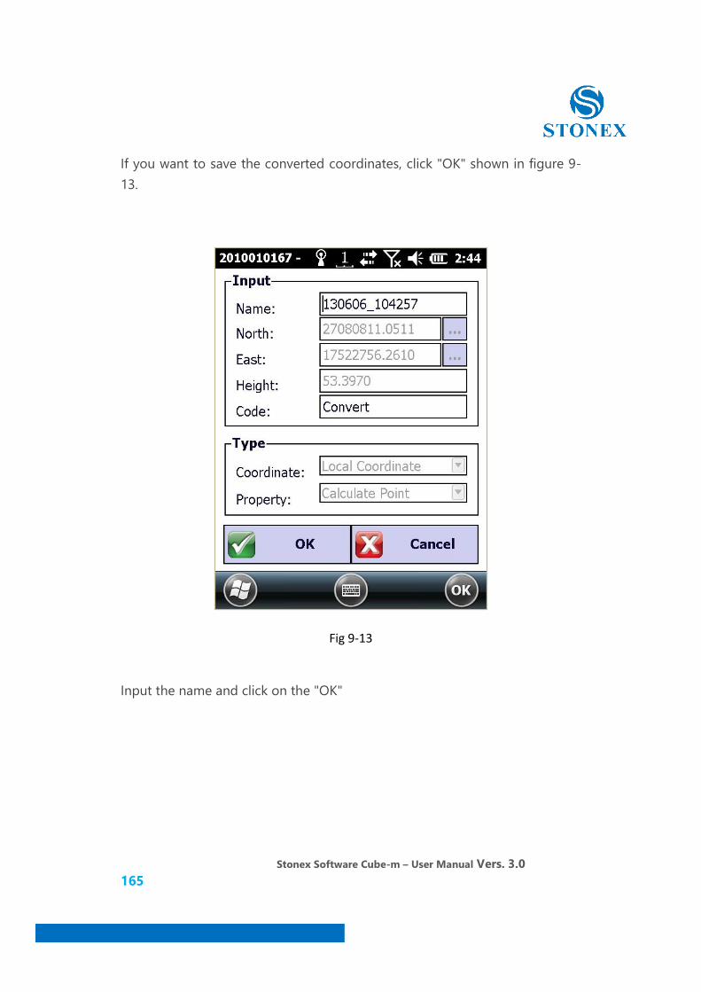
If you want to save the converted coordinates, click "OK" shown in figure 9-13.
Fig 9-13
Input the name and click on the "OK"
Stonex Software Cube-m – User Manual Vers. 3.0 166
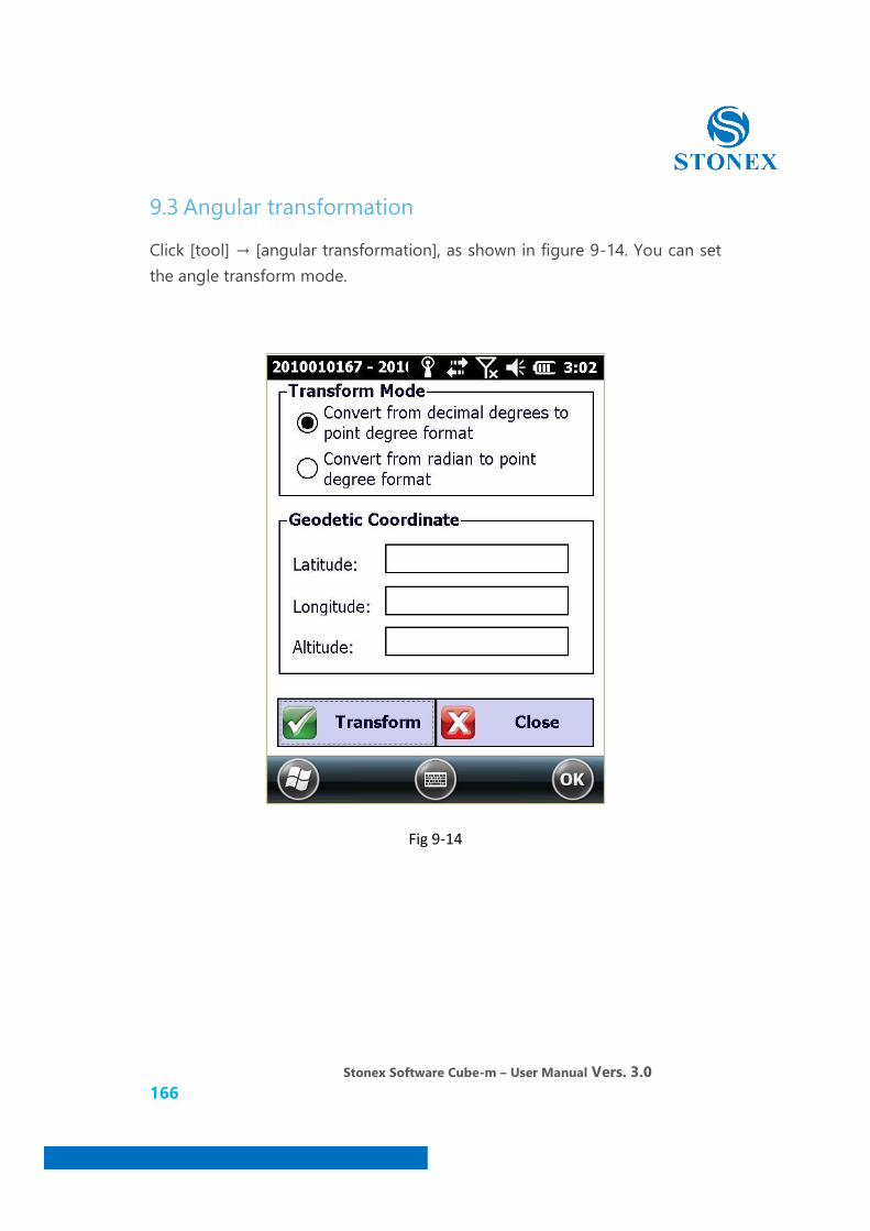
9.3 Angular transformation
Click [tool] → [angular transformation], as shown in figure 9-14. You can set the angle transform mode.
Fig 9-14
Stonex Software Cube-m – User Manual Vers. 3.0 167
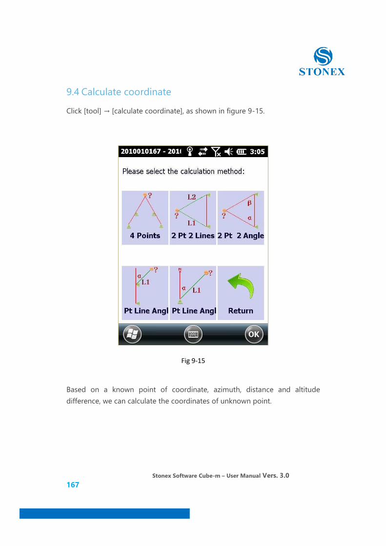
9.4 Calculate coordinate
Click [tool] → [calculate coordinate], as shown in figure 9-15.
Fig 9-15
Based on a known point of coordinate, azimuth, distance and altitude difference, we can calculate the coordinates of unknown point.
Stonex Software Cube-m – User Manual Vers. 3.0 168
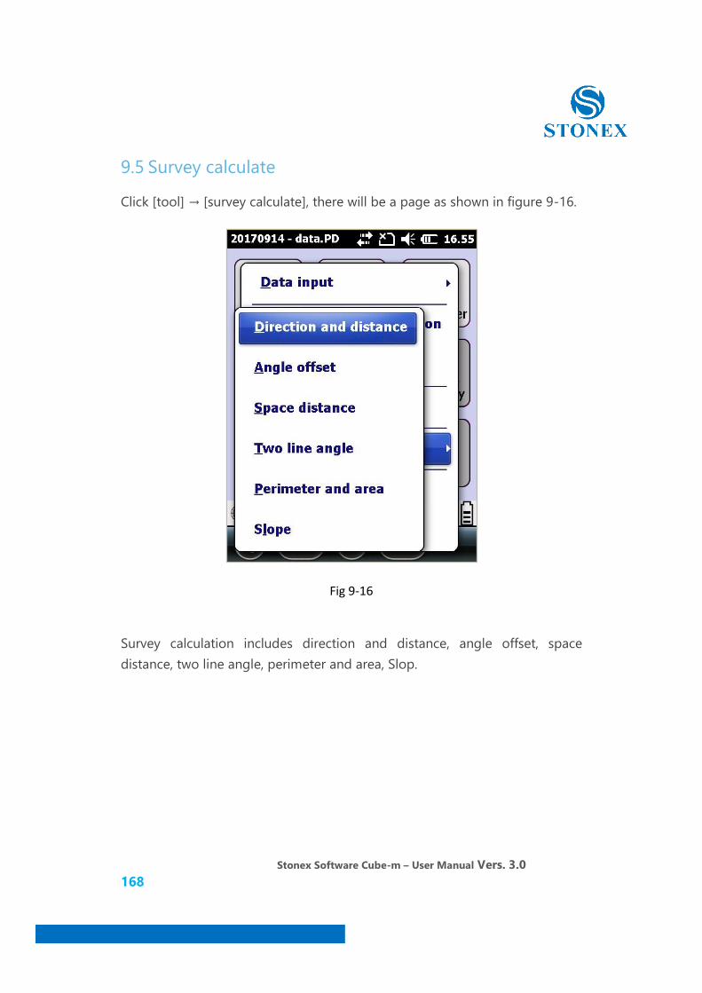
9.5 Survey calculate
Click [tool] → [survey calculate], there will be a page as shown in figure 9-16.
Fig 9-16
Survey calculation includes direction and distance, angle offset, space distance, two line angle, perimeter and area, Slop.
Stonex Software Cube-m – User Manual Vers. 3.0 169
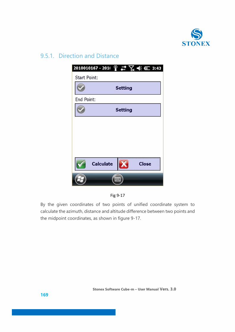
9.5.1. Direction and Distance
Fig 9-17
By the given coordinates of two points of unified coordinate system to calculate the azimuth, distance and altitude difference between two points and the midpoint coordinates, as shown in figure 9-17.

Stonex Software Cube-m – User Manual Vers. 3.0 170
9.5.1 Offset Angle
Fig 9-18
Angle offset distance can be calculated relative to the starting point and end point in point a straight Angle, offset, deflection distance including starting point and end point, as well as the offset, as shown in figure 9-18.
Stonex Software Cube-m – User Manual Vers. 3.0 171
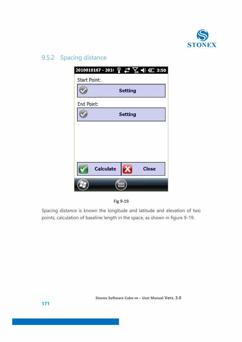
9.5.2 Spacing distance
Fig 9-19
Spacing distance is known the longitude and latitude and elevation of two points, calculation of baseline length in the space, as shown in figure 9-19.
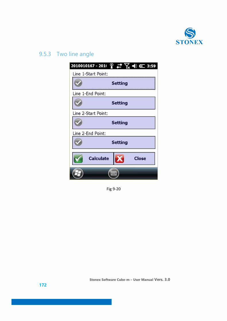
Stonex Software Cube-m – User Manual Vers. 3.0 172
9.5.3 Two line angle
Fig 9-20
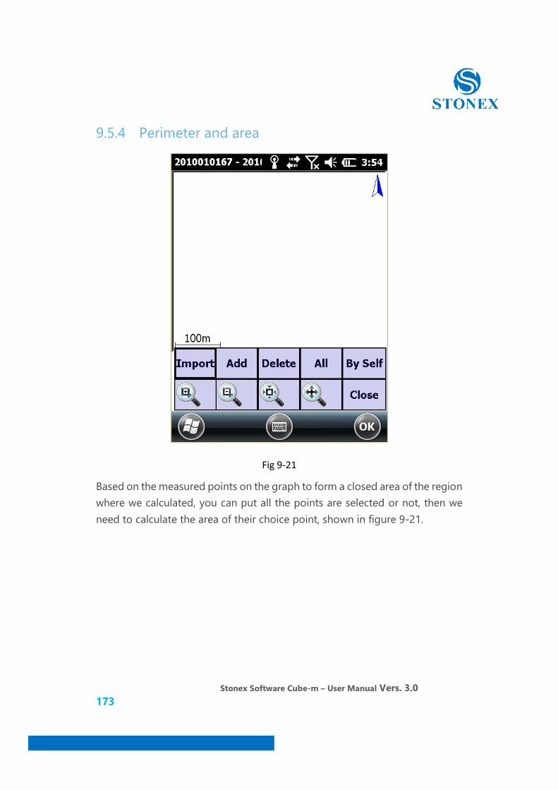
Stonex Software Cube-m – User Manual Vers. 3.0 173
9.5.4 Perimeter and area
Fig 9-21
Based on the measured points on the graph to form a closed area of the region where we calculated, you can put all the points are selected or not, then we need to calculate the area of their choice point, shown in figure 9-21.
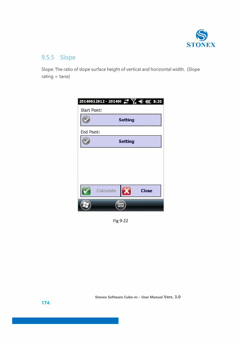
Stonex Software Cube-m – User Manual Vers. 3.0 174
9.5.5 Slope
Slope: The ratio of slope surface height of vertical and horizontal width. (Slope rating = tanα)
Fig 9-22
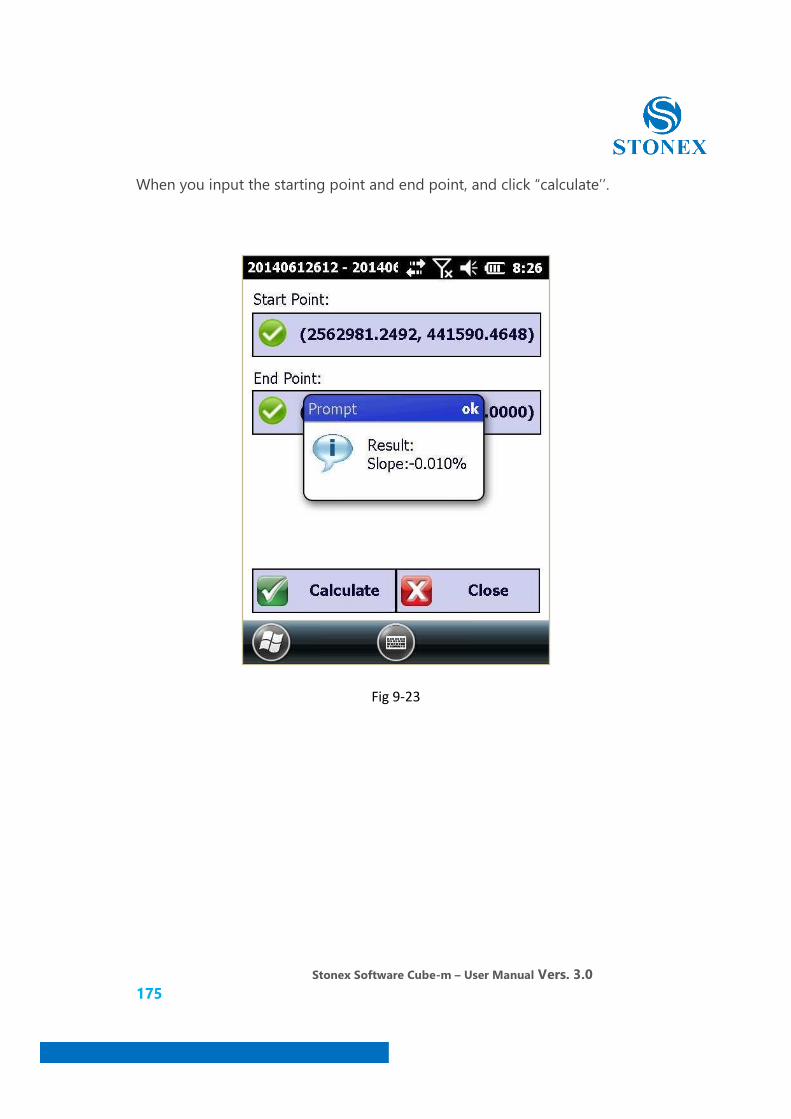
Stonex Software Cube-m – User Manual Vers. 3.0 175
When you input the starting point and end point, and click “calculate’’.
Fig 9-23

Stonex Software Cube-m – User Manual Vers. 3.0 176
10. Software- About
In software main interface, click "about" appeared register software, registered instrument, battery Level, about instrument and about software five sub-menu, as shown in figure 10-1
Fig 10-1
"About" menu is used to display the software information and system operation information.

Stonex Software Cube-m – User Manual Vers. 3.0 177
10.1 Registered instrument
Click on equipment registered, you can view the registration information RTK instrument, if the instrument is not registered or the registration code has expired, you can enter the registration code to registered, shown in figure 10-2.
Fig 10-2
"Register device" is the RTK receiver to register, register need to receiver and handheld in the machine status.
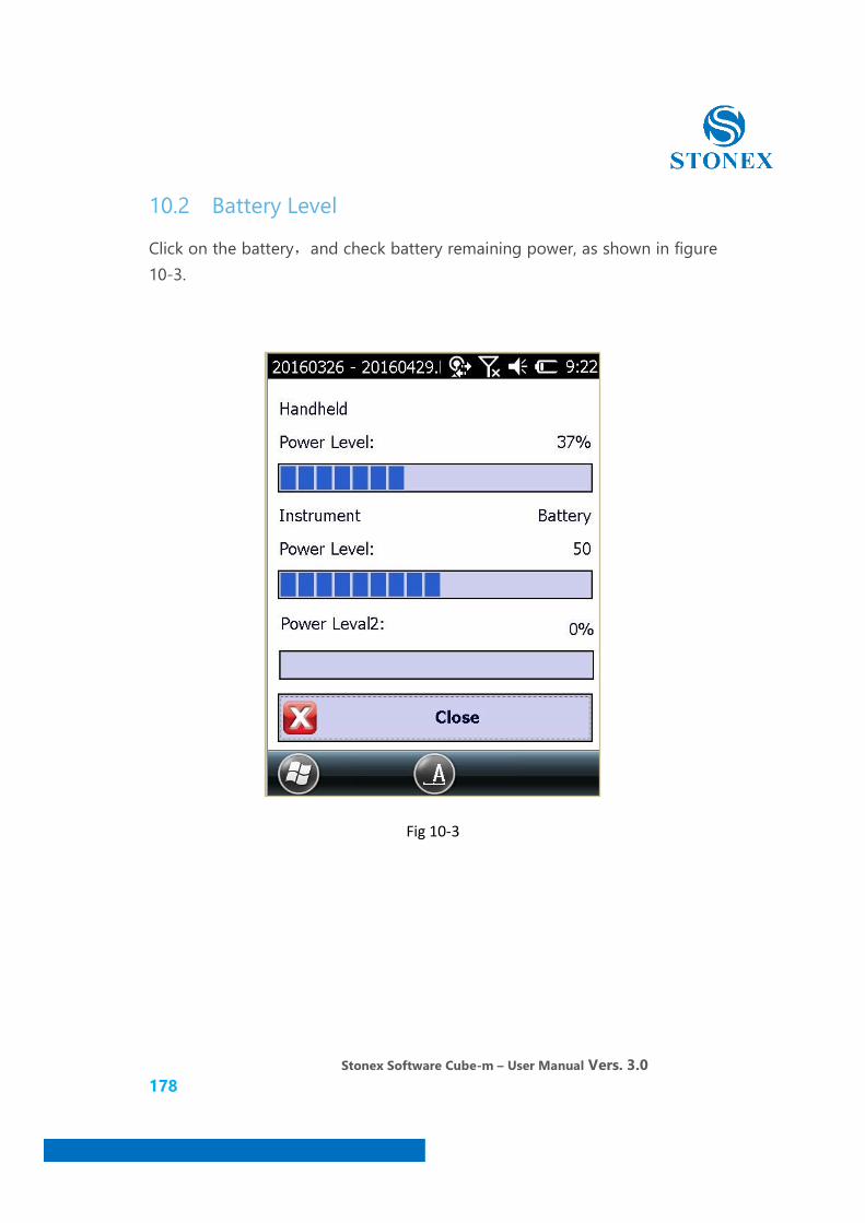
Stonex Software Cube-m – User Manual Vers. 3.0 178
10.2 Battery Level
Click on the battery,and check battery remaining power, as shown in figure 10-3.
Fig 10-3
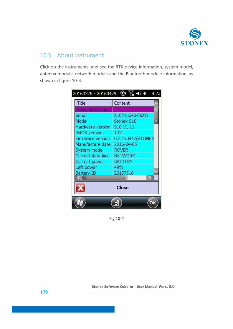
Stonex Software Cube-m – User Manual Vers. 3.0 179
10.3 About instrument
Click on the instruments, and see the RTK device information, system model, antenna module, network module and the Bluetooth module information, as shown in figure 10-4.
Fig 10-4

Stonex Software Cube-m – User Manual Vers. 3.0 180
10.4 About software
Click on the software, and see the software version, compiled date and other related information, as shown in figure 10-5.
Stonex Software Cube-m – User Manual Vers. 3.0 181
11. The simple operating procedures of RTK
Field Surveying
Following is a simple operation procedure of the software, if you want to see the detailed procedures, please refer to the description in the below.
1. Span the base station, set up the work mode of GNSS mainframe (you could also set the receiver work mode by handset)
2. Open Cube-m software and connect the base station, then create a new project and set the parameters of the coordinate system, set up the parameters of base station, at last make the base station transmit differential signal.
3. Connect the rover and ste up the parameters of mobile station, make the rover receive the differential data of the base station, at last the solution state of rover will be fixed solution.
4. When the rover in the narrowband and the fixed solution state, measure the WGS84 original coordinate of the known point in the surveyed area. According to the original coordinates and local coordinates of the known point, solve the transformation parameters between two coordinate systems.
5. By using of coordinate transformation parameters, the RTK measured WGS-84 coordinates will be automatically converted into local coordinates. In addition, you should use at least one known point coordinate to inspect whether the conversion is correct.
6. Measurement, stakeout and other operations in the local coordinate system, to obtain the coordinate data in the local coordinate system.
7. Convert the coordinate data format into the data format which you need by your handset.
Stonex Software Cube-m – User Manual Vers. 3.0 182
8. Installed ActiveSync software in the computer, then connect the handset and computer through the USB cable, and then transfer data to the computer for subsequent mapping operation.
In general, using different coordinate conversion method according to different known conditions, the main conversion methods are: four-parameter + elevation correction, seven-parameter, seven-parameter + four-parameter + elevation correction. Using four-parameter requires at least two or more known location coordinates and works at any coordinate system, but using seven -parameter need at least three or more coordinates in national coordinate system, the following we will descript the detailed RTK measurement procedures by using four-parameter + elevation plane correction.
11.1 Set up the base station
The base station could be set up on a known point or unknown points
When you set up the base station, you should to meet the following requirements:
a. The elevation angle must above 15 degrees, no large obstructions.
b. No electromagnetic interference (within 200 meters, there is no microwave stations, radar stations, mobile signal station. No power lines within 50 meters)
c. When work with radio station, the base station position is relatively high, and it is better that no major obstructions between the base station and the rover station, or the differential propagation distance is shortened;
d. At least two known points coordinate (coordinate point may be any coordinate system, it is preferably three or more known points coordinates, so that you could calibrate the accuracy of the known points coordinate).
Stonex Software Cube-m – User Manual Vers. 3.0 183
e. Regardless of the base station set up at a known point or unknown point, whether coordinate system is national, local or construction coordinate, this method is applicable.
f. When working with an external radio, the satellite antennas of base station and radio antenna recommended distance difference is greater than 2 meters, so as not to affect the reception of satellite signals when the station transmitting differential data.
Set up and connected the GNSS base station, then press the power button to turn on the receiver and wait for the base station tracking satellites (Note: If you use an external radio to work with base station, you need to connect all the cables and antennas, then open plug-in radio first, at last open the receiver)

Stonex Software Cube-m – User Manual Vers. 3.0 184
11.2 Connect the handset and the mainframe
Open the base station receiver, click key on the lower left corner of the
handset desktop, click the icon to run the Cube-m software, enter the project management interface shown in Figure 11-1. You could create, open, delete projects.
Fig 11-1 Fig 11-2
Click [New] as shown in Figure 11-2. Enter the project name, the operator and other relevant information, creation date defaults to the system date.

Stonex Software Cube-m – User Manual Vers. 3.0 185
After this information has been entered, click OK to enter the communication settings screen shown in Figure 11-3.
Fig 11-3 Fig 11-4
Click the drop-down box of the corresponding model, shown in Figure 11-4, select the appropriate instrument type, select "S9/S6/S10/S3" said the handset connected to the corresponding models (S9/S10/S6/S3).
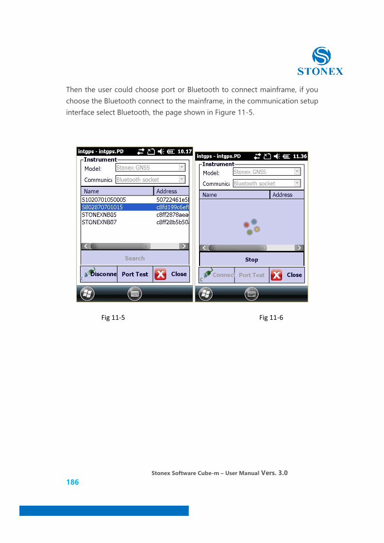
Stonex Software Cube-m – User Manual Vers. 3.0 186
Then the user could choose port or Bluetooth to connect mainframe, if you choose the Bluetooth connect to the mainframe, in the communication setup interface select Bluetooth, the page shown in Figure 11-5.
Fig 11-5 Fig 11-6
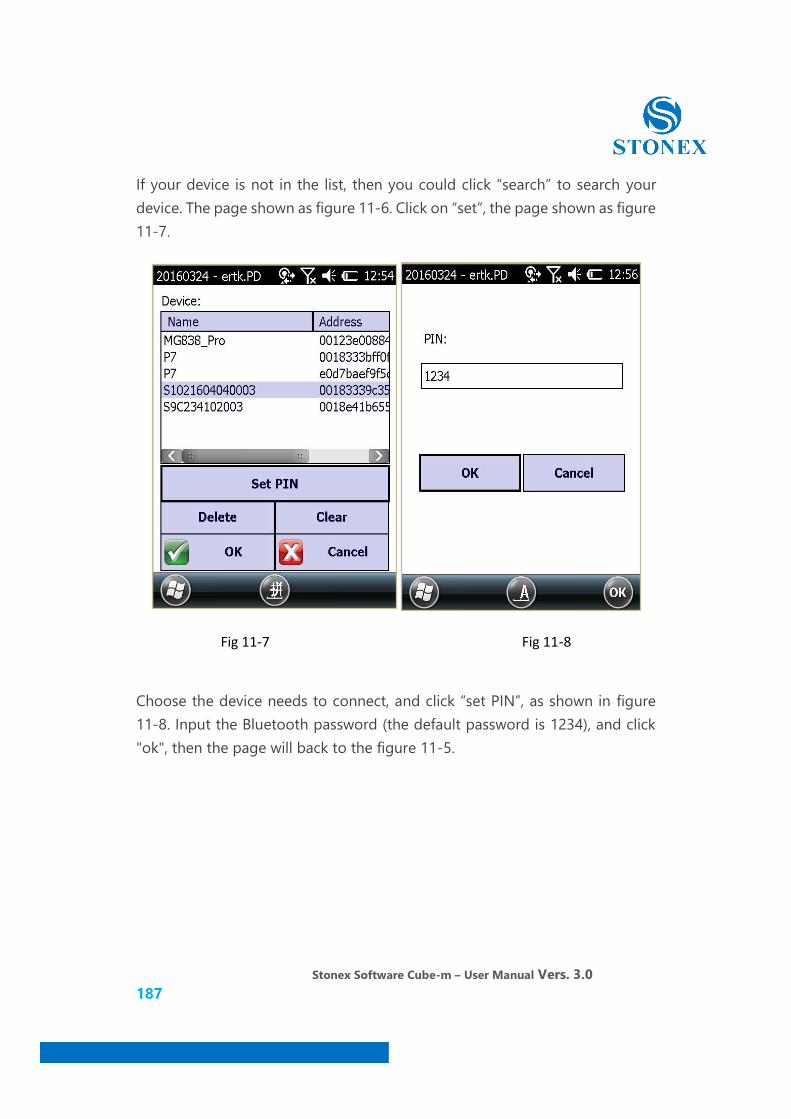
Stonex Software Cube-m – User Manual Vers. 3.0 187
If your device is not in the list, then you could click “search” to search your device. The page shown as figure 11-6. Click on “set”, the page shown as figure 11-7.
Fig 11-7 Fig 11-8
Choose the device needs to connect, and click “set PIN”, as shown in figure 11-8. Input the Bluetooth password (the default password is 1234), and click "ok", then the page will back to the figure 11-5.
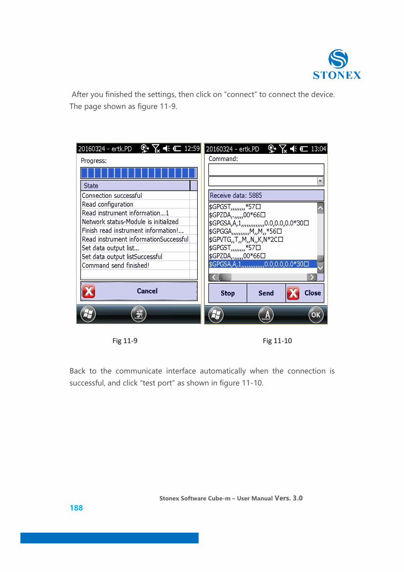
Stonex Software Cube-m – User Manual Vers. 3.0 188
After you finished the settings, then click on “connect” to connect the device. The page shown as figure 11-9.
Fig 11-9 Fig 11-10
Back to the communicate interface automatically when the connection is successful, and click “test port” as shown in figure 11-10.
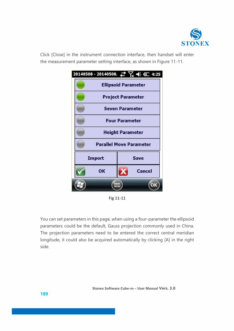
Stonex Software Cube-m – User Manual Vers. 3.0 189
Click [Close] in the instrument connection interface, then handset will enter the measurement parameter setting interface, as shown in Figure 11-11.
Fig 11-11
You can set parameters in this page, when using a four-parameter the ellipsoid parameters could be the default, Gauss projection commonly used in China. The projection parameters need to be entered the correct central meridian longitude, it could also be acquired automatically by clicking [A] in the right side.

Stonex Software Cube-m – User Manual Vers. 3.0 190
11.3 Set up base station
After the receiver in base station could track satellites, click [instrument] on the software main interface, select the [mode] - - [base setting] in the drop-down menu, shown in Figure 11-12. Select [single] in the "Start Parameter", enter the station name in the “base ID”, shown in Figure 11-13.
Fig 11-12 Fig 11-13
NOTE: If you set up the base station at a known point, you know the WGS84 coordinates of the base station, you can specify a base station coordinates, then select [specify coordinate] and input reference station coordinates and instrument height in [base coordinate] and [base antenna height] to start the base station.
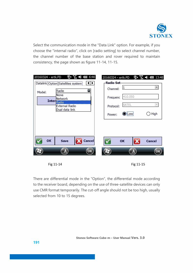
Stonex Software Cube-m – User Manual Vers. 3.0 191
Select the communication mode in the "Data Link" option. For example, if you choose the “internal radio”, click on [radio setting] to select channel number, the channel number of the base station and rover required to maintain consistency, the page shown as figure 11-14, 11-15.
Fig 11-14 Fig 11-15
There are differential mode in the "Option", the differential mode according to the receiver board, depending on the use of three-satellite devices can only use CMR format temporarily. The cut-off angle should not be too high, usually selected from 10 to 15 degrees.

Stonex Software Cube-m – User Manual Vers. 3.0 192
Select the satellite system which will be used in the "satellite system" option, the base station and rover station of this project should keep consistency , the pages shown in figure 11-16, 11-17
Fig 11-16 Fig 11-17
Click “OK” after setting has been completed; the base station begins configuration and start-up, the page shown in figure 11-18. After start-up is completed, the radio indicator of the mainframe start flashing once per second, the main interface displays "GPS: base station", it means the base station starts successfully.

Stonex Software Cube-m – User Manual Vers. 3.0 193
As shown in figure 11-19.
Fig 11-18 Fig 11-19
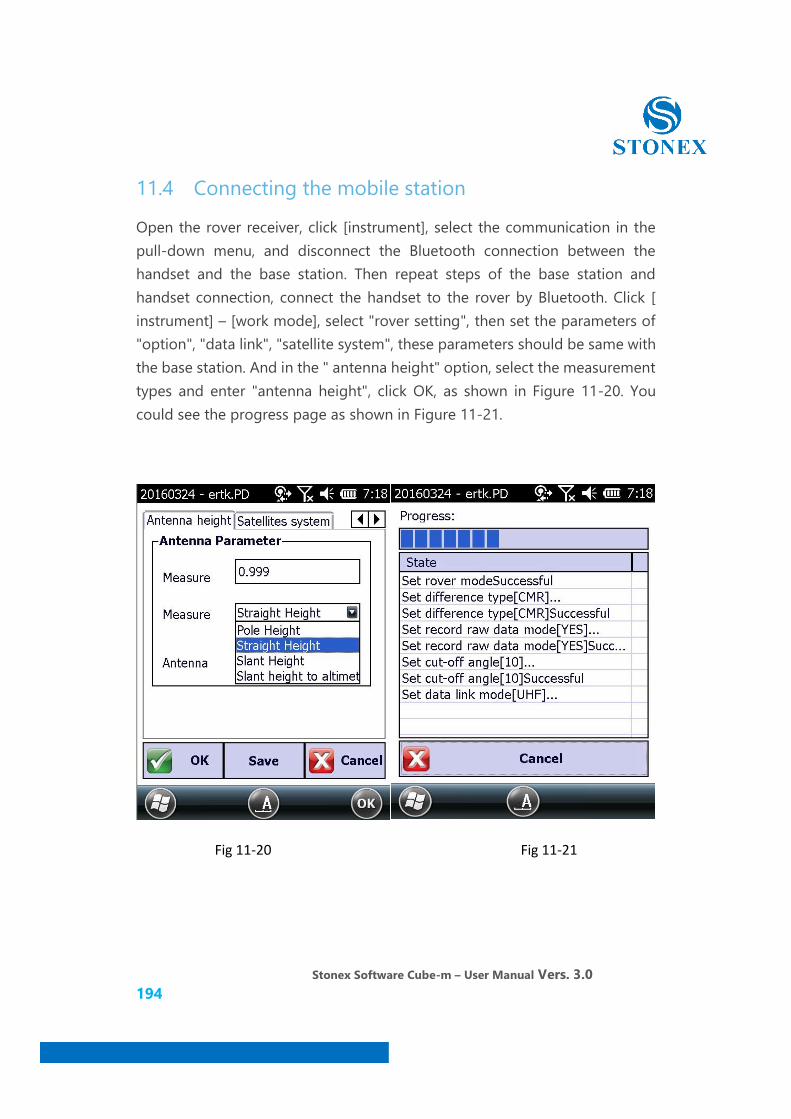
Stonex Software Cube-m – User Manual Vers. 3.0 194
11.4 Connecting the mobile station
Open the rover receiver, click [instrument], select the communication in the pull-down menu, and disconnect the Bluetooth connection between the handset and the base station. Then repeat steps of the base station and handset connection, connect the handset to the rover by Bluetooth. Click [ instrument] – [work mode], select "rover setting", then set the parameters of "option", "data link", "satellite system", these parameters should be same with the base station. And in the " antenna height" option, select the measurement types and enter "antenna height", click OK, as shown in Figure 11-20. You could see the progress page as shown in Figure 11-21.
Fig 11-20 Fig 11-21

Stonex Software Cube-m – User Manual Vers. 3.0 195
11.5 Calculating Transformation Parameter
First moved the rover to the first known point. When the rover is in fixed solution, click [parameter] - [convert parameter] in main menu, there will be the interface of parameter calculation, then click on [add] at the lower left corner, the page shown in figure 11-22. Click on [setting] menu to enter the coordinates of the known input point, and get the GPS position coordinates, the page shown as figure 11-23.
Fig 11-22 Fig 11-23
Put the pole to the test point and click OK to start smooth acquisition, click [Stop] after acquisition for a short time, then select antenna height measurement types and enter the measured height, and click OK.
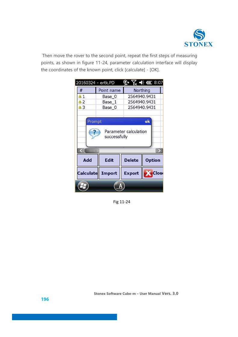
Stonex Software Cube-m – User Manual Vers. 3.0 196
Then move the rover to the second point, repeat the first steps of measuring points, as shown in figure 11-24, parameter calculation interface will display the coordinates of the known point, click [calculate] - [OK].
Fig 11-24

Stonex Software Cube-m – User Manual Vers. 3.0 197
In the coordinate system interface, it is possible to view the parameters of the plane and height convert, as shown in figure 11-25 and 11-26. In four parameters, the scale parameter is usually infinitely close to the value of 1, the value is generally 1.000x or 0.999x. If the value does not match, please check whether there is operator error or other relevant circumstances of coordinate error during operation. If the parameter meet the requirements, click OK, then click [Close] at the lower right corner of the parameter calculation interface to exit, and assigned the conversion parameters to the current project.
Fig 11-25 Fig 11-26
1. Check whether the parameters are correct at the known points. After the parameters checked ok, you could survey, stakeout and do other work, the data collected will be stored in the library of measurement points. After the work is completed, click [project] – [file export] - [data file] to convert the file format into the required formats, the data files which has been exported are stored in the handset. installed Activesync software on your computer, using USB cable to connect the handset and computer, copy the exported data to your computer, then you could perform follow-up mapping operations.
Stonex Software Cube-m – User Manual Vers. 3.0 198
2. If the base station has been restart or moved, and if it is required to use project parameters as before. Then you could use [parameter] - [Station calibration] function, and you could use the marked point to calibrate. After the coordinate system has been calibrated, the current coordinate system will be same with the one you used just now.
Note: If you want to use the marked point to calibrate, you need to have a known point coordinate which has been measured in the before base station. So you should save the before base station coordinate to the point library.

Stonex Software Cube-m – User Manual Vers. 3.0 199
STONEX® SRL
Via Cimabue, 39 - 20851 Lissone (MB)
Tel : +390392783008 ; +390392785575 | Fax :+390392789576
www.stonexpositioning.com | [email protected]