Built-In Indicators to Discover Interesting Drill Paths in a Cube
Upload
khangminh22Category
view
1download
0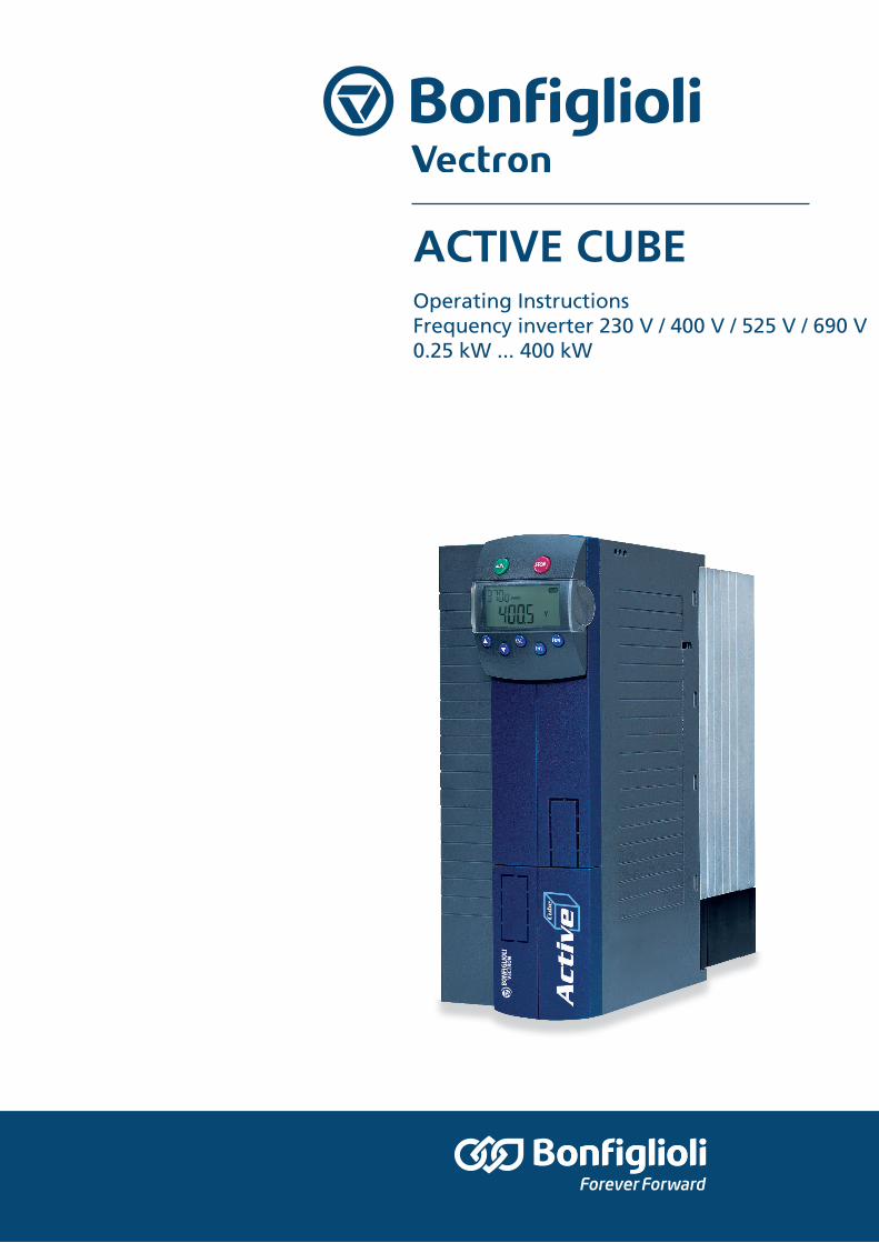
ACTIVE CUBE
Operating Instructions Frequency inverter 230 V / 400 V / 525 V / 690 V 0.25 kW ... kW

09/20 Operating Instructions ACU 3
TABLE OF CONTENTS
1 General Information about the Documentation .......................................................... 10 1.1 Instruction manuals ......................................................................................... 10 1.2 This document .................................................................................................. 11 1.3 Warranty and liability ....................................................................................... 12 1.4 Obligation ......................................................................................................... 12 1.5 Copyright .......................................................................................................... 13 1.6 Storage ............................................................................................................. 13 1.7 Final decommissioning ..................................................................................... 13
2 General safety instructions and information on use .................................................... 14 2.1 Terminology ...................................................................................................... 14 2.2 Designated use ................................................................................................. 14 2.3 Misuse ............................................................................................................... 15 2.4 Residual risks ................................................................................................... 15 2.5 Safety and warning signs on frequency inverter ............................................. 15 2.6 Warning information and symbols used in the Operating Instructions ........... 15
2.6.1 Hazard classes .................................................................................................. 15 2.6.2 Hazard symbols ................................................................................................ 16 2.6.3 Prohibition signs ............................................................................................... 16 2.6.4 Personal safety equipment ............................................................................... 16 2.6.5 Recycling .......................................................................................................... 16 2.6.6 Grounding symbol ............................................................................................ 16 2.6.7 ESD symbol ....................................................................................................... 17 2.6.8 Information signs ............................................................................................. 17 2.6.9 Font style in documentation ............................................................................. 17
2.7 Directives and guidelines to be adhered to by the operator ............................ 17 2.8 Operator's general plant documentation ......................................................... 17 2.9 Operator's/operating staff's responsibilities ................................................... 17
2.9.1 Selection and qualification of staff .................................................................. 17 2.9.2 General work safety ......................................................................................... 17 2.9.3 Ear protectors ................................................................................................... 18
2.10 Organizational measures .................................................................................. 18 2.10.1 General ............................................................................................................. 18 2.10.2 Use in combination with third-party products ................................................. 18 2.10.3 Handling and installation ................................................................................. 18 2.10.4 Electrical connections ....................................................................................... 18 2.10.5 Safe operation .................................................................................................. 19 2.10.6 Maintenance and service/troubleshooting ...................................................... 19 2.10.7 Final decommissioning ..................................................................................... 19
2.11 Safety Instructions on Function “Safe Torque Off” (STO) ............................... 20
3 Storage and transport .................................................................................................. 22 3.1 Storage ............................................................................................................. 22 3.2 Special safety instructions on transport of heavy frequency inverters ........... 22 3.3 Dimensions/weight .......................................................................................... 22 3.4 Transfer to place of installation ....................................................................... 23 3.5 Unpacking the device ....................................................................................... 23 3.6 Bringing the device into installation position .................................................. 23
3.6.1 Sizes 1 through 6 .............................................................................................. 23
4 Operating Instructions ACU 09/20
3.6.2 Sizes 7 and 8 ..................................................................................................... 24
4 Scope of supply ............................................................................................................ 25 4.1 Sizes 1 and 2: ACU 210 (up to 3.0 kW) and 410 (up to 4.0 kW) ...................... 25 4.2 Sizes 3 and 4: ACU 210 (4.0 to 9.2 kW) and 410 (5.5 to 15.0 kW) .................. 26 4.3 Size 5 ACU 410 (18.5 to 30.0 kW) .................................................................... 26 4.4 Size 6 ACU 410 (37.0 to 65.0 kW) .................................................................... 27 4.5 Size 7 ACU 410 (75.0 to 160.0 kW) .................................................................. 28 4.6 Size 8 ACU 410, ACU 510 and ACU 610 (160 through 400 kW) ....................... 29
5 Technical data .............................................................................................................. 30 5.1 General technical data...................................................................................... 30 5.2 Technical Data – Control Electronic Equipment ............................................... 32 5.3 ACU 210 Size 1 (0.25 to 1.1 kW, 230 V) ........................................................... 33 5.4 ACU 210 Size 2 (1.5 to 3.0 kW, 230 V) ............................................................. 34 5.5 ACU 210 Sizes 3 and 4 (4.0 to 9.2 kW, 230 V) ................................................. 35 5.6 ACU 410 Size 1 (0.25 to 1.5 kW, 400 V) ........................................................... 36 5.7 ACU 410 Size 2 (1.85 to 4.0 kW, 400 V) ........................................................... 37 5.8 ACU 410 Sizes 3 and 4 (5.5 to 15.0 kW, 400 V) ............................................... 38 5.9 ACU 410 Size 5 (18.5 to 30.0 kW, 400 V) ......................................................... 39 5.10 ACU 410 Size 6 (37.0 to 65.0 kW, 400 V) ......................................................... 40 5.11 ACU 410 Size 7 (75.0 to 200.0 kW, 400 V) ....................................................... 41 5.12 ACU 410 Size 8 (160.0...400.0 kW, 400 V) ....................................................... 42 5.13 ACU 510 Size 8 (160.0...400.0 kW, 525 V) ....................................................... 43 5.14 ACU 610 Size 8 (160.0...400.0 kW, 690 V) ....................................................... 44 5.15 Operation diagrams .......................................................................................... 45
6 Mechanical installation ................................................................................................ 46 6.1 Air circulation ................................................................................................... 46 6.2 Sizes 1 and 2: ACU 210 (up to 3.0 kW) and 410 (up to 4.0 KW) ...................... 47 6.3 Sizes 3 and 4: ACU 210 (4.0 to 9.2 kW) and 410 (5.5 to 15.0 kW) .................. 48 6.4 Size 5: ACU 410 (18.5 to 30.0 kW) ................................................................... 49 6.5 Size 6: ACU 410 (37.0 to 65.0 kW) ................................................................... 50 6.6 Size 7: ACU 410 (75.0 to 160.0 kW) ................................................................. 51 6.7 Size 8: ACU 410, 510 and 610 (160.0 to 400.0 kW) ......................................... 53
7 Electrical installation .................................................................................................... 54 7.1 EMC information ............................................................................................... 55 7.2 Block diagram ................................................................................................... 57 7.3 Optional components ....................................................................................... 58
7.3.1 Expansion / Communication modules .............................................................. 58 7.3.2 Shield sheets .................................................................................................... 59
7.4 Connection of Unit ............................................................................................ 59 7.4.1 Dimensioning of conductor cross-section ........................................................ 59 7.4.2 Mains connection .............................................................................................. 62 7.4.3 Motor connection ............................................................................................. 62 7.4.4 Connection of a braking resistor ...................................................................... 64
7.5 Connection by size ............................................................................................ 65 7.5.1 Sizes 1 and 2: ACU 210 (up to 3.0 kW) and 410 (up to 4.0 kW) ...................... 65 7.5.2 Sizes 3 and 4: ACU 210 (4.0 to 9.2 kW) and 410 (5.5 to 15.0 kW) .................. 67 7.5.3 Size 5 ACU 410 (18.5 to 30.0 kW) .................................................................... 69 7.5.4 Size 6 ACU 410 (37.0 to 65.0 kW) .................................................................... 71
09/20 Operating Instructions ACU 5
7.5.5 Size 7 ACU 410 (75.0 to 160.0 kW) .................................................................. 72 7.5.6 Size 8 ACU 410 / ACU 510 / ACU 610 (160.0 to 400.0 kW) ............................. 74
7.6 Control terminals .............................................................................................. 76 7.6.1 External DC 24 V power supply ........................................................................ 77 7.6.2 Relay output ..................................................................................................... 78
7.7 X13 connection in ACU 510 and ACU 610 ........................................................ 78 7.8 Motor Thermo-Contact ..................................................................................... 78 7.9 Wiring control terminals .................................................................................. 78 7.10 Configurations overview .................................................................................. 79
7.10.1 Config 110 – Sensorless Control ...................................................................... 80 7.10.2 Config 111 – Sensorless Control with Tec. Controller ...................................... 80 7.10.3 Config 210 – FOC, Speed Controlled ................................................................ 81 7.10.4 Config 211 – FOC with Tec. Controller ............................................................. 81 7.10.5 Config 230 – FOC, Speed and Torque Controlled ............................................. 82 7.10.6 Config 310 – Speed Control (Sensorless), SynRM ............................................ 82 7.10.7 Config 330 – Switchable Speed and Torque Ctrl (Sensorless), SynRM ............ 83 7.10.8 Config 410 – Sensorless FOC ............................................................................ 83 7.10.9 Config 411 –Sensorless FOC with Technology Controller ................................ 84 7.10.10 Config 430 – Sensorless FOC, Speed and Torque Ctrl .............................. 84 7.10.11 Config 510 – FOC of Synch. Machine, Speed Controlled .......................... 85 7.10.12 Config 511 –FOC of Synch. Machine w/ Tec. Controller ........................... 86 7.10.13 Config 530 – FOC of a Sync. Mach. Speed and Torque Controlled ........... 87 7.10.14 Config 610 – Sensorless FOC of Sync. Machine, Speed Controlled .......... 88 7.10.15 Config 611 – Sensorless FOC of Sync. Machine with Tec Contrllr ............ 88 7.10.16 Config 630 – Sensorless FOC of Sync. Mach Speed & Torque Ctrlld ......... 89
7.11 Installation notes according to UL508c / UL 61800-5-1 ................................. 89
8 Control unit KP500 ....................................................................................................... 91 8.1 Menu structure ................................................................................................. 92 8.2 Main Menu ........................................................................................................ 92 8.3 Actual Value Menu (VAL) .................................................................................. 93 8.4 Parameter Menu (PARA) .................................................................................. 94 8.5 Copy Menu (CPY) .............................................................................................. 95
8.5.1 Reading the Stored Information ...................................................................... 95 8.5.2 Menu structure ................................................................................................. 96 8.5.3 Selecting the Source ......................................................................................... 96 8.5.4 Selecting the Destination ................................................................................. 97 8.5.5 Copy Operation ................................................................................................. 97 8.5.6 Error messages ................................................................................................. 98
8.6 Reading Data From Control Unit ...................................................................... 98 8.6.1 Activation ......................................................................................................... 99 8.6.2 Data transfer .................................................................................................... 99 8.6.3 Resetting to Normal Operation ...................................................................... 100
8.7 Control Menu (CTRL) ...................................................................................... 100 8.8 Controlling the Motor via the Control Unit ..................................................... 100
9 Commissioning of frequency inverter ........................................................................ 103 9.1 Switching on Mains Voltage ........................................................................... 103 9.2 Setup Using the Control Unit .......................................................................... 103
9.2.1 Configuration .................................................................................................. 104 9.2.2 Data Set .......................................................................................................... 108
6 Operating Instructions ACU 09/20
9.2.3 Motor Type ..................................................................................................... 108 9.2.4 Machine data .................................................................................................. 109 9.2.5 Plausibility check ............................................................................................ 109 9.2.6 Parameter identification ................................................................................ 110 9.2.7 Status messages during commissioning (SS…) ............................................. 111 9.2.8 Warnings during commissioning (SA…) ......................................................... 111 9.2.9 Error messages during commissioning (SF…) ............................................... 112 9.2.10 Application data ............................................................................................. 112 9.2.11 Quitting commissioning ................................................................................. 113 9.2.12 Selection of an actual value for display ......................................................... 113
9.3 Setup via the Communication Interface ........................................................ 114 9.4 Check direction of rotation ............................................................................. 115 9.5 Speed sensor .................................................................................................. 115
9.5.1 Speed Sensor 1 ............................................................................................... 116 9.5.2 Speed Sensor 2 ............................................................................................... 116
10 Inverter data .............................................................................................................. 118 10.1 Serial Number ................................................................................................. 118 10.2 Optional Modules ............................................................................................ 118 10.3 Inverter Software Version .............................................................................. 118 10.4 Set Password .................................................................................................. 118 10.5 Control Level .................................................................................................. 118 10.6 User Name ...................................................................................................... 118 10.7 Configuration .................................................................................................. 118 10.8 Language ........................................................................................................ 119 10.9 Programming .................................................................................................. 119
11 Machine data .............................................................................................................. 120 11.1 Rated motor parameters ................................................................................ 120 11.2 Further motor parameters .............................................................................. 120
11.2.1 Stator resistance ............................................................................................ 120 11.2.2 Leakage coefficient ........................................................................................ 121 11.2.3 Magnetizing Current ....................................................................................... 121 11.2.4 Rated slip correction factor ............................................................................ 122 11.2.5 Voltage Constant ............................................................................................ 122 11.2.6 Stator inductance ........................................................................................... 123 11.2.7 Peak current ................................................................................................... 123 11.2.8 Reverse sense of rotation ............................................................................... 123 11.2.9 Iron Axis Impedance Ld for SynRM ................................................................ 124 11.2.10 Air Axis Impedance Lq for SynRM .......................................................... 124
11.3 Internal values ............................................................................................... 124 11.4 Speed Sensor 1 ............................................................................................... 124
11.4.1 Operation Mode Speed Sensor 1 .................................................................... 124 11.4.2 Division Marks, Speed Sensor 1 ..................................................................... 126 11.4.3 Gear factor speed sensor 1 ............................................................................. 127 11.4.4 Filter time constant, Speed Sensor 1 ............................................................. 127
11.5 Sensor evaluation ........................................................................................... 127
12 System data ............................................................................................................... 129 12.1 Actual value system........................................................................................ 129 12.2 Volume Flow and Pressure ............................................................................. 129
09/20 Operating Instructions ACU 7
13 Operating behavior .................................................................................................... 130 13.1 Starting behavior ............................................................................................ 130
13.1.1 Starting Behavior of Sensorless Control System ............................................ 130 13.1.2 Flux formation ................................................................................................ 132 13.1.3 Starting behavior for the SynRM .................................................................... 133
13.2 Stopping behavior .......................................................................................... 134 13.2.1 Switch-Off Threshold...................................................................................... 136 13.2.2 Holding Time .................................................................................................. 136 13.2.3 Stopping behavior for the SynRM .................................................................. 136 13.2.4 Direct current brake ....................................................................................... 137
13.3 Auto start ........................................................................................................ 138 13.4 Search run ...................................................................................................... 138 13.5 Positioning ...................................................................................................... 140
13.5.1 Reference Positioning .................................................................................... 140 13.5.2 Axle Positioning .............................................................................................. 142
14 Error behavior and warning behavior ........................................................................ 144 14.1 Overload Ixt ................................................................................................... 144 14.2 Temperature ................................................................................................... 144 14.3 Controller Status ............................................................................................ 145 14.4 IDC Compensation Limit ................................................................................ 145 14.5 Frequency Switch-off Limit ............................................................................ 146 14.6 Motor temperature ......................................................................................... 146 14.7 Earth fault identifier ....................................................................................... 146 14.8 Phase failure ................................................................................................... 147
14.8.1 Settings for sizes 1 to 7 .................................................................................. 147 14.8.2 Settings for size 8 ........................................................................................... 147
14.9 Automatic acknowledgment of errors/faults ................................................. 148
15 Reference Values........................................................................................................ 149 15.1 Frequency Limits ............................................................................................ 149 15.2 Slip Frequency ................................................................................................ 149 15.3 Percentage Value Limits ................................................................................. 149 15.4 Frequency reference channel ......................................................................... 150 15.5 Reference percentage channel ....................................................................... 152 15.6 Fixed reference values ................................................................................... 155
15.6.1 Fixed frequencies ........................................................................................... 155 15.6.2 JOG frequency ................................................................................................ 155 15.6.3 Fixed percentages .......................................................................................... 156
15.7 Frequency ramps ............................................................................................ 156 15.8 Percentage Value Ramps ................................................................................ 158 15.9 Blocking frequencies ...................................................................................... 158 15.10 Motor potentiometer ...................................................................................... 159
15.10.1 Motorpoti (MP) ....................................................................................... 160 15.10.2 Motorpoti (KP) ........................................................................................ 160 15.10.3 Controlling the Motor via the Control Unit ............................................. 160
16 Control inputs and outputs ........................................................................................ 163 16.1 Multifunction input MFI1................................................................................ 163
16.1.1 Characteristic ................................................................................................. 163 16.1.2 Scaling ............................................................................................................ 164

8 Operating Instructions ACU 09/20
16.1.3 Tolerance Band and Hysteresis ...................................................................... 165 16.1.4 Filter time constant ........................................................................................ 165 16.1.5 Error and warning behavior ........................................................................... 166
16.2 Multifunction Output MFO1 ............................................................................ 167 16.2.1 Analog Output MFO1A .................................................................................... 167 16.2.2 Frequency Output MFO1F ............................................................................... 168
16.3 Digital Outputs ............................................................................................... 169 16.3.1 Digital message .............................................................................................. 171 16.3.2 Setting Frequency .......................................................................................... 171 16.3.3 Reference value reached ................................................................................ 172 16.3.4 Flux forming finished ..................................................................................... 173 16.3.5 Brake release .................................................................................................. 173 16.3.6 Current limitation ........................................................................................... 173 16.3.7 External fan .................................................................................................... 174 16.3.8 Warning mask ................................................................................................ 174 16.3.9 Warning mask, application ............................................................................. 176
16.4 Digital Inputs ................................................................................................. 177 16.4.1 Start command ............................................................................................... 181 16.4.2 3-wire control ................................................................................................. 181 16.4.3 Error Acknowledgment ................................................................................... 181 16.4.4 Timer .............................................................................................................. 181 16.4.5 Thermocontact ............................................................................................... 182 16.4.6 n-/M control change-over .............................................................................. 182 16.4.7 Switch data set ............................................................................................... 182 16.4.8 Fixed Value Change-Over ............................................................................... 183 16.4.9 Motor potentiometer ...................................................................................... 183 16.4.10 Handshake Traverse Function ................................................................ 183 16.4.11 User Warning .......................................................................................... 183 16.4.12 External Error ......................................................................................... 184
16.5 Function Modules ........................................................................................... 184 16.5.1 Timer .............................................................................................................. 184 16.5.2 Comparator ..................................................................................................... 186 16.5.3 Table of functions ........................................................................................... 188 16.5.4 Multiplexer/demultiplexer ............................................................................. 188
17 V/f characteristic ....................................................................................................... 190
18 Control functions ........................................................................................................ 192 18.1 Intelligent current limits ................................................................................ 192 18.2 Voltage controller ........................................................................................... 193 18.3 Technology controller ..................................................................................... 197 18.4 Functions of sensorless control ...................................................................... 203
18.4.1 Slip compensation .......................................................................................... 203 18.4.2 Current limit value controller ......................................................................... 204 18.4.3 Impedance selection for SynRM ..................................................................... 204
18.5 Functions of field-oriented control ................................................................. 205 18.5.1 Current controller ........................................................................................... 205 18.5.2 Advanced current controller ........................................................................... 206 18.5.3 Current controller functions specific to SynRM.............................................. 206 18.5.4 Torque controller ............................................................................................ 207 18.5.5 Speed controller ............................................................................................. 208
09/20 Operating Instructions ACU 9
18.5.6 Acceleration pre-control ................................................................................. 211 18.5.7 Field controller ............................................................................................... 212 18.5.8 Modulation controller ..................................................................................... 213
19 Special functions ........................................................................................................ 215 19.1 Pulse width modulation .................................................................................. 215 19.2 Fan 215 19.3 Bus controller ................................................................................................. 216 19.4 Brake chopper and brake resistance .............................................................. 217 19.5 Motor circuit breaker ...................................................................................... 218
19.5.1 Motor circuit breaker ...................................................................................... 219 19.5.2 Motor protection by I2t monitoring ............................................................... 221
19.6 V-belt monitoring ........................................................................................... 222 19.7 Functions of field-oriented control ................................................................. 222
19.7.1 Motor chopper ................................................................................................ 223 19.7.2 Temperature Adjustment ............................................................................... 223 19.7.3 Speed sensor monitoring................................................................................ 224
19.8 Traverse function ........................................................................................... 225 19.9 Maximum Torque per Ampere: MTPA (P.1003) for SynRM ............................ 226 19.10 Profibus/Internal Notation converter ............................................................ 228
20 Actual values .............................................................................................................. 229 20.1 Actual values of frequency inverter ............................................................... 229 20.2 Actual values of machine................................................................................ 230 20.3 Actual value memory ...................................................................................... 231 20.4 Actual values of the system ........................................................................... 232
20.4.1 Actual value system........................................................................................ 232 20.4.2 Volumetric Flow and Pressure ........................................................................ 232
21 Error protocol ............................................................................................................. 233 21.1 List of errors ................................................................................................... 233 21.2 Error environment .......................................................................................... 236
22 Operational and error diagnosis ................................................................................ 237 22.1 Status display ................................................................................................. 237 22.2 Status of digital signals .................................................................................. 237 22.3 Controller Status ............................................................................................ 238 22.4 Warning Status and Warning Status Application ........................................... 238 22.5 Monitoring the service interval ...................................................................... 239
22.5.1 DC-link ............................................................................................................ 240 22.5.2 Fan .................................................................................................................. 241 22.5.3 Reset service interval ..................................................................................... 242
23 List of parameters ...................................................................................................... 243 23.1 Actual Value Menu (VAL) ................................................................................ 243 23.2 Parameter Menu (PARA) ................................................................................ 245
10 Operating Instructions ACU 09/20
1 General Information about the Documentation 1.1 Instruction manuals For better clarity, the documentation is structured according to the customer-specific requirements made on the frequency inverter.
Quick Start Guide The “Quick Start Guide” describes the basic steps required for mechanical and electrical installation of the frequency inverter. The guided commissioning supports you in the selection of necessary parameters and the configuration of the frequency inverter by the software.
Operating Instructions The Operating Instructions document the complete functionality of the frequency inverter. The parameters required for special purposes, for adjustment to the application and the numerous additional functions are described in detail.
Application manual The application manual supplements the documentation for purposeful installation and commissioning of the frequency inverter. Information on various topics in connection with the use of the frequency inverter is described in context with the specific application.
If you need a copy of the documentation or additional information, contact your local representative of BONFIGLIOLI.
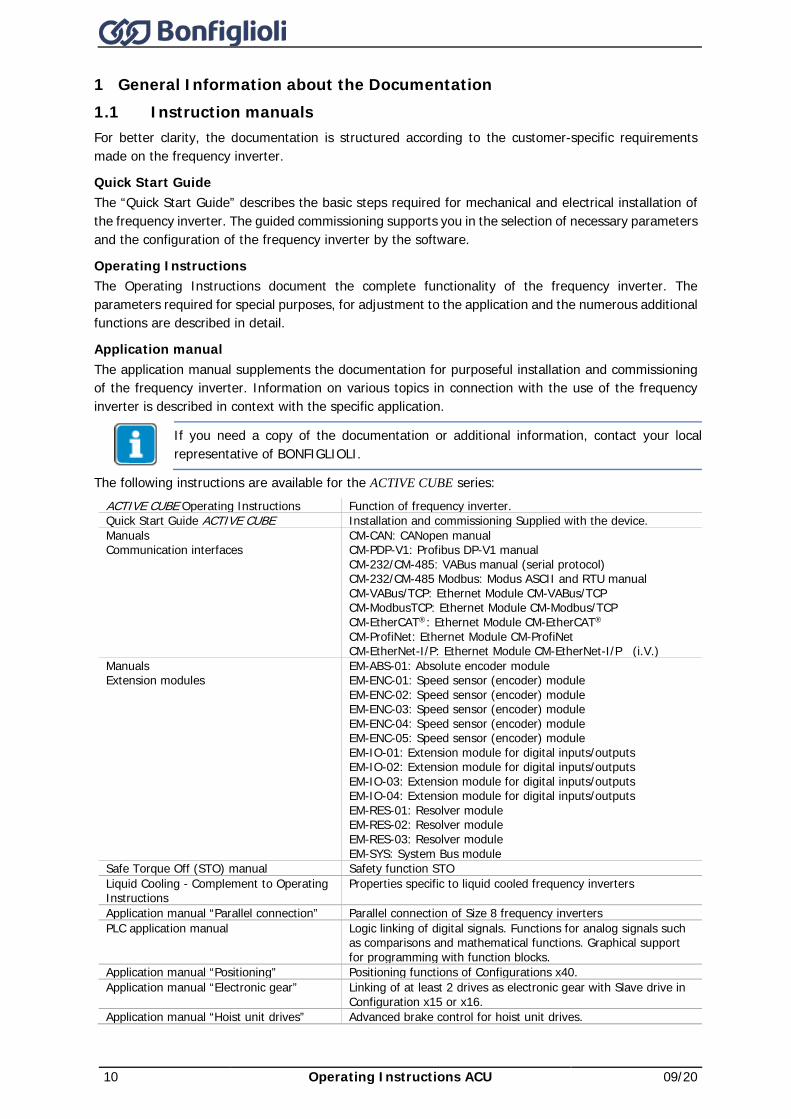
The following instructions are available for the ACTIVE CUBE series: ACTIVE CUBE Operating Instructions Function of frequency inverter. Quick Start Guide ACTIVE CUBE Installation and commissioning Supplied with the device. Manuals Communication interfaces
CM-CAN: CANopen manual CM-PDP-V1: Profibus DP-V1 manual CM-232/CM-485: VABus manual (serial protocol) CM-232/CM-485 Modbus: Modus ASCII and RTU manual CM-VABus/TCP: Ethernet Module CM-VABus/TCP CM-ModbusTCP: Ethernet Module CM-Modbus/TCP CM-EtherCAT®: Ethernet Module CM-EtherCAT® CM-ProfiNet: Ethernet Module CM-ProfiNet CM-EtherNet-I/P: Ethernet Module CM-EtherNet-I/P (i.V.)
Manuals Extension modules
EM-ABS-01: Absolute encoder module EM-ENC-01: Speed sensor (encoder) module EM-ENC-02: Speed sensor (encoder) module EM-ENC-03: Speed sensor (encoder) module EM-ENC-04: Speed sensor (encoder) module EM-ENC-05: Speed sensor (encoder) module EM-IO-01: Extension module for digital inputs/outputs EM-IO-02: Extension module for digital inputs/outputs EM-IO-03: Extension module for digital inputs/outputs EM-IO-04: Extension module for digital inputs/outputs EM-RES-01: Resolver module EM-RES-02: Resolver module EM-RES-03: Resolver module EM-SYS: System Bus module
Safe Torque Off (STO) manual Safety function STO Liquid Cooling - Complement to Operating Instructions
Properties specific to liquid cooled frequency inverters
Application manual “Parallel connection” Parallel connection of Size 8 frequency inverters PLC application manual Logic linking of digital signals. Functions for analog signals such
as comparisons and mathematical functions. Graphical support for programming with function blocks.
Application manual “Positioning” Positioning functions of Configurations x40. Application manual “Electronic gear” Linking of at least 2 drives as electronic gear with Slave drive in
Configuration x15 or x16. Application manual “Hoist unit drives” Advanced brake control for hoist unit drives.
09/20 Operating Instructions ACU 11
The products for CANopen® communication comply with the specifications of the user organization CiA® (CAN in Automation).
The products for EtherCAT® communication comply with the specifications of the user organization ETG (EtherCAT Technology Group).
The present documentation was prepared with great care and it was subjected to extensive and repeated reviews. For reasons of clarity, it was not possible to include all details of all types of the product in the documentation. Neither was it possible to consider all conceivable installation, operation or maintenance situations. If you require further information or if you meet with specific problems which are not dealt with in sufficient detail in the documentation, contact your local BONFIGLIOLI agent. The present document was created in German. Other language versions are translations.
1.2 This document This documentation describes the frequency inverters of the ACTIVE Cube series. The modular hardware and software structure enables customer-specific adaptation of the frequency inverters. Applications with high functionality and dynamism requirements can be realized easily. The Operating Instructions contain important information on the installation and the use of the product in its specified application range. Compliance with this user manual contributes to avoiding risks, minimizing repair cost and downtimes and increasing the reliability and service live of the frequency inverter. For this reason, make sure you read the Operating Instructions carefully. IMPORTANT: Compliance with the documentation is required to ensure safe operation of the frequency inverter. Bonfiglioli Vectron GmbH shall not be held liable for any damage caused by any non-compliance with the documentation.
In case any problems occur which are not covered by the documentation sufficiently, please contact the manufacturer.
For safe commissioning and operation of the ACU (ACTIVE Cube) series, the following documentation must be complied with:
− This Operating Instructions Document − Application manual “Safe Torque Off ACU”
This documentation applies to the following frequency inverter series: − ACTIVE Cube 210 − ACTIVE Cube 410 − ACTIVE Cube 510 − ACTIVE Cube 610
12 Operating Instructions ACU 09/20
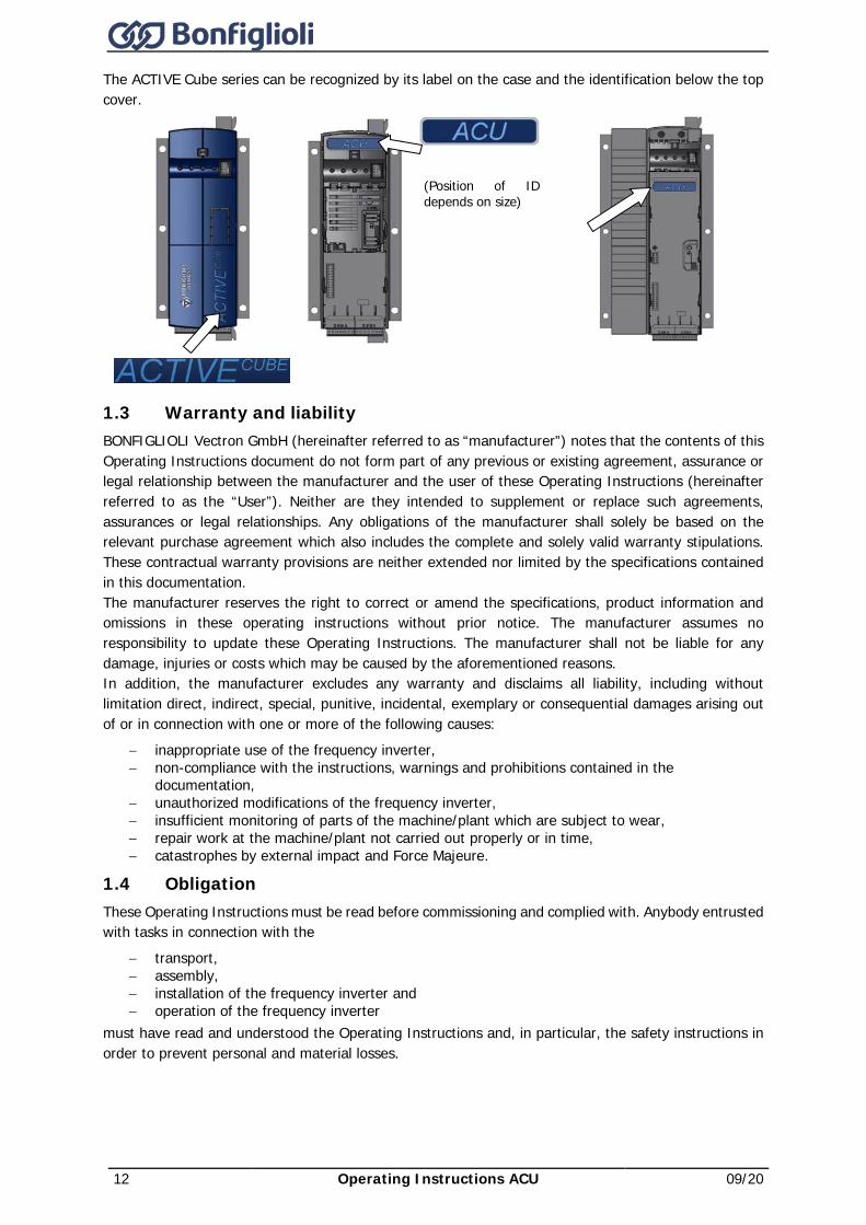
The ACTIVE Cube series can be recognized by its label on the case and the identification below the top cover.
(Position of ID depends on size)
1.3 Warranty and liability BONFIGLIOLI Vectron GmbH (hereinafter referred to as “manufacturer”) notes that the contents of this Operating Instructions document do not form part of any previous or existing agreement, assurance or legal relationship between the manufacturer and the user of these Operating Instructions (hereinafter referred to as the “User”). Neither are they intended to supplement or replace such agreements, assurances or legal relationships. Any obligations of the manufacturer shall solely be based on the relevant purchase agreement which also includes the complete and solely valid warranty stipulations. These contractual warranty provisions are neither extended nor limited by the specifications contained in this documentation. The manufacturer reserves the right to correct or amend the specifications, product information and omissions in these operating instructions without prior notice. The manufacturer assumes no responsibility to update these Operating Instructions. The manufacturer shall not be liable for any damage, injuries or costs which may be caused by the aforementioned reasons. In addition, the manufacturer excludes any warranty and disclaims all liability, including without limitation direct, indirect, special, punitive, incidental, exemplary or consequential damages arising out of or in connection with one or more of the following causes:
− inappropriate use of the frequency inverter, − non-compliance with the instructions, warnings and prohibitions contained in the
documentation, − unauthorized modifications of the frequency inverter, − insufficient monitoring of parts of the machine/plant which are subject to wear, − repair work at the machine/plant not carried out properly or in time, − catastrophes by external impact and Force Majeure.
1.4 Obligation These Operating Instructions must be read before commissioning and complied with. Anybody entrusted with tasks in connection with the
− transport, − assembly, − installation of the frequency inverter and − operation of the frequency inverter
must have read and understood the Operating Instructions and, in particular, the safety instructions in order to prevent personal and material losses.
09/20 Operating Instructions ACU 13
1.5 Copyright In accordance with applicable law any copyrights relating to this document shall remain with
BONFIGLIOLI Vectron GmbH Europark Fichtenhain B6 47807 Krefeld Germany
This document is intended for the operator of the frequency inverter. Any disclosure or copying of this document, exploitation and communication of its contents (as hardcopy or electronically) shall be forbidden, unless permitted expressly. Any non-compliance will constitute an offense against the copyright law, the law against unfair competition and the German Civil Code and may result in claims for damages. All rights relating to patent, utility model or design registration reserved.
1.6 Storage The documentation forms an integral part of the frequency inverter. It must be stored such that it is accessible to operating staff at all times. If the frequency inverter is sold on to other users, then the documentation must also be handed over.
1.7 Final decommissioning After the end of product service life, the user/operator must take the device out of operation.
For more information about the decommissioning of the device refer to the applicable operating instructions document.
Disposal requirements under European Union WEEE regulations The product is marked with the WEEE symbol shown below. This product cannot be disposed as general household waste. Users responsible for the final disposal must make sure that it is carried out in accordance with the European Directive 2012/19/EU, where required, as well as the relative national transposition rules. Fulfil disposal also in according with any other legislation in force in the country.
14 Operating Instructions ACU 09/20
2 General safety instructions and information on use This chapter contains general safety instructions for the Operator and the Operating Staff. At the beginning of certain main chapters, some safety instructions are included which apply to all work described in the relevant chapter. Special work-specific safety instructions are provided before each safety-relevant work step.
2.1 Terminology According to the documentation, different activities must be performed by certain persons with certain qualifications. The groups of persons with the required qualification are defined as follows:
Operator This is the entrepreneur/company who/which operates the frequency inverter and uses it as per the specifications or has it operated by qualified and instructed staff.
Operating staff The term Operating Staff covers persons instructed by the Operator of the frequency inverter and assigned the task of operating the frequency inverter.
Skilled Personnel The term Skilled Personnel covers staff that are assigned special tasks by the Operator of the frequency inverter, e.g. installation, maintenance and service/repair and troubleshooting. Based on their qualification and/or know-how, Skilled Personnel must be capable of identifying defects and assessing functions.
Qualified electrician The term Qualified Electrician covers qualified and trained staff who has special technical know-how and experience with electrical installations. In addition, Qualified Electricians must be familiar with the applicable standards and regulations, they must be able to assess the assigned tasks properly and identify and eliminate potential hazards.
Instructed person The term Instructed Person covers staff who was instructed and trained about/in the assigned tasks and the potential hazards that might result from inappropriate behavior. In addition, instructed persons must have been instructed in the required protection provisions, protective measures, the applicable directives, accident prevention regulations as well as the operating conditions and verified their qualification.
Expert The term Expert covers qualified and trained staff who has special technical know-how and experience relating to frequency inverter. Experts must be familiar with the applicable government work safety directives, accident prevention regulations, guidelines and generally accepted rules of technology in order to assess the operationally safe condition of the frequency inverter.
2.2 Designated use The frequency inverter is designed according to the state of the art and recognized safety regulations. The frequency inverters are electrical drive components intended for installation in industrial plants or machines. Commissioning and start of operation is not allowed until it has been verified that the machine meets the requirements of the EC Machinery Directive 2006/42/EC and DIN EN 60204-1. The frequency inverters meet the requirements of the low voltage directive 2014/35/EU and DIN EN 61800-5-1. CE-labelling is based on these standards. Responsibility for compliance with the EMC Directive 2014/30/EU lies with the operator. Frequency inverters are only available at specialized dealers and are exclusively intended for commercial use as per EN 61000-3-2. No capacitive loads may be connected to the frequency inverter. The technical data, connection specifications and information on ambient conditions are indicated on the rating plate and in the documentation and must be complied with in any case.
09/20 Operating Instructions ACU 15
2.3 Misuse Any use other than that described in "Designated use" shall not be permissible and shall be considered as misuse. For, example, the machine/plant must not be operated
− by uninstructed staff, − while it is not in perfect condition, − without protection enclosure (e.g. covers), − without safety equipment or with safety equipment deactivated, − when general requirements, such as operating conditions and technical data, are not met.
The manufacturer shall not be held liable for any damage resulting from such misuse. The sole risk shall be borne by the operator.
Explosion protection The frequency inverter is an IP 20 ingress protection rating device. For this reason, use of the device in explosive atmospheres is not permitted.
2.4 Residual risks Residual risks are special hazards involved in handling of the frequency inverter which cannot be eliminated despite the safety-compliant design of the device. Residual risks are not obviously identifiable and can be a potential source of injury or a health hazard. Typical residual hazards include:
− Electrical hazard − Danger of contact with energized components due to a defect, opened covers or enclosures or
improper working on electrical equipment. − Danger of contact with energized components in frequency inverter if no external
disconnection device was installed by the operator. During operation, all covers must be installed correctly, and all electrical cabinet doors must be closed to minimize electrical hazards. When LEDs and other indicating elements on the frequency inverter go out, this does not necessarily mean that the device is deenergized. Before carrying out any Work at the device where contact with energized parts might be possible, it must be checked in any case, i.e. irrespective of the status of any indicating elements that may be installed, if the device is deenergized.
Charged capacitors in DC link Sizes 1 through 7 (up to 160 kW): The DC-link may have dangerous voltage levels even up to 3 minutes after shutdown. Size 7 and 8 (as from 160 kW): The DC-link may have dangerous voltage levels even up to 10 minutes after shutdown.
Electrostatic charging Touching electronic components entails the risk of electrostatic discharges.
Thermal hazards Risk of accidents by hot machine/plant surfaces, e.g. heat sink, transformer, fuse or sine filter.
Danger of equipment falling down/over, e.g. during transport Center of gravity is not the middle of the electrical cabinet modules.
2.5 Safety and warning signs on frequency inverter • Comply with all safety instructions and danger information provided on the frequency inverter. • Safety information and warnings on the frequency inverter must not be removed.
2.6 Warning information and symbols used in the Operating Instructions
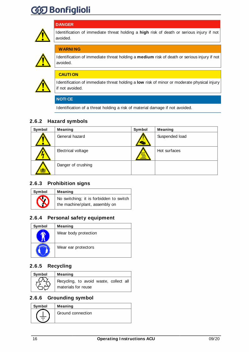
2.6.1 Hazard classes The following hazard identifications and symbols are used to mark particularly important information:
16 Operating Instructions ACU 09/20
DANGER
Identification of immediate threat holding a high risk of death or serious injury if not avoided.
WARNING
Identification of immediate threat holding a medium risk of death or serious injury if not avoided.
CAUTION
Identification of immediate threat holding a low risk of minor or moderate physical injury if not avoided.
NOTICE Identification of a threat holding a risk of material damage if not avoided.
2.6.2 Hazard symbols Symbol Meaning Symbol Meaning
General hazard
Suspended load
Electrical voltage
Hot surfaces
Danger of crushing
2.6.3 Prohibition signs Symbol Meaning
No switching; it is forbidden to switch the machine/plant, assembly on
2.6.4 Personal safety equipment Symbol Meaning
Wear body protection
Wear ear protectors
2.6.5 Recycling Symbol Meaning
Recycling, to avoid waste, collect all materials for reuse
2.6.6 Grounding symbol Symbol Meaning
Ground connection
09/20 Operating Instructions ACU 17
2.6.7 ESD symbol Symbol Meaning
ESD: Electrostatic Sensitive Devices, i.e. components and assemblies sensitive to electrostatic energy
2.6.8 Information signs Symbol Meaning
Tips and information making using the frequency inverter easier.
2.6.9 Font style in documentation Example Font style Use 1234 bold Representation of parameter numbers Parameter inclined,
font: Times New Roman
Representation of parameter names
P.1234 bold Representation of parameter numbers without name, e.g. in formulas Q.1234 bold Representation of source numbers
2.7 Directives and guidelines to be adhered to by the operator The operator must follow the following directives and regulations: • Ensure that the applicable workplace-related accident prevention regulations as well as other
applicable national regulation are accessible to the staff. • An authorized person must ensure, before using the frequency inverter, that the device is used in
compliance with its designated use and that all safety requirements are met. • Additionally, comply with the applicable laws, regulations and directives of the country in which
the frequency inverter is used. • For liquid cooled frequency inverters, comply with the cooling water guideline VGB-R 455 P. • Any additional guidelines and directives that may be required additionally shall be defined by the
operator of the machine/plant considering the operating environment.
2.8 Operator's general plant documentation • In addition to the Operating Instructions, the operator should issue separate internal user
manuals for the frequency inverter. The Operating Instructions of the frequency inverter must be included in the Operating Instructions of the whole plant.
2.9 Operator's/operating staff's responsibilities 2.9.1 Selection and qualification of staff • Any work on the frequency inverter may only be carried out by skilled personnel. The staff must
not be under the influence of any drugs. Note the minimum age required by law. Define the staff's responsibility pertaining to all work on the frequency inverter clearly.
• Work on the electrical components may only be performed by a qualified electrician according to the applicable rules of electrical engineering.
• The operating staff must be trained for the relevant work to be performed.
2.9.2 General work safety • In addition to the Operating Instructions of the machine/plant, any applicable legal or other
regulations relating to accident prevention and environmental protection must be complied with. The staff must be instructed accordingly. Such regulations and/or requirements may include, for example, handling of hazardous media and materials or provision/use of personal protective equipment.
• In addition to this Operating Instructions, issue any additional directives that may be required to meet specific operating requirements, including supervision and reporting requirements, e.g. directives relating to work organization, workflow and employed staff.
• Unless approved of expressly by the manufacturer, do not modify the frequency inverter in any way, including addition of attachments or retrofits.
18 Operating Instructions ACU 09/20
• Only use the frequency inverter if the rated connection and setup values specified by the manufacturer are met.
• Provide appropriate tools as may be required for performing all work on the frequency inverter properly.
2.9.3 Ear protectors • The frequency inverter produces noise. Due to noise development, frequency inverters should
only be installed in normally unstaffed areas. • Noise emission in operation is < 85 dB(A) in the case of sizes 1 through 7. • Noise emission in operation is approx. 86 dB(A) in the case of size 8. Ear protectors must be used
when staying near the frequency inverter.
2.10 Organizational measures 2.10.1 General • Train your staff in the handling and use of the frequency inverter and the machine/plant as well
as the risks involved. • Use of any individual parts or components of the frequency inverter in other parts of the
operator's machine/plant is prohibited. • Optional components for the frequency inverter must be used in accordance with their designated
use and in compliance with the relevant documentation.
2.10.2 Use in combination with third-party products • Please note that Bonfiglioli Vectron GmbH will not accept any responsibility for compatibility with
third-party products (e.g. motors, cables or filters).. • In order to enable optimum system compatibility Bonfiglioli Vectron GmbH offers components
facilitating commissioning and providing optimum synchronization of the machine/plant parts in operation.
• If you use the frequency inverter in combination with third-party products, you do so at your own risk.
2.10.3 Handling and installation • Do not commission any damaged or destroyed components. • Prevent any mechanical overloading of the frequency inverter. Do not bend any components and
never change the isolation distances. • Do not touch any electronic construction elements and contacts. The frequency inverter is
equipped with components which are sensitive to electrostatic energy and can be damaged if handled improperly. Any use of damaged or destroyed components will endanger the machine/plant safety and shall be considered as non-compliance with the applicable standards.
• Only install the frequency inverter in a suitable operating environment. The frequency inverter is exclusively designed for installation in industrial environments.
• If seals are removed from the case, this can result in the warranty becoming null and void.
2.10.4 Electrical connections • The five safety rules must be complied with. • Never touch live terminals. In sizes 1 through 7, the DC-link may have dangerous voltage levels
up to 3 minutes after shutdown. In size 8, the DC-link may have dangerous voltage levels up to 10 minutes after shutdown.
• When performing any work on/with the frequency inverter, always comply with the applicable national and international regulations/laws on work on electrical equipment/plants of the country in which the frequency inverter is used.
• The cables connected to the frequency inverters may not be subjected to high-voltage insulation tests unless appropriate circuitry measures are taken before.
• Only connect the frequency inverter to suitable supply mains. The frequency inverter may be operated in TN, TT and IT grid types. Precautions must be taken for operation in IT grids, see Chapter 7 "Electrical installation". Operation in a corner-grounded TN grid shall not be permissible.
2.10.4.1 The five safety rules When working on/in electrical plants, always follow the five safety rules:
− Disconnect − Secure to prevent restarting
09/20 Operating Instructions ACU 19
− check for absence of voltage, − carry out earthing and short-circuiting − cover or shield neighboring live parts
2.10.5 Safe operation • During operation of the frequency inverter, always comply with the applicable national and
international regulations/laws on work on electrical equipment/plants. • Before commissioning and the start of the operation, make sure to fix all covers and check the
terminals. Check the additional monitoring and protective devices according to the applicable national and international safety directives.
• During operation, all covers must be installed correctly, and all electrical cabinet doors must be closed. During operation, never open the machine/plant.
• No connection work shall be carried out while power supply is on. • The machine/plant holds high voltage levels during operation, is equipped with rotating parts
(fan) and has hot surfaces. Any unauthorized removal of covers, improper use, wrong installation or operation may result in serious injuries or material damage.
• Some components, e.g. the heat sink or braking resistor, may be hot even some time after the machine/plant was shut down. Don't touch any surfaces directly after shutdown. Wear safety gloves where necessary.
• The frequency inverter may hold dangerous voltage levels until the capacitor in the DC link is discharged. After shutdown, wait for at least 3 minutes (sizes 1 through 7) and at least 10 minutes (size 8) before starting any electrical or mechanical work on the frequency inverter. Even after this waiting time, make sure that the equipment is deenergized in accordance with the safety rules before starting the work.
• In order to avoid accidents or damage, only skilled personnel and electricians may carry out the work such as installation, commissioning or setup.
• In the case of a defect of terminals and/or cables, immediately disconnect the frequency inverter from mains supply.
• Persons not familiar with the operation of the frequency inverter and children must not have access to the device.
• Do not bypass nor decommission any protective devices. • The frequency inverter may be connected to power supply every 60 s. This must be considered
when operating a mains contactor in jog operation mode. For commissioning or after an emergency stop, a non-recurrent, direct restart is permissible.
• After a failure and restoration of the power supply, the motor may start unexpectedly if the AutoStart function is activated. If staff are endangered, a restart of the motor must be prevented by means of external circuitry.
• Before commissioning and the start of the operation, make sure to fix all covers and check the terminals. Check the additional monitoring and protective devices according to EN 60204 and applicable the safety directives (e.g. Working Machines Act or Accident Prevention Directives).
2.10.6 Maintenance and service/troubleshooting • Visually inspect the frequency inverter when carrying out the required maintenance work and
inspections at the machine/plant. • Perform the maintenance work and inspections prescribed for the machine carefully, including the
specifications on parts/equipment replacement. • Work on the electrical components may only be performed by a qualified electrician according to
the applicable rules of electrical engineering. Only use original spare parts. • Unauthorized opening and improper interventions in the machine/plant can lead to personal injury
or material damage. Any repair work may only be carried out by the manufacturer or persons approved/licensed by the manufacturer. Any repair work must be carried out by qualified electricians. Check protective equipment regularly.
• Before performing any maintenance work, the machine/plant must be disconnected from mains supply and secured against restarting. The five safety rules must be complied with.
2.10.7 Final decommissioning Unless separate return or disposal agreements were made, recycle the disassembled frequency inverter components: • Scrap metal materials • Recycle plastic elements
20 Operating Instructions ACU 09/20
• Sort and dispose of other component materials
Electric scrap, electronic components, lubricants and other utility materials must be treated as special waste and may only be disposed of by specialized companies.
In any case, comply with any applicable national disposal regulations as regards environmentally compatible disposal of the frequency inverter. For more details, contact the competent local authorities.
2.11 Safety Instructions on Function “Safe Torque Off” (STO) The function „Safe Torque Off“ (STO) is a functional safety feature, i.e. it protects staff from damage, provided that projecting, installation and operation are performed properly. This function does not disconnect the plant from power supply. In order to disconnect the plant from power supply (e.g. for maintenance work), an "Emergency Stop" provision as per EN 60204 must be installed.
WARNING
Uncontrolled Starting Improper installation of the safety circuitry may result in uncontrolled starting of the drive. This may cause death, serious injuries and significant material damage. • Safety functions may only be installed and commissioned by skilled personnel. The STO function is not suitable for emergency stop as per EN 60204. An emergency stop can be realized by installing a mains contactor. An emergency stop according to EN 60204 must be functioning in all operation modes of the frequency inverter. Resetting of an emergency stop must not result in uncontrolled starting of the drive. The drive is started again when the function STO is no longer required. In order to comply with EN 60204, it must be ensured by taking external measures that the drive does not start without prior confirmation. Without a mechanical brake, the drive will not stop immediately but coast to a standstill. If this may result in personal or material damage, additional safety measures must be taken. • If persons may be endangered after disconnection of the motor power supply by
STO, access to the hazard areas must be prevented until the drive has stopped. • Check the safety function at regular intervals according to the results of your risk
analysis. Bonfiglioli Vectron GmbH recommends that the check be performed after one year, at the latest.
The STO function is fail-safe for one fault. However, on rare occasions, the occurrence of component defects may cause jerking of the motor shaft (max. 180°/pole pair, e. g. jerk by 90° with 4-pole motor, 180°/2). • Check if this causes a dangerous movement of the machine. • If the STO function is used, the special safety, installation and instructions on use
instructions shall be complied with.
09/20 Operating Instructions ACU 21
WARNING
Dangerous voltage! The safety function “Safe Torque Off” may only be used if mechanical work is to be performed on the driven machines, not for work on live components. After disconnection of an external DC 24 V power supply, the DC link of the frequency inverter is still connected to mains supply. Even if power supply to the motor is disconnected, and the motor is coasting to a standstill or has already stopped, high voltages may still be present on the motor terminals. Before working (e. g. maintenance) on live parts, the plant must always be disconnected from mains supply (main switch). This must be documented on the plant. When the function “Safe Torque Off” is triggered, the motor is not isolated from the DC link of the frequency inverter. High voltage levels may be present at the motor. • Do not touch live terminals.
The application manual "Safe Torque Off STO" must be complied with, particularly if the safety function described there is used.
22 Operating Instructions ACU 09/20
3 Storage and transport
NOTICE Draining the heat sink
Liquid cooled devices may be transported only with the heat sink completely drained of the coolant. • Use compressed air to drain the heat sink radiator.
3.1 Storage
NOTICE Damage caused by incorrect storage
• Wrong or inappropriate storage may result in damage, e.g. due to moisture and dirt. Avoid major temperature variations and high air humidity.
• During storage, protect the device against moisture and dirt.
• The frequency inverters must be stored in an appropriate way. During storage, the devices must remain in their original packaging.
• The units may only be stored in dry rooms which are protected against dust and moisture and are exposed to small temperature deviations only. The requirements of DIN EN 60721-3-1 for storage, DIN EN 60721-3-2 for transport and labeling on the packaging must be met.
• The duration of storage without connection to the permissible nominal voltage may not exceed one year. After one year of storage, connect the device to mains voltage for 60 minutes. If the duration of storage without connection to the permissible nominal voltage does exceed one year, the inverter capacitors must be re-formed. Contact your Bonfiglioli representative.
3.2 Special safety instructions on transport of heavy frequency inverters
WARNING
High weight and unusual center of gravity! Tilting the frequency inverter may result in death or serious injuries. Due to the size and weight of the frequency inverter, there is the risk of accidents during transport. Center of gravity is not the middle of the frequency inverter. The underside of the frequency inverter, due to its design, cannot support the frequency inverter. • Take utmost care during transport in order to prevent damage and deformation.
Transport, attachment and lifting of loads may only be carried out by specially instructed staff who are familiar with the work.
• Only use suitable transport and lifting equipment with sufficient carrying capacity. The lifting cables/chains used must be able to carry the weight of the frequency inverter. Check the ropes or chains for damage.
• Wear appropriate safety clothing. • When lifting the frequency inverter up ensure that it does not fall over, is displaced,
swings out or falls down. • Before the frequency inverter is lifted up, everybody must have left the work area. • Before transport, make sure the transport path has sufficient carrying capacity. • Do not step under suspended loads. • Do not put the frequency inverter down in upright position without providing a
suitable supporting structure.
3.3 Dimensions/weight
For information on the weight and dimensions of the frequency inverter, refer to chapter 5 “Technical data”.
09/20 Operating Instructions ACU 23
3.4 Transfer to place of installation Transfer to the place of installation is done with the product in its original packaging. Frequency inverters as from size 7 must be transferred to the place of installation in horizontal position, rear-side down. A fork lift truck or crane with crane fork can be used for transfer to the place of installation. • Apply the fork in the middle of the transport unit. • Secure the transport unit to prevent it from falling down and overturning. • Lift the transport unit up carefully. • At the place of installation, put the transport unit down on a level and bearing surface.
3.5 Unpacking the device • Carefully remove packaging. • Check if the delivered devices corresponds to the order. • Check the device for transport damage and completeness. • Any defects/damage must be reported to the supplier immediately.
Ensure that all packaging materials are disposed of in an environmentally compatible manner.
3.6 Bringing the device into installation position 3.6.1 Sizes 1 through 6 • Depending on the weight, one or two persons are required for lifting the device into the
installation position in the electrical cabinet. For information on installation, refer to Chapter 6 "Mechanical installation".
24 Operating Instructions ACU 09/20
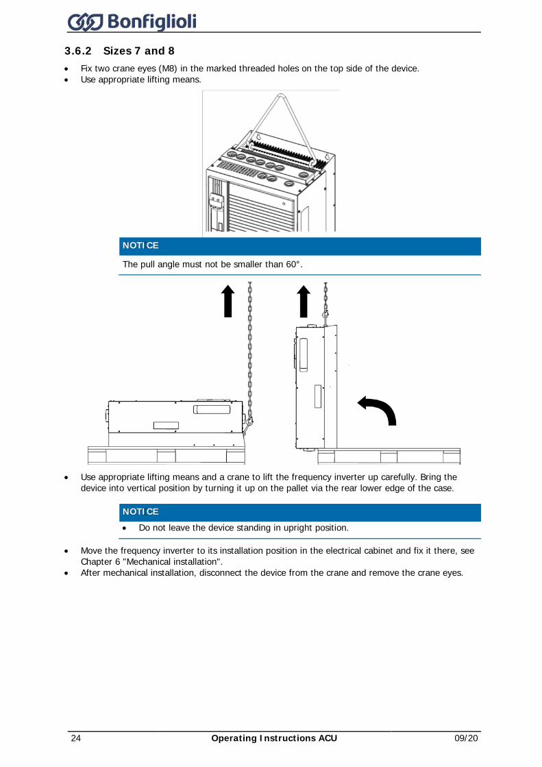
3.6.2 Sizes 7 and 8 • Fix two crane eyes (M8) in the marked threaded holes on the top side of the device. • Use appropriate lifting means.
NOTICE
The pull angle must not be smaller than 60°.
• Use appropriate lifting means and a crane to lift the frequency inverter up carefully. Bring the device into vertical position by turning it up on the pallet via the rear lower edge of the case.
NOTICE • Do not leave the device standing in upright position.
• Move the frequency inverter to its installation position in the electrical cabinet and fix it there, see Chapter 6 "Mechanical installation".
• After mechanical installation, disconnect the device from the crane and remove the crane eyes.
09/20 Operating Instructions ACU 25
4 Scope of supply Due to modular hardware components, the frequency inverters can be integrated in the automation concept easily. The scope of delivery described can be supplemented by optional components and adapted to the customer-specific requirements. The plug-in type connection terminals enable a safe function and quick and easy assembly.
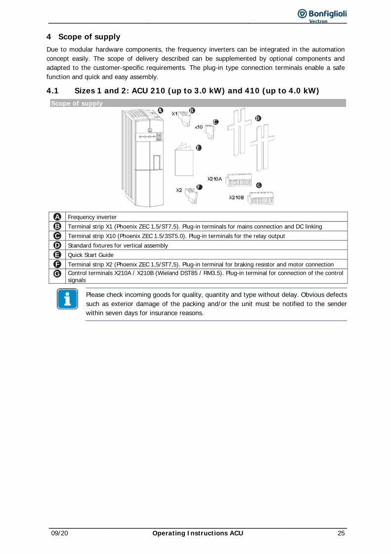
4.1 Sizes 1 and 2: ACU 210 (up to 3.0 kW) and 410 (up to 4.0 kW) Scope of supply
A Frequency inverter B Terminal strip X1 (Phoenix ZEC 1,5/ST7,5). Plug-in terminals for mains connection and DC linking C Terminal strip X10 (Phoenix ZEC 1.5/3ST5.0). Plug-in terminals for the relay output D Standard fixtures for vertical assembly E Quick Start Guide F Terminal strip X2 (Phoenix ZEC 1,5/ST7,5). Plug-in terminal for braking resistor and motor connection G Control terminals X210A / X210B (Wieland DST85 / RM3.5). Plug-in terminal for connection of the control
signals
Please check incoming goods for quality, quantity and type without delay. Obvious defects such as exterior damage of the packing and/or the unit must be notified to the sender within seven days for insurance reasons.
26 Operating Instructions ACU 09/20
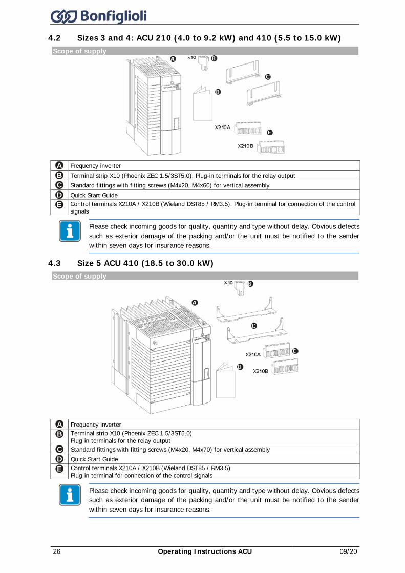
4.2 Sizes 3 and 4: ACU 210 (4.0 to 9.2 kW) and 410 (5.5 to 15.0 kW) Scope of supply
A Frequency inverter B Terminal strip X10 (Phoenix ZEC 1.5/3ST5.0). Plug-in terminals for the relay output C Standard fittings with fitting screws (M4x20, M4x60) for vertical assembly D Quick Start Guide E Control terminals X210A / X210B (Wieland DST85 / RM3.5). Plug-in terminal for connection of the control
signals
Please check incoming goods for quality, quantity and type without delay. Obvious defects such as exterior damage of the packing and/or the unit must be notified to the sender within seven days for insurance reasons.
4.3 Size 5 ACU 410 (18.5 to 30.0 kW) Scope of supply
A Frequency inverter B Terminal strip X10 (Phoenix ZEC 1.5/3ST5.0)
Plug-in terminals for the relay output C Standard fittings with fitting screws (M4x20, M4x70) for vertical assembly D Quick Start Guide E Control terminals X210A / X210B (Wieland DST85 / RM3.5)
Plug-in terminal for connection of the control signals
Please check incoming goods for quality, quantity and type without delay. Obvious defects such as exterior damage of the packing and/or the unit must be notified to the sender within seven days for insurance reasons.
09/20 Operating Instructions ACU 27
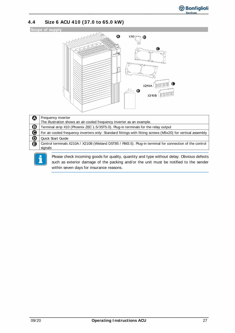
4.4 Size 6 ACU 410 (37.0 to 65.0 kW) Scope of supply
A Frequency inverter The illustration shows an air-cooled frequency inverter as an example.
B Terminal strip X10 (Phoenix ZEC 1.5/3ST5.0). Plug-in terminals for the relay output C For air-cooled frequency inverters only: Standard fittings with fitting screws (M5x20) for vertical assembly D Quick Start Guide E Control terminals X210A / X210B (Wieland DST85 / RM3.5). Plug-in terminal for connection of the control
signals
Please check incoming goods for quality, quantity and type without delay. Obvious defects such as exterior damage of the packing and/or the unit must be notified to the sender within seven days for insurance reasons.
28 Operating Instructions ACU 09/20
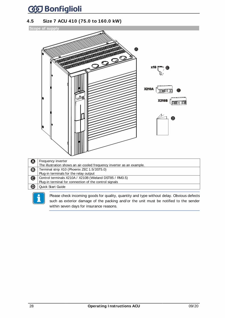
4.5 Size 7 ACU 410 (75.0 to 160.0 kW) Scope of supply
A Frequency inverter The illustration shows an air-cooled frequency inverter as an example.
B Terminal strip X10 (Phoenix ZEC 1.5/3ST5.0) Plug-in terminals for the relay output
C Control terminals X210A / X210B (Wieland DST85 / RM3.5) Plug-in terminal for connection of the control signals
D Quick Start Guide
Please check incoming goods for quality, quantity and type without delay. Obvious defects such as exterior damage of the packing and/or the unit must be notified to the sender within seven days for insurance reasons.
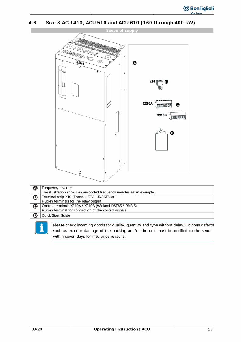
09/20 Operating Instructions ACU 29
4.6 Size 8 ACU 410, ACU 510 and ACU 610 (160 through 400 kW) Scope of supply
A Frequency inverter The illustration shows an air-cooled frequency inverter as an example.
B Terminal strip X10 (Phoenix ZEC 1.5/3ST5.0) Plug-in terminals for the relay output
C Control terminals X210A / X210B (Wieland DST85 / RM3.5) Plug-in terminal for connection of the control signals
D Quick Start Guide
Please check incoming goods for quality, quantity and type without delay. Obvious defects such as exterior damage of the packing and/or the unit must be notified to the sender within seven days for insurance reasons.
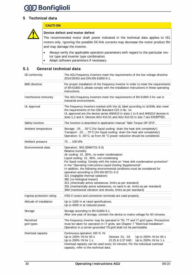
30 Operating Instructions ACU 09/20
5 Technical data CAUTION
Device defect and motor defect The recommended motor shaft power indicated in the technical data applies to IE1 motors only. Ignoring the possible DC-link currents may decrease the motor product life and may damage the inverter. • Always verify the applicable operation parameters with regard to the particular mo-
tor type and inverter type combination. • Adapt software parameters if necessary.
5.1 General technical data CE conformity The ACU frequency inverters meet the requirements of the low voltage directive
2014/35/EU and DIN EN 61800-5-1.
EMC directive For proper installation of the frequency inverter in order to meet the requirements of EN 61800-3, please comply with the installation instructions in these operating instructions.
Interference immunity The ACU frequency inverters meet the requirements of EN 61800-3 for use in industrial environments.
UL Approval The frequency inverters marked with the UL label according to UL508c also meet the requirements of the CSA Standard C22.2-No. 14. UL approved are the device series ANG410 in sizes 1 to 8 and ANG210 devices in sizes 1,2 and 4. Devices ACU 410-51 and ACU 410-53 in size 7 are EXCEPTED.
Safety function The function is described in application manual "Safe Torque Off STO".
Ambient temperature Storage: -25 ... 55°C (for liquid cooling: drain the heat sink completely!) Transport: -25 ... 70°C (for liquid cooling: drain the heat sink completely!) Operation: 0…55°C; as from 40 °C power reduction should be considered.
Ambient pressure 70 ... 106 kPa
Environmental class Operation: 3K3 (EN60721-3-3) Relative humidity Air cooling: 15…85%, no water condensation Liquid cooling: 15…95%, non-condensing For liquid cooling: Comply with the notes on “Heat sink condensation protection” in the “Operating Instructions Liquid Cooling Supplemental”. In addition, the following environmental conditions must be considered for operation according to DIN EN 60721-3-3: 3Z1 (negligible thermal radiation) 3B1 (no biological impact) 3C1 (chemically active substances, limits as per standard) 3S1 (mechanically active substances, no sand in air, limits as per standard) 3M4 (mechanical vibration and shocks, limits as per standard)
Ingress protection rating IP20 if covers and connection terminals are used properly.
Altitude of installation Up to 1000 m at rated specifications. Up to 4000 m at reduced power.
Storage Storage according to EN 61800-5-1. After one year of storage, connect the device to mains voltage for 60 minutes.
Permitted grid types
The frequency inverter may be operated in TN, TT and IT grid types. Precautions must be taken for operation in IT grids, see Chapter 7 "Electrical installation". Operation in a corner-grounded TN grid shall not be permissible.
Overload capacity Continuous operation 100 % IN Up to 150% IN for 60 s Up to 200% IN for 1 s
Devices -01, -03 (0.25 & 0.37 kW):
Up to 200% IN for 60 s Up to 200% IN for 1 s
Overload capacity can be used every 10 minutes. For the individual overload capacity, refer to the technical data.
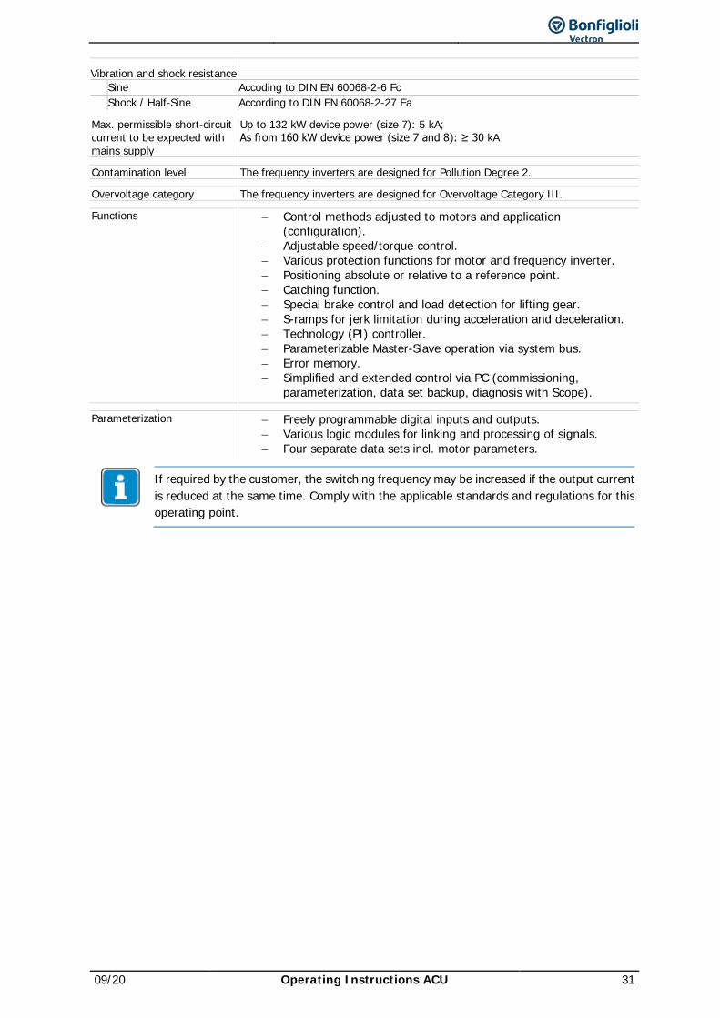
09/20 Operating Instructions ACU 31
Vibration and shock resistance Sine Accoding to DIN EN 60068-2-6 Fc Shock / Half-Sine According to DIN EN 60068-2-27 Ea
Max. permissible short-circuit current to be expected with mains supply
Up to 132 kW device power (size 7): 5 kA; As from 160 kW device power (size 7 and 8): ≥ 30 kA
Contamination level The frequency inverters are designed for Pollution Degree 2.
Overvoltage category The frequency inverters are designed for Overvoltage Category III.
Functions − Control methods adjusted to motors and application (configuration).
− Adjustable speed/torque control. − Various protection functions for motor and frequency inverter. − Positioning absolute or relative to a reference point. − Catching function. − Special brake control and load detection for lifting gear. − S-ramps for jerk limitation during acceleration and deceleration. − Technology (PI) controller. − Parameterizable Master-Slave operation via system bus. − Error memory. − Simplified and extended control via PC (commissioning,
parameterization, data set backup, diagnosis with Scope).
Parameterization − Freely programmable digital inputs and outputs. − Various logic modules for linking and processing of signals. − Four separate data sets incl. motor parameters.
If required by the customer, the switching frequency may be increased if the output current is reduced at the same time. Comply with the applicable standards and regulations for this operating point.
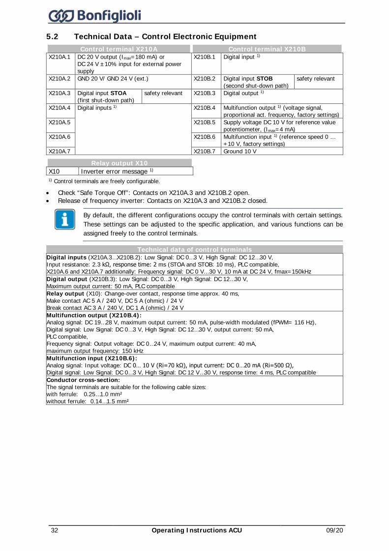
32 Operating Instructions ACU 09/20
5.2 Technical Data – Control Electronic Equipment Control terminal X210A Control terminal X210B
X210A.1 DC 20 V output (Imax=180 mA) or DC 24 V ±10% input for external power supply
X210B.1 Digital input 1)
X210A.2 GND 20 V/ GND 24 V (ext.) X210B.2 Digital input STOB (second shut-down path)
safety relevant
X210A.3 Digital input STOA (first shut-down path)
safety relevant X210B.3 Digital output 1)
X210A.4 Digital inputs 1) X210B.4 Multifunction output 1) (voltage signal, proportional act. frequency, factory settings)
X210A.5 X210B.5 Supply voltage DC 10 V for reference value potentiometer, (Imax=4 mA)
X210A.6 X210B.6 Multifunction input 1) (reference speed 0 … +10 V, factory settings)
X210A.7 X210B.7 Ground 10 V
Relay output X10 X10 Inverter error message 1) 1) Control terminals are freely configurable.
• Check “Safe Torque Off”: Contacts on X210A.3 and X210B.2 open. • Release of frequency inverter: Contacts on X210A.3 and X210B.2 closed.
By default, the different configurations occupy the control terminals with certain settings. These settings can be adjusted to the specific application, and various functions can be assigned freely to the control terminals.
Technical data of control terminals Digital inputs (X210A.3…X210B.2): Low Signal: DC 0…3 V, High Signal: DC 12…30 V, Input resistance: 2.3 kΩ, response time: 2 ms (STOA and STOB: 10 ms), PLC compatible, X210A.6 and X210A.7 additionally: Frequency signal: DC 0 V...30 V, 10 mA at DC 24 V, fmax=150kHz Digital output (X210B.3): Low Signal: DC 0…3 V, High Signal: DC 12…30 V, Maximum output current: 50 mA, PLC compatible Relay output (X10): Change-over contact, response time approx. 40 ms, Make contact AC 5 A / 240 V, DC 5 A (ohmic) / 24 V Break contact AC 3 A / 240 V, DC 1 A (ohmic) / 24 V Multifunction output (X210B.4): Analog signal: DC 19…28 V, maximum output current: 50 mA, pulse-width modulated (fPWM= 116 Hz), Digital signal: Low Signal: DC 0…3 V, High Signal: DC 12…30 V, output current: 50 mA, PLC compatible, Frequency signal: Output voltage: DC 0…24 V, maximum output current: 40 mA, maximum output frequency: 150 kHz Multifunction input (X210B.6): Analog signal: Input voltage: DC 0… 10 V (Ri=70 kΩ), input current: DC 0…20 mA (Ri=500 Ω), Digital signal: Low Signal: DC 0…3 V, High Signal: DC 12 V…30 V, response time: 4 ms, PLC compatible Conductor cross-section: The signal terminals are suitable for the following cable sizes: with ferrule: 0.25…1.0 mm² without ferrule: 0.14…1.5 mm²
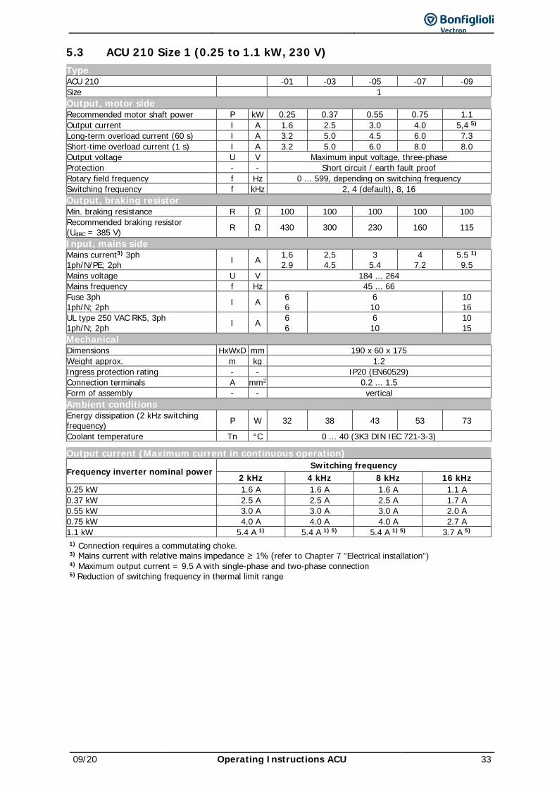
09/20 Operating Instructions ACU 33
5.3 ACU 210 Size 1 (0.25 to 1.1 kW, 230 V) Type ACU 210 -01 -03 -05 -07 -09 Size 1 Output, motor side Recommended motor shaft power P kW 0.25 0.37 0.55 0.75 1.1 Output current I A 1.6 2.5 3.0 4.0 5,4 5) Long-term overload current (60 s) I A 3.2 5.0 4.5 6.0 7.3 Short-time overload current (1 s) I A 3.2 5.0 6.0 8.0 8.0 Output voltage U V Maximum input voltage, three-phase Protection - - Short circuit / earth fault proof Rotary field frequency f Hz 0 ... 599, depending on switching frequency Switching frequency f kHz 2, 4 (default), 8, 16 Output, braking resistor Min. braking resistance R Ω 100 100 100 100 100 Recommended braking resistor (UdBC = 385 V) R Ω 430 300 230 160 115
Input, mains side Mains current3) 3ph 1ph/N/PE; 2ph I A 1,6
2.9 2,5 4.5
3 5.4
4 7.2
5.5 1) 9.5
Mains voltage U V 184 ... 264 Mains frequency f Hz 45 ... 66 Fuse 3ph 1ph/N; 2ph I A 6
6 6 10
10 16
UL type 250 VAC RK5, 3ph 1ph/N; 2ph I A 6
6 6 10
10 15
Mechanical Dimensions HxWxD mm 190 x 60 x 175 Weight approx. m kg 1.2 Ingress protection rating - - IP20 (EN60529) Connection terminals A mm2 0.2 ... 1.5 Form of assembly - - vertical Ambient conditions Energy dissipation (2 kHz switching frequency) P W 32 38 43 53 73
Coolant temperature Tn °C 0 ... 40 (3K3 DIN IEC 721-3-3)
Output current (Maximum current in continuous operation)
Frequency inverter nominal power Switching frequency
2 kHz 4 kHz 8 kHz 16 kHz 0.25 kW 1.6 A 1.6 A 1.6 A 1.1 A 0.37 kW 2.5 A 2.5 A 2.5 A 1.7 A 0.55 kW 3.0 A 3.0 A 3.0 A 2.0 A 0.75 kW 4.0 A 4.0 A 4.0 A 2.7 A 1.1 kW 5.4 A 1) 5.4 A 1) 5) 5.4 A 1) 5) 3.7 A 5) 1) Connection requires a commutating choke. 3) Mains current with relative mains impedance ≥ 1% (refer to Chapter 7 "Electrical installation") 4) Maximum output current = 9.5 A with single-phase and two-phase connection 5) Reduction of switching frequency in thermal limit range
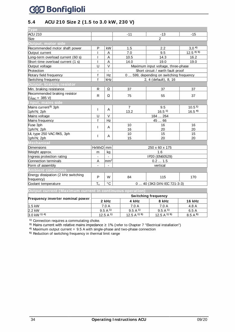
34 Operating Instructions ACU 09/20
5.4 ACU 210 Size 2 (1.5 to 3.0 kW, 230 V) Type ACU 210 -11 -13 -15 Size 2 Output, motor side Recommended motor shaft power P kW 1.5 2.2 3,0 4) Output current I A 7.0 9.5 12.5 4) 5) Long-term overload current (60 s) I A 10.5 14.3 16.2 Short-time overload current (1 s) I A 14.0 19.0 19.0 Output voltage U V Maximum input voltage, three-phase Protection - - Short circuit / earth fault proof Rotary field frequency f Hz 0 ... 599, depending on switching frequency Switching frequency f kHz 2, 4 (default), 8, 16 Output, braking resistor Min. braking resistance R Ω 37 37 37 Recommended braking resistor (UdBC = 385 V) R Ω 75 55 37
Input, mains side Mains current3) 3ph 1ph/N; 2ph I A 7
13.2 9.5
16.5 1) 10.5 1) 16.5 4)
Mains voltage U V 184 ... 264 Mains frequency f Hz 45 ... 66 Fuse 3ph 1ph/N; 2ph I A 10
16 16 20
16 20
UL type 250 VAC RK5, 3ph 1ph/N; 2ph I A 10
15 15 20
15 20
Mechanical Dimensions HxWxD mm 250 x 60 x 175 Weight approx. m kg 1.6 Ingress protection rating - - IP20 (EN60529) Connection terminals A mm2 0.2 ... 1.5 Form of assembly - - vertical Ambient conditions Energy dissipation (2 kHz switching frequency) P W 84 115 170
Coolant temperature Tn °C 0 ... 40 (3K3 DIN IEC 721-3-3)
Output current (Maximum current in continuous operation)
Frequency inverter nominal power Switching frequency
2 kHz 4 kHz 8 kHz 16 kHz 1.5 kW 7.0 A 7.0 A 7.0 A 4.8 A 2.2 kW 9.5 A 1) 9.5 A 1) 9.5 A 1) 6.5 A 3.0 kW 1) 4) 12.5 A 1) 12.5 A 1) 5) 12.5 A 1) 5) 8.5 A 5) 1) Connection requires a commutating choke. 3) Mains current with relative mains impedance ≥ 1% (refer to Chapter 7 "Electrical installation") 4) Maximum output current = 9.5 A with single-phase and two-phase connection 5) Reduction of switching frequency in thermal limit range
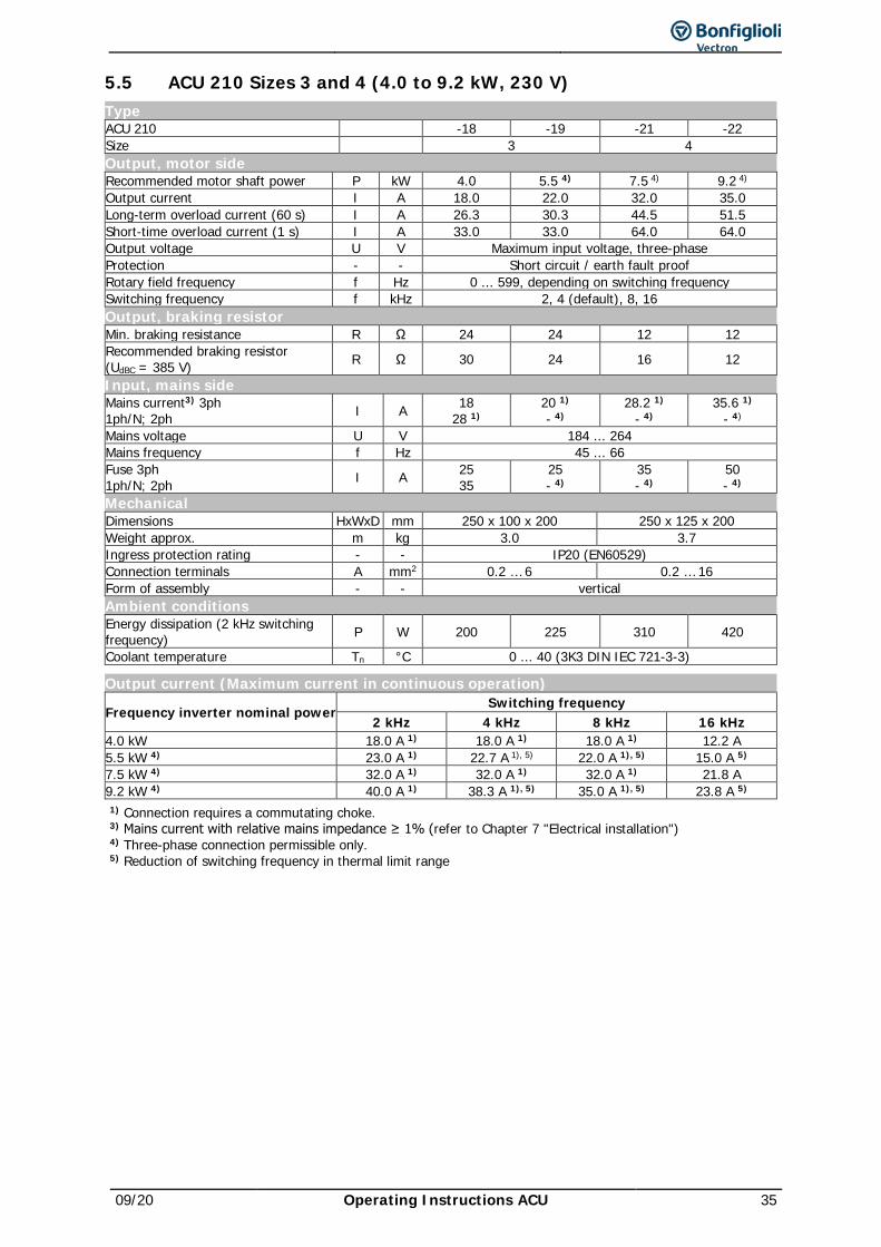
09/20 Operating Instructions ACU 35
5.5 ACU 210 Sizes 3 and 4 (4.0 to 9.2 kW, 230 V) Type ACU 210 -18 -19 -21 -22 Size 3 4 Output, motor side Recommended motor shaft power P kW 4.0 5.5 4) 7.5 4) 9.2 4) Output current I A 18.0 22.0 32.0 35.0 Long-term overload current (60 s) I A 26.3 30.3 44.5 51.5 Short-time overload current (1 s) I A 33.0 33.0 64.0 64.0 Output voltage U V Maximum input voltage, three-phase Protection - - Short circuit / earth fault proof Rotary field frequency f Hz 0 ... 599, depending on switching frequency Switching frequency f kHz 2, 4 (default), 8, 16 Output, braking resistor Min. braking resistance R Ω 24 24 12 12 Recommended braking resistor (UdBC = 385 V) R Ω 30 24 16 12
Input, mains side Mains current3) 3ph 1ph/N; 2ph I A 18
28 1) 20 1) - 4)
28.2 1) - 4)
35.6 1) - 4)
Mains voltage U V 184 ... 264 Mains frequency f Hz 45 ... 66 Fuse 3ph 1ph/N; 2ph I A 25
35 25 - 4)
35 - 4)
50 - 4)
Mechanical Dimensions HxWxD mm 250 x 100 x 200 250 x 125 x 200 Weight approx. m kg 3.0 3.7 Ingress protection rating - - IP20 (EN60529) Connection terminals A mm2 0.2 … 6 0.2 … 16 Form of assembly - - vertical Ambient conditions Energy dissipation (2 kHz switching frequency) P W 200 225 310 420
Coolant temperature Tn °C 0 ... 40 (3K3 DIN IEC 721-3-3)
Output current (Maximum current in continuous operation)
Frequency inverter nominal power Switching frequency
2 kHz 4 kHz 8 kHz 16 kHz 4.0 kW 18.0 A 1) 18.0 A 1) 18.0 A 1) 12.2 A 5.5 kW 4) 23.0 A 1) 22.7 A 1), 5) 22.0 A 1), 5) 15.0 A 5) 7.5 kW 4) 32.0 A 1) 32.0 A 1) 32.0 A 1) 21.8 A 9.2 kW 4) 40.0 A 1) 38.3 A 1), 5) 35.0 A 1), 5) 23.8 A 5) 1) Connection requires a commutating choke. 3) Mains current with relative mains impedance ≥ 1% (refer to Chapter 7 "Electrical installation") 4) Three-phase connection permissible only. 5) Reduction of switching frequency in thermal limit range
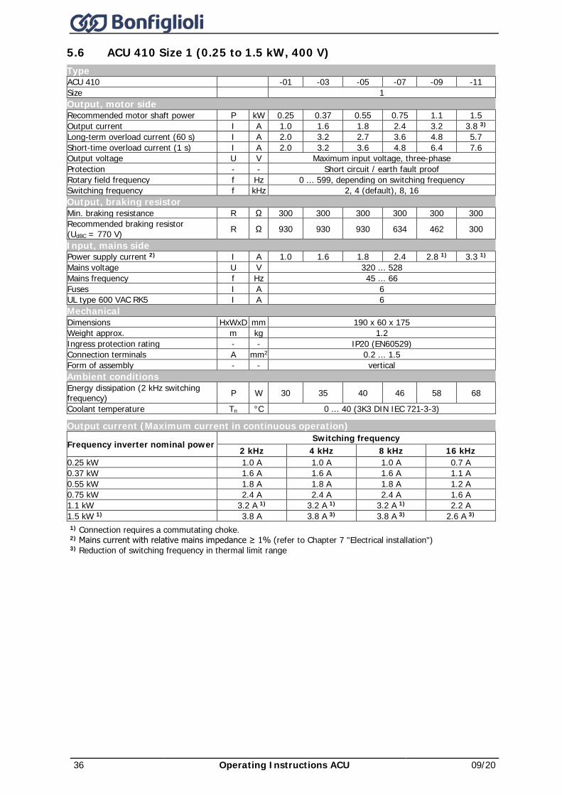
36 Operating Instructions ACU 09/20
5.6 ACU 410 Size 1 (0.25 to 1.5 kW, 400 V) Type ACU 410 -01 -03 -05 -07 -09 -11 Size 1 Output, motor side Recommended motor shaft power P kW 0.25 0.37 0.55 0.75 1.1 1.5 Output current I A 1.0 1.6 1.8 2.4 3.2 3.8 3) Long-term overload current (60 s) I A 2.0 3.2 2.7 3.6 4.8 5.7 Short-time overload current (1 s) I A 2.0 3.2 3.6 4.8 6.4 7.6 Output voltage U V Maximum input voltage, three-phase Protection - - Short circuit / earth fault proof Rotary field frequency f Hz 0 ... 599, depending on switching frequency Switching frequency f kHz 2, 4 (default), 8, 16 Output, braking resistor Min. braking resistance R Ω 300 300 300 300 300 300 Recommended braking resistor (UdBC = 770 V) R Ω 930 930 930 634 462 300
Input, mains side Power supply current 2) I A 1.0 1.6 1.8 2.4 2.8 1) 3.3 1) Mains voltage U V 320 ... 528 Mains frequency f Hz 45 ... 66 Fuses I A 6 UL type 600 VAC RK5 I A 6 Mechanical Dimensions HxWxD mm 190 x 60 x 175 Weight approx. m kg 1.2 Ingress protection rating - - IP20 (EN60529) Connection terminals A mm2 0.2 ... 1.5 Form of assembly - - vertical Ambient conditions Energy dissipation (2 kHz switching frequency) P W 30 35 40 46 58 68
Coolant temperature Tn °C 0 ... 40 (3K3 DIN IEC 721-3-3)
Output current (Maximum current in continuous operation)
Frequency inverter nominal power Switching frequency
2 kHz 4 kHz 8 kHz 16 kHz 0.25 kW 1.0 A 1.0 A 1.0 A 0.7 A 0.37 kW 1.6 A 1.6 A 1.6 A 1.1 A 0.55 kW 1.8 A 1.8 A 1.8 A 1.2 A 0.75 kW 2.4 A 2.4 A 2.4 A 1.6 A 1.1 kW 3.2 A 1) 3.2 A 1) 3.2 A 1) 2.2 A 1.5 kW 1) 3.8 A 3.8 A 3) 3.8 A 3) 2.6 A 3) 1) Connection requires a commutating choke. 2) Mains current with relative mains impedance ≥ 1% (refer to Chapter 7 "Electrical installation") 3) Reduction of switching frequency in thermal limit range
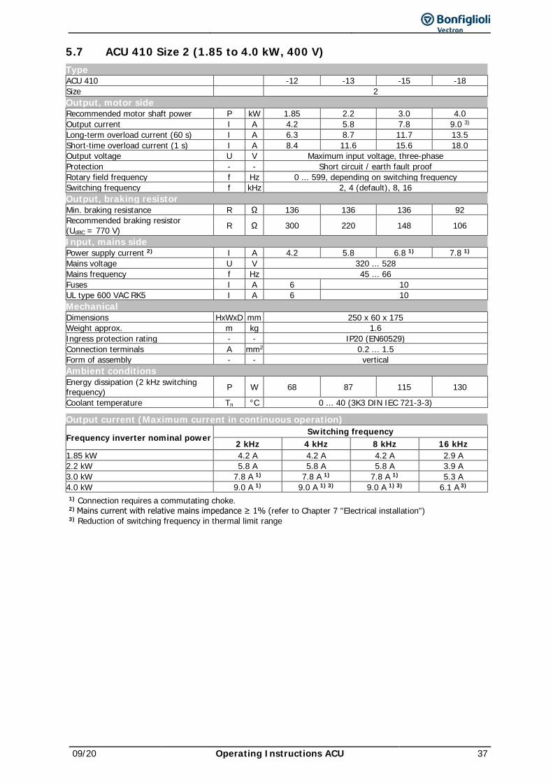
09/20 Operating Instructions ACU 37
5.7 ACU 410 Size 2 (1.85 to 4.0 kW, 400 V) Type ACU 410 -12 -13 -15 -18 Size 2 Output, motor side Recommended motor shaft power P kW 1.85 2.2 3.0 4.0 Output current I A 4.2 5.8 7.8 9.0 3) Long-term overload current (60 s) I A 6.3 8.7 11.7 13.5 Short-time overload current (1 s) I A 8.4 11.6 15.6 18.0 Output voltage U V Maximum input voltage, three-phase Protection - - Short circuit / earth fault proof Rotary field frequency f Hz 0 ... 599, depending on switching frequency Switching frequency f kHz 2, 4 (default), 8, 16 Output, braking resistor Min. braking resistance R Ω 136 136 136 92 Recommended braking resistor (UdBC = 770 V) R Ω 300 220 148 106
Input, mains side Power supply current 2) I A 4.2 5.8 6.8 1) 7.8 1) Mains voltage U V 320 ... 528 Mains frequency f Hz 45 ... 66 Fuses I A 6 10 UL type 600 VAC RK5 I A 6 10 Mechanical Dimensions HxWxD mm 250 x 60 x 175 Weight approx. m kg 1.6 Ingress protection rating - - IP20 (EN60529) Connection terminals A mm2 0.2 ... 1.5 Form of assembly - - vertical Ambient conditions Energy dissipation (2 kHz switching frequency) P W 68 87 115 130
Coolant temperature Tn °C 0 ... 40 (3K3 DIN IEC 721-3-3)
Output current (Maximum current in continuous operation)
Frequency inverter nominal power Switching frequency
2 kHz 4 kHz 8 kHz 16 kHz 1.85 kW 4.2 A 4.2 A 4.2 A 2.9 A 2.2 kW 5.8 A 5.8 A 5.8 A 3.9 A 3.0 kW 7.8 A 1) 7.8 A 1) 7.8 A 1) 5.3 A 4.0 kW 9.0 A 1) 9.0 A 1) 3) 9.0 A 1) 3) 6.1 A 3) 1) Connection requires a commutating choke. 2) Mains current with relative mains impedance ≥ 1% (refer to Chapter 7 "Electrical installation") 3) Reduction of switching frequency in thermal limit range
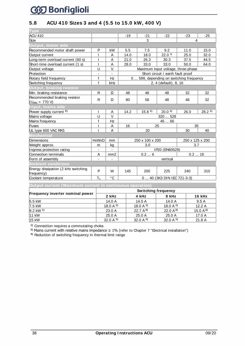
38 Operating Instructions ACU 09/20
5.8 ACU 410 Sizes 3 and 4 (5.5 to 15.0 kW, 400 V) Type ACU 410 -19 -21 -22 -23 -25 Size 3 4 Output, motor side Recommended motor shaft power P kW 5.5 7.5 9.2 11.0 15.0 Output current I A 14.0 18.0 22.0 3) 25.0 32.0 Long-term overload current (60 s) I A 21.0 26.3 30.3 37.5 44.5 Short-time overload current (1 s) I A 28.0 33.0 33.0 50.0 64.0 Output voltage U V Maximum input voltage, three-phase Protection - - Short circuit / earth fault proof Rotary field frequency f Hz 0 ... 599, depending on switching frequency Switching frequency f kHz 2, 4 (default), 8, 16 Output, braking resistor Min. braking resistance R Ω 48 48 48 32 32 Recommended braking resistor (UdBC = 770 V) R Ω 80 58 48 48 32
Input, mains side Power supply current 2) I A 14.2 15.8 1) 20.0 1) 26.0 28.2 1) Mains voltage U V 320 ... 528 Mains frequency f Hz 45 ... 66 Fuses I A 16 25 35 UL type 600 VAC RK5 I A 20 30 40 Mechanical Dimensions HxWxD mm 250 x 100 x 200 250 x 125 x 200 Weight approx. m kg 3.0 3.7 Ingress protection rating - - IP20 (EN60529) Connection terminals A mm2 0.2 ... 6 0.2 ... 16 Form of assembly - - vertical Ambient conditions Energy dissipation (2 kHz switching frequency) P W 145 200 225 240 310
Coolant temperature Tn °C 0 ... 40 (3K3 DIN IEC 721-3-3)
Output current (Maximum current in continuous operation)
Frequency inverter nominal power Switching frequency
2 kHz 4 kHz 8 kHz 16 kHz 5.5 kW 14.0 A 14.0 A 14.0 A 9.5 A 7.5 kW 18.0 A 1) 18.0 A 1) 18.0 A 1) 12.2 A 9.2 kW 1) 23.0 A 22.7 A 3) 22.0 A 3) 15.0 A 3) 11 kW 25.0 A 25.0 A 25.0 A 17.0 A 15 kW 32.0 A 1) 32.0 A 1) 32.0 A 1) 21.8 A 1) Connection requires a commutating choke. 2) Mains current with relative mains impedance ≥ 1% (refer to Chapter 7 "Electrical installation") 3) Reduction of switching frequency in thermal limit range

09/20 Operating Instructions ACU 39
5.9 ACU 410 Size 5 (18.5 to 30.0 kW, 400 V) Type ACU 410 -27 -29 -31 Size 5 Output, motor side Recommended motor shaft power P kW 18.5 22.0 30.0 Output current I A 40.0 45.0 60.0 Long-term overload current (60 s) I A 60.0 67.5 90.0 Short-time overload current (1 s) I A 80.0 90.0 120.0 Output voltage U V Maximum input voltage, three-phase Protection - - Short circuit / earth fault proof Rotary field frequency f Hz 0 ... 599, depending on switching frequency Switching frequency f kHz 2, 4 (default), 8 Output, braking resistor Min. braking resistance R Ω 16 Recommended braking resistor (UdBC = 770 V) R Ω 26 22 16
Input, mains side Power supply current 2) I A 42.0 50.0 58.0 1) Mains voltage U V 320 ... 528 Mains frequency f Hz 45 ... 66 Fuses I A 50 63 UL type 600 VAC RK5 I A 50 60 Mechanical Dimensions HxWxD mm 250x200x260 Weight approx. m kg 8 Ingress protection rating - - IP20 (EN60529) Connection terminals A mm2 up to 25 Form of assembly - - vertical Ambient conditions Energy dissipation (2 kHz switching frequency) P W 445 535 605
Coolant temperature Tn °C 0 ... 40 (3K3 DIN IEC 721-3-3)
Output current (Maximum current in continuous operation)
Frequency inverter nominal power Switching frequency
2 kHz 4 kHz 8 kHz 18.5 kW 40.0 A 40.0 A 40.0 A 22 kW 45.0 A 45.0 A 45.0 A 30 kW 60.0 A 1) 60.0 A 1) 60.0 A 1) 1) Connection requires a commutating choke. 2) Mains current with relative mains impedance ≥ 1% (refer to Chapter 7 "Electrical installation")
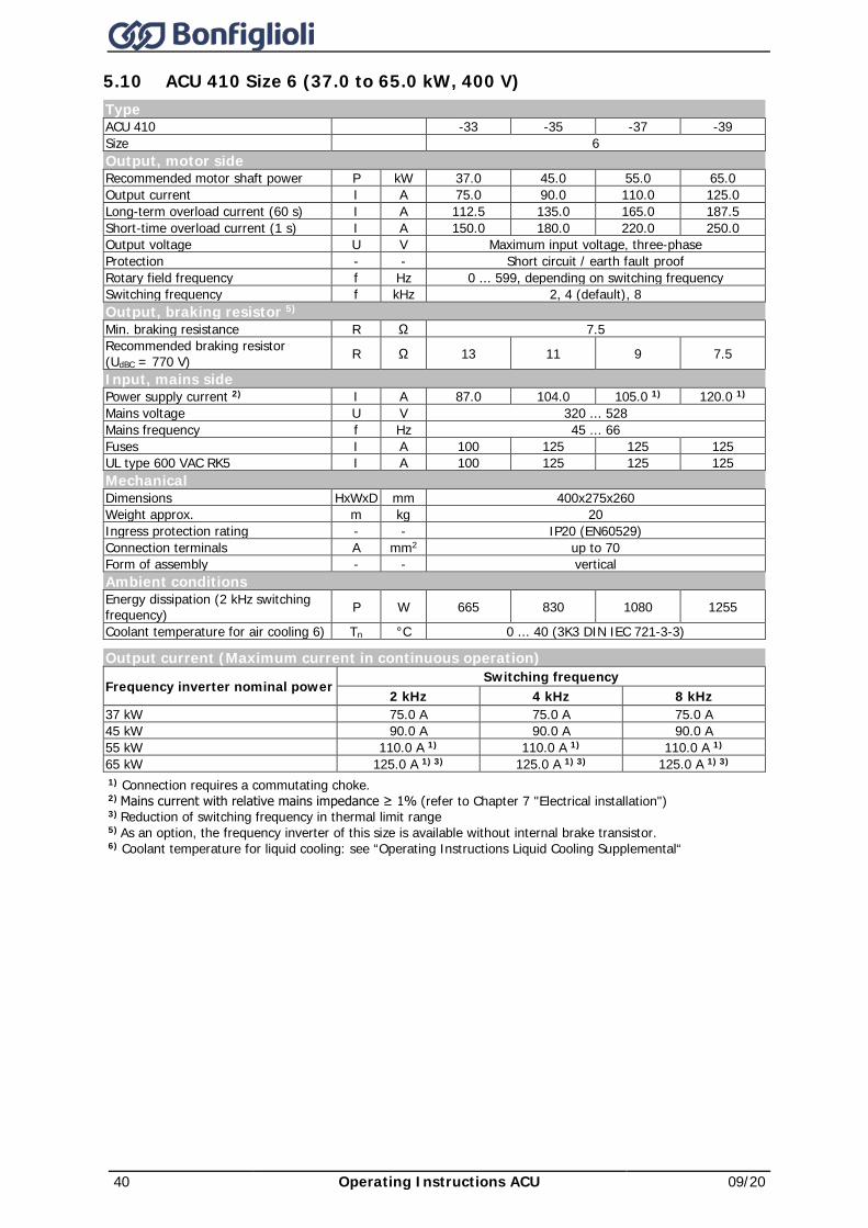
40 Operating Instructions ACU 09/20
5.10 ACU 410 Size 6 (37.0 to 65.0 kW, 400 V) Type ACU 410 -33 -35 -37 -39 Size 6 Output, motor side Recommended motor shaft power P kW 37.0 45.0 55.0 65.0 Output current I A 75.0 90.0 110.0 125.0 Long-term overload current (60 s) I A 112.5 135.0 165.0 187.5 Short-time overload current (1 s) I A 150.0 180.0 220.0 250.0 Output voltage U V Maximum input voltage, three-phase Protection - - Short circuit / earth fault proof Rotary field frequency f Hz 0 ... 599, depending on switching frequency Switching frequency f kHz 2, 4 (default), 8 Output, braking resistor 5) Min. braking resistance R Ω 7.5 Recommended braking resistor (UdBC = 770 V) R Ω 13 11 9 7.5
Input, mains side Power supply current 2) I A 87.0 104.0 105.0 1) 120.0 1) Mains voltage U V 320 ... 528 Mains frequency f Hz 45 ... 66 Fuses I A 100 125 125 125 UL type 600 VAC RK5 I A 100 125 125 125 Mechanical Dimensions HxWxD mm 400x275x260 Weight approx. m kg 20 Ingress protection rating - - IP20 (EN60529) Connection terminals A mm2 up to 70 Form of assembly - - vertical Ambient conditions Energy dissipation (2 kHz switching frequency) P W 665 830 1080 1255
Coolant temperature for air cooling 6) Tn °C 0 ... 40 (3K3 DIN IEC 721-3-3)
Output current (Maximum current in continuous operation)
Frequency inverter nominal power Switching frequency
2 kHz 4 kHz 8 kHz 37 kW 75.0 A 75.0 A 75.0 A 45 kW 90.0 A 90.0 A 90.0 A 55 kW 110.0 A 1) 110.0 A 1) 110.0 A 1) 65 kW 125.0 A 1) 3) 125.0 A 1) 3) 125.0 A 1) 3) 1) Connection requires a commutating choke. 2) Mains current with relative mains impedance ≥ 1% (refer to Chapter 7 "Electrical installation") 3) Reduction of switching frequency in thermal limit range 5) As an option, the frequency inverter of this size is available without internal brake transistor. 6) Coolant temperature for liquid cooling: see “Operating Instructions Liquid Cooling Supplemental“
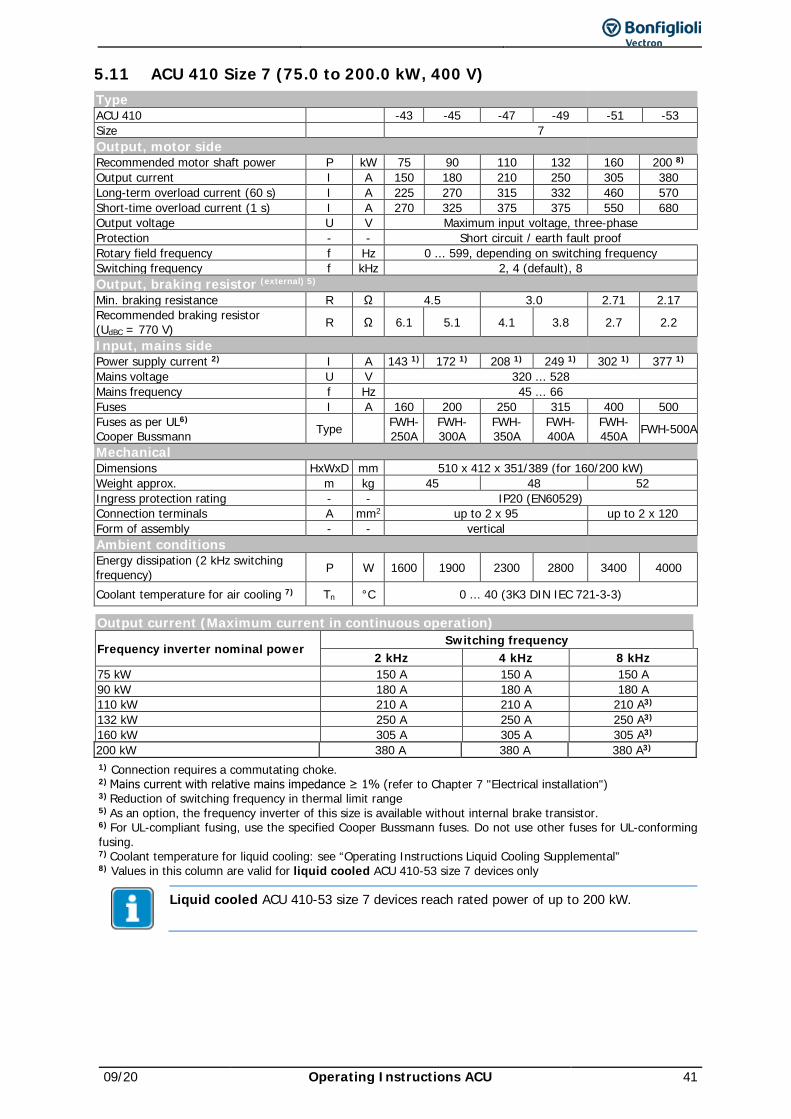
09/20 Operating Instructions ACU 41
5.11 ACU 410 Size 7 (75.0 to 200.0 kW, 400 V) Type ACU 410 -43 -45 -47 -49 -51 -53 Size 7 Output, motor side Recommended motor shaft power P kW 75 90 110 132 160 200 8) Output current I A 150 180 210 250 305 380 Long-term overload current (60 s) I A 225 270 315 332 460 570 Short-time overload current (1 s) I A 270 325 375 375 550 680 Output voltage U V Maximum input voltage, three-phase Protection - - Short circuit / earth fault proof Rotary field frequency f Hz 0 ... 599, depending on switching frequency Switching frequency f kHz 2, 4 (default), 8 Output, braking resistor (external) 5) Min. braking resistance R Ω 4.5 3.0 2.71 2.17 Recommended braking resistor (UdBC = 770 V) R Ω 6.1 5.1 4.1 3.8 2.7 2.2
Input, mains side Power supply current 2) I A 143 1) 172 1) 208 1) 249 1) 302 1) 377 1) Mains voltage U V 320 ... 528 Mains frequency f Hz 45 ... 66 Fuses I A 160 200 250 315 400 500 Fuses as per UL6) Cooper Bussmann Type FWH-
250A FWH-300A
FWH-350A
FWH-400A
FWH-450A FWH-500A
Mechanical Dimensions HxWxD mm 510 x 412 x 351/389 (for 160/200 kW) Weight approx. m kg 45 48 52 Ingress protection rating - - IP20 (EN60529) Connection terminals A mm2 up to 2 x 95 up to 2 x 120 Form of assembly - - vertical Ambient conditions Energy dissipation (2 kHz switching frequency) P W 1600 1900 2300 2800 3400 4000
Coolant temperature for air cooling 7) Tn °C 0 ... 40 (3K3 DIN IEC 721-3-3)
Output current (Maximum current in continuous operation)
Frequency inverter nominal power Switching frequency
2 kHz 4 kHz 8 kHz 75 kW 150 A 150 A 150 A 90 kW 180 A 180 A 180 A 110 kW 210 A 210 A 210 A3) 132 kW 250 A 250 A 250 A3) 160 kW 305 A 305 A 305 A3) 200 kW 380 A 380 A 380 A3) 1) Connection requires a commutating choke. 2) Mains current with relative mains impedance ≥ 1% (refer to Chapter 7 "Electrical installation") 3) Reduction of switching frequency in thermal limit range 5) As an option, the frequency inverter of this size is available without internal brake transistor. 6) For UL-compliant fusing, use the specified Cooper Bussmann fuses. Do not use other fuses for UL-conforming fusing. 7) Coolant temperature for liquid cooling: see “Operating Instructions Liquid Cooling Supplemental” 8) Values in this column are valid for liquid cooled ACU 410-53 size 7 devices only
Liquid cooled ACU 410-53 size 7 devices reach rated power of up to 200 kW.
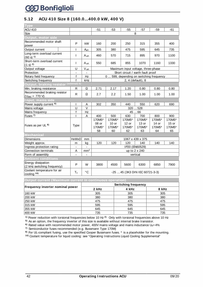
42 Operating Instructions ACU 09/20
5.12 ACU 410 Size 8 (160.0...400.0 kW, 400 V) Type ACU 410 -51 -53 -55 -57 -59 -61 Size 8 Output, motor side Recommended motor shaft power P kW 160 200 250 315 355 400
Output current I Aeff. 305 380 475 595 645 735 Long-term overload current (60 s) 1) I A eff. 460 570 715 895 970 1100
Short-term overload current (1 s) 2) I A eff. 550 685 855 1070 1160 1330
Output voltage U V eff. Maximum input voltage, three-phase Protection - - Short circuit / earth fault proof Rotary field frequency f Hz 0 ... 599, depending on switching frequency Switching frequency f kHz 2, 4 (default), 8 Output, braking resistor (external) 5) Min. braking resistance R Ω 2.71 2.17 1.20 0.80 0.80 0.80 Recommended braking resistor (UdBC = 770 V) R Ω 2.7 2.2 1.50 1.00 1.00 1.00
Input, mains side Power supply current 6) I A 302 350 440 550 620 690 Mains voltage U V 320 … 528 Mains frequency f Hz 45 … 66 Fuses 7) I A 400 500 630 700 800 900
Fuses as per UL 8) Type 170M5* 08 or
170M5* 58
170M5* 10 or
170M5* 60
170M5* 12 or
170M5* 62
170M5* 13 or
170M5* 63
170M5* 14 or
170M5* 64
170M5* 15 or
170M5* 65
Mechanical Dimensions HxWxD mm 1067 x 439 x 375 Weight approx. m kg 120 120 120 140 140 140 Ingress protection rating - - IP20 (EN60529) Connection terminals A mm2 up to 2 x 240 Form of assembly - - vertical Ambient conditions Energy dissipation (2 kHz switching frequency) P W 3800 4500 5600 6300 6850 7900
Coolant temperature for air cooling 10) Tn °C -25 … 45 (3K3 DIN IEC 60721-3-3)
Output current (Maximum current in continuous operation)
Frequency inverter nominal power Switching frequency
2 kHz 4 kHz 8 kHz 160 kW 305 305 305 200 kW 380 380 380 250 kW 475 475 475 315 kW 595 595 595 355 kW 645 645 645 400 kW 735 735 735 1) Power reduction with torsional frequencies below 10 Hz 2) Only with torsional frequencies above 10 Hz 5) As an option, the frequency inverter of this size is available without internal brake transistor. 6) Rated value with recommended motor power, 400V mains voltage and mains inductance UK=4% 7) Semiconductor fuses recommended (e.g. Bussmann Type 170M) 8) For UL-compliant fusing, use the specified Cooper Bussmann fuses. * is a placeholder for the mounting. 10) Coolant temperature for liquid cooling: see “Operating Instructions Liquid Cooling Supplemental“
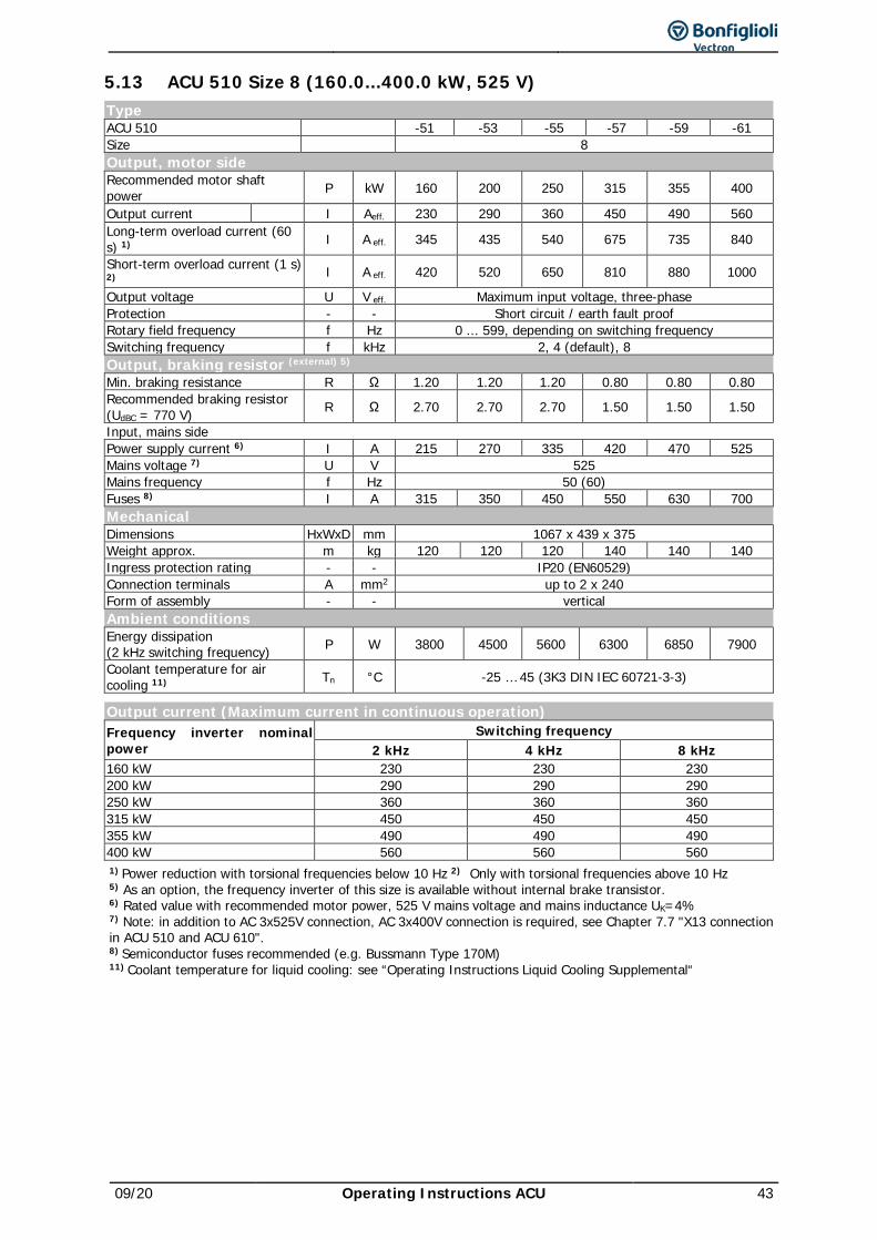
09/20 Operating Instructions ACU 43
5.13 ACU 510 Size 8 (160.0...400.0 kW, 525 V) Type ACU 510 -51 -53 -55 -57 -59 -61 Size 8 Output, motor side Recommended motor shaft power P kW 160 200 250 315 355 400
Output current I Aeff. 230 290 360 450 490 560 Long-term overload current (60 s) 1) I A eff. 345 435 540 675 735 840
Short-term overload current (1 s) 2) I A eff. 420 520 650 810 880 1000
Output voltage U V eff. Maximum input voltage, three-phase Protection - - Short circuit / earth fault proof Rotary field frequency f Hz 0 ... 599, depending on switching frequency Switching frequency f kHz 2, 4 (default), 8 Output, braking resistor (external) 5) Min. braking resistance R Ω 1.20 1.20 1.20 0.80 0.80 0.80 Recommended braking resistor (UdBC = 770 V) R Ω 2.70 2.70 2.70 1.50 1.50 1.50
Input, mains side Power supply current 6) I A 215 270 335 420 470 525 Mains voltage 7) U V 525 Mains frequency f Hz 50 (60) Fuses 8) I A 315 350 450 550 630 700 Mechanical Dimensions HxWxD mm 1067 x 439 x 375 Weight approx. m kg 120 120 120 140 140 140 Ingress protection rating - - IP20 (EN60529) Connection terminals A mm2 up to 2 x 240 Form of assembly - - vertical Ambient conditions Energy dissipation (2 kHz switching frequency) P W 3800 4500 5600 6300 6850 7900
Coolant temperature for air cooling 11) Tn °C -25 … 45 (3K3 DIN IEC 60721-3-3)
Output current (Maximum current in continuous operation) Frequency inverter nominal power
Switching frequency 2 kHz 4 kHz 8 kHz
160 kW 230 230 230 200 kW 290 290 290 250 kW 360 360 360 315 kW 450 450 450 355 kW 490 490 490 400 kW 560 560 560 1) Power reduction with torsional frequencies below 10 Hz 2) Only with torsional frequencies above 10 Hz 5) As an option, the frequency inverter of this size is available without internal brake transistor. 6) Rated value with recommended motor power, 525 V mains voltage and mains inductance UK=4% 7) Note: in addition to AC 3x525V connection, AC 3x400V connection is required, see Chapter 7.7 "X13 connection in ACU 510 and ACU 610". 8) Semiconductor fuses recommended (e.g. Bussmann Type 170M) 11) Coolant temperature for liquid cooling: see “Operating Instructions Liquid Cooling Supplemental“
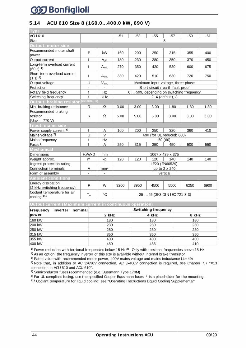
44 Operating Instructions ACU 09/20
5.14 ACU 610 Size 8 (160.0...400.0 kW, 690 V) Type ACU 610 -51 -53 -55 -57 -59 -61 Size 8 Output, motor side Recommended motor shaft power P kW 160 200 250 315 355 400
Output current I Aeff. 180 230 280 350 370 450 Long-term overload current (60 s) 1) I A eff. 270 350 420 530 600 675
Short-term overload current (1 s) 2) I A eff. 330 420 510 630 720 750
Output voltage U V eff. Maximum input voltage, three-phase Protection - - Short circuit / earth fault proof Rotary field frequency f Hz 0 ... 599, depending on switching frequency Switching frequency f kHz 2, 4 (default), 8 Output, braking resistor (external) 5) Min. braking resistance R Ω 3.00 3.00 3.00 1.80 1.80 1.80 Recommended braking resistor (UdBC = 770 V)
R Ω 5.00 5.00 5.00 3.00 3.00 3.00
Input, mains side Power supply current 6) I A 160 200 250 320 360 410 Mains voltage 7) U V 690 (for UL reduced: 600) Mains frequency f Hz 50 (60) Fuses 8) I A 250 315 350 450 500 550 Mechanical Dimensions HxWxD mm 1067 x 439 x 375 Weight approx. m kg 120 120 120 140 140 140 Ingress protection rating - - IP20 (EN60529) Connection terminals A mm2 up to 2 x 240 Form of assembly - - vertical Ambient conditions Energy dissipation (2 kHz switching frequency) P W 3200 3950 4500 5500 6250 6900
Coolant temperature for air cooling 11) Tn °C -25 … 45 (3K3 DIN IEC 721-3-3)
Output current (Maximum current in continuous operation) Frequency inverter nominal power
Switching frequency 2 kHz 4 kHz 8 kHz
160 kW 180 180 180 200 kW 230 230 230 250 kW 280 280 280 315 kW 350 350 350 355 kW 400 400 400 400 kW 450 436 410 1) Power reduction with torsional frequencies below 15 Hz 2) Only with torsional frequencies above 15 Hz 5) As an option, the frequency inverter of this size is available without internal brake transistor 6) Rated value with recommended motor power, 400V mains voltage and mains inductance UK=4% 7) Note that, in addition to AC 3x690V connection, AC 3x400V connection is required, see Chapter 7.7 "X13 connection in ACU 510 and ACU 610". 8) Semiconductor fuses recommended (e.g. Bussmann Type 170M) 9) For UL-compliant fusing, use the specified Cooper Bussmann fuses. * is a placeholder for the mounting. 11) Coolant temperature for liquid cooling: see “Operating Instructions Liquid Cooling Supplemental“
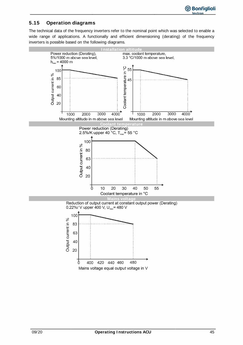
09/20 Operating Instructions ACU 45
5.15 Operation diagrams The technical data of the frequency inverters refer to the nominal point which was selected to enable a wide range of applications. A functionally and efficient dimensioning (derating) of the frequency inverters is possible based on the following diagrams.
Installation altitude
Coolant temperature
Mains voltage
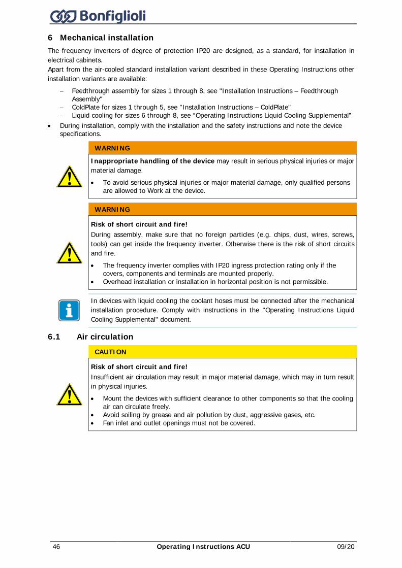
46 Operating Instructions ACU 09/20
6 Mechanical installation The frequency inverters of degree of protection IP20 are designed, as a standard, for installation in electrical cabinets. Apart from the air-cooled standard installation variant described in these Operating Instructions other installation variants are available:
− Feedthrough assembly for sizes 1 through 8, see "Installation Instructions – Feedthrough Assembly"
− ColdPlate for sizes 1 through 5, see "Installation Instructions – ColdPlate" − Liquid cooling for sizes 6 through 8, see “Operating Instructions Liquid Cooling Supplemental”
• During installation, comply with the installation and the safety instructions and note the device specifications.
WARNING
Inappropriate handling of the device may result in serious physical injuries or major material damage. • To avoid serious physical injuries or major material damage, only qualified persons
are allowed to Work at the device.
WARNING
Risk of short circuit and fire! During assembly, make sure that no foreign particles (e.g. chips, dust, wires, screws, tools) can get inside the frequency inverter. Otherwise there is the risk of short circuits and fire. • The frequency inverter complies with IP20 ingress protection rating only if the
covers, components and terminals are mounted properly. • Overhead installation or installation in horizontal position is not permissible.
In devices with liquid cooling the coolant hoses must be connected after the mechanical installation procedure. Comply with instructions in the "Operating Instructions Liquid Cooling Supplemental" document.
6.1 Air circulation CAUTION
Risk of short circuit and fire! Insufficient air circulation may result in major material damage, which may in turn result in physical injuries. • Mount the devices with sufficient clearance to other components so that the cooling
air can circulate freely. • Avoid soiling by grease and air pollution by dust, aggressive gases, etc. • Fan inlet and outlet openings must not be covered.
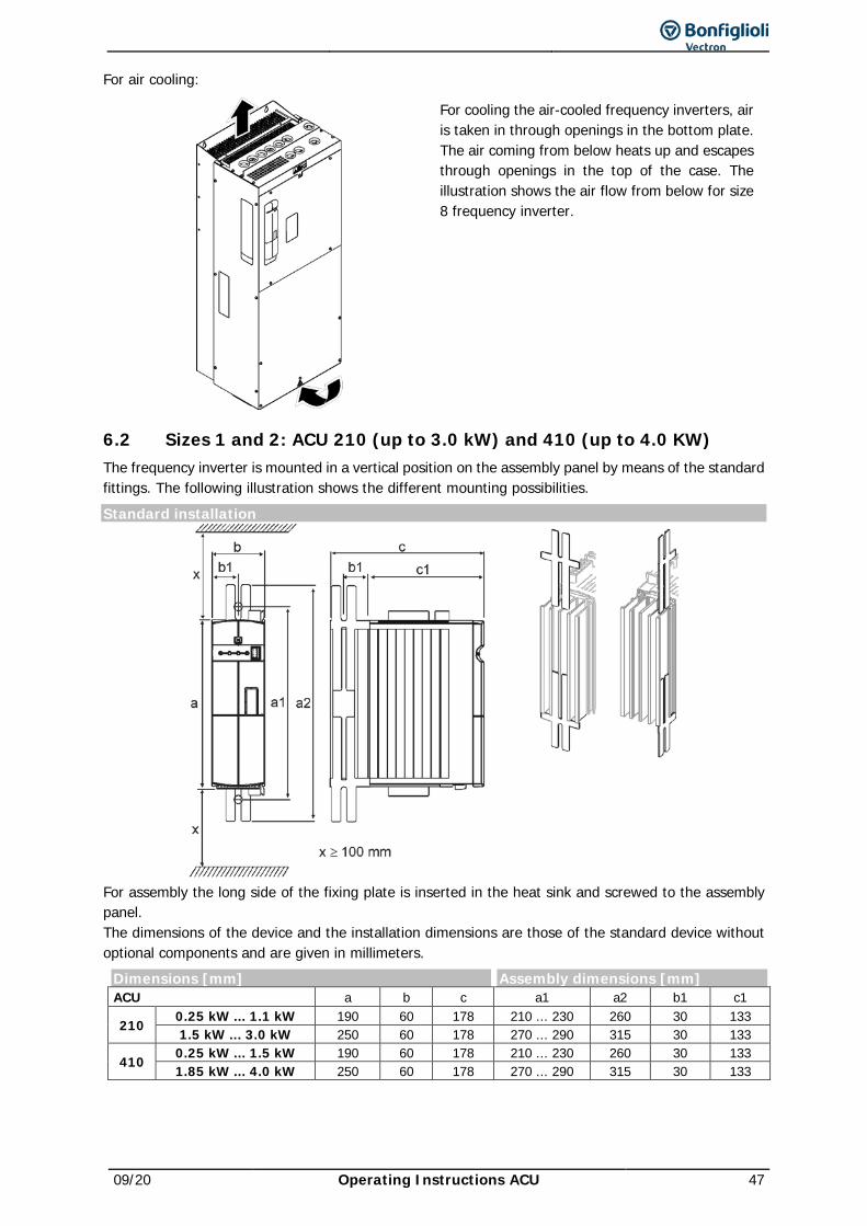
09/20 Operating Instructions ACU 47
For air cooling:
For cooling the air-cooled frequency inverters, air is taken in through openings in the bottom plate. The air coming from below heats up and escapes through openings in the top of the case. The illustration shows the air flow from below for size 8 frequency inverter.
6.2 Sizes 1 and 2: ACU 210 (up to 3.0 kW) and 410 (up to 4.0 KW) The frequency inverter is mounted in a vertical position on the assembly panel by means of the standard fittings. The following illustration shows the different mounting possibilities. Standard installation
For assembly the long side of the fixing plate is inserted in the heat sink and screwed to the assembly panel. The dimensions of the device and the installation dimensions are those of the standard device without optional components and are given in millimeters.
Dimensions [mm] Assembly dimensions [mm] ACU a b c a1 a2 b1 c1
210 0.25 kW ... 1.1 kW 190 60 178 210 ... 230 260 30 133 1.5 kW ... 3.0 kW 250 60 178 270 ... 290 315 30 133
410 0.25 kW ... 1.5 kW 190 60 178 210 ... 230 260 30 133 1.85 kW ... 4.0 kW 250 60 178 270 ... 290 315 30 133
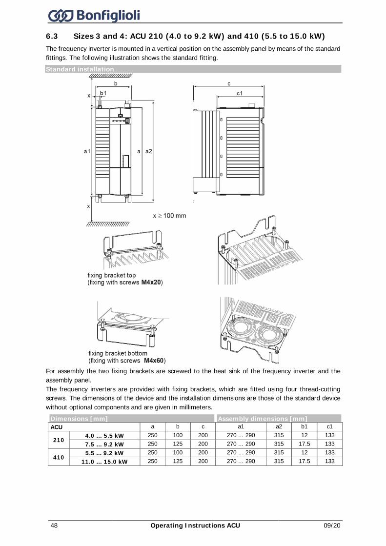
48 Operating Instructions ACU 09/20
6.3 Sizes 3 and 4: ACU 210 (4.0 to 9.2 kW) and 410 (5.5 to 15.0 kW) The frequency inverter is mounted in a vertical position on the assembly panel by means of the standard fittings. The following illustration shows the standard fitting. Standard installation
For assembly the two fixing brackets are screwed to the heat sink of the frequency inverter and the assembly panel. The frequency inverters are provided with fixing brackets, which are fitted using four thread-cutting screws. The dimensions of the device and the installation dimensions are those of the standard device without optional components and are given in millimeters.
Dimensions [mm] Assembly dimensions [mm] ACU a b c a1 a2 b1 c1
210 4.0 … 5.5 kW 250 100 200 270 ... 290 315 12 133 7.5 … 9.2 kW 250 125 200 270 ... 290 315 17.5 133
410 5.5 ... 9.2 kW 250 100 200 270 ... 290 315 12 133
11.0 … 15.0 kW 250 125 200 270 ... 290 315 17.5 133
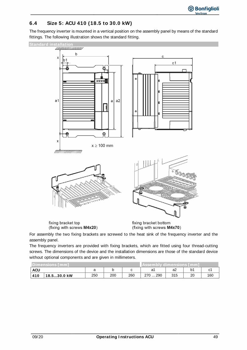
09/20 Operating Instructions ACU 49
6.4 Size 5: ACU 410 (18.5 to 30.0 kW) The frequency inverter is mounted in a vertical position on the assembly panel by means of the standard fittings. The following illustration shows the standard fitting. Standard installation
For assembly the two fixing brackets are screwed to the heat sink of the frequency inverter and the assembly panel. The frequency inverters are provided with fixing brackets, which are fitted using four thread-cutting screws. The dimensions of the device and the installation dimensions are those of the standard device without optional components and are given in millimeters.
Dimensions [mm] Assembly dimensions [mm] ACU a b c a1 a2 b1 c1 410 18.5...30.0 kW 250 200 260 270 … 290 315 20 160
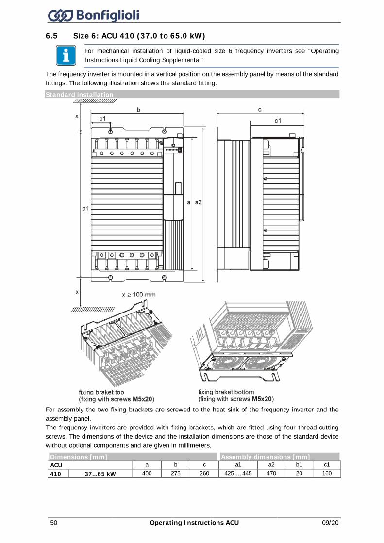
50 Operating Instructions ACU 09/20
6.5 Size 6: ACU 410 (37.0 to 65.0 kW)
For mechanical installation of liquid-cooled size 6 frequency inverters see “Operating Instructions Liquid Cooling Supplemental”.
The frequency inverter is mounted in a vertical position on the assembly panel by means of the standard fittings. The following illustration shows the standard fitting. Standard installation
For assembly the two fixing brackets are screwed to the heat sink of the frequency inverter and the assembly panel. The frequency inverters are provided with fixing brackets, which are fitted using four thread-cutting screws. The dimensions of the device and the installation dimensions are those of the standard device without optional components and are given in millimeters.
Dimensions [mm] Assembly dimensions [mm] ACU a b c a1 a2 b1 c1 410 37...65 kW 400 275 260 425 … 445 470 20 160
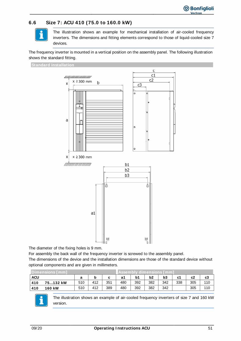
09/20 Operating Instructions ACU 51
6.6 Size 7: ACU 410 (75.0 to 160.0 kW)
The illustration shows an example for mechanical installation of air-cooled frequency inverters. The dimensions and fitting elements correspond to those of liquid-cooled size 7 devices.
The frequency inverter is mounted in a vertical position on the assembly panel. The following illustration shows the standard fitting.
Standard installation
The diameter of the fixing holes is 9 mm. For assembly the back wall of the frequency inverter is screwed to the assembly panel. The dimensions of the device and the installation dimensions are those of the standard device without optional components and are given in millimeters.
Dimensions [mm] Assembly dimensions [mm] ACU a b c a1 b1 b2 b3 c1 c2 c3 410 75...132 kW 510 412 351 480 392 382 342 338 305 110 410 160 kW 510 412 389 480 392 382 342 305 110
The illustration shows an example of air-cooled frequency inverters of size 7 and 160 kW version.
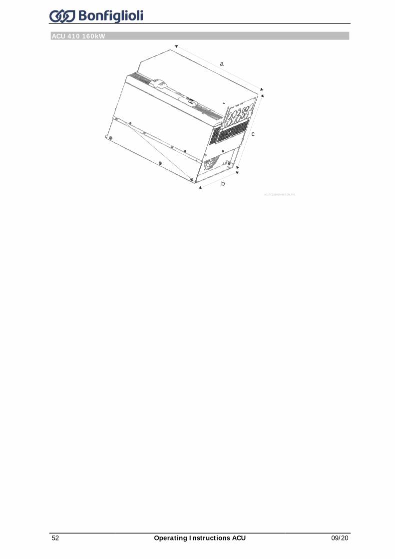
52 Operating Instructions ACU 09/20
ACU 410 160kW
ACx7-TZ-160kW-00-ISOM_V01
b
c
a
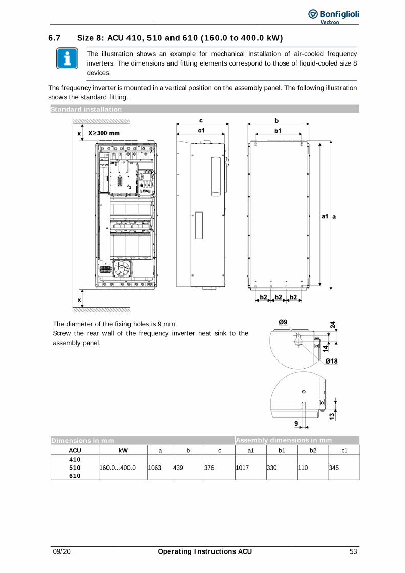
09/20 Operating Instructions ACU 53
6.7 Size 8: ACU 410, 510 and 610 (160.0 to 400.0 kW)
The illustration shows an example for mechanical installation of air-cooled frequency inverters. The dimensions and fitting elements correspond to those of liquid-cooled size 8 devices.
The frequency inverter is mounted in a vertical position on the assembly panel. The following illustration shows the standard fitting. Standard installation
The diameter of the fixing holes is 9 mm. Screw the rear wall of the frequency inverter heat sink to the assembly panel.
Dimensions in mm Assembly dimensions in mm ACU kW a b c a1 b1 b2 c1 410 510 610
160.0...400.0 1063 439 376 1017 330 110 345
54 Operating Instructions ACU 09/20
7 Electrical installation WARNING
Dangerous voltage! When the frequency inverter is disconnected from power supply, the mains, DC-link voltage and motor terminals may still be live for some time. Work at the device may only be started once the DC link capacitors have discharged. The time to wait is at least 3 minutes in the case of sizes 1 through 7 and at least 10 minutes in the case of size 8. • The electrical installation must be carried out by qualified electricians according to
the general and regional safety and installation directives. • The documentation and device specification must be complied with during
installation. • Before any assembly or connection work, discharge the frequency inverter. Verify
safe isolation from power supply. • Do not connect inappropriate voltage sources. The nominal voltage of the
frequency inverter must correspond to the supply voltage. • The frequency inverter must be connected to ground potential. • Do not remove any covers of the frequency inverter while power supply is on.
The connecting cables must be protected externally, considering the maximum voltage and current values of the fuses. The mains fuses and cable cross-sections are to be selected according to EN 602041 and DIN VDE 0298 Part 4 for the nominal operating point of the frequency inverter. According to UL/CSA, the frequency inverter is suitable for operation at a supply network of a maximum of 480 VAC which delivers a maximum symmetrical current of 5000 A (effective value) if protected by fuses of class RK5. Only use copper cables with a temperature range of 60 / 75 °C.
The fuses must be chosen depending on the individual application. The values recommended in the technical data apply for the continuous rated operation without overload.
The frequency inverters are to be grounded properly, i.e. large connection area and with good conductivity. The leakage current of the frequency inverters may exceed AC 3.5 mA or DC 10 mA. According to EN 61800-5-1 a permanent connection must be provided. The protective conductor cross-section required for grounding the fixing plate must be selected according to the size of the unit. In these applications, the cross-section must correspond to the recommended cross-section of the wire.
CAUTION
Improperly mounted covers IP20 ingress protection rating is only achieved with terminals plugged and with properly mounted covers. Improperly mounted covers lead to ingress of dirt or foreign objects into the housing of the device and might lead to malfunctions. • Take care to mount all covers correctly and properly. • Insert all terminal connectors and mount all covers before starting operation.
Special connection variants are possible apart from the standard connection variant described in these Operating Instructions:
− Parallel connection (see "Application Manual – Parallel Connection") − DC supply (if you have any questions on this, contact BONFIGLIOLI Customer Service.)
In devices ACU 510 and ACU 610 of size 8, reconnection of the DC power supply unit is required to ensure proper cooling. Please contact BONFIGLIOLI Customer Service.
09/20 Operating Instructions ACU 55
Connection conditions • The frequency inverter is suited for connection to the public or industrial supply mains according
to the technical data. If the transformer output of the supply mains is ≤ 500 kVA, a mains commutation choke is only necessary for the frequency inverters identified in the technical data. The other frequency inverters are suitable for connection without a mains commutating choke with a relative mains impedance ≥ 1%.
• It must be checked, based on the specifications of EN 61000-3-2, if the devices can be connected to the public supply means without taking additional measures. The frequency inverters ≤ 9.2 kW with integrated EMC filter comply with the emission limits of the product standard EN 61800-3 up to a motor cable length of 10 m, without additional measures being required. Increased requirements in connection with the specific application of the frequency inverter are to be met by means of optional components. Commutating chokes and EMC filters are optionally available for the series of devices.
• Operation on an unearthed mains (IT mains) is admissible when using devices specifically constructed for this purpose. Please contact BONFIGLIOLI for details.
• Interference-free operation with residual current device is guaranteed at a tripping current ≥ 30 mA if the following points are observed:
− One-phase power supply (L1/N): Pulse current and alternating current sensitive residual current devices (Type A acc. to EN 61800-5-1)
− Two-phase power supply (L1/L2) or Three-phase power supply (L1/L2/L3): All-current sensitive residual current devices (Type B acc. to EN 61800-5-1)
− Use EMC filters with reduced leakage current or, if possible, do not use EMC filters at all. − The length of the shielded motor cable is ≤ 10 m and there are no additional capacitive
components between the mains or motor cables and PE.
NOTICE Unexpected current
Please note (according to EN 61800-5-1): This product may cause direct current in the protective earth conductor. • Where residual current devices (RCD) or residual current monitors (RCM) are used
as a protection against direct or indirect contact, only RCDs / RCMs of Type B are permissible on the power supply side of this product.
• The fuses to be used are to be selected depending on the specific application. The safety recommendations in the Technical Data are valid for continuous operation without overload.
7.1 EMC information The frequency inverters are designed according to the requirements and limit values of product standard EN 61800-3 with an interference immunity factor (EMI) for operation in industrial applications. Electromagnetic interference is to be avoided by expert installation and observation of the specific product information.
Measures • Install the frequency inverters and commutating chokes on a metal mounting panel. Ideally, the
mounting panel should be galvanized, not painted. • Provide proper equipotential bonding within the system or plant. Plant components such as
electrical cabinets, control panels, machine frames must be connected by means of PE cables, i.e. sufficient area and with good conductivity.
• The shield of the control cables is to be connected to ground potential properly, i.e. with good conductivity, on both sides (shield clamp). Mount shield clamps for cable shields close to the unit.
• Connect the frequency inverter, the commutating choke, external filters and other components to an earthing point via short cables.
• Excessive cable length and loosely suspended cabling must be avoided. • Contactors, relays and solenoids in the electrical cabinet are to be provided with suitable
interference suppression components.

56 Operating Instructions ACU 09/20
1 fuse 2 circuit breaker 3 line choke (optional) 4 input filter (optional) 5 cable shield 6 braking resistor (optional) 7 output filter (optional)
A Mains connection The length of the mains supply cable is not limited. However, it must be installed separate from the control, data and motor cables. B DC-link connection
The frequency inverters are to be connected to the same mains potential or a common direct voltage source. Cables longer than 300 mm are to be shielded. The shield must be connected to the mounting panel on both sides. C Control connection
Keep control and signal cables physically separate from the power cables. Analog signal lines are to be connected to the shield potential on one side. Install sensor cables separate from motor cables. D Motor and braking resistor
The shield of the motor cable is to be connected to ground potential properly on both sides. On the motor side use a metal compression gland. On the frequency inverter side an appropriate shield clamp is to be used. The signal cable used for monitoring the motor temperature must be kept separate from the motor cable. Connect the shield of this line on both sides. If a braking resistor is used, the connection cable must also be shielded, and the shield is to be connected to earth potential on both sides.
Relay The relay enables using high-energy signals.
Line choke Line chokes reduce mains harmonics and reactive power. In addition, a longer service life of the frequency inverter is possible. When using a line choke, note that line chokes may reduce the maximum output voltage of the frequency inverter. The line choke must be installed between the mains connection and the input filter.
Input filter Input filters reduce grid-bound, high-frequency radio interference voltage.
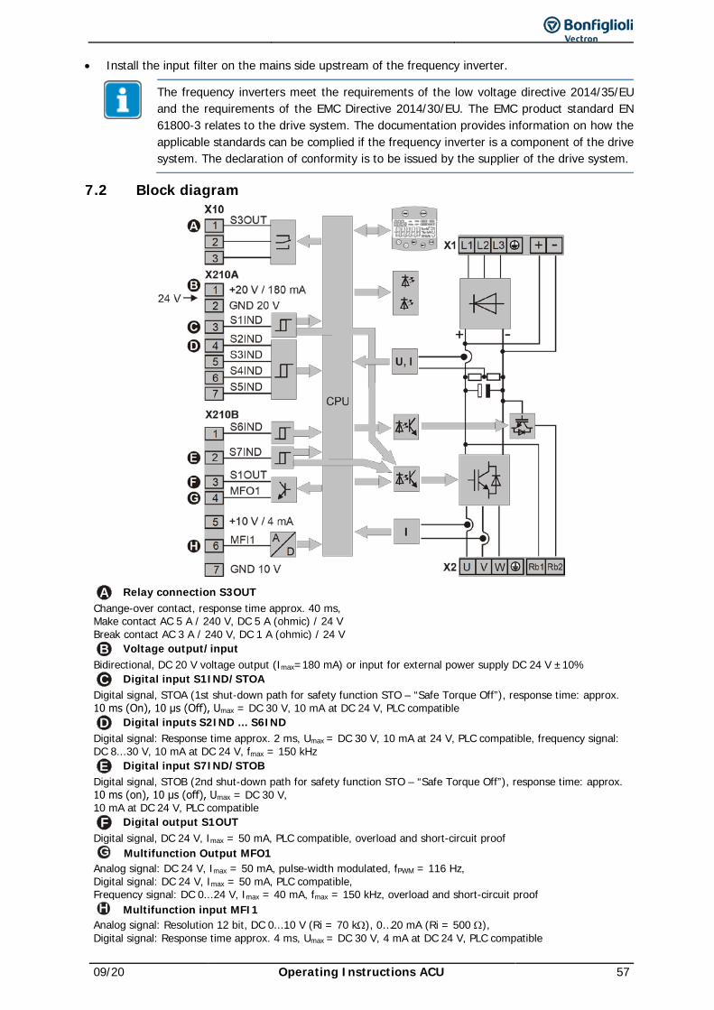
09/20 Operating Instructions ACU 57
• Install the input filter on the mains side upstream of the frequency inverter.
The frequency inverters meet the requirements of the low voltage directive 2014/35/EU and the requirements of the EMC Directive 2014/30/EU. The EMC product standard EN 61800-3 relates to the drive system. The documentation provides information on how the applicable standards can be complied if the frequency inverter is a component of the drive system. The declaration of conformity is to be issued by the supplier of the drive system.
7.2 Block diagram
A Relay connection S3OUT Change-over contact, response time approx. 40 ms, Make contact AC 5 A / 240 V, DC 5 A (ohmic) / 24 V Break contact AC 3 A / 240 V, DC 1 A (ohmic) / 24 V B Voltage output/input
Bidirectional, DC 20 V voltage output (Imax=180 mA) or input for external power supply DC 24 V ±10% C Digital input S1IND/STOA
Digital signal, STOA (1st shut-down path for safety function STO – “Safe Torque Off”), response time: approx. 10 ms (On), 10 μs (Off), Umax = DC 30 V, 10 mA at DC 24 V, PLC compatible D Digital inputs S2IND ... S6IND
Digital signal: Response time approx. 2 ms, Umax = DC 30 V, 10 mA at 24 V, PLC compatible, frequency signal: DC 8...30 V, 10 mA at DC 24 V, fmax = 150 kHz E Digital input S7IND/STOB
Digital signal, STOB (2nd shut-down path for safety function STO – “Safe Torque Off”), response time: approx. 10 ms (on), 10 μs (off), Umax = DC 30 V, 10 mA at DC 24 V, PLC compatible F Digital output S1OUT
Digital signal, DC 24 V, Imax = 50 mA, PLC compatible, overload and short-circuit proof Multifunction Output MFO1
Analog signal: DC 24 V, Imax = 50 mA, pulse-width modulated, fPWM = 116 Hz, Digital signal: DC 24 V, Imax = 50 mA, PLC compatible, Frequency signal: DC 0...24 V, Imax = 40 mA, fmax = 150 kHz, overload and short-circuit proof
Multifunction input MFI1 Analog signal: Resolution 12 bit, DC 0...10 V (Ri = 70 kΩ), 0…20 mA (Ri = 500 Ω), Digital signal: Response time approx. 4 ms, Umax = DC 30 V, 4 mA at DC 24 V, PLC compatible
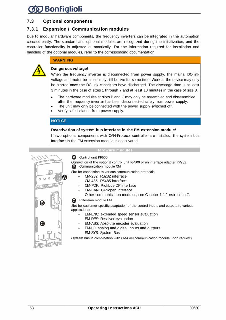
58 Operating Instructions ACU 09/20
7.3 Optional components 7.3.1 Expansion / Communication modules Due to modular hardware components, the frequency inverters can be integrated in the automation concept easily. The standard and optional modules are recognized during the initialization, and the controller functionality is adjusted automatically. For the information required for installation and handling of the optional modules, refer to the corresponding documentation.
WARNING
Dangerous voltage! When the frequency inverter is disconnected from power supply, the mains, DC-link voltage and motor terminals may still be live for some time. Work at the device may only be started once the DC link capacitors have discharged. The discharge time is at least 3 minutes in the case of sizes 1 through 7 and at least 10 minutes in the case of size 8. • The hardware modules at slots B and C may only be assembled and disassembled
after the frequency inverter has been disconnected safely from power supply. • The unit may only be connected with the power supply switched off. • Verify safe isolation from power supply.
NOTICE Deactivation of system bus interface in the EM extension module!
If two optional components with CAN-Protocol controller are installed, the system bus interface in the EM extension module is deactivated!
Hardware modules
A Control unit KP500 Connection of the optional control unit KP500 or an interface adapter KP232. B Communication module CM
Slot for connection to various communication protocols: − CM-232: RS232 interface − CM-485: RS485 interface − CM-PDP: Profibus-DP interface − CM-CAN: CANopen interface − Other communication modules, see Chapter 1.1 "Instructions".
C Extension module EM Slot for customer-specific adaptation of the control inputs and outputs to various applications:
− EM-ENC: extended speed sensor evaluation − EM-RES: Resolver evaluation − EM-ABS: Absolute encoder evaluation − EM-IO, analog and digital inputs and outputs − EM-SYS: System Bus
(system bus in combination with CM-CAN communication module upon request)
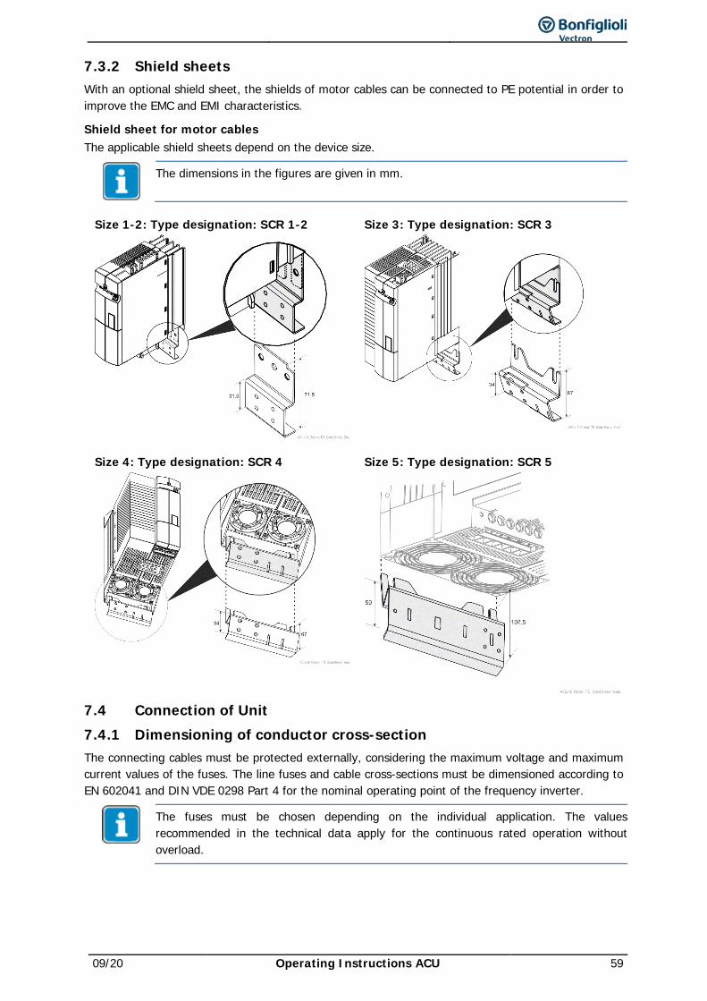
09/20 Operating Instructions ACU 59
7.3.2 Shield sheets With an optional shield sheet, the shields of motor cables can be connected to PE potential in order to improve the EMC and EMI characteristics.
Shield sheet for motor cables The applicable shield sheets depend on the device size.
The dimensions in the figures are given in mm.
Size 1-2: Type designation: SCR 1-2 Size 3: Type designation: SCR 3
Size 4: Type designation: SCR 4 Size 5: Type designation: SCR 5
7.4 Connection of Unit 7.4.1 Dimensioning of conductor cross-section The connecting cables must be protected externally, considering the maximum voltage and maximum current values of the fuses. The line fuses and cable cross-sections must be dimensioned according to EN 602041 and DIN VDE 0298 Part 4 for the nominal operating point of the frequency inverter.
The fuses must be chosen depending on the individual application. The values recommended in the technical data apply for the continuous rated operation without overload.
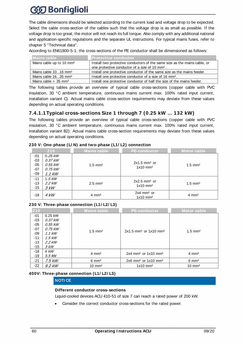
60 Operating Instructions ACU 09/20
The cable dimensions should be selected according to the current load and voltage drop to be expected. Select the cable cross-section of the cables such that the voltage drop is as small as possible. If the voltage drop is too great, the motor will not reach its full torque. Also comply with any additional national and application-specific regulations and the separate UL instructions. For typical mains fuses, refer to chapter 5 "Technical data". According to EN61800-5-1, the cross-sections of the PE conductor shall be dimensioned as follows:
Mains cable Protective conductor Mains cable up to 10 mm² Install two protective conductors of the same size as the mains cable, or
one protective conductor of a size of 10 mm². Mains cable 10…16 mm² Install one protective conductor of the same size as the mains feeder. Mains cable 16…35 mm² Install one protective conductor of a size of 16 mm². Mains cable > 35 mm² Install one protective conductor of half the size of the mains feeder.
The following tables provide an overview of typical cable cross-sections (copper cable with PVC insulation, 30 °C ambient temperature, continuous mains current max. 100% rated input current, installation variant C). Actual mains cable cross-section requirements may deviate from these values depending on actual operating conditions.
7.4.1.1 Typical cross-sections Size 1 through 7 (0.25 kW … 132 kW) The following tables provide an overview of typical cable cross-sections (copper cable with PVC insulation, 30 °C ambient temperature, continuous mains current max. 100% rated input current, installation variant B2). Actual mains cable cross-section requirements may deviate from these values depending on actual operating conditions.
230 V: One-phase (L/N) and two-phase (L1/L2) connection 210 Mains cable PE-conductor Motor cable
-01 -03 -05 -07 -09
0.25 kW 0.37 kW 0.55 kW 0.75 kW 1.1 kW
1.5 mm² 2x1.5 mm² or 1x10 mm² 1.5 mm²
-11 -13 -15
1.5 kW 2.2 kW 3 kW
2.5 mm² 2x2.5 mm² or 1x10 mm² 1.5 mm²
-18 4 kW 4 mm² 2x4 mm² or 1x10 mm² 4 mm²
230 V: Three-phase connection (L1/L2/L3) 210 Mains cable PE-conductor Motor cable -01 -03 -05 -07 -09 -11 -13 -15
0.25 kW 0.37 kW 0.55 kW 0.75 kW 1.1 kW 1.5 kW 2.2 kW 3 kW
1.5 mm² 2x1.5 mm² or 1x10 mm² 1.5 mm²
-18 -19
4 kW 5.5 kW 4 mm² 2x4 mm² or 1x10 mm² 4 mm²
-21 7.5 kW 6 mm² 2x6 mm² or 1x10 mm² 6 mm² -22 9.2 kW 10 mm² 1x10 mm² 10 mm²
400V: Three-phase connection (L1/L2/L3)
NOTICE Different conductor cross-sections
Liquid-cooled devices ACU 410-51 of size 7 can reach a rated power of 200 kW. • Consider the correct conductor cross-sections for the rated power.
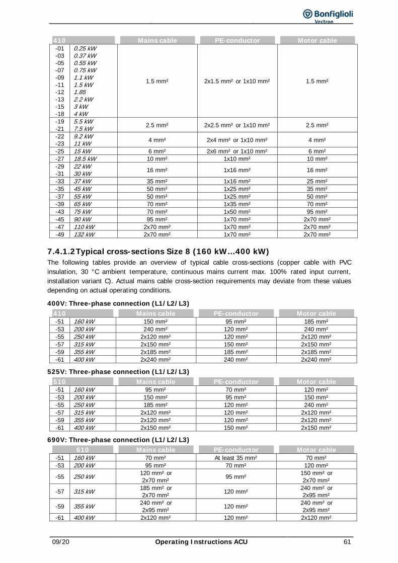
09/20 Operating Instructions ACU 61
410 Mains cable PE-conductor Motor cable -01 -03 -05 -07 -09 -11 -12 -13 -15 -18
0.25 kW 0.37 kW 0.55 kW 0.75 kW 1.1 kW 1.5 kW 1.85 2.2 kW 3 kW 4 kW
1.5 mm² 2x1.5 mm² or 1x10 mm² 1.5 mm²
-19 -21
5.5 kW 7.5 kW 2.5 mm² 2x2.5 mm² or 1x10 mm² 2.5 mm²
-22 -23
9.2 kW 11 kW 4 mm² 2x4 mm² or 1x10 mm² 4 mm²
-25 15 kW 6 mm² 2x6 mm² or 1x10 mm² 6 mm² -27 18.5 kW 10 mm² 1x10 mm² 10 mm² -29 -31
22 kW 30 kW 16 mm² 1x16 mm² 16 mm²
-33 37 kW 35 mm² 1x16 mm² 25 mm² -35 45 kW 50 mm² 1x25 mm² 35 mm² -37 55 kW 50 mm² 1x25 mm² 50 mm² -39 65 kW 70 mm² 1x35 mm² 70 mm² -43 75 kW 70 mm² 1x50 mm² 95 mm² -45 90 kW 95 mm² 1x70 mm² 2x70 mm² -47 110 kW 2x70 mm² 1x70 mm² 2x70 mm² -49 132 kW 2x70 mm² 1x70 mm² 2x70 mm²
7.4.1.2 Typical cross-sections Size 8 (160 kW…400 kW) The following tables provide an overview of typical cable cross-sections (copper cable with PVC insulation, 30 °C ambient temperature, continuous mains current max. 100% rated input current, installation variant C). Actual mains cable cross-section requirements may deviate from these values depending on actual operating conditions.
400V: Three-phase connection (L1/L2/L3) 410 Mains cable PE-conductor Motor cable -51 160 kW 150 mm² 95 mm² 185 mm² -53 200 kW 240 mm² 120 mm² 240 mm² -55 250 kW 2x120 mm² 120 mm² 2x120 mm² -57 315 kW 2x150 mm² 150 mm² 2x150 mm² -59 355 kW 2x185 mm² 185 mm² 2x185 mm² -61 400 kW 2x240 mm² 240 mm² 2x240 mm²
525V: Three-phase connection (L1/L2/L3) 510 Mains cable PE-conductor Motor cable -51 160 kW 95 mm² 70 mm² 120 mm² -53 200 kW 150 mm² 95 mm² 150 mm² -55 250 kW 185 mm² 120 mm² 240 mm² -57 315 kW 2x120 mm² 120 mm² 2x120 mm² -59 355 kW 2x120 mm² 120 mm² 2x120 mm² -61 400 kW 2x150 mm² 150 mm² 2x150 mm²
690V: Three-phase connection (L1/L2/L3) 610 Mains cable PE-conductor Motor cable
-51 160 kW 70 mm² At least 35 mm² 70 mm² -53 200 kW 95 mm² 70 mm² 120 mm²
-55 250 kW 120 mm² or 2x70 mm² 95 mm² 150 mm² or
2x70 mm²
-57 315 kW 185 mm² or 2x70 mm² 120 mm² 240 mm² or
2x95 mm²
-59 355 kW 240 mm² or 2x95 mm² 120 mm² 240 mm² or
2x95 mm² -61 400 kW 2x120 mm² 120 mm² 2x120 mm²
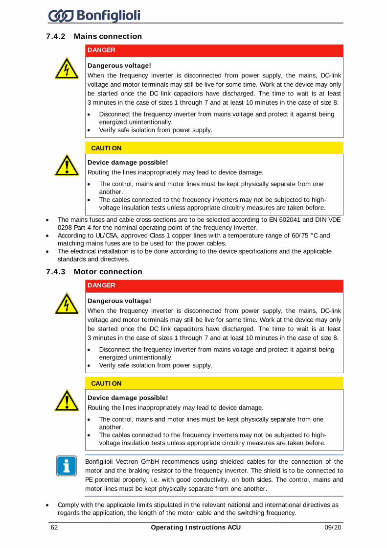
62 Operating Instructions ACU 09/20
7.4.2 Mains connection
DANGER
Dangerous voltage! When the frequency inverter is disconnected from power supply, the mains, DC-link voltage and motor terminals may still be live for some time. Work at the device may only be started once the DC link capacitors have discharged. The time to wait is at least 3 minutes in the case of sizes 1 through 7 and at least 10 minutes in the case of size 8. • Disconnect the frequency inverter from mains voltage and protect it against being
energized unintentionally. • Verify safe isolation from power supply.
CAUTION
Device damage possible! Routing the lines inappropriately may lead to device damage. • The control, mains and motor lines must be kept physically separate from one
another. • The cables connected to the frequency inverters may not be subjected to high-
voltage insulation tests unless appropriate circuitry measures are taken before.
• The mains fuses and cable cross-sections are to be selected according to EN 602041 and DIN VDE 0298 Part 4 for the nominal operating point of the frequency inverter.
• According to UL/CSA, approved Class 1 copper lines with a temperature range of 60/75 °C and matching mains fuses are to be used for the power cables.
• The electrical installation is to be done according to the device specifications and the applicable standards and directives.
7.4.3 Motor connection
DANGER
Dangerous voltage! When the frequency inverter is disconnected from power supply, the mains, DC-link voltage and motor terminals may still be live for some time. Work at the device may only be started once the DC link capacitors have discharged. The time to wait is at least 3 minutes in the case of sizes 1 through 7 and at least 10 minutes in the case of size 8. • Disconnect the frequency inverter from mains voltage and protect it against being
energized unintentionally. • Verify safe isolation from power supply.
CAUTION
Device damage possible! Routing the lines inappropriately may lead to device damage. • The control, mains and motor lines must be kept physically separate from one
another. • The cables connected to the frequency inverters may not be subjected to high-
voltage insulation tests unless appropriate circuitry measures are taken before.
Bonfiglioli Vectron GmbH recommends using shielded cables for the connection of the motor and the braking resistor to the frequency inverter. The shield is to be connected to PE potential properly, i.e. with good conductivity, on both sides. The control, mains and motor lines must be kept physically separate from one another.
• Comply with the applicable limits stipulated in the relevant national and international directives as regards the application, the length of the motor cable and the switching frequency.
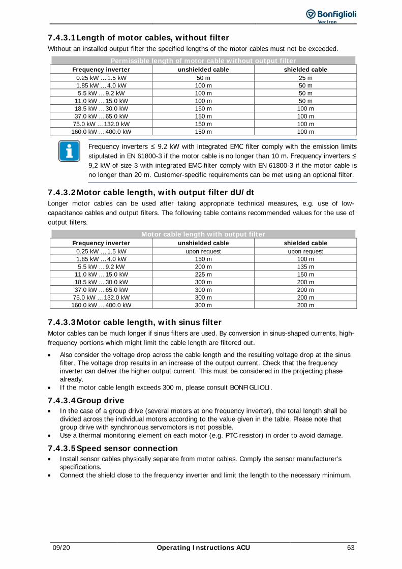
09/20 Operating Instructions ACU 63
7.4.3.1 Length of motor cables, without filter Without an installed output filter the specified lengths of the motor cables must not be exceeded.
Permissible length of motor cable without output filter Frequency inverter unshielded cable shielded cable
0.25 kW … 1.5 kW 50 m 25 m 1.85 kW … 4.0 kW 100 m 50 m 5.5 kW … 9.2 kW 100 m 50 m
11.0 kW … 15.0 kW 100 m 50 m 18.5 kW … 30.0 kW 150 m 100 m 37.0 kW … 65.0 kW 150 m 100 m 75.0 kW … 132.0 kW 150 m 100 m 160.0 kW … 400.0 kW 150 m 100 m
Frequency inverters ≤ 9.2 kW with integrated EMC filter comply with the emission limits stipulated in EN 61800-3 if the motor cable is no longer than 10 m. Frequency inverters ≤ 9,2 kW of size 3 with integrated EMC filter comply with EN 61800-3 if the motor cable is no longer than 20 m. Customer-specific requirements can be met using an optional filter.
7.4.3.2 Motor cable length, with output filter dU/dt Longer motor cables can be used after taking appropriate technical measures, e.g. use of low-capacitance cables and output filters. The following table contains recommended values for the use of output filters.
Motor cable length with output filter Frequency inverter unshielded cable shielded cable
0.25 kW … 1.5 kW upon request upon request 1.85 kW … 4.0 kW 150 m 100 m 5.5 kW … 9.2 kW 200 m 135 m
11.0 kW … 15.0 kW 225 m 150 m 18.5 kW … 30.0 kW 300 m 200 m 37.0 kW … 65.0 kW 300 m 200 m 75.0 kW … 132.0 kW 300 m 200 m 160.0 kW … 400.0 kW 300 m 200 m
7.4.3.3 Motor cable length, with sinus filter Motor cables can be much longer if sinus filters are used. By conversion in sinus-shaped currents, high-frequency portions which might limit the cable length are filtered out. • Also consider the voltage drop across the cable length and the resulting voltage drop at the sinus
filter. The voltage drop results in an increase of the output current. Check that the frequency inverter can deliver the higher output current. This must be considered in the projecting phase already.
• If the motor cable length exceeds 300 m, please consult BONFIGLIOLI.
7.4.3.4 Group drive • In the case of a group drive (several motors at one frequency inverter), the total length shall be
divided across the individual motors according to the value given in the table. Please note that group drive with synchronous servomotors is not possible.
• Use a thermal monitoring element on each motor (e.g. PTC resistor) in order to avoid damage.
7.4.3.5 Speed sensor connection • Install sensor cables physically separate from motor cables. Comply the sensor manufacturer's
specifications. • Connect the shield close to the frequency inverter and limit the length to the necessary minimum.
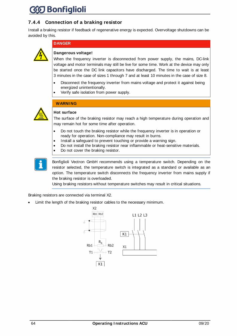
64 Operating Instructions ACU 09/20
7.4.4 Connection of a braking resistor Install a braking resistor if feedback of regenerative energy is expected. Overvoltage shutdowns can be avoided by this.
DANGER
Dangerous voltage! When the frequency inverter is disconnected from power supply, the mains, DC-link voltage and motor terminals may still be live for some time. Work at the device may only be started once the DC link capacitors have discharged. The time to wait is at least 3 minutes in the case of sizes 1 through 7 and at least 10 minutes in the case of size 8. • Disconnect the frequency inverter from mains voltage and protect it against being
energized unintentionally. • Verify safe isolation from power supply.
WARNING
Hot surface The surface of the braking resistor may reach a high temperature during operation and may remain hot for some time after operation. • Do not touch the braking resistor while the frequency inverter is in operation or
ready for operation. Non-compliance may result in burns. • Install a safeguard to prevent touching or provide a warning sign. • Do not install the braking resistor near inflammable or heat-sensitive materials. • Do not cover the braking resistor.
Bonfiglioli Vectron GmbH recommends using a temperature switch. Depending on the resistor selected, the temperature switch is integrated as a standard or available as an option. The temperature switch disconnects the frequency inverter from mains supply if the braking resistor is overloaded. Using braking resistors without temperature switches may result in critical situations.
Braking resistors are connected via terminal X2. • Limit the length of the braking resistor cables to the necessary minimum.
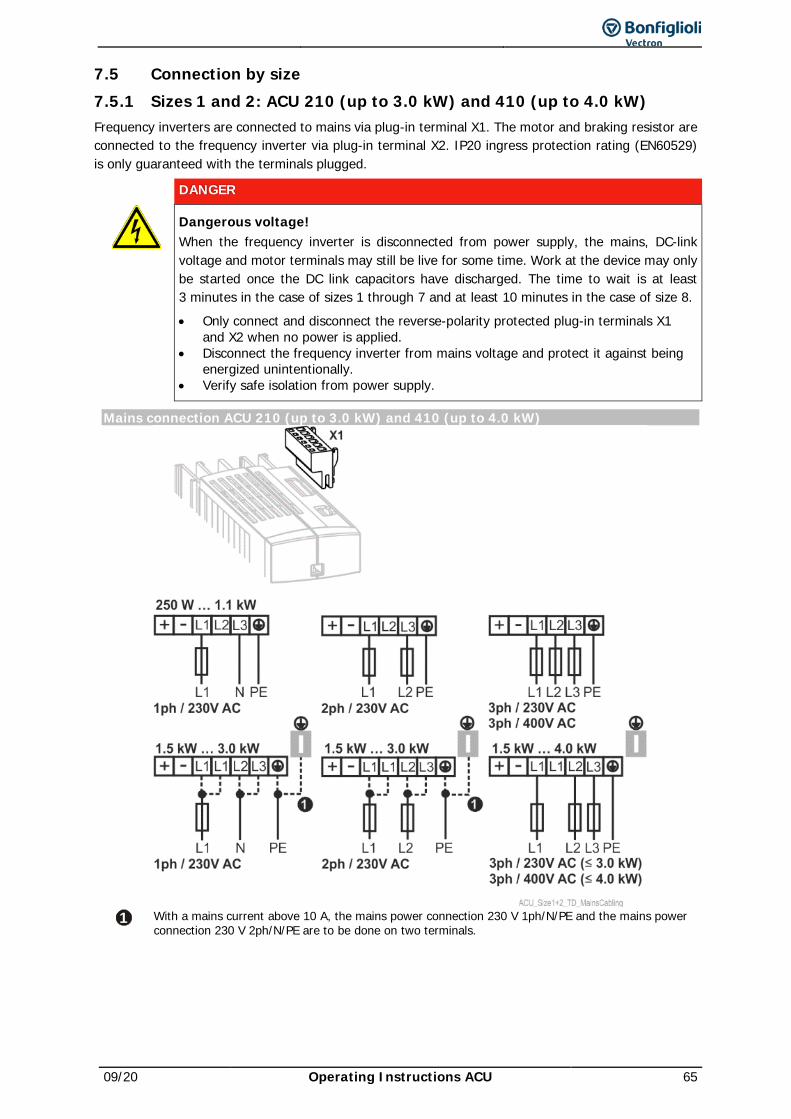
09/20 Operating Instructions ACU 65
7.5 Connection by size 7.5.1 Sizes 1 and 2: ACU 210 (up to 3.0 kW) and 410 (up to 4.0 kW) Frequency inverters are connected to mains via plug-in terminal X1. The motor and braking resistor are connected to the frequency inverter via plug-in terminal X2. IP20 ingress protection rating (EN60529) is only guaranteed with the terminals plugged.
DANGER
Dangerous voltage! When the frequency inverter is disconnected from power supply, the mains, DC-link voltage and motor terminals may still be live for some time. Work at the device may only be started once the DC link capacitors have discharged. The time to wait is at least 3 minutes in the case of sizes 1 through 7 and at least 10 minutes in the case of size 8. • Only connect and disconnect the reverse-polarity protected plug-in terminals X1
and X2 when no power is applied. • Disconnect the frequency inverter from mains voltage and protect it against being
energized unintentionally. • Verify safe isolation from power supply.
Mains connection ACU 210 (up to 3.0 kW) and 410 (up to 4.0 kW)
1 With a mains current above 10 A, the mains power connection 230 V 1ph/N/PE and the mains power
connection 230 V 2ph/N/PE are to be done on two terminals.

66 Operating Instructions ACU 09/20
Motor connection ACU 210 (up to 3.0 kW) and 410 (up to 4.0 kW)
Connection of brake resistor with temperature switch
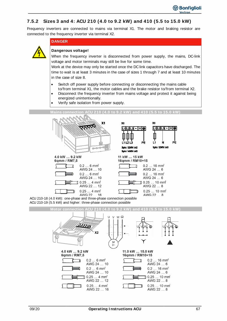
09/20 Operating Instructions ACU 67
7.5.2 Sizes 3 and 4: ACU 210 (4.0 to 9.2 kW) and 410 (5.5 to 15.0 kW) Frequency inverters are connected to mains via terminal X1. The motor and braking resistor are connected to the frequency inverter via terminal X2.
DANGER
Dangerous voltage! When the frequency inverter is disconnected from power supply, the mains, DC-link voltage and motor terminals may still be live for some time. Work at the device may only be started once the DC link capacitors have discharged. The time to wait is at least 3 minutes in the case of sizes 1 through 7 and at least 10 minutes in the case of size 8. • Switch off power supply before connecting or disconnecting the mains cable
to/from terminal X1, the motor cables and the brake resistor to/from terminal X2. • Disconnect the frequency inverter from mains voltage and protect it against being
energized unintentionally. • Verify safe isolation from power supply.
Mains connection ACU 210 (4.0 to 9.2 kW) and 410 (5.5 to 15.0 kW)
ACU 210-18 (4.0 kW): one-phase and three-phase connection possible ACU 210-19 (5.5 kW) and higher: three-phase connection possible
Motor connection ACU 210 (4.0 to 9.2 kW) and 410 (5.5 to 15.0 kW)

68 Operating Instructions ACU 09/20
Connection of brake resistor with temperature switch

09/20 Operating Instructions ACU 69
7.5.3 Size 5 ACU 410 (18.5 to 30.0 kW) Frequency inverters are connected to mains via terminal X1. The motor and braking resistor are connected to the frequency inverter via terminal X2.
DANGER
Dangerous voltage! When the frequency inverter is disconnected from power supply, the mains, DC-link voltage and motor terminals may still be live for some time. Work at the device may only be started once the DC link capacitors have discharged. The time to wait is at least 3 minutes in the case of sizes 1 through 7 and at least 10 minutes in the case of size 8. • Disconnect the frequency inverter from mains voltage and protect it against being
energized unintentionally. • Verify safe isolation from power supply. • Switch off power supply before connecting or disconnecting the mains cable
to/from terminal X1, the motor cables and the brake resistor to/from terminal X2.
Mains connection ACU 410 (18.5 to 30.0 kW)
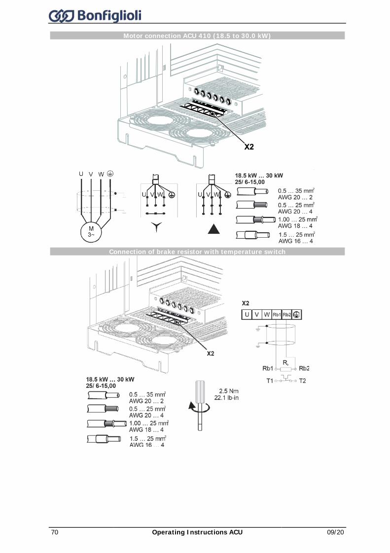
70 Operating Instructions ACU 09/20
Motor connection ACU 410 (18.5 to 30.0 kW)
Connection of brake resistor with temperature switch
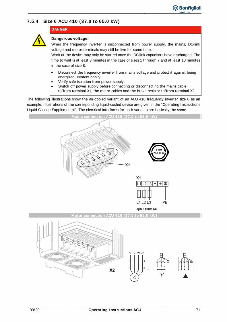
09/20 Operating Instructions ACU 71
7.5.4 Size 6 ACU 410 (37.0 to 65.0 kW)
DANGER
Dangerous voltage! When the frequency inverter is disconnected from power supply, the mains, DC-link voltage and motor terminals may still be live for some time. Work at the device may only be started once the DC link capacitors have discharged. The time to wait is at least 3 minutes in the case of sizes 1 through 7 and at least 10 minutes in the case of size 8. • Disconnect the frequency inverter from mains voltage and protect it against being
energized unintentionally. • Verify safe isolation from power supply. • Switch off power supply before connecting or disconnecting the mains cable
to/from terminal X1, the motor cables and the brake resistor to/from terminal X2.
The following illustrations show the air-cooled variant of an ACU 410 frequency inverter size 6 as an example. Illustrations of the corresponding liquid-cooled device are given in the “Operating Instructions Liquid Cooling Supplemental”. The electrical interfaces for both variants are basically the same.
Mains connection ACU 410 (37.0 to 65.0 kW)
Motor connection ACU 410 (37.0 to 65.0 kW)
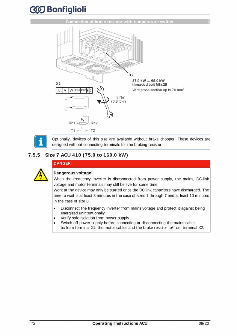
72 Operating Instructions ACU 09/20
Connection of brake resistor with temperature switch
Optionally, devices of this size are available without brake chopper. These devices are designed without connecting terminals for the braking resistor.
7.5.5 Size 7 ACU 410 (75.0 to 160.0 kW)
DANGER
Dangerous voltage! When the frequency inverter is disconnected from power supply, the mains, DC-link voltage and motor terminals may still be live for some time. Work at the device may only be started once the DC link capacitors have discharged. The time to wait is at least 3 minutes in the case of sizes 1 through 7 and at least 10 minutes in the case of size 8. • Disconnect the frequency inverter from mains voltage and protect it against being
energized unintentionally. • Verify safe isolation from power supply. • Switch off power supply before connecting or disconnecting the mains cable
to/from terminal X1, the motor cables and the brake resistor to/from terminal X2.
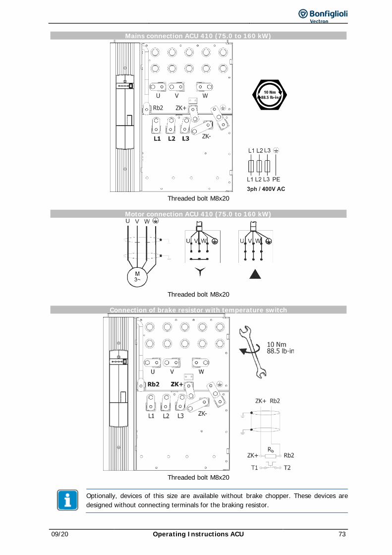
09/20 Operating Instructions ACU 73
Mains connection ACU 410 (75.0 to 160 kW)
Threaded bolt M8x20
Motor connection ACU 410 (75.0 to 160 kW)
Threaded bolt M8x20
Connection of brake resistor with temperature switch
Threaded bolt M8x20
Optionally, devices of this size are available without brake chopper. These devices are designed without connecting terminals for the braking resistor.
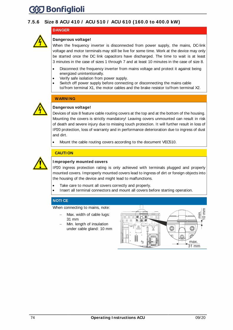
74 Operating Instructions ACU 09/20
7.5.6 Size 8 ACU 410 / ACU 510 / ACU 610 (160.0 to 400.0 kW)
DANGER
Dangerous voltage! When the frequency inverter is disconnected from power supply, the mains, DC-link voltage and motor terminals may still be live for some time. Work at the device may only be started once the DC link capacitors have discharged. The time to wait is at least 3 minutes in the case of sizes 1 through 7 and at least 10 minutes in the case of size 8. • Disconnect the frequency inverter from mains voltage and protect it against being
energized unintentionally. • Verify safe isolation from power supply. • Switch off power supply before connecting or disconnecting the mains cable
to/from terminal X1, the motor cables and the brake resistor to/from terminal X2.
WARNING
Dangerous voltage! Devices of size 8 feature cable routing covers at the top and at the bottom of the housing. Mounting the covers is strictly mandatory! Leaving covers unmounted can result in risk of death and severe injury due to missing touch protection. It will further result in loss of IP20 protection, loss of warranty and in performance deterioration due to ingress of dust and dirt. • Mount the cable routing covers according to the document VEC510.
CAUTION
Improperly mounted covers IP20 ingress protection rating is only achieved with terminals plugged and properly mounted covers. Improperly mounted covers lead to ingress of dirt or foreign objects into the housing of the device and might lead to malfunctions. • Take care to mount all covers correctly and properly. • Insert all terminal connectors and mount all covers before starting operation.
NOTICE
When connecting to mains, note: − Max. width of cable lugs:
31 mm − Min. length of insulation
under cable gland: 10 mm
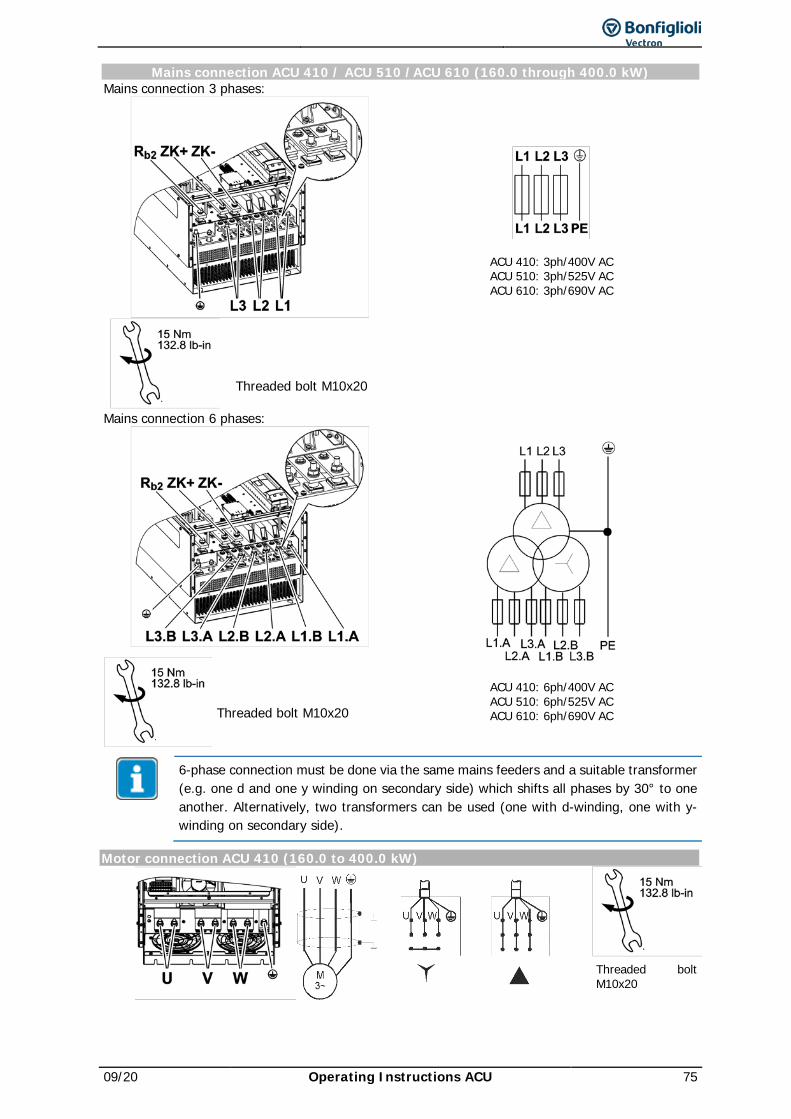
09/20 Operating Instructions ACU 75
Mains connection ACU 410 / ACU 510 /ACU 610 (160.0 through 400.0 kW) Mains connection 3 phases:
ACU 410: 3ph/400V AC ACU 510: 3ph/525V AC ACU 610: 3ph/690V AC
Threaded bolt M10x20
Mains connection 6 phases:
ACU 410: 6ph/400V AC ACU 510: 6ph/525V AC ACU 610: 6ph/690V AC
Threaded bolt M10x20
6-phase connection must be done via the same mains feeders and a suitable transformer (e.g. one d and one y winding on secondary side) which shifts all phases by 30° to one another. Alternatively, two transformers can be used (one with d-winding, one with y-winding on secondary side).
Motor connection ACU 410 (160.0 to 400.0 kW)
Threaded bolt M10x20
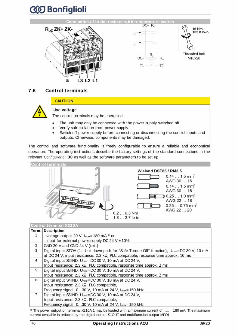
76 Operating Instructions ACU 09/20
Connection of brake resistor with temperature switch
Threaded bolt
M10x20
7.6 Control terminals
The control and software functionality is freely configurable to ensure a reliable and economical operation. The operating instructions describe the factory settings of the standard connections in the relevant Configuration 30 as well as the software parameters to be set up.
Control terminals
Control terminal X210A Term. Description
1 - voltage output 20 V, Imax=180 mA 1) or - input for external power supply DC 24 V ±10%
2 GND 20 V and GND 24 V (ext.) 3 Digital input STOA (1. shut-down path for “Safe Torque Off” function), Umax=DC 30 V, 10 mA
at DC 24 V, input resistance: 2.3 kΩ, PLC compatible, response time approx. 10 ms 4 Digital input S2IND, Umax=DC 30 V, 10 mA at DC 24 V,
Input resistance: 2.3 kΩ, PLC compatible, response time approx. 2 ms 5 Digital input S3IND, Umax=DC 30 V, 10 mA at DC 24 V,
Input resistance: 2.3 kΩ, PLC compatible, response time approx. 2 ms 6 Digital input S4IND, Umax=DC 30 V, 10 mA at DC 24 V,
Input resistance: 2.3 kΩ, PLC compatible, Frequency signal: 0...30 V, 10 mA at 24 V, fmax=150 kHz
7 Digital input S5IND, Umax=DC 30 V, 10 mA at DC 24 V, Input resistance: 2.3 kΩ, PLC compatible, Frequency signal: 0...30 V, 10 mA at 24 V, fmax=150 kHz
1) The power output on terminal X210A.1 may be loaded with a maximum current of Imax= 180 mA. The maximum current available is reduced by the digital output S1OUT and multifunction output MFO1.
Rb
T1
DC+ Rb2
T2
Rb2DC+
CAUTION
Live voltage The control terminals may be energized. • The unit may only be connected with the power supply switched off. • Verify safe isolation from power supply. • Switch off power supply before connecting or disconnecting the control inputs and
outputs. Otherwise, components may be damaged.
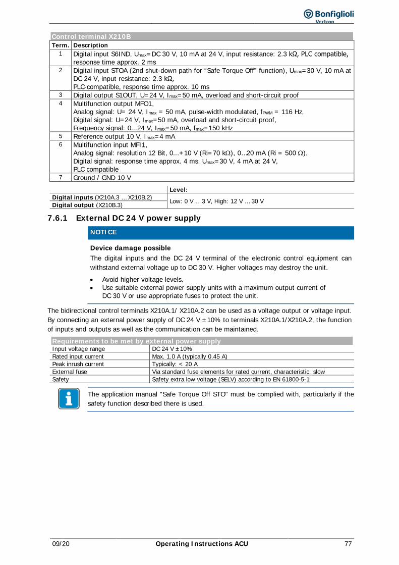
09/20 Operating Instructions ACU 77
Control terminal X210B Term. Description
1 Digital input S6IND, Umax=DC 30 V, 10 mA at 24 V, input resistance: 2.3 kΩ, PLC compatible, response time approx. 2 ms
2 Digital input STOA (2nd shut-down path for “Safe Torque Off” function), Umax=30 V, 10 mA at DC 24 V, input resistance: 2.3 kΩ, PLC-compatible, response time approx. 10 ms
3 Digital output S1OUT, U=24 V, Imax=50 mA, overload and short-circuit proof 4 Multifunction output MFO1,
Analog signal: U= 24 V, Imax = 50 mA, pulse-width modulated, fPWM = 116 Hz, Digital signal: U=24 V, Imax=50 mA, overload and short-circuit proof, Frequency signal: 0...24 V, Imax=50 mA, fmax=150 kHz
5 Reference output 10 V, Imax=4 mA 6 Multifunction input MFI1,
Analog signal: resolution 12 Bit, 0...+10 V (Ri=70 kΩ), 0…20 mA (Ri = 500 Ω), Digital signal: response time approx. 4 ms, Umax=30 V, 4 mA at 24 V, PLC compatible
7 Ground / GND 10 V
Level: Digital inputs (X210A.3 … X210B.2) Low: 0 V … 3 V, High: 12 V … 30 V Digital output (X210B.3)
7.6.1 External DC 24 V power supply
NOTICE Device damage possible
The digital inputs and the DC 24 V terminal of the electronic control equipment can withstand external voltage up to DC 30 V. Higher voltages may destroy the unit. • Avoid higher voltage levels. • Use suitable external power supply units with a maximum output current of
DC 30 V or use appropriate fuses to protect the unit.
The bidirectional control terminals X210A.1/ X210A.2 can be used as a voltage output or voltage input. By connecting an external power supply of DC 24 V ±10% to terminals X210A.1/X210A.2, the function of inputs and outputs as well as the communication can be maintained.
Requirements to be met by external power supply Input voltage range DC 24 V ±10% Rated input current Max. 1.0 A (typically 0.45 A) Peak inrush current Typically: < 20 A External fuse Via standard fuse elements for rated current, characteristic: slow Safety Safety extra low voltage (SELV) according to EN 61800-5-1
The application manual "Safe Torque Off STO" must be complied with, particularly if the safety function described there is used.
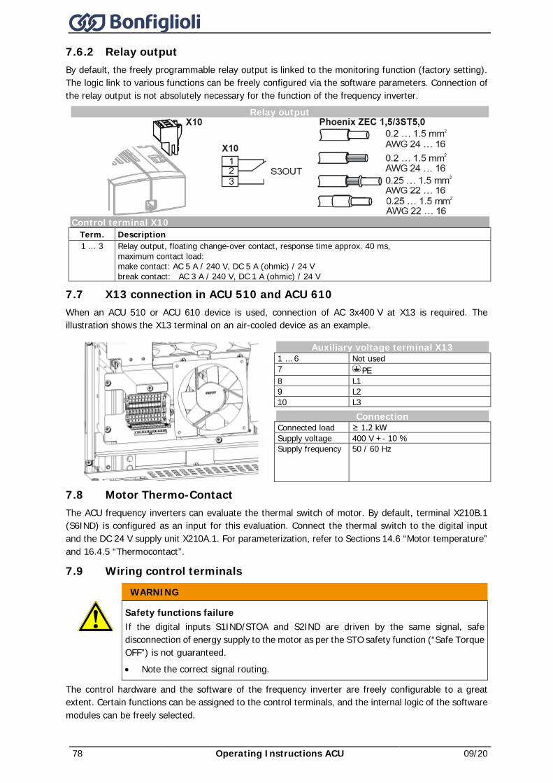
78 Operating Instructions ACU 09/20
7.6.2 Relay output By default, the freely programmable relay output is linked to the monitoring function (factory setting). The logic link to various functions can be freely configured via the software parameters. Connection of the relay output is not absolutely necessary for the function of the frequency inverter.
Relay output
Control terminal X10
Term. Description 1 ... 3 Relay output, floating change-over contact, response time approx. 40 ms,
maximum contact load: make contact: AC 5 A / 240 V, DC 5 A (ohmic) / 24 V break contact: AC 3 A / 240 V, DC 1 A (ohmic) / 24 V
7.7 X13 connection in ACU 510 and ACU 610 When an ACU 510 or ACU 610 device is used, connection of AC 3x400 V at X13 is required. The illustration shows the X13 terminal on an air-cooled device as an example.
Auxiliary voltage terminal X13 1 … 6 Not used 7 PE 8 L1 9 L2 10 L3 Connection Connected load ≥ 1.2 kW Supply voltage 400 V +- 10 % Supply frequency 50 / 60 Hz
7.8 Motor Thermo-Contact The ACU frequency inverters can evaluate the thermal switch of motor. By default, terminal X210B.1 (S6IND) is configured as an input for this evaluation. Connect the thermal switch to the digital input and the DC 24 V supply unit X210A.1. For parameterization, refer to Sections 14.6 “Motor temperature” and 16.4.5 “Thermocontact”.
7.9 Wiring control terminals WARNING
Safety functions failure If the digital inputs S1IND/STOA and S2IND are driven by the same signal, safe disconnection of energy supply to the motor as per the STO safety function (“Safe Torque OFF”) is not guaranteed. • Note the correct signal routing.
The control hardware and the software of the frequency inverter are freely configurable to a great extent. Certain functions can be assigned to the control terminals, and the internal logic of the software modules can be freely selected.
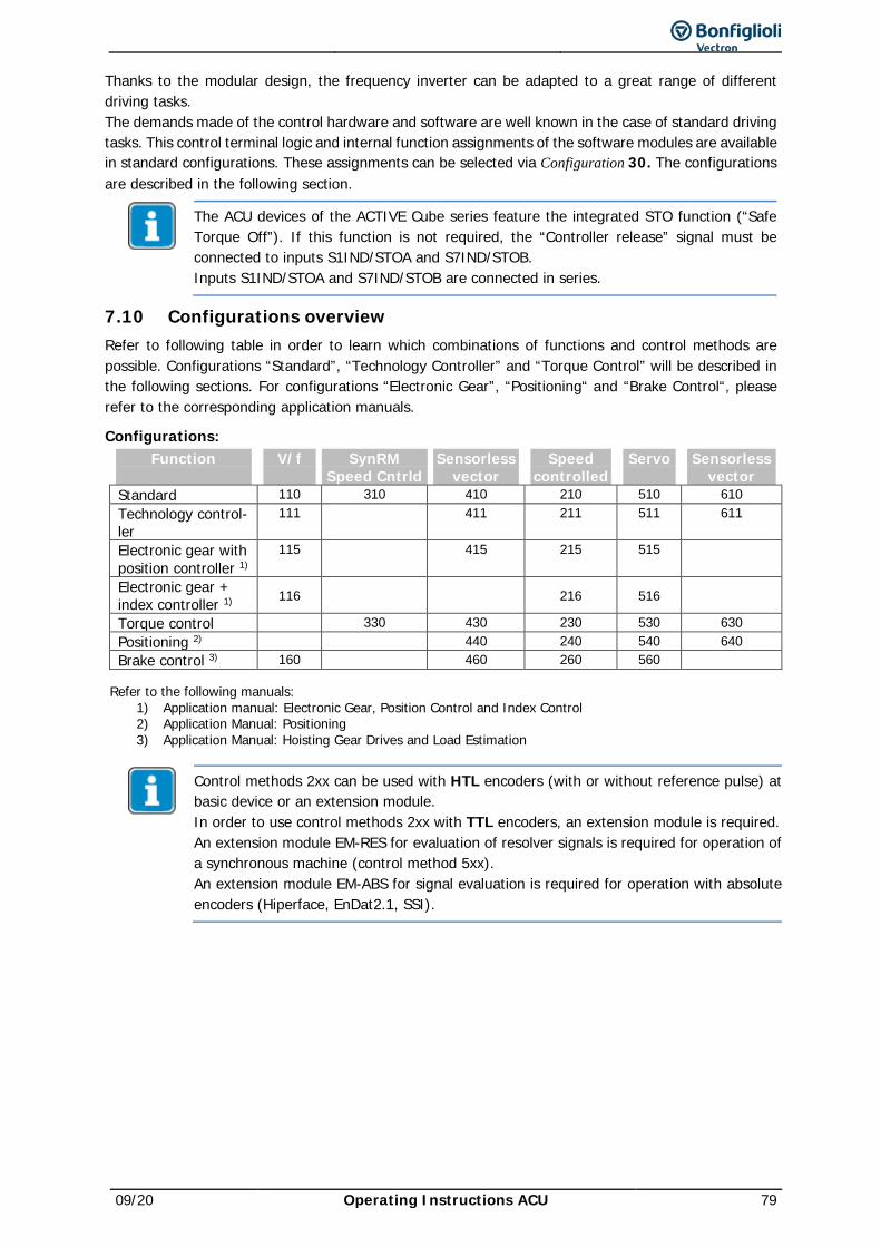
09/20 Operating Instructions ACU 79
Thanks to the modular design, the frequency inverter can be adapted to a great range of different driving tasks. The demands made of the control hardware and software are well known in the case of standard driving tasks. This control terminal logic and internal function assignments of the software modules are available in standard configurations. These assignments can be selected via Configuration 30. The configurations are described in the following section.
The ACU devices of the ACTIVE Cube series feature the integrated STO function (“Safe Torque Off”). If this function is not required, the “Controller release” signal must be connected to inputs S1IND/STOA and S7IND/STOB. Inputs S1IND/STOA and S7IND/STOB are connected in series.
7.10 Configurations overview Refer to following table in order to learn which combinations of functions and control methods are possible. Configurations “Standard”, “Technology Controller” and “Torque Control” will be described in the following sections. For configurations “Electronic Gear”, “Positioning“ and “Brake Control“, please refer to the corresponding application manuals.
Configurations: Function
V/f
SynRM
Speed Cntrld Sensorless
vector Speed
controlled Servo
Sensorless
vector Standard 110 310 410 210 510 610 Technology control-ler
111 411 211 511 611
Electronic gear with position controller 1)
115 415 215 515
Electronic gear + index controller 1) 116
216 516
Torque control 330 430 230 530 630 Positioning 2) 440 240 540 640 Brake control 3) 160 460 260 560
Refer to the following manuals: 1) Application manual: Electronic Gear, Position Control and Index Control 2) Application Manual: Positioning 3) Application Manual: Hoisting Gear Drives and Load Estimation
Control methods 2xx can be used with HTL encoders (with or without reference pulse) at basic device or an extension module. In order to use control methods 2xx with TTL encoders, an extension module is required. An extension module EM-RES for evaluation of resolver signals is required for operation of a synchronous machine (control method 5xx). An extension module EM-ABS for signal evaluation is required for operation with absolute encoders (Hiperface, EnDat2.1, SSI).
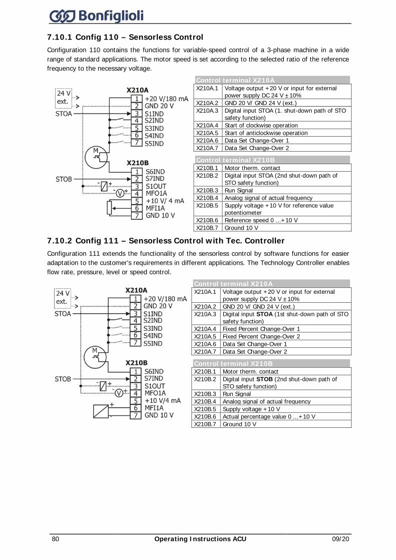
80 Operating Instructions ACU 09/20
7.10.1 Config 110 – Sensorless Control Configuration 110 contains the functions for variable-speed control of a 3-phase machine in a wide range of standard applications. The motor speed is set according to the selected ratio of the reference frequency to the necessary voltage.
Control terminal X210A X210A.1 Voltage output +20 V or input for external
power supply DC 24 V ±10% X210A.2 GND 20 V/ GND 24 V (ext.) X210A.3 Digital input STOA (1. shut-down path of STO
safety function) X210A.4 Start of clockwise operation X210A.5 Start of anticlockwise operation X210A.6 Data Set Change-Over 1 X210A.7 Data Set Change-Over 2
Control terminal X210B X210B.1 Motor therm. contact X210B.2 Digital input STOA (2nd shut-down path of
STO safety function) X210B.3 Run Signal X210B.4 Analog signal of actual frequency X210B.5 Supply voltage +10 V for reference value
potentiometer X210B.6 Reference speed 0 ...+10 V X210B.7 Ground 10 V
7.10.2 Config 111 – Sensorless Control with Tec. Controller Configuration 111 extends the functionality of the sensorless control by software functions for easier adaptation to the customer's requirements in different applications. The Technology Controller enables flow rate, pressure, level or speed control.
Control terminal X210A X210A.1 Voltage output +20 V or input for external
power supply DC 24 V ±10% X210A.2 GND 20 V/ GND 24 V (ext.) X210A.3 Digital input STOA (1st shut-down path of STO
safety function) X210A.4 Fixed Percent Change-Over 1 X210A.5 Fixed Percent Change-Over 2 X210A.6 Data Set Change-Over 1 X210A.7 Data Set Change-Over 2
Control terminal X210B X210B.1 Motor therm. contact X210B.2 Digital input STOB (2nd shut-down path of
STO safety function) X210B.3 Run Signal X210B.4 Analog signal of actual frequency X210B.5 Supply voltage +10 V X210B.6 Actual percentage value 0 ...+10 V X210B.7 Ground 10 V
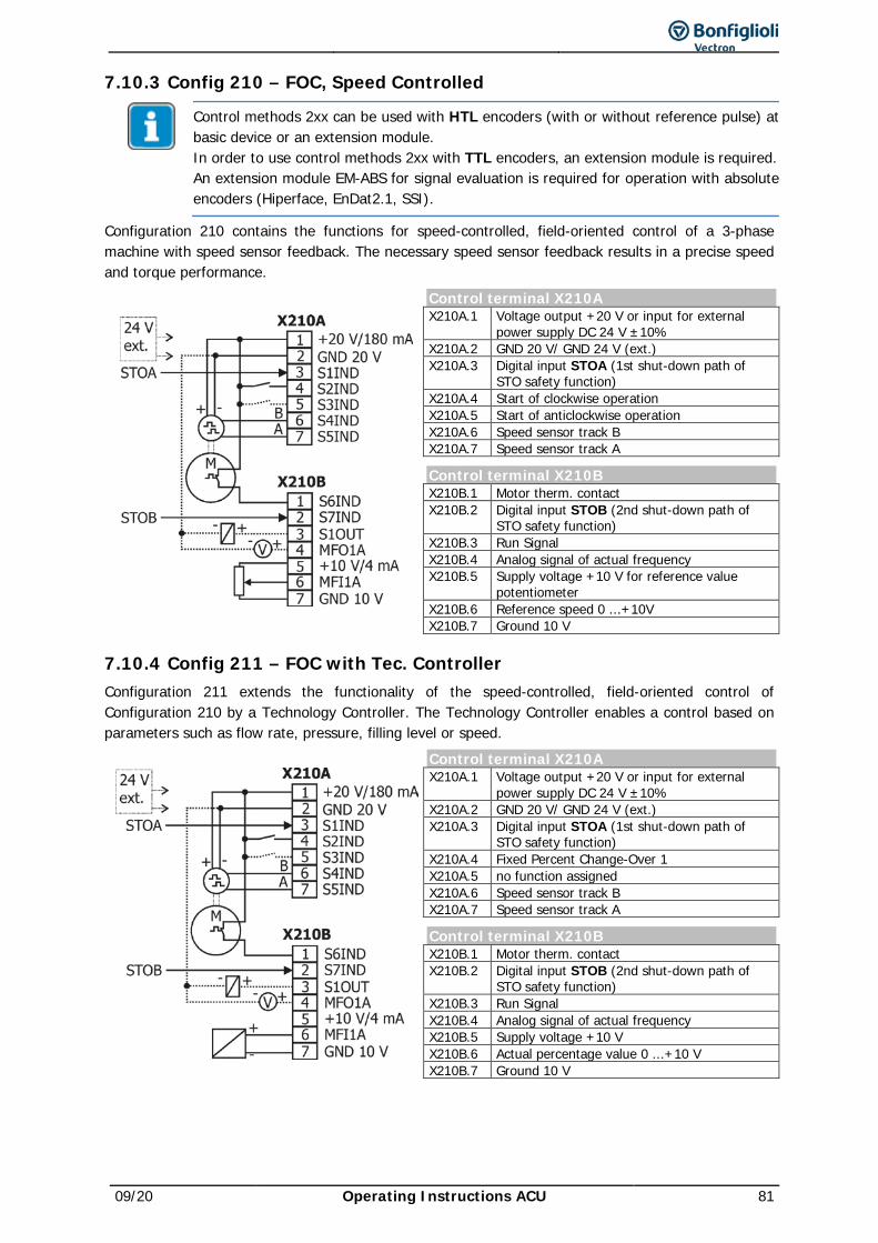
09/20 Operating Instructions ACU 81
7.10.3 Config 210 – FOC, Speed Controlled
Control methods 2xx can be used with HTL encoders (with or without reference pulse) at basic device or an extension module. In order to use control methods 2xx with TTL encoders, an extension module is required. An extension module EM-ABS for signal evaluation is required for operation with absolute encoders (Hiperface, EnDat2.1, SSI).
Configuration 210 contains the functions for speed-controlled, field-oriented control of a 3-phase machine with speed sensor feedback. The necessary speed sensor feedback results in a precise speed and torque performance.
Control terminal X210A X210A.1 Voltage output +20 V or input for external
power supply DC 24 V ±10% X210A.2 GND 20 V/ GND 24 V (ext.) X210A.3 Digital input STOA (1st shut-down path of
STO safety function) X210A.4 Start of clockwise operation X210A.5 Start of anticlockwise operation X210A.6 Speed sensor track B X210A.7 Speed sensor track A
Control terminal X210B X210B.1 Motor therm. contact X210B.2 Digital input STOB (2nd shut-down path of
STO safety function) X210B.3 Run Signal X210B.4 Analog signal of actual frequency X210B.5 Supply voltage +10 V for reference value
potentiometer X210B.6 Reference speed 0 ...+10V X210B.7 Ground 10 V
7.10.4 Config 211 – FOC with Tec. Controller Configuration 211 extends the functionality of the speed-controlled, field-oriented control of Configuration 210 by a Technology Controller. The Technology Controller enables a control based on parameters such as flow rate, pressure, filling level or speed.
Control terminal X210A X210A.1 Voltage output +20 V or input for external
power supply DC 24 V ±10% X210A.2 GND 20 V/ GND 24 V (ext.) X210A.3 Digital input STOA (1st shut-down path of
STO safety function) X210A.4 Fixed Percent Change-Over 1 X210A.5 no function assigned X210A.6 Speed sensor track B X210A.7 Speed sensor track A
Control terminal X210B X210B.1 Motor therm. contact X210B.2 Digital input STOB (2nd shut-down path of
STO safety function) X210B.3 Run Signal X210B.4 Analog signal of actual frequency X210B.5 Supply voltage +10 V X210B.6 Actual percentage value 0 ...+10 V X210B.7 Ground 10 V
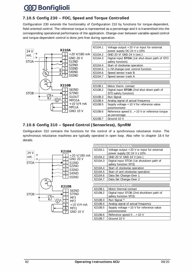
82 Operating Instructions ACU 09/20
7.10.5 Config 230 – FOC, Speed and Torque Controlled Configuration 230 extends the functionality of Configuration 210 by functions for torque-dependent, field-oriented control. The reference torque is represented as a percentage and it is transmitted into the corresponding operational performance of the application. Change-over between variable-speed control and torque-dependent control is done jerk-free during operation.
Control terminal X210A X210A.1 Voltage output +20 V or input for external
power supply DC 24 V ±10% X210A.2 GND 20 V/ GND 24 V (ext.) X210A.3 Digital input STOA (1st shut-down path of STO
safety function) X210A.4 Start of clockwise operation X210A.5 n-/M change-over control function X210A.6 Speed sensor track B X210A.7 Speed sensor track A
Control terminal X210B X210B.1 Motor therm. contact X210B.2 Digital input STOB (2nd shut-down path of
STO safety function) X210B.3 Run Signal X210B.4 Analog signal of actual frequency X210B.5 Supply voltage +10 V for reference value
potentiometer X210B.6 Reference speed 0...+10 V or reference torque
as percentage X210B.7 Ground 10 V
7.10.6 Config 310 – Speed Control (Sensorless), SynRM Configuration 310 contains the functions for the control of a synchronous reluctance motor. The synchronous reluctance machines are typically operated in open loop. Also refer to chapter 18.4 for details.
Control terminal X210A X210A.1 Voltage output +20 V or input for external
power supply DC 24 V ±10% X210A.2 GND 20 V/ GND 24 V (ext.) X210A.3 Digital input STOA (1st shutdown path of
safety function STO) X210A.4 Start of clockwise operation X210A.5 Start of anti-clockwise operation X210A.6 Data Set Change-Over 1 X210A.7 Data Set Change-Over 2
Control terminal X210B X210B.1 Motor thermal contact X210B.2 Digital input STOB (2nd shutdown path of
safety function STO) X210B.3 Run Signal 1) X210B.4 Analog signal of actual frequency X210B.5 Supply voltage +10 V for reference value
potentiometer X210B.6 Reference speed 0 ...+10 V X210B.7 Ground 10 V
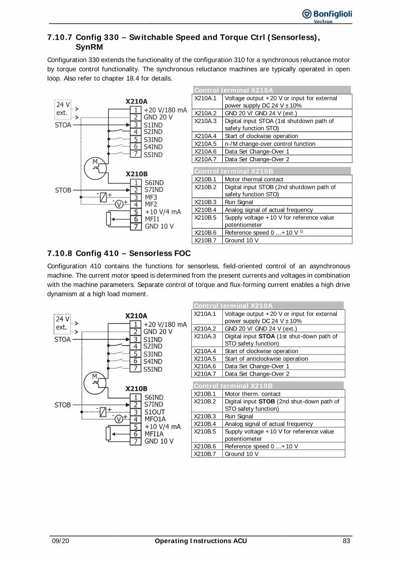
09/20 Operating Instructions ACU 83
7.10.7 Config 330 – Switchable Speed and Torque Ctrl (Sensorless), SynRM
Configuration 330 extends the functionality of the configuration 310 for a synchronous reluctance motor by torque control functionality. The synchronous reluctance machines are typically operated in open loop. Also refer to chapter 18.4 for details.
Control terminal X210A X210A.1 Voltage output +20 V or input for external
power supply DC 24 V ±10% X210A.2 GND 20 V/ GND 24 V (ext.) X210A.3 Digital input STOA (1st shutdown path of
safety function STO) X210A.4 Start of clockwise operation X210A.5 n-/M change-over control function X210A.6 Data Set Change-Over 1 X210A.7 Data Set Change-Over 2
Control terminal X210B X210B.1 Motor thermal contact X210B.2 Digital input STOB (2nd shutdown path of
safety function STO) X210B.3 Run Signal X210B.4 Analog signal of actual frequency X210B.5 Supply voltage +10 V for reference value
potentiometer X210B.6 Reference speed 0 ...+10 V 1) X210B.7 Ground 10 V
7.10.8 Config 410 – Sensorless FOC Configuration 410 contains the functions for sensorless, field-oriented control of an asynchronous machine. The current motor speed is determined from the present currents and voltages in combination with the machine parameters. Separate control of torque and flux-forming current enables a high drive dynamism at a high load moment.
Control terminal X210A X210A.1 Voltage output +20 V or input for external
power supply DC 24 V ±10% X210A.2 GND 20 V/ GND 24 V (ext.) X210A.3 Digital input STOA (1st shut-down path of
STO safety function) X210A.4 Start of clockwise operation X210A.5 Start of anticlockwise operation X210A.6 Data Set Change-Over 1 X210A.7 Data Set Change-Over 2
Control terminal X210B X210B.1 Motor therm. contact X210B.2 Digital input STOB (2nd shut-down path of
STO safety function) X210B.3 Run Signal X210B.4 Analog signal of actual frequency X210B.5 Supply voltage +10 V for reference value
potentiometer X210B.6 Reference speed 0 ...+10 V X210B.7 Ground 10 V
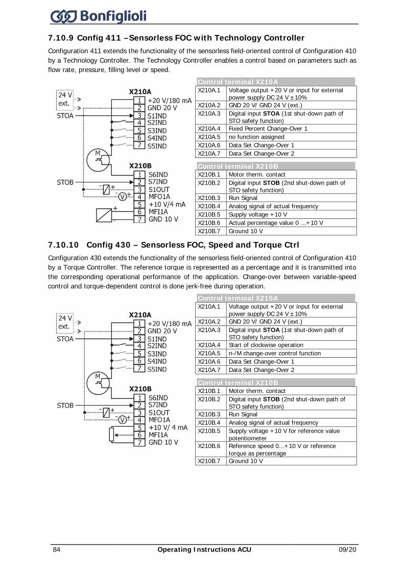
84 Operating Instructions ACU 09/20
7.10.9 Config 411 –Sensorless FOC with Technology Controller Configuration 411 extends the functionality of the sensorless field-oriented control of Configuration 410 by a Technology Controller. The Technology Controller enables a control based on parameters such as flow rate, pressure, filling level or speed.
7.10.10 Config 430 – Sensorless FOC, Speed and Torque Ctrl Configuration 430 extends the functionality of the sensorless field-oriented control of Configuration 410 by a Torque Controller. The reference torque is represented as a percentage and it is transmitted into the corresponding operational performance of the application. Change-over between variable-speed control and torque-dependent control is done jerk-free during operation.
Control terminal X210A X210A.1 Voltage output +20 V or input for external
power supply DC 24 V ±10% X210A.2 GND 20 V/ GND 24 V (ext.) X210A.3 Digital input STOA (1st shut-down path of
STO safety function) X210A.4 Fixed Percent Change-Over 1 X210A.5 no function assigned X210A.6 Data Set Change-Over 1 X210A.7 Data Set Change-Over 2
Control terminal X210B X210B.1 Motor therm. contact X210B.2 Digital input STOB (2nd shut-down path of
STO safety function) X210B.3 Run Signal X210B.4 Analog signal of actual frequency X210B.5 Supply voltage +10 V X210B.6 Actual percentage value 0 ...+10 V X210B.7 Ground 10 V
Control terminal X210A X210A.1 Voltage output +20 V or input for external
power supply DC 24 V ±10% X210A.2 GND 20 V/ GND 24 V (ext.) X210A.3 Digital input STOA (1st shut-down path of
STO safety function) X210A.4 Start of clockwise operation X210A.5 n-/M change-over control function X210A.6 Data Set Change-Over 1 X210A.7 Data Set Change-Over 2
Control terminal X210B X210B.1 Motor therm. contact X210B.2 Digital input STOB (2nd shut-down path of
STO safety function) X210B.3 Run Signal X210B.4 Analog signal of actual frequency X210B.5 Supply voltage +10 V for reference value
potentiometer X210B.6 Reference speed 0...+10 V or reference
torque as percentage X210B.7 Ground 10 V
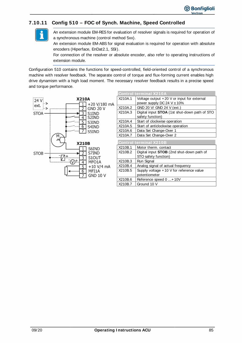
09/20 Operating Instructions ACU 85
7.10.11 Config 510 – FOC of Synch. Machine, Speed Controlled
An extension module EM-RES for evaluation of resolver signals is required for operation of a synchronous machine (control method 5xx). An extension module EM-ABS for signal evaluation is required for operation with absolute encoders (Hiperface, EnDat2.1, SSI). For connection of the resolver or absolute encoder, also refer to operating instructions of extension module.
Configuration 510 contains the functions for speed-controlled, field-oriented control of a synchronous machine with resolver feedback. The separate control of torque and flux-forming current enables high drive dynamism with a high load moment. The necessary resolver feedback results in a precise speed and torque performance.
Control terminal X210A X210A.1 Voltage output +20 V or input for external
power supply DC 24 V ±10% X210A.2 GND 20 V/ GND 24 V (ext.) X210A.3 Digital input STOA (1st shut-down path of STO
safety function) X210A.4 Start of clockwise operation X210A.5 Start of anticlockwise operation X210A.6 Data Set Change-Over 1 X210A.7 Data Set Change-Over 2
Control terminal X210B X210B.1 Motor therm. contact X210B.2 Digital input STOB (2nd shut-down path of
STO safety function) X210B.3 Run Signal X210B.4 Analog signal of actual frequency X210B.5 Supply voltage +10 V for reference value
potentiometer X210B.6 Reference speed 0 ...+10V X210B.7 Ground 10 V
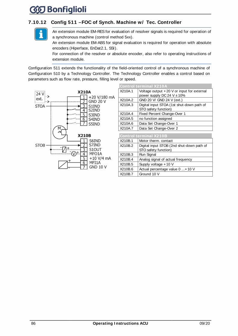
86 Operating Instructions ACU 09/20
7.10.12 Config 511 –FOC of Synch. Machine w/ Tec. Controller
An extension module EM-RES for evaluation of resolver signals is required for operation of a synchronous machine (control method 5xx). An extension module EM-ABS for signal evaluation is required for operation with absolute encoders (Hiperface, EnDat2.1, SSI). For connection of the resolver or absolute encoder, also refer to operating instructions of extension module.
Configuration 511 extends the functionality of the field-oriented control of a synchronous machine of Configuration 510 by a Technology Controller. The Technology Controller enables a control based on parameters such as flow rate, pressure, filling level or speed.
Control terminal X210A X210A.1 Voltage output +20 V or input for external
power supply DC 24 V ±10% X210A.2 GND 20 V/ GND 24 V (ext.) X210A.3 Digital input STOA (1st shut-down path of
STO safety function) X210A.4 Fixed Percent Change-Over 1 X210A.5 no function assigned X210A.6 Data Set Change-Over 1 X210A.7 Data Set Change-Over 2
Control terminal X210B X210B.1 Motor therm. contact X210B.2 Digital input STOB (2nd shut-down path of
STO safety function) X210B.3 Run Signal X210B.4 Analog signal of actual frequency X210B.5 Supply voltage +10 V X210B.6 Actual percentage value 0 ...+10 V X210B.7 Ground 10 V
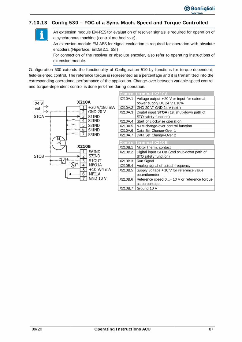
09/20 Operating Instructions ACU 87
7.10.13 Config 530 – FOC of a Sync. Mach. Speed and Torque Controlled
An extension module EM-RES for evaluation of resolver signals is required for operation of a synchronous machine (control method 5xx). An extension module EM-ABS for signal evaluation is required for operation with absolute encoders (Hiperface, EnDat2.1, SSI). For connection of the resolver or absolute encoder, also refer to operating instructions of extension module.
Configuration 530 extends the functionality of Configuration 510 by functions for torque-dependent, field-oriented control. The reference torque is represented as a percentage and it is transmitted into the corresponding operational performance of the application. Change-over between variable-speed control and torque-dependent control is done jerk-free during operation.
Control terminal X210A X210A.1 Voltage output +20 V or input for external
power supply DC 24 V ±10% X210A.2 GND 20 V/ GND 24 V (ext.) X210A.3 Digital input STOA (1st shut-down path of
STO safety function) X210A.4 Start of clockwise operation X210A.5 n-/M change-over control function X210A.6 Data Set Change-Over 1 X210A.7 Data Set Change-Over 2
Control terminal X210B X210B.1 Motor therm. contact X210B.2 Digital input STOB (2nd shut-down path of
STO safety function) X210B.3 Run Signal X210B.4 Analog signal of actual frequency X210B.5 Supply voltage +10 V for reference value
potentiometer X210B.6 Reference speed 0...+10 V or reference torque
as percentage X210B.7 Ground 10 V
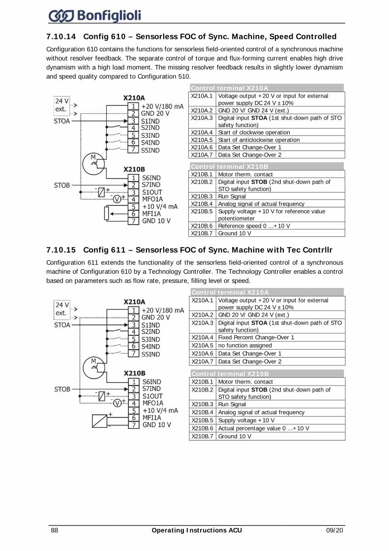
88 Operating Instructions ACU 09/20
7.10.14 Config 610 – Sensorless FOC of Sync. Machine, Speed Controlled Configuration 610 contains the functions for sensorless field-oriented control of a synchronous machine without resolver feedback. The separate control of torque and flux-forming current enables high drive dynamism with a high load moment. The missing resolver feedback results in slightly lower dynamism and speed quality compared to Configuration 510.
Control terminal X210A X210A.1 Voltage output +20 V or input for external
power supply DC 24 V ±10% X210A.2 GND 20 V/ GND 24 V (ext.) X210A.3 Digital input STOA (1st shut-down path of STO
safety function) X210A.4 Start of clockwise operation X210A.5 Start of anticlockwise operation X210A.6 Data Set Change-Over 1 X210A.7 Data Set Change-Over 2
Control terminal X210B X210B.1 Motor therm. contact X210B.2 Digital input STOB (2nd shut-down path of
STO safety function) X210B.3 Run Signal X210B.4 Analog signal of actual frequency X210B.5 Supply voltage +10 V for reference value
potentiometer X210B.6 Reference speed 0 ...+10 V X210B.7 Ground 10 V
7.10.15 Config 611 – Sensorless FOC of Sync. Machine with Tec Contrllr Configuration 611 extends the functionality of the sensorless field-oriented control of a synchronous machine of Configuration 610 by a Technology Controller. The Technology Controller enables a control based on parameters such as flow rate, pressure, filling level or speed.
Control terminal X210A X210A.1 Voltage output +20 V or input for external
power supply DC 24 V ±10% X210A.2 GND 20 V/ GND 24 V (ext.) X210A.3 Digital input STOA (1st shut-down path of STO
safety function) X210A.4 Fixed Percent Change-Over 1 X210A.5 no function assigned X210A.6 Data Set Change-Over 1 X210A.7 Data Set Change-Over 2
Control terminal X210B X210B.1 Motor therm. contact X210B.2 Digital input STOB (2nd shut-down path of
STO safety function) X210B.3 Run Signal X210B.4 Analog signal of actual frequency X210B.5 Supply voltage +10 V X210B.6 Actual percentage value 0 ...+10 V X210B.7 Ground 10 V
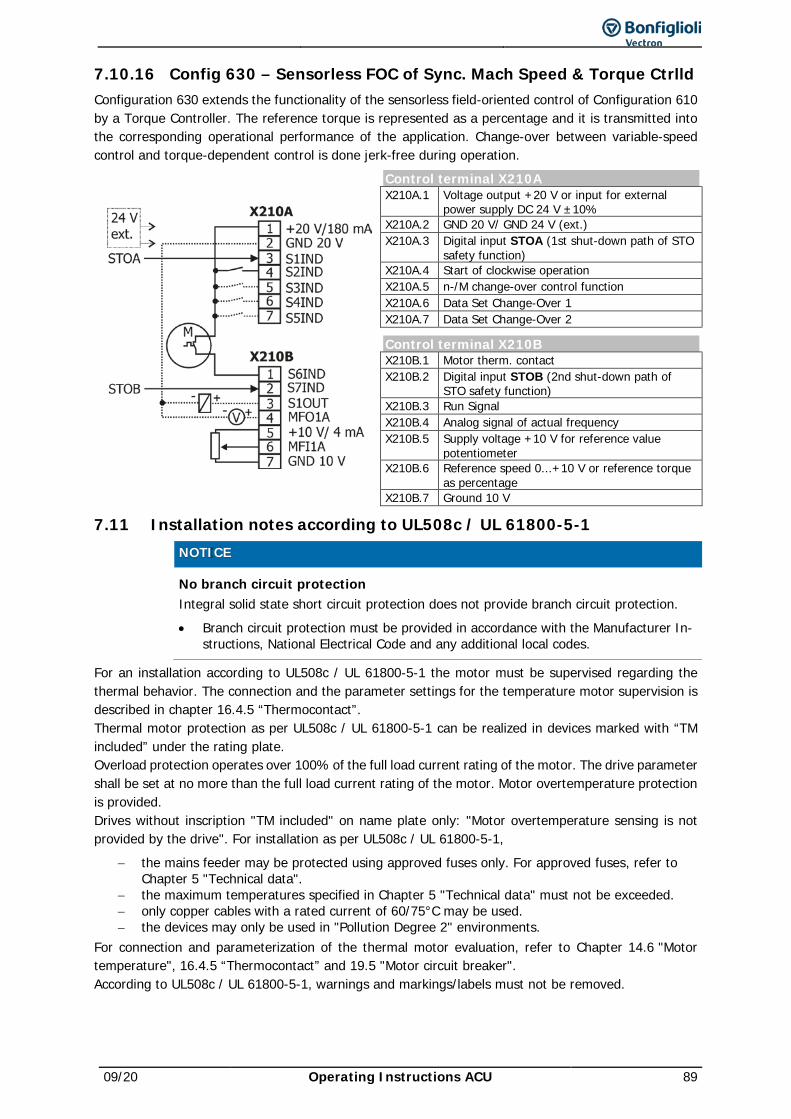
09/20 Operating Instructions ACU 89
7.10.16 Config 630 – Sensorless FOC of Sync. Mach Speed & Torque Ctrlld Configuration 630 extends the functionality of the sensorless field-oriented control of Configuration 610 by a Torque Controller. The reference torque is represented as a percentage and it is transmitted into the corresponding operational performance of the application. Change-over between variable-speed control and torque-dependent control is done jerk-free during operation.
Control terminal X210A X210A.1 Voltage output +20 V or input for external
power supply DC 24 V ±10% X210A.2 GND 20 V/ GND 24 V (ext.) X210A.3 Digital input STOA (1st shut-down path of STO
safety function) X210A.4 Start of clockwise operation X210A.5 n-/M change-over control function X210A.6 Data Set Change-Over 1 X210A.7 Data Set Change-Over 2
Control terminal X210B X210B.1 Motor therm. contact X210B.2 Digital input STOB (2nd shut-down path of
STO safety function) X210B.3 Run Signal X210B.4 Analog signal of actual frequency X210B.5 Supply voltage +10 V for reference value
potentiometer X210B.6 Reference speed 0...+10 V or reference torque
as percentage X210B.7 Ground 10 V
7.11 Installation notes according to UL508c / UL 61800-5-1
NOTICE
No branch circuit protection Integral solid state short circuit protection does not provide branch circuit protection. • Branch circuit protection must be provided in accordance with the Manufacturer In-
structions, National Electrical Code and any additional local codes.
For an installation according to UL508c / UL 61800-5-1 the motor must be supervised regarding the thermal behavior. The connection and the parameter settings for the temperature motor supervision is described in chapter 16.4.5 “Thermocontact”. Thermal motor protection as per UL508c / UL 61800-5-1 can be realized in devices marked with “TM included” under the rating plate. Overload protection operates over 100% of the full load current rating of the motor. The drive parameter shall be set at no more than the full load current rating of the motor. Motor overtemperature protection is provided. Drives without inscription "TM included" on name plate only: "Motor overtemperature sensing is not provided by the drive". For installation as per UL508c / UL 61800-5-1,
− the mains feeder may be protected using approved fuses only. For approved fuses, refer to Chapter 5 "Technical data".
− the maximum temperatures specified in Chapter 5 "Technical data" must not be exceeded. − only copper cables with a rated current of 60/75°C may be used. − the devices may only be used in "Pollution Degree 2" environments.
For connection and parameterization of the thermal motor evaluation, refer to Chapter 14.6 "Motor temperature", 16.4.5 “Thermocontact” and 19.5 "Motor circuit breaker". According to UL508c / UL 61800-5-1, warnings and markings/labels must not be removed.
90 Operating Instructions ACU 09/20
Short-circuit current rating
For Size 1 to 6 Suitable for use on a circuit capable of delivering not more than 5,000 rms symmetrical amperes, 480 V AC maximum when protected by K5 Class Fuses.
For Size 7 Suitable for use on a circuit capable of delivering not more than 10,000 rms symmetrical amperes, 480 V AC maximum when protected by RK5 Class Fuses or R/C (JFHR2) Semiconductor Fuse, Type FWH-xxxA, manufactured by Cooper Bussmann LLC.
For Size 8 -51, -53, -55 Suitable For Use On A Circuit Capable Of Delivering Not More Than 18 kA rms Symmetrical Amperes, 480 V AC Maximum when protected by Semiconductor fuses Types 170M5* made by Cooper Bussmann LLC.
For Size 8 -57, -59, -61 Suitable For Use On A Circuit Capable Of Delivering Not More Than 30 kA rms Symmetrical Amperes, 480 V AC Maximum when protected by Semiconductor fuses Types 170M5* made by Cooper Bussmann LLC.

09/20 Operating Instructions ACU 91
8 Control unit KP500 The optional KP500 control unit is a practical tool for controlling the frequency inverter and setting and displaying the frequency inverter parameters. The control unit is not absolutely necessary for the operation of the frequency inverter and can be plugged on when required.
Buttons A RUN Used for starting the drive and opening the CTRL menu.
Press the RUN key to open the motor potentiometer function. STOP Used for opening the CTRL menu, stopping the drive and acknowledging faults
J Navigate in menu structure and select parameters. Increase or reduce parameter values.
ENT Open parameters or switch within the menu structure. Confirm the selected function or parameter.
ESC Used for aborting parameters or switching back to the previous menu within the menu structure. Cancel the function or reset parameter value.
FUN Used for switching over the key function, access to special functions. Display
B Three-digit 7-segment display to show the parameter number.
C One-digit 7-segment display for display of the active data record, direction of rotation etc.
D Display selected menu branch: VAL Show actual values. PARA Select parameters and adjust parameter values. CTRL Select a function for adjustment and/or display via the operating unit:
SEtUP Guided commissioning. CtrL motor potentiometer and jog function.
CPY Copy parameters via the control unit: ALL All parameter values are copied. Act Active parameter values are copied only. FOr Control unit memory is formatted and deleted.
E Status and operating messages: WARN Warning about a critical operating behavior. FAULT Message indicating that the unit was switched off due to a fault. RUN Flashing: signalizes readiness for operation
Lighting signalizes operation and release of the power part REM Active remote control via interface connection. F Function switch-over with the FUN key.
F Five-digit 7-segment display for display of parameter value and sign.
G Physical unit of parameter value displayed.
H Active acceleration or deceleration ramp.
I Current direction of rotation of the drive.
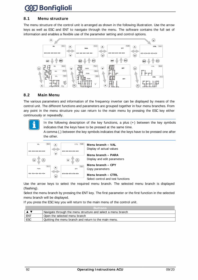
92 Operating Instructions ACU 09/20
8.1 Menu structure The menu structure of the control unit is arranged as shown in the following illustration. Use the arrow keys as well as ESC and ENT to navigate through the menu. The software contains the full set of information and enables a flexible use of the parameter setting and control options.
8.2 Main Menu The various parameters and information of the frequency inverter can be displayed by means of the control unit. The different functions and parameters are grouped together in four menu branches. From any point in the menu structure you can return to the main menu by pressing the ESC key either continuously or repeatedly.
In the following description of the key functions, a plus (+) between the key symbols indicates that the keys have to be pressed at the same time. A comma (,) between the key symbols indicates that the keys have to be pressed one after the other.
Menu branch – VAL Display of actual values
Menu branch – PARA Display and edit parameters
Menu branch – CPY Copy parameters
Menu branch – CTRL Select control and test functions
Use the arrow keys to select the required menu branch. The selected menu branch is displayed (flashing). Select the menu branch by pressing the ENT key. The first parameter or the first function in the selected menu branch will be displayed. If you press the ESC key you will return to the main menu of the control unit.
Buttons Navigate through the menu structure and select a menu branch ENT Open the selected menu branch ESC Quitting the menu branch and return to the main menu.
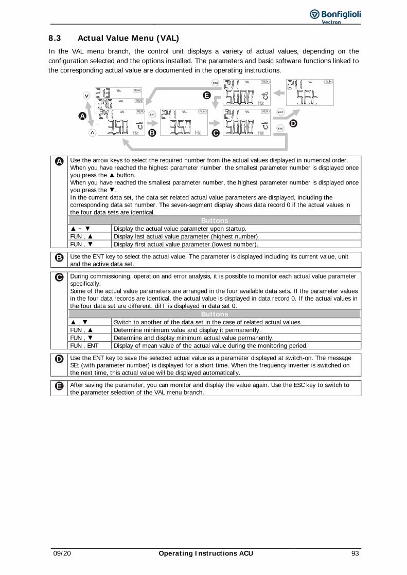
09/20 Operating Instructions ACU 93
8.3 Actual Value Menu (VAL) In the VAL menu branch, the control unit displays a variety of actual values, depending on the configuration selected and the options installed. The parameters and basic software functions linked to the corresponding actual value are documented in the operating instructions.
ENT
ESC
ENT
ESC
A
B CD
E
A Use the arrow keys to select the required number from the actual values displayed in numerical order. When you have reached the highest parameter number, the smallest parameter number is displayed once you press the button. When you have reached the smallest parameter number, the highest parameter number is displayed once you press the . In the current data set, the data set related actual value parameters are displayed, including the corresponding data set number. The seven-segment display shows data record 0 if the actual values in the four data sets are identical.
Buttons + Display the actual value parameter upon startup. FUN , Display last actual value parameter (highest number). FUN , Display first actual value parameter (lowest number).
B Use the ENT key to select the actual value. The parameter is displayed including its current value, unit and the active data set.
C During commissioning, operation and error analysis, it is possible to monitor each actual value parameter specifically. Some of the actual value parameters are arranged in the four available data sets. If the parameter values in the four data records are identical, the actual value is displayed in data record 0. If the actual values in the four data set are different, diFF is displayed in data set 0.
Buttons , Switch to another of the data set in the case of related actual values. FUN , Determine minimum value and display it permanently. FUN , Determine and display minimum actual value permanently. FUN , ENT Display of mean value of the actual value during the monitoring period.
D Use the ENT key to save the selected actual value as a parameter displayed at switch-on. The message SEt (with parameter number) is displayed for a short time. When the frequency inverter is switched on the next time, this actual value will be displayed automatically.
E After saving the parameter, you can monitor and display the value again. Use the ESC key to switch to the parameter selection of the VAL menu branch.
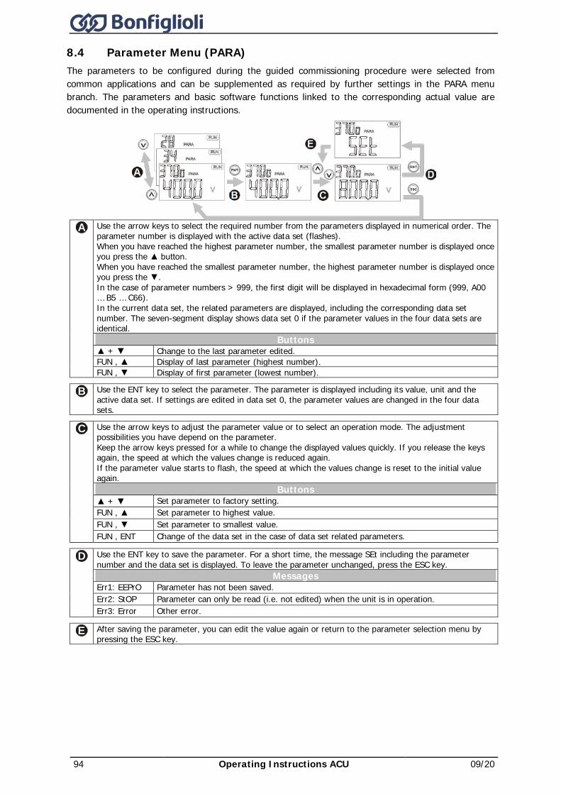
94 Operating Instructions ACU 09/20
8.4 Parameter Menu (PARA) The parameters to be configured during the guided commissioning procedure were selected from common applications and can be supplemented as required by further settings in the PARA menu branch. The parameters and basic software functions linked to the corresponding actual value are documented in the operating instructions.
A Use the arrow keys to select the required number from the parameters displayed in numerical order. The
parameter number is displayed with the active data set (flashes). When you have reached the highest parameter number, the smallest parameter number is displayed once you press the button. When you have reached the smallest parameter number, the highest parameter number is displayed once you press the . In the case of parameter numbers > 999, the first digit will be displayed in hexadecimal form (999, A00 … B5 … C66). In the current data set, the related parameters are displayed, including the corresponding data set number. The seven-segment display shows data set 0 if the parameter values in the four data sets are identical.
Buttons + Change to the last parameter edited. FUN , Display of last parameter (highest number). FUN , Display of first parameter (lowest number).
B Use the ENT key to select the parameter. The parameter is displayed including its value, unit and the active data set. If settings are edited in data set 0, the parameter values are changed in the four data sets.
C Use the arrow keys to adjust the parameter value or to select an operation mode. The adjustment possibilities you have depend on the parameter. Keep the arrow keys pressed for a while to change the displayed values quickly. If you release the keys again, the speed at which the values change is reduced again. If the parameter value starts to flash, the speed at which the values change is reset to the initial value again.
Buttons + Set parameter to factory setting. FUN , Set parameter to highest value. FUN , Set parameter to smallest value. FUN , ENT Change of the data set in the case of data set related parameters.
D Use the ENT key to save the parameter. For a short time, the message SEt including the parameter number and the data set is displayed. To leave the parameter unchanged, press the ESC key.
Messages Err1: EEPrO Parameter has not been saved. Err2: StOP Parameter can only be read (i.e. not edited) when the unit is in operation. Err3: Error Other error.
E After saving the parameter, you can edit the value again or return to the parameter selection menu by pressing the ESC key.
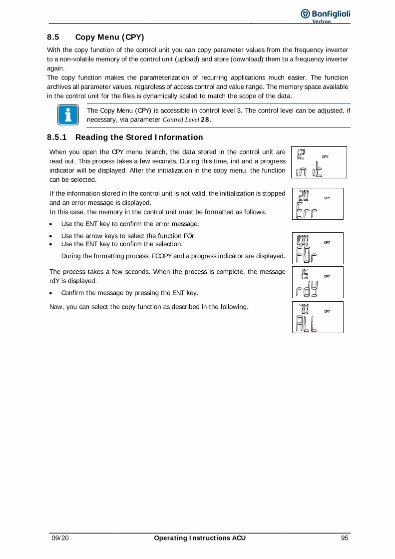
09/20 Operating Instructions ACU 95
8.5 Copy Menu (CPY) With the copy function of the control unit you can copy parameter values from the frequency inverter to a non-volatile memory of the control unit (upload) and store (download) them to a frequency inverter again. The copy function makes the parameterization of recurring applications much easier. The function archives all parameter values, regardless of access control and value range. The memory space available in the control unit for the files is dynamically scaled to match the scope of the data.
The Copy Menu (CPY) is accessible in control level 3. The control level can be adjusted, if necessary, via parameter Control Level 28.
8.5.1 Reading the Stored Information When you open the CPY menu branch, the data stored in the control unit are read out. This process takes a few seconds. During this time, init and a progress indicator will be displayed. After the initialization in the copy menu, the function can be selected.
If the information stored in the control unit is not valid, the initialization is stopped and an error message is displayed. In this case, the memory in the control unit must be formatted as follows: • Use the ENT key to confirm the error message.
• Use the arrow keys to select the function FOr. • Use the ENT key to confirm the selection.
During the formatting process, FCOPY and a progress indicator are displayed.
The process takes a few seconds. When the process is complete, the message rdY is displayed.
• Confirm the message by pressing the ENT key.
Now, you can select the copy function as described in the following.
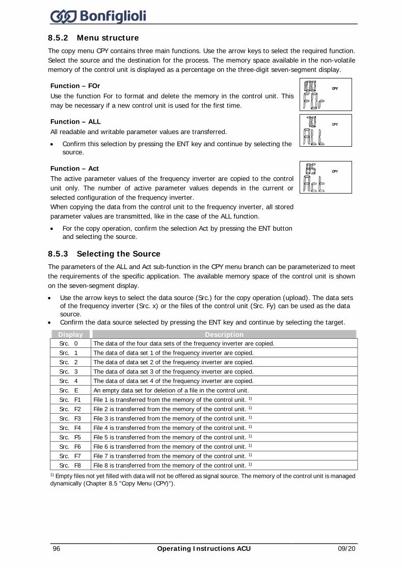
96 Operating Instructions ACU 09/20
8.5.2 Menu structure The copy menu CPY contains three main functions. Use the arrow keys to select the required function. Select the source and the destination for the process. The memory space available in the non-volatile memory of the control unit is displayed as a percentage on the three-digit seven-segment display.
Function – FOr Use the function For to format and delete the memory in the control unit. This may be necessary if a new control unit is used for the first time.
Function – ALL All readable and writable parameter values are transferred. • Confirm this selection by pressing the ENT key and continue by selecting the
source.
Function – Act The active parameter values of the frequency inverter are copied to the control unit only. The number of active parameter values depends in the current or selected configuration of the frequency inverter. When copying the data from the control unit to the frequency inverter, all stored parameter values are transmitted, like in the case of the ALL function. • For the copy operation, confirm the selection Act by pressing the ENT button
and selecting the source.
8.5.3 Selecting the Source The parameters of the ALL and Act sub-function in the CPY menu branch can be parameterized to meet the requirements of the specific application. The available memory space of the control unit is shown on the seven-segment display. • Use the arrow keys to select the data source (Src.) for the copy operation (upload). The data sets
of the frequency inverter (Src. x) or the files of the control unit (Src. Fy) can be used as the data source.
• Confirm the data source selected by pressing the ENT key and continue by selecting the target.
Display Description Src. 0 The data of the four data sets of the frequency inverter are copied. Src. 1 The data of data set 1 of the frequency inverter are copied. Src. 2 The data of data set 2 of the frequency inverter are copied. Src. 3 The data of data set 3 of the frequency inverter are copied. Src. 4 The data of data set 4 of the frequency inverter are copied. Src. E An empty data set for deletion of a file in the control unit. Src. F1 File 1 is transferred from the memory of the control unit. 1) Src. F2 File 2 is transferred from the memory of the control unit. 1) Src. F3 File 3 is transferred from the memory of the control unit. 1) Src. F4 File 4 is transferred from the memory of the control unit. 1) Src. F5 File 5 is transferred from the memory of the control unit. 1) Src. F6 File 6 is transferred from the memory of the control unit. 1) Src. F7 File 7 is transferred from the memory of the control unit. 1) Src. F8 File 8 is transferred from the memory of the control unit. 1)
1) Empty files not yet filled with data will not be offered as signal source. The memory of the control unit is managed dynamically (Chapter 8.5 "Copy Menu (CPY)").
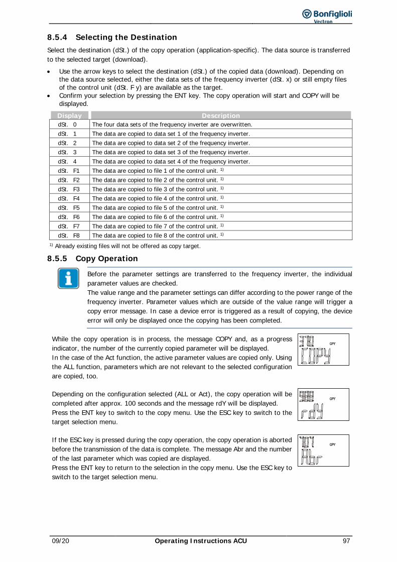
09/20 Operating Instructions ACU 97
8.5.4 Selecting the Destination Select the destination (dSt.) of the copy operation (application-specific). The data source is transferred to the selected target (download). • Use the arrow keys to select the destination (dSt.) of the copied data (download). Depending on
the data source selected, either the data sets of the frequency inverter (dSt. x) or still empty files of the control unit (dSt. F y) are available as the target.
• Confirm your selection by pressing the ENT key. The copy operation will start and COPY will be displayed. Display Description dSt. 0 The four data sets of the frequency inverter are overwritten. dSt. 1 The data are copied to data set 1 of the frequency inverter. dSt. 2 The data are copied to data set 2 of the frequency inverter. dSt. 3 The data are copied to data set 3 of the frequency inverter. dSt. 4 The data are copied to data set 4 of the frequency inverter. dSt. F1 The data are copied to file 1 of the control unit. 1) dSt. F2 The data are copied to file 2 of the control unit. 1) dSt. F3 The data are copied to file 3 of the control unit. 1) dSt. F4 The data are copied to file 4 of the control unit. 1) dSt. F5 The data are copied to file 5 of the control unit. 1) dSt. F6 The data are copied to file 6 of the control unit. 1) dSt. F7 The data are copied to file 7 of the control unit. 1) dSt. F8 The data are copied to file 8 of the control unit. 1)
1) Already existing files will not be offered as copy target.
8.5.5 Copy Operation
Before the parameter settings are transferred to the frequency inverter, the individual parameter values are checked. The value range and the parameter settings can differ according to the power range of the frequency inverter. Parameter values which are outside of the value range will trigger a copy error message. In case a device error is triggered as a result of copying, the device error will only be displayed once the copying has been completed.
While the copy operation is in process, the message COPY and, as a progress indicator, the number of the currently copied parameter will be displayed. In the case of the Act function, the active parameter values are copied only. Using the ALL function, parameters which are not relevant to the selected configuration are copied, too.
Depending on the configuration selected (ALL or Act), the copy operation will be completed after approx. 100 seconds and the message rdY will be displayed. Press the ENT key to switch to the copy menu. Use the ESC key to switch to the target selection menu.
If the ESC key is pressed during the copy operation, the copy operation is aborted before the transmission of the data is complete. The message Abr and the number of the last parameter which was copied are displayed. Press the ENT key to return to the selection in the copy menu. Use the ESC key to switch to the target selection menu.
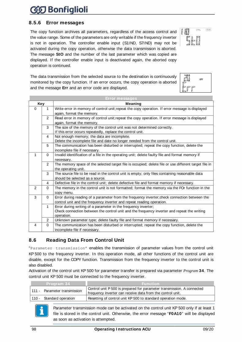
98 Operating Instructions ACU 09/20
8.5.6 Error messages The copy function archives all parameters, regardless of the access control and the value range. Some of the parameters are only writable if the frequency inverter is not in operation. The controller enable input (S1IND, S7IND) may not be activated during the copy operation, otherwise the data transmission is aborted. The message StO and the number of the last parameter which was copied are displayed. If the controller enable input is deactivated again, the aborted copy operation is continued.
The data transmission from the selected source to the destination is continuously monitored by the copy function. If an error occurs, the copy operation is aborted and the message Err and an error code are displayed.
Error messages Key Meaning
0 1 Write error in memory of control unit; repeat the copy operation. If error message is displayed again, format the memory.
2 Read error in memory of control unit; repeat the copy operation. If error message is displayed again, format the memory.
3 The size of the memory of the control unit was not determined correctly. If this error occurs repeatedly, replace the control unit.
4 Not enough memory; the data are incomplete. Delete the incomplete file and date no longer needed from the control unit.
5 The communication has been disturbed or interrupted; repeat the copy function, delete the incomplete file if necessary.
1 0 Invalid identification of a file in the operating unit; delete faulty file and format memory if necessary.
2 The memory space of the selected target file is occupied; delete file or use different target file in the operating unit.
3 The source file to be read in the control unit is empty; only files containing reasonable data should be selected as a source.
4 Defective file in the control unit; delete defective file and format memory if necessary. 2 0 The memory in the control unit is not formatted; format the memory via the FOr function in the
copy menu. 3 0 Error during reading of a parameter from the frequency inverter; check connection between the
control unit and the frequency inverter and repeat reading operation. 1 Error during writing of a parameter in the frequency inverter;
Check connection between the control unit and the frequency inverter and repeat the writing operation.
2 Unknown parameter type; delete faulty file and format memory if necessary. 4 0 The communication has been disturbed or interrupted; repeat the copy function, delete the
incomplete file if necessary.
8.6 Reading Data From Control Unit “Parameter transmission” enables the transmission of parameter values from the control unit KP 500 to the frequency inverter. In this operation mode, all other functions of the control unit are disable, except for the COPY function. Transmission from the frequency inverter to the control unit is also disabled. Activation of the control unit KP 500 for parameter transfer is prepared via parameter Program 34. The control unit KP 500 must be connected to the frequency inverter.
Program 34 Function 111 - Parameter transmission Control unit P 500 is prepared for parameter transmission. A connected
frequency inverter can receive data from the control unit. 110 - Standard operation Resetting of control unit KP 500 to standard operation mode.
Parameter transmission mode can be activated on the control unit KP 500 only if at least 1 file is stored in the control unit. Otherwise, the error message “F0A10” will be displayed as soon as activation is attempted.
09/20 Operating Instructions ACU 99
8.6.1 Activation The control unit KP 500 can be configured both via the keys of the KP 500 and via any available CM communication module. For configuration and activation of the KP 500 control unit, proceed as follows:
Activation via keyboard of control unit • In the parameter menu PARA, use the arrow keys to select parameter Program 34, and confirm
your selection by pressing the ENT key. • Use the arrow keys to set value 111 – Parameter transmission and confirm your selection
by pressing the ENT key.
Now the control unit is ready for activation.
Before data transmission, the control unit must be initialized: • Unplug the control unit from the frequency inverter and connect again to the same or another
frequency inverter.
The initialization is started. During the time of initialization, init and a progress indicator are displayed. After initialization, the control unit KP°500 is ready for transfer of data to the frequency inverter.
Adjustment of parameter Program(ming) 34 to value 111 – Parameter transmission, can be undone via the control unit, provided that the control unit has not been initialized yet. • In Parameter Program(ming) 34 use the arrow keys to set the value
110 – Normal operation again and confirm by pressing the ENT key.
Activation via communication module CM
Activation of the control unit through a communication connection is possible only if the frequency inverter is fitted with an optional communication module CM, and communication takes place via this module. The control unit must be connected to the frequency inverter.
• Establish connection to frequency inverter. • Start communication and select parameter Program 34 via the communication interface. • Via the communication interface, enter value 111 in parameter Program 34 and confirm this
value. • Via the communication interface in parameter Program 34, enter 123 and confirm this value.
The frequency inverter is re-initialized. The display of the control unit reads rESEt. After that, the unit is initialized.
8.6.2 Data transfer In order to transmit a file from the control unit to the frequency inverter, proceed as follows: • Connect control unit KP 500 to the frequency inverter.
After initialization, the data sources available for transmission are displayed. • Use the arrow keys to select the data source (Src. Fy) for the transmission to the frequency
inverter. The files stored in the control unit are available as data sources.
The files stored in the control unit contain all information and parameters stored according to the selected copy function ALL or Act (see Chapter 8.5 "Copy Menu (CPY)") in the control unit.
• Confirm your selection by pressing the ENT key.
The copy process is started. While the copy operation is in process, COPY and, as a progress indicator, the number of the currently copied parameter will be displayed. As soon as the copy operation is complete, the control unit will be re-initialized.
100 Operating Instructions ACU 09/20
8.6.3 Resetting to Normal Operation A control unit KP°500 activated for parameter transmission can be reset to full functionality (standard operation) via a specific key code on the control unit or via each available communication module CM.
Resetting on control unit • Press RUN and STOP keys on control unit simultaneously for approx. 1 second.
When the process is complete, – – – – – is displayed briefly. Then the top menu level of the control unit is available.
• In the parameter menu PARA, use the arrow keys to select parameter Program 34, and confirm your selection by pressing the ENT key.
• Use the arrow keys to set value 110 – Normal operation and confirm your selection by pressing the ENT key.
The control unit is set to normal operation.
Resetting via communication module CM and/or using control software VPlus
Resetting of the control unit through a communication connection is possible only if the frequency inverter is fitted with an optional communication module CM, and communication takes place via this module.
• Establish connection to frequency inverter. • Start communication and select parameter Program 34 via the communication connection. • Via the communication connection, enter value 110 in parameter Program 34 and confirm this
value. • Via the communication connection enter value 123 in parameter Program 34 and confirm this
value by pressing Enter.
The frequency inverter is reset. The display of the control unit reads rESEt. After resetting, the control unit is available again with full functionality.
8.7 Control Menu (CTRL)
In order to be able to control the drive via the control unit, the digital inputs S1IND/STOA and S7IND/STOB must be connected for enabling the output.
In the CTRL menu branch, various functions are available which make commissioning easier and enable the control of the inverter via the control unit. The frequency inverters can be controlled by means of the control unit and/or a communication module. If you want to control the frequency inverter via an optional communication module, the necessary adjustments can be made via parameter Local/Remote 412. Via this parameter, you can specify which functions will be available to the controller. Depending on the operation mode selected, only some of the control menu functions are available. Refer to chapter 19.3"Bus controller" for a detailed description of parameter Local/Remote 412.
8.8 Controlling the Motor via the Control Unit The operating unit enables control of the connected motor in accordance with the selected operating mode of the parameter Local/Remote 412.
In order to be able to control the drive via the control unit, the digital inputs S1IND/STOA (STOA/terminal X210A.3) and S7IND/STOB (STOB/terminal X210B.2) must be connected for enabling the output. These are the inputs for the shut-down paths of the ST= safety function “Safe Torque Off”.
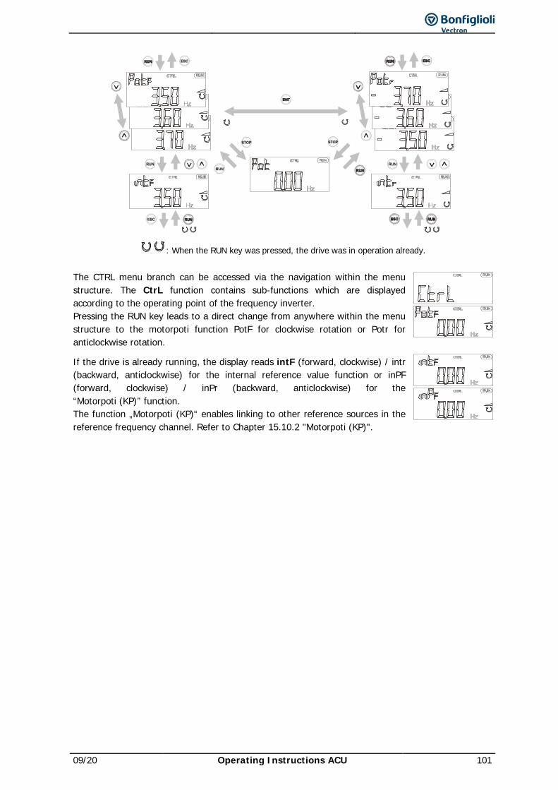
09/20 Operating Instructions ACU 101
: When the RUN key was pressed, the drive was in operation already.
The CTRL menu branch can be accessed via the navigation within the menu structure. The CtrL function contains sub-functions which are displayed according to the operating point of the frequency inverter. Pressing the RUN key leads to a direct change from anywhere within the menu structure to the motorpoti function PotF for clockwise rotation or Potr for anticlockwise rotation.
If the drive is already running, the display reads intF (forward, clockwise) / intr (backward, anticlockwise) for the internal reference value function or inPF (forward, clockwise) / inPr (backward, anticlockwise) for the “Motorpoti (KP)” function. The function „Motorpoti (KP)“ enables linking to other reference sources in the reference frequency channel. Refer to Chapter 15.10.2 "Motorpoti (KP)".
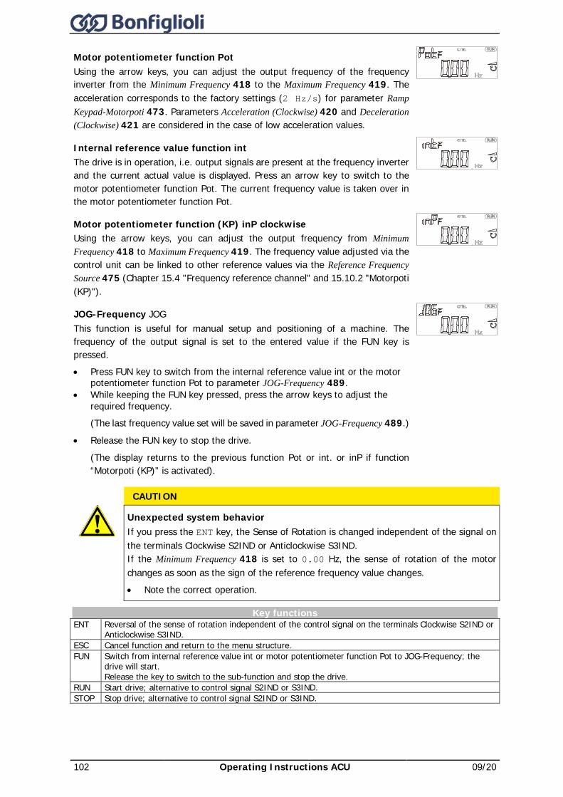
102 Operating Instructions ACU 09/20
Motor potentiometer function Pot Using the arrow keys, you can adjust the output frequency of the frequency inverter from the Minimum Frequency 418 to the Maximum Frequency 419. The acceleration corresponds to the factory settings (2 Hz/s) for parameter Ramp Keypad-Motorpoti 473. Parameters Acceleration (Clockwise) 420 and Deceleration (Clockwise) 421 are considered in the case of low acceleration values.
Internal reference value function int The drive is in operation, i.e. output signals are present at the frequency inverter and the current actual value is displayed. Press an arrow key to switch to the motor potentiometer function Pot. The current frequency value is taken over in the motor potentiometer function Pot.
Motor potentiometer function (KP) inP clockwise Using the arrow keys, you can adjust the output frequency from Minimum Frequency 418 to Maximum Frequency 419. The frequency value adjusted via the control unit can be linked to other reference values via the Reference Frequency Source 475 (Chapter 15.4 "Frequency reference channel" and 15.10.2 "Motorpoti (KP)").
JOG-Frequency JOG This function is useful for manual setup and positioning of a machine. The frequency of the output signal is set to the entered value if the FUN key is pressed. • Press FUN key to switch from the internal reference value int or the motor
potentiometer function Pot to parameter JOG-Frequency 489. • While keeping the FUN key pressed, press the arrow keys to adjust the
required frequency. (The last frequency value set will be saved in parameter JOG-Frequency 489.)
• Release the FUN key to stop the drive.
(The display returns to the previous function Pot or int. or inP if function “Motorpoti (KP)” is activated).
CAUTION
Unexpected system behavior If you press the ENT key, the Sense of Rotation is changed independent of the signal on the terminals Clockwise S2IND or Anticlockwise S3IND. If the Minimum Frequency 418 is set to 0.00 Hz, the sense of rotation of the motor changes as soon as the sign of the reference frequency value changes. • Note the correct operation.
Key functions ENT Reversal of the sense of rotation independent of the control signal on the terminals Clockwise S2IND or
Anticlockwise S3IND. ESC Cancel function and return to the menu structure. FUN Switch from internal reference value int or motor potentiometer function Pot to JOG-Frequency; the
drive will start. Release the key to switch to the sub-function and stop the drive.
RUN Start drive; alternative to control signal S2IND or S3IND. STOP Stop drive; alternative to control signal S2IND or S3IND.
09/20 Operating Instructions ACU 103
9 Commissioning of frequency inverter
NOTICE If filters (e.g. dU/dt filters or sine filters) are used between the frequency inverter and
machine, the following must be noted. For configurations with sensor feedback (2xx, 5xx): • Carry out the installation with the filter connected. Note the filter manufacturer's
specifications concerning permissible switching frequencies. During setup note that the filter may be overloaded thermally.
For configurations without sensor feedback (1xx, 4xx, 6xx): • Carry out the installation without connected filters. After setup, connect the filters
between the frequency inverter and the motor.
NOTICE In liquid-cooled devices:
• Vent the cooling circuit. • Initiate the cooling circuit.
See instructions in the "Operating Instructions Liquid Cooling Supplemental" document.
9.1 Switching on Mains Voltage After completion of the installation work, make sure to check all control and power connections again before switching on the mains voltage. When all electrical connections are correct, make sure that the frequency inverter is not enabled (control inputs S1IND/STOA and S7IND/STOB open). After power-up, the frequency inverter carries out a self-test and the relay output (X10) reports "Fault". After a few seconds, the self-test is complete, the relay (X10) picks up and signals "no fault ". If the unit is in "as-delivered" condition or after resetting the unit to the factory settings, the guided commissioning procedure is started automatically. On the control unit, the “SetUP“ menu from the menu branch CTRL is displayed.
9.2 Setup Using the Control Unit The guided commissioning of the frequency inverter determines all parameter settings relevant to the required application. The available parameters were selected based on known standard drive applications. This facilitates the selection of the important parameters. After successful completion of the SETUP routine, the actual value Actual Frequency 241 from the VAL menu branch is displayed on the control unit. Now, the user should check whether further parameters are relevant for the application.
The guided commissioning contains the function for parameter identification. The parameters are determined by way of measurement and set accordingly. Guided commissioning must be carried out when the machine is cold, since a part of the machine data depends on the operating temperature.
NOTICE For control of a synchronous machine and setting parameter Configuration 30 to “510 -
FOC Syn. Speed Controlled , you will have to cancel the guided commissioning first by pressing the ESC key after the “SEtUP” message and set parameter Offset 382.
• To do this, proceed according to the operating instructions for the extension module EM-RES or EM-ABS-01 installed.
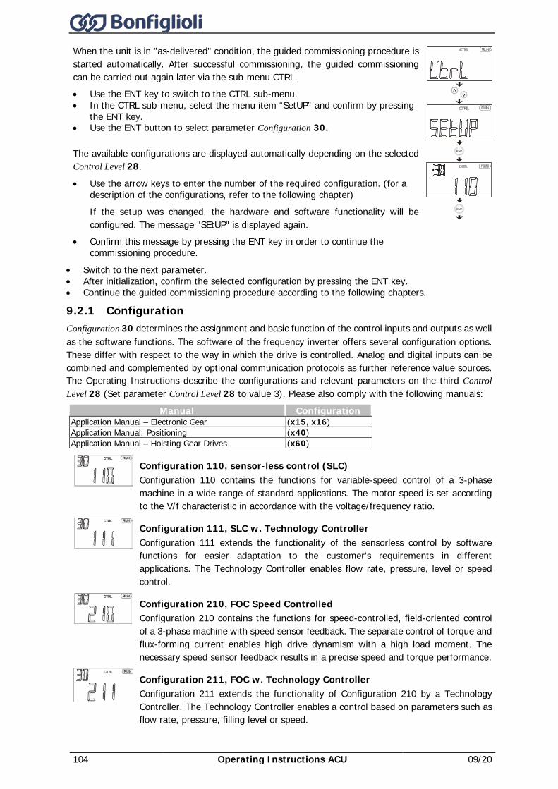
104 Operating Instructions ACU 09/20
When the unit is in "as-delivered" condition, the guided commissioning procedure is started automatically. After successful commissioning, the guided commissioning can be carried out again later via the sub-menu CTRL. • Use the ENT key to switch to the CTRL sub-menu. • In the CTRL sub-menu, select the menu item “SetUP” and confirm by pressing
the ENT key. • Use the ENT button to select parameter Configuration 30.
The available configurations are displayed automatically depending on the selected Control Level 28.
• Use the arrow keys to enter the number of the required configuration. (for a description of the configurations, refer to the following chapter) If the setup was changed, the hardware and software functionality will be configured. The message "SEtUP" is displayed again.
• Confirm this message by pressing the ENT key in order to continue the commissioning procedure.
ENT
ENT
• Switch to the next parameter. • After initialization, confirm the selected configuration by pressing the ENT key. • Continue the guided commissioning procedure according to the following chapters.
9.2.1 Configuration Configuration 30 determines the assignment and basic function of the control inputs and outputs as well as the software functions. The software of the frequency inverter offers several configuration options. These differ with respect to the way in which the drive is controlled. Analog and digital inputs can be combined and complemented by optional communication protocols as further reference value sources. The Operating Instructions describe the configurations and relevant parameters on the third Control Level 28 (Set parameter Control Level 28 to value 3). Please also comply with the following manuals:
Manual Configuration Application Manual – Electronic Gear (x15, x16) Application Manual: Positioning (x40) Application Manual – Hoisting Gear Drives (x60)
Configuration 110, sensor-less control (SLC) Configuration 110 contains the functions for variable-speed control of a 3-phase machine in a wide range of standard applications. The motor speed is set according to the V/f characteristic in accordance with the voltage/frequency ratio.
Configuration 111, SLC w. Technology Controller Configuration 111 extends the functionality of the sensorless control by software functions for easier adaptation to the customer's requirements in different applications. The Technology Controller enables flow rate, pressure, level or speed control.
Configuration 210, FOC Speed Controlled Configuration 210 contains the functions for speed-controlled, field-oriented control of a 3-phase machine with speed sensor feedback. The separate control of torque and flux-forming current enables high drive dynamism with a high load moment. The necessary speed sensor feedback results in a precise speed and torque performance.
Configuration 211, FOC w. Technology Controller Configuration 211 extends the functionality of Configuration 210 by a Technology Controller. The Technology Controller enables a control based on parameters such as flow rate, pressure, filling level or speed.
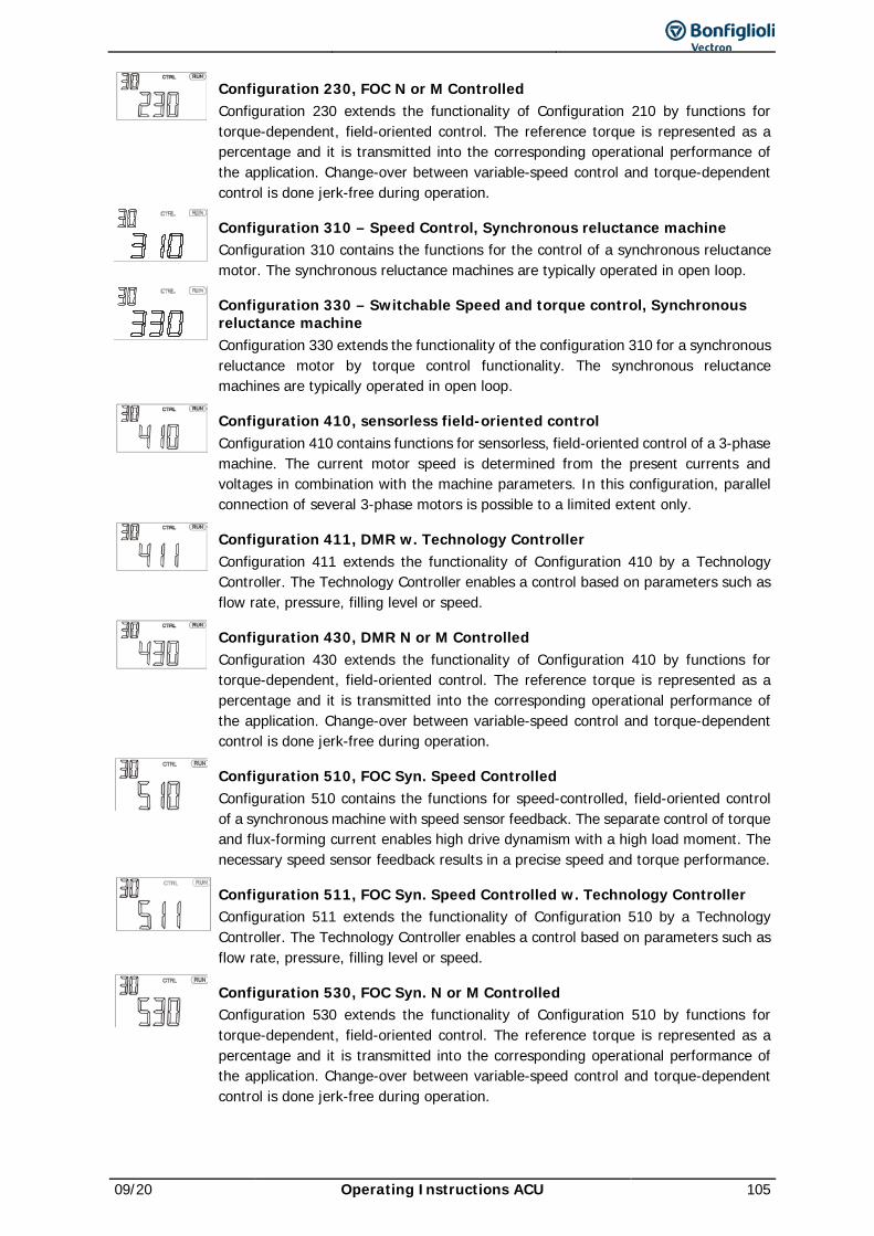
09/20 Operating Instructions ACU 105
Configuration 230, FOC N or M Controlled Configuration 230 extends the functionality of Configuration 210 by functions for torque-dependent, field-oriented control. The reference torque is represented as a percentage and it is transmitted into the corresponding operational performance of the application. Change-over between variable-speed control and torque-dependent control is done jerk-free during operation.
Configuration 310 – Speed Control, Synchronous reluctance machine Configuration 310 contains the functions for the control of a synchronous reluctance motor. The synchronous reluctance machines are typically operated in open loop.
Configuration 330 – Switchable Speed and torque control, Synchronous reluctance machine Configuration 330 extends the functionality of the configuration 310 for a synchronous reluctance motor by torque control functionality. The synchronous reluctance machines are typically operated in open loop.
Configuration 410, sensorless field-oriented control Configuration 410 contains functions for sensorless, field-oriented control of a 3-phase machine. The current motor speed is determined from the present currents and voltages in combination with the machine parameters. In this configuration, parallel connection of several 3-phase motors is possible to a limited extent only.
Configuration 411, DMR w. Technology Controller Configuration 411 extends the functionality of Configuration 410 by a Technology Controller. The Technology Controller enables a control based on parameters such as flow rate, pressure, filling level or speed.
Configuration 430, DMR N or M Controlled Configuration 430 extends the functionality of Configuration 410 by functions for torque-dependent, field-oriented control. The reference torque is represented as a percentage and it is transmitted into the corresponding operational performance of the application. Change-over between variable-speed control and torque-dependent control is done jerk-free during operation.
Configuration 510, FOC Syn. Speed Controlled Configuration 510 contains the functions for speed-controlled, field-oriented control of a synchronous machine with speed sensor feedback. The separate control of torque and flux-forming current enables high drive dynamism with a high load moment. The necessary speed sensor feedback results in a precise speed and torque performance.
Configuration 511, FOC Syn. Speed Controlled w. Technology Controller Configuration 511 extends the functionality of Configuration 510 by a Technology Controller. The Technology Controller enables a control based on parameters such as flow rate, pressure, filling level or speed.
Configuration 530, FOC Syn. N or M Controlled Configuration 530 extends the functionality of Configuration 510 by functions for torque-dependent, field-oriented control. The reference torque is represented as a percentage and it is transmitted into the corresponding operational performance of the application. Change-over between variable-speed control and torque-dependent control is done jerk-free during operation.
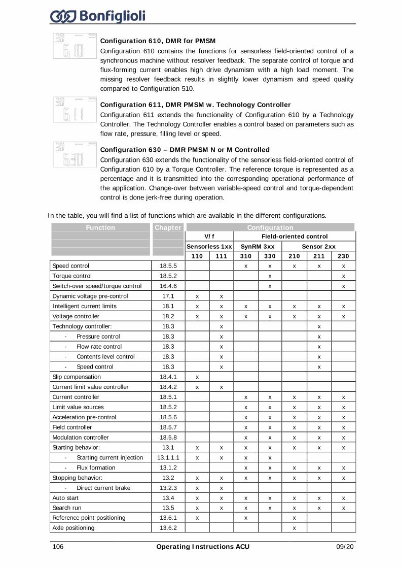
106 Operating Instructions ACU 09/20
Configuration 610, DMR for PMSM Configuration 610 contains the functions for sensorless field-oriented control of a synchronous machine without resolver feedback. The separate control of torque and flux-forming current enables high drive dynamism with a high load moment. The missing resolver feedback results in slightly lower dynamism and speed quality compared to Configuration 510.
Configuration 611, DMR PMSM w. Technology Controller Configuration 611 extends the functionality of Configuration 610 by a Technology Controller. The Technology Controller enables a control based on parameters such as flow rate, pressure, filling level or speed.
Configuration 630 – DMR PMSM N or M Controlled Configuration 630 extends the functionality of the sensorless field-oriented control of Configuration 610 by a Torque Controller. The reference torque is represented as a percentage and it is transmitted into the corresponding operational performance of the application. Change-over between variable-speed control and torque-dependent control is done jerk-free during operation.
In the table, you will find a list of functions which are available in the different configurations. Function
Chapter
Configuration V/f Field-oriented control
Sensorless 1xx SynRM 3xx Sensor 2xx 110 111 310 330 210 211 230
Speed control 18.5.5 x x x x x Torque control 18.5.2 x x Switch-over speed/torque control 16.4.6 x x Dynamic voltage pre-control 17.1 x x Intelligent current limits 18.1 x x x x x x x Voltage controller 18.2 x x x x x x x Technology controller: 18.3 x x
- Pressure control 18.3 x x - Flow rate control 18.3 x x - Contents level control 18.3 x x - Speed control 18.3 x x
Slip compensation 18.4.1 x Current limit value controller 18.4.2 x x Current controller 18.5.1 x x x x x Limit value sources 18.5.2 x x x x x Acceleration pre-control 18.5.6 x x x x x Field controller 18.5.7 x x x x x Modulation controller 18.5.8 x x x x x Starting behavior: 13.1 x x x x x x x
- Starting current injection 13.1.1.1 x x x x - Flux formation 13.1.2 x x x x x
Stopping behavior: 13.2 x x x x x x x - Direct current brake 13.2.3 x x
Auto start 13.4 x x x x x x x Search run 13.5 x x x x x x x Reference point positioning 13.6.1 x x x Axle positioning 13.6.2 x
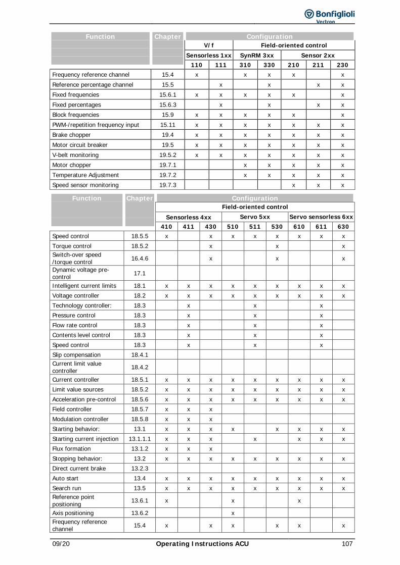
09/20 Operating Instructions ACU 107
Function
Chapter
Configuration V/f Field-oriented control
Sensorless 1xx SynRM 3xx Sensor 2xx 110 111 310 330 210 211 230
Frequency reference channel 15.4 x x x x x Reference percentage channel 15.5 x x x x Fixed frequencies 15.6.1 x x x x x x Fixed percentages 15.6.3 x x x x Block frequencies 15.9 x x x x x x PWM-/repetition frequency input 15.11 x x x x x x x Brake chopper 19.4 x x x x x x x Motor circuit breaker 19.5 x x x x x x x V-belt monitoring 19.5.2 x x x x x x x Motor chopper 19.7.1 x x x x x Temperature Adjustment 19.7.2 x x x x x Speed sensor monitoring 19.7.3 x x x
Function
Chapter
Configuration Field-oriented control
Sensorless 4xx Servo 5xx Servo sensorless 6xx 410 411 430 510 511 530 610 611 630
Speed control 18.5.5 x x x x x x x x Torque control 18.5.2 x x x Switch-over speed /torque control 16.4.6 x x x
Dynamic voltage pre-control 17.1
Intelligent current limits 18.1 x x x x x x x x x Voltage controller 18.2 x x x x x x x x x Technology controller: 18.3 x x x Pressure control 18.3 x x x Flow rate control 18.3 x x x Contents level control 18.3 x x x Speed control 18.3 x x x Slip compensation 18.4.1 Current limit value controller 18.4.2
Current controller 18.5.1 x x x x x x x x x Limit value sources 18.5.2 x x x x x x x x x Acceleration pre-control 18.5.6 x x x x x x x x x Field controller 18.5.7 x x x Modulation controller 18.5.8 x x x Starting behavior: 13.1 x x x x x x x x Starting current injection 13.1.1.1 x x x x x x x Flux formation 13.1.2 x x x Stopping behavior: 13.2 x x x x x x x x x Direct current brake 13.2.3 Auto start 13.4 x x x x x x x x x Search run 13.5 x x x x x x x x x Reference point positioning 13.6.1 x x x
Axis positioning 13.6.2 x Frequency reference channel 15.4 x x x x x x
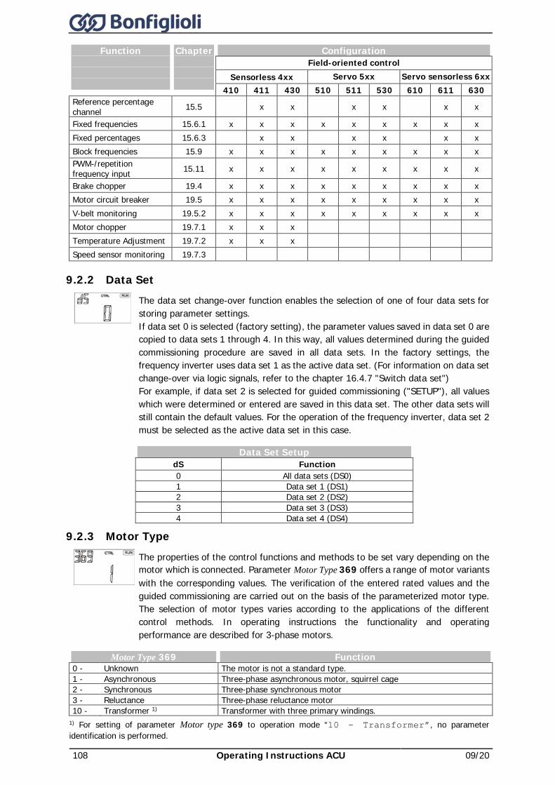
108 Operating Instructions ACU 09/20
Function
Chapter
Configuration Field-oriented control
Sensorless 4xx Servo 5xx Servo sensorless 6xx 410 411 430 510 511 530 610 611 630
Reference percentage channel 15.5 x x x x x x
Fixed frequencies 15.6.1 x x x x x x x x x Fixed percentages 15.6.3 x x x x x x Block frequencies 15.9 x x x x x x x x x PWM-/repetition frequency input 15.11 x x x x x x x x x
Brake chopper 19.4 x x x x x x x x x Motor circuit breaker 19.5 x x x x x x x x x V-belt monitoring 19.5.2 x x x x x x x x x Motor chopper 19.7.1 x x x Temperature Adjustment 19.7.2 x x x Speed sensor monitoring 19.7.3
9.2.2 Data Set
The data set change-over function enables the selection of one of four data sets for storing parameter settings. If data set 0 is selected (factory setting), the parameter values saved in data set 0 are copied to data sets 1 through 4. In this way, all values determined during the guided commissioning procedure are saved in all data sets. In the factory settings, the frequency inverter uses data set 1 as the active data set. (For information on data set change-over via logic signals, refer to the chapter 16.4.7 "Switch data set") For example, if data set 2 is selected for guided commissioning ("SETUP"), all values which were determined or entered are saved in this data set. The other data sets will still contain the default values. For the operation of the frequency inverter, data set 2 must be selected as the active data set in this case.
Data Set Setup dS Function 0 All data sets (DS0) 1 Data set 1 (DS1) 2 Data set 2 (DS2) 3 Data set 3 (DS3) 4 Data set 4 (DS4)
9.2.3 Motor Type
The properties of the control functions and methods to be set vary depending on the motor which is connected. Parameter Motor Type 369 offers a range of motor variants with the corresponding values. The verification of the entered rated values and the guided commissioning are carried out on the basis of the parameterized motor type. The selection of motor types varies according to the applications of the different control methods. In operating instructions the functionality and operating performance are described for 3-phase motors.
Motor Type 369 Function 0 - Unknown The motor is not a standard type. 1 - Asynchronous Three-phase asynchronous motor, squirrel cage 2 - Synchronous Three-phase synchronous motor 3 - Reluctance Three-phase reluctance motor 10 - Transformer 1) Transformer with three primary windings.
1) For setting of parameter Motor type 369 to operation mode “10 – Transformer”, no parameter identification is performed.
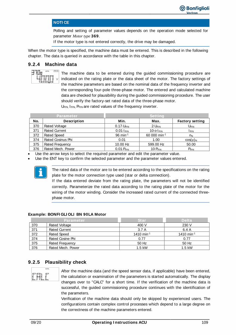
09/20 Operating Instructions ACU 109
NOTICE Polling and setting of parameter values depends on the operation mode selected for
parameter Motor type 369. If the motor type is not entered correctly, the drive may be damaged.
When the motor type is specified, the machine data must be entered. This is described in the following chapter. The data is queried in accordance with the table in this chapter.
9.2.4 Machine data
The machine data to be entered during the guided commissioning procedure are indicated on the rating plate or the data sheet of the motor. The factory settings of the machine parameters are based on the nominal data of the frequency inverter and the corresponding four-pole three-phase motor. The entered and calculated machine data are checked for plausibility during the guided commissioning procedure. The user should verify the factory-set rated data of the three-phase motor. UFIN, IFIN, PFIN are rated values of the frequency inverter.
Parameter Setting No. Description Min. Max. Factory setting 370 Rated Voltage 0.17⋅UFIN 2⋅UFIN UFIN 371 Rated Current 0.01⋅IFIN 10⋅o⋅IFIN IFIN 372 Rated Speed 96 min-1 60 000 min-1 nN 374 Rated Cosinus Phi 0.01 1.00 cos(ϕ)N 375 Rated Frequency 10.00 Hz 599.00 Hz 50.00 376 Rated Mech. Power 0.01⋅PFIN 10⋅PFIN PFIN
• Use the arrow keys to select the required parameter and edit the parameter value. • Use the ENT key to confirm the selected parameter and the parameter values entered.
The rated data of the motor are to be entered according to the specifications on the rating plate for the motor connection type used (star or delta connection). If the data entered deviate from the rating plate, the parameters will not be identified correctly. Parameterize the rated data according to the rating plate of the motor for the wiring of the motor winding. Consider the increased rated current of the connected three-phase motor.
Example: BONFIGLIOLI BN 90LA Motor Parameter Star Delta
370 Rated Voltage 400 V 230 V 371 Rated Current 3.7 A 6.4 A 372 Rated Speed 1410 min-1 1410 min-1 374 Rated Cosine Phi 0.77 0.77 375 Rated Frequency 50 Hz 50 Hz 376 Rated Mech. Power 1.5 kW 1.5 kW
9.2.5 Plausibility check
After the machine data (and the speed sensor data, if applicable) have been entered, the calculation or examination of the parameters is started automatically. The display changes over to "CALC" for a short time. If the verification of the machine data is successful, the guided commissioning procedure continues with the identification of the parameters. Verification of the machine data should only be skipped by experienced users. The configurations contain complex control processes which depend to a large degree on the correctness of the machine parameters entered.
110 Operating Instructions ACU 09/20
The warning and error messages displayed during the verification process have to be observed. If a critical condition is detected during the guided commissioning, it is displayed by the control unit. Depending on the deviation from the expected parameter value, either a warning or an error message is displayed. • To ignore the warning or error messages, press the ENT key. The guided commissioning is
continued. However, it is recommended that the data be checked and corrected if necessary. • To correct the entered parameter values after the warning or error message, press the ESC key.
Use the arrow keys to switch to the parameter value which is to be corrected.
If an error message is displayed, the rated values must be checked and corrected. The guided commissioning procedure is the rated values have been entered correctly. Aborting the guided commissioning procedure by pressing ESC key should only be done be expert users because it may be possible that rated values have not been entered or determined correctly.
9.2.6 Parameter identification
In addition to the parameterized rated data, the selected configuration demands knowledge of further machine data not stated on the rating plate of the three-phase machine. In addition to entering the rated motor parameters or as an alternative, the required machine data can also be measured during the guided commissioning process. The machine data are measured while the drive is at a standstill. The measured values are entered in the parameter automatically either directly or after the calculation. The procedure and the duration of the parameter identification depend on the type of machine connected and the device. After checking the machine data entered, the guided commissioning switches to the parameter identification. Confirm the display "PAidE" by pressing the ENT key. During the parameter identification, the connected load is measured.
No parameter identification is performed for setting Parameter Motor Type 369 of Operation Mode “10 - Transformer”.
The safety functions of the frequency inverter avoid enabling of the power unit if no signal is present at digital input S1IND/STOA (terminal X210A.3) and S7IND/STOB (terminal X210B.2). If signals were already applied at the beginning of the guided commissioning, the "StO" message is not displayed.
In order to be able to control the drive via the control unit, the digital inputs S1IND/STOA (terminal X210A.3) and S7IND/STOB (terminal X210B.2) must be connected for enabling the output.
Confirm the final "rEAdY" message by pressing the ENT key. Cancelling the operation with the ESC key or withdrawing the enable signal S1IND/STOA or S7IND/STOP results in an incomplete take-over of the values.
Guided commissioning must be carried out when the machine is cold, since a part of the machine data depends on the operating temperature.
After completion of the parameter identification, warning messages may be displayed. Depending on the warning message code, the following instructions should be followed and the measures indicated should be taken.
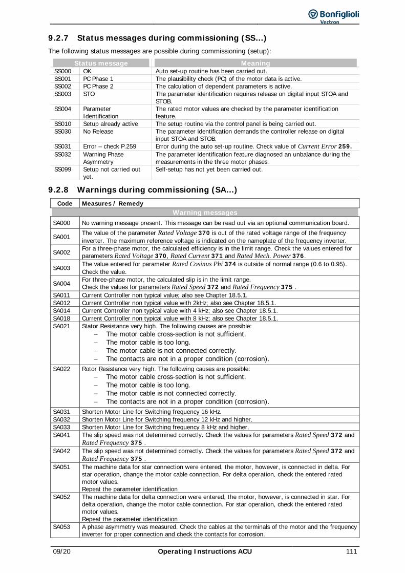
09/20 Operating Instructions ACU 111
9.2.7 Status messages during commissioning (SS…) The following status messages are possible during commissioning (setup):
Status message Meaning SS000 OK Auto set-up routine has been carried out. SS001 PC Phase 1 The plausibility check (PC) of the motor data is active. SS002 PC Phase 2 The calculation of dependent parameters is active. SS003 STO The parameter identification requires release on digital input STOA and
STOB. SS004 Parameter
Identification The rated motor values are checked by the parameter identification feature.
SS010 Setup already active The setup routine via the control panel is being carried out. SS030 No Release The parameter identification demands the controller release on digital
input STOA and STOB. SS031 Error – check P.259 Error during the auto set-up routine. Check value of Current Error 259. SS032 Warning Phase
Asymmetry The parameter identification feature diagnosed an unbalance during the measurements in the three motor phases.
SS099 Setup not carried out yet.
Self-setup has not yet been carried out.
9.2.8 Warnings during commissioning (SA…) Code Measures / Remedy
Warning messages SA000 No warning message present. This message can be read out via an optional communication board.
SA001 The value of the parameter Rated Voltage 370 is out of the rated voltage range of the frequency inverter. The maximum reference voltage is indicated on the nameplate of the frequency inverter.
SA002 For a three-phase motor, the calculated efficiency is in the limit range. Check the values entered for parameters Rated Voltage 370, Rated Current 371 and Rated Mech. Power 376.
SA003 The value entered for parameter Rated Cosinus Phi 374 is outside of normal range (0.6 to 0.95). Check the value.
SA004 For three-phase motor, the calculated slip is in the limit range. Check the values for parameters Rated Speed 372 and Rated Frequency 375 .
SA011 Current Controller non typical value; also see Chapter 18.5.1. SA012 Current Controller non typical value with 2kHz; also see Chapter 18.5.1. SA014 Current Controller non typical value with 4 kHz; also see Chapter 18.5.1. SA018 Current Controller non typical value with 8 kHz; also see Chapter 18.5.1. SA021 Stator Resistance very high. The following causes are possible:
− The motor cable cross-section is not sufficient. − The motor cable is too long. − The motor cable is not connected correctly. − The contacts are not in a proper condition (corrosion).
SA022 Rotor Resistance very high. The following causes are possible: − The motor cable cross-section is not sufficient. − The motor cable is too long. − The motor cable is not connected correctly. − The contacts are not in a proper condition (corrosion).
SA031 Shorten Motor Line for Switching frequency 16 kHz. SA032 Shorten Motor Line for Switching frequency 12 kHz and higher. SA033 Shorten Motor Line for Switching frequency 8 kHz and higher. SA041 The slip speed was not determined correctly. Check the values for parameters Rated Speed 372 and
Rated Frequency 375 . SA042 The slip speed was not determined correctly. Check the values for parameters Rated Speed 372 and
Rated Frequency 375 . SA051 The machine data for star connection were entered, the motor, however, is connected in delta. For
star operation, change the motor cable connection. For delta operation, check the entered rated motor values. Repeat the parameter identification
SA052 The machine data for delta connection were entered, the motor, however, is connected in star. For delta operation, change the motor cable connection. For star operation, check the entered rated motor values. Repeat the parameter identification
SA053 A phase asymmetry was measured. Check the cables at the terminals of the motor and the frequency inverter for proper connection and check the contacts for corrosion.
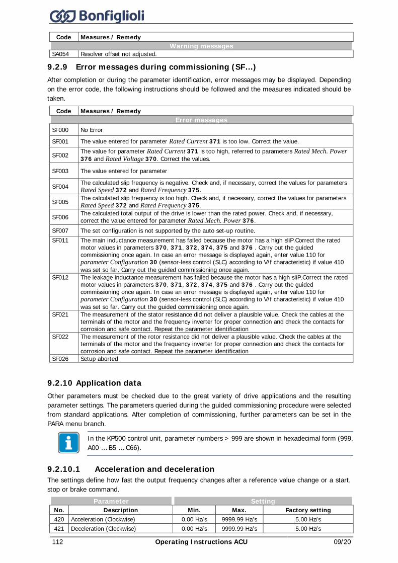
112 Operating Instructions ACU 09/20
Code Measures / Remedy Warning messages
SA054 Resolver offset not adjusted.
9.2.9 Error messages during commissioning (SF…) After completion or during the parameter identification, error messages may be displayed. Depending on the error code, the following instructions should be followed and the measures indicated should be taken.
Code Measures / Remedy Error messages
SF000 No Error
SF001 The value entered for parameter Rated Current 371 is too low. Correct the value.
SF002 The value for parameter Rated Current 371 is too high, referred to parameters Rated Mech. Power 376 and Rated Voltage 370. Correct the values.
SF003 The value entered for parameter
SF004 The calculated slip frequency is negative. Check and, if necessary, correct the values for parameters Rated Speed 372 and Rated Frequency 375.
SF005 The calculated slip frequency is too high. Check and, if necessary, correct the values for parameters Rated Speed 372 and Rated Frequency 375.
SF006 The calculated total output of the drive is lower than the rated power. Check and, if necessary, correct the value entered for parameter Rated Mech. Power 376.
SF007 The set configuration is not supported by the auto set-up routine. SF011 The main inductance measurement has failed because the motor has a high sliP.Correct the rated
motor values in parameters 370, 371, 372, 374, 375 and 376 . Carry out the guided commissioning once again. In case an error message is displayed again, enter value 110 for parameter Configuration 30 (sensor-less control (SLC) according to V/f characteristic) if value 410 was set so far. Carry out the guided commissioning once again.
SF012 The leakage inductance measurement has failed because the motor has a high sliP.Correct the rated motor values in parameters 370, 371, 372, 374, 375 and 376 . Carry out the guided commissioning once again. In case an error message is displayed again, enter value 110 for parameter Configuration 30 (sensor-less control (SLC) according to V/f characteristic) if value 410 was set so far. Carry out the guided commissioning once again.
SF021 The measurement of the stator resistance did not deliver a plausible value. Check the cables at the terminals of the motor and the frequency inverter for proper connection and check the contacts for corrosion and safe contact. Repeat the parameter identification
SF022 The measurement of the rotor resistance did not deliver a plausible value. Check the cables at the terminals of the motor and the frequency inverter for proper connection and check the contacts for corrosion and safe contact. Repeat the parameter identification
SF026 Setup aborted
9.2.10 Application data Other parameters must be checked due to the great variety of drive applications and the resulting parameter settings. The parameters queried during the guided commissioning procedure were selected from standard applications. After completion of commissioning, further parameters can be set in the PARA menu branch.
In the KP500 control unit, parameter numbers > 999 are shown in hexadecimal form (999, A00 … B5 … C66).
9.2.10.1 Acceleration and deceleration The settings define how fast the output frequency changes after a reference value change or a start, stop or brake command.
Parameter Setting No. Description Min. Max. Factory setting 420 Acceleration (Clockwise) 0.00 Hz/s 9999.99 Hz/s 5.00 Hz/s 421 Deceleration (Clockwise) 0.00 Hz/s 9999.99 Hz/s 5.00 Hz/s
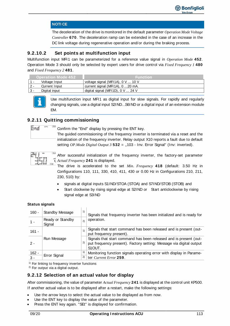
09/20 Operating Instructions ACU 113
NOTICE The deceleration of the drive is monitored in the default parameter Operation Mode Voltage
Controller 670. The deceleration ramp can be extended in the case of an increase in the DC link voltage during regenerative operation and/or during the braking process.
9.2.10.2 Set points at multifunction input Multifunction input MFI1 can be parameterized for a reference value signal in Operation Mode 452. Operation Mode 3 should only be selected by expert users for drive control via Fixed Frequency 1 480 and Fixed Frequency 2 481.
Operation Mode 452 Function 1 - Voltage Input voltage signal (MFI1A), 0 V ... 10 V 2 - Current Input current signal (MFI1A), 0 ...20 mA. 3 - Digital input digital signal (MFI1D), 0 V ... 24 V
Use multifunction input MFI1 as digital input for slow signals. For rapidly and regularly changing signals, use a digital input S2IND…S6IND or a digital input of an extension module EM.
9.2.11 Quitting commissioning
Confirm the "End" display by pressing the ENT key. The guided commissioning of the frequency inverter is terminated via a reset and the initialization of the frequency inverter. Relay output X10 reports a fault due to default setting OP.Mode Digital Output 3 532 = „103 - Inv. Error Signal“ (Inv: inverted).
After successful initialization of the frequency inverter, the factory-set parameter Actual Frequency 241 is displayed. The drive is accelerated to the set Min. Frequency 418 (default: 3.50 Hz in Configurations 110, 111, 330, 410, 411, 430 or 0.00 Hz in Configurations 210, 211, 230, 510) by: • signals at digital inputs S1IND/STOA (STOA) and S7IND/STOB (STOB) and • Start clockwise by rising signal edge at S2IND or Start anticlockwise by rising
signal edge at S3IND
Status signals
160 - Standby Message 1) Signals that frequency inverter has been initialized and is ready for operation. 1 - Ready or Standby
Signal 2)
161 -
Run Message
1) Signals that start command has been released and is present (out-put frequency present).
2 - 2) Signals that start command has been released and is present (out-put frequency present). Factory setting: Message via digital output S1OUT.
162 - Error Signal 1) Monitoring function signals operating error with display in Parame-
ter Current Error 259. 3 - 2) 1) For linking to frequency inverter functions 2) For output via a digital output.
9.2.12 Selection of an actual value for display After commissioning, the value of parameter Actual Frequency 241 is displayed at the control unit KP500. If another actual value is to be displayed after a restart, make the following settings: • Use the arrow keys to select the actual value to be displayed as from now. • Use the ENT key to display the value of the parameter. • Press the ENT key again. "SEt" is displayed for confirmation.
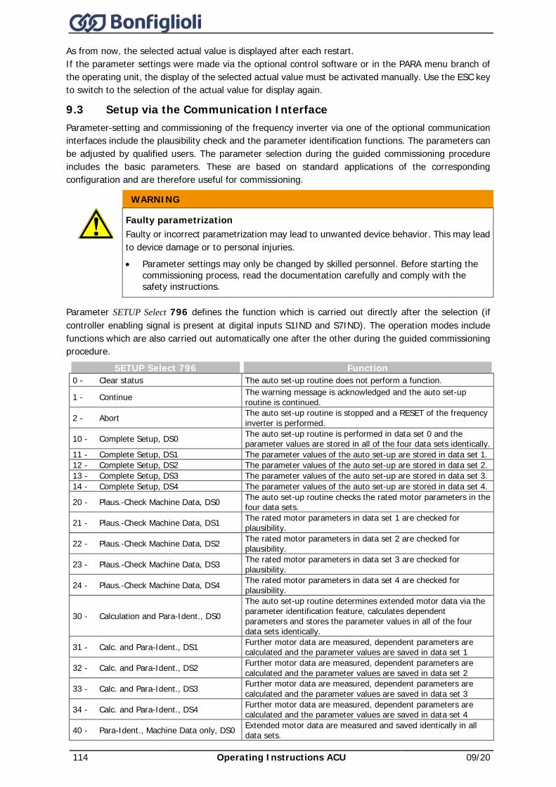
114 Operating Instructions ACU 09/20
As from now, the selected actual value is displayed after each restart. If the parameter settings were made via the optional control software or in the PARA menu branch of the operating unit, the display of the selected actual value must be activated manually. Use the ESC key to switch to the selection of the actual value for display again.
9.3 Setup via the Communication Interface Parameter-setting and commissioning of the frequency inverter via one of the optional communication interfaces include the plausibility check and the parameter identification functions. The parameters can be adjusted by qualified users. The parameter selection during the guided commissioning procedure includes the basic parameters. These are based on standard applications of the corresponding configuration and are therefore useful for commissioning.
WARNING
Faulty parametrization Faulty or incorrect parametrization may lead to unwanted device behavior. This may lead to device damage or to personal injuries. • Parameter settings may only be changed by skilled personnel. Before starting the
commissioning process, read the documentation carefully and comply with the safety instructions.
Parameter SETUP Select 796 defines the function which is carried out directly after the selection (if controller enabling signal is present at digital inputs S1IND and S7IND). The operation modes include functions which are also carried out automatically one after the other during the guided commissioning procedure.
SETUP Select 796 Function 0 - Clear status The auto set-up routine does not perform a function.
1 - Continue The warning message is acknowledged and the auto set-up routine is continued.
2 - Abort The auto set-up routine is stopped and a RESET of the frequency inverter is performed.
10 - Complete Setup, DS0 The auto set-up routine is performed in data set 0 and the parameter values are stored in all of the four data sets identically.
11 - Complete Setup, DS1 The parameter values of the auto set-up are stored in data set 1. 12 - Complete Setup, DS2 The parameter values of the auto set-up are stored in data set 2. 13 - Complete Setup, DS3 The parameter values of the auto set-up are stored in data set 3. 14 - Complete Setup, DS4 The parameter values of the auto set-up are stored in data set 4.
20 - Plaus.-Check Machine Data, DS0 The auto set-up routine checks the rated motor parameters in the four data sets.
21 - Plaus.-Check Machine Data, DS1 The rated motor parameters in data set 1 are checked for plausibility.
22 - Plaus.-Check Machine Data, DS2 The rated motor parameters in data set 2 are checked for plausibility.
23 - Plaus.-Check Machine Data, DS3 The rated motor parameters in data set 3 are checked for plausibility.
24 - Plaus.-Check Machine Data, DS4 The rated motor parameters in data set 4 are checked for plausibility.
30 - Calculation and Para-Ident., DS0 The auto set-up routine determines extended motor data via the parameter identification feature, calculates dependent parameters and stores the parameter values in all of the four data sets identically.
31 - Calc. and Para-Ident., DS1 Further motor data are measured, dependent parameters are calculated and the parameter values are saved in data set 1
32 - Calc. and Para-Ident., DS2 Further motor data are measured, dependent parameters are calculated and the parameter values are saved in data set 2
33 - Calc. and Para-Ident., DS3 Further motor data are measured, dependent parameters are calculated and the parameter values are saved in data set 3
34 - Calc. and Para-Ident., DS4 Further motor data are measured, dependent parameters are calculated and the parameter values are saved in data set 4
40 - Para-Ident., Machine Data only, DS0 Extended motor data are measured and saved identically in all data sets.
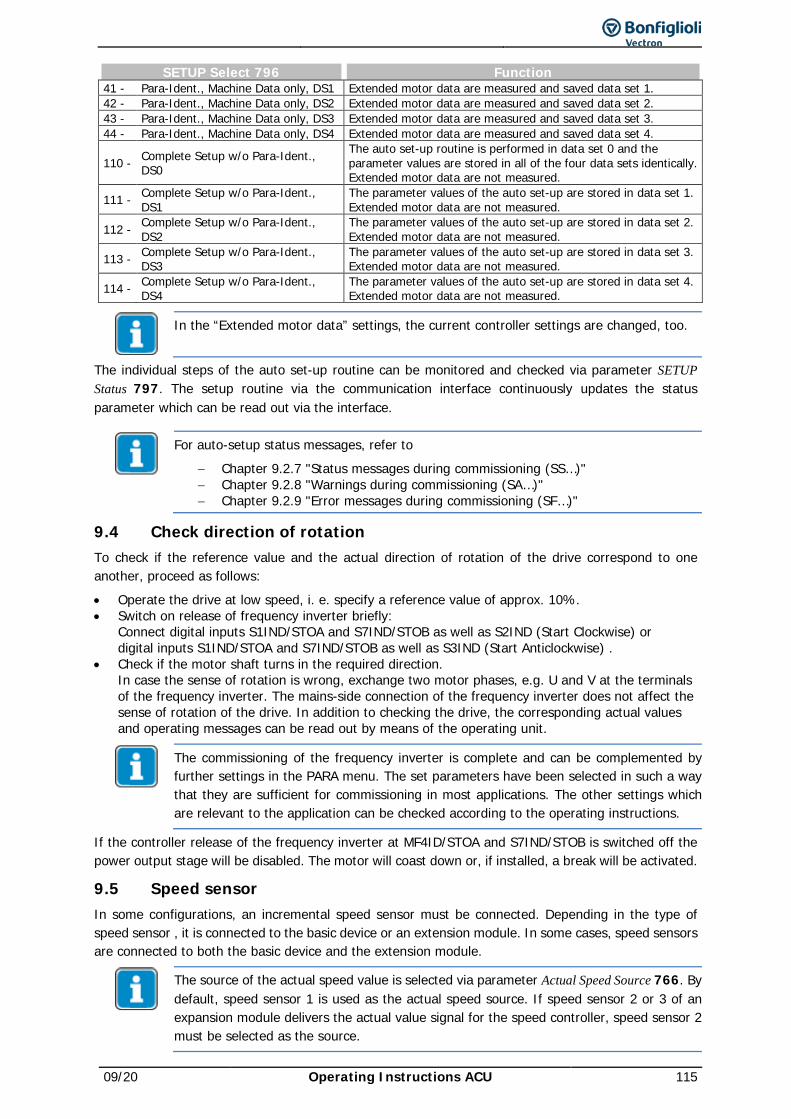
09/20 Operating Instructions ACU 115
SETUP Select 796 Function 41 - Para-Ident., Machine Data only, DS1 Extended motor data are measured and saved data set 1. 42 - Para-Ident., Machine Data only, DS2 Extended motor data are measured and saved data set 2. 43 - Para-Ident., Machine Data only, DS3 Extended motor data are measured and saved data set 3. 44 - Para-Ident., Machine Data only, DS4 Extended motor data are measured and saved data set 4.
110 - Complete Setup w/o Para-Ident., DS0
The auto set-up routine is performed in data set 0 and the parameter values are stored in all of the four data sets identically. Extended motor data are not measured.
111 - Complete Setup w/o Para-Ident., DS1
The parameter values of the auto set-up are stored in data set 1. Extended motor data are not measured.
112 - Complete Setup w/o Para-Ident., DS2
The parameter values of the auto set-up are stored in data set 2. Extended motor data are not measured.
113 - Complete Setup w/o Para-Ident., DS3
The parameter values of the auto set-up are stored in data set 3. Extended motor data are not measured.
114 - Complete Setup w/o Para-Ident., DS4
The parameter values of the auto set-up are stored in data set 4. Extended motor data are not measured.
In the “Extended motor data” settings, the current controller settings are changed, too.
The individual steps of the auto set-up routine can be monitored and checked via parameter SETUP Status 797. The setup routine via the communication interface continuously updates the status parameter which can be read out via the interface.
For auto-setup status messages, refer to − Chapter 9.2.7 "Status messages during commissioning (SS…)" − Chapter 9.2.8 "Warnings during commissioning (SA…)" − Chapter 9.2.9 "Error messages during commissioning (SF…)"
9.4 Check direction of rotation To check if the reference value and the actual direction of rotation of the drive correspond to one another, proceed as follows: • Operate the drive at low speed, i. e. specify a reference value of approx. 10%. • Switch on release of frequency inverter briefly:
Connect digital inputs S1IND/STOA and S7IND/STOB as well as S2IND (Start Clockwise) or digital inputs S1IND/STOA and S7IND/STOB as well as S3IND (Start Anticlockwise) .
• Check if the motor shaft turns in the required direction. In case the sense of rotation is wrong, exchange two motor phases, e.g. U and V at the terminals of the frequency inverter. The mains-side connection of the frequency inverter does not affect the sense of rotation of the drive. In addition to checking the drive, the corresponding actual values and operating messages can be read out by means of the operating unit.
The commissioning of the frequency inverter is complete and can be complemented by further settings in the PARA menu. The set parameters have been selected in such a way that they are sufficient for commissioning in most applications. The other settings which are relevant to the application can be checked according to the operating instructions.
If the controller release of the frequency inverter at MF4ID/STOA and S7IND/STOB is switched off the power output stage will be disabled. The motor will coast down or, if installed, a break will be activated.
9.5 Speed sensor In some configurations, an incremental speed sensor must be connected. Depending in the type of speed sensor , it is connected to the basic device or an extension module. In some cases, speed sensors are connected to both the basic device and the extension module.
The source of the actual speed value is selected via parameter Actual Speed Source 766. By default, speed sensor 1 is used as the actual speed source. If speed sensor 2 or 3 of an expansion module delivers the actual value signal for the speed controller, speed sensor 2 must be selected as the source.
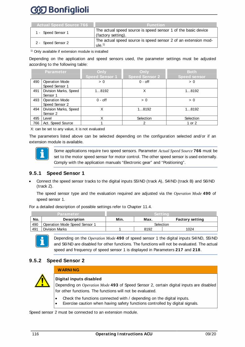
116 Operating Instructions ACU 09/20
Actual Speed Source 766 Function
1 - Speed Sensor 1 The actual speed source is speed sensor 1 of the basic device (factory setting).
2 - Speed Sensor 2 The actual speed source is speed sensor 2 of an extension mod-ule.1)
1) Only available if extension module is installed
Depending on the application and speed sensors used, the parameter settings must be adjusted according to the following table:
Parameter
Only Speed Sensor 1
Only Speed Sensor 2
Both Speed sensor
490 Operation Mode Speed Sensor 1
> 0 0 - off > 0
491 Division Marks, Speed Sensor 1
1...8192 X 1...8192
493 Operation Mode Speed Sensor 2
0 - off > 0 > 0
494 Division Marks, Speed Sensor 2
X 1...8192 1...8192
495 Level X Selection Selection 766 Act. Speed Source 1 2 1 or 2
X: can be set to any value, it is not evaluated
The parameters listed above can be selected depending on the configuration selected and/or if an extension module is available.
Some applications require two speed sensors. Parameter Actual Speed Source 766 must be set to the motor speed sensor for motor control. The other speed sensor is used externally. Comply with the application manuals “Electronic gear” and “Positioning”.
9.5.1 Speed Sensor 1 • Connect the speed sensor tracks to the digital inputs S5IND (track A), S4IND (track B) and S6IND
(track Z). The speed sensor type and the evaluation required are adjusted via the Operation Mode 490 of speed sensor 1.
For a detailed description of possible settings refer to Chapter 11.4. Parameter Setting
No. Description Min. Max. Factory setting 490 Operation Mode Speed Sensor 1 Selection 491 Division Marks 1 8192 1024
Depending on the Operation Mode 490 of speed sensor 1 the digital inputs S4IND, S5IND and S6IND are disabled for other functions. The functions will not be evaluated. The actual speed and frequency of speed sensor 1 is displayed in Parameters 217 and 218.
9.5.2 Speed Sensor 2 WARNING
Digital inputs disabled Depending on Operation Mode 493 of Speed Sensor 2, certain digital inputs are disabled for other functions. The functions will not be evaluated. • Check the functions connected with / depending on the digital inputs. • Exercise caution when having safety functions controlled by digital signals.
Speed sensor 2 must be connected to an extension module.
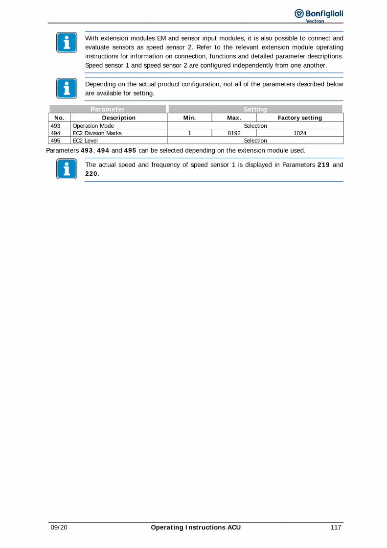
09/20 Operating Instructions ACU 117
With extension modules EM and sensor input modules, it is also possible to connect and evaluate sensors as speed sensor 2. Refer to the relevant extension module operating instructions for information on connection, functions and detailed parameter descriptions. Speed sensor 1 and speed sensor 2 are configured independently from one another.
Depending on the actual product configuration, not all of the parameters described below are available for setting.
Parameter Setting No. Description Min. Max. Factory setting
493 Operation Mode Selection 494 EC2 Division Marks 1 8192 1024 495 EC2 Level Selection
Parameters 493, 494 and 495 can be selected depending on the extension module used.
The actual speed and frequency of speed sensor 1 is displayed in Parameters 219 and 220.
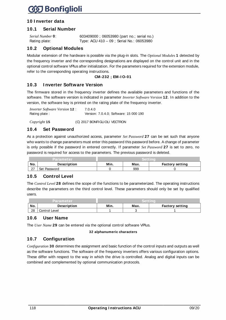
118 Operating Instructions ACU 09/20
10 Inverter data 10.1 Serial Number
Serial Number 0: 603409000 ; 06053980 (part no.; serial no.) Rating plate: Type: ACU 410 – 09 ; Serial No.: 06053980
10.2 Optional Modules Modular extension of the hardware is possible via the plug-in slots. The Optional Modules 1 detected by the frequency inverter and the corresponding designations are displayed on the control unit and in the optional control software VPlus after initialization. For the parameters required for the extension module, refer to the corresponding operating instructions.
CM-232 ; EM-IO-01
10.3 Inverter Software Version The firmware stored in the frequency inverter defines the available parameters and functions of the software. The software version is indicated in parameter Inverter Software Version 12. In addition to the version, the software key is printed on the rating plate of the frequency inverter.
Inverter Software Version 12 : 7.0.4.0 Rating plate : Version: 7.0.4.0; Software: 15 000 190
Copyright 15 (C) 2017 BONFIGLIOLI VECTRON
10.4 Set Password As a protection against unauthorized access, parameter Set Password 27 can be set such that anyone who wants to change parameters must enter this password this password before. A change of parameter is only possible if the password in entered correctly. If parameter Set Password 27 is set to zero, no password is required for access to the parameters. The previous password is deleted.
Parameter Setting No. Description Min. Max. Factory setting 27 Set Password 0 999 0
10.5 Control Level The Control Level 28 defines the scope of the functions to be parameterized. The operating instructions describe the parameters on the third control level. These parameters should only be set by qualified users.
Parameter Setting No. Description Min. Max. Factory setting 28 Control Level 1 3 1
10.6 User Name The User Name 29 can be entered via the optional control software VPlus.
32 alphanumeric characters
10.7 Configuration Configuration 30 determines the assignment and basic function of the control inputs and outputs as well as the software functions. The software of the frequency inverters offers various configuration options. These differ with respect to the way in which the drive is controlled. Analog and digital inputs can be combined and complemented by optional communication protocols.
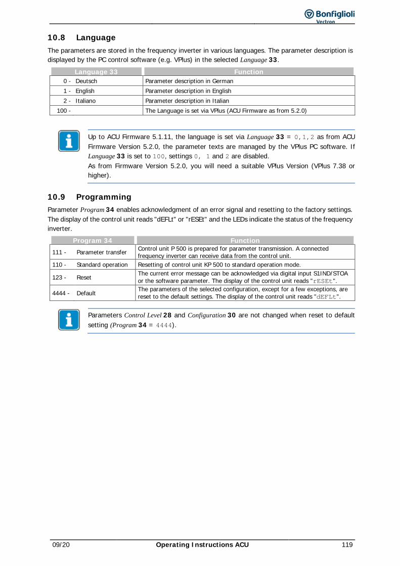
09/20 Operating Instructions ACU 119
10.8 Language The parameters are stored in the frequency inverter in various languages. The parameter description is displayed by the PC control software (e.g. VPlus) in the selected Language 33.
Language 33 Function 0 - Deutsch Parameter description in German 1 - English Parameter description in English 2 - Italiano Parameter description in Italian
100 - The Language is set via VPlus (ACU Firmware as from 5.2.0)
Up to ACU Firmware 5.1.11, the language is set via Language 33 = 0,1,2 as from ACU Firmware Version 5.2.0, the parameter texts are managed by the VPlus PC software. If Language 33 is set to 100, settings 0, 1 and 2 are disabled. As from Firmware Version 5.2.0, you will need a suitable VPlus Version (VPlus 7.38 or higher).
10.9 Programming Parameter Program 34 enables acknowledgment of an error signal and resetting to the factory settings. The display of the control unit reads "dEFLt" or "rESEt" and the LEDs indicate the status of the frequency inverter.
Program 34 Function 111 - Parameter transfer Control unit P 500 is prepared for parameter transmission. A connected
frequency inverter can receive data from the control unit. 110 - Standard operation Resetting of control unit KP 500 to standard operation mode.
123 - Reset The current error message can be acknowledged via digital input S1IND/STOA or the software parameter. The display of the control unit reads "rESEt".
4444 - Default The parameters of the selected configuration, except for a few exceptions, are reset to the default settings. The display of the control unit reads "dEFLt".
Parameters Control Level 28 and Configuration 30 are not changed when reset to default setting (Program 34 = 4444).
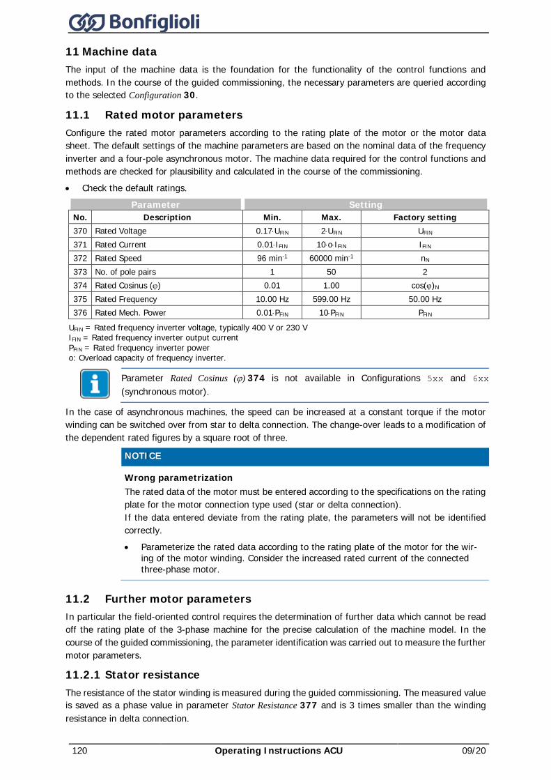
120 Operating Instructions ACU 09/20
11 Machine data The input of the machine data is the foundation for the functionality of the control functions and methods. In the course of the guided commissioning, the necessary parameters are queried according to the selected Configuration 30.
11.1 Rated motor parameters Configure the rated motor parameters according to the rating plate of the motor or the motor data sheet. The default settings of the machine parameters are based on the nominal data of the frequency inverter and a four-pole asynchronous motor. The machine data required for the control functions and methods are checked for plausibility and calculated in the course of the commissioning. • Check the default ratings.
Parameter Setting No. Description Min. Max. Factory setting 370 Rated Voltage 0.17⋅UFIN 2⋅UFIN UFIN 371 Rated Current 0.01⋅IFIN 10⋅o⋅IFIN IFIN 372 Rated Speed 96 min-1 60000 min-1 nN 373 No. of pole pairs 1 50 2 374 Rated Cosinus (ϕ) 0.01 1.00 cos(ϕ)N 375 Rated Frequency 10.00 Hz 599.00 Hz 50.00 Hz 376 Rated Mech. Power 0.01⋅PFIN 10⋅PFIN PFIN
UFIN = Rated frequency inverter voltage, typically 400 V or 230 V IFIN = Rated frequency inverter output current PFIN = Rated frequency inverter power o: Overload capacity of frequency inverter.
Parameter Rated Cosinus (ϕ) 374 is not available in Configurations 5xx and 6xx (synchronous motor).
In the case of asynchronous machines, the speed can be increased at a constant torque if the motor winding can be switched over from star to delta connection. The change-over leads to a modification of the dependent rated figures by a square root of three.
NOTICE
Wrong parametrization The rated data of the motor must be entered according to the specifications on the rating plate for the motor connection type used (star or delta connection). If the data entered deviate from the rating plate, the parameters will not be identified correctly. • Parameterize the rated data according to the rating plate of the motor for the wir-
ing of the motor winding. Consider the increased rated current of the connected three-phase motor.
11.2 Further motor parameters In particular the field-oriented control requires the determination of further data which cannot be read off the rating plate of the 3-phase machine for the precise calculation of the machine model. In the course of the guided commissioning, the parameter identification was carried out to measure the further motor parameters.
11.2.1 Stator resistance The resistance of the stator winding is measured during the guided commissioning. The measured value is saved as a phase value in parameter Stator Resistance 377 and is 3 times smaller than the winding resistance in delta connection.
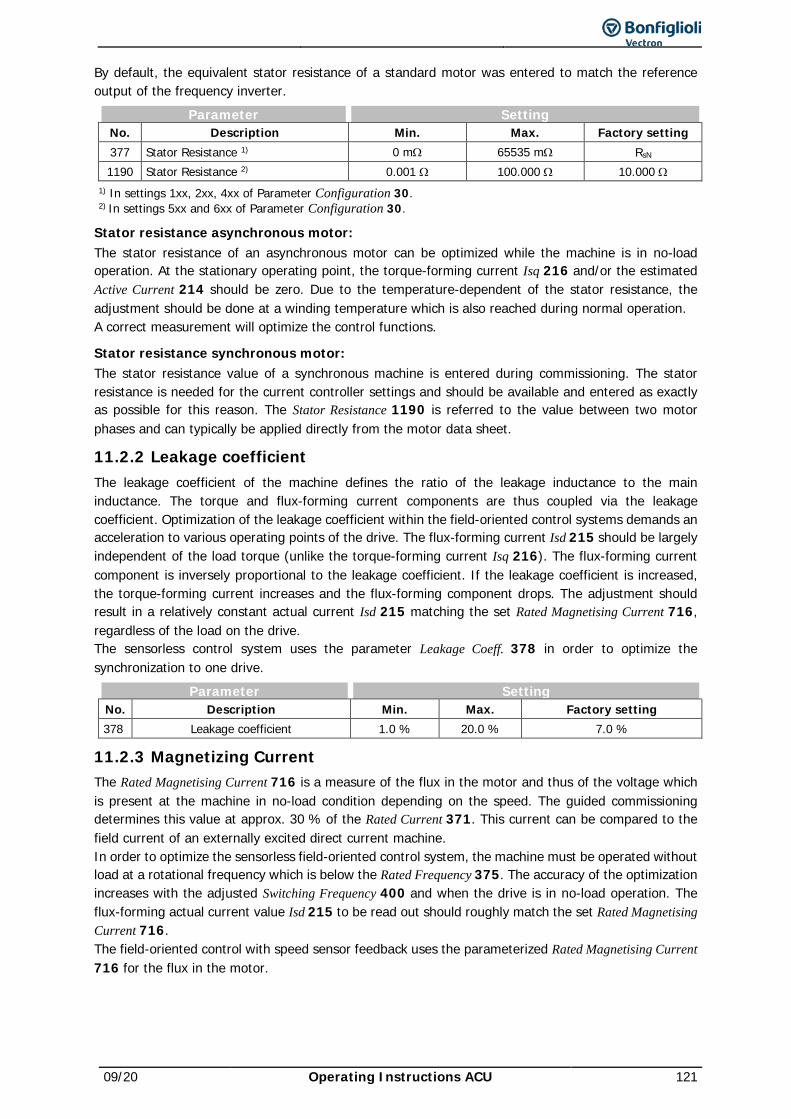
09/20 Operating Instructions ACU 121
By default, the equivalent stator resistance of a standard motor was entered to match the reference output of the frequency inverter.
Parameter Setting No. Description Min. Max. Factory setting 377 Stator Resistance 1) 0 mΩ 65535 mΩ RsN 1190 Stator Resistance 2) 0.001 Ω 100.000 Ω 10.000 Ω
1) In settings 1xx, 2xx, 4xx of Parameter Configuration 30. 2) In settings 5xx and 6xx of Parameter Configuration 30.
Stator resistance asynchronous motor: The stator resistance of an asynchronous motor can be optimized while the machine is in no-load operation. At the stationary operating point, the torque-forming current Isq 216 and/or the estimated Active Current 214 should be zero. Due to the temperature-dependent of the stator resistance, the adjustment should be done at a winding temperature which is also reached during normal operation. A correct measurement will optimize the control functions.
Stator resistance synchronous motor: The stator resistance value of a synchronous machine is entered during commissioning. The stator resistance is needed for the current controller settings and should be available and entered as exactly as possible for this reason. The Stator Resistance 1190 is referred to the value between two motor phases and can typically be applied directly from the motor data sheet.
11.2.2 Leakage coefficient The leakage coefficient of the machine defines the ratio of the leakage inductance to the main inductance. The torque and flux-forming current components are thus coupled via the leakage coefficient. Optimization of the leakage coefficient within the field-oriented control systems demands an acceleration to various operating points of the drive. The flux-forming current Isd 215 should be largely independent of the load torque (unlike the torque-forming current Isq 216). The flux-forming current component is inversely proportional to the leakage coefficient. If the leakage coefficient is increased, the torque-forming current increases and the flux-forming component drops. The adjustment should result in a relatively constant actual current Isd 215 matching the set Rated Magnetising Current 716, regardless of the load on the drive. The sensorless control system uses the parameter Leakage Coeff. 378 in order to optimize the synchronization to one drive.
Parameter Setting No. Description Min. Max. Factory setting 378 Leakage coefficient 1.0 % 20.0 % 7.0 %
11.2.3 Magnetizing Current The Rated Magnetising Current 716 is a measure of the flux in the motor and thus of the voltage which is present at the machine in no-load condition depending on the speed. The guided commissioning determines this value at approx. 30 % of the Rated Current 371. This current can be compared to the field current of an externally excited direct current machine. In order to optimize the sensorless field-oriented control system, the machine must be operated without load at a rotational frequency which is below the Rated Frequency 375. The accuracy of the optimization increases with the adjusted Switching Frequency 400 and when the drive is in no-load operation. The flux-forming actual current value Isd 215 to be read out should roughly match the set Rated Magnetising Current 716. The field-oriented control with speed sensor feedback uses the parameterized Rated Magnetising Current 716 for the flux in the motor.
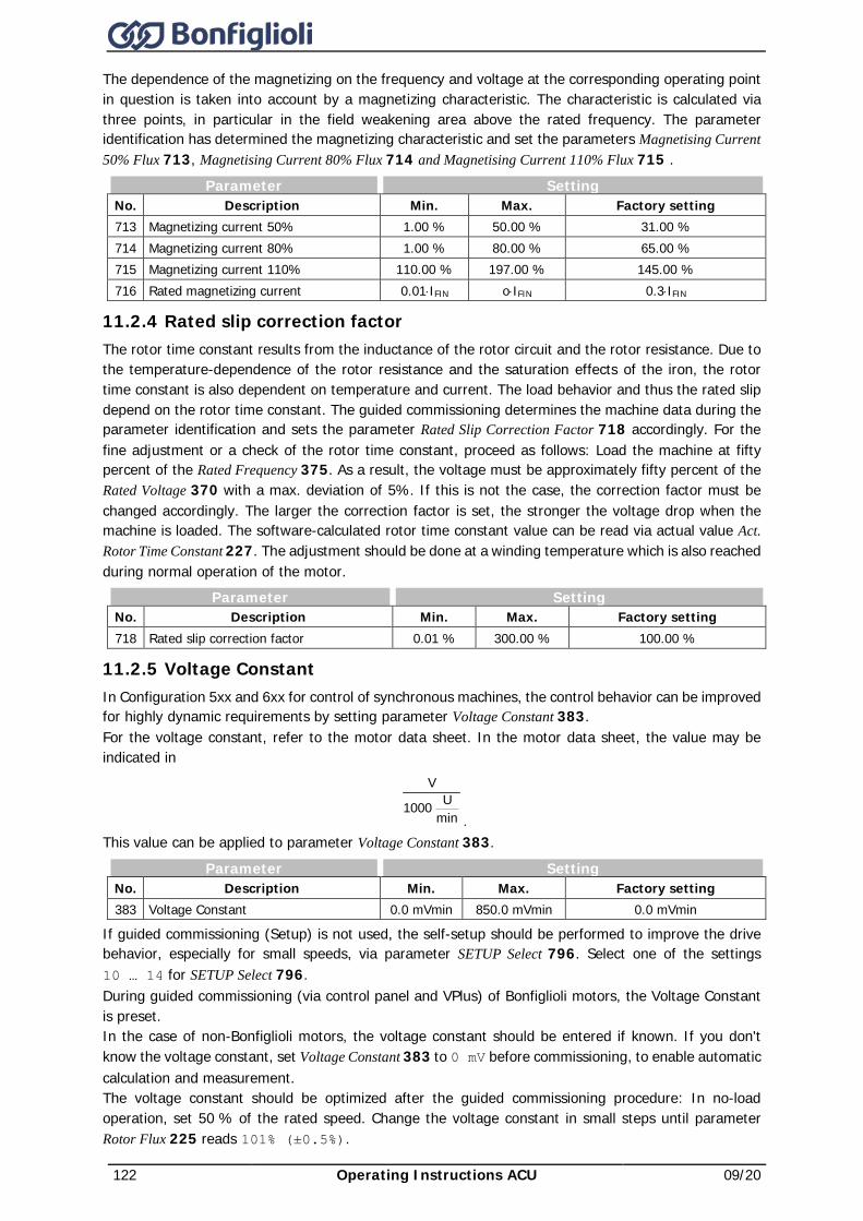
122 Operating Instructions ACU 09/20
The dependence of the magnetizing on the frequency and voltage at the corresponding operating point in question is taken into account by a magnetizing characteristic. The characteristic is calculated via three points, in particular in the field weakening area above the rated frequency. The parameter identification has determined the magnetizing characteristic and set the parameters Magnetising Current 50% Flux 713, Magnetising Current 80% Flux 714 and Magnetising Current 110% Flux 715 .
Parameter Setting No. Description Min. Max. Factory setting 713 Magnetizing current 50% 1.00 % 50.00 % 31.00 % 714 Magnetizing current 80% 1.00 % 80.00 % 65.00 % 715 Magnetizing current 110% 110.00 % 197.00 % 145.00 % 716 Rated magnetizing current 0.01⋅IFIN o⋅IFIN 0.3⋅IFIN
11.2.4 Rated slip correction factor The rotor time constant results from the inductance of the rotor circuit and the rotor resistance. Due to the temperature-dependence of the rotor resistance and the saturation effects of the iron, the rotor time constant is also dependent on temperature and current. The load behavior and thus the rated slip depend on the rotor time constant. The guided commissioning determines the machine data during the parameter identification and sets the parameter Rated Slip Correction Factor 718 accordingly. For the fine adjustment or a check of the rotor time constant, proceed as follows: Load the machine at fifty percent of the Rated Frequency 375. As a result, the voltage must be approximately fifty percent of the Rated Voltage 370 with a max. deviation of 5%. If this is not the case, the correction factor must be changed accordingly. The larger the correction factor is set, the stronger the voltage drop when the machine is loaded. The software-calculated rotor time constant value can be read via actual value Act. Rotor Time Constant 227. The adjustment should be done at a winding temperature which is also reached during normal operation of the motor.
Parameter Setting No. Description Min. Max. Factory setting 718 Rated slip correction factor 0.01 % 300.00 % 100.00 %
11.2.5 Voltage Constant In Configuration 5xx and 6xx for control of synchronous machines, the control behavior can be improved for highly dynamic requirements by setting parameter Voltage Constant 383. For the voltage constant, refer to the motor data sheet. In the motor data sheet, the value may be indicated in
minU 1000
V
. This value can be applied to parameter Voltage Constant 383.
Parameter Setting No. Description Min. Max. Factory setting 383 Voltage Constant 0.0 mVmin 850.0 mVmin 0.0 mVmin
If guided commissioning (Setup) is not used, the self-setup should be performed to improve the drive behavior, especially for small speeds, via parameter SETUP Select 796. Select one of the settings 10 … 14 for SETUP Select 796. During guided commissioning (via control panel and VPlus) of Bonfiglioli motors, the Voltage Constant is preset. In the case of non-Bonfiglioli motors, the voltage constant should be entered if known. If you don't know the voltage constant, set Voltage Constant 383 to 0 mV before commissioning, to enable automatic calculation and measurement. The voltage constant should be optimized after the guided commissioning procedure: In no-load operation, set 50 % of the rated speed. Change the voltage constant in small steps until parameter Rotor Flux 225 reads 101% (±0.5%).
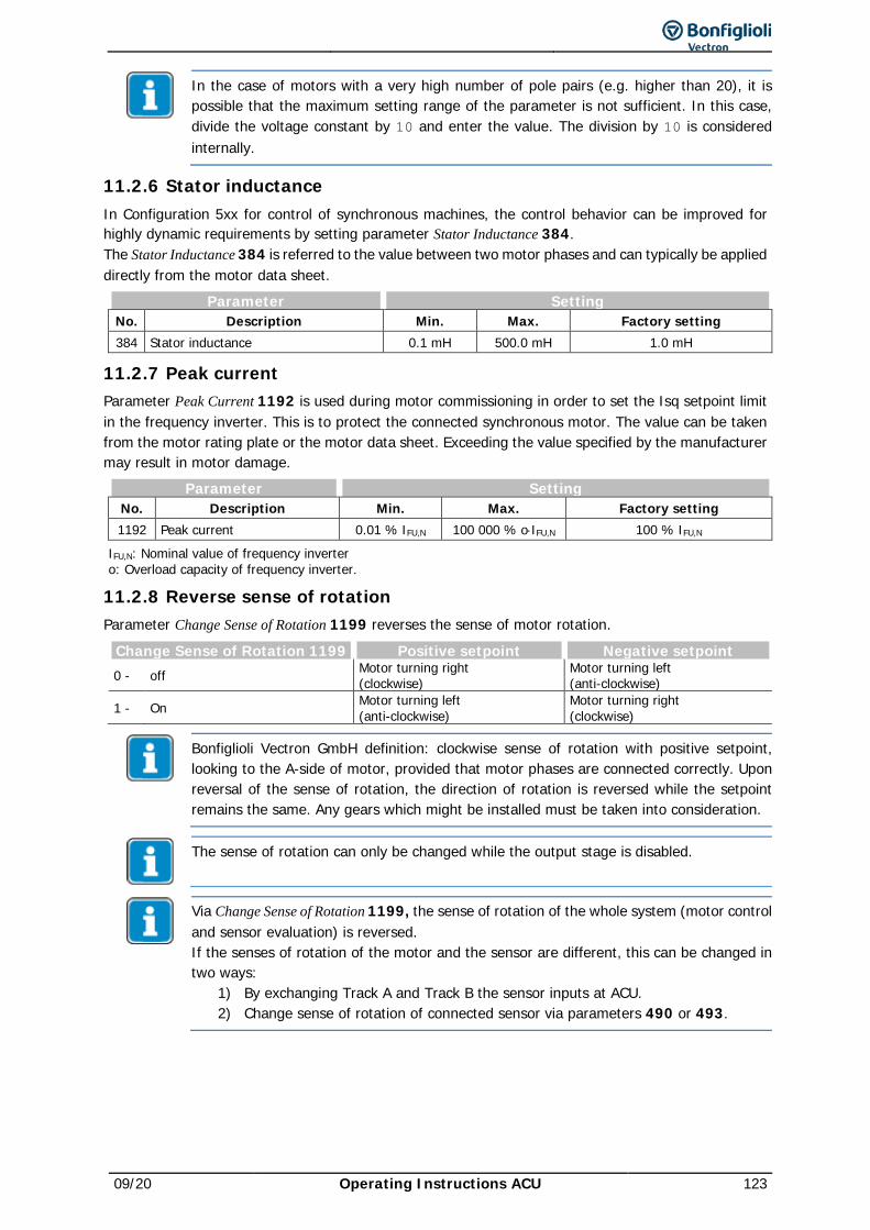
09/20 Operating Instructions ACU 123
In the case of motors with a very high number of pole pairs (e.g. higher than 20), it is possible that the maximum setting range of the parameter is not sufficient. In this case, divide the voltage constant by 10 and enter the value. The division by 10 is considered internally.
11.2.6 Stator inductance In Configuration 5xx for control of synchronous machines, the control behavior can be improved for highly dynamic requirements by setting parameter Stator Inductance 384. The Stator Inductance 384 is referred to the value between two motor phases and can typically be applied directly from the motor data sheet.
Parameter Setting No. Description Min. Max. Factory setting 384 Stator inductance 0.1 mH 500.0 mH 1.0 mH
11.2.7 Peak current Parameter Peak Current 1192 is used during motor commissioning in order to set the Isq setpoint limit in the frequency inverter. This is to protect the connected synchronous motor. The value can be taken from the motor rating plate or the motor data sheet. Exceeding the value specified by the manufacturer may result in motor damage.
Parameter Setting No. Description Min. Max. Factory setting 1192 Peak current 0.01 % IFU,N 100 000 % o⋅IFU,N 100 % IFU,N
IFU,N: Nominal value of frequency inverter o: Overload capacity of frequency inverter.
11.2.8 Reverse sense of rotation Parameter Change Sense of Rotation 1199 reverses the sense of motor rotation.
Change Sense of Rotation 1199 Positive setpoint Negative setpoint 0 - off Motor turning right
(clockwise) Motor turning left (anti-clockwise)
1 - On Motor turning left (anti-clockwise)
Motor turning right (clockwise)
Bonfiglioli Vectron GmbH definition: clockwise sense of rotation with positive setpoint, looking to the A-side of motor, provided that motor phases are connected correctly. Upon reversal of the sense of rotation, the direction of rotation is reversed while the setpoint remains the same. Any gears which might be installed must be taken into consideration.
The sense of rotation can only be changed while the output stage is disabled.
Via Change Sense of Rotation 1199, the sense of rotation of the whole system (motor control and sensor evaluation) is reversed. If the senses of rotation of the motor and the sensor are different, this can be changed in two ways:
1) By exchanging Track A and Track B the sensor inputs at ACU. 2) Change sense of rotation of connected sensor via parameters 490 or 493.

124 Operating Instructions ACU 09/20
11.2.9 Iron Axis Impedance Ld for SynRM The parameter Iron Axis Impedance 1051 determines the inductivity value for the stator of the motor. The value for the inductivity should be entered, if known. If the value is not known before commissioning, the default value may be left as is. Otherwise an estimated value can be entered. The correct values can be measured by the parameter identification procedure. See chapter 9.2.6 Parameter identification for further details.
For the correct operational behavior it is necessary that the SETUP parameter identification is carried out.
11.2.10 Air Axis Impedance Lq for SynRM The parameter Air Axis Impedance 1052 determines the inductivity value for the air gap axis of the motor. The value for the inductivity should be entered, if known. If the value is not known before commissioning, the default value may be left as is. Otherwise an estimated value can be entered. The correct values can be measured by the parameter identification procedure. See chapter 9.2.6 Parameter identification for further details.
11.3 Internal values The following parameters are used for internal calculation of motor data and do not require any set-up.
Parameter Parameter No. Description No. Description 399 Internal value 01 706 Internal value 08 402 Internal value 02 707 Internal value 09 508 Internal value 03 708 Internal value 10 702 Internal value 04 709 Internal value 11 703 Internal value 05 745 Internal value 12 704 Internal value 06 798 Internal value 13 705 Internal value 07
11.4 Speed Sensor 1 The frequency inverters are to be adapted to the application depending on the requirements. Some of the available Configurations 30 require continuous measurement of the actual speed for the control functions and methods. The necessary connection of an incremental speed sensor is done on the digital control terminals S5IND (track A) and S4IND (track B) of the frequency inverter.
With extension modules EM and sensor input modules, it is also possible to connect and evaluate sensors as speed sensor 2. Please refer to the corresponding operating instructions. Speed sensor 1 and speed sensor 2 are configured independently from one another.
11.4.1 Operation Mode Speed Sensor 1 Operation Mode 490 for speed sensor 1 can be selected according to the connected incremental speed sensor. A unipolar speed sensor is to be connected to the standard control terminals.
Operation Mode 490 Function
0 - off Speed measurement is not active; the digital inputs are available for other functions.
1 – Single Evaluation Two-channel speed sensor with recognition of direction of rotation via track signals A and B; one signal edge is evaluated per division mark.
4 – Quadruple Evalua-tion
Two-channel speed sensor with recognition of direction of rotation via track signals A and B; four signal edges are evaluated per divi-sion mark.
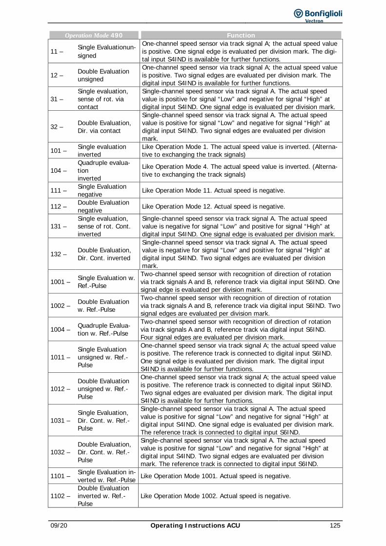
09/20 Operating Instructions ACU 125
Operation Mode 490 Function
11 – Single Evaluationun-signed
One-channel speed sensor via track signal A; the actual speed value is positive. One signal edge is evaluated per division mark. The digi-tal input S4IND is available for further functions.
12 – Double Evaluation unsigned
One-channel speed sensor via track signal A; the actual speed value is positive. Two signal edges are evaluated per division mark. The digital input S4IND is available for further functions.
31 – Single evaluation, sense of rot. via contact
Single-channel speed sensor via track signal A. The actual speed value is positive for signal “Low” and negative for signal “High” at digital input S4IND. One signal edge is evaluated per division mark.
32 – Double Evaluation, Dir. via contact
Single-channel speed sensor via track signal A. The actual speed value is positive for signal “Low” and negative for signal “High” at digital input S4IND. Two signal edges are evaluated per division mark.
101 – Single evaluation inverted
Like Operation Mode 1. The actual speed value is inverted. (Alterna-tive to exchanging the track signals)
104 – Quadruple evalua-tion inverted
Like Operation Mode 4. The actual speed value is inverted. (Alterna-tive to exchanging the track signals)
111 – Single Evaluation negative Like Operation Mode 11. Actual speed is negative.
112 – Double Evaluation negative Like Operation Mode 12. Actual speed is negative.
131 – Single evaluation, sense of rot. Cont. inverted
Single-channel speed sensor via track signal A. The actual speed value is negative for signal “Low” and positive for signal “High” at digital input S4IND. One signal edge is evaluated per division mark.
132 – Double Evaluation, Dir. Cont. inverted
Single-channel speed sensor via track signal A. The actual speed value is negative for signal “Low” and positive for signal “High” at digital input S4IND. Two signal edges are evaluated per division mark.
1001 – Single Evaluation w. Ref.-Pulse
Two-channel speed sensor with recognition of direction of rotation via track signals A and B, reference track via digital input S6IND. One signal edge is evaluated per division mark.
1002 – Double Evaluation w. Ref.-Pulse
Two-channel speed sensor with recognition of direction of rotation via track signals A and B, reference track via digital input S6IND. Two signal edges are evaluated per division mark.
1004 – Quadruple Evalua-tion w. Ref.-Pulse
Two-channel speed sensor with recognition of direction of rotation via track signals A and B, reference track via digital input S6IND. Four signal edges are evaluated per division mark.
1011 – Single Evaluation unsigned w. Ref.-Pulse
One-channel speed sensor via track signal A; the actual speed value is positive. The reference track is connected to digital input S6IND. One signal edge is evaluated per division mark. The digital input S4IND is available for further functions.
1012 – Double Evaluation unsigned w. Ref.-Pulse
One-channel speed sensor via track signal A; the actual speed value is positive. The reference track is connected to digital input S6IND. Two signal edges are evaluated per division mark. The digital input S4IND is available for further functions.
1031 – Single Evaluation, Dir. Cont. w. Ref.-Pulse
Single-channel speed sensor via track signal A. The actual speed value is positive for signal “Low” and negative for signal “High” at digital input S4IND. One signal edge is evaluated per division mark. The reference track is connected to digital input S6IND.
1032 – Double Evaluation, Dir. Cont. w. Ref.-Pulse
Single-channel speed sensor via track signal A. The actual speed value is positive for signal “Low” and negative for signal “High” at digital input S4IND. Two signal edges are evaluated per division mark. The reference track is connected to digital input S6IND.
1101 – Single Evaluation in-verted w. Ref.-Pulse Like Operation Mode 1001. Actual speed is negative.
1102 – Double Evaluation inverted w. Ref.-Pulse
Like Operation Mode 1002. Actual speed is negative.
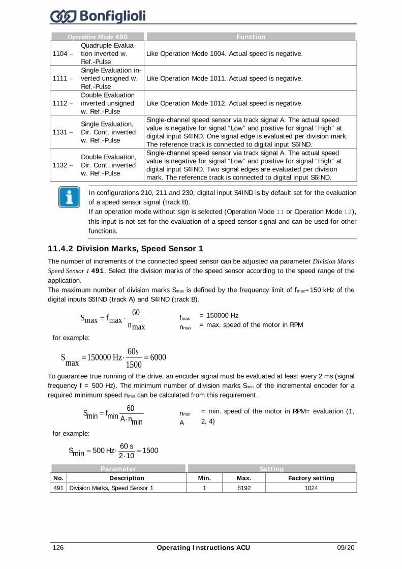
126 Operating Instructions ACU 09/20
Operation Mode 490 Function
1104 – Quadruple Evalua-tion inverted w. Ref.-Pulse
Like Operation Mode 1004. Actual speed is negative.
1111 – Single Evaluation in-verted unsigned w. Ref.-Pulse
Like Operation Mode 1011. Actual speed is negative.
1112 – Double Evaluation inverted unsigned w. Ref.-Pulse
Like Operation Mode 1012. Actual speed is negative.
1131 – Single Evaluation, Dir. Cont. inverted w. Ref.-Pulse
Single-channel speed sensor via track signal A. The actual speed value is negative for signal “Low” and positive for signal “High” at digital input S4IND. One signal edge is evaluated per division mark. The reference track is connected to digital input S6IND.
1132 – Double Evaluation, Dir. Cont. inverted w. Ref.-Pulse
Single-channel speed sensor via track signal A. The actual speed value is negative for signal “Low” and positive for signal “High” at digital input S4IND. Two signal edges are evaluated per division mark. The reference track is connected to digital input S6IND.
In configurations 210, 211 and 230, digital input S4IND is by default set for the evaluation of a speed sensor signal (track B). If an operation mode without sign is selected (Operation Mode 11 or Operation Mode 12), this input is not set for the evaluation of a speed sensor signal and can be used for other functions.
11.4.2 Division Marks, Speed Sensor 1 The number of increments of the connected speed sensor can be adjusted via parameter Division Marks Speed Sensor 1 491. Select the division marks of the speed sensor according to the speed range of the application. The maximum number of division marks Smax is defined by the frequency limit of fmax=150 kHz of the digital inputs S5IND (track A) and S4IND (track B).
maxn 60 maxfmaxS ⋅=
for example:
60001500
60sHz 150000maxS =⋅=
fmax nmax
= 150000 Hz = max. speed of the motor in RPM
To guarantee true running of the drive, an encoder signal must be evaluated at least every 2 ms (signal frequency f = 500 Hz). The minimum number of division marks Smin of the incremental encoder for a required minimum speed nmin can be calculated from this requirement.
minnA 60
minfminS⋅
=
for example:
1500102s 60Hz 500minS =
⋅⋅=
nmin A
= min. speed of the motor in RPM = evaluation (1, 2, 4)
Parameter Setting No. Description Min. Max. Factory setting 491 Division Marks, Speed Sensor 1 1 8192 1024
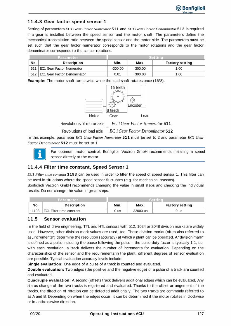
09/20 Operating Instructions ACU 127
11.4.3 Gear factor speed sensor 1 Setting of parameters EC1 Gear Factor Numerator 511 and EC1 Gear Factor Denominator 512 is required if a gear is installed between the speed sensor and the motor shaft. The parameters define the mechanical transmission ratio between the speed sensor and the motor side. The parameters must be set such that the gear factor numerator corresponds to the motor rotations and the gear factor denominator corresponds to the sensor rotations.
Parameter Setting No. Description Min. Max. Factory setting 511 EC1 Gear Factor Numerator -300.00 300.00 1.00 512 EC1 Gear Factor Denominator 0.01 300.00 1.00
Example: The motor shaft turns twice while the load shaft rotates once (16/8).
512511
axis load of sRevolutionaxismotor of sRevolution
rDenominato Factor Gear 1 ECNumerator Factor Gear 1 EC
=
In this example, parameter EC1 Gear Factor Numerator 511 must be set to 2 and parameter EC1 Gear Factor Denominator 512 must be set to 1.
For optimum motor control, Bonfiglioli Vectron GmbH recommends installing a speed sensor directly at the motor.
11.4.4 Filter time constant, Speed Sensor 1 EC1 Filter time constant 1193 can be used in order to filter the speed of speed sensor 1. This filter can be used in situations where the speed sensor fluctuates (e.g. for mechanical reasons). Bonfiglioli Vectron GmbH recommends changing the value in small steps and checking the individual results. Do not change the value in great steps.
Parameter Setting No. Description Min. Max. Factory setting 1193 EC1 Filter time constant 0 us 32000 us 0 us
11.5 Sensor evaluation In the field of drive engineering, TTL and HTL sensors with 512, 1024 or 2048 division marks are widely used. However, other division mark values are used, too. These division marks (often also referred to as „increments“) determine the resolution (accuracy) at which a plant can be operated. A “division mark" is defined as a pulse including the pause following the pulse – the pulse-duty factor is typically 1:1, i.e. with each revolution, a track delivers the number of increments for evaluation. Depending on the characteristics of the sensor and the requirements in the plant, different degrees of sensor evaluation are possible. Typical evaluation accuracy levels include: Single evaluation: One edge of a pulse of a track is counted and evaluated. Double evaluation: Two edges (the positive and the negative edge) of a pulse of a track are counted and evaluated. Quadruple evaluation: A second (offset) track delivers additional edges which can be evaluated. Any status change of the two tracks is registered and evaluated. Thanks to the offset arrangement of the tracks, the direction of rotation can be detected additionally. The two tracks are commonly referred to as A and B. Depending on when the edges occur, it can be determined if the motor rotates in clockwise or in anticlockwise direction.
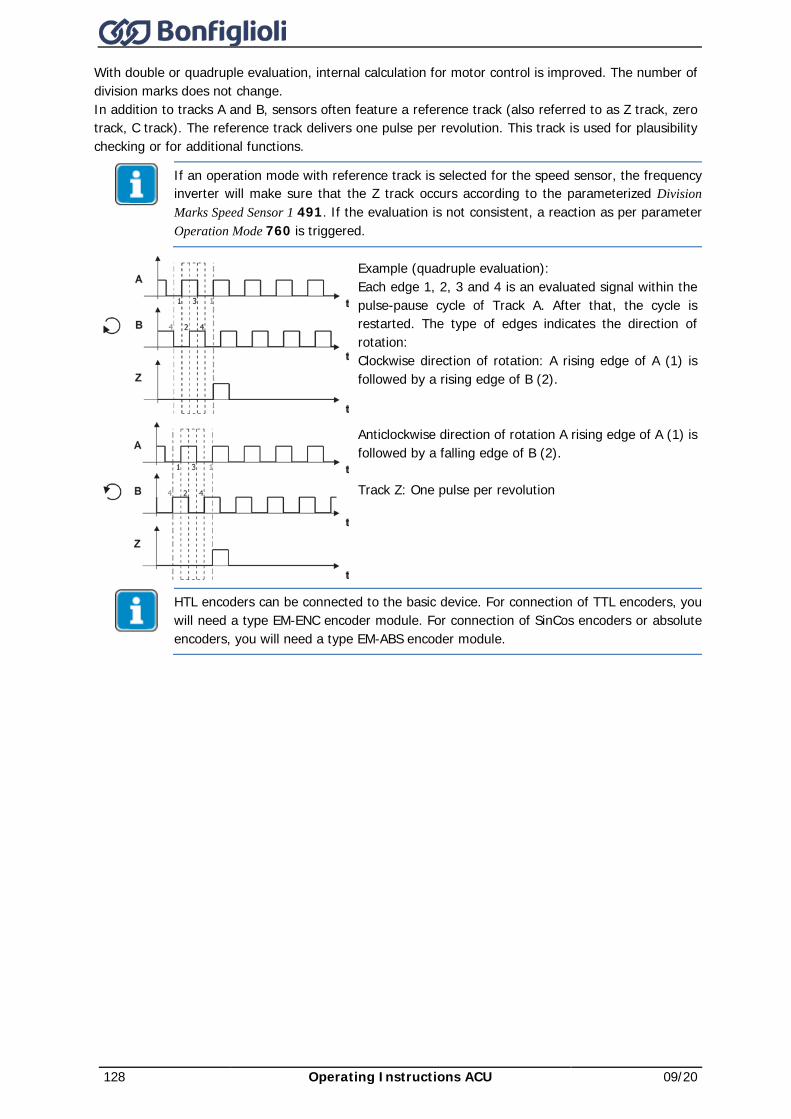
128 Operating Instructions ACU 09/20
With double or quadruple evaluation, internal calculation for motor control is improved. The number of division marks does not change. In addition to tracks A and B, sensors often feature a reference track (also referred to as Z track, zero track, C track). The reference track delivers one pulse per revolution. This track is used for plausibility checking or for additional functions.
If an operation mode with reference track is selected for the speed sensor, the frequency inverter will make sure that the Z track occurs according to the parameterized Division Marks Speed Sensor 1 491. If the evaluation is not consistent, a reaction as per parameter Operation Mode 760 is triggered.
Example (quadruple evaluation): Each edge 1, 2, 3 and 4 is an evaluated signal within the pulse-pause cycle of Track A. After that, the cycle is restarted. The type of edges indicates the direction of rotation: Clockwise direction of rotation: A rising edge of A (1) is followed by a rising edge of B (2).
Anticlockwise direction of rotation A rising edge of A (1) is followed by a falling edge of B (2). Track Z: One pulse per revolution
HTL encoders can be connected to the basic device. For connection of TTL encoders, you will need a type EM-ENC encoder module. For connection of SinCos encoders or absolute encoders, you will need a type EM-ABS encoder module.
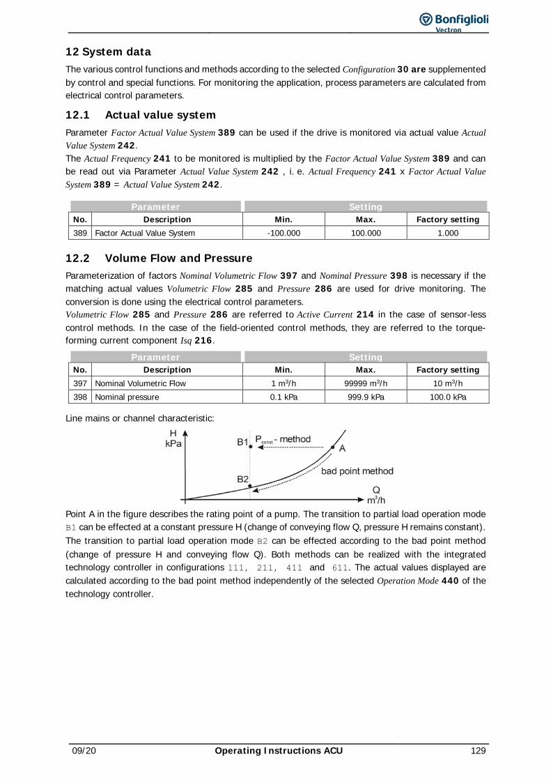
09/20 Operating Instructions ACU 129
12 System data The various control functions and methods according to the selected Configuration 30 are supplemented by control and special functions. For monitoring the application, process parameters are calculated from electrical control parameters.
12.1 Actual value system Parameter Factor Actual Value System 389 can be used if the drive is monitored via actual value Actual Value System 242. The Actual Frequency 241 to be monitored is multiplied by the Factor Actual Value System 389 and can be read out via Parameter Actual Value System 242 , i. e. Actual Frequency 241 x Factor Actual Value System 389 = Actual Value System 242.
Parameter Setting No. Description Min. Max. Factory setting 389 Factor Actual Value System -100.000 100.000 1.000
12.2 Volume Flow and Pressure Parameterization of factors Nominal Volumetric Flow 397 and Nominal Pressure 398 is necessary if the matching actual values Volumetric Flow 285 and Pressure 286 are used for drive monitoring. The conversion is done using the electrical control parameters. Volumetric Flow 285 and Pressure 286 are referred to Active Current 214 in the case of sensor-less control methods. In the case of the field-oriented control methods, they are referred to the torque-forming current component Isq 216.
Parameter Setting No. Description Min. Max. Factory setting 397 Nominal Volumetric Flow 1 m3/h 99999 m3/h 10 m3/h 398 Nominal pressure 0.1 kPa 999.9 kPa 100.0 kPa
Line mains or channel characteristic:
Point A in the figure describes the rating point of a pump. The transition to partial load operation mode B1 can be effected at a constant pressure H (change of conveying flow Q, pressure H remains constant). The transition to partial load operation mode B2 can be effected according to the bad point method (change of pressure H and conveying flow Q). Both methods can be realized with the integrated technology controller in configurations 111, 211, 411 and 611. The actual values displayed are calculated according to the bad point method independently of the selected Operation Mode 440 of the technology controller.
130 Operating Instructions ACU 09/20
13 Operating behavior The operational behavior of the frequency inverter can be adjusted to the application by setting the parameters appropriately. In particular the acceleration and deceleration behavior can be selected according to the selected Configuration 30. Additionally, features such as Auto Start, and the synchronization and positioning functions facilitate the integration in the application.
13.1 Starting behavior The start of the 3-phase machine can be parameterized in accordance with the control functions and methods. In contrast to the sensorless control method, the field-oriented control methods only require the definition of the limit values Max. Flux-Formation Time 780 and Current during Flux-Formation 781 for the adjustment of the acceleration behavior. The acceleration behavior of the sensorless control method in configurations 110 and 111 can be selected as described in the following chapter.
13.1.1 Starting Behavior of Sensorless Control System Parameter Operation Mode 620 for the starting behavior is available in Configurations 110 and 111. Depending on the operation mode selected, the machine is magnetized first or a starting current is impressed. The voltage drop across the stator resistance which reduces the torque in the lower frequency range can be compensated by the IxR compensation. To ensure the correct function of the IxR compensation, the stator resistance is determined during the guided commissioning. The IxR compensation is only activated when the stator resistance was determined correctly.
Operation Mode 620 Starting behavior
0 - off
During startup, at an output frequency of 0 Hz, the voltage is set via pa-rameter Starting Voltage 600. After this, the output voltage and the out-put frequency are changed according to the control method. The break-away torque and the current at the start is determined by the adjusted starting voltage. It may be necessary to optimize the starting behavior via the parameter Starting Voltage 600.
1 - Magnetization
In this operation mode, the Current during Flux-Formation 781 for mag-netization is impressed into the motor after release. The output fre-quency is kept at 0 Hz for the Max. Flux-Formation Time 780. After this time has expired, the output frequency follows the adjusted V/f charac-teristic. (see operation mode 0- Off)
2 - Magnetisa-tion+Current Impr.
Operation mode 2 includes operation mode 1. Once the Max. Flux-For-mation Time780 has elapsed, the output frequency is increased according to the set acceleration. If the output frequency reaches the value set with the parameter Frequency Limit 624 the Starting Current 623 is with-drawn. There is a smooth transition to 1.4 times the frequency limit to the set V/f characteristic. As from this operating point, the output cur-rent depends on the load.
3 - Magnetization +IxR compensa-tion
Operation mode 3 includes operation mode 1 of the start function. When the output frequency reaches the value set with parameter Fre-quency Limit 624, the increase of the output voltage by the IxR compen-sation becomes effective. The V/f characteristic is displaced by the por-tion of voltage which depends on the stator resistance.
4 - Magnetization +current impr.+I*R-Comp.
In this operation mode, the current set with the parameter Current dur-ing Flux-Formation 781 is impressed into the motor for magnetization af-ter release. The output frequency is kept at 0 Hz for the Max. Flux-For-mation Time 780. Once this time has elapsed, the output frequency is in-creased according to the set acceleration. Once the output frequency reaches the value set with parameter Frequency Limit 624, the Starting Current 623 is withdrawn. There is a smooth transition to the V/f char-acteristic, and a load-dependent output current is obtained. At the same time, the increase of the output voltage by the IxR compensation be-comes effective as from this output frequency. The V/f characteristic is displaced by the portion of voltage which depends on the stator re-sistance.
09/20 Operating Instructions ACU 131
Operation Mode 620 Starting behavior
12 - Magn.+ Curr.ImP. w. Ramp Stop
Operation mode 12 contains an additional function to guarantee a start-ing behavior under difficult conditions. The magnetization and starting current impression are done according to operation mode 2. The ramp stop takes the current consumption of the motor at the corresponding operating point into account and controls the frequency and voltage change by stopping the ramp. The Controller Status 275 signals interven-tion of the controller by displaying message “RSTP”.
14 -
Magn.+ Curr.ImP. w. RS.+ I*R-Comp.
In this operation mode, the functions of operation mode 12 are ex-tended by the compensation of the voltage drop across the stator re-sistance. When the output frequency reaches the value set with parame-ter Frequency Limit 624, the increase of the output voltage by the IxR compensation becomes effective. The V/f characteristic is displaced by the portion of voltage which depends on the stator resistance.
In contrast to field-oriented control systems, sensorless control systems feature a current controller which controls the starting behavior. The PI controller controls the current impress of parameter Starting Current 623. The proportional and integrating part of the current controller can be set via parameters Amplification 621 and Integral Time 622. The control functions can be deactivated by setting the parameters to 0.
Parameter Setting No. Description Min. Max. Factory setting 621 Amplification 0.01 10.00 1.00 622 Integral Time 1 ms 30 000 ms 50 ms
13.1.1.1 Starting current The Starting Current 623 ensures, particularly for high-torque start, a sufficient torque until the Frequency Limit 624 is reached. Applications in which high current is permanently needed at a low speed are to be realized using forced-ventilated motors to prevent thermal overload.
Parameter Setting No. Description Min. Max. Factory setting 623 Starting current 0.0 A o⋅IFIN IFIN
IFIN = Rated frequency inverter output current o: Overload capacity of frequency inverter.
In the following settings, the starting current injection is used for the starting behavior:
− Configuration 30 = 1xx (V/f control of asynchronous motor), Operation mode 620 =2, 4, 12 or 14
− Configuration 30= 4xx (FOC of an asynchronous motor) − Configuration 30= 610 (PMSM: sensor-less field-oriented control -DMC), synchronous motor − Configuration 30= 310 Speed Control (sensorless), Synchronous reluctance machine (SRM) − Configuration 30= 330 Switchable Speed and torque control (sensorless), Synchronous
reluctance machine (SRM)
13.1.1.2 Frequency Limit The Starting Current 623 is impressed in configurations 1xx, 3xx, 4xx and 6xx for control of the relevant configuration until the Frequency Limit 624 is reached. Permanent operating points below the frequency limit are only permissible if forced-ventilated motors are used. The transition to the control method of the selected Configuration 30 takes place above the frequency limit. The Frequency Limit 624 is set automatically during guided motor commissioning in the field-oriented configurations 3xx, 4xx and 6xx. In V/f control configuration 1xx, parameter Frequency Limit 624 is not changed during guided motor commissioning.
Parameter Setting No. Description Min. Max. Factory setting 624 Frequency Limit 0.00 Hz 100.00 Hz 2.60 Hz
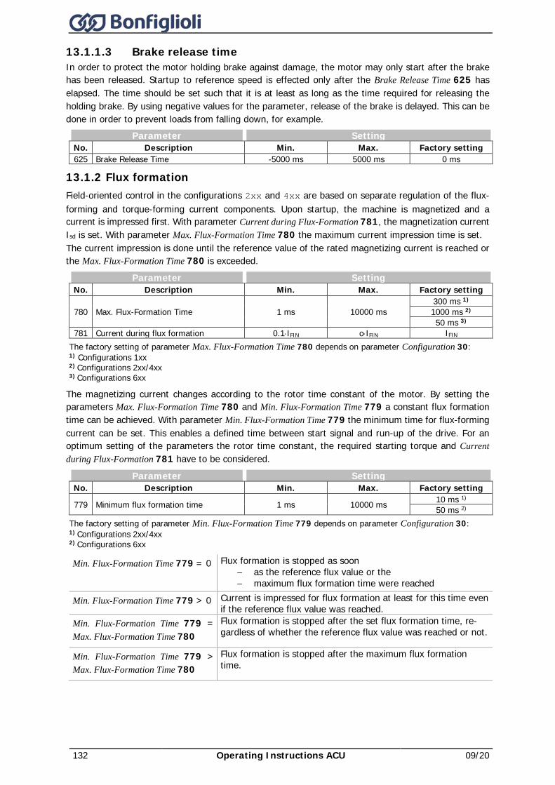
132 Operating Instructions ACU 09/20
13.1.1.3 Brake release time In order to protect the motor holding brake against damage, the motor may only start after the brake has been released. Startup to reference speed is effected only after the Brake Release Time 625 has elapsed. The time should be set such that it is at least as long as the time required for releasing the holding brake. By using negative values for the parameter, release of the brake is delayed. This can be done in order to prevent loads from falling down, for example.
Parameter Setting No. Description Min. Max. Factory setting 625 Brake Release Time -5000 ms 5000 ms 0 ms
13.1.2 Flux formation Field-oriented control in the configurations 2xx and 4xx are based on separate regulation of the flux-forming and torque-forming current components. Upon startup, the machine is magnetized and a current is impressed first. With parameter Current during Flux-Formation 781, the magnetization current Isd is set. With parameter Max. Flux-Formation Time 780 the maximum current impression time is set. The current impression is done until the reference value of the rated magnetizing current is reached or the Max. Flux-Formation Time 780 is exceeded.
Parameter Setting No. Description Min. Max. Factory setting
780 Max. Flux-Formation Time 1 ms 10000 ms 300 ms 1) 1000 ms 2) 50 ms 3)
781 Current during flux formation 0.1⋅IFIN o⋅IFIN IFIN The factory setting of parameter Max. Flux-Formation Time 780 depends on parameter Configuration 30: 1) Configurations 1xx 2) Configurations 2xx/4xx 3) Configurations 6xx
The magnetizing current changes according to the rotor time constant of the motor. By setting the parameters Max. Flux-Formation Time 780 and Min. Flux-Formation Time 779 a constant flux formation time can be achieved. With parameter Min. Flux-Formation Time 779 the minimum time for flux-forming current can be set. This enables a defined time between start signal and run-up of the drive. For an optimum setting of the parameters the rotor time constant, the required starting torque and Current during Flux-Formation 781 have to be considered.
Parameter Setting No. Description Min. Max. Factory setting
779 Minimum flux formation time 1 ms 10000 ms 10 ms 1) 50 ms 2)
The factory setting of parameter Min. Flux-Formation Time 779 depends on parameter Configuration 30: 1) Configurations 2xx/4xx 2) Configurations 6xx
Min. Flux-Formation Time 779 = 0 Flux formation is stopped as soon − as the reference flux value or the − maximum flux formation time were reached
Min. Flux-Formation Time 779 > 0 Current is impressed for flux formation at least for this time even if the reference flux value was reached.
Min. Flux-Formation Time 779 = Max. Flux-Formation Time 780
Flux formation is stopped after the set flux formation time, re-gardless of whether the reference flux value was reached or not.
Min. Flux-Formation Time 779 > Max. Flux-Formation Time 780
Flux formation is stopped after the maximum flux formation time.

09/20 Operating Instructions ACU 133
13.1.3 Starting behavior for the SynRM The following parameters are relevant for the starting behavior of the synchronous reluctance machine:
Parameter No. Description 1029 Operation mode starting behavior 468 Breakaway current 1050 Maximum time at f < flimit 1071 Maximum current of current injection
Operation mode starting behaviour 1029 1 - Current injection
The parameter identification sets the values for each − Starting current 623, − Breakaway current 468, − Current during flux-formation 781, − Maximum current of current injection 1071 = 1.2 * P.371 and − Holding Current 1008
to the value of the Rated magnetizing current 716. Depending on the application (required torque at low frequency) these values must be increased. For startup in sensorless control mode three options are possible:
1 Start with current injection (standard) 2 Start with field oriented control
Only possible at fast ramps
Starting current 623 See chapter 13.1.1.1 Starting current. The starting current value should be within the range of the Rated magnetizing current 716 and Rated current 371.
Breakaway current 468 To provide extra torque at zero speed the amplitude of the injected current vector can be increased by setting a current value in P.468. The amplitude of the current vector is reduced to the value set in Starting Current 623 when the Frequency Limit 624 is reached and if no load is detected. High values ( > IN ) set in P.468 will lead to poor starting performance at no load. • Set P.468 not higher than needed if the start at no load is required.
If higher starting torque is required, set the P.468 to higher current values (e. g. 150% of IN) and also adapt P.1071 (P.468 is limited by P.1071, Maximum Current of Current Injection) after parameter identification process during setup.
Area of (Starting) Current Adaption
P1070 P1072
|I|
fP624flim
80% flim
20% flim
P623 - Starting Current
P468 - Breakaway Current
P1071 – max. Current
Turning of d-q-CoordinatesP1069 - Pendulum Damping
Current Injection Field Oriented Control
Example without Load:
Load Angle Q9363 < P1072à Current is ramped to P623
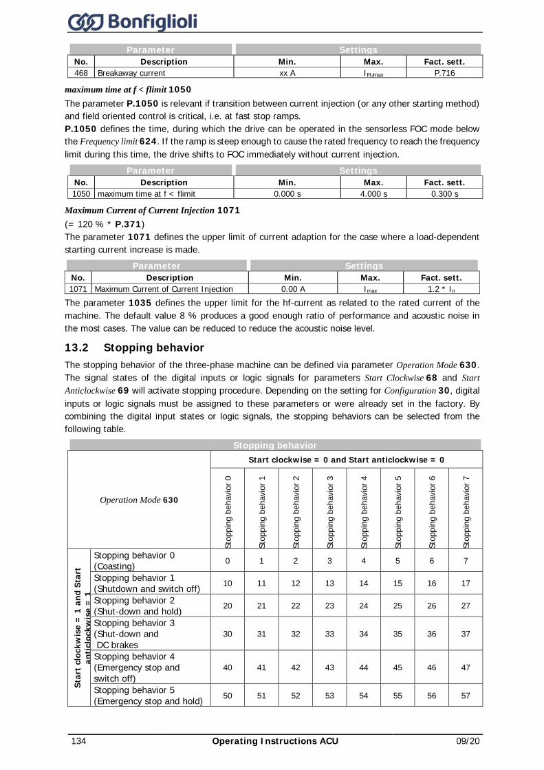
134 Operating Instructions ACU 09/20
Parameter Settings No. Description Min. Max. Fact. sett. 468 Breakaway current xx A IFUmax P.716
maximum time at f < flimit 1050 The parameter P.1050 is relevant if transition between current injection (or any other starting method) and field oriented control is critical, i.e. at fast stop ramps. P.1050 defines the time, during which the drive can be operated in the sensorless FOC mode below the Frequency limit 624. If the ramp is steep enough to cause the rated frequency to reach the frequency limit during this time, the drive shifts to FOC immediately without current injection.
Parameter Settings No. Description Min. Max. Fact. sett. 1050 maximum time at f < flimit 0.000 s 4.000 s 0.300 s
Maximum Current of Current Injection 1071 (= 120 % * P.371) The parameter 1071 defines the upper limit of current adaption for the case where a load-dependent starting current increase is made.
Parameter Settings No. Description Min. Max. Fact. sett. 1071 Maximum Current of Current Injection 0.00 A Imax 1.2 * In
The parameter 1035 defines the upper limit for the hf-current as related to the rated current of the machine. The default value 8 % produces a good enough ratio of performance and acoustic noise in the most cases. The value can be reduced to reduce the acoustic noise level.
13.2 Stopping behavior The stopping behavior of the three-phase machine can be defined via parameter Operation Mode 630. The signal states of the digital inputs or logic signals for parameters Start Clockwise 68 and Start Anticlockwise 69 will activate stopping procedure. Depending on the setting for Configuration 30, digital inputs or logic signals must be assigned to these parameters or were already set in the factory. By combining the digital input states or logic signals, the stopping behaviors can be selected from the following table.
Stopping behavior
Operation Mode 630
Start clockwise = 0 and Start anticlockwise = 0
Stop
ping
beh
avio
r 0
Stop
ping
beh
avio
r 1
Stop
ping
beh
avio
r 2
Stop
ping
beh
avio
r 3
Stop
ping
beh
avio
r 4
Stop
ping
beh
avio
r 5
Stop
ping
beh
avio
r 6
Stop
ping
beh
avio
r 7
Star
t clo
ckw
ise
= 1
and
Sta
rt
antic
lock
wis
e =
1
Stopping behavior 0 (Coasting) 0 1 2 3 4 5 6 7
Stopping behavior 1 (Shutdown and switch off) 10 11 12 13 14 15 16 17
Stopping behavior 2 (Shut-down and hold) 20 21 22 23 24 25 26 27
Stopping behavior 3 (Shut-down and DC brakes
30 31 32 33 34 35 36 37
Stopping behavior 4 (Emergency stop and switch off)
40 41 42 43 44 45 46 47
Stopping behavior 5 (Emergency stop and hold) 50 51 52 53 54 55 56 57
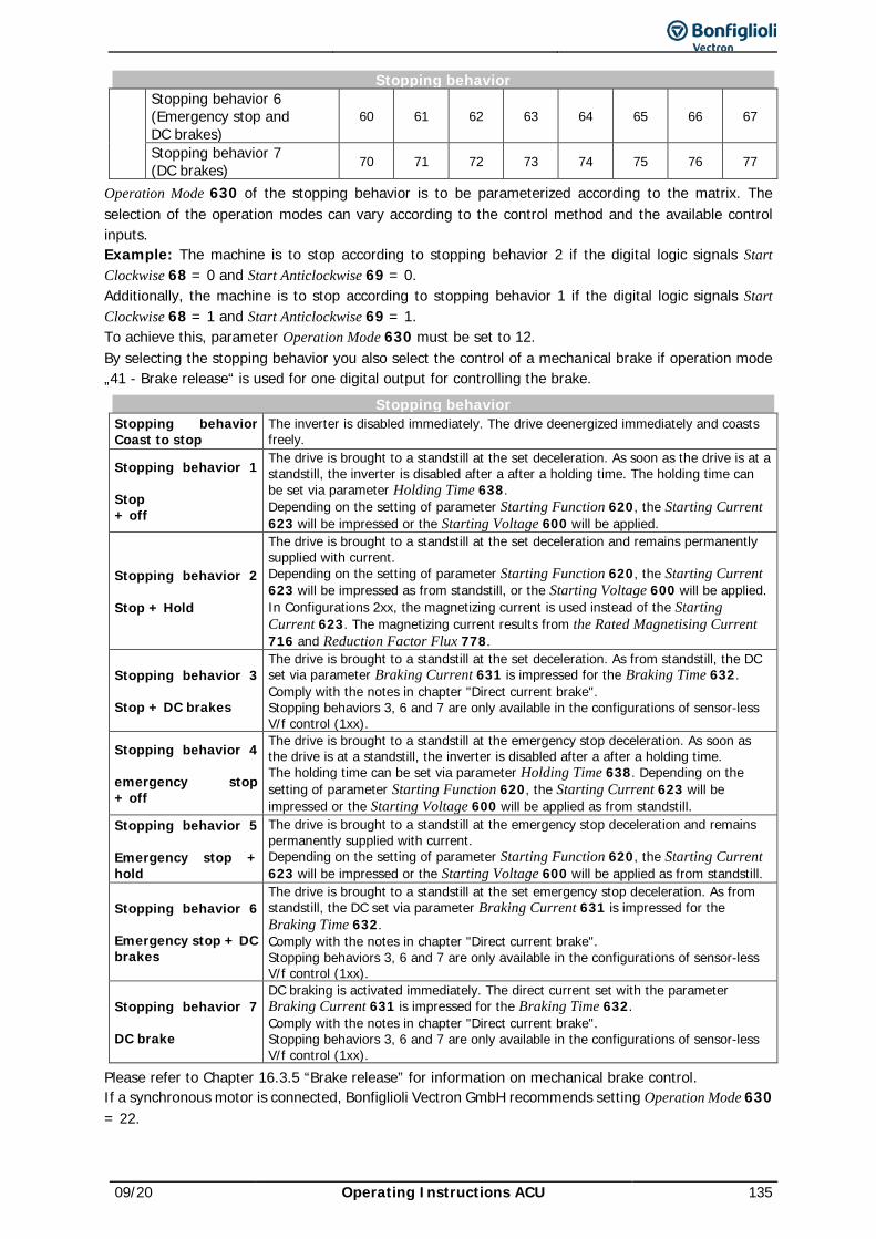
09/20 Operating Instructions ACU 135
Stopping behavior Stopping behavior 6 (Emergency stop and DC brakes)
60 61 62 63 64 65 66 67
Stopping behavior 7 (DC brakes) 70 71 72 73 74 75 76 77
Operation Mode 630 of the stopping behavior is to be parameterized according to the matrix. The selection of the operation modes can vary according to the control method and the available control inputs. Example: The machine is to stop according to stopping behavior 2 if the digital logic signals Start Clockwise 68 = 0 and Start Anticlockwise 69 = 0. Additionally, the machine is to stop according to stopping behavior 1 if the digital logic signals Start Clockwise 68 = 1 and Start Anticlockwise 69 = 1. To achieve this, parameter Operation Mode 630 must be set to 12. By selecting the stopping behavior you also select the control of a mechanical brake if operation mode „41 - Brake release“ is used for one digital output for controlling the brake.
Stopping behavior Stopping behavior Coast to stop
The inverter is disabled immediately. The drive deenergized immediately and coasts freely.
Stopping behavior 1 Stop + off
The drive is brought to a standstill at the set deceleration. As soon as the drive is at a standstill, the inverter is disabled after a after a holding time. The holding time can be set via parameter Holding Time 638. Depending on the setting of parameter Starting Function 620, the Starting Current 623 will be impressed or the Starting Voltage 600 will be applied.
Stopping behavior 2 Stop + Hold
The drive is brought to a standstill at the set deceleration and remains permanently supplied with current. Depending on the setting of parameter Starting Function 620, the Starting Current 623 will be impressed as from standstill, or the Starting Voltage 600 will be applied. In Configurations 2xx, the magnetizing current is used instead of the Starting Current 623. The magnetizing current results from the Rated Magnetising Current 716 and Reduction Factor Flux 778.
Stopping behavior 3 Stop + DC brakes
The drive is brought to a standstill at the set deceleration. As from standstill, the DC set via parameter Braking Current 631 is impressed for the Braking Time 632. Comply with the notes in chapter "Direct current brake". Stopping behaviors 3, 6 and 7 are only available in the configurations of sensor-less V/f control (1xx).
Stopping behavior 4 emergency stop + off
The drive is brought to a standstill at the emergency stop deceleration. As soon as the drive is at a standstill, the inverter is disabled after a after a holding time. The holding time can be set via parameter Holding Time 638. Depending on the setting of parameter Starting Function 620, the Starting Current 623 will be impressed or the Starting Voltage 600 will be applied as from standstill.
Stopping behavior 5 Emergency stop + hold
The drive is brought to a standstill at the emergency stop deceleration and remains permanently supplied with current. Depending on the setting of parameter Starting Function 620, the Starting Current 623 will be impressed or the Starting Voltage 600 will be applied as from standstill.
Stopping behavior 6 Emergency stop + DC brakes
The drive is brought to a standstill at the set emergency stop deceleration. As from standstill, the DC set via parameter Braking Current 631 is impressed for the Braking Time 632. Comply with the notes in chapter "Direct current brake". Stopping behaviors 3, 6 and 7 are only available in the configurations of sensor-less V/f control (1xx).
Stopping behavior 7 DC brake
DC braking is activated immediately. The direct current set with the parameter Braking Current 631 is impressed for the Braking Time 632. Comply with the notes in chapter "Direct current brake". Stopping behaviors 3, 6 and 7 are only available in the configurations of sensor-less V/f control (1xx).
Please refer to Chapter 16.3.5 “Brake release” for information on mechanical brake control. If a synchronous motor is connected, Bonfiglioli Vectron GmbH recommends setting Operation Mode 630 = 22.
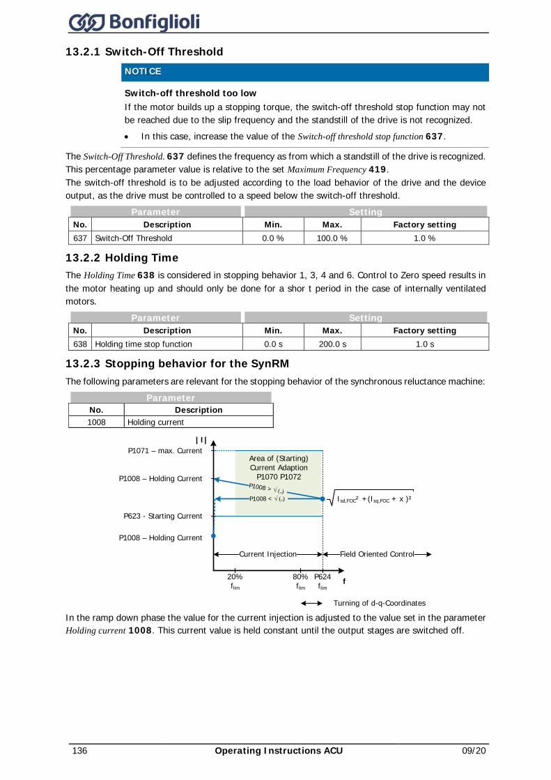
136 Operating Instructions ACU 09/20
13.2.1 Switch-Off Threshold
NOTICE Switch-off threshold too low
If the motor builds up a stopping torque, the switch-off threshold stop function may not be reached due to the slip frequency and the standstill of the drive is not recognized. • In this case, increase the value of the Switch-off threshold stop function 637.
The Switch-Off Threshold. 637 defines the frequency as from which a standstill of the drive is recognized. This percentage parameter value is relative to the set Maximum Frequency 419. The switch-off threshold is to be adjusted according to the load behavior of the drive and the device output, as the drive must be controlled to a speed below the switch-off threshold.
Parameter Setting No. Description Min. Max. Factory setting 637 Switch-Off Threshold 0.0 % 100.0 % 1.0 %
13.2.2 Holding Time The Holding Time 638 is considered in stopping behavior 1, 3, 4 and 6. Control to Zero speed results in the motor heating up and should only be done for a shor t period in the case of internally ventilated motors.
Parameter Setting No. Description Min. Max. Factory setting 638 Holding time stop function 0.0 s 200.0 s 1.0 s
13.2.3 Stopping behavior for the SynRM The following parameters are relevant for the stopping behavior of the synchronous reluctance machine:
Parameter No. Description 1008 Holding current
In the ramp down phase the value for the current injection is adjusted to the value set in the parameter Holding current 1008. This current value is held constant until the output stages are switched off.
Area of (Starting) Current Adaption
P1070 P1072
|I|
fP624flim
80% flim
20% flim
P623 - Starting Current
P1008 – Holding CurrentP1008 > √ (...)
P1071 – max. Current
Turning of d-q-CoordinatesP1069 - Pendulum Damping
Isd,FOC² +(Isq,FOC + x )²
Current Injection Field Oriented Control
P1008 – Holding Current
P1008 < √ (...)
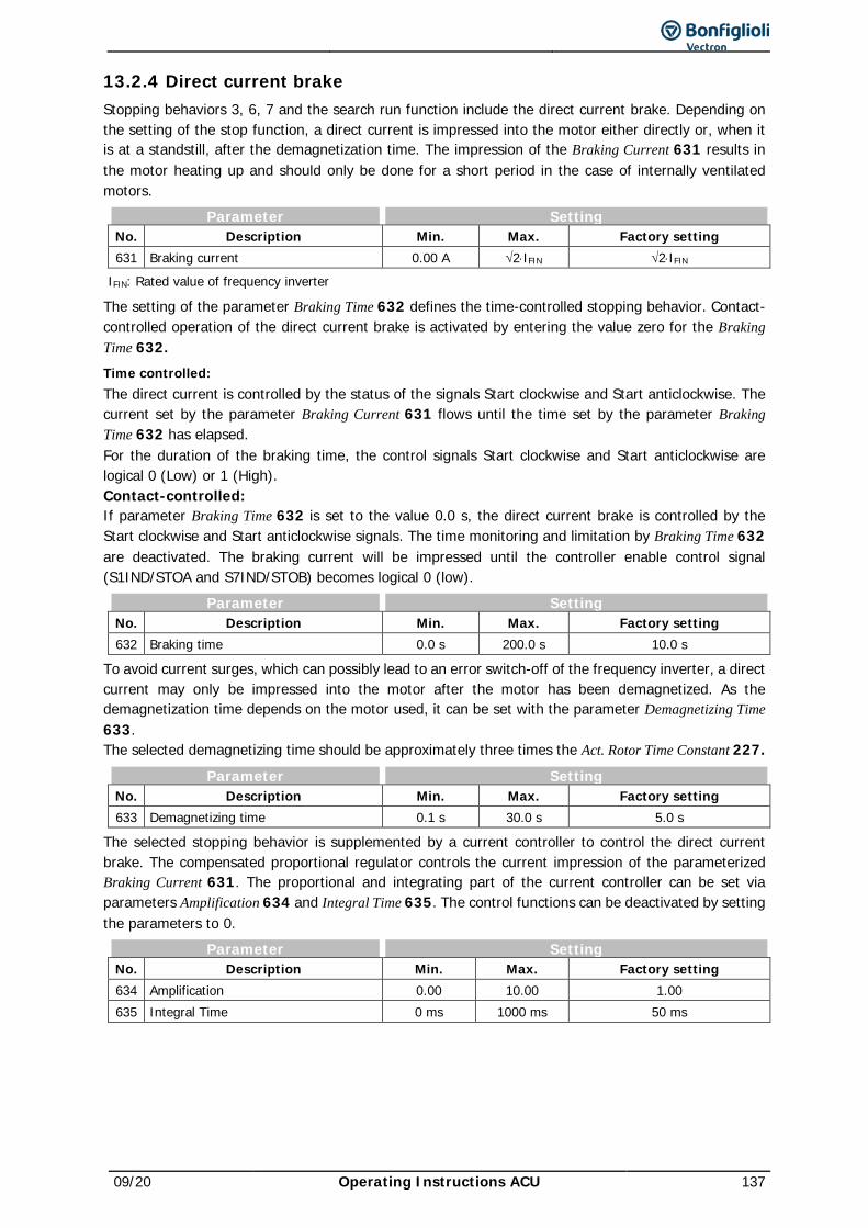
09/20 Operating Instructions ACU 137
13.2.4 Direct current brake Stopping behaviors 3, 6, 7 and the search run function include the direct current brake. Depending on the setting of the stop function, a direct current is impressed into the motor either directly or, when it is at a standstill, after the demagnetization time. The impression of the Braking Current 631 results in the motor heating up and should only be done for a short period in the case of internally ventilated motors.
Parameter Setting No. Description Min. Max. Factory setting 631 Braking current 0.00 A √2⋅IFIN √2⋅IFIN
IFIN: Rated value of frequency inverter
The setting of the parameter Braking Time 632 defines the time-controlled stopping behavior. Contact-controlled operation of the direct current brake is activated by entering the value zero for the Braking Time 632. Time controlled: The direct current is controlled by the status of the signals Start clockwise and Start anticlockwise. The current set by the parameter Braking Current 631 flows until the time set by the parameter Braking Time 632 has elapsed. For the duration of the braking time, the control signals Start clockwise and Start anticlockwise are logical 0 (Low) or 1 (High). Contact-controlled: If parameter Braking Time 632 is set to the value 0.0 s, the direct current brake is controlled by the Start clockwise and Start anticlockwise signals. The time monitoring and limitation by Braking Time 632 are deactivated. The braking current will be impressed until the controller enable control signal (S1IND/STOA and S7IND/STOB) becomes logical 0 (low).
Parameter Setting No. Description Min. Max. Factory setting 632 Braking time 0.0 s 200.0 s 10.0 s
To avoid current surges, which can possibly lead to an error switch-off of the frequency inverter, a direct current may only be impressed into the motor after the motor has been demagnetized. As the demagnetization time depends on the motor used, it can be set with the parameter Demagnetizing Time 633. The selected demagnetizing time should be approximately three times the Act. Rotor Time Constant 227.
Parameter Setting No. Description Min. Max. Factory setting 633 Demagnetizing time 0.1 s 30.0 s 5.0 s
The selected stopping behavior is supplemented by a current controller to control the direct current brake. The compensated proportional regulator controls the current impression of the parameterized Braking Current 631. The proportional and integrating part of the current controller can be set via parameters Amplification 634 and Integral Time 635. The control functions can be deactivated by setting the parameters to 0.
Parameter Setting No. Description Min. Max. Factory setting 634 Amplification 0.00 10.00 1.00 635 Integral Time 0 ms 1000 ms 50 ms
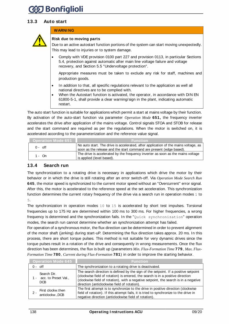
138 Operating Instructions ACU 09/20
13.3 Auto start WARNING
Risk due to moving parts Due to an active autostart function portions of the system can start moving unexpectedly. This may lead to injuries or to system damage. • Comply with VDE provision 0100 part 227 and provision 0113, in particular Sections
5.4, protection against automatic after main line voltage failure and voltage recovery, and Section 5.5 "Undervoltage protection".
Appropriate measures must be taken to exclude any risk for staff, machines and production goods.
• In addition to that, all specific regulations relevant to the application as well all national directives are to be complied with.
• When the Autostart function is activated, the operator, in accordance with DIN EN 61800-5-1, shall provide a clear warning/sign in the plant, indicating automatic restart.
The auto start function is suitable for applications which permit a start at mains voltage by their function. By activation of the auto-start function via parameter Operation Mode 651, the frequency inverter accelerates the drive after application of the mains voltage. Control signals STOA and STOB for release and the start command are required as per the regulations. When the motor is switched on, it is accelerated according to the parameterization and the reference value signal.
Operation Mode 651 Function 0 - off No auto start. The drive is accelerated, after application of the mains voltage, as
soon as the release and the start command are present (edge based).
1 - On The drive is accelerated by the frequency inverter as soon as the mains voltage is applied (level based).
13.4 Search run The synchronization to a rotating drive is necessary in applications which drive the motor by their behavior or in which the drive is still rotating after an error switch-off. Via Operation Mode Search Run 645, the motor speed is synchronized to the current motor speed without an "Overcurrent" error signal. After this, the motor is accelerated to the reference speed at the set acceleration. This synchronization function determines the current rotary frequency of the drive via a search run in operation modes 1 to 5. The synchronization in operation modes 10 to 15 is accelerated by short test impulses. Torsional frequencies up to 175 Hz are determined within 100 ms to 300 ms. For higher frequencies, a wrong frequency is determined and the synchronization fails. In the "Quick synchronization" operation modes, the search run cannot determine whether an synchronization attempt has failed. For operation of a synchronous motor, the flux direction can be determined in order to prevent alignment of the motor shaft (jerking) during start-uP. Determining the flux direction takes approx. 20 ms. In this process, there are short torque pulses. This method is not suitable for very dynamic drives since the torque pulses result in a rotation of the drive and consequently in wrong measurements. Once the flux direction has been determines, the flux is built up (parameters Min. Flux-Formation Time 779, Max. Flux-Formation Time 780, Current during Flux-Formation 781) in order to improve the starting behavior.
Operation Mode 645 Function 0 - off The synchronization to a rotating drive is deactivated.
1 - Search Dir. acc. to Preset Val., DCB
The search direction is defined by the sign of the setpoint. If a positive setpoint (clockwise field of rotation) is entered, the search is in a positive direction (clockwise field of rotation), with a negative setpoint, the search is in a negative direction (anticlockwise field of rotation).
2 - First clockw. then anticlockw.,DCB
The first attempt is to synchronize to the drive in positive direction (clockwise field of rotation). If this attempt fails, it is tried to synchronize to the drive in negative direction (anticlockwise field of rotation).
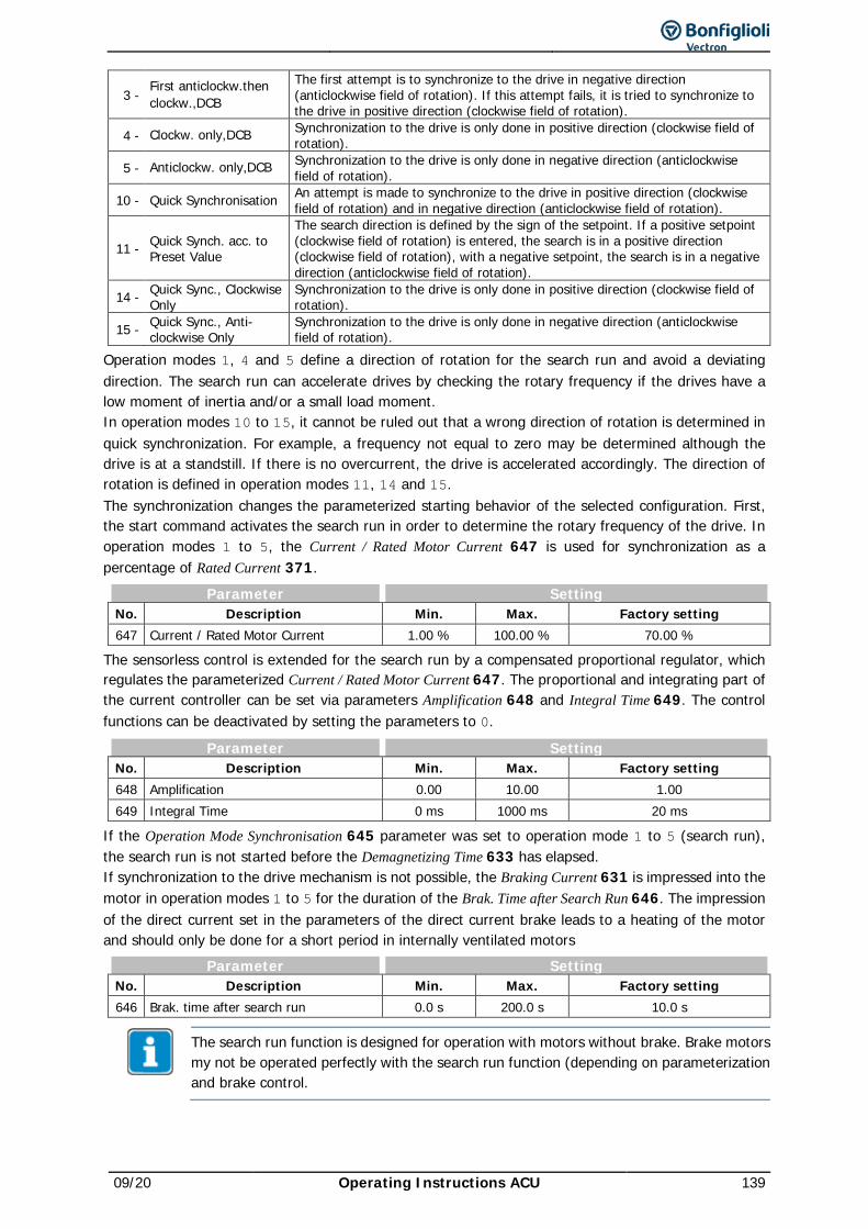
09/20 Operating Instructions ACU 139
3 - First anticlockw. then clockw.,DCB
The first attempt is to synchronize to the drive in negative direction (anticlockwise field of rotation). If this attempt fails, it is tried to synchronize to the drive in positive direction (clockwise field of rotation).
4 - Clockw. only, DCB Synchronization to the drive is only done in positive direction (clockwise field of rotation).
5 - Anticlockw. only,DCB Synchronization to the drive is only done in negative direction (anticlockwise field of rotation).
10 - Quick Synchronisation An attempt is made to synchronize to the drive in positive direction (clockwise field of rotation) and in negative direction (anticlockwise field of rotation).
11 - Quick Synch. acc. to Preset Value
The search direction is defined by the sign of the setpoint. If a positive setpoint (clockwise field of rotation) is entered, the search is in a positive direction (clockwise field of rotation), with a negative setpoint, the search is in a negative direction (anticlockwise field of rotation).
14 - Quick Sync., Clockwise Only
Synchronization to the drive is only done in positive direction (clockwise field of rotation).
15 - Quick Sync., Anti-clockwise Only
Synchronization to the drive is only done in negative direction (anticlockwise field of rotation).
Operation modes 1, 4 and 5 define a direction of rotation for the search run and avoid a deviating direction. The search run can accelerate drives by checking the rotary frequency if the drives have a low moment of inertia and/or a small load moment. In operation modes 10 to 15, it cannot be ruled out that a wrong direction of rotation is determined in quick synchronization. For example, a frequency not equal to zero may be determined although the drive is at a standstill. If there is no overcurrent, the drive is accelerated accordingly. The direction of rotation is defined in operation modes 11, 14 and 15. The synchronization changes the parameterized starting behavior of the selected configuration. First, the start command activates the search run in order to determine the rotary frequency of the drive. In operation modes 1 to 5, the Current / Rated Motor Current 647 is used for synchronization as a percentage of Rated Current 371.
Parameter Setting No. Description Min. Max. Factory setting 647 Current / Rated Motor Current 1.00 % 100.00 % 70.00 %
The sensorless control is extended for the search run by a compensated proportional regulator, which regulates the parameterized Current / Rated Motor Current 647. The proportional and integrating part of the current controller can be set via parameters Amplification 648 and Integral Time 649. The control functions can be deactivated by setting the parameters to 0.
Parameter Setting No. Description Min. Max. Factory setting 648 Amplification 0.00 10.00 1.00 649 Integral Time 0 ms 1000 ms 20 ms
If the Operation Mode Synchronisation 645 parameter was set to operation mode 1 to 5 (search run), the search run is not started before the Demagnetizing Time 633 has elapsed. If synchronization to the drive mechanism is not possible, the Braking Current 631 is impressed into the motor in operation modes 1 to 5 for the duration of the Brak. Time after Search Run 646. The impression of the direct current set in the parameters of the direct current brake leads to a heating of the motor and should only be done for a short period in internally ventilated motors
Parameter Setting No. Description Min. Max. Factory setting 646 Brak. time after search run 0.0 s 200.0 s 10.0 s
The search run function is designed for operation with motors without brake. Brake motors my not be operated perfectly with the search run function (depending on parameterization and brake control.
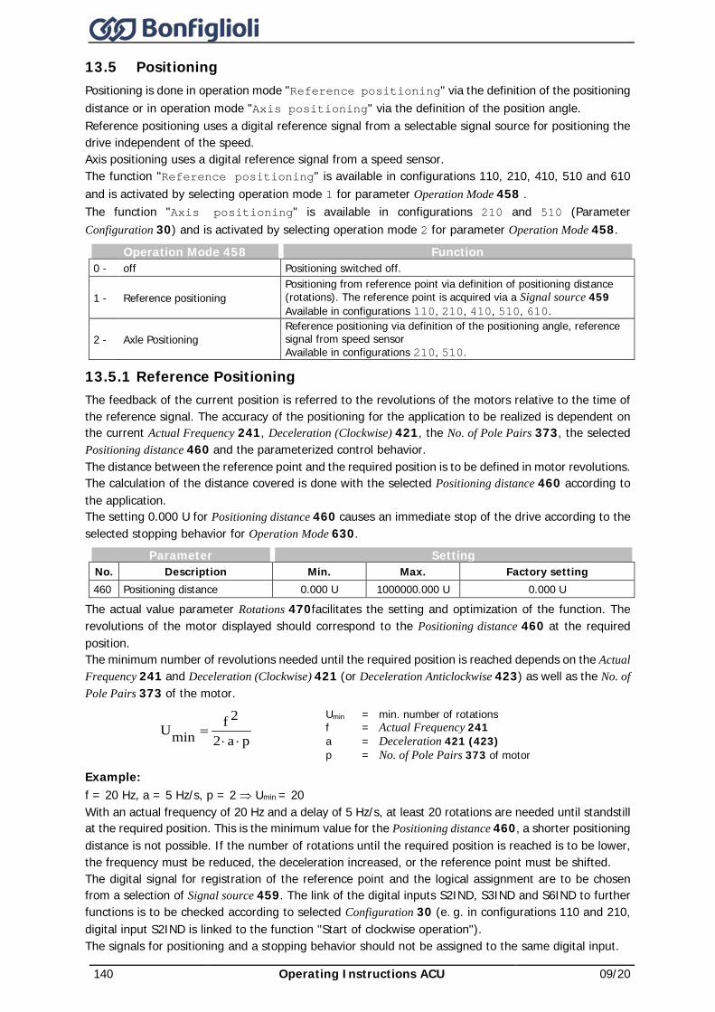
140 Operating Instructions ACU 09/20
13.5 Positioning Positioning is done in operation mode "Reference positioning" via the definition of the positioning distance or in operation mode "Axis positioning" via the definition of the position angle. Reference positioning uses a digital reference signal from a selectable signal source for positioning the drive independent of the speed. Axis positioning uses a digital reference signal from a speed sensor. The function "Reference positioning" is available in configurations 110, 210, 410, 510 and 610 and is activated by selecting operation mode 1 for parameter Operation Mode 458 . The function "Axis positioning" is available in configurations 210 and 510 (Parameter Configuration 30) and is activated by selecting operation mode 2 for parameter Operation Mode 458.
Operation Mode 458 Function 0 - off Positioning switched off.
1 - Reference positioning Positioning from reference point via definition of positioning distance (rotations). The reference point is acquired via a Signal source 459 Available in configurations 110, 210, 410, 510, 610.
2 - Axle Positioning Reference positioning via definition of the positioning angle, reference signal from speed sensor Available in configurations 210, 510.
13.5.1 Reference Positioning The feedback of the current position is referred to the revolutions of the motors relative to the time of the reference signal. The accuracy of the positioning for the application to be realized is dependent on the current Actual Frequency 241, Deceleration (Clockwise) 421, the No. of Pole Pairs 373, the selected Positioning distance 460 and the parameterized control behavior. The distance between the reference point and the required position is to be defined in motor revolutions. The calculation of the distance covered is done with the selected Positioning distance 460 according to the application. The setting 0.000 U for Positioning distance 460 causes an immediate stop of the drive according to the selected stopping behavior for Operation Mode 630.
Parameter Setting No. Description Min. Max. Factory setting 460 Positioning distance 0.000 U 1000000.000 U 0.000 U
The actual value parameter Rotations 470facilitates the setting and optimization of the function. The revolutions of the motor displayed should correspond to the Positioning distance 460 at the required position. The minimum number of revolutions needed until the required position is reached depends on the Actual Frequency 241 and Deceleration (Clockwise) 421 (or Deceleration Anticlockwise 423) as well as the No. of Pole Pairs 373 of the motor.
pa2
2fminU
⋅⋅=
Umin = min. number of rotations f = Actual Frequency 241 a = Deceleration 421 (423) p = No. of Pole Pairs 373 of motor
Example: f = 20 Hz, a = 5 Hz/s, p = 2 ⇒ Umin = 20 With an actual frequency of 20 Hz and a delay of 5 Hz/s, at least 20 rotations are needed until standstill at the required position. This is the minimum value for the Positioning distance 460, a shorter positioning distance is not possible. If the number of rotations until the required position is reached is to be lower, the frequency must be reduced, the deceleration increased, or the reference point must be shifted. The digital signal for registration of the reference point and the logical assignment are to be chosen from a selection of Signal source 459. The link of the digital inputs S2IND, S3IND and S6IND to further functions is to be checked according to selected Configuration 30 (e. g. in configurations 110 and 210, digital input S2IND is linked to the function "Start of clockwise operation"). The signals for positioning and a stopping behavior should not be assigned to the same digital input.
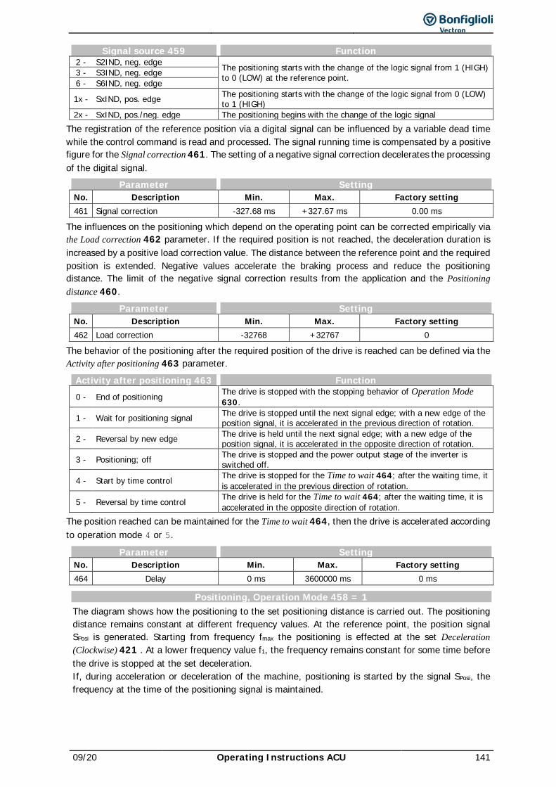
09/20 Operating Instructions ACU 141
Signal source 459 Function 2 - S2IND, neg. edge The positioning starts with the change of the logic signal from 1 (HIGH)
to 0 (LOW) at the reference point. 3 - S3IND, neg. edge 6 - S6IND, neg. edge
1x - SxIND, pos. edge The positioning starts with the change of the logic signal from 0 (LOW) to 1 (HIGH)
2x - SxIND, pos./neg. edge The positioning begins with the change of the logic signal The registration of the reference position via a digital signal can be influenced by a variable dead time while the control command is read and processed. The signal running time is compensated by a positive figure for the Signal correction 461. The setting of a negative signal correction decelerates the processing of the digital signal.
Parameter Setting No. Description Min. Max. Factory setting 461 Signal correction -327.68 ms +327.67 ms 0.00 ms
The influences on the positioning which depend on the operating point can be corrected empirically via the Load correction 462 parameter. If the required position is not reached, the deceleration duration is increased by a positive load correction value. The distance between the reference point and the required position is extended. Negative values accelerate the braking process and reduce the positioning distance. The limit of the negative signal correction results from the application and the Positioning distance 460.
Parameter Setting No. Description Min. Max. Factory setting 462 Load correction -32768 +32767 0
The behavior of the positioning after the required position of the drive is reached can be defined via the Activity after positioning 463 parameter.
Activity after positioning 463 Function 0 - End of positioning The drive is stopped with the stopping behavior of Operation Mode
630.
1 - Wait for positioning signal The drive is stopped until the next signal edge; with a new edge of the position signal, it is accelerated in the previous direction of rotation.
2 - Reversal by new edge The drive is held until the next signal edge; with a new edge of the position signal, it is accelerated in the opposite direction of rotation.
3 - Positioning; off The drive is stopped and the power output stage of the inverter is switched off.
4 - Start by time control The drive is stopped for the Time to wait 464; after the waiting time, it is accelerated in the previous direction of rotation.
5 - Reversal by time control The drive is held for the Time to wait 464; after the waiting time, it is accelerated in the opposite direction of rotation.
The position reached can be maintained for the Time to wait 464, then the drive is accelerated according to operation mode 4 or 5.
Parameter Setting No. Description Min. Max. Factory setting 464 Delay 0 ms 3600000 ms 0 ms
Positioning, Operation Mode 458 = 1 The diagram shows how the positioning to the set positioning distance is carried out. The positioning distance remains constant at different frequency values. At the reference point, the position signal SPosi is generated. Starting from frequency fmax the positioning is effected at the set Deceleration (Clockwise) 421 . At a lower frequency value f1, the frequency remains constant for some time before the drive is stopped at the set deceleration. If, during acceleration or deceleration of the machine, positioning is started by the signal SPosi, the frequency at the time of the positioning signal is maintained.
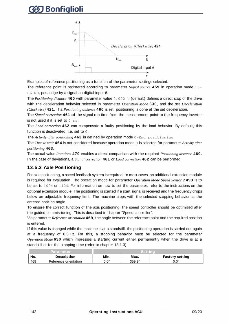
142 Operating Instructions ACU 09/20
Examples of reference positioning as a function of the parameter settings selected. The reference point is registered according to parameter Signal source 459 in operation mode 16–S6IND, pos. edge by a signal on digital input 6. The Positioning distance 460 with parameter value 0.000 U (default) defines a direct stop of the drive with the deceleration behavior selected in parameter Operation Mode 630, and the set Deceleration (Clockwise) 421. If a Positioning distance 460 is set, positioning is done at the set deceleration. The Signal correction 461 of the signal run time from the measurement point to the frequency inverter is not used if it is set to 0 ms. The Load correction 462 can compensate a faulty positioning by the load behavior. By default, this function is deactivated, i.e. set to 0. The Activity after positioning 463 is defined by operation mode 0–End positioning. The Time to wait 464 is not considered because operation mode 0 is selected for parameter Activity after positioning 463. The actual value Rotations 470 enables a direct comparison with the required Positioning distance 460. In the case of deviations, a Signal correction 461 or Load correction 462 can be performed.
13.5.2 Axle Positioning For axle positioning, a speed feedback system is required. In most cases, an additional extension module is required for evaluation. The operation mode for parameter Operation Mode Speed Sensor 2 493 is to be set to 1004 or 1104. For information on how to set the parameter, refer to the instructions on the optional extension module. The positioning is started if a start signal is received and the frequency drops below an adjustable frequency limit. The machine stops with the selected stopping behavior at the entered position angle. To ensure the correct function of the axis positioning, the speed controller should be optimized after the guided commissioning. This is described in chapter "Speed controller". Via parameter Reference orientation 469, the angle between the reference point and the required position is entered. If this value is changed while the machine is at a standstill, the positioning operation is carried out again at a frequency of 0.5 Hz. For this, a stopping behavior must be selected for the parameter Operation Mode 630 which impresses a starting current either permanently when the drive is at a standstill or for the stopping time (refer to chapter 13.1.3).
Parameter Setting No. Description Min. Max. Factory setting 469 Reference orientation 0.0° 359.9° 0.0°
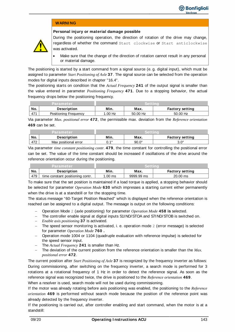
09/20 Operating Instructions ACU 143
WARNING
Personal injury or material damage possible During the positioning operation, the direction of rotation of the drive may change, regardless of whether the command Start clockwise or Start anticlockwise was activated. • Make sure that the change of the direction of rotation cannot result in any personal
or material damage.
The positioning is started by a start command from a signal source (e. g. digital input), which must be assigned to parameter Start Positioning of Axle 37. The signal source can be selected from the operation modes for digital inputs described in chapter "16.4". The positioning starts on condition that the Actual Frequency 241 of the output signal is smaller than the value entered in parameter Positioning Frequency 471. Due to a stopping behavior, the actual frequency drops below the positioning frequency.
Parameter Setting No. Description Min. Max. Factory setting 471 Positioning Frequency 1.00 Hz 50.00 Hz 50.00 Hz
Via parameter Max. positional error 472, the permissible max. deviation from the Reference orientation 469 can be set.
Parameter Setting No. Description Min. Max. Factory setting 472 Max positional error 0.1° 90.0° 3.0°
Via parameter time constant positioning contr. 479, the time constant for controlling the positional error can be set. The value of the time constant should be increased if oscillations of the drive around the reference orientation occur during the positioning.
Parameter Setting No. Description Min. Max. Factory setting 479 time constant positioning contr. 1.00 ms 9999.99 ms 20.00 ms
To make sure that the set position is maintained if a load torque is applied, a stopping behavior should be selected for parameter Operation Mode 630 which impresses a starting current either permanently when the drive is at a standstill or for the stopping time. The status message “60-Target Position Reached” which is displayed when the reference orientation is reached can be assigned to a digital output. The message is output on the following conditions:
− Operation Mode 2 (axle positioning) for parameter Operation Mode 458 is selected. − The controller enable signal at digital inputs S1IND/STOA and S7IND/STOB is switched on. − Enable axis positioning 37 is activated. − The speed sensor monitoring is activated, i. e. operation mode 2 (error message) is selected
for parameter Operation Mode 760 . − Operation mode 1004 or 1104 (quadruple evaluation with reference impulse) is selected for
the speed sensor input. − The Actual Frequency 241 is smaller than Hz. − The deviation of the current position from the reference orientation is smaller than the Max.
positional error 472. The current position after Start Positioning of Axle 37 is recognized by the frequency inverter as follows: During commissioning, after switching on the frequency inverter, a search mode is performed for 3 rotations at a rotational frequency of 1 Hz in order to detect the reference signal. As soon as the reference signal was recognized twice, the drive is positioned to the Reference orientation 469. When a resolver is used, search mode will not be used during commissioning. If the motor was already rotating before axis positioning was enabled, the positioning to the Reference orientation 469 is performed without search mode because the position of the reference point was already detected by the frequency inverter. If the positioning is carried out, after controller enabling and start command, when the motor is at a standstill:
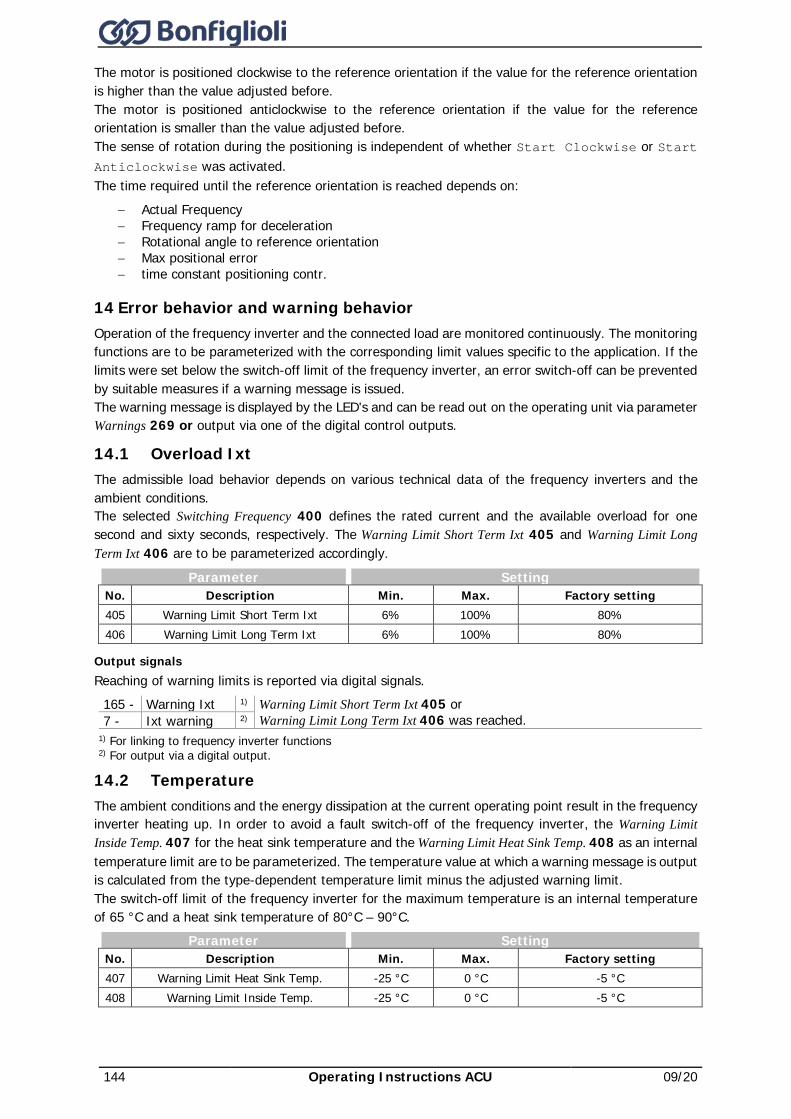
144 Operating Instructions ACU 09/20
The motor is positioned clockwise to the reference orientation if the value for the reference orientation is higher than the value adjusted before. The motor is positioned anticlockwise to the reference orientation if the value for the reference orientation is smaller than the value adjusted before. The sense of rotation during the positioning is independent of whether Start Clockwise or Start Anticlockwise was activated. The time required until the reference orientation is reached depends on:
− Actual Frequency − Frequency ramp for deceleration − Rotational angle to reference orientation − Max positional error − time constant positioning contr.
14 Error behavior and warning behavior Operation of the frequency inverter and the connected load are monitored continuously. The monitoring functions are to be parameterized with the corresponding limit values specific to the application. If the limits were set below the switch-off limit of the frequency inverter, an error switch-off can be prevented by suitable measures if a warning message is issued. The warning message is displayed by the LED's and can be read out on the operating unit via parameter Warnings 269 or output via one of the digital control outputs.
14.1 Overload Ixt The admissible load behavior depends on various technical data of the frequency inverters and the ambient conditions. The selected Switching Frequency 400 defines the rated current and the available overload for one second and sixty seconds, respectively. The Warning Limit Short Term Ixt 405 and Warning Limit Long Term Ixt 406 are to be parameterized accordingly.
Parameter Setting No. Description Min. Max. Factory setting 405 Warning Limit Short Term Ixt 6% 100% 80% 406 Warning Limit Long Term Ixt 6% 100% 80%
Output signals Reaching of warning limits is reported via digital signals.
165 - Warning Ixt 1) Warning Limit Short Term Ixt 405 or Warning Limit Long Term Ixt 406 was reached. 7 - Ixt warning 2)
1) For linking to frequency inverter functions 2) For output via a digital output.
14.2 Temperature The ambient conditions and the energy dissipation at the current operating point result in the frequency inverter heating up. In order to avoid a fault switch-off of the frequency inverter, the Warning Limit Inside Temp. 407 for the heat sink temperature and the Warning Limit Heat Sink Temp. 408 as an internal temperature limit are to be parameterized. The temperature value at which a warning message is output is calculated from the type-dependent temperature limit minus the adjusted warning limit. The switch-off limit of the frequency inverter for the maximum temperature is an internal temperature of 65 °C and a heat sink temperature of 80°C – 90°C.
Parameter Setting No. Description Min. Max. Factory setting 407 Warning Limit Heat Sink Temp. -25 °C 0 °C -5 °C 408 Warning Limit Inside Temp. -25 °C 0 °C -5 °C
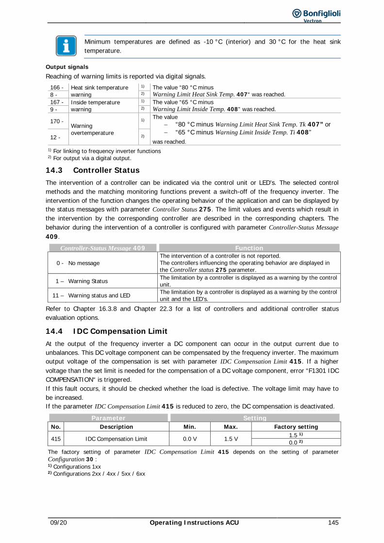
09/20 Operating Instructions ACU 145
Minimum temperatures are defined as -10 °C (interior) and 30 °C for the heat sink temperature.
Output signals Reaching of warning limits is reported via digital signals.
166 - Heat sink temperature warning
1) The value “80 °C minus Warning Limit Heat Sink Temp. 407“ was reached. 8 - 2)
167 - Inside temperature warning
1) The value “65 °C minus Warning Limit Inside Temp. 408” was reached. 9 - 2)
170 - Warning overtemperature
1) The value − “80 °C minus Warning Limit Heat Sink Temp. Tk 407” or − “65 °C minus Warning Limit Inside Temp. Ti 408”
was reached. 12 - 2)
1) For linking to frequency inverter functions 2) For output via a digital output.
14.3 Controller Status The intervention of a controller can be indicated via the control unit or LED's. The selected control methods and the matching monitoring functions prevent a switch-off of the frequency inverter. The intervention of the function changes the operating behavior of the application and can be displayed by the status messages with parameter Controller Status 275. The limit values and events which result in the intervention by the corresponding controller are described in the corresponding chapters. The behavior during the intervention of a controller is configured with parameter Controller-Status Message 409.
Controller-Status Message 409 Function
0 - No message The intervention of a controller is not reported. The controllers influencing the operating behavior are displayed in the Controller status 275 parameter.
1 – Warning Status The limitation by a controller is displayed as a warning by the control unit.
11 – Warning status and LED The limitation by a controller is displayed as a warning by the control unit and the LED's.
Refer to Chapter 16.3.8 and Chapter 22.3 for a list of controllers and additional controller status evaluation options.
14.4 IDC Compensation Limit At the output of the frequency inverter a DC component can occur in the output current due to unbalances. This DC voltage component can be compensated by the frequency inverter. The maximum output voltage of the compensation is set with parameter IDC Compensation Limit 415. If a higher voltage than the set limit is needed for the compensation of a DC voltage component, error “F1301 IDC COMPENSATION“ is triggered. If this fault occurs, it should be checked whether the load is defective. The voltage limit may have to be increased. If the parameter IDC Compensation Limit 415 is reduced to zero, the DC compensation is deactivated.
Parameter Setting No. Description Min. Max. Factory setting
415 IDC Compensation Limit 0.0 V 1.5 V 1.5 1) 0.0 2)
The factory setting of parameter IDC Compensation Limit 415 depends on the setting of parameter Configuration 30 : 1) Configurations 1xx 2) Configurations 2xx / 4xx / 5xx / 6xx
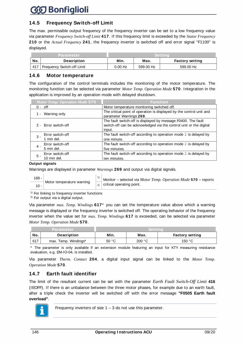
146 Operating Instructions ACU 09/20
14.5 Frequency Switch-off Limit The max. permissible output frequency of the frequency inverter can be set to a low frequency value via parameter Frequency Switch-off Limit 417. If this frequency limit is exceeded by the Stator Frequency 210 or the Actual Frequency 241, the frequency inverter is switched off and error signal "F1100" is displayed.
Parameter Setting No. Description Min. Max. Factory setting 417 Frequency Switch-off Limit 0.00 Hz 599.00 Hz 599.00 Hz
14.6 Motor temperature The configuration of the control terminals includes the monitoring of the motor temperature. The monitoring function can be selected via parameter Motor Temp. Operation Mode 570. Integration in the application is improved by an operation mode with delayed shutdown.
Motor Temp. Operation Mode 570 Function 0 - off Motor temperature monitoring switched off.
1 - Warning only The critical point of operation is displayed by the control unit and parameter Warnings 269.
2 - Error switch-off The fault switch-off is displayed by message F0400. The fault switch-off can be acknowledged via the control unit or the digital input.
3 - Error switch-off 1 min del.
The fault switch-off according to operation mode 2 is delayed by one minute.
4 - Error switch-off 5 min del.
The fault switch-off according to operation mode 2 is delayed by five minutes.
5 - Error switch-off 10 min del.
The fault switch-off according to operation mode 2 is delayed by ten minutes.
Output signals Warnings are displayed in parameter Warnings 269 and output via digital signals.
168 - Motor temperature warning
1) Monitor – selected via Motor Temp. Operation Mode 570 – reports critical operating point. 10 - 2)
1) For linking to frequency inverter functions 2) For output via a digital output.
Via parameter max. Temp. Windings 617* you can set the temperature value above which a warning message is displayed or the frequency inverter is switched off. The operating behavior of the frequency inverter when the value set for max. Temp. Windings 617 is exceeded, can be selected via parameter Motor Temp. Operation Mode 570.
Parameter Setting No. Description Min. Max. Factory setting 617 max. Temp. Windings* 50 °C 200 °C 150 °C
* The parameter is only available if an extension module featuring an input for KTY measuring resistance evaluation, e.g. EM-IO-04, is installed.
Via parameter Therm. Contact 204, a digital input signal can be linked to the Motor Temp. Operation Mode 570.
14.7 Earth fault identifier The limit of the resultant current can be set with the parameter Earth Fault Switch-Off Limit 416 (IEOFF). If there is an unbalance between the three motor phases, for example due to an earth fault, after a triple check the inverter will be switched off with the error message "F0505 Earth fault overload".
Frequency inverters of size 1 – 3 do not use this parameter.
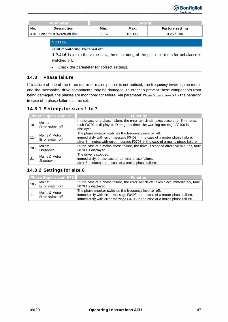
09/20 Operating Instructions ACU 147
Parameter Setting No. Description Min. Max. Factory setting 416 Earth fault switch-off limit 0.0 A 0 * IFIN 0.25 * IFIN
NOTICE Fault monitoring switched off
If P.416 is set to the value 0 A, the monitoring of the phase currents for unbalance is switched off. • Check the parameter for correct settings.
14.8 Phase failure If a failure of one of the three motor or mains phases is not noticed, the frequency inverter, the motor and the mechanical drive components may be damaged. In order to prevent these components from being damaged, the phases are monitored for failure. Via parameter Phase Supervision 576 the behavior in case of a phase failure can be set.
14.8.1 Settings for sizes 1 to 7 Phase Supervision 576 Function
10 - Mains: Error switch-off
In the case of a phase failure, the error switch-off takes place after 5 minutes, fault F0703 is displayed. During this time, the warning message A0100 is displayed.
11 - Mains & Motor: Error switch-off
The phase monitor switches the frequency inverter off: immediately with error message F0403 in the case of a motor phase failure, after 5 minutes with error message F0703 in the case of a mains phase failure.
20 - Mains: Shutdown
In the case of a mains phase failure, the drive is stopped after five minutes, fault F0703 is displayed.
21 - Mains & Motor: Shutdown
The drive is stopped: immediately, in the case of a motor phase failure, after 5 minutes in the case of a mains phase failure.
14.8.2 Settings for size 8 Phase Supervision 576 Function 10 - Mains:
Error switch-off In the case of a phase failure, the error switch-off takes place immediately, fault F0703 is displayed.
11 - Mains & Motor: Error switch-off
The phase monitor switches the frequency inverter off: immediately with error message F0403 in the case of a motor phase failure, immediately with error message F0703 in the case of a mains phase failure
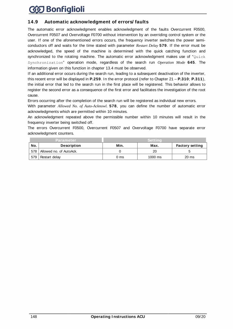
148 Operating Instructions ACU 09/20
14.9 Automatic acknowledgment of errors/faults The automatic error acknowledgment enables acknowledgment of the faults Overcurrent F0500, Overcurrent F0507 and Overvoltage F0700 without intervention by an overriding control system or the user. If one of the aforementioned errors occurs, the frequency inverter switches the power semi-conductors off and waits for the time stated with parameter Restart Delay 579. If the error must be acknowledged, the speed of the machine is determined with the quick catching function and synchronized to the rotating machine. The automatic error acknowledgment makes use of “Quick Synchronization” operation mode, regardless of the search run Operation Mode 645. The information given on this function in chapter 13.4 must be observed. If an additional error occurs during the search run, leading to a subsequent deactivation of the inverter, this recent error will be displayed in P.259. In the error protocol (refer to Chapter 21 – P.310; P.311), the initial error that led to the search run in the first place will be registered. This behavior allows to register the second error as a consequence of the first error and facilitates the investigation of the root cause. Errors occurring after the completion of the search run will be registered as individual new errors. With parameter Allowed No. of Auto-Acknowl. 578, you can define the number of automatic error acknowledgments which are permitted within 10 minutes. An acknowledgment repeated above the permissible number within 10 minutes will result in the frequency inverter being switched off. The errors Overcurrent F0500, Overcurrent F0507 and Overvoltage F0700 have separate error acknowledgment counters.
Parameter Setting No. Description Min. Max. Factory setting 578 Allowed no. of AutoAck. 0 20 5 579 Restart delay 0 ms 1000 ms 20 ms
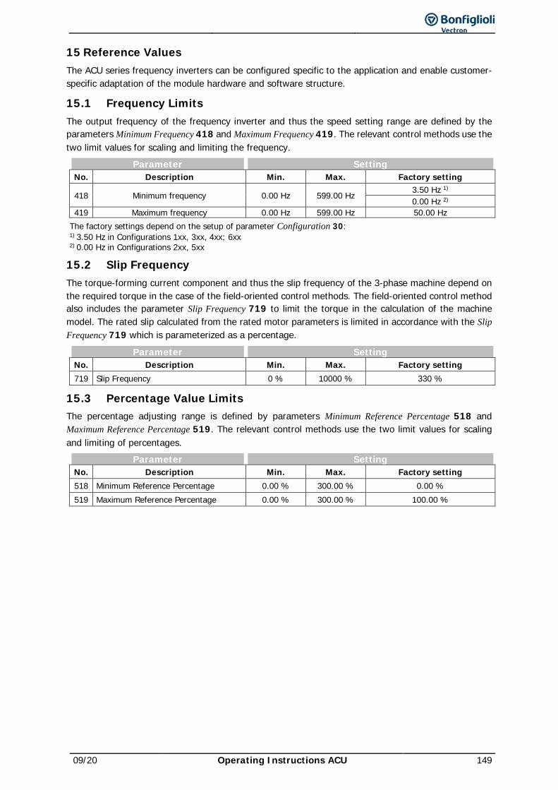
09/20 Operating Instructions ACU 149
15 Reference Values The ACU series frequency inverters can be configured specific to the application and enable customer-specific adaptation of the module hardware and software structure.
15.1 Frequency Limits The output frequency of the frequency inverter and thus the speed setting range are defined by the parameters Minimum Frequency 418 and Maximum Frequency 419. The relevant control methods use the two limit values for scaling and limiting the frequency.
Parameter Setting No. Description Min. Max. Factory setting
418 Minimum frequency 0.00 Hz 599.00 Hz 3.50 Hz 1) 0.00 Hz 2)
419 Maximum frequency 0.00 Hz 599.00 Hz 50.00 Hz The factory settings depend on the setup of parameter Configuration 30: 1) 3.50 Hz in Configurations 1xx, 3xx, 4xx; 6xx 2) 0.00 Hz in Configurations 2xx, 5xx
15.2 Slip Frequency The torque-forming current component and thus the slip frequency of the 3-phase machine depend on the required torque in the case of the field-oriented control methods. The field-oriented control method also includes the parameter Slip Frequency 719 to limit the torque in the calculation of the machine model. The rated slip calculated from the rated motor parameters is limited in accordance with the Slip Frequency 719 which is parameterized as a percentage.
Parameter Setting No. Description Min. Max. Factory setting 719 Slip Frequency 0 % 10000 % 330 %
15.3 Percentage Value Limits The percentage adjusting range is defined by parameters Minimum Reference Percentage 518 and Maximum Reference Percentage 519. The relevant control methods use the two limit values for scaling and limiting of percentages.
Parameter Setting No. Description Min. Max. Factory setting 518 Minimum Reference Percentage 0.00 % 300.00 % 0.00 % 519 Maximum Reference Percentage 0.00 % 300.00 % 100.00 %
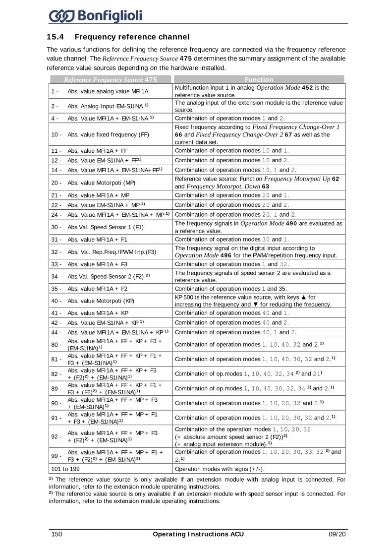
150 Operating Instructions ACU 09/20
15.4 Frequency reference channel The various functions for defining the reference frequency are connected via the frequency reference value channel. The Reference Frequency Source 475 determines the summary assignment of the available reference value sources depending on the hardware installed.
Reference Frequency Source 475 Function 1 - Abs. value analog value MFI1A Multifunction input 1 in analog Operation Mode 452 is the
reference value source.
2 - Abs. Analog Input EM-S1INA 1) The analog input of the extension module is the reference value source.
4 - Abs. Value MFI1A + EM-S1INA 1) Combination of operation modes 1 and 2.
10 - Abs. value fixed frequency (FF) Fixed frequency according to Fixed Frequency Change-Over 1 66 and Fixed Frequency Change-Over 2 67 as well as the current data set.
11 - Abs. value MFI1A + FF Combination of operation modes 10 and 1. 12 - Abs. Value EM-S1INA + FF1) Combination of operation modes 10 and 2. 14 - Abs. Value MFI1A + EM-S1INA+FF1) Combination of operation modes 10, 1 and 2.
20 - Abs. value Motorpoti (MP) Reference value source: Function Frequency Motorpoti Up 62 and Frequency Motorpot. Down 63
21 - Abs. value MFI1A + MP Combination of operation modes 20 and 1. 22 - Abs. Value EM-S1INA + MP 1) Combination of operation modes 20 and 2. 24 - Abs. Value MFI1A + EM-S1INA + MP 1) Combination of operation modes 20, 1 and 2.
30 - Abs.Val. Speed Sensor 1 (F1) The frequency signals in Operation Mode 490 are evaluated as a reference value.
31 - Abs. value MFI1A + F1 Combination of operation modes 30 and 1.
32 - Abs. Val. Rep.Freq./PWM Inp.(F3) The frequency signal on the digital input according to Operation Mode 496 for the PWM/repetition frequency input.
33 - Abs. value MFI1A + F3 Combination of operation modes 1 and 32.
34 - Abs.Val. Speed Sensor 2 (F2) 2) The frequency signals of speed sensor 2 are evaluated as a reference value.
35 - Abs. value MFI1A + F2 Combination of operation modes 1 and 35.
40 - Abs. value Motorpoti (KP) KP 500 is the reference value source, with keys for increasing the frequency and for reducing the frequency.
41 - Abs. value MFI1A + KP Combination of operation modes 40 and 1. 42 - Abs. Value EM-S1INA + KP 1) Combination of operation modes 40 and 2. 44 - Abs. Value MFI1A + EM-S1INA + KP 1) Combination of operation modes 40, 1 and 2.
80 - Abs. value MFI1A + FF + KP + F3 + (EM-S1INA)1) Combination of operation modes 1, 10, 40, 32 and 2.1)
81 - Abs. value MFI1A + FF + KP + F1 + F3 + (EM-S1INA)1) Combination of operation modes 1, 10, 40, 30, 32 and 2.1)
82 - Abs. value MFI1A + FF + KP + F3 + (F2)2) + (EM-S1INA)1) Combination of op.modes 1, 10, 40, 32, 34 2) and 21)
89 - Abs. value MFI1A + FF + KP + F1 + F3 + (F2)2) + (EM-S1INA)1) Combination of op.modes 1, 10, 40, 30, 32, 34 2) and 2.1)
90 - Abs. value MFI1A + FF + MP + F3 + (EM-S1INA)1) Combination of operation modes 1, 10, 20, 32 and 2.1)
91 - Abs. value MFI1A + FF + MP + F1 + F3 + (EM-S1INA)1) Combination of operation modes 1, 10, 20, 30, 32 and 2.1)
92 - Abs. value MFI1A + FF + MP + F3 + (F2)2) + (EM-S1INA)1)
Combination of the operation modes 1, 10, 20, 32 (+ absolute amount speed sensor 2 (F2))2) (+ analog input extension module).1)
99 - Abs. value MFI1A + FF + MP + F1 + F3 + (F2)2) + (EM-S1INA)1)
Combination of operation modes 1, 10, 20, 30, 33, 32 2) and 2.1)
101 to 199 Operation modes with signs (+/-). 1) The reference value source is only available if an extension module with analog input is connected. For information, refer to the extension module operating instructions. 2) The reference value source is only available if an extension module with speed sensor input is connected. For information, refer to the extension module operating instructions.
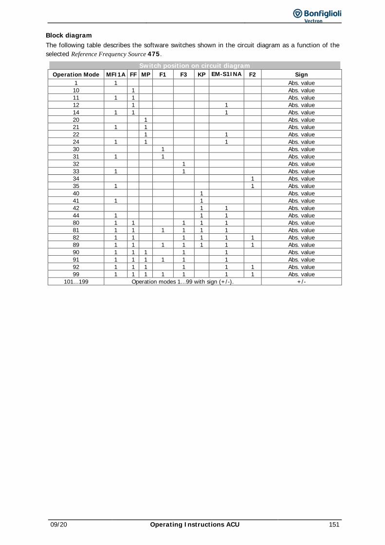
09/20 Operating Instructions ACU 151
Block diagram The following table describes the software switches shown in the circuit diagram as a function of the selected Reference Frequency Source 475.
Switch position on circuit diagram Operation Mode MFI1A FF MP F1 F3 KP EM-S1INA F2 Sign
1 1 Abs. value 10 1 Abs. value 11 1 1 Abs. value 12 1 1 Abs. value 14 1 1 1 Abs. value 20 1 Abs. value 21 1 1 Abs. value 22 1 1 Abs. value 24 1 1 1 Abs. value 30 1 Abs. value 31 1 1 Abs. value 32 1 Abs. value 33 1 1 Abs. value 34 1 Abs. value 35 1 1 Abs. value 40 1 Abs. value 41 1 1 Abs. value 42 1 1 Abs. value 44 1 1 1 Abs. value 80 1 1 1 1 1 Abs. value 81 1 1 1 1 1 1 Abs. value 82 1 1 1 1 1 1 Abs. value 89 1 1 1 1 1 1 1 Abs. value 90 1 1 1 1 1 Abs. value 91 1 1 1 1 1 1 Abs. value 92 1 1 1 1 1 1 Abs. value 99 1 1 1 1 1 1 1 Abs. value
101...199 Operation modes 1...99 with sign (+/-). +/-
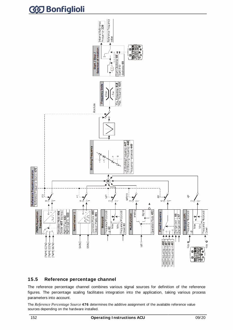
152 Operating Instructions ACU 09/20
15.5 Reference percentage channel The reference percentage channel combines various signal sources for definition of the reference figures. The percentage scaling facilitates integration into the application, taking various process parameters into account. The Reference Percentage Source 476 determines the additive assignment of the available reference value sources depending on the hardware installed.
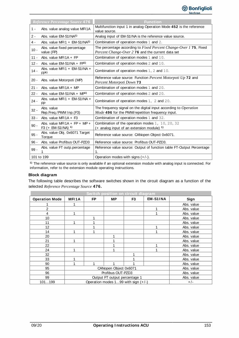
09/20 Operating Instructions ACU 153
Reference Percentage Source 476 Function 1 - Abs. value analog value MFI1A Multifunction input 1 in analog Operation Mode 452 is the reference
value source. 2 - Abs. value EM-S1INA1) Analog input of EM-S1INA is the reference value source. 4 - Abs. value MFI1 + EM-S1INA1) Combination of operation modes 1 and 2.
10 - Abs. value fixed percentage value (FP)
The percentage according to Fixed Percent Change-Over 1 75, Fixed Percent Change-Over 2 76 and the current data set
11 - Abs. value MFI1A + FP Combination of operation modes 1 and 10. 12 - Abs. value EM-S1INA + FP1) Combination of operation modes 2 and 10.
14 - Abs. value MFI1 + EM-S1INA + FP1) Combination of operation modes 1, 2 and 10.
20 - Abs. value Motorpoti (MP) Reference value source: Function Percent Motorpoti Up 72 and Percent Motorpoti Down 73
21 - Abs. value MFI1A + MP Combination of operation modes 1 and 20. 22 - Abs. value EM-S1INA + MP1) Combination of operation modes 2 and 20.
24 - Abs. value MFI1 + EM-S1INA + FP Combination of operation modes 1, 2 and 20.
32 - Abs. value Rep.Freq./PWM Inp.(F3)
The frequency signal on the digital input according to Operation Mode 496 for the PWM/repetition frequency input.
33 - Abs. value MFI1A + F3 Combination of operation modes 1 and 32.
90 - Abs. value MFI1A + FP + MP + F3 (+ EM-S1INA) 1)
Combination of the operation modes 1, 10, 20, 32 (+ analog input of an extension module) 1)
95 - Abs. value Obj. 0x6071 Target Torque Reference value source: CANopen Object 0x6071.
96 - Abs. value Profibus OUT-PZD3 Reference value source: Profibus OUT-PZD3.
99 - Abs. value FT outp.percentage 1
Reference value source: Output of function table FT-Output Percentage 1.
101 to 199 Operation modes with signs (+/-). 1) The reference value source is only available if an optional extension module with analog input is connected. For information, refer to the extension module operating instructions.
Block diagram The following table describes the software switches shown in the circuit diagram as a function of the selected Reference Percentage Source 476.
Switch position on circuit diagram Operation Mode MFI1A FP MP F3 EM-S1INA Sign
1 1 Abs. value 2 1 Abs. value 4 1 1 Abs. value 10 1 Abs. value 11 1 1 Abs. value 12 1 1 Abs. value 14 1 1 1 Abs. value 20 1 Abs. value 21 1 1 Abs. value 22 1 1 Abs. value 24 1 1 1 Abs. value 32 1 Abs. value 33 1 1 Abs. value 90 1 1 1 1 Abs. value 95 CANopen Object 0x6071 Abs. value 96 Profibus OUT-PZD3 Abs. value 99 Output FT output percentage 1 Abs. value
101...199 Operation modes 1...99 with sign (+/-) +/-
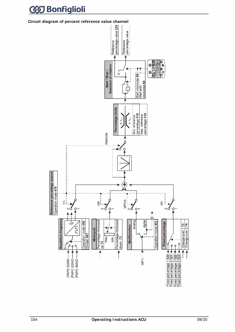
154 Operating Instructions ACU 09/20
Circuit diagram of percent reference value channel
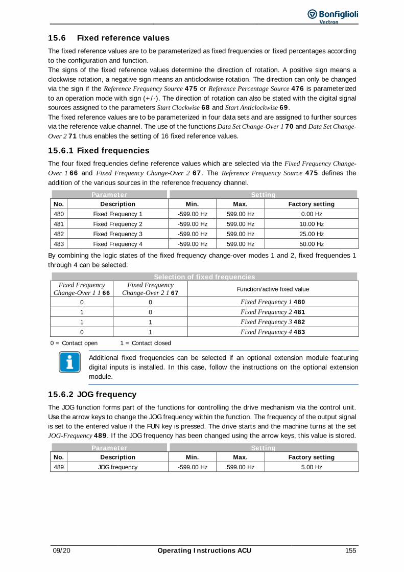
09/20 Operating Instructions ACU 155
15.6 Fixed reference values The fixed reference values are to be parameterized as fixed frequencies or fixed percentages according to the configuration and function. The signs of the fixed reference values determine the direction of rotation. A positive sign means a clockwise rotation, a negative sign means an anticlockwise rotation. The direction can only be changed via the sign if the Reference Frequency Source 475 or Reference Percentage Source 476 is parameterized to an operation mode with sign (+/-). The direction of rotation can also be stated with the digital signal sources assigned to the parameters Start Clockwise 68 and Start Anticlockwise 69. The fixed reference values are to be parameterized in four data sets and are assigned to further sources via the reference value channel. The use of the functions Data Set Change-Over 1 70 and Data Set Change-Over 2 71 thus enables the setting of 16 fixed reference values.
15.6.1 Fixed frequencies The four fixed frequencies define reference values which are selected via the Fixed Frequency Change-Over 1 66 and Fixed Frequency Change-Over 2 67. The Reference Frequency Source 475 defines the addition of the various sources in the reference frequency channel.
Parameter Setting No. Description Min. Max. Factory setting 480 Fixed Frequency 1 -599.00 Hz 599.00 Hz 0.00 Hz 481 Fixed Frequency 2 -599.00 Hz 599.00 Hz 10.00 Hz 482 Fixed Frequency 3 -599.00 Hz 599.00 Hz 25.00 Hz 483 Fixed Frequency 4 -599.00 Hz 599.00 Hz 50.00 Hz
By combining the logic states of the fixed frequency change-over modes 1 and 2, fixed frequencies 1 through 4 can be selected:
Selection of fixed frequencies Fixed Frequency
Change-Over 1 1 66 Fixed Frequency
Change-Over 2 1 67 Function/active fixed value
0 0 Fixed Frequency 1 480 1 0 Fixed Frequency 2 481 1 1 Fixed Frequency 3 482 0 1 Fixed Frequency 4 483
0 = Contact open 1 = Contact closed
Additional fixed frequencies can be selected if an optional extension module featuring digital inputs is installed. In this case, follow the instructions on the optional extension module.
15.6.2 JOG frequency The JOG function forms part of the functions for controlling the drive mechanism via the control unit. Use the arrow keys to change the JOG frequency within the function. The frequency of the output signal is set to the entered value if the FUN key is pressed. The drive starts and the machine turns at the set JOG-Frequency 489. If the JOG frequency has been changed using the arrow keys, this value is stored.
Parameter Setting No. Description Min. Max. Factory setting 489 JOG frequency -599.00 Hz 599.00 Hz 5.00 Hz
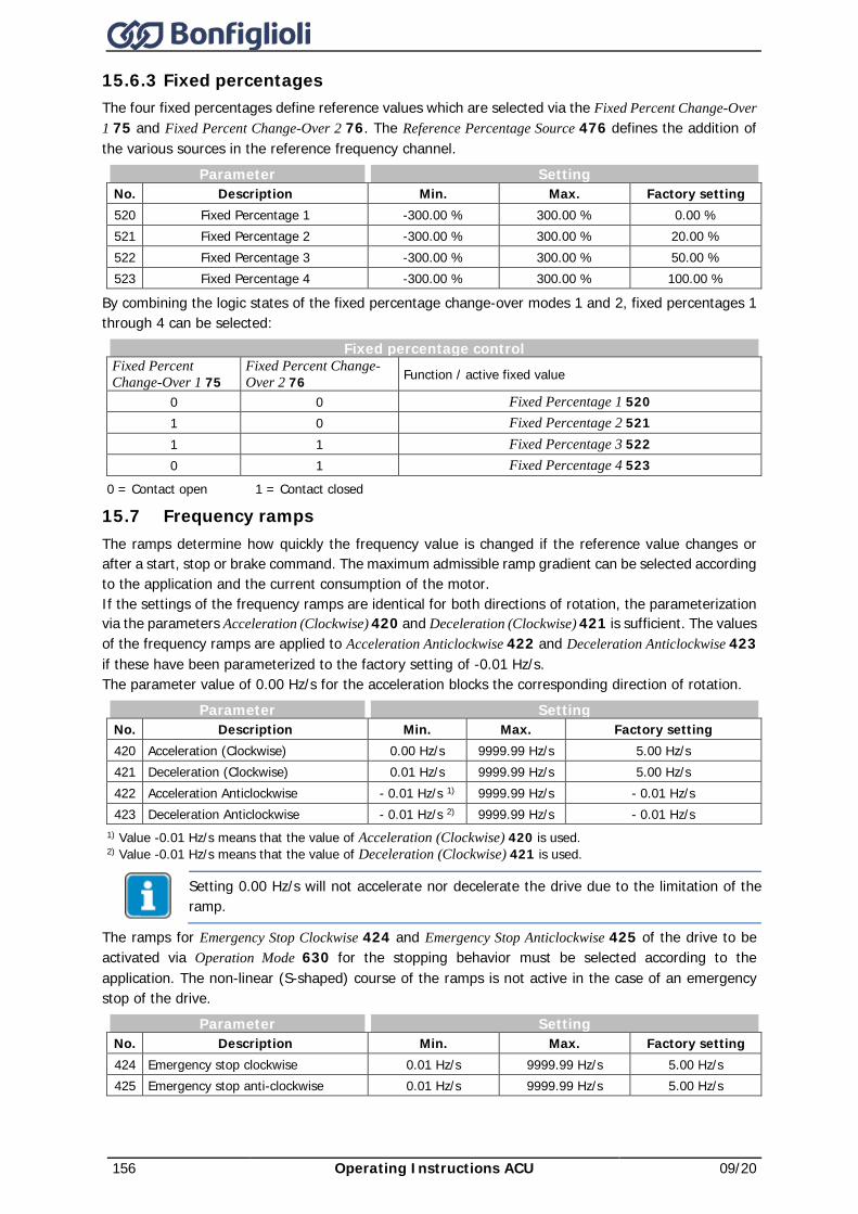
156 Operating Instructions ACU 09/20
15.6.3 Fixed percentages The four fixed percentages define reference values which are selected via the Fixed Percent Change-Over 1 75 and Fixed Percent Change-Over 2 76. The Reference Percentage Source 476 defines the addition of the various sources in the reference frequency channel.
Parameter Setting No. Description Min. Max. Factory setting 520 Fixed Percentage 1 -300.00 % 300.00 % 0.00 % 521 Fixed Percentage 2 -300.00 % 300.00 % 20.00 % 522 Fixed Percentage 3 -300.00 % 300.00 % 50.00 % 523 Fixed Percentage 4 -300.00 % 300.00 % 100.00 %
By combining the logic states of the fixed percentage change-over modes 1 and 2, fixed percentages 1 through 4 can be selected:
Fixed percentage control Fixed Percent Change-Over 1 75
Fixed Percent Change-Over 2 76 Function / active fixed value
0 0 Fixed Percentage 1 520 1 0 Fixed Percentage 2 521 1 1 Fixed Percentage 3 522 0 1 Fixed Percentage 4 523
0 = Contact open 1 = Contact closed
15.7 Frequency ramps The ramps determine how quickly the frequency value is changed if the reference value changes or after a start, stop or brake command. The maximum admissible ramp gradient can be selected according to the application and the current consumption of the motor. If the settings of the frequency ramps are identical for both directions of rotation, the parameterization via the parameters Acceleration (Clockwise) 420 and Deceleration (Clockwise) 421 is sufficient. The values of the frequency ramps are applied to Acceleration Anticlockwise 422 and Deceleration Anticlockwise 423 if these have been parameterized to the factory setting of -0.01 Hz/s. The parameter value of 0.00 Hz/s for the acceleration blocks the corresponding direction of rotation.
Parameter Setting No. Description Min. Max. Factory setting 420 Acceleration (Clockwise) 0.00 Hz/s 9999.99 Hz/s 5.00 Hz/s 421 Deceleration (Clockwise) 0.01 Hz/s 9999.99 Hz/s 5.00 Hz/s 422 Acceleration Anticlockwise - 0.01 Hz/s 1) 9999.99 Hz/s - 0.01 Hz/s 423 Deceleration Anticlockwise - 0.01 Hz/s 2) 9999.99 Hz/s - 0.01 Hz/s
1) Value -0.01 Hz/s means that the value of Acceleration (Clockwise) 420 is used. 2) Value -0.01 Hz/s means that the value of Deceleration (Clockwise) 421 is used.
Setting 0.00 Hz/s will not accelerate nor decelerate the drive due to the limitation of the ramp.
The ramps for Emergency Stop Clockwise 424 and Emergency Stop Anticlockwise 425 of the drive to be activated via Operation Mode 630 for the stopping behavior must be selected according to the application. The non-linear (S-shaped) course of the ramps is not active in the case of an emergency stop of the drive.
Parameter Setting No. Description Min. Max. Factory setting 424 Emergency stop clockwise 0.01 Hz/s 9999.99 Hz/s 5.00 Hz/s 425 Emergency stop anti-clockwise 0.01 Hz/s 9999.99 Hz/s 5.00 Hz/s
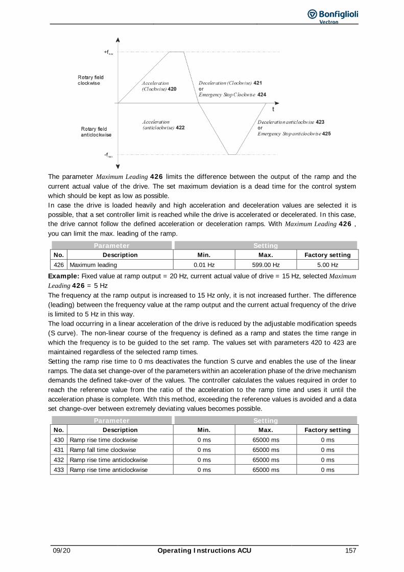
09/20 Operating Instructions ACU 157
The parameter Maximum Leading 426 limits the difference between the output of the ramp and the current actual value of the drive. The set maximum deviation is a dead time for the control system which should be kept as low as possible. In case the drive is loaded heavily and high acceleration and deceleration values are selected it is possible, that a set controller limit is reached while the drive is accelerated or decelerated. In this case, the drive cannot follow the defined acceleration or deceleration ramps. With Maximum Leading 426 , you can limit the max. leading of the ramp.
Parameter Setting No. Description Min. Max. Factory setting 426 Maximum leading 0.01 Hz 599.00 Hz 5.00 Hz
Example: Fixed value at ramp output = 20 Hz, current actual value of drive = 15 Hz, selected Maximum Leading 426 = 5 Hz The frequency at the ramp output is increased to 15 Hz only, it is not increased further. The difference (leading) between the frequency value at the ramp output and the current actual frequency of the drive is limited to 5 Hz in this way. The load occurring in a linear acceleration of the drive is reduced by the adjustable modification speeds (S curve). The non-linear course of the frequency is defined as a ramp and states the time range in which the frequency is to be guided to the set ramp. The values set with parameters 420 to 423 are maintained regardless of the selected ramp times. Setting the ramp rise time to 0 ms deactivates the function S curve and enables the use of the linear ramps. The data set change-over of the parameters within an acceleration phase of the drive mechanism demands the defined take-over of the values. The controller calculates the values required in order to reach the reference value from the ratio of the acceleration to the ramp time and uses it until the acceleration phase is complete. With this method, exceeding the reference values is avoided and a data set change-over between extremely deviating values becomes possible.
Parameter Setting No. Description Min. Max. Factory setting 430 Ramp rise time clockwise 0 ms 65000 ms 0 ms 431 Ramp fall time clockwise 0 ms 65000 ms 0 ms 432 Ramp rise time anticlockwise 0 ms 65000 ms 0 ms 433 Ramp rise time anticlockwise 0 ms 65000 ms 0 ms
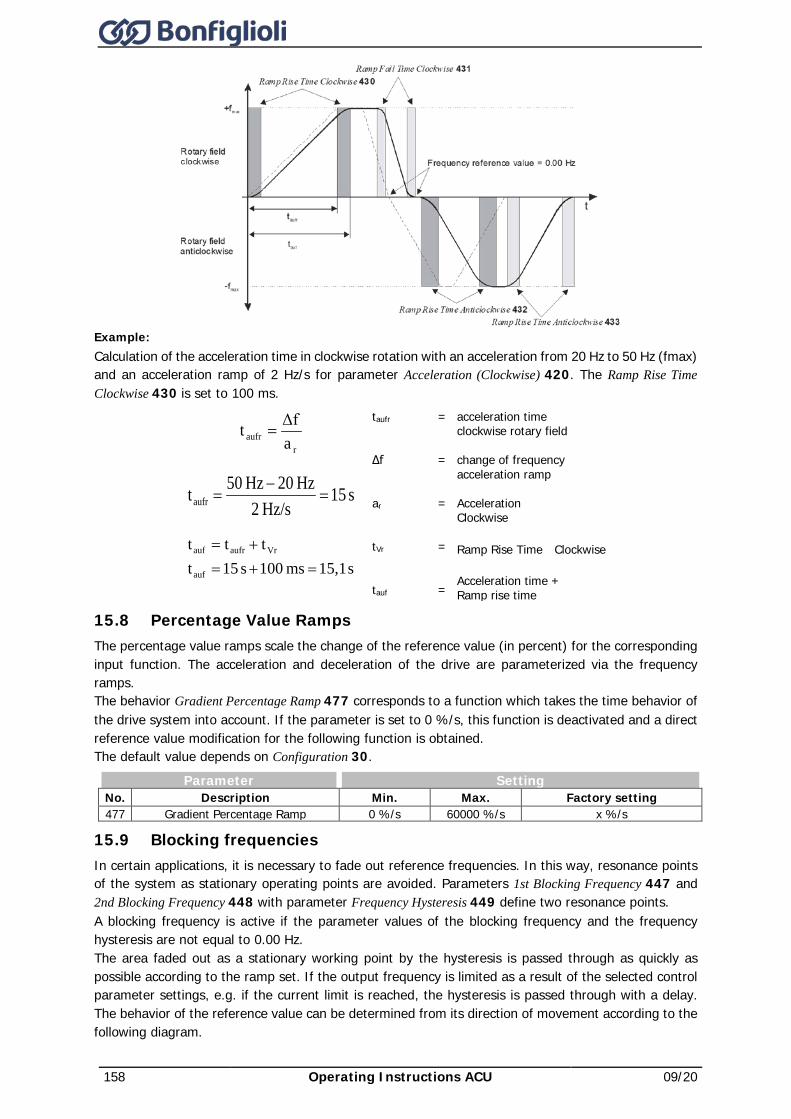
158 Operating Instructions ACU 09/20
Example: Calculation of the acceleration time in clockwise rotation with an acceleration from 20 Hz to 50 Hz (fmax) and an acceleration ramp of 2 Hz/s for parameter Acceleration (Clockwise) 420. The Ramp Rise Time Clockwise 430 is set to 100 ms.
raufr a
Δft =
s 15Hz/s 2
Hz 20Hz 50taufr =−
=
s 15,1ms 100s 15tttt
auf
Vraufrauf
=+=+=
taufr ∆f ar tVr tauf
= = = = =
acceleration time clockwise rotary field change of frequency acceleration ramp Acceleration Clockwise Ramp Rise Time Clockwise Acceleration time + Ramp rise time
15.8 Percentage Value Ramps The percentage value ramps scale the change of the reference value (in percent) for the corresponding input function. The acceleration and deceleration of the drive are parameterized via the frequency ramps. The behavior Gradient Percentage Ramp 477 corresponds to a function which takes the time behavior of the drive system into account. If the parameter is set to 0 %/s, this function is deactivated and a direct reference value modification for the following function is obtained. The default value depends on Configuration 30.
Parameter Setting No. Description Min. Max. Factory setting 477 Gradient Percentage Ramp 0 %/s 60000 %/s x %/s
15.9 Blocking frequencies In certain applications, it is necessary to fade out reference frequencies. In this way, resonance points of the system as stationary operating points are avoided. Parameters 1st Blocking Frequency 447 and 2nd Blocking Frequency 448 with parameter Frequency Hysteresis 449 define two resonance points. A blocking frequency is active if the parameter values of the blocking frequency and the frequency hysteresis are not equal to 0.00 Hz. The area faded out as a stationary working point by the hysteresis is passed through as quickly as possible according to the ramp set. If the output frequency is limited as a result of the selected control parameter settings, e.g. if the current limit is reached, the hysteresis is passed through with a delay. The behavior of the reference value can be determined from its direction of movement according to the following diagram.
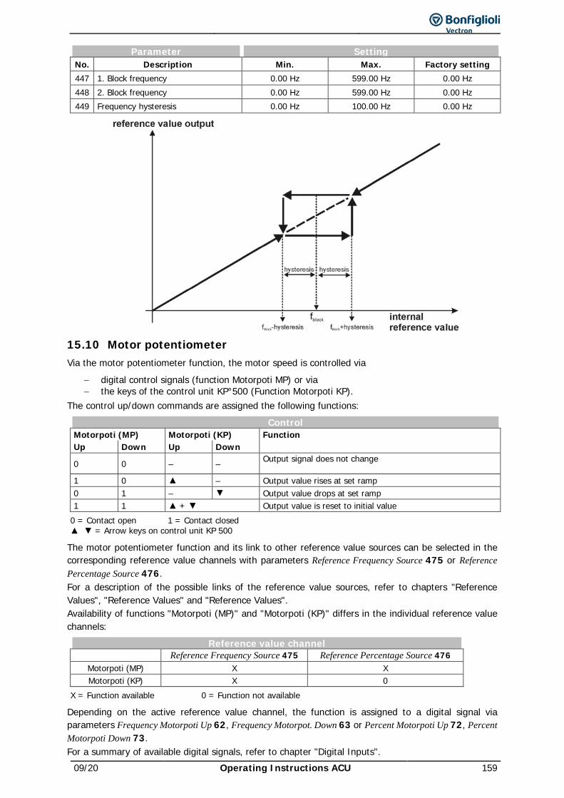
09/20 Operating Instructions ACU 159
Parameter Setting No. Description Min. Max. Factory setting 447 1. Block frequency 0.00 Hz 599.00 Hz 0.00 Hz 448 2. Block frequency 0.00 Hz 599.00 Hz 0.00 Hz 449 Frequency hysteresis 0.00 Hz 100.00 Hz 0.00 Hz
15.10 Motor potentiometer Via the motor potentiometer function, the motor speed is controlled via
− digital control signals (function Motorpoti MP) or via − the keys of the control unit KP°500 (Function Motorpoti KP).
The control up/down commands are assigned the following functions: Control
Motorpoti (MP) Motorpoti (KP) Function Up Down Up Down
0 0 – – Output signal does not change
1 0 – Output value rises at set ramp 0 1 – Output value drops at set ramp 1 1 + Output value is reset to initial value
0 = Contact open 1 = Contact closed = Arrow keys on control unit KP 500
The motor potentiometer function and its link to other reference value sources can be selected in the corresponding reference value channels with parameters Reference Frequency Source 475 or Reference Percentage Source 476. For a description of the possible links of the reference value sources, refer to chapters "Reference Values", "Reference Values" and "Reference Values". Availability of functions "Motorpoti (MP)" and "Motorpoti (KP)" differs in the individual reference value channels:
Reference value channel Reference Frequency Source 475 Reference Percentage Source 476
Motorpoti (MP) X X Motorpoti (KP) X 0
X = Function available 0 = Function not available
Depending on the active reference value channel, the function is assigned to a digital signal via parameters Frequency Motorpoti Up 62, Frequency Motorpot. Down 63 or Percent Motorpoti Up 72, Percent Motorpoti Down 73. For a summary of available digital signals, refer to chapter "Digital Inputs".
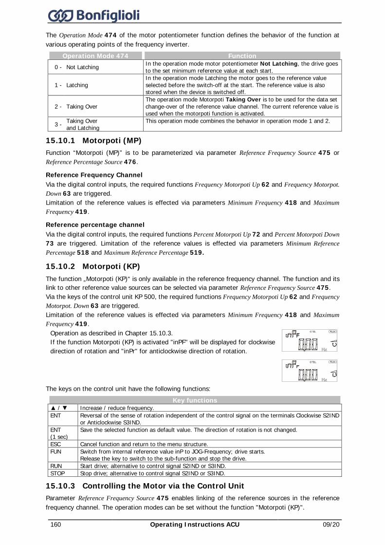
160 Operating Instructions ACU 09/20
The Operation Mode 474 of the motor potentiometer function defines the behavior of the function at various operating points of the frequency inverter.
Operation Mode 474 Function 0 - Not Latching In the operation mode motor potentiometer Not Latching, the drive goes
to the set minimum reference value at each start.
1 - Latching In the operation mode Latching the motor goes to the reference value selected before the switch-off at the start. The reference value is also stored when the device is switched off.
2 - Taking Over The operation mode Motorpoti Taking Over is to be used for the data set change-over of the reference value channel. The current reference value is used when the motorpoti function is activated.
3 - Taking Over and Latching
This operation mode combines the behavior in operation mode 1 and 2.
15.10.1 Motorpoti (MP) Function “Motorpoti (MP)” is to be parameterized via parameter Reference Frequency Source 475 or Reference Percentage Source 476.
Reference Frequency Channel Via the digital control inputs, the required functions Frequency Motorpoti Up 62 and Frequency Motorpot. Down 63 are triggered. Limitation of the reference values is effected via parameters Minimum Frequency 418 and Maximum Frequency 419.
Reference percentage channel Via the digital control inputs, the required functions Percent Motorpoti Up 72 and Percent Motorpoti Down 73 are triggered. Limitation of the reference values is effected via parameters Minimum Reference Percentage 518 and Maximum Reference Percentage 519.
15.10.2 Motorpoti (KP) The function „Motorpoti (KP)“ is only available in the reference frequency channel. The function and its link to other reference value sources can be selected via parameter Reference Frequency Source 475. Via the keys of the control unit KP 500, the required functions Frequency Motorpoti Up 62 and Frequency Motorpot. Down 63 are triggered. Limitation of the reference values is effected via parameters Minimum Frequency 418 and Maximum Frequency 419.
Operation as described in Chapter 15.10.3. If the function Motorpoti (KP) is activated "inPF" will be displayed for clockwise direction of rotation and "inPr" for anticlockwise direction of rotation.
The keys on the control unit have the following functions:
Key functions / Increase / reduce frequency. ENT Reversal of the sense of rotation independent of the control signal on the terminals Clockwise S2IND
or Anticlockwise S3IND. ENT (1 sec)
Save the selected function as default value. The direction of rotation is not changed.
ESC Cancel function and return to the menu structure. FUN Switch from internal reference value inP to JOG-Frequency; drive starts.
Release the key to switch to the sub-function and stop the drive. RUN Start drive; alternative to control signal S2IND or S3IND. STOP Stop drive; alternative to control signal S2IND or S3IND.
15.10.3 Controlling the Motor via the Control Unit Parameter Reference Frequency Source 475 enables linking of the reference sources in the reference frequency channel. The operation modes can be set without the function "Motorpoti (KP)".
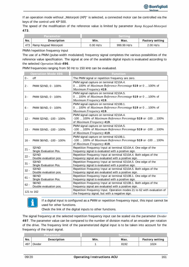
09/20 Operating Instructions ACU 161
If an operation mode without „Motorpoti (KP)“ is selected, a connected motor can be controlled via the keys of the control unit KP 500. The speed of the modification of the reference value is limited by parameter Ramp Keypad-Motorpoti 473.
Parameter Setting No. Description Min. Max. Factory setting 473 Ramp Keypad Motorpoti 0.00 Hz/s 999.99 Hz/s 2.00 Hz/s
PWM-/repetition frequency input The use of a PWM (pulse-width modulated) frequency signal completes the various possibilities of the reference value specification. The signal at one of the available digital inputs is evaluated according to the selected Operation Mode 496. PWM frequencies ranging from 50 Hz to 150 kHz can be evaluated.
Operation Mode 496 Function 0 - off The PWM signal or repetition frequency are zero.
2 - PWM S2IND, 0 - 100% PWM signal capture on terminal X210A.4. 0 … 100% of Maximum Reference Percentage 519 or 0 … 100% of Maximum Frequency 419.
3 - PWM S3IND, 0 - 100% PWM signal capture on terminal X210A.5. 0 … 100% of Maximum Reference Percentage 519 or 0 … 100% of Maximum Frequency 419.
6 - PWM S6IND, 0 - 100% PWM signal capture on terminal X210B.1. 0 … 100% of Maximum Reference Percentage 519 or 0 … 100% of Maximum Frequency 419.
12 - PWM S2IND, -100 - 100% PWM signal capture on terminal X210A.4. -100 … 100% of Maximum Reference Percentage 519 or -100 … 100% of Maximum Frequency 419.
13 - PWM S3IND, -100 - 100% PWM signal capture on terminal X210A.5. -100 … 100% of Maximum Reference Percentage 519 or -100 … 100% of Maximum Frequency 419.
16 - PWM S6IND, -100 - 100% PWM signal capture on terminal X210B.1. -100 … 100% of Maximum Reference Percentage 519 or -100 … 100% of Maximum Frequency 419.
21 - S2IND Single Evaluation Pos.
Repetition Frequency Input at terminal X210A.4. One edge of the frequency signal is evaluated with a positive sign.
22 - S2IND Double evaluation pos.
Repetition Frequency Input at terminal X210A.4. Both edges of the frequency signal are evaluated with a positive sign.
31 - S3IND Single Evaluation Pos.
Repetition Frequency Input at terminal X210A.5. One edge of the frequency signal is evaluated with a positive sign.
32 - S3IND Double evaluation pos.
Repetition Frequency Input at terminal X210A.5. Both edges of the frequency signal are evaluated with a positive sign.
61 - S6IND Single Evaluation Pos.
Repetition Frequency Input at terminal X210B.1. One edge of the frequency signal is evaluated with a positive sign.
62 - S6IND Double evaluation pos.
Repetition Frequency Input at terminal X210B.1. Both edges of the frequency signal are evaluated with a positive sign.
121 to 162 Repetition Frequency Input. Operation modes 21 to 62 with evaluation of the frequency signal, but with a negative sign.
If a digital input is configured as a PWM or repetition frequency input, this input cannot be used for other functions. Check the link of the digital inputs to other functions.
The signal frequency at the selected repetition frequency input can be scaled via the parameter Divider 497. The parameter value can be compared to the number of division marks of an encoder per rotation of the drive. The frequency limit of the parameterized digital input is to be taken into account for the frequency of the input signal.
Parameter Setting No. Description Min. Max. Factory setting 497 Divider 1 8192 1024
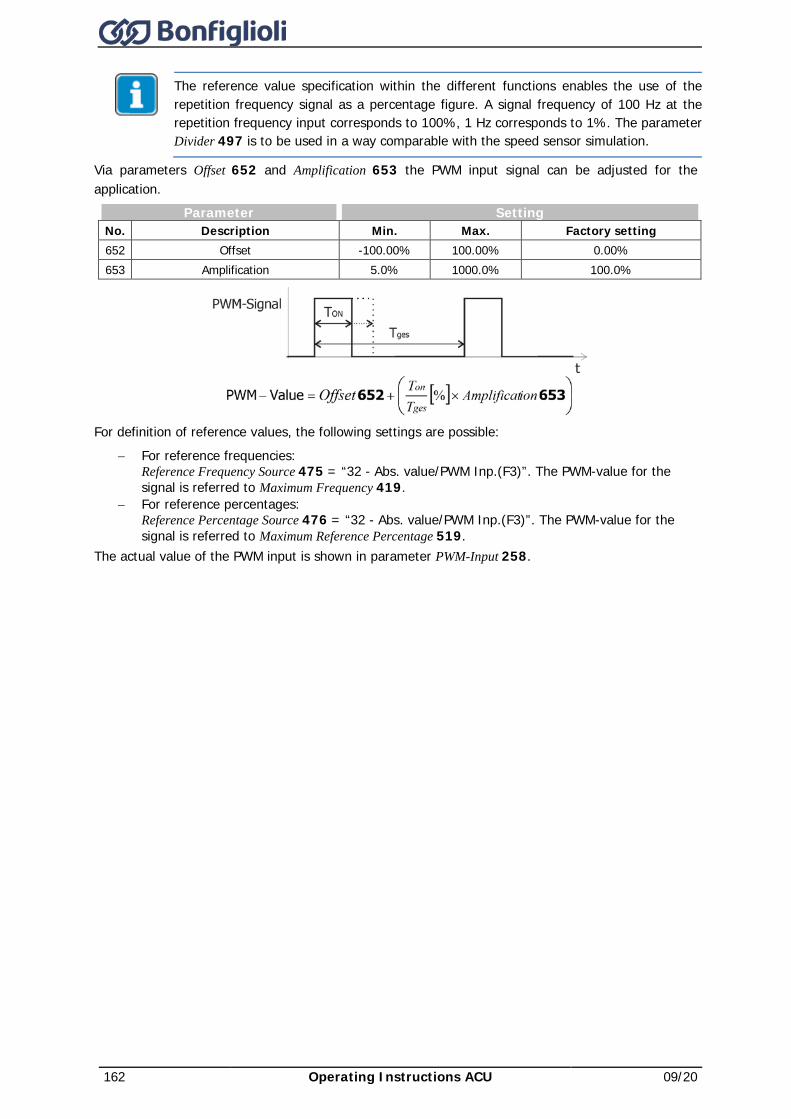
162 Operating Instructions ACU 09/20
The reference value specification within the different functions enables the use of the repetition frequency signal as a percentage figure. A signal frequency of 100 Hz at the repetition frequency input corresponds to 100%, 1 Hz corresponds to 1%. The parameter Divider 497 is to be used in a way comparable with the speed sensor simulation.
Via parameters Offset 652 and Amplification 653 the PWM input signal can be adjusted for the application.
Parameter Setting No. Description Min. Max. Factory setting 652 Offset -100.00% 100.00% 0.00% 653 Amplification 5.0% 1000.0% 100.0%
For definition of reference values, the following settings are possible:
− For reference frequencies: Reference Frequency Source 475 = “32 - Abs. value/PWM Inp.(F3)”. The PWM-value for the signal is referred to Maximum Frequency 419.
− For reference percentages: Reference Percentage Source 476 = “32 - Abs. value/PWM Inp.(F3)”. The PWM-value for the signal is referred to Maximum Reference Percentage 519.
The actual value of the PWM input is shown in parameter PWM-Input 258.
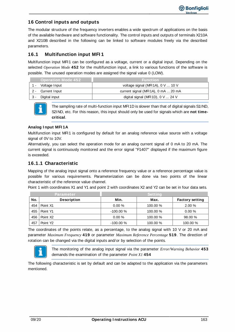
09/20 Operating Instructions ACU 163
16 Control inputs and outputs The modular structure of the frequency inverters enables a wide spectrum of applications on the basis of the available hardware and software functionality. The control inputs and outputs of terminals X210A and X210B described in the following can be linked to software modules freely via the described parameters.
16.1 Multifunction input MFI1 Multifunction input MFI1 can be configured as a voltage, current or a digital input. Depending on the selected Operation Mode 452 for the multifunction input, a link to various functions of the software is possible. The unused operation modes are assigned the signal value 0 (LOW).
Operation Mode 452 Function 1 - Voltage Input voltage signal (MFI1A), 0 V ... 10 V 2 - Current Input current signal (MFI1A), 0 mA … 20 mA 3 - Digital input digital signal (MFI1D), 0 V ... 24 V
The sampling rate of multi-function input MFI1D is slower than that of digital signals S1IND, S2IND, etc. For this reason, this input should only be used for signals which are not time-critical.
Analog Input MFI1A Multifunction input MFI1 is configured by default for an analog reference value source with a voltage signal of 0V to 10V. Alternatively, you can select the operation mode for an analog current signal of 0 mA to 20 mA. The current signal is continuously monitored and the error signal "F1407" displayed if the maximum figure is exceeded.
16.1.1 Characteristic Mapping of the analog input signal onto a reference frequency value or a reference percentage value is possible for various requirements. Parameterization can be done via two points of the linear characteristic of the reference value channel. Point 1 with coordinates X1 and Y1 and point 2 with coordinates X2 and Y2 can be set in four data sets.
Parameter Setting No. Description Min. Max. Factory setting 454 Point X1 0.00 % 100.00 % 2.00 % 455 Point Y1 -100.00 % 100.00 % 0.00 % 456 Point X2 0.00 % 100.00 % 98.00 % 457 Point Y2 -100.00 % 100.00 % 100.00 %
The coordinates of the points relate, as a percentage, to the analog signal with 10 V or 20 mA and parameter Maximum Frequency 419 or parameter Maximum Reference Percentage 519. The direction of rotation can be changed via the digital inputs and/or by selection of the points.
The monitoring of the analog input signal via the parameter Error/Warning Behavior 453 demands the examination of the parameter Point X1 454
The following characteristic is set by default and can be adapted to the application via the parameters mentioned.
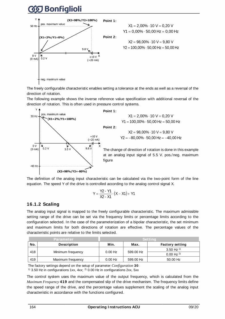
164 Operating Instructions ACU 09/20
Point 1: V0,20 V102,00%X1 =⋅=
Hz 0,00Hz 50,000,00%Y1 =⋅= Point 2:
V9,80 V1098,00%X2 =⋅= Hz 0,005Hz 50,000,00%10Y2 =⋅=
The freely configurable characteristic enables setting a tolerance at the ends as well as a reversal of the direction of rotation. The following example shows the inverse reference value specification with additional reversal of the direction of rotation. This is often used in pressure control systems.
Point 1: V0,20 V102,00%X1 =⋅=
Hz 50,00Hz 50,000,00%10Y1 =⋅= Point 2:
V9,80 V1098,00%X2 =⋅= Hz 0,004Hz 50,000,00%8Y2 −=⋅−=
The change of direction of rotation is done in this example at an analog input signal of 5.5 V. pos./neg. maximum figure
The definition of the analog input characteristic can be calculated via the two-point form of the line equation. The speed Y of the drive is controlled according to the analog control signal X.
( ) Y1X1XX1-X2Y1-Y2 Y +−⋅=
16.1.2 Scaling The analog input signal is mapped to the freely configurable characteristic. The maximum admissible setting range of the drive can be set via the frequency limits or percentage limits according to the configuration selected. In the case of the parameterization of a bipolar characteristic, the set minimum and maximum limits for both directions of rotation are effective. The percentage values of the characteristic points are relative to the limits selected.
Parameter Setting No. Description Min. Max. Factory setting
418 Minimum frequency 0.00 Hz 599.00 Hz 3.50 Hz 1) 0.00 Hz 2)
419 Maximum frequency 0.00 Hz 599.00 Hz 50.00 Hz The factory settings depend on the setup of parameter Configuration 30: 1) 3.50 Hz in configurations 1xx, 4xx; 2) 0.00 Hz in configurations 2xx, 5xx
The control system uses the maximum value of the output frequency, which is calculated from the Maximum Frequency 419 and the compensated slip of the drive mechanism. The frequency limits define the speed range of the drive, and the percentage values supplement the scaling of the analog input characteristic in accordance with the functions configured.
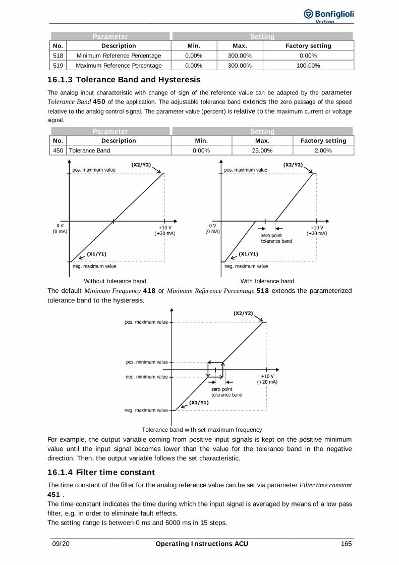
09/20 Operating Instructions ACU 165
Parameter Setting No. Description Min. Max. Factory setting 518 Minimum Reference Percentage 0.00% 300.00% 0.00% 519 Maximum Reference Percentage 0.00% 300.00% 100.00%
16.1.3 Tolerance Band and Hysteresis The analog input characteristic with change of sign of the reference value can be adapted by the parameter Tolerance Band 450 of the application. The adjustable tolerance band extends the zero passage of the speed relative to the analog control signal. The parameter value (percent) is relative to the maximum current or voltage signal.
Parameter Setting No. Description Min. Max. Factory setting 450 Tolerance Band 0.00% 25.00% 2.00%
Without tolerance band
With tolerance band
The default Minimum Frequency 418 or Minimum Reference Percentage 518 extends the parameterized tolerance band to the hysteresis.
Tolerance band with set maximum frequency
For example, the output variable coming from positive input signals is kept on the positive minimum value until the input signal becomes lower than the value for the tolerance band in the negative direction. Then, the output variable follows the set characteristic.
16.1.4 Filter time constant The time constant of the filter for the analog reference value can be set via parameter Filter time constant 451 . The time constant indicates the time during which the input signal is averaged by means of a low pass filter, e.g. in order to eliminate fault effects. The setting range is between 0 ms and 5000 ms in 15 steps.
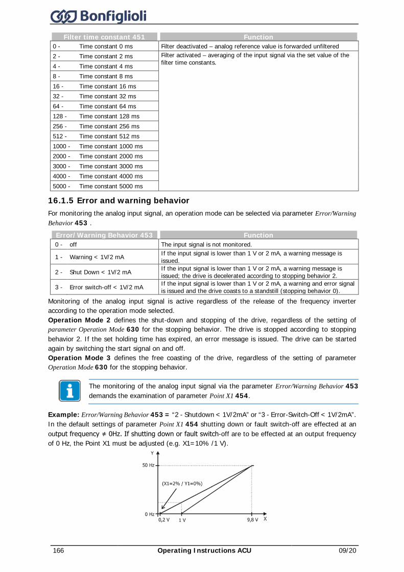
166 Operating Instructions ACU 09/20
Filter time constant 451 Function 0 - Time constant 0 ms Filter deactivated – analog reference value is forwarded unfiltered 2 - Time constant 2 ms Filter activated – averaging of the input signal via the set value of the
filter time constants. 4 - Time constant 4 ms 8 - Time constant 8 ms 16 - Time constant 16 ms 32 - Time constant 32 ms 64 - Time constant 64 ms 128 - Time constant 128 ms 256 - Time constant 256 ms 512 - Time constant 512 ms 1000 - Time constant 1000 ms 2000 - Time constant 2000 ms 3000 - Time constant 3000 ms 4000 - Time constant 4000 ms 5000 - Time constant 5000 ms
16.1.5 Error and warning behavior For monitoring the analog input signal, an operation mode can be selected via parameter Error/Warning Behavior 453 .
Error/Warning Behavior 453 Function 0 - off The input signal is not monitored.
1 - Warning < 1V/2 mA If the input signal is lower than 1 V or 2 mA, a warning message is issued.
2 - Shut Down < 1V/2 mA If the input signal is lower than 1 V or 2 mA, a warning message is issued; the drive is decelerated according to stopping behavior 2.
3 - Error switch-off < 1V/2 mA If the input signal is lower than 1 V or 2 mA, a warning and error signal is issued and the drive coasts to a standstill (stopping behavior 0).
Monitoring of the analog input signal is active regardless of the release of the frequency inverter according to the operation mode selected. Operation Mode 2 defines the shut-down and stopping of the drive, regardless of the setting of parameter Operation Mode 630 for the stopping behavior. The drive is stopped according to stopping behavior 2. If the set holding time has expired, an error message is issued. The drive can be started again by switching the start signal on and off. Operation Mode 3 defines the free coasting of the drive, regardless of the setting of parameter Operation Mode 630 for the stopping behavior.
The monitoring of the analog input signal via the parameter Error/Warning Behavior 453 demands the examination of parameter Point X1 454.
Example: Error/Warning Behavior 453 = “2 - Shutdown < 1V/2mA” or “3 - Error-Switch-Off < 1V/2mA”. In the default settings of parameter Point X1 454 shutting down or fault switch-off are effected at an output frequency ≠ 0Hz. If shutting down or fault switch-off are to be effected at an output frequency of 0 Hz, the Point X1 must be adjusted (e.g. X1=10% /1 V).
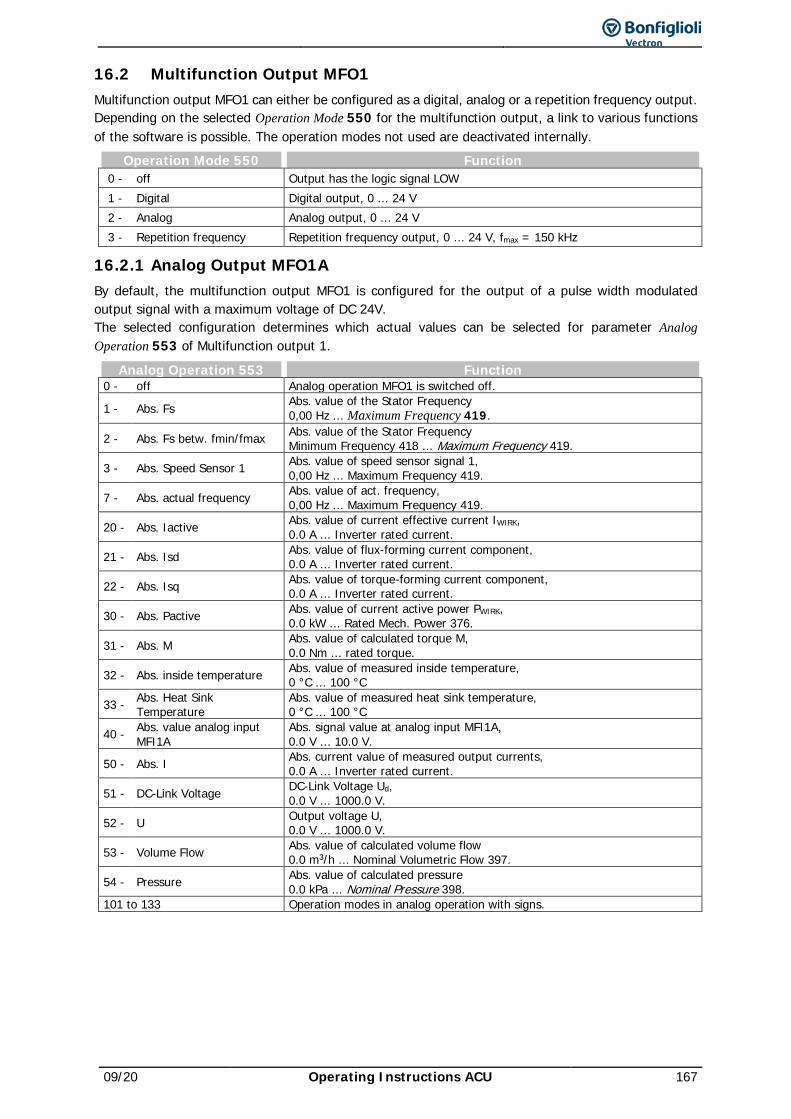
09/20 Operating Instructions ACU 167
16.2 Multifunction Output MFO1 Multifunction output MFO1 can either be configured as a digital, analog or a repetition frequency output. Depending on the selected Operation Mode 550 for the multifunction output, a link to various functions of the software is possible. The operation modes not used are deactivated internally.
Operation Mode 550 Function 0 - off Output has the logic signal LOW 1 - Digital Digital output, 0 ... 24 V 2 - Analog Analog output, 0 ... 24 V 3 - Repetition frequency Repetition frequency output, 0 ... 24 V, fmax = 150 kHz
16.2.1 Analog Output MFO1A By default, the multifunction output MFO1 is configured for the output of a pulse width modulated output signal with a maximum voltage of DC 24V. The selected configuration determines which actual values can be selected for parameter Analog Operation 553 of Multifunction output 1.
Analog Operation 553 Function 0 - off Analog operation MFO1 is switched off.
1 - Abs. Fs Abs. value of the Stator Frequency 0,00 Hz ... Maximum Frequency 419.
2 - Abs. Fs betw. fmin/fmax Abs. value of the Stator Frequency Minimum Frequency 418 ... Maximum Frequency 419.
3 - Abs. Speed Sensor 1 Abs. value of speed sensor signal 1, 0,00 Hz ... Maximum Frequency 419.
7 - Abs. actual frequency Abs. value of act. frequency, 0,00 Hz ... Maximum Frequency 419.
20 - Abs. Iactive Abs. value of current effective current IWIRK, 0.0 A ... Inverter rated current.
21 - Abs. Isd Abs. value of flux-forming current component, 0.0 A ... Inverter rated current.
22 - Abs. Isq Abs. value of torque-forming current component, 0.0 A ... Inverter rated current.
30 - Abs. Pactive Abs. value of current active power PWIRK, 0.0 kW ... Rated Mech. Power 376.
31 - Abs. M Abs. value of calculated torque M, 0.0 Nm ... rated torque.
32 - Abs. inside temperature Abs. value of measured inside temperature, 0 °C ... 100 °C
33 - Abs. Heat Sink Temperature
Abs. value of measured heat sink temperature, 0 °C ... 100 °C
40 - Abs. value analog input MFI1A
Abs. signal value at analog input MFI1A, 0.0 V ... 10.0 V.
50 - Abs. I Abs. current value of measured output currents, 0.0 A ... Inverter rated current.
51 - DC-Link Voltage DC-Link Voltage Ud, 0.0 V ... 1000.0 V.
52 - U Output voltage U, 0.0 V ... 1000.0 V.
53 - Volume Flow Abs. value of calculated volume flow 0.0 m3/h ... Nominal Volumetric Flow 397.
54 - Pressure Abs. value of calculated pressure 0.0 kPa ... Nominal Pressure 398.
101 to 133 Operation modes in analog operation with signs.
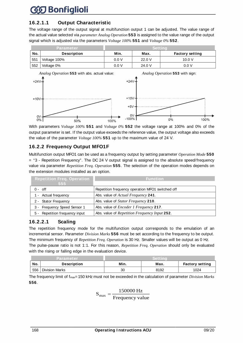
168 Operating Instructions ACU 09/20
16.2.1.1 Output Characteristic The voltage range of the output signal at multifunction output 1 can be adjusted. The value range of the actual value selected via parameter Analog Operation 553 is assigned to the value range of the output signal which is adjusted via the parameters Voltage 100% 551 and Voltage 0% 552.
Parameter Setting No. Description Min. Max. Factory setting 551 Voltage 100% 0.0 V 22.0 V 10.0 V 552 Voltage 0% 0.0 V 24.0 V 0.0 V
Analog Operation 553 with abs. actual value: Analog Operation 553 with sign:
With parameters Voltage 100% 551 and Voltage 0% 552 the voltage range at 100% and 0% of the output parameter is set. If the output value exceeds the reference value, the output voltage also exceeds the value of the parameter Voltage 100% 551 up to the maximum value of 24 V.
16.2.2 Frequency Output MFO1F Multifunction output MFO1 can be used as a frequency output by setting parameter Operation Mode 550 = “3 - Repetition Frequency”. The DC 24 V output signal is assigned to the absolute speed/frequency value via parameter Repetition Freq. Operation 555. The selection of the operation modes depends on the extension modules installed as an option.
Repetition Freq. Operation 555
Function
0 - off Repetition frequency operation MFO1 switched off 1 - Actual frequency Abs. value of Actual Frequency 241. 2 - Stator Frequency Abs. value of Stator Frequency 210. 3 - Frequency Speed Sensor 1 Abs. value of Encoder 1 Frequency 217. 5 - Repetition frequency input Abs. value of Repetition Frequency Input 252.
16.2.2.1 Scaling The repetition frequency mode for the multifunction output corresponds to the emulation of an incremental sensor. Parameter Division Marks 556 must be set according to the frequency to be output. The minimum frequency of Repetition Freq. Operation is 30 Hz. Smaller values will be output as 0 Hz. The pulse-pause ratio is not 1:1. For this reason, Repetition Freq. Operation should only be evaluated with the rising or falling edge in the evaluation device.
Parameter Setting No. Description Min. Max. Factory setting 556 Division Marks 30 8192 1024
The frequency limit of fmax=150 kHz must not be exceeded in the calculation of parameter Division Marks 556.
valueFrequency Hz 150000Smax =
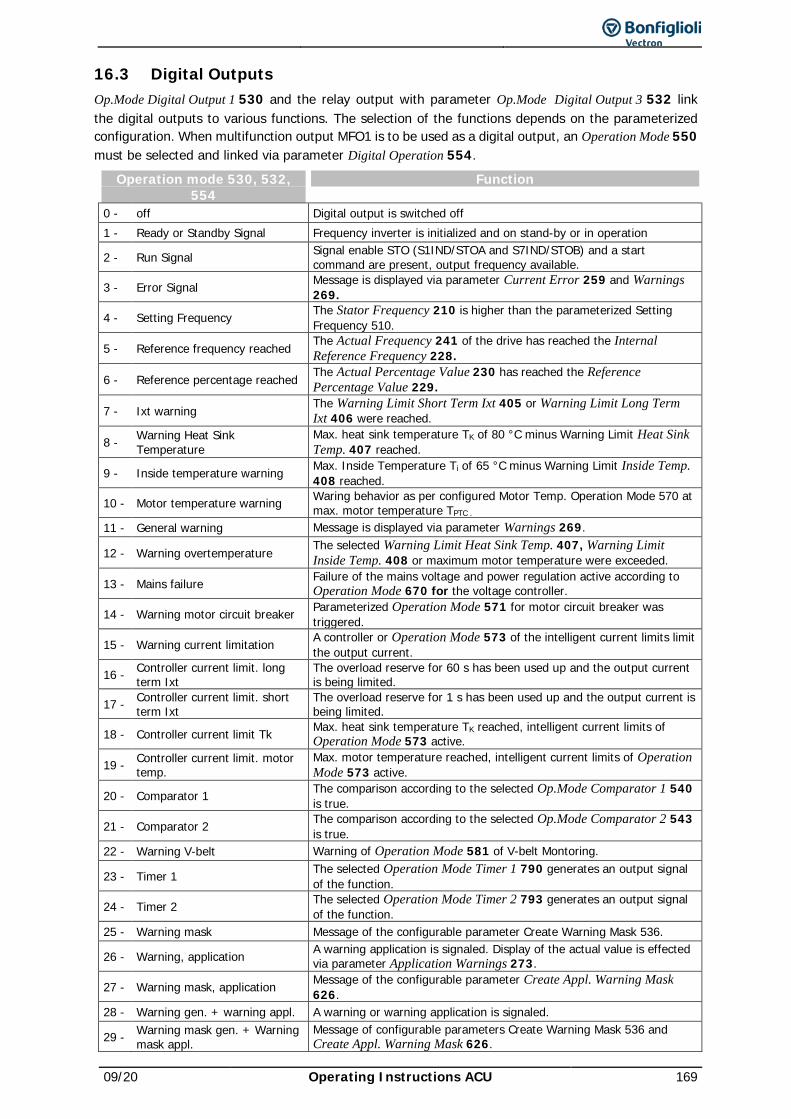
09/20 Operating Instructions ACU 169
16.3 Digital Outputs Op.Mode Digital Output 1 530 and the relay output with parameter Op.Mode Digital Output 3 532 link the digital outputs to various functions. The selection of the functions depends on the parameterized configuration. When multifunction output MFO1 is to be used as a digital output, an Operation Mode 550 must be selected and linked via parameter Digital Operation 554.
Operation mode 530, 532, 554
Function
0 - off Digital output is switched off 1 - Ready or Standby Signal Frequency inverter is initialized and on stand-by or in operation
2 - Run Signal Signal enable STO (S1IND/STOA and S7IND/STOB) and a start command are present, output frequency available.
3 - Error Signal Message is displayed via parameter Current Error 259 and Warnings 269.
4 - Setting Frequency The Stator Frequency 210 is higher than the parameterized Setting Frequency 510.
5 - Reference frequency reached The Actual Frequency 241 of the drive has reached the Internal Reference Frequency 228.
6 - Reference percentage reached The Actual Percentage Value 230 has reached the Reference Percentage Value 229.
7 - Ixt warning The Warning Limit Short Term Ixt 405 or Warning Limit Long Term Ixt 406 were reached.
8 - Warning Heat Sink Temperature
Max. heat sink temperature TK of 80 °C minus Warning Limit Heat Sink Temp. 407 reached.
9 - Inside temperature warning Max. Inside Temperature Ti of 65 °C minus Warning Limit Inside Temp. 408 reached.
10 - Motor temperature warning Waring behavior as per configured Motor Temp. Operation Mode 570 at max. motor temperature TPTC .
11 - General warning Message is displayed via parameter Warnings 269.
12 - Warning overtemperature The selected Warning Limit Heat Sink Temp. 407, Warning Limit Inside Temp. 408 or maximum motor temperature were exceeded.
13 - Mains failure Failure of the mains voltage and power regulation active according to Operation Mode 670 for the voltage controller.
14 - Warning motor circuit breaker Parameterized Operation Mode 571 for motor circuit breaker was triggered.
15 - Warning current limitation A controller or Operation Mode 573 of the intelligent current limits limit the output current.
16 - Controller current limit. long term Ixt
The overload reserve for 60 s has been used up and the output current is being limited.
17 - Controller current limit. short term Ixt
The overload reserve for 1 s has been used up and the output current is being limited.
18 - Controller current limit Tk Max. heat sink temperature TK reached, intelligent current limits of Operation Mode 573 active.
19 - Controller current limit. motor temp.
Max. motor temperature reached, intelligent current limits of Operation Mode 573 active.
20 - Comparator 1 The comparison according to the selected Op.Mode Comparator 1 540 is true.
21 - Comparator 2 The comparison according to the selected Op.Mode Comparator 2 543 is true.
22 - Warning V-belt Warning of Operation Mode 581 of V-belt Montoring.
23 - Timer 1 The selected Operation Mode Timer 1 790 generates an output signal of the function.
24 - Timer 2 The selected Operation Mode Timer 2 793 generates an output signal of the function.
25 - Warning mask Message of the configurable parameter Create Warning Mask 536.
26 - Warning, application A warning application is signaled. Display of the actual value is effected via parameter Application Warnings 273.
27 - Warning mask, application Message of the configurable parameter Create Appl. Warning Mask 626.
28 - Warning gen. + warning appl. A warning or warning application is signaled.
29 - Warning mask gen. + Warning mask appl.
Message of configurable parameters Create Warning Mask 536 and Create Appl. Warning Mask 626.
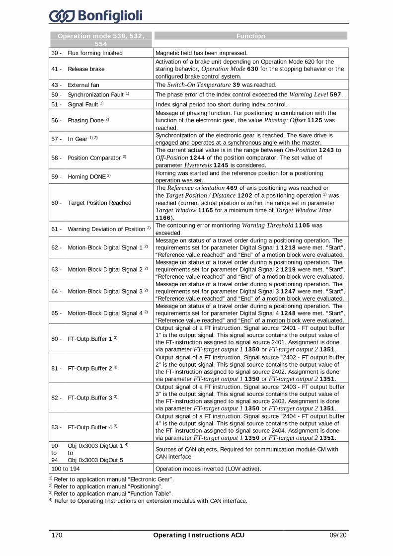
170 Operating Instructions ACU 09/20
Operation mode 530, 532, 554
Function
30 - Flux forming finished Magnetic field has been impressed.
41 - Release brake Activation of a brake unit depending on Operation Mode 620 for the staring behavior, Operation Mode 630 for the stopping behavior or the configured brake control system.
43 - External fan The Switch-On Temperature 39 was reached. 50 - Synchronization Fault 1) The phase error of the index control exceeded the Warning Level 597. 51 - Signal Fault 1) Index signal period too short during index control.
56 - Phasing Done 2) Message of phasing function. For positioning in combination with the function of the electronic gear, the value Phasing: Offset 1125 was reached.
57 - In Gear 1) 2) Synchronization of the electronic gear is reached. The slave drive is engaged and operates at a synchronous angle with the master.
58 - Position Comparator 2) The current actual value is in the range between On-Position 1243 to Off-Position 1244 of the position comparator. The set value of parameter Hysteresis 1245 is considered.
59 - Homing DONE 2) Homing was started and the reference position for a positioning operation was set.
60 - Target Position Reached
The Reference orientation 469 of axis positioning was reached or the Target Position / Distance 1202 of a positioning operation 2) was reached (current actual position is within the range set in parameter Target Window 1165 for a minimum time of Target Window Time 1166).
61 - Warning Deviation of Position 2) The contouring error monitoring Warning Threshold 1105 was exceeded.
62 - Motion-Block Digital Signal 1 2) Message on status of a travel order during a positioning operation. The requirements set for parameter Digital Signal 1 1218 were met. “Start”, “Reference value reached” and “End” of a motion block were evaluated.
63 - Motion-Block Digital Signal 2 2) Message on status of a travel order during a positioning operation. The requirements set for parameter Digital Signal 2 1219 were met. “Start”, “Reference value reached” and “End” of a motion block were evaluated.
64 - Motion-Block Digital Signal 3 2) Message on status of a travel order during a positioning operation. The requirements set for parameter Digital Signal 3 1247 were met. “Start”, “Reference value reached” and “End” of a motion block were evaluated.
65 - Motion-Block Digital Signal 4 2) Message on status of a travel order during a positioning operation. The requirements set for parameter Digital Signal 4 1248 were met. “Start”, “Reference value reached” and “End” of a motion block were evaluated.
80 - FT-Outp.Buffer 1 3)
Output signal of a FT instruction. Signal source "2401 - FT output buffer 1" is the output signal. This signal source contains the output value of the FT-instruction assigned to signal source 2401. Assignment is done via parameter FT-target output 1 1350 or FT-target output 2 1351.
81 - FT-Outp.Buffer 2 3)
Output signal of a FT instruction. Signal source "2402 - FT output buffer 2" is the output signal. This signal source contains the output value of the FT-instruction assigned to signal source 2402. Assignment is done via parameter FT-target output 1 1350 or FT-target output 2 1351.
82 - FT-Outp.Buffer 3 3)
Output signal of a FT instruction. Signal source "2403 - FT output buffer 3" is the output signal. This signal source contains the output value of the FT-instruction assigned to signal source 2403. Assignment is done via parameter FT-target output 1 1350 or FT-target output 2 1351.
83 - FT-Outp.Buffer 4 3)
Output signal of a FT instruction. Signal source "2404 - FT output buffer 4" is the output signal. This signal source contains the output value of the FT-instruction assigned to signal source 2404. Assignment is done via parameter FT-target output 1 1350 or FT-target output 2 1351.
90 to 94
Obj 0x3003 DigOut 1 4) to Obj 0x3003 DigOut 5
Sources of CAN objects. Required for communication module CM with CAN interface
100 to 194 Operation modes inverted (LOW active). 1) Refer to application manual “Electronic Gear”. 2) Refer to application manual “Positioning”. 3) Refer to application manual “Function Table”. 4) Refer to Operating Instructions on extension modules with CAN interface.
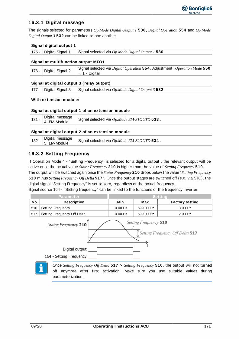
09/20 Operating Instructions ACU 171
16.3.1 Digital message The signals selected for parameters Op.Mode Digital Output 1 530, Digital Operation 554 and Op.Mode Digital Output 3 532 can be linked to one another.
Signal digital output 1 175 - Digital Signal 1 Signal selected via Op.Mode Digital Output 1 530.
Signal at multifunction output MFO1
176 - Digital Signal 2 Signal selected via Digital Operation 554. Adjustment: Operation Mode 550 = 1 - Digital
Signal at digital output 3 (relay output) 177 - Digital Signal 3 Signal selected via Op.Mode Digital Output 3 532.
With extension module:
Signal at digital output 1 of an extension module
181 - Digital message 4, EM-Module Signal selected via Op.Mode EM-S1OUTD 533 .
Signal at digital output 2 of an extension module
182 - Digital message 5, EM-Module Signal selected via Op.Mode EM-S2OUTD 534 .
16.3.2 Setting Frequency If Operation Mode 4 - “Setting Frequency” is selected for a digital output , the relevant output will be active once the actual value Stator Frequency 210 is higher than the value of Setting Frequency 510. The output will be switched again once the Stator Frequency 210 drops below the value “Setting Frequency 510 minus Setting Frequency Off Delta 517”. Once the output stages are switched off (e.g. via STO), the digital signal “Setting Frequency” is set to zero, regardless of the actual frequency. Signal source 164 - "Setting frequency" can be linked to the functions of the frequency inverter.
Parameter Setting No. Description Min. Max. Factory setting 510 Setting Frequency 0.00 Hz 599.00 Hz 3.00 Hz 517 Setting Frequency Off Delta 0.00 Hz 599.00 Hz 2.00 Hz
Once Setting Frequency Off Delta 517 > Setting Frequency 510, the output will not turned off anymore after first activation. Make sure you use suitable values during parameterization.
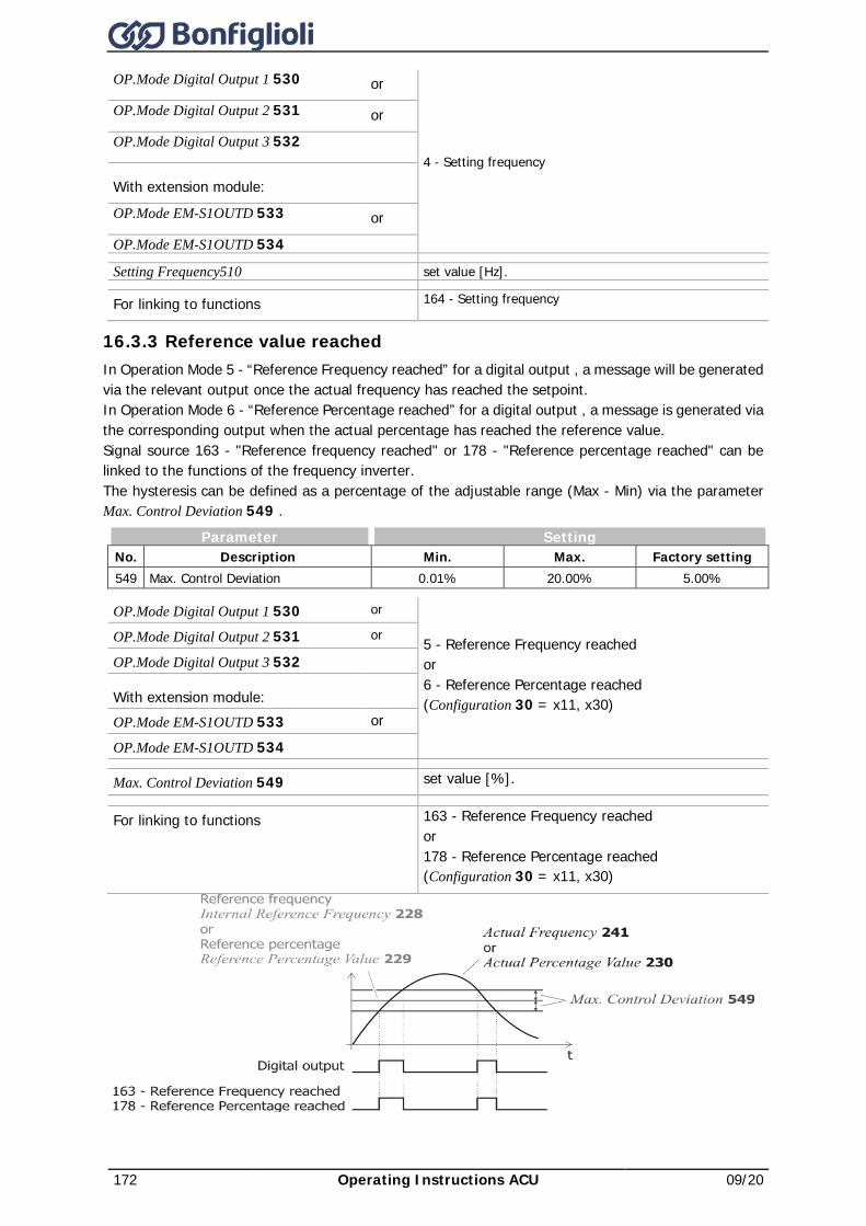
172 Operating Instructions ACU 09/20
OP.Mode Digital Output 1 530 or
4 - Setting frequency
OP.Mode Digital Output 2 531 or OP.Mode Digital Output 3 532
With extension module: OP.Mode EM-S1OUTD 533 or
OP.Mode EM-S1OUTD 534
Setting Frequency510 set value [Hz].
For linking to functions 164 - Setting frequency
16.3.3 Reference value reached In Operation Mode 5 - “Reference Frequency reached” for a digital output , a message will be generated via the relevant output once the actual frequency has reached the setpoint. In Operation Mode 6 - “Reference Percentage reached” for a digital output , a message is generated via the corresponding output when the actual percentage has reached the reference value. Signal source 163 - "Reference frequency reached" or 178 - "Reference percentage reached" can be linked to the functions of the frequency inverter. The hysteresis can be defined as a percentage of the adjustable range (Max - Min) via the parameter Max. Control Deviation 549 .
Parameter Setting No. Description Min. Max. Factory setting 549 Max. Control Deviation 0.01% 20.00% 5.00%
OP.Mode Digital Output 1 530 or
5 - Reference Frequency reached or 6 - Reference Percentage reached (Configuration 30 = x11, x30)
OP.Mode Digital Output 2 531 or
OP.Mode Digital Output 3 532
With extension module: OP.Mode EM-S1OUTD 533 or
OP.Mode EM-S1OUTD 534
Max. Control Deviation 549 set value [%].
For linking to functions 163 - Reference Frequency reached or 178 - Reference Percentage reached (Configuration 30 = x11, x30)
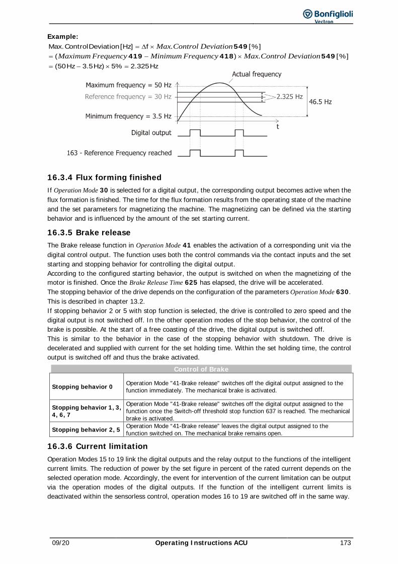
09/20 Operating Instructions ACU 173
Example:
Hz325.2%5)Hz5.3Hz50([%])(
[%]f]Hz[DeviationControl.Max
=×−=
×−=×∆=
549418419549
DeviationControlMax.FrequencyMinimumFrequencyMaximumDeviationControlMax.
16.3.4 Flux forming finished If Operation Mode 30 is selected for a digital output, the corresponding output becomes active when the flux formation is finished. The time for the flux formation results from the operating state of the machine and the set parameters for magnetizing the machine. The magnetizing can be defined via the starting behavior and is influenced by the amount of the set starting current.
16.3.5 Brake release The Brake release function in Operation Mode 41 enables the activation of a corresponding unit via the digital control output. The function uses both the control commands via the contact inputs and the set starting and stopping behavior for controlling the digital output. According to the configured starting behavior, the output is switched on when the magnetizing of the motor is finished. Once the Brake Release Time 625 has elapsed, the drive will be accelerated. The stopping behavior of the drive depends on the configuration of the parameters Operation Mode 630. This is described in chapter 13.2. If stopping behavior 2 or 5 with stop function is selected, the drive is controlled to zero speed and the digital output is not switched off. In the other operation modes of the stop behavior, the control of the brake is possible. At the start of a free coasting of the drive, the digital output is switched off. This is similar to the behavior in the case of the stopping behavior with shutdown. The drive is decelerated and supplied with current for the set holding time. Within the set holding time, the control output is switched off and thus the brake activated.
Control of Brake
Stopping behavior 0 Operation Mode "41-Brake release" switches off the digital output assigned to the function immediately. The mechanical brake is activated.
Stopping behavior 1, 3, 4, 6, 7
Operation Mode "41-Brake release" switches off the digital output assigned to the function once the Switch-off threshold stop function 637 is reached. The mechanical brake is activated.
Stopping behavior 2, 5 Operation Mode “41-Brake release” leaves the digital output assigned to the function switched on. The mechanical brake remains open.
16.3.6 Current limitation Operation Modes 15 to 19 link the digital outputs and the relay output to the functions of the intelligent current limits. The reduction of power by the set figure in percent of the rated current depends on the selected operation mode. Accordingly, the event for intervention of the current limitation can be output via the operation modes of the digital outputs. If the function of the intelligent current limits is deactivated within the sensorless control, operation modes 16 to 19 are switched off in the same way.
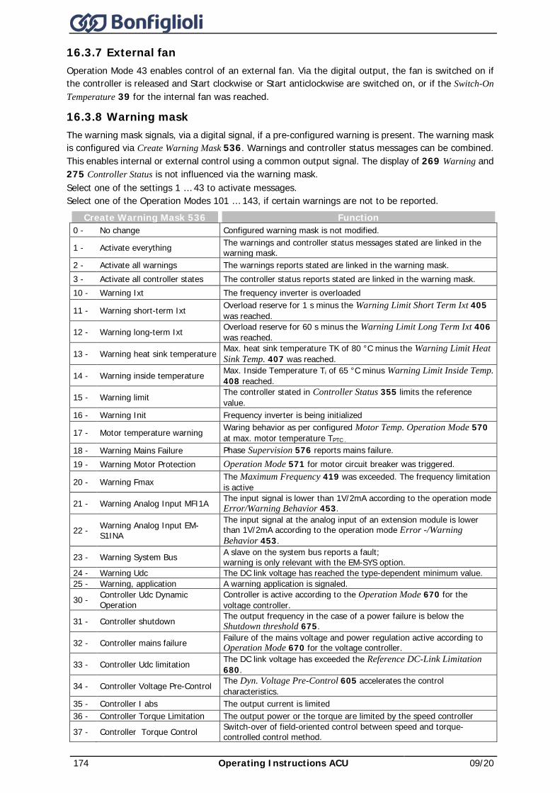
174 Operating Instructions ACU 09/20
16.3.7 External fan Operation Mode 43 enables control of an external fan. Via the digital output, the fan is switched on if the controller is released and Start clockwise or Start anticlockwise are switched on, or if the Switch-On Temperature 39 for the internal fan was reached.
16.3.8 Warning mask The warning mask signals, via a digital signal, if a pre-configured warning is present. The warning mask is configured via Create Warning Mask 536. Warnings and controller status messages can be combined. This enables internal or external control using a common output signal. The display of 269 Warning and 275 Controller Status is not influenced via the warning mask. Select one of the settings 1 … 43 to activate messages. Select one of the Operation Modes 101 … 143, if certain warnings are not to be reported.
Create Warning Mask 536 Function 0 - No change Configured warning mask is not modified.
1 - Activate everything The warnings and controller status messages stated are linked in the warning mask.
2 - Activate all warnings The warnings reports stated are linked in the warning mask. 3 - Activate all controller states The controller status reports stated are linked in the warning mask. 10 - Warning Ixt The frequency inverter is overloaded
11 - Warning short-term Ixt Overload reserve for 1 s minus the Warning Limit Short Term Ixt 405 was reached.
12 - Warning long-term Ixt Overload reserve for 60 s minus the Warning Limit Long Term Ixt 406 was reached.
13 - Warning heat sink temperature Max. heat sink temperature TK of 80 °C minus the Warning Limit Heat Sink Temp. 407 was reached.
14 - Warning inside temperature Max. Inside Temperature Ti of 65 °C minus Warning Limit Inside Temp. 408 reached.
15 - Warning limit The controller stated in Controller Status 355 limits the reference value.
16 - Warning Init Frequency inverter is being initialized
17 - Motor temperature warning Waring behavior as per configured Motor Temp. Operation Mode 570 at max. motor temperature TPTC .
18 - Warning Mains Failure Phase Supervision 576 reports mains failure. 19 - Warning Motor Protection Operation Mode 571 for motor circuit breaker was triggered.
20 - Warning Fmax The Maximum Frequency 419 was exceeded. The frequency limitation is active
21 - Warning Analog Input MFI1A The input signal is lower than 1V/2mA according to the operation mode Error/Warning Behavior 453.
22 - Warning Analog Input EM-S1INA
The input signal at the analog input of an extension module is lower than 1V/2mA according to the operation mode Error -/Warning Behavior 453.
23 - Warning System Bus A slave on the system bus reports a fault; warning is only relevant with the EM-SYS option.
24 - Warning Udc The DC link voltage has reached the type-dependent minimum value. 25 - Warning, application A warning application is signaled.
30 - Controller Udc Dynamic Operation
Controller is active according to the Operation Mode 670 for the voltage controller.
31 - Controller shutdown The output frequency in the case of a power failure is below the Shutdown threshold 675.
32 - Controller mains failure Failure of the mains voltage and power regulation active according to Operation Mode 670 for the voltage controller.
33 - Controller Udc limitation The DC link voltage has exceeded the Reference DC-Link Limitation 680.
34 - Controller Voltage Pre-Control The Dyn. Voltage Pre-Control 605 accelerates the control characteristics.
35 - Controller I abs The output current is limited 36 - Controller Torque Limitation The output power or the torque are limited by the speed controller
37 - Controller Torque Control Switch-over of field-oriented control between speed and torque-controlled control method.
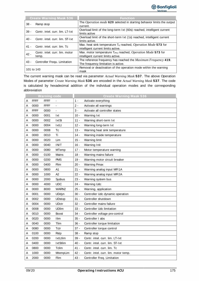
09/20 Operating Instructions ACU 175
Create Warning Mask 536 Function 38 - Ramp stop The Operation mode 620 selected in starting behavior limits the output
current.
39 - Contr. intel. curr. lim. LT-Ixt Overload limit of the long-term Ixt (60s) reached, intelligent current limits active
40 - Contr. intel. curr. lim. ST-Ixt Overload limit of the short-term Ixt (1s) reached, intelligent current limits active.
41 - Contr. intel. curr. lim. Tc Max. heat sink temperature TK reached, Operation Mode 573 for intelligent current limits active.
42 - Contr. intel. curr. lim. motor temp.
Max. motor temperature TPTC reached, Operation Mode 573 for intelligent current limits active.
43 - Controller Frequ. Limitation The reference frequency has reached the Maximum Frequency 419. The frequency limitation is active.
101 to 143 Removal or deactivation of the operation mode within the warning mask
The current warning mask can be read via parameter Actual Warning Mask 537. The above Operation Modes of parameter Create Warning Mask 536 are encoded in the Actual Warning Mask 537. The code is calculated by hexadecimal addition of the individual operation modes and the corresponding abbreviation
Warning code Create Warning Mask 536 A FFFF FFFF - 1 - Activate everything A 0000 FFFF - 2 - Activate all warnings A FFFF 0000 - 3 - Activate all controller states A 0000 0001 Ixt 10 - Warning Ixt A 0000 0002 IxtSt 11 - Warning short-term Ixt A 0000 0004 IxtLt 12 - Warning long-term Ixt A 0000 0008 Tc 13 - Warning heat sink temperature A 0000 0010 Ti 14 - Warning inside temperature A 0000 0020 Lim 15 - Warning limit A 0000 0040 INIT 16 - Warning Init A 0000 0080 MTemp 17 - Motor temperature warning A 0000 0100 Mains 18 - Warning mains failure A 0000 0200 PMS 19 - Warning motor circuit breaker A 0000 0400 Flim 20 - Warning Fmax A 0000 0800 A1 21 - Warning analog input MFI1A A 0000 1000 A2 22 - Warning analog input MFI2A A 0000 2000 Sysbus 23 - Warning system bus A 0000 4000 UDC 24 - Warning Udc A 0000 8000 WARN2 25 - Warning, application A 0001 0000 UDdyn 30 - Controller Udc dynamic operation A 0002 0000 UDstop 31 - Controller shutdown A 0004 0000 UDctr 32 - Controller mains failure A 0008 0000 UDlim 33 - Controller Udc limitation A 0010 0000 Boost 34 - Controller voltage pre-control A 0020 0000 Ilim 35 - Controller I abs A 0040 0000 Tlim 36 - Controller torque limitation A 0080 0000 Tctr 37 - Controller torque control A 0100 0000 Rstp 38 - Ramp stop A 0200 0000 IxtLtlim 39 - Contr. intel. curr. lim. LT-Ixt A 0400 0000 IxtStlim 40 - Contr. intel. curr. lim. ST-Ixt A 0800 0000 Tclim 41 - Contr. intel. curr. lim. Tc A 1000 0000 MtempLim 42 - Contr. intel. curr. lim. motor temp. A 2000 0000 Flim 43 - Controller Freq. Limitation
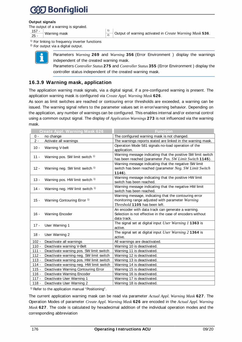
176 Operating Instructions ACU 09/20
Output signals The output of a warning is signaled.
157 - Warning mask 1) Output of warning activated in Create Warning Mask 536. 25 - 2)
1) For linking to frequency inverter functions 2) For output via a digital output.
Parameters Warning 269 and Warning 356 (Error Environment ) display the warnings independent of the created warning mask. Parameters Controller Status 275 and Controller Status 355 (Error Environment ) display the controller status independent of the created warning mask.
16.3.9 Warning mask, application The application warning mask signals, via a digital signal, if a pre-configured warning is present. The application warning mask is configured via Create Appl. Warning Mask 626. As soon as limit switches are reached or contouring error thresholds are exceeded, a warning can be issued. The warning signal refers to the parameter values set in error/warning behavior. Depending on the application, any number of warnings can be configured. This enables internal and/or external control using a common output signal. The display of Application Warnings 273 is not influenced via the warning mask.
Create Appl. Warning Mask 626 Function 0 - no change The configured warning mask is not changed. 2 - Activate all warnings The warnings reports stated are linked in the warning mask.
10 - Warning V-belt Operation Mode 581 signals no-load operation of the application.
11 - Warning pos. SW limit switch 1) Warning message indicating that the positive SW limit switch has been reached (parameter Pos. SW Limit Switch 1145).
12 - Warning neg. SW limit switch 1) Warning message indicating that the negative SW limit switch has been reached (parameter Neg. SW Limit Switch 1146).
13 - Warning pos. HW limit switch 1) Warning message indicating that the positive HW limit switch has been reached.
14 - Warning neg. HW limit switch 1) Warning message indicating that the negative HW limit switch has been reached.
15 - Warning Contouring Error 1) Warning message, indicating that the contouring error monitoring range adjusted with parameter Warning Threshold 1105 has been left.
16 - Warning Encoder An encoder with data track can generate a warning. Selection is not effective in the case of encoders without data track.
17 - User Warning 1 The signal set at digital input User Warning 1 1363 is active.
18 - User Warning 2 The signal set at digital input User Warning 2 1364 is active.
102 - Deactivate all warnings All warnings are deactivated. 110 - Deactivate warning V-Belt Warning 10 is deactivated. 111 - Deactivate warning pos. SW limit switch Warning 11 is deactivated. 112 - Deactivate warning neg. SW limit switch Warning 12 is deactivated. 113 - Deactivate warning pos. HW limit switch Warning 13 is deactivated. 114 - Deactivate warning neg. HW limit switch Warning 14 is deactivated. 115 - Deactivate Warning Contouring Error Warning 15 is deactivated. 116 - Deactivate Warning Encoder Warning 16 is deactivated. 117 - Deactivate User Warning 1 Warning 17 is deactivated. 118 - Deactivate User Warning 2 Warning 18 is deactivated.
1) Refer to the application manual “Positioning”.
The current application warning mask can be read via parameter Actual Appl. Warning Mask 627. The Operation Modes of parameter Create Appl. Warning Mask 626 are encoded in the Actual Appl. Warning Mask 627. The code is calculated by hexadecimal addition of the individual operation modes and the corresponding abbreviation
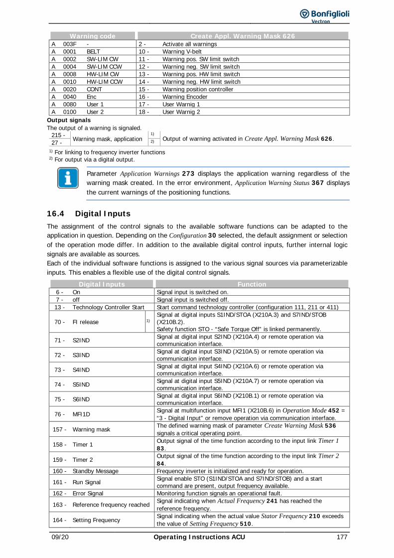
09/20 Operating Instructions ACU 177
Warning code Create Appl. Warning Mask 626 A 003F - 2 - Activate all warnings A 0001 BELT 10 - Warning V-belt A 0002 SW-LIM CW 11 - Warning pos. SW limit switch A 0004 SW-LIM CCW 12 - Warning neg. SW limit switch A 0008 HW-LIM CW 13 - Warning pos. HW limit switch A 0010 HW-LIM CCW 14 - Warning neg. HW limit switch A 0020 CONT 15 - Warning position controller A 0040 Enc 16 - Warning Encoder A 0080 User 1 17 - User Warnig 1 A 0100 User 2 18 - User Warnig 2
Output signals The output of a warning is signaled.
215 - Warning mask, application 1) Output of warning activated in Create Appl. Warning Mask 626. 27 - 2)
1) For linking to frequency inverter functions 2) For output via a digital output.
Parameter Application Warnings 273 displays the application warning regardless of the warning mask created. In the error environment, Application Warning Status 367 displays the current warnings of the positioning functions.
16.4 Digital Inputs The assignment of the control signals to the available software functions can be adapted to the application in question. Depending on the Configuration 30 selected, the default assignment or selection of the operation mode differ. In addition to the available digital control inputs, further internal logic signals are available as sources. Each of the individual software functions is assigned to the various signal sources via parameterizable inputs. This enables a flexible use of the digital control signals.
Digital Inputs Function 6 - On Signal input is switched on. 7 - off Signal input is switched off. 13 - Technology Controller Start Start command technology controller (configuration 111, 211 or 411)
70 - FI release 1) Signal at digital inputs S1IND/STOA (X210A.3) and S7IND/STOB (X210B.2). Safety function STO - “Safe Torque Off” is linked permanently.
71 - S2IND Signal at digital input S2IND (X210A.4) or remote operation via communication interface.
72 - S3IND Signal at digital input S3IND (X210A.5) or remote operation via communication interface.
73 - S4IND Signal at digital input S4IND (X210A.6) or remote operation via communication interface.
74 - S5IND Signal at digital input S5IND (X210A.7) or remote operation via communication interface.
75 - S6IND Signal at digital input S6IND (X210B.1) or remote operation via communication interface.
76 - MFI1D Signal at multifunction input MFI1 (X210B.6) in Operation Mode 452 = “3 - Digital Input” or remove operation via communication interface.
157 - Warning mask The defined warning mask of parameter Create Warning Mask 536 signals a critical operating point.
158 - Timer 1 Output signal of the time function according to the input link Timer 1 83.
159 - Timer 2 Output signal of the time function according to the input link Timer 2 84.
160 - Standby Message Frequency inverter is initialized and ready for operation.
161 - Run Signal Signal enable STO (S1IND/STOA and S7IND/STOB) and a start command are present, output frequency available.
162 - Error Signal Monitoring function signals an operational fault.
163 - Reference frequency reached Signal indicating when Actual Frequency 241 has reached the reference frequency.
164 - Setting Frequency Signal indicating when the actual value Stator Frequency 210 exceeds the value of Setting Frequency 510.
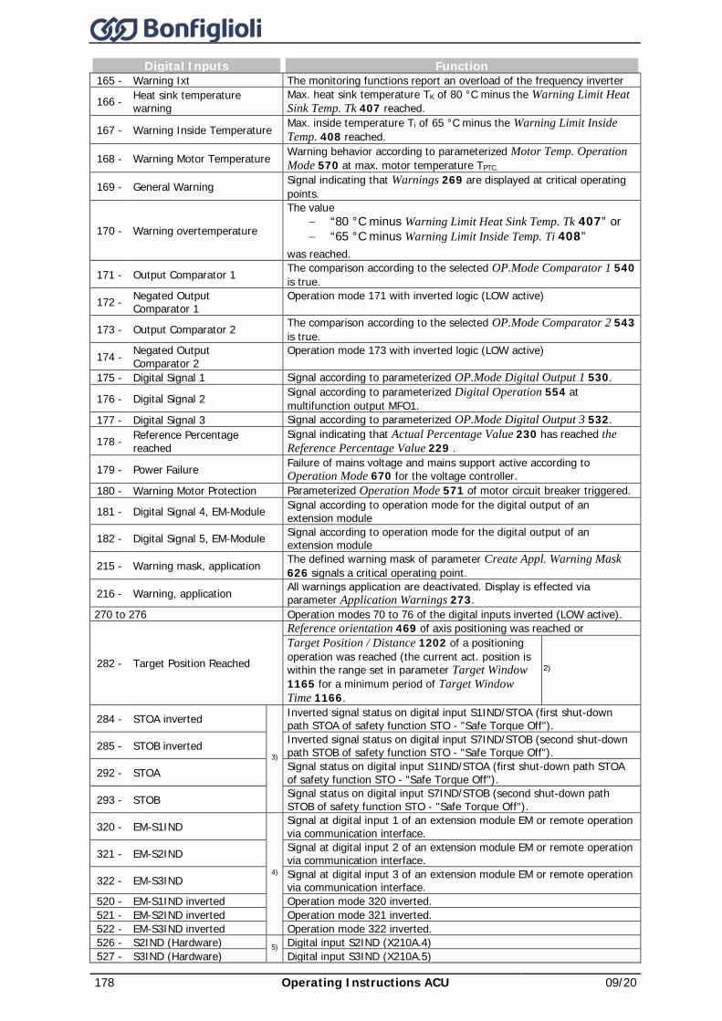
178 Operating Instructions ACU 09/20
Digital Inputs Function 165 - Warning Ixt The monitoring functions report an overload of the frequency inverter
166 - Heat sink temperature warning
Max. heat sink temperature TK of 80 °C minus the Warning Limit Heat Sink Temp. Tk 407 reached.
167 - Warning Inside Temperature Max. inside temperature Ti of 65 °C minus the Warning Limit Inside Temp. 408 reached.
168 - Warning Motor Temperature Warning behavior according to parameterized Motor Temp. Operation Mode 570 at max. motor temperature TPTC.
169 - General Warning Signal indicating that Warnings 269 are displayed at critical operating points.
170 - Warning overtemperature
The value − “80 °C minus Warning Limit Heat Sink Temp. Tk 407” or − “65 °C minus Warning Limit Inside Temp. Ti 408”
was reached.
171 - Output Comparator 1 The comparison according to the selected OP.Mode Comparator 1 540 is true.
172 - Negated Output Comparator 1
Operation mode 171 with inverted logic (LOW active)
173 - Output Comparator 2 The comparison according to the selected OP.Mode Comparator 2 543 is true.
174 - Negated Output Comparator 2
Operation mode 173 with inverted logic (LOW active)
175 - Digital Signal 1 Signal according to parameterized OP.Mode Digital Output 1 530.
176 - Digital Signal 2 Signal according to parameterized Digital Operation 554 at multifunction output MFO1.
177 - Digital Signal 3 Signal according to parameterized OP.Mode Digital Output 3 532.
178 - Reference Percentage reached
Signal indicating that Actual Percentage Value 230 has reached the Reference Percentage Value 229 .
179 - Power Failure Failure of mains voltage and mains support active according to Operation Mode 670 for the voltage controller.
180 - Warning Motor Protection Parameterized Operation Mode 571 of motor circuit breaker triggered.
181 - Digital Signal 4, EM-Module Signal according to operation mode for the digital output of an extension module
182 - Digital Signal 5, EM-Module Signal according to operation mode for the digital output of an extension module
215 - Warning mask, application The defined warning mask of parameter Create Appl. Warning Mask 626 signals a critical operating point.
216 - Warning, application All warnings application are deactivated. Display is effected via parameter Application Warnings 273.
270 to 276 Operation modes 70 to 76 of the digital inputs inverted (LOW active).
282 - Target Position Reached
Reference orientation 469 of axis positioning was reached or Target Position / Distance 1202 of a positioning operation was reached (the current act. position is within the range set in parameter Target Window 1165 for a minimum period of Target Window Time 1166.
2)
284 - STOA inverted
3)
Inverted signal status on digital input S1IND/STOA (first shut-down path STOA of safety function STO - "Safe Torque Off").
285 - STOB inverted Inverted signal status on digital input S7IND/STOB (second shut-down path STOB of safety function STO - "Safe Torque Off").
292 - STOA Signal status on digital input S1IND/STOA (first shut-down path STOA of safety function STO - "Safe Torque Off").
293 - STOB Signal status on digital input S7IND/STOB (second shut-down path STOB of safety function STO - "Safe Torque Off").
320 - EM-S1IND
4)
Signal at digital input 1 of an extension module EM or remote operation via communication interface.
321 - EM-S2IND Signal at digital input 2 of an extension module EM or remote operation via communication interface.
322 - EM-S3IND Signal at digital input 3 of an extension module EM or remote operation via communication interface.
520 - EM-S1IND inverted Operation mode 320 inverted. 521 - EM-S2IND inverted Operation mode 321 inverted. 522 - EM-S3IND inverted Operation mode 322 inverted. 526 - S2IND (Hardware) 5) Digital input S2IND (X210A.4) 527 - S3IND (Hardware) Digital input S3IND (X210A.5)
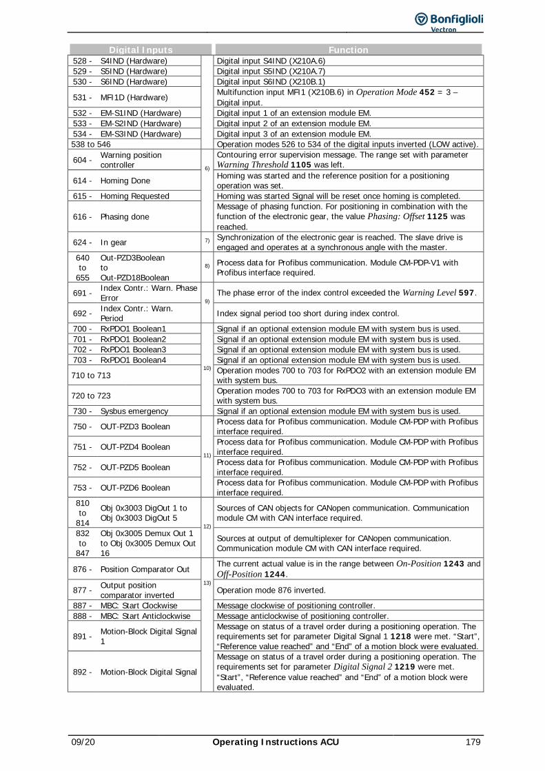
09/20 Operating Instructions ACU 179
Digital Inputs Function 528 - S4IND (Hardware) Digital input S4IND (X210A.6) 529 - S5IND (Hardware) Digital input S5IND (X210A.7) 530 - S6IND (Hardware) Digital input S6IND (X210B.1)
531 - MFI1D (Hardware) Multifunction input MFI1 (X210B.6) in Operation Mode 452 = 3 – Digital input.
532 - EM-S1IND (Hardware) Digital input 1 of an extension module EM. 533 - EM-S2IND (Hardware) Digital input 2 of an extension module EM. 534 - EM-S3IND (Hardware) Digital input 3 of an extension module EM. 538 to 546 Operation modes 526 to 534 of the digital inputs inverted (LOW active).
604 - Warning position controller 6)
Contouring error supervision message. The range set with parameter Warning Threshold 1105 was left.
614 - Homing Done Homing was started and the reference position for a positioning operation was set.
615 - Homing Requested
Homing was started Signal will be reset once homing is completed.
616 - Phasing done Message of phasing function. For positioning in combination with the function of the electronic gear, the value Phasing: Offset 1125 was reached.
624 - In gear 7) Synchronization of the electronic gear is reached. The slave drive is engaged and operates at a synchronous angle with the master.
640 to
655
Out-PZD3Boolean to Out-PZD18Boolean
8) Process data for Profibus communication. Module CM-PDP-V1 with Profibus interface required.
691 - Index Contr.: Warn. Phase Error 9)
The phase error of the index control exceeded the Warning Level 597.
692 - Index Contr.: Warn. Period Index signal period too short during index control.
700 - RxPDO1 Boolean1
10)
Signal if an optional extension module EM with system bus is used. 701 - RxPDO1 Boolean2 Signal if an optional extension module EM with system bus is used. 702 - RxPDO1 Boolean3 Signal if an optional extension module EM with system bus is used. 703 - RxPDO1 Boolean4 Signal if an optional extension module EM with system bus is used.
710 to 713 Operation modes 700 to 703 for RxPDO2 with an extension module EM with system bus.
720 to 723 Operation modes 700 to 703 for RxPDO3 with an extension module EM with system bus.
730 - Sysbus emergency Signal if an optional extension module EM with system bus is used.
750 - OUT-PZD3 Boolean
11)
Process data for Profibus communication. Module CM-PDP with Profibus interface required.
751 - OUT-PZD4 Boolean Process data for Profibus communication. Module CM-PDP with Profibus interface required.
752 - OUT-PZD5 Boolean Process data for Profibus communication. Module CM-PDP with Profibus interface required.
753 - OUT-PZD6 Boolean Process data for Profibus communication. Module CM-PDP with Profibus interface required.
810 to
814 Obj 0x3003 DigOut 1 to Obj 0x3003 DigOut 5
12)
Sources of CAN objects for CANopen communication. Communication module CM with CAN interface required.
832 to
847
Obj 0x3005 Demux Out 1 to Obj 0x3005 Demux Out 16
Sources at output of demultiplexer for CANopen communication. Communication module CM with CAN interface required.
876 - Position Comparator Out 13)
The current actual value is in the range between On-Position 1243 and Off-Position 1244.
877 - Output position comparator inverted Operation mode 876 inverted.
887 - MBC: Start Clockwise Message clockwise of positioning controller. 888 - MBC: Start Anticlockwise
Message anticlockwise of positioning controller.
891 - Motion-Block Digital Signal 1
Message on status of a travel order during a positioning operation. The requirements set for parameter Digital Signal 1 1218 were met. “Start”, “Reference value reached” and “End” of a motion block were evaluated.
892 - Motion-Block Digital Signal
Message on status of a travel order during a positioning operation. The requirements set for parameter Digital Signal 2 1219 were met. “Start”, “Reference value reached” and “End” of a motion block were evaluated.
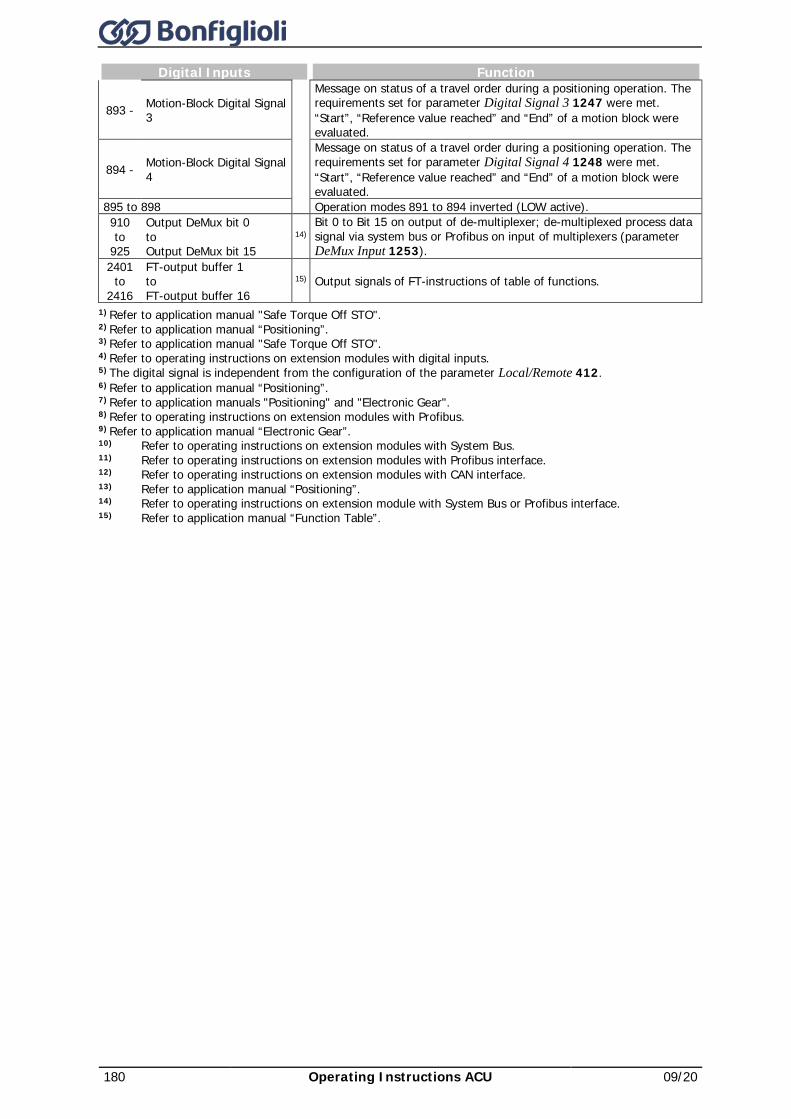
180 Operating Instructions ACU 09/20
Digital Inputs Function
893 - Motion-Block Digital Signal 3
Message on status of a travel order during a positioning operation. The requirements set for parameter Digital Signal 3 1247 were met. “Start”, “Reference value reached” and “End” of a motion block were evaluated.
894 - Motion-Block Digital Signal 4
Message on status of a travel order during a positioning operation. The requirements set for parameter Digital Signal 4 1248 were met. “Start”, “Reference value reached” and “End” of a motion block were evaluated.
895 to 898 Operation modes 891 to 894 inverted (LOW active). 910 to
925
Output DeMux bit 0 to Output DeMux bit 15
14) Bit 0 to Bit 15 on output of de-multiplexer; de-multiplexed process data signal via system bus or Profibus on input of multiplexers (parameter DeMux Input 1253).
2401 to
2416
FT-output buffer 1 to FT-output buffer 16
15) Output signals of FT-instructions of table of functions.
1) Refer to application manual "Safe Torque Off STO". 2) Refer to application manual “Positioning”. 3) Refer to application manual "Safe Torque Off STO". 4) Refer to operating instructions on extension modules with digital inputs. 5) The digital signal is independent from the configuration of the parameter Local/Remote 412. 6) Refer to application manual “Positioning”. 7) Refer to application manuals "Positioning" and "Electronic Gear". 8) Refer to operating instructions on extension modules with Profibus. 9) Refer to application manual “Electronic Gear”. 10) Refer to operating instructions on extension modules with System Bus. 11) Refer to operating instructions on extension modules with Profibus interface. 12) Refer to operating instructions on extension modules with CAN interface. 13) Refer to application manual “Positioning”. 14) Refer to operating instructions on extension module with System Bus or Profibus interface. 15) Refer to application manual “Function Table”.
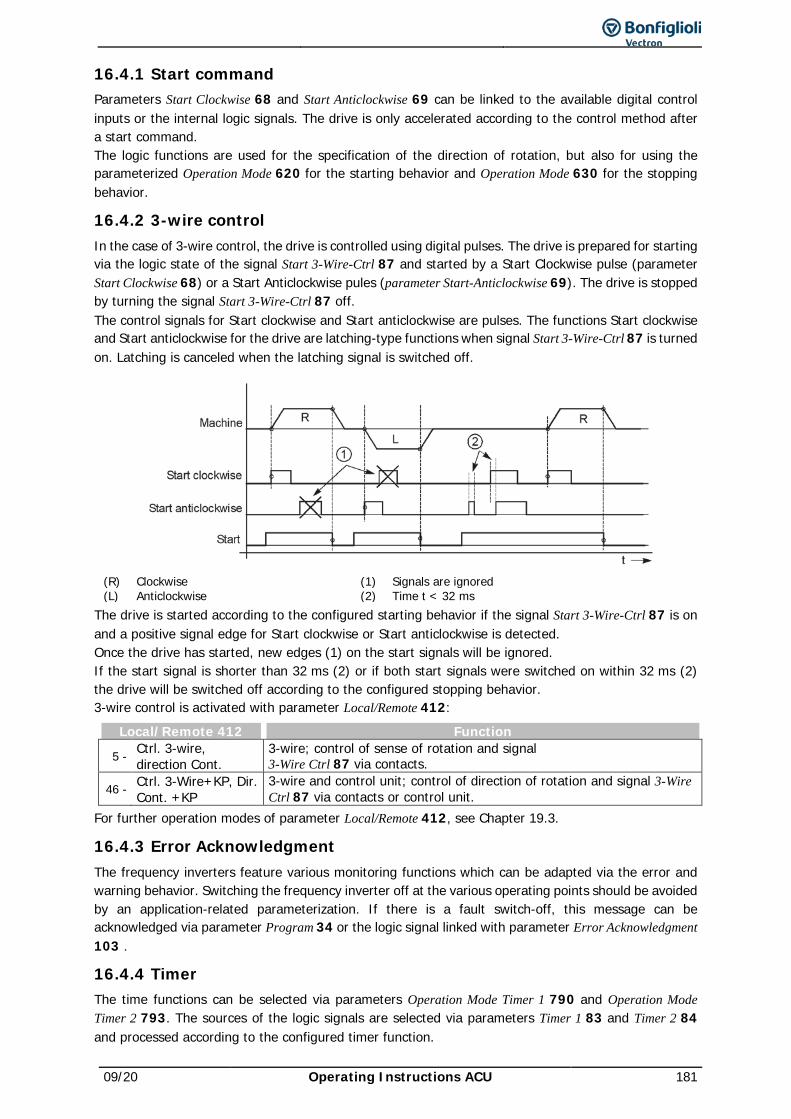
09/20 Operating Instructions ACU 181
16.4.1 Start command Parameters Start Clockwise 68 and Start Anticlockwise 69 can be linked to the available digital control inputs or the internal logic signals. The drive is only accelerated according to the control method after a start command. The logic functions are used for the specification of the direction of rotation, but also for using the parameterized Operation Mode 620 for the starting behavior and Operation Mode 630 for the stopping behavior.
16.4.2 3-wire control In the case of 3-wire control, the drive is controlled using digital pulses. The drive is prepared for starting via the logic state of the signal Start 3-Wire-Ctrl 87 and started by a Start Clockwise pulse (parameter Start Clockwise 68) or a Start Anticlockwise pules (parameter Start-Anticlockwise 69). The drive is stopped by turning the signal Start 3-Wire-Ctrl 87 off. The control signals for Start clockwise and Start anticlockwise are pulses. The functions Start clockwise and Start anticlockwise for the drive are latching-type functions when signal Start 3-Wire-Ctrl 87 is turned on. Latching is canceled when the latching signal is switched off.
(R) Clockwise (1) Signals are ignored (L) Anticlockwise (2) Time t < 32 ms
The drive is started according to the configured starting behavior if the signal Start 3-Wire-Ctrl 87 is on and a positive signal edge for Start clockwise or Start anticlockwise is detected. Once the drive has started, new edges (1) on the start signals will be ignored. If the start signal is shorter than 32 ms (2) or if both start signals were switched on within 32 ms (2) the drive will be switched off according to the configured stopping behavior. 3-wire control is activated with parameter Local/Remote 412:
Local/Remote 412 Function
5 - Ctrl. 3-wire, direction Cont.
3-wire; control of sense of rotation and signal 3-Wire Ctrl 87 via contacts.
46 - Ctrl. 3-Wire+KP, Dir. Cont. +KP
3-wire and control unit; control of direction of rotation and signal 3-Wire Ctrl 87 via contacts or control unit.
For further operation modes of parameter Local/Remote 412, see Chapter 19.3.
16.4.3 Error Acknowledgment The frequency inverters feature various monitoring functions which can be adapted via the error and warning behavior. Switching the frequency inverter off at the various operating points should be avoided by an application-related parameterization. If there is a fault switch-off, this message can be acknowledged via parameter Program 34 or the logic signal linked with parameter Error Acknowledgment 103 .
16.4.4 Timer The time functions can be selected via parameters Operation Mode Timer 1 790 and Operation Mode Timer 2 793. The sources of the logic signals are selected via parameters Timer 1 83 and Timer 2 84 and processed according to the configured timer function.
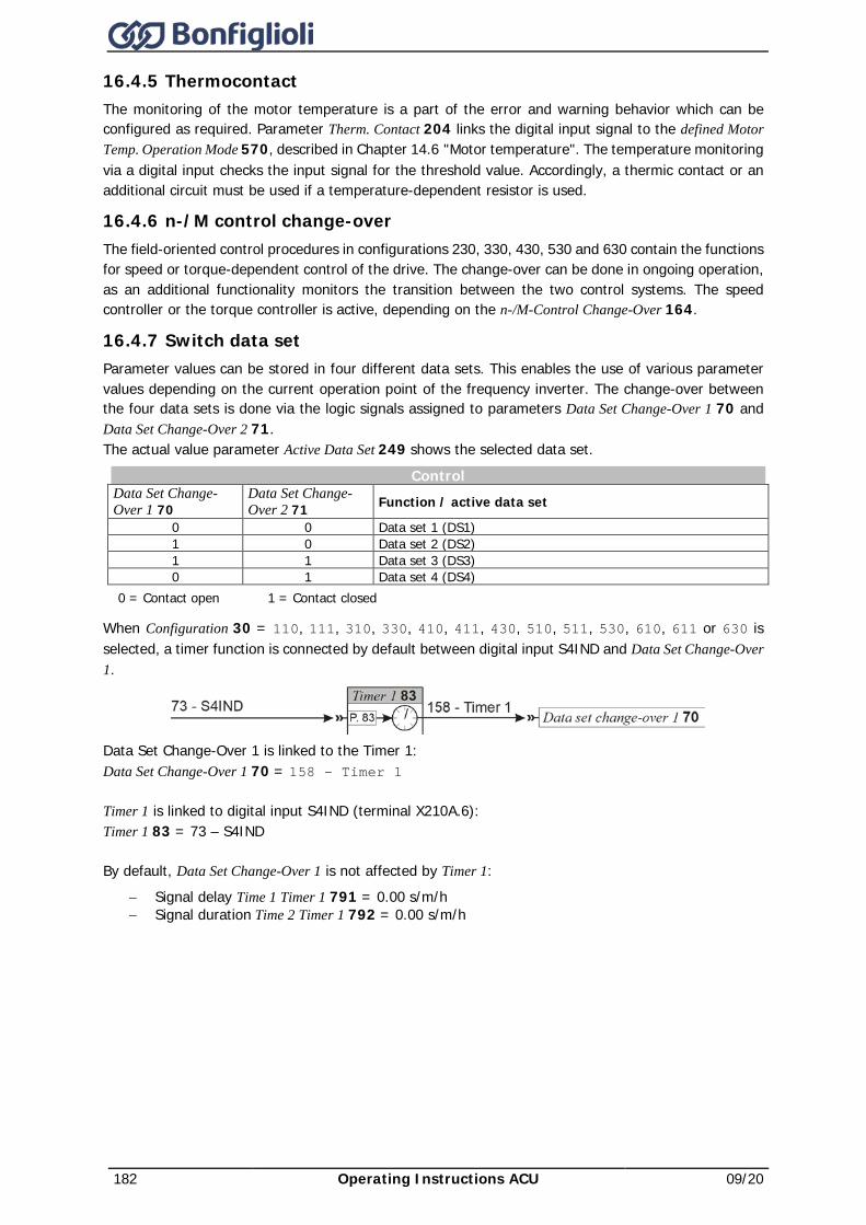
182 Operating Instructions ACU 09/20
16.4.5 Thermocontact The monitoring of the motor temperature is a part of the error and warning behavior which can be configured as required. Parameter Therm. Contact 204 links the digital input signal to the defined Motor Temp. Operation Mode 570, described in Chapter 14.6 "Motor temperature". The temperature monitoring via a digital input checks the input signal for the threshold value. Accordingly, a thermic contact or an additional circuit must be used if a temperature-dependent resistor is used.
16.4.6 n-/M control change-over The field-oriented control procedures in configurations 230, 330, 430, 530 and 630 contain the functions for speed or torque-dependent control of the drive. The change-over can be done in ongoing operation, as an additional functionality monitors the transition between the two control systems. The speed controller or the torque controller is active, depending on the n-/M-Control Change-Over 164.
16.4.7 Switch data set Parameter values can be stored in four different data sets. This enables the use of various parameter values depending on the current operation point of the frequency inverter. The change-over between the four data sets is done via the logic signals assigned to parameters Data Set Change-Over 1 70 and Data Set Change-Over 2 71. The actual value parameter Active Data Set 249 shows the selected data set.
Control Data Set Change-Over 1 70
Data Set Change-Over 2 71 Function / active data set
0 0 Data set 1 (DS1) 1 0 Data set 2 (DS2) 1 1 Data set 3 (DS3) 0 1 Data set 4 (DS4)
0 = Contact open 1 = Contact closed
When Configuration 30 = 110, 111, 310, 330, 410, 411, 430, 510, 511, 530, 610, 611 or 630 is selected, a timer function is connected by default between digital input S4IND and Data Set Change-Over 1.
Data Set Change-Over 1 is linked to the Timer 1: Data Set Change-Over 1 70 = 158 – Timer 1
Timer 1 is linked to digital input S4IND (terminal X210A.6): Timer 1 83 = 73 – S4IND
By default, Data Set Change-Over 1 is not affected by Timer 1: − Signal delay Time 1 Timer 1 791 = 0.00 s/m/h − Signal duration Time 2 Timer 1 792 = 0.00 s/m/h
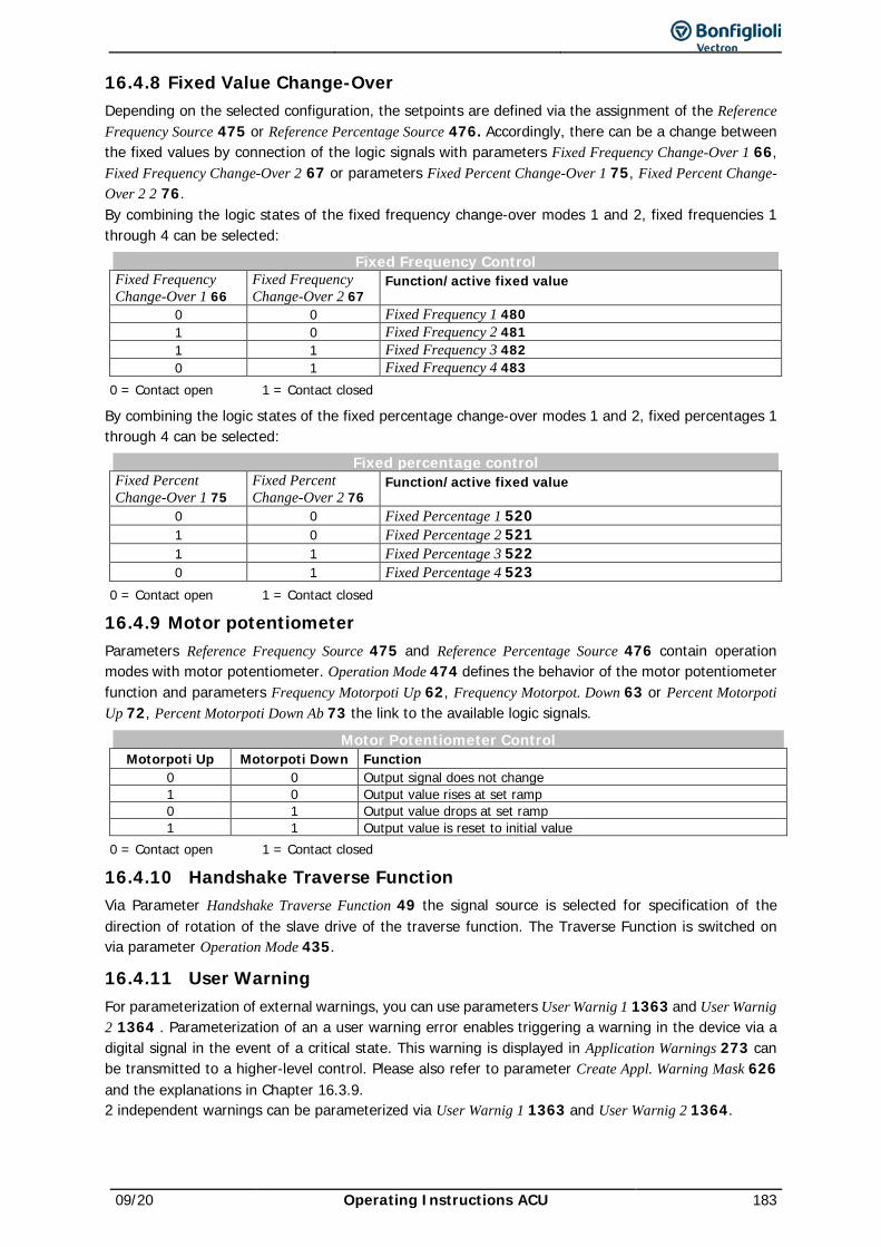
09/20 Operating Instructions ACU 183
16.4.8 Fixed Value Change-Over Depending on the selected configuration, the setpoints are defined via the assignment of the Reference Frequency Source 475 or Reference Percentage Source 476. Accordingly, there can be a change between the fixed values by connection of the logic signals with parameters Fixed Frequency Change-Over 1 66, Fixed Frequency Change-Over 2 67 or parameters Fixed Percent Change-Over 1 75, Fixed Percent Change-Over 2 2 76. By combining the logic states of the fixed frequency change-over modes 1 and 2, fixed frequencies 1 through 4 can be selected:
Fixed Frequency Control Fixed Frequency Change-Over 1 66
Fixed Frequency Change-Over 2 67
Function/active fixed value
0 0 Fixed Frequency 1 480 1 0 Fixed Frequency 2 481 1 1 Fixed Frequency 3 482 0 1 Fixed Frequency 4 483
0 = Contact open 1 = Contact closed
By combining the logic states of the fixed percentage change-over modes 1 and 2, fixed percentages 1 through 4 can be selected:
Fixed percentage control Fixed Percent Change-Over 1 75
Fixed Percent Change-Over 2 76
Function/active fixed value
0 0 Fixed Percentage 1 520 1 0 Fixed Percentage 2 521 1 1 Fixed Percentage 3 522 0 1 Fixed Percentage 4 523
0 = Contact open 1 = Contact closed
16.4.9 Motor potentiometer Parameters Reference Frequency Source 475 and Reference Percentage Source 476 contain operation modes with motor potentiometer. Operation Mode 474 defines the behavior of the motor potentiometer function and parameters Frequency Motorpoti Up 62, Frequency Motorpot. Down 63 or Percent Motorpoti Up 72, Percent Motorpoti Down Ab 73 the link to the available logic signals.
Motor Potentiometer Control Motorpoti Up Motorpoti Down Function
0 0 Output signal does not change 1 0 Output value rises at set ramp 0 1 Output value drops at set ramp 1 1 Output value is reset to initial value
0 = Contact open 1 = Contact closed
16.4.10 Handshake Traverse Function Via Parameter Handshake Traverse Function 49 the signal source is selected for specification of the direction of rotation of the slave drive of the traverse function. The Traverse Function is switched on via parameter Operation Mode 435.
16.4.11 User Warning For parameterization of external warnings, you can use parameters User Warnig 1 1363 and User Warnig 2 1364 . Parameterization of an a user warning error enables triggering a warning in the device via a digital signal in the event of a critical state. This warning is displayed in Application Warnings 273 can be transmitted to a higher-level control. Please also refer to parameter Create Appl. Warning Mask 626 and the explanations in Chapter 16.3.9. 2 independent warnings can be parameterized via User Warnig 1 1363 and User Warnig 2 1364.
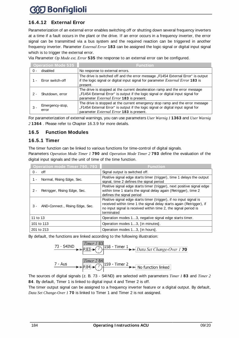
184 Operating Instructions ACU 09/20
16.4.12 External Error Parameterization of an external error enables switching off or shutting down several frequency inverters at a time if a fault occurs in the plant or the drive. If an error occurs in a frequency inverter, the error signal can be transmitted via a bus system and the required reaction can be triggered in another frequency inverter. Parameter External Error 183 can be assigned the logic signal or digital input signal which is to trigger the external error. Via Parameter Op Mode ext. Error 535 the response to an external error can be configured.
Operation Mode 535 Function 0 - disabled No response to external errors.
1 - Error switch-off The drive is switched off and the error message „F1454 External Error“ is output if the logic signal or digital input signal for parameter External Error 183 is present.
2 - Shutdown, error The drive is stopped at the current deceleration ramp and the error message „F1454 External Error“ is output if the logic signal or digital input signal for parameter External Error 183 is present.
3 - Emergency-stop, error
The drive is stopped at the current emergency stop ramp and the error message „F1454 External Error“ is output if the logic signal or digital input signal for parameter External Error 183 is present.
For parameterization of external warnings, you can use parameters User Warnig 1 1363 and User Warnig 2 1364 . Please refer to Chapter 16.3.9 for more details.
16.5 Function Modules 16.5.1 Timer The timer function can be linked to various functions for time-control of digital signals. Parameters Operation Mode Timer 1 790 and Operation Mode Timer 2 793 define the evaluation of the digital input signals and the unit of time of the time function.
Operation mode Timer 790, 793 Function 0 - off Signal output is switched off.
1 - Normal, Rising Edge, Sec. Positive signal edge starts timer (trigger), time 1 delays the output signal, time 2 defines the signal period
2 - Retrigger, Rising Edge, Sec. Positive signal edge starts timer (trigger), next positive signal edge within time 1 starts the signal delay again (Retrigger), time 2 defines the signal period
3 - AND-Connect., Rising Edge, Sec. Positive signal edge starts timer (trigger), if no input signal is received within time 1 the signal delay starts again (Retrigger), if no input signal is received within time 2, the signal period is terminated
11 to 13 Operation modes 1...3, negative signal edge starts timer. 101 to 113 Operation modes 1...3, [in minutes]. 201 to 213 Operation modes 1...3, [in hours].
By default, the functions are linked according to the following illustration:
The sources of digital signals (z. B. 73 - S4IND) are selected with parameters Timer 1 83 and Timer 2 84. By default, Timer 1 is linked to digital input 4 and Timer 2 is off. The timer output signal can be assigned to a frequency inverter feature or a digital output. By default, Data Set Change-Over 1 70 is linked to Timer 1 and Timer 2 is not assigned.
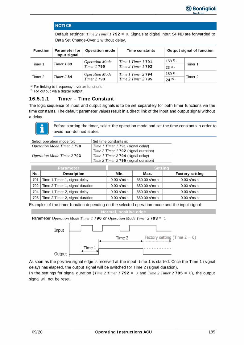
09/20 Operating Instructions ACU 185
NOTICE Default settings: Time 2 Timer 1 792 = 0. Signals at digital input S4IND are forwarded to
Data Set Change-Over 1 without delay.
Function Parameter for input signal
Operation mode Time constants Output signal of function
Timer 1 Timer 1 83 Operation Mode Timer 1 790
Time 1 Timer 1 791 Time 2 Timer 1 792
158 1) - Timer 1
23 2) -
Timer 2 Timer 2 84 Operation Mode Timer 2 793
Time 1 Timer 2 794 Time 2 Timer 2 795
159 1) - Timer 2
24 2) - 1) For linking to frequency inverter functions 2) For output via a digital output.
16.5.1.1 Timer – Time Constant The logic sequence of input and output signals is to be set separately for both timer functions via the time constants. The default parameter values result in a direct link of the input and output signal without a delay.
Before starting the timer, select the operation mode and set the time constants in order to avoid non-defined states.
Select operation mode for: Set time constants in: Operation Mode Timer 1 790 Time 1 Timer 1 791 (signal delay) Time 2 Timer 1 792 (signal duration) Operation Mode Timer 2 793 Time 1 Timer 2 794 (signal delay) Time 2 Timer 2 795 (signal duration)
Parameter Setting No. Description Min. Max. Factory setting 791 Time 1 Timer 1, signal delay 0.00 s/m/h 650.00 s/m/h 0.00 s/m/h 792 Time 2 Timer 1, signal duration 0.00 s/m/h 650.00 s/m/h 0.00 s/m/h 794 Time 1 Timer 2, signal delay 0.00 s/m/h 650.00 s/m/h 0.00 s/m/h 795 Time 2 Timer 2, signal duration 0.00 s/m/h 650.00 s/m/h 0.00 s/m/h
Examples of the timer function depending on the selected operation mode and the input signal: Normal, positive edge
Parameter Operation Mode Timer 1 790 or Operation Mode Timer 2 793 = 1
As soon as the positive signal edge is received at the input, time 1 is started. Once the Time 1 (signal delay) has elapsed, the output signal will be switched for Time 2 (signal duration). In the settings for signal duration (Time 2 Timer 1 792 = 0 and Time 2 Timer 2 795 = 0), the output signal will not be reset.
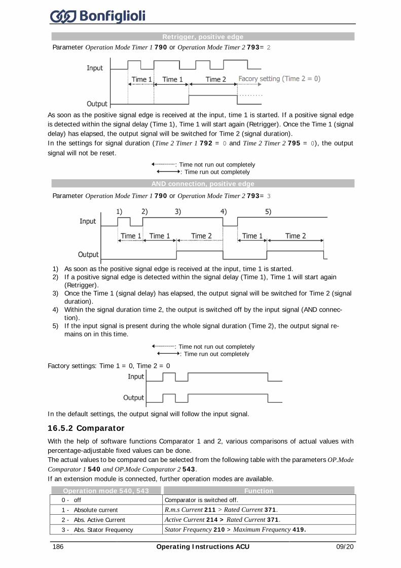
186 Operating Instructions ACU 09/20
Retrigger, positive edge Parameter Operation Mode Timer 1 790 or Operation Mode Timer 2 793= 2
As soon as the positive signal edge is received at the input, time 1 is started. If a positive signal edge is detected within the signal delay (Time 1), Time 1 will start again (Retrigger). Once the Time 1 (signal delay) has elapsed, the output signal will be switched for Time 2 (signal duration). In the settings for signal duration (Time 2 Timer 1 792 = 0 and Time 2 Timer 2 795 = 0), the output signal will not be reset.
: Time not run out completely : Time run out completely
AND connection, positive edge
Parameter Operation Mode Timer 1 790 or Operation Mode Timer 2 793= 3
1) As soon as the positive signal edge is received at the input, time 1 is started. 2) If a positive signal edge is detected within the signal delay (Time 1), Time 1 will start again
(Retrigger). 3) Once the Time 1 (signal delay) has elapsed, the output signal will be switched for Time 2 (signal
duration). 4) Within the signal duration time 2, the output is switched off by the input signal (AND connec-
tion). 5) If the input signal is present during the whole signal duration (Time 2), the output signal re-
mains on in this time.
: Time not run out completely : Time run out completely
Factory settings: Time 1 = 0, Time 2 = 0
In the default settings, the output signal will follow the input signal.
16.5.2 Comparator With the help of software functions Comparator 1 and 2, various comparisons of actual values with percentage-adjustable fixed values can be done. The actual values to be compared can be selected from the following table with the parameters OP.Mode Comparator 1 540 and OP.Mode Comparator 2 543. If an extension module is connected, further operation modes are available.
Operation mode 540, 543 Function 0 - off Comparator is switched off. 1 - Absolute current R.m.s Current 211 > Rated Current 371. 2 - Abs. Active Current Active Current 214 > Rated Current 371. 3 - Abs. Stator Frequency Stator Frequency 210 > Maximum Frequency 419.
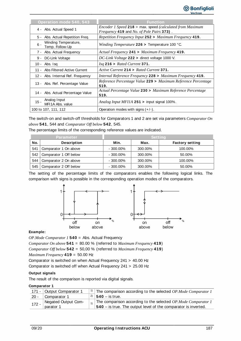
09/20 Operating Instructions ACU 187
Operation mode 540, 543 Function 4 - Abs. Actual Speed 1 Encoder 1 Speed 218 > max. speed (calculated from Maximum
Frequency 419 and No. of Pole Pairs 373) . 5 - Abs. Actual Repetition Freq. Repetition Frequency Input 252 > Maximum Frequency 419.
6 - Winding Temperature, Temp. Follow-Up Winding Temperature 226 > Temperature 100 °C.
7 - Abs. Actual Frequency Actual Frequency 241 > Maximum Frequency 419. 9 - DC-Link Voltage DC-Link Voltage 222 > direct voltage 1000 V.
10 - Abs. Isq Isq 216 > Rated Current 371. 11 - Abs Filtered Active Current Active Current 214 > Rated Current 371. 12 - Abs. Internal Ref. Frequency Internal Reference Frequency 228 > Maximum Frequency 419.
13 - Abs. Ref. Percentage Value Reference Percentage Value 229 > Maximum Reference Percentage 519.
14 - Abs. Actual Percentage Value Actual Percentage Value 230 > Maximum Reference Percentage 519.
15 - Analog Input MFI1A Abs. value Analog Input MFI1A 251 > input signal 100%.
100 to 107, 111, 112 Operation modes with signs (+/-).
The switch-on and switch-off thresholds for Comparators 1 and 2 are set via parameters Comparator On above 541, 544 and Comparator Off below 542, 545. The percentage limits of the corresponding reference values are indicated.
Parameter Setting No. Description Min. Max. Factory setting 541 Comparator 1 On above - 300.00% 300.00% 100.00% 542 Comparator 1 Off below - 300.00% 300.00% 50.00% 544 Comparator 2 On above - 300.00% 300.00% 100.00% 545 Comparator 2 Off below - 300.00% 300.00% 50.00%
The setting of the percentage limits of the comparators enables the following logical links. The comparison with signs is possible in the corresponding operation modes of the comparators.
Example: OP.Mode Comparator 1 540 = Abs. Actual Frequency Comparator On above 541 = 80.00 % (referred to Maximum Frequency 419) Comparator Off below 542 = 50,00 % (referred to Maximum Frequency 419) Maximum Frequency 419 = 50.00 Hz Comparator is switched on when Actual Frequency 241 > 40.00 Hz Comparator is switched off when Actual Frequency 241 > 25.00 Hz Output signals The result of the comparison is reported via digital signals. Comparator 1
171 - Output Comparator 1 1) The comparison according to the selected OP.Mode Comparator 1 540 – is true. 20 - Comparator 1 2)
172 - Negated Output Com-parator 1
1) The comparison according to the selected OP.Mode Comparator 1 540 – is true. The output level of the comparator is inverted.
188 Operating Instructions ACU 09/20
Comparator 2 173 - Output Comparator 2 1) The comparison according to the selected OP.Mode Comparator 2
543 – is true. 21 - Comparator 2 2)
174 - Negated Output Com-parator 2
1) The comparison according to the selected OP.Mode Comparator 2 543 – is true. The output level of the comparator is inverted.
1) For linking to frequency inverter functions 2) For output via a digital output.
16.5.3 Table of functions With the table of functions, external analog or digital signals and internal logic signals of the frequency inverter can be linked to one another. Apart from standard AND, OR and XOR combinations, various complex logic functions such as RS Flip Flop are available. The corresponding output value can be used for other logic instructions and digital outputs. Logic instructions can be combined to one another so that any complex links can be realized. Up to 32 instructions enable flexible adjustment for linking different input signals. Analog functions include, for example, comparisons of analog input values, mathematical functions, PID control functions, filters, control of positioning functions limitations, switches and counters. Example: A drive is to start if
− release is given AND S5IND is set OR
− release is given AND S6IND and MFI1D are set. For a detailed description, refer to the application manual “Function Table”.
16.5.4 Multiplexer/demultiplexer The multiplexer/demultiplexer enables the transfer of various digital signals between an overriding controller and frequency inverters via field bus or between frequency inverters via the system bus. For parameterization of the multiplexer and demultiplexer using the VTable application, the commissioning and diagnosis software VPlus, version 4.0.2 or higher is required.
Multiplexer: The multiplexer features 16 inputs for logic signals or digital input signals. On the output, the logic signal 927 – Output MUX for the inputs of the TxPDO process data of the system bus or for PZDx-IN process data of the Profibus can be used.
Operation mode Factory setting 1252 Mux inputs 7 - off
Parameters Mux Input Index (write) 1250 and Mux Input Index (read) 1251 for the input signals of the multiplexer enable parameterization via the control unit KP500 or the application VTable in VPlus.
Parameter Setting No. Description Min. Max. Factory setting 1250 Mux input index (write) 1) 0 33 1 1251 Mux input index (read) 0 33 1
1) non-volatile (fixed parameterization): Volatile: 0: all indices in EEPROM 17: all indices in RAM
1…16: On index in EEPROM 18…33: Index 1…16 in RAM
Setting "0" for Mux Input Index (write) 1250 will change all data in EEPROM and RAM. In the case of non-volatile storage (0..16), the changed values are still available when power supply is switched on again. In the case of volatile storage (17…33), the data is only stored in RAM. If the unit is switched off, this data is lost and the data required are loaded from EEPROM.
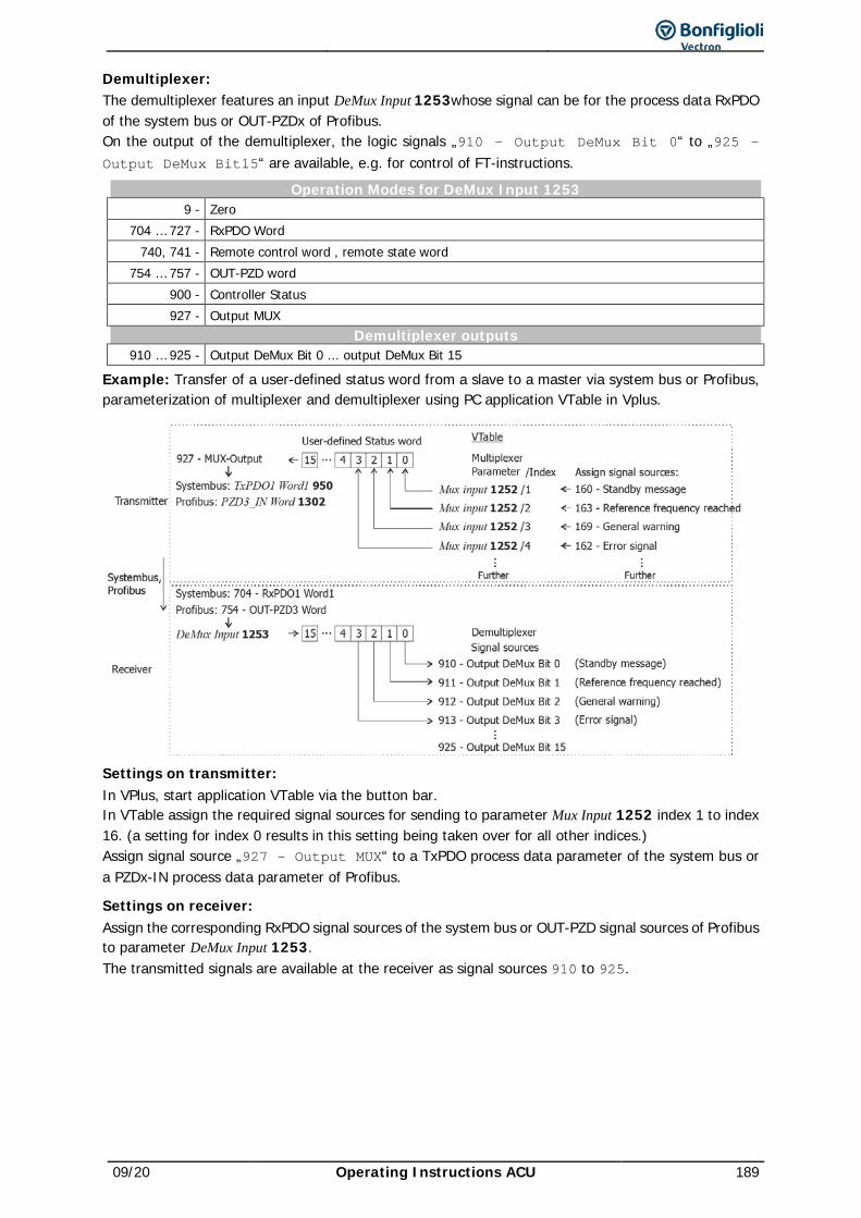
09/20 Operating Instructions ACU 189
Demultiplexer: The demultiplexer features an input DeMux Input 1253whose signal can be for the process data RxPDO of the system bus or OUT-PZDx of Profibus. On the output of the demultiplexer, the logic signals „910 – Output DeMux Bit 0“ to „925 – Output DeMux Bit15“ are available, e.g. for control of FT-instructions.
Operation Modes for DeMux Input 1253 9 - Zero
704 … 727 - RxPDO Word 740, 741 - Remote control word , remote state word
754 … 757 - OUT-PZD word 900 - Controller Status 927 - Output MUX
Demultiplexer outputs 910 … 925 - Output DeMux Bit 0 ... output DeMux Bit 15
Example: Transfer of a user-defined status word from a slave to a master via system bus or Profibus, parameterization of multiplexer and demultiplexer using PC application VTable in Vplus.
Settings on transmitter: In VPlus, start application VTable via the button bar. In VTable assign the required signal sources for sending to parameter Mux Input 1252 index 1 to index 16. (a setting for index 0 results in this setting being taken over for all other indices.) Assign signal source „927 – Output MUX“ to a TxPDO process data parameter of the system bus or a PZDx-IN process data parameter of Profibus.
Settings on receiver: Assign the corresponding RxPDO signal sources of the system bus or OUT-PZD signal sources of Profibus to parameter DeMux Input 1253. The transmitted signals are available at the receiver as signal sources 910 to 925.
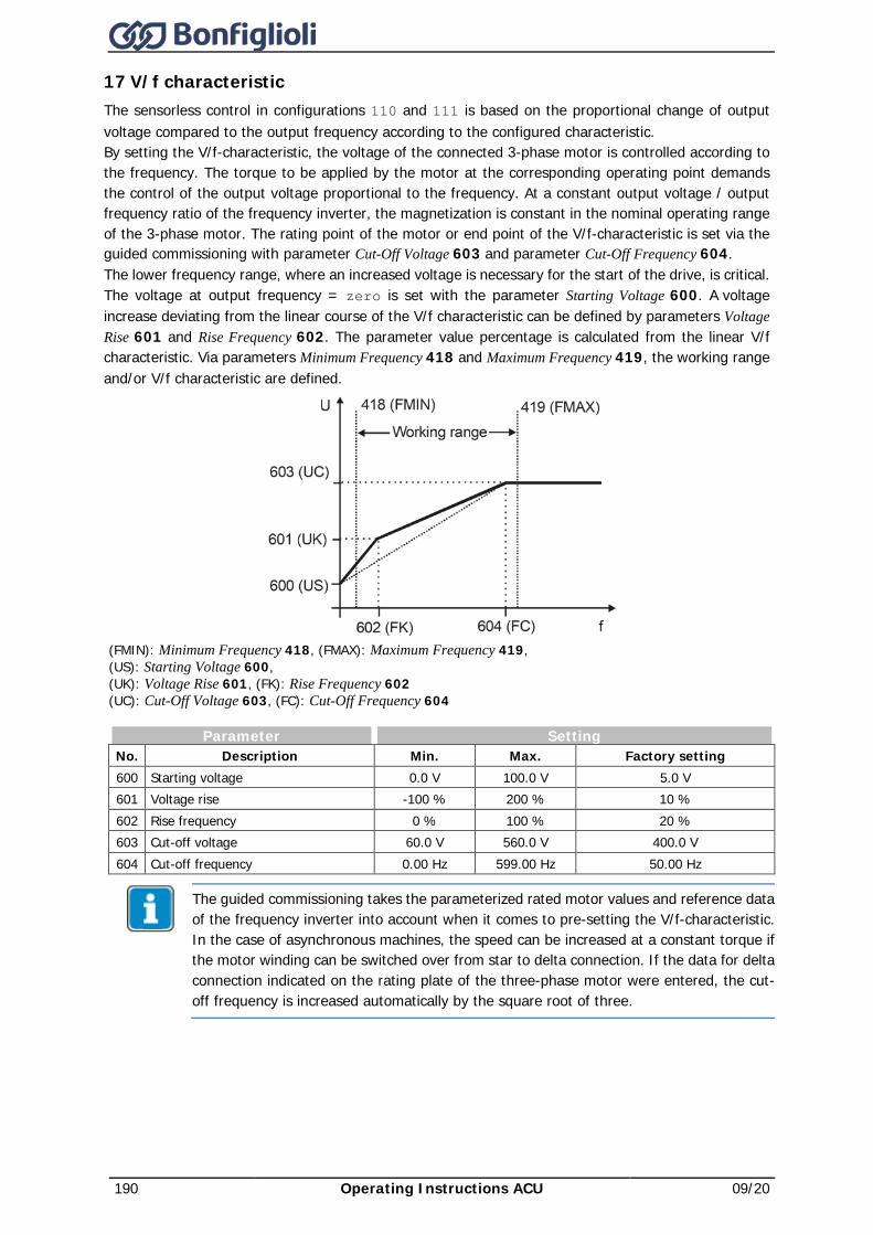
190 Operating Instructions ACU 09/20
17 V/f characteristic The sensorless control in configurations 110 and 111 is based on the proportional change of output voltage compared to the output frequency according to the configured characteristic. By setting the V/f-characteristic, the voltage of the connected 3-phase motor is controlled according to the frequency. The torque to be applied by the motor at the corresponding operating point demands the control of the output voltage proportional to the frequency. At a constant output voltage / output frequency ratio of the frequency inverter, the magnetization is constant in the nominal operating range of the 3-phase motor. The rating point of the motor or end point of the V/f-characteristic is set via the guided commissioning with parameter Cut-Off Voltage 603 and parameter Cut-Off Frequency 604. The lower frequency range, where an increased voltage is necessary for the start of the drive, is critical. The voltage at output frequency = zero is set with the parameter Starting Voltage 600. A voltage increase deviating from the linear course of the V/f characteristic can be defined by parameters Voltage Rise 601 and Rise Frequency 602. The parameter value percentage is calculated from the linear V/f characteristic. Via parameters Minimum Frequency 418 and Maximum Frequency 419, the working range and/or V/f characteristic are defined.
(FMIN): Minimum Frequency 418, (FMAX): Maximum Frequency 419, (US): Starting Voltage 600, (UK): Voltage Rise 601, (FK): Rise Frequency 602 (UC): Cut-Off Voltage 603, (FC): Cut-Off Frequency 604
Parameter Setting No. Description Min. Max. Factory setting 600 Starting voltage 0.0 V 100.0 V 5.0 V 601 Voltage rise -100 % 200 % 10 % 602 Rise frequency 0 % 100 % 20 % 603 Cut-off voltage 60.0 V 560.0 V 400.0 V 604 Cut-off frequency 0.00 Hz 599.00 Hz 50.00 Hz
The guided commissioning takes the parameterized rated motor values and reference data of the frequency inverter into account when it comes to pre-setting the V/f-characteristic. In the case of asynchronous machines, the speed can be increased at a constant torque if the motor winding can be switched over from star to delta connection. If the data for delta connection indicated on the rating plate of the three-phase motor were entered, the cut-off frequency is increased automatically by the square root of three.
09/20 Operating Instructions ACU 191
The default Cut-Off Voltage 603 (UC) and Cut-Off Frequency 604 (FC) are derived from the motor data Rated Voltage 370 and Rated Frequency 375. With the parameterized Starting Voltage 600 (US), the linear equation of the V/f-characteristic results.
V 5,0fHz 0,00Hz 50,00
V 5,0-V 400,0USf0FC
USUCU +⋅
−
=+⋅
−−
=
The Rise Frequency 602 (FK) is entered as a percentage of the Cut-Off Frequency 604 (FC), the default value is f=10 Hz. The output voltage for the default Voltage Rise 601 (UK) is calculated as U=92.4V.
( ) ( ) ( ) V 92,41,1V 5Hz 500,2Hz 0Hz 50V 5-V 400UK1USFCFK
0FCUSUCU =⋅
+⋅⋅
−=+⋅
+⋅⋅
−−
=
Dynamic voltage pre-control The Dyn. Voltage Pre-Control 605 accelerates the control behavior of the current limit controller (parameter Operation Mode 610) and the voltage controller (parameter Operation Mode 670). The output voltage value resulting from the U/F characteristic is changed by addition of the calculated voltage pre-control.
Parameter Setting No. Description Min. Max. Factory setting 605 Dyn. Voltage Pre-Control 0 % 200 % 100 %
192 Operating Instructions ACU 09/20
18 Control functions The frequency inverters provide a selection of established control methods in Configuration 30. The selected control structure can parameterized as required and optimized for the application by further functions.
18.1 Intelligent current limits The current limits to be set according to the application avoid inadmissible loading of the connected load and prevent a fault switch-off of the frequency inverter. The function extends the current controller available in the control system. The specified overload reserve of the frequency inverter can be utilized optimally using the intelligent current limits, particularly in applications with dynamic load changes. The criterion to be selected via parameter Operation Mode 573 defines the threshold to the activation of the intelligent current limit. The parameterized rated motor current or the reference current of the frequency inverter is synchronized as the limit value of the intelligent current limits.
Operation Mode 573 Function 0 - off The function is switched off. 1 - Ixt Limitation to the overload of the frequency inverter (Ixt).
10 - Tc Limitation to the maximum heat sink temperature (TC) 11 - Ixt + Tc Operation mode 1 and 10 (Ixt + TC) 20 - Motor temp. Limitation to motor temperature (TMotor) 21 - Motor temp.+ Ixt Operation mode 20 and 1 (TMotor + Ixt) 30 - Tc + Motor temp. Operation mode 10 and 20 (TC + TMotor)
31 - Tc + Motor temp. + Ixt Operation mode 10, 20 and 1 (TC + TMotor + Ixt).
The threshold selected via parameter Operation Mode 573 is monitored by the intelligent current limits. In the operation modes with motor and heat sink temperature monitoring, the reduction of power selected with the parameter Power Limit 574 is done when the threshold value has been reached. This is achieved by a reduction of the output current and the speed in motor operation. The load behavior of the connected machine must be a function of the speed to ensure a sensible use of the intelligent current limits. The total time of the power reduction as a result of an increased motor or heat sink temperature contains not only the cooling time, but also the additionally defined Limitation Time 575. The definition of the power limit should be selected as small as possible in order to give the drive sufficient time to cool down. The reference value is the rated output of the frequency inverter or the set rated power of the motor.
Parameter Setting No. Description Min. Max. Factory setting 574 Power Limit 40.00% 95.00% 80.00% 575 Limitation Time 5 min 300 min 15 min
In the operation modes with overload reserve (Ixt), the output current will be reduced if the threshold is exceeded. A distinction is made in this context between long-time and short-time overload reserve. After the short-term overload (1s) has been used up, the output current is reduced to the long-term overload current matching the present switching frequency. After the long-term overload current has been used up (60s), the output current is reduced to the rated current which also depends on the switching frequency. If the output current has already been reduced due to the fact that the long-term overload has been used up, the short-term overload is no longer available even if it has not been used up beforehand. The defined overload reserve (Ixt) of the frequency inverter is available again after 10 minutes of operation at reduced power. Output signals Reaching of a limit – selected in Operation Mode 573 – can be signaled via digital outputs.
15 - Warning current limitation The intelligent current limits limit the output current.
16 - Controller current limit. long term Ixt
The overload reserve for 60 s has been used up and the out-put current is being limited.
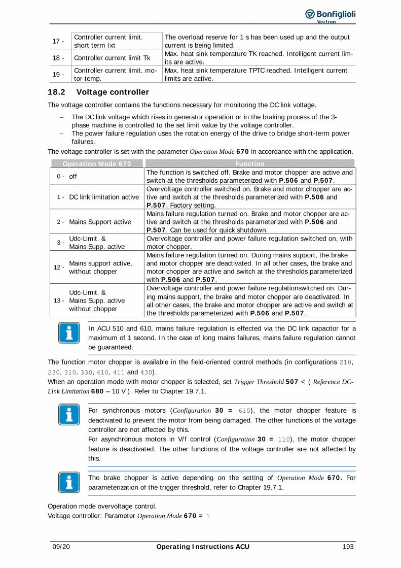
09/20 Operating Instructions ACU 193
17 - Controller current limit. short term Ixt
The overload reserve for 1 s has been used up and the output current is being limited.
18 - Controller current limit Tk Max. heat sink temperature TK reached. Intelligent current lim-its are active.
19 - Controller current limit. mo-tor temp.
Max. heat sink temperature TPTC reached. Intelligent current limits are active.
18.2 Voltage controller The voltage controller contains the functions necessary for monitoring the DC link voltage.
− The DC link voltage which rises in generator operation or in the braking process of the 3-phase machine is controlled to the set limit value by the voltage controller.
− The power failure regulation uses the rotation energy of the drive to bridge short-term power failures.
The voltage controller is set with the parameter Operation Mode 670 in accordance with the application.
Operation Mode 670 Function
0 - off The function is switched off. Brake and motor chopper are active and switch at the thresholds parameterized with P.506 and P.507.
1 - DC link limitation active Overvoltage controller switched on. Brake and motor chopper are ac-tive and switch at the thresholds parameterized with P.506 and P.507. Factory setting.
2 - Mains Support active Mains failure regulation turned on. Brake and motor chopper are ac-tive and switch at the thresholds parameterized with P.506 and P.507. Can be used for quick shutdown.
3 - Udc-Limit. & Mains Supp. active
Overvoltage controller and power failure regulation switched on, with motor chopper.
12 - Mains support active, without chopper
Mains failure regulation turned on. During mains support, the brake and motor chopper are deactivated. In all other cases, the brake and motor chopper are active and switch at the thresholds parameterized with P.506 and P.507.
13 - Udc-Limit. & Mains Supp. active without chopper
Overvoltage controller and power failure regulationswitched on. Dur-ing mains support, the brake and motor chopper are deactivated. In all other cases, the brake and motor chopper are active and switch at the thresholds parameterized with P.506 and P.507.
In ACU 510 and 610, mains failure regulation is effected via the DC link capacitor for a maximum of 1 second. In the case of long mains failures, mains failure regulation cannot be guaranteed.
The function motor chopper is available in the field-oriented control methods (in configurations 210, 230, 310, 330, 410, 411 and 430). When an operation mode with motor chopper is selected, set Trigger Threshold 507 < ( Reference DC-Link Limitation 680 – 10 V ). Refer to Chapter 19.7.1.
For synchronous motors (Configuration 30 = 610), the motor chopper feature is deactivated to prevent the motor from being damaged. The other functions of the voltage controller are not affected by this. For asynchronous motors in V/f control (Configuration 30 = 110), the motor chopper feature is deactivated. The other functions of the voltage controller are not affected by this.
The brake chopper is active depending on the setting of Operation Mode 670. For parameterization of the trigger threshold, refer to Chapter 19.7.1.
Operation mode overvoltage control, Voltage controller: Parameter Operation Mode 670 = 1
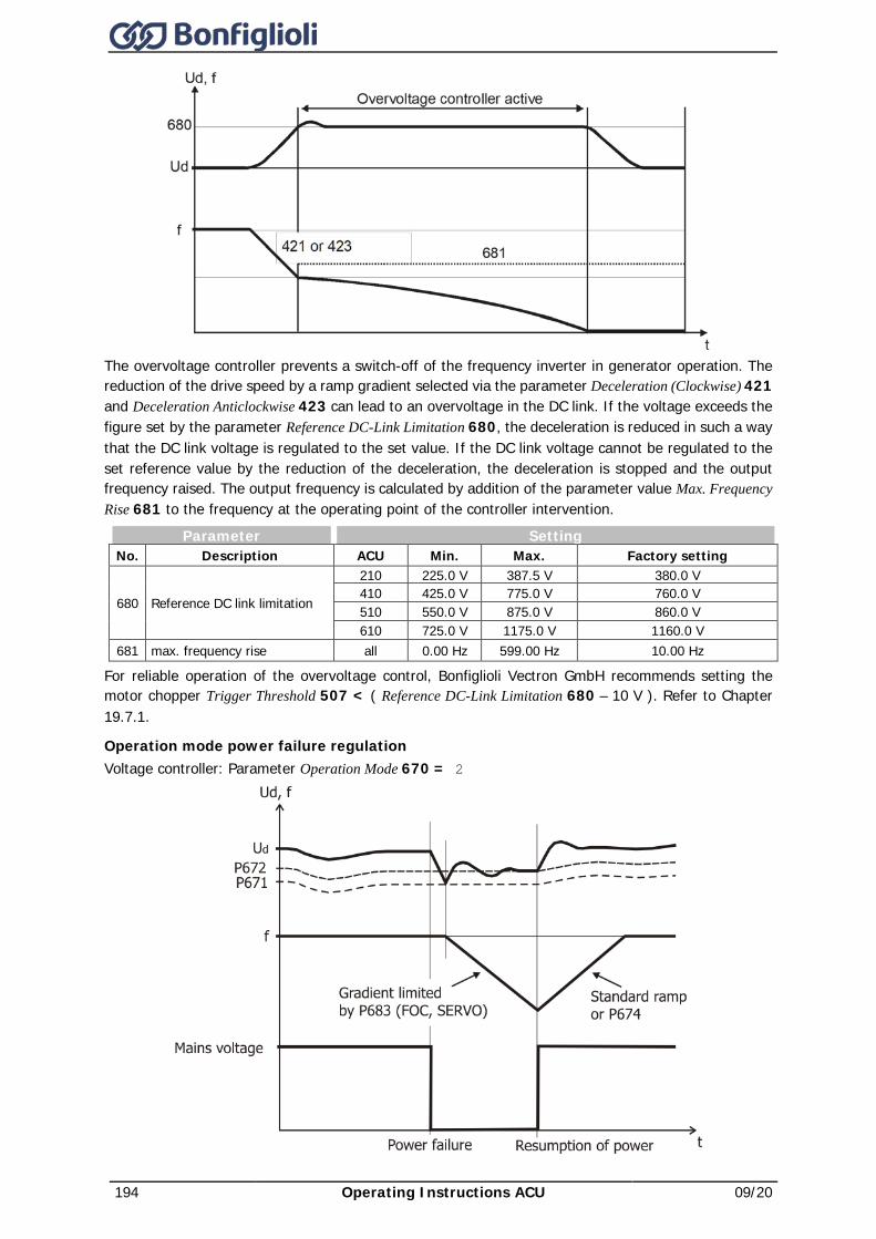
194 Operating Instructions ACU 09/20
The overvoltage controller prevents a switch-off of the frequency inverter in generator operation. The reduction of the drive speed by a ramp gradient selected via the parameter Deceleration (Clockwise) 421 and Deceleration Anticlockwise 423 can lead to an overvoltage in the DC link. If the voltage exceeds the figure set by the parameter Reference DC-Link Limitation 680, the deceleration is reduced in such a way that the DC link voltage is regulated to the set value. If the DC link voltage cannot be regulated to the set reference value by the reduction of the deceleration, the deceleration is stopped and the output frequency raised. The output frequency is calculated by addition of the parameter value Max. Frequency Rise 681 to the frequency at the operating point of the controller intervention.
Parameter Setting No. Description ACU Min. Max. Factory setting
680 Reference DC link limitation
210 225.0 V 387.5 V 380.0 V 410 425.0 V 775.0 V 760.0 V 510 550.0 V 875.0 V 860.0 V 610 725.0 V 1175.0 V 1160.0 V
681 max. frequency rise all 0.00 Hz 599.00 Hz 10.00 Hz
For reliable operation of the overvoltage control, Bonfiglioli Vectron GmbH recommends setting the motor chopper Trigger Threshold 507 < ( Reference DC-Link Limitation 680 – 10 V ). Refer to Chapter 19.7.1.
Operation mode power failure regulation Voltage controller: Parameter Operation Mode 670 = 2
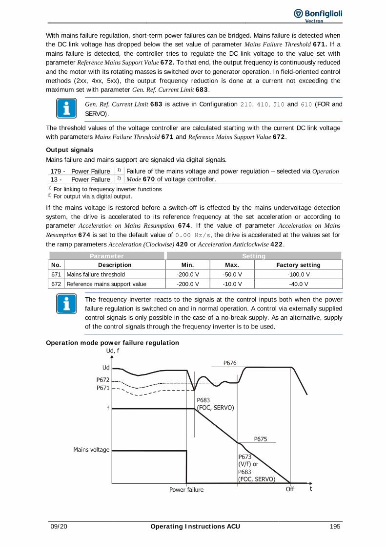
09/20 Operating Instructions ACU 195
With mains failure regulation, short-term power failures can be bridged. Mains failure is detected when the DC link voltage has dropped below the set value of parameter Mains Failure Threshold 671. If a mains failure is detected, the controller tries to regulate the DC link voltage to the value set with parameter Reference Mains Support Value 672. To that end, the output frequency is continuously reduced and the motor with its rotating masses is switched over to generator operation. In field-oriented control methods (2xx, 4xx, 5xx), the output frequency reduction is done at a current not exceeding the maximum set with parameter Gen. Ref. Current Limit 683.
Gen. Ref. Current Limit 683 is active in Configuration 210, 410, 510 and 610 (FOR and SERVO).
The threshold values of the voltage controller are calculated starting with the current DC link voltage with parameters Mains Failure Threshold 671 and Reference Mains Support Value 672.
Output signals Mains failure and mains support are signaled via digital signals.
179 - Power Failure 1) Failure of the mains voltage and power regulation – selected via Operation Mode 670 of voltage controller. 13 - Power Failure 2)
1) For linking to frequency inverter functions 2) For output via a digital output.
If the mains voltage is restored before a switch-off is effected by the mains undervoltage detection system, the drive is accelerated to its reference frequency at the set acceleration or according to parameter Acceleration on Mains Resumption 674. If the value of parameter Acceleration on Mains Resumption 674 is set to the default value of 0.00 Hz/s, the drive is accelerated at the values set for the ramp parameters Acceleration (Clockwise) 420 or Acceleration Anticlockwise 422.
Parameter Setting No. Description Min. Max. Factory setting 671 Mains failure threshold -200.0 V -50.0 V -100.0 V 672 Reference mains support value -200.0 V -10.0 V -40.0 V
The frequency inverter reacts to the signals at the control inputs both when the power failure regulation is switched on and in normal operation. A control via externally supplied control signals is only possible in the case of a no-break supply. As an alternative, supply of the control signals through the frequency inverter is to be used.
Operation mode power failure regulation
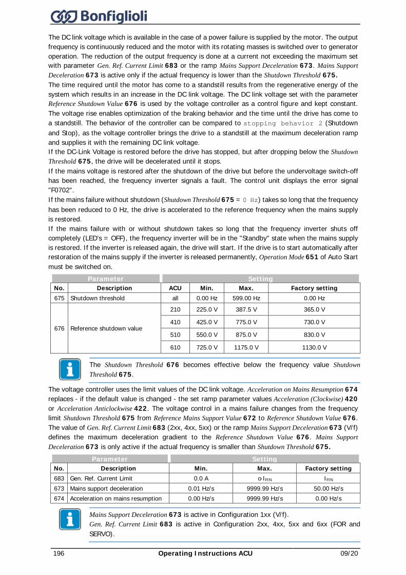
196 Operating Instructions ACU 09/20
The DC link voltage which is available in the case of a power failure is supplied by the motor. The output frequency is continuously reduced and the motor with its rotating masses is switched over to generator operation. The reduction of the output frequency is done at a current not exceeding the maximum set with parameter Gen. Ref. Current Limit 683 or the ramp Mains Support Deceleration 673. Mains Support Deceleration 673 is active only if the actual frequency is lower than the Shutdown Threshold 675. The time required until the motor has come to a standstill results from the regenerative energy of the system which results in an increase in the DC link voltage. The DC link voltage set with the parameter Reference Shutdown Value 676 is used by the voltage controller as a control figure and kept constant. The voltage rise enables optimization of the braking behavior and the time until the drive has come to a standstill. The behavior of the controller can be compared to stopping behavior 2 (Shutdown and Stop), as the voltage controller brings the drive to a standstill at the maximum deceleration ramp and supplies it with the remaining DC link voltage. If the DC-Link Voltage is restored before the drive has stopped, but after dropping below the Shutdown Threshold 675, the drive will be decelerated until it stops. If the mains voltage is restored after the shutdown of the drive but before the undervoltage switch-off has been reached, the frequency inverter signals a fault. The control unit displays the error signal "F0702". If the mains failure without shutdown (Shutdown Threshold 675 = 0 Hz) takes so long that the frequency has been reduced to 0 Hz, the drive is accelerated to the reference frequency when the mains supply is restored. If the mains failure with or without shutdown takes so long that the frequency inverter shuts off completely (LED's = OFF), the frequency inverter will be in the "Standby" state when the mains supply is restored. If the inverter is released again, the drive will start. If the drive is to start automatically after restoration of the mains supply if the inverter is released permanently, Operation Mode 651 of Auto Start must be switched on.
Parameter Setting No. Description ACU Min. Max. Factory setting 675 Shutdown threshold all 0.00 Hz 599.00 Hz 0.00 Hz
676 Reference shutdown value
210 225.0 V 387.5 V 365.0 V
410 425.0 V 775.0 V 730.0 V
510 550.0 V 875.0 V 830.0 V
610 725.0 V 1175.0 V 1130.0 V
The Shutdown Threshold 676 becomes effective below the frequency value Shutdown Threshold 675.
The voltage controller uses the limit values of the DC link voltage. Acceleration on Mains Resumption 674 replaces - if the default value is changed - the set ramp parameter values Acceleration (Clockwise) 420 or Acceleration Anticlockwise 422. The voltage control in a mains failure changes from the frequency limit Shutdown Threshold 675 from Reference Mains Support Value 672 to Reference Shutdown Value 676. The value of Gen. Ref. Current Limit 683 (2xx, 4xx, 5xx) or the ramp Mains Support Deceleration 673 (V/f) defines the maximum deceleration gradient to the Reference Shutdown Value 676. Mains Support Deceleration 673 is only active if the actual frequency is smaller than Shutdown Threshold 675.
Parameter Setting No. Description Min. Max. Factory setting 683 Gen. Ref. Current Limit 0.0 A o⋅IFIN IFIN 673 Mains support deceleration 0.01 Hz/s 9999.99 Hz/s 50.00 Hz/s 674 Acceleration on mains resumption 0.00 Hz/s 9999.99 Hz/s 0.00 Hz/s
Mains Support Deceleration 673 is active in Configuration 1xx (V/f). Gen. Ref. Current Limit 683 is active in Configuration 2xx, 4xx, 5xx and 6xx (FOR and SERVO).
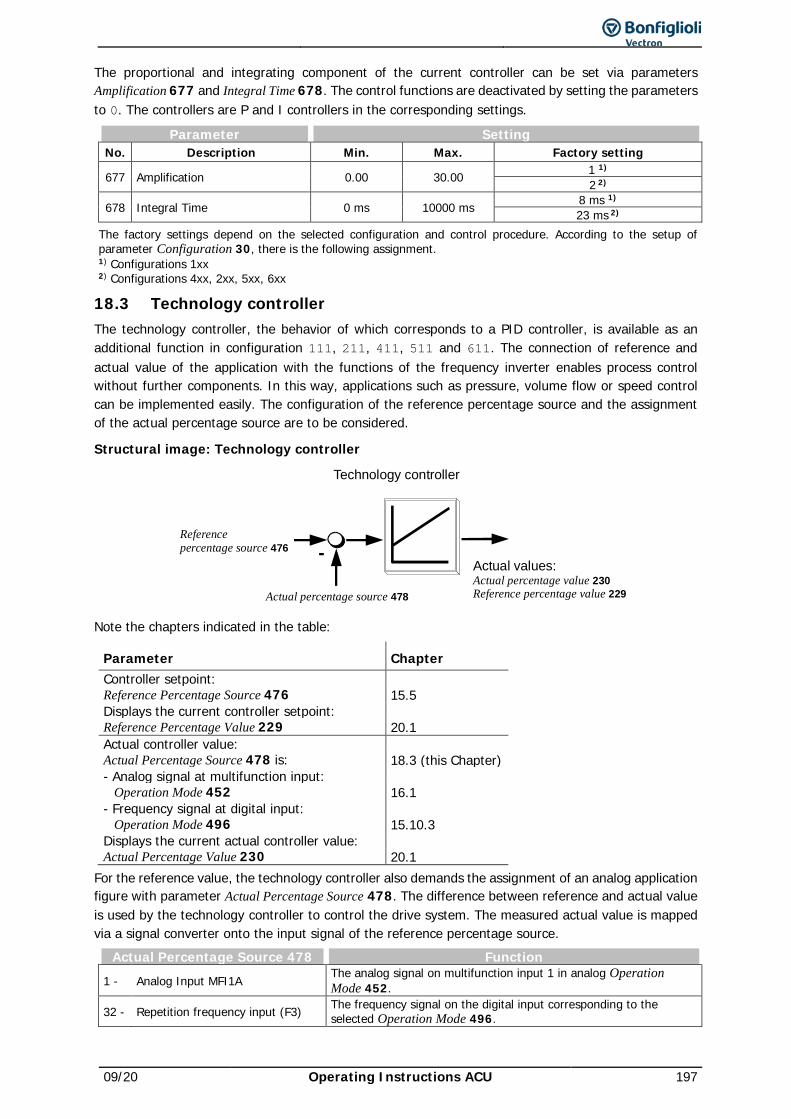
09/20 Operating Instructions ACU 197
The proportional and integrating component of the current controller can be set via parameters Amplification 677 and Integral Time 678. The control functions are deactivated by setting the parameters to 0. The controllers are P and I controllers in the corresponding settings.
Parameter Setting No. Description Min. Max. Factory setting
677 Amplification 0.00 30.00 1 1) 2 2)
678 Integral Time 0 ms 10000 ms 8 ms 1) 23 ms 2)
The factory settings depend on the selected configuration and control procedure. According to the setup of parameter Configuration 30, there is the following assignment. 1) Configurations 1xx 2) Configurations 4xx, 2xx, 5xx, 6xx
18.3 Technology controller The technology controller, the behavior of which corresponds to a PID controller, is available as an additional function in configuration 111, 211, 411, 511 and 611. The connection of reference and actual value of the application with the functions of the frequency inverter enables process control without further components. In this way, applications such as pressure, volume flow or speed control can be implemented easily. The configuration of the reference percentage source and the assignment of the actual percentage source are to be considered.
Structural image: Technology controller
-
Technology controller
Referencepercentage source 476
Actual percentage source 478
Actual values:Actual percentage value 230Reference percentage value 229
Note the chapters indicated in the table:
Parameter Chapter Controller setpoint: Reference Percentage Source 476 15.5 Displays the current controller setpoint: Reference Percentage Value 229 20.1 Actual controller value: Actual Percentage Source 478 is: 18.3 (this Chapter) - Analog signal at multifunction input: Operation Mode 452 16.1 - Frequency signal at digital input: Operation Mode 496 15.10.3 Displays the current actual controller value: Actual Percentage Value 230 20.1
For the reference value, the technology controller also demands the assignment of an analog application figure with parameter Actual Percentage Source 478. The difference between reference and actual value is used by the technology controller to control the drive system. The measured actual value is mapped via a signal converter onto the input signal of the reference percentage source.
Actual Percentage Source 478 Function 1 - Analog Input MFI1A The analog signal on multifunction input 1 in analog Operation
Mode 452.
32 - Repetition frequency input (F3) The frequency signal on the digital input corresponding to the selected Operation Mode 496.
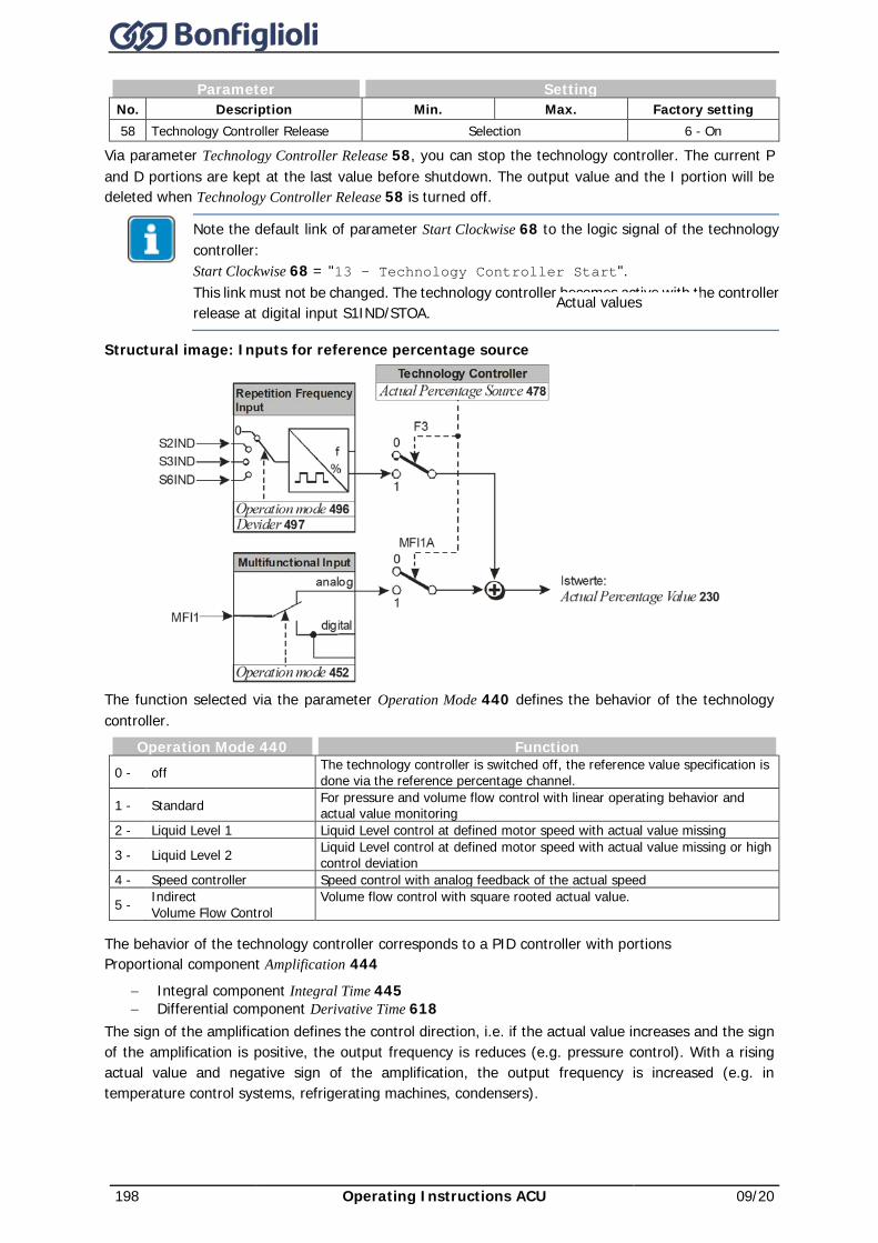
198 Operating Instructions ACU 09/20
Parameter Setting No. Description Min. Max. Factory setting 58 Technology Controller Release Selection 6 - On
Via parameter Technology Controller Release 58, you can stop the technology controller. The current P and D portions are kept at the last value before shutdown. The output value and the I portion will be deleted when Technology Controller Release 58 is turned off.
Note the default link of parameter Start Clockwise 68 to the logic signal of the technology controller: Start Clockwise 68 = "13 – Technology Controller Start". This link must not be changed. The technology controller becomes active with the controller release at digital input S1IND/STOA.
Structural image: Inputs for reference percentage source
The function selected via the parameter Operation Mode 440 defines the behavior of the technology controller.
Operation Mode 440 Function 0 - off The technology controller is switched off, the reference value specification is
done via the reference percentage channel.
1 - Standard For pressure and volume flow control with linear operating behavior and actual value monitoring
2 - Liquid Level 1 Liquid Level control at defined motor speed with actual value missing
3 - Liquid Level 2 Liquid Level control at defined motor speed with actual value missing or high control deviation
4 - Speed controller Speed control with analog feedback of the actual speed
5 - Indirect Volume Flow Control
Volume flow control with square rooted actual value.
The behavior of the technology controller corresponds to a PID controller with portions Proportional component Amplification 444
− Integral component Integral Time 445 − Differential component Derivative Time 618
The sign of the amplification defines the control direction, i.e. if the actual value increases and the sign of the amplification is positive, the output frequency is reduces (e.g. pressure control). With a rising actual value and negative sign of the amplification, the output frequency is increased (e.g. in temperature control systems, refrigerating machines, condensers).
Actual values
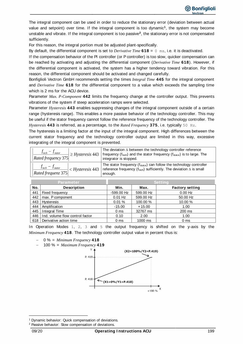
09/20 Operating Instructions ACU 199
The integral component can be used in order to reduce the stationary error (deviation between actual value and setpoint) over time. If the integral component is too dynamic1, the system may become unstable and vibrate. If the integral component is too passive2, the stationary error is not compensated sufficiently. For this reason, the integral portion must be adjusted plant-specifically. By default, the differential component is set to Derivative Time 618 = 0 ms, i.e. it is deactivated. If the compensation behavior of the PI controller (or P controller) is too slow, quicker compensation can be reached by activating and adjusting the differential component (Derivative Time 618). However, if the differential component is activated, the system has a higher tendency toward vibration. For this reason, the differential component should be activated and changed carefully. Bonfiglioli Vectron GmbH recommends setting the times Integral Time 445 for the integral component and Derivative Time 618 for the differential component to a value which exceeds the sampling time which is 2 ms for the ACU device. Parameter Max. P-Component 442 limits the frequency change at the controller output. This prevents vibrations of the system if steep acceleration ramps were selected. Parameter Hysteresis 443 enables suppressing changes of the integral component outside of a certain range (hysteresis range). This enables a more passive behavior of the technology controller. This may be useful if the stator frequency cannot follow the reference frequency of the technology controller. The Hysteresis 443 is referred, as a percentage, to the Rated Frequency 375, i.e. typically 50 Hz. The hysteresis is a limiting factor at the input of the integral component. High differences between the current stator frequency and the technology controller output are limited in this way, excessive integrating of the integral component is prevented.
443375
HysteresisfrequencyRated
ff statortech ≥−
The deviation ∆ between the technology controller reference frequency (ftech) and the stator frequency (fstator) is to large. The integrator is stopped.
443375
HysteresisfrequenzRated
ff statortech <−
The stator frequency (fstator) can follow the technology controller reference frequency (ftech) sufficiently. The deviation ∆ is small enough.
Parameter Setting No. Description Min. Max. Factory setting 441 Fixed frequency -599.00 Hz 599.00 Hz 0.00 Hz 442 max. P component 0.01 Hz 599.00 Hz 50.00 Hz 443 Hysteresis 0.01 % 100.00 % 10.00 % 444 Amplification -15.00 +15.00 1.00 445 Integral Time 0 ms 32767 ms 200 ms 446 Ind. volume flow control factor 0.10 2.00 1.00 618 Derivative action time 0 ms 1000 ms 0 ms
In Operation Modes 1, 2, 3 and 5 the output frequency is shifted on the y-axis by the Minimum Frequency 418. The technology controller output value in percent thus is:
− 0 % = Minimum Frequency 418 − 100 % = Maximum Frequency 419
1 Dynamic behavior: Quick compensation of deviations. 2 Passive behavior: Slow compensation of deviations.
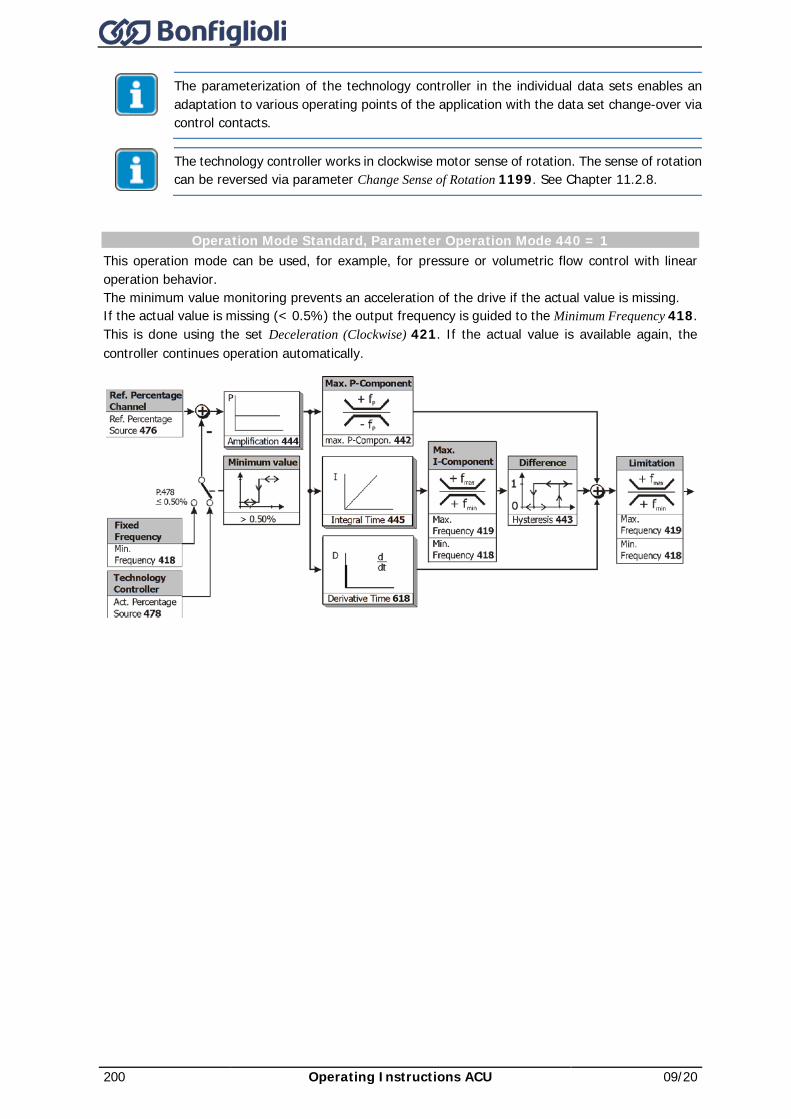
200 Operating Instructions ACU 09/20
The parameterization of the technology controller in the individual data sets enables an adaptation to various operating points of the application with the data set change-over via control contacts.
The technology controller works in clockwise motor sense of rotation. The sense of rotation can be reversed via parameter Change Sense of Rotation 1199. See Chapter 11.2.8.
Operation Mode Standard, Parameter Operation Mode 440 = 1 This operation mode can be used, for example, for pressure or volumetric flow control with linear operation behavior. The minimum value monitoring prevents an acceleration of the drive if the actual value is missing. If the actual value is missing (< 0.5%) the output frequency is guided to the Minimum Frequency 418. This is done using the set Deceleration (Clockwise) 421. If the actual value is available again, the controller continues operation automatically.
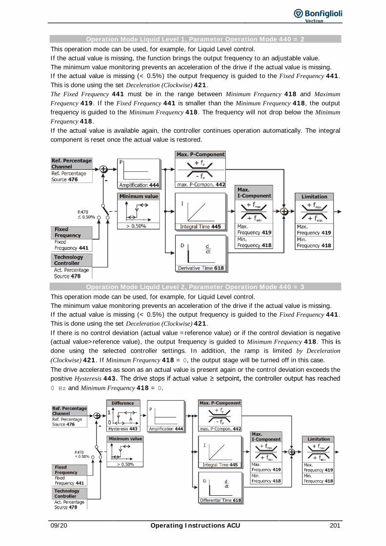
09/20 Operating Instructions ACU 201
Operation Mode Liquid Level 1, Parameter Operation Mode 440 = 2 This operation mode can be used, for example, for Liquid Level control. If the actual value is missing, the function brings the output frequency to an adjustable value. The minimum value monitoring prevents an acceleration of the drive if the actual value is missing. If the actual value is missing (< 0.5%) the output frequency is guided to the Fixed Frequency 441. This is done using the set Deceleration (Clockwise) 421. The Fixed Frequency 441 must be in the range between Minimum Frequency 418 and Maximum Frequency 419. If the Fixed Frequency 441 is smaller than the Minimum Frequency 418, the output frequency is guided to the Minimum Frequency 418. The frequency will not drop below the Minimum Frequency 418. If the actual value is available again, the controller continues operation automatically. The integral component is reset once the actual value is restored.
Operation Mode Liquid Level 2, Parameter Operation Mode 440 = 3 This operation mode can be used, for example, for Liquid Level control. The minimum value monitoring prevents an acceleration of the drive if the actual value is missing. If the actual value is missing (< 0.5%) the output frequency is guided to the Fixed Frequency 441. This is done using the set Deceleration (Clockwise) 421. If there is no control deviation (actual value =reference value) or if the control deviation is negative (actual value>reference value), the output frequency is guided to Minimum Frequency 418. This is done using the selected controller settings. In addition, the ramp is limited by Deceleration (Clockwise) 421. If Minimum Frequency 418 = 0, the output stage will be turned off in this case. The drive accelerates as soon as an actual value is present again or the control deviation exceeds the positive Hysteresis 443. The drive stops if actual value ≥ setpoint, the controller output has reached 0 Hz and Minimum Frequency 418 = 0.
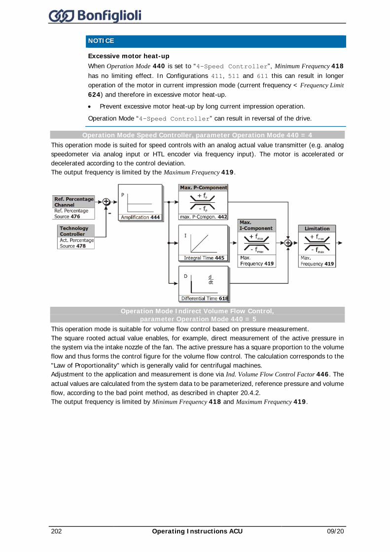
202 Operating Instructions ACU 09/20
NOTICE Excessive motor heat-up
When Operation Mode 440 is set to “4-Speed Controller”, Minimum Frequency 418 has no limiting effect. In Configurations 411, 511 and 611 this can result in longer operation of the motor in current impression mode (current frequency < Frequency Limit 624) and therefore in excessive motor heat-up. • Prevent excessive motor heat-up by long current impression operation.
Operation Mode “4-Speed Controller” can result in reversal of the drive.
Operation Mode Speed Controller, parameter Operation Mode 440 = 4 This operation mode is suited for speed controls with an analog actual value transmitter (e.g. analog speedometer via analog input or HTL encoder via frequency input). The motor is accelerated or decelerated according to the control deviation. The output frequency is limited by the Maximum Frequency 419.
Operation Mode Indirect Volume Flow Control, parameter Operation Mode 440 = 5
This operation mode is suitable for volume flow control based on pressure measurement. The square rooted actual value enables, for example, direct measurement of the active pressure in the system via the intake nozzle of the fan. The active pressure has a square proportion to the volume flow and thus forms the control figure for the volume flow control. The calculation corresponds to the "Law of Proportionality" which is generally valid for centrifugal machines. Adjustment to the application and measurement is done via Ind. Volume Flow Control Factor 446. The actual values are calculated from the system data to be parameterized, reference pressure and volume flow, according to the bad point method, as described in chapter 20.4.2. The output frequency is limited by Minimum Frequency 418 and Maximum Frequency 419.
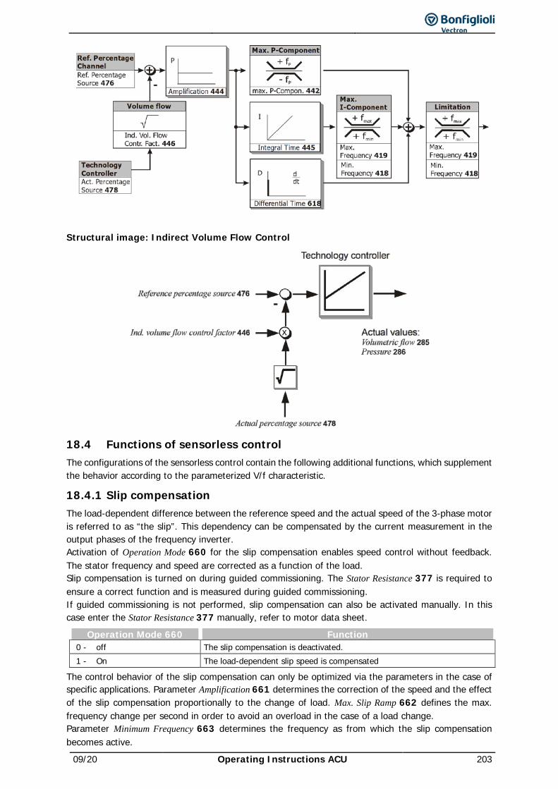
09/20 Operating Instructions ACU 203
Structural image: Indirect Volume Flow Control
18.4 Functions of sensorless control The configurations of the sensorless control contain the following additional functions, which supplement the behavior according to the parameterized V/f characteristic.
18.4.1 Slip compensation The load-dependent difference between the reference speed and the actual speed of the 3-phase motor is referred to as “the slip”. This dependency can be compensated by the current measurement in the output phases of the frequency inverter. Activation of Operation Mode 660 for the slip compensation enables speed control without feedback. The stator frequency and speed are corrected as a function of the load. Slip compensation is turned on during guided commissioning. The Stator Resistance 377 is required to ensure a correct function and is measured during guided commissioning. If guided commissioning is not performed, slip compensation can also be activated manually. In this case enter the Stator Resistance 377 manually, refer to motor data sheet.
Operation Mode 660 Function 0 - off The slip compensation is deactivated. 1 - On The load-dependent slip speed is compensated
The control behavior of the slip compensation can only be optimized via the parameters in the case of specific applications. Parameter Amplification 661 determines the correction of the speed and the effect of the slip compensation proportionally to the change of load. Max. Slip Ramp 662 defines the max. frequency change per second in order to avoid an overload in the case of a load change. Parameter Minimum Frequency 663 determines the frequency as from which the slip compensation becomes active.
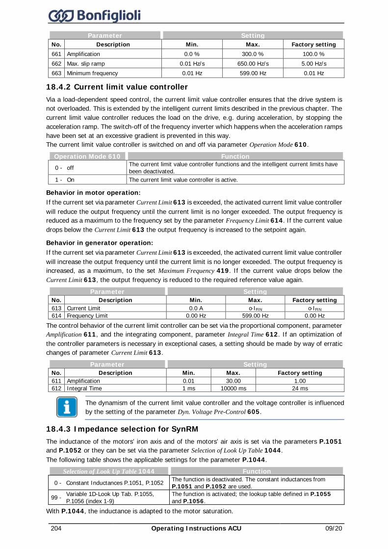
204 Operating Instructions ACU 09/20
Parameter Setting No. Description Min. Max. Factory setting 661 Amplification 0.0 % 300.0 % 100.0 % 662 Max. slip ramp 0.01 Hz/s 650.00 Hz/s 5.00 Hz/s 663 Minimum frequency 0.01 Hz 599.00 Hz 0.01 Hz
18.4.2 Current limit value controller Via a load-dependent speed control, the current limit value controller ensures that the drive system is not overloaded. This is extended by the intelligent current limits described in the previous chapter. The current limit value controller reduces the load on the drive, e.g. during acceleration, by stopping the acceleration ramp. The switch-off of the frequency inverter which happens when the acceleration ramps have been set at an excessive gradient is prevented in this way. The current limit value controller is switched on and off via parameter Operation Mode 610.
Operation Mode 610 Function 0 - off The current limit value controller functions and the intelligent current limits have
been deactivated. 1 - On The current limit value controller is active.
Behavior in motor operation: If the current set via parameter Current Limit 613 is exceeded, the activated current limit value controller will reduce the output frequency until the current limit is no longer exceeded. The output frequency is reduced as a maximum to the frequency set by the parameter Frequency Limit 614. If the current value drops below the Current Limit 613 the output frequency is increased to the setpoint again.
Behavior in generator operation: If the current set via parameter Current Limit 613 is exceeded, the activated current limit value controller will increase the output frequency until the current limit is no longer exceeded. The output frequency is increased, as a maximum, to the set Maximum Frequency 419. If the current value drops below the Current Limit 613, the output frequency is reduced to the required reference value again.
Parameter Setting No. Description Min. Max. Factory setting 613 Current Limit 0.0 A o⋅IFIN o⋅IFIN 614 Frequency Limit 0.00 Hz 599.00 Hz 0.00 Hz
The control behavior of the current limit controller can be set via the proportional component, parameter Amplification 611, and the integrating component, parameter Integral Time 612. If an optimization of the controller parameters is necessary in exceptional cases, a setting should be made by way of erratic changes of parameter Current Limit 613.
Parameter Setting No. Description Min. Max. Factory setting 611 Amplification 0.01 30.00 1.00 612 Integral Time 1 ms 10000 ms 24 ms
The dynamism of the current limit value controller and the voltage controller is influenced by the setting of the parameter Dyn. Voltage Pre-Control 605.
18.4.3 Impedance selection for SynRM The inductance of the motors’ iron axis and of the motors’ air axis is set via the parameters P.1051 and P.1052 or they can be set via the parameter Selection of Look Up Table 1044. The following table shows the applicable settings for the parameter P.1044.
Selection of Look Up Table 1044 Function 0 - Constant Inductances P.1051, P.1052 The function is deactivated. The constant inductances from
P.1051 and P.1052 are used.
99 - Variable 1D-Look Up Tab. P.1055, P.1056 (index 1-9)
The function is activated; the lookup table defined in P.1055 and P.1056.
With P.1044, the inductance is adapted to the motor saturation.
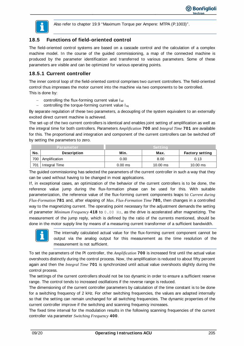
09/20 Operating Instructions ACU 205
Also refer to chapter 19.9 “Maximum Torque per Ampere: MTPA (P.1003)”.
18.5 Functions of field-oriented control The field-oriented control systems are based on a cascade control and the calculation of a complex machine model. In the course of the guided commissioning, a map of the connected machine is produced by the parameter identification and transferred to various parameters. Some of these parameters are visible and can be optimized for various operating points.
18.5.1 Current controller The inner control loop of the field-oriented control comprises two current controllers. The field-oriented control thus impresses the motor current into the machine via two components to be controlled. This is done by:
− controlling the flux-forming current value Isd − controlling the torque-forming current value Isq
By separate regulation of these two parameters, a decoupling of the system equivalent to an externally excited direct current machine is achieved. The set-up of the two current controllers is identical and enables joint setting of amplification as well as the integral time for both controllers. Parameters Amplification 700 and Integral Time 701 are available for this. The proportional and integration and component of the current controllers can be switched off by setting the parameters to zero.
Parameter Setting No. Description Min. Max. Factory setting 700 Amplification 0.00 8.00 0.13 701 Integral Time 0.00 ms 10.00 ms 10.00 ms
The guided commissioning has selected the parameters of the current controller in such a way that they can be used without having to be changed in most applications. If, in exceptional cases, an optimization of the behavior of the current controllers is to be done, the reference value jump during the flux-formation phase can be used for this. With suitable parameterization, the reference value of the flux-forming current components leaps to Current during Flux-Formation 781 and, after elapsing of Max. Flux-Formation Time 780, then changes in a controlled way to the magnetizing current. The operating point necessary for the adjustment demands the setting of parameter Minimum Frequency 418 to 0.00 Hz, as the drive is accelerated after magnetizing. The measurement of the jump reply, which is defined by the ratio of the currents mentioned, should be done in the motor supply line by means of a measuring current transformer of a sufficient bandwidth.
The internally calculated actual value for the flux-forming current component cannot be output via the analog output for this measurement as the time resolution of the measurement is not sufficient.
To set the parameters of the PI controller, the Amplification 700 is increased first until the actual value overshoots distinctly during the control process. Now, the amplification is reduced to about fifty percent again and then the Integral Time 701 is synchronized until actual value overshoots slightly during the control process. The settings of the current controllers should not be too dynamic in order to ensure a sufficient reserve range. The control tends to increased oscillations if the reverse range is reduced. The dimensioning of the current controller parameters by calculation of the time constant is to be done for a switching frequency of 2 kHz. For other switching frequencies, the values are adapted internally so that the setting can remain unchanged for all switching frequencies. The dynamic properties of the current controller improve if the switching and scanning frequency increases. The fixed time interval for the modulation results in the following scanning frequencies of the current controller via parameter Switching Frequency 400.
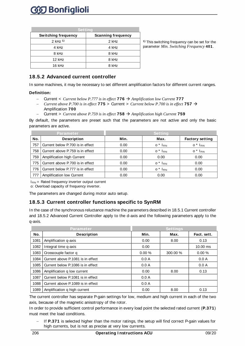
206 Operating Instructions ACU 09/20
Setting
Switching frequency Scanning frequency 2 kHz 1) 2 kHz 1) This switching frequency can be set for the
parameter Min. Switching Frequency 401. 4 kHz 4 kHz 8 kHz 8 kHz 12 kHz 8 kHz 16 kHz 8 kHz
18.5.2 Advanced current controller In some machines, it may be necessary to set different amplification factors for different current ranges.
Definition: − Current < Current below P.777 is in effect 776 à Amplification low Current 777 − Current above P.700 is in effect 775 > Current > Current below P.700 is in effect 757 à
Amplification 700 − Current > Current above P.759 is in effect 758 à Amplification high Current 759
By default, the parameters are preset such that the parameters are not active and only the basic parameters are active.
Parameter Setting No. Description Min. Max. Factory setting 757 Current below P.700 is in effect 0.00 o * IFIN o * IFIN 758 Current above P.759 is in effect 0.00 o * IFIN o * IFIN 759 Amplification high Current 0.00 0.00 0.00 775 Current above P.700 is in effect 0.00 o * IFIN 0.00 776 Current below P.777 is in effect 0.00 o * IFIN 0.00 777 Amplification low Current 0.00 0.00 0.00
IFIN = Rated frequency inverter output current o: Overload capacity of frequency inverter.
The parameters are changed during motor auto setup.
18.5.3 Current controller functions specific to SynRM In the case of the synchronous reluctance machine the parameters described in 18.5.1 Current controller and 18.5.2 Advanced Current Controller apply to the d-axis and the following parameters apply to the q-axis.
Parameter Settings No. Description Min. Max. Fact. sett. 1081 Amplification q-axis 0.00 8.00 0.13 1082 Integral time q-axis 0.00 10.00 ms 1083 Crosscouple factor q 0.00 % 300.00 % 0.00 % 1084 Current above P.1081 is in effect 0.0 A 0.0 A 1085 Current below P.1086 is in effect 0.0 A 0.0 A 1086 Amplification q low current 0.00 8.00 0.13 1087 Current below P.1081 is in effect 0.0 A 1088 Current above P.1089 is in effect 0.0 A 1089 Amplification q high current 0.00 8.00 0.13
The current controller has separate P-gain settings for low, medium and high current in each of the two axis, because of the magnetic anisotropy of the rotor. In order to provide sufficient control performance in every load point the selected rated current (P.371) must meet the load conditions.
− If P.371 is selected higher than the motor ratings, the setup will find correct P-gain values for high currents, but is not as precise at very low currents.
09/20 Operating Instructions ACU 207
− If MTPA is used (currents are reduced at low load), it is important to check the setting of the P-gain for low currents (P.777 and P.1086) and increase if needed.
During setup, best results are obtained when Rated Current 371 is selected to 1.0 * the name plate rating.
18.5.4 Torque controller The torque-controlled Configurations 230, 330, 430, 530 and 630 enable sensor-less torque control as an alternative to speed control. Torque control is possible above the Frequency Limit 624. Below the frequency limit, current impression is active at the current reference frequency as the reference frequency. In this case, the torque is not controlled but is set depending on the load behavior and the Starting Current 623. In order to obtain torque controlled starting, the reference frequency should be above the Frequency Limit 624. For example, this is guaranteed if Minimum Frequency 418 > Frequency Limit 624.
− f < Frequency Limit 624: Current impression − f ≥ Frequency Limit 624: Direct Torque Control DMR
The Frequency Limit 624 is set automatically during motor commissioning.
18.5.4.1 Torque preset The reference torque can be specified as follows: Set parameter n-/M-Control Change-Over 164 to “6 - On” or link it to a digital signal and turn it on. Select the torque preset source via parameter Reference Percentage Source 1 476. For example:
− The reference torque can be set via multifunction input 1 (MFI1A) if the following setting is selected: Reference Percentage Source 1 476 = “1 - Analog value MFI1A” (factory setting).
100 % torque refer to torque calculated from Rated mech. power 376 (motor power) and Rated Speed 372 (rated motor speed). Parameter Torque 224 shows the actual torque value. • Select setting of parameter Operation Mode Search Run 645 according to the application. Refer to
Chapter 13.5.
18.5.4.2 Upper and lower frequency limit in torque control NOTICE
Unexpected dynamic behavior If torque control is activated while the torsional frequency is outside the range between Frequency Upper Limit 767 and Frequency Lower Limit 768, (e.g. when a machine is started from standstill or a quickly rotating machine is stopped quickly), the permissible speed range will be approached without ramps by means of the speed controller. In this case, the torque is only limited by the limitations of the speed controller (current and torque). For this reason, there may be unexpected dynamic behavior.
In many situations, the speed must be limited at operating points with reduced or without load torque, as the speed is adjusted according to the preset torque and the load behavior. To avoid unwanted speeds (in most cases excessive speed, but sometimes low speeds, too, and to avoid current impression), the speed is limited by the speed controller via Frequency Upper Limit 767 and Frequency Lower Limit 768. As from the limit, the speed is adjusted to the maximum (Frequency Upper Limit 767 and Frequency Lower Limit 768) which corresponds to the behavior of the speed controller. In addition, the controller limits the speed to the Maximum Frequency 419. This limitation is done by the speed controller – changes of the speed controller affect the speed behavior in the limit range of the 3 parameters mentioned accordingly. In current impression mode, the frequency is also limited to the Minimum Frequency 418– in direct torque control mode, this limit is not active.
208 Operating Instructions ACU 09/20
Parameter Setting No. Description Min. Max. Factory setting 767 Frequency upper limit -599.00 Hz 599.00 Hz 599.00 Hz 768 Frequency lower limit -599.00 Hz 599.00 Hz -599.00 Hz
Positive values limit clockwise speed, negative values limit anticlockwise speed. If, for example, both values are positive (> 0 Hz), anticlockwise operation will be disabled.
18.5.4.3 Limit value sources The limitation of the frequency can be done by setting fixed values and by linking to an analog input parameter. The analog value is limited via parameters Minimum Reference Percentage 518 and Maximum Reference Percentage 519, but does not consider the Gradient Percentage Ramp 477 of the reference percentage value channel. The assignment is done for the torque controller via parameters Frequency Upper Limit Source 769 and Frequency Lower Limit Source 770.
Operation mode 769, 770 Function 101 - Analog Input MFI1A Multifunction input 1 in analog Operation Mode 452 is the source.
110 - Fixed Limit The selected parameter values are taken into account to limit the speed controller.
201 - Inv. Analog Input MFI1A Operation mode 101, inverted. 210 - Inv. Fixed Limit Operation mode 110, inverted.
18.5.4.4 Switching over between speed control and torque control With the signal assigned to parameter n-/M-Control Change-Over 164, you can switch between speed control and torque control. See Chapter 16.4.6.
18.5.5 Speed controller The actual speed source is selected via parameter Actual Speed Source 766. In the default setting, Speed Sensor 1 is used as the source of actual speed. If Speed Sensor 2 of an extension module is to deliver the actual value signal for the speed controller, Speed Sensor 2 must be selected as the source. Alternatively, the speed controller can derive the actual speed value from the machine model in in Configurations 3xx, 4xx, and 6xx (Parameter Configuration 30).
Operation Mode 766 Function 1 - Speed Sensor 1 The actual speed source is speed sensor 1 of the basic device (factory setting). 2 - Speed Sensor 2 The actual speed source is speed sensor 2 of an extension module.1)
3 - Machine Model The speed controller receives the calculated actual speed value from the machine model. Can be set in configurations 4xx and 6xx.
4 - Speedtracking EC 1 Speedtracking by comparison between the calculated machine model and speed sensor 1 to increase speed accuracy. Can be set in configurations 4xx and 6xx. The setting for parameter Integral Time Speedtracking 515 is considered.
5 - Speedtracking EC 2
Speed compensation by comparison between the calculated machine model and speed sensor 2 of an extension module1) to increase speed accuracy. Can be set in configurations 4xx and 6xx. The setting for parameter Integral Time Speedtracking 515 is considered.
20 - Speed Observer SynRM
The speed source is the speed observer output frequency. This value is set automatically during the setup of the synchronous reluctance machine.
1) Only available if extension module is installed
The control of the torque-forming current components is done in the outer control loop by the speed controller. Via parameter Operation Mode 720, you can select the operation mode for the speed controller. The operation mode defines the use of the parameterizable limits. These are referred to the direction of rotation and the direction of the torque and depend on the selected configuration.
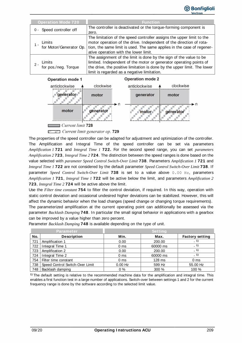
09/20 Operating Instructions ACU 209
Operation Mode 720 Function
0 - Speed controller off The controller is deactivated or the torque-forming component is zero.
1 - Limits for Motor/Generator Op.
The limitation of the speed controller assigns the upper limit to the motor operation of the drive. Independent of the direction of rota-tion, the same limit is used. The same applies in the case of regener-ative operation with the lower limit.
2 - Limits for pos./neg. Torque
The assignment of the limit is done by the sign of the value to be limited. Independent of the motor or generator operating points of the drive, the positive limitation is done by the upper limit. The lower limit is regarded as a negative limitation.
The properties of the speed controller can be adapted for adjustment and optimization of the controller. The Amplification and Integral Time of the speed controller can be set via parameters Amplification 1 721 and Integral Time 1 722. For the second speed range, you can set parameters Amplification 2 723, Integral Time 2 724. The distinction between the speed ranges is done based on the value selected with parameter Speed Control Switch-Over Limit 738. Parameters Amplification 1 721 and Integral Time 1 722 are not considered by the default parameter Speed Control Switch-Over Limit 738. If parameter Speed Control Switch-Over Limit 738 is set to a value above 0.00 Hz, parameters Amplification 1 721, Integral Time 1 722 will be active below the limit, and parameters Amplification 2 723, Integral Time 2 724 will be active above the limit. Use the Filter time constant 754 to filter the control deviation, if required. In this way, operation with static control deviation and occasional undesired higher deviations can be stabilized. However, this will affect the dynamic behavior when the load changes (speed change or changing torque requirements). The parameterized amplification at the current operating point can additionally be assessed via the parameter Backlash Damping 748. In particular the small signal behavior in applications with a gearbox can be improved by a value higher than zero percent. Parameter Backlash Damping 748 is available depending on the type of unit.
Parameter Setting No. Description Min. Max. Factory setting 721 Amplification 1 0.00 200.00 - 1) 722 Integral Time 1 0 ms 60000 ms - 1) 723 Amplification 2 0.00 200.00 - 1) 724 Integral Time 2 0 ms 60000 ms - 1) 754 Filter time constant 0 ms 128 ms 0 ms 738 Speed Control Switch-Over Limit 0.00 Hz 599 Hz 55.00 Hz 748 Backlash damping 0 % 300 % 100 %
1) The default setting is relative to the recommended machine data for the amplification and integral time. This enables a first function test in a large number of applications. Switch-over between settings 1 and 2 for the current frequency range is done by the software according to the selected limit value.
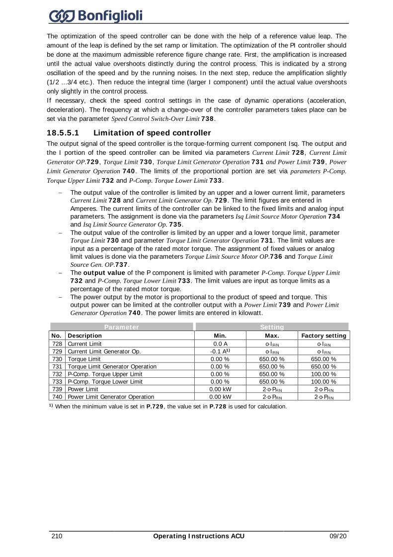
210 Operating Instructions ACU 09/20
The optimization of the speed controller can be done with the help of a reference value leap. The amount of the leap is defined by the set ramp or limitation. The optimization of the PI controller should be done at the maximum admissible reference figure change rate. First, the amplification is increased until the actual value overshoots distinctly during the control process. This is indicated by a strong oscillation of the speed and by the running noises. In the next step, reduce the amplification slightly (1/2 ...3/4 etc.). Then reduce the integral time (larger I component) until the actual value overshoots only slightly in the control process. If necessary, check the speed control settings in the case of dynamic operations (acceleration, deceleration). The frequency at which a change-over of the controller parameters takes place can be set via the parameter Speed Control Switch-Over Limit 738.
18.5.5.1 Limitation of speed controller The output signal of the speed controller is the torque-forming current component Isq. The output and the I portion of the speed controller can be limited via parameters Current Limit 728, Current Limit Generator OP.729, Torque Limit 730, Torque Limit Generator Operation 731 and Power Limit 739, Power Limit Generator Operation 740. The limits of the proportional portion are set via parameters P-Comp. Torque Upper Limit 732 and P-Comp. Torque Lower Limit 733.
− The output value of the controller is limited by an upper and a lower current limit, parameters Current Limit 728 and Current Limit Generator Op. 729. The limit figures are entered in Amperes. The current limits of the controller can be linked to the fixed limits and analog input parameters. The assignment is done via the parameters Isq Limit Source Motor Operation 734 and Isq Limit Source Generator Op. 735.
− The output value of the controller is limited by an upper and a lower torque limit, parameter Torque Limit 730 and parameter Torque Limit Generator Operation 731. The limit values are input as a percentage of the rated motor torque. The assignment of fixed values or analog limit values is done via the parameters Torque Limit Source Motor OP.736 and Torque Limit Source Gen. OP.737.
− The output value of the P component is limited with parameter P-Comp. Torque Upper Limit 732 and P-Comp. Torque Lower Limit 733. The limit values are input as torque limits as a percentage of the rated motor torque.
− The power output by the motor is proportional to the product of speed and torque. This output power can be limited at the controller output with a Power Limit 739 and Power Limit Generator Operation 740. The power limits are entered in kilowatt.
Parameter Setting No. Description Min. Max. Factory setting 728 Current Limit 0.0 A o⋅IFIN o⋅IFIN 729 Current Limit Generator Op. -0.1 A1) o⋅IFIN o⋅IFIN 730 Torque Limit 0.00 % 650.00 % 650.00 % 731 Torque Limit Generator Operation 0.00 % 650.00 % 650.00 % 732 P-Comp. Torque Upper Limit 0.00 % 650.00 % 100.00 % 733 P-Comp. Torque Lower Limit 0.00 % 650.00 % 100.00 % 739 Power Limit 0.00 kW 2⋅o⋅PFIN 2⋅o⋅PFIN 740 Power Limit Generator Operation 0.00 kW 2⋅o⋅PFIN 2⋅o⋅PFIN
1) When the minimum value is set in P.729, the value set in P.728 is used for calculation.
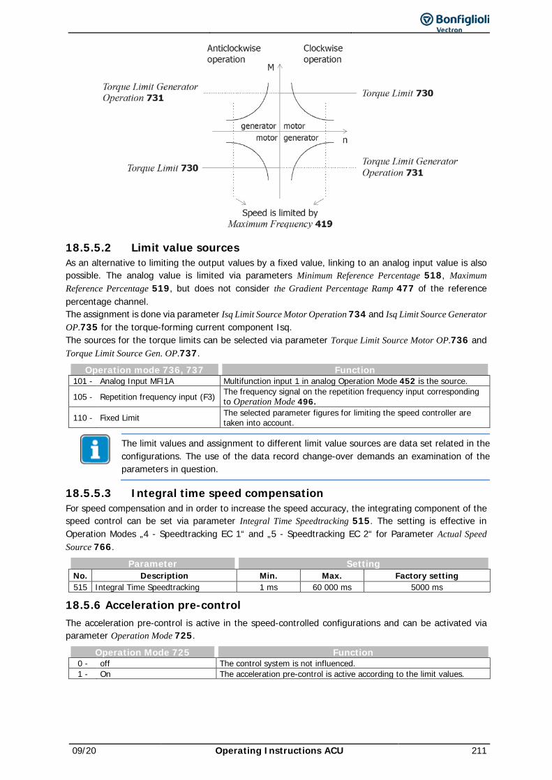
09/20 Operating Instructions ACU 211
18.5.5.2 Limit value sources As an alternative to limiting the output values by a fixed value, linking to an analog input value is also possible. The analog value is limited via parameters Minimum Reference Percentage 518, Maximum Reference Percentage 519, but does not consider the Gradient Percentage Ramp 477 of the reference percentage channel. The assignment is done via parameter Isq Limit Source Motor Operation 734 and Isq Limit Source Generator OP.735 for the torque-forming current component Isq. The sources for the torque limits can be selected via parameter Torque Limit Source Motor OP.736 and Torque Limit Source Gen. OP.737.
Operation mode 736, 737 Function 101 - Analog Input MFI1A Multifunction input 1 in analog Operation Mode 452 is the source.
105 - Repetition frequency input (F3) The frequency signal on the repetition frequency input corresponding to Operation Mode 496.
110 - Fixed Limit The selected parameter figures for limiting the speed controller are taken into account.
The limit values and assignment to different limit value sources are data set related in the configurations. The use of the data record change-over demands an examination of the parameters in question.
18.5.5.3 Integral time speed compensation For speed compensation and in order to increase the speed accuracy, the integrating component of the speed control can be set via parameter Integral Time Speedtracking 515. The setting is effective in Operation Modes „4 - Speedtracking EC 1“ and „5 - Speedtracking EC 2“ for Parameter Actual Speed Source 766.
Parameter Setting No. Description Min. Max. Factory setting 515 Integral Time Speedtracking 1 ms 60 000 ms 5000 ms
18.5.6 Acceleration pre-control The acceleration pre-control is active in the speed-controlled configurations and can be activated via parameter Operation Mode 725.
Operation Mode 725 Function 0 - off The control system is not influenced. 1 - On The acceleration pre-control is active according to the limit values.
212 Operating Instructions ACU 09/20
The acceleration pre-control controlled parallel to the speed controller reduces the reaction time of the drive system to a change of reference values. The minimum acceleration time defines the modification speed of the reference speed value as from which a torque necessary for acceleration of the drive is pre-controlled. Acceleration of the mass depends on the Mech. Time Constant 727 of the system. The value calculated from the increase of the reference value and the multiplication factor of the torque required is added to the output signal of the speed controller.
Parameter Setting No. Description Min. Max. Factory setting 726 Minimum acceleration 0.1 Hz/s 6500.0 Hz/s 1.0 Hz/s 727 Mech. Time Constant 1 ms 60000 ms 10 ms
For optimal setting, the acceleration pre-control is switched on and the mechanical time constant is set to the minimum value. The output value of the speed controller is compared to the minimum acceleration time during the acceleration processes. The frequency ramp is to be set to the highest value occurring in operation at which the output figure of the speed controller is not yet limited. Now, the value of the Minimum Acceleration 726 is set to half the set acceleration ramp so that it is ensured that the acceleration pre-control is active. The acceleration pre-control is not raised by increasing the Mech. Time Constant 727 until the output figure corresponds to the time modification of the drive mechanism during the acceleration processes.
18.5.7 Field controller The flux-forming current component is controlled by the field controller. The guided commissioning optimizes the parameters of the field controller by measuring the time constant and magnetizing curve of the connected asynchronous motor. The parameters of the field controller are selected such that they can be used without changes in most applications. The proportional and the integrating part of the field controller are to be set via parameters Amplification 741 and Integral Time 742.
Parameter Setting No. Description Min. Max. Factory setting 717 Reference Flux 0.01% 300.00% 100.00% 741 Amplification 0.0 100.0 5.0 742 Integral Time 0.0 ms 1000.0 ms 100.0 ms
Please note that any changes of the field controller should only be made in the base speed range. If the field controller must be optimized, set the Field Controller Integral Time 742 = Act. Rotor Time Constant 227 / 2, i.e. half the rotor time constants. In most applications, this change will be sufficient. If additional optimization is required, please proceed as follows: • First set the output frequency (e.g. via reference frequency) such that the actual value Modulation
223 = 80…90 % Reference Modulation 750. • Now, change parameter Reference Flux 717 from 100 % to 90 %. While doing so, oscillograph Isd.
The course of the signal of the flux-forming current Isd should reach the stationary value after overshooting without oscillation.
• Adjust parameters Amplification 741 and Integral Time 742 according to the application requirements.
• Change the Reference Flux 717 back to 100 % and repeat the reference flux jump, while analyzing the changes by means of oscillography. Repeat these steps if necessary.
If a quick transition into field weakening is necessary for the application, the integral time should be reduced. For good dynamic behavior, choose a relatively high value for Amplification 741 of the controller. Note that high overshoot is necessary for good control behavior in controlling of a load with low-pass behavior, for example a 3-phase machine. Parameter Reduction Factor Flux 778 reduces the stall current when a stopping behavior is selected with “Stop” function. This stopping behavior is selected if Parameter Operation Mode 630 is set to 2x (20 … 27 – “R->0, Stop, … ”) or x2 (2, 12, 22, 32, 42, 52, 62, 72 – “ … , R->0, Stop”). The stopping behavior is described in Chapter 13.2 “Stopping behavior”.
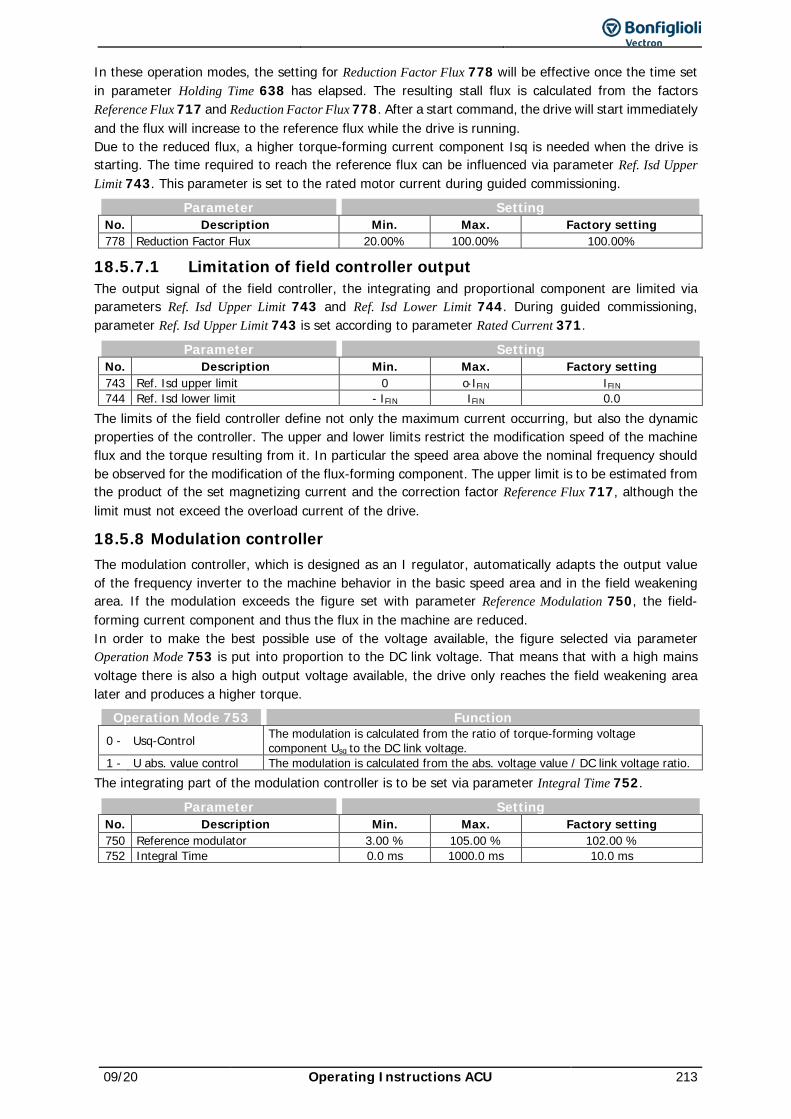
09/20 Operating Instructions ACU 213
In these operation modes, the setting for Reduction Factor Flux 778 will be effective once the time set in parameter Holding Time 638 has elapsed. The resulting stall flux is calculated from the factors Reference Flux 717 and Reduction Factor Flux 778. After a start command, the drive will start immediately and the flux will increase to the reference flux while the drive is running. Due to the reduced flux, a higher torque-forming current component Isq is needed when the drive is starting. The time required to reach the reference flux can be influenced via parameter Ref. Isd Upper Limit 743. This parameter is set to the rated motor current during guided commissioning.
Parameter Setting No. Description Min. Max. Factory setting 778 Reduction Factor Flux 20.00% 100.00% 100.00%
18.5.7.1 Limitation of field controller output The output signal of the field controller, the integrating and proportional component are limited via parameters Ref. Isd Upper Limit 743 and Ref. Isd Lower Limit 744. During guided commissioning, parameter Ref. Isd Upper Limit 743 is set according to parameter Rated Current 371.
Parameter Setting No. Description Min. Max. Factory setting 743 Ref. Isd upper limit 0 o⋅IFIN IFIN 744 Ref. Isd lower limit - IFIN IFIN 0.0
The limits of the field controller define not only the maximum current occurring, but also the dynamic properties of the controller. The upper and lower limits restrict the modification speed of the machine flux and the torque resulting from it. In particular the speed area above the nominal frequency should be observed for the modification of the flux-forming component. The upper limit is to be estimated from the product of the set magnetizing current and the correction factor Reference Flux 717, although the limit must not exceed the overload current of the drive.
18.5.8 Modulation controller The modulation controller, which is designed as an I regulator, automatically adapts the output value of the frequency inverter to the machine behavior in the basic speed area and in the field weakening area. If the modulation exceeds the figure set with parameter Reference Modulation 750, the field-forming current component and thus the flux in the machine are reduced. In order to make the best possible use of the voltage available, the figure selected via parameter Operation Mode 753 is put into proportion to the DC link voltage. That means that with a high mains voltage there is also a high output voltage available, the drive only reaches the field weakening area later and produces a higher torque.
Operation Mode 753 Function 0 - Usq-Control The modulation is calculated from the ratio of torque-forming voltage
component Usq to the DC link voltage. 1 - U abs. value control The modulation is calculated from the abs. voltage value / DC link voltage ratio.
The integrating part of the modulation controller is to be set via parameter Integral Time 752.
Parameter Setting No. Description Min. Max. Factory setting 750 Reference modulator 3.00 % 105.00 % 102.00 % 752 Integral Time 0.0 ms 1000.0 ms 10.0 ms
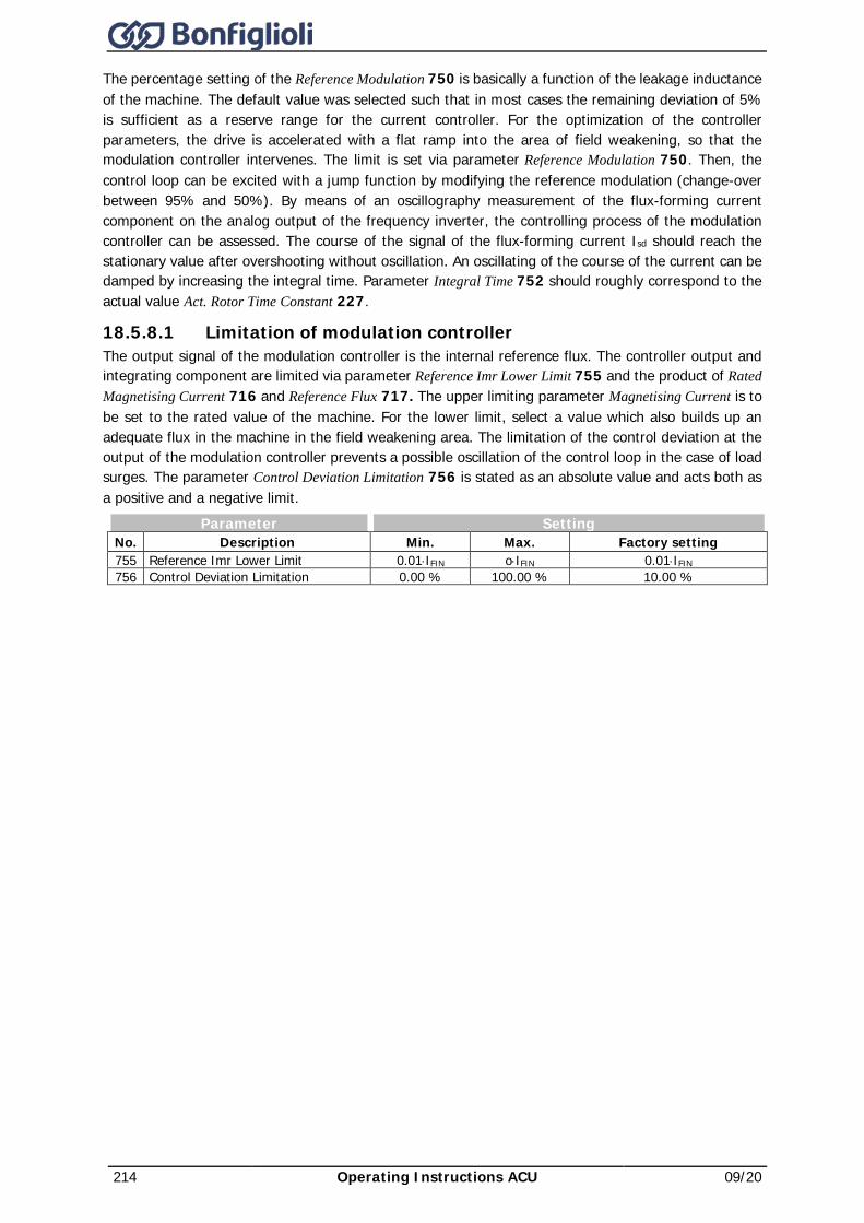
214 Operating Instructions ACU 09/20
The percentage setting of the Reference Modulation 750 is basically a function of the leakage inductance of the machine. The default value was selected such that in most cases the remaining deviation of 5% is sufficient as a reserve range for the current controller. For the optimization of the controller parameters, the drive is accelerated with a flat ramp into the area of field weakening, so that the modulation controller intervenes. The limit is set via parameter Reference Modulation 750. Then, the control loop can be excited with a jump function by modifying the reference modulation (change-over between 95% and 50%). By means of an oscillography measurement of the flux-forming current component on the analog output of the frequency inverter, the controlling process of the modulation controller can be assessed. The course of the signal of the flux-forming current Isd should reach the stationary value after overshooting without oscillation. An oscillating of the course of the current can be damped by increasing the integral time. Parameter Integral Time 752 should roughly correspond to the actual value Act. Rotor Time Constant 227.
18.5.8.1 Limitation of modulation controller The output signal of the modulation controller is the internal reference flux. The controller output and integrating component are limited via parameter Reference Imr Lower Limit 755 and the product of Rated Magnetising Current 716 and Reference Flux 717. The upper limiting parameter Magnetising Current is to be set to the rated value of the machine. For the lower limit, select a value which also builds up an adequate flux in the machine in the field weakening area. The limitation of the control deviation at the output of the modulation controller prevents a possible oscillation of the control loop in the case of load surges. The parameter Control Deviation Limitation 756 is stated as an absolute value and acts both as a positive and a negative limit.
Parameter Setting No. Description Min. Max. Factory setting 755 Reference Imr Lower Limit 0.01⋅IFIN o⋅IFIN 0.01⋅IFIN 756 Control Deviation Limitation 0.00 % 100.00 % 10.00 %
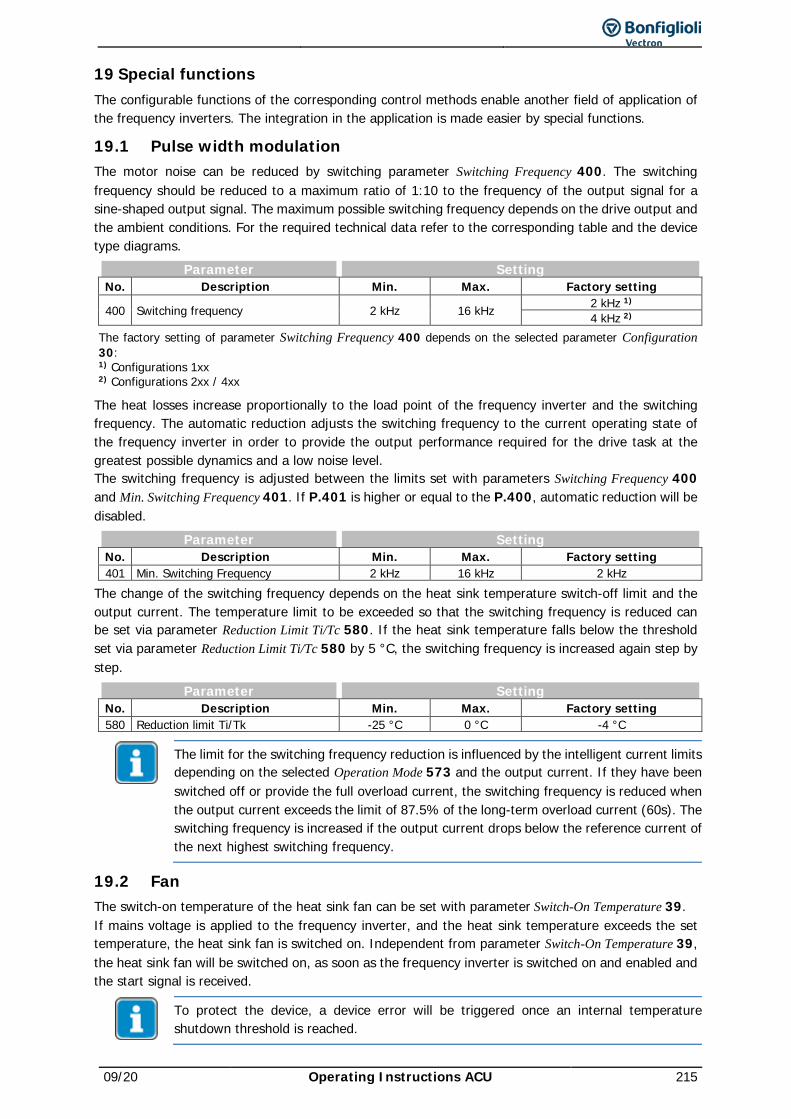
09/20 Operating Instructions ACU 215
19 Special functions The configurable functions of the corresponding control methods enable another field of application of the frequency inverters. The integration in the application is made easier by special functions.
19.1 Pulse width modulation The motor noise can be reduced by switching parameter Switching Frequency 400. The switching frequency should be reduced to a maximum ratio of 1:10 to the frequency of the output signal for a sine-shaped output signal. The maximum possible switching frequency depends on the drive output and the ambient conditions. For the required technical data refer to the corresponding table and the device type diagrams.
Parameter Setting No. Description Min. Max. Factory setting
400 Switching frequency 2 kHz 16 kHz 2 kHz 1) 4 kHz 2)
The factory setting of parameter Switching Frequency 400 depends on the selected parameter Configuration 30: 1) Configurations 1xx 2) Configurations 2xx / 4xx
The heat losses increase proportionally to the load point of the frequency inverter and the switching frequency. The automatic reduction adjusts the switching frequency to the current operating state of the frequency inverter in order to provide the output performance required for the drive task at the greatest possible dynamics and a low noise level. The switching frequency is adjusted between the limits set with parameters Switching Frequency 400 and Min. Switching Frequency 401. If P.401 is higher or equal to the P.400, automatic reduction will be disabled.
Parameter Setting No. Description Min. Max. Factory setting 401 Min. Switching Frequency 2 kHz 16 kHz 2 kHz
The change of the switching frequency depends on the heat sink temperature switch-off limit and the output current. The temperature limit to be exceeded so that the switching frequency is reduced can be set via parameter Reduction Limit Ti/Tc 580. If the heat sink temperature falls below the threshold set via parameter Reduction Limit Ti/Tc 580 by 5 °C, the switching frequency is increased again step by step.
Parameter Setting No. Description Min. Max. Factory setting 580 Reduction limit Ti/Tk -25 °C 0 °C -4 °C
The limit for the switching frequency reduction is influenced by the intelligent current limits depending on the selected Operation Mode 573 and the output current. If they have been switched off or provide the full overload current, the switching frequency is reduced when the output current exceeds the limit of 87.5% of the long-term overload current (60s). The switching frequency is increased if the output current drops below the reference current of the next highest switching frequency.
19.2 Fan The switch-on temperature of the heat sink fan can be set with parameter Switch-On Temperature 39. If mains voltage is applied to the frequency inverter, and the heat sink temperature exceeds the set temperature, the heat sink fan is switched on. Independent from parameter Switch-On Temperature 39, the heat sink fan will be switched on, as soon as the frequency inverter is switched on and enabled and the start signal is received.
To protect the device, a device error will be triggered once an internal temperature shutdown threshold is reached.
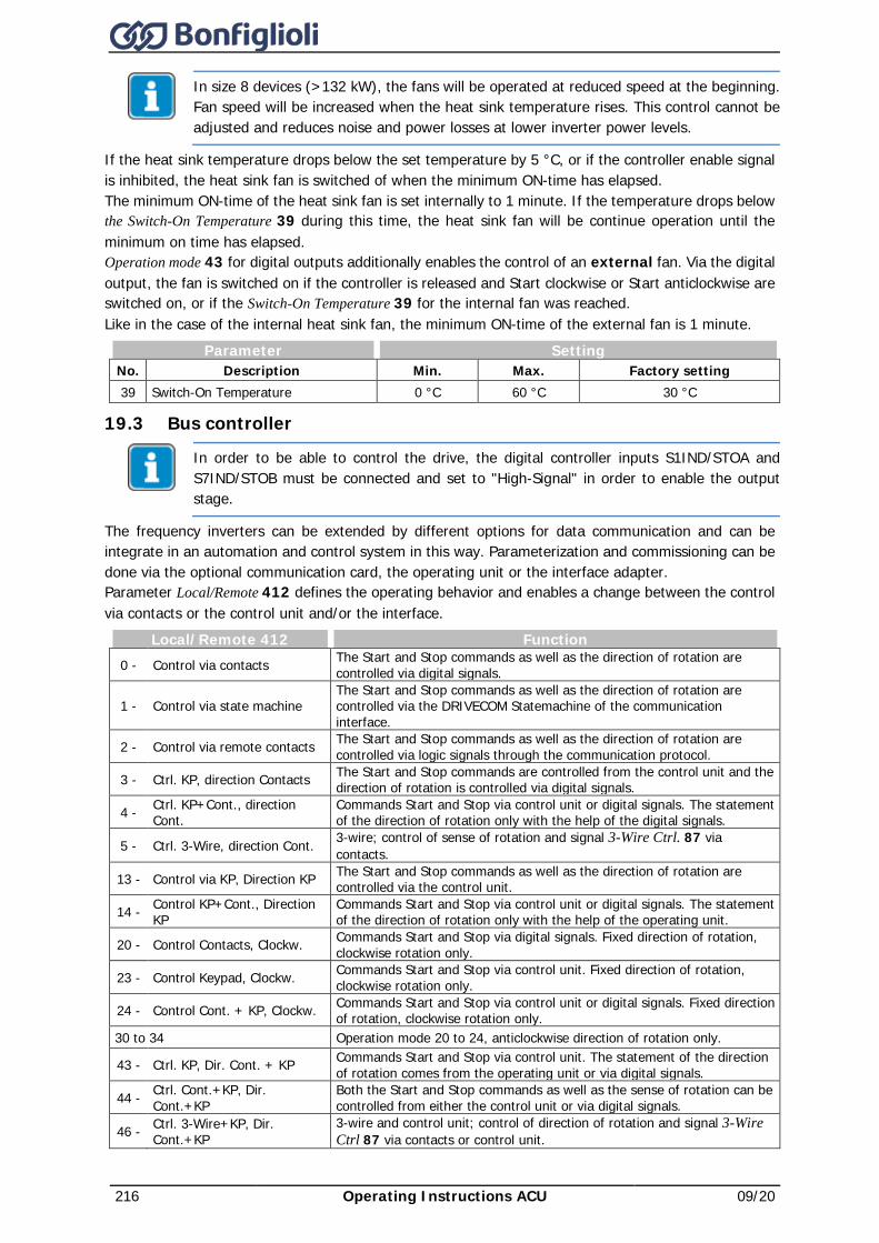
216 Operating Instructions ACU 09/20
In size 8 devices (>132 kW), the fans will be operated at reduced speed at the beginning. Fan speed will be increased when the heat sink temperature rises. This control cannot be adjusted and reduces noise and power losses at lower inverter power levels.
If the heat sink temperature drops below the set temperature by 5 °C, or if the controller enable signal is inhibited, the heat sink fan is switched of when the minimum ON-time has elapsed. The minimum ON-time of the heat sink fan is set internally to 1 minute. If the temperature drops below the Switch-On Temperature 39 during this time, the heat sink fan will be continue operation until the minimum on time has elapsed. Operation mode 43 for digital outputs additionally enables the control of an external fan. Via the digital output, the fan is switched on if the controller is released and Start clockwise or Start anticlockwise are switched on, or if the Switch-On Temperature 39 for the internal fan was reached. Like in the case of the internal heat sink fan, the minimum ON-time of the external fan is 1 minute.
Parameter Setting No. Description Min. Max. Factory setting 39 Switch-On Temperature 0 °C 60 °C 30 °C
19.3 Bus controller
In order to be able to control the drive, the digital controller inputs S1IND/STOA and S7IND/STOB must be connected and set to "High-Signal" in order to enable the output stage.
The frequency inverters can be extended by different options for data communication and can be integrate in an automation and control system in this way. Parameterization and commissioning can be done via the optional communication card, the operating unit or the interface adapter. Parameter Local/Remote 412 defines the operating behavior and enables a change between the control via contacts or the control unit and/or the interface.
Local/Remote 412 Function 0 - Control via contacts The Start and Stop commands as well as the direction of rotation are
controlled via digital signals.
1 - Control via state machine The Start and Stop commands as well as the direction of rotation are controlled via the DRIVECOM Statemachine of the communication interface.
2 - Control via remote contacts The Start and Stop commands as well as the direction of rotation are controlled via logic signals through the communication protocol.
3 - Ctrl. KP, direction Contacts The Start and Stop commands are controlled from the control unit and the direction of rotation is controlled via digital signals.
4 - Ctrl. KP+Cont., direction Cont.
Commands Start and Stop via control unit or digital signals. The statement of the direction of rotation only with the help of the digital signals.
5 - Ctrl. 3-Wire, direction Cont. 3-wire; control of sense of rotation and signal 3-Wire Ctrl. 87 via contacts.
13 - Control via KP, Direction KP The Start and Stop commands as well as the direction of rotation are controlled via the control unit.
14 - Control KP+Cont., Direction KP
Commands Start and Stop via control unit or digital signals. The statement of the direction of rotation only with the help of the operating unit.
20 - Control Contacts, Clockw. Commands Start and Stop via digital signals. Fixed direction of rotation, clockwise rotation only.
23 - Control Keypad, Clockw. Commands Start and Stop via control unit. Fixed direction of rotation, clockwise rotation only.
24 - Control Cont. + KP, Clockw. Commands Start and Stop via control unit or digital signals. Fixed direction of rotation, clockwise rotation only.
30 to 34 Operation mode 20 to 24, anticlockwise direction of rotation only.
43 - Ctrl. KP, Dir. Cont. + KP Commands Start and Stop via control unit. The statement of the direction of rotation comes from the operating unit or via digital signals.
44 - Ctrl. Cont.+KP, Dir. Cont.+KP
Both the Start and Stop commands as well as the sense of rotation can be controlled from either the control unit or via digital signals.
46 - Ctrl. 3-Wire+KP, Dir. Cont.+KP
3-wire and control unit; control of direction of rotation and signal 3-Wire Ctrl 87 via contacts or control unit.
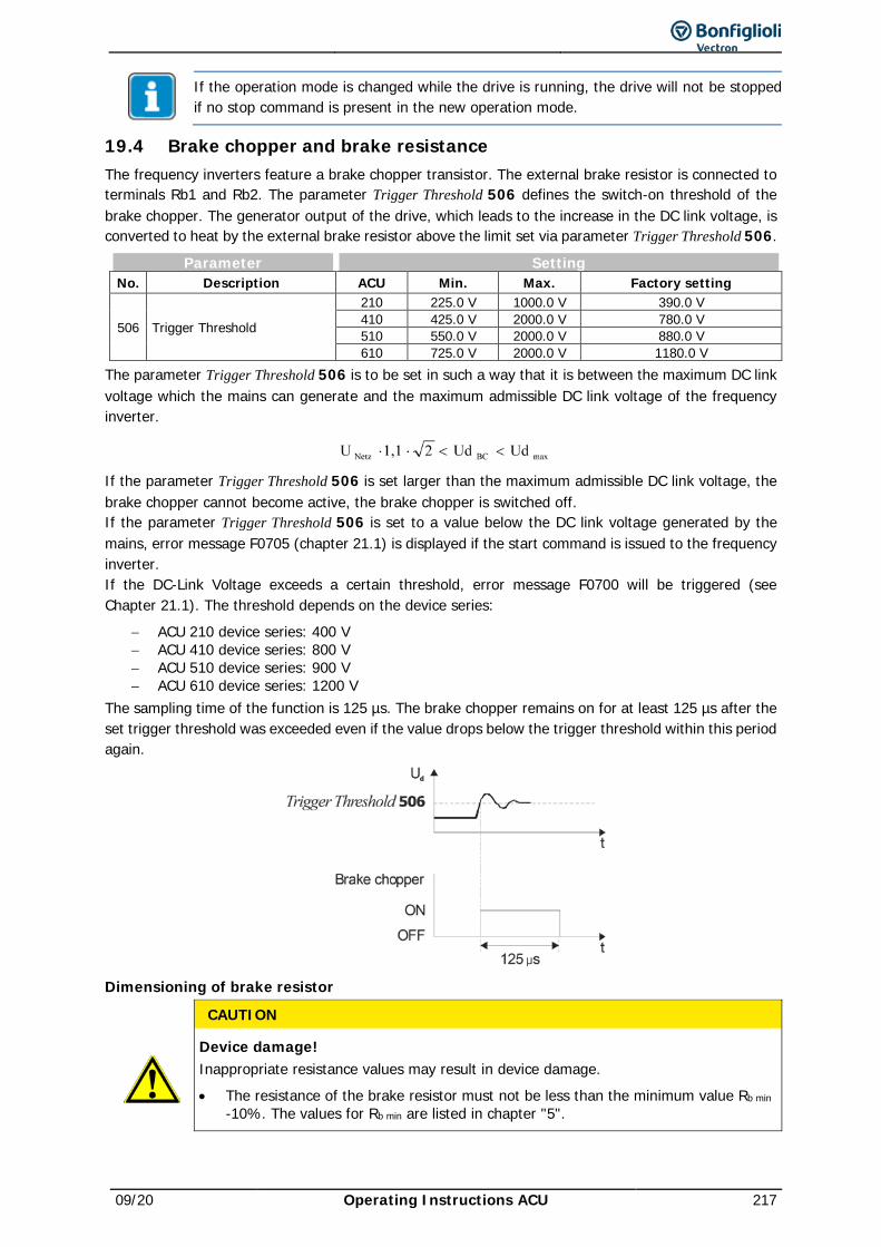
09/20 Operating Instructions ACU 217
If the operation mode is changed while the drive is running, the drive will not be stopped if no stop command is present in the new operation mode.
19.4 Brake chopper and brake resistance The frequency inverters feature a brake chopper transistor. The external brake resistor is connected to terminals Rb1 and Rb2. The parameter Trigger Threshold 506 defines the switch-on threshold of the brake chopper. The generator output of the drive, which leads to the increase in the DC link voltage, is converted to heat by the external brake resistor above the limit set via parameter Trigger Threshold 506.
Parameter Setting No. Description ACU Min. Max. Factory setting
506 Trigger Threshold
210 225.0 V 1000.0 V 390.0 V 410 425.0 V 2000.0 V 780.0 V 510 550.0 V 2000.0 V 880.0 V 610 725.0 V 2000.0 V 1180.0 V
The parameter Trigger Threshold 506 is to be set in such a way that it is between the maximum DC link voltage which the mains can generate and the maximum admissible DC link voltage of the frequency inverter.
If the parameter Trigger Threshold 506 is set larger than the maximum admissible DC link voltage, the brake chopper cannot become active, the brake chopper is switched off. If the parameter Trigger Threshold 506 is set to a value below the DC link voltage generated by the mains, error message F0705 (chapter 21.1) is displayed if the start command is issued to the frequency inverter. If the DC-Link Voltage exceeds a certain threshold, error message F0700 will be triggered (see Chapter 21.1). The threshold depends on the device series:
− ACU 210 device series: 400 V − ACU 410 device series: 800 V − ACU 510 device series: 900 V − ACU 610 device series: 1200 V
The sampling time of the function is 125 µs. The brake chopper remains on for at least 125 µs after the set trigger threshold was exceeded even if the value drops below the trigger threshold within this period again.
Dimensioning of brake resistor
CAUTION
Device damage! Inappropriate resistance values may result in device damage. • The resistance of the brake resistor must not be less than the minimum value Rb min
-10%. The values for Rb min are listed in chapter "5".
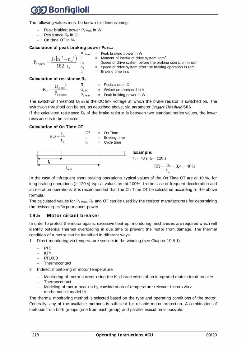
218 Operating Instructions ACU 09/20
The following values must be known for dimensioning: − Peak braking power Pb Peak in W − Resistance Rb in Ω − On time OT in %
Calculation of peak braking power Pb Peak
( )b
22
21
Spitze b t182nnJP
⋅−⋅
=
Pb Peak = Peak braking power in W J = Moment of inertia of drive system kgm2 n1 = Speed of drive system before the braking operation in rpm n2 = Speed of drive system after the braking operation in rpm tb = Braking time in s
Calculation of resistance Rb
Spitze b
2BC d
b PUR =
Rb = Resistance in Ω Ud BC = Switch-on threshold in V Pb Peak = Peak braking power in W
The switch-on threshold Ud BC is the DC link voltage at which the brake resistor is switched on. The switch-on threshold can be set, as described above, via parameter Trigger Threshold 506. If the calculated resistance Rb of the brake resistor is between two standard series values, the lower resistance is to be selected.
Calculation of On Time OT
OT = On Time tb = Braking time tZ = Cycle time
Example: tb = 48 s, tZ = 120 s
In the case of infrequent short braking operations, typical values of the On Time OT are at 10 %, for long braking operations (≥ 120 s) typical values are at 100%. In the case of frequent deceleration and acceleration operations, it is recommended that the On Time OT be calculated according to the above formula. The calculated values for Pb Peak, Rb and OT can be used by the resistor manufacturers for determining the resistor-specific permanent power.
19.5 Motor circuit breaker In order to protect the motor against excessive heat-up, monitoring mechanisms are required which will identify potential thermal overloading in due time to prevent the motor from damage. The thermal condition of a motor can be identified in different ways. 1 Direct monitoring via temperature sensors in the winding (see Chapter 19.5.1)
− PTC − KTY − PT1000 − Thermocontact
2 Indirect monitoring of motor temperature − Monitoring of motor current using the K- characteristic of an integrated motor circuit breaker − Thermocontact − Modeling of motor heat-up by consideration of temperature-relevant factors via a
mathematical model I2t The thermal monitoring method is selected based on the type and operating conditions of the motor. Generally, any of the available methods is sufficient for reliable motor protection. A combination of methods from both groups (one from each group) and parallel execution is possible.
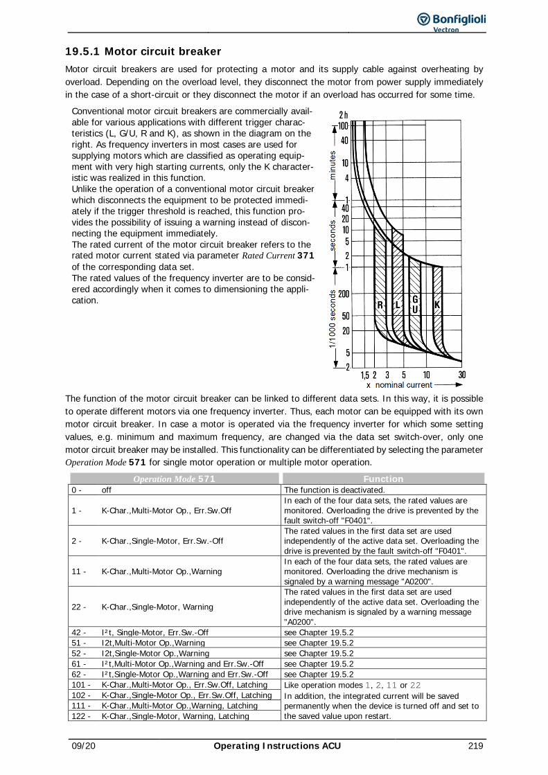
09/20 Operating Instructions ACU 219
19.5.1 Motor circuit breaker Motor circuit breakers are used for protecting a motor and its supply cable against overheating by overload. Depending on the overload level, they disconnect the motor from power supply immediately in the case of a short-circuit or they disconnect the motor if an overload has occurred for some time.
Conventional motor circuit breakers are commercially avail-able for various applications with different trigger charac-teristics (L, G/U, R and K), as shown in the diagram on the right. As frequency inverters in most cases are used for supplying motors which are classified as operating equip-ment with very high starting currents, only the K character-istic was realized in this function. Unlike the operation of a conventional motor circuit breaker which disconnects the equipment to be protected immedi-ately if the trigger threshold is reached, this function pro-vides the possibility of issuing a warning instead of discon-necting the equipment immediately. The rated current of the motor circuit breaker refers to the rated motor current stated via parameter Rated Current 371 of the corresponding data set. The rated values of the frequency inverter are to be consid-ered accordingly when it comes to dimensioning the appli-cation.
The function of the motor circuit breaker can be linked to different data sets. In this way, it is possible to operate different motors via one frequency inverter. Thus, each motor can be equipped with its own motor circuit breaker. In case a motor is operated via the frequency inverter for which some setting values, e.g. minimum and maximum frequency, are changed via the data set switch-over, only one motor circuit breaker may be installed. This functionality can be differentiated by selecting the parameter Operation Mode 571 for single motor operation or multiple motor operation.
Operation Mode 571 Function 0 - off The function is deactivated.
1 - K-Char.,Multi-Motor Op., Err.Sw.Off In each of the four data sets, the rated values are monitored. Overloading the drive is prevented by the fault switch-off "F0401".
2 - K-Char.,Single-Motor, Err.Sw.-Off The rated values in the first data set are used independently of the active data set. Overloading the drive is prevented by the fault switch-off "F0401".
11 - K-Char.,Multi-Motor Op.,Warning In each of the four data sets, the rated values are monitored. Overloading the drive mechanism is signaled by a warning message "A0200".
22 - K-Char.,Single-Motor, Warning The rated values in the first data set are used independently of the active data set. Overloading the drive mechanism is signaled by a warning message "A0200".
42 - I²t, Single-Motor, Err.Sw.-Off see Chapter 19.5.2 51 - I2t,Multi-Motor Op.,Warning see Chapter 19.5.2 52 - I2t,Single-Motor Op.,Warning see Chapter 19.5.2 61 - I²t,Multi-Motor Op.,Warning and Err.Sw.-Off see Chapter 19.5.2 62 - I²t,Single-Motor Op.,Warning and Err.Sw.-Off see Chapter 19.5.2 101 - K-Char.,Multi-Motor Op., Err.Sw.Off, Latching Like operation modes 1, 2, 11 or 22
In addition, the integrated current will be saved permanently when the device is turned off and set to the saved value upon restart.
102 - K-Char.,Single-Motor Op., Err.Sw.Off, Latching 111 - K-Char.,Multi-Motor Op.,Warning, Latching 122 - K-Char.,Single-Motor, Warning, Latching
220 Operating Instructions ACU 09/20
Multiple motor operation Parameter Operation Mode 571 = 1, 11, 101 or 111
In multiple motor operation, it is assumed that each data set is assigned to a corresponding motor. For this, one motor and one motor circuit breaker are assigned to each data set. In this operation mode, the rated values of the active data set are monitored. The current output current of the frequency inverter is only taken into account in the motor circuit breaker activated by the data set. In the motor circuit breakers of the other data sets, zero current is expected, with the result that the thermal decay functions are taken into account. In combination with the data set change-over, the function of the motor circuit breakers is similar to that of motors connected alternately to the mains with their own circuit breakers. In addition, in Operation Modes 101 and 111, the integrated current will be saved permanently when the device is turned off and set to the saved value upon restart.
Single motor operation Parameter Operation Mode 571 = 2, 22, 102 or 122
In single motor operation, only one motor circuit breaker, which monitors the output current of the frequency inverter, is active. In the case of a data set change-over, only the switch-off limits derived from the rated machine parameters are changed over. Accumulated thermal values are used after the change-over as well. In the case of the data set change-over, please ensure that the machine data are stated identically for all data sets. In combination with the data set change-over, the function of the motor circuit breaker is similar to that of motors connected alternately to the mains with one common circuit breaker. In addition, in Operation Modes 102 and 122, the integrated current will be saved permanently when the device is turned off and set to the saved value upon restart.
Reset-proof Parameter Operation Mode 571 = 101, 102, 111 or 122. The internal state of the motor circuit breaker is saved permanently (reset-proof). These settings are to be used in the case of regular short-time mains failure/disconnection. This guarantees correct motor protection for the application even in the case of short-time mains failure/disconnection. Motor protection, in particular self-ventilation motors, is improved via a Frequency Limit 572 which can be set as a percentage of the rated frequency.
Parameter Setting No. Description Min. Max. Factory setting 572 Frequency Limit 0% 300% 0%
Output signals Digital signals signal that of the function "motor circuit breaker" has been triggered.
180 - Warning Motor Protection
1) Triggering of “motor circuit breaker” function as per Operation Mode 571 is reported. 14 - 2)
1) For linking to frequency inverter functions 2) For output via a digital output.
In Operation Modes 101, 102, 111 and 122, the function set in parameter Operation Mode 571 should be the same in all data sets.
In the calculation of the triggering time, the output current measured in working points below the frequency limit will be valued at a factor between 1 and 2. This factor is determined depending on the stator frequency. In this way, the higher thermal load of self-ventilated motors in the lower speed range is considered. The table shows an extract of the factors for a 50 Hz motor.
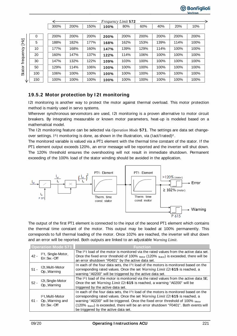
09/20 Operating Instructions ACU 221
Frequency Limit 572 300% 200% 150% 100% 80% 60% 40% 20% 10% 0 200% 200% 200% 200% 200% 200% 200% 200% 200% 5 188% 182% 177% 168% 162% 153% 139% 114% 100% 10 177% 168% 160% 147% 139% 129% 114% 100% 100% 20 160% 147% 137% 122% 114% 106% 100% 100% 100% 30 147% 132% 122% 109% 103% 100% 100% 100% 100% 50 129% 114% 106% 100% 100% 100% 100% 100% 100% 100 106% 100% 100% 100% 100% 100% 100% 100% 100% 150 100% 100% 100% 100% 100% 100% 100% 100% 100%
19.5.2 Motor protection by I2t monitoring I2t monitoring is another way to protect the motor against thermal overload. This motor protection method is mainly used in servo systems. Wherever synchronous servomotors are used, I2t monitoring is a proven alternative to motor circuit breakers. By integrating measurable or known motor parameters, heat-up is modeled based on a mathematical model. The I2t monitoring feature can be selected via Operation Mode 571. The settings are data set change-over settings. I²t monitoring is done, as shown in the illustration, via (Iact/Irated)². The monitored variable is valued via a PT1 element with the thermal time constant of the stator. If the PT1 element output exceeds 120%, an error message will be reported and the inverter will shut down. The 120% threshold ensures the overshooting will not result in immediate shutdown. Permanent exceeding of the 100% load of the stator winding should be avoided in the application.
The output of the first PT1 element is connected to the input of the second PT1 element which contains the thermal time constant of the motor. This output may be loaded at 100% permanently. This corresponds to full thermal loading of the motor. Once 102% are reached, the inverter will shut down and an error will be reported. Both outputs are linked to an adjustable Warning Limit.
Operation Mode 571 Function
42 - I²t, Single-Motor, Err.Sw.-Off
The I²t load of the motor is monitored via the rated values from the active data set. Once the fixed error threshold of 100% Motor (120% Stator) is exceeded, there will be an error shutdown “F0401” by the active data set.
51 - I2t,Multi-Motor Op.,Warning
In each of the four data sets, the I²t load of the motors is monitored based on the corresponding rated values. Once the set Warning Limit I2t 615 is reached, a warning “A0200” will be triggered by the active data set.
52 - I2t,Single-Motor Op.,Warning
The I²t load of the motor is monitored via the rated values from the active data SE. Once the set Warning Limit I2t 615 is reached, a warning “A0200” will be triggered by the active data set.
61 - I²t,Multi-Motor Op.,Warning and Err.Sw.-Off
In each of the four data sets, the I²t load of the motors is monitored based on the corresponding rated values. Once the set Warning Limit I2t 615 is reached, a warning “A0200” will be triggered. Once the fixed error threshold of 100% Motor (120% Stator) is exceeded, there will be an error shutdown “F0401”. Both events will be triggered by the active data set.
Stat
or fr
eque
ncy
[Hz]
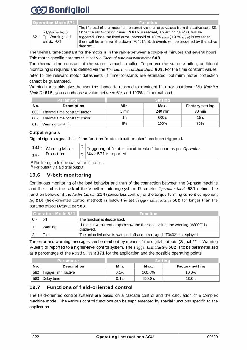
222 Operating Instructions ACU 09/20
Operation Mode 571 Function
62 - I²t,Single-Motor Op.,Warning and Err.Sw.-Off
The I²t load of the motor is monitored via the rated values from the active data SE. Once the set Warning Limit I2t 615 is reached, a warning “A0200” will be triggered. Once the fixed error threshold of 100% Motor (120% Stator) is exceeded, there will be an error shutdown “F0401”. Both events will be triggered by the active data set.
The thermal time constant for the motor is in the range between a couple of minutes and several hours. This motor-specific parameter is set via Thermal time constant motor 608. The thermal time constant of the stator is much smaller. To protect the stator winding, additional monitoring is required and defined via the Thermal time constant stator 609. For the time constant values, refer to the relevant motor datasheets. If time constants are estimated, optimum motor protection cannot be guaranteed. Warning thresholds give the user the chance to respond to imminent I²t error shutdown. Via Warning Limit I2t 615, you can choose a value between 6% and 100% of thermal load.
Parameter Setting No. Description Min. Max. Factory setting 608 Thermal time constant motor 1 min 240 min 30 min 609 Thermal time constant stator 1 s 600 s 15 s
615 Warning Limit I2t 6% 100% 80%
Output signals Digital signals signal that of the function "motor circuit breaker" has been triggered.
180 - Warning Motor Protection
1) Triggering of “motor circuit breaker” function as per Operation Mode 571 is reported. 14 - 2)
1) For linking to frequency inverter functions 2) For output via a digital output.
19.6 V-belt monitoring Continuous monitoring of the load behavior and thus of the connection between the 3-phase machine and the load is the task of the V-belt monitoring system. Parameter Operation Mode 581 defines the function behavior if the Active Current 214 (sensorless control) or the torque-forming current component Isq 216 (field-oriented control method) is below the set Trigger Limit Iactive 582 for longer than the parameterized Delay Time 583.
Operation Mode 581 Function 0 - off The function is deactivated.
1 - Warning If the active current drops below the threshold value, the warning "A8000" is displayed.
2 - Fault The unloaded drive is switched off and error signal "F0402" is displayed
The error and warning messages can be read out by means of the digital outputs (Signal 22 - “Warning V-Belt”) or reported to a higher-level control system. The Trigger Limit Iactive 582 is to be parameterized as a percentage of the Rated Current 371 for the application and the possible operating points.
Parameter Setting No. Description Min. Max. Factory setting 582 Trigger limit Iactive 0.1% 100.0% 10.0% 583 Delay time 0.1 s 600.0 s 10.0 s
19.7 Functions of field-oriented control The field-oriented control systems are based on a cascade control and the calculation of a complex machine model. The various control functions can be supplemented by special functions specific to the application.
09/20 Operating Instructions ACU 223
19.7.1 Motor chopper The field-oriented control systems contain the function for adapted implementation of the generator energy into heat in the connected three-phase machine. This enables the realization of dynamic speed changes at minimum system costs. The torque and speed behavior of the drive system is not influenced by the parameterized braking behavior. The parameter Trigger Threshold 507 of the DC link voltage defines the switch-on threshold of the motor chopper function.
Parameter Setting No. Description ACU Min. Max. Factory setting
507 Trigger Threshold
210 225.0 V 1000.0 V 400.0 V 410 425.0 V 2000.0 V 800.0 V 510 550.0 V 2000.0 V 900.0 V 610 725.0 V 2000.0 V 1200.0 V
The parameter Trigger Threshold 507 is to be set in such a way that it is between the maximum DC link voltage which the mains can generate and the maximum admissible DC link voltage of the frequency inverter.
maxdMCNetz UdU21,1U <<⋅⋅
If the parameter Trigger Threshold 507 is set larger than the maximum admissible DC link voltage, the motor chopper cannot become active, the motor chopper is switched off. If the set Trigger Threshold 507 is smaller than the maximum DC link voltage the mains can generate, error message F0706 (see Chapter 21.1) is displayed when the frequency inverter is switched on.
The motor chopper function will only work if it was activated via the voltage controller Operation Mode 670 . Refer to Chapter 18.2.
For synchronous motors (Configuration 30=5xx or 6xx), the motor chopper feature is deactivated to prevent the motor from being damaged. The other functions of the voltage controller are not affected by this.
Note that, by default, the motor chopper Trigger Threshold 507 and brake chopper Trigger Threshold 506 are set to different values. When using both functions make sure the set thresholds are suitable for the application.
19.7.2 Temperature Adjustment The field-oriented control systems are based on the most precise calculation of the machine model possible. The rotor time constant is an important machine variable for the calculation. The figure to be read out via the parameter Act. Rotor Time Constant 227 is calculated from the inductance of the rotor circuit and the rotor resistance. The dependence of the rotor time constant on the motor temperature can be taken into account in the case of particularly high precision requirements via a suitable measurement. Via Operation Mode 465 for the temperature adjustment, you can select different methods and actual value sources for temperature measurement.
Operation Mode 465 Function 0 - off The function is deactivated.
1 - Temp. meas. on MFI1A Temperature synchronization (0 ... 200 °C => 0 ... 10 V / 0 … 20 mA), actual temperature value at multifunction input 1
4 - Temp.meas. upon start Determination of temperature by frequency inverter via measurement of the winding resistance without external temperature measurement
11 - Vectron temP.meas. on MFI1A
Temperature synchronization; act. temperature value across analog multi-function input. (-26.0 °C … 207.8 °C => 0 ... 10 V / 0 … 20 mA)
Operation mode 1 requires an external temperature measurement system which evaluates the temperature sensor and maps the temperature range from 0...200 °C to an analog voltage or current signal. Operation Mode 452 of multifunction input MFI1 must be selected accordingly.
224 Operating Instructions ACU 09/20
Operation mode 4 is available in configurations 210, 211, 230, 260 and 460. When the signals Controller release and Start clockwise or Start anticlockwise are present, the motor temperature and the rotor time constant are synchronized by means of the measured winding resistance. For Operation Mode 11, an optional temperature measurement board from Bonfiglioli Vectron GmbH is required. This board can be connected to the 20 V power supply on the frequency inverter. This board converts the temperature to an analog voltage or current signal in a range from -26.0 °C to 207.8 °C. The resistance of the measuring resistor KTY84/130 to be used is 1000 Ω at a temperature of 100 °C. The material used for the rotor winding of the motor is taken into account via the parameter Temperature Coefficient 466. This value defines the change of the rotor resistance as a function of the temperature for a certain material of the rotor winding. Typical temperature coefficients are 39%/100 °K for copper and 36%/100 °K for aluminum at a temperature of 20 °C. The temperature characteristic within the software is calculated via the aforementioned temperature coefficient and the parameter Adjusting Temperature 467. The adjustment temperature enables an additional optimization of the rotor time constant alongside the parameter Rated Slip Correction Factor 718.
Parameter Setting No. Description Min. Max. Factory setting 466 Temperature coefficient 0.00%/100 °K 300.00%/100 °K 39.00%/100 °K 467 Adjusting temperature -50 °C 300 °C 35 °C
The synchronization of the rotor time constant as a function of the winding temperature can be adjusted. The default values should normally be sufficiently precise so that neither an adjustment of the rotor time constants via the parameter Rated Slip Correction Factor 718 nor an adjustment of the temperature synchronization via the parameter Temperature Coefficient 466 is necessary. If an adjustment is necessary, please remember that the rotor time constant is calculated by the guided commissioning via the machine data. The Adjusting Temperature 467 is to be set to the temperature at which the optimization of the extended machine data was carried out. The temperature can be read out via the actual value parameter Winding Temperature 226 and can be used in the optimization for the parameter.
19.7.3 Speed sensor monitoring Failures of the speed sensor lead to a faulty behavior of the drive, as the measured speed forms the foundation of the control system. By default, the speed sensor monitoring system continuously monitors the speed sensor signal, the track signals. If an extension module EM is connected, the number of division marks is monitored additionally. If, while the frequency inverter is released, a faulty signal is recognized for longer than the timeout, a fault switch-off is carried out. If parameter Operation Mode 760 is set to zero, the monitoring function is deactivated.
Operation Mode 760 Function 0 - off The function is deactivated. 2 - Error A error signal is displayed according to the timeouts set.
The speed sensor monitoring is to be parameterized in the part functions according to the application. The monitoring function becomes active with the release of the frequency inverter and the start command. The timeout defines a monitoring time in which the condition for the fault switch-off must be fulfilled without interruption. If one of the timeouts is set to zero, this monitoring function is deactivated.
Parameter Setting No. Description Min. Max. Factory setting 761 Timeout: Signal fault 0 ms 65000 ms 1000 ms 762 Timeout: Track fault 0 ms 65000 ms 1000 ms 763 Timeout: Direction of rotation fault 0 ms 65000 ms 1000 ms 782 Timeout: Drive blocked 0 ms 65000 ms 1000 ms
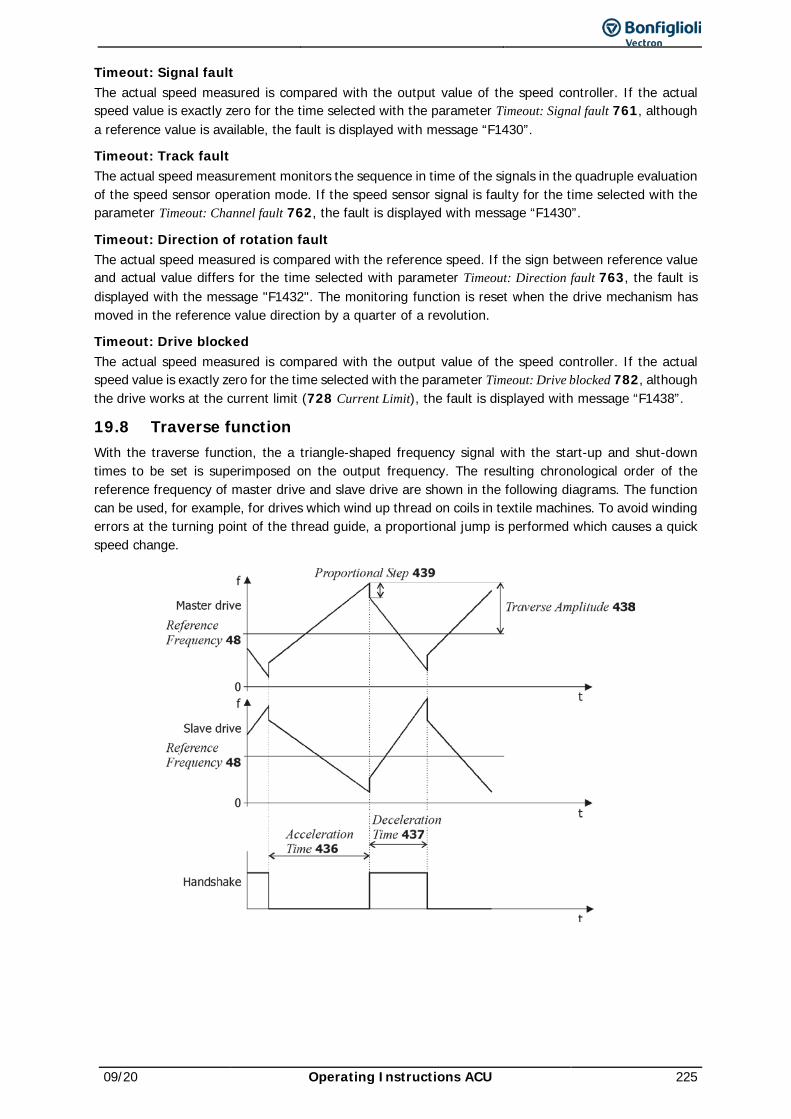
09/20 Operating Instructions ACU 225
Timeout: Signal fault The actual speed measured is compared with the output value of the speed controller. If the actual speed value is exactly zero for the time selected with the parameter Timeout: Signal fault 761, although a reference value is available, the fault is displayed with message “F1430”.
Timeout: Track fault The actual speed measurement monitors the sequence in time of the signals in the quadruple evaluation of the speed sensor operation mode. If the speed sensor signal is faulty for the time selected with the parameter Timeout: Channel fault 762, the fault is displayed with message “F1430”.
Timeout: Direction of rotation fault The actual speed measured is compared with the reference speed. If the sign between reference value and actual value differs for the time selected with parameter Timeout: Direction fault 763, the fault is displayed with the message "F1432". The monitoring function is reset when the drive mechanism has moved in the reference value direction by a quarter of a revolution.
Timeout: Drive blocked The actual speed measured is compared with the output value of the speed controller. If the actual speed value is exactly zero for the time selected with the parameter Timeout: Drive blocked 782, although the drive works at the current limit (728 Current Limit), the fault is displayed with message “F1438”.
19.8 Traverse function With the traverse function, the a triangle-shaped frequency signal with the start-up and shut-down times to be set is superimposed on the output frequency. The resulting chronological order of the reference frequency of master drive and slave drive are shown in the following diagrams. The function can be used, for example, for drives which wind up thread on coils in textile machines. To avoid winding errors at the turning point of the thread guide, a proportional jump is performed which causes a quick speed change.
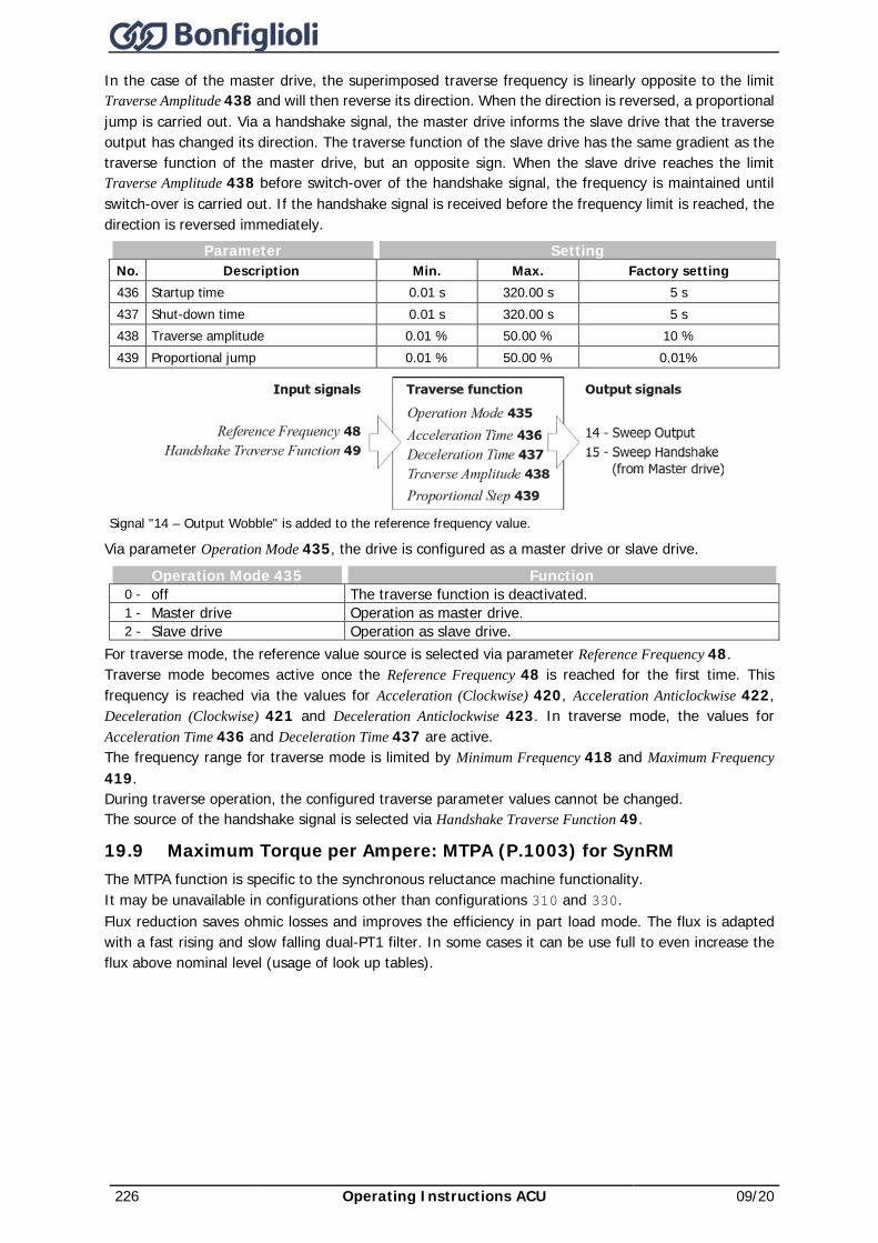
226 Operating Instructions ACU 09/20
In the case of the master drive, the superimposed traverse frequency is linearly opposite to the limit Traverse Amplitude 438 and will then reverse its direction. When the direction is reversed, a proportional jump is carried out. Via a handshake signal, the master drive informs the slave drive that the traverse output has changed its direction. The traverse function of the slave drive has the same gradient as the traverse function of the master drive, but an opposite sign. When the slave drive reaches the limit Traverse Amplitude 438 before switch-over of the handshake signal, the frequency is maintained until switch-over is carried out. If the handshake signal is received before the frequency limit is reached, the direction is reversed immediately.
Parameter Setting No. Description Min. Max. Factory setting 436 Startup time 0.01 s 320.00 s 5 s 437 Shut-down time 0.01 s 320.00 s 5 s 438 Traverse amplitude 0.01 % 50.00 % 10 % 439 Proportional jump 0.01 % 50.00 % 0.01%
Signal "14 – Output Wobble" is added to the reference frequency value.
Via parameter Operation Mode 435, the drive is configured as a master drive or slave drive.
Operation Mode 435 Function 0 - off The traverse function is deactivated. 1 - Master drive Operation as master drive. 2 - Slave drive Operation as slave drive.
For traverse mode, the reference value source is selected via parameter Reference Frequency 48. Traverse mode becomes active once the Reference Frequency 48 is reached for the first time. This frequency is reached via the values for Acceleration (Clockwise) 420, Acceleration Anticlockwise 422, Deceleration (Clockwise) 421 and Deceleration Anticlockwise 423. In traverse mode, the values for Acceleration Time 436 and Deceleration Time 437 are active. The frequency range for traverse mode is limited by Minimum Frequency 418 and Maximum Frequency 419. During traverse operation, the configured traverse parameter values cannot be changed. The source of the handshake signal is selected via Handshake Traverse Function 49.
19.9 Maximum Torque per Ampere: MTPA (P.1003) for SynRM The MTPA function is specific to the synchronous reluctance machine functionality. It may be unavailable in configurations other than configurations 310 and 330. Flux reduction saves ohmic losses and improves the efficiency in part load mode. The flux is adapted with a fast rising and slow falling dual-PT1 filter. In some cases it can be use full to even increase the flux above nominal level (usage of look up tables).
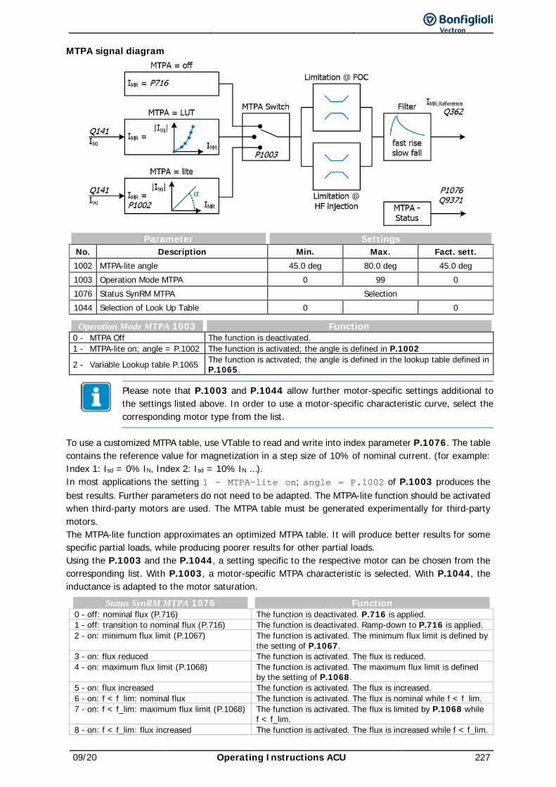
09/20 Operating Instructions ACU 227
MTPA signal diagram
Parameter Settings No. Description Min. Max. Fact. sett. 1002 MTPA-lite angle 45.0 deg 80.0 deg 45.0 deg 1003 Operation Mode MTPA 0 99 0 1076 Status SynRM MTPA Selection 1044 Selection of Look Up Table 0 0
Operation Mode MTPA 1003 Function 0 - MTPA Off The function is deactivated. 1 - MTPA-lite on; angle = P.1002 The function is activated; the angle is defined in P.1002
2 - Variable Lookup table P.1065 The function is activated; the angle is defined in the lookup table defined in P.1065.
Please note that P.1003 and P.1044 allow further motor-specific settings additional to the settings listed above. In order to use a motor-specific characteristic curve, select the corresponding motor type from the list.
To use a customized MTPA table, use VTable to read and write into index parameter P.1076. The table contains the reference value for magnetization in a step size of 10% of nominal current. (for example: Index 1: Isd = 0% IN, Index 2: Isd = 10% IN …). In most applications the setting 1 - MTPA-lite on; angle = P.1002 of P.1003 produces the best results. Further parameters do not need to be adapted. The MTPA-lite function should be activated when third-party motors are used. The MTPA table must be generated experimentally for third-party motors. The MTPA-lite function approximates an optimized MTPA table. It will produce better results for some specific partial loads, while producing poorer results for other partial loads. Using the P.1003 and the P.1044, a setting specific to the respective motor can be chosen from the corresponding list. With P.1003, a motor-specific MTPA characteristic is selected. With P.1044, the inductance is adapted to the motor saturation.
Status SynRM MTPA 1076 Function 0 - off: nominal flux (P.716) The function is deactivated. P.716 is applied. 1 - off: transition to nominal flux (P.716) The function is deactivated. Ramp-down to P.716 is applied. 2 - on: minimum flux limit (P.1067) The function is activated. The minimum flux limit is defined by
the setting of P.1067. 3 - on: flux reduced The function is activated. The flux is reduced. 4 - on: maximum flux limit (P.1068) The function is activated. The maximum flux limit is defined
by the setting of P.1068. 5 - on: flux increased The function is activated. The flux is increased. 6 - on: f < f_lim: nominal flux The function is activated. The flux is nominal while f < f_lim. 7 - on: f < f_lim: maximum flux limit (P.1068) The function is activated. The flux is limited by P.1068 while
f < f_lim. 8 - on: f < f_lim: flux increased The function is activated. The flux is increased while f < f_lim.
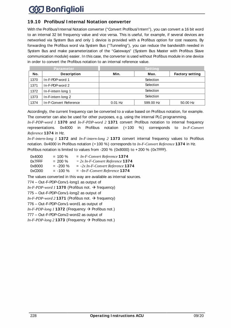
228 Operating Instructions ACU 09/20
19.10 Profibus/Internal Notation converter With the Profibus/Internal Notation converter (“Convert Profibus/Intern”), you can convert a 16 bit word to an internal 32 bit frequency value and vice versa. This is useful, for example, if several devices are networked via System Bus and only 1 device is provided with a Profibus option for cost reasons. By forwarding the Profibus word via System Bus (“Tunneling”), you can reduce the bandwidth needed in System Bus and make parameterization of the “Gateways” (System Bus Master with Profibus Slave communication module) easier. In this case, the converter is used without Profibus module in one device in order to convert the Profibus notation to an internal reference value.
Parameter Setting No. Description Min. Max. Factory setting
1370 In-F-PDP-word 1 Selection 1371 In-F-PDP-word 2 Selection
1372 In-F-intern long 1 Selection 1373 In-F-intern long 2 Selection
1374 In-F-Convert Reference 0.01 Hz 599.00 Hz 50.00 Hz
Accordingly, the current frequency can be converted to a value based on Profibus notation, for example. The converter can also be used for other purposes, e.g. using the internal PLC programming. In-F-PDP-word 1 1370 and In-F-PDP-word 2 1371 convert Profibus notation to internal frequency representations. 0x4000 in Profibus notation (=100 %) corresponds to In-F-Convert Reference 1374 in Hz. In-F-intern-long 1 1372 and In-F-intern-long 2 1373 convert internal frequency values to Profibus notation. 0x4000 in Profibus notation (=100 %) corresponds to In-F-Convert Reference 1374 in Hz. Profibus notation is limited to values from -200 % (0x8000) to +200 % (0x7FFF).
0x4000 = 100 % = In-F-Convert Reference 1374 0x7FFF = 200 % = 2x In-F-Convert Reference 1374 0x8000 = -200 % = -2x In-F-Convert Reference 1374 0xC000 = -100 % = -In-F-Convert Reference 1374
The values converted in this way are available as internal sources. 774 – Out-F-PDP-Conv1-long1 as output of In-F-PDP-word 1 1370 (Profibus not. à frequency) 775 – Out-F-PDP-Conv1-long2 as output of In-F-PDP-word 2 1371 (Profibus not. à frequency) 776 – Out-F-PDP-Conv1-word1 as output of In-F-PDP-long 1 1372 (Frequency à Profibus not.) 777 – Out-F-PDP-Conv2-word2 as output of In-F-PDP-long 2 1373 (Frequency à Profibus not.)
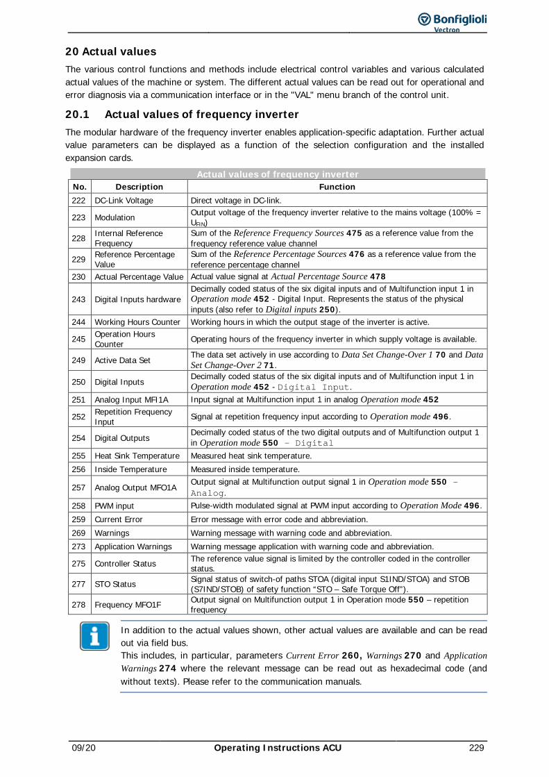
09/20 Operating Instructions ACU 229
20 Actual values The various control functions and methods include electrical control variables and various calculated actual values of the machine or system. The different actual values can be read out for operational and error diagnosis via a communication interface or in the "VAL" menu branch of the control unit.
20.1 Actual values of frequency inverter The modular hardware of the frequency inverter enables application-specific adaptation. Further actual value parameters can be displayed as a function of the selection configuration and the installed expansion cards.
Actual values of frequency inverter No. Description Function 222 DC-Link Voltage Direct voltage in DC-link.
223 Modulation Output voltage of the frequency inverter relative to the mains voltage (100% = UFIN)
228 Internal Reference Frequency
Sum of the Reference Frequency Sources 475 as a reference value from the frequency reference value channel
229 Reference Percentage Value
Sum of the Reference Percentage Sources 476 as a reference value from the reference percentage channel
230 Actual Percentage Value Actual value signal at Actual Percentage Source 478
243 Digital Inputs hardware Decimally coded status of the six digital inputs and of Multifunction input 1 in Operation mode 452 - Digital Input. Represents the status of the physical inputs (also refer to Digital inputs 250).
244 Working Hours Counter Working hours in which the output stage of the inverter is active.
245 Operation Hours Counter Operating hours of the frequency inverter in which supply voltage is available.
249 Active Data Set The data set actively in use according to Data Set Change-Over 1 70 and Data Set Change-Over 2 71.
250 Digital Inputs Decimally coded status of the six digital inputs and of Multifunction input 1 in Operation mode 452 - Digital Input.
251 Analog Input MFI1A Input signal at Multifunction input 1 in analog Operation mode 452
252 Repetition Frequency Input Signal at repetition frequency input according to Operation mode 496.
254 Digital Outputs Decimally coded status of the two digital outputs and of Multifunction output 1 in Operation mode 550 - Digital
255 Heat Sink Temperature Measured heat sink temperature. 256 Inside Temperature Measured inside temperature.
257 Analog Output MFO1A Output signal at Multifunction output signal 1 in Operation mode 550 – Analog.
258 PWM input Pulse-width modulated signal at PWM input according to Operation Mode 496. 259 Current Error Error message with error code and abbreviation. 269 Warnings Warning message with warning code and abbreviation. 273 Application Warnings Warning message application with warning code and abbreviation.
275 Controller Status The reference value signal is limited by the controller coded in the controller status.
277 STO Status Signal status of switch-of paths STOA (digital input S1IND/STOA) and STOB (S7IND/STOB) of safety function “STO – Safe Torque Off”).
278 Frequency MFO1F Output signal on Multifunction output 1 in Operation mode 550 – repetition frequency
In addition to the actual values shown, other actual values are available and can be read out via field bus. This includes, in particular, parameters Current Error 260, Warnings 270 and Application Warnings 274 where the relevant message can be read out as hexadecimal code (and without texts). Please refer to the communication manuals.
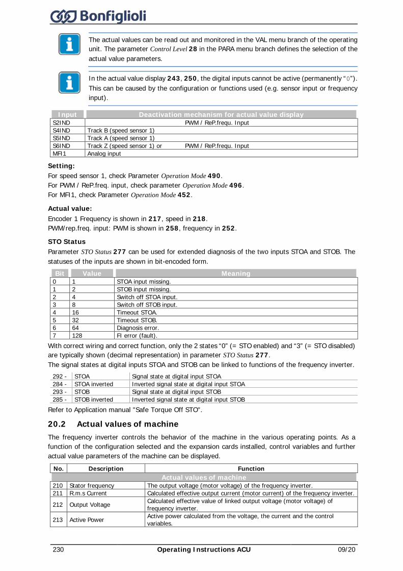
230 Operating Instructions ACU 09/20
The actual values can be read out and monitored in the VAL menu branch of the operating unit. The parameter Control Level 28 in the PARA menu branch defines the selection of the actual value parameters.
In the actual value display 243, 250, the digital inputs cannot be active (permanently “0”). This can be caused by the configuration or functions used (e.g. sensor input or frequency input).
Input Deactivation mechanism for actual value display S2IND PWM / ReP.frequ. Input S4IND Track B (speed sensor 1) S5IND Track A (speed sensor 1) S6IND Track Z (speed sensor 1) or PWM / ReP.frequ. Input MFI1 Analog input
Setting: For speed sensor 1, check Parameter Operation Mode 490. For PWM / ReP.freq. input, check parameter Operation Mode 496. For MFI1, check Parameter Operation Mode 452.
Actual value: Encoder 1 Frequency is shown in 217, speed in 218. PWM/rep.freq. input: PWM is shown in 258, frequency in 252.
STO Status Parameter STO Status 277 can be used for extended diagnosis of the two inputs STOA and STOB. The statuses of the inputs are shown in bit-encoded form.
Bit Value Meaning 0 1 STOA input missing. 1 2 STOB input missing. 2 4 Switch off STOA input. 3 8 Switch off STOB input. 4 16 Timeout STOA. 5 32 Timeout STOB. 6 64 Diagnosis error. 7 128 FI error (fault).
With correct wiring and correct function, only the 2 states “0” (= STO enabled) and “3” (= STO disabled) are typically shown (decimal representation) in parameter STO Status 277. The signal states at digital inputs STOA and STOB can be linked to functions of the frequency inverter.
292 - STOA Signal state at digital input STOA 284 - STOA inverted Inverted signal state at digital input STOA 293 - STOB Signal state at digital input STOB 285 - STOB inverted Inverted signal state at digital input STOB
Refer to Application manual "Safe Torque Off STO".
20.2 Actual values of machine The frequency inverter controls the behavior of the machine in the various operating points. As a function of the configuration selected and the expansion cards installed, control variables and further actual value parameters of the machine can be displayed.
No. Description Function Actual values of machine
210 Stator frequency The output voltage (motor voltage) of the frequency inverter. 211 R.m.s Current Calculated effective output current (motor current) of the frequency inverter.
212 Output Voltage Calculated effective value of linked output voltage (motor voltage) of frequency inverter.
213 Active Power Active power calculated from the voltage, the current and the control variables.
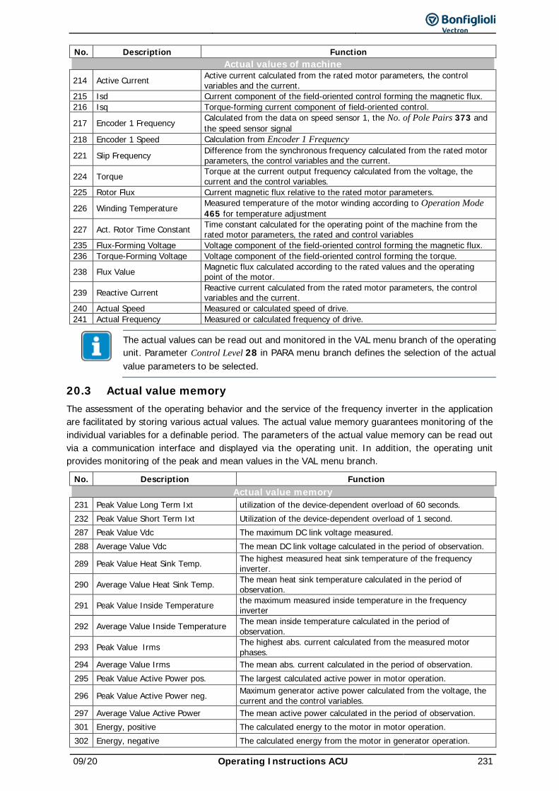
09/20 Operating Instructions ACU 231
No. Description Function Actual values of machine
214 Active Current Active current calculated from the rated motor parameters, the control variables and the current.
215 Isd Current component of the field-oriented control forming the magnetic flux. 216 Isq Torque-forming current component of field-oriented control.
217 Encoder 1 Frequency Calculated from the data on speed sensor 1, the No. of Pole Pairs 373 and the speed sensor signal
218 Encoder 1 Speed Calculation from Encoder 1 Frequency
221 Slip Frequency Difference from the synchronous frequency calculated from the rated motor parameters, the control variables and the current.
224 Torque Torque at the current output frequency calculated from the voltage, the current and the control variables.
225 Rotor Flux Current magnetic flux relative to the rated motor parameters.
226 Winding Temperature Measured temperature of the motor winding according to Operation Mode 465 for temperature adjustment
227 Act. Rotor Time Constant Time constant calculated for the operating point of the machine from the rated motor parameters, the rated and control variables
235 Flux-Forming Voltage Voltage component of the field-oriented control forming the magnetic flux. 236 Torque-Forming Voltage Voltage component of the field-oriented control forming the torque.
238 Flux Value Magnetic flux calculated according to the rated values and the operating point of the motor.
239 Reactive Current Reactive current calculated from the rated motor parameters, the control variables and the current.
240 Actual Speed Measured or calculated speed of drive. 241 Actual Frequency Measured or calculated frequency of drive.
The actual values can be read out and monitored in the VAL menu branch of the operating unit. Parameter Control Level 28 in PARA menu branch defines the selection of the actual value parameters to be selected.
20.3 Actual value memory The assessment of the operating behavior and the service of the frequency inverter in the application are facilitated by storing various actual values. The actual value memory guarantees monitoring of the individual variables for a definable period. The parameters of the actual value memory can be read out via a communication interface and displayed via the operating unit. In addition, the operating unit provides monitoring of the peak and mean values in the VAL menu branch.
No. Description Function Actual value memory
231 Peak Value Long Term Ixt utilization of the device-dependent overload of 60 seconds. 232 Peak Value Short Term Ixt Utilization of the device-dependent overload of 1 second. 287 Peak Value Vdc The maximum DC link voltage measured. 288 Average Value Vdc The mean DC link voltage calculated in the period of observation.
289 Peak Value Heat Sink Temp. The highest measured heat sink temperature of the frequency inverter.
290 Average Value Heat Sink Temp. The mean heat sink temperature calculated in the period of observation.
291 Peak Value Inside Temperature the maximum measured inside temperature in the frequency inverter
292 Average Value Inside Temperature The mean inside temperature calculated in the period of observation.
293 Peak Value Irms The highest abs. current calculated from the measured motor phases.
294 Average Value Irms The mean abs. current calculated in the period of observation. 295 Peak Value Active Power pos. The largest calculated active power in motor operation.
296 Peak Value Active Power neg. Maximum generator active power calculated from the voltage, the current and the control variables.
297 Average Value Active Power The mean active power calculated in the period of observation. 301 Energy, positive The calculated energy to the motor in motor operation. 302 Energy, negative The calculated energy from the motor in generator operation.
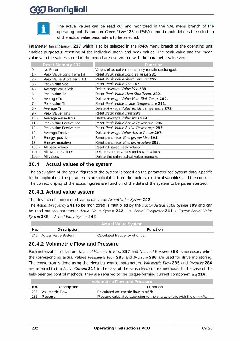
232 Operating Instructions ACU 09/20
The actual values can be read out and monitored in the VAL menu branch of the operating unit. Parameter Control Level 28 in PARA menu branch defines the selection of the actual value parameters to be selected.
Parameter Reset Memory 237 which is to be selected in the PARA menu branch of the operating unit enables purposeful resetting of the individual mean and peak values. The peak value and the mean value with the values stored in the period are overwritten with the parameter value zero.
Reset Memory 237 Function 0 - No Reset Values of actual value memory remain unchanged. 1 - Peak Value Long Term Ixt Reset Peak Value Long Term Ixt 231 2 - Peak Value Short Term Ixt Reset Peak Value Short Term Ixt 232 3 - Peak value Vdc Reset Peak Value Vdc 287. 4 - Average value Vdc Delete Average Value Vdc 288. 5 - Peak value Tc Reset Peak Value Heat Sink Temp. 289. 6 - Average Tc Delete Average Value Heat Sink Temp. 290. 7 - Peak value Ti Reset Peak Value Inside Temperature 291. 8 - Average Ti Delete Average Value Inside Temperature 292. 9 - Peak Value Irms Reset Peak Value Irms 293. 10 - Average Value Irms Delete Average Value Irms 294. 11 - Peak value Pactive pos. Reset Peak Value Active Power pos. 295. 12 - Peak value Pactive neg. Reset Peak Value Active Power neg. 296. 13 - Average Pactive Delete Average Value Active Power 297. 16 - Energy, positive Reset parameter Energy, positive 301. 17 - Energy, negative Reset parameter Energy, negative 302. 100 - All peak values Reset all saved peak values. 101 - All average values Delete average values and saved values. 102 - All values Delete the entire actual value memory.
20.4 Actual values of the system The calculation of the actual figures of the system is based on the parameterized system data. Specific to the application, the parameters are calculated from the factors, electrical variables and the controls. The correct display of the actual figures is a function of the data of the system to be parameterized.
20.4.1 Actual value system The drive can be monitored via actual value Actual Value System 242. The Actual Frequency 241 to be monitored is multiplied by the Factor Actual Value System 389 and can be read out via parameter Actual Value System 242, i.e. Actual Frequency 241 x Factor Actual Value System 389 = Actual Value System 242.
Actual Value System No. Description Function 242 Actual Value System Calculated frequency of drive.
20.4.2 Volumetric Flow and Pressure Parameterization of factors Nominal Volumetric Flow 397 and Nominal Pressure 398 is necessary when the corresponding actual values Volumetric Flow 285 and Pressure 286 are used for drive monitoring. The conversion is done using the electrical control parameters. Volumetric Flow 285 and Pressure 286 are referred to the Active Current 214 in the case of the sensorless control methods. In the case of the field-oriented control methods, they are referred to the torque-forming current component Isq 216.
Volumetric Flow and Pressure No. Description Function 285 Volumetric Flow Calculated volumetric flow in m³/h. 286 Pressure Pressure calculated according to the characteristic with the unit kPa.
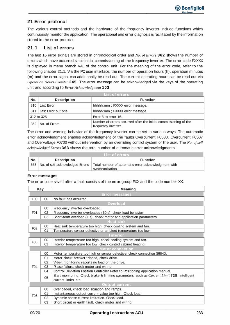
09/20 Operating Instructions ACU 233
21 Error protocol The various control methods and the hardware of the frequency inverter include functions which continuously monitor the application. The operational and error diagnosis is facilitated by the information stored in the error protocol.
21.1 List of errors The last 16 error signals are stored in chronological order and No. of Errors 362 shows the number of errors which have occurred since initial commissioning of the frequency inverter. The error code FXXXX is displayed in menu branch VAL of the control unit. For the meaning of the error code, refer to the following chapter 21.1. Via the PC user interface, the number of operation hours (h), operation minutes (m) and the error signal can additionally be read out. The current operating hours can be read out via Operation Hours Counter 245. The error message can be acknowledged via the keys of the operating unit and according to Error Acknowledgment 103.
List of errors No. Description Function 310 Last Error hhhhh:mm ; FXXXX error message. 311 Last Error but one hhhhh:mm ; FXXXX error message. 312 to 325 Error 3 to error 16.
362 No. of Errors Number of errors occurred after the initial commissioning of the frequency inverter.
The error and warning behavior of the frequency inverter can be set in various ways. The automatic error acknowledgment enables acknowledgment of the faults Overcurrent F0500, Overcurrent F0507 and Overvoltage F0700 without intervention by an overriding control system or the user. The No. of self acknowledged Errors 363 shows the total number of automatic error acknowledgments.
List of errors No. Description Function 363 No. of self acknowledged Errors Total number of automatic error acknowledgment with
synchronization.
Error messages The error code saved after a fault consists of the error group FXX and the code number XX.
Key Meaning Error messages
F00 00 No fault has occurred. Overload
F01 00 Frequency inverter overloaded. 02 Frequency inverter overloaded (60 s), check load behavior 03 Short-term overload (1 s), check motor and application parameters
Heat sink F02 00 Heat sink temperature too high, check cooling system and fan.
01 Temperature sensor defective or ambient temperature too low. Interior
F03 00 Interior temperature too high, check cooling system and fan. 01 Interior temperature too low, check control cabinet heating.
Motor connection
F04
00 Motor temperature too high or sensor defective, check connection S6IND. 01 Motor circuit breaker tripped, check drive. 02 V-belt monitoring reports no load on the drive. 03 Phase failure, check motor and wiring. 04 Control Deviation Position Controller Refer to Positioning application manual.
05 Start monitoring. Check brake & limiting parameters, such as Current Limit 728, intelligent current limits, etc.
Output current
F05
00 Overloaded, check load situation and ramps. 01 Instantaneous output current value too high. Check load. 02 Dynamic phase current limitation. Check load. 03 Short circuit or earth fault, check motor and wiring.
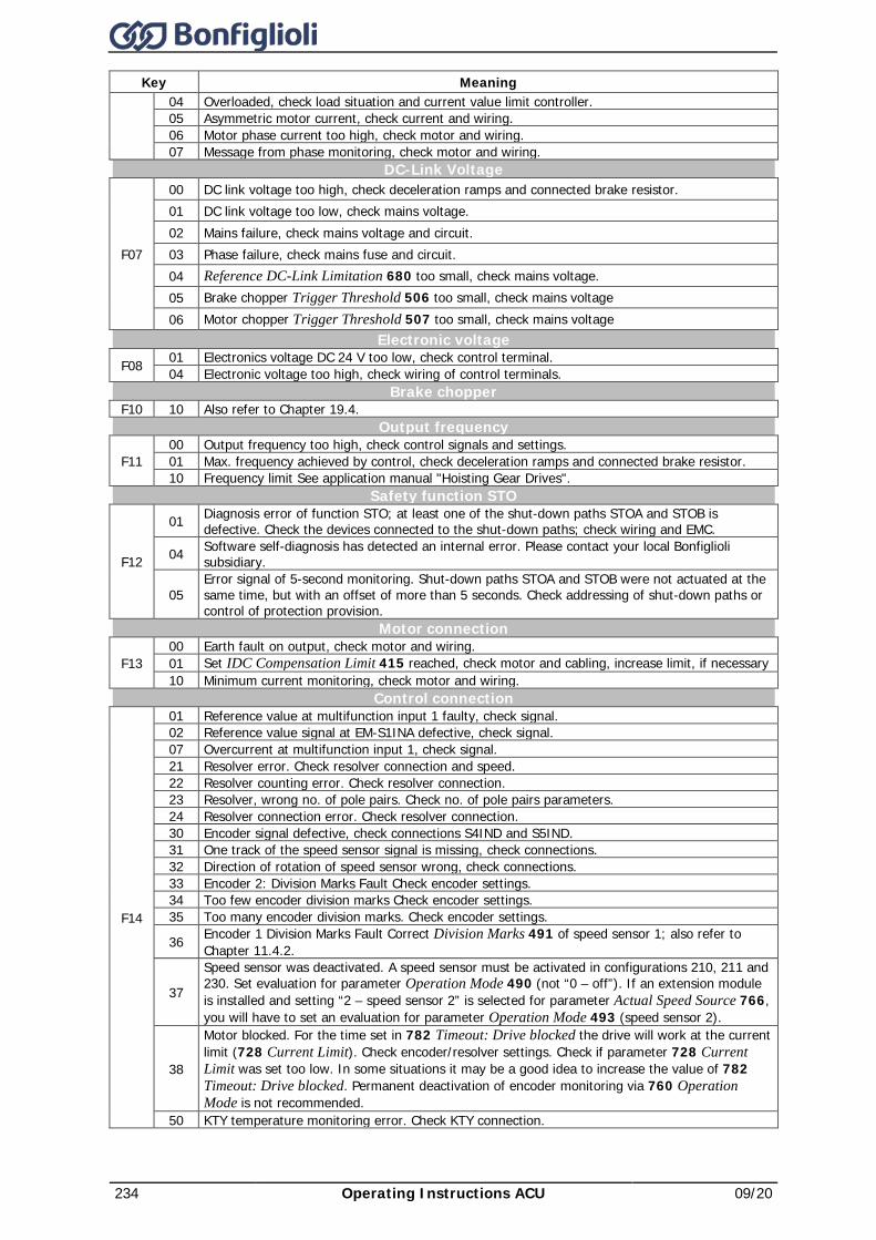
234 Operating Instructions ACU 09/20
Key Meaning 04 Overloaded, check load situation and current value limit controller. 05 Asymmetric motor current, check current and wiring. 06 Motor phase current too high, check motor and wiring. 07 Message from phase monitoring, check motor and wiring.
DC-Link Voltage
F07
00 DC link voltage too high, check deceleration ramps and connected brake resistor. 01 DC link voltage too low, check mains voltage. 02 Mains failure, check mains voltage and circuit. 03 Phase failure, check mains fuse and circuit. 04 Reference DC-Link Limitation 680 too small, check mains voltage. 05 Brake chopper Trigger Threshold 506 too small, check mains voltage 06 Motor chopper Trigger Threshold 507 too small, check mains voltage
Electronic voltage F08 01 Electronics voltage DC 24 V too low, check control terminal.
04 Electronic voltage too high, check wiring of control terminals. Brake chopper
F10 10 Also refer to Chapter 19.4. Output frequency
F11 00 Output frequency too high, check control signals and settings. 01 Max. frequency achieved by control, check deceleration ramps and connected brake resistor. 10 Frequency limit See application manual "Hoisting Gear Drives".
Safety function STO
F12
01 Diagnosis error of function STO; at least one of the shut-down paths STOA and STOB is defective. Check the devices connected to the shut-down paths; check wiring and EMC.
04 Software self-diagnosis has detected an internal error. Please contact your local Bonfiglioli subsidiary.
05 Error signal of 5-second monitoring. Shut-down paths STOA and STOB were not actuated at the same time, but with an offset of more than 5 seconds. Check addressing of shut-down paths or control of protection provision.
Motor connection
F13 00 Earth fault on output, check motor and wiring. 01 Set IDC Compensation Limit 415 reached, check motor and cabling, increase limit, if necessary 10 Minimum current monitoring, check motor and wiring.
Control connection
F14
01 Reference value at multifunction input 1 faulty, check signal. 02 Reference value signal at EM-S1INA defective, check signal. 07 Overcurrent at multifunction input 1, check signal. 21 Resolver error. Check resolver connection and speed. 22 Resolver counting error. Check resolver connection. 23 Resolver, wrong no. of pole pairs. Check no. of pole pairs parameters. 24 Resolver connection error. Check resolver connection. 30 Encoder signal defective, check connections S4IND and S5IND. 31 One track of the speed sensor signal is missing, check connections. 32 Direction of rotation of speed sensor wrong, check connections. 33 Encoder 2: Division Marks Fault Check encoder settings. 34 Too few encoder division marks Check encoder settings. 35 Too many encoder division marks. Check encoder settings.
36 Encoder 1 Division Marks Fault Correct Division Marks 491 of speed sensor 1; also refer to Chapter 11.4.2.
37
Speed sensor was deactivated. A speed sensor must be activated in configurations 210, 211 and 230. Set evaluation for parameter Operation Mode 490 (not “0 – off”). If an extension module is installed and setting “2 – speed sensor 2” is selected for parameter Actual Speed Source 766, you will have to set an evaluation for parameter Operation Mode 493 (speed sensor 2).
38
Motor blocked. For the time set in 782 Timeout: Drive blocked the drive will work at the current limit (728 Current Limit). Check encoder/resolver settings. Check if parameter 728 Current Limit was set too low. In some situations it may be a good idea to increase the value of 782 Timeout: Drive blocked. Permanent deactivation of encoder monitoring via 760 Operation Mode is not recommended.
50 KTY temperature monitoring error. Check KTY connection.
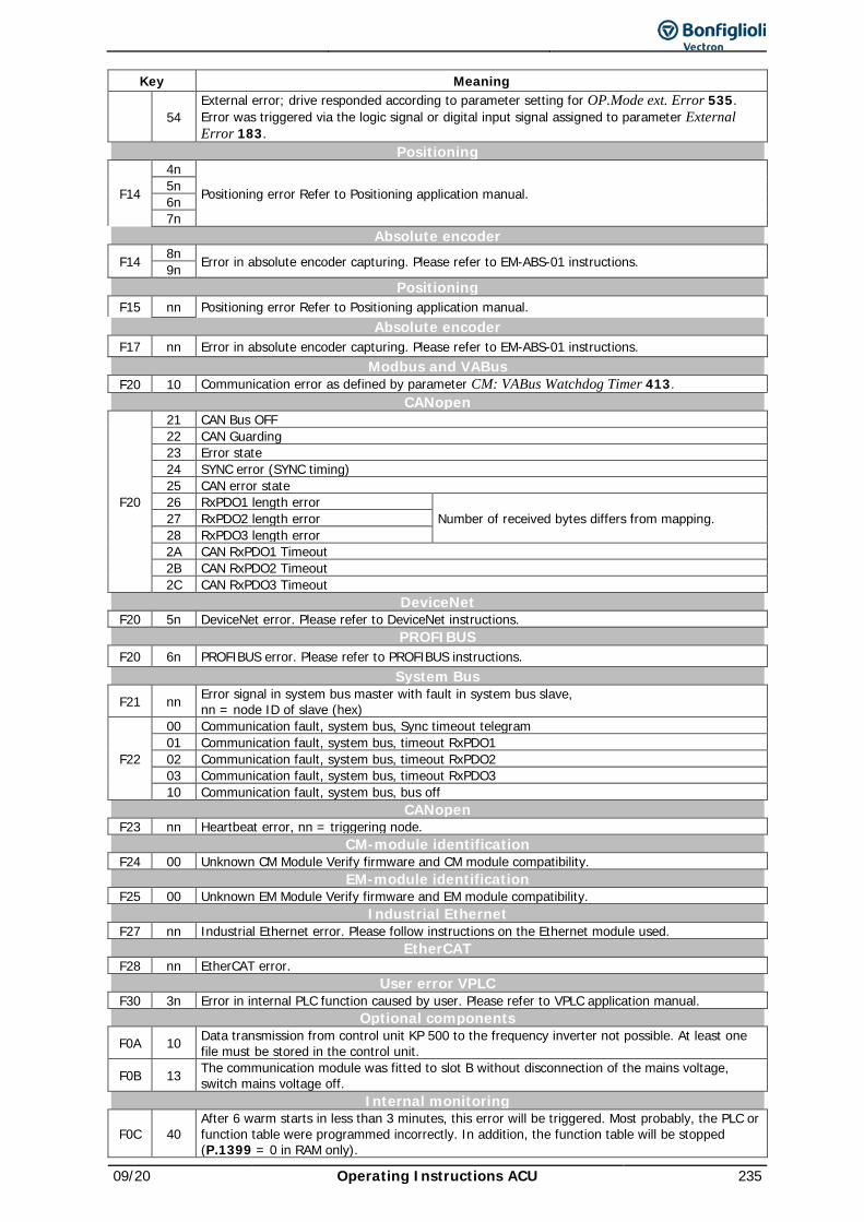
09/20 Operating Instructions ACU 235
Key Meaning
54 External error; drive responded according to parameter setting for OP.Mode ext. Error 535. Error was triggered via the logic signal or digital input signal assigned to parameter External Error 183.
Positioning
F14
4n
Positioning error Refer to Positioning application manual. 5n 6n 7n
Absolute encoder F14 8n Error in absolute encoder capturing. Please refer to EM-ABS-01 instructions. 9n
Positioning F15 nn Positioning error Refer to Positioning application manual.
Absolute encoder F17 nn Error in absolute encoder capturing. Please refer to EM-ABS-01 instructions.
Modbus and VABus F20 10 Communication error as defined by parameter CM: VABus Watchdog Timer 413.
CANopen
F20
21 CAN Bus OFF 22 CAN Guarding 23 Error state 24 SYNC error (SYNC timing) 25 CAN error state 26 RxPDO1 length error
Number of received bytes differs from mapping. 27 RxPDO2 length error 28 RxPDO3 length error 2A CAN RxPDO1 Timeout 2B CAN RxPDO2 Timeout 2C CAN RxPDO3 Timeout
DeviceNet F20 5n DeviceNet error. Please refer to DeviceNet instructions.
PROFIBUS F20 6n PROFIBUS error. Please refer to PROFIBUS instructions.
System Bus F21 nn Error signal in system bus master with fault in system bus slave,
nn = node ID of slave (hex)
F22
00 Communication fault, system bus, Sync timeout telegram 01 Communication fault, system bus, timeout RxPDO1 02 Communication fault, system bus, timeout RxPDO2 03 Communication fault, system bus, timeout RxPDO3 10 Communication fault, system bus, bus off
CANopen F23 nn Heartbeat error, nn = triggering node.
CM-module identification F24 00 Unknown CM Module Verify firmware and CM module compatibility.
EM-module identification F25 00 Unknown EM Module Verify firmware and EM module compatibility.
Industrial Ethernet F27 nn Industrial Ethernet error. Please follow instructions on the Ethernet module used.
EtherCAT F28 nn EtherCAT error.
User error VPLC F30 3n Error in internal PLC function caused by user. Please refer to VPLC application manual.
Optional components F0A 10 Data transmission from control unit KP 500 to the frequency inverter not possible. At least one
file must be stored in the control unit.
F0B 13 The communication module was fitted to slot B without disconnection of the mains voltage, switch mains voltage off.
Internal monitoring
F0C 40 After 6 warm starts in less than 3 minutes, this error will be triggered. Most probably, the PLC or function table were programmed incorrectly. In addition, the function table will be stopped (P.1399 = 0 in RAM only).
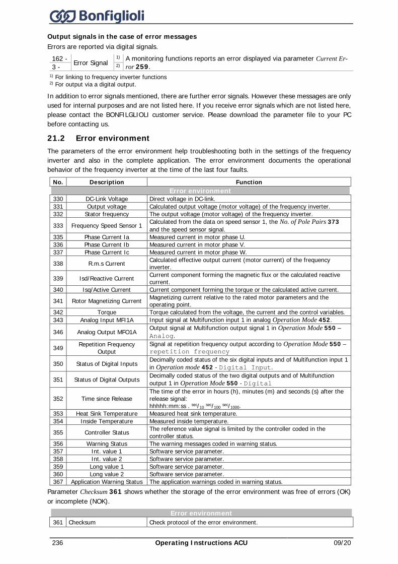
236 Operating Instructions ACU 09/20
Output signals in the case of error messages Errors are reported via digital signals.
162 - Error Signal 1) A monitoring functions reports an error displayed via parameter Current Er-
ror 259. 3 - 2) 1) For linking to frequency inverter functions 2) For output via a digital output.
In addition to error signals mentioned, there are further error signals. However these messages are only used for internal purposes and are not listed here. If you receive error signals which are not listed here, please contact the BONFILGLIOLI customer service. Please download the parameter file to your PC before contacting us.
21.2 Error environment The parameters of the error environment help troubleshooting both in the settings of the frequency inverter and also in the complete application. The error environment documents the operational behavior of the frequency inverter at the time of the last four faults.
No. Description Function Error environment
330 DC-Link Voltage Direct voltage in DC-link. 331 Output voltage Calculated output voltage (motor voltage) of the frequency inverter. 332 Stator frequency The output voltage (motor voltage) of the frequency inverter.
333 Frequency Speed Sensor 1 Calculated from the data on speed sensor 1, the No. of Pole Pairs 373 and the speed sensor signal.
335 Phase Current Ia Measured current in motor phase U. 336 Phase Current Ib Measured current in motor phase V. 337 Phase Current Ic Measured current in motor phase W.
338 R.m.s Current Calculated effective output current (motor current) of the frequency inverter.
339 Isd/Reactive Current Current component forming the magnetic flux or the calculated reactive current.
340 Isq/Active Current Current component forming the torque or the calculated active current.
341 Rotor Magnetizing Current Magnetizing current relative to the rated motor parameters and the operating point.
342 Torque Torque calculated from the voltage, the current and the control variables. 343 Analog Input MFI1A Input signal at Multifunction input 1 in analog Operation Mode 452.
346 Analog Output MFO1A Output signal at Multifunction output signal 1 in Operation Mode 550 – Analog.
349 Repetition Frequency Output
Signal at repetition frequency output according to Operation Mode 550 – repetition frequency
350 Status of Digital Inputs Decimally coded status of the six digital inputs and of Multifunction input 1 in Operation mode 452 - Digital Input.
351 Status of Digital Outputs Decimally coded status of the two digital outputs and of Multifunction output 1 in Operation Mode 550 - Digital
352 Time since Release The time of the error in hours (h), minutes (m) and seconds (s) after the release signal: hhhhh:mm:ss . sec/10 sec/100 sec/1000.
353 Heat Sink Temperature Measured heat sink temperature. 354 Inside Temperature Measured inside temperature.
355 Controller Status The reference value signal is limited by the controller coded in the controller status.
356 Warning Status The warning messages coded in warning status. 357 Int. value 1 Software service parameter. 358 Int. value 2 Software service parameter. 359 Long value 1 Software service parameter. 360 Long value 2 Software service parameter. 367 Application Warning Status The application warnings coded in warning status.
Parameter Checksum 361 shows whether the storage of the error environment was free of errors (OK) or incomplete (NOK).
Error environment 361 Checksum Check protocol of the error environment.
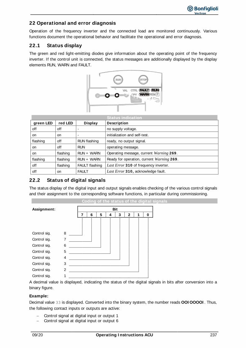
09/20 Operating Instructions ACU 237
22 Operational and error diagnosis Operation of the frequency inverter and the connected load are monitored continuously. Various functions document the operational behavior and facilitate the operational and error diagnosis.
22.1 Status display The green and red light-emitting diodes give information about the operating point of the frequency inverter. If the control unit is connected, the status messages are additionally displayed by the display elements RUN, WARN and FAULT.
Status indication green LED red LED Display Description
off off - no supply voltage. on on - initialization and self-test. flashing off RUN flashing ready, no output signal. on off RUN operating message. on flashing RUN + WARN Operating message, current Warning 269. flashing flashing RUN + WARN Ready for operation, current Warning 269. off flashing FAULT flashing Last Error 310 of frequency inverter. off on FAULT Last Error 310, acknowledge fault.
22.2 Status of digital signals The status display of the digital input and output signals enables checking of the various control signals and their assignment to the corresponding software functions, in particular during commissioning.
Coding of the status of the digital signals
Assignment: Bit 7 6 5 4 3 2 1 0
Control sig. 8
Control sig. 7
Control sig. 6
Control sig. 5
Control sig. 4
Control sig. 3
Control sig. 2
Control sig. 1
A decimal value is displayed, indicating the status of the digital signals in bits after conversion into a binary figure.
Example: Decimal value 33 is displayed. Converted into the binary system, the number reads OOIOOOOI. Thus, the following contact inputs or outputs are active:
− Control signal at digital input or output 1 − Control signal at digital input or output 6
238 Operating Instructions ACU 09/20
22.3 Controller Status The controller status can be used to establish which of the control functions are active. If a several controllers are active at the time, a controller code composed of the sum total of the individual codes is displayed. The display of the controller status by the control unit and the light-emitting diodes can be parameterized via the Controller-Status Message 409.
Coding of the controller status CXXXX ABCDE Controller key Controller abbreviation
Key Controller Status C 00 00 - No controller active. C 00 01 UDdyn Voltage controller is in the rise phase according to Operation Mode 670 C 00 02 UDstop The output frequency in power failure is below the Shutdown Threshold 675
C 00 04 UDctr Failure of the mains voltage and power regulation active according to Operation Mode 670 of the voltage controller
C 00 08 UDlim DC-Link voltage exceeded Reference DC-Link Limitation 680. C 00 10 Boost The Dyn. Voltage Pre-Control 605 accelerates the control system.
C 00 20 Ilim The output current is limited by the current limit value controller or the speed controller.
C 00 40 Tlim The output power or the torque are limited by the speed controller
C 00 80 Tctr Switch-over of field-oriented control between speed and torque-controlled control method.
C 01 00 Rstp The Operation Mode 620 selected in starting behavior limits the output current C 02 00 IxtLtLim Overload limit of the long-term Ixt (60s) reached, intelligent current limits active C 04 00 IxtStLim Overload limit of the short-term Ixt (1s) reached, intelligent current limits active.
C 08 00 Tclim Max. heat sink temperature TK reached, intelligent current limits of Operation Mode 573 active.
C 10 00 PTClim Max. motor temperature TPTC reached, intelligent current limits of Operation Mode 573 active
C 20 00 Flim Reference frequency has reached the Maximum Frequency 419. The frequency limitation is active.
Example: The controller status is displayed as
C0024 UDctr Ilim The controller status results from the hexadecimal sum of the controller codes (0004+0020 = 0024). At the same, the power failure regulation and also the current limitation of the speed controller are active.
22.4 Warning Status and Warning Status Application The current warning is displayed by a message in the warning status and can be used for early reporting of a critical operational condition. If a warning is present, this is indicated by the flashing red LED and the display field WARN of the control unit. If several warnings are present, the warning status is displayed as the sum of the individual warning codes. The warning masks created through parameters Create Warning Mask 536 and Create Appl. Warning Mask 626 have no influence on the warnings displayed. Via actual value parameters Warnings 269, Application Warnings 273, Warning Status 356 (in error environment) and Application Warning Status 367 (in error environment) all warnings present at the time of the error are displayed.
Coding of the warning status
AXXXX ABCDE Warning key Warning abbreviation
Meaning of key displayed by parameter Warning Status 356:
Key Warning Status A 00 00 - No warning present.
09/20 Operating Instructions ACU 239
A 00 01 Ixt Frequency inverter overloaded (A0002 or A0004) A 00 02 IxtSt Overload for 60 s relative to the nominal output of the frequency inverter A 00 04 IxtLt Short-time overload for 1 s relative to the nominal output of the frequency inverter.
A 00 08 Tc Max. heat sink temperature TK of 80 °C minus Warning Limit Heat Sink Temp. 407 reached.
A 00 10 Ti Max. inside temperature Ti of 65 °C minus Warning Limit Inside Tepmp. 408 reached. A 00 20 Lim The controller stated in Controller Status 275 is limiting the reference figure. A 00 40 INIT Frequency inverter is being initialized
A 00 80 PTC Warning behavior as per configured Motor Temp.Operation Mode 570 at max. motor temperature TMotor.
A 01 00 Mains Phase Supervision 576 reports mains phase failure.
A 02 00 PMS Motor circuit breaker parameterized in Operation Mode 571 tripped. A 04 00 Flim The Maximum Frequency 419 was exceeded. The frequency limitation is active.
A 08 00 A1 The input signal MFI1A is lower than 1 V / 2 mA according to the operation mode for the Error/Warning Behavior 453.
A 10 00 A2 The input signal is lower than 1 V / 2 mA according to the operation mode for the Error/Warning Behavior 453.
A 20 00 SYS A slave on the system bus reports a fault; warning is only relevant with the EM-SYS option. A 40 00 UDC The DC link voltage has reached the type-dependent minimum value.
A 80 00 WARN2 In Application Warning Status 367, a warning is present.
Example: The following warning status is displayed: A008D Ixt IxtLt Tc PTC The warning status results from the hexadecimal sum of the warning codes (0001+0004+0008+0080 = 008D). The short-term overload (1 s), warning limit heat sink temperature and warning limit motor temperature warnings are present.
Output signals Warnings are signaled via digital signals.
169 - General Warning 1) Signal when message is output in Warnings 269. 11 - General warning 2) 1) For linking to frequency inverter functions 2) For output via a digital output.
Meaning of code displayed by parameter Application Warning Status 367:
Key Warning Status A 00 00 NO WARNING No warning present. A 00 01 BELT Warning V-Belt by Operation Mode 581. A 00 02 SW-LIM CW Positive SW limit switch was reached (parameter Pos. SW Limit Switch 1145). A 00 04 SW-LIM CCW Negative SW limit switch was reached (parameter Neg. SW Limit Switch 1146). A 00 08 HW-LIM CW The positive HW limit switch was reached. A 00 10 HW-LIM CCW The negative HW limit switch was reached. A 00 20 CONT The contouring error monitoring range set with Warning Threshold 1105 was left. A 00 40 Enc A connected encoder with data track triggered a warning. A 00 80 User 1 The signal set at digital input User Warnig 1 1 1363 is active. A 01 00 User 2 The signal set at digital input User Warnig 2 1 1364 is active.
Output signals Application Warnings are signaled via digital signals .
216 - Warning, application 1) Signal when message is output in Application Warnings 273. 26 - 2)
1) For linking to frequency inverter functions 2) For output via a digital output.
22.5 Monitoring the service interval During operation of electric drives, mechanical and electrical components are exposed to wear and tear.
240 Operating Instructions ACU 09/20
The service interval remaining until the next service (percentage of maintenance interval) of the following components can be monitored:
− DC-link of frequency inverter − Fan of frequency inverter
1533 Maintenance Note When the service interval until service has expired (value 0%), the frequency inverter can indicate
− via parameter Maintenance Note 1533 that maintenance is required or − output a warning message
The behavior can be set up. The service interval remaining until service can be displayed via parameters. Service is required as soon as the remaining service interval until maintenance has expired (value 0%). It must also be checked if the component must be replaced.
22.5.1 DC-link Signalling when service is required The DC-link of the frequency inverter is equipped with electrolyte capacitors. The service interval for electrolyte capacitors is mainly defined by the temperature. In high temperatures the electrolytic liquid will evaporate, which reduces the capacitance of the capacitor. The temperature inside the electrolyte capacitor depends on two factors: the ambient temperature and the internal heating caused by current ripple. The temperature of the electrolyte capacitors is measured by a sensor, so that high ambient temperatures are taken into account for service interval calculation.
1534 Operation Mode Service Interval DC-link Via parameter Operation Mode Service Interval DC-link 1534, you can set how the warning is to occur when the remaining service interval until service has expired. The information can be indicated in a parameter or a service message can be output.
Operation Mode Service Interval DC-link 1534
Function
0 - No Action The service interval remaining until service is monitored. The remaining service interval (in percent) can be indicated via parameter Service Interval DC-link 1530. No service info or message is output.
1 - Service Parameter Message
The service interval remaining until service is monitored. The remaining service interval (in percent) can be indicated via parameter Service Interval DC-link 1530. As soon as the remaining time until service has expired, parameter Maintenance Note 1533 will show the message "M0001 Service DC-Link". Factory setting.
2 - Alarm Message
The service interval remaining until service is monitored. The remaining service interval (in percent) can be indicated via parameter Service Interval DC-link 1530. As soon as the time remaining until service has expired:
− Parameter Maintenance Note 1533 will show the mes-sage "M0001 Service DC-Link".
− A warning message will be put out and a warning signal will be set. The warning will also be displayed on the op-erator panel.
Parameter Maintenance Note 1533 displays message "M0000" if the remaining service interval until service of the DC-link has not elapsed and no service is required.
Warning signal Expiry of the time remaining until service is signaled.
264 - Warning service DC-link For linking to frequency inverter functions.
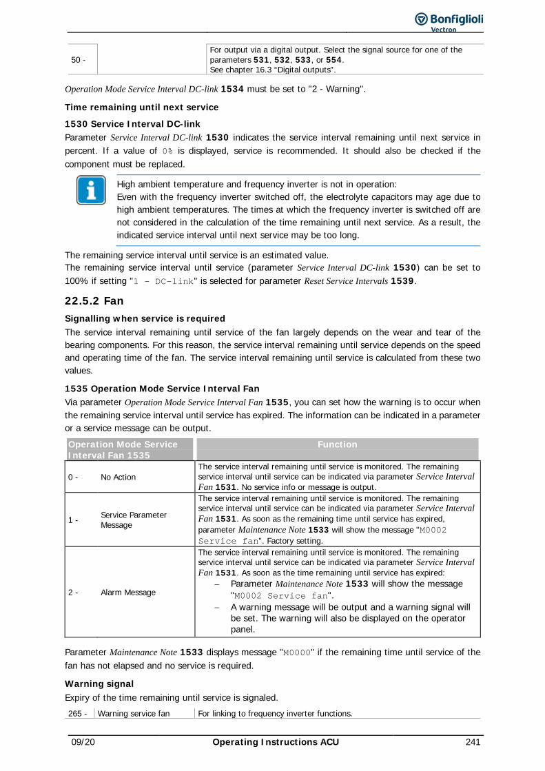
09/20 Operating Instructions ACU 241
50 - For output via a digital output. Select the signal source for one of the parameters 531, 532, 533, or 554. See chapter 16.3 “Digital outputs”.
Operation Mode Service Interval DC-link 1534 must be set to "2 - Warning".
Time remaining until next service
1530 Service Interval DC-link Parameter Service Interval DC-link 1530 indicates the service interval remaining until next service in percent. If a value of 0% is displayed, service is recommended. It should also be checked if the component must be replaced.
High ambient temperature and frequency inverter is not in operation: Even with the frequency inverter switched off, the electrolyte capacitors may age due to high ambient temperatures. The times at which the frequency inverter is switched off are not considered in the calculation of the time remaining until next service. As a result, the indicated service interval until next service may be too long.
The remaining service interval until service is an estimated value. The remaining service interval until service (parameter Service Interval DC-link 1530) can be set to 100% if setting "1 - DC-link" is selected for parameter Reset Service Intervals 1539.
22.5.2 Fan Signalling when service is required The service interval remaining until service of the fan largely depends on the wear and tear of the bearing components. For this reason, the service interval remaining until service depends on the speed and operating time of the fan. The service interval remaining until service is calculated from these two values.
1535 Operation Mode Service Interval Fan Via parameter Operation Mode Service Interval Fan 1535, you can set how the warning is to occur when the remaining service interval until service has expired. The information can be indicated in a parameter or a service message can be output. Operation Mode Service Interval Fan 1535
Function
0 - No Action The service interval remaining until service is monitored. The remaining service interval until service can be indicated via parameter Service Interval Fan 1531. No service info or message is output.
1 - Service Parameter Message
The service interval remaining until service is monitored. The remaining service interval until service can be indicated via parameter Service Interval Fan 1531. As soon as the remaining time until service has expired, parameter Maintenance Note 1533 will show the message "M0002 Service fan". Factory setting.
2 - Alarm Message
The service interval remaining until service is monitored. The remaining service interval until service can be indicated via parameter Service Interval Fan 1531. As soon as the time remaining until service has expired:
− Parameter Maintenance Note 1533 will show the message "M0002 Service fan".
− A warning message will be output and a warning signal will be set. The warning will also be displayed on the operator panel.
Parameter Maintenance Note 1533 displays message "M0000" if the remaining time until service of the fan has not elapsed and no service is required.
Warning signal Expiry of the time remaining until service is signaled.
265 - Warning service fan For linking to frequency inverter functions.
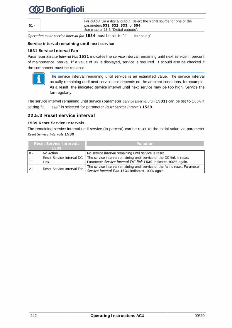
242 Operating Instructions ACU 09/20
51 - For output via a digital output. Select the signal source for one of the parameters 531, 532, 533, or 554. See chapter 16.3 “Digital outputs”.
Operation mode service interval fan 1534 must be set to "2 - Warning".
Service interval remaining until next service
1531 Service Interval Fan Parameter Service Interval Fan 1531 indicates the service interval remaining until next service in percent of maintenance interval. If a value of 0% is displayed, service is required. It should also be checked if the component must be replaced.
The service interval remaining until service is an estimated value. The service interval actually remaining until next service also depends on the ambient conditions, for example. As a result, the indicated service interval until next service may be too high. Service the fan regularly.
The service interval remaining until service (parameter Service Interval Fan 1531) can be set to 100% if setting "2 - fan" is selected for parameter Reset Service Intervals 1539.
22.5.3 Reset service interval 1539 Reset Service Intervals The remaining service interval until service (in percent) can be reset to the initial value via parameter Reset Service Intervals 1539.
Reset Service Intervals 1539
Function
0 - No Action No service interval remaining until service is reset.
1 - Reset Service Interval DC-Link
The service interval remaining until service of the DC-link is reset. Parameter Service Interval DC-link 1530 indicates 100% again.
2 - Reset Service Interval Fan The service interval remaining until service of the fan is reset. Parameter Service Interval Fan 1531 indicates 100% again.
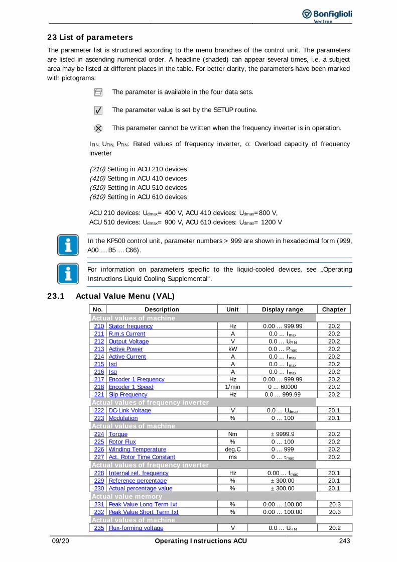
09/20 Operating Instructions ACU 243
23 List of parameters The parameter list is structured according to the menu branches of the control unit. The parameters are listed in ascending numerical order. A headline (shaded) can appear several times, i.e. a subject area may be listed at different places in the table. For better clarity, the parameters have been marked with pictograms:
The parameter is available in the four data sets.
The parameter value is set by the SETUP routine.
This parameter cannot be written when the frequency inverter is in operation.
IFIN, UFIN, PFIN: Rated values of frequency inverter, o: Overload capacity of frequency inverter
(210) Setting in ACU 210 devices (410) Setting in ACU 410 devices (510) Setting in ACU 510 devices (610) Setting in ACU 610 devices
ACU 210 devices: Udmax= 400 V, ACU 410 devices: Udmax=800 V, ACU 510 devices: Udmax= 900 V, ACU 610 devices: Udmax= 1200 V
In the KP500 control unit, parameter numbers > 999 are shown in hexadecimal form (999, A00 … B5 … C66).
For information on parameters specific to the liquid-cooled devices, see „Operating Instructions Liquid Cooling Supplemental“.
23.1 Actual Value Menu (VAL) No. Description Unit Display range Chapter Actual values of machine 210 Stator frequency Hz 0.00 ... 999.99 20.2 211 R.m.s Current A 0.0 ... Imax 20.2 212 Output Voltage V 0.0 ... UFIN 20.2 213 Active Power kW 0.0 ... Pmax 20.2 214 Active Current A 0.0 ... Imax 20.2 215 Isd A 0.0 ... Imax 20.2 216 Isq A 0.0 ... Imax 20.2 217 Encoder 1 Frequency Hz 0.00 ... 999.99 20.2 218 Encoder 1 Speed 1/min 0 ... 60000 20.2 221 Slip Frequency Hz 0.0 ... 999.99 20.2 Actual values of frequency inverter 222 DC-Link Voltage V 0.0 ... Udmax 20.1 223 Modulation % 0 ... 100 20.1 Actual values of machine 224 Torque Nm ± 9999.9 20.2 225 Rotor Flux % 0 ... 100 20.2 226 Winding Temperature deg.C 0 ... 999 20.2 227 Act. Rotor Time Constant ms 0 ... τmax 20.2 Actual values of frequency inverter 228 Internal ref. frequency Hz 0.00 ... fmax 20.1 229 Reference percentage % ± 300.00 20.1 230 Actual percentage value % ± 300.00 20.1 Actual value memory 231 Peak Value Long Term Ixt % 0.00 ... 100.00 20.3 232 Peak Value Short Term Ixt % 0.00 ... 100.00 20.3 Actual values of machine 235 Flux-forming voltage V 0.0 ... UFIN 20.2
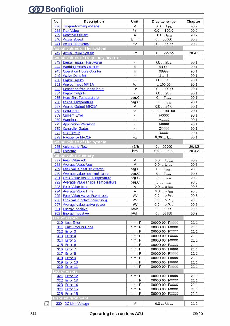
244 Operating Instructions ACU 09/20
No. Description Unit Display range Chapter 236 Torque-forming voltage V 0.0 ... UFIN 20.2 238 Flux Value % 0.0 ... 100.0 20.2 239 Reactive Current A 0.0 ... Imax 20.2 240 Actual Speed 1/min 0 ... 60000 20.2 241 Actual Frequency Hz 0.0 ... 999.99 20.2 Actual values of the system 242 Actual Value System Hz 0.0 ... 999.99 20.4.1 Actual values of frequency inverter 243 Digital Inputs (Hardware) - 00 ... 255 20.1 244 Working Hours Counter h 99999 20.1 245 Operation Hours Counter h 99999 20.1 249 Active Data Set - 1 ... 4 20.1 250 Digital Inputs - 00 ... 255 20.1 251 Analog Input MFI1A % ± 100.00 20.1 252 Repetition frequency input Hz 0.0 ... 999.99 20.1 254 Digital Outputs - 00 ... 255 20.1 255 Heat Sink Temperature deg.C 0 ... Tkmax 20.1 256 Inside Temperature deg.C 0 ... Timax 20.1 257 Analog Output MFO1A V 0.0 ... 24.0 20.1 258 PWM input % 0.00 … 100.00 20.1 259 Current Error - FXXXX 20.1 269 Warnings - AXXXX 20.1 273 Application Warnings - AXXXX 20.1 275 Controller Status - CXXXX 20.1 277 STO Status - XXXX 20.1 278 Frequency MFO1F Hz 0.00 ... fmax 20.1 Actual values of the system 285 Volumetric Flow m3/h 0 ... 99999 20.4.2 286 Pressure kPa 0.0 ... 999.9 20.4.2 Actual value memory 287 Peak Value Vdc V 0.0 ... Udmax 20.3 288 Average Value Vdc V 0.0 ... Udmax 20.3 289 Peak value heat sink temp. deg.C 0 ... Tkmax 20.3 290 Average value heat sink temp. deg.C 0 ... Tkmax 20.3 291 Peak Value Inside Temperature deg.C 0 ... Timax 20.3 292 Average Value Inside Temperature deg.C 0 ... Timax 20.3 293 Peak Value Irms A 0.0 ... o⋅IFIN 20.3 294 Average Value Irms A 0.0 ... o⋅IFIN 20.3 295 Peak Value Active Power pos. kW 0.0 ... o⋅PFIN 20.3 296 Peak value active power neg. kW 0.0 ... o⋅PFIN 20.3 297 Average value active power kW 0.0 ... o⋅PFIN 20.3 301 Energy, positive kWh 0 ... 99999 20.3 302 Energy, negative kWh 0 ... 99999 20.3 List of errors 310 Last Error h:m; F 00000:00; FXXXX 21.1 311 Last Error but one h:m; F 00000:00; FXXXX 21.1 312 Error 3 h:m; F 00000:00; FXXXX 21.1 313 Error 4 h:m; F 00000:00; FXXXX 21.1 314 Error 5 h:m; F 00000:00; FXXXX 21.1 315 Error 6 h:m; F 00000:00; FXXXX 21.1 316 Error 7 h:m; F 00000:00; FXXXX 21.1 317 Error 8 h:m; F 00000:00; FXXXX 21.1 318 Error 9 h:m; F 00000:00; FXXXX 21.1 319 Error 10 h:m; F 00000:00; FXXXX 21.1 320 Error 11 h:m; F 00000:00; FXXXX 21.1 List of errors 321 Error 12 h:m; F 00000:00; FXXXX 21.1 322 Error 13 h:m; F 00000:00; FXXXX 21.1 323 Error 14 h:m; F 00000:00; FXXXX 21.1 324 Error 15 h:m; F 00000:00; FXXXX 21.1 325 Error 16 h:m; F 00000:00; FXXXX 21.1 Error environment
330 DC-Link Voltage V 0.0 ... Udmax 21.2
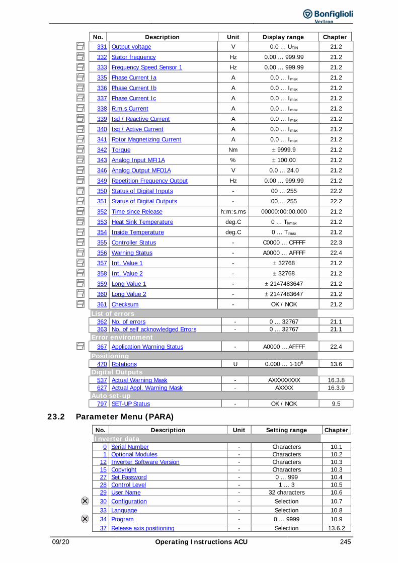
09/20 Operating Instructions ACU 245
No. Description Unit Display range Chapter 331 Output voltage V 0.0 ... UFIN 21.2 332 Stator frequency Hz 0.00 ... 999.99 21.2 333 Frequency Speed Sensor 1 Hz 0.00 ... 999.99 21.2 335 Phase Current Ia A 0.0 ... Imax 21.2 336 Phase Current Ib A 0.0 ... Imax 21.2 337 Phase Current Ic A 0.0 ... Imax 21.2 338 R.m.s Current A 0.0 ... Imax 21.2 339 Isd / Reactive Current A 0.0 ... Imax 21.2 340 Isq / Active Current A 0.0 ... Imax 21.2 341 Rotor Magnetizing Current A 0.0 ... Imax 21.2 342 Torque Nm ± 9999.9 21.2 343 Analog Input MFI1A % ± 100.00 21.2 346 Analog Output MFO1A V 0.0 ... 24.0 21.2 349 Repetition Frequency Output Hz 0.00 ... 999.99 21.2 350 Status of Digital Inputs - 00 ... 255 22.2 351 Status of Digital Outputs - 00 ... 255 22.2 352 Time since Release h:m:s.ms 00000:00:00.000 21.2 353 Heat Sink Temperature deg.C 0 ... Tkmax 21.2 354 Inside Temperature deg.C 0 ... Timax 21.2 355 Controller Status - C0000 ... CFFFF 22.3 356 Warning Status - A0000 ... AFFFF 22.4 357 Int. Value 1 - ± 32768 21.2 358 Int. Value 2 - ± 32768 21.2 359 Long Value 1 - ± 2147483647 21.2 360 Long Value 2 - ± 2147483647 21.2 361 Checksum - OK / NOK 21.2
List of errors 362 No. of errors - 0 ... 32767 21.1 363 No. of self acknowledged Errors - 0 ... 32767 21.1 Error environment
367 Application Warning Status - A0000 … AFFFF 22.4 Positioning 470 Rotations U 0.000 ... 1⋅106 13.6 Digital Outputs 537 Actual Warning Mask - AXXXXXXXX 16.3.8 627 Actual Appl. Warning Mask - AXXXX 16.3.9 Auto set-up 797 SET-UP Status - OK / NOK 9.5
23.2 Parameter Menu (PARA) No. Description Unit Setting range Chapter Inverter data 0 Serial Number - Characters 10.1 1 Optional Modules - Characters 10.2 12 Inverter Software Version - Characters 10.3 15 Copyright - Characters 10.3 27 Set Password - 0 ... 999 10.4 28 Control Level - 1 ... 3 10.5 29 User Name - 32 characters 10.6 30 Configuration - Selection 10.7 33 Language - Selection 10.8 34 Program - 0 ... 9999 10.9 37 Release axis positioning - Selection 13.6.2
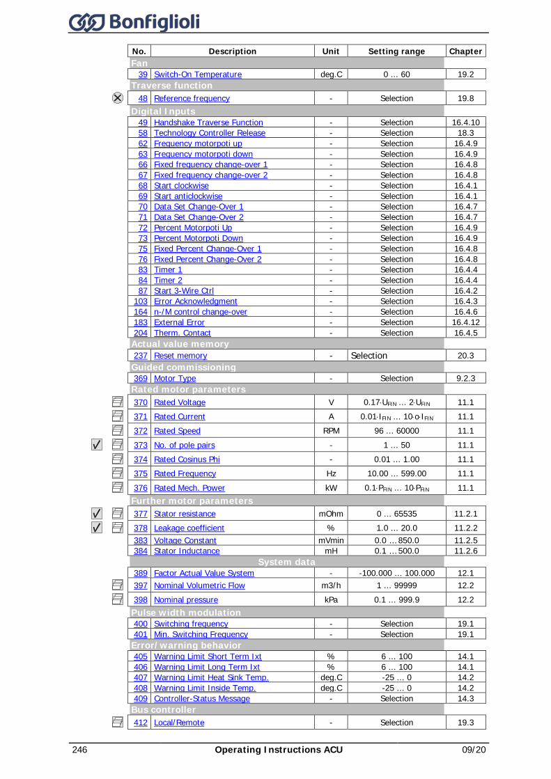
246 Operating Instructions ACU 09/20
No. Description Unit Setting range Chapter Fan 39 Switch-On Temperature deg.C 0 ... 60 19.2 Traverse function 48 Reference frequency - Selection 19.8 Digital Inputs 49 Handshake Traverse Function - Selection 16.4.10 58 Technology Controller Release - Selection 18.3 62 Frequency motorpoti up - Selection 16.4.9 63 Frequency motorpoti down - Selection 16.4.9 66 Fixed frequency change-over 1 - Selection 16.4.8 67 Fixed frequency change-over 2 - Selection 16.4.8 68 Start clockwise - Selection 16.4.1 69 Start anticlockwise - Selection 16.4.1 70 Data Set Change-Over 1 - Selection 16.4.7 71 Data Set Change-Over 2 - Selection 16.4.7 72 Percent Motorpoti Up - Selection 16.4.9 73 Percent Motorpoti Down - Selection 16.4.9 75 Fixed Percent Change-Over 1 - Selection 16.4.8 76 Fixed Percent Change-Over 2 - Selection 16.4.8 83 Timer 1 - Selection 16.4.4 84 Timer 2 - Selection 16.4.4 87 Start 3-Wire Ctrl - Selection 16.4.2 103 Error Acknowledgment - Selection 16.4.3 164 n-/M control change-over - Selection 16.4.6 183 External Error - Selection 16.4.12 204 Therm. Contact - Selection 16.4.5 Actual value memory 237 Reset memory - Selection 20.3 Guided commissioning 369 Motor Type - Selection 9.2.3 Rated motor parameters 370 Rated Voltage V 0.17⋅UFIN ... 2⋅UFIN 11.1 371 Rated Current A 0.01⋅IFIN ... 10⋅o⋅IFIN 11.1 372 Rated Speed RPM 96 ... 60000 11.1 373 No. of pole pairs - 1 ... 50 11.1 374 Rated Cosinus Phi - 0.01 ... 1.00 11.1 375 Rated Frequency Hz 10.00 ... 599.00 11.1 376 Rated Mech. Power kW 0.1⋅PFIN ... 10⋅PFIN 11.1 Further motor parameters 377 Stator resistance mOhm 0 ... 65535 11.2.1 378 Leakage coefficient % 1.0 ... 20.0 11.2.2 383 Voltage Constant mVmin 0.0 … 850.0 11.2.5 384 Stator Inductance mH 0.1 … 500.0 11.2.6 System data 389 Factor Actual Value System - -100.000 ... 100.000 12.1 397 Nominal Volumetric Flow m3/h 1 ... 99999 12.2 398 Nominal pressure kPa 0.1 ... 999.9 12.2 Pulse width modulation 400 Switching frequency - Selection 19.1 401 Min. Switching Frequency - Selection 19.1 Error/warning behavior 405 Warning Limit Short Term Ixt % 6 ... 100 14.1 406 Warning Limit Long Term Ixt % 6 ... 100 14.1 407 Warning Limit Heat Sink Temp. deg.C -25 ... 0 14.2 408 Warning Limit Inside Temp. deg.C -25 ... 0 14.2 409 Controller-Status Message - Selection 14.3 Bus controller 412 Local/Remote - Selection 19.3
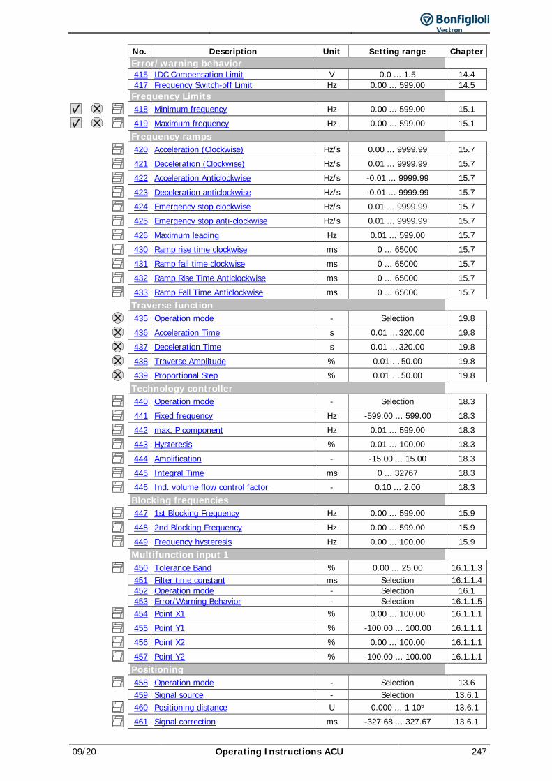
09/20 Operating Instructions ACU 247
No. Description Unit Setting range Chapter Error/warning behavior 415 IDC Compensation Limit V 0.0 ... 1.5 14.4 417 Frequency Switch-off Limit Hz 0.00 ... 599.00 14.5 Frequency Limits
418 Minimum frequency Hz 0.00 ... 599.00 15.1
419 Maximum frequency Hz 0.00 ... 599.00 15.1 Frequency ramps 420 Acceleration (Clockwise) Hz/s 0.00 ... 9999.99 15.7 421 Deceleration (Clockwise) Hz/s 0.01 ... 9999.99 15.7 422 Acceleration Anticlockwise Hz/s -0.01 ... 9999.99 15.7 423 Deceleration anticlockwise Hz/s -0.01 ... 9999.99 15.7 424 Emergency stop clockwise Hz/s 0.01 ... 9999.99 15.7 425 Emergency stop anti-clockwise Hz/s 0.01 ... 9999.99 15.7 426 Maximum leading Hz 0.01 ... 599.00 15.7 430 Ramp rise time clockwise ms 0 ... 65000 15.7 431 Ramp fall time clockwise ms 0 ... 65000 15.7 432 Ramp Rise Time Anticlockwise ms 0 ... 65000 15.7 433 Ramp Fall Time Anticlockwise ms 0 ... 65000 15.7 Traverse function 435 Operation mode - Selection 19.8 436 Acceleration Time s 0.01 … 320.00 19.8 437 Deceleration Time s 0.01 … 320.00 19.8 438 Traverse Amplitude % 0.01 … 50.00 19.8 439 Proportional Step % 0.01 … 50.00 19.8 Technology controller 440 Operation mode - Selection 18.3 441 Fixed frequency Hz -599.00 ... 599.00 18.3 442 max. P component Hz 0.01 ... 599.00 18.3 443 Hysteresis % 0.01 ... 100.00 18.3 444 Amplification - -15.00 ... 15.00 18.3 445 Integral Time ms 0 ... 32767 18.3 446 Ind. volume flow control factor - 0.10 ... 2.00 18.3 Blocking frequencies 447 1st Blocking Frequency Hz 0.00 ... 599.00 15.9 448 2nd Blocking Frequency Hz 0.00 ... 599.00 15.9 449 Frequency hysteresis Hz 0.00 ... 100.00 15.9 Multifunction input 1 450 Tolerance Band % 0.00 ... 25.00 16.1.1.3 451 Filter time constant ms Selection 16.1.1.4 452 Operation mode - Selection 16.1 453 Error/Warning Behavior - Selection 16.1.1.5 454 Point X1 % 0.00 ... 100.00 16.1.1.1 455 Point Y1 % -100.00 ... 100.00 16.1.1.1 456 Point X2 % 0.00 ... 100.00 16.1.1.1 457 Point Y2 % -100.00 ... 100.00 16.1.1.1 Positioning 458 Operation mode - Selection 13.6 459 Signal source - Selection 13.6.1 460 Positioning distance U 0.000 ... 1 106 13.6.1 461 Signal correction ms -327.68 ... 327.67 13.6.1

248 Operating Instructions ACU 09/20
No. Description Unit Setting range Chapter 462 Load correction - -32768 ... 32767 13.6.1 463 Activity after positioning - Selection 13.6.1 464 Time to wait ms 0 ... 3.6 106 13.6.1 Temperature Adjustment 465 Operation mode - Selection 19.7.2 466 Temperature coefficient %/100 0.00 ... 300.00 19.7.2 467 Adjusting temperature deg.C -50.0 ... 300.0 19.7.2 Positioning 469 Reference orientation ° 0.0 ... 359.9 13.6.2 471 Positioning Frequency Hz 1.00 ... 50.00 13.6.2 472 Max positional error ° 0.1 ... 90.0 13.6.2 Motor potentiometer 473 Ramp Keypad Motorpoti Hz/s 0.01 ... 999.99 15.10.3 474 Operation mode - Selection 15.10 Reference Frequency Channel 475 Reference frequency source - Selection 15.4 Reference percentage channel 476 Reference Percentage Source - Selection 15.5 Percentage ramp 477 Gradient Percentage Ramp %/s 0 ... 60000 15.8 Technology controller 478 Actual percentage source - Selection 18.3 Positioning 479 time constant positioning contr. ms 1.00 ... 9999.99 13.6.2 Fixed frequencies 480 Fixed Frequency 1 Hz -599.00 ... 599.00 15.6.1 481 Fixed Frequency 2 Hz -599.00 ... 599.00 15.6.1 482 Fixed Frequency 3 Hz -599.00 ... 599.00 15.6.1 483 Fixed Frequency 4 Hz -599.00 ... 599.00 15.6.1 489 JOG frequency Hz -599.00 ... 599.00 15.6.2 Speed Sensor 1 490 Operation mode - Selection 11.4.1 491 Division Marks - 1 ... 8192 11.4.2 PWM-/repetition frequency input 496 Operation mode - Selection 15.11 497 Divider - 1 ... 8192 15.11 Brake Chopper
506 Trigger Threshold V 225 ... 1000 (210) 425 ... 2000 (410) 550 … 2000 (510) 725 … 2000 (610)
19.4
Motor chopper
507 Trigger Threshold V 225 ... 1000 (210) 425 ... 2000 (410) 550 … 2000 (510) 725 … 2000 (610)
19.7.1
Digital Outputs 510 Setting Frequency Hz 0.00 ... 599.00 16.3.2 Speed Sensor 1 511 EC1 Gear Factor Numerator - -300.00 … 300.00 11.4.3 512 EC1 Gear Factor Denominator - 0.01 … 300.00 11.4.3 Speed controller 515 Integral Time Speedtracking ms 1 … 60 000 18.5.4.3 Digital Outputs
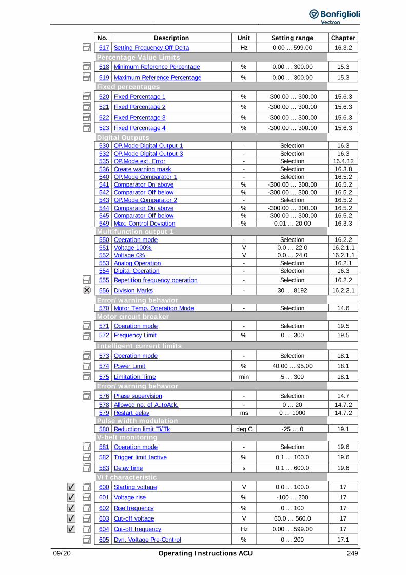
09/20 Operating Instructions ACU 249
No. Description Unit Setting range Chapter 517 Setting Frequency Off Delta Hz 0.00 … 599.00 16.3.2 Percentage Value Limits 518 Minimum Reference Percentage % 0.00 ... 300.00 15.3 519 Maximum Reference Percentage % 0.00 ... 300.00 15.3 Fixed percentages 520 Fixed Percentage 1 % -300.00 ... 300.00 15.6.3 521 Fixed Percentage 2 % -300.00 ... 300.00 15.6.3 522 Fixed Percentage 3 % -300.00 ... 300.00 15.6.3 523 Fixed Percentage 4 % -300.00 ... 300.00 15.6.3 Digital Outputs 530 OP.Mode Digital Output 1 - Selection 16.3 532 OP.Mode Digital Output 3 - Selection 16.3 535 OP.Mode ext. Error - Selection 16.4.12 536 Create warning mask - Selection 16.3.8 540 OP.Mode Comparator 1 - Selection 16.5.2 541 Comparator On above % -300.00 ... 300.00 16.5.2 542 Comparator Off below % -300.00 ... 300.00 16.5.2 543 OP.Mode Comparator 2 - Selection 16.5.2 544 Comparator On above % -300.00 ... 300.00 16.5.2 545 Comparator Off below % -300.00 ... 300.00 16.5.2 549 Max. Control Deviation % 0.01 ... 20.00 16.3.3 Multifunction output 1 550 Operation mode - Selection 16.2.2 551 Voltage 100% V 0.0 ... 22.0 16.2.1.1 552 Voltage 0% V 0.0 ... 24.0 16.2.1.1 553 Analog Operation - Selection 16.2.1 554 Digital Operation - Selection 16.3 555 Repetition frequency operation - Selection 16.2.2 556 Division Marks - 30 ... 8192 16.2.2.1 Error/warning behavior 570 Motor Temp. Operation Mode - Selection 14.6 Motor circuit breaker 571 Operation mode - Selection 19.5
572 Frequency Limit % 0 ... 300 19.5 Intelligent current limits 573 Operation mode - Selection 18.1 574 Power Limit % 40.00 ... 95.00 18.1 575 Limitation Time min 5 ... 300 18.1 Error/warning behavior 576 Phase supervision - Selection 14.7 578 Allowed no. of AutoAck. - 0 ... 20 14.7.2 579 Restart delay ms 0 ... 1000 14.7.2 Pulse width modulation 580 Reduction limit Ti/Tk deg.C -25 ... 0 19.1 V-belt monitoring 581 Operation mode - Selection 19.6 582 Trigger limit Iactive % 0.1 ... 100.0 19.6 583 Delay time s 0.1 ... 600.0 19.6 V/f characteristic 600 Starting voltage V 0.0 ... 100.0 17 601 Voltage rise % -100 ... 200 17 602 Rise frequency % 0 ... 100 17 603 Cut-off voltage V 60.0 ... 560.0 17 604 Cut-off frequency Hz 0.00 ... 599.00 17 605 Dyn. Voltage Pre-Control % 0 ... 200 17.1
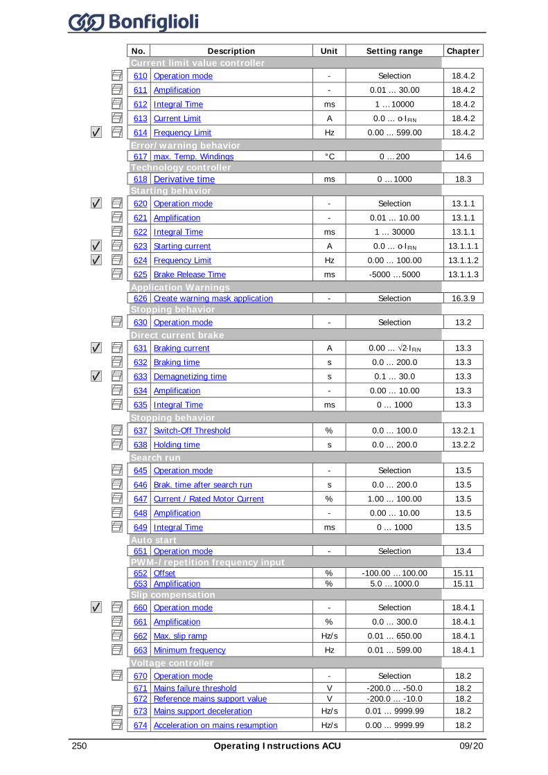
250 Operating Instructions ACU 09/20
No. Description Unit Setting range Chapter Current limit value controller 610 Operation mode - Selection 18.4.2 611 Amplification - 0.01 ... 30.00 18.4.2 612 Integral Time ms 1 … 10000 18.4.2 613 Current Limit A 0.0 ... o⋅IFIN 18.4.2 614 Frequency Limit Hz 0.00 ... 599.00 18.4.2 Error/warning behavior 617 max. Temp. Windings °C 0 … 200 14.6 Technology controller 618 Derivative time ms 0 … 1000 18.3 Starting behavior 620 Operation mode - Selection 13.1.1 621 Amplification - 0.01 ... 10.00 13.1.1 622 Integral Time ms 1 ... 30000 13.1.1 623 Starting current A 0.0 ... o⋅IFIN 13.1.1.1 624 Frequency Limit Hz 0.00 ... 100.00 13.1.1.2 625 Brake Release Time ms -5000 … 5000 13.1.1.3 Application Warnings 626 Create warning mask application - Selection 16.3.9 Stopping behavior 630 Operation mode - Selection 13.2 Direct current brake 631 Braking current A 0.00 ... √2⋅IFIN 13.3 632 Braking time s 0.0 ... 200.0 13.3 633 Demagnetizing time s 0.1 ... 30.0 13.3 634 Amplification - 0.00 ... 10.00 13.3 635 Integral Time ms 0 ... 1000 13.3 Stopping behavior 637 Switch-Off Threshold % 0.0 ... 100.0 13.2.1 638 Holding time s 0.0 ... 200.0 13.2.2 Search run 645 Operation mode - Selection 13.5 646 Brak. time after search run s 0.0 ... 200.0 13.5 647 Current / Rated Motor Current % 1.00 ... 100.00 13.5 648 Amplification - 0.00 ... 10.00 13.5 649 Integral Time ms 0 ... 1000 13.5 Auto start 651 Operation mode - Selection 13.4 PWM-/repetition frequency input 652 Offset % -100.00 … 100.00 15.11 653 Amplification % 5.0 … 1000.0 15.11 Slip compensation 660 Operation mode - Selection 18.4.1 661 Amplification % 0.0 ... 300.0 18.4.1 662 Max. slip ramp Hz/s 0.01 ... 650.00 18.4.1 663 Minimum frequency Hz 0.01 ... 599.00 18.4.1 Voltage controller 670 Operation mode - Selection 18.2 671 Mains failure threshold V -200.0 ... -50.0 18.2 672 Reference mains support value V -200.0 ... -10.0 18.2 673 Mains support deceleration Hz/s 0.01 ... 9999.99 18.2 674 Acceleration on mains resumption Hz/s 0.00 ... 9999.99 18.2
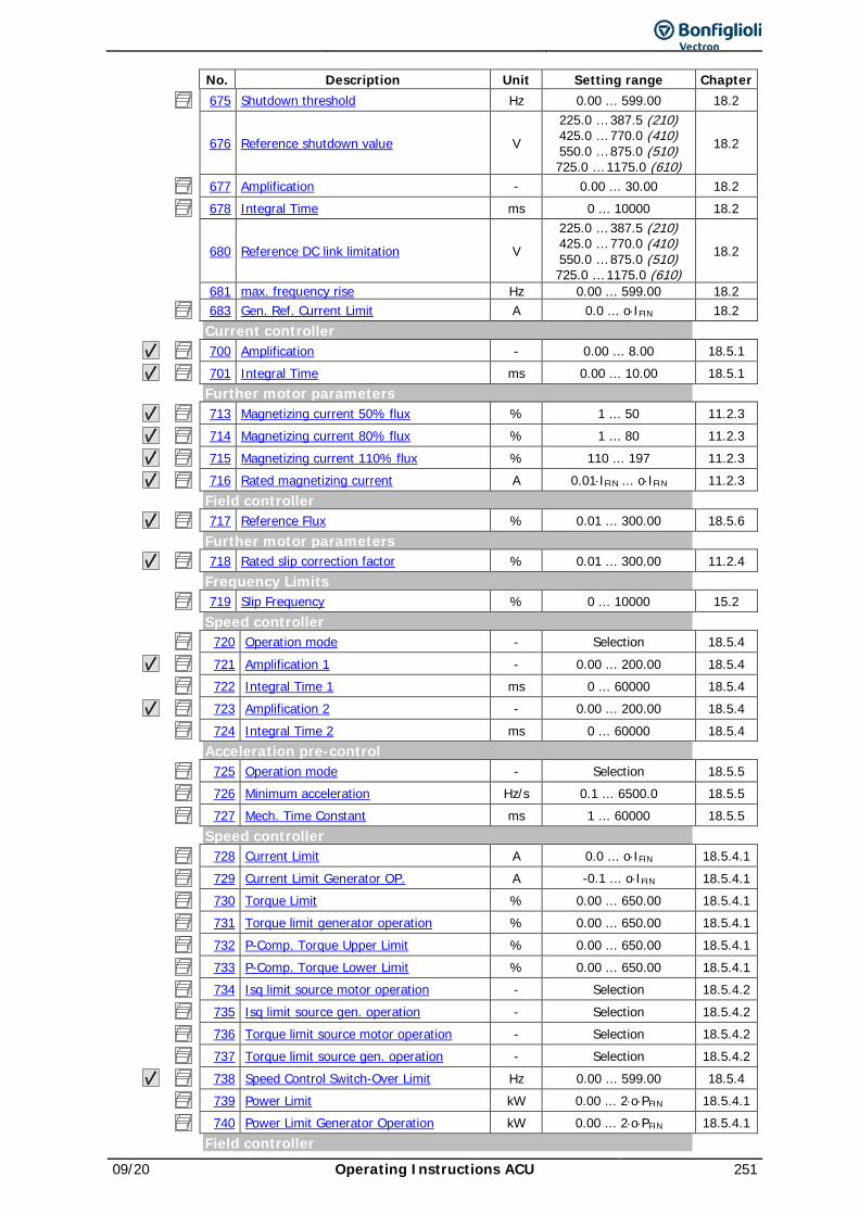
09/20 Operating Instructions ACU 251
No. Description Unit Setting range Chapter 675 Shutdown threshold Hz 0.00 ... 599.00 18.2
676 Reference shutdown value V 225.0 … 387.5 (210) 425.0 … 770.0 (410) 550.0 … 875.0 (510) 725.0 … 1175.0 (610)
18.2
677 Amplification - 0.00 ... 30.00 18.2 678 Integral Time ms 0 ... 10000 18.2
680 Reference DC link limitation V 225.0 … 387.5 (210) 425.0 … 770.0 (410) 550.0 … 875.0 (510) 725.0 … 1175.0 (610)
18.2
681 max. frequency rise Hz 0.00 ... 599.00 18.2 683 Gen. Ref. Current Limit A 0.0 ... o⋅IFIN 18.2 Current controller 700 Amplification - 0.00 ... 8.00 18.5.1 701 Integral Time ms 0.00 ... 10.00 18.5.1 Further motor parameters 713 Magnetizing current 50% flux % 1 ... 50 11.2.3 714 Magnetizing current 80% flux % 1 ... 80 11.2.3 715 Magnetizing current 110% flux % 110 ... 197 11.2.3 716 Rated magnetizing current A 0.01⋅IFIN ... o⋅IFIN 11.2.3 Field controller 717 Reference Flux % 0.01 ... 300.00 18.5.6 Further motor parameters 718 Rated slip correction factor % 0.01 ... 300.00 11.2.4 Frequency Limits 719 Slip Frequency % 0 ... 10000 15.2 Speed controller 720 Operation mode - Selection 18.5.4 721 Amplification 1 - 0.00 ... 200.00 18.5.4 722 Integral Time 1 ms 0 ... 60000 18.5.4 723 Amplification 2 - 0.00 ... 200.00 18.5.4 724 Integral Time 2 ms 0 ... 60000 18.5.4 Acceleration pre-control 725 Operation mode - Selection 18.5.5 726 Minimum acceleration Hz/s 0.1 ... 6500.0 18.5.5 727 Mech. Time Constant ms 1 ... 60000 18.5.5 Speed controller 728 Current Limit A 0.0 ... o⋅IFIN 18.5.4.1 729 Current Limit Generator OP. A -0.1 ... o⋅IFIN 18.5.4.1 730 Torque Limit % 0.00 ... 650.00 18.5.4.1 731 Torque limit generator operation % 0.00 ... 650.00 18.5.4.1 732 P-Comp. Torque Upper Limit % 0.00 ... 650.00 18.5.4.1 733 P-Comp. Torque Lower Limit % 0.00 ... 650.00 18.5.4.1 734 Isq limit source motor operation - Selection 18.5.4.2 735 Isq limit source gen. operation - Selection 18.5.4.2 736 Torque limit source motor operation - Selection 18.5.4.2 737 Torque limit source gen. operation - Selection 18.5.4.2 738 Speed Control Switch-Over Limit Hz 0.00 ... 599.00 18.5.4 739 Power Limit kW 0.00 ... 2⋅o⋅PFIN 18.5.4.1 740 Power Limit Generator Operation kW 0.00 ... 2⋅o⋅PFIN 18.5.4.1 Field controller
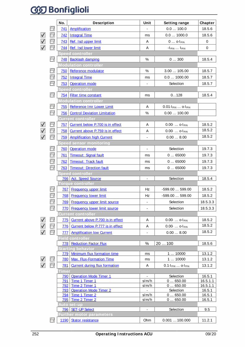
252 Operating Instructions ACU 09/20
No. Description Unit Setting range Chapter 741 Amplification - 0.0 ... 100.0 18.5.6 742 Integral Time ms 0.0 ... 1000.0 18.5.6 743 Ref. Isd upper limit A 0 ... o⋅IFIN 0 744 Ref. Isd lower limit A -IFIN ... IFIN 0
Speed controller 748 Backlash damping % 0 ... 300 18.5.4
Modulation controller 750 Reference modulator % 3.00 ... 105.00 18.5.7 752 Integral Time ms 0.0 ... 1000.00 18.5.7 753 Operation mode - Selection 18.5.7
Speed controller 754 Filter time constant ms 0...128 18.5.4
Modulation controller 755 Reference Imr Lower Limit A 0.01⋅IFIN ... o⋅IFIN 756 Control Deviation Limitation % 0.00 ... 100.00
Current controller 757 Current below P.700 is in effect A 0.00⋅ ... o⋅IFIN 18.5.2 758 Current above P.759 is in effect A 0.00⋅ ... o⋅IFIN 18.5.2
759 Amplification high Current - 0.00 ... 8.00 18.5.2
Speed sensor monitoring 760 Operation mode - Selection 19.7.3 761 Timeout: Signal fault ms 0 ... 65000 19.7.3 762 Timeout: Track fault ms 0 ... 65000 19.7.3 763 Timeout: Direction fault ms 0 ... 65000 19.7.3
Speed controller 766 Act. Speed Source - Selection 18.5.4
Torque controller 767 Frequency upper limit Hz -599.00 ... 599.00 18.5.2 768 Frequency lower limit Hz -599.00 ... 599.00 18.5.2 769 Frequency upper limit source - Selection 18.5.3.3 770 Frequency lower limit source - Selection 18.5.3.3
Current controller 775 Current above P.700 is in effect A 0.00⋅ ... o⋅IFIN 18.5.2 776 Current below P.777 is in effect A 0.00⋅ ... o⋅IFIN 18.5.2
777 Amplification low Current - 0.00 ... 8.00 18.5.2 Field controller
778 Reduction Factor Flux % 20 … 100 18.5.6 Starting behavior
779 Minimum flux formation time ms 1 ... 10000 13.1.2 780 Max. Flux-Formation Time ms 1 ... 10000 13.1.2 781 Current during flux formation A 0.1⋅IFIN ... o⋅IFIN 13.1.2
Timer 790 Operation Mode Timer 1 - Selection 16.5.1 791 Time 1 Timer 1 s/m/h 0 ... 650.00 16.5.1.1 792 Time 2 Timer 1 s/m/h 0 ... 650.00 16.5.1.1 793 Operation Mode Timer 2 - Selection 16.5.1 794 Time 1 Timer 2 s/m/h 0 ... 650.00 16.5.1 795 Time 2 Timer 2 s/m/h 0 ... 650.00 16.5.1
Auto set-up 796 SET-UP Select - Selection 9.5
Further motor parameters 1190 Stator resistance Ohm 0.001 … 100.000 11.2.1
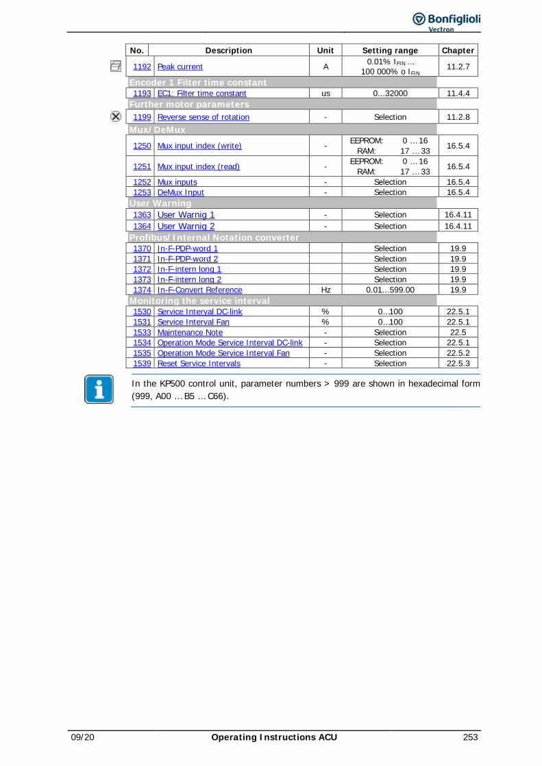
09/20 Operating Instructions ACU 253
No. Description Unit Setting range Chapter
1192 Peak current A 0.01% IFIN … 100 000% o IFIN 11.2.7
Encoder 1 Filter time constant 1193 EC1: Filter time constant us 0...32000 11.4.4 Further motor parameters 1199 Reverse sense of rotation - Selection 11.2.8 Mux/DeMux
1250 Mux input index (write) - EEPROM: 0 … 16 16.5.4 RAM: 17 … 33
1251 Mux input index (read) - EEPROM: 0 … 16 16.5.4 RAM: 17 … 33 1252 Mux inputs - Selection 16.5.4 1253 DeMux Input - Selection 16.5.4 User Warning 1363 User Warnig 1 - Selection 16.4.11 1364 User Warnig 2 - Selection 16.4.11 Profibus/Internal Notation converter 1370 In-F-PDP-word 1 Selection 19.9 1371 In-F-PDP-word 2 Selection 19.9 1372 In-F-intern long 1 Selection 19.9 1373 In-F-intern long 2 Selection 19.9 1374 In-F-Convert Reference Hz 0.01...599.00 19.9 Monitoring the service interval 1530 Service Interval DC-link % 0…100 22.5.1 1531 Service Interval Fan % 0…100 22.5.1 1533 Maintenance Note - Selection 22.5 1534 Operation Mode Service Interval DC-link - Selection 22.5.1 1535 Operation Mode Service Interval Fan - Selection 22.5.2 1539 Reset Service Intervals - Selection 22.5.3
In the KP500 control unit, parameter numbers > 999 are shown in hexadecimal form (999, A00 … B5 … C66).
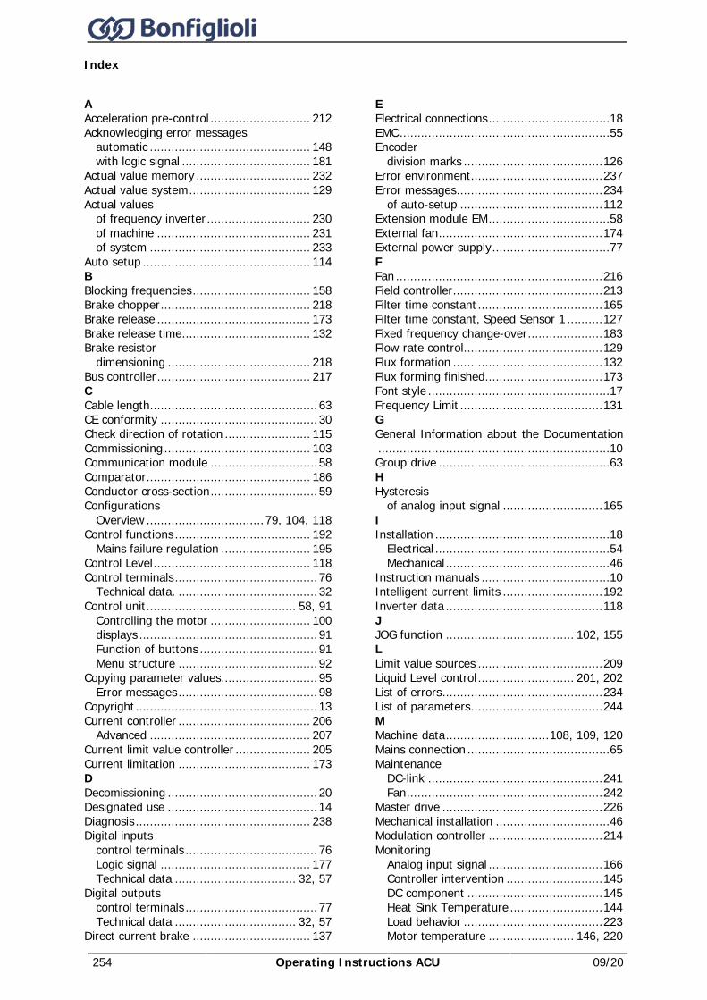
254 Operating Instructions ACU 09/20
Index
A Acceleration pre-control ............................ 212 Acknowledging error messages
automatic ............................................. 148 with logic signal .................................... 181
Actual value memory ................................ 232 Actual value system .................................. 129 Actual values
of frequency inverter ............................. 230 of machine ........................................... 231 of system ............................................. 233
Auto setup ............................................... 114 B Blocking frequencies ................................. 158 Brake chopper .......................................... 218 Brake release ........................................... 173 Brake release time .................................... 132 Brake resistor
dimensioning ........................................ 218 Bus controller ........................................... 217 C Cable length ............................................... 63 CE conformity ............................................ 30 Check direction of rotation ........................ 115 Commissioning ......................................... 103 Communication module .............................. 58 Comparator .............................................. 186 Conductor cross-section .............................. 59 Configurations
Overview ................................. 79, 104, 118 Control functions ...................................... 192
Mains failure regulation ......................... 195 Control Level ............................................ 118 Control terminals ........................................ 76
Technical data. ....................................... 32 Control unit .......................................... 58, 91
Controlling the motor ............................ 100 displays .................................................. 91 Function of buttons ................................. 91 Menu structure ....................................... 92
Copying parameter values ........................... 95 Error messages ....................................... 98
Copyright ................................................... 13 Current controller ..................................... 206
Advanced ............................................. 207 Current limit value controller ..................... 205 Current limitation ..................................... 173 D Decomissioning .......................................... 20 Designated use .......................................... 14 Diagnosis ................................................. 238 Digital inputs
control terminals ..................................... 76 Logic signal .......................................... 177 Technical data .................................. 32, 57
Digital outputs control terminals ..................................... 77 Technical data .................................. 32, 57
Direct current brake ................................. 137
E Electrical connections ..................................18 EMC ...........................................................55 Encoder
division marks ....................................... 126 Error environment ..................................... 237 Error messages ......................................... 234
of auto-setup ........................................ 112 Extension module EM ..................................58 External fan .............................................. 174 External power supply .................................77 F Fan .......................................................... 216 Field controller .......................................... 213 Filter time constant ................................... 165 Filter time constant, Speed Sensor 1 .......... 127 Fixed frequency change-over ..................... 183 Flow rate control....................................... 129 Flux formation .......................................... 132 Flux forming finished................................. 173 Font style ...................................................17 Frequency Limit ........................................ 131 G General Information about the Documentation .................................................................10 Group drive ................................................63 H Hysteresis
of analog input signal ............................ 165 I Installation .................................................18
Electrical .................................................54 Mechanical ..............................................46
Instruction manuals ....................................10 Intelligent current limits ............................ 192 Inverter data ............................................ 118 J JOG function .................................... 102, 155 L Limit value sources ................................... 209 Liquid Level control ........................... 201, 202 List of errors ............................................. 234 List of parameters ..................................... 244 M Machine data ............................. 108, 109, 120 Mains connection ........................................65 Maintenance
DC-link ................................................. 241 Fan ....................................................... 242
Master drive ............................................. 226 Mechanical installation ................................46 Modulation controller ................................ 214 Monitoring
Analog input signal ................................ 166 Controller intervention ........................... 145 DC component ...................................... 145 Heat Sink Temperature .......................... 144 Load behavior ....................................... 223 Motor temperature ........................ 146, 220
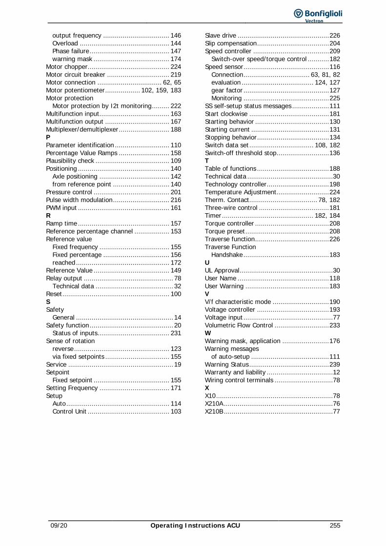
09/20 Operating Instructions ACU 255
output frequency .................................. 146 Overload .............................................. 144 Phase failure ......................................... 147 warning mask ....................................... 174
Motor chopper.......................................... 224 Motor circuit breaker ................................ 219 Motor connection ................................. 62, 65 Motor potentiometer .................. 102, 159, 183 Motor protection
Motor protection by I2t monitoring ......... 222 Multifunction input.................................... 163 Multifunction output ................................. 167 Multiplexer/demultiplexer .......................... 188 P Parameter identification ............................ 110 Percentage Value Ramps .......................... 158 Plausibility check ...................................... 109 Positioning ............................................... 140
Axle positioning .................................... 142 from reference point ............................. 140
Pressure control ....................................... 201 Pulse width modulation ............................. 216 PWM input ............................................... 161 R Ramp time ............................................... 157 Reference percentage channel .................. 153 Reference value
Fixed frequency .................................... 155 Fixed percentage .................................. 156 reached ................................................ 172
Reference Value ....................................... 149 Relay output .............................................. 78
Technical data ........................................ 32 Reset ....................................................... 100 S Safety
General .................................................. 14 Safety function ........................................... 20
Status of inputs..................................... 231 Sense of rotation
reverse ................................................. 123 via fixed setpoints ................................. 155
Service ...................................................... 19 Setpoint
Fixed setpoint ....................................... 155 Setting Frequency .................................... 171 Setup
Auto ..................................................... 114 Control Unit .......................................... 103
Slave drive ............................................... 226 Slip compensation ..................................... 204 Speed controller ....................................... 209
Switch-over speed/torque control ........... 182 Speed sensor ............................................ 116
Connection .................................. 63, 81, 82 evaluation ..................................... 124, 127 gear factor ............................................ 127 Monitoring ............................................ 225
SS self-setup status messages ................... 111 Start clockwise ......................................... 181 Starting behavior ...................................... 130 Starting current ........................................ 131 Stopping behavior ..................................... 134 Switch data set ................................. 108, 182 Switch-off threshold stop ........................... 136 T Table of functions ..................................... 188 Technical data ............................................30 Technology controller ................................ 198 Temperature Adjustment........................... 224 Therm. Contact................................... 78, 182 Three-wire control .................................... 181 Timer ............................................... 182, 184 Torque controller ...................................... 208 Torque preset ........................................... 208 Traverse function ...................................... 226 Traverse Function
Handshake ............................................ 183 U UL Approval ................................................30 User Name ............................................... 118 User Warning ........................................... 183 V V/f characteristic mode ............................. 190 Voltage controller ..................................... 193 Voltage input ..............................................77 Volumetric Flow Control ............................ 233 W Warning mask, application ........................ 176 Warning messages
of auto-setup ........................................ 111 Warning Status ......................................... 239 Warranty and liability ..................................12 Wiring control terminals ..............................78 X X10 ............................................................78 X210A ........................................................76 X210B ........................................................77


Bonfiglioli Riduttori S.p.A.Via Giovanni XXIII, 7/A40012 Lippo di Calderara di RenoBologna (Italy)
tel: +39 051 647 3111fax: +39 051 647 [email protected]
Bonfiglioli has been designing and developing innovativeand reliable power transmission and control solutionsfor industry, mobile machinery and renewable energy applicacations since 1956.
COD. VEC 170 R3
Copyright © 2022 FDOKUMEN