Solving the Rubik's cube with deep reinforcement learning ...
Upload
independentCategory
view
0download
0
Beam-splitting cube for fringe-projection,holographic, and shearographic interferometry
Huai M. Shang, Michael Y. Y. Hung, Cheng G. Quan, and Cho J. Tay
We describe a simple method in which the techniques of fringe-projection, holographic, and shearographicinterferometry may be readily realized with a commercial beam-splitting cube, a laser source, and a beamexpander. With the use of a computer algorithm, moire fringes may be derived digitally from the fringesthat are projected onto a reference surface and onto an object surface. Successful use of the beam-splitting cube for these optical methods is attributed to the refraction of the two split beams that exit fromthe two adjacent faces of the cube. By careful orientation of the cube, the two refracted light beams willconverge and interfere, resulting in the formation of Young’s interference fringes for the fringe-projectionmethod. When the hypotenuse of the beam-splitting cube is placed nearly normal to an illuminatedobject, both the image and the mirror image of the object will be formed behind the cube where a camerais placed. This optical setup thus forms the basis for double-exposure holography when these twoimages are fully overlapped and for shearography when the images are slightly laterally displaced.© 2001 Optical Society of America
OCIS codes: 120.2880, 120.3180.
1. Introduction
Fringe-projection, moire, holographic, and shearo-graphic interferometry are four basic optical tech-niques for inspection and measurement; theirunderlying principles and applications are found innumerous books.1–12 The techniques of moire andfringe-projection interferometry require generatingand projecting a grating, which generally comprisesuniformly distributed straight fringe lines, on a testsurface.1–5,8–14 In the projected-fringe techniquethe fringe lines appearing on a diffuse surface aredistorted, resulting in a phase change related tothe profile �or Z depth� of the surface. For a specu-larly reflective surface, however, surface slopes aremeasured.14 In the moire methods the gratingthat is either projected or bonded on the test surfaceinterferes with a reference grating, resulting in theformation of a low-density fringe pattern that de-
picts in-plane displacements or Z depths. As willbe seen below, there is similarity, from the theoret-ical point of view, between the techniques of fringeprojection and moire interferometry, except thathigh-frequency gratings are to be used in moireinterferometry for the reconstruction of low-densityfringes.
Holographic interferometry requires a separatereference beam to interfere with the object beam dur-ing recording; in digital holography or electronicspeckle pattern interferometry, a beam-splitting cubeis generally used for generating and combining thereference and object beams.3,4,7,9–12 In shearogra-phy, light scattered from two neighboring points onthe test object serves as reference and object beamssimultaneously; this is achieved with an image-shearing device that often is a Michelson interferom-eter, a glass wedge, or a birefringent prism.4,9,12,15,16
As such, shearography with large image shearing hasbeen perceived17 as being equivalent to holographicinterferometry in which displacement-related fringesare reconstructed, whereas shearography with smallimage shearing refers to conventional shearographyin which strain-related fringes are reconstructed.Thus the governing equations for holographic andshearographic interferometry are similar.
The following derivations are common to digitaltechniques in fringe-projection, moire, holographic,and shearographic interferometry.1–17 The initial
When this research was performed, the authors were with theDepartment of Mechanical Engineering, National University ofSingapore, 10 Kent Ridge Crescent, 119260 Singapore. M. Y. Y.Hung was on leave from the Department of Mechanical Engineer-ing, Oakland University, Rochester Hills, Michigan 48309. H. M.Shang’s e-mail address is [email protected].
Received 24 August 2000; revised manuscript received 21 May2001.
0003-6935�01�315615-09$15.00�0© 2001 Optical Society of America
1 November 2001 � Vol. 40, No. 31 � APPLIED OPTICS 5615

intensity distribution I1 on the test surface may bedescribed with the following basic equation:
I1 � a � b cos �, (1)
where a is the background intensity, b is intensityvariation arising from nonuniformity in illuminationand surface reflectivity, and � is the initial phase.The initial intensity I1 may therefore be regarded asthe reference intensity distribution. In the case ofthe fringe-projection and the moire techniques, as-sume that the reference intensity on a planar refer-ence surface belongs to a family of uniformlydistributed straight fringe lines perpendicular to thereference x axis and that the initial phase � is relatedto the pitch m of the grating by the expression � ��2��m�x. However, in holographic and shearo-graphic interferometry, � is the initial random phasedepicting the relative phase between the referencebeam and the object beam, and I1 refers to the initialintensity distribution recorded with the CCD camerabefore the test surface is subjected to a load increment.
When the initial phase � is perturbed by the three-dimensional profile of a test surface or by deforma-tion, the resulting intensity distribution I2 recordedwith the CCD camera is now described by the follow-ing expression,
I2 � a � b cos�� � ��, (2)
where � is the phase change from the initial phase �.In fringe-projection and moire interferometry, � ��2��m��, where � is the distortion of the referencegrating of pitch m. In holographic and shearo-graphic interferometry, � is the change in the relativephase �between reference and object beams� due tosurface deformation.
Computer-based optical techniques generally in-volve pixel-by-pixel image subtraction; hence, numer-ically, the difference of I1 in Eq. �1� and I2 in Eq. �2�is given by the following expression:
�Idiff� � �4b2 sin�� ��
2��sin��
2� , (3)
where the phase change � manifests as a visiblefringe pattern on the computer monitor. Thus thetechniques of moire, fringe-projection, holographic,and shearographic interferometry may be perceivedto be theoretically similar.
Existing literature1–17 has suggested that inter-ferometric methods in moire, fringe-projection, holo-graphic, and shearographic interferometry frequentlymake use of either a beam-splitting device �such asthe Michelson interferometer� or a pair of closelyspaced point sources split from the same laser sourceby means of optical fibers. Each method has its ownmerits and shortcomings. For instance, the Michel-son interferometer readily generates and projects agrating or splits and combines the object and refer-ence beams. But with the use of at least two reflect-ing mirrors and with light passing through the beam-splitting cube a few times, undesirable optical noises
and losses of light are the main concerns. The use ofoptical fibers is inexpensive, but it requires carefulpositioning of the fiber launchers. Our main objec-tive in this paper is to demonstrate that the use of acommercial beam-splitting cube, a laser, and a beamexpander can readily be used to realize moire, fringe-projection, holographic, and shearographic inter-ferometry.
2. Use of Beam-Splitting Cube for Fringe-Projectionand Moire Interferometry
Figure 1 shows the transmission of a ray of light Uithrough a commercial beam-splitting cube ABCD,which is normally made of two glass prisms cementedtogether along the hypotenuse AC with a spacerplaced between them. The angle included betweenthe AB face and the AC face is �, and the incidenceangle at E of the incoming ray Ui is 1. Taking therefractive index of the glass prism as ng and that ofthe surrounding media �which is normally still air� asna, we determine the angle of refraction 2, using thewell-known Snell’s law. Thus
sin 2 � �na�ng�sin 1. (4)
When ray EF encounters the AC face at F, it is splitinto the refracted ray FG and the reflected ray FH.When we consider the spacer along AC to be a verythin layer, rays EF and FG may be taken as collinear.Light ray FG emerges from the CD face at G to be-come ray Ua, whose refraction angle is given by
� 1, (5)
where 1 is the incidence angle of the incoming lightray Ui. It is worth mentioning that the thickness ofthe spacer along AC would not alter the conclusionthat � 1 at the exiting CD face, except the point ofemergence is displaced slightly away from G.
Fig. 1. Reflection and refraction of light rays in a beam-splittingcube.
5616 APPLIED OPTICS � Vol. 40, No. 31 � 1 November 2001

The reflected ray FH exits from the BC face at H toform the refracted light ray U. The use of Snell’slaw shows that the refraction angle is given by thefollowing expression:
sin � � �ng�na��cos�2� � 2� , (6)
where the angle 2 is related to the incidence angle 1by Eq. �4�.
Finally, the angle � between the two emerging raysU and U may be expressed in terms of �Eq. �5� and �Eq. �6� with the scalar product of the unitvectors of light rays U and U. Thus
� � ��1 � � ��2�. (7)
In selecting the sign of the enclosed term in Eq. �7�,the condition of � � ��1 � � ���2� , where � � 0corresponds to converging light rays U and U sothat interference takes place to form the well-knownYoung’s interference fringes. However, the condi-tion of � � ��1 � ����2� , where � � 0 correspondsto diverging light rays U and U so that light inter-ference is not possible.
The angle � in commercial beam-splitting cubes isgenerally equal to ��4, so from Eq. �6� the refractionangle is given by � 1. Subsequently, the use ofEq. �7� ensures that the light rays U and U areconverging to permit interference when 1 � ��4,whereas the light rays U and U are divergent when1 � ��4.
For illustration Fig. 2 shows the use of a commer-cial beam-splitting cube for fringe projection. Theunexpanded laser beam Ui with a large incidenceangle �1 � ��4 , upon exiting the cube, is split intotwo light rays U and U that converge at K. Withthe beam expander placed near K, the expandedbeams of U and U will interfere to generate Young’sinterference fringes, which are in the form of a hy-
perboloid of revolution.1,3–7 A typical fringe patternthat is projected onto a planar surface is shown inFig. 3, demonstrating also that both coarse grating��9-mm pitch in Fig. 3�a� and fine grating ��33-�mpitch in Fig. 3�b� can be obtained. The fine gratingdensity of 30 lines�mm is equivalent to having 3fringe lines on a 100-�m-long test specimen, therebyenabling deformation studies in microsystems. Fig-ure 4 shows the distortion of the fringe lines on arock—the curved fringe lines indicate the presence oftwo principal curvatures, and the broken fringe linesindicate step increment in the Z depth.
When the fringe lines on the test surface are suf-ficiently fine, moire fringes may be reconstructed inthe light of Eq. �3�. Figure 5 illustrates the forma-
Fig. 2. Optical layout for the generation and projection of inter-ference grating using a beam-splitting cube.
Fig. 3. Typical fringe pattern that is generated and projected ontoa planar surface. �a� Coarse grating of �9-mm pitch, as is de-duced from the 3-cm-long paper clip placed on the planar surface,�b� fine grating of �33-�m pitch.
1 November 2001 � Vol. 40, No. 31 � APPLIED OPTICS 5617

tion of the typical inverted-V-shaped moire fringesthat depict lines of constant Z on a conical surface.The moire fringes are reconstructed by means of sub-tracting the intensity distribution of the referencegrating �on a planar surface� from the intensity distri-bution of the distorted grating �on the cone surface�.
3. Object and Mirror Images Formed with aBeam-Splitting Cube
With reference to Fig. 1, when two mutually coherentlight rays U and U propagate toward the BC andthe CD faces, respectively, of a beam-splitting cube,
reflection–refraction of light at the hypotenuse ACwill result in U and U exiting from AB face at Ewith the same angle denoted by 1. The two parallelexiting rays will subsequently be combined �with in-terference� to a single ray Ui. Thus, as illustrated inFig. 6�a�, an object placed at the vicinity of corner Cleads to the formation of two images—the image ofthe object �via path GFE� and its mirror image �viapath HFE�—at the vicinity of corner A where a CCDcamera is placed. An example of the image of anobject that is fully overlapping with its mirror imageis shown in Fig. 6�b�. By rotation of the beam-splitting cube about its vertical axis, the image of theobject and its mirror image may also be partiallyoverlapping, as shown in Fig. 6�c�. It will be shownbelow that, with fully overlapping images, the recon-structed fringe pattern is related to the relative dis-placement between two points on the object, whereaswith partially overlapping images, the reconstructedfringe pattern is related to the relative displacement-gradient between two points on the object.
Figure 7 illustrates three images of a three-dimensional object: the object image �curve A�, amirror image that partially overlaps with the objectimage �curve B�, and a mirror image that fully over-laps with the object image �curve C�. The object isilluminated with a laser source located at S�xS, yS,zS�. Thus, if the mirror image fully overlaps withthe object image, light scattered from points P�xP, yP,zP� and Q2�xQ2, yQ2, zQ2� on the object, with xQ2 ��xP, will interfere at H�xH, yH, zH� on the cameraimage plane. If the mirror image partially overlapswith the object image, light scattered from pointsP�xP, yP, zP� and Q�xQ, yQ, zQ� on the object willinterfere at H�xH, yH, zH� on the camera image plane.If the object image and its mirror image are grosslyoverlapping, the points Q and Q2 may be consideredto be two neighboring points on the object surface.The relationship between the coordinates of P�xP, yP,zP� and Q2�xQ2, yQ2, zQ2� and the relationship be-tween those of P�xP, yP, zP� and Q�xQ, yQ, zQ� aregiven as follows:
xQ � �xP � �x,
yQ � yP,
zQ � zP � �ZQ,
xQ2 � �xP,
yQ2 � yP,
zQ2 � zP � �ZQ2, (8)
where �x denotes the amount of image shearing alongthe reference x axis, which is also the lateral distancebetween the two neighboring points Q and Q2; �ZQdenotes the z coordinate of Q relative to P when thetwo images are partially overlapping; and �ZQ2 de-notes the z coordinate of Q2 relative to P when the twoimages are fully overlapping.
Assume that an incremental load is applied on theobject surface. Point P�xP, yP, zP� on the object sur-face moves to P��x�P, y�P, z�P�, point Q�xQ, yQ, zQ� on the
Fig. 4. Distorted fringe lines when the generated interferencefringes are projected onto a three-dimensional object.
Fig. 5. Typical inverted-V-shaped moire fringes reconstructeddigitally from the projected fringe lines on a reference planar sur-face and a conical surface.
5618 APPLIED OPTICS � Vol. 40, No. 31 � 1 November 2001

object surface moves to Q��x�Q, y�Q, z�Q�, and pointQ2�xQ2, yQ2, zQ2� on the object surface moves toQ�2�x�Q2, y�Q2, z�Q2�. The relationship between the co-ordinates of P�xP, yP, zP� and P��x�P, y�P, z�P�, the rela-tionship between the coordinates of Q�xQ, yQ, zQ� andQ��x�Q, y�Q, z�Q�, and the relationship between the co-ordinates of Q2�xQ2, yQ2, zQ2� and Q�2�x�Q2, y�Q2, z�Q2�are given as follows:
x�P � xP � uP,
y�P � yP � vP,
z�P � zP � wP,
x�Q � �xP � �x � uP � �uQ,
y�Q � yP � vP � �vQ,
z�Q � zP � �ZQ � wP � �wQ,
x�Q2 � �xP � uP � �uQ2,
y�Q2 � yP � vP � �vQ2,
z�Q2 � zP � wP � �ZQ2 � �wQ2, (9)
where �uP, vP, wP� denote the displacement compo-nents of point P, ��uQ, �vQ, �wQ� denote the relativedisplacement components between Q and P, and��uQ2, �vQ2, �wQ2� denote the relative displacementcomponents between Q2 and P. Hence �uQ � �uQ �
Fig. 6. Formation of the image and the mirror image of an object with the use of a beam-splitting cube. �a� Optical setup. �b� Imageof the object and its mirror image are fully overlapping. �c� Image of the object and its mirror image are partially overlapping.
1 November 2001 � Vol. 40, No. 31 � APPLIED OPTICS 5619

uP�, �vQ � �vQ � vP�, �wQ � �wQ � wP�, �uQ2 � �uQ2 �uP�, �vQ2 � �vQ2 � vP�, and �wQ2 � �wQ2 � wP�.
4. Fully Overlapping Object and Mirror Images
During the first exposure, scattered light from theobject surface at P�xP, yP, zP� and Q2�xQ2, yQ2, zQ2�are brought to interfere at H�xH, yH, zH� on the imageplane of the camera. The initial intensity I1 re-corded on the camera image plane is described by Eq.�1�, and the initial phase � is given by ��P � �Q2�,where
�P � �2�����SP � PH�,
�Q2 � �2�����SQ2 � Q2 H�, (10)
with � denoting the wavelength of the laser source.The lengths SP, PH, SQ2, and Q2H are determinedfrom the coordinates of S, P, Q2, and H �see Eqs. �8� .
During the second exposure when the object sur-face is deformed slightly, P�xP, yP, zP� and Q2�xQ2,yQ2, zQ2� attain the respective positions P��x�P, y�P, z�P�and Q�2�x�Q2, y�Q2, z�Q2�. The intensity I2 recorded onthe camera image plane is now described by Eq. �2�;the phase �� � �� is given by ���P � ��Q2�, where
��P �2�
��SP� � P�H�,
��Q2 �2�
��SQ�2 � Q�2 H�, (11)
with the lengths SP�, P�H, SQ�2; and Q�2H determinedfrom the coordinates of S, P�, Q�2, and H �see Eqs. �9� .
For a distantly located camera H and laser source Sit is permissible to invoke the following assumptions:
1SP� � SQ�2
�1
SP � SQ�
12 RS
,
1P�H � Q�2 H
�1
PH � QH�
12 RH
, (12a)
where
RS2 � xS
2 � yS2 � zS
2 ,
RH2 � xH
2 � yH2 � zH
2 . (12b)
Thus the phase change �I due to displacement ofthe object surface between the two exposures is de-rived and shown by the following general expression:
�I � �a �2�
� �� xS
RS�
xH
RH��uQ2 � � yS
RS�
yH
RH��vQ2
� � zS
RS�
zH
RH��wQ2� , (13a)
where
With the values of RS and RH being large comparedwith the dimensions and the displacements of theobject, it is permissible to neglect the value of �a inrelation �13b�. Thus the reconstructed phase fringegiven in relation �13a� is described by the followingexpression:
�I �2�
� �� xS
RS�
xH
RH��uQ2 � � yS
RS�
yH
RH��vQ2
� � zS
RS�
zH
RH��wQ2� . (14a)
With the use of the relations �uQ2 � �uQ2 � uP�,�vQ2 � �vQ2 � vP�, and �wQ2 � �wQ2 � wP�, relation�14a� is rewritten as follows:
�I �2�
� �� xS
RS�
xH
RH��uQ2 � uP� � � yS
RS�
yH
RH��vQ2
� vP� � � zS
RS�
zH
RH��wQ2 � wP�� . (14b)
Thus the reconstructed phase-fringe pattern issimilar to a typical holographic interference fringepattern except that it depicts the relative displace-ment between points P and Q2 on the object surface.In the special case of symmetrical deformation, phase
Fig. 7. Schematic diagram of the formation of object image and itsmirror image: curve A, object image; curve B mirror image thatpartially overlaps with the object image; curve C, mirror imagethat fully overlaps with the object image.
�a ��
� �4xP uP � 2�� xP � uP��uQ2 � � yP � vP��vQ2 � � zP � wP��wQ2 ���uQ2
2 � �vQ22 � �wQ2
2 � � 2�wP � �wQ2��ZQ2� 1
RS�
1RH
� . (13b)
5620 APPLIED OPTICS � Vol. 40, No. 31 � 1 November 2001

fringes are not reconstructed, because �uQ2 � �vQ2 ��wQ2 � 0, which leads to �I � 0. As an example,Fig. 8�a� shows the absence of phase fringes when afully clamped circular plate is subjected to a centralpoint load increment. However, for nonsymmetri-cal deformation, �uQ2 � 0, �vQ2 � 0, and �wQ2 � 0,resulting in the reconstruction of phase fringes.As an example, Fig. 8�b� shows the displacementfringes caused by unsymmetrical deflection of a cen-trally loaded square plate with three sides fullyclamped and the fourth side partially clamped.The experimental results in Fig. 8�a�, Fig. 8�b�, and
relation �14b� infer that the use of fully overlappingimages is an excellent means of identifying nonsym-metrical deformation.
Assume that half the object surface is covered witha planar surface. The image of the planar surfacewill then overlap with the image of the other half ofthe object surface. For convenience it is assumedthat point Q2 in Fig. 7 is covered by the planarsurface—this is equivalent to the condition of uQ2 �vQ2 � wQ2 � 0, whereas uP � 0, vP � 0, and wP � 0.As an example, Fig. 8�c� shows the presence of atypical holographic interference fringe pattern for a
Fig. 8. Typical results for object image fully overlapping with its mirror image. �a� Absence of fringes when a fully clamped circular plateis subjected to symmetrical deformation by a point load increment. �b� Presence of fringes when a square plate with three sides fullyclamped and the fourth side partially clamped is subjected to central point load increment. �c� Formation of conventional holographicfringe pattern when a centrally loaded, fully clamped circular plate is half covered with a planar surface.
1 November 2001 � Vol. 40, No. 31 � APPLIED OPTICS 5621
fully clamped circular plate subjected to central pointload increment. The slight departure of the recon-structed fringes from being perfectly circular is at-tributed to the slight tilt of the reference planarsurface during experimentation.
5. Partially Overlapping Object and Mirror Images
With this arrangement the value of image shearing�x gives a measure of the extent to which the imageof the object overlaps with its mirror image. Dur-ing the first exposure, scattered light from pointsP�xP, yP, zP� and Q�xQ, yQ, zQ� on the object surfaceinterfere at H on the camera image plane. Duringthe second exposure, the position of point P�xP, yP,zP� becomes P��x�P, y�P, z�P�, and the position of Q�xQ,yQ, zQ� becomes Q��x�Q, y�Q, z�Q�, where their spatialcoordinates are interrelated in accordance withEqs. �8� and �9�. Again, treating RS and RH aslarge quantities compared with xP, yP, and zP andignoring the higher-order terms ��uQ�2, ��vQ�2, and��wQ�2 reduces the phase change given by the gen-eral expression in Eqs. �11� to the following relation:
�II � �b �2�
� �� xS
RS�
xH
RH��uQ � � yS
RS�
yH
RH��vQ
� � zS
RS�
zH
RH��wQ� , (15a)
where
With the values of RS and RH large compared withthe dimensions and the displacements of the object, itis permissible to neglect the value of �b in relation�15b�. Thus the reconstructed phase fringe given inrelation �15a� is described by the following expression:
�II �2�
� �� xS
RS�
xH
RH��uQ � � yS
RS�
yH
RH��vQ
� � zS
RS�
zH
RH��wQ� . (16a)
With the use of �uQ � �uQ � uP�, �vQ � �vQ � vP�,and �wQ � �wQ � wP�, relation �16a� is rewritten asfollows:
�II �2�
� �� xS
RS�
xH
RH��uQ � uP� � � yS
RS�
yH
RH��vQ
� vP� � � zS
RS�
zH
RH��wQ � wP�� . (16b)
For small image shearing �x, the points Q and Q2are two neighboring points on the object surface, andtherefore their respective displacements may be ex-pressed in terms of Taylor’s expansion series. Tak-
ing the first-order approximation in the expansionseries, we obtain the following expressions:
uQ � uQ2 ��u� x
�x,
vQ � vQ2 ��v� x
�x,
wQ � wQ2 ��w� x
�x, (17)
where
��u� x� , ��v
� x� , ��w� x�
denote the relative displacements of two neighboringpoints Q and Q2 on the object surface during defor-mation. Thus, upon substitution of Eqs. �17� intorelation �16b� and combining it with relation �14b�,the following expression is obtained:
�II � �I �2�
� �� xS
RS�
xH
RH� �u
� x� � yS
RS�
yH
RH� �v
� x
� � zS
RS�
zH
RH� �w
� x��x, (18)
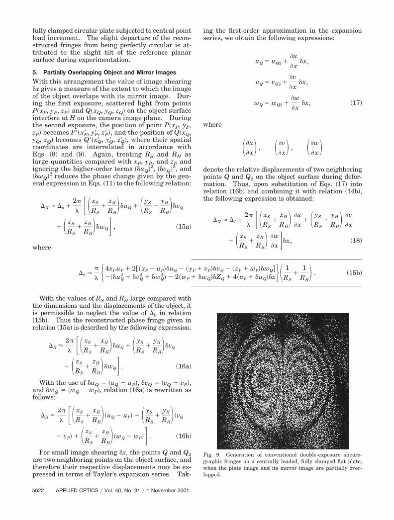
Fig. 9. Generation of conventional double-exposure shearo-graphic fringes on a centrally loaded, fully clamped flat plate,when the plate image and its mirror image are partially over-lapped.
�b ��
� � 4xP uP � 2�� xP � uP��uQ � � yP � vP��vQ � � zP � wP��wQ ���uQ
2 � �vQ2 � �wQ
2 � � 2�wP � �wQ��ZQ � 4�uP � �uQ��x� 1RS
�1
RH� . (15b)
5622 APPLIED OPTICS � Vol. 40, No. 31 � 1 November 2001

where �I is expressed in relation �14b� and where theexpression describes a holographic interferencefringe pattern depicting the relative displacement be-tween points P�xP, yP, zP� and Q2 � ��xP, yP, �z ��ZQ2�� on the object surface. In the special case ofsymmetrical deformation where �I � 0, relation �18�readily reveals the reconstruction of conventionalshearographic fringe patterns that depict lines of con-stant displacement gradients along the reference x ory direction, depending on the direction of imageshearing. As an illustration, Fig. 9 shows the famil-iar butterfly-shaped fringe pattern for a centrallyloaded fully clamped circular plate when the plateimage and its mirror image are partially overlapped.
6. Conclusion
We have demonstrated what to our knowledge is anovel use of a commercial beam-splitting cube for thetechniques of fringe-projection, moire, holographic,and shearographic interferometry. The underlyingprinciple is based on the reflection–refraction prop-erties of the beam-splitting cube so that when the twosplit beams emerge from the two adjacent faces of thecube they converge and generate the well-knownYoung’s interference fringes for the fringe-projectiontechnique. With reversibility of light waves, thereflection–refraction properties of the beam-splittingcube also permit generation of holographic andshearographic interference fringe patterns depend-ing on the amount of overlap between the object im-age and its mirror image. Test results and theoryhave shown that the use of fully overlapping imagesis particularly useful for detecting unsymmetrical de-formation of the test object. Furthermore, with thismethod, the object and reference beams are transmit-ted within the beam-splitting cube, hence relaxingthe need for environmental stability during testing.
References1. R. J. Collier, C. B. Burckhardt, and L. H. Lin, Optical Holog-
raphy �Academic, New York, 1971�.
2. J. W. Dally and W. F. Riley, Experimental Stress Analysis�McGraw-Hill, Tokyo, 1978�.
3. C. M. Vest, Holographic Interferometry �Wiley, New York,1978�.
4. R. K. Erf, ed., Speckle Metrology �Academic, New York, 1978�.5. Y. I. Ostrovsky, M. M. Butusov, and G. V. Ostrovskaya,
Interferometry by Holography �Springer-Verlag, New York,1980�.
6. N. Abramson, The Making and Evaluation of Holograms �Ac-ademic, New York, 1981�.
7. R. Jones and C. Wykes, Holographic and Speckle Interferom-etry: a Discussion of the Theory, Practice and Application ofthe Techniques, 2nd ed. �Cambridge University, Cambridge,UK, 1989�.
8. D. Post, B. Han, and P. Ifju, High Sensitivity Moire: Experi-mental Analysis for Mechanics and Materials �Springer-Verlag, Germany, 1994�.
9. P. K. Rastogi, ed., Optical Measurement Techniques and Ap-plications �Artech House, Norwood, Mass., 1997�.
10. W. Juptner and W. Osten, eds., Fringe ’97: Automatic Pro-cessing of Fringe Patterns, Vol. 3 of Akademie Verlag Series inOptical Metrology �Akademie Verlag, Berlin, 1997�.
11. R. S. Sirohi and K. D. Hinsch, eds., Selected Papers on Ho-lographic Interferometry: Principles and Techniques, Vol.MS 144 of SPIE Milestone Series �Society for Photo-OpticalInstrumentation Engineers, Bellingham, Wash., 1998�.
12. P. K. Rastogi and D. Inaudi, eds., Trends in Optical Non-Destructive Testing and Inspection �Elsevier, London, 2000�.
13. Y. Y. Hung, L. Lin, H. M. Shang, and B. G. Park, “Practical 3Dcomputer vision techniques for full-field surface measure-ment,” Opt. Eng. 139, 143–149 �2000�.
14. Y. Y. Hung and H. M. Shang, Computer-Vision Technique forNondestructive Testing of Specularly Reflective Objects, in Pro-ceedings of the International Conference on Trends in OpticalNondestructive Testing �Ecole Polytechnique Federale de Lau-sanne, Lausanne, Switzerland, 2000�, pp. 387–394.
15. J. A. Leendertz and J. N. Butters, “An image-shearing speckle-pattern interferometer for measuring bending moments,” J.Phys. E 6, 1107–1110 �1973�.
16. Y. Y. Hung, “A speckle-shearing interferometer,” Opt. Com-mun. 11, 132–135 �1974�.
17. H. M. Shang, Y. Y. Hung, W. D. Luo, and F. Chen, “Surfaceprofiling using shearography,” Opt. Eng. 139, 23–31 �2000�.
1 November 2001 � Vol. 40, No. 31 � APPLIED OPTICS 5623
Copyright © 2022 FDOKUMEN