CineLife+ RGB PLF - Christie Digital
77
Installation and Setup Guide 020-103072-04 CineLife+ RGB PLF CP4440-RGB, CP4450-RGB
-
Upload
khangminh22 -
Category
Documents
-
view
1 -
download
0
Transcript of CineLife+ RGB PLF - Christie Digital

Installation and Setup Guide020-103072-04
CineLife+ RGB PLFCP4440-RGB, CP4450-RGB

NOTICESCOPYRIGHT AND TRADEMARKS
Copyright © 2021 Christie Digital Systems USA Inc. All rights reserved.
All brand names and product names are trademarks, registered trademarks or trade names of their respective holders.
GENERAL
Every effort has been made to ensure accuracy, however in some cases changes in the products or availability could occur which may not be reflected in thisdocument. Christie reserves the right to make changes to specifications at any time without notice. Performance specifications are typical, but may varydepending on conditions beyond Christie's control such as maintenance of the product in proper working conditions. Performance specifications are based oninformation available at the time of printing. Christie makes no warranty of any kind with regard to this material, including, but not limited to, impliedwarranties of fitness for a particular purpose. Christie will not be liable for errors contained herein or for incidental or consequential damages in connectionwith the performance or use of this material. Manufacturing facilities in Canada and China are ISO 9001 certified.
WarrantyProducts are warranted under Christie’s standard limited warranty, the details of which are available at https://www.christiedigital.com/help-center/warranties/ or by contacting your Christie dealer or Christie.
PREVENTATIVE MAINTENANCE
Preventative maintenance is an important part of the continued and proper operation of your product. Failure to perform maintenance as required, and inaccordance with the maintenance schedule specified by Christie, will void the warranty. For preventative maintenance schedules, refer to www.christiedigital.com.
REGULATORY
The product has been tested and found to comply with the limits for a Class A digital device, pursuant to Part 15 of the FCC Rules. These limits are designedto provide reasonable protection against harmful interference when the product is operated in a commercial environment. The product generates, uses, andcan radiate radio frequency energy and, if not installed and used in accordance with the instruction manual, may cause harmful interference to radiocommunications. Operation of the product in a residential area is likely to cause harmful interference in which case the user will be required to correct theinterference at the user’s own expense. Changes or modifications not expressly approved by the party responsible for compliance could void the user'sauthority to operate the equipment
CAN ICES-3 (A) / NMB-3 (A)
이 기기는 업무용(A급)으로 전자파적합등록을 한 기기이오니 판매자 또는 사용자는 이점을 주의하시기 바라며, 가정 외의 지역에서 사용하는 것을 목적으로 합니다.
ENVIRONMENTAL
The product is designed and manufactured with high-quality materials and components that can be recycled and reused. This symbol means that electrical
and electronic equipment, at their end-of-life, should be disposed of separately from regular waste. Please dispose of the product appropriately and accordingto local regulations. In the European Union, there are separate collection systems for used electrical and electronic products. Please help us to conserve theenvironment we live in!

ContentSafety precautions. . . . . . . . . . . . . . . . . . . . . . . . . . . . . . . . . . . . . . . . . . . . . . . . . 6
General safety precautions. . . . . . . . . . . . . . . . . . . . . . . . . . . . . . . . . . . . . . . . . . . . . 6
Laser safety precautions. . . . . . . . . . . . . . . . . . . . . . . . . . . . . . . . . . . . . . . . . . . . . . . 6
AC power precautions. . . . . . . . . . . . . . . . . . . . . . . . . . . . . . . . . . . . . . . . . . . . . . . . .7
Light intensity hazard distance. . . . . . . . . . . . . . . . . . . . . . . . . . . . . . . . . . . . . . . . . . . 7
Product labels. . . . . . . . . . . . . . . . . . . . . . . . . . . . . . . . . . . . . . . . . . . . . . . . . . . . .11
General hazards. . . . . . . . . . . . . . . . . . . . . . . . . . . . . . . . . . . . . . . . . . . . . . . . . 11
Mandatory action. . . . . . . . . . . . . . . . . . . . . . . . . . . . . . . . . . . . . . . . . . . . . . . . .12
Electrical labels. . . . . . . . . . . . . . . . . . . . . . . . . . . . . . . . . . . . . . . . . . . . . . . . . . 12
Additional hazard labels. . . . . . . . . . . . . . . . . . . . . . . . . . . . . . . . . . . . . . . . . . . . 12
Introduction. . . . . . . . . . . . . . . . . . . . . . . . . . . . . . . . . . . . . . . . . . . . . . . . . . . . . 14Product documentation. . . . . . . . . . . . . . . . . . . . . . . . . . . . . . . . . . . . . . . . . . . . . . . 14
Related documentation. . . . . . . . . . . . . . . . . . . . . . . . . . . . . . . . . . . . . . . . . . . . . 15
Projector components. . . . . . . . . . . . . . . . . . . . . . . . . . . . . . . . . . . . . . . . . . . . . . . . 16
Chiller components. . . . . . . . . . . . . . . . . . . . . . . . . . . . . . . . . . . . . . . . . . . . . . . . . 18
List of components. . . . . . . . . . . . . . . . . . . . . . . . . . . . . . . . . . . . . . . . . . . . . . . . . .19
Key features. . . . . . . . . . . . . . . . . . . . . . . . . . . . . . . . . . . . . . . . . . . . . . . . . . . . . .19
Contact your dealer. . . . . . . . . . . . . . . . . . . . . . . . . . . . . . . . . . . . . . . . . . . . . . . . . 19
Technical support. . . . . . . . . . . . . . . . . . . . . . . . . . . . . . . . . . . . . . . . . . . . . . . . . . .20
Installing and setting up. . . . . . . . . . . . . . . . . . . . . . . . . . . . . . . . . . . . . . . . . . . . 21Site requirements. . . . . . . . . . . . . . . . . . . . . . . . . . . . . . . . . . . . . . . . . . . . . . . . . . 21
Power specifications. . . . . . . . . . . . . . . . . . . . . . . . . . . . . . . . . . . . . . . . . . . . . . . . . 22
Preparing the installation site. . . . . . . . . . . . . . . . . . . . . . . . . . . . . . . . . . . . . . . . . . . 22
Lifting and positioning the projector. . . . . . . . . . . . . . . . . . . . . . . . . . . . . . . . . . . . . . . 22
Connecting to power. . . . . . . . . . . . . . . . . . . . . . . . . . . . . . . . . . . . . . . . . . . . . . . . 25
Connecting to an uninterruptible power supply. . . . . . . . . . . . . . . . . . . . . . . . . . . . . . . . 29
Installing the lens. . . . . . . . . . . . . . . . . . . . . . . . . . . . . . . . . . . . . . . . . . . . . . . . . . 31
Installing the touch panel. . . . . . . . . . . . . . . . . . . . . . . . . . . . . . . . . . . . . . . . . . . . . 33
Projector power modes. . . . . . . . . . . . . . . . . . . . . . . . . . . . . . . . . . . . . . . . . . . . . . . 34
Setting up the chiller unit. . . . . . . . . . . . . . . . . . . . . . . . . . . . . . . . . . . . . . . . . . . . . 35
Connecting the chiller communication cable. . . . . . . . . . . . . . . . . . . . . . . . . . . . . . . . 35
Connecting the chiller power cable. . . . . . . . . . . . . . . . . . . . . . . . . . . . . . . . . . . . . . 37
CineLife+ RGB PLF Installation and Setup Guide–CP4440-RGB, CP4450-RGB 3020-103072-04 Rev. 1 (03-2021)Copyright © 2021 Christie Digital Systems USA, Inc. All rights reserved.

Connecting the coolant lines. . . . . . . . . . . . . . . . . . . . . . . . . . . . . . . . . . . . . . . . . .39
Installing the chiller duct. . . . . . . . . . . . . . . . . . . . . . . . . . . . . . . . . . . . . . . . . . . . 41
Filling and starting the chiller. . . . . . . . . . . . . . . . . . . . . . . . . . . . . . . . . . . . . . . . . 41
Setting the chiller setpoint. . . . . . . . . . . . . . . . . . . . . . . . . . . . . . . . . . . . . . . . . . . 43
Maintaining the chiller. . . . . . . . . . . . . . . . . . . . . . . . . . . . . . . . . . . . . . . . . . . . . .44
System operation for CP4440-RGB and CP4450-RGB projectors. . . . . . . . . . . . . . . . . . . . . .44
Turning the projector on or off. . . . . . . . . . . . . . . . . . . . . . . . . . . . . . . . . . . . . . . . . . 44
Logging on to the projector. . . . . . . . . . . . . . . . . . . . . . . . . . . . . . . . . . . . . . . . . . . . 45
Turning the light source on or off. . . . . . . . . . . . . . . . . . . . . . . . . . . . . . . . . . . . . . . . . 45
Activating marriage. . . . . . . . . . . . . . . . . . . . . . . . . . . . . . . . . . . . . . . . . . . . . . . . . 45
Completing the installation checklist. . . . . . . . . . . . . . . . . . . . . . . . . . . . . . . . . . . . . . . 45
Video Input panel. . . . . . . . . . . . . . . . . . . . . . . . . . . . . . . . . . . . . . . . . . . . . . . . . 46HDMI video source. . . . . . . . . . . . . . . . . . . . . . . . . . . . . . . . . . . . . . . . . . . . . . . . . .47
HDMI video formats. . . . . . . . . . . . . . . . . . . . . . . . . . . . . . . . . . . . . . . . . . . . . . . 47
SDI video source. . . . . . . . . . . . . . . . . . . . . . . . . . . . . . . . . . . . . . . . . . . . . . . . . . . 49
SDI video formats. . . . . . . . . . . . . . . . . . . . . . . . . . . . . . . . . . . . . . . . . . . . . . . . 49
Integrated Media Block (IMB) video source. . . . . . . . . . . . . . . . . . . . . . . . . . . . . . . . . . .54
Series 2 IMB video formats. . . . . . . . . . . . . . . . . . . . . . . . . . . . . . . . . . . . . . . . . . 54
HDMI video source connection from an IMB. . . . . . . . . . . . . . . . . . . . . . . . . . . . . . . . 57
SDI video source connection from an IMB. . . . . . . . . . . . . . . . . . . . . . . . . . . . . . . . . 57
Using channels to set input signal parameters. . . . . . . . . . . . . . . . . . . . . . . . . . .58
Managing the light source. . . . . . . . . . . . . . . . . . . . . . . . . . . . . . . . . . . . . . . . . . .60Creating a new laser file for CP4440-RGB and CP4450-RGB. . . . . . . . . . . . . . . . . . . . . . . . 60
Modifying an existing laser file. . . . . . . . . . . . . . . . . . . . . . . . . . . . . . . . . . . . . . . . . . 62
Copying existing laser settings to a new file. . . . . . . . . . . . . . . . . . . . . . . . . . . . . . . . . . 62
Deleting a laser file. . . . . . . . . . . . . . . . . . . . . . . . . . . . . . . . . . . . . . . . . . . . . . . . . 63
Adjusting the image. . . . . . . . . . . . . . . . . . . . . . . . . . . . . . . . . . . . . . . . . . . . . . . 64Calibrating the Intelligent Lens System. . . . . . . . . . . . . . . . . . . . . . . . . . . . . . . . . . . . . 64
Correcting vignetting. . . . . . . . . . . . . . . . . . . . . . . . . . . . . . . . . . . . . . . . . . . . . . . . 64
Adjusting tilt and leveling the projector. . . . . . . . . . . . . . . . . . . . . . . . . . . . . . . . . . . . . 64
Correcting keystone effect. . . . . . . . . . . . . . . . . . . . . . . . . . . . . . . . . . . . . . . . . . . . . 65
Displaying a test pattern. . . . . . . . . . . . . . . . . . . . . . . . . . . . . . . . . . . . . . . . . . . . . . 66
Adjusting the integrator rod and fold mirror. . . . . . . . . . . . . . . . . . . . . . . . . . . . . . . . . . 66
Adjusting the boresight. . . . . . . . . . . . . . . . . . . . . . . . . . . . . . . . . . . . . . . . . . . . . . . 69
Adjusting DMD convergence. . . . . . . . . . . . . . . . . . . . . . . . . . . . . . . . . . . . . . . . . . . . 72
Content
CineLife+ RGB PLF Installation and Setup Guide–CP4440-RGB, CP4450-RGB 4020-103072-04 Rev. 1 (03-2021)Copyright © 2021 Christie Digital Systems USA, Inc. All rights reserved.

Correcting on-screen color. . . . . . . . . . . . . . . . . . . . . . . . . . . . . . . . . . . . . . . . . . . . . 73
Regulatory. . . . . . . . . . . . . . . . . . . . . . . . . . . . . . . . . . . . . . . . . . . . . . . . . . . . . . 74Safety. . . . . . . . . . . . . . . . . . . . . . . . . . . . . . . . . . . . . . . . . . . . . . . . . . . . . . . . . 74
Electro-magnetic compatibility. . . . . . . . . . . . . . . . . . . . . . . . . . . . . . . . . . . . . . . . . . 74
Emissions. . . . . . . . . . . . . . . . . . . . . . . . . . . . . . . . . . . . . . . . . . . . . . . . . . . . . 74
Immunity. . . . . . . . . . . . . . . . . . . . . . . . . . . . . . . . . . . . . . . . . . . . . . . . . . . . . 74
Environmental. . . . . . . . . . . . . . . . . . . . . . . . . . . . . . . . . . . . . . . . . . . . . . . . . . . . 75
Content
CineLife+ RGB PLF Installation and Setup Guide–CP4440-RGB, CP4450-RGB 5020-103072-04 Rev. 1 (03-2021)Copyright © 2021 Christie Digital Systems USA, Inc. All rights reserved.

Safety precautionsLearn about the safety precautions related to the Christie CineLife+ RGB PLF projector. This projectoris intended for use in a cinema environment.
General safety precautionsRead all safety and warning guidelines before installing or operating the projector.
Warning! If not avoided, the following could result in death or serious injury.
• TRIP OR FIRE HAZARD! Position all cables where they cannot contact hot surfaces, be pulled, betripped over, or damaged by persons walking on or objects rolling over the cables.
• This product must be installed within a restricted access location not accessible by the generalpublic.
• Only personnel who are trained on the precautions for the restricted access location can begranted entry to the area.
• Install the product so users and the audience cannot enter the restricted area at eye level.
• ELECTRICAL and BURN HAZARD! Use caution when accessing internal components.
• High leakage current present when connected to IT power systems.
• FIRE AND SHOCK HAZARD! Use only the attachments, accessories, tools, and replacement partsspecified by Christie.
• FIRE HAZARD! Do not use a power cord, harness, or cable that appears damaged.
• Lift equipment must be used to position the product.
• Do not install or operate the projector in any position that does not meet the stated productspecifications for alignment and orientation.
Caution! If not avoided, the following could result in minor or moderate injury.
• Only Christie qualified technicians are permitted to open product enclosures.
Laser safety precautionsRead all safety and warning guidelines before operating the projector laser.
Warning! If not avoided, the following could result in death or serious injury.
• Do not operate the cinema projector without all of its covers in place.
• LASER RADIATION HAZARD! This projector has a built-in Class 4 laser module. Never attempt todisassemble or modify the laser module.
• Do not look directly into the lens when the light source is on. The extremely high brightness cancause permanent eye damage.
• Possible hazardous optical radiation emitted from this product. (Risk group 3)
CineLife+ RGB PLF Installation and Setup Guide–CP4440-RGB, CP4450-RGB 6020-103072-04 Rev. 1 (03-2021)Copyright © 2021 Christie Digital Systems USA, Inc. All rights reserved.

AC power precautionsRead all safety and warning guidelines before connecting to AC power.
Warning! If not avoided, the following could result in death or serious injury.
• SHOCK HAZARD! Only use the AC power cord provided with the product or recommended byChristie.
• FIRE AND SHOCK HAZARD! Do not attempt operation unless the power cord, power socket, andpower plug meet the appropriate local rating standards.
• SHOCK HAZARD! Do not attempt operation if the AC supply is not within the specified voltageand current, as specified on the license label.
• SHOCK HAZARD! The optional UPS power cord must be inserted into an outlet with grounding.
• SHOCK HAZARD! Disconnect the product from AC before installing, moving, servicing, cleaning,removing components, or opening any enclosure.
• Install the product near an easily accessible AC receptacle.
Caution! If not avoided, the following could result in minor or moderate injury.
• FIRE HAZARD! Do not use a power cord, harness, or cable that appears damaged.
• FIRE OR SHOCK HAZARD! Do not overload power outlets and extension cords.
• SHOCK HAZARD! Power supply uses double pole/neutral fusing.
Light intensity hazard distanceThis projector has been classified as Risk Group 3 as per the IEC 62471-5:2015 standard due topossible hazardous optical and thermal radiation being emitted.
Warning! If not avoided, the following could result in serious injury.
• PERMANENT/TEMPORARY BLINDNESS HAZARD! No direct exposure to the beam must bepermitted. Class 1 Laser Product - Risk Group 3 according to IEC 60825-1:2014 and IEC62471-5:2015.
• PERMANENT/TEMPORARY BLINDNESS HAZARD! Operators must control access to the beamwithin the hazard distance or install the product at the height that prevents exposure ofspectators' eyes within the hazard distance. The hazard zone must be no lower than 2.5 meters(US installations) or 2.0 meters (global installations) above any surface upon which any personsare permitted to stand and the horizontal clearance to the hazard zone must be a minimum 1.0meters.
• EXTREME BRIGHTNESS! Do not place reflective objects in the product light path.
The following diagram and table show the zones for ocular and skin hazard distances:
Safety precautions
CineLife+ RGB PLF Installation and Setup Guide–CP4440-RGB, CP4450-RGB 7020-103072-04 Rev. 1 (03-2021)Copyright © 2021 Christie Digital Systems USA, Inc. All rights reserved.

• A—Hazard zone. The region of space where the projection light from the laser-illuminatedprojector is above emission limits for Risk Group 2. The light intensity may cause eye damageafter a momentary or brief exposure (before a person can avert his or her eyes away from thelight source). The light may cause skin burns to occur.
• B—Hazard distance. Operators must control access to the beam within the hazard distance orinstall the product preventing potential exposure of the spectators' eyes from being in thehazard distance.
• C—No access zone. Horizontal clearance of the no access zone must be a minimum of 1.0meters.
• D—Vertical distance to hazard zone. The hazard zone must be no lower than 2.5 meters (USinstallations) or 2.0 meters (global installations) above any surface upon which any personsare permitted to stand.
• E—Represents the top view of the projector.
• F—Represents the side view of the projector.
The following table lists the hazard distance for the Christie projector lens with the zoom adjusted toits most hazardous position.
For US and international hazard distances based upon IEC 62471-5:2015, Photobiological safety oflamps and lamp systems – Part 5: Image projectors.
Projection Lens(Throw Ratio 4K)
Part Number Hazard Distance (m)CP4440-RGB and CP4450-RGB
0.90:1 HB fixed lens 38-809071-XX 1.6
1.13-1.66:1 DLPCine HB zoom lens 108-342100-XX 2.7
1.13-1.72:1 Enhanced DC 4K HB zoom lens 163-141107-XX 2.9
1.35-1.84:1 Enhanced DC 4K HB zoom lens 163-142108-XX 3.1
1.31-1.85:1 DLPCine HB zoom lens 108-335102-XX 3.1
1.45-2.10:1 Enhanced DC 4K HB zoom lens 163-143109-XX 3.5
Safety precautions
CineLife+ RGB PLF Installation and Setup Guide–CP4440-RGB, CP4450-RGB 8020-103072-04 Rev. 1 (03-2021)Copyright © 2021 Christie Digital Systems USA, Inc. All rights reserved.

Projection Lens(Throw Ratio 4K)
Part Number Hazard Distance (m)CP4440-RGB and CP4450-RGB
1.45-2.17:1 DLPCine HB zoom lens 108-336103-XX 3.6
1.65-2.70:1 Enhanced DC 4K HB zoom lens 163-144100-XX 4.5
1.63-2.71:1 DLPCine HB zoom lens 108-337104-XX 4.5
1.95-3.26:1 DLPCine HB zoom lens 108-338105-XX 5.4
2.71-3.89:1 DLPCine HB zoom lens 108-278101-XX 6.4
1.13-1.66:1 DLPCine UHC zoom lens 163-103105-XX 2.5
1.13-1.72:1 Enhanced DC 4K UHC zoom lens 163-145101-XX 2.6
1.35-1.84:1 Enhanced DC 4K UHC zoom lens 163-146102-XX 2.7
1.31-1.85:1 DLPCine UHC zoom lens 163-104106-XX 2.7
1.45-2.10:1 Enhanced DC 4K UHC zoom lens 163-147103-XX 3.1
1.45-2.17:1 DLPCine UHC zoom lens 163-105107-XX 3.3
1.65-2.70:1 Enhanced DC 4K UHC zoom lens 163-148104-XX 3.8
1.63-2.71:1 DLPCine UHC zoom lens 163-106108-XX 3.8
1.95-3.26:1 DLPCine UHC zoom lens 163-107109-XX 4.7
2.71-3.89:1 DLPCine UHC zoom lens 163-108100-XX 5.6
The graph that follows is for reference only; use the hazard distances in the preceding table.
CP4440-RGB/CP4450-RGB Hazard distance for HB and UHC lenses
Safety precautions
CineLife+ RGB PLF Installation and Setup Guide–CP4440-RGB, CP4450-RGB 9020-103072-04 Rev. 1 (03-2021)Copyright © 2021 Christie Digital Systems USA, Inc. All rights reserved.

For Installations in the United StatesThe following must be in place for laser-illuminated projector installations in the United States:
• The projection room shall be clearly identified by the posting of laser warning and restrictedaccess signs, and by restricting entry through physical means. The projection room sign mustdisplay the warning "No direct exposure to beam shall be permitted".
• The Christie Laser Projection System Installation Checklist must be fully completed after theinstallation and sent to [email protected]. A copy can remain on-site. Thischecklist can be found as a separate document in the accessory box with the manual.
• Certain US states have additional laser regulatory requirements. Contact [email protected] for additional regulatory requirements.
Safety precautions
CineLife+ RGB PLF Installation and Setup Guide–CP4440-RGB, CP4450-RGB 10020-103072-04 Rev. 1 (03-2021)Copyright © 2021 Christie Digital Systems USA, Inc. All rights reserved.

Product labelsLearn about the labels that may be used on the product. Labels on your product may be yellow orblack and white.
General hazardsHazard warnings also apply to accessories once they are installed in a Christie product that isconnected to power.
Fire and Shock Hazard
To prevent fire or shock hazards, do not expose this product to rain or moisture.
Do not alter the power plug, overload the power outlet, or use it with extension cords.
Do not remove the product enclosure.
Only Christie qualified technicians are authorized to service the product.
Electrical Hazard
Risk of electric shock.
Do not remove the product enclosure.
Only Christie qualified technicians are authorized to service the product.
Warning! If not avoided, the following could result in death or serious injury.
Electric shock hazard. To avoid personal injury, disconnect all power sources beforeperforming maintenance or service.
Electrocution hazard. To avoid personal injury, always disconnect all power sourcesbefore performing maintenance or service procedures.
Laser hazard. To avoid personal injury, avoid eye or skin exposure to direct orscattered radiations.
Caution! If not avoided, the following could result in minor or moderate injury.
Hot surface hazard. To avoid personal injury, allow the product to cool for therecommended cool down time before touching or handling for maintenance orservice.
Moving fan blade. To avoid personal injury, keep hands clear and loose clothing tiedback. Always disconnect all power sources before performing maintenance or serviceprocedures.
Notice. If not avoided, the following could result in property damage.
Safety precautions
CineLife+ RGB PLF Installation and Setup Guide–CP4440-RGB, CP4450-RGB 11020-103072-04 Rev. 1 (03-2021)Copyright © 2021 Christie Digital Systems USA, Inc. All rights reserved.

Mandatory actionConsult the service manual.
Disconnect all power sources before performing maintenance or service procedures.
Electrical labelsIndicates the presence of a protective earth ground.
Indicates the presence of an earth ground.
Additional hazard labelsIndicates Class 4 laser radiation when open. Avoid eyeor skin exposure to direct or scattered radiation.
CLASS 1 LASER PRODUCT IEC 60825-1:2014
Wavelengths:
CP4440-RGB: 450nm - 661nm
CP4450-RGB: 450nm - 645nm
FDA laser variance (US projectors only). This product isin conformity with performance standards for laserproducts under 21 CFR 1040, except with respect tothose characteristics authorized by Variance Number2019-V-3343 effective on August 16, 2019.
Indicates a light hazard. Do not look directly into thelens. The extreme high brightness can cause permanenteye damage. Class 1 Laser Product - Risk Group 3according to IEC 60825-1:2014 and IEC 62471-5:2015.
Safety precautions
CineLife+ RGB PLF Installation and Setup Guide–CP4440-RGB, CP4450-RGB 12020-103072-04 Rev. 1 (03-2021)Copyright © 2021 Christie Digital Systems USA, Inc. All rights reserved.

Indicates high leakage current. Earth or groundconnection essential before connecting the powersupply.
Indicates a light hazard. Do not look directly into thelens. The extreme high brightness can cause permanenteye damage.
Indicates moving parts hazard for the motorized lensmount. To avoid personal injury, keep hands clear andclothing tied back.
Safety precautions
CineLife+ RGB PLF Installation and Setup Guide–CP4440-RGB, CP4450-RGB 13020-103072-04 Rev. 1 (03-2021)Copyright © 2021 Christie Digital Systems USA, Inc. All rights reserved.

IntroductionThis manual is intended for professionally trained operators of Christie high-brightness CineLife+ RGBPLF projection systems.For complete production documentation and technical support, go to www.christiedigital.com.
Product documentationFor installation, setup, and user information, see the product documentation available on the ChristieDigital Systems USA Inc. website. Read all instructions before using or servicing this product.
CP4440-RGBTo access the documentation from the Christie website:
• Go to http://bit.ly/2NwVsRy orhttps://www.christiedigital.com/en-us/cinema/cinema-products/digital-cinema-projectors/christie-cp4440-rgb
• Scan the QR code using a QR code reader app on a smartphone or tablet.
CP4450-RGBTo access the documentation from the Christie website:
• Go to http://bit.ly/2UYil0V orhttps://www.christiedigital.com/en-us/cinema/cinema-products/digital-cinema-projectors/christie-cp4450-rgb
• Scan the QR code using a QR code reader app on a smartphone or tablet.
CineLife+ RGB PLF Installation and Setup Guide–CP4440-RGB, CP4450-RGB 14020-103072-04 Rev. 1 (03-2021)Copyright © 2021 Christie Digital Systems USA, Inc. All rights reserved.

Related documentationAdditional information on the projector is available in the following documents.
• CineLife+ RGB PLF User Guide (P/N: 020-103073-XX)
• CineLife+ RGB PLF Product Safety Guide (P/N: 020-103071-XX)
• CineLife+ RGB PLF Service Guide (P/N: 020-103076-XX)
• CineLife+ 1.1.0 Serial Commands Guide (P/N: 020-103075-XX)
Introduction
CineLife+ RGB PLF Installation and Setup Guide–CP4440-RGB, CP4450-RGB 15020-103072-04 Rev. 1 (03-2021)Copyright © 2021 Christie Digital Systems USA, Inc. All rights reserved.

Projector componentsLearn about the components of the projector.
Introduction
CineLife+ RGB PLF Installation and Setup Guide–CP4440-RGB, CP4450-RGB 16020-103072-04 Rev. 1 (03-2021)Copyright © 2021 Christie Digital Systems USA, Inc. All rights reserved.

ID Component
A Projector lens
B Service access door
C Communications panel
External devices are connected here.
D Exhaust duct connection
E Touch panel
A touch-sensitive screen used to control the projector.
The touch panel is an optional feature on CP4415 and CP4420 projectors. If there is notouch panel installed, use the Remote UI feature. See Using the Remote UI.
F AC input circuit breaker A
G AC input circuit breaker B
H UPS input
I AC receptacle B
J AC receptacle A
K Liquid cooling supply line connection
L Liquid cooling return line connection
M Communication connection for the chiller
N Adjustable feet
Turn the adjustable feet to increase or decrease the projector height.
Introduction
CineLife+ RGB PLF Installation and Setup Guide–CP4440-RGB, CP4450-RGB 17020-103072-04 Rev. 1 (03-2021)Copyright © 2021 Christie Digital Systems USA, Inc. All rights reserved.

Chiller componentsLearn about the components of the chiller, which is used with CP4440-RGB and CP4450-RGBprojectors.
ID Component
A Coolant hose
B Reservoir fill cap
C Coolant inlet port
D Coolant outlet port
E Exhaust vent
F Communication signal terminal
G Power supply terminal
H Chiller coolant filter
I Coolant drain port
Related information
Setting up the chiller unit (on page 35)
Introduction
CineLife+ RGB PLF Installation and Setup Guide–CP4440-RGB, CP4450-RGB 18020-103072-04 Rev. 1 (03-2021)Copyright © 2021 Christie Digital Systems USA, Inc. All rights reserved.

List of componentsVerify that all components were received with the projector.
• Touch panel, touch panel harness, and panel mounting arm
• High security key to open the projector service access door
• Teyu Chiller CW-6200AN (P/N: 163-124108-XX)
• Chiller Setup Kit Plumbing (P/N: 163-149105-XX)
• Chiller Setup Kit Air Ducts (P/N: 163-150107-XX)
• Coolant Propylene Glycol (P/N: 003-006744-XX)
• Optional PLF Cinema Pedestal (P/N: 163-126100-XX)
An optional UPS inlet power cord is also available.
Key featuresUnderstand the important features of the projector.
• Solid-state Christie RealLaser™ RGB laser illumination
• Three-chip 1.38 inch 4K DLP™ light engine
• Christie CineLife+™ electronics platform for ultra-fast processing
• High frame rate playback of 4K at 120 Hz, for premium, large format cinema venues
• Dual, direct-coupled laser modules integrated in the projector chassis
• Ability to work with Mystique software
• 4K 3D playback capability
• LiteLOC™ color lock feature for constant image brightness and color
• Compatible with ultra high contrast (UHC) lens suite
• External chiller unit with exhaust adapter (CP4440-RGB and CP4450-RGB projectors only)
Contact your dealerRecord the information about your installation and keep this information with your records to assistwith any servicing of your product. If you encounter a problem, contact your dealer.
Purchase record
Dealer:
Dealer or Christie Sales/Service contact phone number:
Serial number:
The serial number can be found on the license label located on the display panel.
Purchase date:
Installation date:
Introduction
CineLife+ RGB PLF Installation and Setup Guide–CP4440-RGB, CP4450-RGB 19020-103072-04 Rev. 1 (03-2021)Copyright © 2021 Christie Digital Systems USA, Inc. All rights reserved.

Technical supportTechnical support for Christie Cinema products is available at:
• +1-877-334-4267
• Christie Professional Services: +1-800-550-3061 or [email protected]
Introduction
CineLife+ RGB PLF Installation and Setup Guide–CP4440-RGB, CP4450-RGB 20020-103072-04 Rev. 1 (03-2021)Copyright © 2021 Christie Digital Systems USA, Inc. All rights reserved.

Installing and setting upLearn how to position and install the projector.
Site requirementsTo safely install and operate CineLife+ RGB PLF projectors, the installation location must meet theseminimum requirements.
Physical operating environment• Ambient temperature (operating) 10°C to 35°C (50°F to 95°F )
• Humidity (non-condensing) 10% to 80%
• Operating altitude 0 to 3000 meters (0 to 9843 feet)
• Site cleanliness: ISO Class 9 or cleaner
Projector exhaust ductingSufficient ventilation is required around the projector to regulate the temperature of the projectorelectronics and optical components.The projector has an 8" built-in exhaust duct. If necessary, exhaust HVAC ducts can be connected tothe projector.The installation site must provide an airflow 450 cubic feet per minute (CFM) at 1 to 1000 meterselevation, and must accommodate a heat load of 4 kW.
For each additional 1000 meters above sea level, increase the airflow (CFM) value by 15%. If anextraction duct is not used, the operating temperature range is restricted to 10°C to 25°C at a maximumaltitude of 2000 meters.
Projector power connectionsThe projector requires two, 30A maximum rated, certified wall circuit breakers (one for each MainInput). The wall circuit breakers must be part of the building and easily accessible.The projector must be connected to power using hard-wired connections. The projector light sourcerequires the permanent AC connections to operate. A qualified electrician is required to connect theprojector to AC power.There is also an available connector for an uninterruptible power supply (UPS) to provide backuppower for the projector electronics only. The UPS connection requires a 20A maximum rated circuitbreaker.
Chiller power connectionThe chiller is connected to AC power through a power supply terminal located at the front of the chillerunit.
CineLife+ RGB PLF Installation and Setup Guide–CP4440-RGB, CP4450-RGB 21020-103072-04 Rev. 1 (03-2021)Copyright © 2021 Christie Digital Systems USA, Inc. All rights reserved.

A qualified electrician is required to connect the chiller unit to AC power. For detailed information, referto the documentation provided by the chiller manufacturer. For electrical rating information, refer tothe license label on the chiller.
Related information
Connecting to power (on page 25)Connecting to an uninterruptible power supply (on page 29)Connecting the chiller power cable (on page 37)
Power specificationsLearn the power requirements for the projector.
Item Main Input AMain Input B
UPS Input
Voltage range 200 - 240 VAC
single phase
200 - 240 VAC
single phase
Maximum current 16 A 10 A
Line frequency 50-60 Hz 50-60 Hz
Preparing the installation siteEnsure the installation area is ready for the components.
1. Clear the installation area.
2. Post laser hazard warning signs at all entry doors.
3. Place each component near its installation location.
Lifting and positioning the projectorSafely lift and position the projector in the location where it will be used.
Warning! If not avoided, the following could result in death or serious injury.
• Lift equipment must be used to position the product.
• Do not install or operate the projector in any position that does not meet the stated productspecifications for alignment and orientation.
This product must be installed in a landscape orientation, with all four feet supported on a levelsurface. Do not install or operate the projector in an inverted position. If your site has any installationrequirements other than a typical theater projection booth, contact Christie for assistance.
Installing and setting up
CineLife+ RGB PLF Installation and Setup Guide–CP4440-RGB, CP4450-RGB 22020-103072-04 Rev. 1 (03-2021)Copyright © 2021 Christie Digital Systems USA, Inc. All rights reserved.

• Before lifting and positioning the projector, refer to the light intensity hazard distances.
• To avoid damage to the lens mount when lifting the projector, do not apply the load across thefront of the projector.
1. Using appropriately rated lift equipment, lift up the projector and move it to the location whereit will be used.
2. When lifting, ensure the load is applied only to the structural frame members across twoopposite sides of the projector. The load should never be applied directly to a panel, cover, orother non-structural component of the projector. The following illustrations show the structuralframe members of the projector:
Lower projectorframe
Right side projectorframe
Installing and setting up
CineLife+ RGB PLF Installation and Setup Guide–CP4440-RGB, CP4450-RGB 23020-103072-04 Rev. 1 (03-2021)Copyright © 2021 Christie Digital Systems USA, Inc. All rights reserved.

Left side projectorframe
Rear projectorframe
Alternatively, the projector can be lifted using four rigging eyebolts installed into the fouranchor points in the top frame of the projector.
3. If you are installing the projector with the optional PLF Cinema Pedestal (P/N: 163-126100-XX), follow the instructions provided with that accessory. For more information on availableaccessories, see the CineLife+ RGB PLF Specifications Guide (P/N: 020-103074-XX).
4. Position the projector so it is centered and parallel with the theater screen. If space is limited,aim the projector slightly off-center and use lens offset to center the image on the screen.
Related information
Light intensity hazard distance (on page 7)
Installing and setting up
CineLife+ RGB PLF Installation and Setup Guide–CP4440-RGB, CP4450-RGB 24020-103072-04 Rev. 1 (03-2021)Copyright © 2021 Christie Digital Systems USA, Inc. All rights reserved.
Connecting to powerThe recommended setup is to provide two hard-wired connections to AC power. When connecting theprojector to AC power, follow all electrical codes for your location.
Warning! If not avoided, the following could result in death or serious injury.
• Always connect the ground or earth first to reduce shock hazard.
• FIRE HAZARD! Do not use a power cord, harness, or cable that appears damaged.
• FIRE AND SHOCK HAZARD! Do not attempt operation unless the power cord, power socket, andpower plug meet the appropriate local rating standards.
• SHOCK HAZARD! Do not attempt operation if the AC supply is not within the specified voltageand current, as specified on the license label.
• SHOCK HAZARD! A dedicated, protected ground or earth wire must be installed on the productby Christie qualified technicians or electricians before it can be connected to power.
• A certified electrician must be present during installation to ensure the installation meets thelocal electrical code.
Caution! If not avoided, the following could result in minor or moderate injury.
• Use an appropriately sized strain relief connector with the knockout plate provided, to ensureadequate environmental sealing and to prevent the AC supply cable from accidentally being tornout or rubbing against the knockout plate.
• Two, 30A maximum rated, certified wall circuit breakers are required. They must be part of thebuilding and easily accessible.
• Use a minimum of 12 AWG copper wire, grounding included, for the connection of the main ACsupply to the projector's ground lug.
• Either copper or aluminum is acceptable as conductor wiring material to the terminal block.
Installing and setting up
CineLife+ RGB PLF Installation and Setup Guide–CP4440-RGB, CP4450-RGB 25020-103072-04 Rev. 1 (03-2021)Copyright © 2021 Christie Digital Systems USA, Inc. All rights reserved.

A Main input A (200 - 240 VAC, 16 A)
B Main input B (200 - 240 VAC, 16 A)
C UPS circuit breaker
D UPS inlet (200 - 240 VAC, 10 A)
E Main input circuit breakers (A and B)
1. Remove the rear cover of the projector by unscrewing the six captive screws.
Installing and setting up
CineLife+ RGB PLF Installation and Setup Guide–CP4440-RGB, CP4450-RGB 26020-103072-04 Rev. 1 (03-2021)Copyright © 2021 Christie Digital Systems USA, Inc. All rights reserved.

2. On the back right side of the projector, remove the eight screws holding the two AC receptacleknockout plates and then remove the two plates.
The AC supplies are routed to each terminal block through an appropriate strain relief mountedon the knockout plates.
Installing and setting up
CineLife+ RGB PLF Installation and Setup Guide–CP4440-RGB, CP4450-RGB 27020-103072-04 Rev. 1 (03-2021)Copyright © 2021 Christie Digital Systems USA, Inc. All rights reserved.

3. To open the AC input area of the projector, remove the six screws holding the cover and swingthe cover downwards to open it.
4. Taking the approved line cord for your location, strip the cable jacket on the line cord toexpose a 120 mm length of the bundled wires.
5. Cut the Line (black or brown) and Neutral (white or blue) wires to shorten them to a lengthbetween 80 to 100 mm.
6. Using a wire stripper, strip the insulation from each individual wire to expose 10 mm of barewire on the end.
7. Repeat steps 4 to 6 for the second line cord.
8. Pass the wires through the strain reliefs on each knockout plate and through the AC inputcover.
9. For each terminal block, fasten the bare end of the wires into the Ground (G), Line (L), andNeutral (N) terminal connectors, starting first with the Ground (green) connection, followed bythe Line (black or brown) and Neutral (white or blue) connections.
Installing and setting up
CineLife+ RGB PLF Installation and Setup Guide–CP4440-RGB, CP4450-RGB 28020-103072-04 Rev. 1 (03-2021)Copyright © 2021 Christie Digital Systems USA, Inc. All rights reserved.
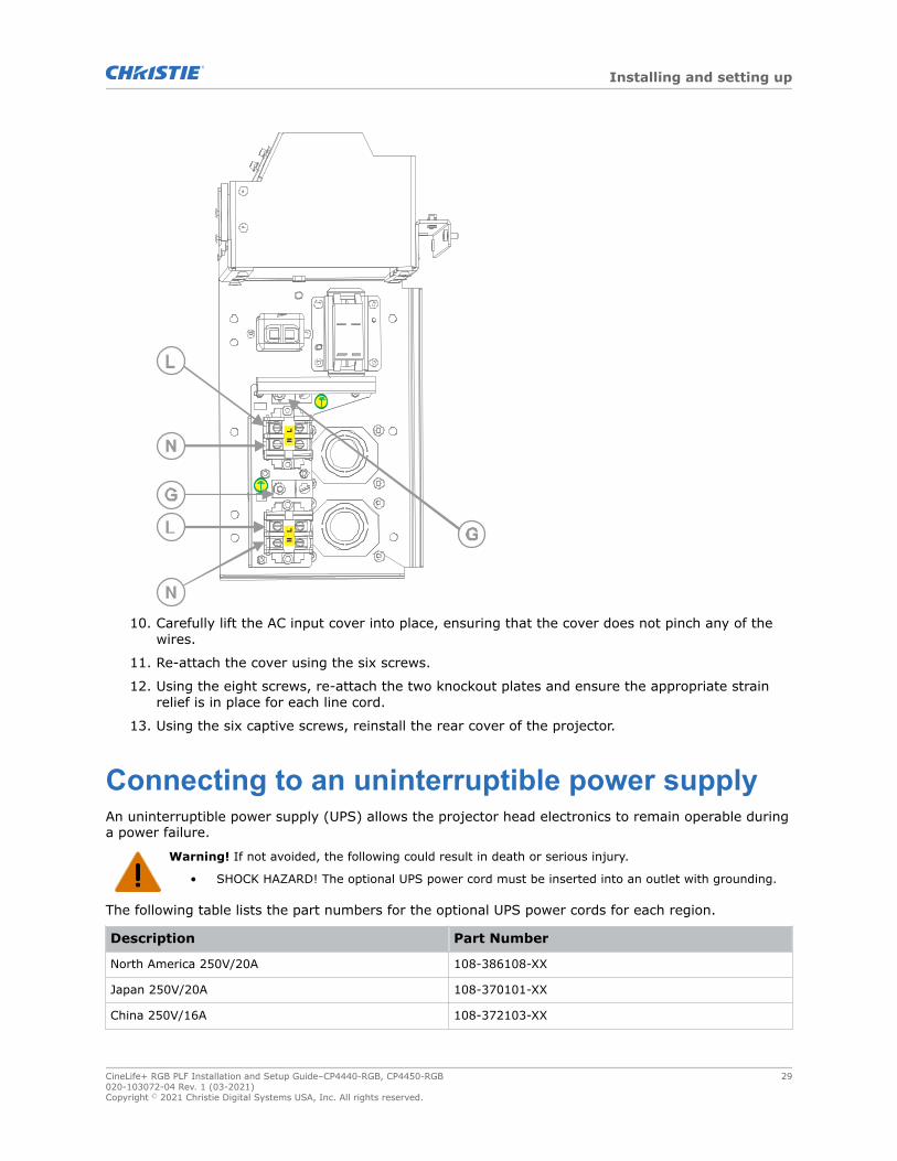
10. Carefully lift the AC input cover into place, ensuring that the cover does not pinch any of thewires.
11. Re-attach the cover using the six screws.
12. Using the eight screws, re-attach the two knockout plates and ensure the appropriate strainrelief is in place for each line cord.
13. Using the six captive screws, reinstall the rear cover of the projector.
Connecting to an uninterruptible power supplyAn uninterruptible power supply (UPS) allows the projector head electronics to remain operable duringa power failure.
Warning! If not avoided, the following could result in death or serious injury.
• SHOCK HAZARD! The optional UPS power cord must be inserted into an outlet with grounding.
The following table lists the part numbers for the optional UPS power cords for each region.
Description Part Number
North America 250V/20A 108-386108-XX
Japan 250V/20A 108-370101-XX
China 250V/16A 108-372103-XX
Installing and setting up
CineLife+ RGB PLF Installation and Setup Guide–CP4440-RGB, CP4450-RGB 29020-103072-04 Rev. 1 (03-2021)Copyright © 2021 Christie Digital Systems USA, Inc. All rights reserved.

Description Part Number
EU/UK 250V/16A 108-430108-XX
EU 250V/16A 108-564106-XX
Korea 250V/16A 108-378109-XX
India 250V/16A 108-565107-XX
South Africa 250V/16A 108-566108-XX
Australia 250V/16A 108-435103-XX
The UPS is connected through two 12V power supplies on the projector. The following illustrationshows the power supplies and connections.
A 12V power supply A
B 12V power supply B
C UPS B plug
Installing and setting up
CineLife+ RGB PLF Installation and Setup Guide–CP4440-RGB, CP4450-RGB 30020-103072-04 Rev. 1 (03-2021)Copyright © 2021 Christie Digital Systems USA, Inc. All rights reserved.

D IN-LINE B input plug
E 48V power supply B
F 48V power supply A
G IN-LINE A input plug
H UPS A plug
Before connecting the UPS device, ensure the projector is disconnected from power.
1. Remove the rear cover of the projector by unscrewing the six captive screws.
2. Disconnect the IN-LINE A input plug from the 12V power supply A (top left).
3. Remove the protective cap from the UPS A plug.
4. Connect the UPS A plug to the 12V power supply A.
5. Place the protective cap from the UPS A plug on the IN-LINE A input plug.
6. Repeat steps 2 to 5 for the UPS B and IN-LINE B plugs on the 12V power supply B (top right).
7. Reinstall the rear panel of the projector.
8. Obtain the appropriate line cord for your region and plug the cord into the UPS device, andthen into the UPS inlet on the projector.
A UPS circuit breaker
B UPS inlet (200 - 240 VAC, 10 A)
Installing the lensThe lens seals the projection head, preventing contaminants from entering the main electronics area.
Before installing the lens, ensure that you turn off the projector and the circuit breaker switches.
Installing and setting up
CineLife+ RGB PLF Installation and Setup Guide–CP4440-RGB, CP4450-RGB 31020-103072-04 Rev. 1 (03-2021)Copyright © 2021 Christie Digital Systems USA, Inc. All rights reserved.

Do not operate the projector without a lens installed. Install a lens plug when you install or transportthe projector.
1. Remove the lens caps from the front and rear of the lens.
Lens caps must be removed or they can melt and damage the lens.
2. Position the lens so that the UP label is facing upward.
3. Turn the clamp on the lens mount to the open position.
4. Fully insert the lens into the lens mount opening without turning, until it reaches the stopposition.
5. Connect the lens zoom motor to the two zoom motor harness connectors.
6. Lock the lens assembly in place by rotating the lens clamp downward.
Installing and setting up
CineLife+ RGB PLF Installation and Setup Guide–CP4440-RGB, CP4450-RGB 32020-103072-04 Rev. 1 (03-2021)Copyright © 2021 Christie Digital Systems USA, Inc. All rights reserved.

Installing the touch panelThe touch panel controls projector functions and provides quick access to projector information.
The touch panel can be mounted on the rear panel or either side of the projector.
1. Remove the touch panel and the mounting arm from their packaging.
2. Attach one end of the touch panel mounting arm over the ball joint on the rear of the touchpanel.
A Mounting arm
B Ball joint
3. While supporting the touch panel, fit the other end of the touch panel mounting arm over theball joint on the rear panel of the projector.
Installing and setting up
CineLife+ RGB PLF Installation and Setup Guide–CP4440-RGB, CP4450-RGB 33020-103072-04 Rev. 1 (03-2021)Copyright © 2021 Christie Digital Systems USA, Inc. All rights reserved.

4. Tighten the mounting arm until it fits tightly on the ball joint.
5. Connect the touch panel USB cable to the USB port on the rear of the touch panel.
6. Connect the other end of the USB cable to a USB port on the projector input panel.
When connecting the USB cable, the locking screw should be tightened using no more than 2 in-lb of torque. Over-tightening the locking screw can damage the connector.
7. To install the touch panel on either side of the projector, uninstall the four screws securing theball mount and remove it.Leave the small adapter puck with the four screws installed.
8. Select a side to install the ball mount with the three button head screws.The ball mount has hole patterns for 4-point and 3-point mounting.
9. Install the touch panel to the new ball location.
10. To turn the touch panel on, press the power button on the top of the panel.If the projector is not connected to AC power with breakers in the ON position, you cannot turnthe touch panel on.
To ensure that the touch panel starts up successfully, the touch panel must be connected to theprojector before the projector is powered on.
Projector power modesThe CineLife+ RGB PLF projectors track laser operation hours for the laser optical sub-systems (LOS).
The projector operates with the following power modes:
Installing and setting up
CineLife+ RGB PLF Installation and Setup Guide–CP4440-RGB, CP4450-RGB 34020-103072-04 Rev. 1 (03-2021)Copyright © 2021 Christie Digital Systems USA, Inc. All rights reserved.

Mode Description
Standby • CineLife+ electronics remain on standby with the light engine off
• Fans, laser optical sub-systems (LOS), and thermo-electric cooler (TEC) devicesare off
• IMB is off (IMB automation does not function)
Projector on • CineLife+ electronics and light engine are on
• LOS and TEC devices are off
• Chiller is on (CP4440-RGB and CP4450-RGB projectors only)
• IMB is on
Light source on • CineLife+ electronics and light engine are on
• LOS and TEC devices are on
• Fans run at full speed
• Chiller is on (CP4440-RGB and CP4450-RGB projectors only)
• IMB is on
Setting up the chiller unitFor detailed information on setting up the chiller, refer to the documentation provided by themanufacturer of the chiller unit.
Once the chiller is connected to AC and the chiller communication cable is connected to the projector,the projector controls the chiller automatically to maintain the required coolant temperature.
Connecting the chiller communication cableThe chiller communication cable is connected through a signal terminal located at the front of thechiller unit. The connection allows communication between the projector and the chiller.
The chiller communication cable includes an RS-485 connector, attached cable with rubber grommet,and three terminal connectors.
The installation of the chiller communication cable must be performed by a Christie qualified technician.
1. Remove the cover for the signal terminal by unscrewing the two cover screws.
Installing and setting up
CineLife+ RGB PLF Installation and Setup Guide–CP4440-RGB, CP4450-RGB 35020-103072-04 Rev. 1 (03-2021)Copyright © 2021 Christie Digital Systems USA, Inc. All rights reserved.

2. Connect the A, B, and PE harness connectors to the corresponding terminals.
Do not use the H1, H2, or H3 terminals.
3. Tighten the screws at each terminal.
4. Re-attach the signal terminal cover using the two cover screws. To avoid pinching the cable,ensure the cable and rubber grommet are placed inside the cover cutout.
5. Connect the RS-485 connector to a serial cable and into the RS-485 communication port onthe projector.
Installing and setting up
CineLife+ RGB PLF Installation and Setup Guide–CP4440-RGB, CP4450-RGB 36020-103072-04 Rev. 1 (03-2021)Copyright © 2021 Christie Digital Systems USA, Inc. All rights reserved.

Connecting the chiller power cableThe chiller is connected to AC power through a power supply terminal located at the front of the chillerunit.
The wires of the supplied power cord are connected to the three terminals in the power supplyterminal.
• A qualified electrician is required to connect the chiller unit to AC power. For detailedinformation, refer to the documentation provided by the chiller manufacturer.
• For electrical rating information, refer to the license label on the chiller. Additional information isavailable in the chiller's product documentation.
1. Remove the cover for the power supply terminal by unscrewing the two cover screws.
2. Ensure the rubber grommet is installed on the cable at the connector end. The grommetprovides strain relief protection for the power cable.
Installing and setting up
CineLife+ RGB PLF Installation and Setup Guide–CP4440-RGB, CP4450-RGB 37020-103072-04 Rev. 1 (03-2021)Copyright © 2021 Christie Digital Systems USA, Inc. All rights reserved.

3. Connect the L, N, and PE harness connectors to the corresponding terminals.
4. Tighten the screws at each terminal.
5. Route the power cable through the slot provided on the terminal block cover. To avoid pinchingthe power cable, ensure the cable and rubber grommet are placed inside the cover cutout.
Installing and setting up
CineLife+ RGB PLF Installation and Setup Guide–CP4440-RGB, CP4450-RGB 38020-103072-04 Rev. 1 (03-2021)Copyright © 2021 Christie Digital Systems USA, Inc. All rights reserved.

6. Re-attach the terminal block cover using the two cover screws.
7. Plug the power cable into an appropriately rated AC power outlet.
Connecting the coolant linesThe required coolant lines and hose accessories are available in the Christie Chiller Setup Kit Plumbing(P/N: 163-149105-XX).
• Make sure the coolant lines connecting the projector and chiller are installed at floor level.Installing the coolant lines at a higher elevation, such as across a ceiling, can result in abackflow through the lines and an overflow of the chiller reservoir. If your site requiresinstallation on different levels, contact Christie technical support for further information.
• In dual projector installations, verify that the chiller communication cables are connectedcorrectly between each projector-chiller pair and that the cables are not cross-connected relativeto the coolant lines.
1. Position the chiller.
2. Install the required hose accessories on the chiller inlet and outlet ports, including:
• inlet hose from the chiller inlet port to the chiller filter
• hose and elbow fitting at the filter inlet
• outlet hose and elbow fitting at the chiller outlet port
The inlet filter and hose barbs required for the chiller are pre-installed.
Installing and setting up
CineLife+ RGB PLF Installation and Setup Guide–CP4440-RGB, CP4450-RGB 39020-103072-04 Rev. 1 (03-2021)Copyright © 2021 Christie Digital Systems USA, Inc. All rights reserved.

3. Connect the coolant lines between the chiller and the projector. To avoid cross-connections, thesupply and return lines have specific male and female quick connectors that connect into theprojector.a) Connect the open end of the Chiller Outlet hose to the chiller outlet port and tighten the
required worm gear clamp.
b) Attach the Chiller Outlet quick connector (male) to the projector inlet port (female).
c) Connect the open end of the Chiller Inlet hose to the chiller inlet port (at the filter) andtighten the required worm gear clamp.
d) Attach the Chiller Inlet quick connector (female) to the projector outlet port (male).
Installing and setting up
CineLife+ RGB PLF Installation and Setup Guide–CP4440-RGB, CP4450-RGB 40020-103072-04 Rev. 1 (03-2021)Copyright © 2021 Christie Digital Systems USA, Inc. All rights reserved.

A Projector coolant inlet port
B Projector coolant outlet port
For detailed information on connecting the coolant lines and hose accessories, refer to theChristie Chiller Setup Kit Instruction Sheet (P/N: 020-103145-XX).
Installing the chiller ductInstalling a chiller duct and exhaust conduit allows warm air generated by chiller to be removed fromthe projection room.
1. Attach the duct over the exhaust fan on the top of the chiller unit.The duct is available in the Christie Chiller Setup Kit Air Ducts (P/N: 163-150107-XX).For detailed information on connecting the chiller duct, refer to the Christie Chiller Setup KitInstruction Sheet P/N: 020-103145-XX.
2. If required, a reducer duct is also provided in the kit and can be installed over the base duct toaccommodate smaller diameter exhaust conduits.
3. Once installed, connect the duct into the exhaust conduit to vent the heated air outside of theprojection room.
Filling and starting the chillerEnsure the coolant lines are connected to the projector and all connections are tightened.
1. Open the chiller reservoir fill cap.
Installing and setting up
CineLife+ RGB PLF Installation and Setup Guide–CP4440-RGB, CP4450-RGB 41020-103072-04 Rev. 1 (03-2021)Copyright © 2021 Christie Digital Systems USA, Inc. All rights reserved.

2. Using the provided funnel, fill the chiller reservoir with the required coolant (Propylene GlycolP/N: 163-130105-XX).
3. Start the chiller and allow the coolant lines to fill.
4. Check the coolant level in the reservoir and top up the coolant as required.
For detailed information on operating and maintaining the chiller, refer to the productdocumentation provided by the chiller manufacturer.
5. On the projector touch panel, select Laser Settings > Laser Power/LiteLOC Setup, andunder Chiller Setpoint, set the required temperature for the chiller.The recommended chiller set point temperature is 24°C.
6. Verify that coolant is flowing in the correct direction and that there are no leaks in the system.
7. Ensure the chiller communication cable between the projector and the chiller is connectedcorrectly.
To avoid thermal shutdown conditions in dual projector installations, Christie recommendsrunning each chiller and its attached projector separately, with light on, to confirm that chillercommunication cables are not cross-connected relative to the coolant lines.
Related information
Setting the chiller setpoint (on page 43)Creating a new laser file for CP4440-RGB and CP4450-RGB (on page 60)
Installing and setting up
CineLife+ RGB PLF Installation and Setup Guide–CP4440-RGB, CP4450-RGB 42020-103072-04 Rev. 1 (03-2021)Copyright © 2021 Christie Digital Systems USA, Inc. All rights reserved.

Setting the chiller setpointThe chiller setpoint represents the temperature of the coolant that is supplied to projector.
The default chiller setpoint temperature is 24°C. The default setting addresses many typical projectionbooth conditions, ensuring maximum projector brightness and operating efficiency.If room temperatures or relative humidity are allowed to rise, the maximum power setting availablefor the lasers is reduced and brightness is decreased as a result.
The projector is equipped with sensors that monitor ambient temperature and humidity. When selectingthe chiller setpoint, use the actual temperature and relative humidity of the projection booth expectedduring operating conditions. Selecting a setpoint that does not reflect actual show environmentconditions may result in a sub-optimal projection image.
1. Use the reference chart below to determine the coolant temperature required for your site.
2. On the Y axis of the chart, find the Maximum Room Temperature expected in the projectionbooth.
3. On the X axis of the chart, find the Maximum Room Relative Humidity.
4. To identify the correct chiller setpoint temperature, find the intersection of the two rows.Choosing a chiller setpoint temperature that falls outside the green area means that projectorbrightness is reduced.
5. On the projector touch panel, select Laser Settings > Laser Power/LiteLOC Setup, andfollow the steps for creating a new laser file, including setting the chiller setpoint value.
Related information
Creating a new laser file for CP4440-RGB and CP4450-RGB (on page 60)
Installing and setting up
CineLife+ RGB PLF Installation and Setup Guide–CP4440-RGB, CP4450-RGB 43020-103072-04 Rev. 1 (03-2021)Copyright © 2021 Christie Digital Systems USA, Inc. All rights reserved.

Maintaining the chillerFor detailed information on maintaining the chiller equipment, refer to the product documentationprovided by the chiller manufacturer.
To identify any leaks or problems, perform regular visual inspections of the chiller equipment andconnections to the projector.Follow the recommended coolant replacement and preventative maintenance schedules. For moreinformation, contact Christie technical support.
Dispose of coolant in accordance with local regulations.
System operation for CP4440-RGB and CP4450-RGB projectorsUnderstand the correct sequence for powering up and operating CP4440-RGB and CP4450-RGBsystems.
The connected chiller must always be turned on first and turned off only after the projector is turnedoff.The system is ready to operate when the following steps are completed:
1. The connected chiller unit is powered on.
2. The projector's main power switches are ON.
3. Communication between the projector and the connected chiller is confirmed, and coolanttemperatures are correctly maintained.If a thermal shutdown occurs in a dual projector installation, verify that the chillercommunication cables are connected correctly between each projector-chiller pair. This ensuresthat there is no cross-connection relative to the coolant lines.
Related information
Connecting the chiller communication cable (on page 35)Connecting the coolant lines (on page 39)Filling and starting the chiller (on page 41)
Turning the projector on or offTurn on the projector to display content, or turn off the projector to conserve energy or service theprojector.
To operate the projector, the circuit breakers must be in the ON position. If you are servicing theprojector or removing the protective covers, ensure that the MAIN and UPS circuit breakers are in the offposition.
In the right toolbar, select and hold Power.
If the light source is on when turning off the projector, the light source enters a ten-minutecool-down period automatically.
Installing and setting up
CineLife+ RGB PLF Installation and Setup Guide–CP4440-RGB, CP4450-RGB 44020-103072-04 Rev. 1 (03-2021)Copyright © 2021 Christie Digital Systems USA, Inc. All rights reserved.
Logging on to the projectorLog on to the projector to access projector menus.
1. Select Login.
2. In the User list, select a user name.
3. Enter your password.
4. Select Login.
Turning the light source on or offTurn the light source on to display content or view test patterns, turn the light off to extend the life ofthe lasers.
• To turn the light source on or off, in the right toolbar, select and hold Light.
If you turn on the light source when the projector power is off, power is turned onautomatically.Allow the projector to cool down for 10 minutes after turning it off.
If you turn on the laser source while the projector is cooling down, the lasers turn on.
Activating marriageYou must complete marriage to display content and to comply with the Digital Cinema Initiatives (DCI)specification.
For more information on marriage, refer to CineLife+ RGB PLF User Guide (P/N: 020-103073-XX).You cannot complete marriage remotely.
1. In the left navigation menu, select Service Setup > Marriage Setup.
2. Select Start and complete the Marriage Setup wizard.
3. Select Finish.
4. Verify that the marriage ring is installed correctly and an anti-tamper alarm does not appearon the touch panel.
Completing the installation checklistComplete the provided installation checklist (P/N: 020-103137-XX) and return it to Christie.
Installing and setting up
CineLife+ RGB PLF Installation and Setup Guide–CP4440-RGB, CP4450-RGB 45020-103072-04 Rev. 1 (03-2021)Copyright © 2021 Christie Digital Systems USA, Inc. All rights reserved.

Video Input panelThe Video Input panel, located on the projector side input panel (operator side), has a variety of portsthat can supply alternative video content to the projector.
Connector ID Port Description
A HDMI Input 1 and HDMI Input 2 Type A connector
HDMI v2.0 protocol supporting EDID 1.3 with HDCPv1.4 and 2.2 support
B SDI Input 1, SDI Input 2, SDI Input3, and SDI Input 4
75 ohm Micro-BNC Connector
Multi-Rate SDI in accordance with SMPTE ST 259(270Mb/s), ST 292-1 (1.5Gb/s), ST 424 (3.0Gb/s), ST2081-1 (6Gb/s) and ST 2082-1 (12Gb/s)
C Display Port (DP1 and DP2)
D Christie Link port
E Software-Defined Video overEthernet (SDVoE) port
F USB-C port Connects the projector touch panel.
CineLife+ RGB PLF Installation and Setup Guide–CP4440-RGB, CP4450-RGB 46020-103072-04 Rev. 1 (03-2021)Copyright © 2021 Christie Digital Systems USA, Inc. All rights reserved.

Connector ID Port Description
G USB port
H Ethernet port Connects to the local network and can send CineLife+serial commands.
I Marriage status LED indicator In full power mode, a green LED indicates that theprojector is properly married and encrypted content canbe displayed. A red LED indicates marriage is brokenand encrypted content cannot be displayed.
J Fire alarm connection
K RS232 communication port
L GPIO port Connects the projector to external automation orautomation devices.
M Connects the projector to 3D devices
HDMI video sourcePlug the HDMI source directly into the Video Input panel.
Table 1: Supported HDMI input configurations
Input configuration Description
Single-Input Accepts connection of one HDMI cable. Supports both 2D and 3D frame-packed, topand bottom. In this configuration, the HDMI input supplies the entire video raster.
HDMI video formatsThe two HDMI inputs support the following image formats.
• 1920 x 1080 (HD)
• 3840 x 2160 (UHD)
• Fractional 1/1.001 frame rates.
Single-Link 2DEach HDMI input supports the following Single-Input (one cable) 2D 2K and 4K HDMI 2.0 imageformats.
Table 2: Single-Input 2D 2K and 4K HDMI 2.0 image formats
Type Format (Hres xVres)
Frame rate (Hz) Sampling Bit-depth
2K 2048x1080 24, 25, 30, 50, 60,120
Y'C'BC'R/RGB/4:4:4
Y'CBCR/4:2:2
8/10/12bpc
Video Input panel
CineLife+ RGB PLF Installation and Setup Guide–CP4440-RGB, CP4450-RGB 47020-103072-04 Rev. 1 (03-2021)Copyright © 2021 Christie Digital Systems USA, Inc. All rights reserved.

Type Format (Hres xVres)
Frame rate (Hz) Sampling Bit-depth
4K 4096x2160 24, 25, 30 Y'C'BC'R/RGB/4:4:4
Y'CBCR/4:2:2
8/10/12bpc
50, 60 Y'C'BC'R/RGB/4:4:4 8bpc
50, 60 Y'C'BC'R/4:2:2 8/10/12bpc
Single-Link 2D: HD 720p and 1080iEach HDMI input supports the following Single-Input (one cable) 2D HD HDMI 2.0 image formats.
Table 3: Single-Input 2D HD HDMI 2.0 image formats
Type Format (Hresx Vres)
Frame rate Sampling Bit-depth Notes
HD 1280x720 24, 25, 30, 50,60
Y'C'BC'R/RGB/4:4:4
Y'CBCR/4:2:2
8/10/12bpc -
1920x1080i 25, 30 Y'C'BC'R/RGB/4:4:4
Y'CBCR/4:2:2
8/10/12bpc 2048x1080interlaced (50/60Hz field rate)
Single-Input 2D: PCEach HDMI input supports the following Single-Input (one cable) 2D HDMI 2.0 PC image formats.
Table 4: Single-Input 2D HDMI 2.0 PC image formats
Type Format (Hres xVres)
Frame rate (Hz) Sampling Bit-depth
PC 1280x800 60 RGB 8bpc
1280x960 60 RGB 8bpc
1280x1024 60 RGB 8bpc
1440x900 60 RGB 8bpc
1680x1050 60 RGB 8bpc
1600x1200 60 RGB 8bpc
2048x1200 60 RGB 8bpc
Single-Input 3D: 2K / HDEach HDMI input supports the following Single-Input (one cable) 3D 2K / HD HDMI 2.0 image formats.
Video Input panel
CineLife+ RGB PLF Installation and Setup Guide–CP4440-RGB, CP4450-RGB 48020-103072-04 Rev. 1 (03-2021)Copyright © 2021 Christie Digital Systems USA, Inc. All rights reserved.
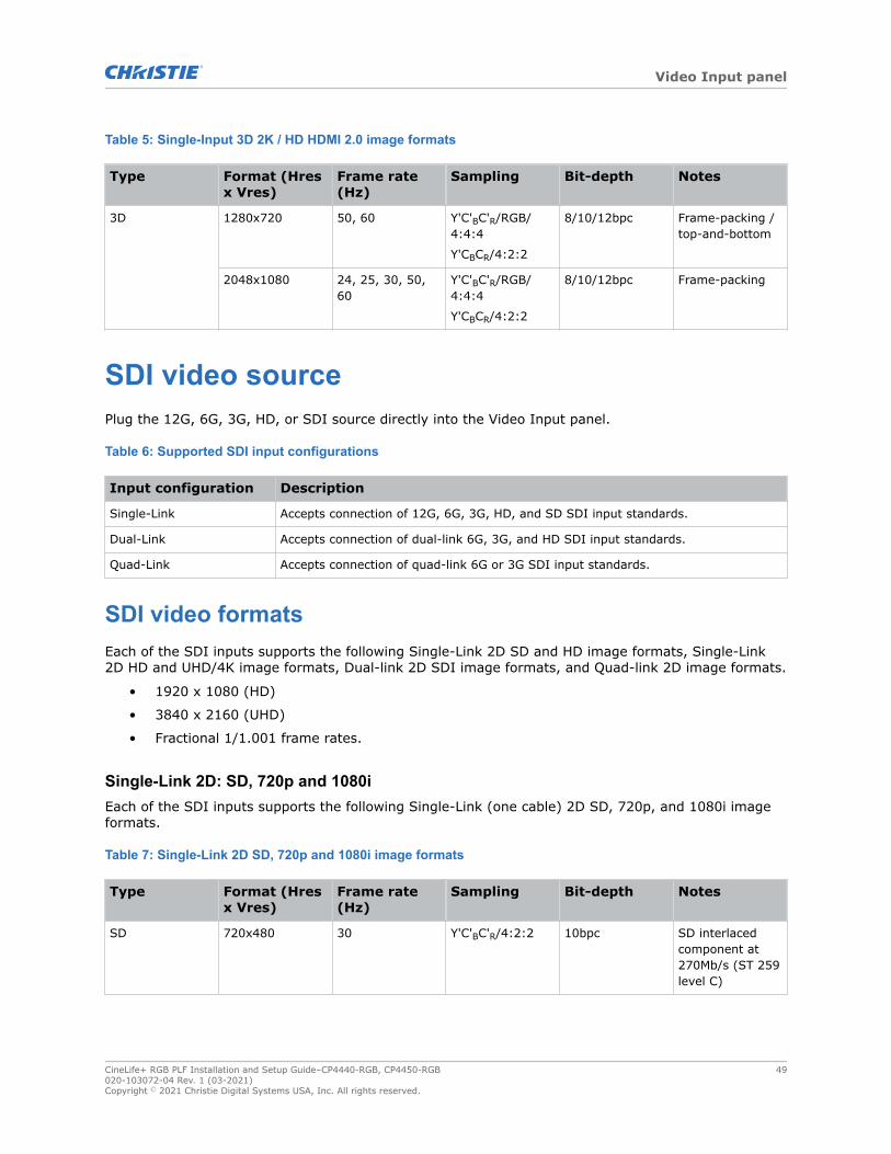
Table 5: Single-Input 3D 2K / HD HDMI 2.0 image formats
Type Format (Hresx Vres)
Frame rate(Hz)
Sampling Bit-depth Notes
3D 1280x720 50, 60 Y'C'BC'R/RGB/4:4:4
Y'CBCR/4:2:2
8/10/12bpc Frame-packing /top-and-bottom
2048x1080 24, 25, 30, 50,60
Y'C'BC'R/RGB/4:4:4
Y'CBCR/4:2:2
8/10/12bpc Frame-packing
SDI video sourcePlug the 12G, 6G, 3G, HD, or SDI source directly into the Video Input panel.
Table 6: Supported SDI input configurations
Input configuration Description
Single-Link Accepts connection of 12G, 6G, 3G, HD, and SD SDI input standards.
Dual-Link Accepts connection of dual-link 6G, 3G, and HD SDI input standards.
Quad-Link Accepts connection of quad-link 6G or 3G SDI input standards.
SDI video formatsEach of the SDI inputs supports the following Single-Link 2D SD and HD image formats, Single-Link2D HD and UHD/4K image formats, Dual-link 2D SDI image formats, and Quad-link 2D image formats.
• 1920 x 1080 (HD)
• 3840 x 2160 (UHD)
• Fractional 1/1.001 frame rates.
Single-Link 2D: SD, 720p and 1080iEach of the SDI inputs supports the following Single-Link (one cable) 2D SD, 720p, and 1080i imageformats.
Table 7: Single-Link 2D SD, 720p and 1080i image formats
Type Format (Hresx Vres)
Frame rate(Hz)
Sampling Bit-depth Notes
SD 720x480 30 Y'C'BC'R/4:2:2 10bpc SD interlacedcomponent at270Mb/s (ST 259level C)
Video Input panel
CineLife+ RGB PLF Installation and Setup Guide–CP4440-RGB, CP4450-RGB 49020-103072-04 Rev. 1 (03-2021)Copyright © 2021 Christie Digital Systems USA, Inc. All rights reserved.

Type Format (Hresx Vres)
Frame rate(Hz)
Sampling Bit-depth Notes
Interlaced (60 Hzfield rate)
720x576 25 Y'C'BC'R/4:2:2 10bpc SD interlacedcomponent at270Mb/s (ST 259level C)Interlaced (50 Hzfield rate)
HD 1280x720 24, 25, 30, 50,60
Y'C'BC'R/4:2:2 10bpc HD 720p Y'C'BC'Rcomponent at1.5Gb/s (ST292-1)
1280x720 24, 25, 30, 50,60
Y'C'BC'R/4:4:4(4) 10bpc HD 720pY'C'BC'R/RGBcomponent at3.0Gb/s (ST425-1) level A
2K 2048x1080 25, 30 Y'C'BC'R/4:2:2 10bpc HD 1080icomponent at1.5Gb/s (ST292-1) Interlaced(50/60 Hz fieldrate)
Single-Link 2D: 2K and 4K (HD / UHD)Each of the SDI inputs supports the following Single-Link (one cable) 2D HD and UHD/4K imageformats.
Table 8: Single-Link 2D HD and UHD/4K image formats
Type Format (Hresx Vres)
Frame rate(Hz)
Sampling Bit-depth Notes
2K 2048x1080 24, 25, 30 Y'C'BC'R/4:2:2 10bpc HD 1080pcomponent at1.5Gb/s (ST292-1)
48, 50, 60 Y'C'BC'R/4:2:2 10bpc HD 1080pcomponent at3.0Gb/s (ST425-1) level A
24, 25, 30 Y'C'BC'R/RGB/4:4:4(4)
12bpc HD 1080pY'C'BC'R/RGBcomponent at3.0Gb/s (ST425-1) level A
Video Input panel
CineLife+ RGB PLF Installation and Setup Guide–CP4440-RGB, CP4450-RGB 50020-103072-04 Rev. 1 (03-2021)Copyright © 2021 Christie Digital Systems USA, Inc. All rights reserved.

Type Format (Hresx Vres)
Frame rate(Hz)
Sampling Bit-depth Notes
24, 25, 30 Y'C'BC'R/4:2:2(4) 12bpc HD 1080pY'C'BC'Rcomponent at3.0Gb/s (ST425-1) level A
48, 50, 60 Y'C'BC'R/RGB/4:4:4(4)
10bpc HD 1080pY'C'BC'R/RGBcomponent at6.0Gb/s (ST2081-10) mode 2structure II
48, 50, 60 Y'C'BC'R/RGB/4:4:4
12bpc HD 1080pY'C'BC'R/RGBcomponent at6.0Gb/s (ST2081-10) mode 2structure III
4K 4096x2160 48, 50, 60 Y'C'BC'R/4:2:2 10bpc 2160p Y'C'BC'Rcomponent at6.0Gb/s (ST2081-10) mode 1structure 1
24, 25, 30 Y'C'BC'R/RGB/4:4:4(4)
10bpc 2160pY'C'BC'R/RGBcomponent at12.0Gb/s (ST2082-10) mode 1structure 2
24, 25, 30 Y'C'BC'R/RGB/4:4:4
12bpc 2160pY'C'BC'R/RGBcomponent at12.0Gb/s (ST2082-10) mode 1structure 3
24, 25, 30 Y'C'BC'R/4:2:2(4) 12bpc 2160p Y'C'BC'Rcomponent at12.0Gb/s (ST2082-10) mode 1structure 4
Dual-link 2D: 2K and 4K (HD / UHD)Dual-link SDI is a fixed configuration where:
• SDI 1 = link 1 of input 1
• SDI 2 = link 2 of input 1
• SDI 3 = link 1 of input 2
Video Input panel
CineLife+ RGB PLF Installation and Setup Guide–CP4440-RGB, CP4450-RGB 51020-103072-04 Rev. 1 (03-2021)Copyright © 2021 Christie Digital Systems USA, Inc. All rights reserved.

• SDI 4 = link 2 of input 2
The following Dual-link (two cable) 2D SDI input formats are supported.
Table 9: Dual-link 2D: 2K and 4K (HD / UHD) image formats
Type Format (Hresx Vres)
Frame rate(Hz)
Sampling Bit-depth Notes
2K 2048x1080 48, 50, 60 Y'C'BC'R/RGB/4:4:4(4)
10bpc Y'C'BC'R/RGBcomponent atdual-link 3Gb/s
(ST 425-3) levelA structure II
Y'C'BC'R/RGB/4:4:4
12bpc Y'C'BC'R/RGBcomponent atdual-link 3Gb/s
(ST 425-3) levelA structure III
Y'C'BC'R/4:2:2 12bpc Y'C'BC'Rcomponent atdual-link 3Gb/s
(ST 425-3) levelA structure IV
Y'C'BC'R/4:2:2:4 12bpc Y'C'BC'Rcomponent atdual-link 3Gb/s
(ST 425-3) levelA structure IV
4K 4096x2160 48, 50, 60 Y'C'BC'R/4:2:2 10bpc Y'C'BC'Rcomponent atdual-link 6Gb/s
(ST 2081-11)mode 1
24, 25, 30 Y'C'BC'R/RGB/4:4:4(4)
10bpc Y'C'BC'R /RGBcomponent atdual-link 6Gb/s
(ST 2081-11)mode 1
Y'C'BC'R/RGB/4:4:4
12bpc Y'C'BC'R/RGBcomponent atdual-link 6Gb/s
(ST 2081-11)mode 1
Y'C'BC'R/4:2:2 12bpc Y'C'BC'Rcomponent atdual-link 6Gb/s
(ST 2081-11)mode 1
Video Input panel
CineLife+ RGB PLF Installation and Setup Guide–CP4440-RGB, CP4450-RGB 52020-103072-04 Rev. 1 (03-2021)Copyright © 2021 Christie Digital Systems USA, Inc. All rights reserved.

Type Format (Hresx Vres)
Frame rate(Hz)
Sampling Bit-depth Notes
Y'C'BC'R/4:2:2:4 12bpc Y'C'BC'Rcomponent atdual-link 6Gb/s
(ST 2081-11)mode 1
Quad-link 2D: 4K (UHD)Quad-link 2D is a fixed configuration where the quad-link input is as follows.
• SDI 1 = link 1
• SDI 2 = link 2
• SDI 3 = link 3
• SDI 4 = link 4
The following Quad-link (four cable) 2D image formats are supported.
Table 10: Quad-link 2D: 4K (UHD) image formats
Type Format Frame rate(Hz)
Sampling Bit-depth Notes
4K 4096x2160 24, 25, 30 Y'C'BC'R/RGB/4:4:4(4)
10bpc Y'C'BC'R/RGBcomponent atquad-link 3Gb/s
(ST 425-5) levelA structure 2
Y'C'BC'R/RGB/4:4:4
12bpc Y'C'BC'R/RGBcomponent atquad-link 3Gb/s
(ST 425-5) levelA structure 3
Y'C'BC'R/4:2:2(4) 12bpc Y'C'BC'Rcomponent atquad-link 3Gb/s
(ST 425-5) levelA structure 4
Y'C'BC'R/4:2:2 12bpc Y'C'BC'Rcomponent atquad-link 3Gb/s
(ST 425-5) levelA structure 4
48, 50, 60 Y'C'BC'R/RGB/4:4:4(4)
10bpc Y'C'BC'R/RGBcomponent atquad-link 6Gb/s
Video Input panel
CineLife+ RGB PLF Installation and Setup Guide–CP4440-RGB, CP4450-RGB 53020-103072-04 Rev. 1 (03-2021)Copyright © 2021 Christie Digital Systems USA, Inc. All rights reserved.

Type Format Frame rate(Hz)
Sampling Bit-depth Notes
(ST 2081-12)mode 2 structureIII
Y'C'BC'R/RGB/4:4:4
12bpc Y'C'BC'R/RGBcomponent atquad-link 6Gb/s
(ST 2081-12)mode 2 structureIII
Y'C'BC'R/4:2:2:4 12bpc Y'C'BC'Rcomponent atquad-link 6Gb/s
(ST 2081-12)mode 2 structureIV
Integrated Media Block (IMB) video sourceConnect a compatible device to either the S2 or S4 interface of the projector to send digital video datafrom an IMB to the projector.
Table 11: Supported IMB input configurations
Input configuration Description
IMB – S2 or S4 Enables connection of MPEG-2 video formats.
Enables connection of MPEG-2 MXF interop video formats.
Enables connection of SMPTE-compatible 2D and 3D video formats
Contact Christie Technical Support to learn which S2 and S4 IMB devices are compatible with Christieprojectors.
Series 2 IMB video formatsS2 IMB video format support is determined by the IMB make and model. Refer to the associated IMBdocumentation to understand which of the following video signals are supported.All MPEG-2 content is converted in the media block to RGB 4:4:4 8-bit before play out.
Video Input panel
CineLife+ RGB PLF Installation and Setup Guide–CP4440-RGB, CP4450-RGB 54020-103072-04 Rev. 1 (03-2021)Copyright © 2021 Christie Digital Systems USA, Inc. All rights reserved.

MPEG
Table 12: MPEG image formats
Format Resolution Max FrameRate 2D
Max FrameRate 3D
Min FrameRate
Bit Depth
VGA 640x480 120.0 120.0 23.0 8-bits
525 4SIF 704x480 120.0 120.0 23.0 8-bits
525 SD 720x480 120.0 120.0 23.0 8-bits
4CIF 704x576 120.0 120.0 23.0 8-bits
625 SD 800x600 120.0 120.0 23.0 8-bits
SVGA 1024x768 79.6 79.6 23.0 8-bits
XGA 1024x768 79.6 79.6 23.0 8-bits
720p HD 1280x720 68.0 68.0 23.0 8-bits
4VGA 1280x960 51.0 51.0 23.0 8-bits
SXGA 1280x1024 47.8 N/A 23.0 8-bits
525 16SIF 1408x960 46.3 N/A 23.0 8-bits
16CIF 1408x1152 38.6 N/A 23.0 8-bits
4SVGA 1600x1200 32.6 N/A 23.0 8-bits
1080 HD 2048x1080 30.0 N/A 23.0 8-bits
MPEG-2 MXF interop – 2D
Table 13: MPEG-2 MXF interop – 2D image formats
Format Resolution Max FrameRate 2D
Max FrameRate 3D
Min FrameRate
Bit Depth
VGA 640x480 120.0 120.0 23.0 8-bits
525 4SIF 704x480 120.0 120.0 23.0 8-bits
525 SD 720x480 120.0 120.0 23.0 8-bits
4CIF 704x576 120.0 120.0 23.0 8-bits
625 SD 800x600 120.0 120.0 23.0 8-bits
SVGA 1024x768 79.6 79.6 23.0 8-bits
XGA 1024x768 79.6 79.6 23.0 8-bits
720p HD 1280x720 68.0 68.0 23.0 8-bits
4VGA 1280x960 51.0 51.0 23.0 8-bits
SXGA 1280x1024 47.8 N/A 23.0 8-bits
525 16SIF 1408x960 46.3 N/A 23.0 8-bits
Video Input panel
CineLife+ RGB PLF Installation and Setup Guide–CP4440-RGB, CP4450-RGB 55020-103072-04 Rev. 1 (03-2021)Copyright © 2021 Christie Digital Systems USA, Inc. All rights reserved.

Format Resolution Max FrameRate 2D
Max FrameRate 3D
Min FrameRate
Bit Depth
16CIF 1408x1152 38.6 N/A 23.0 8-bits
4SVGA 1600x1200 32.6 N/A 23.0 8-bits
1080 HD 2048x1080 30.0 N/A 23.0 8-bits
SMPTE-compatible cinema formats - 2D (JPEG 2000)
Table 14: SMPTE-compatible cinema formats - 2D (JPEG 2000) image formats
Specification Resolution Frame Rate Color Format Bit Depth
SMPTE 428-1-2006 2048x1080 24.0 X’Y’Z’ (4:4:4) 12-bits
SMPTE 428-11-2009 2048x1080 25.0 X’Y’Z’ (4:4:4) 12-bits
SMPTE 428-11-2009 2048x1080 30.0 X’Y’Z’ (4:4:4) 12-bits
SMPTE 428-1-2006 2048x1080 48.0 X’Y’Z’ (4:4:4) 12-bits
SMPTE 428-11-2009 2048x1080 50.0 X’Y’Z’ (4:4:4) 12-bits
SMPTE 428-11-2009 2048x1080 60.0 X’Y’Z’ (4:4:4) 12-bits
-- 2048x1080 100.0 X’Y’Z’ (4:4:4) 12-bits
-- 2048x1080 120.00 X’Y’Z’ (4:4:4) 12-bits
SMPTE 428-1-2006 4096x2160 24.0 X’Y’Z’ (4:4:4) 12-bits
SMPTE 428-11-2009 4096x2160 25.0 X’Y’Z’ (4:4:4) 12-bits
SMPTE 428-11-2009 4096x2160 30.0 X’Y’Z’ (4:4:4) 12-bits
-- 4096x2160 48 X’Y’Z’ (4:4:4) 12-bits
-- 4096x2160 50 X’Y’Z’ (4:4:4) 12-bits
-- 4096x2160 60 X’Y’Z’ (4:4:4) 12-bits
-- 4096x2160 100 X’Y’Z’ (4:4:4) 12-bits
-- 4096x2160 120 X’Y’Z’ (4:4:4) 12-bits
SMPTE-compatible cinema formats - 3D (JPEG 2000)
Table 15: SMPTE-compatible cinema formats - 3D (JPEG 2000) image formats
Specification Resolution Frame Rate (pereye)
Color Format Bit Depth
SMPTE 428-1-2006 2048 x 1080 24.0 x 2 X’Y’Z’ (4:4:4) 12-bits
SMPTE 428-1-2006 48.0 x 2
50.0 x 2
SMPTE 428-11-2009 60.0 x 2
Video Input panel
CineLife+ RGB PLF Installation and Setup Guide–CP4440-RGB, CP4450-RGB 56020-103072-04 Rev. 1 (03-2021)Copyright © 2021 Christie Digital Systems USA, Inc. All rights reserved.

Specification Resolution Frame Rate (pereye)
Color Format Bit Depth
4096 x 2160 24.0 x 2 X’Y’Z’ (4:4:4) 12-bits
48.0 x 2
50.0 x 2
60.0 x 2
HDMI video source connection from an IMBThe projector can accept digital video data from HDMI sources connected to applicable IMB devices.The input configurations supported are determined by the IMB device directly.
IMB devices supporting HDMI selection from the projector UIContact Christie Technical Support to learn which IMB devices provide HDMI source selection from theprojector UI.HDMI input selection directly from the IMB may also be possible via the IMB UI. The inputconfigurations supported are determined by the IMB make and model.
SDI video source connection from an IMBThe projector can accept digital video data from SDI sources connected to applicable IMB devices.The input configurations supported are determined by the IMB device directly.
IMB devices supporting SDI selection from the projector UIContact Christie Technical Support to learn which IMB devices provide SDI source selection from theprojector UI.SDI input selection directly from the IMB may also be possible via the IMB UI. The input configurationssupported are determined by the IMB make and model.
Video Input panel
CineLife+ RGB PLF Installation and Setup Guide–CP4440-RGB, CP4450-RGB 57020-103072-04 Rev. 1 (03-2021)Copyright © 2021 Christie Digital Systems USA, Inc. All rights reserved.

Using channels to setinput signal parametersChannels store customized projector settings for different video input signal parameters.
The following describes only those parameters associated with input signal selection that should beconfigured by the user.
Additional parameter settings are required to fully describe a channel setup. Refer to CineLife+ RGB PLFUser Guide (P/N: 020-103073-XX) for further information.
To create a new channel or edit the input video signal parameters for an existing channel, follow thesesteps.
1. In the left navigation menu, select Channel Setup.
2. Select + Add Channel to create a new channel or, in the left panel, select a channel name toselect it for editing.
3. To define the input video signal parameters for the channel, complete the following fields.
Field name Description
Name The channel name
Input Type Select the input signal sources from one of the following.
• HDMI Input 1
• HDMI Input 2
• IMB
• IMB HDMI
(Available only if the selected IMB device supports HDMI selection fromprojector UI.)
• IMB SDI
(Available only if the selected IMB device supports SDI selection fromprojector UI.)
• SDI - 1
• SDI - 2
• SDI - 3
• SDI - 4
• SDI - Dual-Input (1,2)
• SDI - Dual-Input (3,4)
• SDI - Quad
Data Format The default is AUTO.
CineLife+ RGB PLF Installation and Setup Guide–CP4440-RGB, CP4450-RGB 58020-103072-04 Rev. 1 (03-2021)Copyright © 2021 Christie Digital Systems USA, Inc. All rights reserved.

Field name Description
The bit-depth, sampling format, and color space of the input signal isautomatically determined from metadata carried in the source.
Scan Type Determines the input scanning format. Select one of the following.
• Auto (default setting)
The scanning format of the input signal (interlaced or progressive) isautomatically determined from metadata carried in the source or bymeasuring scanning parameters of the source.
• Progressive
Forces the input signal scanning format to progressive, overriding anymetadata in the input signal.
3D Sync Input Mode Specifies whether a specific frame of input data has left eye or right eye data.Select one of the following.
• Auto (default setting)
The left-eye / right eye 3D-sync information is automatically determinedfrom metadata carried in the source or from the specific input typeselection.
• 2D mode
Forces the input signal to be interpreted as a 2D signal, overriding anymetadata in the input signal.
Color Space Specifies the method of internal color decoding that will be applied to thecurrently selected input source. Select from the following.
• Auto (default setting)
Appropriate color decoding will be automatically selected in accordancewith the input signal color format.
• RGB (Full Range)
Appropriate color decoding will be selected in accordance with the inputsignal being a full-range, 12-bit per component, RGB color format.
• RGB (Limited Range)
Appropriate color decoding will be selected in accordance with the inputsignal being a limited-range, 10-bit per component, RGB color format.
• XYZ
Appropriate color decoding will be selected in accordance with the inputsignal being a full-range, 12-bit per component, XYZ color format.
4. Select Save.
Using channels to set input signal parameters
CineLife+ RGB PLF Installation and Setup Guide–CP4440-RGB, CP4450-RGB 59020-103072-04 Rev. 1 (03-2021)Copyright © 2021 Christie Digital Systems USA, Inc. All rights reserved.

Managing the lightsourceLearn how to configure a laser file and use the projector's LiteLOC™ feature.The laser file allows you to control the power settings of the red, green, and blue (RGB) lasers. TheLiteLOC™ feature ensures that color and brightness are held at the level you set.For CP4440-RGB and CP4450-RGB projectors, you can create multiple laser files to manage varyingscreen sizes, brightness requirements, chiller setpoint temperatures, and types of content (such as2D, 3D, and alternative content).
Creating a new laser file for CP4440-RGB andCP4450-RGBCreate a laser file to store the power settings for the RGB laser light source and the chiller setpoint.
The maximum (MAX) power limit for Red and Green changes according to the value set for the chillersetpoint temperature. For Red, Green, and Blue power levels, system stability may be affected if levelsare set below the minimum (MIN) power limit shown.To ensure color and brightness are held at the required levels for your installation, Christierecommends that you enable LiteLOC for each laser file you create.
CineLife+ RGB PLF Installation and Setup Guide–CP4440-RGB, CP4450-RGB 60020-103072-04 Rev. 1 (03-2021)Copyright © 2021 Christie Digital Systems USA, Inc. All rights reserved.
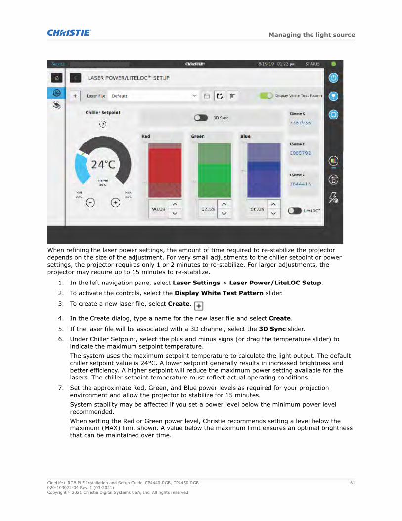
When refining the laser power settings, the amount of time required to re-stabilize the projectordepends on the size of the adjustment. For very small adjustments to the chiller setpoint or powersettings, the projector requires only 1 or 2 minutes to re-stabilize. For larger adjustments, theprojector may require up to 15 minutes to re-stabilize.
1. In the left navigation pane, select Laser Settings > Laser Power/LiteLOC Setup.
2. To activate the controls, select the Display White Test Pattern slider.
3. To create a new laser file, select Create.
4. In the Create dialog, type a name for the new laser file and select Create.
5. If the laser file will be associated with a 3D channel, select the 3D Sync slider.
6. Under Chiller Setpoint, select the plus and minus signs (or drag the temperature slider) toindicate the maximum setpoint temperature.The system uses the maximum setpoint temperature to calculate the light output. The defaultchiller setpoint value is 24°C. A lower setpoint generally results in increased brightness andbetter efficiency. A higher setpoint will reduce the maximum power setting available for thelasers. The chiller setpoint temperature must reflect actual operating conditions.
7. Set the approximate Red, Green, and Blue power levels as required for your projectionenvironment and allow the projector to stabilize for 15 minutes.System stability may be affected if you set a power level below the minimum power levelrecommended.When setting the Red or Green power level, Christie recommends setting a level below themaximum (MAX) limit shown. A value below the maximum limit ensures an optimal brightnessthat can be maintained over time.
Managing the light source
CineLife+ RGB PLF Installation and Setup Guide–CP4440-RGB, CP4450-RGB 61020-103072-04 Rev. 1 (03-2021)Copyright © 2021 Christie Digital Systems USA, Inc. All rights reserved.

8. If color or brightness is not at the target level, refine the Red, Green, and Blue power settingsto achieve the target, and then allow the projector to re-stabilize for an additional 3 to 5minutes.
The projector is considered stable when there are no further adjustments and you obtain thesame screen state results after two sets of measurements, 5 minutes apart.
9. Once the correct color and brightness are achieved and the projector has stabilized, select theLiteLOC slider to lock the settings.The color of the slider turns to green to indicate the settings are locked. The projector'sLiteLOC system maintains the brightness and color levels.
10. To save the new laser file, select Save .
Color sensor (CSense) data are displayed on the interface to provide feedback on the currentcolor sensor information.
Related information
Setting the chiller setpoint (on page 43)
Modifying an existing laser fileModify the settings in the laser file to change the laser power settings or the chiller setpoint.
When refining the laser power settings, the amount of time required to re-stabilize the projectordepends on the size of the adjustment. For very small adjustments, including changes to the chillersetpoint temperature or power settings, the projector requires only 1 or 2 minutes to re-stabilize. Forlarger adjustments, the projector may require up to 15 minutes to re-stabilize.
1. In the left navigation pane, select Laser Settings > Laser Power/LiteLOC Setup.
2. To begin modifying the settings, select Display White Test Pattern.
3. From the Laser File list, select the laser file to edit.
4. To unlock the file, select the LiteLOC slider.The color of the slider turns to gray to indicate the settings are unlocked.
5. (CP4440-RGB and CP4450-RGB only) Adjust the Chiller Setpoint and the power levels for Red,Green, and Blue as required to achieve the correct color and brightness on screen.
6. Once the correct color and brightness are achieved and the projector has stabilized, select theLiteLOC slider to lock the settings.The color of the slider turns to green to indicate the settings are locked.
7. To save the new settings, select Save.
Copying existing laser settings to a new fileCopy an existing laser file when you want to create a new file with similar settings.
1. In the left navigation pane, select Laser Settings > Laser Power/LiteLOC Setup.
2. Select the Display White Test Pattern slider.
3. From the Laser File list, select the file you want to copy.
4. To save the new laser file, select Save As.
Managing the light source
CineLife+ RGB PLF Installation and Setup Guide–CP4440-RGB, CP4450-RGB 62020-103072-04 Rev. 1 (03-2021)Copyright © 2021 Christie Digital Systems USA, Inc. All rights reserved.

5. Type a new name for the laser file and then select Save.
6. Adjust the maximum expected temperature and power settings as required for the newconfiguration.
Deleting a laser fileDelete a laser file when the configuration is no longer required.
1. In the left navigation menu, select Laser Settings > Laser Power/LiteLOC Setup.
2. Select the Display White Test Pattern slider.
3. In the Laser File list, select the file to delete.
4. Select Delete.
5. To confirm the deletion, select Delete.
Managing the light source
CineLife+ RGB PLF Installation and Setup Guide–CP4440-RGB, CP4450-RGB 63020-103072-04 Rev. 1 (03-2021)Copyright © 2021 Christie Digital Systems USA, Inc. All rights reserved.

Adjusting the imageLearn how to adjust image geometry so it displays correctly.
Calibrating the Intelligent Lens SystemOn CineLife+ RGB PLF projectors, the Intelligent Lens System (ILS) is activated by default.
Use the Auto Calibrate feature of the ILS to find and compensate for motor backlash, and to determinethe movement range for the currently installed lens.
1. In the left navigation menu, select Image Settings > ILS File Setup.
2. From the ILS File list, select an available ILS file.
3. Select Auto Calibrate.
4. Select Continue.The system performs the lens calibration.
Correcting vignettingAn image that is brighter at the center than it is at the sides needs vignetting correction.
If your image suffers from vignetting, the lens has reached the end of its offset travel range.
If your installation does not allow the image to be centered with the center of the screen,move the entire projector in the direction of lens travel.
Adjusting tilt and leveling the projectorTo ensure optimum performance, install the projector so it is centered and parallel with the screen.
To compensate for tilt or offset, you can adjust the projector feet and the lens mount position.This product must be installed in a landscape orientation, with all four feet supported on a levelsurface. Do not install or operate the projector in an inverted position. If your site has any installationrequirements other than a typical theater projection booth, contact Christie for assistance.
The front-to-back tilt of the projector must not exceed 15° in a downward direction or 3° in an upwarddirection. The side-to-side tilt must be within +3° to -3° of level.
1. To adjust the height of the projector, loosen the lock nut on the adjustable feet on the bottomof the projector.
CineLife+ RGB PLF Installation and Setup Guide–CP4440-RGB, CP4450-RGB 64020-103072-04 Rev. 1 (03-2021)Copyright © 2021 Christie Digital Systems USA, Inc. All rights reserved.

A Adjustable wrench for 18 mm - 24 mm
B Lock
C Turn to adjust height
2. Extend or retract the feet.
3. When the adjustment is correct, tighten the lock nut.
Correcting keystone effectLearn how to adjust the image to correct keystone effect.
Keystone effect occurs when you project an image onto the screen at an angle. As a result, the imageappears distorted and resembles a trapezoid.
When making the adjustments, set the light source to minimum power.
Horizontal keystone Vertical keystone
Projector skewed horizontally to the screen Projector tilted vertically to the screen
1. If the image suffers from slight keystone effect, it can be corrected with electronic cropping.
Adjusting the image
CineLife+ RGB PLF Installation and Setup Guide–CP4440-RGB, CP4450-RGB 65020-103072-04 Rev. 1 (03-2021)Copyright © 2021 Christie Digital Systems USA, Inc. All rights reserved.

2. If the keystone effect is severe, you can unevenly adjust the feet to compensate for projectortilt.It is recommended that you use lens offset to align the center of the image to the center of thescreen before you correct the keystone effect.
3. If one side of the image is longer than another, adjust the tilt and level of the projector.
Displaying a test patternDisplay a test pattern to refine and adjust the projected image, or to diagnose and correct imageissues.
1. In the right toolbar, select Test Patterns.
2. Select Full Screen.
3. Select a test pattern.When a test pattern is active, a blue bar appears below the test pattern icon in the right pane.
4. To display a 2D test pattern in 3D mode, select the 3D Sync option.The 3D Sync option is selected automatically for 3D test patterns. 3D test patterns cannot bedisplayed in 2D mode.
5. To change the frame rate of the test pattern display, select from the available Frame Rateoptions:
• For 2D test patterns, the available frame rates are 24, 30, 48, and 60 Frames Per Second(FPS). The default value is 24 FPS.
• For 3D test patterns, the available frame rates are 48 and 60 FPS. The default value is 48FPS.
Changing the frame rate of the display can assist with color measurement when working withcorrected colors.When you change the frame rate option, that option is applied to the next test pattern youselect unless it is not available for that pattern. If a selected frame rate is not available, thedefault frame rate is applied for the test pattern display.
Adjusting the integrator rod and fold mirrorUnderstand how to adjust the integrator rod and fold mirror to control the illumination spot on theDMD.
Extreme misalignment of projection optics can cause permanent damage to critical opticalcomponents. Only Christie qualified technicians can perform internal optical adjustments.The integrator rod and fold mirror adjustments are set by Christie. Make adjustments only if screenshadows are visible.
When adjusting the fold mirror, set the light source to minimum power.
1. In the right toolbar, select Test Patterns.
2. Select the RGB-4K-Integrator Rod test pattern and display it full screen.
Adjusting the image
CineLife+ RGB PLF Installation and Setup Guide–CP4440-RGB, CP4450-RGB 66020-103072-04 Rev. 1 (03-2021)Copyright © 2021 Christie Digital Systems USA, Inc. All rights reserved.

Refer to the test pattern for guidance on making the adjustments. The right panel of the testpattern provides information about the integrator zoom and focus adjustments. The left panelprovides information about the fold mirror adjustments.
3. Open the Service door on the side of the projector.
4. To use the integrator rod optical controls, open the access door for the Zoom and Focuspaddles.
5. Loosen the lock screw for the Zoom and Focus paddles.
Adjusting the image
CineLife+ RGB PLF Installation and Setup Guide–CP4440-RGB, CP4450-RGB 67020-103072-04 Rev. 1 (03-2021)Copyright © 2021 Christie Digital Systems USA, Inc. All rights reserved.

6. Set the integrator rod Zoom paddle to the minimum.
7. Loosen the fold mirror screws to unlock the fold mirror adjustment knobs.
8. To make horizontal adjustments on the fold mirror, use the orange adjustment knob.To make vertical adjustments on the fold mirror, use the purple adjustment knob.
Adjusting the image
CineLife+ RGB PLF Installation and Setup Guide–CP4440-RGB, CP4450-RGB 68020-103072-04 Rev. 1 (03-2021)Copyright © 2021 Christie Digital Systems USA, Inc. All rights reserved.

9. Adjust the fold mirror until either the top left edge or the bottom right edge of the illuminationspot becomes visible on the DMD.
10. Adjust the integrator rod Focus paddle to optimize focus for one of the following:
• Along the top edge of the image, approximately one-third across the image from the left.
• Along the bottom edge of the image, approximately one-third across the image from theright.
11. Adjust the fold mirror to center the image on the DMD array.
12. Use the integrator rod Zoom paddle to increase the zoom until the entire active area is filled,with no dark areas at the edges or corners.Ensure that overfill is minimized to improve DMD life and system optical efficiency forbrightness.
13. Once the adjustments are complete, tighten the lock screw for the Zoom and Focus paddles,and the two fold mirror screws.
14. Close the access door for the Zoom and Focus paddles.
Adjusting the boresightA boresight adjustment balances the tilt of the lens mount to compensate for screen-to-projector tilt.
Warning! If not avoided, the following could result in death or serious injury.
• Do not look directly into the lens when the light source is on. The extremely high brightness cancause permanent eye damage.
• FIRE HAZARD! Keep hands, clothes, and all combustible material away from the concentratedlight beam of the projector.
Caution! If not avoided, the following could result in minor or moderate injury.
• This procedure must be performed by Christie qualified technicians.
When making the adjustments, set the light source to minimum power.
To following steps are intended to achieve the highest quality image distributed across the full screen.
1. Close the shutter on the projector to avoid accidental exposure to the projection beam whenworking in close proximity to the projection lens.
Adjusting the image
CineLife+ RGB PLF Installation and Setup Guide–CP4440-RGB, CP4450-RGB 69020-103072-04 Rev. 1 (03-2021)Copyright © 2021 Christie Digital Systems USA, Inc. All rights reserved.

2. Using a 3 mm driver, unlock the horizontal and vertical lock screws (Lock A, B, and C).To unlock the vertical lock screw (Lock C), flip open the cover flap (G) using the screwdriver.
A Horizontal lock screw (Lock A)
B Horizontal lock screw (Lock B)
C Vertical lock screw (Lock C)
D Vertical boresight screw
E Horizontal boresight screw
F Manual focus knob
G Cover flap
3. Open the shutter on the projector.
4. In the right toolbar, select Test Patterns .
5. Select the RGB-4K-Boresight pattern and display it full screen.
Adjusting the image
CineLife+ RGB PLF Installation and Setup Guide–CP4440-RGB, CP4450-RGB 70020-103072-04 Rev. 1 (03-2021)Copyright © 2021 Christie Digital Systems USA, Inc. All rights reserved.

When adjusting the boresight screws, ensure that the shutter is closed to avoid accidentalexposure to the projection beam when operating in close proximity to the projection lens. Openthe shutter only to view the test pattern.
6. Start with the horizontal boresight adjustment. Use the ILS controls to move the projectionlens into the projector, or turn the manual focus knob (F) counterclockwise to slightly defocusthe green cross-hair patterns (+) at the right and left edges of the test pattern.
7. Use the ILS controls or turn the focus knob (F) clockwise to begin focusing the image. Watchfor either the left or right cross-hair patterns (+) to come into focus.
8. If the left side comes into focus first, use a 5 mm driver to turn the horizontal boresightadjustment screw (E) clockwise until the left and right are equally out of focus.If the right side comes into focus first, turn the horizontal boresight screw counterclockwise.
9. Repeat steps 6 to 8 as required to obtain an even focus at the right and left edges of thescreen.
10. Next perform the vertical boresight adjustment. Use the ILS controls to move the projectionlens into the projector, or turn the focus knob (F) counterclockwise to slightly defocus thegreen cross-hair patterns (+) at the top and bottom of the screen.
11. Use the ILS controls or turn the focus knob (F) clockwise to begin focusing the image. Watchfor either the top or bottom cross-hair patterns (+) to come into focus.
12. If the bottom comes into focus first, use a 5 mm driver to turn the vertical boresightadjustment screw (D) counterclockwise until the top and bottom are equally out of focus.If the top comes into focus first, turn the vertical boresight screw clockwise.
13. Repeat steps 10 to 12 as required to obtain an even focus at the top and bottom of the screen.
14. Once the correct focus has been achieved, lock the three lock screws.When locking the lock screws, start with the horizontal lock screws (Lock A and Lock B) andturn them until they just touch the base. Repeat for the vertical lock screw (Lock C). Continuethe gradual tightening of each screw, until all lock screws are tight.
When stabilizing image vibration, Lock B may be left locked or unlocked at the discretion of theinstaller.
Adjusting the image
CineLife+ RGB PLF Installation and Setup Guide–CP4440-RGB, CP4450-RGB 71020-103072-04 Rev. 1 (03-2021)Copyright © 2021 Christie Digital Systems USA, Inc. All rights reserved.

15. If you used the focus knob (F) to make the adjustments manually, run an ILS auto calibration.
16. Fine tune the focus on cross-hair patterns I (horizontal) and II (vertical) using the ILScontrols only.The goal is to obtain good focus at the center and on all sides of the screen, including thesquare patterns across the screen.
Adjusting DMD convergenceA convergence problem can be identified when one or more projected colors (red, green, and blue)appears misaligned when examined with a convergence test pattern.
The three colors should overlap to form pure white lines throughout the image and one or more poorlyconverged individual colors may appear adjacent to some or all of the lines.When adjusting the convergence, you are adjusting red and green to blue.
If you wear glasses with corrective lenses when performing this adjustment, ensure that you are viewingthe test pattern on a straight angle through the optical axis of your glasses, and not from a tilted orangled perspective. This avoids a prismatic effect that can appear to shift convergence when viewing atan angle.
1. Before adjusting DMD convergence, ensure the projector has reached a steady operationalstate. If switching from a white or bright test pattern to a dark convergence test pattern, or ifwarming up the projector after a shutdown, allow 15 minutes for stabilization so that theoptics can reach a steady state.
2. In the right toolbar, select Test Patterns.
3. Select the RGB-4K-Convergence test pattern and display it full screen.
4. Open the Service door on the side of the projector.
5. To adjust the convergence knobs, use the 3 mm driver included with the projector.If adjusting by hand without using the tool, pull out the convergence adjustment knobs toengage them.
Adjusting the image
CineLife+ RGB PLF Installation and Setup Guide–CP4440-RGB, CP4450-RGB 72020-103072-04 Rev. 1 (03-2021)Copyright © 2021 Christie Digital Systems USA, Inc. All rights reserved.

6. Use the Convergence test pattern to assist with adjusting the horizontal and vertical lines.Horizontal adjustments are controlled by adjusting knob 3.Vertical convergence and rotation are controlled by adjusting knobs 1 and 2. Christierecommends rotating a single knob a maximum of a quarter rotation before adjusting thesecond knob a quarter rotation. For example, if using one hand, turn the left knob a quarterrotation and then the right knob a quarter rotation, and so on. Adjusting a single knob forvertical or rotational adjustment to an extreme before adjusting the second knob may result inthe convergence mechanism binding.
For the best stability, Christie recommends setting convergence while rotating the knobs in aclockwise direction. This may require first adjusting convergence by turning the knobs counter-clockwise, and finalizing the convergence with a clockwise approach. This applies to all knobs.
7. When complete, push in all the convergence adjustment knobs to disengage them.
Correcting on-screen colorAfter installation, further image adjustments may be required to correct color on the screen.
The next steps may include creating a Measured Color Gamut Data (MCDG) file and configuring aPureformity Color™ Technology (PCT) file to achieve optimal color and brightness uniformity.For more information on managing color settings, see the CineLife+ RGB PLF User Guide (P/N:020-103073-XX).
Adjusting the image
CineLife+ RGB PLF Installation and Setup Guide–CP4440-RGB, CP4450-RGB 73020-103072-04 Rev. 1 (03-2021)Copyright © 2021 Christie Digital Systems USA, Inc. All rights reserved.
RegulatoryThis product conforms to the latest regulations and standards related to product safety,environmental, and electromagnetic compatibility (EMC) requirements.
Safety• ANSI/UL 60950-1 – Information Technology Equipment – Safety – Part 1: General
Requirements
• CAN/CSA C22.2 No. 60950-1-07 – Information Technology Equipment – Safety – Part 1:General Requirements
• IEC/EN 60825-1 – Safety of Laser Products – Part 1: Equipment Classification andRequirements
• IEC 60950-1 IEC/EN 60950-1 – Information Technology Equipment – Safety – Part 1: GeneralRequirements
• IEC/EN 62471-5 – Photobiological Safety of Lamps and Lamp Systems – Part 5: Imageprojectors
Electro-magnetic compatibility
Emissions• CAN ICES-003 (A)/NMB-003 (A) – Information Technology Equipment (Including Digital
Apparatus) – Limits and Methods of Measurement
• CISPR 32/EN 55032, Class A – Electromagnetic Compatibility of Multimedia Equipment –Emission Requirements
• FCC CFR47, Part 15, Subpart B, Class A – Unintentional Radiators
• IEC 61000-3-2/EN61000-3-2: Limits for harmonic current emissions for equipment with inputcurrent ≤ 16 A
• IEC 61000-3-3/EN61000-3-3: Limitations of Voltage Changes, Voltage Fluctuations, and Flickerinput current ≤ 16 A
• IEC 61000-3-11/EN61000-3-11: Limitations of Voltage Changes, Voltage Fluctuations, andFlicker for equipment with rated current ≤ 75 A
• IEC 61000-3-12/EN61000-3-12: Limits for harmonic current emissions for equipment forsystems with input current > 16 A and ≤ 75 A per phase
Immunity• CISPR 24/EN55024 EMC Requirements – Information Technology Equipment
CineLife+ RGB PLF Installation and Setup Guide–CP4440-RGB, CP4450-RGB 74020-103072-04 Rev. 1 (03-2021)Copyright © 2021 Christie Digital Systems USA, Inc. All rights reserved.

Environmental• China Ministry of Information Industry (along with 7 other Government Agencies) Order No.32
(01/2016) on the control of pollution caused by electronic information products, hazardoussubstances concentration limits (GB/T 26572 - 2011), and the applicable product markingrequirement (SJ/T 11364 - 2014).
• EU Directive (2011/65/EU) on the restriction of the uses of certain hazardous substances(RoHS) in electrical and electronic equipment and the applicable official amendment(s).
• EU Directive (2012/19/EU) on waste and electrical and electronic equipment (WEEE) and theapplicable official amendment(s).
• Regulation (EC) No. 1907/2006 on the registration, evaluation, authorization and restriction ofchemicals (REACH) and the applicable official amendment(s).
Regulatory
CineLife+ RGB PLF Installation and Setup Guide–CP4440-RGB, CP4450-RGB 75020-103072-04 Rev. 1 (03-2021)Copyright © 2021 Christie Digital Systems USA, Inc. All rights reserved.

For the most current technical documentation, visit www.christiedigital.com.
Christie Digital Systems Canada Inc.ph: 519 744 8005
Christie Digital Systems USA, Inc.ph: 714 236 8610
Corporate offi ces
United Kingdomph: +44 (0) 118 977 8000
Middle Eastph: +971 (0) 503 6800
Spainph: +34 91 633 9990
Singaporeph: +65 6877 8737
Africaph: +27 (0)11 510 0094
Korea (Seoul)ph: +82 2 702 1601
Japan (Tokyo)ph: 81 3 3599 7481
Indiaph: +91 (080) 6708 9999
Germanyph: +49 (0) 221 99512 0
Russiaph: +36 (0) 1 47 48 100
China (Shanghai)ph: +86 21 6030 0500
China (Beijing)ph: +86 10 6561 0240
Brazilph: +55 (11) 2548 4753
Australiaph: +61 (0) 7 3624 4888
Worldwide offi ces
Italyph: +39 (0) 2 9902 1161
Independent sales consultant offi ces
Mexicoph: +52 55 4744 1790
United States (Arizona)ph: 602 943 5700
Columbiaph: +57 (318) 447 3179