Spyder X20 - Christie Digital
172
Spyder X20 User Manual 020-000916-01
-
Upload
khangminh22 -
Category
Documents
-
view
1 -
download
0
Transcript of Spyder X20 - Christie Digital

Spyder X20
User Manual 020-000916-01


Spyder X20
User Manual 020-000916-01

NOTICES
COPYRIGHT AND TRADEMARKS
Copyright © 2016 Christie Digital Systems USA, Inc. All rights reserved.
All brand names and product names are trademarks, registered trademarks or trade names of their respective holders.
GENERAL
Every effort has been made to ensure accuracy, however in some cases changes in the products or availability could occur which may not be
reflected in this document. Christie reserves the right to make changes to specifications at any time without notice. Performance specifications
are typical, but may vary depending on conditions beyond Christie's control such as maintenance of the product in proper working conditions.
Performance specifications are based on information available at the time of printing. Christie makes no warranty of any kind with regard to this
material, including, but not limited to, implied warranties of fitness for a particular purpose. Christie will not be liable for errors contained herein
or for incidental or consequential damages in connection with the performance or use of this material. Canadian manufacturing facility is ISO 9001
and 14001 certified.
WARRANTY
Products are warranted under Christie’s standard limited warranty, the complete details of which are available by contacting your Christie dealer
or Christie. In addition to the other limitations that may be specified in Christie’s standard limited warranty and, to the extent relevant or
applicable to your product, the warranty does not cover:
1. Problems or damage occurring during shipment, in either direction.
2. Projector lamps (See Christie’s separate lamp program policy).
3. Problems or damage caused by use of a projector lamp beyond the recommended lamp life, or use of a lamp other than a Christie lamp supplied by Christie or
an authorized distributor of Christie lamps.
4. Problems or damage caused by combination of a product with non-Christie equipment, such as distribution systems, cameras, DVD players, etc., or use of a
product with any non-Christie interface device.
5. Problems or damage caused by the use of any lamp, replacement part or component purchased or obtained from an unauthorized distributor of Christie lamps,
replacement parts or components including, without limitation, any distributor offering Christie lamps, replacement parts or components through the internet
(confirmation of authorized distributors may be obtained from Christie).
6. Problems or damage caused by misuse, improper power source, accident, fire, flood, lightning, earthquake or other natural disaster.
7. Problems or damage caused by improper installation/alignment, or by equipment modification, if by other than Christie service personnel or a Christie
authorized repair service provider.
8. Problems or damage caused by use of a product on a motion platform or other movable device where such product has not been designed, modified or
approved by Christie for such use.
9. Problems or damage caused by use of a projector in the presence of an oil-based fog machine or laser-based lighting that is unrelated to the projector.
10. For LCD projectors, the warranty period specified in the warranty applies only where the LCD projector is in “normal use” which means the LCD projector is
not used more than 8 hours a day, 5 days a week.
11. Except where the product is designed for outdoor use, problems or damage caused by use of the product outdoors unless such product is protected from
precipitation or other adverse weather or environmental conditions and the ambient temperature is within the recommended ambient temperature set forth in
the specifications for such product.
12. Image retention on LCD flat panels.
13. Defects caused by normal wear and tear or otherwise due to normal aging of a product.
The warranty does not apply to any product where the serial number has been removed or obliterated. The warranty also does not apply to any
product sold by a reseller to an end user outside of the country where the reseller is located unless (i) Christie has an office in the country where
the end user is located or (ii) the required international warranty fee has been paid.
The warranty does not obligate Christie to provide any on site warranty service at the product site location.
PREVENTATIVE MAINTENANCE
Preventative maintenance is an important part of the continued and proper operation of your product. Please see the Maintenance section for
specific maintenance items as they relate to your product. Failure to perform maintenance as required, and in accordance with the maintenance
schedule specified by Christie, will void the warranty.
REGULATORY (if applicable)
The product has been tested and found to comply with the limits for a Class A digital device, pursuant to Part 15 of the FCC Rules. These limits are
designed to provide reasonable protection against harmful interference when the product is operated in a commercial environment. The product
generates, uses, and can radiate radio frequency energy and, if not installed and used in accordance with the instruction manual, may cause
harmful interference to radio communications. Operation of the product in a residential area is likely to cause harmful interference in which case
the user will be required to correct the interference at the user’s own expense.
CAN ICES-3 (A) / NMB-3 (A)
이 기기는 업무용(A급)으로 전자파적합등록을 한 기기이오니 판매자 또는 사용자는 이점을 주의하시기 바라며, 가정 외의 지역에서 사용하는 것을
목적으로 합니다.

ENVIRONMENTAL
The product is designed and manufactured with high-quality materials and components that can be recycled and reused. This symbol means
that electrical and electronic equipment, at their end-of-life, should be disposed of separately from regular waste. Please dispose of the product
appropriately and according to local regulations. In the European Union, there are separate collection systems for used electrical and electronic
products. Please help us to conserve the environment we live in!

China RoHS Compliance Information 关于中国《电子信息产品污染控制管理办法》的说明
• Environmentally Friendly Use Period
环保使用期限
The year number in the centre of the label indicates the Environmentally Friendly Use Period,
which is required to mark on the electronic information product sold in China according to the
China RoHS regulations.
本标志中表示的年数是根据《电子信息产品污染控制管理办法》(2006年2月28日)以及《电子信
息产品污染控制标识要求》(2006年11月6日)制定的、适用于在中华人民共和国境内销售的电子
信息产品的环保使用期限。
• Material Concentration Values Table
有毒有害物质含量表
Part Name 部件名称
Material Concentration
(有毒有害物质或元素)
铅
(Pb)
汞
(Hg)
镉
(Cd)
六价铬
(Cr 6+)
多溴联苯
(PBB)
多溴二联苯醚
(PBDE)
Low voltage power supply 低压电源 X O O O O O
Standby LVPS 备用低压电源 X O O O O O
Switch 开关 X O O O O O
Ballast 镇流器 X O O O O O
Line filter 滤波器 X O O O O O
Ignitor 点火器 X O O O O O
Harness/cable 连接电线/缆 X O O O O O
Integrated Cinema Processor 集成处理板 X O O O O O
Projector Intelligence Board 智能板 X O O O O O
Backplane 底板 X O X O O O
Internal Motor Control Board 内部电机控制板 X O O O O O
Touch Panel Controller 触摸控制屏 X O O O O O
Blower/fan 吹风机/风扇 O O O O O O
Sensor 传感器 O O O O O O
Illumination optics system 照明光学系统 X O X O O O
Projection lens 投影镜头 X O X O O O
Mechanical enclosure* 机械附件 X O O O O O
Lamp 灯泡 X O O O O O
Motorized intelligent lens mount (optional)
智能电动镜头架
(备选件) X O O O O O
Note:
O: indicates that the concentration value of the particular hazardous substance contained in all the homogeneous materials for this part,
according to EIP-A, EIP-B, EIP-C, is below the stipulated levels in China SJ/T11363-2006.
表示该有毒有害物质在该部件所有均质材料中的含量均在SJ/T11363-2006规定的限量要求以下。
X: indicates that the concentration value of the particular hazardous substance contained in all the homogeneous materials for this part,
according to EIP-A, EIP-B, EIP-C, may be above the stipulated levels in China SJ/T11363-2006.
表示该有毒有害物质至少在该部件的某一均质材料中的含量可能超出SJ/T11363-2006规定的限量要求。
* This part uses metallic alloys, which may contain Lead.
- 因该部件使用金属合金材料,故可能含有铅。

Addendum Translated copies of this document are provided on the CD in the back of this document. The CD may also contain
additional product documentation. Read all instructions before using or servicing this product.
本文档的翻译副本在本文档背面的 CD 上提供。该 CD 中还可能包含其他产品文档。使用或
维修本产品之前请务必阅读所有说明。
文件背面的光碟提供了本文件的翻譯副本。這張光碟可能另外包含其他產品文件。請先閱讀
所有指示再使用或送修本產品。
Le CD au dos de ce document contient des traductions de celui-ci dans différentes langues. Ce CD peut également contenir de
la documentation supplémentaire sur le produit. Lisez toutes les instructions avant d'utiliser ou d'entretenir ce
produit.
Übersetzte Versionen dieses Dokuments werden auf der CD auf dem Vorsatzblatt dieses Dokuments bereitgestellt. Die
CD kann auch zusätzliche Produktdokumentation enthalten. Bitte lesen Sie diese Anweisungen vor der Verwendung
dieses Produkts oder vor der Ausführung von Wartungsarbeiten am Produkt.
Le copie tradotte di questo documento sono fornite sul CD, sul retro di questo documento. Il CD potrebbe anche
contenere altra documentazione sul prodotto. Si prega di leggere tutte le istruzioni prima di utilizzare questo
prodotto o sottoporlo a manutenzione.
このドキュメントの翻訳版がこのドキュメントの裏面のCDで提供されています。CDには追加の製品
マニュアルも収められています。この製品を使用したり、機能させたりする前に、すべての指示を
お読みください。
이 문서의 번역된 사본이 이 문서 후면의 CD에서 제공됩니다. 이 CD에는 추가 제품 설명서가 포함되어
있을 수 있습니다. 이 제품을 사용하거나 수리하기 전에 모든 지침을 확인하십시오 .
Copias traduzidas deste documento são fornecida no CD contido na parte de trás deste documento. O CD pode conter
documentação adicional do produto. Leia todas as instruções antes de usar ou prestar serviço com este produto.
Перевод данного документа представлен на компакт-диске на оборотной стороне документа. Компакт-диск может также содержать дополнительную документацию по продукту. Перед использованием или обслуживанием продукта ознакомьтесь со всеми инструкциями.
Las copias traducidas de este documento se proporcionan en el CD que se encuentra en la parte trasera. En el CD
también puede encontrar documentación adicional del producto. Lea todas las instrucciones antes de utilizar o
realizar el mantenimiento de este producto.
Перекладені екземпляри цього документа містяться на компакт-диску, який додано до цього документа. На компакт-диску може також бути додаткова документація до виробу. Перш ніж користуватися виробом або його обслуговувати, прочитайте всі інструкції .

Spyder X20 User Manual 8
020-000916-01 Rev. 1 (04-2016)
Content
Overview ......................................................................................... 13
Components of the Spyder System ........................................................................................ 13
Spyder System Introduction .................................................................. 14
Spyder Terms And Concepts ................................................................................................. 14
Installing Vista Advanced ...................................................................... 17
Computer Requirements ...................................................................................................... 17
Microsoft Windows Requirements ....................................................................................... 17
Installing the Spyder Control Suite ........................................................................................ 17
Advanced Client Configuration .............................................................................................. 18
Special Requirements ....................................................................................................... 18
Permission Requirements .................................................................................................. 18
Spyder Network Basics ..................................................................................................... 18
Getting Started With Vista Advanced ....................................................... 20
Connecting to the Spyder System ......................................................................................... 20
User Interface Introduction .................................................................................................. 21
Modifying the panel layout ................................................................................................... 23
Saving and Recalling Panel Layouts ....................................................................................... 25
Getting Started .................................................................................. 26
Using the configuration UI .................................................................................................... 26
Working With Sources .......................................................................................................... 29
Working with the sources list ............................................................................................. 30
Source Properties Panel .................................................................................................... 30
Configuring a New Source .................................................................................................... 31
Input Keyer Modes ........................................................................................................... 33
KeyFrame Manipulation ........................................................................................................ 34
Borders .......................................................................................................................... 35
Shadows ......................................................................................................................... 35
Clones ............................................................................................................................ 35
Cropping ......................................................................................................................... 36
Pan and Zoom ................................................................................................................. 36
Standard and Custom Shapes ........................................................................................... 36
Layer Test Patterns ............................................................................................................. 40

Spyder X20 User Manual 9
020-000916-01 Rev. 1 (04-2016)
Working with Still Images ...................................................................... 42
Treatments ....................................................................................... 43
Using the Display Simulator ................................................................... 44
Command Keys .................................................................................. 46
Relative and Absolute Modes ............................................................................................. 46
Scripting .......................................................................................... 48
Script Panel .................................................................................................................... 48
Cue Triggers ....................................................................................................................... 49
Function Keys .................................................................................... 50
System Layout Grid ............................................................................. 51
Alert Viewer ..................................................................................... 53
Devices ............................................................................................ 54
Configuring a New Device .................................................................................................... 54
EDID Management ............................................................................... 55
Accessing the EDID Manager ................................................................................................ 55
Recording EDID Data from a Display Device ........................................................................... 56
Programming Spyder input EDID ........................................................................................... 56
Verifying Spyder Input EDID ................................................................................................. 57
License Management ........................................................................... 59
Requesting a License ........................................................................................................... 59
Installing a license .............................................................................................................. 60
Viewing Current License Status ............................................................................................. 60
Available Options for Spyder ................................................................................................. 61
Maintenance Contract ....................................................................................................... 61
Stereoscopic (SSO) .......................................................................................................... 61
User Diagnostics ................................................................................. 62
Real-Time Protection ........................................................................................................... 62
Real-Time Protection Alerts ............................................................................................... 62
Configuring Real-Time Protection ....................................................................................... 62
User Diagnostics Viewer ....................................................................................................... 63
Hot-Sync .......................................................................................... 65
Options for Hot-Sync ........................................................................................................... 65

Spyder X20 User Manual 10
020-000916-01 Rev. 1 (04-2016)
Push Routers ................................................................................................................... 65
Apply Output Configurations.............................................................................................. 66
Video Playback .................................................................................. 67
Required Hardware .............................................................................................................. 67
Supported Playback Devices ................................................................................................. 67
Getting Started ................................................................................................................... 68
Adding a New PlayItem .................................................................................................... 68
PlayItem Property Panel ....................................................................................................... 69
Configuring Video Playback Devices ................................................................................... 70
Configuring PlayItems ...................................................................................................... 71
Manual PlayItem Control ...................................................................................................... 72
Property Panel Controls .................................................................................................... 72
Register List Controls ....................................................................................................... 72
Scripting with Machine Control .............................................................. 74
Triggering PlayItems from Scripts ......................................................................................... 74
Triggering Scripts from PlayItems ......................................................................................... 74
PlayItem Drag-Drop Operations in Script ................................................................................ 75
Still Server (X20 Only) ......................................................................... 77
Still Server PC Requirements ................................................................................................ 77
Minimum Requirements: ................................................................................................... 77
Recommended Specification:............................................................................................. 78
Installing and Configuring the Still Server .............................................................................. 78
Configuring X20 to use the Still Serve .................................................................................... 78
Sample Configuration .......................................................................... 80
Using the Setup Configuration GUI ........................................................................................ 80
Adding Background Images to the V.I. Canvas .................................................................... 84
Adding Input Sources ....................................................................................................... 86
Adding Sources to the PixelSpace ...................................................................................... 88
Automating Tasks with Scripts and Function Keys ................................................................ 90
Sample Screen Configurations ................................................................ 93
(4 x 2) PixelSpace Sample Configuration ............................................................................ 93
(4) projector Blend with Rotated flanking displays ............................................................... 98
(8) projectors EdgeBlend and Rotated .............................................................................. 101
Working with Mullions (Dead Space for Fluid Window Fly’s) ................................................. 103
Troubleshooting ................................................................................................................ 105

Spyder X20 User Manual 11
020-000916-01 Rev. 1 (04-2016)
Changing the IP Address on the X20 ................................................................................ 105
Using X20 for configurations with a tall VI ......................................................................... 106
FIX: Application Crashes Related to DirectX ...................................................................... 107
LAN Card Priority Setting Network Not found ..................................................................... 107
Connecting to an X20 using remote.................................................................................. 108
Spyder X20 dual-link support .......................................................................................... 108
External Control Protocol ................................................................... 111
Serial Connectivity ............................................................................................................ 111
Ethernet Connectivity ........................................................................................................ 111
Command Overview Table .................................................................................................. 111
Command Processor Responses .......................................................................................... 113
Supported Command Descriptions ....................................................................................... 113
Layer Alignment Effects ..................................................................................................... 125
Substituting Layer IDs with Device Assignments ................................................................... 126
Understanding Registers .................................................................................................... 127
Register Types .................................................................................................................. 128
Spyder Hardware .............................................................................. 129
Important Safety Instructions ............................................................................................. 129
Cautions and Safety Notices ............................................................................................ 130
FCC Notice - For Commercial Use Only ................................................................................. 130
Battery Warning ............................................................................................................ 130
Service Warning ............................................................................................................ 130
Class I Construction Warning .......................................................................................... 130
Operating in 110V or 220 ................................................................................................... 131
Spyder Hardware Family .................................................................... 132
Spyder Models and Options ................................................................................................ 134
Spyder 200 Series ......................................................................................................... 134
Spyder 300 Series ......................................................................................................... 134
Inputs .......................................................................................................................... 135
Outputs ........................................................................................................................ 135
Options ........................................................................................................................ 136
Power Control................................................................................................................ 139
Display ......................................................................................................................... 139
Spyder X20 Hardware Family ............................................................... 140
Spyder X20 Models ............................................................................................................ 140
Spyder X20 External Connections ........................................................................................ 140

Spyder X20 User Manual 12
020-000916-01 Rev. 1 (04-2016)
X20 Front Panel ............................................................................... 142
Inputs .......................................................................................................................... 142
Outputs ........................................................................................................................ 143
Power ........................................................................................................................... 143
Front Panel ................................................................................................................... 143
Physical Specifications ....................................................................... 144
Dimensions (W x H x D) ..................................................................................................... 144
Weight ............................................................................................................................. 144
Power Consumption ........................................................................................................... 144
Rack mount Instructions .................................................................................................... 145
Spyder Expansion ............................................................................. 146
Virtual Image (VI) ............................................................................................................. 146
Signal Flow ....................................................................................................................... 147
Serial Expansion ............................................................................................................... 147
Serial Expansion Group Example ......................................................................................... 148
Discreet Expansion ............................................................................................................ 151
Discreet Expansion Example ............................................................................................... 152
Seamless Parallel Expansion ............................................................................................... 156
Unrestricted Layers ........................................................................................................... 156
Restricted Layers .............................................................................................................. 156
Combining Restricted and Unrestricted Layers ...................................................................... 157
Operator Monitors ............................................................................................................. 157
Seamless Parallel Expansion Example .................................................................................. 157
Configuring the Frame Groups and their AOR ........................................................................ 161
Unrestricted Layers ........................................................................................................... 162
Spyder X20 HDCP Functionality (Option) ................................................. 164
Configuring HDCP Mode ..................................................................................................... 168
Displaying HDCP Status in the UI ........................................................................................ 169
Output Status ................................................................................................................... 169
Input Status ..................................................................................................................... 169
License Status .................................................................................................................. 169
Updating a Fielded X20 to Support HDCP ................................................ 171

Spyder X20 User Manual 13
020-000916-01 Rev. 1 (04-2016)
Overview This manual covers the Vista Advanced control application for the Spyder windowing processor. The Vista
Advanced user interface contains a myriad of features and usability enhancements over previous Vista control
solutions.
To understand the software control environment for Spyder, some understanding of the Spyder windowing
processor itself is required. Where applicable, this manual will provide conceptual and operational information
on the Spyder windowing processor.
Components of the Spyder System
The individual components of the Spyder windowing system vary depending on the Spyder installation
environment. Spyder systems are generally composed from one or more of the following base components:
1. Spyder processor: This is the hardware-based video processor core of the system. The Spyder processor
is a modular system composed of the Spyder boxes / frames. Adding boxes expands the system and
allows more video inputs / windows to be managed.
2. Vista Advanced: Regardless of the Spyder installation environment, this application is used to perform
initial configuration of the system, and provides an elaborate, user friendly interface to view and
manipulate any section of the Spyder system. This PC based software application provides online and
offline editing capabilities for the Spyder processor.
3. Montage II: For the most demanding live switching applications, this hardware control surface provides
immediate access to pre-built and live controls within the Spyder processor. Individual button segments
on the Montage II console can be user defined to perform one of several operations including source
selection, window transitions, presets, keying, script running, and more.
4. Custom External Control Systems: Spyder provides an elaborate external control protocol, enabling
integrators and ISV customers to develop customized control systems and user interfaces. Typical
applications include, but are not limited to, integration AMX or Crestron systems. These control systems
are generally found in installations where Spyder is only one of several disparate systems combined to
form a larger system.

Spyder System Introduction
Spyder X20 User Manual 14
020-000916-01 Rev. 1 (04-2016)
Spyder System Introduction Spyder's unique architecture allows for a resolution and video format independent environment. Users are no
longer restricted to the resolution of a single source, or a single display. Multiple displays can be combined to
generate a massive resolution of what the audience sees to exceed what any single display can handle. By using
Spyder to drive multiple displays you can achieve greater brightness, image quality and resolution than
previously possible.
Spyder Terms And Concepts Throughout this manual and the Advanced software application, certain terms will be used to describe Spyder
functions and operations. To effectively use Advanced, it is important to understand a few terms:
SOURCE: A source refers to a device providing a video input to the Spyder system, such as a computer or DVD
player. Each source is defined by the user, and contains an input configuration, a user definable name, and
either a router input or hard patched layer.
LAYER: Also referred to interchangeably as a window, a layer is a defined as a single input displayed on the
Spyder VI, displaying either a live video input or a still image. Each layer is generated by one of the Spyder input
modules, and therefore a 1-to-1 relationship exists between the number of layers in a Spyder system and the
number of physical input cards contained within that system.
KEYFRAME: Visual attributes applied to a layer such as size, position, borders, shadows, or clone modes are
known as KeyFrame attributes.
PRIORITY: As it applies to Spyder layers, priority refers to the natural Z-order of multiple layers stacked on top
of each other. The Spyder is designed with a physically fixed priority; layer one will always be shown below layer
two, layer two will always be shown below layer three, and so on.
BACKGROUND: Spyder provides two background layers that can contain user-defined still images, provided in
any standard image format (JPG, BMP, TIFF, PNG, GIF, Etc.) that are loaded into individual PixelSpaces.
Backgrounds are displayed behind all Spyder layers.
PIXELSPACE: A Pixel Space is a clipping rectangle, used to segment a section of the Spyder VI for the purpose of
defining a screen area.
VISUAL IMAGE (VI): Internally, Spyder generates a massively high resolution display, which can be thought of
as a video canvas. This canvas within Spyder is referred to as the Visual Image or VI for short. The VI is
segmented into one or more partitions, known as PixelSpaces, which define overall screen sizes to be output by
Spyder.
Figure 1 depicts two defined PixelSpaces that exist within the VI, the first of which has a resolution of 3,496 x
1,050 pixels. Although this image is using only a portion of the available video space within Spyder, the

Spyder System Introduction
Spyder X20 User Manual 15
020-000916-01 Rev. 1 (04-2016)
resolution is considerably larger than a single output device such as a monitor or projector can accept. Figure 2
shows the division of four (4) outputs which each display their respective section of the virtual image within
Spyder.
Figure 1: Spyder's internal Visual Image (VI)
Figure 2: Multiple outputs used to display the image within Spyder
The VI within any single Spyder box has a fixed maximum number of available pixels that can be allocated into
individual PixelSpaces. The number of actual available pixels varies according to several factors; however the
table below provides some general pixel counts based on user definable VI refresh rates.
Frame Rate (Hz) Pixels Available
23.97 16,500,000
25 15,800,000
29.97 13,200,000
48 8,200,000
50 7,900,000
59.94 6,600,000
Figure 3: Spyder VI size at various frame rates (200/300 Series)
Frame Rate (Hz) Pixels Available
NTSC 20,000,000
PAL 20,000,000
23.98 20,000,000
24 20,000,000
25 20,000,000
29.97 20,000,000
30 20,000,000

Spyder System Introduction
Spyder X20 User Manual 16
020-000916-01 Rev. 1 (04-2016)
Frame Rate (Hz) Pixels Available 48 20,000,000
50 20,000,000
60 20,000,000
Figure 4: Spyder VI size at various frame rates (X20 Series)
Note: The physical input and output module count in Spyder has no effect on the internal VI size.

Installing Vista Advanced
Spyder X20 User Manual 17
020-000916-01 Rev. 1 (04-2016)
Installing Vista Advanced Vista Advanced is a PC based software application that provides for initial system configuration, live control, and
building data libraries such as treatment or preset lists. To get started, the Vista Advanced software must be
installed on a PC meeting the minimum requirements listed below.
Computer Requirements Below is a list of software and hardware requirements for Vista Advanced. The hardware specs listed should be
considered as the minimum specifications for satisfactory operation.
Microsoft Windows Requirements
Microsoft’s Windows platform provides a rating called the ‘Windows Experience Index’, which measures the
capability of your computer’s hardware and software configuration and expresses this measurement as a
number called a base score. A higher base score generally means that your computer will perform better and
faster than a computer with a lower base score, and makes it simple to purchase a PC with confidence that it will
work properly with the Vista Advanced software interface.
REQUIREMENTS
‘Windows Experience Index’ of 4.0 or greater
Installing the Spyder Control Suite The Vista Advanced software is provided as part of the ‘Spyder Control Suite’ software package, which is
included with the shipment of the Spyder system on a discus drive. Software updates are released regularly,
and can be obtained from the Christie web site. Contact Christie technical support at:
http://www.christiedigital.com/en-us/product-support/support-offices/Pages/default.aspx
Follow the procedure below to install the Vista Advanced software on your computer.
1. Turn off any other programs running on the computer.
2. First download Microsoft .Net Framework 1.1, along with any Service Packs for that version.
3. Install the Microsoft .NET Framework (version 4 or later) main program and then the Service Packs, in
their proper order (Service Pack 1, then Service Pack 2, and so on).
4. Then install Vista Advanced.
Note: When installing and first starting Vista Advanced, watch for any messages about possible system problems
(e.g. “missing Direct X”). You may need to download newer drivers for your video card, or replace your existing
video card for a supported model.

Installing Vista Advanced
Spyder X20 User Manual 18
020-000916-01 Rev. 1 (04-2016)
Advanced Client Configuration This section is intended for advanced users and systems administrators deploying the Vista Control Suite
software. The Vista control suite software has specific permission requirements that may require manual
configuration after installation to allow non-administrators to use the application effectively. Typically, these
permissions are set automatically as part of the installation, and so no action will need to be taken. For more
information on setting permissions on access control lists (ACLs), see your system administrator.
Special Requirements
Although the application does not require that it be installed on any particular disk drive, the data path for the
application has been hard coded to ‘C:\SPYDER’. This means that any machine running Vista Advanced must
contain a writable C drive in their system.
Permission Requirements
The Vista Basic application will require that all application users have access to the following directories:
Folder Permission Required
C:\Spyder <Full Control>
<Installation Path> <Full Control>
Spyder Network Basics A correctly configured and trouble free network is essential for Vista Advanced. An incorrectly configured or
unstable network can cause interruptions to the client/server communication. To ensure network performance,
the following should be addressed:
1. It is recommended that Spyder and all clients be installed on a closed network.
Spyder communicates to its clients via broadcast traffic. This traffic can be intensive to an
already active network.
It is recommended that any unnecessary device(s) that also generate large amounts of network
traffic be placed on a separate network.
2. Client PC configurations
Configuring a network card with multiple IP address should be avoided when possible.
Enabling a secondary wired/wireless Ethernet connection is not recommended.
3. Network infrastructure
The use of complex routers and managed switching equipment is not recommended.
Communication interruptions are possible if these devices are not configured properly.
4. Temporary disruptions in network connectivity may cause a loss of communication with Spyder.

Installing Vista Advanced
Spyder X20 User Manual 19
020-000916-01 Rev. 1 (04-2016)
If the connection between Spyder and its client(s) are interrupted, it is possible for the
communication socket to break. This would cause a temporary loss of communication until the
socket is restored by restarting the client application.

Getting Started With Vista Advanced
Spyder X20 User Manual 20
020-000916-01 Rev. 1 (04-2016)
Getting Started With Vista Advanced This section describes the initial steps to get connected and working with the Spyder windowing processor.
Connecting to the Spyder System When Vista Advanced starts, the server connection manager will be displayed in the properties panel along the
right side of the application. The server connection manager displays all Spyder
frames available on the network, their associated version numbers, and options for
connecting, updating, and disconnecting from the frames.
TO CONNECT TO A REMOTE SERVER: Click its IP address in the list of available
servers. Above the list, click the ‘Connect’ button to connect.
TO DISCONNECT FROM A REMOTE SERVER:
Select the currently connected server, and then click the ‘Disconnect’ button to
disconnect.
Note: Spyder frames configured as expansion link slaves will not appear in the server connection dialog; they
must first be configured as master or individual frames. Use the expansion link configuration panel (Tools >
Configure Expansion Link) to reconfigure any slave frame(s).
The Vista Advanced version on the client PC must match the firmware version of the Spyder frame before a
connection will be allowed. In cases where the software versions do not match, the ‘Connect’ button text reads
‘Update Now’, and a dialog appears when connecting to the
frame requesting confirmation to update the Spyder frame
firmware to match the client version. Figure 5 shows the
firmware update confirmation dialog.

Getting Started With Vista Advanced
Spyder X20 User Manual 21
020-000916-01 Rev. 1 (04-2016)
Figure 5: Firmware Update Confirmation
User Interface Introduction The Vista Advanced user interface is comprised of a series of panels, each responsible for a specific portion of
the overall functionality within the application. When starting Advanced for the first time, a default panel layout
is loaded, which is shown in Figure 6.
Figure 6: Default panel groups within Advanced
BOTTOM DOCKED PANEL GROUP
o Script: Provides a viewing and editing environment for command key scripts.
o System Layout: Provides an advanced view of Spyder hardware allocations correlated with
PixelSpace and frame group definitions. Useful for viewing parallel configuration details.
o Alert Viewer: Displays real-time diagnostic information for both the Advanced application and a
connected Spyder server. Provides visibility into the Spyder system, and is useful for
troubleshooting application or general system problems.
o Devices: The devices panel emulates the transition controller on a Montage II controller.
o System Patch: Provides a simplistic, real-time view of layer associations with PixelSpaces, and
PixelSpace associations with outputs.
LEFT SIDE DOCKED PANEL GROUP
o Sources: The source list contains all user-defined video inputs connected to Spyder. Users can
click sources in the list to view source properties, or can drag individual sources to other panels
to apply sources to layers or scripting elements.

Getting Started With Vista Advanced
Spyder X20 User Manual 22
020-000916-01 Rev. 1 (04-2016)
o Stills: The still list displays all image files uploaded by the user. Users can add or remove still
images using this panel, or can drag stills in the list to other panels to apply stills to layers or
scripting elements.
o Treatments: This list contains user-defined KeyFrame ‘snippets’, which can be learned from an
existing layer, applied to one or more layers, or removed from this panel.
CENTER PANEL (LEFT)
o Display Simulator: The display simulator is the core panel in the Vista Advanced application, and
is the only panel that cannot be hidden or closed.
CENTER PANEL GROUP (RIGHT)
O Command Keys: Command keys combine the simple preset learn / recall concept found in
traditional windowing systems with a powerful back-end scripting system. The number of
command keys displayed in the panel is user definable, and up to 20 pages of command keys
can be created.
O Function Keys: Function keys provide simple, single step operations such as router salvo recalls.
Function keys can be recalled manually, or can be linked to command key recalls, which adds
additional flexibility to the scripting system.
RIGHT PANEL (TOP)
o Properties: The properties panel is used to view and edit properties for any object selected in
the Advanced application. This panel is context sensitive, meaning that the entire contents of
the panel will change depending on the current user selection within the application.
RIGHT PANEL (BOTTOM)
o Dynamic Help: Like the properties panel, the contents of the dynamic help panel change to
provide in-context information for the current user selection. Dynamic help describes the object
clicked on by a user, and provides additional tips and tricks to get the most from the Advanced
interface.

Getting Started With Vista Advanced
Spyder X20 User Manual 23
020-000916-01 Rev. 1 (04-2016)
Modifying the panel layout The Vista Advanced panel layout system allows for extensive user interface customization. Users can change the
application layout to better support their monitor resolution, span the application across multiple monitors, or
simply close out unused panels. The panel operations below describe how to manipulate a panel layout.
COLLAPSED PANEL (1): An infrequently used panel can be ‘Collapsed’, reducing
the amount of space it uses on the screen substantially. Resting the mouse over a
collapsed panel will cause it to expand. When the mouse leaves the area of a
collapsible panel, the panel will automatically return to the collapsed state.
AUTO-HIDE (2): The auto-hide pin icon controls the collapsible state of a panel.
The pin icon is a toggle button, meaning each click of the mouse on this icon will
change the enable or disable auto hide.
CLOSING A PANEL (3): An unused panel can be closed by clicking the ‘X’ button
at the top right of a panel. When a panel is grouped with other panels to form a
‘tab’ group, clicking the ‘X’ will close only the panel within the currently selected
tab.
OPENING A PANEL: Panels which have been previously closed can always be re-
opened from the application ‘View’ menu. The view menu displays all closable
panels within Advanced by name, and selecting any panel will toggle its closed
state.
DOCKING / UNDOCKING PANELS: A docked panel is physically attached to the application window, and is the
default mode for all panels in Advanced. An undocked panel works much like a standard dialog window, able to
be moved or resized independently of the main application window. A docked panel can be undocked by
double-clicking the title bar of the panel. Similarly, an undocked panel can be re-docked in its last docked
location by double clicking its title bar.
CUSTOM PANEL DOCKING: When dragging a panel over the Advanced application, docking handles
automatically will appear, allowing the user to dock the panel either in relation to either other panels or to the
application window itself. When dragging a panel within the Advanced interface, releasing the mouse over one
of the dock handles will complete the docking operation. Figure 7 below shows the various available docking
handles. If the mouse is released while not over a dock handle, the panel will become undocked.
2
31

Getting Started With Vista Advanced
Spyder X20 User Manual 24
020-000916-01 Rev. 1 (04-2016)
1.
2.
3
45
Figure 7: Docking Options
APPLICATION LEFT EDGE DOCK: Panels dragged onto this docking handle will be docked to the left
edge of the application window, completely spanning the edge of the Advanced application from top to
bottom.
APPLICATION TOP EDGE DOCK: Panels dragged onto the application top docking handle will be
docked to the top edge of the application itself, and will run the entire width of the application window.
APPLICATION RIGHT EDGE DOCK: Panels dragged onto the application right docking handle will be
docked to the right edge of the application window, spanning the entire right edge of the Advanced
application from top to bottom.
APPLICATION BOTTOM EDGE DOCK: Panels dragged onto the application bottom docking handle will
be docked to the bottom edge of the application, and will run the entire width of the application
window.
PANEL DOCKING CONTROLS: While a panel is dragged over the top of another panel, a series of
docking controls will appear over the drop target panel. The four outside edges of the docking control
allow the panel being dragged to be docked to any of the drop target’s four sides. The drop icon in the
center of the control specifies a ‘tab’ dock, and is useful for putting several infrequently controls into the
same space and tabbing between them as needed.

Getting Started With Vista Advanced
Spyder X20 User Manual 25
020-000916-01 Rev. 1 (04-2016)
Saving and Recalling Panel Layouts By default, the Vista default factory layout is loaded each time Advanced starts. The ‘Layout’ menu on the
application main toolbar controls the layout that is loaded on startup, and additionally allows custom user
layouts to be saved and recalled.
DEFAULT LAYOUT: The default layout refers to the layout that will be loaded by
default when starting the Vista Advanced application. The ‘Save as Default’
option saves a snapshot of the current panel layout as the default. To get back to
the default layout after making panel configuration edits, select ‘Load Default
Layout’.
Note: The default layout will only be loaded on startup if the ‘AutoLoadLayout’
user option is set to true. This value can be found in the user options property
panel (Tools Options).
CUSTOM LAYOUT: The custom layout menu expands, allowing one or more user-defined panel layouts to be
stored and recalled at any time. To create a new custom layout, click ‘Layout’ ‘Custom Layout’ ‘New
Custom Layout’. A popup dialog will appear asking for a name for the new layout. Once saved, each custom
layout will be listed by name under the ‘Custom Layout’ section of the ‘Layout’ menu for easy recall.
VISTA DEFAULT LAYOUT: This layout represents the factory default layout, which is the same layout seen
when starting Advanced for the first time. This layout cannot be edited by the user, and can be used to restore
the layout of the Advanced application to its factory default at any time.
Figure 8: TCP/IP Properties Dialog

Getting Started
Spyder X20 User Manual 26
020-000916-01 Rev. 1 (04-2016)
Getting Started Once the system has been connected together, and the video sources have been physically connected, Vista
Advanced can be used to create a show / program. The first step is getting the initial system configured. That
means configuring PixelSpaces, outputs, and sources.
Using the configuration UI The process below walks through creating a new screen configuration using the Spyder Configuration Manager.
Building a new configuration
1. From the ‘File’ menu select ‘New’. The Spyder Configuration Manager dialog opens. The links listed on
the welcome screen enable you to choose one of the new configuration operations listed below:
1. START WITH NEW EMPTY CONFIGURATION: This is the most commonly used option, which is used to
build a new configuration from scratch.
2. LOAD LAST USED CONFIGURATION: If a configuration has previously been built using Vista Advanced,
this option will recall the selections made previously. This option is particularly useful when making
minor changes to a previously built configuration.
3. LOAD CONFIGURATION FROM FILE: A configuration previously created and saved within the
configuration manager UI using the ‘File’ ‘Save’ option can be recalled from disk using this option.
Note that this option does not work with Vista Advanced Project (*.vap) files. For recalling project files,
use the ‘Restore’ option from the ‘File’ main menu.
Figure 9: Spyder Configuration Manager welcome screen
2. The second page of the welcome screen displays a list of eight (8) frame selectors with associated IP
addresses, as shown in Figure 10. The IP Address of every Spyder frame on the network will appear in

Getting Started
Spyder X20 User Manual 27
020-000916-01 Rev. 1 (04-2016)
each of the IP address lists. Select the model of each Spyder frame in the order it will appear in the
expansion chain, and select the frame’s corresponding IP Address in the adjacent dropdown control.
At the bottom of the frame rate selection screen, select the desired frame rate for the Spyder system before
clicking ‘Next’.
Figure 10: Configuration Manager frame selection

Getting Started
Spyder X20 User Manual 28
020-000916-01 Rev. 1 (04-2016)
3. The Layout Template section of the Configuration Manager allows PixelSpaces (screens) to be defined
individually or based on standard templates. Any combination of wide screen or individual screens can
be added by selecting a PixelSpace definition from the ‘Templates’ tab, or from the ‘Individual Screens’
tab. Selected PixelSpace definitions appear above in the Screen Configurations window. Click any of the
pixel spaces added to change the properties of each, such as the output count, format, connection and
layers required for that pixel space. Note that rotation is available only on Spyder systems utilizing one
or more DX-4 output modules. In rotation mode, the output count will be limited to two of the four
physical outputs.
Figure 11: Server Manager
4. Click next. Based on your entered properties from above, a successful working configuration notice will
appear. If a message reads failed to find a working configuration then go back and change the number
of layers, outputs, or resolution of the pixel spaces, since you may be exceeding a pixel limit based on
your hardware setup.
5. If a valid configuration has been created, one or more colored overlays appear over your configuration,
indicating the automatically generated frame group associations. If an operation monitor (preview) is
desired, simply select the desired resolution of this monitor. Note that an operator’s monitor can only
be assigned on an unused universal output; DX4 output modules do not support operator monitor
modes.

Getting Started
Spyder X20 User Manual 29
020-000916-01 Rev. 1 (04-2016)
Figure 12: Configuration Manager virtual partitions
6. Click next and select the data types you would like to clear or keep. From here you can also add a
default router. Additional routers may be added after a new configuration.
7. Click next and select apply to Spyder hardware now if connected to a Spyder system or select apply to
virtual pc if not connected and working in virtual mode.
8. If all settings are as desired and a valid configuration has been found, click finish and all settings are
applied to your Spyder system and any updates will occur. This may restart any Spyders in your
expansion chain. If a restart occurs after work progress is finished, you must reconnect to the master
Spyder.
Working With Sources Vista Advanced offers a number of options for sources. Right clicking the mouse in the Source section will show
the various options. In addition to adding a source, an existing source may be deleted, or a new source space
may be inserted. You may also copy an existing source to allow the user to have multiple input configurations
to the same source.

Getting Started
Spyder X20 User Manual 30
020-000916-01 Rev. 1 (04-2016)
Working with the sources list
Figure 13: Layout Menu
The sources list contains Auto Configure, which is used to re-sort the existing list of sources.
Copy to New Source will copy the configuration settings to a new source. This can be a time saver if you have
many similar sources.
Configure a Source allows the user to manually configure a selected source or to review the settings of a
selected source.
Note: Make sure you have the right source selected before using any of these menu options. Click the source
name/number on the right, and make sure the desired source is selected.
Note: A wrench symbol by a listed source indicates it is the current source in the input configuration mode.
Right click the source and select ‘Exit configure source’ to exit configuration mode.
Source Properties Panel
When an existing source is selected from the source list, a context sensitive panel appears displaying properties
specific to the selected source.

Getting Started
Spyder X20 User Manual 31
020-000916-01 Rev. 1 (04-2016)
NAME: Displays the user-defined name for the source.
THUMBNAIL: Allows user to associate an image file to represent the source within
the Advanced user interface.
ROUTER: If the source is being patched into Spyder using that is controlled by
Spyder, select the router from the drop down list. The blue links above the router
dropdown allow for additional routers to be added, or existing routers to be edited or
removed.
LAYER / INPUT: If the router selection is set to ‘<Direct to Layer>’, this control is
used to specify the physical input number that the source is patched to. If a router is
specified, this number specifies the router input providing the source.
PREFERRED TREATMENT: Optionally, specifies a treatment to automatically be
applied to a layer when the source is selected.
PREFERRED LAYER: Optionally, specifies a layer to be used when opening the source
in a new layer. If the requested layer is in use when the source is recalled, the first
available layer will be used instead.
Configuring a New Source A source within Spyder is defined as an input configuration, which stores format specific information such as
connector type and resolution, and an associated router or layer assignment.
TO CONFIGURE A NEW SOURCE:
1. Make sure the system is physically connected with power to all sources.
Note: Always double check connections and ensure that each source is on the correct input; and that the source
is powered on and outputting a video signal. This can save a lot of unnecessary troubleshooting.
2. Right click in the Sources section and select “Add new source”. (see screenshot below)
Fill out information under the Properties section (see screen shot below). Enter the source name, the Input Type
(HD15, DVI, and so on). In the Router section provide a name for the router and the input number for this
source. [If no router is used, use the Router selection combo box to select “Direct to Layer” or select the Remove
link to remove the router].
Figure 14: Configuration Manager
templates

Getting Started
Spyder X20 User Manual 32
020-000916-01 Rev. 1 (04-2016)
Figure 17: Areas of new source configuration
3. Select the router that the source is connected to from the drop down list. If the connected router is not
yet defined, you can click the Add link above the router combo box and enter the Router type and size,
the connector type (on the router). While in the router configuration panel you can optionally adjust the
patch configuration with the Spyder system (the patch of a router is the way each router outputs are
connected to the Spyder inputs).
Note: Remember, the arrows at the top of the Properties section can be used to go back to previous menus – or
forward.
4. Select whether the input configuration is: New, Link, Copy. New creates a completely new configuration,
Copy creates a configuration from an existing configuration, and Link associates the new source to an
existing input configuration.
5. Once the first panel is complete, click Configure Source under Add new Source (top right corner of panel
– see previous screenshot above<<provide figure number>>).
6. Fill in the input configuration information (part will already be auto filled). [Use the Autosync button to
automatically detect the type and properties of the video source.]
Figure 15: Source List
Figure 16: Source
Properties

Getting Started
Spyder X20 User Manual 33
020-000916-01 Rev. 1 (04-2016)
Figure 18: Input Configuration
7. Scroll down menu in properties section until you see the section show below. Adjust the brightness,
contrast, hue, and saturation as needed. Return to the initial settings by clicking on the default button.
Input Keyer Modes
Spyder supports multiple types of key modes, which provide a way to cut user-defined portions of a live video
input signal away, allowing for visual effects such as non-rectangular windows and titling. The various key
modes supported by Spyder are listed below.
1. LUMA KEY: Clips pixels away from source image that are below a user-defined darkness
threshold.
2. COLOR KEY: Clips pixels within a user specified threshold from a specific color from the source.
3. LINEAR KEY: A linear key is comprised of two video sources, known as a cut signal and a fill
signal. The fill signal represents the source video material intended to be shown on screen, and
the luminance (green) channel of the cut signal is used as a real-time video mask. Like the
luminance and color key, the linear key allows for non-rectangular shapes to be created,
however a greater deal of control is provided with the linear key since the video input used to
generate the cut is a completely different video signal.
1. To add a new source, right click on
the Source section and select “Add”.
2. Fill in information under the
properties panel.
3. Create and Configure Input opens
more source panel inputs.

Getting Started
Spyder X20 User Manual 34
020-000916-01 Rev. 1 (04-2016)
Key modes can be selected from the input configuration property panel. When using a linear key, which
requires the use of two adjacent Spyder layers, the cut signal must be provided on the lowest of the two layers.
KeyFrame Manipulation Following the Source and Input Configuration panels is the Key Frame panel. The Key Frame panel is used to set
various attributes for a source / window – such as window border attributes, window size and position
attributes, and so on.
LAYER POSITIONING is represented as a decimal value using a relative coordinate system, measured from the
center of the layer in relation to the PixelSpace in which the layer was last applied. In relative coordinates, the
left and top edges of a PixelSpace are considered to be -1.0, and the bottom and right edges are considered to
be 1.0. A layer with an X and Y position of 0.0 will be seen directly in the center of its containing PixelSpace.
THE KEYFRAME WIDTH value represents the horizontal size of the layer, in pixels, as shown on screen. The
height of the layer is calculated based on the aspect ratio of the source, and so a height value is not provided
within the KeyFrame properties.

Getting Started
Spyder X20 User Manual 35
020-000916-01 Rev. 1 (04-2016)
DURATION is used in conjunction with scripting to control the amount of time, in frames, a layer will take to
transition from one KeyFrame to another.
Borders
A border provides a natural three-dimensional look to a window and allows the presenter to draw attention to
a particular window. The Border section allows the user to place borders around each layer / source-window to
accent them or differentiate them. A specific color can be selected by setting color percentage (at the top of
the Border section) or by using the Custom button to select and create custom colors.
BORDER PROPERTIES:
1. COLOR: A user defined RGB color assigned to the border.
2. THICKNESS: Defines the thickness of the border around the
window.
3. VERTICAL / HORIZONTAL OFFSET: This refers to lighting
offset. It duplicates the appearance of an angled lighting effect.
4. INSIDE SOFTNESS: The degree to which the border will soften
/ blend with the inside video. As a border is softened it becomes less
defined on the outside edges.
5. OUTSIDE SOFTNESS: The degree to which a border softens /
blends with the outside.
Shadows
Just below the Border adjustments within the KeyFrame panel, the
Shadow section allows the user to control shadow properties on the
layer, providing an immersive, more 3D look to an otherwise flat layer.
SHADOW PROPERTIES:
1. Vertical / Horizontal Offset: Allows shadow distance and
direction from layer to be adjusted, allowing the shadow to be
positioned anywhere (360 degrees) around the layer.
2. Size: Controls the width of the shadow. A larger shadow
gives the visual effect of the layer appearing further away from the
background content.
3. Softness: Allows adjustment to soften the edges of the
shadow, providing a harder or more subdued shadow effect.
4. Transparency: Controls the overall darkness of the
shadow. The adjustment range is from 0 (black) to 255 (transparent).
Clones
A Clone is a ‘free’ duplicate copy of a layer. As the name suggests, a
clone will share all KeyFrame properties with the original layer such as

Getting Started
Spyder X20 User Manual 36
020-000916-01 Rev. 1 (04-2016)
size, border, and shadow settings, with the exception of the horizontal position. The clone can exist anywhere
on a horizontal offset from the original layer, however the clone cannot be positioned at a vertical offset. This is
particularly useful for widescreen applications where the same video source must be repeated on each side of
the screen.
A clone can be selected to operate in Mirror or Offset mode. In Mirror mode the clone will move in a mirror
image to the original window. If the original Window is moved towards the clone window, the clone widow will
move in the opposite direction (towards the original window). If the original window is moved away from the
clone window, the clone window will move away from the original window. This will occur only on the
horizontal. The windows will always stay at equal height, in respect to each other, vertically.
If a clone is created in Offset mode the clone will always stay the same distance (offset) from the original on the
horizontal plane. If the original window is moved towards the right, the clone will move the same distance to the
right. Again, this only occurs on the horizontal plane. The windows will move together and stay at the same
height on the vertical.
Cropping
Any layer can also be cropped on any and every edge. Tabbed with the A/R offset and Pan/Zoom controls, the
bottom of the KeyFrame panel contains cropping controls. Four sliders marked Top, Left, Bottom, and Right
allow each edge of the selected layer to be used to crop part of the image out. Crop adjustments are
represented in decimal format, with values between 0.0 (no crop) and 1.0 (Full crop).
The ‘Reset Crop’ button, located immediately above the crop slider controls, will remove any cropping by setting
each edge to a crop value of 0.0.
Aspect Ratio Offset
Aspect ratio offsetting allows the aspect ratio defined in the source input configuration to be adjusted, up or
down, to effectively override the aspect ratio of the layer.
Pan and Zoom
Any area of a Spyder input module can be zoomed in on to enhance a specific area of an input. Once a layer has
been zoomed in on, horizontal and vertical pan controls allow the area of interest to be moved around within
the input.
Standard and Custom Shapes
A custom shape can be added to a source or a still.

Getting Started
Spyder X20 User Manual 37
020-000916-01 Rev. 1 (04-2016)
Start by bringing a source into preview.
Select “Shape” from the Border/Shadow menu. Click on each shape to see a live preview of how it will look on
the screen.

Getting Started
Spyder X20 User Manual 38
020-000916-01 Rev. 1 (04-2016)
Change the border thickness to 50 or higher.

Getting Started
Spyder X20 User Manual 39
020-000916-01 Rev. 1 (04-2016)
Select a texture type.
The textures appear real time as they are selected. The selected textures may not be a fit for the desired “look”
so a custom texture can be applied.

Getting Started
Spyder X20 User Manual 40
020-000916-01 Rev. 1 (04-2016)
For this look, the American flag was selected as the shape type.
Click on each shape to see which shape is most appropriate for the look you would like.
Layer Test Patterns Layer test patterns are useful for troubleshooting purposes, and the test pattern section of the layer
properties panel allows a user to specify a test pattern type as well as additional options such as grids and
alignment circles.

Getting Started
Spyder X20 User Manual 41
020-000916-01 Rev. 1 (04-2016)
PATTERN: selects the type of test pattern. It provides a pull down menu with a
choice of Color Bars, Grid, Gray, Grill, and Sweep patterns.
TYPE: Displays available test patterns available for the selected pattern. For
instance, if Grid is selected as the pattern, then the Type menu will offer the
type of Grid: 32 x 32, 64 x 64, etc.
OPTIONS: Additional pattern overlay options are available for any test pattern
type loaded. The various pattern options are listed below:
OUTLINE: Draws a 1-pixel white outline around pattern
CENTER O: Draws a 1-pixel circle filling the pattern raster.
GRID: Loads a white grid over the selected pattern.
CENTER X: Draws an ‘x’ from corner to corner of image.
Once the desired pattern is selected, click Load to assign that pattern to the
source. Otherwise click Clear to return to the Source Configuration and start
over.
Load Standard/Load User Defined: Loads resolution rates to associate with the source.
Use raster control to set the edges of a corresponding video input.
If AutoDetect doesn’t work for “Sync Type,” manually enter sync type.
Working with Still Images
Spyder X20 User Manual 42
020-000916-01 Rev. 1 (04-2016)
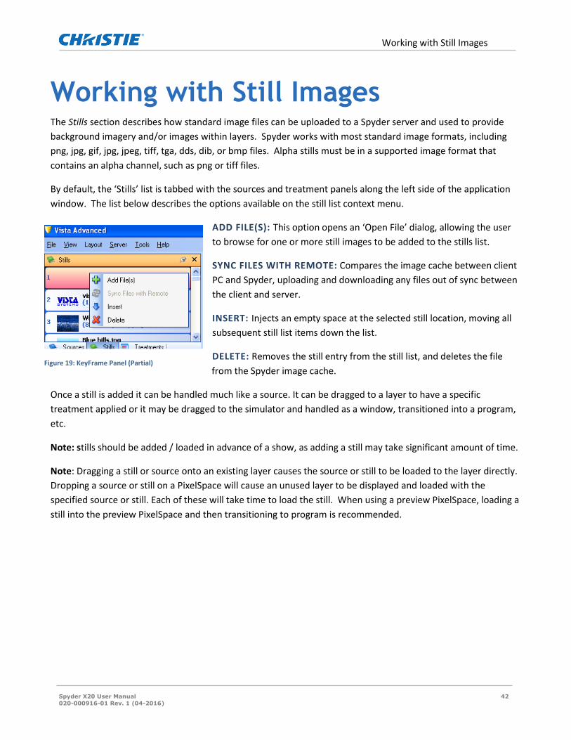
Working with Still Images The Stills section describes how standard image files can be uploaded to a Spyder server and used to provide
background imagery and/or images within layers. Spyder works with most standard image formats, including
png, jpg, gif, jpg, jpeg, tiff, tga, dds, dib, or bmp files. Alpha stills must be in a supported image format that
contains an alpha channel, such as png or tiff files.
By default, the ‘Stills’ list is tabbed with the sources and treatment panels along the left side of the application
window. The list below describes the options available on the still list context menu.
ADD FILE(S): This option opens an ‘Open File’ dialog, allowing the user
to browse for one or more still images to be added to the stills list.
SYNC FILES WITH REMOTE: Compares the image cache between client
PC and Spyder, uploading and downloading any files out of sync between
the client and server.
INSERT: Injects an empty space at the selected still location, moving all
subsequent still list items down the list.
DELETE: Removes the still entry from the still list, and deletes the file
from the Spyder image cache.
Once a still is added it can be handled much like a source. It can be dragged to a layer to have a specific
treatment applied or it may be dragged to the simulator and handled as a window, transitioned into a program,
etc.
Note: stills should be added / loaded in advance of a show, as adding a still may take significant amount of time.
Note: Dragging a still or source onto an existing layer causes the source or still to be loaded to the layer directly.
Dropping a source or still on a PixelSpace will cause an unused layer to be displayed and loaded with the
specified source or still. Each of these will take time to load the still. When using a preview PixelSpace, loading a
still into the preview PixelSpace and then transitioning to program is recommended.
Figure 19: KeyFrame Panel (Partial)

Treatments
Spyder X20 User Manual 43
020-000916-01 Rev. 1 (04-2016)
Treatments At the bottom of the top left section of the Vista Advanced panel is a tab called Treatments. A treatment is a
collection of key frame information that can be applied to one or more layers in the system at any time.
Treatments offer a considerable speed increase over manually adjusting the key frame for a layer, and make it
easy to provide a consistent look between windows. A default treatment can even be selected, extending the
consistent look of multiple layers by automatically applying a treatment to all layers before they are displayed
on screen.
TO CREATE A TREATMENT:
Select a layer using the display simulator containing the KeyFrame properties to be converted to a
treatment.
Right click in an unused list location within the ‘Treatment’ panel to display the treatment context
menu.
Select ‘Add New Treatment’ from the popup context menu. A popup dialog appears containing
placement for the treatment name, as well as a series of checkboxes used to select the specific
KeyFrame properties to be applied as part of the treatment recall.
TO APPLY A TREATMENT TO A LAYER:
1. A treatment can be applied to a single layer by either dragging the desired treatment from the
treatment list onto a layer in the simulator or patch control.
2. A treatment can be applied to multiple layers simultaneously by first selecting the layers from within the
display simulator, and then double-clicking the desired treatment. When applying a treatment to
multiple layers, a dialog may appear requesting confirmation.
3. Apply treatments to script elements by dragging a desired treatment from the treatment list onto a
script element at the desired cue location. If a KeyFrame is already defined at the selected element cue,
the treatment will be applied to the existing element KeyFrame properties. If no KeyFrame already
exists at the specified location, a new KeyFrame will automatically be added to the element.

Using the Display Simulator
Spyder X20 User Manual 44
020-000916-01 Rev. 1 (04-2016)
Using the Display Simulator The simulator is an intuitive, easy to use control for users familiar with working in Microsoft Windows based
applications. Like most panels within Advanced, the simulator supports a drag-drop capability, allowing content
such as sources or stills to be dropped onto PixelSpaces or layers within the simulator to manipulate the Spyder
system. Layers and PixelSpaces are selected simply by clicking them, and layer sizing and adjustment can be
performed by clicking and dragging layers or grabbing layer corners, respectively.
3
4
5
2
1
Figure 20: Display simulator control
SECTIONS OF DISPLAY SIMULATOR:
1. PIXELSPACE SELECTION: Provides a button for each PixelSpace currently displayed within the simulator
control. Clicking a PixelSpace selection button causes the simulator to zoom in on the selected
PixelSpace.
2. SIMULATOR CONFIGURATION TOOLBAR: Contains controls thst manipulate the control operations
provided by the display simulator.
a. VIEW STACK: Contains a list of various PixelSpace views available within the simulator control.
A view stack is created every time multiple PixelSpaces occupy the same space, allowing a user
to view a PixelSpace that might otherwise be obscured by another PixelSpace.
b. DURATION: Sets the duration of the transition (in frames) for live layer transition operations
such as mixing a layer on or off screen.

Using the Display Simulator
Spyder X20 User Manual 45
020-000916-01 Rev. 1 (04-2016)
c. DISCONNECT LAYERS: Command key scripts support a live-editing mode, in which any
KeyFrame changes made manually on a layer after recalling a script cue will be saved back to the
script automatically. To prevent accidentally editing script data, users can press the ‘Disconnect
Layers’ button to ensure that layer changes made will not be persisted.
3. LAYER ALIGNMENT TOOLBAR: Provides simple, yet powerful alignment and sizing capabilities for one
or more layers selected within the simulator. Hovering the mouse over any of the alignment icons
displays a tooltip, providing a brief description of the icon’s functionality.
4. PROGRAM PIXELSPACE(S): This area displays all program PixelSpaces included in the current view stack.
5. PREVIEW PIXELSPACE(S): If the Spyder system was configured to use preview PixelSpaces as part of
initial configuration, a preview section of the simulator will appear, allowing for off-screen editing.

Command Keys
Spyder X20 User Manual 46
020-000916-01 Rev. 1 (04-2016)
Command Keys A command key works like a preset. Every command key, however, is based upon an extensive scripting engine,
which allows for user extensibility simply not possible in a preset. When a command key is activated, a default
cue is being executed in the background to process the command key data.
This section will focus on command key usage in its most basic form, providing traditional preset-style learning
and recalling of user-defined screen looks. These screen looks contain source and KeyFrame information for one
or more layers.
A Command Key appears as a button on a PC running Vista Advanced, with ‘PVW’ and ‘PGM’ buttons
which execute the command key contents into the preview or program PixelSpace, respectively. The
‘PVW’ section of the command key will glow yellow when recalled to preview, and the ‘PGM’ section of
the key will glow red when recalled to program.
TO CREATE A COMMAND KEY
1. Right Click in the Command Key Section (shown below)
2. Select either ‘Create from Preview’, ‘Create from Program’, ‘Create from Screens’, or ‘Create Empty’, as
desired.
3. A popup dialog will prompt you for the name of the new Command Key. Enter the name and then click
OK.
A Command Key will be in edit mode after selected until either the disconnect button is pressed in the
Command Key window, or until another command key is recalled that takes control of all layers in the original
command key. If a command key shows red in program or yellow in preview, the Command Key is in edit mode
and any changes to layers will be saved in that command key.
Relative and Absolute Modes
Absolute and relative command key modes differ in the handling of layers not defined specifically as part of the
command key.
ABSOLUTE: When recalled, any layers not specifically defined within the command key will be mixed
off screen as part of the absolute command key recall.
RELATIVE: A relative command key affects only layers defined within the command key, and does not
remove or otherwise modify any other layers on screen.

Command Keys
Spyder X20 User Manual 47
020-000916-01 Rev. 1 (04-2016)
Figure 21: Layer Pattern Generator

Scripting
Spyder X20 User Manual 48
020-000916-01 Rev. 1 (04-2016)
Scripting Every command key is based on a script file, and a Script consists of displays various sources or stills, referred to
as elements, which span a period of time in the form of cues. Shown below is the Script panel and the Script
timeline.
Script Panel
A script element represents one or more layers of the system, spanning two or more cues. Element types
encapsulate sources, stills, and mixers; enhancing their definitions by optionally adding KeyFrames by right
clicking the element at each cue, and specifying mix on / off or effect durations for the respective on / off or
effect cues.
1. Add an element to the script by dragging a source or still from a content panel onto the script. The
element will automatically be added at the location of the drop cue, starting on the drop layer
2. Drag the bottom edge of the element to adjust its cue length.
3. Click on the element to open the properties for the element in the properties panel. The element
properties panel will adjust the element name, associated thumbnail, as well as the entrance / exit
durations.
4. By default, an element only contains one KeyFrame. This KeyFrame defines the initial location of the
element on screen. As the script advances, each element uses the last defined KeyFrame. This is known
as the ‘driving KeyFrame’. To add KeyFrames to an element, right click the element at a cue location,
and select ‘Add KeyFrame’. When editing the KeyFrame of a layer defined as a script element, the
‘driving KeyFrame’ is automatically modified.
Note: You can change the duration of the element on individual KeyFrames allowing you to adjust transition
durations within the script.

Scripting
Spyder X20 User Manual 49
020-000916-01 Rev. 1 (04-2016)
1. You can create looks on screen and ‘snapshot’ them to the script. After creating a look using the display
simulator, right-click in the command key area and select ‘Create from Screens’ from the context menu
presented.
2. You can create a Mixer out of a script element by right clicking on that element and ‘convert to mixer’.
By dropping multiple sources into the same element at different cues, allows you to mix sources in one
window using the script.
3. You can create an input array out of a script element by right clicking on that element and ‘convert to
input array’. This will allow you to display two sources simultaneously. If one source is not ready, the
other source will wait until that source is ready to be displayed. This is very useful when using a high-def
dual-head background source.
4. Add an off element to a script by right clicking in a cue and layer cross box and select add off element.
An off element becomes useful when working with relative command keys.
Cue Triggers A cue trigger can be used to automate the execution of a script cue. It can be based on the Spyder’s internal
clock, or it can be controlled from an external time source. The following trigger types are available within
Spyder:
WAIT TRIGGER: Causes the script processor to count down a specified number of frames and then execute the
next script cue. When the wait Trigger cue is executed, the countdown timer begins automatically, allowing
multiple wait triggers to be created on subsequent cues to automate multi-step scripting operations.
WAITX TRIGGER: The wait ‘X’ trigger is an unresolved time trigger. The first time a script cue using a wait ‘X’
trigger is executed, the scripting engine will begin counting the number of frames until the next cue is manually
executed. The script engine will then automatically record the elapsed time and change the cue trigger’s type
from WaitX to Wait. Subsequent executions of the script cue will function as a standard wait trigger.
TIME TRIGGER: Allows an external clock source to provide a time code that will be monitored for a user-
defined timecode, which will cause the next cue to be executed by the scripting engine. The external clock
source must be provided from a device connected to the SourceMaster deck controller, and therefore must
support a standard playback machine protocol such as BVW75 or Odetics. Refer to Required Hardware (page
67).
To add a Trigger to a script cue, click on the cue within the script panel, and select a trigger type and Trigger
length value on the properties panel.

Function Keys
Spyder X20 User Manual 50
020-000916-01 Rev. 1 (04-2016)
Function Keys A Function Key provides one of several user-definable functions. Unlike the extensible scripting architecture
used with Command Keys, Function keys are fixed purpose and can generally be thought of as shortcut keys.
Typical Functions include:
1. LAYER OFFSET: Defines horizontal and vertical offsets that can be applied to one or more windows.
Typically used to create ‘Fly Off’ effects.
2. LOAD A SOURCE ON LAYER: Used to load a defined source onto one or more layers.
3. LOAD A STILL ON LAYER: Used to load a still on a layer.
4. SWITCH ROUTER SALVO: Used to switch outputs on a router not directly connected to Spyder.
5. EXTERNAL COMMAND KEY RECALL: Recalls a Command Key on a remote Spyder.
6. BACKGROUND MIX: Used to mix backgrounds between programs and preview then with the click of a
Function Key.
7. NETWORK COMMAND: Sends a single UDP or TCP string in ASCII format to a user-specified port at a
user-specified IP address.
8. Note: Special values can be entered into the ASCII command string of the network command function
key to send carriage return, new line, and hex characters by using the following escape codes:
a. \r: Sends a carriage return character
b. \n: Sends a newline character
c. \X00: Sends a hex character, where the ‘00’ represents a hex encoded value.
When right-clicking an unused area of the function key grid, the list of function key types (listed above)can be
added.
TO ADD A FUNCTION KEY
1. Right Click in the Function Key section (make sure the Function Key tab is selected).
2. Select the desired Function Key type off from the contextual menu that appears.
3. Select the Function Key icon and enter the required information in the Properties section.
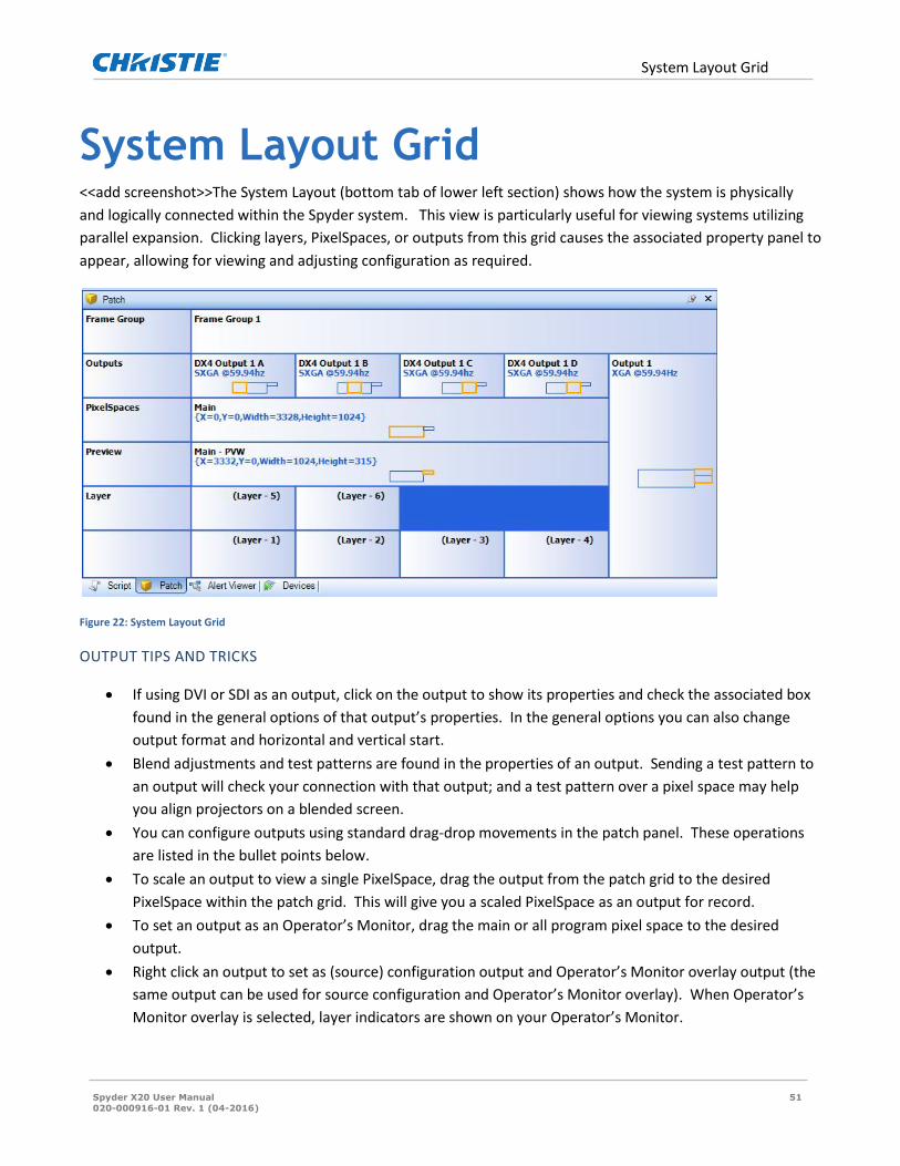
System Layout Grid
Spyder X20 User Manual 51
020-000916-01 Rev. 1 (04-2016)
System Layout Grid <<add screenshot>>The System Layout (bottom tab of lower left section) shows how the system is physically
and logically connected within the Spyder system. This view is particularly useful for viewing systems utilizing
parallel expansion. Clicking layers, PixelSpaces, or outputs from this grid causes the associated property panel to
appear, allowing for viewing and adjusting configuration as required.
Figure 22: System Layout Grid
OUTPUT TIPS AND TRICKS
If using DVI or SDI as an output, click on the output to show its properties and check the associated box
found in the general options of that output’s properties. In the general options you can also change
output format and horizontal and vertical start.
Blend adjustments and test patterns are found in the properties of an output. Sending a test pattern to
an output will check your connection with that output; and a test pattern over a pixel space may help
you align projectors on a blended screen.
You can configure outputs using standard drag-drop movements in the patch panel. These operations
are listed in the bullet points below.
To scale an output to view a single PixelSpace, drag the output from the patch grid to the desired
PixelSpace within the patch grid. This will give you a scaled PixelSpace as an output for record.
To set an output as an Operator’s Monitor, drag the main or all program pixel space to the desired
output.
Right click an output to set as (source) configuration output and Operator’s Monitor overlay output (the
same output can be used for source configuration and Operator’s Monitor overlay). When Operator’s
Monitor overlay is selected, layer indicators are shown on your Operator’s Monitor.

System Layout Grid
Spyder X20 User Manual 52
020-000916-01 Rev. 1 (04-2016)
When configuring a DX4 output, (output with 4 DVI ports), the four outputs must be set at the same
resolution but can “look” at or display different portions of pixel spaces. This is very useful with blended
screens and arrays.
A DX4 output can be rotated. This rotation happens in the output and does not rotate a PixelSpace.
This can be useful for tall and narrow displays such as LED walls.

Alert Viewer
Spyder X20 User Manual 53
020-000916-01 Rev. 1 (04-2016)
Alert Viewer The Alert Viewer tab shows a list of informational, warning, and error messages that occur in both the Vista
Advanced application and a remotely connected Spyder frame. Anytime Vista Advanced performs a significant
action, or any time a connected Spyder system encounters an error, an entry is logged in the Alert Viewer panel.
The Alert Viewer is typically used only for troubleshooting. For instance, if Vista Advanced performs incorrectly
or doesn’t carry out desired instructions, the user can view the Alert Viewer to see if there is a noted problem or
pattern. The Alert View information can be saved or a screen shot of the panel can be made for Christie support
staff to better identify the cause of problems.

Devices
Spyder X20 User Manual 54
020-000916-01 Rev. 1 (04-2016)
Devices The Devices tab is in the lower left of the Vista panel, just to the left of the Alert Viewer tab. A device is a way of
manipulating layers, mixing layers, etc. A device can be a single layer device, a dual layer, or a mixer. The devices
section is in the lower left of the Vista; panel, once the Devices tab has been selected. Devices will be shown as a
box. A total of eight devices can be configured.
Configuring a New Device To configure a new device, click on the device box in the devices section. In the properties section, an input
panel will appear where device information can be entered. Here a device can be assigned to be a mixer, for
layers 1 and 2, for instance. Check the Morph box if the Morph effect is desired, and so on.
The device boxes on the lower left work like the transition control on the Montage II control. Clicking on the
device box allows the user to start manipulating the device – and the device function can be run also.
You can change the duration time of a mixer in the duration box in the upper left corner of the devices pane.
Figure 23: Devices Panel
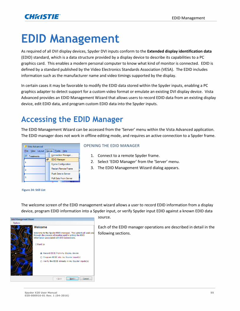
EDID Management
Spyder X20 User Manual 55
020-000916-01 Rev. 1 (04-2016)
EDID Management As required of all DVI display devices, Spyder DVI inputs conform to the Extended display identification data
(EDID) standard, which is a data structure provided by a display device to describe its capabilities to a PC
graphics card. This enables a modern personal computer to know what kind of monitor is connected. EDID is
defined by a standard published by the Video Electronics Standards Association (VESA). The EDID includes
information such as the manufacturer name and video timings supported by the display.
In certain cases it may be favorable to modify the EDID data stored within the Spyder inputs, enabling a PC
graphics adapter to detect support for a custom video format or emulate an existing DVI display device. Vista
Advanced provides an EDID Management Wizard that allows users to record EDID data from an existing display
device, edit EDID data, and program custom EDID data into the Spyder inputs.
Accessing the EDID Manager The EDID Management Wizard can be accessed from the ‘Server’ menu within the Vista Advanced application.
The EDID manager does not work in offline editing mode, and requires an active connection to a Spyder frame.
OPENING THE EDID MANAGER
1. Connect to a remote Spyder frame.
2. Select ‘EDID Manager’ from the ‘Server’ menu.
3. The EDID Management Wizard dialog appears.
The welcome screen of the EDID management wizard allows a user to record EDID information from a display
device, program EDID information into a Spyder input, or verify Spyder input EDID against a known EDID data
source.
Each of the EDID manager operations are described in detail in the
following sections.
Figure 24: Still List

EDID Management
Spyder X20 User Manual 56
020-000916-01 Rev. 1 (04-2016)
Recording EDID Data from a Display Device After selecting the ‘Record EDID from my display device’
option from the EDID Manager welcome screen and clicking
‘Next’, users are prompted to select a Spyder output
connected to a display device over DVI. The series of steps
below describe the process of recording EDID data from a
display device.
TO RECORD EDID DATA
Select an output from the drop down list of outputs. When recording EDID from a universal output
module, verify the DVI cable is connected to the ‘A’ side of the output.
Click ‘Read Now’. The Spyder will attempt to read EDID data from the display device connected to the
specified output, and then a success or failure dialog will be displayed. If the EDID within the display
device is loaded correctly, the ‘Next’ button is enabled.
Click the ‘Next’ button to display the ‘Save EDID Information’ screen. This screen provides multiple
options for using the recorded EDID data.
o The recorded EDID data can be immediately used to program the Spyder DVI inputs. Refer to the
‘Programming Spyder input EDID’ section below for further instruction.
o The EDID information can be saved to a file for later recall. If selecting this option, click the
‘Browse…’ button to specify a location and filename for the EDID file to be created, and then click
‘Next’. The ‘Finished’ screen will be displayed, and the EDID recording process will be complete.
Programming Spyder input EDID The EDID data contained on the Spyder input module must be
programmed by an external device, and as a result
programming an EDID using the EDID Manager requires the
use of a Spyder output, connected via DVI into a Spyder input.
The DVI channel on a selected output module works as a
transmitter, loading EDID data onto the connected input
module.
To prevent accidental overwriting the EDID data in a display
device, the third descriptor block in the EDID packet is
reserved to uniquely identify a Spyder input module. Before Figure 25: EDID Manager welcome screen

EDID Management
Spyder X20 User Manual 57
020-000916-01 Rev. 1 (04-2016)
programming occurs, a connection check reads the current EDID from the device connected to the selected
output module, and ensures that the descriptor block matches the unique signature of a Spyder input.
After the connection check, the output module transmits the EDID data, overwriting the current EDID data
stored on the input module. After programming completes, the EDID is read back from the input module and is
compared to the EDID data written to ensure the operation completed successfully.
TO PROGRAM EDID INTO THE SPYDER INPUT
From the ‘Load EDID Data’ screen, users are prompted to supply an EDID data source. Users can select
either the original Vista factory EDID, EDID data to be obtained from a display device, or EDID
information loaded from a file. If obtaining an EDID from a display device, the steps described in the
previous section (Recording EDID Data from a Display Device), will be performed before continuing.
Click ‘Next’ after loading EDID data to display the ‘Program EDID into Spyder Inputs’ screen.
Select the output to be used to write EDID into the Spyder input(s) from the drop down list. When
programming EDID using a universal output module, verify the DVI cable is connected to the ‘A’ side of
the output.
Click the ‘Start’ button. The EDID Management Wizard performs the steps mentioned above to
complete the programming process. When completed, a popup dialog appears indicating the success or
failure of the programming process.
Repeat step 2 for each input to be programmed.
Click ‘Next’ after all Spyder input modules have been programmed to display the ‘Finished’ screen.
Verifying Spyder Input EDID Comparing the EDID data stored within the Spyder input is
useful during EDID troubleshooting to ensure that the EDID
data stored in a Spyder input matches an expected data
source.
The verification process is very close to the EDID
programming process; however the actual programming step
is bypassed during the verification operation.
TO VERIFY THE SPYDER EDID AGAINST A KNOWN DATA SOURCE
Figure 26: Recording EDID Data

EDID Management
Spyder X20 User Manual 58
020-000916-01 Rev. 1 (04-2016)
From the ‘Load EDID Data’ screen, users are prompted to supply an EDID data source. Users can
select either the original Vista factory EDID, or EDID information loaded from a file. Click ‘Next’
after loading EDID data to display the ‘Verify EDID data’ screen.
Select the output to be used to read EDID from the Spyder input from the drop down list. If
selecting a universal output module, verify the DVI cable is connected to the ‘A’ side of the
output.
Click the ‘Verify’ button. The EDID Management Wizard verifies the connection to the Spyder
input and then compares the loaded EDID data to the EDID read from the input. When
completed, a popup dialog appears indicating the success or failure of the verification process.
Click ‘Next’ after all Spyder input modules have been verified to display the ‘Finished’ screen.
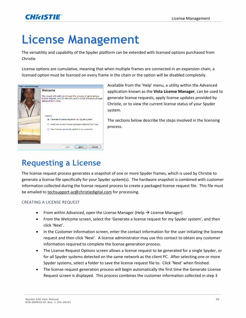
License Management
Spyder X20 User Manual 59
020-000916-01 Rev. 1 (04-2016)
License Management The versatility and capability of the Spyder platform can be extended with licensed options purchased from
Christie
License options are cumulative, meaning that when multiple frames are connected in an expansion chain, a
licensed option must be licensed on every frame in the chain or the option will be disabled completely.
Available from the ‘Help’ menu, a utility within the Advanced
application known as the Vista License Manager, can be used to
generate license requests, apply license updates provided by
Christie, or to view the current license status of your Spyder
system.
The sections below describe the steps involved in the licensing
process.
Requesting a License The license request process generates a snapshot of one or more Spyder frames, which is used by Christie to
generate a license file specifically for your Spyder system(s). The hardware snapshot is combined with customer
information collected during the license request process to create a packaged license request file. This file must
be emailed to [email protected] for processing.
CREATING A LICENSE REQUEST
From within Advanced, open the License Manager (Help License Manager)
From the Welcome screen, select the ‘Generate a license request for my Spyder system’, and then
click ‘Next’.
In the Customer Information screen, enter the contact information for the user initiating the license
request and then click ‘Next’. A license administrator may use this contact to obtain any customer
information required to complete the license generation process.
The License Request Options screen allows a license request to be generated for a single Spyder, or
for all Spyder systems detected on the same network as the client PC. After selecting one or more
Spyder systems, select a folder to save the license request file to. Click ‘Next’ when finished.
The license request generation process will begin automatically the first time the Generate License
Request screen is displayed. This process combines the customer information collected in step 3

License Management
Spyder X20 User Manual 60
020-000916-01 Rev. 1 (04-2016)
with one or more Spyder hardware snapshots, and writes a single file called ‘License.req’ upon
completing successfully. Click ‘Next’ after the license request generation process completes.
The Finished screen will display the full path to the generated license request file. This file must be
manually emailed to [email protected] to request a license file. Click ‘Finish’ to
close the Vista License Manager.
Installing a license Upon receiving a license request, a license administrator at Christie will generate an appropriate license file
based on the provided hardware and customer information combined with relevant purchasing history for
licensed options. This license file will be emailed to the customer email address supplied in the license request,
which is then to be installed by the customer.
The Vista License Manager guides users through a short series of steps to apply license files obtained from
Christie. The steps below outline the process of installing a license file on a Spyder frame.
INSTALLING A LICENSE FILE
1. Copy all license files obtained from Christie to a directory on the client PC hard drive. Do NOT rename
or change the extension of the license files, or they will become invalid.
2. From within Advanced, open the License Manager (Help License Manager).
3. From the Welcome screen, select the ‘Install one or more license packages obtained from Vista’, and
then click ‘Next’.
4. In the Browse for License Package screen, click the ‘Browse…’ button to select a folder on your local
hard drive containing one or more license files. After selecting a directory, all license packages found in
the specified directory will be listed at the bottom of the screen. Ensure at least one license file has
been found, and then click ‘Next’.
5. The first time the Apply License(s) to Server screen is displayed, a confirmation prompt will appear
warning that applying a license file causes the Spyder frame to restart. Click yes to acknowledge the
dialog and continue applying the license file(s). After license file application is complete, click ‘Next’ to
continue.
6. Click ‘Next’ at the Finished screen to close the License Manager.
Viewing Current License Status Viewing the current license status for a Spyder system displays the current status of all available license options
within the Spyder system. Because licensed options are cumulative when frames are connected together over
the expansion link, viewing license files on each frame can be particularly useful in troubleshooting licensing
issues on expanded systems.
The Vista License Manager can be used to view license status on both master and slave Spyder frames. The
steps below outline the process of viewing licensed options.

License Management
Spyder X20 User Manual 61
020-000916-01 Rev. 1 (04-2016)
VIEWING CURRENT LICENSE OPTIONS
1. From within Advanced, open the License Manager (Help License Manager).
2. From the Welcome screen, select the ‘View licenses previously applied to my system(s)’, and then click
‘Next’.
3. The View Existing License screen contains a dropdown list, which lists each Spyder frame currently
detected on the same network as the client PC. The license manager automatically downloads and
displays the state of all license options from a remote Spyder system when an IP address is selected.
Click ‘Finish’ to close the license manager after viewing any desired Spyder licenses.
Available Options for Spyder The item(s) listed below provide a brief introduction to the various license protected features for Spyder. For
more information on any of the items below, or for information on purchasing one or more of the licensed
options, contact Christie technical support at:
http://www.christiedigital.com/en-us/product-support/support-offices/Pages/default.aspx
Maintenance Contract
In addition to providing extended hardware coverage and support services, maintenance contracts purchased
for the Spyder system enable owners to access software updates containing new features and functionality. A
license containing an active maintenance contract is required to update to new software versions at and above
version 3.0.
Stereoscopic (SSO)
New and existing Spyder customers can extend the power of the Spyder hardware platform by incorporating
stereoscopic input and output processing capabilities. The stereoscopic option for Spyder allows for any
combination of 2D video inputs and 3D (active or passive) stereoscopic inputs to be displayed on the same
screen simultaneously. Spyder outputs also support passive or active stereoscopic modes, allowing Spyder to
natively run 3D display devices.

User Diagnostics
Spyder X20 User Manual 62
020-000916-01 Rev. 1 (04-2016)
User Diagnostics Spyder user diagnostics is a solid tool set that can be used to analyze and detect typical Spyder problems, and
also can be used to proactively detect issues in real-time before they become serious problems.
Real-Time Protection Spyder user diagnostics monitors the real-time state of the Spyder hardware, detecting events that occur while
the system is running. Making the user aware of potential problems early can prevent serious problems from
occurring in the future.
Real-Time Protection Alerts
The user alerting mechanism of Real-Time protection uses balloon dialogs appearing
on the Windows taskbar. This allows warnings to be displayed in the event of the
Advanced / Basic application being minimized, or otherwise not visible to the user.
When an alert popup is displayed, the user is given the option to open the user
diagnostics form from Vista Advanced, or to close the warning dialog. If the user
chooses to close (ignore) the alert popup, the popup will not be shown again for 15
minutes, or the next application startup. Additionally the user has the option of
selecting a ‘Don’t show this again’ checkbox, which will create an exception in the real-
time protection configuration to prevent the message from being displayed again.
Configuring Real-Time Protection
Real-Time protection is enabled by default. Users can manually disable real-time protection entirely, or
individual types of warnings can be suppressed. The Real-Time protection configuration dialog is available from
the ‘Tools’ menu within Vista Advanced and Vista Basic.
Figure 27: Programming Spyder Input EDID

User Diagnostics
Spyder X20 User Manual 63
020-000916-01 Rev. 1 (04-2016)
Figure 28: Automatic Protection General Options
Figure 29: Automatic Protection Exceptions
User Diagnostics Viewer The user diagnostics form (available from the ‘Tools’ menu) is the main dialog used to view collected data, run
additional testing, and interact with the user
diagnostics system. Details about detected problems,
as well as printable reports, are available from this
dialog.
The user diagnostics viewer provides an immediate
high-level summary of the current system state, and
additionally provides an advanced drill-down tree of
advanced information on each module within the
Spyder frame(s).
SECTIONS OF VIEWER
OVERALL STATUS: Provides quick overview
of overall system status.
INDIVIDUAL TEST STATUS: Shows overview
of individual tests run on all applicable
modules.
PRINTABLE REPORTS: Drop down list of report views
available for diagnostic data. Figure 30: Verifying Spyder EDID
1.
2.
3.
5.
6.
4.

User Diagnostics
Spyder X20 User Manual 64
020-000916-01 Rev. 1 (04-2016)
DETAIL TABS: Shows description of the currently selected test and an advanced drill-down of all
modules in the system. In cases where a test is in a warning or error state, a recommendations panel is
displayed with suggestions on resolving the detected problem(s).
RESET ERROR COUNTERS: Clears any previous test results, including any error counters.
REFRESH NOW: Runs all tests on each module in the system and immediately refreshes the form to
display the results.

Hot-Sync
Spyder X20 User Manual 65
020-000916-01 Rev. 1 (04-2016)
Hot-Sync The HotSync feature allows all data for one Spyder frame to be pushed to another Spyder frame for use as an
immediate backup system should a primary Spyder system fail. Specifically, HotSync is a user-initiated
synchronization system designed to be used frequently while programming Spyder content to ensure a backup
system contains a constantly refreshed version
of the live system data. This can be used in
mission critical scenarios where multiple
Spyder systems run in parallel to provide
immediate disaster recovery should a system
suddenly fail.
The function performed from the hot-sync
dialog is essentially an abbreviated backup /
restore procedure, and can be thought of as
data being backed up on the currently connected server and being
restored on a backup server.
Note that the HotSync feature does not provide automatic fail-over; manual intervention is required to migrate
to a backup system should a primary Spyder system fail. The manual fail-over is typically accomplished by
routing the outputs of both the primary and backup Spyder frames through a downstream routing switcher
before running into display devices, allowing fast switching between the Spyder frames.
Options for Hot-Sync When running parallel Spyder systems, specific portions of configuration data may remain specific to each of the
redundant systems. The HotSync feature provides options to exclude certain sections of configuration data
when synchronizing, and these options are described below.
Push Routers
Depending on the level of redundancy required for a given configuration, multiple Spyder systems may share the
same physical routing switcher. To accomplish this, the router patch definition on each Spyder system will differ
to distinguish the physical router outputs that correlate to the Spyder frame inputs. When performing a
HotSync in this configuration, it is not desirable to overwrite the router definitions specific to each backup
system. In these scenarios the ‘Push Routers’ checkbox should be unchecked, preventing router definitions to
be updated on the HotSync backup frame.
Figure 31: Real-Time Alert

Hot-Sync
Spyder X20 User Manual 66
020-000916-01 Rev. 1 (04-2016)
Figure 32: User Diagnostics Viewer
When excluding router definitions from the HotSync, it is important to ensure
the router ID within all Spyder frame(s) match to ensure all source definitions
using the router(s) will function correctly on the backup system(s).
The router ID can be found at the top of the router properties panel within
Vista Advanced.
Apply Output Configurations
Output configurations can be pushed to a backup Spyder frame as part of the HotSync operation. This is useful
when performing an initial HotSync between multiple Spyder systems, or when output configurations are
changed on the primary system and need to be replicated to a backup system. Applying output configurations
will cause outputs to flicker, making it an undesirable operation when performing several HotSync operations.
Provided the output configurations have not changed on the primary system, it is typically not necessary to
update the output configurations on the backup system(s) after initial configuration.

Video Playback
Spyder X20 User Manual 67
020-000916-01 Rev. 1 (04-2016)
Video Playback The rich feature set of Spyder can optionally be extended with VTR (Video Tape Recorder) and DDR (Digital Disk
Recorder) playback device control. Up to eight (8) playback devices can be connected to Spyder simultaneously,
and these devices can be controlled ‘live’ or as part of command key execution. Devices connected to Spyder
can additionally operate as time-code source providers, allowing frame-accurate triggering of command key /
script cues.
Note: In the following sections pertaining to machine control, the terms playback device, VTR, DDR, and deck
may be used interchangeably when referring to a video playback device.
Required Hardware Playback device integration requires the use of SourceMaster. SourceMaster is a 1-RU (rack unit) product
manufactured by Christie as an accessory device which connects to Spyder via Ethernet, and in turn connects to
up to four (4) RS-422/485 serial-based playback devices. A maximum of two SourceMaster units can be placed
on a single Ethernet network to control a total of eight (8) devices from a single Spyder system.
Detailed information on the SourceMaster hardware platform, where not specifically related to Spyder, is
outside of the scope of this manual. Contact Christie for additional information on SourceMaster.
Supported Playback Devices The VTR/DDR playback device market is heavily standardized on a small number of control protocols, and as
such control systems (including Spyder) can integrate with an overwhelming majority of these devices without
the need for special drivers or custom software. Non-clip controlled devices supporting the Sony BVW75
protocol (also known as the Sony 9-pin protocol), or clip-based device supporting the Odetics protocol can be
controlled from Spyder.
Note that some playback devices may require manual settings to enable control from external devices; refer to
the manufacturer documentation for your specific device for detailed instructions. Regardless of device, the
definitions for the previously mentioned protocols define the serial settings as 38400 baud, 8 data bits, odd
parity, and one stop bit. As such, these values are set by default in Spyder and are not user definable.

Video Playback
Spyder X20 User Manual 68
020-000916-01 Rev. 1 (04-2016)
Figure 33: HotSync Dialog
Getting Started Typical usage of a video playback device includes cueing and playing a collection of
video segments. A segment may be a short 30 second video, or a video that spans
several minutes or hours. Spyder uses the term PlayItem to refer to a pre-configured
segment of video playback. The individual data elements of a PlayItem are described
along with their associated user interface elements in the sections that follow.
The user interface for PlayItems is organized and managed by a register list that
appears tabbed with the source and still lists. This list is hidden by default, and can be
enabled from the ‘View’ menu on the main toolbar of Vista Advanced.
Adding a New PlayItem
Adding a new PlayItem begins much like creating other types of data in Vista Advanced. Begin by right-clicking
an unused register in the PlayItems list, and the select ‘Add’ from the popup context menu. A dialog will appear,
asking for the name of the new PlayItem. Enter a name into this dialog, and then click OK. Upon clicking OK, a
new PlayItem will be listed in the PlayItems list with the specified name, and the property panel for Advanced
will change to show the relevant properties for the newly created PlayItem.
Figure 34: Adding a new PlayItem
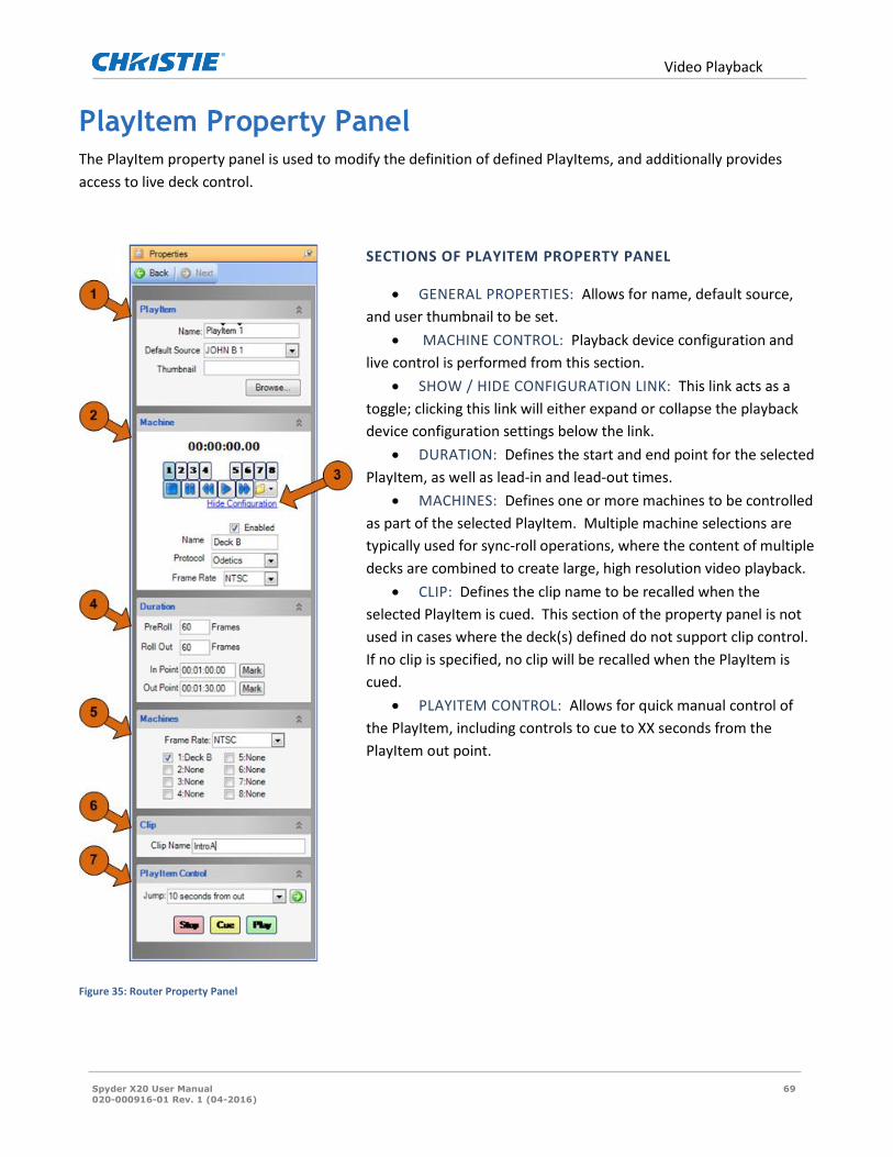
Video Playback
Spyder X20 User Manual 69
020-000916-01 Rev. 1 (04-2016)
PlayItem Property Panel The PlayItem property panel is used to modify the definition of defined PlayItems, and additionally provides
access to live deck control.
SECTIONS OF PLAYITEM PROPERTY PANEL
GENERAL PROPERTIES: Allows for name, default source,
and user thumbnail to be set.
MACHINE CONTROL: Playback device configuration and
live control is performed from this section.
SHOW / HIDE CONFIGURATION LINK: This link acts as a
toggle; clicking this link will either expand or collapse the playback
device configuration settings below the link.
DURATION: Defines the start and end point for the selected
PlayItem, as well as lead-in and lead-out times.
MACHINES: Defines one or more machines to be controlled
as part of the selected PlayItem. Multiple machine selections are
typically used for sync-roll operations, where the content of multiple
decks are combined to create large, high resolution video playback.
CLIP: Defines the clip name to be recalled when the
selected PlayItem is cued. This section of the property panel is not
used in cases where the deck(s) defined do not support clip control.
If no clip is specified, no clip will be recalled when the PlayItem is
cued.
PLAYITEM CONTROL: Allows for quick manual control of
the PlayItem, including controls to cue to XX seconds from the
PlayItem out point.
Figure 35: Router Property Panel

Video Playback
Spyder X20 User Manual 70
020-000916-01 Rev. 1 (04-2016)
Configuring Video Playback Devices
Device configuration is performed from the Machine section of the
PlayItem property panel. This can seem counter-intuitive, as it
requires a PlayItem to be created before machine definitions can
be viewed and/or edited.
Two groups of buttons, labeled 1-4 and 5-8, select a SourceMaster
port*. All controls in the Machine section of the property panel
(timecode, live controls, and configuration) follow the selected
SourceMaster port. If the configuration (bottom) area is not
visible as shown in the image to the right, click the blue ‘Show
Configuration’ link to expand this area.
* Ports 1-4 refer to the four ports on a SourceMaster device configured as a master, and ports 5-8 refer to the
four ports on a SourceMaster configured as a slave. The master / slave selection is set physically on the
SourceMaster hardware; refer to the SourceMaster hardware documentation for additional information.
The device configuration area allows a custom, or ‘friendly’, name to be set for the device, as well as the
communication protocol and frame rate specific to the device hardware. Some playback devices may support
multiple protocols, and the largest difference between the various protocols is clip control. From the supported
protocols, BVW75 is the only protocol which does not support clip control. As a result, clip control specific
operations will be unavailable for devices controlled from Spyder using this protocol. As a general rule, prefer
the Odetics or the DoReMi protocol in cases where these protocols are supported by the device.
Once the device settings have been applied, verify basic device communication by pressing the play and stop
buttons in the machine control panel to verify the device is being controlled, and to ensure that the correct
timecode is being displayed. If device control is not working properly, check the following:
QUICK TROUBLESHOOTING
1. CLIP CONTROLLED?
a. Clip controlled devices may require a clip to be loaded before normal control operations will be
accepted, and so it may be necessary to select a clip from the drop-down folder button in the
machine control panel before using the other media control buttons.
2. NO COMMUNICATION?
a. Ensure the machine is physically connected to the correct SourceMaster port, and that the
machine is set to remote control mode (if applicable). Also check the playback device
configuration to ensure it is set to be controlled by the same protocol selected in the Spyder
machine control properties.
3. CONTROL WORKING BUT TIMECODE NOT REFRESHING?
a. The most common cause of this problem is the RS-232 / RS-422 port on SourceMaster being
switched to RS-232. Check this setting on the back of SourceMaster to ensure it is set to RS-422.
Figure 36: PlayItem menu
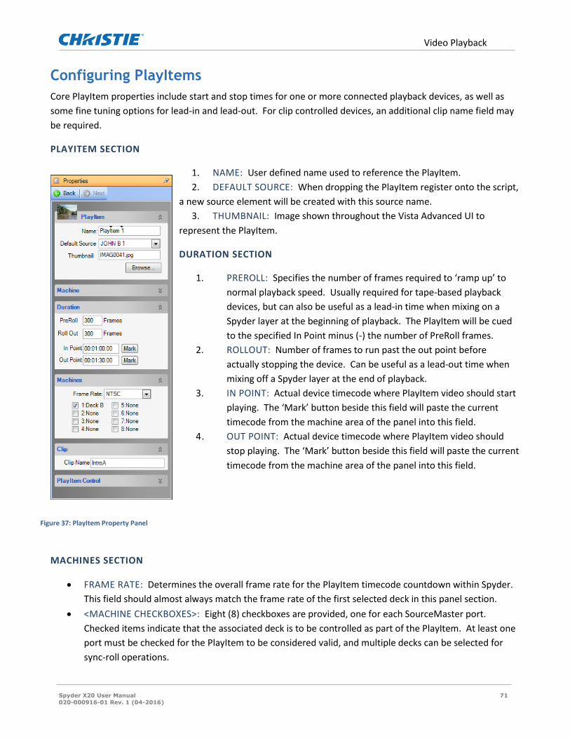
Video Playback
Spyder X20 User Manual 71
020-000916-01 Rev. 1 (04-2016)
Configuring PlayItems
Core PlayItem properties include start and stop times for one or more connected playback devices, as well as
some fine tuning options for lead-in and lead-out. For clip controlled devices, an additional clip name field may
be required.
PLAYITEM SECTION
1. NAME: User defined name used to reference the PlayItem.
2. DEFAULT SOURCE: When dropping the PlayItem register onto the script,
a new source element will be created with this source name.
3. THUMBNAIL: Image shown throughout the Vista Advanced UI to
represent the PlayItem.
DURATION SECTION
1. PREROLL: Specifies the number of frames required to ‘ramp up’ to
normal playback speed. Usually required for tape-based playback
devices, but can also be useful as a lead-in time when mixing on a
Spyder layer at the beginning of playback. The PlayItem will be cued
to the specified In Point minus (-) the number of PreRoll frames.
2. ROLLOUT: Number of frames to run past the out point before
actually stopping the device. Can be useful as a lead-out time when
mixing off a Spyder layer at the end of playback.
3. IN POINT: Actual device timecode where PlayItem video should start
playing. The ‘Mark’ button beside this field will paste the current
timecode from the machine area of the panel into this field.
4. OUT POINT: Actual device timecode where PlayItem video should
stop playing. The ‘Mark’ button beside this field will paste the current
timecode from the machine area of the panel into this field.
MACHINES SECTION
FRAME RATE: Determines the overall frame rate for the PlayItem timecode countdown within Spyder.
This field should almost always match the frame rate of the first selected deck in this panel section.
<MACHINE CHECKBOXES>: Eight (8) checkboxes are provided, one for each SourceMaster port.
Checked items indicate that the associated deck is to be controlled as part of the PlayItem. At least one
port must be checked for the PlayItem to be considered valid, and multiple decks can be selected for
sync-roll operations.
Figure 37: PlayItem Property Panel

Video Playback
Spyder X20 User Manual 72
020-000916-01 Rev. 1 (04-2016)
When multiple decks are selected in a single PlayItem, all decks will receive cue, stop, and play
commands simultaneously from SourceMaster, enabling all operations to be triggered at the same time
on all devices. In cases where long running sync-rolls are desired, clock skew between the decks may
cause drifts in the time code between the decks. In these cases, timecode chase or genlock may be
required between the decks. See the manufacturer documentation for further information on the
specific options available for the device type being used.
CLIP SECTION
CLIP NAME: When controlling clip-based playback devices, this field is used to specify the clip that
should be loaded when recalling the PlayItem. If this field is not specified, or if the deck protocol used
does not support clip control, no clip will be recalled when the PlayItem is cued.
Manual PlayItem Control PlayItems can be controlled from either the PlayItem property panel or the PlayItem register list. While the
controls in the PlayItem panel are useful and provided mostly for quick testing, the controls available in the
PlayItem register list make live control very easy to use and monitor.
Property Panel Controls
The PlayItem control section located at the bottom of the PlayItem
property panel allows for quick access to playing, stopping, and cueing
the currently selected PlayItem. This is useful functionality when testing
or tweaking PlayItem timing. The Jump selection allows the PlayItem to
be cued to 10-120 seconds from the out point, allowing the clip out point
to be adjusted without the requirement of viewing the entire length of the PlayItem.
Register List Controls
Context menu items on the PlayItem register list allow for the same cue, jump, play,
and stop control of all PlayItems as found in the PlayItem property panel, without
the additional clicking and mouse movement required to jump between the register
list and the property panel. The ‘Jump To’ menu items allow for cueing from the
out point of the PlayItem in increments from 10-180 seconds.
The register list additionally displays current status information for all PlayItems
simultaneously, providing a quick visual reference for PlayItem state. When a
PlayItem is not currently running, the in-point and total running time (TRT) will be
displayed in the PlayItem register. While the PlayItem is active, countdown
Figure 38: Machine Control
Figure 39: PlayItem Properties

Video Playback
Spyder X20 User Manual 73
020-000916-01 Rev. 1 (04-2016)
timecode information is displayed. Figure 41, shows an example of a PlayItem register display during the various
active / running states.
REGISTER DISPLAY FOR EACH PLAYITEM STATE
INACTIVE
PlayItem is not currently running. In point and total running time (TRT) are displayed.
CUED
PlayItem has been cued to the PlayItem in-point time code, minus the PreRoll frames (360 frames, or 10 seconds in this example).
PREROLL
PlayItem has started playing; however the in-point has not yet been reached. The PreRoll is counting down the amount of time remaining before the in-point is reached (9 seconds and 28 frames remaining in this example).
PLAYING
The PlayItem is currently playing and has passed the in-point. PlayItem register shows the amount of time remaining before the out-point is reached (18 seconds and 23 frames in this example).
ROLLOUT
The PlayItem has passed the out-point, and is continuing to play until the time code has reached the out-point plus the RollOut frame count (360 frames, or 10 seconds in this example). In this example, 9 seconds and 21 frames of RollOut remain before the decks associated with this PlayItem will be stopped.
Figure 40: Register Display for each PlayItem State

Scripting with Machine Control
Spyder X20 User Manual 74
020-000916-01 Rev. 1 (04-2016)
Scripting with Machine Control The ability to manually control source devices from the same interface which controls the Spyder windowing
processor is very useful functionality; the full benefit of device control integration, however, is realized when
using PlayItems to extend the command key / scripting platform. With Spyder it is possible for PlayItems to be
executed via scripting, and alternately it is possible for scripts to be executed from PlayItems (through the use of
timecode triggers). This deep level of integration allows for granular control and management of tightly coupled
timed events spanning multiple discreet components.
Triggering PlayItems from Scripts Each cue in a command key script contains its own set of properties specific to that cue. Included in these
properties are options to cue, play, or stop one or more existing PlayItems. Whenever defined on a cue, a
specified PlayItem operation will be executed whenever the associated script cue is executed.
To add or edit PlayItem specific properties for a script cue, start by clicking the script
cue to display the dynamic property panel for the cue itself. PlayItems have their own
section of the cue property panel, where one or more PlayItems are selected, along
with a desired operation. Note that the PlayItems section of the cue property panel will
automatically expand as additional PlayItems are defined, allowing an unlimited
number of PlayItem commands to be added to the cue.
Triggering Scripts from PlayItems Every script can be associated with a SourceMaster port, referred to as a
clock source, which is used by the Spyder scripting engine to allow
changes in timecode to trigger script execution. Each script is allowed only
one clock source; it is not possible to use timecode from multiple
SourceMaster ports to trigger the execution of a single script. To set the
clock source for a script / command key, click a desired command key and
edit the ‘Clock Source’ section shown in the dynamic property panel.
Each cue in the Spyder scripting engine contains a
‘trigger’ property, which can optionally be set to
a ‘Time’ value. When a script executes a cue with an associated time trigger, the
Figure 41: PlayItem Property Panel Controls
Figure 42: PlayItem
Register List Controls
Figure 43: PlayItem section of
Cue Panel

Scripting with Machine Control
Spyder X20 User Manual 75
020-000916-01 Rev. 1 (04-2016)
scripting engine will monitor the script’s clock source port until its time code reaches a specified timecode, and
then automatically execute the next cue in the script.
PlayItem Drag-Drop Operations in Script To simplify the process of associating PlayItems with command key scripts, certain drag-drop operations can be
used between the PlayItem panel and the script panel.
DRAG A PLAYITEM TO A SCRIPT CUE
When dragging a PlayItem from the PlayItem register list onto a cue in the script window a PlayItem cue
command will be added one cue before the cue dropped on, and the drop cue will add a PlayItem play command
and a time trigger to automatically advance the script at the end point of the PlayItem. The clock source for the
script will additionally be set to the first machine port defined in the PlayItem.
PlayItem dragged to script cue 1
PlayItem cue and play commands added, as well as a time trigger to advance the script at the PlayItem out point.
Figure 44: Dropping a PlayItem onto a Script Cue
DRAG A PLAYITEM TO A SCRIPT LAYER
Dragging a PlayItem to an unused area within the script grid will complete the same operations to the script cues
as when dragging a PlayItem onto a script cue, and will additionally add a source element with the default
source specified on the PlayItem (if defined).

Scripting with Machine Control
Spyder X20 User Manual 76
020-000916-01 Rev. 1 (04-2016)
PlayItem dragged to the script cell located at cue 1, layer 1
In addition to PlayItem play and cue commands being generated, a source element has been created with the default source defined on the PlayItem.
Figure 45: Dropping a PlayItem onto a Script Layer

Still Server (X20 Only)
Spyder X20 User Manual 77
020-000916-01 Rev. 1 (04-2016)
Still Server (X20 Only) The Still Server is a software application which can be run on an external PC and used in conjunction with the
Spyder X20 product line to dramatically increase the speed of still image loading in the system.
The still image server application works by connecting to the Spyder X20 with both an Ethernet and a DVI video
connection. When a still image file needs to be loaded, the X20 sends the file (if needed) and control commands
which instruct the still server to display the image on its DVI output. The DVI signal is then captured directly into
memory at the X20 OpMon input connector and routed as needed through the system.
Figure 46: Still Image Server Topology
The figure above shows the high-level topology of the still server when used in conjunction with the Spyder X20.
Still Server PC Requirements The still server application does not require a PC with a large amount of processing resources; it can be run with
most off-the-shelf Windows based computers with a DVI output. Being a graphics server with network image
transfer functionality, the greatest performance gains can be made from newer graphics cards and a gigabit
Ethernet enabled network. The minimum and recommended specifications for the Still server PC are below:
Minimum Requirements:
Pentium 4 2.5Ghz CPU
512Mb RAM
Windows XP SP3
100Mbit Network port
DVI output supporting 2048x1200 resolution

Still Server (X20 Only)
Spyder X20 User Manual 78
020-000916-01 Rev. 1 (04-2016)
Recommended Specification:
Intel Core™2 Duo 2.6Ghz CPU
2048Mb RAM
Windows Vista / Windows 7 (Note Windows 8 or above is not supported)
1000Mbit Network port
DVI output supporting 2048x1200 resolution
Note: The still server application should not be run on the same PC running the Vista Advanced client
application.
Installing and Configuring the Still Server The still server application is available on the Christie web site, along with the latest release versions of the Vista
Advanced software platform. While not always required, it is always recommended that the still server
application software be updated at the same time as the Vista Advanced / X20 server software.
Christie provides a Windows installer based setup experience for the still
server application, much like the installation for the Vista Advanced software
package. After installing the still server application, the still server
application will appear in the Windows start menu, as shown in figure 46
(left).
If desired, the still server application shortcut can be copied to the Startup
folder in the Windows start menu, causing the still server application to
automatically run each time Windows starts.
By default, the still server application will position its diagnostic window on
the main screen, and the still server capture window will be maximized on
the second screen (if present). In cases where only one output is configured
on the still server PC, the still server’s capture window will be maximized to
cover the primary screen, which initially appears as a solid black screen. To close this window at any time,
simply press ALT+F4 to close the still server application.
Configuring X20 to use the Still Serve Additional settings in the X20 must be configured using the Vista Advanced software after a still server is
configured and running on the Spyder network. After connecting to a Spyder X20 using the Vista Advanced
software, select the ‘Still Server Configuration’ option from the ‘Server’ menu. This will cause the still server
configuration property panel to be displayed.
Figure 47: Setting Clock Source

Still Server (X20 Only)
Spyder X20 User Manual 79
020-000916-01 Rev. 1 (04-2016)
The ‘Still Server Enabled’ checkbox controls whether or not the X20 should attempt to contact an external still
server for image loading, and the ‘IP Address’ field must contain the address of an available still server.
The ‘Delay Before Capture (ms)’ option is an advanced setting which adjusts the amount of time the X20 will
wait (in milliseconds) between sending the command to display an image and the time it actually captures the
image. Reducing this value effectively reduces the delay time involved in image captures, and may yield faster
image load times. Too low of a value may cause the image capture process may become unreliable, as shown in
Figure 48. The minimum capture delay value varies depending on the computer platform being used for the still
server application, and so experimentation may be required in scenarios where still loading performance
increases are desired even when using the still image server. The default delay value as of the time of this
writing is 300ms.
Figure 48: Sixteen stills loaded into layers using a still image server

Sample Configuration
Spyder X20 User Manual 80
020-000916-01 Rev. 1 (04-2016)
Sample Configuration This section contains a sample configuration.
Using the Setup Configuration GUI Setting up the X20 to work with the Vista Advanced Software GUI is accomplished by using the setup GUI. This
section of the manual will create a sample two screen configuration. The Vista Advanced GUI will allow you to
configure a system virtually to either preconfigure a unit or to become familiar with the Vista Advanced
Software.
1. Go to File New. The Vista Systems Configuration GUI will open.
2. Select “Start with new empty configuration”

Sample Configuration
Spyder X20 User Manual 81
020-000916-01 Rev. 1 (04-2016)
3. Select “Virtual Frame for the I.P. address and X20 1608” for the Spyder Model type. Select NTSC or PAL
depending on your region/video standard.
4. Select “Single Widescreen”.
5. Note the Pixel Space is Automatically Created.
6. Set the number of outputs to 2. This will create a 2 projector blend with 256 pixels of overlap.
7. Set the resolution of your projectors under the output resolution Format Name drop down menu. This
should match the native resolution of your projector for optimal image quality.
http://en.wikipedia.org/wiki/Display_resolution
8. Set the Connection type to match your projector input type i.e. DVI, SDI, VGA.
9. Click Next.

Sample Configuration
Spyder X20 User Manual 82
020-000916-01 Rev. 1 (04-2016)
10. Select a preview monitor. Note that a preview pixel space is automatically allocated in the V.I.
11. Items like Stills, Input Configurations and Presets are stored in the Processor. To start with a clean
configuration Click “Select All”. All of the Checkboxes will populate automatically. This is also where
you may select an external router. We will be using the X20 internal router for this sample configuration
so no router selection is needed. The X20 Internal Crosspoint Switcher will be used to route video.

Sample Configuration
Spyder X20 User Manual 83
020-000916-01 Rev. 1 (04-2016)
For this sample configuration we will be using a virtual X20. Configuring an X20 can be done offline in virtual
mode so that full configurations can be created offline.

Sample Configuration
Spyder X20 User Manual 84
020-000916-01 Rev. 1 (04-2016)
A success message will appear indicating the configuration is valid and the virtual GUI is ready for programing.
The Vista Advanced Default Layout
Main Screen PixelsSpace. This represents “Program Out” which are the two projectors in this case
seemed together with an edge blend.
Main PVW is the Preview output
Looking at the System Patch you can see how the PixelSpaces are allocated.
Output 1 (Left Projector) and Output 2 (Right Projector) together comprise the main output PixelSpace. Output 3
is allocated for the “Preview” output.
Adding Background Images to the V.I. Canvas
By right clicking in the Preview (PVW) space a custom image or color can be selected.

Sample Configuration
Spyder X20 User Manual 85
020-000916-01 Rev. 1 (04-2016)
Select an Image with sufficient resolution and the correct aspect ratio for your Pixelspace for optional image
quality.

Sample Configuration
Spyder X20 User Manual 86
020-000916-01 Rev. 1 (04-2016)
Use the same process from the Program or (Main) Pixel Space and select a different still background Image.
We have now created backgrounds for both Program and Main that are mixable.
By right clicking and selecting “Mix Background” notice that the backgrounds for Main and Preview swap with a
smooth mix transition. The rate of the mix is determined by the “Duration” rate which is 60 frames (or one
second) in this example.
Adding Input Sources
It will simplify things if you know which sources you want to connect to the Spyder. Creating a source list will
simplify the input configuration. In this example we will connect:

Sample Configuration
Spyder X20 User Manual 87
020-000916-01 Rev. 1 (04-2016)
Input Format X20 Input Input Type
1 NTSC Composite 1 BNC
2 1400 x 1050 DVI 2 DVI
3 RGB Component 3 BNC
4 1400 x 1050 DVI 4 DVI
5 HDSDI 5 BNC
6-16 TBD
Note that the Physical inputs on the X20 are BNC for Odd numbered inputs and DVI for Even numbered
Inputs. Connect Sources form the Source list. Interlaced sources cannot be used on the DVI
connector. Only odd inputs have de-interlacers.
Right Click in the Sources Tab on Source 1 and select “Add new Source”.
Select “Create and Configure Input”.
Select the input type. In this case select “Composite”.
Select the “Autosync button. “Save Required” will appear. Click the Save button.
Repeat this for each input source.
Pressing the Capture Key will create a custom Icon in the simulator by frame-grabbing the respective
input source and creating an Icon of the representing the full input image. You can also select a custom
icon to identify inputs graphically.

Sample Configuration
Spyder X20 User Manual 88
020-000916-01 Rev. 1 (04-2016)
Note that odd numbered inputs are BNC and even numbered inputs are DVI connectors.
Adding Sources to the PixelSpace
After inputs have been configured the input source list should look something like this.
Click on a source and it will highlight red.

Sample Configuration
Spyder X20 User Manual 89
020-000916-01 Rev. 1 (04-2016)
The input can now be dragged to the Program or Preview Pixelspace. Note that the System Patch
routes input source 1 (Layer 1) to the Preview Pixelspace. Also note the yellow route patch and the
yellow boarder around Source 1. The Yellow indicates that Source is in Preview.
When you drag a new Source to preview a new router patch is created in the System patch.

Sample Configuration
Spyder X20 User Manual 90
020-000916-01 Rev. 1 (04-2016)
Dragging a Source to Program will make the Source immediately live on the Program output. Note that
the router patch is now Red for Source 3 and that there is a red dot on both the Source List and Router
Patch indicating that the source is live in Program. Also note that Sources 1 and 2 have Yellow dots next
to the Source icons in both the Source List and Router Map indicating Sources 1 and 2 are in Preview.
Automating Tasks with Scripts and Function Keys
In this example we will use a Function Key to automate the Mix Background function.
Select the Function Key tab and then right click. Select Add Background Mix Key.
You will be prompted to name the Function.
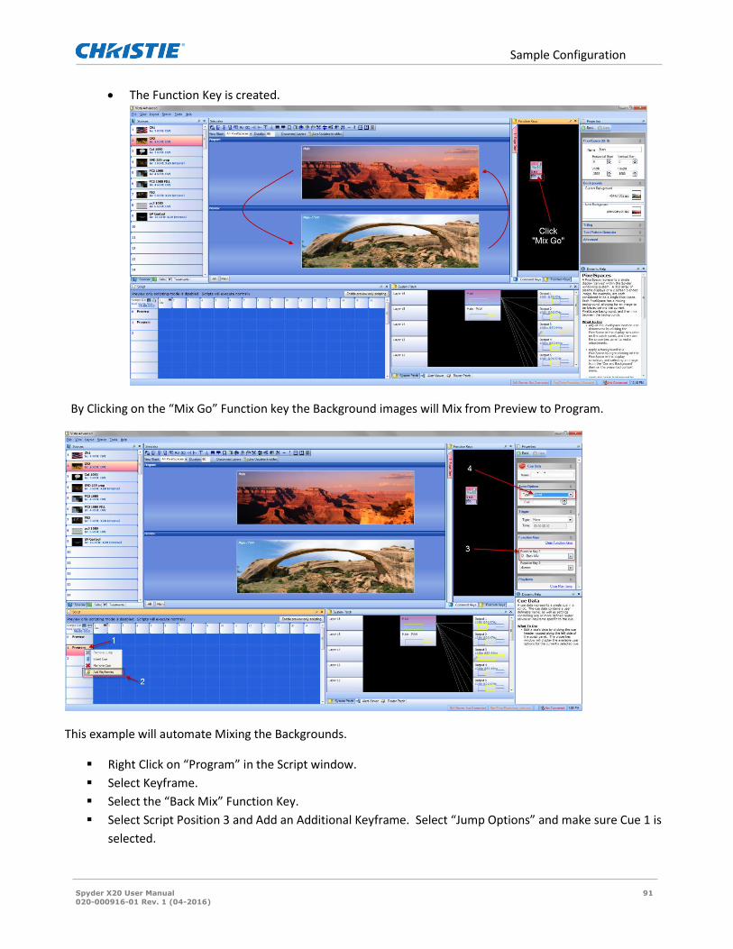
Sample Configuration
Spyder X20 User Manual 91
020-000916-01 Rev. 1 (04-2016)
The Function Key is created.
By Clicking on the “Mix Go” Function key the Background images will Mix from Preview to Program.
This example will automate Mixing the Backgrounds.
Right Click on “Program” in the Script window.
Select Keyframe.
Select the “Back Mix” Function Key.
Select Script Position 3 and Add an Additional Keyframe. Select “Jump Options” and make sure Cue 1 is
selected.

Sample Configuration
Spyder X20 User Manual 92
020-000916-01 Rev. 1 (04-2016)
Double Click on the Preview Cue (Cue Zero).
Hit the spacebar
The Cue Line will move down and execute the Keyframe “Back Mix” function.
The GOTO 1 will execute the Keyframe mix with each spacebar press.

Sample Screen Configurations
Spyder X20 User Manual 93
020-000916-01 Rev. 1 (04-2016)
Sample Screen Configurations
(4 x 2) PixelSpace Sample Configuration
To create this Pixelspace using the Vista Advanced Configuration GUI.
Start with new empty configuration.

Sample Screen Configurations
Spyder X20 User Manual 94
020-000916-01 Rev. 1 (04-2016)
Select the model of Spyder you are using.
Click next.
Select screen output format.
Select Single Widescreen
Name the Screen
Change the Screen output from the default (3) to (4).
Change the Vertical output from the default (1) to (2).
Change the Horizontal Overlap from the default of (256 for edge blending) to (0).
Click Next.

Sample Screen Configurations
Spyder X20 User Manual 95
020-000916-01 Rev. 1 (04-2016)
Select Frame Rate and click next.
Click Next.

Sample Screen Configurations
Spyder X20 User Manual 96
020-000916-01 Rev. 1 (04-2016)
Click Apply to local PC now (Virtual Mode).

Sample Screen Configurations
Spyder X20 User Manual 97
020-000916-01 Rev. 1 (04-2016)
These output positions are automatically created by the GUI wizard.
Screen H-Start V-Start
1 0 0
2 1928 0
3 3856 0
4 5784 0
5 0 1080
6 1928 1080
7 3856 1080
8 5784 1080
The Pixelspace is now configured and ready to use. Note that the yellow boxes are each graphically
representing which area of the screen they are contributing to.

Sample Screen Configurations
Spyder X20 User Manual 98
020-000916-01 Rev. 1 (04-2016)
(4) projector Blend with Rotated flanking displays
To create a four projector blend with a 300 pixel overlap and two rotated displays using the Advanced GUI.
Start with new empty configuration

Sample Screen Configurations
Spyder X20 User Manual 99
020-000916-01 Rev. 1 (04-2016)
Select the type of Spyder you are using.
Click Next.
Note: Building the pixel space from Left to Right will simplify the process.
Select the display resolution
Click Add Additional Discreet Screen.
Click the New Screen to open the properties panel.
Select Rotation 90 degrees since this is the left most rotated display.
Click next
To add the Widescreen
1. Click Add Additional Widescreen
2. Click the Widescreen PixelSpace to reveal the Properties.

Sample Screen Configurations
Spyder X20 User Manual 100
020-000916-01 Rev. 1 (04-2016)
3. Change the Horizontal Outputs for the default (3) to (4).
4. Change the Horizontal overlap from the default (256) to (300)
Add the final screen
1. Select Add Additional Discreet Screen.
2. Click in the New Screen Pixelspace.
3. Select 90 Degrees on the Rotation drop down.
4. Click next.
5. One the next two screens click next and then Apply to local PC (Virtual Mode).
The System Patch graphically displays how the screens are allocated in the V.I.

Sample Screen Configurations
Spyder X20 User Manual 101
020-000916-01 Rev. 1 (04-2016)
(8) projectors EdgeBlend and Rotated
To create this Pixelspace using the Vista Advanced Configuration GUI.
1. Start with a new empty configuration.

Sample Screen Configurations
Spyder X20 User Manual 102
020-000916-01 Rev. 1 (04-2016)
2. Select the type of Spyder you are using.
3. Click next.
4. Select screen output format.
5. Select Single Widescreen
6. Change the Screen output from the default (3) to (8).
a. Change the Horizontal Overlap from the default of (256 for edge blending) to (216).
7. Change the rotation setting to 90 Degrees.
8. Click Next.
9. On the next two screens click next and then Apply to local PC (Virtual Mode).

Sample Screen Configurations
Spyder X20 User Manual 103
020-000916-01 Rev. 1 (04-2016)
Working with Mullions (Dead Space for Fluid Window Fly’s)
Spyder X20 in Parallel
When there is the need to expand beyond 20 megapixels or eight outputs for a single conclusive system the X20
is capable of running in a mode called ‘parallel’. When the X2Os are in this mode each X20 has its area of
responsibility, called AOR, in which sources that are required to be shared between AORs use an input from
each X20. A single user interface is used.

Sample Screen Configurations
Spyder X20 User Manual 104
020-000916-01 Rev. 1 (04-2016)
The top screens are controlled by X20 (1) and are Frame Group 1. The bottom screens are controlled by X20 (2)
and are Frame Group 2
This 4 x 4 cube array with a VI of 7680 x 4320 pixels is an example of a Parallel Expansion. The upper grey
represents Frame Group A and the lower green Frame Group B. Each frame group supports 8 outputs assigned
to the AOR (area of responsibility) of the entire VI. Each Frame Group has inputs (layers) that are contained to
that Frame Group. When a source is displayed across both Frame Groups it will need a layer from each as in the
example above (Layers 2A and 2B). If a source is NOT across two frame groups as in the other two examples just
the layer in that Frame Group is used. An upstream matrix switcher will automatically assign the same source in
both the A and B layers and the system will automatically assign the slave layer when required.

Sample Screen Configurations
Spyder X20 User Manual 105
020-000916-01 Rev. 1 (04-2016)
Troubleshooting This section contains information to help troubleshoot your system.
Changing the IP Address on the X20
1. Click the Start Button>All Programs>Accessories>Remote Desktop Connection. Depending on your operating
system, the Remote Desktop Connection may be further embedded in an Accessories>Communication
folder.
2. Enter the existing know IP address of the X20 frame in the Computer: field and click Connect.
3. You should see a generic Windows login screen appear. The login and password for the Spyder frame is
Cricket and Cricket.

Sample Screen Configurations
Spyder X20 User Manual 106
020-000916-01 Rev. 1 (04-2016)
4. Once logged into the X20 frame, you are now sitting in front of a generic Windows XP installation and will
want to navigate to your Network Connections window. This is usually, Start> Settings> Network
Connections. You are looking for the active Local Area Connection.
5. Right-click, select Properties, choose Internet Protocol (TCP/IP), and click Properties again.
6. Here, you should be able to change the IP address, verify the Subnet Mask is the same on the X20 frame as it
is on your Vista Advanced client machine (typical settings include 255.255.255.0 and 255.255.0.0, for
example), and a Default gateway is not necessary. Click OK.
7. You will be disconnected from the Remote Desktop Session since the IP address has now changed. The unit
will need to be manually power cycled for the new IP address to be applied.
Using X20 for configurations with a tall VI
More Information
Currently, the maximum VI height when using X20 is 2400 pixels tall. If larger than 2400 pixels tall is necessary,
multiple X20 frames can be operated in parallel to achieve the desired height. When a configuration exceeds
1860 pixels, the system will restrict which layers are able to accept stills. This also has an effect on which layers
Sample Screen Configurations
Spyder X20 User Manual 107
020-000916-01 Rev. 1 (04-2016)
are able to use the bitmap borders and shapes feature in the X20. In these configurations, layers 3, 6, 11, and 14
are able to use these features.
Affected Versions
All versions
FIX: Application Crashes Related to DirectX
More Information
In versions of Vista Advanced 2009 prior to 3.5.0, the display simulator portion of the user interface was
generated using a managed implementation of Microsoft's DirectX platform (MDX). DirectX is commonly found
in gaming and data visualization applications, and allows applications to high performance by taking advantage
of hardware acceleration found in commodity graphics cards.
The managed DirectX implementation was depreciated by Microsoft in 2009, in favor of newer technologies
such as XNA and WPF. While the simulator control continued to work, it was unable to take advantage of newer
versions of DirectX technologies. Additionally, a small (but growing) number of customers running on various PC
hardware reported compatibility issues that ranged from simulator 'lock-ups' to no simulator display at all.
Resolution
As of version 3.5.0, the display simulator portion of the Vista Advanced interface was rebuilt using the Windows
Presentation Foundation (WPF). WPF allows Vista Advanced to continue providing a high performance,
hardware accelerated UI while resolving the issues mentioned above and ensuring future compatibility with the
latest enhancements with the Microsoft software platform.
All users experiencing problems in software versions prior to 3.4.3 are encouraged to upgrade to the latest
version of software (Version 3.5.5 at the time of this writing).
Applies To
Vista Advanced 2005 (All Versions)
Vista Advanced 2009 Version 3.4.3 and lower
LAN Card Priority Setting Network Not found
Often times, a user is connected to a wireless network for internet access as well as a LAN adapter for Spyder
communication. In the past, it was recommended or necessary for the wireless network adapter to be disabled
due to the fact the wireless adapter IP would take priority over the LAN adapter IP and interfere or inhibit
Spyder communication.
The METRIC parameter of each of the adapters on the computer can be manipulated to force an actual priority.
To do this, navigate to the Network settings on the client PC and access Properties for the LAN network adapter.
Access the TCP/IPv4 properties for LAN network adapter and at the normal screen for entering the IP settings
Sample Screen Configurations
Spyder X20 User Manual 108
020-000916-01 Rev. 1 (04-2016)
you will see the Advanced button at the bottom of the window. Clicking that allows you to attach multiple
different IP addresses to the same network card. At the bottom of that window is the METRIC setting. By
default, Windows will set this to AUTOMATIC. Uncheck AUTOMATIC and enter the value “2” as the metric
parameter for the wired LAN adapter on the network that Spyder is on.
Now access TCP/IPv4 settings for the wireless adapter, and set the metric parameter to "3" (windows reserves
the metric parameter of "1" for the loopback adapter).
When Vista Advanced starts up, it is “looking” at the adapter with the lowest METRIC.
Connecting to an X20 using remote
Remote desktop is included with the Windows XP and later operating systems. If you are running Windows
2000, the Remote Desktop Client can be downloaded at http://www.microsoft.com/windowsxp/down ...
entdl.mspx.
The steps below outline the process of connecting to the Spyder frame using the Remote Desktop Client.
1. Open Remote Desktop (Start -> Programs -> Accessories ->Communications -> Remote Desktop Connection.)
2. For the 'Computer' name in the Remote Desktop Connection dialog box, enter the current IP Address of the
Spyder system and then click 'Connect'. The IP Address of the Spyder can be viewed from the LCD display on the
front panel of the Spyder frame.
3. A Windows XP logon box will be displayed. Enter the following username and password, and then click 'OK' to
log into the Spyder desktop.
Username: Cricket
Password: Cricket
Spyder X20 dual-link support
Overview
Certain inputs and outputs of the Spyder X20 will support 2560x1600@60Hz or up to 330MHz***. This
document discusses the capabilities of the individual inputs and outputs.
Inputs
All of the X20 DVI inputs can support dual link resolutions, however because of the extreme bandwidth
requirements, the preceding analog input connector is disabled while the dual-link source is in use.
Example:
When a dual-link source is used on input 2, the system will utilize the resources from Input 1, therefore disabling
the connector.

Sample Screen Configurations
Spyder X20 User Manual 109
020-000916-01 Rev. 1 (04-2016)
Dual-link and layers
The following layers are able to display a dual link source: 1, 4, 7, 9, 12, and 15. Also, when one of these layers is
being used for a dual link source, the next adjacent layer is also used. The X20 0808 is able to support 3
simultaneous dual-link sources (layers 1/2, 4/5, and 7/8). The X20 1608 is able to support 6 simultaneous dual-
link sources (layers 1/2, 4/5, 7/8, 9/10, 12/13, and 15/16).
Example:
When a dual-link source is being used on layer 1, layer 2 will be used as well. This is shown in the simulator by a
1/2 in the layer label in the upper left corner.

Sample Screen Configurations
Spyder X20 User Manual 110
020-000916-01 Rev. 1 (04-2016)
Outputs
The Spyder X20 will support dual-link resolutions on odd numbered outputs.
Example:
Outputs 1, 3, 5, and 7 will support dual-link.
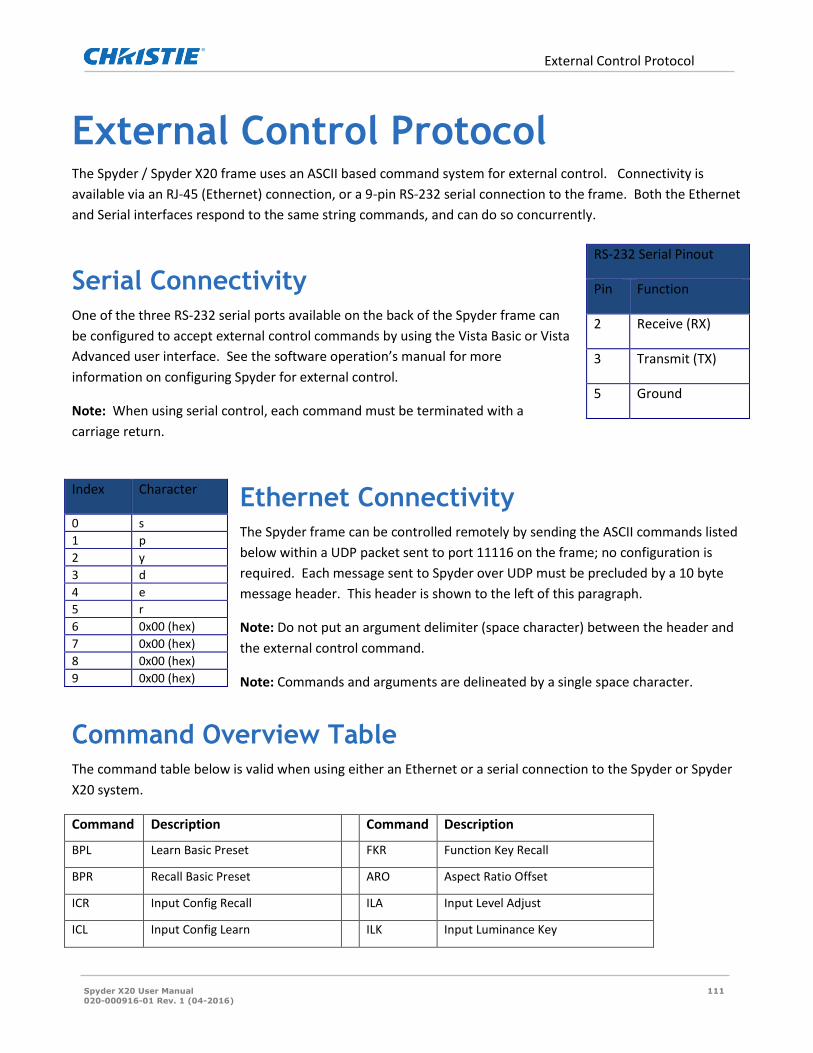
External Control Protocol
Spyder X20 User Manual 111
020-000916-01 Rev. 1 (04-2016)
External Control Protocol The Spyder / Spyder X20 frame uses an ASCII based command system for external control. Connectivity is
available via an RJ-45 (Ethernet) connection, or a 9-pin RS-232 serial connection to the frame. Both the Ethernet
and Serial interfaces respond to the same string commands, and can do so concurrently.
Serial Connectivity One of the three RS-232 serial ports available on the back of the Spyder frame can
be configured to accept external control commands by using the Vista Basic or Vista
Advanced user interface. See the software operation’s manual for more
information on configuring Spyder for external control.
Note: When using serial control, each command must be terminated with a
carriage return.
Ethernet Connectivity The Spyder frame can be controlled remotely by sending the ASCII commands listed
below within a UDP packet sent to port 11116 on the frame; no configuration is
required. Each message sent to Spyder over UDP must be precluded by a 10 byte
message header. This header is shown to the left of this paragraph.
Note: Do not put an argument delimiter (space character) between the header and
the external control command.
Note: Commands and arguments are delineated by a single space character.
Command Overview Table The command table below is valid when using either an Ethernet or a serial connection to the Spyder or Spyder
X20 system.
Command Description Command Description
BPL Learn Basic Preset FKR Function Key Recall
BPR Recall Basic Preset ARO Aspect Ratio Offset
ICR Input Config Recall ILA Input Level Adjust
ICL Input Config Learn ILK Input Luminance Key
RS-232 Serial Pinout
Pin Function
2 Receive (RX)
3 Transmit (TX)
5 Ground
Index Character
0 s
1 p
2 y
3 d
4 e
5 r
6 0x00 (hex)
7 0x00 (hex)
8 0x00 (hex)
9 0x00 (hex)

External Control Protocol
Spyder X20 User Manual 112
020-000916-01 Rev. 1 (04-2016)
Command Description Command Description
SDN Restart Spyder Server ICK Input Color Key
SAV Force Server Save LAP Layer Assign PixelSpace
RSC Recall Script Cue FRZ Freeze Layer(s)
TRN Transition Layer(s) RSN Request Source Names
KSZ Layer Size Adjust RLC Request Layer Count
KTL Learn Treatment RAR Request Aspect Ratio
KTR Recall Treatment SCR Script Cue Request
SLD Still Load on Layer(s) RRC Request Register Count
SCL Still Clear on Layer(s) RRL Request Register List
BTR Background Transition ARL Apply Register to Layer(s)
BLD Background Load Image RBL Request Basic Preset List
KBD Border Adjust KSH Shadow Adjust
CSO Clear Still on Output CRP Crop Adjust
LSO Load Still on Output SRA Source Apply to Layer(s)
RPS Request I/O Processor Status RPD Request PixelSpace Definitions
LCK Learn Command Key LAC Layer Alignment Control
ZPA Zoom / Pan Adjust RLK Request Layer KeyFrame
RLS Request Layer Source LCC Layer Clone Control
RCS Request Connection Status DCK Delete Command Key
IRA Input Config Raster QRC Query Router Crosspoint(s)
LSP Layer Size and Position OFZ Output Freeze
OCM Output Configuration Mode OCF Output Configuration Format
OCR Output Configuration Rotation OCS Output Configuration Save
OCB Output Configuration Blending DMB Device Mixer Bus Apply
DMT Device Mixer Transition
Note: Some commands listed display their last argument as ‘Argument x ~ XX:’. These commands allow the last
argument field to be repeated, allowing multiples of the last argument to be specified with a single command.
Note: Some commands listed display argument(s) with an asterisk. These options are optional; however no
further arguments may be entered in the command.

External Control Protocol
Spyder X20 User Manual 113
020-000916-01 Rev. 1 (04-2016)
Note: When specifying layer IDs in Spyder commands, note that the IDs start at 2. Layer ID 0 and 1 are reserved
for future commands using the two background layers of the system.
Note: String argument spaces must be replaced with the three character ASCII string %20 to create a valid
command, as space is used as the argument delimiter.
Command Processor Responses A response is returned for every command sent to the Spyder system. If multiple values are returned in a single
response, the argument delimiter is an ASCII space character, and argument values containing a space will be
converted to the 3 character ASCII string “%20”. The first response argument is always the error code for the
command, which lets the user know if a command was successfully processed. The table below displays the
various responses which can be returned by the Spyder.
Response Response Name Description
0 Success Command was successfully processed 1 Empty Data requested is not available 2 Header Invalid command specified 3 Argument Count Missing required minimum number of arguments 4 Argument Value One or more arguments were invalid 5 Execution An error occurred while processing the command. Check alert
log in Spyder Basic / Advanced software for details. 6 Checksum * Reserved *
Supported Command Descriptions
Basic Preset Learn Stores the current screen layout to a specified preset ID. Command: BPL Argument 1: Preset ID to save current window position and keyframe information to. Argument 2: Duration. This argument is optional. If not specified, duration will default to 60.
Basic Preset Recall This command recalls an existing basic preset from the frame, by using its corresponding ID. Command: BPR Argument 1: Preset ID to recall from server. Argument 2: Duration. This argument is optional. If not specified, duration will default to 60. Input Configuration Recall This command loads a previously saved input configuration onto the video source of a specified layer ID. Command: ICR Argument 1: Configuration ID. This is the ID number to store the layer ID’s current input configuration to. Set the Configuration ID to -1 to force auto sync. Argument 2: The layer ID to apply the specified input configuration to.

External Control Protocol
Spyder X20 User Manual 114
020-000916-01 Rev. 1 (04-2016)
Argument 3*: If -1 is set for argument 1, this value will set the connector type to be switched to and auto synced on a layer. 0=HD15, 1=DVI, 2=SDI, 3=Composite, 4=S-Video Input Config Learn This command saves the input configuration for a specified layer ID, to a specified input configuration ID for later recall. Command: ICL Argument 1: Input configuration ID to save to. Argument 2: Layer ID to save configuration information from. Restart Spyder Server This command allows the user to remotely restart the server application remotely. Command: SDN Argument 1: 0 = Power Off, 1 = Restart Force Server Save This command forces the remote Spyder frame to flush all configuration and user data changes to non-volatile storage. Command: SAV Recall Script Cue This command recalls an existing script at a specified cue. Use ‘Vista Advanced’ software interface to build scripts. Argument 3 optionally defines the ID type being recalled in argument 1, and defaults to ‘ScriptID’ if not specified. See “Understanding Registers” in this manual for information on registers. Note: To access registers on pages above the first page, add (<Page number> * 1000) to the register ID to be recalled. For example, to recall a script at register ID 2 on page 3, send a register ID of 3002. Command: RSC Argument 1: ID to recall Argument 2: Script Cue to recall Argument 3*: ID Type in Argument 1 (S=ScriptID, R=RegisterID) Transition Layer(s) This command transitions layers on and off of their currently assigned PixelSpace. Command: TRN Argument 1: 0 = Mix Off - 1 = Mix On Argument 2: Transition Duration (in frames) Argument 3 ~ XX: Layer ID to transition Layer Size Change This command sets the horizontal size of one or more specified layers. Vertical size adjusts automatically to ensure the layer’s aspect ratio. Command: KSZ Argument 1: Horizontal Size (in pixels) Argument 2 ~ XX: Layer ID to set size Layer Position Change This command sets the horizontal and vertical position of one or more specified layers. Positions are mapped in pixels, relative to the top left PixelSpace corner associated with the layer. Position changes can be relative to the layer’s current position, or can be an absolute position setting. Command: KPS Argument 1: 0 = Absolute Position / 1 = Relative Position Argument 2: Horizontal Position Argument 3: Vertical Position Argument 4 ~ XX: Layer ID to set position

External Control Protocol
Spyder X20 User Manual 115
020-000916-01 Rev. 1 (04-2016)
Layer Size and Position Change This command sets the horizontal and vertical position of one or more layers, as well as their size. In cases where size and position are being modified simultaneously for an application, this command is recommended over using the individual layer size and position commands. Position and size changes can be relative to the layer’s current position, or can be an absolute position setting. Command: LSP Argument 1: 0 = Absolute Position / 1 = Relative Position Argument 2: Horizontal Position (Pixels) Argument 3: Vertical Position (Pixels) Argument 4: Horizontal Layer Size (Pixels) Argument 5 ~ XX: Layer ID(s) to set Treatment Learn This command learns keyframe attributes from a specified layer. Command: KTL Argument 1: Treatment ID to learn (-1 for next available) Argument 2: Layer ID to learn from Argument 3*: Learn Position Argument 4*: Learn Crop Argument 5*: Learn Clone Argument 6*: Learn Border Argument 7*: Learn Shadow Treatment Recall This command recalls a treatment to one or more specified layers. Command: KTR Argument 1: Treatment ID to recall Argument 2 ~ XX: Layer ID to recall treatment to Load Still on Layer This command loads a specified file onto one or more specified layers. Command: SLD Argument 1: File name to load Argument 2 ~ XX: Layer ID to load still image on Clear Still on Layer This command clears any loaded still image from one or more specified layers. Command: SCL Argument 1 ~ XX: Layer ID to clear still image from Load Still on Background This command loads a specified file onto either the current or next background layer. The image name specified will automatically be scaled to fit the PixelSpace if the image is not the same size as the PixelSpace it is being loaded on. Command: BLD Argument 1: File name to load Argument 2: PixelSpace ID to load to Argument 3: 0 = Load Next / 1 = Load Current Transition Background This command transitions the background layers across all PixelSpaces defined in the system. Note that it is not possible to transition individual PixelSpace backgrounds. Command: BTR
External Control Protocol
Spyder X20 User Manual 116
020-000916-01 Rev. 1 (04-2016)
Argument 1*: Transition duration (in frames) Border Adjust This command forces adjusts one or more specified border properties on a specified layer. Note that the color specific arguments are optional, but all 3 (RGB) must be specified to be processed. Command: KBD Argument 1: Layer ID to adjust Argument 2: Border Thickness (-255 – 255, negative for outside softness) Argument 3*: Color Red (0-255) Argument 4*: Color Green (0-255) Argument 5*: Color Blue (0-255) Argument 6*: H-Bevel offset (0-255) Argument 7*: V-Bevel offset (0-255) Argument 8*: Inside Softness (0-255) Shadow Adjust This command adjusts the shadow parameters for a specified layer Command: KSH Argument 1: Layer ID to adjust Argument 2*: Horizontal Position (0-255) Argument 3*: Vertical Position (0-255) Argument 4*: Size (0-255) Argument 5*: Transparency (0-255) Argument 6*: Outside Softness (0-255) Crop Layer This command sets left, right, top, and bottom cropping for one or more specified layers. Command: CRP Argument 1: Left Crop (0.0 – 1.0) Argument 2: Right Crop (0.0 – 1.0) Argument 3: Top Crop (0.0 – 1.0) Argument 4: Bottom Crop (0.0 – 1.0) Argument 5 ~ XX: Layer ID to Apply Crop to Source Apply This command applies an existing source to one or more specified layers. A source is defined as an input configuration and a router input. Use Vista Advanced to create sources and define connected routers. Command: SRA Argument 1: Source Name Argument 2 ~ XX: Layer ID(s) to apply source to. Router Crosspoint Recall This command is used to switch crosspoints on a router connected to the Spyder frame. Note that argument 2 is optional; if it is not specified, the logical patch is switched. A ‘logical’ output refers to the router patch configured from the Spyder software interfaces, which is stored as part of a router configuration. Also note that arguments 3 (output) and 4 (input) can be repeated as many times as a user likes to stack a series of switches into a single command. If the router and the Spyder control protocol for the router support ‘stack and trigger’ switching, Spyder will use this functionality automatically when sending a command with multiple switch assignments. Command: RCR Argument 1: Router ID to switch. Argument 2: (L = Switch Logical Output, P = Switch Physical Outputs) Argument 3: Output to switch (Zero based). Argument 4: Input to switch to (Zero based).

External Control Protocol
Spyder X20 User Manual 117
020-000916-01 Rev. 1 (04-2016)
Function Key Recall This command will recall a single function key defined in Spyder. Optionally, layer arguments can be listed in this command for relative function keys. Argument 3 optionally defines the ID type being recalled in argument 1, and defaults to ‘Function Key ID’ if not specified. See “Understanding Registers” in this manual for information on registers. Note: To access registers on pages above the first page, add (<Page number> * 1000) to the register ID to be recalled. For example, to recall a function key at register ID 2 on page 3, send a register ID of 3002. Command: FKR Argument 1: Function Key ID to recall. Argument 2* ~ XX: Layer ID(s) to be included in relative function key. Argument 3*: ID Type in Argument 1 (F=Function Key ID, R=RegisterID) Request PixelSpace Definitions This command returns a list of all PixelSpaces currently defined in the Spyder system. Syntax: RPD Response: <Result Code> <Count> [<ID> <Name> <Current Background> <Next Background> <X Position> <YPosition> <Width> <Height> <RenewalGroup ID>]… Command: RPD Aspect Ratio Offset This command is used to adjust the aspect ratio offset KeyFrame parameter of one or more layers. This aspect ratio command can be used to set the total aspect ratio for a layer, or can adjust KeyFrame aspect ratio offset directly. Command: ARO Argument 1: A/R Type (t = set total A/R, o = set KeyFrame A/R offset, a = adjust existing KeyFrame A/R offset). Argument 2: Floating point aspect ratio value (Ex: 0.17). Argument 3 ~ XX: Layer ID(s) to apply aspect ratio offset to. Input Level Adjust This command allows for adjustment of brightness, hue, contrast, and saturation on any layer in the system. Command: ILA Argument 1: Brightness (0.0 – 2.0) Argument 2: Contrast (0.0 – 2.5) Argument 3: Hue (-180 – 180) Argument 4: Saturation (0.0 – 2.0) Argument 5 ~ XX: Layer(s) to apply settings to. Input Luminance Key This command allows for enabling, disabling, and adjustment of the luminance key for one or more Spyder layers. If disabling key with this command, all key specific arguments will not be used, and should be set to zero. Note that this command is mutually exclusive with the ‘Input Color Key’ command (below). If this command is used, color key will automatically be disabled. Command: ILK Argument 1: Key enabled (0 = Off, 1 = On) Argument 2: Clip (0 – 512) Argument 3: Gain (0 – 512) Argument 4 ~ XX: Layer(s) to apply settings to. Input Color Key This command allows for enabling, disabling, and adjustment of the color key for one or more Spyder layers. If disabling key with this command, all key specific arguments will not be used, and should be set to zero. Note that this command is mutually exclusive with the ‘Input Luminance Key’ command (above). If this command is used, luminance key will automatically be disabled.

External Control Protocol
Spyder X20 User Manual 118
020-000916-01 Rev. 1 (04-2016)
Command: ICK Argument 1: Key enabled (0 = Off, 1 = On) Argument 2: Color Red (0 – 255) Argument 3: Color Green (0 – 255) Argument 4: Color Blue (0 – 255) Argument 5: Range Red (0 – 255) Argument 6: Range Green (0 – 255) Argument 7: Range Blue (0 – 255) Argument 8: Color Gain (0 – 512) Argument 9 ~ XX: Layer(s) to apply settings to. Layer Assign PixelSpace This command associates a layer with a particular PixelSpace. The layer can optionally be made visible at the time this command is applied, allowing additional commands to be sent to configure the layer before it is transitioned on screen with the TRN command. Command: LAP Argument 1: PixelSpace ID to associate layer with Argument 2: Make Visible (0 = Don’t make visible, 1 = Make Visible Argument 3 ~ XX: Layer(s) to apply PixelSpace settings to. Freeze Layer(s) This command is used to freeze or un-freeze one or more layers within Spyder. Command: FRZ Argument 1: (1 = Enable Freeze, 0 = Disable Freeze) Argument 2~XX: Layer(s) to freeze / un-freeze Freeze Output(s) This command is used to freeze or un-freeze one or more outputs within Spyder. Note that this command is compatible with universal outputs only. DX4 outputs do not support individual freeze / unfreeze functionality. Command: OFZ Argument 1: (1 = Enable Freeze, 0 = Disable Freeze) Argument 2~XX: Outputs(s) to freeze / un-freeze Request Source Name(s) Retrieves a list of sources defined within Spyder. This command returns a list of source names separated by spaces. Command: RSN Request Layer Count This command retrieves the logical layer count within the connected Spyder system. As this logical layer count includes the two background layers within Spyder; applications will typically want to subtract two from the response. Command: RLC Request Aspect Ratio This command is used to request the aspect ratio of a defined source. Command: RAR Argument 1: Source name or layer ID Script Cue Request This command will request the current execution cue of a specified script ID. Returns a single integer value representing the current cue of the specified script, or -1 if the specified script is not being executed on any layer. Command: SCR Argument 1: ID to request status for

External Control Protocol
Spyder X20 User Manual 119
020-000916-01 Rev. 1 (04-2016)
Argument 2*: ID Type in Argument 1 (S=ScriptID, R=RegisterID) Request Register Count This command returns the number of registers for a specified data type, optionally in a specific page. Syntax: RRC <RegisterType> [<Page>] Response: <Result Code> <Register Count> Command: RRC Argument 1: Register type (See ‘Register Types’ section in this manual) Argument 2*: Page number to return (zero based index), or -1 for all pages. Request Register List This command returns a list of registers and their associated IDs for a specified data type, optionally in a specific page. Because the register lists can be particularly long, additional arguments are available to request portions of the list at a time. Syntax: RRL <RegisterType> [<Page>] [<StartIndex>] [<MaxCount>] [<chars>] Response: <Result Code> <Return Count> [<Register1 ID> <Register1 Name>]… Command: RRL Argument 1: Register type (See ‘Register Types’ section in this manual) Argument 2*: Page number to return (zero based index), or -1 for all pages. Argument 3*: Start index to begin returning Argument 4*: Maximum number of registers to return Argument 5*: Number of characters to truncate register names to. Apply Register to Layer This command applies a specified register to one or more layers. This is useful for recalling register data types such as sources or treatments to layers. Command: ARL Argument 1: Register type (See ‘Register Types’ section in this manual) Argument 2: Register ID to recall Argument 3~XX: Layer IDs to recall specified register to Request Basic Preset List This command returns a list of basic preset names and their associated IDs. Because the basic preset lists can be particularly long, additional arguments are available to request portions of the list at a time. Syntax: RBL [<StartIndex>] [<MaxCount>] [<chars>] Response: <Result Code> <Return Count> [<Preset1 ID> <Preset1 Name>]… Command: RBL Argument 1*: Start index to begin returning Argument 2*: Maximum number of registers to return Argument 3*: Number of characters to truncate names to. Clear Still on Output This command will clear an image currently loaded on a specified output ID. Note that the ChannelID argument is only necessary on the quad-output DX4 output modules. If no channel ID is specified for a DX4 output ID, all channels will be cleared. Command: CSO Argument 1: Output ID to clear image on Argument 2*: Channel ID on output module to clear (0-3). Load Still on Output This command will load an unscaled still image directly onto a Spyder output, for the purpose of loading custom test patterns. The file name specified must exist in the ‘Stills’ directory on the Spyder server, which can be accessed using FTP

External Control Protocol
Spyder X20 User Manual 120
020-000916-01 Rev. 1 (04-2016)
or the Spyder client software. Note that the channel ID argument is only necessary on the quad-output DX4 output modules, in which case the channel ID argument is required. Command: LSO Argument 1: File Name of image to load Argument 2: Output ID to load image on Argument 3*: Channel ID on DX4 output module to load to (0-3). Request I/O Processor Status Asynchronous operations, such as still loading, are processed serially (one at a time) as background tasks in Spyder. You can query the current state of the I/O processor for use in external state logic such as needing to wait for image load commands to complete. The status returned includes a numeric value from 0-100 giving the percent progress, as well as an ASCII string with a generic description of the task being processed. When idle, this request will return 0 for progress and nothing for the status message. Syntax: RPS [<chars>] Response: <Result Code> <Progress> <Status Message> Command: RPS Argument 1*: Number of characters to truncate names to. Learn Command Key A command key can be learned, or recorded, from the current layer status on screen. This function will perform the same operation as learning a new command key from one of the Vista software interfaces. Syntax: LCK <Absolute/Relative> <Name> <Register ID> <Learn From><Learn Mixers> Response: <Result Code> <CommandKey ID> <Script ID> Command: LCK Argument 1: Learn as (0 = Absolute / 1 = Relative) Argument 2: Command key name Argument 3: Register ID to learn command key to Argument 4: Learn from (1 = Preview Only / 2 = Program Only / 3 = Both) Argument 5: Learn as Mixers (0 = False / 1 = True) Zoom / Pan Adjust The ZPA command can be used to change the zoom and/or the pan KeyFrame controls on a specified layer. Adjustments can be relative to the layer’s existing pan / zoom settings or can be set to specific values directly. Syntax: ZPA <Recall Mode> <Zoom> <Horz Pan> <Vert Pan> <Layer ID> Command: ZPA Argument 1: Recall Mode (0 = Absolute values / 1 = Relative adjustment) Argument 2: Zoom Value (Effective Range = 0.0 to 20.0) Argument 3: Horizontal Pan Value (Effective Range = -2048 to 2048) Argument 4: Vertical Pan Value (Effective Range = -2048 to 2048) Argument 5: Layer ID Layer Clone Control The LCC command can be used to adjust the clone property on the KeyFrame of a specified layer. Clone modes can be switched between Off, Mirror, or Offset, and an optional parameter can be specified to set the offset distance (in relative coordinates) for the clone position. If an Offset clone mode is specified with no offset value, the clone offset value stored in the layer’s current KeyFrame will be used. Command: LCC Argument 1: Layer ID Argument 2: Clone Mode (0 = Off / 1 = Offset / 2 = Mirror) Argument 3*: Clone offset (relative coordinate number) Request Layer KeyFrame
External Control Protocol
Spyder X20 User Manual 121
020-000916-01 Rev. 1 (04-2016)
The RLK command retrieves the KeyFrame values for a specified layer ID. Note that additional values may be appended to this command’s response in future versions of the Spyder firmware, and the requesting device software should be written to handle additional appended values. Syntax: RLK <Layer ID> Response: <Result Code> <Relative HPosition> <Relative VPosition> <X Position> <Y Position> <Width> <Height> <Border Thickness> <Border Red> <Border Green> <Border Blue> <Border HBezel Offset> <Border VBezel Offset> <Border Inside Softness> <Border Outside Softness> <OutSide Edges**> <Shadow HOffset> <Shadow VOffset> <Shadow HSize> <Shadow Softness> <Shadow Transparency> <Clone Mode***> <Clone Offset> <Left Crop> <Right Crop> <Top Crop> <Bottom Crop> <Crop Anchor****> <AR Offset> <Zoom> <HPan> <VPan> <PixelSpace ID> <Transparency> Command: RLK Argument 1: Layer ID ** Outside Edges are provided as a hexadecimal value, with the lower 4 bits indicating specific edges enabled as shown below:
0x01: Top enabled 0x02: Bottom enabled 0x04: Left enabled 0x08: Right enabled
*** Clone Mode: 0=Off, 1=Offset, 2=Mirror **** Crop Anchor: 0 =Input Center, 1=Window Center Request Layer Source The RLS command retrieves the current source name and associated source register ID loaded on a specified layer. If no source is currently assigned to the specified layer, the ‘Empty’ result code will be returned with no further parameters. If a source is assigned to the specified layer, but no corresponding register can be found, a -1 will be returned for the register ID. Syntax: RLS <Layer ID> Response: <Result Code> <Source Name> <Source Register ID> Command: RLS Argument 1: LayerID Layer Alignment Control The layer alignment control allows one or more layer KeyFrames to be manipulated by the Spyder server to achieve a specified alignment effect. The alignment effects are the same as the ones available from the simulator control of the Vista control suite software clients. Command: LAC Argument 1: Alignment effect ID. See ‘Layer Alignment Effects’ table below Argument 2: Alignment recall duration (specified in frames) Argument 3~XX: Layer ID(s) Delete Command Key This command can be used to delete an existing command key by either a specified register ID, or by a script ID. Note that argument two is optional, if not supplied is defaulted to ‘Script ID’. Command: DCK Argument 1: ID to Delete Argument 2*: ID Type in Argument 1 (S=ScriptID, R=RegisterID) Request Connection Status This command allows for the current connected or disconnected status of a specified input to be queried. When called, the system will poll the current connector type of the specified input in an attempt to determine if a video source is connected. Calling applications should be careful not to call this command too frequently (more than once per second), or degraded system performance may occur as a result. Syntax: RCS <Layer ID>
External Control Protocol
Spyder X20 User Manual 122
020-000916-01 Rev. 1 (04-2016)
Response: <Result Code> <Layer ID> <Current Connector Type> <Connection Status>
Connection Status (0=Disconnected, 1=Connected, 2=Unknown)
Current Connector Type (0=HD15, 1=DVI, 2=SDI, 3=Composite, 4=SVideo) Command: RCS Argument 1: Layer ID to check connection status on Input Config Raster Input video rastering commands, which allow the video shown inside of a window to be re-positioned on a per-edge basis, can be made with this command. This command can additionally be used to perform an ‘auto raster’ (analog only), in which a specified layer inspects the video content currently in the layer and re-positions the input video automatically. Syntax: IRA <Layer ID> <Edge> <Delta> Response: <Result Code> Command: IRA Argument 1: Layer ID to adjust Argument 2: Edge to adjust (L=Left, R=Right, T=Top, B=Bottom, A=AutoRaster) Argument 3*: Number of pixels to move
1. Negative numbers move video edge inwards 2. Positive numbers move video edge outwards
Query Router Crosspoint(s) This command allows one or all router outputs to be queried for their currently connected input. In the case of level controlled routers, the input returned will be the input connected to the output on the level configured to be controlled by Spyder. If no specific output is supplied, the inputs for all outputs will be returned. Outputs / inputs returned are zero indexed, so for example output 1 on the router will be returned as a zero (0). An output with no input connected (disconnected) will return a -1 for the input. Syntax: QRC <Router ID> [<Output ID>] Response: <Result Code> <Router ID> <Output>:<Input> [<Output>:<Input>] Command: QRC Argument 1: Router ID to query Argument 2*: Router output to query status for Output Configuration Format This command sets the video format being output by a specified output. Currently this command supports configuring VESA output formats only. Additionally, Spyder outputs support specific output refresh rates, and in cases where an unsupported refresh rate is specified, the closest available refresh value will be used. Syntax: OCF <Output ID> <HActive> <VActive> <FrameRate> <Interlaced> [<Reduced Blanking>] Response: <Result Code> Command: OCF Argument 1: Output ID to set (zero based) Argument 2: Horizontal Active resolution Argument 3: Vertical Active Resolution Argument 4: Refresh Rate (Supports floating point precision (Ex: 59.94)) Argument 5: Interlaced format (0 = Non-Interlaced, 1 = Interlaced) Argument 6*: Reduced blanking timing (0 = Standard Timing, 1 = Reduced Blanking Timing)
Output Configuration Mode

External Control Protocol
Spyder X20 User Manual 123
020-000916-01 Rev. 1 (04-2016)
This command sets the output mode for a specified output. The argument list for this command varies depending on the mode being applied. Supported modes include Normal, OpMon, and Scaled. Syntax (Normal Mode): OCM <Output ID> Normal [<HStart>] [<VStart>] [<DX4 Channel>] Response: <Result Code> Command: OCM Argument 1: Output ID to set (zero based) Argument 2: Mode (Set to the ASCII string ‘Normal’) Argument 3*: Horizontal start position for output on the VI Argument 4*: Vertical start position for output on the VI Argument 5*: DX4 Output Channel (0-3) (Note: Applies only to DX4 output cards) Syntax (OpMon Mode): OCM <Output ID> OpMon <PixelSpace ID> Response: <Result Code> Command: OCM Argument 1: Output ID to set (zero based) Argument 2: Mode (Set to the ASCII string ‘OpMon’) Argument 3: Program PixelSpace to focus OpMon on. If a preview ID is supplied, its associated program PixelSpace will be applied. Syntax (Scaled Mode): OCM <Output ID> Scaled <PixelSpace ID> Response: <Result Code> Command: OCM Argument 1: Output ID to set (zero based) Argument 2: Mode (Set to the ASCII string ‘Scaled) Argument 3: Program PixelSpace to focus Scaled output on. If a preview ID is supplied, its associated program PixelSpace will be applied. Output Configuration Rotation This command sets the rotation parameter of a specified output. Note that rotation is not supported on all output module types (contact Christie support for additional information). Also note that rotation is available in 90 degree increments only. Syntax: OCR <Output ID> <Rotation Angle> Response: <Result Code> Command: OCR Argument 1: Output ID to set (zero based) Argument 2: Rotation Angle (Valid values are 0, 90, 180, 270) Output Configuration Blending This command enables or disables the blending on a Spyder output, and additionally allows the blend curve size, type, and curve parameters to be adjusted. Syntax: OCB <Output ID> <Edge> <Enable> <Blend Width> <Mode> <Curve1> <Curve2> Response: <Result Code> Command: OCB Argument 1: Output ID to configure (zero based)

External Control Protocol
Spyder X20 User Manual 124
020-000916-01 Rev. 1 (04-2016)
Argument 2: Edge (L = Left, R = Right) Argument 3: Enable (0 = Disable, 1 = Enable) Argument 4*: Width of blend size (in pixels) Argument 5*: Blend Mode (Valid Values are Bezier, Gamma, Velocity) Argument 6*: Curve Parameter 1 (Range 0.000 – 1.000) Argument 7*: Curve Parameter 2 (Range 0.000 – 1.000) Output Configuration Save This command forces the active configuration for an output to be saved to persistent storage on the Spyder server. This command must be called after making output configuration adjustments to prevent changes from being lost when the system is restarted. Syntax: OCS <Output ID> Response: <Result Code> Command: OCS Argument 1: Output ID to save (zero based) Device Mixer Bus Apply Intended for devices configured as Mixers, this command allows the active bus to be selected for one or more control devices defined in the system. The available bus selections are described below: OFF: Both layers for a device are off screen PVW: The program layer of the device is in preview, and the preview layer is off screen PGM: Both the program and preview layers are visible in their respective PixelSpaces Syntax: DMB <Duration> <Bus> <Device Index 1> [<Device Index 2>…] Response: <Result Code> Command: DMB Argument 1: Transition duration to be applied to layers coming on or off of program (in frames) Argument 2: Bus state to apply to device (OFF, PVW, or PGM). See description above. Argument 3-XX: Target Device index(es) (zero based) Device Mixer Transition Intended for devices configured as Mixers, this command allows a mixer AutoTrans to be initiated on one or more devices. Note that the duration can be set to 1 to effectively force a ‘cut’ transition. Syntax: DMT <Duration> <DeviceID> [<DeviceID>…] Response: <Result Code> Command: DMT Argument 1: Transition duration to be applied (in frames) Argument 2-XX: Target Device index(es) (zero based)

External Control Protocol
Spyder X20 User Manual 125
020-000916-01 Rev. 1 (04-2016)
Layer Alignment Effects Recall ID
Effect Name Minimum Layers
Description
0 Align Bottom 2 Repositions specified layers vertically to make bottom edge of layers match the first specified layer.
1 Align Center 2 Repositions specified layers horizontally to make center position of all layers match the first specified layer.
2 Align Left 2 Repositions specified layers horizontally to make left edge of all layers match the first specified layer.
3 Align Middle 2 Repositions specified layers vertically to make center position of all layers match the first specified layer.
4 Align Right 2 Repositions all specified layers horizontally to make right edge of all layers match the first specified layer.
5 Align Top 2 Repositions specified layers vertically to make top edge of layers match the first specified layer.
6 Center Horizontal
1 Repositions all specified layer(s) as a group so that layers are centered horizontally in their current PixelSpace.
7 Center Vertical 1 Repositions all specified layer(s) as a group so that layers are centered vertically in their current PixelSpace.
8 Horizontal Decrement
2 Decreases the horizontal spacing between two or more layers.
9 Horizontal Increment
2 Increases the horizontal spacing between two or more layers.
10 Make Horizontal Equal
3 Makes the horizontal spacing between all specified layers equal to the spacing between the first and second specified layers
11 Make Same Height
2 Makes all specified layers the same height as the first specified layer, maintaining aspect ratio in all layers.
12 Make Same Width
2 Makes all specified layers the same height as the first specified layer, maintaining aspect ratio in all layers.
13 Make Vertically Equal
3 Makes the vertical spacing between all specified layers equal to the spacing between the first and second specified layers.
14 Remove Horizontal Spacing
2 Removes spacing between specified layers, causing them to be horizontally stacked in the order specified.

External Control Protocol
Spyder X20 User Manual 126
020-000916-01 Rev. 1 (04-2016)
Recall ID
Effect Name Minimum Layers
Description
15 Remove Vertical Spacing
2 Removes spacing between specified layers, causing them to be vertically stacked in the order specified.
16 Size to Display Height
1 Resizes specified layer(s) to fill their respective PixelSpace vertically. No adjustment is made to the horizontal position.
17 Size to Display Width
1 Resizes specified layer(s) to fill their respective PixelSpace horizontally, and centers the input vertically.
18 Snap to Bottom
1 Repositions specified layers vertically to align bottom edges of layers with the bottom of their PixelSpaces.
19 Snap Left 1 Repositions the specified layers horizontally to align left edges of layers with the left edge of their PixelSpaces.
20 SnapRight 1 Repositions the specified layers horizontally to align right edges of layers with the right edge of their PixelSpaces.
21 SnapTop 1 Repositions the specified layers vertically to align top edges of the layers with the top edge of their PixelSpaces.
22 Stack Horizontal
2 Makes all layers the same height, centers them vertically with the first specified layer, and then positions them in a horizontal array running to the right of the first layer.
23 Stack Vertical 2 Makes all layers the same width, centers them horizontally with the first specified layer, and positions them in a vertical array running downward starting at the first layer’s position.
24 Swap Windows 2 Swaps horizontal position and size between the two specified layers.
Substituting Layer IDs with Device Assignments In some scenarios it may be desirable to provide layer IDs relative to an associated control device already
defined in the Spyder system. Devices provide a layer of indirection over the top of the normal layering system,
and in such cases where devices are in use it can be helpful to specify device definitions in lieu of hard layer IDs
and allow the external control system to determine the corresponding layer ID(s) at runtime.
A special encoding is used to specify a device assignment, and this encoding is parsed before the actual
command processing is performed. As such, any command argument requiring a layer ID can accept an encoded
device definition. Below are examples of the device encoding syntax:
1. Selecting Device Index 2 Program Bus: <DVCE2:PGM>
2. Selecting Device Index 3 Preview Bus: <DVCE3:PVW>
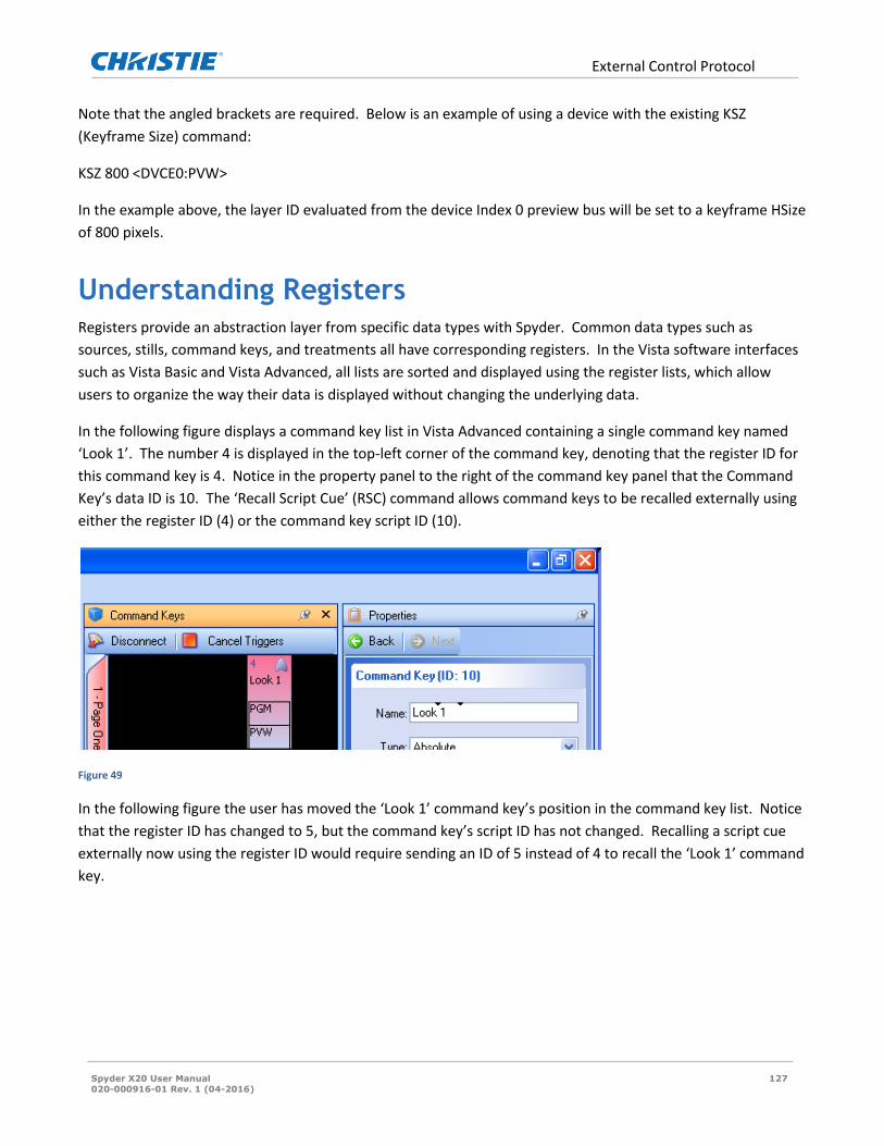
External Control Protocol
Spyder X20 User Manual 127
020-000916-01 Rev. 1 (04-2016)
Note that the angled brackets are required. Below is an example of using a device with the existing KSZ
(Keyframe Size) command:
KSZ 800 <DVCE0:PVW>
In the example above, the layer ID evaluated from the device Index 0 preview bus will be set to a keyframe HSize
of 800 pixels.
Understanding Registers Registers provide an abstraction layer from specific data types with Spyder. Common data types such as
sources, stills, command keys, and treatments all have corresponding registers. In the Vista software interfaces
such as Vista Basic and Vista Advanced, all lists are sorted and displayed using the register lists, which allow
users to organize the way their data is displayed without changing the underlying data.
In the following figure displays a command key list in Vista Advanced containing a single command key named
‘Look 1’. The number 4 is displayed in the top-left corner of the command key, denoting that the register ID for
this command key is 4. Notice in the property panel to the right of the command key panel that the Command
Key’s data ID is 10. The ‘Recall Script Cue’ (RSC) command allows command keys to be recalled externally using
either the register ID (4) or the command key script ID (10).
Figure 49
In the following figure the user has moved the ‘Look 1’ command key’s position in the command key list. Notice
that the register ID has changed to 5, but the command key’s script ID has not changed. Recalling a script cue
externally now using the register ID would require sending an ID of 5 instead of 4 to recall the ‘Look 1’ command
key.
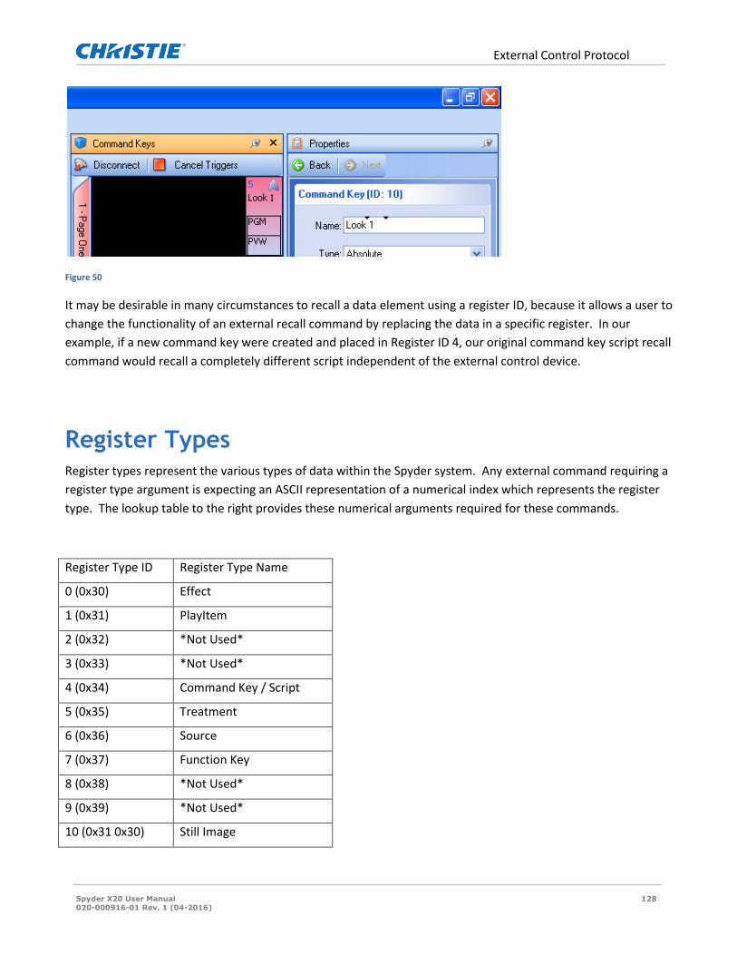
External Control Protocol
Spyder X20 User Manual 128
020-000916-01 Rev. 1 (04-2016)
Figure 50
It may be desirable in many circumstances to recall a data element using a register ID, because it allows a user to
change the functionality of an external recall command by replacing the data in a specific register. In our
example, if a new command key were created and placed in Register ID 4, our original command key script recall
command would recall a completely different script independent of the external control device.
Register Types Register types represent the various types of data within the Spyder system. Any external command requiring a
register type argument is expecting an ASCII representation of a numerical index which represents the register
type. The lookup table to the right provides these numerical arguments required for these commands.
Register Type ID Register Type Name
0 (0x30) Effect
1 (0x31) PlayItem
2 (0x32) *Not Used*
3 (0x33) *Not Used*
4 (0x34) Command Key / Script
5 (0x35) Treatment
6 (0x36) Source
7 (0x37) Function Key
8 (0x38) *Not Used*
9 (0x39) *Not Used*
10 (0x31 0x30) Still Image

Spyder Hardware
Spyder X20 User Manual 129
020-000916-01 Rev. 1 (04-2016)
Spyder Hardware This section is designed to give an overview of Spyder features, functionality and operation. The detailed
operation of will be found in the respective manuals for each individual control platform.
Important Safety Instructions
This symbol indicates the presence of “dangerous voltage” within the product enclosure that
may be significant enough to cause a risk of electrical shock.
1. Read these instructions. 2. Keep these instructions. 3. Heed all warnings. 4. Follow all instructions. 5. Do not use this apparatus near water. Do not place objects containing water on top of or near the unit. 6. Clean only with a dry cloth. 7. Do not block any ventilation openings. Install in accordance with the manufacturer’s instructions. 8. Do not install near any heat sources such as radiators, heat registers, stoves, or other apparatus (including amplifiers)
that produce heat. 9. Do not defeat the safety purpose of the polarized or grounding – type plug. A polarized plug has two blades with one
wider than the other. A grounding type plug has two blades and a third grounding prong. The wide blade or the third prong is provided for your safety. If the provided plug does not fit into your outlet, consult an electrician for replacement of the obsolete outlet.
10. Protect the power cord from being walked on or pinched particularly at plugs, convenience receptacles and the point where they exit from the apparatus.
11. Only use attachments/accessories specified by the manufacturer. 12. Use only with the cart, stand, tripod, bracket or table specified by the manufacturer or sold with the apparatus. When a
cart is used caution when moving the cart/apparatus combination to avoid injury from tip-over. 13. Unplug the apparatus during lightning storms or when unused for long periods of time. 14. Refer all servicing to qualified service personnel. Servicing is required when the apparatus has been damaged in any
way such as power-supply cord or plug is damaged, liquid has been spilled or objects have fallen into the apparatus, the apparatus has been exposed to rain or moisture, does not operate normally or has been dropped.

Spyder Hardware
Spyder X20 User Manual 130
020-000916-01 Rev. 1 (04-2016)
Cautions and Safety Notices
FCC Notice - For Commercial Use Only This device complies with part 15 of the FCC rules. Operation is subject to the following 2 conditions: (1) This
device may not cause harmful interference (2) This device must accept any interference received, including any
interference that may cause undesired operation. This Class A digital apparatus complies with Canadian ICES-
003. Cet appareil numérique de la classe A est conform à la norme NMB-003 du Canada.
Battery Warning
The battery in Spyder is not intended to be replaced by the user. Failure to follow these instructions will void
the warranty of the unit.
Danger of explosion if battery is incorrectly replaced.
Replace only with the same or equivalent type of battery.
Service Warning
All servicing instructions are for use by qualified service personnel only. There are no procedures, exchange, or
parts that are inside the unit that are intended to be performed by the user. Any procedure performed inside
the unit is intended to be performed by qualified service personnel only.
To reduce the risk of electrical shock, the service technician shall remove the cord from the wall receptacle and
the rear of the unit before attempting to service the unit.
Unplug all power and power supply cords from the apparatus before servicing
Failure to follow these instructions may void the warranty.
Class I Construction Warning
An apparatus with Class I construction shall be connected to a MAINS socket outlet with a protective earthing
connection.

Spyder Hardware
Spyder X20 User Manual 131
020-000916-01 Rev. 1 (04-2016)
Operating in 110V or 220 Spyder ships in the setting predetermined by where it is shipping to be ready for operation out of the box. It
comes with a sticker over the AC inlet noting if it is set for 110V or 220V. If operating with a voltage other than
what it is set for, a few changes need to be made.
TO CHANGE FROM 110V TO 220V:
1. Pull the fuse holder (See figure 1.1.2) from the AC inlet (See figure 1.1.3). 2. Pull the jumper and current fuse from the fuse holder. 3. Add fuses included with shipping kit (2-3A fuses for 3RU or 2-2A fuses for 2RU). One on each side of the fuse holder. 4. Insert fuse holder back into the AC inlet and power up. You are now set for 220V.
TO CHANGE FROM 220V TO 110V:
1. Pull the fuse holder (See figure 1.1.2) from the AC inlet (See figure 1.1.3). 2. Pull both fuses from the fuse holder 3. Add jumper (See figure 1.1.1) on one side of fuse holder and fuse on the other side that is included with shipping kit (1-
5A fuse for 3RU or 1-3A fuse for 2RU). 4. Insert fuse holder back into the AC inlet and power up. You are now set for 110V.

Spyder Hardware Family
Spyder X20 User Manual 132
020-000916-01 Rev. 1 (04-2016)
Spyder Hardware Family Spyder is a compact versatile video processing product with superb capabilities to blend, window and scale a
very wide array of video signals with unparalleled quality and ease.
The compact modular design allows Spyder to be used to display a virtually endless variety of windows through
a single output, or stretch a single input across multiple displays to create a seamless widescreen image, and do
just about anything in-between.
Spyder consists of 2 model families, the 200 and 300 series, each family has multiple configurations available to
meet the most demanding environment and all models have expansion ability (optional) to provide more
inputs/windows or more output/displays or both.
Spyder control can be accomplished multiple ways depending on application:
1. Spyder control suite PC based software applications 2. Hardware based Vista controllers 3. 3rd party control systems such as Crestron or AMX
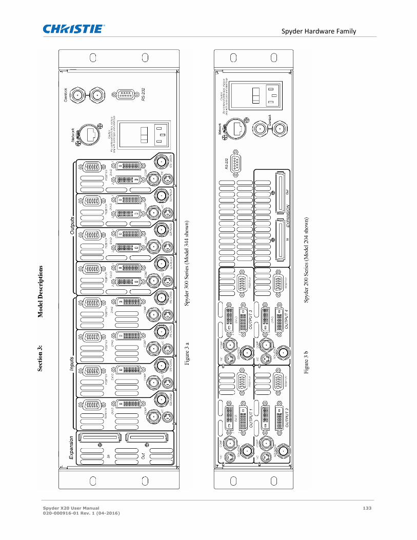
Spyder Hardware Family
Spyder X20 User Manual 133
020-000916-01 Rev. 1 (04-2016)
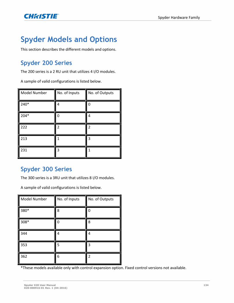
Spyder Hardware Family
Spyder X20 User Manual 134
020-000916-01 Rev. 1 (04-2016)
Spyder Models and Options This section describes the different models and options.
Spyder 200 Series
The 200 series is a 2 RU unit that utilizes 4 I/O modules.
A sample of valid configurations is listed below.
Model Number No. of Inputs No. of Outputs
240* 4 0
204* 0 4
222 2 2
213 1 3
231 3 1
Spyder 300 Series
The 300 series is a 3RU unit that utilizes 8 I/O modules.
A sample of valid configurations is listed below.
Model Number No. of Inputs No. of Outputs
380* 8 0
308* 0 8
344 4 4
353 5 3
362 6 2
*These models available only with control expansion option. Fixed control versions not available.

Spyder Hardware Family
Spyder X20 User Manual 135
020-000916-01 Rev. 1 (04-2016)
Inputs
Note: Interlaced sources cannot be used on the DVI connector. Only odd inputs have de-interlacers
1. Pixel clock limits for analog and digital.
Analog- 165MHz
Digital- 330MHz
Below are listed the standard video formats accepted by Spyder:
24p, NTSC, PAL, and SECAM
Analog RGB (SOG, Composite or Separate Sync)
Analog YUV
SDI (Only available on Odd Inputs)
HD-SDI (Only available on Odd Inputs)
DVI-Single Link
DVI-Dual Link
Stereo Sync
Each input module has a single input connector for the supported signal types:
1. ANALOG 2. SDI/ HD-SDI 3. DVI 4. Composite and S-Video (Comp/ S-Vid Optional)
Each input is universal: an input can be dynamically assigned and used as a mixer, a mixer, or a key. These
settings are also accomplished from the chosen control type.
Outputs
Each Output Module has various video connectors on the rear. Conditions exist when multiple output types can
be utilized.
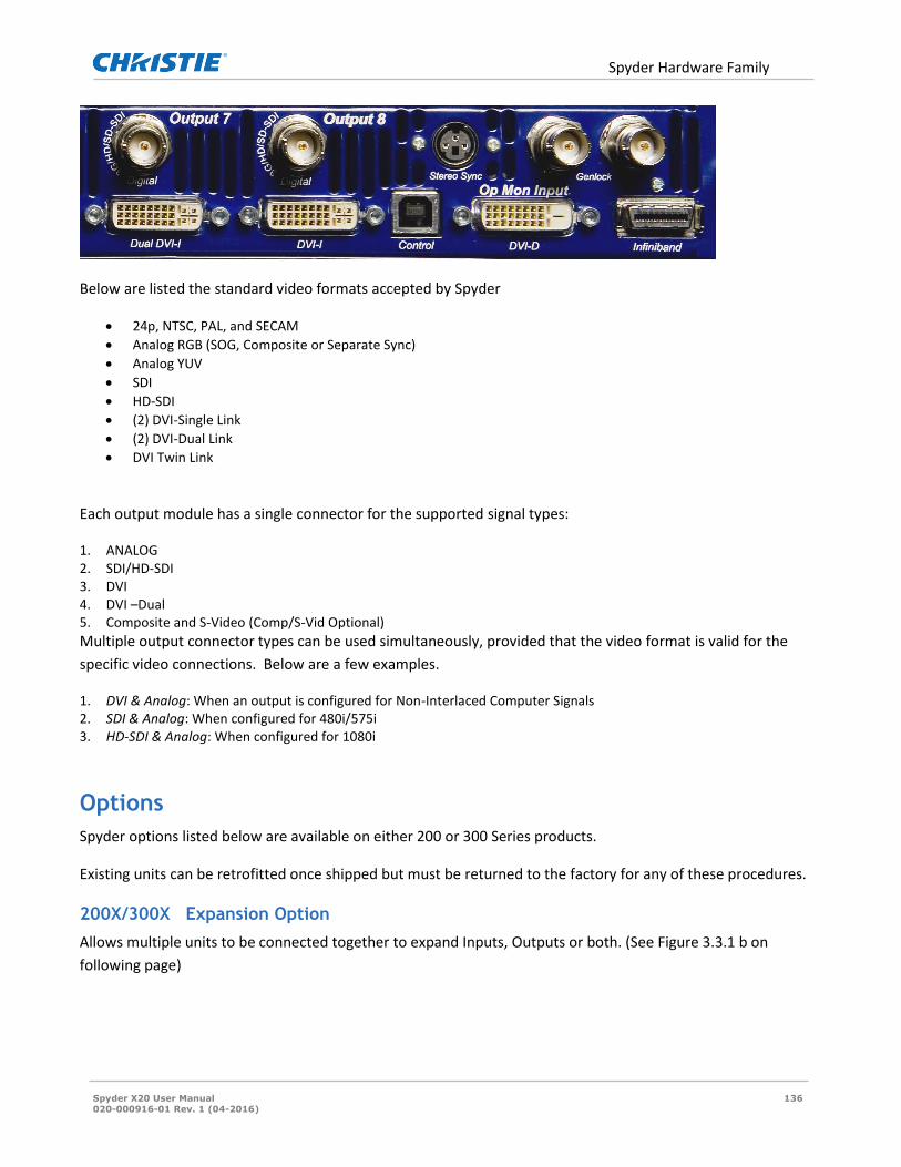
Spyder Hardware Family
Spyder X20 User Manual 136
020-000916-01 Rev. 1 (04-2016)
Below are listed the standard video formats accepted by Spyder
24p, NTSC, PAL, and SECAM
Analog RGB (SOG, Composite or Separate Sync)
Analog YUV
SDI
HD-SDI
(2) DVI-Single Link
(2) DVI-Dual Link
DVI Twin Link
Each output module has a single connector for the supported signal types:
1. ANALOG 2. SDI/HD-SDI 3. DVI 4. DVI –Dual 5. Composite and S-Video (Comp/S-Vid Optional)
Multiple output connector types can be used simultaneously, provided that the video format is valid for the
specific video connections. Below are a few examples.
1. DVI & Analog: When an output is configured for Non-Interlaced Computer Signals 2. SDI & Analog: When configured for 480i/575i 3. HD-SDI & Analog: When configured for 1080i
Options
Spyder options listed below are available on either 200 or 300 Series products.
Existing units can be retrofitted once shipped but must be returned to the factory for any of these procedures.
200X/300X Expansion Option
Allows multiple units to be connected together to expand Inputs, Outputs or both. (See Figure 3.3.1 b on
following page)

Spyder Hardware Family
Spyder X20 User Manual 137
020-000916-01 Rev. 1 (04-2016)
InfiniBand Cable (Vista P/N CAB-60670)
This cable allows multiple Spyder units to be connected to the Expansion Ports. This option is only applicable
with the 200X or 300X Option.
200C/300C (Composite/S-Video Option)
When selected this option will provide Composite (BNC) and S-Video (SVHS)
connections on each Input and each Output of the Spyder unit.

Spyder Hardware Family
Spyder X20 User Manual 138
020-000916-01 Rev. 1 (04-2016)

Spyder Hardware Family
Spyder X20 User Manual 139
020-000916-01 Rev. 1 (04-2016)
Power Control
The Spyder uses a soft power scheme. Pressing the Standby switch initiates a power up cycle and after a short
boot time the front panel display will indicate operational status. Pressing the Standby switch again initiates the
power down cycle after which the unit enters standby mode. There is a hard power switch on the rear that
should be used only when Spyder is in the standby state (Standby Switch LED is off).
The user should avoid disconnecting the primary power source (AC input) until the unit is in standby
mode. Failure to do this could result in hard drive data corruption.
Display
The Spyder enclosure is equipped with a status/error display located on the front panel. This is helpful in
determining proper start-up and shut-down of the unit, as well as indicating error messages. The following
diagram indicates the status when the unit has been booted up and has determined the version, frame, I/O
configuration and IP address.

Spyder X20 Hardware Family
Spyder X20 User Manual 140
020-000916-01 Rev. 1 (04-2016)
Spyder X20 Hardware Family Spyder X20 is a second generation Spyder hardware line. X20 increases both the I/O capacity and virtual image
space (VI) available within a single chassis, making a powerful and cost-effective solution for mid-range Spyder
configurations.
Spyder X20 Models Spyder X20 uses a modular chassis design, which can be populated at the factory with various combinations of
input and output channels as required. Available chassis sizes start at three-slot configurations.
Note that not all slots must be filled in a chassis; a larger chassis will operate without all slots being filled. This
makes an easy hardware upgrade path for systems that may need to increase capacity over time.
Spyder X20 External Connections The connections for the Spyder X20’s internal computer are exposed on the back panel. These connections are
for factory use only, and are not intended to be connected to external peripherals (keyboard / mouse / monitor)
by a user. Specifically, the following connections are exposed:
Keyboard Mouse
Monitor (HD15) USB
Microphone Input Speaker Outputs

Spyder X20 Hardware Family
Spyder X20 User Manual 141
020-000916-01 Rev. 1 (04-2016)
Figure 51: X20 1608 Back Panel

X20 Front Panel
Spyder X20 User Manual 142
020-000916-01 Rev. 1 (04-2016)
X20 Front Panel
Inputs
The connector types alternate on each input connector for maximum flexibility, and the specific connector types
are listed below. For each input, only one connector / signal type can be selected at a time.
Odd Input Connectors (1, 3, 5, etc.)
1. Analog (3 or 4 wire BNC)
2. Composite / S-Video (Shares BNC with composite analog sync signal)
3. SDI / HD-SDI / 3G-SDI (Single dedicated BNC)
Even Input Connectors (2, 4, 6, etc.)
1. DVI-I (Analog and Digital on single connector)
2. Stereo Sync input (3-Pin DIN)

X20 Front Panel
Spyder X20 User Manual 143
020-000916-01 Rev. 1 (04-2016)
Outputs
Each Output Module has various video connectors on the rear. Multiple output connectors can be enabled
simultaneously, provided that the user defined output format is valid for the connector. SXGA (1280x1024) for
example, is valid for DVI and analog connectors, but is not a valid format for SDI, composite, or S-Video
connectors.
Each output channel provides the following connector types:
3. DVI-I (Analog and Digital on single connector) 4. SDI / HD-SDI / 3G-SDI
Power
The X20 uses a soft power scheme. Pressing the Standby switch initiates a power up cycle and after a short boot
time the front panel display will indicate operational status. Pressing the Standby switch again initiates the
power down cycle after which the unit enters standby mode. Holding the power button on the front panel of the
system for 13-15 seconds can be used to force power off, however this technique may cause permanent
configuration data loss.
The user should avoid disconnecting the primary power source (AC input) until the unit is in standby
mode. Failure to do this could result in hard drive data corruption.
Front Panel
The X20 enclosure is equipped with a LCD / switch button interface located on the front panel. This interface
allows for both control and access to status information of the unit. As the front panel functionality is
dependent on the version of firmware running on the unit, actual front panel operation is discussed in detail in
the software / operator’s manual for the X20.

Physical Specifications
Spyder X20 User Manual 144
020-000916-01 Rev. 1 (04-2016)
Physical Specifications
Dimensions (W x H x D) 1. Spyder X20 4 RU: 17.3 x 7 x 21.9 inches (43.9 x 17.78 x 55.6 centimeters) 2. Spyder 3 RU: 17.3 x 5.3 x 22.1 inches (43.9 x 13.3 x 56.1 centimeters) 3. Spyder 2 RU: 17.3 x 3.5 x 22.1 inches (43.9 x 8.9 x 56.1 centimeters)
Weight 1. Spyder X20 4 RU: 70lbs (Approx) 2. Spyder 3 RU: 33lbs (Approx) 3. Spyder 2 RU: 25lbs (Approx)
Power Consumption 1. Spyder X20 4 RU: 100-240V AC 1000W max (Fuse: Internal Auto-Resetting) 2. Spyder 3 RU: 100-240V AC 375W max (Fuse: 5A Slow-Blow) 3. Spyder 2 RU: 100-240V AC 225W max (Fuse: 3A Slow-Blow) 4. Stand By Power (200 / 300 / X20 Series): <20W

Physical Specifications
Spyder X20 User Manual 145
020-000916-01 Rev. 1 (04-2016)
Rack mount Instructions
Figure 52 : Rack Mounting

Spyder Expansion
Spyder X20 User Manual 146
020-000916-01 Rev. 1 (04-2016)
Spyder Expansion This section explains and demonstrates the expansion of Spyder Servers using the Spyder Advanced Software
and assumes the software release of 2.7 or later. There are two classifications of expansion, Serial and Parallel.
Serial Expansion is required to increase the total of inputs and outputs (I/O) of a system. Parallel expansion is
required when the pixel limitation of one VI needs to be exceeded. There are two types of the Parallel Expansion
classification, Discreet Expansion and Seamless Expansion. Any expansion requires the Spyder Servers to have
the Expansion Module Option. Two prerequisites of understanding expansion, Vista System’s Virtual Image, and
signal flow are required.
Virtual Image (VI) The underlying power of the Spyder System is through the use of the Virtual Image (VI). The VI is the full
amount of bandwidth available to create the user defined pixels spaces that the outputs support. The resolution
of the outputs determine the amount of pixels used and therefore how much of the available bandwidth of the
VI. Multiple pixel spaces can be created within the same VI, but the entire VI has a fixed bandwidth limitation. It
is not necessary to use all the bandwidth but it cannot be exceeded without Parallel Expansion. The maximum
bandwidth of the VI is dependent on the system frame rate which is the rate of data refresh. For example, a
system running at 59.94 frames (NTSC setting) refreshes the data of the entire VI at 59.94 frames per second.
The Spyder user has several preset frame rates to choose from depending on the application. The frame rate can
be chosen at the original time of a new configuration using the Configuration Manager or can be changed later
using the Server/Frame Configuration menu in the advanced software.
Frame Rate: Suggested Applications:
59.94 6.6 million pixels Staging and Broadcast
29.97 13 million pixels Command and Control
50 8 million pixels PAL Staging and Broadcast
25 16 million pixels PAL Command and Control
24 16.5 million pixels Film Industry and 24p applications
Note: Spyders using the SSO option must always use the higher frame rate of NTSC. When using the
Stereoscopic Option VI capacity is halved.
The formula for determining the VI is: V pixels (highest) x H pixels.
Determining if the maximum is exceeded is dependent on Frame Rate.
Example: Two outputs at 1400 x 1050 each and one at 1920 x 1080 with a 640 x 480 operator’s monitor and a
frame rate of NTSC use 5,788,800 pixels of the 6.6 million available.
5,788,800 pixels = 1080 x 1400 + 1400 + 1920 + 640

Spyder Expansion
Spyder X20 User Manual 147
020-000916-01 Rev. 1 (04-2016)
Signal Flow There is always a hierarchy of signal flow through any Spyder System starting upstream with the inputs and
ending with the downstream outputs. Each input (layer) in the system adds its share of pixel information to the
VI and passes it along downstream through the frame(s) starting with the remaining inputs, thru to the outputs,
and out the expansion module port if expansion is used. The first input in a frame is always the first upstream
layer. Refer to the below diagram.
Signal never flows upstream therefore upstream outputs cannot support downstream inputs.
Serial Expansion Serial expansion is required to increase the total of inputs and outputs (I/O) of a system by using a series of
Spyder Servers. The entire expanded system is still defined within a single Virtual Image (VI) and cannot exceed
that pixel limitation. Although each individual Spyder Server is capable of supporting an entire VI, such as a
standalone 344 model, I/O capacity is limited to the amount of input and output cards that can be mounted in a

Spyder Expansion
Spyder X20 User Manual 148
020-000916-01 Rev. 1 (04-2016)
300 series frame. To increase the total I/O of the system expansion is required. Understanding the signal flow
through expanded Spyder Servers is very important in designing a Spyder System and determining whether
expansion is required.
Expansion requires the creation of Expansion Groups with the first upstream Spyder Server frame in the system
as the Master and the remainder Slaves. Each Spyder Server is always a Master until it is put in an Expansion
Group and then it may become a Slave depending on its position in the Expansion Group.
Serial Expansion Group Example Using the above diagram as an example these are the user requirements:
One blended projector screen using three 2K projectors with a 512 pixel blend. The requirement is for 12 layers
of data or video to be placed anywhere across the pixel space simultaneously. Frame Rate will be NTSC with an
800 x 600 preview.
Hardware available:
1. Spyder 344 (A) with expansion IP: 172.16.17.20
2. Spyder 344 (B) with expansion IP: 172.16.17.40
3. Spyder 240 with expansion IP: 172.16.17.60
One ISIS analog 16 x 16 matrix switch
Screen 1

Spyder Expansion
Spyder X20 User Manual 149
020-000916-01 Rev. 1 (04-2016)
Connect the frames with their expansion cables in the following order of signal flow. Connect 240 to 344 (A) to
344 (B). The 240 will be the master frame and the two 344’s will be slaves.
Connect the first 4 outputs from the ISIS matrix switch to the 240, the next 4 to 344 (A) and the next 4 to the
second 344 (B). Connect the ISIS serial cable to a serial port on the 240.
Start the Advanced software on the client PC and select File/New. The Spyder Configuration Manager will open
and select Start with new empty configuration.
From the drop down menus select the matching IP address to frame in the order of the system starting from the
master frame which is the 240. If doing a system configuration off-line choose ‘virtual’ instead of an IP address.
After the frames are selected choose NTSC for frame rate. Click Next.

Spyder Expansion
Spyder X20 User Manual 150
020-000916-01 Rev. 1 (04-2016)
In this menu select ‘single widescreen’ in the template tab.
Next click on the actual pixel space for the widescreen in
the Screen Configurations window and fill in the
appropriate output information as follows:
Horizontal Outputs: 3
Vertical Outputs: 1
Horizontal Overlap: 512
Format: 2048 x 1080 @ 59.94
Connection: DVI if required
Rotation: none
Layers: 12

Spyder Expansion
Spyder X20 User Manual 151
020-000916-01 Rev. 1 (04-2016)
Click next and select 800 x 600 as a preview. Click next again and ‘select all’ to clear all data and ‘select clear all
routers and add’: Isis serial and 16 inputs and 16 outputs
Select next and apply the configuration to either the hardware (online) or to local PC (offline).
If done online the Spyder Frames will reboot and their individual LED panel will show the 240 as Frame 0, the
344 (A) as Slave Frame 1, and 344 (B) as Slave Frame 2.
This completes the configuration and the patch and simulator portion of the GUI will look like the example
below.
In the Patch click and drag outputs 1, 2, and 3 to outputs 5, 6, and 7 respectively so those outputs are
representing their portion of the pixel space. Configuration is complete.
Special Note: Outputs 1, 2, and 3 from 344 (A) will display the same pixel space BUT without the downstream
layers of the second 344 (B). These could possibly be used as ‘clean’ display from downstream keying or Imag.
Discreet Expansion
Discreet expansion allows the use of multiple VI’s using multiple Frame Groups however the layers/inputs
associated with those Frame Groups that make up an individual VI cannot extend to outputs of other Frame

Spyder Expansion
Spyder X20 User Manual 152
020-000916-01 Rev. 1 (04-2016)
Groups of another VI. A Frame Group can be a single server or multiple servers but it refers to a single VI.
Expansion enables the user to use a single control interface and a single matrix router(s) to control and support
the expansion system.
If an Operators Monitor is required each Frame Group will require the pixel capacity for the preview pixel space
and multiple Operators Monitors from the multiple Frame Groups will be utilized.
Discreet Expansion Example
In this example these are the user requirements.
One blended projector screen using three 2K projectors with a 512 blend.
Two discreet screens using three SXGA+ projectors.
Preview is required for this installation.
Hardware available:
1. Spyder 344 (A) with expansion IP: 172.16.17.20
2. Spyder 344 (B) with expansion IP: 172.16.17.40
3. Spyder 240 with expansion IP: 172.16.17.60
4. One ISIS analog 16 x 16 matrix switch
Screen 1 Screen 3 Screen 2

Spyder Expansion
Spyder X20 User Manual 153
020-000916-01 Rev. 1 (04-2016)
Since the blended widescreen using an 800 x 600 preview will use 6,393,600 pixels it will be the first VI. The
existing two screens will require the second VI.
The user decision is to use the 240 with the first 344 (A) to enable the use of eight layers on the blended screen
which is the first VI. The other 344 (B) is the second VI and all four layers will be used as two mixers for the two
screens.
Connect the frames with their expansion cables in the following order of signal flow. Connect 240 to 344 (A) to
344 (B). The 240 will be the master frame and the two 344’s will be slaves.
Although layers from the first 344 (A) will not pass into the second 344 (B) the expansion cable is still required
for the creation of the expansion system. Make sure all frames are on the same network and connected.
Connect the first 8 outputs from the ISIS matrix switch to the 240 and 344 (A) and the next 4 to the second 344
(B). Connect the ISIS serial cable to a serial port on the 240.
Start the Advanced software on the client PC and select File/New. The Spyder Configuration Manager will open
and select Start with new empty configuration.
From the drop down menus select the matching IP address to frame in the order of the system starting from the
master frame which is the 240. If doing a system configuration off-line choose ‘virtual’ instead of an IP address.
After the frames are selected choose NTSC for frame rate. Click Next.

Spyder Expansion
Spyder X20 User Manual 154
020-000916-01 Rev. 1 (04-2016)
In this menu select ‘single widescreen’ in the template tab and select ‘add additional discreet screen’ twice
under the individual screen tab. Next click on the actual pixel space for the widescreen in the Screen
Configurations window and fill in the appropriate output information as follows:
Horizontal Outputs: 3
Vertical Outputs: 1
Horizontal Overlap: 512
Format: 2048 x 1080 @ 59.94
Connection: DVI if required
Rotation: none
Layers: 8

Spyder Expansion
Spyder X20 User Manual 155
020-000916-01 Rev. 1 (04-2016)
Then select the other two pixel spaces and use these settings for both:
Format: 1400 x 1050 @ 59.94
Connection: DVI if required
Rotation: none
Layers: 2
Click next and select 800 x 600 as a preview. Click next again and ‘select all’ to clear all data and ‘select clear all
routers and add’: Isis serial and 16 inputs and 16 outputs
Select next and apply the configuration to either the hardware (online) or to local PC (offline).
This completes the configuration and the patch and simulator portion of the GUI will look like the example
below.
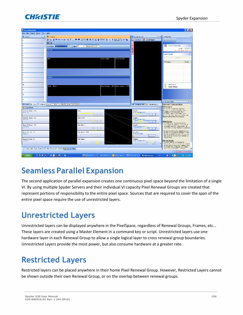
Spyder Expansion
Spyder X20 User Manual 156
020-000916-01 Rev. 1 (04-2016)
Seamless Parallel Expansion
The second application of parallel expansion creates one continuous pixel space beyond the limitation of a single
VI. By using multiple Spyder Servers and their individual VI capacity Pixel Renewal Groups are created that
represent portions of responsibility to the entire pixel space. Sources that are required to cover the span of the
entire pixel space require the use of unrestricted layers.
Unrestricted Layers Unrestricted layers can be displayed anywhere in the PixelSpace, regardless of Renewal Groups, Frames, etc…
These layers are created using a Master Element in a command key or script. Unrestricted layers use one
hardware layer in each Renewal Group to allow a single logical layer to cross renewal group boundaries.
Unrestricted Layers provide the most power, but also consume hardware at a greater rate.
Restricted Layers Restricted layers can be placed anywhere in their home Pixel Renewal Group. However, Restricted Layers cannot
be shown outside their own Renewal Group, or on the overlap between renewal groups.
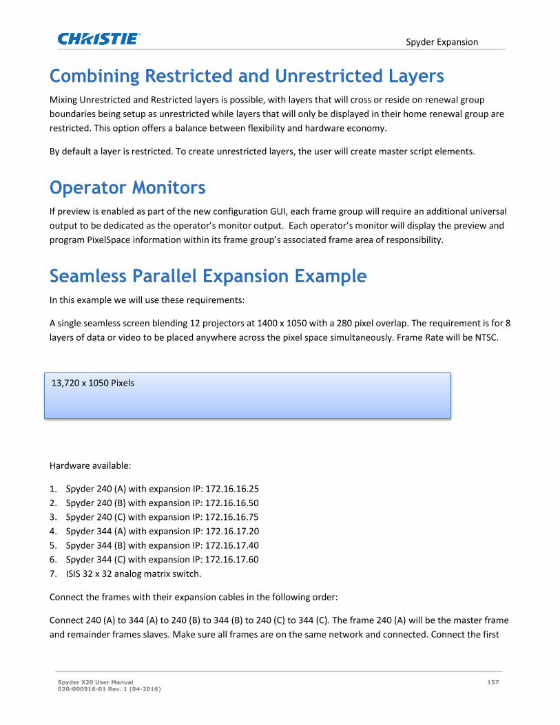
Spyder Expansion
Spyder X20 User Manual 157
020-000916-01 Rev. 1 (04-2016)
Combining Restricted and Unrestricted Layers Mixing Unrestricted and Restricted layers is possible, with layers that will cross or reside on renewal group
boundaries being setup as unrestricted while layers that will only be displayed in their home renewal group are
restricted. This option offers a balance between flexibility and hardware economy.
By default a layer is restricted. To create unrestricted layers, the user will create master script elements.
Operator Monitors If preview is enabled as part of the new configuration GUI, each frame group will require an additional universal
output to be dedicated as the operator’s monitor output. Each operator’s monitor will display the preview and
program PixelSpace information within its frame group’s associated frame area of responsibility.
Seamless Parallel Expansion Example In this example we will use these requirements:
A single seamless screen blending 12 projectors at 1400 x 1050 with a 280 pixel overlap. The requirement is for 8
layers of data or video to be placed anywhere across the pixel space simultaneously. Frame Rate will be NTSC.
Hardware available:
1. Spyder 240 (A) with expansion IP: 172.16.16.25
2. Spyder 240 (B) with expansion IP: 172.16.16.50
3. Spyder 240 (C) with expansion IP: 172.16.16.75
4. Spyder 344 (A) with expansion IP: 172.16.17.20
5. Spyder 344 (B) with expansion IP: 172.16.17.40
6. Spyder 344 (C) with expansion IP: 172.16.17.60
7. ISIS 32 x 32 analog matrix switch.
Connect the frames with their expansion cables in the following order:
Connect 240 (A) to 344 (A) to 240 (B) to 344 (B) to 240 (C) to 344 (C). The frame 240 (A) will be the master frame
and remainder frames slaves. Make sure all frames are on the same network and connected. Connect the first
13,720 x 1050 Pixels

Spyder Expansion
Spyder X20 User Manual 158
020-000916-01 Rev. 1 (04-2016)
four outputs from the ISIS switch to 240 (A), the next four outputs to 344 (A), and continue in order. Connect the
ISIS serial cable to the Master Frame 240 (A) serial port.
Open up the advanced software on the client PC and select File/New. The Spyder Configuration Manager will
open and select Start with new empty configuration.

Spyder Expansion
Spyder X20 User Manual 159
020-000916-01 Rev. 1 (04-2016)
From the drop down menus select the matching IP address to frame in the order of the system starting from the
master frame which is the 240. If doing a system configuration off-line choose ‘virtual’ instead of an IP address.
After the frames are selected choose NTSC for frame rate. Click Next.
In this menu select ‘single widescreen’ in the template tab and next click on the actual pixel space for the
widescreen in the Screen Configurations window and fill in the appropriate output information as follows:
1. Horizontal Outputs: 12
2. Vertical Outputs: 1
3. Horizontal Overlap: 280
4. Format: 1400 x 1050 @ 59.94
5. Connection: DVI if required
6. Rotation: none
7. Layers: 2 (This field can be left with the default value of 2)
Click ‘Next’ and there will be an error message “Pixel Space 0 (Main) is larger than a single VI” in the message
field. In the ‘Run configuration Again Now’ pull-down field choose ‘Force Invalid Configuration’. Since we have
not created the Pixel Renewal Groups yet it assumes there is only a single VI. In the next menu select NTSC and
since there are no physical outputs available for a preview select ‘none’.
Continue with selecting ‘clear all’ and add the ISIS matrix switch. Select next and apply the configuration to
either the hardware (online) or to local PC (offline).

Spyder Expansion
Spyder X20 User Manual 160
020-000916-01 Rev. 1 (04-2016)
This completes the configuration and the patch and simulator portions of the GUI will look like the example
below.
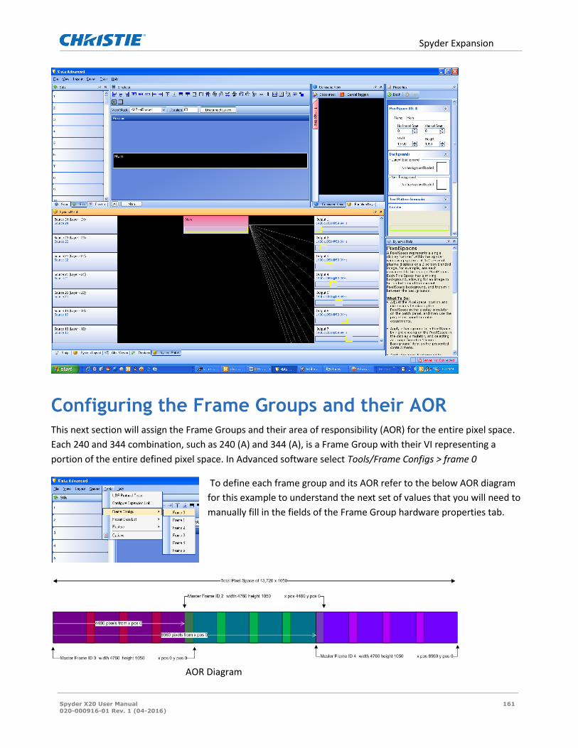
Spyder Expansion
Spyder X20 User Manual 161
020-000916-01 Rev. 1 (04-2016)
Configuring the Frame Groups and their AOR This next section will assign the Frame Groups and their area of responsibility (AOR) for the entire pixel space.
Each 240 and 344 combination, such as 240 (A) and 344 (A), is a Frame Group with their VI representing a
portion of the entire defined pixel space. In Advanced software select Tools/Frame Configs > frame 0
To define each frame group and its AOR refer to the below AOR diagram
for this example to understand the next set of values that you will need to
manually fill in the fields of the Frame Group hardware properties tab.
AOR Diagram

Spyder Expansion
Spyder X20 User Manual 162
020-000916-01 Rev. 1 (04-2016)
Unrestricted Layers To create unrestricted layers a command key must first be created and an element must be applied to at least
one layer. In the below example source ‘TEST’ is an element on layer 1 but layers 9 and 17 are ‘slaved’ to layer 1
so as the source is moved along the pixel space each respective layer to the Frame Renewal Group takes
responsibility of the source. Click on the element in the script and in the properties section select the layer from
the Frame Group to be its slave.
Note in the above example each layer has a red indicator confirming their status as belonging to a Master
Element.
The three layers in the
master element Selecting the slave
layers

Spyder Expansion
Spyder X20 User Manual 163
020-000916-01 Rev. 1 (04-2016)
In the Tools/Options menu there is a setting that will allow
the user to decide to see the slave layers or just the master in
the simulator.
When using Master Elements the matrix switch will
automatically switch the same source in the slave layers.
Layers 9 and 12 hidden because of the Display Simulator option
setting.

Spyder X20 HDCP Functionality (Option)
Spyder X20 User Manual 164
020-000916-01 Rev. 1 (04-2016)
Spyder X20 HDCP Functionality (Option) High-bandwidth Digital Content Protection (HDCP) is a form of digital copy protection developed by Intel to
prevent copying of digital audio and video content as it travels across a digital interface. The system is meant to
stop HDCP-encrypted content from being played on devices that do not support HDCP or which have been
modified to copy HDCP content.
HDCP (High-bandwidth Digital Content Protection) is a system designed for protecting Audio-visual content over
certain high bandwidth interfaces from being copied. HDCP specification was developed by Intel and
administered by Digital Content Protection, LLC which is a subsidiary of Intel. HDCP Revision 1.x was in existence
since 1999 and is adopted by almost all the consumer-electronics manufacturers, content providers and
prominent industry associations. HDCP is supported in various high-bandwidth interfaces (called HDCP-
protected interfaces) including, but not limited to DVI, HDMI and Display port and while HDCP is an optional
feature in DVI, it is mandatory in HDMI. As it is obvious, HDCP 1.x (or simply referred to as HDCP) is an interface
dependent encryption system and was limited to usage in the particular interface for which they are intended,
like DVI or HDMI. But with the advance of technology, several other ways of content distribution came into
existence including wireless distribution, distribution over network and internet. HDCP 2.0 was designed and
brought out to circumvent this issue and is interface-independent and uses more advanced encryption
mechanism leveraging the advancement in encryption technologies since 1999, like AES.
X20 supports HDCP 1.4 which is the most updated revision in the 1.x specifications, and it can inter-operate with
any HDCP 1.0, HDCP 1.1, HDCP 1.2, HDCP 1.3 and HDCP 1.4 compliant devices.
HDCP has three important elements in its operation, namely
1. Encryption and Decryption of Video (and Audio) data
2. Authentication and secret-key derivation
3. Revocation of compromised keys, determined by the DCP, LLC

Spyder X20 HDCP Functionality (Option)
Spyder X20 User Manual 165
020-000916-01 Rev. 1 (04-2016)
HDCP HDCP
AACS
CSS
DRM
Blu Ray Plyer
Game console
Set-top box
Spyder X20
Display
projector
Media Source Repeater Sink
Figure 53 : Content Protection Methodology
At the core of the whole system is the HDCP Cipher which works based on the cryptographic property of the
HDCP Device keys. HDCP Device key is 280 byte long secret data which is issued by DCP, LLC and which is derived
from a Super Master key. Associated with this Device keys is a 5 byte vector called Key Selection Vector (KSV).
Every HDCP-enabled interface is given a unique Device Key along with a KSV which is collectively called Device
Key Set. HDCP-enabled devices are classified as a Source (Transmitter), Receiver (Sink) or a Repeater.
Transmitter enables HDCP Encryption if indicated by the media and also keeps a ‘Revocation list’ which is
updated through distributable media like Blu-ray, DVD or through cable or network connection. Revocation list
includes all the KSVs which are compromised and transmitter verifies that the connected receiver’s KSV is not
included in the list. The scheme of Content protection methodology followed in the industry currently is
illustrated in the figure 1. Receiver responds to requests from transmitter for information and decrypts the
HDCP Content. Repeaters incorporate functional blocks which include both transmitter and Receiver state
machines except for the ‘Revocation’ mechanism in transmitter. X20 falls into the category of a Repeater as X20
receives the data in through HDCP-protected DVI interfaces and after processing, sends out the contents
through HDCP-protected DVI interfaces. Every X20 input and output has a unique ‘Device Key Set’ .
X20 has two working modes with respect to HDCP. These modes take effect on a system-level and there is no
combination involving both these modes at the same time with respect to the functions performed. Figure 2.
illustrates a general connection topology of Spyder X20.
1. HDCP mode – HDCP-enabled devices can connect and transmit HDCP content to X20.
2. Non-HDCP mode –This is the normal working mode of X20. HDCP content will not be displayed.

Spyder X20 HDCP Functionality (Option)
Spyder X20 User Manual 166
020-000916-01 Rev. 1 (04-2016)
Spyder X20
Set-top box
Blu Ray Player
Computer
Spyder X20
Projector
Displays
Spyder X20
SatelliteReceiver
Router
Router
Game console
Figure 54: Connection Topology of Spyder X20
The mode selection is done in Frame Configuration option in the Vista Advanced Software and requires a server
restart to take effect. In HDCP mode, all the interfaces except the HDCP-protected interfaces will be switched
off. SDI and Analog will cease to function and only DVI will continue to work in HDCP mode. All Video
transmitted through the outputs will be HDCP encrypted and will only be able to function with displays or
receivers with HDCP capability (through DVI or HDMI). At the input side, all the inputs including non HDCP-
protected interfaces will continue to work in HDCP mode.
In X20, HDCP Cipher and the associated control logic is implemented in FPGAs. During production the Device Key
Set which is unique for each individual input and output DVI connection is encrypted and programmed into the
PROMs from where FPGAs access these keys when required for authentication and decryption of HDCP content.
X20 Processing
Device Key Set
Not EncryptedNot Encrypted
HDCP
HDCP
HDCPCipher
HDCPCipher
Device Key Set
Input Modules
Output Modules
Figure 55: HDCP Operation in X20

Spyder X20 HDCP Functionality (Option)
Spyder X20 User Manual 167
020-000916-01 Rev. 1 (04-2016)
When an HDCP-enabled transmitter is connected to the input, the transmitter may encrypt the contents using
HDCP before sending through the DVI/HDMI interface. HDCP Authentication can be divided into three stages.
During the first stage, the transmitter and receiver exchanges the KSVs and calculates a secret private key by
calculation done on Device Keys and a pseudo-random number generated by the transmitter's Cipher. Due to
the unique Cryptographic properties of the Device Keys, this secret-key calculated independently by the
transmitter and the X20 input should match. Based on this secret-key, another 2 Byte value will be generated by
the HDCP Cipher and this value is read by the transmitter and should match with the transmitter’s own
generated value. This completes the first stage of authentication.
During the second stage of HDCP authentication, X20 collects the list of KSVs of all the downstream devices
connected to the outputs and sends them to the transmitter. The maximum number of downstream devices for
connection to any transmitter is limited to 127 and maximum number of levels is 7. Each repeater (like X20)
makes up a level. The transmitter keeps a list of KSVs which are revoked. This list is also updated periodically
with the latest list from DCP, LLC through standard means. The transmitter checks list of all KSVs against this list
of revoked KSVs and if any in the list is a revoked one, transmitter does not send the encrypted content. If none
of the KSVs are in the revoked list the transmitter moves on to the third stage.
In the third stage, transmitter encrypts the Audio-Video content using HDCP Cipher using the results calculated
during the first stage of the authentication and sends through the DVI/HDMI interface. X20 input modules
decrypts this HDCP content using the results computed during the first stage of this authentication process and
passes on the video to various other stages of the video processing blocks. In case of Dual-link DVI transmitter,
each link is independently authenticated and encrypted. The X20 HDCP Cipher engine works at 200MHz to
service to the maximum DVI link speed of 165 MHz (for each link separately) at the inputs.
X20 DVI outputs, when connected, will try to authenticate with the receiver device(s) and collect the list of KSVs
and the number of levels of the downstream devices. Based on this data collected across all the connected
output devices, X20 generates a list of KSVs of all the devices connected downstream to X20 and also the
number of levels. This data will be updated to each of the input modules which is used by the input modules
during the second stage of authentication as mentioned. Figure 3. illustrates the HDCP operation in X20.
HDCP at X20 comes with certain limitations which are imposed by the HDCP specification implementation and
compliance requirements. HDCP Contents will only be available through the digital interfaces which are
supported as per the HDCP 1.4 specification (HDCP-protected interfaces), therefore in HDCP mode, all Analog
and SDI outputs in X20 will be shutdown (all Analog/SDI inputs will work as in normal mode).
X20 is an HDCP Repeater and passes along all the KSVs from all the downstream devices to the transmitter
device. X20 has the capability to handle and support the maximum possible levels of 7 and maximum supported
number of devices which is 127. The transmitter which is connected to the X20 may not have the capability to
support this many levels and number of devices and is up to the implementation of the transmitter as to the
effect on going above the limit of levels and number of devices supported by the particular device. X20 does not
have any control if transmitter chooses not to send HDCP content due to this in such situations.

Spyder X20 HDCP Functionality (Option)
Spyder X20 User Manual 168
020-000916-01 Rev. 1 (04-2016)
In HDCP mode, all downstream traffic from X20 will be encrypted using HDCP Cipher irrespective of the nature
of incoming video through upstream connections. The upstream devices may choose to encrypt or not to
encrypt the contents based on the type of video content, but as soon as a device is connected downstream to
X20, X20 starts the authentication process and only HDCP enabled displays or devices will function.
HDCP mode also restricts the X20 outputs to function only in single link mode even for the Odd numbered
outputs (In normal mode Odd-numbered DVI outputs in X20 function at Dual-link rates).
During HDCP Authentication and content transfer, devices use the I2C (DDC) channel in DVI connections. The
reliability of I2C communication, in certain cases may depend on the length and quality of the cable and can
impact the HDCP communication.
Another concern is regarding usage of DVI distribution amplifiers, routers or splitters which are used in between
the sources and X20. If these devices are unable to manage HDCP or pass-through the DDC communication with
reliability, HDCP connection may end up being broken and unusable.
The X20 is categorized as an HDCP repeater. The definition of a repeater (from Wikipedia) is as follows:
A repeater accepts content, decrypts it, then re-encrypts and retransmits the data. It may perform some signal processing,
such as up-converting video into a higher-resolution format, or splitting out the audio portion of the signal.
Note that after source content is decrypted in the X20, it may not be retransmitted / output in any unencrypted
signal. HDCP support is a system-wide switch in X20, and as a result there are no supported scenarios involving
simultaneous HDCP outputs and non-HDCP outputs in the same system.
Configuring HDCP Mode Enabling / disabling HDCP mode for X20 can be performed from the frame configuration panel (‘Server’ ->
‘Frame Configuration’) in Vista Advanced, and requires a ‘soft’ restart of the X20 frame. When enabled, only DVI
outputs which have made a successful HDCP handshake with the downstream display device will be enabled. All
other output connectors will be disabled.

Spyder X20 HDCP Functionality (Option)
Spyder X20 User Manual 169
020-000916-01 Rev. 1 (04-2016)
Displaying HDCP Status in the UI
Output Status Each of the X20 outputs completes a handshake with a downstream device before video will begin outputting.
The result of the handshake process will be displayed in the system patch utility, and will be represented as an
icon on each of the outputs. A green LED icon indicates a successful handshake has completed and the output is
transmitting encrypted video. An amber/red LED icon indicates that the handshaking process has failed, and the
output is not transmitting video.
Input Status Input handshaking status is not available with HDCP devices, and as a result no additional status information will
be added for the input / source side of the system.
License Status As with other licensed options, the licensing status of HDCP can be viewed in the existing License Administrator
dialog available from the ‘Help’ menu.

Spyder X20 HDCP Functionality (Option)
Spyder X20 User Manual 170
020-000916-01 Rev. 1 (04-2016)

Updating a Fielded X20 to Support HDCP
Spyder X20 User Manual 171
020-000916-01 Rev. 1 (04-2016)
Updating a Fielded X20 to Support HDCP Adding HDCP support to the X20 involves a combination of hardware, firmware, and licensing modification. An
HDCP license can technically be purchased for any fielded system, however a factory return may be required to
apply the required updates. Please consult the factory for details.