HS Series - Christie Digital
42
HS Series 4K7-HS/4K10-HS Installation and Setup Guide 020-001449-03
-
Upload
khangminh22 -
Category
Documents
-
view
1 -
download
0
Transcript of HS Series - Christie Digital

HS Series4K7-HS/4K10-HS
Installation and Setup Guide020-001449-03

NOTICES
COPYRIGHT AND TRADEMARKS
Copyright ©2020 Christie Digital Systems USA Inc. All rights reserved.
All brand names and product names are trademarks, registered trademarks or trade names of their respective holders.
GENERAL
Every effort has been made to ensure accuracy, however in some cases changes in the products or availability could occur which may not be reflected in this document. Christie reserves the right to make changes to specifications at any time without notice. Performance specifications are typical, but may vary depending on conditions beyond Christie's control such as maintenance of the product in proper working conditions. Performance specifications are based on information available at the time of printing. Christie makes no warranty of any kind with regard to this material, including, but not limited to, implied warranties of fitness for a particular purpose. Christie will not be liable for errors contained herein or for incidental or consequential damages in connection with the performance or use of this material. Canadian manufacturing facility is ISO 9001 and 14001 certified.
WARRANTY
Products are warranted under Christie’s standard limited warranty, the complete details of which are available by contacting your Christie dealer or Christie. In addition to the other limitations that may be specified in Christie’s standard limited warranty and, to the extent relevant or applicable to your product, the warranty does not cover:
a. Problems or damage occurring during shipment, in either direction.
b. Problems or damage caused by combination of a product with non-Christie equipment, such as distribution systems, cameras, DVD players, etc., or use of a product with any non-Christie interface device.
c. Problems or damage caused by misuse, improper power source, accident, fire, flood, lightning, earthquake, or other natural disaster.
d. Problems or damage caused by improper installation/alignment, or by equipment modification, if by other than Christie service personnel or a Christie authorized repair service provider.
e. Problems or damage caused by use of a product on a motion platform or other movable device where such product has not been designed, modified or approved by Christie for such use.
f. Except where the product is designed for outdoor use, problems or damage caused by use of the product outdoors unless such product is protected from precipitation or other adverse weather or environmental conditions and the ambient temperature is within the recommended ambient temperature set forth in the specifications for such product.
g. Defects caused by normal wear and tear or otherwise due to normal aging of a product.
The warranty does not apply to any product where the serial number has been removed or obliterated. The warranty also does not apply to any product sold by a reseller to an end user outside of the country where the reseller is located unless (i) Christie has an office in the country where the end user is located or (ii) the required international warranty fee has been paid.
The warranty does not obligate Christie to provide any on site warranty service at the product site location.
PREVENTATIVE MAINTENANCE
Preventative maintenance is an important part of the continued and proper operation of your product. Failure to perform maintenance as required, and in accordance with the maintenance schedule specified by Christie, will void the warranty.
REGULATORY
The product has been tested and found to comply with the limits for a Class A digital device, pursuant to Part 15 of the FCC Rules. These limits are designed to provide reasonable protection against harmful interference when the product is operated in a commercial environment. The product generates, uses, and can radiate radio frequency energy and, if not installed and used in accordance with the instruction manual, may cause harmful interference to radio communications. Operation of the product in a residential area is likely to cause harmful interference in which case the user will be required to correct the interference at the user’s own expense.
CAN ICES-3 (A)/NMB-3 (A)
이 기기는 업무용 (A급 )으로 전자파적합등록을 한 기기이오니 판매자 또는 사용자는 이점을 주의하시기 바라며 , 가정 외의 지역에서 사용하는 것을 목적으로 합니다 .
ENVIRONMENTAL
The product is designed and manufactured with high-quality materials and components that can be recycled and reused. This symbol means that electrical and electronic equipment, at their end-of-life, should be disposed of separately from regular waste. Please dispose of the product appropriately and according to local regulations. In the European Union, there are separate collection systems for used electrical and electronic products. Please help us to conserve the environment we live in!

Content
Introduction . . . . . . . . . . . . . . . . . . . . . . . . . . . . . . . . . . . . . . . . . . . . . . . . . . . . . . 5Safety and warning guidelines . . . . . . . . . . . . . . . . . . . . . . . . . . . . . . . . . . . . . . . . . . . .5
AC/power precautions . . . . . . . . . . . . . . . . . . . . . . . . . . . . . . . . . . . . . . . . . . . . . . . .6
Installation safety and warning guidelines . . . . . . . . . . . . . . . . . . . . . . . . . . . . . . . . . .6
Laser safety precautions . . . . . . . . . . . . . . . . . . . . . . . . . . . . . . . . . . . . . . . . . . . . . .6
Product labels . . . . . . . . . . . . . . . . . . . . . . . . . . . . . . . . . . . . . . . . . . . . . . . . . . . . .7
Projector overview . . . . . . . . . . . . . . . . . . . . . . . . . . . . . . . . . . . . . . . . . . . . . . . . . . . .9
Contact your dealer . . . . . . . . . . . . . . . . . . . . . . . . . . . . . . . . . . . . . . . . . . . . . . . . . . . .9
Key features . . . . . . . . . . . . . . . . . . . . . . . . . . . . . . . . . . . . . . . . . . . . . . . . . . . . . . . . .9
How the projector works . . . . . . . . . . . . . . . . . . . . . . . . . . . . . . . . . . . . . . . . . . . . . . . 10
List of components . . . . . . . . . . . . . . . . . . . . . . . . . . . . . . . . . . . . . . . . . . . . . . . . . . . 10
Product documentation . . . . . . . . . . . . . . . . . . . . . . . . . . . . . . . . . . . . . . . . . . . . . . . . 11
Related documentation . . . . . . . . . . . . . . . . . . . . . . . . . . . . . . . . . . . . . . . . . . . . . . 11
Installation and setup . . . . . . . . . . . . . . . . . . . . . . . . . . . . . . . . . . . . . . . . . . . . . . 12Site requirements . . . . . . . . . . . . . . . . . . . . . . . . . . . . . . . . . . . . . . . . . . . . . . . . . . . . 12
Physical operating environment . . . . . . . . . . . . . . . . . . . . . . . . . . . . . . . . . . . . . . . . 12
Power connection . . . . . . . . . . . . . . . . . . . . . . . . . . . . . . . . . . . . . . . . . . . . . . . . . . 12
Physical specifications . . . . . . . . . . . . . . . . . . . . . . . . . . . . . . . . . . . . . . . . . . . . . . . . . 12
Projector components . . . . . . . . . . . . . . . . . . . . . . . . . . . . . . . . . . . . . . . . . . . . . . . . . 13
Front view . . . . . . . . . . . . . . . . . . . . . . . . . . . . . . . . . . . . . . . . . . . . . . . . . . . . . . . 13
Rear view . . . . . . . . . . . . . . . . . . . . . . . . . . . . . . . . . . . . . . . . . . . . . . . . . . . . . . . 14
Left view . . . . . . . . . . . . . . . . . . . . . . . . . . . . . . . . . . . . . . . . . . . . . . . . . . . . . . . . 14
Right view . . . . . . . . . . . . . . . . . . . . . . . . . . . . . . . . . . . . . . . . . . . . . . . . . . . . . . . 15
Built-in keypad . . . . . . . . . . . . . . . . . . . . . . . . . . . . . . . . . . . . . . . . . . . . . . . . . . . . . . 16
Input/Output (I/O) panel . . . . . . . . . . . . . . . . . . . . . . . . . . . . . . . . . . . . . . . . . . . . . . . 17
IR remote keypad . . . . . . . . . . . . . . . . . . . . . . . . . . . . . . . . . . . . . . . . . . . . . . . . . . . . 18
Positioning the display . . . . . . . . . . . . . . . . . . . . . . . . . . . . . . . . . . . . . . . . . . . . . . . . . 20
Installing the ceiling mount . . . . . . . . . . . . . . . . . . . . . . . . . . . . . . . . . . . . . . . . . . . 21
Leveling the projector . . . . . . . . . . . . . . . . . . . . . . . . . . . . . . . . . . . . . . . . . . . . . . . 21
Installing the projector lens . . . . . . . . . . . . . . . . . . . . . . . . . . . . . . . . . . . . . . . . . . . . . 22
Calibrating the lens motor . . . . . . . . . . . . . . . . . . . . . . . . . . . . . . . . . . . . . . . . . . . . . . 22
Removing the projector lens . . . . . . . . . . . . . . . . . . . . . . . . . . . . . . . . . . . . . . . . . . . . . 23
Removing and installing the fuse . . . . . . . . . . . . . . . . . . . . . . . . . . . . . . . . . . . . . . . . . . 24
4K7-HS/4K10-HS Installation and Setup Guide 3020-001449-03 Rev. 1 (03-2020)Copyright ©2020 Christie Digital Systems USA Inc. All rights reserved.

Content
Connecting to AC power . . . . . . . . . . . . . . . . . . . . . . . . . . . . . . . . . . . . . . . . . . . . . . . . 25
Turning on the projector . . . . . . . . . . . . . . . . . . . . . . . . . . . . . . . . . . . . . . . . . . . . . . . 26
Turning off the projector . . . . . . . . . . . . . . . . . . . . . . . . . . . . . . . . . . . . . . . . . . . . . . . 26
LED status indicator . . . . . . . . . . . . . . . . . . . . . . . . . . . . . . . . . . . . . . . . . . . . . . . . . . 27
Status LED . . . . . . . . . . . . . . . . . . . . . . . . . . . . . . . . . . . . . . . . . . . . . . . . . . . . . . . 27
Shutter LED . . . . . . . . . . . . . . . . . . . . . . . . . . . . . . . . . . . . . . . . . . . . . . . . . . . . . . 27
Calculating the lens offset . . . . . . . . . . . . . . . . . . . . . . . . . . . . . . . . . . . . . . . . . . . . . . 28
Adjusting boresight . . . . . . . . . . . . . . . . . . . . . . . . . . . . . . . . . . . . . . . . . . . . . . . . . . . 30
Connecting to devices . . . . . . . . . . . . . . . . . . . . . . . . . . . . . . . . . . . . . . . . . . . . . 32Connecting to a computer . . . . . . . . . . . . . . . . . . . . . . . . . . . . . . . . . . . . . . . . . . . . . . 32
Connecting to video equipment . . . . . . . . . . . . . . . . . . . . . . . . . . . . . . . . . . . . . . . . . . . 33
Signal connectivity specifications . . . . . . . . . . . . . . . . . . . . . . . . . . . . . . . . . . . . . 34HDMI video formats . . . . . . . . . . . . . . . . . . . . . . . . . . . . . . . . . . . . . . . . . . . . . . . . . . 34
DVI video formats . . . . . . . . . . . . . . . . . . . . . . . . . . . . . . . . . . . . . . . . . . . . . . . . . . . . 35
DisplayPort video formats . . . . . . . . . . . . . . . . . . . . . . . . . . . . . . . . . . . . . . . . . . . . . . 36
HDBaseT video formats . . . . . . . . . . . . . . . . . . . . . . . . . . . . . . . . . . . . . . . . . . . . . . . . 37
Picture-in-picture/picture-by-picture (PIP/PBP) compatibility . . . . . . . . . . . . . . . . . . . . . . . 38
Regulatory . . . . . . . . . . . . . . . . . . . . . . . . . . . . . . . . . . . . . . . . . . . . . . . . . . . . . . 39Safety . . . . . . . . . . . . . . . . . . . . . . . . . . . . . . . . . . . . . . . . . . . . . . . . . . . . . . . . . . . . 39
Laser safety . . . . . . . . . . . . . . . . . . . . . . . . . . . . . . . . . . . . . . . . . . . . . . . . . . . . . . . . 39
Electro-magnetic compatibility . . . . . . . . . . . . . . . . . . . . . . . . . . . . . . . . . . . . . . . . . . . 39
Emissions . . . . . . . . . . . . . . . . . . . . . . . . . . . . . . . . . . . . . . . . . . . . . . . . . . . . . . . 39
Immunity . . . . . . . . . . . . . . . . . . . . . . . . . . . . . . . . . . . . . . . . . . . . . . . . . . . . . . . 40
Environmental . . . . . . . . . . . . . . . . . . . . . . . . . . . . . . . . . . . . . . . . . . . . . . . . . . . . . . 40
4K7-HS/4K10-HS Installation and Setup Guide 4020-001449-03 Rev. 1 (03-2020)Copyright ©2020 Christie Digital Systems USA Inc. All rights reserved.

Introduction
This manual is intended for Christie qualified installers and trained operators of 4K7-HS/4K10-HS projection systems.For complete 4K7-HS/4K10-HS product documentation and technical support, go to www.christiedigital.com.
Safety and warning guidelinesRead all safety and warning guidelines before installing or operating the projector. This projector must be operated in an environment that meets the operating range specification. Use only the attachments and/or accessories recommended by Christie. Use of others may result in the risk of fire, shock, or personal injury.
Warning! If not avoided, the following could result in death or serious injury.
• Do not expose the product to moisture. • Do not operate the product without all of its covers in place. • This product must be installed within a restricted access location not accessible by the general
public. • Only personnel who are trained on the precautions for the restricted access location can be
granted entry to the area. • FIRE HAZARD! Keep hands, clothes, and all combustible material away from the concentrated
light beam of the projector. • TRIP OR FIRE HAZARD! Position all cables where they cannot contact hot surfaces, be pulled, be
tripped over, or damaged by persons walking on or objects rolling over the cables. • SHOCK HAZARD! Disconnect the product from AC before installing, moving, servicing, cleaning,
removing components, or opening any enclosure. • OPTICAL RADIATION HAZARD! Disconnect the power plug from the AC outlet if the product is not
being used for an extended period of time. • Do not allow anything to rest on the power cord. • Always provide proper ventilation for the product to prevent overheating.
Caution! If not avoided, the following could result in minor or moderate injury.
• Only Christie qualified technicians are permitted to open product enclosures. • All procedures must be performed by Christie qualified technicians.
Notice. If not avoided, the following may result in equipment or property damage.
• Always use a lens plug when installing or moving the product. This prevents contaminants from entering the product.
• Only use cleaning solutions recommended by Christie. All other cleaning solutions may cause product damage and will void the warranty.
4K7-HS/4K10-HS Installation and Setup Guide 5020-001449-03 Rev. 1 (03-2020)Copyright ©2020 Christie Digital Systems USA Inc. All rights reserved.

Introduction
AC/power precautionsRead all AC/power precautions before installing or operating the projector.
Installation safety and warning guidelinesRead all installation safety and warning guidelines before installing the projector.
Laser safety precautionsThis product is classified as Class 1 Laser Product-Risk Group 2 according to IEC 60825-1:2014 complies with FDA regulations 21 CFR 1040.10 and 1040.11 as a Risk Group 2, LIP (Laser Illuminated Projector) as defined in IEC 62471:2006 except for deviations pursuant to Laser Notice No. 50, dated June 24, 2007.
Warning! If not avoided, the following could result in death or serious injury.
• FIRE HAZARD! Do not use a power cord, harness, or cable that appears damaged. • FIRE OR SHOCK HAZARD! Do not overload power outlets and extension cords. • SHOCK HAZARD! Only use the AC power cord provided with the product or recommended by
Christie. • FIRE AND SHOCK HAZARD! Do not attempt operation unless the power cord, power socket, and
power plug meet the appropriate local rating standards. • SHOCK HAZARD! Do not attempt operation if the AC supply is not within the specified voltage
and current, as specified on the license label. • SHOCK HAZARD! The AC power cord must be inserted into an outlet with grounding. • SHOCK HAZARD! Disconnect the product from AC before installing, moving, servicing, cleaning,
removing components, or opening any enclosure. • Install the product near an easily accessible AC receptacle.
Warning! If not avoided, the following could result in death or serious injury.
• High leakage current present when connected to IT power systems.
Caution! If not avoided, the following could result in minor or moderate injury.
• ELECTRICAL and BURN HAZARD! Use caution when accessing internal components. • Only Christie qualified technicians are authorized to use the tools provided in the toolbox.
Warning! If not avoided, the following could result in death or serious injury.
• This projector has a built-in Class 4 laser module. Never attempt to disassemble or modify the projector.
• Any operation or adjustment not specifically instructed in the User manual creates the risk of hazardous laser radiation exposure.
• Do not open or disassemble the projector as this may cause damage or exposure to laser radiation.
• Do not stare into beam when the projector is on. The bright light may result in permanent eye damage.
• When turning on the projector, make sure no one within projection range is looking into the lens. • Follow the control, adjustment, or operation procedures to avoid damage or injury from exposure
of laser radiation. • The instructions for the assembly, operation, and maintenance include clear warnings concerning
precautions to avoid possible exposure to hazardous laser radiation.
4K7-HS/4K10-HS Installation and Setup Guide 6020-001449-03 Rev. 1 (03-2020)Copyright ©2020 Christie Digital Systems USA Inc. All rights reserved.
Introduction
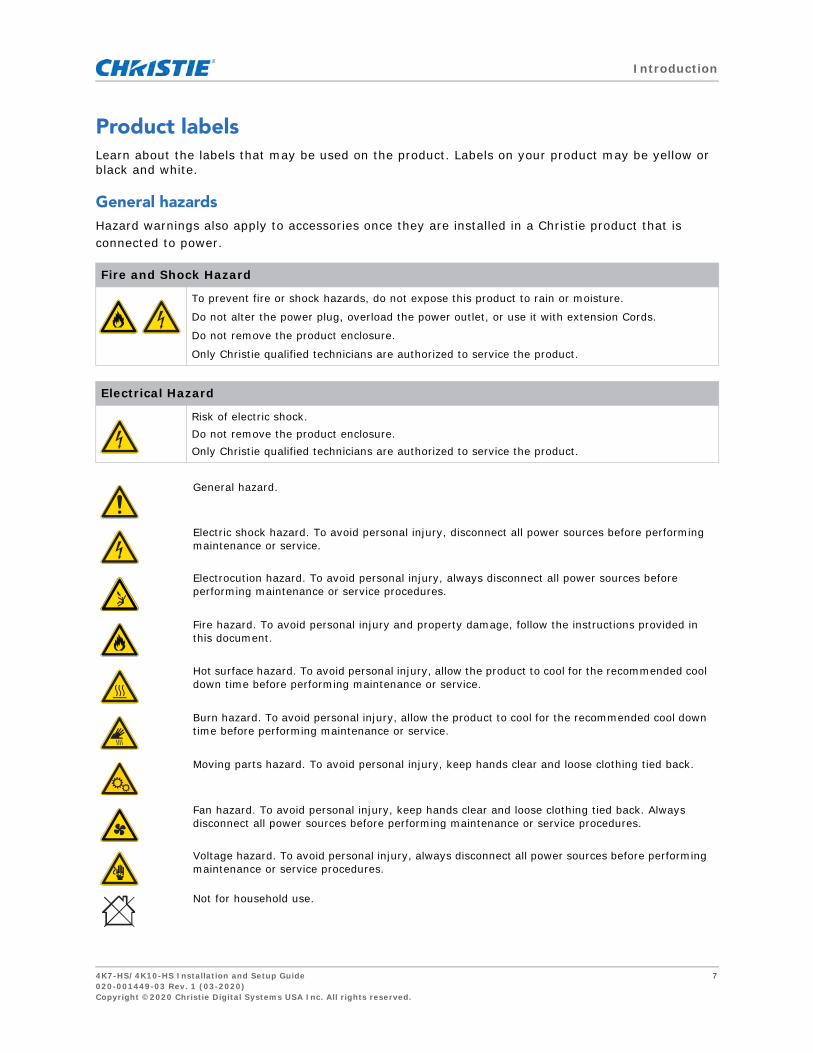
Product labelsLearn about the labels that may be used on the product. Labels on your product may be yellow or black and white.
General hazardsHazard warnings also apply to accessories once they are installed in a Christie product that is connected to power.
Fire and Shock Hazard
To prevent fire or shock hazards, do not expose this product to rain or moisture.
Do not alter the power plug, overload the power outlet, or use it with extension Cords.
Do not remove the product enclosure.
Only Christie qualified technicians are authorized to service the product.
Electrical Hazard
Risk of electric shock. Do not remove the product enclosure. Only Christie qualified technicians are authorized to service the product.
General hazard.
Electric shock hazard. To avoid personal injury, disconnect all power sources before performing maintenance or service.
Electrocution hazard. To avoid personal injury, always disconnect all power sources before performing maintenance or service procedures.
Fire hazard. To avoid personal injury and property damage, follow the instructions provided in this document.
Hot surface hazard. To avoid personal injury, allow the product to cool for the recommended cool down time before performing maintenance or service.
Burn hazard. To avoid personal injury, allow the product to cool for the recommended cool down time before performing maintenance or service.
Moving parts hazard. To avoid personal injury, keep hands clear and loose clothing tied back.
Fan hazard. To avoid personal injury, keep hands clear and loose clothing tied back. Always disconnect all power sources before performing maintenance or service procedures.
Voltage hazard. To avoid personal injury, always disconnect all power sources before performing maintenance or service procedures.
Not for household use.
4K7-HS/4K10-HS Installation and Setup Guide 7020-001449-03 Rev. 1 (03-2020)Copyright ©2020 Christie Digital Systems USA Inc. All rights reserved.

Introduction
Mandatory action
Electrical labels
Laser labels
Consult the service manual.
Disconnect all power sources before performing maintenance or service procedures.
Indicates the presence of an earth ground.
Do not look into the projector lens when the laser is on. The bright light may result in permanent eye damage.
This projector has been classified as Class 1 Laser Product-Risk Group 2 according to IEC 60825-1:2014, IEC 62471:2006, and IEC 62471-5:2015.
4K7-HS/4K10-HS Installation and Setup Guide 8020-001449-03 Rev. 1 (03-2020)Copyright ©2020 Christie Digital Systems USA Inc. All rights reserved.

Introduction
Projector overviewThe 4K7-HS/4K10-HS projector is a professional, 4K UHD resolution projector system using Digital Light Processing (DLP™) technology from Texas Instruments. It provides high standard of image quality along with high degree of flexibility, providing great alternatives for fixed installation environments to enhance users visual experience.
Contact your dealerRecord the information about your projector and keep this information with your records to assist with the servicing of your projector. If you encounter a problem with your Christie projector, contact your dealer.
Key featuresUnderstand the important features of the projector.
• 4K UHD (3840x2160) resolution with high brightness performance
• Lens suite options for installation flexibility
• Projection lens compatibility:
• Horizontal offset ranges with half image size: +/-60%
• Vertical offset ranges with half image size: +/-140%
Measurements comply with industry standards where offset is calculated as a ratio of the number of pixels shifted up or down to half image size.
• Christie Twist™ and Mystique™ allow for easy and quick blending and warping
Support for Mystique™ camera based alignment system (sold separately)
• Full HD 3D technology with frame sequential up to 120Hz
Purchase record
Dealer:
Dealer or Christie Sales/Service contact phone number:
Projector serial number:
The serial number can be found on the license label located on the display panel
Purchase date:
Installation date:
Ethernet settings
Default gateway
Projector IP address
Subnet mask
4K7-HS/4K10-HS Installation and Setup Guide 9020-001449-03 Rev. 1 (03-2020)Copyright ©2020 Christie Digital Systems USA Inc. All rights reserved.

Introduction
• A wide range of connectivity including 3G-SDI, HDBaseT, and 3D inputs
• HDBaseT 4K extension card supports HD video streaming through RJ45 (standard on 4K10-HS, sold separately for 4K7-HS)
• Optional SDVoE and 3G-SDI card for more efficient AV integration and connectivity
• 360 degrees projection enabled by laser light source
• Compatible with HDR content
• Motion Enhancement and Motion Compensation (MEMC) technology for smooth picture quality when projecting fast motion video
• Wireless desktop display using wireless dongle (optional)
• SNMP traps and email notifications
• All video formats can be resized to full screen either horizontally or vertically while maintaining aspect ratio
• The projector can be operated using any of the following:
• The built-in keypad, the infrared (IR) remote keypad, a wired remote keypad, a PC/ device using serial communications (Ethernet or RS232)
• A web page using Ethernet or from a PC or device using a wireless USB dongle (optional)
How the projector worksThe 4K7-HS/4K10-HS projector accepts a variety of input signals for a wide range of commercial projection applications.Designed with solid-state illumination light sources and phosphor technology, the red, green and blue color elements are segmented through a phosphor wheel and then modulated by one Digital Micromirror Device (DMD) panel responding to incoming data streams of digitized red, green and blue color information. As these digital streams flow from the source, light from the responding on pixels of the DMD panel is reflected, converged, and then projected to the screen through projection lenses, where all pixel reflections are superimposed in sharp full-color images.
List of componentsThis projector comes with all the items listed below. Check to make sure your package is complete.If anything is missing, contact your dealer.
• AC power cord
• IR remote keypad
• Product Safety Guide
4K7-HS/4K10-HS Installation and Setup Guide 10020-001449-03 Rev. 1 (03-2020)Copyright ©2020 Christie Digital Systems USA Inc. All rights reserved.

Introduction
Product documentationFor installation, setup, and user information, see the product documentation available on the Christie Digital Systems USA Inc. website at www.christiedigital.com. Read all instructions before using or servicing this product.
1. Access the documentation from the Christie website:
• Go to this URL: http://bit.ly/2JtghsE or
https://www.christiedigital.com/en-us/business/products/projectors/1-chip-dlp/hs-series
• Scan the QR code using a QR code reader app on a smartphone or tablet.
2. On the product page, select the model and switch to the Downloads tab.
Related documentationAdditional information on the projector is available in the following documents.
• 4K7-HS/4K10-HS Installation and Setup Guide (P/N: 020-001449-XX)
• 4K7-HS/4K10-HS Product Safety Guide (P/N: 020-001450-XX)
• 4K7-HS/4K10-HS User Manual (P/N: 020-001451-XX)
• 4K7-HS/4K10-HS Specification Guide (P/N: 020-001452-XX)
• 4K7-HS/4K10-HS Service Manual (P/N: 020-001453-XX)
• 4K7-HS/4K10-HS Lens Throw Ratios Technical Reference Information (P/N: 020-102940-XX)
• 4K7-HS and 4K10-HS Serial API Commands Technical Reference (P/N: 020-102782-XX)
• Twist User Guide (P/N: 020-101380-XX)
• Mystique Operate Instruction Sheet (P/N: 020-102382-XX)
4K7-HS/4K10-HS Installation and Setup Guide 11020-001449-03 Rev. 1 (03-2020)Copyright ©2020 Christie Digital Systems USA Inc. All rights reserved.

Installation and setup
Learn how to install, connect, and optimize the projector display.
Site requirementsTo safely install and operate the projector, the instalation location must meet these minimum requirements.
Physical operating environmentProvides specifications for the operating environment.
• Ambient temperature (operating): 0°C to 40°C (32°F to 104°F) up to 2500 ft
• Humidity (non-condensing): 10% to 85% RH
• Operating altitude: 10,000 ft maximum at 0 to 30°C ambient temperature
Power connectionThe projector uses an universal AC power system that allows the projector to operate at full brightness with a power supply of 100-240 VAC or 200-240 VAC, depending on the regions. Operating the device outside of this voltage range may cause unsatisfactory operation or damage to the projector. To ensure safe operation, only use the AC power cord provided with the product or recommended by Christie. See Connecting to AC power on page 25 for further information on the power requirements.
Physical specificationsLearn the dimensions and weight of the projector before installation.
• Projection size, excluding lens, feet (L x W x H): 23.6 x 20.5 x 8.4” (600 x 520 x 214 mm)
• Shipping size, without lens (L x W x H): 35.6 x 29.9 x 14.8” (905 x 760 x 365 mm)
• Weight, without lens: 34.0 kg (74.86 lbs)
• Shipping weight, without lens: 44.5 kg (97.98 lbs)
4K7-HS/4K10-HS Installation and Setup Guide 12020-001449-03 Rev. 1 (03-2020)Copyright ©2020 Christie Digital Systems USA Inc. All rights reserved.

Installation and setup
Projector componentsIdentify the main components of the projector.
Front viewIdentify the main components on the front of the projector.
ID Part name Description
1 Projection lens Allows powered and automatic lens shifting and adjustment: vertical and horizontal offsets, zoom, and focus.
2 Front IR sensors Receives signals from the IR remote keypad. Keep the signal path to the sensors unobstructed for uninterrupted communication with the projector.
3 Adjustable feet Raises or lowers the feet to level the projector.
4 USB WIFI Connects to a wireless dongle. Slide the left front cover downwards to access the USB WIFI port.
USB WIFI
2
1
3
4
4K7-HS/4K10-HS Installation and Setup Guide 13020-001449-03 Rev. 1 (03-2020)Copyright ©2020 Christie Digital Systems USA Inc. All rights reserved.

Installation and setup
Rear viewIdentify the main components on the rear of the projector.
Left viewIdentify the main components on the left side of the projector.
ID Part name Description
1 Rear IR sensor Receives signals from the IR remote keypad. Keep the signal path unobstructed for uninterrupted communication with the projector.
2 Cooling air vents (exhaust) Provides cooling to the projector. Keep these vents unobstructed to prevent the projector from overheating.
ID Part name Description
1 Cooling air vents (intake) Provides cooling to the projector. Keep these vents unobstructed to prevent the projector from overheating.
1
2
1
4K7-HS/4K10-HS Installation and Setup Guide 14020-001449-03 Rev. 1 (03-2020)Copyright ©2020 Christie Digital Systems USA Inc. All rights reserved.

Installation and setup
Right viewIdentify the main component on the right side of the projector.
ID Part name Description
1 Input/Output (I/O) panel Connects the projector to external devices.
2 Built-in keypad Controls the projector.
3 Fuse Fuse T16 A/250 VAC
4 Power button Powers the projector on or off.
5 AC input Connects to the supplied power adapter (100-240 VAC).
6 Kensington lock Secures the projector to counter tops, tables, and so on.
3G-SDI IN 3G-SDI OUTHDBaseT
T16A/250V~
21
54
3
6
4K7-HS/4K10-HS Installation and Setup Guide 15020-001449-03 Rev. 1 (03-2020)Copyright ©2020 Christie Digital Systems USA Inc. All rights reserved.

Installation and setup
Built-in keypadThe built-in keypad controls the projector.
ID Button Description
1 AUTO Automatically optimizes an image.
2 POWER Turns the projector on or off.
3 SHUTTER Displays or blanks the video image.
4 OSD Hides or shows the on-screen display (OSD) menus.
5 HELP Displays the instructions for source connection.
6 MENU Displays the menus.
7 Arrow keys Adjusts a setting up or down, or navigate within a menu.
8 INPUT Selects an input for the main or picture in picture/picture by picture (PIP/PBP) image.
9 FOCUS Adjusts the focus.
10 LENS Adjusts the lens vertical or horizontal offset setting.
11 ZOOM Adjusts the zoom.
12 BACK Returns to the previous level or exits the menus if at top level.
7
9
8
11
12
1
2
3
5
6
4 10
4K7-HS/4K10-HS Installation and Setup Guide 16020-001449-03 Rev. 1 (03-2020)Copyright ©2020 Christie Digital Systems USA Inc. All rights reserved.

Installation and setup
Input/Output (I/O) panelIdentify the components of the Input/Output (I/O) panel.
ID Connector name ID Connector name
1 REMOTE OUT 9 RJ45 (10/100 Mbps)
2 REMOTE IN 10 3D SYNC IN
3 RS232 11 3D SYNC OUT
4 HDMI IN1 12 USB WIFI (5 V/500 mA)
5 HDMI IN2 13 HDBaseT
6 HDMI OUT 14 3G-SDI OUT
7 DVI 15 3G-SDI IN
8 DISPLAYPORT
• The two optional card slots can accommodate extension cards such as the HDBaseT input card, the 3G-SDI In/3G-SDI Out card, and the SDVoE input card.
• The HDBaseT input card is installed as standard on the 4K10-HS.
HDBaseT
HDBaseT
3G-SDI IN 3G-SDI OUT
USB WIFI
1 2 3 4 5 6 7 8 9 10 11
13
14
15
Front view
Right view
12
4K7-HS/4K10-HS Installation and Setup Guide 17020-001449-03 Rev. 1 (03-2020)Copyright ©2020 Christie Digital Systems USA Inc. All rights reserved.

Installation and setup
IR remote keypadThe IR remote keypad communicates with the projector by way of wireless communications.Use a cable length of 20 m or less. If the length of cable exceeds 20 m, the IR remote keypad may not work correctly.
ID Button Description
1 SHUTTER Displays or blanks the video image.
2 ON Turns the projector on.
3 GAMMA Adjusts the mid-range levels.
4 BRIGHT Adjusts the amount of light in the image.
5 PIPPBP
Turns picture-in-picture/picture-by-picture (PIP/PBP) on or off.
SHUTTER
VGA
HDMI2 DVI-D
BNC
DP
3G-SDI HDBaseT
PRESENT.
CVBS
HDMI1
16
17
18
1920
21
22
24
25
2627
28
29
1
2
3
45
6
7
8
9
10
11
12
1314
15
23
4K7-HS/4K10-HS Installation and Setup Guide 18020-001449-03 Rev. 1 (03-2020)Copyright ©2020 Christie Digital Systems USA Inc. All rights reserved.

Installation and setup
6 SIZE Adjusts the PIP/PBP size.
7 Number keys Enter a number, such as a channel, value, and so on. The on-screen display (OSD) indicates if a function is not supported.
8 HELP Displays the instructions for source connection.
9 MENU Displays the menus.
10 Arrow keys Adjusts a setting up or down to navigate within a menu.
11 TEST Displays a test pattern.
12 AUTO Automatically synchronizes the projector to an input source.
13 OSD Hides or shows OSD menus.
14 KEYSTONE H Adjusts the horizontal keystone.
15 KEYSTONE V Adjusts the vertical keystone.
16 STANDBY Turns the projector off.
17 CONTR Adjusts the difference between dark and light.
18 HOTKEY
Selects your preset key quickly.
19 SWAP Swaps the main and PIP/PBP images.
20 LAYOUT Adjusts the PIP/PBP layout.
21 FOCUS Adjusts the focus to improve image clarity as required.
22 ZOOM Adjusts the zoom to achieve a required image size.
23 PROJ Changes the IR remote keypad ID.
• To assign an ID, press PROJ + <1 to 9>. • To return to the universal IR remote ID, press PROJ + 0.
24 EXIT Returns to previous level or exit menus if at top level.
25 ENTER Selects a highlighted menu item, or changes or accepts a value.
26 INPUT Selects an input for the main or PIP/PBP image.
27 INFO Displays the projector information.
28 LENS H Adjusts the position of the image horizontally.
29 LENS V Adjusts the position of the image vertically.
ID Button Description
4K7-HS/4K10-HS Installation and Setup Guide 19020-001449-03 Rev. 1 (03-2020)Copyright ©2020 Christie Digital Systems USA Inc. All rights reserved.

Installation and setup
Positioning the displayWhen you select a position for the projector, consider the size and shape of your screen, the location of your power outlets, and the distance between the projector and the rest of your equipment. Follow these general guidelines:
• Position the projector on a flat surface at a right angle to the screen. The projector (with the standard lens) must be at least 4.7 ft (1.42 m) from the projection screen.
• Position the projector to the required distance from the screen. The distance from the lens of the projector to the screen, the zoom setting, and the video format determine the size of the projected image.
• Determine the lens throw ratio.For more information detailing the throw ratio for each lens, refer to the 4K7-HS/4K10-HS Lens Throw Ratios Technical Reference Information (020-102940-XX).
• 360 degree free orientation operation
When installing the projector in portrait orientation, Christie recommends that the built in keypad and power inputs face upwards. This allows access to the built in keypad and power connections during operation.
HDBaseT
T16A/250V~
HDBaseT
T16A/250V~
HDBa
seT
T1
6A
/25
0V
~
HDBaseT
T1
6A
/25
0V
~
4K7-HS/4K10-HS Installation and Setup Guide 20020-001449-03 Rev. 1 (03-2020)Copyright ©2020 Christie Digital Systems USA Inc. All rights reserved.

Installation and setup
Installing the ceiling mountMount the projector with a Christie-approved mount or rigging frame (such as the Christie One Mount Plus, P/N: 140-117100-XX, and Christie One Aluminum Rigging Frame, P/N: 140-137102-XX), using the four mounting points on the underside of the projector.
Leveling the projectorTo adjust the vertical position of the projector, turn in or out of the adjustable feet on the bottom of the projector.
Warning! If not avoided, the following could result in death or serious injury.
• When not mounted properly, the projector may fall.• The warranty on this projector does not cover damage caused by the use of a non-recommended
ceiling mount kit or installation of the ceiling mount kit in an improper location.
Refer to the installation instructions and safety guidelines provided in the kit (such as the Christie One Mount Plus, P/N: 140-117100-XX, and Christie One Aluminum Rigging Frame, P/N: 140-137102-XX).
4K7-HS/4K10-HS Installation and Setup Guide 21020-001449-03 Rev. 1 (03-2020)Copyright ©2020 Christie Digital Systems USA Inc. All rights reserved.

Installation and setup
Installing the projector lens
Only use the lens compatible with Christie 4K7-HS/4K10-HS projectors.
1. Remove the dust cover from the lens opening.
2. Release the screw on the lens release button with an M2.5 Allen key.
3. Align the top of the lens with the red marker on front cover.
4. Insert the lens into the projector and turn it clockwise until you hear a clicking sound.
Calibrating the lens motorEnsure the lens motor is calibrated before using the projector. Failure to calibrate the lens motor properly may cause following implications.
• Inability to use the full range of the lens motor.
• Lens motor traveling beyond the lens shifting range.
• Damage to the projector.
Warning! If not avoided, the following could result in death or serious injury.
• Turn off the projector and remove the power cord, before installing or replacing a lens.
• When handling the projector after lens installation, make sure the front lens cap is placed on the lens to protect the lens surface from potential damage.
• When carrying or moving the projector, do not handle by the lens. This may damage the lens, the chassis, or other mechanical parts within the projector.
4K7-HS/4K10-HS Installation and Setup Guide 22020-001449-03 Rev. 1 (03-2020)Copyright ©2020 Christie Digital Systems USA Inc. All rights reserved.

Installation and setup
Calibrate the lens motors when any of the following conditions are met:
• After a lens change.
• After the projector is moved.
• After any manual adjustment made to the zoom or focus.
To calibrate the lens motor:
1. Press MENU on the remote control or built-in keypad.
2. Select Configuration > Lens Settings > Lens Calibration.
3. Press ENTER.
4. To start the lens calibration, select OK.
Removing the projector lensTo safely remove the projection lens, complete the following steps.
1. Center the lens while the projector is switched on by pressing the LENS H or LENS V button and then pressing ENTER.
Ensure the lens is at or near its center position. Attempting to remove the lens with a large offset may cause damage to the lens assembly.
2. Turn off the projector.
3. Allow the projector to cool down into standby mode before replacing the lens.
4. After the projector has cooled down and prior to replacing the lens, remove the power cord.
5. Push in and hold the lens release button.
6. Turn the lens counterclockwise by a quarter to release the lens.
7. Gently pull the lens out of the lens holder.
Christie recommends covering the lens opening with the dust cover to prevent damage to the projector.
4K7-HS/4K10-HS Installation and Setup Guide 23020-001449-03 Rev. 1 (03-2020)Copyright ©2020 Christie Digital Systems USA Inc. All rights reserved.

Installation and setup
Removing and installing the fuseTo remove and install the fuse, complete the following steps.
1. Turn the projector off.
2. Remove the screw on the fuse with a flat-head screwdriver.
3. Remove the fuse and replace it with the new one.
4K7-HS/4K10-HS Installation and Setup Guide 24020-001449-03 Rev. 1 (03-2020)Copyright ©2020 Christie Digital Systems USA Inc. All rights reserved.

Installation and setup
Connecting to AC powerTo operate the projector at full brightness, make sure the power supply meets the power requirements for 4K7-HS/4K10-HS projectors. See Power connection on page 12 for more information.
To safely connect the AC power:
1. Connect the AC power cord to the AC inlet on the projector.
2. To keep the AC power cord from falling out, lock it with the safety latch.
3. To unplug the AC power cord, pull up the safety latch.
Model name Power requirements
4K7-HS/4K10-HS 100-240 VAC, 50/60 Hz, 12 A
200-240 VAC, 50/60 Hz, 6 A (rated for China, India, and Korea)
100 VAC, 50/60 Hz, 12 A, 1050 W (rated for Japan)
110-240 VAC, 50/60 Hz, 10 A (rated for Taiwan)
For more information detailing the power requirements, refer to the 4K7-HS/4K10-HS Specification Guide (P/N: 020-001452-XX).
4K7-HS/4K10-HS Installation and Setup Guide 25020-001449-03 Rev. 1 (03-2020)Copyright ©2020 Christie Digital Systems USA Inc. All rights reserved.

Installation and setup
Turning on the projectorThe projector cables must be securely connected before turning the power on.
1. Plug the projector in to AC power.
The Power button on the built in keypad is illuminated when the power cables are connected.
2. Ensure the lens has been installed in the projector.
3. Ensure that no one or no objects are in the beam path before turning on the projector.
4. To turn on the projector, on the IR remote keypad or on the built-in keypad press .
The status LED is green with a long blink.
5. To select an input source and turn it on, on the IR remote keypad select INPUT.
Available input sources are HDMI1, HDMI2, DVI, DisplayPort, HDBaseT (standard on 4K10-HS),
and 3G-SDI (optional). The projector detects the source you selected and displays the image.
6. If using the projector for the first time, select a preferred language from the main menu after the startup screen is displayed.
Turning off the projectorPower off the projector in preparation for inspection or maintenance.
1. To turn the projector off, on the IR remote keypad or built-in keypad press .
A warning message appears on the displayed image.
2. To confirm your selection, press again.
If you do not press again, the warning message disappears after three seconds and the projector remains on.
Warning! If not avoided, the following could result in death or serious injury.
• Do not look into the projector lens when the laser is on. The bright light may result in permanent eye damage.
4K7-HS/4K10-HS Installation and Setup Guide 26020-001449-03 Rev. 1 (03-2020)Copyright ©2020 Christie Digital Systems USA Inc. All rights reserved.

Installation and setup
LED status indicatorLED status indicator helps identify the projector state. LEDs are defined below.
Status LEDIdentify the LED state colors and meaning.
Shutter LEDIdentify the shutter LED state colors and meaning.
LED status Projector state
Off AC power is off (without AC plugged in).
Green (flashing) Projector is in startup mode.
Green (solid) System is operating normally.
Blue (flashing) Projector is cooling down.
Blue (solid) Projector is in standby mode.
Yellow (flashing) A problem exists with the projector that will not cause it to shut down.
Examples of warnings include: filter needs changing, one of the pumps is damaged, or a fan is operating at full speed due to over temperature of laser diode (LD) driver.
Yellow (solid) The end user is turning off the projector while it is in a warning state.
Red (flashing) An error with the projector exists causing it to shut down.
Examples of errors include: fan failure, over temperature, wrongly installed filter, or color wheel (CW) failure.
Red (solid) The user is turning off the projector while it is in an error state.
White (flashing) Projector is in a flash (LAN) update state.
LED status Projector state
Off Projector is on and an image is displayed. Shutter is open.
Magenta (solid) Projector is on and the image is blank. Shutter is closed.
4K7-HS/4K10-HS Installation and Setup Guide 27020-001449-03 Rev. 1 (03-2020)Copyright ©2020 Christie Digital Systems USA Inc. All rights reserved.

Installation and setup
Calculating the lens offsetAdjust the offset to align the image on the screen with half image size.
• The vertical image offset (shift) range for 4K7-HS/4K10-HS projectors is +/-140%.
• The horizontal image offset (shift) range for the projector is +/-60%.
• The method for calculating lens offset complies with industry standards, with which the image offset is calculated by half image size. For example for vertical lens offset:
• At 0% offset (or on axis), the center of the image is on the lens center, so half of the image appears above and half appears below the lens center.
• At +100% offset, all of the image appears above the lens center.
The following show the vertical and horizontal image offsets for the 4K7-HS/4K10-HS projectors:
• Vertical image offset: 0%
• Vertical image offset: +/-140%
0%
0%
Lens center
Lens center
+14
0%-1
40%
4K7-HS/4K10-HS Installation and Setup Guide 28020-001449-03 Rev. 1 (03-2020)Copyright ©2020 Christie Digital Systems USA Inc. All rights reserved.

Installation and setup
• Horizontal image offset: +/-60%
%06+%06-
Lens
cen
ter
4K7-HS/4K10-HS Installation and Setup Guide 29020-001449-03 Rev. 1 (03-2020)Copyright ©2020 Christie Digital Systems USA Inc. All rights reserved.
Installation and setup
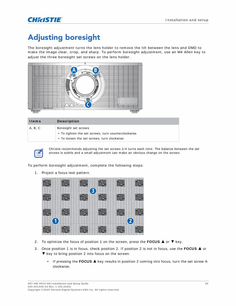
Adjusting boresightThe boresight adjustment turns the lens holder to remove the tilt between the lens and DMD to make the image clear, crisp, and sharp. To perform boresight adjustment, use an M4 Allen key to adjust the three boresight set screws on the lens holder.
To perform boresight adjustment, complete the following steps:
1. Project a focus test pattern.
2. To optimize the focus of position 1 on the screen, press the FOCUS or key.
3. Once position 1 is in focus, check position 2. If position 2 is not in focus, use the FOCUS or key to bring position 2 into focus on the screen.
• If pressing the FOCUS key results in position 2 coming into focus, turn the set screw A clockwise.
Items Description
A, B, C Boresight set screws
• To tighten the set screws, turn counterclockwise.• To loosen the set screws, turn clockwise.
Christie recommends adjusting the set screws 1/4 turns each time. The balance between the set screws is subtle and a small adjustment can make an obvious change on the screen.
B
C
A
3
1 2
4K7-HS/4K10-HS Installation and Setup Guide 30020-001449-03 Rev. 1 (03-2020)Copyright ©2020 Christie Digital Systems USA Inc. All rights reserved.

Installation and setup
• If pressing the FOCUS key results in position 2 coming into focus, turn the set screw A counterclockwise.
4. Refocus position 1 and check if position 2 is also in focus. If not, repeat step 3 and 4 until both position 1 and 2 are in focus.
5. To optimize the focus of position 3 on the screen, turn the set screw C clockwise or counterclockwise.
• If pressing the FOCUS key results in position 3 coming into focus, turn the set screw C clockwise.
• If pressing the FOCUS key results in position 3 coming into focus, turn the set screw C counterclockwise.
6. Repeat from step 2 until the projected focus pattern is as sharp as possible in the center, left, right, top, and bottom of the screen.
7. If the projector is still not in focus, reset the set screw position:
a. Turn the set screws counterclockwise until tight.
b. Turn the set screws 1.5 turns in the clockwise direction back to their factory default setting.
c. Check that the alignment of the set screws matches what is shown in the image above.
4K7-HS/4K10-HS Installation and Setup Guide 31020-001449-03 Rev. 1 (03-2020)Copyright ©2020 Christie Digital Systems USA Inc. All rights reserved.

Connecting to devices
This section covers the information on connecting the 4K7-HS/4K10-HS projector to a computer and video equipment.
Connecting to a computerLearn what cables/connectors can be used to connect to various devices.
ID Connector name ID Connector name
1 HDMI cable 4 DVI In cable
2 RS232 cable 5 DisplayPort cable
3 HDMI cable 6 Power cord
HDBaseT
T16A/250V~
1 3 4 5
6
2
Desktop LaptopMonitor
4K7-HS/4K10-HS Installation and Setup Guide 32020-001449-03 Rev. 1 (03-2020)Copyright ©2020 Christie Digital Systems USA Inc. All rights reserved.

Connecting to devices
Connecting to video equipmentLearn what cable/connectors may be used to connect to various video sources.
ID Connector name ID Connector name
1 HDMI cable 3 DisplayPort cable
2 DVI In cable
• After connecting the projector to an input device, the projector automatically detects the input source. You can also select an input source by pressing INPUT.
• Due to the difference in applications for each country, the accessories required in some regions may differ from those shown.
• This diagram is for illustrative purposes only and does not indicate that these accessories are supplied with the projector.
HDBaseT
1 2 3
DVD player Video cassette recorder Component video output equipment
4K7-HS/4K10-HS Installation and Setup Guide 33020-001449-03 Rev. 1 (03-2020)Copyright ©2020 Christie Digital Systems USA Inc. All rights reserved.

Signal connectivity specifications
Identify the signal connectivity specifications for 4K7-HS/4K10-HS projector.The list of formats listed below are not exhaustive and other formats may be supported. For more information, contact Christie Technical Support.
HDMI video formatsIdentify the video formats for the HDMI input.
Signal Type Format Hres Vres Frame rate (Hz) Sampling Bit-Depth
PC 640x480 640 480 60,72,75,85,66.6 RGB/4:4:4/4:2:2 8/10/12bpc
800x600 800 600 60,72,75,85,120 RGB/4:4:4/4:2:2 8/10/12bpc
832x624 832 624 75 RGB/4:4:4/4:2:2 8/10/12bpc
848x480 848 480 50,60,75,85 RGB/4:4:4/4:2:2 8/10/12bpc
1024x768 1024 768 60,75,85,120 RGB/4:4:4/4:2:2 8/10/12bpc
1152x864 1152 864 60,70,75,85 RGB/4:4:4/4:2:2 8/10/12bpc
1152x870 1152 870 75 RGB/4:4:4/4:2:2 8/10/12bpc
1280x720 1280 720 50,60,75,85,120 RGB/4:4:4/4:2:2 8/10/12bpc
1280x768 1280 768 60,75,85 RGB/4:4:4/4:2:2 8/10/12bpc
1280x800 1280 800 50,60,75,85 RGB/4:4:4/4:2:2 8/10/12bpc
1280x960 1280 960 50,60,75,85 RGB/4:4:4/4:2:2 8/10/12bpc
1280x1024 1280 1024 50,60,75,85 RGB/4:4:4/4:2:2 8/10/12bpc
1360x768 1360 768 50,60,75,85 RGB/4:4:4/4:2:2 8/10/12bpc
1368x768 1368 768 60 RGB/4:4:4/4:2:2 8/10/12bpc
1400x1050 1400 1050 50,60,75 RGB/4:4:4/4:2:2 8/10/12bpc
1440x900 1440 900 60,75 RGB/4:4:4/4:2:2 8/10/12bpc
1600x900 1600 900 60 RGB/4:4:4/4:2:2 8/10/12bpc
1600x1200 1600 1200 60 RGB/4:4:4/4:2:2 8/10/12bpc
4K7-HS/4K10-HS Installation and Setup Guide 34020-001449-03 Rev. 1 (03-2020)Copyright ©2020 Christie Digital Systems USA Inc. All rights reserved.

Signal connectivity specifications
DVI video formatsIdentify the video formats for the DVI input.
PC 1920x1080 1920 1080 50,60 RGB/4:4:4/4:2:2 8/10/12bpc
1920x1200RB 1920 1920 50,60 RGB/4:4:4/4:2:2 8/10/12bpc
SDTV 480i 60 RGB/4:4:4/4:2:2 8/10/12bpc
576i 50 RGB/4:4:4/4:2:2 8/10/12bpc
EDTV 480p 60 RGB/4:4:4/4:2:2 8/10/12bpc
576p 50 RGB/4:4:4/4:2:2 8/10/12bpc
HDTV 1080i 25,29,30 RGB/4:4:4/4:2:2 8/10/12bpc
720p 50,59,60 RGB/4:4:4/4:2:2 8/10/12bpc
1080p 23,24,25,29,30,50,59,60 RGB/4:4:4/4:2:2 8/10/12bpc
Mandatory 3D Frame Packing 1080p
24 RGB/4:4:4/4:2:2 8/10/12bpc
Frame Packing 720p
50,60 RGB/4:4:4/4:2:2 8/10/12bpc
Top and Bottom 720p
50,60 RGB/4:4:4/4:2:2 8/10/12bpc
Top and Bottom 1080p
24 RGB/4:4:4/4:2:2 8/10/12bpc
Frame sequential 3D
1920x1080 120 RGB/4:4:4 8bpc
4K 3840x2160 3840 2160 24,50,60 RGB/4:2:2 8/10/12bpc
3840x2160 3840 2160 24,50,60 RGB/4:4:4 8bpc
Signal Type Format Hres Vres Frame rate (Hz) Sampling Bit-Depth
PC 640x480 640 480 60,72,75,85,66.6 RGB 8bpc
800x600 800 600 60,72,75,85,120 RGB 8bpc
832x624 832 624 75 RGB 8bpc
848x480 848 480 50,60,75,85 RGB 8bpc
1024x768 1024 768 60,75,85,120 RGB 8bpc
1152x864 1152 864 60,70,75,85 RGB 8bpc
1152x870 1152 870 75 RGB 8bpc
1280x720 1280 720 50,60,75,85,120 RGB 8bpc
1280x768 1280 768 60,75,85 RGB 8bpc
1280x800 1280 800 50,60,75,85 RGB 8bpc
Signal Type Format Hres Vres Frame rate (Hz) Sampling Bit-Depth
4K7-HS/4K10-HS Installation and Setup Guide 35020-001449-03 Rev. 1 (03-2020)Copyright ©2020 Christie Digital Systems USA Inc. All rights reserved.
Signal connectivity specifications
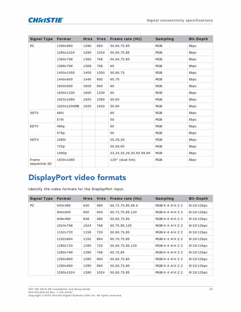
DisplayPort video formatsIdentify the video formats for the DisplayPort input.
PC 1280x960 1280 960 50,60,75,85 RGB 8bpc
1280x1024 1280 1024 50,60,75,85 RGB 8bpc
1360x768 1360 768 50,60,75,85 RGB 8bpc
1368x768 1368 768 60 RGB 8bpc
1400x1050 1400 1050 50,60,75 RGB 8bpc
1440x900 1440 900 60,75 RGB 8bpc
1600x900 1600 900 60 RGB 8bpc
1600x1200 1600 1200 60 RGB 8bpc
1920x1080 1920 1080 50,60 RGB 8bpc
1920x1200RB 1920 1920 50,60 RGB 8bpc
SDTV 480i 60 RGB 8bpc
576i 50 RGB 8bpc
EDTV 480p 60 RGB 8bpc
576p 50 RGB 8bpc
HDTV 1080i 25,29,30 RGB 8bpc
720p 50,59,60 RGB 8bpc
1080p 23,24,25,29,30,50,59,60 RGB 8bpc
Frame sequential 3D
1920x1080 120* (dual link) RGB 8bpc
Signal Type Format Hres Vres Frame rate (Hz) Sampling Bit-Depth
PC 640x480 640 480 60,72,75,85,66.6 RGB/4:4:4/4:2:2 8/10/12bpc
800x600 800 600 60,72,75,85,120 RGB/4:4:4/4:2:2 8/10/12bpc
848x480 848 480 50,60,75,85 RGB/4:4:4/4:2:2 8/10/12bpc
1024x768 1024 768 60,75,85,120 RGB/4:4:4/4:2:2 8/10/12bpc
1152x720 1150 720 50,60,75,85 RGB/4:4:4/4:2:2 8/10/12bpc
1152x864 1152 864 60,70,75,85 RGB/4:4:4/4:2:2 8/10/12bpc
1280x720 1280 720 50,60,75,85,120 RGB/4:4:4/4:2:2 8/10/12bpc
1280x768 1280 768 60,75,85 RGB/4:4:4/4:2:2 8/10/12bpc
1280x800 1280 800 50,60,75,85 RGB/4:4:4/4:2:2 8/10/12bpc
1280x960 1280 960 50,60,75,85 RGB/4:4:4/4:2:2 8/10/12bpc
1280x1024 1280 1024 50,60,75,85 RGB/4:4:4/4:2:2 8/10/12bpc
Signal Type Format Hres Vres Frame rate (Hz) Sampling Bit-Depth
4K7-HS/4K10-HS Installation and Setup Guide 36020-001449-03 Rev. 1 (03-2020)Copyright ©2020 Christie Digital Systems USA Inc. All rights reserved.

Signal connectivity specifications
HDBaseT video formatsIdentify the video formats for the HDBaseT input. The HDBaseT extension card is installed on the 4K10-HS as a standard accessory. For 4K7-HS, purchase the card separately.
PC 1360x768 1360 768 50,60,75,85 RGB/4:4:4/4:2:2 8/10/12bpc
1368x768 1368 768 60 RGB/4:4:4/4:2:2 8/10/12bpc
1400x1050 1400 1050 50,60,75 RGB/4:4:4/4:2:2 8/10/12bpc
1440x900 1440 900 60,75 RGB/4:4:4/4:2:2 8/10/12bpc
1600x900 1600 900 60 RGB/4:4:4/4:2:2 8/10/12bpc
1600x1200 1600 1200 60 RGB/4:4:4/4:2:2 8/10/12bpc
1920x1080 1920 1080 50,60 RGB/4:4:4/4:2:2 8/10/12bpc
1920x1200RB 1920 1920 50,60 RGB/4:4:4/4:2:2 8/10/12bpc
SDTV 480i 60 RGB/4:4:4 6/8/10/12bpc
576i 50 RGB/4:4:4 6/8/10/12bpc
EDTV 480p 60 RGB/4:4:4 6/8/10/12bpc
576p 50 RGB/4:4:4 6/8/10/12bpc
HDTV 1080i 25,29,30 RGB/4:4:4 6/8/10/12bpc
720p 50,59,60 RGB/4:4:4 6/8/10/12bpc
1080p 23,24,25,29,30,50,59,60 RGB/4:4:4 8bpc
Frame sequential 3D
1920x1080 120 RGB/4:2:2 8/10/12bpc
4K 3840x2160 3840 2160 20,50,60 RGB/4:4:4 8bpc
Signal Type Format Hres Vres Frame rate (Hz) Sampling Bit-Depth
4K 3840x2160 3840 2160 50,60 RGB 8bpc
3840x2160 3840 2160 50,60 4:4:4 8bpc
3840x2160 3840 2160 50,60 4:2:0*1 10bpc*2
3840x2160 3840 2160 50,60 4:2:0*1 10bdq HDR*2
3840x2160 3840 2160 50,60 4:2:0*1 12bpc
3840x2160 3840 2160 50,60 4:2:0*1 12bpc HDR
3840x2160 3840 2160 50,60 4:2:2 8bpc*2
3840x2160 3840 2160 50,60 4:2:2 10bpc*2
3840x2160 3840 2160 50,60 4:2:2 10bdq HDR*2
3840x2160 3840 2160 50,60 4:2:2 12bpc
Signal Type Format Hres Vres Frame rate (Hz) Sampling Bit-Depth
4K7-HS/4K10-HS Installation and Setup Guide 37020-001449-03 Rev. 1 (03-2020)Copyright ©2020 Christie Digital Systems USA Inc. All rights reserved.

Signal connectivity specifications
Picture-in-picture/picture-by-picture (PIP/PBP) compatibilityThe following table details the picture-in-picture/picture-by-picture (PIP/PBP) compatibility.
• Dot (●): PIP/PBP combinations are enabled.
4K 3840x2160 3840 2160 50,60 4:2:2 12bpc HDR
3840x2160 3840 2160 25,30 RGB 10bpc
3840x2160 3840 2160 25,30 RGB 12bpc
3840x2160 3840 2160 25,30 4:4:4 10bpc
3840x2160 3840 2160 25,30 4:4:4 10bdq HDR
3840x2160 3840 2160 25,30 4:4:4 12bpc
1. The signal with sampling rate of 4:2:0 is output as 4:2:2 if utilized by DSC compression.2. The 4:2:2 signals are always output as 12bits.
PIP/PBP Matrix DisplayPort DVI HDMI1 HDMI2 Extension Card -1
Extension Card -2
DisplayPort ● ● ● ●
DVI ● ● ● ●
HDMI1 ● ●
HDMI2 ● ●
Extension Card -1 ● ●
Extension Card -2 ● ●
Signal Type Format Hres Vres Frame rate (Hz) Sampling Bit-Depth
4K7-HS/4K10-HS Installation and Setup Guide 38020-001449-03 Rev. 1 (03-2020)Copyright ©2020 Christie Digital Systems USA Inc. All rights reserved.

Regulatory
This product conforms to the following regulations related to product safety, environmental requirements and electromagnetic compatibility (EMC).
Safety• CAN/CSA C22.2 No. 60950-1-07 - Information Technology Equipment – Safety – Part 1:
General Requirements
• ANSI/UL 60950-1-2014 – Information Technology Equipment – Safety – Part 1: General Requirements
• IEC/EN 60950-1 – Information Technology Equipment – Safety – Part 1: General Requirements
Laser safety• IEC 60825-1:2014 – Safety of Laser Products – Part 1: Equipment Classification and
Requirements
• IEC 62471:2006 – Photobiological safety of lamps and lamp systems
• IEC 62471-5:2015 – Photobiological safety of lamps and lamp systems – Part 5: Image projectors
• FDA 2015-02 – Immediately in Effect Guidance Document: Classification and Requirements for Laser Illuminated Projectors (LIPs)
Electro-magnetic compatibility
Emissions• FCC CFR47, Part 15, Subpart B/ANSI C63.4, Class A - Unintentional Radiators
• CAN ICES-3 (A/B) / NMB-3 (A)
• CISPR 32:2014/EN 55032:2014, Class A - Information Technology
• IEC 61000-3-2/EN61000-3-2 - Limits for Harmonic Current Emissions
• IEC 61000-3-3/EN61000-3-3 - Limitations of Voltage Changes, Voltage Fluctuations, and Flicker
4K7-HS/4K10-HS Installation and Setup Guide 39020-001449-03 Rev. 1 (03-2020)Copyright ©2020 Christie Digital Systems USA Inc. All rights reserved.

Specifications
Immunity• CISPR 24: 2010/EN55024:2010 - EMC Requirements - Information Technology Equipment
Environmental• EU Directive (2011/65/EU) on the restriction of the uses of certain hazardous substances
(RoHS) in electrical and electronic equipment and the applicable official amendment(s)
• EU Directive (2012/19/EU) on waste and electrical and electronic equipment (WEEE) and the applicable official amendment(s)
• Regulation (EC) No 1907/2006 concerning the Registration, Evaluation, Authorisation and Restriction of Chemicals (REACH) and the applicable official amendment(s)
• China Ministry of Information Industry Order No.39 (02/2006) on the control of pollution caused by electronic information products, hazardous substances concentration limits (SJ/T11363-2006), and the applicable product marking requirement (SJ/T11364-2006)
4K7-HS/4K10-HS Installation and Setup Guide 40020-001449-03 Rev. 1 (03-2020)Copyright ©2020 Christie Digital Systems USA Inc. All rights reserved.

Christie
Kitchen
ph: 519
Christie
Cypres
ph: 714
Corpo
8000
161
les
es
York)
na)
Digital Systems Canada Inc.er
744 8005
Digital Systems USA, Inc.
s
236 8610
rate of ces
United Kingdom
ph: +44 (0) 118 977
United Arab Emirates
ph: +971 4 3206688
Spain
ph: +34 91 633 9990
Singapore
ph: +65 6877 8737
Republic of South Africa
ph: +27 (0)11 510 0094
Korea (Seoul)
ph: +82 2 702 1601
Japan (Tokyo)
ph: 81 3 3599 7481
India
ph: +91 (080) 6708 9999
Germany
ph: +49 2161 664540
France
ph: +33 (0) 1 41 21 44 04
Russian Federation
and Eastern Europe
ph: +36 (0) 1 47 48 100
China (Shanghai)
ph: +86 21 6278 7708
China (Beijing)
ph: +86 10 6561 0240
Brazil
ph: +55 (11) 2548 4753
Australia
ph: +61 (0) 7 3624 4888
Worldwide of ces
Italy
ph: +39 (0) 2 9902 1
Independant sa
consultant of c
Mexico
ph: +52 55 4744 1790
United States (New
ph: 646 779 2014
United States (Arizo
ph: 602 943 5700
For the most current technical documentation, visit www.christiedigital.com.