MODULE 4 LOCATING AND CLAMPING METHODS
138
MODULE 4 LOCATING AND CLAMPING METHODS
-
Upload
khangminh22 -
Category
Documents
-
view
2 -
download
0
Transcript of MODULE 4 LOCATING AND CLAMPING METHODS
MODULE 4
LOCATING AND CLAMPING
METHODS
Jigs and fixtures are the economical ways to
produce a component in mass.
These are special work holding and tool guiding
device.
Quality of the performance of a process largely
influenced by the quality of jigs and fixtures used for
this purpose.
The main purpose of a fixture is to locate and in the
cases hold a workpiece during an operation
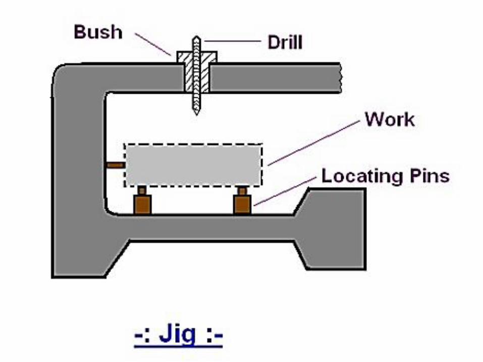
A jig differs from a fixture - it guides the
tool to its correct position or towards its correct
movement during an operation in addition to
locating and supporting the workpiece.
An example of jig is when a key is
duplicated, the original key is used as base for
the path reader which guides the movement of
tool to make its duplicate key.
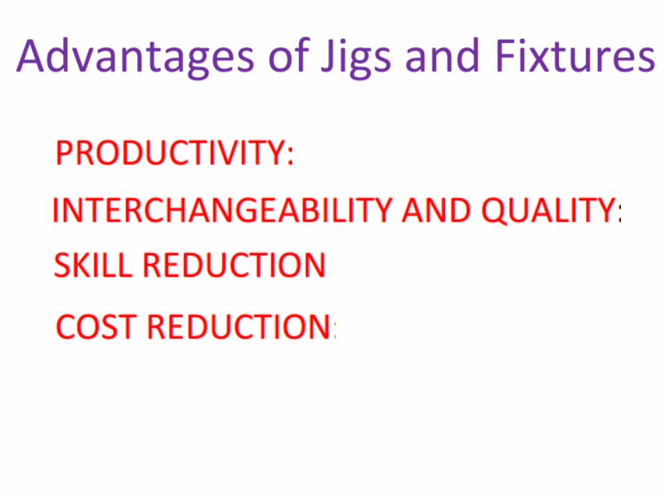
PURPOSE AND ADVANTAGES OF JIGS AND
FIXTURES
1) It reduces or sometimes eliminates the efforts of
marking, measuring and setting of workpiece on a
machine and maintains the accuracy of
performance.
2) The workpiece and tool are relatively located at
their exact positions before the operation
automatically within negligible time. So it reduces
product cycle time.
3) Variability of dimension in mass production is very
low so manufacturing processes supported by use
of jigs and fixtures maintain a consistent quality.
(4) Due to low variability in dimension assembly
operation becomes easy, low rejection due to les
defective production is observed.
(5) It reduces the production cycle time so increases
production capacity. Simultaneously working by more
than one tool on the same workpiece is possible.
(6) The operating conditions like speed, feed rate and
depth of cut can be set to higher values due to rigidity
of clamping of workpiece by jigs and fixtures.
PURPOSE AND ADVANTAGES OF JIGS AND
FIXTURES

(7) Operators working becomes comfortable as his
efforts in setting the workpiece can be eliminated.
(8) Semi-skilled operators can be assigned the work so
it saves the cost of manpower also.
(9) There is no need to examine the quality of product
provided that quality of employed jigs and fixtures is
ensured.
PURPOSE AND ADVANTAGES OF JIGS AND
FIXTURES
IMPORTANT CONSIDERATIONS WHILE
DESIGNING JIGS AND FIXTURES
(a) Study of workpiece and finished component size and
geometry.
(b) Type and capacity of the machine, its extent of automation.
(c) Provision of locating devices in the machine.
(d) Available clamping arrangements in the machine.
(e) Available indexing devices, their accuracy.
(f) Evaluation of variability in the performance results of the
machine.
(g) Rigidity and of the machine tool under consideration.
(h) Study of ejecting devices, safety devices, etc.
(i) Required level of the accuracy in the work and quality to
be produced.
Location refers to the establishment of
a desired relationship between the
workpiece and the jigs or fixture correctness
of location directly influences the accuracy
of the finished product.
LOCATION???...
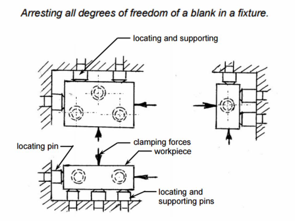
The jigs and fixtures are desired so that all
undesirable movements of the workpiece can be
restricted.
Determination of the locating points and
clamping of the workpiece serve to restrict
movements of the component in any direction,
while setting it in a particular pre-decided
position relative to the jig.

Before deciding the locating points it is
advisable to find out the all possible
degrees of freedom of the workpiece.
Then some of the degrees of freedom or
all of them are restrained by making
suitable arrangements. These arrangements
are called locators.

LOCATING METHODS
JIGS & FIXTURES

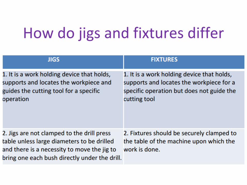
It is a work holding device that holds,
supports and locates the workpiece and
guides the cutting tool for a specific
operation.
JIGS

FIXTURES
It is a work holding device that holds,
supports and locates the workpiece for a
specific operation but does not guide the
cutting tool.

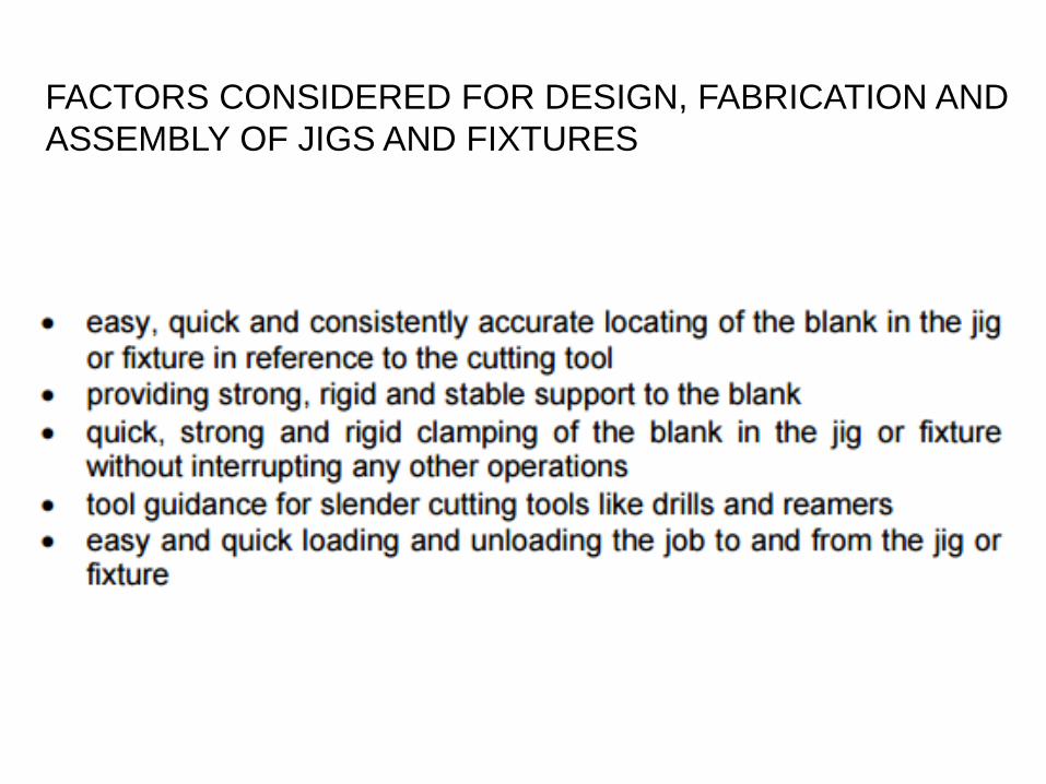
FACTORS CONSIDERED FOR DESIGN, FABRICATION AND
ASSEMBLY OF JIGS AND FIXTURES

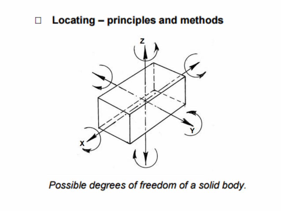

Degree of Freedom
Degree of Freedom is defined as
number of independent motion a body
has
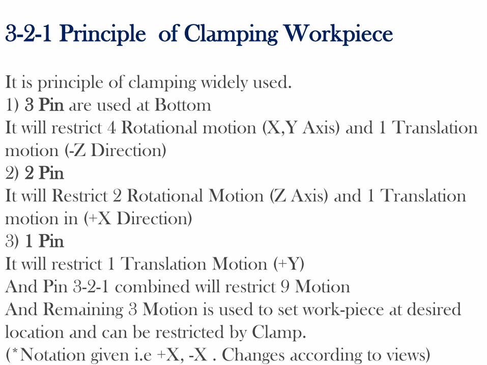
3-2-1 Principle of Clamping Workpiece
It is principle of clamping widely used.
1) 3 Pin are used at Bottom
It will restrict 4 Rotational motion (X,Y Axis) and 1 Translation
motion (-Z Direction)
2) 2 Pin
It will Restrict 2 Rotational Motion (Z Axis) and 1 Translation
motion in (+X Direction)
3) 1 Pin
It will restrict 1 Translation Motion (+Y)
And Pin 3-2-1 combined will restrict 9 Motion
And Remaining 3 Motion is used to set work-piece at desired
location and can be restricted by Clamp.
(*Notation given i.e +X, -X . Changes according to views)

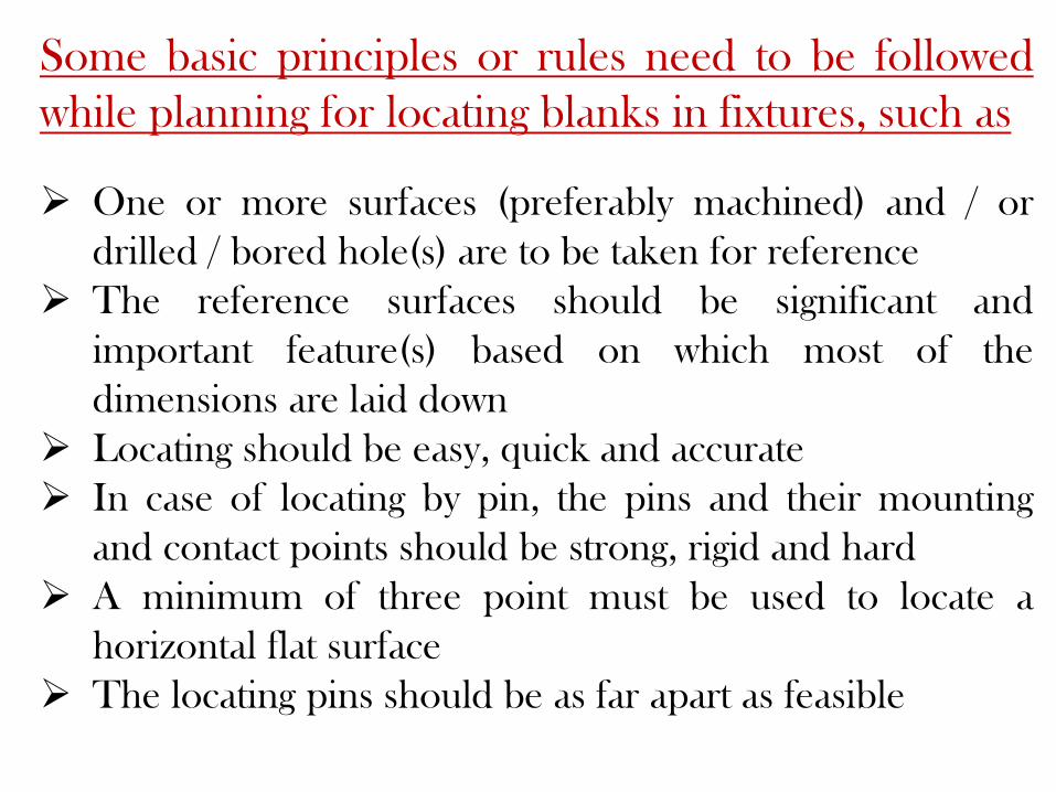
Some basic principles or rules need to be followed
while planning for locating blanks in fixtures, such as
One or more surfaces (preferably machined) and / or
drilled / bored hole(s) are to be taken for reference
The reference surfaces should be significant and
important feature(s) based on which most of the
dimensions are laid down
Locating should be easy, quick and accurate
In case of locating by pin, the pins and their mounting
and contact points should be strong, rigid and hard
A minimum of three point must be used to locate a
horizontal flat surface
The locating pins should be as far apart as feasible
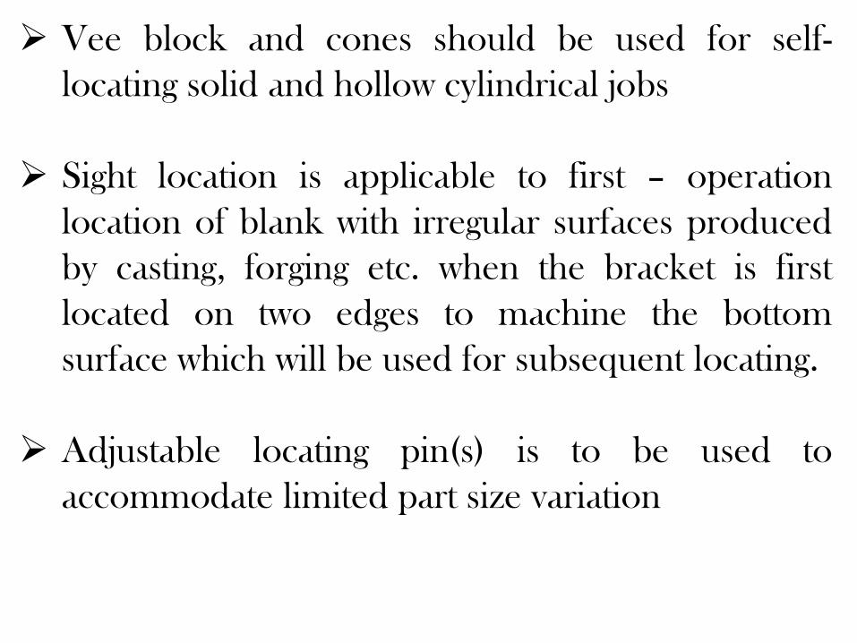
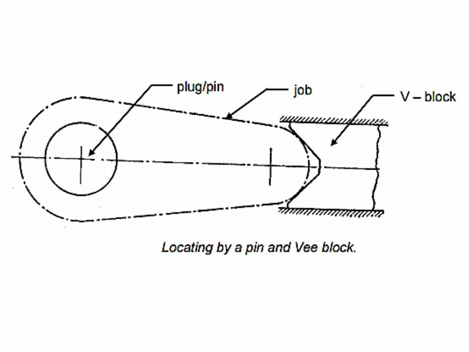
Vee block and cones should be used for self-
locating solid and hollow cylindrical jobs
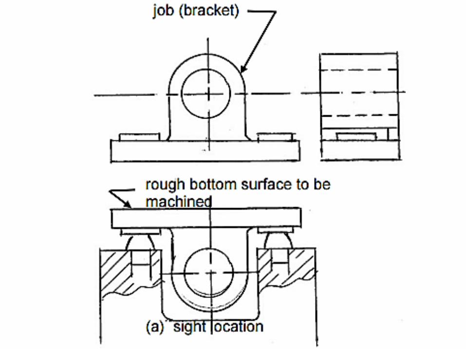
Sight location is applicable to first – operation
location of blank with irregular surfaces produced
by casting, forging etc. when the bracket is first
located on two edges to machine the bottom
surface which will be used for subsequent locating.
Adjustable locating pin(s) is to be used to
accommodate limited part size variation

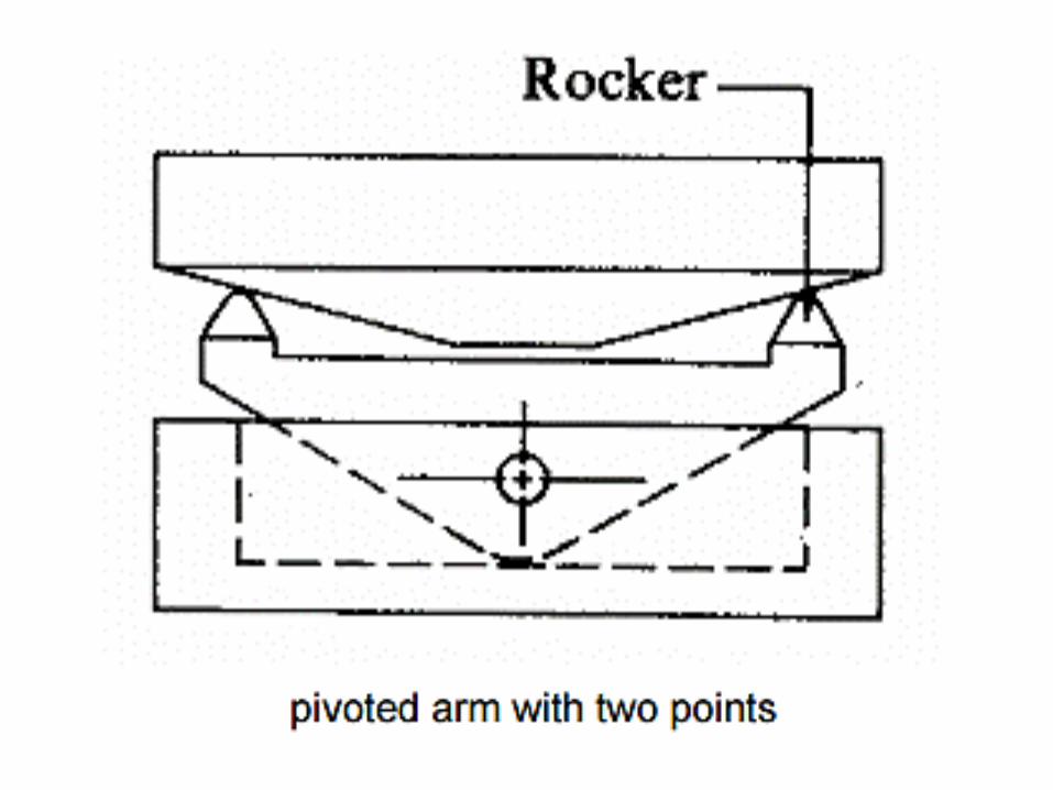
For locating large jobs by rough bottom
surface one of the three pins may be
replaced by a pivoted arm.
The pivoted arm provides two contact
points.
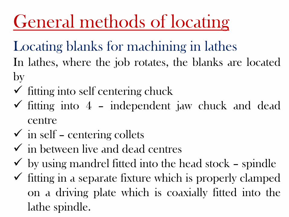
General methods of locating
Locating blanks for machining in lathesIn lathes, where the job rotates, the blanks are located
by
fitting into self centering chuck
fitting into 4 – independent jaw chuck and dead
centre
in self – centering collets
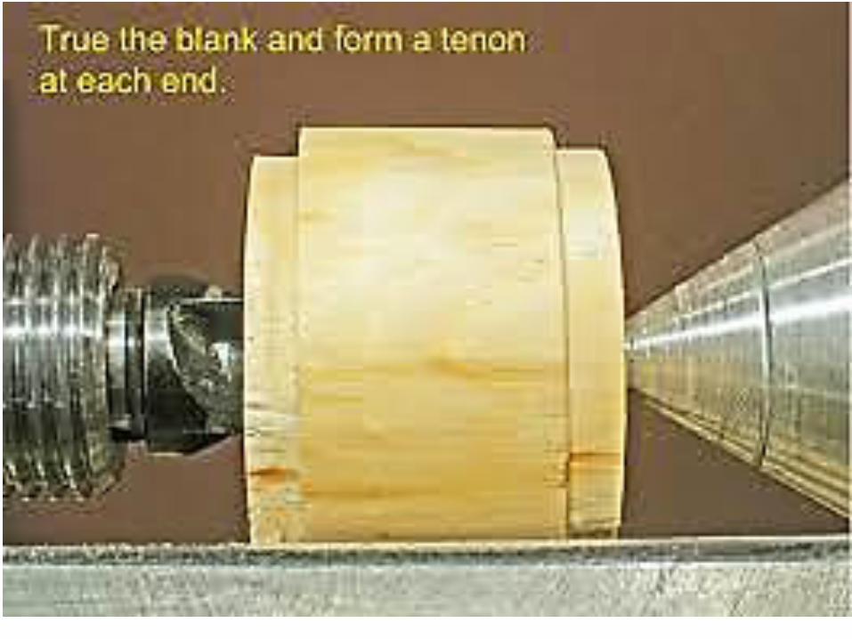
in between live and dead centres
by using mandrel fitted into the head stock – spindle
fitting in a separate fixture which is properly clamped
on a driving plate which is coaxially fitted into the
lathe spindle.


Locating for machining in other than lathes
In machine tools like drilling machine, boring
machine, milling machine, planing machine,
broaching machine and surface grinding machine
the job remains fixed on the bed or work table of
those machine tools.
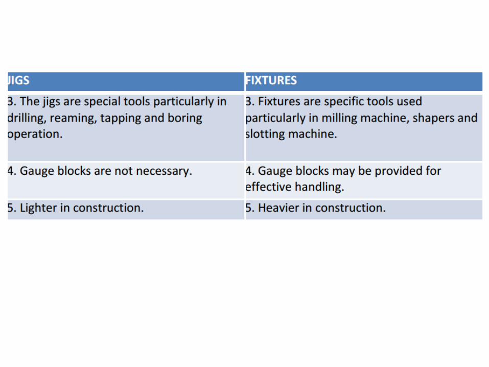
Fixtures are mostly used in the aforesaid machine
tools and jig specially for drilling, reaming etc. for
batch production.

Locating by flat surfaces
a)
b)
c)

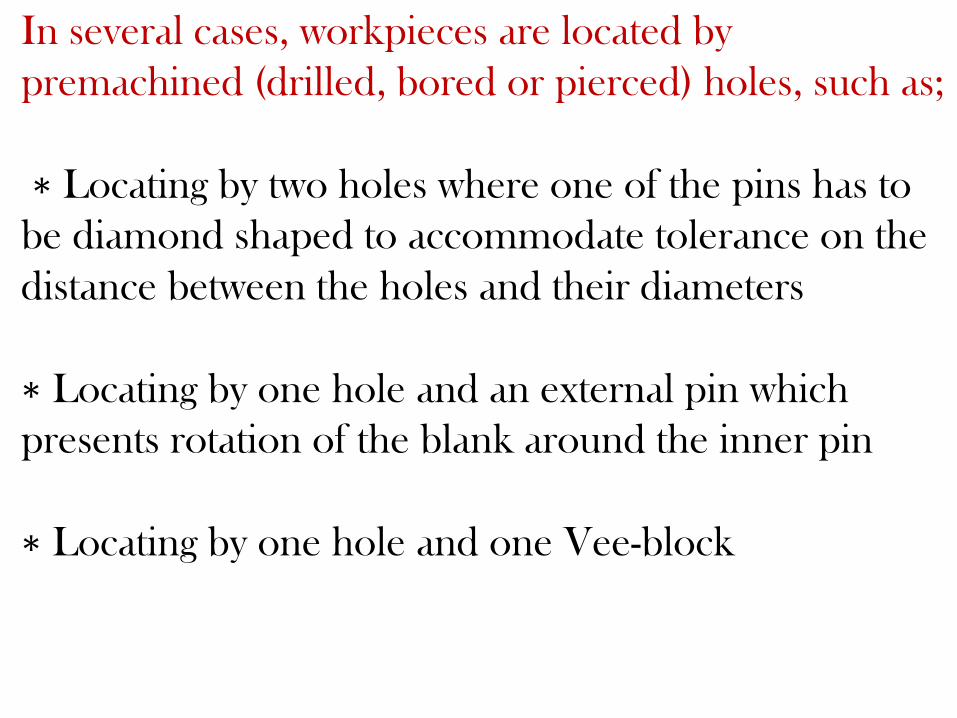
In several cases, workpieces are located by
premachined (drilled, bored or pierced) holes, such as;
∗ Locating by two holes where one of the pins has to
be diamond shaped to accommodate tolerance on the
distance between the holes and their diameters
∗ Locating by one hole and an external pin which
presents rotation of the blank around the inner pin
∗ Locating by one hole and one Vee-block

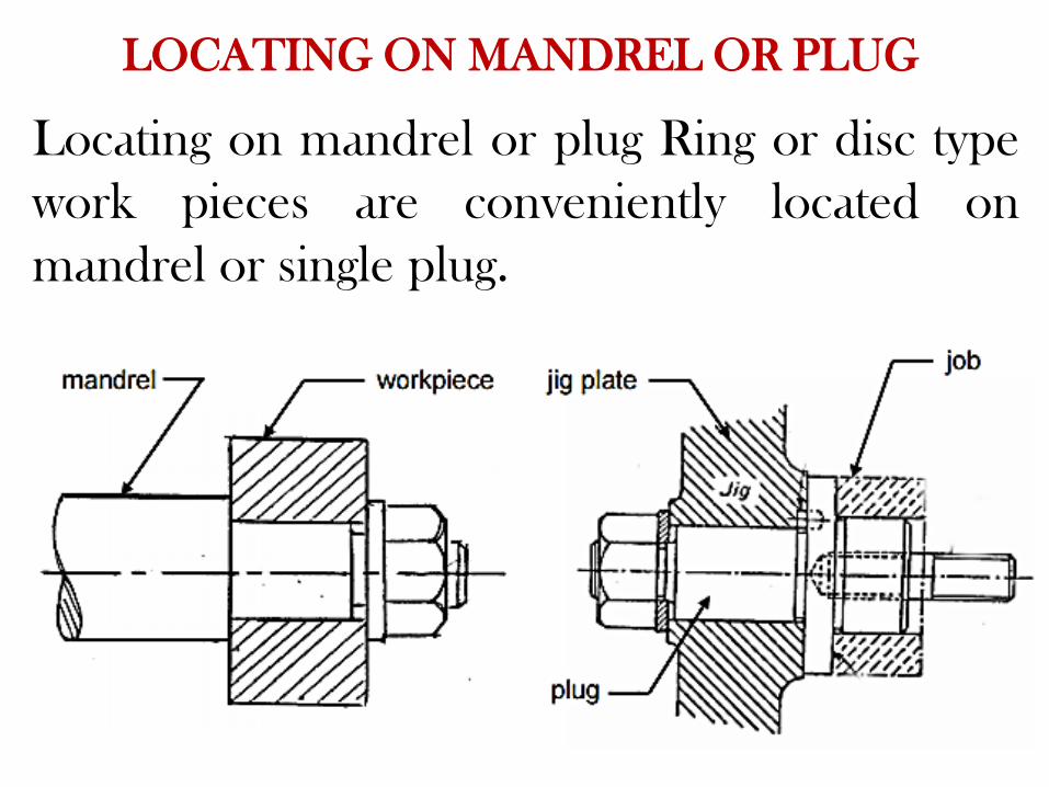
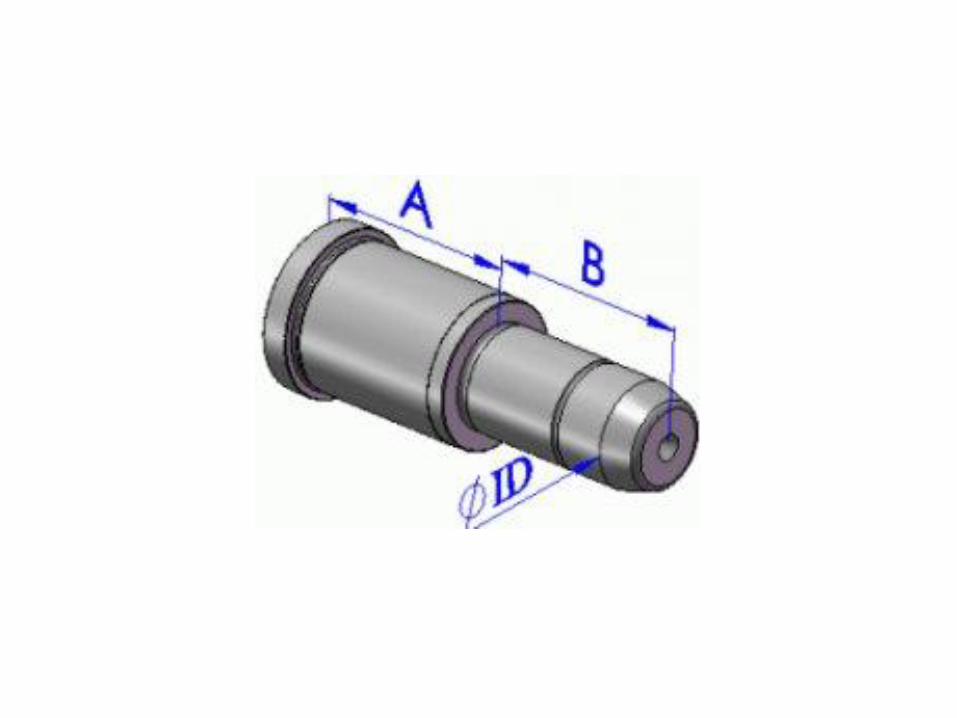
Locating on mandrel or plug Ring or disc type
work pieces are conveniently located on
mandrel or single plug.
LOCATING ON MANDREL OR PLUG

Supporting – principles and methods
Workpiece has to be properly placed in
the jig or fixture not only for desired positioning
and orientation but also on strong and rigid
support such that the blank does not elastically
deflect or deform under the actions of the
clamping forces, cutting forces and even its own
weigh
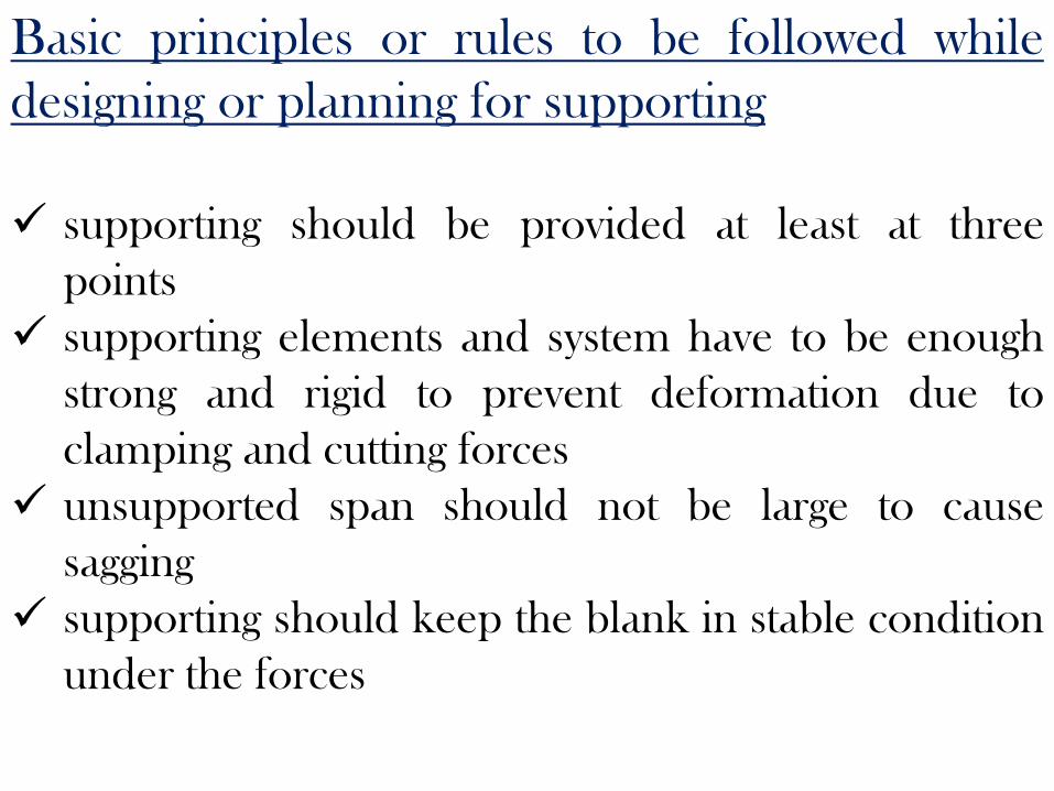
Basic principles or rules to be followed while
designing or planning for supporting
supporting should be provided at least at three
points
supporting elements and system have to be enough
strong and rigid to prevent deformation due to
clamping and cutting forces
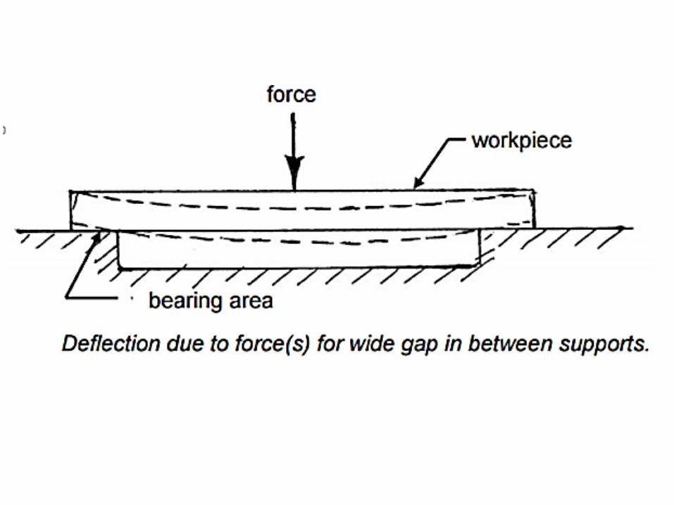
unsupported span should not be large to cause
sagging
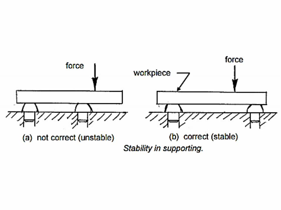
supporting should keep the blank in stable condition
under the forces
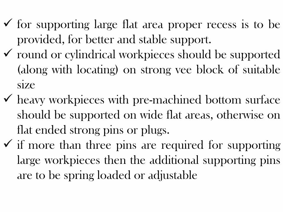
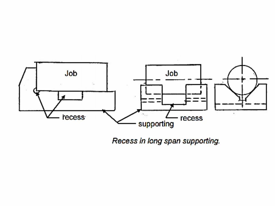
for supporting large flat area proper recess is to be
provided, for better and stable support.
round or cylindrical workpieces should be supported
(along with locating) on strong vee block of suitable
size
heavy workpieces with pre-machined bottom surface
should be supported on wide flat areas, otherwise on
flat ended strong pins or plugs.
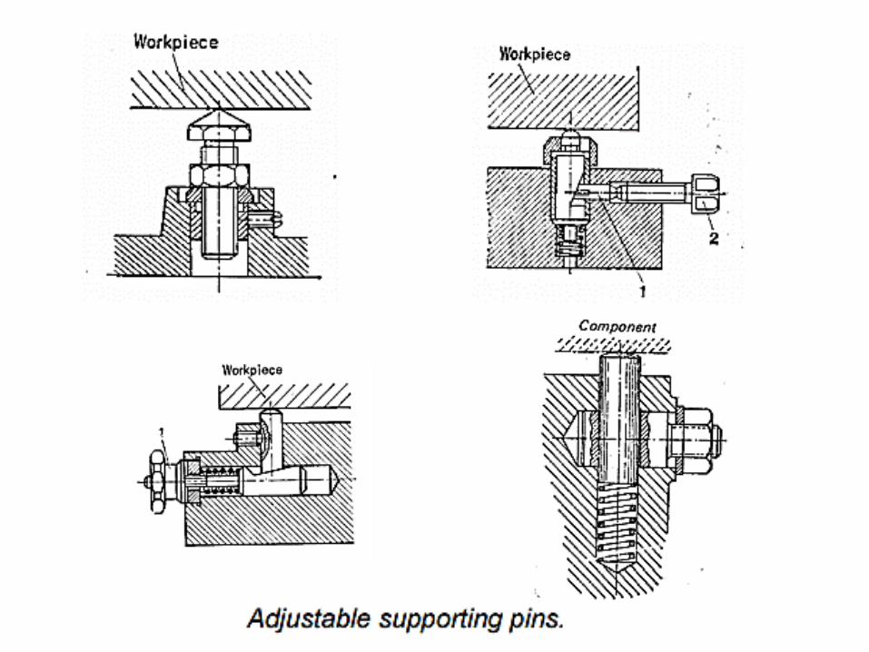
if more than three pins are required for supporting
large workpieces then the additional supporting pins
are to be spring loaded or adjustable
additional adjustable supporting pins need to be
provided
∗ to compensate part size variation
∗ when the supporting surface is large and irregular
∗ when clamping and cutting forces are large
• ring or disc type jobs, specially requiring indexing
should be supported (and located) in mandrel

What is Clamping?
Once workpiece is located, it is necessary to
press it against locating surfaces and hold it there
against the force acting upon it.
The tool designer refers to this action as
clamping and the mechanisms used for this
action are known as clamps.
Clamping Principles
• Clamp should firmly hold the workpiece
without distorting it.
• Should overcome the maximum possible
force exerted on workpiece by using minimum
clamping force
• Easy to operate
• Vibrations should tighten the cams and
wedges in the clamp design(if any) and not
loosen them
Types Of Clamping
• Mechanical Actuation Clamps
• Pneumatic and Hydraulic Clamps
• Vacuum Clamping
• Magnetic Clamping
• Electrostatic Clamping
• Non Mechanical Clamping
• Special Clamping Operations

Clamping of workpiece in fixtures
In jigs and fixtures the workpiece
or blank has to be strongly and rigidly
clamped against the supporting
surfaces and also the locating features
so that the blank does not get
displaced at all under the cutting forces
during machining.
While designing for clamping the following
factors essentially need to be considered :
Clamping need to be strong and rigid enough
to hold the blank firmly during machining
Clamping should be easy, quick and
consistently adequate
Clamping should be such that it is not affected
by vibration, chatter or heavy pressure
Way of clamping and unclamping should not
hinder loading and unloading the blank in the
jig or fixture
the clamp and clamping force must not damage or
deform the workpiece
clamping operation should be very simple and
quick acting when the jig or fixture is to be used
more frequently and for large volume of work οclamps, which move by slide or slip or tend to do
so during applying clamping forces, should be
avoided
clamping system should comprise of less number
of parts for ease of design, operation and
maintenance
the wearing parts should be hard or hardened and
also be easily replaceable
clamping force should act on heavy part(s) and
against supporting and locating surfaces
clamping force should be away from the
machining thrust forces
clamping method should be fool proof and safe
clamping must be reliable but also inexpensive
Various methods of clamping
Clamping method and system are basically of
two categories :
(a) general type without much consideration on
speed of clamping operations
(b) (b) quick acting type
Principles of Clamping
•Position
•Strength
•Productivity
•Operator fatigue

Principles of ClampingPosition:
•Clamping system should be positioned at thick sections
of the workpiece.
•Clamping should be positioned to direct the clamping force on a strong, supported part of the workpiece.
•Clampingon unsupported part bendsslender workpieces, affects accuracy of operation.
Distortion of
unsupported
workpiece
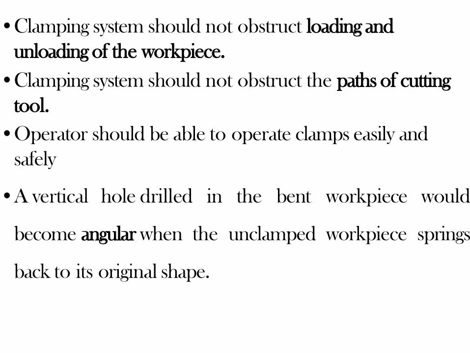
•Clamping system should not obstruct loading and
unloading of the workpiece.
•Clamping system should not obstruct the paths of cutting
tool.
•Operator should be able to operate clamps easily and
safely
•A vertical hole drilled in the bent workpiece would
become angular when the unclamped workpiece springs
back to its original shape.
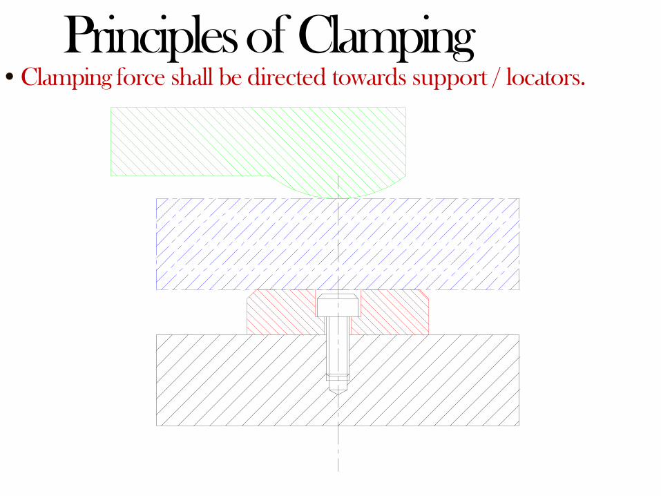
•Clamping force shall be directed towards support / locators.
Principles of Clamping

•Clamp shall be directly in line with thesupport
Principles of Clamping
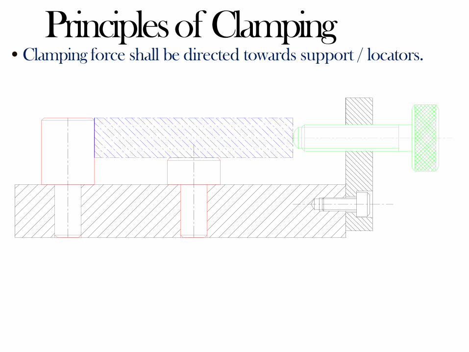
•Clamping force shall be directed towards support / locators.
Principles of Clamping

• Clamps shall apply force against supported area of work piece
Principles of Clamping
Good Bad
Principles of ClampingStrength:
•The clamping system should be capable to hold the
workpiece securely against the forces developed during
operation.
•Clamping device should be capable to be unaffected by
the vibrations generated during an operation.
•The clamping force should not dent or damage the
workpiece with excessive pressure.
•For clamping weak and fragile workpiece, clampingforce
should beequally distributed over a wider area of the
workpiece.
•While clamping soft workpiece, clamps should be fitted
with pads or softer materials such as Nylon or Fibre to
prevent damage and denting of the workpiece.
•Clamping faces should be hardened by proper treatments
to minimize their wearing out.
Principles of Clamping
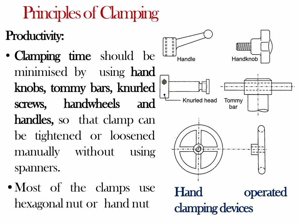
Productivity:
• Clamping time should be
minimised by using hand
knobs, tommy bars, knurled
screws, handwheels and
handles, so that clamp can
be tightened or loosened
manually without using
spanners.
•Most of the clamps use
hexagonal nut or hand nutHand operated
clamping devices

Principles of Clamping
Hand operated
clamping devices
Principles of Clamping
Operator Fatigue:
•Operator fatigue should be taken into account.
•Clamping should be operator friendly.
• Clamping and releasing should be easy and less time consuming.
• Maintenance should be easy.
•If considerable number of clamps are to be tightened or
loosened repeatedly, it is better to use pneumatic or hydraulic
clampingwhich reducesoperator fatigue and savesclampingtime.
• Hand nuts are more convenient for the operator than hexagonal
nuts becausea spanner is not required to tightenthem.
Methods of Clamping
Clamping method and system are basically of two
categories:
1.General type without much consideration of the
speed of clamping operations.
2.Quick acting clamping method / quick action
clamps.
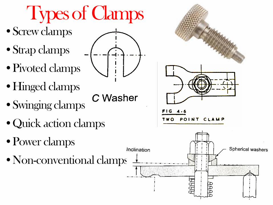
Types of Clamps•Screw clamps
•Strap clamps
•Pivoted clamps
•Hinged clamps
•Swinging clamps
•Quick action clamps
•Power clamps
•Non-conventional clamps

ScrewClamps•They are threaded devices with knurled collar, hand knob,
Allen keys, tommy bar or spanner flats for rotating and
tightening the screw.
•They are used for light clamping.
Screw Clamp
Screw Clamps
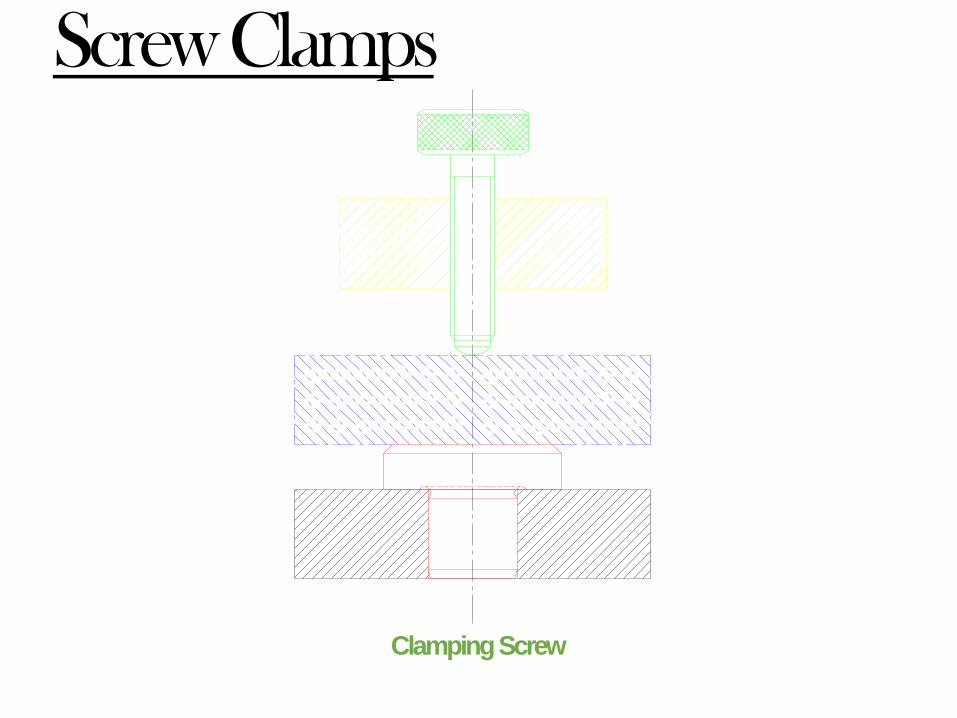
•The clamping area of screw is increased by
providing a pad.
• The clamping pad remains stationary on the
workpiece while the screw rotates and rubs on
the conical seat of the pad.
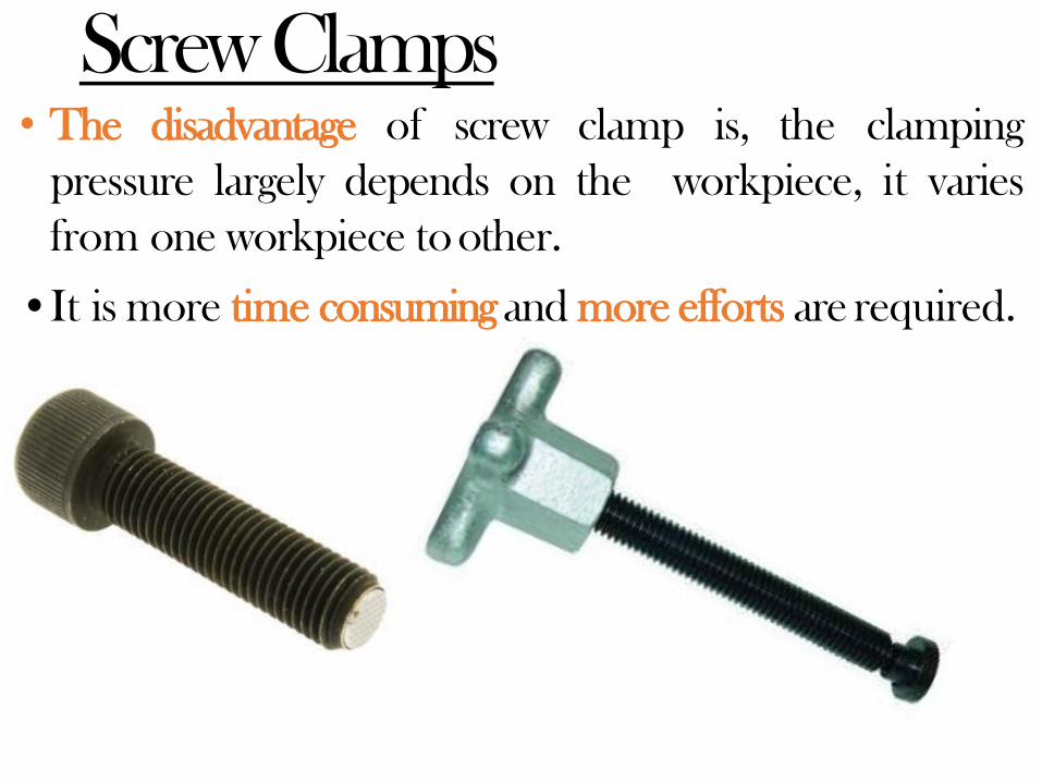
Screw Clamps• The disadvantage of screw clamp is, the clamping
pressure largely depends on the workpiece, it varies
from one workpiece to other.
•It is more time consumingand more efforts are required.
Screw Clamps
ClampingScrew

ScrewClamps
ClampingScrew

ScrewClamps
ClampingScrew

ScrewClamps

Strap or Plate Clamps

Strap / Plate / Bridge Clamps•It is very simple and reliable clamping device.
•The clamping force is applied by spring loaded nut.
Strap Clamp
Strap / Plate / Bridge Clamps
•These are made of rectangular plates and act like levers.
•The clamps are tightened by rotating a hexagonal nut on a
clampingscrew.
•One end of the clamp presses against the workpiece and the
other end on the heel pin.
• The toe i.e. clamping face of the clamp is curved and the pressure
face of the heel pin is made spherical to take care of any variations
in theworkpiece.
• Spherical washers permits the clamp to tilt with respect to the
screw and the nut.
Strap / Plate / Bridge Clamps
•Strap clamps are provided with a washer and spring
below the clamp.
• The spring lifts the clamp as the nut is loosened and
workpiece becomes free.
•The Spring holds the clamp in a raised position during
loading and unloading of the workpiece.
• Washer prevents the entry of the spring in the hole of
the clamp.
•Clamp is rotated about the stud to release the workpiece.
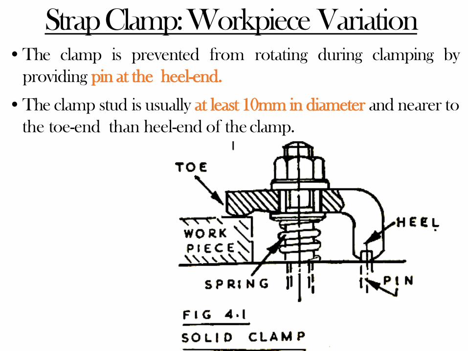
Strap Clamp: Workpiece Variation•The clamp is prevented from rotating during clamping by
providing pin at the heel-end.
•The clamp stud is usually at least 10mm in diameter and nearer to
the toe-end than heel-end of the clamp.

Strap Clamp: Workpiece Variation
• The heel pin engages the clamp plate to prevent it from rotating
during clamping.
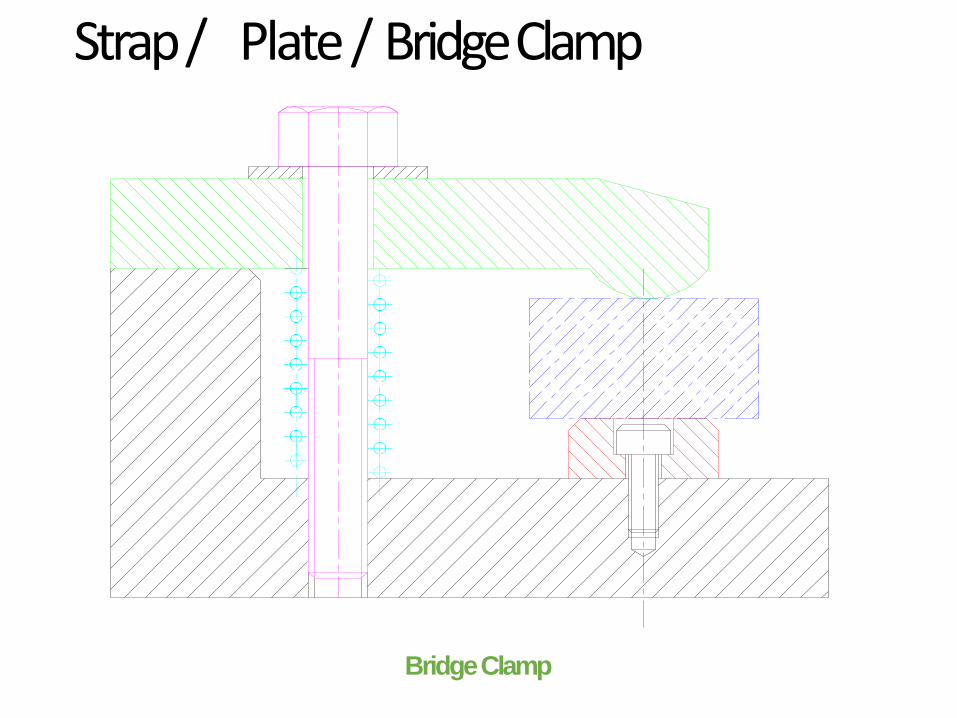
Strap / Plate / Bridge Clamp
Bridge Clamp

Retractable Strap Clamp• When clamps fall in the
loading and unloading,
path of
they are
made slotted to permit linear
withdrawal.
• The clamp is retraced to the position
shown by chain dotted line during
loading and unloading of the
workpiece.
• Slotted clamp plate so that the
workpiece can be released without
clamprotation.
• Adjustable heel pin is used where
workpiece height is likely to vary
more considerably.Slotted Strap Clamp with
adjustable heel pin

Retractable Strap Clamp

“U”Clamp
•U Clamp can be removed altogether to facilitate loading
and unloading of the workpiece.
U Clamp with open slot
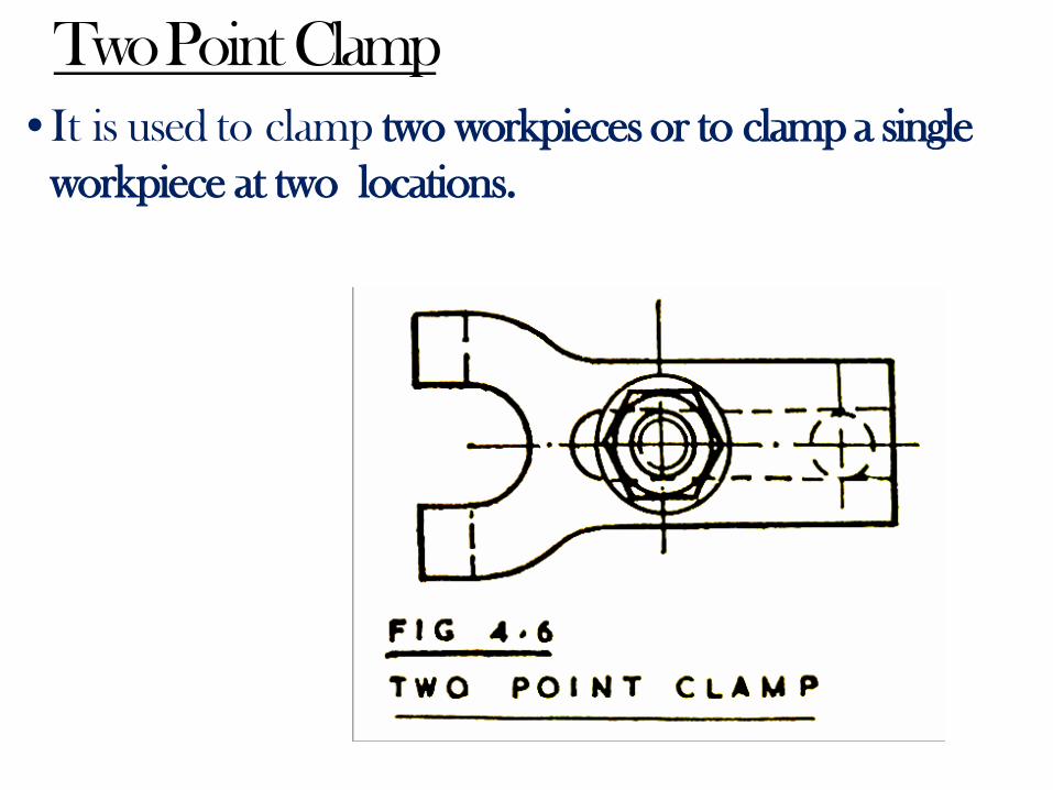
Two Point Clamp
•It is used to clamp two workpieces or to clamp a single
workpiece at two locations.

Swinging Strap Clamp• This type of clamp can be rotated by 90o to clear the passage for loading and
unloading the workpiece.
• The clamp is swung to the position shown by the chain dotted line during loading
and unloading of theworkpieces.
Swinging Strap Clamp
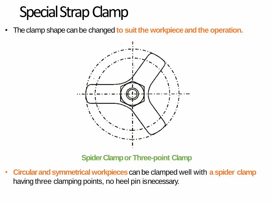
Special Strap Clamp• The clamp shape can be changed to suit the workpiece and the operation.
Spider Clamp or Three-point Clamp
• Circular and symmetrical workpieces can be clamped well with a spider clamp
having three clamping points, no heel pin isnecessary.

• Gooseneck Clamp can reduce the clamp height with respect to the work piece
height.
StrapClamp
GooseneckClamp
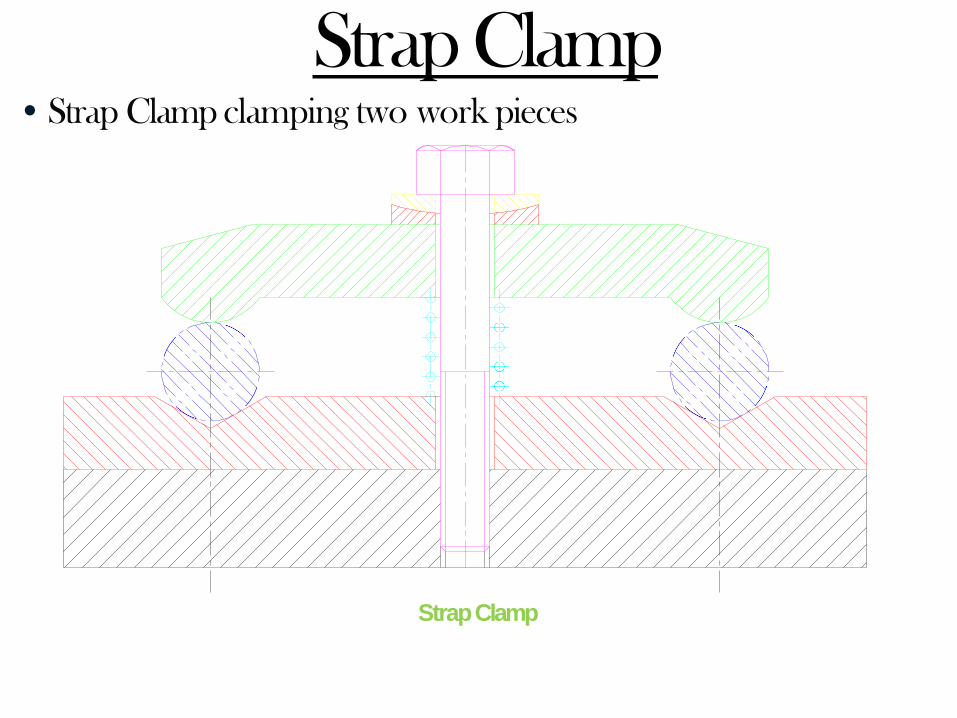
• Strap Clamp clamping two work pieces
Strap Clamp
StrapClamp

Strap Clamp: Workpiece Variation
Universal Clamp with cylindrical washer

Edge Clamps
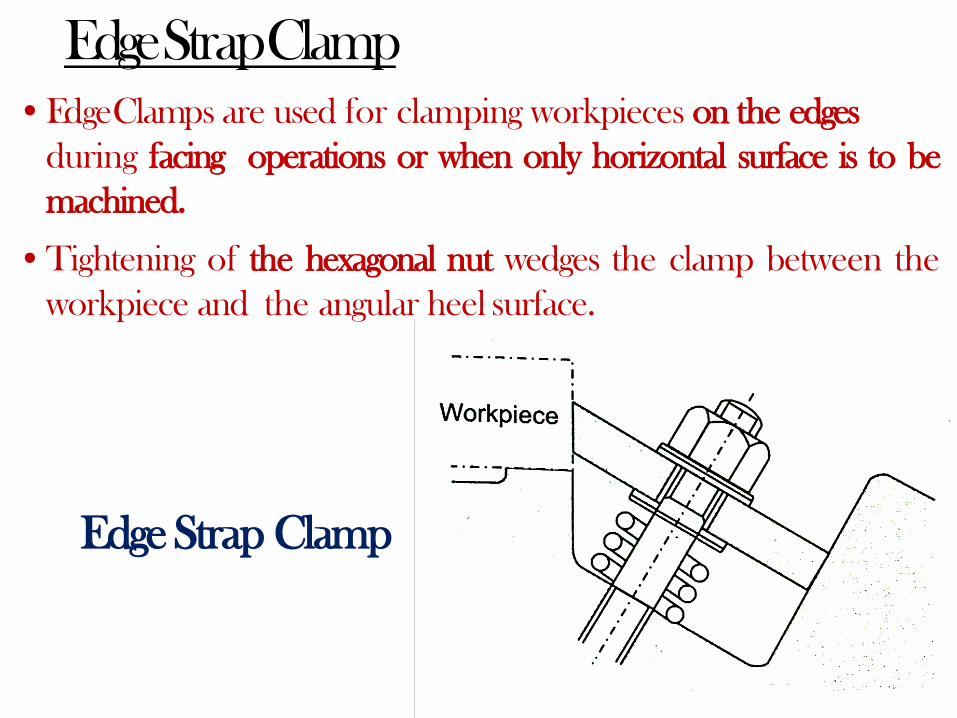
Edge StrapClamp
•EdgeClamps are used for clamping workpieces on the edges
during facing operations or when only horizontal surface is to be
machined.
•Tightening of the hexagonal nut wedges the clamp between the
workpiece and the angular heel surface.
Edge Strap Clamp

Edge JawClamp•Edge jaw clamp slides down the inclined heel as the
hexagonal nut is tightened.
•Tightening of the hexagonal nut pushes the jaw against
the workpiece to clampits edge.
Edge Jaw Clamp

Pivoted Clamps
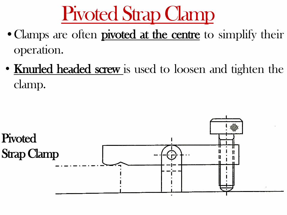
Pivoted Strap Clamp•Clamps are often pivoted at the centre to simplify their
operation.
• Knurled headed screw is used to loosen and tighten the
clamp.
Pivoted
Strap Clamp
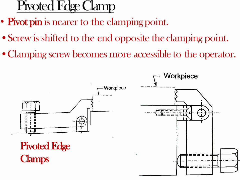
Pivoted EdgeClamp• Pivot pin is nearer to the clampingpoint.
•Screw is shifted to the end opposite theclamping point.
•Clamping screw becomes more accessible to the operator.
Pivoted Edge
Clamps
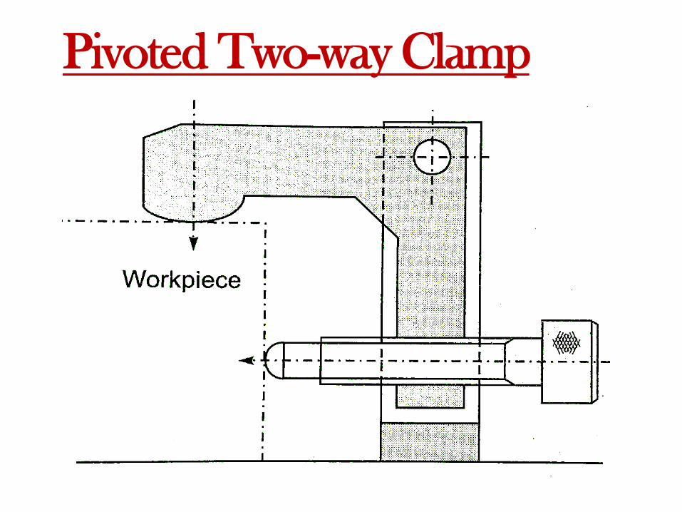
Pivoted Two-wayClamp
•Pivot action can be used for two-way clamping of the
workpiece.
• Tightening of the screw makes the curved surface of the
clamp touch the workpiece and further tightening of
the screw clamps the workpiece vertically and
horizontally.
•Two-way clamp also pushes the workpiece against two
locators.
Pivoted Two-way Clamp

Hinged / LatchClamps
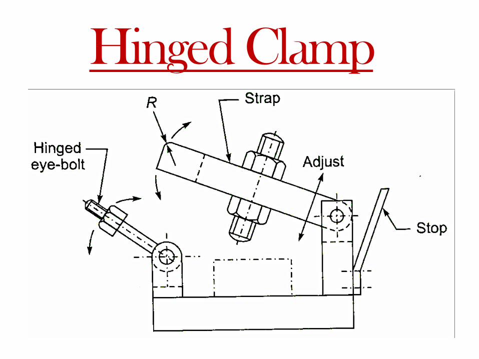
Hinged Clamp
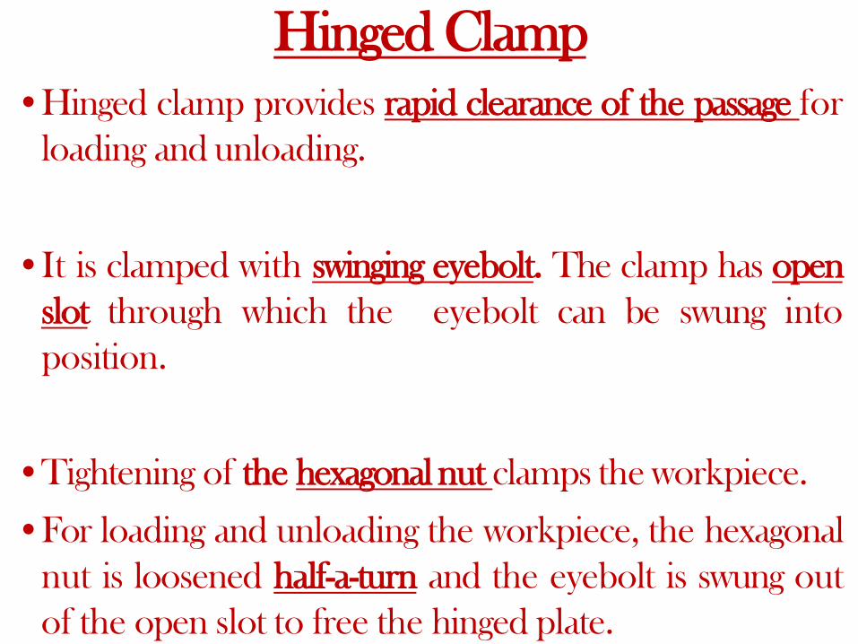
•Hinged clamp provides rapid clearance of the passage for
loading and unloading.
•It is clamped with swinging eyebolt. The clamp has open
slot through which the eyebolt can be swung into
position.
•Tightening of the hexagonal nut clamps the workpiece.
•For loading and unloading the workpiece, the hexagonal
nut is loosened half-a-turn and the eyebolt is swung out
of the open slot to free the hinged plate.
Hinged Clamp
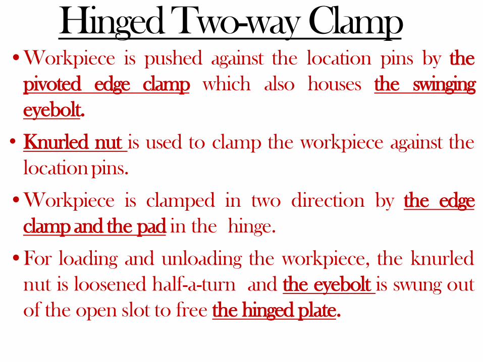
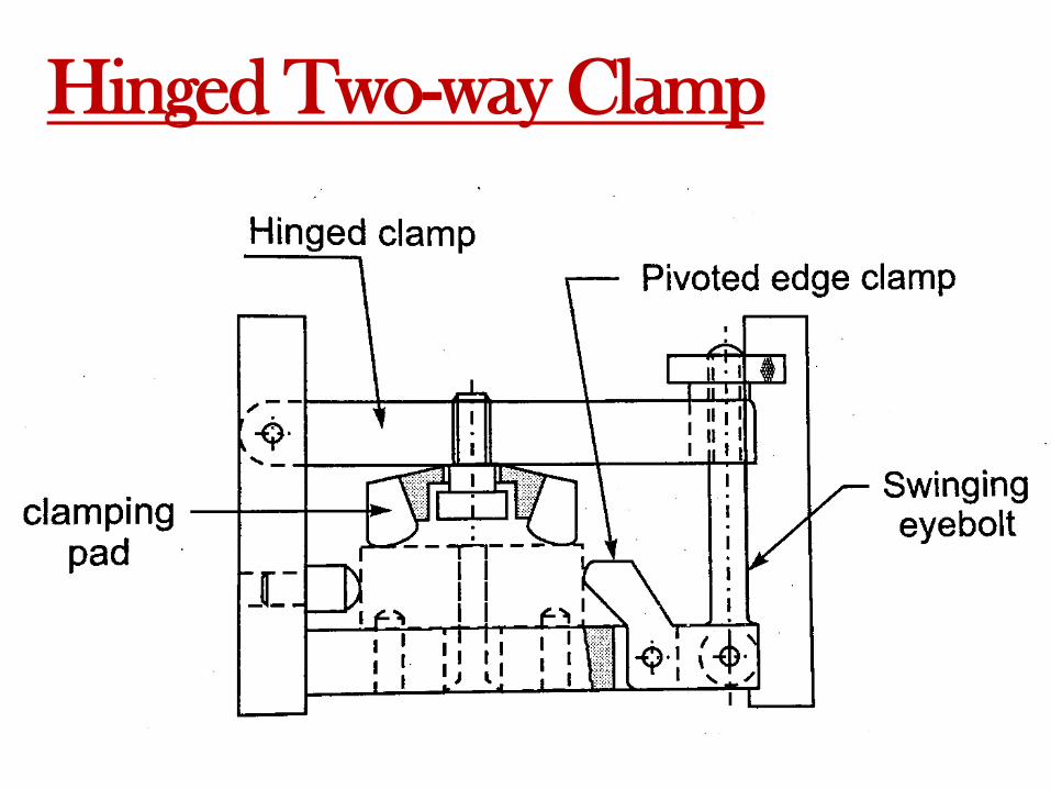
Hinged Two-way Clamp•Workpiece is pushed against the location pins by the
pivoted edge clamp which also houses the swinging
eyebolt.
• Knurled nut is used to clamp the workpiece against the
locationpins.
•Workpiece is clamped in two direction by the edge
clamp and the pad in the hinge.
•For loading and unloading the workpiece, the knurled
nut is loosened half-a-turn and the eyebolt is swung out
of the open slot to free the hinged plate.
Hinged Two-way Clamp

CWasher
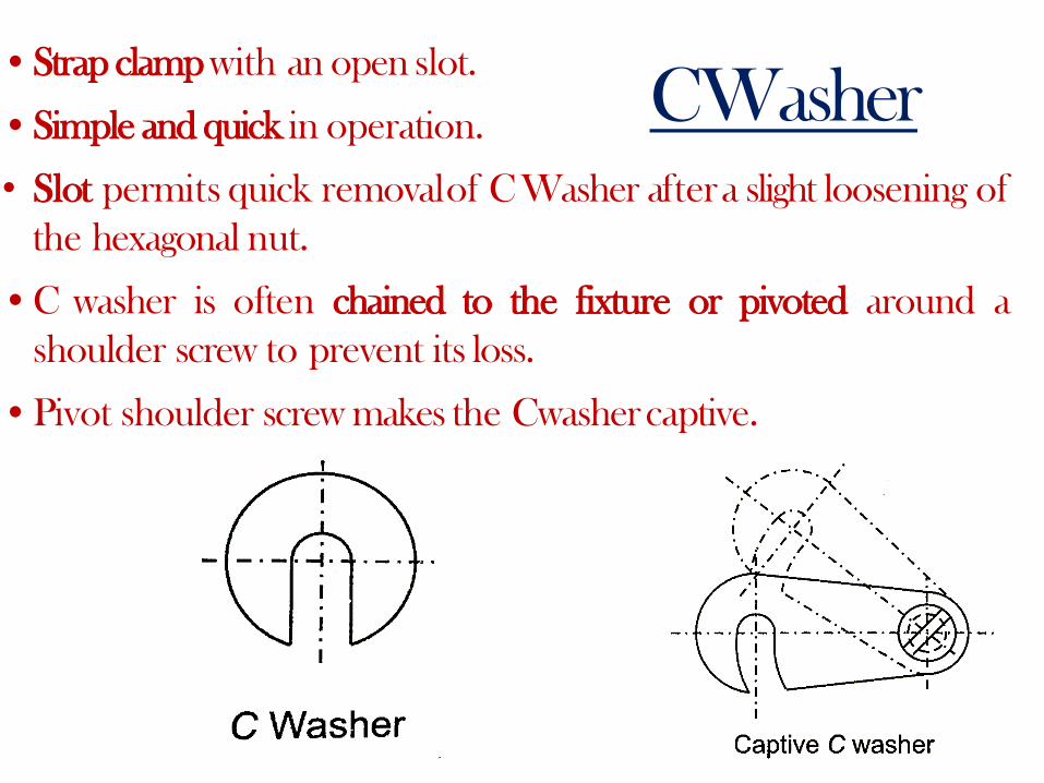
CWasher•Strap clamp with an open slot.
•Simple and quick in operation.
• Slot permits quick removalof CWasher aftera slight loosening of
the hexagonal nut.
•C washer is often chained to the fixture or pivoted around a
shoulder screw to prevent its loss.
•Pivot shoulder screw makes the Cwashercaptive.

SwingingClamps

SwingingClamps• Theses clamps are swung to the position.
• They rotate in the plane of the plate.
• Figure depict the swinging clamp pivoted
about the shoulderscrew.
• Workpiece is clamped by knurled head
screw.

SwingingClamps

SwingingClamps• Swinging latch with an open slot atone end..
• The latch is swung around pivot P at the otherend.
• Shoulder screw S enters the open slot during operation.
• The workpiece is clamped by knurled headscrew.

SwingingClamps• Types of latches and their methods
of operation.
• Chain-dotted line shows the latches
in their clear loading and unloading
position.
• Shoulder screws are often used as
pivots for thrustpads.
• The shoulder diameter must be
bigger than the thrust diameter so
that the shoulder face acts as a stop
when the screw istightened.

SwingingClamps• Swinging clamp with CWasher

Quick Action Clamps
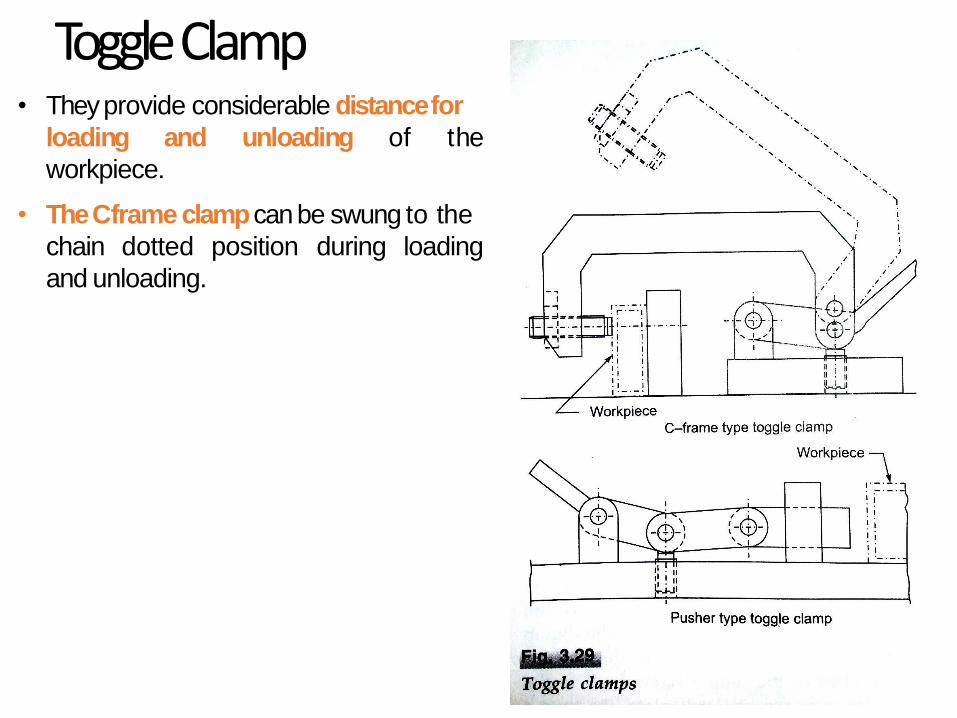
ToggleClamp• They provide considerable distancefor
loading and unloading of the
workpiece.
• The Cframe clamp can be swung to the
chain dotted position during loading
and unloading.

ToggleClamp• The pusher-type toggle clamp withdraws backwards during unclamping.
• Toggle clamps are provided with clamping screws to accommodate workpiece
variations.

ToggleClamp
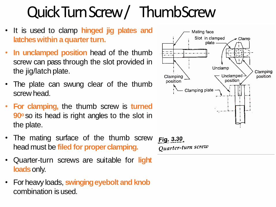
Quick Turn Screw / ThumbScrew• It is used to clamp hinged jig plates and
latcheswithin a quarter turn.
• In unclamped position head of the thumb
screw can pass through the slot provided in
the jig/latch plate.
• The plate can swung clear of the thumb
screw head.
• For clamping, the thumb screw is turned
90o so its head is right angles to the slot in
the plate.
• The mating surface of the thumb screw
head must be filed for properclamping.
• Quarter-turn screws are suitable for light
loadsonly.
• For heavy loads, swinging eyebolt and knob
combination is used.
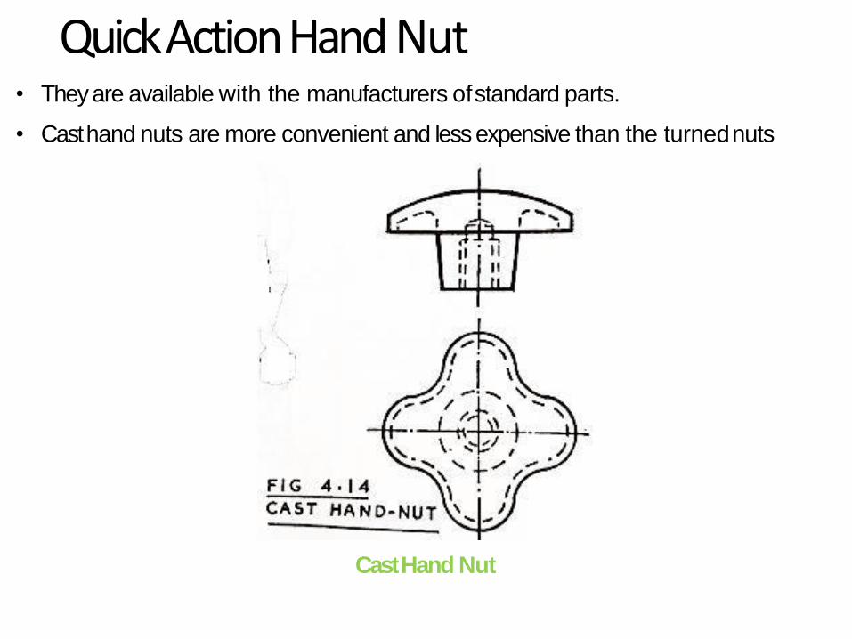
Quick Action Hand Nut
Cast Hand Nut
• They are available with the manufacturers ofstandard parts.
• Cast hand nuts are more convenient and less expensive than the turnednuts
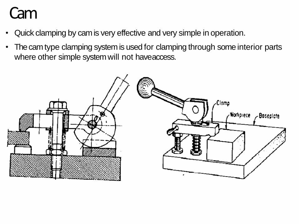
Cam• Quick clamping by cam is very effective and very simple in operation.
• The cam type clamping system is used for clamping through some interior parts
where other simple system will not haveaccess.
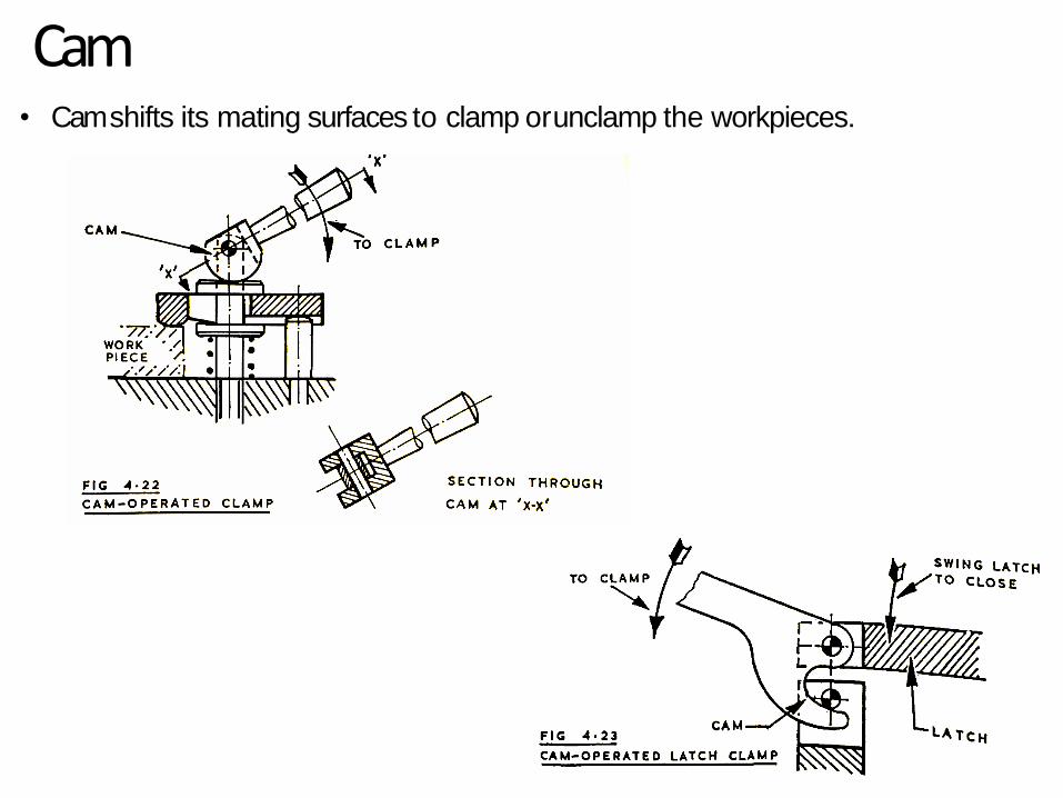
Cam• Cam shifts its mating surfaces to clamp orunclamp the workpieces.

Multiple Clamping
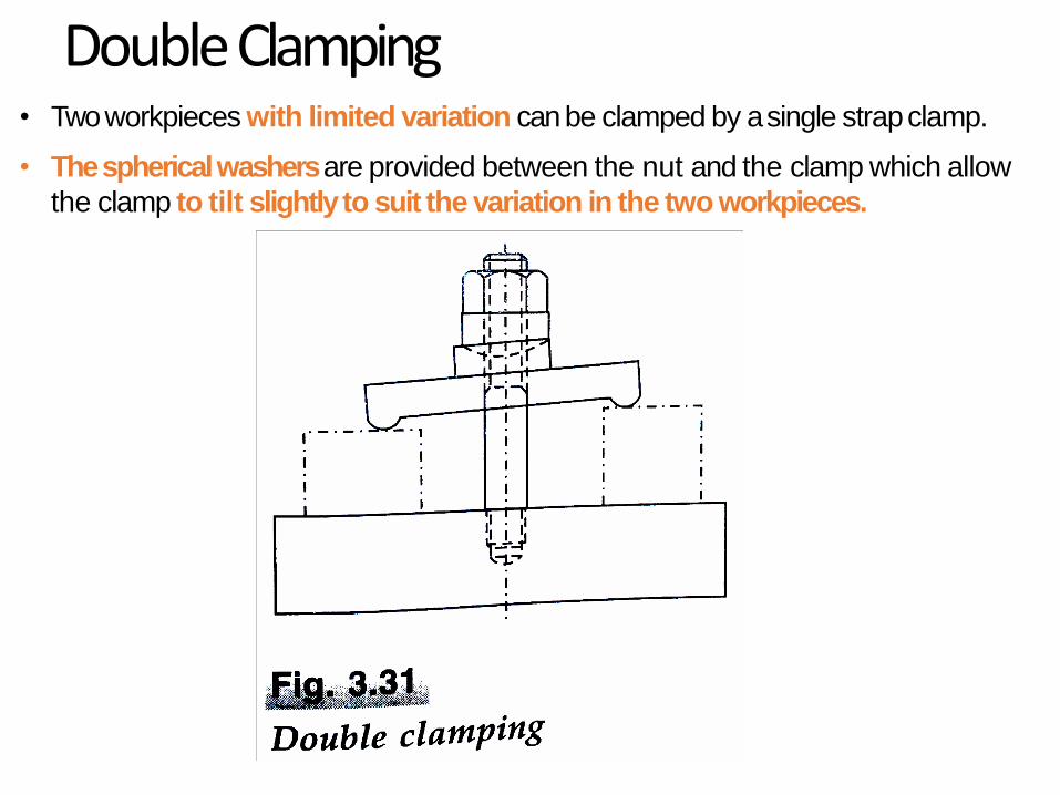
DoubleClamping• Two workpieces with limited variation can be clamped by a single strapclamp.
• The spherical washers are provided between the nut and the clamp which allow
the clamp to tilt slightly to suit the variation in the two workpieces.
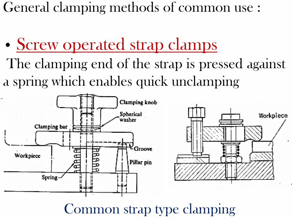
General clamping methods of common use :
• Screw operated strap clampsThe clamping end of the strap is pressed against
a spring which enables quick unclamping
Common strap type clamping
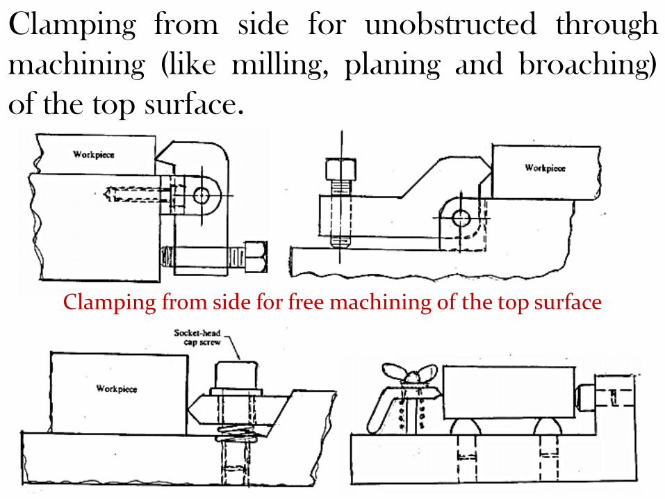
Clamping from side for unobstructed through
machining (like milling, planing and broaching)
of the top surface.
Clamping from side for free machining of the top surface

Clamping by swing plates
Such clamping, are simple and relatively quick in
operation but is suitable for jobs of relatively
smaller size, simpler shape and requiring lesser
clamping forces.
Clamping by swing plates
Other conventional clamping methods
include :
∗ Vices like drilling and milling vices
∗ Magnetic chucks
∗ Chucks and collets for lathe work

Quick clamping methods and systems
ο Use of quick acting nut – a typical of
such nut and its application
Quick acting nut for rapid clamping
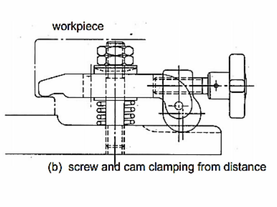
Cam clamping
Quick clamping by cam is very effective and very
simple in operation. Some popular methods and
systems of clamping by cam.
The cam and screw type clamping system is used
for clamping through some interior parts where other
simple system will not have access.

clamping by cam
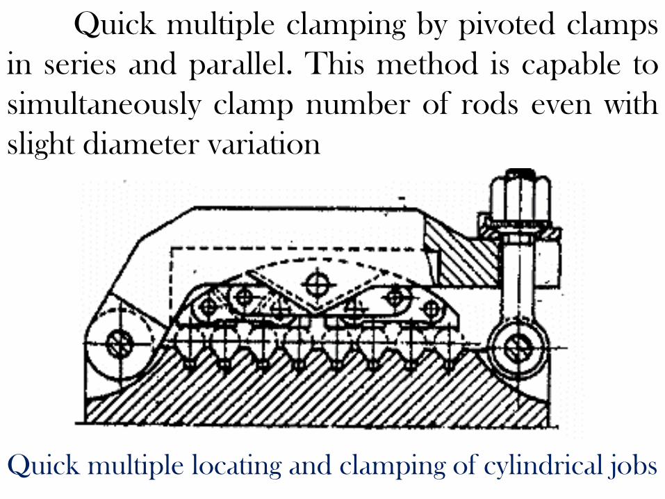
Quick multiple clamping by pivoted clamps
in series and parallel. This method is capable to
simultaneously clamp number of rods even with
slight diameter variation
Quick multiple locating and clamping of cylindrical jobs