Pipe Cable Locating (PCL) / Electromagnetic Locating (EML)
18
-
Upload
khangminh22 -
Category
Documents
-
view
0 -
download
0
Transcript of Pipe Cable Locating (PCL) / Electromagnetic Locating (EML)


NDTSID spec 1.1 PCL/EML 1st Edition, 2019
1
Pipe Cable Locating (PCL) / Electromagnetic Locating (EML)
Table of Contents
A – Acknowledgements to Steering, Technical Workgroup 1,1 .................................................. 2 B – Background .............................................................................................................................. 3
B1 – History ..................................................................................................................................................... 3 B2 – Significance, Application and Scope of Specification ....................................................................... 3
B2,1 Significance and application ................................................................................................................ 3
B2,2 Scope ................................................................................................................................................... 4
B3 – Glossary .................................................................................................................................................. 5 B4 – Theories and Principles ........................................................................................................................ 6
B4,1 Electromagnetic induction ............................................................................................................. 6
B4,2 Capacitance controlled by material and PCL/EML system ............................................................ 6
B4,3 Active and passive signal ............................................................................................................... 7
B4,4 Effective distance of testing/survey along the utility .................................................................... 7
B4,5 Accuracy ......................................................................................................................................... 7
C – Qualified Personnel .................................................................................................................. 9 C1 – Personnel ................................................................................................................................................ 9 C2 – Signatory ................................................................................................................................................. 9 C3 – Survey Officer......................................................................................................................................... 9
D – Instrumentation ...................................................................................................................... 10 D1 Signal Transmitter ........................................................................................................................... 10 D2 Signal Receiver ................................................................................................................................ 11 D3 Equipment Calibration and Depth Verification ............................................................................ 11
E – General Testing and Survey procedure ................................................................................ 12 E1 – Desktop Study, Visual Inspection and On-site Test/Survey ............................................................ 12 E2 – PCL/EML Survey................................................................................................................................... 13
F – Reporting ................................................................................................................................ 14 F1 – Findings and Survey Drawings ........................................................................................................... 14 F2 – Survey/Test Report .............................................................................................................................. 15
G – Limitations .............................................................................................................................. 16 H – References and Bibliography ................................................................................................ 17
prepared by Wallace W.L. LAI Department of Land Surveying and Geo-informatics (LSGI), The Hong Kong Polytechnic University https://www.polyu.edu.hk/lsgi/uusspec/en/publications Copyright by The Hong Kong Polytechnic University, 2019. All rights reserved.

NDTSID spec 1.1 PCL/EML 1st Edition, 2019
2
A – Acknowledgements to Steering, Technical Workgroup 1,1
This document (1,1) is one of the six specifications prepared for accrediting laboratories/survey companies conducting underground utility survey. Others include 1,2 ground penetrating radar, 2,1 visual inspection, 2.2 acoustic methods for leak detection, 3,1 flow survey and 3.2 Infrared thermography. Three consultation meetings were held from September 2018 to February 2019. The project team expresses the greatest appreciation and gratitude to the following parties for providing support during the drafting and implementation of this specification.
- Workgroup 1,1 members
Chan Yuen-Lok (The Hong Kong and China Gas Company Limited (Towngas)) Chiu Sing-Kit (Hong Kong Telecommunication (HKT) Ltd.) Fung Yuk-Lun, George (MTR Corporation Ltd.) Ho Shun-Yat, Sam (Sum Kee Construction Ltd.) Kung Hiu-Leung, Daniel (Hong Kong Institute of Utility Specialists) Lee Tsz-Ki, Pinky (Castco Testing Centre Ltd) Mak Wai-Fung, Wilfred (3M Hong Kong Ltd) Mong Seng-Ming (Geotechnics & Concrete Engineering (Hong Kong) Ltd. John Pimlott (Radiodetection (Asia) Ltd.) Siu Ka-Lai, Peter (Viewbond Hong Kong Limited) Wong King (Hong Kong Institute of Utility Specialists and BUDA Surveying Ltd.) Yan Kwok-Keung (China HK Society for Trenchless Technology, Waterland Detection Engineering Ltd.) Chairman: Lai Wai-Lok, Wallace (LSGI, PolyU) - Local steering committee members:
Chan Pak-Keung (Adjunct Professor, University of Hong Kong) Lau W. Tony (Technical Director, Black & Veatch Ltd.) Lo K.Y. Victor (Chairman, Civil Discipline Advisory Panel and Past Chairman of Civil Division of HKIE) Wong Kin-Yan, Samson (Former senior accreditation officer of Hong Kong Accreditation Services) Chairman: Lai Wai-Lok, Wallace (LSGI, PolyU)
- International advisory committee members:
Nicole Metje (University of Birmingham, UK) Tom Iseley (Trenchless Technology Center, USA) George Tuckwell (RSK Environment Ltd., UK). Chairman: Lai Wai-Lok, Wallace (LSGI, PolyU) - PolyU LSGI project team: Chairman Lai Wai-Lok, Wallace, Cheung Wei-Yat, Bella, Chiu Sin-Yau, Lydia, Luo Xiang-Huan, Tess, Sham Fung-Chu, Janet, and Chang Kwong-Wai, Ray. - Funding support by Innovation and Technology Fund and industrial sponsorship by Sum Kee
Construction Ltd. on the project ‘Development of specifications and standards for Underground Utility (UU) Survey based on Nondestructive Testing, Surveying, Imaging and Diagnostic (NDTSID) Approaches’
- Written support on the project from the Water Supplies Department, Drainage Services Department, Housing Authority, Hong Kong Certification and Testing Council, HKSARG and MTR Corporation is gratefully acknowledged.
- English editing and proofreading by Dr. Mick Atha is acknowledged.

NDTSID spec 1.1 PCL/EML 1st Edition, 2019
3
B – Background
B1 – History
The history of locating underground utilities developed from the discovery of electromagnetism by Michael Faraday. The principle of electromagnetism underpins the most widely used technology for locating underground utility pipes and cables. A brief history of the development, with reference to Radiodetection (2008), is as follows:
Year History 1831 Michael Faraday presented a paper about the characteristics of electromagnetism to
the Royal Institution in London
1910 It is the earliest record of applying electromagnetic technology for locating underground cables. The setup was a coil wound round a wooden truss.
1920s Dr Gerhard R. Fisher of California received the first patent issued for an aircraft radio direction finder, or called the Metallascope which became the first buried pipe and cable locating set of equipment.
1964 An engineering section in the Bell Laboratories studied the problem of accurate location of their newly built buried cables. The study concluded that an antenna with twin sensing aerials give more accurate lateral position and also depth measurement of a target cable. The design, called the Depthometer, was designed and manufactured by the Western Electric Company.
1970s The first commercial twin aerial antenna locator was made by the Electrolocation company in Bristol, England. The company, which later became Radiodetection Ltd, developed the twin aerial system without being aware of the earlier Bell Labs developments.
Recent Modern PCL/EML combine active and passive signal reception to locate a target utility by making a quick sweep, in addition, some more advancements are: - multi-frequency locating sets allow selection of the most suitable frequency for a
variety of specific applications, - electronic depth measurement, - current measurement along the length of a pipe or cable for detecting
discontinuity of signals due to coating or insulation defects, - recognition of current direction for verification of the identity of a target line - a range of accessories (sonde, ID marker).
B2 – Significance, Application and Scope of Specification
B2,1 Significance and application
Underground utilities are the veins of any city. Lack of power, water, drainage, sewerage, lighting or communications paralyzes a community. It is not surprising that this paralysis often happens when utilities are not correctly located before digging occur. Information provided by PCL/EML is therefore an essential prerequisite to safe digging (Haddon, 2001; Hyung and Dulcy, 2004; Metje et al. 2007; Lanka et al. 2002). Spiking a power cable or breaking a water-carrying utility can lead to suspension of services, and in many cases, causes causalities. Locating and mapping utilities with geo-referenced positioning, and testing and diagnosing discontinuities in faulty utilities and cables helps
NDTSID spec 1.1 PCL/EML 1st Edition, 2019
4
to reduce the extent of damage, as it is well-known that design and as-built drawings do not provide reliable and accurate information.
The geo-referenced underground utilities drawing/map is the major deliverable of surveys aimed at locating underground utility pipes and cables, but how these maps are produced based on proper test/survey/diagnostic procedures varies significantly between companies and individuals. Erroneous or incomplete information about the utilities map can mislead the user, causing unnecessary damage and exposing the public and workers to danger. Experience and knowledge of the subject area greatly enhance the credibility of the utilities map and, most importantly, help clarify when the test/survey/diagnostic results are uncertain due to site, materials and equipment limitations rather than the signatory/survey Officers’ abilities. The successful management of the above factors can be summarized in a 4M1E framework, namely Man/woman, Machine, Materials, Methods and Environment, which can be applied within an accreditation framework following ‘ISO/IEC 17025: 2017: General requirements for the competence of testing and calibration laboratories’. In view of the above needs, this document provides a unified specification and standard for PCL/EML use based on 4M1E, which aims to help utility companies, laboratories/survey companies, developers, estate managers, contractors and consultants to maintain consistent standards of UU testing, surveying, imaging and diagnosis.
Although electromagnetic testing/survey methods can be highly accurate under the right conditions, the consistent and reliable interpretation of the received PCL/EML signals, which determines the spatial distribution of underground utilities, can be performed only by an experienced data analyst. Such experience can be gained through use of the system and through training courses provided by various equipment manufacturers or consulting companies.
B2,2 Scope
1. This specification covers the history, theories/principles, equipment, field procedures, interpretation of data, and methods used with non-destructive and near-surface PCL/EML systems.
2. The approach suggested in this PCL/EML specification is the most commonly used, widely accepted, and well proven after reviewing a number of international practices (ASCE, 2003; CSA, 2011; EMSD, 2005, AS, 2013; HKIUS, 2014), and manufacturers’ guidelines (3M, 1998; Radiodetection, 2008). However, other approaches or variants of PCL/EML that are technically sound may be substituted if technically verified, validated and documented.
3. This specification does not purport to address all of the safety concerns, if any, associated with its use. It is the responsibility of the user to establish appropriate health and safety practices and determine the applicability of regulatory limitations prior to use.

NDTSID spec 1.1 PCL/EML 1st Edition, 2019
5
B3 – Glossary
The glossary in this specification is modified from the book ‘ABC’s and XYZ’s of Locating Buried Pipes and Cables’ by Radiodetection.
Accreditation body
4M1E Man/woman (Signatory and Survey Officer), machine, material, method, environment
Active signal An alternating current signal applied to a metallic conductive pipe/cable/conductor with a transmitter, which results in a magnetic field that can be detected with the locator receiver.
Cable shield A conductive layer surrounding a cable’s conductors that provides electrical screening. Usually the shield is isolated from the ground by a plastic sheath or other insulator. The shield is generally terminated to a ground connection at the end of a cable’s length.
Clamp A locator accessory fitting round a pipe or cable, used either for application of the transmitter signal or as a receiver antenna. Sometimes it is known as a coupler or ‘close induction’.
Coupling A signal applied to the target utility transfers to other nearby utilities, thereby causing distortion of magnetic field shape and errors of positioning.
Meter A visual display to indicate response when the receiver detects a signal. Noise Term for spurious and interfering electrical signals from nearby above-
ground or underground sources. Passive signal A signal that occurs ‘naturally’ on a buried metal pipe or cable such as
50/60Hz energy or LF/VLF radio energy. Pinpoint An action involving the use of the locator receiver to locate the exact
position of a target utility. Precision pinpoint
A further action making use of different locating modes to confirm the precision of a pinpoint.
Rebars Reinforcing steel mesh in concrete. Response The indication on the receiver visual display or loudspeaker or headphones
when the receiver detects a signal. The response may be varied for a given signal by adjusting the receiver sensitivity level. The response value is usually indicated as a percentage of full scale deflection.
Search An action involving the use of the locator to identify the distribution of magnetic field strength corresponding to UU in an area.
Sheath Outer insulating jacket surrounding the shield and/or conductors of a cable. Sheath fault Damage to the sheath or insulation surrounding a cable shield causing an
unintentional conductive path enabling current flow between the shield and ground.
Sonde A self-contained waterproof battery-powered transmitter whose fixed-frequency signal can be located by the receiver. Sondes are commonly used for locating non-metallic drains or ducts or for monitoring boring tool progress.
Sweep An action involving the use of the receiver to locate the radiating passive signals of cables. It is usually done in an orderly grid pattern to cover the whole survey area.
Trace An action involving the use of the receiver to follow the route of a utility identified by active or passive signal.
Geo-referencing
The action of tying in the coordinate system of a survey map with a ground system of local or global geographic coordinates.

NDTSID spec 1.1 PCL/EML 1st Edition, 2019
6
B4 – Theories and Principles
B4,1 Electromagnetic induction
It is a common misunderstanding that a pipe and cable locator locates underground pipes or cables. Instead, it detects the magnetic field induced by an alternating electrical current flowing along the utilities, and this is why the induction is described as an electro-magnetic type. This magnetic field manifests a cylindrical shape around the utilities irrespective of the material properties of the host materials. Thus when the detection of the magnetic field is converted to ‘signal’, the location of the utilities can be measured. An alternating current induces a detectable magnetic field because the periodic oscillation of reversals makes effective location possible. Back in Faraday’s time, the most basic principle of electromagnetic induction could be demonstrated by inserting a bar magnet into a coil or wire connected to a voltmeter. The voltmeter will only show a deflection indicating the generation of current when the magnet moves in and out of the coil. When the motion stops, the voltmeter reads zero. The quicker the movement (i.e. higher frequency), the higher is the reading. Alternating a field at a higher frequency therefore also induces a higher voltage for the same field strength.
B4,2 Capacitance controlled by material and PCL/EML system
The loop of an electric circuit must be closed to allow for current flow. So if a buried conductor (i.e. utility) is properly insulated, how can a low-powered current source in the ground produce a detectable current flow? The answer is not the voltage but capacitance of the underground ac circuits in which electrons are able to jump across insulation and reach the mass of the surrounding soil as a conducting layer.
Capacitance is increased through the induction of a stronger magnetic field due to the combined effects of buried materials and the equipment used. For materials, a large pipe or cable diameter increases the utility’s surface area in contact with the soil, and a host environment of wet soil is a better conductor than dry soil and gives rise to higher capacitance because of the circuit’s good return path. But the trade-off is that the easy return path means that the signal is lost over a short distance along the utility’s length. On the contrary, low ground conductivity requires more energy input to the utility, but it will be more easily detectable over a greater area. From the equipment perspective, a higher transmitting power (i.e. by increasing the signal current) and higher signal frequency generate a larger ac voltage, which results in larger current being induced in the conductor and a greater capacitance of the return circuit. However, a high frequency signal flows to ground via capacitance more easily, and the signal is lost over a short distance along the utility’s length. A further drawback of high frequencies is the coupling of the induced magnetic field by mutual induction with other utilities in the vicinity, especially in a congested underground environment (Siu and Lai, in press). The start-up frequency when attempting on-site active detection of any kind of utilities must be decided by the survey officer, but in general the recommended starting frequency is 33 kHz. The normal frequency range used is between 500 Hz and 200 kHz. Given that there is unlikely to be an optimum frequency that fits for all purposes and different kinds of utilities, the survey officer shall have the discretion to make and record appropriate decisions based on the site situation.

NDTSID spec 1.1 PCL/EML 1st Edition, 2019
7
B4,3 Active and passive signal
An active signal is an alternating electric current applied to a metallic conductive pipe/cable/conductor with a transmitter, which results in a magnetic field that can be detected with the locator receiver on the ground. Reception of the signal can be in either peak mode (low-high-low) or null mode (high-low-high) corresponding to the maximum magnetic field passing the horizontal and vertical aerials, respectively.
- Direct connection: The signal transmitter is connected directly to the pipe or cable via an access point (red lead) such as a valve, meter or the end of the conductor in order to generate an output ac voltage to form a circuit, which induces a magnetic field that can be received on the ground. The return circuit is closed by connecting the transmitter to the earth ground (i.e. infinite electrical resistance) through a black lead attached to a properly grounded metallic surface object, such as a handrail, lamp post or manhole cover.
- Signal Clamping: Clamping gives a similar result to direct connection, but without electrical contact to the utility or the need for grounding. The output from the signal transmitter is applied by clamping round the utility with a split toroidal magnetic core, which carries a primary winding that magnetizes the core with the ac signal. Then, the utility becomes a secondary transformer carrying a strong signal, provided that each side of the utility is adequately grounded.
- Induction: The physical contact in direct connection or signal clamping is not required. The aerial in a signal transmitter is fed with an ac voltage for the purpose of inducing a magnetic field through the coil and then returning it through the UU. The major drawback is the very easy coupling of the induced magnetic field by mutual induction with other utilities in the vicinity, especially in a congested underground environment.
A passive signal occurs ‘naturally’ on live power cables generating 50/60Hz electric power energy, VLF radio or cable TV energy. Although there is significant convenience in surveying with passive signals, active signal methods are still preferred for accurate tracing. Also, very low frequency long wave radio energy from distant transmitters exists in the atmosphere world-wide. The ground provides return paths for this energy, in particular via buried metallic utilities, which then act as aerials re-radiating these signals.
B4,4 Effective distance of testing/survey along the utility
For a designated current strength, the effective distance over which a signal can travel will decay to zero as a factor of rate of signal loss along a utility. The most distant point detectable before the signal drops to zero will be subject to receiver sensitivity, which enhances the signal to noise ratio. As a general rule of thumb, the higher the current, the easier the detection will be. The rate of signal loss is nominally dependent on the capacitance of the underground circuit as discussed in Section B4,2. A logarithmic or decibel scale may be used to depict the rate of signal loss along a utility. In principle, there are three ways to compensate for the loss of capacitance along a utility alignment:
- Reduce the rate of signal loss. - Increase the signal current. - Increase the receiver sensitivity.
For comprehensive details, see the relevant section of the Radiodetection (2008) and 3M (1999).
B4,5 Accuracy
The accuracy levels (absolute or relative to depth, whichever is greater) stated in PAS 128 (2014) shall be the benchmark of test/survey accuracy in reliable survey using active mode, while
NDTSID spec 1.1 PCL/EML 1st Edition, 2019
8
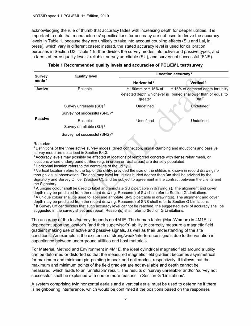
acknowledging the rule of thumb that accuracy fades with increasing depth for deeper utilities. It is important to note that manufacturers’ specifications for accuracy are not used to derive the accuracy levels in Table 1, because they are unlikely to take into account coupling effects (Siu and Lai, in press), which vary in different cases; instead, the stated accuracy level is used for calibration purposes in Section D3. Table 1 further divides the survey modes into active and passive types, and in terms of three quality levels: reliable, survey unreliable (SU), and survey not successful (SNS).
Table 1 Recommended quality levels and accuracies of PCL/EML test/survey
Survey mode 1
Quality level Location accuracy 2
Horizontal 3 Vertical 4
Active Reliable ± 150mm or ± 15% of
detected depth whichever is greater
± 15% of detected depth for utility
buried shallower than or equal to 3m 7
Survey unreliable (SU) 5 Undefined Undefined
Survey not successful (SNS) 6
Passive Reliable Undefined Undefined
Survey unreliable (SU) 5
Survey not successful (SNS) 6
Remarks: 1 Definitions of the three active survey modes (direct connection, signal clamping and induction) and passive survey mode are described in Section B4,3. 2 Accuracy levels may possibly be affected at locations of reinforced concrete with dense rebar mesh, or locations where underground utilities (e.g. in urban or rural areas) are densely populated. 3 Horizontal location refers to the centreline of the utility. 4 Vertical location refers to the top of the utility, provided the size of the utilities is known in record drawings or through visual observation. The accuracy level for utilities buried deeper than 3m shall be advised by the Signatory and Survey Officer (Section C), and be subject to agreement in the contract between the clients and the Signatory. 5 A unique colour shall be used to label and annotate SU pipe/cable in drawing(s). The alignment and cover depth may be predicted from the record drawing. Reason(s) of SU shall refer to Section G Limitations. 6 A unique colour shall be used to label and annotate SNS pipe/cable in drawing(s). The alignment and cover depth may be predicted from the record drawing. Reason(s) of SNS shall refer to Section G Limitations. 7 If Survey Officer decides that such accuracy level cannot be reached, the suggested level of accuracy shall be suggested in the survey sheet and report. Reason(s) shall refer to Section G Limitations.
The accuracy of the test/survey depends on 4M1E. The human factor (Man/Woman) in 4M1E is dependent upon the locator’s (and their supervisor’s) ability to correctly measure a magnetic field gradient making use of active and passive signals, as well as their understanding of the site conditions. An example is the existence of strong/weak/interference signals due to the variation in capacitance between underground utilities and host materials.
For Material, Method and Environment in 4M1E, the ideal cylindrical magnetic field around a utility can be deformed or distorted so that the measured magnetic field gradient becomes asymmetrical for maximum and minimum pin-pointing in peak and null modes, respectively. It follows that the maximum and minimum points of the field gradient are not available and depth cannot be measured, which leads to an ‘unreliable’ result. The results of ‘survey unreliable’ and/or ‘survey not successful’ shall be explained with one or more reasons in Section G ‘Limitations’.
A system comprising twin horizontal aerials and a vertical aerial must be used to determine if there is neighbouring interference, which would be confirmed if the positions based on the responses

NDTSID spec 1.1 PCL/EML 1st Edition, 2019
9
from the two systems do not match. This matching permits the multi-aerial PCL/EML to check if the response makes sense and if the signal is suitable for measuring a depth up to the requirements of accuracies in Table 1.
C – Qualified Personnel
C1 – Personnel
The Signatories and Survey Officers for all NDTSID shall meet the personal requirements in Section C2 and C3 below, respectively.
C2 – Signatory
C2,1 A Signatory of a report shall either have:
(i) a Bachelor of Science (e.g. Geomatics/Land Surveying) or Engineering (e.g. Civil/Electrical/Materials/Mechanical/Gas/Industrial) degree with specialization in underground-utility (UU) survey or a Bachelor of Science (e.g. Geomatics/Land Surveying) degree with not at less than 200 contact hours of BSc/BEng’s UU training plus final year project, provided by a recognized tertiary institution plus at least three years of technical and managerial experience of underground utilities, within which a period of two years is substantially1 related to the subject matter in this specification, or
(ii) a valid certificate or diploma2 of specialization in PCL/EML issued by a recognized organization operating under international standards or qualifications framework level 4 plus at least five years of technical and managerial experience of underground utilities, within which three years are substantially related to the subject matter in this specification, or
(iii) at least a higher certificate or diploma issued by a recognized technical institute or an
equivalent qualification in a relevant discipline, with at least seven years of direct technical and managerial experience, within which five years are directly related to the subject matter in this specification, plus relevant training courses2 covering the content in this specification.
1 Direct technical and managerial involvement in 10 test/survey reports in different contracts/works orders. 2 A typical certificate/diploma shall include all aspects covered in this specification.
C3 – Survey Officer
C3,1 A Survey Officer shall normally be supervised by a Signatory having the necessary qualifications, experience and technical knowledge. A Survey Officer shall be a competent person for locating electricity cables approved under The Electricity Supply Lines (Protection) Regulation, made under the Electricity Ordinance, Cap. 406H, and shall either have
(i) a Bachelor of Science (e.g. Geomatics/Land Surveying) or Engineering (e.g. Civil/Electrical/Materials/Mechanical/Gas/Industrial) degree with specialization in underground-utility (UU) survey or a Bachelor of Science (e.g. Geomatics/Land Surveying) with not at less than 100 contact hours of BSc/BEng’s UU training provided by a recognized tertiary institution, plus at least one year of on-the-job experience substantially3 related to the subject matter in this specification, or

NDTSID spec 1.1 PCL/EML 1st Edition, 2019
10
(ii) a valid certificate or diploma4 of specialization in PCL/EML issued by a recognized organization operating under international standards or qualifications framework level 3 plus at least two years of substantial on-the-job experience3 related to the subject matter in this specification, or
(iii) at least a higher certificate or diploma issued by a recognized technical institute or an equivalent qualification in a relevant discipline, plus at least three years of substantial on-the-job experience3 related to the subject matter in this specification, plus relevant training course covering the content in this specification4.
(iv) at least eight years of substantial on-the-job experience3 related to the subject
matter in this specification.
3 On-the-job direct involvement in 10 test/survey reports in different contracts/works orders. 4 A typical certificate/diploma shall include all hands-on aspects covered in this specification.
C3,2 A Survey Officer shall be evaluated based on technical competence and the lab/survey company is required to keep a separate list of qualified Survey Officers who are permitted to perform each survey/test and sign the worksheet, for the purpose of checking by the Accreditation Body. As approvals are granted in the context of the survey/tests being performed by a particular lab/survey company, they shall not be considered as personal qualifications.
D – Instrumentation
The enclosures and protection of the instrumentation shall be weatherproof to IP54 and/or NEMA 3S and suitable for usage in all weathers and climates in a temperate range of -200C to +500C. The output circuitry shall be protected against accidental connection to conductors at up to 240V at 50/60Hz. In general, the following two main components of PCL/EML instrumentation are required to comply with the ‘machine’ part in 4M1E.
D1 Signal Transmitter
The signal transmitter shall be capable of operating in at least six signal frequencies ranging from 500Hz to 200kHz. It shall be available in each set of instrument for various active mode connection, and 50/60Hz and VLF, for passive power and radio mode detection. The output signal shall be continuous sine wave with minimum 0.5 Watt output power, while a minimum 3 Watts power is required for locating most distribution systems, and power of up to 5 or even 10 Watts is required for long distance traces or for utilities with high resistance joints. The transmitter shall also be equipped with the accessories tabulated in Table 2.
Table 2 Accessories of PCL/EML
Accessories Descriptions Clamp Made of split toroidal magnetic core. Cable Connect the transmitter to a remote ground point. Cable should be supplied
on a reel or drum. Transmitting sonde Signal transmission frequency shall correspond to a frequency on the
PCL/EML receiver. Plug connector Connect the transmitter to live domestic socket onto the service cable and the
distribution cable in the street (optional). Live cable connector Connect the transmitter directly to a low voltage live conductor at a junction
box or a substation. This method shall only be used by competent person registered under Electrical and Mechanical Services Department of HKSAR Government (optional).

NDTSID spec 1.1 PCL/EML 1st Edition, 2019
11
D2 Signal Receiver
The locator set shall be a combination of twin horizontal aerials (peak mode measurement), with one aerial mounted above the other, and a vertical aerial (null mode measurement). The basic specification of the receiver shall include:
- An aerial and circuitry capable of readily receiving the transmitter frequency in (1) active connection mode, (2) 50/60Hz energy from power cables in passive power mode, (3) VLF radio energy in passive radio mode, and (4) Cable TV in passive mode.
- Simultaneous visual and audio response to the signal. It can be either a loudspeaker or headphones.
- Manual gain control for adjustment of receiver sensitivity or auto/manual gain control to avoid the need for sensitivity level adjustment in order to keep the meter on scale.
- An electronic depth measurement feature for measuring depth to the target. - Current measurement indication to allow confirmation of utility identity in congested areas.
D3 Equipment Calibration and Depth Verification
The calibration process shall comply with the requirements of ISO/IEC 17025 and shall be conducted by a calibration body or manufacturer. The requirements for equipment calibration/verification intervals for PCL/EML are provided in Table 3. These requirements shall be complied with unless overridden by more stringent testing specifications. If a laboratory/surveying company has the necessary reference equipment and expertise, then calibration/verification can be done internally. Nevertheless, the laboratory/survey company must have the necessary resources consistent with the accuracy required and any standards relevant to the calibration/verification concerned. The Signatory/Survey Officers conducting the in-house calibration/verification shall be properly trained and calibration/verification procedures shall be documented. All calibration/verification procedures and records shall be ready for examination during accreditation assessments. Equipment shall be properly stored and maintained. A suitable environment shall be provided for storage. When handling heavy testing equipment on site, the laboratory/surveying company shall comply with any relevant construction site safety regulations applicable to their testing personnel. Equipment that is moved from one location to another shall, where relevant, be checked before use. Precautions shall be taken to ensure that, after transportation to a site, testing equipment remains in a serviceable state and in calibration. Appropriate checks shall be performed on site to confirm the equipment’s calibration status before testing/surveying commences. The depth verification shall be performed in an open area, away from any steel or reinforced concrete structure that would cause distortion of the magnetic field. A typical 5-step procedure is suggested as follows: (1) lay a 60 m long wire and bend it into a square of 15 m x 15 m and connect the transmitter to both ends of the wire. (2) switch the transmitter to all frequencies ranging from 500 Hz to 200 kHz and trace at least 12 points on the wire loop. (3) position the receiver where a peak response over a distribution of low-high-low magnetic field is resulted. Repeat the trace with any step frequency between 500 Hz to 200kHz available in the equipment. (4) for every test, position the receiver on a wood / plastic platform right above the wire so that the bottom of the receiver is at least 50 cm above the centre of the wire. (5) measure the receiver’s distance along the wire at 3m intervals along the loop starting from any corner, but do not take a measurement at the four corners. All values must fall within the acceptance criteria suggested by the manufacturer.

NDTSID spec 1.1 PCL/EML 1st Edition, 2019
12
Table 3 Specific Calibration/Verification Requirements
Type of equipment Maximum period between successive calibration/verification
Calibration/verification procedure or guidance documents and equipment requirements
Pipe Cable Locator/Electromagnetic Locator
5 years (calibration) Calibration shall be conducted by a competent calibration body or manufacturer.
1 year (depth verification) Accuracy requirement provided by the manufacturer shall be observed, and shall be better or equivalent to equipment specifications. Procedure in Section D3 shall be followed.
Before each test (verification before use)
Self-test suggested by the manufacturer
Other equipment related to this PCL/EML survey (e.g. total station, digital level)
1 year (calibration) Accuracy requirement provided by the manufacturer shall be observed.
E – General Testing and Survey procedure
The test/survey shall be accredited by the relevant Accreditation Body. The following standardized working procedures shall apply to general test/survey works. For sites with specific conditions and requirements, a method statement shall be supplemented separately.
E1 – Desktop Study, Visual Inspection and On-site Test/Survey
The site’s boundary shall be confirmed and agreed with the client’s representative and be marked to provide on-site limits for the field crew led by Survey Officer. The geo-referencing by topographic survey shall use well-established control points. A comprehensive desktop search of the available and ‘best-known’ utility maps shall be completed to provide the potential layout of utilities before the PCL/EML test/survey. Temporary traffic arrangements (TTA) shall be prepared by the crew for the sake of safety.
A visual inspection shall be carried out to record all visible ground level surface features potentially related to underground utilities, such as manholes, draw pits, inspection/valve chambers and gullies, street furniture connected to pipes and cables such as lamp posts, illuminated road signs and bollards. The locations of all known and recordable underground utilities within the site shall be surveyed. Gravity sewers and drainage utilities shall also be marked and, where visible, the direction and flow, diameter and invert depth of each tunnel should be recorded. Manhole covers and valves outside the immediate site boundary (i.e. last connection) shall be opened, marked, traced and reported if the utilities enter into the survey area. Where cable/duct bands are identified, the number of cables/ducts and configurations shall be recorded on-site on the worksheet. Where a bundle of cables is identified, a carpet of cables shall be marked on the drawing with the outer cables shown on each side of the bundle.

NDTSID spec 1.1 PCL/EML 1st Edition, 2019
13
E2 – PCL/EML Survey
The instrumentation detailed in Section D shall be used to locate metallic pipes and tracer wires laid for non-metallic utilities when there is a nearby access point, such as valve chamber or manhole a maximum of 20 meters from the site or on the route being surveyed. The following general procedures shall be followed by the crew led by the Survey Officer.
Table 4 Survey Procedures of PCL/EML
Procedures Actions
(a) Passive mode survey
For power cables, sweep for live cables with ‘power mode’ in zig-zag pattern within the site boundary. Mark the location by spray paint or other means when a genuine signal is detected. The same procedure applies also to Radio and Cable TV.
(b) Active mode survey: applying transmitter signal and good grounding
1. Connect the signal transmitter directly to the metallic part of the utility valves (e.g. gas and water) through the anode red lead, and seek out a good grounding through the cathode black lead to close the circuit. The grounding point shall be as far away as possible from the predicted alignment of the utility and the active connection point, so as to avoid signal cancellation between the forward and return path. The established return circuit shall not be resistive, and the acceptable resistance value shall follow the suggestions in the manufacturer’s guidelines. If the resistance threshold is exceeded, clean the connection wires and re-connect, or re-establish the circuit until resistance does not exceed the threshold suggested by the equipment manufacturer.
2. If the target utility is exposed in a trial pit or accessible from the ground, connect the signal transmitter directly to the metallic part of the utility valves (e.g. gas and water) through the signal clamp without grounding.
3. After the establishment of the circuit, turn on the transmitter and start with
an optimal frequency decided by the Survey Officer.
4. For drains or sewers, a sonde shall be inserted in a manhole or access point from upstream to downstream, if necessary.
(c) Search, trace and depth measurement (active mode)
1. Tune the receiver to the same frequency as the signal transmitter and start to search for the signal. Trace radially and centred about the connection point. Make sure the locator aerial is perpendicular to the predicted alignment extending from the connection point.
2. Observe low-high-low signal levels in peak mode (i.e. distribution of
magnetic field strength) by adjusting sensitivity when necessary. When such a distribution is suspected to indicate the position of the target utility, turn 900 to observe the decay of signal to confirm the alignment (before turning 900) at the location of the high signal level. Turn back to the original position and switch to null mode to observe the reversed high-low-high distribution of the magnetic field. If the ‘high’ position in peak mode coincides with the ‘low’ position in null mode, confirm and measure the utility’s depth. Then mark the locations of the target utility on the ground.

NDTSID spec 1.1 PCL/EML 1st Edition, 2019
14
3. Search the nearby area to check if the above signal is coupled to any
nearby utilities within the arm radius, or a radius of 3-5 metres. Measure the electrical current level on the target utility and other utilities located within the arm radius (or 3-5 metres’ radius). Check, record and make sure the current value of the target utility is higher than any other nearby utilities.
(d) Pinpointing and recording
1. Walk away from the traced point, repeat the above searching, tracing and depth measurement procedure, marking further points along the route on the ground and on worksheet. The interval between the traced points shall not exceed 5m for discrete areas, and shall not exceed 10m when surveying along the road, while each surface feature, change of direction and bifurcation must be marked.
2. Record the survey mode and frequency for detection of any utilities. Geo-reference each traced point by total station referenced to local control points.
3. Give reasons if the survey of any particular utility is declared as ‘survey
unreliable (SU)’ in active survey mode after the best efforts of the site crew. One or more of the following reasons in Section G ‘Limitations’ shall be listed.
4. Give reasons if the survey of any particular utility is declared as ‘survey
not successful (SNS)’ in active survey mode after the best efforts of the site crew. One or more of the following reasons in Section G ‘Limitations’ shall be listed.
F – Reporting
F1 – Findings and Survey Drawings
The report’s findings shall be clearly provided in survey drawing(s) of the underground utility alignments and associated ground features (connected by the traced points) marked on site using topographical survey methods making use of instruments including total stations and digital levels. The following points concerning the findings and survey drawings shall be followed:
(a) The alignment, depicted in different colours, and respective depth of any utilities within the site boundary shall be presented at an interval of 5m in discrete areas or with intervals not exceeding 10m for survey along the road, and at each surface feature, change of direction and bifurcation in a utility drawing at 1:100 or 1:200 scale, or in a scale agreed with the client.
(b) In the drawing, utilities shall be connected to identified ground features like roads and buildings contained in location plan, and indicate change of direction, if any. All reported coordinates and levels are referenced to the HK80 Datum and the Hong Kong Principal Datum respectively. (The coordinates for N,E are presented as 8*****.***, 8*****.***, relative to the HK80 Datum. Normally, “All levels are referred to HKPD” and must be present in the survey plan).
(c) The depth shall be annotated at each recording point and at positions with significant changes of depth. The depth of metallic utilities shall be shown using the notation - 0.76d – (two decimal places) with a cross mark on each respective utility. The electrical current levels of the locations

NDTSID spec 1.1 PCL/EML 1st Edition, 2019
15
at which depth is measured and at the active connection point shall be recorded in the worksheet.
(d) The depth of metallic utilities detected by PCL/EML shall be referenced to the centre of the pipes/cables and the inverts of gravity utilities such as sewers and drains if sonde is used or the measurement is through manhole survey.
(e) Information recorded by the survey shall be compared with the existing utility record drawings, and any discrepancy shall be reported. For each site, at least two critical and representative vertical sections shall be provided.
(f) When any utilities are detected but not up to the accuracies stated in Table 1, they shall be declared as “survey unreliable (SU)” in the drawing, and the basis for that declaration shall be reported according to one or more of the reasons in Section G ‘Limitations’.
(g) When utilities are shown in record drawings and/or are suspected to exit, but are not detectable, they may still be reported in the drawings and shall be declared as “survey not successful (SNS)” subject to agreement with the client, and the reasons for the ‘SNS’ status shall be reported according to one or more of the reasons in Section G ‘Limitations’.
(h) For a ‘reliable’ survey of any utilities, the accuracy levels presented in Table 1 are expected. If the survey results do not comply with Table 1, then the existence of the utilities shall be reported as ‘SU’.
(i) Submission in the format of a Geographic Information System (GIS) & Building Information Model (BIM) is highly recommended and shall refer to the clients’ requirements.
F2 – Survey/Test Report
The survey/test report shall be completed by a qualified Survey Officer(s) and the results shall be reported in an endorsed report. The report shall include, but not be limited to, the following sections:
- Introduction and background - Site areas, boundary and conditions (Section E2) - Record drawings of utilities within the site area. - Theories and principles (Section B4) - General test/survey procedures (Section E) and site-specific procedures, - Instrumentation (Section D) - Summary of findings for every utility relative to data accuracy levels stated in Table 1 - Survey drawings in CAD/GIS/BIM formats (Section F1) - Limitations (Section G) - Conclusion - Site photos in Appendix - Record drawing (reference utility plans provided by utility companies and clients)

NDTSID spec 1.1 PCL/EML 1st Edition, 2019
16
G – Limitations
- Utilities detection shall be declared ‘survey unreliable (SU)’ and/or ‘survey not successful (SNS)’ according to the following examples. The lab/survey company shall expand the list as an in-house procedure, if necessary.
Table 5 Limitations of PCL/EML Survey
Limitations Examples Reasons of declaring ‘Survey Unreliable’
Reasons of declaring ‘Survey not successful’
A. Coupling effects of nearby utilities
Pipes or cables are buried in the same lateral or vertical level and are very close to each other, or close to a 900 vertical and horizontal bend, or junctions. These common scenarios make tracing of individual pipes or cables unrealistic and reduce resolution because of the interference of coupled magnetic fields with similar field strength on parallel/nearby utilities (Siu and Lai, in press). The Survey Officer shall declare and record on-site such coupling effects as ‘survey unreliable’ or ‘survey not successful’. For example, when the armour layer/shield of the target cable is isolated from the connected earthing point, signal is diverted and coupled to other cables connected to the same earthing points of the target cable.
Applicable Applicable
B. Record drawings
Utility information is not available or incomplete or is in general inaccurate
Applicable Applicable
C. Lack of closed loop for signal propagation
A closed loop through the target pipe or cable may not be formed causing only a weak signal to be propagated. For example, (1) the armour layer/shield of the target cable is only earthed at one side; (2) the armour layer/shield of the target cable is not connected when cables are joined. It is more likely to happen for optical fibre cables and less likely to happen for telephone cables.
Applicable Applicable
D. Depth range limits
A general rule of thumb for the depth range limit is 3 metres for directly buried metallic pipes, 4.5 metres if a double depth antenna is used, and 6 metres for non-metallic pipes with a proper access point, such as a nearby manhole. ‘Survey not successful’ shall be declared if these depth limits are exceeded.
Not applicable Applicable
E. Site constraints
Despite the best efforts of the Survey Officer, the nearby active connection points such as valves or manholes or pits are still ‘unable to locate (UTL)’, or ‘unable to open (UTO)’, or ‘unable to get access (UTGA)’. In this case, the best attempt shall be made to locate the next closest connection points to trace the
Not applicable Applicable
NDTSID spec 1.1 PCL/EML 1st Edition, 2019
17
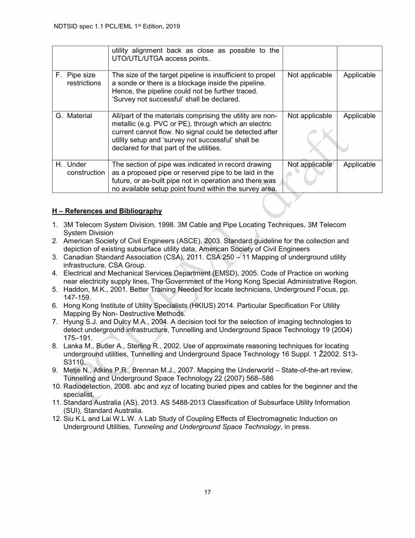
utility alignment back as close as possible to the UTO/UTL/UTGA access points.
F. Pipe size restrictions
The size of the target pipeline is insufficient to propel a sonde or there is a blockage inside the pipeline. Hence, the pipeline could not be further traced. ‘Survey not successful’ shall be declared.
Not applicable Applicable
G. Material All/part of the materials comprising the utility are non-metallic (e.g. PVC or PE), through which an electric current cannot flow. No signal could be detected after utility setup and ‘survey not successful’ shall be declared for that part of the utilities.
Not applicable Applicable
H. Under construction
The section of pipe was indicated in record drawing as a proposed pipe or reserved pipe to be laid in the future, or as-built pipe not in operation and there was no available setup point found within the survey area.
Not applicable Applicable
H – References and Bibliography
1. 3M Telecom System Division, 1998. 3M Cable and Pipe Locating Techniques, 3M Telecom System Division
2. American Society of Civil Engineers (ASCE), 2003. Standard guideline for the collection and depiction of existing subsurface utility data, American Society of Civil Engineers
3. Canadian Standard Association (CSA), 2011. CSA 250 – 11 Mapping of underground utility infrastructure, CSA Group.
4. Electrical and Mechanical Services Department (EMSD), 2005. Code of Practice on working near electricity supply lines, The Government of the Hong Kong Special Administrative Region.
5. Haddon, M.K., 2001. Better Training Needed for locate technicians, Underground Focus, pp. 147-159.
6. Hong Kong Institute of Utility Specialists (HKIUS) 2014. Particular Specification For Utility Mapping By Non- Destructive Methods.
7. Hyung S.J. and Dulcy M.A., 2004. A decision tool for the selection of imaging technologies to detect underground infrastructure, Tunnelling and Underground Space Technology 19 (2004) 175–191.
8. Lanka M., Butler A., Sterling R., 2002. Use of approximate reasoning techniques for locating underground utilities, Tunnelling and Underground Space Technology 16 Suppl. 1 Ž2002. S13-S3110.
9. Metje N., Atkins P.R., Brennan M.J., 2007. Mapping the Underworld – State-of-the-art review, Tunnelling and Underground Space Technology 22 (2007) 568–586
10. Radiodetection, 2008. abc and xyz of locating buried pipes and cables for the beginner and the specialist.
11. Standard Australia (AS), 2013. AS 5488-2013 Classification of Subsurface Utility Information (SUI), Standard Australia.
12. Siu K.L and Lai W.L.W. A Lab Study of Coupling Effects of Electromagnetic Induction on Underground Utilities, Tunneling and Underground Space Technology, in press.