Exploration of Versatile Clamping Mechanism and Brace ...
32
Exploration of Versatile Clamping Mechanism and Brace System for Table Attachment to Lamp Posts and Poles in Urban Settings by Bryan A. Macomber Submitted to the Department of Mechanical Engineering in Partial Fulfillment of the Requirements for the Degree of Bachelor of Science in Engineering as Recommended by the Department of Mechanical Engineering at the MASSACHUSETTS INSTITUTE OF TECHNOLOGY JUNE 2012 © 2012 Bryan A. Macomber. All rights reserved. The author hereby grants to MIT permission to reproduce and to distribute publicly paper and electronic copies of this thesis document in whole or in part in any medium now known or hereafter created. Signature of Author: ______________________________________ Department of Mechanical Engineering May 10, 2012 Certified by: __________________________________________ Maria Yang Assistant Professor of Mechanical Engineering Thesis Supervisor Accepted by:__________________________________________ John H. Lienhard V Samuel C. Collins Professor of Mechanical Engineering Undergraduate Officer
-
Upload
khangminh22 -
Category
Documents
-
view
1 -
download
0
Transcript of Exploration of Versatile Clamping Mechanism and Brace ...
Exploration of Versatile Clamping Mechanism and Brace System for Table Attachment to Lamp Posts and Poles in Urban Settings
by
Bryan A. Macomber
Submitted to the Department of Mechanical Engineering
in Partial Fulfillment of the Requirements for the Degree of
Bachelor of Science in Engineering as Recommended by the Department of Mechanical Engineering
at the
MASSACHUSETTS INSTITUTE OF TECHNOLOGY
JUNE 2012
© 2012 Bryan A. Macomber. All rights reserved.
The author hereby grants to MIT permission to reproduce and to distribute publicly paper and electronic copies of this thesis document in whole or in
part in any medium now known or hereafter created.
Signature of Author: ______________________________________Department of Mechanical Engineering
May 10, 2012
Certified by: __________________________________________Maria Yang
Assistant Professor of Mechanical Engineering Thesis Supervisor
Accepted by:__________________________________________John H. Lienhard V
Samuel C. Collins Professor of Mechanical EngineeringUndergraduate Officer

Exploration of Versatile Clamping Mechanism and Brace System for Table
Attachment to Lamp Poles and Street Signs in Urban Settings
by
Bryan A. Macomber
Submitted to the Department of Mechanical Engineering on May 10, 2012, in Partial Fulfillment of the
Requirements for the Degree of
Bachelors of Science in Engineering as Recommended by the Department of Mechanical Engineering
Abstract
The goal of this thesis is to explore potential designs for a table that attaches to poles and street signs outside food trucks. A convenient placement of tables could greatly facilitate and improve the eating experience for food truck customers and simultaneously keep people nearby for repeated business and community development. A table design without legs, that uses existing structures, such as street signs, telephone poles and lamp posts for support, was initially explored. Three goals were identified for the table’s functionality. These goals included clamping to signs and poles of various diameters, safely supporting large loads and a simple, quick deployment process. Initial prototypes failed in fulfilling all three goals, largely due to inappropriate clamping mechanisms. In choosing a ratchet tie down strap as the final clamping mechanism, further improvements and designs were explo red. Ultimately, an all in one table and brace system, involving an unfolding table surface was settled on.
Thesis Supervisor: Maria YangTitle: Assistant Professor of Mechanical Engineering
2

Acknowledgements
The author would like to thank Professor Maria Yang for her support and guidance during the writing of this thesis.
The author would like to acknowledge the following members from his 2.009 team for their contribution to the initial prototypes:
Jared DarbyJess IacobucciKami KlauberCharlie KleneCat Thu Nguyen Huu
The author also wishes to thank the following mentors, instructors and partners from 2.009:
David WallaceDaniel BraunsteinJohan SoninAyr Muir
3

Table of Contents
1. Introduction 7
1.1 Food Trucks 7
1.2 Functionality of Table 9
1.3 Requirements of Table 10
2. Initial Prototypes 12
2.1 First Prototype 12
2.2 Second Prototype 14
2.3 Table-Top Design 17
3. Exploring a New Design 19
3.1 Clamping Mechanism 19
3.2 Brace Array 20
3.3 Grooved Table Top 22
4. Design Decisions 25
4.1 Combination of Designs 25
4.2 New Direction 25
5. Future Considerations 29
5.1 Improving Versatility 29
5.2 Potential Impact 30
4

List of Figures
Figure 1-1: A Clover food truck in Cambridge 8
Figure 2-1: A diagram of the clamping mechanism 12
Figure 2-2: The value of a versatile clamping mechanism 13
Figure 2-3: Photos of the first prototype, attached to a tree 14
Figure 2-4: Double snap grip used in second prototype 15
Figure 2-5: The steps to assemble and disassemble 16
Figure 2-6: The snap grip and brace design 16
Figure 2-7: Photos of the second prototype, attached to a pole 17
Figure 2-8: Exploration of elliptical table top shapes 18
Figure 3-1: A ratchet tie down strap 20
Figure 3-2: An initial concept sketch of the potential design 21
Figure 3-3: A prototype of the brace array design 21
Figure 3-4: Any load, P, applied to the table top 22
Figure 3-5: Conceptual drawing of a grooved table top design 23
Figure 3-6: A diagram detailing the grooved table top design 24
Figure 4-1: Conceptual drawing of the new design direction 26
Figure 4-2: The light gray area represents the table surface 27
Figure 4-3: Sketch and diagram of a potential hinge design 28
Figure 5-1: Attachment pieces could be designed 29
Figure 5-2: A vision for a potential scene outside a food truck 30
5

List of Tables
Table 1-1: An outline of the design requirements for the table 11
6

Chapter 1Introduction
Food trucks have become an increasingly popular dining option over the last few
years. These establishments park on the side of the road and attract hundreds of
customers over lunch hours. But food trucks do not offer tables or seating, so customers
have no where to eat their meal and often leave the food truck location juggling their
beverage and food. A convenient placement of tables could greatly facilitate the eating
process for food truck customers and also keep people around food trucks for repeated
business and community development. Typical benches are fairly uncommon in an
urban setting and don't provide a place to set one’s food. Additionally, foldable
furniture is not an appropriate solution, especially on crowded street sidewalks. There
are no products out there that directly solve this problem.
This thesis describes my work designing and prototyping a novel portable table that
attaches to poles and street signs to improve and facilitate the eating experience around
food trucks, where eating surfaces are greatly limited. The design of this table began as
a team project in MIT’s senior product development course, 2.009. Clover food trucks
began as a specific client for the initial prototypes and has since served as inspiration for
future designs. I am now developing the design on my own.
1.1 Food Trucks In the US, in 2010, there were over 41,770 food stalls or trucks, representing a 10%
increase from 2005 [1]. While a large portion of these food trucks are independent
entities, “many non-mobile foodservice establishments are turning to food trucks to
promote their products, particularly in urban settings” [1]. Food trucks are beginning to
attract consumers in search for a “less expensive alternative to lunch or dinner” [1].
7
Food trucks give restaurant owners the opportunity for brand expansion and presence.
This mobile foodservice allows restaurants to expand their brand beyond the typical
footprint of a restaurant.
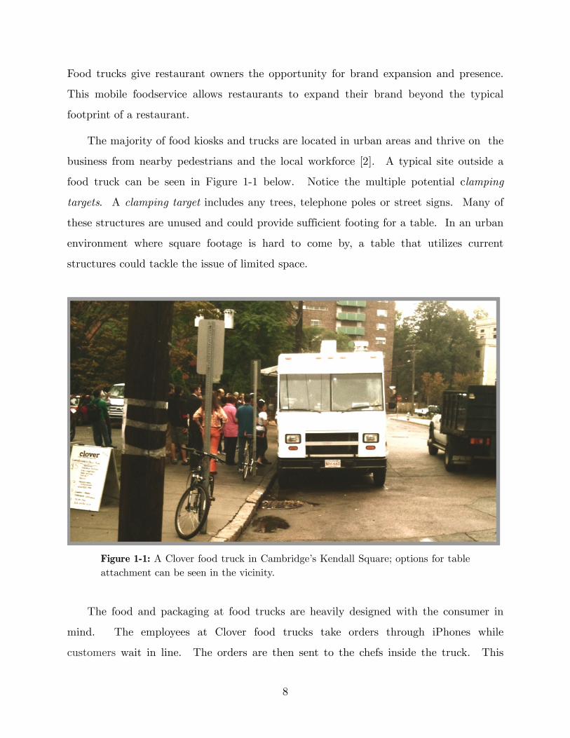
The majority of food kiosks and trucks are located in urban areas and thrive on the
business from nearby pedestrians and the local workforce [2]. A typical site outside a
food truck can be seen in Figure 1-1 below. Notice the multiple potential clamping
targets. A clamping target includes any trees, telephone poles or street signs. Many of
these structures are unused and could provide sufficient footing for a table. In an urban
environment where square footage is hard to come by, a table that utilizes current
structures could tackle the issue of limited space.
Figure 1-1: A Clover food truck in Cambridge’s Kendall Square; options for table attachment can be seen in the vicinity.
The food and packaging at food trucks are heavily designed with the consumer in
mind. The employees at Clover food trucks take orders through iPhones while
customers wait in line. The orders are then sent to the chefs inside the truck. This
8

innovation improves the experience of ordering and does away with the typical structure
of queues. But the experience surrounding food trucks, for the most part, has been
neglected and undesigned. By designing portable surfaces for users to place their food
and beverages on, the user experience outside food trucks could be greatly improved,
not only facilitating the eating experience but keeping food truck consumers around for
repeated business. The founder of Clover, Ayr Muir, agreed there was a need for
portable furniture outside food trucks [3]. He emphasized the importance of designing
food truck furniture for both employees who are responsible for set up and the food
truck customers.
Food trucks may have abandoned the roof of a typical restaurant, but for
established restaurants attempting to expand their brand, portable tables could create
an outdoor restaurant atmosphere. Simple, easily attached tables could create a number
of possibilities for food trucks and could significantly improve the post-purchase
experience.
1.2 Functionality of TableAfter considering a number of potential designs, including foldable tables to be
stored inside the food truck and tables that folded out from the side of the truck, it was
decided that the optimal design would have no table legs and would use existing
structures, such as street signs, telephone poles and lamp posts for support. This would
provide food truck customers with an appropriate, on-the-go eating experience. The
table would also leave no footprint, a priority in urban areas.
Three goals have been identified for the functionality of the table. It must be able
to clamp to various clamp targets of variable size, like street signs and poles. It must be
incredibly safe, supporting the weight of food and any additional forces. And it must be
quick and easy to deploy.
9

The challenges lie in determining an appropriate attachment mechanism that’s non-
marking and sufficiently strong. Another difficulty involves designing table braces and a
table top that will work with poles and trees of various diameters. It is my goal to
design a creative and effective solution to a relatively new and previously unrecognized
problem.
1.3 Requirements of TableIn deciding that trees, poles and street signs were the most appropriate structure to
attach a table to, an inventory of the diameter of these structures was required. In the
vicinity of Kendall Square’s Clover food truck, poles and trees ranged from 3.5” to 14.2”
in diameter. A wide variety of clamping target diameters exist, emphasizing the need
for a versatile clamping mechanism. The goal is for owners of the table to attach it to
whatever clamping target they choose, based on proximity to their vending location.
Designing a table that can only attach to one size or shape diminishes the usefulness of
this table.
Before creating the first prototype, three goals were identified: ease of deployment,
load capacity and the ability to clamp to various clamp targets. The initial prototype
set out to tackle all three, with an emphasis on clamping to various targets, as this was
seen as the most appealing feature. More specific goals are detailed in Table 1 below.
10

Table 1: An outline of the design requirements for the table.
Customer Need Product Attribute Engineering Spec
2-3 People/Table Load Capacity;Size > 100 lbs / 6’ perimeter
Quick Attachment Attachment Time 1 person in 30 sec.
Truck Storage Disassembled Volume 2 ft3
Safety Time to Failure 500 Attachments
Affordable Price < $100
Versatility Clamp Diameter 3”- 9”
This table is meant to serve two to three people. In designing a table for this many
people comes the requirement to bear large loads. While most loads will be limited to
the weight of the food and beverage, the table must be designed for more extreme
situations. A safe maximum load of 100 pounds was identified and by setting this load
at a sufficiently high level, the table will be designed with safety in mind.
An essential characteristic of the table is its quick attachment. The longer it takes
an employee to assemble and attach the table, the less likely it is to be used. Employees
are paid for their time and have many tasks to complete. It is essential that setting up
this table takes no more than 30 seconds.
Parallel to the need for quick attachment is the ease with which the table can be
stored. Food trucks won’t be very willing to carry around a bulky table that takes up
space in an already cramped truck. The table must be designed to collapse into a
compact size for storage inside a food truck. A collapsed table volume of 2 cubic feet
was targeted. The following chapters describe my efforts at choosing an appropriate
clamping mechanism and designing supporting braces and a table surface.
11
Chapter 2Initial Prototypes
To explore initial clamping mechanisms, table top designs and attachment methods,
two prototypes were constructed. The three identified goals were used to guide the
initial prototypes. These three goals included the ability to clamp to various clamp
targets, the ability to bear high loads, and the quick setup and attachment of the table.
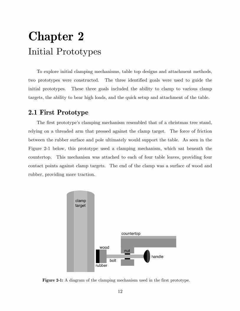
2.1 First PrototypeThe first prototype’s clamping mechanism resembled that of a christmas tree stand,
relying on a threaded arm that pressed against the clamp target. The force of friction
between the rubber surface and pole ultimately would support the table. As seen in the
Figure 2-1 below, this prototype used a clamping mechanism, which sat beneath the
countertop. This mechanism was attached to each of four table leaves, providing four
contact points against clamp targets. The end of the clamp was a surface of wood and
rubber, providing more traction.
Figure 2-1: A diagram of the clamping mechanism used in the first prototype.
12

The practicality of this design is depicted conceptually in Figure 2-2 below.
Because each table leaf had its own clamping mechanism, oddly shaped clamp targets
could be secured to.
Figure 2-2: The value of a versatile clamping mechanism, attaching to a tree (left), pole (middle) and street sign (right).
In initial explorations of the table design, a folding mechanism was greatly desired
due to its small folded footprint and intuitive expanding method. But unfolding the
table into four quarter circles when half is already secured to a clamping target isn’t
possible, as the pole blocks the unfolding. Because of this, alternate folding and
unfolding techniques were eventually explored (see section 4.2).
To create one structural surface out of four smaller surfaces, stop hinges were
fastened to the bottom of each leaf. These were ultimately replaced with a locking
mechanism that sat beneath each leaf, providing greater stability. Understanding the
need for stability and structure while attempting to create a foldable, collapsable surface
proved to be a challenging feature.
13

Figure 2-3: Photos of the first prototype, attached to a tree. Photo credit: Melody Kuna.
Images of the first prototype can be seen in Figure 2-3 above. While this design
adequately accomplished the goal of clamping to various clamp targets, it could not
bear a load more than 5 lbs and was incredibly difficult to attach, requiring two people.
One individual had to hold the two leaves while the other reached under and turned the
handle, moving the rubber surface closer to the clamp target. Additionally, the friction
force was largely due to the rubber contacts added to the end of clamping mechanism
rather than force applied by turning the threaded arm. It was concluded that a
clamping mechanism that was stronger and easier to use was needed.
2.2 Second PrototypeThe focus of the second prototype was to find a successful method for clamping. It
was important to create a functioning prototype to observe users engaging with the
table and elicit feedback. Therefore, a clamping mechanism that could sufficiently
support a table surface was required. The previous prototype, while successful in some
respects, wasn’t fully functional. Because of this desire to create a functioning
prototype, the goal of clamping to various targets was initially abandoned.
A plastic double snap grip was identified as a potentially appropriate clamping
device. These snap grips, seen below in Figure 2-4, are typically used as hose or tube
14

clamps clamps for specific diameters. Snap grips come in several different diameter
ranges, but each range is small. The snap grip chosen had a diameter range from 3.1”
to 3.4” and would fit an identified pole of 3.25.” The snap grip proved to be very strong
and durable, withstanding well over 100 lbs.
Figure 2-4: Double snap grip used in second prototype. Photo credit: McMaster-Carr
While not incredibly user friendly, snap grips are intuitive and use a logical
ratcheting design to tightly clamp to any cylindrical object. The snap grip can be
secured to a pole by inserting the single finger into the double snap grip cavity, where
force allows the teeth to lock in place. Unfortunately, these snap grips required a
wrench or pliers to achieve the final snap.
To remove, the user would simply pull one end up and push the other down to slide
the teeth out of their locking place. Snap grips are very easy to unsnap, once the user
knows how this is done. These steps of assembly and disassembly are depicted in Figure
2-5 below. The idea of easy disassembly to those familiar with the device is a desired
feature of the table. To ensure that the table isn’t stolen or tampered with, a
mechanism that isn’t intuitive to use for those unfamiliar with it would be ideal.
15

Figure 2-5: The steps to assemble and disassemble the double snap grips.
To utilize these snap grips in the context of supporting a table, corner braces were
fastened around the circumference of the snap grips. An image of this assembly is
depicted in Figure 2-6.
Figure 2-6: The snap grip and brace design which could be attached to a pole of appropriate diameter.
16

Five holes were drilled into each snap grip, and steel corner braces were attached.
This entire assembly was then attached to the pole. Because of interference between the
screw heads and the pole, a wrench was required to make the final “click” of the snap
grips to firmly secure the clamping mechanism to the pole. Peg holes were drilled into
each corner brace and each table leaf was outfitted with pegs to fit snuggly into these
holes, ultimately securing each leaf to the braces.
Figure 2-7: Photos of the second prototype, attached to a pole outside MIT’s Stratton Student Center. Photo credit: Melody Kuna.
The right image in Figure 2-7 depicts the difficulty of assembling the second
prototype. Exact placement of each table leaf was required and even once the table
leaves were attached, nothing secured them from being displaced upward. Something
preventing an upward moment was required.
2.3 Table-Top DesignOriginally, a circular shape was settled on for the table top. But after observing the
location of most street poles, an elliptical shape was proposed. Since the majority of
lamp posts and street signs sit at the edge of the sidewalk, bordering the street, one side
of the table would be completely facing the street, where few people would choose to
stand and eat. For this reason, an off-center elliptical shape would allow the most space
17

for people standing on the sidewalk, and the least space for the street-side. A few
sketches exploring different elliptical shapes can be seen in Figure 2-8.
Figure 2-8: Exploration of elliptical table top shapes.
These shapes give the table a unique, intriguing character, with the user’s
experience in mind. The table top design is dependent on the clamping mechanism, but
once the clamping method is determined, a logical and exciting table top shape will be
pursued.
18

Chapter 3Exploring a New Design
It was determined that the snap grip wasn’t the optimal clamping mechanism due
to its lack of versatility and difficulty to manually achieve the complete grip around the
pole. From building two prototypes, a clamping device wasn’t discovered, but it was
made clear that only once an adequate clamping mechanism was settled on could the
rest of the table be designed.
3.1 Clamping MechanismIn designing the current prototype, the most essential factor was determining the
clamping mechanism. By settling on a reliable mechanism, the remainder of the table
could be designed more effectively. The requirements for a clamping device were as
follows: it must withstand a load of at least 100 pounds, it must be easy to attach, and
it must fit various diameters. The previous clamping mechanisms had advantages that
directed my search. In searching for a variable ratcheting clamping device, I was led to
ratchet tie down mechanisms. These ratcheting devices are used to tie down and secure
large objects on trailers and truck beds, utilizing a long nylon strap and a ratcheting
mechanism. These devices are known for their versatility as they “can be used to secure
a wide variety of objects to various support surfaces” [4]. Furthermore, ratcheting tie
downs are incredibly strong, relying on friction and the application of “tension to ensure
that the object to be secured is retained securely” [4]. A similar device to the one
described above is seen in Figure 3-1.
19

Figure 3-1: A ratchet tie down strap. A user simply cranks the handle, which retracts the strap thus tightening the grip.
This ratchet tie down strap was acquired and then adapted to work with poles and
cylindrical objects. The purchased ratcheting device was reported to have a work load
limit of 333 pounds [5]. By cutting off the nylon from one end and removing the hook
on the other end, the strap could simply be fed through the ratcheting device. While
feeding the strap through the device isn’t incredibly easy to do, the device, for the most
part, meets the previously defined clamp requirements and allowed further development
of the prototype. It was concluded that this ratcheting tie down device, or a very
similar embodiment of it, would be at the core of the table design.
3.2 Brace ArrayWith the clamping mechanism determined, initial designs for the braces could be
explored. The first design involved a simple corner brace with a slit for the nylon strap
of the ratcheting tie down mechanism to be fed through.
20

Figure 3-2: An initial concept sketch of the potential design using the ratchet tie down strap (left) and a potential table top design using the ratchet strap (right).
Instead of simply attaching a table top to the corner braces, I explored a solution
where the braces became the table top, roughly sketched in Figure 3-2. By laser cutting
60 braces out of 1/8” thick acrylic, a more dynamic brace design was created. The idea
explored was to be free of a typical table top, and would feature a more modular table
surface.
As seen in the scale prototype below, with each brace attached to the pole, an
effective and visually appealing dining surface was created. Additionally, this brace
design enabled a modular table, where users could walk up and separate sections from
one another, effectively creating their own personalized space.
Figure 3-3: A protoype of the brace array design made from 60 acrylic braces.
Disadvantages of this design included the difficulty in attaching an array of braces.
It is unwieldy and challenging to secure to the pole. Additionally, it wasn’t easy to
21

ensure that each brace was orthogonal to the pole. If one looks closely at Figure 3-3,
many of the braces aren’t perfectly perpendicular to the pole. This would have to be
corrected. Furthermore, some sort of surface would need to exist to bridge the gap
between each brace.
3.3 Grooved Table TopA more classic design was explored, attempting to achieve a typical brace and table
top design. This design aimed to fix the problems discovered in the second prototype,
where dowels didn’t fully secure the table top. As illustrated in Figure 3-4 below, when
a load, P, was applied to the edge of the table, a moment, M, was created and the table
surface would torque upward. This is an unacceptable feature. The table surface must
feel sturdy, without noticeable wiggle or movement.
Figure 3-4: Any load, P, applied to the table top creates a moment, M, that lifted the table surface upward.
Additionally, to improve the structural stability of the table as a whole, a truss like
shape was settled on for the structural design of the braces, and likely will last
throughout future designs.
22
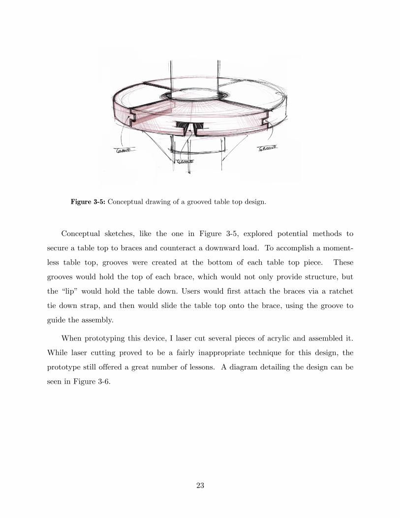
Figure 3-5: Conceptual drawing of a grooved table top design.
Conceptual sketches, like the one in Figure 3-5, explored potential methods to
secure a table top to braces and counteract a downward load. To accomplish a moment-
less table top, grooves were created at the bottom of each table top piece. These
grooves would hold the top of each brace, which would not only provide structure, but
the “lip” would hold the table down. Users would first attach the braces via a ratchet
tie down strap, and then would slide the table top onto the brace, using the groove to
guide the assembly.
When prototyping this device, I laser cut several pieces of acrylic and assembled it.
While laser cutting proved to be a fairly inappropriate technique for this design, the
prototype still offered a great number of lessons. A diagram detailing the design can be
seen in Figure 3-6.
23

Figure 3-6: A diagram detailing the grooved table top design.
The specific groove was successful as the table top was secure along its central axis,
but nothing held the table leaves in place along their outer edge. Braces would be
needed at the edge of each leaf for complete support, unless each leaf was small in
surface area. Thus, braces would exist at the center of each leaf and also at their edges.
Edge braces would provide support for adjacent leaves. While several improvements to
this design were outlined, an effective combination of the two newer prototypes was
ultimately brainstormed and explored.
24

Chapter 4Design Decisions
After prototyping and testing the previous ideas, it was determined that the most
elegant and feasible solution was an all in one brace and table top design. This solution
is a combination of the two directions explored in the last prototyping phase.
4.1 Combination of Designs In speaking to users about the brace array prototype, the small gaps between
braces evoked a feeling of uncertainty. Users were hesitant to place food and beverages
on the current surface. While an intriguing design, something was needed to create a
flush, full table surface.
In the more classic brace and table top design, multiple parts proved to contradict
the goal of a simple table design that was easy to assemble and disassemble. The fewest
number of parts was ideal. Additionally, the number of steps involved in attaching
braces and then sliding on several table leaves was too high, adding to the complexity
and time to assemble the table.
By effectively combining these two designs, I hoped to achieve the elegance of the
dynamic brace array design while still providing a sturdy table top surface for the user.
The focus of the new design was to create a hinging mechanism, that when unfolded,
created a table surface.
4.2 New DirectionInitial sketches explore the general concept of this final design. As seen below in
Figure 4-1, the user will attach the table to the pole, and then simply pull it around the
table, unfolding each table leaf. This design features several hinged pieces, that when
unfolded, snap into a horizontal position.
25

Figure 4-1: Conceptual drawing of the new design direction. The blue arrow at the top right alludes to the action of unfolding the table by simply pulling it around the pole.
One unsettled issue is what part of the design will take the load. In the sketch
above, the hinges, or a similar folding mechanism will be responsible for bearing all the
load. This design will need to be altered so braces support the table top, rather than
hinges. The ratchet tie down straps can bear well over 100 pounds, but the table must
be designed such that the supporting parts, like the braces and hinges, won’t fail at a
smaller load.
Another advantage in choosing this design with multiple braces, is the distribution
of load. Instead of three or four braces taking the majority of the weight, the load will
be distributed across several braces.
26

Figure 4-2: The light gray area represents the table surface, wrapped around poles of various sizes. In each of the three images, the gray surface is the same area, wrapped around various pole diameters.
An issue that previous designs didn’t fully address was adapting the table size to
various pole diameters. In earlier designs, the table top was a fixed area and to
accommodate various pole diameters, a hole was left in the middle. But for this design,
the braces would simply wrap around the pole and if there were too many braces, a
brace could be removed. If there were too few, braces could be added. The diagram
above illustrates the value of this design. The light gray area represents the table
surface, wrapped around poles of various sizes. If a user wanted to complete the circle,
they could add braces to the end.
A sketch and diagram of a potential hinge design is depicted below in Figure 4-3. If
hinges are strategically placed, the braces and individual table sections can create a
flush table surface.
27

Figure 4-3: Sketch and diagram of a potential hinge design.
Not only would this design enable improved versatility, but in a folded, compact
form, the table would take up very little space. The issue of storage wasn’t heavily
considered during the previous prototypes, but the current direction would fulfill the
initial goal of a small collapsed, storage volume.
28

Chapter 5Future Considerations
This thesis has explored a number of ways to design key elements of the table. This
section offers potential future explorations for the design.
5.1 Improving VersatilityIn expanding the use of this table, it must have the ability to be attached to street
poles and objects that aren’t perfectly, or even closely circular in cross section. A
common street sign design involves bent sheet metal, resembling the shape in Figure 5-1
below. The current clamping apparatus won’t sufficiently attach to such a shape, but
by designing attachment pieces, this issue could be solved.
Figure 5-1: Attachment pieces could be designed to enable clamping to oddly shaped clamp targets.
These attachment pieces could be designed at the request of food truck owners and
sold separately. While the current clamping mechanism is versatile and attaches to a
29

variety of shapes, it is unlikely that any clamping mechanism of reasonable price and
simplicity would be able to fit all shapes.
5.2 Potential ImpactWhile food trucks are a logical direct customer, they don’t represent the sole
potential customer for a table that would attach to nearby poles and trees. This
product could serve college campuses with ample outdoor space during times like
graduation or admit weekends. Additionally, the product could be attached to lamps
and trees in public parks and schools, thus optimizing the efficiency of space and
removing the need for some lunch benches. The scope and end-use of this product has
no specific definition and if designed and marketed correctly could serve a large variety
of people in a number of unique ways.
A vision for a potential scene outside a food truck is depicted below in Figure 5-2.
These tables are a simple solution to a common problem.
Figure 5-2: A vision for a potential scene outside a food truck with tables attached to nearby trees and poles.
30

Ayr Muir, Clover’s founder, summarized the ultimate vision for this product. He
said that there was no need to limit the application to just food trucks and that
“instead this can be a broad engagement in the changing way we congregate, eat, etc. in
crowded places like cities” [6].
31

Bibliography
32
[1] Stensson, Annika. "Food Trucks Gaining Momentum, New Research Finds." National Restaurant Association, 8 Sept. 2011. Web. 26 Mar. 2012.
[2] Street Stalls/Kiosks in the US. Rep. August 2011. Passport GMID. Web. 2 Oct. 2011.
[3] Muir, Ayr. Personal interview. 30 Sept. 2011.
[4] Breeden, Winston, and Robert Breeden. Ratchet Tie-Down. Winston Products LLC, assignee. Patent 8099836. 24 Jan. 2012. Print.
[5] McMaster-Carr. Web. 2 Feb. 2012. <http://www.mcmaster.com/#ratchet-straps/=hf3kyi>.
[6] Muir, Ayr. "Project Update." Message to the author. 22 Oct. 2011. E-mail.