Toggle-Brace-Damper Seismic Energy Dissipation Systems
8
JOURNAL OF STRUCTURAL ENGINEERING / FEBRUARY 2001 / 105 TOGGLE-BRACE-DAMPER SEISMIC ENERGY DISSIPATION SYSTEMS By Michael C. Constantinou, 1 Member, ASCE, Panos Tsopelas, 2 Associate Member, ASCE, Wilhelm Hammel, 3 and Ani N. Sigaher, 4 Student Member, ASCE ABSTRACT: Energy dissipation systems are being increasingly employed in the United States to provide en- hanced seismic protection for new and retrofit building and bridge construction. The hardware utilized includes yielding steel devices, friction devices, viscoelastic solid devices, and mostly, so far, fluid viscous devices. This hardware has been used in either diagonal or chevron brace configurations. This paper presents three new configurations that utilize toggle-brace mechanisms to substantially magnify the effect of damping devices so that they can be utilized effectively in applications of small structural drift. Shake table testing of a large scale steel model structure and analysis are used to demonstrate the utility of these configurations. The experimental results demonstrate substantial increases in the damping ratio despite the use of small size damping devices, and, accordingly, significant attenuation of the seismic response of the tested stiff structure is observed. Moreover, the experimental results are found to be consistent with analytical predictions based on either simplified methods or response history analysis. Applications of the new configurations are briefly described. INTRODUCTION Energy dissipation or damping systems are being increas- ingly used in new and retrofit construction in order to dissipate much of the earthquake-induced energy in elements not form- ing part of the gravity framing system. These elements exhibit either hysteretic behavior (e.g., yielding steel devices) or vis- coelastic/viscous behavior (e.g., fluid viscous devices). Despite substantial differences in the behavior of these elements, all are used with the philosophy of limiting or eliminating damage to the structural frame (Federal Emergency Management Agency 1997; Soong and Dargush 1997; Constantinou et al. 1998). The application of seismic energy dissipation systems dif- fers in various countries. For example, Japanese engineers have primarily used yielding steel devices and viscoelastic fluid or solid devices. In the United States, the majority of the applications utilize fluid viscous dampers. In all of these ap- plications, diagonal brace and chevron brace configurations have been used for the delivery of forces from the energy dissipation devices to the structural frame. The use of these configurations is apparently based on the experience of engi- neers with bracing systems in steel construction and the fact that experimental research studies utilized only these two con- figurations for energy dissipation systems. It is generally recognized that stiff structural systems re- spond to dynamic excitation with small drifts and small in- terstory velocities. This fact, coupled with the practice of im- plementing damping devices either as diagonal elements or as horizontal elements on top of chevron bracing, leads to device displacements that are less than or equal to the drift. This, in turn, results in the requirement for substantial forces in the damping devices for effective energy dissipation. On the basis of these considerations, it appears that stiff structural systems 1 Prof. and Chair., Dept. of Civ., Struct., and Envir. Engrg., Univ. at Buffalo, State Univ. of New York, Buffalo, NY 14260. 2 Asst. Prof., Dept. of Civ. Engrg., Catholic Univ. of America, Wash- ington, DC 20064. 3 Engr., KPMG Int., Frankfurt, Germany; formerly, Grad. Res. Asst., Dept. of Civ., Struct., and Envir. Engrg., Univ. at Buffalo, State Univ.of New York, Buffalo, NY. 4 Grad. Res. Asst., Dept. of Civ., Struct., and Envir. Engrg., Univ. at Buffalo, State Univ. of New York, Buffalo, NY. Note. Associate Editor: Takeru Igusa. Discussion open until July 1, 2001. To extend the closing date one month, a written request must be filed with the ASCE Manager of Journals. The manuscript for this paper was submitted for review and possible publication on March 22, 2000. This paper is part of the Journal of Structural Engineering, Vol. 127, No. 2, February, 2001. qASCE, ISSN 0733-9445/01/0002-0105–0112/ $8.00 1 $.50 per page. Paper No. 22317. may not be suitable for implementation of energy dissipation systems. This paper describes three novel configurations of energy dissipation devices which are based on the toggle mechanism and which result in device displacements that are larger than the structural drift. The amount of magnification depends on the geometry of the toggle braces and can be significant; how- ever, practical values are in the range of 2.0–5.0. As a result of the energy dissipation device displacement magnification, the required device force is reduced by the same amount, lead- ing to highly effective systems that are eminently suitable for stiff structural systems. The paper describes the toggle-brace-damper concept, pre- sents a theoretical treatment of its behavior, and gives experi- mental results that confirm the validity of the concept and the developed theory. The experimental study includes shake table testing of a half-length scale model equipped with linear fluid viscous dampers. INTRODUCTION TO TOGGLE-BRACE THEORY Consider the diagonal and chevron brace configurations, in which the displacement of the energy dissipation devices is either equal to (case of chevron brace) or less than (case of diagonal brace) the drift of the story at which the devices are installed. That is u = f ? u (1) D where u D = device (or damper) relative displacement along the axis of the damper; u = interstory drift; and f = magnification factor. For the chevron brace configuration, f = 1.0, whereas for the diagonal configuration, f = cos u, where u = angle of inclination of the damper. Similarly, the force along the axis of the damper, F D , is related to the horizontal component of force, F, exerted by the damper on the frame F = f ? F (2) D Fig. 1 illustrates the diagonal and chevron brace configurations and the force F and interstory drift u for a single-story struc- ture. Consider that this single-story structure has effective weight W and a fundamental period (for elastic conditions) T, and that it is fitted with a fluid linear viscous damper for which F = C ? u ˙ (3) D o D where C o = damping coefficient; and u ˙ D = relative velocity between the ends of the damper along the axis of the damper. The damping ratio is Downloaded 18 Nov 2009 to 194.177.202.209. Redistribution subject to ASCE license or copyright; see http://pubs.asce.org/copyright
-
Upload
independent -
Category
Documents
-
view
5 -
download
0
Transcript of Toggle-Brace-Damper Seismic Energy Dissipation Systems

TOGGLE-BRACE-DAMPER SEISMIC ENERGY DISSIPATION SYSTEMS
By Michael C. Constantinou,1 Member, ASCE, Panos Tsopelas,2 Associate Member, ASCE,Wilhelm Hammel,3 and Ani N. Sigaher,4 Student Member, ASCE
ABSTRACT: Energy dissipation systems are being increasingly employed in the United States to provide en-hanced seismic protection for new and retrofit building and bridge construction. The hardware utilized includesyielding steel devices, friction devices, viscoelastic solid devices, and mostly, so far, fluid viscous devices. Thishardware has been used in either diagonal or chevron brace configurations. This paper presents three newconfigurations that utilize toggle-brace mechanisms to substantially magnify the effect of damping devices sothat they can be utilized effectively in applications of small structural drift. Shake table testing of a large scalesteel model structure and analysis are used to demonstrate the utility of these configurations. The experimentalresults demonstrate substantial increases in the damping ratio despite the use of small size damping devices,and, accordingly, significant attenuation of the seismic response of the tested stiff structure is observed. Moreover,the experimental results are found to be consistent with analytical predictions based on either simplified methodsor response history analysis. Applications of the new configurations are briefly described.
INTRODUCTION
Energy dissipation or damping systems are being increas-ingly used in new and retrofit construction in order to dissipatemuch of the earthquake-induced energy in elements not form-ing part of the gravity framing system. These elements exhibiteither hysteretic behavior (e.g., yielding steel devices) or vis-coelastic/viscous behavior (e.g., fluid viscous devices). Despitesubstantial differences in the behavior of these elements, allare used with the philosophy of limiting or eliminating damageto the structural frame (Federal Emergency ManagementAgency 1997; Soong and Dargush 1997; Constantinou et al.1998).
The application of seismic energy dissipation systems dif-fers in various countries. For example, Japanese engineershave primarily used yielding steel devices and viscoelasticfluid or solid devices. In the United States, the majority of theapplications utilize fluid viscous dampers. In all of these ap-plications, diagonal brace and chevron brace configurationshave been used for the delivery of forces from the energydissipation devices to the structural frame. The use of theseconfigurations is apparently based on the experience of engi-neers with bracing systems in steel construction and the factthat experimental research studies utilized only these two con-figurations for energy dissipation systems.
It is generally recognized that stiff structural systems re-spond to dynamic excitation with small drifts and small in-terstory velocities. This fact, coupled with the practice of im-plementing damping devices either as diagonal elements or ashorizontal elements on top of chevron bracing, leads to devicedisplacements that are less than or equal to the drift. This, inturn, results in the requirement for substantial forces in thedamping devices for effective energy dissipation. On the basisof these considerations, it appears that stiff structural systems
1Prof. and Chair., Dept. of Civ., Struct., and Envir. Engrg., Univ. atBuffalo, State Univ. of New York, Buffalo, NY 14260.
2Asst. Prof., Dept. of Civ. Engrg., Catholic Univ. of America, Wash-ington, DC 20064.
3Engr., KPMG Int., Frankfurt, Germany; formerly, Grad. Res. Asst.,Dept. of Civ., Struct., and Envir. Engrg., Univ. at Buffalo, State Univ. ofNew York, Buffalo, NY.
4Grad. Res. Asst., Dept. of Civ., Struct., and Envir. Engrg., Univ. atBuffalo, State Univ. of New York, Buffalo, NY.
Note. Associate Editor: Takeru Igusa. Discussion open until July 1,2001. To extend the closing date one month, a written request must befiled with the ASCE Manager of Journals. The manuscript for this paperwas submitted for review and possible publication on March 22, 2000.This paper is part of the Journal of Structural Engineering, Vol. 127,No. 2, February, 2001. qASCE, ISSN 0733-9445/01/0002-0105–0112/$8.00 1 $.50 per page. Paper No. 22317.
Downloaded 18 Nov 2009 to 194.177.202.209. Redistribution subje
may not be suitable for implementation of energy dissipationsystems.
This paper describes three novel configurations of energydissipation devices which are based on the toggle mechanismand which result in device displacements that are larger thanthe structural drift. The amount of magnification depends onthe geometry of the toggle braces and can be significant; how-ever, practical values are in the range of 2.0–5.0. As a resultof the energy dissipation device displacement magnification,the required device force is reduced by the same amount, lead-ing to highly effective systems that are eminently suitable forstiff structural systems.
The paper describes the toggle-brace-damper concept, pre-sents a theoretical treatment of its behavior, and gives experi-mental results that confirm the validity of the concept and thedeveloped theory. The experimental study includes shake tabletesting of a half-length scale model equipped with linear fluidviscous dampers.
INTRODUCTION TO TOGGLE-BRACE THEORY
Consider the diagonal and chevron brace configurations, inwhich the displacement of the energy dissipation devices iseither equal to (case of chevron brace) or less than (case ofdiagonal brace) the drift of the story at which the devices areinstalled. That is
u = f ?u (1)D
where uD = device (or damper) relative displacement along theaxis of the damper; u = interstory drift; and f = magnificationfactor. For the chevron brace configuration, f = 1.0, whereasfor the diagonal configuration, f = cos u, where u = angle ofinclination of the damper. Similarly, the force along the axisof the damper, FD, is related to the horizontal component offorce, F, exerted by the damper on the frame
F = f ?F (2)D
Fig. 1 illustrates the diagonal and chevron brace configurationsand the force F and interstory drift u for a single-story struc-ture. Consider that this single-story structure has effectiveweight W and a fundamental period (for elastic conditions) T,and that it is fitted with a fluid linear viscous damper for which
F = C ? u̇ (3)D o D
where Co = damping coefficient; and u̇D = relative velocitybetween the ends of the damper along the axis of the damper.The damping ratio is
JOURNAL OF STRUCTURAL ENGINEERING / FEBRUARY 2001 / 105
ct to ASCE license or copyright; see http://pubs.asce.org/copyright

FIG. 2. Illustration of Toggle-Brace-Damper Configurations,Magnification Factors, and Damping Ratios of Single-StoryStructure with Fluid Linear Viscous Devices
FIG. 1. Illustration of Diagonal and Chevron Brace Configura-tions, Magnification Factors, and Damping Ratios of Single-Story Structure with Fluid Linear Viscous Devices
2C ? f ?g ?Tob = (4)
4 ?p ?W
The significance of the configuration of the energy dissipationsystem is evident in the effect of the magnification factor onthe damping ratio. A damper selected to provide a dampingratio of 5% of critical in the chevron brace configuration willprovide a damping ratio of 3.2% of critical in the diagonalconfiguration of Fig. 1.
Eq. (4) also demonstrates that configurations with a mag-nification factor larger than unity are very effective in en-hancing the damping ratio with a reduced requirement fordamper force. The development, analysis, and testing of threesuch configurations is the subject of this paper. Illustrated inFig. 2, these configurations utilize shallow trusses to magnifythe effect of the structural drift on the damper displacementand also to magnify the small damper force and deliver it tothe structural frame. Expressions for the magnification factorunder conditions of small rotations, and some typical values,are given in Fig. 2. It is of interest to note in this figure that,if the same damper that provided the damping ratio of 5% in
106 / JOURNAL OF STRUCTURAL ENGINEERING / FEBRUARY 2001
Downloaded 18 Nov 2009 to 194.177.202.209. Redistribution sub
FIG. 3. Analysis of Toggle Brace Movement
the chevron configuration (Fig. 1) is used in the toggle-braceconfigurations, the damping ratio would have been between30 and 50% of critical.
Such performance is achieved with the selection of magni-fication factor values in the range of 2.5–3.0. That is, thedisplacement of the damper is 2.5–3.0 times the interstorydrift [(1)]. This itself represents a desirable feature when theinterstory drift is small, such as in seismic applications in stiffstructural systems (e.g., reinforced concrete shear wall or steel-braced dual systems) or in wind applications. For such appli-cations of small drift, fluid viscous dampers require specialdetailing that increases their size and, accordingly, their cost.Moreover, when drifts are small, the required damping forcesare large, leading to further increase in the cost of the energydissipation system. Therefore, the utilization of configurationswith a large magnification factor, such as in the toggle-brace-damper systems, may lead to cost savings.
The potential for cost savings and the possibility for ex-tending the application of energy dissipation systems to stiffstructures or structures with small drifts motivated a study ofwhich selected results are reported herein. A more compre-hensive account of the work on the upper and lower togglesystems (Fig. 2) may be found in the report of Constantinouet al. (1997). Since then, the Yerba Buena tower in San Fran-cisco has been designed with a reverse toggle-brace-dampersystem (Fig. 2). This necessitated some further work, which isalso reported herein.
MAGNIFICATION FACTOR IN TOGGLE-BRACESYSTEMS
The magnification factor, f, is the ratio of the damper dis-placement, uD, to the interstory drift, u. Illustrated in Fig. 3are the three toggle systems within a one-story frame and ananalysis of their kinematics. On the basis of this figure
u uA9B9 2 ABuDf = = (5)
u u
where and = lengths of segments AB and A9B9, re-AB A9B9spectively. It should be noted that the illustration in Fig. 3neglects any deformations in the frame (only the rigid body
ject to ASCE license or copyright; see http://pubs.asce.org/copyright

motion is considered) and any reduction in height due to therotation of the columns. The contribution of the latter is insig-nificant for typical values of the interstory drift ratio. However,the deformations of the frame may have some noticeable effecton the magnification factor in the upper and lower toggle con-figurations. For example, consider the upper toggle configu-ration in a frame with pinned supports, a rigid beam-to-columnconnection on the right, and a simple beam-to-column con-nection on the left. On lateral deformation towards the right,as shown in Fig. 3, the point of attachment B moves upwards,which causes reduction in the damper displacement and in themagnification factor. The opposite occurs when the simplebeam-to-column connection is placed on the right side and therigid connection on the left. The resulting downward move-ment of point B causes an increase of the magnification factor.However, regardless of the structural system configuration, themagnification factor is reduced due to displacements causedby the forces in the damper and the toggle braces.
The displacement of the damper can be established on thebasis of the kinematics of the system and the aforementionedconstraints as follows:
• For the upper toggle system
h <1u = 6 2 < ? tan u 2 h ? tan u 2 u 2D 1 1 1H FScos u cos u1 1
2 1/2
21 < ?cos(u 6 f) 1 (h 2 < ?sin(u 6 f))1 1 1 1D G J(6)
• For the lower toggle system1/2
1 2 ?cos(u 6 f)1u = 6< ? 1 1 2 2 tan uD 1 1FS D G2cos u cos u1 1
(7)
where angle f is determined from the following equation oflength preservation:
2 2 2 2< = h 1 < 1 (< 1 u) 2 2 ?h ?< ?sin(u 6 f)2 1 1 1
2 2 ? (< 1 u) ?< ?cos(u 6 f)1 1 (8)
• For the reverse toggle system2u = 6[a ?< ? tan u 2 {[a ?< ?sin(u 7 f) 1 u]D 2 2 2 2
2 1/21 [h 2 a ?< ?cos(u 7 f)] } ]2 2 (9)
where2 2 2 2< = h 1 < 1 (< 2 u) 2 2h ?< ?cos(u 7 f)1 2 2 2
2 2 ? (< 2 u) ?< ?sin(u 7 f)2 2 (10)
In the above equations, positive drift u and rotation f are asshown in Fig. 3. Moreover, the positive sign holds for drifttowards the right (positive u and f), whereas the negativesigns hold for drift towards the left.
Eqs. (6)–(10) reveal a complex nonlinear relation betweenthe damper displacement uD and drift u. While an exact andexplicit solution of these equations has been derived (Con-stantinou et al. 1997), the solution is too complex to be ofpractical use. Rather, because practical design of toggle sys-tems results in small rotations (angle f), simple expressionsfor the magnification factor can be obtained by retaining onlylinear terms in f and u in (6)–(10). The result is:
• For the upper toggle system
sin u2f = 1 sin u (11)1cos(u 1 u )1 2
Downloaded 18 Nov 2009 to 194.177.202.209. Redistribution subje
FIG. 4. Dependency of Magnification Factor on Toggle Geom-etry
• For the lower toggle system
sin u2f = (12)
cos(u 1 u )1 2
• For the reverse toggle system
a ?cos u1f = 2 cos u (13)2cos(u 1 u )1 2
Eqs. (11)–(13) reveal that the magnification factor attainsvery large values as the sum of angles u1 and u2 approaches907. The 907 configuration is, of course, useless, since the tog-gles form a straight member that acts as a brace. Of signifi-cance is the sensitivity of the magnification factor on changesin the geometry. This is best presented in plots of the magni-fication factor, as shown in Fig. 4, for the upper and reversetoggle systems. Practical configurations are those for whichsmall changes in the geometry do not cause large changes inthe magnification factor. Such considerations limit the practicalvalues of the magnification factor in the range of about 2–5.For example, two such configurations are identified in Fig. 4.They, respectively, have magnification factor values of 3.2(tested upper toggle configuration) and 2.5 (configuration ofYerba Buena Tower in San Francisco).
The writers were able to configure toggle systems in thelaboratory with an accuracy of 0.17. However, they observedchanges in the geometry of toggles by as much 0.27 due tomovement in the joints and supports of the model (slippage,distortion, and inelastic action during testing). It appears thatit is appropriate to consider changes in the angles by about60.37 when assessing the sensitivity of toggle systems.
FORCES IN TOGGLE-BRACE SYSTEMS
The determination of forces in the toggle-brace system isneeded for the assessment of the safety of the toggles and for
JOURNAL OF STRUCTURAL ENGINEERING / FEBRUARY 2001 / 107
ct to ASCE license or copyright; see http://pubs.asce.org/copyright

FIG. 5. Analysis of Forces Acting on Frame and Toggle Sys-tem
establishing the relation between the force in the damper andthe horizontal component of force that acts on the structure.The latter is expressed by (2), in which f is given by (11)–(13). Fig. 5 shows a one-story frame with the three togglesystems. It should be noted that the frame is a mechanism sothat force F represents the component of the inertia force thatis balanced by forces supplied by the damping system. More-over, equilibrium is considered in the undeformed configura-tion, an assumption consistent with small displacement theory.
Simple equilibrium results in the following axial forces inthe toggles:
T = F ? tan(u 1 u ) (14)1 D 1 2
FDT = (15)2 cos(u 1 u )1 2
a ?FDT = (16)3 cos(u 1 u )1 2
T = a ?F ? tan(u 1 u ) (17)4 D 1 2
Note that forces T1 and T2 are tensile, whereas forces T3 andT4 are compressive (for force F acting as shown in Fig. 5).Moreover, toggle BC of the reverse toggle system is subjectedto bending moment, which is maximum at the point of con-nection to the damper and is equal to a? (1 2 a) ?FD?<2.
Horizontal equilibrium of the beam results in the relationbetween the force F and the damper force FD. It is easilyconfirmed that this relation is described by (2), with f givenby (11)–(13). That is, the magnification factor is given by
F uDf = = (18)
F uD
Eq. (18) leads to the expected result FD ?uD = F?u, which de-notes the correctness of the analysis.
108 / JOURNAL OF STRUCTURAL ENGINEERING / FEBRUARY 2001
Downloaded 18 Nov 2009 to 194.177.202.209. Redistribution subject
DAMPING RATIO
Consider a building with a damping system consisting oflinear viscous dampers. The system is nonclassically damped,and calculation of its modal properties, including the dampingratio, requires complex eigenvalue analysis [e.g., see Constan-tinou and Symans (1992) for application in the case of struc-tures with viscous fluid dampers and Veletsos and Ventura(1986) for a comprehensive treatment of complex eigenvalueanalysis]. However, results of acceptable accuracy may be ob-tained by approximate methods in which the assumption ismade that the mode shapes of the nonclassically damped struc-ture are identical to those of the undamped structure. Energyconsiderations can then be easily utilized to predict the con-tribution of the damping system to the damping ratio in eachmode of vibration. Warburton and Soni (1977) presented cri-teria for determining when the mode shapes of the undampedstructure may be used to analyze nonclassically damped struc-tures.
The Federal Emergency Management Agency (1997) guide-lines for seismic rehabilitation describe this methodology andprovide an equation for the calculation of the damping ratio(equation 9-30 in FEMA 1997). This equation can easily bemodified to account for toggle-brace-damper systems. Specif-ically, it may easily be shown that the contribution to thedamping ratio in the kth mode of vibration is given by
2 2T ? C ? f ?f ?gk j j rjOj
b = (19)k24 ?p ? W ?fi iO
i
where Tk = period of vibration in the kth mode; fi = kth modedisplacement at floor i; frj = kth mode relative displacementin story j; Cj = damping coefficient of a damping device in-stalled in story j [(3)]; fj = magnification factor for the dampingsystem containing the damping device with coefficient Cj; andWi = reactive weight of floor level i. Moreover, summation (j
extends over all stories and summation (i extends over allfloor levels. Note that fj in (18) is given by (11)–(13) for thetoggle systems; it is equal to unity for devices installed on topof chevron braces and equal to cos uj, uj = angle of inclinationof device j, for devices installed in the diagonal configuration.It should also be noted that, for a single-story structure (e.g.,Fig. 2), frj = fi = 1, i = j = 1, and (19) collapses to (4).
EXPERIMENTAL VERIFICATION
Description of Tested Structure
A half-length scale steel model structure was constructedfor the purpose of testing the toggle-brace systems. The modelconsisted of two frames, as shown in Fig. 6. Characteristicsof this model are as follows:
1. Beam-to-column connections which could easily be con-verted from simple to rigid. This allowed for testing ofa single frame in a configuration with all simple connec-tions (a mechanism) that allowed for a direct observationof the toggle-brace-damper system behavior. Moreover,combinations of two rigid connections per frame (termedrigid-rigid), one rigid and one simple connection perframe (termed rigid-simple), and a highly asymmetricone with one frame having rigid-rigid connections andthe other having rigid-simple connections were tested onthe shake table.
2. Connections between the two toggles and the damperand between the toggles and the beam and column. Thefirst connection was developed as a true pin including aspherical bushing for avoiding the transfer of moment to
to ASCE license or copyright; see http://pubs.asce.org/copyright
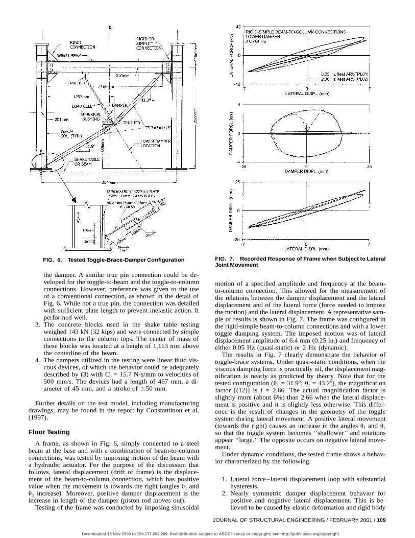
FIG. 6. Tested Toggle-Brace-Damper Configuration
the damper. A similar true pin connection could be de-veloped for the toggle-to-beam and the toggle-to-columnconnections. However, preference was given to the useof a conventional connection, as shown in the detail ofFig. 6. While not a true pin, the connection was detailedwith sufficient plate length to prevent inelastic action. Itperformed well.
3. The concrete blocks used in the shake table testingweighed 143 kN (32 kips) and were connected by simpleconnections to the column tops. The center of mass ofthese blocks was located at a height of 1,113 mm abovethe centerline of the beam.
4. The dampers utilized in the testing were linear fluid vis-cous devices, of which the behavior could be adequatelydescribed by (3) with Co = 15.7 N-s/mm to velocities of500 mm/s. The devices had a length of 467 mm, a di-ameter of 45 mm, and a stroke of 650 mm.
Further details on the test model, including manufacturingdrawings, may be found in the report by Constantinou et al.(1997).
Floor Testing
A frame, as shown in Fig. 6, simply connected to a steelbeam at the base and with a combination of beam-to-columnconnections, was tested by imposing motion of the beam witha hydraulic actuator. For the purpose of the discussion thatfollows, lateral displacement (drift of frame) is the displace-ment of the beam-to-column connection, which has positivevalue when the movement is towards the right (angles u1 andu2 increase). Moreover, positive damper displacement is theincrease in length of the damper (piston rod moves out).
Testing of the frame was conducted by imposing sinusoidal
Downloaded 18 Nov 2009 to 194.177.202.209. Redistribution sub
FIG. 7. Recorded Response of Frame when Subject to LateralJoint Movement
motion of a specified amplitude and frequency at the beam-to-column connection. This allowed for the measurement ofthe relations between the damper displacement and the lateraldisplacement and of the lateral force (force needed to imposethe motion) and the lateral displacement. A representative sam-ple of results is shown in Fig. 7. The frame was configured inthe rigid-simple beam-to-column connections and with a lowertoggle damping system. The imposed motion was of lateraldisplacement amplitude of 6.4 mm (0.25 in.) and frequency ofeither 0.05 Hz (quasi-static) or 2 Hz (dynamic).
The results in Fig. 7 clearly demonstrate the behavior oftoggle-brace systems. Under quasi-static conditions, when theviscous damping force is practically nil, the displacement mag-nification is nearly as predicted by theory. Note that for thetested configuration (u1 = 31.97; u2 = 43.27), the magnificationfactor [(12)] is f = 2.66. The actual magnification factor isslightly more (about 6%) than 2.66 when the lateral displace-ment is positive and it is slightly less otherwise. This differ-ence is the result of changes in the geometry of the togglesystem during lateral movement. A positive lateral movement(towards the right) causes an increase in the angles u1 and u2
so that the toggle system becomes ‘‘shallower’’ and rotationsappear ‘‘large.’’ The opposite occurs on negative lateral move-ment.
Under dynamic conditions, the tested frame shows a behav-ior characterized by the following:
1. Lateral force–lateral displacement loop with substantialhysteresis.
2. Nearly symmetric damper displacement behavior forpositive and negative lateral displacement. This is be-lieved to be caused by elastic deformation and rigid body
JOURNAL OF STRUCTURAL ENGINEERING / FEBRUARY 2001 / 109
ject to ASCE license or copyright; see http://pubs.asce.org/copyright
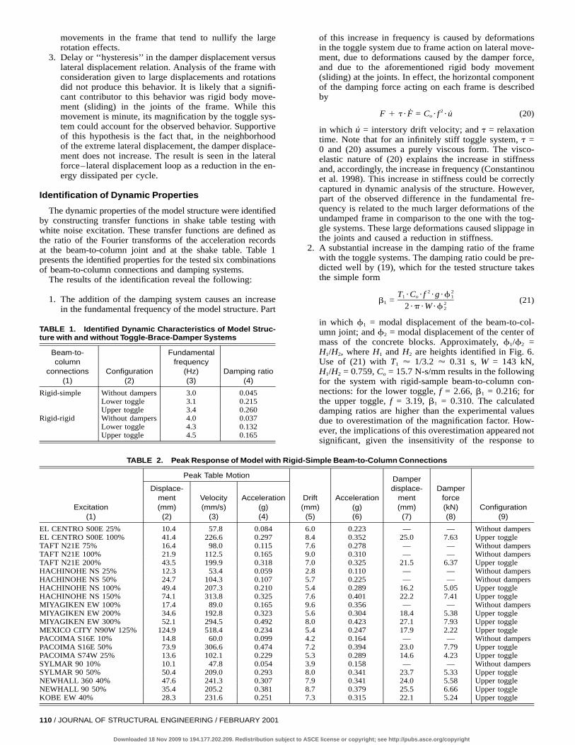
TABLE 1. Identified Dynamic Characteristics of Model Struc-ture with and without Toggle-Brace-Damper Systems
Beam-to-column
connections(1)
Configuration(2)
Fundamentalfrequency
(Hz)(3)
Damping ratio(4)
Rigid-simple Without dampersLower toggleUpper toggle
3.03.13.4
0.0450.2150.260
Rigid-rigid Without dampersLower toggleUpper toggle
4.04.34.5
0.0370.1320.165
movements in the frame that tend to nullify the largerotation effects.
3. Delay or ‘‘hysteresis’’ in the damper displacement versuslateral displacement relation. Analysis of the frame withconsideration given to large displacements and rotationsdid not produce this behavior. It is likely that a signifi-cant contributor to this behavior was rigid body move-ment (sliding) in the joints of the frame. While thismovement is minute, its magnification by the toggle sys-tem could account for the observed behavior. Supportiveof this hypothesis is the fact that, in the neighborhoodof the extreme lateral displacement, the damper displace-ment does not increase. The result is seen in the lateralforce–lateral displacement loop as a reduction in the en-ergy dissipated per cycle.
Identification of Dynamic Properties
The dynamic properties of the model structure were identifiedby constructing transfer functions in shake table testing withwhite noise excitation. These transfer functions are defined asthe ratio of the Fourier transforms of the acceleration recordsat the beam-to-column joint and at the shake table. Table 1presents the identified properties for the tested six combinationsof beam-to-column connections and damping systems.
The results of the identification reveal the following:
1. The addition of the damping system causes an increasein the fundamental frequency of the model structure. Part
110 / JOURNAL OF STRUCTURAL ENGINEERING / FEBRUARY 2001
Downloaded 18 Nov 2009 to 194.177.202.209. Redistribution subje
of this increase in frequency is caused by deformationsin the toggle system due to frame action on lateral move-ment, due to deformations caused by the damper force,and due to the aforementioned rigid body movement(sliding) at the joints. In effect, the horizontal componentof the damping force acting on each frame is describedby
2˙F 1 t ?F = C ? f ? u̇ (20)o
in which u̇ = interstory drift velocity; and t = relaxationtime. Note that for an infinitely stiff toggle system, t =0 and (20) assumes a purely viscous form. The visco-elastic nature of (20) explains the increase in stiffnessand, accordingly, the increase in frequency (Constantinouet al. 1998). This increase in stiffness could be correctlycaptured in dynamic analysis of the structure. However,part of the observed difference in the fundamental fre-quency is related to the much larger deformations of theundamped frame in comparison to the one with the tog-gle systems. These large deformations caused slippage inthe joints and caused a reduction in stiffness.
2. A substantial increase in the damping ratio of the framewith the toggle systems. The damping ratio could be pre-dicted well by (19), which for the tested structure takesthe simple form
2 2T ?C ? f ?g ?f1 o 1b = (21)1 22 ?p ?W ?f 2
in which f1 = modal displacement of the beam-to-col-umn joint; and f2 = modal displacement of the center ofmass of the concrete blocks. Approximately, f1/f2 =H1/H2, where H1 and H2 are heights identified in Fig. 6.Use of (21) with T1 ' 1/3.2 ' 0.31 s, W = 143 kN,H1/H2 = 0.759, Co = 15.7 N-s/mm results in the followingfor the system with rigid-sample beam-to-column con-nections: for the lower toggle, f = 2.66, b1 = 0.216; forthe upper toggle, f = 3.19, b1 = 0.310. The calculateddamping ratios are higher than the experimental valuesdue to overestimation of the magnification factor. How-ever, the implications of this overestimation appeared notsignificant, given the insensitivity of the response to
TABLE 2. Peak Response of Model with Rigid-Simple Beam-to-Column Connections
Excitation(1)
Peak Table Motion
Displace-ment(mm)(2)
Velocity(mm/s)
(3)
Acceleration(g)(4)
Drift(mm)(5)
Acceleration(g)(6)
Damperdisplace-
ment(mm)(7)
Damperforce(kN)(8)
Configuration(9)
EL CENTRO S00E 25% 10.4 57.8 0.084 6.0 0.223 — — Without dampersEL CENTRO S00E 100% 41.4 226.6 0.297 8.4 0.352 25.0 7.63 Upper toggleTAFT N21E 75% 16.4 98.0 0.115 7.6 0.278 — — Without dampersTAFT N21E 100% 21.9 112.5 0.165 9.0 0.310 — — Without dampersTAFT N21E 200% 43.5 199.9 0.318 7.0 0.325 21.5 6.37 Upper toggleHACHINOHE NS 25% 12.3 53.4 0.059 2.8 0.110 — — Without dampersHACHINOHE NS 50% 24.7 104.3 0.107 5.7 0.225 — — Without dampersHACHINOHE NS 100% 49.4 207.3 0.210 5.4 0.289 16.2 5.05 Upper toggleHACHINOHE NS 150% 74.1 313.8 0.325 7.6 0.401 22.2 7.41 Upper toggleMIYAGIKEN EW 100% 17.4 89.0 0.165 9.6 0.356 — — Without dampersMIYAGIKEN EW 200% 34.6 192.8 0.323 5.6 0.304 18.4 5.38 Upper toggleMIYAGIKEN EW 300% 52.1 294.5 0.492 8.0 0.423 27.1 7.93 Upper toggleMEXICO CITY N90W 125% 124.9 518.4 0.234 5.4 0.247 17.9 2.22 Upper togglePACOIMA S16E 10% 14.8 60.0 0.099 4.2 0.164 — — Without dampersPACOIMA S16E 50% 73.9 306.6 0.474 7.2 0.394 23.0 7.79 Upper togglePACOIMA S74W 25% 13.6 102.1 0.229 5.3 0.289 14.6 4.23 Upper toggleSYLMAR 90 10% 10.1 47.8 0.054 3.9 0.158 — — Without dampersSYLMAR 90 50% 50.4 209.0 0.293 8.0 0.341 23.7 5.33 Upper toggleNEWHALL 360 40% 47.6 241.3 0.307 7.9 0.341 24.0 5.58 Upper toggleNEWHALL 90 50% 35.4 205.2 0.381 8.7 0.379 25.5 6.66 Upper toggleKOBE EW 40% 28.3 231.6 0.251 7.3 0.315 22.1 5.24 Upper toggle
ct to ASCE license or copyright; see http://pubs.asce.org/copyright
small changes in the damping ratio of a highly dampedstructure.
Shake Table Testing
A total of 80 shake table tests were conducted using re-corded earthquakes. The testing was conducted with a lengthscale factor of 2 and a time scale factor of A total of 312.Ïinstruments were utilized to record the dynamic response ofthe tested structure. They included load cells, accelerometers,and displacement transducers. A detailed presentation of theresults of testing can be found in Constantinou et al. (1997).Herein, the writers will restrict the presentation to the case ofthe system with rigid-simple beam-to-column connections atboth frames and with the upper toggle system (as seen in Fig.6). As shown in Table 1, this system had its fundamental fre-quency in the range of 3.0–3.4 Hz. Table 2 presents the shaketable results for this case. Qualitatively similar results wereobtained in the other tested configurations. The table containsinformation on the excitation, including the peak table motion,and the peak response of the structure in terms of drift; thatis, displacement of the beam-to-column joint with respect tothe table, acceleration of the joint, and the damper force anddisplacement. These quantities are the average of two valuesmeasured for the two frames of the model. The two measuredvalues differed as a result of some accidental asymmetry inthe model. In general, the corner column drift response wasin the range of 1.0–1.08 times the average drift. Moreover, ahighly asymmetric configuration was tested with an eccentric-ity between the center of mass and the center of resistanceestimated at 14% of the distance between frames. In this asym-metric configuration only the upper toggle system was tested.The structure exhibited an asymmetric response with a cornercolumn drift in the range of 1.05–1.13 of the average drift[see Constantinou et al. (1997) for details].
The earthquake excitations used in the shake table testingconsisted of the 1940 El Centro, component S00E; the 1952Taft, component N21E; the 1971 San Fernando at PacoimaDam, components S16E and S74W; the 1985 Mexico City atSCT, component N90W; the Japanese 1978 Miyagiken-Oki,component EW; the 1968 Hachinohe, component NS; the 1995Kobe, component EW; the 1994 Northridge records at Sylmar,component 907; and Newhall, components 907 and 3607. Theserecords were scaled in amplitude of acceleration by the per-centage figure shown in Table 2. For example, the designationTAFT N21E 200% denotes that the excitation was the Taftmotion, component N21E, with the acceleration multipliedby 2.0.
The results in Table 2 demonstrate the utility of the toggle-damper systems. The systems provide for a systematic andsubstantial reduction of drift and, for this case of nearly elasticstructural response, reduction of acceleration. Moreover, theresults in Table 2 provide information on the magnificationfactor, as it may be calculated as the ratio of the peak damperdisplacement to the peak drift displacement. The values for theupper toggle system are in the range of 2.75–3.39. By com-parison, the theoretical value [(11)] is 3.19. It is interesting tonote that the lower values of the magnification factor occurredwhen the drift was positive (that is, in the direction towardsthe right; Fig. 6). This is consistent with the behavior of theframe as shown in Fig. 7, which is likely caused by smallslippage in the joints.
ANALYTICAL PREDICTION OF RESPONSE
Dynamic response-history analysis of the tested structurehas been conducted using the computer code ANSYS (ANSYS1996). This program allowed for analysis of the structure withconsideration given to large deformations and rotations. How-
Downloaded 18 Nov 2009 to 194.177.202.209. Redistribution sub
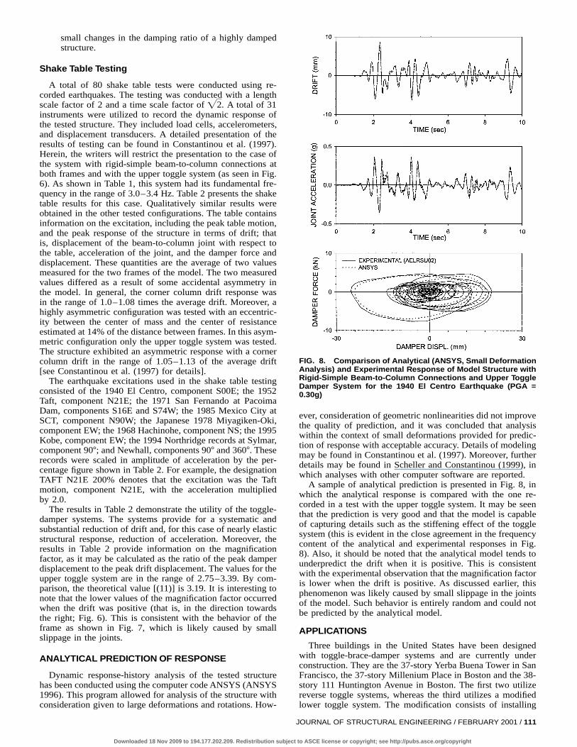
FIG. 8. Comparison of Analytical (ANSYS, Small DeformationAnalysis) and Experimental Response of Model Structure withRigid-Simple Beam-to-Column Connections and Upper ToggleDamper System for the 1940 El Centro Earthquake (PGA =0.30g)
ever, consideration of geometric nonlinearities did not improvethe quality of prediction, and it was concluded that analysiswithin the context of small deformations provided for predic-tion of response with acceptable accuracy. Details of modelingmay be found in Constantinou et al. (1997). Moreover, furtherdetails may be found in Scheller and Constantinou (1999), inwhich analyses with other computer software are reported.
A sample of analytical prediction is presented in Fig. 8, inwhich the analytical response is compared with the one re-corded in a test with the upper toggle system. It may be seenthat the prediction is very good and that the model is capableof capturing details such as the stiffening effect of the togglesystem (this is evident in the close agreement in the frequencycontent of the analytical and experimental responses in Fig.8). Also, it should be noted that the analytical model tends tounderpredict the drift when it is positive. This is consistentwith the experimental observation that the magnification factoris lower when the drift is positive. As discussed earlier, thisphenomenon was likely caused by small slippage in the jointsof the model. Such behavior is entirely random and could notbe predicted by the analytical model.
APPLICATIONS
Three buildings in the United States have been designedwith toggle-brace-damper systems and are currently underconstruction. They are the 37-story Yerba Buena Tower in SanFrancisco, the 37-story Millenium Place in Boston and the 38-story 111 Huntington Avenue in Boston. The first two utilizereverse toggle systems, whereas the third utilizes a modifiedlower toggle system. The modification consists of installing
JOURNAL OF STRUCTURAL ENGINEERING / FEBRUARY 2001 / 111
ject to ASCE license or copyright; see http://pubs.asce.org/copyright
the damper at an angle greater than 907 with respect to thelower toggle (see Fig. 2) so that the two toggles and thedamper directly connect to the beam-to-column joints. Themagnification factor for this configuration is given by (12)after multiplication by cos u3, where u3 = angle of damper axiswith respect to the 907 line. For the 111 Huntington Avenuebuilding, angle u3 = 21.57, so that the magnification factor isreduced by a small amount (about 7%). However, the instal-lation with connections of the toggles and dampers directly tothe beam-to-column joints eliminates additional bending in thebeams and provides for easy and reliable calculation of themagnification factor. Interestingly, all three applications are forthe reduction of wind-induced vibrations.
SUMMARY AND CONCLUSIONS
Toggle-brace-damper systems represent novel energy dissi-pation systems that operate on the principle of magnificationof small damper forces in shallow trusses and delivery of themagnified forces to the structural frame. They are very suitablefor applications of small structural drift, as may be the case inapplications of seismic hazard mitigation in stiff structures andin applications of wind response reduction.
This paper presented the theory of toggle-brace-damper sys-tems and experimental results that demonstrate their utility andeffectiveness. The centerpiece of this theory is the magnifi-cation factor, of which simple analytical expressions have beenpresented for three alternate configurations of toggle systems.The utility and effectiveness of the systems was demonstratedin the shake table testing of a half-length scale steel modelwith a weight of 143 kN and which was configured to have afundamental frequency in the range of 3.0–4.5 Hz (dependingon the connection details) and damping ratio in the range ofabout 0.04 (without dampers) to 0.26. With such substantialincreases in the damping ratio, the toggle systems were foundto noticeably reduce drift and acceleration.
The response of the tested model could be analytically pre-dicted with acceptable accuracy utilizing response history
112 / JOURNAL OF STRUCTURAL ENGINEERING / FEBRUARY 2001
Downloaded 18 Nov 2009 to 194.177.202.209. Redistribution sub
analysis without the necessity to consider large deformationeffects. Moreover, expressions for the prediction of the damp-ing ratio and forces in the toggles have been derived. Theseexpressions may be used within the context of simplified meth-ods of analysis, as for example those presented in FederalEmergency Management Agency (1997).
ACKNOWLEDGMENTS
This work was supported by the Great Regional Industrial Technology(GRIT) Program with funds provided by the U.S. Department of Com-merce, and by Taylor Devices, Inc., N. Tonawanda, New York.
APPENDIX. REFERENCES
ANSYS user’s manual, version 5.3. (1996). Swanson Analysis Systems,Houston, Pa.
Constantinou, M. C., Soong, T. T. and Dargush, G. F. (1998). Passiveenergy dissipation systems for structural design and retrofit, Multidis-ciplinary Center for Earthquake Engineering Research, Buffalo, N.Y.
Constantinou, M. C., and Symans, M. D. (1992). ‘‘Experimental and an-alytical investigation of seismic response of structures with supple-mental fluid viscous dampers.’’ Tech. Rep. NCEER-92-0032, NationalCenter for Earthquake Engineering Research, Buffalo, N.Y.
Constantinou, M. C., Tsopelas, P., and Hammel, W. (1997). ‘‘Testing andmodeling of an improved damper configuration for stiff structural sys-tems.’’ ^http://civil.eng.buffalo.edu/usersontwk/&
Federal Emergency Management Agency (FEMA). (1997). ‘‘NEHRP pro-visions for the seismic rehabilitation of buildings.’’ Reps. FEMA 273(Guidelines) and 274 (Commentary), Washington, D.C.
Scheller, J., and Constantinou, M. C. (1999). ‘‘Response history analysisof structures with seismic isolation and energy dissipation systems:Verification examples for program SAP2000.’’ Tech. Rep. MCEER-99-0002, Multidisciplinary Center for Earthquake Engineering Research,Buffalo, N.Y.
Soong, T. T., and Dargush, G. F. (1997). Passive energy dissipation sys-tems in structural engineering, Wiley, Chichester, U.K.
Veletsos, A. S., and Ventura, C. E. (1986). ‘‘Modal analysis of non-pro-portionally damped linear systems.’’ Earthquake Engrg. and Struct.Dyn., 14, 217–243.
Warburton, G. B., and Soni, S. R. (1977). ‘‘Errors in response calculationsfor non-classically damped structures.’’ Earthquake Engrg. and Struct.Dyn., 5, 365–376.
ject to ASCE license or copyright; see http://pubs.asce.org/copyright