Study on improvements of the five-point double-toggle mould ...
14
Study on improvements of the five-point double-toggle mould clamping mechanism W Y Lin 1 * and K M Hsiao 2 1 Department of Mechanical Engineering, De Lin Institute of Technology, Tucheng, Taiwan 2 Department of Mechanical Engineering, National Chiao Tung University, Hsinchu, Taiwan Abstract: In current designs of the conventional and Fanuc five-point double-toggle mechanisms, the lengths of moving-platen side links are greater than the lengths of tailstock-platen side links in order to provide enough horizontal space for the ejector unit and to avoid the unsound transmission characteristic. In this study, another method to provide such a space is adopted. From a parametric study, the method can be proved practicable and the individual profiles of toggle linkages for the two types of mechanism with the characteristics of time saving or a larger opening stroke and/or thrust saving can be found. Moreover, objective comparisons of the performances between the two types of mechanism are also given. Keywords: five-point double-toggle mould clamping mechanism, injection-moulding machines NOTATION a, b, c, k i ði ¼ 1–4Þ parameters defined in equation (36) a A , a E accelerations of the moving platen and the crosshead A 1 , A 2 , A c cross-sectional areas of link 1, link 2 and the tie bar d A vertical distance between point C and point A d E vertical distance between point C and point E d f vertical distance between the centre-line of the machine and the upper surface of the frame d 0 vertical distance between the centre-line of the machine and point C e 1 , e 2 distances defined in Fig. 8 E 1 , E 2 , E c Young’s modulus of link 1, link 2 and the tie bar F AB , F BF , F CF axial forces in a single link 1, the segments BF and CF of a single link 2 F cl clamping force F ij , M ij ði, j ¼ 1–6Þ forces and moments exerted by all members i on a single member j F o thrust applied to the crosshead F 0 o thrust applied to the crosshead at the beginning of the mould clamping operation F o, max maximum value of the thrust F o during the real mould clamping process F p o, max minimum value of F o, max in each case of L 1 =L 2 g acceleration of gravity h, h ej horizontal nearest distances between point B and the left end of the ejector unit defined in Fig. 8 h 0 CE horizontal distance between point E and point C in the initial position L c length of the tie bar L CF distance between points C and F L i ði ¼ 1–4Þ distances between points A and B, B and C, D and E and C and D m 6 mass of the moving platen with the ejector unit and the moving mould M a mechanical advantage n c number of the tie bar n i ði ¼ 1–4Þ number of member i r B , r C , r D radii of pin joints B, C and D R B , R D semi-widths of links 1 and the crosshead links The MS was received on 26 August 2003 and was accepted after revision for publication on 19 March 2004. * Corresponding author: Department of Mechanical Engineering, De Lin Institute of Technology, 1 Alley 380, Ching Yun Road, Tucheng, Taiwan. 761 C16603 # IMechE 2004 Proc. Instn Mech. Engrs Vol. 218 Part C: J. Mechanical Engineering Science at PENNSYLVANIA STATE UNIV on March 4, 2016 pic.sagepub.com Downloaded from
-
Upload
khangminh22 -
Category
Documents
-
view
2 -
download
0
Transcript of Study on improvements of the five-point double-toggle mould ...

Study on improvements of the five-point double-togglemould clamping mechanism
W Y Lin1* and K M Hsiao
2
1Department of Mechanical Engineering, De Lin Institute of Technology, Tucheng, Taiwan2Department of Mechanical Engineering, National Chiao Tung University, Hsinchu, Taiwan
Abstract: In current designs of the conventional and Fanuc five-point double-toggle mechanisms,the lengths of moving-platen side links are greater than the lengths of tailstock-platen side links inorder to provide enough horizontal space for the ejector unit and to avoid the unsound transmissioncharacteristic. In this study, another method to provide such a space is adopted. From a parametricstudy, the method can be proved practicable and the individual profiles of toggle linkages for the twotypes of mechanism with the characteristics of time saving or a larger opening stroke and/or thrustsaving can be found. Moreover, objective comparisons of the performances between the two types ofmechanism are also given.
Keywords: five-point double-toggle mould clamping mechanism, injection-moulding machines
NOTATION
a, b, c, ki ði ¼ 1–4Þparameters defined in equation (36)
aA, aE accelerations of the moving platen and thecrosshead
A1,A2,Ac cross-sectional areas of link 1, link 2 andthe tie bar
dA vertical distance between point C andpoint A
dE vertical distance between point C andpoint E
df vertical distance between the centre-line ofthe machine and the upper surface of theframe
d0 vertical distance between the centre-line ofthe machine and point C
e1, e2 distances defined in Fig. 8E1,E2,Ec Young’s modulus of link 1, link 2 and the
tie barFAB,FBF,FCF
axial forces in a single link 1, the segmentsBF and CF of a single link 2
Fcl clamping forceFi j,Mi j ði, j ¼ 1–6Þ
forces and moments exerted by allmembers i on a single member j
Fo thrust applied to the crossheadF0o thrust applied to the crosshead at the
beginning of the mould clampingoperation
Fo, max maximum value of the thrust Fo duringthe real mould clamping process
Fpo, max minimum value of Fo, max in each case of
L1=L2
g acceleration of gravityh, hej horizontal nearest distances between point
B and the left end of the ejector unitdefined in Fig. 8
h0CE horizontal distance between point E andpoint C in the initial position
Lc length of the tie barLCF distance between points C and FLi ði ¼ 1–4Þ distances between points A and B, B and
C, D and E and C and Dm6 mass of the moving platen with the ejector
unit and the moving mouldMa mechanical advantagenc number of the tie barni ði ¼ 1–4Þ number of member irB, rC, rD radii of pin joints B, C and DRB,RD semi-widths of links 1 and the crosshead
links
The MS was received on 26 August 2003 and was accepted after revisionfor publication on 19 March 2004.* Corresponding author: Department of Mechanical Engineering, De LinInstitute of Technology, 1 Alley 380, Ching Yun Road, Tucheng,Taiwan.
761
C16603 # IMechE 2004 Proc. Instn Mech. Engrs Vol. 218 Part C: J. Mechanical Engineering Science at PENNSYLVANIA STATE UNIV on March 4, 2016pic.sagepub.comDownloaded from

SE,SA displacements of the crosshead and themoving platen
Th,Tm,Ts dimensions defined in Figs 1 and 2Tv overall height (vertical length) of the
machineUc elongation of the tie barsUc parameter defined in equation (17)vA, vE velocities of the moving platen and the
crosshead
a, b, g, gC,f angles defined in Figs 4 and 5_aa, €aa angular velocity and angular acceleration
of link 2ac, bc,fc angles a, b and f in the position when the
moving mould is just in contact with thestationary mould
a0, b0,f0 angles a, b and f in the initial positionb angle defined in equation (48)b�,f� angles defined in Fig. 6dAB, dBC, dDE
axial shortened lengths of link 1, link 2and the crosshead link
dBF, dCF shortened lengths of axial segments BFand CF of links 2
Dh,Dh0CE parameters defined in equations (50) and(51)
DTh,DTv increments of the overall horizontal lengthand height of the machine
�,�s kinetic and static friction coefficientsrB, rC, rD friction radii of pin joints B, C and D
ð Þ0 quantity in the state of the initial positionof the mould clamping process
ð Þc quantity at the time of the contactposition
ð*Þ quantity in the state of the final positionof the mould clamping process
ð Þ� quantity only for the original mechanism
1 INTRODUCTION
The conventional five-point double-toggle mould clamp-ing mechanism as shown in Fig. 1 is extensively used forinjection-moulding machines with a clamping force ofbetween about 490 kN (50 metric tons) and 4900 kN(500 metric tons) [1, 2]. Fanuc Japan Company Limiteddeveloped a new five-point double-toggle mould clamp-ing mechanism shown in Fig. 2 and took out a USPatent in 1998 [3]. Note that no quantitative results werereported in reference [3]. The extent of the superiority ofFanuc’s five-point double-toggle mould clamping hasnot been shown in the literature. In Figs 1 and 2, the
upper portion above the centre-line (CL) of each mouldclamping mechanism illustrates a mould closing statewith the toggle fully extended in a straight line but noreal mould clamping, while the lower portion below thecentre-line (CL) illustrates the maximum stroke ofmould opening of each mould clamping mechanism.
Constructions common to the conventional andFanuc five-point mould clamping mechanisms will bedescribed in brief [3]. Let numerals 1 to 8 shown inFigs 1 and 2 denote moving-platen side links (links 1),tailstock-platen side links (links 2), crosshead links(links 3), crosshead (4), tailstock platen (5), movingplaten (6), tie bars (7), stationary platen (8) and ejectorunit (9, not shown in Figs 1 and 2) respectively in thisstudy. A stationary platen (8) is fixed to the injection-moulding machine body (frame) and four tie bars (7) areimmovably fixed individually to the four corners of thestationary platen. A tailstock platen (5), mounted on the(precision ground) steel band fixed on the frame, isattached to the respective end portions of the tie bars. Amoving platen (6), mounted by the support blocks (orrollers) on the (precision ground) steel band fixed on theframe, is fitted on the tie bars and is able to slide. As two
Fig. 1 Conventional five-point double-toggle mould clamp-ing mechanism
Fig. 2 Fanuc five-point double-toggle mould clampingmechanism
W Y LIN AND K M HSIAO762
Proc. Instn Mech. Engrs Vol. 218 Part C: J. Mechanical Engineering Science C16603 # IMechE 2004 at PENNSYLVANIA STATE UNIV on March 4, 2016pic.sagepub.comDownloaded from

sets of toggle links, which are formed of links 1 andlinks 2, are bent or stretched synchronously, the movingplaten moves towards or away from the tailstock platen,causing the mould opening or closing operation to beperformed. A crosshead (4), which is movable straightin the mould opening or closing direction by meansof a drive mechanism composed of a ball nut-screw(or hydraulic ram, etc.), is on the centre-line (CL)intermediate between the two sets of toggle links that arevertically juxtaposed. The respective distal ends of twosets of crosshead links (3) that are pivotally mounted onthe upper and lower sides of the crosshead, pull in orpush out joint portions of the toggle links, depending onthe moving direction of the crosshead. In the last stageof the mould closing operation, the tailstock platen willmove away from the moving platen and the tie bars willbe stretched after contact between the moving mouldattached to the moving platen and the stationarymould attached to the stationary platen. This part ofthe mould closing operation is called real mouldclamping in this paper. Points A to E denote centresof pin joints. The difference between the conventionaland Fanuc five-point clamping mechanisms is describedin the following. On link 2 of the conventional five-pointtype shown in Fig. 1, the projection is formed at aninside position (towards the crosshead) on the portion oflink 2 that is near joint B. On the other hand, for link 2of the Fanuc five-point type shown in Fig. 2, theprojection is formed at an outside position (outwardfrom the crosshead) on the portion of link 2 that is nearjoint B. The angles between the vector CD and thevector CB in the conventional and Fanuc five-pointtypes are both denoted gC, measured positive as shownin Figs 1 and 2 for the former and the latter respectively.
The design of a toggle mould clamping mechanismdemands: (a) a large opening stroke (output stroke),(b) a short time for mould opening and (c) a largemechanical advantage. The time for mould opening (orclosing) operation is related to the stroke of thecrosshead (input stroke) and the velocity of the movingplaten. Note that the input and output strokes, inpractice, are defined in the mould closing operationwithout real mould clamping. The demand for anincrease in mechanical advantage is equivalent to thedemand for a decrease in the necessary maximum thrustapplied to the crosshead during the real mould clampingoperation. In the current designs of the conventionaland Fanuc five-point double-toggle mechanisms, thelengths of moving-platen side links are greater than thelengths of tailstock-platen side links in order to provideenough horizontal space for the ejector unit and toavoid the unsound transmission characteristic. Anotherfeature of profiles of the toggle linkages in the currentdesign is the projection joint D at an inside or outsideposition on the portion of link 2 near joint B, so that thelength of the flange of the tailstock platen is fairly wide(see Figs 1 and 2) and the initial position of point E is as
near the tailstock platen as possible to satisfy the desiredopening stroke.
The aims of this study are to adopt another method toprovide enough horizontal space for the ejector unit andto use a parametric study to prove the methodpracticable and to find the individual profiles of thetoggle linkages of the two types of mechanism with thecharacteristics of time saving or larger opening strokeand/or thrust saving as improvements on them. More-over, an objective comparison of the performancesbetween the two types of mechanism is also given. Notethat the analytical model of the conventional five-pointtype is common to that of the Fanuc five-point type. Ifthe formulation for the conventional five-point type isestablished, the formulation for the Fanuc five-pointtype can be obtained by replacing the angle gC of theformulation of the conventional five-point type with theangle � gC. Unless otherwise stated, only the model forthe conventional five-point type is presented in thispaper. For comparison, the method for connecting links1 and links 2 shown in Fig. 3, which is a schematic planview, is used in the conventional and Fanuc five-pointclamping mechanisms.
2 INPUT STROKE AND OUTPUT STROKE
The degree of freedom for the five-point double-togglemechanism is one that can be obtained from Gruebler-type formulae [4, 5]. Figure 4 depicts a skeleton drawingfor the lower half of the conventional five-point double-toggle mould clamping mechanism. The solid linesdenote the position during the mould closing operationwithout real mould clamping and the dashed linesdenote the maximum mould opening state, i.e. the initialposition. The final position for the mould closingoperation is achieved when the toggle is fully extendedin a straight line. In this study, the symbol ð*Þ denotesthat the quantity in parentheses is in the state of the finalposition of the mould closing operation.
Fig. 3 Method for connections of links 1, links 2 and cross-head links 3
STUDY ON IMPROVEMENTS OF THE FIVE-POINT DOUBLE-TOGGLE MOULD CLAMPING MECHANISM 763
C16603 # IMechE 2004 Proc. Instn Mech. Engrs Vol. 218 Part C: J. Mechanical Engineering Science at PENNSYLVANIA STATE UNIV on March 4, 2016pic.sagepub.comDownloaded from

From Fig. 4 and the geometry of the final position ofthe mould closing operation,
L2 sin a0 � L1 sinðp� b0Þ¼ L2 sin a� L1 sinðp� bÞ ¼ dA ð1Þ
L4 sinða0 þ gCÞ þ L3 sinðp� f0Þ¼ L4 sinðaþ gCÞ þ L3 sinðp� fÞ ¼ dE ð2Þebb ¼ eaaþ p ð3Þ
SE ¼ L4½cosðaþ gCÞ � cosða0 þ gCÞ�þ L3½cosðp� f0Þ � cosðp� fÞ� ð4Þ
SA ¼ L1½cosðp� bÞ � cosðp� b0Þ�þ L2ðcos a� cos a0Þ ð5Þ
vE ¼ �L4½sinðaþ gCÞ þ cosðaþ gCÞ tanðp� fÞ� _aað6Þ
vA ¼ �L2½sin aþ cos a tanðp� bÞ� _aa ð7ÞaE ¼ �L4½sinðaþ gCÞ þ cosðaþ gCÞ tanðp� fÞ�€aa
� L4
�cosðaþ gCÞ � sinðaþ gCÞ tanðp� fÞ
� L4 cos2ðaþ gCÞ
L3 cos3ðp� fÞ�_aa2 ð8Þ
aA ¼ �L2½sin aþ cos a tanðp� bÞ�€aa
� L2
�cos a� sin a tanðp� bÞ
þ L2 cos2 a
L1 cos3ðp� bÞ�_aa2 ð9Þ
h0CE ¼ L3 cosðp� f0Þ � L4 cosða0 þ gCÞ ð10Þ
where Li ði ¼ 1--4Þ are the distances between points Aand B, B and C, D and E and C and D respectively at
the undeformed state of the mechanism; SE and SA arethe displacements of the crosshead and the movingplaten respectively; _aa and €aa are the angular velocity andangular acceleration of links 2 respectively; vA and vEare the velocities of the moving platen and the crossheadrespectively; aA and aE are the accelerations of themoving platen and the crosshead respectively; h0CE is thehorizontal distance between point E and point C inthe initial position, measured positive if the former is tothe left of the latter.
The expressions for the input stroke eSSE and theoutput stroke, or the so-called opening stroke eSSA, can beobtained using equations (1) to (5). In this study, thevalues of dA, dE,L1,L2,L4, eSSA, eSSE and eff are prescribed.The values of eaa and ebb can be obtained from equations(1) and (3). The values of a0, b0 and f0 can be obtainedfrom the expression for eSSA and equations (1) and (2).The values of gC and L3 can be obtained from theexpression for eSSE and equation (2).
3 ELASTOSTATIC MODEL
The necessary maximum thrust applied to the crosshead,which reflects the performance of mechanical advantageof a toggle mould clamping mechanism, should occur inthe course of the real mould clamping operation. Thus,only the real mould clamping operation is considered inthis section. In the course of the real mould clamping, inorder to develop the clamping force, the toggle clampingmechanism must overcome the friction forces in pinjoints (hinge friction) and slider connections, and thetotal deformation force of the tie bars. Here, the slider
Fig. 4 Geometry of the conventional toggle linkage during mould closing
W Y LIN AND K M HSIAO764
Proc. Instn Mech. Engrs Vol. 218 Part C: J. Mechanical Engineering Science C16603 # IMechE 2004 at PENNSYLVANIA STATE UNIV on March 4, 2016pic.sagepub.comDownloaded from

connections comprise the crosshead and the guide rods,and the tailstock platen and the (precision ground) steelbands. In practice, the design of the toggle mouldclamping mechanism tends towards rugged. However,the effect of the toggle linkage deformation should beconsidered unless the stiffness of the toggle linkage isvery much greater than that of the tie bars. Moreover,the effect of hinge friction should not be negligible forthe mould clamping operation [5]. Hydrodynamiclubrication between toggle pins and bushings cannotbe achieved due to the reciprocating motion of thetoggle mechanism and heavy contact forces. Thelubrication between the two members may be consideredas boundary or thin-film lubrication. A partial break-down of a thin oil or grease film between the twomembers usually occurs during real mould clamping,because of heavy forces. Such a situation may causedirect physical contact and rubbing between two metalmembers. This type of friction may be considered asCoulomb friction [6]. Conservatively, it may be reason-able to assume that Coulomb friction in the pin joints isvalid for the mould clamping operation [5]. To achievethe desired clamping force, the velocity is alwaysreduced to a very low value in the course of real mouldclamping. The following assumptions are made:
1. The axial deformation displacements of links and tiebars are small, and the flexural deformations of linksand tie bars are negligible.
2. The inertia forces, the weights and the friction forcesin the slider connections can be neglected whencompared to the total deformation force of the tiebars and the thrust of the crosshead.
3. The deformation effects of the mould and the mouldplatens are negligible.
4. Coulomb friction is valid for the friction in pin joints.5. The friction coefficients are the same for all pin
joints.
Due to assumption 1, the equilibrium equations of thetoggle clamping system are constructed at the un-deformed configuration of the toggle clamping systemduring the real mould clamping operation in this study.
Figure 5 depicts a skeleton drawing for the lower halfof the conventional five-point double-toggle mouldclamping mechanism during the real mould clampingoperation. The dashed lines denote the position whenthe moving mould is just in contact with the stationarymould. It is assumed that the toggle mechanism and thetie bars are not yet deformed in this state. After contact,the toggle linkage is subjected to compressive force.Thus, besides the rigid-body motion, compressivedeformation arises for the toggle linkage. As can beseen from the solid line shown in Fig. 5, the movingplaten is at rest and the tailstock platen movesbackwards after contact. The final position for the realmould clamping operation is achieved when the toggle isfully extended in a straight line.
From Fig. 5, the geometry of the final position of thereal mould clamping operation and the assumption ofsmall deformation give
L2 sin ac � L1 sinðp� bcÞ¼ ðL2 � dBCÞ sin a� ðL1 � dABÞ sinðp� bÞ¼ dA ð11Þ
Fig. 5 Geometry of the conventional toggle linkage during real mould clamping
STUDY ON IMPROVEMENTS OF THE FIVE-POINT DOUBLE-TOGGLE MOULD CLAMPING MECHANISM 765
C16603 # IMechE 2004 Proc. Instn Mech. Engrs Vol. 218 Part C: J. Mechanical Engineering Science at PENNSYLVANIA STATE UNIV on March 4, 2016pic.sagepub.comDownloaded from

L4 sinðac þ gCÞ þ L3 sinðp� fcÞ¼ ðLCF � dCFÞ sin aþ L4 sin gC cos a
þ ðL3 � dDEÞ sinðp� fÞ ¼ dE ð12Þebb ¼ eaaþ p ð13ÞLCF ¼ L4 cos gC ð14Þtan g ¼ L4 sin gC
LCF � dCFð15Þ
Uc ¼ ðL1 � dABÞ cosðp� bÞ � L1 cosðp� bcÞþ ðL2 � dBCÞ cos a� L2 cos ac
¼ Uc � dAB cosðp� bÞ � dBC cos a ð16ÞUc ¼ L1½cosðp� bÞ � cosðp� bcÞ�
þ L2ðcos a� cos acÞ ð17Þ
where LCF is the distance between point C and point Fat the undeformed state of the mechanism, Uc is theelongation of the tie bars, dAB, dBC and dDE are the axialshortened lengths of links 1, 2 and 3 respectively and dBFand dCF are the shortened lengths of axial segments BFand CF of links 2 respectively. Due to the assumption ofsmall deformation, dAB, dBC, dDE and dCF in equations(11), (12) and (15) are dropped in this study. Thus, thevalues of eaa, ebb and eff and g ¼ gC can be obtained usingequations (11) to (15).
Let Fi j shown in Fig. 6 represent the force exerted byall members i on a single member j. The circles shown inFig. 6 are called friction circles [5, 6]. For the sake ofclarity, the friction circles in Fig. 6 have been greatlyexaggerated in magnitude. From Figs 1 and 6, the free-body diagrams for each member and joint can be easilydrawn (not shown) and the equations of equilibrium
required for the real mould clamping operation aregiven as follows:
n2F12 ¼ n1F21 ¼ n1F61 ¼ F16 ð18ÞFcl ¼ F16 cosðp� bþ b�Þ ð19Þn4F34 ¼ n3F43 ¼ n3F23 ¼ n2F32 ð20ÞFo ¼ n4F34 cosðp� f� f�Þ ð21ÞF52x ¼ F12 cosðp� bþ b�Þ � F32 cosðp� f� f�Þ ð22ÞF52y ¼ F32 sinðp� f� f�Þ � F12 sinðp� bþ b�Þ ð23ÞM52 ¼ F32½L4 sinðpþ aþ g� f� f�Þ þ rD�
� F12½L2 sinðpþ a� bþ b�Þ þ rB�¼ rC
ffiffiffiffiffiffiffiffiffiffiffiffiffiffiffiffiffiffiffiffiffiffiffiF252x þ F2
52y
q5 0 ð24Þ
Fc ¼ n2F52x ð25Þ
b� ¼ sin� 1 2rBL1
� �, f� ¼ sin� 1 2rD
L3
� �ð26Þ
rB ¼ �ffiffiffiffiffiffiffiffiffiffiffiffiffi1þ �2
p rB, rC ¼ �ffiffiffiffiffiffiffiffiffiffiffiffiffi1þ �2
p rC
rD ¼ �ffiffiffiffiffiffiffiffiffiffiffiffiffi1þ �2
p rD
ð27Þ
where ni ði ¼ 1– 4Þ is the number of members i. Inequation (19), Fcl is the clamping force shown in Fig. 1.In equation (21), Fo is the thrust transmitted to thecrosshead. In equation (25), Fc is the total tension force
Fig. 6 Conventional toggle linkage subjected to loading during real mould clamping
W Y LIN AND K M HSIAO766
Proc. Instn Mech. Engrs Vol. 218 Part C: J. Mechanical Engineering Science C16603 # IMechE 2004 at PENNSYLVANIA STATE UNIV on March 4, 2016pic.sagepub.comDownloaded from

of the tie bars. In equation (27), � is the frictioncoefficient in all pin joints, rB, rC and rD are the radii ofpin joints B, C and D respectively and rB, rC and rD arethe corresponding friction radii [5, 6] respectively. Notethat the radius of joint A is equal to that of joint B andthe radius of joint E is equal to that of joint D. M52 inequation (24) must be non-negative, because therotation of links 2 is clockwise during the mouldclamping operation.
From equations (18) and (19) and Fig. 6, thecompressive axial force in a single link 1 may beexpressed as
FAB ¼ Fcl cos b�n1 cosðp� bþ b�Þ
ð28Þ
From equations (18) to (21) and Fig. 6, the compressiveaxial force in the segments BF and CF of a single link 2may be expressed as
FBF ¼ Fcl cosðpþ a� bþ b�Þn2 cosðp� bþ b�Þ
ð29Þ
FCF ¼ FBF � Fo cosðpþ a� f� f�Þn2 cosðp� f� f�Þ
ð30Þ
From equations (28) to (30), dAB and dBC, the axialshortened length of links 1 and 2, may be expressed by
dAB ¼ FABL1
A1E1ð31Þ
dBC ¼ FCFL4 cos gA2E2
þ FBFðL2 � L4 cos gÞA2E2
ð32Þ
where Ai and Ei ði ¼ 1, 2Þ are the cross-sectional areaand Young’s modulus of links 1 and 2 respectively.
The elongation of the tie bars, Uc, given in equation(16), may be expressed by
Uc ¼ FcLc
ncAcEcð33Þ
where Fc is the total tension of the tie bars given inequation (25), Lc is the length of the tie bars, nc is thenumber of tie bars and Ac and Ec are the cross-sectionalarea and Young’s modulus of the tie bars respectively.Substituting equations (31) to (33) into equation (16)gives
FcLc
ncAcEcþ FABL1
A1E1cosðp� bÞ
þ FCFL4 cos gA2E2
þ FBFðL2 � L4 cos gÞA2E2
� �cos a
¼ Uc ð34Þ
Using equations (22) to (24) gives
aF232 � 2bF12F32 þ cF2
12 ¼ 0 ð35Þ
where
a ¼ k21 � k3, b ¼ k1k2 � k3k4, c ¼ k22 � k3
k1 ¼ L4 sinðpþ aþ g� f� f�Þ þ rDk2 ¼ L2 sinðpþ a� bþ b�Þ þ rBk3 ¼ r2C, k4 ¼ cosðfþ f� � bþ b�Þ
ð36ÞFrom equation (35) and the inequality M5250 given inequation (24),
F12
F32¼ a
bþffiffiffiffiffiffiffiffiffiffiffiffiffiffiffib2 � ac
p ð37Þ
From equations (18) to (21) and (37), the mechanicaladvantage Ma of the five-point double toggle mechan-ism may be obtained as
Ma ¼ Fcl
Fo¼ a
bþffiffiffiffiffiffiffiffiffiffiffiffiffiffiffib2 � ac
p cosðp� bþ b�Þcosðp� f� f�Þ
ð38Þ
From equations (18) to (22) and (25),
Fc þ Fo ¼ Fcl ð39ÞAfter substituting equations (28) to (30) into equation(34), the relationship of the total deformational force ofthe tie bars Fc, the clamping force Fcl and the necessarythrust applied to the crosshead Fo can be obtained fromequations (34), (38) and (39).
For a specified final clamping force, the final totaldeformational force of the tie bars and the thrustapplied to the crosshead can be obtained from equations(38) and (39). Then, the final deformations for links 1and 2 and the tie bars can be calculated from equations(28) to (33). Then, using equations (11), (12), (16) and(17), the values of ac, bc and fc required at the beginningof the real mould clamping operation can be deter-mined.
4 PARAMETRIC STUDIES
A conventional five-point double-toggle mechanismused in an injection-moulding machine serves as theobject of improvement in the parametric study. Thegeometric properties are as follows: L1 ¼ 231 mm, A1 ¼2184 mm2 and n1 ¼ 6 for links 1; L2 ¼ 164 mm,L4 ¼ 133:17 mm, gC ¼ 28:49�, A2 ¼ 3276 mm2, n2 ¼ 4,rB ¼ 22:5 mm, rC ¼ 22:5 mm, rD ¼ 15:0 mm, RB ¼42 mm and RD ¼ 29 mm for links 2; L3 ¼ 70:04 mmand n3 ¼ 2 for links 3; n4 ¼ 1 for the crosshead; Lc ¼1250 mm,Ac ¼ 2827 mm2 and nc ¼ 4 for the tie bars;dA ¼ 5 mm, dE ¼ 135 mm,d0 ¼ 235 mm, df ¼ 350 mm,h0
�CE ¼ 101:44 mm, e1 ¼ 47 mm and e2 ¼ 81 mm,
where RB and RD are the semi-widths of links 1 andthe crosshead links respectively (see Figs 1 and 2);
STUDY ON IMPROVEMENTS OF THE FIVE-POINT DOUBLE-TOGGLE MOULD CLAMPING MECHANISM 767
C16603 # IMechE 2004 Proc. Instn Mech. Engrs Vol. 218 Part C: J. Mechanical Engineering Science at PENNSYLVANIA STATE UNIV on March 4, 2016pic.sagepub.comDownloaded from

d0 is the vertical distance between the centre-line ofthe machine and point C; df is the vertical distancebetween the centre-line of the machine and the uppersurface of the frame; e1 and e2 will be introduced insection 6. The superscript � is used only for the originalmechanism. Young’s modulus of the toggle links madeof ductile irons is 172GPa (17 593 kgf/mm2) andYoung’s modulus of the tie bars made of Cr–Mo steelsis 204GPa (20 800 kgf/mm2). The input stroke ~SS�
E is215.23mm and the output stroke ~SS�
A is 180.67mm forthis mechanism. When the final total deformationalforce of the tie bars ~FFc ¼ 539 kN (55 000 kgf ) isconsidered, it is possible to obtain, using the elastostaticmodel, the variations of the necessary thrust applied tothe crosshead with angle a, shown in Fig. 7 for severalfriction coefficients under consideration and neglectingthe deformational effect of the toggle linkage. It can beseen from Fig. 7 that a maximum thrust Fo, max isnecessary to drive the crosshead and the effects of thehinge friction and the deformational effect of the togglelinkage should not be neglected for the real mouldclamping operation. If both factors are neglected, themaximum thrusts are underestimated by about 45.5 and60.5 per cent for the friction coefficients 0.05 and 0.1respectively.
Without changing the specifications of the mouldclamping force and the ejector unit, the space betweenthe tie bar and the maximum allowable mould thicknessand the stationary mould platen for the object ofimprovement, let A1, A2, Ac, n1, n2, n3, nc, rB, rC, rD, RB,RD, e1, e2, dA, dE, d0, df , Tm, Ts (see Figs 1 and 2) andL1 þ L2 be invariable in the parametric study. Forcomparison, the final orientation of the crosshead link,~ff ¼ 92�, will be kept invariable. Moreover, the frictioncoefficient in the pin joints during the real mouldclamping process is assumed to be 0.1 and the final totaldeformational force of the tie bars ~FFc ¼ 539 kN(55 000 kgf) is considered. Let ~SSA ¼ ~SS�
A and ~SSE ¼ ~SS�E
for case (a), ~SSA ¼ ~SS�A and ~SSE ¼ 0:7 ~SS�
E for case (b) (time
saving) and ~SSA ¼ 1:4 ~SS�A and ~SSE ¼ ~SS�
E for case (c) (largeropening stroke). Also let L1=L2 be 1.6–0.6 with adecrement 0.1 and then let the value of L4=L2 vary from1.2 to 0.3 with a decrement 0.01 to find the profiles ofthe toggle linkages of two types with a minimum valueof Fo, max, denoted by Fp
o, max, in each case of L1=L2.Therefore, the profiles of the toggle linkages can beobtained for the two types with characteristics of timesaving or larger opening stroke and/or thrust saving.
5 INTERFERENCES
For the conventional five-point double-toggle type, inorder to prevent the interference between the togglelinkages of two sets, the profiles of the two sets obtainedby the parametric study may satisfy the followingconditions with the minimum clearance 6mm betweenthe two sets. If a0 þ gC5p=2, then check
L2 sin a0 þ RB5d0 � 3 and
L4 sinða0 þ gCÞ þ RD5d0 � 3
ð40ÞIf a05p=2 and a0 þ gC5p=2, then check
L2 sin a0 þ RB5d0 � 3 and L4 þ RD5d0 � 3 ð41ÞIf a05p=2, then check
L2 þ RB5d0 � 3 and L4 þ RD5d0 � 3 ð42ÞFor the Fanuc five-point double-toggle type, in order
to prevent the interference between the toggle linkagesof two sets, the profiles of the toggle linkages obtainedby the parametric study may satisfy the followingconditions. If a05p=2, then check
L2 sin a0 þ RB5d0 � 3 and
L4 sinða0 � gCÞ þ RD5d0 � 3
ð43ÞIf a05p=2 and a0 � gC5p=2, then check
L2 þ RB 4 d0 � 3 and
L4 sinða0 � gCÞ þ RD5d0 � 3
ð44ÞIf a0 � gC5p=2, then check
L2 þ RB 4 d0 � 3 and L4 þ RD 4 d0 � 3 ð45ÞIf the crosshead links shown in Fig. 2 interfere with
links 1 situated in the middle position (see Fig. 3), whenthe crosshead retreats to the position for the maximummould opening stroke, the links 1 situated in themiddle position will be removed, so that the numberof links 1 is equal to four. Then, the cross-sectional area
Fig. 7 Thrust applied to the crosshead versus angle a showingthe two effects
W Y LIN AND K M HSIAO768
Proc. Instn Mech. Engrs Vol. 218 Part C: J. Mechanical Engineering Science C16603 # IMechE 2004 at PENNSYLVANIA STATE UNIV on March 4, 2016pic.sagepub.comDownloaded from

(i.e. the thickness) of each link 1 will be increased 1.5times for comparison. Besides, the additional conditiongiven below for the Fanuc five-point type may besatisfied to prevent the interference between the cross-head link and the frame of the machine:
L3 cos ~ff� p2
� �þ RD5df þ dE � d0 � 5 ð46Þ
where the minimum clearance between them is taken tobe 5mm. To raise the mechanical advantage of theFanuc five-point type, the ratio of L4 to L2 may beincreased, as a result of which it is probable that theinterference between the crosshead link and the framewill occur. In this study, by increasing the height of thesupport block underlying the platen rather than the sizeof the platen, the interference will be prevented and thequality of the moulding will not be influenced. If the sizeof the platen is increased, reduction of the mouldclamping mechanism in size and weight is hindered.Moreover, during the real mould clamping operationonly the upper and lower end portions of the movingplaten are pressed strongly. In the case where a mould tobe attached is small sized, the moving platen may becurved; furthermore, this curvature may prevent asatisfactory mould clamping force from being trans-mitted to the central portion of the mould, thus possiblycausing defective moulding [3]. In this study, to bringthe performance of the Fanuc five-point type into fullplay, the condition of equation (46) will be loosened forsome cases, but the necessary increment of the overallheight of the machine DTv will be shown. Thus, theincrement of the height of the support block underlyingthe platen is 1
2DTv.
6 OVERALL LENGTH OF THE MECHANISM
The pin joint A is pivotally mounted on the flange(projection) of the moving platen. An ejector unit isfixed to the moving platen. Let hej denote the nearesthorizontal distance (see Fig. 8) between point B and theleft end of the ejector unit having a horizontal distancee1 with the point A during the mould closing (oropening) process. From Fig. 8, it can be seen that
hej ¼ L1 sin b� e1 ð47Þ
b ¼b0 �
p2
if a05p2
cos� 1 L2 � dA
L1
� �if a05
p2
8>><>>: ð48Þ
where e1 is measured positive, as shown in Fig. 8. Let hdenote the horizontal nearest distance between point Band the left end of the ejector unit with the perpendi-cular clearance 5mm between the right side of the links1 and the left bottom end of the ejector unit, as shown in
Fig. 8. Then
h ¼ L1 sin bþ ðRB þ 5Þ sec b� ðd0 � dA � e2Þ tan bð49Þ
where e2 is the vertical distance between the centre-lineof the machine and the bottom end of the ejector unitand b is given in equation (48).
The value of h is adopted as a standard to avoidinterference between the links and the ejector unit. Insome cases of this study (e.g. L15L2), if the space is notenough for the ejector unit, the horizontal length of theflange of the moving platen will be lengthened. Thefollowing should be checked:
Dh ¼ hej � h ð50Þ
If the value of Dh is positive, this indicates that the spaceis enough for the ejector unit, so the horizontal length ofthe flange of the moving platen can be decreased by Dh,but without exceeding an allowable value, say 30mm forthe object of improvement. If the value of Dh is negative,the method of increasing the horizontal length of theflange of the moving platen by �Dh is adopted.
The pin joint C is pivotally mounted on the flange ofthe tailstock platen. Thus, the horizontal length of theflange of the tailstock platen is the summation of h0CEgiven in equation (10) and a given value of clearance.Let Dh0CE denote the difference between h0CE and h0�CE, i.e.
Dh0CE ¼ h0CE � h0�CE ð51Þ
Fig. 8 Geometries with the horizontal nearest distancesbetween point B and the ejector unit for the twoconditions
STUDY ON IMPROVEMENTS OF THE FIVE-POINT DOUBLE-TOGGLE MOULD CLAMPING MECHANISM 769
C16603 # IMechE 2004 Proc. Instn Mech. Engrs Vol. 218 Part C: J. Mechanical Engineering Science at PENNSYLVANIA STATE UNIV on March 4, 2016pic.sagepub.comDownloaded from

If the value of Dh0CE is negative in some cases of thisstudy (e.g. L15L2), this indicates that the horizontallength of the flange of the tailstock platen can bedecreased by Dh0CE, but without exceeding an allowablevalue, say 180mm for the object of improvement.Because the values of dA, d0 and L1 þ L2 remaininvariable, the distance between point A and point Cin the final position is also invariable. Therefore,variations of the overall horizontal lengths of themechanisms DTh obtained in the study can be expressedas
DTh ¼ Dh0CE � Dh ð52Þ
7 TRANSMISSION AND BUFFER
CHARACTERISTICS
Most of the injection-moulding machines have three-step to five-step adjustment of the mould closing speed.To prevent mould damage, the velocity of the crossheadat the stage of contact between the moving mould andthe stationary mould is always reduced to a very lowvalue. Upon contacting, the velocity and acceleration ofthe moving platen suddenly drop to zero, therebyresulting in the impact and shock. The condition of ahigh contact velocity and acceleration represents anunsound buffer characteristic of the mechanism. Theyshould be checked. In this study, the velocity of thecrosshead for the mould closing operation is givenbelow. The times for the first stage with a constantacceleration of 120 mm=s2, the second stage with aconstant velocity of 60 mm=s and the third stage with aconstant deceleration of 120 mm=s2 are 0.5, 1.5 and0.25 s respectively. The time for the fourth stage with aconstant velocity of 30mm/s until the occurrence of thecontact is determined by the initial position and thecontact position. The symbols of a0A, v
cA, and acA denote
the initial acceleration, the contact velocity and thecontact acceleration of the moving platen respectively.
The condition of a high and maximum initialacceleration of the moving platen during the mouldclosing operation will appear in some cases, e.g. L15L2,where the mechanical advantage of the toggle linkage atthe initial position is a very small minimum valuesmaller than 1.0. Thus, such a condition might result inthe necessary thrust F0
o at the beginning of the mouldclamping operation exceeding the maximum thrustFo, max during the real mould clamping operation, andmay be considered as an unsound transmission char-acteristic of the mechanism; such a condition should beavoided. In some cases where a small and maximumacceleration might appear at the early stage of themould closing process very near the initial position, themechanical advantage may not be a minimum value andthen the difference of the thrust between the position
with the maximum acceleration and the initial positionmay be slight compared to the value of Fo, max. Thus, thetoggle linkage obtained by the parametric study shouldsatisfy the following condition:
F0o ¼ m6ða0A þ g�sÞ
M0a
5Fo, max ð53Þ
where m6 is the mass of the moving platen with theejector unit and the moving mould, M0
a is the mechan-ical advantage of the toggle linkage at the initialposition, g is the acceleration of gravity and �s is thestatic friction coefficient at the slider connection for themoving platen. In this study, the values of m6 and �s are220 kg and 0.125 respectively. The static frictioncoefficient in pin joints is 0.125 for M0
a .
8 RESULTS AND DISCUSSION
The variations of Fpo, max=F
�o, max, a
0A, v
cA, a
cA,DTh and
DTv with L1=L2 for case (a) are shown in Table 1. Itcan be seen from Table 1 that the value of Fp
o, max for theFanuc five-point type is up to about 31 per cent smallerthan the one for the conventional five-point type. Thedifferences of Fp
o, max between the two types can reachabout 35, 37 and 39 per cent if the overall height of theFanuc five-point type increases by 51.0, 120.0 and178.4mm respectively. It seems that the effect ofreducing the thrust is not remarkable when the overallheight of the Fanuc type is increased. Moreover, thevalues of Fp
o, max become lower with a decrease in L1=L2
for either the conventional or the Fanuc five-point type.The reductions of the thrust Fp
o, max for the conventionaland Fanuc five-point types reach only about 4 and 10per cent respectively; on the other hand, the overallhorizontal lengths of the mechanisms of the two typescan be decreased by about 30mm.
The variations of Fpo, max=F
�o, max, a
0A,F
0o=F
po, max, v
cA, a
cA
and DTh with L1=L2 for case (b) are shown in Table 2. Itcan be seen from Table 2 that the value of Fp
o, max for theFanuc five-point type is about 5–19 per cent smallerthan the one for the conventional five-point type. Onceagain, the values of Fp
o, max become lower with areduction in L1=L2 for either the conventional or theFanuc five-point type. Note that the effect of thrustsaving for the Fanuc type does not become manifestedin the case of L1=L2 > 1:1 for time saving. Thedifferences of Fp
o, max between the two cases of L1=L2 ¼1:6 and 0.7 for the conventional and the Fanuc five-point types can reach about 22 and 30 per centrespectively. However, in the case of L1=L2 ¼ 0:6 inTable 2, the initial acceleration of the moving platen andthe initial thrust F0
o applied to the crosshead becomevery large, so toggle linkages of this kind should not beadopted. On the other hand, the increments of theoverall horizontal lengths between the two cases of
W Y LIN AND K M HSIAO770
Proc. Instn Mech. Engrs Vol. 218 Part C: J. Mechanical Engineering Science C16603 # IMechE 2004 at PENNSYLVANIA STATE UNIV on March 4, 2016pic.sagepub.comDownloaded from
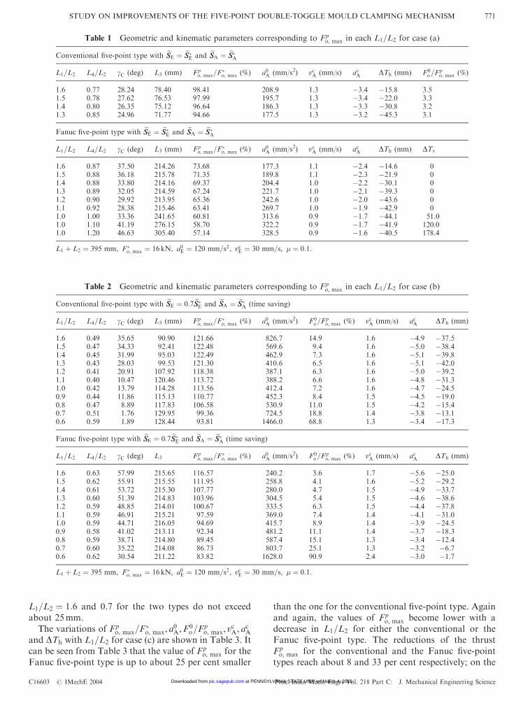
L1=L2 ¼ 1:6 and 0.7 for the two types do not exceedabout 25mm.
The variations of Fpo, max=F
�o, max, a
0A,F
0o=F
po, max, v
cA, a
cA
and DTh with L1=L2 for case (c) are shown in Table 3. Itcan be seen from Table 3 that the value of Fp
o, max for theFanuc five-point type is up to about 25 per cent smaller
than the one for the conventional five-point type. Againand again, the values of Fp
o, max become lower with adecrease in L1=L2 for either the conventional or theFanuc five-point type. The reductions of the thrustFpo, max for the conventional and the Fanuc five-point
types reach about 8 and 33 per cent respectively; on the
Table 2 Geometric and kinematic parameters corresponding to Fpo, max in each L1=L2 for case (b)
Conventional five-point type with eSSE ¼ 0:7eSS�E and eSSA ¼ eSS�
A (time saving)
L1=L2 L4=L2 gC (deg) L3 (mm) Fpo, max=F
�o, max (%) a0A (mm/s2) F0
o=Fpo, max (%) vcA (mm/s) acA DTh (mm)
1.6 0.49 35.65 90.90 121.66 826.7 14.9 1.6 �4.9 �37.51.5 0.47 34.33 92.41 122.48 569.6 9.4 1.6 �5.0 �38.41.4 0.45 31.99 95.03 122.49 462.9 7.3 1.6 �5.1 �39.81.3 0.43 28.03 99.53 121.30 410.6 6.5 1.6 �5.1 �42.01.2 0.41 20.91 107.92 118.38 387.1 6.3 1.6 �5.0 �39.21.1 0.40 10.47 120.46 113.72 388.2 6.6 1.6 �4.8 �31.31.0 0.42 13.79 114.28 113.56 412.4 7.2 1.6 �4.7 �24.50.9 0.44 11.86 115.13 110.77 452.3 8.4 1.5 �4.5 �19.00.8 0.47 8.89 117.83 106.58 530.9 11.0 1.5 �4.2 �15.40.7 0.51 1.76 129.95 99.36 724.5 18.8 1.4 �3.8 �13.10.6 0.59 1.89 128.44 93.81 1466.0 68.8 1.3 �3.4 �17.3
Fanuc five-point type with eSSE ¼ 0:7eSS�E and eSSA ¼ eSS�
A (time saving)
L1=L2 L4=L2 gC (deg) L3 Fpo, max=F
�o, max (%) a0A (mm/s2) F0
o=Fpo, max (%) vcA (mm/s) acA DTh (mm)
1.6 0.63 57.99 215.65 116.57 240.2 3.6 1.7 �5.6 �25.01.5 0.62 55.91 215.55 111.95 258.8 4.1 1.6 �5.2 �29.21.4 0.61 53.72 215.30 107.77 280.0 4.7 1.5 �4.9 �33.71.3 0.60 51.39 214.83 103.96 304.5 5.4 1.5 �4.6 �38.61.2 0.59 48.85 214.01 100.67 333.5 6.3 1.5 �4.4 �37.81.1 0.59 46.91 215.21 97.59 369.0 7.4 1.4 �4.1 �31.01.0 0.59 44.71 216.05 94.69 415.7 8.9 1.4 �3.9 �24.50.9 0.58 41.02 213.11 92.34 481.2 11.1 1.4 �3.7 �18.30.8 0.59 38.71 214.80 89.45 587.4 15.1 1.3 �3.4 �12.40.7 0.60 35.22 214.08 86.73 803.7 25.1 1.3 �3.2 �6.70.6 0.62 30.54 211.22 83.82 1628.0 90.9 2.4 �3.0 �1.7
L1 þ L2 ¼ 395 mm, F�o, max ¼ 16 kN, a0E ¼ 120 mm=s2, vcE ¼ 30 mm=s, � ¼ 0:1.
Table 1 Geometric and kinematic parameters corresponding to Fpo, max in each L1=L2 for case (a)
Conventional five-point type with eSSE ¼ eSS�E and eSSA ¼ eSS�
A
L1=L2 L4=L2 gC (deg) L3 (mm) Fpo, max=F
�o, max (%) a0A (mm/s2) vcA (mm/s) acA DTh (mm) F0
o=Fpo, max (%)
1.6 0.77 28.24 78.40 98.41 208.9 1.3 �3.4 �15.8 3.51.5 0.78 27.62 76.53 97.99 195.7 1.3 �3.4 �22.0 3.31.4 0.80 26.35 75.12 96.64 186.3 1.3 �3.3 �30.8 3.21.3 0.85 24.96 71.77 94.66 177.5 1.3 �3.2 �45.3 3.1
Fanuc five-point type with eSSE ¼ eSS�E and eSSA ¼ eSS�
A
L1=L2 L4=L2 gC (deg) L3 (mm) Fpo, max=F
�o, max (%) a0A (mm/s2) vcA (mm/s) acA DTh (mm) DTv
1.6 0.87 37.50 214.26 73.68 177.3 1.1 �2.4 �14.6 01.5 0.88 36.18 215.78 71.35 189.8 1.1 �2.3 �21.9 01.4 0.88 33.80 214.16 69.37 204.4 1.0 �2.2 �30.1 01.3 0.89 32.05 214.59 67.24 221.7 1.0 �2.1 �39.3 01.2 0.90 29.92 213.95 65.36 242.6 1.0 �2.0 �43.6 01.1 0.92 28.38 215.46 63.41 269.7 1.0 �1.9 �42.9 01.0 1.00 33.36 241.65 60.81 313.6 0.9 �1.7 �44.1 51.01.0 1.10 41.19 276.15 58.70 322.2 0.9 �1.7 �41.9 120.01.0 1.20 46.63 305.40 57.14 328.5 0.9 �1.6 �40.5 178.4
L1 þ L2 ¼ 395 mm, F�o, max ¼ 16 kN, a0E ¼ 120 mm=s2, vcE ¼ 30 mm=s, � ¼ 0:1.
STUDY ON IMPROVEMENTS OF THE FIVE-POINT DOUBLE-TOGGLE MOULD CLAMPING MECHANISM 771
C16603 # IMechE 2004 Proc. Instn Mech. Engrs Vol. 218 Part C: J. Mechanical Engineering Science at PENNSYLVANIA STATE UNIV on March 4, 2016pic.sagepub.comDownloaded from
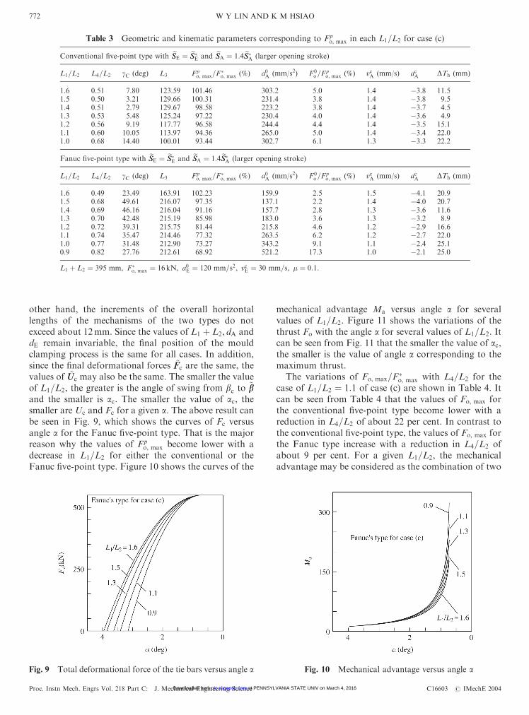
other hand, the increments of the overall horizontallengths of the mechanisms of the two types do notexceed about 12mm. Since the values of L1 þ L2, dA anddE remain invariable, the final position of the mouldclamping process is the same for all cases. In addition,since the final deformational forces ~FFc are the same, thevalues of ~UUc may also be the same. The smaller the valueof L1=L2, the greater is the angle of swing from bc to ~bband the smaller is ac. The smaller the value of ac, thesmaller are Uc and Fc for a given a. The above result canbe seen in Fig. 9, which shows the curves of Fc versusangle a for the Fanuc five-point type. That is the majorreason why the values of Fp
o, max become lower with adecrease in L1=L2 for either the conventional or theFanuc five-point type. Figure 10 shows the curves of the
mechanical advantage Ma versus angle a for severalvalues of L1=L2. Figure 11 shows the variations of thethrust Fo with the angle a for several values of L1=L2. Itcan be seen from Fig. 11 that the smaller the value of ac,the smaller is the value of angle a corresponding to themaximum thrust.
The variations of Fo, max=F�o, max with L4=L2 for the
case of L1=L2 ¼ 1:1 of case (c) are shown in Table 4. Itcan be seen from Table 4 that the values of Fo, max forthe conventional five-point type become lower with areduction in L4=L2 of about 22 per cent. In contrast tothe conventional five-point type, the values of Fo, max forthe Fanuc type increase with a reduction in L4=L2 ofabout 9 per cent. For a given L1=L2, the mechanicaladvantage may be considered as the combination of two
Table 3 Geometric and kinematic parameters corresponding to Fpo, max in each L1=L2 for case (c)
Conventional five-point type with eSSE ¼ eSS�E and eSSA ¼ 1:4eSS�
A (larger opening stroke)
L1=L2 L4=L2 gC (deg) L3 Fpo, max=F
�o, max (%) a0A (mm/s2) F0
o=Fpo, max (%) vcA (mm/s) acA DTh (mm)
1.6 0.51 7.80 123.59 101.46 303.2 5.0 1.4 �3.8 11.51.5 0.50 3.21 129.66 100.31 231.4 3.8 1.4 �3.8 9.51.4 0.51 2.79 129.67 98.58 223.2 3.8 1.4 �3.7 4.51.3 0.53 5.48 125.24 97.22 230.4 4.0 1.4 �3.6 4.91.2 0.56 9.19 117.77 96.58 244.4 4.4 1.4 �3.5 15.11.1 0.60 10.05 113.97 94.36 265.0 5.0 1.4 �3.4 22.01.0 0.68 14.40 100.01 93.44 302.7 6.1 1.3 �3.3 22.2
Fanuc five-point type with eSSE ¼ eSS�E and eSSA ¼ 1:4eSS�
A (larger opening stroke)
L1=L2 L4=L2 gC (deg) L3 Fpo, max=F
�o, max (%) a0A (mm/s2) F0
o=Fpo, max (%) vcA (mm/s) acA DTh (mm)
1.6 0.49 23.49 163.91 102.23 159.9 2.5 1.5 �4.1 20.91.5 0.68 49.61 216.07 97.35 137.1 2.2 1.4 �4.0 20.71.4 0.69 46.16 216.04 91.16 157.7 2.8 1.3 �3.6 11.61.3 0.70 42.48 215.19 85.98 183.0 3.6 1.3 �3.2 8.91.2 0.72 39.31 215.75 81.44 215.8 4.6 1.2 �2.9 16.61.1 0.74 35.47 214.46 77.32 263.5 6.2 1.2 �2.7 22.01.0 0.77 31.48 212.90 73.27 343.2 9.1 1.1 �2.4 25.10.9 0.82 27.76 212.61 68.92 521.2 17.3 1.0 �2.1 25.0
L1 þ L2 ¼ 395 mm, F�o, max ¼ 16 kN, a0E ¼ 120 mm=s2, vcE ¼ 30 mm=s, � ¼ 0:1.
Fig. 9 Total deformational force of the tie bars versus angle a Fig. 10 Mechanical advantage versus angle a
W Y LIN AND K M HSIAO772
Proc. Instn Mech. Engrs Vol. 218 Part C: J. Mechanical Engineering Science C16603 # IMechE 2004 at PENNSYLVANIA STATE UNIV on March 4, 2016pic.sagepub.comDownloaded from

major factors. One is k1=k2, the other is 1= cosðp� fÞ.The latter is dominant for both types of mechanisms.From all of the numerical results for a given L1=L2, thevalues of gC decrease for the two types with a reductionin L4=L2, and then the values of L3 increase for theconventional type and decrease for the Fanuc type.Since the final orientation of the crosshead link is thesame, the greater the value of L3, the smaller is the angleof swing from fc to
~ff and then the greater is the value of1= cosðp� fÞ. Thus, the values of Fo, max for theconventional five-point type is lower with a reductionin L4=L2. However, the values of Fo, max for the Fanucfive-point type increase with a reduction in L4=L2. Onlyone exception occurs in the case of the conventional and
Fanuc types with L1=L2 ¼ 1:6 in case (c) individually.However, the differences among the values of Fo, max inthe cases are very small, only up to about 0.1 and 2 percent respectively.
It can be seen from Tables 1 to 3 that the impactvelocity and acceleration are relatively small. Thus, thefive-point double-toggle mechanism inherently has thebuffer characteristic.
9 CONCLUSIONS
The elastostatic model using Coulomb friction for thefive-point double-toggle clamping mechanism is pre-sented in order to find the maximum thrust applied tothe crosshead during the real mould clamping operation.The effects of the hinge friction and the deformationaleffect of the toggle linkage should not be neglected forthe real mould clamping operation. If both factors areneglected, the maximum thrusts are underestimated byabout 45.5 and 60.5 per cent for friction coefficients of0.05 and 0.1 respectively, based on the present model.
The present study adopts lengthening the flange(projection) of the moving platen rather than the lengthof links 1 to provide enough horizontal space for theejector unit, if necessary. In such a case, the length of theflange of the tailstock platen can be decreased. Thevariations of the overall horizontal lengths of the togglemechanisms, whether for time saving or for a largeropening stroke as obtained in the present study, areacceptable.
Table 4 Geometric parameters and Fo, max versus L4=L2 in the case of L1=L2 ¼ 1:1 for case (c)
Two types of mechanisms with eSSE ¼ 1:0eSS�E,
eSSA ¼ 1:4eSS�A and L1=L2 ¼ 1:1
Conventional five-point type Fanuc five-point type
L4=L2 gC (deg) L3 Fo, max=F�o, max (%) L4=L2 gC (deg) L3 Fo, max=F
�o, max (%)
0.70 33.37 61.23 116.63 0.74 35.47 214.46 77.320.69 32.02 64.84 114.31 0.73 34.41 211.28 77.670.68 30.58 68.59 112.09 0.72 33.28 208.01 78.030.67 29.01 72.53 109.94 0.71 32.09 204.64 78.410.66 27.32 76.69 107.84 0.70 30.83 201.16 78.820.65 25.45 81.12 105.78 0.69 29.48 197.56 79.250.64 23.37 85.90 103.74 0.68 28.03 193.80 79.720.63 21.01 91.17 101.66 0.67 26.47 189.86 80.220.62 18.25 97.14 99.51 0.66 24.77 185.70 80.760.61 14.84 104.27 97.18 0.65 22.91 181.27 81.370.60 10.05 113.97 94.36 0.64 20.83 176.49 82.04
0.63 18.47 171.22 82.810.62 15.71 165.25 83.740.61 12.30 158.12 84.900.60 7.51 148.42 86.62
L1 þ L2 ¼ 395 mm, F�o, max ¼ 16 kN, � ¼ 0:1.
Fig. 11 Thrust applied to the crosshead versus angle a
STUDY ON IMPROVEMENTS OF THE FIVE-POINT DOUBLE-TOGGLE MOULD CLAMPING MECHANISM 773
C16603 # IMechE 2004 Proc. Instn Mech. Engrs Vol. 218 Part C: J. Mechanical Engineering Science at PENNSYLVANIA STATE UNIV on March 4, 2016pic.sagepub.comDownloaded from

The present design for the conventional five-pointtype resulting from the parameter study enables theinput stroke to be reduced by 30 per cent or the openingstroke to be increased by 40 per cent of the object ofimprovement, while decreasing the thrust by about1 and 7 per cent respectively. On the other hand, thepresent design for the conventional five-point typeenables the thrust of the object of improvement to bereduced by about 5 per cent, without changing the inputand opening strokes. Adoption of the Fanuc five-pointtype according to the parameter study enables the inputstroke to be reduced by 30 per cent or the opening stroketo be increased by 40 per cent of the object ofimprovement, while decreasing the thrust by about 13and 31 per cent respectively. On the other hand, theadoption of the Fanuc five-point type enables the thrustof the improved mechanism to be reduced by about 37per cent, without changing the input stroke and outputstrokes.
The Fanuc five-point type is much superior to theconventional five-point type in the thrust saving and/orlarger opening stroke. The present study brings theperformances of the Fanuc five-point type into full play.Note that the difference in the thrust between the twotypes minimizes to be 12 per cent in the time saving case.
The ratio of L1 to L2, whether for the conventional orfor the Fanuc five-point type, should be as small as
possible for thrust saving on condition that thegeometry can be satisfied and the transmission char-acteristic can be accepted. Furthermore, the ratio of L4
to L2 should be as small as possible for the conventionalfive-point type but as great as possible for the Fanucfive-point type on condition that the geometry can besatisfied and the interference can be prevented. Thepresent study can be directly applied to the five-pointdouble-toggle clamping mechanism of a die-castmachine.
REFERENCES
1 Smith, A. How to Choose a Plastics Injection Moulding
Machine, 1995 (AMI Business Publishing, Bristol).
2 Johannaber, F. Injection Molding Machines, 1994 (Hanser,
New York).
3 Ito, S. and Nishimura, K. Mold clamping mechanism of an
injection molding machine. US Pat. Doc. 5843496, 1998.
4 Norton, R. L. Design of Machinery, 1999 (McGraw-Hill,
New York).
5 Burton, P. Kinematics and Dynamics of Planar Machinery,
1979 (Prentice-Hall, Englewood Cliffs, New Jersey).
6 Wilson, C. E., Sadler, J. P. and Michels, W. J. Kinematics
and Dynamics of Machinery, 1983 (Harper and Row, New
York).
W Y LIN AND K M HSIAO774
Proc. Instn Mech. Engrs Vol. 218 Part C: J. Mechanical Engineering Science C16603 # IMechE 2004 at PENNSYLVANIA STATE UNIV on March 4, 2016pic.sagepub.comDownloaded from