Recent Improvements on the Thermal Infrared Hyperspectral ...
55
Recent Improvements on the Thermal Infrared Hyperspectral Images of the SIELETERS Airborne System O. Gazzano, Y. Ferrec, C. Coudrain and L. Rousset-Rouvière ( ONERA / DOTA )
-
Upload
khangminh22 -
Category
Documents
-
view
4 -
download
0
Transcript of Recent Improvements on the Thermal Infrared Hyperspectral ...
Recent Improvements on the
Thermal Infrared Hyperspectral Images of the
SIELETERS Airborne System
O. Gazzano, Y. Ferrec, C. Coudrain and L. Rousset-Rouvière
( ONERA / DOTA )
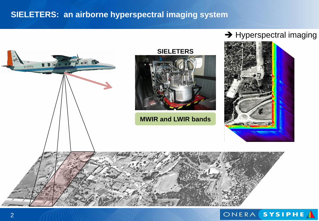
SIELETERS: an airborne hyperspectral imaging system
2
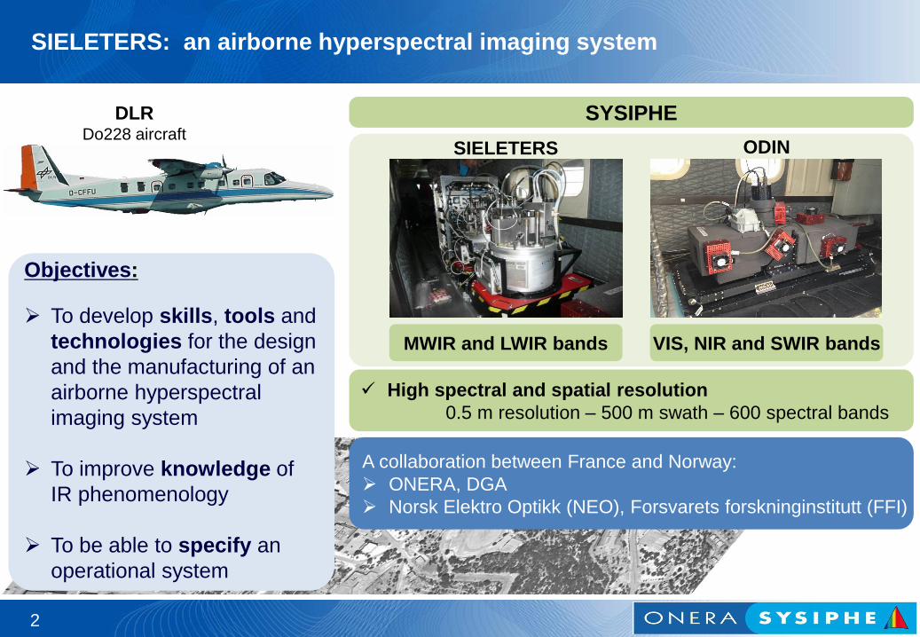
MWIR and LWIR bands
SIELETERS
Hyperspectral imaging
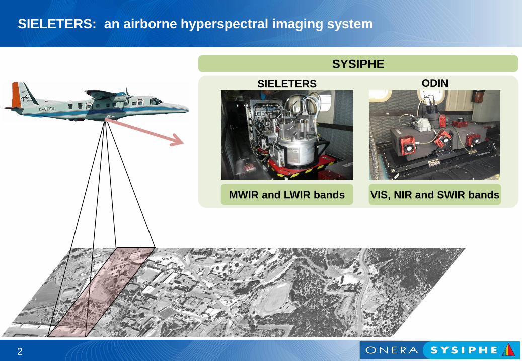
SIELETERS: an airborne hyperspectral imaging system
2
MWIR and LWIR bands
SIELETERS
VIS, NIR and SWIR bands
ODIN
SYSIPHE

A collaboration between France and Norway:
ONERA, DGA
Norsk Elektro Optikk (NEO), Forsvarets forskninginstitutt (FFI)
SIELETERS: an airborne hyperspectral imaging system
2
MWIR and LWIR bands
High spectral and spatial resolution
0.5 m resolution – 500 m swath – 600 spectral bands
SIELETERS ODIN
SYSIPHE
VIS, NIR and SWIR bands
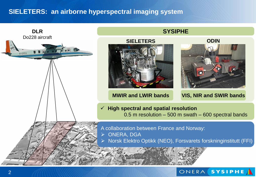
DLR Do228 aircraft
A collaboration between France and Norway:
ONERA, DGA
Norsk Elektro Optikk (NEO), Forsvarets forskninginstitutt (FFI)
SIELETERS: an airborne hyperspectral imaging system
2
MWIR and LWIR bands
High spectral and spatial resolution
0.5 m resolution – 500 m swath – 600 spectral bands
Objectives:
To develop skills, tools and
technologies for the design
and the manufacturing of an
airborne hyperspectral
imaging system
To improve knowledge of
IR phenomenology
To be able to specify an
operational system
SIELETERS ODIN
SYSIPHE
VIS, NIR and SWIR bands
DLR Do228 aircraft
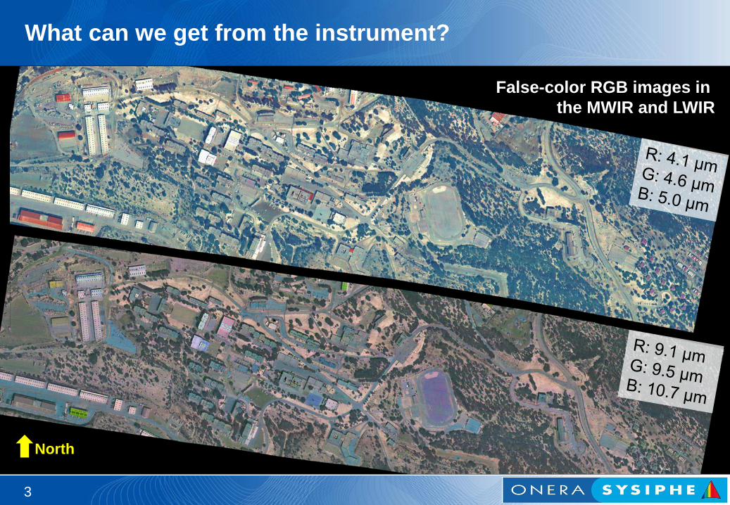
What can we get from the instrument?
3
False-color RGB images in
the MWIR and LWIR
North
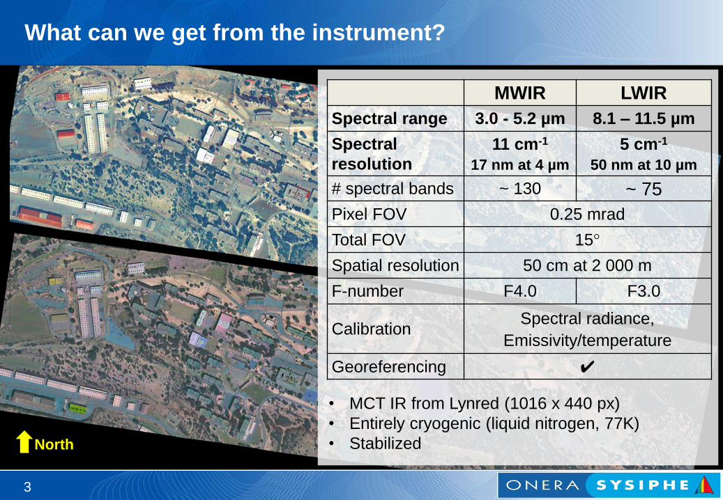
What can we get from the instrument?
3
aa MWIR LWIR
Spectral range 3.0 - 5.2 µm 8.1 – 11.5 µm
Spectral
resolution
11 cm-1
17 nm at 4 µm
5 cm-1
50 nm at 10 µm
# spectral bands ~ 130 ~ 75
Pixel FOV 0.25 mrad
Total FOV 15°
Spatial resolution 50 cm at 2 000 m
F-number F4.0 F3.0
Calibration Spectral radiance,
Emissivity/temperature
Georeferencing ✔
North
• MCT IR from Lynred (1016 x 440 px)
• Entirely cryogenic (liquid nitrogen, 77K)
• Stabilized
SIELETERS / SYSIPHE
airborne campaigns
4
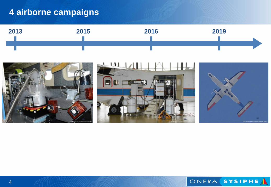
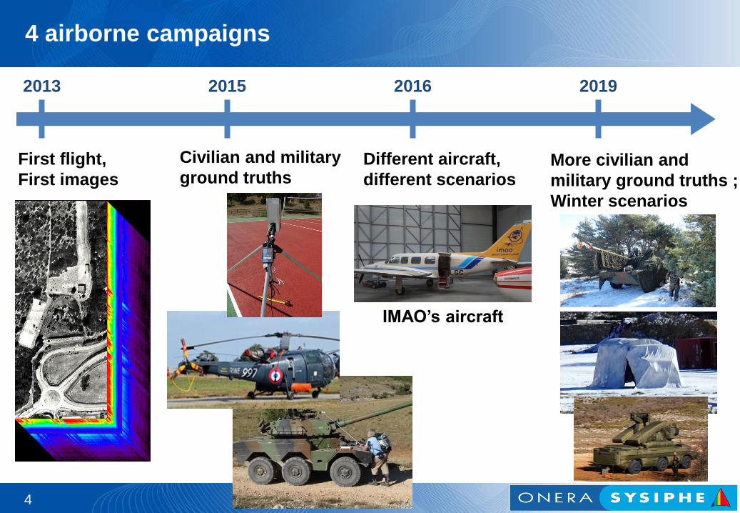
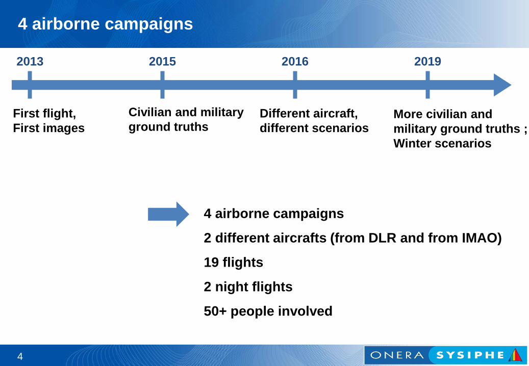
4 airborne campaigns
4
2013 2015 2016 2019
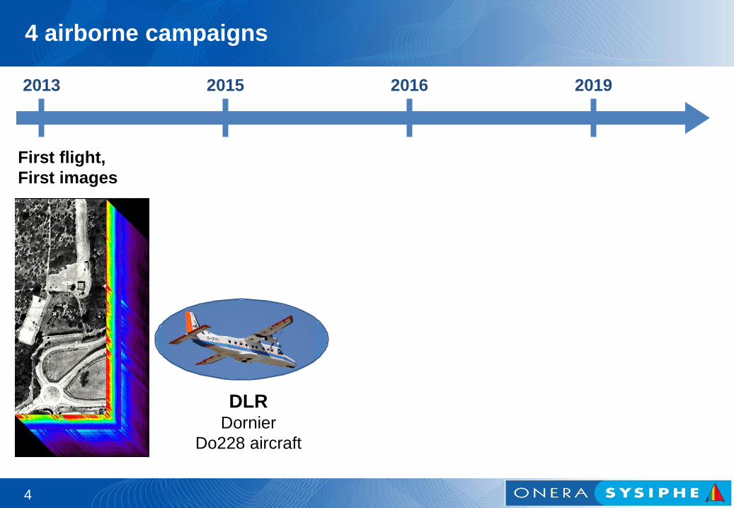
4 airborne campaigns
4
2013 2015 2016 2019
First flight,
First images
DLR Dornier
Do228 aircraft
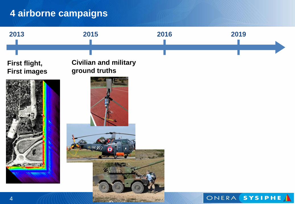
4 airborne campaigns
4
2013 2015 2016 2019
First flight,
First images
Civilian and military
ground truths
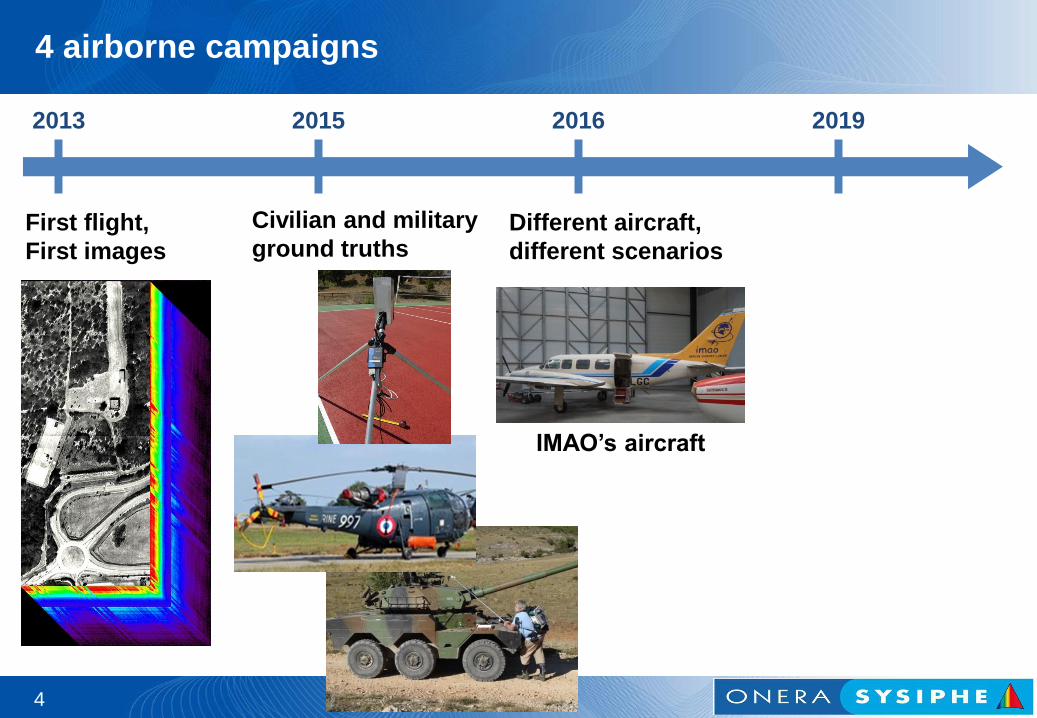
4 airborne campaigns
4
2013 2015 2016 2019
First flight,
First images
Civilian and military
ground truths Different aircraft,
different scenarios
IMAO’s aircraft
4 airborne campaigns
4
2013 2015 2016 2019
First flight,
First images
Civilian and military
ground truths Different aircraft,
different scenarios More civilian and
military ground truths ;
Winter scenarios
IMAO’s aircraft
4 airborne campaigns
4
2013 2015 2016 2019
First flight,
First images
Civilian and military
ground truths Different aircraft,
different scenarios More civilian and
military ground truths ;
Winter scenarios
4 airborne campaigns
2 different aircrafts (from DLR and from IMAO)
19 flights
2 night flights
50+ people involved
How does the system work?
5

SIELETERS instrument: an imaging static Fourier transform spectrometer
5
22
0 m
Static Michelson
interferometer
500 m ; Ground sampling: 0.50 m

SIELETERS instrument: an imaging static Fourier transform spectrometer
5
22
0 m
Static Michelson
interferometer
500 m ; Ground sampling: 0.50 m
Interference
fringes
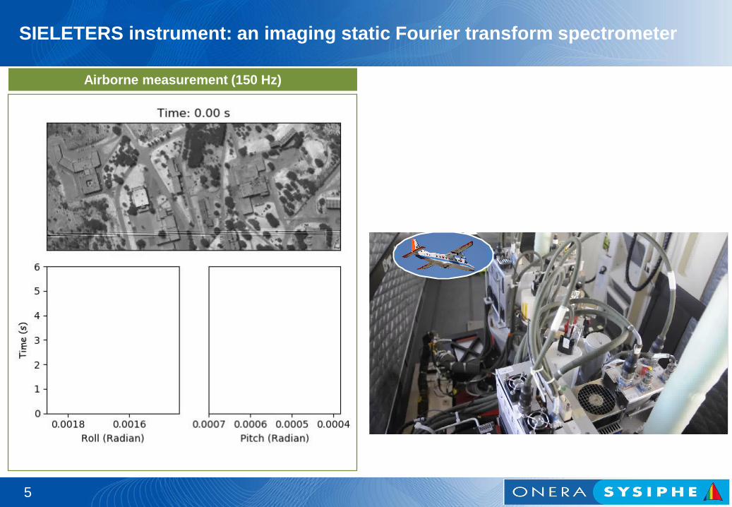
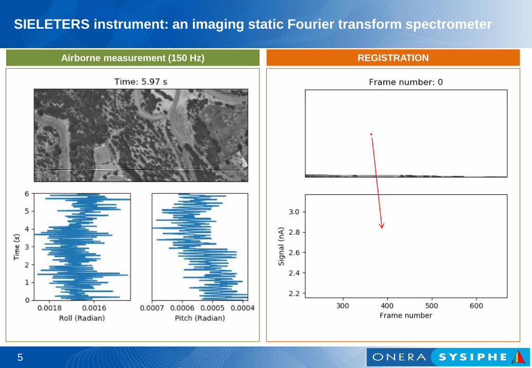
SIELETERS instrument: an imaging static Fourier transform spectrometer
Airborne measurement (150 Hz)
5
SIELETERS instrument: an imaging static Fourier transform spectrometer
Airborne measurement (150 Hz) REGISTRATION
5
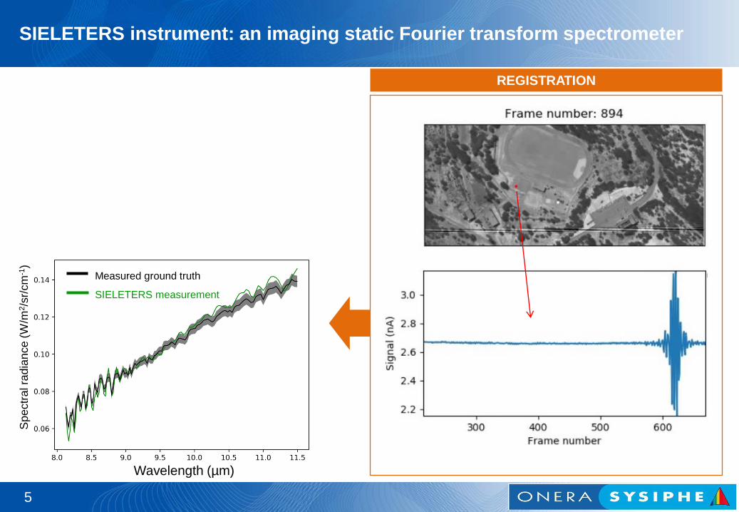
SIELETERS instrument: an imaging static Fourier transform spectrometer
REGISTRATION
Wavelength (µm)
Measured ground truth
SIELETERS measurement
Sp
ectr
al ra
dia
nce (
W/m
2/s
r/cm
-1)
5

SIELETERS instrument: an imaging static Fourier transform spectrometer
REGISTRATION
Wavelength (µm)
Measured ground truth
SIELETERS measurement
Sp
ectr
al ra
dia
nce (
W/m
2/s
r/cm
-1)
Example : False-color RGB image
R = 9.12 µm, G = 9.52 µm, B = 10.75 µm)
5
6
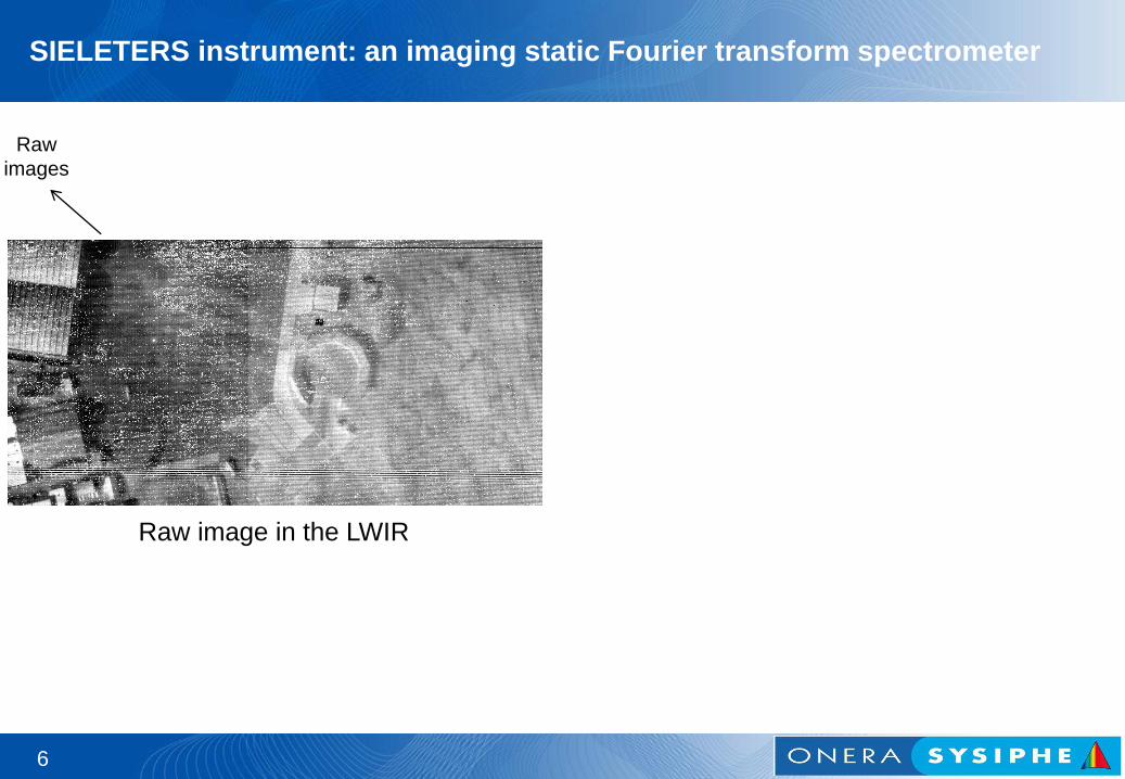
SIELETERS instrument: an imaging static Fourier transform spectrometer
Raw image in the LWIR
Raw
images
6
Raw
images
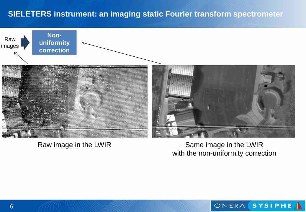
Non-
uniformity
correction
SIELETERS instrument: an imaging static Fourier transform spectrometer
Raw image in the LWIR Same image in the LWIR
with the non-uniformity correction
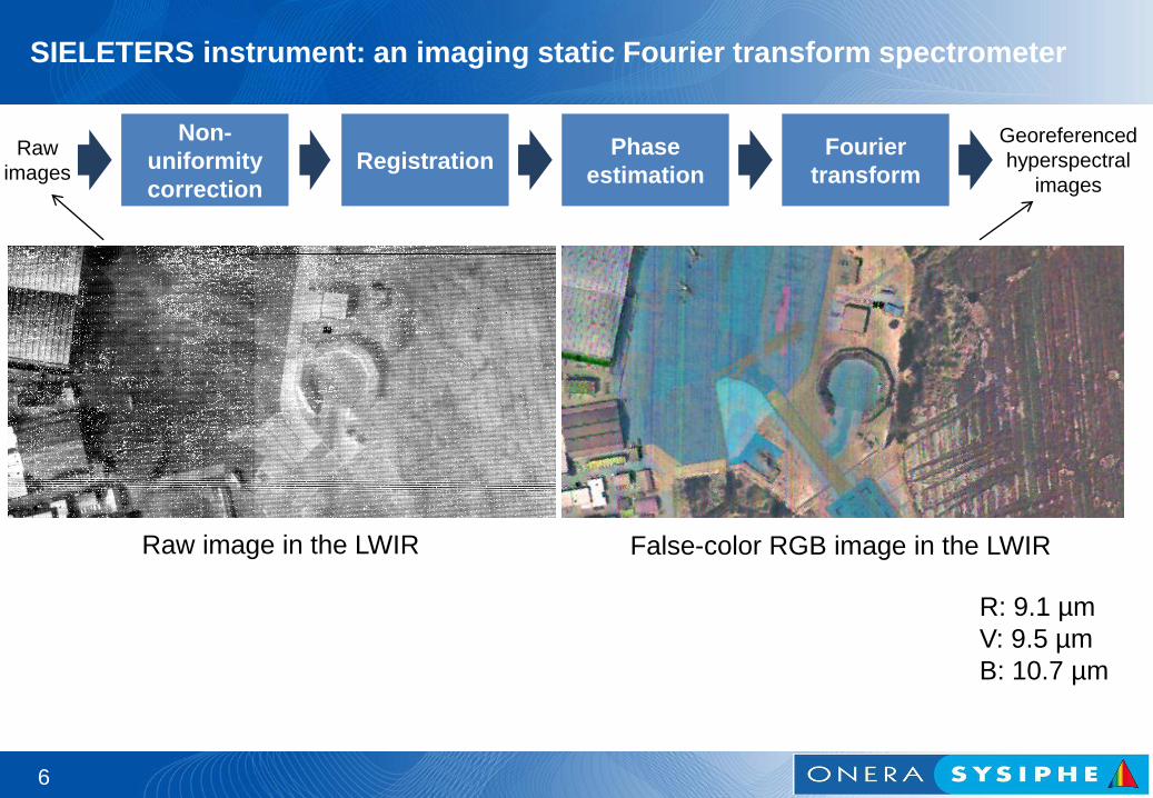
6
Raw
images
Georeferenced
hyperspectral
images
Non-
uniformity
correction
Registration Fourier
transform
Phase
estimation
Raw image in the LWIR False-color RGB image in the LWIR
R: 9.1 µm
V: 9.5 µm
B: 10.7 µm
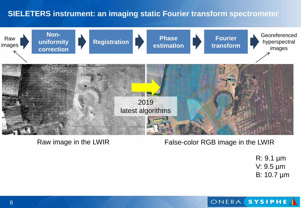
SIELETERS instrument: an imaging static Fourier transform spectrometer
6
Raw
images
Georeferenced
hyperspectral
images
Non-
uniformity
correction
Registration Fourier
transform
Phase
estimation
Raw image in the LWIR False-color RGB image in the LWIR
R: 9.1 µm
V: 9.5 µm
B: 10.7 µm
2019
latest algorithms
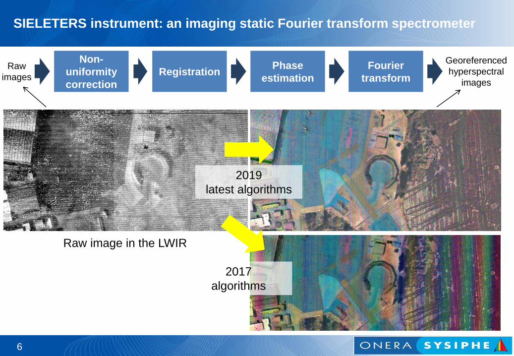
SIELETERS instrument: an imaging static Fourier transform spectrometer
6
Raw
images
Georeferenced
hyperspectral
images
Non-
uniformity
correction
Registration Fourier
transform
Phase
estimation
Raw image in the LWIR
2019
latest algorithms
2017
algorithms
SIELETERS instrument: an imaging static Fourier transform spectrometer

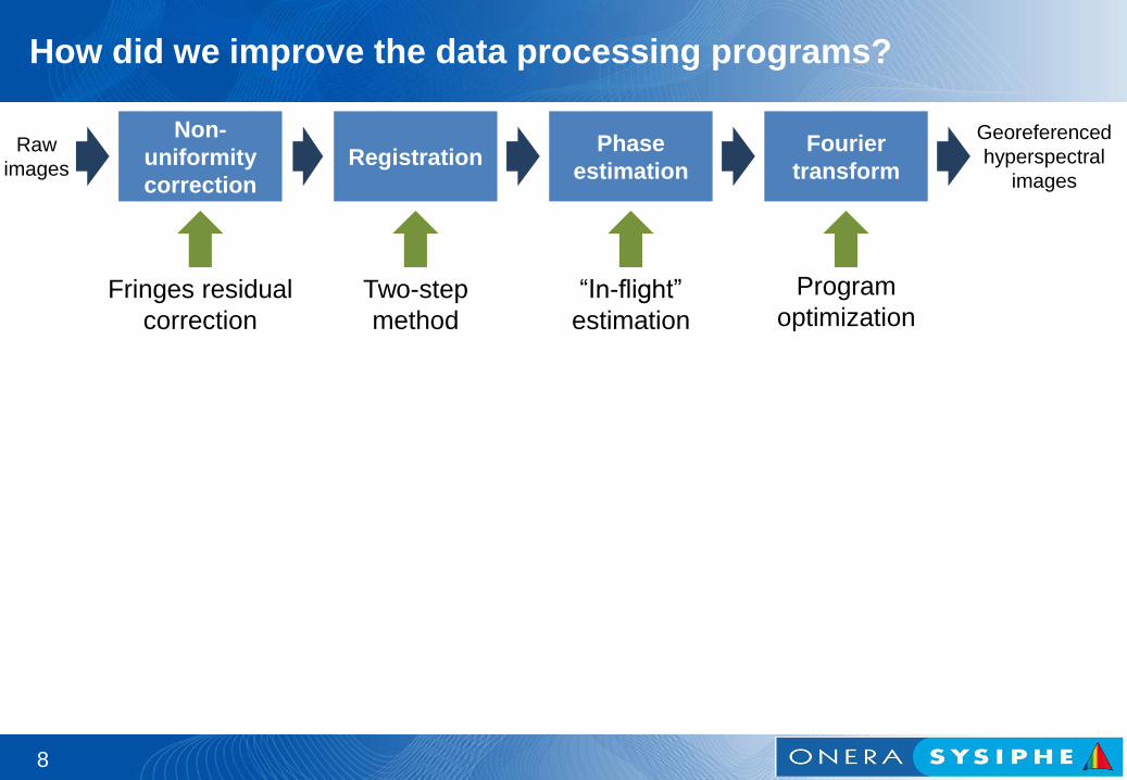
How did we improve the data
processing programs?
7
7
Raw
images
Georeferenced
hyperspectral
images
Non-
uniformity
correction
Registration Fourier
transform
Phase
estimation
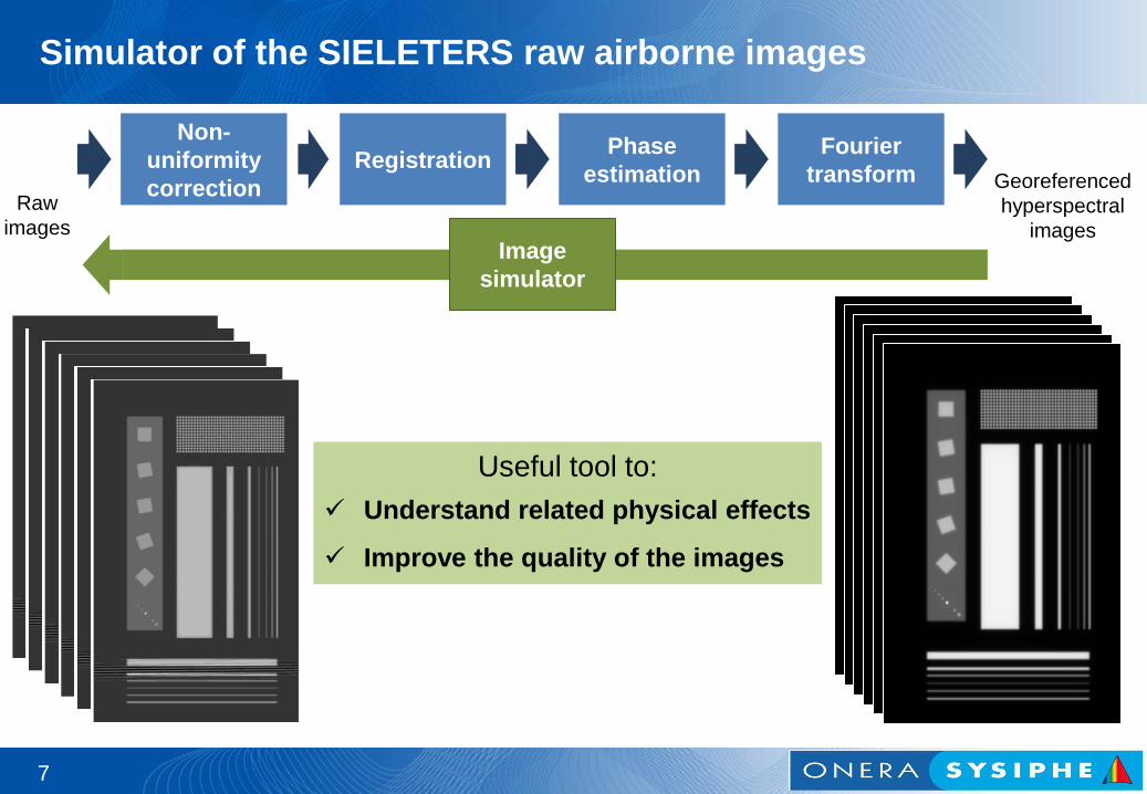
Simulator of the SIELETERS raw airborne images
Image
simulator
Useful tool to:
Understand related physical effects
Improve the quality of the images
8
How did we improve the data processing programs?
Raw
images
Georeferenced
hyperspectral
images
Non-
uniformity
correction
Registration Fourier
transform
Phase
estimation
Fringes residual
correction
Two-step
method
“In-flight”
estimation
Program
optimization
9
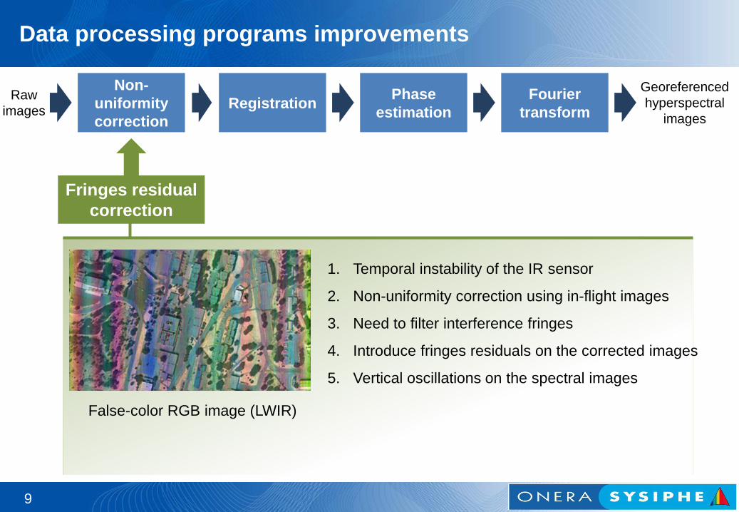
Data processing programs improvements
Raw
images
Georeferenced
hyperspectral
images
Non-
uniformity
correction
Registration Fourier
transform
Phase
estimation
False-color RGB image (LWIR)
Fringes residual
correction
1. Temporal instability of the IR sensor
2. Non-uniformity correction using in-flight images
3. Need to filter interference fringes
4. Introduce fringes residuals on the corrected images
5. Vertical oscillations on the spectral images
9
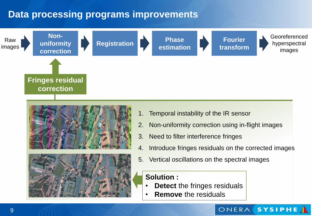
Data processing programs improvements
Raw
images
Georeferenced
hyperspectral
images
Non-
uniformity
correction
Registration Fourier
transform
Phase
estimation
1. Temporal instability of the IR sensor
2. Non-uniformity correction using in-flight images
3. Need to filter interference fringes
4. Introduce fringes residuals on the corrected images
5. Vertical oscillations on the spectral images
Fringes residual
correction
False-color RGB image (LWIR) Solution :
• Detect the fringes residuals
• Remove the residuals
10
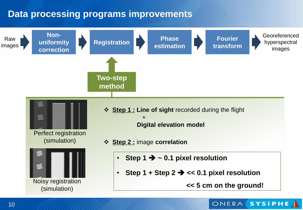
Data processing programs improvements
Raw
images
Georeferenced
hyperspectral
images
Non-
uniformity
correction
Registration Fourier
transform
Phase
estimation
Two-step
method
Perfect registration
(simulation)
Noisy registration
(simulation)
Step 1 : Line of sight recorded during the flight
+
Digital elevation model
Step 2 : image correlation
• Step 1 ~ 0.1 pixel resolution
• Step 1 + Step 2 << 0.1 pixel resolution
<< 5 cm on the ground!
11
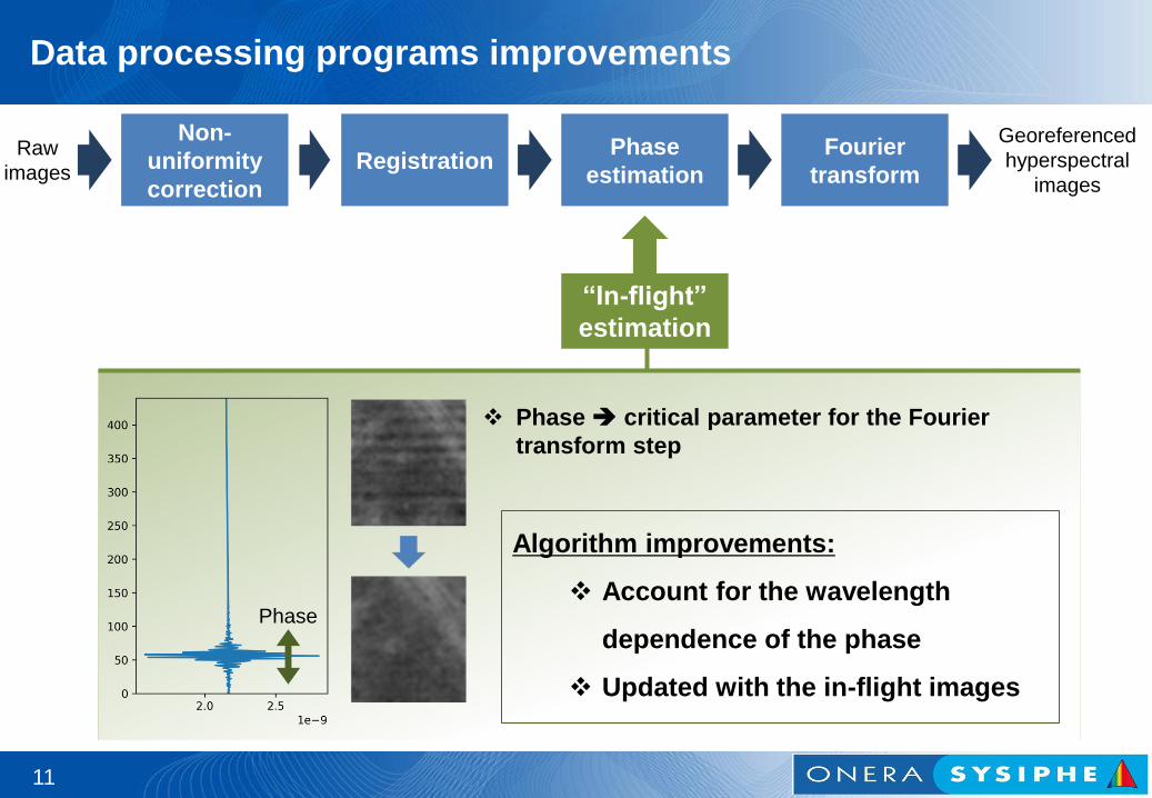
Data processing programs improvements
Raw
images
Georeferenced
hyperspectral
images
Non-
uniformity
correction
Registration Fourier
transform
Phase
estimation
Phase critical parameter for the Fourier
transform step
Algorithm improvements:
Account for the wavelength
dependence of the phase
Updated with the in-flight images
“In-flight”
estimation
Phase
12
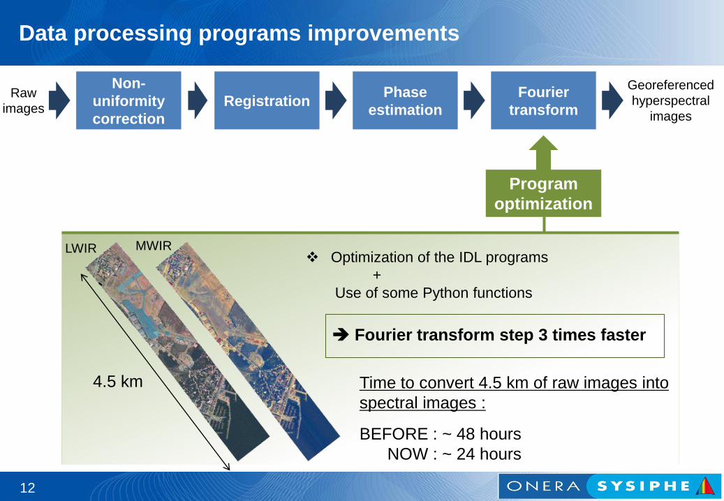
Data processing programs improvements
Raw
images
Georeferenced
hyperspectral
images
Non-
uniformity
correction
Registration Fourier
transform
Phase
estimation
Program
optimization
4.5 km
LWIR MWIR Optimization of the IDL programs
+
Use of some Python functions
Fourier transform step 3 times faster
Time to convert 4.5 km of raw images into
spectral images :
BEFORE : ~ 48 hours
NOW : ~ 24 hours
Some results
13
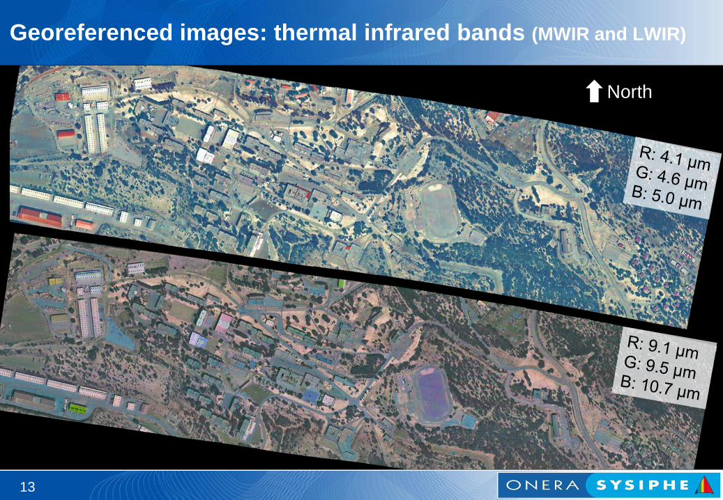
Georeferenced images: thermal infrared bands (MWIR and LWIR)
13
North
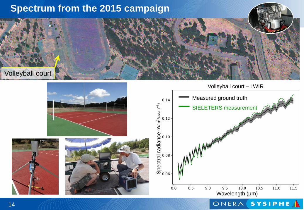
Spectrum from the 2015 campaign
14
Wavelength (µm)
Measured ground truth
SIELETERS measurement
Sp
ectr
al ra
dia
nce
Volleyball court – LWIR
Volleyball court
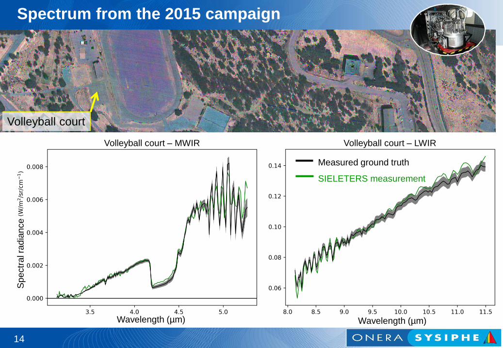
Spectrum from the 2015 campaign
14
Wavelength (µm)
Sp
ectr
al ra
dia
nce
Measured ground truth
SIELETERS measurement
Wavelength (µm)
Volleyball court – MWIR Volleyball court – LWIR
Volleyball court
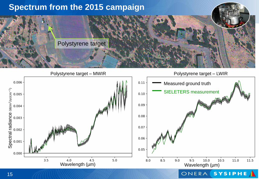
Spectrum from the 2015 campaign
15
Wavelength (µm)
Sp
ectr
al ra
dia
nce
Measured ground truth
SIELETERS measurement
Wavelength (µm)
Polystyrene target – MWIR Polystyrene target – LWIR
Polystyrene target
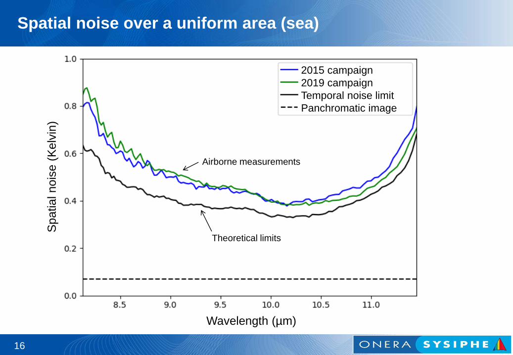
Spatial noise over a uniform area (sea)
16
Wavelength (µm)
Spatial nois
e (
Kelv
in)
2015 campaign
2019 campaign
Temporal noise limit
Panchromatic image
Airborne measurements
Theoretical limits
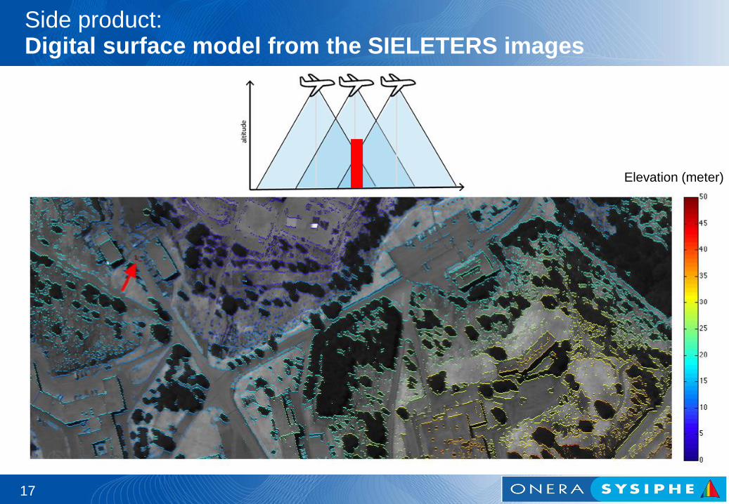
Side product: Digital surface model from the SIELETERS images
17
Elevation (meter)
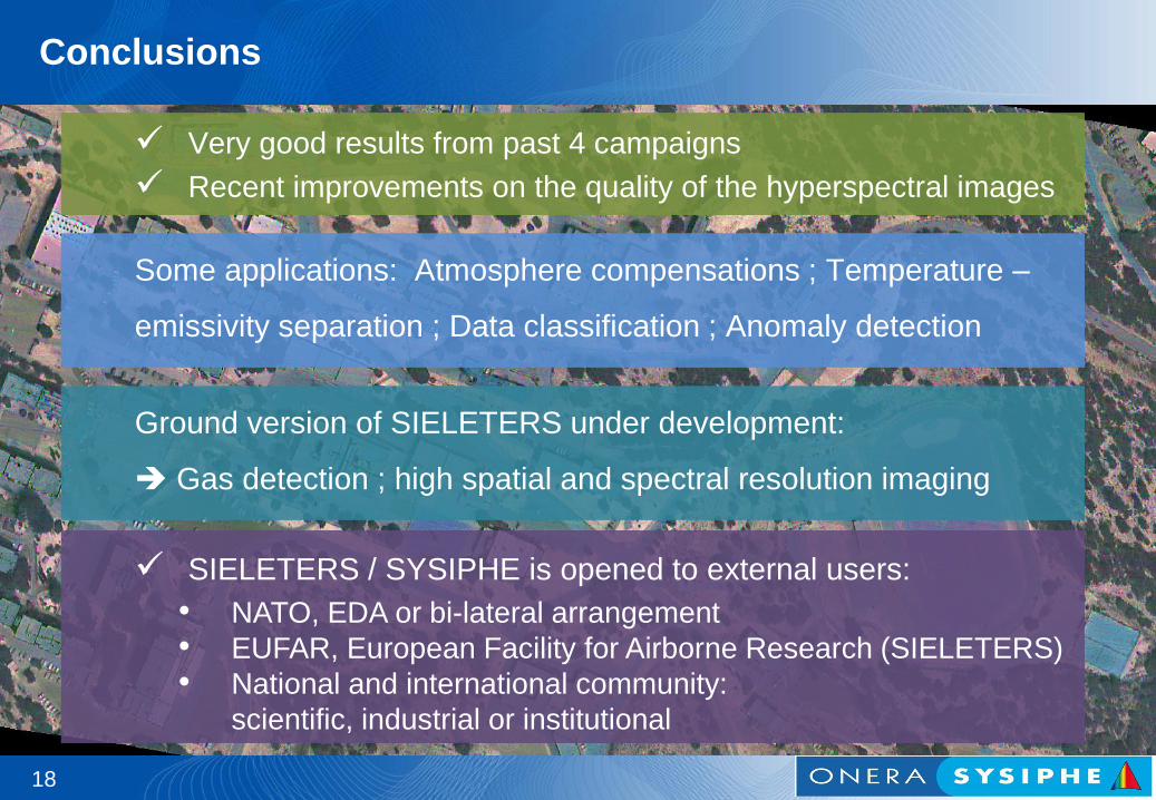
Conclusions
Very good results from past 4 campaigns
Recent improvements on the quality of the hyperspectral images
Some applications: Atmosphere compensations ; Temperature –
emissivity separation ; Data classification ; Anomaly detection
SIELETERS / SYSIPHE is opened to external users:
• NATO, EDA or bi-lateral arrangement
• EUFAR, European Facility for Airborne Research (SIELETERS)
• National and international community:
scientific, industrial or institutional
18
Ground version of SIELETERS under development:
Gas detection ; high spatial and spectral resolution imaging
Thank you for your attention
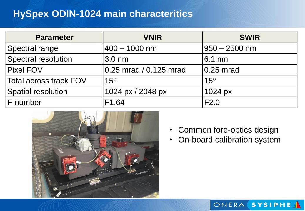
HySpex ODIN-1024 main characteritics
Parameter VNIR SWIR
Spectral range 400 – 1000 nm 950 – 2500 nm
Spectral resolution 3.0 nm 6.1 nm
Pixel FOV 0.25 mrad / 0.125 mrad 0.25 mrad
Total across track FOV 15° 15°
Spatial resolution 1024 px / 2048 px 1024 px
F-number F1.64 F2.0
• Common fore-optics design
• On-board calibration system
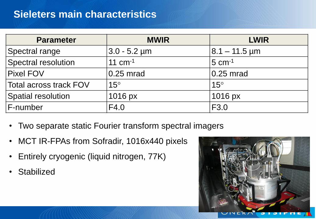
Sieleters main characteristics
Parameter MWIR LWIR
Spectral range 3.0 - 5.2 µm 8.1 – 11.5 µm
Spectral resolution 11 cm-1 5 cm-1
Pixel FOV 0.25 mrad 0.25 mrad
Total across track FOV 15° 15°
Spatial resolution 1016 px 1016 px
F-number F4.0 F3.0
• Two separate static Fourier transform spectral imagers
• MCT IR-FPAs from Sofradir, 1016x440 pixels
• Entirely cryogenic (liquid nitrogen, 77K)
• Stabilized
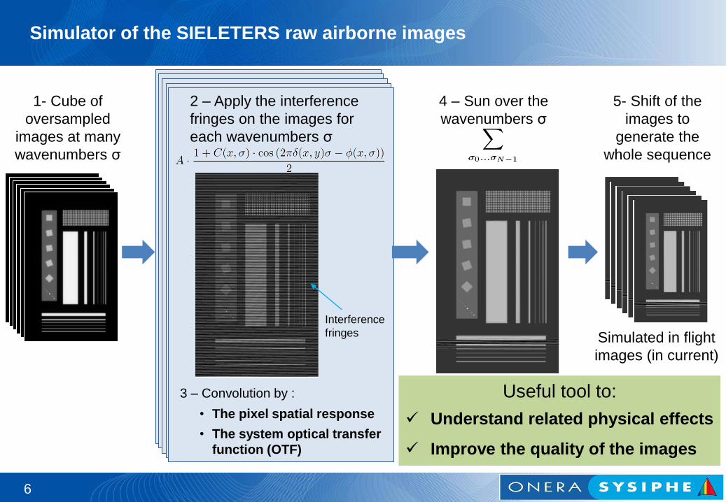
Simulator of the SIELETERS raw airborne images
6
1- Cube of
oversampled
images at many
wavenumbers σ
• The pixel spatial response
• The system optical transfer
function (OTF)
3 – Convolution by :
2 – Apply the interference
fringes on the images for
each wavenumbers σ
Simulated in flight
images (in current)
5- Shift of the
images to
generate the
whole sequence
4 – Sun over the
wavenumbers σ
Interference
fringes
Useful tool to:
Understand related physical effects
Improve the quality of the images
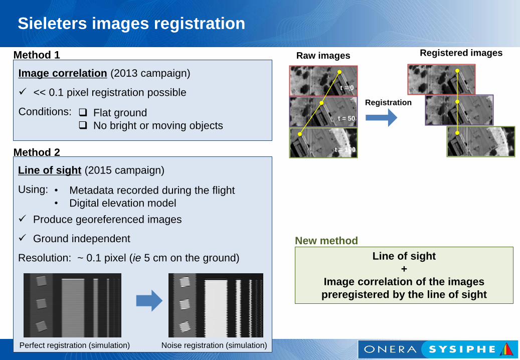
Registered images
t = 0
t = 50
t = 100
Registration
Image correlation (2013 campaign)
<< 0.1 pixel registration possible
Conditions:
Method 1
Line of sight (2015 campaign)
Using:
Produce georeferenced images
Ground independent
Resolution: ~ 0.1 pixel (ie 5 cm on the ground)
Method 2
Perfect registration (simulation) Noise registration (simulation)
Raw images
Flat ground
No bright or moving objects
• Metadata recorded during the flight
• Digital elevation model
Line of sight
+
Image correlation of the images
preregistered by the line of sight
New method
Sieleters images registration
8
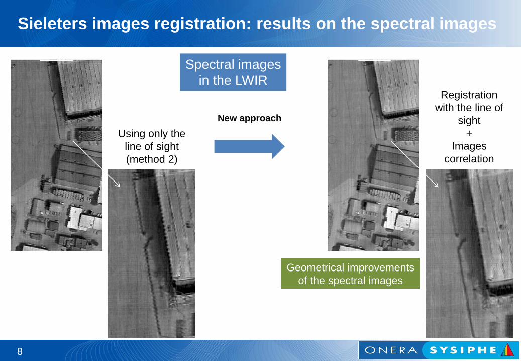
New approach
Geometrical improvements
of the spectral images
Spectral images
in the LWIR
Using only the
line of sight
(method 2)
Registration
with the line of
sight
+
Images
correlation
Sieleters images registration: results on the spectral images
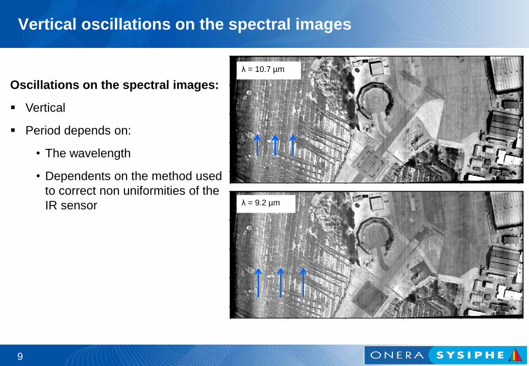
Vertical oscillations on the spectral images
9
Oscillations on the spectral images:
Vertical
Period depends on:
• The wavelength
• Dependents on the method used
to correct non uniformities of the
IR sensor
λ = 10.7 µm
λ = 9.2 µm
10
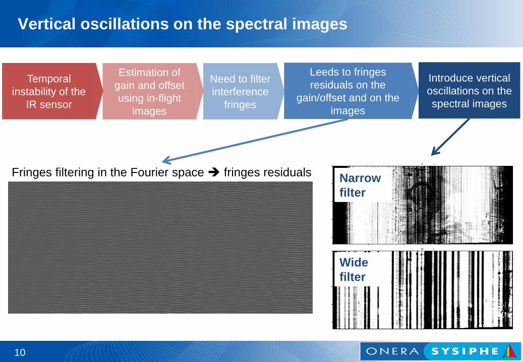
Wide
filter
Narrow
filter
Temporal
instability of the
IR sensor
Estimation of
gain and offset
using in-flight
images
Need to filter
interference
fringes
Leeds to fringes
residuals on the
gain/offset and on the
images
Fringes filtering in the Fourier space fringes residuals
Introduce vertical
oscillations on the
spectral images
Vertical oscillations on the spectral images
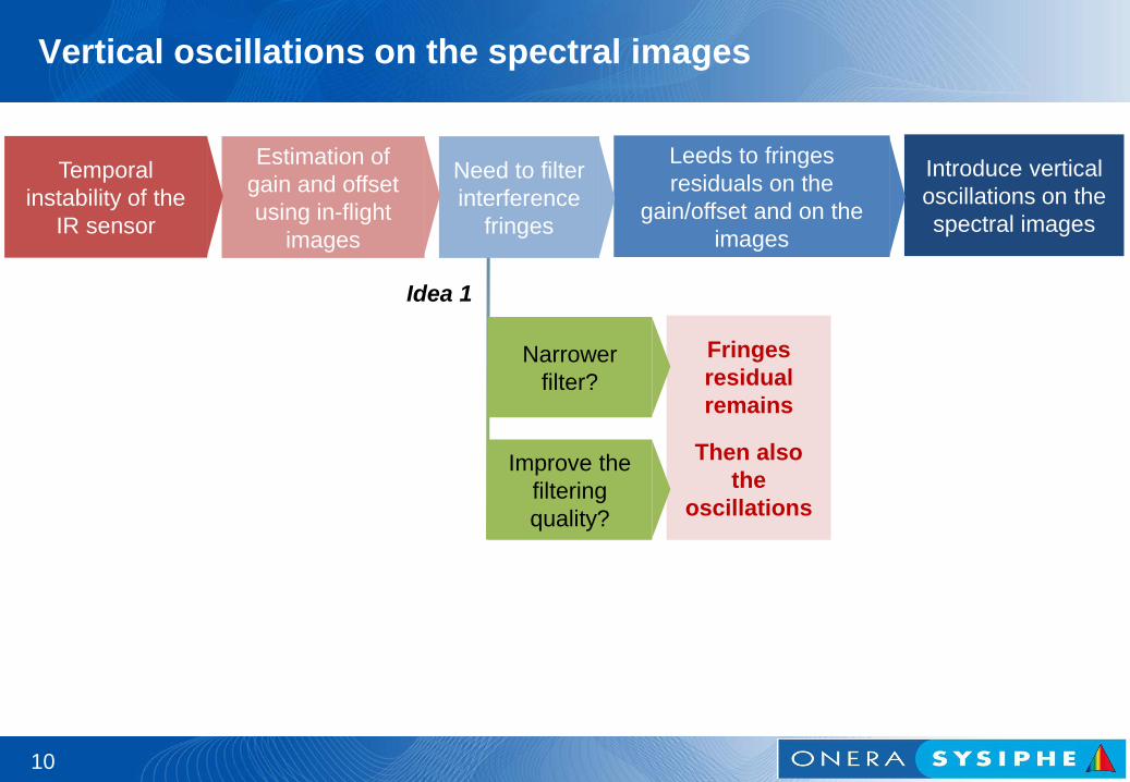
Fringes
residual
remains
Then also
the
oscillations
10
Improve the
filtering
quality?
Narrower
filter?
Idea 1
Temporal
instability of the
IR sensor
Estimation of
gain and offset
using in-flight
images
Need to filter
interference
fringes
Leeds to fringes
residuals on the
gain/offset and on the
images
Introduce vertical
oscillations on the
spectral images
Vertical oscillations on the spectral images

Remove the
residuals
10
Detect the
fringes
residuals
Idea 2
Temporal
instability of the
IR sensor
Estimation of
gain and offset
using in-flight
images
Need to filter
interference
fringes
Leeds to fringes
residuals on the
gain/offset and on the
images
Introduce vertical
oscillations on the
spectral images
Vertical oscillations on the spectral images
✓
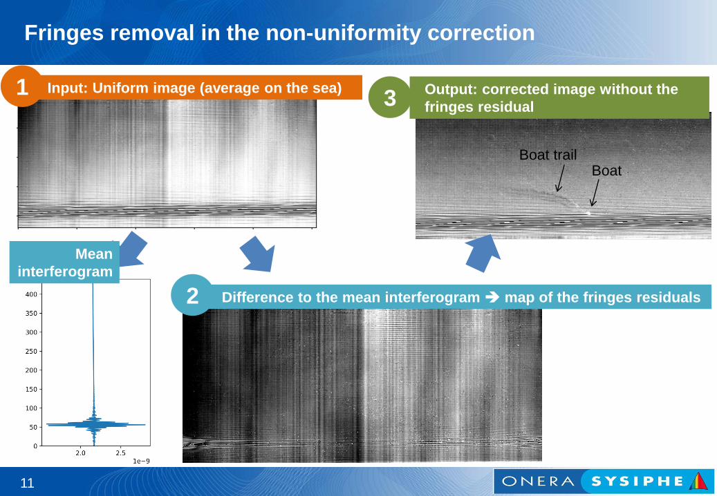
Fringes removal in the non-uniformity correction
11
Mean
interferogram
Boat Boat trail
Input: Uniform image (average on the sea) 1
Difference to the mean interferogram map of the fringes residuals 2
Output: corrected image without the
fringes residual 3
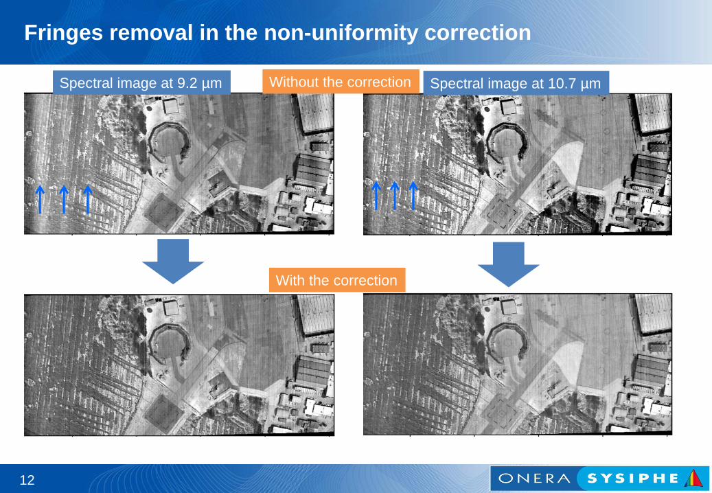
Fringes removal in the non-uniformity correction
12
Spectral image at 9.2 µm Spectral image at 10.7 µm
With the correction
Without the correction