
HMI Application Improvements and Documentation Tools
52
HMI Application Improvements and Documentation Tools Nico Hanhimäki Degree thesis for Bachelor of Engineering Degree Program in Electrical and Automation Engineering Vaasa 2022
-
Upload
khangminh22 -
Category
Documents
-
view
1 -
download
0
Transcript of HMI Application Improvements and Documentation Tools

HMI Application Improvements and Documentation Tools
Nico Hanhimäki
Degree thesis for Bachelor of Engineering
Degree Program in Electrical and Automation Engineering
Vaasa 2022

DEGREE THESIS
Author: Nico Hanhimäki
Degree Programme and place of study: Electrical Engineering and Automation, Vaasa
Specialisation: Automation
Supervisors: Joachim Böling
Kaj Hagström
Title: HMI Application Improvements and Documentation Tools
_______________________________________________________________________________
Date: 28.4.2022 Number of pages: 43 Appendices: _______________________________________________________________________________
Abstract The objective of this Bachelor’s thesis was to make improvements to a Wonderware InTouch based
HMI application, that has been modified by Company X to fit Company Y’s powerplant and marine
installation projects. The reason behind the improvements was to make the application
modification for project-specific installations more flexible. Alongside the improvements, some
tools were created to simplify documentation of the HMI application windows required for each
project.
First, to be able to modify and test the application improvements, a system environment consisting
of a Thin Client workstation, a firewall and a server running the required virtual machines with
VMware ESXi as hypervisor was configured. A database containing the tags required for the
improvements was created for the Wonderware InTouch application. For the documentation of the
HMI windows, two separate tools were made. The first one was applied to the InTouch application
and the second one was VBA coded in Excel.
The practical part of this thesis describes how the HMI application improvements and the
documentation tools were executed in detail. The primary hardware and software and theory
related to the tasks are covered in this thesis. The thesis also provides the reader with information
about working with tags, scripting, and how to export and import databases in Wonderware
InTouch.
The results of this thesis are an enhanced and well-tested HMI application, that can be installed for
future projects, and fully working documentation tools.
_______________________________________________________________________________
Language: English Key Words: HMI, Wonderware InTouch, Database

EXAMENSARBETE
Författare: Nico Hanhimäki
Utbildning och ort: El- och automationsteknik, Vasa
Inriktning: Automation
Handledare: Joachim Böling
Kaj Hagström
Titel: HMI-applikationsförbättringar samt dokumentationsverktyg
_________________________________________________________________________
Datum: 28.4.2022 Sidantal: 43 Bilagor: _________________________________________________________________________
Abstrakt
Examensarbetets mål är att göra förbättringar i en Wonderware InTouch-baserad HMI-applikation,
som Företaget X har modifierat för att passa Företaget Y:s kraftverk- och marininstallationsprojekt.
Syftet med förbättringarna var att göra applikationsmodifieringen mera flexibel för projektspecifika
installationer. Verktyg skapades vid sidan om förbättringarna för att underlätta dokumentationen
av HMI-applikationsfönstren, som krävs för varje projekt.
Först för att kunna möjliggöra modifiering och testning av applikationsförändringarna
konfigurerades en systemmiljö, som bestod av en Thin Client-arbetsstation, en brandvägg och en
server med hypervisor VMware ESXi. På servern installerade man de nödvändiga virtuella
maskinerna. En databas, som innehöll tags som behövdes för förbättringarna, skapades åt
Wonderware InTouch-applikationen. För dokumenteringen av HMI-applikationsfönstren, skapades
två verktyg, varav den första implementerades i InTouch-applikationen och den andra kodades med
VBA i Excel.
I den praktiska delen av examensarbetet gås igenom hur applikationsförbättringarna samt
dokumentationsverktygen förverkligades i detalj. De hårdvaror och mjukvaror som användes under
arbetet, samt uppgiftsrelaterad teori behandlas i detta examensarbete. Information om tags, hur
skript fungerar och hur man exporterar och importerar en databas med InTouch-applikationen
presenteras.
Examensarbetets resultat blev ett förbättrad och vältestad HMI-applikation som kan installeras till
framtida projekt. Helt fungerande dokumentationsverktyg åstadkoms.
_________________________________________________________________________
Språk: engelska Nyckelord: HMI, Wonderware InTouch, databas

OPINNÄYTETYÖ Tekijä: Nico Hanhimäki
Koulutus ja paikkakunta: Sähkö- ja automaatiotekniikka, Vaasa
Suuntautumisvaihtoehto: Automaatiotekniikka
Ohjaajat: Joachim Böling
Kaj Hagström
Nimike: HMI-applikaation parannus ja dokumentointityökalut
_________________________________________________________________________
Päivämäärä: 28.4.2022 Sivumäärä: 43 Liitteet: _________________________________________________________________________
Tiivistelmä
Opinnäytetyön tavoitteena oli tehdä parannuksia Wonderware InTouch -pohjaiseen HMI-
applikaatioon, jota Yritys X on muokannut soveltumaan Yritys Y:n voimalaitos- ja laiva-
asennusprojekteihin. Syy parannuksiin oli tehdä applikaation muokkaaminen joustavammaksi
projektikohtaisia asennuksia varten. Parannuksien ohella luotiin työkaluja, joilla helpotetaan
jokaiseen projektiin vaadittavaa HMI-applikaatioikkunoiden dokumentointia.
Ensin konfiguroitiin järjestelmäympäristö, joka koostuu Thin Client -työasemasta, palomuurista ja
palvelimesta. Palvelimelle asennettiin tarvittavat virtuaalikoneet, joita isännöi VMware ESXi.
Järjestelmäympäristön käyttö mahdollisti applikaatioparannusten muokkaamisen ja testaamisen.
Wonderware InTouch applikaatiolle luotiin tietokanta, joka sisälsi tarvittavat tagit parannuksia
varten. HMI-applikaatioikkunoiden dokumentaatiota varten luotiin kaksi erillistä työkalua. Toinen
luotiin InTouch-applikaatiolle ja toinen koodattiin käyttäen VBA:ta Excelissä.
Opinnäytetyön käytännöllisessä osiossa käydään yksityiskohtaisesti läpi, kuinka HMI-
applikaatioparannukset ja dokumentointityökalut toteutettiin. Työssä käytetyt laitteet ja ohjelmat
sekä ajankohtaista teoriaa liittyen tehtäviin käsitellään tässä opinnäytetyössä. Lisäksi opinnäytetyö
tarjoaa lukijalle tietoa tageista ja skripteistä sekä tietokannan tuonnista ja viennistä InTouch-
applikaatiolla.
Opinnäytetyön tulos on kehitetty ja hyvin testattu HMI-applikaatio, joka on valmis käyttöönottoon
tuleviin projekteihin, sekä täysin toimivat dokumentointityökalut.
_________________________________________________________________________
Kieli: englanti Avainsanat: HMI, Wonderware InTouch, tietokanta

Table of Contents 1 Introduction ............................................................................................................................... 1
1.1 Background and Purpose ................................................................................................... 1
1.2 Requested Improvements and Documentation Tools ....................................................... 1
1.2.1 Modification of Application Menu System................................................................. 1
1.2.2 Development License Detection ................................................................................ 2
1.2.3 Dual Printer Setup ...................................................................................................... 2
1.2.4 Documentation Tools for the HMI ............................................................................. 2
1.3 Disposition .......................................................................................................................... 2
2 Relevant Theory ......................................................................................................................... 3
2.1 HMI ..................................................................................................................................... 3
2.2 SCADA ................................................................................................................................. 3
2.3 Database in general ............................................................................................................ 4
3 Wonderware InTouch ................................................................................................................ 4
3.1 Working with Tags in InTouch ............................................................................................ 4
3.1.1 Memory tags .............................................................................................................. 5
3.1.2 Indirect tags ................................................................................................................ 5
3.2 Exporting and Importing Tags ............................................................................................ 5
3.2.1 DBDump ..................................................................................................................... 6
3.2.2 DBLoad ....................................................................................................................... 6
3.3 Scripting .............................................................................................................................. 8
4 Hardware and Software ............................................................................................................ 9
4.1 HP Thin Client t540 ............................................................................................................. 9
4.2 Fortigate 140E POE ............................................................................................................. 9
4.3 Dell PowerEdge R440 ....................................................................................................... 10
4.4 Veeam Backup and Replication ........................................................................................ 10
4.5 Microsoft Excel ................................................................................................................. 10
4.6 Windows Powershell ........................................................................................................ 10
5 Method .................................................................................................................................... 11
5.1 System Environment Setup .............................................................................................. 11
5.1.1 Firewall configuration .............................................................................................. 11
5.1.2 VM Setup and Restoration ....................................................................................... 13
5.1.3 Thin Client Setup ...................................................................................................... 15
5.2 Application Menu Modification ....................................................................................... 16
5.2.1 Created Tagname Dictionary Database .................................................................... 17
5.2.2 Modified Menu Buttons ........................................................................................... 19
5.2.3 Scripts ....................................................................................................................... 21
5.3 Development License Detection ...................................................................................... 24
5.4 Dual Printer Setup ............................................................................................................ 26

5.5 HMI Screenshot Tool ........................................................................................................ 29
5.6 HMI Documentation Tool ................................................................................................. 36
5.6.1 The desired functionalities ....................................................................................... 36
5.6.2 Create project sheet ................................................................................................. 37
5.6.3 Import HMI screenshots ........................................................................................... 37
5.6.4 Generate documentation layout .............................................................................. 39
5.6.5 Delete screenshots ................................................................................................... 39
5.6.6 Additional VBA code ................................................................................................. 40
6 Result ....................................................................................................................................... 41
7 Conclusion ............................................................................................................................... 42
8 References ............................................................................................................................... 43

List of Figures and Tables Figure 1: CSV file export dialog .......................................................................................................... 6 Figure 2: CSV file created in Excel ...................................................................................................... 6 Figure 3: DBLoad selection in Application Manager .......................................................................... 7 Figure 4: CSV file import dialog .......................................................................................................... 7 Figure 5: HP Thin Client t540 .............................................................................................................. 9 Figure 6: Fortigate 140E POE .............................................................................................................. 9 Figure 7: Dell PowerEdge R440 Rack Server .................................................................................... 10 Figure 8: Visualization of the configured system environment ....................................................... 11 Figure 9: Fortigate GUI ..................................................................................................................... 12 Figure 10: Selecting restoration in the drop-down list .................................................................... 12 Figure 11: Firewall policy between CWA and CWR .......................................................................... 12 Figure 12: Firewall policy from CWC to CWR ................................................................................... 13 Figure 13: Network configuration in ESXi ........................................................................................ 13 Figure 14: Login to the server .......................................................................................................... 13 Figure 15: VMs to be stored to the server using Veaam.................................................................. 14 Figure 16: VMs started ..................................................................................................................... 14 Figure 17: Adding base application to the Application Manager ..................................................... 14 Figure 18: Network configuration for remote connection between Thin Client and CWA ............. 15 Figure 19: Adding remote access to InTouch HMI application view ................................................ 15 Figure 20: Application menu requiring modification ....................................................................... 16 Figure 21: How the modification will ideally work ........................................................................... 17 Figure 22: Defined memory message tags ....................................................................................... 18 Figure 23: Defined indirect message tags ........................................................................................ 18 Figure 24: Defined memory integer tags ......................................................................................... 18 Figure 25: Defined indirect analog tags ........................................................................................... 19 Figure 26: Example of an action script for buttons at row 2............................................................ 19 Figure 27: Example of an action script for buttons at row 3............................................................ 20 Figure 28: Expression to disable buttons at row 3 ........................................................................... 20 Figure 29: Example of a visibility expression for the frame around a row 3 button........................ 20 Figure 30: Data change script to acquire active engine type ........................................................... 21 Figure 31: Data change script to acquire engine type windows from row 3 buttons based on the active engine type ............................................................................................................................ 21 Figure 32: QuickFunction to acquire the active engine type based on engine number selected from row 2 buttons ................................................................................................................................... 22 Figure 33: Stores active window depending on engine type and the button number. ................... 22 Figure 34: Checks if a window exists and is dissimilar to the previously active window. ................ 23 Figure 35: Checks and calls a window belonging to Common. ........................................................ 23 Figure 36: Key script to shift between engines. Shifts left to right. ................................................. 24 Figure 37: The directory where the development license is located ............................................... 24 Figure 38: Condition script to detect the development license. ...................................................... 25 Figure 39: Visibility expression for the development license indication. ........................................ 25 Figure 40: Indication of an existing development license ................................................................ 25 Figure 41: Key scrip to delete the development license via the HMI .............................................. 26 Figure 42: Visibility expressions for the delete development license button .................................. 26 Figure 43: Checking the communication to the printers from the Fortigate CLI ............................. 27 Figure 44: Firewall policy from CWA to the Printer ......................................................................... 27 Figure 45: Printers added to the CWA ............................................................................................. 27 Figure 46: Action script to select a printer ....................................................................................... 28 Figure 47: Condition script to print the HMI window ...................................................................... 28 Figure 48: Calling the printer selection from print screen option ................................................... 28

Figure 49: Powershell script for capturing a screenshot and creating a default image file............. 29 Figure 50: Created screenshot selection menu ............................................................................... 29 Figure 51: Key script for calling the screenshot selection menu ..................................................... 30 Figure 52: Action script for the buttons located in the screenshot selection .................................. 30 Figure 53: Action script located at the OK button ........................................................................... 31 Figure 54: Create a screenshot folder and initiate trigger values for the screenshot tags.............. 31 Figure 55: Data change script functioning as a timer for the screenshot tool ................................ 32 Figure 56: Capturing the screenshot when timer hits 2 .................................................................. 32 Figure 57: Renaming the captured image file when timer hits 5 ..................................................... 33 Figure 58: Shifting between HMI windows when timer hits 8 ......................................................... 34 Figure 59: Looping through the bitstring to find selected engines .................................................. 34 Figure 60: Wait time for trend chart window activates when timer hits 10 ................................... 35 Figure 61: Inserts date to the folder name and indicates of a successful screenshot capturing process. ............................................................................................................................................ 35 Figure 62: The created folder containing the captured image files ................................................. 35 Figure 63: The documentation tool worksheet ............................................................................... 36 Figure 64: User form used to insert project data ............................................................................. 37 Figure 65: Created project sheet with data from the user form ..................................................... 37 Figure 66: User can select the folder from where screenshots are imported ................................. 38 Figure 67: VBA code that allows the user to select the screenshot folder ...................................... 38 Figure 68: Example of imported image files to the documentation tool ......................................... 38 Figure 69: VBA code which loops through the image files to be imported ..................................... 39 Figure 70: Generates the company specific document layout ........................................................ 39 Figure 71: Option to delete the imported image files ..................................................................... 40 Figure 72: VBA code to delete all imported image files ................................................................... 40 Figure 73: Hides the documentation tool when user selects print .................................................. 40 Figure 74: Unhides the tool after printing has completed ............................................................... 40
Abbreviations
CLI = Command Line Interface
CSV = Comma Separated Value
DB = Database
DBMS = Database Management System
FAT = Factory Acceptance Test
GUI = Graphical User Interface
HMI = Human Machine Interface
I/O = Input/Output
IP = Internet Protocol
POE = Power Over Ethernet
RAM = Random Access Memory
RDP = Remote Desktop Protocol
SCADA = Supervisory Control and Data Acquisition
USB = Universal Serial Bus
VBA = Visual Basic for Applications
VM = Virtual Machine

1
1 Introduction
This Bachelor’s thesis was done for Company X, which has been working as a subcontractor for
Company Ys projects. This introduction consists of background information, purpose, disposition
and introduces the tasks requested to be made in this thesis.
1.1 Background and Purpose
Since the beginning of the 21st century, Company X has provided help for Company Ys powerplant
and marine installation projects. One of the tasks has been to modify Wonderware InTouch based
HMI applications to fit each installation project. Depending on how many and what type of engines
or engine automation systems exist in a certain project, the application modification can get
cumbersome. To simplify the modification process for the HMI application developer, further
application improvements are required to be made.
For each project, it is mandatory to document the HMI application windows for FAT documentation.
Currently, the documentation is done manually by taking a screenshot of each HMI window making
the method quite time-consuming. Tools were requested to be created to automate the
documentation.
The aims of this thesis work are to make the HMI application more flexible with some improvements
and to create tools, that can automate HMI window documentation and save time.
1.2 Requested Improvements and Documentation Tools
The requested improvements and documentation tools for HMI windows are shortly described
below.
1.2.1 Modification of Application Menu System
The HMI application menu is currently designed to call up process windows from each button itself,
making the need of having multiple different menus for each engine type. A solution is to create
new buttons with indirect tags that would call up each process window based on the memory tag
that the indirect tag is referring to. The modification should be usable in both single and dual
monitor setups.

2
1.2.2 Development License Detection
Occasionally, the development license for the InTouch application has remained unremoved from
the server running the HMI application. The license is used during the modification of the
application and therefore it is required to be deleted before a project is commissioned. To reduce
the chance of this happening, a script in InTouch would be made to detect the development license
file and indicate on the HMI display if a license is detected.
1.2.3 Dual Printer Setup
The current official solution for systems that have a multiple printer setup, the printer selection is
hardcoded based on the hostname of a Thin Client workstation or a server. To improve the system,
the operator could select a default printer for each workstation or console from the HMI. The
default printer is saved to an internal memory message tag, and the operator could select from the
selection dialog which printer should be used.
1.2.4 Documentation Tools for the HMI
A script shall be made to display each HMI window and print each of them to a USB memory stick.
When the script is initiated, there should be a pop-up that allows USB selection, and allows the
selection of process windows to be taken screenshots of. The automated screenshot process shall
go through each process window group, and in case a process window is not available or there is
no name stored in a database element, then the process window should not be called up.
Utilizing the HMI screenshot tool mentioned earlier, each screenshot shall be saved as image files
and be named according to the name of the HMI window. For documentation, a VBA coded excel
used for creating the HMI window documents will be made.
1.3 Disposition
This Bachelor’s thesis is divided into separate chapters. The first three chapters will provide the
reader with some theory that is related to the tasks. Chapter two contains generic information
about HMIs, SCADA systems and Databases, while chapter three introduces Wonderware InTouch
and some of its features. The covered features consist of working with tags in InTouch, exporting
and importing databases containing assigned tags, and scripting. In Chapter four, the primary
hardware and software and their purpose in this thesis are described.
Chapter five covers the practical part of this thesis, explaining how the system environment was
configured and how the improvements and the documentation tools were created in detail.

3
Chapter six provides the result and chapter seven offers a concluding discussion about the result,
the challenges that were encountered, and other general thoughts about this thesis.
2 Relevant Theory
This chapter covers theory that is relevant to this thesis.
2.1 HMI
HMI is an acronym for Human Machine Interface. It is a user interface providing control and
monitoring over system processes. Graphical illustrations of processes are depicted on an HMI
panel or a PC display from which an operator can track and administer events occurring in the
processes.
When systems get more advanced, complexity may grow causing safety concerns, inconveniences
of operations and risks of human errors. Consideration while developing HMI interfaces must
thereby be made to achieve effective control over processes and reliable feedback from a process
enhancing the operational decisions. Realistic and high-quality presentations of processes, alarms,
trends etc., are required for HMIs [1].
2.2 SCADA
SCADA stands for Supervisory Control and Data Acquisition. It is used in various systems to control
system resources and acquire data from them. In detail, SCADA systems collect data from field
devices, transfers it to a central computer facility, and displays it textually or graphically to an
operator who monitors and controls the process according to the received data. The inputs and
outputs involved in a process are monitored and controlled using data transmission systems and
HMIs. Different types of tasks involved in a system are manually operated or automated. Usually,
SCADA systems are designed with fault tolerance and have a significant redundancy built in.
A general SCADA control center consists of a control server, HMIs, an engineering station and a data
historian all connected to a local area network. In this center, data is collected and logged from
devices such as RTUs and PLCs which are located at sites and used to control actuators and monitor
sensors. The additional responsibilities at a control center are analyzing data trends, reporting, and
alarming when conditions of processes get critical [2].

4
2.3 Database in general
To simplify accessibility, manageability, and updateability of data, databases are utilized. With them
data can be stored and sorted in an organized manner. A set of physical devices and programs are
used for controlling the data collection, the most crucial of them being DBMS. DBMS, or Database
Management System, is a software that has the role to administrate a database. It provides the
interface between the database and its end-users, allowing the users to collect, optimize and
arrange data in desired ways. By writing appropriate Database Access Language commands and
submitting them to the DBMS, the existing data can be modified, retrieved, or loaded from the
system. Reduced data redundancy, improved data security and easier data integrity from
application programs are a few advantages of a database [3].
3 Wonderware InTouch
Wonderware InTouch is an HMI visualization software, with which a graphical presentation of the
industrial environment is developed and presented. A product is created with InTouch, using the
visual objects located in the HMI application windows. The GUIs created with InTouch are used by
operators to monitor and administer processes.
A standalone InTouch HMI application consists of Application Manager, WindowMaker and
WindowViewer. To create and manage applications, Application Manager is used. WindowMaker
is used for developing and modifying the HMI applications which can then be run by
WindowViewer. It is possible to switch between WindowMaker and WindowViewer to simplify the
testing and development of applications [4].
This chapter provides information about working with tags, how to import and export tag definition
databases and scripting in InTouch.
3.1 Working with Tags in InTouch
In an InTouch HMI application, a tag represents a data item. These tags are used for components in
the process environment whose properties are desired to be monitored and controlled in the
InTouch application. Different types of tags can be utilized for different types of data collected from
a process component.
Each created tag is defined to a WindowMaker tool known as Tagname Dictionary. By using the
tool, the name and the type of a certain tag can be assigned. The tool allows also to specify further
details for a tag, for example min and max values. When an InTouch application has been started

5
by the WindowViewer, the application reads the tags and inserts them into a runtime memory. The
tags placed in the runtime memory, will interact with the application using scripts and animation
links. The values and status information from components assigned with a certain type of tags are
tracked by the application [5].
Next, the tag types which were used in this thesis are shortly described.
3.1.1 Memory tags
Memory tags are used for creating system constants and simulations. These tags can also be utilized
as calculated variables that can be accessed by other programs. There are four types of memory
tags that can be selected.
• Memory discrete is a tag assigned with Boolean values.
• Memory integer is a tag containing a 32-bit integer value between -2,147,483,648 and
2,147,483,647.
• A Memory real tag is assigned with a floating decimal point number.
• A Memory message tag is assigned with a text string that can be up to 131 characters long.
[5]
3.1.2 Indirect tags
Indirect tags are defined as pointers for other tags. When the indirect tag is equated to another
source tag, the value related to the source tag is synchronized together with the indirect tag. If the
value changes, the indirect tag will mirror it. There are discrete, analog and message types of
indirect tags available and these types are comparable to similar memory and I/O types.
By using indirect tags, the development time minimizes. Fewer application windows are required
to be created because multiple processes that are running in a process environment can be
represented by a single window object [5].
3.2 Exporting and Importing Tags
Two utility programs are used for exporting and importing Tagname Dictionary databases in the
InTouch application. The database is allowed by these utilities to be copied, modified, or developed
in separate portions and then merged into a single InTouch application.

6
3.2.1 DBDump
DBDump exports the Tagname Dictionary database as a CSV file that can be viewed and edited in
another program such as Excel. Both InTouch WindowMaker and WindowViewer must be closed
before executing the export from the InTouch Application Manager. A CSV file export dialog appears
after the user has selected an application and pressed the DBDump icon.
Figure 1: CSV file export dialog
The user can define the name of the CSV file, the folder where the file will be exported to and either
group the data in the export file by the types of tags or alphabetically by tag name depending on if
the “Group output by type” check box is checked or not. After pressing ok, a message box will appear
to indicate a successful export [6].
3.2.2 DBLoad
DBLoad imports a properly formatted Tagname Dictionary file. The file can manually be created
with any program that supports CSV file formats. It is also possible to import a DBDump file from
another InTouch application. In Figure 2, a CSV file created with Excel is shown.
Figure 2: CSV file created in Excel

7
A set of keywords are contained in a CSV file. All keywords are preceded with a colon and each
keyword includes a set of associated attributes that specify properties of access names, alarm
groups, and tags. This way the data is organized in the file.
Before importing the CSV file to the InTouch application, both WindowMaker and WindowViewer
must be closed. Due to the possibility of tag definition differences, it is also recommended to back
up the application whose Tagname Dictionary will be loaded from the import file. The application,
where the CSV file should be imported to is selected in the Application Manager by selecting the
DBLoad icon.
Figure 3: DBLoad selection in Application Manager
By clicking the icon, the CSV file import dialog box appears where the user can locate the file and
select it.
Figure 4: CSV file import dialog
After selecting OK, the DBLoad will handle the duplicate tags while loading data into the Tagname
Dictionary according to the value assigned to the :MODE keyword. It is mandatory to specify the
operating mode for the files to be imported. The following table describes the action each value
does when a duplicate tag is encountered.

8
Table 1: Operating modes for duplicate tag handling
Operating mode Description
:MODE=REPLACE Deletes the existing duplicate tag and replaces it with the tag from the import file.
:MODE=UPDATE Overwrites the existing duplicate tag definition only with data explicitly specified from the import file.
:MODE=ASK DBLoad stops and a list of options to handle duplicate tags appears.
:MODE=IGNORE The duplicate tags are ignored and the DBLoad import continues processing the remaining file records.
:MODE=TERMINATE The operation to import stops
:MODE=TEST Scans the import file for errors without attempting to load the tag definitions. A report is generated that identifies the errors by line number and location in the import file.
[6]
3.3 Scripting
InTouch has its own scripting language called QuickScript, with which a user can build robust
applications. A script is defined as a set of instructions that direct an application to perform some
actions. In InTouch, there are seven types of scripts that are defined by what causes them to
execute. The script types that were used in this thesis are described below:
• Window scripts execute periodically when an InTouch window remains open or once when
a window is opened or closed.
• Key scripts execute once or periodically when a certain keyboard shortcut is pressed or
released.
• Data change scripts execute once when the value of a certain tag or declaration changes.
• Action scripts execute once or periodically when a user presses on an InTouch HMI graphic
object.
To allow complex effect creation for applications and simplify developing, QuickFunctions can be
used. These are functions written in QuickScript and stored in the QuickFunctions library. By using
another script or from an animation link expression, QuickFunctions can easily be called [7].

9
4 Hardware and Software
The hardware and software used in this thesis are covered in this chapter.
4.1 HP Thin Client t540
A Thin Client is a remotely accessible computer. Instead of running on a localized hard drive, a Thin
Client runs from resources stored on a central server by connecting remotely to the servers
computing environment. The server contains and stores most of the applications, sensitive data,
and memory that a Thin Client can acquire [8].
In this thesis, HP Thin Client t540 with two monitors was set up to demonstrate a normal operator
workstation and to be able to test the application improvements. The HMI view is remotely
accessed from the used server running the VM with InTouch application.
Figure 5: HP Thin Client t540
4.2 Fortigate 140E POE
With a firewall it is possible to create policies between network segments and route the network
traffic. Fortigate 140E POE was used in this thesis to route the communication between the Thin
Client and the server, and to enable access to the user interfaces by connecting a personal laptop
to it. The firewall is configurable using its GUI or CLI [9].
Figure 6: Fortigate 140E POE

10
4.3 Dell PowerEdge R440
The Dell PowerEdge R440 rack server was used for running the VMs required for HMI application
modification and testing. The server is equipped with Intel Xeon Scalable processor, 64 Gb RAM and
with two 1 Tb hard drives. VMware ESXi was already installed on the server, which is a bare-metal
hypervisor that installs directly to a server without the need to install an operating system. The
direct installation allows resources of the physical server to perform more efficiently [10].
Figure 7: Dell PowerEdge R440 Rack Server
4.4 Veeam Backup and Replication
Veeam Backup and Replication is a data protection and disaster recovery software, with which the
user can backup and restore VMs [11]. In this thesis, the software was used for restoring the
required VMs to the server.
4.5 Microsoft Excel
Microsoft Excel is a spreadsheet program with which formatting, organizing, and calculating data is
achievable in a spreadsheet [12]. The program was used to create the database for the
improvements and to make one of the HMI window documentation tools with VBA coding.
4.6 Windows Powershell
Windows PowerShell is an object-oriented automation solution and scripting language which can
be used to control and automate the administration of Windows Operating System and other
applications [13]. A Powershell script was utilized for the HMI screenshot tool implemented on the
InTouch application.
11
5 Method
This chapter will cover the setup of the system environment, the made application improvements
and documentation tools.
5.1 System Environment Setup
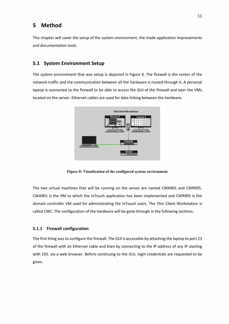
The system environment that was setup is depicted in Figure 8. The firewall is the center of the
network traffic and the communication between all the hardware is routed through it. A personal
laptop is connected to the firewall to be able to access the GUI of the firewall and later the VMs
located on the server. Ethernet cables are used for data linking between the hardware.
Figure 8: Visualization of the configured system environment
The two virtual machines that will be running on the server are named CWA901 and CWR905.
CWA901 is the VM to which the InTouch application has been implemented and CWR905 is the
domain controller VM used for administrating the InTouch users. The Thin Client Workstation is
called CWC. The configuration of the hardware will be gone through in the following sections.
5.1.1 Firewall configuration
The first thing was to configure the firewall. The GUI is accessible by attaching the laptop to port 23
of the firewall with an Ethernet cable and then by connecting to the IP address of any IP starting
with 192. via a web browser. Before continuing to the GUI, login credentials are requested to be
given.

12
Figure 9: Fortigate GUI
To avoid defining the necessary firewall configuration manually an already existing configuration
file used in previous projects was utilized. The configuration file can be restored from the drop-
down list, which is shown in Figure 10. The file provides the required configurations to allow
network traffic between the hardware.
Figure 10: Selecting restoration in the drop-down list
The paramount configurations, which were included after the configuration file was restored
successfully, are covered next. A firewall policy rule is configured to allow communication between
the CWA and CWR (figure 11).
Figure 11: Firewall policy between CWA and CWR
A firewall policy to allow communication from the Thin Client workstation to CWR is configured.
The configuration can be seen in figure 12.

13
Figure 12: Firewall policy from CWC to CWR
5.1.2 VM Setup and Restoration
Before restoring the VMs to the server, configurations must be made in VMware ESXi. Due to that
the server has already been in use, the only configuration required was to set network groups for
the VMs.
Figure 13: Network configuration in ESXi
Before being able to restore VMs with Veeam, a connection is required to be made to the server by
initializing the server IP and log in with its credentials.
Figure 14: Login to the server

14
The VMs can then be imported to the software and restored afterwards to the server.
Figure 15: VMs to be stored to the server using Veaam
After full restoration, the VMs can be started.
Figure 16: VMs started
After connecting to the CWA901 a base application of the InTouch was imported to the determined
directory. To allow usage of WindowMaker and WindowViewer for modification and testing, the
base application is then added to the Application Manager (figure 17).
Figure 17: Adding base application to the Application Manager

15
5.1.3 Thin Client Setup
For remote connection to the workstation from CWA901, a network configuration on the Thin
Client must be made. The address of the server and login credentials have to be provided via the
Thin Clients RDP Connection Manager (figure 18).
Figure 18: Network configuration for remote connection between Thin Client and CWA
To access the InTouch HMI view on the Thin Client, the directory to InTouch software must be
provided (figure 19). The command given will execute the WindowViewer and view the imported
base application located in the specific directory.
Figure 19: Adding remote access to InTouch HMI application view

16
5.2 Application Menu Modification
The application menu to be modified is shown in figure 20. Mainly, changes in the buttons located
on the second and the third row were essential.
Figure 20: Application menu requiring modification
As of now, each button on the third row is defined with a process window that is called by its name
when the window-specific button is pressed. The name of a process window is defined as a value
for a memory message tag. This method is inconvenient during an application modification for a
project installation that involves multiple engine types or multiple engine automation system types.
Instead, each button should be numerically identified and contain an indirect message tag. When a
certain button is pressed, the process window defined as value for a memory message tag would
be synchronized with the value of the indirect message tag added to the button, and then shown
on the display. Which engine number with its engine type has been selected is required to be known
to determine which memory message tag referring to a process window should be equated with
the indirect tag. Therefore, two data change scripts are utilized.
The first data change script will contain an indirect analog tag referring to the active engine type.
The tag will be equated with a memory integer tag referring to a type for an engine number. The
memory tag will change when the engine number changes. This provides a different engine type
stored in the indirect tag if the type is dissimilar for the selected engine number compared with the
previously selected.
The second data change script will take the indirect analog tag assigned to identify the active engine
type as a condition. The script will contain the indirect message tags specified for each button
equated with the memory message tags assigned for each engine type specific process window.
When the active engine type tag changes value, each memory message tag will change and store a
new value to the indirect message tags. This way, new engine type specific process windows can be
shown from the buttons located in the third row. Figure 21 illustrates the ideal plan described
above.

17
Figure 21: How the modification will ideally work
The buttons located at “Common” should be modified with the same principle, except utilizing the
data change scripts would not be necessary. To simplify the identification of each created tag, the
name of a tag should contain a numerical value referring to a specific engine type or a button that
belongs to the engine type. Each process window should be renamed according to the engine type
to which they are belonging to.
Various other scripts had to be included and modified to fulfill the window selection by engine type.
The purposes of the additional scripts were to avoid unnecessary window change if the selected
engine number has the same engine type as the previous engine number, and to achieve proper
behavior of the menu if the number of process windows for a certain engine type differs. Duplicate
versions of the application menu and the scripts were made to enable the same improvement for
the dual monitor view. The improvements for the dual screen will not be covered due to the
similarity of the created tags and scripts.
5.2.1 Created Tagname Dictionary Database
The required tags were created in an Excel workbook which can then be converted to a CSV file and
imported to the InTouch application. Some of the memory message tags used for defining an engine
type or a common process window are shown in Figure 22. Some of the tags were defined without
values to have the opportunity to test the behavior of the application menu when a certain engine
type has fewer process windows to be called.

18
Figure 22: Defined memory message tags
The required indirect message tags which are used for referring to the process window to be shown
when a button is pressed are shown in figure 23.
Figure 23: Defined indirect message tags
The defined memory Integer tags are shown in figure 24. The tags used for defining the type for a
specific engine number and some additional required tags are listed here.
Figure 24: Defined memory integer tags

19
Finally, the indirect analog tag for defining the selected engine type is shown in figure 25.
Figure 25: Defined indirect analog tags
5.2.2 Modified Menu Buttons
The action scripts of the buttons located in the second row, where modified as shown in figure 26.
Each button has its own specified position and engine number. The script will check if the location
of the pressed button is on the first or on the redundant screen and then changes the values of the
tags relevant to the pressed button and the location on the monitor. A function is called which
provides the engine type depending on what engine number has been given as an argument to the
function.
Figure 26: Example of an action script for buttons at row 2
Each button on the third row has an action script that will similarly check the location and change
values accordingly. The script in each button contains a button specific indirect message tag which
is equalized with a memory message tag that is assigned for storing the value of the selected
window. This tag is then given as an argument to a function that will show the selected window.

20
Figure 27: Example of an action script for buttons at row 3
Each button at the third row should be disabled if the window is already showing or if the window
to be shown does not exist, in other words there is no value stored in the indirect tag. This is done
by providing expressions for the button that will disable the button if either of these expressions
are true. The expressions for the button are shown in figure 28.
Figure 28: Expression to disable buttons at row 3
Each row 3 button has a frame around it which is used to indicate if the button is selected. Each
frame should be visible if the value of the tag defined for the currently shown window is equal to
the value of the button specific indirect message tag.
Figure 29: Example of a visibility expression for the frame around a row 3 button

21
5.2.3 Scripts
The scripts added or modified are reviewed next. First, the indirect tag used for defining the current
active engine type tag has been inserted to the data change script, which executes when the engine
number changes. The value of the indirect tag is updated when the value of the memory integer
tag changes according to the active engine number.
Figure 30: Data change script to acquire active engine type
When the active engine type changes, the second data change script will update the values of the
indirect message tags with the values from the memory message tags. The memory message tags
will change if the tag referring to the active engine type changes.
Figure 31: Data change script to acquire engine type windows from row 3 buttons based on the active
engine type

22
The QuickFunction which is called from the buttons located on the second row and which takes the
engine number as an argument is shown in Figure 32. Same as in the first data change script, it
stores the active engine type value to the indirect tag. If the type has changed, it calls the function
to get the active window depending on which button is currently active on the third row.
Figure 32: QuickFunction to acquire the active engine type based on engine number selected from row
2 buttons
The second QuickFunction provides the window to be shown depending on the button number
taken as an argument. The value of the tag referring to the process window to be shown is stored
in an indirect message tag used for calling a window.
Figure 33: Stores active window depending on engine type and the button number.

23
If the memory tag for calling a process window has no value stored, the code loops through the
buttons that are located before the currently selected button. When it finds a tag containing a
relevant value the window will be called by the value of the tag and the position of indication
changes to the button which is referring to the window. This part of the script promotes the menu
to select the nearest available process window to be displayed if the engine type has changed and
the data of the previously selected window is unavailable for this specific engine type. This part of
the script also prevents similar windows to be called up, which would cause unnecessary flickering
or screen update, if the engine type has not changed.
Figure 34: Checks if a window exists and is dissimilar to the previously active window.
If the selected window was not engine specific, a window for common is displayed instead
according to the number of the button. Here, the selected process window must also be dissimilar
to the previously shown window.
Figure 35: Checks and calls a window belonging to Common.

24
During the modification, an additional feature for the application menu was requested to be made.
The user should be allowed to shift between the engine number buttons with keyboard shortcuts
in both horizontal directions. The key script shown in figure 36 is used for shifting between the
engine buttons from left to right by pressing the add sign on the keyboard. If the user shifts beyond
the maximum number of engines available, the shifting begins again from the first engine number.
To shift from right to left, the user must press the subtract sign on the keyboard.
Figure 36: Key script to shift between engines. Shifts left to right.
5.3 Development License Detection
It was required that the development license detection would only occur on the CWA. The detection
should also take place periodically. A decision was made that the license should be text based
indicated if it exists in the specified directory. First, the directory where the development license is
inserted, and the file type of the license had to be acknowledged.
Figure 37: The directory where the development license is located

25
For the periodical detection of the license a condition script was created. The condition defined for
the script permits the script to be always active. The execution interval was set to 10 seconds and
during every 10 seconds the script checks if there is a file type determined for the license in the
specified directory. The return value will be discrete and stored in the memory tag.
Figure 38: Condition script to detect the development license.
A visibility condition was added to the text-based indication. The indication is visible when the
returned value stored in the memory tag is true and when the application is used by the CWA user.
Figure 39: Visibility expression for the development license indication.
The indication will appear on the first row of the application menu.
Figure 40: Indication of an existing development license
An additional action to delete the development license from the InTouch HMI application was
requested. A button was added to the configuration window of the HMI application. After pressing
the button, the action script seen in figure 41 will run. The script will show a message box that asks
if the user wants to delete the existing development license. If the return value corresponds to a

26
yes, the license will be deleted, and a message box will appear informing that the license has been
deleted.
Figure 41: Key scrip to delete the development license via the HMI
The button used to delete the development license is visible for the manager accounts or higher,
and when there is an existing license in the specified directory. When the license has been deleted,
the button will hide itself until a new license is inserted.
Figure 42: Visibility expressions for the delete development license button
5.4 Dual Printer Setup
The currently used method for projects with multiple printers is that the printers are hardcoded
based on the hostname for Thin Clients and the InTouch application VMs running on the servers.
This means that only one printer can be used by a specific Thin Client or VM to print out HMI
window views, making the method prone to printing failure if the specific printer is down. An ideal
solution is to have a selection dialog for the printers, from which the user can select which printer
to be utilized without taking into consideration the hostname that called the printing action.
Before being able to test the improved printer setup, 2 printers were added to the network. The
two printers were connected to the firewall via ports 20 and 21. From the CLI available in the
firewalls GUI, the printers were tested if they communicated with the system. The defined IP
addresses for the printers were 192.x.x.y and 192.x.x.z.

27
Figure 43: Checking the communication to the printers from the Fortigate CLI
A firewall policy was added to allow communication from CWA to both printers. The printers are
identified as CWP901 and CWP902.
Figure 44: Firewall policy from CWA to the Printer
The printers were added to the CWA via printer and scanners.
Figure 45: Printers added to the CWA
In InTouch, a window for the printer selection was created. The menu includes buttons specified
for each printer. When a user clicks one of the buttons the action script in figure 46 hides the
selection menu, stores the printer’s name to the memory tag and executes a print function.

28
Figure 46: Action script to select a printer
The print function will activate a condition script that will execute the printing process. The most
relevant row of this script is row 4, where an already existing application will process the currently
open HMI window and then print the window to the selected printer according to the name of the
printer stored in the memory tag.
Figure 47: Condition script to print the HMI window
The printer selection menu will appear when the user presses the print screen option.
Figure 48: Calling the printer selection from print screen option

29
5.5 HMI Screenshot Tool
Currently, an application is used for printing and saving HMI process windows to a USB memory
stick that is selected from a popup dialog when the save screen option has been activated. The plan
was to utilize the application, but after some testing a conclusion was made that the application
did not support automated screenshot capturing. Instead, a Powershell script is utilized to capture
the screenshots. The script will create a default image file of the captured screenshot and insert it
in the determined directory.
Figure 49: Powershell script for capturing a screenshot and creating a default image file
To clarify the HMI process window selection, the user should have the opportunity to pick multiple
engines of which the process windows belonging to the selected engines would be captured.
Therefore, a window was created in InTouch that enables engine selection when the window is
called.
Figure 50: Created screenshot selection menu
The window itself is called using the keyboard shortcut Ctrl + Shift + s.

30
Figure 51: Key script for calling the screenshot selection menu
For each engine number there is a button located on the selection window, with which the state of
the selected button is determined with discrete values. If the user has chosen an engine number, a
discrete true will be stored to the memory tag uniquely assigned for the specific engine number.
Otherwise, a discrete false will be stored.
Figure 52: Action script for the buttons located in the screenshot selection
When the user presses the OK button, the action script of the button will hide the selection window.
The script then checks if the Powershell script is in the determined directory. If it is, the script loops
through each memory tag belonging to each engine. A string of binary values will be stored in a
memory tag that contains the states of each available engine. An idea was to store the selected
engines using arrays, but due to InTouch not supporting arrays the method using a string of binary
values seemed convenient. Finally, the script sets the condition true for activating the screenshot
tool.

31
Figure 53: Action script located at the OK button
The condition script in figure 54 will execute when the tag defined for activating the screenshot tool
has been set to true. The script ensures that the primary process window to be taken a screenshot
of is the overview window by calling the function specified for that window. The HMI view will
update immediately to the overview window from the previously active window. A folder where
the screenshots will be stored is created to the specific directory and tags allowing to proceed with
the screenshot capturing are initiated with trigger values.
Figure 54: Create a screenshot folder and initiate trigger values for the screenshot tags
The key actions that the tool will execute are capturing a screenshot of the currently visible process
window, naming the image file according to the creation date and the name of the process window,
and callings to the next available window. To accomplish a successful execution of each action, a
timer is required. The data change script shown in figure 55 utilizes the system time by taking the
system tag for seconds as condition. A memory tag used for time counting increases its value by

32
one every time the value of the system tag changes. The value of the memory tag increases only
when the screenshot tool is active.
Figure 55: Data change script functioning as a timer for the screenshot tool
To exploit the time counter tag with which the actions within the screenshot tool are triggered, a
condition script was created. The conditions for activating the script are based on determined
values that are stored in the time counter tag when the previously mentioned data change script
executes every second and increases the value of the tag. Each value is defined specifically for each
action within the tool.
When the value of the time counter tag corresponds to 2 the script will execute the Powershell
script used for capturing screenshots of the process windows (figure 56).
Figure 56: Capturing the screenshot when timer hits 2

33
Renaming the captured images according to the creation date and the HMI process window will
happen when the timer reaches 5 (figure 57). If the captured HMI process window is engine based,
the script will add an indication to the file name based on the engine.
Figure 57: Renaming the captured image file when timer hits 5
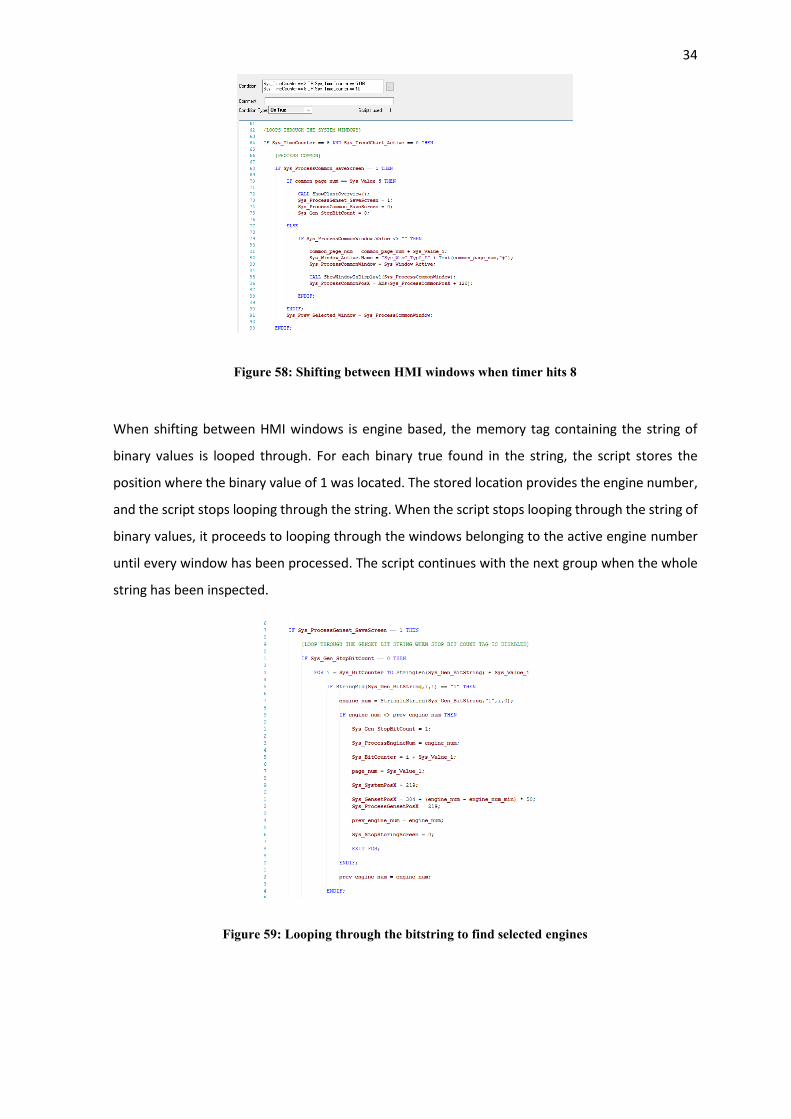
The shifting between HMI windows is done when the timer reaches 8 (figure 58). Each process
group included in the system has their own discrete memory tag that will be active or inactive
depending on if the process group is looped through or not. Starting with “Common”, the script
checks if the window to be shown exists by referring to the value of the memory message tag
specified for the window. If it exists, the process window will be shown. The script iterates until the
determined maximum value representing the total amount of windows in the process group has
been reached and then proceeds to the next group. The scripts for shifting through the windows
are quite similar for each process group and therefore all groups are not covered. It can be
mentioned that the value of the time counter tag is reset after each HMI window shift.
34
Figure 58: Shifting between HMI windows when timer hits 8
When shifting between HMI windows is engine based, the memory tag containing the string of
binary values is looped through. For each binary true found in the string, the script stores the
position where the binary value of 1 was located. The stored location provides the engine number,
and the script stops looping through the string. When the script stops looping through the string of
binary values, it proceeds to looping through the windows belonging to the active engine number
until every window has been processed. The script continues with the next group when the whole
string has been inspected.
Figure 59: Looping through the bitstring to find selected engines

35
Due to the undefined delay in opening the chart window located in the trends group, an additional
timer condition had to be inserted (figure 60). It functions as a wait time for the window to open
properly.
Figure 60: Wait time for trend chart window activates when timer hits 10
After every HMI window has been looped through a function is called that will add the current date
on the folder name and informs the user of a successful screenshot capturing process. After
informing, the tool can be reused.
Figure 61: Inserts date to the folder name and indicates of a successful screenshot capturing process.
The result after using the HMI screenshot tool can be seen in figure 62.
Figure 62: The created folder containing the captured image files

36
5.6 HMI Documentation Tool
The screenshot documentation tool was created with VBA in Excel. This section describes the
planned functionality and the actions that are executable using the documentation tool.
5.6.1 The desired functionalities
To ease the documentation of the HMI process windows and to only require one Excel workbook
to create several documentations, a documentation tool was planned considering the following
functionality requirements:
• To allow the user to smoothly edit and add data to the project sheet, a user form could be
created.
• Instead of manually inserting every screenshot taken of a project specific HMI application
into an Excel workbook, the process of adding the screenshots could be automated. The
user is required to only select the screenshot folder, which was created with the HMI
screenshot tool covered in the previous section.
• A Company X specific document layout should be generated for each HMI document page.
• To save time, an action to delete all recently imported screenshots could be an option for
the user.
With the above-mentioned requirements acknowledged, a worksheet in an Excel document was
created as a tool sheet and which contains four different buttons. Each button has their own unique
action according to the above-mentioned functionality requirements that will execute when a
button is pressed.
Figure 63: The documentation tool worksheet
Next, the executable actions from each button are explained in detail.

37
5.6.2 Create project sheet
When the first button is pressed a user form will appear. The user will be requested to insert project
specific data on the form.
Figure 64: User form used to insert project data
After filling the form and pressing OK a new sheet called “Project” is added in the workbook
containing the data from the user form. This sheet is used as a title page for the document.
Figure 65: Created project sheet with data from the user form
5.6.3 Import HMI screenshots
With the second button the user can import the HMI screenshots captured from the application.
When pressed, file explorer will open from which the user can select the folder containing the
screenshot image files.

38
Figure 66: User can select the folder from where screenshots are imported
The VBA code responsible of this action can be seen in figure 67.
Figure 67: VBA code that allows the user to select the screenshot folder
After choosing the folder the program will loop through the files in the folder removing the creation
date and filetype from the filename. It will then add a new worksheet after the previously created
sheet and insert the screenshot into it. Finally, the worksheet is named according to the name of
the image file. The order in which the sheets with the imported screenshots are added is based on
the creation date of the image files. If the user wants to reimport some images the program will
either place the imported screenshot on a worksheet that has the same name as the image file or
create a new one somewhere among the sheets depending on the creation date of the image.
Figure 68: Example of imported image files to the documentation tool

39
The code for the image import is shown in figure 69.
Figure 69: VBA code which loops through the image files to be imported
5.6.4 Generate documentation layout
After the screenshots are imported the user can press the third button to generate a Company X
specific document layout for the title page and the screenshot worksheets. When the button is
pressed, the VBA program will loop through all the worksheets adding them in an array. The array
is then selected and for each worksheet contained in it, the program will add the necessary layout
design. When the layout is generated to all the sheets, the document is ready.
Figure 70: Generates the company specific document layout
5.6.5 Delete screenshots
The user has the option to delete the worksheets which contain the HMI screenshots with the
fourth button. The HMI screenshot worksheets will be stored in array which will then be deleted, if
the user has selected yes from the message box that appears when the delete button is pressed.
After the delete action has been executed, the tool sheet and the project sheet are the only
worksheets left in the workbook.

40
Figure 71: Option to delete the imported image files
The VBA code to delete the sheets containing the HMI screenshots is shown in figure 72.
Figure 72: VBA code to delete all imported image files
5.6.6 Additional VBA code
To avoid printing the documentation tool sheet, a VBA code will hide the sheet when the user
selects to print the HMI document. After the printing has been executed, the sheet will reappear
by calling the “AfterPrint” function.
Figure 73: Hides the documentation tool when user selects print
Figure 74: Unhides the tool after printing has completed

41
6 Result
After a reasonable number of tests, it can be ascertained that the application improvements
function flawlessly. The modified application menu works as expected. Correct windows are shown
when the type of engine changes. The number of buttons that are visible on the third row of the
menu varies when an engine type is selected that has a dissimilar number of windows compared to
the previously selected engine type. Shifting between engine buttons with shortcut keys also
worked without any inconveniences.
The indication of the development license detection tool was tested by removing and reinserting
the license located in the specified directory. The result of this test was an indication that activated
and deactivated every 10 seconds when the license was deleted and relocated to the directory. This
test was done both with and without the delete license command. For the dual printer setup,
printing occurred from the printer that was selected from the printer selection menu. Both printers
were tested from CWA and CWC, and the same anticipated result came from both.
When it comes to the HMI screenshot tool, it performs surprisingly well. The tool takes the
screenshot of the active process window, stores it in the desired directory, and proceeds to the
next window. These actions execute in the correct order and no malfunctions occur. Although the
tool works well there are a few deficiencies. Due to the commands used in the tool requiring certain
processing periods for proper execution, the iteration time for processing every single window is
quite slow. When the whole timing is based on seconds, the whole process to go through all the
HMI windows can take up to several minutes. The feature to allow the user to select a USB memory
stick where the screenshot should be stored is currently unavailable. Possibly, future modifications
could be done to allow this with the tool.
Finally, the HMI documentation tool made in Excel does fulfill the requested criteria. The images
captured with the HMI screenshot tool can easily be imported to the tool just by selecting the
created screenshot folder. Each image is inserted into its own worksheet after which the
worksheets can be generated with company specific documentation layout. The tool provides
reusability, simplicity and is also time saving. Unfortunately, the tool has some inconvenient
functionalities. The date with a document specific format must be specified via the user form, due
to the Microsoft’s regional settings messing the format up if the date is specified directly to the
worksheet. Some of the names of the HMI screenshots exceed 31 characters which is the max limit
of naming an excel worksheet. Because of this, an application error occurs and to solve this the VBA
code must shorten the names if the number of characters is greater than 31.

42
7 Conclusion
The objectives of this Bachelor’s thesis were to make improvements to the InTouch based HMI
application and develop tools for the HMI windows documentation. The improvements made in the
application were desired to allow flexibility during application modifications for project specific
installations, whereas the tools would provide a simpler and less time-consuming solution to create
HMI window documents for FAT documentation. Although, some of the requested features could
not be added the expected functionalities for both the improvements and the tools were achieved.
The most challenging part of this thesis was to plan and get the scripts to provide proper executions
with which the requested functionalities would be fulfilled. Mainly, the creation of the scripts for
the HMI screenshot tool caused some inconveniencies due to the number of HMI windows located
in different process groups that had to be looped through. Also, finding a secondary method to
capture screenshots and the application not supporting arrays brought reconsiderations in how the
scripts would provide the desired actions. Luckily, solutions were found.
Making this thesis has been a delightful experience. To be able to work with tasks that require
problem-solving and logical thinking, was considered as a brilliant educational and enhancing
opportunity. Even though challenges occurred, discovering and creating solutions with which
challenges were eliminated seemed to be a great chance to improve troubleshooting skills.
Information about how to act when similar challenges appear in the future was also provided.
During this thesis I received a better understanding of working with InTouch. The InTouch
application itself is quite simple to work with when you understand the basics of how to import and
export databases, how to utilize scripts and how to define tags. How to configure system
environments became more familiar. Nowadays, these types of environments are preferably used
in plants, so it is a great asset to know how to set them up.

43
8 References
[1] E. Normanyo, F. Husinu and O. R. Agyare, "Developing a Human Machine Interface (HMI) for Industrial Automated Systems using Siemens Simatic WinCC Flexible Advanced Software," 2014. [Online]. Available: https://citeseerx.ist.psu.edu/viewdoc/download?doi=10.1.1.681.7586&rep=rep1&type=pdf.
[2] K. Stouffer, S. Lightman, V. Pillitteri, M. Abrams and A. Hahn, "Guide to Industrial Control Systems (ICS) Security," 2014. [Online]. Available: http://www.gocs.com.de/pages/fachberichte/archiv/164-sp800_82_r2_draft.pdf.
[3] M. R. Vaishnavi, "What is a Database? Definition, Types and Components," 2020. [Online]. Available: https://www.edureka.co/blog/what-is-a-database/.
[4] Wonderware, "InTouch® HMI Concepts and Capabilities Guide," AVEVA, [Online]. Available: https://cdn.logic-control.com/docs/Wonderware/InTouch/ITConcepts.pdf.
[5] Wonderware, ”InTouch® HMI Application Management and Extension Guide,” [Online]. Available: https://cdn.logic-control.com/docs/Wonderware/InTouch/ITAppManagement.pdf.
[6] Wonderware, ”InTouch® HMI Data Management Guide,” [Online]. Available: https://cdn.logic-control.com/docs/Wonderware/InTouch/ITDataManagement.pdf.
[7] Wonderware, ”InTouch® HMI Scripting and Logic Guide,” [Online]. Available: https://cdn.logic-control.com/media/ITScriptsAndLogic.pdf.
[8] Forcepoint, ”What is a Thin Client?,” [Online]. Available: https://www.forcepoint.com/cyber-edu/thin-client#.
[9] Fortigate 140E, [Online]. Available: https://www.avfirewalls.com/FortiGate-140E.asp.
[10] VMware ESXi, [Online]. Available: https://www.vmware.com/fi/products/esxi-and-esx.html.
[11] Veeam Backup & Replication, [Online]. Available: https://helpcenter.veeam.com/docs/backup/vsphere/overview.html?ver=110.
[12] Corporate Finance Institute, ”Excel Definition,” [Online]. Available: https://corporatefinanceinstitute.com/resources/excel/study/excel-definition-overview/.
[13] Guru99, ”Powershell Tutorial for Beginners: Learn Powershell Scripting,” [Online]. Available: https://www.guru99.com/powershell-tutorial.html.