Suggested Improvements in Designing Soil-Steel Structures
9
96 TRANSPORTATION RESEARCH RECORD 1 23 1 Suggested Improvements in Designing Soil-Steel Structures ]OHN B. KENNEDY AND ]ANT. LABA Soil-steel structures have been used widely as short-span bridges and as substitutes for concrete culverts. However, many of these structures .have now shown signs of distress, with some suffering catastrophic collapse. Generally, such failures are related to the failure of the surrounding soil to provide the necessary support to the steel In paper, the concept of reinforcing the surroundmg granular sod, as well as tying the flexible steel struc- ture into the stable part of the surrounding soil by horizontally placed galvanized ties, is introduced. !t is shown that this novel concept wo.uld lead to improvements in the structural response durmg construction and at the service load stage. Such construc- tion will (a) add considerable stiffness to the soil and decrease the movement of the backfill in service, such as during freeze-thaw (b) restrain the movement of the steel structure; and (c) mduce large deformations, in case of overload, and therefore give ample warning before failure. Results from tests on soil-steel struc- tural models are reported. In the past three decades, soil-steel structures have been used successfully on short-span bridges; in many cases, the struc- tures replaced the traditional concrete culverts on municipal and proved to be quite economical. The design principle is based on the assumption that when the flexible steel struc- ture is subjected to a vertical load the structure will deform bringing into play passive soil pressure counteracting the of the applied vertical pressure; therefore, perfect interaction between the steel structure and the soil backfill is essential during the life of the structure. As the soil cover increases the bending moments and shears in the steel structure negligible, and the steel structure is then designed predomi- nantly for in-plane compression. A recent survey (J) has shown that an alarming number of soil-steel structures in Ontario Canada, have shown signs of distress such as cracks at holes; buckling and rupture of bottom plates; gross distortion of cross section, including buckling of top plates; uplift of bottom plates; crimping of ridge corrugations. Actual failures of soil-steel structures have occurred in the past; some have been catastrophic, involving loss of life (2, p. 12). Besides the unfortunate errors in construction, these fail- ures and distress signs can be attributed mainly to the failure of the s?il to provide the necessary and expected support to the flexible steel structure after construction and during its service life. The current practice of some designers, providing ture, will not correct this problem in the long run. Such designs, in addition to being uneconomical, will only increase further the load paths to the steel structure and decrease those to the surrounding soil. The truth of this statement was also dem- onstrated recently by tests on earth-covered slabs (3). University of Windsor, Windsor, Ontario, Canada, N9B 3P4 . !n this paper, the concept of reinforcing the surrounding soII, as well as tying the flexible steel structure into the stable surrounding soil by horizontally placed galvanized ties: is mtroduced; it is believed that the adoption of such a design concept can prevent failures in soil-steel structures. The types of failure and their causes are described below. TYPES OF FAILURE AND THEIR CAUSES Failure in soil-steel structures can be of different form as follows: • Crimp formation-Crimps in the steel structure (Fig- ure 1) occur mainly on the valley of the section, extending sometimes to the ridges. Such crimps are caused by excessive bending and/or direct thrust in the steel structure. Also, dur- ing manufacturing, the bending of the corrugated flat sheets to small radii, as required for haunches of pipe arches, may cause such dimples on the interior valleys. • Joint failure-Joint failures in the steel structure (Figure 2) occur due to excessive shear or bearing stresses; tearing of bolt holes is then a usual occurrence and rusting of the unpro- tected torn metal will accelerate failure of the joint. The seam connection can cause local increase in the bending of the steel structure, or it may create local weakness leading to failure. !hus proper attention to the seam design and bolt pattern (4) 1s necessary. Poor initial compaction of the soil during con- struction and unforeseen settlement would also contribute to joint failure. • Excessive deformation-The steel structure can undergo excessive lateral wall displacement, which gives rise to exces- sive vertical deflection at the crown, causing additional stresses due to bending in the vicinity of the crown. Such a condition is due. mainly to poor compaction of the side fill during con- or to the loss of initial compaction at a later stage m the hfe of the soil-steel structure. • Lifting of the invert of the steel structure- This distress (Figure 3) results from soil settlement under the haunches of the steel structure (4) or from increased water level under the steel structure, creating an uplift on the bottom plates. The types of overall failures in soil-steel structures follow: • Buckling of the steel structure- Buckling of the steel structure can lead to catastrophic failure. Excessive thrust in the structure coupled with excessive deflection around the crown can trigger such instability. The consideration of buck- ling becomes even more critical for large-span structures under
-
Upload
khangminh22 -
Category
Documents
-
view
1 -
download
0
Transcript of Suggested Improvements in Designing Soil-Steel Structures

96 TRANSPORTATION RESEARCH RECORD 123 1
Suggested Improvements in Designing Soil-Steel Structures
]OHN B. KENNEDY AND ]ANT. LABA
Soil-steel structures have been used widely as short-span bridges and as substitutes for concrete culverts. However, many of these structures .have now shown signs of distress, with some suffering catastrophic collapse. Generally, such failures are related to the failure of the surrounding soil to provide the necessary support to the steel ~tructure. In t~is paper, the concept of reinforcing the surroundmg granular sod, as well as tying the flexible steel structure into the stable part of the surrounding soil by horizontally placed galvanized ties, is introduced. !t is shown that this novel desi~n concept wo.uld lead to improvements in the structural response durmg construction and at the service load stage. Such construction will (a) add considerable stiffness to the soil and decrease the movement of the backfill in service, such as during freeze-thaw ~ycles; (b) restrain the movement of the steel structure; and (c) mduce large deformations, in case of overload, and therefore give ample warning before failure. Results from tests on soil-steel structural models are reported.
In the past three decades, soil-steel structures have been used successfully on short-span bridges; in many cases, the structures replaced the traditional concrete culverts on municipal ~oads and proved to be quite economical. The design principle is based on the assumption that when the flexible steel structure is subjected to a vertical load the structure will deform bringing into play passive soil pressure counteracting the effec~ of the applied vertical pressure ; therefore, perfect interaction between the steel structure and the soil backfill is essential during the life of the structure. As the soil cover increases the bending moments and shears in the steel structure becom~ negligible, and the steel structure is then designed predominantly for in-plane compression. A recent survey (J) has shown that an alarming number of soil-steel structures in Ontario Canada, have shown signs of distress such as cracks at bol~ holes; buckling and rupture of bottom plates; gross distortion of cross section, including buckling of top plates; uplift of bottom plates; crimping of ridge corrugations. Actual failures of soil-steel structures have occurred in the past; some have been catastrophic, involving loss of life (2, p. 12).
Besides the unfortunate errors in construction, these failures and distress signs can be attributed mainly to the failure of the s?il to provide the necessary and expected support to the flexible steel structure after construction and during its service life. The current practice of some designers, providing 2dd!t!~~~l ~t!ffe~i~g b~~t b~~~:; t~ ;-~i~fv;~;; ~he :;~cc1 ~~~tuc
ture, will not correct this problem in the long run. Such designs, in addition to being uneconomical, will only increase further the load paths to the steel structure and decrease those to the surrounding soil. The truth of this statement was also demonstrated recently by tests on earth-covered slabs (3).
University of Windsor , Windsor, Ontario, Canada, N9B 3P4.
!n this paper, the concept of reinforcing the surrounding soII, as well as tying the flexible steel structure into the stable ~art ~f ~he surrounding soil by horizontally placed galvanized ties: is mtroduced; it is believed that the adoption of such a design concept can prevent failures in soil-steel structures. The types of failure and their causes are described below.
TYPES OF FAILURE AND THEIR CAUSES
Failure in soil-steel structures can be of different form as follows:
• Crimp formation-Crimps in the steel structure (Figure 1) occur mainly on the valley of the section, extending sometimes to the ridges. Such crimps are caused by excessive bending and/or direct thrust in the steel structure. Also, during manufacturing, the bending of the corrugated flat sheets to small radii, as required for haunches of pipe arches, may cause such dimples on the interior valleys .
• Joint failure-Joint failures in the steel structure (Figure 2) occur due to excessive shear or bearing stresses; tearing of bolt holes is then a usual occurrence and rusting of the unprotected torn metal will accelerate failure of the joint. The seam connection can cause local increase in the bending of the steel structure, or it may create local weakness leading to failure. !hus proper attention to the seam design and bolt pattern ( 4) 1s necessary. Poor initial compaction of the soil during construction and unforeseen settlement would also contribute to joint failure.
• Excessive deformation-The steel structure can undergo excessive lateral wall displacement , which gives rise to excessive vertical deflection at the crown, causing additional stresses due to bending in the vicinity of the crown. Such a condition is due. mainly to poor compaction of the side fill during con~truct10.n or to the loss of initial compaction at a later stage m the hfe of the soil-steel structure.
• Lifting of the invert of the steel structure-This distress (Figure 3) results from soil settlement under the haunches of the steel structure (4) or from increased water level under the steel structure, creating an uplift on the bottom plates.
The types of overall failures in soil-steel structures follow:
• Buckling of the steel structure-Buckling of the steel structure can lead to catastrophic failure. Excessive thrust in the structure coupled with excessive deflection around the crown can trigger such instability. The consideration of buckling becomes even more critical for large-span structures under
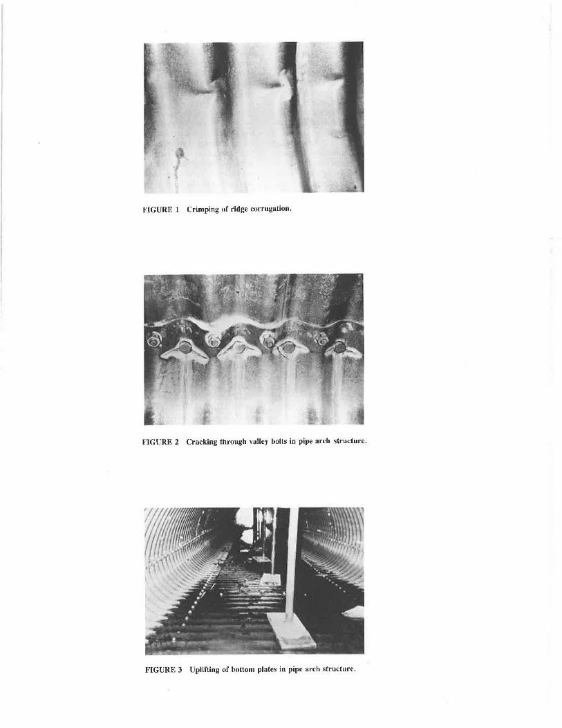
FIGURE I Crimping of ridge corrugation.
FIGURE 2 Cracking through valley bolts in pipe arch structure.
FIGURE 3 Uplifting of bottom plates in pipe arch structure.

98
shallow cover, and for structures in the shape of pipe arches and horizontal ellipses.
• Soil failure above the steel structure-Soil-steel structures under shallow soil cover are susceptible to wedge shear failure or tension failure in the soil cover (Figures 4 and 5). Uneven loadings, poor compaction of the soil, and high flexibility of the steel structure all contribute to such soil failure. Currently, design codes specify a minimum depth of soil cover to prevent such failure.
• Bearing failure of soil-The soil pressure at the interface between the soil and the steel structure tends to be inversely proportional to the radius of the curvature of the steel structure in the form of pipe arches or horizontal ellipses (5). Such soil pressure may exceed the ultimate bearing capacity of the soil, thus precipitating failure of the surrounding soil (6).
• Failure due to temperature effects-Temperature variations can significantly affect the structural performance of soil-steel structures. For example, the soil envelope at the invert and around the haunches of pipe arches can become saturated with water and then freeze when the temperature drops; this freezing causes increased pressure on the steel structure as well as displacement in the soil envelope, leading to nonuniform deformation in the steel structure and in the surrounding soil. With thawing, the void ratio in the soil increases (i.e., there is a reduction in the soil density). Cycles of freezing and thawing will then lead to a considerable reduction in the initial compaction of the backfill as well as to higher water seepage and consequently to loss of fine soil particles. Furthermore, with temperature rise, frozen soil containing ice can exert significant pressure against the confining boundaries of steel structures. Moreover, in cold climates ad-freezing (frost grip) forces can be readily activated, restricting the freedom of deformation of the steel structure. Variations in the ice content around the steel structure will produce a vari-
Load
...J!f~,.=-.,. ., .. ii4C •~Xiii '
~'O FIGURE 4 Shear failure of soil cover.
·+-FIGURE 5 Tension failure in soil cover.
TRANSPO/ffA T/ON RESEARCH RECORD 1231
ation in the ad-freezing forces around the steel structure, causing additional strains. The failures reported by Moore (J) at the haunches of pipe arches can be attributed in large measure to the loss of initial compaction due to the combined action of temperature and seepage effects.
The structural strength and stiffness of soil-steel structures are derived from the full interaction between the surrounding soil and the steel structure; this interaction is created due to the deformation of the steel structure during backfilling. When such interaction is not fully realized due to the poor performance of the soil backfill either during construction or under service loads, problems in the structural response of the structure, either in the form of local failure or complete failure can be expected. A better performance of the soil backfill can be ensured by (a) reinforcing the soil around and above the steel structure by means of galvanized metallic ties and (b) tying the steel structures into the surrounding granular soil. As a result, the soil-steel structure is transformed to the reinforced soil-steel structure described below. The required dependency on deformation in a soil-steel structure is not necessary in a reinforced soil-steel structure where the deformation is greatly minimized; in such a structure, a stiffened reinforced granular soil coupled with a steel structure tied into the soil combine to produce a nearly self-equilibrating structure.
THE REINFORCED SOIL-STEEL STRUCTURE
A reinforced soil-steel structure is a soil-steel structure in which (a) the soil cover above the crown of the steel structure is reinforced by layers of horizontally placed galvanized ties and (b) the steel structure is nailed into the granular backfill by layers of horizontally placed galvanized ties (reinforcement) (Figure 6). To illustrate the structural response of this novel concept of bridge construction, an experimental test program was carried out on five bridge models. The theoretical analysis of this structure was based on the finite element method and has been discussed in detail elsewhere (7).
Experimental Study
This study was carried out on models built inside a Plexiglas box 76 in. long by 35 in. wide by 36 in. deep with 1-in. wall thickness. The soil material was coarse, dry sand. The reinforcing ties were made of thin shim steel 0.001-in . thick, 1-in. wide, and 25-in. long with an ultimate tensile strength of 120 ksi; particles of the same sand were glued to the ties to increase their frictional resistance. The magnitude of their frictional capacity was checked and determined by means of the shear box test . To investigate the influence of reinforcing the soil cover above the arch structure and of tying back the arch into the soil, five different design models (Figure 7) were built and tested.
In design I, a relatively stiff steel arch, having a span of 30 in. and a rise of 8 in., was used; in designs II to V, more flexible aluminum arches, each with a span of 30 in. and a rise of 8 in., were employed; two soil covers were used (Figure 7) to represent relatively shallow and deep soil cover situations. The geometric properties of the metallic arches were

Kennedy and Laba
Roadway Level
Arch
FIGURE 6 Reinforced soil-steel structures.
Design Arch Tie-backed Reinforced Sketch No. Material Arch soil cover
I Steel a No No - -Jh
Q ng
II Aluminum b
No No - "*'J ~ h
b _t
111 Aluminum Yes No - -f ~r.(i=
b J.
IV Aluminum Yes Yes =tntf r.t.
111111 ·th v Aluminumb Yes Yes ~I
r. t.
a .b Stiff Arch , Flexi ble Arch, h • 4 inches , r. t.z reinforcing tie Arch Span • 30 in. ; Rise-Sin.
FIGURE 7 Different bridge designs studied.
as follows: For the steel arch in Bridge Model I , area A = 5.16 x 10- 2 in. 2/in.; moment of inertia, I = 1.50 x 10- 3
in .4/in .; for the aluminum arches in Bridge Models II to V, A = 4.92 x 10- 2 in. 2/in., I = 9.5 x 10 - 6 in .4/in. Strains were measured by 0.4-in .-long strain gauges , and dial gauges of0.001-in. travel sensitivity were used to measure deflections
Srro in Gage loco lion
Resisting Zone
38 in.
6.05 psi
4 .67 psi 1·
2.8 psi
15in ==+-
.!: co
99
FIGURE 8 Geometry of Bridge Model V showing strain gauge locations and potential failure contours.
(a) Thrust Distribution (b) Moment Distribution
FIGURE 9 Comparison of results for thrust and moment.
during construction and during the application of the external vertical surface loading at the center. This loading was applied by means of a hydraulic jack through a rigid rectangular HSS beam 12-in. wide and spanning the width of the model (Figure 8) . It is recognized that the size of these models does not represent a prototype situation; however, the purpose of the experimental tests was to study trends of this new bridge construction, and furthermore, the test results were used to substantiate and verify the theoretical results from a finite element solution (7). Tests on a full-scale structure are contemplated.
Discussion of Test Results
A typical comparison for thrust and moment along the arch for Models I, II, and IV is shown in Figure 9; the results, shown in Figure 9(a), show that the thrust is almost uniform along the arch for the three models . Although there is no significant difference between the thrusts in Models I and II, the thrust in Model IV is less than half that in Models I and II. The results indicate that the thrust in the arch is not affected by the arch stiffness but is greatly influenced by the stiffness of both the surrounding soil and the soil cover. Furthermore, as shown in Figure 9(b) , reinforcing the surrounding soil and the soil cover in Model IV practically eliminates the moment along the arch profile, in contrast to Model I; this observation indicates that adding stiffness to the metallic arch (Model I) attracts more load unto the arch (3) and hence greater undesirable moments leading to a more expensive structure.

100
The vertical deflections of the arch crown for Bridge Models II, III, and IV are compared in Figure 10; it can be observed from Figure 7 that these three models were similar except for tying the arch and reinforcing the soil cover. The results in Figure 10 show that Bridge Models III and IV carried more than 2 and 31/2 times, respectively, the maximum load carried by Bridge Model II. Bridge Model IV was able to sustain 85 percent of its maximum load-carrying capacity even when the crown deflection was as large as one-half the arch rise. This outcome is significant because such a response would provide adequate warning of an impending collapse; such a warning might have averted the catastrophic collapses in Ohio (2) and Ontario (J). In Figure 11, the snap-through collapse of Bridge Model II is shown; Bridge Models III and IV exhibited a progressive type of failure with large displacements accompanied with pull-out failure of the reinforcing ties attached to the arch; the failure for Br.idge Model IV is shown in Figure 12. Other comparisons are given elsewhere (7).
The pressure transmitted to the steel structure due to dead load would be sensibly the same in a soil-steel structure and in a reinforced soil-steel structure; ho\vever, because of the restraining forces in the ties nailing the steel structure into the soil, the latter structure would be capable of withstanding several times the pressure of the former structure, as shown
0 4
~ _, ll. 3 a: :;; _, 2 < u ;::: a: w >
Model IV
Model Il l -----o-------6... , IY" ---,
-- Analysis ----Experiment
1 2 3 4 5 DEFLECTION OF ARCH CROWN, inch
FIGURE IO Comparison of crown deflections for Bridge Models II, III, and IV.
TRANSPORT A T!ON RESEARCH RECORD 123 1
in the buckling analysis below. The live load pressure on the steel structure would be quite different in the two designs, being much smaller in a reinforced soil-steel structure. This is a result of reinforcing the soil cover in the latter design where the truck loads would be dispersed at a much wider angle than in the former traditional design.
Potential Failure Contours Around Arch
In a reinforced soil system the tensile force distribution along the reinforcing ties is not uniform, but is usually maximum at some distance from the connection point, depending on the loading conditions and the geometry of the structure (Figure 13). The curve drawn through the locus of the maximum tensile forces developed in the reinforcing ties forms a contour that divides the soil mass into two zones: the active zone and the resisting zone. In the active zone, the frictional forces exerted by the soil on the reinforcing ties are directed toward the arch wall; in the resisting zone, the frictional forces exerted by the soil on the reinforcing ties are directed toward the free end of the reinforcing ties. By holding the active and the resisting zones together on opposite sides of the contour line, the reinforcing ties provide cohesion to the granular soil mass. The movement of such contour lines under progressively applied vertical surcharge loading at the center of Bridge Model V is shown in Figure 8. As the arch begins to deform laterally near the haunches and the crown moves downward in an attempt to redistribute the pressure, the contour lines separating the active and the resisting zones move toward the center line of the structure. Thus, the active zone narrows while the resisting zone expands. The progressively increasing involvement of the stable part of the reinforced soil backfill of the resisting zone in carrying the increasing values of the applied load is clearly demonstrated in Figure 8.
Buckling Analysis
Consider the cylindrical thin shell in Figure 14, with radius R and a subtended angle 2a, subjected to hydrostatic pressure
FIGURE 11 Snap-through collapse of Bridge Model II.

Kennedy and Laba
FIGURE 12 Progressive failure of Bridge Model IV.
Active Zone
}~ \ v /
Resisting Zone
r 1; 'V1--sond-Bockfill
FIGURE 13 Distribution of tensile force along a reinforcing tie.
q from an assumed noncompressible soil (fluid soil). In the case of bending of cylindrical thin shells, the displacements due to extension of the centerline of the shell are negligibly small in comparison with the displacements due to bending. The condition of inextensional deformation of such shells can be shown to be (8)
(dvld0) - w = 0 (1)
in which v and w are the tangential and radial displacements of a point on the centerline of the shell defined by 0. Applying
101
Equation 1 for the hinged support condition of the shell in Figure 14, the tangential displacement v vanishes at the hinged supports only if
l2a
0 w de = o (2)
The cylindrical shell in Figure 14 will buckle in two half-sine waves ab as shown by the dotted line; a one half-sine wave is not feasible because this would violate the condition of inextensibility, Equation 1. The thrust in the shell, T, assumed to be sensibly constant along the shell, can be shown to be
T = qR (3)
Thus the differential equation of the deflection curve of the buckled shell (Figure 13) becomes (8)
(4)
in which v is Poisson's ratio of the shell material and EI is the flexural rigidity of the shell. Putting
(1 - v2) qR3 k2 = 1 + ~---~~-
£ / (5)
Equation 4 can be written as
0 (6)
whose solution is
w = A sin k0 + B cos k0 (7)
The hinged conditions at the two supports require B = 0, and A (sin 2a k) = O; or
sin 2a k = 0 (8)
The critical buckling load corresponds to the smallest root of
FIGURE 14 Buckled shape of hinged cylindrical shell under hydrostatic pressure.

102
Equation 8, obtained by satisfying the condition of inextensibility given by Equation 2, taking k as
k = 1Tla. (9)
Using this value of kin Equation 5 yields the critical buckling pressure
(10)
A cylindrical shell identical to that in Figure 14 is shown in Figure 15 where the shell is tied into the soil. The elastic restraint afforded by the reinforcing ties will force the shell to ·buckle in more than two half-sine waves (Figure 15). For the buckled mode shape in Figure 15(a), it can be shown that
(11)
and hence the critical buckling pressure becomes
(12)
The buckling mode in the shape of three half-sine waves, shown in Figure 15(b), is a more likely shape as evidenced by the deformation in Figure 12; in this case, the condition of inextensibility, given by Equation 2, is satisfied by making the areas of the two waves ab equal to that of wave bb. This is accomplished by taking
(1 . ke . 3ke)
w = A 3 sm 4 - sm 4
FIGURE 15 Buckled shapes of tied hinged cylindrical shell under hydrostatic pressure.
(13)
TRANSPORTATION RESEARCH RECORD 12.H
and
k = 27r/a. (14)
Thus, the critical buckling pressure for the three half-sine wave shape becomes
[12]
which is the same as that for the four half-wine wave shape, Figure 15. It can be shown (8) that the provision of three or more reinforcing ties per one half-sine wave would produce the deformation shapes in Figure 15. Such number of ties can be readily accommodated in a practical design. The values of the terms in the last parenthesis in Equations 10 and 12 are compared in Table 1 for different values of the central angle 2a.. It can be observed that the presence of the reinforcing ties increases the buckling load capacity at least fourfold; furthermore, the stiffened reinforced soil surrounding the steel structure will enabie the structure to sustain even greater thrust T than in the case of a structure surrounded by unreinforced soil.
Comparative Study
To illustrate the economy of this novel construction, the volumes of steel used in the traditional soil-steel structure and in a reinforced soil-steel structure were determined. The particulars of the circular arch structure, to be loaded by an Ontario Highway Bridge Design Code truck (9) with live load W = 63 kips, were as follows: span S = 35 ft; rise = 14 ft; height of soil cover, H = 7 ft; granular backfill with unit weight 'Y = 115 lb/ft3 and angle of internal friction<!> = 40°. The complete design is given elsewhere (7). The volumes of the steel in the two designs are compared in Table 2. The volume of steel for the stiffening beams in the traditional design has been augmented by a factor of 4 to reflect the difference between the $0.50/lb cost for a straight beam and the $2.00/lb cost for a bent beam. Furthermore, although calculations show (7) that the corrugated section for the arch in the proposed design can be as small as 22/J in. by Y2 in. by 0 .079 in., stiffness requirements for practical handling and installation require a section of 6 in. by 2 in . by 0.28 in.; temporary support during erection is required in both designs. The comparison in Table 2 reveals that savings of about 33 percent can be realized in a reinforced soil-steel structure design. Furthermore, the traditional design in this case, requiring the use of stiffening beams bent to the shape of the steel arch, is costly to construct in comparison to the latter design where the galvanized steel ties are attached lo the a1d1 by means of a bolted connection through relatively light angles; relatively small forces exist at such bolted connections. as shown in Figure 13. Moreover, the inherent advantages in reinforcing the backfill further add to the superiority of the latter design.
Height of Soil Cover
The design of a soil-steel structure is influenced by the ratio HIS, in which H = height of soil cover and S = the arch

Kennedy and Laba 103
TABLE 1 COMPARISON OF BUCKLING LOADS GIVEN BY EQUATIONS 10 AND 12
'lr2 2
ffi 2a 4ir 1 2- l 2-a a
(<legs.) (a) (b)
30° 143 575 4.02
60° 35 143 4.08
90° 15 63 4.2
120° 8 35 4.38
150° 4.76 22.04 4.63
180° 3 15 5
TABLE 2 VOLUME OF STEEL USED IN TRADITIONAL AND PROPOSED DESIGNS IN FT3/FT
Traditional Design Proposed Design
Corrugated Section 1.38 1.38 for Arch (6 in x 2 in x 0.28 in) (6 in x 2 in x 0.28 in)
Steel Ties for Arch and Soil Cover NIL
Stiffening Beams for Traditional 0.61 x 4 = 2.44
1.15
NIL
Design (W6 x 15.5 spaced 2 ~ ft.)
Total Volume of Steel 3.82
span. A relatively shallow cover can lead to premature soil failure and thus a sudden transfer of load to the steel structure. It has been shown in a parametric study (7) that an increase in HIS produces a wider dispersion of the vertical load P applied at the road surface and thus permits a significant increase in that external load. It has also been shown that when the soil cover is reinforced and the steel arch is tied by soil friction as suggested herein, the load-carrying capacity of the structure is augmented further. Design equations are reported (7) for HIS between 0.1and0.5; such ratios encompass the range of normal practice for soil-steel structures. The reinforcing ties for the soil cover are designed not to break or pull out following the procedure proposed by Binquet and Lee (10). The first layer of ties should be placed at a distance below the road surface of not more than two-thirds of the assumed truck wheel width; and the number of layers should be greater than four but not more than eight.
The Problem of Corrosion
Galvanized steel structures are subject to corrosion; the amount and rate of such corrosion depend on environmental conditions. Based on data collected by Lee (11) on buried culverts,
2.53
it was suggested that a corrosion rate of 0.001 to 0.002 in./year is appropriate for such structures. However, based on recent on-site examination of many soil-steel structures (1), it is recommended that the higher rate of 0.002 in.lyear should be used for corrosion protection. Using this rate and a 50-year design life results in an additional 0.10 in. of steel for corrosion protection. Lee (11) has shown that the cost of this extra steel is small compared to the cost of the backfill. The use of epoxy paint should also be seriously considered as a solution to the problem of corrosion.
ADVANTAGES OF THE PROPOSED CONSTRUCTION
Generally, it has been found that an increase in the stiffness of the backfill (as in reinforced soil) effects a reduction in bending moments in the steel structure and an increase in the stiffness of the steel structure results in the opposite. Therefore, designers of soil-steel structures using the latter practice should reevaluate their designs. Reinforcing the backfill would in effect increase several fold the load paths in soil-steel structures. This novel concept of bridge construction would lead to improvements in the structural response during construe-
104
tion, at the working load stage, and at the ultimate load stage . In particular, this design would accomplish the following:
1. Add considerable stiffness to the soil, thus increasing its shear strength and delaying any potential soil failure; it would reduce the axial thrust and almost eliminate bending moments in the steel structure due to live load by inducing water dispersion lines for wheel loads at road level. Crimp formation during and subsequent to construction and tearing of the metal at bolt holes thus become unlikely, leading to an economical design.
2. Activate the entire reinforced soil medium to assist in the transmission of load (and not only the soil immediately surrounding the steel structure); thus, multiload paths are created, enhancing the structural response at both the serviceability and ultimate load stages.
3. Considerably decrease the movement of the backfill during freeze-thaw cycles and temperature variations; recent laboratory tests conducted by the second author on reinforced and unreinforced soil samples subjected to freeze-thaw cycles show that the reinforced soil samples exhibited insignificant movement and relative deformation in comparison to the unreinforced soil samples.
4. Restrain the movement of the steel structure during construction and at the service load stage by reinforcing ties attached to the steel structure and tied back by friction to the surrounding granular soil. As a consequence, the bending moment in the steel structure becomes negligible and the buckling load capacity is increased several fold. Furthermore, the possibility of loss of soil support around the steel structure becomes much less likely. Even if such loss occurs, the steel structure would still be restrained against movement because of the ties (Figure 6). During the backfilling operation, only small movement of the steel structure, sufficient to develop tensile stresses in the soil reinforcing ties, will take place. As the backfilling progresses, the ties connected to the lower part of the steel arch (or pipe arch) (Figure 6) will provide the restraining forces, assuring proper soil-structure contact. When the backfill is placed above the crown of the steel structure, the crown flattens slightly, increasing substantially the tie forces in the upper part and decreasing to some extent the tie forces in the lower part of the steel structure. However, the restraint provided by the ties attached to the upper part of the steel structure and the weight of soil surcharge will prevent any slack in the lower ties. Thus, any subsequent incipient movement of the structure due to live load or to loss of backfill locally will be instantaneously resisted by the forces in the ties attached to the steel structure.
5. In the case of overload, make it possible to induce large deformations in the steel structures before a significant number of pull-out tie failures occur. Catastrophic failures of soilsteel structures can be avoided with the adoption of this new bridge construction.
CONCLUDING REMARKS
A novel concept has been introduced for the construction of soil-steel structures. By reinforcing the backfill and soil cover
TRANSPORTATION RESEARCH RECORD 1231
and by tying the steel structure into the backfill, an efficient and economical structure is produced. In reinforcing the soil, the stiffness of the packfill is enhanced; movement of the backfill during construction, freeze-thaw cycles, temperature changes, and unsymmetrical loading is restrained; and wheel loads at road level are dispersed over a much wider area. In tying the steel structure into the backfill, the movement of the structure is reduced, virtually eliminating the bending moment and substantially increasing the buckling load capacity . Catastrophic failure can be avoided; any excessive deflection or other types of distress can prompt rehabilitation or strengthening long before total failure occurs. This design concept provides a number of long-term benefits and ensures the application of the guiding principle that there be multiple load paths in a structure. Construction and testing of a fullscale reinforced soil-steel structure are planned as a continuation of this project .
ACKNOWLEDGMENT
This research was financially supported by the Natural Sciences and Engineering Council of Canada, Grant Nos. 9039 and 9028.
REFERENCES
1. R. G. Moore . Observed Signs of Distress in Soil-Steel Structures. Proc., 2nd lnternmional Conference on Shor/ tmd Medium Span Bridges, Ottawa, nnada, August 1986, pp. 343-357.
2. Culvert Failure Kills Five. Engineering News Record. January 27, 1983, p . 12.
3. S. A. Kiger . Ultimate Capacity of Earth-Covered Slabs. Journal of Structural Engineering-ASCE, Vol. 114, No. 10, Oct. 1988, pp. 2343-2356.
4. B. Bakht and A. C. Agarwal. On Distress in Pipe-Arches. Proc., 1988 Annual Conference, Canadian Society for Civil Engineering, May 1988, pp. 532- 551.
5. H. A. White and J.P. Layer. The Corrugated Metal Conduit as a Compression Ring. liRB Proc., Vol. 39, 1960, pp. 389- 397.
6. Handbook of Steel Drainage a11d Migliivay Construction Prod11c1s. American Iron and Steel Institute. New York, 1980.
7. J . B. Kennedy, J. T. Laba, and H. Shaheen. Reinforced SoilMetal Structures. Journal of Structural Engineering-ASCE, Vol. 114, No. ST-6, June 1988, pp. 1372-1389.
8. S. P. Timoshenko and J . M. Gere. Theory of Elastic Stability. McGraw-Hill, New York, 1961.
9. The Ontario Bridge Code. Ontario Ministry of Transportation and Communications, Downsview, Ontario, Canada, 1983.
10. J, Binquet and K. L. Lee. Bearing Capacity Tests on Reinforced Earth Slabs. Journal of the Geotechnical Engineering DivisionASCE, Vol. 101, No. GT12, Dec. 1975, pp. 1241-1255.
11. K. L. Lee, B.'D. Adams, and J. J . Vagneron. Reinforced Earth Walls. Journal of the Soil Mechanics and Foundations DivisionASCE, Vol. 99, No. SMlO, Oct. 1973, pp. 745-764.
Publication of 1his paper sponsored by Committee on Culverts and Hydraulic Structures.