DeGolyer Estate Restroom Improvements
610
Dallas Park and Recreation Department Dallas Arboretum and Botanical Garden DeGolyer Estate Restroom Improvements 8525 Garland Road Dallas, Texas 75218 ISSUE FOR BID 07 MAY 2021 PROJECT NUMBER PKR-2017-00002878 GSRA PROJECT NUMBER 2602
-
Upload
khangminh22 -
Category
Documents
-
view
0 -
download
0
Transcript of DeGolyer Estate Restroom Improvements

Dallas Park and Recreation Department Dallas Arboretum and Botanical Garden
DeGolyer Estate Restroom Improvements
8525 Garland Road Dallas, Texas 75218
ISSUE FOR BID
07 MAY 2021
PROJECT NUMBER PKR-2017-00002878 GSRA PROJECT NUMBER 2602

City of Dallas Dallas Arboretum & Botanical Garden SEALS PAGE DeGolyer Estate Restroom Improvements 000007 - 1 GSRA Project No. 2602
SECTION 000007
SEALS PAGE
ARCHITECT: GSR ANDRADE ARCHITECTS
4121 Commerce Street, Suite One Dallas, Texas 75226 (214) 722-4916 voice (214) 887-0559 facsimile
Contact: Robert Croysdale, AIA, LEED AP BD+C
05/07/2021

City of Dallas Dallas Arboretum & Botanical Garden SEALS PAGE DeGolyer Estate Restroom Improvements 000007.1 - 1 GSRA Project No. 2602
SECTION 000007.1
SEALS PAGE
The Specification Sections listed below were prepared by or under the direct supervision of the MEP
Engineer:
James T. Barron, PE
B&H ENGINEERS, INC.
511 E John Carpenter Fwy
Suite 250
Irving, Texas 75062
DIVISION 22 - PLUMBING
220500 COMMON WORK RESULTS FOR PLUMBING
220517 SLEEVES AND SLEEVE SEALS FOR PLUMBING PIPING
220519 METERS AND GAGES FOR PLUMBING PIPING
220523 GENERAL-DUTY VALVES FOR PLUMBING PIPING
220529 HANGERS AND SUPPORTS FOR PLUMBING PIPING AND EQUIPMENT
220533 HEAT TRACING FOR PLUMBING PIPING
220553 IDENTIFICATION FOR PLUMBING PIPING AND EQUIPMENT
220719 PLUMBING PIPING INSULATION
221116 DOMESTIC WATER PIPING
221123 DOMESTIC WATER PUMPS
221314 STORM DRAINAGE, SANITARY WASTE, AND VENT PIPING
223400 FUEL-FIRED, DOMESTIC-WATER HEATERS
224000 PLUMBING FIXTURES
224019 PLUMBING SPECIALTIES
224700 ELECTRIC WATER COOLERS
DIVISION 23 - HEATING, VENTILATING, AND AIR CONDITIONING (HVAC)
230510 BASIC MECHANICAL REQUIREMENTS
230513 COMMON MOTOR REQUIREMENTS FOR HVAC EQUIPMENT
230529 HANGERS AND SUPPORTS FOR HVAC PIPING AND EQUIPMENT
230553 IDENTIFICATION FOR HVAC PIPING AND EQUIPMENT
230593 TESTING, ADJUSTING, AND BALANCING FOR HVAC
230713 DUCT INSULATION
230719 HVAC PIPING INSULATION
231123 FACILITY NATURAL-GAS PIPING
232113 HYDRONIC PIPING
232300 REFRIGERANT PIPING
233113 METAL DUCTS
05-07-2021

City of Dallas Dallas Arboretum & Botanical Garden SEALS PAGE DeGolyer Estate Restroom Improvements 000007.1 - 2 GSRA Project No. 2602
233300 AIR DUCT ACCESSORIES
233713 DIFFUSERS, REGISTERS, AND GRILLES
238129 VARIABLE REFRIGERANT FLOW HVAC SYSTEM
238239 UNIT HEATERS
DIVISION 26 - ELECTRICAL
260500 COMMON WORK RESULTS FOR ELECTRICAL
260519 LOW-VOLTAGE ELECTRICAL POWER CONDUCTORS AND CABLES
260526 GROUNDING AND BONDING FOR ELECTRICAL SYSTEMS
260529 HANGERS AND SUPPORTS FOR ELECTRICAL SYSTEMS
260533 RACEWAY AND BOXES FOR ELECTRICAL SYSTEMS
260544 SLEEVES AND SLEEVE SEALS FOR ELECTRICAL SYSTEMS
260553 IDENTIFICATION FOR ELECTRICAL SYSTEMS
262416 PANELBOARDS
262726 WIRING DEVICES
262813 FUSES
262816 ENCLOSED SWITCHES AND CIRCUIT BREAKERS
265119 LED INTERIOR LIGHTING
265219 EMERGENCY AND EXIT LIGHTING
265619 LED EXTERIOR LIGHTING

City of Dallas Dallas Arboretum & Botanical Garden TABLE OF CONTENTS DeGolyer Estate Restroom Improvements 000010 - 1 GSRA Project No. 2602
CITY OF DALLAS
DALLAS ARBORETUM & BOTANICAL GARDEN
DEGOLYER ESTATE RESTROOM IMPROVEMENTS
TABLE OF CONTENTS
VOLUME 1
SECTION SECTION TITLE ISSUE DATE
DIVISION 0 – PROCUREMENT AND CONTRACTING REQUIREMENTS
000007 Seals Pages ..................................................................................................... 07 May 2021 000010 Table of Contents ............................................................................................. 07 May 2021
PROPOSAL INFORMATION/EVALUATION
000050 Advertisement for Bids ..................................................................................... 07 May 2021
000060 Instructions to Bidders ..................................................................................... 07 May 2021
000070 Instructions for Completion of Bid Submittal .................................................... 07 May 2021
000080 Office of Environmental Quality Contractor Policy ........................................... 07 May 2021
000085 Request for Vendor Information ....................................................................... 07 May 2021
PROPOSAL FORMS
000103 Project Directory .............................................................................................. 07 May 2021
000105 Bid Form ........................................................................................................... 07 May 2021
000110 Bid Bond ........................................................................................................... 07 May 2021
000115 Bidder's Affidavit of Safety Record, CR No. 89-1132 ...................................... 07 May 2021
000125 City of Dallas Business Inclusion and Development - Affidavit ....................... 07 May 2021
000126 City of Dallas Business Inclusion and Development - Ethnic Workforce Composition Report (for CSP projects over $250,000) ................................... 07 May 2021
000127 City of Dallas Business Inclusion and Development - MWBE Utilization History (for CSP projects over $250,000) ........................................................ 07 May 2021
000128 City of Dallas Business Inclusion and Development - Type of Work for Prime and Subs (for CSP projects over $250,000) ......................................... 07 May 2021
000135 Delinquent Taxes and Accounts Receivable Report ....................................... 07 May 2021
000140 Prior Contractual Activities ............................................................................... 07 May 2021
000145 Environmental Record Affidavit ....................................................................... 07 May 2021
000150 Cement Preference Certification Form ............................................................ 07 May 2021
000155 Senate Bill 252 Acknowledgement .................................................................. 07 May 2021
000160 House Bill 89 Acknowledgement ..................................................................... 07 May 2021
000165 Contractor Ownership Information Form ......................................................... 07 May 2021
AGREEMENT FORMS/GENERAL CONDITIONS OF THE CONTRACT
000205 Building Construction Services Agreement ..................................................... 07 May 2021
000210 City of Dallas General Conditions for Building Construction ........................... 07 May 2021
000215 Attachment - Insurance Requirements ............................................................ 07 May 2021
SUPPLEMENTARY CONDITIONS
000305 Noise Ordinance .............................................................................................. 07 May 2021
000310 Safety Policies ................................................................................................. 07 May 2021
000320 Fire Safety at Construction .............................................................................. 07 May 2021
000325 Equal Opportunity Contract Compliance: Ord. No. 14486 ............................... 07 May 2021
000330 Wage Rates - Schedule "A" Building Construction .......................................... 07 May 2021
000335 Wage Rates - Schedule "B" Highway/Heavy Construction ............................. 07 May 2021
000340 Texas Commission on Environmental Quality (TCEP) – Section on Discharge from Construction Site .................................................................... 07 May 2021
000345 Concrete/Cement Delivery Certification ........................................................... 07 May 2021
SECTION SECTION TITLE ISSUE DATE
City of Dallas Dallas Arboretum & Botanical Garden TABLE OF CONTENTS DeGolyer Estate Restroom Improvements 000010 - 2 GSRA Project No. 2602
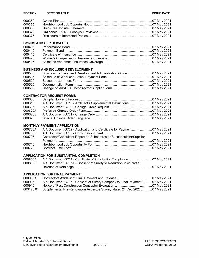
000350 Ozone Plan ...................................................................................................... 07 May 2021
000355 Neighborhood Job Opportunities ..................................................................... 07 May 2021
000360 Drug-Free Jobsite Statement ........................................................................... 07 May 2021
000370 Ordinance 27748 - Lobbyist Provisions ........................................................... 07 May 2021
000375 Disclosure of Interested Parties ....................................................................... 07 May 2021
BONDS AND CERTIFICATES
000405 Performance Bond ........................................................................................... 07 May 2021
000410 Payment Bond ................................................................................................. 07 May 2021
000415 Certificate of Insurance .................................................................................... 07 May 2021
000420 Worker's Compensation Insurance Coverage ................................................. 07 May 2021
000425 Asbestos Abatement Insurance Coverage ...................................................... 07 May 2021
BUSINESS AND INCLUSION DEVELOPMENT
000505 Business Inclusion and Development Administration Guide ........................... 07 May 2021
000515 Schedule of Work and Actual Payment Form .................................................. 07 May 2021
000520 Subcontractor Intent Form ............................................................................... 07 May 2021
000525 Documentation Form ....................................................................................... 07 May 2021
000530 Change of M/WBE Subcontractor/Supplier Form ............................................ 07 May 2021
CONTRACTOR REQUEST FORMS
000605 Sample Notice to Proceed ............................................................................... 07 May 2021
000610 AIA Document G710 - Architect's Supplemental Instructions ......................... 07 May 2021
000615 AIA Document G709 - Change Order Request ............................................... 07 May 2021
000620A Preferred Change Order Form ......................................................................... 07 May 2021
000620B AIA Document G701 - Change Order .............................................................. 07 May 2021
000625 Special Change Order Language .................................................................... 07 May 2021
MONTHLY PAYMENT APPLICATION
000700A AIA Document G702 - Application and Certificate for Payment ...................... 07 May 2021
000700B AIA Document G703 - Continuation Sheet ...................................................... 07 May 2021
000705 Contractor/Consultant Report on Subcontractor/Subconsultant/Supplier Payment ........................................................................................................... 07 May 2021
000710 Neighborhood Job Opportunity Form .............................................................. 07 May 2021
000720 Contract Time Form ......................................................................................... 07 May 2021
APPLICATION FOR SUBSTANTIAL COMPLETION
000800A AIA Document G704 - Certificate of Substantial Completion .......................... 07 May 2021
000800B AIA Document G707A - Consent of Surety to Reduction in or Partial Release of Retainage ...................................................................................... 07 May 2021
APPLICATION FOR FINAL PAYMENT
000905A Contractors Affidavit of Final Payment and Release ....................................... 07 May 2021
000905B AIA Document G707 - Consent of Surety Company to Final Payment ........... 07 May 2021
000915 Notice of Post Construction Contractor Evaluation ......................................... 07 May 2021
003126.01 Supplemental Pre-Renovation Asbestos Survey, dated 21 Dec 2020 ............ 07 May 2021

SECTION SECTION TITLE ISSUE DATE
City of Dallas Dallas Arboretum & Botanical Garden TABLE OF CONTENTS DeGolyer Estate Restroom Improvements 000010 - 3 GSRA Project No. 2602
TABLE OF CONTENTS
VOLUME 2
DIVISION 1 - GENERAL REQUIREMENTS 011000 Summary .......................................................................................................... 07 May 2021 012200 Unit Prices ........................................................................................................ 07 May 2021 012500 Substitution Procedures ................................................................................... 07 May 2021 Substitution Request Form 012600 Contract Modification Procedures .................................................................... 07 May 2021 012973 Schedule of Values .......................................................................................... 07 May 2021 013100 Project Management and Coordination ........................................................... 07 May 2021 013119 Project Meetings .............................................................................................. 07 May 2021 013200 Construction Progress Documentation ............................................................ 07 May 2021 013300 Submittal Procedures ....................................................................................... 07 May 2021 013516 Alteration Project Procedures .......................................................................... 07 May 2021 014200 References ....................................................................................................... 07 May 2021 015000 Temporary Facilities and Controls ................................................................... 07 May 2021 015300 Mold Prevention Measures .............................................................................. 07 May 2021 016000 Product Requirements ..................................................................................... 07 May 2021 017300 Execution ......................................................................................................... 07 May 2021 017329 Cutting and Patching ........................................................................................ 07 May 2021 017400 Cleaning ........................................................................................................... 07 May 2021 017419 Construction Waste Management and Disposal ............................................. 07 May 2021 017500 Starting and Adjusting ...................................................................................... 07 May 2021 017700 Closeout Procedures ....................................................................................... 07 May 2021 017800 Closeout Submittals ......................................................................................... 07 May 2021 017823 Operation and Maintenance Material ............................................................... 07 May 2021 017839 Project Record Documents .............................................................................. 07 May 2021 018119 Indoor Air Quality Management ....................................................................... 07 May 2021
DIVISION 2 – EXISTING CONDITIONS
024119 Selective Demolition ........................................................................................ 07 May 2021 DIVISION 3 - CONCRETE NOT USED DIVISION 4 – MASONRY
040100 Masonry Restoration and Cleaning ................................................................. 07 May 2021 040511 Masonry Mortaring and Grouting ..................................................................... 07 May 2021
DIVISION 5 - METALS 054000 Cold-Formed Metal Framing ............................................................................ 07 May 2021 055001 Metal Fabrications ............................................................................................ 07 May 2021 DIVISION 6 - WOOD AND PLASTICS 061000 Rough Carpentry .............................................................................................. 07 May 2021 064023 Interior Architectural Woodwork ....................................................................... 07 May 2021 066400 Plastic Paneling ............................................................................................... 07 May 2021 DIVISION 7 - THERMAL AND MOISTURE PROTECTION 070150.19 Preparation for Reroofing ................................................................................. 07 May 2021 072100 Thermal Insulation ........................................................................................... 07 May 2021 073200 Clay Roof Tile .................................................................................................. 07 May 2021 076200 Sheet Metal Flashing and Trim ........................................................................ 07 May 2021 077100 Roof Specialties ............................................................................................... 07 May 2021

SECTION SECTION TITLE ISSUE DATE
City of Dallas Dallas Arboretum & Botanical Garden TABLE OF CONTENTS DeGolyer Estate Restroom Improvements 000010 - 4 GSRA Project No. 2602
077200 Roof Accessories ............................................................................................. 07 May 2021 079200 Joint Sealants .................................................................................................. 07 May 2021
DIVISION 8 - DOORS AND WINDOWS 080300 Conservation Treatment for Period Openings ................................................. 07 May 2021 081113 Hollow Metal Doors and Frames ..................................................................... 07 May 2021 081216 Aluminum Frames ............................................................................................ 07 May 2021 081426 Flush Wood Doors ........................................................................................... 07 May 2021 083100 Floor Access Door ........................................................................................... 07 May 2021 085113 Aluminum Windows ......................................................................................... 07 May 2021 087100 Door Hardware ................................................................................................. 07 May 2021 088000 Glazing ............................................................................................................. 07 May 2021 088113 Decorative Glass Glazing ................................................................................ 07 May 2021 088300 Mirrors .............................................................................................................. 07 May 2021 089000 Louvers and Vents ........................................................................................... 07 May 2021
DIVISION 9 - FINISHES 090190.52 Maintenance Repainting .................................................................................. 07 May 2021 092216 Non-Structural Metal Framing .......................................................................... 07 May 2021 092423.10 Cement Stucco Renovation ............................................................................. 07 May 2021 092424 Interior Cement Plaster Repair ........................................................................ 07 May 2021 092900 Gypsum Board ................................................................................................. 07 May 2021 093000 Tiling ................................................................................................................. 07 May 2021 095100 Acoustical Panel Ceilings ................................................................................. 07 May 2021 098116 Acoustical Blanket Insulation ........................................................................... 07 May 2021 099000 Painting ............................................................................................................ 07 May 2021
DIVISION 10 - SPECIALTIES 101400 Signage ............................................................................................................ 07 May 2021 102113 Toilet Compartments ........................................................................................ 07 May 2021 102800 Toilet and Bath Accessories ............................................................................ 07 May 2021 104400 Fire Protection Specialties ............................................................................... 07 May 2021 105910 Aluminum Counter Support Brackets .............................................................. 07 May 2021
DIVISION 11 - EQUIPMENT NOT USED
DIVISION 12 - FURNISHINGS 123662 Engineered Surfacings ..................................................................................... 07 May 2021
DIVISION 13 - SPECIAL CONSTRUCTION NOT USED DIVISION 14 - CONVEYING SYSTEMS
NOT USED
DIVISION 21 – FIRE SUPPRESSION
NOT USED
DIVISION 22 – PLUMBING
220500 Common Work Results for Plumbing .............................................................. 07 May 2021 220517 Sleeves and Sleeve Seals for Plumbing Piping .............................................. 07 May 2021 220519 Meters and Gages for Plumbing Piping .......................................................... 07 May 2021 220523 General-Duty Valves for Plumbing Piping ...................................................... 07 May 2021 220529 Hangers and Supports for Plumbing Piping and Equipment .......................... 07 May 2021 220533 Heat Tracing for Plumbing Piping ................................................................... 07 May 2021 220553 Identification for Plumbing Piping and Equipment .......................................... 07 May 2021

SECTION SECTION TITLE ISSUE DATE
City of Dallas Dallas Arboretum & Botanical Garden TABLE OF CONTENTS DeGolyer Estate Restroom Improvements 000010 - 5 GSRA Project No. 2602
220719 Plumbing Piping Insulation .............................................................................. 07 May 2021 221116 Domestic Water Piping ................................................................................... 07 May 2021 221123 Domestic Water Pumps .................................................................................. 07 May 2021 221314 Storm Drainage, Sanitary Waste and Vent Piping .......................................... 07 May 2021 223400 Fuel-Fired Domestic Water Heaters ............................................................... 07 May 2021 224000 Plumbing Fixtures ........................................................................................... 07 May 2021 224019 Plumbing Specialties ....................................................................................... 07 May 2021 224700 Electric Water Coolers .................................................................................... 07 May 2021
DIVISION 23 – HEATING VENTILATION AND AIR CONDITIONING
230510 Basic Mechanical Requirements .................................................................... 07 May 2021 230513 Common Motor Requirements for HVAC Equipment ...................................... 07 May 2021 230529 Hangers and Supports for HVAC Piping and Equipment ............................... 07 May 2021 230553 Identification for HVAC Piping and Equipment ............................................... 07 May 2021 230593 Testing, Adjusting, and Balancing for HVAC .................................................. 07 May 2021 230713 Duct Insulation ................................................................................................ 07 May 2021 230719 HVAC Piping Insulation ................................................................................... 07 May 2021 231123 Facility Natural-Gas Piping ............................................................................. 07 May 2021 232113 Hydronic Piping ............................................................................................... 07 May 2021 232300 Refrigerant Piping ........................................................................................... 07 May 2021 233113 Metal Ducts ..................................................................................................... 07 May 2021 233300 Air Duct Accessories ....................................................................................... 07 May 2021 233713 Air Diffusers, Registers, and Grilles ................................................................ 07 May 2021 238129 Variable Refrigerant Flow HVAC Systems ..................................................... 07 May 2021 238239 Unit Heaters .................................................................................................... 07 May 2021 DIVISION 26 – ELECTRICAL
260500 Common Work Results for Electrical .............................................................. 07 May 2021 260519 Low-Voltage Electrical Power Conductors and Cables ................................... 07 May 2021 260526 Grounding and Bonding for Electrical Systems ............................................... 07 May 2021 260529 Hangers and Supports for Electrical Systems ................................................ 07 May 2021 260533 Raceway and Boxes for Electrical Systems ................................................... 07 May 2021 260544 Sleeves and Sleeve Seals for Electrical Raceways and Cabling ................... 07 May 2021 260553 Identification for Electrical Systems ................................................................ 07 May 2021 262416 Panelboards .................................................................................................... 07 May 2021 262726 Wiring Devices ................................................................................................ 07 May 2021 262813 Fuses .............................................................................................................. 07 May 2021 262816 Enclosed Switches and Circuit Breakers ........................................................ 07 May 2021 265119 LED Interior Lighting ....................................................................................... 07 May 2021 265219 Emergency and Exit Lighting .......................................................................... 07 May 2021 265619 LED Exterior Lighting ...................................................................................... 07 May 2021 DIVISION 27 – COMMUNICATIONS NOT USED
DIVISION 28 – ELECTRONIC SAFETY AND SECURITY
NOT USED DIVISION 31 - EARTHWORK
NOT USED DIVISION 32 – EXTERIOR IMPROVEMENTS
321400 Unit Paving ....................................................................................................... 07 May 2021 323231 Wood Fences and Gates ................................................................................. 07 May 2021 DIVISION 33 – UTILITIES
NOT USED END OF TABLE OF CONTENTS

2270 Springlake Road, Ste 800 Farmers Branch, Texas 75234
Telephone 972-919-3300
www.atcgroupservices.com
December 21, 2020
Ms. Mahbuba Khan
Senior Architect / Project Manager
City of Dallas / Park and Recreation
1500 Marilla Street, 6FN
Dallas, TX 75201
Subject: Supplemental Pre-Renovation Asbestos Survey
Dallas Arboretum – DeGolyer House (Servant Quarters / Green House) 8525 Garland Road Dallas, Texas 75218
ATC Project Number: NPCOD20011
Dear Ms. Khan, ATC Group Services, LLC (ATC) was retained by City of Dallas / Park and Recreation to perform a supplemental asbestos survey of the materials expected to be impacted during the renovation of the Dallas Arboretum – DeGolyer House Servant’s Quarters and Green House located at 8525 Garland Road in Dallas, Texas (the Site). This investigation included a review of a previous asbestos report dated June 22, 2018, a visual inspection and physical survey to identify suspect asbestos-containing materials (ACMs) and evaluate their general condition. The scope of work for this assessment included the sampling and laboratory analysis of suspect friable and non-friable ACMs in the proposed renovation areas, as depicted by drawings provided by ATC.
Site Description The site consists of a one story historical servant’s house and green house, which is planned for renovations for public restroom installations. Square footage of the Site is approximately 2,400 square feet (SF). ATC only sampled supplemental materials, which were expected to be disturbed during renovations. Supplemental suspect ACMs that may be disturbed during restoration/remediation activities included the following materials: Grout (2 types); roof shingles; window caulk; flashing caulk; window glazing (2 types); sink undercoat; subfloor vapor barrier; door frame caulk; and HVAC duct mastic (2 types).
ACM Survey Bulk sampling was conducted in general accordance with procedures outlined in the Texas Department of State Health Services (TDSHS) Texas Asbestos Health Protection Rules (TAHPR) and the U.S. Environmental Protection Agency (EPA) guidance document entitled Guidance for Controlling Asbestos-Containing Materials in Buildings (Document No. 560/5-85/024). The asbestos inspection was performed by ATC Representatives Mr. John Bjorn Olson (TDSHS Asbestos Inspector License No. 603772) and Mr. Drew Benson (TDSHS Asbestos Inspector License No. 602409) on December 8, 2020.
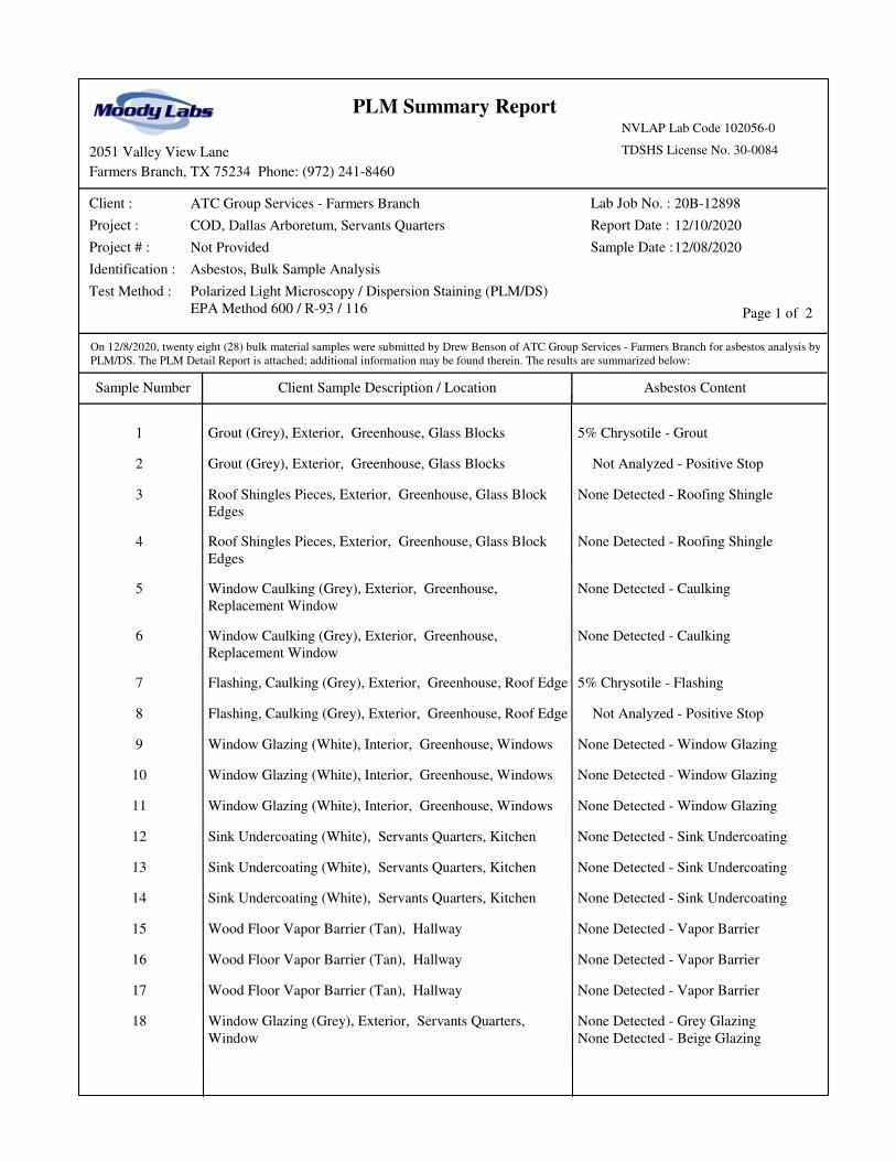
ATC collected 28 (twenty-eight) bulk samples of suspect ACMs from the Site. Bulk samples of suspect materials were analyzed by Moody Labs, LLC (TDSHS Laboratory License No. 30-0084) in Farmers Branch, Texas, using approved polarized light microscopy with dispersion staining (PLM/DS) methods.

December 21, 2020 Page 2 of 5
ATC Project No. NPCOD20011
Moody Labs, LLC is accredited with the EPA Interim Asbestos Bulk Sample Analysis Quality Assurance Program and the National Voluntary Laboratory Accreditation Program (NVLAP Labe Code 102056-0). The PLM/DS analytical method is modeled after U.S. EPA Publication EPA/600/R-93/116: Test Method for the Determination of Asbestos in Bulk Materials, July 1993. If a material is identified as containing greater than 1% asbestos, it is considered to be an ACM. The complete asbestos laboratory report, dated December 10, 2020 is attached.
Limitations This report is not to be utilized as a bidding document or as a project specification document since it does not have all the components required to serve as an Asbestos Project Design document or an Abatement Work plan. Our professional services have been performed, our findings obtained, and our conclusions prepared in accordance with customary principles and practices in the fields of environmental science and engineering. This statement is in lieu of other statements either expressed or implied. This report does not warrant against future operations or conditions, nor does it warrant against operations or conditions present of a type or at a location not investigated. This report is certified to the City of Dallas / Park and Recreation. The scope of services performed in execution of this evaluation may not be appropriate to satisfy the needs of other users, and use or re-use of this document or the findings, conclusions, or recommendations is at the risk of said user.
Conclusions Asbestos (greater than 1%) was identified in the following materials:
Block Window Grout (Grey) – 5% Chrysotile, Associated with Green House, Approximately 64 SF
Roof Flashing Mastic (Grey) – 5% Chrysotile, Associated with Green House, Approximately 30
Linear Feet (LF)
HVAC Mastic (White) – 10% Chrysotile, Associated with Green House Electrical Room Attic,
Approximately 20 LF
HVAC Mastic (Black) – 60% Chrysotile, Associated with Green House Electrical Room Attic,
Approximately 8 LF
Door Frame Caulking (Grey) – 5% Chrysotile, Associated with Green House Electrical Room,
Approximately 20 LF
Recommendations The asbestos-containing HVAC mastic, door frame caulk, block window grout, and metal flashing mastic are classified as a Category II Non-Friable ACM. These materials are regulated by the TDSHS, EPA National Emission Standards for Hazardous Air Pollutants (NESHAP), and the OSHA rules and regulations. ATC offers the following recommendations:
Removal of the asbestos-containing materials must be performed in accordance with TAHPR,
OSHA, and NESHAP regulations by a TDSHS-licensed asbestos abatement contractor, under the
direction of a TDSHS – licensed Individual Asbestos Consultant and specification.
It is recommended that the waste should be disposed of in a landfill that accepts asbestos waste.
The asbestos-containing materials may be left in place under an operations and maintenance
program as long as the material remains undisturbed by renovation activities.

December 21, 2020 Page 3 of 5
ATC Project No. NPCOD20011
The remaining sampled materials were reported as non-detect for the presence of asbestos. Therefore, they are not regulated and can be removed and disposed of as construction debris. If any additional materials are to be disturbed during renovation activities, these materials must be assumed to contain asbestos until sampling and analysis proves otherwise. Additional ACM may be present at the site in inaccessible or concealed spaces. These spaces include, but are not limited to, pipe chases, spaces between wall/ceiling/door/floor cavities, interior of mechanical components such as boiler cavities, interior ducts, beneath foundation pads, etc. If future maintenance/renovation/demolition activities make these areas accessible, ATC recommends that a thorough assessment of these spaces be conducted at that time to identify and confirm the presence or absence of additional ACMs. Until then, all such unidentified materials should be treated as assumed ACM in accordance with 40 CFR 76.
Attached are the laboratory results for the samples submitted. Please feel free to call us at (972) 919-3300 should you have any questions or require additional information. Sincerely, ATC Group Services LLC
John Bjorn Olson, OHST TDSHS Asbestos Inspector License No. 603772 Direct Line +1 972 919 3324 Email: [email protected]
Drew Benson TDSHS Asbestos Inspector License No. 602409 Direct Line +1 972 919 3322 Email: [email protected]
Catherine G. McLain, MS, CMC, CIH Senior Technical Review/Practice Group Leader TDSHS IAC License No. 105451 Direct Line +1 346 227 7971 Email: [email protected]
Enc: Table 1: Sample Results
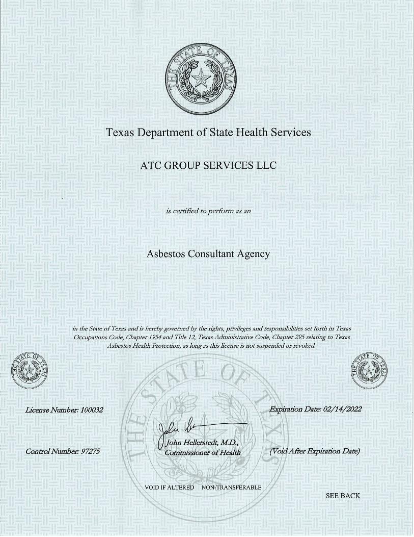
PLM Summary Report ATC Survey Data Form and Chain of Custody Sample Location Drawing Photo Log Licenses/Certification

December 21, 2020 Page 4 of 5
ATC Project No. NPCOD20011
TABLE 1: SAMPLE RESULTS
DALLAS ARBORETUM – DEGOLYER HOUSE SERVANTS QUARTERS & GREEN HOUSE
8525 GARLAND ROAD DALLAS, TEXAS 75218
ATC PROJECT NO. NPCOD20011
Sample
Number
Material
Description Location(s)
Approximate
Quantity
Friability
N/L/H
Damage
N/M/S Results %
01 Block Window Grout (Grey)
Green House Exterior
64 SF L N 5% Chrysotile
Asbestos
02 Block Window Grout (Grey)
Green House Exterior
--- L N PS
03 Asphalt Roof
Shingles (Red) Green House
Exterior Corner NA N N ND
04 Asphalt Roof
Shingles (Red)
Green House Exterior Corner
by Block Windows
NA N N ND
05 Window Caulking
(Grey) Green House
Exterior NA N N ND
06 Window Caulking
(Grey) Green House
Exterior NA N N ND
07 Flashing
Caulking (Grey) Green House
Exterior 30 LF N N
5% Chrysotile Asbestos
08 Flashing
Caulking (Grey) Green House
Exterior --- N N PS
09 Window Glazing
(White) Green House
Interior NA H Y ND
10 Window Glazing
(White) Green House
Interior NA H Y ND
11 Window Glazing
(White) Green House
Interior NA H Y ND
12 Sink Undercoating
(White)
Servants Quarters Kitchen
NA N N ND
13 Sink Undercoating
(White) Servants Quarters Kitchen
NA N N ND
14 Sink Undercoating
(White) Servants Quarters Kitchen
NA N N ND
15 Wood Floor Vapor
Barrier (Tan) Servants Quarters
NA N N ND
16 Wood Floor Vapor
Barrier (Tan) Servants Quarters
NA N N ND
17 Wood Floor Vapor
Barrier (Tan) Servants Quarters
NA N N ND
18 Window Glazing
(Grey)
Servants Quarters Exterior Window
NA N N ND

December 21, 2020 Page 5 of 5
ATC Project No. NPCOD20011
TABLE 1: SAMPLE RESULTS DALLAS ARBORETUM – DEGOLYER HOUSE
SERVANTS QUARTERS & GREEN HOUSE 8525 GARLAND ROAD DALLAS, TEXAS 75218
ATC PROJECT NO. NPCOD20011
Sample
Number
Material
Description Location(s)
Approximate
Quantity
Friability
N/L/H
Damage
N/M/S Results %
19 Window Glazing
(Grey)
Servants Quarters Exterior Window
NA N N ND
20 Door Frame
Caulking (Grey)
Green House Electrical
Room 20 LF N M
5% Chrysotile Asbestos
21 Door Frame
Caulking (Grey)
Green House Electrical
Room --- N M PS
22 Door Frame
Caulking (Grey)
Green House Electrical
Room --- N M PS
23 HVAC Mastic
(White) Attic Electrical
Room 20 LF L M
10% Chrysotile Asbestos
24 HVAC Mastic
(White) Attic Electrical
Room --- L M PS
25 HVAC Mastic
(White) Attic Electrical
Room --- L M PS
26 HVAC Mastic
(Black) Attic Electrical
Room 8 LF L M
60% Chrysotile Asbestos
27 HVAC Mastic
(Black) Attic Electrical
Room --- L M PS
28 HVAC Mastic
(Black) Attic Electrical
Room --- L M PS
Results: ND = None Detected PS= Positive Stop Quantity: SF=Square Feet LF=Linear Feet --- = Same as Above Friability: N=None L=Low H=High --- = Same as Above Damage: N=None M=Minor S=Significant --- = Same as Above Asbestos: (1) Amosite, (2) Chrysotile, (3) Crocidolite
PLM Summary Report
Client :
Project :
Project # :
Identification :
Test Method :
ATC Group Services - Farmers Branch
COD, Dallas Arboretum, Servants Quarters
Not Provided
Asbestos, Bulk Sample Analysis
Sample Number Client Sample Description / Location Asbestos Content
Sample Date :
On 12/8/2020, twenty eight (28) bulk material samples were submitted by Drew Benson of ATC Group Services - Farmers Branch for asbestos analysis by
PLM/DS. The PLM Detail Report is attached; additional information may be found therein. The results are summarized below:
Page 1 of 2
Lab Job No. :
Report Date :
20B-12898
12/08/2020
12/10/2020
NVLAP Lab Code 102056-0
TDSHS License No. 30-0084
Polarized Light Microscopy / Dispersion Staining (PLM/DS)
EPA Method 600 / R-93 / 116
2051 Valley View Lane
Farmers Branch, TX 75234 Phone: (972) 241-8460
1 Grout (Grey), Exterior, Greenhouse, Glass Blocks 5% Chrysotile - Grout
2 Grout (Grey), Exterior, Greenhouse, Glass Blocks Not Analyzed - Positive Stop
3 Roof Shingles Pieces, Exterior, Greenhouse, Glass Block
Edges
None Detected - Roofing Shingle
4 Roof Shingles Pieces, Exterior, Greenhouse, Glass Block
Edges
None Detected - Roofing Shingle
5 Window Caulking (Grey), Exterior, Greenhouse,
Replacement Window
None Detected - Caulking
6 Window Caulking (Grey), Exterior, Greenhouse,
Replacement Window
None Detected - Caulking
7 Flashing, Caulking (Grey), Exterior, Greenhouse, Roof Edge 5% Chrysotile - Flashing
8 Flashing, Caulking (Grey), Exterior, Greenhouse, Roof Edge Not Analyzed - Positive Stop
9 Window Glazing (White), Interior, Greenhouse, Windows None Detected - Window Glazing
10 Window Glazing (White), Interior, Greenhouse, Windows None Detected - Window Glazing
11 Window Glazing (White), Interior, Greenhouse, Windows None Detected - Window Glazing
12 Sink Undercoating (White), Servants Quarters, Kitchen None Detected - Sink Undercoating
13 Sink Undercoating (White), Servants Quarters, Kitchen None Detected - Sink Undercoating
14 Sink Undercoating (White), Servants Quarters, Kitchen None Detected - Sink Undercoating
15 Wood Floor Vapor Barrier (Tan), Hallway None Detected - Vapor Barrier
16 Wood Floor Vapor Barrier (Tan), Hallway None Detected - Vapor Barrier
17 Wood Floor Vapor Barrier (Tan), Hallway None Detected - Vapor Barrier
18 Window Glazing (Grey), Exterior, Servants Quarters,
Window
None Detected - Grey Glazing
None Detected - Beige Glazing

PLM Summary Report
Client :
Project :
Project # :
Identification :
Test Method :
ATC Group Services - Farmers Branch
COD, Dallas Arboretum, Servants Quarters
Not Provided
Asbestos, Bulk Sample Analysis
Sample Number Client Sample Description / Location Asbestos Content
Sample Date :
On 12/8/2020, twenty eight (28) bulk material samples were submitted by Drew Benson of ATC Group Services - Farmers Branch for asbestos analysis by
PLM/DS. The PLM Detail Report is attached; additional information may be found therein. The results are summarized below:
Page 2 of 2
Lab Job No. :
Report Date :
20B-12898
12/08/2020
12/10/2020
NVLAP Lab Code 102056-0
TDSHS License No. 30-0084
Polarized Light Microscopy / Dispersion Staining (PLM/DS)
EPA Method 600 / R-93 / 116
2051 Valley View Lane
Farmers Branch, TX 75234 Phone: (972) 241-8460
19 Window Glazing (Grey), Exterior, Servants Quarters,
Window
None Detected - Grey Glazing
None Detected - Beige Glazing
20 Door Caulking (Grey), Electrical Room off Greenhouse 5% Chrysotile - Caulking
21 Door Caulking (Grey), Electrical Room off Greenhouse Not Analyzed - Positive Stop
22 Door Caulking (Grey), Electrical Room off Greenhouse Not Analyzed - Positive Stop
23 Mastic (White), Ducting in Attic 10% Chrysotile - White Mastic
24 Mastic (White), Ducting in Attic Not Analyzed - Positive Stop
25 Mastic (White), Ducting in Attic Not Analyzed - Positive Stop
26 Mastic (Black), Ducting in Attic 60% Chrysotile - Black Mastic
27 Mastic (Black), Ducting in Attic Not Analyzed - Positive Stop
28 Mastic (Black), Ducting in Attic Not Analyzed - Positive Stop
Brian R. Schmidt, Nathan WoodAnalyst(s):
Lab Director : Bruce Crabb Approved Signatory :
Thank you for choosing Moody Labs
Lab Manager : Heather Lopez Approved Signatory :
These samples were analyzed by layers. Quantification, unless otherwise noted, is performed by calibrated visual
estimate. The test report shall not be reproduced, except in full, without written approval of the laboratory. The results
relate only to the items tested. These test results do not imply endorsement by NVLAP or any agency of the U.S.
Government. Accredited by the National Voluntary Laboratory Accreditation Program for Bulk Asbestos Fiber Analysis
under Lab Code 102056-0.

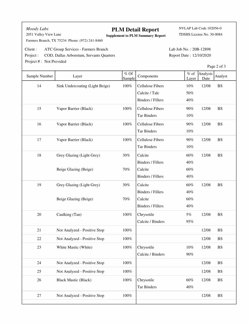
PLM Detail Report
Project # : Not Provided
Page 1 of 3
Sample Number Layer Components% Of
Sample
Analysis
Date
% of
LayerAnalyst
Supplement to PLM Summary Report
Client :
Project :
ATC Group Services - Farmers Branch
COD, Dallas Arboretum, Servants Quarters
Lab Job No. :
Report Date :
20B-12898
12/10/2020
2051 Valley View Lane
Farmers Branch, TX 75234 Phone: (972) 241-8460
Moody Labs NVLAP Lab Code 102056-0
TDSHS License No. 30-0084
Chrysotile1 Grout (Grey) 100% 12/085% NW
Calcite1 Grout (Grey) 100% 12/0855% NW
Binders / Fillers1 Grout (Grey) 100% 12/0840% NW
2 Not Analyzed - Positive Stop 100% 12/08 NW
Aggregate3 Sand Layer (Tan) 15% 12/08100% NW
Calcite / Tar Binders3 Roofing Shingle (Black) 85% 12/08100% NW
Aggregate4 Sand Layer (Tan) 15% 12/08100% NW
Calcite / Tar Binders4 Roofing Shingle (Black) 85% 12/08100% NW
Calcite5 Caulking (Off-White) 100% 12/0850% NW
Binders / Fillers5 Caulking (Off-White) 100% 12/0850% NW
Calcite6 Caulking (Off-White) 100% 12/0850% NW
Binders / Fillers6 Caulking (Off-White) 100% 12/0850% NW
Chrysotile7 Flashing (Black) 100% 12/085% BS
Calcite / Tar Binders7 Flashing (Black) 100% 12/0895% BS
8 Not Analyzed - Positive Stop 100% 12/08 BS
Calcite / Talc9 Window Glazing (Off-White) 100% 12/0860% BS
Binders / Fillers9 Window Glazing (Off-White) 100% 12/0840% BS
Calcite / Talc10 Window Glazing (Off-White) 100% 12/0860% BS
Binders / Fillers10 Window Glazing (Off-White) 100% 12/0840% BS
Calcite / Talc11 Window Glazing (Off-White) 100% 12/0860% BS
Binders / Fillers11 Window Glazing (Off-White) 100% 12/0840% BS
Cellulose Fibers12 Sink Undercoating (Light Beige) 100% 12/0810% BS
Calcite / Talc12 Sink Undercoating (Light Beige) 100% 12/0850% BS
Binders / Fillers12 Sink Undercoating (Light Beige) 100% 12/0840% BS
Cellulose Fibers13 Sink Undercoating (Light Beige) 100% 12/0810% BS
Calcite / Talc13 Sink Undercoating (Light Beige) 100% 12/0850% BS
Binders / Fillers13 Sink Undercoating (Light Beige) 100% 12/0840% BS
PLM Detail Report
Project # : Not Provided
Page 2 of 3
Sample Number Layer Components% Of
Sample
Analysis
Date
% of
LayerAnalyst
Supplement to PLM Summary Report
Client :
Project :
ATC Group Services - Farmers Branch
COD, Dallas Arboretum, Servants Quarters
Lab Job No. :
Report Date :
20B-12898
12/10/2020
2051 Valley View Lane
Farmers Branch, TX 75234 Phone: (972) 241-8460
Moody Labs NVLAP Lab Code 102056-0
TDSHS License No. 30-0084
Cellulose Fibers14 Sink Undercoating (Light Beige) 100% 12/0810% BS
Calcite / Talc14 Sink Undercoating (Light Beige) 100% 12/0850% BS
Binders / Fillers14 Sink Undercoating (Light Beige) 100% 12/0840% BS
Cellulose Fibers15 Vapor Barrier (Black) 100% 12/0890% BS
Tar Binders15 Vapor Barrier (Black) 100% 12/0810% BS
Cellulose Fibers16 Vapor Barrier (Black) 100% 12/0890% BS
Tar Binders16 Vapor Barrier (Black) 100% 12/0810% BS
Cellulose Fibers17 Vapor Barrier (Black) 100% 12/0890% BS
Tar Binders17 Vapor Barrier (Black) 100% 12/0810% BS
Calcite18 Grey Glazing (Light Grey) 30% 12/0860% BS
Binders / Fillers18 Grey Glazing (Light Grey) 30% 12/0840% BS
Calcite18 Beige Glazing (Beige) 70% 12/0860% BS
Binders / Fillers18 Beige Glazing (Beige) 70% 12/0840% BS
Calcite19 Grey Glazing (Light Grey) 30% 12/0860% BS
Binders / Fillers19 Grey Glazing (Light Grey) 30% 12/0840% BS
Calcite19 Beige Glazing (Beige) 70% 12/0860% BS
Binders / Fillers19 Beige Glazing (Beige) 70% 12/0840% BS
Chrysotile20 Caulking (Tan) 100% 12/085% BS
Calcite / Binders20 Caulking (Tan) 100% 12/0895% BS
21 Not Analyzed - Positive Stop 100% 12/08 BS
22 Not Analyzed - Positive Stop 100% 12/08 BS
Chrysotile23 White Mastic (White) 100% 12/0810% BS
Calcite / Binders23 White Mastic (White) 100% 12/0890% BS
24 Not Analyzed - Positive Stop 100% 12/08 BS
25 Not Analyzed - Positive Stop 100% 12/08 BS
Chrysotile26 Black Mastic (Black) 100% 12/0860% BS
Tar Binders26 Black Mastic (Black) 100% 12/0840% BS
27 Not Analyzed - Positive Stop 100% 12/08 BS

PLM Detail Report
Project # : Not Provided
Page 3 of 3
Sample Number Layer Components% Of
Sample
Analysis
Date
% of
LayerAnalyst
Supplement to PLM Summary Report
Client :
Project :
ATC Group Services - Farmers Branch
COD, Dallas Arboretum, Servants Quarters
Lab Job No. :
Report Date :
20B-12898
12/10/2020
2051 Valley View Lane
Farmers Branch, TX 75234 Phone: (972) 241-8460
Moody Labs NVLAP Lab Code 102056-0
TDSHS License No. 30-0084
28 Not Analyzed - Positive Stop 100% 12/08 BS


01
Green
House
Elec.
Room
Kitchen
Subfloor Access
.John Bjorn Olson
TDSHS Inspector
License No. 603772
City of Dallas
Dallas Arboretum – Servants Quarters
8525 Garland Road
Dallas, Texas
Sample Locations Drawing
Project No. NPCOD20011
Legend
01 – Non- ACM Sample Location
01 – ACM Sample Location
17
04
Drew Benson
TDSHS Inspector
License No. 602409
02
05 06
16
18
19
23 24 2526 27 28
03
0807
09 10 11
12
13
14
15
20 21 22
Subfloor Access

City of Dallas – Dallas Arboretum – DeGolyer House Servant’s Quarters
Supplemental Asbestos Survey 8525 Garland Road Dallas, Texas 75218
Project No. NPCOD20011 1 ATC Group Services, LLC
Photo 1: Exterior DeGolyer House Front Photo 2: Exterior of Green House and Servants Quarters
Photo 3: Green House Exterior Windows Photo 4: Green House Block Windows
Photo 5: Block Window Grout and Grey Caulking Photo 6: Interior Green House Window Glazing

City of Dallas – Dallas Arboretum – DeGolyer House Servant’s Quarters
Supplemental Asbestos Survey 8525 Garland Road Dallas, Texas 75218
Project No. NPCOD20011 2 ATC Group Services, LLC
Photo 7: Servants Quarters Kitchen Sinks Photo 8: Subfloor
Photo 9: Subfloor Vapor Barrier Photo 10: Attic Access Hatch
Photo 11: Attic Space above Servants Quarters (No Air
Ducts) Photo 12: Exterior Windows where Doors will be Installed

City of Dallas – Dallas Arboretum – DeGolyer House Servant’s Quarters
Supplemental Asbestos Survey 8525 Garland Road Dallas, Texas 75218
Project No. NPCOD20011 3 ATC Group Services, LLC
Photo 13: Exterior Window Glazing Photo 14: Window Glazing Debris Pile underneath Window
Photo 15: Green House Electrical Room Attic Hatch Photo 16: HVAC Duct Debris above Electrical Room
Photo 17: HVAC Duct Mastic (White) and (Black) Photo 18: No Insulation in Attic above Ceiling Plaster


�ˇ�����˝���������� �/�L�F�H�Q�V�H���'�H�W�D�L�O�V
�K�W�W�S�V�˛�����Y�R���U�D�V���G�V�K�V���V�W�D�W�H���W�[���X�V���G�D�W�D�P�D�U�W���G�H�W�D�L�O�V�3�U�L�Q�W�7�;�5�$�6���G�R�"�D�Q�F�K�R�U� �U�H�V�W�R�U�H ������
�1�D�P�H�˛
�/�L�F�H�Q�V�H���7�\�S�H�˛
�/�L�F�H�Q�V�H���6�W�D�W�X�V�˛
�(�[ �S�L�U�\���' �D�W�H�˛
�(�I�I�H�F�W�L�Y�H���5�D�Q�N���' �D�W�H�˛
�/�L�F�H�Q�V�H�H��V���5�R�O�H�˛
�5�H�O�D�W�H�G���3�D�U�W�\���5�R�O�H�˛
�6�W�D�W�X�V�˛
�( �[ �S�L�U�D�W�L�R�Q�'�D�W�H�˛
�/�L�F�H�Q�V�H���1�X�P �E�H�U� �̨����� �˘ �� �˘ �� �&�X�U�U�H�Q�W���'�D�W�H��̨��� �ˇ �� �� �˝ �� �� �� �� �� ������ � �̨� �ˆ ���$�0
�0 �&�/�$�, �1�����&�$�7�+�( �5�,�1�( ���*
�$�V�E�H�V�W�R�V���,�Q�G�L�Y�L�G�X�D�O���&�R�Q�V�X�O�W�D�Q�W
�&�X�U�U�H�Q�W
�� �� �� �� �˙ �� �� �� �� ��
�� �˘ �� �� �˝ �� �� �� �� �ˇ
�$�G�G�U�H�V�V�H�V �� ���0 �D�L�Q���$�G�G�U�H�V�V �$�G�G�U�H�V�V �+�2�8�6�7�2�1�������7�;
�+�$�5�5�,�6
�ˆ �ˆ �� �ˆ ��
�8�6
�0 �D�L�O�L�Q�J���$�G�G�U�H�V�V�����( �Q�W�H�U���Q�D�P �H�R�I���F�R�P �S�D�Q�\ ���R�U���L�Q�G�L�Y�L�G�X�D�O�D�V�V�R�F�L�D�W�H�G���Z�L�W�K���W�K�H���P�D�L�O�L�Q�J�D�G�G�U�H�V�V��
�$�G�G�U�H�V�V �0 �&�/ �$�,�1�����&�$�7�+�( �5�,�1�( ���*
�+�2�8�6�7�2�1�������7�;
�+�$�5�5�,�6
�ˆ �ˆ �� �ˆ ��
�8�6
�3�K�R�Q�H���1�X�P�E�H�U�˛ �ˆ �� �� �� �� �� �ˆ �˙ �ˆ ��
�$�V�E�H�V�W�R�V���&�R�Q�V�X�O�W�D�Q�W���$�J�H�Q�F�\���'�H�V�L�J�Q�D�W�H�G���3�H�U�V�R�Q
�$�V�E�H�V�W�R�V���,�Q�G�L�Y�L�G�X�D�O���&�R�Q�V�X�O�W�D�Q�W
�$�V�E�H�V�W�R�V���&�R�Q�V�X�O�W�D�Q�W���$�J�H�Q�F�\
�5�H�O�D�W�H�G���3�D�U�W�\ ���1�D�P �H �/�L�F�H�Q�V�H �$�G�G�U�H�V�V ��
�$�7�&���*�5�2�8�3���6�(�5�9�,�&�( �6���/�/�&
�$�V�E�H�V�W�R�V���&�R�Q�V�X�O�W�D�Q�W���$�J�H�Q�F�\�� �� �� �� �� �� ��
�&�X�U�U�H�Q�W
�� �� �� �� �� �� �� �� �� ��
�� �ˇ �� �ˇ ���: �( �6�7�&�+�$�6�( ���'�5 �,�9�(
�+�2�8�6�7�2�1�������7�;
�+�$�5�5�,�6
�ˆ �ˆ �� �� ��
�8�6


City of Dallas Dallas Arboretum & Botanical Garden SUMMARY DeGolyer Estate Restroom Improvements 011000 - 1 GSRA Project No. 2602
SECTION 011000
SUMMARY
PART 1 - GENERAL
1.1 RELATED DOCUMENTS
A. Drawings and general provisions of the Contract, including General and Supplementary Conditions and other Division 01 Specification Sections, apply to this Section.
1.2 SUMMARY
A. Section includes: 1. Project information. 2. Work covered by Contract Documents. 3. Work by Owner. 4. Access to site. 5. Coordination with occupants. 6. Work restrictions. 7. Specification and drawing conventions.
1.3 PROJECT INFORMATION
A. Project Identification: DeGolyer Estate Envelope Repair. 1. Project Location: 8525 Garland Road, Dallas, Texas 75218.
B. Owner: City of Dallas Park and Recreation Department. C. User: Dallas Arboretum and Botanical Garden, Dallas, Texas 75218. D. Architect: GSR Andrade Architects, Dallas, Texas 75226.
1.4 WORK COVERED BY CONTRACT DOCUMENTS
A. The Work of the Project is defined by the Contract Documents and consists of the following: 1. Interior Work in the DeGolyer Estate Caretaker Wing, including demolition of the
existing interior walls, doors, ceilings, floors, fixtures, select windows, etc., and interior renovations for a new men’s restroom, women’s restroom, family restroom, lobby, custodial room and storage room.
2. Exterior Work, including architectural and envelope improvements associated with the DeGolyer Estate Caretaker Wing. a. Removal of three (3) windows and wall below to create three (3) new doorways. b. Restoration of one (1) window. c. Inclusion of two (2) louver openings, as required for mechanical improvements.
3. Site Work outside of the Caretaker Wing, including stone paved walkways, mechanical yard fencing improvements and landscape improvements to damaged areas.
B. Type of Contract 1. Project will be constructed under a single prime contract.
1.5 WORK BY OWNER
A. General: Cooperate fully with Owner so work may be carried out smoothly, without interfering with or delaying work under this Contract or work by Owner. Coordinate the Work of this Contract with work performed by Owner.
1.6 ACCESS TO SITE
A. General: Contractor shall have full use of Project site for construction operations during construction period. Contractor's use of Project site is limited only by Owner's right to perform work or to retain other contractors on portions of Project.
B. Use of Site: Limit use of Project site to work in areas indicated. Do not disturb portions of Project site beyond areas in which the Work is indicated.
C. Condition of Existing Building: Maintain portions of existing building affected by construction operations in a weathertight condition throughout construction period. Repair damage caused

City of Dallas Dallas Arboretum & Botanical Garden SUMMARY DeGolyer Estate Restroom Improvements 011000 - 2 GSRA Project No. 2602
by construction operations.
1.1 COORDINATION WITH OCCUPANTS A. Full Owner Occupancy: Owner will occupy site and/or existing/adjacent building(s) or
room(s) during entire construction period. Cooperate with Owner during construction operations to minimize conflicts and facilitate Owner usage. Perform the Work so as not to interfere with Owner's day-to-day operations. Maintain existing exits unless otherwise indicated. 1. Maintain access to existing walkways, corridors, and other adjacent occupied or used
facilities. Do not close or obstruct walkways, corridors, or other occupied or used facilities without written permission from Owner and approval of authorities having jurisdiction.
2. Notify the Owner not less than 72 hours in advance of activities that will affect Owner's operations.
B. Partial Owner Occupancy: Owner will occupy the premises during entire construction period, with the exception of areas under construction. Cooperate with Owner during construction operations to minimize conflicts and facilitate Owner usage. Perform the Work so as not to interfere with Owner's operations. Maintain existing exits unless otherwise indicated. 1. Maintain access to existing walkways, corridors, and other adjacent occupied or used
facilities. Do not close or obstruct walkways, corridors, or other occupied or used facilities without written permission from Owner and authorities having jurisdiction.
2. Provide not less than 72 hours' notice to Owner of activities that will affect Owner's operations.
1.7 WORK RESTRICTIONS
A. Work Restrictions, General: Comply with restrictions on construction operations. 1. Comply with limitations on use of public streets and other requirements of authorities
having jurisdiction. B. On-Site Work Hours: Limit work in the existing building to AFTER normal business
working hours, from 6:00 p.m. to 8:00 a.m., Monday through Saturday, except as otherwise indicated or approved by Owner. 1. Hours for Core Drilling and other noisy activity: Coordinate with Owner. Perform
when building/area is least occupied. C. Existing Utility Interruptions: Do not interrupt utilities serving facilities occupied by Owner or
others unless permitted under the following conditions and then only after providing temporary utility services according to requirements indicated: 1. Notify Owner not less than two days in advance of proposed utility interruptions. 2. Obtain Owner's written permission before proceeding with utility interruptions.
D. Noise, Vibration, and Odors: Coordinate operations that may result in high levels of noise and vibration, odors, or other disruption to Owner occupancy with Owner. 1. Notify Owner not less than two days in advance of proposed disruptive operations. 2. Obtain Owner's written permission before proceeding with disruptive operations.
E. Nonsmoking Building: Smoking is not permitted within the building or within 25 feet of entrances, operable windows, or outdoor air intakes.
F. Employee Identification: Provide identification tags for Contractor personnel working on the Project site. Require personnel to utilize identification tags at all times.
G. Use of Existing Building: Maintain existing building in a weathertight condition throughout construction period. Repair damage caused by construction operations. Protect building and its occupants during construction period.
1.8 SPECIFICATION AND DRAWING CONVENTIONS A. Specification Content: The Specifications use certain conventions for the style of language
and the intended meaning of certain terms, words, and phrases when used in particular situations. These conventions are as follows: 1. Imperative mood and streamlined language are generally used in the Specifications.

City of Dallas Dallas Arboretum & Botanical Garden SUMMARY DeGolyer Estate Restroom Improvements 011000 - 3 GSRA Project No. 2602
The words "shall," "shall be," or "shall comply with," depending on the context, are implied where a colon (:) is used within a sentence or phrase.
2. Specification requirements are to be performed by Contractor unless specifically stated otherwise.
B. Division 01 General Requirements: Requirements of Sections in Division 01 apply to the Work of all Sections in the Specifications.
C. Drawing Coordination: Requirements for materials and products identified on the Drawings are described in detail in the Specifications. One or more of the following are used on the Drawings to identify materials and products: 1. Terminology: Materials and products are identified by the typical generic terms used in
the individual Specifications Sections. 2. Abbreviations: Materials and products are identified by abbreviations published as part
of the U.S. National CAD Standard and scheduled on Drawings. 3. Keynoting: Materials and products are identified by reference keynotes referencing
Specification Section numbers found in this Project Manual.
PART 2 - PRODUCTS (Not Used)
PART 3 - EXECUTION (Not Used)
END OF SECTION

City of Dallas
Dallas Arboretum & Botanical Garden UNIT PRICES DeGolyer Estate Restroom Improvements 012200 - 1 GSRA Project No. 2602
SECTION 012200
UNIT PRICES
PART 1 - GENERAL 1.1 GENERAL:
A. Where unit prices are stated in the Contract Documents, the unit price shall include, except as otherwise noted, the providing of all costs required for the complete construction of the specified unit of work, including: cost of materials and delivery; cost of installation labor, including social security, insurance and other required fringe benefits; workman's compensation insurance; bond premiums; rental value of equipment and machinery; taxes; incidental expenses; and supervision.
B. Each unit price shall be total cost or credit to Owner. C. Materials and methods for unit prices shall be in accordance with applicable product specifications
included in this Project Manual.
1.2 METHOD OF ADJUSTMENT: A. Unit prices stated in the Contract Documents are for adjusting the Cost of Work in case of
variations of quantities from the Work described in the Contract Documents. B. Except as otherwise specified, unit prices stated shall apply to both deductive and additive
variations of quantities. C. Unit prices included in the Agreement shall remain in effect until date of final completion of entire
Work. D. Adjustment to Cost of the Work will be by Change Order on basis of net accumulative change for
each category.
1.3 PROCEDURES A. Unit prices include all necessary material, plus cost for delivery, installation, insurance, overhead,
and profit. B. Measurement and Payment: Refer to individual Specification Sections for work that requires
establishment of unit prices. Methods of measurement and payment for unit prices are specified in those Sections.
C. Owner reserves the right to reject Contractor's measurement of work-in-place that involves use of established unit prices and to have this work measured, at Owner's expense, by an independent surveyor acceptable to Contractor.
D. List of Unit Prices: A schedule of unit prices is included in Part 3. Specification Sections referenced in the schedule contain requirements for materials described under each unit price.
PART 2 – PRODUCTS (Not Used) PART 3 – EXECUTION 3.1. SCHEDULE OF UNIT PRICES:
A. Unit Price No. 1 – Wood Roof Deck Replacement: 1. Replacing deteriorated decking or non-matching decking as specified in Section 061000. 2. Unit of measurement: Per sq. ft.
B. Unit Price No. 2 – Clay Roof Tile Replacement: 1. Replacement of additional clay roof tile as specified in Section 073200. 2. Unit of measurement: Per tile.
C. Unit Price No. 3 – Exterior Painting of Stucco: 1. Additional painting of exterior stucco as specified in Sections 092423.10 and 099600. 2. Unit of measurement: Per sq. ft.
D. Unit Price No. 4 – Interior Painting: 1. Additional painting of interior walls or ceiling as specified in Sections 090190.52 and
099000. 2. Unit of measurement: Per sq. ft.
END OF SECTION

City of Dallas Dallas Arboretum & Botanical Garden DeGolyer Estate Restroom Improvements
ALTERNATESGSRA Project No. 2602012300 - 1
SECTION 012300
ALTERNATES
PART 1 - GENERAL
1.1 RELATED DOCUMENTS A. Drawings and general provisions of the Contract, including General and Supplementary
Conditions and other Division 01 Specification Sections, apply to this Section.
1.2 SUMMARY A. Section includes administrative and procedural requirements for alternates.
1.3 DEFINITIONS A. Alternate: An amount proposed by bidders and stated on the Bid Form for certain work defined
in the Bidding Requirements that may be added to or deducted from the base bid amount if Owner decides to accept a corresponding change either in the amount of construction to be completed or in the products, materials, equipment, systems, or installation methods described in the Contract Documents. 1. Alternates described in this Section are part of the Work only if enumerated in the
Agreement. 2. The cost or credit for each alternate is the net addition to or deduction from the Contract
Sum to incorporate alternate into the Work. No other adjustments are made to the Contract Sum.
1.4 PROCEDURES 1. Include as part of each alternate, miscellaneous devices, accessory objects, and similar
items incidental to or required for a complete installation whether or not indicated as part of alternate.
B. Notification: Immediately following award of the Contract, notify each party involved, in writing, of the status of each alternate. Indicate if alternates have been accepted, rejected, or deferred for later consideration. Include a complete description of negotiated modifications to alternates.
C. Execute accepted alternates under the same conditions as other work of the Contract. D. Schedule: A schedule of alternates is included at the end of this Section. Specification
Sections referenced in schedule contain requirements for materials necessary to achieve the work described under each alternate.
PART 2 - PRODUCTS (Not Used)
PART 3 - EXECUTION
3.1 SCHEDULE OF ALTERNATES A. Alternate No. 1:
1.
END OF SECTION

City of Dallas Dallas Arboretum & Botanical Garden SUBSTITUTION PROCEDURES DeGolyer Estate Restroom Improvements 012500 - 1 GSRA Project No. 2602
SECTION 012500
SUBSTITUTION PROCEDURES
PART 1 - GENERAL
1.1 RELATED DOCUMENTS
A. Drawings and general provisions of the Contract, including General and Supplementary Conditions and other Division 01 Specification Sections, apply to this Section.
1.2 SUMMARY
A. Section includes administrative and procedural requirements for substitutions.
1.3 DEFINITIONS
A. Substitutions: Changes in products, materials, equipment, and methods of construction from those required by the Contract Documents and proposed by Contractor. 1. Substitutions for Cause: Changes proposed by Contractor that are required due to
changed Project conditions, such as unavailability of product, regulatory changes, or unavailability of required warranty terms.
2. Substitutions for Convenience: Changes proposed by Contractor or Owner that are not required in order to meet other Project requirements but may offer advantage to Contractor or Owner.
1.4 SUBMITTALS
A. Substitution Requests: Submit one PDF file of each request for consideration. Identify product or fabrication or installation method to be replaced. Include Specification Section number and title and Drawing numbers and titles. 1. Substitution Request Form: Use CSI Form 13.1A. 2. Documentation: Show compliance with requirements for substitutions and the following,
as applicable: a. Statement indicating why specified product or fabrication or installation can not be
provided, if applicable. b. Coordination information, including a list of changes or modifications needed to
other parts of the Work and to construction performed by Owner and separate contractors that will be necessary to accommodate proposed substitution.
c. Detailed comparison of significant qualities of proposed substitution with those of the Work specified. Include annotated copy of applicable specification section. Significant qualities may include attributes such as performance, weight, size, durability, visual effect, sustainable design characteristics, warranties, and specific features and requirements indicated. Indicate deviations, if any, from the Work specified.
d. Product Data, including drawings and descriptions of products and fabrication and installation procedures.
e. Samples, where applicable or requested. f. Certificates and qualification data, where applicable or requested. g. List of similar installations for completed projects with project names and
addresses and names and addresses of architects and owners. h. Material test reports from a qualified testing agency indicating and interpreting
test results for compliance with requirements indicated. i. Research reports evidencing compliance with building code in effect for Project,
from ICC- ES. j. Detailed comparison of Contractor's construction schedule using proposed
substitution with products specified for the Work, including effect on the overall Contract Time. If specified product or method of construction cannot be provided within the Contract Time, include letter from manufacturer, on

City of Dallas Dallas Arboretum & Botanical Garden SUBSTITUTION PROCEDURES DeGolyer Estate Restroom Improvements 012500 - 2 GSRA Project No. 2602
manufacturer's letterhead, stating date of receipt of purchase order, lack of availability, or delays in delivery.
k. Cost information, including a proposal of change, if any, in the Contract Sum. l. Contractor's certification that proposed substitution complies with requirements in
the Contract Documents except as indicated in substitution request, is compatible with related materials, and is appropriate for applications indicated.
3. Contractor's waiver of rights to additional payment or time that may subsequently become necessary because of failure of proposed substitution to produce indicated results.Architect's Action: If necessary, Architect will request additional information or documentation for evaluation within 7 days of receipt of a request for substitution. Architect will notify Contractor of acceptance or rejection of proposed substitution within 15 days of receipt of request, or seven days of receipt of additional information or documentation, whichever is later. a. Forms of Acceptance: Change Order, Construction Change Directive, or
Architect's Supplemental Instructions for minor changes in the Work. b. Use product specified if Architect does not issue a decision on use of a proposed
substitution within time allocated.
1.5 QUALITY ASSURANCE
A. Compatibility of Substitutions: Investigate and document compatibility of proposed substitution with related products and materials. Engage qualified testing agency to perform compatibility tests recommended by manufacturers.
1.6 PROCEDURES A. Coordination: Modify or adjust affected work as necessary to integrate work of the approved
substitutions.
PART 2 - PRODUCTS
2.1 SUBSTITUTIONS A. Substitutions for Cause: Submit requests for substitution immediately upon discovery of need
for change, but not later than 15 days prior to time required for preparation and review of related submittals. 1. Conditions: Architect will consider Contractor's request for substitution when the
following conditions are satisfied. If the following conditions are not satisfied, Architect will return requests without action, except to record noncompliance with these requirements: a. Requested substitution is consistent with the Contract Documents and will
produce indicated results. b. Substitution request is fully documented and properly submitted. c. Requested substitution will not adversely affect Contractor's construction
schedule. d. Requested substitution has received necessary approvals of authorities having
jurisdiction. e. Requested substitution is compatible with other portions of the Work. f. Requested substitution has been coordinated with other portions of the Work. g. Requested substitution provides specified warranty. h. If requested substitution involves more than one contractor, requested substitution
has been coordinated with other portions of the Work, is uniform and consistent, is compatible with other products, and is acceptable to all contractors involved.
B. Substitutions for Convenience: Not allowed, unless otherwise indicated. C. Substitutions for Convenience: Architect will consider requests for substitution if received within
60 days after commencement of the Work. Requests received after that time may be considered or rejected at discretion of Architect. 1. Conditions: Architect will consider Contractor's request for substitution when the
following conditions are satisfied. If the following conditions are not satisfied, Architect will return requests without action, except to record noncompliance with these

City of Dallas Dallas Arboretum & Botanical Garden SUBSTITUTION PROCEDURES DeGolyer Estate Restroom Improvements 012500 - 3 GSRA Project No. 2602
requirements: a. Requested substitution offers Owner a substantial advantage in cost, time, energy
conservation, or other considerations, after deducting additional responsibilities Owner must assume. Owner's additional responsibilities may include compensation to Architect for redesign and evaluation services, increased cost of other construction by Owner, and similar considerations.
b. Requested substitution does not require extensive revisions to the Contract Documents.
c. Requested substitution is consistent with the Contract Documents and will produce indicated results.
d. Substitution request is fully documented and properly submitted. e. Requested substitution will not adversely affect Contractor's construction
schedule. f. Requested substitution has received necessary approvals of authorities having
jurisdiction. g. Requested substitution is compatible with other portions of the Work. h. Requested substitution has been coordinated with other portions of the Work. i. Requested substitution provides specified warranty. j. If requested substitution involves more than one contractor, requested substitution
has been coordinated with other portions of the Work, is uniform and consistent, is compatible with other products, and is acceptable to all contractors involved.
PART 3 - EXECUTION (Not Used)
END OF SECTION

City of Dallas Dallas Arboretum & Botanical Garden DeGolyer Estate Restroom Improvements
SUBSTITUTION REQUEST FORMGSRA Project No. 2602012500.13 - 1
SECTION 012500.13
SUBSTITUTION REQUEST FORM
PROJECT: (After Contract Award)
TO: _________________________________
_________________________________
NO. ____________ DATE: _________________________________
Contractor hereby requests acceptance of the following product or system as a substitution in accordance with provisions of Division 01 Section “Substitution Procedures:”
1. SPECIFIED PRODUCT OR SYSTEM
Substitution request for: _________________________________________________
Specification Section No.: _________________ Article/ Paragraph:
2. REASON FOR SUBSTITUTION REQUEST
SPECIFIED PRODUCT . . . PROPOSED PRODUCT . . .
Is no longer available. Will reduce construction time
Is unable to meet project schedule. Will result in cost savings of
Is unsuitable for the designated application. $ to Project
Cannot interface with adjacent materials. Is for supplier’s convenience
Is not compatible with adjacent materials. Is for subcontractor’s convenience
Cannot provide the specified warranty. Other:
Cannot be constructed as indicated _________________________________________
Cannot be obtained due to one or more of the following:
Strike Bankruptcy of manufacturer or supplier
Lockout Similar occurrence (explain below)
3. SUPPORTING DATA
Drawings, specifications, product data, performance data, test data, and any other necessary information to
facilitate review of the Substitution Request are attached.
Sample is attached. Sample will be sent if requested.
4. QUALITY COMPARISON
Provide all necessary side-by-side comparative data as required to facilitate review of Substitution Request:
SPECIFIED PRODUCT PROPOSED PRODUCT
Manufacturer: __________________________ ___________________________
Name / Brand: __________________________ ___________________________

City of Dallas Dallas Arboretum & Botanical Garden DeGolyer Estate Restroom Improvements
SUBSTITUTION REQUEST FORMGSRA Project No. 2602
012500.13 - 2
Catalog No.: __________________________ ___________________________
Vendor: __________________________ ___________________________
Variations: __________________________ ___________________________
(Add Additional Sheets If Necessary)
Local Distributor or Supplier: ___________________________________________
Maintenance Service Available:
Spare Parts Source:
Warranty:
5. PREVIOUS INSTALLATIONS
Identification of at least three similar projects on which proposed substitution was used:
PROJECT #1:
Project: _______________________________________________________
Address: _______________________________________________________
_______________________________________________________
Architect: _______________________________________________________
Owner: _______________________________________________________
Contractor: _______________________________________________________
Date Installed: ___________________________
PROJECT #2:
Project: _______________________________________________________
Address: _______________________________________________________
_______________________________________________________
Architect: _______________________________________________________
Owner: _______________________________________________________
Contractor: _______________________________________________________
Date Installed: _
6. EFFECT OF SUBSTITUTION
Proposed substitution affects other work or trades:
_______________________________________________________________________
_______________________________________________________________________

City of Dallas Dallas Arboretum & Botanical Garden DeGolyer Estate Restroom Improvements
SUBSTITUTION REQUEST FORMGSRA Project No. 2602
012500.13 - 3
Proposed substitution requires dimensional revisions or redesign of architectural, structural, M-E-P, life safety, or other
work:
No Yes (if Yes, attach data explaining revisions)
7. STATEMENT OF CONFORMANCE OF REQUEST TO CONTRACT REQUIREMENTS
Contractor and Subcontractor have investigated the proposed substitution and hereby represent that:
A. They have personally investigated the proposed substitution and believe that it is equal to or superior in all respects to specified product, except as stated above;
B. The proposed substitution is in compliance with applicable codes and ordinances;
C. The proposed substitution will provide same warranty as specified for specified product;
D. They will coordinate the incorporation of the proposed substitution into the Work, and will include modifications to the Work as required to fully integrate the substitution;
E. They have included complete cost data and implications of the substitution (attached);
F. They will pay any redesign fees incurred by the Architect or any of the Architect’s consultants, and any special inspection costs incurred by the Owner, caused by the use of this product;
G. They waive all future claims for added cost or time to the Contract related to the substitution, or that become known after substitution is accepted.
H. The Architect’s approval, if granted, will be based upon reliance upon data submitted and the opinion, knowledge, information, and belief of the Architect at the time decision is rendered and Addendum is issued; and that Architect’s approval therefore is interim in nature and subject to reevaluation and reconsideration as additional data, materials, workmanship, and coordination with other work are observed and reviewed.
Contractor: ________________________________________ (Name of Contractor)
Date:___________________ By:
Subcontractor:
(Name of Subcontractor)
Date:___________________ By:
Note: Unresponsive or incomplete requests will be rejected and returned without review.
8. ARCHITECT'S REVIEW AND ACTION
Substitution is accepted.
Substitution is accepted, with the following comments:
___________________________________________________________________
___________________________________________________________________
Resubmit Substitution Request:
Provide more information in the following areas: ________________
_______________________________________________________________
_______________________________________________________________
Provide proposal indicating amount of savings / credit to Owner

City of Dallas Dallas Arboretum & Botanical Garden DeGolyer Estate Restroom Improvements
SUBSTITUTION REQUEST FORMGSRA Project No. 2602
012500.13 - 4
Bidding Contractor shall sign Bidder's Statement of Conformance
Bidding Subcontractor shall sign Bidder's Statement of Conformance
Substitution is not accepted:
Substitution Request received too late.
Substitution Request received directly from subcontractor or supplier.
Substitution Request not submitted in accordance with requirements.
Substitution Request Form is not properly executed.
Substitution Request does not indicate what item is being proposed.
Insufficient information submitted to facilitate proper evaluation.
Proposed product does not appear to comply with specified requirements.
Proposed product will require substantial revisions to Contract Documents.
By: ___________________________________________
Date:
Architect has relied upon the information provided by the Contractor, and makes no claim as to the accuracy, completeness, or validity of such information. If an accepted substitution is later found to be not in compliance with the Contract Documents, Contractor shall provide the specified product.
9. OWNER’S REVIEW AND ACTION
Substitution is accepted; Architect to prepare Change Order.
Substitution is not accepted.
Owner will pay Architect directly for redesign fees.
Include Architect’s Additional Service fee for implementing the substitution in the Change Order.
By: ____________________________________________
(Owner/Owner's Representative)
Date:
END OF FORM

City of Dallas
Dallas Arboretum & Botanical Garden CONTRACT MODIFICATION PROCEDURES
DeGolyer Estate Restroom Improvements 012600 - 1 GSRA Project No. 2602
SECTION 012600
CONTRACT MODIFICATION PROCEDURES
PART 1 - GENERAL
1.01 SUMMARY
A. This Section specifies administrative and procedural requirements for handling and processing Contract modifications.
B. Related Requirements: 1. Conditions of the Contract.
1.02 MINOR CHANGES IN THE WORK
A. Architect will issue supplemental instructions authorizing Minor Changes in the Work, not involving adjustment to the Contract Sum or the Contract Time, on AIA Document G710, "Architect's Supplemental Instructions" or Architect’s standard form.
1.03 PROPOSAL REQUESTS
A. Owner-Initiated Proposal Requests: Architect will issue a detailed description of proposed changes in the Work that may require adjustment to the Contract Sum or the Contract Time. If necessary, the description will include supplemental or revised Drawings and Specifications. 1. Proposal Requests issued by Architect are for information only. Do not consider them
instructions either to stop work in progress or to execute the proposed change. 2. Within 20 days or within time specified in Proposal Request after receipt of Proposal
Request, submit a quotation estimating cost adjustments to the Contract Sum and the Contract Time necessary to execute the change. a. Include a list of quantities of products required or eliminated and unit costs, with total
amount of purchases and credits to be made. If requested, furnish survey data to substantiate quantities.
b. Indicate applicable taxes, delivery charges, equipment rental, and amounts of trade discounts.
c. Include an updated Contractor's Construction Schedule that indicates the effect of the change, including, but not limited to, changes in activity duration, start and finish times, and activity relationship. Use available total float before requesting an extension of the Contract Time.
B. Contractor-Initiated Proposals: If latent or unforeseen conditions require modifications to the Contract, Contractor may propose changes by submitting a request for a change to Architect 1. Include a statement outlining reasons for the change and the effect of the change on the
Work. Provide a complete description of the proposed change. Indicate the effect of the proposed change on the Contract Sum and the Contract Time.
2. Include a list of quantities of products required or eliminated and unit costs, with total amount of purchases and credits to be made. If requested, furnish survey data to substantiate quantities.
3. Indicate applicable taxes, delivery charges, equipment rental, and amounts of trade discounts.
4. Include an updated Contractor's Construction Schedule that indicates the effect of the change, including, but not limited to, changes in activity duration, start and finish times, and activity relationship. Use available total float before requesting an extension of the Contract Time.
5. Comply with requirements in Division 1 Section "Product Requirements" if the proposed change requires substitution of one product or system for product or system specified.
C. Proposal Request Form: AIA Document G709 Proposal Requests or Architect’s standard form.

City of Dallas
Dallas Arboretum & Botanical Garden CONTRACT MODIFICATION PROCEDURES
DeGolyer Estate Restroom Improvements 012600 - 2 GSRA Project No. 2602
1.04 CHANGE ORDER PROCEDURES
A. On approval of a Proposal Request, Architect will issue a Change Order for signatures of Owner and Contractor on AIA Document G701.
B. Description: Written Change of work within Contract Scope consisting of additions, deletions and other revisions, including proposed basis for adjustment to Contract Sum and Contract Time. Change Orders are signed by Owner, Architect and Contractor. Owner’s signature authorized changes.
C. Procedure: Document is prepared and signed by Architect; sent to Contractor for acceptance and signature; approved and signed by Owner; distributed to Architect and Contractor. Contractor shall perform changes upon receipt.
D. Lump Sum Change Order: Based on Proposal Request and Contractor’s sum quotation, or Contractor’s request for Change Order as approved by Architect.
E. Unit Price Change Order: 1. For predetermined unit prices and quantities, Change Order will be executed on a lump
sum basis. 2. For unit costa or quantities of work which are not predetermined, execute work and utilize
standard Public Works prices. Changes in Contract Sum or Time will be computed as specified for time and material Change Order.
F. Correlation of Contractor Submittals: 1. Promptly revise Schedule of Values and Application for Payment Forms to record each
authorized Change Order as a separate line item and adjust the Contract Sum as shown on Change Order.
2. Promptly revise Progress Schedules to reflect any change in Contract Time, revise sub-schedules to adjust times for other items of work affected by the change, and resubmit.
3. Promptly enter changes in Project Record Documents.
1.05 CONSTRUCTION CHANGE DIRECTIVE
A. Construction Change Directive: Architect may issue a Construction Change Directive on AIA Document G714. Construction Change Directive instructs Contractor to proceed with a change in the Work, for subsequent inclusion in a Change Order. 1. Construction Change Directive contains a complete description of change in the Work. It
also designates method to be followed to determine change in the Contract Sum or the Contract Time.
B. Documentation: Maintain detailed records on a time and material basis of work required by the Construction Change Directive. 1. After completion of change, submit an itemized account and supporting data necessary to
substantiate cost and time adjustments to the Contract.
PART 2 - PRODUCTS (NOT USED)
PART 3 - EXECUTION (NOT USED)
END OF SECTION

City of Dallas
Dallas Arboretum & Botanical Garden SCHEDULE OF VALUES
DeGolyer Estate Restroom Improvements 012973 - 1 GSRA Project No. 2602
SECTION 012973
SCHEDULE OF VALUES
PART 1 - GENERAL
1.01 SUMMARY
A. Procedures for preparation and submittal of Schedule of Values.
1.02 RELATED SECTIONS
A. General Conditions, where applicable.
1.03 FORM OF SUBMITTAL
A. Submit typewritten Schedule of Values on AIA Form G703, “Continuation Sheet” of Application and Certificate for Payment.
B. Use Table of Contents of this Project Manual as basis of format for listing costs of work for sections under Divisions 00 – 32.
C. Identify each line item with number and title respective major section of Specifications.
1.04 PREPARING SCHEDULE OF VALUES
A. Schedule shall list component parts of Work in sufficient detail to serve as a basis for computing values for progress payments during construction.
B. Itemize separate line item cost for Work required by each section, or groups of sections, of this Project Manual.
C. For each major subcontract, list products and operations of that subcontract as separate line items.
D. In addition to line item costs of each specification section, furnish line item costs for each of the following general cost items. 1. Bonds and insurance. 2. Field supervision and layout. 3. Temporary facilities and controls. 4. Testing 5. Other General Conditions or General Requirements items.
E. List allowances in specified amount for each allowance.
F. Each line item in the Schedule of Values shall include its proper share of overhead and profit.
G. Sum of all values listed in schedule shall equal total Contract Sum.
1.05 SUBMITTAL
A. Submit 3 copies of Schedule of Values at least 15 days prior to submitting first Application for Payment.
B. Upon request by Owner’s Representative or Architect, support values given with such data that will substantiate their correctness.
PART 2 - PRODUCTS (NOT APPLICABLE)
PART 3 - EXECUTION (NOT APPLICABLE)
END OF SECTION

City of Dallas Dallas Arboretum & Botanical Garden PROJECT MANAGEMENT & COORDINATION DeGolyer Estate Restroom Improvements 013100 - 1 GSRA Project No. 2602
SECTION 013100
PROJECT MANAGEMENT AND COORDINATION
PART 1 - GENERAL
1.1 RELATED DOCUMENTS
A. Drawings and general provisions of the Contract, including General and Supplementary Conditions and other Division 01 Specification Sections, apply to this Section.
1.2 SUMMARY
A. Section includes administrative provisions for coordinating construction operations on Project including, but not limited to, the following: 1. General project coordination procedures. 2. Administrative and supervisory personnel. 3. Coordination drawings. 4. Requests for Information (RFIs). 5. Project Web site.
B. Each contractor shall participate in coordination requirements. Certain areas of responsibility are assigned to a specific contractor.
1.3 DEFINITIONS
A. RFI: Request from Owner, Architect, or Contractor seeking information from each other during construction.
1.4 COORDINATION
A. Coordination: Coordinate construction operations included in different Sections of the Specifications to ensure efficient and orderly installation of each part of the Work. Coordinate construction operations, included in different Sections that depend on each other for proper installation, connection, and operation. 1. Schedule construction operations in sequence required to obtain the best results where
installation of one part of the Work depends on installation of other components, before or after its own installation.
2. Coordinate installation of different components to ensure maximum performance and accessibility for required maintenance, service, and repair.
3. Make adequate provisions to accommodate items scheduled for later installation. B. Prepare memoranda for distribution to each party involved, outlining special procedures
required for coordination. Include such items as required notices, reports, and list of attendees at meetings. 1. Prepare similar memoranda for Owner and separate contractors if coordination of
their Work is required. C. Administrative Procedures: Coordinate scheduling and timing of required administrative
procedures with other construction activities to avoid conflicts and to ensure orderly progress of the Work. Such administrative activities include, but are not limited to, the following: 1. Preparation of Contractor's construction schedule. 2. Preparation of the schedule of values. 3. Installation and removal of temporary facilities and controls. 4. Delivery and processing of submittals. 5. Progress meetings. 6. Pre-Installation conferences. 7. Project closeout activities. 8. Startup and adjustment of systems. 9. Project closeout activities.
1.5 KEY PERSONNEL
A. Key Personnel Names: Within 15 days of starting construction operations, submit a list of key

City of Dallas Dallas Arboretum & Botanical Garden PROJECT MANAGEMENT & COORDINATION DeGolyer Estate Restroom Improvements 013100 - 2 GSRA Project No. 2602
personnel assignments, including superintendent and other personnel in attendance at Project site. Identify individuals and their duties and responsibilities; list addresses and telephone numbers, including home, office, and cellular telephone numbers and email addresses. Provide names, addresses, and telephone numbers of individuals assigned as standbys in the absence of individuals assigned to Project. 1. Post copies of list in project meeting room, in temporary field office, and by each
temporary
telephone. Keep list current at all times.
1.6 REQUESTS FOR INFORMATION (RFIs)
A. General: Immediately on discovery of the need for additional information or interpretation of the Contract Documents, Contractor shall prepare and submit an RFI. All RFIs should be sent directly to the Architect via email or posted to project collaboration site (if one is being utilized). The Architect will redistribute to the appropriate reviewer. 1. Architect will return RFIs submitted to Architect by other entities controlled by
Contractor with no response. 2. Coordinate and submit RFIs in a prompt manner so as to avoid delays in Contractor's
work or work of subcontractors. B. Content of the RFI: Include a detailed, legible description of item needing information or
interpretation and the following: 1. Project name. 2. Project number. 3. Date. 4. Name of Contractor. 5. Name of Architect. 6. RFI number, numbered sequentially. 7. RFI subject. 8. RFI Question 9. Specification Section number and title and related paragraphs, as appropriate. 10. Drawing number and detail references, as appropriate. 11. Field dimensions and conditions, as appropriate. 12. Contractor's suggested resolution. If Contractor's solution(s) impacts the Contract
Time or the Contract Sum, Contractor shall state impact in the RFI. 13. Contractor's signature. 14. Attachments: Include sketches, descriptions, measurements, photos, Product Data,
Shop Drawings, coordination drawings, and other information necessary to fully describe items needing interpretation. a. Include dimensions, thicknesses, structural grid references, and details of
affected materials, assemblies, and attachments on attached sketches. C. RFI Forms: Software-generated form with substantially the same content as indicated above,
acceptable to Architect. RFIs should be emailed to Architect with the following format standards: 1) RFI should include RFI # in subject line of email along with brief description; 2) Body of email should include question or description of RFI and suggestion. Sketches or other necessary documents should be attached to email in PDF format.
D. Architect's Action: Architect will review each RFI, determine action required, and respond. Allow 7 business days for Architect's response for each RFI. RFIs received by Architect after 1:00 p.m. will be considered as received the following working day. 1. The following RFIs will be returned without action:
a. Requests for approval of submittals. b. Requests for approval of substitutions. c. Requests for coordination information already indicated in the Contract
Documents. d. Requests for adjustments in the Contract Time or the Contract Sum. e. Requests for interpretation of Architect's actions on submittals. f. Incomplete RFIs or inaccurately prepared RFIs.
2. Architect's action may include a request for additional information, in which case Architect's time for response will date from time of receipt of additional information.
3. Architect's action on RFIs that may result in a change to the Contract Time or the

City of Dallas Dallas Arboretum & Botanical Garden PROJECT MANAGEMENT & COORDINATION DeGolyer Estate Restroom Improvements 013100 - 3 GSRA Project No. 2602
Contract Sum may be eligible for Contractor to submit Change Proposal according to Division 01 Section "Contract Modification Procedures." a. If Contractor believes the RFI response warrants change in the Contract
Time or the Contract Sum, notify Architect in writing within 10 days of receipt of the RFI response.
E. On receipt of Architect's action, update the RFI log and immediately distribute the RFI response to affected parties. Review response and notify Architect within seven days if Contractor disagrees with response.
F. RFI Log: Prepare, maintain, and submit a tabular log of RFIs organized by the RFI number. Submit log weekly. Submit log with not less than the following: 1. RFI Log Date 2. Project name. 3. Name and address of Contractor. 4. Name and address of Architect and Construction Manager.
5. RFI number including RFIs that were dropped and not submitted. 6. RFI description. 7. Date the RFI was submitted. 8. Request Date 9. Date Architect's and Construction Manager's response was received. 10. Identification of related Minor Change in the Work, Construction Change Directive, and
Proposal Request, as appropriate. 11. Identification of related Field Order, Work Change Directive, and Proposal Request, as
appropriate.
1.7 PROJECT MEETINGS
A. General: Schedule and conduct meetings and conferences at Project site, unless otherwise indicated. 1. Attendees: Inform participants and others involved, and individuals whose presence is
required, of date and time of each meeting. Notify Owner and Architect of scheduled meeting dates and times.
2. Agenda: Prepare the meeting agenda. Distribute the agenda to all invited attendees. 3. Minutes: Entity responsible for conducting meeting will record significant discussions
and agreements achieved. Distribute the meeting minutes to everyone concerned, including Owner and Architect, within three days of the meeting.
B. Pre-construction Conference: Schedule and conduct a pre-construction conference before starting construction, at a time convenient to Owner and Architect, but no later than 15 days after execution of the Agreement. 1. Conduct the conference to review responsibilities and personnel assignments. 2. Attendees: Authorized representatives of Owner, Owner's Commissioning Authority,
Construction Manager, Architect, and their consultants; Contractor and its superintendent; major subcontractors; suppliers; and other concerned parties shall attend the conference. Participants at the conference shall be familiar with Project and authorized to conclude matters relating to the Work.
3. Agenda: Discuss items of significance that could affect progress, including the following: a. Tentative construction schedule. b. Phasing. c. Critical work sequencing and long-lead items. d. Designation of key personnel and their duties. e. Lines of communications. f. Procedures for processing field decisions and Change Orders. g. Procedures for RFIs. h. Procedures for testing and inspecting. i. Procedures for processing Applications for Payment. j. Distribution of the Contract Documents. k. Submittal procedures. l. Sustainable design requirements. m. Preparation of record documents.
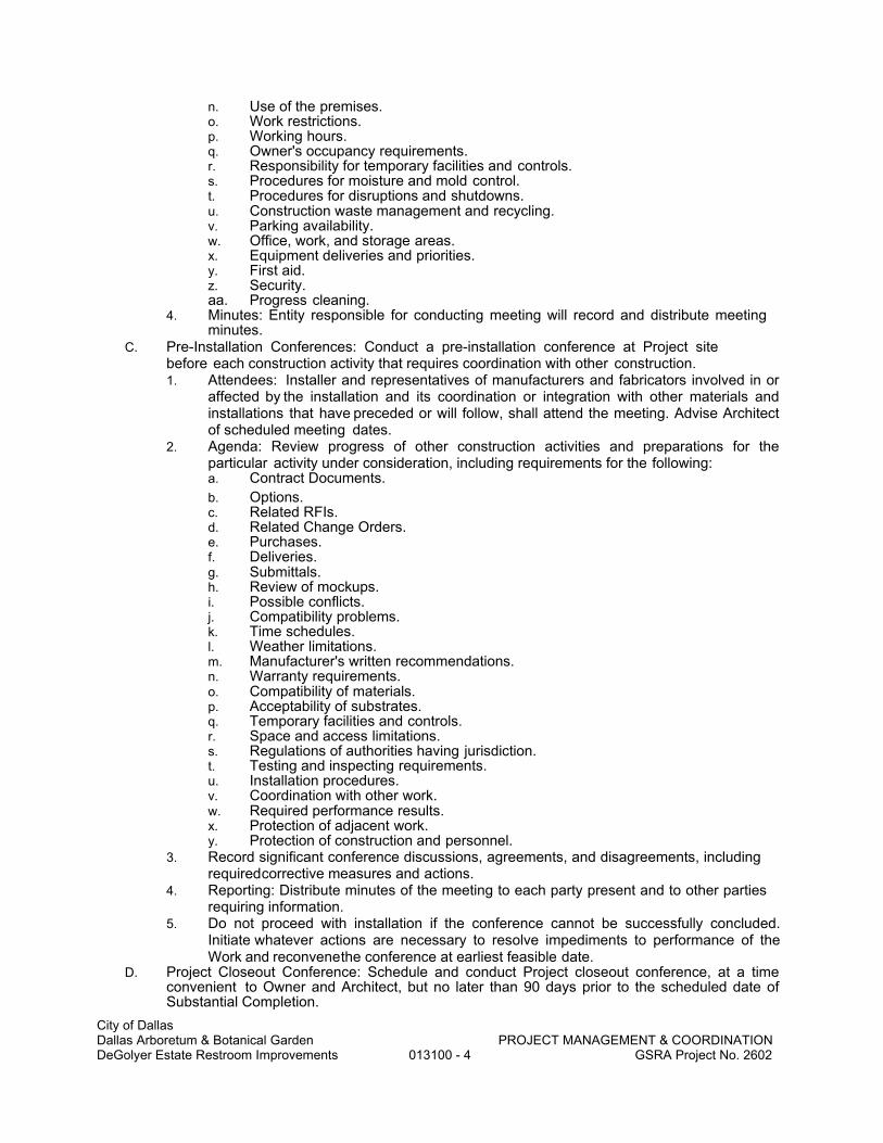
City of Dallas Dallas Arboretum & Botanical Garden PROJECT MANAGEMENT & COORDINATION DeGolyer Estate Restroom Improvements 013100 - 4 GSRA Project No. 2602
n. Use of the premises. o. Work restrictions. p. Working hours. q. Owner's occupancy requirements. r. Responsibility for temporary facilities and controls. s. Procedures for moisture and mold control. t. Procedures for disruptions and shutdowns. u. Construction waste management and recycling. v. Parking availability. w. Office, work, and storage areas. x. Equipment deliveries and priorities. y. First aid. z. Security. aa. Progress cleaning.
4. Minutes: Entity responsible for conducting meeting will record and distribute meeting minutes.
C. Pre-Installation Conferences: Conduct a pre-installation conference at Project site before each construction activity that requires coordination with other construction. 1. Attendees: Installer and representatives of manufacturers and fabricators involved in or
affected by the installation and its coordination or integration with other materials and installations that have preceded or will follow, shall attend the meeting. Advise Architect of scheduled meeting dates.
2. Agenda: Review progress of other construction activities and preparations for the particular activity under consideration, including requirements for the following: a. Contract Documents.
b. Options. c. Related RFIs. d. Related Change Orders. e. Purchases. f. Deliveries. g. Submittals. h. Review of mockups. i. Possible conflicts. j. Compatibility problems. k. Time schedules. l. Weather limitations. m. Manufacturer's written recommendations. n. Warranty requirements. o. Compatibility of materials. p. Acceptability of substrates. q. Temporary facilities and controls. r. Space and access limitations. s. Regulations of authorities having jurisdiction. t. Testing and inspecting requirements. u. Installation procedures. v. Coordination with other work. w. Required performance results. x. Protection of adjacent work. y. Protection of construction and personnel.
3. Record significant conference discussions, agreements, and disagreements, including required corrective measures and actions.
4. Reporting: Distribute minutes of the meeting to each party present and to other parties requiring information.
5. Do not proceed with installation if the conference cannot be successfully concluded. Initiate whatever actions are necessary to resolve impediments to performance of the Work and reconvene the conference at earliest feasible date.
D. Project Closeout Conference: Schedule and conduct Project closeout conference, at a time convenient to Owner and Architect, but no later than 90 days prior to the scheduled date of Substantial Completion.

City of Dallas Dallas Arboretum & Botanical Garden PROJECT MANAGEMENT & COORDINATION DeGolyer Estate Restroom Improvements 013100 - 5 GSRA Project No. 2602
1. Conduct the conference to review requirements and responsibilities related to Project closeout.
2. Attendees: Authorized representatives of Owner, Architect, and their consultants; Contractor and its superintendent; major subcontractors; suppliers; and other concerned parties shall attend the meeting. Participants at the meeting shall be familiar with Project and authorized to conclude matters relating to the Work.
3. Agenda: Discuss items of significance that could affect or delay Project closeout, including the following: a. Preparation of record documents. b. Procedures required prior to inspection for Substantial Completion and for final
inspection for acceptance. c. Submittal of written warranties. d. Requirements for preparing sustainable design documentation. e. Requirements for preparing operations and maintenance data. f. Requirements for demonstration and training. g. Preparation of Contractor's punch list. h. Procedures for processing Applications for Payment at Substantial Completion
and for final payment. i. Submittal procedures. j. Coordination of separate contracts. k. Owner's partial occupancy requirements. l. Installation of Owner's furniture, fixtures, and equipment. m. Responsibility for removing temporary facilities and controls.
4. Minutes: Entity conducting meeting will record and distribute meeting minutes. E. Progress Meetings: Conduct progress meetings at agreed upon intervals.
1. Coordinate dates of meetings with preparation of payment requests. 2. Attendees: In addition to representatives of Owner, Owner's Commissioning
Authority, Construction Manager, and Architect, each contractor, and other entity concerned with current progress or involved in planning, coordination, or performance of future activities shall be represented at these meetings. All participants at the meeting shall be familiar with Project and
authorized to conclude matters relating to the Work. 3. Agenda: Review and correct or approve minutes of previous progress meeting.
Review other items of significance that could affect progress. Include topics for discussion as appropriate to status of Project. a. Contractor's Construction Schedule: Review progress since the last meeting.
Determine whether each activity is on time, ahead of schedule, or behind schedule, in relation to Contractor's construction schedule. Determine how construction behind schedule will be expedited; secure commitments from parties involved to do so. Discuss whether schedule revisions are required to ensure that current and subsequent activities will be completed within the Contract Time. 1) Review schedule for next period.
b. Review present and future needs of each entity present, including the following: 1) Interface requirements. 2) Sequence of operations. 3) Status of submittals. 4) Deliveries. 5) Off-site fabrication. 6) Access. 7) Site utilization. 8) Temporary facilities and controls. 9) Progress cleaning. 10) Quality and work standards. 11) Status of correction of deficient items. 12) Field observations. 13) Status of RFIs. 14) Status of proposal requests. 15) Pending changes.

City of Dallas Dallas Arboretum & Botanical Garden PROJECT MANAGEMENT & COORDINATION DeGolyer Estate Restroom Improvements 013100 - 6 GSRA Project No. 2602
16) Status of Change Orders. 17) Pending claims and disputes. 18) Documentation of information for payment requests.
4. Minutes: Entity responsible for conducting the meeting will record and distribute the meeting minutes to each party present and to parties requiring information. a. Schedule Updating: Revise Contractor's construction schedule after each progress
meeting where revisions to the schedule have been made or recognized. Issue revised schedule concurrently with the report of each meeting.
F. Coordination Meetings: Conduct Project coordination meetings at regular intervals. Project coordination meetings are in addition to specific meetings held for other purposes, such as progress meetings and pre- installation conferences. 1. Attendees: In addition to representatives of Owner and Architect, each contractor,
subcontractor, supplier, and other entity concerned with current progress or involved in planning, coordination, or performance of future activities shall be represented at these meetings. All participants at the meetings shall be familiar with Project and authorized to conclude matters relating to the Work.
2. Agenda: Review and correct or approve minutes of the previous coordination meeting. Review other items of significance that could affect progress. Include topics for discussion as appropriate to status of Project. a. Combined Contractor's Construction Schedule: Review progress since the last
coordination meeting. Determine whether each contract is on time, ahead of schedule, or behind schedule, in relation to combined Contractor's construction schedule. Determine how construction behind schedule will be expedited; secure commitments from parties involved to do so. Discuss whether schedule revisions are required to ensure that current and subsequent activities will be completed within the Contract Time.
b. Schedule Updating: Revise combined Contractor's construction schedule after each coordination meeting where revisions to the schedule have been made or recognized. Issue revised schedule concurrently with report of each meeting.
c. Review present and future needs of each contractor present, including the following: 1) Interface requirements. 2) Sequence of operations. 3) Status of submittals. 4) Deliveries. 5) Off-site fabrication. 6) Access. 7) Site utilization.
8) Temporary facilities and controls. 9) Work hours. 10) Hazards and risks. 11) Progress cleaning. 12) Quality and work standards. 13) Change Orders.
3. Reporting: Record meeting results and distribute copies to everyone in attendance and to others affected by decisions or actions resulting from each meeting.
PART 2 - PRODUCTS (Not Used)
PART 3 - EXECUTION (Not Used)
END OF SECTION

City of Dallas
Dallas Arboretum & Botanical Garden PROJECT MEETINGS
DeGolyer Estate Restroom Improvements 013119 - 1 GSRA Project No. 2602
SECTION 013119
PROJECT MEETINGS
PART 1 - GENERAL
1.01 SUMMARY
A. Schedule and administer pre-construction meeting, progress meetings, pre-installation conferences, pre-contract closeout conference and specially called meetings throughout the progress of the work. 1. Prepare agenda for meetings. 2. Distribute written notice of each meeting 2 days in advance of meeting date. 3. Make physical arrangements for meetings. 4. Preside at meetings. 5. Record the minutes; include significant proceedings and decisions. 6. Reproduce and distribute copies of minutes within 2 days after each meeting.
a. To participants in meeting. b. To parties affected by decisions made at meeting. c. Furnish one copy each of minutes to Owner’s Representative and Architect.
B. Representatives of subcontractors and suppliers attending meetings shall be qualified and authorized to act on behalf of entity each represents.
1.02 PRE-CONSTRUCTION CONFERENCE
A. Conduct a pre-construction conference to be held at a time and location to be designated by the Owner’s Representative.
B. Representatives of the Owner and Architect will be present.
C. Representatives of the Contractor, including project superintendent and major subcontractors, shall be present.
D. As a minimum, the following items will be on meeting agenda: 1. Review of proposed subcontractors. 2. Designation of key personnel. 3. Communications. 4. Schedule of Values. 5. Construction Schedule. 6. Schedule of Submittals. 7. Site access, working hours, security, parking and designated storage areas. 8. Submittals. 9. Procedures for maintaining Project Record Documents. 10. Processing Field Decisions and Change Orders. 11. Procedures for processing Applications for Payment.
1.03 PROGRESS AND COORDINATION MEETINGS
A. During progress of construction, schedule and conduct progress and coordination meetings on a bi-weekly basis.
B. The project superintendent and representatives of designated subcontractors shall attend meetings.
C. As a minimum, following items will be on meeting agenda: 1. Review minutes of previous meeting. 2. Review work progress since last meeting.

City of Dallas
Dallas Arboretum & Botanical Garden PROJECT MEETINGS
DeGolyer Estate Restroom Improvements 013119 - 2 GSRA Project No. 2602
3. Note field observations, problems and decisions. 4. Review off-site fabrication problems. 5. Revise construction schedule as required. 6. Review submittal schedules and effect on construction schedule. 7. Review proposed changes and effect on construction schedule. 8. Coordination between elements of work. Coordinate projected progress with other
subcontractors. 9. Clarification decisions required of Architect or Owner. 10. Review of subcontractor’s forces on project. 11. Plan progress during next work period. 12. Delivery of Owner-Furnished equipment and work of separate Contractors. 13. Review status and content of Project Record Documents.
1.04 PREINSTALLATION CONFERENCES
A. Where required by the individual Specification sections, conduct a pre-installation conference in accordance with requirements of the respective Specification sections.
B. Convene pre-installation conferences at site prior to commencing work of the respective Specification section.
1.05 PRE-CONTRACT CLOSEOUT CONFERENCE
A. A pre-contract closeout conference will be held at the site at least 30 days prior to scheduled date of Substantial Completion.
B. Representatives of the Owner and Architect will be present.
C. Representatives of the Contractor, including project superintendent, mechanical and electrical subcontractors and other designated subcontractors shall be present.
D. As a minimum, the following items will be on meeting agenda: 1. Substantial Completion procedures, including punch list procedures. 2. Review of Contract Closeout submittal requirements, including:
a. Project record documents. b. Subcontractors and suppliers list. c. Operating and maintenance manuals. d. Instructions to Owner’s personnel. e. Warranties and certificates. f. Keys and keying schedule. g. Evidence of payment and release of liens. h. Certificate of insurance for products and completed operations. i. Requirements of Regulatory Agencies having Jurisdiction
1) Identify and schedule agency notifications and submissions required by Agency for Agency inspection.
2) Schedule required agency inspections. 3) Certificates of compliance with requirements of Regulatory Agencies having
Jurisdiction. j. Final inspection procedures. k. Final application for payment procedures.
PART 2 - PRODUCTS - NOT APPLICABLE
PART 3 - EXECUTION - NOT APPLICABLE
END OF SECTION

City of Dallas
Dallas Arboretum & Botanical Garden CONSTRUCTION PROGRESS DOCUMENTATION
DeGolyer Estate Restroom Improvements 013200 - 1 GSRA Project No. 2602
SECTION 013200
CONSTRUCTION PROGRESS DOCUMENTATION
PART 1 - GENERAL
1. 1 SUMMARY
A. Procedures for preparation and submission of Contractor’s construction schedules for the Work and periodic updating.
B. Critical action report of required Owner and Architect actions or decisions.
1. 2 FORM OF SCHEDULES
A. Prepare in horizontal bar chart form. 1. Separate bar for each trade or operation. 2. Identify first work day of each week.
B. Prepare in chronological order of start of each item of work.
C. Identify each item by major specification section number or trade.
1. 3 CONTENT OF SCHEDULES
A. Provide complete sequence of construction activity. 1. Indicate dates for beginning and completion of each activity. 2. Indicate projected percentage of completion for each item, as of first day of each month. 3. Identify major milestones including dates for Notice to Proceed, pre-installation
conferences, pre-contract closeout conference, Architect’s punch list, facility start-up activities, operating system instructions and demonstrations, Regulatory Agency of Jurisdiction inspections, Substantial Completion.
4. Products delivery schedule. Indicate dates for: a. Delivery of Owner-furnished products and products furnished by separate contractors. b. Contractor’s receipt of rough-in information required for coordination of products
furnished by others. c. Installation of products furnished by others. Identify major categories and unique
equipment items separately. 5. Include calendar days from date of start of project to date of completion.
1. 4 CRITICAL ACTION REPORT
A. Provide a separate summary report of dates for required Owner and Architect actions or decisions that would affect construction schedule.
1. 5 REVISIONS TO SCHEDULES
A. Submit schedule updates and graphically illustrate the progress of each activity to date of submittal, and projected completion date of each activity.
B. Identify activities modified since previous submittal, major changes in scope, and other identifiable changes.
C. Provide narrative report to define problem areas, anticipated delays, and impact on Schedule. Report corrective action taken, or proposed, and its effect.
1. 6 SUBMITTALS
A. Submit initial schedules and critical action report within 15 days after date of Notice to Proceed.
B. Submit monthly revised schedules accurately depicting progress to first day of each month. Submit with each application for payment submittal.

City of Dallas
Dallas Arboretum & Botanical Garden CONSTRUCTION PROGRESS DOCUMENTATION
DeGolyer Estate Restroom Improvements 013200 - 2 GSRA Project No. 2602
C. Submit monthly revised critical action report concurrent with construction schedule submittal.
D. Submit number of copies required by Contractor, plus one copy to be retained by Architect and one copy to be retained by the Owner’s Representative.
PART 2 - PRODUCTS (NOT APPLICABLE)
PART 3 - EXECUTION (NOT APPLICABLE)
END OF SECTION

City of Dallas Dallas Arboretum & Botanical Garden SUBMITTAL PROCEDURES DeGolyer Estate Restroom Improvements 013300 - 1 GSRA Project No. 2602
SECTION 013300
SUBMITTAL PROCEDURES
PART 1 - GENERAL
1.1 RELATED DOCUMENTS A. Drawings and general provisions of the Contract, including General and Supplementary
Conditions and other Division 01 Specification Sections, apply to this Section.
1.2 SUMMARY
A. Section includes requirements for the submittal schedule and administrative and procedural requirements for submitting Shop Drawings, Product Data, Material Safety Data Sheets (MSDS), Samples, and other submittals.
1.3 DEFINITIONS
A. Action Submittals: Written and graphic information and physical samples that require Architect's responsive action. Action submittals are those submittals indicated in individual Specification Sections as action submittals.
B. Informational Submittals: Written and graphic information and physical samples that do not require Architect's responsive action. Submittals may be rejected for not complying with requirements. Informational submittals are those submittals indicated in individual Specification Sections as informational submittals.
C. File Transfer Protocol (FTP): Communications protocol that enables transfer of files to and from another computer over a network and that serves as the basis for standard Internet protocols. An FTP site is a portion of a network located outside of network firewalls within which internal and external users are able to access files.
D. Portable Document Format (PDF): An open standard file format licensed by Adobe Systems used for representing documents in a device-independent and display resolution-independent fixed-layout document format.
1.4 ACTION SUBMITTALS
A. Submittal Schedule: Submit a schedule of submittals, arranged in chronological order by dates required by construction schedule. Include time required for review, ordering, manufacturing, fabrication, and delivery when establishing dates. Include additional time required for making corrections or modifications to submittals noted by the Architect and additional time for handling and reviewing submittals required by those corrections. 1. Coordinate submittal schedule with list of subcontracts, the schedule of values, and
Contractor's construction schedule. 2. Initial Submittal: Submit concurrently with start-up construction schedule. Include
submittals required during the first 60 days of construction. List those submittals required to maintain orderly progress of the Work and those required early because of long lead-time for manufacture or fabrication.
3. Final Submittal: Submit concurrently with the first complete submittal of Contractor's construction schedule. Submit revised submittal schedule to reflect changes in current status and timing for submittals.
4. Format: Arrange the following information in a tabular format: a. Scheduled date for first submittal. b. Specification Section number and title. c. Submittal category: Action, informational. d. Name of subcontractor. e. Description of the Work covered. f. Scheduled date for Architect's final release or approval. g. Scheduled dates for purchasing.

City of Dallas Dallas Arboretum & Botanical Garden SUBMITTAL PROCEDURES DeGolyer Estate Restroom Improvements 013300 - 2 GSRA Project No. 2602
h. Scheduled dates for installation. i. Activity or event number.
1.5 SUBMITTAL ADMINISTRATIVE REQUIREMENTS
A. Architect's Digital Data Files: Electronic copies of CAD Drawings will be provided by Architect for Contractor's use in preparing coordination submittals.
1. Architect will furnish Contractor one set of drawing files for use in preparing Shop Drawings and Project record drawings.
2. Architect makes no representations as to the accuracy or completeness of digital data drawing files as they relate to the Contract Drawings.
3. Digital Drawing Software Program: The Contract Drawings are available in AutoCAD 2004 (.dwg).
4. Contractor shall execute a data licensing agreement in the form of Agreement included in Project Manual.
5. The following CAD files will by furnished for each appropriate discipline: AE floor, finish, reflected ceiling and site plans.
B. Coordination: Coordinate preparation and processing of submittals with performance of construction activities. 1. Coordinate each submittal with fabrication, purchasing, testing, delivery, other
submittals, and related activities that require sequential activity. 2. Submit all submittal items required for each Specification Section concurrently unless
partial submittals for portions of the Work are approved by Architect. 3. Submit action submittals and informational submittals required by the same
Specification Section as separate packages under separate transmittals. 4. Coordinate transmittal of different types of submittals for related parts of the Work so
processing will not be delayed because of need to review submittals concurrently for coordination.
5. Architect reserves the right to withhold action on a submittal requiring coordination with other submittals until related submittals are received.
C. Processing Time: Allow time for submittal review, including time for resubmittals, as follows. Time for review shall commence on Architect's receipt of submittal. No extension of the Contract Time will be authorized because of failure to transmit submittals enough in advance of the Work to permit processing, including resubmittals. Submittals received after 1:00 pm will be considered to have been received the following day. 1. Allow 10 business days for initial review of each submittal. Allow additional time if
coordination with subsequent submittals is required. Architect will advise Contractor when a submittal being processed must be delayed for coordination. Allow 4-week review time for large or complex submittals that will require additional review time. The following are examples but not limited to such submittals: Mechanical, Electrical, Plumbing, Millwork, Curtain Wall, Structural Steel, Doors Frames Hardware (total opening).
2. Intermediate Review: If intermediate submittal is necessary, process it in same manner as initial submittal.
3. Resubmittal Review: Allow 10 business days for review of each resubmittal. 4. Sequential Review: Where sequential review of submittals by Architect's consultants,
Owner, or other parties is indicated, allow 20 business days for initial review of each submittal.
D. Identification and Information: Place a permanent label or title block on each copy submittal item for identification. 1. On large format Shop Drawings, Contractor shall stamp each individual page as well as
the reviewer’s stamp. 2. Indicate name of firm or entity that prepared each submittal on label or title block. 3. Provide a space approximately 6 by 8 inches on label or beside title block to record
Contractor's review and approval markings and action taken by Architect. 4. Include the following information for processing and recording action taken:
a. Project name.

City of Dallas Dallas Arboretum & Botanical Garden SUBMITTAL PROCEDURES DeGolyer Estate Restroom Improvements 013300 - 3 GSRA Project No. 2602
b. Date. c. Name of Architect. d. Name of Contractor. e. Name of subcontractor. f. Name of supplier. g. Name of manufacturer. h. Submittal number or other unique identifier, including revision identifier.
1) Submittal number shall use Specification Section number followed by a decimal point and then a sequential number (e.g., 061000.01). Resubmittals shall include an alphabetic suffix after another decimal point (e.g., 061000.01.A).
i. Number and title of appropriate Specification Section. j. Drawing number and detail references, as appropriate. k. Location(s) where product is to be installed, as appropriate. l. Other necessary identification.
E. Identification and Information: Identify and incorporate information in each electronic submittal file as follows:
1. Assemble complete submittal package into a single indexed file with links enabling navigation to each item.
2. Name file with submittal number or other unique identifier, including revision identifier. a. For typical projects that do not require separate submittals for different buildings or
sub the submittal file name shall use Specification Section number followed by a dash and then a sequential number. Resubmittals shall include a numerical suffix after another dash. Include brief description of submittal after sequential number or resubmittal suffix. (e.g., 061000-001-0 Rough Carpentry).
b. For complex projects that require project identifier for separate buildings within a project or require individual submittals to be submitted by multiple subcontractors, the submittal file name shall follow the following. Specification Section number followed by a decimal point and then a sequential number. Resubmittals shall include an alphabetic suffix after another decimal point. Project Identifier should follow in parentheses (e.g., 061000-001-0 (LNHS) Rough Carpentry).
3. Provide means for insertion to permanently record Contractor's review and approval markings and action taken by Architect.
4. Include the following information on an inserted cover sheet: a. Project name. b. Date. c. Name and address of Architect. d. Name of Contractor. e. Name of firm or entity that prepared submittal. f. Name of subcontractor. g. Name of supplier. h. Name of manufacturer. i. Number and title of appropriate Specification Section. j. Drawing number and detail references, as appropriate. k. Location(s) where product is to be installed, as appropriate. l. Related physical samples submitted directly. m. Other necessary identification.
5. Include the following information as keywords in the electronic file metadata: a. Project name. b. Number and title of appropriate Specification Section. c. Manufacturer name. d. Product name.
F. Options: Identify options requiring selection by the Architect. G. Deviations: Identify deviations from the Contract Documents on submittals. H. Additional Paper Copies: Unless additional copies are required for final submittal, and
unless Architect observes noncompliance with provisions in the Contract Documents, initial submittal may serve as final submittal.
a. Submit one copy of submittal to concurrent reviewer in addition to specified

City of Dallas Dallas Arboretum & Botanical Garden SUBMITTAL PROCEDURES DeGolyer Estate Restroom Improvements 013300 - 4 GSRA Project No. 2602
number of copies to Architect. I. Transmittal: Assemble each submittal individually and appropriately for transmittal and
handling. Transmit each submittal using a transmittal form. Architect will return submittals, without review, received from sources other than Contractor. 1. Transmittal Form: Use standard contractor form as approved by Architect Owner. 2. On an attached separate sheet, prepared on Contractor's letterhead, record relevant
information, requests for data, revisions other than those requested by Architect on previous submittals, and deviations from requirements in the Contract Documents, including minor variations and limitations. Include same identification information as related submittal.
J. Resubmittals: Make resubmittals in same form and number of copies as initial submittal. 1. Note date and content of previous submittal. 2. Note date and content of revision in label or title block and clearly indicate extent of
revision. 3. Include all submitted information from previous submittal in resubmittal, to form a
comprehensive document for Architect’s review. 4. Resubmit submittals until they are marked with ‘Reviewed’, ‘Furnish as Corrected’
notation from Architect's action stamp, or with approval notation from alternate reviewer K. Distribution: Furnish copies of final submittals to manufacturers, subcontractors, suppliers,
fabricators, and installers, authorities having jurisdiction, and others as necessary for performance of construction activities. Show distribution on transmittal forms.
L. Use for Construction: Use only final submittals that are marked with ‘Reviewed’, ‘Furnish as Corrected’ notation from Architect's action stamp, or with approval notation from alternate reviewer.
PART 2 - PRODUCTS
2.1 SUBMITTAL PROCEDURES A. General Submittal Procedure Requirements: Prepare and submit submittals required by
individual Specification Sections. Types of submittals are indicated in individual Specification Sections. 1. Email or upload electronic submittals as PDF electronic files directly to Architect’s Info
Exchange Folder (Newforma) specifically established for Project. a. Architect will return annotated file. Annotate and retain one copy of file as an
electronic Project record document file. 2. Action Submittals: For large format drawings and submittals (larger than 11 x 17), submit
PDF file plus 2 hard copies. For smaller format drawings and submittals (11x17 or less), provide only PDF file. Architect will return only the marked-up PDF.
3. Informational Submittals: Submit two paper copies of each submittal, unless otherwise indicated. Architect will not return copies.
4. Closeout Submittals and Maintenance Material Submittals: Comply with requirements specified in Division 01 Section "Closeout Procedures."
5. Certificates and Certifications Submittals: Provide a statement that includes signature of entity responsible for preparing certification. Certificates and certifications shall be signed by an officer or other individual authorized to sign documents on behalf of that entity. a. Provide a digital signature with digital certificate on electronically-submitted
certificates and certifications where indicated. b. Provide a notarized statement on original paper copy certificates and
certifications where indicated. 6. Test and Inspection Reports Submittals: Comply with requirements specified in Division
01 Section "Quality Requirements." B. Product Data: Collect information into a single submittal for each element of construction
and type of product or equipment. 1. If information must be specially prepared for submittal because standard published

City of Dallas Dallas Arboretum & Botanical Garden SUBMITTAL PROCEDURES DeGolyer Estate Restroom Improvements 013300 - 5 GSRA Project No. 2602
data are not suitable for use, submit as Shop Drawings, not as Product Data. 2. Material Safety Data Sheets (MSDS) will be required for all building materials used in
renovations. 3. Mark each copy of each submittal to show which products and options are applicable. 4. Include the following information, as applicable:
a. Manufacturer's catalog cuts. b. Manufacturer's product specifications. c. Standard color charts. d. Statement of compliance with specified referenced standards. e. Testing by recognized testing agency. f. Application of testing agency labels and seals. g. Notation of coordination requirements. h. Availability and delivery time information.
5. For equipment, include the following in addition to the above, as applicable: a. Wiring diagrams showing factory-installed wiring. b. Printed performance curves. c. Operational range diagrams. d. Clearances required to other construction, if not indicated on accompanying Shop
Drawings. 6. Submit Product Data before or concurrent with Samples. 7. Submit Product Data in the following format:
a. PDF electronic file. C. Shop Drawings: Prepare Project-specific information, drawn accurately to scale. Do not base
Shop Drawings on reproductions of the Contract Documents or standard printed data. 1. Preparation: Fully illustrate requirements in the Contract Documents. Include the
following information, as applicable: a. Identification of products. b. Schedules. c. Compliance with specified standards. d. Notation of coordination requirements. e. Notation of dimensions established by field measurement. f. Relationship and attachment to adjoining construction clearly indicated. g. Seal and signature of professional engineer if specified.
2. Sheet Size: Except for templates, patterns, and similar full-size drawings, submit Shop Drawings on sheets at least 8-1/2 by 11 inches but no larger than 30 by 42 inches.
3. Submit Shop Drawings in the following format: 4. For large format drawings and submittals (larger than 11 x 17), submit PDF file plus 2
hard copies. For smaller format drawings and submittals (11x17 or less), provide only PDF file. Architect will return only the marked-up PDF.
D. Samples: Submit Samples for review of kind, color, pattern, and texture for a check of these characteristics with other elements and for a comparison of these characteristics between submittal and actual component as delivered and installed. 1. Transmit Samples that contain multiple, related components such as accessories
together in one submittal package. 2. Identification: Attach label on unexposed side of Samples that includes the following:
a. Generic description of Sample. b. Product name and name of manufacturer. c. Sample source. d. Number and title of applicable Specification Section.
3. Disposition: Maintain sets of approved Samples at Project site, available for quality-control comparisons throughout the course of construction activity. Sample sets may be used to determine final acceptance of construction associated with each set. a. Samples that may be incorporated into the Work are indicated in individual
Specification Sections. Such Samples must be in an undamaged condition at time of use.
b. Samples not incorporated into the Work, or otherwise designated as Owner's property, are the property of Contractor.
4. Samples for Initial Selection: Submit manufacturer's color charts consisting of units or

City of Dallas Dallas Arboretum & Botanical Garden SUBMITTAL PROCEDURES DeGolyer Estate Restroom Improvements 013300 - 6 GSRA Project No. 2602
sections of units showing the full range of colors, textures, and patterns available. a. Number of Samples: Submit three full set(s) of available choices where color,
pattern, texture, or similar characteristics are required to be selected from manufacturer's product line. Architect will return submittal with options selected.
5. Samples for Verification: Submit full-size units or Samples of size indicated, prepared from same material to be used for the Work, cured and finished in manner specified, and physically identical with material or product proposed for use, and that show full range of color and texture variations expected. Samples include, but are not limited to, the following: partial sections of manufactured or fabricated components; small cuts or containers of materials; complete units of repetitively used materials; swatches showing color, texture, and pattern; color range sets; and components used for independent testing and inspection. a. Number of Samples: Submit sets of Samples. Architect will retain one sample set;
remainder will be returned. Mark up and retain one returned Sample set as a Project record sample. 1) Submit a single Sample where assembly details, workmanship, fabrication
techniques, connections, operation, and other similar characteristics are to be demonstrated.
2) If variation in color, pattern, texture, or other characteristic is inherent in material or product represented by a Sample, submit at least three sets of paired units that show approximate limits of variations.
E. Product Schedule: As required in individual Specification Sections, prepare a written summary indicating types of products required for the Work and their intended location. Include the following information in tabular form: 1. Type of product. Include unique identifier for each product indicated in the Contract
Documents. 2. Manufacturer and product name, and model number if applicable. 3. Number and name of room or space. 4. Location within room or space. 5. Submit product schedule in the following format:
a. PDF electronic file. F. Contractor's Construction Schedule: Comply with requirements specified in Division 01 Section
"Construction Progress Documentation." G. Application for Payment: Comply with requirements specified in Division 01 Section "Payment
Procedures." H. Schedule of Values: Comply with requirements specified in Division 01 Section "Payment
Procedures." I. Subcontract List: Prepare a written summary identifying individuals or firms proposed for each
portion of the Work, including those who are to furnish products or equipment fabricated to a special design. Use CSI Form 1.5A. Include the following information in tabular form: 1. Name, address, and telephone number of entity performing subcontract or supplying
products. 2. Number and title of related Specification Section(s) covered by subcontract. 3. Drawing number and detail references, as appropriate, covered by subcontract.
4. Submit subcontract list in the following format: a. PDF electronic file.
J. Coordination Drawings: Comply with requirements specified in Division 01 Section "Project Management and Coordination."
K. Qualification Data: Prepare written information that demonstrates capabilities and experience of firm or person. Include lists of completed projects with project names and addresses, contact information of architects and owners, and other information specified.
L. Welding Certificates: Prepare written certification that welding procedures and personnel comply with requirements in the Contract Documents. Submit record of Welding Procedure Specification and Procedure Qualification Record on American Welding Society (AWS) forms. Include names of firms and personnel certified.
M. Installer Certificates: Submit written statements on manufacturer's letterhead certifying that Installer complies with requirements in the Contract Documents and, where required, is

City of Dallas Dallas Arboretum & Botanical Garden SUBMITTAL PROCEDURES DeGolyer Estate Restroom Improvements 013300 - 7 GSRA Project No. 2602
authorized by manufacturer for this specific Project. N. Manufacturer Certificates: Submit written statements on manufacturer's letterhead certifying
that manufacturer complies with requirements in the Contract Documents. Include evidence of manufacturing experience where required.
O. Product Certificates: Submit written statements on manufacturer's letterhead certifying that product complies with requirements in the Contract Documents.
P. Material Certificates: Submit written statements on manufacturer's letterhead certifying that material complies with requirements in the Contract Documents.
Q. Material Test Reports: Submit reports written by a qualified testing agency, on testing agency's standard form, indicating and interpreting test results of material for compliance with requirements in the Contract Documents.
R. Product Test Reports: Submit written reports indicating current product produced by manufacturer complies with requirements in the Contract Documents. Base reports on evaluation of tests performed by manufacturer and witnessed by a qualified testing agency, or on comprehensive tests performed by a qualified testing agency.
S. Research Reports: Submit written evidence, from a model code organization acceptable to authorities having jurisdiction, that product complies with building code in effect for Project. Include the following information: 1. Name of evaluation organization. 2. Date of evaluation. 3. Time period when report is in effect. 4. Product and manufacturers' names. 5. Description of product. 6. Test procedures and results. 7. Limitations of use.
T. Schedule of Tests and Inspections: Comply with requirements specified in Division 01 Section "Quality Requirements."
U. Pre-construction Test Reports: Submit reports written by a qualified testing agency, on testing agency's standard form, indicating and interpreting results of tests performed before installation of product, for compliance with performance requirements in the Contract Documents.
V. Compatibility Test Reports: Submit reports written by a qualified testing agency, on testing agency's standard form, indicating and interpreting results of compatibility tests performed before installation of product. Include written recommendations for primers and substrate preparation needed for adhesion.
W. Field Test Reports: Submit reports indicating and interpreting results of field tests performed either during installation of product or after product is installed in its final location, for compliance with requirements in the Contract Documents.
X. Maintenance Data: Comply with requirements specified in Division 01 Section "Operation and Maintenance Data."
Y. Design Data: Prepare and submit written and graphic information, including, but not limited to, performance and design criteria, list of applicable codes and regulations, and calculations. Include list of assumptions and other performance and design criteria and a summary of loads. Include load diagrams if applicable. Provide name and version of software, if any, used for calculations. Include page numbers.
2.2 DELEGATED-DESIGN SERVICES A. Performance and Design Criteria: Where professional design services or certifications by a
design professional are specifically required of Contractor by the Contract Documents, provide products and systems complying with specific performance and design criteria indicated. 1. If criteria indicated are not sufficient to perform services or certification required, submit
a written request for additional information to Architect. B. Delegated-Design Services Certification: In addition to Shop Drawings, Product Data, and other
required submittals, submit digitally-signed PDF electronic file and three paper copies of certificate, signed and sealed by the responsible design professional, for each product and system specifically assigned to Contractor to be designed or certified by a design professional.

City of Dallas Dallas Arboretum & Botanical Garden SUBMITTAL PROCEDURES DeGolyer Estate Restroom Improvements 013300 - 8 GSRA Project No. 2602
1. Indicate that products and systems comply with performance and design criteria in the Contract Documents. Include list of codes, loads, and other factors used in performing these services.
PART 3 - EXECUTION
3.1 CONTRACTOR'S REVIEW A. Action and Informational Submittals: Review each submittal and check for coordination with
other Work of the Contract and for compliance with the Contract Documents. Note corrections and field dimensions. Mark with approval stamp before submitting to Architect.
B. Project Closeout and Maintenance/Material Submittals: Refer to requirements in Division 01 Section "Closeout Procedures."
C. Approval Stamp: Stamp each submittal with a uniform, approval stamp. Include Project name and location, submittal number, Specification Section title and number, name of reviewer, date of Contractor's approval, and statement certifying that submittal has been reviewed, checked, and approved for compliance with the Contract Documents.
3.2 ARCHITECT'S ACTION
A. General: Architect will not review submittals that do not bear Contractor's approval stamp and will return them without action.
B. Action Submittals: Architect will review each submittal, make marks to indicate corrections or modifications required, and return it. Architect will stamp each submittal with an action stamp and will mark stamp appropriately to indicate action, as follows: 1. Reviewed 2. Revise and Resubmit 3. Rejected 4. Furnish As Corrected 5. No Action Taken.
C. Informational Submittals: Architect will review each submittal and will not return it, or will return it if it does not comply with requirements. Architect will forward each submittal to appropriate party.
D. Partial submittals prepared for a portion of the Work will be reviewed when use of partial submittals has received prior approval from Architect.
E. Incomplete submittals are not acceptable, will be considered non-responsive, and will be returned without review.
F. Submittals not required by the Contract Documents may not be reviewed and may be discarded.
END OF SECTION

City of Dallas Dallas Arboretum & Botanical Garden ALTERATION PROJECT PROCEDURES
DeGolyer Estate Restroom Improvements 013516 - 1 GSRA Project No. 2602
SECTION 013516
ALTERATION PROJECT PROCEDURES
PART 1 - GENERAL
1.1 SUMMARY A. This Section includes:
1. Products and installation for patching and extending Work within construction areas of existing facilities.
2. Providing transition and adjustments. 3. Repair of damaged surfaces and finishes.
B. Related Sections include the following: 1. Division 01 Section “Temporary Facilities and Controls” for construction of temporary fire-
rated partitions to separate existing occupied areas from construction areas.
1.2 OCCUPANCY, ACCESS, AND PROTECTION A. Entire existing facility will be occupied during progress of construction for conduct of normal
operations. B. Cooperate with Owner in scheduling operations to minimize conflict and to permit continuous
usage. Perform work not to interfere with operations of occupied areas. C. Existing facilities will remain in full operation during execution of this Work. Exercise every
precaution to ensure safety and protection for existing facilities, occupants, merchandise, pedestrians, and vehicles. 1. Maintain safe access and egress at all times for occupants, pedestrians, and vehicles. 2. Provide protection to prevent damage to facilities, merchandise, and vehicles from dust,
water, weather, and other similar harmful elements. 3. Maintain exiting from facilities to provide safe passage complying with applicable codes.
1.3 SCHEDULING OF WORK A. Make arrangements with Owner and schedule Work to avoid interference with normal
operations of occupied areas. Submit schedule and summary of applicable Work within occupied areas and obtain Owner approval not less than two days prior to commencement of such Work. 1. Requests for use of certain existing loading docks, passage ways, and other similar
spaces within areas outside limits of construction operations will be limited to day-by-day basis and must be approved in advance by Owner.
B. Coordinate access and scheduling of Work within tenant areas with Owner.
1.4 TORCH-CUTTING AND WELDING PROCEDURES A. Notify Owner in advance of torch-cutting and welding operations performed within occupied
areas; obtain approval prior to proceeding with such operations. 1. Neither open-flame torch-cutting, welding nor arc-welding are allowed without having
secured appropriate permit from Fire Marshal or authority having jurisdiction. 2. Keep portable fire extinguisher of appropriate class within reach during welding or torch-
cutting operations. 3. Screen arc-welding from vision of passersby.
B. Maintain a “Fire Watch” for minimum of 60 minutes after completion of each torch-cutting and welding operation.
1.5 UTILITY SERVICE OUTAGES A. Keep utility and service outages to minimum and perform only after written approval of Owner is
received. 1. Requests for outages will not be considered unless they include an identification of areas
which will be affected by proposed outage.

City of Dallas Dallas Arboretum & Botanical Garden ALTERATION PROJECT PROCEDURES
DeGolyer Estate Restroom Improvements 013516 - 2 GSRA Project No. 2602
2. Schedule outages for times other than normal business hours. 3. Make requests for outages minimum of five calendar days in advance of proposed
outage. B. Contractor: Responsible for investigating utility and service lines to determine effect of outage
upon building operations outside of limit of operations. Obtain approval in advance from Owner to execute investigations.
1.6 KEYS A. When necessary to perform Work, Owner will issue keys to existing mechanical/electrical
equipment spaces. Contractor to comply with all Owner protocols in the handling of keys. B. Return keys at end of each work day; request keys on succeeding days, if necessary.
PART 2 - PRODUCTS
2.1 MATERIALS A. Type and Quality of Existing Products: Use products or types of construction that exist in
structure, as needed to patch, extend, or match existing Work. 1. Generally, Contract Documents do not define products or standards of workmanship
present in existing construction. 2. Determine by inspecting and testing products where necessary, referring to existing work
as quality standard. B. New Materials: Comply with Specifications for each product involved.
1. Match existing products and work for patching existing work. C. Materials for Temporary Fire-Rated Partitions: Comply with provisions of Division 01 Section
“Temporary Facilities and Controls.” D. Salvaged Materials: Salvage sufficient quantities of cut or removed material to replace damaged
Work of existing construction, when material is not readily obtainable on current market. 1. Store salvaged items in dry, secure place on site.
PART 3 - EXECUTION
3.1 EXAMINATION A. Verify that areas are ready for alteration and remodeling. B. Discrepancies: Verify dimensions and elevations indicated in layout of existing work.
1. Prior to commencing work, carefully compare and check Contract Documents for discrepancies in locations or elevations of work to be executed.
2. Refer discrepancies among Drawings and existing conditions to Architect for adjustment before work affected is performed.
3.2 PREPARATION A. Construct temporary fire-rated partitions to separate existing occupied areas from construction
and alteration areas. Comply with provisions of Division 01 Section “Temporary Facilities and Controls.”
B. Cut, move, or remove items as necessary for access to alteration and renovation Work. 1. Remove unsuitable material not marked for salvage, such as rotted wood, corroded
metals, deteriorated masonry and concrete, and other deteriorated materials. Replace materials as specified for finished Work.
2. Remove debris and abandoned items from area and from concealed spaces. C. Cutting and Removal: Perform cutting and removal work to remove minimum necessary, and in
manner to avoid damage to adjacent work. Cut finish surfaces such as masonry, tile, plaster, or metals by methods to terminate surfaces in straight line at natural point of division.
D. Prepare surface and remove surface finishes as necessary to provide for proper installation of new materials and finishes.
E. Close openings in exterior surfaces to protect existing Work from weather and extremes of
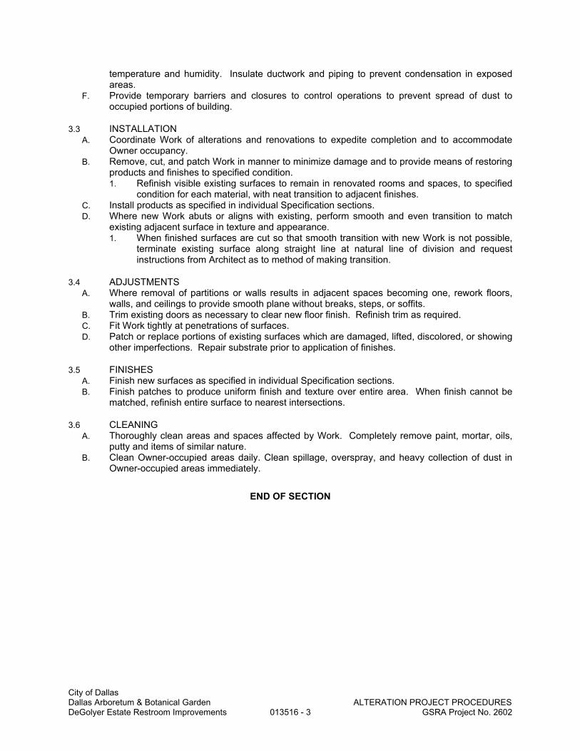
City of Dallas Dallas Arboretum & Botanical Garden ALTERATION PROJECT PROCEDURES
DeGolyer Estate Restroom Improvements 013516 - 3 GSRA Project No. 2602
temperature and humidity. Insulate ductwork and piping to prevent condensation in exposed areas.
F. Provide temporary barriers and closures to control operations to prevent spread of dust to occupied portions of building.
3.3 INSTALLATION A. Coordinate Work of alterations and renovations to expedite completion and to accommodate
Owner occupancy. B. Remove, cut, and patch Work in manner to minimize damage and to provide means of restoring
products and finishes to specified condition. 1. Refinish visible existing surfaces to remain in renovated rooms and spaces, to specified
condition for each material, with neat transition to adjacent finishes. C. Install products as specified in individual Specification sections. D. Where new Work abuts or aligns with existing, perform smooth and even transition to match
existing adjacent surface in texture and appearance. 1. When finished surfaces are cut so that smooth transition with new Work is not possible,
terminate existing surface along straight line at natural line of division and request instructions from Architect as to method of making transition.
3.4 ADJUSTMENTS A. Where removal of partitions or walls results in adjacent spaces becoming one, rework floors,
walls, and ceilings to provide smooth plane without breaks, steps, or soffits. B. Trim existing doors as necessary to clear new floor finish. Refinish trim as required. C. Fit Work tightly at penetrations of surfaces. D. Patch or replace portions of existing surfaces which are damaged, lifted, discolored, or showing
other imperfections. Repair substrate prior to application of finishes.
3.5 FINISHES A. Finish new surfaces as specified in individual Specification sections. B. Finish patches to produce uniform finish and texture over entire area. When finish cannot be
matched, refinish entire surface to nearest intersections.
3.6 CLEANING A. Thoroughly clean areas and spaces affected by Work. Completely remove paint, mortar, oils,
putty and items of similar nature. B. Clean Owner-occupied areas daily. Clean spillage, overspray, and heavy collection of dust in
Owner-occupied areas immediately.
END OF SECTION

City of Dallas Dallas Arboretum & Botanical Garden REFERENCES DeGolyer Estate Restroom Improvements 014200 - 1 GSRA Project No. 2602
SECTION 014200
REFERENCES
PART 1 - GENERAL
1.1 RELATED DOCUMENTS A. Drawings and general provisions of the Contract, including General and Supplementary
Conditions and other Division 01 Specification Sections, apply to this Section.
1.2 DEFINITIONS
A. General: Basic Contract definitions are included in the Conditions of the Contract. B. "Approved": When used to convey Architect's action on Contractor's submittals, applications,
and requests, "approved" is limited to Architect's duties and responsibilities as stated in the Conditions of the Contract.
C. "Directed": A command or instruction by Architect. Other terms including "requested," "authorized," "selected," "required," and "permitted" have the same meaning as "directed."
D. "Indicated": Requirements expressed by graphic representations or in written form on Drawings, in Specifications, and in other Contract Documents. Other terms including "shown," "noted," "scheduled," and "specified" have the same meaning as "indicated."
E. "Regulations": Laws, ordinances, statutes, and lawful orders issued by authorities having jurisdiction, and rules, conventions, and agreements within the construction industry that control performance of the Work.
F. "Furnish": Supply and deliver to Project site, ready for unloading, unpacking, assembly, installation, and similar operations.
G. "Install": Operations at Project site including unloading, temporarily storing, unpacking, assembling, erecting, placing, anchoring, applying, working to dimension, finishing, curing, protecting, cleaning, and similar operations.
H. "Provide": Furnish and install, complete and ready for the intended use. I. "Project Site": Space available for performing construction activities. The extent of Project site
is shown on Drawings and may or may not be identical with the description of the land on which Project is to be built.
1.3 INDUSTRY STANDARDS
A. Applicability of Standards: Unless the Contract Documents include more stringent requirements, applicable construction industry standards have the same force and effect as if bound or copied directly into the Contract Documents to the extent referenced. Such standards are made a part of the Contract Documents by reference.
B. Publication Dates: Comply with standards in effect as of date of the Contract Documents unless otherwise indicated.
C. Copies of Standards: Each entity engaged in construction on Project should be familiar with industry standards applicable to its construction activity. Copies of applicable standards are not bound with the Contract Documents. 1. Where copies of standards are needed to perform a required construction activity,
obtain copies directly from publication source.
1.4 ABBREVIATIONS AND ACRONYMS
A. Industry Organizations: Where abbreviations and acronyms are used in Specifications or other Contract Documents, they shall mean the recognized name of the entities indicated in Gale's "Encyclopedia of Associations" or in Columbia Books' "National Trade & Professional Associations of the United States."
END OF SECTION

City of Dallas Dallas Arboretum & Botanical Garden TEMPORARY FACILITIES & CONTROLS DeGolyer Estate Restroom Improvements 015000 - 1 GSRA Project No. 2602
SECTION 015000
TEMPORARY FACILITIES AND CONTROLS
PART 1 - GENERAL
1.1 RELATED DOCUMENTS A. Drawings and general provisions of the Contract, including General and Supplementary
Conditions and other Division 01 Specification Sections, apply to this Section.
1.2 SUMMARY A. Section includes requirements for temporary utilities, support facilities, and security and
protection facilities.
1.3 USE CHARGES A. General: Installation and removal of and use charges for temporary facilities shall be included
in the Contract Sum unless otherwise indicated. Allow other entities to use temporary services and facilities without cost, including, but not limited to, Owner's own forces, Architect, testing agencies, and authorities having jurisdiction.
B. Electric Power Service from Existing System: Electric power from Owner's existing system is available for use without metering and without payment of use charges. Provide connections and extensions of services as required for construction operations.
1.4 INFORMATIONAL SUBMITTALS A. Dust-Control and HVAC-Control Plan: Submit coordination drawing and narrative that indicates
the dust-control and HVAC-control measures proposed for use, proposed locations, and proposed time frame for their operation. Identify further options if proposed measures are later determined to be inadequate. Include the following: 1. Locations of dust-control partitions at each phase of the work. 2. HVAC system isolation schematic drawing. 3. Location of proposed air filtration system discharge. 4. Other dust-control measures. 5. Waste management plan.
1.5 QUALITY ASSURANCE A. Accessible Temporary Egress: Comply with applicable provisions in the U.S. Architectural &
Transportation Barriers Compliance Board's ADA-ABA Accessibility Guidelines.
1.6 PROJECT CONDITIONS A. Temporary Use of Permanent Facilities: Engage installer of each permanent service to assume
responsibility for operation, maintenance, and protection of each permanent service during its use as a construction facility before Owner's acceptance, regardless of previously assigned responsibilities.
PART 2 - PRODUCTS
2.1 MATERIALS A. Polyethylene Sheet: Reinforced, fire-resistive sheet, 10 mils minimum thickness, with flame-
spread rating of 15 or less per ASTM E 84. B. Dust Control Adhesive-Surface Walk-off Mats: Provide mats minimum 36 by 60 inches. C. Insulation: Unfaced mineral-fiber blanket, manufactured from glass, slag wool, or rock wool;
with maximum flame-spread and smoke-developed indexes of 25 and 50, respectively
2.2 TEMPORARY FACILITIES A. Common-Use Field Office: Of sufficient size to accommodate needs of Owner, Architect, and

City of Dallas Dallas Arboretum & Botanical Garden TEMPORARY FACILITIES & CONTROLS DeGolyer Estate Restroom Improvements 015000 - 2 GSRA Project No. 2602
construction personnel office activities and to accommodate project meetings specified in other Division 01 Sections. Keep office clean and orderly. Furnish and equip offices as follows: 1. Furniture required for Project-site documents including file cabinets, plan tables, plan
racks, and bookcases. 2. Conference room of sufficient size to accommodate meetings of 10 individuals. Provide
electrical power service and 120-V ac duplex receptacles, with not less than 1 receptacle on each wall. Furnish room with conference table, chairs, and 4-foot- square tack and marker boards.
3. Drinking water and private toilet. 4. Coffee machine and supplies. 5. Heating and cooling equipment necessary to maintain a uniform indoor temperature of 68
to 72 deg F. 6. Lighting fixtures capable of maintaining average illumination of 20 fc (215 lx) at desk
height.
2.3 EQUIPMENT A. Fire Extinguishers: Portable, UL rated; with class and extinguishing agent as required by
locations and classes of fire exposure B. Permanent HVAC System: If Owner authorizes use of permanent HVAC system for temporary
use during construction, provide filter with MERV of 8 at each return air grille in system and remove at end of construction and clean HVAC system as required in Division 01 Section "Closeout Procedures".
C. Air Filtration Units: HEPA primary and secondary filter-equipped portable units with four-stage filtration. Provide single switch for emergency shutoff. Configure to run continuously.
PART 3 - EXECUTION
3.1 INSTALLATION, GENERAL A. Locate facilities where they will serve Project adequately and result in minimum interference
with performance of the Work. Relocate and modify facilities as required by progress of the Work.
B. Provide each facility ready for use when needed to avoid delay. Do not remove until facilities are no longer needed or are replaced by authorized use of completed permanent facilities.
3.2 TEMPORARY UTILITY INSTALLATION A. General: Connect to existing service.
1. Arrange with Owner for time when service can be interrupted, if necessary, to make connections for temporary services.
B. Water Service: Connect to Owner's existing water service facilities. Clean and maintain water service facilities in a condition acceptable to Owner. At Substantial Completion, restore these facilities to condition existing before initial use.
C. Sanitary Facilities: Provide temporary toilets, wash facilities, and drinking water for use of construction personnel. Comply with requirements of authorities having jurisdiction for type, number, location, operation, and maintenance of fixtures and facilities. 1. Toilets: Use of Owner's existing toilet facilities will be permitted, as long as facilities are
cleaned and maintained in a condition acceptable to Owner. At Substantial Completion, restore these facilities to condition existing before initial use.
D. Isolation of Work Areas in Occupied Facilities: Prevent dust, fumes, and odors from entering occupied areas. 1. Prior to commencing work, isolate the HVAC system in area where work is to be
performed in accordance with approved coordination drawings. a. Disconnect supply and return ductwork in work area from HVAC systems servicing
occupied areas. b. Maintain negative air pressure within work area using HEPA-equipped air filtration
units, starting with commencement of temporary partition construction, and continuing until removal of temporary partitions is complete.

City of Dallas Dallas Arboretum & Botanical Garden TEMPORARY FACILITIES & CONTROLS DeGolyer Estate Restroom Improvements 015000 - 3 GSRA Project No. 2602
2. Maintain dust partitions during the Work. Use vacuum collection attachments on dust-producing equipment. Isolate limited work within occupied areas using portable dust containment devices.
3. Perform daily construction cleanup and final cleanup using approved, HEPA-filter-equipped vacuum equipment.
E. Ventilation and Humidity Control: Provide temporary ventilation required by construction activities for curing or drying of completed installations or for protecting installed construction from adverse effects of high humidity. Select equipment that will not have a harmful effect on completed installations or elements being installed. Coordinate ventilation requirements to produce ambient condition required and minimize energy consumption. 1. Provide dehumidification systems when required to reduce substrate moisture levels to
level required to allow installation or application of finishes. F. Electric Power Service: Connect to Owner's existing electric power service. Maintain
equipment in a condition acceptable to Owner. G. Lighting: Provide temporary lighting with local switching that provides adequate illumination for
construction operations, observations, inspections, and traffic conditions. 1. Install and operate temporary lighting that fulfills security and protection requirements
without operating entire system. 2. Install lighting for Project identification sign.
H. Telephone Service: Provide temporary telephone service in common-use facilities for use by all construction personnel. Install one telephone line(s) for each field office. 1. Provide additional telephone lines for the following:
a. Provide a dedicated telephone line for each facsimile machine in each field office. 2. Provide superintendent with cellular telephone or portable two-way radio for use when
away from field office. I. Electronic Communication Service: Provide a desktop computer in the primary field office
adequate for use by Architect and Owner to access project electronic documents and maintain electronic communications. Equip computer with not less than the following: 1. Processor: Intel Pentium D or Intel CoreDuo, 1.8 GHz processing speed. 2. Memory: 2 gigabyte. 3. Disk storage: 80 gigabyte hard disk drive and combination DVD-RW/CD-RW drive. 4. Display: 19-inch (480-mm) LCD monitor with 128 Mb dedicated video RAM. 5. Full-size keyboard and mouse. 6. Network Connectivity: 10/100BaseT Ethernet. 7. Operating System: Microsoft Windows XP Professional or Microsoft Windows Vista
Business. 8. Productivity Software:
a. Microsoft Office Professional, XP or higher, including Word, Excel, and Outlook. b. Adobe Reader 7.0 or higher. c. WinZip 7.0 or higher.
9. Printer: "All-in-one" unit equipped with printer server, combining color printing, photocopying, scanning, and faxing, or separate units for each of these 3 functions.
10. Internet Service: Broadband modem, router and ISP, equipped with hardware firewall, providing minimum 384 Kbps upload and 1 Mbps download speeds at each computer.
11. Internet Security: Integrated software, providing software firewall, virus, spyware, phishing and spam protection in a combined application.
12. Backup: External hard drive, minimum 40 gigabyte, with automated backup software providing daily backups.
3.3 SUPPORT FACILITIES INSTALLATION A. General: Comply with the following:
1. Provide construction for temporary offices, shops, and sheds located within construction area or within 30 feet of building lines that is noncombustible according to ASTM E 136. Comply with NFPA 241.
2. Maintain support facilities until Architect schedules Substantial Completion inspection. Remove before Substantial Completion. Personnel remaining after Substantial
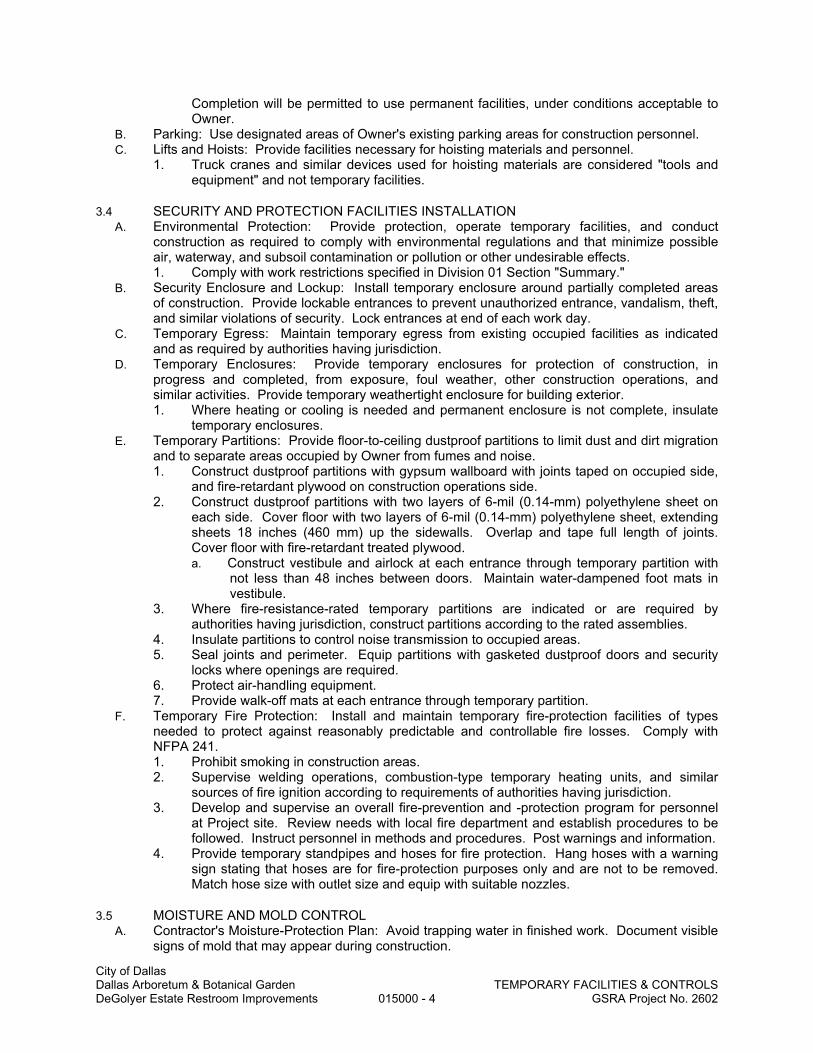
City of Dallas Dallas Arboretum & Botanical Garden TEMPORARY FACILITIES & CONTROLS DeGolyer Estate Restroom Improvements 015000 - 4 GSRA Project No. 2602
Completion will be permitted to use permanent facilities, under conditions acceptable to Owner.
B. Parking: Use designated areas of Owner's existing parking areas for construction personnel. C. Lifts and Hoists: Provide facilities necessary for hoisting materials and personnel.
1. Truck cranes and similar devices used for hoisting materials are considered "tools and equipment" and not temporary facilities.
3.4 SECURITY AND PROTECTION FACILITIES INSTALLATION A. Environmental Protection: Provide protection, operate temporary facilities, and conduct
construction as required to comply with environmental regulations and that minimize possible air, waterway, and subsoil contamination or pollution or other undesirable effects. 1. Comply with work restrictions specified in Division 01 Section "Summary."
B. Security Enclosure and Lockup: Install temporary enclosure around partially completed areas of construction. Provide lockable entrances to prevent unauthorized entrance, vandalism, theft, and similar violations of security. Lock entrances at end of each work day.
C. Temporary Egress: Maintain temporary egress from existing occupied facilities as indicated and as required by authorities having jurisdiction.
D. Temporary Enclosures: Provide temporary enclosures for protection of construction, in progress and completed, from exposure, foul weather, other construction operations, and similar activities. Provide temporary weathertight enclosure for building exterior. 1. Where heating or cooling is needed and permanent enclosure is not complete, insulate
temporary enclosures. E. Temporary Partitions: Provide floor-to-ceiling dustproof partitions to limit dust and dirt migration
and to separate areas occupied by Owner from fumes and noise. 1. Construct dustproof partitions with gypsum wallboard with joints taped on occupied side,
and fire-retardant plywood on construction operations side. 2. Construct dustproof partitions with two layers of 6-mil (0.14-mm) polyethylene sheet on
each side. Cover floor with two layers of 6-mil (0.14-mm) polyethylene sheet, extending sheets 18 inches (460 mm) up the sidewalls. Overlap and tape full length of joints. Cover floor with fire-retardant treated plywood. a. Construct vestibule and airlock at each entrance through temporary partition with
not less than 48 inches between doors. Maintain water-dampened foot mats in vestibule.
3. Where fire-resistance-rated temporary partitions are indicated or are required by authorities having jurisdiction, construct partitions according to the rated assemblies.
4. Insulate partitions to control noise transmission to occupied areas. 5. Seal joints and perimeter. Equip partitions with gasketed dustproof doors and security
locks where openings are required. 6. Protect air-handling equipment. 7. Provide walk-off mats at each entrance through temporary partition.
F. Temporary Fire Protection: Install and maintain temporary fire-protection facilities of types needed to protect against reasonably predictable and controllable fire losses. Comply with NFPA 241. 1. Prohibit smoking in construction areas. 2. Supervise welding operations, combustion-type temporary heating units, and similar
sources of fire ignition according to requirements of authorities having jurisdiction. 3. Develop and supervise an overall fire-prevention and -protection program for personnel
at Project site. Review needs with local fire department and establish procedures to be followed. Instruct personnel in methods and procedures. Post warnings and information.
4. Provide temporary standpipes and hoses for fire protection. Hang hoses with a warning sign stating that hoses are for fire-protection purposes only and are not to be removed. Match hose size with outlet size and equip with suitable nozzles.
3.5 MOISTURE AND MOLD CONTROL A. Contractor's Moisture-Protection Plan: Avoid trapping water in finished work. Document visible
signs of mold that may appear during construction.
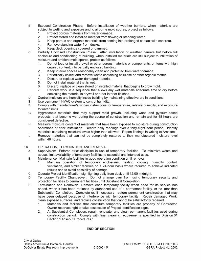
City of Dallas Dallas Arboretum & Botanical Garden TEMPORARY FACILITIES & CONTROLS DeGolyer Estate Restroom Improvements 015000 - 5 GSRA Project No. 2602
B. Exposed Construction Phase: Before installation of weather barriers, when materials are subject to wetting and exposure and to airborne mold spores, protect as follows: 1. Protect porous materials from water damage. 2. Protect stored and installed material from flowing or standing water. 3. Keep porous and organic materials from coming into prolonged contact with concrete. 4. Remove standing water from decks. 5. Keep deck openings covered or dammed.
C. Partially Enclosed Construction Phase: After installation of weather barriers but before full enclosure and conditioning of building, when installed materials are still subject to infiltration of moisture and ambient mold spores, protect as follows: 1. Do not load or install drywall or other porous materials or components, or items with high
organic content, into partially enclosed building. 2. Keep interior spaces reasonably clean and protected from water damage. 3. Periodically collect and remove waste containing cellulose or other organic matter. 4. Discard or replace water-damaged material. 5. Do not install material that is wet. 6. Discard, replace or clean stored or installed material that begins to grow mold. 7. Perform work in a sequence that allows any wet materials adequate time to dry before
enclosing the material in drywall or other interior finishes. D. Control moisture and humidity inside building by maintaining effective dry-in conditions. E. Use permanent HVAC system to control humidity. F. Comply with manufacturer's written instructions for temperature, relative humidity, and exposure
to water limits. G. Hygroscopic materials that may support mold growth, including wood and gypsum-based
products, that become wet during the course of construction and remain wet for 48 hours are considered defective.
H. Measure moisture content of materials that have been exposed to moisture during construction operations or after installation. Record daily readings over a forty-eight hour period. Identify materials containing moisture levels higher than allowed. Report findings in writing to Architect.
I. Remove materials that can not be completely restored to their manufactured moisture level within 48 hours.
3.6 OPERATION, TERMINATION, AND REMOVAL A. Supervision: Enforce strict discipline in use of temporary facilities. To minimize waste and
abuse, limit availability of temporary facilities to essential and intended uses. B. Maintenance: Maintain facilities in good operating condition until removal.
1. Maintain operation of temporary enclosures, heating, cooling, humidity control, ventilation, and similar facilities on a 24-hour basis where required to achieve indicated results and to avoid possibility of damage.
C. Operate Project-identification-sign lighting daily from dusk until 12:00 midnight. D. Temporary Facility Changeover: Do not change over from using temporary security and
protection facilities to permanent facilities until Substantial Completion. E. Termination and Removal: Remove each temporary facility when need for its service has
ended, when it has been replaced by authorized use of a permanent facility, or no later than Substantial Completion. Complete or, if necessary, restore permanent construction that may have been delayed because of interference with temporary facility. Repair damaged Work, clean exposed surfaces, and replace construction that cannot be satisfactorily repaired. 1. Materials and facilities that constitute temporary facilities are property of Contractor.
Owner reserves right to take possession of Project identification signs. 2. At Substantial Completion, repair, renovate, and clean permanent facilities used during
construction period. Comply with final cleaning requirements specified in Division 01 Section "Closeout Procedures."
END OF SECTION

City of Dallas Dallas Arboretum & Botanical Garden DeGolyer Estate Restroom Improvements
MOLD PREVENTION MEASURESGSRA Project No. 2602
015300 -
SECTION 015300
MOLD PREVENTION MEASURES
PART 1 - GENERAL
1.1 RELATED DOCUMENTS A. Drawings and general provisions of the Contract, including General and Supplementary
Conditions and other Division 1 Specification Sections, apply to this Section.
1.2 SUMMARY
A. Section includes: Administrative and procedural requirements to help prevent mold contamination in construction.
1.3 SUBMITTALS
A. Reports: Submit reports required in this Section, including but not limited to the following: 1. Sightings of existing mold. 2. Window and storefront testing. 3. Moisture contents of materials. 4. Exterior sealant cracks, damage, and deterioration.
1.4 QUALITY ASSURANCE
A. Pre-construction Meeting: Review requirements of this Section at Pre-construction Meeting.
1.5 PRODUCT DELIVERY, STORAGE, AND HANDLING
A. Deliver, store, and handle products using means and methods that will prevent damage, deterioration, and loss, including theft. Comply with manufacturer's written instructions.
B. Do not bring finish materials into building until building is in a conditioned state. Protect finish materials stored within building. Stage materials off the floor and cover with waterproof covering. Examples of these materials include, but are not limited to, insulation, gypsum products, wall coverings, carpet, ceiling tile, wood products, etc.
C. Remove from Project site damaged materials or materials that have become wet. Do not install such materials.
1.6 PROJECT CONDITIONS
A. Perform daily visual inspections of existing building for existing mold. Report sightings of mold to Architect.
B. Remove water found within building during construction immediately. 1. Energize lift stations and sump pumps as early in Project as possible. Use temporary
pumps if necessary, to get water out of building and drain lines. C. Ventilation:
1. Verify that existing HVAC system is providing positive pressure in building. 2. Provide adequate air circulation and ventilation during demolition phase(s). 3. Seal off return air ducts and diffusers to prevent construction dust and moisture
from entering occupied areas and HVAC system. 4. Provide temporary outside air ventilation as building becomes enclosed.
D. Maintain clean project site, free from hazards, garbage, and debris. E. Eating, drinking, and smoking are not permitted within building. F. Slope perimeter grades, both temporary and final grades, away from building structure. G. Verify that condensate pans drain properly beginning with initial installation. H. Flash roof penetrations immediately. Do not allow water to penetrate to floor below. I. Seal window openings prior to window installation with plastic to prevent moisture entry. J. Cover stored and installed ductwork and installed duct openings with plastic to prevent dust,
debris, and moisture from entering ductwork. Repair damaged plastic barrier. K. Do not operate air handling equipment below 60 degrees F supply air temperature until
building is 100 percent enclosed. L. Monitor humidity and temperature for conformance to installation requirements defined by
1
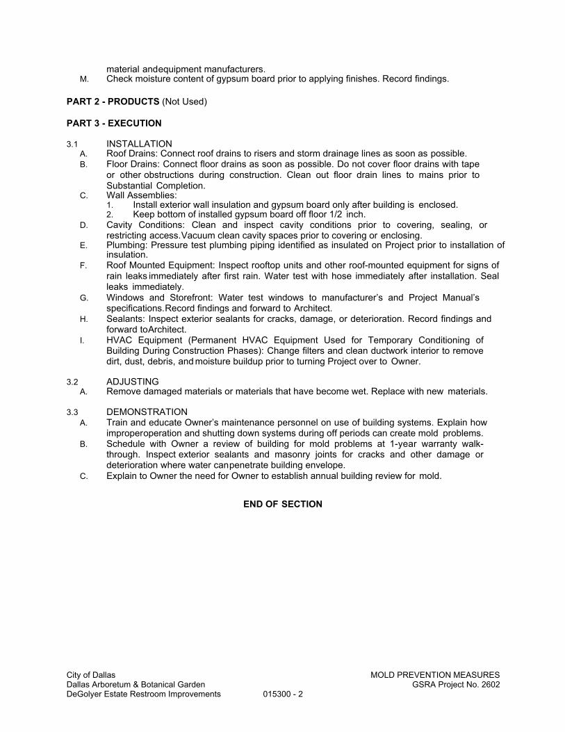
City of Dallas Dallas Arboretum & Botanical Garden DeGolyer Estate Restroom Improvements
MOLD PREVENTION MEASURESGSRA Project No. 2602
015300 - 2
material and equipment manufacturers. M. Check moisture content of gypsum board prior to applying finishes. Record findings.
PART 2 - PRODUCTS (Not Used)
PART 3 - EXECUTION
3.1 INSTALLATION A. Roof Drains: Connect roof drains to risers and storm drainage lines as soon as possible. B. Floor Drains: Connect floor drains as soon as possible. Do not cover floor drains with tape
or other obstructions during construction. Clean out floor drain lines to mains prior to Substantial Completion.
C. Wall Assemblies: 1. Install exterior wall insulation and gypsum board only after building is enclosed. 2. Keep bottom of installed gypsum board off floor 1/2 inch.
D. Cavity Conditions: Clean and inspect cavity conditions prior to covering, sealing, or restricting access. Vacuum clean cavity spaces prior to covering or enclosing.
E. Plumbing: Pressure test plumbing piping identified as insulated on Project prior to installation of insulation.
F. Roof Mounted Equipment: Inspect rooftop units and other roof-mounted equipment for signs of rain leaks immediately after first rain. Water test with hose immediately after installation. Seal leaks immediately.
G. Windows and Storefront: Water test windows to manufacturer’s and Project Manual’s specifications. Record findings and forward to Architect.
H. Sealants: Inspect exterior sealants for cracks, damage, or deterioration. Record findings and forward to Architect.
I. HVAC Equipment (Permanent HVAC Equipment Used for Temporary Conditioning of Building During Construction Phases): Change filters and clean ductwork interior to remove dirt, dust, debris, and moisture buildup prior to turning Project over to Owner.
3.2 ADJUSTING
A. Remove damaged materials or materials that have become wet. Replace with new materials.
3.3 DEMONSTRATION
A. Train and educate Owner’s maintenance personnel on use of building systems. Explain how improper operation and shutting down systems during off periods can create mold problems.
B. Schedule with Owner a review of building for mold problems at 1-year warranty walk-through. Inspect exterior sealants and masonry joints for cracks and other damage or deterioration where water can penetrate building envelope.
C. Explain to Owner the need for Owner to establish annual building review for mold.
END OF SECTION

City of Dallas Dallas Arboretum & Botanical Garden PRODUCT REQUIREMENTS DeGolyer Estate Restroom Improvements 016000 - 1 GSRA Project No. 2602
SECTION 016000
PRODUCT REQUIREMENTS
PART 1 - GENERAL
1.1 RELATED DOCUMENTS A. Drawings and general provisions of the Contract, including General and Supplementary
Conditions and other Division 01 Specification Sections, apply to this Section.
1.2 SUMMARY
A. Section includes administrative and procedural requirements for selection of products for use in Project; product delivery, storage, and handling; manufacturers' standard warranties on products; special warranties; and comparable products.
1.3 DEFINITIONS
A. Products: Items obtained for incorporating into the Work, whether purchased for Project or taken from previously purchased stock. The term "product" includes the terms "material," "equipment," "system," and terms of similar intent. 1. Named Products: Items identified by manufacturer's product name, including make or
model number or other designation shown or listed in manufacturer's published product literature, that is current as of date of the Contract Documents.
2. New Products: Items that have not previously been incorporated into another project or facility. Products salvaged from other projects are not considered new products.
3. Comparable Product: Product that is demonstrated and approved through submittal process to have the indicated qualities related to type, function, dimension, in-service performance, physical properties, appearance, and other characteristics that equal or exceed those of specified product.
B. Basis-of-Design Product Specification: A specification in which a specific manufacturer's product is named and accompanied by the words "basis-of-design product," including make or model number or other designation, to establish the significant qualities related to type, function, dimension, in-service performance, physical properties, appearance, and other characteristics for purposes of evaluating comparable products of additional manufacturers named in the specification.
1.4 ACTION SUBMITTALS
A. Comparable Product Requests: Submit request for consideration of each comparable product. Identify product or fabrication or installation method to be replaced. Include Specification Section number and title and Drawing numbers and titles. 1. Include data to indicate compliance with the requirements specified in "Comparable
Products" Article. 2. Architect's Action: If necessary, Architect will request additional information or
documentation for evaluation within one week of receipt of a comparable product request. Architect will notify Contractor of approval or rejection of proposed comparable product request within 15 days of receipt of request, or seven days of receipt of additional information or documentation, whichever is later. a. Form of Approval: As specified in Division 01 Section "Submittal Procedures." b. Use product specified if Architect does not issue a decision on use of a
comparable product request within time allocated. B. Basis-of-Design Product Specification Submittal: Comply with requirements in Division 01
Section "Submittal Procedures." Show compliance with requirements.
1.5 QUALITY ASSURANCE
A. Compatibility of Options: If Contractor is given option of selecting between two or more products for use on Project, select product compatible with products previously selected, even if

City of Dallas Dallas Arboretum & Botanical Garden PRODUCT REQUIREMENTS DeGolyer Estate Restroom Improvements 016000 - 2 GSRA Project No. 2602
previously selected products were also options.
1.6 PRODUCT DELIVERY, STORAGE, AND HANDLING A. Deliver, store, and handle products using means and methods that will prevent damage,
deterioration, and loss, including theft and vandalism. Comply with manufacturer's written instructions.
B. Delivery and Handling: 1. Schedule delivery to minimize long-term storage at Project site and to prevent
overcrowding of construction spaces. 2. Coordinate delivery with installation time to ensure minimum holding time for items that
are flammable, hazardous, easily damaged, or sensitive to deterioration, theft, and other losses.
3. Deliver products to Project site in an undamaged condition in manufacturer's original sealed container or other packaging system, complete with labels and instructions for handling, storing, unpacking, protecting, and installing.
4. Inspect products on delivery to determine compliance with the Contract Documents and to determine that products are undamaged and properly protected.
C. Storage: 1. Store products to allow for inspection and measurement of quantity or counting of units. 2. Store materials in a manner that will not endanger Project structure. 3. Store products that are subject to damage by the elements, under cover in a weather-
tight enclosure above ground, with ventilation adequate to prevent condensation. 4. Store foam plastic from exposure to sunlight, except to extent necessary for period of
installation and concealment. 5. Comply with product manufacturer's written instructions for temperature, humidity,
ventilation, and weather-protection requirements for storage. 6. Protect stored products from damage and liquids from freezing. 7. Provide a secure location and enclosure at Project site for storage of materials and
equipment by Owner's construction forces. Coordinate location with Owner.
1.7 PRODUCT WARRANTIES
A. Warranties specified in other Sections shall be in addition to, and run concurrent with, other warranties required by the Contract Documents. Manufacturer's disclaimers and limitations on product warranties do not relieve Contractor of obligations under requirements of the Contract Documents. 1. Manufacturer's Warranty: Written warranty furnished by individual manufacturer for a
particular product and specifically endorsed by manufacturer to Owner. 2. Special Warranty: Written warranty required by the Contract Documents to provide
specific rights for Owner. B. Special Warranties: Prepare a written document that contains appropriate terms and
identification, ready for execution. 1. Manufacturer's Standard Form: Modified to include Project-specific information and
properly executed. 2. Specified Form: When specified forms are included with the Specifications, prepare a
written document using indicated form properly executed. 3. Refer to Divisions 02 through 49. Sections for specific content requirements and
particular requirements for submitting special warranties. C. Submittal Time: Comply with requirements in Division 01 Section "Closeout Procedures."
PART 2 - PRODUCTS
2.1 PRODUCT SELECTION PROCEDURES A. General Product Requirements: Provide products that comply with the Contract Documents,
are undamaged and, unless otherwise indicated, are new at time of installation. 1. Provide products complete with accessories, trim, finish, fasteners, and other items
needed for a complete installation and indicated use and effect.

City of Dallas Dallas Arboretum & Botanical Garden PRODUCT REQUIREMENTS DeGolyer Estate Restroom Improvements 016000 - 3 GSRA Project No. 2602
2. Standard Products: If available, and unless custom products or nonstandard options are specified, provide standard products of types that have been produced and used successfully in similar situations on other projects.
3. Owner reserves the right to limit selection to products with warranties not in conflict with requirements of the Contract Documents.
4. Where products are accompanied by the term "as selected," Architect will make selection.
5. Descriptive, performance, and reference standard requirements in the Specifications establish salient characteristics of products.
6. Or Equal: For products specified by name and accompanied by the term "or equal," or "or approved equal," or "or approved," comply with requirements in "Comparable Products" Article to
obtain approval for use of an unnamed product. 7. Where all other criteria are met, contractor shall give preference to products that:
a. Are extracted, harvested and/or manufactured closer to the project location. b. Have longer warranted life span under normal use. c. Result in less construction waste d. Have recycled content
8. Do not use the following products: a. No ACM or hazardous-containing building materials in all new construction or
renovations. The Contractor shall not install any materials in the performance of the Work that contain asbestos or asbestos-related material such as hydrated mineral silicate, including chrysolite, amosite, crocidolite, tremolite, anthophylite or actinolite, whether friable or non-friable.
b. Products containing CFCs or HCFCs. c. Composite wood products containing added urea formaldehyde. d. Paints, coatings, adhesives and sealants for use on the building interior that do
not comply with LEED NC 2009 EQc4.1 and 4.2 requirements. B. Product Selection Procedures:
1. Product: Where Specifications name a single manufacturer and product, provide the named product that complies with requirements. Comparable products or substitutions for Contractor's convenience will not be considered.
2. Manufacturer/Source: Where Specifications name a single manufacturer or source, provide a product by the named manufacturer or source that complies with requirements. Comparable products or substitutions for Contractor's convenience will not be considered.
3. Products: a. Restricted List: Where Specifications include a list of names of both
manufacturers and products, provide one of the products listed that complies with requirements. Comparable products or substitutions for Contractor's convenience will be considered, unless otherwise indicated.
b. Non-restricted List: Where Specifications include a list of names of both available manufacturers and products, provide one of the products listed, or an unnamed product, that complies with requirements. Comply with requirements in "Comparable Products" Article for consideration of an unnamed product.
4. Manufacturers: a. Restricted List: Where Specifications include a list of manufacturers' names,
provide a product by one of the manufacturers listed that complies with requirements. Comparable products or substitutions for Contractor's convenience will be considered, unless otherwise indicated.
b. Non-restricted List: Where Specifications include a list of available manufacturers, provide a product by one of the manufacturers listed, or a product by an unnamed manufacturer, that complies with requirements. Comply with requirements in "Comparable Products" Article for consideration of an unnamed manufacturer's product.
5. Basis-of-Design Product: Where Specifications name a product, or refer to a product indicated on Drawings, and include a list of manufacturers, provide the specified or

City of Dallas Dallas Arboretum & Botanical Garden PRODUCT REQUIREMENTS DeGolyer Estate Restroom Improvements 016000 - 4 GSRA Project No. 2602
indicated product or a comparable product by one of the other named manufacturers. Drawings and Specifications indicate sizes, profiles, dimensions, and other characteristics that are based on the product named. Comply with requirements in "Comparable Products" Article for consideration of an unnamed product by one of the other named manufacturers.
C. Visual Matching Specification: Where Specifications require "match Architect's sample", provide a product that complies with requirements and matches Architect's sample. Architect's decision will be final on whether a proposed product matches. 1. If no product available within specified category matches and complies with other
specified requirements, comply with requirements in Division 01 Section "Substitution Procedures" for proposal of product.
D. Visual Selection Specification: Where Specifications include the phrase "as selected by Architect from manufacturer's full range" or similar phrase, select a product that complies with requirements. Architect will select color, gloss, pattern, density, or texture from manufacturer's product line that includes both standard and premium items.
2.2 COMPARABLE PRODUCTS A. Conditions for Consideration: Architect will consider Contractor's request for comparable
product when the following conditions are satisfied. If the following conditions are not satisfied, Architect may return requests without action, except to record noncompliance with these requirements: 1. Evidence that the proposed product does not require revisions to the Contract
Documents, that it is consistent with the Contract Documents and will produce the indicated results, and that it is compatible with other portions of the Work.
2. Detailed comparison of significant qualities of proposed product with those named in the Specifications. Significant qualities include attributes such as performance, weight, size, durability, LEED requirements, visual effect, and specific features and requirements indicated.
3. Evidence that proposed product provides specified warranty. 4. List of similar installations for completed projects with project names and addresses and
names and addresses of architects and owners, if requested. 5. Samples, if requested.
PART 3 – EXECUTION 3.1 HAZARDOUS MATERIALS A. In the event hazardous materials are installed, whether intentional or by negligence, the
Contractor shall bear the cost of correcting the work, including costs associated with testing, abatement, replacement materials, and all associated labor.
END OF SECTION

City of Dallas Dallas Arboretum & Botanical Garden EXECUTION DeGolyer Estate Restroom Improvements 017300 - 1 GSRA Project No. 2602
SECTION 017300
EXECUTION
PART 1 - GENERAL
1.1 RELATED DOCUMENTS A. Drawings and general provisions of the Contract, including General and Supplementary
Conditions and other Division 01 Specification Sections, apply to this Section.
1.2 SUMMARY
A. Section includes general administrative and procedural requirements governing execution of the Work including, but not limited to, the following: 1. Construction layout. 2. Field engineering and surveying. 3. Installation of the Work. 4. Cutting and patching. 5. Coordination of Owner-installed products. 6. Progress cleaning. 7. Starting and adjusting. 8. Protection of installed construction. 9. Correction of the Work.
1.3 DEFINITIONS
A. Cutting: Removal of in-place construction necessary to permit installation or performance of other work.
B. Patching: Fitting and repair work required to restore construction to original conditions after installation of other work.
1.4 INFORMATIONAL SUBMITTALS
A. Qualification Data: For land surveyor. B. Certificates: Submit certificate signed by land surveyor certifying that location and
elevation of improvements comply with requirements. C. Certified Surveys: Submit two copies signed by land surveyor. D. Final Property Survey: Submit 10 copies showing the Work performed and record survey data.
1.5 QUALITY ASSURANCE
A. Land Surveyor Qualifications: A professional land surveyor who is legally qualified to practice in jurisdiction where Project is located and who is experienced in providing land-surveying services of the kind indicated.
B. Cutting and Patching: Comply with requirements for and limitations on cutting and patching of construction elements. 1. Structural Elements: When cutting and patching structural elements, notify Architect of
locations and details of cutting and await directions from the Architect before proceeding. Shore, brace, and support structural element during cutting and patching. Do not cut and patch structural elements in a manner that could change their load-carrying capacity or increase deflection
2. Operational Elements: Do not cut and patch operating elements and related components in a manner that results in reducing their capacity to perform as intended or that results in increased maintenance or decreased operational life or safety. Operational elements include the following: a. Primary operational systems and equipment. b. Fire separation assemblies. c. Air or smoke barriers. d. Fire-suppression systems.

City of Dallas Dallas Arboretum & Botanical Garden EXECUTION DeGolyer Estate Restroom Improvements 017300 - 2 GSRA Project No. 2602
e. Mechanical systems piping and ducts. f. Control systems. g. Communication systems. h. Conveying systems. i. Electrical wiring systems. j. Operating systems of special construction.
3. Other Construction Elements: Do not cut and patch other construction elements or components in
a manner that could change their load-carrying capacity, that results in reducing their capacity to perform as intended, or that results in increased maintenance or decreased operational life or safety. Other construction elements include but are not limited to the following: a. Water, moisture, or vapor barriers. b. Membranes and flashings. c. Exterior curtain-wall construction. d. Equipment supports. e. Piping, ductwork, vessels, and equipment. f. Noise- and vibration-control elements and systems.
4. Visual Elements: Do not cut and patch construction in a manner that results in visual evidence of cutting and patching. Do not cut and patch exposed construction in a manner that would, in Architect's opinion, reduce the building's aesthetic qualities. Remove and replace construction that has been cut and patched in a visually unsatisfactory manner.
C. Cutting and Patching Conference: Before proceeding, meet at Project site with parties involved in cutting and patching, including mechanical and electrical trades. Review areas of potential interference and conflict. Coordinate procedures and resolve potential conflicts before proceeding.
D. Manufacturer's Installation Instructions: Obtain and maintain on-site manufacturer's written recommendations and instructions for installation of products and equipment.
1.6 WARRANTY
A. Existing Warranties: Remove, replace, patch, and repair materials and surfaces cut or damaged during installation or cutting and patching operations, by methods and with materials so as not to void existing warranties.
PART 2 - PRODUCTS
2.1 MATERIALS A. General: Comply with requirements specified in other Sections.
1. For projects requiring compliance with sustainable design and construction practices and procedures, utilize products for patching that comply with requirements of Division 01 Section "Sustainable Design Requirements."
B. In-Place Materials: Use materials for patching identical to in-place materials. For exposed surfaces, use materials that visually match in-place adjacent surfaces to the fullest extent possible. 1. If identical materials are unavailable or cannot be used, use materials that, when
installed, will provide a match acceptable to the Architect for the visual and functional performance of in-place materials.
PART 3 - EXECUTION
3.1 EXAMINATION A. Existing Conditions: The existence and location of underground and other utilities and
construction indicated as existing are not guaranteed. Before beginning site work, investigate and verify the existence and location of underground utilities, mechanical and electrical systems, and other construction affecting the Work.

City of Dallas Dallas Arboretum & Botanical Garden EXECUTION DeGolyer Estate Restroom Improvements 017300 - 3 GSRA Project No. 2602
1. Before construction, verify the location and invert elevation at points of connection of sanitary sewer, storm sewer, and water-service piping; underground electrical services, and other utilities.
2. Furnish location data for work related to Project that must be performed by public utilities serving Project site.
B. Examination and Acceptance of Conditions: Before proceeding with each component of the Work, examine substrates, areas, and conditions, with Installer or Applicator present where indicated, for compliance with requirements for installation tolerances and other conditions affecting performance. Record observations. 1. Written Report: Where a written report listing conditions detrimental to performance of
the Work is required by other Sections, include the following: a. Description of the Work. b. List of detrimental conditions, including substrates. c. List of unacceptable installation tolerances. d. Recommended corrections.
2. Verify compatibility with and suitability of substrates, including compatibility with existing finishes or primers.
3. Examine roughing-in for mechanical and electrical systems to verify actual locations of connections
before equipment and fixture installation. 4. Examine walls, floors, and roofs for suitable conditions where products and systems
are to be installed. 5. Proceed with installation only after unsatisfactory conditions have been corrected.
Proceeding with the Work indicates acceptance of surfaces and conditions. 3.2 PREPARATION
A. Existing Utility Information: Furnish information to Owner that is necessary to adjust, move, or relocate existing utility structures, utility poles, lines, services, or other utility appurtenances located in or affected by construction. Coordinate with authorities having jurisdiction.
B. Field Measurements: Take field measurements as required to fit the Work properly. Recheck measurements before installing each product. Where portions of the Work are indicated to fit to other construction, verify dimensions of other construction by field measurements before fabrication. Coordinate fabrication schedule with construction progress to avoid delaying the Work.
C. Space Requirements: Verify space requirements and dimensions of items shown diagrammatically on Drawings.
D. Review of Contract Documents and Field Conditions: Immediately on discovery of the need for clarification of the Contract Documents caused by differing field conditions outside the control of the Contractor, submit a request for information to Architect according to requirements in Division 01 Section "Project Management and Coordination."
3.3 CONSTRUCTION LAYOUT
A. Verification: Before proceeding to lay out the Work, verify layout information shown on Drawings, in relation to the property survey and existing benchmarks. If discrepancies are discovered, notify Architect promptly.
B. General: Engage a land surveyor to lay out the Work using accepted surveying practices. 1. Establish benchmarks and control points to set lines and levels at each story of
construction and elsewhere as needed to locate each element of Project. 2. Establish dimensions within tolerances indicated. Do not scale Drawings to obtain
required dimensions. 3. Inform installers of lines and levels to which they must comply. 4. Check the location, level and plumb, of every major element as the Work progresses. 5. Notify Architect when deviations from required lines and levels exceed allowable
tolerances. 6. Close site surveys with an error of closure equal to or less than the standard
established by authorities having jurisdiction.

City of Dallas Dallas Arboretum & Botanical Garden EXECUTION DeGolyer Estate Restroom Improvements 017300 - 4 GSRA Project No. 2602
C. Site Improvements: Locate and lay out site improvements, including pavements, grading, fill and topsoil placement, utility slopes, and rim and invert elevations.
D. Building Lines and Levels: Locate and lay out control lines and levels for structures, building foundations, column grids, and floor levels, including those required for mechanical and electrical work. Transfer survey markings and elevations for use with control lines and levels. Level foundations and piers from two or more locations.
E. Record Log: Maintain a log of layout control work. Record deviations from required lines and levels. Include beginning and ending dates and times of surveys, weather conditions, name and duty of each survey party member, and types of instruments and tapes used. Make the log available for reference by Architect.
3.4 FIELD ENGINEERING
A. Identification: Owner will identify existing benchmarks, control points, and property corners. B. Reference Points: Locate existing permanent benchmarks, control points, and similar
reference points before beginning the Work. Preserve and protect permanent benchmarks and control points during construction operations. 1. Do not change or relocate existing benchmarks or control points without prior written
approval of Architect. Report lost or destroyed permanent benchmarks or control points promptly. Report the need to relocate permanent benchmarks or control points to Architect before proceeding.
2. Replace lost or destroyed permanent benchmarks and control points promptly. Base replacements on the original survey control points.
C. Benchmarks: Establish and maintain a minimum of two permanent benchmarks on Project site, referenced to data established by survey control points. Comply with authorities having jurisdiction for type and size of benchmark. 1. Record benchmark locations, with horizontal and vertical data, on Project Record
Documents. 2. Where the actual location or elevation of layout points cannot be marked, provide
temporary
reference points sufficient to locate the Work. 3. Remove temporary reference points when no longer needed. Restore marked
construction to its original condition. D. Certified Survey: On completion of foundation walls, major site improvements, and other work
requiring field-engineering services, prepare a certified survey showing dimensions, locations, angles, and elevations of construction and site work.
E. Final Property Survey: Engage a land surveyor to prepare a final property survey showing significant features (real property) for Project. Include on the survey a certification, signed by land surveyor, that principal metes, bounds, lines, and levels of Project are accurately positioned as shown on the survey. 1. Show boundary lines, monuments, streets, site improvements and utilities, existing
improvements and significant vegetation, adjoining properties, acreage, grade contours, and the distance and bearing from a site corner to a legal point.
2. Recording: At Substantial Completion, have the final property survey recorded by or with authorities having jurisdiction as the official "property survey."
3.5 INSTALLATION
A. General: Locate the Work and components of the Work accurately, in correct alignment and elevation, as indicated. 1. Make vertical work plumb and make horizontal work level. 2. Where space is limited, install components to maximize space available for maintenance
and ease of removal for replacement. 3. Conceal pipes, ducts, and wiring in finished areas, unless otherwise indicated.
B. Comply with manufacturer's written instructions and recommendations for installing products in applications indicated.
C. Install products at the time and under conditions that will ensure the best possible results. Maintain conditions required for product performance until Substantial Completion.
D. Conduct construction operations so no part of the Work is subjected to damaging operations or

City of Dallas Dallas Arboretum & Botanical Garden EXECUTION DeGolyer Estate Restroom Improvements 017300 - 5 GSRA Project No. 2602
loading in excess of that expected during normal conditions of occupancy. E. Tools and Equipment: Do not use tools or equipment that produce harmful noise levels. F. Templates: Obtain and distribute to the parties involved templates for work specified to be
factory prepared and field installed. Check Shop Drawings of other work to confirm that adequate provisions are made for locating and installing products to comply with indicated requirements.
G. Attachment: Provide blocking and attachment plates and anchors and fasteners of adequate size and number to securely anchor each component in place, accurately located and aligned with other portions of the Work. Where size and type of attachments are not indicated, verify size and type required for load conditions. 1. Mounting Heights: Where mounting heights are not indicated, mount components
at heights directed by Architect. 2. Allow for building movement, including thermal expansion and contraction. 3. Coordinate installation of anchorages. Furnish setting drawings, templates, and
directions for installing anchorages, including sleeves, concrete inserts, anchor bolts, and items with integral anchors, that are to be embedded in concrete or masonry. Deliver such items to Project site in time for installation.
H. Joints: Make joints of uniform width. Where joint locations in exposed work are not indicated, arrange joints for the best visual effect. Fit exposed connections together to form hairline joints.
I. Hazardous Materials: Use products, cleaners, and installation materials that are not considered hazardous.
3.6 CUTTING AND PATCHING
A. Cutting and Patching, General: Employ skilled workers to perform cutting and patching. Proceed with cutting and patching at the earliest feasible time, and complete without delay. 1. Cut in-place construction to provide for installation of other components or
performance of other construction, and subsequently patch as required to restore surfaces to their original condition.
B. Temporary Support: Provide temporary support of work to be cut. C. Protection: Protect in-place construction during cutting and patching to prevent damage.
Provide protection from adverse weather conditions for portions of Project that might be exposed during cutting and patching operations.
D. Adjacent Occupied Areas: Where interference with use of adjoining areas or interruption of free passage to adjoining areas is unavoidable, coordinate cutting and patching in accordance with requirements of Division 01 Section "Summary."
E. Existing Utility Services and Mechanical/Electrical Systems: Where existing services/systems are required
to be removed, relocated, or abandoned, bypass such services/systems before cutting to prevent interruption to occupied areas.
F. Cutting: Cut in-place construction by sawing, drilling, breaking, chipping, grinding, and similar operations, including excavation, using methods least likely to damage elements retained or adjoining construction. If possible, review proposed procedures with original Installer; comply with original Installer's written recommendations. 1. In general, use hand or small power tools designed for sawing and grinding, not
hammering and chopping. Cut holes and slots neatly to minimum size required, and with minimum disturbance of adjacent surfaces. Temporarily cover openings when not in use.
2. Finished Surfaces: Cut or drill from the exposed or finished side into concealed surfaces.
3. Concrete and Masonry: Cut using a cutting machine, such as an abrasive saw or a diamond-core drill.
4. Excavating and Backfilling: Comply with requirements in applicable Division 31 Sections where required by cutting and patching operations.
5. Mechanical and Electrical Services: Cut off pipe or conduit in walls or partitions to be removed. Cap, valve, or plug and seal remaining portion of pipe or conduit to prevent entrance of moisture or other foreign matter after cutting.

City of Dallas Dallas Arboretum & Botanical Garden EXECUTION DeGolyer Estate Restroom Improvements 017300 - 6 GSRA Project No. 2602
6. Proceed with patching after construction operations requiring cutting are complete. G. Patching: Patch construction by filling, repairing, refinishing, closing up, and similar
operations following performance of other work. Patch with durable seams that are as invisible as practicable. Provide materials and comply with installation requirements specified in other Sections, where applicable. 1. Inspection: Where feasible, test and inspect patched areas after completion to
demonstrate physical integrity of installation. 2. Exposed Finishes: Restore exposed finishes of patched areas and extend finish
restoration into retained adjoining construction in a manner that will minimize evidence of patching and refinishing. a. Clean piping, conduit, and similar features before applying paint or other finishing
materials. b. Restore damaged pipe covering to its original condition.
3. Floors and Walls: Where walls or partitions that are removed extend one finished area into another, patch and repair floor and wall surfaces in the new space. Provide an even surface of uniform finish, color, texture, and appearance. Remove in-place floor and wall coverings and replace with new materials, if necessary, to achieve uniform color and appearance. a. Where patching occurs in a painted surface, prepare substrate and apply primer
and intermediate paint coats appropriate for substrate over the patch, and apply final paint coat over entire unbroken surface containing the patch. Provide additional coats until patch blends with adjacent surfaces.
4. Ceilings: Patch, repair, or re-hang in-place ceilings as necessary to provide an even-plane surface of uniform appearance.
5. Exterior Building Enclosure: Patch components in a manner that restores enclosure to a weather- tight condition.
H. Cleaning: Clean areas and spaces where cutting and patching are performed. Remove paint, mortar, oils, putty, and similar materials from adjacent finished surfaces.
3.7 OWNER-INSTALLED PRODUCTS
A. Site Access: Provide access to Project site for Owner's construction personnel. B. Coordination: Coordinate construction and operations of the Work with work performed
by Owner's construction personnel. 1. Construction Schedule: Inform Owner of Contractor's preferred construction schedule for
Owner's portion of the Work. Adjust construction schedule based on a mutually agreeable timetable. Notify Owner if changes to schedule are required due to differences in actual construction progress.
2. Pre-installation Conferences: Include Owner's construction personnel at pre-installation conferences covering portions of the Work that are to receive Owner's work. Attend pre-installation conferences conducted by Owner's construction personnel if portions of the Work depend on Owner's construction.
3.8 PROGRESS CLEANING A. General: Clean Project site and work areas daily, including common areas. Enforce
requirements strictly. Dispose of materials lawfully. 1. Comply with requirements in NFPA 241 for removal of combustible waste materials and
debris. 2. Do not hold waste materials more than seven days during normal weather or three
days if the temperature is expected to rise above 80 deg. F. 3. Containerize hazardous and unsanitary waste materials separately from other
waste. Mark containers appropriately and dispose of legally, according to regulations. a. Utilize containers intended for holding waste materials of type to be stored.
4. Coordinate progress cleaning for joint-use areas where more than one installer has worked.
B. Site: Maintain Project site free of waste materials and debris. C. Work Areas: Clean areas where work is in progress to the level of cleanliness necessary

City of Dallas Dallas Arboretum & Botanical Garden EXECUTION DeGolyer Estate Restroom Improvements 017300 - 7 GSRA Project No. 2602
for proper execution of the Work. 1. Remove liquid spills promptly. 2. Where dust would impair proper execution of the Work, broom-clean or vacuum the
entire work area, as appropriate. D. Installed Work: Keep installed work clean. Clean installed surfaces according to written
instructions of manufacturer or fabricator of product installed, using only cleaning materials specifically recommended. If specific cleaning materials are not recommended, use cleaning materials that are not hazardous to health or property and that will not damage exposed surfaces.
E. Concealed Spaces: Remove debris from concealed spaces before enclosing the space. F. Exposed Surfaces in Finished Areas: Clean exposed surfaces and protect as necessary
to ensure freedom from damage and deterioration at time of Substantial Completion. G. Waste Disposal: Do not bury or burn waste materials on-site. Do not wash waste materials
down sewers or into waterways. Comply with waste disposal requirements in Division 01 Section "Temporary Facilities and Controls." Division 01 Section "Construction Waste Management and Disposal."
H. During handling and installation, clean and protect construction in progress and adjoining materials already in place. Apply protective covering where required to ensure protection from damage or deterioration at Substantial Completion.
I. Clean and provide maintenance on completed construction as frequently as necessary through the remainder of the construction period. Adjust and lubricate operable components to ensure operability without damaging effects.
J. Limiting Exposures: Supervise construction operations to assure that no part of the construction completed or in progress, is subject to harmful, dangerous, damaging, or otherwise deleterious exposure during the construction period.
3.9 STARTING AND ADJUSTING A. Coordinate startup and adjusting of equipment and operating components with requirements in
Division 01 Section "General Commissioning Requirements." B. Start equipment and operating components to confirm proper operation. Remove
malfunctioning units, replace with new units, and retest. C. Adjust equipment for proper operation. Adjust operating components for proper operation without
binding. D. Test each piece of equipment to verify proper operation. Test and adjust controls and
safeties. Replace damaged and malfunctioning controls and equipment. E. Manufacturer's Field Service: Comply with qualification requirements in Division 01
Section "Quality Requirements."
3.10 PROTECTION OF INSTALLED CONSTRUCTION A. Provide final protection and maintain conditions that ensure installed Work is without
damage or deterioration at time of Substantial Completion. B. Comply with manufacturer's written instructions for temperature and relative humidity.
3.11 CORRECTION OF THE WORK A. Repair or remove and replace defective construction. Restore damaged substrates and finishes.
1. Repairing includes replacing defective parts, refinishing damaged surfaces, touching up with matching materials, and properly adjusting operating equipment.
B. Restore permanent facilities used during construction to their specified condition. C. Remove and replace damaged surfaces that are exposed to view if surfaces cannot be
repaired without visible evidence of repair. D. Repair components that do not operate properly. Remove and replace operating components
that cannot be repaired. E. Remove and replace chipped, scratched, and broken glass or reflective surfaces.
END OF SECTION

City of Dallas
Dallas Arboretum & Botanical Garden CUTTING AND PATCHING
DeGolyer Estate Restroom Improvements 017329 - 1 GSRA Project No. 2602
SECTION 017329
CUTTING AND PATCHING
PART 1 - GENERAL
1.01 SUMMARY
A. Procedural requirements for cutting and patching.
1.02 RELATED SECTIONS
A. General Conditions, where required.
B. Section 013516 - Alterations Project Procedures.
C. Sections for specific requirements and limitations applicable to cutting and patching individual parts of the Work; Specification section for that work.
1.03 SCOPE
A. Execute cutting including excavating, fitting and patching required to complete Work or to: 1. Make several parts fit properly. 2. Uncover portions of Work to provide for installation of out of sequence Work. 3. Remove and replace defective work. 4. Remove and replace work not conforming to requirements of Contract Documents. 5. Remove samples of installed work as specified for testing. 6. Provide penetrations of non-structural surfaces for installation of piping and conduit.
B. In addition to other contract requirements, upon written instructions of Architect: 1. Uncover work to provide for Architect observation of covered work. 2. Remove samples of installed materials for testing. 3. Remove work to provide for alteration of completed work.
C. Do not cut into or cut away structural members nor excavate beneath foundations or load bearing structures without notification, and approval from Architect.
D. Do not cut into or cut away concrete elements or structures without notification, and approval from Architect.
E. Obtain written permission of separate contractor whose work will be affected by proposed cutting and patching.
1.04 SUBMITTALS
A. Submit written notice to Architect a minimum of 3 days in advance of executing cutting which affects: 1. Work of Owner or any separate contractor. 2. Structural integrity of Work, cutting concrete and steel structural members, cutting masonry
elements. 3. Integrity of weather exposed or moisture resistant elements. 4. Efficiency, operation or maintenance of operational equipment. 5. Visual qualities of sight-exposed elements.
B. Request shall include: 1. Identification of Project, description of affected work, necessity for cutting, effect on other
Work, effect on structural integrity of project, description of proposed work. Designate: a. Scope of cutting and patching. b. Trades to execute work. c. Products proposed to be used.

City of Dallas
Dallas Arboretum & Botanical Garden CUTTING AND PATCHING
DeGolyer Estate Restroom Improvements 017329 - 2 GSRA Project No. 2602
d. Extent of refinishing. e. Proposed schedule for cutting and patching.
2. Alternatives to cutting and patching.
C. Should conditions of Work, or schedule, indicate change of materials or methods, submit written recommendation to Architect, including: 1. Conditions indicating change. 2. Recommendations for alternative materials or methods. 3. Submittals as required for substitutions as specified in Section 016000.
D. Submit written notice 3 days in advance to Architect designating time work will be uncovered to provide for observation requested by Architect or regulatory agency of jurisdiction.
PART 2 - PRODUCTS
2.01 MATERIALS
A. For replacement of work removed, comply with Specifications for each specific product involved.
PART 3 - EXECUTION
3.01 EXAMINATION
A. Examine existing conditions of Work, including elements subject to movement or damage during cutting and patching, and during excavation and backfilling.
B. After uncovering work, examine conditions affecting installation of new products, or performance of work.
C. Do not proceed until unsatisfactory conditions have been corrected.
3.02 PREPARATION
A. Provide temporary shoring, bracing and support to maintain structural integrity of affected portion of Work.
B. Provide protection for other portions of Work.
C. Provide protection from elements for portion of Work which may be exposed by cutting and patching, and maintain excavations free of water.
3.03 PERFORMANCE
A. Execute fitting and adjustment of products to provide finished installation to comply with specified products, functions, tolerances and finishes.
B. Execute cutting by methods which will prevent damage to other work and will provide proper surfaces to receive installation of repairs and new work. 1. Neatly cut and remove materials, and prepare openings to receive new work. 2. Remove concrete in small sections. 3. Provide shoring, bracing, and other supports to prevent movement, settlement, or collapse
of remaining or adjacent wall areas, structure, or facilities. 4. Arrange shoring, bracing, and supports to prevent overloading of structure.
C. Execute excavating and backfilling by methods which will prevent damage to other work and will prevent settlement.
D. Restore work which has been cut or removed; install new products to provide completed Work in accord with requirements of Contract Documents.
E. Refinish sight-exposed surfaces to provide specified uniform finish to match adjacent finishes. 1. Continuous Surfaces: To nearest intersections.

City of Dallas
Dallas Arboretum & Botanical Garden CUTTING AND PATCHING
DeGolyer Estate Restroom Improvements 017329 - 3 GSRA Project No. 2602
2. Assembly: Entire refinishing.
F. Fit work airtight to pipes, sleeves, ducts, conduit and other penetrations through surfaces.
G. At penetrations of fire-rated construction, completely seal voids with firestopping materials in accordance with Section 078400.
3.04 CLEAN UP
A. Remove debris, rubbish, and materials resulting from cutting and patching operations.
B. Transport materials and legally dispose of off site.
END OF SECTION

City of Dallas
Dallas Arboretum & Botanical Garden CLEANING
DeGolyer Estate Restroom Improvements 017400 - 1 GSRA Project No. 2602
SECTION 017400
CLEANING
PART 1 - GENERAL
1.01 SUMMARY
A. Progress cleaning during construction.
B. Final cleaning at completion of Work.
1.02 RELATED SECTIONS
A. General Conditions, where required.
B. Cleaning up required for specific Products or work; Specification Section for that work.
1.03 DESCRIPTION
A. Execute periodic cleaning during construction to prevent accumulations of waste materials.
B. Execute final cleaning prior to inspection for Substantial Completion of the Work.
1.04 REGULATORY REQUIREMENTS
A. Fire Protection: Store volatile waste in covered metal containers and remove from premises daily.
B. Pollution Control: Conduct clean-up and disposal operations to comply with local codes, ordinances and anti-pollution laws. 1. Burning or burying of rubbish and waste materials on the project site is prohibited. 2. Disposal of volatile fluid wastes, (such as mineral spirits, oil or paint thinner), in storm or
sanitary sewer systems or into streams or waterways is prohibited.
PART 2 - PRODUCTS
2.01 CLEANING MATERIALS
A. Use only cleaning materials which will not create hazards to health or property and which will not damage surfaces.
B. Use only those cleaning materials recommended by manufacturer of surface to be cleaned.
C. Use cleaning materials only on surfaces recommended by cleaning material manufacturer.
PART 3 - EXECUTION
3.01 CLEANING DURING CONSTRUCTION
A. Execute periodic cleaning to keep Work, site and adjacent properties free from accumulations of waste materials, rubbish and debris, resulting from construction operations.
B. At not less than every week during progress of Work, clean up site and access and legally dispose of waste materials, rubbish and debris away from site.
C. Provide on-site dump containers for collection of waste materials, rubbish and debris.
D. Do not allow waste materials, rubbish and debris to accumulate and become an unsightly or hazardous condition.
E. Lower waste materials in a controlled manner with as few handlings as possible; do not drop or throw materials from heights.
F. Remove debris and rubbish from pipe chases, plenums, attics, crawl spaces, and other closed

City of Dallas
Dallas Arboretum & Botanical Garden CLEANING
DeGolyer Estate Restroom Improvements 017400 - 2 GSRA Project No. 2602
or remote spaces, prior to closing the space.
G. Sprinkle dusty debris with water.
H. Broom clean and damp mop hard surfaces after removing dusty debris.
I. Vacuum clean interior building areas prior to start of finish painting and continue vacuum cleaning on an as needed basis until building is ready for acceptance or occupancy.
J. Control cleaning operations so that dust and other contaminants will not adhere to wet or newly painted surfaces.
3.02 FINAL CLEANING
A. In addition to removal of debris and cleaning specified in other sections, clean interior and exterior sight exposed surfaces.
B. Employ skilled workmen for final cleaning.
C. Remove grease, mastics, adhesives, dust, dirt, stains, labels, fingerprints and other foreign materials from sight exposed interior and exterior surfaces and finishes.
D. Repair, patch and touch up marred surfaces to match adjacent finishes.
E. Remove waste, debris, and surplus material from site. Clean grounds; remove stains, spills and foreign substances from paved areas. Broom clean paved surfaces; rake clean other surfaces of grounds.
F. Clean surfaces of equipment; remove excess lubrication.
G. Clean plumbing fixtures to a sanitary condition.
H. Clean light fixtures and lamps.
I. Ventilating System: 1. Clean permanent filters and replace disposable filters if units were operated during
construction. 2. Clean ducts, blowers and coils free of dirt and dust.
J. Wash and polish glazing and mirrors.
K. Vacuum carpeted floor areas.
L. Replace waste, foreign matter and debris from roofs, gutters, area ways and drainage systems.
M. Prior to Substantial Completion inspection, conduct an examination of sight-exposed interior and exterior surfaces, and all work areas, to verify that entire Work is clean. Maintain cleaning until Substantial Completion.
END OF SECTION

City of Dallas Dallas Arboretum & Botanical Garden CONSTRUCTION WASTE MANAGEMENT DeGolyer Estate Restroom Improvements 017419 - 1 GSRA Project No. 2602
SECTION 017419
CONSTRUCTION WASTE MANAGEMENT AND DISPOSAL
PART 1 – GENERAL
1.1 SUMMARY
A. Section includes administrative and procedural requirements for waste reduction, including salvaging, recycling, and disposing of nonhazardous waste.
1.2 DEFINITIONS
A. Construction Waste: Building improvement materials and other solid waste resulting from construction, remodeling, renovation, or repair operations. Construction waste includes packaging.
B. Demolition Waste: Building and site improvement materials resulting from demolition or selective demolition operations.
C. Disposal: Removal off-site of demolition and construction waste and subsequent sale, recycling, reuse, or deposit in landfill or incinerator acceptable to authorities having jurisdiction.
D. Hazardous Materials: Construction and demolition debris that are regulated for disposal by local, city, county, state, or Federal authorities.
E. Reclamation Materials: Construction and demolition debris that meets the requirements of a product manufacturer's reclamation program where the debris is removed and prepared for shipping to a manufacturer's facility for reuse in producing new products.
F. Recycle: Recovery of demolition or construction waste for subsequent processing in preparation for reuse.
G. Recyclable Materials: Construction and demolition debris that can be recovered and processed into new products or materials. Recyclable materials include, but are not limited to, the following:
1. Metals: Ferrous (iron, steel, stainless steel, galvanized steel) and non-ferrous (copper, brass, bronze, aluminum) types and containers made from metals such as pails, buckets and beverage cans. Paint cans shall be cleaned to qualify.
2. Concrete.
3. Gypsum wallboard.
4. Paper products such as generated from field office activities and clean corrugated packaging cardboard.
5. Wood products, including untreated dimensional lumber, plywood, oriented strand board, hardboard, particleboard and crates and pallets made from wood products.
6. Carpet and padding.
7. Plastics and containers made from plastics such as pails, buckets, and beverage
bottles.
8. Glass: Glass beverage containers, window and mirror glass.
9. Asphaltic concrete paving.
10. Clean and uncontaminated, excavated soils not intended for other on-site use.

City of Dallas Dallas Arboretum & Botanical Garden CONSTRUCTION WASTE MANAGEMENT DeGolyer Estate Restroom Improvements 017419 - 2 GSRA Project No. 2602
11. Stumps and trees removed as a part of land clearing operations.
H. Salvage: Recovery of demolition or construction waste and subsequent sale or reuse in another facility.
I. Salvage and Reuse: Recovery of demolition or construction waste and subsequent incorporation into the Work.
1.3 PERFORMANCE REQUIREMENTS
A. Achieve end-of-Project rates for diverting from landfill 50 percent by weight of total non- hazardous solid waste generated by the Work. Use all reasonable and legal means to divert construction and demolition waste from landfills and incinerators. Facilitate recycling, reclamation, and salvage of materials.
B. Practice efficient waste management in the use of materials in the course of the Work. Reduce waste by minimizing factors that contribute to waste and achieve the most efficient use of resources and materials; uses water efficiently; avoids practices such as over-packaging, improper storage, ordering errors, poor planning, breakage, mishandling and contamination
1.4 ACTION SUBMITTALS
A. Waste Management Plan: Submit plan within 7 days of date established for commencement of the Work.
1.5 INFORMATIONAL SUBMITTALS
A. Waste Management Reports: Concurrent with each Application for Payment, submit report. Use "Waste Management Report" form in Document 006000 "Forms."
B. Waste Reduction Calculations: Before request for Substantial Completion, submit calculated end-of-Project rates for salvage, recycling, and disposal as a percentage of total waste generated by the Work.
C. Records of Donations: Indicate receipt and acceptance of salvageable waste donated to individuals and organizations. Indicate whether organization is tax exempt.
D. Records of Sales: Indicate receipt and acceptance of salvageable waste sold to individuals and organizations. Indicate whether organization is tax exempt.
E. Recycling and Processing Facility Records: Indicate receipt and acceptance of recyclable waste by recycling and processing facilities licensed to accept them. Include manifests, weight tickets, receipts, and invoices.
F. Landfill and Incinerator Disposal Records: Indicate receipt and acceptance of waste by landfills and incinerator facilities licensed to accept them. Include manifests, weight tickets, receipts, and invoices.
G. Sustainability Submittal: Sustainability letter template for Credit MR 2, signed by Contractor, tabulating total waste material, quantities diverted and means by which it is diverted, and statement that requirements for the credit have been met.

City of Dallas Dallas Arboretum & Botanical Garden CONSTRUCTION WASTE MANAGEMENT DeGolyer Estate Restroom Improvements 017419 - 3 GSRA Project No. 2602
H. Statement of Refrigerant Recovery: Signed by refrigerant recovery technician responsible for recovering refrigerant, stating that all refrigerant that was present was recovered and that recovery was performed according to EPA regulations. Include name and address of technician and date refrigerant was recovered.
1.6 QUALITY ASSURANCE
A. Refrigerant Recovery Technician Qualifications: Certified by EPA-approved certification program.
B. Regulatory Requirements: Comply with hauling and disposal regulations of authorities having jurisdiction.
C. Waste Management Conference: Conduct preconstruction conference at Project site to comply with requirements in Section 01 31 00 "Project Management and Coordination." Review methods and procedures related to waste management including, but not limited to, the following:
1. Review and discuss waste management plan including responsibilities of waste management coordinator.
2. Review requirements for documenting quantities of each type of waste and its disposition.
3. Review and finalize procedures for materials separation and verify availability of containers and bins needed to avoid delays.
4. Review procedures for periodic waste collection and transportation to recycling and disposal facilities.
5. Review waste management requirements for each trade.
1.7 WASTE MANAGEMENT PLAN
A. General: Develop a waste management plan according to ASTM E 1609 and requirements in this Section. Plan shall consist of waste identification, waste reduction work plan, and cost/revenue analysis. Distinguish between demolition and construction waste. Indicate quantities by weight or volume, but use same units of measure throughout waste management plan.
B. Waste Identification: Indicate anticipated types and quantities of demolition and construction waste generated by the Work. Use "Waste Management Plan Summary" form in Section 000600 "Forms." Include estimated quantities and assumptions for estimates.
C. Waste Management Plan: List each type of waste and whether it will be salvaged, recycled, or disposed of in landfill or incinerator. Include points of waste generation, total quantity of each type of waste, quantity for each means of recovery, and handling and transportation procedures.
1. Salvaged Materials for Reuse: For materials that will be salvaged and reused in this Project, describe methods for preparing salvaged materials before incorporation into the Work.
2. Salvaged Materials for Sale: For materials that will be sold to individuals and organizations, include list of their names, addresses, and telephone numbers.
3. Salvaged Materials for Donation: For materials that will be donated to individuals and organizations, include list of their names, addresses, and telephone numbers.
4. Recycled Materials: Include list of local receivers and processors and type of recycled materials each will accept. Include names, addresses, and telephone numbers.

City of Dallas Dallas Arboretum & Botanical Garden CONSTRUCTION WASTE MANAGEMENT DeGolyer Estate Restroom Improvements 017419 - 4 GSRA Project No. 2602
5. Disposed Materials: Indicate how and where materials will be disposed of. Include name, address, and telephone number of each landfill and incinerator facility.
6. Handling and Transportation Procedures: Include method that will be used for separating recyclable waste including sizes of containers, container labeling, and designated location where materials separation will be performed.
PART 2 - PRODUCTS
2.1 MANUFACTURERS
A. Reclamation Programs: Research and prepare a plan to work with manufacturers who have programs to receive used materials. Known reclamation programs are available from, but not limited to, the following manufacturers:
1. Carpet:
a. ReEntryProgram by Interface.
b. Antron, Invista.
c. CON-tinuum by Constantine & Covanta.
d. Local carpet and carpet cushion reclamation centers may be found on http://www.carpetrecovery.org/.
2. Ceiling Panels: Armstrong World Industries, Inc.
3. Resilient Flooring: ReUse Program by Tarkett.
PART 3 - EXECUTION
3.1 PLAN IMPLEMENTATION
A. General: Implement approved waste management plan. Provide handling, containers, storage, signage, transportation, and other items as required to implement waste management plan during the entire duration of the Contract.
B. Waste Management Coordinator: Engage a waste management coordinator to be responsible for implementing, monitoring, and reporting status of waste management work plan. Waste management coordinator may have other duties on site.
C. Training: Train workers, subcontractors, and suppliers on proper waste management procedures, as appropriate for the Work.
1. Distribute waste management plan to everyone concerned within three days of submittal return.
2. Distribute waste management plan to entities when they first begin work on-site. Review plan procedures and locations established for salvage, recycling, and disposal.
3.2 RECYCLING WASTE AND RECLAMATION
A. General: Recycle paper and beverage containers used by on-site workers.
B. Recycling Incentives: Revenues, savings, rebates, tax credits, and other incentives received for recycling waste materials shall accrue to Contractor.

City of Dallas Dallas Arboretum & Botanical Garden CONSTRUCTION WASTE MANAGEMENT DeGolyer Estate Restroom Improvements 017419 - 5 GSRA Project No. 2602
C. Preparation of Waste: Prepare and maintain recyclable waste materials according to recycling or reuse facility requirements. Maintain materials free of dirt, adhesives, solvents, petroleum contamination, and other substances deleterious to the recycling process.
D. Procedures: Separate recyclable waste from nonrecyclable waste materials, trash, and debris.
1. Designate separate on-site areas for recyclable waste and nonrecyclable materials, trash and debris. Locate each area in order that non-recyclable debris will not contaminate materials to be reused or recycled. Provide appropriately marked containers or bins for controlling waste until removed from Project site. Include list of acceptable and unacceptable materials at each container and bin.
a. Inspect containers and bins for contamination and remove contaminated materials if found.
2. Maintain the facilities in an orderly condition.
3. Cut all items to lengths and sizes to fit within the containers or bins provided.
4. Where there is sufficient quantity of a specific recyclable debris item (for example; salvaged metal doors and frames or duct work), make arrangements for items to be bundled, banded or tied, and stack in a designated location for a special pick-up.
5. Separate construction and demolition debris at the project site by the following method:
a. Co-Mingled Method: Place all recyclable construction and demolition debris into containers or bins and transport to a recycling facility where recyclable and salvageable materials are removed, sorted, and processed. Co-mingled waste hauler shall provide the documentation required to achieve the specified waste diversion requirement. When using this method it is imperative to prevent paints or liquids from contaminating materials that are otherwise considered recyclable.
E. Reclamation: Provide on-site operations to remove reclamation materials and package or palletize in accordance with manufacturer's reclamation program requirements.
3.3 DISPOSAL OF WASTE
A. General: Except for items or materials to be salvaged, recycled, or otherwise reused, remove waste materials from Project site and legally dispose of them in a landfill or incinerator acceptable to authorities having jurisdiction.
1. Except as otherwise specified, do not allow waste materials that are to be disposed of accumulate on-site.
2. Remove and transport debris in a manner that will prevent spillage on adjacent surfaces and areas.
B. Burning: Do not burn waste materials.
C. Do not dispose waste materials in building trash dumpster.
END OF SECTION

EVALUATIONS APPENDIX A
CONSTRUCTION WASTE MANAGEMENT AND DISPOSAL 017419
FORM CWM-1: CONSTRUCTION WASTE IDENTIFICATION
MATERIAL CATEGORY GENERATION
POINT
EST. QUANTITY
OF MATERIALS
RECEIVED* (A)
EST. WASTE - %
(B)
TOTAL EST.
QUANTITY OF
WASTE* (C = A x B)
EST. VOLUME
CY (CM) EST. WEIGHT
TONS (TONNES) REMARKS AND
ASSUMPTIONS
Packaging: Cardboard Packaging: Boxes Packaging: Plastic Sheet or Film
Packaging: Polystyrene Packaging: Pallets or Skids Packaging: Crates Packaging: Paint Cans Packaging: Plastic Pails Site-Clearing Waste Masonry or CMU Lumber: Cut-Offs Lumber: Warped Pieces Plywood or OSB (scraps) Wood Forms Wood Waste Chutes Wood Trim (cut-offs) Metals Insulation Roofing Joint Sealant Tubes Gypsum Board (scraps) Carpet and Pad (scraps) Piping Electrical Conduit Other:
* Insert units of measure.

EVALUATIONS APPENDIX A
FORM CWM-2: DEMOLITION WASTE IDENTIFICATION
MATERIAL DESCRIPTION EST. QUANTITY EST. VOLUME
CY (CM) EST. WEIGHT
TONS (TONNES) REMARKS AND ASSUMPTIONS
Asphaltic Concrete Paving Concrete Brick CMU Lumber Plywood and OSB Wood Paneling Wood Trim Miscellaneous Metals Structural Steel Rough Hardware Insulation Roofing Doors and Frames Door Hardware Windows Glazing Acoustical Tile Carpet Carpet Pad Demountable Partitions Equipment Cabinets Plumbing Fixtures Piping Piping Supports and Hangers Valves Sprinklers Mechanical Equipment Electrical Conduit Copper Wiring Light Fixtures Lamps Lighting Ballasts Electrical Devices Switchgear and Panelboards Transformers Other:

EVALUATIONS APPENDIX A
FORM CWM-3: CONSTRUCTION WASTE REDUCTION WORK PLAN
MATERIAL CATEGORY
GENERATION
POINT
TOTAL EST.
QUANTITY
OF WASTE
TONS (TONNES)
DISPOSAL METHOD AND QUANTITY
HANDLING AND TRANSPORTION
PROCEDURES EST. AMOUNT
SALVAGED
TONS (TONNES)
EST. AMOUNT
RECYCLED
TONS (TONNES)
EST. AMOUNT DISPOSED
TO LANDFILL
TONS (TONNES)
Packaging: Cardboard Packaging: Boxes Packaging: Plastic Sheet or Film
Packaging: Polystyrene Packaging: Pallets or Skids Packaging: Crates Packaging: Paint Cans Packaging: Plastic Pails Site-Clearing Waste Masonry or CMU Lumber: Cut-Offs Lumber: Warped Pieces Plywood or OSB (scraps) Wood Forms Wood Waste Chutes Wood Trim (cut-offs) Metals Insulation Roofing Joint Sealant Tubes Gypsum Board (scraps) Carpet and Pad (scraps) Piping Electrical Conduit Other:

EVALUATIONS APPENDIX A
FORM CWM-4: DEMOLITION WASTE REDUCTION WORK PLAN
MATERIAL CATEGORY
GENERATION
POINT
TOTAL EST.
QUANTITY
OF WASTE
TONS (TONNES)
DISPOSAL METHOD AND QUANTITY
HANDLING AND TRANSPORTION
PROCEDURES EST. AMOUNT
SALVAGED
TONS (TONNES)
EST. AMOUNT
RECYCLED
TONS (TONNES)
EST. AMOUNT
DISPOSED TO LANDFILL
TONS (TONNES)
Asphaltic Concrete Paving Concrete Brick CMU Lumber Plywood and OSB Wood Paneling Wood Trim Miscellaneous Metals Structural Steel Rough Hardware Insulation Roofing Doors and Frames Door Hardware Windows Glazing Acoustical Tile Carpet Carpet Pad Demountable Partitions Equipment Cabinets Plumbing Fixtures Piping Supports and Hangers Valves Sprinklers Mechanical Equipment Electrical Conduit Copper Wiring Light Fixtures Lamps Lighting Ballasts Electrical Devices Switchgear and Panelboards Transformers Other:

EVALUATIONS APPENDIX A
FORM CWM-5: COST/REVENUE ANALYSIS OF CONSTRUCTION WASTE REDUCTION WORK PLAN
MATERIALS
TOTAL
QUANTITY OF
MATERIALS
(VOL. OR
WEIGHT)
(A)
EST. COST OF
DISPOSAL
(B)
TOTAL EST.
COST OF
DISPOSAL
(C = A x B)
REVENUE FROM
SALVAGED
MATERIALS
(D)
REVENUE FROM
RECYCLED
MATERIALS
(E)
LANDFILL
TIPPING FEES
AVOIDED
(F)
HANDLING AND
TRANSPORTATION
COSTS AVOIDED
(G)
NET COST
SAVINGS OF
WORK PLAN
(H = D+E+F+G)
Packaging: Cardboard Packaging: Boxes Packaging: Plastic Sheet or Film
Packaging: Polystyrene Packaging: Pallets or Skids Packaging: Crates Packaging: Paint Cans Packaging: Plastic Pails Site-Clearing Waste Masonry or CMU Lumber: Cut-Offs Lumber: Warped Pieces Plywood or OSB (scraps) Wood Forms Wood Waste Chutes Wood Trim (cut-offs) Metals Insulation Roofing Joint Sealant Tubes Gypsum Board (scraps) Carpet and Pad (scraps) Piping Electrical Conduit Other:

EVALUATIONS APPENDIX A
FORM CWM-6: COST/REVENUE ANALYSIS OF DEMOLITION WASTE REDUCTION WORK PLAN
MATERIALS
TOTAL QUANTITY
OF MATERIALS
(VOL. OR WEIGHT)
(A)
EST. COST OF
DISPOSAL
(B)
TOTAL EST.
COST OF
DISPOSAL
(C = A x B)
REVENUE FROM
SALVAGED
MATERIALS
(D)
REVENUE FROM
RECYCLED
MATERIALS
(E)
LANDFILL
TIPPING FEES
AVOIDED
(F)
HANDLING AND
TRANSPORTATION
COSTS AVOIDED
(G)
NET COST
SAVINGS OF
WORK PLAN
(H = D+E+F+G)
Asphaltic Concrete Paving
Concrete Brick CMU Lumber Plywood and OSB Wood Paneling Wood Trim Miscellaneous Metals Structural Steel Rough Hardware Insulation Roofing Doors and Frames Door Hardware Windows Glazing Acoustical Tile Carpet Carpet Pad Demountable Partitions Equipment Cabinets Plumbing Fixtures Piping Supports and Hangers Valves Sprinklers Mech. Equipment Electrical Conduit Copper Wiring Light Fixtures Lamps Lighting Ballasts Electrical Devices Switchgear and Panelboards
Transformers Other:

CONSTRUCTION WASTE MANAGEMENT AND DISPOSAL 01 74 19 - E1
EVALUATIONS APPENDIX A
FORM CWM-7: CONSTRUCTION WASTE REDUCTION PROGRESS REPORT
MATERIAL CATEGORY
GENERATION
POINT
TOTAL
QUANTITY
OF WASTE
TONS (TONNES)
(A)
QUANTITY OF WASTE SALVAGED QUANTITY OF WASTE RECYCLED TOTAL
QUANTITY OF
WASTE
RECOVERED
TONS (TONNES)
(D = B + C)
TOTAL
QUANTITY
OF WASTE
RECOVERED
%
(D / A x 100)
ESTIMATED
TONS (TONNES)
ACTUAL
TONS (TONNES)
(B)
ESTIMATED
TONS (TONNES)
ACTUAL
TONS (TONNES)
(C)
Packaging: Cardboard Packaging: Boxes Packaging: Plastic Sheet or Film
Packaging: Polystyrene Packaging: Pallets or Skids Packaging: Crates Packaging: Paint Cans Packaging: Plastic Pails Site-Clearing Waste Masonry or CMU Lumber: Cut-Offs Lumber: Warped Pieces Plywood or OSB (scraps) Wood Forms Wood Waste Chutes Wood Trim (cut-offs) Metals Insulation Roofing Joint Sealant Tubes Gypsum Board (scraps) Carpet and Pad (scraps) Piping Electrical Conduit Other:

EVALUATIONS APPENDIX A
FORM CWM-8: DEMOLITION WASTE REDUCTION PROGRESS REPORT
MATERIAL CATEGORY
GENERATION
POINT
TOTAL QUANTITY
OF WASTE
TONS (TONNES)
(A)
QUANTITY OF WASTE
SALVAGED QUANTITY OF WASTE
RECYCLED TOTAL
QUANTITY OF
WASTE
RECOVERED
TONS (TONNES)
(D = B + C)
TOTAL
QUANTITY
OF WASTE
RECOVERED
%
(D / A x 100)
ESTIMATED
TONS
(TONNES)
ACTUAL
TONS
(TONNES)
(B)
ESTIMATED
TONS
(TONNES)
ACTUAL
TONS (TONNES)
(C)
Asphaltic Concrete Paving Concrete Brick CMU Lumber Plywood and OSB Wood Paneling Wood Trim Miscellaneous Metals Structural Steel Rough Hardware Insulation Roofing Doors and Frames Door Hardware Windows Glazing Acoustical Tile Carpet Carpet Pad Demountable Partitions Equipment Cabinets Plumbing Fixtures Piping Supports and Hangers Valves Sprinklers Mechanical Equipment Electrical Conduit Copper Wiring Light Fixtures Lamps Lighting Ballasts Electrical Devices Switchgear and Panelboards Transformers Other:

City of Dallas
Dallas Arboretum & Botanical Garden STARTING AND ADJUSTING
DeGolyer Estate Restroom Improvements 017500 - 1 GSRA Project No. 2602
SECTION 017500
STARTING AND ADJUSTING
PART 1 - GENERAL
1.01 REQUIREMENTS INCLUDED
A. Starting of systems.
B. System demonstrations and Owner personnel instruction for equipment and systems for which operating and maintenance data is required.
1.02 RELATED SECTIONS
A. Manufacturer’s Field Reports – Respective Specification Sections.
B. Section 017800 - Closeout Submittals: Operating and Maintenance Data.
1.03 QUALITY ASSURANCE
A. Instructors: 1. Qualified member(s) of installers’ staffs and authorized representative(s) of component,
assembly, or system manufacturer(s). 2. Refer to individual specification sections for additional requirements.
1.04 PRESENTATION
A. Project Information 1. Submit separate report for each system or type of equipment, subject to Owner’s
Representative approval. a. Submit report, with preliminary information indicated, to Owner’s Representative at
least 15 days prior to first instruction period. b. Submit completed report; one copy each to Owner’s Representative and Architect.
2. Submit Owner Instruction Schedule to Owner’s Representative, 30 days prior to first instruction. Coordinate schedule with Owner’s Representative.
1.05 STARTING SYSTEMS
A. Coordinate schedule for start-up of various equipment and systems.
B. Notify Architect and Owner’s Representative 7 days prior to start-up of each item.
C. Verify that each piece of equipment or system has been checked for proper lubrication, drive rotation, belt tension, control sequence, or other conditions which may cause damage.
D. Verify that tests, meter readings, and specified electrical characteristics agree with those required by equipment or system manufacturer.
E. Verify wiring and support components for equipment are complete and tested.
F. Execute start-up under supervision of responsible manufacturer’s technical representative and Contractor’s personnel in accordance with manufacturer’s instructions.
G. When specified in individual specification sections, require manufacturer to provide authorized representative to be present at site to inspect, check and approve equipment or system installation prior to start-up, and to supervise placing equipment or system in operation.
H. Submit a written report confirming that equipment or system has been properly installed and is functioning correctly.

City of Dallas
Dallas Arboretum & Botanical Garden STARTING AND ADJUSTING
DeGolyer Estate Restroom Improvements 017500 - 2 GSRA Project No. 2602
1.06 DEMONSTRATIONS AND INSTRUCTIONS
A. Instruct Owner’s personnel in operation, adjustment and maintenance of operating equipment, and systems and finish materials. 1. Schedule instruction at times agreed upon by Owner and Owner’s Representative. 2. For equipment requiring seasonal operation, perform instructions for other season with 6-
months.
B. Instruct Owner’s personnel in proper maintenance of finish materials.
C. Amount of time to be devoted to instructions shall be a minimum of 8 hours.
D. Use operating and maintenance manual as basis of instruction. Explain use of operating and maintenance manuals.
E. Tour building areas involved and identify: 1. Maintenance points and access. 2. Control locations and equipment.
F. Explain operating sequences. 1. Identify location and show operation of switches, valves, and controls, used to start, stop
and adjust systems. 2. Explain use of flow diagrams, operating sequence diagrams, and other instructions. 3. Demonstrate operation through complete cycle(s) and full range of operation in all modes,
including testing and adjusting relevant to operation.
G. Explain use of control equipment, including temperature settings, switch modes, available adjustments, reading of gages; and functions that must be serviced only by authorized representatives.
H. Explain trouble shooting procedures. 1. Demonstrate commonly occurring problems. 2. Note procedures which must be performed by factory personnel.
I. Explain maintenance procedures and requirements. 1. Identify items requiring periodic maintenance. 2. Demonstrate typical preventive maintenance procedures and recommended typical
maintenance intervals. 3. Demonstrate other commonly occurring maintenance procedures not part of preventive
maintenance program. 4. Identify maintenance materials to be used.
J. Furnish tools required.
PART 2 - PRODUCTS (NOT APPLICABLE)
PART 3 - EXECUTION (NOT APPLICABLE)
END OF SECTION

City of Dallas Dallas Arboretum & Botanical Garden CLOSEOUT PROCEDURES DeGolyer Estate Restroom Improvements 017700 - 1 GSRA Project No. 2602
SECTION 017700
CLOSEOUT PROCEDURES
PART 1 - GENERAL
1.1 RELATED DOCUMENTS A. Drawings and general provisions of the Contract, including General and Supplementary
Conditions and other Division 01 Specification Sections, apply to this Section.
1.2 SUMMARY
A. Section includes administrative and procedural requirements for contract closeout, including, but not limited to, the following: 1. Substantial Completion procedures. 2. Final completion procedures. 3. Warranties. 4. Final cleaning.
1.3 SUBSTANTIAL COMPLETION
A. Preliminary Procedures: Before requesting inspection for determining date of Substantial Completion, complete the following. List items below that are incomplete with request. 1. Prepare a list of items to be completed and corrected (punch list), the value of items on
the list, and reasons why the Work is not complete. 2. Advise Owner of pending insurance changeover requirements. 3. Submit specific warranties, workmanship bonds, maintenance service
agreements, final certifications, and similar documents. 4. Obtain and submit releases permitting Owner unrestricted use of the Work and access
to services and utilities. Include occupancy permits, operating certificates, and similar releases.
5. Prepare and submit Project Record Documents, operation and maintenance manuals, final completion construction photographic documentation, damage or settlement surveys, property surveys, and similar final record information.
6. Deliver tools, spare parts, extra materials, and similar items to location designated by Owner. Label with manufacturer's name and model number where applicable.
7. Make final changeover of permanent locks and deliver keys to Owner. Advise Owner's personnel of changeover in security provisions.
8. Complete startup testing of systems. 9. Submit test/adjust/balance records. 10. Terminate and remove temporary facilities from Project site, along with mockups,
construction tools, and similar elements. 11. Advise Owner of changeover in heat and other utilities. 12. Submit changeover information related to Owner's occupancy, use, operation, and
maintenance. 13. Complete final cleaning requirements, including touchup painting. 14. Touch up and otherwise repair and restore marred exposed finishes to eliminate visual
defects. B. Inspection: Submit a written request for inspection for Substantial Completion. On receipt of
request, Architect will either proceed with inspection or notify Contractor of unfulfilled requirements. Architect will prepare the Certificate of Substantial Completion after inspection or will notify Contractor of items, either on Contractor's list or additional items identified by Architect, that must be completed or corrected before certificate will be issued. 1. Re-inspection: Request re-inspection when the Work identified in previous
inspections as incomplete is completed or corrected. 2. Results of completed inspection will form the basis of requirements for final completion.

City of Dallas Dallas Arboretum & Botanical Garden CLOSEOUT PROCEDURES DeGolyer Estate Restroom Improvements 017700 - 2 GSRA Project No. 2602
1.4 FINAL COMPLETION A. Preliminary Procedures: Before requesting final inspection for determining final completion,
complete the following: 1. Submit a final Application for Payment according to Division 01 Section "Payment
Procedures." 2. Submit certified copy of Architect's Substantial Completion inspection list of items to be
completed or corrected (punch list), endorsed and dated by Architect. The certified copy of the list shall state that each item has been completed or otherwise resolved for acceptance.
3. Submit evidence of final, continuing insurance coverage complying with insurance requirements.
4. Submit pest-control final inspection report and warranty. 5. Instruct Owner's personnel in operation, adjustment, and maintenance of products,
equipment, and systems. B. Inspection: Submit a written request for final inspection for acceptance. On receipt of request,
Architect will either proceed with inspection or notify Contractor of unfulfilled requirements. Architect will prepare a final Certificate for Payment after inspection or will notify Contractor of construction that must be completed or corrected before certificate will be issued. 1. Re-inspection: Request re-inspection when the Work identified in previous inspections
as incomplete is completed or corrected. Include cost for re-inspection based on incomplete work of the Contractor.
1.5 LIST OF INCOMPLETE ITEMS (PUNCH LIST)
A. Organization of List: Include name and identification of each space and area affected by construction operations for incomplete items and items needing correction including, if necessary, areas disturbed by Contractor that are outside the limits of construction. Use CSI Form 14.1A attached or form provide by Contractor and approved by Architect. 1. Organize list of spaces in sequential order, starting with exterior areas first. 2. Organize items applying to each space by major element, including categories for ceiling,
individual walls, floors, equipment, and building systems. 3. Include the following information at the top of each page:
a. Project name. b. Date. c. Name of Architect. d. Name of Contractor. e. Page number.
4. Submit list of incomplete items in the following format: a. PDF electronic file.
1.6 WARRANTIES
A. Submittal Time: Submit written warranties on request of Architect for designated portions of the Work where commencement of warranties other than date of Substantial Completion is indicated.
B. Partial Occupancy: Submit properly executed warranties within 15 days of completion of designated portions of the Work that are completed and occupied or used by Owner during construction period by separate agreement with Contractor.
C. Organize warranty documents into an orderly sequence based on the table of contents of the Project Manual. 1. Bind warranties and bonds in heavy-duty, three-ring, vinyl-covered, loose-leaf binders,
thickness as necessary to accommodate contents, and sized to receive 8-1/2-by-11-inch paper.
2. Provide heavy paper dividers with plastic-covered tabs for each separate warranty. Mark tab to identify the product or installation. Provide a typed description of the product or installation, including the name of the product and the name, address, and telephone number of Installer.
3. Identify each binder on the front and spine with the typed or printed title

City of Dallas Dallas Arboretum & Botanical Garden CLOSEOUT PROCEDURES DeGolyer Estate Restroom Improvements 017700 - 3 GSRA Project No. 2602
"WARRANTIES," Project name, and name of Contractor. 4. Scan warranties and bonds and assemble complete warranty and bond submittal
package into a single indexed electronic PDF file with links enabling navigation to each item. Provide table of contents at beginning of document.
D. Provide additional copies of each warranty to include in operation and maintenance manuals. PART 2 - PRODUCTS
2.1 MATERIALS A. Cleaning Agents: Use cleaning materials and agents recommended by manufacturer or
fabricator of the surface to be cleaned. Do not use cleaning agents that are potentially hazardous to health or property or that might damage finished surfaces. 1. Use cleaning products that meet Green Seal GS-37, or if GS-37 is not applicable, use
products that comply with the California Code of Regulations maximum allowable VOC levels.
PART 3 - EXECUTION
3.1 FINAL CLEANING A. General: Perform final cleaning. Conduct cleaning and waste-removal operations to comply
with local laws and ordinances and Federal and local environmental and antipollution regulations.
B. Cleaning: Employ experienced workers or professional cleaners for final cleaning. Clean each surface or unit to condition expected in an average commercial building cleaning and maintenance program. Comply with manufacturer's written instructions. 1. Complete the following cleaning operations before requesting inspection for
certification of Substantial Completion for entire Project or for a portion of Project: a. Clean Project site, yard, and grounds, in areas disturbed by construction activities,
including landscape development areas, of rubbish, waste material, litter, and other foreign substances.
b. Sweep paved areas broom clean. Remove petrochemical spills, stains, and other foreign deposits.
c. Rake grounds that are neither planted nor paved to a smooth, even-textured surface.
d. Remove tools, construction equipment, machinery, and surplus material from Project site.
e. Remove snow and ice to provide safe access to building. f. Clean exposed exterior and interior hard-surfaced finishes to a dirt-free condition,
free of stains, films, and similar foreign substances. Avoid disturbing natural weathering of exterior surfaces. Restore reflective surfaces to their original condition.
g. Remove debris and surface dust from limited access spaces, including roofs, plenums, shafts, trenches, equipment vaults, manholes, attics, and similar spaces.
h. Sweep concrete floors broom clean in unoccupied spaces. i. Vacuum carpet and similar soft surfaces, removing debris and excess nap;
shampoo if visible soil or stains remain. j. Clean transparent materials, including mirrors and glass in doors and windows.
Remove glazing compounds and other noticeable, vision-obscuring materials. Replace chipped or broken glass and other damaged transparent materials. Polish mirrors and glass, taking care not to scratch surfaces.
k. Remove labels that are not permanent. l. Touch up and otherwise repair and restore marred, exposed finishes and
surfaces. Replace finishes and surfaces that cannot be satisfactorily repaired or restored or that already show evidence of repair or restoration. 1) Do not paint over "UL" and other required labels and identification,
including mechanical and electrical nameplates.

City of Dallas Dallas Arboretum & Botanical Garden CLOSEOUT PROCEDURES DeGolyer Estate Restroom Improvements 017700 - 4 GSRA Project No. 2602
m. Wipe surfaces of mechanical and electrical equipment, elevator equipment, and similar equipment. Remove excess lubrication, paint and mortar droppings, and other foreign substances.
n. Replace parts subject to operating conditions during construction that may impede operation or reduce longevity.
o. Clean plumbing fixtures to a sanitary condition, free of stains, including stains resulting from water exposure.
p. Replace disposable air filters and clean permanent air filters. Clean exposed surfaces of diffusers, registers, and grills.
q. Clean ducts, blowers, and coils if units were operated without filters during construction or that display contamination with particulate matter upon inspection. 1) Clean HVAC system in compliance with NADCA Standard 1992-01. Provide
written report upon completion of cleaning. r. Clean light fixtures, lamps, globes, and reflectors to function with full efficiency.
Replace burned-out bulbs, and those noticeably dimmed by hours of use, and defective and noisy starters in fluorescent and mercury vapor fixtures to comply with requirements for new fixtures.
s. Leave Project clean and ready for occupancy. C. Pest Control: Engage an experienced, licensed exterminator to make a final inspection and rid
Project of rodents, insects, and other pests. Prepare a report. D. Construction Waste Disposal: Comply with waste disposal requirements in Division 01 Section
"Construction Waste Management and Disposal."
END OF SECTION

City of Dallas
Dallas Arboretum & Botanical Garden CLOSEOUT SUBMITTALS
DeGolyer Estate Restroom Improvements 017800 - 1 GSRA Project No. 2602
SECTION 017800
CLOSEOUT SUBMITTALS
PART 1 - GENERAL
1.01 SUMMARY
A. Project Record Documents.
B. Subcontractors and Suppliers List.
C. Operating and Maintenance Manuals. 1. Manual of equipment and systems. 2. Manual of products, materials and finishes.
D. Warranties and Certificates; including evidence of compliance with requirements of governing authorities.
E. Evidence of Payment and Release of Liens.
F. Final Adjustment of Accounts.
G. Final Application for Payment
1.02 RELATED SECTIONS
A. Section 017700 - Closeout Procedures.
B. Section 017823 - Operation and Maintenance Material.
C. Product maintenance information required for specific products, materials, and finishes; Respective Specification for each product, material and finish.
1.03 PROJECT RECORD DOCUMENTS
A. Maintenance of Record Documents: 1. Store Record Documents in field office, apart from other documents used for construction.
Provide files and racks for storage of Record Documents. 2. Do not use Record Documents for construction purposes. 3. Label each document, “PROJECT RECORD” in two-inch-high printed letters.
B. Recording: 1. Keep Record Documents current with construction progress. 2. Do not conceal any work until required information is recorded. 3. Record information on a set of Record Drawings and Project Manual. 4. Record Drawings: Legibly mark to record actual construction:
a. Field changes of dimension and details. b. Changes made by Change Order or modifications. c. Details not on original Drawings. d. Record Specifications and Addenda: Legibly mark each section to record:
1) Manufacturer, trade name, catalog number of each product and item of equipment actually installed, particularly optional items and substitution items.
2) Changes made by Addenda, Change Order or modification. 3) Compliance: Compliance with the maintenance and recording requirements shall
be and remain the sole responsibility of the Contractor. With submission of the record documents Contractor shall provide Owner and Architect with a written certification that such documents comply with this Section and that Architect and Owner are entitled to rely upon such completeness and certification.

City of Dallas
Dallas Arboretum & Botanical Garden CLOSEOUT SUBMITTALS
DeGolyer Estate Restroom Improvements 017800 - 2 GSRA Project No. 2602
1.04 SUBCONTRACTORS AND SUPPLIERS LIST
A. Provide a complete list of names, addresses and telephone numbers of all subcontractors and suppliers employed on the Work. List portions of the Work performed by each entity.
1.05 FORM AND CONTENT OF MANUALS
A. Assemble operating and maintenance manuals, and warranties and certificates in three-ring binders.
B. Format: 1. Size: 8-1/2 in. x 11 in., fold larger sheets to fit into binders. 2. Indexing: Tabbed fly-leaf for each separate product or system. 3. Identification: Each binder cover and spine identified with title of manual, subject matter of
contents and project title.
C. Binders: Commercial quality, 3-ring, with durable and cleanable clear plastic sleeves on spine to hold label describing contents.
D. Table of Contents: Provide for each volume, arranged in a systematic order. 1. Contractor, name of responsible principal, address and telephone number. 2. A list of each product required to be included, indexed to content of volume. 3. List, with each product, name, address and telephone number of subcontractor or installer
and local source of supply for parts and replacement. 4. Identify each product by product name and other identifying symbols as set forth in
Contract Documents.
E. Product Data: 1. Include only those sheets which are pertinent to specific product. 2. Annotate each sheet to clearly identify specific product or part installed and data applicable
to installation.
F. Drawings: 1. Supplement Product Data with drawings as necessary to clearly illustrate relations of
component parts of equipment and systems and control and flow diagrams. 2. Coordinate drawings with information in Project Record Documents to assure correct
illustration of completed installation. 3. Do not use Project Record Documents as maintenance drawings.
G. Written Text: provide as required to supplement Product Data for particular installation, organized in a consistent format and in logical sequence of instructions for each procedure.
H. Warranties and Service Contracts: Include copy of each warranty issued and of each service contract issued.
1.06 MANUAL FOR EQUIPMENT AND SYSTEMS
A. Content, for each unit of equipment and system, as appropriate: 1. Description of unit and component parts.
a. Function, normal operating characteristics, and limiting conditions. b. Performance curves, engineering data and tests. c. Complete nomenclature and commercial number of replaceable parts. d. Operating Procedures:
1) Start-up, break-in, routine and normal operating instructions. 2) Regulation, control, stopping, shutdown and emergency instructions. 3) Summer and winter operating instructions. 4) Special operating instructions.

City of Dallas
Dallas Arboretum & Botanical Garden CLOSEOUT SUBMITTALS
DeGolyer Estate Restroom Improvements 017800 - 3 GSRA Project No. 2602
e. Maintenance Procedures: 1) Routine operations. 2) Guide to “trouble-shooting”. 3) Disassembly, repair and reassembly. 4) Alignment, adjusting and checking.
f. Servicing and lubrication schedule. g. Manufacturer’s printed operating and maintenance instructions. h. Description of sequence of operation by control manufacturer. i. Original manufacturer’s parts list, illustrations, assembly drawings and diagrams
required for maintenance. j. As-installed control diagrams by controls manufacturer. k. Each contractor’s coordination drawings including as-installed color coded piping
diagrams. l. Charts of valve tag numbers, with location and function of each valve. m. List of original manufacturer’s spare parts, manufacturer’s current prices, and
recommended quantities to be maintained in storage. n. Include testing and balancing reports. o. Other data as required under pertinent sections of specifications.
B. Content, for each electric and electronic system, as appropriate. 1. Description of system and component parts.
a. Function, normal operating characteristics, and limiting conditions. b. Performance curves, engineering data and tests. c. Complete nomenclature and commercial number of replaceable parts. d. Circuit directories of panelboards.
1) Electrical service. 2) Controls. 3) Communications
e. As-installed color coded wiring diagrams. f. Operating Procedures:
1) Routing and normal operating instructions. 2) Sequences required. 3) Special operating instructions.
g. Maintenance Procedures: 1) Routine operations. 2) Guide to “trouble-shooting”. 3) Disassembly, repair and reassembly. 4) Adjustment and checking.
h. Manufacturer’s printed operating and maintenance instructions. i. List of original manufacturer’s spare parts, manufacturer’s current prices, and
recommended quantities to be maintained in storage. j. Other data as required under pertinent sections of specifications.
C. Additional requirements for operating and maintenance data: Respective sections of Specifications.
1.07 MANUAL FOR PRODUCT MAINTENANCE
A. Content: Maintenance data for building products, applied materials and finishes where required in individual Specification sections.
B. Building Products, Applied Materials, and Finishes: Include product data, with catalog number, size, composition, and color and texture designations. Provide information for re-ordering custom manufactured products.
C. Instructions for Care and Maintenance: Include manufacturer’s recommendations for cleaning

City of Dallas
Dallas Arboretum & Botanical Garden CLOSEOUT SUBMITTALS
DeGolyer Estate Restroom Improvements 017800 - 4 GSRA Project No. 2602
agents and methods, precautions against detrimental agents and methods, and recommended schedule for cleaning and maintenance.
D. Moisture-Protection and Weather-Exposed Products: Include product data listing applicable reference standards, chemical composition, and details of installation. Provide recommendations for inspections, maintenance, and repair.
E. Additional Requirements: As specified in individual Specifications sections.
1.08 WARRANTIES AND CERTIFICATES
A. Compile specified warranties and certificates of compliance.
B. Review to verify compliance with Contract Documents.
C. Warranties shall be written in the name of the Owner.
D. Assemble warranties and certificates executed by each of respective manufacturers, suppliers and subcontractors.
E. Number of original signed copies required: 2 each.
F. Table of Contents: Neatly typed, using Table of Contents of Project Manual as format.
G. Provide complete information for each item. 1. Name and location of project. 2. Name and address of Contractor. 3. Product, equipment or system. 4. Firm, with name of principal, address and telephone number. 5. Scope. 6. Date of beginning and duration of warranty. 7. Provide information for Owner’s personnel:
a. Proper procedure in case of failure. b. Instances which might affect validity of warranty.
H. Prior to final payment, submit following certificates: 1. Certificate of Insurance for Products and Completed Operations. 2. Certificate or other written evidence of compliance with requirements of governing
authorities: a. Certificate of Occupancy. b. Certificates of Inspection.
1) Mechanical systems. 2) Electrical systems. 3) Fire protection system. 4) Fire alarm system. 5) Elevators.
1.09 SUBMITTALS
A. Manuals: 1. Submit two copies of proposed format and outline of manuals at least 45 days prior to
Substantial Completion. Architect will return with comments. 2. For equipment, or component parts of equipment put into service during construction and
operated by Owner, submit documents within 10 days after acceptance of designated portions of the Work.
3. Submit 2 copies of data manuals in final form with 15 days prior to Substantial Completion. 4. Architect will review manuals for completeness of contents.
a. Manuals will be returned with comments for revisions, if necessary. b. Correct, modify or complete manuals to comply with Architect’s comments.
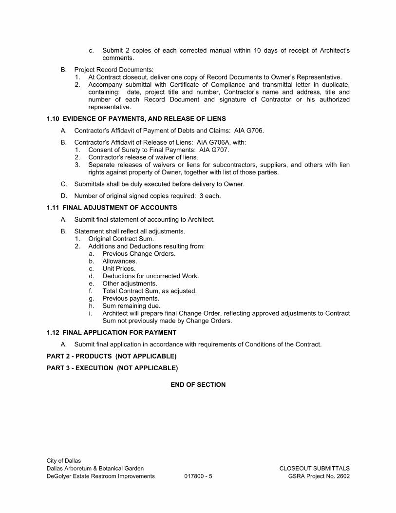
City of Dallas
Dallas Arboretum & Botanical Garden CLOSEOUT SUBMITTALS
DeGolyer Estate Restroom Improvements 017800 - 5 GSRA Project No. 2602
c. Submit 2 copies of each corrected manual within 10 days of receipt of Architect’s comments.
B. Project Record Documents: 1. At Contract closeout, deliver one copy of Record Documents to Owner’s Representative. 2. Accompany submittal with Certificate of Compliance and transmittal letter in duplicate,
containing: date, project title and number, Contractor’s name and address, title and number of each Record Document and signature of Contractor or his authorized representative.
1.10 EVIDENCE OF PAYMENTS, AND RELEASE OF LIENS
A. Contractor’s Affidavit of Payment of Debts and Claims: AIA G706.
B. Contractor’s Affidavit of Release of Liens: AIA G706A, with: 1. Consent of Surety to Final Payments: AIA G707. 2. Contractor’s release of waiver of liens. 3. Separate releases of waivers or liens for subcontractors, suppliers, and others with lien
rights against property of Owner, together with list of those parties.
C. Submittals shall be duly executed before delivery to Owner.
D. Number of original signed copies required: 3 each.
1.11 FINAL ADJUSTMENT OF ACCOUNTS
A. Submit final statement of accounting to Architect.
B. Statement shall reflect all adjustments. 1. Original Contract Sum. 2. Additions and Deductions resulting from:
a. Previous Change Orders. b. Allowances. c. Unit Prices. d. Deductions for uncorrected Work. e. Other adjustments. f. Total Contract Sum, as adjusted. g. Previous payments. h. Sum remaining due. i. Architect will prepare final Change Order, reflecting approved adjustments to Contract
Sum not previously made by Change Orders.
1.12 FINAL APPLICATION FOR PAYMENT
A. Submit final application in accordance with requirements of Conditions of the Contract.
PART 2 - PRODUCTS (NOT APPLICABLE)
PART 3 - EXECUTION (NOT APPLICABLE)
END OF SECTION

City of Dallas Dallas Arboretum & Botanical Garden OPERATION AND MAINTENANCE MATERIAL DeGolyer Estate Restroom Improvements 017823 - 1 GSRA Project No. 2602
SECTION 017823
OPERATION AND MAINTENANCE MATERIAL
PART 1 - GENERAL
1.1 RELATED DOCUMENTS A. Drawings and general provisions of the Contract, including General and Supplementary
Conditions and other Division 01 Specification Sections, apply to this Section.
1.2 SUMMARY
A. Section includes administrative and procedural requirements for preparing operation and maintenance manuals, including the following: 1. Operation and maintenance documentation directory. 2. Emergency manuals. 3. Operation manuals for systems, subsystems, and equipment. 4. Product maintenance manuals. 5. Systems and equipment maintenance manuals.
1.3 DEFINITIONS
A. System: An organized collection of parts, equipment, or subsystems united by regular interaction.
B. Subsystem: A portion of a system with characteristics similar to a system.
1.4 CLOSEOUT SUBMITTALS
A. Manual Content: Operations and maintenance manual content is specified in individual specification sections to be reviewed at the time of Section submittals. Submit reviewed manual content formatted and organized as required by this Section. 1. Where applicable, clarify and update reviewed manual content to correspond to
modifications and field conditions. B. Format: Submit operations and maintenance manuals in the following format:
1. PDF electronic file. Assemble each manual into a composite electronically-indexed file. Submit on digital media acceptable to Architect. a. Name each indexed document file in composite electronic index with applicable
item name. Include a complete electronically-linked operation and maintenance directory.
b. Enable inserted reviewer comments on draft submittals. 2. One paper copy. Include a complete operation and maintenance directory. Enclose
title pages and directories in clear plastic sleeves. Architect will return. C. Initial Manual Submittal: Submit draft copy of each manual at least 30 days before commencing
demonstration and training. Architect will comment on whether general scope and content of manual are acceptable.
D. Final Manual Submittal: Submit each manual in final form prior to requesting inspection for Substantial Completion and at least 15 days before commencing demonstration and training. Architect will return copy with comments. 1. Correct or modify each manual to comply with Architect's comments. Submit copies of
each corrected manual within 15 days of receipt of Architect's comments and prior to commencing demonstration and training.
PART 2 - PRODUCTS
2.1 OPERATION AND MAINTENANCE DOCUMENTATION DIRECTORY A. Organization: Include a section in the directory for each of the following:
1. List of documents.

City of Dallas Dallas Arboretum & Botanical Garden OPERATION AND MAINTENANCE MATERIAL DeGolyer Estate Restroom Improvements 017823 - 2 GSRA Project No. 2602
2. List of systems. 3. List of equipment. 4. Table of contents.
B. List of Systems and Subsystems: List systems alphabetically. Include references to operation and maintenance manuals that contain information about each system.
C. List of Equipment: List equipment for each system, organized alphabetically by system. For pieces of equipment not part of system, list alphabetically in separate list.
D. Tables of Contents: Include a table of contents for each emergency, operation, and maintenance manual.
E. Identification: In the documentation directory and in each operation and maintenance manual, identify each system, subsystem, and piece of equipment with same designation used in the Contract Documents. If no designation exists, assign a designation according to ASHRAE Guideline 4, "Preparation of Operating and Maintenance Documentation for Building Systems."
2.2 REQUIREMENTS FOR EMERGENCY, OPERATION, AND MAINTENANCE MANUALS
A. Organization: Unless otherwise indicated, organize each manual into a separate section for each system and subsystem, and a separate section for each piece of equipment not part of a system. Each manual shall contain the following materials, in the order listed: 1. Title page. 2. Table of contents. 3. Manual contents.
B. Title Page: Include the following information: 1. Subject matter included in manual. 2. Name and address of Project. 3. Name and address of Owner. 4. Date of submittal. 5. Name and contact information for Contractor. 6. Name and contact information for Construction Manager. 7. Name and contact information for Architect. 8. Names and contact information for major consultants to the Architect that designed
the systems contained in the manuals. 9. Cross-reference to related systems in other operation and maintenance manuals.
C. Table of Contents: List each product included in manual, identified by product name, indexed to the content of the volume, and cross-referenced to Specification Section number in Project Manual. 1. If operation or maintenance documentation requires more than one volume to
accommodate data, include comprehensive table of contents for all volumes in each volume of the set.
D. Manual Contents: Organize into sets of manageable size. Arrange contents alphabetically by system, subsystem, and equipment. If possible, assemble instructions for subsystems, equipment, and components of one system into a single binder.
E. Manuals, Electronic Files: Submit manuals in the form of a multiple file composite electronic PDF file for each manual type required. 1. Electronic Files: Use electronic files prepared by manufacturer where available. Where
scanning of paper documents is required, configure scanned file for minimum readable file size.
2. File Names and Bookmarks: Enable bookmarking of individual documents based upon file names. Name document files to correspond to system, subsystem, and equipment names used in manual directory and table of contents. Group documents for each system and subsystem into individual composite bookmarked files, then create composite manual, so that resulting bookmarks reflect the system, subsystem, and equipment names in a readily navigated file tree. Configure electronic manual to display bookmark panel upon opening file.
F. Manuals, Paper Copy: Submit manuals in the form of hard copy, bound and labeled volumes. 1. Binders: Heavy-duty, three-ring, vinyl-covered, [loose-leaf] [post-type] binders, in
thickness necessary to accommodate contents, sized to hold 8-1/2-by-11-inch paper; with clear plastic sleeve on spine to hold label describing contents and with pockets inside

City of Dallas Dallas Arboretum & Botanical Garden OPERATION AND MAINTENANCE MATERIAL DeGolyer Estate Restroom Improvements 017823 - 3 GSRA Project No. 2602
covers to hold folded oversize sheets. a. If two or more binders are necessary to accommodate data of a system,
organize data in each binder into groupings by subsystem and related components. Cross-reference other binders if necessary to provide essential information for proper operation or maintenance of equipment or system.
b. Identify each binder on front and spine, with printed title "OPERATION AND MAINTENANCE MANUAL," Project title or name, [and] subject matter of contents [, and indicate Specification Section number on bottom of spine]. Indicate volume number for multiple-volume sets.
2. Dividers: Heavy-paper dividers with plastic-covered tabs for each section of the manual. Mark each tab to indicate contents. Include typed list of products and major components of equipment included in the section on each divider, cross-referenced to Specification Section number and title of Project Manual.
3. Protective Plastic Sleeves: Transparent plastic sleeves designed to enclose diagnostic software storage media for computerized electronic equipment.
4. Supplementary Text: Prepared on 8-1/2-by-11-inch white bond paper. 5. Drawings: Attach reinforced, punched binder tabs on drawings and bind with text.
a. If oversize drawings are necessary, fold drawings to same size as text pages and use as foldouts.
b. If drawings are too large to be used as foldouts, fold and place drawings in labeled envelopes and bind envelopes in rear of manual. At appropriate locations in manual, insert typewritten pages indicating drawing titles, descriptions of contents, and drawing locations.
2.3 EMERGENCY MANUALS
A. Content: Organize manual into a separate section for each of the following: 1. Type of emergency. 2. Emergency instructions. 3. Emergency procedures.
B. Type of Emergency: Where applicable for each type of emergency indicated below, include instructions and procedures for each system, subsystem, piece of equipment, and component: 1. Fire. 2. Flood. 3. Gas leak. 4. Water leak. 5. Power failure. 6. Water outage. 7. System, subsystem, or equipment failure. 8. Chemical release or spill.
C. Emergency Instructions: Describe and explain warnings, trouble indications, error messages, and similar codes and signals. Include responsibilities of Owner's operating personnel for notification of Installer, supplier, and manufacturer to maintain warranties.
D. Emergency Procedures: Include the following, as applicable: 1. Instructions on stopping. 2. Shutdown instructions for each type of emergency. 3. Operating instructions for conditions outside normal operating limits. 4. Required sequences for electric or electronic systems. 5. Special operating instructions and procedures.
2.4 OPERATION MANUALS
A. Content: In addition to requirements in this Section, include operation data required in individual Specification Sections and the following information: 1. System, subsystem, and equipment descriptions. Use designations for systems and
equipment indicated on Contract Documents. 2. Performance and design criteria if Contractor is delegated design responsibility. 3. Operating standards. 4. Operating procedures.

City of Dallas Dallas Arboretum & Botanical Garden OPERATION AND MAINTENANCE MATERIAL DeGolyer Estate Restroom Improvements 017823 - 4 GSRA Project No. 2602
5. Operating logs. 6. Wiring diagrams. 7. Control diagrams. 8. Piped system diagrams. 9. Precautions against improper use. 10. License requirements including inspection and renewal dates.
B. Descriptions: Include the following: 1. Product name and model number. Use designations for products indicated on
Contract Documents. 2. Manufacturer's name. 3. Equipment identification with serial number of each component. 4. Equipment function. 5. Operating characteristics. 6. Limiting conditions. 7. Performance curves. 8. Engineering data and tests. 9. Complete nomenclature and number of replacement parts.
C. Operating Procedures: Include the following, as applicable: 1. Startup procedures. 2. Equipment or system break-in procedures.
3. Routine and normal operating instructions. 4. Regulation and control procedures. 5. Instructions on stopping. 6. Normal shutdown instructions. 7. Seasonal and weekend operating instructions. 8. Required sequences for electric or electronic systems. 9. Special operating instructions and procedures.
D. Systems and Equipment Controls: Describe the sequence of operation, and diagram controls as installed.
E. Piped Systems: Diagram piping as installed, and identify color-coding where required for identification.
2.5 PRODUCT MAINTENANCE MANUALS
A. Content: Organize manual into a separate section for each product, material, and finish. Include source information, product information, maintenance procedures, repair materials and sources, and warranties and bonds, as described below.
B. Source Information: List each product included in manual, identified by product name and arranged to match manual's table of contents. For each product, list name, address, and telephone number of Installer or supplier and maintenance service agent, and cross-reference Specification Section number and title in Project Manual and drawing or schedule designation or identifier where applicable.
C. Product Information: Include the following, as applicable: 1. Product name and model number. 2. Manufacturer's name. 3. Color, pattern, and texture. 4. Material and chemical composition. 5. Reordering information for specially manufactured
products. D. Maintenance Procedures: Include manufacturer's written recommendations and the following:
1. Inspection procedures. 2. Types of cleaning agents to be used and methods of cleaning. 3. List of cleaning agents and methods of cleaning detrimental to product. 4. Schedule for routine cleaning and maintenance. 5. Repair instructions.
E. Repair Materials and Sources: Include lists of materials and local sources of materials and related services.
F. Warranties and Bonds: Include copies of warranties and bonds and lists of circumstances and conditions that would affect validity of warranties or bonds. 1. Include procedures to follow and required notifications for warranty claims.

City of Dallas Dallas Arboretum & Botanical Garden OPERATION AND MAINTENANCE MATERIAL DeGolyer Estate Restroom Improvements 017823 - 5 GSRA Project No. 2602
2.6 SYSTEMS AND EQUIPMENT MAINTENANCE MANUALS
A. Content: For each system, subsystem, and piece of equipment not part of a system, include source information, manufacturers' maintenance documentation, maintenance procedures, maintenance and service schedules, spare parts list and source information, maintenance service contracts, and warranty and bond information, as described below.
B. Source Information: List each system, subsystem, and piece of equipment included in manual, identified by product name and arranged to match manual's table of contents. For each product, list name, address, and telephone number of Installer or supplier and maintenance service agent, and cross-reference Specification Section number and title in Project Manual and drawing or schedule designation or identifier where applicable.
C. Manufacturers' Maintenance Documentation: Manufacturers' maintenance documentation including the following information for each component part or piece of equipment: 1. Standard maintenance instructions and bulletins. 2. Drawings, diagrams, and instructions required for maintenance, including disassembly
and component removal, replacement, and assembly. 3. Identification and nomenclature of parts and
components. 4. List of items recommended to be stocked as spare
parts. D. Maintenance Procedures: Include the following information and items that detail essential
maintenance procedures: 1. Test and inspection instructions. 2. Troubleshooting guide. 3. Precautions against improper maintenance. 4. Disassembly; component removal, repair, and replacement; and reassembly
instructions. 5. Aligning, adjusting, and checking instructions. 6. Demonstration and training video recording, if available.
E. Maintenance and Service Schedules: Include service and lubrication requirements, list of required lubricants for equipment, and separate schedules for preventive and routine maintenance and service with standard time allotment. 1. Scheduled Maintenance and Service: Tabulate actions for daily, weekly, monthly,
quarterly, semiannual, and annual frequencies. 2. Maintenance and Service Record: Include manufacturers' forms for recording
maintenance. F. Spare Parts List and Source Information: Include lists of replacement and repair parts, with
parts identified and cross-referenced to manufacturers' maintenance documentation and local sources of maintenance materials and related services.
G. Maintenance Service Contracts: Include copies of maintenance agreements with name and telephone number of service agent.
H. Warranties and Bonds: Include copies of warranties and bonds and lists of circumstances and conditions that would affect validity of warranties or bonds. 1. Include procedures to follow and required notifications for warranty claims.
PART 3 - EXECUTION
3.1 MANUAL PREPARATION AND DELIVERY A. Operation and Maintenance Documentation Directory: Prepare a separate manual that
provides an organized reference to emergency, operation, and maintenance manuals. B. Emergency Manual: Assemble a complete set of emergency information indicating procedures
for use by emergency personnel and by Owner's operating personnel for types of emergencies indicated.
C. Product Maintenance Manual: Assemble a complete set of maintenance data indicating care and maintenance of each product, material, and finish incorporated into the Work.
D. Operation and Maintenance Manuals: Assemble a complete set of operation and

City of Dallas Dallas Arboretum & Botanical Garden OPERATION AND MAINTENANCE MATERIAL DeGolyer Estate Restroom Improvements 017823 - 6 GSRA Project No. 2602
maintenance data indicating operation and maintenance of each system, subsystem, and piece of equipment not part of a system. 1. Engage a factory-authorized service representative to assemble and prepare information
for each system, subsystem, and piece of equipment not part of a system. 2. Prepare a separate manual for each system and subsystem, in the form of an
instructional manual for use by Owner's operating personnel. E. Manufacturers' Data: Where manuals contain manufacturers' standard printed data, include
only sheets pertinent to product or component installed. Mark each sheet to identify each product or component incorporated into the Work. If data include more than one item in a tabular format, identify each item using appropriate references from the Contract Documents. Identify data applicable to the Work and delete references to information not applicable. 1. Prepare supplementary text if manufacturers' standard printed data are not available and
where the information is necessary for proper operation and maintenance of equipment or systems.
F. Drawings: Prepare drawings supplementing manufacturers' printed data to illustrate the relationship of component parts of equipment and systems and to illustrate control sequence and flow diagrams. Coordinate these drawings with information contained in record Drawings to ensure correct illustration of completed installation. 1. Do not use original project record documents as part of operation and maintenance
manuals. 2. Comply with requirements of newly prepared record Drawings in Division 01 Section
"Project Record Documents." G. Comply with Division 01 Section "Closeout Procedures" for schedule for submitting operation
and maintenance documentation. H. Include transmittal with all deliveries to Owner. Request receipt confirmation.
END OF SECTION
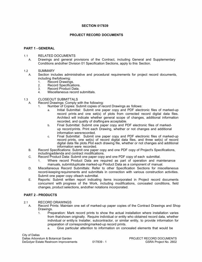
City of Dallas Dallas Arboretum & Botanical Garden PROJECT RECORD DOCUMENTS DeGolyer Estate Restroom Improvements 017839 - 1 GSRA Project No. 2602
SECTION 017839
PROJECT RECORD DOCUMENTS
PART 1 - GENERAL
1.1 RELATED DOCUMENTS A. Drawings and general provisions of the Contract, including General and Supplementary
Conditions and other Division 01 Specification Sections, apply to this Section.
1.2 SUMMARY
A. Section includes administrative and procedural requirements for project record documents, including the following: 1. Record Drawings. 2. Record Specifications. 3. Record Product Data. 4. Miscellaneous record submittals.
1.3 CLOSEOUT SUBMITTALS
A. Record Drawings: Comply with the following: 1. Number of Copies: Submit copies of record Drawings as follows:
a. Initial Submittal: Submit one paper copy and PDF electronic files of marked-up record prints and one set(s) of plots from corrected record digital data files. Architect will indicate whether general scope of changes, additional information recorded, and quality of drafting are acceptable.
b. Final Submittal: Submit one paper copy and PDF electronic files of marked-up record prints. Print each Drawing, whether or not changes and additional information were recorded.
c. Final Submittal: Submit one paper copy and PDF electronic files of marked-up record prints, one set(s) of record digital data files, and three set(s) of record digital data file plots. Plot each drawing file, whether or not changes and additional information were recorded.
B. Record Specifications: Submit one paper copy and one PDF copy of Project's Specifications, including addenda and contract modifications.
C. Record Product Data: Submit one paper copy and one PDF copy of each submittal. 1. Where record Product Data are required as part of operation and maintenance
manuals, submit duplicate marked-up Product Data as a component of manual. D. Miscellaneous Record Submittals: Refer to other Specification Sections for miscellaneous
record-keeping requirements and submittals in connection with various construction activities. Submit one paper copy of each submittal.
E. Reports: Submit written report indicating items incorporated in Project record documents concurrent with progress of the Work, including modifications, concealed conditions, field changes, product selections, and other notations incorporated.
PART 2 - PRODUCTS
2.1 RECORD DRAWINGS A. Record Prints: Maintain one set of marked-up paper copies of the Contract Drawings and Shop
Drawings. 1. Preparation: Mark record prints to show the actual installation where installation varies
from that shown originally. Require individual or entity who obtained record data, whether individual or entity is Installer, subcontractor, or similar entity, to provide information for preparation of corresponding marked-up record prints. a. Give particular attention to information on concealed elements that would be

City of Dallas Dallas Arboretum & Botanical Garden PROJECT RECORD DOCUMENTS DeGolyer Estate Restroom Improvements 017839 - 2 GSRA Project No. 2602
difficult to identify or measure and record later. b. Accurately record information in an acceptable drawing technique. c. Record data as soon as possible after
obtaining it. d. Record and check the markup before enclosing concealed installations. e. Cross-reference record prints to corresponding archive photographic
documentation. 2. Content: Types of items requiring marking include, but are not limited to, the following:
a. Dimensional changes to Drawings.
b. Revisions to details shown on Drawings. c. Depths of foundations below first floor. d. Locations and depths of underground utilities. e. Revisions to routing of piping and conduits. f. Revisions to electrical circuitry. g. Actual equipment locations. h. Duct size and routing. i. Locations of concealed internal utilities. j. Changes made by Change Order or Construction Change Directive. k. Changes made following Architect's written
orders. l. Details not on the original Contract Drawings. m. Field records for variable and concealed conditions. n. Record information on the Work that is shown only schematically.
3. Mark the Contract Drawings and Shop Drawings completely and accurately. Utilize personnel proficient at recording graphic information in production of marked-up record prints.
4. Mark record sets with erasable, red-colored pencil. Use other colors to distinguish between changes for different categories of the Work at same location.
5. Mark important additional information that was either shown schematically or omitted from original Drawings.
6. Note Construction Change Directive numbers, alternate numbers, Change Order numbers, and similar identification, where applicable.
B. Record Digital Data Files: Immediately before inspection for Certificate of Substantial Completion, review marked-up record prints with Architect. When authorized, prepare a full set of corrected digital data files of the Contract Drawings, as follows: 1. Format: Same digital data software program, version, and operating system as
the original Contract Drawings. 2. Format: DWG, Version [Insert designation], operating in Microsoft Windows Apple
Macintosh operating system. 3. Format: Annotated PDF electronic file with comment function enabled. 4. Incorporate changes and additional information previously marked on record
prints. Delete, redraw, and add details and notations where applicable. 5. Refer instances of uncertainty to Architect through Construction Manager for
resolution. C. Newly Prepared Record Drawings: Prepare new Drawings instead of preparing record
Drawings where Architect determines that neither the original Contract Drawings nor Shop Drawings are suitable to show actual installation. 1. New Drawings may be required when a Change Order is issued as a result of
accepting an alternate, substitution, or other modification. 2. Consult Architect and Construction Manager for proper scale and scope of detailing and
notations required to record the actual physical installation and its relation to other construction. Integrate newly prepared record Drawings into record Drawing sets; comply with procedures for formatting, organizing, copying, binding, and submitting.
D. Format: Identify and date each record Drawing; include the designation "PROJECT RECORD DRAWING" in a prominent location. 1. Record Prints: Organize record prints and newly prepared record Drawings into
manageable sets. Bind each set with durable paper cover sheets. Include identification

City of Dallas Dallas Arboretum & Botanical Garden PROJECT RECORD DOCUMENTS DeGolyer Estate Restroom Improvements 017839 - 3 GSRA Project No. 2602
on cover sheets. 2. Format: Annotated PDF electronic file with comment function enabled. 3. Record Digital Data Files: Organize digital data information into separate electronic
files that correspond to each sheet of the Contract Drawings. Name each file with the sheet identification. Include identification in each digital data file.
4. Identification: As follows: a. Project name. b. Date. c. Designation "PROJECT RECORD DRAWINGS." d. Name of Architect and Construction Manager. e. Name of Contractor.
2.2 RECORD SPECIFICATIONS A. Preparation: Mark Specifications to indicate the actual product installation where installation
varies from that indicated in Specifications, addenda, and contract modifications. 1. Give particular attention to information on concealed products and installations that
cannot be readily identified and recorded later. 2. Mark copy with the proprietary name and model number of products, materials, and
equipment furnished, including substitutions and product options selected. 3. Record the name of manufacturer, supplier, Installer, and other information necessary to
provide a record of selections made. 4. For each principal product, indicate whether record Product Data has been submitted in
operation and maintenance manuals instead of submitted as record Product Data. 5. Note related Change Orders, record Product Data, and record Drawings where
applicable. B. Format: Submit record Specifications as annotated PDF electronic file paper copy
scanned PDF electronic file(s) of marked up paper copy of Specifications.
2.3 RECORD PRODUCT DATA
A. Preparation: Mark Product Data to indicate the actual product installation where installation varies substantially from that indicated in Product Data submittal. 1. Give particular attention to information on concealed products and installations that
cannot be readily identified and recorded later. 2. Include significant changes in the product delivered to Project site and changes in
manufacturer's written instructions for installation. 3. Note related Change Orders, record Specifications, and record Drawings where
applicable. B. Format: Submit record Product Data as annotated PDF electronic file paper copy scanned PDF
electronic file(s) of marked up paper copy of Product Data. 1. Include record Product Data directory organized by specification section number
and title, electronically linked to each item of record Product Data.
2.4 MISCELLANEOUS RECORD SUBMITTALS
A. Assemble miscellaneous records required by other Specification Sections for miscellaneous record keeping and submittal in connection with actual performance of the Work. Bind or file miscellaneous records and identify each, ready for continued use and reference.
B. Format: Submit miscellaneous record submittals as PDF electronic file paper copy scanned PDF electronic file(s) of marked up miscellaneous record submittals. 1. Include miscellaneous record submittals directory organized by specification section
number and title, electronically linked to each item of miscellaneous record submittals.

City of Dallas Dallas Arboretum & Botanical Garden PROJECT RECORD DOCUMENTS DeGolyer Estate Restroom Improvements 017839 - 4 GSRA Project No. 2602
PART 3 - EXECUTION
3.1 RECORDING AND MAINTENANCE A. Recording: Maintain one copy of each submittal during the construction period for project
record document purposes. Post changes and modifications to project record documents as they occur; do not wait until the end of Project.
B. Maintenance of Record Documents and Samples: Store record documents and Samples in the field office apart from the Contract Documents used for construction. Do not use project record documents for construction purposes. Maintain record documents in good order and in a clean, dry, legible condition, protected from deterioration and loss. Provide access to project record documents for Architect's and Construction Manager's reference during normal working hours.
END OF SECTION

City of Dallas Dallas Arboretum & Botanical Garden IAQ MANAGEMENT DeGolyer Estate Restroom Improvements 018119 - 1 GSRA Project No. 2602
SECTION 018119
INDOOR AIR QUALITY (IAQ) MANAGEMENT
PART 1 - GENERAL
1.1 RELATED DOCUMENTS
A. Drawings and general provisions of the Contract, including General and Supplementary Conditions and other Division 01 Specification Sections, apply to this Section.
1.2 SUMMARY
A. Section Includes:
1. Special requirements for Indoor Air Quality (IAQ) management during construction operations.
a. Control of emissions during construction.
b. Moisture control during construction.
2. Procedures for testing baseline IAQ. Baseline IAQ requirements specify maximum indoor pollutant concentrations for acceptance of the facility.
1.3 REFERENCES
A. Definitions: Definitions pertaining to sustainable development: As defined in ASTM E 2114.
1. Adequate Ventilation: Ventilation, including air circulation and air changes, required to cure materials, dissipate humidity, and prevent accumulation of particulates, dust, fumes, vapors, or gases.
2. Hazardous Materials: Any material that is regulated as a hazardous material in accordance with 49 CFR 173, requires a Material Safety Data Sheet (MSDS) in accordance with 29 CFR 1910.1200, or which during end use, treatment, handling, storage, transportation or disposal meets or has components which meet or have the potential to meet the definition of a Hazardous Waste in accordance with 40 CFR 261.
a. Hazardous materials include: pesticides, biocides, and carcinogens as listed by recognized authorities, such as the Environmental Protection Agency (EPA) and the International Agency for Research on Cancer (IARC).
3. Indoor Air Quality (IAQ): The composition and characteristics of the air in an enclosed space that affect the occupants of that space. The indoor air quality of a space refers to the relative quality of air in a building with respect to contaminants and hazards and is determined by the level of indoor air pollution and other characteristics of the air, including those that impact thermal comfort such as air temperature, relative humidity and air speed.
4. Interior Final Finishes: Materials and products that will be exposed at interior, occupied spaces; including flooring, wallcovering, finish carpentry, ceilings, and sealants.
5. Packaged Dry Products: Materials and products that are installed in dry form and are delivered to the site in manufacturer's packaging; including carpets, resilient flooring, ceiling tiles, and insulation.
6. Wet Products: Materials and products installed in wet form, including paints, sealants, adhesives, special coatings, and other materials which require curing.

City of Dallas Dallas Arboretum & Botanical Garden IAQ MANAGEMENT DeGolyer Estate Restroom Improvements 018119 - 2 GSRA Project No. 2602
1.4 ADMINISTRATIVE REQUIREMENTS
A. Preconstruction Conference: After award of Contract and prior to the commencement of the Work, schedule and conduct meeting with Owner and Architect to discuss the proposed IAQ Management Plan and to develop mutual understanding relative to details of environmental protection.
1.5 SUBMITTALS
A. Indoor Air Quality (IAQ) Management Plan: Not less than 10 days before the preconstruction conference, prepare and submit an IAQ Management Plan including, but not limited to, the following:
1. Procedures for control of emissions during construction.
a. Identify schedule for application of interior finishes.
2. Procedures for moisture control during construction.
a. Identify porous materials and absorptive materials.
b. Identify schedule for inspection of stored and installed absorptive materials.
3. Revise and resubmit Plan as required by Architect.
a. Approval of Contractor's Plan will not relieve the Contractor of responsibility for compliance with applicable environmental regulations.
B. Product Data:
1. Submit product data for filtration media used during construction and during operation. Include Minimum Efficiency Reporting Value (MERV).
2. Submit air pressure difference maps for each mode of operation of HVAC.
3. Material Safety Data Sheets: Submit MSDSs for inclusion in Operation and Maintenance Manual for the following products.
a. Adhesives.
b. Floor and wall patching/leveling materials.
c. Caulking and sealants.
d. Insulating materials.
e. Fireproofing and firestopping.
f. Carpet.
g. Paint.
h. Clear finish for wood surfaces.
i. Lubricants.
j. Cleaning products.
C. Inspection and Test Reports:
1. Moisture control inspections.
2. Moisture content testing.
3. Moisture penetration testing.
4. Microbial growth testing.
5. Baseline Indoor Air Quality test report.
1.6 QUALITY ASSURANCE
A. Testing Agency Qualifications: Minimum of 5 years’ experience in performing the types of testing specified herein.

City of Dallas Dallas Arboretum & Botanical Garden IAQ MANAGEMENT DeGolyer Estate Restroom Improvements 018119 - 3 GSRA Project No. 2602
PART 2 - PRODUCTS
2.1 GENERAL ENVIRONMENTAL ISSUES
A. Mold and Mildew: Materials that have evidence of growth of molds or mildew are not acceptable, including both stored and installed materials. Immediately remove from site and dispose of properly.
B. Moisture Stains: Materials that have evidence of moisture damage, including stains, are not acceptable, including both stored and installed materials. Immediately remove from site and dispose of properly.
2.2 CLEANING PRODUCTS
A. Use low-toxic and lowest-emitting spot removers and cleaning agents for surfaces, equipment, and workers' personal use.
B. Use HEPA-filter equipped vacuum cleaners for the final cleaning.
PART 3 – EXECUTION
3.1 IAQ MANAGEMENT - EMISSIONS CONTROL
A. During construction operations, follow the recommendations in SMACNA "IAQ Guidelines for Occupied Buildings under Construction."
B. HVAC Protection:
1. Seal return registers during construction operations.
2. Provide temporary exhaust during construction operations
3. To the greatest extent possible, isolate and/or shut down the return side of the HVAC system during construction. When ventilation system must be operational during construction activities, provide temporary filters.
C. Source Control:
1. Provide low and zero VOC materials as specified.
2. Do not use products in combination with or in contact with other products that can be identified as combining to form toxic fumes or sustained odors.
D. Pathway Interruption: Isolate areas of work as necessary to prevent contamination of clean or occupied spaces. Provide pressure differentials and/or physical barriers to protect clean or occupied spaces.
E. Housekeeping: During construction, maintain project and building products and systems to prevent contamination of building spaces.
F. Scheduling: Schedule construction operations involving wet products prior to packaged dry products to the greatest extent possible.
1. Do not use solvents within interior areas that may penetrate and be retained in absorptive materials such as concrete, gypsum board, wood, cellulose products, fibrous material, and textiles.

City of Dallas Dallas Arboretum & Botanical Garden IAQ MANAGEMENT DeGolyer Estate Restroom Improvements 018119 - 4 GSRA Project No. 2602
G. Inspect ductwork for refuse, contaminants, moisture, and other foreign contamination prior to commissioning by Owner. Notify Owner of satisfactory inspection prior to beginning of commissioning.
3.2 IAQ MANAGEMENT - MOISTURE CONTROL
A. Housekeeping:
1. Keep materials dry. Protect stored on-site and installed absorptive materials from moisture damage.
2. Verify that installed materials and products are dry prior to sealing and weatherproofing the building envelope.
3. Install interior absorptive materials only after building envelope is sealed and weatherproofed.
B. Inspections: Document and report results of inspections; state whether or not inspections indicate satisfactory conditions.
1. Examine materials for dampness as they arrive. If acceptable to Architect, dry damp materials completely prior to installation; otherwise, reject materials that arrive damp.
2. Examine materials for mold as they arrive and reject materials that arrive contaminated with mold.
3. Inspect stored and installed absorptive materials regularly for dampness and mold growth. Inspect after each rain event.
a. Where stored on-site or installed absorptive materials become wet, notify Architect. Inspect for damage. If acceptable to Architect, dry completely prior to closing in assemblies; otherwise, remove and replace with new materials.
4. Site Drainage: Verify that final grades of site work and landscaping drain surface water and ground water away from the building.
5. Weatherproofing: Inspect moisture control materials as they are being installed. Include the following:
a. Air Barrier: Verify air barrier is installed without punctures and/or other damage. Verify air barrier is sealed completely.
b. Flashing: Verify correct shingling of the flashing for roof, walls, windows, doors, and other penetrations.
c. Insulation Layer: Verify insulation is installed without voids.
d. Roofing: In accordance with ASTM D 7186.
C. Schedule:
1. Schedule work such that absorptive materials, including but not limited to porous insulations, paper-faced gypsum board, ceiling tile, and finish flooring, are not installed until they can be protected from rain and construction-related water.
2. Weatherproof as quickly as possible. Schedule installation of moisture-control materials, including but not limited to air barriers, flashing, exterior sealants and roofing, at the earliest possible time.
D. Testing for Moisture Content: Test moisture content of porous materials and absorptive materials to ensure that they are dry before sealing them into an assembly. Document and report results of testing. Where tests are not satisfactory, dry materials and retest. If satisfactory results cannot be obtained with retest, remove and replace with new materials.
1. Concrete: Moisture test as per one or more of the following; unless otherwise indicated, acceptable upper limits for concrete are less than 4 percent top inch; less than 85 percent headspace RH; less than 3 lbs/1000 sq. ft./day:

City of Dallas Dallas Arboretum & Botanical Garden IAQ MANAGEMENT DeGolyer Estate Restroom Improvements 018119 - 5 GSRA Project No. 2602
a. ASTM D 4263 - Test Method for Indicating Moisture in Concrete by the Plastic Sheet Method.
b. ASTM F 1869 - Test Method for Measuring Moisture Vapor Emission Rate of Concrete Subfloor Using Anhydrous Calcium Chloride.
c. ASTM F 2170 - Test Method for Determining Relative Humidity in Concrete Floor Slabs Using In Situ Probes.
2. Wood: Moisture test as per ASTM D 4444 - Standard Test Methods for Use and Calibration of Hand-Held Moisture Meters; unless otherwise indicated, acceptable upper limits for wood products are less than 20 percent at center of piece; less than 15 percent at surface.
3. Gypsum Board, Insulation, and Other Absorptive Materials: Moisture test with a Pinless Moisture Meter to assess patterns of moisture, if any.
E. Testing for Moisture Penetration:
1. Windows: Test as per ASTM E 1105 - Test Method for Field Determination of Water Penetration of Installed Exterior Windows, Skylights, Doors, and Curtain Walls by Uniform or Cyclic Static Air Pressure Difference; unless otherwise indicated, acceptable upper limits are no leakage for 15 minutes.
2. Horizontal Waterproofing (not roofing): Test as per ASTM D 5957 - Standard Guide for Flood Testing Horizontal Waterproofing Installations; acceptable upper limits are no leakage for 15 minutes.
3. Exterior Walls:
a. Air Tightness of the Enclosure Test: ASTM E 779 - Standard Test Method for Determining Air Leakage Rate by Fan Pressurization or ASTM E 1827 - Standard Test Methods for Determining Air tightness of Buildings Using an Orifice Blower Door.
b. Water Leakage: Review as per ASTM E 2128 - Standard Guide for Evaluating Water Leakage of Building Walls.
F. Testing for Support of Microbial Growth: Test and report in accordance with ASTM D 6329 - Standard Guide for Developing Methodology for Evaluating the Ability of Indoor Materials to Support Microbial Growth Using Static Environmental Chambers. Indicate susceptibility of product or material to colonization and amplification of microorganisms. Identify microorganisms and conditions of testing.
1. Normal Conditions: Perform testing at 35 degrees C and 50 percent relative humidity.
2. Extreme Conditions: Perform worst-case scenarios screening tests by providing an atmosphere where environmental conditions may be favorable for microbial growth.
3. Perform testing for the following:
a. Fireproofing material on appropriate substrate.
b. Acoustical ceilings.
c. Wallcovering.
END OF SECTION

City of Dallas Dallas Arboretum & Botanical Garden SELECTIVE DEMOLITION DeGolyer Estate Restroom Improvements 024119 - 1 GSRA Project No. 2602
SECTION 024119
SELECTIVE DEMOLITION
PART 1 - GENERAL
1.1 RELATED DOCUMENTS A. Drawings and general provisions of the Contract, including General and Supplementary
Conditions and Division 01 Specification Sections, apply to this Section.
1.2 SUMMARY A. Section Includes:
1. Demolition and removal of selected portions of building or structure. 2. Salvage of existing items to be reused or recycled.
1.3 DEFINITIONS A. Remove: Detach items from existing construction and legally dispose of them off-site unless
indicated to be removed and salvaged or removed and reinstalled. B. Remove and Salvage: Carefully detach from existing construction, in a manner to prevent
damage, and deliver to Owner. C. Remove and Reinstall: Detach items from existing construction, prepare for reuse, and reinstall
where indicated. D. Existing to Remain: Existing items of construction that are not to be permanently removed and
that are not otherwise indicated to be removed, removed and salvaged, or removed and reinstalled.
1.4 MATERIALS OWNERSHIP A. Historic items, relics, antiques, and similar objects including, but not limited to, cornerstones and
their contents, commemorative plaques and tablets, and other items of interest or value to Owner that may be uncovered during demolition remain the property of Owner. 1. Carefully salvage in a manner to prevent damage and promptly return to Owner.
1.5 PREINSTALLATION MEETINGS A. Pre-demolition Conference: Conduct conference at Project site.
1. Inspect and discuss condition of construction to be selectively demolished. 2. Review structural load limitations of existing structure. 3. Review and finalize selective demolition schedule and verify availability of materials,
demolition personnel, equipment, and facilities needed to make progress and avoid delays.
4. Review requirements of work performed by other trades that rely on substrates exposed by selective demolition operations.
5. Review areas where existing construction is to remain and requires protection.
1.6 INFORMATIONAL SUBMITTALS A. Proposed Protection Measures: Submit report, including drawings, that indicates the measures
proposed for protecting individuals and property, for environmental protection, for dust control and, for noise control. Indicate proposed locations and construction of barriers.
B. Schedule of Selective Demolition Activities: Indicate the following: 1. Detailed sequence of selective demolition and removal work, with starting and ending
dates for each activity. Ensure Owner's on-site operations are uninterrupted. 2. Interruption of utility services. Indicate how long utility services will be interrupted. 3. Coordination for shutoff, capping, and continuation of utility services. 4. Coordination of Owner's continuing occupancy of portions of existing building and of
Owner's partial occupancy of completed Work. C. Inventory: Submit a list of items to be removed and salvaged and deliver to Owner prior to start

City of Dallas Dallas Arboretum & Botanical Garden SELECTIVE DEMOLITION DeGolyer Estate Restroom Improvements 024119 - 2 GSRA Project No. 2602
of demolition. D. Pre-demolition Photographs or Video: Submit before Work begins. E. Warranties: Documentation indicated that existing warranties are still in effect after completion
of selective demolition.
1.7 CLOSEOUT SUBMITTALS A. Inventory: Submit a list of items that have been removed and salvaged. B. Landfill Records: Indicate receipt and acceptance of hazardous wastes by a landfill facility
licensed to accept hazardous wastes.
1.8 QUALITY ASSURANCE A. Refrigerant Recovery Technician Qualifications: Certified by an EPA-approved certification
program.
1.9 FIELD CONDITIONS A. Owner will occupy portions of building immediately adjacent to selective demolition area.
Conduct selective demolition so Owner's operations will not be disrupted. B. Conditions existing at time of inspection for bidding purpose will be maintained by Owner as far
as practical. 1. Before selective demolition, Owner will remove the following items:
a. Office equipment, furniture. C. Notify Architect of discrepancies between existing conditions and Drawings before proceeding
with selective demolition. D. Hazardous Materials: It is not expected that hazardous materials will be encountered in the
Work. 1. Hazardous materials will be removed by Owner before start of the Work. 2. If suspected hazardous materials are encountered, do not disturb; immediately notify
Architect and Owner. Hazardous materials will be removed by Owner under a separate contract.
E. Storage or sale of removed items or materials on-site is not permitted. F. Utility Service: Maintain existing utilities indicated to remain in service and protect them against
damage during selective demolition operations. 1. Maintain fire-protection facilities in service during selective demolition operations.
1.10 WARRANTY A. Existing Warranties: Remove, replace, patch, and repair materials and surfaces cut or
damaged during selective demolition, by methods and with materials so as not to void existing warranties. Notify warrantor before proceeding.
B. Notify warrantor on completion of selective demolition, and obtain documentation verifying that existing system has been inspected and warranty remains in effect. Submit documentation at Project closeout.
PART 2 - PRODUCTS
2.1 PEFORMANCE REQUIREMENTS A. Regulatory Requirements: Comply with governing EPA notification regulations before
beginning selective demolition. Comply with hauling and disposal regulations of authorities having jurisdiction.
B. Standards: Comply with ANSI/ASSE A10.6 and NFPA 241.
PART 3 - EXECUTION
3.1 EXAMINATION A. Verify that utilities have been disconnected and capped before starting selective demolition
operations.

City of Dallas Dallas Arboretum & Botanical Garden SELECTIVE DEMOLITION DeGolyer Estate Restroom Improvements 024119 - 3 GSRA Project No. 2602
B. Review record documents of existing construction provided by Owner. Owner does not guarantee that existing conditions are same as those indicated in record documents.
C. Survey existing conditions and correlate with requirements indicated to determine extent of selective demolition required.
D. When unanticipated mechanical, electrical, or structural elements that conflict with intended function or design are encountered, investigate and measure the nature and extent of conflict. Promptly submit a written report to Architect.
E. Perform an engineering survey of condition of building to determine whether removing any element might result in structural deficiency or unplanned collapse of any portion of structure or adjacent structures during selective building demolition operations. 1. Perform surveys as the Work progresses to detect hazards resulting from selective
demolition activities. 2. Steel Tendons: Locate tensioned steel tendons and include recommendations for de-
tensioning. F. Survey of Existing Conditions: Record existing conditions by use of measured drawings
preconstruction photographs preconstruction videotapes and templates. 1. Comply with requirements specified in Division 01 Section "Photographic
Documentation." 2. Inventory and record the condition of items to be removed and salvaged. Provide
photographs of conditions that might be misconstrued as damage caused by salvage operations.
3. Before selective demolition or removal of existing building elements that will be reproduced or duplicated in final Work, make permanent record of measurements, materials, and construction details required to make exact reproduction.
3.2 UTILITY SERVICES AND MECHANICAL/ELECTRICAL SYSTEMS A. Existing Services/Systems to Remain: Maintain services/systems indicated to remain and
protect them against damage. 1. Comply with requirements for existing services/systems interruptions specified in
Division 01 Section "Summary." B. Existing Services/Systems to Be Removed, Relocated, or Abandoned: Locate, identify,
disconnect, and seal or cap off indicated utility services and mechanical/electrical systems serving areas to be selectively demolished. 1. Owner will arrange to shut off indicated services/systems when requested by Contractor. 2. If services/systems are required to be removed, relocated, or abandoned, provide
temporary services/systems that bypass area of selective demolition and that maintain continuity of services/systems to other parts of building.
3. Disconnect, demolish, and remove fire-suppression systems, plumbing, and HVAC systems, equipment, and components indicated to be removed. a. Piping to Be Removed: Remove portion of piping indicated to be removed and cap
or plug remaining piping with same or compatible piping material. b. Piping to Be Abandoned in Place: Drain piping and cap or plug piping with same
or compatible piping material. c. Equipment to Be Removed: Disconnect and cap services and remove equipment. d. Equipment to Be Removed and Reinstalled: Disconnect and cap services and
remove, clean, and store equipment; when appropriate, reinstall, reconnect, and make equipment operational.
e. Equipment to Be Removed and Salvaged: Disconnect and cap services and remove equipment and deliver to Owner.
f. Ducts to Be Removed: Remove portion of ducts indicated to be removed and plug remaining ducts with same or compatible ductwork material.
g. Ducts to Be Abandoned in Place: Cap or plug ducts with same or compatible ductwork material.
3.3 PREPARATION
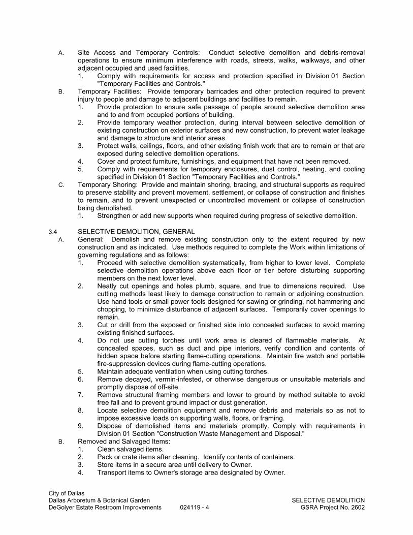
City of Dallas Dallas Arboretum & Botanical Garden SELECTIVE DEMOLITION DeGolyer Estate Restroom Improvements 024119 - 4 GSRA Project No. 2602
A. Site Access and Temporary Controls: Conduct selective demolition and debris-removal operations to ensure minimum interference with roads, streets, walks, walkways, and other adjacent occupied and used facilities. 1. Comply with requirements for access and protection specified in Division 01 Section
"Temporary Facilities and Controls." B. Temporary Facilities: Provide temporary barricades and other protection required to prevent
injury to people and damage to adjacent buildings and facilities to remain. 1. Provide protection to ensure safe passage of people around selective demolition area
and to and from occupied portions of building. 2. Provide temporary weather protection, during interval between selective demolition of
existing construction on exterior surfaces and new construction, to prevent water leakage and damage to structure and interior areas.
3. Protect walls, ceilings, floors, and other existing finish work that are to remain or that are exposed during selective demolition operations.
4. Cover and protect furniture, furnishings, and equipment that have not been removed. 5. Comply with requirements for temporary enclosures, dust control, heating, and cooling
specified in Division 01 Section "Temporary Facilities and Controls." C. Temporary Shoring: Provide and maintain shoring, bracing, and structural supports as required
to preserve stability and prevent movement, settlement, or collapse of construction and finishes to remain, and to prevent unexpected or uncontrolled movement or collapse of construction being demolished. 1. Strengthen or add new supports when required during progress of selective demolition.
3.4 SELECTIVE DEMOLITION, GENERAL A. General: Demolish and remove existing construction only to the extent required by new
construction and as indicated. Use methods required to complete the Work within limitations of governing regulations and as follows: 1. Proceed with selective demolition systematically, from higher to lower level. Complete
selective demolition operations above each floor or tier before disturbing supporting members on the next lower level.
2. Neatly cut openings and holes plumb, square, and true to dimensions required. Use cutting methods least likely to damage construction to remain or adjoining construction. Use hand tools or small power tools designed for sawing or grinding, not hammering and chopping, to minimize disturbance of adjacent surfaces. Temporarily cover openings to remain.
3. Cut or drill from the exposed or finished side into concealed surfaces to avoid marring existing finished surfaces.
4. Do not use cutting torches until work area is cleared of flammable materials. At concealed spaces, such as duct and pipe interiors, verify condition and contents of hidden space before starting flame-cutting operations. Maintain fire watch and portable fire-suppression devices during flame-cutting operations.
5. Maintain adequate ventilation when using cutting torches. 6. Remove decayed, vermin-infested, or otherwise dangerous or unsuitable materials and
promptly dispose of off-site. 7. Remove structural framing members and lower to ground by method suitable to avoid
free fall and to prevent ground impact or dust generation. 8. Locate selective demolition equipment and remove debris and materials so as not to
impose excessive loads on supporting walls, floors, or framing. 9. Dispose of demolished items and materials promptly. Comply with requirements in
Division 01 Section "Construction Waste Management and Disposal." B. Removed and Salvaged Items:
1. Clean salvaged items. 2. Pack or crate items after cleaning. Identify contents of containers. 3. Store items in a secure area until delivery to Owner. 4. Transport items to Owner's storage area designated by Owner.

City of Dallas Dallas Arboretum & Botanical Garden SELECTIVE DEMOLITION DeGolyer Estate Restroom Improvements 024119 - 5 GSRA Project No. 2602
5. Protect items from damage during transport and storage. C. Removed and Reinstalled Items:
1. Clean and repair items to functional condition adequate for intended reuse. 2. Pack or crate items after cleaning and repairing. Identify contents of containers. 3. Protect items from damage during transport and storage. 4. Reinstall items in locations indicated. Comply with installation requirements for new
materials and equipment. Provide connections, supports, and miscellaneous materials necessary to make item functional for use indicated.
D. Existing Items to Remain: Protect construction indicated to remain against damage and soiling during selective demolition. When permitted by Architect, items may be removed to a suitable, protected storage location during selective demolition and cleaned and reinstalled in their original locations after selective demolition operations are complete.
3.5 SELECTIVE DEMOLITION PROCEDURES FOR SPECIFIC MATERIALS A. Concrete: Demolish in small sections. Using power-driven saw, cut concrete to a depth of at
least 3/4 inch at junctures with construction to remain. Dislodge concrete from reinforcement at perimeter of areas being demolished, cut reinforcement, and then remove remainder of concrete. Neatly trim openings to dimensions indicated.
B. Masonry: Demolish in small sections. Cut masonry at junctures with construction to remain, using power-driven saw, then remove masonry between saw cuts.
C. Concrete Slabs-on-Grade: Saw-cut perimeter of area to be demolished, then break up and remove.
D. Resilient Floor Coverings: Remove floor coverings and adhesive according to recommendations in RFCI's "Recommended Work Practices for the Removal of Resilient Floor Coverings." Do not use methods requiring solvent-based adhesive strippers.
E. Roofing: Remove no more existing roofing than what can be covered in one day by new roofing and so that building interior remains watertight and weathertight. See Division 07 Section 077313 – Clay Tile Roofing for detailed new roofing requirements and replacement. 1. Remove existing roof membrane, flashings, copings, and roof accessories. 2. Remove existing roofing system down to substrate, if substrate is of suitable condition. 3. Replace decking that has been damaged.
3.6 DISPOSAL OF DEMOLISHED MATERIALS A. General: Except for items or materials indicated to be recycled, reused, salvaged, reinstalled,
or otherwise indicated to remain Owner's property, remove demolished materials from Project site and legally dispose of them in an EPA-approved landfill. 1. Do not allow demolished materials to accumulate on-site. 2. Remove and transport debris in a manner that will prevent spillage on adjacent surfaces
and areas. 3. Remove debris from elevated portions of building by chute, hoist, or other device that will
convey debris to grade level in a controlled descent. 4. Comply with requirements specified in Division 01 Section "Construction Waste
Management and Disposal." B. Disposal: Transport demolished materials and dispose of at designated spoil areas on Owner's
property.
3.7 CLEANING A. Clean adjacent structures and improvements of dust, dirt, and debris caused by selective
demolition operations. Return adjacent areas to condition existing before selective demolition operations began.
END OF SECTION

City of Dallas Dallas Arboretum & Botanical Garden COLD-FORMED METAL FRAMING DeGolyer Estate Restroom Improvements 054000 - 1 GSRA Project No. 2602
SECTION 054000
COLD-FORMED METAL FRAMING
PART 1 - GENERAL
1.1 RELATED DOCUMENTS A. Drawings and general provisions of the Contract, including General and Supplementary
Conditions and Division 01 Specification Sections, apply to this Section.
1.2 SUMMARY A. This Section includes the following:
1. Interior non-load-bearing wall framing. 2. Ceiling joist framing.
1.3 PERFORMANCE REQUIREMENTS A. Structural Performance: Provide cold-formed metal framing capable of withstanding design
loads within limits and under conditions indicated. 1. Design Loads: As follows:
a. Dead Loads: Weights of materials and construction. b. Live Loads: Refer to Drawings.
2. Deflection Limits: Design framing systems to withstand design loads without deflections greater than the following: a. Exterior Non-Load-Bearing Framing: Horizontal deflection of 1/240 at EIFS and
ACM veneer, 1/360 at Portland cement veneer, 1/600 at masonry veneer of the wall height.
b. Ceiling Joist Framing: Vertical deflection of 1/240 of the span. 3. Design framing systems to provide for movement of framing members without damage or
overstressing, sheathing failure, connection failure, undue strain on fasteners and anchors, or other detrimental effects when subject to a maximum ambient temperature change of 120 deg F.
4. Design framing system to maintain clearances at openings, to allow for construction tolerances, and to accommodate live load deflection of primary building structure as follows: a. Upward and downward movement of 1 inch.
B. Cold-Formed Steel Framing, General: Design according to AISI's "Standard for Cold-Formed Steel Framing - General Provisions." 1. Design exterior non-load-bearing wall framing to accommodate horizontal deflection
without regard for contribution of sheathing materials. 2. Roof Trusses: Design according to AISI's "Standard for Cold-Formed Steel Framing -
Truss Design."
1.4 SUBMITTALS A. Product Data: For each type of cold-formed metal framing product and accessory indicated. B. Sustainable Submittal:
1. Product data for products having recycled content, documentation indicating percentages by weight of postconsumer and preconsumer recycled content. a. Include statement indicating costs for each product having recycled content.]
C. Shop Drawings: Show layout, spacings, sizes, thicknesses, and types of cold-formed metal framing; fabrication; and fastening and anchorage details, including mechanical fasteners. Show reinforcing channels, opening framing, supplemental framing, strapping, bracing, bridging, splices, accessories, connection details, and attachment to adjoining work. 1. For cold-formed metal framing indicated to comply with design loads, include structural
analysis data signed and sealed by the qualified professional engineer responsible for their preparation.

City of Dallas Dallas Arboretum & Botanical Garden COLD-FORMED METAL FRAMING DeGolyer Estate Restroom Improvements 054000 - 2 GSRA Project No. 2602
1.5 QUALITY ASSURANCE A. Engineering Responsibility: Preparation of Shop Drawings, design calculations, and other
structural data by a qualified professional engineer, licensed to practice at the project location. B. Professional Engineer Qualifications: A professional engineer who is legally qualified to
practice in jurisdiction where Project is located and who is experienced in providing engineering services of the kind indicated. Engineering services are defined as those performed for installations of cold-formed metal framing that are similar to those indicated for this Project in material, design, and extent.
C. Testing Agency Qualifications: An independent testing agency, acceptable to authorities having jurisdiction, qualified according to ASTM E 329 to conduct the testing indicated.
D. Product Tests: Mill certificates or data from a qualified independent testing agency indicating steel sheet complies with requirements, including base-metal thickness, yield strength, tensile strength, total elongation, chemical requirements, ductility, and metallic-coating thickness.
E. Welding: Qualify procedures and personnel according to AWS D1.1, "Structural Welding Code--Steel," and AWS D1.3, "Structural Welding Code--Sheet Steel."
F. Fire-Test-Response Characteristics: Where indicated, provide cold-formed metal framing identical to that of assemblies tested for fire resistance per ASTM E 119 by a testing and inspecting agency acceptable to authorities having jurisdiction.
G. AISI Specifications and Standards: Comply with AISI's "North American Specification for the Design of Cold-Formed Steel Structural Members" and its "Standard for Cold-Formed Steel Framing - General Provisions." 1. Comply with AISI's "Standard for Cold-Formed Steel Framing - Truss Design."
H. Comply with AISI's "Standard for Cold-Formed Steel Framing - Prescriptive Method for One and Two Family Dwellings."
I. Preinstallation Conference: Conduct conference at Project site to comply with requirements in Division 01 Section "Project Management and Coordination."
1.6 DELIVERY, STORAGE, AND HANDLING A. Protect cold-formed metal framing from corrosion, deformation, and other damage during
delivery, storage, and handling. B. Store cold-formed metal framing, protect with a waterproof covering, and ventilate to avoid
condensation.
PART 2 - PRODUCTS
2.1 MANUFACTURERS A. Available Manufacturers: Subject to compliance with requirements, manufacturers offering
cold-formed metal framing that may be incorporated into the Work include, but are not limited to, the following:
B. Manufacturers: Subject to compliance with requirements, provide cold-formed metal framing by one of the following: 1. Clark Western Building Systems. 2. Dale/Incor. 3. Dietrich Metal Framing; a Worthington Industries Company. 4. MarinoWare; a division of Ware Industries.
2.2 MATERIALS A. Recycled Content of Steel Products: Provide products with an average recycled content of
steel products so postconsumer recycled content plus one-half of preconsumer recycled content is not less than 25 percent.
B. Steel Sheet: ASTM A 1003, Structural Grade, Type H, metallic coated, of grade and coating weight as follows: 1. Grade: As required by structural performance. 2. Coating: G90 or equivalent.

City of Dallas Dallas Arboretum & Botanical Garden COLD-FORMED METAL FRAMING DeGolyer Estate Restroom Improvements 054000 - 3 GSRA Project No. 2602
C. Steel Sheet for Vertical Deflection Clips: ASTM A 653, structural steel, zinc coated, of grade and coating as follows: 1. Grade: As required by structural performance. 2. Coating: G90.
2.3 LOAD-BEARING WALL FRAMING A. Steel Studs: Manufacturer's standard C-shaped steel studs, of web depths indicated, punched,
with stiffened flanges, and as follows: 1. Minimum Base-Metal Thickness: As required by design. 2. Flange Width: 1-5/8 inches. 3. Section Properties: As required by design.
B. Steel Track: Manufacturer's standard U-shaped steel track, of web depths indicated, unpunched, with straight flanges, and as follows: 1. Minimum Base-Metal Thickness: Matching steel studs. 2. Flange Width: 1-1/4 inches.
2.4 FRAMING ACCESSORIES A. Fabricate steel-framing accessories from steel sheet, ASTM A 1003, Structural Grade, Type H,
metallic coated, of same grade and coating weight used for framing members. B. Provide accessories of manufacturer's standard thickness and configuration, unless otherwise
indicated, as follows: 1. Supplementary framing. 2. Bracing, bridging, and solid blocking. 3. Web stiffeners. 4. Anchor clips. 5. End clips. 6. Gusset plates. 7. Stud kickers, knee braces, and girts. 8. Joist hangers and end closures. 9. Hole reinforcing plates. 10. Backer plates.
2.5 ANCHORS, CLIPS, AND FASTENERS A. Steel Shapes and Clips: ASTM A 36, zinc coated by hot-dip process according to ASTM A 123. B. Anchor Bolts: ASTM F 1554, Grade [36] [55], threaded carbon-steel hex-headed bolts and
carbon-steel nuts; and flat, hardened-steel washers; zinc coated by mechanically deposition according to ASTM B 695, Class 50.
C. Expansion Anchors: Fabricated from corrosion-resistant materials, with capability to sustain, without failure, a load equal to 5 times design load, as determined by testing per ASTM E 488 conducted by a qualified independent testing agency.
D. Power-Actuated Anchors: Fastener system of type suitable for application indicated, fabricated from corrosion-resistant materials, with capability to sustain, without failure, a load equal to 10 times design load, as determined by testing per ASTM E 1190 conducted by a qualified independent testing agency.
E. Mechanical Fasteners: ASTM C 1513, corrosion-resistant-coated, self-drilling, self-tapping steel drill screws. 1. Head Type: Low-profile head beneath sheathing, manufacturer's standard elsewhere.
F. Welding Electrodes: Comply with AWS standards.
2.6 MISCELLANEOUS MATERIALS A. Galvanizing Repair Paint: ASTM A 780. B. Shims: Load bearing, high-density multi-monomer plastic, non-leaching. C. Sealer Gaskets: Closed-cell neoprene foam, 1/4 inch thick, selected from manufacturer's
standard widths to match width of bottom track or rim track members.

City of Dallas Dallas Arboretum & Botanical Garden COLD-FORMED METAL FRAMING DeGolyer Estate Restroom Improvements 054000 - 4 GSRA Project No. 2602
2.7 FABRICATION A. Fabricate cold-formed metal framing and accessories plumb, square, and true to line, and with
connections securely fastened, according to referenced AISI's specifications and standards, manufacturer's written instructions, and requirements in this Section. 1. Fabricate framing assemblies using jigs or templates. 2. Cut framing members by sawing or shearing; do not torch cut. 3. Fasten cold-formed metal framing members by welding, screw fastening, clinch
fastening, or riveting as standard with fabricator. Wire tying of framing members is not permitted. a. Comply with AWS D1.3 requirements and procedures for welding, appearance and
quality of welds, and methods used in correcting welding work. b. Locate mechanical fasteners and install according to Shop Drawings, with screw
penetrating joined members by not less than three exposed screw threads. 4. Fasten other materials to cold-formed metal framing by welding, bolting, or screw
fastening, according to Shop Drawings. B. Reinforce, stiffen, and brace framing assemblies to withstand handling, delivery, and erection
stresses. Lift fabricated assemblies to prevent damage or permanent distortion. C. Fabrication Tolerances: Fabricate assemblies level, plumb, and true to line to a maximum
allowable tolerance variation of 1/8 inch in 10 feet and as follows: 1. Spacing: Space individual framing members no more than plus or minus 1/8 inch from
plan location. Cumulative error shall not exceed minimum fastening requirements of sheathing or other finishing materials.
2. Squareness: Fabricate each cold-formed metal framing assembly to a maximum out-of-square tolerance of 1/8 inch.
PART 3 - EXECUTION
3.1 EXAMINATION A. Examine supporting substrates and abutting structural framing for compliance with requirements
for installation tolerances and other conditions affecting performance. 1. Proceed with installation only after unsatisfactory conditions have been corrected.
3.2 PREPARATION A. Install load bearing shims or grout between the underside of wall bottom track or rim track and
the top of foundation wall or slab at stud or joist locations to ensure a uniform bearing surface on supporting concrete or masonry construction.
B. Install sealer gaskets to isolate the underside of wall bottom track or rim track and the top of foundation wall or slab at stud or joist locations.
3.3 INSTALLATION, GENERAL A. Cold-formed metal framing may be shop or field fabricated for installation, or it may be field
assembled. B. Install cold-formed metal framing according to AISI's "Standard for Cold-Formed Steel Framing -
General Provisions" and to manufacturer's written instructions unless more stringent requirements are indicated.
C. Install shop- or field-fabricated, cold-formed framing and securely anchor to supporting structure. 1. Screw, bolt, or weld wall panels at horizontal and vertical junctures to produce flush,
even, true-to-line joints with maximum variation in plane and true position between fabricated panels not exceeding 1/16 inch.
D. Install cold-formed metal framing and accessories plumb, square, and true to line, and with connections securely fastened. 1. Cut framing members by sawing or shearing; do not torch cut. 2. Fasten cold-formed metal framing members by welding, screw fastening, clinch
fastening, or riveting. Wire tying of framing members is not permitted.
City of Dallas Dallas Arboretum & Botanical Garden COLD-FORMED METAL FRAMING DeGolyer Estate Restroom Improvements 054000 - 5 GSRA Project No. 2602
a. Comply with AWS D1.3 requirements and procedures for welding, appearance and quality of welds, and methods used in correcting welding work.
b. Locate mechanical fasteners and install according to Shop Drawings, and complying with requirements for spacing, edge distances, and screw penetration.
E. Install framing members in one-piece lengths unless splice connections are indicated for track or tension members.
F. Install temporary bracing and supports to secure framing and support loads comparable in intensity to those for which structure was designed. Maintain braces and supports in place, undisturbed, until entire integrated supporting structure has been completed and permanent connections to framing are secured.
G. Do not bridge building expansion and control joints with cold-formed metal framing. Independently frame both sides of joints.
H. Install insulation, specified in Division 07 Section "Thermal Insulation," in built-up exterior framing members, such as headers, sills, boxed joists, and multiple studs at openings, that are inaccessible on completion of framing work.
I. Fasten hole reinforcing plate over web penetrations that exceed size of manufacturer's standard punched openings.
J. Erection Tolerances: Install cold-formed metal framing level, plumb, and true to line to a maximum allowable tolerance variation of 1/8 inch in 10 feet and as follows: 1. Space individual framing members no more than plus or minus 1/8 inch from plan
location. Cumulative error shall not exceed minimum fastening requirements of sheathing or other finishing materials.
3.4 LOAD-BEARING WALL INSTALLATION A. Install continuous top and bottom tracks sized to match studs. Align tracks accurately and
securely anchor at corners and ends, and at spacings as follows: 1. Anchor Spacing: As shown on Shop Drawings.
B. Squarely seat studs against top and bottom tracks with gap not exceeding of 1/8 inch between the end of wall framing member and the web of track. Fasten both flanges of studs to top and bottom tracks. Space studs as follows: 1. Stud Spacing: As required by design. 2. Stud Depth: As indicated on Drawings. 3. Stud Gage: As required by design.
C. Set studs plumb, except as needed for diagonal bracing or required for non-plumb walls or warped surfaces and similar configurations.
D. Align studs vertically where floor framing interrupts wall-framing continuity. Where studs cannot be aligned, continuously reinforce track to transfer loads.
E. Align floor and roof framing over studs. Where framing cannot be aligned, continuously reinforce track to transfer loads.
F. Anchor studs abutting structural columns or walls, including masonry walls, to supporting structure as indicated.
G. Install supplementary framing, blocking, and bracing in stud framing indicated to support fixtures, equipment, services, casework, heavy trim, furnishings, and similar work requiring attachment to framing. 1. If type of supplementary support is not indicated, comply with stud manufacturer's written
recommendations and industry standards in each case, considering weight or load resulting from item supported.
H. Install horizontal bridging in stud system, spaced as indicated on Shop Drawings. Fasten at each stud intersection. 1. Bridging: Cold-rolled steel channel, welded or mechanically fastened to webs of punched
studs with a minimum of 2 screws into each flange of the clip angle for framing members up to 6 inches deep.
2. Bridging: Combination of flat, taut, steel sheet straps of width and thickness indicated and stud-track solid blocking of width and thickness to match studs. Fasten flat straps to stud flanges and secure solid blocking to stud webs or flanges.

City of Dallas Dallas Arboretum & Botanical Garden COLD-FORMED METAL FRAMING DeGolyer Estate Restroom Improvements 054000 - 6 GSRA Project No. 2602
3. Bridging: Proprietary bridging bars installed according to manufacturer's written instructions.
I. Install steel sheet diagonal bracing straps to both stud flanges, terminate at and fasten to reinforced top and bottom tracks. Fasten clip-angle connectors to multiple studs at ends of bracing and anchor to structure.
J. Install miscellaneous framing and connections, including supplementary framing, web stiffeners, clip angles, continuous angles, anchors, and fasteners, to provide a complete and stable wall-framing system.
3.5 FIELD QUALITY CONTROL A. Testing: Owner will engage a qualified independent testing and inspecting agency to perform
field tests and inspections and prepare test reports. B. Field and shop welds will be subject to testing and inspecting. C. Testing agency will report test results promptly and in writing to Contractor and Architect. D. Remove and replace work where test results indicate that it does not comply with specified
requirements. E. Additional testing and inspecting, at Contractor's expense, will be performed to determine
compliance of replaced or additional work with specified requirements.
3.6 REPAIRS AND PROTECTION A. Galvanizing Repairs: Prepare and repair damaged galvanized coatings on fabricated and
installed cold-formed metal framing with galvanized repair paint according to ASTM A 780 and manufacturer's written instructions.
B. Provide final protection and maintain conditions, in a manner acceptable to manufacturer and Installer, that ensure that cold-formed metal framing is without damage or deterioration at time of Substantial Completion.
END OF SECTION

City of Dallas Dallas Arboretum & Botanical Garden METAL FABRICATIONS DeGolyer Estate Restroom Improvements 055001 - 1 GSRA Project No. 2602
SECTION 055001
METAL FABRICATIONS
PART 1 - GENERAL
1.1 RELATED DOCUMENTS A. Drawings and general provisions of the Contract, including General and Supplementary
Conditions and Division 01 Specification Sections, apply to this Section.
1.2 SUMMARY A. Section Includes:
1. Steel framing and supports for countertops. 2. Steel framing and supports for mechanical and electrical equipment. 3. Steel framing and supports for applications where framing and supports are not specified
in other Sections. 4. Loose bearing and leveling plates for applications where they are not specified in other
Sections. B. Products furnished, but not installed, under this Section:
1. Loose steel lintels. 2. Anchor bolts, steel pipe sleeves, slotted-channel inserts, and wedge-type inserts
indicated to be cast into concrete or built into unit masonry.
1.3 PERFORMANCE REQUIREMENTS A. Delegated Design: Design ladders alternating tread devices, including comprehensive
engineering analysis by a qualified professional engineer, using performance requirements and design criteria indicated.
1.4 SUBMITTALS A. Product Data: For the following:
1. Paint products. 2. Grout.
B. Shop Drawings: Show fabrication and installation details for metal fabrications. 1. Include plans, elevations, sections, and details of metal fabrications and their
connections. Show anchorage and accessory items. C. Welding certificates.
1.5 QUALITY ASSURANCE A. Welding Qualifications: Qualify procedures and personnel according to AWS D1.1/D1.1M,
"Structural Welding Code - Steel." B. Welding Qualifications: Qualify procedures and personnel according to the following:
1. AWS D1.1, "Structural Welding Code - Steel."
1.6 PROJECT CONDITIONS A. Field Measurements: Verify actual locations of walls and other construction contiguous with
metal fabrications by field measurements before fabrication.
1.7 COORDINATION A. Coordinate selection of shop primers with topcoats to be applied over them. Comply with paint
and coating manufacturers' written recommendations to ensure that shop primers and topcoats are compatible with one another.
B. Coordinate installation of anchorages. Furnish setting drawings, templates, and directions for installing anchorages, including sleeves, concrete inserts, anchor bolts, and items with integral anchors, that are to be embedded in concrete or masonry. Deliver such items to Project site in

City of Dallas Dallas Arboretum & Botanical Garden METAL FABRICATIONS DeGolyer Estate Restroom Improvements 055001 - 2 GSRA Project No. 2602
time for installation.
PART 2 - PRODUCTS
2.1 METALS, GENERAL A. Metal Surfaces, General: Provide materials with smooth, flat surfaces unless otherwise
indicated. For metal fabrications exposed to view in the completed Work, provide materials without seam marks, roller marks, rolled trade names, or blemishes.
2.2 FERROUS METALS A. Steel Plates, Shapes, and Bars: ASTM A 36. B. Steel Pipe: ASTM A 53, standard weight (Schedule 40) unless otherwise indicated.
2.3 FASTENERS A. General: Unless otherwise indicated, provide Type 304 stainless-steel fasteners for exterior
use and zinc-plated fasteners with coating complying with ASTM B 633 or ASTM F 1941, Class Fe/Zn 5, at exterior walls. Select fasteners for type, grade, and class required. 1. Provide stainless-steel fasteners for fastening aluminum.
B. Steel Bolts and Nuts: Regular hexagon-head bolts, ASTM A 307, Grade A; with hex nuts, ASTM A 563; and, where indicated, flat washers.
C. Steel Bolts and Nuts: Regular hexagon-head bolts, ASTM A 325, Type 3; with hex nuts, ASTM A 563, Grade C3; and, where indicated, flat washers.
D. Stainless-Steel Bolts and Nuts: Regular hexagon-head annealed stainless-steel bolts, ASTM F 593; with hex nuts, ASTM F 594; and, where indicated, flat washers; Alloy Group 1.
E. Anchor Bolts: ASTM F 1554, Grade 36, of dimensions indicated; with nuts, ASTM A 563; and, where indicated, flat washers. 1. Hot-dip galvanize or provide mechanically deposited, zinc coating where item being
fastened is indicated to be galvanized. F. Eyebolts: ASTM A 489. G. Machine Screws: ASME B18.6.3. H. Lag Screws: ASME B18.2.1. I. Wood Screws: Flat head, ASME B18.6.1. J. Plain Washers: Round, ASME B18.22.1. K. Lock Washers: Helical, spring type, ASME B18.21.1. L. Anchors, General: Anchors capable of sustaining, without failure, a load equal to six times the
load imposed when installed in unit masonry and four times the load imposed when installed in concrete, as determined by testing according to ASTM E 488, conducted by a qualified independent testing agency.
M. Cast-in-Place Anchors in Concrete: Either threaded type or wedge type unless otherwise indicated; galvanized ferrous castings, either ASTM A 47 malleable iron or ASTM A 27 cast steel. Provide bolts, washers, and shims as needed, all hot-dip galvanized per ASTM F 2329.
N. Post-Installed Anchors: chemical anchors. 1. Material for Exterior Locations and Where Stainless Steel is Indicated: Alloy Group 1
stainless-steel bolts, ASTM F 593, and nuts, ASTM F 594.
2.4 MISCELLANEOUS MATERIALS A. Welding Rods and Bare Electrodes: Select according to AWS specifications for metal alloy
welded. B. Universal Shop Primer: Fast-curing, lead- and chromate-free, universal modified-alkyd primer
complying with MPI#79 and compatible with topcoat. C. Galvanizing Repair Paint: High-zinc-dust-content paint complying with SSPC-Paint 20 and
compatible with paints specified to be used over it. D. Bituminous Paint: Cold-applied asphalt emulsion complying with ASTM D 1187. E. Non-shrink, Metallic Grout: Factory-packaged, ferrous-aggregate grout complying with ASTM C
1107, specifically recommended by manufacturer for heavy-duty loading applications. F. Non-shrink, Nonmetallic Grout: Factory-packaged, non-staining, non-corrosive, nongaseous

City of Dallas Dallas Arboretum & Botanical Garden METAL FABRICATIONS DeGolyer Estate Restroom Improvements 055001 - 3 GSRA Project No. 2602
grout complying with ASTM C 1107. Provide grout specifically recommended by manufacturer for interior and exterior applications.
2.5 FABRICATION, GENERAL A. Shop Assembly: Pre-assemble items in the shop to greatest extent possible. Disassemble
units only as necessary for shipping and handling limitations. Use connections that maintain structural value of joined pieces. Clearly mark units for reassembly and coordinated installation.
B. Cut, drill, and punch metals cleanly and accurately. Remove burrs and ease edges to a radius of approximately 1/32 inch unless otherwise indicated. Remove sharp or rough areas on exposed surfaces.
C. Form bent-metal corners to smallest radius possible without causing grain separation or otherwise impairing work.
D. Form exposed work with accurate angles and surfaces and straight edges. E. Weld corners and seams continuously to comply with the following:
1. Use materials and methods that minimize distortion and develop strength and corrosion resistance of base metals.
2. Obtain fusion without undercut or overlap. 3. Remove welding flux immediately. 4. At exposed connections, finish exposed welds and surfaces smooth and blended so no
roughness shows after finishing and contour of welded surface matches that of adjacent surface.
F. Form exposed connections with hairline joints, flush and smooth, using concealed fasteners or welds where possible. Where exposed fasteners are required, use Phillips flat-head (countersunk) fasteners unless otherwise indicated. Locate joints where least conspicuous.
G. Fabricate seams and other connections that will be exposed to weather in a manner to exclude water. Provide weep holes where water may accumulate.
H. Cut, reinforce, drill, and tap metal fabrications as indicated to receive finish hardware, screws, and similar items.
I. Provide for anchorage of type indicated; coordinate with supporting structure. Space anchoring devices to secure metal fabrications rigidly in place and to support indicated loads. 1. Where units are indicated to be cast into concrete or built into masonry, equip with
integrally welded steel strap anchors, 1/8 by 1-1/2 inches, with a minimum 6-inch embedment and 2-inch hook, not less than 8 inches from ends and corners of units and 24 inches o.c., unless otherwise indicated.
2.6 MISCELLANEOUS FRAMING AND SUPPORTS A. General: Provide steel framing and supports not specified in other Sections as needed to
complete the Work. B. Fabricate units from steel shapes, plates, and bars of welded construction unless otherwise
indicated. Fabricate to sizes, shapes, and profiles indicated and as necessary to receive adjacent construction. 1. Fabricate units from slotted channel framing where indicated.
C. Prime miscellaneous framing and supports with where indicated.
2.7 LOOSE STEEL LINTELS A. Fabricate loose steel lintels from steel angles and shapes of size indicated for openings and
recesses in masonry walls and partitions at locations indicated. Fabricate in single lengths for each opening unless otherwise indicated. Weld adjoining members together to form a single unit where indicated.
B. Galvanize loose steel lintels located in exterior walls.
2.8 FINISHES, GENERAL A. Comply with NAAMM's "Metal Finishes Manual for Architectural and Metal Products" for
recommendations for applying and designating finishes. B. Finish metal fabrications after assembly.

City of Dallas Dallas Arboretum & Botanical Garden METAL FABRICATIONS DeGolyer Estate Restroom Improvements 055001 - 4 GSRA Project No. 2602
C. Finish exposed surfaces to remove tool and die marks and stretch lines, and to blend into surrounding surface.
2.9 STEEL AND IRON FINISHES A. Shop prime iron and steel items not indicated to be galvanized unless they are to be embedded
in concrete, sprayed-on fireproofing, or masonry, or unless otherwise indicated. 1. Shop prime with universal shop primer unless zinc-rich primer is indicated.
2.10 ALUMINUM FINISHES A. Finish designations prefixed by AA comply with the system established by the Aluminum
Association for designating aluminum finishes. B. Provide aluminum finish in class 1 clear anodized.
PART 3 - EXECUTION
3.1 INSTALLATION, GENERAL A. Cutting, Fitting, and Placement: Perform cutting, drilling, and fitting required for installing metal
fabrications. Set metal fabrications accurately in location, alignment, and elevation; with edges and surfaces level, plumb, true, and free of rack; and measured from established lines and levels.
B. Fit exposed connections accurately together to form hairline joints. Weld connections that are not to be left as exposed joints but cannot be shop welded because of shipping size limitations. Do not weld, cut, or abrade surfaces of exterior units that have been hot-dip galvanized after fabrication and are for bolted or screwed field connections.
C. Field Welding: Comply with the following requirements: 1. Use materials and methods that minimize distortion and develop strength and corrosion
resistance of base metals. 2. Obtain fusion without undercut or overlap. 3. Remove welding flux immediately. 4. At exposed connections, finish exposed welds and surfaces smooth and blended so no
roughness shows after finishing and contour of welded surface matches that of adjacent surface.
D. Fastening to In-Place Construction: Provide anchorage devices and fasteners where metal fabrications are required to be fastened to in-place construction. Provide threaded fasteners for use with concrete and masonry inserts, toggle bolts, through bolts, lag screws, wood screws, and other connectors.
E. Provide temporary bracing or anchors in formwork for items that are to be built into concrete, masonry, or similar construction.
F. Corrosion Protection: Coat concealed surfaces of aluminum that will come into contact with grout, concrete, masonry, wood, or dissimilar metals with the following: 1. Cast Aluminum: Heavy coat of bituminous paint. 2. Extruded Aluminum: Two coats of clear lacquer.
3.2 INSTALLING MISCELLANEOUS FRAMING AND SUPPORTS A. General: Install framing and supports to comply with requirements of items being supported,
including manufacturers' written instructions and requirements indicated on Shop Drawings.
3.3 INSTALLING BEARING AND LEVELING PLATES A. Clean concrete and masonry bearing surfaces of bond-reducing materials, and roughen to
improve bond to surfaces. Clean bottom surface of plates. B. Set bearing and leveling plates on wedges, shims, or leveling nuts. After bearing members
have been positioned and plumbed, tighten anchor bolts. Do not remove wedges or shims but, if protruding, cut off flush with edge of bearing plate before packing with grout. 1. Use non-shrink grout, either metallic or nonmetallic, in concealed locations where not
exposed to moisture; use non-shrink, non-metallic grout in exposed locations unless

City of Dallas Dallas Arboretum & Botanical Garden METAL FABRICATIONS DeGolyer Estate Restroom Improvements 055001 - 5 GSRA Project No. 2602
otherwise indicated. 2. Pack grout solidly between bearing surfaces and plates to ensure that no voids remain.
3.4 ADJUSTING AND CLEANING A. Touchup Painting: Immediately after erection, clean field welds, bolted connections, and
abraded areas. Paint uncoated and abraded areas with the same material as used for shop painting to comply with SSPC-PA 1 for touching up shop-painted surfaces. 1. Apply by brush or spray to provide a minimum 2.0-mil dry film thickness.
B. Touchup Painting: Cleaning and touchup painting of field welds, bolted connections, and abraded areas of shop paint are specified in Division 09 painting Sections.
C. Galvanized Surfaces: Clean field welds, bolted connections, and abraded areas and repair galvanizing to comply with ASTM A 780.
END OF SECTION

City of Dallas Dallas Arboretum & Botanical Garden ROUGH CARPENTRY DeGolyer Estate Restroom Improvements 061000 - 1 GSRA Project No. 2602
SECTION 061000
ROUGH CARPENTRY
PART 1 - GENERAL
1.1 RELATED DOCUMENTS A. Drawings and general provisions of the Contract, including General and Supplementary
Conditions and Division 01 Specification Sections, apply to this Section.
1.2 SUMMARY A. Section Includes:
1. Wood blocking and nailers. 2. Plywood backing panels.
1.3 DEFINITIONS A. Dimension Lumber: Lumber of 2 inches nominal actual or greater but less than 5 inches
nominal 114 mm actual in least dimension. B. Lumber grading agencies, and the abbreviations used to reference them, include the following:
1. NeLMA: Northeastern Lumber Manufacturers' Association. 2. WCLIB: West Coast Lumber Inspection Bureau. 3. WWPA: Western Wood Products Association.
1.4 ACTION SUBMITTALS A. Product Data: For each type of process and factory-fabricated product. Indicate component
materials and dimensions and include construction and application details. 1. Include data for wood-preservative treatment from chemical treatment manufacturer and
certification by treating plant that treated materials comply with requirements. Indicate type of preservative used and net amount of preservative retained.
2. Include data for fire-retardant treatment from chemical treatment manufacturer and certification by treating plant that treated materials comply with requirements. Include physical properties of treated materials based on testing by a qualified independent testing agency.
3. For fire-retardant treatments, include physical properties of treated lumber both before and after exposure to elevated temperatures, based on testing by a qualified independent testing agency according to ASTM D 5664.
4. For products receiving a waterborne treatment, include statement that moisture content of treated materials was reduced to levels specified before shipment to Project site.
5. Include copies of warranties from chemical treatment manufacturers for each type of treatment.
6. For adhesives, documentation including printed statement of VOC content. 7. For composite wood products, documentation indicating that product contains no added
formaldehyde. B. Sustainable Submittals:
1. Certificates for chain-of-custody indicating that products specified to be made from certified wood comply with forest certification requirements. Include documentation that manufacturer is certified for chain of custody by an FSC-accredited certification body. Include statement indicating cost for each certified wood product.
2. Product Data for adhesives, documentation including printed statement of VOC content. 3. Product Data for composite wood products, documentation indicating that product
contains no urea formaldehyde.
1.5 QUALITY ASSURANCE A. Testing Agency Qualifications: For testing agency providing classification marking for fire-
retardant treated material, an inspection agency acceptable to authorities having jurisdiction that

City of Dallas Dallas Arboretum & Botanical Garden ROUGH CARPENTRY DeGolyer Estate Restroom Improvements 061000 - 2 GSRA Project No. 2602
periodically performs inspections to verify that the material bearing the classification marking is representative of the material tested.
1.6 DELIVERY, STORAGE, AND HANDLING A. Stack lumber flat with spacers beneath and between each bundle to provide air circulation.
Protect lumber from weather by covering with waterproof sheeting, securely anchored. Provide for air circulation around stacks and under coverings.
PART 2 - PRODUCTS
2.1 GENERAL REQUIREMENTS A. Dimension Lumber: Comply with PS 20 and requirements of specified grading agencies.
1. Species: Douglas Fir-Larch, unless otherwise indicated. 2. If no species is specified, provide any species graded by the agency specified; if no
grading agency is specified, provide lumber graded by any grading agency meeting the specified requirements.
3. Grading Agency: Any grading agency whose rules are approved by the Board of Review, American Lumber Standard Committee (www.alsc.org) and who provides grading service for the species and grade specified; provide lumber stamped with grade mark unless otherwise indicated.
B. Lumber fabricated from old growth timber is not permitted.
2.2 WOOD PRODUCTS, GENERAL A. Certified Wood: Materials shall be produced from wood obtained from forests certified by an
FSC-accredited certification body to comply with FSC STD-01-001, "FSC Principles and Criteria for Forest Stewardship.
B. Lumber: DOC PS 20 and applicable rules of grading agencies indicated. If no grading agency is indicated, provide lumber that complies with the applicable rules of any rules-writing agency certified by the ALSC Board of Review. Provide lumber graded by an agency certified by the ALSC Board of Review to inspect and grade lumber under the rules indicated. 1. Factory mark each piece of lumber with grade stamp of grading agency. 2. Where nominal sizes are indicated, provide actual sizes required by DOC PS 20 for
moisture content specified. Where actual sizes are indicated, they are minimum dressed sizes for dry lumber.
3. Provide dressed lumber, S4S, unless otherwise indicated. C. Maximum Moisture Content of Lumber: 15 percent for 2-inch nominal thickness or less, 19
percent for more than 2-inch nominal thickness unless otherwise indicated.
2.3 WOOD-PRESERVATIVE-TREATED LUMBER A. Preservative Treatment by Pressure Process: AWPA U1; Use Category UC2 for interior
construction not in contact with the ground. 1. Preservative Chemicals: Acceptable to authorities having jurisdiction and containing no
arsenic or chromium. Do not use inorganic boron (SBX) for sill plates. B. Kiln-dry lumber after treatment to a maximum moisture content of 19 percent. Do not use
material that is warped or that does not comply with requirements for untreated material. C. Mark lumber with treatment quality mark of an inspection agency approved by the ALSC Board
of Review. D. Application: Treat items indicated on Drawings, and the following:
1. Wood cants, nailers, curbs, equipment support bases, blocking, stripping, and similar members in connection with roofing, flashing, vapor barriers, and waterproofing.
2. Wood sills, sleepers, blocking, and similar concealed members in contact with masonry or concrete.

City of Dallas Dallas Arboretum & Botanical Garden ROUGH CARPENTRY DeGolyer Estate Restroom Improvements 061000 - 3 GSRA Project No. 2602
2.4 FIRE-RETARDANT-TREATED MATERIALS A. General: Where fire-retardant-treated materials are indicated, use materials complying with
requirements in this article, that are acceptable to authorities having jurisdiction, and with fire-test-response characteristics specified as determined by testing identical products per test method indicated by a qualified testing agency.
B. Fire-Retardant-Treated Lumber and Plywood by Pressure Process: Products with a flame spread index of 25 or less when tested according to ASTM E 84, and with no evidence of significant progressive combustion when the test is extended an additional 20 minutes, and with the flame front not extending more than 10.5 feet beyond the centerline of the burners at any time during the test. 1. Use treatment that does not promote corrosion of metal fasteners. 2. Exterior Type: Treated materials shall comply with requirements specified above for fire-
retardant-treated lumber and plywood by pressure process after being subjected to accelerated weathering according to ASTM D 2898. Use for exterior locations and where indicated.
3. Interior Type A: Treated materials shall have a moisture content of 28 percent or less when tested according to ASTM D 3201 at 92 percent relative humidity. Use where exterior type is not indicated.
4. Design Value Adjustment Factors: Treated lumber shall be tested according ASTM D 5664 and design value adjustment factors shall be calculated according to ASTM D 6841.
C. Kiln-dry lumber after treatment to a maximum moisture content of 19 percent. Kiln-dry plywood after treatment to a maximum moisture content of 15 percent.
D. Identify fire-retardant-treated wood with appropriate classification marking of qualified testing agency.
E. Application: Treat all rough carpentry unless otherwise indicated.
2.5 MISCELLANEOUS LUMBER A. General: Provide miscellaneous lumber indicated and lumber for support or attachment of other
construction, including the following: 1. Blocking. 2. Nailers. 3. Rooftop equipment bases and support curbs.
B. For items of dimension lumber size, provide No. 2 grade lumber and any of the following species: 1. Spruce-pine-fir (south); NeLMA, WCLIB, or WWPA.
C. For blocking not used for attachment of other construction, Utility, Stud, or No. 2 grade lumber of any species may be used provided that it is cut and selected to eliminate defects that will interfere with its attachment and purpose.
D. For blocking and nailers used for attachment of other construction, select and cut lumber to eliminate knots and other defects that will interfere with attachment of other work.
2.6 PLYWOOD BACKING PANELS A. Equipment Backing Panels: DOC PS 1, Exterior, AC, fire-retardant treated, in thickness
indicated or, if not indicated, not less than 3/4-inch nominal thickness.
2.7 FASTENERS A. General: Provide fasteners of size and type indicated that comply with requirements specified
in this article for material and manufacture. 1. Where rough carpentry is exposed to weather, in ground contact, pressure-preservative
treated, or in area of high relative humidity, provide fasteners of Type 304 stainless steel. B. Nails, Brads, and Staples: ASTM F 1667. C. Power-Driven Fasteners: NES NER-272. D. Wood Screws: ASME B18.6.1. E. Lag Bolts: ASME B18.2.1; ASME B18.2.3.8M.

City of Dallas Dallas Arboretum & Botanical Garden ROUGH CARPENTRY DeGolyer Estate Restroom Improvements 061000 - 4 GSRA Project No. 2602
F. Bolts: Steel bolts complying with ASTM A 307, Grade AASTM F 568M, Property Class 4.6; with ASTM A 563 ASTM hex nuts and, where indicated, flat washers.
G. Expansion Anchors: Anchor bolt and sleeve assembly of material indicated below with capability to sustain, without failure, a load equal to six times the load imposed when installed in unit masonry assemblies and equal to four times the load imposed when installed in concrete as determined by testing per ASTM E 488 conducted by a qualified independent testing and inspecting agency. 1. Material: Carbon-steel components, zinc plated to comply with ASTM B 633, Class
Fe/Zn 5.
PART 3 - EXECUTION
3.1 INSTALLATION, GENERAL A. Set rough carpentry to required levels and lines, with members plumb, true to line, cut, and
fitted. Fit rough carpentry to other construction; scribe and cope as needed for accurate fit. Locate nailers, blocking, grounds, and similar supports to comply with requirements for attaching other construction.
B. Install plywood backing panels by fastening to studs; coordinate locations with utilities requiring backing panels. Install fire-retardant treated plywood backing panels with classification marking of testing agency exposed to view.
C. Sort and select lumber so that natural characteristics will not interfere with installation or with fastening other materials to lumber. Do not use materials with defects that interfere with function of member or pieces that are too small to use with minimum number of joints or optimum joint arrangement.
D. Comply with AWPA M4 for applying field treatment to cut surfaces of preservative-treated lumber. 1. Use inorganic boron for items that are continuously protected from liquid water. 2. Use copper naphthenate for items not continuously protected from liquid water.
E. Securely attach rough carpentry work to substrate by anchoring and fastening as indicated, complying with the following: 1. Table 2304.9.1, "Fastening Schedule," in ICC's International Building Code. 2. Table R602.3(1), "Fastener Schedule for Structural Members," and Table R602.3(2),
"Alternate Attachments," in ICC's International Residential Code for One- and Two-Family Dwellings.
3.2 WOOD BLOCKING, AND NAILER INSTALLATION A. Install where indicated and where required for attaching other work. Form to shapes indicated
and cut as required for true line and level of attached work. Coordinate locations with other work involved.
B. Attach items to substrates to support applied loading. Recess bolts and nuts flush with surfaces unless otherwise indicated.
C. Where wood-preservative-treated lumber is installed adjacent to metal decking, install continuous flexible flashing separator between wood and metal decking.
3.3 PROTECTION A. Protect wood that has been treated with inorganic boron (SBX) from weather. If, despite
protection, inorganic boron-treated wood becomes wet, apply EPA-registered borate treatment. Apply borate solution by spraying to comply with EPA-registered label.
B. Protect rough carpentry from weather. If, despite protection, rough carpentry becomes wet, apply EPA-registered borate treatment. Apply borate solution by spraying to comply with EPA-registered label.
END OF SECTION

City of Dallas Dallas Arboretum & Botanical Garden INTERIOR ARCHITECTURAL WOODWORK DeGolyer Estate Restroom Improvements 064023 - 1 GSRA Project No. 2602
SECTION 064023
INTERIOR ARCHITECTURAL WOODWORK
PART 1 - GENERAL
1.1 RELATED DOCUMENTS A. Drawings and general provisions of the Contract, including General and Supplementary
Conditions and Division 01 Specification Sections, apply to this Section.
1.2 SUMMARY
A. This Section includes the following: 1. Crown moulding. 2. Window sills, damaged needing to be replaced. 3. Shop finishing of interior woodwork.
B. Interior architectural woodwork includes wood furring, blocking, shims, and hanging strips for installing woodwork items unless concealed within other construction before woodwork installation.
1.3 SUBMITTALS
A. Product Data: For panel products and high-pressure decorative laminate and finishing materials and processes. 1. Include data for fire-retardant treatment from chemical treatment manufacturer and
certification by treating plant that treated materials comply with requirements. B. Shop Drawings: Show location of each item, dimensioned plans and elevations, large-scale
details, attachment devices, and other components. 1. Show details in sufficient scale to determine compliance with the intent of the Quality
Standard Grade specified. 2. Show locations and sizes of furring, blocking, and hanging strips, including concealed
blocking and reinforcement specified in other Sections. 3. Show locations and sizes of cutouts and holes for plumbing fixtures installed in
architectural woodwork. C. Samples for Initial Selection D. Samples for Verification:
1. Solid-surfacing materials, 6 inches square. 2. Corner pieces as follows:
a. Cabinet-front frame joints between stiles and rails, as well as exposed end pieces, 18 inches high by 18 inches wide by 6 inches deep.
b. Miter joints for standing trim. 3. Include product data indicating the location of harvest or extraction and manufacture
for each material.
1.4 QUALITY ASSURANCE
A. Fabricator Qualifications: Shop that employs skilled workers who custom-fabricate products similar to those required for this Project and whose products have a record of successful in-service performance. Shop is a certified participant in AWI's Quality Certification Program.
B. Installer Qualifications: Certified participant in AWI's Quality Certification Program. C. Quality Standard: Unless otherwise indicated, comply with AWI's "Architectural Woodwork
Quality Standards" for grades of interior architectural woodwork indicated for construction, finishes, installation, and other requirements.
1.5 DELIVERY, STORAGE, AND HANDLING A. Do not deliver woodwork until painting and similar operations that could damage woodwork
have been completed in installation areas. If woodwork must be stored in other than installation areas, store only in areas where environmental conditions comply with requirements
City of Dallas Dallas Arboretum & Botanical Garden INTERIOR ARCHITECTURAL WOODWORK DeGolyer Estate Restroom Improvements 064023 - 2 GSRA Project No. 2602
specified in "Project Conditions" Article.
1.6 PROJECT CONDITIONS
A. Environmental Limitations: Do not deliver or install woodwork until building is enclosed, wet work is complete, and HVAC system is operating and maintaining temperature and relative humidity at occupancy levels during the remainder of the construction period.
B. Environmental Limitations: Do not deliver or install woodwork until building is enclosed, wet work is complete, and HVAC system is operating and maintaining temperature between 60 and 90 deg F and relative humidity between 25 and 55 percent during the remainder of the construction period.
C. Field Measurements: Where woodwork is indicated to fit to other construction, verify dimensions of other construction by field measurements before fabrication, and indicate measurements on Shop Drawings. Coordinate fabrication schedule with construction progress to avoid delaying the Work. 1. Locate concealed framing, blocking, and reinforcements that support woodwork by field
measurements before being enclosed, and indicate measurements on Shop Drawings. 2. Established Dimensions: Where field measurements cannot be made without delaying
the Work, establish dimensions and proceed with fabricating woodwork without field measurements. Provide allowance for trimming at site, and coordinate construction to ensure that actual dimensions correspond to established dimensions.
1.7 COORDINATION
A. Coordinate sizes and locations of framing, blocking, furring, reinforcements, and other related units of Work specified in other Sections to ensure that interior architectural woodwork can be supported and installed as indicated.
PART 2 - PRODUCTS
2.1 MATERIALS A. General:
1. Provide wood products which are FSC certified and have no added urea formaldehyde. 2. Provide materials that comply with requirements of AWI's quality standard for each type
of woodwork and quality grade specified, unless otherwise indicated. B. Wood Products: Comply with the following:
1. Hardboard: Tempered, AHA A135.4. 2. Medium-Density Fiberboard: ANSI A208.2, Grade as indicated below, made with binder
containing no urea formaldehyde. a. Type A : MDF, MR10 – ANSI A208.2, Grade 130. b. Type B: MDF, MR30 – ANSI A208.2, Grade 155. c. Type C: MDF, MR50 – ANSI A208.2, Grade 150
3. Colors/textures: To match existing, as indicate in Finish Legend.
2.2 MISCELLANEOUS MATERIALS
A. Furring, Blocking, Shims, and Hanging Strips: Softwood or hardwood lumber, kiln dried to less than 15 percent moisture content.
B. Anchors: Select material, type, size, and finish required for each substrate for secure anchorage. Provide nonferrous-metal or hot-dip galvanized anchors and inserts on inside face of exterior walls and elsewhere as required for corrosion resistance. Provide toothed-steel or lead expansion sleeves for drilled-in-place anchors.
C. Adhesives, General: Do not use adhesives that contain urea formaldehyde. D. VOC Limits for Installation Adhesives and Glues: Use installation adhesives that comply with
the following limits for VOC content when calculated according to 40 CFR 59, Subpart D (EPA Method 24): 1. Wood Glues: 30 g/L. 2. Contact Adhesive: 250 g/L.

City of Dallas Dallas Arboretum & Botanical Garden INTERIOR ARCHITECTURAL WOODWORK DeGolyer Estate Restroom Improvements 064023 - 3 GSRA Project No. 2602
2.3 FABRICATION, GENERAL
A. Wood Moisture Content: Comply with requirements of referenced quality standard for wood moisture content in relation to ambient relative humidity during fabrication and in installation areas.
B. Fabricate woodwork to dimensions, profiles, and details indicated. Ease edges to radius indicated for the following: 1. Corners of Cabinets and Edges of Solid-Wood (Lumber) Members 3/4 Inch Thick or
Less: 1/16 inch. 2. Edges of Rails and Similar Members More Than 3/4 Inch Thick: 1/8 inch. 3. Corners and Edges of Solid-Wood (Lumber) Members and Rails: 1/16 inch.
C. Complete fabrication, including assembly, finishing, and hardware application, to maximum extent possible before shipment to Project site. Disassemble components only as necessary for shipment and installation. Where necessary for fitting at site, provide ample allowance for scribing, trimming, and fitting. 1. Notify Architect seven days in advance of the dates and times woodwork fabrication will
be complete. 2. Trial fit assemblies at fabrication shop that cannot be shipped completely
assembled. Install dowels, screws, bolted connectors, and other fastening devices that can be removed after trial fitting. Verify that various parts fit as intended and check measurements of assemblies against field measurements indicated on Shop Drawings before disassembling for shipment.
PART 3 - EXECUTION
3.1 PREPARATION A. Before installation, condition woodwork to average prevailing humidity conditions in installation
areas. B. Before installing architectural woodwork, examine shop-fabricated work for completion and
complete work as required, including removal of packing and back-priming.
3.2 INSTALLATION A. Grade: Install woodwork to comply with requirements for the same grade specified in Part 2 for
fabrication of type of woodwork involved. B. Assemble woodwork and complete fabrication at Project site to comply with requirements for
fabrication in Part 2, to extent that it was not completed in the shop. C. Install woodwork level, plumb, true, and straight. Shim as required with concealed shims. Install
level and plumb (including tops) to a tolerance of 1/8 inch in 96 inches. D. Scribe and cut woodwork to fit adjoining work, refinish cut surfaces, and repair damaged finish at
cuts. E. Anchor woodwork to anchors or blocking built in or directly attached to substrates. Secure with
countersunk, concealed fasteners and blind nailing as required for complete installation. Use fine finishing nails or finishing screws for exposed fastening, countersunk and filled flush with woodwork and matching final finish if transparent finish is indicated.
3.3 ADJUSTING AND CLEANING
A. Repair damaged and defective woodwork, where possible, to eliminate functional and visual defects; where not possible to repair, replace woodwork. Adjust joinery for uniform appearance.
B. Clean, lubricate, and adjust hardware. C. Clean woodwork on exposed and semi-exposed surfaces. Touch up shop-applied finishes to
restore damaged or soiled areas.
END OF SECTION

City of Dallas Dallas Arboretum & Botanical Garden PLASTIC PANELING DeGolyer Estate Restroom Improvements 066400 - 1 GSRA Project No. 2602
SECTION 066400
PLASTIC PANELING
PART 1 - GENERAL
1.1 RELATED DOCUMENTS A. Drawings and general provisions of the Contract, including General and Supplementary
Conditions and Division 01 Specification Sections, apply to this Section.
1.2 SUMMARY A. Section includes glass-fiber reinforced plastic (FRP) wall paneling and trim accessories.
1.3 SUBMITTALS A. Product Data: For each type of product indicated. B. Samples for Initial Selection: For plastic paneling and trim accessories. C. Samples for Verification: For plastic paneling and trim accessories, in manufacturer's standard
sizes.
1.4 QUALITY ASSURANCE A. Source Limitations: Obtain plastic paneling and trim accessories from single manufacturer. B. Surface-Burning Characteristics: As determined by testing identical products according to
ASTM E 84 by a qualified testing agency. Identify products with appropriate markings of applicable testing agency. 1. Flame-Spread Index: 25 or less. 2. Smoke-Developed Index: 450 or less. 3. Testing Agency: Acceptable to authorities having jurisdiction.
1.5 PROJECT CONDITIONS A. Environmental Limitations: Do not deliver or install plastic paneling until spaces are enclosed
and weathertight and temporary HVAC system is operating and maintaining ambient temperature and humidity conditions at occupancy levels during the remainder of the construction period.
PART 2 - PRODUCTS
2.1 PLASTIC SHEET PANELING A. General: Gelcoat-finished, glass-fiber reinforced plastic panels complying with ASTM D 5319.
1. Manufacturers: Subject to compliance with requirements, provide products by one of the following: a. Kemlite Company Inc. b. Marlite. c. Nudo Products, Inc.
2. Nominal Thickness: Not less than 0.09 inch. 3. Surface Finish: Refer to Finish Legend. 4. Color: As indicated by manufacturer's designations.
2.2 ACCESSORIES A. Trim Accessories: Manufacturer's standard one-piece vinyl extrusions designed to retain and
cover edges of panels. Provide division bars, inside corners, outside corners, and caps as needed to conceal edges. 1. Color: Match panels.
B. Exposed Fasteners: Nylon drive rivets recommended by panel manufacturer. C. Concealed Mounting Splines: Continuous, H-shaped aluminum extrusions designed to fit into
grooves routed in edges of factory-laminated panels and to be fastened to substrate.
City of Dallas Dallas Arboretum & Botanical Garden PLASTIC PANELING DeGolyer Estate Restroom Improvements 066400 - 2 GSRA Project No. 2602
D. Adhesive: As recommended by plastic paneling manufacturer. 1. VOC Content: 50 g/L or less when calculated according to 40 CFR 59, Subpart D (EPA
Method 24). E. Sealant: Single-component, mildew-resistant, neutral-curing silicone sealant recommended by
plastic paneling manufacturer and complying with requirements in Division 07 Section "Joint Sealants." 1. VOC Content: 250 g/L or less when calculated according to 40 CFR 59, Subpart D (EPA
Method 24).
PART 3 - EXECUTION
3.1 EXAMINATION A. Examine substrates and conditions, with Installer present, for compliance with requirements for
installation tolerances and other conditions affecting performance of the Work. B. Proceed with installation only after unsatisfactory conditions have been corrected.
3.2 PREPARATION A. Remove wallpaper, vinyl wall covering, loose or soluble paint, and other materials that might
interfere with adhesive bond. B. Prepare substrate by sanding high spots and filling low spots as needed to provide flat, even
surface for panel installation. C. Clean substrates of substances that could impair bond of adhesive, including oil, grease, dirt,
and dust. D. Condition panels by unpacking and placing in installation space before installation according to
manufacturer's written recommendations. E. Lay out paneling before installing. Locate panel joints to provide equal panels at ends of walls
not less than half the width of full panels. 1. Mark plumb lines on substrate at trim accessory locations for accurate installation. 2. Locate trim accessories to allow clearance at panel edges according to manufacturer's
written instructions.
3.3 INSTALLATION A. Install plastic paneling according to manufacturer's written instructions. B. Install panels in a full spread of adhesive. C. Install panels with fasteners. Layout fastener locations and mark on face of panels so that
fasteners are accurately aligned. 1. Drill oversized fastener holes in panels and center fasteners in holes. 2. Apply sealant to fastener holes before installing fasteners.
D. Install factory-laminated panels using concealed mounting splines in panel joints. E. Install trim accessories with adhesive. F. Fill grooves in trim accessories with sealant before installing panels and bed inside corner trim
in a bead of sealant. G. Maintain uniform space between panels and wall fixtures. Fill space with sealant. H. Maintain uniform space between adjacent panels and between panels and floors, ceilings, and
fixtures. Fill space with sealant. I. Remove excess sealant and smears as paneling is installed. Clean with solvent recommended
by sealant manufacturer and then wipe with clean dry cloths until no residue remains.
END OF SECTION

City of Dallas Dallas Arboretum & Botanical Garden PREPARATION FOR REROOFING DeGolyer Estate Restroom Improvements 070150.19 - 1 GSRA Project No. 2602
SECTION 070150.19
PREPARATION FOR REROOFING
PART 1 - GENERAL
1.1 RELATED DOCUMENTS
A. Drawings and general provisions of the Contract, including General and Supplementary Conditions and Division 01 Specification Sections, apply to this Section.
1.2 SUMMARY
A. Section Includes:
1. Partial tear-off of roof areas indicated. 2. Removal of base flashings.
B. Related Requirements:
1. Section 011000 – Summary, for use of the premises and phasing requirements. 2. Section 015000 – Temporary Facilities and Controls, for temporary construction and
environmental-protection measures for reroofing preparation. 3. Section 061000 – Rough Carpentry, for roof decking. 4. Section 077200 – Clay Roof Tile 5. Section 076000 – Sheet Metal Work, for flashing and trim.
1.3 DEFINITIONS
A. Roofing Terminology: Definitions in ASTM D 1079 and glossary of NRCA's "The NRCA Roofing and Waterproofing Manual" apply to work of this Section.
B. Full Roof Tear-Off: Removal of existing roofing system from deck.
C. Partial Roof Tear-Off: Removal of selected components and accessories from existing roofing system.
1.4 ACTION SUBMITTALS
A. Product Data: For each type of product.
B. Shop Drawings: Include plans, sections, and details.
1.5 INFORMATIONAL SUBMITTALS
A. Qualification Data: For Installer.
1. Include certificate that Installer is approved by warrantor of existing roofing system.

City of Dallas Dallas Arboretum & Botanical Garden PREPARATION FOR REROOFING DeGolyer Estate Restroom Improvements 070150.19 - 2 GSRA Project No. 2602
2. Include certificate that Installer is licensed to perform asbestos abatement.
B. Fastener pull-out test report.
C. Photographs or Videotape: Show existing conditions of adjoining construction and site improvements, including exterior and interior finish surfaces, that might be misconstrued as having been damaged by reroofing operations. Submit before Work begins.
D. Landfill Records: Indicate receipt and acceptance of demolished roofing materials and hazardous wastes, such as asbestos-containing materials, by a landfill facility licensed to accept them.
1.6 QUALITY ASSURANCE
A. Installer Qualifications: Approved by warrantor of existing roofing system to work on existing roofing.
B. Regulatory Requirements: Comply with governing EPA notification regulations before beginning roofing removal. Comply with hauling and disposal regulations of authorities having jurisdiction.
C. Reroofing Conference: Conduct conference at Project site.
1. Meet with Owner; Architect; Owner's insurer if applicable; testing and inspecting agency representative; roofing system manufacturer's representative; roofing Installer, including project manager, superintendent, and foreman; and installers whose work interfaces with or affects reroofing, including installers of roof deck, roof accessories, and roof-mounted equipment.
2. Review methods and procedures related to roofing system tear-off and replacement, including, but not limited to, the following:
a. Reroofing preparation, including roofing system manufacturer's written instructions. b. Temporary protection requirements for existing roofing system components that
are to remain. c. Existing roof drains and roof drainage during each stage of reroofing, and roof-
drain plugging and plug removal. d. Construction schedule and availability of materials, Installer's personnel,
equipment, and facilities needed to avoid delays. e. Existing roof deck conditions requiring notification of Architect. f. Existing roof deck removal procedures and Owner notifications. g. Condition and acceptance of existing roof deck and base flashing substrate for
reuse. h. Structural loading limitations of roof deck during reroofing. i. Base flashings, special roofing details, drainage, penetrations, equipment curbs,
and condition of other construction that affect reroofing. j. HVAC shutdown and sealing of air intakes. k. Shutdown of fire-suppression, -protection, and -alarm and -detection systems. l. Asbestos removal and discovery of asbestos-containing materials. m. Governing regulations and requirements for insurance and certificates if
applicable. n. Existing conditions that may require notification of Architect before proceeding.

City of Dallas Dallas Arboretum & Botanical Garden PREPARATION FOR REROOFING DeGolyer Estate Restroom Improvements 070150.19 - 3 GSRA Project No. 2602
1.7 FIELD CONDITIONS
A. Existing Roofing System: Clay tile roofing.
B. Owner will occupy portions of building immediately below reroofing area. Conduct reroofing so Owner's operations are not disrupted. Provide Owner with not less than 72 hours' notice of activities that may affect Owner's operations.
1. Coordinate work activities daily with Owner so Owner can place protective dust and water-leakage covers over sensitive equipment and furnishings, shut down HVAC and fire-alarm or -detection equipment if needed, and evacuate occupants from below work area.
2. Before working over structurally impaired areas of deck, notify Owner to evacuate occupants from below affected area. Verify that occupants below work area have been evacuated before proceeding with work over impaired deck area.
C. Protect building to be reroofed, adjacent buildings, walkways, site improvements, exterior plantings, and landscaping from damage or soiling from reroofing operations.
D. Maintain access to existing walkways, corridors, and other adjacent occupied or used facilities.
E. Weather Limitations: Proceed with reroofing preparation only when existing and forecasted weather conditions permit Work to proceed without water entering existing roofing system or building.
1. Remove only as much roofing in one day as can be made watertight in the same day.
F. Hazardous Materials:
1. Known hazardous materials will be removed by Owner before start of the Work. Existing roof will be left no less watertight than before removal.
2. If materials suspected of containing hazardous materials are encountered, do not disturb; immediately notify Architect and Owner. Hazardous materials will be removed by Owner under a separate contract.
G. Hazardous Materials: A report on the presence of hazardous materials is on file for review and use. Examine report to become aware of locations where hazardous materials are present.
1. Hazardous material remediation is specified elsewhere in the Contract Documents. 2. Do not disturb hazardous materials or items suspected of containing hazardous materials
except according to procedures specified elsewhere in the Contract Documents. 3. Coordinate reroofing preparation with hazardous material remediation to prevent water
from entering existing roofing system or building.
1.8 WARRANTY
A. Existing Warranties: Remove, replace, patch, and repair materials and surfaces cut or damaged during reroofing, by methods and with materials so as not to void existing roofing system warranty. Notify warrantor before proceeding.
1. Notify warrantor of existing roofing system on completion of reroofing, and obtain documentation verifying that existing roofing system has been inspected and warranty remains in effect. Submit documentation at Project closeout.
City of Dallas Dallas Arboretum & Botanical Garden PREPARATION FOR REROOFING DeGolyer Estate Restroom Improvements 070150.19 - 4 GSRA Project No. 2602
PART 2 - PRODUCTS
2.1 TEMPORARY PROTECTION MATERIALS
A. Plywood: DOC PS1, Grade CD Exposure 1.
B. OSB: DOC PS2, Exposure 1.
2.2 TEMPORARY ROOFING MATERIALS
A. Design and selection of materials for temporary roofing are Contractor's responsibilities.
B. Sheathing Paper: Red-rosin type, minimum 3 lb/100 sq. ft. (0.16 kg/sq. m).
C. Base Sheet: ASTM D 4601, Type II, nonperforated, asphalt-impregnated and -coated, glass-fiber sheet.
D. Glass-Fiber Felts: ASTM D 2178, Type IV, asphalt-impregnated, glass-fiber felt.
E. Asphalt Primer: ASTM D 41/D 41M.
F. Roofing Asphalt: ASTM D 312, Type III or IV.
G. Base Sheet Fasteners: Capped head, factory-coated steel fasteners, listed in FM Global's "Approval Guide."
2.3 INFILL AND REPLACEMENT MATERIALS
A. Use infill materials matching existing roofing system materials unless otherwise indicated.
1. Infill materials are specified in Section 073200 – Clay Roof Tile, unless otherwise indicated.
B. Wood deck, wood blocking, curbs, and nailers are specified in Section 061000 – Rough Carpentry.
2.4 AUXILIARY REROOFING MATERIALS
A. General: Use auxiliary reroofing preparation materials recommended by roofing system manufacturer for intended use and compatible with components of [existing and ]new roofing system.
PART 3 - EXECUTION
3.1 PREPARATION
A. Shut off rooftop utilities and service piping before beginning the Work.

City of Dallas Dallas Arboretum & Botanical Garden PREPARATION FOR REROOFING DeGolyer Estate Restroom Improvements 070150.19 - 5 GSRA Project No. 2602
B. Test existing roof drains to verify that they are not blocked or restricted. Immediately notify Architect of any blockages or restrictions.
C. Protect existing roofing system that is not to be reroofed.
1. Loosely lay 1-inch- (25-mm-) minimum thick, expanded polystyrene (EPS) insulation over existing roofing in areas indicated. Loosely lay 15/32-inch (12-mm) plywood or OSB panels over EPS. Extend EPS past edges of plywood or OSB panels a minimum of 1 inch (25 mm).
2. Limit traffic and material storage to areas of existing roofing that have been protected. 3. Maintain temporary protection and leave in place until replacement roofing has been
completed. Remove temporary protection on completion of reroofing.
D. Coordinate with Owner to shut down air-intake equipment in the vicinity of the Work. Cover air-intake louvers before proceeding with reroofing work that could affect indoor air quality or activate smoke detectors in the ductwork.
E. During removal operations, have sufficient and suitable materials on-site to facilitate rapid installation of temporary protection in the event of unexpected rain.
F. Maintain roof drains in functioning condition to ensure roof drainage at end of each workday. Prevent debris from entering or blocking roof drains and conductors. Use roof-drain plugs specifically designed for this purpose. Remove roof-drain plugs at end of each workday, when no work is taking place, or when rain is forecast.
1. If roof drains are temporarily blocked or unserviceable due to roofing system removal or partial installation of new roofing system, provide alternative drainage method to remove water and eliminate ponding. Do not permit water to enter into or under existing roofing system components that are to remain.
3.2 ROOF TEAR-OFF
A. General: Notify Owner each day of extent of roof tear-off proposed for that day.
B. Remove pavers and accessories from roofing. Store and protect tiles and accessories for reuse. Discard cracked tiles.
C. Full Roof Tear-Off: Where indicated, remove existing roofing and other roofing system components down to the deck.
1. Remove substrate board, vapor retarder, roof insulation and cover board. 2. Remove wood blocking, curbs, and nailers. 3. Remove fasteners from deck or cut fasteners off slightly above deck surface.
D. Partial Roof Tear-Off: Where indicated, remove existing roofing and immediately check for presence of moisture by visually observing substrate that is to remain.
1. Coordinate with Owner's inspector to schedule times for tests and inspections immediately after removal.
2. With an electrical capacitance moisture-detection meter, spot check substrate that is to remain.
3. Remove wet or damp materials below existing roofing and above deck. 4. Inspect wood blocking, curbs, and nailers for deterioration and damage. If wood blocking,
curbs, or nailers have deteriorated, immediately notify Architect.

City of Dallas Dallas Arboretum & Botanical Garden PREPARATION FOR REROOFING DeGolyer Estate Restroom Improvements 070150.19 - 6 GSRA Project No. 2602
5. Remove fasteners from deck or cut fasteners off slightly above deck surface.
3.3 DECK PREPARATION
A. Inspect deck after tear-off of roofing system.
B. Verify that substrate is visibly dry and free of moisture. Test for capillary moisture by plastic sheet method according to ASTM D 4263 or by pouring 1 pint (0.5 L) of hot roofing asphalt on deck at start of each day's work and at start of each roof area or plane. Do not proceed with roofing work if moisture condenses under plastic sheet or if asphalt test sample foams or can be easily and cleanly stripped after cooling.
C. If broken or loose fasteners that secure deck panels to one another or to structure are observed, or if deck appears or feels inadequately attached, immediately notify Architect. Do not proceed with installation until directed by Architect.
D. If deck surface is unsuitable for receiving new roofing or if structural integrity of deck is suspect, immediately notify Architect. Do not proceed with installation until directed by Architect.
E. Provide additional deck securement as indicated on Drawings.
F. Replace plywood roof sheathing as indicated on Drawings.
G. Replace plywood roof sheathing as directed by Architect. Roof sheathing replacement will be paid for by adjusting the Contract Sum according to unit prices included in the Contract Documents.
3.4 INFILL MATERIALS INSTALLATION
A. Immediately after roof tear-off, and inspection and repair, if needed, of deck, fill in tear-off areas to match existing roofing system construction.
1. Installation of infill materials is specified in Section 077200 – Clay Roof Tile. 2. Installation of wood blocking, curbs, and nailers is specified in Section 061000 – Rough
Carpentry.
B. Install new roofing patch over roof infill area. If new roofing is installed the same day tear-off is made, roofing patch is not required.
3.5 BASE FLASHING REMOVAL
A. Remove existing base flashings. Clean substrates of contaminants, such as asphalt, sheet materials, dirt, and debris.
B. Do not damage metal counterflashings that are to remain. Replace metal counterflashings damaged during removal with counterflashings specified in Section 076000 "Sheet Metal Work.”
C. Inspect parapet sheathing, wood blocking, curbs, and nailers for deterioration and damage. If parapet sheathing, wood blocking, curbs, or nailers have deteriorated, immediately notify Architect.
City of Dallas Dallas Arboretum & Botanical Garden PREPARATION FOR REROOFING DeGolyer Estate Restroom Improvements 070150.19 - 7 GSRA Project No. 2602
D. Remove existing parapet sheathing and replace with new parapet sheathing to comply with Section 061600 "Sheathing." If parapet framing, wood blocking, curbs, or nailers have deteriorated, immediately notify Architect.
E. When directed by Architect, replace parapet framing, wood blocking, curbs, and nailers to comply with Section 061000 – Rough Carpentry.
3.6 FASTENER PULL-OUT TESTING
A. Perform fastener pull-out tests according to SPRI FX-1, and submit test report to Architect and roofing manufacturer before installing new roofing system.
1. Obtain roofing manufacturer's approval to proceed with specified fastening pattern. Roofing manufacturer may furnish revised fastening pattern commensurate with pull-out test results.
3.7 DISPOSAL
A. Collect demolished materials and place in containers. Promptly dispose of demolished materials. Do not allow demolished materials to accumulate on-site.
1. Storage or sale of demolished items or materials on-site is not permitted.
B. Transport and legally dispose of demolished materials off Owner's property.
END OF SECTION

City of Dallas Dallas Arboretum & Botanical Garden THERMAL INSULATION DeGolyer Estate Restroom Improvements 072100 - 1 GSRA Project No. 2602
SECTION 072100
THERMAL INSULATION
PART 1 GENERAL
1.01 SECTION INCLUDES
A. Board and batt insulation at locations detailed on the drawings.
1.02 RELATED REQUIREMENTS
A. Section 098116 – Acoustical Blanket Insulation: Sound attenuation insulation.
1.03 REFERENCE STANDARDS
A. ASTM C578 - Standard Specification for Rigid, Cellular Polystyrene Thermal Insulation.
B. ASTM C665 - Standard Specification for Mineral-Fiber Blanket Thermal Insulation for Light Frame Construction and Manufactured Housing.
C. ASTM E84 - Standard Test Method for Surface Burning Characteristics of Building Materials.
D. ASTM E136 - Standard Test Method for Behavior of Materials in a Vertical Tube Furnace At 750 Degrees C.
E. ASTM E2357 - Standard Test Method for Determining Air Leakage of Air Barrier Assemblies.
1.04 SUBMITTALS
A. See Division 1 sections for submittal procedures.
B. Product Data: Provide data on product characteristics, performance criteria, and product limitations.
C. Manufacturer's Certificate: Certify that products meet or exceed specified requirements.
D. Manufacturer's Installation Instructions: Include information on special environmental conditions required for installation and installation techniques.
1.05 FIELD CONDITIONS
A. Do not install insulation adhesives when temperature or weather conditions are detrimental to successful installation.
PART 2 PRODUCTS
2.01 BATT INSULATION MATERIALS
A. Glass Fiber Batt Insulation: Flexible preformed batt or blanket, complying with ASTM C665; friction fit.
1. Flame Spread Index: 75 or less, when tested in accordance with ASTM E84.
2. Smoke Developed Index: 450 or less, when tested in accordance with ASTM E84.
3. Combustibility: Non-combustible, when tested in accordance with ASTM E136, except for facing, if any.
4. Thickness: As indicated on drawings.
5. Facing: Asphalt treated mesh reinforced Kraft paper, one side.
C. Manufacturers:
a. CertainTeed Corporation: www.certainteed.com.
b. Johns Manville: www.jm.com.
c. Owens Corning Corporation: www.ocbuildingspec.com/#sle.
d. Substitutions: See Section 016000 - Product Requirements.
2.02 ACCESSORIES
A. Tape: Bright aluminum self-adhering type, mesh reinforced, 2 inch wide.
B. Tape joints of rigid insulation in accordance with roofing and insulation manufacturers' instructions.

City of Dallas Dallas Arboretum & Botanical Garden THERMAL INSULATION DeGolyer Estate Restroom Improvements 072100 - 2 GSRA Project No. 2602
C. Insulation Fasteners: Impaling clip of unfinished steel with washer retainer and clips, to be adhered to surface to receive insulation, length to suit insulation thickness and substrate, capable of securely and rigidly fastening insulation in place.
D. Adhesive: Type recommended by insulation manufacturer for application.
PART 3 EXECUTION
3.01 EXAMINATION
A. Verify that substrate, adjacent materials, and insulation materials are dry and that substrates are ready to receive insulation.
B. Verify substrate surfaces are flat, free of honeycomb, fins, irregularities, or materials or substances that may impede adhesive bond.
3.02 BATT INSTALLATION
A. Install insulation and vapor retarder in accordance with manufacturer's instructions.
B. Install in exterior wall and roof spaces without gaps or voids. Do not compress insulation.
C. Trim insulation neatly to fit spaces. Insulate miscellaneous gaps and voids.
D. Fit insulation tightly in cavities and tightly to exterior side of mechanical and electrical services within the plane of the insulation.
E. Install with factory applied vapor retarder membrane facing warm side of building spaces. Lap ends and side flanges of membrane over framing members.
F. Tape seal butt ends, lapped flanges, and tears or cuts in membrane.
3.03 FIELD QUALITY CONTROL
A. See Section 014300 - Quality Assurance, for additional requirements.
3.04 PROTECTION
A. Do not permit installed insulation to be damaged prior to its concealment.
END OF SECTION

City of Dallas Dallas Arboretum & Botanical Garden CLAY ROOF TILE DeGolyer Estate Restroom Improvements 073200 - 1 GSRA Project No. 2602
SECTION 073200
CLAY ROOF TILE
PART 1 - GENERAL
1.1 SECTION INCLUDES A. Clay roof tile B. Fasteners. C. Underlayment.
1.2 RELATED SECTIONS
A. Section 012100 – Allowances B. Section 061000 – Rough Carpentry C. Section 076200 – Sheet Metal Flashing and Trim
1.3 REFERENCES
A. ASTM B 749 - Standard Specification for Lead and Lead Alloy Strip, Sheet, and Plate Products. B. ASTM C 67 - Standard Test Methods of Sampling and Testing Brick and Structural Clay Tile. C. ASTM C 387 - Standard Specification for Packaged, Dry, Combined Materials for Mortar and
Concrete. D. ASTM C 887 - Standard Specification for Packaged, Dry, Combined Materials for Surface
Bonding Mortar. E. ASTM C 1167 - Standard Specification for Clay Roof Tiles. F. ASTM D 1970 - Standard Specification for Self-Adhering Polymer Modified Bituminous Sheet
Materials Used as Steep Roofing Underlayment for Ice Dam Protection.
1.4 SUBMITTALS A. Submit under provisions of Section 013000. B. Product Data: Manufacturer's descriptive literature for products specified in this section. C. Shop Drawings: Indicate the following:
1. Roof tile: a. Exposure pattern. b. Locations and configurations of special shapes. c. Locations and configuration of each type roof flashing.
D. Selection Samples: Two sets of color charts or samples representing manufacturer's full range of available colors.
E. Verification Samples: Three full-size tile samples of each type tile specified, representing actual color and finish of products to be installed.
F. Manufacturer's printed installation instructions for each product, including product storage requirements.
G. Closeout Submittals: Warranty documents, issued and executed by tile manufacturer, countersigned by Contractor.
1.5 QUALITY ASSURANCE
A. Installer Qualifications: Company specializing in installing roofing of the type specified in this section, with no fewer than three years of documented experience.
B. Mock-Up: 1. Construct mock-up using materials specified in this section. 2. Construct mock-up as directed, at location indicated or directed. 3. Construct mock-up at location indicated or directed with approximate size being 4 feet by 4
feet. 4. Obtain Architect's acceptance of mock-up before beginning construction activities of this
section; accepted mock-up will be standard by which completed work of this section is

City of Dallas Dallas Arboretum & Botanical Garden CLAY ROOF TILE DeGolyer Estate Restroom Improvements 073200 - 2 GSRA Project No. 2602
judged. 5. Mock-up may remain as part of Work if approved.
C. Pre-Installation Meeting: 1. Convene at job site seven (7) calendar days prior to scheduled beginning of construction
activities of this section to review requirements of this section. 2. Require attendance by representatives of the following:
a. Owner, Architect, Building Envelope Consultant, Roofing Manufacturer's Technical Field Representative, Roofing Contractor's Project Manager and Roofing Contractor's Project Superintendent.
3. Notify Architect seven (7) calendar days in advance of scheduled meeting date.
1.6 DELIVERY, STORAGE, AND HANDLING A. Store products of this section in manufacturer's unopened packaging until installation and in
location as approved by Owner. B. Maintain storage area conditions for products of this section in accordance with manufacturer's
instructions until installation. C. Existing tiles shall be stored in accordance with manufacturer’s instructions.
1.7 WARRANTY
A. Product Warranty: 1. The clay roof tile manufacturer shall provide a 75-year warranty guaranteeing material
integrity and color fastness for roof tile. B. Special Warranties: 1. Roofing Contractor Warranty: The Contractor warrants products of this section, as installed, to be
in accordance with the Contract Documents and free from faults, leaks and defects in materials and workmanship for a period of 3 years.
1.8 EXTRA MATERIALS A. Provide an additional quantity of roof tile matching tile installed, in the amount of 3 percent of the
total installed, but not less than one full carton, for Owner's use in roof maintenance. B. Store extra materials palletized in location as directed by Owner.
PART 2 - PRODUCTS
2.1 EXISTING CLAY ROOF TILE A. Intact and serviceable existing clay tiles shall be salvaged and reused whenever possible.
New clay tiles being incorporated into existing clay tile roofs shall match existing as closely as possible. Clay tiles from the same manufacturer as the original shall be used if possible.
2.2 MANUFACTURER A. Tile Manufacturer: Ludowici Roof Tile; P.O. Box 69, 4757 Tile Plant Road, New Lexington, OH
43764. Tel: (800) 945-8453. Email: [email protected]. www.ludowici.com,
2.3 CLAY ROOF TILE A. Roof Tile - General: Incombustible, vitrified tile manufactured from shale and fire clays, having
less than 2.0 percent moisture absorption when tested in accordance with ASTM C 67, and meeting Grade 1 freeze/thaw resistance requirements when tested in accordance with ASTM C 1167. 1. Colors: Range of colors to match existing. 2. Textures: Range of textures to match existing.
B. Clay Roof Tile Type:
1. Acceptable product: 18.375 inch Tapered Barrel Mission to Match Existing. a. Profile: High. b. Nominal size: 8.0 inches (203.2 mm) wide by 18.375 inches (466.7 mm) long. c. Average exposure: 11.5 inches (292.1 mm) center to center by 15.375 inches

City of Dallas Dallas Arboretum & Botanical Garden CLAY ROOF TILE DeGolyer Estate Restroom Improvements 073200 - 3 GSRA Project No. 2602
(390.5 mm) long. 2. Accessory tile pieces required:
a. Short Course Cover tile b. Eave Closure tile c. Top Fixture tile d. Rolled Rake tile e. Circular Cover Hip tile f. Circular Cover Hip Starter tile
g. Circular Cover Ridge tile h. Circular Cover Closed Ridge End tile i. Circular Cover Hip and Ridge Terminal tile
2.4 ACCESSORY MATERIALS
A. Underlayment: Self-adhering rubberized asphalt underlayment for high temperature applications: 1. Manufacturer: GCP Applied Technologies, Inc., www.gcpat.com. 2. Product Grace & Water Shield HT or equivalent approved product.
B. Wood Stringers: S4S, maximum 19 percent moisture content, nominal 1.5 inch (38.1 mm) thick, of height required to support tile.
C. Flashing: Refer to Section 07 60 00. D. Tile Fasteners: Corrosion-resistant; types and sizes specified in manufacturer's instructions for
indicated uses and conditions. E. Screws: No. 8 or No. 9 brass or stainless steel, flathead Phillips or square drive, not less than
1- 3/4 inches (45 mm) long. F. Nails for Solid Wood Deck: Corrosion resistant copper, brass, or stainless steel; minimum 3/8
inch (9.5 mm) head diameter; shank of minimum 11 gage (3 mm) diameter and length sufficient to penetrate 3/4 inch (19 mm) into deck but not through the underside.
G. Wood Nailers and Cant Strips: Preservative-treated wood, as specified in Section 0610 00.
2.5 FLASHING FABRICATION A. Refer to Section 076000 – Sheet Metal Work.
PART 3 - EXECUTION
3.1 DESIGN INTENT A. Design Intent: The intent of the Contract Documents is for the existing clay tile roof to be
removed and reinstalled as completely as possible. Damaged and degraded tile is to be replaced in a manner that will result in the complete tile installation having a visual match to the existing less the existing clay tile roof deficiencies to include damaged tile, soiled tile, tile with algae growth, etc.
3.2 EXAMINATION A. Verify that roofing penetrations and plumbing stacks are in place and properly flashed to deck
surface. B. Verify that deck surfaces are dry and free of ridges, warps, and voids. C. Damaged/degraded tiles identified for removal and demolition shall be marked with a color
mark within 7 days of Notice to Proceed.
3.3 PREPARATION A. Comply with tile manufacturer's recommendations on preparation of acceptable roof deck. B. Broom clean deck surfaces prior to installation of underlayment.
3.4 UNDERLAYMENT AND ACCESSORY INSTALLATION
A. Installation: Install roofing underlayment on sloped and vertical surfaces at locations indicated on drawings. Strictly comply with manufacturer's installation instructions including but not limited to the following:

City of Dallas Dallas Arboretum & Botanical Garden CLAY ROOF TILE DeGolyer Estate Restroom Improvements 073200 - 4 GSRA Project No. 2602
1. Install underlayment so as for it to be covered with clay tile roofing before the exposure limitation for such product is exceeded.
2. Do not install underlayment on wet or frozen substrates. 3. Install when surface temperature of substrate is a minimum of 40F and rising. 4. Remove dust, dirt, loose materials and protrusions for deck surface. 5. Install membrane on clean, dry, continuous structural deck. Fill voids and damaged or
unsupported areas prior to installation. 6. Prime masonry surfaces using manufacturer's recommended product. 7. Starting at the low point of all roof areas as shown, install underlayment in a manner
that will result in all laps shed water. Install the membrane in valleys from the low point working upslope.
8. Provide minimum 3-1/2 inch side laps and 6 inch minimum end laps following lap lines market on underlayment.
9. Install vertical "base" flashings where flashings or counter flashings are to be installed, preparing and priming substrates as recommended by manufacturer.
10. Patch penetrations and damage using manufacturer's recommended methods. 11. Install underlayment over wood nailers as shown extending onto the underlayment
installed on the wood decking a minimum of 2 inches. 12. Strip in sheet metal flashings as indicated.
B. Install flashing at all locations where roof intersects other roofs, sidewall or parapet walls, chimneys, plumbing vents and similar projections where applicable.
3.5 TILE INSTALLATION A. Existing reusable clay tiles removed shall be intermingled with new clay tiles to provide a
smooth visual transition between new and existing areas. B. Install tile roofing in strict conformance with manufacturer's instructions. Overhang of tile at
eaves shall match existing. C. Install first course over eave closure, with overhang to match existing.
1. Do not drive fasteners tightly against tiles, to reduce risk of breakage and to allow natural deck movement.
2. Allow tile to "hang" on its fasteners. D. Install each subsequent course with exposure in each course to match existing. Wet cut tile at
hips. cricket and valleys, using masonry saw with diamond blade. E. Install accessory tiles where shown and as recommended by manufacturer.
3.6 PROTECTION A. Do not permit traffic over finished roof surface unless absolutely necessary. B. Minimize traffic over finished roof surface. If necessary, wear soft-soled shoes and walk on the
"butt" of the tile in order to avoid breakage. C. Replace tile broken due to improper protection or traffic control.
END OF SECTION

City of Dallas Dallas Arboretum & Botanical Garden SHEET METAL FLASHING AND TRIM DeGolyer Estate Restroom Improvements 076200 - 1 GSRA Project No. 2602
SECTION 076200
SHEET METAL FLASHING AND TRIM
PART 1 GENERAL
1.01 SECTION INCLUDES
A. Fabricated sheet metal items, including flashings, counterflashings, gutters, downspouts, and other items indicated in Schedule.
B. Sealants for joints within sheet metal fabrications.
1.02 REFERENCE STANDARDS
A. AAMA 2604 - Voluntary Specification, Performance Requirements and Test Procedures for High Performance Organic Coatings on Aluminum Extrusions and Panels (with Coil Coating Appendix); 2017a.
B. AAMA 2605 - Voluntary Specification, Performance Requirements and Test Procedures for Superior Performing Organic Coatings on Aluminum Extrusions and Panels (with Coil Coating Appendix); 2017a.
C. ASTM A653/A653M - Standard Specification for Steel Sheet, Zinc-Coated (Galvanized) or Zinc-Iron Alloy-Coated (Galvannealed) by the Hot-Dip Process; 2017.
D. ASTM B209 - Standard Specification for Aluminum and Aluminum-Alloy Sheet and Plate; 2014.
E. ASTM B209M - Standard Specification for Aluminum and Aluminum-Alloy Sheet and Plate (Metric); 2014.
F. ASTM C920 - Standard Specification for Elastomeric Joint Sealants; 2018.
G. ASTM D4586/D4586M - Standard Specification for Asphalt Roof Cement, Asbestos-Free; 2007, with Editorial Revision (2012).
H. SMACNA (ASMM) - Architectural Sheet Metal Manual; 2012.
1.03 ADMINISTRATIVE REQUIREMENTS
A. Preinstallation Meeting: Convene one week before starting work of this section.
1.04 SUBMITTALS
A. See Division 1 sections for submittal procedures.
B. Shop Drawings: Indicate material profile, jointing pattern, jointing details, fastening methods, flashings, terminations, and installation details.
1.05 QUALITY ASSURANCE
A. Perform work in accordance with SMACNA (ASMM) requirements and standard details, except as otherwise indicated.
B. Fabricator and Installer Qualifications: Company specializing in sheet metal work with five years of documented experience.
1.06 DELIVERY, STORAGE, AND HANDLING
A. Stack material to prevent twisting, bending, and abrasion, and to provide ventilation. Slope metal sheets to ensure drainage.
B. Prevent contact with materials that could cause discoloration or staining.

City of Dallas Dallas Arboretum & Botanical Garden SHEET METAL FLASHING AND TRIM DeGolyer Estate Restroom Improvements 076200 - 2 GSRA Project No. 2602
PART 2 PRODUCTS
2.01 SHEET MATERIALS
A. Galvanized Steel: ASTM A653/A653M, with G90/Z275 zinc coating; minimum 24 gage, (0.0239 inch) thick base metal.
B. Pre-Finished Galvanized Steel: ASTM A653/A653M, with G90/Z275 zinc coating; minimum 24 gage, (0.0239) inch thick base metal, shop pre-coated with PVDF coating.
1. PVDF (Polyvinylidene Fluoride) Coating: Superior Performance Organic Finish, AAMA 2605; multiple coat, thermally cured fluoropolymer finish system.
2. Color: Custom color selected by Architect.
C. Pre-Finished Aluminum: ASTM B209 (ASTM B209M); 20 gage, (0.032 inch) thick; plain finish shop pre-coated with fluoropolymer coating.
1. Fluoropolymer Coating: High Performance Organic Finish, AAMA 2604; multiple coat, thermally cured fluoropolymer finish system.
2. Color: Custom color selected by Architect.
2.02 FABRICATION
A. Form sections true to shape, accurate in size, square, and free from distortion or defects.
B. Form pieces in longest possible lengths.
C. Hem exposed edges on underside 1/2 inch; miter and seam corners.
D. Form material with flat lock seams, except where otherwise indicated; at moving joints, use sealed lapped, bayonet-type or interlocking hooked seams.
E. Fabricate corners from one piece with minimum 18 inch long legs; seam for rigidity, seal with sealant.
F. Fabricate flashings to allow toe to extend 2 inches over roofing gravel. Return and brake edges.
2.03 GUTTER AND DOWNSPOUT FABRICATION
A. Gutters and Downspouts: Pre-Finished Galvanized Steel: ASTM A653/A653M, with G90/Z275 zinc coating; gage meeting SMACNA requirements, shop pre-coated with PVDF coating.
B. Gutters: SMACNA (ASMM), Half-round profile.
C. Downspouts: Circular profile.
D. Size: Size for rainfall intensity determined by a storm occurrence of 1 in 10 years in accordance with SMACNA (ASMM).
E. Accessories: Profiled to suit gutters and downspouts.
1. Anchorage Devices: In accordance with SMACNA (ASMM) requirements.
2. Gutter Supports: Brackets.
3. Downspout Supports: Brackets.
F. Seal metal joints.
2.04 ACCESSORIES
A. Fasteners: Galvanized steel, with soft neoprene washers.
B. Primer: Zinc chromate type.
C. Concealed Sealants: Non-curing butyl sealant.
D. Exposed Sealants: ASTM C920; elastomeric sealant, with minimum movement capability as recommended by manufacturer for substrates to be sealed; color to match adjacent material.
E. Plastic Cement: ASTM D4586/D4586M, Type I.
F. Reglets: Surface mounted type, galvanized steel.

City of Dallas Dallas Arboretum & Botanical Garden SHEET METAL FLASHING AND TRIM DeGolyer Estate Restroom Improvements 076200 - 3 GSRA Project No. 2602
PART 3 EXECUTION
3.01 EXAMINATION
A. Verify roof openings, curbs, pipes, sleeves, ducts, and vents through roof are solidly set, reglets in place, and nailing strips located.
B. Verify roofing termination and base flashings are in place, sealed, and secure.
3.02 PREPARATION
A. Install starter and edge strips, and cleats before starting installation.
B. Install surface mounted reglets true to lines and levels, and seal top of reglets with sealant.
C. Back paint concealed metal surfaces with protective backing paint to a minimum dry film thickness of 15 mil.
3.03 INSTALLATION
A. Comply with drawing details.
B. Secure flashings in place using concealed fasteners, and use exposed fasteners only where permitted..
C. Apply plastic cement compound between metal flashings and felt flashings.
D. Fit flashings tight in place; make corners square, surfaces true and straight in planes, and lines accurate to profiles.
E. Seal metal joints watertight.
F. Secure gutters and downspouts in place with concealed fasteners.
G. Slope gutters 1/4 inch per 10 feet, minimum.
H. Set splash pads under downspouts.
3.04 FIELD QUALITY CONTROL
A. See Division 1 sections for field inspection requirements.
B. Inspection will involve surveillance of work during installation to ascertain compliance with specified requirements.
END OF SECTION

City of Dallas Dallas Arboretum & Botanical Garden ROOF SPECIALTIES DeGolyer Estate Restroom Improvements 077100 - 1 GSRA Project No. 2602
SECTION 077100
ROOF SPECIALTIES
PART 1 - GENERAL
1.1 RELATED DOCUMENTS
A. Drawings and general provisions of the Contract, including General and Supplementary Conditions and Division 01 Specification Sections, apply to this Section.
1.2 SUMMARY A. Section Includes:
1. Copings. 2. Roof-edge flashings. 3. Roof-edge drainage systems. 4. Reglets and counterflashings.
1.3 PERFORMANCE REQUIREMENTS A. General Performance: Roof specialties shall withstand exposure to weather and resist thermal-
ly induced movement without failure, rattling, leaking, or fastener disengagement due to defec-tive manufacture, fabrication, installation, or other defects in construction.
A. FM Approvals' Listing: Manufacture and install copings roof-edge flashings that are listed in FM Approvals' "RoofNav" and approved for windstorm classification Class 1-90. Identify materials with FM Approvals' markings.
B. SPRI Wind Design Standard: Manufacture and install copings roof-edge flashings tested according to SPRI ES-1 and capable of resisting pressure as required by code:
C. Thermal Movements: Allow for thermal movements from ambient and surface temperature changes to prevent buckling, opening of joints, hole elongation, overstressing of components, failure of joint sealants, failure of connections, and other detrimental effects. Provide clips that resist rotation and avoid shear stress as a result of thermal movements. Base calculations on surface temperatures of materials due to both solar heat gain and nighttime-sky heat loss. 1. Temperature Change (Range): 120 deg F, ambient; 180 deg F, material surfaces.
1.4 SUBMITTALS A. Product Data: For each type of product indicated. Include construction details, material
descriptions, dimensions of individual components and profiles, and finishes. B. Retain first paragraph below for Work that involves custom fabrication or if manufacturer's
product data are inadequate. C. Shop Drawings: For roof specialties. Include plans, elevations, expansion-joint locations,
keyed details, and attachments to other work. Distinguish between plant- and field-assembled work. Include the following: 1. Details for expansion and contraction; locations of expansion joints, including direction of
expansion and contraction. 2. Pattern of seams and layout of fasteners, cleats, clips, and other attachments. 3. Details of termination points and assemblies, including fixed points. 4. Details of special conditions.
B. Samples for Initial Selection: For each type of roof specialty indicated with factory-applied color finishes.
D. Product Test Reports: Based on evaluation of comprehensive tests performed by a qualified testing agency, for copings and .
E. Maintenance Data: For roofing specialties to include in maintenance manuals. F. Installer Qualifications: Submit evidence that Installer’s existing company has minimum of
5-years continuous experience in application of specified materials. Submit list of at least five completed projects of similar scope and size, including:

City of Dallas Dallas Arboretum & Botanical Garden ROOF SPECIALTIES DeGolyer Estate Restroom Improvements 077100 - 2 GSRA Project No. 2602
1. Project name. 2. Owner’s name. 3. Owner’s Representative name, address, and telephone number. 4. Description of work. 5. Sheet metal members installed. 6. Project supervisor. 7. Total cost of sheet metal work and total cost of project. 8. Completion date
1.5 QUALITY ASSURANCE A. Mockups: Build mockups to verify selections made under sample submittals and to
demonstrate aesthetic effects and set quality standards for fabrication and installation. 1. Build mockup of typical roof edge, including fascia gutter downspout , approximately 10
feet long, including supporting construction, seams, attachments, underlayment, and accessories.
2. Approval of mockups does not constitute approval of deviations from the Contract Documents contained in mockups unless Architect specifically approves such deviations in writing.
3. Approved mockups may become part of the completed Work if undisturbed at time of Substantial Completion.
B. Pre-installation Meeting 1. Conduct meeting at Project site. 2. Review requirements for sheet metal Work, including:
a. Construction schedule and availability of materials, Installer’s personnel, equipment, and facilities needed to make progress and avoid delays.
b. Site use, access, staging, and set-up location limitations. c. Approved mockup procedures. d. Forecast weather conditions. e. Surface preparation and substrate condition and pretreatment. f. Installation procedures. g. Special details. h. Testing and inspection requirements. i. Site protection measures.
3. Governing regulations if applicable. 4. Contractor’s site foreman, waterproofing manufacturer’s technical representative,
waterproofing Installer, sheet metal fabricator, sheet metal Installer, Owner’s Representative, and Architect/Engineer shall attend.
1.6 DELIVERY, STORAGE, AND HANDLING
A. Do not store roof specialties in contact with other materials that might cause staining, denting, or other surface damage. Store roof specialties away from uncured concrete and masonry.
B. Protect strippable protective covering on roof specialties from exposure to sunlight and high humidity, except to extent necessary for the period of roof specialties installation.
1.7 WARRANTY A. Special Finish Warranty: Standard form in which manufacturer agrees to repair finishes or
replace aluminum that shows evidence of deterioration of factory-applied finishes within specified warranty period. 1. Deterioration includes, but is not limited to, the following:
a. Color fading more than 5 Hunter units when tested according to ASTM D 2244. b. Chalking in excess of a No. 8 rating when tested according to ASTM D 4214. c. Cracking, checking, peeling, or failure of paint to adhere to bare metal.
2. Warranty Period: 10 years from date of Substantial Completion.

City of Dallas Dallas Arboretum & Botanical Garden ROOF SPECIALTIES DeGolyer Estate Restroom Improvements 077100 - 3 GSRA Project No. 2602
PART 2 - PRODUCTS
2.1 CONCEALED METALS
A. Zinc-Coated (Galvanized) Steel Sheet: ASTM A 653, G90 coating designation.
2.2 UNDERLAYMENT MATERIALS A. Self-adhering underlayment in first paragraph below is suitable for high temperatures
associated with exposed metals used in roofing applications. These underlayments are used to resist leaks from roof areas where ice dams may form. Revise if high-temperature underlayment is not required.
B. Self-Adhering, High-Temperature Sheet: Minimum 30 to 40 mils thick, consisting of slip-resisting polyethylene-film top surface laminated to layer of butyl or SBS-modified asphalt adhesive, with release-paper backing; cold applied. Provide primer when recommended by underlayment manufacturer. 1. Thermal Stability: ASTM D 1970; stable after testing at 240 deg F. 2. Low-Temperature Flexibility: ASTM D 1970; passes after testing at minus 20 deg F. 3. Products: Subject to compliance with requirements, provide one of the following:
a. Carlisle Coatings & Waterproofing; CCW WIP 300HT. b. Grace Construction Products, a unit of W. R. Grace & Co.; Ultra. c. Henry Company; Blueskin PE200 HT.
2.3 MISCELLANEOUS MATERIALS A. General: Provide materials and types of fasteners, protective coatings, sealants, and other
miscellaneous items required by manufacturer for a complete installation. B. Fasteners: Manufacturer's recommended fasteners, suitable for application and designed to
meet performance requirements. Furnish the following unless otherwise indicated: 1. Exposed Penetrating Fasteners: Gasketed screws with hex washer heads matching
color of sheet metal. C. Elastomeric Sealant: ASTM C 920, elastomeric silicone polymer sealant of type, grade, class,
and use classifications required by roofing-specialty manufacturer for each application. D. Bituminous Coating: Cold-applied asphalt emulsion complying with ASTM D 1187.
2.4 COPINGS A. Copings: Manufactured coping system consisting of formed-metal coping cap in section lengths
a minimum of 8 feet and not exceeding 12 feet, concealed anchorage; corner units, end cap units, and concealed splice plates with same finish as coping caps. 1. Basis-of-Design Product: Subject to compliance with requirements, provide Metal-Era,
Inc., Perma-tite Coping or comparable product by one of the following: a. Hickman Company, W. P. b. Johns Manville.
2. Coping-Cap Material: Aluminum: Conforming to ASTM B202-92a (UNS Alloy Designation A93003-H14 or A933004-H34), .050” minimum thickness. Exposed aluminum sheet metal shall have a high-performance organic finish, thermocured and containing not less than 70 percent polyvinylidene fluoride resin by weight, complying with AAMA 2604.
3. Corners: Factory mitered and mechanically clinched and sealed watertight.
2.5 ROOF-EDGE FLASHINGS A. Roof-Edge Fascia: Manufactured, two-piece, roof-edge fascia consisting of snap-on metal
fascia cover in section lengths not exceeding 12 feet and a continuous formed- or extruded-aluminum anchor bar with integral drip-edge cleat to engage fascia cover. Provide matching corner units. 1. Manufacturers: Subject to compliance with requirements, provide products by one of the
following: a. Hickman Company, W. P. b. Johns Manville.
City of Dallas Dallas Arboretum & Botanical Garden ROOF SPECIALTIES DeGolyer Estate Restroom Improvements 077100 - 4 GSRA Project No. 2602
c. Metal-Fab Manufacturing, LLC. 2. Fascia Cover: Fabricated from the following exposed metal:
a. Aluminum: Conforming to ASTM B202-92a (UNS Alloy Designation A93003-H14 or A933004-H34), .050” minimum thickness. Exposed aluminum sheet metal shall have a high-performance organic finish, thermocured and containing not less than 70 percent polyvinylidene fluoride resin by weight, complying with AAMA 2604. .
3. Corners: Factory mitered and mechanically clinched and sealed watertight. 4. Splice Plates: Concealed, of same material, finish, and shape as fascia cover.
2.6 ROOF-EDGE DRAINAGE SYSTEMS A. Manufacturers: Subject to compliance with requirements, provide products by one of the
following available manufacturers offering products that may be incorporated into the Work include, but are not limited to, the following:
B. Gutters: Manufactured in uniform section lengths not exceeding 12 feet, with matching corner units, ends, outlet tubes, and other accessories. Elevate back edge at least 1 inch above front edge. Furnish flat-stock gutter straps, gutter brackets, expansion joints, and expansion-joint covers fabricated from same metal as gutters. 1. Fabricate from the following exposed metal:
a. Aluminum: Conforming to ASTM B202-92a (UNS Alloy Designation A93003-H14 or A933004-H34), .050” minimum thickness. Exposed aluminum sheet metal shall have a high-performance organic finish, thermocured and containing not less than 70 percent polyvinylidene fluoride resin by weight, complying with AAMA 2604. .
2. Gutter Profile: Insert style according to SMACNA's "Architectural Sheet Metal Manual." 3. Corners: Factory mitered and mechanically clinched and sealed watertight. 4. Gutter Supports: Gutter brackets with finish matching the gutters. 5. Gutter Accessories: Continuous screened leaf guard with sheet metal frame, and
Bullnose ends for half-round gutter. 2.7 REGLETS AND COUNTERFLASHINGS
A. Basis-of-Design Product: Subject to compliance with requirements, provide or comparable product by one of the following: 1. Cheney Flashing Company. 2. Fry Reglet Corporation. 3. Heckmann Building Products Inc. 4. Hickman Company, W. P. 5. Metal-Era, Inc. 6. MM Systems Corporation.
B. Reglets: Manufactured units formed to provide secure interlocking of separate reglet and counterflashing pieces, from the following exposed metal: 1. Aluminum .050” thickness 2. Corners: Factory mitered and mechanically clinched and sealed watertight. 3. Surface-Mounted Type: Provide reglets with slotted holes for fastening to substrate, with
neoprene or other suitable weatherproofing washers, and with channel for sealant at top edge.
C. Counterflashings: Manufactured units of heights to overlap top edges of base flashings by 4 inches and in lengths not exceeding 12 feet designed to snap into reglets and compress against base flashings with joints lapped, from the following exposed metal: 1. Aluminum: Conforming to ASTM B202-92a (UNS Alloy Designation A93003-H14 or
A933004-H34), .050” minimum thickness. Exposed aluminum sheet metal shall have a high-performance organic finish, thermocured and containing not less than 70 percent polyvinylidene fluoride resin by weight, complying with AAMA 2604.
2. Wind Clips: 24 gauge stainless steel spaced 24 inches on center. D. Miscellaneous Materials
1. General: Provide materials and types of fasteners, solder, welding rods, protective coatings, separators, sealants, and other miscellaneous items required for installation.

City of Dallas Dallas Arboretum & Botanical Garden ROOF SPECIALTIES DeGolyer Estate Restroom Improvements 077100 - 5 GSRA Project No. 2602
2. Fasteners: Self-tapping screws, self-locking rivets and bolts, and other suitable fasteners designed to withstand design loads. Size fasteners to provide penetration into substrate of at least 3/4 inches for wood screws. a. Use stainless-steel fasteners, except that aluminum fasteners may be used with
aluminum sheet metal. b. Exposed Fasteners: Heads match color of sheet metal by means of factory-applied
coating. c. Fasteners for Flashing and Trim: Blind fasteners or self-drilling screws, gasketed,
with hex washer head. 1) Blind Fasteners: High-strength aluminum or stainless-steel rivets.
3. Metal to Concrete or Masonry: All fasteners to have a 1” minimum and 1¾” maximum embedment in the concrete substrate and 1¼” minimum embedment into masonry substrate. a. Concrete/masonry screw fasteners ¼” by 1¾” long with integral neoprene head
washers for predrilled holes. 1) Approved manufacturers:
a) ITW Buildex, Itasca, IL b) Elco Industries, Inc., Rockford, IL c) Approved equal meeting the requirements noted above and as
recommended or approved by the component manufacturer. a. Masonry anchors type fasteners ¼” by 1½” (minimum) long stainless steel (pas-
sive) pin and zinc alloy insert with integral neoprene head washers. 1) Approved manufacturers:
a) “Zamac Nailin” with stainless steel nails by the Rawlplug Co., Inc. New York, NY.
b) Approved equal meeting the requirements noted above and as recommended or approved by the component manufacturer
4. Metal-to-Metal Joint Sealant a. One-component silicone elastomeric sealant, FS TT-S-00230C Class A, TT-S-
001543A Class A: 1) “Silpruf Silicone Weatherproofing Sealant,” manufactured by General
Electric Company, Silicone Products Department, Waterford, NY 2) “Dow-Corning 795 Silicone Building Sealant,” manufactured by Dow Corning
Corporation, Midland, MI 3) “Spectrum 1”, manufactured by Tremco, Beachwood, O
5. Concrete-to-Metal Joint Sealant a. One-component silicone elastomeric sealant, FS TT-S-00230C Class A, TT-S-
001543A Class A: 1) “Silpruf Silicone Weatherproofing Sealant,” manufactured by General
Electric Company, Silicone Products Department, Waterford, NY 2) “Dow-Corning 795 Silicone Building Sealant,” manufactured by Dow Corning
Corporation, Midland, MI 3) “Spectrum 1”, manufactured by Tremco, Beachwood
b. Color of exposed sealant shall be as approved by ARCHITECT from manufacturer’s full colors similar to finishes of the adjacent substrate.
6. Joint Filler a. Closed-cell expanded polyethylene (rod), non-gassing:
1) “Expand-O-Foam”, manufactured by (Williams Products, Inc. 2) “Sof Rod”, manufactured by Nomanco, Inc. 3) “Sonofoam Backer-Rod”, manufactured by Sonneborn-Contech
7. Joint Cleaner: Type recommended by the manufacturer of the sealing compound for the specific joint surface and conditions.
8. Joint Primer and Sealer: Type recommended by the manufacturer of the sealing compound for the specific joint surface and conditions.
9. Bond Breaker: Polyethylene tape compatible with sealants used.

City of Dallas Dallas Arboretum & Botanical Garden ROOF SPECIALTIES DeGolyer Estate Restroom Improvements 077100 - 6 GSRA Project No. 2602
2.8 GENERAL FINISH REQUIREMENTS
A. Comply with NAAMM's "Metal Finishes Manual for Architectural and Metal Products" for recommendations for applying and designating finishes.
B. Protect mechanical and painted finishes on exposed surfaces from damage by applying a strippable, temporary protective covering before shipping.
C. Appearance of Finished Work: Noticeable variations in same piece are not acceptable. Variations in appearance of adjoining components are acceptable if they are within the range of approved Samples and are assembled or installed to minimize contrast.
PART 3 - EXECUTION
3.1 EXAMINATION
A. Examine substrates, areas, and conditions, with Installer present, to verify actual locations, dimensions, and other conditions affecting performance of the Work.
B. Examine walls, roof edges, and parapets for suitable conditions for roof specialties. C. Verify that substrate is sound, dry, smooth, clean, sloped for drainage, and securely anchored. D. Proceed with installation only after unsatisfactory conditions have been corrected.
3.2 UNDERLAYMENT INSTALLATION A. Self-Adhering Sheet Underlayment: Install wrinkle free. Apply primer if required by
underlayment manufacturer. Comply with temperature restrictions of underlayment manufacturer for installation; use primer rather than nails for installing underlayment at low temperatures. Apply in shingle fashion to shed water. Overlap edges not less than 3-1/2 inches. Roll laps with roller. Cover underlayment within 14 days.
B. Slip Sheet: Install with tape or adhesive for temporary anchorage to minimize use of mechanical fasteners under copper sheet metals roof specialties. Apply in shingle fashion to shed water, with lapped joints of not less than 2 inches.
3.3 INSTALLATION, GENERAL A. General: Install roof specialties according to manufacturer's written instructions. Anchor roof
specialties securely in place, with provisions for thermal and structural movement. Use fasteners, solder, protective coatings, separators, sealants, and other miscellaneous items as required to complete roof-specialty systems. 1. Install roof specialties level, plumb, true to line and elevation; with limited oil-canning and
without warping, jogs in alignment, buckling, or tool marks. 2. Provide uniform, neat seams with minimum exposure of solder and sealant. 3. Install roof specialties to fit substrates and to result in watertight performance. Verify
shapes and dimensions of surfaces to be covered before manufacture. 4. Torch cutting of roof specialties is not permitted. 5. Do not use graphite pencils to mark metal surfaces.
B. Metal Protection: Protect metals against galvanic action by separating dissimilar metals from contact with each other or with corrosive substrates by painting contact surfaces with bituminous coating or by other permanent separation as recommended by manufacturer. 1. Coat concealed side of roof specialties with bituminous coating where in contact with
wood, ferrous metal, or cementitious construction. 2. Underlayment: Where installing metal flashing directly on cementitious or wood
substrates, install a course of self-adhering, high-temperature sheet underlayment . C. Expansion Provisions: Allow for thermal expansion of exposed roof specialties.
1. Space movement joints at a maximum of 12 feet with no joints within 18 inches of corners or intersections unless otherwise shown on Drawings.
2. When ambient temperature at time of installation is between 40 and 70 deg F, set joint members for 50 percent movement each way. Adjust setting proportionately for installation at higher ambient temperatures.
City of Dallas Dallas Arboretum & Botanical Garden ROOF SPECIALTIES DeGolyer Estate Restroom Improvements 077100 - 7 GSRA Project No. 2602
D. Fastener Sizes: Use fasteners of sizes that will penetrate wood blocking or sheathing not less than 1-1/4 inches for nails and not less than 3/4 inch for wood screws.
E. Seal joints with elastomeric sealant as required by roofing-specialty manufacturer. F. Seal joints as required for watertight construction. Place sealant to be completely concealed in
joint. Do not install sealants at temperatures below 40 deg F.
3.4 COPING INSTALLATION A. Install cleats, anchor plates, and other anchoring and attachment accessories and devices with
concealed fasteners. B. Anchor copings to meet performance requirements.
1. Interlock face and back leg drip edges of snap-on coping cap into cleated anchor plates anchored to substrate at 30-inch centers.
3.5 ROOF-EDGE FLASHING INSTALLATION A. Install cleats, cants, and other anchoring and attachment accessories and devices with
concealed fasteners. B. Anchor roof edgings with manufacturer's required devices, fasteners, and fastener spacing to
meet performance requirements.
3.6 ROOF-EDGE DRAINAGE-SYSTEM INSTALLATION A. General: Install components to produce a complete roof-edge drainage system according to
manufacturer's written instructions. Coordinate installation of roof perimeter flashing with installation of roof-edge drainage system.
B. Gutters: Join and seal gutter lengths. Allow for thermal expansion. Attach gutters to firmly anchored gutter supports spaced not more than 24 inches apart. Attach ends with rivets and seal with sealant to make watertight. Slope to downspouts. 1. Install gutter with expansion joints at locations indicated but not exceeding 50 feet apart.
Install expansion joint caps. 2. Install continuous leaf guards on gutters with non-corrosive fasteners, removable for
cleaning gutters. C. Splash Pans: Install where downspouts discharge on low-slope roofs. Set in elastomeric
sealant. D. Conductor Heads: Anchor securely to wall with elevation of conductor top edge 1 inch below
gutter discharge.
3.7 REGLET AND COUNTERFLASHING INSTALLATION A. General: Coordinate installation of reglets and counterflashings with installation of base
flashings. B. Surface-Mounted Reglets: Install reglets to receive flashings where flashing without embedded
reglets is indicated on Drawings. Install at height so that inserted counterflashings overlap 4 inches over top edge of base flashings.
C. Counterflashings: Insert counterflashings into reglets or other indicated receivers; ensure that counterflashings overlap 4 inches over top edge of base flashings. Lap counterflashing joints a minimum of 4 inches and bed with elastomeric sealant. Fit counterflashings tightly to base flashings.
3.8 INSTALLATION OF SEALANT MATERIALS A. All surfaces to receive the joint sealants shall be examined by the contractor. Any surfaces,
which are found to be unsuitable for installation of the joint sealants, shall be brought to the attention of the Architect for resolution. Application or installation of the material constitutes acceptance of the surface of the substrate.
B. All surfaces to receive sealants shall be clean, dry, and free of any loose materials, dirt, dust, laitance, rust, oil, frost, and other contaminants. 1. The surfaces shall be blast cleaned with oil free compressed air to remove the dust of
cleaning.

City of Dallas Dallas Arboretum & Botanical Garden ROOF SPECIALTIES DeGolyer Estate Restroom Improvements 077100 - 8 GSRA Project No. 2602
2. The surfaces shall be cleaned with sealant manufacturer’s approved solvents. C. Use appropriate primers on concrete, masonry and metal surfaces to receive joint sealants in
accordance with the recommendations of the sealant manufacturer. D. The contractor shall make test applications at the beginning of the sealant work, in all types of
prepared joints or surface applications, to determine if preparation steps have been adequate for optimum sealant adhesion. These test applications will be reviewed by the Architect prior to the start of the work.
E. Install all materials in accordance with the manufacturer's printed instructions, as well as the following: 1. Install bond breakers and backer rods in locations and of the type recommended by the
sealant manufacturer to prevent bond of sealant to surfaces where such bond might im-pair the performance of the sealant. Backer rods shall typically be installed under 25% compression of rod material unless otherwise recommended by sealant manufacturer.
2. Application of joint sealant materials shall be made by cartridge-type caulking guns. 3. Compounds shall not be installed when surface and ambient temperatures are below
40oF unless specifically approved by the Architect. Compounds also shall not be installed when surface and ambient temperatures are above 100oF.
4. Run sealant beads sufficiently slow enough to be certain that the entire cavity is filled from bottom up. Air pockets or voids along the edges are not acceptable.
5. Tool sealant surfaces to the shapes shown, or if none is shown, to flush or slightly con-cave surface. Tooling of sealants with soap, detergent or other lubricant is not allowed.
F. All surfaces adjacent to sealants shall be protected, unless otherwise approved by the Architect. Use pressure sensitive tape to prevent staining of adjacent surfaces, or spillage and migration of sealant out of the joints.
G. Do not place dissimilar sealant materials in contact with each other. Follow sealant manufacturer's recommendations for separation of dissimilar materials.
H. All sealant material to be covered shall be allowed to fully cure in accordance with manufacturer's recommendations
3.9 CLEANING AND PROTECTION A. Clean exposed metal surfaces of substances that interfere with uniform oxidation and
weathering. B. Clean and neutralize flux materials. Clean off excess solder and sealants. C. Remove temporary protective coverings and strippable films as roof specialties are installed.
On completion of installation, clean finished surfaces including removing unused fasteners, metal filings, pop rivet stems, and pieces of flashing. Maintain roof specialties in a clean condition during construction.
D. Replace roof specialties that have been damaged or that cannot be successfully repaired by finish touch-up or similar minor repair procedures.
END OF SECTION

City of Dallas Dallas Arboretum & Botanical Garden ROOF ACCESSORIES DeGolyer Estate Restroom Improvements 077200 - 1 GSRA Project No. 2602
SECTION 077200
ROOF ACCESSORIES
PART 1 - GENERAL
1.1 RELATED DOCUMENTS A. Drawings and general provisions of the Contract, including General and Supplementary
Conditions and Division 01 Specification Sections, apply to this Section.
1.2 SUMMARY A. Section Includes:
1. Equipment supports. 2. Pipe supports.
1.3 PERFORMANCE REQUIREMENTS A. General Performance: Roof accessories shall withstand exposure to weather and resist
thermally induced movement without failure, rattling, leaking, or fastener disengagement due to defective manufacture, fabrication, installation, or other defects in construction.
B. Design Wind Loads: As indicated on structural drawings or as otherwise determined using design wind loads applicable to Project from basic wind speed indicated in miles per hour, according to ASCE 7, Section 6.5, "Method 2-Analytical Procedure."
1.4 SUBMITTALS A. Product Data: For each type of roof accessory indicated. Include construction details, material
descriptions, dimensions of individual components and profiles, and finishes. B. Shop Drawings: For roof accessories. Include plans, elevations, keyed details, and
attachments to other work. Indicate dimensions, loadings, and special conditions. Distinguish between plant- and field-assembled work.
C. Samples: For each exposed product and for each color and texture specified, prepared on Samples of size to adequately show color.
D. Operation and Maintenance Data: For roof accessories to include in operation and maintenance manuals. Provide at project close-out.
E. Warranty: Sample of special warranty.
1.5 COORDINATION A. Coordinate layout and installation of roof accessories with roofing membrane and base flashing
and interfacing and adjoining construction to provide a leakproof, weathertight, secure, and non-corrosive installation.
B. Coordinate dimensions with rough-in information or Shop Drawings of equipment to be supported.
1.6 WARRANTY A. Special Warranty on Painted Finishes: Manufacturer's standard form in which manufacturer
agrees to repair finishes or replace roof accessories that show evidence of deterioration of factory-applied finishes within specified warranty period. 1. Fluoropolymer Finish: Deterioration includes, but is not limited to, the following:
a. Color fading more than 5 Hunter units when tested according to ASTM D 2244. b. Chalking in excess of a No. 8 rating when tested according to ASTM D 4214. c. Cracking, checking, peeling, or failure of paint to adhere to bare metal.
2. Finish Warranty Period: 20 years from date of Substantial Completion.

City of Dallas Dallas Arboretum & Botanical Garden ROOF ACCESSORIES DeGolyer Estate Restroom Improvements 077200 - 2 GSRA Project No. 2602
PART 2 - PRODUCTS
2.1 METAL MATERIALS A. Aluminum-Zinc Alloy-Coated Steel Sheet: ASTM A 792, AZ50 coated.
1. Exposed Coil-Coated Finish: Prepainted by the coil-coating process to comply with ASTM A 755/A 755M. Prepare, pretreat, and apply coating to exposed metal surfaces to comply with coating and resin manufacturers' written instructions. a. Two-Coat Fluoropolymer Finish: AAMA 621. System consisting of primer and
fluoropolymer color topcoat containing not less than 70 percent PVDF resin by weight.
2. Concealed Finish: Pretreat with manufacturer's standard white or light-colored acrylic or polyester-backer finish consisting of prime coat and wash coat, with a minimum total dry film thickness of 0.5 mil.
B. Aluminum Extrusions and Tubes: ASTM B 221, manufacturer's standard alloy and temper for type of use, finished to match assembly where used, otherwise mill finished.
C. Stainless-Steel Sheet and Shapes: ASTM A 240 or ASTM A 666, Type 304. D. Steel Shapes: ASTM A 36, hot-dip galvanized according to ASTM A 123 unless otherwise
indicated. E. Galvanized-Steel Tube: ASTM A 500, round tube, hot-dip galvanized according to ASTM A
123. F. Steel Pipe: ASTM A 53, galvanized.
2.2 MISCELLANEOUS MATERIALS A. General: Provide materials and types of fasteners, protective coatings, sealants, and other
miscellaneous items required by manufacturer for a complete installation. B. Glass-Fiber Board Insulation: ASTM C 726, thickness as indicated. C. Wood Nailers: Softwood lumber, pressure treated with waterborne preservatives for
aboveground use, acceptable to authorities having jurisdiction, containing no arsenic or chromium, and complying with AWPA C2; not less than 1-1/2 inches thick. Provide fire retardent treated where required by code.
D. Underlayment: 1. Felt: ASTM D 226, Type II (No. 30), asphalt-saturated organic felt, non-perforated.
E. Fasteners: Roof accessory manufacturer's recommended fasteners suitable for application and metals being fastened. Match finish of exposed fasteners with finish of material being fastened. Provide nonremovable fastener heads to exterior exposed fasteners. Furnish the following unless otherwise indicated: 1. Fasteners for Zinc-Coated or Aluminum-Zinc Alloy-Coated Steel: Series 300 stainless
steel or hot-dip zinc-coated steel according to ASTM A 153 or ASTM F 2329. 2. Fasteners for Aluminum Sheet: Aluminum or Series 300 stainless steel. 3. Fasteners for Stainless-Steel Sheet: Series 300 stainless steel.
F. Elastomeric Sealant: ASTM C 920, elastomeric silicone polymer sealant as recommended by roof accessory manufacturer for installation indicated; low modulus; of type, grade, class, and use classifications required to seal joints and remain watertight.
2.3 EQUIPMENT SUPPORTS A. Equipment Supports: Internally reinforced metal equipment supports capable of supporting
superimposed live and dead loads, including equipment loads and other construction indicated on Drawings; with welded or mechanically fastened and sealed corner joints, integral metal cant, and integrally formed deck-mounting flange at perimeter bottom. 1. Manufacturers: Subject to compliance with requirements, provide products by one of the
following: a. Curbs Plus, Inc. b. Custom Solution Roof and Metal Products. c. Pate Company (The). d. Thybar Corporation.

City of Dallas Dallas Arboretum & Botanical Garden ROOF ACCESSORIES DeGolyer Estate Restroom Improvements 077200 - 3 GSRA Project No. 2602
B. Size: Coordinate dimensions with roughing-in information or Shop Drawings of equipment to be supported.
C. Material: 0.050 inch thick aluminum. 1. Finish: Two-coat fluoropolymer . 2. Color: As selected by Architect from manufacturer's full range.
D. Construction: 1. Insulation: Factory insulated with 1-1/2-inch- thick glass-fiber board insulation. 2. Liner: Same material as equipment support, of manufacturer's standard thickness and
finish. 3. Factory-installed continuous wood nailers 3-1/2 inches wide at tops of equipment
supports. 4. Metal Counterflashing: Manufacturer's standard, removable, fabricated of same metal
and finish as equipment support. 5. Fabricate equipment supports to minimum height of 12 inches unless otherwise
indicated. 6. Security Grille: Provide where indicated.
2.4 PIPE SUPPORTS A. Pipe Supports:
1. Manufacturers: Subject to compliance with requirements, provide products by one of the following: a. Portable Pipe Hangers Inc.
2. Pipe Support Height: As indicated on Drawings. 3. Roller Assembly: With stainless-steel roller and high-density polypropylene base plate,
sized for supported pipes.
2.5 GENERAL FINISH REQUIREMENTS A. Comply with NAAMM's "Metal Finishes Manual for Architectural and Metal Products" for
recommendations for applying and designating finishes. B. Appearance of Finished Work: Noticeable variations in same piece are not acceptable.
Variations in appearance of adjoining components are acceptable if they are within the range of approved Samples and are assembled or installed to minimize contrast.
PART 3 - EXECUTION
3.1 EXAMINATION A. Examine substrates, areas, and conditions, with Installer present, to verify actual locations,
dimensions, and other conditions affecting performance of the Work. B. Verify that substrate is sound, dry, smooth, clean, sloped for drainage, and securely anchored. C. Verify dimensions of roof openings for roof accessories. D. Proceed with installation only after unsatisfactory conditions have been corrected.
3.2 INSTALLATION A. General: Install roof accessories according to manufacturer's written instructions.
1. Install roof accessories level, plumb, true to line and elevation, and without warping, jogs in alignment, excessive oil canning, buckling, or tool marks.
2. Anchor roof accessories securely in place so they are capable of resisting indicated loads.
3. Use fasteners, separators, sealants, and other miscellaneous items as required to complete installation of roof accessories and fit them to substrates.
4. Install roof accessories to resist exposure to weather without failing, rattling, leaking, or loosening of fasteners and seals.
B. Metal Protection: Protect metals against galvanic action by separating dissimilar metals from contact with each other or with corrosive substrates by painting contact surfaces with bituminous coating or by other permanent separation as recommended by manufacturer.

City of Dallas Dallas Arboretum & Botanical Garden ROOF ACCESSORIES DeGolyer Estate Restroom Improvements 077200 - 4 GSRA Project No. 2602
1. Underlayment: Where installing roof accessories directly on cementitious or wood substrates, install a course of felt underlayment and cover with a slip sheet, or install a course of polyethylene sheet.
C. Equipment Support Installation: Install equipment supports so top surfaces are level with each other.
D. Pipe Support Installation: Install pipe supports so top surfaces are in contact with and provide equally distributed support along length of supported item.
E. Seal joints with elastomeric sealant as required by roof accessory manufacturer.
3.3 REPAIR AND CLEANING A. Galvanized Surfaces: Clean field welds, bolted connections, and abraded areas and repair
galvanizing according to ASTM A 780. B. Touch up factory-primed surfaces with compatible primer ready for field painting according to
Division 09 painting Sections. C. Clean exposed surfaces according to manufacturer's written instructions. D. Clean off excess sealants. E. Replace roof accessories that have been damaged or that cannot be successfully repaired by
finish touchup or similar minor repair procedures.
END OF SECTION

City of Dallas Dallas Arboretum & Botanical Garden JOINT SEALANTS DeGolyer Estate Restroom Improvements 079200 - 1 GSRA Project No. 2602
SECTION 079200
JOINT SEALANTS
PART 1 - GENERAL
1.1 RELATED DOCUMENTS A. Drawings and general provisions of the Contract, including General and Supplementary
Conditions and Division 01 Specification Sections, apply to this Section.
1.2 SUMMARY
A. Section Includes: 1. Silicone joint sealants. 2. Urethane joint sealants. 3. Latex joint sealants. 4. Acoustical joint sealants.
1.3 SUBMITTALS
A. Product Data: For each joint-sealant product indicated. B. Samples for Initial Selection: Manufacturer's color charts consisting of strips of cured
sealants showing the full range of colors available for each product exposed to view. C. Joint-Sealant Schedule: Include the following information:
1. Joint-sealant application, joint location, and designation. 2. Joint-sealant manufacturer and product name. 3. Joint-sealant formulation. 4. Joint-sealant color.
D. Product Test Reports: Based on evaluation of comprehensive tests performed by a qualified testing agency, indicating that sealants comply with requirements.
E. Field-Adhesion Test Reports: For each sealant application tested.
1.4 QUALITY ASSURANCE
A. Installer Qualifications: Manufacturer's authorized representative who is trained and approved for installation of units required for this Project.
B. Source Limitations: Obtain each kind of joint sealant from single source from single manufacturer.
1.5 PROJECT CONDITIONS
A. Do not proceed with installation of joint sealants under the following conditions: 1. When ambient and substrate temperature conditions are outside limits permitted by
joint-sealant manufacturer or are below 40 deg F. 2. When joint substrates are wet. 3. Where joint widths are less than those allowed by joint-sealant manufacturer for
applications indicated. 4. Where contaminants capable of interfering with adhesion have not yet been removed
from joint substrates.
1.6 WARRANTY
A. Special Installer's Warranty: Manufacturer's standard form in which Installer agrees to repair or replace joint sealants that do not comply with performance and other requirements specified in this Section within specified warranty period. 1. Warranty Period: Two years from date of Substantial Completion.
B. Special Manufacturer's Warranty: Manufacturer's standard form in which joint-sealant manufacturer agrees to furnish joint sealants to repair or replace those that do not comply with performance and other requirements specified in this Section within specified warranty period. 1. Warranty Period: 20 years from date of Substantial Completion for silicone sealants.
C. Special warranties specified in this article exclude deterioration or failure of joint sealants

City of Dallas Dallas Arboretum & Botanical Garden JOINT SEALANTS DeGolyer Estate Restroom Improvements 079200 - 2 GSRA Project No. 2602
from the following: 1. Movement of the structure caused by structural settlement or errors attributable to
design or construction resulting in stresses on the sealant exceeding sealant manufacturer's written specifications for sealant elongation and compression.
2. Disintegration of joint substrates from natural causes exceeding design specifications.
3. Mechanical damage caused by individuals, tools, or other outside agents. 4. Changes in sealant appearance caused by accumulation of dirt or other atmospheric
contaminants.
PART 2 - PRODUCTS
2.1 MATERIALS, GENERAL A. Compatibility: Provide joint sealants, backings, and other related materials that are
compatible with one another and with joint substrates under conditions of service and application, as demonstrated by joint- sealant manufacturer, based on testing and field experience.
B. VOC Content of Interior Sealants: Provide sealants and sealant primers for use inside the weatherproofing system that comply with the following limits for VOC content when calculated according to 40 CFR 59, Part 59, Subpart D (EPA Method 24): 1. Architectural Sealants: 250 g/L. 2. Sealant Primers for Nonporous Substrates: 250 g/L. 3. Sealant Primers for Porous Substrates: 775 g/L.
C. Liquid-Applied Joint Sealants: Comply with ASTM C 920 and other requirements indicated for each liquid- applied joint sealant specified, including those referencing ASTM C 920 classifications for type, grade, class, and uses related to exposure and joint substrates. 1. Suitability for Immersion in Liquids. Where sealants are indicated for Use I for joints
that will be continuously immersed in liquids, provide products that have undergone testing according to ASTM C 1247. Liquid used for testing sealants is deionized water, unless otherwise indicated.
D. Stain-Test-Response Characteristics: Where sealants are specified to be non-staining to porous substrates, provide products that have undergone testing according to ASTM C 1248 and have not stained porous joint substrates indicated for Project.
E. Suitability for Contact with Food: Where sealants are indicated for joints that will come in repeated contact with food, provide products that comply with 21 CFR 177.2600.
F. Colors of Exposed Joint Sealants: As selected by Architect from manufacturer's full range.
2.2 SILICONE JOINT SEALANTS
A. Single-Component, Nonsag, Neutral-Curing Silicone Joint Sealant (S-GP) : ASTM C 920, Type S, Grade NS, Class 50, for Use NT. 1. Products: Subject to compliance with requirements, provide one of the following:
a. BASF Building Systems; Omniseal 50. b. Dow Corning Corporation; 795. c. GE Advanced Materials - Silicones; SilGlaze II SCS2800. d. Pecora Corporation; 864.
B. Mildew-Resistant, Single-Component, Acid-Curing Silicone Joint Sealant (S-S:) ASTM C 920, Type S, Grade NS, Class 25, for Use NT. 1. Products: Subject to compliance with requirements, provide one of the following:
a. BASF Building Systems; Omniplus. b. Dow Corning Corporation; 786 Mildew Resistant. c. GE Advanced Materials - Silicones; Sanitary SCS1700. d. Tremco Incorporated; Tremsil 200 Sanitary.
2.3 URETHANE JOINT SEALANTS A. Multi-component, Non-sag, Urethane Joint Sealant (U-MC): ASTM C 920, Type M, Grade NS,
Class 50, for Use NT. 1. Products: Subject to compliance with requirements, provide one of the following:
a. Pecora Corporation; Dynatrol II. b. Polymeric Systems, Inc.; PSI-270.

City of Dallas Dallas Arboretum & Botanical Garden JOINT SEALANTS DeGolyer Estate Restroom Improvements 079200 - 3 GSRA Project No. 2602
B. Multi-component, Self-Leveling, Traffic-Grade, Urethane Joint Sealant (U-TB): ASTM C 920, Type M, Grade SL, Class 50, for Use T. 1. Products: Subject to compliance with requirements, provide one of the following:
a. Polymeric Systems, Inc.; PSI-270. b. Tremco Incorporated; Dymeric 240 FC. c. Pecora; Dynatread.
2.4 LATEX JOINT SEALANTS
A. Latex Joint Sealant (AL): Acrylic latex or siliconized acrylic latex, ASTM C 834, Type OP, Grade NF. 1. Products: Subject to compliance with requirements, provide one of the following:
a. BASF Building Systems; Sonolac.
b. Bostik, Inc.; Chem-Calk 600. c. May National Associates, Inc. d. Pecora Corporation; AC-20+. e. Tremco Incorporated; Tremflex 834.
2.5 ACOUSTICAL JOINT SEALANTS (AC)
A. Acoustical Joint Sealant: Manufacturer's standard non-sag, paintable, non-staining latex sealant complying with ASTM C 834. Product effectively reduces airborne sound transmission through perimeter joints and openings in building construction as demonstrated by testing representative assemblies according to ASTM E 90. 1. Products: Subject to compliance with requirements, provide one of the following:
a. Pecora Corporation; AC-20 FTR. b. USG Corporation; SHEETROCK Acoustical Sealant.
2.6 MISCELLANEOUS MATERIALS
A. Primer: Material recommended by joint-sealant manufacturer where required for adhesion of sealant to joint substrates indicated, as determined from preconstruction joint-sealant-substrate tests and field tests.
B. Cleaners for Nonporous Surfaces: Chemical cleaners acceptable to manufacturers of sealants and sealant backing materials, free of oily residues or other substances capable of staining or harming joint substrates and adjacent nonporous surfaces in any way, and formulated to promote optimum adhesion of sealants to joint substrates.
C. Masking Tape: Non-staining, nonabsorbent material compatible with joint sealants and surfaces adjacent to joints.
D. Backer Rod: 1. General: Provide sealant backings of material and type that are non-staining; are
compatible with joint substrates, sealants, primers, and other joint fillers; and are approved for applications indicated by sealant manufacturer based on field experience and laboratory testing
2. Elastomeric Tubing Sealant Backings: Neoprene, butyl, EPDM, or silicone tubing complying with ASTM D 1056, nonabsorbent to water and gas, and capable of remaining resilient at temperatures down to minus 26 deg F. Provide products with low compression set and of size and shape to provide a secondary seal, to control sealant depth, and otherwise contribute to optimum sealant performance
3. Bond-Breaker Tape: Polyethylene tape or other plastic tape recommended by sealant manufacturer for preventing sealant from adhering to rigid, inflexible joint-filler materials or joint surfaces at back of joint where such adhesion would result in sealant failure. Provide self-adhesive tape where applicable
PART 3 - EXECUTION
3.1 EXAMINATION A. Examine joints indicated to receive joint sealants, with Installer present, for compliance with
requirements for joint configuration, installation tolerances, and other conditions affecting joint-

City of Dallas Dallas Arboretum & Botanical Garden JOINT SEALANTS DeGolyer Estate Restroom Improvements 079200 - 4 GSRA Project No. 2602
sealant performance. B. Proceed with installation only after unsatisfactory conditions have been corrected.
3.2 PREPARATION
A. Surface Cleaning of Joints: Clean out joints immediately before installing joint sealants to comply with joint-sealant manufacturer's written instructions and the following requirements: 1. Remove all foreign material from joint substrates that could interfere with adhesion of
joint sealant, including dust, paints (except for permanent, protective coatings tested and approved for sealant adhesion and compatibility by sealant manufacturer), old joint sealants, oil, grease, waterproofing, water repellents, water, surface dirt, and frost.
2. Clean porous joint substrate surfaces by brushing, grinding, mechanical abrading, or a combination of these methods to produce a clean, sound substrate capable of developing optimum bond with joint sealants. Remove loose particles remaining after cleaning operations above by vacuuming or blowing out joints with oil-free compressed air. Porous joint substrates include the following: a. Concrete. b. Masonry. c. Unglazed surfaces of ceramic tile. d. Exterior insulation and finish systems.
3. Remove laitance and form-release agents from concrete. 4. Clean nonporous joint substrate surfaces with chemical cleaners or other means that do
not stain,
harm substrates, or leave residues capable of interfering with adhesion of joint sealants. Nonporous joint substrates include the following: a. Metal. b. Glass. c. Porcelain enamel. d. Glazed surfaces of ceramic tile.
B. Joint Priming: Prime joint substrates where recommended by joint-sealant manufacturer or as indicated by preconstruction joint-sealant-substrate tests or prior experience. Apply primer to comply with joint-sealant manufacturer's written instructions. Confine primers to areas of joint-sealant bond; do not allow spillage or migration onto adjoining surfaces.
C. Masking Tape: Use masking tape where required to prevent contact of sealant or primer with adjoining surfaces that otherwise would be permanently stained or damaged by such contact or by cleaning methods required to remove sealant smears. Remove tape immediately after tooling without disturbing joint seal.
3.3 INSTALLATION OF JOINT SEALANTS A. General: Comply with joint-sealant manufacturer's written installation instructions for
products and applications indicated, unless more stringent requirements apply. B. Sealant Installation Standard: Comply with recommendations in ASTM C 1193 for use of joint
sealants as applicable to materials, applications, and conditions indicated. C. Install sealant backings of kind indicated to support sealants during application and at position
required to produce cross-sectional shapes and depths of installed sealants relative to joint widths that allow optimum sealant movement capability. 1. Do not leave gaps between ends of sealant backings. 2. Do not stretch, twist, puncture, or tear sealant backings. 3. Remove absorbent sealant backings that have become wet before sealant application
and replace them with dry materials. D. Install sealants using proven techniques that comply with the following and at the same time
backings are installed: 1. Place sealants so they directly contact and fully wet joint substrates. 2. Completely fill recesses in each joint configuration. 3. Produce uniform, cross-sectional shapes and depths relative to joint widths that allow
optimum sealant movement capability. E. Tooling of Non-sag Sealants: Immediately after sealant application and before skinning or
curing begins, tool sealants according to requirements specified in subparagraphs below to

City of Dallas Dallas Arboretum & Botanical Garden JOINT SEALANTS DeGolyer Estate Restroom Improvements 079200 - 5 GSRA Project No. 2602
form smooth, uniform beads of configuration indicated; to eliminate air pockets; and to ensure contact and adhesion of sealant with sides of joint. 1. Remove excess sealant from surfaces adjacent to joints. 2. Use tooling agents that are approved in writing by sealant manufacturer and that do
not discolor sealants or adjacent surfaces. 3. Provide concave joint profile per Figure 8A in ASTM C 1193, unless otherwise
indicated. 4. Provide flush joint profile where indicated per Figure 8B in ASTM C 1193. 5. Provide recessed joint configuration of recess depth and at locations indicated per
Figure 8C in ASTM C 1193. a. Use masking tape to protect surfaces adjacent to recessed tooled joints.
F. Acoustical Sealant Installation: At sound-rated assemblies and elsewhere as indicated, seal construction at perimeters, behind control joints, and at openings and penetrations with a continuous bead of acoustical sealant. Install acoustical sealant at both faces of partitions at perimeters and through penetrations. Comply with ASTM C 919 and with manufacturer's written recommendations.
3.4 FIELD QUALITY CONTROL
A. Field-Adhesion Testing: Field test joint-sealant adhesion to joint substrates as follows: 1. Extent of Testing: Test completed and cured sealant joints as follows:
a. Perform 10 tests for the first 1000 feet of joint length for each kind of sealant and joint substrate.
b. Perform 1 test for each 1000 feet of joint length thereafter or 1 test per each floor per elevation.
2. Test Method: Test joint sealants according to Method A, Field-Applied Sealant Joint Hand Pull Tab, in Appendix X1 in ASTM C 1193 or Method A, Tail Procedure, in ASTM C 1521. a. For joints with dissimilar substrates, verify adhesion to each substrate separately;
extend cut along one side, verifying adhesion to opposite side. Repeat procedure for opposite side.
3. Inspect tested joints and report on the following:
a. Whether sealants filled joint cavities and are free of voids. b. Whether sealant dimensions and configurations comply with specified
requirements. c. Whether sealants in joints connected to pulled-out portion failed to adhere to joint
substrates or tore cohesively. Include data on pull distance used to test each kind of product and joint substrate. Compare these results to determine if adhesion passes sealant manufacturer's field-adhesion hand-pull test criteria.
4. Record test results in a field-adhesion-test log. Include dates when sealants were installed, names of persons who installed sealants, test dates, test locations, whether joints were primed, adhesion results and percent elongations, sealant fill, sealant configuration, and sealant dimensions.
5. Repair sealants pulled from test area by applying new sealants following same procedures used originally to seal joints. Ensure that original sealant surfaces are clean and that new sealant contacts original sealant.
B. Evaluation of Field-Adhesion Test Results: Sealants not evidencing adhesive failure from testing or noncompliance with other indicated requirements will be considered satisfactory. Remove sealants that fail to adhere to joint substrates during testing or to comply with other requirements. Retest failed applications until test results prove sealants comply with indicated requirements.
3.5 CLEANING
A. Clean off excess sealant or sealant smears adjacent to joints as the Work progresses by methods and with cleaning materials approved in writing by manufacturers of joint sealants and of products in which joints occur.

City of Dallas Dallas Arboretum & Botanical Garden JOINT SEALANTS DeGolyer Estate Restroom Improvements 079200 - 6 GSRA Project No. 2602
3.6 PROTECTION A. Protect joint sealants during and after curing period from contact with contaminating
substances and from damage resulting from construction operations or other causes so sealants are without deterioration or damage at time of Substantial Completion. If, despite such protection, damage or deterioration occurs, cut out and remove damaged or deteriorated joint sealants immediately so installations with repaired areas are indistinguishable from original work.
3.7 JOINT-SEALANT SCHEDULE
A. Sealant Schedule: 1. Exterior locations:
a. Wall joints: 1) Bordered on both sides by porous building material (concrete, stone,
masonry, exterior insulation and finish systems): Designation S-GP 2) Bordered on both sides by non-porous building material (coated and
uncoated metals, anodized aluminum, porcelain tile, and glass): Designation S-GP
3) Bordered on one side by porous building material (concrete, stone, masonry) and other side by non-porous building material (coated and uncoated metals, anodized aluminum, porcelain tile, and glass): Designation S-GP.
b. Perimeter of penetrations through walls: Designation S-GP c. Expansion joints in ceilings, soffits, and overhead surfaces: Designation S-GP d. Control joints and perimeter of penetrations in ceilings, soffits, and overhead
surfaces: Designation S-GP
e. Wall and ceiling joints between frames and their rough opening: Designation S-GP.
f. Wall and ceiling joints between frames and adjoining surfaces: Designation S-GP.
g. Joints and perimeter of penetrations in horizontal pedestrian and vehicle traffic surfaces: Designation U-TB.
2. Interior Joints: a. Wall and ceiling joints subject to movement: Designation U-MC. b. Wall and ceiling joints not subject to movement: Designation AL. c. Interior side of exterior openings: U-MC. d. Floor joints: Designation U-TB. e. Wall and ceiling joints between frames and their rough opening: Designation AL. f. Wall and ceiling joints between frames and adjoining surfaces: Designation AL. g. Interior Sanitary Joints; Joints Between Plumbing Fixtures and Adjoining Floor,
Wall, and Ceiling Surfaces; Joints Between Shower Door Enclosure Components and Adjacent Finish Surfaces; Joints in Dietary and Food Preparation Areas, Kitchens, Food Storage Areas, and Areas Subject to Frequent Wet Cleaning, including joints between walls and floors, Joints Between Back Splashes and Wall Substrates: Designation S-S.
END OF SECTION

SECTION 080300
CONSERVATION TREATMENT FOR PERIOD OPENINGS
PART 1 - GENERAL 1.1 SECTION INCLUDES
A. Renovation of exterior wood doors and wood trim. B. Replacement of glazing compound with wood cants at wood windows and doors.
1.2 RELATED SECTIONS
A. Section 099000 - Painting and Coatings.
1.3 SUBMITTALS A. Submit under provisions of Section 013000. B. Product Data: Manufacturer's descriptive literature for products specified in this section. C. Product Safety Data Sheets for each product specified in this section. D. Copy of manufacturer's recommended installation instructions.
1.4 DELIVERY, STORAGE, AND HANDLING
A. Store products of this section in accordance with manufacturer's requirements. 1.5 MOCKUP
A. Complete wood restoration of one wood window and one wood door for review and approval. 1. Prepare mockups until approved samples have been achieved. 2. Approved mockups can remain as a part of the Work.
PART 2 - PRODUCTS 2.1 WOOD RESTORATION SYSTEM
A. Products: 1. Wood Consolidant: LiquidWood by Abatron, www.abatron.com. 2. Shrink-Free Adhesive Putty: WoodEpox by Abatron, www.abatron.com
2.2 WOOD CANT STRIPS A. Products: Quarter sawn cypress sized to replicate the glazing compound that is being removed on
wood windows and doors.
PART 3 - EXECUTION 3.1 PREPARATON
A. Preparation of Wood Surfaces: 1. Remove old paint, dirt, debris, glazing compounds and sealants. 2. Clean oily surfaces with detergent, water or solvents in accordance with manufacturer's
requirements. 3.2 PREPARATON
A. Application of Wood Consolidant and Shrink-Free Adhesive Putty at Wood Windows and Doors: 1. Apply consolidant to prepared wood surfaces with a brush or by pouring directly onto
surfaces in accordance with manufacturer's recommendations. 3. Sand putty to achieve profiles on wood doors and windows to match the original.
3.3 INSTALLATION OF CYPRESS CANT STRIPS A. Cut cypress to meet the requirements of each pane of glazing, mitering all joints. B. Bed cypress cants in silicone sealant specified in Section 079200 against the wood mullions and
against the glazing.
City of DallasDallas Arboretum & Botanical GardenDeGolyer Estate Restroom Improvements 080300 - 1
CONSERVATION TREATMENT FORPERIOD OPENINGS
GSRA Project No. 2602

C. Secure cypress cants in place with pin finish nails installed in a counter sunk manner at six inches on center maximum or a minimum of three per pane of glass.
D. Install putty in voids at counter sunk finish nails and as required to fill any open gaps in the mitered joint and sand to a smooth surface that is ready to accept coatings as specified in Section 099000.
END OF SECTION
City of DallasDallas Arboretum & Botanical GardenDeGolyer Estate Restroom Improvements
CONSERVATION TREATMENT FORPERIOD OPENINGS
GSRA Project No. 2602080300 - 2

City of Dallas Dallas Arboretum & Botanical Garden HOLLOW METAL DOORS AND FRAMES DeGolyer Estate Restroom Improvements 081113 - 1 GSRA Project No. 2602
SECTION 081113
HOLLOW METAL DOORS AND FRAMES
PART 1 - GENERAL
1.1 RELATED DOCUMENTS
A. Drawings and general provisions of the Contract, including General and Supplementary Conditions and Division 01 Specification Sections, apply to this Section.
1.2 SUMMARY
A. Section Includes:
1. Standard and custom hollow metal doors and frames. 2. Louvers installed in hollow metal doors.
B. Related Sections:
1. Division 04 Section "Unit Masonry" for embedding anchors for hollow metal work into masonry construction.
2. Division 08 Section "Door Hardware". 3. Division 09 Sections "Exterior Painting" and "Interior Painting" for field painting hollow
metal doors and frames.
C. Codes and References: Comply with the version year adopted by the Authority Having Jurisdiction. 1. ANSI/SDI A250.8 - Recommended Specifications for Standard Steel Doors and Frames. 2. ANSI/SDI A250.4 - Test Procedure and Acceptance Criteria for Physical Endurance for Steel
Doors, Frames, Frames Anchors and Hardware Reinforcing. 3. ANSI/SDI A250.6 - Recommended Practice for Hardware Reinforcing on Standard Steel
Doors and Frames. 4. ANSI/SDI A250.10 - Test Procedure and Acceptance Criteria for Prime Painted Steel
Surfaces for Steel Doors and Frames. 5. ANSI/SDI A250.11 - Recommended Erection Instructions for Steel Frames. 6. ASTM A1008 - Standard Specification for Steel Sheet, Cold-Rolled, Carbon, Structural, High-
Strength Low-Alloy and High-Strength Low-Alloy with Improved Formability. 7. ASTM A653 - Standard Specification for Steel Sheet, Zinc-Coated (Galvanized) or Zinc-Iron
Alloy-Coated (Galvannealed) by the Hot-Dip Process. 8. ASTM A924 - Standard Specification for General Requirements for Steel Sheet, Metallic-
Coated by the Hot-Dip Process. 9. ASTM C 1363 - Standard Test Method for Thermal Performance of Building Assemblies by
Means of a Hot Box Apparatus. 10. ANSI/BHMA A156.115 - Hardware Preparation in Steel Doors and Frames. 11. ANSI/SDI 122 - Installation and Troubleshooting Guide for Standard Steel Doors and
Frames. 12. ANSI/NFPA 80 - Standard for Fire Doors and Fire Windows; National Fire Protection
Association. 13. ANSI/NFPA 105: Standard for the Installation of Smoke Door Assemblies. 14. FEMA P-361 2015 – Design and Construction Guidance for Community Safe Rooms.

City of Dallas Dallas Arboretum & Botanical Garden HOLLOW METAL DOORS AND FRAMES DeGolyer Estate Restroom Improvements 081113 - 2 GSRA Project No. 2602
15. NFPA 252 - Standard Methods of Fire Tests of Door Assemblies; National Fire Protection Association.
16. UL 10C - Positive Pressure Fire Tests of Door Assemblies. 17. UL 1784 - Standard for Air Leakage Tests of Door Assemblies.
1.3 SUBMITTALS
A. Product Data: For each type of product indicated. Include construction details, material descriptions, core descriptions, hardware reinforcements, profiles, anchors, fire-resistance rating, and finishes.
B. Door hardware supplier is to furnish templates, template reference number and/or physical hardware to the steel door and frame supplier in order to prepare the doors and frames to receive the finish hardware items.
C. Shop Drawings: Include the following:
1. Elevations of each door design. 2. Details of doors, including vertical and horizontal edge details and metal thicknesses. 3. Frame details for each frame type, including dimensioned profiles and metal thicknesses. 4. Locations of reinforcement and preparations for hardware. 5. Details of anchorages, joints, field splices, and connections. 6. Details of accessories. 7. Details of moldings, removable stops, and glazing. 8. Details of conduit and preparations for power, signal, and control systems.
D. Samples for Verification:
1. Samples are only required by request of the architect and for manufacturers that are not current members of the Steel Door Institute.
1.4 QUALITY ASSURANCE
A. Source Limitations: Obtain hollow metal doors and frames through one source from a single manufacturer wherever possible.
B. Quality Standard: In addition to requirements specified, furnish SDI-Certified manufacturer products that comply with ANSI/SDI A250.8, latest edition, "Recommended Specifications for Standard Steel Doors and Frames".
C. Fire-Rated Door Assemblies: Assemblies complying with NFPA 80 that are listed and labeled by a qualified testing agency, for fire-protection ratings indicated, based on testing at positive pressure according to UL10C (neutral pressure at 40” above sill) or UL 10C.
1. Oversize Fire-Rated Door Assemblies Construction: For units exceeding sizes of tested assemblies, attach construction label certifying doors are built to standard construction requirements for tested and labeled fire rated door assemblies except for size.
2. Temperature-Rise Limit: Where indicated and at vertical exit enclosures (stairwell openings) and exit passageways, provide doors that have a maximum transmitted temperature end point of not more than 450 deg F (250 deg C) above ambient after 30 minutes of standard fire-test exposure.
3. Smoke Control Door Assemblies: Comply with NFPA 105.

City of Dallas Dallas Arboretum & Botanical Garden HOLLOW METAL DOORS AND FRAMES DeGolyer Estate Restroom Improvements 081113 - 3 GSRA Project No. 2602
a. Smoke "S" Label: Doors to bear “S” label, and include smoke and draft control gasketing applied to frame and on meeting stiles of pair doors.
D. Fire-Rated, Borrowed-Light Frame Assemblies: Assemblies complying with NFPA 80 that are listed and labeled, by a testing and inspecting agency acceptable to authorities having jurisdiction, for fire-protection ratings indicated, based on testing according to NFPA 257. Provide labeled glazing material.
1.5 DELIVERY, STORAGE, AND HANDLING
A. Deliver hollow metal work palletized, wrapped, or crated to provide protection during transit and Project site storage. Do not use non-vented plastic.
B. Deliver welded frames with two removable spreader bars across bottom of frames, tack welded to jambs and mullions.
C. Store hollow metal work under cover at Project site. Place in stacks of five units maximum in a vertical position with heads up, spaced by blocking, on minimum 4-inch high wood blocking. Do not store in a manner that traps excess humidity.
1. Provide minimum 1/4-inch space between each stacked door to permit air circulation. Door and frames to be stacked in a vertical upright position.
1.6 PROJECT CONDITIONS
A. Field Measurements: Verify actual dimensions of openings by field measurements before fabrication.
1.7 COORDINATION
A. Coordinate installation of anchorages for hollow metal frames. Furnish setting drawings, templates, and directions for installing anchorages, including sleeves, concrete inserts, anchor bolts, and items with integral anchors. Deliver such items to Project site in time for installation.
1.8 WARRANTY
A. Special Warranty: Manufacturer's standard form in which manufacturer agrees to repair or replace doors that fail in materials or workmanship within specified warranty period.
B. Warranty includes installation and finishing that may be required due to repair or replacement of defective doors.
PART 2 - PRODUCTS
2.1 MANUFACTURERS
A. Manufacturers: Subject to compliance with requirements, provide steel doors and frames from a SDI Certified manufacturer:
1. CECO Door Products (C). 2. Curries Company (CU).

City of Dallas Dallas Arboretum & Botanical Garden HOLLOW METAL DOORS AND FRAMES DeGolyer Estate Restroom Improvements 081113 - 4 GSRA Project No. 2602
2.2 MATERIALS
A. Cold-Rolled Steel Sheet: ASTM A 1008/A 1008M, Commercial Steel (CS), Type B; suitable for exposed applications.
B. Metallic-Coated Steel Sheet: ASTM A 653/A 653M, Commercial Steel (CS), Type B; with minimum G60 (Z180) or A60 (ZF180) metallic coating.
C. Frame Anchors: ASTM A 653/A 653M, Commercial Steel (CS), Commercial Steel (CS), Type B; with minimum G60 (Z180) or A60 (ZF180) metallic coating.
2.3 HOLLOW METAL DOORS
A. General: Provide 1-3/4 inch doors of design indicated, not less than thickness indicated; fabricated with smooth surfaces, without visible joints or seams on exposed faces unless otherwise indicated. Comply with ANSI/SDI A250.8 and ANSI/NAAMM HMMA 867.
B. Exterior Doors: Face sheets fabricated of commercial quality hot-dipped zinc coated steel that complies with ASTM A 653/A 653M, Coating Designation A60. Provide doors complying with requirements indicated below by referencing ANSI/SDI A250.8 for level and model and ANSI/SDI A250.4 for physical performance level:
1. Design: Flush panel. 2. Core Construction: Manufacturer's standard vertical steel-stiffener core. Minimum 22
gauge steel-stiffeners at 6 inches on-center construction attached by spot welds spaced not more than 5" on centers. Spaces between stiffeners filled with fiberglass insulation (minimum density 0.8#/cubic ft.).
3. Level/Model: Level 3 and Physical Performance Level A (Extra Heavy Duty), Minimum 16 gauge (0.053-inch - 1.3-mm) thick steel, Model 2.
4. Level/Model: Level 2 and Physical Performance Level B (Heavy Duty), Minimum 18 gauge (0.042-inch - 1.0-mm) thick steel, Model 2.
5. Top and Bottom Edges: Reinforce tops and bottoms of doors with a continuous steel channel not less than 16 gauge, extending the full width of the door and welded to the face sheet. Doors with an inverted top channel to include a steel closure channel, screw attached, with the web of the channel flush with the face sheets of the door. Plastic or composite channel fillers are not acceptable.
6. Hinge Reinforcement: Minimum 7 gauge (3/16") plate 1-1/4" x 9" or minimum 14 gauge continuous channel with pierced holes, drilled and tapped.
7. Hardware Reinforcements: Fabricate according to ANSI/SDI A250.6 with reinforcing plates from same material as door face sheets.
C. Interior Doors: Face sheets fabricated of commercial quality cold rolled steel that complies with ASTM A 1008/A 1008M. Provide doors complying with requirements indicated below by referencing ANSI/SDI A250.8 for level and model and ANSI/SDI A250.4 for physical performance level:
1. Design: Flush panel. 2. Core Construction: Manufacturer's standard vertical steel-stiffener core. Minimum 22
gauge steel-stiffeners at 6 inches on-center construction attached by spot welds spaced not more than 5" on centers. Spaces between stiffeners filled with fiberglass insulation (minimum density 0.8#/cubic ft.).
a. Fire Door Core: As required to provide fire-protection and temperature-rise ratings indicated.

City of Dallas Dallas Arboretum & Botanical Garden HOLLOW METAL DOORS AND FRAMES DeGolyer Estate Restroom Improvements 081113 - 5 GSRA Project No. 2602
3. Level/Model: Level 2 and Physical Performance Level B (Heavy Duty), Minimum 18 gauge (0.042-inch - 1.0-mm) thick steel, Model 2.
4. Level/Model: Level 3 and Physical Performance Level A (Extra Heavy Duty), minimum 16 gauge (0.053-inch - 1.3-mm) thick steel, Model 2.
5. Top and Bottom Edges: Reinforce tops and bottoms of doors with a continuous steel channel not less than 16 gauge, extending the full width of the door and welded to the face sheet.
6. Hinge Reinforcement: Minimum 7 gauge (3/16") plate 1-1/4" x 9" or minimum 14 gauge continuous channel with pierced holes, drilled and tapped.
7. Hardware Reinforcements: Fabricate according to ANSI/SDI A250.6 with reinforcing plates from same material as door face sheets.
D. Manufacturers Basis of Design:
1. CECO Door Products (C) Steel-Stiffened - Medallion Series. 2. CECO Door Products (C) Temperature Rise - Fuego Series. 3. Curries Company (CU) - Steel-Stiffened - 747 Series. 4. Curries Company (CU) - Temperature Rise - 727 Series.
2.4 HOLLOW METAL FRAMES
A. General: Comply with ANSI/SDI A250.8 and with details indicated for type and profile.
B. Exterior Frames: Fabricated of hot-dipped zinc coated steel that complies with ASTM A 653/A 653M, Coating Designation A60.
1. Fabricate frames with mitered or coped corners. Profile as indicated on drawings. 2. Manufacturers Basis of Design:
a. CECO Door Products (C) – SR Series. b. Curries Company (CU) – CM Series.
C. Interior Frames: Fabricated from cold-rolled steel sheet that complies with ASTM A 1008/A 1008M.
1. Fabricate frames with mitered or coped corners. Profile as indicated on drawings. 2. Manufacturers Basis of Design:
a. CECO Door Products (C) - BU Series.
D. Fire rated frames: Fabricate frames in accordance with NFPA 80, listed and labeled by a qualified testing agency, for fire-protection ratings indicated.
E. Hardware Reinforcement: Fabricate according to ANSI/SDI A250.6 Table 4 with reinforcement plates from same material as frames.
2.5 FRAME ANCHORS
A. Jamb Anchors:
1. Masonry Type: Adjustable strap-and-stirrup or T-shaped anchors to suit frame size, formed from A60 metallic coated material, not less than 0.042 inch thick, with corrugated or perforated straps not less than 2 inches wide by 10 inches long; or wire anchors not less than 0.177 inch thick.

City of Dallas Dallas Arboretum & Botanical Garden HOLLOW METAL DOORS AND FRAMES DeGolyer Estate Restroom Improvements 081113 - 6 GSRA Project No. 2602
2. Stud Wall Type: Designed to engage stud and not less than 0.042 inch thick. 3. Compression Type for Drywall Slip-on (Knock-Down) Frames: Adjustable compression
anchors.
B. Floor Anchors: Floor anchors to be provided at each jamb, formed from A60 metallic coated material, not less than 0.042 inches thick.
C. Mortar Guards: Formed from same material as frames, not less than 0.016 inches thick.
2.6 LOUVERS
A. Metal Louvers: Door manufacturer's standard metal louvers unless otherwise indicated.
1. Blade Type: Vision proof inverted V or inverted Y. 2. Metal and Finish: Galvanized steel, 0.040 inch thick, factory primed for paint finish with
baked enamel or powder coated finish. Match pre-finished door paint color where applicable.
B. Louvers for Fire Rated Doors: Metal louvers with fusible link and closing device, listed and labeled for use in doors with fire protection rating of 1-1/2 hours and less.
1. Manufacturers: Subject to compliance with requirements, provide door manufacturers standard louver to meet rating indicated.
2. Metal and Finish: Galvanized steel, 0.040 inch thick, factory primed for paint finish with baked enamel or powder coated finish. Match pre-finished door paint color where applicable.
2.7 LIGHT OPENINGS AND GLAZING
A. Stops and Moldings: Provide stops and moldings around glazed lites where indicated. Form corners of stops and moldings with butted or mitered hairline joints at fabricator’s shop. Fixed and removable stops to allow multiple glazed lites each to be removed independently. Coordinate frame rabbet widths between fixed and removable stops with the type of glazing and installation indicated.
B. Moldings for Glazed Lites in Doors and Loose Stops for Glazed Lites in Frames: Minimum 20 gauge thick, fabricated from same material as door face sheet in which they are installed.
C. Fixed Frame Moldings: Formed integral with hollow metal frames, a minimum of 5/8 inch (16 mm) high unless otherwise indicated. Provide fixed frame moldings and stops on outside of exterior and on secure side of interior doors and frames.
D. Preformed Metal Frames for Light Openings: Manufacturer's standard frame formed of 0.048-inch-thick, cold rolled steel sheet; with baked enamel or powder coated finish; and approved for use in doors of fire protection rating indicated. Match pre-finished door paint color where applicable.
2.8 ACCESSORIES
A. Mullions and Transom Bars: Join to adjacent members by welding or rigid mechanical anchors.
B. Grout Guards: Formed from same material as frames, not less than 0.016 inches thick.

City of Dallas Dallas Arboretum & Botanical Garden HOLLOW METAL DOORS AND FRAMES DeGolyer Estate Restroom Improvements 081113 - 7 GSRA Project No. 2602
2.9 FABRICATION
A. Fabricate hollow metal work to be rigid and free of defects, warp, or buckle. Accurately form metal to required sizes and profiles, with minimum radius for thickness of metal. Where practical, fit and assemble units in manufacturer's plant. When shipping limitations so dictate, frames for large openings are to be fabricated in sections for splicing or splining in the field by others.
B. Tolerances: Fabricate hollow metal work to tolerances indicated in ANSI/SDI A250.8.
C. Hollow Metal Doors:
1. Exterior Doors: Provide optional weep-hole openings in bottom of exterior doors to permit moisture to escape where specified.
2. Glazed Lites: Factory cut openings in doors with applied trim or kits to fit. Factory install glazing where indicated.
3. Continuous Hinge Reinforcement: Provide welded continuous 12 gauge strap for continuous hinges specified in hardware sets in Division 08 Section "Door Hardware".
D. Hollow Metal Frames:
1. Shipping Limitations: Where frames are fabricated in sections due to shipping or handling limitations, provide alignment plates or angles at each joint, fabricated of same thickness metal as frames.
2. Welded Frames: Weld flush face joints continuously; grind, fill, dress, and make smooth, flush, and invisible.
a. Welded frames are to be provided with two steel spreaders temporarily attached to the bottom of both jambs to serve as a brace during shipping and handling. Spreader bars are for bracing only and are not to be used to size the frame opening.
3. High Frequency Hinge Reinforcement: Provide high frequency hinge reinforcements at door openings 48-inches and wider with mortise butt type hinges at top hinge locations.
4. Continuous Hinge Reinforcement: Provide welded continuous 12 gauge straps for continuous hinges specified in hardware sets in Division 08 Section "Door Hardware".
5. Provide countersunk, flat- or oval-head exposed screws and bolts for exposed fasteners unless otherwise indicated for removable stops, provide security screws at exterior locations.
6. Mortar Guards: Provide guard boxes at back of hardware mortises in frames at all hinges and strike preps regardless of grouting requirements.
7. Floor Anchors: Weld anchors to bottom of jambs and mullions with at least four spot welds per anchor.
8. Jamb Anchors: Provide number and spacing of anchors as follows:
a. Masonry Type: Locate anchors not more than 18 inches from top and bottom of frame. Space anchors not more than 32 inches o.c. and as follows:
1) Two anchors per jamb up to 60 inches high. 2) Three anchors per jamb from 60 to 90 inches high. 3) Four anchors per jamb from 90 to 120 inches high. 4) Four anchors per jamb plus 1 additional anchor per jamb for each 24 inches
or fraction thereof above 120 inches high.
b. Stud Wall Type: Locate anchors not more than 18 inches from top and bottom of frame. Space anchors not more than 32 inches o.c. and as follows:

City of Dallas Dallas Arboretum & Botanical Garden HOLLOW METAL DOORS AND FRAMES DeGolyer Estate Restroom Improvements 081113 - 8 GSRA Project No. 2602
1) Three anchors per jamb up to 60 inches high. 2) Four anchors per jamb from 60 to 90 inches high. 3) Five anchors per jamb from 90 to 96 inches high. 4) Five anchors per jamb plus 1 additional anchor per jamb for each 24 inches
or fraction thereof above 96 inches high. 5) Two anchors per head for frames above 42 inches wide and mounted in metal
stud partitions. 9. Door Silencers: Except on weatherstripped or gasketed doors, drill stops to receive door
silencers. Silencers to be supplied by frame manufacturer regardless if specified in Division 08 Section "Door Hardware".
E. Hardware Preparation: Factory prepare hollow metal work to receive template mortised hardware; include cutouts, reinforcement, mortising, drilling, and tapping according to the Door Hardware Schedule and templates furnished as specified in Division 08 Section "Door Hardware."
1. Locate hardware as indicated, or if not indicated, according to ANSI/SDI A250.8. 2. Reinforce doors and frames to receive non-template, mortised and surface mounted door
hardware. 3. Comply with applicable requirements in ANSI/SDI A250.6 and ANSI/DHI A115 Series
specifications for preparation of hollow metal work for hardware. 4. Coordinate locations of conduit and wiring boxes for electrical connections with Division 26
Sections.
2.10 STEEL FINISHES
A. Prime Finishes: Doors and frames to be cleaned, and chemically treated to insure maximum finish paint adhesion. Surfaces of the door and frame exposed to view to receive a factory applied coat of rust inhibiting shop primer.
1. Shop Primer: Manufacturer's standard, fast-curing, lead and chromate free primer complying with ANSI/SDI A250.10 acceptance criteria; recommended by primer manufacturer for substrate; and compatible with substrate and field-applied coatings.
PART 3 - EXECUTION
3.1 EXAMINATION
A. Examine substrates, areas, and conditions, with Installer present, for compliance with requirements for installation tolerances and other conditions affecting performance of the Work.
B. General Contractor to verify the accuracy of dimensions given to the steel door and frame manufacturer for existing openings or existing frames (strike height, hinge spacing, hinge back set, etc.).
C. Proceed with installation only after unsatisfactory conditions have been corrected.
3.2 PREPARATION
A. Remove welded in shipping spreaders installed at factory. Restore exposed finish by grinding, filling, and dressing, as required to make repaired area smooth, flush, and invisible on exposed faces.

City of Dallas Dallas Arboretum & Botanical Garden HOLLOW METAL DOORS AND FRAMES DeGolyer Estate Restroom Improvements 081113 - 9 GSRA Project No. 2602
B. Prior to installation, adjust and securely brace welded hollow metal frames for square, level, twist, and plumb condition.
C. Tolerances shall comply with SDI-117 "Manufacturing Tolerances Standard Steel Doors and Frames."
D. Drill and tap doors and frames to receive non-template, mortised, and surface-mounted door hardware.
3.3 INSTALLATION
A. General: Install hollow metal work plumb, rigid, properly aligned, and securely fastened in place; comply with Drawings and manufacturer's written instructions.
B. Hollow Metal Frames: Install hollow metal frames of size and profile indicated. Comply with ANSI/SDI A250.11 and NFPA 80 at fire rated openings.
1. Set frames accurately in position, plumbed, leveled, aligned, and braced securely until permanent anchors are set. After wall construction is complete and frames properly set and secured, remove temporary braces, leaving surfaces smooth and undamaged. Shim as necessary to comply with installation tolerances.
2. Floor Anchors: Provide floor anchors for each jamb and mullion that extends to floor, and secure with post-installed expansion anchors.
3. Masonry Walls: Coordinate installation of frames to allow for solidly filling space between frames and masonry with mortar.
4. Grout Requirements: Do not grout head of frames unless reinforcing has been installed in head of frame. Do not grout vertical or horizontal closed mullion members.
C. Hollow Metal Doors: Fit hollow metal doors accurately in frames, within clearances specified below. Shim as necessary. 1. Non-Fire-Rated Standard Steel Doors:
a. Jambs and Head: 1/8 inch plus or minus 1/16 inch. b. Between Edges of Pairs of Doors: 1/8 inch plus or minus 1/16 inch. c. Between Bottom of Door and Top of Threshold: Maximum 3/8 inch. d. Between Bottom of Door and Top of Finish Floor (No Threshold): Maximum 3/4 inch.
2. Fire-Rated Doors: Install doors with clearances according to NFPA 80.
3.4 ADJUSTING AND CLEANING
A. Final Adjustments: Check and readjust operating hardware items immediately before final inspection. Leave work in complete and proper operating condition. Remove and replace defective work, including hollow metal work that is warped, bowed, or otherwise unacceptable.
B. Remove grout and other bonding material from hollow metal work immediately after installation.
C. Prime-Coat and Painted Finish Touchup: Immediately after erection, sand smooth rusted or damaged areas of prime coat, or painted finishes, and apply touchup of compatible air drying, rust-inhibitive primer, zinc rich primer (exterior and galvanized openings) or finish paint.
END OF SECTION

City of Dallas Dallas Arboretum & Botanical Garden ALUMINUM FRAMES DeGolyer Estate Restroom Improvements 081216 - 1 GSRA Project No. 2602
SECTION 081216
ALUMINUM FRAMES
PART 1 - GENERAL
1.1 RELATED DOCUMENTS A. Drawings and general provisions of the Contract, including General and Supplementary
Conditions and Division 01 Specification Sections, apply to this Section.
1.2 SUMMARY A. Section includes interior aluminum frames for doors and glazing installed in gypsum board
partitions.
1.3 SUBMITTALS A. Product Data: For each type of product indicated. Include construction details, material
descriptions, dimensions of individual components and profiles, fire-resistance rating, and finishes.
B. Shop Drawings: Include the following: 1. Frame details for each frame type, including dimensioned profiles and metal thicknesses. 2. Locations of reinforcements and preparations for hardware. 3. Details of each different wall-opening condition. 4. Details of anchorages, joints, field splices, and connections. 5. Details of accessories. 6. Details of moldings, removable stops, and glazing. 7. Details of conduits and preparations for power, signal, and control systems.
C. Schedule: For interior aluminum frames. Use same designations indicated on Drawings. Coordinate with door hardware schedule and glazing.
D. Product Test Reports: Based on evaluation of comprehensive tests performed by a qualified testing agency, for each type of interior aluminum frame.
1.4 QUALITY ASSURANCE A. Source Limitations: Obtain interior aluminum frames from single source from single
manufacturer. B. Fire-Rated Assemblies: Assemblies complying with NFPA 80 that are listed and labeled by a
qualified testing agency, for fire-protection ratings indicated, based on testing at positive pressure according to NFPA 252 or UL 10C.
C. Smoke- and Draft-Control Assemblies: At corridors, smoke barriers, smoke partitions, and elsewhere as indicated, provide assemblies tested according to UL 1784 and installed in compliance with NFPA 105. 1. Air Leakage Rate: Maximum air leakage of 0.3 cfm/sq. ft. at the tested pressure
differential of 0.3-inch wg of water.
1.5 DELIVERY, STORAGE, AND HANDLING A. Deliver interior aluminum frames palletized, wrapped, or crated to provide protection during
transit and Project-site storage. Do not use non-vented plastic. Store interior aluminum frames under cover at Project site.
PART 2 - PRODUCTS
2.1 MANUFACTURERS A. Manufacturers:
1. Frameworks Manufacturing. 2. Interior Components Inc. 3. Versatrac.

City of Dallas Dallas Arboretum & Botanical Garden ALUMINUM FRAMES DeGolyer Estate Restroom Improvements 081216 - 2 GSRA Project No. 2602
4. Wilson Partitions. 5. Modulex.
2.2 COMPONENTS A. Aluminum Framing: ASTM B 221, Alloy 6063-T5 or alloy and temper required to suit structural
and finish requirements, not less than 0.062 inch thick. B. Door Frames: Extruded aluminum, reinforced for hinges, strikes, and closers.
1. 90-Minute Fire-Protection Rating: Fabricate aluminum frame assemblies with a cold-formed, primed, interior steel liner.
C. Glazing Frames: Extruded aluminum, for glazing thickness indicated. D. Ceiling Tracks: Extruded aluminum. E. Trim: Extruded aluminum, not less than 0.062 inch thick, with removable snap-in glazing stops
and door stops without exposed fasteners.
2.3 ACCESSORIES A. Fasteners: Aluminum, nonmagnetic, stainless-steel or other noncorrosive metal fasteners
compatible with frames, stops, panels, reinforcement plates, hardware, anchors, and other items being fastened.
B. Door Silencers: Manufacturer's standard continuous mohair, wool pile, or vinyl seals. C. Smoke Seals: Intumescent strip or fire-rated gaskets. D. Glazing Gaskets: Manufacturer's standard extruded or molded plastic, to accommodate glazing
thickness indicated. E. Glazing: Comply with requirements in Division 08 Section "Glazing." F. Hardware: Comply with requirements in Division 08 door hardware Sections.
2.4 FABRICATION A. Provide concealed corner reinforcements and alignment clips for accurately fitted hairline joints
at butted or mitered connections. B. Factory prepare interior aluminum frames to receive templated mortised hardware; include
cutouts, reinforcements, mortising, drilling, and tapping, according to the Door Hardware Schedule and templates furnished as specified in Division 08 Section "Door Hardware." 1. Locate hardware as required by fire-rated label for assembly.
C. Fabricate frames for glazing with removable stops to allow glazing replacement without dismantling frame. 1. Locate removable stops on the inside of spaces accessed by keyed doors.
D. Fabricate components to allow secure installation without exposed fasteners.
2.5 GENERAL FINISH REQUIREMENTS A. Comply with NAAMM's "Metal Finishes Manual for Architectural and Metal Products" for
recommendations for applying and designating finishes. B. Appearance of Finished Work: Noticeable variations in same piece are not acceptable.
Variations in appearance of adjoining components are acceptable if they are within the range of approved Samples and are assembled or installed to minimize contrast.
2.6 ALUMINUM FINISHES A. Clear Anodic Finish: AAMA 611, AA-M12C22A31, Class II, 0.010 mm or thicker. B. Dark Bronze Anodic Finish: AAMA 611, AA-M12C22A31, Class II, 0.010 mm or thicker.
PART 3 - EXECUTION
3.1 EXAMINATION A. Examine walls, floors, and ceilings, with Installer present, for conditions affecting performance
of the Work. B. Verify that wall thickness does not exceed standard tolerances allowed by throat size indicated. C. Proceed with installation only after unsatisfactory conditions have been corrected.

City of Dallas Dallas Arboretum & Botanical Garden ALUMINUM FRAMES DeGolyer Estate Restroom Improvements 081216 - 3 GSRA Project No. 2602
3.2 INSTALLATION A. General: Install interior aluminum frames plumb, rigid, properly aligned, and securely fastened
in place; comply with manufacturer's written instructions. B. Set frames accurately in position and plumbed, aligned, and securely anchored to substrates.
1. At fire-protection-rated openings, install interior aluminum frames according to NFPA 80. C. Install frame components in the longest possible lengths; components up to 96 inches long
must be one piece. 1. Fasten to suspended ceiling grid on maximum 48-inch centers, using sheet metal screws
or other fasteners approved by frame manufacturer. 2. Use concealed installation clips to produce tightly fitted and aligned splices and
connections. 3. Secure clips to extruded main-frame components and not to snap-in or trim members. 4. Do not leave screws or other fasteners exposed to view when installation is complete.
3.3 CLEANING A. Clean exposed frame surfaces promptly after installation, using cleaning methods
recommended by frame manufacturer and according to AAMA 609 & 610. B. Touch up marred frame surfaces so touchup is not visible from a distance of 48 inches.
Remove and replace frames with damaged finish that cannot be satisfactorily repaired.
END OF SECTION

City of Dallas Dallas Arboretum & Botanical Garden FLUSH WOOD DOORS DeGolyer Estate Restroom Improvements 081426 - 1 GSRA Project No. 2602
SECTION 081426
FLUSH WOOD DOORS
PART 1 GENERAL
1.01 SECTION INCLUDES
A. Flush wood doors:
1. Flush and flush glazed configuration
2. Fire-rated, non-rated
3. Acoustical
1.02 REFERENCE STANDARDS
A. ASTM C1048 - Standard Specification for Heat-Strengthened and Fully Tempered Flat Glass; 2012.
B. ASTM E90 - Standard Test Method for Laboratory Measurement of Airborne Sound Transmission Loss of Building Partitions and Elements; 2009 (Reapproved 2016).
C. ASTM E413 - Classification for Rating Sound Insulation; 2016.
D. ASTM E2112 - Standard Practice for Installation of Exterior Windows, Doors and Skylights; 2007 (Reapproved 2016).
E. AWI/AWMAC/WI (AWS) - Architectural Woodwork Standards; 2014, with Errata (2016).
F. AWMAC/WI (NAAWS) - North American Architectural Woodwork Standards, U.S. Version 3.1; 2016, with Errata (2017).
G. NFPA 80 - Standard for Fire Doors and Other Opening Protectives; 2016.
H. NFPA 105 - Standard for Smoke Door Assemblies and Other Opening Protectives; 2016.
I. UL 10C - Standard for Positive Pressure Fire Tests of Door Assemblies; Current Edition, Including All Revisions.
J. UL 1784 - Standard for Air Leakage Tests of Door Assemblies; Current Edition, Including All Revisions.
1.03 SUBMITTALS
A. See Division 1 sections for submittal procedures.
B. Product Data: Indicate door core materials and construction; veneer species, type and characteristics.
C. Shop Drawings: Show doors and frames, elevations, sizes, types, swings, undercuts, beveling, blocking for hardware, factory machining, factory finishing, cutouts for glazing and other details.
1. Provide information as required by AWI/AWMAC/WI (AWS) or AWMAC/WI (NAAWS).
D. Certificate: Submit labels and certificates required by quality assurance and quality control programs.
E. Test Reports: Show compliance with specified requirements for the following:
1. Sound-retardant doors and frames; sealed panel tests are not acceptable.
F. Manufacturer's Installation Instructions: Indicate special installation instructions.
G. Manufacturer's Qualification Statement.
H. Warranty, executed in Owner's name.
1.04 QUALITY ASSURANCE
A. Maintain one copy of the specified door quality standard on site for review during installation and finishing.

City of Dallas Dallas Arboretum & Botanical Garden FLUSH WOOD DOORS DeGolyer Estate Restroom Improvements 081426 - 2 GSRA Project No. 2602
B. Manufacturer Qualifications: Company specializing in manufacturing the products specified in this section, with not less than five years of documented experience.
1. Company with at least one project within the past 5 years with value of woodwork within 20 percent of cost of woodwork for this project.
C. Installer Qualifications: Company specializing in performing work of the type specified in this section, with not less than five years of documented experience.
1.05 DELIVERY, STORAGE, AND HANDLING
A. Package, deliver and store doors in accordance with specified quality standard.
B. Accept doors on site in manufacturer's packaging. Inspect for damage.
C. Protect doors with resilient packaging sealed with heat shrunk plastic. Do not store in damp or wet areas; or in areas where sunlight might bleach veneer. Seal top and bottom edges with tinted sealer if stored more than one week. Break seal on site to permit ventilation.
1.06 WARRANTY
A. See Section 017800 - Closeout Submittals, for additional warranty requirements.
B. Interior Doors: Provide manufacturer's warranty for the life of the installation.
C. Include coverage for delamination of veneer, warping beyond specified installation tolerances, defective materials, and telegraphing core construction.
PART 2 PRODUCTS
2.01 MANUFACTURERS
A. Wood Veneer Faced Doors:
1. Eggers Industries: www.eggersindustries.com/#sle.
2. Graham Wood Doors: www.grahamdoors.com/#sle.
3. Haley Brothers: www.haleybros.com/#sle.
4. Marshfield DoorSystems, Inc: www.marshfielddoors.com/#sle.
5. Oregon Door: www.oregondoor.com/#sle.
6. Substitutions: See Section 016000 - Product Requirements.
B. Sound-Rated Wood Doors:
1. Overly Door Company: www.overly.com/#sle.
2. Substitutions: See Section 016000 - Product Requirements.
2.02 DOORS AND PANELS
A. Doors: Refer to drawings for locations and additional requirements.
1. Quality Standard: Custom Grade, Heavy Duty performance, in accordance with AWI/AWMAC/WI (AWS) or AWMAC/WI (NAAWS), unless noted otherwise.
2. Wood Veneer Faced Doors: 5-ply unless otherwise indicated.
B. Exterior Doors: Flush solid core construction and water repellent treated.
1. Thickness: 1-3/4 inches, unless otherwise indicated.
2. Facing: Wood veneer for field opaque finish as indicated on drawings.
C. Interior Doors: 1-3/4 inches thick unless otherwise indicated; flush construction.
1. Provide solid core doors at each location.
2. Fire Rated Doors: Tested to ratings indicated on drawings in accordance with UL 10C - Positive Pressure; Underwriters Laboratories Inc (UL) or Intertek/Warnock Hersey (WHI) labeled without any visible seals when door is open.
3. Smoke and Draft Control Doors (Indicated as "S" on Drawings): In addition to required fire rating, provide door assemblies tested in accordance with UL 1784 with maximum air leakage of 3.0 cfm per sq ft of door opening at 0.10 inch wg pressure at both ambient and elevated temperatures for "S" label; if necessary, provide additional gasketing or edge sealing.

City of Dallas Dallas Arboretum & Botanical Garden FLUSH WOOD DOORS DeGolyer Estate Restroom Improvements 081426 - 3 GSRA Project No. 2602
4. Sound-Rated Doors: Minimum STC of 40, calculated in accordance with ASTM E413, tested in accordance with ASTM E90.
5. Wood veneer facing for field opaque finish as indicated on drawings.
2.03 DOOR AND PANEL CORES
A. Non-Rated Solid Core and 20 Minute Rated Doors: Type particleboard core (PC), plies and faces as indicated.
B. Fire-Rated Doors: Mineral core type, with fire resistant composite core (FD), plies and faces as indicated above; with core blocking as required to provide adequate anchorage of hardware without through-bolting.
C. Sound-Rated Doors: Particleboard core (PC) construction as required to achieve STC rating specified; plies and faces as indicated above.
2.04 DOOR FACINGS
A. Veneer Facing for Opaque Finish: Medium density overlay (MDO), in compliance with indicated quality standard.
2.05 DOOR CONSTRUCTION
A. Fabricate doors in accordance with door quality standard specified.
B. Cores Constructed with stiles and rails:
1. Provide solid blocks at lock edge for hardware reinforcement.
2. Provide solid blocking for other through bolted hardware.
C. Where supplementary protective edge trim is required, install trim after veneer facing has been applied full-width.
D. At exterior doors, provide aluminum flashing at the top and bottom rail.
E. Glazed Openings: Non-removable stops on non-secure side; sizes and configurations as indicated on drawings.
F. Factory machine doors for hardware other than surface-mounted hardware, in accordance with hardware requirements and dimensions.
G. Factory fit doors for frame opening dimensions identified on shop drawings, with edge clearances in accordance with specified quality standard.
1. Exception: Doors to be field finished.
H. Provide edge clearances in accordance with the quality standard specified.
2.06 ACCESSORIES
A. Hollow Metal Door Frames: As specified in Section 081113.
B. Glazed Openings:
1. Provide glazing that complies with applicable codes for size and type of glazing.
C. Glazing Stops: Aluminum channel shape, mitered corners; prepared for countersink style tamper proof screws.
D. Door Hardware: As specified in Section 087100.
PART 3 EXECUTION
3.01 EXAMINATION
A. Verify existing conditions before starting work.
B. Verify that opening sizes and tolerances are acceptable.
C. Do not install doors in frame openings that are not plumb or are out-of-tolerance for size or alignment.

City of Dallas Dallas Arboretum & Botanical Garden FLUSH WOOD DOORS DeGolyer Estate Restroom Improvements 081426 - 4 GSRA Project No. 2602
3.02 INSTALLATION
A. Install doors in accordance with manufacturer's instructions and specified quality standard.
1. Install fire-rated doors in accordance with NFPA 80 requirements.
2. Install smoke and draft control doors in accordance with NFPA 105 requirements.
3. Install exterior doors in accordance with ASTM E2112.
B. Field-Finished Doors: Trimming to fit is acceptable.
1. Adjust width of non-rated doors by cutting equally on both jamb edges.
2. Trim maximum of 3/4 inch off bottom edges.
3. Trim fire-rated doors in strict compliance with fire rating limitations.
C. Use machine tools to cut or drill for hardware.
D. Coordinate installation of doors with installation of frames and hardware.
E. Coordinate installation of glazing.
F. Install door louvers plumb and level.
3.03 TOLERANCES
A. Comply with specified quality standard for fit and clearance tolerances.
B. Comply with specified quality standard for telegraphing, warp, and squareness.
3.04 ADJUSTING
A. Adjust doors for smooth and balanced door movement.
B. Adjust closers for full closure.
3.05 SCHEDULE
A. Refer to Door and Frame Schedule appended to Section 087100 - Door Hardware.
END OF SECTION

City of Dallas Dallas Arboretum & Botanical Garden FLOOR ACCESS DOORS DeGolyer Estate Restroom Improvements 083100 - 1 GSRA Project No. 2602
SECTION 083100
FLOOR ACCESS DOORS
PART 1 - GENERAL
1.1 SUMMARY
A. Work Included: Provide factory-fabricated floor access doors.
1.2 SUBMITTALS
A. Product Data: Submit manufacturer’s product data.
B. Shop Drawings: Submit shop drawings including profiles, accessories, location, adjacent construction interface, and dimensions.
C. Warranty: Submit executed copy of manufacturer’s standard warranty.
1.3 QUALITY ASSURANCE
A. Manufacturer: A minimum of 5 years experience manufacturing similar products.
B. Installer: A minimum of 2 years experience installing similar products.
C. Manufacturer’s Quality System: Registered to ISO 9001:2008 Quality Standards including in-house engineering for product design activities.
1.4 DELIVERY, STORAGE AND HANDLING
A. Deliver products in manufacturer’s original packaging. Store materials in a dry, protected, well-vented area. Inspect product upon receipt and report damaged material immediately to delivering carrier and note such damage on the carrier’s freight bill of lading.
1.5 WARRANTY
A. Manufacturer’s Warranty: Provide manufacturer’s standard warranty. Materials shall be free of defects in material and workmanship for a period of five years from the date of purchase. Should a part fail to function in normal use within this period, manufacturer shall furnish a new part at no charge.
PART 2 - PRODUCTS
2.1 MANUFACTURER
A. Basis-of-Design Manufacturer: Type TER Floor Access Door by The Bilco Company, P.O. Box 1203, New Haven, CT 06505, 1-203-934-6363, Fax: 1-203-933-8478, Web: www.bilco.com.

City of Dallas Dallas Arboretum & Botanical Garden FLOOR ACCESS DOORS DeGolyer Estate Restroom Improvements 083100 - 2 GSRA Project No. 2602
2.2 ACCESS DOOR
A. Furnish and install where indicated on plans vault access door TER, size width 2’-0” x length 2’-0”. Length denotes hinge side. The floor access door shall be single leaf and pre-assembled from the manufacturer.
B. Performance characteristics:
1. Cover: Shall be reinforced to support a minimum live load of 150 psf (732kg/m2) with a maximum deflection of 1/150th of the span.
2. Operation of the cover shall be smooth and easy with controlled operation throughout the entire arc of opening and closing.
3. Operation of the cover shall not be affected by temperature.
C. Cover shall have a 1” (25mm) fillable pan to receive a quarry tile flooring material, including type, thickness, and weight per ft2. All fill material to be furnished and installed by others in the field.
D. Frame: Shall be extruded aluminum with full anchor flange around the perimeter.
E. Lifting mechanisms: Manufacturer shall provide the required number and size of compression spring operators enclosed in telescopic tubes to provide, smooth, easy, and controlled cover operation throughout the entire arc of opening and to act as a check in retarding downward motion of the cover when closing. The upper tube shall be the outer tube to prevent accumulation of moisture, grit, and debris inside the lower tube assembly. The lower tube shall interlock with a flanged support shoe fastened to a formed 1/4” (6mm) gusset support plate.
F. A removable exterior turn/lift handle with a spring loaded ball detent shall be provided to open the and the latch release shall be protected by a flush, gasketed, removable screw plug.
G. Hardware:
1. Hinges: Shall be a continuous heavy duty Type 316 stainless steel hinge that is accessible only when the cover is in the open position.
2. Cover shall be equipped with an aluminum hold open arm that automatically locks the cover in the open position.
3. Cover shall be fitted with the required number and size of compression spring operators. 4. A Type 316 stainless steel snap lock with fixed handle shall be mounted on the underside
of the cover. 5. Hardware: Compression spring tubes shall be an anti-corrosive composite, all fasteners
shall be Type 316 stainless steel material, and all other hardware shall be zinc plated and chromate sealed. [For installation in highly corrosive environments or when prolonged exposure to hot water or steam is anticipated, specify Type 316 stainless steel hardware].
H. Finishes: Factory finish shall be mill finish aluminum with bituminous coating applied to the exterior of the frame.
PART 3 - EXECUTION
3.1 EXAMINATION
A. Examine substrates and openings for compliance with requirements for installation tolerances and other conditions affecting performance. Proceed with installation only after unsatisfactory conditions have been corrected.
City of Dallas Dallas Arboretum & Botanical Garden FLOOR ACCESS DOORS DeGolyer Estate Restroom Improvements 083100 - 3 GSRA Project No. 2602
B. Contractor is to measure and confirm existing flooring structural framing prior to cutting opening, and is to notify Architect of any necessary modifications to be made in location and/or orientation.
3.2 INSTALLATION
A. Install products in strict accordance with manufacturer’s instructions and approved submittals. Locate units level, plumb, and in proper alignment with adjacent work.
1. Test units for proper function and adjust until proper operation is achieved. 2. Repair finishes damaged during installation. 3. Restore finishes so no evidence remains of corrective work.
3.3 ADJUSTING AND CLEANING
A. Clean exposed surfaces using methods acceptable to the manufacturer which will not damage finish.
END OF SECTION

City of Dallas Dallas Arboretum & Botanical Garden ALUMINUM WINDOWS DeGolyer Estate Restroom Improvements 085113 - 1 GSRA Project No. 2602
SECTION 085113
ALUMINUM WINDOWS
PART 1 - GENERAL
1.1 RELATED DOCUMENTS
A. Drawings and general provisions of the Contract, including General and Supplementary Conditions and Division 01 Specification Sections, apply to this Section.
1.2 SUMMARY
A. Section includes aluminum windows for interior locations.
1.3 PREINSTALLATION MEETINGS
A. Preinstallation Conference: Conduct conference at Project site.
1. Review and finalize construction schedule and verify availability of materials, Installer's personnel, equipment, and facilities needed to make progress and avoid delays.
2. Review and discuss the finishing of aluminum windows that is required to be coordinated with the finishing of other aluminum work for color and finish matching.
3. Review, discuss, and coordinate the interrelationship of aluminum windows with other exterior wall components. Include provisions for anchoring, flashing, weeping, sealing perimeters, and protecting finishes.
4. Review and discuss the sequence of work required to construct a watertight and weathertight exterior building envelope.
5. Inspect and discuss the condition of substrate and other preparatory work performed by other trades.
1.4 ACTION SUBMITTALS
A. Product Data: For each type of product.
1. Include construction details, material descriptions, glazing and fabrication methods, dimensions of individual components and profiles, hardware, and finishes for aluminum windows.
B. Shop Drawings: For aluminum windows.
1. Include plans, elevations, sections, hardware, accessories, insect screens, operational clearances, and details of installation, including anchor, flashing, and sealant installation.
C. Samples: For each exposed product and for each color specified, [2 by 4 inches (50 by 100 mm)] <Insert dimensions> in size.
D. Samples for Initial Selection: For units with factory-applied finishes.

City of Dallas Dallas Arboretum & Botanical Garden ALUMINUM WINDOWS DeGolyer Estate Restroom Improvements 085113 - 2 GSRA Project No. 2602
1. Include Samples of hardware and accessories involving color selection.
E. Samples for Verification: For aluminum windows and components required, showing full range of color variations for finishes, and prepared on Samples of size indicated below:
1. Exposed Finishes: [2 by 4 inches (50 by 100 mm)] <Insert dimensions>. 2. Exposed Hardware: Full-size units.
F. Product Schedule: For aluminum windows. Use same designations indicated on Drawings.
1.5 INFORMATIONAL SUBMITTALS
A. Qualification Data: For manufacturer and Installer.
B. Product Test Reports: For each type of aluminum window, for tests performed by a qualified testing agency.
C. Field quality-control reports.
D. Sample Warranties: For manufacturer's warranties.
1.6 QUALITY ASSURANCE
A. Manufacturer Qualifications: A manufacturer capable of fabricating aluminum windows that meet or exceed performance requirements indicated and of documenting this performance by test reports and calculations.
B. Installer Qualifications: An installer acceptable to aluminum window manufacturer for installation of units required for this Project.
C. Mockups: Build mockups to verify selections made under Sample submittals, to demonstrate aesthetic effects, and to set quality standards for materials and execution.
1. Build mockup of typical wall area as shown on Drawings. 2. Approval of mockups does not constitute approval of deviations from the Contract
Documents contained in mockups unless Architect specifically approves such deviations in writing.
3. Subject to compliance with requirements, approved mockups may become part of the completed Work if undisturbed at time of Substantial Completion.
1.7 WARRANTY
A. Manufacturer's Warranty: Manufacturer agrees to repair or replace aluminum windows that fail in materials or workmanship within specified warranty period.
1. Failures include, but are not limited to, the following:
a. Failure to meet performance requirements. b. Structural failures including excessive deflection, water leakage, condensation,
and air infiltration. c. Faulty operation of movable sash and hardware. d. Deterioration of materials and finishes beyond normal weathering.

City of Dallas Dallas Arboretum & Botanical Garden ALUMINUM WINDOWS DeGolyer Estate Restroom Improvements 085113 - 3 GSRA Project No. 2602
e. Failure of insulating glass.
2. Warranty Period:
a. Window: [10] <Insert number> years from date of Substantial Completion. b. Glazing Units: [Five] [10] [20] <Insert number> years from date of Substantial
Completion. c. Aluminum Finish: [10] [20] <Insert number> years from date of Substantial
Completion.
PART 2 - PRODUCTS
2.1 MANUFACTURERS
A. Source Limitations: Obtain aluminum windows from single source from single manufacturer.
2.2 WINDOW PERFORMANCE REQUIREMENTS
A. Product Standard: Comply with AAMA/WDMA/CSA 101/I.S.2/A440 for definitions and minimum standards of performance, materials, components, accessories, and fabrication unless more stringent requirements are indicated.
1. Window Certification: AAMA certified with label attached to each window.
B. Performance Class and Grade: AAMA/WDMA/CSA 101/I.S.2/A440 as follows:
1. Minimum Performance Class: [R] [LC] [CW] [AW] [As indicated on Drawings] <Insert class>.
2. Minimum Performance Grade: [15] [20] [25] [30] [35] [40] [45] [50] [As indicated on Drawings] <Insert grade>.
C. Thermal Transmittance: NFRC 100 maximum whole-window U-factor of [0.30 Btu/sq. ft. x h x deg F (1.71 W/sq. m x K)] [0.32 Btu/sq. ft. x h x deg F (1.83 W/sq. m x K)] [0.35 Btu/sq. ft. x h x deg F (2.0 W/sq. m x K)] [0.60 Btu/sq. ft. x h x deg F (3.43 W/sq. m x K)] <Insert value>.
D. Solar Heat-Gain Coefficient (SHGC): NFRC 200 maximum whole-window SHGC of [0.40] [0.30] [0.27] <Insert value>.
E. Condensation-Resistance Factor (CRF): Provide aluminum windows tested for thermal performance according to AAMA 1503, showing a CRF of [45] [52] <Insert value>.
F. Thermal Movements: Provide aluminum windows, including anchorage, that allow for thermal movements resulting from the following maximum change (range) in ambient and surface temperatures by preventing buckling, opening of joints, overstressing of components, failure of joint sealants, failure of connections, and other detrimental effects. Base engineering calculation on surface temperatures of materials due to both solar heat gain and nighttime-sky heat loss.
1. Temperature Change: [120 deg F (67 deg C) ambient; 180 deg F (100 deg C) material surfaces] <Insert temperature change>.

City of Dallas Dallas Arboretum & Botanical Garden ALUMINUM WINDOWS DeGolyer Estate Restroom Improvements 085113 - 4 GSRA Project No. 2602
2.3 ALUMINUM WINDOWS
A. Types: Provide the following types in locations indicated on Drawings:
1. Casement: Inswing.
B. Frames and Sashes: Aluminum extrusions complying with AAMA/WDMA/CSA 101/I.S.2/A440.
1. Thermally Improved Construction: Fabricate frames, sashes, and muntins with an integral, concealed, low-conductance thermal barrier located between exterior materials and window members exposed on interior side in a manner that eliminates direct metal-to-metal contact.
C. Glass: Clear annealed glass, ASTM C1036, Type 1, Class 1, q3.
1. Kind: Fully tempered [where indicated on Drawings] <Insert requirements>.
D. Glazing System: [Manufacturer's standard factory-glazing system that produces weathertight seal] <Insert glazing requirements>.
1. Dual Glazing System:
a. Interior Lite: [Glass] <Insert type>. b. Exterior Lite: [Glass] [Insulating-glass unit] <Insert type>.
E. Hardware, General: Provide manufacturer's standard hardware fabricated from aluminum, stainless steel, carbon steel complying with AAMA 907, or other corrosion-resistant material compatible with adjacent materials; designed to smoothly operate, tightly close, and securely lock windows, and sized to accommodate sash weight and dimensions.
1. Exposed Hardware Color and Finish: [As indicated by manufacturer's designations] [Match Architect's sample] [As selected by Architect from manufacturer's full range] <Insert color and finish>.
F. Casement Window Hardware:
1. Gear-Type Rotary Operators: Complying with AAMA 901 when tested according to ASTM E405, Method A. Provide operators that function without requiring the removal of interior screens or using screen wickets.
a. Type and Style: [Match Architect's sample] [As selected by Architect from manufacturer's full range of types and styles] <Insert type and style>.
2. Hinges: [Non-friction type, not less than two per sash] <Insert requirements>. 3. Lock: [Lift-type throw, cam-action lock with keeper] [Lever handle and cam-action
lock with keeper] [Dual lever handles, tie rod, and cam-action lock with keepers] [Key-operated custodial lock with keeper and removable handle] [Concealed multipoint lock operated by single lever handle or lift-type throw] <Insert requirements>.
4. Limit Devices: [Concealed friction adjustor, adjustable stay bar] [Concealed support arms with adjustable, limited, hold-open] <Insert type> limit devices designed to restrict sash opening.
a. Limit clear opening to [4 inches (100 mm)] <Insert dimension> for ventilation; with custodial key release.

City of Dallas Dallas Arboretum & Botanical Garden ALUMINUM WINDOWS DeGolyer Estate Restroom Improvements 085113 - 5 GSRA Project No. 2602
5. Pole Operators: Tubular-shaped anodized aluminum; with rubber-capped lower end and standard push-pull hook at top to match hardware design; of sufficient length to operate window without reaching more than 60 inches (1500 mm) above floor; one pole operator and pole hanger per room that has operable windows more than 72 inches (1800 mm) above floor.
G. Hung Window Hardware:
1. Counterbalancing Mechanism: Complying with AAMA 902, concealed, of size and capacity to hold sash stationary at any open position.
2. Locks and Latches: Allow unobstructed movement of the sash across adjacent sash in direction indicated and operated from the inside only.[ Provide key-operated custodial locks.]
3. Tilt Latch: Releasing latch allows sash to pivot about horizontal axis to facilitate cleaning exterior surfaces from the interior.
H. Horizontal-Sliding Window Hardware:
1. Sill Cap/Track: [Extruded-aluminum track with natural anodized finish] [Manufacturer's standard] <Insert track material and finish> of dimensions and profile indicated; designed to comply with performance requirements indicated and to drain to the exterior.
2. Locks and Latches: Allow unobstructed movement of the sash across adjacent sash in direction indicated and operated from the inside only.[ Provide key-operated custodial locks.]
3. Roller Assemblies: Low-friction design.
I. Weather Stripping: Provide full-perimeter weather stripping for each operable sash unless otherwise indicated.
J. Fasteners: Noncorrosive and compatible with window members, trim, hardware, anchors, and other components.
1. Exposed Fasteners: Do not use exposed fasteners to greatest extent possible. For application of hardware, use fasteners that match finish hardware being fastened.
2.4 ACCESSORIES
A. Integral Ventilating System/Device: Where indicated, provide weather-stripped, adjustable, horizontal fresh-air vent, with a free airflow slot, full width of window sash by approximately [1 inch (25 mm)] [3 inches (75 mm)] when open, complying with AAMA/WDMA/CSA 101/I.S.2/A440. Equip vent bar with an integral insect screen, removable for cleaning.
B. Subsills: [Thermally broken] [Nonthermal], extruded-aluminum subsills in configurations indicated on Drawings.
C. Interior Trim: Extruded-aluminum profiles in sizes and configurations indicated on Drawings.
D. Panning Trim: Extruded-aluminum profiles in sizes and configurations indicated on Drawings.

City of Dallas Dallas Arboretum & Botanical Garden ALUMINUM WINDOWS DeGolyer Estate Restroom Improvements 085113 - 6 GSRA Project No. 2602
2.5 FABRICATION
A. Fabricate aluminum windows in sizes indicated. Include a complete system for assembling components and anchoring windows.
B. Glaze aluminum windows in the factory.
C. Weather strip each operable sash to provide weathertight installation.
D. Weep Holes: Provide weep holes and internal passages to conduct infiltrating water to exterior.
E. Provide water-shed members above side-hinged sashes and similar lines of natural water penetration.
F. Mullions: Provide mullions and cover plates, matching window units, complete with anchors for support to structure and installation of window units. Allow for erection tolerances and provide for movement of window units due to thermal expansion and building deflections. Provide mullions and cover plates capable of withstanding design wind loads of window units.
G. [Bow] [Bay] Window Assemblies: Provide [operating] [and] [fixed] units in configuration indicated. Provide window frames, sashes, hardware, and other trim and components necessary for a complete, secure, and weathertight installation, including the following:
1. Angled mullion posts with interior and exterior trim. 2. Angled interior and exterior extension and trim. 3. Exterior head and sill casings and trim.
H. Complete fabrication, assembly, finishing, hardware application, and other work in the factory to greatest extent possible. Disassemble components only as necessary for shipment and installation.
2.6 GENERAL FINISH REQUIREMENTS
A. Comply with NAAMM's "Metal Finishes Manual" for recommendations for applying and designating finishes.
B. Protect mechanical finishes on exposed surfaces from damage by applying a strippable, temporary protective covering before shipping.
C. Appearance of Finished Work: Noticeable variations in same piece are not acceptable. Variations in appearance of adjoining components are acceptable if they are within the range of approved Samples and are assembled or installed to minimize contrast.
2.7 ALUMINUM FINISHES
A. Finish designations prefixed by AA comply with the system established by the Aluminum Association for designating aluminum finishes.
B. Class II, Clear Anodic Finish: AA-M12C22A31 (Mechanical Finish: nonspecular as fabricated; Chemical Finish: etched, medium matte; Anodic Coating: Architectural Class II, clear coating 0.010 mm or thicker) complying with AAMA 611.
City of Dallas Dallas Arboretum & Botanical Garden ALUMINUM WINDOWS DeGolyer Estate Restroom Improvements 085113 - 7 GSRA Project No. 2602
C. Class II, Color Anodic Finish: AA-M12C22A32/A34 (Mechanical Finish: nonspecular as fabricated; Chemical Finish: etched, medium matte; Anodic Coating: Architectural Class II, integrally colored or electrolytically deposited color coating 0.010 mm or thicker) complying with AAMA 611.
1. Color: Light bronze.
PART 3 - EXECUTION
3.1 EXAMINATION
A. Examine openings, substrates, structural support, anchorage, and conditions, with Installer present, for compliance with requirements for installation tolerances and other conditions affecting performance of the Work.
B. Verify rough opening dimensions, levelness of sill plate, and operational clearances.
C. Examine wall flashings, vapor retarders, water and weather barriers, and other built-in components to ensure weathertight window installation.
D. Proceed with installation only after unsatisfactory conditions have been corrected.
3.2 INSTALLATION
A. Comply with manufacturer's written instructions for installing windows, hardware, accessories, and other components. For installation procedures and requirements not addressed in manufacturer's written instructions, comply with installation requirements in ASTM E2112.
B. Install windows level, plumb, square, true to line, without distortion or impeding thermal movement, anchored securely in place to structural support, and in proper relation to wall flashing and other adjacent construction to produce weathertight construction.
C. Install windows and components to drain condensation, water penetrating joints, and moisture migrating within windows to the exterior.
D. Separate aluminum and other corrodible surfaces from sources of corrosion or electrolytic action at points of contact with other materials.
3.3 ADJUSTING, CLEANING, AND PROTECTION
A. Adjust operating sashes and hardware for a tight fit at contact points and weather stripping for smooth operation and weathertight closure.
B. Clean exposed surfaces immediately after installing windows. Avoid damaging protective coatings and finishes. Remove excess sealants, glazing materials, dirt, and other substances.
1. Keep protective films and coverings in place until final cleaning.
C. Remove and replace glass that has been broken, chipped, cracked, abraded, or damaged during construction period.

City of Dallas Dallas Arboretum & Botanical Garden ALUMINUM WINDOWS DeGolyer Estate Restroom Improvements 085113 - 8 GSRA Project No. 2602
D. Protect window surfaces from contact with contaminating substances resulting from construction operations. If contaminating substances do contact window surfaces, remove contaminants immediately according to manufacturer's written instructions.
END OF SECTION

City of Dallas Dallas Arboretum & Botanical Garden DOOR HARDWARE DeGolyer Estate Restroom Improvements 087100 - 1 GSRA Project No. 2602
SECTION 087100
DOOR HARDWARE
PART 1 - GENERAL
1.1 RELATED DOCUMENTS
A. Drawings and general provisions of the Contract, including General and Supplementary Conditions and Division 1 Specification Sections, apply to this Section.
1.2 SUMMARY
A. This Section includes commercial door hardware for the following:
1. Swinging doors. 2. Other doors to the extent indicated.
B. Door hardware includes, but is not necessarily limited to, the following:
1. Mechanical door hardware. 2. Electromechanical door hardware. 3. Automatic operators. 4. Cylinders specified for doors in other sections.
C. Related Sections:
1. Division 08 Section “Door Hardware Schedule”. 2. Division 08 Section “Hollow Metal Doors and Frames”. 3. Division 08 Section “Automatic Door Operators”. 4. Division 08 Section “Access Control Hardware”. 5. Division 28 Section “Access Control”.
D. Codes and References: Comply with the version year adopted by the Authority Having Jurisdiction.
1. ANSI A117.1 - Accessible and Usable Buildings and Facilities. 2. FEMA P-361 2015 - Design and Construction Guidance for Community Safe Rooms. 3. ICC 500-2014, ICC/NSSA Standard for the Design and Construction of Storm Shelters. 4. ICC/IBC - International Building Code. 5. NFPA 70 - National Electrical Code. 6. NFPA 80 - Fire Doors and Windows. 7. NFPA 101 - Life Safety Code. 8. NFPA 105 - Installation of Smoke Door Assemblies. 9. UL/ULC and CSA C22.2 – Standards for Automatic Door Operators Used on Fire and
Smoke Barrier Doors and Systems of Doors. 10. State Building Codes, Local Amendments.
E. Standards: All hardware specified herein shall comply with the following industry standards:
1. ANSI/BHMA Certified Product Standards - A156 Series 2. UL10C – Positive Pressure Fire Tests of Door Assemblies

City of Dallas Dallas Arboretum & Botanical Garden DOOR HARDWARE DeGolyer Estate Restroom Improvements 087100 - 2 GSRA Project No. 2602
1.3 SUBMITTALS
A. Product Data: Manufacturer's product data sheets including installation details, material descriptions, dimensions of individual components and profiles, operational descriptions and finishes.
B. Door Hardware Schedule: Prepared by or under the supervision of supplier, detailing fabrication and assembly of door hardware, as well as procedures and diagrams. Coordinate the final Door Hardware Schedule with doors, frames, and related work to ensure proper size, thickness, hand, function, and finish of door hardware.
1. Format: Comply with scheduling sequence and vertical format in DHI's "Sequence and Format for the Hardware Schedule."
2. Organization: Organize the Door Hardware Schedule into door hardware sets indicating complete designations of every item required for each door or opening. Organize door hardware sets in same order as in the Door Hardware Sets at the end of Part 3. Submittals that do not follow the same format and order as the Door Hardware Sets will be rejected and subject to resubmission.
3. Content: Include the following information:
a. Type, style, function, size, label, hand, and finish of each door hardware item. b. Manufacturer of each item. c. Fastenings and other pertinent information. d. Location of door hardware set, cross-referenced to Drawings, both on floor
plans and in door and frame schedule. e. Explanation of abbreviations, symbols, and codes contained in schedule. f. Mounting locations for door hardware. g. Door and frame sizes and materials. h. Warranty information for each product.
4. Submittal Sequence: Submit the final Door Hardware Schedule at earliest possible date, particularly where approval of the Door Hardware Schedule must precede fabrication of other work that is critical in the Project construction schedule. Include Product Data, Samples, Shop Drawings of other work affected by door hardware, and other information essential to the coordinated review of the Door Hardware Schedule.
C. Shop Drawings: Details of electrified access control hardware indicating the following:
1. Wiring Diagrams: Upon receipt of approved schedules, submit detailed system wiring diagrams for power, signaling, monitoring, communication, and control of the access control system electrified hardware. Differentiate between manufacturer-installed and field-installed wiring. Include the following:
a. Elevation diagram of each unique access controlled opening showing location and interconnection of major system components with respect to their placement in the respective door openings.
b. Complete (risers, point-to-point) access control system block wiring diagrams. c. Wiring instructions for each electronic component scheduled herein.
2. Electrical Coordination: Coordinate with related sections the voltages and wiring details required at electrically controlled and operated hardware openings.

City of Dallas Dallas Arboretum & Botanical Garden DOOR HARDWARE DeGolyer Estate Restroom Improvements 087100 - 3 GSRA Project No. 2602
D. Keying Schedule: After a keying meeting with the owner has taken place prepare a separate keying schedule detailing final instructions. Submit the keying schedule in electronic format. Include keying system explanation, door numbers, key set symbols, hardware set numbers and special instructions. Owner must approve submitted keying schedule prior to the ordering of permanent cylinders/cores.
E. Informational Submittals:
1. Product Test Reports: Indicating compliance with cycle testing requirements, based on evaluation of comprehensive tests performed by manufacturer and witnessed by a qualified independent testing agency.
F. Operating and Maintenance Manuals: Provide manufacturers operating and maintenance manuals for each item comprising the complete door hardware installation in quantity as required in Division 01, Closeout Submittals.
1.4 QUALITY ASSURANCE
A. Manufacturers Qualifications: Engage qualified manufacturers with a minimum 5 years of documented experience in producing hardware and equipment similar to that indicated for this Project and that have a proven record of successful in-service performance.
B. Installer Qualifications: A minimum 3 years documented experience installing both standard and electrified door hardware similar in material, design, and extent to that indicated for this Project and whose work has resulted in construction with a record of successful in-service performance.
C. Door Hardware Supplier Qualifications: Experienced commercial door hardware distributors with a minimum 5 years documented experience supplying both mechanical and electromechanical hardware installations comparable in material, design, and extent to that indicated for this Project. Supplier recognized as a factory direct distributor by the manufacturers of the primary materials with a warehousing facility in Project's vicinity. Supplier to have on staff a certified Architectural Hardware Consultant (AHC) available during the course of the Work to consult with Contractor, Architect, and Owner concerning both standard and electromechanical door hardware and keying.
D. Source Limitations: Obtain each type and variety of door hardware specified in this section from a single source unless otherwise indicated.
1. Electrified modifications or enhancements made to a source manufacturer's product line by a secondary or third party source will not be accepted.
2. Provide electromechanical door hardware from the same manufacturer as mechanical door hardware, unless otherwise indicated.
E. Each unit to bear third party permanent label demonstrating compliance with the referenced standards.
F. Keying Conference: Conduct conference to comply with requirements in Division 01 Section "Project Meetings." Keying conference to incorporate the following criteria into the final keying schedule document:
1. Function of building, purpose of each area and degree of security required. 2. Plans for existing and future key system expansion. 3. Requirements for key control storage and software.

City of Dallas Dallas Arboretum & Botanical Garden DOOR HARDWARE DeGolyer Estate Restroom Improvements 087100 - 4 GSRA Project No. 2602
4. Installation of permanent keys, cylinder cores and software. 5. Address and requirements for delivery of keys.
G. Pre-Submittal Conference: Conduct coordination conference in compliance with requirements in Division 01 Section "Project Meetings" with attendance by representatives of Supplier(s), Installer(s), and Contractor(s) to review proper methods and the procedures for receiving, handling, and installing door hardware.
1. Prior to installation of door hardware, conduct a project specific training meeting to instruct the installing contractors' personnel on the proper installation and adjustment of their respective products. Product training to be attended by installers of door hardware (including electromechanical hardware) for aluminum, hollow metal and wood doors. Training will include the use of installation manuals, hardware schedules, templates and physical product samples as required.
2. Inspect and discuss electrical roughing-in, power supply connections, and other preparatory work performed by other trades.
3. Review sequence of operation narratives for each unique access controlled opening. 4. Review and finalize construction schedule and verify availability of materials. 5. Review the required inspecting, testing, commissioning, and demonstration procedures
H. At completion of installation, provide written documentation that components were applied to manufacturer's instructions and recommendations and according to approved schedule.
1.5 DELIVERY, STORAGE, AND HANDLING
A. Inventory door hardware on receipt and provide secure lock-up and shelving for door hardware delivered to Project site. Do not store electronic access control hardware, software or accessories at Project site without prior authorization.
B. Tag each item or package separately with identification related to the final Door Hardware Schedule, and include basic installation instructions with each item or package.
C. Deliver, as applicable, permanent keys, cylinders, cores, access control credentials, software and related accessories directly to Owner via registered mail or overnight package service. Instructions for delivery to the Owner shall be established at the "Keying Conference".
1.6 COORDINATION
A. Templates: Obtain and distribute to the parties involved templates for doors, frames, and other work specified to be factory prepared for installing standard and electrified hardware. Check Shop Drawings of other work to confirm that adequate provisions are made for locating and installing hardware to comply with indicated requirements.
B. Door Hardware and Electrical Connections: Coordinate the layout and installation of scheduled electrified door hardware and related access control equipment with required connections to source power junction boxes, low voltage power supplies, detection and monitoring hardware, and fire and detection alarm systems.
C. Door and Frame Preparation: Doors and corresponding frames are to be prepared, reinforced and pre-wired (if applicable) to receive the installation of the specified electrified, monitoring, signaling and access control system hardware without additional in-field modifications.

City of Dallas Dallas Arboretum & Botanical Garden DOOR HARDWARE DeGolyer Estate Restroom Improvements 087100 - 5 GSRA Project No. 2602
1.7 WARRANTY
A. General Warranty: Reference Division 01, General Requirements. Special warranties specified in this Article shall not deprive Owner of other rights Owner may have under other provisions of the Contract Documents and shall be in addition to, and run concurrent with, other warranties made by Contractor under requirements of the Contract Documents.
B. Warranty Period: Written warranty, executed by manufacturer(s), agreeing to repair or replace components of standard and electrified door hardware that fails in materials or workmanship within specified warranty period after final acceptance by the Owner. Failures include, but are not limited to, the following:
1. Structural failures including excessive deflection, cracking, or breakage. 2. Faulty operation of the hardware. 3. Deterioration of metals, metal finishes, and other materials beyond normal weathering. 4. Electrical component defects and failures within the systems operation.
C. Standard Warranty Period: One year from date of Substantial Completion, unless otherwise indicated.
D. Special Warranty Periods:
1. Ten years for mortise locks and latches. 2. Five years for motorized electric latch retraction exit devices. 3. Two years for electromechanical door hardware.
1.8 MAINTENANCE SERVICE
A. Maintenance Tools and Instructions: Furnish a complete set of specialized tools and maintenance instructions as needed for Owner's continued adjustment, maintenance, and removal and replacement of door hardware.
PART 2 - PRODUCTS
2.1 SCHEDULED DOOR HARDWARE
A. General: Provide door hardware for each door to comply with requirements in Door Hardware Sets and each referenced section that products are to be supplied under.
B. Designations: Requirements for quantity, item, size, finish or color, grade, function, and other distinctive qualities of each type of door hardware are indicated in the Door Hardware Sets at the end of Part 3. Products are identified by using door hardware designations, as follows:
1. Named Manufacturer's Products: Product designation and manufacturer are listed for each
door hardware type required for the purpose of establishing requirements. Manufacturers' names are abbreviated in the Door Hardware Schedule.
C. Substitutions: Requests for substitution and product approval for inclusive mechanical and electromechanical door hardware in compliance with the specifications must be submitted in writing and in accordance with the procedures and time frames outlined in Division 01, Substitution Procedures. Approval of requests is at the discretion of the architect, owner, and their designated consultants.

City of Dallas Dallas Arboretum & Botanical Garden DOOR HARDWARE DeGolyer Estate Restroom Improvements 087100 - 6 GSRA Project No. 2602
2.2 HINGING DEVICES
A. Hinges: ANSI/BHMA A156.1 certified butt hinges with number of hinge knuckles and other options as specified in the Door Hardware Sets.
1. Quantity: Provide the following hinge quantity:
a. Two Hinges: For doors with heights up to 60 inches. b. Three Hinges: For doors with heights 61 to 90 inches. c. Four Hinges: For doors with heights 91 to 120 inches. d. For doors with heights more than 120 inches, provide 4 hinges, plus 1 hinge
for every 30 inches of door height greater than 120 inches.
2. Hinge Size: Provide the following, unless otherwise indicated, with hinge widths sized for door thickness and clearances required:
a. Widths up to 3’0”: 4-1/2” standard or heavy weight as specified. b. Sizes from 3’1” to 4’0”: 5” standard or heavy weight as specified.
3. Hinge Weight and Base Material: Unless otherwise indicated, provide the following:
a. Exterior Doors: Heavy weight, non-ferrous, ball bearing or oil impregnated bearing hinges unless Hardware Sets indicate standard weight.
b. Interior Doors: Standard weight, steel, ball bearing or oil impregnated bearing hinges unless Hardware Sets indicate heavy weight.
4. Hinge Options: Comply with the following:
a. Non-removable Pins: Provide set screw in hinge barrel that, when tightened into a groove in hinge pin, prevents removal of pin while door is closed; for the all out-swinging lockable doors.
5. Manufacturers:
a. McKinney Products; ASSA ABLOY Architectural Door Accessories (MK).
B. Continuous Geared Hinges: ANSI/BHMA A156.26 Grade 1-600 certified continuous geared hinge. with minimum 0.120-inch thick extruded 6060 T6 aluminum alloy hinge leaves and a minimum overall width of 4 inches. Hinges are non-handed, reversible and fabricated to template screw locations. Factory trim hinges to suit door height and prepare for electrical cut-outs.
1. Manufacturers:
a. McKinney Products; ASSA ABLOY Architectural Door Accessories (MK). b. Pemko Products; ASSA ABLOY Architectural Door Accessories (PE).
C. Pin and Barrel Continuous Hinges: ANSI/BHMA A156.26 Grade 1-600 certified pin and barrel continuous hinges with minimum 14 gauge Type 304 stainless steel hinge leaves, concealed teflon coated stainless pin, and twin self lubricated nylon bearings at each knuckle separation. Factory trim hinges to suit door height and prepare for electrical cut-outs.
1. Manufacturers:
a. Markar Products; ASSA ABLOY Architectural Door Accessories (MR). b. McKinney Products; ASSA ABLOY Architectural Door Accessories (MK).

City of Dallas Dallas Arboretum & Botanical Garden DOOR HARDWARE DeGolyer Estate Restroom Improvements 087100 - 7 GSRA Project No. 2602
c. Pemko Products; ASSA ABLOY Architectural Door Accessories (PE).
2.3 DOOR OPERATING TRIM
A. Flush Bolts and Surface Bolts: ANSI/BHMA A156.3 and A156.16, Grade 1, certified.
1. Flush bolts to be furnished with top rod of sufficient length to allow bolt retraction device location approximately six feet from the floor.
2. Furnish dust proof strikes for bottom bolts. 3. Surface bolts to be minimum 8” in length and U.L. listed for labeled fire doors and U.L.
listed for windstorm components where applicable. 4. Provide related accessories (mounting brackets, strikes, coordinators, etc.) as required for
appropriate installation and operation.
5. Manufacturers:
a. Rockwood Products; ASSA ABLOY Architectural Door Accessories (RO).
B. Door Push Plates and Pulls: ANSI/BHMA A156.6 certified door pushes and pulls of type and design specified in the Hardware Sets. Coordinate and provide proper width and height as required where conflicting hardware dictates.
1. Push/Pull Plates: Minimum .050 inch thick, size as indicated in hardware sets, with beveled edges, secured with exposed screws unless otherwise indicated.
2. Door Pull and Push Bar Design: Size, shape, and material as indicated in the hardware sets. Minimum clearance of 2 1/2-inches from face of door unless otherwise indicated.
3. Offset Pull Design: Size, shape, and material as indicated in the hardware sets. Minimum clearance of 2 1/2-inches from face of door and offset of 90 degrees unless otherwise indicated.
4. Fasteners: Provide manufacturer's designated fastener type as indicated in Hardware Sets.
5. Manufacturers: a. Rockwood Products; ASSA ABLOY Architectural Door Accessories (RO).
2.4 CYLINDERS AND KEYING
A. General: Cylinder manufacturer to have minimum (10) years experience designing secured master key systems and have on record a published security keying system policy.
B. Source Limitations: Obtain each type of keyed cylinder and keys from the same source manufacturer as locksets and exit devices, unless otherwise indicated.
C. Cylinders: Original manufacturer cylinders complying with the following:
1. Mortise Type: Threaded cylinders with rings and cams to suit hardware application. 2. Rim Type: Cylinders with back plate, flat-type vertical or horizontal tailpiece, and raised
trim ring. 3. Bored-Lock Type: Cylinders with tailpieces to suit locks. 4. Mortise and rim cylinder collars to be solid and recessed to allow the cylinder face to be
flush and be free spinning with matching finishes. 5. Keyway: Manufacturer’s Standard.
D. Keying System: Each type of lock and cylinders to be factory keyed.

City of Dallas Dallas Arboretum & Botanical Garden DOOR HARDWARE DeGolyer Estate Restroom Improvements 087100 - 8 GSRA Project No. 2602
1. Conduct specified "Keying Conference" to define and document keying system instructions and requirements.
2. Furnish factory cut, nickel-silver large bow permanently inscribed with a visual key control number as directed by Owner.
3. New System: Key locks to a new key system as directed by the Owner.
E. Key Quantity: Provide the following minimum number of keys:
1. Change Keys per Cylinder: Two (2) 2. Master Keys (per Master Key Level/Group): Five (5). 3. Construction Keys (where required): Ten (10).
F. Construction Keying: Provide construction master keyed cylinders.
G. Key Registration List (Bitting List):
1. Provide keying transcript list to Owner's representative in the proper format for importing into key control software.
2. Provide transcript list in writing or electronic file as directed by the Owner.
H. Key Control Cabinet: Provide a key control system including envelopes, labels, and tags with self-locking key clips, receipt forms, 3-way visible card index, temporary markers, permanent markers, and standard metal cabinet. Key control cabinet shall have expansion capacity of 150% of the number of locks required for the project.
1. Manufacturers:
a. Lund Equipment (LU). b. MMF Industries (MM). c. Telkee (TK).
I. Key Control Software: Provide one network version of "Key Wizard" branded key management software package that includes one year of technical support and upgrades to software at no charge. Provide factory key system formatted for importing into “Key Wizard” software.
2.5 MECHANICAL LOCKS AND LATCHING DEVICES
A. Mortise Locksets, Grade 1 (Heavy Duty): ANSI/BHMA A156.13, Series 1000, Operational Grade 1 certified. Locksets are to be manufactured with a corrosion resistant steel case and be field-reversible for handing without disassembly of the lock body.
1. Manufacturers:
a. Corbin Russwin Hardware (RU) – ML2000 Series. b. No Substitution.
B. Multi-Point Locksets, FEMA: Three-point locking system device engineered for in-swinging and out-swinging door applications on windstorm safe shelter rooms. Extra heavy duty steel component construction securing the door to the frame at top, bottom and center latch positions. All three latching points are automatically activated when the device is locked. Multi-Point Deadlocking System shall be used only with doors, frames and associated hardware that have been engineered, tested and approved for a complete opening assembly system.
1. ANSI-BHMA listed to A156.37 Grade 1 for multi-point locks:

City of Dallas Dallas Arboretum & Botanical Garden DOOR HARDWARE DeGolyer Estate Restroom Improvements 087100 - 9 GSRA Project No. 2602
a. Lever torque to retract all bolts less than 28 in.lb. b. Cycle tested to 800,000 cycles.
2. NFPA 80 and NFPA 101 life safety requirements. 3. UL10B or UL10C, 3-hour fire rated openings.
4. Latchbolt Construction:
a. Center Bolt to be one piece, ¾” throw anti-friction stainless steel latch and one piece, 1” throw, hardened stainless steel deadbolt; 2-3/4” standard backset.
b. Top and Bottom Bolts to be ¾” x ¾” stainless steel square latchbolt with ¾” projection.
5. Independent top and bottom bolt projection shall be field adjustable:
a. From the center mortise pocket. b. Ability to make field adjustments while the door is in the hung position without
the removal of the door. c. Top and Bottom Bolts and the Center Mortise Case shall be factory installed
into the door assembly. 6. Bottom strike shall be offset and reversible to accommodate alignment issues due to rough
opening tolerances.
7. Devices must be able to accommodate sectional rose and lever trim to match the design style and architectural finishes of the balance of the lockset and latches as specified.
8. Devices must be available with electronic access control options for higher or everyday
use and traceability.
9. Devices must be available with rod-dogging indicator options: a. Operated by single-point latching for non-emergency or normal use of the
space. b. Ability to hold rods in a retracted state. c. Day-to-day operations with mortise lock only. d. Indicator to show status.
10. Manufacturers:
a. Corbin Russwin Hardware (RU) - FE6600 Series. b. No Substitution.
2.6 AUXILIARY LOCKS
A. Cylindrical Deadlocks: ANSI/BHMA A156.36, Grade 1, cylindrical type deadlocks to fit standard ANSI 161 preparation and 1 3/8" to 1 3/4" thickness doors. Provide tapered collars to resist vandalism and 1" throw solid steel bolt with hardened steel roller pins. Deadlocks to be products of the same source manufacturer and keyway as other locksets.
1. Manufacturers:
a. Corbin Russwin Hardware (RU) - DL3200 Series. b. No Substitution.

City of Dallas Dallas Arboretum & Botanical Garden DOOR HARDWARE DeGolyer Estate Restroom Improvements 087100 - 10 GSRA Project No. 2602
2.7 LOCK AND LATCH STRIKES
A. Strikes: Provide manufacturer's standard strike with strike box for each latch or lock bolt, with curved lip extended to protect frame, finished to match door hardware set, unless otherwise indicated, and as follows:
1. Flat-Lip Strikes: For locks with three-piece antifriction latchbolts, as recommended by manufacturer.
2. Extra-Long-Lip Strikes: For locks used on frames with applied wood casing trim. 3. Aluminum-Frame Strike Box: Provide manufacturer's special strike box fabricated for
aluminum framing. 4. Double-lipped strikes: For locks at double acting doors. Furnish with retractable stop for
rescue hardware applications.
B. Standards: Comply with the following:
1. Strikes for Mortise Locks and Latches: BHMA A156.13. 2. Strikes for Bored Locks and Latches: BHMA A156.2. 3. Strikes for Auxiliary Deadlocks: BHMA A156.36. 4. Dustproof Strikes: BHMA A156.16.
2.8 CONVENTIONAL EXIT DEVICES
A. General Requirements: All exit devices specified herein shall meet or exceed the following criteria:
1. At doors not requiring a fire rating, provide devices complying with NFPA 101 and listed and labeled for "Panic Hardware" according to UL305. Provide proper fasteners as required by manufacturer including sex nuts and bolts at openings specified in the Hardware Sets.
2. Where exit devices are required on fire rated doors, provide devices complying with NFPA 80 and with UL labeling indicating "Fire Exit Hardware". Provide devices with the proper fasteners for installation as tested and listed by UL. Consult manufacturer’s catalog and template book for specific requirements.
3. Except on fire rated doors, provide exit devices with hex key dogging device to hold the pushbar and latch in a retracted position. Provide optional keyed cylinder dogging on devices where specified in Hardware Sets.
4. Devices must fit flat against the door face with no gap that permits unauthorized dogging of the push bar. The addition of filler strips is required in any case where the door light extends behind the device as in a full glass configuration.
5. Electromechanical Options: Subject to same compliance standards and requirements as mechanical exit devices, electrified devices to be of type and design as specified in hardware sets. Include any specific controllers when conventional power supplies are not sufficient to provide the proper inrush current.
6. Lever Operating Trim: Where exit devices require lever trim, furnish manufacturer's heavy duty escutcheon trim with threaded studs for thru-bolts.
a. Lock Trim Design: As indicated in Hardware Sets, provide finishes and designs to match that of the specified locksets.

City of Dallas Dallas Arboretum & Botanical Garden DOOR HARDWARE DeGolyer Estate Restroom Improvements 087100 - 11 GSRA Project No. 2602
b. Where function of exit device requires a cylinder, provide a cylinder (Rim or Mortise) as specified in Hardware Sets.
7. Vertical Rod Exit Devices: Where surface or concealed vertical rod exit devices are used at interior openings, provide as less bottom rod (LBR) unless otherwise indicated. Provide dust proof strikes where thermal pins are required to project into the floor.
8. Narrow Stile Applications: At doors constructed with narrow stiles, or as specified in Hardware Sets, provide devices designed for maximum 2” wide stiles.
9. Dummy Push Bar: Nonfunctioning push bar matching functional push bar.
10. Rail Sizing: Provide exit device rails factory sized for proper door width application.
11. Through Bolt Installation: For exit devices and trim as indicated in Door Hardware Sets.
2.9 DOOR CLOSERS
A. All door closers specified herein shall meet or exceed the following criteria:
1. General: Door closers to be from one manufacturer, matching in design and style, with the same type door preparations and templates regardless of application or spring size. Closers to be non-handed with full sized covers including installation and adjusting information on inside of cover.
2. Standards: Closers to comply with UL-10C for Positive Pressure Fire Test and be U.L. listed for use of fire rated doors.
3. Cycle Testing: Provide closers which have surpassed 15 million cycles in a test witnessed and verified by UL.
4. Size of Units: Comply with manufacturer's written recommendations for sizing of door closers depending on size of door, exposure to weather, and anticipated frequency of use. Where closers are indicated for doors required to be accessible to the physically handicapped, provide units complying with ANSI ICC/A117.1.
5. Closer Arms: Provide heavy duty, forged steel closer arms unless otherwise indicated in Hardware Sets.
6. Closers shall not be installed on exterior or corridor side of doors; where possible install
closers on door for optimum aesthetics.
7. Closer Accessories: Provide door closer accessories including custom templates, special mounting brackets, spacers and drop plates as required for proper installation. Provide through-bolt and security type fasteners as specified in the hardware sets.
B. Door Closers, Surface Mounted (Large Body Cast Iron): ANSI/BHMA A156.4, Grade 1 surface mounted, heavy duty door closers with complete spring power adjustment, sizes 1 thru 6; and fully operational adjustable according to door size, frequency of use, and opening force. Closers to be rack and pinion type, one piece cast iron body construction, with adjustable backcheck and separate non-critical valves for closing sweep and latch speed control.
1. Manufacturers:

City of Dallas Dallas Arboretum & Botanical Garden DOOR HARDWARE DeGolyer Estate Restroom Improvements 087100 - 12 GSRA Project No. 2602
a. Corbin Russwin Hardware (RU) - DC8000 Series. b. LCN Closers (LC) - 4040XP Series. c. Norton Door Controls (NO) – 9500 Series.
C. Door Closers, Surface Mounted (Heavy Duty): ANSI/BHMA A156.4, Grade 1 surface mounted, heavy duty door closers with complete spring power adjustment, sizes 1 thru 6; and fully operational adjustable according to door size, frequency of use, and opening force. Closers to be rack and pinion type, one piece cast iron or aluminum alloy body construction, with adjustable backcheck and separate non-critical valves for closing sweep and latch speed control. Provide non-handed units standard.
1. Manufacturers:
a. Corbin Russwin Hardware (RU) - DC6000 Series. b. Corbin Russwin Hardware (RU) - DC8000 Series. c. LCN Closers (LC) - 4040 Series. d. Norton Door Controls (NO) - 7500 Series.
2.10 ARCHITECTURAL TRIM
A. Door Protective Trim
1. General: Door protective trim units to be of type and design as specified below or in the Hardware Sets.
2. Size: Fabricate protection plates (kick, armor, or mop) not more than 2" less than door width (LDW) on stop side of single doors and 1” LDW on stop side of pairs of doors, and not more than 1" less than door width on pull side. Coordinate and provide proper width and height as required where conflicting hardware dictates. Height to be as specified in the Hardware Sets.
3. Where plates are applied to fire rated doors with the top of the plate more than 16” above the bottom of the door, provide plates complying with NFPA 80. Consult manufacturer’s catalog and template book for specific requirements for size and applications.
4. Protection Plates: ANSI/BHMA A156.6 certified protection plates (kick, armor, or mop), fabricated from the following:
a. Stainless Steel: 300 grade, 050-inch thick.
5. Options and fasteners: Provide manufacturer's designated fastener type as specified in the Hardware Sets. Provide countersunk screw holes.
6. Manufacturers:
a. Rockwood Products; ASSA ABLOY Architectural Door Accessories (RO).
2.11 DOOR STOPS AND HOLDERS
A. General: Door stops and holders to be of type and design as specified below or in the Hardware Sets.

City of Dallas Dallas Arboretum & Botanical Garden DOOR HARDWARE DeGolyer Estate Restroom Improvements 087100 - 13 GSRA Project No. 2602
B. Door Stops and Bumpers: ANSI/BHMA A156.16, Grade 1 certified door stops and wall bumpers. Provide wall bumpers, either convex or concave types with anchorage as indicated, unless floor or other types of door stops are specified in Hardware Sets. Do not mount floor stops where they will impede traffic. Where floor or wall bumpers are not appropriate, provide overhead type stops and holders.
1. Manufacturers:
a. Rockwood Products; ASSA ABLOY Architectural Door Accessories (RO).
C. Overhead Door Stops and Holders: ANSI/BHMA A156.6, Grade 1 certified overhead stops and holders to be surface or concealed types as indicated in Hardware Sets. Track, slide, arm and jamb bracket to be constructed of extruded bronze and shock absorber spring of heavy tempered steel. Provide non-handed design with mounting brackets as required for proper operation and function.
1. Manufacturers:
a. Rixson Door Controls (RF). b. Rockwood Products; ASSA ABLOY Architectural Door Accessories (RO). c. Sargent Manufacturing (SA).
2.12 ARCHITECTURAL SEALS
A. General: Thresholds, weatherstripping, and gasket seals to be of type and design as specified below or in the Hardware Sets. Provide continuous weatherstrip gasketing on exterior doors and provide smoke, light, or sound gasketing on interior doors where indicated. At exterior applications provide non-corrosive fasteners and elsewhere where indicated.
B. Smoke Labeled Gasketing: Assemblies complying with NFPA 105 that are listed and labeled by a testing and inspecting agency acceptable to authorities having jurisdiction, for smoke control ratings indicated, based on testing according to UL 1784.
1. Provide smoke labeled perimeter gasketing at all smoke labeled openings.
C. Fire Labeled Gasketing: Assemblies complying with NFPA 80 that are listed and labeled by a testing and inspecting agency acceptable to authorities having jurisdiction, for fire ratings indicated, based on testing according to UL-10C.
1. Provide intumescent seals as indicated to meet UL10C Standard for Positive Pressure Fire Tests of Door Assemblies, and NPFA 252, Standard Methods of Fire Tests of Door Assemblies.
D. Sound-Rated Gasketing: Assemblies that are listed and labeled by a testing and inspecting agency, for sound ratings indicated.
E. Replaceable Seal Strips: Provide only those units where resilient or flexible seal strips are easily replaceable and readily available from stocks maintained by manufacturer.
F. Manufacturers:
1. Pemko Products; ASSA ABLOY Architectural Door Accessories (PE).
City of Dallas Dallas Arboretum & Botanical Garden DOOR HARDWARE DeGolyer Estate Restroom Improvements 087100 - 14 GSRA Project No. 2602
2.13 FABRICATION
A. Fasteners: Provide door hardware manufactured to comply with published templates generally prepared for machine, wood, and sheet metal screws. Provide screws according to manufacturers recognized installation standards for application intended.
2.14 FINISHES
A. Standard: Designations used in the Hardware Sets and elsewhere indicate hardware finishes complying with ANSI/BHMA A156.18, including coordination with traditional U.S. finishes indicated by certain manufacturers for their products.
B. Provide quality of finish, including thickness of plating or coating (if any), composition, hardness, and other qualities complying with manufacturer's standards, but in no case less than specified by referenced standards for the applicable units of hardware
C. Protect mechanical finishes on exposed surfaces from damage by applying a strippable, temporary protective covering before shipping.
PART 3 - EXECUTION
3.1 EXAMINATION
A. Examine scheduled openings, with Installer present, for compliance with requirements for installation tolerances, labeled fire door assembly construction, wall and floor construction, and other conditions affecting performance.
B. Notify architect of any discrepancies or conflicts between the door schedule, door types, drawings and scheduled hardware. Proceed only after such discrepancies or conflicts have been resolved in writing.
3.2 PREPARATION
A. Hollow Metal Doors and Frames: Comply with ANSI/DHI A115 series.
B. Wood Doors: Comply with ANSI/DHI A115-W series.
3.3 INSTALLATION
A. Install each item of mechanical and electromechanical hardware and access control equipment to comply with manufacturer's written instructions and according to specifications.
1. Installers are to be trained and certified by the manufacturer on the proper installation and adjustment of fire, life safety, and security products including: hanging devices; locking devices; closing devices; and seals.
B. Mounting Heights: Mount door hardware units at heights indicated in following applicable publications, unless specifically indicated or required to comply with governing regulations:

City of Dallas Dallas Arboretum & Botanical Garden DOOR HARDWARE DeGolyer Estate Restroom Improvements 087100 - 15 GSRA Project No. 2602
1. Standard Steel Doors and Frames: DHI's "Recommended Locations for Architectural Hardware for Standard Steel Doors and Frames."
2. Wood Doors: DHI WDHS.3, "Recommended Locations for Architectural Hardware for Wood Flush Doors."
3. Where indicated to comply with accessibility requirements, comply with ANSI A117.1 "Accessibility Guidelines for Buildings and Facilities."
4. Provide blocking in drywall partitions where wall stops or other wall mounted hardware is located.
C. Retrofitting: Install door hardware to comply with manufacturer's published templates and written instructions. Where cutting and fitting are required to install door hardware onto or into surfaces that are later to be painted or finished in another way, coordinate removal, storage, and reinstallation of surface protective trim units with finishing work specified in Division 9 Sections. Do not install surface-mounted items until finishes have been completed on substrates involved.
D. Thresholds: Set thresholds for exterior and acoustical doors in full bed of sealant complying with requirements specified in Division 7 Section "Joint Sealants."
E. Storage: Provide a secure lock up for hardware delivered to the project but not yet installed. Control the handling and installation of hardware items so that the completion of the work will not be delayed by hardware losses before and after installation.
3.4 FIELD QUALITY CONTROL
A. Field Inspection: Supplier will perform a final inspection of installed door hardware and state in report whether work complies with or deviates from requirements, including whether door hardware is properly installed, operating and adjusted.
3.5 ADJUSTING
A. Initial Adjustment: Adjust and check each operating item of door hardware and each door to ensure proper operation or function of every unit. Replace units that cannot be adjusted to operate as intended. Adjust door control devices to compensate for final operation of heating and ventilating equipment and to comply with referenced accessibility requirements.
3.6 CLEANING AND PROTECTION
A. Protect all hardware stored on construction site in a covered and dry place. Protect exposed hardware installed on doors during the construction phase. Install any and all hardware at the latest possible time frame.
B. Clean adjacent surfaces soiled by door hardware installation.
C. Clean operating items as necessary to restore proper finish. Provide final protection and maintain conditions that ensure door hardware is without damage or deterioration at time of owner occupancy.

City of Dallas Dallas Arboretum & Botanical Garden DOOR HARDWARE DeGolyer Estate Restroom Improvements 087100 - 16 GSRA Project No. 2602
3.7 DEMONSTRATION
A. Instruct Owner's maintenance personnel to adjust, operate, and maintain mechanical and electromechanical door hardware.
3.8 DOOR HARDWARE SETS
A. The hardware sets represent the design intent and direction of the owner and architect. They are a guideline only and should not be considered a detailed hardware schedule. Discrepancies, conflicting hardware and missing items should be brought to the attention of the architect with corrections made prior to the bidding process. Omitted items not included in a hardware set should be scheduled with the appropriate additional hardware required for proper application and functionality.
B. The supplier is responsible for handing and sizing all products and providing the correct option for the appropriate door type and material where more than one is presented in the hardware sets. Quantities listed are for each pair of doors, or for each single door.
3.9 SCHEDULE
Hardware Group No. 203
For use on Door #(s):
104 105
Provide each SGL door(s) with the following:
QTY DESCRIPTION CATALOG NUMBER FINISH MFR
3 EA HINGE 5BB1 4.5 X 4.5 639 IVE
1 EA STOREROOM LOCK L9080T 17A 612 SCH
1 EA FSIC CORE FSIC CORE - KEYED AS REQ 612 SCH
1 EA WALL/FLOOR STOP WS406CCV/FS436 AS REQD 612 IVE
1 EA GASKETING 488S H & J BK ZER
Hardware Group No. 341
For use on Door #(s):
103
Provide each SGL door(s) with the following:
QTY DESCRIPTION CATALOG NUMBER FINISH MFR
3 EA HINGE 5BB1 4.5 X 4.5 639 IVE
1 EA PRIVACY LOCK L9496T 17A 612 SCH
1 EA FSIC CORE FSIC CORE – KEYED AS REQ 612 SCH
1 EA SURFACE CLOSER 4050A REG OR PA MOUNT TO SUIT COND
716 LCN
1 EA KICK PLATE 8400 10" X 2" LDW B-CS 612 IVE
1 EA WALL/FLOOR STOP WS406CCV/FS436 AS REQD 612 IVE
1 EA GASKETING 488S H & J BK ZER

City of Dallas Dallas Arboretum & Botanical Garden DOOR HARDWARE DeGolyer Estate Restroom Improvements 087100 - 17 GSRA Project No. 2602
Hardware Group No. 801P
For use on Door #(s):
101 102A
Provide each SGL door(s) with the following:
QTY DESCRIPTION CATALOG NUMBER FINISH MFR
3 EA HINGE 5BB1 4.5 X 4.5 639 IVE
2 EA LONG PULL 9266 BTB – LENGTH AS SHOWN
ON DETAIL
612 IVE
1 EA SURFACE CLOSER 4050A REG OR PA MOUNT TO SUIT COND
716 LCN
1 EA KICK PLATE 8400 10" X 2" LDW B-CS 612 IVE
1 EA WALL/FLOOR STOP WS406CCV/FS436 AS REQD 612 IVE
1 EA GASKETING 488S H & J BK ZER
Hardware Group No. 801PDL
For use on Door #(s):
100
Provide each SGL door(s) with the following:
QTY DESCRIPTION CATALOG NUMBER FINISH MFR
3 1
EA EA
HINGE DEADLOCK
5BB1 4.5 X 4.5 B663T
639 612
IVE SCH
1 EA FSIC CORE FSIC CORE – KEYED AS REQ 612 SCH
2 EA LONG PULL 9266 BTB – LENGTH AS SHOWN
ON DETAIL
612 IVE
1 EA SURFACE CLOSER 4050A SHCUSH MOUNT TO SUIT COND
716 LCN
1 EA KICK PLATE 8400 10" X 2" LDW B-CS 612 IVE
1 EA GASKETING 488S H & J BK ZER
END OF SECTION

City of Dallas Dallas Arboretum & Botanical Garden GLAZING DeGolyer Estate Restroom Improvements 088000 - 1 GSRA Project No. 2602
SECTION 088000
GLAZING
PART 1 - GENERAL
1.1 RELATED DOCUMENTS A. Drawings and general provisions of the Contract, including General and Supplementary
Conditions and Division 01 Specification Sections, apply to this Section.
1.2 SUMMARY
A. Section includes glazing for the following products and applications, including those specified in other Sections where glazing requirements are specified by reference to this Section: 1. Windows. 2. Doors. 3. Interior borrowed lites.
1.3 DEFINITIONS
A. Glass Manufacturers: Firms that produce primary glass, fabricated glass, or both, as defined in referenced glazing publications.
B. Glass Thicknesses: Indicated by thickness designations in millimeters according to ASTM C 1036.
1.4 PERFORMANCE REQUIREMENTS
A. General: Installed glazing systems shall withstand normal thermal movement and wind and impact loads (where applicable) without failure, including loss or glass breakage attributable to the following: defective manufacture, fabrication, or installation; failure of sealants or gaskets to remain watertight and airtight; deterioration of glazing materials; or other defects in construction.
B. Delegated Design: Design glass, including comprehensive engineering analysis according to ASTM E 1300 by a qualified professional engineer, using the following design criteria: 1. Design Wind Pressures: As indicated on Drawings. 2. Design Wind Pressures: Determine design wind pressures applicable to Project
according to ASCE/SEI 7, based on heights above grade indicated on Drawings. a. Basic Wind Speed: 90 mph.
3. Vertical Glazing: For glass surfaces sloped 15 degrees or less from vertical, design glass to resist design wind pressure based on glass type factors for short-duration load.
4. Maximum Lateral Deflection: For glass supported on all four edges, limit center-of-glass deflection at design wind pressure to not more than 1/50 times the short-side length or 1 inch, whichever is less.
5. Differential Shading: Design glass to resist thermal stresses induced by differential shading within individual glass lites.
C. Thermal Movements: Allow for thermal movements from ambient and surface temperature changes acting on glass framing members and glazing components. 1. Temperature Change: 120 deg F, ambient; 180 deg F, material surfaces.
1.5 SUBMITTALS
A. Product Data: For each glass product and glazing material indicated. B. Glass Samples: For each type of glass product other than clear monolithic vision glass; 12
inches square. 1. Insulating glass.
C. Glazing Accessory Samples: For gaskets, sealants, and colored spacers, in 12-inch lengths. Install sealant Samples between two strips of material representative in color of the adjoining

City of Dallas Dallas Arboretum & Botanical Garden GLAZING DeGolyer Estate Restroom Improvements 088000 - 2 GSRA Project No. 2602
framing system. D. Glazing Schedule: List glass types and thicknesses for each size opening and location.
Use same designations indicated on Drawings. E. Delegated-Design Submittal: For glass indicated to comply with performance requirements
and design criteria, including analysis data signed and sealed by the qualified professional engineer responsible for their preparation.
F. Product Certificates: For glass and glazing products, from manufacturer. G. Preconstruction adhesion and compatibility test report.
1.6 QUALITY ASSURANCE A. Manufacturer Qualifications for Insulating-Glass Units with Sputter-Coated, Low-E Coatings:
A qualified insulating-glass manufacturer who is approved and certified by coated-glass manufacturer.
B. Installer Qualifications: A qualified installer who employs glass installers for this Project who are certified under the National Glass Association's Certified Glass Installer Program.
C. Glass Testing Agency Qualifications: A qualified independent testing agency accredited according to the NFRC CAP 1 Certification Agency Program.
D. Sealant Testing Agency Qualifications: An independent testing agency qualified according to ASTM C 1021 to conduct the testing indicated.
E. Source Limitations for Glass: Obtain insulating glass from single source from single manufacturer for each glass type.
F. Source Limitations for Glazing Accessories: Obtain from single source from single manufacturer for each product and installation method.
G. Glazing Publications: Comply with published recommendations of glass product manufacturers and organizations below, unless more stringent requirements are indicated. Refer to these publications for glazing terms not otherwise defined in this Section or in referenced standards. 1. GANA Publications: GANA's "Laminated Glazing Reference Manual" and GANA's
"Glazing Manual." 2. IGMA Publication for Insulating Glass: SIGMA TM-3000, "North American Glazing
Guidelines for Sealed Insulating Glass Units for Commercial and Residential Use." H. Safety Glazing Labeling: Where safety glazing labeling is indicated, permanently mark glazing
with certification label of the SGCC or another certification agency acceptable to authorities having jurisdiction. Label shall indicate manufacturer's name, type of glass, thickness, and safety glazing standard with which glass complies.
I. Insulating-Glass Certification Program: Permanently marked either on spacers or on at least one component lite of units with appropriate certification label of IGCC.
1.7 DELIVERY, STORAGE, AND HANDLING
A. Protect glazing materials according to manufacturer's written instructions. Prevent damage to glass and glazing materials from condensation, temperature changes, direct exposure to sun, or other causes.
1.8 PROJECT CONDITIONS
A. Environmental Limitations: Do not proceed with glazing when ambient and substrate temperature conditions are outside limits permitted by glazing material manufacturers and when glazing channel substrates are wet from rain, frost, condensation, or other causes. 1. Do not install glazing sealants when ambient and substrate temperature conditions
are outside limits permitted by sealant manufacturer or below 40 deg F.
1.9 WARRANTY
A. Manufacturer's Special Warranty for Coated-Glass Products: Manufacturer's standard form in which coated-glass manufacturer agrees to replace coated-glass units that deteriorate within specified warranty period. Deterioration of coated glass is defined as defects developed from normal use that are not attributed to glass breakage or to maintaining and cleaning coated glass

City of Dallas Dallas Arboretum & Botanical Garden GLAZING DeGolyer Estate Restroom Improvements 088000 - 3 GSRA Project No. 2602
contrary to manufacturer's written instructions. Defects include peeling, cracking, and other indications of deterioration in coating. 1. Warranty Period: 10 years from date of Substantial Completion.
PART 2 - PRODUCTS
2.1 GLASS PRODUCTS, GENERAL A. Thickness: Where glass thickness is indicated, it is a minimum. Provide glass lites in
thicknesses as needed to comply with requirements indicated. 1. Minimum Glass Thickness for Exterior Lites: Not less than 6.0 mm. 2. Thickness of Tinted Glass: Provide same thickness for each tint color indicated
throughout Project. B. Strength: Where float glass is indicated, provide annealed float glass, Kind HS heat-treated
float glass, or Kind FT heat-treated float glass as needed to comply with "Performance Requirements" Article. Where heat-strengthened glass is indicated, provide Kind HS heat-treated float glass or Kind FT heat-treated float glass as needed to comply with "Performance Requirements" Article. Where fully tempered glass is indicated, provide Kind FT heat-treated float glass.
C. Thermal and Optical Performance Properties: Provide glass with performance properties specified, as indicated in manufacturer's published test data, based on procedures indicated below: 1. For monolithic-glass lites, properties are based on units with lites 6.0 mm thick. 2. For laminated-glass lites, properties are based on products of construction indicated. 3. U-Factors: Center-of-glazing values, according to NFRC 100 and based on LBL's
WINDOW 5.2 computer program, expressed as Btu/sq. ft. x h x deg F. 4. Solar Heat-Gain Coefficient and Visible Transmittance: Center-of-glazing values,
according to NFRC 200 and based on LBL's WINDOW 5.2 computer program. 5. Visible Reflectance: Center-of-glazing values, according to NFRC 300.
2.2 GLASS PRODUCTS
A. Float Glass: ASTM C 1036, Type I, Quality-Q3, Class I (clear) unless otherwise indicated. B. Heat-Treated Float Glass: ASTM C 1048; Type I; Quality-Q3; Class I (clear) unless otherwise
indicated; of kind and condition indicated. 1. Fabrication Process: By horizontal (roller-hearth) process with roll-wave distortion
parallel to bottom edge of glass as installed unless otherwise indicated. 2. For uncoated glass, comply with requirements for Condition A. 3. For coated vision glass, comply with requirements for Condition C (other coated glass).
2.3 GLAZING GASKETS
A. Dense Compression Gaskets: Molded or extruded gaskets of profile and hardness required to maintain watertight seal, made from one of the following: 1. Neoprene complying with ASTM C 864. 2. EPDM complying with ASTM C 864. 3. Silicone complying with ASTM C 1115. 4. Thermoplastic polyolefin rubber complying with ASTM C 1115.
2.4 GLAZING SEALANTS A. General:
1. Compatibility: Provide glazing sealants that are compatible with one another and with other materials they will contact, including glass products, seals of insulating-glass units, and glazing channel substrates, under conditions of service and application, as demonstrated by sealant manufacturer based on testing and field experience.
2. Suitability: Comply with sealant and glass manufacturers' written instructions for selecting glazing sealants suitable for applications indicated and for conditions existing at time of installation.
3. VOC Content: For sealants used inside of the weatherproofing system, not more than

City of Dallas Dallas Arboretum & Botanical Garden GLAZING DeGolyer Estate Restroom Improvements 088000 - 4 GSRA Project No. 2602
250 g/L when calculated according to 40 CFR 59, Subpart D. 4. Colors of Exposed Glazing Sealants: As selected by Architect from manufacturer's full
range. B. Glazing Sealant: Neutral-curing silicone glazing sealant complying with ASTM C 920, Type S,
Grade NS, Class 100/50, Use NT. 1. Products: Subject to compliance with requirements, provide one of the following:
a. Dow Corning Corporation; 790. b. GE Advanced Materials - Silicones; SilPruf LM SCS2700. c. Pecora Corporation; 890. d. Tremco Incorporated; Spectrem 1.
C. Glazing Sealant: Neutral-curing silicone glazing sealant complying with ASTM C 920, Type S, Grade NS, Class 50, Use NT. 1. Products: Subject to compliance with requirements, provide one of the following:
a. Dow Corning Corporation; 795. b. GE Advanced Materials - Silicones; SilGlaze II SCS2800. c. Pecora Corporation; 864. d. Tremco Incorporated; Spectrem 2.
D. Glazing Sealants for Fire-Rated Glazing Products: Products that are approved by testing agencies that listed and labeled fire-resistant glazing products with which they are used for applications and fire- protection ratings indicated.
2.5 GLAZING TAPES
A. Back-Bedding Mastic Glazing Tapes: Preformed, butyl-based, 100 percent solids elastomeric tape; non- staining and non-migrating in contact with nonporous surfaces; with or without spacer rod as recommended in writing by tape and glass manufacturers for application indicated; and complying with ASTM C 1281 and AAMA 800 for products indicated below: 1. AAMA 804.3 tape, where indicated. 2. AAMA 806.3 tape, for glazing applications in which tape is subject to continuous
pressure. 3. AAMA 807.3 tape, for glazing applications in which tape is not subject to continuous
pressure.
2.6 MISCELLANEOUS GLAZING MATERIALS
A. General: Provide products of material, size, and shape complying with referenced glazing standard, requirements of manufacturers of glass and other glazing materials for application indicated, and with a proven record of compatibility with surfaces contacted in installation.
B. Cleaners, Primers, and Sealers: Types recommended by sealant or gasket manufacturer. C. Setting Blocks: Elastomeric material with a Shore, Type A durometer hardness of 85, plus or
minus 5. D. Spacers: Elastomeric blocks or continuous extrusions of hardness required by glass
manufacturer to maintain glass lites in place for installation indicated. E. Edge Blocks: Elastomeric material of hardness needed to limit glass lateral movement (side
walking). F. Cylindrical Glazing Sealant Backing: ASTM C 1330, Type O (open-cell material), of size and
density to control glazing sealant depth and otherwise produce optimum glazing sealant performance.
G. Perimeter Insulation for Fire-Resistive Glazing: Product that is approved by testing agency that listed and labeled fire-resistant glazing product with which it is used for application and fire-protection rating indicated.
2.7 FABRICATION OF GLAZING UNITS
A. Fabricate glazing units in sizes required to fit openings indicated for Project, with edge and face clearances, edge and surface conditions, and bite complying with written instructions of product manufacturer and referenced glazing publications, to comply with system performance requirements.
B. Clean-cut or flat-grind vertical edges of butt-glazed monolithic lites to produce square edges

City of Dallas Dallas Arboretum & Botanical Garden GLAZING DeGolyer Estate Restroom Improvements 088000 - 5 GSRA Project No. 2602
with slight chamfers at junctions of edges and faces. C. Grind smooth and polish exposed glass edges and corners.
2.8 MONOLITHIC-GLASS TYPES A. Clear float glass fully tempered float glass.
1. Thickness: 6.0 mm. 2. Provide safety glazing labeling.
PART 3 - EXECUTION
3.1 EXAMINATION A. Examine framing, glazing channels, and stops, with Installer present, for compliance with the
following: 1. Manufacturing and installation tolerances, including those for size, squareness, and
offsets at corners. 2. Presence and functioning of weep systems. 3. Minimum required face and edge clearances. 4. Effective sealing between joints of glass-framing members.
B. Proceed with installation only after unsatisfactory conditions have been corrected.
3.2 PREPARATION
A. Clean glazing channels and other framing members receiving glass immediately before glazing. Remove coatings not firmly bonded to substrates.
B. Examine glazing units to locate exterior and interior surfaces. Label or mark units as needed so that exterior and interior surfaces are readily identifiable. Do not use materials that will leave visible marks in the completed work.
3.3 GLAZING, GENERAL
A. Comply with combined written instructions of manufacturers of glass, sealants, gaskets, and other glazing materials, unless more stringent requirements are indicated, including those in referenced glazing publications.
B. Adjust glazing channel dimensions as required by Project conditions during installation to provide necessary bite on glass, minimum edge and face clearances, and adequate sealant thicknesses, with reasonable tolerances.
C. Protect glass edges from damage during handling and installation. Remove damaged glass from Project site and legally dispose of off Project site. Damaged glass is glass with edge damage or other imperfections that, when installed, could weaken glass and impair performance and appearance.
D. Apply primers to joint surfaces where required for adhesion of sealants, as determined by preconstruction testing.
E. Install setting blocks in sill rabbets, sized and located to comply with referenced glazing publications, unless otherwise required by glass manufacturer. Set blocks in thin course of compatible sealant suitable for heel bead.
F. Do not exceed edge pressures stipulated by glass manufacturers for installing glass lites. G. Provide spacers for glass lites where length plus width is larger than 50 inches.
1. Locate spacers directly opposite each other on both inside and outside faces of glass. Install correct size and spacing to preserve required face clearances, unless gaskets and glazing tapes are used that have demonstrated ability to maintain required face clearances and to comply with system performance requirements.
2. Provide 1/8-inch minimum bite of spacers on glass and use thickness equal to sealant width. With glazing tape, use thickness slightly less than final compressed thickness of tape.
H. Provide edge blocking where indicated or needed to prevent glass lites from moving sideways in glazing channel, as recommended in writing by glass manufacturer and according to requirements in referenced glazing publications.
I. Set glass lites in each series with uniform pattern, draw, bow, and similar characteristics.

City of Dallas Dallas Arboretum & Botanical Garden GLAZING DeGolyer Estate Restroom Improvements 088000 - 6 GSRA Project No. 2602
J. Set glass lites with proper orientation so that coatings face exterior or interior as specified. K. Where wedge-shaped gaskets are driven into one side of channel to pressurize sealant or
gasket on opposite side, provide adequate anchorage so gasket cannot walk out when installation is subjected to movement.
L. Square cut wedge-shaped gaskets at corners and install gaskets in a manner recommended by gasket manufacturer to prevent corners from pulling away; seal corner joints and butt joints with sealant recommended by gasket manufacturer.
3.4 TAPE GLAZING
A. Position tapes on fixed stops so that, when compressed by glass, their exposed edges are flush with or protrude slightly above sightline of stops.
B. Install tapes continuously, but not necessarily in one continuous length. Do not stretch tapes to make them fit opening.
C. Cover vertical framing joints by applying tapes to heads and sills first and then to jambs. Cover horizontal framing joints by applying tapes to jambs and then to heads and sills.
D. Place joints in tapes at corners of opening with adjoining lengths butted together, not lapped. Seal joints in tapes with compatible sealant approved by tape manufacturer.
E. Do not remove release paper from tape until right before each glazing unit is installed. F. Apply heel bead of elastomeric sealant. G. Center glass lites in openings on setting blocks and press firmly against tape by inserting
dense compression gaskets formed and installed to lock in place against faces of removable stops. Start gasket applications at corners and work toward centers of openings.
H. Apply cap bead of elastomeric sealant over exposed edge of tape.
3.5 GASKET GLAZING (DRY)
A. Cut compression gaskets to lengths recommended by gasket manufacturer to fit openings exactly, with allowance for stretch during installation.
B. Insert soft compression gasket between glass and frame or fixed stop so it is securely in place with joints miter cut and bonded together at corners.
C. Installation with Drive-in Wedge Gaskets: Center glass lites in openings on setting blocks and press firmly against soft compression gasket by inserting dense compression gaskets formed and installed to lock in place against faces of removable stops. Start gasket applications at corners and work toward centers of openings. Compress gaskets to produce a weathertight seal without developing bending stresses in glass. Seal gasket joints with sealant recommended by gasket manufacturer.
D. Installation with Pressure-Glazing Stops: Center glass lites in openings on setting blocks and press firmly against soft compression gasket. Install dense compression gaskets and pressure-glazing stops, applying pressure uniformly to compression gaskets. Compress gaskets to produce a weathertight seal without developing bending stresses in glass. Seal gasket joints with sealant recommended by gasket manufacturer.
E. Install gaskets so they protrude past face of glazing stops.
3.6 SEALANT GLAZING (WET)
A. Install continuous spacers, or spacers combined with cylindrical sealant backing, between glass lites and glazing stops to maintain glass face clearances and to prevent sealant from extruding into glass channel and blocking weep systems until sealants cure. Secure spacers or spacers and backings in place and in position to control depth of installed sealant relative to edge clearance for optimum sealant performance.
B. Force sealants into glazing channels to eliminate voids and to ensure complete wetting or bond of sealant to glass and channel surfaces.
C. Tool exposed surfaces of sealants to provide a substantial wash away from glass.
3.7 CLEANING AND PROTECTION A. Protect exterior glass from damage immediately after installation by attaching crossed

City of Dallas Dallas Arboretum & Botanical Garden GLAZING DeGolyer Estate Restroom Improvements 088000 - 7 GSRA Project No. 2602
streamers to framing held away from glass. Do not apply markers to glass surface. Remove nonpermanent labels and clean surfaces.
B. Protect glass from contact with contaminating substances resulting from construction operations. If, despite such protection, contaminating substances do come into contact with glass, remove substances immediately as recommended in writing by glass manufacturer.
C. Examine glass surfaces adjacent to or below exterior concrete and other masonry surfaces at frequent intervals during construction, but not less than once a month, for buildup of dirt, scum, alkaline deposits, or stains; remove as recommended in writing by glass manufacturer.
D. Remove and replace glass that is broken, chipped, cracked, or abraded or that is damaged from natural causes, accidents, and vandalism, during construction period.
E. Wash glass on both exposed surfaces in each area of Project not more than four days before date scheduled for inspections that establish date of Substantial Completion. Wash glass as recommended in writing by glass manufacturer.
END OF SECTION

City of Dallas Dallas Arboretum & Botanical Garden DECORATIVE GLASS GLAZING DeGolyer Estate Restroom Improvements 088113 - 1 GSRA Project No. 2602
SECTION 088113
DECORATIVE GLASS GLAZING
PART 1 - GENERAL
1.1 RELATED DOCUMENTS A. Drawings and general provisions of the Contract, including General and Supplementary
Conditions and Division 01 Specification Sections, apply to this Section.
1.2 SUMMARY A. Section includes the following decorative glass for interior applications:
1. Glass with decorative film overlay.
1.3 DEFINITION A. Glass Thickness: Indicated by thickness designations in millimeters according to ASTM C
1036.
1.4 PERFORMANCE REQUIREMENTS A. General Performance: Installed glazing systems shall withstand normal thermal movement and
impact loads (where applicable) without failure, including loss or glass breakage attributable to the following: defective manufacture, fabrication, or installation; deterioration of glazing materials; or other defects in construction.
B. Delegated Design: Design glass installed adjacent to walking surfaces, including comprehensive engineering analysis by a qualified professional engineer, using performance requirements and design criteria indicated. 1. Differential deflection of adjacent unsupported edges shall not exceed glass thickness
when subjected to 50 lbf/ft. applied horizontally to one panel at any point up to 42 inches above the adjacent walking surface.
2. Base design on thickness at thinnest part of the glass.
1.5 SUBMITTALS A. Product Data: For each decorative-glass and glazing product indicated. B. Shop Drawings: For decorative glass. Show fabrication and installation details. Include the
following: 1. Size and location of penetrations. 2. Glazing method. 3. Mounting method. 4. Attachments to other work. 5. Full-size details of edge-finished profiles.
C. Glass Samples: For the following products, 12 inches square: 1. Each type of decorative glass. 2. Each edge treatment on type of decorative glass. 3. Each decorative film overlay on type of decorative glass. 4. Each applied coating on type of decorative glass.
D. Delegated-Design Submittal: For glass indicated to comply with performance requirements and design criteria, including analysis data signed and sealed by the qualified professional engineer responsible for their preparation.
E. Warranty: Sample of special warranty.
1.6 QUALITY ASSURANCE A. Installer Qualifications: A qualified installer who employs glass installers for this Project who are
certified under NGA's Certified Glass Installer Program. B. Sealant Testing Agency Qualifications: An independent testing agency qualified according to

City of Dallas Dallas Arboretum & Botanical Garden DECORATIVE GLASS GLAZING DeGolyer Estate Restroom Improvements 088113 - 2 GSRA Project No. 2602
ASTM C 1021 to conduct the testing indicated. C. Source Limitations for Glass: Obtain each type of decorative glass from single source from
single manufacturer. D. Source Limitations for Glazing Accessories: Obtain from single source from single
manufacturer, for each product and installation method. E. Glazing Publications: Comply with published recommendations in GANA's "Laminated Glazing
Reference Manual" and GANA's "Glazing Manual" unless more stringent requirements are indicated. See these publications for glazing terms not otherwise defined in this Section or in referenced standards.
F. Safety Glazing: Where safety glazing is indicated, comply with testing requirements in 16 CFR 1201 for Category II materials. 1. Labeling: Permanently mark glazing with certification label of the SGCC. Label shall
indicate manufacturer's name, type of glass, thickness, and safety glazing standard that glass complies with.
G. Mockups: Build mockups to verify selections made under sample submittals and to demonstrate aesthetic effects and set quality standards for fabrication and installation. 1. Build mockups in the location and of the size indicated or, if not indicated, as directed by
Architect. 2. Approved mockups may become part of the completed Work if undisturbed at time of
Substantial Completion.
1.7 DELIVERY, STORAGE, AND HANDLING A. Protect decorative glass and glazing materials according to manufacturer's written instructions
and as needed to prevent damage to surfaces and edges. B. Retain packaging and sequencing numbers for decorative-glass units.
1.8 PROJECT CONDITIONS A. Environmental Limitations: Do not deliver or install decorative glass until spaces are enclosed
and weathertight, wet work in spaces is complete and dry, and temporary HVAC system is operating and maintaining ambient temperature and humidity conditions at occupancy levels during the remainder of the construction period.
B. Field Measurements: Verify actual dimensions of openings and construction contiguous with decorative glass by field measurements before fabrication.
1.9 WARRANTY A. Special Warranty on Laminated Glass: Manufacturer's standard form in which laminated-glass
manufacturer agrees to replace laminated-glass units that deteriorate within specified warranty period. Deterioration of laminated glass is defined as defects developed from normal use that are not attributed to glass breakage or to maintaining and cleaning laminated glass contrary to manufacturer's written instructions. Defects include edge separation, delamination materially obstructing vision through glass, and blemishes exceeding those allowed by referenced laminated-glass standard. 1. Warranty Period: Five years from date of Substantial Completion.
PART 2 - PRODUCTS
2.1 GLASS PRODUCTS, GENERAL A. Thickness: Where glass thickness is indicated, it is a minimum. Provide glass lites in
thicknesses as needed to comply with requirements indicated. B. Strength: Where float glass is indicated, provide annealed float glass, Kind HS heat-treated
float glass, or Kind FT heat-treated float glass as needed to comply with requirements indicated. Where heat-strengthened glass is indicated, provide Kind HS heat-treated float glass or Kind FT heat-treated float glass as needed to comply with requirements indicated. Where fully tempered glass is indicated, provide Kind FT heat-treated float glass.

City of Dallas Dallas Arboretum & Botanical Garden DECORATIVE GLASS GLAZING DeGolyer Estate Restroom Improvements 088113 - 3 GSRA Project No. 2602
2.2 WINDOW FILM TYPES A. Window Film Type WF-1: Glass with decorative film overlay. Use translucent, dimensionally
stable, cast PVC film, 2-mil- minimum thickness, with pressure-sensitive, clear adhesive back for adhering to glass and releasable protective backing. 1. Products: Subject to compliance with requirements, provide one of the following:
a. Manufacturer/Product: Solyx b. Pattern: Solyx-SXWF-WM White Matte Film
2. Glass Type: Clear Heat-Strengthened Float Glass. 3. Glass Thickness: ¼” Thickness, Tempered. 4. Comply with requirements for safety glazing. 5. Use: Interior Door Full Vision Panels. Refer to Door Schedule 6. Location:
a. Door Type D2 – Single Full Lite Glass Door
2.3 GLAZING MATERIALS A. Glazing Gaskets, Sealants, Tapes, and Miscellaneous Glazing Materials: As specified in
Division 08 Section "Glazing." 1. Elastomeric Glazing Sealants: ASTM C 920.
a. Color: As selected by Architect from manufacturer's full range. B. Joint Sealants: As specified in Division 07 Section "Joint Sealants."
2.4 HARDWARE FOR GLASS INSTALLATION A. Fasteners: Fabricated of same basic metal and alloy as fastened metal and matching it in
finished color and texture where fasteners are exposed. B. Gaskets and Wedges: Manufacturer's standard, compatible with decorative glass type
indicated. C. Anchors and Inserts: Provide devices as required for hardware installation.
2.5 DECORATIVE-GLASS FABRICATION A. Fabricate decorative glass and provide other glazing products in sizes required to glaze
openings indicated for Project, with edge and face clearances, edge and surface conditions, and bite complying with written recommendations of product manufacturer and with referenced glazing standard.
B. Edge Finishing: Fabricate finished edges to produce smooth, polished edges without chips, scratches, or warps. 1. Finished Edge: Rounded polished. 2. Edge-Finished Glass Adhesive: Clear, nonyellowing, as recommended by manufacturer.
C. Decorative Film Overlay: Apply squarely aligned to glass edges, uniformly smooth, and free from tears, air bubbles, wrinkles, and rough edges, in single sheet completely overlaying the back face of clean glass, according to manufacturer's written instructions, including surface preparation and application temperature limitations.
PART 3 - EXECUTION
3.1 EXAMINATION A. Examine decorative-glass framing members, with Installer present, for compliance with the
following: 1. Manufacturing and installation tolerances, including those for size, squareness, and
offsets at corners. 2. Minimum required face or edge clearances. 3. Effective sealing between joints of decorative-glass framing members.
B. Proceed with installation only after unsatisfactory conditions have been corrected.
3.2 PREPARATION

City of Dallas Dallas Arboretum & Botanical Garden DECORATIVE GLASS GLAZING DeGolyer Estate Restroom Improvements 088113 - 4 GSRA Project No. 2602
A. Clean glazing channels and other framing members receiving glass immediately before glazing. Remove coatings not firmly bonded to substrates.
B. Examine glazing units to locate orientation of outer surfaces as indicated on Drawings. Label or mark units as needed so that surface orientation is readily identifiable. Do not use materials that leave visible marks in the completed Work.
3.3 INSTALLATION A. Set decorative-glass units in each series true in line with uniform orientation, pattern, draw, bow,
and similar characteristics. B. Set glass lites with proper orientation so that each outer surface faces the direction indicated on
Drawings. C. Set decorative glass in locations indicated on Drawings. Install glass with hardware and
accessories according to hardware manufacturer's written instructions. Attach hardware securely to mounting surfaces and building structure.
D. Set decorative glass in locations indicated on Drawings.
3.4 GLAZING, GENERAL A. Decorative Glass: Install glazing as specified in Division 08 Section "Glazing." B. Comply with combined written instructions of manufacturers of gaskets, glass, sealants, tapes,
and other glazing materials unless more stringent requirements are indicated, including those in referenced glazing publications.
C. Adjust glazing channel dimensions during installation as required by Project conditions to provide necessary bite on glass, minimum edge and face clearances, and adequate sealant thicknesses, with reasonable tolerances.
D. Protect glass edges from damage during handling and installation. Remove damaged glass from Project site and legally dispose of off Project site. Damaged glass is glass with edge damage or other imperfections that, when installed, could weaken glass and impair performance and appearance.
E. Apply primers to joint surfaces where required for adhesion of sealants, as determined by preconstruction testing.
F. Install setting blocks in sill rabbets, sized and located to comply with referenced glazing publications, unless otherwise required by glass manufacturer. Set blocks in thin course of compatible sealant suitable for heel bead.
G. Do not exceed edge pressures stipulated by glass manufacturers for installing glass lites. H. Provide spacers for glass lites where length plus width is more than 50 inches.
1. Locate spacers directly opposite each other on both inside and outside faces of glass. Install correct size and spacing to preserve required face clearances, unless gaskets and glazing tapes are used that have demonstrated ability to maintain required face clearances, and to comply with system performance requirements.
2. Provide 1/8-inch minimum bite of spacers on glass and use thickness equal to sealant width. With glazing tape, use thickness slightly less than final compressed thickness of tape.
I. Provide edge blocking where indicated or needed to prevent glass lites from moving sideways in glazing channel, as recommended in writing by glass manufacturer and according to requirements in referenced glazing publications.
3.5 SEALANT GLAZING (WET) A. Install continuous spacers, or spacers combined with cylindrical sealant backing, between glass
lites and glazing stops to maintain glass face clearances and to prevent sealant from extruding into glass channel and blocking weep systems until sealants cure. Secure spacers or spacers and backings in place and in position to control depth of installed sealant relative to edge clearance for optimum sealant performance.
B. Force sealants into glazing channels[ and between glass-to-glass joints] to eliminate voids and to ensure complete wetting or bond of sealant to glass and channel surfaces.
C. Tool exposed surfaces of sealants smooth.

City of Dallas Dallas Arboretum & Botanical Garden DECORATIVE GLASS GLAZING DeGolyer Estate Restroom Improvements 088113 - 5 GSRA Project No. 2602
3.6 CLEANING AND PROTECTION A. Protect decorative glass from damage immediately after installation by attaching crossed
streamers to framing and held away from glass. Do not apply markers to glass surface. Remove nonpermanent labels, and clean surfaces.
B. Protect glass from contact with contaminating substances resulting from construction operations. If, despite such protection, contaminating substances do come into contact with glass, remove substances immediately as recommended in writing by glass manufacturer.
C. Remove and replace glass that is broken, chipped, cracked, or abraded or that is damaged from natural causes, accidents, and vandalism, during construction period.
D. Wash glass on both exposed surfaces in each area of Project not more than four days before date scheduled for inspections that establish date of Substantial Completion. Wash glass as recommended in writing by glass manufacturer.
END OF SECTION

City of Dallas Dallas Arboretum & Botanical Garden MIRRORS DeGolyer Estate Restroom Improvements 088300 - 1 GSRA Project No. 2602
SECTION 088300
MIRRORS
PART 1 - GENERAL
1.1 RELATED DOCUMENTS A. Drawings and general provisions of the Contract, including General and Supplementary
Conditions and Division 01 Specification Sections, apply to this Section.
1.2 SUMMARY A. Section includes the following types of silvered flat glass mirrors:
1. Annealed monolithic glass mirrors.
1.3 SUBMITTALS A. Product Data: For each type of product indicated.
1. Mirrors. Include description of materials and process used to produce each type of silvered flat glass mirror specified that indicates sources of glass, glass coating components, edge sealer, and quality-control provisions.
B. Shop Drawings: Include mirror elevations, edge details, mirror hardware, and attachments to other work.
C. Product Certificates: For each type of mirror and mirror mastic, from manufacturer. D. Maintenance Data: For mirrors to include in maintenance manuals. E. Warranty: Sample of special warranty.
1.4 QUALITY ASSURANCE A. Installer Qualifications: A qualified installer who employs glass installers for this Project who are
certified under the National Glass Association's Certified Glass Installer Program. B. Source Limitations for Mirrors: Obtain mirrors from single source from single manufacturer. C. Source Limitations for Mirror Accessories: Obtain mirror glazing accessories from single
source. D. Glazing Publications: Comply with the following published recommendations:
1. GANA's "Glazing Manual" unless more stringent requirements are indicated. Refer to this publication for definitions of glass and glazing terms not otherwise defined in this Section or in referenced standards.
2. GANA Mirror Division's "Mirrors, Handle with Extreme Care: Tips for the Professional on the Care and Handling of Mirrors."
E. Safety Glazing Products: For film-backed tempered mirrors, provide products complying with testing requirements in 16 CFR 1201 for Category II materials.
F. Preconstruction Mirror Mastic Compatibility Test: Submit mirror mastic products to mirror manufacturer for testing to determine compatibility of mastic with mirror backing film and substrates on which mirrors are installed.
1.5 DELIVERY, STORAGE, AND HANDLING A. Protect mirrors according to mirror manufacturer's written instructions and as needed to prevent
damage to mirrors from moisture, condensation, temperature changes, direct exposure to sun, or other causes.
B. Comply with mirror manufacturer's written instructions for shipping, storing, and handling mirrors as needed to prevent deterioration of silvering, damage to edges, and abrasion of glass surfaces and applied coatings. Store indoors.
1.6 PROJECT CONDITIONS A. Environmental Limitations: Do not install mirrors until ambient temperature and humidity
conditions are maintained at levels indicated for final occupancy.

City of Dallas Dallas Arboretum & Botanical Garden MIRRORS DeGolyer Estate Restroom Improvements 088300 - 2 GSRA Project No. 2602
1.7 WARRANTY A. Special Warranty: Manufacturer's standard form in which mirror manufacturer agrees to replace
mirrors that deteriorate within specified warranty period. Deterioration of mirrors is defined as defects developed from normal use that are not attributed to mirror breakage or to maintaining and cleaning mirrors contrary to manufacturer's written instructions. Defects include discoloration, black spots, and clouding of the silver film. 1. Warranty Period: Five years from date of Substantial Completion.
PART 2 - PRODUCTS
2.1 SILVERED FLAT GLASS MIRRORS A. Glass Mirrors, General: ASTM C 1503; manufactured using copper-free, low-lead mirror
coating process. 1. Manufacturers: Subject to compliance with requirements, provide products by one of the
following: a. Arch Aluminum & Glass Co., Inc. b. Avalon Glass and Mirror Company. c. Binswanger Mirror; a division of Vitro America, Inc. d. Guardian Industries. e. Virginia Mirror Company, Inc.
B. Clear Glass: Mirror Select Quality. 1. Nominal Thickness: 6.0 mm.
2.2 MISCELLANEOUS MATERIALS A. Setting Blocks: Elastomeric material with a Shore, Type A durometer hardness of 85, plus or
minus 5. B. Mirror Mastic: An adhesive setting compound, asbestos-free, produced specifically for setting
mirrors and certified by both mirror manufacturer and mastic manufacturer as compatible with glass coating and substrates on which mirrors will be installed. 1. Manufacturers: Subject to compliance with requirements, provide products by one of the
following: a. OSI Sealants, Inc. b. Palmer Products Corporation. c. Pecora Corporation.
C. Film Backing for Safety Mirrors: Film backing and pressure-sensitive adhesive; both compatible with mirror backing paint as certified by mirror manufacturer.
2.3 MIRROR HARDWARE A. Top and Bottom Aluminum J-Channels: Aluminum extrusions with a return deep enough to
produce a glazing channel to accommodate mirrors of thickness indicated and in lengths required to cover bottom and top edges of each mirror in a single piece. 1. Bottom Trim: J-channels formed with front leg and back leg not less than 3/8 and 7/8
inch in height, respectively, and a thickness of not less than 0.04 inch. a. Products: Subject to compliance with requirements, provide one of the following:
1) Laurence, C. R. Co., Inc.; CRL Standard "J" Channel. 2) Sommer & Maca Industries, Inc.; Aluminum Shallow Nose "J" Moulding
Lower Bar. 2. Finish: Clear bright anodized.
B. Fasteners: Fabricated of same basic metal and alloy as fastened metal and matching it in finished color and texture where fasteners are exposed.
C. Anchors and Inserts: Provide devices as required for mirror hardware installation. Provide toothed or lead-shield expansion-bolt devices for drilled-in-place anchors. Provide galvanized anchors and inserts for applications on inside face of exterior walls and where indicated.

City of Dallas Dallas Arboretum & Botanical Garden MIRRORS DeGolyer Estate Restroom Improvements 088300 - 3 GSRA Project No. 2602
2.4 FABRICATION A. Mirror Sizes: To suit Project conditions, and before tempering, cut mirrors to final sizes and
shapes. B. Cutouts: Fabricate cutouts before tempering for notches and holes in mirrors without marring
visible surfaces. Locate and size cutouts so they fit closely around penetrations in mirrors. C. Mirror Edge Treatment: Flat polished.
1. Seal edges of mirrors with edge sealer after edge treatment to prevent chemical or atmospheric penetration of glass coating.
2. Require mirror manufacturer to perform edge treatment and sealing in factory immediately after cutting to final sizes.
PART 3 - EXECUTION
3.1 EXAMINATION A. Examine substrates, over which mirrors are to be mounted, with Installer present, for
compliance with installation tolerances, substrate preparation, and other conditions affecting performance of the Work.
B. Verify compatibility with and suitability of substrates, including compatibility of mirror mastic with existing finishes or primers.
C. Proceed with installation only after unsatisfactory conditions have been corrected and surfaces are dry.
3.2 PREPARATION A. Comply with mastic manufacturer's written installation instructions for preparation of substrates,
including coating substrates with mastic manufacturer's special bond coating where applicable.
3.3 INSTALLATION A. General: Install mirrors to comply with mirror manufacturer's written instructions and with
referenced GANA publications. Mount mirrors accurately in place in a manner that avoids distorting reflected images.
B. Provide a minimum air space of 1/8 inch between back of mirrors and mounting surface for air circulation between back of mirrors and face of mounting surface.
C. Wall-Mounted Mirrors: Install mirrors with mastic and mirror hardware. Attach mirror hardware securely to mounting surfaces with mechanical fasteners installed with anchors or inserts as applicable. Install fasteners so heads do not impose point loads on backs of mirrors. 1. Top and Bottom Aluminum J-Channels: Provide setting blocks 1/8 inch thick by 4 inches
long at quarter points. To prevent trapping water, provide, between setting blocks, two slotted weeps not less than 1/4 inch wide by 3/8 inch long at bottom channel.
2. Install mastic as follows: a. Apply barrier coat to mirror backing where approved in writing by manufacturers of
mirrors and backing material. b. Apply mastic to comply with mastic manufacturer's written instructions for coverage
and to allow air circulation between back of mirrors and face of mounting surface. c. After mastic is applied, align mirrors and press into place while maintaining a
minimum air space of 1/8 inch between back of mirrors and mounting surface.
3.4 CLEANING AND PROTECTION A. Protect mirrors from breakage and contaminating substances resulting from construction
operations. B. Do not permit edges of mirrors to be exposed to standing water. C. Maintain environmental conditions that will prevent mirrors from being exposed to moisture from
condensation or other sources for continuous periods of time.

City of Dallas Dallas Arboretum & Botanical Garden MIRRORS DeGolyer Estate Restroom Improvements 088300 - 4 GSRA Project No. 2602
D. Wash exposed surface of mirrors not more than four days before date scheduled for inspections that establish date of Substantial Completion. Wash mirrors as recommended in writing by mirror manufacturer.
END OF SECTION

City of Dallas Dallas Arboretum & Botanical Garden LOUVERS AND VENTS DeGolyer Estate Restroom Improvements 089000 - 1 GSRA Project No. 2602
SECTION 089000
LOUVERS AND VENTS
PART 1 - GENERAL
1.1 RELATED DOCUMENTS A. Drawings and general provisions of the Contract, including General and Supplementary
Conditions and Division 01 Specification Sections, apply to this Section.
1.2 SUMMARY A. Section Includes:
1. Fixed, extruded-aluminum louvers associated with mechanical systems.
1.3 DEFINITIONS A. Louver Terminology: Definitions of terms for metal louvers contained in AMCA 501 apply to this
Section unless otherwise defined in this Section or in referenced standards. B. Horizontal Louver: Louver with horizontal blades; i.e., the axes of the blades are horizontal. C. Drainable-Blade Louver: Louver with blades having gutters that collect water and drain it to
channels in jambs and mullions, which carry it to bottom of unit and away from opening.
1.4 PERFORMANCE REQUIREMENTS A. Delegated Design: Design louvers, including comprehensive engineering analysis by a
qualified professional engineer, using structural performance requirements and design criteria indicated.
B. Structural Performance: Louvers shall withstand the effects of gravity loads and the following loads and stresses within limits and under conditions indicated without permanent deformation of louver components, noise or metal fatigue caused by louver blade rattle or flutter, or permanent damage to fasteners and anchors. Wind pressures shall be considered to act normal to the face of the building. 1. Wind Loads: Determine loads based on a uniform pressure as indicated on Drawings.
C. Thermal Movements: Allow for thermal movements from ambient and surface temperature changes, without buckling, opening of joints, overstressing of components, failure of connections, or other detrimental effects. 1. Temperature Change (Range): 120 deg F, ambient; 180 deg F, material surfaces.
D. Louver Performance Ratings: Provide louvers complying with requirements specified, as demonstrated by testing manufacturer's stock units identical to those provided, except for length and width according to AMCA 500-L.
1.5 SUBMITTALS A. Product Data: For each type of product indicated.
1. For louvers specified to bear AMCA seal, include printed catalog pages showing specified models with appropriate AMCA Certified Ratings Seals.
B. Shop Drawings: For louvers and accessories. Include plans, elevations, sections, details, and attachments to other work. Show frame profiles and blade profiles, angles, and spacing. 1. Show weep paths, gaskets, flashing, sealant, and other means of preventing water
intrusion. 2. Show mullion profiles and locations.
C. Samples for Initial Selection: For units with factory-applied color finishes. D. Delegated-Design Submittal: For louvers indicated to comply with structural performance
requirements and design criteria, including analysis data signed and sealed by the qualified professional engineer responsible for their preparation.
1.6 QUALITY ASSURANCE A. Source Limitations: Obtain louvers and vents from single source from a single manufacturer

City of Dallas Dallas Arboretum & Botanical Garden LOUVERS AND VENTS DeGolyer Estate Restroom Improvements 089000 - 2 GSRA Project No. 2602
where indicated to be of same type, design, or factory-applied color finish. B. Welding: Qualify procedures and personnel according to the following:
1. AWS D1.2/D1.2M, "Structural Welding Code - Aluminum." C. SMACNA Standard: Comply with recommendations in SMACNA's "Architectural Sheet Metal
Manual" for fabrication, construction details, and installation procedures.
1.7 PROJECT CONDITIONS A. Field Measurements: Verify actual dimensions of openings by field measurements before
fabrication.
1.8 WARRANTY A. Special Finish Warranty: Standard form in which manufacturer agrees to repair finishes or
replace aluminum that shows evidence of deterioration of factory-applied finishes within specified warranty period. 1. Deterioration includes, but is not limited to, the following:
a. Color fading more than 5 Hunter units when tested according to ASTM D 2244. b. Chalking in excess of a No. 8 rating when tested according to ASTM D 4214. c. Cracking, checking, peeling, or failure of paint to adhere to bare metal.
2. Warranty Period: 10 years from date of Substantial Completion.
PART 2 - PRODUCTS
2.1 MATERIALS A. Aluminum Extrusions: ASTM B 221, Alloy 6063-T5, T-52, or T6. B. Fasteners: Use types and sizes to suit unit installation conditions.
1. Use Phillips flat-head screws for exposed fasteners unless otherwise indicated. 2. For fastening aluminum, use aluminum or 300 series stainless-steel fasteners. 3. For fastening galvanized steel, use hot-dip-galvanized steel or 300 series stainless-steel
fasteners. 4. For fastening stainless steel, use 300 series stainless-steel fasteners. 5. For color-finished louvers, use fasteners with heads that match color of louvers.
C. Postinstalled Fasteners for Concrete and Masonry: Torque-controlled expansion anchors, made from stainless-steel components, with capability to sustain, without failure, a load equal to 4 times the loads imposed, for concrete, or 6 times the load imposed, for masonry, as determined by testing per ASTM E 488, conducted by a qualified independent testing agency.
D. Bituminous Paint: Cold-applied asphalt emulsion complying with ASTM D 1187.
2.2 FABRICATION, GENERAL A. Assemble louvers in factory to minimize field splicing and assembly. Disassemble units as
necessary for shipping and handling limitations. Clearly mark units for reassembly and coordinated installation.
B. Maintain equal louver blade spacing, including separation between blades and frames at head and sill, to produce uniform appearance.
C. Fabricate frames, including integral sills, to fit in openings of sizes indicated, with allowances made for fabrication and installation tolerances, adjoining material tolerances, and perimeter sealant joints. 1. Frame Type: Channel unless otherwise indicated.
D. Include supports, anchorages, and accessories required for complete assembly. E. Provide subsills made of same material as louvers for recessed louvers. F. Join frame members to each other and to fixed louver blades with fillet welds, threaded
fasteners, or both, as standard with louver manufacturer unless otherwise indicated or size of louver assembly makes bolted connections between frame members necessary.
2.3 FIXED, EXTRUDED-ALUMINUM LOUVERS A. Horizontal, Continuous-Line, Drainable-Blade Louver: Drainable-blade louver with blade gutters

City of Dallas Dallas Arboretum & Botanical Garden LOUVERS AND VENTS DeGolyer Estate Restroom Improvements 089000 - 3 GSRA Project No. 2602
(drains) in rear two-thirds of blades only and with semi-recessed mullions capable of collecting and draining water from blades. 1. Manufacturers: Subject to compliance with requirements, provide products by one of the
following: a. Airolite Company, LLC (The). b. Arrow United Industries; a division of Mestek, Inc. c. Construction Specialties, Inc. d. Greenheck Fan Corporation. e. Ruskin Company; Tomkins PLC.
2. Louver Depth: 4 inches. 3. Frame and Blade Nominal Thickness: Not less than 0.080 inch. 4. Louver Performance Ratings:
a. Free Area: Not less than [Insert free area] for 48-inch- wide by 48-inch- high louver.
b. Point of Beginning Water Penetration: Not less than [850 fpm] [Insert velocity]. c. Air Performance: Not more than 0.10-inch wg static pressure drop at 800-fpm
velocity free-area velocity.
2.4 LOUVER SCREENS A. General: Provide screen at each exterior louver.
1. Screen Location for Fixed Louvers: Interior face. 2. Screening Type: Bird screening .
B. Secure screen frames to louver frames with machine screws with heads finished to match louver, spaced a maximum of 6 inches from each corner and at 12 inches o.c.
C. Louver Screen Frames: Fabricate with mitered corners to louver sizes indicated. 1. Metal: Same kind and form of metal as indicated for louver to which screens are
attached. 2. Finish: Same finish as louver frames to which louver screens are attached. 3. Type: Rewirable frames with a driven spline or insert.
D. Louver Screening for Aluminum Louvers: 1. Bird Screening: Aluminum, 1/2-inch- square mesh, 0.063-inch wire.
2.5 BLANK-OFF PANELS A. Uninsulated, Blank-Off Panels: Metal sheet attached to back of louver.
1. Aluminum sheet for aluminum louvers, not less than 0.050-inch nominal thickness. 2. Panel Finish: Same finish applied to louvers. 3. Attach blank-off panels with clips.
2.6 FINISHES, GENERAL A. Comply with NAAMM's "Metal Finishes Manual for Architectural and Metal Products" for
recommendations for applying and designating finishes.
2.7 ALUMINUM FINISHES A. Finish louvers after assembly. B. High-Performance Organic Finish: 2 coat fluoropolymer finish complying with AAMA 2605 and
containing not less than 70 percent PVDF resin by weight in both color coat and clear topcoat. Prepare, pretreat, and apply coating to exposed metal surfaces to comply with coating and resin manufacturers' written instructions. 1. Color and Gloss: As selected by Architect from manufacturer's full range to match
adjacent surface.
PART 3 - EXECUTION
3.1 EXAMINATION A. Examine substrates and openings, with Installer present, for compliance with requirements for
installation tolerances and other conditions affecting performance.
City of Dallas Dallas Arboretum & Botanical Garden LOUVERS AND VENTS DeGolyer Estate Restroom Improvements 089000 - 4 GSRA Project No. 2602
B. Proceed with installation only after unsatisfactory conditions have been corrected.
3.2 PREPARATION A. Coordinate setting drawings, diagrams, templates, instructions, and directions for installation of
anchorages that are to be embedded in concrete or masonry construction. Coordinate delivery of such items to Project site.
3.3 INSTALLATION A. Locate and place louvers and vents level, plumb, and at indicated alignment with adjacent work. B. Use concealed anchorages where possible. Provide brass or lead washers fitted to screws
where required to protect metal surfaces and to make a weathertight connection. C. Form closely fitted joints with exposed connections accurately located and secured. D. Provide perimeter reveals and openings of uniform width for sealants and joint fillers, as
indicated. E. Repair finishes damaged by cutting, welding, soldering, and grinding. Restore finishes so no
evidence remains of corrective work. Return items that cannot be refinished in the field to the factory, make required alterations, and refinish entire unit or provide new units.
F. Protect unpainted galvanized and nonferrous-metal surfaces that will be in contact with concrete, masonry, or dissimilar metals from corrosion and galvanic action by applying a heavy coating of bituminous paint or by separating surfaces with waterproof gaskets or nonmetallic flashing.
G. Install concealed gaskets, flashings, joint fillers, and insulation as louver installation progresses, where weathertight louver joints are required. Comply with Division 07 Section "Joint Sealants" for sealants applied during louver installation.
3.4 ADJUSTING AND CLEANING A. Clean exposed surfaces of louvers and vents that are not protected by temporary covering, to
remove fingerprints and soil during construction period. Do not let soil accumulate during construction period.
B. Before final inspection, clean exposed surfaces with water and a mild soap or detergent not harmful to finishes. Thoroughly rinse surfaces and dry.
C. Restore louvers and vents damaged during installation and construction so no evidence remains of corrective work. If results of restoration are unsuccessful, as determined by Architect, remove damaged units and replace with new units. 1. Touch up minor abrasions in finishes with air-dried coating that matches color and gloss
of, and is compatible with, factory-applied finish coating.
END OF SECTION

City of Dallas Dallas Arboretum & Botanical Garden MAINTENANCE REPAINTING DeGolyer Estate Restroom Improvements 090190.52 - 1 GSRA Project No. 2602
SECTION 090190.52
MAINTENANCE REPAINTING
PART 1 - GENERAL
1.1 RELATED DOCUMENTS
A. Drawings and general provisions of the Contract, including General and Supplementary Conditions and Division 01 Specification Sections, apply to this Section.
1.2 SUMMARY
A. Section includes historic treatment and maintenance repainting as follows:
1. Monochromatic painting of historic surfaces, including staining and varnishing of historic wood.
2. Patching substrates. 3. Repainting, including staining and varnishing of wood.
B. Related Requirements:
1. Section 013516 "Alteration Project Procedures" for general remodeling, renovation, repair, and maintenance requirements.
2. Section 080300 “Conservation Treatment for Period Openings.” 3. Section 099000 "Painting" for Paint materials and systems. 4. Wood Stains and Transparent Finishes
1.3 UNIT PRICES
A. Work of this Section is affected by unit prices specified in Section 012200 "Unit Prices." 1. Unit prices apply to authorized additions to and deletions from Work as authorized by Change
Orders.
1.4 DEFINITIONS A. Design Reference Sample: A Sample that represents Architect's prebid selection of work to be
matched; it may be existing work or specially produced for Project. B. Glazing: Applying translucent paint material (glaze) to protect paint beneath it and impart a more
uniform surface gloss. C. Historic Paint Materials: Paint materials manufactured to match historic paint formulations; either
custom-formulated products or standard products of manufacturers of historic paint materials. D. Modern Paint Materials: Paint materials not designed to match historic paint formulations but that
may be required to match historic paint colors. E. Gloss Level 1: Not more than 5 units at 60 degrees and 10 units at 85 degrees, according to
ASTM D 523. F. Gloss Level 2: Not more than 10 units at 60 degrees and 10 to 35 units at 85 degrees, according to
ASTM D 523. G. Gloss Level 3: 10 to 25 units at 60 degrees and 10 to 35 units at 85 degrees, according to
ASTM D 523.

City of Dallas Dallas Arboretum & Botanical Garden MAINTENANCE REPAINTING DeGolyer Estate Restroom Improvements 090190.52 - 2 GSRA Project No. 2602
H. Gloss Level 4: 20 to 35 units at 60 degrees and not less than 35 units at 85 degrees, according to ASTM D 523.
I. Gloss Level 5: 35 to 70 units at 60 degrees, according to ASTM D 523. J. Gloss Level 6: 70 to 85 units at 60 degrees, according to ASTM D 523. K. Gloss Level 7: More than 85 units at 60 degrees, according to ASTM D 523.
1.5 PREINSTALLATION MEETINGS
A. Preinstallation Conference: Conduct conference at Project site.
1.6 SEQUENCING AND SCHEDULING
A. Perform maintenance repainting in the following sequence, which includes work specified in this and other Sections:
1. Dismantle existing surface-mounted objects and hardware except items indicated to remain in place. Tag items with location identification and protect.
2. Verify that temporary protections have been installed. 3. Examine condition of surfaces to be painted. 4. Remove existing paint to the degree required for each substrate and surface condition of
existing paint. 5. Apply paint system. 6. Reinstall dismantled surface-mounted objects and hardware unless otherwise indicated.
1.7 ACTION SUBMITTALS
A. Product Data: For each type of product.
1. Include recommendations for product application and use. 2. Include test data substantiating that products comply with requirements. 3. For paints and coatings, documentation including printed statement of VOC content. 4. For paints and coatings, documentation indicating that products comply with the testing and
product requirements of the California Department of Health Services' "Standard Practice for the Testing of Volatile Organic Emissions from Various Sources Using Small-Scale Environmental Chambers."
B. Samples: For each type of paint system and each pattern, color, and gloss; minimum 6 inches (150 mm) long in least dimension, but not less than whole pattern.
1. Include stepped Samples defining each separate coat, including fillers and primers. Resubmit until each required sheen, color, and texture is achieved.
2. For each painted color being matched to a standardized color-coding system, include the color chips from the color-coding-system company with Samples.
3. Include a list of materials for each coat of each Sample. 4. Label each Sample for location and application. 5. Sample Size:
a. Painted Surfaces: 4-by-8-inch (100-by-200-mm) Samples for each color and material, on hardboard.
b. Stained or Natural Wood: 12-by-12-inch (300-by-300-mm) Samples of natural- or stained-wood finish, on representative surfaces.
C. Product List: For each paint product indicated, include the following:
1. Cross-reference to paint system and locations of application areas. Use same designations indicated on Drawings and in schedules.
City of Dallas Dallas Arboretum & Botanical Garden MAINTENANCE REPAINTING DeGolyer Estate Restroom Improvements 090190.52 - 3 GSRA Project No. 2602
2. Printout of current "MPI Approved Products List" for each MPI-product category specified in paint systems, with the proposed product highlighted.
3. VOC content.
1.8 INFORMATIONAL SUBMITTALS
A. Historic Treatment Program: Submit before work begins.
B. Color Matching Certificate: For computer-matched colors.
C. Preconstruction Test Reports: For historic treatment of painting, cleaning materials, paint removers and paint coatings and systems.
1.9 MAINTENANCE MATERIAL SUBMITTALS
A. Furnish extra paint materials, from the same production run, that match products applied and that are packaged with protective covering for storage and identified with labels describing contents, including material, finish, source, and location on building.
1. Quantity: Furnish Owner with an additional 5 percent, but not less than 1 gal. (3.8 L) or one case, as appropriate, of each material and color applied.
1.10 QUALITY ASSURANCE
A. Color Matching: Custom computer-match paint colors to colors indicated on Drawings. For colors indicated by a standardized coding system, obtain a color chip for each color indicated from the color-coding-system company; computer match paint colors to the color chips.
B. Mockups: Prepare mockups of maintenance repainting processes for each type of coating system and substrate indicated and each color and finish required to demonstrate aesthetic effects and to set quality standards for materials and execution. Duplicate appearance of approved Sample submittals.
1. Locate mockups on existing surfaces where directed by Architect in locations that enable viewing under same conditions as the completed Work.
2. Surface-Preparation Mockups: On existing surfaces using applicable specified methods of cleaning and other surface preparation, provide mockup sample of at least 100 sq. ft. (9 sq. m).
3. Coating Mockups: Two surfaces of at least 100 sq. ft. (9 sq. m) to represent surfaces and conditions for application of each type of coating system under same conditions as the completed Work.
4. Approval of mockups does not constitute approval of deviations from the Contract Documents contained in mockups unless Architect specifically approves such deviations in writing.
5. Subject to compliance with requirements, approved mockups may become part of the completed Work if undisturbed at time of Substantial Completion.
C. Preinstallation Conference: Conduct conference at Project site.
1. Construction schedule. Verify availability of materials, personnel, equipment, and facilities needed to make progress and avoid delays.
2. Materials, material application, colors, patterns, and sequencing.

City of Dallas Dallas Arboretum & Botanical Garden MAINTENANCE REPAINTING DeGolyer Estate Restroom Improvements 090190.52 - 4 GSRA Project No. 2602
1.11 DELIVERY, STORAGE, AND HANDLING
A. Store materials not in use in tightly covered containers in well-ventilated areas with ambient temperatures continuously maintained at not less than 45 deg F (7 deg C).
1. Maintain containers in clean condition, free of foreign materials and residue. 2. Remove rags and waste daily.
1.12 FIELD CONDITIONS
A. Weather Limitations: Proceed with maintenance repainting only when existing and forecasted weather conditions are within the environmental limits set by each manufacturer's written instructions and specified requirements.
B. Apply paints only when temperature of surfaces to be painted and ambient air temperatures are between 50 and 95 deg F (10 and 35 deg C).
C. Concealed and undocumented historic items, murals, and similar objects encountered during historic treatment remain Owner's property. Carefully protect each item or object.
D. Do not apply paint in snow, rain, fog, or mist; when relative humidity exceeds 85 percent; at temperatures less than 5 deg F (3 deg C) above the dew point; or to damp or wet surfaces.
1. Painting may continue during inclement weather if surfaces and areas to be painted are enclosed and heated within temperature limits specified by manufacturer for surface preparation and during paint application and drying periods.
1.13 SEQUENCING AND SCHEDULING
A. Perform historic treatment of painting in the following general sequence:
1. Dismantle existing surface-mounted objects and hardware except items indicated to remain in place. Tag items with location identification and protect.
2. Verify that temporary protections have been installed to suit Project conditions. 3. Examine condition of surfaces to be painted. 4. Remove existing paint to the degree required for each substrate and surface condition of
existing paint. 5. Apply paint system. 6. Reinstall dismantled surface-mounted objects and hardware except as otherwise indicated.
PART 2 - PRODUCTS
2.1 PREPARATORY CLEANING MATERIALS
A. Water: Potable.
B. Hot Water: Water heated to a temperature of 140 to 160 deg F (60 to 71 deg C).
C. Detergent Solution: Solution prepared by mixing 2 cups (0.5 L) of tetrasodium pyrophosphate (TSPP), 1/2 cup (125 mL) of laundry detergent that contains no ammonia, 5 quarts (5 L) of 5 percent sodium hypochlorite bleach, and 15 quarts (15 L) of warm water for every 5 gal. (20 L) of solution required.

City of Dallas Dallas Arboretum & Botanical Garden MAINTENANCE REPAINTING DeGolyer Estate Restroom Improvements 090190.52 - 5 GSRA Project No. 2602
D. Mildewcide: Commercial proprietary mildewcide or a job-mixed solution prepared by mixing 1/3 cup (80 mL) of household detergent that contains no ammonia, 1 quart (1 L) of 5 percent sodium hypochlorite bleach, and 3 quarts (3 L) of warm water.
E. Abrasives for Ferrous Metal Cleaning: Aluminum oxide paper, emery paper, fine steel wool, steel scrapers, and steel-wire brushes of various sizes.
F. Rust Remover: Manufacturer's standard phosphoric acid-based gel formulation, also called "naval jelly," for removing corrosion from iron and steel.
2.2 PAINT REMOVERS
A. Manufacturers: Subject to compliance with requirements, provide products by one of the following available manufacturers offering products that may be incorporated into the Work include, but are not limited to, the following:
1. ABR Products, Inc. 2. Back to Nature Products Company. 3. Cathedral Stone Products, Inc. 4. Dumond Chemicals, Inc. 5. Hydroclean; Hydrochemical Techniques, Inc. 6. PROSOCO, Inc.
B. Alkaline Paste Paint Remover: Manufacturer's standard alkaline paste or gel formulation for removing paint from masonry, stone, wood, plaster, or metal as required to suit Project; and containing no methylene chloride.
C. Covered or Skin-Forming Alkaline Paint Remover: Manufacturer's standard covered or skin-forming alkaline paste or gel formulation for removing paint from masonry, stone, wood, plaster, or metal as required to suit Project; and containing no methylene chloride.
D. Solvent-Type Paste Paint Remover: Manufacturer's standard water-rinsable, solvent-type paste or gel formulation for removing paint from masonry, stone, wood, plaster, or metal as required to suit Project.
E. Low-Odor, Solvent-Type Paste Paint Remover: Manufacturer's standard low-odor, water-rinsable, solvent-type paste, gel, or foamed emulsion formulation for removing paint from masonry, stone, wood, plaster, or metal as required to suit Project; and containing no methanol or methylene chloride.
F. Covered, Solvent-Type Paste Paint Remover: Manufacturer's standard, low-odor, covered, water-rinsable, solvent-type paste or gel formulation for removing paint from masonry, stone, wood, plaster, or metal as required to suit Project; and containing no methanol or methylene chloride.
2.3 PAINT, GENERAL
A. Material Compatibility:
1. Provide materials for use within each paint system that are compatible with one another and substrates indicated, under conditions of service and application as demonstrated by manufacturer, based on testing and field experience.
2. For each coat in a paint system, provide products recommended in writing by manufacturers of topcoat for use in paint system and on substrate indicated.

City of Dallas Dallas Arboretum & Botanical Garden MAINTENANCE REPAINTING DeGolyer Estate Restroom Improvements 090190.52 - 6 GSRA Project No. 2602
B. Colors: As selected by Architect from full range of industry colors.
2.4 PAINT MATERIALS, GENERAL
A. MPI Standards: Provide products that comply with MPI standards indicated and that are listed in its "MPI Approved Products List."
B. Transition Coat: Paint manufacturer's recommended coating for use where a residual existing coating is incompatible with the paint system.
2.5 HISTORIC PAINT MATERIALS
A. VOC Content of Field-Applied Interior Paints and Coatings: For field applications that are inside the weatherproofing system, paints and coatings shall comply with the following VOC content limits when calculated according to 40 CFR 59, Subpart D (EPA Method 24):
1. Flat Paints and Coatings: VOC not more than 50 g/L. 2. Nonflat Paints and Coatings: VOC not more than 150 g/L. 3. Primers, Sealers, and Undercoaters: VOC not more than 200 g/L. 4. Anticorrosive and Antirust Paints Applied to Ferrous Metals: VOC not more than 250 g/L. 5. Floor Coatings: VOC not more than 100 g/L. 6. Shellacs, Clear: VOC not more than 730 g/L. 7. Shellacs, Pigmented: VOC not more than 550 g/L.
2.6 MODERN PAINT MATERIALS
A. General: See Section 099000 “Painting and Coating," and Section 099600 "High-Performance Coating" for modern paint materials and application methods unless otherwise indicated in this Section. Furnish in historic colors as indicated.
B. VOC Content of Field-Applied Interior Paints and Coatings: For field applications that are inside the weatherproofing system, paints and coatings shall comply with the following VOC content limits when calculated according to 40 CFR 59, Subpart D (EPA Method 24):
1. Flat Paints and Coatings: VOC not more than 50 g/L. 2. Nonflat Paints and Coatings: VOC not more than 150 g/L. 3. Primers, Sealers, and Undercoaters: VOC not more than 200 g/L. 4. Anticorrosive and Antirust Paints Applied to Ferrous Metals: VOC not more than 250 g/L. 5. Floor Coatings: VOC not more than 100 g/L. 6. Shellacs, Clear: VOC not more than 730 g/L. 7. Shellacs, Pigmented: VOC not more than 550 g/L.
2.7 PAINT MATERIALS
A. Primers and Sealers:
1. Primer Sealer, Latex, Interior: MPI #50.
2. Primer, Latex, for Interior Wood: MPI #39.
3. Primer Sealer, Alkyd, Interior: MPI #45.
4. Undercoat, Enamel, Interior: MPI #46.

City of Dallas Dallas Arboretum & Botanical Garden MAINTENANCE REPAINTING DeGolyer Estate Restroom Improvements 090190.52 - 7 GSRA Project No. 2602
5. Primer, Stain Blocking, Water Based: MPI #137.
6. Alkyd, Sanding Sealer, Clear: MPI #102.
7. Shellac: MPI #88.
8. Stain, Semi-Transparent, for Interior Wood: MPI #90.
B. Metal Primers:
1. Primer, Metal, Surface Tolerant: MPI #23.
2. Primer, Alkyd, Anti-Corrosive for Metal: MPI #79.
3. Primer, Rust-Inhibitive, Water Based: MPI #107.
4. Primer, Zinc Rich, Organic: MPI #18.
5. Primer, Zinc-Rich, Epoxy: MPI #20.
6. Primer, Epoxy, Anti-Corrosive, for Metal: MPI #101.
C. Wood Primers:
1. Primer, Latex for Exterior Wood: MPI #6.
2. Primer, Alkyd for Exterior Wood: MPI #5.
D. Water-Based Paints:
1. Latex, Exterior Flat (Gloss Level 1): MPI #10.
2. Latex, Exterior Low Sheen (Gloss Levels 3-4): MPI #15.
3. Latex, Exterior Semigloss (Gloss Level 5): MPI #11.
4. Latex, Exterior, Gloss (Gloss Level 6): MPI #119.
5. Latex, Interior, Institutional Low Odor/VOC, Flat (Gloss Level 1): MPI #143.
6. Latex, Interior, Institutional Low Odor/VOC (Gloss Level 2): MPI #144.
7. Latex, Interior, Institutional Low Odor/VOC (Gloss Level 3): MPI #145.
8. Latex, Interior, Institutional Low Odor/VOC (Gloss Level 4): MPI #146.
9. Latex, Interior, Institutional Low Odor/VOC, Semigloss (Gloss Level 5): MPI #147.
10. Latex, Interior, Institutional Low Odor/VOC, Gloss (Gloss Level 6): MPI #148.
E. Solvent-Based Paints:
1. Alkyd, Exterior Flat (Gloss Level 1): MPI #8.
2. Alkyd, Exterior, Semigloss (Gloss Level 5): MPI #94.

City of Dallas Dallas Arboretum & Botanical Garden MAINTENANCE REPAINTING DeGolyer Estate Restroom Improvements 090190.52 - 8 GSRA Project No. 2602
3. Alkyd, Exterior Gloss (Gloss Level 6): MPI #9.
4. Alkyd, Interior, Flat (Gloss Level 1): MPI #49.
5. Alkyd, Interior, (Gloss Level 3): MPI #51.
6. Alkyd, Interior, Semigloss (Gloss Level 5): MPI #47.
7. Alkyd, Interior, Gloss (Gloss Level 6): MPI #48.
F. Epoxy Coatings:
1. Epoxy, Gloss: MPI #77.
2. Epoxy, High-Build, Low Gloss: MPI #108.
G. Polyurethane Coatings:
1. Polyurethane, Two-Component, Pigmented, Gloss (Gloss Level 6): MPI #72.
2.8 PATCHING MATERIALS
A. Wood-Patching Compound: Two-part, epoxy-resin, wood-patching compound; knife-grade formulation as recommended in writing by manufacturer for type of wood repair indicated, tooling time required for the detail of work, and site conditions. Compound shall be designed for filling voids in damaged wood materials that have deteriorated from weathering and decay. Compound shall be capable of filling deep holes and spreading to feather edge.
1. Products: Subject to compliance with requirements, available products that may be incorporated into the Work include, but are not limited to, the following:
a. Abatron, Inc.; LiquidWood with WoodEpox. b. Advanced Repair Technology, Inc.; Primatrate with Flex-Tec HV. c. ConServ Epoxy LLC; Flexible Epoxy Consolidant 100 with Flexible Epoxy Patch 200. d. Polymeric Systems, Inc.; QuickWood. e. West System Inc.; West System. f. Wood Care Systems; ROTFIX with SCULPWOOD.
B. Metal-Patching Compound: Two-part, polyester-resin, metal-patching compound; knife-grade formulation as recommended in writing by manufacturer for type of metal repair indicated, tooling time required for the detail of work, and site conditions. Compound shall be produced for filling metal that has deteriorated from corrosion. Filler shall be capable of filling deep holes and spreading to feather edge.
C. Cementitious Patching Compounds: Cementitious patching compounds and repair materials specifically manufactured for filling cementitious substrates and for sanding or tooling prior to repainting; formulation as recommended in writing by manufacturer for type of cementitious substrate indicated, exposure to weather and traffic, the detail of work, and site conditions.
D. Gypsum-Plaster Patching Compound: Finish coat plaster and bonding compound according to ASTM C 842 and manufacturer's written instructions.

City of Dallas Dallas Arboretum & Botanical Garden MAINTENANCE REPAINTING DeGolyer Estate Restroom Improvements 090190.52 - 9 GSRA Project No. 2602
PART 3 - EXECUTION
3.1 PROTECTION
A. Comply with each manufacturer's written instructions for protecting building and other surfaces against damage from exposure to its products. Prevent chemical solutions from coming into contact with people, motor vehicles, landscaping, buildings, and other surfaces that could be harmed by such contact.
1. Cover adjacent surfaces with materials that are proven to resist chemical solutions being used unless the solutions will not damage adjacent surfaces. Use protective materials that are UV resistant and waterproof. Apply masking agents to comply with manufacturer's written instructions. Do not apply liquid masking agent to painted or porous surfaces. When no longer needed, promptly remove masking to prevent adhesive staining.
2. Do not apply chemical solutions during winds of sufficient force to spread them to unprotected surfaces.
3. Neutralize and collect alkaline and acid wastes before disposal. 4. Dispose of runoff from operations by legal means and in a manner that prevents soil erosion,
undermining of paving and foundations, damage to landscaping, and water penetration into building interiors.
3.2 HISTORIC TREATMENT PROCEDURES, GENERAL
A. General: In treating historic items, disturb them as minimally as possible and as follows:
1. Apply each product according to manufacturer's written instructions unless otherwise indicated.
2. Stop the progress of deterioration and corrosion by removing failed coatings and corrosion and repainting.
3. Verify that substrate surface conditions are suitable for painting. 4. Allow other trades to repair items in place and retain as much original material as possible
before repainting. 5. Reproduce original, historic paint systems where indicated or scheduled. 6. Make historic treatment of materials reversible whenever possible unless otherwise indicated. 7. Install temporary protective measures to protect historic painted surfaces that are indicated to
be treated later.
B. Mechanical Abrasion: Where mechanical abrasion is needed for the work, use only the gentlest mechanical methods, such as scraping and lightly hand sanding, that will not abrade softer substrates, reducing clarity of detail. Do not use abrasive methods such as rotary sanding, rotary wire brushing, or power tools except as indicated as part of the historic treatment program and as approved by Architect.
C. Heat Processes: Do not use torches, heat guns, or heat plates.
3.3 EXAMINATION
A. Examine substrates and conditions, with Installer present, for compliance with requirements for maximum moisture content and other conditions affecting performance of painting work. Comply with paint manufacturer's written instructions for inspection.
B. Maximum Moisture Content of Substrates: Do not begin application of coatings unless moisture content of exposed surface is below the maximum value recommended in writing by paint

City of Dallas Dallas Arboretum & Botanical Garden MAINTENANCE REPAINTING DeGolyer Estate Restroom Improvements 090190.52 - 10 GSRA Project No. 2602
manufacturer and not greater than the following maximum values when measured with an electronic moisture meter appropriate to the substrate material:
1. Concrete: 12 percent. 2. Gypsum Board: 12 percent. 3. Gypsum Plaster: 12 percent. 4. Masonry (Clay and CMU): 12 percent. 5. Portland Cement Plaster: 12 percent. 6. Wood: 15 percent.
C. Alkalinity: Do not begin application of coatings unless surface alkalinity is within range recommended in writing by paint manufacturer. Conduct alkali testing with litmus paper on exposed plaster, cementitious, and masonry surfaces.
D. Verify suitability of substrates, including surface conditions and compatibility with existing finishes and primers.
1. If existing surfaces cannot be prepared to an acceptable condition for proper finishing by using specified surface-preparation methods, notify Architect in writing.
E. Begin coating application only after unsatisfactory conditions have been corrected and surfaces are dry.
1. Beginning coating application constitutes Contractor's acceptance of substrates and conditions.
3.4 PREPARATORY CLEANING
A. General: Use the gentlest, appropriate method necessary to clean surfaces in preparation for painting. Clean all surfaces, corners, contours, and interstices.
B. Detergent Cleaning: Wash surfaces by hand using clean rags, sponges, and bristle brushes. Scrub surface with detergent solution and bristle brush until soil is thoroughly dislodged and can be removed by rinsing. Use small brushes to remove soil from joints and crevices. Dip brush in solution often to ensure that adequate fresh detergent is used and that surface remains wet. Rinse with water applied by clean rags or sponges.
C. Solvent Cleaning: Use solvent cleaning to remove oil, grease, smoke, tar, and asphalt from painted or unpainted surfaces before other preparation work. Wipe surfaces with solvent using clean rags and sponges. If necessary, spot-solvent cleaning may be employed just prior to commencement of paint application, provided enough time is allowed for complete evaporation. Use clean solvent and clean rags for the final wash to ensure that all foreign materials have been removed. Do not use solvents, including primer thinner and turpentine, that leave residue.
D. Mildew: Clean off existing mildew, algae, moss, plant material, loose paint, grease, dirt, and other debris by scrubbing with bristle brush or sponge and detergent solution. Scrub mildewed areas with mildewcide. Rinse with water applied by clean rags or sponges.
E. Chemical Rust Removal:
1. Remove loose rust scale with specified abrasives for ferrous-metal cleaning. 2. Apply rust remover with brushes or as recommended in writing by manufacturer. 3. Allow rust remover to remain on surface for period recommended in writing by manufacturer
or as determined by preconstruction testing. Do not allow extended dwell time.

City of Dallas Dallas Arboretum & Botanical Garden MAINTENANCE REPAINTING DeGolyer Estate Restroom Improvements 090190.52 - 11 GSRA Project No. 2602
4. Wipe off residue with mineral spirits and either steel wool or soft rags, or clean with method recommended in writing by manufacturer to remove residue.
5. Dry immediately with clean, soft cloths. Follow direction of grain in metal. 6. Prime immediately to prevent rust. Do not touch cleaned metal surface until primed.
F. Mechanical Rust Removal:
1. Remove rust with specified abrasives for ferrous-metal cleaning. Clean to bright metal. 2. Wipe off residue with mineral spirits and either steel wool or soft rags. 3. Dry immediately with clean, soft cloths. Follow direction of grain in metal. 4. Prime immediately to prevent rust. Do not touch cleaned metal surface until primed.
3.5 PAINT REMOVAL
A. General: Remove paint where indicated. Where cleaning methods have been attempted and further removal of the paint is required because of incompatible or unsatisfactory surfaces for repainting, remove paint to extent required by conditions.
1. Application: Apply paint removers according to paint-remover manufacturer's written instructions. Do not allow paint removers to remain on surface for periods longer than those indicated or recommended in writing by manufacturer.
a. Apply materials to all surfaces, corners, contours, and interstices, to provide a uniform final appearance without streaks.
b. After work is complete, remove protection no longer required. Remove tape and adhesive marks.
2. Brushes: Use brushes that are resistant to chemicals being used.
a. Metal Substrates: If using wire brushes on metal, use brushes of same metal composition as metal being treated.
b. Wood Substrates: Do not use wire brushes.
3. Spray Equipment: Use spray equipment that provides controlled application at volume and pressure indicated, measured at nozzle. Adjust pressure and volume to ensure that spray methods do not damage surfaces.
a. Equip units with pressure gages. b. Unless otherwise indicated, hold spray nozzle at least 6 inches (150 mm) from surface
and apply material in horizontal, back-and-forth sweeping motion, overlapping previous strokes to produce uniform coverage.
c. For chemical spray application, use low-pressure tank or chemical pump suitable for chemical indicated, equipped with nozzle having a cone-shaped spray.
d. For water-spray application, use fan-shaped spray tip that disperses water at an angle of 25 to 50 degrees.
e. For heated water-spray application, use equipment capable of maintaining temperature between 140 and 160 deg F (60 and 71 deg C) at flow rates indicated.
B. Paint Removal with Hand Tools: Remove paint manually using hand-held scrapers, wire brushes, sandpaper, and metallic wool as appropriate for the substrate material.
C. Paint Removal with Alkaline Paste Paint Remover:
1. Remove loose and peeling paint using water, scrapers, stiff brushes, or a combination of these. Let surface dry thoroughly.

City of Dallas Dallas Arboretum & Botanical Garden MAINTENANCE REPAINTING DeGolyer Estate Restroom Improvements 090190.52 - 12 GSRA Project No. 2602
2. Apply paint remover to dry, painted surface with brushes. 3. Allow paint remover to remain on surface for period recommended in writing by manufacturer
or as determined by preconstruction testing. 4. Rinse with cold water applied by low-pressure spray to remove chemicals and paint residue. 5. Use mechanical methods recommended in writing by manufacturer to remove chemicals and
paint residue. 6. Repeat process if necessary to remove all paint.
D. Paint Removal with Covered or Skin-Forming Alkaline Paint Remover:
1. Remove loose and peeling paint using water, scrapers, stiff brushes, or a combination of these. Let surface dry thoroughly.
2. Apply paint remover to dry, painted surface with brushes or as recommended in writing by manufacturer.
3. Apply cover according to manufacturer's written instructions. 4. Allow paint remover to remain on surface for period recommended in writing by manufacturer
or as determined by preconstruction testing. 5. Scrape off paint and remover. 6. Rinse with cold water applied by low-pressure spray to remove chemicals and paint residue. 7. Use mechanical methods recommended in writing by manufacturer to remove chemicals and
paint residue. 8. For spots of remaining paint, apply alkaline paste paint remover according to "Paint Removal
with Alkaline Paste Paint Remover" Paragraph.
E. Paint Removal with Solvent-Type Paste Paint Remover:
1. Remove loose and peeling paint using water, scrapers, stiff brushes, or a combination of these. Let surface dry thoroughly.
2. Apply thick coating of paint remover to dry, painted surface with natural-fiber cleaning brush, deep-nap roller, or large paintbrush. Apply in one or two coats according to manufacturer's written instructions.
3. Allow paint remover to remain on surface for period recommended in writing by manufacturer or as determined by preconstruction testing.
4. Rinse with cold water applied by low-pressure spray to remove chemicals and paint residue. 5. Use mechanical methods recommended in writing by manufacturer to remove chemicals and
paint residue. 6. Repeat process if necessary to remove all paint.
F. Paint Removal with Covered, Solvent-Type Paste Paint Remover:
1. Remove loose and peeling paint using water, scrapers, stiff brushes, or a combination of these. Let surface dry thoroughly.
2. Apply paint remover to dry, painted surface with natural-fiber cleaning brush, deep-nap roller, or large paint brush or as recommended in writing by manufacturer.
3. Apply cover according to manufacturer's written instructions. 4. Allow paint remover to remain on surface for period recommended in writing by manufacturer
or as determined by preconstruction testing. 5. Scrape off paint and remover. 6. Rinse with cold water applied by low-pressure spray to remove chemicals and paint residue. 7. Use mechanical methods recommended in writing by manufacturer to remove remaining
chemicals and paint residue.

City of Dallas Dallas Arboretum & Botanical Garden MAINTENANCE REPAINTING DeGolyer Estate Restroom Improvements 090190.52 - 13 GSRA Project No. 2602
3.6 SUBSTRATE REPAIR
A. General: Repair substrate surface defects that are inconsistent with the surface appearance of adjacent materials and finishes.
B. Wood Substrate:
1. Repair wood defects including dents and gouges more than 1/4 inch (6 mm) in size and all holes and cracks by filling with wood-patching compound and sanding smooth. Reset or remove protruding fasteners.
2. Where existing paint is allowed to remain, sand irregular buildup of paint, runs, and sags to achieve a uniformly smooth surface.
C. Cementitious Material Substrate:
1. General: Repair defects including dents and chips more than 1/2 inch (13 mm) in size and all holes and cracks by filling with cementitious patching compound and sanding smooth. Remove protruding fasteners.
2. New and Bare Plaster: Neutralize surface of plaster with mild acid solution as recommended in writing by paint manufacturer. In lieu of acid neutralization, follow manufacturer's written instruction for primer or transition coat over alkaline plaster surfaces.
3. Concrete, Cement Plaster, and Other Cementitious Products: Remove efflorescence, chalk, dust, dirt, grease, oils, and release agents. If surfaces are too alkaline to paint, correct this condition before painting.
D. Gypsum-Plaster and Gypsum-Board Substrates:
1. Repair defects including dents and chips more than 1/4 inch (6 mm) in size and all holes and cracks by filling with gypsum-plaster patching compound and sanding smooth. Remove protruding fasteners.
2. Rout out surface cracks to remove loose, unsound material; fill with patching compound and sand smooth.
E. Metal Substrate:
1. Preparation: Treat repair locations by wire-brushing and solvent cleaning. Use chemical or mechanical rust removal method to clean off rust.
2. Defects in Metal Surfaces: Repair non-load-bearing defects in existing metal surfaces, including dents and gouges more than 1/8 inch (3 mm) deep or 1 inch (25 mm) across and all holes and cracks by filling with metal-patching compound and sanding smooth. Remove burrs and protruding fasteners.
3. Priming: Prime iron and steel surfaces immediately after repair to prevent flash rusting. Stripe paint corners, crevices, bolts, welds, and sharp edges. Apply two coats to surfaces that are inaccessible after completion of the Work.
3.7 PAINT APPLICATION, GENERAL
A. Comply with manufacturers' written instructions for application methods unless otherwise indicated in this Section.
B. Prepare surfaces to be painted according to the Surface-Preparation Schedule and with manufacturer's written instructions for each substrate condition.
C. Apply a transition coat over incompatible existing coatings.
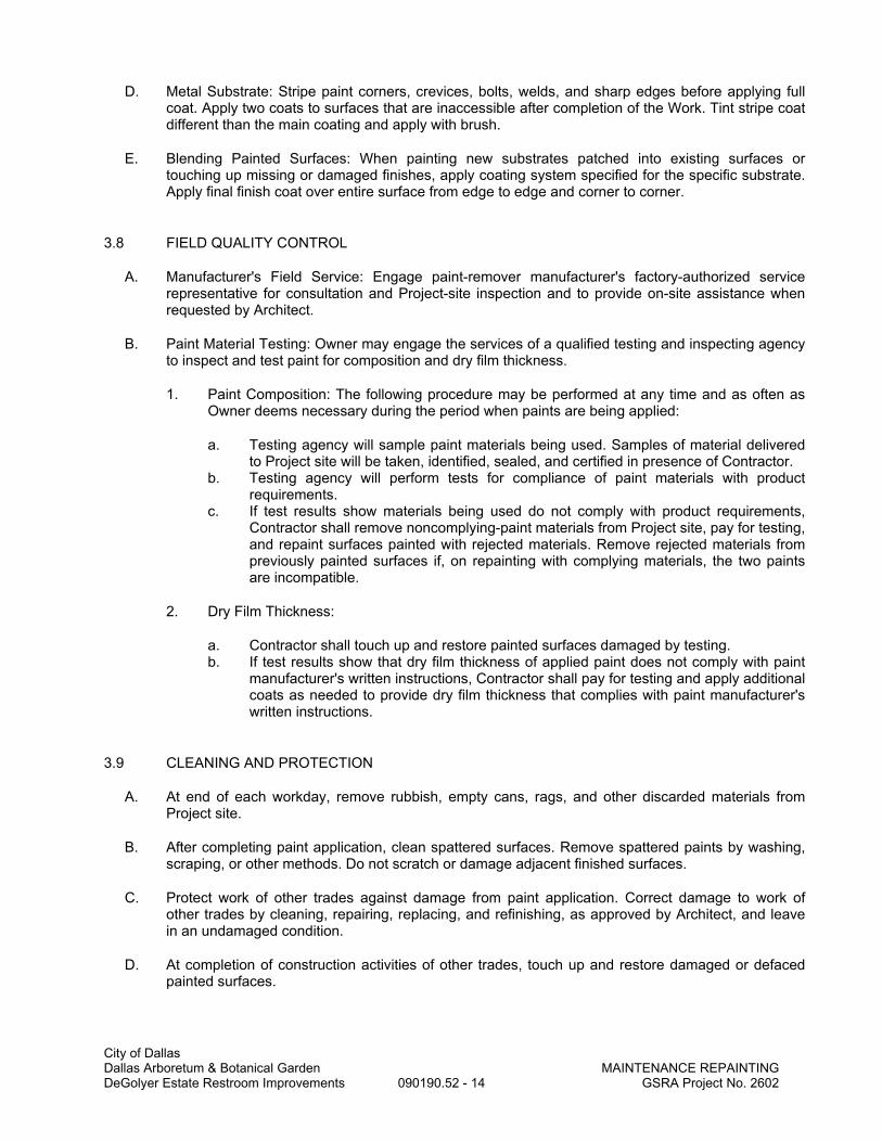
City of Dallas Dallas Arboretum & Botanical Garden MAINTENANCE REPAINTING DeGolyer Estate Restroom Improvements 090190.52 - 14 GSRA Project No. 2602
D. Metal Substrate: Stripe paint corners, crevices, bolts, welds, and sharp edges before applying full coat. Apply two coats to surfaces that are inaccessible after completion of the Work. Tint stripe coat different than the main coating and apply with brush.
E. Blending Painted Surfaces: When painting new substrates patched into existing surfaces or touching up missing or damaged finishes, apply coating system specified for the specific substrate. Apply final finish coat over entire surface from edge to edge and corner to corner.
3.8 FIELD QUALITY CONTROL
A. Manufacturer's Field Service: Engage paint-remover manufacturer's factory-authorized service representative for consultation and Project-site inspection and to provide on-site assistance when requested by Architect.
B. Paint Material Testing: Owner may engage the services of a qualified testing and inspecting agency to inspect and test paint for composition and dry film thickness.
1. Paint Composition: The following procedure may be performed at any time and as often as Owner deems necessary during the period when paints are being applied:
a. Testing agency will sample paint materials being used. Samples of material delivered to Project site will be taken, identified, sealed, and certified in presence of Contractor.
b. Testing agency will perform tests for compliance of paint materials with product requirements.
c. If test results show materials being used do not comply with product requirements, Contractor shall remove noncomplying-paint materials from Project site, pay for testing, and repaint surfaces painted with rejected materials. Remove rejected materials from previously painted surfaces if, on repainting with complying materials, the two paints are incompatible.
2. Dry Film Thickness:
a. Contractor shall touch up and restore painted surfaces damaged by testing. b. If test results show that dry film thickness of applied paint does not comply with paint
manufacturer's written instructions, Contractor shall pay for testing and apply additional coats as needed to provide dry film thickness that complies with paint manufacturer's written instructions.
3.9 CLEANING AND PROTECTION
A. At end of each workday, remove rubbish, empty cans, rags, and other discarded materials from Project site.
B. After completing paint application, clean spattered surfaces. Remove spattered paints by washing, scraping, or other methods. Do not scratch or damage adjacent finished surfaces.
C. Protect work of other trades against damage from paint application. Correct damage to work of other trades by cleaning, repairing, replacing, and refinishing, as approved by Architect, and leave in an undamaged condition.
D. At completion of construction activities of other trades, touch up and restore damaged or defaced painted surfaces.

City of Dallas Dallas Arboretum & Botanical Garden MAINTENANCE REPAINTING DeGolyer Estate Restroom Improvements 090190.52 - 15 GSRA Project No. 2602
3.10 SURFACE-PREPARATION SCHEDULE
A. General: Before painting, prepare surfaces where indicated on Drawings for painting according to applicable requirements specified in this schedule.
1. Examine surfaces to evaluate each surface condition according to paragraphs below. 2. Where existing degree of soiling prevents examination, preclean surface and allow it to dry
before making an evaluation. 3. Repair substrate defects according to "Substrate Repair" Article.
B. Surface Preparation for MPI DSD 0 Degree of Surface Degradation:
1. Surface Condition: Existing paint film in good condition and tightly adhered. 2. Paint Removal: Not required. 3. Preparation for Painting: Wash surface by detergent cleaning; use solvent cleaning where
needed. Roughen or degloss cleaned surfaces to ensure paint adhesion according to paint manufacturer's written instructions.
C. Surface Preparation for MPI DSD 1 Degree of Surface Degradation:
1. Surface Condition: Paint film cracked or broken but adhered. 2. Paint Removal: Scrape by hand-tool cleaning methods to remove loose paint until only tightly
adhered paint remains. 3. Preparation for Painting: Wash surface by detergent cleaning; use other cleaning methods for
small areas of bare substrate if required. Roughen, degloss, and sand the cleaned surfaces to ensure paint adhesion and a smooth finish according to paint manufacturer's written instructions.
D. Surface Preparation for MPI DSD 2 Degree of Surface Degradation:
1. Surface Condition: Paint film loose, flaking, or peeling. 2. Paint Removal: Remove loose, flaking, or peeling paint film by hand-tool or chemical paint-
removal methods. 3. Preparation for Painting: Wash surface by detergent cleaning; use solvent cleaning where
needed. Use other cleaning methods for small areas of bare substrate if required. Sand surfaces to smooth remaining paint film edges. Prepare bare cleaned surface to be painted according to paint manufacturer's written instructions for substrate construction materials.
E. Surface Preparation for MPI DSD 3 Degree of Surface Degradation:
1. Surface Condition: Paint film severely deteriorated, obscuring fine architectural detail work because of paint-layer buildup and surface indicated to have paint completely removed.
2. Paint Removal: Completely remove paint film by hand-tool or chemical paint-removal methods. Remove rust.
3. Preparation for Painting: Prepare bare cleaned surface according to paint manufacturer's written instructions for substrate construction materials.
F. Surface Preparation for MPI DSD 4 Degree of Surface Degradation:
1. Surface Condition: Missing material, small holes and openings, and deteriorated or corroded substrate.
2. Substrate Preparation: Repair, replace, and treat substrate according to "Substrate Repair" Article[ and requirements in other Specification Sections].
3. Preparation for Painting: Sand substrate surfaces to smooth remaining paint film edges and prepare according to paint manufacturer's written instructions for substrate construction materials. Remove rust.

City of Dallas Dallas Arboretum & Botanical Garden MAINTENANCE REPAINTING DeGolyer Estate Restroom Improvements 090190.52 - 16 GSRA Project No. 2602
4. Painting: Paint as required for MPI DSD 2 degree of surface degradation.
3.11 EXTERIOR MAINTENANCE REPAINTING SCHEDULE
A. Wood Columns, Beams, Ceilings, and Siding:
1. Latex System: MPI REX 6.2A system.
a. Prime Coat: For MPI DSD 1 degree of surface degradation, touch up with topcoat. b. Prime Coat: For MPI DSD 2 degree of surface degradation, spot prime with Primer,
Alkyd for Exterior Wood, MPI #5. c. Prime Coat: For MPI DSD 2 degree of surface degradation, spot prime with Primer,
Latex for Exterior Wood, MPI #6. d. Prime Coat: For MPI DSD 3 degree of surface degradation, fully prime coat with
Primer, Alkyd for Exterior Wood, MPI #5. e. Prime Coat: For MPI DSD 3 degree of surface degradation, fully prime coat with
Primer, Latex for Exterior Wood, MPI #6. f. Intermediate Coat: Latex, exterior, matching topcoat. g. Topcoat: Latex, exterior flat (Gloss Levels 1-2), MPI #10. h. Topcoat: Latex, exterior, low sheen (Gloss Levels 3-4), MPI #15. i. Topcoat: Latex, exterior semigloss (Gloss Level 5), MPI #11. j. Topcoat: Latex, exterior gloss (Gloss Level 6), MPI #119. k. Color: Match existing colors.
2. Alkyd System: MPI REX 6.2C system.
a. Prime Coat: For MPI DSD 1 degree of surface degradation, touch up with topcoat. b. Prime Coat: For MPI DSD 2 degree of surface degradation, spot prime with Primer,
Alkyd for Exterior Wood, MPI #5. c. Prime Coat: For MPI DSD 3 degree of surface degradation, fully prime coat with
Primer, Alkyd for Exterior Wood, MPI #5. d. Intermediate Coat: Latex, exterior, matching topcoat. e. Topcoat: Alkyd, exterior flat (Gloss Level 1), MPI #8. f. Topcoat: Alkyd, exterior semigloss (Gloss Level 5), MPI #94. g. Topcoat: Alkyd, exterior gloss (Gloss Level 6), MPI #9. h. Color: Match existing colors.
B. Wood Doors, Windows, Frames, Casings and Smooth Fasciae:
1. Latex System: MPI REX 6.3A system.
a. Prime Coat: For MPI DSD 1 degree of surface degradation, touch up with topcoat. b. Prime Coat: For MPI DSD 2 degree of surface degradation, spot prime with Primer,
Alkyd for Exterior Wood, MPI #5. c. Prime Coat: For MPI DSD 3 degree of surface degradation, fully prime coat with
Primer, Alkyd for Exterior Wood, MPI #5. d. Intermediate Coat: Latex, exterior, matching topcoat. e. Topcoat: Latex, exterior flat (Gloss Levels 1-2), MPI #10. f. Topcoat: Latex, exterior, low sheen (Gloss Levels 3-4), MPI #15. g. Topcoat: Latex, exterior semigloss (Gloss Level 5), MPI #11. h. Topcoat: Latex, exterior gloss (Gloss Level 6), MPI #119. i. Color: Match existing colors.
2. Alkyd System: MPI REX 6.3B system.

City of Dallas Dallas Arboretum & Botanical Garden MAINTENANCE REPAINTING DeGolyer Estate Restroom Improvements 090190.52 - 17 GSRA Project No. 2602
a. Prime Coat: For MPI DSD 1 degree of surface degradation, touch up with topcoat. b. Prime Coat: For MPI DSD 2 degree of surface degradation, spot prime with Primer,
Alkyd for Exterior Wood, MPI #5. c. Prime Coat: For MPI DSD 3 degree of surface degradation, fully prime coat with
Primer, Alkyd for Exterior Wood, MPI #5. d. Intermediate Coat: Alkyd, exterior, matching topcoat. e. Topcoat: Alkyd, exterior flat (Gloss Level 1), MPI #8. f. Topcoat: Alkyd, exterior semigloss (Gloss Level 5), MPI #94. g. Topcoat: Alkyd, exterior gloss (Gloss Level 6), MPI #9. h. Color: Match existing colors.
3. Varnish System (Clear): MPI REX 6.3F system.
a. Prime Coat: For MPI DSD 1 degree of surface degradation, touch up with topcoat. b. Prime Coat: For MPI DSD 2 degree of surface degradation, spot prime with topcoat. c. Prime Coat: For MPI DSD 3 degree of surface degradation, fully prime coat with
topcoat. d. Intermediate Coat: Exterior varnish matching topcoat e. Topcoat: Varnish, with UV inhibitor, exterior, semigloss (Gloss Level 5), MPI #30. f. Topcoat: Varnish, with UV inhibitor, exterior, gloss (Gloss Level 6), MPI #29. g. Topcoat: Varnish, marine spar, exterior, gloss (Gloss Level 6), MPI #28.
3.12 INTERIOR MAINTENANCE REPAINTING SCHEDULE
A. Ferrous Metal Substrates: Iron railing, Metal Windows, Frames:
1. Latex System: MPI RIN 5.1N system.
a. Prime Coat: For MPI DSD 1 degree of surface degradation, touch up with topcoat. b. Prime Coat: For MPI DSD 2 degree of surface degradation, spot prime with Primer,
Metal, Surface Tolerant, MPI #23. c. Prime Coat: For MPI DSD 2 degree of surface degradation, spot prime with Primer,
Alkyd, Anti-Corrosive for Metal, MPI #79. d. Prime Coat: For MPI DSD 2 degree of surface degradation, spot prime with Primer,
Rust-Inhibitive, Water Based, MPI #107. e. Prime Coat: For MPI DSD 3 degree of surface degradation, fully prime coat with
Primer, Metal, Surface Tolerant, MPI #23. f. Prime Coat: For MPI DSD 3 degree of surface degradation, fully prime coat with
Primer, Alkyd, Anti-Corrosive for Metal, MPI #79. g. Prime Coat: For MPI DSD 3 degree of surface degradation, fully prime coat with
Primer, Rust-Inhibitive, Water Based, MPI #107. h. Intermediate Coat: Latex matching topcoat. i. Topcoat: Latex, interior, flat (Gloss Level 1), MPI #53. j. Topcoat: Latex, interior (Gloss Level 2), MPI #44. k. Topcoat: Latex, interior (Gloss Level 3), MPI #52. l. Topcoat: Latex, interior (Gloss Level 4), MPI #43. m. Topcoat: Latex, interior, semigloss (Gloss Level 5), MPI #54. n. Topcoat: Latex, interior, gloss (Gloss Level 6), MPI #114. o. Color: Match existing colors.
2. Alkyd System: MPI RIN 5.1E system.
a. Prime Coat: For MPI DSD 1 degree of surface degradation, touch up with topcoat. b. Prime Coat: For MPI DSD 2 degree of surface degradation, spot prime with Primer,
Metal, Surface Tolerant, MPI #23.

City of Dallas Dallas Arboretum & Botanical Garden MAINTENANCE REPAINTING DeGolyer Estate Restroom Improvements 090190.52 - 18 GSRA Project No. 2602
c. Prime Coat: For MPI DSD 2 degree of surface degradation, spot prime with Primer, Alkyd, Anti-Corrosive for Metal, MPI #79.
d. Prime Coat: For MPI DSD 3 degree of surface degradation, fully prime coat with Primer, Metal, Surface Tolerant, MPI #23.
e. Prime Coat: For MPI DSD 3 degree of surface degradation, fully prime coat with Primer, Alkyd, Anti-Corrosive for Metal, MPI #79.
f. Intermediate Coat: Alkyd, matching topcoat. g. Topcoat: Alkyd, interior, flat (Gloss Level 1), MPI #49. h. Topcoat: Alkyd, interior (Gloss Level 3), MPI #51. i. Topcoat: Alkyd, interior, semigloss (Gloss Level 5), MPI #47. j. Topcoat: Alkyd, interior, gloss (Gloss Level 6), MPI #48. k. Color: Match existing colors.
3. High-Performance, Pigmented-Polyurethane-over-Epoxy System: MPI RIN 5.1H system.
a. Prime Coat: For MPI DSD 1 degree of surface degradation, touch up with Epoxy, Gloss, MPI #77.
b. Prime Coat: For MPI DSD 2 degree of surface degradation, spot prime with Primer, Zinc Rich, Organic, MPI #18.
c. Prime Coat: For MPI DSD 2 degree of surface degradation, spot prime with Primer, Zinc Rich, Epoxy, MPI #20.
d. Prime Coat: For MPI DSD 3 degree of surface degradation, fully prime coat with Primer, Zinc Rich, Organic, MPI #18.
e. Prime Coat: For MPI DSD 3 degree of surface degradation, fully prime coat with Primer, Zinc Rich, Epoxy, MPI #20.
f. Intermediate Coat in Primed Areas: Epoxy, Gloss, MPI #77. g. Topcoat: Polyurethane, two-component, pigmented, gloss (Gloss Level 6), MPI #72. h. Second Topcoat: Polyurethane, two-component, pigmented, gloss (Gloss
Level 6), MPI #72. i. Color: Match existing colors.
B. Wood Columns, Beams and Ceilings:
1. Latex System over Latex Primer: MPI RIN 6.2D system.
a. Prime Coat: For MPI DSD 1 degree of surface degradation, touch up with topcoat. b. Prime Coat: For MPI DSD 2 degree of surface degradation, spot prime with Primer,
Latex, for Interior Wood, MPI #39. c. Prime Coat: For MPI DSD 3 degree of surface degradation, fully prime coat with
Primer, Latex, for Interior Wood, MPI #39. d. Intermediate Coat: Latex, interior, matching topcoat. e. Topcoat: Latex, interior flat (Gloss Level 1), MPI #53. f. Topcoat: Latex, interior (Gloss Level 2), MPI #44. g. Topcoat: Latex, interior (Gloss Level 3), MPI #52. h. Topcoat: Latex, interior (Gloss Level 4), MPI #43. i. Topcoat: Latex, interior, semigloss (Gloss Level 5), MPI #54. j. Topcoat: Latex, interior, gloss (Gloss Level 6), MPI #114. k. Color: Match existing colors.
2. Latex System over Alkyd Primer: MPI RIN 6.2A system.
a. Prime Coat: For MPI DSD 1 degree of surface degradation, touch up with topcoat. b. Prime Coat: For MPI DSD 2 degree of surface degradation, spot prime with Undercoat,
Enamel, Interior, MPI #46. c. Prime Coat: For MPI DSD 3 degree of surface degradation, fully prime coat with
Undercoat, Enamel, Interior, MPI #46.

City of Dallas Dallas Arboretum & Botanical Garden MAINTENANCE REPAINTING DeGolyer Estate Restroom Improvements 090190.52 - 19 GSRA Project No. 2602
d. Intermediate Coat: Latex, interior, matching topcoat. e. Topcoat: Latex, interior flat (Gloss Level 1), MPI #53. f. Topcoat: Latex, interior (Gloss Level 2), MPI #44. g. Topcoat: Latex, interior (Gloss Level 3), MPI #52. h. Topcoat: Latex, interior (Gloss Level 4), MPI #43. i. Topcoat: Latex, interior, semigloss (Gloss Level 5), MPI #54. j. Topcoat: Latex, interior, gloss (Gloss Level 6), MPI #114. k. Color: Match existing colors.
3. Alkyd System: MPI RIN 6.2C system.
a. Prime Coat: For MPI DSD 1 degree of surface degradation, touch up with topcoat. b. Prime Coat: For MPI DSD 2 degree of surface degradation, spot prime with Undercoat,
Enamel, Interior, MPI #46. c. Prime Coat: For MPI DSD 3 degree of surface degradation, fully prime coat with
Undercoat, Enamel, Interior, MPI #46. d. Intermediate Coat: Alkyd, matching topcoat. e. Topcoat: Alkyd, interior, flat (Gloss Level 1), MPI #49. f. Topcoat: Alkyd, interior (Gloss Level 3), MPI #51. g. Topcoat: Alkyd, interior, semigloss (Gloss Level 5) MPI #47. h. Topcoat: Alkyd, interior, gloss (Gloss Level 6), MPI #48. i. Color: Match existing colors.
C. Wood Doors, Windows, Frames and Moldings:
1. Low-Odor Latex System over Latex Primer: MPI RIN 6.3V system.
a. Prime Coat: For MPI DSD 1 degree of surface degradation, touch up with topcoat. b. Prime Coat: For MPI DSD 2 degree of surface degradation, spot prime with Primer,
Latex, for Interior Wood, MPI #39. c. Prime Coat: For MPI DSD 3 degree of surface degradation, fully prime coat with
Primer, Latex, for Interior Wood, MPI #39. d. Intermediate Coat: Latex, interior, matching topcoat. e. Topcoat: Latex, interior, institutional low odor/VOC flat (Gloss Level 1), MPI #143. f. Topcoat: Latex, interior, institutional low odor/VOC (Gloss Level 2), MPI #144. g. Topcoat: Latex, interior, institutional low odor/VOC (Gloss Level 3), MPI #145. h. Topcoat: Latex, interior, institutional low odor/VOC (Gloss Level 4), MPI #146. i. Topcoat: Latex, interior, institutional low odor/VOC, semigloss (Gloss
Level 5), MPI #147. j. Topcoat: Latex, interior, institutional low odor/VOC, gloss (Gloss Level 6), MPI #148. k. Color: Match existing colors.
2. Latex System over Alkyd Primer: MPI RIN 6.3A system.
a. Prime Coat: For MPI DSD 1 degree of surface degradation, touch up with topcoat. b. Prime Coat: For MPI DSD 2 degree of surface degradation, spot prime with Undercoat,
Enamel, Interior, MPI #46. c. Prime Coat: For MPI DSD 3 degree of surface degradation, fully prime coat with
Undercoat, Enamel, Interior, MPI #46. d. Intermediate Coat: Latex, interior, matching topcoat. e. Topcoat: Latex, interior, semigloss (Gloss Level 5), MPI #54. f. Topcoat: Latex, interior, gloss (Gloss Level 6), MPI #114. g. Color: Match existing colors.
3. Alkyd System: MPI RIN 6.3B system.

City of Dallas Dallas Arboretum & Botanical Garden MAINTENANCE REPAINTING DeGolyer Estate Restroom Improvements 090190.52 - 20 GSRA Project No. 2602
a. Prime Coat: For MPI DSD 1 degree of surface degradation, touch up with topcoat. b. Prime Coat: For MPI DSD 2 degree of surface degradation, spot prime with Undercoat,
Enamel, Interior, MPI #46. c. Prime Coat: For MPI DSD 3 degree of surface degradation, fully prime coat with
Undercoat, Enamel, Interior, MPI #46. d. Intermediate Coat: Alkyd, matching topcoat. e. Topcoat: Alkyd, interior, semigloss (Gloss Level 5) MPI #47. f. Topcoat: Alkyd, interior, gloss (Gloss Level 6), MPI #48. g. Color: Match existing colors.
4. Alkyd Varnish System (Clear): MPI RIN 6.3J.
a. Prime Coat: For MPI DSD 1 degree of surface degradation, touch up with topcoat. b. Prime Coat: For MPI DSD 2 degree of surface degradation, spot prime with
Shellac, MPI #88. c. Prime Coat: For MPI DSD 2 degree of surface degradation, spot prime with Alkyd,
Sanding Sealer, Clear, MPI #102. d. Prime Coat: For MPI DSD 3 degree of surface degradation, fully prime coat with
Shellac, MPI #88. e. Prime Coat: For MPI DSD 3 degree of surface degradation, fully prime coat with Alkyd,
Sanding Sealer, Clear, MPI #102. f. Intermediate Coat: Interior varnish matching topcoat. g. Topcoat: Varnish, interior, flat (Gloss Level 1), MPI #73. h. Topcoat: Varnish, interior, semigloss (Gloss Level 5), MPI #74. i. Topcoat: Varnish, interior, gloss (Gloss Level 6), MPI #75.
D. Plaster:
1. Low-Odor Latex System over Waterborne Primer: MPI RIN 9.2M system.
a. Prime Coat: For MPI DSD 1 degree of surface degradation, touch up with topcoat. b. Prime Coat: For MPI DSD 2 degree of surface degradation, spot prime with Primer
Sealer, Latex, Interior, MPI #50. c. Prime Coat: For MPI DSD 2 degree of surface degradation, spot prime with Primer,
Stain Blocking, Water Based, MPI #137. d. Prime Coat: For MPI DSD 3 degree of surface degradation, fully prime coat with Primer
Sealer, Latex, Interior, MPI #50. e. Prime Coat: For MPI DSD 3 degree of surface degradation, fully prime coat with
Primer, Stain Blocking, Water Based, MPI #137. f. Topcoat: Latex, interior, institutional low odor/VOC flat (Gloss Level 1), MPI #143. g. Topcoat: Latex, interior, institutional low odor/VOC (Gloss Level 2), MPI #144. h. Topcoat: Latex, interior, institutional low odor/VOC (Gloss Level 3), MPI #145. i. Topcoat: Latex, interior, institutional low odor/VOC (Gloss Level 4), MPI #146. j. Topcoat: Latex, interior, institutional low odor/VOC, semigloss (Gloss
Level 5), MPI #147. k. Topcoat: Latex, interior, institutional low odor/VOC, gloss (Gloss Level 6), MPI #148. l. Color: Match existing colors.
2. Latex System over Alkyd Primer: MPI RIN 9.2K system.
a. Prime Coat: For MPI DSD 1 degree of surface degradation, touch up with topcoat. b. Prime Coat: For MPI DSD 2 degree of surface degradation, spot prime with Primer
Sealer, Alkyd, Interior, MPI #45. c. Prime Coat: For MPI DSD 3 degree of surface degradation, fully prime coat Primer
Sealer, Alkyd, Interior, MPI #45. d. Intermediate Coat: Latex matching topcoat.

City of Dallas Dallas Arboretum & Botanical Garden MAINTENANCE REPAINTING DeGolyer Estate Restroom Improvements 090190.52 - 21 GSRA Project No. 2602
e. Topcoat: Latex, interior, flat (Gloss Level 1), MPI #53. f. Topcoat: Latex, interior (Gloss Level 2), MPI #44. g. Topcoat: Latex, interior (Gloss Level 3), MPI #52. h. Topcoat: Latex, interior (Gloss Level 4), MPI #43. i. Topcoat: Latex, interior, semigloss (Gloss Level 5), MPI #54. j. Color: Match existing colors.
3. Alkyd System: MPI RIN 9.2C system.
a. Prime Coat: For MPI DSD 1 degree of surface degradation, touch up with topcoat. b. Prime Coat: For MPI DSD 2 degree of surface degradation, spot prime with Primer
Sealer, Latex, Interior, MPI #50. c. Prime Coat: For MPI DSD 2 degree of surface degradation, spot prime with Primer,
Stain Blocking, Water Based, MPI #137. d. Prime Coat: For MPI DSD 3 degree of surface degradation, fully prime coat with Primer
Sealer, Latex, Interior, MPI #50. e. Prime Coat: For MPI DSD 3 degree of surface degradation, fully prime coat with
Primer, Stain Blocking, Water Based, MPI #137. f. Intermediate Coat: Alkyd, matching topcoat. g. Topcoat: Alkyd, interior, flat (Gloss Level 1), MPI #49. h. Topcoat: Alkyd, interior (Gloss Level 3), MPI #51. i. Topcoat: Alkyd, interior, semigloss (Gloss Level 5), MPI #47. j. Topcoat: Alkyd, interior, gloss (Gloss Level 6), MPI #48. k. Color: Match existing colors.
END OF SECTION

City of Dallas Dallas Arboretum & Botanical Garden NON-STRUCTURAL METAL FRAMING DeGolyer Estate Restroom Improvements 092216 - 1 GSRA Project No. 2602
SECTION 092216
NON-STRUCTURAL METAL FRAMING
PART 1 - GENERAL
1.1 RELATED DOCUMENTS A. Drawings and general provisions of the Contract, including General and Supplementary
Conditions and Division 01 Specification Sections, apply to this Section.
1.2 SUMMARY A. Section Includes:
1. Non-load-bearing steel framing systems for interior gypsum board assemblies. 2. Suspension systems for interior gypsum ceilings, soffits, and grid systems.
1.3 ACTION SUBMITTALS A. Product Data: For each type of product.
1.4 INFORMATIONAL SUBMITTALS A. Evaluation Reports: For firestop tracks, from ICC-ES.
PART 2 - PRODUCTS
2.1 PERFORMANCE REQUIREMENTS A. Fire-Test-Response Characteristics: For fire-resistance-rated assemblies that incorporate non-
load-bearing steel framing, provide materials and construction identical to those tested in assembly indicated, according to ASTM E 119 by an independent testing agency.
B. STC-Rated Assemblies: For STC-rated assemblies, provide materials and construction identical to those tested in assembly indicated, according to ASTM E 90 and classified according to ASTM E 413 by an independent testing agency.
2.2 FRAMING SYSTEMS A. Recycled Content of Steel Products: Postconsumer recycled content plus one-half of
preconsumer recycled content not less than 25 percent. B. Framing Members, General: Comply with ASTM C 754 for conditions indicated.
1. Steel Sheet Components: Comply with ASTM C 645 requirements for metal unless otherwise indicated.
2. Protective Coating: ASTM A 653, G40, hot-dip galvanized unless otherwise indicated. C. Studs and Runners: ASTM C 645.
1. Steel Studs and Runners: a. Depth: As indicated on Drawings. b. Minimum Base Metal Thickness: 20 gage unless indicated otherwise on Drawings. c. Interior Metal Stud/Gypsum Board Assemblies, Typical Locations: Withstand
lateral loading (air pressure) of 5 psf with deflection limit not more than L/240 of partition height
d. Interior Metal Stud/Gypsum Board Assemblies at Atriums, Lobbies, Service Corridors, Exit Corridors, Elevator Lobbies, Vertical Shafts, and walls receiving plaster veneer: Withstand lateral loading (air pressure) of 7.5 psf with deflection limit not more than L/360 of partition height.
e. Interior Metal Stud/Gypsum Board Assemblies at Locations with Ceramic Tile or Other Hard Surface Finishes: Withstand typical lateral loading (air pressure) with deflection limit not more than L/360 of partition height
f. Where wall mounted equipment, woodwork, and casework items are indicated or elsewhere as shown on Drawings, provide minimum 16 gage studs

City of Dallas Dallas Arboretum & Botanical Garden NON-STRUCTURAL METAL FRAMING DeGolyer Estate Restroom Improvements 092216 - 2 GSRA Project No. 2602
g. At partitions scheduled to receive tile backing panels or ceramic tile finish, provide minimum 20 gage studs
D. Slip-Type Head Joints: Where indicated, provide one of the following: 1. Deflection Track: Steel sheet top runner manufactured to prevent cracking of finishes
applied to interior partition framing resulting from deflection of structure above; in thickness not less than indicated for studs and in width to accommodate depth of studs. a. Products: Subject to compliance with requirements, provide one of the following:
1) Dietrich Metal Framing; SLP-TRK Slotted Deflection Track. 2) Steel Network Inc. (The); VertiClip SLD Series.
E. Firestop Tracks: Top runner manufactured to allow partition heads to expand and contract with movement of the structure while maintaining continuity of fire-resistance-rated assembly indicated; in thickness not less than indicated for studs and in width to accommodate depth of studs. 1. Products: Subject to compliance with requirements, provide one of the following:
a. Fire Trak Corp.; Fire Trak System attached to studs with Fire Trak Posi Klip. b. Steel Network Inc. (The); VertiClip SLD Series.
F. Flat Strap and Backing Plate: Steel sheet for blocking and bracing in length and width indicated. 1. Minimum Base-Metal Thickness: 0.018 inch.
G. Cold-Rolled Channel Bridging: Steel, 0.053-inch minimum base-metal thickness, with minimum 1/2-inch- wide flanges. 1. Depth: As indicated on Drawings. 2. Clip Angle: Not less than 1-1/2 by 1-1/2 inches, 0.068-inch- thick, galvanized steel.
H. Hat-Shaped, Rigid Furring Channels: ASTM C 645. 1. Minimum Base-Metal Thickness: 0.018 inch. 2. Depth: 7/8 inch.
I. Resilient Furring Channels: 1/2-inch- deep, steel sheet members designed to reduce sound transmission. 1. Configuration: Asymmetrical.
J. Cold-Rolled Furring Channels: 0.053-inch uncoated-steel thickness, with minimum 1/2-inch- wide flanges. 1. Depth: 3/4 inch. 2. Furring Brackets: Adjustable, corrugated-edge type of steel sheet with minimum
uncoated-steel thickness of 0.033 inch. 3. Tie Wire: ASTM A 641/A 641M, Class 1 zinc coating, soft temper, 0.062-inch- diameter
wire, or double strand of 0.048-inch- diameter wire.
2.3 SUSPENSION SYSTEMS A. Tie Wire: ASTM A 641, Class 1 zinc coating, soft temper, 0.062-inch- diameter wire, or double
strand of 0.048-inch- diameter wire. B. Hanger Attachments to Concrete:
1. Anchors: Fabricated from corrosion-resistant materials with holes or loops for attaching wire hangers and capable of sustaining, without failure, a load equal to 5 times that imposed by construction as determined by testing according to ASTM E 488 by an independent testing agency. a. Type: Postinstalled, expansion anchor.
2. Powder-Actuated Fasteners: Suitable for application indicated, fabricated from corrosion-resistant materials with clips or other devices for attaching hangers of type indicated, and capable of sustaining, without failure, a load equal to 10 times that imposed by construction as determined by testing according to ASTM E 1190 by an independent testing agency.
C. Wire Hangers: ASTM A 641, Class 1 zinc coating, soft temper, 0.16 inch in diameter. D. Carrying Channels: Cold-rolled, commercial-steel sheet with a base-metal thickness of 0.053
inch and minimum 1/2-inch- wide flanges. 1. Depth: 1-1/2 inches.

City of Dallas Dallas Arboretum & Botanical Garden NON-STRUCTURAL METAL FRAMING DeGolyer Estate Restroom Improvements 092216 - 3 GSRA Project No. 2602
E. Furring Channels (Furring Members): 1. Cold-Rolled Channels: 0.053-inch uncoated-steel thickness, with minimum 1/2-inch-
wide flanges, 3/4 inch deep. 2. Hat-Shaped, Rigid Furring Channels: ASTM C 645, 7/8 inch deep.
a. Minimum Base-Metal Thickness: 0.018 inch. 3. Resilient Furring Channels: 1/2-inch- deep members designed to reduce sound
transmission. a. Configuration: Asymmetrical.
F. Grid Suspension System for Gypsum Board Ceilings: ASTM C 645, direct-hung system composed of main beams and cross-furring members that interlock. 1. Products: Subject to compliance with requirements, provide one of the following:
a. Armstrong World Industries, Inc.; Drywall Grid Systems. b. Chicago Metallic Corporation; Drywall Grid System. c. USG Corporation; Drywall Suspension System.
2.4 AUXILIARY MATERIALS A. General: Provide auxiliary materials that comply with referenced installation standards.
1. Fasteners for Metal Framing: Of type, material, size, corrosion resistance, holding power, and other properties required to fasten steel members to substrates.
B. Isolation Strip at Exterior Walls: Provide the following: 1. Foam Gasket: Adhesive-backed, closed-cell vinyl foam strips that allow fastener
penetration without foam displacement, 1/8 inch thick, in width to suit steel stud size.
PART 3 - EXECUTION
3.1 EXAMINATION A. Examine areas and substrates, with Installer present, and including welded hollow-metal
frames, cast-in anchors, and structural framing, for compliance with requirements and other conditions affecting performance of the Work.
B. Proceed with installation only after unsatisfactory conditions have been corrected.
3.2 PREPARATION A. Suspended Assemblies: Coordinate installation of suspension systems with installation of
overhead structure to ensure that inserts and other provisions for anchorages to building structure have been installed to receive hangers at spacing required to support the Work and that hangers will develop their full strength. 1. Furnish concrete inserts and other devices indicated to other trades for installation in
advance of time needed for coordination and construction. B. Coordination with Sprayed Fire-Resistive Materials:
1. Before sprayed fire-resistive materials are applied, attach offset anchor plates or ceiling runners (tracks) to surfaces indicated to receive sprayed fire-resistive materials. Where offset anchor plates are required, provide continuous plates fastened to building structure not more than 24 inches o.c.
2. After sprayed fire-resistive materials are applied, remove them only to extent necessary for installation of non-load-bearing steel framing. Do not reduce thickness of fire-resistive materials below that required for fire-resistance ratings indicated. Protect adjacent fire-resistive materials from damage.
3.3 INSTALLATION, GENERAL A. Installation Standard: ASTM C 754.
1. Gypsum Board Assemblies: Also comply with requirements in ASTM C 840 that apply to framing installation.
B. Install supplementary framing, and blocking to support fixtures, equipment services, heavy trim, grab bars, toilet accessories, furnishings, or similar construction.
C. Install bracing at terminations in assemblies.

City of Dallas Dallas Arboretum & Botanical Garden NON-STRUCTURAL METAL FRAMING DeGolyer Estate Restroom Improvements 092216 - 4 GSRA Project No. 2602
D. Do not bridge building control and expansion joints with non-load-bearing steel framing members. Frame both sides of joints independently.
3.4 INSTALLING FRAMED ASSEMBLIES A. Install framing system components according to spacings indicated, but not greater than
spacings required by referenced installation standards for assembly types. B. Where studs are installed directly against exterior masonry walls or dissimilar metals at exterior
walls, install isolation strip between studs and exterior wall. C. Install studs so flanges within framing system point in same direction. D. Install tracks (runners) at floors and overhead supports. Extend framing full height to structural
supports or substrates above suspended ceilings except where partitions are indicated to terminate at suspended ceilings. Continue framing around ducts penetrating partitions above ceiling. 1. Slip-Type Head Joints: Where framing extends to overhead structural supports, install to
produce joints at tops of framing systems that prevent axial loading of finished assemblies.
2. Door Openings: Screw vertical studs at jambs to jamb anchor clips on door frames; install runner track section (for cripple studs) at head and secure to jamb studs. a. Install two studs at each jamb unless otherwise indicated. b. Install cripple studs at head adjacent to each jamb stud, with a minimum 1/2-inch
clearance from jamb stud to allow for installation of control joint in finished assembly.
c. Extend jamb studs through suspended ceilings and attach to underside of overhead structure.
3. Other Framed Openings: Frame openings other than door openings the same as required for door openings unless otherwise indicated. Install framing below sills of openings to match framing required above door heads.
4. Fire-Resistance-Rated Partitions: Install framing to comply with fire-resistance-rated assembly indicated and support closures and to make partitions continuous from floor to underside of solid structure. a. Firestop Track: Where indicated, install to maintain continuity of fire-resistance-
rated assembly indicated. 5. Sound-Rated Partitions: Install framing to comply with sound-rated assembly indicated. 6. Curved Partitions:
a. Bend track to uniform curve and locate straight lengths so they are tangent to arcs. b. Begin and end each arc with a stud, and space intermediate studs equally along
arcs. On straight lengths of no fewer than two studs at ends of arcs, place studs 6 inches o.c.
E. Direct Furring: 1. Screw to wood framing. 2. Attach to concrete or masonry with stub nails, screws designed for masonry attachment,
or powder-driven fasteners spaced 24 inches o.c. F. Installation Tolerance: Install each framing member so fastening surfaces vary not more than
1/8 inch from the plane formed by faces of adjacent framing.
3.5 INSTALLING SUSPENSION SYSTEMS A. Install suspension system components according to spacings indicated, but not greater than
spacings required by referenced installation standards for assembly types. 1. Hangers: 48 inches o.c. 2. Carrying Channels (Main Runners): 48 inches o.c. 3. Furring Channels (Furring Members): 16 inches o.c.
B. Isolate suspension systems from building structure where they abut or are penetrated by building structure to prevent transfer of loading imposed by structural movement.
C. Suspend hangers from building structure as follows: 1. Install hangers plumb and free from contact with insulation or other objects within ceiling

City of Dallas Dallas Arboretum & Botanical Garden NON-STRUCTURAL METAL FRAMING DeGolyer Estate Restroom Improvements 092216 - 5 GSRA Project No. 2602
plenum that are not part of supporting structural or suspension system. a. Splay hangers only where required to miss obstructions and offset resulting
horizontal forces by bracing, countersplaying, or other equally effective means. 2. Where width of ducts and other construction within ceiling plenum produces hanger
spacings that interfere with locations of hangers required to support standard suspension system members, install supplemental suspension members and hangers in the form of trapezes or equivalent devices. a. Size supplemental suspension members and hangers to support ceiling loads
within performance limits established by referenced installation standards. 3. Wire Hangers: Secure by looping and wire tying, either directly to structures or to inserts,
eye screws, or other devices and fasteners that are secure and appropriate for substrate, and in a manner that will not cause hangers to deteriorate or otherwise fail.
4. Do not attach hangers to steel roof deck. 5. Do not attach hangers to permanent metal forms. Furnish cast-in-place hanger inserts
that extend through forms. 6. Do not attach hangers to rolled-in hanger tabs of composite steel floor deck. 7. Do not connect or suspend steel framing from ducts, pipes, or conduit.
D. Fire-Resistance-Rated Assemblies: Wire tie furring channels to supports. E. Grid Suspension Systems: Attach perimeter wall track or angle where grid suspension systems
meet vertical surfaces. Mechanically join main beam and cross-furring members to each other and butt-cut to fit into wall track.
F. Installation Tolerances: Install suspension systems that are level to within 1/8 inch in 12 feet measured lengthwise on each member that will receive finishes and transversely between parallel members that will receive finishes.
END OF SECTION
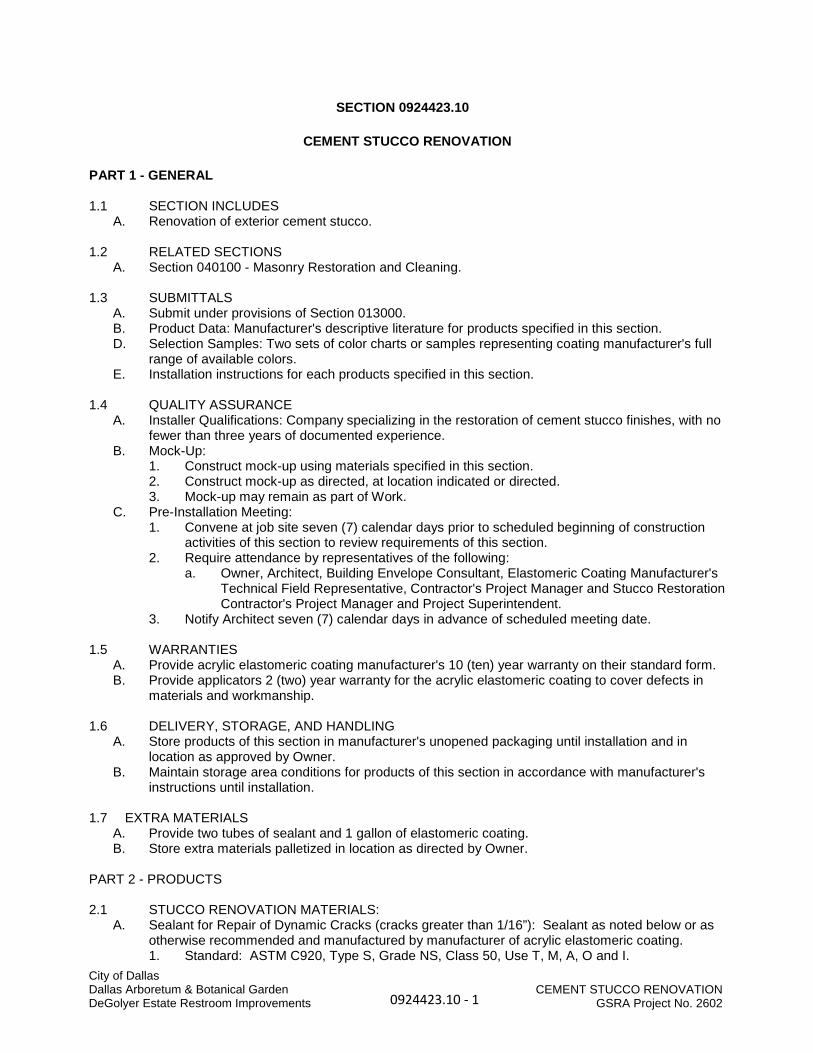
SECTION 0924423.10
CEMENT STUCCO RENOVATION
PART 1 - GENERAL 1.1 SECTION INCLUDES
A. Renovation of exterior cement stucco.
1.2 RELATED SECTIONS A. Section 040100 - Masonry Restoration and Cleaning.
1.3 SUBMITTALS A. Submit under provisions of Section 013000. B. Product Data: Manufacturer's descriptive literature for products specified in this section. D. Selection Samples: Two sets of color charts or samples representing coating manufacturer's full
range of available colors. E. Installation instructions for each products specified in this section.
1.4 QUALITY ASSURANCE
A. Installer Qualifications: Company specializing in the restoration of cement stucco finishes, with no fewer than three years of documented experience.
B. Mock-Up: 1. Construct mock-up using materials specified in this section. 2. Construct mock-up as directed, at location indicated or directed. 3. Mock-up may remain as part of Work.
C. Pre-Installation Meeting: 1. Convene at job site seven (7) calendar days prior to scheduled beginning of construction
activities of this section to review requirements of this section. 2. Require attendance by representatives of the following:
a. Owner, Architect, Building Envelope Consultant, Elastomeric Coating Manufacturer's Technical Field Representative, Contractor's Project Manager and Stucco Restoration Contractor's Project Manager and Project Superintendent.
3. Notify Architect seven (7) calendar days in advance of scheduled meeting date. 1.5 WARRANTIES
A. Provide acrylic elastomeric coating manufacturer's 10 (ten) year warranty on their standard form. B. Provide applicators 2 (two) year warranty for the acrylic elastomeric coating to cover defects in
materials and workmanship.
1.6 DELIVERY, STORAGE, AND HANDLING A. Store products of this section in manufacturer's unopened packaging until installation and in
location as approved by Owner. B. Maintain storage area conditions for products of this section in accordance with manufacturer's
instructions until installation. 1.7 EXTRA MATERIALS
A. Provide two tubes of sealant and 1 gallon of elastomeric coating. B. Store extra materials palletized in location as directed by Owner.
PART 2 - PRODUCTS 2.1 STUCCO RENOVATION MATERIALS:
A. Sealant for Repair of Dynamic Cracks (cracks greater than 1/16”): Sealant as noted below or as otherwise recommended and manufactured by manufacturer of acrylic elastomeric coating. 1. Standard: ASTM C920, Type S, Grade NS, Class 50, Use T, M, A, O and I.
0924423.10 - 1
City of DallasDallas Arboretum & Botanical GardenDeGolyer Estate Restroom Improvements
CEMENT STUCCO RENOVATIONGSRA Project No. 2602

2. Source: Dymonic 100 by Tremco. B. Sealant for Static Cracks: Knife Brade or Brush Grade patching compound as manufactured and
recommended by manufacturer of acrylic elastomeric coating. C. Acrylic Elastomeric Coating: MasterProtect EL750 as manufactured by BASF, color as selected.
2.2 CLEANING MATERIALS - Refer to Section 040100. 2.3 CLEANING EQUIPMENT - Refer to Section 040100.
PART 3 - EXECUTION 3.1 STUCCO RENOVATION:
A. Cleaning of Stucco Surfaces: Refer to Section 040100. B. Stucco Renovation:
1. Prepare dynamic cracks as recommended by sealant manufacturer. 2. Install Type 2 sealant at all dynamic cracks in a manner that will allow repaired areas to blend
into the adjacent stucco without such having an obvious appearance as of having been patched. Rework treatment of dynamic cracks until acceptable results are achieved.
3. Apply acrylic elastomeric coating where scheduled in accordance with manufacturer’s requirements noting that sand may need to be added to coating to achieve the desired aesthetic noted above.
3.2 CLEANUP
A. Remove and legally dispose of products related to the scope of work specified in this section.
END OF SECTION
0924423.10 - 2
City of DallasDallas Arboretum & Botanical GardenDeGolyer Estate Restroom Improvements
CEMENT STUCCO RENOVATIONGSRA Project No. 2602

City of Dallas Dallas Arboretum & Botanical Garden INTERIOR CEMENT PLASTER REPAIR DeGolyer Estate Restroom Improvements 092424 - 1 GSRA Project No. 2602
SECTION 092424
INTERIOR CEMENT PLASTER REPAIR
PART 1 - GENERAL
1.1 RELATED DOCUMENTS A. Drawings and general provisions of the Contract, including General and Supplementary
Conditions and Division 01 Specification Sections, apply to this Section. B. U.S. Department of the Interior Preservation Brief 21 – Repairing Historic Flat Plaster-Walls and
Ceilings, National Park Service.
1.2 SUMMARY A. Section Includes:
1. Portland cement plasterwork repair.
1.3 SUBMITTALS A. Product Data: For each type of product indicated. B. Shop Drawings: Application of plaster repair, including proposed control joint locations, where
applicable.
1.4 QUALITY ASSURANCE A. Fire-Resistance Ratings: Where indicated, provide portland cement plaster assemblies
identical to those of assemblies tested for fire resistance per ASTM E 119 by a qualified testing agency. Identify products with appropriate markings of applicable testing agency. 1. Indicate design designations from UL's "Fire Resistance Directory" or from the listings of
another qualified testing agency.
1.5 DELIVERY, STORAGE, AND HANDLING A. Store materials inside under cover and keep them dry and protected against damage from
weather, direct sunlight, surface contamination, corrosion, construction traffic, and other causes.
1.6 PROJECT CONDITIONS A. Comply with ASTM C 926 requirements. B. Interior Plasterwork: Maintain room temperatures at greater than 40 deg F for at least 48 hours
before plaster application, and continuously during and after application. 1. Avoid conditions that result in plaster drying out during curing period. Distribute heat
evenly; prevent concentrated or uneven heat on plaster. 2. Ventilate building spaces as required to remove water in excess of that required for
hydrating plaster in a manner that prevents drafts of air from contacting surfaces during plaster application and until plaster is dry.
PART 2 - PRODUCTS
2.1 METAL LATH A. Expanded-Metal Lath: ASTM C 847 with ASTM A 653, G60, hot-dip galvanized zinc coating.
1. Manufacturers: Subject to compliance with requirements, provide products by one of the following: a. Alabama Metal Industries Corporation; a Gibraltar Industries company. b. CEMCO. c. ClarkDietrich Building Systems. d. MarinoWARE. e. Phillips Manufacturing Co.
2. Diamond-Mesh Lath: Self-furring, 3.4 lb/sq. yd..

City of Dallas Dallas Arboretum & Botanical Garden INTERIOR CEMENT PLASTER REPAIR DeGolyer Estate Restroom Improvements 092424 - 2 GSRA Project No. 2602
B. Paper Backing: FS UU-B-790, Type I, Grade D, Style 2 vapor-permeable paper. 1. Provide paper-backed lath at exterior locations.
2.2 ACCESSORIES A. General: Comply with ASTM C 1063 and coordinate depth of trim and accessories with
thicknesses and number of plaster coats required. B. Metal Accessories:
1. Manufacturers: Subject to compliance with requirements, provide products by one of the following: a. Alabama Metal Industries Corporation; a Gibraltar Industries company. b. CEMCO. c. ClarkDietrich Building Systems. d. MarinoWARE. e. Phillips Manufacturing Co.
2. External-Corner Reinforcement: Fabricated from metal lath with ASTM A 653, G60, hot-dip galvanized zinc coating.
3. Cornerbeads: Fabricated from zinc-coated (galvanized) steel. a. Small nose cornerbead with expanded flanges; use unless otherwise indicated.
4. Casing Beads: Fabricated from zinc-coated (galvanized) steel; square-edged style; with expanded flanges. Provide holes in base of casing bead to provide for drainage from behind plaster.
5. Control Joints: Fabricated from zinc-coated (galvanized) steel; one-piece-type, folded pair of unperforated screeds in M-shaped configuration; with perforated flanges and removable protective tape on plaster face of control joint.
6. Expansion Joints: Fabricated from zinc-coated (galvanized) steel; folded pair of unperforated screeds in M-shaped configuration; with expanded flanges.
2.3 MISCELLANEOUS MATERIALS A. Water for Mixing: Potable and free of substances capable of affecting plaster set or of
damaging plaster, lath, or accessories. B. Fiber for Base Coat: Alkaline-resistant glass or polypropylene fibers, 1/2 inch long, free of
contaminants, manufactured for use in portland cement plaster. C. Bonding Compound: ASTM C 932. D. Steel Drill Screws: For metal-to-metal fastening, ASTM C 1002 or ASTM C 954, as required by
thickness of metal being fastened; with pan head that is suitable for application; in lengths required to achieve penetration through joined materials of no fewer than three exposed threads.
E. Fasteners for Attaching Metal Lath to Substrates: Complying with ASTM C 1063. F. Wire: ASTM A 641/A 641M, Class 1 zinc coating, soft temper, not less than 0.0475-inch
diameter, unless otherwise indicated.
2.4 PLASTER MATERIALS A. Portland Cement: ASTM C 150, Type I. B. Masonry Cement: ASTM C 91, Type N.
1. Color for Finish Coats: Gray. C. Colorants for Job-Mixed Finish Coats: Colorfast mineral pigments that produce finish plaster
color to match Architect's sample. D. Sand Aggregate: ASTM C 897.
1. Color for Job-Mixed Finish Coats: In color matching Architect's sample. E. Ready-Mixed Finish-Coat Plaster: Mill-mixed portland cement, aggregates, coloring agents,
and proprietary ingredients. 1. Products: Subject to compliance with requirements, provide one of the following:
a. El Rey Stucco Company, Inc., a brand of ParexLaHabra, Inc.; Premium Stucco Finish.
b. Florida Stucco; Florida Stucco.

City of Dallas Dallas Arboretum & Botanical Garden INTERIOR CEMENT PLASTER REPAIR DeGolyer Estate Restroom Improvements 092424 - 3 GSRA Project No. 2602
c. LaHabra, a brand of ParexLaHabra, Inc.; Exterior Stucco Color Coat. d. SonoWall, BASF Wall Systems, Inc.; Thoro Stucco. e. USG Corporation; Oriental Exterior Finish Stucco.
2. Color: As selected by Architect from manufacturer's full range.
2.5 PLASTER MIXES A. General: Comply with ASTM C 926 for applications indicated.
1. Fiber Content: Add fiber to base-coat mixes after ingredients have mixed at least two minutes. Comply with fiber manufacturer's written instructions for fiber quantities in mixes, but do not exceed 1 lb of fiber/cu. yd. of cementitious materials.
B. Base-Coat Mixes for Use over Metal Lath: Scratch and brown coats for three-coat plasterwork as follows: 1. Portland and Masonry Cement Mixes:
a. Scratch Coat: For cementitious material, mix 1 part portland cement and 1 part masonry cement. Use 2-1/2 to 4 parts aggregate per part of cementitious material.
b. Brown Coat: For cementitious material, mix 1 part portland cement and 1 part masonry cement. Use 3 to 5 parts aggregate per part of cementitious material, but not less than volume of aggregate used in scratch coat.
C. Factory-Prepared Finish-Coat Mixes: For ready-mixed finish-coat plasters acrylic-based finish coatings, comply with manufacturer's written instructions.
PART 3 - EXECUTION
3.1 EXAMINATION A. Examine areas and substrates, with Installer present, and including welded hollow-metal
frames, cast-in anchors, and structural framing, for compliance with requirements and other conditions affecting performance of the Work.
B. Proceed with installation only after unsatisfactory conditions have been corrected.
3.2 PREPARATION A. Protect adjacent work from soiling, spattering, moisture deterioration, and other harmful effects
caused by plastering. B. Prepare solid substrates for plaster that are smooth or that do not have the suction capability
required to bond with plaster according to ASTM C 926.
3.3 INSTALLING METAL LATH A. Expanded-Metal Lath: Install according to ASTM C 1063.
1. Partition Framing and Vertical Furring: Install flat diamond-mesh lath. 2. Flat-Ceiling and Horizontal Framing: Install flat diamond-mesh lath. 3. Curved-Ceiling Framing: Install flat diamond-mesh lath. 4. On Solid Surfaces, Not Otherwise Furred: Install self-furring, diamond-mesh lath.
3.4 INSTALLING ACCESSORIES A. Install according to ASTM C 1063 and at locations indicated on Drawings. B. Reinforcement for External Corners:
1. Install lath-type, external-corner reinforcement at exterior locations. 2. Install cornerbead at interior and exterior locations.
C. Control Joints: Install control joints at locations indicated on Drawings or in specific locations approved by Architect for visual effect as follows: 1. As required to delineate plasterwork into areas (panels) of the following maximum sizes:
a. Vertical Surfaces: 144 sq. ft.. b. Horizontal and other Non-vertical Surfaces: 100 sq. ft..
2. At distances between control joints of not greater than 18 feet o.c. 3. As required to delineate plasterwork into areas (panels) with length-to-width ratios of not
greater than 2-1/2:1.

City of Dallas Dallas Arboretum & Botanical Garden INTERIOR CEMENT PLASTER REPAIR DeGolyer Estate Restroom Improvements 092424 - 4 GSRA Project No. 2602
4. Where control joints occur in surface of construction directly behind plaster. 5. Where plasterwork areas change dimensions, to delineate rectangular-shaped areas
(panels) and to relieve the stress that occurs at the corner formed by the dimension change.
3.5 PLASTER APPLICATION A. General: Comply with ASTM C 926.
1. Do not deviate more than plus or minus 1/4 inch in 10 feet from a true plane in finished plaster surfaces, as measured by a 10-foot straightedge placed on surface.
2. Finish plaster flush with metal frames and other built-in metal items or accessories that act as a plaster ground unless otherwise indicated. Where casing bead does not terminate plaster at metal frame, cut base coat free from metal frame before plaster sets and groove finish coat at junctures with metal.
3. Provide plaster surfaces that are ready to receive field-applied finishes indicated. B. Bonding Compound: Apply on unit masonry and concrete plaster bases. C. Walls; Base-Coat Mixes for Use over Metal Lath: Scratch and brown coats for three-coat
plasterwork; 3/4-inch thickness. 1. Portland and masonry cement mixes.
D. Ceilings; Base-Coat Mixes for Use over Metal Lath: Scratch and brown coats for three-coat plasterwork; 3/4 inch thick. 1. Portland and masonry cement mixes.
E. Plaster Finish Coats: Apply to provide float finish to match existing F. Concealed Exterior Plasterwork: Where plaster application will be used as a base for adhered
finishes, omit finish coat.
3.6 PLASTER REPAIRS A. Repair or replace work to eliminate cracks, dents, blisters, buckles, crazing and check cracking,
dry outs, efflorescence, sweat outs, and similar defects and where bond to substrate has failed.
3.7 PROTECTION A. Remove temporary protection and enclosure of other work. Promptly remove plaster from door
frames, windows, and other surfaces not indicated to be plastered. Repair floors, walls, and other surfaces stained, marred, or otherwise damaged during plastering.
END OF SECTION

City of Dallas Dallas Arboretum & Botanical Garden GYPSUM BOARD DeGolyer Estate Restroom Improvements 092900 - 1 GSRA Project No. 2602
SECTION 092900
GYPSUM BOARD
PART 1 - GENERAL
1.1 RELATED DOCUMENTS A. Drawings and general provisions of the Contract, including General and Supplementary
Conditions and Division 01 Specification Sections, apply to this Section.
1.2 SUMMARY A. Section Includes:
1. Interior gypsum board. 2. Tile backing panels.
1.3 ACTION SUBMITTALS A. Product Data: For each type of product. B. Samples: For the following products:
1. Trim Accessories: Full-size Sample in 12-inch- long length for each trim accessory indicated.
1.4 QUALITY ASSURANCE A. Mockups: Before beginning gypsum board installation, install mockups of at least 100 sq. ft. in
surface area to demonstrate aesthetic effects and set quality standards for materials and execution. 1. Install mockups for the following:
a. Each level of gypsum board finish indicated for use in exposed locations. b. Each texture finish indicated.
2. Apply or install final decoration indicated, including painting and wall coverings, on exposed surfaces for review of mockups.
3. Simulate finished lighting conditions for review of mockups. 4. Subject to compliance with requirements, approved mockups may become part of the
completed Work if undisturbed at time of Substantial Completion.
1.5 DELIVERY, STORAGE AND HANDLING A. Store materials inside under cover and keep them dry and protected against weather,
condensation, direct sunlight, construction traffic, and other potential causes of damage. Stack panels flat and supported on risers on a flat platform to prevent sagging.
1.6 FIELD CONDITIONS A. Environmental Limitations: Comply with ASTM C 840 requirements or gypsum board
manufacturer's written recommendations, whichever are more stringent. B. Do not install paper-faced gypsum panels until installation areas are enclosed and conditioned. C. Do not install panels that are wet, those that are moisture damaged, and those that are mold
damaged. 1. Indications that panels are wet or moisture damaged include, but are not limited to,
discoloration, sagging, or irregular shape. 2. Indications that panels are mold damaged include, but are not limited to, fuzzy or
splotchy surface contamination and discoloration.
PART 2 - PRODUCTS
2.1 PERFORMANCE REQUIREMENTS A. Fire-Resistance-Rated Assemblies: For fire-resistance-rated assemblies, provide materials and

City of Dallas Dallas Arboretum & Botanical Garden GYPSUM BOARD DeGolyer Estate Restroom Improvements 092900 - 2 GSRA Project No. 2602
construction identical to those tested in assembly indicated according to ASTM E 119 by an independent testing agency.
B. STC-Rated Assemblies: For STC-rated assemblies, provide materials and construction identical to those tested in assembly indicated according to ASTM E 90 and classified according to ASTM E 413 by an independent testing agency.
2.2 GYPSUM BOARD, GENERAL A. Size: Provide maximum lengths and widths available that will minimize joints in each area and
that correspond with support system indicated.
2.3 INTERIOR GYPSUM BOARD A. Manufacturers: Subject to compliance with requirements, provide products by one of the
following: 1. American Gypsum. 2. CertainTeed Corp. 3. Georgia-Pacific Gypsum LLC. 4. National Gypsum Company. 5. Temple-Inland. 6. USG Corporation.
B. Gypsum Board, Type X: ASTM C 1396. 1. Thickness: 5/8 inch. 2. Long Edges: Tapered.
C. Flexible Gypsum Board: ASTM C 1396. Manufactured to bend to fit radii and to be more flexible than standard regular-type gypsum board of same thickness. 1. Thickness: 1/4 inch. 2. Long Edges: Tapered.
D. Gypsum Ceiling Board: ASTM C 1396. 1. Thickness: 1/2 inch. 2. Long Edges: Tapered.
E. Abuse-Resistant Gypsum Board: ASTM C 1629, Level 1. 1. Core: 5/8 inch, Type X. 2. Long Edges: Tapered. 3. Mold Resistance: ASTM D 3273, score of 10. 4. Locations: All corridors, dock and service corridors.
F. Moisture- and Mold-Resistant Gypsum Board: ASTM C 1396. With moisture- and mold-resistant core and paper surfaces. 1. Core: 5/8 inch, Type X. 2. Long Edges: Tapered. 3. Mold Resistance: ASTM D 3273, score of 10. 4. Locations: Restrooms, janitor closets, other locations where water exposure is probable.
2.4 SPECIALTY GYPSUM BOARD A. Gypsum Board, Type C: ASTM C 1396. Manufactured to have increased fire-resistive
capability. 1. Products: Subject to compliance with requirements, provide one of the following:
a. American Gypsum; Firebloc Type C. b. CertainTeed Corp.; ProRoc Type C. c. Georgia-Pacific Gypsum LLC; Fireguard C. d. National Gypsum Company; Gold Bond Fire-Shield C. e. Temple-Inland; Type TG-C. f. USG Corporation; Firecode C Core.
2. Thickness: As required by fire-resistance-rated assembly indicated on Drawings. 3. Long Edges: Tapered.
B. Mold Resistant Glass-Mat Interior Gypsum Board: ASTM C 1658. With fiberglass mat laminated to both sides. Specifically designed for interior use.

City of Dallas Dallas Arboretum & Botanical Garden GYPSUM BOARD DeGolyer Estate Restroom Improvements 092900 - 3 GSRA Project No. 2602
1. Products: Subject to compliance with requirements, provide one of the following: a. Georgia-Pacific Gypsum LLC; DensArmour Plus.
2. Core: 5/8 inch, Type X. 3. Long Edges: Tapered. 4. Mold Resistance: ASTM D 3273, score of 10.
2.5 TILE BACKING PANELS A. Glass-Mat, Water-Resistant Backing Board: ASTM C 1178/C 1178M, with manufacturer's
standard edges. 1. Products: Subject to compliance with requirements, provide one of the following:
a. CertainTeed Corp.; GlasRoc Tile Backer. b. Georgia-Pacific Gypsum LLC; DensShield Tile Backer.
2. Core: 5/8 inch, Type X. 3. Mold Resistance: ASTM D 3273, score of 10.
2.6 TRIM ACCESSORIES A. Interior Trim: ASTM C 1047.
1. Material: Galvanized or aluminum-coated steel sheet or rolled zinc. 2. Shapes:
a. Cornerbead. b. Bullnose bead. c. LC-Bead: J-shaped; exposed long flange receives joint compound. d. L-Bead: L-shaped; exposed long flange receives joint compound. e. U-Bead: J-shaped; exposed short flange does not receive joint compound. f. Expansion (control) joint. g. Curved-Edge Cornerbead: With notched or flexible flanges.
B. Aluminum Trim: Extruded accessories of profiles and dimensions indicated. 1. Manufacturers: Subject to compliance with requirements, provide products by one of the
following: a. Fry Reglet Corp. b. Gordon, Inc. c. Pittcon Industries.
2. Aluminum: Alloy and temper with not less than the strength and durability properties of ASTM B 221, Alloy 6063-T5.
3. Finish: Corrosion-resistant primer compatible with joint compound and finish materials specified.
2.7 JOINT TREATMENT MATERIALS A. General: Comply with ASTM C 475/C 475M. B. Joint Tape:
1. Interior Gypsum Board: Paper. 2. Exterior Gypsum Soffit Board: Paper. 3. Glass-Mat Gypsum Sheathing Board: 10-by-10 glass mesh. 4. Tile Backing Panels: As recommended by panel manufacturer.
C. Joint Compound for Interior Gypsum Board: For each coat use formulation that is compatible with other compounds applied on previous or for successive coats. 1. Prefilling: At open joints, rounded or beveled panel edges, and damaged surface areas,
use setting-type taping compound. 2. Embedding and First Coat: For embedding tape and first coat on joints, fasteners, and
trim flanges, use drying-type, all-purpose compound. a. Use setting-type compound for installing paper-faced metal trim accessories.
3. Fill Coat: For second coat, use drying-type, all-purpose compound. 4. Finish Coat: For third coat, use drying-type, all-purpose compound. 5. Skim Coat: For final coat of Level 5 finish, use drying-type, all-purpose compound.
D. Joint Compound for Exterior Applications:

City of Dallas Dallas Arboretum & Botanical Garden GYPSUM BOARD DeGolyer Estate Restroom Improvements 092900 - 4 GSRA Project No. 2602
1. Exterior Gypsum Soffit Board: Use setting-type taping compound and setting-type, sandable topping compound.
2. Glass-Mat Gypsum Sheathing Board: As recommended by sheathing board manufacturer.
E. Joint Compound for Tile Backing Panels: 1. Glass-Mat, Water-Resistant Backing Panel: As recommended by backing panel
manufacturer. 2. Cementitious Backer Units: As recommended by backer unit manufacturer.
2.8 AUXILIARY MATERIALS A. General: Provide auxiliary materials that comply with referenced installation standards and
manufacturer's written recommendations. B. Laminating Adhesive: Adhesive or joint compound recommended for directly adhering gypsum
panels to continuous substrate. 1. Laminating adhesive shall have a VOC content of 50 Insert value g/L or less when
calculated according to 40 CFR 59, Subpart D (EPA Method 24). C. Steel Drill Screws: ASTM C 1002, unless otherwise indicated.
1. Use screws complying with ASTM C 954 for fastening panels to steel members from 0.033 to 0.112 inch thick.
2. For fastening cementitious backer units, use screws of type and size recommended by panel manufacturer.
D. Sound Attenuation Blankets: ASTM C 665, Type I (blankets without membrane facing) produced by combining thermosetting resins with mineral fibers manufactured from glass, slag wool, or rock wool. 1. Fire-Resistance-Rated Assemblies: Comply with mineral-fiber requirements of assembly.
E. Acoustical Joint Sealant: Manufacturer's standard nonsag, paintable, nonstaining latex sealant complying with ASTM C 834. Product effectively reduces airborne sound transmission through perimeter joints and openings in building construction as demonstrated by testing representative assemblies according to ASTM E 90. 1. Products: Subject to compliance with requirements, provide one of the following:
a. Accumetric LLC; BOSS 824 Acoustical Sound Sealant. b. Pecora Corporation; AC-20 FTR AIS-919. c. Specified Technologies, Inc.; Smoke N Sound Acoustical Sealant. d. USG Corporation; SHEETROCK Acoustical Sealant.
2. Acoustical joint sealant shall have a VOC content of 250 g/L or less when calculated according to 40 CFR 59, Subpart D (EPA Method 24).
PART 3 - EXECUTION
3.1 EXAMINATION A. Examine areas and substrates including welded hollow-metal frames and framing, with Installer
present, for compliance with requirements and other conditions affecting performance. B. Examine panels before installation. Reject panels that are wet, moisture damaged, and mold
damaged. C. Proceed with installation only after unsatisfactory conditions have been corrected.
3.2 APPLYING AND FINISHING PANELS, GENERAL A. Comply with ASTM C 840. B. Install ceiling panels across framing to minimize the number of abutting end joints and to avoid
abutting end joints in central area of each ceiling. Stagger abutting end joints of adjacent panels not less than one framing member.
C. Install panels with face side out. Butt panels together for a light contact at edges and ends with not more than 1/16 inch of open space between panels. Do not force into place.
D. Locate edge and end joints over supports, except in ceiling applications where intermediate supports or gypsum board back-blocking is provided behind end joints. Do not place tapered

City of Dallas Dallas Arboretum & Botanical Garden GYPSUM BOARD DeGolyer Estate Restroom Improvements 092900 - 5 GSRA Project No. 2602
edges against cut edges or ends. Stagger vertical joints on opposite sides of partitions. Do not make joints other than control joints at corners of framed openings.
E. Form control and expansion joints with space between edges of adjoining gypsum panels. F. Cover both faces of support framing with gypsum panels in concealed spaces (above ceilings,
etc., except in chases braced internally. 1. Unless concealed application is indicated or required for sound, fire, air, or smoke
ratings, coverage may be accomplished with scraps of not less than 8 sq. ft. in area. 2. Fit gypsum panels around ducts, pipes, and conduits. 3. Where partitions intersect structural members projecting below underside of floor/roof
slabs and decks, cut gypsum panels to fit profile formed by structural members; allow 1/4- to 3/8-inch- wide joints to install sealant.
G. Isolate perimeter of gypsum board applied to non-load-bearing partitions at structural abutments, except floors. Provide 1/4- to 1/2-inch- wide spaces at these locations and trim edges with edge trim where edges of panels are exposed. Seal joints between edges and abutting structural surfaces with acoustical sealant.
H. Attachment to Steel Framing: Attach panels so leading edge or end of each panel is attached to open (unsupported) edges of stud flanges first.
I. Wood Framing: Install gypsum panels over wood framing, with floating internal corner construction. Do not attach gypsum panels across the flat grain of wide-dimension lumber, including floor joists and headers. Float gypsum panels over these members or provide control joints to counteract wood shrinkage.
J. STC-Rated Assemblies: Seal construction at perimeters, behind control joints, and at openings and penetrations with a continuous bead of acoustical sealant. Install acoustical sealant at both faces of partitions at perimeters and through penetrations. Comply with ASTM C 919 and with manufacturer's written recommendations for locating edge trim and closing off sound-flanking paths around or through assemblies, including sealing partitions above acoustical ceilings.
K. Install sound attenuation blankets before installing gypsum panels unless blankets are readily installed after panels have been installed on one side.
3.3 APPLYING INTERIOR GYPSUM BOARD A. Install interior gypsum board in the following locations:
1. Wallboard Type: Vertical surfaces unless otherwise indicated. 2. Type X: Vertical surfaces unless otherwise indicated. 3. Flexible Type: Apply in double layer at curved assemblies. 4. Ceiling Type: Ceiling surfaces. 5. Abuse-Resistant Type: As indicated on Drawings. 6. Moisture- and Mold-Resistant Type: As indicated on Drawings. 7. Type C: Where required for specific fire-resistance-rated assembly indicated. 8. Glass-Mat Interior Type: Behind all wall tile.
B. Single-Layer Application: 1. On ceilings, apply gypsum panels before wall/partition board application to greatest
extent possible and at right angles to framing unless otherwise indicated. 2. On partitions/walls, apply gypsum panels vertically (parallel to framing) unless otherwise
indicated or required by fire-resistance-rated assembly, and minimize end joints. a. Stagger abutting end joints not less than one framing member in alternate courses
of panels. b. At stairwells and other high walls, install panels horizontally unless otherwise
indicated or required by fire-resistance-rated assembly. 3. On Z-furring members, apply gypsum panels vertically (parallel to framing) with no end
joints. Locate edge joints over furring members. 4. Fastening Methods: Apply gypsum panels to supports with steel drill screws.
C. Multilayer Application: 1. On ceilings, apply gypsum board indicated for base layers before applying base layers on
walls/partitions; apply face layers in same sequence. Apply base layers at right angles to framing members and offset face-layer joints one framing member, 16 inches minimum,

City of Dallas Dallas Arboretum & Botanical Garden GYPSUM BOARD DeGolyer Estate Restroom Improvements 092900 - 6 GSRA Project No. 2602
from parallel base-layer joints, unless otherwise indicated or required by fire-resistance-rated assembly.
2. On partitions/walls, apply gypsum board indicated for base layers and face layers vertically (parallel to framing) with joints of base layers located over stud or furring member and face-layer joints offset at least one stud or furring member with base-layer joints, unless otherwise indicated or required by fire-resistance-rated assembly. Stagger joints on opposite sides of partitions.
3. On Z-furring members, apply base layer vertically (parallel to framing) and face layer either vertically (parallel to framing) or horizontally (perpendicular to framing) with vertical joints offset at least one furring member. Locate edge joints of base layer over furring members.
4. Fastening Methods: Fasten base layers and face layers separately to supports with screws.
D. Laminating to Substrate: Where gypsum panels are indicated as directly adhered to a substrate (other than studs, joists, furring members, or base layer of gypsum board), comply with gypsum board manufacturer's written recommendations and temporarily brace or fasten gypsum panels until fastening adhesive has set.
E. Curved Surfaces: 1. Install panels horizontally (perpendicular to supports) and unbroken, to extent possible,
across curved surface plus 12-inch- long straight sections at ends of curves and tangent to them.
2. For double-layer construction, fasten base layer to studs with screws 16 inches o.c. Center gypsum board face layer over joints in base layer, and fasten to studs with screws spaced 12 inches o.c.
3.4 APPLYING TILE BACKING PANELS A. Glass-Mat, Water-Resistant Backing Panels: Comply with manufacturer's written installation
instructions and install at showers, tubs, and where indicated. Install with 1/4-inch gap where panels abut other construction or penetrations.
B. Where tile backing panels abut other types of panels in same plane, shim surfaces to produce a uniform plane across panel surfaces.
3.5 INSTALLING TRIM ACCESSORIES A. General: For trim with back flanges intended for fasteners, attach to framing with same
fasteners used for panels. Otherwise, attach trim according to manufacturer's written instructions.
B. Control Joints: Install control joints according to ASTM C 840 and in specific locations approved by Architect for visual effect.
C. Interior Trim: Install in the following locations: 1. Cornerbead: Use at outside corners unless otherwise indicated. 2. LC-Bead: Use at exposed panel edges. 3. Curved-Edge Cornerbead: Use at curved openings.
D. Exterior Trim: Install in the following locations: 1. Cornerbead: Use at outside corners. 2. LC-Bead: Use at exposed panel edges.
E. Aluminum Trim: Install in locations indicated on Drawings.
3.6 FINISHING GYPSUM BOARD A. General: Treat gypsum board joints, interior angles, edge trim, control joints, penetrations,
fastener heads, surface defects, and elsewhere as required to prepare gypsum board surfaces for decoration. Promptly remove residual joint compound from adjacent surfaces.
B. Prefill open joints, rounded or beveled edges, and damaged surface areas. C. Apply joint tape over gypsum board joints, except for trim products specifically indicated as not
intended to receive tape. D. Gypsum Board Finish Levels: Finish panels to levels indicated below and according to

City of Dallas Dallas Arboretum & Botanical Garden GYPSUM BOARD DeGolyer Estate Restroom Improvements 092900 - 7 GSRA Project No. 2602
ASTM C 840: 1. Level 1: Ceiling plenum areas, concealed areas, and where indicated. 2. Level 2: Panels that are substrate for tile and acoustical tile, and where indicated on
Drawings. 3. Level 4: Panels that are substrate for wall coverings, and at panel surfaces that will be
exposed to view, unless otherwise indicated. a. Primer and its application to surfaces are specified in other Division 09 Sections.
4. Level 5: At gloss, semi-gloss, enamel or non-textured flat paint locations, and where indicated on Drawings. a. Primer and its application to surfaces are specified in other Division 09 Sections.
E. Glass-Mat Gypsum Sheathing Board: Finish according to manufacturer's written instructions for use as exposed soffit board.
F. Glass-Mat Faced Panels: Finish according to manufacturer's written instructions. G. Cementitious Backer Units: Finish according to manufacturer's written instructions.
3.7 PROTECTION A. Protect adjacent surfaces from drywall compound and promptly remove from floors and other
non-drywall surfaces. Repair surfaces stained, marred, or otherwise damaged during drywall application.
B. Protect installed products from damage from weather, condensation, direct sunlight, construction, and other causes during remainder of the construction period.
C. Remove and replace panels that are wet, moisture damaged, and mold damaged. 1. Indications that panels are wet or moisture damaged include, but are not limited to,
discoloration, sagging, or irregular shape. 2. Indications that panels are mold damaged include, but are not limited to, fuzzy or
splotchy surface contamination and discoloration.
END OF SECTION

City of Dallas Dallas Arboretum & Botanical Garden TILING DeGolyer Estate Restroom Improvements 093000 - 1 GSRA Project No. 2602
SECTION 093000
TILING
PART 1 - GENERAL
1.1 SUMMARY
A. Section Includes:
1. Base and wall tile. 2. Cementitious mortar and epoxy grout. 3. Cementitious backer units installed as part of tile installations.
1.2 SUBMITTALS
A. Product Data: For each product indicated.
B. Samples:
1. Each type, composition, color, and finish of tile. 2. Assembled samples with grouted joints for each type, composition, color, and finish of
tile.
PART 2 - PRODUCTS
2.1 MANUFACTURERS
A. Basis of Design: Contract Documents are based on products specified on the Drawings to establish a standard of quality. Other manufacturers with products having equivalent characteristics may be considered, provided deviations are minor and design concept expressed in Contract Documents is not changed, as judged by Architect.
2.2 TILE PRODUCTS
A. ANSI Ceramic Tile Standard: Provide Standard grade tile that complies with ANSI A137.1, "Specifications for Ceramic Tile," for types, compositions, and other characteristics indicated.
B. FloorScore Compliance: Tile shall comply with requirements of FloorScore Standard.
2.3 ACCESSORY MATERIALS
2.4 SETTING AND GROUTING MATERIALS
A. Thin-Set Mortar:
1. Material Quality Standard: ANSI A118.4, with following physical properties:
a. Manufacturer’s premium polymer modified thin-set product; gray color. b. Integral antimicrobial product added during manufacturing to resist mold and
mildew growth. c. Non-sag capability. d. Suitable for use in mortar beds up to 3/4 in thick.

City of Dallas Dallas Arboretum & Botanical Garden TILING DeGolyer Estate Restroom Improvements 093000 - 2 GSRA Project No. 2602
2. Available Manufacturers and Products:
a. Custom Building Products; MagaLite Crack Prevention Mortar. b. Laticrete International, Inc.; Laticrete 255 MultiMax Multipurpose Thin-Set Mortar. c. Mapei Corp.; Ultralite Mortar.
B. Epoxy Grout:
1. Material Quality Standard: ANSI A118.3, with following physical properties:
a. 100 percent solids. b. Chemical-resistant, water-cleanable, multiple component product. c. Resistant to intermittent exposure to temperatures of up to 212 deg F. d. Mold and mildew resistant.
2. Available Manufacturers and Products:
a. Laticrete International, Inc.; SpectralLOK PRO Grout Part AB Liquids and Part C Powders.
b. Mapei Corp.; Kerpoxy IEG-CQ.
C. Acceptable Manufacturers: Subject to compliance with requirements of Contract Documents, provide product by one of manufacturers listed alphabetically below.
1. Bonsal American. 2. Bostik, Inc. 3. Custom Building Products. 4. LATICRETE International Inc. 5. MAPEI Corporation. 6. TEC Specialty Products Inc.
2.5 MISCELLANEOUS MATERIALS
A. Elastomeric Sealants:
1. Sealants shall have a VOC content of 250 g/L or less when calculated according to 40 CFR 59, Subpart D (EPA Method 24).
2. One-Part, Mildew-Resistant Silicone: ASTM C 920; Type S; Grade NS; Class 25; Uses NT, G, A, and, as applicable to nonporous joint substrates indicated, O; formulated with fungicide, intended for in-service exposures of high humidity and extreme temperatures.
a. Acceptable Manufacturers: Subject to compliance with requirements of Contract Documents, provide product by one of manufacturers listed alphabetically below.
1) Dow Corning Corporation; Dow Corning 786. 2) GE Silicones; Sanitary 1700. 3) Pecora Corporation; Pecora 898 Sanitary Silicone Sealant. 4) Tremco, Inc.; Tremsil 600 White.
3. Multipart, Pourable Urethane Sealant for Use T: ASTM C 920; Type M; Grade P; Class 25; Uses T, M, A, and, as applicable to joint substrates indicated, O.

City of Dallas Dallas Arboretum & Botanical Garden TILING DeGolyer Estate Restroom Improvements 093000 - 3 GSRA Project No. 2602
a. Acceptable Manufacturers: Subject to compliance with requirements of Contract Documents, provide product by one of manufacturers listed alphabetically below.
1) Bostik; Chem-Calk 550. 2) Mameco International, Inc.; Vulkem 245. 3) Pecora Corporation; NR-200 Urexpan. 4) Tremco, Inc.; THC-900.
B. Trowelable Underlayments and Patching Compounds: Latex-modified, Portland cement-based formulation provided or approved by manufacturer of tile-setting materials.
C. Grout Sealer: Manufacturer's standard silicone product for sealing grout joints that does not change color or appearance of grout.
PART 3 - EXECUTION
3.1 EXAMINATION
A. Acceptance of Surfaces and Conditions:
1. Examine substrates, areas, and conditions to verify actual locations, dimensions, and other conditions affecting performance of the Work.
2. Proceed with installation only after unsatisfactory conditions have been corrected. 3. Starting work within a particular area will be construed as acceptance of surface
conditions.
3.2 PREPARATION
A. Remove coatings, including curing compounds and other substances that contain soap, wax, oil, or silicone, that are incompatible with tile-setting materials.
B. Fill cracks, holes, and depressions with trowelable leveling and patching compound according to tile-setting material manufacturer's written instructions.
C. Remove protrusions, bumps, and ridges by sanding or grinding.
D. Blending: For tile exhibiting color variations, use factory blended tile or blend tiles at Project site before installing.
E. Tile Backer Board Installation: Comply with requirements of TCNA, tile manufacturer and the following. Install behind tile unless otherwise noted. Discontinue installation 1/2 inch from the top of the tile for applications that do not extend to the ceiling. Provide 1/4 inch gap between edge of the board and the floor. Seal joint with joint sealant.
3.3 INSTALLATION, GENERAL
A. ANSI Tile Installation Standards: Comply with parts of ANSI A108 Series "Specifications for Installation of Ceramic Tile" that apply to types of setting and grouting materials and to methods indicated in ceramic tile installation schedules.
B. TCNA Installation Guidelines: TCNA's "Handbook for Ceramic Tile Installation." Comply with TCNA installation methods indicated in ceramic tile installation schedules.

City of Dallas Dallas Arboretum & Botanical Garden TILING DeGolyer Estate Restroom Improvements 093000 - 4 GSRA Project No. 2602
C. Extend tile work into recesses and under or behind equipment and fixtures to form complete covering without interruptions, unless otherwise indicated. Terminate work neatly at obstructions, edges, and corners without disrupting pattern or joint alignments.
D. Accurately form intersections and returns. Perform cutting and drilling of tile without marring visible surfaces. Grind cut edges of tile abutting trim, finish, or built-in items. Fit tile closely to electrical outlets, piping, fixtures, and other penetrations so plates, collars, or covers overlap tile.
E. Jointing Pattern: Lay tile in grid pattern, unless otherwise indicated. Align joints when adjoining tiles on floor, base, walls, and trim are same size. Lay out tile work and center tile fields in both directions in each space or on each wall area. Adjust to minimize tile cutting. Provide uniform joint widths, unless otherwise indicated.
F. Expansion Joints: Locate expansion joints and other sealant-filled joints during installation of setting materials, mortar beds, and tile. Do not saw-cut joints after installing tiles.
1. Locate joints in tile surfaces directly above joints in concrete substrates. 2. Prepare joints and apply sealants to comply with requirements in Division 07 Section
"Joint Sealants."
G. Grout tile to comply with requirements of ANSI A108.10, unless otherwise indicated.
1. For chemical-resistant epoxy grouts, comply with ANSI A108.6.
H. Install waterproofing to comply with ANSI A108.13 and waterproofing manufacturer's written instructions to produce waterproof membrane of uniform thickness bonded securely to substrate.
I. Install tile with joint widths to match existing wall installation.
J. Apply grout sealer to cementitious grout joints in tile floors according to grout-sealer manufacturer's written instructions. As soon as grout sealer has penetrated grout joints, remove excess sealer and sealer that has gotten on tile faces by wiping with soft cloth.
3.4 WALL TILE INSTALLATION SCHEDULE
A. Interior wall installation; thin-set mortar; over gypsum board; TCNA W243 or cementitious backer units; TCNA W244C.
END OF SECTION

City of Dallas Dallas Arboretum & Botanical Garden ACOUSTICAL PANEL CEILINGS DeGolyer Estate Restroom Improvements 095100 - 1 GSRA Project No. 2602
SECTION 095100
ACOUSTICAL PANEL CEILINGS
PART 1 - GENERAL
1.1 SUMMARY
A. Section Includes:
1. Acoustical panels. 2. Exposed suspension systems for ceilings. 3. Accessories indicated, specified, or required to complete installation
1.2 SUBMITTALS
A. Product Data: Manufacturer’s technical product literature for each type of product indicated.
B. Coordination Drawings: Drawn to scale and coordinating acoustical panel ceiling installation with hanger attachment to building structure and ceiling mounted items:
A. Samples for Verification: For each component indicated and for each exposed finish required, prepared on Samples of sizes indicated below:
1. Acoustical Panels: Set of 6 inch square Samples of each type, color, pattern, and texture. 2. Exposed Suspension-System Members, Moldings, and Trim: Set of 6 inch long Samples
of each type, finish, and color
1.3 QUALITY ASSURANCE
A. Pre-installation Conference: Conduct conference at Project site.
PART 2 - PRODUCTS
2.1 MANUFACTURERS
A. Basis of Design: Contract Documents are based on products specified on the Drawings to establish a standard of quality. Other available manufacturers with products having equivalent characteristics may be considered, provided deviations are minor and design concept expressed in Contract Documents is not changed, as judged by Architect.
2.2 ACOUSTICAL PANEL CEILINGS
A. Acoustical Panels:
1. Standard: Comply with ASTM E 1264. 2. Products that are equivalent to color, texture, pattern, finish, appearance, and material
quality characteristics indicated by basis of design selection.
2.3 METAL SUSPENSION SYSTEM
A. Products: Subject to compliance with requirements, provide metal suspension system by same manufacturer as acoustical ceiling panels.

City of Dallas Dallas Arboretum & Botanical Garden ACOUSTICAL PANEL CEILINGS DeGolyer Estate Restroom Improvements 095100 - 2 GSRA Project No. 2602
B. Metal Suspension System Standard: Comply with ASTM C 635.
C. Attachment Devices: Size for five times the design load indicated in ASTM C 635, Table 1, "Direct Hung," unless otherwise indicated. Comply with seismic design requirements.
1. Power-Actuated Fasteners in Concrete: Fastener system of type suitable for application indicated, fabricated from corrosion-resistant materials, with clips or other accessory devices for attaching hangers of type indicated, and with capability to sustain, without failure, a load equal to 10 times that imposed by ceiling construction, as determined by testing per ASTM E 1190, conducted by a qualified testing and inspecting agency.
D. Wire Hangers, Braces, and Ties: Zinc-coated carbon-steel wire; ASTM A 641, Class 1 zinc coating, soft temper.
1. Size: Select wire diameter so its stress at 3 times hanger design load (ASTM C 635, Table 1, "Direct Hung") will be less than yield stress of wire, but provide not less than 0.106-inch- diameter wire.
E. Metal Edge Moldings and Trim: Type and profile indicated or, if not indicated, manufacturer's standard moldings for edges and penetrations that comply with seismic design requirements; formed from sheet metal of same material, finish, and color as that used for exposed flanges of suspension system runners.
F. Double-Web, Steel Suspension System: Main and cross runners roll formed from cold-rolled steel sheet, pre-painted, electrolytically zinc coated, or hot-dip galvanized according to ASTM A 653, not less than G30 coating designation, with prefinished wide metal caps on flanges, width as indicated.
1. Structural Classification: Heavy-duty system. 2. End Condition of Cross Runners: Butt-edge type. 3. Cap Material: Steel cold-rolled sheet. 4. Cap Finish: Painted white. 5. Width: 9/16 and 15/16 inches as indicated by basis of design selection.
PART 3 - EXECUTION
3.1 EXAMINATION
A. Acceptance of Surfaces and Conditions:
1. Examine substrates, areas, and conditions to verify actual locations, dimensions, and other conditions affecting performance of the Work.
2. Proceed with installation only after unsatisfactory conditions have been corrected. 3. Starting work within a particular area will be construed as acceptance of surface conditions.
3.2 INSTALLATION
A. Comply with ASTM C 636 and seismic design requirements indicated, per manufacturer's written instructions and CISCA's "Ceiling Systems Handbook."
B. Measure each ceiling area and establish layout of acoustical panels to balance border widths at opposite edges of each ceiling. Avoid using less-than-half-width panels at borders.

City of Dallas Dallas Arboretum & Botanical Garden ACOUSTICAL PANEL CEILINGS DeGolyer Estate Restroom Improvements 095100 - 3 GSRA Project No. 2602
C. Suspend ceiling hangers from building's structural members, plumb and free from contact with insulation or other objects within ceiling plenum. Splay hangers only where required to miss obstructions; offset resulting horizontal forces by bracing, countersplaying, or other equally effective means. Where width of ducts and other construction within ceiling plenum produces hanger spacings that interfere with location of hangers, use trapezes or equivalent devices. When steel framing does not permit installation of hanger wires at spacing required, install carrying channels or other supplemental support for attachment of hanger wires.
1. Do not support ceilings directly from permanent metal forms or floor deck; anchor into concrete slabs.
2. Do not attach hangers to steel roof deck.
D. Install edge moldings and trim of type indicated at perimeter of acoustical ceiling area and where necessary to conceal edges of acoustical panels. Screw attach moldings to substrate at intervals not more than 16 inches o.c. and not more than 3 inches from ends, leveling with ceiling suspension system to a tolerance of 1/8 inch in 12 feet. Miter corners accurately and connect securely.
E. Install suspension system runners so they are square and securely interlocked with one another. Remove and replace dented, bent, or kinked members.
F. Install acoustical panels with undamaged edges and fit accurately into suspension system runners and edge moldings. Scribe and cut panels at borders and penetrations to provide a neat, precise fit.
END OF SECTION

City of Dallas Dallas Arboretum & Botanical Garden ACOUSTICAL BLANKET INSULATION DeGolyer Estate Restroom Improvements 098116 - 1 GSRA Project No. 2602
SECTION 098116
ACOUSTICAL BLANKET INSULATION
PART 1 - GENERAL
1.1 SUMMARY A. This Section includes the following:
1. Concealed building insulation. B. Related Sections include the following:
1. Division 09 Sections "Gypsum Board Assemblies" for installation in metal-framed assemblies of insulation specified by reference to this Section.
1.2 ACTION SUBMITTALS A. Product Data: For each type of product indicated.
1.3 QUALITY ASSURANCE A. Source Limitations: Obtain each type of building insulation through one source. B. Fire-Test-Response Characteristics: Provide insulation and related materials with the fire-test-
response characteristics indicated, as determined by testing identical products per test method indicated below by UL or another testing and inspecting agency acceptable to authorities having jurisdiction. Identify materials with appropriate markings of applicable testing and inspecting agency. 1. Surface-Burning Characteristics: ASTM E 84. 2. Fire-Resistance Ratings: ASTM E 119. 3. Combustion Characteristics: ASTM E 136.
1.4 DELIVERY, STORAGE, AND HANDLING A. Protect insulation materials from physical damage and from deterioration by moisture, soiling,
and other sources. Store inside and in a dry location. Comply with manufacturer's written instructions for handling, storing, and protecting during installation.
PART 2 - PRODUCTS
2.1 MANUFACTURERS A. Manufacturers: Subject to compliance with requirements, provide products by one of the
following: 1. Glass-Fiber Insulation:
a. CertainTeed Corporation. b. Johns Manville Corporation. c. Owens Corning.
2. Slag-Wool-/Rock-Wool-Fiber Insulation: a. Fibrex Insulations Inc. b. Owens Corning. c. Thermafiber.
2.2 INSULATING MATERIALS A. General: Provide insulating materials that comply with requirements and with referenced
standards. 1. Preformed Units: Sizes to fit applications indicated; selected from manufacturer's
standard thicknesses, widths, and lengths. B. Unfaced Mineral-Fiber Blanket Insulation (in walls): ASTM C 665, Type I (blankets without
membrane facing); consisting of fibers manufactured from slag or rock wool; with maximum

City of Dallas Dallas Arboretum & Botanical Garden ACOUSTICAL BLANKET INSULATION DeGolyer Estate Restroom Improvements 098116 - 2 GSRA Project No. 2602
flame-spread and smoke-developed indices of 25 and 50, respectively; passing ASTM E 136 for combustion characteristics.
C. Unfaced, Flexible Glass-Fiber Board Insulation (above ceilings): ASTM C 612, Type IA; ASTM C 553, Types I, II, and III; or ASTM C 665, Type I; with maximum flame-spread and smoke-developed indices of 25 and 50, respectively; and of the following properties: 1. Nominal density of 1.0 lb/cu. ft. thermal resistivity of 3.7 deg F x h x sq. ft./Btu x in. at
75 deg F. 2. Nominal density of not less than 1.5 lb/cu. ft. nor more than 1.7 lb/cu., thermal resistivity
of 4 deg F x h x sq. ft./Btu x in. at 75 deg F. 3. Combustion Characteristics: Passes ASTM E 136.
PART 3 - EXECUTION
3.1 EXAMINATION A. Examine substrates and conditions, with Installer present, for compliance with requirements for
Sections in which substrates and related work are specified and other conditions affecting performance.
B. Proceed with installation only after unsatisfactory conditions have been corrected.
3.2 PREPARATION A. Clean substrates of substances harmful to insulations or vapor retarders, including removing
projections capable of puncturing vapor retarders or of interfering with insulation attachment.
3.3 INSTALLATION, GENERAL A. Comply with insulation manufacturer's written instructions applicable to products and application
indicated. B. Install insulation that is undamaged, dry, and unsoiled and that has not been left exposed at any
time to ice and snow. C. Extend insulation in thickness indicated to envelop entire area to be insulated. Cut and fit tightly
around obstructions and fill voids with insulation. Remove projections that interfere with placement.
D. Apply single layer of insulation to produce thickness indicated, unless multiple layers are otherwise shown or required to make up total thickness.
3.4 INSTALLATION OF GENERAL BUILDING INSULATION A. Install mineral-fiber blankets in cavities formed by framing members according to the following
requirements: 1. Use blanket widths and lengths that fill the cavities formed by framing members. If more
than one length is required to fill cavity, provide lengths that will produce a snug fit between ends.
2. Place blankets in cavities formed by framing members to produce a friction fit between edges of insulation and adjoining framing members.
3.5 PROTECTION A. Protect installed insulation and vapor retarders from damage due to harmful weather exposures,
physical abuse, and other causes. Provide temporary coverings or enclosures where insulation is subject to abuse and cannot be concealed and protected by permanent construction immediately after installation.
END OF SECTION

City of Dallas Dallas Arboretum & Botanical Garden PAINTING DeGolyer Estate Restroom Improvements 099000 - 1 GSRA Project No. 2602
SECTION 099000
PAINTING
PART 1 GENERAL
1.1 SUMMARY A. Related Documents: General and Supplementary Conditions of the Contract, Division 1 General
Requirements, and Drawings are applicable to this Section. B. Section Includes:
1. Complete interior and exterior surface preparation and finishing for field application of latex based coatings, and requirements for field finishing mechanical and electrical equipment.
2. Examine specifications for various other trades and their provisions regarding their painting. Surfaces that are left unfinished by other sections of specifications, shall be painted or finished as a part of this Section.
3. Colors, including deep tones, will be selected by the Architect. Number of colors to be used on job will be determined by Architect.
1.2 SURFACES NOT TO RECEIVE FIELD FINISHING A. Do not paint copper, bronze, chrome plated items, nickel, stainless steel, Monel metal, lead, face
brick, prefinished wall, ceiling, and floor coverings, items with factory applied final finish (except where exposed on roofs and in finished spaces), elevator shafts, crawl spaces, chases, and plenums above suspended ceilings unless otherwise specified or scheduled.
1.3 DEFINITIONS A. Conform to ASTM D16 for interpretation of terms used in this Section.
1.4 QUALITY ASSURANCE A. Product Manufacturer: Company specializing in manufacturing quality paint and finish products
with 3 years experience. B. Applicator: Company specializing in commercial painting and finishing with 2 years experience. C. Product Labels: Include manufacturer's name, type of paint, stock number, color and label analysis
on label of containers.
1.5 REGULATORY REQUIREMENTS A. Conform to applicable building code for flame spread/fuel contribution/smoke development rating
requirements for finishes. B. Comply with applicable city, county, state, and federal requirements and ordinances regarding
maximum VOC (Volatile Organic Compound) content of all coatings.
1.6 TESTS A. Provide periodic testing with Wet Film Thickness gage to verify that proper thickness of finish
coatings are being applied.
1.7 SUBMITTALS A. Provide product data describing physical performance criteria and composition on all finishing
products. B. Submit 2 samples, 12 by 12 inches in size illustrating range of colors and textures selected for each
surface finishing product scheduled. C. Submit certification from manufacturer of coatings listing all products proposed for each. Certify
that each product meets current applicable regulations and ordinances regarding maximum VOC content.

City of Dallas Dallas Arboretum & Botanical Garden PAINTING DeGolyer Estate Restroom Improvements 099000 - 2 GSRA Project No. 2602
1.8 FIELD SAMPLES A. Provide field sample panel, 96 inches long by 96 inches wide, illustrating each coating color,
texture, and finish intended for use. B. Locate where directed. C. Accepted sample may remain as part of the Work.
1.9 DELIVERY, STORAGE, AND HANDLING A. Deliver products to site under provisions of Section 016000. B. Store and protect products under provisions of Section 016000. C. Deliver products to site in sealed and labeled containers; inspect to verify acceptance. D. Container labeling to include manufacturer's name, type of paint, brand name, brand code,
coverage, surface preparation, drying time, cleanup, color designation, and instructions for mixing and reducing.
E. Store paint materials at minimum ambient temperature of 45 degrees F and a maximum of 90 degrees F, in well ventilated area, unless required otherwise by manufacturer's instructions.
F. Take precautionary measures to prevent fire hazards and spontaneous combustion.
1.10 ENVIRONMENTAL REQUIREMENTS A. Do not apply materials when surface and ambient temperatures are outside the ranges required by
paint manufacturer. B. Provide continuous ventilation and heating facilities to maintain surface and ambient temperatures
above 45 degrees F for 24 hours before, during, and 48 hours after application of finishes, unless required otherwise by manufacturer's instructions.
C. Do not apply exterior coatings during rain or snow, or when relative humidity is above 75 percent, unless required otherwise by manufacturer's instructions.
D. Minimum Application Temperatures for Latex Paints: 45 degrees F for interiors; 50 degrees F for exterior; unless required otherwise by manufacturer's instructions.
E. Minimum Application Temperature for Varnish and Finishes: 65 degrees F for interior or exterior, unless required otherwise by manufacturer's instructions.
F. Provide lighting level of 80 ft candles measured mid- height at substrate surface.
1.11 EXTRA STOCK A. Provide a 5 gallon container of each color to Owner. B. Label each container with color, color number, texture, and room locations, in addition to the
manufacturer's label.
1.12 SCAFFOLDS AND PROTECTION A. Provide adequate safe ladders, scaffolds, and stages necessary to complete work. B. Protect completed finish and paint work, and protect adjacent finish surfaces from paint splatter,
spills and stains. Use adequate drop cloths and masking procedures during progress of work.
1.13 PRECAUTIONS A. Do not store paints, oils, thinners and other flammable items inside the building and shall be stored
in approved containers when not in actual use during the painting job. The fire hazard shall be kept at a minimum.
B. Precaution shall be taken to protect the public and construction workers during the progress of the work.
C. Furnish a temporary fire extinguisher of suitable chemicals and capacity, located near flammable materials.
PART 2 PRODUCTS
2.1 MANUFACTURERS A. Acceptable Manufacturers: Subject to compliance with requirements indicated, provide products of
one of the following:
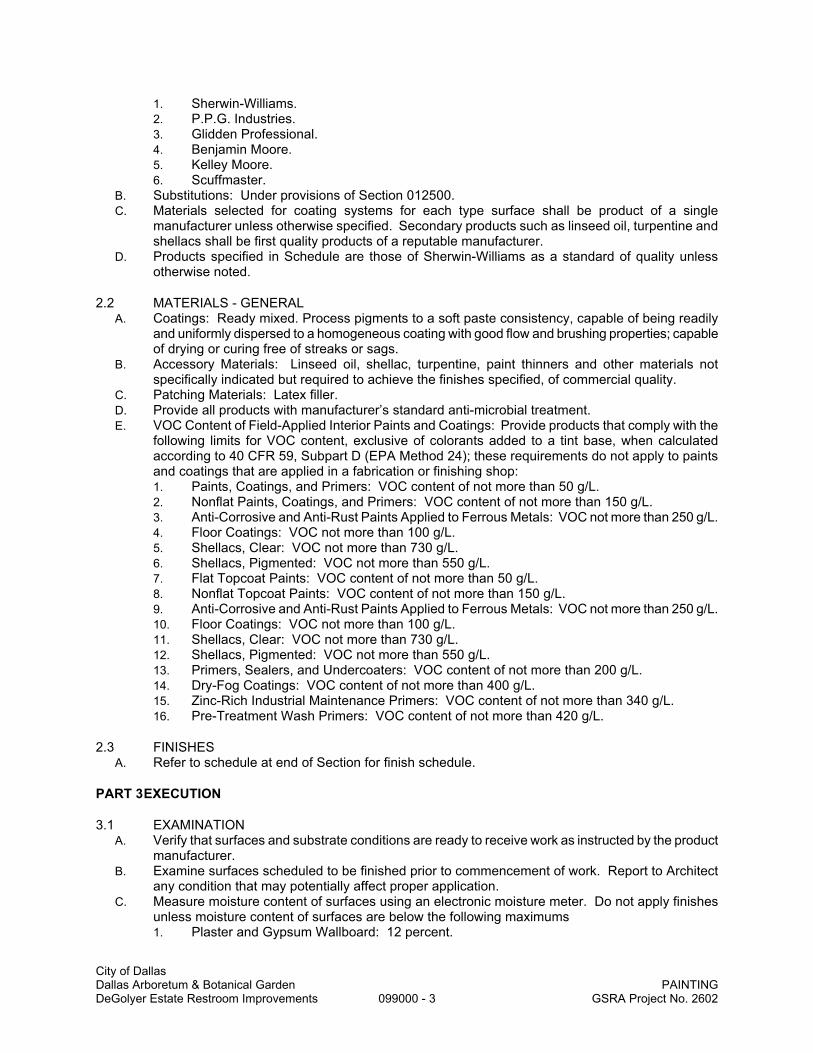
City of Dallas Dallas Arboretum & Botanical Garden PAINTING DeGolyer Estate Restroom Improvements 099000 - 3 GSRA Project No. 2602
1. Sherwin-Williams. 2. P.P.G. Industries. 3. Glidden Professional. 4. Benjamin Moore. 5. Kelley Moore. 6. Scuffmaster.
B. Substitutions: Under provisions of Section 012500. C. Materials selected for coating systems for each type surface shall be product of a single
manufacturer unless otherwise specified. Secondary products such as linseed oil, turpentine and shellacs shall be first quality products of a reputable manufacturer.
D. Products specified in Schedule are those of Sherwin-Williams as a standard of quality unless otherwise noted.
2.2 MATERIALS - GENERAL A. Coatings: Ready mixed. Process pigments to a soft paste consistency, capable of being readily
and uniformly dispersed to a homogeneous coating with good flow and brushing properties; capable of drying or curing free of streaks or sags.
B. Accessory Materials: Linseed oil, shellac, turpentine, paint thinners and other materials not specifically indicated but required to achieve the finishes specified, of commercial quality.
C. Patching Materials: Latex filler. D. Provide all products with manufacturer’s standard anti-microbial treatment. E. VOC Content of Field-Applied Interior Paints and Coatings: Provide products that comply with the
following limits for VOC content, exclusive of colorants added to a tint base, when calculated according to 40 CFR 59, Subpart D (EPA Method 24); these requirements do not apply to paints and coatings that are applied in a fabrication or finishing shop: 1. Paints, Coatings, and Primers: VOC content of not more than 50 g/L. 2. Nonflat Paints, Coatings, and Primers: VOC content of not more than 150 g/L. 3. Anti-Corrosive and Anti-Rust Paints Applied to Ferrous Metals: VOC not more than 250 g/L. 4. Floor Coatings: VOC not more than 100 g/L. 5. Shellacs, Clear: VOC not more than 730 g/L. 6. Shellacs, Pigmented: VOC not more than 550 g/L. 7. Flat Topcoat Paints: VOC content of not more than 50 g/L. 8. Nonflat Topcoat Paints: VOC content of not more than 150 g/L. 9. Anti-Corrosive and Anti-Rust Paints Applied to Ferrous Metals: VOC not more than 250 g/L. 10. Floor Coatings: VOC not more than 100 g/L. 11. Shellacs, Clear: VOC not more than 730 g/L. 12. Shellacs, Pigmented: VOC not more than 550 g/L. 13. Primers, Sealers, and Undercoaters: VOC content of not more than 200 g/L. 14. Dry-Fog Coatings: VOC content of not more than 400 g/L. 15. Zinc-Rich Industrial Maintenance Primers: VOC content of not more than 340 g/L. 16. Pre-Treatment Wash Primers: VOC content of not more than 420 g/L.
2.3 FINISHES A. Refer to schedule at end of Section for finish schedule.
PART 3 EXECUTION
3.1 EXAMINATION A. Verify that surfaces and substrate conditions are ready to receive work as instructed by the product
manufacturer. B. Examine surfaces scheduled to be finished prior to commencement of work. Report to Architect
any condition that may potentially affect proper application. C. Measure moisture content of surfaces using an electronic moisture meter. Do not apply finishes
unless moisture content of surfaces are below the following maximums 1. Plaster and Gypsum Wallboard: 12 percent.

City of Dallas Dallas Arboretum & Botanical Garden PAINTING DeGolyer Estate Restroom Improvements 099000 - 4 GSRA Project No. 2602
2. Masonry, Concrete, and Concrete Unit Masonry: 12 percent. 3. Interior Located Wood: 15 percent, measured in accordance with ASTM D2016. 4. Exterior Located Wood: 15 percent, measured in accordance with ASTM D2016. 5. Concrete Floors: 8 percent.
D. Test shop applied primers for compatibility with subsequent cover materials. E. Beginning of installation means acceptance of existing surfaces and substrate.
3.2 PREPARATION A. Remove electrical plates, hardware, light fixture trim, and fittings prior to preparing surfaces or
finishing. B. Correct minor defects and clean surfaces which affect work of this Section. Remove existing
coatings which exhibit loose surface defects. C. Shellac and seal marks which may bleed through surface finishes. D. Impervious Surfaces: Remove mildew by scrubbing with solution of tri-sodium phosphate and
bleach. Rinse with clean water and allow surface to dry. E. Insulated Coverings: Remove dirt, grease, and oil from canvas and cotton. F. Concrete Floors: Remove contamination, acid etch, and rinse floors with clear water. Verify
required acid- alkali balance is achieved. Allow to dry. G. Gypsum Board Surfaces: Latex fill minor defects. Spot prime defects after repair. H. Galvanized Surfaces: Remove surface contamination and oils and wash with solvent. Apply coat
of etching primer. I. Concrete and Unit Masonry Surfaces Scheduled to Receive Paint Finish: Remove dirt, loose
mortar, scale, salt or alkali powder, and other foreign matter. Remove oil and grease with a solution of tri-sodium phosphate; rinse well and allow to dry. Remove stains caused by weathering of corroding metals with a solution of sodium metasilicate after thoroughly wetting with water. Allow to dry.
J. Plaster Surfaces: Fill hairline cracks, small holes, and imperfections with latex patching plaster. Make smooth and flush with adjacent surfaces. Wash and neutralize high alkali surfaces.
K. Uncoated Steel and Iron Surfaces: Remove grease, scale, dirt, and rust. Where heavy coatings of scale are evident, remove by wire brushing or sandblasting; clean by washing with solvent. Apply a treatment of phosphoric acid solution, ensuring weld joints, bolts, and nuts are similarly cleaned. Spot prime paint after repairs.
L. Shop Primed Steel Surfaces: Sand and scrape to remove loose primer and rust. Feather edges to make touch-up patches inconspicuous. Clean surfaces with solvent. Prime bare steel surfaces.
M. Aluminum with Alodine Finish: Clean by lightly scuff with sandpaper. Remove all dust. N. Interior Wood Items Scheduled to Receive Paint Finish: Wipe off dust and grit prior to priming.
Seal knots, pitch streaks, and sappy sections with sealer. Fill nail holes and cracks after primer has dried; sand between coats.
O. Interior Wood Items Schedule to Receive Transparent Finish: Wipe off dust and grit prior to sealing, seal knots, pitch streaks, and sappy sections with sealer. Fill nail holes and cracks after sealer has dried; sand lightly between coats.
P. Shop Finished Items: Finish in accordance with AWI standards and guide lines. Q. Wood and Metal Doors Scheduled for Painting: Seal top and bottom edges with primer.
3.3 SURFACE PREPARATION OF PREVIOUSLY COATED SURFACES A. General:
1. Remove cracked and deteriorated sealants and calking. 2. Remove chalk deposits and loose, blistered, peeling, scaling, or crazed finish to bare base
material or sound substrate by scraping and sanding. 3. Wash surfaces with solution of TSP to remove wax, oil, grease, and other foreign material;
rinse, and allow to dry. Exercise caution that TSP solution does not soften existing coating. 4. Abrade glossy surfaces by sanding or wiping with liquid de-glosser. 5. Remove mildew as specified above. 6. Test compatibility of existing coatings by applying new coating to small, inconspicuous area.
If new coatings lift or blister existing coatings, request recommendation from Architect.

City of Dallas Dallas Arboretum & Botanical Garden PAINTING DeGolyer Estate Restroom Improvements 099000 - 5 GSRA Project No. 2602
7. Apply specified primer to surfaces scheduled to receive coatings. B. Gypsum Wallboard:
1. Fill cracks and voids with spackling compound. 2. Apply primer over bare surfaces and newly applied texture coatings.
C. Metal: 1. Remove rust from surfaces to bare metal in accordance with SP3 "Power Tool Cleaning". 2. Exercise care not to remove galvanizing. 3. Complete preparation as specified for new work.
D. Wood: 1. Fill cracks, crevices and nail holes with putty or wood filler. 2. Apply primer over bare surfaces and filler material.
3.4 PROTECTION A. Protect elements surrounding the work of this Section from damage or disfiguration. B. Repair damage to other surfaces caused by work of this Section. C. Furnish drop cloths, shields, and protective methods to prevent spray or droppings from disfiguring
other surfaces. D. Remove empty paint containers from site.
3.5 APPLICATION A. The intent of these Specifications is to produce the highest quality appearance of paint and finish
surfaces. Employ skilled mechanics only. The proper preparation of all surfaces will be strictly enforced and wherever finished surfaces show any defects due to improper preparation, workmanship, etc., the defects shall be removed and the work refinished at the expense of the Contractor.
B. Apply products in accordance with manufacturer's instructions. Final finish coats shall have visual evidence of solid hiding and uniform appearance, and shall be free and smooth of brush marks, streaks, sags, runs, laps, or skipped areas.
C. Do not apply finishes to surfaces that are not dry. D. Apply each coat to uniform finish and thickness. E. Apply each coat of paint slightly darker than preceding coat unless otherwise approved. F. Sand lightly between coats on wood and metal items to achieve required finish. G. Allow applied coat to dry before next coat is applied. H. Where clear finishes are required, tint fillers to match wood. Work fillers into the grain before set.
Wipe excess from surface. I. Prime back surfaces of interior and exterior woodwork scheduled to be painted with primer paint. J. Prime back surfaces of interior woodwork scheduled to receive stain or varnish finish with gloss
varnish reduced 25 percent with mineral spirits. K. Edges of paint adjoining other materials or colors shall be sharp and clean with no overlapping.
3.6 FINISHING MECHANICAL AND ELECTRICAL EQUIPMENT A. Paint all shop primed equipment. Paint shop prefinished items where exposed to view in finished
spaces. In mechanical rooms, repair shop pre-finished coatings which have been scratched or otherwise damaged with identical touch-up paint. Sand prior to touching up as required.
B. Remove unfinished louvers, grilles, covers, and access panels on mechanical and electrical components and paint separately.
C. Paint all grilles, registers, diffusers, and speaker grilles to match adjacent wall and ceiling surfaces, except that factory pre-finished items need not be painted if installed in a suspended acoustical ceiling system where the acoustical panels match the mechanical or electrical item color.
D. In all finished spaces, prime and paint exposed pipes, conduit, boxes, ducts, hangers, brackets, collars and supports. Paint to match adjacent surfaces.
E. Repair or replace identification markings on mechanical or electrical equipment when painted accidentally.

City of Dallas Dallas Arboretum & Botanical Garden PAINTING DeGolyer Estate Restroom Improvements 099000 - 6 GSRA Project No. 2602
F. Paint interior surfaces of air ducts and convectors that are visible through grilles and louvers with one coat of flat black paint, to limit of sight line. Paint dampers exposed behind louvers, grilles, and convector to match face panels.
G. Paint all surfaces of plywood backboards for electrical and telephone equipment before installing equipment.
H. Replace electrical plates, hardware, light fixture trim, and fittings removed prior to finishing. I. Paint exposed air handlers, roof ventilators, goose necks, exhaust fans and other items on the roof
with 2 coats exterior enamel. Prepare surfaces in accordance with the base metal or primer as specified herein.
J. Paint concrete support bases with gray floor deck enamel. K. Pipe hangers and other supports need not be painted except where installed in crawl spaces,
where they shall be painted with a thick coat of asphaltic paint.
3.7 CLEANING/TOUCH-UP A. As Work proceeds, promptly remove paint where spilled, splashed, or spattered. B. During progress of Work maintain premises free of unnecessary accumulation of tools, equipment,
surplus materials, and debris. C. Collect cotton waste, cloths, and material which may constitute a fire hazard, place in closed metal
containers and remove daily from site. D. Spot painting will be allowed to correct soiled or damaged paint surfaces only when touch-up spot
will blend into surrounding finish and is invisible to normal viewing (as determined by the Architect). Otherwise, re-coat entire section to corners or visible stopping point.
3.8 V.O.C. (VOLATILE ORGANIC COMPOUND) COMPLIANCE A. Products listed in following schedule and/or substitutes proposed for use by Contractor must be
formulated to meet all applicable ordinances and regulations regarding maximum V.O.C. content. Utilize products which have been specially formulated to need such requirements.
USE HARMONY PAINT LATEX EGGSHELL
3.9 SCHEDULE A. Interior Surfaces - Field Finished
1. Wood - Painted Eggshell a. One coat Sand-N-Go Waterborne Wood Primer, 1.3 mils DFT. b. Two coats Pro-Classic Waterborne Acrylic Semi-gloss, 1.4 mils DFT/coat.
2. Wood - Clear a. Two coats Wood Classics Waterborne Polyurethane Varnish, 1.0 DFT/coat.
3. Wood - Semi-Transparent - Stained a. One coat Minwax Wood Finish. b. Two coats Wood Classics Waterborne Polyurethane Varnish, 1.0 DFT/coat.
4. Gypsum Board - Flat a. One coat texture as approved by Architect. b. One coat Harmony Primer, 1.3 mils DFT. c. Two coats Harmony, Latex Flat, 1.7 mils DFT/coat.
5. Gypsum Board - Eggshell a. One coat texture as approved by Architect. b. One coat Harmony Primer, 1.3 mils DFT. c. Two coats Harmony, Latex Eggshell, 1.4 mils DFT/coat.
6. Gypsum Board - Semi-gloss a. One coat texture as approved by Architect. b. One coat Harmony Primer, 1.3 mils DFT. c. Two coats Harmony, Latex Semigloss, 1.4 mils DFT/coat.
7. Ferrous Metal Items - Eggshell (including hollow metal doors, frames, access doors/frames, handrails, etc): a. One coat Pro-Cryl Universal Water Based Primer, 2-4 mils DFT.

City of Dallas Dallas Arboretum & Botanical Garden PAINTING DeGolyer Estate Restroom Improvements 099000 - 7 GSRA Project No. 2602
b. Two coats Pro-Classic Waterborne Acrylic Semi-Gloss Enamel, 1.4 mils DFT/coat. 8. Miscellaneous Items Exposed to View and Not Otherwise Scheduled: Finish with compatible
paint to match adjacent surface finish and color. B. Exterior Surfaces - Field Finished
1. Ferrous Metal Items: a. Touch up shop primer as required. b. First Coat: Sherwin-Williams, DTM Acrylic B66W1. c. Second Coat: Same as first.
2. Galvanized Metal Items: a. Primer: Sherwin-Williams, Galvite Paint No. B50W3. b. Second Coat: Sherwin-Williams, DTM Acrylic B66W1. c. Third Coat: Same as second.
C. Shop Finishes: Refer to individual sections. D. Colors: Refer to Drawings.
END OF SECTION

City of Dallas Dallas Arboretum & Botanical Garden SIGNAGE DeGolyer Estate Restroom Improvements 101400 - 1 GSRA Project No. 2602
SECTION 101400
SIGNAGE
PART 1 - GENERAL
1.1 SUMMARY A. Related Documents: Provisions established in Conditions of the Contract, Division 01 – General
Requirements, and the Drawings are collectively applicable to this Section. B. Section Includes
1. Identifying devices where shown on the Drawings complete and as specified including the following: a. Directional and traffic signs. b. Interior signs.
2. Coordination for installation of signage.
1.2 RELATED SECTIONS A. Section 012300 – Alternates.
1.3 SUBMITTALS A. Product Data: Include manufacturer’s construction details relative to materials, dimensions of
individual components, profiles, and finishes for each type of sign required. B. Shop Drawings: Provide shop drawings for fabrication and erection of signs. Include plans,
elevations, and large-scale sections of typical members and other components. Show anchors, accessories, layout, and installation details.
C. Samples for Verification: 1. Physical: Submit samples of one competed sign for review and approval. Approved
sample may be incorporated into Project. 2. Color: Submit manufacturer's standard color selection chart. Do not proceed until colors
have been selected.
1.4 QUALITY ASSURANCE A. Single-Source Responsibility: For each separate type of sign required, obtain signs from one
source from a single manufacturer. B. Manufacturer shall have a minimum of five years experience in the manufacturing of signs
specified. C. Codes and Standards:
1. Panel signs shall have 1/32-inch raised copy and grade 2 Braille, and shall comply with all existing federal, state, and local accessibility standards.
2. Code and Standards: Comply with American with Disabilities Act of 1990, Title 3 Provisions, Public Accommodations and Commercial Facilities.
3. Comply with the State of Texas Accessibility Act as administered by the Texas Department of Licensing and Regulation.
PART 2 - PRODUCTS
2.1 MANUFACTURERS A. Acceptable Manufacturers: Subject to compliance with requirements herein, provide products
from one of the following: 1. Takeform, Medina, New York. 2. Best Manufacturing Company, Montrose, Colorado. 3. Mohawk Sign Systems, Schenectady, New York. 4. Nelson-Harkins, Chicago, Illinois. 5. ASI Signs, Dallas, Texas.
B. Substitutions: Under provisions of Section 012500.
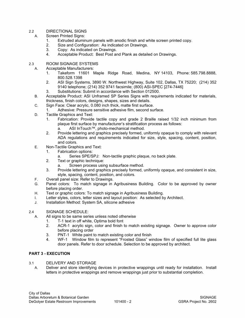
City of Dallas Dallas Arboretum & Botanical Garden SIGNAGE DeGolyer Estate Restroom Improvements 101400 - 2 GSRA Project No. 2602
2.2 DIRECTIONAL SIGNS A. Screen Printed Signs:
1. Extruded aluminum panels with anodic finish and white screen printed copy. 2. Size and Configuration: As indicated on Drawings. 3. Copy: As indicated on Drawings. 4. Acceptable Product: Best Post and Plank as detailed on Drawings.
2.3 ROOM SIGNAGE SYSTEMS A. Acceptable Manufacturers:
1. Takeform 11601 Maple Ridge Road, Medina, NY 14103, Phone: 585.798.8888, 800.528.1398
2. ASI Sign Systems, 3890 W. Northwest Highway, Suite 102, Dallas, TX 75220; (214) 352 9140 telephone; (214) 352 9741 facsimile; (800) ASI-SPEC [274-7446]
3. Substitutions: Submit in accordance with Section 012500. B. Acceptable Product: ASI Unframed SP Series Signs with requirements indicated for materials,
thickness, finish colors, designs, shapes, sizes and details. C. Sign Face: Clear acrylic, 0.080 inch thick, matte first surface.
1. Adhesive: Pressure sensitive adhesive film, second surface. D. Tactile Graphics and Text:
1. Fabrication: Provide tactile copy and grade 2 Braille raised 1/32 inch minimum from plaque first surface by manufacturer’s stratification process as follows: a. ASI InTouch™, photo-mechanical method.
2. Provide lettering and graphics precisely formed, uniformly opaque to comply with relevant ADA regulations and requirements indicated for size, style, spacing, content, position, and colors.
E. Non-Tactile Graphics and Text: 1. Fabrication options:
a. Series SPE/SPJ: Non-tactile graphic plaque, no back plate. 2. Text or graphic technique:
a. Screen process using subsurface method. 3. Provide lettering and graphics precisely formed, uniformly opaque, and consistent in size,
style, spacing, content, position, and colors. F. Overall panel size: Refer to Drawings. G. Panel colors: To match signage in Agribusiness Building. Color to be approved by owner
before placing order. H. Text or graphic colors: To match signage in Agribusiness Building. I. Letter styles, colors, letter sizes and layout position: As selected by Architect. J. Installation Method: System SA, silicone adhesive
2.4 SIGNAGE SCHEDULE: A. All signs to be same series unless noted otherwise
1. T-1 text in off white, Optima bold font 2. ACR-1 acrylic sign, color and finish to match existing signage. Owner to approve color
before placing order 3. PNT-1 White paint to match existing color and finish 4. WF-1 Window film to represent “Frosted Glass” window film of specified full lite glass
door panels. Refer to door schedule. Selection to be approved by architect.
PART 3 - EXECUTION
3.1 DELIVERY AND STORAGE A. Deliver and store identifying devices in protective wrappings until ready for installation. Install
letters in protective wrappings and remove wrappings just prior to substantial completion.

City of Dallas Dallas Arboretum & Botanical Garden SIGNAGE DeGolyer Estate Restroom Improvements 101400 - 3 GSRA Project No. 2602
3.2 INSTALLATION A. Install signs plumb, level and square and in proper planes with other work, at heights required
by accessibility codes and standards. B. Anchor each plastic laminate sign with adhesive. C. Install signs with sufficient amount of foam tape for proper installation. D. Attach as recommended by sign manufacturer. E. Anchor each sign with adhesive. F. Coordinate arrival and installation of graphic signs with hardware installation. Graphic signs
function as and are coordinated with the hardware as shown on the Drawings. G. Room name signs shall be placed on the public side of the door except where noted otherwise. H. Single Door Sign: Provide one sign as specified above, mounted to wall adjacent to door on
knob side. I. Pair of Doors: Provide one sign as specified above, mounted to adjacent wall closest to active
leaf of door. Do not install sign where it will be obstructed by door when door is in the ‘open’ position.
J. Attachment: Mounting to surfaces shall be done by pressure sensitive frame double-faced tape. Signs shall be delivered to the project site with the tape in place and trimmed on each sign, but with the protective paper layer not removed. Paper layer shall be removed just prior to installation of signs.
3.3 COORDINATION A. Coordinate the installation of the identifying devices with the hardware manufacturer for lock set
and knob leave outs as detailed and scheduled.
3.4 DAMAGE A. Any identifying device which is scratched or defaced will be rejected.
3.5 CLEANING A. Remove protective materials and clean all signs. Clean surfaces with plain water or water with
soap or household detergent.
END OF SECTION

City of Dallas Dallas Arboretum & Botanical Garden TOILET COMPARTMENTS DeGolyer Estate Restroom Improvements 102113 - 1 GSRA Project No. 2602
SECTION 102113
TOILET COMPARTMENTS
PART 1 - GENERAL
1.1 RELATED DOCUMENTS A. Drawings and general provisions of the Contract, including General and Supplementary
Conditions and Division 01 Specification Sections, apply to this Section.
1.2 SUMMARY A. Section Includes:
1. Stainless steel toilet compartments configured as toilet enclosures and urinal screens
1.3 SUBMITTALS A. Product Data: For each type of product indicated. Include construction details, material
descriptions, dimensions of individual components and profiles, and finishes. B. Shop Drawings: For toilet compartments. Include plans, elevations, sections, details, and
attachments to other work. 1. Show locations of cutouts for compartment-mounted toilet accessories. 2. Show locations of reinforcements for compartment-mounted grab bars. 3. Show locations of centerlines of toilet fixtures. 4. Show overhead support or bracing locations.
C. Samples for Initial Selection: For each type of unit indicated. Include Samples of hardware and accessories involving material and color selection.
D. Maintenance Data: For toilet compartments to include in maintenance manuals.
1.4 QUALITY ASSURANCE A. Comply with requirements in GSA's CID-A-A-60003, "Partitions, Toilets, Complete." B. Surface-Burning Characteristics: As determined by testing identical products according to
ASTM E 84, or another standard acceptable to authorities having jurisdiction, by a qualified testing agency. Identify products with appropriate markings of applicable testing agency. 1. Flame-Spread Index: 25 or less. 2. Smoke-Developed Index: 450 or less.
C. Regulatory Requirements: Comply with applicable provisions in the U.S. Architectural & Transportation Barriers Compliance Board's "Americans with Disabilities Act (ADA) and Architectural Barriers Act (ABA) Accessibility Guidelines for Buildings and Facilities" for toilet compartments designated as accessible.
1.5 PROJECT CONDITIONS A. Field Measurements: Verify actual locations of toilet fixtures, walls, columns, ceilings, and other
construction contiguous with toilet compartments by field measurements before fabrication.
PART 2 - PRODUCTS
2.1 MATERIALS A. Aluminum Castings: ASTM B 26. B. Aluminum Extrusions: ASTM B 221. C. Steel Sheet: Commercial steel sheet for exposed applications; mill phosphatized and selected
for smoothness. 1. Electrolytically Zinc Coated: ASTM A 879, 01Z. 2. Hot-Dip Galvanized: ASTM A 653, either hot-dip galvanized or galvannealed.
D. Stainless-Steel Sheet: ASTM A 666, Type 304, stretcher-leveled standard of flatness. E. Stainless-Steel Castings: ASTM A 743.

City of Dallas Dallas Arboretum & Botanical Garden TOILET COMPARTMENTS DeGolyer Estate Restroom Improvements 102113 - 2 GSRA Project No. 2602
F. Zamac: ASTM B 86, commercial zinc-alloy die castings.
2.2 STAINLESS STEEL UNITS A. Manufacturers: Subject to compliance with requirements, provide products by one of the
following: 1. Hiney Hiders by Scranton Products: color: see Finish Legend 2. Bradley Corporation; Mills Partitions. 3. Comtec Industries/Capitol Partitions. 4. General Partitions Mfg. Corp. 5. Global Steel Products Corp. 6. Hadrian Manufacturing Inc. 7. Metpar Corp. 8. Santana Products, Inc. 9. Sanymetal; a Crane Plumbing company.
B. Toilet-Enclosure Style: Floor anchored, overhead braced. C. Urinal-Screen Style: Floor anchored, wall hung. D. Door, Panel, and Pilaster Construction: Stainless steel panel material, not less than 1 inch (25
mm) thick, seamless, with eased edges, and with homogenous color and pattern throughout thickness of material. 1. Integral Hinges: Configure doors and pilasters to receive integral hinges. 2. Heat-Sink Strip: Manufacturer's standard continuous, extruded-aluminum or stainless-
steel strip fastened to exposed bottom edges of components to prevent burning. 3. Color and Pattern: Refer to Finish Legend.
E. Pilaster Shoes and Sleeves (Caps): Manufacturer's standard design; stainless steel. F. Brackets (Fittings):
1. Full-Height (Continuous) Type: Manufacturer's standard design.
2.3 ACCESSORIES A. Hardware and Accessories: Manufacturer's standard design, heavy-duty operating hardware
and accessories. 1. Material: Clear-anodized aluminum. 2. Hinges: Manufacturer's standard paired, self-closing type that can be adjusted to hold
doors open at any angle up to 90 degrees. 3. Latch and Keeper: Manufacturer's standard latch unit designed for emergency access
and with combination rubber-faced door strike and keeper. Provide units that comply with regulatory requirements for accessibility at compartments designated as accessible.
4. Coat Hook: Manufacturer's standard combination hook and rubber-tipped bumper, sized to prevent in-swinging door from hitting compartment-mounted accessories.
5. Door Bumper: Manufacturer's standard rubber-tipped bumper at out-swinging doors. 6. Door Pull: Manufacturer's standard unit at out-swinging doors that complies with
regulatory requirements for accessibility. Provide units on both sides of doors at compartments designated as accessible.
B. Anchorages and Fasteners: Manufacturer's standard exposed fasteners of stainless steel or chrome-plated steel or brass, finished to match the items they are securing, with theft-resistant-type heads. Provide sex-type bolts for through-bolt applications. For concealed anchors, use stainless steel, hot-dip galvanized steel, or other rust-resistant, protective-coated steel.
2.4 FABRICATION A. Floor-Anchored Units: Provide manufacturer's standard corrosion-resistant anchoring
assemblies with leveling adjustment nuts at pilasters for structural connection to floor. Provide shoes at pilasters to conceal anchorage.
B. Door Size and Swings: Unless otherwise indicated, provide 24-inch- wide, in-swinging doors for standard toilet compartments and 36-inch- wide, out-swinging doors with a minimum 32-inch- wide, clear opening for compartments designated as accessible.

City of Dallas Dallas Arboretum & Botanical Garden TOILET COMPARTMENTS DeGolyer Estate Restroom Improvements 102113 - 3 GSRA Project No. 2602
PART 3 - EXECUTION
3.1 INSTALLATION A. General: Comply with manufacturer's written installation instructions. Install units rigid, straight,
level, and plumb. Secure units in position with manufacturer's recommended anchoring devices. 1. Maximum Clearances:
a. Pilasters and Panels: 1/2 inch. b. Panels and Walls: 1 inch.
B. Floor-Anchored Units: Set pilasters with anchors penetrating not less than 2 inches into structural floor unless otherwise indicated in manufacturer's written instructions. Level, plumb, and tighten pilasters. Hang doors and adjust so tops of doors are level with tops of pilasters when doors are in closed position.
C. Urinal Screens: Attach with anchoring devices to suit supporting structure. Set units level and plumb, rigid, and secured to resist lateral impact.
3.2 ADJUSTING A. Hardware Adjustment: Adjust and lubricate hardware according to hardware manufacturer's
written instructions for proper operation. Set hinges on in-swinging doors to hold doors open approximately 30 degrees from closed position when unlatched. Set hinges on out-swinging doors to return doors to fully closed position.
END OF SECTION

City of Dallas Dallas Arboretum & Botanical Garden TOILET AND BATH ACCESSORIES DeGolyer Estate Restroom Improvements 102800 - 1 GSRA Project No. 2602
SECTION 102800
TOILET AND BATH ACCESSORIES
PART 1 GENERAL
1.01 SECTION INCLUDES
A. Accessories for toilet rooms and utility rooms.
B. Grab bars.
1.02 RELATED REQUIREMENTS
A. Section 088300 - Mirrors: Other mirrors.
B. Section 102113 - Toilet Compartments.
1.03 REFERENCE STANDARDS
A. ASTM A123/A123M - Standard Specification for Zinc (Hot-Dip Galvanized) Coatings on Iron and Steel Products; 2009.
B. ASTM A269 - Standard Specification for Seamless and Welded Austenitic Stainless Steel Tubing for General Service; 2010.
C. ASTM A653/A653M - Standard Specification for Steel Sheet, Zinc-Coated (Galvanized) or Zinc-Iron Alloy-Coated (Galvannealed) by the Hot-Dip Process; 2010.
D. ASTM A666 - Standard Specification for Annealed or Cold-Worked Austenitic Stainless Steel Sheet, Strip, Plate, and Flat Bar; 2010.
E. ASTM B456 - Standard Specification for Electrodeposited Coatings of Copper Plus Nickel Plus Chromium and Nickel Plus Chromium; 2003 (Reapproved 2009).
F. ASTM C1036 - Standard Specification for Flat Glass; 2006.
G. ASTM C1503 - Standard Specification for Silvered Flat Glass Mirror; 2008.
H. ASTM F2285 - Standard Consumer Safety Performance Specification for Diaper Changing Tables for Commercial Use; 2004 (Reapproved 2010).
I. GSA CID A-A-3002 - Mirrors, Glass; U.S. General Services Administration; 1996.
1.04 SUBMITTALS
A. Procedures for Submittals: Section 013300.
B. Product Data: Provide data on accessories describing size, finish, details of function, attachment methods.
C. Manufacturer's Installation Instructions: Indicate special procedures and conditions requiring special attention.
1.05 QUALITY ASSURANCE:
A. Regulatory Requirements: 1. State of Texas: Texas Accessibility Standard (TAS) of the Architectural Barriers Act,
Article 9102, Texas Civil Statues, April 1, 1994. 2. Federal: American with Disabilities Act of 1990, Title 3 Provisions, Public Accommodations
and Commercial Facilities.

City of Dallas Dallas Arboretum & Botanical Garden TOILET AND BATH ACCESSORIES DeGolyer Estate Restroom Improvements 102800 - 2 GSRA Project No. 2602
PART 2 PRODUCTS
2.01 MANUFACTURERS
A. Model numbers included for toilet accessories are items manufactured by Bobrick Washroom Equipment, Inc., unless otherwise indicated, and are listed as a standard of quality.
B. Other Acceptable Manufacturers: 1. American Specialties, Inc: www.americanspecialties.com. 2. Bradley Corporation: www.bradleycorp.com. 3. Bobrick Washroom Equipment, Inc. 4. Substitutions: Section 012500.
C. All items of each type to be made by the same manufacturer.
2.02 MATERIALS
A. Accessories - General: Shop assembled, free of dents and scratches and packaged complete with anchors and fittings, steel anchor plates, adapters, and anchor components for installation. 1. Grind welded joints smooth. 2. Fabricate units made of metal sheet of seamless sheets, with flat surfaces.
B. Keys: Provide 2 keys for each accessory to Owner; master key all lockable accessories.
C. Stainless Steel Sheet: ASTM A666, Type 304.
D. Stainless Steel Tubing: ASTM A269, Type 304 or 316.
E. Galvanized Sheet Steel: Hot-dipped galvanized steel sheet, ASTM A653/A653M, with G90/Z275 coating.
F. Mirror Glass: Float glass, ASTM C1036 Type I, Class 1, Quality Q2, with silvering, protective and physical characteristics complying with ASTM C1503.
G. Fasteners, Screws, and Bolts: Hot dip galvanized, tamper-proof, security type.
H. Expansion Shields: Fiber, lead, or rubber as recommended by accessory manufacturer for component and substrate.
2.03 FINISHES
A. Stainless Steel: No. 4 satin brushed finish, unless otherwise noted.
B. Chrome/Nickel Plating: ASTM B456, SC 2, satin finish, unless otherwise noted.
C. Galvanizing for Items Other than Sheet: Comply with ASTM A123/A123M; galvanize ferrous metal and fastening devices.
D. Shop Primed Ferrous Metals: Pretreat and clean, spray apply one coat primer and bake.
E. Back paint components where contact is made with building finishes to prevent electrolysis.
2.04 TOILET ROOM ACCESSORIES
A. Toilet Paper Dispenser (Public Toilets): Roll-in-reserve type, designed to allow automatic activation of reserve roll when needed, or manual activation by pressing release bar, surface-mounted, unit with pivot hinge, tumbler lock. 1. Product: Model Georgia Pacific Compact Double Roll Dispenser.
B. Paper Towel Dispenser: Rolled paper type, automated, plastic, surface-mounted, piano-hinged door, with viewing slots on sides as refill indicator and tumbler lock.
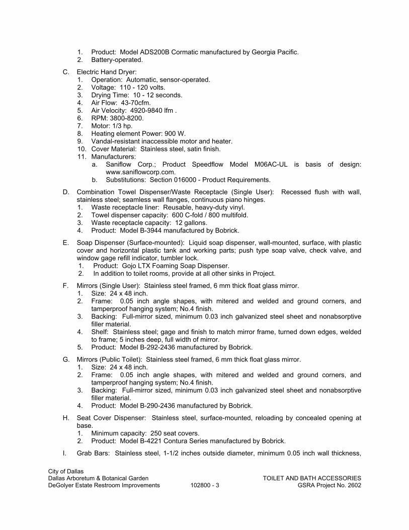
City of Dallas Dallas Arboretum & Botanical Garden TOILET AND BATH ACCESSORIES DeGolyer Estate Restroom Improvements 102800 - 3 GSRA Project No. 2602
1. Product: Model ADS200B Cormatic manufactured by Georgia Pacific. 2. Battery-operated.
C. Electric Hand Dryer: 1. Operation: Automatic, sensor-operated. 2. Voltage: 110 - 120 volts. 3. Drying Time: 10 - 12 seconds. 4. Air Flow: 43-70cfm. 5. Air Velocity: 4920-9840 lfm . 6. RPM: 3800-8200. 7. Motor: 1/3 hp. 8. Heating element Power: 900 W. 9. Vandal-resistant inaccessible motor and heater. 10. Cover Material: Stainless steel, satin finish. 11. Manufacturers:
a. Saniflow Corp.; Product Speedflow Model M06AC-UL is basis of design: www.saniflowcorp.com.
b. Substitutions: Section 016000 - Product Requirements.
D. Combination Towel Dispenser/Waste Receptacle (Single User): Recessed flush with wall, stainless steel; seamless wall flanges, continuous piano hinges. 1. Waste receptacle liner: Reusable, heavy-duty vinyl. 2. Towel dispenser capacity: 600 C-fold / 800 multifold. 3. Waste receptacle capacity: 12 gallons. 4. Product: Model B-3944 manufactured by Bobrick.
E. Soap Dispenser (Surface-mounted): Liquid soap dispenser, wall-mounted, surface, with plastic cover and horizontal plastic tank and working parts; push type soap valve, check valve, and window gage refill indicator, tumbler lock. 1. Product: Gojo LTX Foaming Soap Dispenser. 2. In addition to toilet rooms, provide at all other sinks in Project.
F. Mirrors (Single User): Stainless steel framed, 6 mm thick float glass mirror. 1. Size: 24 x 48 inch. 2. Frame: 0.05 inch angle shapes, with mitered and welded and ground corners, and
tamperproof hanging system; No.4 finish. 3. Backing: Full-mirror sized, minimum 0.03 inch galvanized steel sheet and nonabsorptive
filler material. 4. Shelf: Stainless steel; gage and finish to match mirror frame, turned down edges, welded
to frame; 5 inches deep, full width of mirror. 5. Product: Model B-292-2436 manufactured by Bobrick.
G. Mirrors (Public Toilet): Stainless steel framed, 6 mm thick float glass mirror. 1. Size: 24 x 48 inch. 2. Frame: 0.05 inch angle shapes, with mitered and welded and ground corners, and
tamperproof hanging system; No.4 finish. 3. Backing: Full-mirror sized, minimum 0.03 inch galvanized steel sheet and nonabsorptive
filler material. 4. Product: Model B-290-2436 manufactured by Bobrick.
H. Seat Cover Dispenser: Stainless steel, surface-mounted, reloading by concealed opening at base. 1. Minimum capacity: 250 seat covers. 2. Product: Model B-4221 Contura Series manufactured by Bobrick.
I. Grab Bars: Stainless steel, 1-1/2 inches outside diameter, minimum 0.05 inch wall thickness,

City of Dallas Dallas Arboretum & Botanical Garden TOILET AND BATH ACCESSORIES DeGolyer Estate Restroom Improvements 102800 - 4 GSRA Project No. 2602
nonslip grasping surface finish, concealed flange mounting; 1-1/2 inches clearance between wall and inside of grab bar. Peened finish. 1. Length: 36 and 42 inches. 2. Product: Models B-6806.99 x 36 and B-6806.99 x 42 manufactured by Bobrick.
J. Sanitary Napkin Disposal Unit (Single User): Stainless steel, surface-mounted, self-closing door, locking bottom panel with full-length stainless steel piano-type hinge, removable receptacle. 1. Product: Model B-270 Contura Series manufactured by Bobrick.
K. Sanitary Napkin Disposal Unit (Public Toilets): White enamel metal, back-to-back partition mounting with adjustable flanges, self-closing door, locking bottom panel with full-length stainless steel piano-type hinge, removable receptacle. 1. Product: Model 25033000RMC manufactured by Rochester Midland Corp.
L. Hat and Coat Hook: Satin stainless steel, 1 x 6-1/2 inch hook, concealed flange mounting. 1. Product: model B-6827 by Bobrick.
2.05 UNDERLAVATORY GUARDS
A. Location: Any locations where underlavatory piping is exposed. B. Manufacturers: Subject to compliance with requirements, available manufacturers offering
products that may be incorporated into the Work include, but are not limited to, the following: C. Basis-of-Design Product: Subject to compliance with requirements, provide product indicated
on Drawings or comparable product by one of the following: 1. Plumberex Specialty Products, Inc. 2. Truebro by IPS Corporation.
D. Underlavatory Guard: 1. Description: Insulating pipe covering for supply and drain piping assemblies that prevent
direct contact with and burns from piping; allow service access without removing coverings.
2. Material and Finish: Anti-microbial, molded plastic, white.
2.06 UTILITY ROOM ACCESSORIES
A. Combination Utility Shelf/Mop and Broom Holder: 0.05 inch thick stainless steel, Type 304, with 1/2 inch returned edges, 0.06 inch steel wall brackets. 1. Hooks: 4, 0.06 inch stainless steel rag hooks at shelf front. 2. Mop/broom holders: 3 spring-loaded rubber cam holders at shelf front. 3. Length: 34 inches. 4. Product: Model B-239 manufactured by Bobrick.
PART 3 EXECUTION
3.01 INSTALLATION
A. Install accessories in accordance with manufacturers' instructions.
B. Mounting Heights and Locations: As required by accessibility regulations and as indicated on Drawings.
END OF SECTION

City of Dallas Dallas Arboretum & Botanical Garden FIRE PROTECTION SPECIALTIES DeGolyer Estate Restroom Improvements 104400 - 1 GSRA Project No. 2602
SECTION 104400
FIRE PROTECTION SPECIALTIES
PART 1 GENERAL
1.01 SECTION INCLUDES
A. Fire extinguishers.
B. Fire extinguisher cabinets.
C. Accessories.
1.02 REFERENCE STANDARDS
A. NFPA 10 - Standard for Portable Fire Extinguishers; 2013.
B. UL (FPED) - Fire Protection Equipment Directory; Underwriters Laboratories Inc.; current edition.
1.03 SUBMITTALS
A. See Division 1 sections for submittal procedures.
B. Shop Drawings: Indicate cabinet physical dimensions, rough-in measurements for recessed cabinets, and location.
C. Product Data: Provide extinguisher operational features, color and finish, and anchorage details.
D. Manufacturer's Installation Instructions: Indicate special criteria and wall opening coordination requirements.
E. Manufacturer's Certificate: Certify that products meet or exceed specified requirements.
F. Maintenance Data: Include test, refill or recharge schedules and re-certification requirements.
1.04 FIELD CONDITIONS
A. Do not install extinguishers when ambient temperature may cause freezing of extinguisher ingredients.
PART 2 PRODUCTS
2.01 MANUFACTURERS
A. Fire Extinguishers:
1. Ansul, a Tyco Business: www.ansul.com.
2. Nystrom, Inc: www.nystrom.com.
3. Pyro-Chem, a Tyco Business: www.pyrochem.com.
4. Strike First Corporation of America: www.strikefirstusa.com.
5. Substitutions: See Section 016000 - Product Requirements.
B. Fire Extinguisher Cabinets and Accessories:
1. Ansul, a Tyco Business: www.ansul.com.
2. JL Industries, Inc: www.jlindustries.com.
3. Larsen's Manufacturing Co: www.larsensmfg.com.
4. Potter-Roemer: www.potterroemer.com.
5. Pyro-Chem, a Tyco Business: www.pyrochem.com.
6. Substitutions: See Section 016000 - Product Requirements.

City of Dallas Dallas Arboretum & Botanical Garden FIRE PROTECTION SPECIALTIES DeGolyer Estate Restroom Improvements 104400 - 2 GSRA Project No. 2602
2.02 FIRE EXTINGUISHERS
A. Fire Extinguishers - General: Comply with product requirements of NFPA 10 and applicable codes, whichever is more stringent.
1. Provide extinguishers labeled by UL for the purpose specified and indicated.
B. Dry Chemical Type Fire Extinguishers: Carbon steel tank with pressure gage.
1. Class: A:B:C.
2. Size: 10 pound.
3. Finish: Baked polyester powder coat; color selected by Architect.
2.03 FIRE EXTINGUISHER CABINETS
A. Metal: Formed steel sheet; 0.036 inch thick base metal.
B. Cabinet Configuration: Semi-Recessed type.
1. Sized to accommodate accessories.
2. Form cabinet enclosure with right angle inside corners and seams. Form perimeter trim and door stiles.
3. Acceptable Product: Vertical Duo, manufactured by Larsen’s Manufacturing.
a. Semi Recessed.
b. Stainless Steel.
c. Glazing: Laminated safety glass.
4. Substitutions: See Section 016000 - Product Requirements.
C. Door: Reinforced for flatness and rigidity; latch. Hinge doors for 180 degree opening with two butt hinge. Provide nylon catch.
D. Cabinet Mounting Hardware: Appropriate to cabinet. Pre-drill for anchors.
E. Weld, fill, and grind components smooth.
F. Finish of Cabinet Exterior Trim and Door: Stainless Steel.
G. Finish of Cabinet Interior: Stainless Steel.
PART 3 EXECUTION
3.01 EXAMINATION
A. Verify existing conditions before starting work.
B. Verify rough openings for cabinet are correctly sized and located.
3.02 INSTALLATION
A. Install in accordance with manufacturer's instructions.
B. Install cabinets plumb and level in wall openings.
C. Secure rigidly in place.
D. Place extinguishers and accessories in cabinets.
END OF SECTION

City of Dallas Dallas Arboretum & Botanical Garden ALUMINUM COUNTER SUPPORT BRACKETS DeGolyer Estate Restroom Improvements 105910 - 1 GSRA Project No. 2602
SECTION 105910
ALUMINUM COUNTER SUPPORT BRACKETS
PART 1 - GENERAL
1.01 SECTION INCLUDES
A. Wall mounted, heavy duty, welded aluminum brackets for supporting counter tops.
1.02 RELATED SECTIONS:
A. Section 064023 – Interior Architectural Woodwork: Fabrication of countertops to be supported by welded aluminum brackets.
B. Section 092216 – Non-Structural Metal Framing: Stud partitions for support and anchorage of support brackets.
1.03 REFERENCES
A. American Architectural Manufacturers Association (AAMA): 1. AAMA 607.1 - Voluntary Guide Specification and Inspection Methods for Clear Anodic
Finishes for Architectural Aluminum.
B. American Society for Testing and Materials: ASTM B221 - Aluminum-Alloy Extruded Bar, Rod, Wire, Shape, and Tube.
1.04 SUBMITTALS
A. Procedures for Submittals: Section 013300. 1. Product Data: Product data for each type of support brackets. 2. Shop Drawings: Indicate dimensions and installation details. 3. Installation instructions.
1.05 QUALITY ASSURANCE
A. Manufacturer qualifications: Firm specializing in designing, patenting, and fabricating unique aluminum storage systems, support brackets, handrails, and other architectural specialties with 10 years minimum successful experience.
PART 2 - PRODUCTS
2.01 MANUFACTURERS
A. Rangine Corporation, 330 Reservoir Street, Needham, Massachusetts 02494; 800-826-6006; www.rakks.com.
B. Substitutions: Section 012500.
2.02 MATERIALS
A. Material: Fabricate components from extruded aluminum sections complying with ASTM B221, 6063-T5 alloy and temper.
B. Factory applied finishes: Exposed aluminum surfaces shall be free of scratches and other serious blemishes and be factory finished with clear anodized coating complying with AAMA 607.1 - MM10C22A31.
2.03 WELDED ALUMINUM BRACKETS

City of Dallas Dallas Arboretum & Botanical Garden ALUMINUM COUNTER SUPPORT BRACKETS DeGolyer Estate Restroom Improvements 105910 - 2 GSRA Project No. 2602
A. Type: Support brackets fabricated by welding miter cut extruded aluminum sections, grinding and deburring sharp edges and welds, drilling holes for field attachment, and factory finishing.
B. Flush mounted counter brackets: Unless noted otherwise in Drawings, bracket for 24 inches wide counter or shelf; Model No. EH-1818-FM as maufactured by Rangine Corporation. 1. Construction: Fabricated from horizontal aluminum T section and vertical aluminum L
section. Vertical leg designed to attach to side of supporting stud and be concealed by gypsum board or other wall finish.
2. Size (height by depth): 18 x 20 inches. 3. Load capacity per bracket: 300 pounds. 4. Faceplates: Provide 4 by 4 inches aluminum faceplates with adhesive backing and
notched to fit around vertical flange of flush mounted counter support bracket and conceal penetration through gypsum board providing neat, finished appearance.
PART 3 - EXECUTION
3.01 COORDINATION
A. Coordinate requirements for stud spacing, blocking, and auxiliary structural supports to ensure adequate means for installation and anchorage of support brackets.
B. Coordinate installation of flush mounted support brackets with application of gypsum board finish specified in Section 092216. Ensure that brackets are delivered to site and installed in a timely manner to allow for vertical bracket leg to be concealed by gypsum board.
C. After gypsum board has been applied to stud framing, install adhesive backed aluminum face plates around flush mounted brackets penetrating gypsum board.
3.02 INSTALLATION
A. Install support brackets in accordance with reviewed shop drawings and manufacturer's installation instructions.
B. Install brackets at locations and heights indicated on Drawings, and where required by manufacturer recommendations. Verify locations in field with Architect.
C. Install brackets rigidly to blocking, metal studs or other supporting substrate so that they are securely fastened, plumb, and aligned.
D. Install with fasteners of type, size, and quantity as supplied or recommended by bracket manufacturer for type of application and substrate.
END OF SECTION

City of Dallas Dallas Arboretum & Botanical Garden ENGINEERED SURFACINGS DeGolyer Estate Restroom Improvements 123662 - 1 GSRA Project No. 2602
SECTION 123662
ENGINEERED SURFACINGS
PART 1 - GENERAL
1.1 RELATED DOCUMENTS A. Drawings and general provisions of the Contract, including General and Supplementary
Conditions and Division 01 Specification Sections, apply to this Section.
1.2 SUMMARY A. Drawing Designation: SS B. This Section includes solid surfacing for the following:
1. Counter tops. 2. Threshold
1.3 ACTION SUBMITTALS A. Product Data: For each type of product indicated. B. Shop Drawings: Show thickness, finish, layout, and anchorage details. Indicate attachment
methods, seams, joint treatments, and supports. 1. Show locations and sizes of cutouts and holes for plumbing fixtures, faucets, soap
dispensers, and other items installed in countertops for architectural woodwork 2. Show seam locations. 3. Full-size details, edge details, attachments, etc 4. Locations and sizes of furring, blocking, including concealed blocking and reinforcement
specified in other Sections C. Samples for Verification: For the following:
1. Solid stone surfacing materials, 6 inches square. 2. Cut sample and seam together for representation of seaming techniques. 3. Indicate full range of color and pattern variation.
1.4 INFORMATIONAL SUBMITTALS A. Sustainable Submittals:
1. Manufacturer’s product data for installation adhesives, including printed statement of VOC content and material safety data sheets.
2. Product data indicating that materials are regionally manufactured and within 500 miles of the project site.
1.5 CLOSEOUT SUBMITTALS A. Maintenance Data: Submit manufacturer’s recommended cleaning and maintenance
procedures.
1.6 QUALITY ASSURANCE A. Fabricator Qualifications: Company specializing in fabricating engineered stone surfacing
material with minimum 5 years experience. B. Fire-Test-Response Characteristics: Provide surfacing material with the following surface-
burning characteristics (if required by code) as determined by testing identical products per ASTM E 84 by UL or another testing and inspecting agency acceptable to authorities having jurisdiction: 1. Class I per ASTM E-84 including:
a. Flame Spread: 25 or less.
1.7 PROJECT CONDITIONS A. Field Measurements: Where surfacing is indicated to fit to other construction, verify dimensions
of other construction by field measurements before fabrication and indicate measurements on

City of Dallas Dallas Arboretum & Botanical Garden ENGINEERED SURFACINGS DeGolyer Estate Restroom Improvements 123662 - 2 GSRA Project No. 2602
Shop Drawings. Coordinate fabrication schedule with construction progress to avoid delaying the Work.
1.8 WARRANTY A. Manufacturer’s 10 year warranty against defects in materials. Warranty shall provide material
and labor to repair or replace defective materials. Damage caused by physical or chemical abuse or damage from excessive heat will not be warranted.
PART 2 - PRODUCTS
2.1 SOLID SURFACING A. Acceptable Manufacturers and Products: Subject to compliance with requirements, provide one
of the following products: 1. Dupont, Corian. 2. Formica Corporation, Formica Solid Surfacing. 3. Wilsonart International, Wilsonart Solid Surface. 4. LG Decorative Surfaces.
B. Basis of Design: Refer to Finish Schedule.
2.2 MATERIALS A. Solid Surfacing: Nonporous surfacing material composed of a unique blend of natural minerals
and high-performance acrylic meeting the following criteria: 1. Wear and Cleanability: Passes per ASI Z124.3. 2. Abrasion Resistance: No loss of pattern per NEMA LD3-3.01 and ANSI Z 124.3; weight
loss, 1,000 cycles, 0.2 gm; wear, 10,000 cycles, 0.008 inches. 3. Boiling Water Surface Resistance: No change per NEMA LD3-3.05. 4. High Temperature Resistance: No change per NEMA LD3-3.06. 5. Conductive Heat Resistance: No change per NEMA LD3-3.08. 6. Impact Resistance, Notched Izod: 0.28 ft-lbs/in of notch per ASTM D 256, Method A. 7. Impact Resistance, Ball Drop: 3/4 inch thick sheet, 36 inches with 1/2 pound ball, no
failure per NEMA LD3-3.03. 8. Stain Resistance: Passes, Rating-41, modified with additional stains used, per ANSI
Z124.3. 9. Weatherability: No change, 1000 hours, per ASTM D 1499. 10. Fungi and Bacteria: No attack per ASTM G 21, G 22. 11. Water Absorption: 3/4 inch sheet, 0.04 percent after 24 hours, 0.94 percent long term,
per ASTM D 570. 12. Flammability: Solid colors per ASTM E 84.
a. Flame Spread: Less than 5. b. Smoke Developed: Less than 15. c. Class Rating: 1.
13. Thickness: 1/2 inch (12 mm), unless noted or scheduled otherwise. 14. Colors and Sheen: Refer to Finish Schedule.
2.3 THRESHOLDS A. General: Fabricate to sizes and profiles indicated or required to provide transition between
adjacent floor finishes. 1. Bevel edges at 1:2 slope, with lower edge of bevel aligned with or up to 1/16 inch 1.5 mm
above adjacent floor surface. Finish bevel to match top surface of threshold. Limit height of threshold to 1/2 inch 12.7 mm or less above adjacent floor surface.
B. Thresholds: Minimum abrasion resistance of 10 per ASTM C 1353 or ASTM C 241 and with honed finish. 1. Acceptable Product: Solid Surfacing Threshold to match lavatory tops in room. 2. Color: As selected by Architect from manufacturer’s full available range. 3. Size: 2 inch, double bevel, thickness to match height of adjacent flooring material.

City of Dallas Dallas Arboretum & Botanical Garden ENGINEERED SURFACINGS DeGolyer Estate Restroom Improvements 123662 - 3 GSRA Project No. 2602
2.4 MISCELLANEOUS MATERIALS A. Adhesives and Cements: Non-staining, type as recommended by engineered stone
manufacturer. 1. Waterproof, permanent material which will not induce mildew and fungus growth.
B. Joint Sealants: Two part color matched polyester knife grade adhesive. C. Special Features: Provide edge treatments as detailed in Drawings.
2.5 FABRICATION A. Assemble work at shop and deliver to job ready for installation. Manufacture in largest practical
lengths with seams in least conspicuous locations. B. Fabricate work square and to required lines. C. Recess and conceal fasteners, connections, and reinforcing. D. Design construction and installation details to allow for expansion and contraction of materials.
Properly frame material with tight, hairline joints held rigidly in place. E. Comply with adhesive manufacturer's recommendations for adhesive shelf life, pot life, working
life, mixing, spreading, assembly time, time under pressure and ambient temperatures. F. Fabricate countertops with backsplash and side splashes to profiles indicated or detailed. G. Fabricate items to profiles shown with connections and supports as detailed or as required for
proper installation per manufacturer's recommendations. H. Provide cut-outs for plumbing fixtures and trim, washroom accessories, appliances, and related
items. Confirm layout with manufacturer's cut-outs templates before beginning work. Round corners of cut-outs and sand edges smooth.
I. Do not exceed manufacturer's recommended unsupported overhang distances. J. Finish exposed surfaces smooth and polish to a sheen indicated. K. Radius corners and edges. L. Special Features: Provide edge treatments, integral color feature strips, special inserts, and
other detailed features as shown in Drawings.
PART 3 - EXECUTION
3.1 INSTALLATION A. Install in accordance with manufacturer's printed instructions and approved shop drawings.
Provide templates and rough-in measurements. B. Install surfacing true in line and plane, level, rigid and solidly adhered to substrate. C. Prefit items: Adjust supports to make fit. Align joints over support framing.
1. Provide intermediate supports to that material will not span more than 3 feet in any direction.
2. Cantilevers shall not exceed 12 inches without supplementary support. D. Apply dabs of mastic on supports; place items on supports and attach. E. Install with minimum number of joints practical, using full-length pieces from maximum lengths
available. Cope at returns and square at corners to produce tight-fitting joints with full-surface contact throughout length of joint. Radius cutouts with minimum 3/8 inch corner radius.
F. Install splashes using adhesive. Apply adhesive to back surface only. Place thin bead of seam adhesive along edge where splashes seat.
3.2 TOLERANCES A. Variation in Component Size: Plus or minus 1/8 inch over 10’-0” length. B. Location of Openings: Plus or minus 1/8 inch from indicated location. C. Install countertops level to within 1/8 inch in 10 feet. D. Allow minimum 1/16 inch clearance between edges of countertops and adjacent walls. E. Maximum Offset From True Position: 1/8 inch.
3.3 CLEANING A. Clean work under provisions of Uniform General Conditions. B. Clean and polish fabrications in accordance with manufacturer's instructions.
END OF SECTION

City of Dallas Dallas Arboretum & Botanical Garden COMMON WORK RESULTS FOR PLUMBING DeGolyer Estate Restroom Improvements 220500 - 1 GSRA Project No. 2602
SECTION 220500
COMMON WORK RESULTS FOR PLUMBING
PART 1 - GENERAL
1.1 SECTION REQUIREMENTS
A. Submittals: Product Data.
PART 2 - PRODUCTS
2.1 SLEEVES
A. Mechanical Sleeve Seals: Modular rubber sealing element unit, designed for field assembly, to fill annular space between pipe and sleeve.
B. Galvanized-Steel Sheet: 0.0239-inchminimum thickness; round tube closed with welded longitudinal joint.
C. Steel Pipe: ASTM A 53, Type E, Grade B, Schedule 40, galvanized, plain ends.
D. PVC Pipe: ASTM D 1785, Schedule 40.
2.2 GROUT
A. Description: ASTM C 1107, Grade B, nonshrink and nonmetallic, dry hydraulic-cement grout.
2.3 MOTORS
A. Motor Characteristics: 1. Motors 1/2 HP and Larger: Three phase. 2. Motors Smaller Than 3/4 HP: Single phase. 3. Frequency Rating: 60 Hz. 4. Voltage Rating: NEMA standard voltage for circuit voltage to which motor is connected. 5. Service Factor: 1.15 for open dripproof motors; 1.0 for totally enclosed motors. 6. Duty: Continuous duty at ambient temperature of 105 deg F and at altitude of 3300 feet
above sea level. 7. Capacity and Torque Characteristics: Sufficient to start, accelerate, and operate
connected loads at designated speeds, at installed altitude and environment, with indicated operating sequence, and without exceeding nameplate ratings or considering service factor.
8. Enclosure: Unless otherwise indicated, open dripproof. 9. Motors Used with Variable-Frequency Controllers: Ratings, characteristics, and features
coordinated with and approved by controller manufacturer.
2.4 HANGERS AND SUPPORTS
A. Hanger and Pipe Attachments: Factory fabricated with galvanized coatings; nonmetallic coated for hangers in direct contact with copper tubing.
B. Mechanical-Expansion Anchors: Insert-wedge-type, zinc-coated steel, with pull-out and shear capacities appropriate for supported loads and building materials where used.

City of Dallas Dallas Arboretum & Botanical Garden COMMON WORK RESULTS FOR PLUMBING DeGolyer Estate Restroom Improvements 220500 - 2 GSRA Project No. 2602
2.5 PRESSURE GAGES AND TEST PLUGS
A. Pressure Gages: Direct-mounting, indicating-dial type complying with ASME B40.100. Dry metal case, minimum 2-1/2-inch diameter with red pointer on white face, and plastic window. Minimum accuracy 3 percent of middle half of range. Range two times operating pressure.
B. Test Plug: Corrosion-resistant brass or stainless-steel body with two self-sealing rubber core inserts and gasketed and threaded cap, with extended stem for units to be installed in insulated piping. Minimum pressure and temperature rating 500 psig at 200 deg F
PART 3 - EXECUTION
3.1 MOTOR INSTALLATION
A. Anchor motor assembly to base, adjustable rails, or other support, arranged and sized according to manufacturer's written instructions.
3.2 GENERAL PIPING INSTALLATIONS
A. Install piping free of sags and bends.
B. Install fittings for changes in direction and branch connections.
C. Install sleeves for pipes passing through concrete and masonry walls, gypsum board partitions, and concrete floor and roof slabs.
D. Exterior Wall, Pipe Penetrations: Mechanical sleeve seals installed in steel or cast-iron pipes for wall sleeves.
E. Comply with requirements in Division 07 Section "Penetration Firestopping" for sealing pipe penetrations in fire-rated construction.
F. Install unions at final connection to each piece of equipment.
G. Install dielectric unions and flanges to connect piping materials of dissimilar metals in gas piping.
H. Install dielectric coupling and nipple fittings to connect piping materials of dissimilar metals in water piping.
3.3 GENERAL EQUIPMENT INSTALLATIONS
A. Install equipment to allow maximum possible headroom unless specific mounting heights are not indicated.
B. Install equipment level and plumb, parallel and perpendicular to other building systems and components, unless otherwise indicated.
C. Install mechanical equipment to facilitate service, maintenance, and repair or replacement of components. Connect equipment for ease of disconnecting, with minimum interference to other installations. Extend grease fittings to accessible locations.
D. Install equipment to allow right of way for piping installed at required slope.

City of Dallas Dallas Arboretum & Botanical Garden COMMON WORK RESULTS FOR PLUMBING DeGolyer Estate Restroom Improvements 220500 - 3 GSRA Project No. 2602
3.4 BASES, SUPPORTS, AND ANCHORAGES
A. Anchor equipment to concrete base according to equipment manufacturer's written instructions and according to seismic codes at Project. 1. Construct concrete bases of dimensions indicated, but not less than 4 inches larger in
both directions than supported unit. 2. Install dowel rods on 18-inchcenters around the full perimeter of the base to connect
concrete base to concrete floor. 3. Install epoxy-coated anchor bolts for supported equipment that extend through concrete
base, and anchor into structural concrete floor. 4. Place and secure anchorage devices. Use supported equipment manufacturer's setting
drawings, templates, diagrams, instructions, and directions furnished with items to be embedded.
5. Use 3000-psi, 28-day compressive-strength concrete and reinforcement as specified in Division 03 Section "Cast-in-Place Concrete"
B. Mix and install grout for fire-suppression equipment base bearing surfaces, pump and other equipment base plates, and anchors. Place grout, completely filling equipment bases.
3.5 HANGERS AND SUPPORTS
A. Comply with MSS SP-69 and MSS SP-89. Install building attachments within concrete or to structural steel.
B. Install hangers and supports to allow controlled thermal movement of piping systems.
C. Load Distribution: Install hangers and supports so piping live and dead loading and stresses from movement will not be transmitted to connected equipment.
D. Horizontal-Piping Hangers and Supports: Unless otherwise indicated and except as specified in piping system Specification Sections, install the following types: 1. Adjustable Steel Clevis Hangers (MSS Type 1): For suspension of noninsulated or
insulated stationary pipes, NPS 1/2 to NPS 30. 2. Pipe Hangers (MSS Type 5): For suspension of pipes, NPS 1/2 to NPS 4, to allow off-
center closure for hanger installation before pipe erection. 3. Adjustable Steel Band Hangers (MSS Type 7): For suspension of noninsulated
stationary pipes, NPS 1/2 to NPS 8. 4. Adjustable Band Hangers (MSS Type 9): For suspension of noninsulated stationary
pipes, NPS 1/2 to NPS 8. 5. Adjustable Swivel-Ring Band Hangers (MSS Type 10): For suspension of noninsulated
stationary pipes, NPS 1/2 to NPS 2.
E. Vertical-Piping Clamps: Unless otherwise indicated and except as specified in piping system Specification Sections, install the following types: 1. Extension Pipe or Riser Clamps (MSS Type 8): For support of pipe risers, NPS 3/4 to
NPS 20. 2. Carbon- or Alloy-Steel Riser Clamps (MSS Type 42): For support of pipe risers, NPS 3/4
to NPS 20, if longer ends are required for riser clamps.
3.6 VIBRATION ISOLATION DEVICE INSTALLATION
A. Adjust vibration isolators to allow free movement of equipment limited by restraints.
END OF SECTION

City of Dallas SLEEVES AND SLEEVE Dallas Arboretum & Botanical Garden SEALS FOR PLUMBING PIPING DeGolyer Estate Restroom Improvements 220517 - 1 GSRA Project No. 2602
SECTION 220517
SLEEVES AND SLEEVE SEALS FOR PLUMBING PIPING
PART 1 - GENERAL
1.1 SUMMARY
A. Section Includes: 1. Sleeves. 2. Stack-sleeve fittings. 3. Sleeve-seal systems. 4. Sleeve-seal fittings. 5. Grout.
1.2 SUBMITTALS
A. Product Data: For each type of product indicated.
PART 2 - PRODUCTS
2.1 SLEEVES
A. Cast-Iron Wall Pipes: Cast or fabricated of cast or ductile iron and equivalent to ductile-iron pressure pipe, with plain ends and integral waterstop unless otherwise indicated.
B. Galvanized-Steel Wall Pipes: ASTM A 53/A 53M, Schedule 40, with plain ends and welded steel collar; zinc coated.
C. Galvanized-Steel-Pipe Sleeves: ASTM A 53/A 53M, Type E, Grade B, Schedule 40, zinc coated, with plain ends.
D. PVC-Pipe Sleeves: ASTM D 1785, Schedule 40.
E. Galvanized-Steel-Sheet Sleeves: 0.0239-inch minimum thickness; round tube closed with welded longitudinal joint.
F. Molded-PE or -PP Sleeves: Removable, tapered-cup shaped, and smooth outer surface with nailing flange for attaching to wooden forms.
G. Molded-PVC Sleeves: With nailing flange for attaching to wooden forms.
2.2 STACK-SLEEVE FITTINGS
A. Manufacturers: Subject to compliance with requirements, provide products by one of the following:
B. Basis-of-Design Product: Subject to compliance with requirements, provide product indicated on Drawings or comparable product by one of the following: 1. Smith, Jay R. Mfg. Co. 2. Zurn Specification Drainage Operation; Zurn Plumbing Products Group.
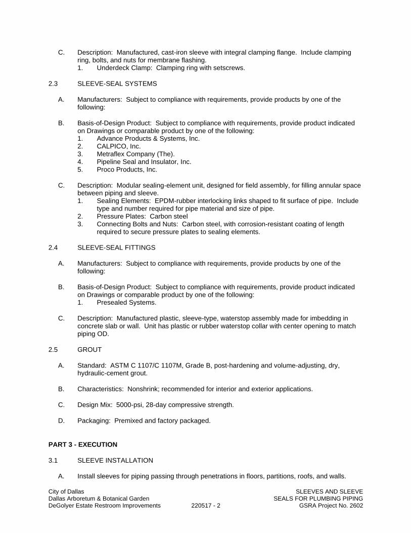
City of Dallas SLEEVES AND SLEEVE Dallas Arboretum & Botanical Garden SEALS FOR PLUMBING PIPING DeGolyer Estate Restroom Improvements 220517 - 2 GSRA Project No. 2602
C. Description: Manufactured, cast-iron sleeve with integral clamping flange. Include clamping ring, bolts, and nuts for membrane flashing. 1. Underdeck Clamp: Clamping ring with setscrews.
2.3 SLEEVE-SEAL SYSTEMS
A. Manufacturers: Subject to compliance with requirements, provide products by one of the following:
B. Basis-of-Design Product: Subject to compliance with requirements, provide product indicated on Drawings or comparable product by one of the following: 1. Advance Products & Systems, Inc. 2. CALPICO, Inc. 3. Metraflex Company (The). 4. Pipeline Seal and Insulator, Inc. 5. Proco Products, Inc.
C. Description: Modular sealing-element unit, designed for field assembly, for filling annular space between piping and sleeve. 1. Sealing Elements: EPDM-rubber interlocking links shaped to fit surface of pipe. Include
type and number required for pipe material and size of pipe. 2. Pressure Plates: Carbon steel 3. Connecting Bolts and Nuts: Carbon steel, with corrosion-resistant coating of length
required to secure pressure plates to sealing elements.
2.4 SLEEVE-SEAL FITTINGS
A. Manufacturers: Subject to compliance with requirements, provide products by one of the following:
B. Basis-of-Design Product: Subject to compliance with requirements, provide product indicated on Drawings or comparable product by one of the following: 1. Presealed Systems.
C. Description: Manufactured plastic, sleeve-type, waterstop assembly made for imbedding in concrete slab or wall. Unit has plastic or rubber waterstop collar with center opening to match piping OD.
2.5 GROUT
A. Standard: ASTM C 1107/C 1107M, Grade B, post-hardening and volume-adjusting, dry, hydraulic-cement grout.
B. Characteristics: Nonshrink; recommended for interior and exterior applications.
C. Design Mix: 5000-psi, 28-day compressive strength.
D. Packaging: Premixed and factory packaged.
PART 3 - EXECUTION
3.1 SLEEVE INSTALLATION
A. Install sleeves for piping passing through penetrations in floors, partitions, roofs, and walls.

City of Dallas SLEEVES AND SLEEVE Dallas Arboretum & Botanical Garden SEALS FOR PLUMBING PIPING DeGolyer Estate Restroom Improvements 220517 - 3 GSRA Project No. 2602
B. For sleeves that will have sleeve-seal system installed, select sleeves of size large enough to provide 1-inch annular clear space between piping and concrete slabs and walls. 1. Sleeves are not required for core-drilled holes.
C. Install sleeves in concrete floors, concrete roof slabs, and concrete walls as new slabs and walls are constructed. 1. Permanent sleeves are not required for holes in slabs formed by molded-PE or -PP
sleeves. 2. Cut sleeves to length for mounting flush with both surfaces.
a. Exception: Extend sleeves installed in floors of mechanical equipment areas or other wet areas 2 inches above finished floor level.
3. Using grout, seal the space outside of sleeves in slabs and walls without sleeve-seal system.
D. Install sleeves for pipes passing through interior partitions. 1. Cut sleeves to length for mounting flush with both surfaces. 2. Install sleeves that are large enough to provide 1/4-inch annular clear space between
sleeve and pipe or pipe insulation. 3. Seal annular space between sleeve and piping or piping insulation; use joint sealants
appropriate for size, depth, and location of joint. Comply with requirements for sealants specified in Division 07 Section "Joint Sealants."
E. Fire-Barrier Penetrations: Maintain indicated fire rating of walls, partitions, ceilings, and floors at pipe penetrations. Seal pipe penetrations with firestop materials. Comply with requirements for firestopping specified in Division 07 Section "Penetration Firestopping."
3.2 STACK-SLEEVE-FITTING INSTALLATION
A. Install stack-sleeve fittings in new slabs as slabs are constructed. 1. Install fittings that are large enough to provide 1/4-inch annular clear space between
sleeve and pipe or pipe insulation. 2. Secure flashing between clamping flanges for pipes penetrating floors with membrane
waterproofing. Comply with requirements for flashing specified in Division 07 Section "Sheet Metal Flashing and Trim."
3. Install section of cast-iron soil pipe to extend sleeve to 2 inches above finished floor level. 4. Extend cast-iron sleeve fittings below floor slab as required to secure clamping ring if ring
is specified. 5. Using grout, seal the space around outside of stack-sleeve fittings.
B. Fire-Barrier Penetrations: Maintain indicated fire rating of floors at pipe penetrations. Seal pipe penetrations with firestop materials. Comply with requirements for firestopping specified in Division 07 Section "Penetration Firestopping."
3.3 SLEEVE-SEAL-SYSTEM INSTALLATION
A. Install sleeve-seal systems in sleeves in exterior concrete walls and slabs-on-grade at service piping entries into building.
B. Select type, size, and number of sealing elements required for piping material and size and for sleeve ID or hole size. Position piping in center of sleeve. Center piping in penetration, assemble sleeve-seal system components, and install in annular space between piping and sleeve. Tighten bolts against pressure plates that cause sealing elements to expand and make a watertight seal.

City of Dallas SLEEVES AND SLEEVE Dallas Arboretum & Botanical Garden SEALS FOR PLUMBING PIPING DeGolyer Estate Restroom Improvements 220517 - 4 GSRA Project No. 2602
3.4 SLEEVE-SEAL-FITTING INSTALLATION
A. Install sleeve-seal fittings in new walls and slabs as they are constructed.
B. Assemble fitting components of length to be flush with both surfaces of concrete slabs and walls. Position waterstop flange to be centered in concrete slab or wall.
C. Using grout, seal the space around outside of sleeve-seal fittings.
3.5 SLEEVE AND SLEEVE-SEAL SCHEDULE
A. Use sleeves and sleeve seals for the following piping-penetration applications: 1. Exterior Concrete Walls above Grade:
a. Piping Smaller Than NPS 6: Cast-iron wall sleeves. b. Piping NPS 6 and Larger: Cast-iron wall sleeves.
2. Exterior Concrete Walls below Grade: a. Piping Smaller Than NPS 6: Galvanized-steel wall sleeves with sleeve-seal system
1) Select sleeve size to allow for 1-inch annular clear space between piping and sleeve for installing sleeve-seal system.
b. Piping NPS 6 and Larger: Galvanized-steel wall sleeves with sleeve-seal system. 1) Select sleeve size to allow for 1-inch annular clear space between piping
and sleeve for installing sleeve-seal system. 3. Concrete Slabs-on-Grade:
a. Piping Smaller Than NPS 6: Galvanized-steel wall sleeves with sleeve-seal system 1) Select sleeve size to allow for 1-inch annular clear space between piping
and sleeve for installing sleeve-seal system. b. Piping NPS 6 and Larger: Galvanized-steel wall sleeves with sleeve-seal system.
1) Select sleeve size to allow for 1-inch annular clear space between piping and sleeve for installing sleeve-seal system.
4. Concrete Slabs above Grade: a. Piping Smaller Than NPS 6: Galvanized-steel-pipe sleeves b. Piping NPS 6 and Larger: Galvanized-steel-pipe sleeves
5. Interior Partitions: a. Piping Smaller Than NPS 6: Galvanized-steel-pipe sleeves. b. Piping NPS 6 and Larger: Galvanized-steel-sheet sleeves.
END OF SECTION

City of Dallas Dallas Arboretum & Botanical Garden METERS AND GAGES FOR PLUMBING PIPING DeGolyer Estate Restroom Improvements 220519 - 1 GSRA Project No. 2602
SECTION 220519
METERS AND GAGES FOR PLUMBING PIPING
PART 1 - GENERAL
1.1 SUMMARY
A. Section Includes: 1. Liquid-in-glass thermometers. 2. Thermowells. 3. Dial-type pressure gages. 4. Gage attachments.
1.2 DEFINITIONS
A. CR: Chlorosulfonated polyethylene synthetic rubber.
B. EPDM: Ethylene-propylene-diene terpolymer rubber.
1.3 SUBMITTALS
A. Product Data: For each type of product indicated.
B. Product certificates.
C. Operation and maintenance data.
PART 2 - PRODUCTS
2.1 GENERAL
A. All piping, fittings, fixtures, or materials that contact potable water shall be lead-free.
2.2 METAL-CASE, LIQUID-IN-GLASS THERMOMETERS
A. Manufacturers: 1. Trerice 2. Weiss 3. Weksler Instruments
B. Case: Die-cast aluminum or brass, 7 inches long.
C. Tube: Red or blue reading, mercury or organic-liquid filled, with magnifying lens.
D. Tube Background: Satin-faced, nonreflective aluminum with permanently etched scale markings.
E. Window: Glass or plastic.
F. Connector: Adjustable type, 180 degrees in vertical plane, 360 degrees in horizontal plane, with locking device.

City of Dallas Dallas Arboretum & Botanical Garden METERS AND GAGES FOR PLUMBING PIPING DeGolyer Estate Restroom Improvements 220519 - 2 GSRA Project No. 2602
G. Stem: Copper-plated steel, aluminum, or brass for thermowell installation and of length to suit installation.
H. Accuracy: Plus or minus 1 percent of range or plus or minus 1 scale Division to maximum of 1.5 percent of range.
2.3 THERMOWELLS
A. Manufacturers: Same as manufacturer of thermometer being used.
B. Description: Pressure-tight, socket-type metal fitting made for insertion into piping and of type, diameter, and length required to hold thermometer.
2.4 PRESSURE GAGES
A. Manufacturers: 1. Trerice 2. Weiss 3. Weksler Instruments
B. Direct-Mounting, Dial-Type Pressure Gages: Indicating-dial type complying with ASME B40.100. 1. Case: Liquid-filled type, drawn steel or cast aluminum, 4-1/2-inch diameter. 2. Pressure-Element Assembly: Bourdon tube, unless otherwise indicated. 3. Pressure Connection: Brass, NPS 1/4, bottom-outlet type unless back-outlet type is
indicated. 4. Movement: Mechanical, with link to pressure element and connection to pointer. 5. Dial: Satin-faced, nonreflective aluminum with permanently etched scale markings. 6. Pointer: Red or other dark-color metal. 7. Window: Glass or plastic. 8. Ring: Metal. 9. Accuracy: Grade B, plus or minus 2 percent of middle half scale. 10. Vacuum-Pressure Range: 30-in. Hg of vacuum to 15 psig of pressure. 11. Range for Fluids under Pressure: Two times operating pressure.
C. Pressure-Gage Fittings: 1. Valves: NPS 1/4 brass or stainless-steel needle type. 2. Syphons: NPS 1/4 coil of brass tubing with threaded ends. 3. Snubbers: ASME B40.5, NPS 1/4 brass bushing with corrosion-resistant, porous-metal
disc of material suitable for system fluid and working pressure.
2.5 TEST PLUGS
A. Manufacturers: 1. Trerice 2. Weiss 3. Weksler Instruments
B. Description: Corrosion-resistant brass or stainless-steel body with core inserts and gasketed and threaded cap, with extended stem for units to be installed in insulated piping.
C. Minimum Pressure and Temperature Rating: 500 psig at 200 deg F.
D. Core Inserts: One or two self-sealing rubber valves. 1. Insert material for air, water, oil, or gas service at 20 to 200 deg F shall be CR.

City of Dallas Dallas Arboretum & Botanical Garden METERS AND GAGES FOR PLUMBING PIPING DeGolyer Estate Restroom Improvements 220519 - 3 GSRA Project No. 2602
2. Insert material for air or water service at minus 30 to plus 275 deg F shall be EPDM.
2.6 GAGE ATTACHMENTS
A. Snubbers: ASME B40.100, brass; with NPS 1/4 or NPS 1/2, ASME B1.20.1 pipe threads and piston-type surge-dampening device. Include extension for use on insulated piping.
B. Valves: Brass ball, with NPS 1/4 or NPS 1/2, ASME B1.20.1 pipe threads.
PART 3 - EXECUTION
3.1 INSTALLATION
A. Install thermowells with socket extending to center of pipe and in vertical position in piping tees.
B. Install thermowells of sizes required to match thermometer connectors. Include bushings if required to match sizes.
C. Install thermowells with extension on insulated piping.
D. Fill thermowells with heat-transfer medium.
E. Install direct-mounted thermometers in thermowells and adjust vertical and tilted positions.
F. Install remote-mounted thermometer bulbs in thermowells and install cases on panels; connect cases with tubing and support tubing to prevent kinks. Use minimum tubing length.
G. Install direct-mounted pressure gages in piping tees with pressure gage located on pipe at the most readable position.
H. Install remote-mounted pressure gages on panel.
I. Install valve and snubber in piping for each pressure gage for fluids.
J. Install thermometers in the following locations: 1. Inlet and outlet of each water heater. 2. Inlets and outlets of each domestic water heat exchanger. 3. Inlet and outlet of each domestic hot-water storage tank. 4. Inlet and outlet of each remote domestic water chiller.
K. Install pressure gages in the following locations: 1. Building water service entrance into building. 2. Inlet and outlet of each pressure-reducing valve. 3. Suction and discharge of each domestic water pump.
L. Install meters and gages adjacent to machines and equipment to allow service and maintenance of meters, gages, machines, and equipment.
M. Adjust faces of meters and gages to proper angle for best visibility.
3.2 THERMOMETER SCALE-RANGE SCHEDULE
A. Scale Range for Domestic Cold-Water Piping: 0 to 100 deg F and minus 20 to plus 50 deg C.

City of Dallas Dallas Arboretum & Botanical Garden METERS AND GAGES FOR PLUMBING PIPING DeGolyer Estate Restroom Improvements 220519 - 4 GSRA Project No. 2602
B. Scale Range for Domestic Hot-Water Piping: 20 to 240 deg F and 0 to 150 deg C.
3.3 PRESSURE-GAGE SCALE-RANGE SCHEDULE
A. Scale Range for Water Service Piping: 0 to 100 psi and 0 to 600 kPa.
B. Scale Range for Domestic Water Piping: 0 to 100 psi and 0 to 600 kPa.
END OF SECTION

City of Dallas GENERAL-DUTY Dallas Arboretum & Botanical Garden VALVES FOR PLUMBING PIPING DeGolyer Estate Restroom Improvements 220523 - 1 GSRA Project No. 2602
SECTION 220523
GENERAL-DUTY VALVES FOR PLUMBING PIPING
PART 1 - GENERAL
1.1 SUMMARY
A. This Section includes the following general-duty valves: 1. Copper-alloy ball valves. 2. Bronze check valves. 3. Spring-loaded, lift-disc check valves.
B. Related Sections include the following: 1. Division 22 piping Sections for specialty valves applicable to those Sections only.
1.2 DEFINITIONS
A. The following are standard abbreviations for valves: 1. CWP: Cold working pressure. 2. EPDM: Ethylene-propylene-diene terpolymer rubber. 3. NBR: Acrylonitrile-butadiene rubber. 4. PTFE: Polytetrafluoroethylene plastic. 5. SWP: Steam working pressure. 6. TFE: Tetrafluoroethylene plastic.
1.3 SUBMITTALS
A. Product Data: For each type of valve indicated. Include body, seating, and trim materials; valve design; pressure and temperature classifications; end connections; arrangement; dimensions; and required clearances. Include list indicating valve and its application. Include rated capacities; shipping, installed, and operating weights; furnished specialties; and accessories.
1.4 QUALITY ASSURANCE
A. ASME Compliance: ASME B31.9 for building services piping valves. 1. Exceptions: Domestic hot- and cold-water piping valves unless referenced.
B. ASME Compliance for Ferrous Valves: ASME B16.10 and ASME B16.34 for dimension and design criteria.
C. NSF Compliance: NSF 61 for valve materials for potable-water service.
1.5 DELIVERY, STORAGE, AND HANDLING
A. Prepare valves for shipping as follows: 1. Protect internal parts against rust and corrosion. 2. Protect threads, flange faces, grooves, and weld ends. 3. Set angle, gate, and globe valves closed to prevent rattling. 4. Set ball and plug valves open to minimize exposure of functional surfaces. 5. Set butterfly valves closed or slightly open. 6. Block check valves in either closed or open position.

City of Dallas GENERAL-DUTY Dallas Arboretum & Botanical Garden VALVES FOR PLUMBING PIPING DeGolyer Estate Restroom Improvements 220523 - 2 GSRA Project No. 2602
B. Use the following precautions during storage: 1. Maintain valve end protection. 2. Store valves indoors and maintain at higher than ambient dew-point temperature. If
outdoor storage is necessary, store valves off the ground in watertight enclosures.
C. Use sling to handle large valves; rig sling to avoid damage to exposed parts. Do not use handwheels or stems as lifting or rigging points.
PART 2 - PRODUCTS
2.1 VALVES, GENERAL
A. Refer to Part 3 "Valve Applications" Article for applications of valves.
B. Bronze Valves: NPS 2 and smaller with threaded ends, unless otherwise indicated.
C. Ferrous Valves: NPS 2-1/2 and larger with flanged ends, unless otherwise indicated.
D. Valve Pressure and Temperature Ratings: Not less than indicated and as required for system pressures and temperatures.
E. Valve Sizes: Same as upstream pipe, unless otherwise indicated.
F. Valve Actuators: 1. Gear Drive: For quarter-turn valves NPS 8 and larger. 2. Handwheel: For valves other than quarter-turn types. 3. Lever Handle: For quarter-turn valves NPS 6 and smaller.
G. Extended Valve Stems: On insulated valves.
H. Valve Flanges: ASME B16.1 for cast-iron valves, ASME B16.5 for steel valves, and ASME B16.24 for bronze valves.
I. Threaded: With threads according to ASME B1.20.1.
J. Valve Bypass and Drain Connections: MSS SP-45.
2.2 COPPER-ALLOY BALL VALVES
A. Manufacturers: 1. Two-Piece and Three Piece, Copper-Alloy Ball Valves:
a. Apollo Valve b. Crane Co. c. Hammond Valve. d. Jamesbury, Inc. e. Watts Industries, Inc.; Water Products Div.
B. Copper-Alloy Ball Valves, General: MSS SP-110.
C. Two-Piece, Copper-Alloy Ball Valves: Brass or bronze body with full-port, chrome-plated bronze ball; PTFE or TFE seats; and 600-psig minimum CWP rating and blowout-proof stem.

City of Dallas GENERAL-DUTY Dallas Arboretum & Botanical Garden VALVES FOR PLUMBING PIPING DeGolyer Estate Restroom Improvements 220523 - 3 GSRA Project No. 2602
D. Three-Piece, Copper-Alloy Ball Valves: Brass or bronze body with full-port, chrome-plated bronze ball; PTFE or TFE seats; and 600-psig minimum CWP rating and blowout-proof stem.
2.3 FERROUS-ALLOY BUTTERFLY VALVES
2.4 BRONZE CHECK VALVES
A. Manufacturers: 1. Swing Check Valves with Metal Disc:
a. Apollo Valve b. Crane Co. c. Hammond Valve. d. Kitz Corporation of America. e. Watts Industries, Inc.; Water Products Div.
B. Bronze Check Valves, General: MSS SP-80.
C. Class 125, Bronze, Horizontal Lift Check Valves: Bronze body with bronze disc and seat.
D. Class 125, Bronze, Vertical Lift Check Valves: Bronze body with bronze disc and seat.
E. Class 125, Bronze, Swing Check Valves: Bronze body with bronze disc and seat.
2.5 GRAY-IRON SWING CHECK VALVES
A. Manufacturers: 1. Type I, Gray-Iron Swing Check Valves with Metal Seats:
a. Apollo Valve. b. Crane Co. c. Milwaukee Valve Company. d. Mueller Co. e. Watts Industries, Inc.; Water Products Div.
B. Gray-Iron Swing Check Valves, General: MSS SP-71.
C. Class 125, gray-iron, swing check valves with metal seats.
D. 175-psig CWP Rating, Swing Check Valves: Ductile-iron body with shouldered ends.
PART 3 - EXECUTION
3.1 EXAMINATION
A. Examine piping system for compliance with requirements for installation tolerances and other conditions affecting performance. 1. Proceed with installation only after unsatisfactory conditions have been corrected.
B. Examine valve interior for cleanliness, freedom from foreign matter, and corrosion. Remove special packing materials, such as blocks, used to prevent disc movement during shipping and handling.

City of Dallas GENERAL-DUTY Dallas Arboretum & Botanical Garden VALVES FOR PLUMBING PIPING DeGolyer Estate Restroom Improvements 220523 - 4 GSRA Project No. 2602
C. Operate valves in positions from fully open to fully closed. Examine guides and seats made accessible by such operations.
D. Examine threads on valve and mating pipe for form and cleanliness.
E. Examine mating flange faces for conditions that might cause leakage. Check bolting for proper size, length, and material. Verify that gasket is of proper size, that its material composition is suitable for service, and that it is free from defects and damage.
F. Do not attempt to repair defective valves; replace with new valves.
3.2 VALVE APPLICATIONS
A. Refer to piping Sections for specific valve applications. If valve applications are not indicated, use the following: 1. Shutoff Service: Ball valves. 2. Throttling Service: Ball valves. 3. Pump Discharge: Spring-loaded, lift-disc check valves.
B. If valves with specified SWP classes or CWP ratings are not available, the same types of valves with higher SWP class or CWP ratings may be substituted.
C. Domestic Water Piping: Use the following types of valves: 1. Ball Valves, NPS 2 and Smaller: Two or Three-piece, 600-psig CWP rating, copper alloy. 2. Ball Valves, NPS 2-1/2 and Larger: Class 150 ferrous alloy. 3. Lift Check Valves, NPS 2 and Smaller: Class 125 horizontal or vertical, bronze. 4. Swing Check Valves, NPS 2 and Smaller: Class 125, bronze. 5. Swing Check Valves, NPS 2-1/2 and Larger: Class 125, gray iron. 6. Wafer Check Valves, NPS 2-1/2 and Larger: Dual-plate, wafer-lug or double-flanged,
Class 125 or 150, ferrous alloy. 7. Spring-Loaded, Lift-Disc Check Valves, NPS 2 and Smaller: Class 125 or 150. 8. Spring-Loaded, Lift-Disc Check Valves, NPS 2-1/2 and Larger: Class 125, cast iron.
D. Select valves with the following end connections: 1. For Copper Tubing, NPS 2 and Smaller: Threaded ends. 2. For Copper Tubing, NPS 2-1/2 to NPS 4: Flanged or threaded ends. 3. For Copper Tubing, NPS 5 and Larger: Flanged ends. 4. For Steel Piping, NPS 2 and Smaller: Threaded ends. 5. For Steel Piping, NPS 2-1/2 and larger: Flanged, or threaded ends.
E. Cut threaded rods used for supports a maximum of 1 inch after fastener.
3.3 VALVE INSTALLATION
A. Piping installation requirements are specified in other Division 23 Sections. Drawings indicate general arrangement of piping, fittings, and specialties.
B. Install valves with unions or flanges at each piece of equipment arranged to allow service, maintenance, and equipment removal without system shutdown.
C. Locate valves for easy access and provide separate support where necessary.
D. Install valves in horizontal piping with stem at or above center of pipe. Valves can be installed in vertical piping if needed.

City of Dallas GENERAL-DUTY Dallas Arboretum & Botanical Garden VALVES FOR PLUMBING PIPING DeGolyer Estate Restroom Improvements 220523 - 5 GSRA Project No. 2602
E. Install valves in position to allow full stem movement.
F. Install chainwheel operators on valves NPS 4 and larger and more than 96 inches above floor. Extend chains to 60 inches above finished floor elevation.
G. Install check valves for proper direction of flow and as follows: 1. Swing Check Valves: In vertical piping with flow upward.
3.4 JOINT CONSTRUCTION
A. Refer to Division 23 Section "Common Work Results for HVAC" for basic piping joint construction.
3.5 ADJUSTING
A. Adjust or replace valve packing after piping systems have been tested and put into service but before final adjusting and balancing. Replace valves if persistent leaking occurs.
END OF SECTION

City of Dallas HANGERS AND SUPPORTS FOR Dallas Arboretum & Botanical Garden PLUMBING PIPING AND EQUIPMENT DeGolyer Estate Restroom Improvements 220529 - 1 GSRA Project No. 2602
SECTION 220529
HANGERS AND SUPPORTS FOR PLUMBING PIPING AND EQUIPMENT
PART 1 - GENERAL
1.1 SUMMARY
A. Section Includes: 1. Metal pipe hangers and supports. 2. Trapeze pipe hangers. 3. Thermal hanger-shield inserts. 4. Fastener systems. 5. Pipe-positioning systems. 6. Equipment supports.
1.2 ACTION SUBMITTALS
A. Product Data: For each type of product.
PART 2 - PRODUCTS
2.1 METAL PIPE HANGERS AND SUPPORTS
A. Carbon-Steel Pipe Hangers and Supports: 1. Description: MSS SP-58, Types 1 through 58, factory-fabricated components. 2. Galvanized Metallic Coatings: Pregalvanized, hot-dip galvanized, or electro-galvanized. 3. Nonmetallic Coatings: Plastic coated or epoxy powder coated. 4. Padded Hangers: Hanger with fiberglass or other pipe insulation pad or cushion to
support bearing surface of piping. 5. Hanger Rods: Continuous-thread rod, nuts, and washer made of carbon steel stainless
steel.
B. Uninsulated Copper Pipe and Tube Hangers: 1. Description: MSS SP-58, Types 1 through 58, copper-coated-steel, factory-fabricated
components. 2. Hanger Rods: Continuous-thread rod, nuts, and washer made of copper-coated steel .
2.2 TRAPEZE PIPE HANGERS
A. Description: MSS SP-58, Type 59, shop- or field-fabricated pipe-support assembly, made from structural-carbon-steel shapes, with MSS SP-58 carbon-steel hanger rods, nuts, saddles, and U-bolts.
2.3 THERMAL HANGER-SHIELD INSERTS
A. Insulation-Insert Material for Cold Piping: ASTM C552, Type II cellular glass with 100-psig or ASTM C591, Type VI, Grade 1 polyisocyanurate with 125-psig minimum compressive strength and vapor barrier.
B. Insulation-Insert Material for Hot Piping: Water-repellent-treated, ASTM C533, Type I calcium silicate with 100-psig ASTM C552, Type II cellular glass with 100-psig or ASTM C591, Type VI, Grade 1 polyisocyanurate with 125-psig minimum compressive strength.

City of Dallas HANGERS AND SUPPORTS FOR Dallas Arboretum & Botanical Garden PLUMBING PIPING AND EQUIPMENT DeGolyer Estate Restroom Improvements 220529 - 2 GSRA Project No. 2602
C. For Trapeze or Clamped Systems: Insert and shield shall cover entire circumference of pipe.
D. For Clevis or Band Hangers: Insert and shield shall cover lower 180 degrees of pipe.
E. Insert Length: Extend 2 inches beyond sheet metal shield for piping operating below ambient air temperature.
2.4 FASTENER SYSTEMS
A. Powder-Actuated Fasteners: Threaded-steel stud, for use in hardened portland cement concrete, with pull-out, tension, and shear capacities appropriate for supported loads and building materials where used.
B. Mechanical-Expansion Anchors: Insert-wedge-type anchors, for use in hardened portland cement concrete, with pull-out, tension, and shear capacities appropriate for supported loads and building materials where used. 1. Indoor Applications: Zinc-coated or stainless steel. 2. Outdoor Applications: Stainless steel.
2.5 PIPE-POSITIONING SYSTEMS
A. Description: IAPMO PS 42 positioning system composed of metal brackets, clips, and straps for positioning piping in pipe spaces; for plumbing fixtures in commercial applications.
2.6 EQUIPMENT SUPPORTS
A. Description: Welded, shop- or field-fabricated equipment support made from structural-carbon-steel shapes.
2.7 MATERIALS
A. Carbon Steel: ASTM A1011/A1011M.
B. Structural Steel: ASTM A36/A36M carbon-steel plates, shapes, and bars; black and galvanized.
C. Grout: ASTM C1107/C1107M, factory-mixed and -packaged, dry, hydraulic-cement, nonshrink and nonmetallic grout; suitable for interior and exterior applications. 1. Properties: Nonstaining, noncorrosive, and nongaseous. 2. Design Mix: 5000-psi , 28-day compressive strength.
PART 3 - EXECUTION
3.1 APPLICATION
A. Comply with requirements in Section 078413 "Penetration Firestopping" for firestopping materials and installation, for penetrations through fire-rated walls, ceilings, and assemblies.
B. Strength of Support Assemblies: Where not indicated, select sizes of components, so strength will be adequate to carry present and future static loads within specified loading limits. Minimum static design load used for strength determination shall be weight of supported components plus 200 lb.

City of Dallas HANGERS AND SUPPORTS FOR Dallas Arboretum & Botanical Garden PLUMBING PIPING AND EQUIPMENT DeGolyer Estate Restroom Improvements 220529 - 3 GSRA Project No. 2602
3.2 HANGER AND SUPPORT INSTALLATION
A. Metal Pipe-Hanger Installation: Comply with MSS SP-58. Install hangers, supports, clamps, and attachments as required to properly support piping from building structure.
B. Metal Trapeze Pipe-Hanger Installation: Comply with MSS SP-58. Arrange for grouping of parallel runs of horizontal piping, and support together on field-fabricated trapeze pipe hangers. 1. Pipes of Various Sizes: Support together and space trapezes for smallest pipe size, or
install intermediate supports for smaller-diameter pipes as specified for individual pipe hangers.
2. Field fabricate from ASTM A36/A36M carbon-steel shapes selected for loads being supported. Weld steel according to AWS D1.1/D1.1M.
C. Thermal Hanger-Shield Installation: Install in pipe hanger or shield for insulated piping.
D. Fastener System Installation: 1. Install powder-actuated fasteners for use in lightweight concrete or concrete slabs less
than 4 inches thick in concrete, after concrete is placed and completely cured. Use operators that are licensed by powder-actuated tool manufacturer. Install fasteners according to powder-actuated tool manufacturer's operating manual.
2. Install mechanical-expansion anchors in concrete, after concrete is placed and completely cured. Install fasteners according to manufacturer's written instructions.
E. Pipe-Positioning-System Installation: Install support devices to make rigid supply and waste piping connections to each plumbing fixture.
F. Install hangers and supports complete with necessary attachments, inserts, bolts, rods, nuts, washers, and other accessories.
G. Equipment Support Installation: Fabricate from welded-structural-steel shapes.
H. Install hangers and supports to allow controlled thermal and seismic movement of piping systems, to permit freedom of movement between pipe anchors, and to facilitate action of expansion joints, expansion loops, expansion bends, and similar units.
I. Install lateral bracing with pipe hangers and supports to prevent swaying.
J. Install building attachments within concrete slabs or attach to structural steel. Install additional attachments at concentrated loads, including valves, flanges, and strainers, NPS 2-1/2 and larger and at changes in direction of piping. Install concrete inserts before concrete is placed; fasten inserts to forms, and install reinforcing bars through openings at top of inserts.
K. Load Distribution: Install hangers and supports, so that piping live and dead loads and stresses from movement will not be transmitted to connected equipment.
L. Pipe Slopes: Install hangers and supports to provide indicated pipe slopes and to not exceed maximum pipe deflections allowed by ASME B31.9 for building services piping.
M. Insulated Piping: 1. Attach clamps and spacers to piping.
a. Piping Operating Above Ambient Air Temperature: Clamp may project through insulation.
b. Piping Operating Below Ambient Air Temperature: Use thermal hanger-shield insert with clamp sized to match OD of insert.

City of Dallas HANGERS AND SUPPORTS FOR Dallas Arboretum & Botanical Garden PLUMBING PIPING AND EQUIPMENT DeGolyer Estate Restroom Improvements 220529 - 4 GSRA Project No. 2602
c. Do not exceed pipe stress limits allowed by ASME B31.9 for building services piping.
2. Install MSS SP-58, Type 39 protection saddles if insulation without vapor barrier is indicated. Fill interior voids with insulation that matches adjoining insulation. a. Option: Thermal hanger-shield inserts may be used. Include steel weight-
distribution plate for pipe NPS 4 and larger if pipe is installed on rollers. 3. Install MSS SP-58, Type 40 protective shields on cold piping with vapor barrier. Shields
shall span an arc of 180 degrees. a. Option: Thermal hanger-shield inserts may be used. Include steel weight-
distribution plate for pipe NPS 4 and larger if pipe is installed on rollers. 4. Shield Dimensions for Pipe: Not less than the following:
a. NPS 1/4 to NPS 3-1/2: 12 inches long and 0.048 inch thick. b. NPS 4: 12 inches long and 0.06 inch thick. c. NPS 5 and NPS 6: 18 inches long and 0.06 inch thick. d. NPS 8 to NPS 14: 24 inches long and 0.075 inch thick. e. NPS 16 to NPS 24: 24 inches long and 0.105 inch thick.
5. Pipes NPS 8 and Larger: Include wood or reinforced calcium-silicate-insulation inserts of length at least as long as protective shield.
6. Thermal Hanger Shields: Install with insulation of same thickness as piping insulation.
3.3 EQUIPMENT SUPPORTS
A. Fabricate structural-steel stands to suspend equipment from structure overhead or to support equipment above floor.
B. Grouting: Place grout under supports for equipment, and make bearing surface smooth.
C. Provide lateral bracing, to prevent swaying, for equipment supports.
3.4 METAL FABRICATIONS
A. Cut, drill, and fit miscellaneous metal fabrications for trapeze pipe hangers and equipment supports.
B. Fit exposed connections together to form hairline joints. Field weld connections that cannot be shop welded because of shipping size limitations.
C. Field Welding: Comply with AWS D1.1/D1.1M procedures for shielded, metal arc welding; appearance and quality of welds; and methods used in correcting welding work.
3.5 ADJUSTING
A. Hanger Adjustments: Adjust hangers to distribute loads equally on attachments and to achieve indicated slope of pipe.
B. Trim excess length of continuous-thread hanger and support rods to 1-1/2 inches.
3.6 PAINTING
A. Touchup: Clean field welds and abraded, shop-painted areas. Paint exposed areas immediately after erecting hangers and supports. Use same materials as those used for shop painting. Comply with SSPC-PA 1 requirements for touching up field-painted surfaces. 1. Apply paint by brush or spray to provide a minimum dry film thickness of 2.0 mils.

City of Dallas HANGERS AND SUPPORTS FOR Dallas Arboretum & Botanical Garden PLUMBING PIPING AND EQUIPMENT DeGolyer Estate Restroom Improvements 220529 - 5 GSRA Project No. 2602
B. Galvanized Surfaces: Clean welds, bolted connections, and abraded areas, and apply galvanizing-repair paint to comply with ASTM A780/A780M.
3.7 HANGER AND SUPPORT SCHEDULE
A. Specific hanger and support requirements are in Sections specifying piping systems and equipment.
B. Comply with MSS SP-58 for pipe-hanger selections and applications that are not specified in piping system Sections.
C. Use hangers and supports with galvanized metallic coatings for piping and equipment that will not have field-applied finishes.
D. Use nonmetallic coatings on attachments for electrolytic protection where attachments are in direct contact with copper tubing.
E. Use carbon-steel pipe hangers and supports and metal trapeze pipe hangers and attachments for general service applications.
F. for hostile environment applications.
G. Use copper-plated pipe hangers and copper or stainless-steel attachments for uninsulated copper piping and tubing.
H. Use padded hangers for piping that is subject to scratching.
I. Use thermal hanger-shield inserts for insulated piping and tubing.
J. Horizontal-Piping Hangers and Supports: Unless otherwise indicated and except as specified in piping system Sections, install the following types: 1. Adjustable, Steel Clevis Hangers (MSS Type 1): For suspension of noninsulated or
insulated, stationary pipes NPS 1/2 to NPS 30. 2. Yoke-Type Pipe Clamps (MSS Type 2): For suspension of up to 1050 deg F pipes NPS 4
to NPS 24, requiring up to 4 inches of insulation. 3. Carbon- or Alloy-Steel, Double-Bolt Pipe Clamps (MSS Type 3): For suspension of pipes
NPS 3/4 to NPS 36, requiring clamp flexibility and up to 4 inches of insulation. 4. Steel Pipe Clamps (MSS Type 4): For suspension of cold and hot pipes NPS 1/2 to
NPS 24 if little or no insulation is required. 5. Pipe Hangers (MSS Type 5): For suspension of pipes NPS 1/2 to NPS 4, to allow off-
center closure for hanger installation before pipe erection. 6. Adjustable, Swivel Split- or Solid-Ring Hangers (MSS Type 6): For suspension of
noninsulated, stationary pipes NPS 3/4 to NPS 8. 7. Adjustable, Steel Band Hangers (MSS Type 7): For suspension of noninsulated,
stationary pipes NPS 1/2 to NPS 8. 8. Adjustable Band Hangers (MSS Type 9): For suspension of noninsulated, stationary
pipes NPS 1/2 to NPS 8. 9. Adjustable, Swivel-Ring Band Hangers (MSS Type 10): For suspension of noninsulated,
stationary pipes NPS 1/2 to NPS 8. 10. Split Pipe Ring with or without Turnbuckle Hangers (MSS Type 11): For suspension of
noninsulated, stationary pipes NPS 3/8 to NPS 8. 11. Extension Hinged or Two-Bolt Split Pipe Clamps (MSS Type 12): For suspension of
noninsulated, stationary pipes NPS 3/8 to NPS 3. 12. U-Bolts (MSS Type 24): For support of heavy pipes NPS 1/2 to NPS 30.

City of Dallas HANGERS AND SUPPORTS FOR Dallas Arboretum & Botanical Garden PLUMBING PIPING AND EQUIPMENT DeGolyer Estate Restroom Improvements 220529 - 6 GSRA Project No. 2602
13. Clips (MSS Type 26): For support of insulated pipes not subject to expansion or contraction.
14. Pipe Saddle Supports (MSS Type 36): For support of pipes NPS 4 to NPS 36, with steel-pipe base stanchion support and cast-iron floor flange or carbon-steel plate.
15. Pipe Stanchion Saddles (MSS Type 37): For support of pipes NPS 4 to NPS 36, with steel-pipe base stanchion support and cast-iron floor flange or carbon-steel plate, and with U-bolt to retain pipe.
16. Adjustable Pipe Saddle Supports (MSS Type 38): For stanchion-type support for pipes NPS 2-1/2 to NPS 36 if vertical adjustment is required, with steel-pipe base stanchion support and cast-iron floor flange.
17. Single-Pipe Rolls (MSS Type 41): For suspension of pipes NPS 1 to NPS 30, from two rods if longitudinal movement caused by expansion and contraction occurs.
18. Adjustable Roller Hangers (MSS Type 43): For suspension of pipes NPS 2-1/2 to NPS 24 from single rod if horizontal movement caused by expansion and contraction occurs.
19. Complete Pipe Rolls (MSS Type 44): For support of pipes NPS 2 to NPS 42 if longitudinal movement caused by expansion and contraction occurs but vertical adjustment is unnecessary.
20. Pipe Roll and Plate Units (MSS Type 45): For support of pipes NPS 2 to NPS 24 if small horizontal movement caused by expansion and contraction occurs and vertical adjustment is unnecessary.
21. Adjustable Pipe Roll and Base Units (MSS Type 46): For support of pipes NPS 2 to NPS 30 if vertical and lateral adjustment during installation, in addition to expansion and contraction, is required.
K. Vertical-Piping Clamps: Unless otherwise indicated and except as specified in piping system Sections, install the following types: 1. Extension Pipe or Riser Clamps (MSS Type 8): For support of pipe risers NPS 3/4 to
NPS 24. 2. Carbon- or Alloy-Steel Riser Clamps (MSS Type 42): For support of pipe risers NPS 3/4
to NPS 24 if longer ends are required for riser clamps.
L. Hanger-Rod Attachments: Unless otherwise indicated and except as specified in piping system Sections, install the following types: 1. Steel Turnbuckles (MSS Type 13): For adjustment of up to 6 inches for heavy loads. 2. Steel Clevises (MSS Type 14): For 120 to 450 deg F piping installations. 3. Swivel Turnbuckles (MSS Type 15): For use with MSS Type 11 split pipe rings. 4. Malleable-Iron Sockets (MSS Type 16): For attaching hanger rods to various types of
building attachments. 5. Steel Weldless Eye Nuts (MSS Type 17): For 120 to 450 deg F piping installations.
M. Building Attachments: Unless otherwise indicated and except as specified in piping system Sections, install the following types: 1. Steel or Malleable-Concrete Inserts (MSS Type 18): For upper attachment to suspend
pipe hangers from concrete ceiling. 2. Top-Beam C-Clamps (MSS Type 19): For use under roof installations with bar-joist
construction, to attach to top flange of structural shape. 3. Side-Beam or Channel Clamps (MSS Type 20): For attaching to bottom flange of beams,
channels, or angles. 4. Center-Beam Clamps (MSS Type 21): For attaching to center of bottom flange of beams. 5. Welded Beam Attachments (MSS Type 22): For attaching to bottom of beams if loads are
considerable and rod sizes are large. 6. C-Clamps (MSS Type 23): For structural shapes. 7. Top-Beam Clamps (MSS Type 25): For top of beams if hanger rod is required tangent to
flange edge. 8. Side-Beam Clamps (MSS Type 27): For bottom of steel I-beams.
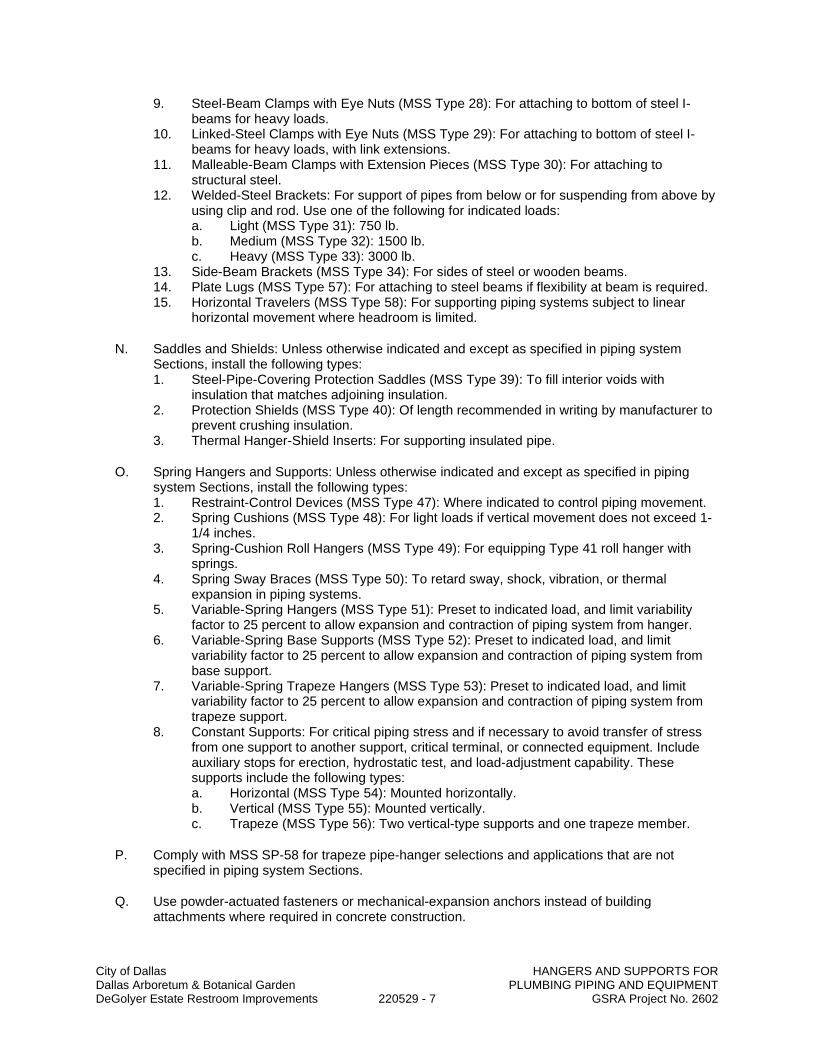
City of Dallas HANGERS AND SUPPORTS FOR Dallas Arboretum & Botanical Garden PLUMBING PIPING AND EQUIPMENT DeGolyer Estate Restroom Improvements 220529 - 7 GSRA Project No. 2602
9. Steel-Beam Clamps with Eye Nuts (MSS Type 28): For attaching to bottom of steel I-beams for heavy loads.
10. Linked-Steel Clamps with Eye Nuts (MSS Type 29): For attaching to bottom of steel I-beams for heavy loads, with link extensions.
11. Malleable-Beam Clamps with Extension Pieces (MSS Type 30): For attaching to structural steel.
12. Welded-Steel Brackets: For support of pipes from below or for suspending from above by using clip and rod. Use one of the following for indicated loads: a. Light (MSS Type 31): 750 lb. b. Medium (MSS Type 32): 1500 lb. c. Heavy (MSS Type 33): 3000 lb.
13. Side-Beam Brackets (MSS Type 34): For sides of steel or wooden beams. 14. Plate Lugs (MSS Type 57): For attaching to steel beams if flexibility at beam is required. 15. Horizontal Travelers (MSS Type 58): For supporting piping systems subject to linear
horizontal movement where headroom is limited.
N. Saddles and Shields: Unless otherwise indicated and except as specified in piping system Sections, install the following types: 1. Steel-Pipe-Covering Protection Saddles (MSS Type 39): To fill interior voids with
insulation that matches adjoining insulation. 2. Protection Shields (MSS Type 40): Of length recommended in writing by manufacturer to
prevent crushing insulation. 3. Thermal Hanger-Shield Inserts: For supporting insulated pipe.
O. Spring Hangers and Supports: Unless otherwise indicated and except as specified in piping system Sections, install the following types: 1. Restraint-Control Devices (MSS Type 47): Where indicated to control piping movement. 2. Spring Cushions (MSS Type 48): For light loads if vertical movement does not exceed 1-
1/4 inches. 3. Spring-Cushion Roll Hangers (MSS Type 49): For equipping Type 41 roll hanger with
springs. 4. Spring Sway Braces (MSS Type 50): To retard sway, shock, vibration, or thermal
expansion in piping systems. 5. Variable-Spring Hangers (MSS Type 51): Preset to indicated load, and limit variability
factor to 25 percent to allow expansion and contraction of piping system from hanger. 6. Variable-Spring Base Supports (MSS Type 52): Preset to indicated load, and limit
variability factor to 25 percent to allow expansion and contraction of piping system from base support.
7. Variable-Spring Trapeze Hangers (MSS Type 53): Preset to indicated load, and limit variability factor to 25 percent to allow expansion and contraction of piping system from trapeze support.
8. Constant Supports: For critical piping stress and if necessary to avoid transfer of stress from one support to another support, critical terminal, or connected equipment. Include auxiliary stops for erection, hydrostatic test, and load-adjustment capability. These supports include the following types: a. Horizontal (MSS Type 54): Mounted horizontally. b. Vertical (MSS Type 55): Mounted vertically. c. Trapeze (MSS Type 56): Two vertical-type supports and one trapeze member.
P. Comply with MSS SP-58 for trapeze pipe-hanger selections and applications that are not specified in piping system Sections.
Q. Use powder-actuated fasteners or mechanical-expansion anchors instead of building attachments where required in concrete construction.

City of Dallas HANGERS AND SUPPORTS FOR Dallas Arboretum & Botanical Garden PLUMBING PIPING AND EQUIPMENT DeGolyer Estate Restroom Improvements 220529 - 8 GSRA Project No. 2602
R. Use pipe-positioning systems in pipe spaces behind plumbing fixtures to support supply and waste piping for plumbing fixtures.
END OF SECTION

City of Dallas Dallas Arboretum & Botanical Garden HEAT TRACING FOR HVAC PIPING DeGolyer Estate Restroom Improvements 220533 - 1 GSRA Project No. 2602
SECTION 220533
HEAT TRACING FOR PLUMBING PIPING
PART 1 - GENERAL
1.1 SUMMARY
A. Section includes heat tracing for HVAC piping with the following electric heating cables: 1. Self-regulating, parallel resistance.
1.2 ACTION SUBMITTALS
A. Product Data: For each type of product.
B. Shop Drawings: For electric heating cable.
1.3 INFORMATIONAL SUBMITTALS
A. Field quality-control reports.
B. Sample Warranty: For special warranty.
1.4 CLOSEOUT SUBMITTALS
A. Operation and maintenance data.
1.5 WARRANTY
A. Special Warranty: Manufacturer agrees to repair or replace electric heating cable that fails in materials or workmanship within specified warranty period. 1. Warranty Period: Three years from date of Substantial Completion.
PART 2 - PRODUCTS
2.1 SELF-REGULATING, PARALLEL-RESISTANCE HEATING CABLES
A. Manufacturers: Subject to compliance with requirements, provide products by one of the following: 1. Delta-Therm Corporation. 2. Pyrotenax; Tyco Thermal Controls. 3. Raychem; Tyco Thermal Controls.
B. Comply with IEEE 515.1.
C. Heating Element: Pair of parallel No. 16 AWG, nickel-coated, stranded copper bus wires embedded in crosslinked conductive polymer core, which varies heat output in response to temperature along its length. Terminate with waterproof, factory-assembled, nonheating leads with connectors at one end, and seal the opposite end watertight. Cable shall be capable of crossing over itself once without overheating.
D. Electrical Insulating Jacket: Flame-retardant polyolefin.
E. Cable Cover: Stainless-steel braid and polyolefin outer jacket with ultraviolet inhibitor.

City of Dallas Dallas Arboretum & Botanical Garden HEAT TRACING FOR HVAC PIPING DeGolyer Estate Restroom Improvements 220533 - 2 GSRA Project No. 2602
F. Maximum Operating Temperature (Power On): 150 deg F.
G. Maximum Exposure Temperature (Power Off): 185 deg F.
H. Electrical Components, Devices, and Accessories: Listed and labeled as defined in NFPA 70, by a qualified testing agency, and marked for intended location and application.
2.2 CONTROLS
A. Remote bulb unit with adjustable temperature range from 30 to 50 deg F.
B. Snap action; open-on-rise, single-pole switch with minimum current rating adequate for connected cable.
C. Remote bulb on capillary, resistance temperature device, or thermistor for directly sensing pipe-wall temperature.
D. Corrosion-resistant, waterproof control enclosure.
2.3 ACCESSORIES
A. Cable Installation Accessories: Fiberglass tape, heat-conductive putty, cable ties, silicone end seals and splice kits, and installation clips all furnished by manufacturer, or as recommended in writing by manufacturer.
B. Warning Labels: Refer to Section 230553 "Identification for HVAC Piping and Equipment."
C. Warning Tape: Continuously printed "Electrical Tracing"; vinyl, at least 3 mils thick, and with pressure-sensitive, permanent, waterproof, self-adhesive back. 1. Width for Markers on Pipes with OD, Including Insulation, Less Than 6 Inches: 3/4 inch
minimum. 2. Width for Markers on Pipes with OD, Including Insulation, 6 Inches or Larger: 1-1/2
inches minimum.
PART 3 - EXECUTION
3.1 INSTALLATION
A. Install electric heating cable across expansion joints according to manufacturer's written instructions; use slack cable to allow movement without damage to cable.
B. Install electric heating cables after piping has been tested and before insulation is installed.
C. Install electric heating cables according to IEEE 515.1.
D. Install insulation over piping with electric cables according to Section 230719 "HVAC Piping Insulation."
E. Install warning tape on piping insulation where piping is equipped with electric heating cables.
F. Set field-adjustable switches and circuit-breaker trip ranges.
G. Ground equipment according to Section 260526 "Grounding and Bonding for Electrical Systems."

City of Dallas Dallas Arboretum & Botanical Garden HEAT TRACING FOR HVAC PIPING DeGolyer Estate Restroom Improvements 220533 - 3 GSRA Project No. 2602
H. Connect wiring according to Section 260519 "Low-Voltage Electrical Power Conductors and Cables."
3.2 FIELD QUALITY CONTROL
A. Perform the following tests and inspections: 1. Perform tests after cable installation but before application of coverings such as
insulation, wall or ceiling construction, or concrete. 2. Test cables for electrical continuity and insulation integrity before energizing. 3. Test cables to verify rating and power input. Energize and measure voltage and current
simultaneously.
B. Repeat tests for continuity, insulation resistance, and input power after applying thermal insulation on pipe-mounted cables.
C. Cables will be considered defective if they do not pass tests and inspections.
D. Prepare test and inspection reports.
E. Remove and replace damaged heat-tracing cables.
END OF SECTION

City of Dallas IDENTIFICATION FOR Dallas Arboretum & Botanical Garden PLUMBING PIPING AND EQUIPMENT DeGolyer Estate Restroom Improvements 220553 - 1 GSRA Project No. 2602
SECTION 220553
IDENTIFICATION FOR PLUMBING PIPING AND EQUIPMENT
PART 1 - GENERAL
1.1 SUMMARY
A. Section Includes: 1. Equipment labels. 2. Warning signs and labels. 3. Pipe labels.
1.2 SUBMITTAL
A. Product Data: For each type of product indicated.
PART 2 - PRODUCTS
2.1 EQUIPMENT LABELS
A. Metal Labels for Equipment: 1. Material and Thickness: Stainless steel, 0.025-inch minimum thickness, and having
predrilled or stamped holes for attachment hardware. 2. Minimum Label Size: Length and width vary for required label content, but not less than
2-1/2 by 3/4 inch. 3. Minimum Letter Size: 1/4 inch for name of units if viewing distance is less than 24
inches, 1/2 inch for viewing distances up to 72 inches, and proportionately larger lettering for greater viewing distances. Include secondary lettering two-thirds to three-fourths the size of principal lettering.
4. Fasteners: Stainless-steel rivets or self-tapping screws. 5. Adhesive: Contact-type permanent adhesive, compatible with label and with substrate.
B. Plastic Labels for Equipment: 1. Material and Thickness: Multilayer, multicolor, plastic labels for mechanical engraving,
1/8 inch thick, and having predrilled holes for attachment hardware. 2. Letter Color: White. 3. Background Color: Black. 4. Maximum Temperature: Able to withstand temperatures up to 160 deg F. 5. Minimum Label Size: Length and width vary for required label content, but not less than
2-1/2 by 3/4 inch. 6. Minimum Letter Size: 1/4 inch for name of units if viewing distance is less than 24
inches, 1/2 inch for viewing distances up to 72 inches, and proportionately larger lettering for greater viewing distances. Include secondary lettering two-thirds to three-fourths the size of principal lettering.
7. Fasteners: Stainless-steel rivets or self-tapping screws. 8. Adhesive: Contact-type permanent adhesive, compatible with label and with substrate.
C. Label Content: Include equipment's unique equipment number.
D. Equipment Label Schedule: For each item of equipment to be labeled, on 8-1/2-by-11-inch bond paper. Tabulate equipment identification number and identify Drawing numbers where equipment is indicated (plans, details, and schedules), plus the Specification Section number

City of Dallas IDENTIFICATION FOR Dallas Arboretum & Botanical Garden PLUMBING PIPING AND EQUIPMENT DeGolyer Estate Restroom Improvements 220553 - 2 GSRA Project No. 2602
and title where equipment is specified. Equipment schedule shall be included in operation and maintenance data.
2.2 WARNING SIGNS AND LABELS
A. Material and Thickness: Multilayer, multicolor, plastic labels for mechanical engraving, 1/8 inch thick, and having predrilled holes for attachment hardware.
B. Letter Color: White.
C. Background Color: Black.
D. Maximum Temperature: Able to withstand temperatures up to 160 deg F.
E. Minimum Label Size: Length and width vary for required label content, but not less than 2-1/2 by 3/4 inch.
F. Minimum Letter Size: 1/4 inch for name of units if viewing distance is less than 24 inches, 1/2 inch for viewing distances up to 72 inches, and proportionately larger lettering for greater viewing distances. Include secondary lettering two-thirds to three-fourths the size of principal lettering.
G. Fasteners: Stainless-steel rivets or self-tapping screws.
H. Adhesive: Contact-type permanent adhesive, compatible with label and with substrate.
I. Label Content: Include caution and warning information, plus emergency notification instructions.
2.3 PIPE LABELS
A. General Requirements for Manufactured Pipe Labels: Preprinted, color-coded, with lettering indicating service, and showing flow direction.
B. Pretensioned Pipe Labels: Precoiled, semirigid plastic formed to cover full circumference of pipe and to attach to pipe without fasteners or adhesive.
C. Self-Adhesive Pipe Labels: Printed plastic with contact-type, permanent-adhesive backing.
D. Pipe Label Contents: Include identification of piping service using same designations or abbreviations as used on Drawings, pipe size, and an arrow indicating flow direction. 1. Flow-Direction Arrows: Integral with piping system service lettering to accommodate both
directions, or as separate unit on each pipe label to indicate flow direction. 2. Lettering Size: At least 1-1/2 inches high.
PART 3 - EXECUTION
3.1 PREPARATION
A. Clean piping and equipment surfaces of substances that could impair bond of identification devices, including dirt, oil, grease, release agents, and incompatible primers, paints, and encapsulants.

City of Dallas IDENTIFICATION FOR Dallas Arboretum & Botanical Garden PLUMBING PIPING AND EQUIPMENT DeGolyer Estate Restroom Improvements 220553 - 3 GSRA Project No. 2602
3.2 EQUIPMENT LABEL INSTALLATION
A. Install or permanently fasten labels on each major item of mechanical equipment.
B. Locate equipment labels where accessible and visible.
3.3 PIPE LABEL INSTALLATION
A. Piping Color-Coding: Painting of piping is specified in Division 09.
B. Locate pipe labels where piping is exposed or above accessible ceilings in finished spaces; machine rooms; accessible maintenance spaces such as shafts, tunnels, and plenums; and exterior exposed locations as follows: 1. Near each valve and control device. 2. Near each branch connection, excluding short takeoffs for fixtures and terminal units.
Where flow pattern is not obvious, mark each pipe at branch. 3. Near penetrations through walls, floors, ceilings, and inaccessible enclosures. 4. At access doors, manholes, and similar access points that permit view of concealed
piping. 5. Near major equipment items and other points of origination and termination. 6. Spaced at maximum intervals of 50 feet along each run. Reduce intervals to 25 feet in
areas of congested piping and equipment. 7. On piping above removable acoustical ceilings. Omit intermediately spaced labels.
C. Pipe Label Color Schedule: 1. Domestic Water Piping:
a. Background Color: Blue. b. Letter Color: White.
2. Sanitary Waste and Storm Drainage Piping: a. Background Color: Red. b. Letter Color: White.
END OF SECTION

City of Dallas Dallas Arboretum & Botanical Garden PLUMBING PIPING INSULATION DeGolyer Estate Restroom Improvements 220719 - 1 GSRA Project No. 2602
SECTION 220719
PLUMBING PIPING INSULATION
PART 1 - GENERAL
1.1 SUMMARY
A. Section includes insulating the following plumbing piping services: 1. Domestic cold-water piping. 2. Domestic hot-water piping. 3. Domestic recirculating hot-water piping. 4. Sanitary waste piping exposed to freezing conditions. 5. Storm-water piping exposed to freezing conditions. 6. Roof drains and rainwater leaders. 7. Supplies and drains for handicap-accessible lavatories and sinks.
1.2 SUBMITTALS
A. Product Data: For each type of product indicated. Include thermal conductivity, water-vapor permeance thickness, and jackets (both factory- and field-applied, if any).
B. Shop Drawings: Include plans, elevations, sections, details, and attachments to other work. 1. Detail application of protective shields, saddles, and inserts at hangers for each type of
insulation and hanger. 2. Detail attachment and covering of heat tracing inside insulation. 3. Detail insulation application at pipe expansion joints for each type of insulation. 4. Detail insulation application at elbows, fittings, flanges, valves, and specialties for each
type of insulation. 5. Detail removable insulation at piping specialties, equipment connections, and access
panels. 6. Detail application of field-applied jackets. 7. Detail application at linkages of control devices.
C. Qualification Data: For qualified Installer.
D. Material Test Reports: From a qualified testing agency acceptable to authorities having jurisdiction indicating, interpreting, and certifying test results for compliance of insulation materials, sealers, attachments, cements, and jackets, with requirements indicated. Include dates of tests and test methods employed.
E. Field quality-control reports.
1.3 QUALITY ASSURANCE
A. Installer Qualifications: Skilled mechanics who have successfully completed an apprenticeship program or another craft training program certified by the Department of Labor, Bureau of Apprenticeship and Training.
B. Surface-Burning Characteristics: For insulation and related materials, as determined by testing identical products according to ASTM E 84 by a testing agency acceptable to authorities having jurisdiction. Factory label insulation and jacket materials and adhesive, mastic, tapes, and cement material containers, with appropriate markings of applicable testing agency. 1. Insulation Installed Indoors: Flame-spread index of 25 or less, and smoke-developed

City of Dallas Dallas Arboretum & Botanical Garden PLUMBING PIPING INSULATION DeGolyer Estate Restroom Improvements 220719 - 2 GSRA Project No. 2602
index of 50 or less. 2. Insulation Installed Outdoors: Flame-spread index of 75 or less, and smoke-developed
index of 150 or less.
C. Comply with the following applicable standards and other requirements specified for miscellaneous components: 1. Supply and Drain Protective Shielding Guards: ICC A117.1.
1.4 DELIVERY, STORAGE, AND HANDLING
A. Packaging: Insulation material containers shall be marked by manufacturer with appropriate ASTM standard designation, type and grade, and maximum use temperature.
1.5 COORDINATION
A. Coordinate sizes and locations of supports, hangers, and insulation shields specified in Division 22 Section "Hangers and Supports for Plumbing Piping and Equipment."
B. Coordinate clearance requirements with piping Installer for piping insulation application. Before preparing piping Shop Drawings, establish and maintain clearance requirements for installation of insulation and field-applied jackets and finishes and for space required for maintenance.
C. Coordinate installation and testing of heat tracing.
1.6 SCHEDULING
A. Schedule insulation application after pressure testing systems and, where required, after installing and testing heat tracing. Insulation application may begin on segments that have satisfactory test results.
B. Complete installation and concealment of plastic materials as rapidly as possible in each area of construction.
PART 2 - PRODUCTS
2.1 INSULATION MATERIALS
A. Comply with requirements in "Piping Insulation Schedule, General," "Indoor Piping Insulation Schedule," "Outdoor, Aboveground Piping Insulation Schedule," and "Outdoor, Underground Piping Insulation Schedule" articles for where insulating materials shall be applied.
B. Products shall not contain asbestos, lead, mercury, or mercury compounds.
C. Products that come in contact with stainless steel shall have a leachable chloride content of less than 50 ppm when tested according to ASTM C 871.
D. Insulation materials for use on austenitic stainless steel shall be qualified as acceptable according to ASTM C 795.
E. Foam insulation materials shall not use CFC or HCFC blowing agents in the manufacturing process.
F. Cellular Glass: Inorganic, incombustible, foamed or cellulated glass with annealed, rigid, hermetically sealed cells. Factory-applied jacket requirements are specified in "Factory-Applied

City of Dallas Dallas Arboretum & Botanical Garden PLUMBING PIPING INSULATION DeGolyer Estate Restroom Improvements 220719 - 3 GSRA Project No. 2602
Jackets" Article. 1. Products: Subject to compliance with requirements, provide one of the following:
a. Pittsburgh Corning Corporation; Foamglass. 2. Block Insulation: ASTM C 552, Type I. 3. Special-Shaped Insulation: ASTM C 552, Type III. 4. Preformed Pipe Insulation without Jacket: Comply with ASTM C 552, Type II, Class 1. 5. Preformed Pipe Insulation with Factory-Applied ASJ: Comply with ASTM C 552, Type II,
Class 2. 6. Factory fabricate shapes according to ASTM C 450 and ASTM C 585.
G. Flexible Elastomeric Insulation: Closed-cell, sponge- or expanded-rubber materials. Comply with ASTM C 534, Type I for tubular materials. 1. Products: Subject to compliance with requirements, provide one of the following:
a. Aeroflex USA, Inc.; Aerocel. b. Armacell LLC; AP Armaflex. c. K-Flex USA; Insul-Lock, Insul-Tube, and K-FLEX LS.
H. Mineral-Fiber Blanket Insulation: Mineral or glass fibers bonded with a thermosetting resin. Comply with ASTM C 553, Type II and ASTM C 1290, Type I. Factory-applied jacket requirements are specified in "Factory-Applied Jackets" Article. 1. Products: Subject to compliance with requirements, provide one of the following:
a. CertainTeed Corp.; SoftTouch Duct Wrap. b. Johns Manville; Microlite. c. Knauf Insulation; Friendly Feel Duct Wrap. d. Manson Insulation Inc.; Alley Wrap. e. Owens Corning; SOFTR All-Service Duct Wrap.
I. Mineral-Fiber, Preformed Pipe Insulation: 1. Products: Subject to compliance with requirements, provide one of the following:
a. Fibrex Insulations Inc.; Coreplus 1200. b. Johns Manville; Micro-Lok. c. Knauf Insulation; 1000-Degree Pipe Insulation. d. Manson Insulation Inc.; Alley-K. e. Owens Corning; Fiberglas Pipe Insulation.
2. Type I, 850 Deg FMaterials: Mineral or glass fibers bonded with a thermosetting resin. Comply with ASTM C 547, Type I, Grade A, with factory-applied ASJ. Factory-applied jacket requirements are specified in "Factory-Applied Jackets" Article.
2.2 INSULATING CEMENTS
A. Mineral-Fiber Insulating Cement: Comply with ASTM C 195. 1. Products: Subject to compliance with requirements, provide one of the following:
a. Ramco Insulation, Inc.; Super-Stik.
B. Expanded or Exfoliated Vermiculite Insulating Cement: Comply with ASTM C 196. 1. Products: Subject to compliance with requirements, provide one of the following:
a. Ramco Insulation, Inc.; Thermokote V.
C. Mineral-Fiber, Hydraulic-Setting Insulating and Finishing Cement: Comply with ASTM C 449. 1. Products: Subject to compliance with requirements, provide one of the following:
a. Ramco Insulation, Inc.; Ramcote 1200 and Quik-Cote.
2.3 ADHESIVES
A. Materials shall be compatible with insulation materials, jackets, and substrates and for bonding

City of Dallas Dallas Arboretum & Botanical Garden PLUMBING PIPING INSULATION DeGolyer Estate Restroom Improvements 220719 - 4 GSRA Project No. 2602
insulation to itself and to surfaces to be insulated, unless otherwise indicated.
B. Cellular-Glass Adhesive: Two-component, thermosetting urethane adhesive containing no flammable solvents, with a service temperature range of minus 100 to plus 200 deg F. 1. Products: Subject to compliance with requirements, provide one of the following:
a. Foster Brand, Specialty Construction Brands, Inc., a business of H. B. Fuller Company; 81-84.
2. For indoor applications, use adhesive that has a VOC content of 50 g/L or less when calculated according to 40 CFR 59, Subpart D (EPA Method 24).
3. Use adhesive that complies with the testing and product requirements of the California Department of Health Services' "Standard Practice for the Testing of Volatile Organic Emissions from Various Sources Using Small-Scale Environmental Chambers," including 2004 Addenda.
C. Flexible Elastomeric and Polyolefin Adhesive: Comply with MIL-A-24179A, Type II, Class I. 1. Products: Subject to compliance with requirements, provide one of the following:
a. Aeroflex USA, Inc.; Aeroseal. b. Armacell LLC; Armaflex 520 Adhesive. c. Foster Brand, Specialty Construction Brands, Inc., a business of H. B. Fuller
Company; 85-75. d. K-Flex USA; R-373 Contact Adhesive.
2. For indoor applications, use adhesive that has a VOC content of 50 g/L or less when calculated according to 40 CFR 59, Subpart D (EPA Method 24).
3. Use adhesive that complies with the testing and product requirements of the California Department of Health Services' "Standard Practice for the Testing of Volatile Organic Emissions from Various Sources Using Small-Scale Environmental Chambers," including 2004 Addenda.
D. Mineral-Fiber Adhesive: Comply with MIL-A-3316C, Class 2, Grade A. 1. Products: Subject to compliance with requirements, provide one of the following:
a. Childers Brand, Specialty Construction Brands, Inc., a business of H. B. Fuller Company; CP-127.
b. Eagle Bridges - Marathon Industries; 225. c. Foster Brand, Specialty Construction Brands, Inc., a business of H. B. Fuller
Company; 85-60/85-70. d. Mon-Eco Industries, Inc.; 22-25.
2. For indoor applications, use adhesive that has a VOC content of 80 g/L or less when calculated according to 40 CFR 59, Subpart D (EPA Method 24).
3. Use adhesive that complies with the testing and product requirements of the California Department of Health Services' "Standard Practice for the Testing of Volatile Organic Emissions from Various Sources Using Small-Scale Environmental Chambers," including 2004 Addenda.
E. ASJ Adhesive, and FSK Jacket Adhesive: Comply with MIL-A-3316C, Class 2, Grade A for bonding insulation jacket lap seams and joints. 1. Products: Subject to compliance with requirements, provide one of the following:
a. Childers Brand, Specialty Construction Brands, Inc., a business of H. B. Fuller Company; CP-82.
b. Eagle Bridges - Marathon Industries; 225. c. Foster Brand, Specialty Construction Brands, Inc., a business of H. B. Fuller
Company; 85-20. d. Mon-Eco Industries, Inc.; 22-25.
2. For indoor applications, use adhesive that has a VOC content of 50 g/L or less when calculated according to 40 CFR 59, Subpart D (EPA Method 24).
3. Use adhesive that complies with the testing and product requirements of the California Department of Health Services' "Standard Practice for the Testing of Volatile Organic

City of Dallas Dallas Arboretum & Botanical Garden PLUMBING PIPING INSULATION DeGolyer Estate Restroom Improvements 220719 - 5 GSRA Project No. 2602
Emissions from Various Sources Using Small-Scale Environmental Chambers," including 2004 Addenda.
F. PVC Jacket Adhesive: Compatible with PVC jacket. 1. Products: Subject to compliance with requirements, provide one of the following:
a. Dow Corning Corporation; 739, Dow Silicone. b. Johns Manville; Zeston Perma-Weld, CEEL-TITE Solvent Welding Adhesive. c. P.I.C. Plastics, Inc.; Welding Adhesive. d. Speedline Corporation; Polyco VP Adhesive.
2. For indoor applications, use adhesive that has a VOC content of 50 g/L or less when calculated according to 40 CFR 59, Subpart D (EPA Method 24).
3. Use adhesive that complies with the testing and product requirements of the California Department of Health Services' "Standard Practice for the Testing of Volatile Organic Emissions from Various Sources Using Small-Scale Environmental Chambers," including 2004 Addenda.
2.4 MASTICS
A. Materials shall be compatible with insulation materials, jackets, and substrates; comply with MIL-PRF-19565C, Type II. 1. For indoor applications, use mastics that have a VOC content of 50 g/L or less when
calculated according to 40 CFR 59, Subpart D (EPA Method 24).
B. Vapor-Barrier Mastic: Water based; suitable for indoor use on below-ambient services. 1. Products: Subject to compliance with requirements, provide one of the following:
a. Foster Brand, Specialty Construction Brands, Inc., a business of H. B. Fuller Company; 30-80/30-90.
b. Vimasco Corporation; 749. 2. Water-Vapor Permeance: ASTM E 96/E 96M, Procedure B, 0.013 permat 43-mildry film
thickness. 3. Service Temperature Range: Minus 20 to plus 180 deg F. 4. Solids Content: ASTM D 1644, 58 percent by volume and 70 percent by weight. 5. Color: White.
C. Vapor-Barrier Mastic: Solvent based; suitable for indoor use on below-ambient services. 1. Products: Subject to compliance with requirements, provide one of the following:
a. Childers Brand, Specialty Construction Brands, Inc., a business of H. B. Fuller Company; CP-30.
b. Eagle Bridges - Marathon Industries; 501. c. Foster Brand, Specialty Construction Brands, Inc., a business of H. B. Fuller
Company; 30-35. d. Mon-Eco Industries, Inc.; 55-10.
2. Water-Vapor Permeance: ASTM F 1249, 0.05 permat 35-mildry film thickness. 3. Service Temperature Range: 0 to 180 deg F. 4. Solids Content: ASTM D 1644, 44 percent by volume and 62 percent by weight. 5. Color: White.
D. Vapor-Barrier Mastic: Solvent based; suitable for outdoor use on below-ambient services. 1. Products: Subject to compliance with requirements, provide one of the following:
a. Childers Brand, Specialty Construction Brands, Inc., a business of H. B. Fuller Company; Encacel.
b. Eagle Bridges - Marathon Industries; 570. c. Foster Brand, Specialty Construction Brands, Inc., a business of H. B. Fuller
Company; 60-95/60-96. 2. Water-Vapor Permeance: ASTM F 1249, 0.05 permat 30-mildry film thickness. 3. Service Temperature Range: Minus 50 to plus 220 deg F.
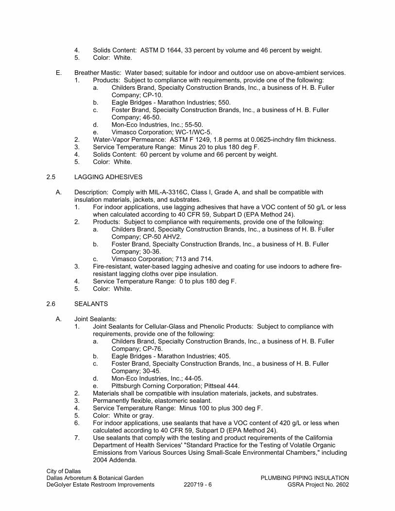
City of Dallas Dallas Arboretum & Botanical Garden PLUMBING PIPING INSULATION DeGolyer Estate Restroom Improvements 220719 - 6 GSRA Project No. 2602
4. Solids Content: ASTM D 1644, 33 percent by volume and 46 percent by weight. 5. Color: White.
E. Breather Mastic: Water based; suitable for indoor and outdoor use on above-ambient services. 1. Products: Subject to compliance with requirements, provide one of the following:
a. Childers Brand, Specialty Construction Brands, Inc., a business of H. B. Fuller Company; CP-10.
b. Eagle Bridges - Marathon Industries; 550. c. Foster Brand, Specialty Construction Brands, Inc., a business of H. B. Fuller
Company; 46-50. d. Mon-Eco Industries, Inc.; 55-50. e. Vimasco Corporation; WC-1/WC-5.
2. Water-Vapor Permeance: ASTM F 1249, 1.8 perms at 0.0625-inchdry film thickness. 3. Service Temperature Range: Minus 20 to plus 180 deg F. 4. Solids Content: 60 percent by volume and 66 percent by weight. 5. Color: White.
2.5 LAGGING ADHESIVES
A. Description: Comply with MIL-A-3316C, Class I, Grade A, and shall be compatible with insulation materials, jackets, and substrates. 1. For indoor applications, use lagging adhesives that have a VOC content of 50 g/L or less
when calculated according to 40 CFR 59, Subpart D (EPA Method 24). 2. Products: Subject to compliance with requirements, provide one of the following:
a. Childers Brand, Specialty Construction Brands, Inc., a business of H. B. Fuller Company; CP-50 AHV2.
b. Foster Brand, Specialty Construction Brands, Inc., a business of H. B. Fuller Company; 30-36.
c. Vimasco Corporation; 713 and 714. 3. Fire-resistant, water-based lagging adhesive and coating for use indoors to adhere fire-
resistant lagging cloths over pipe insulation. 4. Service Temperature Range: 0 to plus 180 deg F. 5. Color: White.
2.6 SEALANTS
A. Joint Sealants: 1. Joint Sealants for Cellular-Glass and Phenolic Products: Subject to compliance with
requirements, provide one of the following: a. Childers Brand, Specialty Construction Brands, Inc., a business of H. B. Fuller
Company; CP-76. b. Eagle Bridges - Marathon Industries; 405. c. Foster Brand, Specialty Construction Brands, Inc., a business of H. B. Fuller
Company; 30-45. d. Mon-Eco Industries, Inc.; 44-05. e. Pittsburgh Corning Corporation; Pittseal 444.
2. Materials shall be compatible with insulation materials, jackets, and substrates. 3. Permanently flexible, elastomeric sealant. 4. Service Temperature Range: Minus 100 to plus 300 deg F. 5. Color: White or gray. 6. For indoor applications, use sealants that have a VOC content of 420 g/L or less when
calculated according to 40 CFR 59, Subpart D (EPA Method 24). 7. Use sealants that comply with the testing and product requirements of the California
Department of Health Services' "Standard Practice for the Testing of Volatile Organic Emissions from Various Sources Using Small-Scale Environmental Chambers," including 2004 Addenda.

City of Dallas Dallas Arboretum & Botanical Garden PLUMBING PIPING INSULATION DeGolyer Estate Restroom Improvements 220719 - 7 GSRA Project No. 2602
B. FSK and Metal Jacket Flashing Sealants: 1. Products: Subject to compliance with requirements, provide one of the following:
a. Childers Brand, Specialty Construction Brands, Inc., a business of H. B. Fuller Company; CP-76.
b. Eagle Bridges - Marathon Industries; 405. c. Foster Brand, Specialty Construction Brands, Inc., a business of H. B. Fuller
Company; 95-44. d. Mon-Eco Industries, Inc.; 44-05.
2. Materials shall be compatible with insulation materials, jackets, and substrates. 3. Fire- and water-resistant, flexible, elastomeric sealant. 4. Service Temperature Range: Minus 40 to plus 250 deg F. 5. Color: Aluminum. 6. For indoor applications, use sealants that have a VOC content of 420 g/L or less when
calculated according to 40 CFR 59, Subpart D (EPA Method 24). 7. Use sealants that comply with the testing and product requirements of the California
Department of Health Services' "Standard Practice for the Testing of Volatile Organic Emissions from Various Sources Using Small-Scale Environmental Chambers," including 2004 Addenda.
C. ASJ Flashing Sealants, and Vinyl, PVDC, and PVC Jacket Flashing Sealants: 1. Products: Subject to compliance with requirements, provide one of the following:
a. Childers Brand, Specialty Construction Brands, Inc., a business of H. B. Fuller Company; CP-76.
2. Materials shall be compatible with insulation materials, jackets, and substrates. 3. Fire- and water-resistant, flexible, elastomeric sealant. 4. Service Temperature Range: Minus 40 to plus 250 deg F. 5. Color: White. 6. For indoor applications, use sealants that have a VOC content of 420 g/L or less when
calculated according to 40 CFR 59, Subpart D (EPA Method 24). 7. Use sealants that comply with the testing and product requirements of the California
Department of Health Services' "Standard Practice for the Testing of Volatile Organic Emissions from Various Sources Using Small-Scale Environmental Chambers," including 2004 Addenda.
2.7 FACTORY-APPLIED JACKETS
A. Insulation system schedules indicate factory-applied jackets on various applications. When factory-applied jackets are indicated, comply with the following: 1. ASJ: White, kraft-paper, fiberglass-reinforced scrim with aluminum-foil backing;
complying with ASTM C 1136, Type I. 2. ASJ-SSL: ASJ with self-sealing, pressure-sensitive, acrylic-based adhesive covered by a
removable protective strip; complying with ASTM C 1136, Type I. 3. FSK Jacket: Aluminum-foil, fiberglass-reinforced scrim with kraft-paper backing;
complying with ASTM C 1136, Type II.
2.8 FIELD-APPLIED FABRIC-REINFORCING MESH
A. Woven Glass-Fiber Fabric: Approximately 2 oz./sq. yd.with a thread count of 10 strands by 10 strands/sq. in. for covering pipe and pipe fittings. 1. Products: Subject to compliance with requirements, provide one of the following:
a. Childers Brand, Specialty Construction Brands, Inc., a business of H. B. Fuller Company; Chil-Glas Number 10.
B. Woven Polyester Fabric: Approximately 1 oz./sq. yd. with a thread count of 10 strands by 10 strands/sq. in., in a Leno weave, for pipe. 1. Products: Subject to compliance with requirements, provide one of the following:

City of Dallas Dallas Arboretum & Botanical Garden PLUMBING PIPING INSULATION DeGolyer Estate Restroom Improvements 220719 - 8 GSRA Project No. 2602
a. Foster Brand, Specialty Construction Brands, Inc., a business of H. B. Fuller Company; Mast-A-Fab.
b. Vimasco Corporation; Elastafab 894.
2.9 FIELD-APPLIED CLOTHS
A. Woven Glass-Fiber Fabric: Comply with MIL-C-20079H, Type I, plain weave, and presized a minimum of 8 oz./sq. yd. 1. Products: Subject to compliance with requirements, provide one of the following:
a. Alpha Associates, Inc.; Alpha-Maritex 84215 and 84217/9485RW, Luben 59.
2.10 FIELD-APPLIED JACKETS
A. Field-applied jackets shall comply with ASTM C 921, Type I, unless otherwise indicated.
B. PVC Jacket: High-impact-resistant, UV-resistant PVC complying with ASTM D 1784, Class 16354-C; thickness as scheduled; roll stock ready for shop or field cutting and forming. Thickness is indicated in field-applied jacket schedules. 1. Products: Subject to compliance with requirements, provide one of the following:
a. Johns Manville; Zeston. b. P.I.C. Plastics, Inc.; FG Series. c. Proto Corporation; LoSmoke. d. Speedline Corporation; SmokeSafe.
2. Adhesive: As recommended by jacket material manufacturer. 3. Color: Color-code jackets based on system. 4. Factory-fabricated fitting covers to match jacket if available; otherwise, field fabricate.
a. Shapes: 45- and 90-degree, short- and long-radius elbows, tees, valves, flanges, unions, reducers, end caps, soil-pipe hubs, traps, mechanical joints, and P-trap and supply covers for lavatories.
C. Metal Jacket: 1. Products: Subject to compliance with requirements, provide one of the following:
a. Childers Brand, Specialty Construction Brands, Inc., a business of H. B. Fuller Company; Metal Jacketing Systems.
b. ITW Insulation Systems; Aluminum and Stainless Steel Jacketing. c. RPR Products, Inc.; Insul-Mate.
2. Aluminum Jacket: Comply with ASTM B 209, Alloy 3003, 3005, 3105, or 5005, Temper H-14. a. Sheet and roll stock ready for shop or field sizing. b. Finish and thickness are indicated in field-applied jacket schedules. c. Moisture Barrier for Indoor Applications: 1-mil-thick, heat-bonded polyethylene
and kraft paper. d. Moisture Barrier for Outdoor Applications: 3-mil-thick, heat-bonded polyethylene
and kraft paper. e. Factory-Fabricated Fitting Covers:
1) Same material, finish, and thickness as jacket. 2) Preformed 2-piece or gore, 45- and 90-degree, short- and long-radius
elbows. 3) Tee covers. 4) Flange and union covers. 5) End caps. 6) Beveled collars. 7) Valve covers. 8) Field fabricate fitting covers only if factory-fabricated fitting covers are not
available. 3. Stainless-Steel Jacket: ASTM A 167 or ASTM A 240/A 240M.

City of Dallas Dallas Arboretum & Botanical Garden PLUMBING PIPING INSULATION DeGolyer Estate Restroom Improvements 220719 - 9 GSRA Project No. 2602
a. Sheet and roll stock ready for shop or field sizing. b. Material, finish, and thickness are indicated in field-applied jacket schedules. c. Moisture Barrier for Indoor Applications: 1-mil-thick, heat-bonded polyethylene
and kraft paper. d. Moisture Barrier for Outdoor Applications: 3-mil-thick, heat-bonded polyethylene
and kraft paper. e. Factory-Fabricated Fitting Covers:
1) Same material, finish, and thickness as jacket. 2) Preformed 2-piece or gore, 45- and 90-degree, short- and long-radius
elbows. 3) Tee covers. 4) Flange and union covers. 5) End caps. 6) Beveled collars. 7) Valve covers. 8) Field fabricate fitting covers only if factory-fabricated fitting covers are not
available.
D. Underground Direct-Buried Jacket: 125-mil-thick vapor barrier and waterproofing membrane consisting of a rubberized bituminous resin reinforced with a woven-glass fiber or polyester scrim and laminated aluminum foil. 1. Products: Subject to compliance with requirements, provide one of the following:
a. Pittsburgh Corning Corporation; Pittwrap. b. Polyguard Products, Inc.; Insulrap No Torch 125.
2.11 TAPES
A. ASJ Tape: White vapor-retarder tape matching factory-applied jacket with acrylic adhesive, complying with ASTM C 1136. 1. Products: Subject to compliance with requirements, provide one of the following:
a. ABI, Ideal Tape Division; 428 AWF ASJ. b. Avery Dennison Corporation, Specialty Tapes Division; Fasson 0836. c. Compac Corporation; 104 and 105. d. Venture Tape; 1540 CW Plus, 1542 CW Plus, and 1542 CW Plus/SQ.
2. Width: 3 inches 3. Thickness: 11.5 mils. 4. Adhesion: 90 ounces force/inch in width. 5. Elongation: 2 percent. 6. Tensile Strength: 40 lbf/inchin width. 7. ASJ Tape Disks and Squares: Precut disks or squares of ASJ tape.
B. FSK Tape: Foil-face, vapor-retarder tape matching factory-applied jacket with acrylic adhesive; complying with ASTM C 1136. 1. Products: Subject to compliance with requirements, provide one of the following:
a. ABI, Ideal Tape Division; 491 AWF FSK. b. Avery Dennison Corporation, Specialty Tapes Division; Fasson 0827. c. Compac Corporation; 110 and 111. d. Venture Tape; 1525 CW NT, 1528 CW, and 1528 CW/SQ.
2. Width: 3 inches. 3. Thickness: 6.5 mils. 4. Adhesion: 90 ounces force/inchin width. 5. Elongation: 2 percent. 6. Tensile Strength: 40 lbf/inchin width. 7. FSK Tape Disks and Squares: Precut disks or squares of FSK tape.
C. PVC Tape: White vapor-retarder tape matching field-applied PVC jacket with acrylic adhesive;

City of Dallas Dallas Arboretum & Botanical Garden PLUMBING PIPING INSULATION DeGolyer Estate Restroom Improvements 220719 - 10 GSRA Project No. 2602
suitable for indoor and outdoor applications. 1. Products: Subject to compliance with requirements, provide one of the following:
a. ABI, Ideal Tape Division; 370 White PVC tape. b. Compac Corporation; 130. c. Venture Tape; 1506 CW NS.
2. Width: 2 inches. 3. Thickness: 6 mils. 4. Adhesion: 64 ounces force/inchin width. 5. Elongation: 500 percent. 6. Tensile Strength: 18 lbf/inchin width.
D. Aluminum-Foil Tape: Vapor-retarder tape with acrylic adhesive. 1. Products: Subject to compliance with requirements, provide one of the following:
a. ABI, Ideal Tape Division; 488 AWF. b. Avery Dennison Corporation, Specialty Tapes Division; Fasson 0800. c. Compac Corporation; 120. d. Venture Tape; 3520 CW.
2. Width: 2 inches. 3. Thickness: 3.7 mils. 4. Adhesion: 100 ounces force/inchin width. 5. Elongation: 5 percent. 6. Tensile Strength: 34 lbf/inchin width.
2.12 SECUREMENTS
A. Bands: 1. Products: Subject to compliance with requirements provide one of the following:
a. ITW Insulation Systems; Gerrard Strapping and Seals. b. RPR Products, Inc.; Insul-Mate Strapping and Seals.
2. Stainless Steel: ASTM A 167 or ASTM A 240/A 240M, Type 304 or Type 316; 0.015 inch thick, 3/4 inchwide with wing seal or closed seal.
3. Aluminum: ASTM B 209, Alloy 3003, 3005, 3105, or 5005; Temper H-14, 0.020 inch thick, 3/4 inch wide with wing seal or closed seal.
B. Staples: Outward-clinching insulation staples, nominal 3/4-inch-wide, stainless steel or Monel.
C. Wire: 0.080-inchnickel-copper alloy 0.062-inchsoft-annealed, stainless steel 0.062-inchsoft-annealed, galvanized steel. 1. Manufacturers: Subject to compliance with requirements, provide products by one of the
following: a. C & F Wire.
2.13 PROTECTIVE SHIELDING GUARDS
A. Protective Shielding Pipe Covers: 1. Manufacturers: Subject to compliance with requirements, provide products by one of the
following: a. Engineered Brass Company. b. McGuire Manufacturing. c. Plumberex. d. Truebro; a brand of IPS Corporation. e. Zurn Industries, LLC; Tubular Brass Plumbing Products Operation.
2. Description: Manufactured plastic wraps for covering plumbing fixture hot- and cold-water supplies and trap and drain piping. Comply with Americans with Disabilities Act (ADA) requirements.

City of Dallas Dallas Arboretum & Botanical Garden PLUMBING PIPING INSULATION DeGolyer Estate Restroom Improvements 220719 - 11 GSRA Project No. 2602
B. Protective Shielding Piping Enclosures: 1. Manufacturers: Subject to compliance with requirements, provide products by one of the
following: a. Truebro; a brand of IPS Corporation. b. Zurn Industries, LLC; Tubular Brass Plumbing Products Operation.
2. Description: Manufactured plastic enclosure for covering plumbing fixture hot- and cold-water supplies and trap and drain piping. Comply with ADA requirements.
PART 3 - EXECUTION
3.1 EXAMINATION
A. Examine substrates and conditions for compliance with requirements for installation tolerances and other conditions affecting performance of insulation application. 1. Verify that systems to be insulated have been tested and are free of defects. 2. Verify that surfaces to be insulated are clean and dry.
B. Proceed with installation only after unsatisfactory conditions have been corrected.
3.2 PREPARATION
A. Surface Preparation: Clean and dry surfaces to receive insulation. Remove materials that will adversely affect insulation application.
B. Surface Preparation: Clean and prepare surfaces to be insulated. Before insulating, apply a corrosion coating to insulated surfaces as follows: 1. Stainless Steel: Coat 300 series stainless steel with an epoxy primer 5 mils thick and an
epoxy finish 5 mils thick if operating in a temperature range between 140 and 300 deg F. Consult coating manufacturer for appropriate coating materials and application methods for operating temperature range.
2. Carbon Steel: Coat carbon steel operating at a service temperature between 32 and 300 deg F with an epoxy coating. Consult coating manufacturer for appropriate coating materials and application methods for operating temperature range.
C. Coordinate insulation installation with the trade installing heat tracing. Comply with requirements for heat tracing that apply to insulation.
D. Mix insulating cements with clean potable water; if insulating cements are to be in contact with stainless-steel surfaces, use demineralized water.
3.3 GENERAL INSTALLATION REQUIREMENTS
A. Install insulation materials, accessories, and finishes with smooth, straight, and even surfaces; free of voids throughout the length of piping including fittings, valves, and specialties.
B. Install insulation materials, forms, vapor barriers or retarders, jackets, and thicknesses required for each item of pipe system as specified in insulation system schedules.
C. Install accessories compatible with insulation materials and suitable for the service. Install accessories that do not corrode, soften, or otherwise attack insulation or jacket in either wet or dry state.
D. Install insulation with longitudinal seams at top and bottom of horizontal runs.

City of Dallas Dallas Arboretum & Botanical Garden PLUMBING PIPING INSULATION DeGolyer Estate Restroom Improvements 220719 - 12 GSRA Project No. 2602
E. Install multiple layers of insulation with longitudinal and end seams staggered.
F. Do not weld brackets, clips, or other attachment devices to piping, fittings, and specialties.
G. Keep insulation materials dry during application and finishing.
H. Install insulation with tight longitudinal seams and end joints. Bond seams and joints with adhesive recommended by insulation material manufacturer.
I. Install insulation with least number of joints practical.
J. Where vapor barrier is indicated, seal joints, seams, and penetrations in insulation at hangers, supports, anchors, and other projections with vapor-barrier mastic. 1. Install insulation continuously through hangers and around anchor attachments. 2. For insulation application where vapor barriers are indicated, extend insulation on anchor
legs from point of attachment to supported item to point of attachment to structure. Taper and seal ends at attachment to structure with vapor-barrier mastic.
3. Install insert materials and install insulation to tightly join the insert. Seal insulation to insulation inserts with adhesive or sealing compound recommended by insulation material manufacturer.
4. Cover inserts with jacket material matching adjacent pipe insulation. Install shields over jacket, arranged to protect jacket from tear or puncture by hanger, support, and shield.
K. Apply adhesives, mastics, and sealants at manufacturer's recommended coverage rate and wet and dry film thicknesses.
L. Install insulation with factory-applied jackets as follows: 1. Draw jacket tight and smooth. 2. Cover circumferential joints with 3-inch-wide strips, of same material as insulation jacket.
Secure strips with adhesive and outward clinching staples along both edges of strip, spaced 4 inches o.c.
3. Overlap jacket longitudinal seams at least 1-1/2 inches. Install insulation with longitudinal seams at bottom of pipe. Clean and dry surface to receive self-sealing lap. Staple laps with outward clinching staples along edge at 2 inches4 inches o.c. a. For below-ambient services, apply vapor-barrier mastic over staples.
4. Cover joints and seams with tape, according to insulation material manufacturer's written instructions, to maintain vapor seal.
5. Where vapor barriers are indicated, apply vapor-barrier mastic on seams and joints and at ends adjacent to pipe flanges and fittings.
M. Cut insulation in a manner to avoid compressing insulation more than 75 percent of its nominal thickness.
N. Finish installation with systems at operating conditions. Repair joint separations and cracking due to thermal movement.
O. Repair damaged insulation facings by applying same facing material over damaged areas. Extend patches at least 4 inches beyond damaged areas. Adhere, staple, and seal patches similar to butt joints.
P. For above-ambient services, do not install insulation to the following: 1. Vibration-control devices. 2. Testing agency labels and stamps. 3. Nameplates and data plates. 4. Cleanouts.

City of Dallas Dallas Arboretum & Botanical Garden PLUMBING PIPING INSULATION DeGolyer Estate Restroom Improvements 220719 - 13 GSRA Project No. 2602
3.4 PENETRATIONS
A. Insulation Installation at Roof Penetrations: Install insulation continuously through roof penetrations. 1. Seal penetrations with flashing sealant. 2. For applications requiring only indoor insulation, terminate insulation above roof surface
and seal with joint sealant. For applications requiring indoor and outdoor insulation, install insulation for outdoor applications tightly joined to indoor insulation ends. Seal joint with joint sealant.
3. Extend jacket of outdoor insulation outside roof flashing at least 2 inches below top of roof flashing.
4. Seal jacket to roof flashing with flashing sealant.
B. Insulation Installation at Underground Exterior Wall Penetrations: Terminate insulation flush with sleeve seal. Seal terminations with flashing sealant.
C. Insulation Installation at Aboveground Exterior Wall Penetrations: Install insulation continuously through wall penetrations. 1. Seal penetrations with flashing sealant. 2. For applications requiring only indoor insulation, terminate insulation inside wall surface
and seal with joint sealant. For applications requiring indoor and outdoor insulation, install insulation for outdoor applications tightly joined to indoor insulation ends. Seal joint with joint sealant.
3. Extend jacket of outdoor insulation outside wall flashing and overlap wall flashing at least 2 inches.
4. Seal jacket to wall flashing with flashing sealant.
D. Insulation Installation at Interior Wall and Partition Penetrations (That Are Not Fire Rated): Install insulation continuously through walls and partitions.
E. Insulation Installation at Fire-Rated Wall and Partition Penetrations: Install insulation continuously through penetrations of fire-rated walls and partitions. 1. Comply with requirements in Division 07 Section "Penetration Firestopping" for
firestopping and fire-resistive joint sealers.
F. Insulation Installation at Floor Penetrations: 1. Pipe: Install insulation continuously through floor penetrations. 2. Seal penetrations through fire-rated assemblies. Comply with requirements in
Division 07 Section "Penetration Firestopping."
3.5 GENERAL PIPE INSULATION INSTALLATION
A. Requirements in this article generally apply to all insulation materials except where more specific requirements are specified in various pipe insulation material installation articles.
B. Insulation Installation on Fittings, Valves, Strainers, Flanges, and Unions: 1. Install insulation over fittings, valves, strainers, flanges, unions, and other specialties with
continuous thermal and vapor-retarder integrity unless otherwise indicated. 2. Insulate pipe elbows using preformed fitting insulation or mitered fittings made from same
material and density as adjacent pipe insulation. Each piece shall be butted tightly against adjoining piece and bonded with adhesive. Fill joints, seams, voids, and irregular surfaces with insulating cement finished to a smooth, hard, and uniform contour that is uniform with adjoining pipe insulation.
3. Insulate tee fittings with preformed fitting insulation or sectional pipe insulation of same material and thickness as used for adjacent pipe. Cut sectional pipe insulation to fit. Butt

City of Dallas Dallas Arboretum & Botanical Garden PLUMBING PIPING INSULATION DeGolyer Estate Restroom Improvements 220719 - 14 GSRA Project No. 2602
each section closely to the next and hold in place with tie wire. Bond pieces with adhesive.
4. Insulate valves using preformed fitting insulation or sectional pipe insulation of same material, density, and thickness as used for adjacent pipe. Overlap adjoining pipe insulation by not less than two times the thickness of pipe insulation, or one pipe diameter, whichever is thicker. For valves, insulate up to and including the bonnets, valve stuffing-box studs, bolts, and nuts. Fill joints, seams, and irregular surfaces with insulating cement.
5. Insulate strainers using preformed fitting insulation or sectional pipe insulation of same material, density, and thickness as used for adjacent pipe. Overlap adjoining pipe insulation by not less than two times the thickness of pipe insulation, or one pipe diameter, whichever is thicker. Fill joints, seams, and irregular surfaces with insulating cement. Insulate strainers so strainer basket flange or plug can be easily removed and replaced without damaging the insulation and jacket. Provide a removable reusable insulation cover. For below-ambient services, provide a design that maintains vapor barrier.
6. Insulate flanges and unions using a section of oversized preformed pipe insulation. Overlap adjoining pipe insulation by not less than two times the thickness of pipe insulation, or one pipe diameter, whichever is thicker.
7. Cover segmented insulated surfaces with a layer of finishing cement and coat with a mastic. Install vapor-barrier mastic for below-ambient services and a breather mastic for above-ambient services. Reinforce the mastic with fabric-reinforcing mesh. Trowel the mastic to a smooth and well-shaped contour.
8. For services not specified to receive a field-applied jacket except for flexible elastomeric and polyolefin, install fitted PVC cover over elbows, tees, strainers, valves, flanges, and unions. Terminate ends with PVC end caps. Tape PVC covers to adjoining insulation facing using PVC tape.
9. Stencil or label the outside insulation jacket of each union with the word "union." Match size and color of pipe labels.
C. Insulate instrument connections for thermometers, pressure gages, pressure temperature taps, test connections, flow meters, sensors, switches, and transmitters on insulated pipes. Shape insulation at these connections by tapering it to and around the connection with insulating cement and finish with finishing cement, mastic, and flashing sealant.
D. Install removable insulation covers at locations indicated. Installation shall conform to the following: 1. Make removable flange and union insulation from sectional pipe insulation of same
thickness as that on adjoining pipe. Install same insulation jacket as adjoining pipe insulation.
2. When flange and union covers are made from sectional pipe insulation, extend insulation from flanges or union long at least two times the insulation thickness over adjacent pipe insulation on each side of flange or union. Secure flange cover in place with stainless-steel or aluminum bands. Select band material compatible with insulation and jacket.
3. Construct removable valve insulation covers in same manner as for flanges, except divide the two-part section on the vertical center line of valve body.
4. When covers are made from block insulation, make two halves, each consisting of mitered blocks wired to stainless-steel fabric. Secure this wire frame, with its attached insulation, to flanges with tie wire. Extend insulation at least 2 inches over adjacent pipe insulation on each side of valve. Fill space between flange or union cover and pipe insulation with insulating cement. Finish cover assembly with insulating cement applied in two coats. After first coat is dry, apply and trowel second coat to a smooth finish.
5. Unless a PVC jacket is indicated in field-applied jacket schedules, finish exposed surfaces with a metal jacket.

City of Dallas Dallas Arboretum & Botanical Garden PLUMBING PIPING INSULATION DeGolyer Estate Restroom Improvements 220719 - 15 GSRA Project No. 2602
3.6 INSTALLATION OF CELLULAR-GLASS INSULATION
A. Insulation Installation on Straight Pipes and Tubes: 1. Secure each layer of insulation to pipe with wire or bands and tighten bands without
deforming insulation materials. 2. Where vapor barriers are indicated, seal longitudinal seams, end joints, and protrusions
with vapor-barrier mastic and joint sealant. 3. For insulation with factory-applied jackets on above-ambient services, secure laps with
outward clinched staples at 6 inches o.c. 4. For insulation with factory-applied jackets on below-ambient services, do not staple
longitudinal tabs. Instead, secure tabs with additional adhesive as recommended by insulation material manufacturer and seal with vapor-barrier mastic and flashing sealant.
B. Insulation Installation on Pipe Flanges: 1. Install preformed pipe insulation to outer diameter of pipe flange. 2. Make width of insulation section same as overall width of flange and bolts, plus twice the
thickness of pipe insulation. 3. Fill voids between inner circumference of flange insulation and outer circumference of
adjacent straight pipe segments with cut sections of cellular-glass block insulation of same thickness as pipe insulation.
4. Install jacket material with manufacturer's recommended adhesive, overlap seams at least 1 inch, and seal joints with flashing sealant.
C. Insulation Installation on Pipe Fittings and Elbows: 1. Install preformed sections of same material as straight segments of pipe insulation when
available. Secure according to manufacturer's written instructions. 2. When preformed sections of insulation are not available, install mitered sections of
cellular-glass insulation. Secure insulation materials with wire or bands.
D. Insulation Installation on Valves and Pipe Specialties: 1. Install preformed sections of cellular-glass insulation to valve body. 2. Arrange insulation to permit access to packing and to allow valve operation without
disturbing insulation. 3. Install insulation to flanges as specified for flange insulation application.
3.7 INSTALLATION OF FLEXIBLE ELASTOMERIC INSULATION
A. Seal longitudinal seams and end joints with manufacturer's recommended adhesive to eliminate openings in insulation that allow passage of air to surface being insulated.
B. Insulation Installation on Pipe Flanges: 1. Install pipe insulation to outer diameter of pipe flange. 2. Make width of insulation section same as overall width of flange and bolts, plus twice the
thickness of pipe insulation. 3. Fill voids between inner circumference of flange insulation and outer circumference of
adjacent straight pipe segments with cut sections of sheet insulation of same thickness as pipe insulation.
4. Secure insulation to flanges and seal seams with manufacturer's recommended adhesive to eliminate openings in insulation that allow passage of air to surface being insulated.
C. Insulation Installation on Pipe Fittings and Elbows: 1. Install mitered sections of pipe insulation. 2. Secure insulation materials and seal seams with manufacturer's recommended adhesive
to eliminate openings in insulation that allow passage of air to surface being insulated.

City of Dallas Dallas Arboretum & Botanical Garden PLUMBING PIPING INSULATION DeGolyer Estate Restroom Improvements 220719 - 16 GSRA Project No. 2602
D. Insulation Installation on Valves and Pipe Specialties: 1. Install preformed valve covers manufactured of same material as pipe insulation when
available. 2. When preformed valve covers are not available, install cut sections of pipe and sheet
insulation to valve body. Arrange insulation to permit access to packing and to allow valve operation without disturbing insulation.
3. Install insulation to flanges as specified for flange insulation application. 4. Secure insulation to valves and specialties and seal seams with manufacturer's
recommended adhesive to eliminate openings in insulation that allow passage of air to surface being insulated.
3.8 INSTALLATION OF MINERAL-FIBER INSULATION
A. Insulation Installation on Straight Pipes and Tubes: 1. Secure each layer of preformed pipe insulation to pipe with wire or bands and tighten
bands without deforming insulation materials. 2. Where vapor barriers are indicated, seal longitudinal seams, end joints, and protrusions
with vapor-barrier mastic and joint sealant. 3. For insulation with factory-applied jackets on above-ambient surfaces, secure laps with
outward clinched staples at 6 inches o.c. 4. For insulation with factory-applied jackets on below-ambient surfaces, do not staple
longitudinal tabs. Instead, secure tabs with additional adhesive as recommended by insulation material manufacturer and seal with vapor-barrier mastic and flashing sealant.
B. Insulation Installation on Pipe Flanges: 1. Install preformed pipe insulation to outer diameter of pipe flange. 2. Make width of insulation section same as overall width of flange and bolts, plus twice the
thickness of pipe insulation. 3. Fill voids between inner circumference of flange insulation and outer circumference of
adjacent straight pipe segments with mineral-fiber blanket insulation. 4. Install jacket material with manufacturer's recommended adhesive, overlap seams at
least 1 inch, and seal joints with flashing sealant.
C. Insulation Installation on Pipe Fittings and Elbows: 1. Install preformed sections of same material as straight segments of pipe insulation when
available. 2. When preformed insulation elbows and fittings are not available, install mitered sections
of pipe insulation, to a thickness equal to adjoining pipe insulation. Secure insulation materials with wire or bands.
D. Insulation Installation on Valves and Pipe Specialties: 1. Install preformed sections of same material as straight segments of pipe insulation when
available. 2. When preformed sections are not available, install mitered sections of pipe insulation to
valve body. 3. Arrange insulation to permit access to packing and to allow valve operation without
disturbing insulation. 4. Install insulation to flanges as specified for flange insulation application.
3.9 FIELD-APPLIED JACKET INSTALLATION
A. Where glass-cloth jackets are indicated, install directly over bare insulation or insulation with factory-applied jackets. 1. Draw jacket smooth and tight to surface with 2-inchoverlap at seams and joints. 2. Embed glass cloth between two 0.062-inch-thick coats of lagging adhesive. 3. Completely encapsulate insulation with coating, leaving no exposed insulation.

City of Dallas Dallas Arboretum & Botanical Garden PLUMBING PIPING INSULATION DeGolyer Estate Restroom Improvements 220719 - 17 GSRA Project No. 2602
B. Where FSK jackets are indicated, install as follows: 1. Draw jacket material smooth and tight. 2. Install lap or joint strips with same material as jacket. 3. Secure jacket to insulation with manufacturer's recommended adhesive. 4. Install jacket with 1-1/2-inchlaps at longitudinal seams and 3-inch-wide joint strips at end
joints. 5. Seal openings, punctures, and breaks in vapor-retarder jackets and exposed insulation
with vapor-barrier mastic.
C. Where PVC jackets are indicated, install with 1-inchoverlap at longitudinal seams and end joints. Seal with manufacturer's recommended adhesive. 1. Apply two continuous beads of adhesive to seams and joints, one bead under lap and the
finish bead along seam and joint edge.
D. Where metal jackets are indicated, install with 2-inchoverlap at longitudinal seams and end joints. Overlap longitudinal seams arranged to shed water. Seal end joints with weatherproof sealant recommended by insulation manufacturer. Secure jacket with stainless-steel bands 12 incheso.c. and at end joints.
3.10 FINISHES
A. Insulation with ASJ, Glass-Cloth, or Other Paintable Jacket Material: Paint jacket with paint system identified below and as specified in Division 09 painting Sections. 1. Flat Acrylic Finish: Two finish coats over a primer that is compatible with jacket material
and finish coat paint. Add fungicidal agent to render fabric mildew proof. a. Finish Coat Material: Interior, flat, latex-emulsion size.
B. Flexible Elastomeric Thermal Insulation: After adhesive has fully cured, apply two coats of insulation manufacturer's recommended protective coating.
C. Color: Final color as selected by Architect. Vary first and second coats to allow visual inspection of the completed Work.
D. Do not field paint aluminum or stainless-steel jackets.
3.11 FIELD QUALITY CONTROL
A. Testing Agency: Engage a qualified testing agency to perform tests and inspections.
B. Perform tests and inspections.
C. Tests and Inspections: 1. Inspect pipe, fittings, strainers, and valves, randomly selected by Architect, by removing
field-applied jacket and insulation in layers in reverse order of their installation. Extent of inspection shall be limited to three locations of straight pipe, three locations of threaded fittings, three locations of welded fittings, two locations of threaded strainers, two locations of welded strainers, three locations of threaded valves, and three locations of flanged valves for each pipe service defined in the "Piping Insulation Schedule, General" Article.
D. All insulation applications will be considered defective Work if sample inspection reveals noncompliance with requirements.

City of Dallas Dallas Arboretum & Botanical Garden PLUMBING PIPING INSULATION DeGolyer Estate Restroom Improvements 220719 - 18 GSRA Project No. 2602
3.12 PIPING INSULATION SCHEDULE, GENERAL
A. Acceptable preformed pipe and tubular insulation materials and thicknesses are identified for each piping system and pipe size range. If more than one material is listed for a piping system, selection from materials listed is Contractor's option.
B. Items Not Insulated: Unless otherwise indicated, do not install insulation on the following: 1. Drainage piping located in crawl spaces. 2. Underground piping. 3. Chrome-plated pipes and fittings unless there is a potential for personnel injury.
3.13 INDOOR PIPING INSULATION SCHEDULE
A. Insulate piping systems in accordance with latest edition of International Energy Conservation Code (ICCC) and ASHRAE standard 90.1. Insulation thicknesses given below are minimum thicknesses.
B. Domestic Cold Water: 1. NPS 1and Smaller: Insulation shall be one of the following:
a. Cellular Glass: 1-1/2 inches thick. b. Flexible Elastomeric: 3/4 inch thick. c. Mineral-Fiber, Preformed Pipe Insulation, Type I: 1 inch thick.
2. NPS 1-1/4 and Larger: Insulation shall be one of the following: a. Cellular Glass: 1-1/2 inches thick. b. Flexible Elastomeric: 1 inch thick. c. Mineral-Fiber, Preformed Pipe Insulation, Type I: 1 inch thick.
C. Domestic Hot and Recirculated Hot Water: 1. NPS 1-1/4 and Smaller: Insulation shall be one of the following:
a. Cellular Glass: 1-1/2 inches thick. b. Flexible Elastomeric: 3/4 inch thick. c. Mineral-Fiber, Preformed Pipe Insulation, Type I: 1 inch thick.
2. NPS 1-1/2 and Larger: Insulation shall be one of the following: a. Cellular Glass: 1-1/2 inches thick. b. Flexible Elastomeric: 1 inch thick. c. Mineral-Fiber, Preformed Pipe Insulation, Type I: 1 inch thick.
D. Domestic Chilled Water (Potable): 1. All Pipe Sizes: Insulation shall be one of the following:
a. Cellular Glass: 1-1/2 inches thick. b. Flexible Elastomeric: 1 inch thick. c. Mineral-Fiber, Preformed Pipe Insulation, Type I: 1 inch thick.
E. Exposed Sanitary Drains, Domestic Water, Domestic Hot Water, and Stops for Plumbing Fixtures for People with Disabilities: 1. All Pipe Sizes: Insulation shall be one of the following:
a. Flexible Elastomeric: 1 inch thick.
F. Sanitary Waste Piping Where Heat Tracing Is Installed: 1. All Pipe Sizes: Insulation shall be one of the following:
a. Cellular Glass: 2 inches thick. b. Mineral-Fiber, Preformed Pipe Insulation, Type I: 1-1/2 inches thick.
G. Floor Drains, Traps, and Sanitary Drain Piping within 10 Feet of Drain Receiving Condensate and Equipment Drain Water below 60 Deg F:

City of Dallas Dallas Arboretum & Botanical Garden PLUMBING PIPING INSULATION DeGolyer Estate Restroom Improvements 220719 - 19 GSRA Project No. 2602
1. All Pipe Sizes: Insulation shall be one of the following: a. Cellular Glass: 1-1/2 inches thick. b. Flexible Elastomeric: 1 inch thick. c. Mineral-Fiber, Preformed Pipe Insulation, Type I: 1 inch thick.
3.14 OUTDOOR, UNDERGROUND PIPING INSULATION SCHEDULE
A. Loose-fill insulation, for belowground piping, is specified in Division 33 piping distribution Sections.
B. Sanitary Waste Piping, All Sizes, Where Heat Tracing Is Installed: Cellular glass, 2 inches thick.
C. Chilled Water, All Sizes: Cellular glass, 2 inches thick.
3.15 INDOOR, FIELD-APPLIED JACKET SCHEDULE
A. Install jacket over insulation material. For insulation with factory-applied jacket, install the field-applied jacket over the factory-applied jacket.
B. If more than one material is listed, selection from materials listed is Contractor's option.
C. Piping, Concealed: 1. None.
D. Piping, Exposed domestic cold water, domestic hot water, domestic recirculating hot water, sanitary waste exposed to freezing conditions, storm water exposed to freezing conditions, roof drains and rainwater leaders, supplies and drains for handicap-accessible lavatories and sinks: 1. PVC, Color-Coded by System: 20 mils thick.
3.16 OUTDOOR, FIELD-APPLIED JACKET SCHEDULE
A. Install jacket over insulation material. For insulation with factory-applied jacket, install the field-applied jacket over the factory-applied jacket.
B. If more than one material is listed, selection from materials listed is Contractor's option.
C. Piping, Concealed domestic cold water, domestic hot water, domestic recirculating hot water, sanitary waste exposed to freezing conditions, storm water exposed to freezing conditions, roof drains and rainwater leaders, supplies and drains for handicap-accessible lavatories and sinks: 1. PVC, Color-Coded by System: 30 mils thick. 2. Aluminum, Smooth: 0.032 inch thick.
D. Piping, Exposed domestic cold water, domestic hot water, domestic recirculating hot water, sanitary waste exposed to freezing conditions, storm water exposed to freezing conditions, roof drains and rainwater leaders, supplies and drains for handicap-accessible lavatories and sinks: 1. Aluminum, Smooth with Z-Shaped Locking Seam 0.032 inch thick. 2. Stainless Steel, Type 304 or Type 316 with Z-Shaped Locking Seam: 0.024 inch thick.
3.17 UNDERGROUND, FIELD-INSTALLED INSULATION JACKET
A. For underground direct-buried piping applications, install underground direct-buried jacket over insulation material.
END OF SECTION
City of Dallas Dallas Arboretum & Botanical Garden DOMESTIC WATER PIPING DeGolyer Estate Restroom Improvements 221116 - 1 GSRA Project No. 2602
SECTION 221116
DOMESTIC WATER PIPING
PART 1 - GENERAL
1.1 SUMMARY
A. This Section includes domestic water piping from 5 feet outside of building to fixtures and equipment inside the building.
B. Related Sections include the following: 1. Division 22 Section "Meters and Gages" for thermometers, pressure gages, and fittings. 2. Division 22 Section "Plumbing Specialties" for water distribution piping specialties.
1.2 PERFORMANCE REQUIREMENTS
A. Provide components and installation capable of producing domestic water piping systems with the following minimum working-pressure ratings, unless otherwise indicated: 1. Domestic Water Service Piping: 160 psig. 2. Domestic Water Distribution Piping: 125 psig.
1.3 SUBMITTALS
A. Product Data: For pipe, tube, fittings, and couplings.
B. Water Samples: Specified in "Cleaning" Article in Part 3.
C. Field Test Reports: Indicate and interpret test results for compliance with performance requirements.
1.4 QUALITY ASSURANCE
A. Piping materials shall bear label, stamp, or other markings of specified testing agency.
B. Comply with NSF 61, "Drinking Water System Components-Health Effects; Sections 1 through 9," for potable domestic water piping and components.
PART 2 - PRODUCTS
2.1 PIPING MATERIALS
A. All piping, fittings, fixtures, or materials that contact potable water shall be lead-free.
B. Refer to Part 3 "Piping Applications" Article for applications of pipe, tube, fitting, and joining materials.
C. Transition Couplings for Aboveground Pressure Piping: Coupling or other manufactured fitting the same size as, with pressure rating at least equal to and ends compatible with, piping to be joined.
D. Transition Couplings for Underground Pressure Piping: AWWA C219, metal, sleeve-Type coupling or other manufactured fitting the same size as, with pressure rating at least equal to
City of Dallas Dallas Arboretum & Botanical Garden DOMESTIC WATER PIPING DeGolyer Estate Restroom Improvements 221116 - 2 GSRA Project No. 2602
and ends compatible with, piping to be joined.
2.2 COPPER TUBING
A. Soft Copper Tube: ASTM B 88, Type K, water tube, annealed temper. 1. Copper Pressure Fittings: ASME B16.18, cast-copper-alloy or ASME B16.22, wrought-
copper, solder-joint fittings. Furnish wrought-copper fittings if indicated. 2. Bronze Flanges: ASME B16.24, Class 150, with solder-joint end. Furnish Class 300
flanges if required to match piping. 3. Copper Unions: MSS SP-123, cast-copper-alloy, hexagonal-stock body, with ball-and-
socket, metal-to-metal seating surfaces and solder-joint or threaded ends.
B. Hard Copper Tube: ASTM B 88, Type L, water tube, drawn temper. 1. Copper Pressure Fittings: ASME B16.18, cast-copper-alloy or ASME B16.22, wrought-
copper, solder-joint fittings. Furnish wrought-copper fittings if indicated. 2. Bronze Flanges: ASME B16.24, Class 150, with solder-joint end. Furnish Class 300
flanges if required to match piping. 3. Copper Unions: MSS SP-123, cast-copper-alloy, hexagonal-stock body, with ball-and-
socket, metal-to-metal seating surfaces and solder-joint or threaded ends. 4. Copper, Grooved-End Fittings: ASTM B 75 copper tube or ASTM B 584 bronze
castings. a. Copper-Tubing, Keyed Couplings: Copper-tube dimensions and Design similar to
AWWAC606. Include ferrous housing sections, gasket suitable for hot water, and bolts and nuts.
2.3 VALVES
A. Refer to Section 220523 "General-Duty Valves for Plumbing Piping" for bronze and cast-iron, general-duty valves.
B. Refer to Section 224019 "Plumbing Specialties" for balancing and drain valves.
PART 3 - EXECUTION
3.1 EXCAVATION
A. Refer to Division 2 Section "Earthwork" for excavating, trenching, and backfilling.
3.2 PIPING APPLICATIONS
A. Transition and special fittings with pressure ratings at least equal to piping rating may be used in applications below, unless otherwise indicated.
B. Flanges may be used on aboveground piping, unless otherwise indicated.
C. Grooved joints may be used on aboveground grooved-end piping.
D. Fitting Option: Mechanically formed tee-branch outlets and brazed joints may be used on aboveground copper tubing.
E. Underground Domestic Water Piping: Use any of the following piping materials for each size range: 1. NPS 3 and Smaller: Soft copper tube, ASTM B88, Type K; wrought-copper, solder joint
fittings; and brazed joints.

City of Dallas Dallas Arboretum & Botanical Garden DOMESTIC WATER PIPING DeGolyer Estate Restroom Improvements 221116 - 3 GSRA Project No. 2602
2. NPS 4 and Larger: Soft copper tube, ASTM B88, Type K; wrought-copper, solder joint fittings; and brazed joints.
F. Aboveground Domestic Water Piping: Use any of the following piping materials for each size range: 1. NPS 1-1/2 and Smaller: Hard copper tube, Type L; copper pressure fittings; and soldered
joints. 2. NPS 2: Hard copper tube, Type L; copper pressure fittings; and soldered joints. 3. NPS 2-1/2 to NPS 6: Hard copper tube, Type L; copper pressure fittings; and soldered
joints. 4. NPS 2-1/2 to NPS 6: Hard copper tube, Type L with grooved ends; copper grooved-end
fittings; copper-tubing, keyed couplings; and grooved joints. 5. NPS 8: Hard copper tube, Type L with grooved ends; copper grooved-end fittings;
copper-tubing, keyed couplings; and grooved joints.
3.3 VALVE APPLICATIONS
A. Drawings indicate valve Types to be used. Where specific valve Types are not indicated, the following requirements apply: 1. Shutoff Duty: Use bronze ball valves for piping NPS 2 and smaller. Use cast- iron
butterfly or gate valves with flanged ends for piping NPS 2-1/2 and larger. 2. Throttling Duty: Use bronze ball valves for piping NPS 2 and smaller. Use cast-iron
butterfly valves with flanged ends for piping NPS 2-1/2 and larger. 3. Hot-Water-Piping, Balancing Duty: Calibrated balancing valves. 4. Drain Duty: Hose-end drain valves.
B. Cast-iron, grooved-end valves may be used with grooved-end piping.
3.4 PIPING INSTALLATION
A. Extend domestic water service piping to exterior water distribution piping in sizes and locations indicated.
B. Install underground copper tubing according to CDA's "Copper Tube Handbook."
C. Install sleeve with water stop and mechanical sleeve seal at each service pipe penetration through foundation wall. Select number of interlocking rubber links required to make installation watertight.
D. Install shutoff valve, hose-end drain valve, strainer, pressure gage, and test tee with valve, inside building at each domestic water service.
E. Install aboveground domestic water piping level and plumb.
F. Fill water piping. Check components to determine that they are not air bound and that piping is full of water.
G. Perform the following steps before operation: 1. Close drain valves, hydrants, and hose bibbs. 2. Open shutoff valves to fully open position. 3. Open throttling valves to proper setting. 4. Remove plugs used during testing of piping and plugs used for temporary sealing of
piping during installation. 5. Remove and clean strainer screens. Close drain valves and replace drain plugs. 6. Remove filter cartridges from housings, and verify that cartridges are as specified for

City of Dallas Dallas Arboretum & Botanical Garden DOMESTIC WATER PIPING DeGolyer Estate Restroom Improvements 221116 - 4 GSRA Project No. 2602
application where used and that cartridges are clean and ready for use.
H. Check plumbing equipment and verify proper settings, adjustments, and operation. Do not operate water heaters before filling with water.
I. Check plumbing specialties and verify proper settings, adjustments, and operation. 1. Water-Pressure Regulators: Set outlet pressure at 80 psig maximum, unless otherwise
indicated.
J. Energize pumps and verify proper operation.
3.5 JOINT CONSTRUCTION
A. Soldered Joints: Use ASTM B 813, water-flushable, lead-free flux; ASTM B 32, lead-free- alloy solder; and ASTM B 828 procedure, unless otherwise indicated.
B. Mechanically Formed Outlets: Form tee in copper tube according to equipment manufacturer's written instructions. Use tool designed for copper tube; drill pilot hole, form collar for outlet, dimple tube to form seating stop, and braze branch tube into collar.
3.6 VALVE INSTALLATION
A. Install sectional valve close to water main on each branch and riser serving plumbing fixtures or equipment. Use ball or gate valves for piping NPS 3 and smaller.
B. Install shutoff valve on each water supply to equipment and on each water supply to plumbing fixtures without supply stops. Use ball valves for piping NPS 3 and smaller. Use butterfly or gate valves for piping NPS 4 and larger.
C. Install drain valves for equipment, at base of each water riser, at low points in horizontal piping, and where required to drain water piping. 1. Install hose-end drain valves at low points in water mains, risers, and branches. 2. Install stop-and-waste drain valves where indicated.
D. Install calibrated balancing valves in each hot-water circulation return branch and discharge side of each pump and circulator. Set calibrated balancing valves partly open to restrict but not stop flow.
3.7 HANGER AND SUPPORT INSTALLATION
A. Refer to Section 220529 "Hangers and Supports for Plumbing Piping" for pipe hanger and support devices. Install the following: 1. Vertical Piping: MSS Type 8 or Type 42, clamps. 2. Individual, Straight, Horizontal Piping Runs: According to the following:
a. 100 Feet and Less: MSS Type 1, adjustable, steel clevis hangers. b. Longer Than 100 Feet: MSS Type 43, adjustable roller hangers. c. Longer Than 100 Feet, if Indicated: MSS Type 49, spring cushion rolls.
3. Multiple, Straight, Horizontal Piping Runs 100 Feet or Longer: MSS Type 44, pipe rolls. a. Support pipe rolls on trapeze.
4. Base of Vertical Piping: MSS Type 52, spring hangers.
B. Install supports according to Division 23 Section "Hangers and Supports."
C. Support vertical piping and tubing at base and at each floor.

City of Dallas Dallas Arboretum & Botanical Garden DOMESTIC WATER PIPING DeGolyer Estate Restroom Improvements 221116 - 5 GSRA Project No. 2602
D. Rod diameter may be reduced 1 size for double-rod hangers, to a minimum of 3/8 inch.
E. Install hangers for copper tubing with the following maximum horizontal spacing and minimum rod diameters: 1. NPS 3/4 and Smaller: 60 inches with 3/8-inch rod. 2. NPS 1 and NPS 1-1/4: 72 inches with 3/8-inch rod. 3. NPS 1-1/2 and NPS 2: 96 inches with 3/8-inch rod. 4. NPS 2-1/2: 108 inches with 1/2-inch rod. 5. NPS 3 to NPS 5: 10 feet with 1/2-inch rod. 6. NPS 6: 10 feet with 5/8-inch rod. 7. NPS 8: 10 feet with 3/4-inch rod.
F. Install supports for vertical copper tubing every 10 feet.
G. Support piping and tubing not listed above according to MSS SP-69 and manufacturer's written instructions.
3.8 CONNECTIONS
A. Drawings indicate general arrangement of piping, fittings, and specialties.
B. Install piping adjacent to equipment and machines to allow service and maintenance.
C. Connect domestic water piping to exterior water service piping. Use transition fitting to join dissimilar piping materials.
D. Connect domestic water piping to service piping with shutoff valve, and extend and connect to the following: 1. Water Heaters: Cold-water supply and hot-water outlet piping in sizes indicated, but not
smaller than sizes of water heater connections. 2. Plumbing Fixtures: Cold- and hot-water supply piping in sizes indicated, but not smaller
than required by plumbing code. Refer to Division 22 Section "Plumbing Fixtures." 3. Equipment: Cold- and hot-water supply piping as indicated, but not smaller than
equipment connections. Provide shutoff valve and union for each connection. Use flanges instead of unions for NPS 2-1/2 and larger.
3.9 FIELD QUALITY CONTROL
A. Inspect domestic water piping as follows: 1. Do not enclose, cover, or put piping into operation until it is inspected and approved by
authorities having jurisdiction. 2. During installation, notify authorities having jurisdiction at least 24 hours before inspection
must be made. Perform tests specified below in presence of authorities having jurisdiction: a. Roughing-in Inspection: Arrange for inspection of piping before concealing or
closing-in after roughing-in and before setting fixtures. b. Final Inspection: Arrange for final inspection by authorities having jurisdiction to
observe tests specified below and to ensure compliance with requirements. 3. Re-inspection: If authorities having jurisdiction find that piping will not pass test or
inspection, make required corrections and arrange for re-inspection. 4. Reports: Prepare inspection reports and have them signed by authorities having
jurisdiction.
B. Test domestic water piping as follows: 1. Test for leaks and defects in new piping and parts of existing piping that have been
City of Dallas Dallas Arboretum & Botanical Garden DOMESTIC WATER PIPING DeGolyer Estate Restroom Improvements 221116 - 6 GSRA Project No. 2602
altered, extended, or repaired. If testing is performed in segments, submit separate report for each test, complete with diagram of portion of piping tested.
2. Leave uncovered and unconcealed new, altered, extended, or replaced domestic water piping until it has been tested and approved. Expose work that was covered or concealed before it was tested.
3. Cap and subject piping to static water pressure of 50 psig above operating pressure, without exceeding pressure rating of piping system materials. Isolate test source and allow to stand for four hours. Leaks and loss in test pressure constitute defects that must be repaired.
4. Repair leaks and defects with new materials and retest piping or portion thereof until satisfactory results are obtained.
5. Prepare reports for tests and required corrective action.
3.10 ADJUSTING
A. Adjust balancing valves in hot-water-circulation return piping to provide adequate flow. 1. Manually adjust ball-Type balancing valves in hot-water-circulation return piping to
provide flow of hot water in each branch. 2. Adjust calibrated balancing valves to flows indicated.
3.11 CLEANING
A. Clean and disinfect potable and nonpotable domestic water piping as follows: 1. Purge new piping and parts of existing domestic water piping that have been altered,
extended, or repaired before using. 2. Use purging and disinfecting procedures prescribed by authorities having jurisdiction or, if
methods are not prescribed, procedures described in either AWWA C651 or AWWA C652 or as described below: a. Flush piping system with clean, potable water until dirty water does not appear at
outlets. b. Fill and isolate system according to either of the following:
1) Fill system or Part thereof with water/chlorine solution with at least 50 ppm of chlorine. Isolate with valves and allow to stand for 24 hours.
2) Fill system or Part thereof with water/chlorine solution with at least 200 ppm of chlorine. Isolate and allow to stand for three hours.
c. Flush system with clean, potable water until no chlorine is in water coming from system after the standing time.
d. Submit water samples in sterile bottles to authorities having jurisdiction. Repeat procedures if biological examination shows contamination.
B. Prepare and submit reports of purging and disinfecting activities.
C. Clean interior of domestic water piping system. Remove dirt and debris as work progresses.
END OF SECTION

City of Dallas Dallas Arboretum & Botanical Garden DOMESTIC WATER PUMPS DeGolyer Estate Restroom Improvements 221123 - 1 GSRA Project No. 2602
SECTION 221123
DOMESTIC WATER PUMPS
PART 1 - GENERAL
1.1 SUMMARY
A. Section Includes: 1. In-line, sealless centrifugal pumps.
1.2 SUBMITTALS
A. Product Data: For each type of product indicated.
B. Operation and maintenance data.
1.3 QUALITY ASSURANCE
A. Electrical Components, Devices, and Accessories: Listed and labeled as defined in NFPA 70, by a qualified testing agency, and marked for intended location and application.
B. UL Compliance: Comply with UL 778 for motor-operated water pumps.
PART 2 - PRODUCTS
2.1 IN-LINE, SEALLESS CENTRIFUGAL PUMPS
A. Manufacturers: Subject to compliance with requirements, provide products by one of the following: 1. Bell & Gossett Domestic Pump; ITT Corporation. 2. Grundfos Pumps Corp.
B. Description: Factory-assembled and -tested, in-line, close-coupled, canned-motor, sealless, overhung-impeller centrifugal pumps.
C. Pump Construction: 1. Pump and Motor Assembly: Hermetically sealed, replaceable-cartridge type with motor
and impeller on common shaft and designed for installation with pump and motor shaft horizontal.
2. Casing: Bronze, with threaded or companion-flange connections. 3. Impeller: Plastic. 4. Motor: Single speed, unless otherwise indicated.
2.2 MOTORS
A. Comply with NEMA designation, temperature rating, service factor, enclosure type, and efficiency requirements for motors specified in Division 22 Section "Common Motor Requirements for Plumbing Equipment." 1. Motor Sizes: Minimum size as indicated. If not indicated, large enough so driven load
will not require motor to operate in service factor range above 1.0. 2. Controllers, Electrical Devices, and Wiring: Comply with requirements for electrical
devices and connections specified in Division 26 Sections.

City of Dallas Dallas Arboretum & Botanical Garden DOMESTIC WATER PUMPS DeGolyer Estate Restroom Improvements 221123 - 2 GSRA Project No. 2602
2.3 CONTROLS
A. Thermostats: Electric; adjustable for control of hot-water circulation pump. 1. Type: Water-immersion temperature sensor, for installation in piping. 2. Range: 65 to 200 deg F. 3. Enclosure: NEMA 250, Type 4X. 4. Operation of Pump: On or off. 5. Transformer: Provide if required. 6. Power Requirement: 24 V, ac. 7. Settings: Start pump at 105 deg F and stop pump at 125 deg F.
PART 3 - EXECUTION
3.1 PUMP INSTALLATION
A. Comply with HI 1.4.
B. Install in-line, sealless centrifugal pumps with shaft horizontal unless otherwise indicated.
C. Install horizontally mounted, in-line, close-coupled centrifugal pumps with shaft horizontal.
D. Install continuous-thread hanger rods and spring hangers with vertical-limit stop of size required to support pump weight. 1. Comply with requirements for vibration isolation devices specified in Division 23 Section
"Vibration and Controls for HVAC Piping and Equipment." Fabricate brackets or supports as required.
2. Comply with requirements for hangers and supports specified in Division 23 Section "Hangers and Supports for HVAC Piping and Equipment."
E. Install thermostats in hot-water return piping.
3.2 CONNECTIONS
A. Comply with requirements for piping specified in Division 22 Section "Domestic Water Piping." Drawings indicate general arrangement of piping, fittings, and specialties.
B. Install piping adjacent to pumps to allow service and maintenance.
C. Connect domestic water piping to pumps. Install suction and discharge piping equal to or greater than size of pump nozzles. 1. Install flexible connectors adjacent to pumps in suction and discharge piping of the
following pumps: a. Horizontally mounted, in-line, close-coupled centrifugal pumps. b. Comply with requirements for flexible connectors specified in Division 22 Section
"Domestic Water Piping." 2. Install shutoff valve and strainer on suction side of each pump, and check, shutoff, and
throttling valves on discharge side of each pump. Install valves same size as connected piping. Comply with requirements for valves specified in Division 22 Section "General-Duty Valves for Plumbing Piping" and comply with requirements for strainers specified in Division 22 Section "Domestic Water Piping."
3. Install pressure gage and snubber at suction of each pump and pressure gage and snubber at discharge of each pump. Install at integral pressure-gage tappings where provided or install pressure-gage connectors in suction and discharge piping around
City of Dallas Dallas Arboretum & Botanical Garden DOMESTIC WATER PUMPS DeGolyer Estate Restroom Improvements 221123 - 3 GSRA Project No. 2602
pumps. Comply with requirements for pressure gages and snubbers specified in Division 22 Section "Meters and Gages for Plumbing Piping."
D. Comply with Division 26 Sections for electrical connections, and wiring methods.
E. Connect thermostats and timers to pumps that they control.
3.3 ADJUSTING
A. Adjust domestic water pumps to function smoothly, and lubricate as recommended by manufacturer.
B. Adjust initial temperature set points.
C. Set field-adjustable switches and circuit-breaker trip ranges as indicated.
END OF SECTION
City of Dallas STORM DRAINAGE, SANITARY Dallas Arboretum & Botanical Garden WASTE, AND VENT PIPING DeGolyer Estate Restroom Improvements 221314 - 1 GSRA Project No. 2602
SECTION 221314
STORM DRAINAGE, SANITARY WASTE, AND VENT PIPING
PART 1 - GENERAL
1.1 SUMMARY
A. This Section includes the following for soil, waste, and vent piping inside the building: 1. Pipe, tube, and fittings. 2. Special pipe fittings. 3. Encasement for underground metal piping.
1.2 DEFINITIONS
A. ABS: Acrylonitrile-butadiene-styrene plastic.
B. EPDM: Ethylene-propylene-dieneterpolymer rubber.
C. LLDPE: Linear, low-density polyethylene plastic.
D. NBR: Acrylonitrile-butadiene rubber.
1.3 PERFORMANCE REQUIREMENTS
A. Components and installation shall be capable of withstanding the following minimum working pressure, unless otherwise indicated: 1. Soil, Waste, and Vent Piping: 10-foot head of water.
1.4 SUBMITTALS
A. Product Data: For pipe, tube, fittings, and couplings.
B. Field quality-control inspection and test reports.
C. Submit manufacturer’s technical product data and installation instructions for all piping material and products.
1.5 QUALITY ASSURANCE
A. Piping materials shall bear label, stamp, or other markings of specified testing agency.
B. Commissioning of a system or systems specified in this section is part of the construction process. Documentation and testing of these systems, as well as training of the Owner’s operation and maintenance personnel, is required in cooperation with the Owner's Representative and the Commissioning Agent. Project Closeout is dependent on successful completion of all commissioning procedures, documentation, and issue closure.
PART 2 - PRODUCTS
2.1 PIPING MATERIALS
A. Refer to Part 3 "Piping Applications" Article for applications of pipe, tube, fitting, and joining

City of Dallas STORM DRAINAGE, SANITARY Dallas Arboretum & Botanical Garden WASTE, AND VENT PIPING DeGolyer Estate Restroom Improvements 221314 - 2 GSRA Project No. 2602
materials.
2.2 HUB-AND-SPIGOT, CAST-IRON SOIL PIPE AND FITTINGS
A. Acceptable Manufacturers for cast iron pipe: 1. Charlotte Pipe Co. 2. Tyler Pipe, Soil Pipe Div.
B. Pipe and Fittings: ASTM A 74, Service and Extra-Heavy class(es).
C. Gaskets: ASTM C 564, rubber.
2.3 HUBLESS CAST-IRON SOIL PIPE AND FITTINGS
A. Acceptable Manufacturers for cast iron pipe: 1. Charlotte Pipe Co. 2. Tyler Pipe, Soil Pipe Div.
B. Pipe and Fittings: ASTM A 888 or CISPI 301.
C. Shielded Couplings: ASTM C 1277 assembly of metal shield or housing, corrosion-resistant fasteners, and rubber sleeve with integral, center pipe stop. 1. Standard, Shielded, Stainless-Steel Couplings: CISPI 310, with stainless-steel
corrugated shield; stainless-steel bands and tightening devices; and ASTM C 564, rubber sleeve. a. Available Manufacturers:
1) ANACO. 2) Fernco, Inc. 3) Ideal Div.; Stant Corp. 4) Mission Rubber Co. 5) Tyler Pipe; Soil Pipe Div.
2. Heavy-Duty, Shielded, Stainless-Steel Couplings: With stainless-steel shield, stainless-steel bands and tightening devices, and ASTM C 564, rubber sleeve. a. Available Manufacturers:
1) ANACO. 2) Clamp-All Corp. 3) Ideal Div.; Stant Corp. 4) Mission Rubber Co. 5) Tyler Pipe; Soil Pipe Div.
3. Heavy-Duty, Shielded, Cast-Iron Couplings: ASTM A 48/A 48M, two-piece, cast-iron housing; stainless-steel bolts and nuts; and ASTM C 564, rubber sleeve. a. Available Manufacturers:
1) MG Piping Products Co.
D. Rigid, Unshielded Couplings: ASTM C 1461, sleeve-type, reducing- or transition-type mechanical coupling molded from ASTM C 1440, TPE material with corrosion-resistant-metal tension band and tightening mechanism on each end. 1. Available Manufacturers:
a. ANACO.
2.4 STEEL PIPE AND FITTINGS
A. Steel Pipe: ASTM A 53/A 53M, Type E or S, Grade A or B, Standard Weight or Schedule 40, galvanized. Include ends matching joining method.

City of Dallas STORM DRAINAGE, SANITARY Dallas Arboretum & Botanical Garden WASTE, AND VENT PIPING DeGolyer Estate Restroom Improvements 221314 - 3 GSRA Project No. 2602
B. Drainage Fittings: ASME B16.12, galvanized, threaded, cast-iron drainage pattern.
C. Pressure Fittings: 1. Steel Pipe Nipples: ASTM A 733 made of ASTM A 53/A 53M or ASTM A 106,
Schedule 40, galvanized, seamless steel pipe. Include ends matching joining method. 2. Malleable-Iron Unions: ASME B16.39; Class 150; hexagonal-stock body with ball-and-
socket, metal-to-metal, bronze seating surface; and female threaded ends. 3. Gray-Iron, Threaded Fittings: ASME B16.4, Class 125, galvanized, standard pattern. 4. Cast-Iron Flanges: ASME B16.1, Class 125. 5. Cast-Iron, Flanged Fittings: ASME B16.1, Class 125, galvanized.
2.5 COPPER TUBE AND FITTINGS
A. Acceptable Manufacturers: 1. Mueller 2. Nibco
B. Copper DWV Tube: ASTM B 306, drainage tube, drawn temper. 1. Copper Drainage Fittings: ASME B16.23, cast copper or ASME B16.29, wrought copper,
solder-joint fittings.
C. Hard Copper Tube: ASTM B 88, Types L and M, water tube, drawn temper. 1. Copper Pressure Fittings: ASME B16.18, cast-copper-alloy or ASME B16.22, wrought-
copper, solder-joint fittings. Furnish wrought-copper fittings if indicated. 2. Copper Flanges: ASME B16.24, Class 150, cast copper with solder-joint end. 3. Copper Unions: MSS SP-123, copper-alloy, hexagonal-stock body with ball-and-socket,
metal-to-metal seating surfaces, and solder-joint or threaded ends.
D. Soft Copper Tube: ASTM B 88, Type L, water tube, annealed temper. 1. Copper Pressure Fittings: ASME B16.18, cast-copper-alloy or ASME B16.22, wrought-
copper, solder-joint fittings. Furnish wrought-copper fittings if indicated.
2.6 SPECIAL PIPE FITTINGS
A. Flexible, Nonpressure Pipe Couplings: Comply with ASTM C 1173, elastomeric, sleeve-type, reducing or transition pattern. Include shear ring, ends of same sizes as piping to be joined, and corrosion-resistant-metal tension band and tightening mechanism on each end. 1. Available Manufacturers:
a. Dallas Specialty & Mfg. Co. b. Fernco, Inc. c. Logan Clay Products Company (The). d. Mission Rubber Co. e. NDS, Inc. f. Plastic Oddities, Inc.
2. Sleeve Materials: a. For Cast-Iron Soil Pipes: ASTM C 564, rubber. b. For Dissimilar Pipes: ASTM D 5926, PVC or other material compatible with pipe
materials being joined.
B. Shielded Nonpressure Pipe Couplings: ASTM C 1460, elastomeric or rubber sleeve with full-length, corrosion-resistant outer shield and corrosion-resistant-metal tension band and tightening mechanism on each end. 1. Available Manufacturers:
a. Cascade Waterworks Mfg. Co. b. Mission Rubber Co.

City of Dallas STORM DRAINAGE, SANITARY Dallas Arboretum & Botanical Garden WASTE, AND VENT PIPING DeGolyer Estate Restroom Improvements 221314 - 4 GSRA Project No. 2602
C. Rigid, Unshielded, Nonpressure Pipe Couplings: ASTM C 1461, sleeve-type reducing- or transition-type mechanical coupling molded from ASTM C 1440, TPE material with corrosion-resistant-metal tension band and tightening mechanism on each end. 1. Available Manufacturers:
a. ANACO.
D. Pressure Pipe Couplings: AWWA C219 metal, sleeve-type same size as, with pressure rating at least equal to, and ends compatible with, pipes to be joined. 1. Available Manufacturers:
a. Dresser, Inc.; DMD Div. b. EBAA Iron Sales, Inc. c. Romac Industries, Inc. d. Viking Johnson.
2. Center-Sleeve Material: Manufacturer's standard. 3. Gasket Material: Natural or synthetic rubber. 4. Metal Component Finish: Corrosion-resistant coating or material.
E. Wall-Penetration Fittings: Compound, ductile-iron coupling fitting with sleeve and flexing sections for up to 20-degree deflection, gaskets, and restrained-joint ends complying with AWWA C110 or AWWA C153. Include AWWA C111, ductile-iron glands, rubber gaskets, and steel bolts. 1. Available Manufacturers:
a. SIGMA Corp.
2.7 ENCASEMENT FOR UNDERGROUND METAL PIPING
A. Description: ASTM A 674 or AWWA C105, high-density, crosslaminated PE film of 0.004-inch or LLDPE film of 0.008-inch minimum thickness.
B. Form: tube.
C. Color: Black or natural.
PART 3 - EXECUTION
3.1 EXCAVATION
A. Refer to other Specification Sections "Earthwork" for excavating, trenching, and backfilling.
3.2 PIPING APPLICATIONS
A. Flanges and unions may be used on aboveground pressure piping, unless otherwise indicated.
B. Aboveground, soil and waste piping NPS 4 and smaller shall be any of the following: 1. Service class, cast-iron soil pipe and fittings; gaskets; and compression joints. 2. Hubless cast-iron soil pipe and fittings; standard, shielded, stainless-steel couplings; and
hubless-coupling joints. 3. Copper DWV tube, copper drainage fittings, and soldered joints.
C. Aboveground, soil and waste piping NPS 5 and larger shall be any of the following: 1. Service class, cast-iron soil pipe and fittings; gaskets; and compression joints. 2. Hubless cast-iron soil pipe and fittings; standard, and heavy-duty shielded, stainless-steel
couplings; and hubless-coupling joints.

City of Dallas STORM DRAINAGE, SANITARY Dallas Arboretum & Botanical Garden WASTE, AND VENT PIPING DeGolyer Estate Restroom Improvements 221314 - 5 GSRA Project No. 2602
D. Aboveground, vent piping NPS 4 and smaller shall be any of the following: 1. Service class, cast-iron soil pipe and fittings; gaskets; and compression joints. 2. Hubless cast-iron soil pipe and fittings; standard, shielded, stainless-steel and rigid,
unshielded couplings; and hubless-coupling joints. 3. Copper DWV tube, copper drainage fittings, and soldered joints.
a. Option for Vent Piping, NPS 2-1/2 and NPS 3-1/2: Hard copper tube, Type M; copper pressure fittings; and soldered joints.
E. Aboveground, vent piping NPS 5 and larger shall be any of the following: 1. Service class, cast-iron soil pipe and fittings; gaskets; and compression joints. 2. Hubless cast-iron soil pipe and fittings; standard, and heavy-duty shielded, stainless-steel
couplings; and hubless-coupling joints.
F. Underground, soil, waste, and vent piping NPS 4 and smaller shall be the following: 1. Service class, cast-iron soil piping; gaskets; and gasketed joints.
G. Underground, soil and waste piping NPS 5 and larger shall be any of the following: 1. Service class, cast-iron soil piping; gaskets; and compression joints.
3.3 PIPING INSTALLATION
A. Basic piping installation requirements are specified in Division 23 Section "Basic Mechanical Materials and Methods."
B. Install cleanouts at grade and extend to where building sanitary drains connect to building sanitary sewers.
C. Install cleanout fitting with closure plug inside the building in sanitary force-main piping.
D. Install underground, ductile-iron, special pipe fittings according to AWWA C600. 1. Install encasement on piping according to ASTM A 674 or AWWA C105.
E. Install cast-iron sleeve with water stop and mechanical sleeve seal at each service pipe penetration through foundation wall. Select number of interlocking rubber links required to make installation watertight. Sleeves and mechanical sleeve seals are specified in Division 23 Section "Basic Mechanical Materials and Methods."
F. Install wall-penetration fitting at each service pipe penetration through foundation wall. Make installation watertight.
G. Install cast-iron soil piping according to CISPI's "Cast Iron Soil Pipe and Fittings Handbook," Chapter IV, "Installation of Cast Iron Soil Pipe and Fittings." 1. Install encasement on underground piping according to ASTM A 674 or AWWA C105.
H. Make changes in direction for soil and waste drainage and vent piping using appropriate branches, bends, and long-sweep bends. Sanitary tees and short-sweep 1/4 bends may be used on vertical stacks if change in direction of flow is from horizontal to vertical. Use long-turn, double Y-branch and 1/8-bend fittings if 2 fixtures are installed back to back or side by side with common drain pipe. Straight tees, elbows, and crosses may be used on vent lines. Do not change direction of flow more than 90 degrees. Use proper size of standard increasers and reducers if pipes of different sizes are connected. Reducing size of drainage piping in direction of flow is prohibited.
I. Lay buried building drainage piping beginning at low point of each system. Install true to grades and alignment indicated, with unbroken continuity of invert. Place hub ends of piping upstream.

City of Dallas STORM DRAINAGE, SANITARY Dallas Arboretum & Botanical Garden WASTE, AND VENT PIPING DeGolyer Estate Restroom Improvements 221314 - 6 GSRA Project No. 2602
Install required gaskets according to manufacturer's written instructions for use of lubricants, cements, and other installation requirements. Maintain swab in piping and pull past each joint as completed.
J. Install soil and waste drainage and vent piping at the following minimum slopes, unless otherwise indicated: 1. Building Sanitary Drain: 2 percent downward in direction of flow for piping NPS 3 and
smaller; 1 percent downward in direction of flow for piping NPS 4 and larger. 2. Horizontal Sanitary Drainage Piping: 2 percent downward in direction of flow. 3. Vent Piping: 1 percent down toward vertical fixture vent or toward vent stack.
K. Install engineered soil and waste drainage and vent piping systems as follows: 1. Combination Waste and Vent: Comply with standards of authorities having jurisdiction. 2. Reduced-Size Venting: Comply with standards of authorities having jurisdiction.
L. Sleeves are not required for cast-iron soil piping passing through concrete slabs-on-grade if slab is without membrane waterproofing.
M. Do not enclose, cover, or put piping into operation until it is inspected and approved by authorities having jurisdiction.
3.4 JOINT CONSTRUCTION
A. Join hub-and-spigot, cast-iron soil piping with gasket joints according to CISPI's "Cast Iron Soil Pipe and Fittings Handbook" for compression joints.
B. Join hub-and-spigot, cast-iron soil piping with calked joints according to CISPI's "Cast Iron Soil Pipe and Fittings Handbook" for lead and oakum calked joints.
C. Join hubless cast-iron soil piping according to CISPI 310 and CISPI's "Cast Iron Soil Pipe and Fittings Handbook" for hubless-coupling joints.
D. Soldered Joints: Use ASTM B 813, water-flushable, lead-free flux; ASTM B 32, lead-free-alloy solder; and ASTM B 828 procedure, unless otherwise indicated.
3.5 VALVE INSTALLATION
A. General valve installation requirements are specified in Section 220523 “General-Duty Valves for Plumbing Piping."
B. Shutoff Valves: Install shutoff valve on each sewage pump discharge. 1. Install gate or full-port ball valve for piping NPS 2 and smaller. 2. Install gate valve for piping NPS 2-1/2 and larger.
C. Check Valves: Install swing check valve, between pump and shutoff valve, on each sewage pump discharge.
D. Backwater Valves: Install backwater valves in piping subject to sewage backflow. 1. Horizontal Piping: Horizontal backwater valves. Use normally closed type, unless
otherwise indicated. 2. Floor Drains: Drain outlet backwater valves, unless drain has integral backwater valve. 3. Install backwater valves in accessible locations. 4. Backwater valve are specified in Division 22 Section "Plumbing Specialties."

City of Dallas STORM DRAINAGE, SANITARY Dallas Arboretum & Botanical Garden WASTE, AND VENT PIPING DeGolyer Estate Restroom Improvements 221314 - 7 GSRA Project No. 2602
3.6 HANGER AND SUPPORT INSTALLATION
A. Pipe hangers and supports are specified in Division 15 Section "Hangers and Supports." Install the following: 1. Vertical Piping: MSS Type 8 or Type 42, clamps. 2. Install individual, straight, horizontal piping runs according to the following:
a. 100 Feet and Less: MSS Type 1, adjustable, steel clevis hangers. b. Longer Than 100 Feet: MSS Type 43, adjustable roller hangers. c. Longer Than 100 Feet, if Indicated: MSS Type 49, spring cushion rolls.
3. Multiple, Straight, Horizontal Piping Runs 100 Feet or Longer: MSS Type 44, pipe rolls. Support pipe rolls on trapeze.
4. Base of Vertical Piping: MSS Type 52, spring hangers.
B. Install supports according to Division 15 Section "Hangers and Supports."
C. Support vertical piping and tubing at base and at each floor.
D. Rod diameter may be reduced 1 size for double-rod hangers, with 3/8-inch minimum rods.
E. Install hangers for cast-iron soil piping with the following maximum horizontal spacing and minimum rod diameters: 1. NPS 1-1/2 and NPS 2: 60 inches with 3/8-inch rod. 2. NPS 3: 60 inches with 1/2-inchrod. 3. NPS 4 and NPS 5: 60 inches with 5/8-inch rod. 4. NPS 6: 60 inches with 3/4-inch rod. 5. NPS 8 to NPS 12: 60 inches with 7/8-inch rod.
F. Install supports for vertical cast-iron soil piping every 15 feet.
G. Install hangers for steel piping with the following maximum horizontal spacing and minimum rod diameters: 1. NPS 1-1/4: 84 inches with 3/8-inch rod. 2. NPS 1-1/2: 108 inches with 3/8-inch rod. 3. NPS 2: 10 feet with 3/8-inch rod. 4. NPS 2-1/2: 11 feet with 1/2-inch rod. 5. NPS 3: 12 feet with 1/2-inchrod. 6. NPS 4 and NPS 5: 12 feet with 5/8-inch rod. 7. NPS 6: 12 feet with 3/4-inch rod. 8. NPS 8 to NPS 12: 12 feet with 7/8-inchrod.
H. Install supports for vertical steel piping every 15 feet.
I. Install hangers for copper tubing with the following maximum horizontal spacing and minimum rod diameters: 1. NPS 1-1/4: 72 inches with 3/8-inch rod. 2. NPS 1-1/2 and NPS 2: 96 inches with 3/8-inch rod. 3. NPS 2-1/2: 108 inches with 1/2-inch rod. 4. NPS 3 to NPS 5: 10 feet with 1/2-inch rod. 5. NPS 6: 10 feet with 5/8-inchrod. 6. NPS 8: 10 feet with 3/4-inchrod.
J. Install supports for vertical copper tubing every 10 feet.
K. Support piping and tubing not listed above according to MSS SP-69 and manufacturer's written instructions.

City of Dallas STORM DRAINAGE, SANITARY Dallas Arboretum & Botanical Garden WASTE, AND VENT PIPING DeGolyer Estate Restroom Improvements 221314 - 8 GSRA Project No. 2602
3.7 CONNECTIONS
A. Drawings indicate general arrangement of piping, fittings, and specialties.
B. Connect soil and waste piping to exterior sanitary sewerage piping. Use transition fitting to join dissimilar piping materials.
C. Connect drainage and vent piping to the following: 1. Plumbing Fixtures: Connect drainage piping in sizes indicated, but not smaller than
required by plumbing code. 2. Plumbing Fixtures and Equipment: Connect atmospheric vent piping in sizes indicated,
but not smaller than required by authorities having jurisdiction. 3. Plumbing Specialties: Connect drainage and vent piping in sizes indicated, but not
smaller than required by plumbing code. 4. Equipment: Connect drainage piping as indicated. Provide shutoff valve, if indicated,
and union for each connection. Use flanges instead of unions for connections NPS 2-1/2 and larger.
3.8 FIELD QUALITY CONTROL
A. During installation, notify authorities having jurisdiction at least 24 hours before inspection must be made. Perform tests specified below in presence of authorities having jurisdiction. 1. Roughing-in Inspection: Arrange for inspection of piping before concealing or closing-in
after roughing-in and before setting fixtures. 2. Final Inspection: Arrange for final inspection by authorities having jurisdiction to observe
tests specified below and to ensure compliance with requirements.
B. Reinspection: If authorities having jurisdiction find that piping will not pass test or inspection, make required corrections and arrange for reinspection.
C. Reports: Prepare inspection reports and have them signed by authorities having jurisdiction.
D. System verification testing is part of the Commissioning Process. Verification testing shall be performed by the contractor and witnessed and documented by the Commissioning Agent.
E. Test sanitary drainage and vent piping according to procedures of authorities having jurisdiction or, in absence of published procedures, as follows: 1. Test for leaks and defects in piping. If testing is performed in segments, submit separate
report for each test, complete with diagram of portion of piping tested. 2. Leave uncovered and unconcealed drainage and vent piping until it has been tested and
approved. Expose work that was covered or concealed before it was tested. 3. Roughing-in Plumbing Test Procedure: Test drainage and vent piping, except outside
leaders, on completion of roughing-in. Close openings in piping system and fill with water to point of overflow, but not less than 10-foot head of water. From 15 minutes before inspection starts to completion of inspection, water level must not drop. Inspect joints for leaks.
4. Finished Plumbing Test Procedure: After plumbing fixtures have been set and traps filled with water, test connections and prove they are gastight and watertight. Plug vent-stack openings on roof and building drains where they leave building. Introduce air into piping system equal to pressure of 1-inch wg. Use U-tube or manometer inserted in trap of water closet to measure this pressure. Air pressure must remain constant without introducing additional air throughout period of inspection. Inspect plumbing fixture connections for gas and water leaks.
5. Repair leaks and defects with new materials and retest piping, or portion thereof, until satisfactory results are obtained.
City of Dallas STORM DRAINAGE, SANITARY Dallas Arboretum & Botanical Garden WASTE, AND VENT PIPING DeGolyer Estate Restroom Improvements 221314 - 9 GSRA Project No. 2602
6. Prepare reports for tests and required corrective action.
3.9 CLEANING
A. Clean interior of piping. Remove dirt and debris as work progresses.
B. Protect drains during remainder of construction period to avoid clogging with dirt and debris and to prevent damage from traffic and construction work.
C. Place plugs in ends of uncompleted piping at end of day and when work stops.
END OF SECTION

City of Dallas Dallas Arboretum & Botanical Garden FUEL-FIRED, DOMESTIC-WATER HEATERS DeGolyer Estate Restroom Improvements 223400 - 1 GSRA Project No. 2602
SECTION 223400
FUEL-FIRED, DOMESTIC-WATER HEATERS
PART 1 - GENERAL
1.1 SUMMARY
A. Section Includes: 1. Commercial, gas-fired, storage, domestic-water heaters.
1.2 ACTION SUBMITTALS
A. Product Data: For each type and size of domestic-water heater indicated.
1.3 INFORMATIONAL SUBMITTALS
A. Product certificates.
B. Domestic-Water Heater Labeling: Certified and labeled by testing agency acceptable to authorities having jurisdiction.
C. Source quality-control reports.
D. Field quality-control reports.
E. Warranty: Sample of special warranty.
1.4 CLOSEOUT SUBMITTALS
A. Operation and maintenance data.
1.5 QUALITY ASSURANCE
A. Electrical Components, Devices, and Accessories: Listed and labeled as defined in NFPA 70, by a qualified testing agency, and marked for intended location and application.
B. ASHRAE/IESNA Compliance: Fabricate and label fuel-fired, domestic-water heaters to comply with ASHRAE/IESNA 90.1.
C. ASME Compliance: 1. Where ASME-code construction is indicated, fabricate and label commercial, domestic-
water heater storage tanks to comply with ASME Boiler and Pressure Vessel Code: Section VIII, Division 1.
2. Where ASME-code construction is indicated, fabricate and label commercial, finned-tube, domestic-water heaters to comply with ASME Boiler and Pressure Vessel Code: Section IV.
D. NSF Compliance: Fabricate and label equipment components that will be in contact with potable water to comply with NSF 61 Annex G, "Drinking Water System Components - Health Effects."

City of Dallas Dallas Arboretum & Botanical Garden FUEL-FIRED, DOMESTIC-WATER HEATERS DeGolyer Estate Restroom Improvements 223400 - 2 GSRA Project No. 2602
1.6 WARRANTY
A. Special Warranty: Manufacturer's standard form in which manufacturer agrees to repair or replace components of fuel-fired, domestic-water heaters that fail in materials or workmanship within specified warranty period. 1. Warranty Periods: From date of Substantial Completion.
a. Commercial, Gas-Fired, Storage, Domestic-Water Heaters: 1) Storage Tank: Five years. 2) Controls and Other Components: Two year(s).
PART 2 - PRODUCTS
2.1 COMMERCIAL, GAS-FIRED, STORAGE, DOMESTIC-WATER HEATERS
A. Commercial, Gas-Fired, Storage, Domestic-Water Heaters: 1. Manufacturers: Subject to compliance with requirements, provide products by one of the
following: a. Lochinvar, LLC. b. PVI Industries, LLC. c. Smith, A. O. Corporation. d. State Industries.
2. Standard: ANSI Z21.10.3/CSA 4.3. 3. Storage-Tank Construction: ASME-code steel with 150-psig working-pressure rating.
a. Tappings: Factory fabricated of materials compatible with tank. Attach tappings to tank before testing. 1) NPS 2 and Smaller: Threaded ends according to ASME B1.20.1. 2) NPS 2-1/2 and Larger: Flanged ends according to ASME B16.5 for steel
and stainless-steel flanges, and according to ASME B16.24 for copper and copper-alloy flanges.
b. Lining: Nickel plate complying with NSF 61 Annex G barrier materials for potable-water tank linings, including extending lining into and through tank fittings and outlets.
4. Factory-Installed Storage-Tank Appurtenances: a. Anode Rod: Replaceable magnesium. b. Dip Tube: Required unless cold-water inlet is near bottom of tank. c. Drain Valve: Corrosion-resistant metal complying with ASSE 1005. d. Insulation: Comply with ASHRAE/IESNA 90.1. Surround entire storage tank except
connections and controls. e. Jacket: Steel with enameled finish. f. Burner: For use with atmospheric, gas-fired, domestic-water heaters and natural-
gas fuel. g. Automatic Ignition: ANSI Z21.20/CSA C22.2 No. 199, electric, automatic, gas-
ignition system. h. Temperature Control: Adjustable thermostat. i. Safety Controls: Automatic, high-temperature-limit and low-water cutoff devices or
systems. j. Combination Temperature-and-Pressure Relief Valves: ANSI Z21.22/CSA 4.4-M.
Include one or more relief valves with total relieving capacity at least as great as heat input, and include pressure setting less than domestic-water heater working-pressure rating. Select one relief valve with sensing element that extends into storage tank.
5. Draft Hood: Draft diverter, complying with ANSI Z21.12. 6. Automatic Damper: ANSI Z21.66/CSA 6.14-M, electrically operated, automatic-vent-
damper device with size matching draft hood. 7. Water heater shall be Energy Star Certified.

City of Dallas Dallas Arboretum & Botanical Garden FUEL-FIRED, DOMESTIC-WATER HEATERS DeGolyer Estate Restroom Improvements 223400 - 3 GSRA Project No. 2602
2.2 DOMESTIC-WATER HEATER ACCESSORIES
A. Domestic-Water Compression Tanks: 1. Manufacturers: Subject to compliance with requirements, provide products by one of the
following: a. AMTROL, Inc. b. Smith, A. O. Corporation. c. State Industries.
2. Description: Steel, pressure-rated tank constructed with welded joints and factory-installed butyl-rubber diaphragm. Include air precharge to minimum system-operating pressure at tank.
3. Construction: a. Tappings: Factory-fabricated steel, welded to tank before testing and labeling.
Include ASME B1.20.1 pipe thread. b. Interior Finish: Comply with NSF 61 Annex G barrier materials for potable-water
tank linings, including extending finish into and through tank fittings and outlets. c. Air-Charging Valve: Factory installed.
4. Capacity and Characteristics: a. Working-Pressure Rating: 150 psig.
B. Drain Pans: Corrosion-resistant metal with raised edge. Comply with ANSI/CSA LC 3. Include dimensions not less than base of domestic-water heater, and include drain outlet not less than NPS 3/4 with ASME B1.20.1 pipe threads or with ASME B1.20.7 garden-hose threads.
C. Piping-Type Heat Traps: Field-fabricated piping arrangement according to ASHRAE/IESNA 90.1.
D. Heat-Trap Fittings: ASHRAE 90.2.
E. Gas Shutoff Valves: ANSI Z21.15/CSA 9.1-M, manually operated. Furnish for installation in piping.
F. Gas Pressure Regulators: ANSI Z21.18/CSA 6.3, appliance type. Include pressure rating as required to match gas supply.
G. Automatic Gas Valves: ANSI Z21.21/CSA 6.5, appliance, electrically operated, on-off automatic valve.
H. Combination Temperature-and-Pressure Relief Valves: Include relieving capacity at least as great as heat input, and include pressure setting less than domestic-water heater working-pressure rating. Select relief valves with sensing element that extends into storage tank. 1. Gas-Fired, Domestic-Water Heaters: ANSI Z21.22/CSA 4.4-M. 2. Oil-Fired, Domestic-Water Heaters: ASME rated and stamped.
I. Pressure Relief Valves: Include pressure setting less than domestic-water heater working-pressure rating. 1. Gas-Fired, Domestic-Water Heaters: ANSI Z21.22/CSA 4.4-M. 2. Oil-Fired, Domestic-Water Heaters: ASME rated and stamped.
J. Vacuum Relief Valves: ANSI Z21.22/CSA 4.4-M.
K. Domestic-Water Heater Stands: Manufacturer's factory-fabricated steel stand for floor mounting, capable of supporting domestic-water heater and water. Provide dimension that will support bottom of domestic-water heater a minimum of 18 inches above the floor.

City of Dallas Dallas Arboretum & Botanical Garden FUEL-FIRED, DOMESTIC-WATER HEATERS DeGolyer Estate Restroom Improvements 223400 - 4 GSRA Project No. 2602
L. Domestic-Water Heater Mounting Brackets: Manufacturer's factory-fabricated steel bracket for wall mounting, capable of supporting domestic-water heater and water.
2.3 SOURCE QUALITY CONTROL
A. Factory Tests: Test and inspect assembled domestic-water heaters and storage tanks specified to be ASME-code construction, according to ASME Boiler and Pressure Vessel Code.
B. Hydrostatically test commercial domestic-water heaters and storage tanks to minimum of one and one-half times pressure rating before shipment.
C. Domestic-water heaters will be considered defective if they do not pass tests and inspections. Comply with requirements in Section 01 40 00 "Quality Requirements" for retesting and reinspecting requirements and Section 01 73 00 "Execution" for requirements for correcting the Work.
D. Prepare test and inspection reports.
PART 3 - EXECUTION
3.1 DOMESTIC-WATER HEATER INSTALLATION
A. Commercial, Domestic-Water Heater Mounting: Install commercial domestic-water heaters on concrete base. Comply with requirements for concrete base specified in Section 03 30 00 "Cast-in-Place Concrete." 1. Exception: Omit concrete bases for commercial domestic-water heaters if installation on
stand, bracket, suspended platform, or directly on floor is indicated. 2. Maintain manufacturer's recommended clearances. 3. Arrange units so controls and devices that require servicing are accessible. 4. Install dowel rods to connect concrete base to concrete floor. Unless otherwise indicated,
install dowel rods on 18-inch centers around the full perimeter of concrete base. 5. For supported equipment, install epoxy-coated anchor bolts that extend through concrete
base and anchor into structural concrete floor. 6. Place and secure anchorage devices. Use setting drawings, templates, diagrams,
instructions, and directions furnished with items to be embedded. 7. Install anchor bolts to elevations required for proper attachment to supported equipment. 8. Anchor domestic-water heaters to substrate.
B. Install domestic-water heaters level and plumb, according to layout drawings, original design, and referenced standards. Maintain manufacturer's recommended clearances. Arrange units so controls and devices needing service are accessible. 1. Install shutoff valves on domestic-water-supply piping to domestic-water heaters and on
domestic-hot-water outlet piping. Comply with requirements for shutoff valves specified in Section 22 05 23.12 "Ball Valves for Plumbing Piping," Section 22 05 23.13 "Butterfly Valves for Plumbing Piping," and Section 22 05 23.15 "Gate Valves for Plumbing Piping."
C. Install gas-fired, domestic-water heaters according to NFPA 54. 1. Install gas shutoff valves on gas supply piping to gas-fired, domestic-water heaters
without shutoff valves. 2. Install gas pressure regulators on gas supplies to gas-fired, domestic-water heaters
without gas pressure regulators if gas pressure regulators are required to reduce gas pressure at burner.
3. Install automatic gas valves on gas supplies to gas-fired, domestic-water heaters if required for operation of safety control.

City of Dallas Dallas Arboretum & Botanical Garden FUEL-FIRED, DOMESTIC-WATER HEATERS DeGolyer Estate Restroom Improvements 223400 - 5 GSRA Project No. 2602
4. Comply with requirements for gas shutoff valves, gas pressure regulators, and automatic gas valves specified in Section 23 11 23 "Facility Natural-Gas Piping."
D. Install combination temperature-and-pressure relief valves in top portion of storage tanks. Use relief valves with sensing elements that extend into tanks. Extend commercial-water-heater relief-valve outlet, with drain piping same as domestic-water piping in continuous downward pitch, and discharge by positive air gap onto closest floor drain.
E. Install combination temperature-and-pressure relief valves in water piping for domestic-water heaters without storage. Extend commercial-water-heater relief-valve outlet, with drain piping same as domestic-water piping in continuous downward pitch, and discharge by positive air gap onto closest floor drain.
F. Install water-heater drain piping as indirect waste to spill by positive air gap into open drains or over floor drains. Install hose-end drain valves at low points in water piping for domestic-water heaters that do not have tank drains. Comply with requirements for hose-end drain valves specified in Section 22 11 19 "Domestic Water Piping Specialties."
G. Install thermometer on outlet piping of domestic-water heaters. Comply with requirements for thermometers specified in Section 22 05 19 "Meters and Gages for Plumbing Piping."
H. Install piping-type heat traps on inlet and outlet piping of domestic-water heater storage tanks without integral or fitting-type heat traps.
I. Fill domestic-water heaters with water.
J. Charge domestic-water compression tanks with air.
3.2 CONNECTIONS
A. Comply with requirements for domestic-water piping specified in Section 22 11 16 "Domestic Water Piping."
B. Comply with requirements for gas piping specified in Section 23 11 23 "Facility Natural-Gas Piping."
C. Drawings indicate general arrangement of piping, fittings, and specialties.
D. Where installing piping adjacent to fuel-fired, domestic-water heaters, allow space for service and maintenance of water heaters. Arrange piping for easy removal of domestic-water heaters.
3.3 IDENTIFICATION
A. Identify system components. Comply with requirements for identification specified in Section 22 05 53 "Identification for Plumbing Piping and Equipment."
3.4 FIELD QUALITY CONTROL
A. Perform tests and inspections. 1. Manufacturer's Field Service: Engage a factory-authorized service representative to
inspect components, assemblies, and equipment installations, including connections, and to assist in testing.
2. Leak Test: After installation, charge system and test for leaks. Repair leaks and retest until no leaks exist.
City of Dallas Dallas Arboretum & Botanical Garden FUEL-FIRED, DOMESTIC-WATER HEATERS DeGolyer Estate Restroom Improvements 223400 - 6 GSRA Project No. 2602
3. Operational Test: After electrical circuitry has been energized, start units to confirm proper operation.
4. Test and adjust controls and safeties. Replace damaged and malfunctioning controls and equipment.
B. Domestic-water heaters will be considered defective if they do not pass tests and inspections. Comply with requirements in Section 01 40 00 "Quality Requirements" for retesting and reinspecting requirements and Section 01 73 00 "Execution" for requirements for correcting the Work.
C. Prepare test and inspection reports.
3.5 DEMONSTRATION
A. Train Owner's maintenance personnel to adjust, operate, and maintain commercial, gas-fired, storage, domestic-water heaters.
END OF SECTION

City of Dallas Dallas Arboretum & Botanical Garden PLUMBING FIXTURES DeGolyer Estate Restroom Improvements 224000 - 1 GSRA Project No. 2602
SECTION 224000
PLUMBING FIXTURES
PART 1 - GENERAL
1.1 SUMMARY
A. This Section includes plumbing fixtures and related components.
B. Related Sections include the following: 1. Division 22 Section "Electric Water Coolers." 2. Division 22 Section "Plumbing Specialties" for backflow preventers and specialty fixtures
not in this Section.
1.2 DEFINITIONS
A. Accessible Fixture: Plumbing fixture that can be approached, entered, and used by people with disabilities.
B. Fitting: Device that controls flow of water into or out of plumbing fixture. Fittings specified in this Section include supplies and stops, faucets and spouts, shower heads and tub spouts, drains and tailpieces, and traps and waste pipes. Piping and general-duty valves are included where indicated.
1.3 SUBMITTALS
A. Product Data: Include selected fixture and trim, fittings, accessories, appliances, appurtenances, equipment, and supports and indicate materials and finishes, dimensions, construction details, and flow-control rates for each type of fixture indicated.
B. Shop Drawings: Diagram power, signal, and control wiring and differentiate between manufacturer-installed and field-installed wiring.
C. Maintenance Data: For plumbing fixtures to include in operation maintenance manuals.
1.4 QUALITY ASSURANCE
A. All piping, fittings, fixtures, or materials that contact potable water shall be lead-free.
B. NSF Compliance: Fabricate and label equipment components that will be in contact with potable water to comply with NSF 61 and NSF 372.
C. Source Limitations: Obtain plumbing fixtures, faucets, and other components of each category through one source from a single manufacturer. 1. Exception: If fixtures, faucets, or other components are not available from a single
manufacturer, obtain similar products from other manufacturers specified for that category.
D. Electrical Components, Devices, and Accessories: Listed and labeled as defined in NFPA 70, Article 100, by a testing agency acceptable to authorities having jurisdiction, and marked for intended use.
E. Regulatory Requirements: Comply with requirements in ICC A117.1, "Accessible and Usable

City of Dallas Dallas Arboretum & Botanical Garden PLUMBING FIXTURES DeGolyer Estate Restroom Improvements 224000 - 2 GSRA Project No. 2602
Buildings and Facilities"; Public Law 90-480, "Architectural Barriers Act"; and Public Law 101-336, "Americans with Disabilities Act"; about plumbing fixtures for people with disabilities.
F. Regulatory Requirements: Comply with requirements in U.S. Architectural & Transportation Barriers Compliance Board's "Uniform Federal Accessibility Standards (UFAS), 1985-494-187" about plumbing fixtures for people with disabilities.
G. Regulatory Requirements: Comply with requirements in Public Law 102-486, "Energy Policy Act," about water flow and consumption rates for plumbing fixtures.
H. NSF Standard: Comply with NSF 61, "Drinking Water System Components--Health Effects," for fixture materials that will be in contact with potable water.
I. Select combinations of fixtures and trim, faucets, fittings, and other components that are compatible.
1.5 COORDINATION
A. Coordinate roughing-in and final plumbing fixture locations, and verify that fixtures can be installed to comply with original design and referenced standards.
1.6 EXTRA MATERIALS
A. Furnish extra materials described below that match products installed and that are packaged with protective covering for storage and identified with labels describing contents. 1. Faucet Washers and O-Rings: Equal to 20 percent of amount of each type and size
installed. 2. Faucet Cartridges and O-Rings: Equal to 10 percent of amount of each type and size
installed. 3. Faucet, Flow-Control Fittings: Equal to 20 percent of amount of each type and size
installed. 4. Supply, Flow-Control Fittings: Equal to 10 percent of amount of each type and size
installed. 5. Flushometer Valve, Repair Kits: Equal to 20 percent of amount of each type installed,
but not less than 3 of each type. 6. Provide hinged-top wood or metal box, or individual metal boxes, with separate
compartments for each type and size of extra materials listed above.
PART 2 - PRODUCTS
2.1 WATER CLOSETS
A. Combination Water Closets/Flush Valves and Accessories. 1. WC-1. Floor mounted, standard 15-inch high, HET flush valve type, with a MaP
performance rating of 1000 as tested by Veritec Consulting, Inc, back outlet, white vitreous china, siphon jet action, elongated bowl, 2-1/8-inch diameter fully glazed trapway, 1-1/2-inch top inlet spud, designed to operate on 1.28 gallons per flush maximum. Flush-valve shall be automatic type, chrome-plated, non-hold open, diaphragm type, 1-inch supply inlet, screwdriver back-check angle stop, vacuum breaker, 1-1/2-inch top outlet spud with wall and spud flanges and 1.28 gallons per flush maximum. Inlet of flush-valve shall be 11-1/2 inches above rim of water closet.
2. WC-2. TAS handicapped, same as WC-1 but mounted at handicapped height 16.5 inches from finished floor to top of seat.
3. See Schedule on Plumbing Drawing for Basis of Design manufacturer and model.

City of Dallas Dallas Arboretum & Botanical Garden PLUMBING FIXTURES DeGolyer Estate Restroom Improvements 224000 - 3 GSRA Project No. 2602
4. Manufacturers: Subject to compliance with requirements, provide products by the manufacturers specified. a. American Standard b. Sloan c. Zurn
B. Seat for water closets. White polypropylene, posture molded, elongated, open front, concealed one-piece stainless steel self-sustaining check hinges and integral molded bumpers. 1. Manufacturers: Subject to compliance with requirements, provide products by the
manufacturers specified. a. American Standard, Model 5901.100.020
C. Carrier for WC-1 and WC-2. Heavy duty 500 lbs. rated, wall-mounted type, adjustable height, compatible with specified water closet, complete with chrome-plated finished exposed trim, foot support, through wall frame, and required accessories for the appropriate type for the pipe materials specified. Assembly to include an adjustable horizontal cast iron closet fitting of the inlet type compatible with the piping type and arrangement as shown on the drawings. 1. Manufacturers: Subject to compliance with requirements, provide products by the
manufacturers specified. a. Josam b. Smith c. Wade d. Zurn
2.2 URINALS
A. Combination Urinals/Flush Valve and Accessories. 1. U-1. Urinal and flush valve, wall-mounted, HEU flush-valve type, white vitreous china,
14-inch minimum elongated rim type, extended privacy sides, washout flush action, flushing rim, integral trap, 3/4 inch top inlet spud and designed to operate on 0.5 gallon per flush maximum. Standard urinal shall be mounted at 24 inches from finished floor to top of bowl rim. Flush valve shall be exposed automatic operated diaphragm type:
2. U-2. TAS handicapped, same as U-1 but mounted at handicapped height 17 inches from finished floor to top of bowl rim.
3. See Schedule on Plumbing Drawing for “Basis of Design” manufacturer and model. 4. Manufacturers: Subject to compliance with requirements, provide products by the
manufacturers specified. a. American Standard b. Sloan c. Zurn
B. Carrier for urinals. Floor supported, compatible with urinal, chrome plated finished exposed trim, adjustable through wall frame including top and bottom hanger plates, steel uprights, block foot supports and accessories. 1. Manufacturers: Subject to compliance with requirements, provide products by the
manufacturers specified. a. Josam b. Smith c. Wade d. Zurn
2.3 LAVATORY SYSTEMS
A. Lavatory Systems and Accessories.

City of Dallas Dallas Arboretum & Botanical Garden PLUMBING FIXTURES DeGolyer Estate Restroom Improvements 224000 - 4 GSRA Project No. 2602
1. L-1. TAS handicapped, 1-station, wall mounted open front sink, venetian crème Corian, size 30 inches x 22 inches x 5 inches, mounting frame support, faucet holes to match specified widespread faucet. Mount at elevation as shown on Architectural wall sections. a. See Schedule on Plumbing Drawing for Basis of Design manufacturer and model.
2.4 JANITOR’S SINK
A. Janitor’s Sink and Accessories. 1. JS-1. Floor mounted, molded polyester or fiberglass material, size. 24 inches x 24
inches x 10 inches, 3 inches drain, mop hanger, hose and hose bracket, vinyl bumper guard, removable combination dome strainer and stainless steel lint basket, white color. a. See Schedule on Plumbing Drawing for Basis of Design manufacturer and model.
2. Faucet for JS-1. Chrome plated brass, 3/4 inch hose thread outlet, wall mounted for concealed supply pipe, wall brace, integral stops, pail hook, and vacuum breaker. a. See Schedule on Plumbing Drawing for Basis of Design manufacturer and model.
3. Trap for JS-1. 3 inches under floor.
2.5 WASHING MACHINE BOX
A. Washing machine Box and Accessories. 1. WMB-1. Recessed PVC box with 1/2 inch chrome plated 1/4 turn ball valves with CPVC
or NPT connections and 2” waste connection. 2. See Schedule on Plumbing Drawing for Basis of Design manufacturer and model.
PART 3 - EXECUTION
3.1 EXAMINATION
A. Examine roughing-in for water soil and for waste piping systems and supports to verify actual locations and sizes of piping connections and that locations and types of supports match those indicated, before plumbing fixture installation. Use manufacturer's roughing-in data if roughing-in data are not indicated.
B. Examine walls, floors, and cabinets for suitable conditions where fixtures are to be installed.
C. Proceed with installation only after unsatisfactory conditions have been corrected.
3.2 FIXTURE INSTALLATION
A. Assemble fixtures, trim, fittings, and other components according to manufacturers' written instructions.
B. For wall-hanging fixtures, install off-floor supports affixed to building substrate. 1. Use carrier supports with waste fitting and seal for back-outlet fixtures. 2. Use carrier supports without waste fitting for fixtures with tubular waste piping. 3. Use chair-type carrier supports with rectangular steel uprights for accessible fixtures.
C. Install back-outlet, wall-hanging fixtures onto waste fitting seals and attach to supports.
D. Install floor-mounting fixtures on closet flanges or other attachments to piping or building substrate.
E. Install wall-hanging fixtures with tubular waste piping attached to supports.

City of Dallas Dallas Arboretum & Botanical Garden PLUMBING FIXTURES DeGolyer Estate Restroom Improvements 224000 - 5 GSRA Project No. 2602
F. Install fixtures level and plumb according to manufacturers' written instructions and roughing-in drawings.
G. Install water-supply piping with stop on each supply to each fixture to be connected to water distribution piping. Attach supplies to supports or substrate within pipe spaces behind fixtures. Install stops in locations where they can be easily reached for operation. 1. Exception: Use ball, gate, or globe valve if stops are not specified with fixture. 2. Install trap and tubular waste piping on drain outlet of each fixture to be directly
connected to sanitary drainage system.
H. Install tubular waste piping on drain outlet of each fixture to be indirectly connected to drainage system.
I. Install flushometer valves for accessible water closets and urinals with handle mounted on wide side of compartment. Install other actuators in locations that are easy for people with disabilities to reach.
J. Install toilet seats on water closets.
K. Install water-supply, flow-control fittings with specified flow rates in fixture supplies at stop valves.
L. Install faucet, flow-control fittings with specified flow rates and patterns in faucet spouts if faucets are not available with required rates and patterns. Include adapters if required.
M. Install shower, flow-control fittings with specified maximum flow rates in shower arms.
N. Install traps on fixture outlets. 1. Exception: Omit trap on fixtures with integral traps. 2. Exception: Omit trap on indirect wastes, unless otherwise indicated.
O. Install escutcheons at piping wall ceiling penetrations in exposed, finished locations and within cabinets and millwork. Use deep-pattern escutcheons if required to conceal protruding fittings.
P. Seal joints between fixtures and walls, floors, and counters using sanitary-type, one-part mildew-resistant, silicone sealant. Match sealant color to fixture color.
3.3 CONNECTIONS
A. Drawings indicate general arrangement of piping, fittings, and specialties.
B. Connect water supplies from water distribution piping to fixtures.
C. Connect drain piping from fixtures to drainage piping.
D. Supply and Waste Connections to Plumbing Fixtures: Connect fixtures with water supplies, stops, risers, traps, and waste piping. Use size fittings required to match fixtures. Connect to plumbing piping.
E. Supply and Waste Connections to Fixtures and Equipment Specified in Other Sections: Connect fixtures and equipment with water supplies, stops, risers, traps, and waste piping specified. Use size fittings required to match fixtures and equipment. Connect to plumbing piping.
F. Ground equipment.
City of Dallas Dallas Arboretum & Botanical Garden PLUMBING FIXTURES DeGolyer Estate Restroom Improvements 224000 - 6 GSRA Project No. 2602
1. Tighten electrical connectors and terminals according to manufacturer's published torque-tightening values. If manufacturer's torque values are not indicated, use those specified in UL 486A and UL 486B.
3.4 FIELD QUALITY CONTROL
A. Verify that installed fixtures are categories and types specified for locations where installed.
B. Check that fixtures are complete with trim, faucets, fittings, and other specified components.
C. Inspect installed fixtures for damage. Replace damaged fixtures and components.
D. Test installed fixtures after water systems are pressurized for proper operation. Replace malfunctioning fixtures and components, then retest. Repeat procedure until units operate properly.
3.5 ADJUSTING
A. Operate and adjust faucets and controls. Replace damaged and malfunctioning fixtures, fittings, and controls.
B. Operate and adjust controls. Replace damaged and malfunctioning units and controls.
C. Adjust water pressure at faucets, shower valves, and flushometer valves to produce proper flow and stream.
D. Replace washers and seals of leaking and dripping faucets and stops.
3.6 CLEANING
A. Clean fixtures, faucets, and other fittings with manufacturers' recommended cleaning methods and materials. Do the following: 1. Remove faucet spouts and strainers, remove sediment and debris, and reinstall strainers
and spouts. 2. Remove sediment and debris from drains.
3.7 PROTECTION
A. Provide protective covering for installed fixtures and fittings.
B. Do not allow use of fixtures for temporary facilities unless approved in writing by Owner.
END OF SECTION

City of Dallas Dallas Arboretum & Botanical Garden PLUMBING SPECIALTIES DeGolyer Estate Restroom Improvements 224019 - 1 GSRA Project No. 2602
SECTION 224019
PLUMBING SPECIALTIES
PART 1 - GENERAL
1.1 SUMMARY
A. This Section includes the following plumbing specialties: 1. Backflow preventers. 2. Water regulators. 3. Automatic Balancing valves. 4. Thermostatic water mixing valves. 5. Water tempering valves. 6. Strainers. 7. Trap seal protection. 8. Backwater valves. 9. Miscellaneous piping specialties. 10. Sleeve penetration systems. 11. Flashing materials. 12. Cleanouts. 13. Floor drains and floor sink drains.
1.2 DEFINITIONS
A. The following are industry abbreviations for plastic piping materials: 1. ABS: Acrylonitrile-butadiene-styrene plastic. 2. PE: Polyethylene plastic. 3. PUR: Polyurethane plastic. 4. PVC: Polyvinyl chloride plastic.
1.3 PERFORMANCE REQUIREMENTS
A. Provide components and installation capable of producing piping systems with following minimum working-pressure ratings, unless otherwise indicated: 1. Domestic Water Piping: 125 psig. 2. Sanitary Waste and Vent Piping: 10-foot head of water. 3. Storm Drainage Piping: 10-foot head of water. 4. Force-Main Piping: 100 psig.
1.4 SUBMITTALS
A. Product Data: Include rated capacities and shipping, installed, and operating weights. Indicate materials, finishes, dimensions, required clearances, and methods of assembly of components; and piping and wiring connections for the following: 1. Backflow preventers and water regulators. 2. Balancing valves, water filters, and strainers. 3. Thermostatic water mixing valves and water tempering valves. 4. Water hammer arresters, air vents, and trap seal primer valves and systems. 5. Drain valves, hose bibbs, and hydrants. 6. Cleanouts, floor drains, open receptors, trench drains, and roof drains. 7. Vent caps, vent terminals, and roof flashing assemblies. 8. Sleeve penetration systems.

City of Dallas Dallas Arboretum & Botanical Garden PLUMBING SPECIALTIES DeGolyer Estate Restroom Improvements 224019 - 2 GSRA Project No. 2602
B. Shop Drawings: Diagram power, signal, and control wiring.
C. Field test reports.
D. Maintenance Data: For plumbing specialties to include in maintenance manuals. Include the following: 1. Backflow preventers and water regulators. 2. Thermostatic water mixing valves and water tempering valves. 3. Hose hydrants.
1.5 QUALITY ASSURANCE
A. Product Options: Drawings indicate size, profiles, and dimensional requirements of plumbing specialties and are based on the specific system indicated.
B. All piping, fittings, fixtures, or materials that contact potable water shall be lead-free.
C. NSF Compliance: Fabricate and label equipment components that will be in contact with potable water to comply with NSF 61 and NSF 372.
D. Plumbing specialties shall bear label, stamp, or other markings of specified testing agency.
E. Electrical Components, Devices, and Accessories: Listed and labeled as defined in NFPA 70, Article 100, by a testing agency acceptable to authorities having jurisdiction, and marked for intended use.
F. ASME Compliance: Comply with ASME B31.9, "Building Services Piping," for piping materials and installation.
G. NSF Compliance: 1. Comply with NSF 61, "Drinking Water System Components--Health Effects, Sections 1
through 9," for potable domestic water plumbing specialties.
1.6 EXTRA MATERIALS
A. Furnish extra materials described below that match products installed and that are packaged with protective covering for storage and identified with labels describing contents. 1. Operating Key Handles: Equal to 100 percent of amount installed for each key-operated
hose bibb and hydrant installed.
PART 2 - PRODUCTS
2.1 BACKFLOW PREVENTERS
A. Available Manufacturers: 1. Ames Co., Inc. 2. CMB Industries, Inc.; Febco Backflow Preventers. 3. Watts Industries, Inc.; Water Products Div. 4. Zurn Industries, Inc.; Wilkins Div.
B. Pipe-Applied, Atmospheric-Type Vacuum Breakers: ASSE 1001, with floating disc and atmospheric vent.
C. Hose-Connection Vacuum Breakers: ASSE 1011, nickel plated, with nonremovable and

City of Dallas Dallas Arboretum & Botanical Garden PLUMBING SPECIALTIES DeGolyer Estate Restroom Improvements 224019 - 3 GSRA Project No. 2602
manual drain features, and ASME B1.20.7, garden-hose threads on outlet. Units attached to rough-bronze-finish hose connections may be rough bronze.
D. Intermediate Atmospheric-Vent Backflow Preventers: ASSE 1012, suitable for continuous pressure application. Include inlet screen and two independent check valves with intermediate atmospheric vent.
E. Antisiphon-Pressure-Type Vacuum Breakers: ASSE 1020, suitable for continuous pressure application. Include shutoff valves, spring-loaded check valve, spring-loaded floating disc, test cocks, and atmospheric vent. 1. Pressure Loss: 5 psig maximum, through middle 1/3 of flow range.
F. Reduced-Pressure Detector Assembly Backflow Preventers: ASSE 1047, FM approved or UL listed, and suitable for continuous pressure application. Include outside screw and yoke gate valves on inlet and outlet, and strainer on inlet. Include test cocks; pressure-differential relief valve with ASME A112.1.2 air-gap fitting located between two positive-seating check valves; and bypass with displacement-type water meter, valves, and reduced-pressure backflow preventer. 1. Pressure Loss: 12 psig maximum, through middle 1/3 of flow range.
G. Hose-Connection Backflow Preventers: ASSE 1052, suitable for at least 3-gpmlow and applications with up to 10-foot head of backwater pressure. Include two check valves; intermediate atmospheric vent; and nonremovable, ASME B1.20.7, garden-hose threads on outlet.Units in paragraph below do not have a hazard rating, but low hazard is assumed. Units are available in NPS 1/8 to NPS 2 (DN 6 to DN 50).
2.2 AUTOMATIC BALANCING VALVES
A. Automatic Balancing Valves For domestic hot water return. No-lead brass body, 1/2 gpm, 200 PSI minimum working pressure at 250 degrees F, 304 stainless steel cartridge, AISI Type 17-7 PH stainless steel spring, EPDM O-ring seals, threaded or soldered connections. 1/2 GPM flow. 1. Available Manufacturers:
a. Griswold 3801(1/2gpm)
2.3 THERMOSTATIC WATER MIXING VALVES
A. Available Manufacturers: 1. Leonard Valve Company. 2. Mark Controls Corp.; Powers Process Controls. 3. Symmons Industries, Inc. 4. Armstrong Rada Company 5. PVI
B. General: Digital Water Mixing Valve: ASSE 1017, manually adjustable, thermostatic water mixing valve with bronze body. Include check stop and union on hot- and cold-water-supply inlets, adjustable temperature setting, and thermometer. 1. Type: Bimetal thermostat, operation and pressure rating 200 psig minimum. 2. Electrical: 120 VAC
C. Thermostatic Water Mixing Valves: Unit, with the following: 1. Piping, valves, and unions. 2. Piping Component Finish: Rough bronze.
D. Manifolded, Thermostatic Water Mixing-Valve Assemblies: Factory-fabricated unit consisting of

City of Dallas Dallas Arboretum & Botanical Garden PLUMBING SPECIALTIES DeGolyer Estate Restroom Improvements 224019 - 4 GSRA Project No. 2602
parallel arrangement of thermostatic water mixing valves. 1. Arrangement: One large-flow, thermostatic water mixing valve with flow-control valve,
pressure regulator, inlet and outlet pressure gages, and one small-flow, thermostatic water mixing valve with flow-control valve. Include outlet thermometer, factory- or field-installed inlet and outlet valves, and other indicated options.
2. Include piping, valves, and unions. 3. Piping Component Finish: Rough bronze. 4. Cabinet: Recessed-mounting steel box with steel hinged door, white enameled finish,
and thermometer in front.
2.4 WATER TEMPERING VALVES
A. Available Manufacturers: 1. Leonard Valve Company. 2. Armstrong Rada company 3. Symmons Industries, Inc. 4. Watts Industries, Inc.; Water Products Div.
B. General: Manually adjustable, thermostatically controlled water tempering valve; bronze body; and adjustable temperature setting.
C. System Water Tempering Valves: Piston or discs controlling both hot- and cold-water flow, capable of limited antiscald protection. Include threaded inlets and outlet. 1. Finish: Chrome plated.
D. Limited-Volume, Water Tempering Valves: Solder-joint inlets and NPS 3/4maximum outlet.
2.5 STRAINERS
A. Strainers: Y-pattern, unless otherwise indicated, and full size of connecting piping. Include ASTM A 666, Type 304, stainless-steel screens with 3/64-inchround perforations, unless otherwise indicated. 1. Pressure Rating: 125-psigminimum steam working pressure, unless otherwise indicated. 2. NPS 2and Smaller: Bronze body, with female threaded ends. 3. NPS 2-1/2and Larger: Cast-iron body, with interior AWWA C550 or FDA-approved,
epoxy coating and flanged ends. 4. Y-Pattern Strainers: Screwed screen retainer with centered blowdown.
a. Drain: Pipe plug.
2.6 MISCELLANEOUS PIPING SPECIALTIES
A. Water Hammer Arresters: ASSE 1010 or PDI-WH 201, metal-bellows type with pressurized metal cushioning chamber. Sizes indicated are based on ASSE 1010 or PDI-WH 201, Sizes A through F. 1. Available Manufacturers:
a. Josam Co. b. Smith, Jay R. Mfg. Co. c. Tyler Pipe; Wade Div. d. Zurn Industries, Inc.; Specification Drainage Operation.
B. Air Vents: Float type for automatic air venting. 1. Bolted Construction: Bronze body with replaceable, corrosion-resistant metal float and
stainless-steel mechanism and seat; threaded NPS 1/2minimum inlet; 125-psig minimum pressure rating at 140 deg F; and threaded vent outlet.

City of Dallas Dallas Arboretum & Botanical Garden PLUMBING SPECIALTIES DeGolyer Estate Restroom Improvements 224019 - 5 GSRA Project No. 2602
C. Roof Flashing Assemblies: Manufactured assembly made of 4-lb/sq. ft, 0.0625-inch-thick, lead flashing collar and skirt extending at least 6 inches from pipe with galvanized steel boot reinforcement, and counterflashing fitting. 1. Available Manufacturers:
a. Acorn Engineering Company; Elmdor/Stoneman Div. 2. Open-Top Vent Cap: Without cap.
D. Open Drains: Shop or field fabricate from ASTM A 74, Service class, hub-and-spigot, cast-iron, soil-pipe fittings. Include P-trap, hub-and-spigot riser section; and where required, increaser fitting, joined with ASTM C 564, rubber gaskets.
E. Floor-Drain Inlet Fittings: Cast iron, with threaded inlet and threaded or spigot outlet, and trap seal primer valve connection.
F. Fixed Air-Gap Fittings: Manufactured cast-iron or bronze drainage fitting with semiopen top with threads or device to secure drainage inlet piping in top and bottom spigot or threaded outlet larger than top inlet. Include design complying with ASME A112.1.2 that will provide fixed air gap between installed inlet and outlet piping.
G. Stack Flashing Fittings: Counterflashing-type, cast-iron fitting, with bottom recess for terminating roof membrane, and with threaded or hub top for extending vent pipe.
H. Vent Terminals: Commercially manufactured, shop- or field-fabricated, frost-proof assembly constructed of galvanized steel, copper, or lead-coated copper. Size to provide 1-inchenclosed air space between outside of pipe and inside of flashing collar extension, with counterflashing.
2.7 FLASHING MATERIALS
A. Copper Sheet: ASTM B 152, of the following minimum weights and thicknesses, unless otherwise indicated: 1. General Applications: 12 oz./sq. ft.. 2. Vent Pipe Flashing: 8 oz./sq. ft.
B. Zinc-Coated Steel Sheet: ASTM A 653/A 653M, with 0.20 percent copper content and 0.04-inchminimum thickness, unless otherwise indicated. Include G90hot-dip galvanized, mill-phosphatized finish for painting if indicated.
C. Elastic Membrane Sheet: ASTM D 4068, flexible, chlorinated polyethylene, 40-milminimum thickness.
D. Fasteners: Metal compatible with material and substrate being fastened.
E. Metal Accessories: Sheet metal strips, clamps, anchoring devices, and similar accessory units required for installation; matching or compatible with material being installed.
F. Solder: ASTM B 32, lead-free alloy.
G. Bituminous Coating: SSPC-Paint 12, solvent-type, bituminous mastic.
2.8 CLEANOUTS
A. Cleanouts: Comply with ASME A112.3.1. 1. Application: Floor cleanout, yard cleanouts, wall cleanout, or exposed piping. 2. Available Products:
a. Josam Co.

City of Dallas Dallas Arboretum & Botanical Garden PLUMBING SPECIALTIES DeGolyer Estate Restroom Improvements 224019 - 6 GSRA Project No. 2602
b. Smith, Jay R. Mfg. Co. c. Tyler Pipe, Wade Div. d. Watts Industries, Inc., Drainage Products Div. e. Zurn Industries, Inc., Specification Drainage Operation.
3. Body or Ferrule Material: Cast iron. 4. Clamping Device: Required. 5. Plug: ABS 6. Outlet Connection: Spigot. 7. Closure: Brass plug with straight threads and gasket. 8. Adjustable Housing Material: Cast iron with threads. 9. Frame and Cover Material and Finish: Nickel-bronze, copper alloy. 10. Frame and Cover Shape: Round.
B. Floor Cleanouts, FCO-1: 1. Application: Light duty floor cleanout. 2. Floor cleanout, cast iron body, adjustable type, light duty nickel bronze top, and thread
ABS plug.
C. Double Yard Cleanouts, ECO: 1. Application: Two-way yard heavy duty exterior cleanout. 2. Double yard cleanout, cast iron body, with straight body for caulking into soil pipe hub,
adjustable, with countersunk ABS plug and double cleanout T. Provide "T" handle wrench.
D. Wall Cleanouts, WCO: 1. Application: Floor cleanout, wall cleanout, or exposed piping. 2. Wall cleanout, recessed type, cast iron body with threaded brass plug, flush mounted
stainless steel access cover with countersunk center screw.
2.9 FLOOR DRAINS
A. Floor Drains, FD-1: Comply with ASME A112.3.1. 1. Application: Floor drain. 2. Available Products:
a. Josam Co. b. Smith, Jay R. Mfg. Co. c. Tyler Pipe, Wade Div. d. Watts Industries, Inc., Drainage Products Div. e. Zurn Industries, Inc., Specification Drainage Operation.
3. Body Material: Gray iron. 4. Seepage Flange: Not required. 5. Clamping Device: Required. 6. Outlet: Bottom. 7. Exposed Surfaces and Interior Lining: Not required. 8. Sediment Bucket: Not required. 9. Strainer Size: 6-inch 10. Top of Body and Strainer Finish: Nickel bronze. 11. Top Shape: Round except in areas with tile flooring where tops shall be square. 12. Top Loading Classification: Light Duty. 13. Trap Material: Not required.
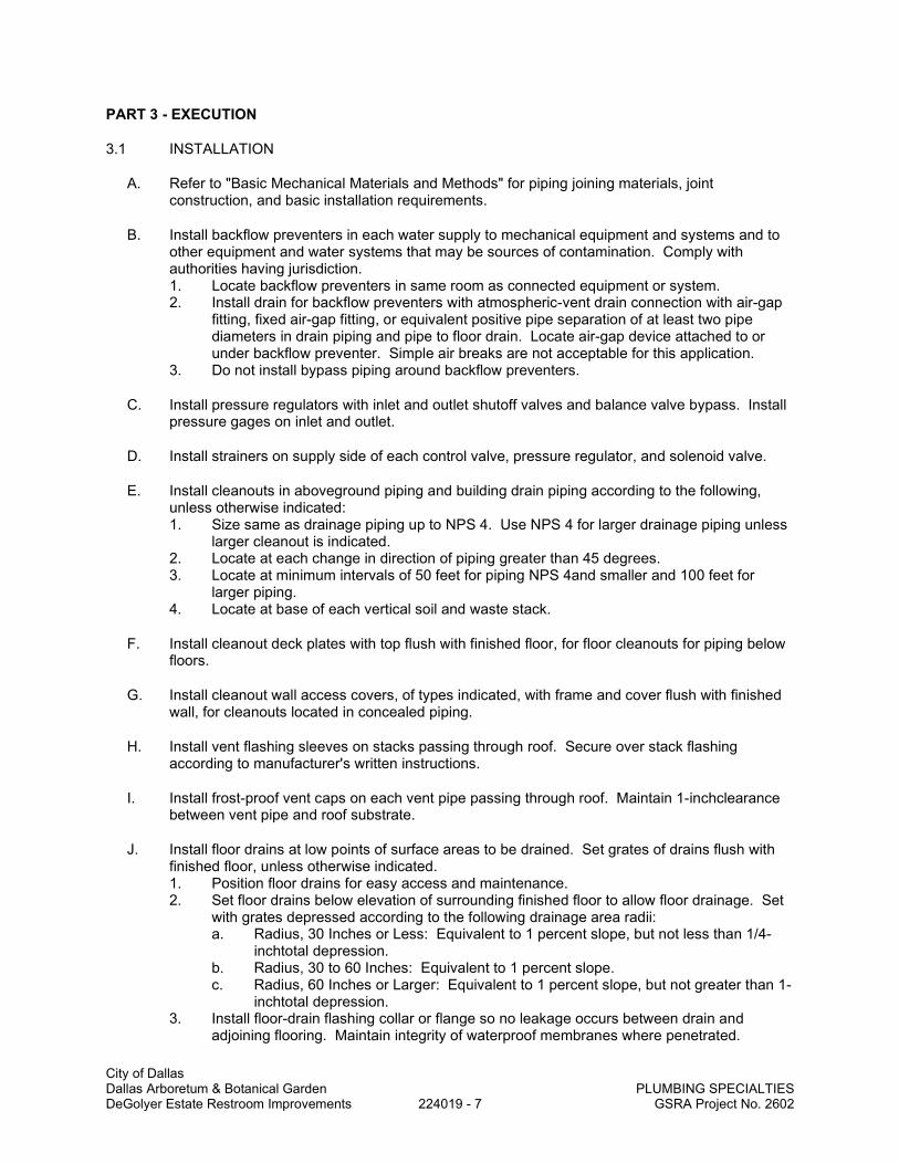
City of Dallas Dallas Arboretum & Botanical Garden PLUMBING SPECIALTIES DeGolyer Estate Restroom Improvements 224019 - 7 GSRA Project No. 2602
PART 3 - EXECUTION
3.1 INSTALLATION
A. Refer to "Basic Mechanical Materials and Methods" for piping joining materials, joint construction, and basic installation requirements.
B. Install backflow preventers in each water supply to mechanical equipment and systems and to other equipment and water systems that may be sources of contamination. Comply with authorities having jurisdiction. 1. Locate backflow preventers in same room as connected equipment or system. 2. Install drain for backflow preventers with atmospheric-vent drain connection with air-gap
fitting, fixed air-gap fitting, or equivalent positive pipe separation of at least two pipe diameters in drain piping and pipe to floor drain. Locate air-gap device attached to or under backflow preventer. Simple air breaks are not acceptable for this application.
3. Do not install bypass piping around backflow preventers.
C. Install pressure regulators with inlet and outlet shutoff valves and balance valve bypass. Install pressure gages on inlet and outlet.
D. Install strainers on supply side of each control valve, pressure regulator, and solenoid valve.
E. Install cleanouts in aboveground piping and building drain piping according to the following, unless otherwise indicated: 1. Size same as drainage piping up to NPS 4. Use NPS 4 for larger drainage piping unless
larger cleanout is indicated. 2. Locate at each change in direction of piping greater than 45 degrees. 3. Locate at minimum intervals of 50 feet for piping NPS 4and smaller and 100 feet for
larger piping. 4. Locate at base of each vertical soil and waste stack.
F. Install cleanout deck plates with top flush with finished floor, for floor cleanouts for piping below floors.
G. Install cleanout wall access covers, of types indicated, with frame and cover flush with finished wall, for cleanouts located in concealed piping.
H. Install vent flashing sleeves on stacks passing through roof. Secure over stack flashing according to manufacturer's written instructions.
I. Install frost-proof vent caps on each vent pipe passing through roof. Maintain 1-inchclearance between vent pipe and roof substrate.
J. Install floor drains at low points of surface areas to be drained. Set grates of drains flush with finished floor, unless otherwise indicated. 1. Position floor drains for easy access and maintenance. 2. Set floor drains below elevation of surrounding finished floor to allow floor drainage. Set
with grates depressed according to the following drainage area radii: a. Radius, 30 Inches or Less: Equivalent to 1 percent slope, but not less than 1/4-
inchtotal depression. b. Radius, 30 to 60 Inches: Equivalent to 1 percent slope. c. Radius, 60 Inches or Larger: Equivalent to 1 percent slope, but not greater than 1-
inchtotal depression. 3. Install floor-drain flashing collar or flange so no leakage occurs between drain and
adjoining flooring. Maintain integrity of waterproof membranes where penetrated.

City of Dallas Dallas Arboretum & Botanical Garden PLUMBING SPECIALTIES DeGolyer Estate Restroom Improvements 224019 - 8 GSRA Project No. 2602
4. Install individual traps for floor drains connected to sanitary building drain, unless otherwise indicated.
K. Fasten wall-hanging plumbing specialties securely to supports attached to building substrate if supports are specified and to building wall construction if no support is indicated.
L. Fasten recessed-type plumbing specialties to reinforcement built into walls.
M. Install wood-blocking reinforcement for wall-mounting and recessed-type plumbing specialties.
N. Install individual shutoff valve in each water supply to plumbing specialties. Use ball, gate, or globe valve if specific valve is not indicated. Install shutoff valves in accessible locations. Refer to Division 15 Section "Valves" for general-duty ball, butterfly, check, gate, and globe valves.
O. Install air vents at piping high points. Include ball, gate, or globe valve in.
P. Install traps on plumbing specialty drain outlets. Omit traps on indirect wastes unless trap is indicated.
Q. Install escutcheons at wall, floor, and ceiling penetrations in exposed finished locations and within cabinets and millwork. Use deep-pattern escutcheons if required to conceal protruding pipe fittings.
3.2 CONNECTIONS
A. Piping installation requirements are specified in other specification Sections. Drawings indicate general arrangement of piping, fittings, and specialties.
B. Install piping adjacent to equipment to allow service and maintenance.
C. Connect plumbing specialties to piping specified in other Division 23 Sections.
D. Ground equipment.
E. Tighten electrical connectors and terminals according to manufacturer's published torque-tightening values. If manufacturer's torque values are not indicated, use those specified in UL 486A and UL 486B.
F. Connect plumbing specialties and devices that require power according to Division 16 Sections.
3.3 FLASHING INSTALLATION
A. Fabricate flashing from single piece unless large pans, sumps, or other drainage shapes are required. Join flashing according to the following if required: 1. Lead Sheets: Burn joints of lead sheets 6-lb/sq. ft., 0.0938-inchthickness or thicker.
Solder joints of lead sheets 4-lb/sq. ft., 0.0625-inch 2. Copper Sheets: Solder joints of copper sheets.
B. Install sheet flashing on pipes, sleeves, and specialties passing through or embedded in floors 1. Pipe Flashing: Sleeve type, matching pipe size, with minimum length of 10 inches, and
skirt or flange extending at least 8 inches around pipe. 2. Sleeve Flashing: Flat sheet, with skirt or flange extending at least 8 inches around
sleeve. 3. Embedded Specialty Flashing: Flat sheet, with skirt or flange extending at least 8 inches
around specialty.

City of Dallas Dallas Arboretum & Botanical Garden PLUMBING SPECIALTIES DeGolyer Estate Restroom Improvements 224019 - 9 GSRA Project No. 2602
C. Set flashing on floors and roofs in solid coating of bituminous cement.
D. Secure flashing into sleeve and specialty clamping ring or device.
E. Install flashing for piping passing through roofs with counterflashing or commercially made flashing fittings.
F. Fabricate and install flashing and pans, sumps, and other drainage shapes.
3.4 LABELING AND IDENTIFYING
A. Equipment Nameplates and Signs: Install engraved plastic-laminate equipment nameplate or sign on or near each backflow preventer, thermostatic water mixing valve, and water tempering valve. 1. Text: Distinguish among multiple units, inform operator of operational requirements,
indicate safety and emergency precautions, and warn of hazards and improper operations, in addition to identifying unit.
3.5 PROTECTION
A. Protect drains during remainder of construction period to avoid clogging with dirt and debris and to prevent damage from traffic and construction work.
B. Place plugs in ends of uncompleted piping at end of each day or when work stops.
END OF SECTION

City of Dallas Dallas Arboretum & Botanical Garden ELECTRIC WATER COOLERS DeGolyer Estate Restroom Improvements 224700 - 1 GSRA Project No. 2602
SECTION 224700
ELECTRIC WATER COOLERS
PART 1 - GENERAL
1.1 SUMMARY
A. This Section includes the following: 1. Electric water coolers. 2. Fixture supports.
1.2 DEFINITIONS
A. Accessible Electric Water Cooler: Fixture that can be approached and used by people with disabilities.
B. Fitting: Device that controls flow of water into or out of fixture.
1.3 SUBMITTALS
A. Product Data: Include rated capacities; shipping, installed, and operating weights; furnished specialties; and accessories for each type of fixture indicated.
B. Shop Drawings: Diagram power, signal, and control wiring and differentiate between manufacturer-installed and field-installed wiring.
C. Field Test Reports: Indicate and interpret test results for compliance with performance requirements.
D. Maintenance Data: For fixtures to include in maintenance manuals specified in Division 1.
1.4 QUALITY ASSURANCE
A. Electrical Components, Devices, and Accessories: Listed and labeled as defined in NFPA 70, Article 100, by a testing agency acceptable to authorities having jurisdiction, and marked for intended use.
B. Regulatory Requirements: Comply with requirements in ICC A117.1, "Accessible and Usable Buildings and Facilities"; Public Law 90-480, "Architectural Barriers Act"; and Public Law 101-336, "Americans with Disabilities Act"; about fixtures for people with disabilities.
C. Regulatory Requirements: Comply with requirements in the U.S. Architectural & Transportation Barriers Compliance Board's "Uniform Federal Accessibility Standards (UFAS), 1985-494-187" about fixtures for people with disabilities.
D. NSF Standard: Comply with NSF 61, "Drinking Water System Components--Health Effects," for fixture materials that will be in contact with potable water.
E. ARI Standard: Comply with ARI 1010, "Self-Contained, Mechanically Refrigerated Drinking-Water Coolers," for water coolers and with ARI's "Directory of Certified Drinking Water Coolers" for type and style classifications.

City of Dallas Dallas Arboretum & Botanical Garden ELECTRIC WATER COOLERS DeGolyer Estate Restroom Improvements 224700 - 2 GSRA Project No. 2602
1.5 COORDINATION
A. Coordinate roughing-in and final fixture locations, and verify that fixtures can be installed to comply with original design and referenced standards.
1.6 EXTRA MATERIALS
A. Furnish extra materials described below that match products installed and that are packaged with protective covering for storage and identified with labels describing contents. 1. Filter Cartridges: Provide 3 extra filters per bottle filler fixture.
PART 2 - PRODUCTS
2.1 ELECTRIC WATER COOLERS
A. Electric Water Coolers and Accessories. 1. EWC-1. Bottle filler station, TAS handicapped for front wheelchair access, surface
wall-mounted, sensor operated, and all stainless steel panels. Unit shall be mounted as shown on Architectural wall sections for handicapped. Unit shall have 3000 gallon capacity filtration system certified to NSF/ANSI 42 and 53. Electric water cooler shall be provided with bubbler guard. Water cooler shall deliver 8.0 GPH of 50oF water, based upon 80oF inlet water temperatures, and 90oF ambient air temperature. Chilled water system shall us R-134a refrigerant. Bottle filler shall deliver 1.0 GPM flow rate of water. Unit shall be lead free design and certified to NSF/ANSI 61 and 372.
2. See Schedule on Plumbing Drawing for Basis of Design manufacturer and model. 3. Supply and stop for electric water coolers: Supplied through the wall, chrome-plated lead
free brass, 1/4 turn, 1/2 inch female standard pipe thread inlet by 3/8 inch O.D. compression type outlet angle stop, wheel or four-armed handle, with flexible riser and wall escutcheon.
4. P-trap for electric water coolers: 17-gauge chrome-plated brass, size 1-1/4 inch, integral cleanout, and wall escutcheons.
PART 3 - EXECUTION
3.1 EXAMINATION
A. Examine roughing-in for water and waste piping systems to verify actual locations of piping connections before fixture installation. Verify that sizes and locations of piping and types of supports match those indicated.
B. Examine walls and floors for suitable conditions where fixtures are to be installed.
C. Proceed with installation only after unsatisfactory conditions have been corrected.
3.2 APPLICATIONS
A. Use carrier off-floor supports for wall-hanging fixtures.
B. Use chrome-plated brass or copper tube, fittings, and valves in locations exposed to view. Plain copper tube, fittings, and valves may be used in concealed locations.

City of Dallas Dallas Arboretum & Botanical Garden ELECTRIC WATER COOLERS DeGolyer Estate Restroom Improvements 224700 - 3 GSRA Project No. 2602
3.3 INSTALLATION
A. Install off-floor supports affixed to building substrate and attach wall-hanging fixtures, unless otherwise indicated.
B. Install fixtures level and plumb.
C. Install water-supply piping with shutoff valve on supply to each fixture to be connected to water distribution piping. Use ball, gate, or globe valve. Install valves in locations where they can be easily reached for operation.
D. Install trap and waste piping on drain outlet of each fixture to be connected to sanitary drainage system.
E. Install pipe escutcheons at wall penetrations in exposed, finished locations. Use deep-pattern escutcheons where required to conceal protruding pipe fittings. Refer to Division 23 Section "Common Work Results for HVAC" for escutcheons.
F. Seal joints between fixtures and walls and floors using sanitary-type, one-part, mildew-resistant, silicone sealant. Match sealant color to fixture color.
3.4 CONNECTIONS
A. Piping installation requirements are specified in other Division 22 Sections. Drawings indicate general arrangement of piping, fittings, and specialties.
B. Connect water supplies from water distribution piping to fixtures.
C. Connect drain piping from fixtures to drainage piping.
D. Ground equipment. 1. Tighten electrical connectors and terminals according to manufacturer's published
torque-tightening values. If manufacturer's torque values are not indicated, use those specified in UL 486A and UL 486B.
3.5 FIELD QUALITY CONTROL
A. Water-Cooler Testing: After electrical circuitry has been energized, test for compliance with requirements. Test and adjust controls and safeties.
B. Repair or replace malfunctioning units. Retest as specified above after repairs or replacements are made.
C. Report test results in writing.
3.6 ADJUSTING
A. Adjust fixture flow regulators for proper flow and stream height.
B. Adjust water-cooler temperature settings.
3.7 CLEANING
A. After completing fixture installation, inspect unit. Remove paint splatters and other spots, dirt, and debris. Repair damaged finish to match original finish.

City of Dallas Dallas Arboretum & Botanical Garden ELECTRIC WATER COOLERS DeGolyer Estate Restroom Improvements 224700 - 4 GSRA Project No. 2602
B. Clean fixtures, on completion of installation, according to manufacturer's written instructions.
3.8 DEMONSTRATION
A. Engage a factory-authorized service representative to train Owner's maintenance personnel to adjust, operate, and maintain units.
END OF SECTION

City of Dallas Dallas Arboretum & Botanical Garden BASIC MECHANICAL REQUIREMENTS DeGolyer Estate Restroom Improvements 230510 - 1 GSRA Project No. 2602
SECTION 230510
BASIC MECHANICAL REQUIREMENTS
PART 1 - GENERAL
1.1 SUMMARY
A. This Section includes the following: 1. Piping materials and installation instructions common to most piping systems. 2. Transition fittings. 3. Dielectric fittings. 4. Mechanical sleeve seals. 5. Sleeves. 6. Escutcheons. 7. Grout. 8. Mechanical demolition. 9. Equipment installation requirements common to equipment sections. 10. Painting and finishing. 11. Concrete bases. 12. Supports and anchorages.
1.2 DEFINITIONS
A. Finished Spaces: Spaces other than mechanical and electrical equipment rooms, furred spaces, pipe and duct shafts, unheated spaces immediately below roof, spaces above ceilings, unexcavated spaces, crawlspaces, and tunnels.
B. Exposed, Interior Installations: Exposed to view indoors. Examples include finished occupied spaces and mechanical equipment rooms.
C. Exposed, Exterior Installations: Exposed to view outdoors or subject to outdoor ambient temperatures and weather conditions. Examples include rooftop locations.
D. Concealed, Interior Installations: Concealed from view and protected from physical contact by building occupants. Examples include above ceilings and in duct shafts.
E. Concealed, Exterior Installations: Concealed from view and protected from weather conditions and physical contact by building occupants but subject to outdoor ambient temperatures. Examples include installations within unheated shelters.
F. The following are industry abbreviations for rubber materials: 1. EPDM: Ethylene-propylene-diene terpolymer rubber. 2. NBR: Acrylonitrile-butadiene rubber.
1.3 SUBMITTALS
A. Product Data: For the following: 1. Transition fittings. 2. Dielectric fittings. 3. Mechanical sleeve seals. 4. Escutcheons.

City of Dallas Dallas Arboretum & Botanical Garden BASIC MECHANICAL REQUIREMENTS DeGolyer Estate Restroom Improvements 230510 - 2 GSRA Project No. 2602
1.4 QUALITY ASSURANCE
A. Electrical Characteristics for Mechanical Equipment: Equipment of differing electrical characteristics may be furnished provided such equipment is proposed on the “Alternate Manufacturer Evaluation Form”, subsequently approved, and connecting electrical services, circuit breakers, and conduit sizes appropriately modified. If minimum energy ratings or efficiencies are specified, equipment shall comply with requirements.
1.5 DELIVERY, STORAGE, AND HANDLING
A. Deliver pipes and tubes with factory-applied end caps. Maintain end caps through shipping, storage, and handling to prevent pipe end damage and to prevent entrance of dirt, debris, and moisture.
1.6 COORDINATION
A. Arrange for pipe spaces, chases, slots, and openings in building structure during progress of construction, to allow for mechanical installations.
B. Coordinate installation of required supporting devices and set sleeves in poured-in-place concrete and other structural components as they are constructed.
C. Coordinate requirements for access panels and doors for mechanical items requiring access that are concealed behind finished surfaces.
PART 2 - PRODUCTS
2.1 PIPE, TUBE, AND FITTINGS
A. Refer to individual Division 23 piping Sections for pipe, tube, and fitting materials and joining methods.
B. Pipe Threads: ASMEB1.20.1 for factory-threaded pipe and pipe fittings.
2.2 JOINING MATERIALS
A. Refer to individual Division 23 piping Sections for special joining materials not listed below.
B. Pipe-Flange Gasket Materials: Suitable for chemical and thermal conditions of piping system contents. 1. ASME B16.21, nonmetallic, flat, asbestos-free, 1/8-inch maximum thickness unless
thickness or specific material is indicated. a. Full-Face Type: For flat-face, Class 125, cast-iron and cast-bronze flanges. b. Narrow-Face Type: For raised-face, Class 250, cast-iron and steel flanges.
2. AWWA C110, rubber, flat face, 1/8 inch thick, unless otherwise indicated; and full-face or ring type, unless otherwise indicated.
C. Flange Bolts and Nuts: ASME B18.2.1, carbon steel, unless otherwise indicated.
D. Plastic, Pipe-Flange Gasket, Bolts, and Nuts: Type and material recommended by piping system manufacturer, unless otherwise indicated.
E. Solder Filler Metals: ASTM B 32, lead-free alloys. Include water-flushable flux according to ASTM B 813.

City of Dallas Dallas Arboretum & Botanical Garden BASIC MECHANICAL REQUIREMENTS DeGolyer Estate Restroom Improvements 230510 - 3 GSRA Project No. 2602
F. Brazing Filler Metals: AWS A5.8, BcuP Series, copper-phosphorus alloys for general-duty brazing, unless otherwise indicated; and AWS A5.8, BAg1, silver alloy for refrigerant piping, unless otherwise indicated.
G. Welding Filler Metals: Comply with AWS D10.12 for welding materials appropriate for wall thickness and chemical analysis of steel pipe being welded.
2.3 TRANSITION FITTINGS
A. AWWA Transition Couplings: Same size as, and with pressure rating at least equal to and with ends compatible with, piping to be joined. 1. Manufacturers:
a. Cascade Waterworks Mfg. Co. b. Dresser Industries, Inc.; DMD Div. c. Smith-Blair, Inc. d. Viking Johnson.
2. Aboveground Pressure Piping: Pipe fitting.
2.4 DIELECTRIC FITTINGS
A. Description: Combination fitting of copper alloy and ferrous materials with threaded, solder-joint, plain, or weld-neck end connections that match piping system materials.
B. Insulating Material: Suitable for system fluid, pressure, and temperature.
C. Dielectric Flanges: Factory-fabricated, companion-flange assembly, for 150- or 300-psig minimum working pressure as required to suit system pressures. 1. Manufacturers:
a. Capitol Manufacturing Co. b. Epco Sales, Inc. c. Watts Industries, Inc.; Water Products Div.
D. Dielectric-Flange Kits: Companion-flange assembly for field assembly. Include flanges, full-face- or ring-type neoprene or phenolic gasket, phenolic or polyethylene bolt sleeves, phenolic washers, and steel backing washers. 1. Manufacturers:
a. Advance Products & Systems, Inc. b. Central Plastics Company. c. Pipeline Seal and Insulator, Inc.
2. Separate companion flanges and steel bolts and nuts shall have 150- or 300-psig minimum working pressure where required to suit system pressures.
E. Dielectric Couplings: Galvanized-steel coupling with inert and noncorrosive, thermoplastic lining; threaded ends; and 300-psig minimum working pressure at 225 deg F. 1. Manufacturers:
a. Calpico, Inc. b. Lochinvar Corp.
F. Dielectric Nipples: Electroplated steel nipple with inert and noncorrosive, thermoplastic lining; plain, threaded, or grooved ends; and 300-psig minimum working pressure at 225 deg F. 1. Manufacturers:
a. Perfection Corp. b. Precision Plumbing Products, Inc. c. Victaulic Co. of America.
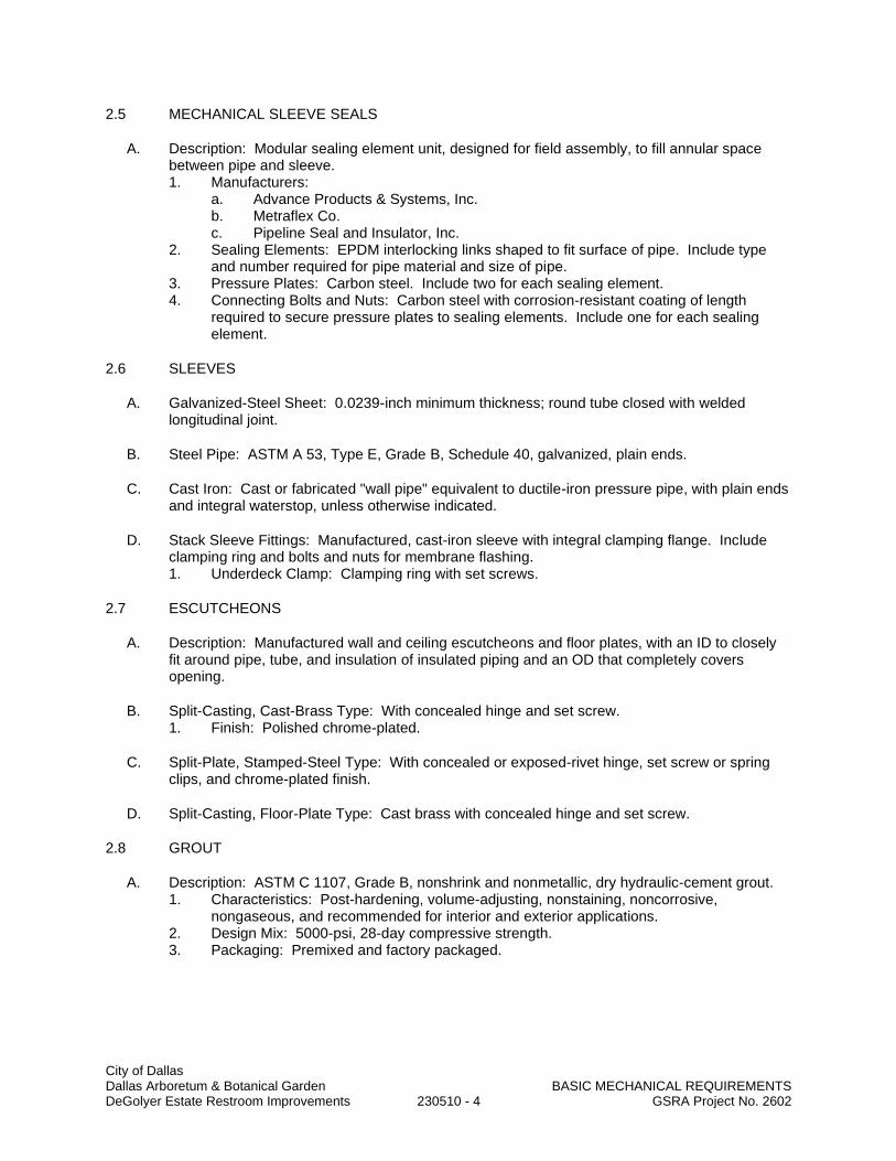
City of Dallas Dallas Arboretum & Botanical Garden BASIC MECHANICAL REQUIREMENTS DeGolyer Estate Restroom Improvements 230510 - 4 GSRA Project No. 2602
2.5 MECHANICAL SLEEVE SEALS
A. Description: Modular sealing element unit, designed for field assembly, to fill annular space between pipe and sleeve. 1. Manufacturers:
a. Advance Products & Systems, Inc. b. Metraflex Co. c. Pipeline Seal and Insulator, Inc.
2. Sealing Elements: EPDM interlocking links shaped to fit surface of pipe. Include type and number required for pipe material and size of pipe.
3. Pressure Plates: Carbon steel. Include two for each sealing element. 4. Connecting Bolts and Nuts: Carbon steel with corrosion-resistant coating of length
required to secure pressure plates to sealing elements. Include one for each sealing element.
2.6 SLEEVES
A. Galvanized-Steel Sheet: 0.0239-inch minimum thickness; round tube closed with welded longitudinal joint.
B. Steel Pipe: ASTM A 53, Type E, Grade B, Schedule 40, galvanized, plain ends.
C. Cast Iron: Cast or fabricated "wall pipe" equivalent to ductile-iron pressure pipe, with plain ends and integral waterstop, unless otherwise indicated.
D. Stack Sleeve Fittings: Manufactured, cast-iron sleeve with integral clamping flange. Include clamping ring and bolts and nuts for membrane flashing. 1. Underdeck Clamp: Clamping ring with set screws.
2.7 ESCUTCHEONS
A. Description: Manufactured wall and ceiling escutcheons and floor plates, with an ID to closely fit around pipe, tube, and insulation of insulated piping and an OD that completely covers opening.
B. Split-Casting, Cast-Brass Type: With concealed hinge and set screw. 1. Finish: Polished chrome-plated.
C. Split-Plate, Stamped-Steel Type: With concealed or exposed-rivet hinge, set screw or spring clips, and chrome-plated finish.
D. Split-Casting, Floor-Plate Type: Cast brass with concealed hinge and set screw.
2.8 GROUT
A. Description: ASTM C 1107, Grade B, nonshrink and nonmetallic, dry hydraulic-cement grout. 1. Characteristics: Post-hardening, volume-adjusting, nonstaining, noncorrosive,
nongaseous, and recommended for interior and exterior applications. 2. Design Mix: 5000-psi, 28-day compressive strength. 3. Packaging: Premixed and factory packaged.

City of Dallas Dallas Arboretum & Botanical Garden BASIC MECHANICAL REQUIREMENTS DeGolyer Estate Restroom Improvements 230510 - 5 GSRA Project No. 2602
PART 3 - EXECUTION
3.1 MECHANICAL DEMOLITION
A. Refer to Division 1 Sections "Cutting and Patching" and "Selective Demolition" for general demolition requirements and procedures.
B. Disconnect, demolish, and remove mechanical systems, equipment, and components indicated to be removed. 1. Piping to Be Removed: Remove portion of piping indicated to be removed and cap or
plug remaining piping with same or compatible piping material. 2. Piping to Be Abandoned in Place: Drain piping and cap or plug piping with same or
compatible piping material. 3. Ducts to Be Removed: Remove portion of ducts indicated to be removed and plug
remaining ducts with same or compatible ductwork material. 4. Ducts to Be Abandoned in Place: Cap or plug ducts with same or compatible ductwork
material. 5. Equipment to Be Removed: Disconnect and cap services and remove equipment. 6. Equipment to Be Removed and Reinstalled: Disconnect and cap services and remove,
clean, and store equipment; when appropriate, reinstall, reconnect, and make equipment operational.
7. Equipment to Be Removed and Salvaged: Disconnect and cap services and remove equipment and deliver to Owner.
C. If pipe, insulation, or equipment to remain is damaged in appearance or is unserviceable, remove damaged or unserviceable portions and replace with new products of equal capacity and quality.
3.2 PIPING SYSTEMS - COMMON REQUIREMENTS
A. Install piping according to the following requirements and Division 23 Sections specifying piping systems.
B. Drawing plans, schematics, and diagrams indicate general location and arrangement of piping systems. Indicated locations and arrangements were used to size pipe and calculate friction loss, expansion, pump sizing, and other design considerations. Install piping as indicated unless deviations to layout are approved.
C. Install piping in concealed locations, unless otherwise indicated and except in equipment rooms and service areas.
D. Install piping indicated to be exposed and piping in equipment rooms and service areas at right angles or parallel to building walls. Diagonal runs are prohibited unless specifically indicated otherwise.
E. Install piping above accessible ceilings to allow sufficient space for ceiling panel removal.
F. Install piping to permit valve servicing.
G. Install piping at indicated slopes.
H. Install piping free of sags and bends.
I. Install fittings for changes in direction and branch connections.

City of Dallas Dallas Arboretum & Botanical Garden BASIC MECHANICAL REQUIREMENTS DeGolyer Estate Restroom Improvements 230510 - 6 GSRA Project No. 2602
J. Install piping to allow application of insulation.
K. Select system components with pressure rating equal to or greater than system operating pressure.
L. Install escutcheons for piping with fittings with penetrations of walls, ceilings, and floors.
M. Install sleeves for pipes passing through concrete and masonry walls and concrete floor and roof slabs. 1. Except for underground wall penetrations, seal annular space between sleeve and pipe
or pipe insulation, using joint sealants appropriate for size, depth, and location of joint.
N. Fire-Barrier Penetrations: Maintain indicated fire rating of walls, partitions, ceilings, and floors at pipe penetrations. Seal pipe penetrations with firestop materials.
O. Verify final equipment locations for roughing-in.
P. Refer to equipment specifications in other Sections of these Specifications for roughing-in requirements.
3.3 PIPING JOINT CONSTRUCTION
A. Join pipe and fittings according to the following requirements and Division 23 Sections specifying piping systems.
B. Ream ends of pipes and tubes and remove burrs. Bevel plain ends of steel pipe.
C. Remove scale, slag, dirt, and debris from inside and outside of pipe and fittings before assembly.
D. Soldered Joints: Apply ASTM B 813, water-flushable flux, unless otherwise indicated, to tube end. Construct joints according to ASTM B 828 or CDA's "Copper Tube Handbook," using lead-free solder alloy complying with ASTM B 32.
E. Brazed Joints: Construct joints according to AWS's "Brazing Handbook," "Pipe and Tube" Chapter, using copper-phosphorus brazing filler metal complying with AWS A5.8.
F. Threaded Joints: Thread pipe with tapered pipe threads according to ASME B1.20.1. Cut threads full and clean using sharp dies. Ream threaded pipe ends to remove burrs and restore full ID. Join pipe fittings and valves as follows: 1. Apply appropriate tape or thread compound to external pipe threads unless dry seal
threading is specified. 2. Damaged Threads: Do not use pipe or pipe fittings with threads that are corroded or
damaged. Do not use pipe sections that have cracked or open welds.
G. Welded Joints: Construct joints according to AWS D10.12, using qualified processes and welding operators according to Part 1 "Quality Assurance" Article.
H. Flanged Joints: Select appropriate gasket material, size, type, and thickness for service application. Install gasket concentrically positioned. Use suitable lubricants on bolt threads.
3.4 PIPING CONNECTIONS
A. Make connections according to the following, unless otherwise indicated: 1. Install unions, in piping NPS 2 and smaller, adjacent to each valve and at final connection

City of Dallas Dallas Arboretum & Botanical Garden BASIC MECHANICAL REQUIREMENTS DeGolyer Estate Restroom Improvements 230510 - 7 GSRA Project No. 2602
to each piece of equipment. 2. Install flanges, in piping NPS 2-1/2 and larger, adjacent to flanged valves and at final
connection to each piece of equipment. 3. Dry Piping Systems: Install dielectric unions and flanges to connect piping materials of
dissimilar metals. 4. Wet Piping Systems: Install dielectric coupling and nipple fittings to connect piping
materials of dissimilar metals.
3.5 EQUIPMENT INSTALLATION - COMMON REQUIREMENTS
A. Install equipment to allow maximum possible headroom unless specific mounting heights are not indicated.
B. Install equipment level and plumb, parallel and perpendicular to other building systems and components in exposed interior spaces, unless otherwise indicated.
C. Install mechanical equipment to facilitate service, maintenance, and repair or replacement of components. Connect equipment for ease of disconnecting, with minimum interference to other installations. Extend grease fittings to accessible locations.
D. Install equipment to allow right of way for piping installed at required slope.
3.6 PAINTING
A. Damage and Touchup: Repair marred and damaged factory-painted finishes with materials and procedures to match original factory finish.
3.7 ERECTION OF METAL SUPPORTS AND ANCHORAGES
A. Refer to Division 5 Section "Metal Fabrications" for structural steel.
B. Cut, fit, and place miscellaneous metal supports accurately in location, alignment, and elevation to support and anchor mechanical materials and equipment.
C. Field Welding: Comply with AWS D1.1.
3.8 GROUTING
A. Mix and install grout for mechanical equipment base bearing surfaces, pump and other equipment base plates, and anchors.
B. Clean surfaces that will come into contact with grout.
C. Provide forms as required for placement of grout.
D. Avoid air entrapment during placement of grout.
E. Place grout, completely filling equipment bases.
F. Place grout on concrete bases and provide smooth bearing surface for equipment.
G. Place grout around anchors.
H. Cure placed grout.
END OF SECTION

City of Dallas COMMON MOTOR Dallas Arboretum & Botanical Garden REQUIREMENTS FOR HVAC EQUIPMENT DeGolyer Estate Restroom Improvements 230513 - 1 GSRA Project No. 2602
SECTION 230513
COMMON MOTOR REQUIREMENTS FOR HVAC EQUIPMENT
PART 1 - GENERAL
1.1 SUMMARY
A. Section includes general requirements for single-phase and polyphase, general-purpose, horizontal, small and medium, squirrel-cage induction motors for use on alternating-current power systems up to 600 V and installed at equipment manufacturer's factory or shipped separately by equipment manufacturer for field installation.
1.2 COORDINATION
A. Coordinate features of motors, installed units, and accessory devices to be compatible with the following: 1. Motor controllers. 2. Torque, speed, and horsepower requirements of the load. 3. Ratings and characteristics of supply circuit and required control sequence. 4. Ambient and environmental conditions of installation location.
PART 2 - PRODUCTS
2.1 GENERAL MOTOR REQUIREMENTS
A. Comply with NEMA MG 1 unless otherwise indicated.
B. Comply with IEEE 841 for severe-duty motors.
2.2 MOTOR CHARACTERISTICS
A. Duty: Continuous duty at ambient temperature of 40 deg C and at altitude of 3300 feet above sea level.
B. Capacity and Torque Characteristics: Sufficient to start, accelerate, and operate connected loads at designated speeds, at installed altitude and environment, with indicated operating sequence, and without exceeding nameplate ratings or considering service factor.
2.3 POLYPHASE MOTORS
A. Description: NEMA MG 1, Design B, medium induction motor.
B. Efficiency: Premium efficient, as defined in NEMA MG 1.
C. Service Factor: 1.15.
D. Multispeed Motors: Variable torque. 1. For motors with 2:1 speed ratio, consequent pole, single winding. 2. For motors with other than 2:1 speed ratio, separate winding for each speed.
E. Multispeed Motors: Separate winding for each speed.

City of Dallas COMMON MOTOR Dallas Arboretum & Botanical Garden REQUIREMENTS FOR HVAC EQUIPMENT DeGolyer Estate Restroom Improvements 230513 - 2 GSRA Project No. 2602
F. Rotor: Random-wound, squirrel cage.
G. Bearings: Regreasable, shielded, antifriction ball bearings suitable for radial and thrust loading.
H. Temperature Rise: Match insulation rating.
I. Insulation: Class F.
J. Code Letter Designation: 1. Motors 15 HP and Larger: NEMA starting Code F or Code G. 2. Motors Smaller Than 15 HP: Manufacturer's standard starting characteristic.
K. Enclosure Material: Cast iron for motor frame sizes 324T and larger; rolled steel for motor frame sizes smaller than 324T.
2.4 ADDITIONAL REQUIREMENTS FOR POLYPHASE MOTORS
A. Motors Used with Reduced-Voltage and Multispeed Controllers: Match wiring connection requirements for controller with required motor leads. Provide terminals in motor terminal box, suited to control method.
B. Motors Used with Variable-Frequency Controllers: Ratings, characteristics, and features coordinated with and approved by controller manufacturer. 1. Windings: Copper magnet wire with moisture-resistant insulation varnish, designed and
tested to resist transient spikes, high frequencies, and short time rise pulses produced by pulse-width-modulated inverters.
2. Premium-Efficient Motors: Class B temperature rise; Class F insulation. 3. Inverter-Duty Motors: Class F temperature rise; Class H insulation. 4. Thermal Protection: Comply with NEMA MG 1 requirements for thermally protected
motors.
C. Severe-Duty Motors: Comply with IEEE 841, with 1.15 minimum service factor.
2.5 SINGLE-PHASE MOTORS
A. Motors larger than 1/20 hp shall be one of the following, to suit starting torque and requirements of specific motor application: 1. Permanent-split capacitor. 2. Split phase. 3. Capacitor start, inductor run. 4. Capacitor start, capacitor run.
B. Multispeed Motors: Variable-torque, permanent-split-capacitor type.
C. Bearings: Prelubricated, antifriction ball bearings or sleeve bearings suitable for radial and thrust loading.
D. Motors 1/20 HP and Smaller: Shaded-pole type.
E. Thermal Protection: Internal protection to automatically open power supply circuit to motor when winding temperature exceeds a safe value calibrated to temperature rating of motor insulation. Thermal-protection device shall automatically reset when motor temperature returns to normal range.

City of Dallas COMMON MOTOR Dallas Arboretum & Botanical Garden REQUIREMENTS FOR HVAC EQUIPMENT DeGolyer Estate Restroom Improvements 230513 - 3 GSRA Project No. 2602
PART 3 - EXECUTION (Not Applicable)
END OF SECTION

City of Dallas HANGERS AND SUPPORTS FOR Dallas Arboretum & Botanical Garden HVAC PIPING AND EQUIPMENT DeGolyer Estate Restroom Improvements 230529 - 1 GSRA Project No. 2602
SECTION 230529
HANGERS AND SUPPORTS FOR HVAC PIPING AND EQUIPMENT
PART 1 - GENERAL
1.1 SUMMARY
A. Section Includes: 1. Metal pipe hangers and supports. 2. Trapeze pipe hangers. 3. Metal framing systems. 4. Thermal-hanger shield inserts. 5. Fastener systems. 6. Pipe stands. 7. Equipment stands. 8. Equipment supports.
B. Related Requirements: 1. Section 055000 "Metal Fabrications" for structural-steel shapes and plates for trapeze
hangers for pipe and equipment supports. 2. Section 233113 "Metal Ducts" for duct hangers and supports.
1.2 ACTION SUBMITTALS
A. Product Data: For each type of product.
B. Shop Drawings: Show fabrication and installation details and include calculations for the following; include Product Data for components: 1. Trapeze pipe hangers. 2. Metal framing systems. 3. Pipe stands. 4. Equipment supports.
C. Delegated-Design Submittal: For trapeze hangers indicated to comply with performance requirements and design criteria, including analysis data signed and sealed by the qualified professional engineer responsible for their preparation. 1. Detail fabrication and assembly of trapeze hangers.
1.3 INFORMATIONAL SUBMITTALS
A. Welding certificates.
1.4 QUALITY ASSURANCE
A. Structural-Steel Welding Qualifications: Qualify procedures and personnel according to AWS D1.1/D1.1M, "Structural Welding Code - Steel."
B. Pipe Welding Qualifications: Qualify procedures and operators according to ASME Boiler and Pressure Vessel Code, Section IX.

City of Dallas HANGERS AND SUPPORTS FOR Dallas Arboretum & Botanical Garden HVAC PIPING AND EQUIPMENT DeGolyer Estate Restroom Improvements 230529 - 2 GSRA Project No. 2602
PART 2 - PRODUCTS
2.1 PERFORMANCE REQUIREMENTS
A. Delegated Design: Engage a qualified professional engineer, as defined in Section 014000 "Quality Requirements," to design trapeze pipe hangers and equipment supports.
B. Structural Performance: Hangers and supports for HVAC piping and equipment shall withstand the effects of gravity loads and stresses within limits and under conditions indicated according to ASCE/SEI 7. 1. Design supports for multiple pipes, including pipe stands, capable of supporting
combined weight of supported systems, system contents, and test water. 2. Design equipment supports capable of supporting combined operating weight of
supported equipment and connected systems and components.
2.2 METAL PIPE HANGERS AND SUPPORTS
A. Carbon-Steel Pipe Hangers and Supports: 1. Description: MSS SP-58, Types 1 through 58, factory-fabricated components. 2. Galvanized Metallic Coatings: Pre-galvanized, hot-dip galvanized, or electro-galvanized. 3. Nonmetallic Coatings: Plastic coated, or epoxy powder-coated. 4. Padded Hangers: Hanger with fiberglass or other pipe insulation pad or cushion to
support bearing surface of piping. 5. Hanger Rods: Continuous-thread rod, nuts, and washer made of stainless steel.
B. Stainless Steel Pipe Hangers and Supports: 1. Description: MSS SP-58, Types 1 through 58, factory-fabricated components. 2. Padded Hangers: Hanger with fiberglass or other pipe insulation pad or cushion to
support bearing surface of piping. 3. Hanger Rods: Continuous-thread rod, nuts, and washer made of stainless steel.
C. Copper Pipe and Tube Hangers: 1. Description: MSS SP-58, Types 1 through 58, copper-plated steel, factory-fabricated
components. 2. Hanger Rods: Continuous-thread rod, nuts, and washer made of stainless steel.
2.3 TRAPEZE PIPE HANGERS
A. Description: MSS SP-58, Type 59, shop- or field-fabricated pipe-support assembly made from structural carbon-steel shapes with MSS SP-58 carbon-steel hanger rods, nuts, saddles, and U-bolts.
2.4 METAL FRAMING SYSTEMS
A. MFMA Manufacturer Metal Framing Systems: 1. Manufacturers: Subject to compliance with requirements, provide products by one of the
following: a. Flex-Strut Inc. b. G-Strut. c. Haydon Corporation. d. MIRO Industries. e. Wesanco, Inc.
2. Description: Shop- or field-fabricated, pipe-support assembly made of steel channels, accessories, fittings, and other components for supporting multiple parallel pipes.
3. Standard: Comply with MFMA-4 factory-fabricated components for field assembly.

City of Dallas HANGERS AND SUPPORTS FOR Dallas Arboretum & Botanical Garden HVAC PIPING AND EQUIPMENT DeGolyer Estate Restroom Improvements 230529 - 3 GSRA Project No. 2602
4. Channels: Continuous slotted stainless steel, Type 304 channel with inturned lips. 5. Channel Width: Selected for applicable load criteria. 6. Channel Nuts: Formed or stamped nuts or other devices designed to fit into channel slot
and, when tightened, prevent slipping along channel. 7. Hanger Rods: Continuous-thread rod, nuts, and washer made of stainless steel Insert
material. 8. Paint Coating: Green epoxy, acrylic, or urethane.
B. Non-MFMA Manufacturer Metal Framing Systems: 1. Manufacturers: Subject to compliance with requirements, provide products by one of the
following: a. Empire Industries, Inc. b. MIRO Industries. c. Rooftop Support Systems, a division of Eberl Iron Works, Inc.
2. Description: Shop- or field-fabricated, pipe-support assembly made of steel channels, accessories, fittings, and other components for supporting multiple parallel pipes.
3. Standard: Comply with MFMA-4 factory-fabricated components for field assembly. 4. Channels: Continuous slotted stainless steel channel with inturned lips. 5. Channel Width: Select for applicable load criteria. 6. Channel Nuts: Formed or stamped nuts or other devices designed to fit into channel slot
and, when tightened, prevent slipping along channel. 7. Hanger Rods: Continuous-thread rod, nuts, and washer made of stainless steel. 8. Paint Coating: Green epoxy, acrylic, or urethane.
2.5 THERMAL-HANGER SHIELD INSERTS
A. Manufacturers: Subject to compliance with requirements, provide products by one of the following: 1. Carpenter & Paterson, Inc. 2. KB Enterprise. 3. nVent (CADDY).
B. Insulation-Insert Material for Cold Piping: ASTM C552, Type II cellular glass with 100-psi minimum compressive strength and vapor barrier.
C. Insulation-Insert Material for Hot Piping: Water-repellent-treated, ASTM C533, Type I calcium silicate with 100-psi minimum compressive strength.
D. For Trapeze or Clamped Systems: Insert and shield shall cover entire circumference of pipe.
E. For Clevis or Band Hangers: Insert and shield shall cover lower 180 degrees of pipe.
F. Insert Length: Extend 2 inches beyond sheet metal shield for piping operating below ambient air temperature.
2.6 FASTENER SYSTEMS
A. Powder-Actuated Fasteners: Threaded-steel stud, for use in hardened portland cement concrete with pull-out, tension, and shear capacities appropriate for supported loads and building materials where used.
B. Mechanical-Expansion Anchors: Insert-wedge-type anchors for use in hardened portland cement concrete; with pull-out, tension, and shear capacities appropriate for supported loads and building materials where used. 1. Indoor Applications: Zinc-coated or stainless steel.

City of Dallas HANGERS AND SUPPORTS FOR Dallas Arboretum & Botanical Garden HVAC PIPING AND EQUIPMENT DeGolyer Estate Restroom Improvements 230529 - 4 GSRA Project No. 2602
2. Outdoor Applications: Stainless steel.
2.7 PIPE STANDS
A. General Requirements for Pipe Stands: Shop- or field-fabricated assemblies made of manufactured corrosion-resistant components to support roof-mounted piping.
B. Compact Pipe Stand: 1. Manufacturers: Subject to compliance with requirements, provide products by one of the
following: a. MIRO Industries. b. PHP Systems/Design. c. Rooftop Support Systems, a division of Eberl Iron Works, Inc.
2. Description: Single base unit with integral-rod roller, pipe clamps, or V-shaped cradle to support pipe, for roof installation without membrane penetration.
3. Base: Single, vulcanized rubber, molded polypropylene, or polycarbonate. 4. Hardware: Galvanized steel or polycarbonate. 5. Accessories: Protection pads.
C. Low-Profile, Single Base, Single-Pipe Stand: 1. Manufacturers: Subject to compliance with requirements, provide products by one of the
following: a. MIRO Industries. b. PHP Systems/Design. c. Rooftop Support Systems, a division of Eberl Iron Works, Inc.
2. Description: Single base with vertical and horizontal members, and pipe support, for roof installation without membrane protection.
3. Base: Single, vulcanized rubber, molded polypropylene, or polycarbonate. 4. Vertical Members: Two, stainless-steel, continuous-thread 1/2-inch rods. 5. Horizontal Member: Adjustable horizontal, stainless-steel pipe support channels. 6. Pipe Supports: Strut clamps. 7. Hardware: Stainless steel. 8. Accessories: Protection pads. 9. Height: 16 inches above roof.
D. High-Profile, Single Base, Single-Pipe Stand: 1. Manufacturers: Subject to compliance with requirements, provide products by one of the
following: a. MIRO Industries. b. PHP Systems/Design. c. Rooftop Support Systems, a division of Eberl Iron Works, Inc.
2. Description: Single base, vertical and horizontal members, and pipe support, for roof installation without membrane penetration.
3. Base: Single vulcanized rubber or molded polypropylene. 4. Vertical Members: Two, stainless-steel, continuous-thread 1/2-inch rods. 5. Horizontal Member: One, adjustable height, stainless-steel pipe support slotted channel
or plate. 6. Pipe Supports: Roller. 7. Hardware: Stainless steel. 8. Accessories: Protection pads, 1/2-inch (12-mm) continuous-thread stainless steel rod. 9. Height: 18-24 inches above roof.
E. High-Profile, Multiple-Pipe Stand: 1. Manufacturers: Subject to compliance with requirements, provide products by one of the
following: a. MIRO Industries.

City of Dallas HANGERS AND SUPPORTS FOR Dallas Arboretum & Botanical Garden HVAC PIPING AND EQUIPMENT DeGolyer Estate Restroom Improvements 230529 - 5 GSRA Project No. 2602
b. PHP Systems/Design. c. Rooftop Support Systems, a division of Eberl Iron Works, Inc.
2. Description: Assembly of bases, vertical and horizontal members, and pipe supports, for roof installation without membrane penetration.
3. Bases: Two or more; vulcanized rubber or molded polypropylene. 4. Vertical Members: Two or more, stainless-steel channels. 5. Horizontal Members: One or more, adjustable height, stainless-steel pipe support. 6. Pipe Supports: Roller or Strut clamps. 7. Hardware: Stainless steel. 8. Accessories: Protection pads[, 1/2-inch continuous-thread rod. 9. Height: 18-24 inches above roof.
F. Curb-Mounted-Type Pipe Stands: Shop- or field-fabricated pipe supports made from structural-steel shapes, continuous-thread rods, and rollers, for mounting on permanent stationary roof curb.
2.8 EQUIPMENT SUPPORTS
A. Description: Welded, shop- or field-fabricated equipment support made from structural carbon-steel shapes.
2.9 OUTDOOR EQUIPMENT STANDS
A. Manufacturers: Subject to compliance with requirements, provide products by one of the following: 1. MIRO Industries. 2. RectorSeal HVAC; a CSW Industrials Company. 3. Rooftop Support Systems, a division of Eberl Iron Works, Inc.
2.10 MATERIALS
A. Aluminum: ASTM B221 (ASTM B221M).
B. Carbon Steel: ASTM A1011/A1011M.
C. Structural Steel: ASTM A36/A36M, carbon-steel plates, shapes, and bars; galvanized.
D. Stainless Steel: ASTM A240/A240M.
E. Threaded Rods: Continuously threaded. Zinc-plated or galvanized steel for indoor applications and stainless steel for outdoor applications. Mating nuts and washers of similar materials as rods.
F. Grout: ASTM C1107/C1107M, factory-mixed and -packaged, dry, hydraulic-cement, nonshrink and nonmetallic grout; suitable for interior and exterior applications. 1. Properties: Nonstaining, noncorrosive, and nongaseous. 2. Design Mix: 5000-psi 28-day compressive strength.
PART 3 - EXECUTION
3.1 APPLICATION
A. Comply with requirements in Section 078413 "Penetration Firestopping" for firestopping materials and installation for penetrations through fire-rated walls, ceilings, and assemblies.

City of Dallas HANGERS AND SUPPORTS FOR Dallas Arboretum & Botanical Garden HVAC PIPING AND EQUIPMENT DeGolyer Estate Restroom Improvements 230529 - 6 GSRA Project No. 2602
B. Strength of Support Assemblies: Where not indicated, select sizes of components so strength will be adequate to carry present and future static loads within specified loading limits. Minimum static design load used for strength determination shall be weight of supported components plus 200 lb.
3.2 HANGER AND SUPPORT INSTALLATION
A. Metal Pipe-Hanger Installation: Comply with MSS SP-58. Install hangers, supports, clamps, and attachments as required to properly support piping from the building structure.
B. Metal Trapeze Pipe-Hanger Installation: Comply with MSS SP-58. Arrange for grouping of parallel runs of horizontal piping, and support together on field-fabricated trapeze pipe hangers. 1. Pipes of Various Sizes: Support together and space trapezes for smallest pipe size or
install intermediate supports for smaller diameter pipes as specified for individual pipe hangers.
2. Field fabricate from ASTM A36/A36M, carbon-steel shapes selected for loads being supported. Weld steel according to AWS D1.1/D1.1M.
C. Fiberglass Pipe-Hanger Installation: Comply with applicable portions of MSS SP-58. Install hangers and attachments as required to properly support piping from building structure.
D. Metal Framing System Installation: Arrange for grouping of parallel runs of piping, and support together on field-assembled strut systems.
E. Thermal-Hanger Shield Installation: Install in pipe hanger or shield for insulated piping.
F. Fastener System Installation: 1. Install powder-actuated fasteners for use in lightweight concrete or concrete slabs less
than 4 inches thick in concrete after concrete is placed and completely cured. Use operators that are licensed by powder-actuated tool manufacturer. Install fasteners according to powder-actuated tool manufacturer's operating manual.
2. Install mechanical-expansion anchors in concrete after concrete is placed and completely cured. Install fasteners according to manufacturer's written instructions.
G. Pipe Stand Installation: 1. Pipe Stand Types except Curb-Mounted Type: Assemble components and mount on
smooth roof surface. Do not penetrate roof membrane. 2. Curb-Mounted-Type Pipe Stands: Assemble components or fabricate pipe stand and
mount on permanent, stationary roof curb. See Section 077200 "Roof Accessories" for curbs.
H. Install hangers and supports complete with necessary attachments, inserts, bolts, rods, nuts, washers, and other accessories.
I. Equipment Support Installation: Fabricate from welded-structural-steel shapes.
J. Install hangers and supports to allow controlled thermal movement of piping systems, to permit freedom of movement between pipe anchors, and to facilitate action of expansion joints, expansion loops, expansion bends, and similar units.
K. Install lateral bracing with pipe hangers and supports to prevent swaying.
L. Install building attachments within concrete slabs or attach to structural steel. Install additional attachments at concentrated loads, including valves, flanges, and strainers, NPS 2-1/2 and

City of Dallas HANGERS AND SUPPORTS FOR Dallas Arboretum & Botanical Garden HVAC PIPING AND EQUIPMENT DeGolyer Estate Restroom Improvements 230529 - 7 GSRA Project No. 2602
larger and at changes in direction of piping. Install concrete inserts before concrete is placed; fasten inserts to forms and install reinforcing bars through openings at top of inserts.
M. Load Distribution: Install hangers and supports so that piping live and dead loads and stresses from movement will not be transmitted to connected equipment.
N. Pipe Slopes: Install hangers and supports to provide indicated pipe slopes and to not exceed maximum pipe deflections allowed by ASME B31.9 for building services piping.
O. Insulated Piping: 1. Attach clamps and spacers to piping.
a. Piping Operating above Ambient Air Temperature: Clamp may project through insulation.
b. Piping Operating below Ambient Air Temperature: Use thermal-hanger shield insert with clamp sized to match OD of insert.
c. Do not exceed pipe stress limits allowed by ASME B31.9 for building services piping.
2. Install MSS SP-58, Type 39, protection saddles if insulation without vapor barrier is indicated. Fill interior voids with insulation that matches adjoining insulation. a. Option: Thermal-hanger shield inserts may be used. Include steel weight-
distribution plate for pipe NPS 4 and larger if pipe is installed on rollers. 3. Install MSS SP-58, Type 40, protective shields on cold piping with vapor barrier. Shields
shall span an arc of 180 degrees. a. Option: Thermal-hanger shield inserts may be used. Include steel weight-
distribution plate for pipe NPS 4 and larger if pipe is installed on rollers. 4. Shield Dimensions for Pipe: Not less than the following:
a. NPS 1/4 to NPS 3-1/2 : 12 inches long and 0.048 inch thick. 5. Thermal-Hanger Shields: Install with insulation same thickness as piping insulation.
3.3 EQUIPMENT SUPPORTS
A. Fabricate structural-steel stands to suspend equipment from structure overhead or to support equipment above floor.
B. Grouting: Place grout under supports for equipment and make bearing surface smooth.
C. Provide lateral bracing, to prevent swaying, for equipment supports.
3.4 METAL FABRICATIONS
A. Cut, drill, and fit miscellaneous metal fabrications for trapeze pipe hangers and equipment supports.
B. Fit exposed connections together to form hairline joints. Field weld connections that cannot be shop welded because of shipping size limitations.
C. Field Welding: Comply with AWS D1.1/D1.1M procedures for shielded, metal arc welding; appearance and quality of welds; and methods used in correcting welding work; and with the following: 1. Use materials and methods that minimize distortion and develop strength and corrosion
resistance of base metals. 2. Obtain fusion without undercut or overlap. 3. Remove welding flux immediately. 4. Finish welds at exposed connections so no roughness shows after finishing and so
contours of welded surfaces match adjacent contours.
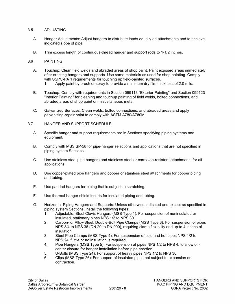
City of Dallas HANGERS AND SUPPORTS FOR Dallas Arboretum & Botanical Garden HVAC PIPING AND EQUIPMENT DeGolyer Estate Restroom Improvements 230529 - 8 GSRA Project No. 2602
3.5 ADJUSTING
A. Hanger Adjustments: Adjust hangers to distribute loads equally on attachments and to achieve indicated slope of pipe.
B. Trim excess length of continuous-thread hanger and support rods to 1-1/2 inches.
3.6 PAINTING
A. Touchup: Clean field welds and abraded areas of shop paint. Paint exposed areas immediately after erecting hangers and supports. Use same materials as used for shop painting. Comply with SSPC-PA 1 requirements for touching up field-painted surfaces. 1. Apply paint by brush or spray to provide a minimum dry film thickness of 2.0 mils.
B. Touchup: Comply with requirements in Section 099113 "Exterior Painting" and Section 099123 "Interior Painting" for cleaning and touchup painting of field welds, bolted connections, and abraded areas of shop paint on miscellaneous metal.
C. Galvanized Surfaces: Clean welds, bolted connections, and abraded areas and apply galvanizing-repair paint to comply with ASTM A780/A780M.
3.7 HANGER AND SUPPORT SCHEDULE
A. Specific hanger and support requirements are in Sections specifying piping systems and equipment.
B. Comply with MSS SP-58 for pipe-hanger selections and applications that are not specified in piping system Sections.
C. Use stainless steel pipe hangers and stainless steel or corrosion-resistant attachments for all applications.
D. Use copper-plated pipe hangers and copper or stainless steel attachments for copper piping and tubing.
E. Use padded hangers for piping that is subject to scratching.
F. Use thermal-hanger shield inserts for insulated piping and tubing.
G. Horizontal-Piping Hangers and Supports: Unless otherwise indicated and except as specified in piping system Sections, install the following types: 1. Adjustable, Steel Clevis Hangers (MSS Type 1): For suspension of noninsulated or
insulated, stationary pipes NPS 1/2 to NPS 30. 2. Carbon- or Alloy-Steel, Double-Bolt Pipe Clamps (MSS Type 3): For suspension of pipes
NPS 3/4 to NPS 36 (DN 20 to DN 900), requiring clamp flexibility and up to 4 inches of insulation.
3. Steel Pipe Clamps (MSS Type 4): For suspension of cold and hot pipes NPS 1/2 to NPS 24 if little or no insulation is required.
4. Pipe Hangers (MSS Type 5): For suspension of pipes NPS 1/2 to NPS 4, to allow off-center closure for hanger installation before pipe erection.
5. U-Bolts (MSS Type 24): For support of heavy pipes NPS 1/2 to NPS 30. 6. Clips (MSS Type 26): For support of insulated pipes not subject to expansion or
contraction.

City of Dallas HANGERS AND SUPPORTS FOR Dallas Arboretum & Botanical Garden HVAC PIPING AND EQUIPMENT DeGolyer Estate Restroom Improvements 230529 - 9 GSRA Project No. 2602
7. Adjustable Pipe Saddle Supports (MSS Type 38): For stanchion-type support for pipes NPS 2-1/2 to NPS 36 if vertical adjustment is required, with steel-pipe base stanchion support and cast-iron floor flange.
8. Pipe Roll and Plate Units (MSS Type 45): For support of pipes NPS 2 to NPS 24 if small horizontal movement caused by expansion and contraction might occur and vertical adjustment is unnecessary.
9. Adjustable Pipe Roll and Base Units (MSS Type 46): For support of pipes NPS 2 to NPS 30 if vertical and lateral adjustment during installation might be required in addition to expansion and contraction.
H. Vertical-Piping Clamps: Unless otherwise indicated and except as specified in piping system Sections, install the following types: 1. Extension Pipe or Riser Clamps (MSS Type 8): For support of pipe risers NPS 3/4 to
NPS 24. 2. Carbon- or Alloy-Steel Riser Clamps (MSS Type 42): For support of pipe risers NPS 3/4
to NPS 24 if longer ends are required for riser clamps.
I. Hanger-Rod Attachments: Unless otherwise indicated and except as specified in piping system Sections, install the following types: 1. Steel Turnbuckles (MSS Type 13): For adjustment up to 6 inches for heavy loads. 2. Steel Clevises (MSS Type 14): For 120 to 450 deg F piping installations. 3. Swivel Turnbuckles (MSS Type 15): For use with MSS Type 11, split pipe rings. 4. Malleable-Iron Sockets (MSS Type 16): For attaching hanger rods to various types of
building attachments. 5. Steel Weldless Eye Nuts (MSS Type 17): For 120 to 450 deg F piping installations.
J. Building Attachments: Unless otherwise indicated and except as specified in piping system Sections, install the following types: 1. Steel or Malleable Concrete Inserts (MSS Type 18): For upper attachment to suspend
pipe hangers from concrete ceiling. 2. C-Clamps (MSS Type 23): For structural shapes. 3. Top-Beam Clamps (MSS Type 25): For top of beams if hanger rod is required tangent to
flange edge. 4. Malleable-Beam Clamps with Extension Pieces (MSS Type 30): For attaching to
structural steel. 5. Welded-Steel Brackets: For support of pipes from below or for suspending from above by
using clip and rod. Use one of the following for indicated loads: a. Light (MSS Type 31): 750 lb. b. Medium (MSS Type 32): 1500 lb. c. Heavy (MSS Type 33): 3000 lb.
6. Horizontal Travelers (MSS Type 58): For supporting piping systems subject to linear horizontal movement where headroom is limited.
K. Saddles and Shields: Unless otherwise indicated and except as specified in piping system Sections, install the following types: 1. Steel-Pipe-Covering Protection Saddles (MSS Type 39): To fill interior voids with
insulation that matches adjoining insulation. 2. Protection Shields (MSS Type 40): Of length recommended in writing by manufacturer to
prevent crushing insulation. 3. Thermal-Hanger Shield Inserts: For supporting insulated pipe.
L. Spring Hangers and Supports: Unless otherwise indicated and except as specified in piping system Sections, install the following types: 1. Restraint-Control Devices (MSS Type 47): Where indicated to control piping movement. 2. Spring Cushions (MSS Type 48): For light loads if vertical movement does not exceed 1-
1/4 inches.

City of Dallas HANGERS AND SUPPORTS FOR Dallas Arboretum & Botanical Garden HVAC PIPING AND EQUIPMENT DeGolyer Estate Restroom Improvements 230529 - 10 GSRA Project No. 2602
3. Spring-Cushion Roll Hangers (MSS Type 49): For equipping Type 41, roll hanger with springs.
4. Spring Sway Braces (MSS Type 50): To retard sway, shock, vibration, or thermal expansion in piping systems.
5. Variable-Spring Hangers (MSS Type 51): Preset to indicated load and limit variability factor to 25 percent to allow expansion and contraction of piping system from hanger.
6. Variable-Spring Base Supports (MSS Type 52): Preset to indicated load and limit variability factor to 25 percent to allow expansion and contraction of piping system from base support.
7. Variable-Spring Trapeze Hangers (MSS Type 53): Preset to indicated load and limit variability factor to 25 percent to allow expansion and contraction of piping system from trapeze support.
8. Constant Supports: For critical piping stress and if necessary to avoid transfer of stress from one support to another support, critical terminal, or connected equipment. Include auxiliary stops for erection, hydrostatic test, and load-adjustment capability. These supports include the following types: a. Horizontal (MSS Type 54): Mounted horizontally. b. Vertical (MSS Type 55): Mounted vertically. c. Trapeze (MSS Type 56): Two vertical-type supports and one trapeze member.
M. Comply with MSS SP-58 for trapeze pipe-hanger selections and applications that are not specified in piping system Sections.
N. Comply with MFMA-103 for metal framing system selections and applications that are not specified in piping system Sections.
O. Use powder-actuated fasteners or mechanical-expansion anchors instead of building attachments where required in concrete construction.
END OF SECTION

City of Dallas IDENTIFICATION FOR HVAC Dallas Arboretum & Botanical Garden PIPING AND EQUIPMENT DeGolyer Estate Restroom Improvements 230553 - 1 GSRA Project No. 2602
SECTION 230553
IDENTIFICATION FOR HVAC PIPING AND EQUIPMENT
PART 1 - GENERAL
1.1 SUMMARY
A. Section Includes: 1. Equipment labels. 2. Warning signs and labels. 3. Pipe labels. 4. Duct labels. 5. Stencils. 6. Valve tags. 7. Warning tags.
1.2 ACTION SUBMITTALS
A. Product Data: For each type of product.
B. Samples: For color, letter style, and graphic representation required for each identification material and device.
C. Equipment Label Schedule: Include a listing of all equipment to be labeled with the proposed content for each label.
D. Valve numbering scheme.
E. Valve Schedules: For each piping system to include in maintenance manuals.
PART 2 - PRODUCTS
2.1 EQUIPMENT LABELS
A. Metal Labels for Equipment: 1. Material and Thickness: stainless steel, 0.025-inch minimum thickness, and having
predrilled or stamped holes for attachment hardware. 2. Letter Color: Black. 3. Background Color: White. 4. Minimum Label Size: Length and width vary for required label content, but not less than
2-1/2 by 3/4 inch. 5. Minimum Letter Size: 1/4 inch for name of units if viewing distance is less than 24 inches,
1/2 inch for viewing distances up to 72 inches, and proportionately larger lettering for greater viewing distances. Include secondary lettering two-thirds to three-quarters the size of principal lettering.
6. Fasteners: Stainless-steel rivets or self-tapping screws. 7. Adhesive: Contact-type permanent adhesive, compatible with label and with substrate.
B. Plastic Labels for Equipment: 1. Material and Thickness: Multilayer, multicolor, plastic labels for mechanical engraving,
1/16 inch thick, and having predrilled holes for attachment hardware. 2. Letter Color: Black.

City of Dallas IDENTIFICATION FOR HVAC Dallas Arboretum & Botanical Garden PIPING AND EQUIPMENT DeGolyer Estate Restroom Improvements 230553 - 2 GSRA Project No. 2602
3. Background Color: White. 4. Maximum Temperature: Able to withstand temperatures up to 160 deg F. 5. Minimum Label Size: Length and width vary for required label content, but not less than
2-1/2 by 3/4 inch. 6. Minimum Letter Size: 1/4 inch for name of units if viewing distance is less than 24 inches,
1/2 inch for viewing distances up to 72 inches, and proportionately larger lettering for greater viewing distances. Include secondary lettering two-thirds to three-quarters the size of principal lettering.
7. Fasteners: Stainless-steel rivets or self-tapping screws. 8. Adhesive: Contact-type permanent adhesive, compatible with label and with substrate.
C. Label Content: Include equipment's Drawing designation or unique equipment number, Drawing numbers where equipment is indicated (plans, details, and schedules), and the Specification Section number and title where equipment is specified.
D. Equipment Label Schedule: For each item of equipment to be labeled, on 8-1/2-by-11-inch bond paper. Tabulate equipment identification number, and identify Drawing numbers where equipment is indicated (plans, details, and schedules) and the Specification Section number and title where equipment is specified. Equipment schedule shall be included in operation and maintenance data.
2.2 WARNING SIGNS AND LABELS
A. Material and Thickness: Multilayer, multicolor, plastic labels for mechanical engraving, 1/16 inch (1.6 mm) thick, and having predrilled holes for attachment hardware.
B. Letter Color: Black.
C. Background Color: White.
D. Maximum Temperature: Able to withstand temperatures up to 160 deg F.
E. Minimum Label Size: Length and width vary for required label content, but not less than 2-1/2 by 3/4 inch.
F. Minimum Letter Size: 1/4 inch (6.4 mm) for name of units if viewing distance is less than 24 inches (600 mm), 1/2 inch (13 mm) for viewing distances up to 72 inches (1830 mm), and proportionately larger lettering for greater viewing distances. Include secondary lettering two-thirds to three-quarters the size of principal lettering.
G. Fasteners: Stainless-steel rivets or self-tapping screws.
H. Adhesive: Contact-type permanent adhesive, compatible with label and with substrate.
I. Label Content: Include caution and warning information plus emergency notification instructions.
2.3 PIPE LABELS
A. General Requirements for Manufactured Pipe Labels: Preprinted, color-coded, with lettering indicating service, and showing flow direction according to ASME A13.1.
B. Pretensioned Pipe Labels: Precoiled, semirigid plastic formed to cover full circumference of pipe and to attach to pipe without fasteners or adhesive.
C. Self-Adhesive Pipe Labels: Printed plastic with contact-type, permanent-adhesive backing.

City of Dallas IDENTIFICATION FOR HVAC Dallas Arboretum & Botanical Garden PIPING AND EQUIPMENT DeGolyer Estate Restroom Improvements 230553 - 3 GSRA Project No. 2602
D. Pipe Label Contents: Include identification of piping service using same designations or abbreviations as used on Drawings; also include pipe size and an arrow indicating flow direction. 1. Flow-Direction Arrows: Integral with piping system service lettering to accommodate both
directions or as separate unit on each pipe label to indicate flow direction. 2. Lettering Size: Size letters according to ASME A13.1 for piping, at least 1/2 inch for
viewing distances up to 72 inches and proportionately larger lettering for greater viewing distances.
2.4 DUCT LABELS
A. Material and Thickness: Multilayer, multicolor, plastic labels for mechanical engraving, 1/16 inch (1.6 mm) thick, and having predrilled holes for attachment hardware.
B. Letter Color: Black.
C. Background Color: White.
D. Maximum Temperature: Able to withstand temperatures up to 160 deg F.
E. Minimum Label Size: Length and width vary for required label content, but not less than 2-1/2 by 3/4 inch.
F. Minimum Letter Size: 1/4 inch for name of units if viewing distance is less than 24 inches, 1/2 inch for viewing distances up to 72 inches, and proportionately larger lettering for greater viewing distances. Include secondary lettering two-thirds to three-quarters the size of principal lettering.
G. Fasteners: Stainless-steel rivets or self-tapping screws.
H. Adhesive: Contact-type permanent adhesive, compatible with label and with substrate.
I. Duct Label Contents: Include identification of duct service using same designations or abbreviations as used on Drawings; also include duct size and an arrow indicating flow direction. 1. Flow-Direction Arrows: Integral with duct system service lettering to accommodate both
directions or as separate unit on each duct label to indicate flow direction.
2.5 STENCILS
A. Stencils for Piping: 1. Lettering Size: Size letters according to ASME A13.1 for piping, at least 1/2 inch for
viewing distances up to 72 inches and proportionately larger lettering for greater viewing distances.
2. Stencil Material: Brass. 3. Stencil Paint: Exterior, gloss, alkyd enamel in colors complying with recommendations in
ASME A13.1 unless otherwise indicated. Paint may be in pressurized spray-can form. 4. Identification Paint: Exterior, alkyd enamel in colors according to ASME A13.1 unless
otherwise indicated. Paint may be in pressurized spray-can form.
B. Stencils for Ducts: 1. Lettering Size: Minimum letter height of 1-1/4 inches for viewing distances up to 15 feet
and proportionately larger lettering for greater viewing distances. 2. Stencil Material: Aluminum. 3. Stencil Paint: Exterior, gloss, alkyd enamel. Paint may be in pressurized spray-can form.

City of Dallas IDENTIFICATION FOR HVAC Dallas Arboretum & Botanical Garden PIPING AND EQUIPMENT DeGolyer Estate Restroom Improvements 230553 - 4 GSRA Project No. 2602
4. Identification Paint: Exterior, alkyd enamel. Paint may be in pressurized spray-can form.
C. Stencils for Access Panels and Door Labels, Equipment Labels, and Similar Operational Instructions: 1. Lettering Size: Minimum letter height of 1/2 inch for viewing distances up to 72 inches
and proportionately larger lettering for greater viewing distances. 2. Stencil Material: Aluminum. 3. Stencil Paint: Exterior, gloss, alkyd enamel. Paint may be in pressurized spray-can form. 4. Identification Paint: Exterior, alkyd enamel. Paint may be in pressurized spray-can form.
2.6 VALVE TAGS
A. Description: Stamped or engraved with 1/4-inch letters for piping system abbreviation and 1/2-inch-mm) numbers. 1. Tag Material: Brass, 0.032-inch (0.8-mm) minimum thickness, and having predrilled or
stamped holes for attachment hardware. 2. Fasteners: Brass wire-link chain or S-hook.
B. Valve Schedules: For each piping system, on 8-1/2-by-11-inch bond paper. Tabulate valve number, piping system, system abbreviation (as shown on valve tag), location of valve (room or space), normal-operating position (open, closed, or modulating), and variations for identification. Mark valves for emergency shutoff and similar special uses. 1. Valve-tag schedule shall be included in operation and maintenance data.
2.7 WARNING TAGS
A. Description: Preprinted or partially preprinted accident-prevention tags of plasticized card stock with matte finish suitable for writing. 1. Size: 3 by 5-1/4 inches minimum. 2. Fasteners: Brass grommet and wire. 3. Nomenclature: Large-size primary caption such as "DANGER," "CAUTION," or "DO NOT
OPERATE." 4. Color: Safety-yellow background with black lettering.
PART 3 - EXECUTION
3.1 PREPARATION
A. Clean piping and equipment surfaces of substances that could impair bond of identification devices, including dirt, oil, grease, release agents, and incompatible primers, paints, and encapsulants.
3.2 GENERAL INSTALLATION REQUIREMENTS
A. Coordinate installation of identifying devices with completion of covering and painting of surfaces where devices are to be applied.
B. Coordinate installation of identifying devices with locations of access panels and doors.
C. Install identifying devices before installing acoustical ceilings and similar concealment.
3.3 EQUIPMENT LABEL INSTALLATION
A. Install or permanently fasten labels on each major item of mechanical equipment.

City of Dallas IDENTIFICATION FOR HVAC Dallas Arboretum & Botanical Garden PIPING AND EQUIPMENT DeGolyer Estate Restroom Improvements 230553 - 5 GSRA Project No. 2602
B. Locate equipment labels where accessible and visible.
3.4 PIPE LABEL INSTALLATION
A. Piping Color Coding: Painting of piping is specified in Division 09.
B. Stenciled Pipe Label Option: Stenciled labels may be provided instead of manufactured pipe labels, at Installer's option. Install stenciled pipe labels, complying with ASME A13.1, on each piping system. 1. Identification Paint: Use for contrasting background. 2. Stencil Paint: Use for pipe marking.
C. Pipe Label Locations: Locate pipe labels where piping is exposed or above accessible ceilings in finished spaces; machine rooms; accessible maintenance spaces such as shafts, tunnels, and plenums; and exterior exposed locations as follows: 1. Near each valve and control device. 2. Near each branch connection, excluding short takeoffs for fixtures and terminal units.
Where flow pattern is not obvious, mark each pipe at branch. 3. Near penetrations and on both sides of through walls, floors, ceilings, and inaccessible
enclosures. 4. At access doors, manholes, and similar access points that permit view of concealed
piping. 5. Near major equipment items and other points of origination and termination. 6. Spaced at maximum intervals of 50 feet along each run. Reduce intervals to 25 feet in
areas of congested piping and equipment. 7. On piping above removable acoustical ceilings. Omit intermediately spaced labels.
D. Directional Flow Arrows: Arrows shall be used to indicate direction of flow in pipes, including pipes where flow is allowed in both directions.
E. Pipe Label Color Schedule: 1. Refrigerant Piping: Black letters on a safety-orange background. 2. Condensate Drain Piping: White letters on a safety-gray background.
3.5 DUCT LABEL INSTALLATION
A. Install plastic-laminated self-adhesive duct labels with permanent adhesive on air ducts in the following color codes: 1. Blue: For supply air ducts. 2. Green: For exhaust-, relief-, and return-air ducts.
B. Stenciled Duct Label Option: Stenciled labels showing service and flow direction may be provided instead of plastic-laminated duct labels, at Installer's option.
C. Locate labels near points where ducts enter into and exit from concealed spaces and at maximum intervals of 50 feet in each space where ducts are exposed or concealed by removable ceiling system.
3.6 VALVE-TAG INSTALLATION
A. Install tags on valves and control devices in piping systems, except check valves, valves within factory-fabricated equipment units, shutoff valves, faucets, convenience and lawn-watering hose connections, and HVAC terminal devices and similar roughing-in connections of end-use fixtures and units. List tagged valves in a valve schedule.

City of Dallas IDENTIFICATION FOR HVAC Dallas Arboretum & Botanical Garden PIPING AND EQUIPMENT DeGolyer Estate Restroom Improvements 230553 - 6 GSRA Project No. 2602
B. Valve-Tag Application Schedule: Tag valves according to size, shape, and color scheme and with captions similar to those indicated in the following subparagraphs: 1. Valve-Tag Size and Shape:
a. Refrigerant: 1-1/2 inches, round. 2. Valve-Tag Colors:
a. Defined by User: White letters on a safety-purple background, black letters on a safety-white background, white letters on a safety-gray background, and white letters on a safety-black background
3.7 WARNING-TAG INSTALLATION
A. Write required message on, and attach warning tags to, equipment and other items where required.
END OF SECTION

City of Dallas TESTING, ADJUSTING, Dallas Arboretum & Botanical Garden AND BALANCING FOR HVAC DeGolyer Estate Restroom Improvements 230593 - 1 GSRA Project No. 2602
SECTION 230593
TESTING, ADJUSTING, AND BALANCING FOR HVAC
PART 1 - GENERAL
1.1 SUMMARY
A. Section Includes: 1. Balancing Air Systems:
a. Constant-volume air systems. 2. Sound tests. 3. Vibration tests. 4. Duct leakage tests. 5. Control system verification.
1.2 DEFINITIONS
A. AABC: Associated Air Balance Council.
B. BAS: Building automation systems.
C. NEBB: National Environmental Balancing Bureau.
D. TAB: Testing, adjusting, and balancing.
E. TABB: Testing, Adjusting, and Balancing Bureau.
F. TAB Specialist: An independent entity meeting qualifications to perform TAB work.
1.3 PREINSTALLATION MEETINGS
A. TAB Conference: If requested by the Owner, conduct a TAB conference at Project site after approval of the TAB strategies and procedures plan to develop a mutual understanding of the details. Provide a minimum of 14 days' advance notice of scheduled meeting time and location. 1. Minimum Agenda Items:
a. The Contract Documents examination report. b. The TAB plan. c. Needs for coordination and cooperation of trades and subcontractors. d. Proposed procedures for documentation and communication flow.
1.4 INFORMATIONAL SUBMITTALS
A. Qualification Data: Within 30 days of Contractor's Notice to Proceed, submit documentation that the TAB specialist and this Project's TAB team members meet the qualifications specified in "Quality Assurance" Article.
B. Contract Documents Examination Report: Within 30 days of Contractor's Notice to Proceed, submit the Contract Documents review report as specified in Part 3.
C. Strategies and Procedures Plan: Within 30 days of Contractor's Notice to Proceed, submit TAB strategies and step-by-step procedures as specified in "Preparation" Article.

City of Dallas TESTING, ADJUSTING, Dallas Arboretum & Botanical Garden AND BALANCING FOR HVAC DeGolyer Estate Restroom Improvements 230593 - 2 GSRA Project No. 2602
D. System Readiness Checklists: Within 30 days of Contractor's Notice to Proceed, submit system readiness checklists as specified in "Preparation" Article.
E. Examination Report: Submit a summary report of the examination review required in "Examination" Article.
F. Certified TAB reports.
G. Sample report forms.
H. Instrument calibration reports, to include the following: 1. Instrument type and make. 2. Serial number. 3. Application. 4. Dates of use. 5. Dates of calibration.
1.5 QUALITY ASSURANCE
A. TAB Specialists Qualifications: Certified by AABC. 1. TAB Field Supervisor: Employee of the TAB specialist and certified by AABC. 2. TAB Technician: Employee of the TAB specialist and certified by AABC as a TAB
technician.
B. TAB Specialists Qualifications: Certified by NEBB or TABB. 1. TAB Field Supervisor: Employee of the TAB specialist and certified by NEBB or TABB. 2. TAB Technician: Employee of the TAB specialist and certified by NEBB or TABB as a
TAB technician.
C. Instrumentation Type, Quantity, Accuracy, and Calibration: Comply with requirements in ASHRAE 111, Section 4, "Instrumentation."
1.6 FIELD CONDITIONS
A. Full Owner Occupancy: Owner will occupy the site and existing building during entire TAB period. Cooperate with Owner during TAB operations to minimize conflicts with Owner's operations.
B. Partial Owner Occupancy: Owner may occupy completed areas of building before Substantial Completion. Cooperate with Owner during TAB operations to minimize conflicts with Owner's operations.
PART 2 - PRODUCTS (Not Applicable)
PART 3 - EXECUTION
3.1 TAB SPECIALISTS
A. Subject to compliance with requirements, available TAB specialists that is qualified for performing VFR system testing and balancing.

City of Dallas TESTING, ADJUSTING, Dallas Arboretum & Botanical Garden AND BALANCING FOR HVAC DeGolyer Estate Restroom Improvements 230593 - 3 GSRA Project No. 2602
3.2 EXAMINATION
A. Examine the Contract Documents to become familiar with Project requirements and to discover conditions in systems designs that may preclude proper TAB of systems and equipment.
B. Examine installed systems for balancing devices, such as test ports, gage cocks, thermometer wells, flow-control devices, balancing valves and fittings, and manual volume dampers. Verify that locations of these balancing devices are applicable for intended purpose and are accessible.
C. Examine the approved submittals for HVAC systems and equipment.
D. Examine design data including HVAC system descriptions, statements of design assumptions for environmental conditions and systems output, and statements of philosophies and assumptions about HVAC system and equipment controls.
E. Examine ceiling plenums and underfloor air plenums used for supply, return, or relief air to verify that they are properly separated from adjacent areas. Verify that penetrations in plenum walls are sealed and fire-stopped if required.
F. Examine equipment performance data including fan and pump curves. 1. Relate performance data to Project conditions and requirements, including system effects
that can create undesired or unpredicted conditions that cause reduced capacities in all or part of a system.
2. Calculate system-effect factors to reduce performance ratings of HVAC equipment when installed under conditions different from the conditions used to rate equipment performance. To calculate system effects for air systems, use tables and charts found in AMCA 201, "Fans and Systems," or in SMACNA's "HVAC Systems - Duct Design." Compare results with the design data and installed conditions.
G. Examine system and equipment installations and verify that field quality-control testing, cleaning, and adjusting specified in individual Sections have been performed.
H. Examine test reports specified in individual system and equipment Sections.
I. Examine HVAC equipment and verify that bearings are greased, belts are aligned and tight, filters are clean, and equipment with functioning controls is ready for operation.
J. Examine terminal units, such as fan coil units, and verify that they are accessible and their controls are connected and functioning.
K. Examine control valves for proper installation for their intended function of throttling, diverting, or mixing fluid flows.
L. Examine operating safety interlocks and controls on HVAC equipment.
M. Report deficiencies discovered before and during performance of TAB procedures. Observe and record system reactions to changes in conditions. Record default set points if different from indicated values.
3.3 PREPARATION
A. Prepare a TAB plan that includes the following: 1. Equipment and systems to be tested. 2. Strategies and step-by-step procedures for balancing the systems.

City of Dallas TESTING, ADJUSTING, Dallas Arboretum & Botanical Garden AND BALANCING FOR HVAC DeGolyer Estate Restroom Improvements 230593 - 4 GSRA Project No. 2602
3. Instrumentation to be used. 4. Sample forms with specific identification for all equipment.
B. Perform system-readiness checks of HVAC systems and equipment to verify system readiness for TAB work. Include, at a minimum, the following: 1. Airside:
a. Verify that leakage and pressure tests on air distribution systems have been satisfactorily completed.
b. Duct systems are complete with terminals installed. c. Volume, smoke, and fire dampers are open and functional. d. Clean filters are installed. e. Fans are operating, free of vibration, and rotating in correct direction. f. Variable-frequency controllers' startup is complete and safeties are verified. g. Automatic temperature-control systems are operational. h. Ceilings are installed. i. Windows and doors are installed. j. Suitable access to balancing devices and equipment is provided.
3.4 GENERAL PROCEDURES FOR TESTING AND BALANCING
A. Perform testing and balancing procedures on each system according to the procedures contained in AABC's "National Standards for Total System Balance" or SMACNA's "HVAC Systems - Testing, Adjusting, and Balancing" and in this Section.
B. Cut insulation, ducts, pipes, and equipment cabinets for installation of test probes to the minimum extent necessary for TAB procedures. 1. After testing and balancing, patch probe holes in ducts with same material and thickness
as used to construct ducts. 2. After testing and balancing, install test ports and duct access doors that comply with
requirements in Section 233300 "Air Duct Accessories." 3. Install and join new insulation that matches removed materials. Restore insulation,
coverings, vapor barrier, and finish according to Section 230713 "Duct Insulation," and Section 230719 "HVAC Piping Insulation."
C. Mark equipment and balancing devices, including damper-control positions, valve position indicators, fan-speed-control levers, and similar controls and devices, with paint or other suitable, permanent identification material to show final settings.
D. Take and report testing and balancing measurements in inch-pound (IP) units.
3.5 GENERAL PROCEDURES FOR BALANCING AIR SYSTEMS
A. Prepare test reports for both fans and outlets. Obtain manufacturer's outlet factors and recommended testing procedures. Cross-check the summation of required outlet volumes with required fan volumes.
B. Prepare schematic diagrams of systems' "as-built" duct layouts.
C. Determine the best locations in main and branch ducts for accurate duct-airflow measurements.
D. Check airflow patterns from the outdoor-air louvers and dampers and the return- and exhaust-air dampers through the supply-fan discharge and mixing dampers.
E. Locate start-stop and disconnect switches, electrical interlocks, and motor starters.
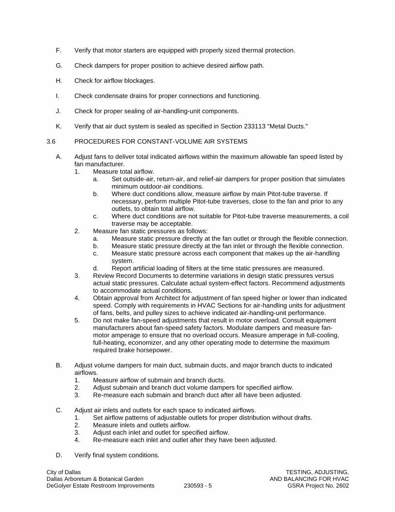
City of Dallas TESTING, ADJUSTING, Dallas Arboretum & Botanical Garden AND BALANCING FOR HVAC DeGolyer Estate Restroom Improvements 230593 - 5 GSRA Project No. 2602
F. Verify that motor starters are equipped with properly sized thermal protection.
G. Check dampers for proper position to achieve desired airflow path.
H. Check for airflow blockages.
I. Check condensate drains for proper connections and functioning.
J. Check for proper sealing of air-handling-unit components.
K. Verify that air duct system is sealed as specified in Section 233113 "Metal Ducts."
3.6 PROCEDURES FOR CONSTANT-VOLUME AIR SYSTEMS
A. Adjust fans to deliver total indicated airflows within the maximum allowable fan speed listed by fan manufacturer. 1. Measure total airflow.
a. Set outside-air, return-air, and relief-air dampers for proper position that simulates minimum outdoor-air conditions.
b. Where duct conditions allow, measure airflow by main Pitot-tube traverse. If necessary, perform multiple Pitot-tube traverses, close to the fan and prior to any outlets, to obtain total airflow.
c. Where duct conditions are not suitable for Pitot-tube traverse measurements, a coil traverse may be acceptable.
2. Measure fan static pressures as follows: a. Measure static pressure directly at the fan outlet or through the flexible connection. b. Measure static pressure directly at the fan inlet or through the flexible connection. c. Measure static pressure across each component that makes up the air-handling
system. d. Report artificial loading of filters at the time static pressures are measured.
3. Review Record Documents to determine variations in design static pressures versus actual static pressures. Calculate actual system-effect factors. Recommend adjustments to accommodate actual conditions.
4. Obtain approval from Architect for adjustment of fan speed higher or lower than indicated speed. Comply with requirements in HVAC Sections for air-handling units for adjustment of fans, belts, and pulley sizes to achieve indicated air-handling-unit performance.
5. Do not make fan-speed adjustments that result in motor overload. Consult equipment manufacturers about fan-speed safety factors. Modulate dampers and measure fan-motor amperage to ensure that no overload occurs. Measure amperage in full-cooling, full-heating, economizer, and any other operating mode to determine the maximum required brake horsepower.
B. Adjust volume dampers for main duct, submain ducts, and major branch ducts to indicated airflows. 1. Measure airflow of submain and branch ducts. 2. Adjust submain and branch duct volume dampers for specified airflow. 3. Re-measure each submain and branch duct after all have been adjusted.
C. Adjust air inlets and outlets for each space to indicated airflows. 1. Set airflow patterns of adjustable outlets for proper distribution without drafts. 2. Measure inlets and outlets airflow. 3. Adjust each inlet and outlet for specified airflow. 4. Re-measure each inlet and outlet after they have been adjusted.
D. Verify final system conditions.

City of Dallas TESTING, ADJUSTING, Dallas Arboretum & Botanical Garden AND BALANCING FOR HVAC DeGolyer Estate Restroom Improvements 230593 - 6 GSRA Project No. 2602
1. Re-measure and confirm that minimum outdoor, return, and relief airflows are within design. Readjust to design if necessary.
2. Re-measure and confirm that total airflow is within design. 3. Re-measure all final fan operating data, rpms, volts, amps, and static profile. 4. Mark all final settings. 5. Test system in economizer mode. Verify proper operation and adjust if necessary. 6. Measure and record all operating data. 7. Record final fan-performance data.
3.7 PROCEDURES FOR MOTORS
A. Motors 1/2 HP and Larger: Test at final balanced conditions and record the following data: 1. Manufacturer's name, model number, and serial number. 2. Motor horsepower rating. 3. Motor rpm. 4. Phase and hertz. 5. Nameplate and measured voltage, each phase. 6. Nameplate and measured amperage, each phase. 7. Starter size and thermal-protection-element rating. 8. Service factor and frame size.
B. Motors Driven by Variable-Frequency Controllers: Test manual bypass of controller to prove proper operation.
3.8 PROCEDURES FOR CONDENSING UNITS
A. Verify proper rotation of fans.
B. Measure entering- and leaving-air temperatures.
C. Record fan and motor operating data.
3.9 PROCEDURES FOR HEAT-TRANSFER COILS
A. Measure, adjust, and record the following data for each electric heating coil: 1. Nameplate data. 2. Airflow. 3. Entering- and leaving-air temperature at full load. 4. Voltage and amperage input of each phase at full load. 5. Calculated kilowatt at full load. 6. Fuse or circuit-breaker rating for overload protection.
B. Measure, adjust, and record the following data for each refrigerant coil: 1. Dry-bulb temperature of entering and leaving air. 2. Wet-bulb temperature of entering and leaving air. 3. Airflow.
3.10 SOUND TESTS
A. After the systems are balanced and construction is Substantially Complete, measure and record sound levels at 5 locations at each floor as designated by the Architect.
B. Instrumentation: 1. The sound-testing meter shall be a portable, general-purpose testing meter consisting of
a microphone, processing unit, and readout.

City of Dallas TESTING, ADJUSTING, Dallas Arboretum & Botanical Garden AND BALANCING FOR HVAC DeGolyer Estate Restroom Improvements 230593 - 7 GSRA Project No. 2602
2. The sound-testing meter shall be capable of showing fluctuations at minimum and maximum levels, and measuring the equivalent continuous sound pressure level (LEQ).
3. The sound-testing meter must be capable of using 1/3 octave band filters to measure mid-frequencies from 31.5 Hz to 8000 Hz.
4. The accuracy of the sound-testing meter shall be plus or minus one decibel.
C. Test Procedures: 1. Perform test at quietest background noise period. Note cause of unpreventable sound
that affects test outcome. 2. Equipment should be operating at design values. 3. Calibrate the sound-testing meter prior to taking measurements. 4. Use a microphone suitable for the type of noise levels measured that is compatible with
meter. Provide a windshield for outside or in-duct measurements. 5. Record a set of background measurements in dBA and sound pressure levels in the eight
un-weighted octave bands 63 Hz to 8000 Hz (NC) with the equipment off. 6. Take sound readings in dBA and sound pressure levels in the eight un-weighted octave
bands 63 Hz to 8000 Hz (NC) with the equipment operating. 7. Take readings no closer than 36 inches from a wall or from the operating equipment and
approximately 60 inches from the floor, with the meter held or mounted on a tripod. 8. For outdoor measurements, move sound-testing meter slowly and scan area that has the
most exposure to noise source being tested. Use A-weighted scale for this type of reading.
D. Reporting: 1. Report shall record the following:
a. Location. b. System tested. c. dBA reading. d. Sound pressure level in each octave band with equipment on and off.
2. Plot sound pressure levels on NC worksheet with equipment on and off.
3.11 VIBRATION TESTS
A. After systems are balanced and construction is Substantially Complete, measure and record vibration levels on equipment having motor horsepower equal to or greater than 10.
B. Instrumentation: 1. Use portable, battery-operated, and microprocessor-controlled vibration meter with or
without a built-in printer. 2. The meter shall automatically identify engineering units, filter bandwidth, amplitude, and
frequency scale values. 3. The meter shall be able to measure machine vibration displacement in mils of deflection,
velocity in inches per second, and acceleration in inches per second squared. 4. Verify calibration date is current for vibration meter before taking readings.
C. Test Procedures: 1. To ensure accurate readings, verify that accelerometer has a clean, flat surface and is
mounted properly. 2. With the unit running, set up vibration meter in a safe, secure location. Connect
transducer to meter with proper cables. Hold magnetic tip of transducer on top of the bearing, and measure unit in mils of deflection. Record measurement, then move transducer to the side of the bearing and record in mils of deflection. Record an axial reading in mils of deflection by holding nonmagnetic, pointed transducer tip on end of shaft.
3. Change vibration meter to velocity (inches per second) measurements. Repeat and record above measurements.

City of Dallas TESTING, ADJUSTING, Dallas Arboretum & Botanical Garden AND BALANCING FOR HVAC DeGolyer Estate Restroom Improvements 230593 - 8 GSRA Project No. 2602
4. Record CPM or rpm. 5. Read each bearing on motor, fan, and pump as required. Track and record vibration
levels from rotating component through casing to base.
D. Reporting: 1. Report shall record location and the system tested. 2. Include horizontal-vertical-axial measurements for tests. 3. Verify that vibration limits follow Specifications, or, if not specified, follow the General
Machinery Vibration Severity Chart or Vibration Acceleration General Severity Chart from the AABC National Standards. Acceptable levels of vibration are normally "smooth" to "good."
4. Include in report General Machinery Vibration Severity Chart, with conditions plotted.
3.12 DUCT LEAKAGE TESTS
A. Witness the duct pressure testing performed by Installer.
B. Verify that proper test methods are used and that leakage rates are within specified tolerances.
C. Report deficiencies observed.
3.13 CONTROLS VERIFICATION
A. In conjunction with system balancing, perform the following: 1. Verify temperature control system is operating within the design limitations. 2. Confirm that the sequences of operation are in compliance with Contract Documents. 3. Verify that controllers are calibrated and function as intended. 4. Verify that controller set points are as indicated. 5. Verify the operation of lockout or interlock systems. 6. Verify the operation of valve and damper actuators. 7. Verify that controlled devices are properly installed and connected to correct controller. 8. Verify that controlled devices travel freely and are in position indicated by controller:
open, closed, or modulating. 9. Verify location and installation of sensors to ensure that they sense only intended
temperature, humidity, or pressure.
B. Reporting: Include a summary of verifications performed, remaining deficiencies, and variations from indicated conditions.
3.14 TOLERANCES
A. Set HVAC system's airflow rates and water flow rates within the following tolerances: 1. Supply, Return, and Exhaust Fans and Equipment with Fans: Plus 10 percent and minus
5 percent. 2. Air Outlets and Inlets: Plus 10 percent and minus 5 percent.
B. Maintaining pressure relationships as designed shall have priority over the tolerances specified above.
3.15 PROGRESS REPORTING
A. Initial Construction-Phase Report: Based on examination of the Contract Documents as specified in "Examination" Article, prepare a report on the adequacy of design for systems balancing devices. Recommend changes and additions to systems balancing devices to facilitate proper performance measuring and balancing. Recommend changes and additions to

City of Dallas TESTING, ADJUSTING, Dallas Arboretum & Botanical Garden AND BALANCING FOR HVAC DeGolyer Estate Restroom Improvements 230593 - 9 GSRA Project No. 2602
HVAC systems and general construction to allow access for performance measuring and balancing devices.
B. Status Reports: Prepare weekly progress reports to describe completed procedures, procedures in progress, and scheduled procedures. Include a list of deficiencies and problems found in systems being tested and balanced. Prepare a separate report for each system and each building floor for systems serving multiple floors.
3.16 FINAL REPORT
A. General: Prepare a certified written report; tabulate and divide the report into separate sections for tested systems and balanced systems. 1. Include a certification sheet at the front of the report's binder, signed and sealed by the
certified testing and balancing engineer. 2. Include a list of instruments used for procedures, along with proof of calibration. 3. Certify validity and accuracy of field data.
B. Final Report Contents: In addition to certified field-report data, include the following: 1. Fan curves. 2. Manufacturers' test data. 3. Field test reports prepared by system and equipment installers. 4. Other information relative to equipment performance; do not include Shop Drawings and
Product Data.
C. General Report Data: In addition to form titles and entries, include the following data: 1. Title page. 2. Name and address of the TAB specialist. 3. Project name. 4. Project location. 5. Architect's name and address. 6. Engineer's name and address. 7. Contractor's name and address. 8. Report date. 9. Signature of TAB supervisor who certifies the report. 10. Table of Contents with the total number of pages defined for each section of the report.
Number each page in the report. 11. Summary of contents including the following:
a. Indicated versus final performance. b. Notable characteristics of systems. c. Description of system operation sequence if it varies from the Contract
Documents. 12. Nomenclature sheets for each item of equipment. 13. Data for terminal units, including manufacturer's name, type, size, and fittings. 14. Notes to explain why certain final data in the body of reports vary from indicated values. 15. Test conditions for fans and pump performance forms including the following:
a. Settings for outdoor-, return-, and exhaust-air dampers. b. Conditions of filters. c. Cooling coil, wet- and dry-bulb conditions. d. Face and bypass damper settings at coils. e. Fan drive settings including settings and percentage of maximum pitch diameter. f. Settings for supply-air, static-pressure controller. g. Other system operating conditions that affect performance.
D. System Diagrams: Include schematic layouts of air and hydronic distribution systems. Present each system with single-line diagram and include the following: 1. Quantities of outdoor, supply, return, and exhaust airflows.

City of Dallas TESTING, ADJUSTING, Dallas Arboretum & Botanical Garden AND BALANCING FOR HVAC DeGolyer Estate Restroom Improvements 230593 - 10 GSRA Project No. 2602
2. Duct, outlet, and inlet sizes. 3. Pipe and valve sizes and locations. 4. Terminal units. 5. Balancing stations. 6. Position of balancing devices.
E. Air-Handling-Unit Test Reports: For air-handling units with coils, include the following: 1. Unit Data:
a. Unit identification. b. Location. c. Make and type. d. Model number and unit size. e. Manufacturer's serial number. f. Unit arrangement and class. g. Discharge arrangement. h. Sheave make, size in inches, and bore. i. Center-to-center dimensions of sheave and amount of adjustments in inches. j. Number, make, and size of belts. k. Number, type, and size of filters.
2. Motor Data: a. Motor make, and frame type and size. b. Horsepower and rpm. c. Volts, phase, and hertz. d. Full-load amperage and service factor. e. Sheave make, size in inches, and bore. f. Center-to-center dimensions of sheave and amount of adjustments in inches.
3. Test Data (Indicated and Actual Values): a. Total airflow rate in cfm). b. Total system static pressure in inches wg). c. Fan rpm. d. Discharge static pressure in inches wg. e. Filter static-pressure differential in inches wg. f. Preheat-coil static-pressure differential in inches wg. g. Cooling-coil static-pressure differential in inches wg. h. Heating-coil static-pressure differential in inches wg. i. Outdoor airflow in cfm). j. Return airflow in cfm). k. Outdoor-air damper position. l. Return-air damper position. m. Vortex damper position.
F. Apparatus-Coil Test Reports: 1. Coil Data:
a. System identification. b. Location. c. Coil type. d. Number of rows. e. Fin spacing in fins per inch o.c. f. Make and model number. g. Face area in sq. ft.. h. Tube size in NPS. i. Tube and fin materials. j. Circuiting arrangement.
2. Test Data (Indicated and Actual Values): a. Airflow rate in cfm. b. Average face velocity in fpm.

City of Dallas TESTING, ADJUSTING, Dallas Arboretum & Botanical Garden AND BALANCING FOR HVAC DeGolyer Estate Restroom Improvements 230593 - 11 GSRA Project No. 2602
c. Air pressure drop in inches wg (Pa). d. Outdoor-air, wet- and dry-bulb temperatures in deg F. e. Return-air, wet- and dry-bulb temperatures in deg F. f. Entering-air, wet- and dry-bulb temperatures in deg F. g. Leaving-air, wet- and dry-bulb temperatures in deg F. h. Water flow rate in gpm (L/s). i. Water pressure differential in feet of head or psig. j. Entering-water temperature in deg F. k. Leaving-water temperature in deg F. l. Refrigerant expansion valve and refrigerant types. m. Refrigerant suction pressure in psig. n. Refrigerant suction temperature in deg F. o. Inlet steam pressure in psig.
G. Electric-Coil Test Reports: For electric furnaces, duct coils, and electric coils installed in central-station air-handling units, include the following: 1. Unit Data:
a. System identification. b. Location. c. Coil identification. d. Capacity in Btu/h (kW). e. Number of stages. f. Connected volts, phase, and hertz. g. Rated amperage. h. Airflow rate in cfm. i. Face area in sq. ft.. j. Minimum face velocity in fpm.
2. Test Data (Indicated and Actual Values): a. Heat output in Btu/h (kW). b. Airflow rate in cfm). c. Air velocity in fpm. d. Entering-air temperature in deg F. e. Leaving-air temperature in deg F. f. Voltage at each connection. g. Amperage for each phase.
H. Fan Test Reports: For supply, return, and exhaust fans, include the following: 1. Fan Data:
a. System identification. b. Location. c. Make and type. d. Model number and size. e. Manufacturer's serial number. f. Arrangement and class. g. Sheave make, size in inches, and bore. h. Center-to-center dimensions of sheave and amount of adjustments in inches.
2. Motor Data: a. Motor make, and frame type and size. b. Horsepower and rpm. c. Volts, phase, and hertz. d. Full-load amperage and service factor. e. Sheave make, size in inches, and bore. f. Center-to-center dimensions of sheave, and amount of adjustments in inches. g. Number, make, and size of belts.
3. Test Data (Indicated and Actual Values): a. Total airflow rate in cfm).

City of Dallas TESTING, ADJUSTING, Dallas Arboretum & Botanical Garden AND BALANCING FOR HVAC DeGolyer Estate Restroom Improvements 230593 - 12 GSRA Project No. 2602
b. Total system static pressure in inches wg. c. Fan rpm. d. Discharge static pressure in inches wg. e. Suction static pressure in inches wg.
I. Round, Flat-Oval, and Rectangular Duct Traverse Reports: Include a diagram with a grid representing the duct cross-section and record the following: 1. Report Data:
a. System and air-handling-unit number. b. Location and zone. c. Traverse air temperature in deg F. d. Duct static pressure in inches wg. e. Duct size in inches. f. Duct area in sq. ft. g. Indicated airflow rate in cfm. h. Indicated velocity in fpm. i. Actual airflow rate in cfm. j. Actual average velocity in fpm. k. Barometric pressure in psig.
J. Air-Terminal-Device Reports (Fan Coil Units): 1. Unit Data:
a. Floor, system and air-handling unit identification. b. Location and zone. c. Apparatus used for test. d. Area served. e. Make. f. Number from system diagram. g. Type and model number. h. Size. i. Effective area in sq. ft.
2. Test Data (Indicated and Actual Values): a. Airflow rate in cfm. b. Air velocity in fpm. c. Preliminary airflow rate as needed in cfm. d. Preliminary velocity as needed in fpm. e. Final airflow rate in cfm. f. Final velocity in fpm. g. Space temperature in deg F.
K. Instrument Calibration Reports: 1. Report Data:
a. Instrument type and make. b. Serial number. c. Application. d. Dates of use. e. Dates of calibration.
3.17 VERIFICATION OF TAB REPORT
A. The TAB specialist's test and balance engineer shall conduct the inspection in the presence of Architect and Construction Manager.
B. Architect and/or Construction Manager shall randomly select measurements, documented in the final report, to be rechecked. Rechecking shall be limited to either 10 percent of the total

City of Dallas TESTING, ADJUSTING, Dallas Arboretum & Botanical Garden AND BALANCING FOR HVAC DeGolyer Estate Restroom Improvements 230593 - 13 GSRA Project No. 2602
measurements recorded or the extent of measurements that can be accomplished in a normal 8-hour business day.
C. If rechecks yield measurements that differ from the measurements documented in the final report by more than the tolerances allowed, the measurements shall be noted as "FAILED."
D. If the number of "FAILED" measurements is greater than 10 percent of the total measurements checked during the final inspection, the testing and balancing shall be considered incomplete and shall be rejected.
E. If TAB work fails, proceed as follows: 1. TAB specialists shall recheck all measurements and make adjustments. Revise the final
report and balancing device settings to include all changes; resubmit the final report and request a second final inspection.
2. If the second final inspection also fails, Owner may contract the services of another TAB specialist to complete TAB work according to the Contract Documents and deduct the cost of the services from the original TAB specialist's final payment.
3. If the second verification also fails, Architect may contact AABC Headquarters regarding the AABC National Performance Guaranty.
F. Prepare test and inspection reports.
3.18 ADDITIONAL TESTS
A. Within 90 days of completing TAB, perform additional TAB to verify that balanced conditions are being maintained throughout and to correct unusual conditions.
B. Seasonal Periods: If initial TAB procedures were not performed during near-peak summer and winter conditions, perform additional TAB during near-peak summer and winter conditions.
END OF SECTION

City of Dallas Dallas Arboretum & Botanical Garden DUCT INSULATION DeGolyer Estate Restroom Improvements 230713 - 1 GSRA Project No. 2602
SECTION 230713
DUCT INSULATION
PART 1 - GENERAL
1.1 SUMMARY
A. Section includes insulating the following duct services: 1. Indoor, concealed supply and outdoor air. 2. Indoor, exposed supply and outdoor air. 3. Indoor, concealed return located in unconditioned space. 4. Indoor, exposed return located in unconditioned space.
B. Related Sections: 1. Section 23 07 19 "HVAC Piping Insulation."
1.2 ACTION SUBMITTALS
A. Product Data: For each type of product indicated.
B. Shop Drawings: Include plans, elevations, sections, details, and attachments to other work. 1. Detail application of protective shields, saddles, and inserts at hangers for each type of
insulation and hanger. 2. Detail insulation application at elbows, fittings, dampers, specialties and flanges for each
type of insulation. 3. Detail application of field-applied jackets. 4. Detail application at linkages of control devices.
1.3 INFORMATIONAL SUBMITTALS
A. Field quality-control reports.
1.4 QUALITY ASSURANCE
A. Surface-Burning Characteristics: For insulation and related materials, as determined by testing identical products according to ASTM E 84, by a testing agency acceptable to authorities having jurisdiction. Factory label insulation and jacket materials and adhesive, mastic, tapes, and cement material containers, with appropriate markings of applicable testing agency. 1. Insulation Installed Indoors: Flame-spread index of 25 or less, and smoke-developed
index of 50 or less. 2. Insulation Installed Outdoors: Flame-spread index of 75 or less, and smoke-developed
index of 150 or less.
PART 2 - PRODUCTS
2.1 INSULATION MATERIALS
A. Comply with requirements in "Duct Insulation Schedule, General," "Indoor Duct and Plenum Insulation Schedule," and "Aboveground, Outdoor Duct and Plenum Insulation Schedule" articles for where insulating materials shall be applied.
B. Products shall not contain asbestos, lead, mercury, or mercury compounds.

City of Dallas Dallas Arboretum & Botanical Garden DUCT INSULATION DeGolyer Estate Restroom Improvements 230713 - 2 GSRA Project No. 2602
C. Foam insulation materials shall not use CFC or HCFC blowing agents in the manufacturing process.
D. Mineral-Fiber Blanket Insulation: Mineral or glass fibers bonded with a thermosetting resin. Comply with ASTM C 553, Type II and ASTM C 1290, Type III with factory-applied or field -applied FSK jacket. Factory-applied jacket requirements are specified in "Factory-Applied Jackets" Article. Field-applied jacket requirements are specified in "Field-Applied Jackets" Article. 1. Manufacturers: Subject to compliance with requirements, provide products by one of the
following: a. CertainTeed Corporation. b. Johns Manville; a Berkshire Hathaway company. c. Knauf Insulation. d. Owens Corning.
E. Mineral-Fiber Board Insulation: Mineral or glass fibers bonded with a thermosetting resin. Comply with ASTM C 612, Type IA or Type IB. For duct and plenum applications, provide insulation with factory-applied FSK jacket. Factory-applied jacket requirements are specified in "Factory-Applied Jackets" Article. 1. Manufacturers: Subject to compliance with requirements, provide products by one of the
following: a. CertainTeed Corporation. b. Johns Manville; a Berkshire Hathaway company. c. Knauf Insulation. d. Owens Corning. e. Manson Insulation Inc.
2.2 ADHESIVES
A. Materials shall be compatible with insulation materials, jackets, and substrates and for bonding insulation to itself and to surfaces to be insulated unless otherwise indicated.
B. Mineral-Fiber Adhesive: Comply with MIL-A-3316C, Class 2, Grade A. 1. Manufacturers: Subject to compliance with requirements, provide products by one of the
following: a. Childers Brand; H. B. Fuller Construction Products. b. Eagle Bridges - Marathon Industries. c. Foster Brand; H. B. Fuller Construction Products.
2. For indoor applications, adhesive shall have a VOC content of 80 g/L or less when calculated according to 40 CFR 59, Subpart D (EPA Method 24).
C. ASJ Adhesive, and FSK Jacket Adhesive: Comply with MIL-A-3316C, Class 2, Grade A for bonding insulation jacket lap seams and joints. 1. Manufacturers: Subject to compliance with requirements, provide products by one of the
following: a. Childers Brand; H. B. Fuller Construction Products. b. Eagle Bridges - Marathon Industries. c. Foster Brand; H. B. Fuller Construction Products.
2. For indoor applications, adhesive shall have a VOC content of 50 g/L or less when calculated according to 40 CFR 59, Subpart D (EPA Method 24).
2.3 MASTICS
A. Materials shall be compatible with insulation materials, jackets, and substrates; comply with MIL-PRF-19565C, Type II.

City of Dallas Dallas Arboretum & Botanical Garden DUCT INSULATION DeGolyer Estate Restroom Improvements 230713 - 3 GSRA Project No. 2602
1. For indoor applications, use mastics that have a VOC content of 50 g/L or less when calculated according to 40 CFR 59, Subpart D (EPA Method 24).
B. Vapor-Barrier Mastic: Water based; suitable for indoor use on below ambient services. 1. Manufacturers: Subject to compliance with requirements, provide products by the
following: a. Foster Brand; H. B. Fuller Construction Products.
2. Water-Vapor Permeance: ASTM F 1249, 1.8 perms at 0.0625-inch dry film thickness. 3. Service Temperature Range: Minus 20 to plus 180 deg F. 4. Solids Content: ASTM D 1644, 58 percent by volume and 70 percent by weight. 5. Color: White.
2.4 SEALANTS
A. FSK and Metal Jacket Flashing Sealants: 1. Manufacturers: Subject to compliance with requirements, provide products by one of the
following: a. Childers Brand; H. B. Fuller Construction Products. b. Eagle Bridges - Marathon Industries. c. Foster Brand; H. B. Fuller Construction Products.
2. Materials shall be compatible with insulation materials, jackets, and substrates. 3. Fire- and water-resistant, flexible, elastomeric sealant. 4. Service Temperature Range: Minus 40 to plus 250 deg F. 5. Color: Aluminum. 6. For indoor applications, use sealants that have a VOC content of 420 g/L or less when
calculated according to 40 CFR 59, Subpart D (EPA Method 24).
2.5 FACTORY-APPLIED JACKETS
A. Insulation system schedules indicate factory-applied jackets on various applications. When factory-applied jackets are indicated, comply with the following: 1. FSK Jacket: Aluminum-foil, fiberglass-reinforced scrim with kraft-paper backing;
complying with ASTM C 1136, Type II.
2.6 FIELD-APPLIED JACKETS
A. Field-applied jackets shall comply with ASTM C 921, Type I, unless otherwise indicated.
B. FSK Jacket: Aluminum-foil-face, fiberglass-reinforced scrim with kraft-paper backing.
2.7 TAPES
A. FSK Tape: Foil-face, vapor-retarder tape matching factory-applied jacket with acrylic adhesive; complying with ASTM C 1136. 1. Manufacturers: Subject to compliance with requirements, provide products by one of the
following: a. Avery Dennison Corporation, Specialty Tapes Division. b. Compac Corporation. c. Ideal Tape Co., Inc., an American Biltrite Company. d. Knauf Insulation.
2. Width: 3 inches. 3. Thickness: 6.5 mils. 4. Adhesion: 90 ounces force/inch in width. 5. Elongation: 2 percent. 6. Tensile Strength: 40 lbf/inch in width.

City of Dallas Dallas Arboretum & Botanical Garden DUCT INSULATION DeGolyer Estate Restroom Improvements 230713 - 4 GSRA Project No. 2602
7. FSK Tape Disks and Squares: Precut disks or squares of FSK tape.
B. Aluminum-Foil Tape: Vapor-retarder tape with acrylic adhesive. 1. Manufacturers: Subject to compliance with requirements, provide products by one of the
following: a. Avery Dennison Corporation, Specialty Tapes Division. b. Compac Corporation. c. Ideal Tape Co., Inc., an American Biltrite Company. d. Knauf Insulation.
2. Width: 2 inches. 3. Thickness: 3.7 mils. 4. Adhesion: 100 ounces force/inch in width. 5. Elongation: 5 percent. 6. Tensile Strength: 34 lbf/inch in width.
2.8 SECUREMENTS
A. Insulation Pins and Hangers: 1. Metal, Adhesively Attached, Perforated-Base Insulation Hangers: Baseplate welded to
projecting spindle that is capable of holding insulation, of thickness indicated, securely in position indicated when self-locking washer is in place. Comply with the following requirements: a. Baseplate: Perforated, galvanized carbon-steel sheet, 0.030 inch thick by 2 inches
square. b. Spindle: Copper- or zinc-coated, low-carbon steel, fully annealed, 0.106-inch-
diameter shank, length to suit depth of insulation indicated. c. Adhesive: Recommended by hanger manufacturer. Product with demonstrated
capability to bond insulation hanger securely to substrates indicated without damaging insulation, hangers, and substrates.
2. Self-Sticking-Base Insulation Hangers: Baseplate welded to projecting spindle that is capable of holding insulation, of thickness indicated, securely in position indicated when self-locking washer is in place. Comply with the following requirements: a. Baseplate: Galvanized carbon-steel sheet, 0.030 inch thick by 2 inches square. b. Spindle: Copper- or zinc-coated, low-carbon steel, fully annealed, 0.106-inch-
diameter shank, length to suit depth of insulation indicated. c. Adhesive-backed base with a peel-off protective cover.
3. Insulation-Retaining Washers: Self-locking washers formed from 0.016-inch-thick, galvanized-steel sheet, with beveled edge sized as required to hold insulation securely in place but not less than 1-1/2 inches in diameter. a. Protect ends with capped self-locking washers incorporating a spring steel insert to
ensure permanent retention of cap in exposed locations.
B. Staples: Outward-clinching insulation staples, nominal 3/4-inch-wide, stainless steel or Monel.
C. Wire: 0.062-inch soft-annealed, galvanized steel.
PART 3 - EXECUTION
3.1 PREPARATION
A. Surface Preparation: Clean and dry surfaces to receive insulation. Remove materials that will adversely affect insulation application.

City of Dallas Dallas Arboretum & Botanical Garden DUCT INSULATION DeGolyer Estate Restroom Improvements 230713 - 5 GSRA Project No. 2602
3.2 GENERAL INSTALLATION REQUIREMENTS
A. Install insulation materials, accessories, and finishes with smooth, straight, and even surfaces; free of voids throughout the length of ducts and fittings.
B. Install insulation materials, vapor barriers or retarders, jackets, and thicknesses required for each item of duct system as specified in insulation system schedules.
C. Install accessories compatible with insulation materials and suitable for the service. Install accessories that do not corrode, soften, or otherwise attack insulation or jacket in either wet or dry state.
D. Install insulation with longitudinal seams at top and bottom of horizontal runs.
E. Install multiple layers of insulation with longitudinal and end seams staggered.
F. Keep insulation materials dry during application and finishing.
G. Install insulation with tight longitudinal seams and end joints. Bond seams and joints with adhesive recommended by insulation material manufacturer.
H. Install insulation with least number of joints practical.
I. Where vapor barrier is indicated, seal joints, seams, and penetrations in insulation at hangers, supports, anchors, and other projections with vapor-barrier mastic. 1. Install insulation continuously through hangers and around anchor attachments. 2. For insulation application where vapor barriers are indicated, extend insulation on anchor
legs from point of attachment to supported item to point of attachment to structure. Taper and seal ends at attachment to structure with vapor-barrier mastic.
3. Install insert materials and install insulation to tightly join the insert. Seal insulation to insulation inserts with adhesive or sealing compound recommended by insulation material manufacturer.
J. Apply adhesives, mastics, and sealants at manufacturer's recommended coverage rate and wet and dry film thicknesses.
K. Install insulation with factory-applied jackets as follows: 1. Draw jacket tight and smooth. 2. Cover circumferential joints with 3-inch-wide strips, of same material as insulation jacket.
Secure strips with adhesive and outward clinching staples along both edges of strip, spaced 4 inches o.c.
3. Overlap jacket longitudinal seams at least 1-1/2 inches. Clean and dry surface to receive self-sealing lap. Staple laps with outward clinching staples along edge at 2 inches o.c. a. For below ambient services, apply vapor-barrier mastic over staples.
4. Cover joints and seams with tape, according to insulation material manufacturer's written instructions, to maintain vapor seal.
5. Where vapor barriers are indicated, apply vapor-barrier mastic on seams and joints and at ends adjacent to duct flanges and fittings.
L. Cut insulation in a manner to avoid compressing insulation more than 75 percent of its nominal thickness.
M. Finish installation with systems at operating conditions. Repair joint separations and cracking due to thermal movement.

City of Dallas Dallas Arboretum & Botanical Garden DUCT INSULATION DeGolyer Estate Restroom Improvements 230713 - 6 GSRA Project No. 2602
N. Repair damaged insulation facings by applying same facing material over damaged areas. Extend patches at least 4 inches beyond damaged areas. Adhere, staple, and seal patches similar to butt joints.
3.3 PENETRATIONS
A. Insulation Installation at Roof Penetrations: Install insulation continuously through roof penetrations. 1. Seal penetrations with flashing sealant. 2. For applications requiring only indoor insulation, terminate insulation above roof surface
and seal with joint sealant. For applications requiring indoor and outdoor insulation, install insulation for outdoor applications tightly joined to indoor insulation ends. Seal joint with joint sealant.
3. Extend jacket of outdoor insulation outside roof flashing at least 2 inches below top of roof flashing.
4. Seal jacket to roof flashing with flashing sealant.
B. Insulation Installation at Aboveground Exterior Wall Penetrations: Install insulation continuously through wall penetrations. 1. Seal penetrations with flashing sealant. 2. For applications requiring only indoor insulation, terminate insulation inside wall surface
and seal with joint sealant. For applications requiring indoor and outdoor insulation, install insulation for outdoor applications tightly joined to indoor insulation ends. Seal joint with joint sealant.
3. Extend jacket of outdoor insulation outside wall flashing and overlap wall flashing at least 2 inches.
4. Seal jacket to wall flashing with flashing sealant.
C. Insulation Installation at Interior Wall and Partition Penetrations (That Are Not Fire Rated): Install insulation continuously through walls and partitions.
D. Insulation Installation at Fire-Rated Wall and Partition Penetrations: Terminate insulation at fire damper sleeves for fire-rated wall and partition penetrations. Externally insulate damper sleeves to match adjacent insulation and overlap duct insulation at least 2 inches. 1. Comply with requirements in Section 078413 "Penetration Firestopping."
E. Insulation Installation at Floor Penetrations: 1. Duct: For penetrations through fire-rated assemblies, terminate insulation at fire damper
sleeves and externally insulate damper sleeve beyond floor to match adjacent duct insulation. Overlap damper sleeve and duct insulation at least 2 inches.
2. Seal penetrations through fire-rated assemblies. Comply with requirements in Section 078413 "Penetration Firestopping."
3.4 INSTALLATION OF MINERAL-FIBER INSULATION
A. Blanket Insulation Installation on Ducts and Plenums: Secure with adhesive and insulation pins. 1. Apply adhesives according to manufacturer's recommended coverage rates per unit
area, for 50 percent coverage of duct and plenum surfaces. 2. Apply adhesive to entire circumference of ducts and to all surfaces of fittings and
transitions. 3. Install either capacitor-discharge-weld pins and speed washers or cupped-head,
capacitor-discharge-weld pins on sides and bottom of horizontal ducts and sides of vertical ducts as follows: a. On duct sides with dimensions 18 inches and smaller, place pins along longitudinal
centerline of duct. Space 3 inches maximum from insulation end joints, and 16 inches o.c.

City of Dallas Dallas Arboretum & Botanical Garden DUCT INSULATION DeGolyer Estate Restroom Improvements 230713 - 7 GSRA Project No. 2602
b. On duct sides with dimensions larger than 18 inches, place pins 16 inches o.c. each way, and 3 inches maximum from insulation joints. Install additional pins to hold insulation tightly against surface at cross bracing.
c. Pins may be omitted from top surface of horizontal, rectangular ducts and plenums.
d. Do not overcompress insulation during installation. e. Impale insulation over pins and attach speed washers. f. Cut excess portion of pins extending beyond speed washers or bend parallel with
insulation surface. Cover exposed pins and washers with tape matching insulation facing.
4. For ducts and plenums with surface temperatures below ambient, install a continuous unbroken vapor barrier. Create a facing lap for longitudinal seams and end joints with insulation by removing 2 inches from one edge and one end of insulation segment. Secure laps to adjacent insulation section with 1/2-inch outward-clinching staples, 1 inch o.c. Install vapor barrier consisting of factory- or field-applied jacket, adhesive, vapor-barrier mastic, and sealant at joints, seams, and protrusions. a. Repair punctures, tears, and penetrations with tape or mastic to maintain vapor-
barrier seal. b. Install vapor stops for ductwork and plenums operating below 50 deg F at 18-foot
intervals. Vapor stops shall consist of vapor-barrier mastic applied in a Z-shaped pattern over insulation face, along butt end of insulation, and over the surface. Cover insulation face and surface to be insulated a width equal to two times the insulation thickness, but not less than 3 inches.
5. Overlap unfaced blankets a minimum of 2 inches on longitudinal seams and end joints. At end joints, secure with steel bands spaced a maximum of 18 inches o.c.
6. Install insulation on rectangular duct elbows and transitions with a full insulation section for each surface. Install insulation on round and flat-oval duct elbows with individually mitered gores cut to fit the elbow.
7. Insulate duct stiffeners, hangers, and flanges that protrude beyond insulation surface with 6-inch-wide strips of same material used to insulate duct. Secure on alternating sides of stiffener, hanger, and flange with pins spaced 6 inches o.c.
3.5 FIELD-APPLIED JACKET INSTALLATION
A. Where FSK jackets are indicated, install as follows: 1. Draw jacket material smooth and tight. 2. Install lap or joint strips with same material as jacket. 3. Secure jacket to insulation with manufacturer's recommended adhesive. 4. Install jacket with 1-1/2-inch laps at longitudinal seams and 3-inch-wide joint strips at end
joints. 5. Seal openings, punctures, and breaks in vapor-retarder jackets and exposed insulation
with vapor-barrier mastic.
3.6 FIELD QUALITY CONTROL
A. Perform tests and inspections.
B. Tests and Inspections: 1. Inspect ductwork, randomly selected by Architect, by removing field-applied jacket and
insulation in layers in reverse order of their installation. Extent of inspection shall be limited to one location for each duct system defined in the "Duct Insulation Schedule, General" Article.
C. All insulation applications will be considered defective Work if sample inspection reveals noncompliance with requirements.

City of Dallas Dallas Arboretum & Botanical Garden DUCT INSULATION DeGolyer Estate Restroom Improvements 230713 - 8 GSRA Project No. 2602
3.7 DUCT INSULATION SCHEDULE, GENERAL
A. Plenums and Ducts Requiring Insulation: 1. Indoor, concealed supply and outdoor air. 2. Indoor, exposed supply and outdoor air. 3. Indoor, concealed return located in unconditioned space. 4. Indoor, exposed return located in unconditioned space.
B. Items Not Insulated: 1. Factory-insulated flexible ducts. 2. Factory-insulated plenums and casings. 3. Flexible connectors. 4. Vibration-control devices. 5. Factory-insulated access panels and doors.
3.8 INDOOR DUCT AND PLENUM INSULATION SCHEDULE
A. Concealed, Supply-Air Duct and Plenum Insulation: Mineral-fiber blanket, 2 inches thick and 0.75-lb/cu. ft. nominal density.
B. Concealed, Return-Air Duct and Plenum Insulation: Mineral-fiber blanket, 2 inches thick and 0.75-lb/cu. ft. nominal density.
C. Concealed, Outdoor-Air Duct and Plenum Insulation: Mineral-fiber blanket, 2 inches thick and 0.75-lb/cu. ft. nominal density.
D. Exposed, Supply-Air Duct and Plenum Insulation: Mineral-Fiber Blanket Insulation, 2 inches thick and 0.75-lb/cu. ft. nominal density with FSK jacket.
E. Exposed, rectangular, outdoor-air duct insulation shall be one of the following 1. Mineral-Fiber Blanket: 2 inches thick and 0.75-lb/cu. ft. nominal density. 2. Mineral-Fiber Board: 2 inches thick and 2-lb/cu. ft. nominal density.
3.9 INDOOR, FIELD-APPLIED JACKET SCHEDULE
A. Install jacket over insulation material. For insulation with factory-applied jacket, install the field-applied jacket over the factory-applied jacket.
B. Ducts and Plenums, Concealed: 1. None.
C. Ducts and Plenums, Exposed in mechanical rooms, janitor closets and storage spaces at 10 ft and lower: 1. FSK Jacket.
D. Ducts and Plenums, Exposed in occupied spaces: 1. FSK Jacket.
END OF SECTION
City of Dallas Dallas Arboretum & Botanical Garden HVAC PIPING INSULATION DeGolyer Estate Restroom Improvements 230719 - 1 GSRA Project No. 2602
SECTION 230719
HVAC PIPING INSULATION
PART 1 - GENERAL
1.1 SUMMARY
A. Section includes insulation for HVAC piping systems.
B. Related Sections: 1. Section 230713 "Duct Insulation" for duct insulation.
1.2 ACTION SUBMITTALS
A. Product Data: For each type of product. Include thermal conductivity, water-vapor permeance thickness, and jackets (both factory and field applied if any).
B. Shop Drawings: Include plans, elevations, sections, details, and attachments to other work. 1. Detail application of protective shields, saddles, and inserts at hangers for each type of
insulation and hanger. 2. Detail insulation application at pipe expansion joints for each type of insulation. 3. Detail insulation application at elbows, fittings, flanges, valves, and specialties for each
type of insulation. 4. Detail removable insulation at piping specialties. 5. Detail application of field-applied jackets. 6. Detail application at linkages of control devices.
1.3 QUALITY ASSURANCE
A. Installer Qualifications: Skilled mechanics who have successfully completed an apprenticeship program or another craft training program certified by the Department of Labor, Bureau of Apprenticeship and Training.
B. Surface-Burning Characteristics: For insulation and related materials, as determined by testing identical products in accordance with ASTM E84, by a testing agency acceptable to authorities having jurisdiction. Factory label insulation and jacket materials and adhesive, mastic, tapes, and cement material containers, with appropriate markings of applicable testing agency. 1. Insulation Installed Indoors: Flame-spread index of 25 or less, and smoke-developed
index of 50 or less. 2. Insulation Installed Outdoors: Flame-spread index of 75 or less, and smoke-developed
index of 150 or less.
1.4 DELIVERY, STORAGE, AND HANDLING
A. Packaging: Insulation material containers shall be marked by manufacturer with appropriate ASTM standard designation, type and grade, and maximum use temperature.
1.5 COORDINATION
A. Coordinate sizes and locations of supports, hangers, and insulation shields specified in Section 230529 "Hangers and Supports for HVAC Piping and Equipment."

City of Dallas Dallas Arboretum & Botanical Garden HVAC PIPING INSULATION DeGolyer Estate Restroom Improvements 230719 - 2 GSRA Project No. 2602
B. Coordinate clearance requirements with piping Installer for piping insulation application. Before preparing piping Shop Drawings, establish and maintain clearance requirements for installation of insulation and field-applied jackets and finishes and for space required for maintenance.
1.6 SCHEDULING
A. Schedule insulation application after pressure testing systems and, where required, after installing and testing heat tracing. Insulation application may begin on segments that have satisfactory test results.
B. Complete installation and concealment of plastic materials as rapidly as possible in each area of construction.
PART 2 - PRODUCTS
2.1 INSULATION MATERIALS
A. Comply with requirements in "Piping Insulation Schedule, General," "Indoor Piping Insulation Schedule," "Outdoor, Aboveground Piping Insulation Schedule," and "Outdoor, Underground Piping Insulation Schedule" articles for where insulating materials shall be applied.
B. Products shall not contain asbestos, lead, mercury, or mercury compounds.
C. Products that come into contact with stainless steel shall have a leachable chloride content of less than 50 ppm when tested in accordance with ASTM C871.
D. Insulation materials for use on austenitic stainless steel shall be qualified as acceptable in accordance with ASTM C795.
E. Foam insulation materials shall not use CFC or HCFC blowing agents in the manufacturing process.
F. Cellular Glass: Inorganic, incombustible, foamed or cellulated glass with annealed, rigid, hermetically sealed cells. Comply with ASTM C552. 1. Manufacturers: Subject to compliance with requirements, provide products by the
following: a. Pittsburgh Corning Corporation.
2. Preformed Pipe Insulation: Type II, Class 1, without jacket. 3. Preformed Pipe Insulation: Type II, Class 2, with factory-applied ASJ jacket. 4. Factory fabricate shapes in accordance with ASTM C450 and ASTM C585. 5. Factory-applied jacket requirements are specified in "Factory-Applied Jackets" Article.
G. Flexible Elastomeric: Closed-cell, sponge- or expanded-rubber materials. Comply with ASTM C534/C534M, Type I for tubular materials, Type II for sheet materials. 1. Manufacturers: Subject to compliance with requirements, provide products by one of the
following: a. Aeroflex USA. b. Airex Manufacturing. c. Armacell LLC.
H. Mineral-Fiber, Preformed Pipe: Mineral or glass fibers bonded with a thermosetting resin. Comply with ASTM C547. 1. Manufacturers: Subject to compliance with requirements, provide products by one of the
following:

City of Dallas Dallas Arboretum & Botanical Garden HVAC PIPING INSULATION DeGolyer Estate Restroom Improvements 230719 - 3 GSRA Project No. 2602
a. Johns Manville; a Berkshire Hathaway company. b. Knauf Insulation. c. Owens Corning.
2. Preformed Pipe Insulation: Type I, Grade A with factory-applied ASJ. 3. 850 deg F. 4. Factory fabricate shapes in accordance with ASTM C450 and ASTM C585. 5. Factory-applied jacket requirements are specified in "Factory-Applied Jackets" Article.
2.2 ADHESIVES
A. Materials shall be compatible with insulation materials, jackets, and substrates and for bonding insulation to itself and to surfaces to be insulated unless otherwise indicated.
B. Cellular-Glass Adhesive: Two-component, thermosetting urethane adhesive containing no flammable solvents, with a service temperature range of minus 100 to plus 200 deg F.
C. Flexible Elastomeric and Polyolefin Adhesive: Solvent-based adhesive. 1. Flame-spread index shall be 25 or less and smoke-developed index shall be 50 or less
as tested in accordance with ASTM E84. 2. Wet Flash Point: Below 0 deg F. 3. Service Temperature Range: 40 to 200 deg F. 4. Color: Black.
D. Mineral-Fiber Adhesive: Comply with MIL-A-3316C, Class 2, Grade A. 1. Manufacturers: Subject to compliance with requirements, provide products by one of the
following: a. Childers Brand; H. B. Fuller Construction Products. b. Foster Brand; H. B. Fuller Construction Products. c. Mon-Eco Industries, Inc.
E. ASJ Adhesive and FSK and PVDC Jacket Adhesive: Comply with MIL-A-3316C, Class 2, Grade A, for bonding insulation jacket lap seams and joints. 1. Manufacturers: Subject to compliance with requirements, provide products by one of the
following: a. Childers Brand; H. B. Fuller Construction Products. b. Foster Brand; H. B. Fuller Construction Products. c. Mon-Eco Industries, Inc.
F. PVC Jacket Adhesive: Compatible with PVC jacket. 1. Manufacturers: Subject to compliance with requirements, provide products by one of the
following: a. Johns Manville; a Berkshire Hathaway company. b. P.I.C. Plastics, Inc. c. Speedline Corporation.
2.3 MASTICS AND COATINGS
A. Materials shall be compatible with insulation materials, jackets, and substrates.
B. Vapor-Retarder Mastic, Water Based: Suitable for indoor use on below-ambient services. 1. Manufacturers: Subject to compliance with requirements, provide products by one of the
following: a. Childers Brand; H. B. Fuller Construction Products. b. Foster Brand; H. B. Fuller Construction Products. c. Knauf Insulation.

City of Dallas Dallas Arboretum & Botanical Garden HVAC PIPING INSULATION DeGolyer Estate Restroom Improvements 230719 - 4 GSRA Project No. 2602
2. Water-Vapor Permeance: Comply with ASTM E96/E96M or ASTM F1249. 3. Service Temperature Range: 0 to plus 180 deg F. 4. Comply with MIL-PRF-19565C, Type II, for permeance requirements. 5. Color: White.
C. Breather Mastic: Water based; suitable for indoor and outdoor use on above-ambient services. 1. Manufacturers: Subject to compliance with requirements, provide products by one of the
following: a. Childers Brand; H. B. Fuller Construction Products. b. Foster Brand; H. B. Fuller Construction Products. c. Knauf Insulation.
2. Water-Vapor Permeance: ASTM E96/E96M, greater than 1.0 perm at manufacturer's recommended dry film thickness.
3. Service Temperature Range: 0 to plus 180 deg F. 4. Color: White.
2.4 LAGGING ADHESIVES
A. Adhesives shall comply with MIL-A-3316C, Class I, Grade A, and shall be compatible with insulation materials, jackets, and substrates. 1. Manufacturers: Subject to compliance with requirements, provide products by one of the
following: a. Childers Brand; H. B. Fuller Construction Products. b. Foster Brand; H. B. Fuller Construction Products.
2. Fire-resistant, water-based lagging adhesive and coating for use indoors to adhere fire-resistant lagging cloths over pipe insulation.
3. Service Temperature Range: 20 to plus 180 deg F. 4. Color: White.
2.5 SEALANTS
A. Materials shall be as recommended by the insulation manufacturer and shall be compatible with insulation materials, jackets, and substrates.
B. Joint Sealants: 1. Manufacturers: Subject to compliance with requirements, provide products by one of the
following: a. Childers Brand; H. B. Fuller Construction Products. b. Foster Brand; H. B. Fuller Construction Products. c. Mon-Eco Industries, Inc.
2. Permanently flexible, elastomeric sealant. a. Service Temperature Range: Minus 150 to plus 250 deg F. b. Color: White or gray.
C. FSK and Metal Jacket Flashing Sealants: 1. Manufacturers: Subject to compliance with requirements, provide products by one of the
following: a. Childers Brand; H. B. Fuller Construction Products. b. Foster Brand; H. B. Fuller Construction Products. c. Mon-Eco Industries, Inc.
2. Fire- and water-resistant, flexible, elastomeric sealant. 3. Service Temperature Range: Minus 40 to plus 250 deg F. 4. Color: Aluminum.
D. ASJ Flashing Sealants and PVDC and PVC Jacket Flashing Sealants:

City of Dallas Dallas Arboretum & Botanical Garden HVAC PIPING INSULATION DeGolyer Estate Restroom Improvements 230719 - 5 GSRA Project No. 2602
1. Manufacturers: Subject to compliance with requirements, provide products by the following: a. Childers Brand; H. B. Fuller Construction Products.
2. Fire- and water-resistant, flexible, elastomeric sealant. 3. Service Temperature Range: Minus 40 to plus 250 deg F. 4. Color: White.
2.6 FACTORY-APPLIED JACKETS
A. Insulation system schedules indicate factory-applied jackets on various applications. When factory-applied jackets are indicated, comply with the following: 1. ASJ: White, kraft-paper, fiberglass-reinforced scrim with aluminum-foil backing;
complying with ASTM C1136, Type I. 2. ASJ-SSL: ASJ with self-sealing, pressure-sensitive, acrylic-based adhesive covered by a
removable protective strip; complying with ASTM C1136, Type I. 3. FSK Jacket: Aluminum-foil, fiberglass-reinforced scrim with kraft-paper backing;
complying with ASTM C1136, Type II.
2.7 FIELD-APPLIED JACKETS
A. Field-applied jackets shall comply with ASTM C1136, Type I, unless otherwise indicated.
B. FSK Jacket: Aluminum-foil-face, fiberglass-reinforced scrim with kraft-paper backing.
C. PVC Jacket: High-impact-resistant, UV-resistant PVC complying with ASTM D1784, Class 16354-C; thickness as scheduled; roll stock ready for shop or field cutting and forming. Thickness is indicated in field-applied jacket schedules. 1. Manufacturers: Subject to compliance with requirements, provide products by one of the
following: a. Airex Manufacturing. b. Johns Manville; a Berkshire Hathaway company. c. P.I.C. Plastics, Inc.
2. Adhesive: As recommended by jacket material manufacturer. 3. Color: White. 4. Factory-fabricated fitting covers to match jacket if available; otherwise, field fabricate.
a. Shapes: 45- and 90-degree, short- and long-radius elbows, tees, valves, flanges, unions, reducers, end caps, soil-pipe hubs, traps, mechanical joints, and P-trap and supply covers for lavatories.
D. Metal Jacket: 1. Manufacturers: Subject to compliance with requirements, provide products by one of the
following: a. ITW Insulation Systems; Illinois Tool Works, Inc. b. RPR Products, Inc.
2. Aluminum Jacket: Comply with ASTM B209, Alloy 3003, 3005, 3105, or 5005, Temper H-14. a. Sheet and roll stock ready for shop or field sizing. b. Finish and thickness are indicated in field-applied jacket schedules. c. Moisture Barrier for Indoor Applications: 1-mil-thick, heat-bonded polyethylene
and kraft paper. d. Moisture Barrier for Outdoor Applications: 3-mil-thick, heat-bonded polyethylene
and kraft paper. e. Factory-Fabricated Fitting Covers:
1) Same material, finish, and thickness as jacket. 2) Preformed two-piece or gore, 45- and 90-degree, short- and long-radius
elbows.

City of Dallas Dallas Arboretum & Botanical Garden HVAC PIPING INSULATION DeGolyer Estate Restroom Improvements 230719 - 6 GSRA Project No. 2602
3) Tee covers. 4) Flange and union covers. 5) End caps. 6) Beveled collars. 7) Valve covers. 8) Field fabricate fitting covers only if factory-fabricated fitting covers are not
available. 3. Stainless-Steel Jacket: ASTM A240/A240M.
a. Sheet and roll stock ready for shop or field sizing. b. Material, finish, and thickness are indicated in field-applied jacket schedules. c. Moisture Barrier for Indoor Applications: 1-mil-thick, heat-bonded polyethylene
and kraft paper. d. Moisture Barrier for Outdoor Applications: 3-mil-thick, heat-bonded polyethylene
and kraft paper. e. Factory-Fabricated Fitting Covers:
1) Same material, finish, and thickness as jacket. 2) Preformed two-piece or gore, 45- and 90-degree, short- and long-radius
elbows. 3) Tee covers. 4) Flange and union covers. 5) End caps. 6) Beveled collars. 7) Valve covers. 8) Field fabricate fitting covers only if factory-fabricated fitting covers are not
available.
2.8 TAPES
A. ASJ Tape: White vapor-retarder tape matching factory-applied jacket with acrylic adhesive, complying with ASTM C1136. 1. Width: 3 inches. 2. Thickness: 11.5 mils. 3. Adhesion: 90 ounces force/inch in width. 4. Elongation: 2 percent. 5. Tensile Strength: 40 lbf/inch in width. 6. ASJ Tape Disks and Squares: Precut disks or squares of ASJ tape.
B. FSK Tape: Foil-face, vapor-retarder tape matching factory-applied jacket with acrylic adhesive; complying with ASTM C1136. 1. Width: 3 inches. 2. Thickness: 6.5 mils. 3. Adhesion: 90 ounces force/inch in width. 4. Elongation: 2 percent. 5. Tensile Strength: 40 lbf/inch in width. 6. FSK Tape Disks and Squares: Precut disks or squares of FSK tape.
C. PVC Tape: White vapor-retarder tape matching field-applied PVC jacket with acrylic adhesive; suitable for indoor and outdoor applications. 1. Width: 2 inches. 2. Thickness: 6 mils. 3. Adhesion: 64 ounces force/inch in width. 4. Elongation: 500 percent. 5. Tensile Strength: 18 lbf/inch in width.
D. Aluminum-Foil Tape: Vapor-retarder tape with acrylic adhesive. 1. Width: 2 inches.

City of Dallas Dallas Arboretum & Botanical Garden HVAC PIPING INSULATION DeGolyer Estate Restroom Improvements 230719 - 7 GSRA Project No. 2602
2. Thickness: 3.7 mils. 3. Adhesion: 100 ounces force/inch in width. 4. Elongation: 5 percent. 5. Tensile Strength: 34 lbf/inch in width.
2.9 SECUREMENTS
A. Bands: 1. Stainless Steel: ASTM A240/A240M, Type 304 or Type 316; 0.015 inch thick, 1/2 inch
wide with wing seal or closed seal. 2. Aluminum: ASTM B209, Alloy 3003, 3005, 3105, or 5005; Temper H-14, 0.020 inch thick,
1/2 inch wide with wing seal or closed seal. 3. Springs: Twin spring set constructed of stainless steel, with ends flat and slotted to
accept metal bands. Spring size is determined by manufacturer for application.
B. Staples: Outward-clinching insulation staples, nominal 3/4 inch wide, stainless steel or Monel.
C. Wire: 0.062-inch soft-annealed, stainless steel.
PART 3 - EXECUTION
3.1 EXAMINATION
A. Examine substrates and conditions for compliance with requirements for installation tolerances and other conditions affecting performance of insulation application. 1. Verify that systems to be insulated have been tested and are free of defects. 2. Verify that surfaces to be insulated are clean and dry.
B. Proceed with installation only after unsatisfactory conditions have been corrected.
3.2 PREPARATION
A. Clean and dry surfaces to receive insulation. Remove materials that will adversely affect insulation application.
B. Clean and prepare surfaces to be insulated. Before insulating, apply a corrosion coating to insulated surfaces as follows: 1. Stainless Steel: Coat 300 series stainless steel with an epoxy primer 5 mils thick and an
epoxy finish 5 mils thick if operating in a temperature range between 140 and 300 deg F. Consult coating manufacturer for appropriate coating materials and application methods for operating temperature range.
2. Carbon Steel: Coat carbon steel operating at a service temperature of between 32 and 300 deg F with an epoxy coating. Consult coating manufacturer for appropriate coating materials and application methods for operating temperature range.
C. Coordinate insulation installation with the tradesman installing heat tracing. Comply with requirements for heat tracing that apply to insulation.
D. Mix insulating cements with clean potable water; if insulating cements are to be in contact with stainless steel surfaces, use demineralized water.

City of Dallas Dallas Arboretum & Botanical Garden HVAC PIPING INSULATION DeGolyer Estate Restroom Improvements 230719 - 8 GSRA Project No. 2602
3.3 GENERAL INSTALLATION REQUIREMENTS
A. Install insulation materials, accessories, and finishes with smooth, straight, and even surfaces; free of voids throughout the length of piping, including fittings, valves, and specialties.
B. Install insulation materials, forms, vapor barriers or retarders, jackets, and of thicknesses required for each item of pipe system, as specified in insulation system schedules.
C. Install accessories compatible with insulation materials and suitable for the service. Install accessories that do not corrode, soften, or otherwise attack insulation or jacket in either wet or dry state.
D. Install insulation with longitudinal seams at top and bottom of horizontal runs.
E. Install multiple layers of insulation with longitudinal and end seams staggered.
F. Do not weld brackets, clips, or other attachment devices to piping, fittings, and specialties.
G. Keep insulation materials dry during storage, application, and finishing. Replace insulation materials that get wet.
H. Install insulation with tight longitudinal seams and end joints. Bond seams and joints with adhesive recommended by insulation material manufacturer.
I. Install insulation with least number of joints practical.
J. Where vapor barrier is indicated, seal joints, seams, and penetrations in insulation at hangers, supports, anchors, and other projections with vapor-barrier mastic. 1. Install insulation continuously through hangers and around anchor attachments. 2. For insulation application where vapor barriers are indicated, extend insulation on anchor
legs from point of attachment to supported item to point of attachment to structure. Taper and seal ends attached to structure with vapor-barrier mastic.
3. Install insert materials and insulation to tightly join the insert. Seal insulation to insulation inserts with adhesive or sealing compound recommended by insulation material manufacturer.
4. Cover inserts with jacket material matching adjacent pipe insulation. Install shields over jacket, arranged to protect jacket from tear or puncture by hanger, support, and shield.
K. Apply adhesives, mastics, and sealants at manufacturer's recommended coverage rate and wet and dry film thicknesses.
L. Install insulation with factory-applied jackets as follows: 1. Draw jacket tight and smooth. 2. Cover circumferential joints with 3-inch-wide strips, of same material as insulation jacket.
Secure strips with adhesive and outward-clinching staples along both edges of strip, spaced 4 inches o.c.
3. Overlap jacket longitudinal seams at least 1-1/2 inches. Install insulation with longitudinal seams at bottom of pipe. Clean and dry surface to receive self-sealing lap. Staple laps with outward-clinching staples along edge at 2 inches o.c. a. For below-ambient services, apply vapor-barrier mastic over staples.
4. Cover joints and seams with tape, in accordance with insulation material manufacturer's written instructions, to maintain vapor seal.
5. Where vapor barriers are indicated, apply vapor-barrier mastic on seams and joints and at ends adjacent to pipe flanges and fittings.

City of Dallas Dallas Arboretum & Botanical Garden HVAC PIPING INSULATION DeGolyer Estate Restroom Improvements 230719 - 9 GSRA Project No. 2602
M. Cut insulation in a manner to avoid compressing insulation more than 25 percent of its nominal thickness.
N. Finish installation with systems at operating conditions. Repair joint separations and cracking due to thermal movement.
O. Repair damaged insulation facings by applying same facing material over damaged areas. Extend patches at least [4 inches beyond damaged areas. Adhere, staple, and seal patches in similar fashion to butt joints.
P. For above-ambient services, do not install insulation to the following: 1. Vibration-control devices. 2. Testing agency labels and stamps. 3. Nameplates and data plates.
3.4 PENETRATIONS
A. Insulation Installation at Roof Penetrations: Install insulation continuously through roof penetrations. 1. Seal penetrations with flashing sealant. 2. For applications requiring only indoor insulation, terminate insulation above roof surface
and seal with joint sealant. For applications requiring indoor and outdoor insulation, install insulation for outdoor applications tightly joined to indoor insulation ends. Seal joint with joint sealant.
3. Extend jacket of outdoor insulation outside roof flashing at least 2 inches below top of roof flashing.
4. Seal jacket to roof flashing with flashing sealant.
B. Insulation Installation at Interior Wall and Partition Penetrations (That Are Not Fire Rated): Install insulation continuously through walls and partitions.
C. Insulation Installation at Fire-Rated Wall and Partition Penetrations: Install insulation continuously through penetrations of fire-rated walls and partitions. 1. Comply with requirements in Section 078413 "Penetration Firestopping" for firestopping
and fire-resistive joint sealers.
D. Insulation Installation at Floor Penetrations: 1. Pipe: Install insulation continuously through floor penetrations. 2. Seal penetrations through fire-rated assemblies. Comply with requirements in
Section 078413 "Penetration Firestopping."
3.5 GENERAL PIPE INSULATION INSTALLATION
A. Requirements in this article generally apply to all insulation materials, except where more specific requirements are specified in various pipe insulation material installation articles.
B. Insulation Installation on Fittings, Valves, Strainers, Flanges, Mechanical Couplings, and Unions: 1. Install insulation over fittings, valves, strainers, flanges, mechanical couplings, unions,
and other specialties with continuous thermal and vapor-retarder integrity unless otherwise indicated.
2. Insulate pipe elbows using preformed fitting insulation or mitered fittings made from same material and density as that of adjacent pipe insulation. Each piece shall be butted tightly against adjoining piece and bonded with adhesive. Fill joints, seams, voids, and irregular

City of Dallas Dallas Arboretum & Botanical Garden HVAC PIPING INSULATION DeGolyer Estate Restroom Improvements 230719 - 10 GSRA Project No. 2602
surfaces with insulating cement finished to a smooth, hard, and uniform contour that is uniform with adjoining pipe insulation.
3. Insulate tee fittings with preformed fitting insulation or sectional pipe insulation of same material and thickness as that used for adjacent pipe. Cut sectional pipe insulation to fit. Butt each section closely to the next and hold in place with tie wire. Bond pieces with adhesive.
4. Insulate valves using preformed fitting insulation or sectional pipe insulation of same material, density, and thickness as that used for adjacent pipe. Overlap adjoining pipe insulation by not less than 2 times the thickness of pipe insulation, or one pipe diameter, whichever is thicker. For valves, insulate up to and including the bonnets, valve stuffing-box studs, bolts, and nuts. Fill joints, seams, and irregular surfaces with insulating cement.
5. Insulate strainers using preformed fitting insulation or sectional pipe insulation of same material, density, and thickness as that used for adjacent pipe. Overlap adjoining pipe insulation by not less than 2 times the thickness of pipe insulation, or one pipe diameter, whichever is thicker. Fill joints, seams, and irregular surfaces with insulating cement. Insulate strainers, so strainer basket flange or plug can be easily removed and replaced without damaging the insulation and jacket. Provide a removable reusable insulation cover. For below-ambient services, provide a design that maintains vapor barrier.
6. Insulate flanges, mechanical couplings, and unions using a section of oversized preformed pipe insulation to fit. Overlap adjoining pipe insulation by not less than 2 times the thickness of pipe insulation, or one pipe diameter, whichever is thicker. Stencil or label the outside insulation jacket of each union with the word "union" matching size and color of pipe labels.
7. Cover segmented insulated surfaces with a layer of finishing cement and coat with a mastic. Install vapor-barrier mastic for below-ambient services and a breather mastic for above-ambient services. Reinforce the mastic with fabric-reinforcing mesh. Trowel the mastic to a smooth and well-shaped contour.
8. For services not specified to receive a field-applied jacket, except for flexible elastomeric and polyolefin, install fitted PVC cover over elbows, tees, strainers, valves, flanges, and unions. Terminate ends with PVC end caps. Tape PVC covers to adjoining insulation facing, using PVC tape.
C. Insulate instrument connections for thermometers, pressure gages, pressure temperature taps, test connections, flow meters, sensors, switches, and transmitters on insulated pipes. Shape insulation at these connections by tapering it to and around the connection with insulating cement and finish with finishing cement, mastic, and flashing sealant.
D. Install removable insulation covers. Installation shall conform to the following: 1. Make removable flange and union insulation from sectional pipe insulation of same
thickness as that on adjoining pipe. Install same insulation jacket as that of adjoining pipe insulation.
2. When flange and union covers are made from sectional pipe insulation, extend insulation from flanges or union at least 2 times the insulation thickness over adjacent pipe insulation on each side of flange or union. Secure flange cover in place with stainless steel or aluminum bands. Select band material compatible with insulation and jacket.
3. Construct removable valve insulation covers in same manner as for flanges, except divide the two-part section on the vertical center line of valve body.
4. When covers are made from block insulation, make two halves, each consisting of mitered blocks wired to stainless steel fabric. Secure this wire frame, with its attached insulation, to flanges with tie wire. Extend insulation at least 2 inches over adjacent pipe insulation on each side of valve. Fill space between flange or union cover and pipe insulation with insulating cement. Finish cover assembly with insulating cement applied in two coats. After first coat is dry, apply and trowel second coat to a smooth finish.
5. Unless a PVC jacket is indicated in field-applied jacket schedules, finish exposed surfaces with a metal jacket.
City of Dallas Dallas Arboretum & Botanical Garden HVAC PIPING INSULATION DeGolyer Estate Restroom Improvements 230719 - 11 GSRA Project No. 2602
3.6 INSTALLATION OF CELLULAR-GLASS INSULATION
A. Insulation Installation on Straight Pipes and Tubes: 1. Secure each layer of insulation to pipe with wire or bands, and tighten bands without
deforming insulation materials. 2. Where vapor barriers are indicated, seal longitudinal seams, end joints, and protrusions
with vapor-barrier mastic and joint sealant. 3. For insulation with factory-applied jackets on above-ambient services, secure laps with
outward-clinched staples at 6 inches o.c. 4. For insulation with factory-applied jackets on below-ambient services, do not staple
longitudinal tabs. Instead, secure tabs with additional adhesive, as recommended by insulation material manufacturer, and seal with vapor-barrier mastic and flashing sealant.
B. Insulation Installation on Pipe Flanges: 1. Install preformed pipe insulation to outer diameter of pipe flange. 2. Make width of insulation section same as overall width of flange and bolts, plus twice the
thickness of pipe insulation. 3. Fill voids between inner circumference of flange insulation and outer circumference of
adjacent straight pipe segments with cut sections of cellular-glass block insulation of same thickness as that of pipe insulation.
4. Install jacket material with manufacturer's recommended adhesive, overlap seams at least 1 inch, and seal joints with flashing sealant.
C. Insulation Installation on Pipe Fittings and Elbows: 1. Install preformed sections of same material as that of straight segments of pipe insulation
when available. Secure according to manufacturer's written instructions. 2. When preformed sections of insulation are not available, install mitered sections of
cellular-glass insulation. Secure insulation materials with wire or bands.
D. Insulation Installation on Valves and Pipe Specialties: 1. Install preformed sections of cellular-glass insulation to valve body. 2. Arrange insulation to permit access to packing and to allow valve operation without
disturbing insulation. 3. Install insulation to flanges as specified for flange insulation application.
3.7 INSTALLATION OF FLEXIBLE ELASTOMERIC INSULATION
A. Seal longitudinal seams and end joints with manufacturer's recommended adhesive to eliminate openings in insulation that allow passage of air to surface being insulated.
B. Insulation Installation on Pipe Flanges: 1. Install pipe insulation to outer diameter of pipe flange. 2. Make width of insulation section same as overall width of flange and bolts, plus twice the
thickness of pipe insulation. 3. Fill voids between inner circumference of flange insulation and outer circumference of
adjacent straight pipe segments with cut sections of sheet insulation of same thickness as that of pipe insulation.
4. Secure insulation to flanges and seal seams with manufacturer's recommended adhesive to eliminate openings in insulation that allow passage of air to surface being insulated.
C. Insulation Installation on Pipe Fittings and Elbows: 1. Install mitered sections of pipe insulation. 2. Secure insulation materials and seal seams with manufacturer's recommended adhesive
to eliminate openings in insulation that allow passage of air to surface being insulated.

City of Dallas Dallas Arboretum & Botanical Garden HVAC PIPING INSULATION DeGolyer Estate Restroom Improvements 230719 - 12 GSRA Project No. 2602
D. Insulation Installation on Valves and Pipe Specialties: 1. Install preformed valve covers manufactured of same material as that of pipe insulation
when available. 2. When preformed valve covers are not available, install cut sections of pipe and sheet
insulation to valve body. Arrange insulation to permit access to packing and to allow valve operation without disturbing insulation.
3. Install insulation to flanges as specified for flange insulation application. 4. Secure insulation to valves and specialties, and seal seams with manufacturer's
recommended adhesive to eliminate openings in insulation that allow passage of air to surface being insulated.
3.8 INSTALLATION OF MINERAL-FIBER INSULATION
A. Insulation Installation on Straight Pipes and Tubes: 1. Secure each layer of preformed pipe insulation to pipe with wire or bands, and tighten
bands without deforming insulation materials. 2. Where vapor barriers are indicated, seal longitudinal seams, end joints, and protrusions
with vapor-barrier mastic and joint sealant. 3. For insulation with factory-applied jackets on above-ambient surfaces, secure laps with
outward-clinched staples at 6 inches o.c. 4. For insulation with factory-applied jackets on below-ambient surfaces, do not staple
longitudinal tabs. Instead, secure tabs with additional adhesive, as recommended by insulation material manufacturer, and seal with vapor-barrier mastic and flashing sealant.
B. Insulation Installation on Pipe Flanges: 1. Install preformed pipe insulation to outer diameter of pipe flange. 2. Make width of insulation section same as overall width of flange and bolts, plus twice the
thickness of pipe insulation. 3. Fill voids between inner circumference of flange insulation and outer circumference of
adjacent straight pipe segments with mineral-fiber blanket insulation. 4. Install jacket material with manufacturer's recommended adhesive, overlap seams at
least 1 inch, and seal joints with flashing sealant.
C. Insulation Installation on Pipe Fittings and Elbows: 1. Install preformed sections of same material as that of straight segments of pipe insulation
when available. 2. When preformed insulation elbows and fittings are not available, install mitered sections
of pipe insulation, to a thickness equal to adjoining pipe insulation. Secure insulation materials with wire or bands.
D. Insulation Installation on Valves and Pipe Specialties: 1. Install preformed sections of same material as that of straight segments of pipe insulation
when available. 2. When preformed sections are not available, install mitered sections of pipe insulation to
valve body. 3. Arrange insulation to permit access to packing and to allow valve operation without
disturbing insulation. 4. Install insulation to flanges as specified for flange insulation application.
3.9 FIELD-APPLIED JACKET INSTALLATION
A. Where glass-cloth jackets are indicated, install directly over bare insulation or insulation with factory-applied jackets. 1. Draw jacket smooth and tight to surface with 2-inch overlap at seams and joints. 2. Embed glass cloth between two 0.062-inch-thick coats of lagging adhesive. 3. Completely encapsulate insulation with coating, leaving no exposed insulation.

City of Dallas Dallas Arboretum & Botanical Garden HVAC PIPING INSULATION DeGolyer Estate Restroom Improvements 230719 - 13 GSRA Project No. 2602
B. Where FSK jackets are indicated, install as follows: 1. Draw jacket material smooth and tight. 2. Install lap or joint strips with same material as jacket. 3. Secure jacket to insulation with manufacturer's recommended adhesive. 4. Install jacket with 1-1/2-inch laps at longitudinal seams and 3-inch-wide joint strips at end
joints. 5. Seal openings, punctures, and breaks in vapor-retarder jackets and exposed insulation
with vapor-barrier mastic.
C. Where PVC jackets are indicated and for horizontal applications, install with 1-inch overlap at longitudinal seams and end joints. Seal with manufacturer's recommended adhesive. 1. Apply two continuous beads of adhesive to seams and joints, one bead under lap and the
finish bead along seam and joint edge.
D. Where metal jackets are indicated, install with 2-inch overlap at longitudinal seams and end joints. Overlap longitudinal seams arranged to shed water. Seal end joints with weatherproof sealant recommended by insulation manufacturer. Secure jacket with stainless steel bands 12 inches o.c. and at end joints.
3.10 FINISHES
A. Insulation with ASJ, Glass-Cloth, or Other Paintable Jacket Material: Paint jacket with paint system identified below and as specified in Section 099113 "Exterior Painting" and Section 099123 "Interior Painting." 1. Flat Acrylic Finish: Two finish coats over a primer that is compatible with jacket material
and finish coat paint. Add fungicidal agent to render fabric mildew proof. a. Finish Coat Material: Interior, flat, latex-emulsion size.
B. Flexible Elastomeric Thermal Insulation: After adhesive has fully cured, apply two coats of insulation manufacturer's recommended protective coating.
C. Color: Final color as selected by Architect. Vary first and second coats to allow visual inspection of the completed Work.
D. Do not field paint aluminum or stainless steel jackets.
3.11 FIELD QUALITY CONTROL
A. Owner will engage a qualified testing agency to perform tests and inspections.
B. Engage a qualified testing agency to perform tests and inspections.
C. Manufacturer's Field Service: Engage a factory-authorized service representative to test and inspect components, assemblies, and equipment installations, including connections.
D. Perform tests and inspections.
E. Tests and Inspections: Inspect pipe, fittings, strainers, and valves, randomly selected by Architect, by removing field-applied jacket and insulation in layers in reverse order of their installation. Extent of inspection shall be limited to five locations of straight pipe, five locations of threaded fittings, three locations of welded fittings, two locations of threaded strainers, two locations of welded strainers, five locations of threaded valves, and five locations of flanged valves for each pipe service defined in the "Piping Insulation Schedule, General" Article.
F. All insulation applications will be considered defective if they do not pass tests and inspections.

City of Dallas Dallas Arboretum & Botanical Garden HVAC PIPING INSULATION DeGolyer Estate Restroom Improvements 230719 - 14 GSRA Project No. 2602
G. Prepare test and inspection reports.
3.12 PIPING INSULATION SCHEDULE, GENERAL
A. Insulation conductivity and thickness per pipe size shall comply with schedules in this Section or with requirements of authorities having jurisdiction, whichever is more stringent.
B. Pipe insulation thickness shall comply with ASHRAE/IESNA 90.1 table titled “Minimum Pipe Insulation Thickness.”
C. Acceptable preformed pipe and tubular insulation materials and thicknesses are identified for each piping system and pipe size range. If more than one material is listed for a piping system, selection from materials listed is Contractor's option.
D. Items Not Insulated: Unless otherwise indicated, do not install insulation on the following: 1. Chrome-plated pipes and fittings unless there is a potential for personnel injury.
3.13 INDOOR PIPING INSULATION SCHEDULE
A. Condensate and Equipment Drain Water below 60 Deg F: 1. All Pipe Sizes: Insulation shall be one of the following:
a. Cellular Glass: 1-1/2 inches thick. b. Flexible Elastomeric: 1 inch thick. c. Mineral-Fiber, Preformed Pipe Insulation, Type I: 1 inch thick.
B. Refrigerant Suction and Hot-Gas Piping: 1. All Pipe Sizes: Insulation shall be one of the following:
a. Flexible Elastomeric: 1 inch thick.
C. Refrigerant Suction and Hot-Gas Flexible Tubing: 1. All Pipe Sizes: Insulation shall be one of the following:
a. Flexible Elastomeric: 2 inches thick.
D. Refrigerant Liquid Piping: 1. All Pipe Sizes: Insulation shall be one of the following:
a. Flexible Elastomeric: 1 inch thick.
3.14 OUTDOOR, ABOVEGROUND PIPING INSULATION SCHEDULE
A. Refrigerant Suction and Hot-Gas Piping: 1. All Pipe Sizes: Insulation shall be one of the following:
a. Flexible Elastomeric: 2 inches thick.
B. Refrigerant Suction and Hot-Gas Flexible Tubing: 1. All Pipe Sizes: Insulation shall be one of the following:
a. Flexible Elastomeric: 2 inches thick.
C. Refrigerant Liquid Piping: 1. All Pipe Sizes: Insulation shall be one of the following:
a. Flexible Elastomeric: 1 inch thick.
3.15 INDOOR, FIELD-APPLIED JACKET SCHEDULE
A. Install jacket over insulation material. For insulation with factory-applied jacket, install the field-applied jacket over the factory-applied jacket.

City of Dallas Dallas Arboretum & Botanical Garden HVAC PIPING INSULATION DeGolyer Estate Restroom Improvements 230719 - 15 GSRA Project No. 2602
B. If more than one material is listed, selection from materials listed is Contractor's option.
C. Piping, Concealed: 1. None.
D. Piping, Exposed: 1. Aluminum, Smooth: 0.020 inch thick.
3.16 OUTDOOR, FIELD-APPLIED JACKET SCHEDULE
A. Install jacket over insulation material. For insulation with factory-applied jacket, install the field-applied jacket over the factory-applied jacket.
B. If more than one material is listed, selection from materials listed is Contractor's option.
C. Piping, Exposed: 1. Stainless Steel, Type 304 or Type 316, Smooth No. 2B Finish with Z-Shaped Locking
Seam: 0.016 inch thick.
END OF SECTION

City of Dallas Dallas Arboretum & Botanical Garden FACILITY NATURAL-GAS PIPING DeGolyer Estate Restroom Improvements 231123 - 1 GSRA Project No. 2602
SECTION 231123
FACILITY NATURAL-GAS PIPING
PART 1 - GENERAL
1.1 SUMMARY
A. This Section includes natural gas piping, specialties, and accessories within the building and on the roof.
1.2 PROJECT CONDITIONS
A. Design values of fuel gas supplied for these systems are as follows: 1. Nominal Heating Value: 1000 Btu/cu. ft. 2. Nominal Specific Gravity: 0.6.
1.3 SUBMITTALS
A. Product Data: For the following: 1. Corrugated, stainless-steel tubing systems. Include associated components. 2. Specialty valves. Include pressure rating, capacity, settings, and electrical connection
data of selected models. 3. Pressure regulators. Include pressure rating, capacity, and settings of selected models.
B. Shop Drawings: For natural gas piping. Include plans and attachments to other Work. Show different pressure zones and indicate pressure for each zone.
C. Wiring Diagrams: Power, signal, and control wiring. Differentiate between manufacturer-installed and field-installed wiring.
D. Field Test Reports: Indicate and interpret test results for compliance with performance requirements.
E. Maintenance Data: For natural gas specialties and accessories to include in maintenance manuals specified in Division 1.
1.4 QUALITY ASSURANCE
A. Electrical Components and Devices: Listed and labeled as defined in NFPA 70, Article 100, by testing agency acceptable to authorities having jurisdiction, and marked for intended use.
B. ANSI Standard: Comply with ANSI Z223.1, "National Fuel Gas Code."
C. FM Standard: Provide components listed in FM's "Fire Protection Approval Guide" if specified to be FM approved.
D. IAS Standard: Provide components listed in IAS's "Directory of A. G. A. and C. G. A Certified Appliances and Accessories" if specified to be IAS listed.
E. UL Standard: Provide components listed in UL's "Gas and Oil Equipment Directory" if specified to be UL listed.
1.5 DELIVERY, STORAGE, AND HANDLING

City of Dallas Dallas Arboretum & Botanical Garden FACILITY NATURAL-GAS PIPING DeGolyer Estate Restroom Improvements 231123 - 2 GSRA Project No. 2602
A. Handle flammable liquids used by Installer with proper precautions and do not leave on premises from end of one day to beginning of next day.
PART 2 - PRODUCTS
2.1 PERFORMANCE REQUIREMENTS
A. Comply with NFPA 54.
B. Minimum Operating-Pressure Ratings: 1. Piping and Valves: 100 psig minimum unless otherwise indicated. 2. Service Regulators: 65 psig minimum unless otherwise indicated.
2.2 MANUFACTURERS
A. Appliance Connector Valves: 1. Conbraco Industries, Inc.; Apollo Div. 2. Mueller Co.; Mueller Gas Products Div. 3. Watts Industries, Inc.; Water Products Div.
B. Gas Valves, NPS 2 and Smaller: 1. Crane Valves. 2. Honeywell, Inc. 3. Milwaukee Valve Co., Inc. 4. Mueller Co.; Mueller Gas Products Div. 5. Watts Industries, Inc.; Water Products Div.
C. Plug Valves, NPS 2-1/2 and Larger: 1. Milliken Valve Co., Inc. 2. Olson Technologies, Inc.; Homestead Valve Div. 3. Walworth Co.
D. Line Pressure Regulators: 1. Eclipse Combustion, Inc. 2. Fisher Controls International, Inc. 3. National Meter. 4. Schlumberger Industries; Gas Div.
E. Appliance Pressure Regulators: 1. Canadian Meter Co., Inc. 2. Eaton Corp.; Controls Div. 3. Harper Wyman Co. 4. SCP, Inc.
2.3 PIPES, TUBES, FITTINGS, AND JOINING MATERIALS
A. Steel Pipe: ASTM A 53; Type E or S; Grade B; Schedule 40; black. 1. Malleable-Iron Threaded Fittings: ASME B16.3, Class 150, standard pattern, with
threaded ends according to ASME B1.20.1. 2. Unions: ASME B16.39, Class 150, malleable iron with brass-to-iron seat, ground joint,
and threaded ends according to ASME B1.20.1. 3. Cast-Iron Flanges and Flanged Fittings: ASME B16.1, Class 125. 4. Steel Welding Fittings: ASME B16.9, wrought steel or ASME B16.11, forged steel. 5. Steel Threaded Fittings: ASME B16.11, forged steel with threaded ends according to

City of Dallas Dallas Arboretum & Botanical Garden FACILITY NATURAL-GAS PIPING DeGolyer Estate Restroom Improvements 231123 - 3 GSRA Project No. 2602
ASME B1.20.1. 6. Joint Compound and Tape: Suitable for natural gas. 7. Steel Flanges and Flanged Fittings: ASME B16.5. 8. Gasket Material: Thickness, material, and type suitable for natural gas.
B. Transition Fittings: Type, material, and end connections to match piping being joined.
C. Common Joining Materials: Refer to Division 23 Section "Common Work Results for HVAC" for joining materials not in this Section.
2.4 PROTECTIVE COATING
A. Furnish pipe and fittings with factory-applied, corrosion-resistant polyethylene coating for use in corrosive atmosphere.
2.5 PIPING SPECIALTIES
A. Flexible Connectors: ANSI Z21.24, copper alloy.
B. Quick-Disconnect Devices: ANSI Z21.41, convenience outlets and matching plug connector.
2.6 SPECIALTY VALVES
A. Valves, NPS 2 and Smaller: Threaded ends according to ASME B1.20.1 for pipe threads.
B. Valves, NPS 2-1/2 and Larger: Flanged ends according to ASME B16.5 for steel flanges and according to ASME B16.24 for copper and copper-alloy flanges.
C. Appliance Connector Valves: ANSI Z21.15 and IAS listed.
D. Gas Stops: Bronze body with AGA stamp, plug type with bronze plug and flat or square head, ball type with chrome-plated brass ball and lever handle, or butterfly valve with stainless-steel disc and fluorocarbon elastomer seal and lever handle; 2-psigminimum pressure rating.
E. Gas Valves, NPS 2and Smaller: ASME B16.33 and IAS-listed bronze body and 125-psig pressure rating. 1. Tamperproof Feature: Include design for locking.
F. Plug Valves, NPS 2-1/2and Larger: ASME B16.38 and MSS SP-78 cast-iron, lubricated plug valves, with 125-psigpressure rating. 1. Tamperproof Feature: Include design for locking.
G. General-Duty Valves, NPS 2-1/2and Larger: ASME B16.38, cast-iron body, suitable for fuel gas service, with "WOG" indicated on valve body, and 125-psigpressure rating. 1. Gate Valves: MSS SP-70, OS&Y type with solid wedge. 2. Butterfly Valves: MSS SP-67, lug type with lever handle.
2.7 PRESSURE REGULATORS
A. Description: Single stage and suitable for fuel gas service. Include steel jacket and corrosion-resistant components, elevation compensator, and atmospheric vent. 1. NPS 2 and Smaller: Threaded ends according to ASME B1.20.1 for pipe threads. 2. NPS 2-1/2and Larger: Flanged ends according to ASME B16.5 for steel flanges and
according to ASME B16.24 for copper and copper-alloy flanges. 3. Service Pressure Regulators: ANSI Z21.80. Include 100-psig-minimum inlet pressure

City of Dallas Dallas Arboretum & Botanical Garden FACILITY NATURAL-GAS PIPING DeGolyer Estate Restroom Improvements 231123 - 4 GSRA Project No. 2602
rating. 4. Line Pressure Regulators: ANSI Z21.80 with 10-psig inlet pressure rating. 5. Line Pressure Regulators: ANSI Z21.80 with 10-psiginlet pressure rating, unless
otherwise indicated. 6. Appliance Pressure Regulators: ANSI Z21.18. Regulator may include vent limiting
device, instead of vent connection, if approved by authorities having jurisdiction.
B. Pressure Regulator Vents: Factory corrosion-resistant screen in opening if not connected to vent piping.
2.8 EARTHQUAKE SHUT-OFF VALVE
A. Description: This gas safety valve is designed to automatically shut off the flow of natural gas to building home in the event of a disturbance such as an earthquake or tornado. Valve shall be threaded connections and rated for 5 psi. The valve activates and automatically shuts off the gas supply when triggered by a 5.4 magnitude seismic event. Acceptable manufacturer and model are Little Firefighter AGV or approved equal.
2.9 PREPARATION
A. Close equipment shutoff valves before turning off fuel gas to premises or section of piping. Perform leakage test as specified in "Field Quality Control" Article to determine that all equipment is turned off in affected piping section.
B. Comply with ANSI Z223.1, "Prevention of Accidental Ignition" Paragraph.
2.10 SERVICE ENTRANCE PIPING
A. Extend fuel gas piping and connect to fuel gas distribution for service entrance to building. 1. Exterior fuel gas distribution system piping, service pressure regulator, and service meter
will be provided by gas utility.
2.11 PIPING APPLICATIONS
A. Flanges, unions, transition, and special fittings with pressure ratings same as or higher than system pressure rating may be used in applications below, unless otherwise indicated.
B. Above Ground Natural Gas Piping: Use the following: 1. NPS 1/2 to NPS 2: Steel pipe, malleable-iron threaded fittings, and threaded joints. 2. NPS 1/2 to NPS 2: Steel pipe, steel welding fittings, and welded joints. 3. NPS 2-1/2 to NPS 4: Steel pipe, malleable-iron threaded fittings, and threaded joints. 4. NPS 2-1/2 to NPS 4: Steel pipe, steel welding fittings, and welded joints. 5. Larger Than NPS 4: Steel pipe, steel welding fittings, and welded joints.
C. Underground Fuel Gas Piping: Steel pipe, steel welding fittings, and welded joints. Encase in containment conduit.
D. Containment Conduits: Steel pipe, steel welding fittings, and welded joints.
2.12 VALVE APPLICATIONS
A. Appliance Shutoff Valves for Pressure 0.5 psig or Less: Appliance connector valve or gas stop.
B. Appliance Shutoff Valves for Pressure 0.5 to 2 psig: Gas stop or gas valve.

City of Dallas Dallas Arboretum & Botanical Garden FACILITY NATURAL-GAS PIPING DeGolyer Estate Restroom Improvements 231123 - 5 GSRA Project No. 2602
C. Appliance Shutoff Valves for Pressure 2 to 5 psig: Gas valve.
D. Piping Line Valves, NPS 2and Smaller: Gas valve.
E. Piping Line Valves, NPS 2-1/2and Larger: Plug valve or general-duty valve.
2.13 PIPING INSTALLATION
A. Comply with NFPA 54 for installation and purging of natural-gas piping.
B. Concealed Locations: Except as specified below, install concealed gas piping in airtight conduit constructed of Schedule 40, seamless, black steel pipe with welded joints. Vent conduit to outside and terminate with screened vent cap. 1. Above-Ceiling Locations: Gas piping may be installed in accessible spaces, subject to
approval of authorities having jurisdiction, whether or not such spaces are used as plenums. Do not locate valves above ceilings.
2. In Floors: Gas piping with welded joints and protective wrapping specified in "Protective Coating" Article in Part 2 may be installed in floors, subject to approval of authorities having jurisdiction. Surround piping cast in concrete slabs with minimum of 1-1/2 inches of concrete. Piping may not be in physical contact with other metallic structures such as reinforcing rods or electrically neutral conductors. Do not embed piping in concrete slabs containing quick-set additives or cinder aggregate.
3. In Floor Channels: Gas piping may be installed in floor channels, subject to approval of authorities having jurisdiction. Channels must have cover and be open to space above cover for ventilation.
4. In Partitions: Do not install concealed piping in solid partitions. Protect tubing from physical damage when installed inside partitions or hollow walls. a. Exception: Tubing passing through partitions or walls.
5. In Walls: Gas piping with welded joints and protective wrapping specified in "Protective Coating" Article in Part 2 may be installed in masonry walls, subject to approval of authorities having jurisdiction.
6. Prohibited Locations: Do not install gas piping in or through circulating air ducts, clothes or trash chutes, chimneys or gas vents (flues), ventilating ducts, or dumbwaiter or elevator shafts. a. Exception: Accessible above-ceiling space specified above.
C. Drips and Sediment Traps: Install drips at points where condensate may collect. Include outlets of service meters. Locate where readily accessible for cleaning and emptying. Do not install where condensate would be subject to freezing. 1. Construct drips and sediment traps using tee fitting with bottom outlet plugged or capped.
Use minimum-length nipple of 3 pipe diameters, but not less than 6 inches long, and same size as connected pipe. Install with space between bottom of drip and floor for removal of plug or cap.
D. Conceal pipe installations in walls, pipe spaces, utility spaces, above ceilings, below grade or floors, and in floor channels, unless indicated to be exposed to view.
E. Install fuel gas piping at uniform grade of 0.1 percent slope upward toward risers.
F. Use eccentric reducer fittings to make reductions in pipe sizes. Install fittings with level side down.
G. Connect branch piping from top or side of horizontal piping.
H. Install unions in pipes NPS 2and smaller, adjacent to each valve, at final connection to each

City of Dallas Dallas Arboretum & Botanical Garden FACILITY NATURAL-GAS PIPING DeGolyer Estate Restroom Improvements 231123 - 6 GSRA Project No. 2602
piece of equipment, and elsewhere as indicated. Unions are not required on flanged devices.
I. Install corrugated, stainless-steel tubing system according to manufacturer's written instructions. Include striker plates to protect tubing from puncture where tubing is restrained and cannot move.
J. Install strainer on inlet of each line pressure regulator and automatic and electrically operated valve.
K. Install pressure gage upstream and downstream from each line pressure regulator.
L. Install flanges on valves, specialties, and equipment having NPS 2-1/2and larger connections.
M. Install vent piping for gas pressure regulators and gas trains, extend outside building, and vent to atmosphere. Terminate vents with turned-down, reducing-elbow fittings with corrosion-resistant insect screens in large end.
N. Install containment conduits for gas piping below slabs, within building, in gastight conduits extending minimum of 4 inches outside building, and vented to atmosphere. Terminate vents with turned-down, reducing-elbow fittings with corrosion-resistant insect screens in large end. Prepare and paint outside of conduits with coal-tar, epoxy-polyamide paint according to SSPC-Paint 16.
2.14 CONNECTIONS
A. Drawings indicate general arrangement of natural gas piping, fittings, and specialties.
B. Install piping adjacent to appliances to allow service and maintenance.
C. Connect piping to appliances using gas with shutoff valves and unions. Install valve upstream from and within 72 inches of each appliance. Install union downstream from valve.
D. Sediment Traps: Install tee fitting with capped nipple in bottom to form drip, as close as practical to inlet of each appliance using gas.
E. Ground equipment. 1. Tighten electrical connectors and terminals according to manufacturer's published
torque-tightening values. If manufacturer's torque values are not indicated, use those specified in UL 486A and UL 486B.
2. Do not use gas pipe as grounding electrode.
2.15 LABELING AND IDENTIFYING
A. Equipment Nameplates and Signs: Install engraved plastic-laminate equipment nameplate or sign on or near each service meter, pressure regulator, and specialty valve. 1. Text: In addition to name of identified unit, distinguish between multiple units, inform
operator of operational requirements, indicate safety and emergency precautions, and warn of hazards and improper operations.
2. Refer to Division 23 Section for nameplates and signs.
2.16 PAINTING 1. All exposed gas piping in finished areas and exterior, including shall be painted with two
920 coats of epoxy paint. Prepare bare metal by thoroughly cleaning and de-greasing and apply primer as recommended by finish coat manufacturer’s written instructions. Color to be approved by Architect.

City of Dallas Dallas Arboretum & Botanical Garden FACILITY NATURAL-GAS PIPING DeGolyer Estate Restroom Improvements 231123 - 7 GSRA Project No. 2602
2.17 FIELD QUALITY CONTROL
A. Inspect, test, and purge piping according to ANSI Z223.1, Part 4 "Inspection, Testing, and Purging," and requirements of authorities having jurisdiction.
B. Repair leaks and defects with new materials and retest system until satisfactory results are obtained.
C. Report test results promptly and in writing to Architect and authorities having jurisdiction.
D. Verify capacities and pressure ratings of service meters, pressure regulators, valves, and specialties.
E. Verify correct pressure settings for pressure regulators.
F. Verify that specified piping tests are complete.
2.18 ADJUSTING
A. Adjust controls and safety devices. Replace damaged and malfunctioning controls and safety devices.
END OF SECTION

City of Dallas Dallas Arboretum & Botanical Garden HYDRONIC PIPING DeGolyer Estate Restroom Improvements 232113 - 1 GSRA Project No. 2602
SECTION 232113
HYDRONIC PIPING
PART 1 - GENERAL
1.1 SUMMARY
A. This Section includes pipe and fitting materials, joining methods, special-duty valves, and specialties for the following: 1. Condensate-drain piping.
1.2 SUBMITTALS
A. Product Data: For each type of the following: 1. Hydronic specialties.
B. Shop Drawings: Detail, at 1/4scale, the piping layout, fabrication of pipe anchors, hangers, supports for multiple pipes, alignment guides, expansion joints and loops, and attachments of the same to the building structure. Detail location of anchors, alignment guides, and expansion joints and loops.
C. Qualification Data: For Installer.
D. Field quality-control test reports.
1.3 QUALITY ASSURANCE
A. Installer Qualifications: 1. Installers of Pressure-Sealed Joints: Installers shall be certified by the pressure-seal joint
manufacturer as having been trained and qualified to join piping with pressure-seal pipe couplings and fittings.
PART 2 - PRODUCTS
2.1 PERFORMANCE REQUIREMENTS
A. Hydronic piping components and installation shall be capable of withstanding the following minimum working pressure and temperature: 1. Condensate-Drain Piping: 100 deg F.
2.2 COPPER TUBE AND FITTINGS
A. Drawn-Temper Copper Tubing: ASTM B 88, Type L.
B. Annealed-Temper Copper Tubing: ASTM B 88, Type K.
C. DWV Copper Tubing: ASTM B 306, Type DWV.
D. Wrought-Copper Fittings: ASME B16.22.
E. Wrought-Copper Unions: ASME B16.22.

City of Dallas Dallas Arboretum & Botanical Garden HYDRONIC PIPING DeGolyer Estate Restroom Improvements 232113 - 2 GSRA Project No. 2602
2.3 PLASTIC PIPE AND FITTINGS
A. CPVC Plastic Pipe: ASTM F 441/F 441M, with wall thickness as indicated in "Piping Applications" Article. 1. CPVC Plastic Pipe Fittings: Socket-type pipe fittings, ASTM F 438 for Schedule 40 pipe;
ASTM F 439 for Schedule 80 pipe.
2.4 JOINING MATERIALS
A. Solder Filler Metals: ASTM B 32, lead-free alloys. Include water-flushable flux according to ASTM B 813.
B. Brazing Filler Metals: AWS A5.8/A5.8M, BCuP Series, copper-phosphorus alloys for joining copper with copper; or BAg-1, silver alloy for joining copper with bronze or steel.
C. Solvent Cements for Joining Plastic Piping: 1. CPVC Piping: ASTM F 493.
a. CPVC solvent cement shall have a VOC content of 490 g/L or less. b. Adhesive primer shall have a VOC content of 550 g/L or less.
2.5 DIELECTRIC FITTINGS
A. Description: Combination fitting of copper-alloy and ferrous materials with threaded, solder-joint, plain, or weld-neck end connections that match piping system materials.
B. Insulating Material: Suitable for system fluid, pressure, and temperature.
C. Dielectric Unions: 1. Manufacturers: Subject to compliance with requirements, provide products by one of the
following: a. Hart Industries International, Inc. b. Watts Regulator Co.; a division of Watts Water Technologies, Inc. c. Zurn Plumbing Products Group; AquaSpec Commercial Products Division.
2. Factory-fabricated union assembly, for 250-psigminimum working pressure at 180 deg F
D. Dielectric Flanges: 1. Manufacturers: Subject to compliance with requirements, provide products by one of the
following: a. Watts Regulator Co.; a division of Watts Water Technologies, Inc.
2. Factory-fabricated companion-flange assembly, for 150- or 300-psig minimum working pressure as required to suit system pressures.
E. Dielectric-Flange Kits: 1. Manufacturers: Subject to compliance with requirements, provide products by one of the
following: a. Advance Products & Systems, Inc. b. Calpico, Inc. c. Central Plastics Company. d. Pipeline Seal and Insulator, Inc.
2. Companion-flange assembly for field assembly. Include flanges, full-face- or ring-type neoprene or phenolic gasket, phenolic or polyethylene bolt sleeves, phenolic washers, and steel backing washers.
3. Separate companion flanges and steel bolts and nuts shall have 150- or 300-psig minimum working pressure where required to suit system pressures.
City of Dallas Dallas Arboretum & Botanical Garden HYDRONIC PIPING DeGolyer Estate Restroom Improvements 232113 - 3 GSRA Project No. 2602
F. Dielectric Couplings: 1. Manufacturers: Subject to compliance with requirements, provide products by one of the
following: a. Calpico, Inc. b. Lochinvar Corporation.
2. Galvanized-steel coupling with inert and noncorrosive thermoplastic lining; threaded ends; and 300-psig minimum working pressure at 225 deg F.
G. Dielectric Nipples: 1. Manufacturers: Subject to compliance with requirements, provide products by one of the
following: a. Precision Plumbing Products, Inc. b. Sioux Chief Manufacturing Company, Inc. c. Victaulic Company of America.
2. Electroplated steel nipple with inert and noncorrosive, thermoplastic lining; plain, threaded, or grooved ends; and 300-psigminimum working pressure at 225 deg F.
PART 3 - EXECUTION
3.1 PIPING APPLICATIONS
A. Auxiliary Systems Piping 1. Equipment Drains and Overflows on the Roof:
a. Schedule 40 CPVC plastic pipe and fittings and solvent-welded joints. 2. Equipment Drains and Overflows Below the Roof:
a. Copper ASTM B88, Type K, hard drawn with ASME B16.23 cast brass or ASME B16.29 solder wrought copper and ASTM B 32, Grade Sb5 soldered joints.
3. .
3.2 PIPING INSTALLATIONS
A. Drawing plans, schematics, and diagrams indicate general location and arrangement of piping systems. Indicate piping locations and arrangements if such were used to size pipe and calculate friction loss, expansion, pump sizing, and other design considerations. Install piping as indicated unless deviations to layout are approved on Coordination Drawings.
B. Install piping in concealed locations, unless otherwise indicated and except in equipment rooms and service areas.
C. Install piping indicated to be exposed and piping in equipment rooms and service areas at right angles or parallel to building walls. Diagonal runs are prohibited unless specifically indicated otherwise.
D. Install piping above accessible ceilings to allow sufficient space for ceiling panel removal.
E. Install piping to permit valve servicing.
F. Install piping at indicated slopes.
G. Install piping free of sags and bends.
H. Install fittings for changes in direction and branch connections.
I. Install piping to allow application of insulation.

City of Dallas Dallas Arboretum & Botanical Garden HYDRONIC PIPING DeGolyer Estate Restroom Improvements 232113 - 4 GSRA Project No. 2602
J. Select system components with pressure rating equal to or greater than system operating pressure.
K. Install groups of pipes parallel to each other, spaced to permit applying insulation and servicing of valves.
L. Install drains, consisting of a tee fitting, NPS 3/4ball valve, and short NPS 3/4threaded nipple with cap, at low points in piping system mains and elsewhere as required for system drainage.
M. Install piping at a uniform grade of 0.2 percent upward in direction of flow.
N. Reduce pipe sizes using eccentric reducer fitting installed with level side up.
O. Install branch connections to mains using tee fittings in main pipe, with the branch connected to the bottom of the main pipe. For up-feed risers, connect the branch to the top of the main pipe.
P. Install unions in piping, NPS 2and smaller, adjacent to valves, at final connections of equipment, and elsewhere as indicated.
Q. Install flanges in piping, NPS 2-1/2and larger, at final connections of equipment and elsewhere as indicated.
R. Identify piping as specified in Division 23 Section "Identification for HVAC Piping and Equipment."
3.3 HANGERS AND SUPPORTS
A. Hanger, support, and anchor devices are specified in Division 23 Section "Hangers and Supports for HVAC Piping and Equipment."
3.4 PIPE JOINT CONSTRUCTION
A. Join pipe and fittings according to the following requirements and Division 23 Sections specifying piping systems.
B. Ream ends of pipes and tubes and remove burrs. Bevel plain ends of steel pipe.
C. Remove scale, slag, dirt, and debris from inside and outside of pipe and fittings before assembly.
D. Soldered Joints: Apply ASTM B 813, water-flushable flux, unless otherwise indicated, to tube end. Construct joints according to ASTM B 828 or CDA's "Copper Tube Handbook," using lead-free solder alloy complying with ASTM B 32.
E. Brazed Joints: Construct joints according to AWS's "Brazing Handbook," "Pipe and Tube" Chapter, using copper-phosphorus brazing filler metal complying with AWS A5.8.
3.5 FIELD QUALITY CONTROL
A. Perform the following tests on hydronic piping: 1. Use ambient temperature water as a testing medium unless there is risk of damage due
to freezing. Another liquid that is safe for workers and compatible with piping may be used.
2. While filling system, use vents installed at high points of system to release air. Use drains installed at low points for complete draining of test liquid.

City of Dallas Dallas Arboretum & Botanical Garden HYDRONIC PIPING DeGolyer Estate Restroom Improvements 232113 - 5 GSRA Project No. 2602
3. Isolate expansion tanks and determine that hydronic system is full of water. 4. Subject piping system to hydrostatic test pressure that is not less than 1.5 times the
system's working pressure. Test pressure shall not exceed maximum pressure for any vessel, pump, valve, or other component in system under test. Verify that stress due to pressure at bottom of vertical runs does not exceed 90 percent of specified minimum yield strength or 1.7 times "SE" value in Appendix A in ASME B31.9, "Building Services Piping."
5. After hydrostatic test pressure has been applied for at least 10 minutes, examine piping, joints, and connections for leakage. Eliminate leaks by tightening, repairing, or replacing components, and repeat hydrostatic test until there are no leaks.
6. Prepare written report of testing.
END OF SECTION

City of Dallas Dallas Arboretum & Botanical Garden REFRIGERANT PIPING DeGolyer Estate Restroom Improvements 232300 - 1 GSRA Project No. 2602
SECTION 232300
REFRIGERANT PIPING
PART 1 - GENERAL
1.1 SUMMARY
A. Section Includes: 1. Refrigerant pipes and fittings. 2. Refrigerant piping valves and specialties. 3. Refrigerants.
1.2 ACTION SUBMITTALS
A. Product Data: For each type of valve, refrigerant piping, and piping specialty. 1. Include pressure drop, based on manufacturer's test data, for the following:
a. Thermostatic expansion valves. b. Solenoid valves. c. Hot-gas bypass valves. d. Filter dryers. e. Strainers. f. Pressure-regulating valves.
B. Shop Drawings: 1. Show layout of refrigerant piping and specialties, including pipe, tube, and fitting sizes;
flow capacities; valve arrangements and locations; slopes of horizontal runs; oil traps; double risers; wall and floor penetrations; and equipment connection details.
2. Show piping size and piping layout, including oil traps, double risers, specialties, and pipe and tube sizes to accommodate, as a minimum, equipment provided, elevation difference between compressor and evaporator, and length of piping to ensure proper operation and compliance with warranties of connected equipment.
3. Show interface and spatial relationships between piping and equipment. 4. Shop Drawing Scale: 1/4 inch equals 1 foot.
1.3 INFORMATIONAL SUBMITTALS
A. Welding certificates.
B. Field quality-control reports.
1.4 CLOSEOUT SUBMITTALS
A. Operation and Maintenance Data: For refrigerant valves and piping specialties to include in maintenance manuals.
1.5 QUALITY ASSURANCE
A. Welding Qualifications: Qualify procedures and personnel according to 2010 ASME Boiler and Pressure Vessel Code: Section IX, "Welding and Brazing Qualifications."
B. Comply with ASHRAE 15, "Safety Code for Refrigeration Systems."
C. Comply with ASME B31.5, "Refrigeration Piping and Heat Transfer Components."

City of Dallas Dallas Arboretum & Botanical Garden REFRIGERANT PIPING DeGolyer Estate Restroom Improvements 232300 - 2 GSRA Project No. 2602
1.6 PRODUCT STORAGE AND HANDLING
A. Store piping with end caps in place to ensure that piping interior and exterior are clean when installed.
PART 2 - PRODUCTS
2.1 PERFORMANCE REQUIREMENTS
A. Line Test Pressure for Refrigerant R-410A: 1. Suction Lines for Air-Conditioning Applications: 300 psig. 2. Suction Lines for Heat-Pump Applications: 535 psig. 3. Hot-Gas and Liquid Lines: 535 psig.
2.2 COPPER TUBE AND FITTINGS
A. Copper Tube: ASTM B 88, Type L or ASTM B 280, Type ACR.
B. Wrought-Copper Fittings: ASME B16.22.
C. Wrought-Copper Unions: ASME B16.22.
D. Solder Filler Metals: ASTM B 32. Use 95-5 tin antimony or alloy HB solder to join copper socket fittings on copper pipe.
E. Brazing Filler Metals: AWS A5.8/A5.8M.
F. Flexible Connectors: 1. Body: Tin-bronze bellows with woven, flexible, tinned-bronze-wire-reinforced protective
jacket. 2. End Connections: Socket ends. 3. Offset Performance: Capable of minimum 3/4-inch misalignment in minimum 7-inch-long
assembly. 4. Working Pressure Rating: Factory test at minimum 500 psig. 5. Maximum Operating Temperature: 250 deg F.
G. Copper Pressure-Seal Fittings for Refrigerant Piping: 1. Standard: UL 207; certified by UL for field installation. Certification as a UL-recognized
component alone is unacceptable. 2. Housing: Copper. 3. O-Rings: HNBR or compatible with specific refrigerant. 4. Tools: Manufacturer's approved special tools. 5. Minimum Rated Pressure: 700 psig.
2.3 VALVES AND SPECIALTIES
A. Diaphragm Packless Valves: 1. Body and Bonnet: Forged brass or cast bronze; globe design with straight-through or
angle pattern. 2. Diaphragm: Phosphor bronze and stainless steel with stainless-steel spring. 3. Operator: Rising stem and hand wheel. 4. Seat: Nylon. 5. End Connections: Socket, union, or flanged. 6. Working Pressure Rating: 500 psig.

City of Dallas Dallas Arboretum & Botanical Garden REFRIGERANT PIPING DeGolyer Estate Restroom Improvements 232300 - 3 GSRA Project No. 2602
7. Maximum Operating Temperature: 275 deg F.
B. Packed-Angle Valves: 1. Body and Bonnet: Forged brass or cast bronze. 2. Packing: Molded stem, back seating, and replaceable under pressure. 3. Operator: Rising stem. 4. Seat: Nonrotating, self-aligning polytetrafluoroethylene. 5. Seal Cap: Forged-brass or valox hex cap. 6. End Connections: Socket, union, threaded, or flanged. 7. Working Pressure Rating: 500 psig. 8. Maximum Operating Temperature: 275 deg F.
C. Check Valves: 1. Body: Ductile iron, forged brass, or cast bronze; globe pattern. 2. Bonnet: Bolted ductile iron, forged brass, or cast bronze; or brass hex plug. 3. Piston: Removable polytetrafluoroethylene seat. 4. Closing Spring: Stainless steel. 5. Manual Opening Stem: Seal cap, plated-steel stem, and graphite seal. 6. End Connections: Socket, union, threaded, or flanged. 7. Maximum Opening Pressure: 0.50 psig. 8. Working Pressure Rating: 500 psig. 9. Maximum Operating Temperature: 275 deg F.
D. Service Valves: 1. Body: Forged brass with brass cap including key end to remove core. 2. Core: Removable ball-type check valve with stainless-steel spring. 3. Seat: Polytetrafluoroethylene. 4. End Connections: Copper spring. 5. Working Pressure Rating: 500 psig.
E. Solenoid Valves: Comply with AHRI 760 and UL 429; listed and labeled by a National Recognized Testing Laboratory (NRTL). 1. Body and Bonnet: Plated steel. 2. Solenoid Tube, Plunger, Closing Spring, and Seat Orifice: Stainless steel. 3. Seat: Polytetrafluoroethylene. 4. End Connections: Threaded. 5. Electrical: Molded, watertight coil in NEMA 250 enclosure of type required by location
with 1/2-inch conduit adapter, and 24 or 115-V ac coil. 6. Working Pressure Rating: 400 psig. 7. Maximum Operating Temperature: 240 deg F.
F. Safety Relief Valves: Comply with 2010 ASME Boiler and Pressure Vessel Code; listed and labeled by an NRTL. 1. Body and Bonnet: Ductile iron and steel, with neoprene O-ring seal. 2. Piston, Closing Spring, and Seat Insert: Stainless steel. 3. Seat: Polytetrafluoroethylene. 4. End Connections: Threaded. 5. Working Pressure Rating: 400 psig. 6. Maximum Operating Temperature: 240 deg F.
G. Thermostatic Expansion Valves: Comply with AHRI 750. 1. Body, Bonnet, and Seal Cap: Forged brass or steel. 2. Diaphragm, Piston, Closing Spring, and Seat Insert: Stainless steel. 3. Packing and Gaskets: Non-asbestos. 4. Capillary and Bulb: Copper tubing filled with refrigerant charge. 5. Suction Temperature: 40 deg F.

City of Dallas Dallas Arboretum & Botanical Garden REFRIGERANT PIPING DeGolyer Estate Restroom Improvements 232300 - 4 GSRA Project No. 2602
6. Superheat: Adjustable. 7. Reverse-flow option (for heat-pump applications). 8. End Connections: Socket, flare, or threaded union. 9. Working Pressure Rating: 700 psig.
H. Hot-Gas Bypass Valves: Comply with UL 429; listed and labeled by an NRTL. 1. Body, Bonnet, and Seal Cap: Ductile iron or steel. 2. Diaphragm, Piston, Closing Spring, and Seat Insert: Stainless steel. 3. Packing and Gaskets: Non-asbestos. 4. Solenoid Tube, Plunger, Closing Spring, and Seat Orifice: Stainless steel. 5. Seat: Polytetrafluoroethylene. 6. Equalizer: Internal. 7. Electrical: Molded, watertight coil in NEMA 250 enclosure of type required by location
with 1/2-inch conduit adapter and 24 or 115-V ac coil. 8. End Connections: Socket. 9. Throttling Range: Maximum 5 psig. 10. Working Pressure Rating: 500 psig. 11. Maximum Operating Temperature: 240 deg F.
I. Straight-Type Strainers: 1. Body: Welded steel with corrosion-resistant coating. 2. Screen: 100-mesh stainless steel. 3. End Connections: Socket or flare. 4. Working Pressure Rating: 500 psig. 5. Maximum Operating Temperature: 275 deg F.
J. Angle-Type Strainers: 1. Body: Forged brass or cast bronze. 2. Drain Plug: Brass hex plug. 3. Screen: 100-mesh monel. 4. End Connections: Socket or flare. 5. Working Pressure Rating: 500 psig. 6. Maximum Operating Temperature: 275 deg F.
K. Moisture/Liquid Indicators: 1. Body: Forged brass. 2. Window: Replaceable, clear, fused glass window with indicating element protected by
filter screen. 3. Indicator: Color coded to show moisture content in parts per million (ppm). 4. Minimum Moisture Indicator Sensitivity: Indicate moisture above 60 ppm. 5. End Connections: Socket or flare. 6. Working Pressure Rating: 500 psig. 7. Maximum Operating Temperature: 240 deg F.
L. Replaceable-Core Filter Dryers: Comply with AHRI 730. 1. Body and Cover: Painted-steel shell with ductile-iron cover, stainless-steel screws, and
neoprene gaskets. 2. Filter Media: 10 micron, pleated with integral end rings; stainless-steel support. 3. Desiccant Media: Activated alumina. 4. Designed for reverse flow (for heat-pump applications). 5. End Connections: Socket. 6. Access Ports: NPS 1/4 connections at entering and leaving sides for pressure differential
measurement. 7. Maximum Pressure Loss: 2 psig. 8. Working Pressure Rating: 500 psig. 9. Maximum Operating Temperature: 240 deg F.

City of Dallas Dallas Arboretum & Botanical Garden REFRIGERANT PIPING DeGolyer Estate Restroom Improvements 232300 - 5 GSRA Project No. 2602
M. Permanent Filter Dryers: Comply with AHRI 730. 1. Body and Cover: Painted-steel shell. 2. Filter Media: 10 micron, pleated with integral end rings; stainless-steel support. 3. Desiccant Media: Activated alumina. 4. Designed for reverse flow (for heat-pump applications). 5. End Connections: Socket. 6. Access Ports: NPS 1/4 connections at entering and leaving sides for pressure differential
measurement. 7. Maximum Pressure Loss: 2 psig. 8. Working Pressure Rating: 500 psig. 9. Maximum Operating Temperature: 240 deg F.
N. Mufflers: 1. Body: Welded steel with corrosion-resistant coating. 2. End Connections: Socket or flare. 3. Working Pressure Rating: 500 psig. 4. Maximum Operating Temperature: 275 deg F.
O. Receivers: Comply with AHRI 495. Retain first subparagraph below for receivers larger than 6 inches (150 mm). 1. Comply with 2010 ASME Boiler and Pressure Vessel Code; listed and labeled by an
NRTL. 2. Comply with UL 207; listed and labeled by an NRTL. 3. Body: Welded steel with corrosion-resistant coating. 4. Tappings: Inlet, outlet, liquid level indicator, and safety relief valve. 5. End Connections: Socket or threaded. 6. Working Pressure Rating: 500 psig. 7. Maximum Operating Temperature: 275 deg F.
P. Liquid Accumulators: Comply with AHRI 495. 1. Body: Welded steel with corrosion-resistant coating. 2. End Connections: Socket or threaded. 3. Working Pressure Rating: 500 psig. 4. Maximum Operating Temperature: 275 deg F.
2.4 REFRIGERANTS
A. ASHRAE 34, R-410A: Pentafluoroethane/Difluoromethane. Refer to equipment schedules on drawings.
PART 3 - EXECUTION
3.1 PIPING APPLICATIONS FOR REFRIGERANT R-410A
A. Suction Lines NPS 1-1/2 and Smaller for Conventional Air-Conditioning Applications: Copper, Type ACR, annealed-temper tubing and wrought-copper fittings with brazed or soldered joints.
B. Suction Lines NPS 2 to NPS 3-1/2 for Conventional Air-Conditioning Applications: Copper, Type ACR or Type L, drawn-temper tubing and wrought-copper fittings with brazed or soldered joints.
C. Hot-Gas and Liquid Lines, and Suction Lines for Heat-Pump Applications: Copper, Type ACR, annealed- or drawn-temper tubing and wrought-copper fittings with brazed or soldered joints.
City of Dallas Dallas Arboretum & Botanical Garden REFRIGERANT PIPING DeGolyer Estate Restroom Improvements 232300 - 6 GSRA Project No. 2602
D. Safety-Relief-Valve Discharge Piping: Copper, Type ACR or Type L, annealed- or drawn-temper tubing and wrought-copper fittings with brazed or soldered joints.
3.2 VALVE AND SPECIALTY APPLICATIONS
A. Install diaphragm packless valves in suction and discharge lines of compressor.
B. Install service valves for gage taps at inlet and outlet of hot-gas bypass valves and strainers if they are not an integral part of valves and strainers.
C. Install a check valve at the compressor discharge and a liquid accumulator at the compressor suction connection.
D. Except as otherwise indicated, install diaphragm packless valves on inlet and outlet side of filter dryers.
E. Install a full-size, three-valve bypass around filter dryers.
F. Install solenoid valves upstream from each expansion valve and hot-gas bypass valve. Install solenoid valves in horizontal lines with coil at top.
G. Install thermostatic expansion valves as close as possible to distributors on evaporators. 1. Install valve so diaphragm case is warmer than bulb. 2. Secure bulb to clean, straight, horizontal section of suction line using two bulb straps. Do
not mount bulb in a trap or at bottom of the line. 3. If external equalizer lines are required, make connection where it will reflect suction-line
pressure at bulb location.
H. Install safety relief valves where required by 2010 ASME Boiler and Pressure Vessel Code. Pipe safety-relief-valve discharge line to outside according to ASHRAE 15.
I. Install moisture/liquid indicators in liquid line at the inlet of the thermostatic expansion valve or at the inlet of the evaporator coil capillary tube.
J. Install strainers upstream from and adjacent to the following unless they are furnished as an integral assembly for the device being protected: 1. Solenoid valves. 2. Thermostatic expansion valves. 3. Hot-gas bypass valves. 4. Compressor.
K. Install filter dryers in liquid line between compressor and thermostatic expansion valve.
L. Install receivers sized to accommodate pump-down charge.
M. Install flexible connectors at compressors.
3.3 PIPING INSTALLATION
A. Drawing plans, schematics, and diagrams indicate general location and arrangement of piping systems; indicated locations and arrangements were used to size pipe and calculate friction loss, expansion, pump sizing, and other design considerations. Install piping as indicated unless deviations to layout are approved on Shop Drawings.
B. Install refrigerant piping according to ASHRAE 15.

City of Dallas Dallas Arboretum & Botanical Garden REFRIGERANT PIPING DeGolyer Estate Restroom Improvements 232300 - 7 GSRA Project No. 2602
C. Install piping in concealed locations unless otherwise indicated and except in equipment rooms and service areas.
D. Install piping indicated to be exposed and piping in equipment rooms and service areas at right angles or parallel to building walls. Diagonal runs are prohibited unless specifically indicated otherwise.
E. Install piping above accessible ceilings to allow sufficient space for ceiling panel removal.
F. Install piping adjacent to machines to allow service and maintenance.
G. Install piping free of sags and bends.
H. Install fittings for changes in direction and branch connections.
I. Select system components with pressure rating equal to or greater than system operating pressure.
J. Refer to Section 230923 "Direct Digital Control (DDC) System for HVAC" and Section 230993.11 "Sequence of Operations for HVAC DDC" for solenoid valve controllers, control wiring, and sequence of operation.
K. Install piping as short and direct as possible, with a minimum number of joints, elbows, and fittings.
L. Arrange piping to allow inspection and service of refrigeration equipment. Install valves and specialties in accessible locations to allow for service and inspection. Install access doors or panels as specified in Section 083113 "Access Doors and Frames" if valves or equipment requiring maintenance is concealed behind finished surfaces.
M. Install refrigerant piping in protective conduit where installed belowground.
N. Install refrigerant piping in rigid or flexible conduit in locations where exposed to mechanical injury.
O. Slope refrigerant piping as follows: 1. Install horizontal hot-gas discharge piping with a uniform slope downward away from
compressor. 2. Install horizontal suction lines with a uniform slope downward to compressor. 3. Install traps and double risers to entrain oil in vertical runs. 4. Liquid lines may be installed level.
P. When brazing or soldering, remove solenoid-valve coils and sight glasses; also remove valve stems, seats, and packing, and accessible internal parts of refrigerant specialties. Do not apply heat near expansion-valve bulb.
Q. Install piping with adequate clearance between pipe and adjacent walls and hangers or between pipes for insulation installation.
R. Identify refrigerant piping and valves according to Section 230553 "Identification for HVAC Piping and Equipment."
S. Install sleeves for piping penetrations of walls, ceilings, and floors. Comply with requirements for sleeves specified in Section 230517 "Sleeves and Sleeve Seals for HVAC Piping."

City of Dallas Dallas Arboretum & Botanical Garden REFRIGERANT PIPING DeGolyer Estate Restroom Improvements 232300 - 8 GSRA Project No. 2602
T. Install sleeve seals for piping penetrations of concrete walls and slabs. Comply with requirements for sleeve seals specified in Section 230517 "Sleeves and Sleeve Seals for HVAC Piping."
U. Install escutcheons for piping penetrations of walls, ceilings, and floors. Comply with requirements for escutcheons specified in Section 230518 "Escutcheons for HVAC Piping."
3.4 PIPE JOINT CONSTRUCTION
A. Ream ends of pipes and tubes and remove burrs. Bevel plain ends of steel pipe.
B. Remove scale, slag, dirt, and debris from inside and outside of pipe and fittings before assembly.
C. Fill pipe and fittings with an inert gas (nitrogen or carbon dioxide), during brazing or welding, to prevent scale formation.
D. Soldered Joints: Construct joints according to ASTM B 828 or CDA's "Copper Tube Handbook."
E. Brazed Joints: Construct joints according to AWS's "Brazing Handbook," Chapter "Pipe and Tube." 1. Use Type BCuP (copper-phosphorus) alloy for joining copper socket fittings with copper
pipe. 2. Use Type BAg (cadmium-free silver) alloy for joining copper with bronze or steel.
F. Threaded Joints: Thread steel pipe with tapered pipe threads according to ASME B1.20.1. Cut threads full and clean using sharp dies. Ream threaded pipe ends to remove burrs and to restore full ID. Join pipe fittings and valves as follows: 1. Apply appropriate tape or thread compound to external pipe threads unless dry-seal
threading is specified. 2. Damaged Threads: Do not use pipe or pipe fittings with threads that are corroded or
damaged. Do not use pipe sections that have cracked or open welds.
G. Steel pipe can be threaded, but threaded joints must be seal brazed or seal welded.
H. Welded Joints: Construct joints according to AWS D10.12M/D10.12.
I. Flanged Joints: Select appropriate gasket material, size, type, and thickness for service application. Install gasket concentrically positioned. Use suitable lubricants on bolt threads.
3.5 INSTALLATION OF HANGERS AND SUPPORTS
A. Comply with Section 230529 "Hangers and Supports for HVAC Piping and Equipment" for hangers, supports, and anchor devices.
B. Install the following pipe attachments: 1. Adjustable steel clevis hangers for individual horizontal runs less than 20 feet long. 2. Roller hangers and spring hangers for individual horizontal runs 20 feet or longer. 3. Pipe Roller: MSS SP-58, Type 44 for multiple horizontal piping 20 feet or longer,
supported on a trapeze. 4. Spring hangers to support vertical runs. 5. Copper-clad hangers and supports for hangers and supports in direct contact with copper
pipe.

City of Dallas Dallas Arboretum & Botanical Garden REFRIGERANT PIPING DeGolyer Estate Restroom Improvements 232300 - 9 GSRA Project No. 2602
C. Install hangers for copper tubing, with maximum horizontal spacing and minimum rod diameters, to comply with MSS-58, locally enforced codes, and authorities having jurisdiction requirements, whichever are most stringent.
D. Support horizontal piping within 12 inches of each fitting.
E. Support vertical runs of copper tubing to comply with MSS-58, locally enforced codes, and authorities having jurisdiction requirements, whichever are most stringent.
3.6 FIELD QUALITY CONTROL
A. Perform the following tests and inspections: 1. Comply with ASME B31.5, Chapter VI. 2. Test refrigerant piping, specialties, and receivers. Isolate compressor, condenser,
evaporator, and safety devices from test pressure if they are not rated above the test pressure.
3. Test high- and low-pressure side piping of each system separately at not less than the pressures indicated in "Performance Requirements" Article. a. Fill system with nitrogen to the required test pressure. b. System shall maintain test pressure at the manifold gage throughout duration of
test. c. Test joints and fittings with electronic leak detector or by brushing a small amount
of soap and glycerin solution over joints. d. Remake leaking joints using new materials, and retest until satisfactory results are
achieved.
B. Prepare test and inspection reports.
3.7 SYSTEM CHARGING
A. Charge system using the following procedures: 1. Install core in filter dryers after leak test but before evacuation. 2. Evacuate entire refrigerant system with a vacuum pump to 500 micrometers. If vacuum
holds for 12 hours, system is ready for charging. 3. Break vacuum with refrigerant gas, allowing pressure to build up to 2 psig. 4. Charge system with a new filter-dryer core in charging line.
3.8 ADJUSTING
A. Adjust thermostatic expansion valve to obtain proper evaporator superheat.
B. Adjust high- and low-pressure switch settings to avoid short cycling in response to fluctuating suction pressure.
C. Adjust set-point temperature of air-conditioning or chilled-water controllers to the system design temperature.
D. Perform the following adjustments before operating the refrigeration system, according to manufacturer's written instructions: 1. Open shutoff valves in condenser water circuit. 2. Verify that compressor oil level is correct. 3. Open compressor suction and discharge valves. 4. Open refrigerant valves except bypass valves that are used for other purposes. 5. Check open compressor-motor alignment and verify lubrication for motors and bearings.

City of Dallas Dallas Arboretum & Botanical Garden REFRIGERANT PIPING DeGolyer Estate Restroom Improvements 232300 - 10 GSRA Project No. 2602
E. Replace core of replaceable filter dryer after system has been adjusted and after design flow rates and pressures are established.
END OF SECTION

City of Dallas Dallas Arboretum & Botanical Garden METAL DUCTS DeGolyer Estate Restroom Improvements 233113 - 1 GSRA Project No. 2602
SECTION 233113
METAL DUCTS
PART 1 - GENERAL
1.1 SUMMARY
A. Section Includes: 1. Single-wall rectangular ducts and fittings. 2. Single-wall round and flat-oval ducts and fittings. 3. Sheet metal materials. 4. Duct liner. 5. Sealants and gaskets. 6. Hangers and supports.
B. Related Sections: 1. Section 230593 "Testing, Adjusting, and Balancing for HVAC" for testing, adjusting, and
balancing requirements for metal ducts. 2. Section 233119 "HVAC Casings" for factory- and field-fabricated casings for mechanical
equipment. 3. Section 233300 "Air Duct Accessories" for dampers, sound-control devices, duct-
mounting access doors and panels, turning vanes, and flexible ducts.
1.2 ACTION SUBMITTALS
A. Product Data: For each type of the following products: 1. Liners and adhesives. 2. Sealants and gaskets.
B. Shop Drawings: 1. Fabrication, assembly, and installation, including plans, elevations, sections,
components, and attachments to other work. 2. Factory- and shop-fabricated ducts and fittings. 3. Duct layout indicating sizes, configuration, liner material, and static-pressure classes. 4. Elevation of top and bottom of ducts. 5. Dimensions of main duct runs from building grid lines. 6. Fittings. 7. Reinforcement and spacing. 8. Seam and joint construction. 9. Penetrations through fire-rated and other partitions. 10. Equipment installation based on equipment being used on Project. 11. Locations for duct accessories, including dampers, turning vanes, and access doors and
panels. 12. Hangers and supports, including methods for duct and building attachment and vibration
isolation.
C. Delegated-Design Submittal: 1. Sheet metal thicknesses. 2. Joint and seam construction and sealing. 3. Reinforcement details and spacing. 4. Materials, fabrication, assembly, and spacing of hangers and supports.

City of Dallas Dallas Arboretum & Botanical Garden METAL DUCTS DeGolyer Estate Restroom Improvements 233113 - 2 GSRA Project No. 2602
1.3 INFORMATIONAL SUBMITTALS
A. Coordination Drawings: A single set of plans or BIM model, drawn to scale, showing the items described in this Section, and coordinated with all building trades.
B. Field quality-control reports.
PART 2 - PRODUCTS
2.1 PERFORMANCE REQUIREMENTS
A. Delegated Duct Design: Duct construction, including sheet metal thicknesses, seam and joint construction, reinforcements, and hangers and supports, shall comply with SMACNA's "HVAC Duct Construction Standards - Metal and Flexible" and with performance requirements and design criteria indicated in "Duct Schedule" Article.
B. Structural Performance: Duct hangers and supports shall withstand the effects of gravity loads and stresses within limits and under conditions described in SMACNA's "HVAC Duct Construction Standards - Metal and Flexible".
C. Airstream Surfaces: Surfaces in contact with airstream shall comply with requirements in ASHRAE 62.1.
D. ASHRAE Compliance: Applicable requirements in ASHRAE 62.1, Section 5 - "Systems and Equipment," and Section 7 - "Construction and System Startup."
E. ASHRAE/IES Compliance: Applicable requirements in ASHRAE/IES 90.1, Section 6.4.4 - "HVAC System Construction and Insulation."
F. Duct Dimensions: Unless otherwise indicated, all duct dimensions indicated on Drawings are inside clear dimensions and do not include insulation or duct wall thickness.
2.2 SINGLE-WALL RECTANGULAR DUCTS AND FITTINGS
A. General Fabrication Requirements: Comply with SMACNA's "HVAC Duct Construction Standards - Metal and Flexible" based on indicated static-pressure class unless otherwise indicated. 1. Construct ducts of galvanized sheet steel unless otherwise indicated. 2. For ducts exposed to weather, construct of Type 304 stainless steel indicated by
manufacturer to be suitable for outdoor installation.
B. Transverse Joints: Fabricate joints in accordance with SMACNA's "HVAC Duct Construction Standards - Metal and Flexible," Figure 2-1, "Rectangular Duct/Transverse Joints," for static-pressure class, applicable sealing requirements, materials involved, duct-support intervals, and other provisions in SMACNA's "HVAC Duct Construction Standards - Metal and Flexible." 1. For ducts with longest side less than 36 inches, select joint types in accordance with
Figure 2-1. 2. For ducts with longest side 36 inches or greater, use flange joint connector Type T-22, T-
24, T-24A, T-25a, or T-25b. Factory-fabricated flanged duct connection system may be used if submitted and approved by engineer of record.
C. Longitudinal Seams: Select seam types and fabricate in accordance with SMACNA's "HVAC Duct Construction Standards - Metal and Flexible," Figure 2-2, "Rectangular Duct/Longitudinal Seams," for static-pressure class, applicable sealing requirements, materials involved, duct-

City of Dallas Dallas Arboretum & Botanical Garden METAL DUCTS DeGolyer Estate Restroom Improvements 233113 - 3 GSRA Project No. 2602
support intervals, and other provisions in SMACNA's "HVAC Duct Construction Standards - Metal and Flexible."
D. Elbows, Transitions, Offsets, Branch Connections, and Other Duct Construction: Select types and fabricate in accordance with SMACNA's "HVAC Duct Construction Standards - Metal and Flexible," Ch. 4, "Fittings and Other Construction," for static-pressure class, applicable sealing requirements, materials involved, duct-support intervals, and other provisions in SMACNA's "HVAC Duct Construction Standards - Metal and Flexible."
2.3 SINGLE-WALL ROUND AND FLAT-OVAL DUCTS AND FITTINGS
A. General Fabrication Requirements: Comply with SMACNA's "HVAC Duct Construction Standards - Metal and Flexible," Ch. 3, "Round, Oval, and Flexible Duct," based on indicated static-pressure class unless otherwise indicated. 1. Construct ducts of galvanized sheet steel unless otherwise indicated. 2. Manufacturers: Subject to compliance with requirements, provide products by one of the
following: a. Ductmate Industries, Inc. b. McGill AirFlow LLC. c. Sheet Metal Connectors, Inc.
B. Flat-Oval Ducts: Indicated dimensions are the duct width (major dimension) and diameter of the round sides connecting the flat portions of the duct (minor dimension).
C. Transverse Joints: Select joint types and fabricate in accordance with SMACNA's "HVAC Duct Construction Standards - Metal and Flexible," Figure 3-1, "Round Duct Transverse Joints," for static-pressure class, applicable sealing requirements, materials involved, duct-support intervals, and other provisions in SMACNA's "HVAC Duct Construction Standards - Metal and Flexible."
D. Longitudinal Seams: Select seam types and fabricate in accordance with SMACNA's "HVAC Duct Construction Standards - Metal and Flexible," Figure 3-2, "Round Duct Longitudinal Seams," for static-pressure class, applicable sealing requirements, materials involved, duct-support intervals, and other provisions in SMACNA's "HVAC Duct Construction Standards - Metal and Flexible." 1. Fabricate round ducts larger than 90 inches in diameter with butt-welded longitudinal
seams. 2. Fabricate flat-oval ducts larger than 72 inches in width (major dimension) with butt-
welded longitudinal seams.
E. Tees and Laterals: Select types and fabricate in accordance with SMACNA's "HVAC Duct Construction Standards - Metal and Flexible," Figure 3-5, "90 Degree Tees and Laterals," and Figure 3-6, "Conical Tees," for static-pressure class, applicable sealing requirements, materials involved, duct-support intervals, and other provisions in SMACNA's "HVAC Duct Construction Standards - Metal and Flexible."
2.4 SHEET METAL MATERIALS
A. General Material Requirements: Comply with SMACNA's "HVAC Duct Construction Standards - Metal and Flexible" for acceptable materials, material thicknesses, and duct construction methods unless otherwise indicated. Sheet metal materials shall be free of pitting, seam marks, roller marks, stains, discolorations, and other imperfections.
B. Galvanized Sheet Steel: Comply with ASTM A653/A653M. 1. Galvanized Coating Designation: G60.

City of Dallas Dallas Arboretum & Botanical Garden METAL DUCTS DeGolyer Estate Restroom Improvements 233113 - 4 GSRA Project No. 2602
2. Finishes for Surfaces Exposed to View: Mill phosphatized.
C. Reinforcement Shapes and Plates: ASTM A36/A36M, steel plates, shapes, and bars; black and galvanized. 1. Where black- and galvanized-steel shapes and plates are used to reinforce aluminum
ducts, isolate the different metals with butyl rubber, neoprene, or EPDM gasket materials.
D. Tie Rods: Galvanized steel, 1/4-inch-minimum diameter for lengths 36 inches or less; 3/8-inch-minimum diameter for lengths longer than 36 inches.
2.5 DUCT LINER
A. General: 1. Duct Liners: Rigid, resin bonded fibrous glass blankets or board with a damage-resistant,
flame retardant veil faced airstream surface.
B. Products: Subject to compliance with requirements, provide one of the following products: 1. Owens Corning QuietR Duct Liner. 2. Johns Manville Linacoustic RC.
C. Thickness: Refer to Drawings.
D. Liner Adhesive: As recommended by insulation manufacturer and complying with NFPA 90A or NFPA 90B. 1. Adhesive shall have a VOC content of 80 g/L or less. 2. Adhesive shall comply with the testing and product requirements of the California
Department of Public Health's "Standard Method for the Testing and Evaluation of Volatile Organic Chemical Emissions from Indoor Sources Using Environmental Chambers."
E. Insulation Pins and Washers: 1. Cupped-Head, Capacitor-Discharge-Weld Pins: Copper- or zinc-coated steel pin, fully
annealed for capacitor-discharge welding, 0.106-inch- diameter shank, length to suit depth of insulation indicated with integral 1-1/2-inch galvanized carbon-steel washer.
2. Insulation-Retaining Washers: Self-locking washers formed from 0.016-inch-thick stainless steel; with beveled edge sized as required to hold insulation securely in place, but not less than 1-1/2 inches in diameter.
F. Shop Application of Duct Liner: Comply with SMACNA's "HVAC Duct Construction Standards - Metal and Flexible," Figure 7-11, "Flexible Duct Liner Installation." 1. Adhere a single layer of indicated thickness of duct liner with at least 90 percent adhesive
coverage at liner contact surface area. Attaining indicated thickness with multiple layers of duct liner is prohibited.
2. Apply adhesive to transverse edges of liner facing upstream that do not receive metal nosing.
3. Butt transverse joints without gaps, and coat joint with adhesive. 4. Fold and compress liner in corners of rectangular ducts or cut and fit to ensure butted-
edge overlapping. 5. Do not apply liner in rectangular ducts with longitudinal joints, except at corners of ducts,
unless duct size and dimensions of standard liner make longitudinal joints necessary. 6. Apply adhesive coating on longitudinal seams in ducts with air velocity of 2500 fpmor
greater. 7. Secure liner with mechanical fasteners 4 inches from corners and at intervals not
exceeding 12 inches transversely; at 3 inches from transverse joints and at intervals not exceeding 18 inches longitudinally.
City of Dallas Dallas Arboretum & Botanical Garden METAL DUCTS DeGolyer Estate Restroom Improvements 233113 - 5 GSRA Project No. 2602
8. Secure transversely oriented liner edges facing the airstream with metal nosings that have either channel or "Z" profiles or are integrally formed from duct wall. Fabricate edge facings at the following locations: a. Fan discharges. b. Intervals of lined duct preceding unlined duct. c. Upstream edges of transverse joints in ducts where air velocities are higher than
2500 fpm or where indicated. 9. Secure insulation between perforated sheet metal inner duct of same thickness as
specified for outer shell. Use mechanical fasteners that maintain inner duct at uniform distance from outer shell without compressing insulation. a. Sheet Metal Inner Duct Perforations: 3/32-inch diameter, with an overall open area
of 23 percent. 10. Terminate inner ducts with buildouts attached to fire-damper sleeves, dampers, turning
vane assemblies, or other devices. Fabricated buildouts (metal hat sections) or other buildout means are optional; when used, secure buildouts to duct walls with bolts, screws, rivets, or welds.
2.6 SEALANT AND GASKETS
A. General Sealant and Gasket Requirements: Surface-burning characteristics for sealants and gaskets shall be a maximum flame-spread index of 25 and a maximum smoke-developed index of 50 when tested in accordance with UL 723; certified by an NRTL.
B. Two-Part Tape Sealing System: 1. Tape: Woven cotton fiber impregnated with mineral gypsum and modified acrylic/silicone
activator to react exothermically with tape to form hard, durable, airtight seal. 2. Tape Width: 4 inches. 3. Sealant: Modified styrene acrylic. 4. Water resistant. 5. Mold and mildew resistant. 6. Maximum Static-Pressure Class: 10 inch wg, positive and negative. 7. Service: Indoor and outdoor. 8. Service Temperature: Minus 40 to plus 200 deg F. 9. Substrate: Compatible with galvanized sheet steel (both PVC coated and bare), stainless
steel, or aluminum. 10. Sealant shall have a VOC content of 420 g/L or less.
C. Water-Based Joint and Seam Sealant: 1. Application Method: Brush on. 2. Solids Content: Minimum 65 percent. 3. Shore A Hardness: Minimum 20. 4. Water resistant. 5. Mold and mildew resistant. 6. VOC: Maximum 75 g/L (less water). 7. Maximum Static-Pressure Class: 10 inch wg, positive and negative. 8. Service: Indoor or outdoor. 9. Substrate: Compatible with galvanized sheet steel (both PVC coated and bare), stainless
steel, or aluminum sheets.
D. Flanged Joint Sealant: Comply with ASTM C920. 1. General: Single-component, acid-curing, silicone, elastomeric. 2. Type: S. 3. Grade: NS. 4. Class: 25. 5. Use: O. 6. Sealant shall have a VOC content of 420 g/L or less.
City of Dallas Dallas Arboretum & Botanical Garden METAL DUCTS DeGolyer Estate Restroom Improvements 233113 - 6 GSRA Project No. 2602
E. Flange Gaskets: Butyl rubber, neoprene, or EPDM polymer with polyisobutylene plasticizer.
F. Round Duct Joint O-Ring Seals: 1. Seal shall provide maximum leakage class of 3 cfm/100 sq. ft. at 1-inch wg and shall be
rated for10-inch wg static-pressure class, positive or negative. 2. EPDM O-ring to seal in concave bead in coupling or fitting spigot. 3. Double-lipped, EPDM O-ring seal, mechanically fastened to factory-fabricated couplings
and fitting spigots.
2.7 HANGERS AND SUPPORTS
A. Hanger Rods for Noncorrosive Environments: Galvanized-steel rods and nuts.
B. Hanger Rods for Corrosive Environments: Electrogalvanized, all-thread rods or galvanized rods with threads painted with zinc-chromate primer after installation.
C. Strap and Rod Sizes: Comply with SMACNA's "HVAC Duct Construction Standards - Metal and Flexible," Table 5-1, "Rectangular Duct Hangers Minimum Size," and Table 5-2, "Minimum Hanger Sizes for Round Duct."
D. Steel Cables for Galvanized-Steel Ducts: Galvanized steel complying with ASTM A603.
E. Steel Cables for Stainless-Steel Ducts: Stainless steel complying with ASTM A492.
F. Steel Cable End Connections: Galvanized-steel assemblies with brackets, swivel, and bolts designed for duct hanger service; with an automatic-locking and clamping device.
G. Duct Attachments: Sheet metal screws, blind rivets, or self-tapping metal screws; compatible with duct materials.
H. Trapeze and Riser Supports: 1. Supports for Galvanized-Steel Ducts: Galvanized-steel shapes and plates. 2. Supports for Stainless-Steel Ducts: Stainless-steel shapes and plates. 3. Supports for Aluminum Ducts: Aluminum or galvanized steel coated with zinc chromate.
PART 3 - EXECUTION
3.1 DUCT INSTALLATION
A. Drawing plans, schematics, and diagrams indicate general location and arrangement of duct system. Indicated duct locations, configurations, and arrangements were used to size ducts and calculate friction loss for air-handling equipment sizing and for other design considerations. Install duct systems as indicated unless deviations to layout are approved on Shop Drawings and coordination drawings.
B. Install ducts in accordance with SMACNA's "HVAC Duct Construction Standards - Metal and Flexible" unless otherwise indicated.
C. Install ducts in maximum practical lengths with fewest possible joints.
D. Install factory- or shop-fabricated fittings for changes in direction, size, and shape and for branch connections.

City of Dallas Dallas Arboretum & Botanical Garden METAL DUCTS DeGolyer Estate Restroom Improvements 233113 - 7 GSRA Project No. 2602
E. Unless otherwise indicated, install ducts vertically and horizontally, and parallel and perpendicular to building lines.
F. Install ducts close to walls, overhead construction, columns, and other structural and permanent enclosure elements of building.
G. Install ducts with a clearance of 1 inch, plus allowance for insulation thickness.
H. Route ducts to avoid passing through transformer vaults and electrical equipment rooms and enclosures.
I. Where ducts pass through non-fire-rated interior partitions and exterior walls and are exposed to view, cover the opening between the partition and duct or duct insulation with sheet metal flanges of same metal thickness as the duct. Overlap openings on four sides by at least 1-1/2 inches.
J. Install fire, combination fire/smoke, and smoke dampers where indicated on Drawings and as required by code, and by local authorities having jurisdiction. Comply with requirements in Section 233300 "Air Duct Accessories" for fire and smoke dampers and specific installation requirements of the damper UL listing.
K. Install heating coils, cooling coils, air filters, dampers, and all other duct-mounted accessories in air ducts where indicated on Drawings.
L. Protect duct interiors from moisture, construction debris and dust, and other foreign materials both before and after installation.
M. Elbows: Use long-radius elbows wherever they fit. 1. Fabricate 90-degree rectangular mitered elbows to include turning vanes. 2. Fabricate 90-degree round elbows with a minimum of three segments for 12 inches and
smaller and a minimum of five segments for 14 inches and larger.
N. Branch Connections: Use lateral or conical branch connections.
3.2 INSTALLATION OF EXPOSED DUCTWORK
A. Protect ducts exposed in finished spaces from being dented, scratched, or damaged.
B. Trim duct sealants flush with metal. Create a smooth and uniform exposed bead. Do not use two-part tape sealing system.
C. Grind welds to provide smooth surface free of burrs, sharp edges, and weld splatter. When welding stainless steel with a No. 3 or 4 finish, grind the welds flush, polish the exposed welds, and treat the welds to remove discoloration caused by welding.
D. Maintain consistency, symmetry, and uniformity in arrangement and fabrication of fittings, hangers and supports, duct accessories, and air outlets.
E. Repair or replace damaged sections and finished work that does not comply with these requirements.

City of Dallas Dallas Arboretum & Botanical Garden METAL DUCTS DeGolyer Estate Restroom Improvements 233113 - 8 GSRA Project No. 2602
3.3 DUCT SEALING
A. Seal ducts for duct static-pressure, seal classes, and leakage classes specified in "Duct Schedule" Article in accordance with SMACNA's "HVAC Duct Construction Standards - Metal and Flexible."
B. Seal ducts at a minimum to the following seal classes in accordance with SMACNA's "HVAC Duct Construction Standards - Metal and Flexible": 1. Comply with SMACNA's "HVAC Duct Construction Standards - Metal and Flexible." 2. Outdoor, Supply-Air Ducts: Seal Class A. 3. Conditioned Space, Supply-Air Ducts in Pressure Classes 2-Inch wg and Lower: Seal
Class C. 4. Conditioned Space, Exhaust Ducts: Seal Class B. 5. Conditioned Space, Return-Air Ducts: Seal Class C.
3.4 HANGER AND SUPPORT INSTALLATION
A. Comply with SMACNA's "HVAC Duct Construction Standards - Metal and Flexible," Chapter 5, "Hangers and Supports."
B. Building Attachments: Concrete inserts, powder-actuated fasteners, or structural-steel fasteners appropriate for construction materials to which hangers are being attached. 1. Where practical, install concrete inserts before placing concrete. 2. Install powder-actuated concrete fasteners after concrete is placed and completely cured. 3. Use powder-actuated concrete fasteners for standard-weight aggregate concretes or for
slabs more than 4 inches thick. 4. Do not use powder-actuated concrete fasteners for lightweight-aggregate concretes or for
slabs less than 4 inches thick.
C. Hanger Spacing: Comply with SMACNA's "HVAC Duct Construction Standards - Metal and Flexible," Table 5-1, "Rectangular Duct Hangers Minimum Size," and Table 5-2, "Minimum Hanger Sizes for Round Duct," for maximum hanger spacing; install hangers and supports within 24 inches of each elbow and within 48 inches of each branch intersection.
D. Hangers Exposed to View: Threaded rod and angle or channel supports.
E. Support vertical ducts with steel angles or channel secured to the sides of the duct with welds, bolts, sheet metal screws, or blind rivets; support at each floor and at a maximum intervals of 16 feet.
F. Install upper attachments to structures. Select and size upper attachments with pull-out, tension, and shear capacities appropriate for supported loads and building materials where used.
3.5 CONNECTIONS
A. Make connections to equipment with flexible connectors complying with Section 233300 "Air Duct Accessories."
B. Comply with SMACNA's "HVAC Duct Construction Standards - Metal and Flexible" for branch, outlet and inlet, and terminal unit connections.

City of Dallas Dallas Arboretum & Botanical Garden METAL DUCTS DeGolyer Estate Restroom Improvements 233113 - 9 GSRA Project No. 2602
3.6 PAINTING
A. Paint interior of metal ducts that are visible through registers and grilles and that do not have duct liner. Apply one coat of flat, black, latex paint over a compatible galvanized-steel primer. Paint materials and application requirements are specified in Section 099113 "Exterior Painting" and Section 099123 "Interior Painting."
3.7 FIELD QUALITY CONTROL
A. Perform tests and inspections.
B. Leakage Tests: 1. Comply with SMACNA's "HVAC Air Duct Leakage Test Manual." Submit a test report for
each test 2. Test the following systems:
a. Supply Ducts with a Pressure Class of 2- Inch wg or Higher: Test representative duct sections totaling no less than 50 percent of total installed duct area for each designated pressure class.
3. Disassemble, reassemble, and seal segments of systems to accommodate leakage testing and for compliance with test requirements.
4. Testing of each duct section is to be performed with access doors, coils, filters, dampers, and other duct-mounted devices in place as designed. No devices are to be removed or blanked off so as to reduce or prevent additional leakage.
5. Test for leaks before applying external insulation. 6. Conduct tests at static pressures equal to maximum design pressure of system or section
being tested. If static-pressure classes are not indicated, test system at maximum system design pressure. Do not pressurize systems above maximum design operating pressure.
7. Give seven days' advance notice for testing.
C. Duct System Cleanliness Tests: 1. Visually inspect duct system to ensure that no visible contaminants are present. 2. Test sections of metal duct system, chosen randomly by Owner, for cleanliness in
accordance with "Description of Method 3 - NADCA Vacuum Test" in NADCA ACR, "Assessment, Cleaning and Restoration of HVAC Systems." a. Acceptable Cleanliness Level: Net weight of debris collected on the filter media
shall not exceed 0.75 mg/100 sq. cm.
D. Duct system will be considered defective if it does not pass tests and inspections.
E. Prepare test and inspection reports.
3.8 DUCT CLEANING
A. Clean new duct system(s) before testing, adjusting, and balancing.
B. Use duct cleaning methodology as indicated in NADCA ACR.
C. Use service openings for entry and inspection. 1. Provide openings with access panels appropriate for duct static-pressure and leakage
class at dampers, coils, and any other locations where required for inspection and cleaning access. Provide insulated panels for insulated or lined duct. Patch insulation and liner as recommended by duct liner manufacturer. Comply with Section 233300 "Air Duct Accessories" for access panels and doors.
2. Disconnect and reconnect flexible ducts as needed for cleaning and inspection. 3. Remove and reinstall ceiling to gain access during the cleaning process.

City of Dallas Dallas Arboretum & Botanical Garden METAL DUCTS DeGolyer Estate Restroom Improvements 233113 - 10 GSRA Project No. 2602
D. Particulate Collection and Odor Control: 1. When venting vacuuming system inside the building, use HEPA filtration with 99.97
percent collection efficiency for 0.3-micron-size (or larger) particles. 2. When venting vacuuming system to outdoors, use filter to collect debris removed from
HVAC system, and locate exhaust downwind and away from air intakes and other points of entry into building.
E. Clean the following components by removing surface contaminants and deposits: 1. Air outlets and inlets (registers, grilles, and diffusers). 2. Supply, return, and exhaust fans including fan housings, plenums (except ceiling supply
and return plenums), scrolls, blades or vanes, shafts, baffles, dampers, and drive assemblies.
3. Air-handling unit internal surfaces and components including mixing box, coil section, air wash systems, spray eliminators, condensate drain pans, humidifiers and dehumidifiers, filters and filter sections, and condensate collectors and drains.
4. Coils and related components. 5. Return-air ducts, dampers, actuators, and turning vanes except in ceiling plenums and
mechanical equipment rooms. 6. Supply-air ducts, dampers, actuators, and turning vanes. 7. Dedicated exhaust and ventilation components and makeup air systems.
F. Mechanical Cleaning Methodology: 1. Clean metal duct systems using mechanical cleaning methods that extract contaminants
from within duct systems and remove contaminants from building. 2. Use vacuum-collection devices that are operated continuously during cleaning. Connect
vacuum device to downstream end of duct sections so areas being cleaned are under negative pressure.
3. Use mechanical agitation to dislodge debris adhered to interior duct surfaces without damaging integrity of metal ducts, duct liner, or duct accessories.
4. Clean fibrous-glass duct liner with HEPA vacuuming equipment; do not permit duct liner to get wet. Replace fibrous-glass duct liner that is damaged, deteriorated, or delaminated or that has friable material, mold, or fungus growth.
5. Clean coils and coil drain pans in accordance with NADCA ACR. Keep drain pan operational. Rinse coils with clean water to remove latent residues and cleaning materials; comb and straighten fins.
6. Provide drainage and cleanup for wash-down procedures. 7. Antimicrobial Agents and Coatings: Apply EPA-registered antimicrobial agents if fungus
is present. Apply antimicrobial agents in accordance with manufacturer's written instructions after removal of surface deposits and debris.
3.9 STARTUP
A. Air Balance: Comply with requirements in Section 230593 "Testing, Adjusting, and Balancing for HVAC."
3.10 DUCT SCHEDULE
A. Fabricate ducts with galvanized sheet steel except as otherwise indicated and as follows: 1. Fabricate all ducts to achieve SMACNA pressure class, seal class, and leakage class as
indicated in duct schedule on drawings.
END OF SECTION

City of Dallas Dallas Arboretum & Botanical Garden AIR DUCT ACCESSORIES DeGolyer Estate Restroom Improvements 233300 - 1 GSRA Project No. 2602
SECTION 233300
AIR DUCT ACCESSORIES
PART 1 - GENERAL
1.1 SUMMARY
A. Section Includes: 1. Backdraft and pressure relief dampers. 2. Barometric relief dampers. 3. Manual volume dampers. 4. Control dampers. 5. Fire dampers. 6. Combination fire and smoke dampers. 7. Flange connectors. 8. Turning vanes. 9. Remote damper operators. 10. Duct-mounted access doors. 11. Flexible ducts 12. Flexible connectors. 13. Duct accessory hardware.
1.2 ACTION SUBMITTALS
A. Product Data: For each type of product. 1. For duct silencers, include pressure drop, dynamic insertion loss, and self-generated
noise data. Include breakout noise calculations for high-transmission-loss casings.
B. Shop Drawings: For duct accessories. Include plans, elevations, sections, details, and attachments to other work. 1. Detail duct accessories' fabrication and installation in ducts and other construction.
Include dimensions, weights, loads, and required clearances; and method of field assembly into duct systems and other construction. Include the following: a. Special fittings. b. Manual volume damper installations. c. Control-damper installations. d. Fire-damper, smoke-damper, combination fire- and smoke-damper, ceiling, and
corridor-damper installations, including sleeves; and duct-mounted access doors and remote damper operators.
e. Duct security bars. f. Include diagrams for power, signal, and control wiring.
1.3 INFORMATIONAL SUBMITTALS
A. Coordination Drawings: Reflected ceiling plans, or BIM model, drawn to scale, on which ceiling-mounted access panels and access doors required for access to duct accessories are shown and coordinated with each other, using input from installers of the items involved.
B. Source quality-control reports.

City of Dallas Dallas Arboretum & Botanical Garden AIR DUCT ACCESSORIES DeGolyer Estate Restroom Improvements 233300 - 2 GSRA Project No. 2602
1.4 CLOSEOUT SUBMITTALS
A. Operation and Maintenance Data: For air duct accessories to include in operation and maintenance manuals.
1.5 MAINTENANCE MATERIAL SUBMITTALS
A. Furnish extra materials that match products installed and that are packaged with protective covering for storage and identified with labels describing contents. 1. Fusible Links: Furnish 5 extra fusible links for storage.
PART 2 - PRODUCTS
2.1 PERFORMANCE REQUIREMENTS
A. Comply with NFPA 90A and NFPA 90B.
B. Comply with SMACNA's "HVAC Duct Construction Standards - Metal and Flexible" for acceptable materials, material thicknesses, and duct construction methods unless otherwise indicated. Sheet metal materials shall be free of pitting, seam marks, roller marks, stains, discolorations, and other imperfections.
2.2 BACKDRAFT AND PRESSURE RELIEF DAMPERS
A. Manufacturers: Subject to compliance with requirements, provide products by one of the following: 1. Greenheck Fan Corporation. 2. Nailor Industries Inc. 3. Ruskin Company.
B. Description: Gravity balanced.
C. Performance: 1. Maximum Air Velocity: 2000 fpm. 2. Maximum System Pressure: 2 inches wg. 3. Leakage:
a. Class II: Leakage shall not exceed 10 cfm/sq. ft. against 1-inch wg differential static pressure.
D. Construction: 1. Frame:
a. Hat shaped. b. 18-gauge-thick stainless steel, with welded or mechanically attached corners and
mounting flange. 2. Blades:
a. Multiple single-piece blades. b. Center pivoted, maximum 6-inch width, 16-gauge-thick, galvanized sheet steel with
sealed edges. 3. Blade Action: Parallel.
E. Blade Seals: Neoprene, mechanically locked.
F. Blade Axles: 1. Material: Stainless steel.

City of Dallas Dallas Arboretum & Botanical Garden AIR DUCT ACCESSORIES DeGolyer Estate Restroom Improvements 233300 - 3 GSRA Project No. 2602
2. Diameter: 0.20 inch.
G. Tie Bars and Brackets: Aluminum.
H. Return Spring: Adjustable tension.
I. Bearings: Steel ball or synthetic pivot bushings.
J. Accessories: 1. Adjustment device to permit setting for varying differential static pressure. 2. Counterweights and spring-assist kits for vertical airflow installations. 3. Chain pulls. 4. Screen Mounting:
a. Rear mounted in sleeve. 1) Sleeve Thickness: 20 gauge minimum. 2) Sleeve Length: 6 inches minimum.
5. Screen Material: Aluminum. 6. Screen Type: Insect. 7. 90-degree stops.
2.3 BAROMETRIC RELIEF DAMPERS
A. Manufacturers: Subject to compliance with requirements, provide products by one of the following: 1. Greenheck Fan Corporation. 2. Nailor Industries Inc. 3. Ruskin Company.
B. General Requirements: 1. Suitable for horizontal or vertical mounting. 2. Maximum Air Velocity: 2000 fpm. 3. Maximum System Pressure: 2 inches wg.
C. Construction: 1. Frame: Hat shaped, 16-gauge-thick, galvanized sheet steel, with welded corners or
mechanically attached and mounting flange. 2. Blades:
a. Multiple, 16-gauge-thick, galvanized sheet steel. b. Maximum Width: 6 inches. c. Action: Parallel. d. Balance: Gravity. e. Eccentrically pivoted.
3. Blade Seals: Neoprene. 4. Blade Axles: Galvanized steel. 5. Tie Bars and Brackets:
a. Material: Galvanized steel. b. Rattle free with 90-degree stop.
6. Bearings: Synthetic.
D. Pressure Adjustment: Return spring or counter weight with adjustable tension.
E. Accessories: 1. Flange on intake. 2. Adjustment device to permit setting for varying differential static pressures.

City of Dallas Dallas Arboretum & Botanical Garden AIR DUCT ACCESSORIES DeGolyer Estate Restroom Improvements 233300 - 4 GSRA Project No. 2602
2.4 MANUAL VOLUME DAMPERS
A. Low-Leakage, Steel, Manual Volume Dampers: 1. Manufacturers: Subject to compliance with requirements, provide products by one of the
following: a. Greenheck Fan Corporation. b. McGill AirFlow LLC. c. Ruskin Company.
2. Performance: a. AMCA Certification: Test and rate in accordance with AMCA 511. b. Leakage:
1) Class I: Leakage shall not exceed 4 cfm/sq. ft. against 1-inch wg differential static pressure.
3. Construction: a. Linkage: Out of airstream. b. Suitable for horizontal or vertical airflow applications.
4. Frames: a. Hat, U, or angle shaped. b. Thickness: 16-gauge galvanized sheet steel. c. Mitered and welded corners. d. Flanges for attaching to walls and flangeless frames for installing in ducts.
5. Blades: a. Multiple or single blade. b. Parallel- or opposed-blade design. c. Stiffen damper blades for stability. d. Stainless, roll-formed steel; 16 gauge thick.
6. Blade Edging Seals: a. Closed-cell neoprene. b. Inflatable seal blade edging or replaceable rubber seals.
7. Blade Jamb Seals: Neoprene. 8. Blade Axles: Stainless steel. 9. Bearings:
a. Molded synthetic Oil-impregnated stainless steel sleeve. b. Dampers mounted with vertical blades to have thrust bearing at each end of every
blade. 10. Tie Bars and Brackets: Galvanized steel. 11. Locking device to hold damper blades in a fixed position without vibration.
B. Jackshaft: 1. Size: 1-inch diameter. 2. Material: Galvanized-steel pipe rotating within pipe-bearing assembly mounted on
supports at each mullion and at each end of multiple-damper assemblies. 3. Length and Number of Mountings: As required to connect linkage of each damper in
multiple-damper assembly.
C. Damper Hardware: 1. Zinc-plated, die-cast core with dial and handle, made of 3/32-inch-thick zinc-plated steel,
and a 3/4-inch hexagon locking nut. 2. Include center hole to suit damper operating-rod size. 3. Include elevated platform for insulated duct mounting.
2.5 CONTROL DAMPERS
A. Manufacturers: Subject to compliance with requirements, provide products by one of the following: 1. Greenheck Fan Corporation.

City of Dallas Dallas Arboretum & Botanical Garden AIR DUCT ACCESSORIES DeGolyer Estate Restroom Improvements 233300 - 5 GSRA Project No. 2602
2. McGill AirFlow LLC. 3. Ruskin Company.
B. General Requirements: 1. Unless otherwise indicated, use parallel-blade configuration for two-position control,
equipment isolation service, and when mixing two airstreams. For other applications, use opposed-blade configuration.
2. Factory or field assemble multiple damper sections to provide a single damper assembly of size required by the application.
C. Performance: 1. AMCA Certification: Test and rate in accordance with AMCA 511. 2. Leakage:
a. Class I: Leakage shall not exceed 4 cfm/sq. ft. against 1-inch wg differential static pressure.
3. Pressure Drop: 0.05 inch wg at 1500 fpm across a 24-by-24-inch damper when tested in accordance with AMCA 500-D, Figure 5.3.
4. Velocity: Up to 3000 fpm. 5. Temperature: Minus 25 to plus 180 deg F. 6. Pressure Rating: Damper close-off pressure equal to fan shutoff pressure with a
maximum blade deflection of 1/200 of blade length.
D. Construction: 1. Linkage out of airstream. 2. Suitable for horizontal or vertical airflow applications. 3. Frames:
a. Hat, U, or angle shaped. b. 18-gauge-thick stainless steel. c. Mitered and welded corners. d. Flanges for attaching to walls and flangeless frames for installing in ducts.
4. Blades: a. Multiple blade with maximum blade width of 8 inches. b. Opposed-blade design. c. Stainless steel. d. 16-gauge-thick single skin.
5. Blade Edging Seals: a. Replaceable Closed-cell neoprene. b. Inflatable seal blade edging, or replaceable rubber seals.
6. Blade Jamb Seal: Flexible stainless steel, compression type. 7. Blade Axles: 1/2-inch diameter; stainless steel. 8. Blade-Linkage Hardware: Zinc-plated steel and brass; ends sealed against blade
bearings. Linkage mounted out of air stream. 9. Bearings:
a. Molded synthetic or Stainless steel sleeve. b. Dampers mounted with vertical blades to have thrust bearings at each end of
every blade.
E. Damper Actuator - Electric: 1. Electric - 120 V ac. 2. UL 873, plenum rated. 3. Two position with fail-safe spring return.
a. Sufficient motor torque and spring torque to drive damper fully open and fully closed with adequate force to achieve required damper seal.
b. Minimum 90-degree drive rotation. 4. Clockwise or counterclockwise drive rotation as required for application. 5. Environmental Operating Range:

City of Dallas Dallas Arboretum & Botanical Garden AIR DUCT ACCESSORIES DeGolyer Estate Restroom Improvements 233300 - 6 GSRA Project No. 2602
a. Temperature: Minus 40 to plus 130 deg F. b. Humidity: 5 to 95 percent relative humidity noncondensing.
6. Environmental enclosure: NEMA 2. 7. Actuator to be factory mounted and provided with a single-point wiring connection.
F. Controllers, Electrical Devices, and Wiring: 1. Comply with requirements for electrical devices and connections specified in
Section 230923 "Direct Digital Control (DDC) System for HVAC." 2. Electrical Connection: 115 V, single phase, 60 Hz.
2.6 FIRE DAMPERS
A. Manufacturers: Subject to compliance with requirements, provide products by one of the following: 1. Greenheck Fan Corporation. 2. Pottorff. 3. Ruskin Company.
B. Type: Static and dynamic; rated and labeled in accordance with UL 555 by an NRTL.
C. Closing rating in ducts up to 4-inch wg static pressure class and minimum 2000 fpm velocity.
D. Fire Rating: 1-1/2 hours.
E. Frame: Curtain type with blades outside airstream Multiple-blade type; fabricated with stainless steel; with mitered and interlocking corners; gauge in accordance with UL listing.
F. Mounting Sleeve: Factory- or field-installed, galvanized sheet steel; gauge in accordance with UL listing.
G. Mounting Orientation: Vertical or horizontal as indicated.
H. Blades: Roll-formed stainless steel, full-length steel blade connectors. Material gauge is to be in accordance with UL listing.
I. Horizontal Dampers: Include blade lock and stainless steel closure spring.
J. Heat-Responsive Device: 1. Replaceable, 165 deg F rated, fusible links.
2.7 COMBINATION FIRE AND SMOKE DAMPERS
A. Manufacturers: Subject to compliance with requirements, provide products by one of the following: 1. Greenheck Fan Corporation. 2. Pottorff. 3. Ruskin Company.
B. General Requirements: 1. Label to indicate conformance to UL 555 and UL 555S by an NRTL. 2. Label to indicate conformance to NFPA 80 and NFPA 90A by an NRTL. 3. Unless otherwise indicated, use parallel-blade configuration.
C. Closing rating in ducts up to 4-inch wg static pressure class and minimum 2000 fpm velocity.

City of Dallas Dallas Arboretum & Botanical Garden AIR DUCT ACCESSORIES DeGolyer Estate Restroom Improvements 233300 - 7 GSRA Project No. 2602
D. Fire Rating: 1-1/2 hours.
E. Performance: 1. AMCA Certification: Test and rate in accordance with AMCE Publication 511. 2. Leakage:
a. Class I: Leakage shall not exceed 4 cfm/sq. ft. against 1-inch wg differential static pressure.
3. Pressure Drop: 0.05 in. wg at 1500 fpm across a 24-by-24-inch damper when tested in accordance with AMCA 500-D, Figure 5.3.
4. Velocity: Up to 3000 fpm. 5. Temperature: Minus 25 to plus 180 deg F. 6. Pressure Rating: Damper close-off pressure equal to fan shutoff pressure with a
maximum blade deflection of 1/200 of blade length.
F. Construction: 1. Suitable or horizontal or vertical airflow applications. 2. Linkage out of airstream. 3. Frame:
a. Hat shaped. b. Stainless steel, with welded or mechanically attached corners and mounting
flange. c. Gauge is to be in accordance with UL listing.
4. Blades: a. Roll-formed, horizontal, airfoil, stainless steel. b. Maximum width and gauge in accordance with UL listing.
5. Blade Edging Seals: a. Silicone rubber.
6. Blade Jamb Seal: Flexible stainless steel, compression type. 7. Blade Axles: 1/2-inch-diameter; [galvanized steel] [stainless steel]; blade-linkage
hardware of zinc-plated steel and brass; ends sealed against blade bearings. Linkage mounted out of airstream.
8. Bearings: a. Molded synthetic or Stainless steel sleeve.
G. Mounting Sleeve: 1. Factory installed, galvanized sheet steel. 2. Length to suit wall or floor application. 3. Gauge in accordance with UL listing.
H. Heat-Responsive Device: 1. Resettable, 165 deg F rated, fire-closure device. 2. Electric resettable device and switch package, factory installed, rated.
I. Master control panel for use in dynamic smoke-management systems.
J. Damper Actuator - Electric: 1. Electric - 120 V ac. 2. UL 873, plenum rated. 3. Designed to operate in smoke-control systems complying with UL 555S requirements. 4. Two position with fail-safe spring return.
a. Sufficient motor torque and spring torque to drive damper fully open and fully closed with adequate force to achieve required damper seal.
b. Maximum 15-second full-stroke closure. c. Minimum 90-degree drive rotation.
5. Clockwise or counterclockwise drive rotation as required for application. 6. Environmental Operating Range:

City of Dallas Dallas Arboretum & Botanical Garden AIR DUCT ACCESSORIES DeGolyer Estate Restroom Improvements 233300 - 8 GSRA Project No. 2602
a. Temperature: Minus 40 to plus 130 deg F. b. Humidity: 5 to 95 percent relative humidity noncondensing.
7. Environmental Enclosure: NEMA 2. 8. Actuator to be factory mounted and provided with single-point wiring connection.
K. Controllers, Electrical Devices, and Wiring: 1. Comply with requirements for electrical devices and connections specified in
Section 230923 "Direct Digital Control (DDC) System for HVAC." 2. Electrical Connection: 115 V, single phase, 60 Hz.
L. Accessories: 1. Auxiliary switches for signaling. 2. Test and reset switches, damper mounted. 3. Smoke Detector: Integral, factory wired for single-point connection.
2.8 FLANGE CONNECTORS
A. Manufacturers: Subject to compliance with requirements, provide products by one of the following: 1. Ductmate Industries, Inc. 2. DynAir; a Carlisle Company. 3. Ward Industries; a brand of Hart & Cooley, Inc.
B. Description: Add-on or roll-formed, factory fabricated, slide-on transverse flange connectors, gaskets, and components.
C. Material: Galvanized steel.
D. Gauge and Shape: Match connecting ductwork.
2.9 TURNING VANES
A. Manufacturers: Subject to compliance with requirements, provide products by one of the following: 1. Ductmate Industries, Inc. 2. Duro Dyne Inc. 3. Ward Industries; a brand of Hart & Cooley, Inc.
B. Manufactured Turning Vanes for Metal Ducts: Fabricate curved blades of galvanized sheet steel; support with bars perpendicular to blades set; set into vane runners suitable for duct mounting. 1. Acoustic Turning Vanes: Fabricate airfoil-shaped aluminum extrusions with perforated
faces and fibrous-glass fill.
C. Manufactured Turning Vanes for Nonmetal Ducts: Fabricate curved blades of resin-bonded fiberglass with acrylic polymer coating; support with bars perpendicular to blades set; set into vane runners suitable for duct mounting.
D. General Requirements: Comply with SMACNA's "HVAC Duct Construction Standards - Metal and Flexible"; Figure 4-3, "Vanes and Vane Runners," and Figure 4-4, "Vane Support in Elbows."
E. Vane Construction: 1. Double wall.

City of Dallas Dallas Arboretum & Botanical Garden AIR DUCT ACCESSORIES DeGolyer Estate Restroom Improvements 233300 - 9 GSRA Project No. 2602
2.10 REMOTE DAMPER OPERATORS
A. Manufacturers: Subject to compliance with requirements, provide products by one of the following: 1. METALAIRE, Inc. 2. Young Regulator Company.
B. Description: Cable system designed for remote manual damper adjustment.
C. Tubing: Brass.
D. Cable: Stainless steel.
E. Wall-Box Mounting: Recessed.
F. Wall-Box Cover-Plate Material: Stainless steel.
2.11 DUCT-MOUNTED ACCESS DOORS
A. Manufacturers: Subject to compliance with requirements, provide products by one of the following: 1. Ductmate Industries, Inc. 2. Duro Dyne Inc. 3. McGill AirFlow LLC. 4. Ruskin Company.
B. Duct-Mounted Access Doors: Fabricate access panels in accordance with SMACNA's "HVAC Duct Construction Standards - Metal and Flexible"; Figure 7-2 (7-2M), "Duct Access Doors and Panels," and Figure 7-3, "Access Doors - Round Duct." 1. Door:
a. Double wall, rectangular. b. Galvanized sheet metal with insulation fill and thickness as indicated for duct
pressure class. c. 24-gauge-thick galvanized steel door panel. d. Vision panel. e. Hinges and Latches: 1-by-1-inch butt or piano hinge and cam latches. f. Fabricate doors airtight and suitable for duct pressure class.
2. Frame: Galvanized sheet steel, with bend-over tabs and foam gaskets. a. 24-gauge-thick galvanized steel or 0.032-inch-thick aluminum frame.
3. Number of Hinges and Locks: a. Access Doors Less Than 12 Inches Square: No hinges and two sash locks. b. Access Doors up to 18 Inches Square: Two hinges and two sash locks. c. Access Doors up to 24 by 48 Inches: Three hinges and two compression
latches with outside and inside handles. d. Access Doors Larger Than 24 by 48 Inches: Four hinges and two compression
latches with outside and inside handles.
C. Pressure Relief Access Door: 1. Door and Frame Material: Galvanized sheet steel.
a. 24-gauge-thick galvanized steel door panel. 2. Door: Double wall with insulation fill with metal thickness applicable for duct pressure
class. 3. Operation: Open outward for positive-pressure ducts and inward for negative-pressure
ducts. 4. Factory set at 3.0 to 8.0 inches wg.

City of Dallas Dallas Arboretum & Botanical Garden AIR DUCT ACCESSORIES DeGolyer Estate Restroom Improvements 233300 - 10 GSRA Project No. 2602
5. Doors close when pressures are within set-point range. 6. Hinge: Continuous piano. 7. Latches: Cam. 8. Seal: Neoprene or foam rubber. 9. Insulation Fill: 1-inch- thick, fibrous-glass or polystyrene-foam board.
2.12 DUCT ACCESS PANEL ASSEMBLIES
A. Manufacturers: Subject to compliance with requirements, provide products by one of the following: 1. Ductmate Industries, Inc. 2. Flame Gard, Inc.
B. Access panels used in cooking applications: 1. Labeled compliant to NFPA 96 for grease duct access doors. 2. Labeled in accordance with UL 1978 by an NRTL.
C. Panel and Frame: Minimum thickness 16-gauge stainless steel.
D. Fasteners: Stainless steel. Panel fasteners shall not penetrate duct wall.
E. Gasket: Comply with NFPA 96, grease-tight, high-temperature ceramic fiber, rated for minimum 2000 deg F.
F. Minimum Pressure Rating: 10 inches wg positive or negative.
2.13 FLEXIBLE DUCTS
A. Manufacturers: Subject to compliance with requirements, provide products by one of the following: 1. Flexmaster U.S.A.,. Inc. 2. Ward Industries; a brand of Hart & Cooley, Inc.
B. Insulated, Flexible Duct: UL 181, Class 1, black polymer film supported by helically wound, spring-steel wire; fibrous-glass insulation; polyethylene vapor-barrier film. 1. Pressure Rating: 4-inch wg positive and 0.5-inch wg negative. 2. Maximum Air Velocity: 4000 fpm (20 m/s). 3. Temperature Range: Minus 20 to plus 175 deg F. 4. Insulation R-Value: Comply with ASHRAE/IES 90.1 (R6).
2.14 FLEXIBLE CONNECTORS
A. Manufacturers: Subject to compliance with requirements, provide products by one of the following: 1. Ductmate Industries, Inc. 2. Duro Dyne Inc. 3. Ward Industries; a brand of Hart & Cooley, Inc.
B. Fire-Performance Characteristics: Adhesives, sealants, fabric materials, and accessory materials shall have flame-spread index not exceeding 25 and smoke-developed index not exceeding 50 when tested in accordance with ASTM E84.
C. Airstream Surfaces: Surfaces in contact with the airstream shall comply with requirements in ASHRAE 62.1.

City of Dallas Dallas Arboretum & Botanical Garden AIR DUCT ACCESSORIES DeGolyer Estate Restroom Improvements 233300 - 11 GSRA Project No. 2602
D. Materials: Flame-retardant or noncombustible fabrics.
E. Coatings and Adhesives: Comply with UL 181, Class 1.
F. Metal-Edged Connectors: Factory fabricated with a fabric strip 3-1/2 inches wide attached to two strips of 2-3/4-inch-wide, 0.028-inch- thick, galvanized sheet steel or 0.032-inch-thick aluminum sheets. Provide metal compatible with connected ducts.
G. Indoor System, Flexible Connector Fabric: Glass fabric double coated with neoprene. 1. Minimum Weight: 26 oz./sq. yd.. 2. Tensile Strength: 480 lbf/inch in the warp and 360 lbf/inch in the filling. 3. Service Temperature: Minus 40 to plus 200 deg F.
H. Outdoor System, Flexible Connector Fabric: Glass fabric double coated with weatherproof, synthetic rubber resistant to UV rays and ozone. 1. Minimum Weight: 24 oz./sq. yd.. 2. Tensile Strength: 530 lbf/inch in the warp and 440 lbf/inch in the filling. 3. Service Temperature: Minus 50 to plus 250 deg F.
2.15 DUCT ACCESSORY HARDWARE
A. Manufacturers: Subject to compliance with requirements, provide products by one of the following: 1. Ductmate Industries, Inc. 2. DynAir; a Carlisle Company. 3. Ward Industries; a brand of Hart & Cooley, Inc.
B. Instrument Test Holes: Cast iron or cast aluminum to suit duct material, including screw cap and gasket. Size to allow insertion of pitot tube and other testing instruments and of length to suit duct-insulation thickness.
C. Adhesives: High strength, quick setting, neoprene based, waterproof, and resistant to gasoline and grease.
2.16 MATERIALS
A. Galvanized Sheet Steel: Comply with ASTM A653/A653M. 1. Galvanized Coating Designation: G90. 2. Exposed-Surface Finish: Mill phosphatized.
B. Stainless Steel Sheets: Comply with ASTM A480/A480M, Type 304, and having a No. 2 finish for concealed ducts and finish for exposed ducts.
C. Aluminum Sheets: Comply with ASTM B209, Alloy 3003, Temper H14; with mill finish for concealed ducts and standard, one-side bright finish for exposed ducts.
D. Extruded Aluminum: Comply with ASTM B221, Alloy 6063, Temper T6.
E. Reinforcement Shapes and Plates: Galvanized-steel reinforcement where installed on galvanized sheet metal ducts; compatible materials for aluminum and stainless steel ducts.
F. Tie Rods: Galvanized steel, 1/4-inch minimum diameter for lengths 36 inches or less; 3/8-inch minimum diameter for lengths longer than 36 inches.

City of Dallas Dallas Arboretum & Botanical Garden AIR DUCT ACCESSORIES DeGolyer Estate Restroom Improvements 233300 - 12 GSRA Project No. 2602
PART 3 - EXECUTION
3.1 INSTALLATION
A. Install duct accessories in accordance with applicable details in SMACNA's "HVAC Duct Construction Standards - Metal and Flexible" for metal ducts and in NAIMA AH116 for fibrous-glass ducts.
B. Install duct accessories of materials suited to duct materials; use galvanized-steel accessories in galvanized-steel and fibrous-glass ducts, stainless steel accessories in stainless steel ducts, and aluminum accessories in aluminum ducts.
C. Install backdraft dampers at inlet of exhaust fans or exhaust ducts as close as possible to exhaust fan unless otherwise indicated.
D. Where multiple damper sections are necessary to achieve required dimensions, provide reinforcement to fully support damper assembly when fully closed at full system design static pressure.
E. Install volume dampers at points on supply, return, and exhaust systems where branches extend from larger ducts. Where dampers are installed in ducts having duct liner, install dampers with hat channels of same depth as liner, and terminate liner with nosing at hat channel.
F. Set dampers to fully open position before testing, adjusting, and balancing.
G. Install test holes at fan inlets and outlets and elsewhere as indicated and as needed for testing and balancing.
H. Install fire and smoke dampers in accordance with UL listing.
I. Install duct access doors on sides of ducts to allow for inspecting, adjusting, and maintaining accessories and equipment at the following locations: 1. Adjacent to and close enough to fire or smoke dampers, to reset or reinstall fusible links.
Access doors for access to fire or smoke dampers having fusible links shall be pressure relief access doors and shall be outward operation for access doors installed upstream from dampers and inward operation for access doors installed downstream from dampers.
2. Elsewhere as indicated.
J. Install access doors with swing against duct static pressure.
K. Access Door Sizes: 1. One-Hand or Inspection Access: 8 by 5 inches. 2. Two-Hand Access: 12 by 6 inches. 3. Head and Hand Access: 18 by 10 inches. 4. Head and Shoulders Access: 21 by 14 inches. 5. Body Access: 25 by 14 inches. 6. Body plus Ladder Access: 25 by 17 inches.
L. Label access doors according to Section 230553 "Identification for HVAC Piping and Equipment" to indicate the purpose of access door.
M. Install flexible connectors to connect ducts to equipment.

City of Dallas Dallas Arboretum & Botanical Garden AIR DUCT ACCESSORIES DeGolyer Estate Restroom Improvements 233300 - 13 GSRA Project No. 2602
N. For fans developing static pressures of 5 inches wg and more, cover flexible connectors with loaded vinyl sheet held in place with metal straps.
O. Install duct test holes where required for testing and balancing purposes.
3.2 FIELD QUALITY CONTROL
A. Tests and Inspections: 1. Operate dampers to verify full range of movement. 2. Inspect locations of access doors, and verify that size and location of access doors are
adequate to perform required operation. 3. Operate fire, smoke, and combination fire and smoke dampers to verify full range of
movement and that proper heat-response device is installed. 4. Inspect turning vanes for proper and secure installation, and verify that vanes do not
move or rattle. 5. Operate remote damper operators to verify full range of movement of operator and
damper.
END OF SECTION

City of Dallas Dallas Arboretum & Botanical Garden AIR DIFFUSERS, REGISTERS AND GRILLES DeGolyer Estate Restroom Improvements 233713 - 1 GSRA Project No. 2602
SECTION 233713
AIR DIFFUSERS, REGISTERS AND GRILLES
PART 1 - GENERAL
1.1 SUMMARY
A. Section Includes: 1. Rectangular and square ceiling diffusers. 2. Linear slot diffusers. 3. Fixed face grilles. 4. Linear bar grilles
B. Related Requirements: 1. Section 233300 "Air Duct Accessories" for fire and smoke dampers and volume-control
dampers not integral to diffusers.
1.2 ACTION SUBMITTALS
A. Product Data: For each type of product. 1. Data Sheet: Indicate materials of construction, finish, and mounting details; and
performance data including throw and drop, static-pressure drop, and noise ratings. 2. Diffuser Schedule: Indicate drawing designation, room location, quantity, model number,
size, and accessories furnished.
1.3 INFORMATIONAL SUBMITTALS
A. Coordination Drawings: Reflected ceiling plans, drawn to scale, on which the following items are shown and coordinated with each other, using input from installers of the items involved: 1. Ceiling suspension assembly members. 2. Method of attaching hangers to building structure. 3. Size and location of initial access modules for acoustical tile. 4. Ceiling-mounted items including lighting fixtures, diffusers, grilles, speakers, sprinklers,
access panels, and special moldings. 5. Duct access panels.
B. Source quality-control reports.
PART 2 - PRODUCTS
2.1 RECTANGULAR AND SQUARE CEILING DIFFUSERS
A. Manufacturers: Subject to compliance with requirements, provide products by one of the following: 1. METALAIRE, Inc. 2. Nailor Industries Inc. 3. Tuttle & Bailey, a division of Air System Components; Johnson Controls, Inc.
B. Material: Aluminum, insulated.
C. Finish: Baked enamel, color selected by Architect.

City of Dallas Dallas Arboretum & Botanical Garden AIR DIFFUSERS, REGISTERS AND GRILLES DeGolyer Estate Restroom Improvements 233713 - 2 GSRA Project No. 2602
D. Face Size: as shown on Drawings.
E. Face Style: Three cone.
F. Mounting: Surface.
G. Pattern: Adjustable.
H. Dampers: Radial opposed blade.
I. Accessories: 1. Equalizing grid. 2. Plaster ring. 3. Safety chain. 4. Wire guard. 5. Sectorizing baffles. 6. Operating rod extension.
2.2 LINEAR SLOT DIFFUSERS
A. Manufacturers: Subject to compliance with requirements, provide products by one of the following: 1. METALAIRE, Inc. 2. Nailor Industries Inc. 3. Titus, a division of Air System Components; Johnson Controls, Inc.
B. Material - Shell: Aluminum, insulated.
C. Material - Pattern Controller and Tees: Aluminum.
D. Finish - Face and Shell: Baked enamel, black.
E. Finish - Pattern Controller: Baked enamel, black.
F. Finish - Tees: Baked enamel, color selected by Architect.
G. Slot Width: as shown on Drawings.
H. Number of Slots: As indicated on drawings.
I. Length: as shown on Drawings.
J. Accessories: As required for ceiling type.
2.3 FIXED FACE GRILLES
A. Manufacturers: Subject to compliance with requirements, provide products by one of the following: 1. METALAIRE, Inc. 2. Nailor Industries Inc. 3. Titus, a division of Air System Components; Johnson Controls, Inc.
B. Material: Aluminum.
C. Finish: Baked enamel, color selected by Architect.

City of Dallas Dallas Arboretum & Botanical Garden AIR DIFFUSERS, REGISTERS AND GRILLES DeGolyer Estate Restroom Improvements 233713 - 3 GSRA Project No. 2602
D. Retain "Face Blade Arrangement" or "Face Arrangement" Subparagraph below.
E. Face Arrangement: Perforated core.
F. Core Construction: Removable.
G. Frame: 1 inch wide.
H. Mounting: Lay in.
2.4 LINEAR BAR GRILLES
A. Manufacturers: Subject to compliance with requirements, provide products by one of the following: 1. METALAIRE, Inc. 2. Nailor Industries Inc. 3. Titus, a division of Air System Components; Johnson Controls, Inc.
B. Material: Aluminum.
C. Finish: Baked enamel, color selected by Architect.
D. Distribution plenum. a. Internal insulation.
2.5 SOURCE QUALITY CONTROL
A. Verification of Performance: Rate diffusers according to ASHRAE 70, "Method of Testing for Rating the Performance of Air Outlets and Inlets."
PART 3 - EXECUTION
3.1 EXAMINATION
A. Examine areas where diffusers are installed for compliance with requirements for installation tolerances and other conditions affecting performance of equipment.
B. Proceed with installation only after unsatisfactory conditions have been corrected.
3.2 INSTALLATION
A. Install diffusers and grilles level and plumb.
B. Ceiling-Mounted Outlets and Inlets: Drawings indicate general arrangement of ducts, fittings, and accessories. Air outlet and inlet locations have been indicated to achieve design requirements for air volume, noise criteria, airflow pattern, throw, and pressure drop. Make final locations where indicated, as much as practical. For units installed in lay-in ceiling panels, locate units in the center of panel. Where architectural features or other items conflict with installation, notify Architect for a determination of final location.
C. Install diffusers with airtight connections to ducts and to allow service and maintenance of dampers, air extractors, and fire dampers.

City of Dallas Dallas Arboretum & Botanical Garden AIR DIFFUSERS, REGISTERS AND GRILLES DeGolyer Estate Restroom Improvements 233713 - 4 GSRA Project No. 2602
3.3 ADJUSTING
A. After installation, adjust diffusers to air patterns indicated, or as directed, before starting air balancing.
END OF SECTION

City of Dallas Dallas Arboretum & Botanical Garden VARIABLE REFRIGERANT FLOW HVAC SYSTEM DeGolyer Estate Restroom Improvements 238129 - 1 GSRA Project No. 2602
SECTION 238129
VARIABLE REFREIGERANT FLOW HVAC SYSTEM
PART 1 - GENERAL
1.1 SUMMARY
A. This Section includes variable refrigerant flow systems with consisting of separate compressor-condenser and indoor unit components.
1.2 SUBMITTALS
A. Product Data: For each unit indicated. Include performance data in terms of capacities, outlet velocities, static pressures, sound power characteristics, motor requirements, and electrical characteristics.
B. Operation and maintenance data.
1.3 QUALITY ASSURANCE
A. Electrical Components, Devices, and Accessories: Listed and labeled as defined in NFPA 70, Article 100, by a testing agency acceptable to authorities having jurisdiction, and marked for intended use.
B. Energy-Efficiency Ratio: Equal to or greater than prescribed by ASHRAE 90.1, "Energy Efficient Design of New Buildings except Low-Rise Residential Buildings."
C. Units shall be designed to operate with HCFC-free refrigerants.
1.4 WARRANTY
A. Special Warranty: Manufacturer's standard form in which manufacturer agrees to repair or replace split-system air-conditioning units that fail in materials and workmanship within five years from date of Substantial Completion.
PART 2 - PRODUCTS
2.1 MANUFACTURERS
A. The HVAC equipment basis of design is Daikin North America. All bidders shall furnish the minimum system standards as defined by the base bid model numbers, model families or as otherwise specified herein. In any event, the contractor shall be responsible for all specified items and intents of this document without further compensation.
2.2 SYSTEM DESCRIPTION
A. The variable capacity heat pump air conditioning system shall be a Daikin Variable Refrigerant Volume Series (heat or cool model) system as specified.
B. The system shall consist of multiple evaporators using PID control, REFNET™ joints and headers, a two-pipe refrigeration distribution system and Daikin VRV condenser unit.

City of Dallas Dallas Arboretum & Botanical Garden VARIABLE REFRIGERANT FLOW HVAC SYSTEM DeGolyer Estate Restroom Improvements 238129 - 2 GSRA Project No. 2602
C. The condenser shall be a direct expansion (DX), air-cooled heat pump, multi-zone air-conditioning system with variable speed inverter driven compressors using R-410A refrigerant.
D. The condensing unit may connect an indoor evaporator capacity up to 200% of the condensing unit capacity. All zones are each capable of operating separately with individual temperature control.
E. The Daikin condensing unit shall be interconnected to the Oxygen8 Nova ERV/Fan Coil System 1. The indoor units shall be connected to the condensing unit utilizing Daikin’s REFNET™
specified piping joints and headers to ensure correct refrigerant flow and balancing. T style joints are not acceptable for a variable refrigerant system.
F. Operation of the system shall permit either cooling or heating of all of the indoor units simultaneously. Each indoor unit or group of indoor units shall be able to provide set temperature independently via a local remote controller, an Intelligent Manager, an Intelligent Controller or a BMS interface.
2.3 VRF SYSTEM REQUIREMENTS
A. Advanced Zoning - A single system shall provide for up to 64 zones.
B. Independent Control - Each indoor unit shall use a dedicated electronic expansion valve with 2000 positions for independent control.
C. VFD Inverter Control and Variable Refrigerant Temperature: Each condensing unit shall use high efficiency, variable speed all “inverter” compressor(s) coupled with inverter fan motors to optimize part load performance. The system capacity and refrigerant temperatures shall be modulated automatically to set suction and condensing pressures while varying the refrigerant volume for the needs of the cooling or heating loads. The control will be automatic and customizable depending on load and weather conditions. 1. Indoor shall use PID to control superheat to deliver a comfortable room temperature
condition and optimize efficiency.
D. Configurator software - Each system shall be available with configurator software package to allow for remote configuration of operational settings and also for assessment of operational data and error codes. 1. If this software is not provided by an alternate manufacturer, for each individual outdoor
unit the contractor shall do the settings manually and keep detailed records for future maintenance purposes.
E. Autocharging - Each system shall have a refrigerant auto-charging function.
F. Flexible Design – 1. Systems shall be capable of up to 540 ft of linear piping between the condensing unit and
furthest located indoor unit. 2. Systems shall be capable of up to 3,280 ft total “one-way” piping in the piping network. 3. Systems shall have a vertical (height) separation of up to 295ft between the condensing
unit and the indoor units. 4. Systems shall be capable of up to 295 ft from the first REFNET™ / branch point. 5. The condensing unit shall have the ability to connect an indoor unit evaporator capacity
of up to 200% of the condensing unit nominal capacity. 6. Systems shall be capable of 98 ft vertical separation between indoor units. 7. Condensing units shall be supported with a fan motor ESP up to 0.32 inches WG as
standard to allow connection of discharge ductwork and to prevent discharge air short circuiting.

City of Dallas Dallas Arboretum & Botanical Garden VARIABLE REFRIGERANT FLOW HVAC SYSTEM DeGolyer Estate Restroom Improvements 238129 - 3 GSRA Project No. 2602
G. Oil Return – Each system shall be furnished with a centrifugal oil separator and active oil recovery cycle.
H. Simple wiring – Systems shall use 16/18 AWG, 2 wire, stranded, non-shielded and non-polarized daisy chain control wiring.
I. Space saving – Each system shall have a condensing unit module footprint no larger than 48-7/8 x 30-3/16 inches.
J. Advanced diagnostics – Systems shall include a self-diagnostic, auto-check function to detect a malfunction and display the type and location.
K. Each condensing unit shall incorporate contacts for electrical demand shedding with optional 3 stage demand control with 12 customizable demand settings.
L. Advanced controls – Each system shall have at least one remote controller capable of controlling up to 16 indoor units.
M. Each system shall be capable of integrating with open protocol BACnet and LonWorks building management systems.
N. Low sound levels - Each system shall use indoor and condensing units with quiet operation as low as 27 dB(A).
2.4 PERFORMANCE:
A. The VRF system performance requirements are shown on the Drawings.
2.5 REFRIGERANT PIPING
A. The system shall be capable of refrigerant piping up to 540 ft actual or 623 ft equivalent from the condensing unit to the furthest indoor unit, a total combined liquid line length of 3,280 ft of piping between the condensing and indoor units with 295 ft maximum vertical difference, without any oil traps or additional components.
B. REFNET™ piping joints and headers shall be used to ensure proper refrigerant balance and flow for optimum system capacity and performance. 1. T style joints shall not be acceptable as this will negatively impact proper refrigerant
balance and flow for optimum system capacity and performance.
2.6 OUTDOOR CONDENSING UNIT
A. GENERAL: 1. The condensing unit is designed specifically for use with VRV series components. 2. The condensing unit shall be factory assembled in the USA and pre-wired with all
necessary electronic and refrigerant controls. 3. The refrigeration circuit of the condensing unit shall consist of Daikin inverter scroll
compressors, motors, fans, condenser coil, electronic expansion valves, solenoid valves, 4-way valve, distribution headers, capillaries, filters, shut off valves, oil separators, service ports and refrigerant accumulator.
4. Liquid and suction lines must be individually insulated between the condensing and indoor units.
5. The condensing unit can be wired and piped with access from the left, right, rear or bottom.

City of Dallas Dallas Arboretum & Botanical Garden VARIABLE REFRIGERANT FLOW HVAC SYSTEM DeGolyer Estate Restroom Improvements 238129 - 4 GSRA Project No. 2602
6. The connection ratio of indoor units to condensing unit shall be permitted up to 200% of nominal capacity.
7. Each condensing system shall be able to support the connection of up to 64 indoor units dependent on the model of the condensing unit.
8. The sound pressure level standard shall be that value as listed in the Daikin engineering manual for the specified models at 3 feet from the front of the unit. The condensing unit shall be capable of operating automatically at further reduced noise during night time or via an external input.
9. The system will automatically restart operation after a power failure and will not cause any settings to be lost, thus eliminating the need for reprogramming.
10. The unit shall incorporate an auto-charging feature to ensure optimum performance. Manual changing should be support with a minimum of 2 hours of system operation data to ensure correct operation.
11. The condensing unit shall be modular in design and should allow for side-by-side installation with minimum spacing.
12. The following safety devices shall be included on the condensing unit; high pressure sensor and switch, low pressure switch, control circuit fuses, crankcase heaters, fusible plug, overload relay, inverter overload protector, thermal protectors for compressor and fan motors, over current protection for the inverter and anti-recycling timers.
13. To ensure the liquid refrigerant does not flash when supplying to the various indoor units, the circuit shall be provided with a sub-cooling feature.
14. Oil recovery cycle shall be automatic occurring 2 hours after start of operation and then every 8 hours of operation.
15. The condensing unit shall be capable of heating operation at 0°F (-18°C) dry bulb ambient temperature without additional low ambient controls or an auxiliary heat source.
B. UNIT CABINET: 1. The condensing unit shall be completely weatherproof and corrosion resistant. The unit
shall be constructed from rust-proofed galvanized steel panels coated with a baked enamel finish.
C. FAN: 1. The condensing unit shall consist of one or more propeller type, direct-drive 350 or 750
W fan motors that have multiple speed operation via a DC (digitally commutating) inverter.
2. The condensing unit fan motor shall have multiple speed operation of the DC (digitally commutating) inverter type, and be of high external static pressure and shall be factory set as standard at 0.12 in. WG. A field setting switch to a maximum 0.32 in. WG pressure is available to accommodate field applied duct for indoor mounting of condensing units.
3. The fan shall be a vertical discharge configuration with a nominal airflow maximum range of 5,544 CFM to 22,283 CFM dependent on model specified.
4. The fan motor shall have inherent protection and permanently lubricated bearings and be mounted.
5. The fan motor shall be provided with a fan guard to prevent contact with moving parts.
D. CONDENSER COIL:
E. COMPRESSOR: 1. The Daikin inverter scroll compressors shall be variable speed (PVM inverter) controlled
which is capable of changing the speed to follow the variations in total cooling and heating load as determined by the suction gas pressure as measured in the condensing unit. a. In addition, samplings of evaporator and condenser temperatures shall be made
so that the high/low pressures detected are read every 20 seconds and calculated.

City of Dallas Dallas Arboretum & Botanical Garden VARIABLE REFRIGERANT FLOW HVAC SYSTEM DeGolyer Estate Restroom Improvements 238129 - 5 GSRA Project No. 2602
With each reading, the compressor capacity (INV frequency) shall be controlled to eliminate deviation from target value. 1) Non –inverter-driven compressors, which may cause starting motor current
to exceed the nominal motor current (RLA) and require larger wire sizing, shall not be allowed.
2. The inverter driven compressors in the condensing unit shall be of highly efficient reluctance DC (digitally commutating), hermetically sealed scroll “G-type” or “J-type”.
3. Neodymium magnets shall be adopted in the rotor construction to yield a higher torque and efficiency in the compressor instead of the normal ferrite magnet type. a. At complete stop of the compressor, the neodymium magnets will position the rotor
into the optimum position for a low torque start. 4. The capacity control range shall be as low as 10% to 100%. 5. The compressor’s motor shall have a cooling system using discharge gas, to avoid
sudden changes in temperature resulting in significant stresses on winding and bearings. 6. Each compressor shall be equipped with a crankcase heater, high pressure safety
switch, and internal thermal overload protector. 7. Oil separators shall be standard with the equipment together with an intelligent oil
management system. 8. The compressor shall be mounted on vibration dampening rubber grommets to minimize
the transmission of vibration, eliminating the standard need for external spring isolation. 9. In the event of compressor failure, the remaining compressors shall continue to operate
and provide heating or cooling as required at a proportionally reduced capacity. The microprocessor and associated controls shall be manually activated to specifically address this condition for single module and manifolded systems.
10. In the case of multiple condenser modules, conjoined operation hours of the compressors shall be balanced by means of the Duty Cycling Function, ensuring sequential starting of each module at each start/stop cycle, completion of oil return, completion of defrost or every 8 hours. When connected to a central control system sequential start is activated for all system on each DIII network.
PART 3 - EXECUTION
3.1 INSTALLATION
A. Install unit components using manufacturer's standard mounting devices securely fastened to building structure.
B. Install outdoor condensing units on concrete equipment pads.
C. Install piping adjacent to unit to allow service and maintenance.
3.2 FIELD QUALITY CONTROL
A. Manufacturer's Field Service: Engage a factory-authorized service representative to inspect field-assembled components and equipment installation, including connections. Report results in writing.
B. Leak Test: After installation, charge system and test for leaks. Repair leaks and retest until no leaks exist.
C. Operational Test: After electrical circuitry has been energized, start units to confirm proper motor rotation and unit operation. Remove malfunctioning units, replace with new components, and retest.

City of Dallas Dallas Arboretum & Botanical Garden VARIABLE REFRIGERANT FLOW HVAC SYSTEM DeGolyer Estate Restroom Improvements 238129 - 6 GSRA Project No. 2602
D. Test and adjust controls and safeties. Replace damaged and malfunctioning controls and equipment.
END OF SECTION

City of Dallas Dallas Arboretum & Botanical Garden UNIT HEATERS DeGolyer Estate Restroom Improvements 238239 - 1 GSRA Project No. 2602
SECTION 238239
UNIT HEATERS
PART 1 - GENERAL
1.1 SUMMARY
A. Section Includes: 1. Propeller unit heaters with electric-resistance heating coils.
1.2 SUBMITTALS
A. Product Data: Include rated capacities, operating characteristics, furnished specialties, and accessories for each product indicated.
B. Shop Drawings: Detail equipment assemblies and indicate dimensions, weights, loads, required clearances, method of field assembly, components, and location and size of each field connection. 1. Plans, elevations, sections, and details. 2. Location and size of each field connection. 3. Equipment schedules to include rated capacities, furnished specialties, and accessories.
C. Field quality-control test reports.
D. Operation and maintenance data.
1.3 QUALITY ASSURANCE
A. Electrical Components, Devices, and Accessories: Listed and labeled as defined in NFPA 70, Article 100, by a testing agency acceptable to authorities having jurisdiction, and marked for intended use.
B. ASHRAE Compliance: Applicable requirements in ASHRAE 62.1-2004, Section 5 - "Systems and Equipment" and Section 7 - "Construction and Startup."
C. ASHRAE/IESNA 90.1-2004 Compliance: Applicable requirements in ASHRAE/IESNA 90.1-2004, Section 6 - "Heating, Ventilating, and Air-Conditioning."
PART 2 - PRODUCTS
2.1 PROPELLER UNIT HEATERS
A. Manufacturers: Subject to compliance with requirements, provide products by one of the following: 1. Engineered Air Ltd. 2. Rosemex Products. 3. Ruffneck Heaters; a division of Lexa Corporation.
B. Description: An assembly including casing, coil, fan, and motor in vertical or horizontal discharge configuration (as shown on Drawings) with adjustable discharge louvers.
C. Comply with UL 2021.

City of Dallas Dallas Arboretum & Botanical Garden UNIT HEATERS DeGolyer Estate Restroom Improvements 238239 - 2 GSRA Project No. 2602
D. Cabinet: Removable panels for maintenance access to controls.
E. Cabinet Finish: Manufacturer's standard baked enamel applied to factory-assembled and -tested propeller unit heater before shipping.
F. Airstream Surfaces: Surfaces in contact with the airstream shall comply with requirements in ASHRAE 62.1-2004.
G. Discharge Louver: Adjustable fin diffuser for horizontal units and conical diffuser for vertical units.
H. Electric-Resistance Heating Elements: Nickel-chromium heating wire, free from expansion noise and 60-Hz hum, embedded in magnesium oxide refractory and sealed in steel or corrosion-resistant metallic sheath with fins no closer than 0.16 inch. Element ends shall be enclosed in terminal box. Fin surface temperature shall not exceed 550 deg F at any point during normal operation. 1. Circuit Protection: One-time fuses in terminal box for overcurrent protection and limit
controls for high-temperature protection of heaters. 2. Wiring Terminations: Stainless-steel or corrosion-resistant material.
I. Fan: Propeller type with aluminum wheel directly mounted on motor shaft in the fan venturi.
J. Fan Motors: 1. Motor Type: Permanently lubricated.
K. Control Devices: Wall-mounted thermostat as shown on Drawings.
PART 3 - EXECUTION
3.1 INSTALLATION
A. Install unit heaters to comply with NFPA 90A.
B. Suspend propeller unit heaters from structure with all-thread hanger rods and elastomeric hangers. Hanger rods and attachments to structure are specified in Division 23 Section "Hangers and Supports for HVAC Piping and Equipment."
C. Install wall-mounted thermostats and switch controls in electrical outlet boxes at heights to match lighting controls. Verify location of thermostats and other exposed control sensors with Drawings and room details before installation.
D. Install new filters in each fan-coil unit within two weeks of Substantial Completion.
E. Comply with safety requirements in UL 1995.
F. Ground equipment according to Division 26 Section "Grounding and Bonding for Electrical Systems."
G. Connect wiring according to Division 26 Section "Low-Voltage Electrical Power Conductors and Cables."
3.2 FIELD QUALITY CONTROL
A. Perform the following field tests and inspections and prepare test reports:

City of Dallas Dallas Arboretum & Botanical Garden UNIT HEATERS DeGolyer Estate Restroom Improvements 238239 - 3 GSRA Project No. 2602
1. Operational Test: After electrical circuitry has been energized, start units to confirm proper motor rotation and unit operation.
2. Operate electric heating elements through each stage to verify proper operation and electrical connections.
3. Test and adjust controls and safety devices. Replace damaged and malfunctioning controls and equipment.
B. Remove and replace malfunctioning units and retest as specified above.
END OF SECTION
City of Dallas Dallas Arboretum & Botanical Garden COMMON WORK RESULTS FOR ELECTRICAL DeGolyer Estate Restroom Improvements 260500 - 1 GSRA Project No. 2602
SECTION 260500
COMMON WORK RESULTS FOR ELECTRICAL
PART 1 - GENERAL
1.1 SUMMARY
A. Section Includes: 1. Sleeves for raceways and cables. 2. Sleeve seals. 3. Grout. 4. Common electrical installation requirements.
1.2 SUBMITTALS
A. Product Data: For sleeve seals.
PART 2 - PRODUCTS
2.1 SLEEVES FOR RACEWAYS AND CABLES
A. Steel Pipe Sleeves: ASTM A 53/A 53M, Type E, Grade B, Schedule 40, galvanized steel, plain ends.
B. Cast-Iron Pipe Sleeves: Cast or fabricated "wall pipe," equivalent to ductile-iron pressure pipe, with plain ends and integral waterstop, unless otherwise indicated.
C. Sleeves for Rectangular Openings: Galvanized sheet steel. 1. Minimum Metal Thickness:
a. For sleeve cross-section rectangle perimeter less than 50 inches and no side more than 16 inches, thickness shall be 0.052 inch.
b. For sleeve cross-section rectangle perimeter equal to, or more than, 50 inches and 1 or more sides equal to, or more than, 16 inches, thickness shall be 0.138 inch.
2.2 SLEEVE SEALS
A. Description: Modular sealing device, designed for field assembly, to fill annular space between sleeve and raceway or cable. 1. Manufacturers: Subject to compliance with requirements, available manufacturers
offering products that may be incorporated into the Work include, but are not limited to, the following: a. Advance Products & Systems, Inc. b. Calpico, Inc. c. Metraflex Co. d. Pipeline Seal and Insulator, Inc.
2. Sealing Elements: EPDM interlocking links shaped to fit surface of cable or conduit. Include type and number required for material and size of raceway or cable.
3. Pressure Plates: Carbon steel. Include two for each sealing element. 4. Connecting Bolts and Nuts: Carbon steel with corrosion-resistant coating of length
required to secure pressure plates to sealing elements. Include one for each sealing element.

City of Dallas Dallas Arboretum & Botanical Garden COMMON WORK RESULTS FOR ELECTRICAL DeGolyer Estate Restroom Improvements 260500 - 2 GSRA Project No. 2602
2.3 GROUT
A. Nonmetallic, Shrinkage-Resistant Grout: ASTM C 1107, factory-packaged, nonmetallic aggregate grout, noncorrosive, nonstaining, mixed with water to consistency suitable for application and a 30-minute working time.
PART 3 - EXECUTION
3.1 COMMON REQUIREMENTS FOR ELECTRICAL INSTALLATION
A. Comply with NECA 1.
B. Measure indicated mounting heights to bottom of unit for suspended items and to center of unit for wall-mounting items.
C. Headroom Maintenance: If mounting heights or other location criteria are not indicated, arrange and install components and equipment to provide maximum possible headroom consistent with these requirements.
D. Equipment: Install to facilitate service, maintenance, and repair or replacement of components of both electrical equipment and other nearby installations. Connect in such a way as to facilitate future disconnecting with minimum interference with other items in the vicinity.
E. Right of Way: Give to piping systems installed at a required slope.
3.2 SLEEVE INSTALLATION FOR ELECTRICAL PENETRATIONS
A. Electrical penetrations occur when raceways, cables, wireways, cable trays, or busways penetrate concrete slabs, concrete or masonry walls, or fire-rated floor and wall assemblies.
B. Concrete Slabs and Walls: Install sleeves for penetrations unless core-drilled holes or formed openings are used. Install sleeves during erection of slabs and walls.
C. Use pipe sleeves unless penetration arrangement requires rectangular sleeved opening.
D. Fire-Rated Assemblies: Install sleeves for penetrations of fire-rated floor and wall assemblies unless openings compatible with firestop system used are fabricated during construction of floor or wall.
E. Cut sleeves to length for mounting flush with both surfaces of walls.
F. Extend sleeves installed in floors 2 inchesabove finished floor level.
G. Size pipe sleeves to provide 1/4-inch annular clear space between sleeve and raceway or cable, unless indicated otherwise.
H. Seal space outside of sleeves with grout for penetrations of concrete and masonry 1. Promptly pack grout solidly between sleeve and wall so no voids remain. Tool exposed
surfaces smooth; protect grout while curing.
I. Interior Penetrations of Non-Fire-Rated Walls and Floors: Seal annular space between sleeve and raceway or cable, using joint sealant appropriate for size, depth, and location of joint. Comply with requirements in Division 07 Section "Joint Sealants.".

City of Dallas Dallas Arboretum & Botanical Garden COMMON WORK RESULTS FOR ELECTRICAL DeGolyer Estate Restroom Improvements 260500 - 3 GSRA Project No. 2602
J. Fire-Rated-Assembly Penetrations: Maintain indicated fire rating of walls, partitions, ceilings, and floors at raceway and cable penetrations. Install sleeves and seal raceway and cable penetration sleeves with firestop materials. Comply with requirements in Division 07 Section "Penetration Firestopping."
K. Roof-Penetration Sleeves: Seal penetration of individual raceways and cables with flexible boot-type flashing units applied in coordination with roofing work.
L. Aboveground, Exterior-Wall Penetrations: Seal penetrations using steel pipe sleeves and mechanical sleeve seals. Select sleeve size to allow for 1-inch annular clear space between pipe and sleeve for installing mechanical sleeve seals.
M. Underground, Exterior-Wall Penetrations: Install cast-iron pipe sleeves. Size sleeves to allow for 1-inch annular clear space between raceway or cable and sleeve for installing mechanical sleeve seals.
3.3 SLEEVE-SEAL INSTALLATION
A. Install to seal exterior wall penetrations.
B. Use type and number of sealing elements recommended by manufacturer for raceway or cable material and size. Position raceway or cable in center of sleeve. Assemble mechanical sleeve seals and install in annular space between raceway or cable and sleeve. Tighten bolts against pressure plates that cause sealing elements to expand and make watertight seal.
3.4 FIRESTOPPING
A. Apply firestopping to penetrations of fire-rated floor and wall assemblies for electrical installations to restore original fire-resistance rating of assembly. Firestopping materials and installation requirements are specified in Division 07 Section "Penetration Firestopping."
END OF SECTION

City of Dallas LOW-VOLTAGE ELECTRICAL Dallas Arboretum & Botanical Garden POWER CONDUCTORS DeGolyer Estate Restroom Improvements 260519 - 1 GSRA Project No. 2602
SECTION 260519
LOW-VOLTAGE ELECTRICAL POWER CONDUCTORS AND CABLES
PART 1 - GENERAL
1.1 SUMMARY
A. This Section includes the following: 1. Building wires and cables rated 600 V and less. 2. Connectors, splices, and terminations rated 600 V and less. 3. Sleeves and sleeve seals for cables.
1.2 SUBMITTALS
A. Product Data: For each type of product indicated.
B. Field quality-control test reports.
1.3 QUALITY ASSURANCE
A. Electrical Components, Devices, and Accessories: Listed and labeled as defined in NFPA 70, Article 100, by a testing agency acceptable to authorities having jurisdiction, and marked for intended use.
B. Comply with NFPA 70.
PART 2 - PRODUCTS
2.1 CONDUCTORS AND CABLES
A. Copper Conductors: Comply with NEMA WC 70.
B. Conductor Insulation: Comply with NEMA WC 70 for Types THHN-THWN, XHHW and SO.
C. Multiconductor Cable: Comply with NEMA WC 70 for metal-clad cable, Type MC with ground wire.
2.2 CONNECTORS AND SPLICES
A. Manufacturers: Subject to compliance with requirements, provide products by one of the following: 1. AFC Cable Systems, Inc. 2. Hubbell Power Systems, Inc. 3. O-Z/Gedney; EGS Electrical Group LLC. 4. 3M; Electrical Products Division. 5. Tyco Electronics Corp.
B. Description: Factory-fabricated connectors and splices of size, ampacity rating, material, type, and class for application and service indicated.
City of Dallas LOW-VOLTAGE ELECTRICAL Dallas Arboretum & Botanical Garden POWER CONDUCTORS DeGolyer Estate Restroom Improvements 260519 - 2 GSRA Project No. 2602
2.3 SLEEVES FOR CABLES
A. Steel Pipe Sleeves: ASTM A 53/A 53M, Type E, Grade B, Schedule 40, galvanized steel, plain ends.
B. Cast-Iron Pipe Sleeves: Cast or fabricated "wall pipe," equivalent to ductile-iron pressure pipe, with plain ends and integral water stop, unless otherwise indicated.
C. Coordinate sleeve selection and application with selection and application of firestopping specified in Division 07 Section "Penetration Firestopping."
2.4 SLEEVE SEALS
A. Manufacturers: Subject to compliance with requirements, provide products by one of the following: 1. Advance Products & Systems, Inc. 2. Calpico, Inc. 3. Metraflex Co. 4. Pipeline Seal and Insulator, Inc.
B. Description: Modular sealing device, designed for field assembly, to fill annular space between sleeve and cable. 1. Sealing Elements: EPDM interlocking links shaped to fit surface of cable or conduit.
Include type and number required for material and size of raceway or cable. 2. Pressure Plates: Carbon steel. Include two for each sealing element. 3. Connecting Bolts and Nuts: Carbon steel with corrosion-resistant coating] of length
required to secure pressure plates to sealing elements. Include one for each sealing element.
PART 3 - EXECUTION
3.1 CONDUCTOR MATERIAL APPLICATIONS
A. Feeders: Copper feeders. Solid for No. 10 AWG and smaller; stranded for No. 8 AWG and larger.
B. Branch Circuits: Copper. Solid for No. 10 AWG and smaller; stranded for No. 8 AWG and larger.
3.2 CONDUCTOR INSULATION AND MULTICONDUCTOR CABLE APPLICATIONS AND WIRING METHODS
A. Service Entrance: Type XHHW, copper single conductors in raceway. Exposed Feeders: Type THHN-THWN, single conductors in raceway.
B. Feeders Concealed in Ceilings, Walls, Partitions, and Crawlspaces: Type THHN-THWN, single conductors in raceway.
C. Feeders Concealed in Concrete, below Slabs-on-Grade, and Underground: Type THHN-THWN, single conductors in raceway.
D. Exposed Branch Circuits, Including in Crawlspaces: Type THHN-THWN, single conductors in raceway.

City of Dallas LOW-VOLTAGE ELECTRICAL Dallas Arboretum & Botanical Garden POWER CONDUCTORS DeGolyer Estate Restroom Improvements 260519 - 3 GSRA Project No. 2602
E. Branch Circuits Concealed in Ceilings, Walls, and Partitions: Type THHN-THWN, single conductors in raceway. Flex conduit or MC cable can be used for fixture whips not to exceed 6 foot.
F. Branch Circuits Concealed in Concrete, below Slabs-on-Grade, and Underground: Type THHN-THWN, single conductors in raceway.
G. Cord Drops and Portable Appliance Connections: Type SO, hard service cord with stainless-steel, wire-mesh, strain relief device at terminations to suit application.
H. Class 1 Control Circuits: Type THHN-THWN, in raceway.
I. Class 2 Control Circuits: Power-limited cable, concealed in raceway.
3.3 INSTALLATION OF CONDUCTORS AND CABLES
A. Conceal cables in finished walls, ceilings, and floors, unless otherwise indicated.
B. Use manufacturer-approved pulling compound or lubricant where necessary; compound used must not deteriorate conductor or insulation. Do not exceed manufacturer's recommended maximum pulling tensions and sidewall pressure values.
C. Use pulling means, including fish tape, cable, rope, and basket-weave wire/cable grips, that will not damage cables or raceway.
D. Install exposed cables parallel and perpendicular to surfaces of exposed structural members, and follow surface contours where possible.
E. Support cables according to Division 26 Sections "Hangers and Supports for Electrical Systems."
F. Identify and color-code conductors and cables according to Division 26 Section "Identification for Electrical Systems."
G. Tighten electrical connectors and terminals according to manufacturer's published torque-tightening values. If manufacturer's torque values are not indicated, use those specified in UL 486A and UL 486B.
H. Make splices and taps that are compatible with conductor material and that possess equivalent or better mechanical strength and insulation ratings than unspliced conductors.
I. Wiring at Outlets: Install conductor at each outlet, with at least 6 inches of slack.
3.4 SLEEVE INSTALLATION FOR ELECTRICAL PENETRATIONS
A. Coordinate sleeve selection and application with selection and application of firestopping specified in Division 07 Section "Penetration Firestopping."
B. Concrete Slabs and Walls: Install sleeves for penetrations unless core-drilled holes or formed openings are used. Install sleeves during erection of slabs and walls.
C. Fire-Rated Assemblies: Install sleeves for penetrations of fire-rated floor and wall assemblies unless openings compatible with firestop system used are fabricated during construction of floor or wall.

City of Dallas LOW-VOLTAGE ELECTRICAL Dallas Arboretum & Botanical Garden POWER CONDUCTORS DeGolyer Estate Restroom Improvements 260519 - 4 GSRA Project No. 2602
D. Cut sleeves to length for mounting flush with both wall surfaces.
E. Extend sleeves installed in floors 2 inches above finished floor level.
F. Size pipe sleeves to provide 1/4-inch annular clear space between sleeve and cable unless sleeve seal is to be installed.
G. Seal space outside of sleeves with grout for penetrations of concrete and masonry and with approved joint compound for gypsum board assemblies.
H. Interior Penetrations of Non-Fire-Rated Walls and Floors: Seal annular space between sleeve and cable, using joint sealant appropriate for size, depth, and location of joint according to Division 07 Section "Joint Sealants."
I. Fire-Rated-Assembly Penetrations: Maintain indicated fire rating of walls, partitions, ceilings, and floors at cable penetrations. Install sleeves and seal with firestop materials according to Division 07 Section "Penetration Firestopping."
J. Roof-Penetration Sleeves: Seal penetration of individual cables with flexible boot-type flashing units applied in coordination with roofing work.
K. Aboveground Exterior-Wall Penetrations: Seal penetrations using sleeves and mechanical sleeve seals. Size sleeves to allow for 1-inch annular clear space between pipe and sleeve for installing mechanical sleeve seals.
L. Underground Exterior-Wall Penetrations: Install cast-iron "wall pipes" for sleeves. Size sleeves to allow for 1-inch annular clear space between cable and sleeve for installing mechanical sleeve seals.
3.5 SLEEVE-SEAL INSTALLATION
A. Install to seal underground exterior-wall penetrations.
B. Use type and number of sealing elements recommended by manufacturer for cable material and size. Position cable in center of sleeve. Assemble mechanical sleeve seals and install in annular space between cable and sleeve. Tighten bolts against pressure plates that cause sealing elements to expand and make watertight seal.
3.6 FIRESTOPPING
A. Apply firestopping to electrical penetrations of fire-rated floor and wall assemblies to restore original fire-resistance rating of assembly according to Division 07 Section "Penetration Firestopping."
3.7 FIELD QUALITY CONTROL
A. Perform tests and inspections and prepare test reports.
B. Tests and Inspections: 1. After installing conductors and cables and before electrical circuitry has been energized,
test service entrance and feeder conductors, for compliance with requirements. 2. Perform each visual and mechanical inspection and electrical test stated in NETA
Acceptance Testing Specification. Certify compliance with test parameters.

City of Dallas LOW-VOLTAGE ELECTRICAL Dallas Arboretum & Botanical Garden POWER CONDUCTORS DeGolyer Estate Restroom Improvements 260519 - 5 GSRA Project No. 2602
3. Infrared Scanning: After Substantial Completion, but not more than 60 days after Final Acceptance, perform an infrared scan of each splice in cables and conductors No. 3 AWG and larger. Remove box and equipment covers so splices are accessible to portable scanner. a. Follow-up Infrared Scanning: Perform an additional follow-up infrared scan of
each splice 11 months after date of Substantial Completion. b. Instrument: Use an infrared scanning device designed to measure temperature or
to detect significant deviations from normal values. Provide calibration record for device.
c. Record of Infrared Scanning: Prepare a certified report that identifies splices checked and that describes scanning results. Include notation of deficiencies detected, remedial action taken, and observations after remedial action.
C. Test Reports: Prepare a written report to record the following: 1. Test procedures used. 2. Test results that comply with requirements. 3. Test results that do not comply with requirements and corrective action taken to achieve
compliance with requirements.
D. Remove and replace malfunctioning units and retest as specified above.
END OF SECTION

City of Dallas GROUNDING AND BONDING Dallas Arboretum & Botanical Garden FOR ELECTRICAL SYSTEMS DeGolyer Estate Restroom Improvements 260526 - 1 GSRA Project No. 2602
SECTION 260526
GROUNDING AND BONDING FOR ELECTRICAL SYSTEMS
PART 1 - GENERAL
1.1 SUMMARY
A. This Section includes methods and materials for grounding systems and equipment.
1.2 SUBMITTALS
A. Product Data: For each type of product indicated.
B. Field quality-control test reports.
1.3 QUALITY ASSURANCE
A. Electrical Components, Devices, and Accessories: Listed and labeled as defined in NFPA 70, Article 100, by a testing agency acceptable to authorities having jurisdiction, and marked for intended use.
B. Comply with UL 467 for grounding and bonding materials and equipment.
PART 2 - PRODUCTS
2.1 CONDUCTORS
A. Insulated Conductors: Copper wire or cable insulated for 600 V unless otherwise required by applicable Code or authorities having jurisdiction.
B. Bare Copper Conductors: 1. Solid Conductors: ASTM B 3. 2. Stranded Conductors: ASTM B 8. 3. Tinned Conductors: ASTM B 33. 4. Bonding Cable: 28 kcmil, 14 strands of No. 17 AWG conductor, 1/4 inch in diameter. 5. Bonding Conductor: No. 4 or No. 6 AWG, stranded conductor. 6. Bonding Jumper: Copper tape, braided conductors, terminated with copper ferrules; 1-
5/8 inches wide and 1/16 inch thick. 7. Tinned Bonding Jumper: Tinned-copper tape, braided conductors, terminated with
copper ferrules; 1-5/8 inches wide and 1/16 inch thick.
2.2 CONNECTORS
A. Listed and labeled by a nationally recognized testing laboratory acceptable to authorities having jurisdiction for applications in which used, and for specific types, sizes, and combinations of conductors and other items connected.
B. Bolted Connectors for Conductors and Pipes: Copper or copper alloy, bolted pressure-type, with at least two bolts. 1. Pipe Connectors: Clamp type, sized for pipe.

City of Dallas GROUNDING AND BONDING Dallas Arboretum & Botanical Garden FOR ELECTRICAL SYSTEMS DeGolyer Estate Restroom Improvements 260526 - 2 GSRA Project No. 2602
C. Welded Connectors: Exothermic-welding kits of types recommended by kit manufacturer for materials being joined and installation conditions.
2.3 GROUNDING ELECTRODES
A. Ground Rods: Copper-clad steel, sectional type; 3/4 inch by10 feet in diameter.
PART 3 - EXECUTION
3.1 APPLICATIONS
A. Conductors: Install solid conductor for No. 8 AWG and smaller, and stranded conductors for No. 6 AWG and larger, unless otherwise indicated.
B. Underground Grounding Conductors: Install bare copper conductor, No. 2/0 AWG minimum. Bury at least 24 inches below grade.
C. Isolated Grounding Conductors: Green-colored insulation with continuous yellow stripe. On feeders with isolated ground, identify grounding conductor where visible to normal inspection, with alternating bands of green and yellow tape, with at least three bands of green and two bands of yellow.
D. Conductor Terminations and Connections: 1. Pipe and Equipment Grounding Conductor Terminations: Bolted connectors. 2. Underground Connections: Welded connectors, except at test wells and as otherwise
indicated. 3. Connections to Ground Rods at Test Wells: Bolted connectors. 4. Connections to Structural Steel: Welded connectors.
3.2 EQUIPMENT GROUNDING
A. Install insulated equipment grounding conductors with the following items, in addition to those required by NFPA 70: 1. Feeders and branch circuits. 2. Lighting circuits. 3. Receptacle circuits. 4. Single-phase motor and appliance branch circuits. 5. Three-phase motor and appliance branch circuits. 6. Flexible raceway runs. 7. Armored and metal-clad cable runs. 8. Busway Supply Circuits: Install insulated equipment grounding conductor from grounding
bus in the switchgear, switchboard, or distribution panel to equipment grounding bar terminal on busway.
9. Computer and Rack-Mounted Electronic Equipment Circuits: Install insulated equipment grounding conductor in branch-circuit runs from equipment-area power panels and power-distribution units.
B. Air-Duct Equipment Circuits: Install insulated equipment grounding conductor to duct-mounted electrical devices operating at 120 V and more, including air cleaners, heaters, dampers, humidifiers, and other duct electrical equipment. Bond conductor to each unit and to air duct and connected metallic piping.

City of Dallas GROUNDING AND BONDING Dallas Arboretum & Botanical Garden FOR ELECTRICAL SYSTEMS DeGolyer Estate Restroom Improvements 260526 - 3 GSRA Project No. 2602
C. Water Heater, Heat-Tracing, and Antifrost Heating Cables: Install a separate insulated equipment grounding conductor to each electric water heater and heat-tracing cable. Bond conductor to heater units, piping, connected equipment, and components.
D. Isolated Grounding Receptacle Circuits: Install an insulated equipment grounding conductor connected to the receptacle grounding terminal. Isolate conductor from raceway and from panelboard grounding terminals. Terminate at equipment grounding conductor terminal of the applicable derived system or service, unless otherwise indicated.
E. Isolated Equipment Enclosure Circuits: For designated equipment supplied by a branch circuit or feeder, isolate equipment enclosure from supply circuit raceway with a nonmetallic raceway fitting listed for the purpose. Install fitting where raceway enters enclosure, and install a separate insulated equipment grounding conductor. Isolate conductor from raceway and from panelboard grounding terminals. Terminate at equipment grounding conductor terminal of the applicable derived system or service, unless otherwise indicated.
F. Signal and Communication Equipment: For telephone, alarm, voice and data, and other communication equipment, provide No. 4 AWG minimum insulated grounding conductor in raceway from grounding electrode system to each service location, terminal cabinet, wiring closet, and central equipment location. 1. Service and Central Equipment Locations and Wiring Closets: Terminate grounding
conductor on a 1/4-by-2-by-12-inch grounding bus. 2. Terminal Cabinets: Terminate grounding conductor on cabinet grounding terminal.
G. Metal and Wood Poles Supporting Outdoor Lighting Fixtures: Install grounding electrode and a separate insulated equipment grounding conductor in addition to grounding conductor installed with branch-circuit conductors.
3.3 INSTALLATION
A. Grounding Conductors: Route along shortest and straightest paths possible, unless otherwise indicated or required by Code. Avoid obstructing access or placing conductors where they may be subjected to strain, impact, or damage.
B. Ground Rods: Drive rods until tops are 2 inches below finished floor or final grade, unless otherwise indicated. 1. Interconnect ground rods with grounding electrode conductor below grade and as
otherwise indicated. Make connections without exposing steel or damaging coating, if any.
2. For grounding electrode system, install at least three rods spaced at least one-rod length from each other and located at least the same distance from other grounding electrodes, and connect to the service grounding electrode conductor.
C. Test Wells: Ground rod driven through drilled hole in bottom of handhole. Handholes are specified in Division 26 Section "Underground Ducts and Raceways for Electrical Systems," and shall be at least 12 inches deep, with cover. 1. Test Wells: Install at least one test well for each service, unless otherwise indicated.
Install at the ground rod electrically closest to service entrance. Set top of test well flush with finished grade or floor.
D. Bonding Straps and Jumpers: Install in locations accessible for inspection and maintenance, except where routed through short lengths of conduit. 1. Bonding to Structure: Bond straps directly to basic structure, taking care not to penetrate
any adjacent parts.

City of Dallas GROUNDING AND BONDING Dallas Arboretum & Botanical Garden FOR ELECTRICAL SYSTEMS DeGolyer Estate Restroom Improvements 260526 - 4 GSRA Project No. 2602
2. Bonding to Equipment Mounted on Vibration Isolation Hangers and Supports: Install so vibration is not transmitted to rigidly mounted equipment.
3. Use exothermic-welded connectors for outdoor locations, but if a disconnect-type connection is required, use a bolted clamp.
E. Grounding and Bonding for Piping: 1. Metal Water Service Pipe: Install insulated copper grounding conductors, in conduit,
from building's main service equipment, or grounding bus, to main metal water service entrances to building. Connect grounding conductors to main metal water service pipes, using a bolted clamp connector or by bolting a lug-type connector to a pipe flange, using one of the lug bolts of the flange. Where a dielectric main water fitting is installed, connect grounding conductor on street side of fitting. Bond metal grounding conductor conduit or sleeve to conductor at each end.
2. Water Meter Piping: Use braided-type bonding jumpers to electrically bypass water meters. Connect to pipe with a bolted connector.
3. Bond each aboveground portion of gas piping system downstream from equipment shutoff valve.
F. Bonding Interior Metal Ducts: Bond metal air ducts to equipment grounding conductors of associated fans, blowers, electric heaters, and air cleaners. Install tinned bonding jumper to bond across flexible duct connections to achieve continuity.
3.4 FIELD QUALITY CONTROL
A. Perform the following tests and inspections and prepare test reports: 1. After installing grounding system but before permanent electrical circuits have been
energized, test for compliance with requirements. 2. Test completed grounding system at each location where a maximum ground-resistance
level is specified, at service disconnect enclosure grounding terminal, and at ground test wells. a. Measure ground resistance not less than two full days after last trace of
precipitation and without soil being moistened by any means other than natural drainage or seepage and without chemical treatment or other artificial means of reducing natural ground resistance.
b. Perform tests by fall-of-potential method according to IEEE 81.
B. Report measured ground resistances that exceed the following values: 1. Power and Lighting Equipment or System with Capacity 500 kVA and Less: 15 ohms. 2. Power and Lighting Equipment or System with Capacity 500 to 1000 kVA: 10 ohms. 3. Power and Lighting Equipment or System with Capacity More Than 1000 kVA: 5 ohms. 4. Power Distribution Units or Panelboards Serving Electronic Equipment: 3 ohm(s).
C. Excessive Ground Resistance: If resistance to ground exceeds specified values, notify Architect promptly and include recommendations to reduce ground resistance.
END OF SECTION

City of Dallas HANGERS AND SUPPORTS Dallas Arboretum & Botanical Garden FOR ELECTRICAL SYSTEMS DeGolyer Estate Restroom Improvements 260529 - 1 GSRA Project No. 2602
SECTION 260529
HANGERS AND SUPPORTS FOR ELECTRICAL SYSTEMS
PART 1 - GENERAL
1.1 SUMMARY
A. Section includes: 1. Hangers and supports for electrical equipment and systems. 2. Construction requirements for concrete bases.
1.2 PERFORMANCE REQUIREMENTS
A. Delegated Design: Design supports for multiple raceways, including comprehensive engineering analysis by a qualified professional engineer, using performance requirements and design criteria indicated.
B. Design supports for multiple raceways capable of supporting combined weight of supported systems and its contents.
C. Design equipment supports capable of supporting combined operating weight of supported equipment and connected systems and components.
D. Rated Strength: Adequate in tension, shear, and pullout force to resist maximum loads calculated or imposed for this Project, with a minimum structural safety factor of five times the applied force.
1.3 SUBMITTALS
A. Product Data: For steel slotted support systems.
B. Shop Drawings: Signed and sealed by a qualified professional engineer. Show fabrication and installation details and include calculations for the following: 1. Trapeze hangers. Include Product Data for components. 2. Steel slotted channel systems. Include Product Data for components. 3. Equipment supports.
C. Welding certificates.
1.4 QUALITY ASSURANCE
A. Welding: Qualify procedures and personnel according to AWS D1.1/D1.1M, "Structural Welding Code - Steel."
B. Comply with NFPA 70.
PART 2 - PRODUCTS
2.1 SUPPORT, ANCHORAGE, AND ATTACHMENT COMPONENTS
A. Steel Slotted Support Systems: Comply with MFMA-4, factory-fabricated components for field assembly.

City of Dallas HANGERS AND SUPPORTS Dallas Arboretum & Botanical Garden FOR ELECTRICAL SYSTEMS DeGolyer Estate Restroom Improvements 260529 - 2 GSRA Project No. 2602
1. Manufacturers: Subject to compliance with requirements, provide products by one of the following: a. Allied Tube & Conduit. b. Cooper B-Line, Inc.; a division of Cooper Industries. c. Thomas & Betts Corporation. d. Unistrut; Tyco International, Ltd. e. Wesanco, Inc.
2. Metallic Coatings: Hot-dip galvanized after fabrication and applied according to MFMA-4. 3. Nonmetallic Coatings: Manufacturer's standard PVC, polyurethane, or polyester coating
applied according to MFMA-4. 4. Painted Coatings: Manufacturer's standard painted coating applied according to MFMA. 5. Channel Dimensions: Selected for applicable load criteria.
B. Raceway and Cable Supports: As described in NECA 1 and NECA 101.
C. Conduit and Cable Support Devices: Steel and malleable-iron hangers, clamps, and associated fittings, designed for types and sizes of raceway or cable to be supported.
D. Support for Conductors in Vertical Conduit: Factory-fabricated assembly consisting of threaded body and insulating wedging plug or plugs for non-armored electrical conductors or cables in riser conduits. Plugs shall have number, size, and shape of conductor gripping pieces as required to suit individual conductors or cables supported. Body shall be malleable iron.
E. Structural Steel for Fabricated Supports and Restraints: ASTM A 36/A 36M, steel plates, shapes, and bars; black and galvanized.
F. Mounting, Anchoring, and Attachment Components: Items for fastening electrical items or their supports to building surfaces include the following: 1. Powder-Actuated Fasteners: Threaded-steel stud, for use in hardened portland cement
concrete, steel, or wood, with tension, shear, and pullout capacities appropriate for supported loads and building materials where used. a. Manufacturers: Subject to compliance with requirements, provide products by one
of the following: 1) Hilti Inc. 2) ITW Ramset/Red Head; a division of Illinois Tool Works, Inc. 3) MKT Fastening, LLC. 4) Simpson Strong-Tie Co., Inc.; Masterset Fastening Systems Unit.
2. Mechanical-Expansion Anchors: Insert-wedge-type, zinc-coated steel, for use in hardened portland cement concrete with tension, shear, and pullout capacities appropriate for supported loads and building materials in which used. a. Manufacturers: Subject to compliance with requirements, provide products by one
of the following: 1) Cooper B-Line, Inc.; a division of Cooper Industries. 2) Empire Tool and Manufacturing Co., Inc. 3) Hilti Inc. 4) ITW Ramset/Red Head; a division of Illinois Tool Works, Inc. 5) MKT Fastening, LLC.
3. Concrete Inserts: Steel or malleable-iron, slotted support system units similar to MSS Type 18; complying with MFMA-4 or MSS SP-58.
4. Clamps for Attachment to Steel Structural Elements: MSS SP-58, type suitable for attached structural element.
5. Through Bolts: Structural type, hex head, and high strength. Comply with ASTM A 325. 6. Toggle Bolts: All-steel springhead type. 7. Hanger Rods: Threaded steel.

City of Dallas HANGERS AND SUPPORTS Dallas Arboretum & Botanical Garden FOR ELECTRICAL SYSTEMS DeGolyer Estate Restroom Improvements 260529 - 3 GSRA Project No. 2602
2.2 FABRICATED METAL EQUIPMENT SUPPORT ASSEMBLIES
A. Description: Welded or bolted, structural-steel shapes, shop or field fabricated to fit dimensions of supported equipment.
B. Materials: Comply with requirements in Division 05 Section "Metal Fabrications" for steel shapes and plates.
PART 3 - EXECUTION
3.1 APPLICATION
A. Comply with NECA 1 and NECA 101 for application of hangers and supports for electrical equipment and systems except if requirements in this Section are stricter.
B. Maximum Support Spacing and Minimum Hanger Rod Size for Raceway: Space supports for EMT, IMC, and RMC as required by NFPA 70. Minimum rod size shall be 1/4 inch in diameter.
C. Multiple Raceways or Cables: Install trapeze-type supports fabricated with steel slotted or other support system, sized so capacity can be increased by at least 25 percent in future without exceeding specified design load limits. 1. Secure raceways and cables to these supports with single-bolt conduit clamps.
D. Spring-steel clamps designed for supporting single conduits without bolts may be used for 1-1/2-inch and smaller raceways serving branch circuits and communication systems above suspended ceilings and for fastening raceways to trapeze supports.
3.2 SUPPORT INSTALLATION
A. Comply with NECA 1 and NECA 101 for installation requirements except as specified in this Article.
B. Raceway Support Methods: In addition to methods described in NECA 1, may be supported by openings through structure members, as permitted in NFPA 70.
C. Strength of Support Assemblies: Where not indicated, select sizes of components so strength will be adequate to carry present and future static loads within specified loading limits. Minimum static design load used for strength determination shall be weight of supported components plus 200 lb.
D. Mounting and Anchorage of Surface-Mounted Equipment and Components: Anchor and fasten electrical items and their supports to building structural elements by the following methods unless otherwise indicated by code: 1. To Wood: Fasten with lag screws or through bolts. 2. To New Concrete: Bolt to concrete inserts. 3. To Masonry: Approved toggle-type bolts on hollow masonry units and expansion anchor
fasteners on solid masonry units. 4. To Existing Concrete: Expansion anchor fasteners. 5. Instead of expansion anchors, powder-actuated driven threaded studs provided with lock
washers and nuts may be used in existing standard-weight concrete 4 inches thick or greater. Do not use for anchorage to lightweight-aggregate concrete or for slabs less than 4 inches thick.
6. To Steel: Beam clamps (MSS Type 19, 21, 23, 25, or 27) complying with MSS SP-69. 7. To Light Steel: Sheet metal screws.

City of Dallas HANGERS AND SUPPORTS Dallas Arboretum & Botanical Garden FOR ELECTRICAL SYSTEMS DeGolyer Estate Restroom Improvements 260529 - 4 GSRA Project No. 2602
8. Items Mounted on Hollow Walls and Nonstructural Building Surfaces: Mount cabinets, panelboards, disconnect switches, control enclosures, pull and junction boxes, transformers, and other devices on slotted-channel racks attached to substrate by means that meet anchorage requirements.
E. Drill holes for expansion anchors in concrete at locations and to depths that avoid reinforcing bars.
3.3 INSTALLATION OF FABRICATED METAL SUPPORTS
A. Comply with installation requirements in Division 05 Section "Metal Fabrications" for site-fabricated metal supports.
B. Cut, fit, and place miscellaneous metal supports accurately in location, alignment, and elevation to support and anchor electrical materials and equipment.
C. Field Welding: Comply with AWS D1.1/D1.1M.
3.4 CONCRETE BASES
A. Construct concrete bases, a minimum of 4 inches above finished floor level, of dimensions indicated but not less than 4 inches larger in both directions than supported unit, and so anchors will be a minimum of 10 bolt diameters from edge of the base. These are required for all floor mounted electrical switchgear and transformers.
B. Use 3000-psi, 28-day compressive-strength concrete. Concrete materials, reinforcement, and placement requirements are specified in Division 03 Section "Cast-in-Place Concrete."
C. Anchor equipment to concrete base. 1. Place and secure anchorage devices. Use supported equipment manufacturer's setting
drawings, templates, diagrams, instructions, and directions furnished with items to be embedded.
2. Install anchor bolts to elevations required for proper attachment to supported equipment. 3. Install anchor bolts according to anchor-bolt manufacturer's written instructions.
3.5 PAINTING
A. Touchup: Clean field welds and abraded areas of shop paint. Paint exposed areas immediately after erecting hangers and supports. Use same materials as used for shop painting. Comply with SSPC-PA 1 requirements for touching up field-painted surfaces. 1. Apply paint by brush or spray to provide minimum dry film thickness of 2.0 mils.
B. Touchup: Comply with requirements in Division 09 painting Sections for cleaning and touchup painting of field welds, bolted connections, and abraded areas of shop paint on miscellaneous metal.
C. Galvanized Surfaces: Clean welds, bolted connections, and abraded areas and apply galvanizing-repair paint to comply with ASTM A 780.
END OF SECTION

City of Dallas RACEWAY AND BOXES Dallas Arboretum & Botanical Garden FOR ELECTRICAL SYSTEMS DeGolyer Estate Restroom Improvements 260533 - 1 GSRA Project No. 2602
SECTION 260533
RACEWAY AND BOXES FOR ELECTRICAL SYSTEMS
PART 1 - GENERAL
1.1 SUMMARY
A. This Section includes raceways, fittings, boxes, enclosures, and cabinets for electrical wiring.
B. See Division 26 Section "Underground Ducts and Raceways for Electrical Systems" for exterior ductbanks and manholes, and underground handholes, boxes, and utility construction.
C. When required, the PVC-coated, threaded conduit system, shall be specifically designed to prevent corrosive conditions from causing early replacement of the conduit. All conduit, fittings and supporting products shall be by the same manufacturer to ensure that a five-year product guarantee is achieved.
1.2 SUBMITTALS
A. Product Data: For surface raceways, wireways and fittings, floor boxes, hinged-cover enclosures, and cabinets.
B. Shop Drawings: For custom enclosures and cabinets. Include plans, elevations, sections, details, and attachments to other work.
C. Installer Certification: For PVC-coated conduit systems, provide installers certification for the Manufacturer’s system that is submitted.
1.3 QUALITY ASSURANCE
A. Electrical Components, Devices, and Accessories: Listed and labeled as defined in NFPA 70, Article 100, by a testing agency acceptable to authorities having jurisdiction, and marked for intended use.
B. Comply with NFPA 70.
PART 2 - PRODUCTS
2.1 METAL CONDUIT AND TUBING
A. Rigid Steel Conduit: ANSI C80.1.
B. PVC Coated Galvanized Rigid Steel Conduit: ETL Verified PVC-001.
C. IMC: ANSI C80.6.
D. EMT: ANSI C80.3.
E. FMC: Zinc-coated steel.
F. LFMC: Flexible steel conduit with PVC jacket.

City of Dallas RACEWAY AND BOXES Dallas Arboretum & Botanical Garden FOR ELECTRICAL SYSTEMS DeGolyer Estate Restroom Improvements 260533 - 2 GSRA Project No. 2602
G. Fittings for Conduit (Including all Types and Flexible and Liquidtight), EMT, and Cable: NEMA FB 1; listed for type and size raceway with which used, and for application and environment in which installed. 1. Conduit Fittings for Hazardous (Classified) Locations: Comply with UL 886. 2. Fittings for EMT: Steel compression type.
2.2 NONMETALLIC CONDUIT AND TUBING
A. ENT: NEMA TC 13.
B. RNC: NEMA TC 2, Type EPC-40-PVC, unless otherwise indicated.
C. LFNC: UL 1660.
D. Fittings for ENT and RNC: NEMA TC 3; match to conduit or tubing type and material.
E. Fittings for LFNC: UL 514B.
2.3 METAL WIREWAYS
A. Manufacturers: Subject to compliance with requirements, provide products by one of the following: 1. Cooper B-Line, Inc. 2. Hoffman. 3. Square D; Schneider Electric.
B. Description: Sheet metal sized and shaped as indicated, NEMA 250, Type 1 , unless otherwise indicated.
C. Fittings and Accessories: Include couplings, offsets, elbows, expansion joints, adapters, hold-down straps, end caps, and other fittings to match and mate with wireways as required for complete system.
D. Wireway Covers: As indicated.
E. Finish: Manufacturer's standard enamel finish.
2.4 PVC-COATED GRC THREADED CONDUIT SYSTEM
A. Manufacturers: Subject to compliance with requirements, provide products by one of the following: 1. Plasti-Bond 2. Perma-Cote 3. KorKap
B. Description: Complete system of PVC-coated conduit, fittings and supporting products furnished by the same manufacturer.
C. Installation: Installation shall be performed in accordance with the Manufacturer’s Installation Manual. To assure correct installation, the installer shall be certified by the Manufacturer to install coated conduit.

City of Dallas RACEWAY AND BOXES Dallas Arboretum & Botanical Garden FOR ELECTRICAL SYSTEMS DeGolyer Estate Restroom Improvements 260533 - 3 GSRA Project No. 2602
2.5 NONMETALLIC WIREWAYS
A. Manufacturers: Subject to compliance with requirements, provide products by one of the following: 1. Hoffman. 2. Lamson & Sessions; Prime Conduit.
B. Description: PVC plastic extruded and fabricated to size and shape indicated, with snap-on cover and mechanically coupled connections with plastic fasteners.
C. Fittings and Accessories: Include couplings, offsets, elbows, expansion joints, adapters, hold-down straps, end caps, and other fittings to match and mate with wireways as required for complete system.
2.6 SURFACE RACEWAYS
A. Surface Metal Raceways: Galvanized steel with snap-on covers. Manufacturer's standard enamel finish in color selected by Architect. 1. Manufacturers: Subject to compliance with requirements, provide products by one of the
following: a. Thomas & Betts Corporation. b. Walker Systems, Inc.; Wiremold Company (The). c. Wiremold Company (The); Electrical Sales Division.
2.7 BOXES, ENCLOSURES, AND CABINETS
A. Sheet Metal Outlet and Device Boxes: NEMA OS 1.
B. Cast-Metal Outlet and Device Boxes: NEMA FB 1, ferrous alloy, Type FD, with gasketed cover.
C. Metal Floor Boxes: Cast or sheet metal, fully adjustable, rectangular.
D. Nonmetallic Floor Boxes: Nonadjustable, round.
E. Small Sheet Metal Pull and Junction Boxes: NEMA OS 1.
F. Cast-Metal Access, Pull, and Junction Boxes: NEMA FB 1, cast aluminum with gasketed cover.
G. Hinged-Cover Enclosures: NEMA 250, Type 1, with continuous-hinge cover with flush latch, unless otherwise indicated. 1. Metal Enclosures: Steel, finished inside and out with manufacturer's standard enamel. 2. NEMA 250, Type 1, galvanized-steel box with removable interior panel and removable
front, finished inside and out with manufacturer's standard enamel. 3. Hinged door in front cover with flush latch and concealed hinge. 4. Key latch to match panelboards. 5. Metal barriers to separate wiring of different systems and voltage. 6. Accessory feet where required for freestanding equipment.
PART 3 - EXECUTION
3.1 RACEWAY APPLICATION
A. Outdoors: Apply raceway products as specified below, unless otherwise indicated: 1. Exposed Conduit: Rigid steel conduit.

City of Dallas RACEWAY AND BOXES Dallas Arboretum & Botanical Garden FOR ELECTRICAL SYSTEMS DeGolyer Estate Restroom Improvements 260533 - 4 GSRA Project No. 2602
2. Concealed Conduit, Aboveground: Rigid steel conduit or IMC. 3. Underground Conduit: Rigid steel conduit and fittings with factory PVC coating. 4. Connection to Vibrating Equipment (Including Transformers and Hydraulic, Pneumatic,
Electric Solenoid, or Motor-Driven Equipment): LFMC. 5. Boxes and Enclosures, Aboveground: NEMA 250, Type 3R.
B. Comply with the following indoor applications, unless otherwise indicated: 1. Exposed, Not Subject to Physical Damage: EMT. 2. Exposed, Not Subject to Severe Physical Damage: EMT. 3. Exposed and Subject to Severe Physical Damage: Rigid steel conduit. Includes
raceways in the following locations: a. Loading dock. b. Corridors used for traffic of mechanized carts, forklifts, and pallet-handling units. c. Mechanical rooms.
4. Exposed and Subject to Corrosive Atmosphere or Corrosive Products: PVC-coated, Galvanized Rigid Conduit (GRC) and fittings.
5. Concealed in Ceilings and Interior Walls and Partitions: EMT. 6. Connection to Vibrating Equipment (Including Transformers and Hydraulic, Pneumatic,
Electric Solenoid, or Motor-Driven Equipment): FMC, except use LFMC in damp or wet locations.
7. Damp or Wet Locations: Rigid steel conduit. 8. Raceways for Optical Fiber or Communications Cable: EMT. 9. Boxes and Enclosures: NEMA 250, Type 1, except use NEMA 250, Type 4, nonmetallic
in damp or wet locations.
C. Minimum Raceway Size: 3/4-inch trade size.
D. Raceway Fittings: Compatible with raceways and suitable for use and location. 1. Rigid and Intermediate Steel Conduit: Use threaded rigid steel conduit fittings, unless
otherwise indicated. 2. For EMT conduit system, TPWD requests compression fitting only, No set screw type
fitting.
3.2 INSTALLATION
A. Comply with NECA 1 for installation requirements applicable to products specified in Part 2 except where requirements on Drawings or in this Article are stricter.
B. Keep raceways at least 6 inches away from parallel runs of flues and steam or hot-water pipes. Install horizontal raceway runs above water and steam piping.
C. Complete raceway installation before starting conductor installation.
D. Support raceways as specified in Division 26 Section "Hangers and Supports for Electrical Systems."
E. Arrange stub-ups so curved portions of bends are not visible above the finished slab.
F. Install no more than the equivalent of three 90-degree bends in any conduit run except for communications conduits, for which fewer bends are allowed.
G. Conceal conduit and EMT within finished walls, ceilings, and floors, unless otherwise indicated.
H. Install conduit in exposed structure ceilings in a neat, orderly and workmanlike manner, and hidden from plain view where possible.

City of Dallas RACEWAY AND BOXES Dallas Arboretum & Botanical Garden FOR ELECTRICAL SYSTEMS DeGolyer Estate Restroom Improvements 260533 - 5 GSRA Project No. 2602
I. Raceways Embedded in Slabs: 1. Run conduit larger than 1-inch trade size, parallel or at right angles to main
reinforcement. Where at right angles to reinforcement, place conduit close to slab support.
2. Arrange raceways to cross building expansion joints at right angles with expansion fittings.
3. Change from ENT to RNC, Type EPC-40-PVC, rigid steel conduit, or IMC before rising above the floor.
J. Raceway Terminations at Locations Subject to Moisture or Vibration: Use insulating bushings to protect conductors, including conductors smaller than No. 4 AWG.
K. Install pull wires in empty raceways. Use polypropylene or monofilament plastic line with not less than 200-lb tensile strength. Leave at least 12 inches of slack at each end of pull wire.
L. Raceways for Optical Fiber and Communications Cable: Install as follows: 1. 3/4-Inch Trade Size and Smaller: Install raceways in maximum lengths of 50 feet. 2. 1-Inch Trade Size and Larger: Install raceways in maximum lengths of 75 feet. 3. Install with a maximum of two 90-degree bends or equivalent for each length of raceway
unless Drawings show stricter requirements. Separate lengths with pull or junction boxes or terminations at distribution frames or cabinets where necessary to comply with these requirements.
M. Install raceway sealing fittings at suitable, approved, and accessible locations and fill them with listed sealing compound. For concealed raceways, install each fitting in a flush steel box with a blank cover plate having a finish similar to that of adjacent plates or surfaces. Install raceway sealing fittings at the following points: 1. Where conduits pass from warm to cold locations, such as boundaries of refrigerated
spaces. 2. Where otherwise required by NFPA 70.
N. Expansion-Joint Fittings for RNC: Install in each run of aboveground conduit that is located where environmental temperature change may exceed 30 deg F, and that has straight-run length that exceeds 25 feet. 1. Install expansion-joint fittings for each of the following locations, and provide type and
quantity of fittings that accommodate temperature change listed for location: a. Outdoor Locations Not Exposed to Direct Sunlight: 125 deg F temperature change. b. Outdoor Locations Exposed to Direct Sunlight: 155 deg F temperature change. c. Indoor Spaces: Connected with the Outdoors without Physical Separation: 125
deg F temperature change. d. Attics: 135 deg F temperature change.
2. Install fitting(s) that provide expansion and contraction for at least 0.00041 inch per foot of length of straight run per deg F of temperature change.
3. Install each expansion-joint fitting with position, mounting, and piston setting selected according to manufacturer's written instructions for conditions at specific location at the time of installation.
O. Flexible Conduit Connections: Use maximum of 72 inches of flexible conduit for recessed and semi-recessed lighting fixtures, ]equipment subject to vibration, noise transmission, or movement; and for transformers and motors. 1. Use LFMC in damp or wet locations subject to severe physical damage. 2. Use LFMC or LFNC in damp or wet locations not subject to severe physical damage.
P. Recessed Boxes in Masonry Walls: Saw-cut opening for box in center of cell of masonry block, and install box flush with surface of wall.

City of Dallas RACEWAY AND BOXES Dallas Arboretum & Botanical Garden FOR ELECTRICAL SYSTEMS DeGolyer Estate Restroom Improvements 260533 - 6 GSRA Project No. 2602
Q. Set metal floor boxes level and flush with finished floor surface.
R. Set nonmetallic floor boxes level. Trim after installation to fit flush with finished floor surface.
3.3 INSTALLATION OF UNDERGROUND CONDUIT
A. Direct-Buried Conduit: 1. Excavate trench bottom to provide firm and uniform support for conduit. Prepare trench
bottom as specified in Division 31 Section "Earth Moving" for pipe less than 6 inches in nominal diameter. Underground conduit, and conduit larger than 1” under building slabs, to be encased in red concrete.
2. Install backfill as specified in Division 31 Section "Earth Moving." 3. After installing conduit and concrete, backfill and compact. Start at tie-in point, and work
toward end of conduit run, leaving conduit at end of run free to move with expansion and contraction as temperature changes during this process. After placing controlled backfill to within 12 inches of finished grade, make final conduit connection at end of run and complete backfilling with normal compaction as specified in Division 31 Section "Earth Moving."
4. Install manufactured duct elbows for stub-ups at poles and equipment and at building entrances through the floor, unless otherwise indicated. Encase elbows for stub-up ducts throughout the length of the elbow.
5. Install manufactured rigid steel conduit elbows for stub-ups at poles and equipment and at building entrances through the floor. a. Couple steel conduits to ducts with adapters designed for this purpose, and
encase coupling with 3 inches of concrete. b. For stub-ups at equipment mounted on outdoor concrete bases, extend steel
conduit horizontally a minimum of 60 inches from edge of equipment pad or foundation. Install insulated grounding bushings on terminations at equipment.
6. Warning Planks: Bury warning planks approximately 12 inches above direct-buried conduits, placing them 24 inches o.c. Align planks along the width and along the centerline of conduit.
3.4 FIRESTOPPING
A. Apply firestopping to electrical penetrations of fire-rated floor and wall assemblies to restore original fire-resistance rating of assembly. Firestopping materials and installation requirements are specified in Division 07 Section "Penetration Firestopping."
END OF SECTION

City of Dallas SLEEVES AND SLEEVE SEALS FOR Dallas Arboretum & Botanical Garden ELECTRICAL RACEWAYS AND CABLING DeGolyer Estate Restroom Improvements 260544 - 1 GSRA Project No. 2602
SECTION 260544
SLEEVES & SLEEVE SEALS FOR ELECTRICAL RACEWAYS & CABLING
PART 1 - GENERAL
1.1 SUMMARY
A. Section Includes: 1. Sleeves for raceway and cable penetration of non-fire-rated construction walls and floors. 2. Sleeve-seal systems. 3. Sleeve-seal fittings. 4. Grout. 5. Silicone sealants.
B. Related Requirements: 1. Section 07 84 13 "Penetration Firestopping" for penetration firestopping installed in fire-
resistance-rated walls, horizontal assemblies, and smoke barriers, with and without penetrating items.
1.2 ACTION SUBMITTALS
A. Product Data: For each type of product.
B. Sustainable Design Submittals:
PART 2 - PRODUCTS
2.1 SLEEVES
A. Wall Sleeves: 1. Steel Pipe Sleeves: ASTM A 53/A 53M, Type E, Grade B, Schedule 40, zinc coated,
plain ends. 2. Cast-Iron Pipe Sleeves: Cast or fabricated "wall pipe," equivalent to ductile-iron pressure
pipe, with plain ends and integral waterstop unless otherwise indicated.
B. Sleeves for Conduits Penetrating Non-Fire-Rated Gypsum Board Assemblies: Galvanized-steel sheet; 0.0239-inch minimum thickness; round tube closed with welded longitudinal joint, with tabs for screw-fastening the sleeve to the board.
C. Sleeves for Rectangular Openings: 1. Material: Galvanized sheet steel. 2. Minimum Metal Thickness:
a. For sleeve cross-section rectangle perimeter less than 50 inches and with no side larger than 16 inches, thickness shall be 0.052 inch.
b. For sleeve cross-section rectangle perimeter 50 inches or more and one or more sides larger than 16 inches, thickness shall be 0.138 inch.
2.2 SLEEVE-SEAL SYSTEMS
A. Description: Modular sealing device, designed for field assembly, to fill annular space between sleeve and raceway or cable.

City of Dallas SLEEVES AND SLEEVE SEALS FOR Dallas Arboretum & Botanical Garden ELECTRICAL RACEWAYS AND CABLING DeGolyer Estate Restroom Improvements 260544 - 2 GSRA Project No. 2602
1. Manufacturers: Subject to compliance with requirements, provide products by one of the following: a. Advance Products & Systems, Inc. b. CALPICO, Inc. c. Metraflex Company (The). d. Pipeline Seal and Insulator, Inc.
2. Sealing Elements: EPDM rubber interlocking links shaped to fit surface of pipe. Include type and number required for pipe material and size of pipe.
3. Pressure Plates: Carbon steel. 4. Connecting Bolts and Nuts: Carbon steel, with corrosion-resistant coating, of length
required to secure pressure plates to sealing elements.
2.3 SLEEVE-SEAL FITTINGS
A. Description: Manufactured plastic, sleeve-type, waterstop assembly made for embedding in concrete slab or wall. Unit shall have plastic or rubber waterstop collar with center opening to match piping OD. 1. Manufacturers: Subject to compliance with requirements, provide products by one of the
following: a. Advance Products & Systems, Inc. b. CALPICO, Inc. c. Metraflex Company (The). d. Pipeline Seal and Insulator, Inc.
2.4 GROUT
A. Description: Nonshrink; recommended for interior and exterior sealing openings in non-fire-rated walls or floors.
B. Standard: ASTM C 1107/C 1107M, Grade B, post-hardening and volume-adjusting, dry, hydraulic-cement grout.
C. Design Mix: 5000-psi, 28-day compressive strength.
D. Packaging: Premixed and factory packaged.
2.5 SILICONE SEALANTS
A. Silicone Sealants: Single-component, silicone-based, neutral-curing elastomeric sealants of grade indicated below. 1. Grade: Pourable (self-leveling) formulation for openings in floors and other horizontal
surfaces that are not fire rated.
B. Silicone Foams: Multicomponent, silicone-based liquid elastomers that, when mixed, expand and cure in place to produce a flexible, nonshrinking foam.
PART 3 - EXECUTION
3.1 SLEEVE INSTALLATION FOR NON-FIRE-RATED ELECTRICAL PENETRATIONS
A. Comply with NECA 1.
B. Comply with NEMA VE 2 for cable tray and cable penetrations.

City of Dallas SLEEVES AND SLEEVE SEALS FOR Dallas Arboretum & Botanical Garden ELECTRICAL RACEWAYS AND CABLING DeGolyer Estate Restroom Improvements 260544 - 3 GSRA Project No. 2602
C. Sleeves for Conduits Penetrating Above-Grade Non-Fire-Rated Concrete and Masonry-Unit Floors and Walls: 1. Interior Penetrations of Non-Fire-Rated Walls and Floors:
a. Seal annular space between sleeve and raceway or cable, using joint sealant appropriate for size, depth, and location of joint. Comply with requirements in Section 07 92 00 "Joint Sealants."
b. Seal space outside of sleeves with mortar or grout. Pack sealing material solidly between sleeve and wall so no voids remain. Tool exposed surfaces smooth; protect material while curing.
2. Use pipe sleeves unless penetration arrangement requires rectangular sleeved opening. 3. Size pipe sleeves to provide 1/4-inch annular clear space between sleeve and raceway
or cable unless sleeve seal is to be installed. 4. Install sleeves for wall penetrations unless core-drilled holes or formed openings are
used. Install sleeves during erection of walls. Cut sleeves to length for mounting flush with both surfaces of walls. Deburr after cutting.
5. Install sleeves for floor penetrations. Extend sleeves installed in floors 2 inches above finished floor level. Install sleeves during erection of floors.
D. Sleeves for Conduits Penetrating Non-Fire-Rated Gypsum Board Assemblies: 1. Use circular metal sleeves unless penetration arrangement requires rectangular sleeved
opening. 2. Seal space outside of sleeves with approved joint compound for gypsum board
assemblies.
E. Roof-Penetration Sleeves: Seal penetration of individual raceways and cables with flexible boot-type flashing units applied in coordination with roofing work.
F. Aboveground, Exterior-Wall Penetrations: Seal penetrations using steel pipe sleeves and mechanical sleeve seals. Select sleeve size to allow for 1-inch annular clear space between pipe and sleeve for installing mechanical sleeve seals.
G. Underground, Exterior-Wall and Floor Penetrations: Install cast-iron pipe sleeves. Size sleeves to allow for 1-inch annular clear space between raceway or cable and sleeve for installing sleeve-seal system.
3.2 SLEEVE-SEAL-SYSTEM INSTALLATION
A. Install sleeve-seal systems in sleeves in exterior concrete walls and slabs-on-grade at raceway entries into building.
B. Install type and number of sealing elements recommended by manufacturer for raceway or cable material and size. Position raceway or cable in center of sleeve. Assemble mechanical sleeve seals and install in annular space between raceway or cable and sleeve. Tighten bolts against pressure plates that cause sealing elements to expand and make watertight seal.
3.3 SLEEVE-SEAL-FITTING INSTALLATION
A. Install sleeve-seal fittings in new walls and slabs as they are constructed.
B. Assemble fitting components of length to be flush with both surfaces of concrete slabs and walls. Position waterstop flange to be centered in concrete slab or wall.
C. Secure nailing flanges to concrete forms.
D. Using grout, seal the space around outside of sleeve-seal fittings.
END OF SECTION
City of Dallas Dallas Arboretum & Botanical Garden IDENTIFICATION FOR ELECTRICAL SYSTEMS DeGolyer Estate Restroom Improvements 260553 - 1 GSRA Project No. 2602
SECTION 260553
IDENTIFICATION FOR ELECTRICAL SYSTEMS
PART 1 - GENERAL
1.1 SUMMARY
A. Section Includes: 1. Identification for raceways. 2. Identification of power and control cables. 3. Identification for conductors. 4. Underground-line warning tape. 5. Warning labels and signs. 6. Instruction signs. 7. Equipment identification labels. 8. Miscellaneous identification products.
1.2 SUBMITTALS
A. Product Data: For each electrical identification product indicated.
1.3 QUALITY ASSURANCE
A. Comply with ANSI A13.1.
B. Comply with NFPA 70.
C. Comply with 29 CFR 1910.144 and 29 CFR 1910.145.
D. Comply with ANSI Z535.4 for safety signs and labels.
E. Adhesive-attached labeling materials, including label stocks, laminating adhesives, and inks used by label printers, shall comply with UL 969.
PART 2 - PRODUCTS
2.1 POWER RACEWAY IDENTIFICATION MATERIALS
A. Comply with ANSI A13.1 for minimum size of letters for legend and for minimum length of color field for each raceway size.
B. Colors for Raceways Carrying Circuits at 600 V or Less: 1. Black letters on an orange field 2. Legend: Indicate voltage.
C. Self-Adhesive Vinyl Labels for Raceways Carrying Circuits at 600 V or Less: Preprinted, flexible label laminated with a clear, weather- and chemical-resistant coating and matching wraparound adhesive tape for securing ends of legend label.
D. Snap-Around Labels for Raceways Carrying Circuits at 600 V or Less: Slit, pretensioned, flexible, preprinted, color-coded acrylic sleeve, with diameter sized to suit diameter of raceway or cable it identifies and to stay in place by gripping action.

City of Dallas Dallas Arboretum & Botanical Garden IDENTIFICATION FOR ELECTRICAL SYSTEMS DeGolyer Estate Restroom Improvements 260553 - 2 GSRA Project No. 2602
E. Snap-Around, Color-Coding Bands for Raceways Carrying Circuits at 600 V or Less: Slit, pretensioned, flexible, solid-colored acrylic sleeve, 2 inches long, with diameter sized to suit diameter of raceway or cable it identifies and to stay in place by gripping action.
F. Write-On Tags: Polyester tag, 0.015 inch thick, with corrosion-resistant grommet and cable tie for attachment to conductor or cable. 1. Marker for Tags: Permanent, waterproof, black ink marker recommended by tag
manufacturer. 2. Marker for Tags: Machine-printed, permanent, waterproof, black ink marker
recommended by printer manufacturer.
2.2 CONDUCTOR IDENTIFICATION MATERIALS
A. Color-Coding Conductor Tape: Colored, self-adhesive vinyl tape not less than 3 mils thick by 1 to 2 inches wide.
B. Self-Adhesive Vinyl Labels: Preprinted, flexible label laminated with a clear, weather- and chemical-resistant coating and matching wraparound adhesive tape for securing ends of legend label.
C. Marker Tapes: Vinyl or vinyl-cloth, self-adhesive wraparound type, with circuit identification legend machine printed by thermal transfer or equivalent process.
D. Write-On Tags: Polyester tag, 0.015 inch thick, with corrosion-resistant grommet and cable tie for attachment to conductor or cable. 1. Marker for Tags: Permanent, waterproof, black ink marker recommended by tag
manufacturer. 2. Marker for Tags: Machine-printed, permanent, waterproof, black ink marker
recommended by printer manufacturer.
2.3 FLOOR MARKING TAPE
A. 2-inch-wide, 5-mil pressure-sensitive vinyl tape, with black and white stripes and clear vinyl overlay.
2.4 UNDERGROUND-LINE WARNING TAPE
A. Tape: 1. Detectable. 2. Recommended by manufacturer for the method of installation and suitable to identify and
locate underground electrical and communications utility lines. 3. Printing on tape shall be permanent and shall not be damaged by burial operations. 4. Tape material and ink shall be chemically inert, and not subject to degrading when
exposed to acids, alkalis, and other destructive substances commonly found in soils.
B. Color and Printing: 1. Comply with ANSI Z535.1 through ANSI Z535.5. 2. Inscriptions for Red-Colored Tapes: ELECTRIC LINE, HIGH VOLTAGE, Inscriptions for
Orange-Colored Tapes: TELEPHONE CABLE, CATV CABLE, COMMUNICATIONS CABLE, OPTICAL FIBER CABLE.
2.5 WARNING LABELS AND SIGNS
A. Comply with NFPA 70 and 29 CFR 1910.145.

City of Dallas Dallas Arboretum & Botanical Garden IDENTIFICATION FOR ELECTRICAL SYSTEMS DeGolyer Estate Restroom Improvements 260553 - 3 GSRA Project No. 2602
B. Self-Adhesive Warning Labels: Factory-printed, multicolor, pressure-sensitive adhesive labels, configured for display on front cover, door, or other access to equipment unless otherwise indicated.
C. Baked-Enamel Warning Signs: 1. Preprinted aluminum signs, punched or drilled for fasteners, with colors, legend, and size
required for application. 2. 1/4-inch grommets in corners for mounting. 3. Nominal size, 7 by 10 inches.
D. Metal-Backed, Butyrate Warning Signs: 1. Weather-resistant, nonfading, preprinted, cellulose-acetate butyrate signs with 0.0396-
inch galvanized-steel backing; and with colors, legend, and size required for application. 2. 1/4-inch grommets in corners for mounting. 3. Nominal size, 10 by 14 inches.
E. Warning label and sign shall include, but are not limited to, the following legends: 1. Multiple Power Source Warning: "DANGER - ELECTRICAL SHOCK HAZARD -
EQUIPMENT HAS MULTIPLE POWER SOURCES." 2. Workspace Clearance Warning: "WARNING - OSHA REGULATION - AREA IN FRONT
OF ELECTRICAL EQUIPMENT MUST BE KEPT CLEAR FOR 36 INCHES."
2.6 INSTRUCTION SIGNS
A. Engraved, laminated acrylic or melamine plastic, minimum 1/16 inch thick for signs up to 20 sq. inches and 1/8 inch thick for larger sizes. 1. Engraved legend with black letters on white face. 2. Punched or drilled for mechanical fasteners. 3. Framed with mitered acrylic molding and arranged for attachment at applicable
equipment.
B. Adhesive Film Label: Machine printed, in black, by thermal transfer or equivalent process. Minimum letter height shall be 3/8 inch.
C. Adhesive Film Label with Clear Protective Overlay: Machine printed, in black, by thermal transfer or equivalent process. Minimum letter height shall be 3/8 inch. Overlay shall provide a weatherproof and UV-resistant seal for label.
2.7 EQUIPMENT IDENTIFICATION LABELS
A. Adhesive Film Label with Clear Protective Overlay: Machine printed, in black, by thermal transfer or equivalent process. Minimum letter height shall be 3/8 inch. Overlay shall provide a weatherproof and UV-resistant seal for label.
B. Self-Adhesive, Engraved, Laminated Acrylic or Melamine Label: Adhesive backed, with white letters on a dark-gray background. Minimum letter height shall be 3/8 inch.
C. Stenciled Legend: In nonfading, waterproof, black ink or paint. Minimum letter height shall be 1 inch.
2.8 MISCELLANEOUS IDENTIFICATION PRODUCTS
A. Paint: Comply with requirements in Division 09 painting Sections for paint materials and application requirements. Select paint system applicable for surface material and location (exterior or interior).

City of Dallas Dallas Arboretum & Botanical Garden IDENTIFICATION FOR ELECTRICAL SYSTEMS DeGolyer Estate Restroom Improvements 260553 - 4 GSRA Project No. 2602
B. Fasteners for Labels and Signs: Self-tapping, stainless-steel screws or stainless-steel machine screws with nuts and flat and lock washers.
PART 3 - EXECUTION
3.1 INSTALLATION
A. Location: Install identification materials and devices at locations for most convenient viewing without interference with operation and maintenance of equipment.
B. Apply identification devices to surfaces that require finish after completing finish work.
C. Self-Adhesive Identification Products: Clean surfaces before application, using materials and methods recommended by manufacturer of identification device.
D. Attach signs and plastic labels that are not self-adhesive type with mechanical fasteners appropriate to the location and substrate.
E. System Identification Color-Coding Bands for Raceways and Cables: Each color-coding band shall completely encircle cable or conduit. Place adjacent bands of two-color markings in contact, side by side. Locate bands at changes in direction, at penetrations of walls and floors, at 50-foot maximum intervals in straight runs, and at 25-foot maximum intervals in congested areas.
F. Underground-Line Warning Tape: During backfilling of trenches install continuous underground-line warning tape directly above line at 6 to 8 inches below finished grade. Use multiple tapes where width of multiple lines installed in a common trench or concrete envelope exceeds 16 inches overall.
G. Painted Identification: Comply with requirements in Division 09 painting Sections for surface preparation and paint application.
3.2 IDENTIFICATION SCHEDULE
A. Accessible Raceways, 600 V or Less, for Service, Feeder, and Branch Circuits More Than 30 A., and 120 V to ground: Install labels at 10-foot maximum intervals.
B. Accessible Raceways and Cables within Buildings: Identify the covers of each junction and pull box of the following systems with self-adhesive vinyl labels with the wiring system legend, circuit numbers and system voltage. System legends shall be as follows: 1. Emergency Power. 2. Power. 3. Lighting 4. UPS.
C. Power-Circuit Conductor Identification, 600 V or Less: For conductors in vaults, pull and junction boxes, manholes, and hand holes, use color-coding conductor tape to identify the phase. 1. Color-Coding for Phase and Voltage Level Identification, 600 V or Less: Use colors listed
below for ungrounded service feeder and branch-circuit conductors. a. Color shall be factory applied or field applied for sizes larger than No. 8 AWG, if
authorities having jurisdiction permit. b. Colors for 240/120-V Circuits:
1) Phase A: Black.

City of Dallas Dallas Arboretum & Botanical Garden IDENTIFICATION FOR ELECTRICAL SYSTEMS DeGolyer Estate Restroom Improvements 260553 - 5 GSRA Project No. 2602
2) Phase B: Red. 3) Phase C: Blue.
c. Field-Applied, Color-Coding Conductor Tape: Apply in half-lapped turns for a minimum distance of 6 inches from terminal points and in boxes where splices or taps are made. Apply last two turns of tape with no tension to prevent possible unwinding. Locate bands to avoid obscuring factory cable markings.
D. Install instructional sign including the color-code for grounded and ungrounded conductors using adhesive-film-type labels.
E. Conductors to Be Extended in the Future: Attach write-on tags to conductors and list source.
F. Auxiliary Electrical Systems Conductor Identification: Identify field-installed alarm, control, and signal connections. 1. Identify conductors, cables, and terminals in enclosures and at junctions, terminals, and
pull points. Identify by system and circuit designation. 2. Use system of marker tape designations that is uniform and consistent with system used
by manufacturer for factory-installed connections. 3. Coordinate identification with Project Drawings, manufacturer's wiring diagrams, and the
Operation and Maintenance Manual.
G. Locations of Underground Lines: Identify with underground-line warning tape for power, lighting, communication, and control wiring and optical fiber cable. 1. Limit use of underground-line warning tape to direct-buried cables. 2. Install underground-line warning tape for both direct-buried cables and cables in raceway.
H. Workspace Indication: Install floor marking tape to show working clearances in the direction of access to live parts. Workspace shall be as required by NFPA 70 and 29 CFR 1926.403 unless otherwise indicated. Do not install at flush-mounted panelboards and similar equipment in finished spaces.
I. Warning Labels for Indoor Cabinets, Boxes, and Enclosures for Power and Lighting: Self-adhesive warning labels. 1. Comply with 29 CFR 1910.145. 2. Identify system voltage with black letters on an orange background. 3. Apply to exterior of door, cover, or other access. 4. For equipment with multiple power or control sources, apply to door or cover of
equipment including, but not limited to, the following: a. Power transfer switches. b. Controls with external control power connections.
J. Operating Instruction Signs: Install instruction signs to facilitate proper operation and maintenance of electrical systems and items to which they connect. Install instruction signs with approved legend where instructions are needed for system or equipment operation.
K. Emergency Operating Instruction Signs: Install instruction signs with white legend on a red background with minimum 3/8-inch-high letters for emergency instructions at equipment used for power transfer or load shedding.
L. Equipment Identification Labels: On each unit of equipment, install unique designation label that is consistent with wiring diagrams, schedules, and the Operation and Maintenance Manual. Apply labels to disconnect switches and protection equipment, central or master units, control panels, control stations, terminal cabinets, and racks of each system. Systems include power, lighting, control, communication, signal, monitoring, and alarm systems unless equipment is provided with its own identification.

City of Dallas Dallas Arboretum & Botanical Garden IDENTIFICATION FOR ELECTRICAL SYSTEMS DeGolyer Estate Restroom Improvements 260553 - 6 GSRA Project No. 2602
1. Labeling Instructions: a. Indoor Equipment: Self-adhesive, engraved, laminated acrylic or melamine label.
Unless otherwise indicated, provide a single line of text with 1/2-inch-high letters on 1-1/2-inch-high label; where two lines of text are required, use labels 2 inches high.
b. Outdoor Equipment: Engraved, laminated acrylic or melamine label. c. Elevated Components: Increase sizes of labels and letters to those appropriate for
viewing from the floor. d. Unless provided with self-adhesive means of attachment, fasten labels with
appropriate mechanical fasteners that do not change the NEMA or NRTL rating of the enclosure.
END OF SECTION

City of Dallas Dallas Arboretum & Botanical Garden PANELBOARDS DeGolyer Estate Restroom Improvements 262416 - 1 GSRA Project No. 2602
SECTION 262416
PANELBOARDS
PART 1 - GENERAL
1.1 SUMMARY
A. Section includes distribution panelboards and lighting and appliance branch-circuit panelboards.
1.2 SUBMITTALS
A. Product Data: For each type of product indicated.
B. Shop Drawings: For each panelboard and related equipment. 1. Include dimensioned plans, elevations, sections, and details. Show tabulations of
installed devices, equipment features, and ratings. 2. Detail enclosure types and details for types other than NEMA 250, Type 1. 3. Detail bus configuration, current, and voltage ratings. 4. Short-circuit current rating of panelboards and overcurrent protective devices. 5. Include evidence of NRTL listing for series rating of installed devices. 6. Detail features, characteristics, ratings, and factory settings of individual overcurrent
protective devices and auxiliary components. 7. Include wiring diagrams for power, signal, and control wiring. 8. Include time-current coordination curves for each type and rating of overcurrent
protective device included in panelboards.
C. Field quality-control reports.
D. Panelboard schedules for installation in panelboards.
E. Operation and maintenance data.
1.3 QUALITY ASSURANCE
A. Electrical Components, Devices, and Accessories: Listed and labeled as defined in NFPA 70, by a qualified testing agency, and marked for intended location and application.
B. Comply with NEMA PB 1.
C. Comply with NFPA 70.
1.4 WARRANTY
A. Special Warranty: Manufacturer's standard form in which manufacturer agrees to repair or replace transient voltage suppression devices that fail in materials or workmanship within specified warranty period. 1. Warranty Period: one year from date of Substantial Completion.

City of Dallas Dallas Arboretum & Botanical Garden PANELBOARDS DeGolyer Estate Restroom Improvements 262416 - 2 GSRA Project No. 2602
PART 2 - PRODUCTS
2.1 GENERAL REQUIREMENTS FOR PANELBOARDS
A. Enclosures: Flush- and surface-mounted cabinets. 1. Rated for environmental conditions at installed location.
a. Indoor Dry and Clean Locations: NEMA 250, Type 1. b. Outdoor Locations: NEMA 250, Type 3R. c. Wash-Down Areas: NEMA 250, Type 4X. d. Other Wet or Damp Indoor Locations: NEMA 250, Type 4.
2. Front: Secured to box with concealed trim clamps. For surface-mounted fronts, match box dimensions; for flush-mounted fronts, overlap box.
3. Hinged Front Cover: Entire front trim hinged to box and with standard door within hinged trim cover.
4. Directory Card: Inside panelboard door, types on heavy stock and mounted in transparent card holder.
B. Incoming Mains Location: Top and bottom.
C. Phase, Neutral, and Ground Buses: Hard-drawn copper, 98 percent conductivity.
D. Conductor Connectors: Suitable for use with conductor material and sizes. 1. Material: Hard-drawn copper, 98 percent conductivity. 2. Main and Neutral Lugs: Compression type. 3. Ground Lugs and Bus Configured Terminators: Compression type. 4. Feed-Through Lugs: Compression type, suitable for use with conductor material. Locate
at opposite end of bus from incoming lugs or main device. 5. Subfeed (Double) Lugs: Compression type suitable for use with conductor material.
Locate at same end of bus as incoming lugs or main device.
E. Service Equipment Label: NRTL labeled for use as service equipment for panelboards with one or more main service disconnecting and overcurrent protective devices.
F. Future Devices: Mounting brackets, bus connections, filler plates, and necessary appurtenances required for future installation of devices.
G. Panelboard Short-Circuit Current Rating: Rated for series-connected system with integral or remote upstream overcurrent protective devices and labeled by an NRTL. Include size and type of allowable upstream and branch devices, and listed and labeled for series-connected short-circuit rating by an NRTL.
2.2 DISTRIBUTION PANELBOARDS
A. Manufacturers: Subject to compliance with requirements, provide products by one of the following: 1. Eaton Electrical Inc.; Cutler-Hammer Business Unit. 2. General Electric Company; GE Consumer & Industrial - Electrical Distribution. 3. Siemens Energy & Automation, Inc. 4. Square D; a brand of Schneider Electric.
B. Panelboards: NEMA PB 1, power and feeder distribution type.
C. Doors: Secured with vault-type latch with tumbler lock; keyed alike.
D. Mains: Circuit breaker or lugs only as indicated.

City of Dallas Dallas Arboretum & Botanical Garden PANELBOARDS DeGolyer Estate Restroom Improvements 262416 - 3 GSRA Project No. 2602
E. Branch Overcurrent Protective Devices: For Circuit-Breaker Frame Sizes 125 A and Smaller: Plug-in circuit breakers. Tandem breakers are prohibited.
F. Branch Overcurrent Protective Devices: For Circuit-Breaker Frame Sizes Larger Than 125 A: Bolt-on circuit breakers; plug-in circuit breakers where individual positive-locking device requires mechanical release for removal.
2.3 LIGHTING AND APPLIANCE BRANCH-CIRCUIT PANELBOARDS
A. Manufacturers: Subject to compliance with requirements, provide products by one of the following: 1. Eaton Electrical Inc.; Cutler-Hammer Business Unit. 2. General Electric Company; GE Consumer & Industrial - Electrical Distribution. 3. Siemens Energy & Automation, Inc. 4. Square D; a brand of Schneider Electric.
B. Panelboards: NEMA PB 1, lighting and appliance branch-circuit type.
C. Mains: Circuit breaker or lugs only.
D. Branch Overcurrent Protective Devices: Bolt-on circuit breakers, replaceable without disturbing adjacent units.
E. Contactors in Main Bus: NEMA ICS 2, Class A, electrically held, general-purpose controller, with same short-circuit interrupting rating as panelboard. 1. External Control-Power Source: 24-V control circuit.
F. Doors: Concealed hinges; secured with flush latch with tumbler lock; keyed alike.
G. Column-Type Panelboards: Narrow gutter extension, with cover, to overhead junction box equipped with ground and neutral terminal buses.
2.4 DISCONNECTING AND OVERCURRENT PROTECTIVE DEVICES
A. Manufacturers: Subject to compliance with requirements, provide products by one of the following: 1. Eaton Electrical Inc.; Cutler-Hammer Business Unit. 2. General Electric Company; GE Consumer & Industrial - Electrical Distribution. 3. Siemens Energy & Automation, Inc. 4. Square D; a brand of Schneider Electric.
B. Molded-Case Circuit Breaker (MCCB): Comply with UL 489, with series-connected rating to meet available fault currents. 1. Thermal-Magnetic Circuit Breakers: Inverse time-current element for low-level overloads,
and instantaneous magnetic trip element for short circuits. Adjustable magnetic trip setting for circuit-breaker frame sizes 250 A and larger.
2. Adjustable Instantaneous-Trip Circuit Breakers: Magnetic trip element with front-mounted, field-adjustable trip setting.
3. Electronic trip circuit breakers with rms sensing; field-replaceable rating plug or field-replicable electronic trip; and the following field-adjustable settings: a. Instantaneous trip. b. Long- and short-time pickup levels. c. Long- and short-time time adjustments. d. Ground-fault pickup level, time delay, and I2t response.
4. Current-Limiting Circuit Breakers: Frame sizes 400 A and smaller; let-through ratings

City of Dallas Dallas Arboretum & Botanical Garden PANELBOARDS DeGolyer Estate Restroom Improvements 262416 - 4 GSRA Project No. 2602
less than NEMA FU 1, RK-5. 5. GFCI Circuit Breakers: Single- and two-pole configurations with Class A ground-fault
protection (6-mA trip). 6. Ground-Fault Equipment Protection (GFEP) Circuit Breakers: Class B ground-fault
protection (30-mA trip). 7. Arc-Fault Circuit Interrupter (AFCI) Circuit Breakers: Comply with UL 1699; 120/240-V,
single-pole configuration. 8. Molded-Case Circuit-Breaker (MCCB) Features and Accessories:
a. Standard frame sizes, trip ratings, and number of poles. b. Lugs: Compression style, suitable for number, size, trip ratings, and conductor
materials. c. Application Listing: Appropriate for application; Type SWD for switching
fluorescent lighting loads; Type HID for feeding fluorescent and high-intensity discharge (HID) lighting circuits.
d. Ground-Fault Protection: Integrally mounted relay and trip unit with adjustable pickup and time-delay settings, push-to-test feature, and ground-fault indicator.
e. Communication Capability: Universal-mounted communication module with functions and features compatible with power monitoring and control system specified in Division 26 Section "Electrical Power Monitoring and Control."
f. Shunt Trip: 24-V trip coil energized from separate circuit, set to trip at 55 percent of rated voltage.
g. Handle Padlocking Device: Fixed attachment, for locking circuit-breaker handle in on or off position.
h. Handle Clamp: Loose attachment, for holding circuit-breaker handle in on position.
PART 3 - EXECUTION
3.1 INSTALLATION
A. Receive, inspect, handle, store and install panelboards and accessories according to NECA 407.
B. Mount top of trim 90 inches above finished floor unless otherwise indicated.
C. Mount panelboard cabinet plumb and rigid without distortion of box. Mount recessed panelboards with fronts uniformly flush with wall finish and mating with back box.
D. Install overcurrent protective devices and controllers not already factory installed. 1. Set field-adjustable, circuit-breaker trip ranges.
E. Install filler plates in unused spaces.
F. Stub four 1-inch empty conduits from panelboard into accessible ceiling space or space designated to be ceiling space in the future. Stub four 1-inch empty conduits into raised floor space or below slab not on grade.
G. Arrange conductors in gutters into groups and bundle and wrap with wire ties.
H. Comply with NECA 1.
3.2 IDENTIFICATION
A. Identify field-installed conductors, interconnecting wiring, and components; provide warning signs complying with Division 26 Section "Identification for Electrical Systems."

City of Dallas Dallas Arboretum & Botanical Garden PANELBOARDS DeGolyer Estate Restroom Improvements 262416 - 5 GSRA Project No. 2602
B. Create a directory to indicate installed circuit loads and incorporating Owner's final room designations. Obtain approval before installing. Use a computer or typewriter to create directory; handwritten directories are not acceptable.
C. Panelboard Nameplates: Label each panelboard with a nameplate complying with requirements for identification specified in Division 26 Section "Identification for Electrical Systems."
D. Device Nameplates: Label each branch circuit device in distribution panelboards with a nameplate complying with requirements for identification specified in Division 26 Section "Identification for Electrical Systems."
3.3 FIELD QUALITY CONTROL
A. Perform tests and inspections.
B. Acceptance Testing Preparation: 1. Test insulation resistance for each panelboard bus, component, connecting supply,
feeder, and control circuit. 2. Test continuity of each circuit.
C. Tests and Inspections: 1. Perform each visual and mechanical inspection and electrical test stated in NETA
Acceptance Testing Specification. Certify compliance with test parameters. 2. Correct malfunctioning units on-site, where possible, and retest to demonstrate
compliance; otherwise, replace with new units and retest.
D. Panelboards will be considered defective if they do not pass tests and inspections.
E. Prepare test and inspection reports, including a certified report that identifies panelboards included and that describes scanning results. Include notation of deficiencies detected, remedial action taken, and observations after remedial action.
END OF SECTION

City of Dallas Dallas Arboretum & Botanical Garden WIRING DEVICES DeGolyer Estate Restroom Improvements 262726 - 1 GSRA Project No. 2602
SECTION 262726
WIRING DEVICES
PART 1 - GENERAL
1.1 SUMMARY
A. This Section includes the following: 1. Receptacles, receptacles with integral GFCI, and associated device plates. 2. Wall-box and ceiling mounted motion sensors. 3. Wall-switch and exterior occupancy sensors.
1.2 SUBMITTALS
A. Product Data: For each type of product indicated.
B. Shop Drawings: List of legends and description of materials and process used for pre-marking wall plates.
C. Samples: One for each type of device and wall plate specified, in each color specified.
D. Operation and Maintenance Data: For wiring devices to include in all manufacturers' packing label warnings and instruction manuals that include labeling conditions.
1.3 QUALITY ASSURANCE
A. Electrical Components, Devices, and Accessories: Listed and labeled as defined in NFPA 70, Article 100, by a testing agency acceptable to authorities having jurisdiction, and marked for intended use.
B. Comply with NFPA 70.
PART 2 - PRODUCTS
2.1 MANUFACTURERS
A. Manufacturers' Names: Shortened versions (shown in parentheses) of the following manufacturers' names are used in other Part 2 articles: 1. Cooper Wiring Devices; a division of Cooper Industries, Inc. (Cooper). 2. Hubbell Incorporated; Wiring Device-Kellems (Hubbell). 3. Leviton Mfg. Company Inc. (Leviton). 4. Pass & Seymour/Legrand; Wiring Devices & Accessories (Pass & Seymour). 5. BLC; a division of Albert Sterling & Associates, Inc.
2.2 GFCI RECEPTACLES
A. General Description: Straight blade, feed-through type. Comply with NEMA WD 1, NEMA WD 6, UL 498, and UL 943, Class A, and include indicator light that is lighted when device is tripped.
B. Duplex GFCI Convenience Receptacles, 125 V, 20 A:

City of Dallas Dallas Arboretum & Botanical Garden WIRING DEVICES DeGolyer Estate Restroom Improvements 262726 - 2 GSRA Project No. 2602
1. Manufacturers: Subject to compliance with requirements, provide products by one of the following: a. Cooper; GF20. b. Pass & Seymour; 2084.
2.3 WALL PLATES
A. Single and combination types to match corresponding wiring devices. Finish and color to be approved by Architect. 1. Plate-Securing Screws: Metal with head color to match plate finish. 2. Material for Finished Spaces: 0.035-inch- thick, satin-finished stainless steel 3. Material for Unfinished Spaces: Galvanized steel 4. Material for Damp Locations: Cast aluminum with hinged lift cover, and listed and
labeled for use in "wet locations."
2.4 FINISHES
A. Color: Wiring device catalog numbers in Section Text do not designate device color. 1. Wiring Devices Connected to Normal Power System: As selected by Architect, unless
otherwise indicated or required by NFPA 70 or device listing.
PART 3 - EXECUTION
3.1 INSTALLATION
A. Comply with NECA 1, including the mounting heights listed in that standard, unless otherwise noted.
B. Coordination with Other Trades: 1. Take steps to ensure that devices and their boxes are protected. Do not place wall finish
materials over device boxes and do not cut holes for boxes with routers that are guided by riding against outside of the boxes.
2. Keep outlet boxes free of plaster, drywall joint compound, mortar, cement, concrete, dust, paint, and other material that may contaminate the raceway system, conductors, and cables.
3. Install device boxes in brick or block walls so that the cover plate does not cross a joint unless the joint is troweled flush with the face of the wall.
4. Install wiring devices after all wall preparation, including painting, is complete.
C. Conductors: 1. Do not strip insulation from conductors until just before they are spliced or terminated on
devices. 2. Strip insulation evenly around the conductor using tools designed for the purpose. Avoid
scoring or nicking of solid wire or cutting strands from stranded wire. 3. The length of free conductors at outlets for devices shall meet provisions of NFPA 70,
Article 300, without pigtails.
D. Device Installation: 1. Replace all devices that have been in temporary use during construction or that show
signs that they were installed before building finishing operations were complete. 2. Keep each wiring device in its package or otherwise protected until it is time to connect
conductors. 3. Do not remove surface protection, such as plastic film and smudge covers, until the last
possible moment.

City of Dallas Dallas Arboretum & Botanical Garden WIRING DEVICES DeGolyer Estate Restroom Improvements 262726 - 3 GSRA Project No. 2602
4. Connect devices to branch circuits using pigtails that are not less than 6 inches in length. 5. When there is a choice, use side wiring with binding-head screw terminals. Wrap solid
conductor tightly clockwise, 2/3 to 3/4 of the way around terminal screw. 6. Use a torque screwdriver when a torque is recommended or required by the
manufacturer. 7. When conductors larger than No. 12 AWG are installed on 15- or 20-A circuits, splice
No. 12 AWG pigtails for device connections. 8. Tighten unused terminal screws on the device. 9. When mounting into metal boxes, remove the fiber or plastic washers used to hold device
mounting screws in yokes, allowing metal-to-metal contact.
E. Receptacle Orientation: 1. Install ground pin of vertically mounted receptacles up, and on horizontally mounted
receptacles to the right.
F. Device Plates: Do not use oversized or extra-deep plates. Repair wall finishes and remount outlet boxes when standard device plates do not fit flush or do not cover rough wall opening.
G. Occupancy Sensors: Install devices that provide total coverage for the areas shown on the drawings. Add additional sensors if required for coverage.
H. Arrangement of Devices: Unless otherwise indicated, mount flush, with long dimension vertical and with grounding terminal of receptacles on top. Group adjacent switches under single, multigang wall plates.
3.2 IDENTIFICATION
A. Comply with Division 26 Section "Identification for Electrical Systems." 1. Receptacles: Identify panelboard and circuit number from which served. Use durable
wire markers or tags inside outlet boxes.
3.3 FIELD QUALITY CONTROL
A. Perform tests and inspections and prepare test reports. 1. Test Instruments: Use instruments that comply with UL 1436. 2. Test Instrument for Convenience Receptacles: Digital wiring analyzer with digital readout
or illuminated LED indicators of measurement.
B. Tests for Convenience Receptacles: 1. Line Voltage: Acceptable range is 105 to 132 V. 2. Percent Voltage Drop under 15-A Load: A value of 6 percent or higher is not acceptable. 3. Ground Impedance: Values of up to 2 ohms are acceptable. 4. GFCI Trip: Test for tripping values specified in UL 1436 and UL 943. 5. Using the test plug, verify that the device and its outlet box are securely mounted. 6. The tests shall be diagnostic, indicating damaged conductors, high resistance at the
circuit breaker, poor connections, inadequate fault current path, defective devices, or similar problems. Correct circuit conditions, remove malfunctioning units and replace with new, and retest as specified above.
END OF SECTION

City of Dallas Dallas Arboretum & Botanical Garden FUSES DeGolyer Estate Restroom Improvements 262813 - 1 GSRA Project No. 2602
SECTION 262813
FUSES
PART 1 - GENERAL
1.1 SUMMARY
A. Section Includes: Cartridge fuses rated 600-V ac and less for use in the following: 1. Control circuits. 2. Motor-control centers. 3. Panelboards. 4. Switchboards. 5. Enclosed controllers. 6. Enclosed switches.
1.2 SUBMITTALS
A. Product Data: For each type of product indicated.
B. Operation and maintenance data.
1.3 QUALITY ASSURANCE
A. Electrical Components, Devices, and Accessories: Listed and labeled as defined in NFPA 70, by a qualified testing agency, and marked for intended location and application.
B. Comply with NEMA FU 1 for cartridge fuses.
C. Comply with NFPA 70.
PART 2 - PRODUCTS
2.1 MANUFACTURERS
A. Manufacturers: Subject to compliance with requirements, provide products by one of the following: 1. Cooper Bussmann, Inc. 2. Edison Fuse, Inc. 3. Ferraz Shawmut, Inc. 4. Littelfuse, Inc.
2.2 CARTRIDGE FUSES
A. Characteristics: NEMA FU 1, nonrenewable cartridge fuses with voltage ratings consistent with circuit voltages. 1. Type CC: 600-V, zero- to 30-A rating, 200 kAIC, fast acting.
2. Type J: 600-V, zero- to 600-A rating, 200 kAIC, time delay.
B. Electrical Components, Devices, and Accessories: Listed and labeled as defined in NFPA 70, by a qualified testing agency, and marked for intended location and application.

City of Dallas Dallas Arboretum & Botanical Garden FUSES DeGolyer Estate Restroom Improvements 262813 - 2 GSRA Project No. 2602
C. Comply with NEMA FU 1 for cartridge fuses.
D. Comply with NFPA 70.
E. Coordinate fuse ratings with utilization equipment nameplate limitations of maximum fuse size and with system short-circuit current levels.
PART 3 - EXECUTION
3.1 FUSE APPLICATIONS
A. Motor Branch Circuits: Class J, time delay.
B. Other Branch Circuits Class J, time delay.
C. Control Circuits: Class CC, fast acting.
3.2 INSTALLATION
A. Install fuses in fusible devices. Arrange fuses so rating information is readable without removing fuse.
3.3 IDENTIFICATION
A. Install labels complying with requirements for identification specified in Division 26 Section "Identification for Electrical Systems" and indicating fuse replacement information on inside door of each fused switch and adjacent to each fuse block and holder.
END OF SECTION
City of Dallas ENSLOSED SWITCHES Dallas Arboretum & Botanical Garden AND CIRCUIT BREAKERS DeGolyer Estate Restroom Improvements 262816 - 1 GSRA Project No. 2602
SECTION 262816
ENCLOSED SWITCHES AND CIRCUIT BREAKERS
PART 1 - GENERAL
1.1 SUMMARY
A. Section Includes: 1. Fusible switches. 2. Nonfusible switches. 3. Receptacle switches. 4. Shunt trip switches. 5. Molded-case circuit breakers (MCCBs). 6. Enclosures.
1.2 DEFINITIONS
A. NC: Normally closed.
B. NO: Normally open.
C. SPDT: Single pole, double throw.
1.3 SUBMITTALS
A. Product Data: For each type of enclosed switch, circuit breaker, accessory, and component indicated.
B. Shop Drawings: For enclosed switches and circuit breakers. Include plans, elevations, sections, details, and attachments to other work. 1. Wiring Diagrams: For power, signal, and control wiring.
C. Field quality-control reports.
D. Operation and maintenance data.
1.4 QUALITY ASSURANCE
A. Electrical Components, Devices, and Accessories: Listed and labeled as defined in NFPA 70, by a qualified testing agency, and marked for intended location and application.
B. Comply with NFPA 70.
PART 2 - PRODUCTS
2.1 FUSIBLE SWITCHES
A. Manufacturers: Subject to compliance with requirements, provide products by one of the following: 1. Eaton Electrical Inc.; Cutler-Hammer Business Unit. 2. General Electric Company; GE Consumer & Industrial - Electrical Distribution. 3. Siemens Energy & Automation, Inc.

City of Dallas ENSLOSED SWITCHES Dallas Arboretum & Botanical Garden AND CIRCUIT BREAKERS DeGolyer Estate Restroom Improvements 262816 - 2 GSRA Project No. 2602
4. Square D; a brand of Schneider Electric.
B. Type HD, Heavy Duty, Single Throw, 600-V ac, 1200 A and Smaller: UL 98 and NEMA KS 1, horsepower rated, with clips or bolt pads to accommodate indicated fuses, lockable handle with capability to accept three padlocks, and interlocked with cover in closed position.
C. Accessories: 1. Equipment Ground Kit: Internally mounted and labeled for copper and aluminum ground
conductors. 2. Neutral Kit: Internally mounted; insulated, capable of being grounded and bonded;
labeled for copper and aluminum neutral conductors. 3. Class R Fuse Kit: Provides rejection of other fuse types when Class J fuses are
specified. 4. Lugs: Suitable for number, size, and conductor material. 5. Service-Rated Switches: Labeled for use as service equipment.
2.2 NONFUSIBLE SWITCHES
A. Manufacturers: Subject to compliance with requirements, provide products by one of the following: 1. Eaton Electrical Inc.; Cutler-Hammer Business Unit. 2. General Electric Company; GE Consumer & Industrial - Electrical Distribution. 3. Siemens Energy & Automation, Inc. 4. Square D; a brand of Schneider Electric.
B. Type HD, Heavy Duty, Single Throw, 240-V ac, 1200 A and Smaller: UL 98 and NEMA KS 1, horsepower rated, lockable handle with capability to accept three padlocks, and interlocked with cover in closed position.
C. Type HD, Heavy Duty, Six Pole, Single Throw, 600-V ac, 200 A and Smaller: UL 98 and NEMA KS 1, horsepower rated, lockable handle with capability to accept three padlocks, and interlocked with cover in closed position.
D. Accessories: 1. Equipment Ground Kit: Internally mounted and labeled for copper and aluminum ground
conductors. 2. Neutral Kit: Internally mounted; insulated, capable of being grounded and bonded;
labeled for copper and aluminum neutral conductors. 3. Lugs: Suitable for number, size, and conductor material.
2.3 MOLDED-CASE CIRCUIT BREAKERS
A. Manufacturers: Subject to compliance with requirements, provide products by one of the following: 1. Eaton Electrical Inc.; Cutler-Hammer Business Unit. 2. General Electric Company; GE Consumer & Industrial - Electrical Distribution. 3. Siemens Energy & Automation, Inc. 4. Square D; a brand of Schneider Electric.
B. General Requirements: Comply with UL 489, NEMA AB 1, and NEMA AB 3, with interrupting capacity to comply with available fault currents.
C. Thermal-Magnetic Circuit Breakers: Inverse time-current element for low-level overloads and instantaneous magnetic trip element for short circuits. Adjustable magnetic trip setting for circuit-breaker frame sizes 250 A and larger.

City of Dallas ENSLOSED SWITCHES Dallas Arboretum & Botanical Garden AND CIRCUIT BREAKERS DeGolyer Estate Restroom Improvements 262816 - 3 GSRA Project No. 2602
D. Electronic Trip Circuit Breakers: Field-replaceable rating plug, rms sensing, with the following field-adjustable settings: 1. Instantaneous trip. 2. Long- and short-time pickup levels. 3. Long- and short-time time adjustments. 4. Ground-fault pickup level, time delay, and I2t response.
E. Current-Limiting Circuit Breakers: Frame sizes 400 A and smaller, and let-through ratings less than NEMA FU 1, RK-5.
F. Features and Accessories: 1. Standard frame sizes, trip ratings, and number of poles. 2. Lugs: Suitable for number, size, trip ratings, and conductor material. 3. Application Listing: Appropriate for application; Type SWD for switching fluorescent
lighting loads; Type HID for feeding fluorescent and high-intensity discharge lighting circuits.
4. Ground-Fault Protection: Comply with UL 1053; integrally mounted, self-powered type with mechanical ground-fault indicator; relay with adjustable pickup and time-delay settings, push-to-test feature, internal memory, and shunt trip unit; and three-phase, zero-sequence current transformer/sensor.
5. Shunt Trip: Trip coil energized from separate circuit, with coil-clearing contact. 6. Auxiliary Contacts: Two SPDT switches with "a" and "b" contacts; "a" contacts mimic
circuit-breaker contacts, "b" contacts operate in reverse of circuit-breaker contacts. 7. Alarm Switch: One NO contact that operates only when circuit breaker has tripped.
2.4 ENCLOSURES
A. Enclosed Switches and Circuit Breakers: NEMA AB 1, NEMA KS 1, NEMA 250, and UL 50, to comply with environmental conditions at installed location. 1. Indoor, Dry and Clean Locations: NEMA 250, Type 1. 2. Outdoor Locations: NEMA 250, Type 3R. 3. Wash-Down Areas: NEMA 250, Type 4X. 4. Other Wet or Damp, Indoor Locations: NEMA 250, Type 4. 5. Indoor Locations Subject to Dust, Falling Dirt, and Dripping Noncorrosive Liquids:
NEMA 250, Type 12.
PART 3 - EXECUTION
3.1 INSTALLATION
A. Install individual wall-mounted switches and circuit breakers with tops at uniform height unless otherwise indicated.
B. Temporary Lifting Provisions: Remove temporary lifting eyes, channels, and brackets and temporary blocking of moving parts from enclosures and components.
C. Install fuses in fusible devices.
D. Comply with NECA 1.
3.2 IDENTIFICATION
A. Comply with requirements in Division 26 Section "Identification for Electrical Systems."

City of Dallas ENSLOSED SWITCHES Dallas Arboretum & Botanical Garden AND CIRCUIT BREAKERS DeGolyer Estate Restroom Improvements 262816 - 4 GSRA Project No. 2602
1. Identify field-installed conductors, interconnecting wiring, and components; provide warning signs.
2. Label each enclosure with engraved metal or laminated-plastic nameplate.
3.3 FIELD QUALITY CONTROL
A. Perform tests and inspections.
B. Acceptance Testing Preparation: 1. Test insulation resistance for each enclosed switch and circuit breaker, component,
connecting supply, feeder, and control circuit. 2. Test continuity of each circuit.
C. Tests and Inspections: 1. Perform each visual and mechanical inspection and electrical test stated in NETA
Acceptance Testing Specification. Certify compliance with test parameters. 2. Correct malfunctioning units on-site, where possible, and retest to demonstrate
compliance; otherwise, replace with new units and retest.
D. Enclosed switches and circuit breakers will be considered defective if they do not pass tests and inspections.
E. Prepare test and inspection reports, including a certified report that identifies enclosed switches and circuit breakers and that describes scanning results. Include notation of deficiencies detected, remedial action taken, and observations after remedial action.
END OF SECTION

City of Dallas Dallas Arboretum & Botanical Garden LED INTERIOR LIGHTING DeGolyer Estate Restroom Improvements 265119 - 1 GSRA Project No. 2602
SECTION 265119
LED INTERIOR LIGHTING
PART 1 - GENERAL
1.1 SUMMARY
A. Section Includes: 1. Interior solid-state luminaires that use LED technology. 2. Lighting fixture supports.
1.2 DEFINITIONS
A. CCT: Correlated color temperature.
B. CRI: Color Rendering Index.
C. Fixture: See "Luminaire."
D. IP: International Protection or Ingress Protection Rating.
E. LED: Light-emitting diode.
F. Lumen: Measured output of lamp and luminaire, or both.
G. Luminaire: Complete lighting unit, including lamp, reflector, and housing.
1.3 ACTION SUBMITTALS
A. Product Data: For each type of product, arranged by designation.
B. Shop Drawings: For nonstandard or custom luminaires. 1. Include plans, elevations, sections, and mounting and attachment details. 2. Include details of luminaire assemblies. Indicate dimensions, weights, loads, required
clearances, method of field assembly, components, and location and size of each field connection.
3. Include diagrams for power, signal, and control wiring.
1.4 INFORMATIONAL SUBMITTALS
A. Coordination Drawings: Reflected ceiling plan(s) and other details, drawn to scale and coordinated with each other, using input from installers of the items involved:
B. Product Certificates: For each type of luminaire.
C. Sample warranty.
1.5 CLOSEOUT SUBMITTALS
A. Operation and maintenance data.

City of Dallas Dallas Arboretum & Botanical Garden LED INTERIOR LIGHTING DeGolyer Estate Restroom Improvements 265119 - 2 GSRA Project No. 2602
1.6 WARRANTY
A. Warranty: Manufacturer and Installer agree to repair or replace components of luminaires that fail in materials or workmanship within specified warranty period.
B. Warranty Period: Five year(s) from date of Substantial Completion.
PART 2 - PRODUCTS
2.1 LUMINAIRE REQUIREMENTS
A. Electrical Components, Devices, and Accessories: Listed and labeled as defined in NFPA 70, by a qualified testing agency, and marked for intended location and application.
B. NRTL Compliance: Luminaires for hazardous locations shall be listed and labeled for indicated class and division of hazard by an NRTL.
C. FM Global Compliance: Luminaires for hazardous locations shall be listed and labeled for indicated class and division of hazard by FM Global.
D. Recessed Fixtures: Comply with NEMA LE 4.
E. CRI of minimum 80. CCT of 4100 K.
F. Rated lamp life of 70,000 hours.
G. Lamps dimmable from 100 percent to 0 percent of maximum light output.
H. Internal driver.
I. Nominal Operating Voltage: 120 V ac, 240 V ac, 277 V ac, 12 V dc, or 24 V dc. 1. Lens Thickness: At least 0.125 inch minimum unless otherwise indicated.
J. Housings: 1. Extruded-aluminum housing and heat sink. 2. Clear, anodized, powder-coat or painted finish.
2.2 STRIP LIGHT
A. Manufacturers: Refer to Drawings.
B. Minimum 750 lumens. Minimum allowable efficacy of 75 lumens per watt.
C. Integral junction box with conduit fittings.
2.3 MATERIALS
A. Metal Parts: 1. Free of burrs and sharp corners and edges. 2. Sheet metal components shall be steel unless otherwise indicated. 3. Form and support to prevent warping and sagging
B. Doors, Frames, and Other Internal Access: Smooth operating, free of light leakage under operating conditions, and designed to permit relamping without use of tools. Designed to

City of Dallas Dallas Arboretum & Botanical Garden LED INTERIOR LIGHTING DeGolyer Estate Restroom Improvements 265119 - 3 GSRA Project No. 2602
prevent doors, frames, lenses, diffusers, and other components from falling accidentally during relamping and when secured in operating position.
C. Diffusers, and Globes: 1. Prismatic acrylic 2. Acrylic: One hundred percent virgin acrylic plastic, with high resistance to yellowing and
other changes due to aging, exposure to heat, and UV radiation. 3. Glass: Annealed crystal glass unless otherwise indicated. 4. Lens Thickness: At least 0.125 inch minimum unless otherwise indicated.
D. Housings: 1. Extruded-aluminum housing and heat sink. 2. Clear anodized powder-coat painted finish.
2.4 METAL FINISHES
A. Variations in finishes are unacceptable in the same piece. Variations in finishes of adjoining components are acceptable if they are within the range of approved Samples and if they can be and are assembled or installed to minimize contrast.
2.5 LUMINAIRE SUPPORT COMPONENTS
A. Comply with requirements in Section 26 05 29 "Hangers and Supports for Electrical Systems" for channel and angle iron supports and nonmetallic channel and angle supports.
B. Single-Stem Hangers: 1/2-inch steel tubing with swivel ball fittings and ceiling canopy. Finish same as luminaire.
C. Wires: ASTM A 641/A 641 M, Class 3, soft temper, zinc-coated steel, 12 gage .
D. Rod Hangers: 3/16-inch minimum diameter, cadmium-plated, threaded steel rod.
E. Hook Hangers: Integrated assembly matched to luminaire, line voltage, and equipment with threaded attachment, cord, and locking-type plug.
PART 3 - EXECUTION
3.1 INSTALLATION
A. Comply with NECA 1.
B. Install luminaires level, plumb, and square with ceilings and walls unless otherwise indicated.
C. Install lamps in each luminaire.
D. Supports: Sized and rated for luminaire weight.
E. Flush-Mounted Luminaire Support: Secured to outlet box.
F. Wall-Mounted Luminaire Support: 1. Attached to structural members in walls. 2. Do not attach luminaires directly to gypsum board.
G. Ceiling-Mounted Luminaire Support:

City of Dallas Dallas Arboretum & Botanical Garden LED INTERIOR LIGHTING DeGolyer Estate Restroom Improvements 265119 - 4 GSRA Project No. 2602
1. Ceiling mount with two 5/32-inch-diameter aircraft cable supports 120 inches in length. 2. Ceiling mount with pendant mount with 5/32-inch-diameter aircraft cable supports
adjustable to 120 inches in length. 3. Ceiling mount with hook mount.
H. Suspended Luminaire Support: 1. Pendants and Rods: Where longer than 48 inches, brace to limit swinging. 2. Stem-Mounted, Single-Unit Luminaires: Suspend with twin-stem hangers. Support with
approved outlet box and accessories that hold stem and provide damping of luminaire oscillations. Support outlet box vertically to building structure using approved devices.
3. Continuous Rows of Luminaires: Use tubing or stem for wiring at one point and tubing or rod wire support for suspension for each unit length of luminaire chassis, including one at each end.
4. Do not use ceiling grid as support for pendant luminaires. Connect support wires or rods to building structure.
I. Comply with requirements in Section 26 05 19 "Low-Voltage Electrical Power Conductors and Cables" for wiring connections.
J. Identify system components, wiring, cabling, and terminals. Comply with requirements for identification specified in Section 26 05 53 "Identification for Electrical Systems."
3.2 FIELD QUALITY CONTROL
A. Perform the following tests and inspections: 1. Operational Test: After installing luminaires, switches, and accessories, and after
electrical circuitry has been energized, test units to confirm proper operation. 2. Test for Emergency Lighting: Interrupt power supply to demonstrate proper operation.
Verify transfer from normal power to battery power and retransfer to normal.
B. Luminaire will be considered defective if it does not pass operation tests and inspections.
C. Prepare test and inspection reports.
END OF SECTION

City of Dallas Dallas Arboretum & Botanical Garden EMERGENCY AND EXIT LIGHTING DeGolyer Estate Restroom Improvements 265219 - 1 GSRA Project No. 2602
SECTION 265219
EMERGENCY AND EXIT LIGHTING
PART 1 - GENERAL
1.1 SUMMARY
A. Section Includes: 1. Emergency lighting units. 2. Exit signs. 3. Luminaire supports.
1.2 DEFINITIONS
A. CCT: Correlated color temperature.
B. CRI: Color Rendering Index.
C. Emergency Lighting Unit: A lighting unit with integral or remote emergency battery powered supply and the means for controlling and charging the battery and unit operation.
D. Fixture: See "Luminaire" Paragraph.
E. Lumen: Measured output of lamp and luminaire, or both.
F. Luminaire: Complete lighting unit, including lamp, reflector, and housing.
1.3 ACTION SUBMITTALS
A. Product Data: For each type of emergency lighting unit, exit sign, and emergency lighting support, arranged by designation.
B. Shop Drawings: For nonstandard or custom luminaires. 1. Include plans, elevations, sections, and mounting and attachment details. 2. Include details of equipment assemblies. Indicate dimensions, weights, loads, required
clearances, method of field assembly, components, and location and size of each field connection.
3. Include diagrams for power, signal, and control wiring.
1.4 INFORMATIONAL SUBMITTALS
A. Coordination Drawings: Reflected ceiling plan(s) and other details, drawn to scale, coordinated with each other, using input from installers of the items involved:
B. Product Certificates: For each type of luminaire.
C. Sample Warranty.
1.5 CLOSEOUT SUBMITTALS
A. Operation and maintenance data.

City of Dallas Dallas Arboretum & Botanical Garden EMERGENCY AND EXIT LIGHTING DeGolyer Estate Restroom Improvements 265219 - 2 GSRA Project No. 2602
1.6 WARRANTY
A. Warranty: Manufacturer and Installer agree to repair or replace components of luminaires that fail in materials or workmanship within specified warranty period. 1. Warranty Period: Five year(s) from date of Substantial Completion.
B. Special Warranty for Emergency Lighting Batteries: Manufacturer's standard form in which manufacturer of battery-powered emergency lighting unit agrees to repair or replace components of rechargeable batteries that fail in materials or workmanship within specified warranty period.
PART 2 - PRODUCTS
2.1 GENERAL REQUIREMENTS FOR EMERGENCY LIGHTING
A. Electrical Components, Devices, and Accessories: Listed and labeled as defined in NFPA 70, by a qualified testing agency, and marked for intended location and application.
B. NRTL Compliance: Fabricate and label emergency lighting units, exit signs, and batteries to comply with UL 924.
C. Comply with NFPA 70 and NFPA 101.
D. Comply with NEMA LE 4 for recessed luminaires.
E. Comply with UL 1598 for recessed luminaires.
F. Internal Type Emergency Power Unit: Self-contained, modular, battery-inverter unit, factory mounted within luminaire body and compatible with ballast or driver. 1. Emergency Connection: Operate one lamp(s) continuously at an output of 1100 lumens
each upon loss of normal power. Connect unswitched circuit to battery-inverter unit and switched circuit to fixture ballast.
2. Operation: Relay automatically turns lamp on when power-supply circuit voltage drops to 80 percent of nominal voltage or below. Lamp automatically disconnects from battery when voltage approaches deep-discharge level. When normal voltage is restored, relay disconnects lamps from battery, and battery is automatically recharged and floated on charger.
3. Environmental Limitations: Rate equipment for continuous operation under the following conditions unless otherwise indicated: a. Ambient Storage Temperature: Not less than minus 4 deg F and not exceeding
140 deg F. b. Humidity: More than 95 percent (condensing). c. Altitude: Exceeding 3300 feet.
4. Test Push-Button and Indicator Light: Visible and accessible without opening fixture or entering ceiling space. a. Push Button: Push-to-test type, in unit housing, simulates loss of normal power
and demonstrates unit operability. b. Indicator Light: LED indicates normal power on. Normal glow indicates trickle
charge; bright glow indicates charging at end of discharge cycle. 5. Battery: Sealed, maintenance-free, nickel-cadmium type. 6. Charger: Fully automatic, solid-state, constant-current type with sealed power transfer
relay.

City of Dallas Dallas Arboretum & Botanical Garden EMERGENCY AND EXIT LIGHTING DeGolyer Estate Restroom Improvements 265219 - 3 GSRA Project No. 2602
7. Integral Self-Test: Factory-installed electronic device automatically initiates code-required test of unit emergency operation at required intervals. Test failure is annunciated by an integral audible alarm and a flashing red LED.
2.2 EMERGENCY LIGHTING
A. General Requirements for Emergency Lighting Units: Self-contained units.
B. Emergency Luminaires: 1. Manufacturers: Subject to compliance with requirements, provide products by one of the
following: a. Amerlux. b. Architectural Lighting Works. c. Cooper Lighting, an Eaton business. d. Lithonia Lighting; Acuity Brands Lighting, Inc.
2. Emergency Luminaires: as indicated on Interior Lighting Fixture Schedule, with the following additional features: a. Operating at nominal voltage of 120 V ac or 277 V ac. b. Internal emergency power unit. c. Rated for installation in damp locations, and for sealed and gasketed fixtures in
wet locations. d. UL 94 5VA flame rating.
2.3 EXIT SIGNS
A. Internally Lighted Signs: 1. Manufacturers: Subject to compliance with requirements, provide products by one of the
following: a. Amerlux. b. Cooper Lighting, an Eaton business. c. Lithonia Lighting; Acuity Brands Lighting, Inc.
2. Operating at nominal voltage of 120 V ac. 3. Lamps for AC Operation: LEDs; 50,000 hours minimum rated lamp life. 4. Self-Powered Exit Signs (Battery Type): Internal emergency power unit.
2.4 MATERIALS
A. Metal Parts: 1. Free of burrs and sharp corners and edges. 2. Sheet metal components shall be steel unless otherwise indicated. 3. Form and support to prevent warping and sagging.
B. Doors, Frames, and Other Internal Access: 1. Smooth operating, free of light leakage under operating conditions. 2. Designed to permit relamping without use of tools. 3. Designed to prevent doors, frames, lenses, diffusers, and other components from falling
accidentally during relamping and when secured in operating position.
C. Diffusers and Globes: 1. Clear, UV-stabilized acrylic. 2. Acrylic: 100 percent virgin acrylic plastic, with high resistance to yellowing and other
changes due to aging, exposure to heat, and UV radiation. 3. Lens Thickness: At least 0.125 inch minimum unless otherwise indicated.
D. Housings:

City of Dallas Dallas Arboretum & Botanical Garden EMERGENCY AND EXIT LIGHTING DeGolyer Estate Restroom Improvements 265219 - 4 GSRA Project No. 2602
1. Extruded aluminum housing and heat sink. 2. White anodized or powder coat finish.
E. Conduit: Rigid galvanized steel, minimum 3/4 inch in diameter.
2.5 METAL FINISHES
A. Appearance of Finished Work: Noticeable variations in same piece are not acceptable. Variations in appearance of adjoining components are acceptable if they are within the range of approved Samples and are assembled or installed to minimize contrast.
2.6 LUMINAIRE SUPPORT COMPONENTS
A. Comply with requirements in Section 26 05 29 "Hangers and Supports for Electrical Systems" for channel and angle iron supports and nonmetallic channel and angle supports.
PART 3 - EXECUTION
3.1 INSTALLATION
A. Comply with NECA 1.
B. Install luminaires level, plumb, and square with ceilings and walls unless otherwise indicated.
C. Install lamps in each luminaire.
D. Supports: 1. Sized and rated for luminaire and emergency power unit weight. 2. Able to maintain luminaire position when testing emergency power unit. 3. Provide support for luminaire and emergency power unit without causing deflection of
ceiling or wall. 4. Luminaire-mounting devices shall be capable of supporting a horizontal force of 100
percent of luminaire and emergency power unit weight and vertical force of 400 percent of fixture weight.
E. Wall-Mounted Luminaire Support: 1. Attached to structural members in walls. 2. Do not attach fixtures directly to gypsum board.
F. Suspended Luminaire Support: 1. Pendants and Rods: Where longer than 48 inches, brace to limit swinging. 2. Stem-Mounted, Single-Unit Fixtures: Suspend with twin-stem hangers. Support with
approved outlet box and accessories that hold stem and provide damping of fixture oscillations. Support outlet box vertically to building structure using approved devices.
3. Do not use ceiling grid as support for pendant luminaires. Connect support wires or rods to building structure.
G. Ceiling Grid Mounted Luminaires: 1. Secure to any required outlet box. 2. Secure emergency power unit using approved fasteners in a minimum of four locations,
spaced near corners of emergency power unit.
H. Identify system components, wiring, cabling, and terminals. Comply with requirements for identification specified in Section 26 05 53 "Identification for Electrical Systems."

City of Dallas Dallas Arboretum & Botanical Garden EMERGENCY AND EXIT LIGHTING DeGolyer Estate Restroom Improvements 265219 - 5 GSRA Project No. 2602
3.2 FIELD QUALITY CONTROL
A. Perform the following tests and inspections: 1. Test for Emergency Lighting: Interrupt power supply to demonstrate proper operation.
Verify transfer from normal power to battery power and retransfer to normal.
B. Luminaire will be considered defective if it does not pass operation tests and inspections.
C. Prepare test and inspection reports.
END OF SECTION
City of Dallas Dallas Arboretum & Botanical Garden LED EXTERIOR LIGHTING DeGolyer Estate Restroom Improvements 265619 - 1 GSRA Project No. 2602
SECTION 265619
LED EXTERIOR LIGHTING
PART 1 - GENERAL
1.1 SUMMARY
A. Section Includes: 1. Exterior solid-state luminaires that are designed for and exclusively use LED lamp
technology. 2. Luminaire supports. 3. Luminaire-mounted photoelectric relays.
1.2 DEFINITIONS
A. CCT: Correlated color temperature.
B. CRI: Color rendering index.
C. Fixture: See "Luminaire."
D. IP: International Protection or Ingress Protection Rating
E. Lumen: Measured output of lamp and luminaire, or both.
F. Luminaire: Complete lighting unit, including lamp, reflector, and housing.
1.3 ACTION SUBMITTALS
A. Product Data: For each type of luminaire.
B. Shop Drawings: For nonstandard or custom luminaires. 1. Include plans, elevations, sections, and mounting and attachment details. 2. Include details of luminaire assemblies. Indicate dimensions, weights, loads, required
clearances, method of field assembly, components, and location and size of each field connection.
3. Include diagrams for power, signal, and control wiring.
C. Delegated-Design Submittal: For luminaire supports. 1. Include design calculations for luminaire supports.
1.4 INFORMATIONAL SUBMITTALS
A. Coordination Drawings: Plans, drawn to scale and coordinated.
B. Product Certificates: For each type of the following: 1. Luminaire. 2. Photoelectric relay.
C. Sample warranty.

City of Dallas Dallas Arboretum & Botanical Garden LED EXTERIOR LIGHTING DeGolyer Estate Restroom Improvements 265619 - 2 GSRA Project No. 2602
1.5 CLOSEOUT SUBMITTALS
A. Operation and maintenance data. 1. Provide a list of all lamp types used on Project. Use ANSI and manufacturers' codes. 2. Provide a list of all photoelectric relay types used on Project; use manufacturers' codes.
1.6 FIELD CONDITIONS
A. Mark locations of exterior luminaires for approval by Architect prior to the start of luminaire installation.
1.7 WARRANTY
A. Warranty: Manufacturer and Installer agree to repair or replace components of luminaires that fail in materials or workmanship within specified warranty period. 1. Warranty Period: Five year(s) from date of Substantial Completion.
PART 2 - PRODUCTS
2.1 LUMINAIRE REQUIREMENTS
A. Electrical Components, Devices, and Accessories: Listed and labeled as defined in NFPA 70, by a qualified testing agency, and marked for intended location and application.
B. NRTL Compliance: Luminaires shall be listed and labeled for indicated class and division of hazard by an NRTL.
C. FM Global Compliance: Luminaires for hazardous locations shall be listed and labeled for indicated class and division of hazard by FM Global.
D. UL Compliance: Comply with UL 1598 and listed for wet location.
E. Lamp base complying with ANSI C81.61 or IEC 60061-1.
F. CRI of minimum 70. CCT of 3000 K.
G. L70 lamp life of 70,000 hours.
H. Lamps dimmable from 100 percent to 0 percent of maximum light output.
I. Nominal Operating Voltage: 120 V ac.
J. In-line Fusing: On the primary for each luminaire.
K. Lamp Rating: Lamp marked for outdoor use and in enclosed locations.
L. Source Limitations: Obtain luminaires from single source from a single manufacturer.
M. Source Limitations: For luminaires, obtain each color, grade, finish, type, and variety of luminaire from single source with resources to provide products of consistent quality in appearance and physical properties.

City of Dallas Dallas Arboretum & Botanical Garden LED EXTERIOR LIGHTING DeGolyer Estate Restroom Improvements 265619 - 3 GSRA Project No. 2602
2.2 LUMINAIRE TYPES
A. Area and Site: 1. Manufacturers: Subject to compliance with requirements, provide products by one of the
following: a. Refer to Light Fixture Schedules
2. Luminaire Shape: As scheduled. 3. Mounting: As scheduled. 4. Luminaire-Mounting Height: As scheduled. 5. Distribution: As scheduled.
2.3 MATERIALS
A. Metal Parts: Free of burrs and sharp corners and edges.
B. Sheet Metal Components: Corrosion-resistant aluminum. Form and support to prevent warping and sagging.
C. Lens and Refractor Gaskets: Use heat- and aging-resistant resilient gaskets to seal and cushion lenses and refractors in luminaire doors.
D. Reflecting surfaces shall have minimum reflectance as follows unless otherwise indicated: 1. White Surfaces: 85 percent. 2. Specular Surfaces: 83 percent. 3. Diffusing Specular Surfaces: 75 percent.
E. Housings: 1. Rigidly formed, weather- and light-tight enclosure that will not warp, sag, or deform in
use. 2. Provide filter/breather for enclosed luminaires.
2.4 FINISHES
A. Variations in Finishes: Noticeable variations in same piece are unacceptable. Variations in appearance of adjoining components are acceptable if they are within the range of approved Samples and are assembled or installed to minimize contrast.
B. Luminaire Finish: Manufacturer's standard paint applied to factory-assembled and -tested luminaire before shipping. Where indicated, match finish process and color of pole or support materials.
C. Factory-Applied Finish for Aluminum Luminaires: Comply with NAAMM's "Metal Finishes Manual for Architectural and Metal Products" for recommendations for applying and designating finishes. 1. Finish designations prefixed by AA comply with the system established by the Aluminum
Association for designating aluminum finishes. 2. Natural Satin Finish: Provide fine, directional, medium satin polish (AA-M32); buff
complying with AA-M20 requirements; and seal aluminum surfaces with clear, hard-coat wax.
3. Class I, Clear-Anodic Finish: AA-M32C22A41 (Mechanical Finish: Medium satin; Chemical Finish: Etched, medium matte; Anodic Coating: Architectural Class I, clear coating 0.018 mm or thicker) complying with AAMA 611.
4. Class I, Color-Anodic Finish: AA-M32C22A42/A44 (Mechanical Finish: Medium satin; Chemical Finish: Etched, medium matte; Anodic Coating: Architectural Class I, integrally

City of Dallas Dallas Arboretum & Botanical Garden LED EXTERIOR LIGHTING DeGolyer Estate Restroom Improvements 265619 - 4 GSRA Project No. 2602
colored or electrolytically deposited color coating 0.018 mm or thicker), complying with AAMA 611. a. Color: Medium bronze unless otherwise scheduled.
D. Factory-Applied Finish for Steel Luminaires: Comply with NAAMM's "Metal Finishes Manual for Architectural and Metal Products" for recommendations for applying and designating finishes. 1. Surface Preparation: Clean surfaces to comply with SSPC-SP 1, to remove dirt, oil,
grease, and other contaminants that could impair paint bond. Grind welds and polish surfaces to a smooth, even finish. Remove mill scale and rust, if present, from uncoated steel, complying with SSPC-SP 5/NACE No. 1 or SSPC-SP 8.
2. Exterior Surfaces: Manufacturer's standard finish consisting of one or more coats of primer and two finish coats of high-gloss, high-build polyurethane enamel. a. Color: As selected from manufacturer's standard catalog of colors. b. Color: Match Architect's sample of manufacturer's standard color. c. Color: As selected by Architect from manufacturer's full range.
2.5 LUMINAIRE SUPPORT COMPONENTS
A. Comply with requirements in Section 26 05 29 "Hangers and Supports for Electrical Systems" for channel and angle iron supports and nonmetallic channel and angle supports.
PART 3 - EXECUTION
3.1 GENERAL INSTALLATION REQUIREMENTS
A. Comply with NECA 1.
B. Use fastening methods and materials selected and approved by manufacturer.
C. Install lamps in each luminaire.
D. Fasten luminaire to structural support.
E. Supports: 1. Sized and rated for luminaire weight. 2. Able to maintain luminaire position after cleaning and relamping. 3. Support luminaires without causing deflection of finished surface. 4. Luminaire-mounting devices shall be capable of supporting a horizontal force of 100
percent of luminaire weight and a vertical force of 400 percent of luminaire weight.
F. Wall-Mounted Luminaire Support: 1. Attached to structural members in walls.
G. Wiring Method: Install cables in raceways. Conceal raceways and cables.
H. Install luminaires level, plumb, and square with finished grade unless otherwise indicated. Install luminaires at height and aiming angle as indicated on Drawings.
I. Coordinate layout and installation of luminaires with other construction.
J. Adjust luminaires that require field adjustment or aiming. Include adjustment of photoelectric device to prevent false operation of relay by artificial light sources, favoring a north orientation.

City of Dallas Dallas Arboretum & Botanical Garden LED EXTERIOR LIGHTING DeGolyer Estate Restroom Improvements 265619 - 5 GSRA Project No. 2602
K. Comply with requirements in Section 26 05 19 "Low-Voltage Electrical Power Conductors and Cables" and 260533 "Raceways and Boxes for Electrical Systems" for wiring connections and wiring methods.
3.2 INSTALLATION OF INDIVIDUAL GROUND-MOUNTED LUMINAIRES
A. Aim as indicated on Drawings.
B. Install on concrete base with top 4 inches above finished grade or surface at luminaire location. Cast conduit into base, and finish by troweling and rubbing smooth. Concrete materials, installation, and finishing are specified in Section 03 30 00 "Cast-in-Place Concrete."
3.3 CORROSION PREVENTION
A. Aluminum: Do not use in contact with earth or concrete. When in direct contact with a dissimilar metal, protect aluminum by insulating fittings or treatment.
B. Steel Conduits: Comply with Section 26 05 33 "Raceways and Boxes for Electrical Systems." In concrete foundations, wrap conduit with 0.010-inch-thick, pipe-wrapping plastic tape applied with a 50 percent overlap.
3.4 IDENTIFICATION
A. Identify system components, wiring, cabling, and terminals. Comply with requirements for identification specified in Section 26 05 53 "Identification for Electrical Systems."
3.5 FIELD QUALITY CONTROL
A. Inspect each installed luminaire for damage. Replace damaged luminaires and components.
B. Perform the following tests and inspections: 1. Operational Test: After installing luminaires, switches, and accessories, and after
electrical circuitry has been energized, test units to confirm proper operation. 2. Verify operation of photoelectric controls.
C. Illumination Tests: 1. Measure light intensities at night. Use photometers with calibration referenced to NIST
standards. Comply with the following IES testing guide(s): a. IES LM-5. b. IES LM-50. c. IES LM-52. d. IES LM-64. e. IES LM-72.
2. Operational Test: After installing luminaires, switches, and accessories, and after electrical circuitry has been energized, test units to confirm proper operation.
D. Luminaire will be considered defective if it does not pass tests and inspections.
E. Prepare a written report of tests, inspections, observations, and verifications indicating and interpreting results. If adjustments are made to lighting system, retest to demonstrate compliance with standards.

City of Dallas Dallas Arboretum & Botanical Garden LED EXTERIOR LIGHTING DeGolyer Estate Restroom Improvements 265619 - 6 GSRA Project No. 2602
3.6 DEMONSTRATION
A. Train Owner's maintenance personnel to adjust, operate, and maintain luminaires and photocell relays.
END OF SECTION

City of Dallas Dallas Arboretum & Botanical Garden UNIT PAVINGDeGolyer Estate Restroom Improvements 321400 - 1 GSRA Project No. 2602
SECTION 321400
UNIT PAVING
PART 1 - GENERAL
1.1 RELATED DOCUMENTS
A. Drawings and general provisions of the Contract, including General and Supplementary Conditions and Division 01 Specification Sections, apply to this Section.
1.2 SUMMARY
A. Section Includes: 1. Stone pavers. 2. Curbs and edge restraints.
1.3 PREINSTALLATION MEETINGS
A. Preinstallation Conference: Conduct conference at Project site.
1.4 ACTION SUBMITTALS
A. Product Data:
1. For materials other than water and aggregates. 2. For the following:
a. Pavers. b. Mortar and grout materials. c. Edge restraints.
B. Sieve Analyses: For aggregate setting-bed materials, according to ASTM C136.
C. Samples for Initial Selection: For each type of unit paver indicated.
1. Joint materials involving color selection. 2. Exposed edge restraints involving color selection.
D. Samples for Verification: For full-size units of each type of unit paver indicated
1. Joint materials. 2. Exposed edge restraints.
1.5 INFORMATIONAL SUBMITTALS
A. Qualification Data: For Installer.

City of Dallas Dallas Arboretum & Botanical Garden UNIT PAVINGDeGolyer Estate Restroom Improvements 321400 - 2 GSRA Project No. 2602
B. Adhesion and Compatibility Test Reports: From latex-additive manufacturer for mortar and grout containing latex additives.
C. Material Certificates: For unit pavers. Include statements of material properties indicating compliance with requirements, including compliance with standards. Provide for each type and size of unit.
D. Product Test Reports: Based on evaluation of comprehensive tests performed by a qualified testing agency, for unit pavers, indicating compliance with requirements.
1. For solid interlocking paving units, include test data for freezing and thawing according to ASTM C67.
1.6 QUALITY ASSURANCE
A. Installer Qualifications: A qualified unit paving installer. 1. Commercial Paver Technician Designation.
B. Mockups: Build mockups to verify selections made under Sample submittals, to demonstrate aesthetic effects, and to set quality standards for materials and execution.
1. Subject to compliance with requirements, approved mockups may become part of the completed Work if undisturbed at time of Substantial Completion.
1.7 PRECONSTRUCTION TESTING
A. Preconstruction Adhesion and Compatibility Testing: Submit to latex-additive manufacturer, for testing as indicated below, Samples of flooring materials that will contact or affect mortar and grout that contain latex additives.
1. Use manufacturer's standard test methods to determine whether mortar and grout materials will obtain optimal adhesion with, and will be nonstaining to, installed brick and other materials constituting brick flooring installation.
1.8 DELIVERY, STORAGE, AND HANDLING
A. Store pavers on elevated platforms in a dry location. If units are not stored in an enclosed location, cover tops and sides of stacks with waterproof sheeting, securely tied.
B. Store cementitious materials on elevated platforms, under cover, and in a dry location. Do not use cementitious materials that have become damp.
C. Store aggregates where grading and other required characteristics can be maintained and contamination avoided.
D. Store liquids in tightly closed containers protected from freezing.
E. Store asphalt cement and other bituminous materials in tightly closed containers.

City of Dallas Dallas Arboretum & Botanical Garden UNIT PAVINGDeGolyer Estate Restroom Improvements 321400 - 3 GSRA Project No. 2602
1.9 FIELD CONDITIONS
A. Cold-Weather Protection: Do not use frozen materials or materials mixed or coated with ice or frost. Do not build on frozen subgrade or setting beds. Remove and replace unit paver work damaged by frost or freezing.
B. Weather Limitations for Mortar and Grout:
1. Cold-Weather Requirements: Comply with cold-weather construction requirements contained in TMS 602/ACI 530.1/ASCE 6.
2. Hot-Weather Requirements: Comply with hot-weather construction requirements contained in TMS 602/ACI 530.1/ASCE 6. Provide artificial shade and windbreaks and use cooled materials as required. Do not apply mortar to substrates with temperatures of 100 deg F (38 deg C) and higher.
a. When ambient temperature exceeds 100 deg F (38 deg C), or when wind velocity exceeds 8 mph (13 km/h) and ambient temperature exceeds 90 deg F (32 deg C), set pavers within 1 minute of spreading setting-bed mortar.
PART 2 - PRODUCTS
2.1 MANUFACTURERS
A. Source Limitations: Obtain each type of unit paver, joint material, and setting material from single source with resources to provide materials and products of consistent quality in appearance and physical properties.
B. All stone pavers shall be from a sole source, same quarry strata – matching in color unless otherwise indicated.
C. Dimension cut bluestone pavers for mortar setting bed installation: 1. Stone type: Bluestone 2. Thickness: as specified by drawing 3. Size: as specified by drawing 4. Color: as specified by drawing 5. Finish: Sawn thermal.
2.2 CURBS AND EDGE RESTRAINTS
A. Steel Edge Restraints: Manufacturer's standard painted steel edging 3/16 inch (4.8 mm) thick by 4 inches (100 mm) high with loops pressed from or welded to face to receive stakes at 36 inches (900 mm) o.c. and steel stakes 15 inches (380 mm) long for each loop. 1. Color: As selected by Architect from manufacturer's full range.
2.3 ACCESSORIES
A. Cork Joint Filler: Preformed strips complying with ASTM D1752, Type II.
B. Compressible Foam Filler: Preformed strips complying with ASTM D1056, Grade 2A1.

City of Dallas Dallas Arboretum & Botanical Garden UNIT PAVINGDeGolyer Estate Restroom Improvements 321400 - 4 GSRA Project No. 2602
2.4 AGGREGATE SETTING-BED MATERIALS
A. Graded Aggregate for Base: Sound, crushed stone or gravel complying with ASTM D448 for Size No. 8.
B. Sand for Leveling Course: Sound, sharp, washed, natural sand or crushed stone complying with gradation requirements in ASTM C33/C33M for fine aggregate.
C. Stone Screenings for Leveling Course: Sound stone screenings complying with ASTM D448 for Size No. 10.
D. Sand for Joints: Fine, sharp, washed, natural sand or crushed stone with 100 percent passing No. 16 (1.18-mm) sieve and no more than 10 percent passing No. 200 (0.075-mm) sieve.
1. Provide sand of color needed to produce required joint color.
E. Drainage Geotextile: Nonwoven needle-punched geotextile fabric, manufactured for subsurface drainage applications, made from polyolefins or polyesters; with elongation greater than 50 percent; complying with AASHTO M 288 and the following, measured per test methods referenced:
1. Survivability: Class 2, AASHTO M 288. 2. Apparent Opening Size: No. 40 (0.425-mm) sieve, maximum; ASTM D4751. 3. Permittivity: 0.5 per second, minimum; ASTM D4491. 4. UV Stability: 50 percent after 500 hours' exposure, ASTM D4355.
F. Herbicide: Commercial chemical for weed control, registered with the EPA. Provide in granular, liquid, or wettable powder form.
2.5 MORTAR SETTING-BED MATERIALS
A. Portland Cement: ASTM C150/C150M, Type I or Type II.
B. Hydrated Lime: ASTM C207, Type S.
C. Sand: ASTM C144.
D. Water: Potable.
E. Reinforcing Wire Fabric: Galvanized, welded wire fabric, 2 by 2 inches (50.8 by 50.8 mm) by 0.062 inch (1.57 mm) in diameter; comply with ASTM A185/A185M and ASTM A82/A82M except for minimum wire size.
2.6 GROUT MATERIALS
A. Sand-Portland Cement Grout: ANSI A108.10, made of white or gray cement and white or colored aggregate as required to produce color indicated.
1. Colored Mortar Pigments for Grout: Natural and synthetic iron and chromium oxides, compounded for use in mortar and grout mixes. Use only pigments that have proved, through testing and experience, to be satisfactory for use in Portland cement grout.
B. Grout Colors: As selected by Architect from manufacturer's full range to match existing.
City of Dallas Dallas Arboretum & Botanical Garden UNIT PAVINGDeGolyer Estate Restroom Improvements 321400 - 5 GSRA Project No. 2602
C. Water: Potable.
2.7 MORTAR AND GROUT MIXES
A. General: Comply with referenced standards and with manufacturers' written instructions for mix proportions, mixing equipment, mixer speeds, mixing containers, mixing times, and other procedures needed to produce setting-bed and joint materials of uniform quality and with optimal performance characteristics. Discard mortars and grout if they have reached their initial set before being used.
B. Mortar-Bed Bond Coat: Mix neat cement and water to a creamy consistency.
C. Portland Cement-Lime Setting-Bed Mortar: Type M complying with ASTM C270, Proportion Specification.
D. Latex-Modified, Portland Cement Setting-Bed Mortar: Proportion and mix Portland cement, sand, and latex additive for setting bed to comply with written instructions of latex-additive manufacturer and as necessary to produce stiff mixture with a moist surface when bed is ready to receive pavers.
E. Latex-Modified, Portland Cement Bond Coat: Proportion and mix Portland cement, aggregate, and liquid latex for bond coat to comply with written instructions of liquid-latex manufacturer.
F. Job-Mixed Portland Cement Grout: Proportion and mix job-mixed Portland cement and aggregate grout to match setting-bed mortar except omit hydrated lime and use enough water to produce a pourable mixture.
1. Pigmented Grout: Select and proportion pigments with other ingredients to produce color required. Do not exceed pigment-to-cement ratio of 1 to 10, by weight.
2. Colored-Aggregate Grout: Produce color required by combining colored aggregates with Portland cement of selected color.
G. Packaged Grout: Proportion and mix according to grout manufacturer's written instructions.
PART 3 - EXECUTION
3.1 EXAMINATION
A. Examine surfaces indicated to receive unit paving, with Installer present, for compliance with requirements for installation tolerances and other conditions affecting performance.
B. Where unit paving is to be installed over waterproofing, examine waterproofing installation, with waterproofing Installer present, for protection from paving operations, including areas where waterproofing system is turned up or flashed against vertical surfaces.
C. Proceed with installation only after unsatisfactory conditions have been corrected.
3.2 PREPARATION
A. Remove substances from concrete substrates that could impair mortar bond, including curing and sealing compounds, form oil, and laitance.

City of Dallas Dallas Arboretum & Botanical Garden UNIT PAVINGDeGolyer Estate Restroom Improvements 321400 - 6 GSRA Project No. 2602
B. Sweep concrete substrates to remove dirt, dust, debris, and loose particles.
C. Proof-roll prepared subgrade according to requirements in Section 312000 "Earth Moving" to identify soft pockets and areas of excess yielding. Proceed with unit paver installation only after deficient subgrades have been corrected and are ready to receive [subbase] [and] [base] course for unit pavers.
3.3 INSTALLATION, GENERAL
A. Do not use unit pavers with chips, cracks, voids, discolorations, or other defects that might be visible or cause staining in finished work.
B. Mix pavers from several pallets or cubes, as they are placed, to produce uniform blend of colors and textures.
C. Cut unit pavers with motor-driven masonry saw equipment to provide clean, sharp, unchipped edges. Cut units to provide pattern indicated and to fit adjoining work neatly. Use full units without cutting where possible. Hammer cutting is not acceptable.
1. For concrete pavers, a block splitter may be used.
D. Handle protective-coated brick pavers to prevent coated surfaces from contacting backs or edges of other units. If, despite these precautions, coating does contact bonding surfaces of brick, remove coating from bonding surfaces before setting brick.
E. Joint Pattern: Running bond.
F. Pavers over Waterproofing: Exercise care in placing pavers and setting materials over waterproofing so protection materials are not displaced and waterproofing is not punctured or otherwise damaged. Carefully replace protection materials that become displaced and arrange for repair of damaged waterproofing before covering with paving.
1. Provide joint filler at waterproofing that is turned up on vertical surfaces unless otherwise indicated.
G. Tolerances:
1. Do not exceed 1/32-inch (0.8-mm) unit-to-unit offset from flush (lippage) or 1/8 inch in 10 feet (3 mm in 3 m) from level, or indicated slope, for finished surface of paving.
H. Expansion and Control Joints:
1. Provide for sealant-filled joints at locations and of widths indicated. Provide compressible foam filler as backing for sealant-filled joints unless otherwise indicated; where unfilled joints are indicated, provide temporary filler until paver installation is complete. Install joint filler before setting pavers. Sealant materials and installation are specified in Section 079200 "Joint Sealants."
2. Provide cork joint filler at locations and of widths indicated. Install joint filler before setting pavers. Make top of joint filler flush with top of pavers.
I. Provide edge restraints as indicated. Install edge restraints before placing unit pavers.
1. Install edge restraints to comply with manufacturer's written instructions. Install stakes at intervals required to hold edge restraints in place during and after unit paver installation.

City of Dallas Dallas Arboretum & Botanical Garden UNIT PAVINGDeGolyer Estate Restroom Improvements 321400 - 7 GSRA Project No. 2602
2. For metal edge restraints with top edge exposed, drive stakes at least 1 inch (25 mm) below top edge.
3. Install job-built concrete edge restraints to comply with requirements in Section 033000 "Cast-in-Place Concrete."
4. Where pavers set in mortar bed are indicated as edge restraints for pavers set in aggregate setting bed, install pavers set in mortar and allow mortar to cure before placing aggregate setting bed and remainder of pavers. Cut off mortar bed at a steep angle so it will not interfere with aggregate setting bed.
5. Where pavers embedded in concrete are indicated as edge restraints for pavers set in aggregate setting bed, install pavers embedded in concrete and allow concrete to cure before placing aggregate setting bed and remainder of pavers. Hold top of concrete below aggregate setting bed.
J. Provide steps made of pavers as indicated. Install paver steps before installing adjacent pavers.
1. Where pavers set in mortar bed are indicated for steps constructed adjacent to pavers set in aggregate setting bed, install steps and allow mortar to cure before placing aggregate setting bed and remainder of pavers. Cut off mortar bed at a steep angle so it will not interfere with aggregate setting bed.
3.4 MORTAR SETTING-BED APPLICATIONS
A. Saturate concrete subbase with clean water several hours before placing setting bed. Remove surface water about one hour before placing setting bed.
B. Apply mortar-bed bond coat over surface of concrete subbase about 15 minutes before placing mortar bed. Do not exceed 1/16-inch (1.6-mm) thickness for bond coat. Limit area of bond coat to avoid its drying out before placing setting bed.
C. Apply mortar bed over bond coat; spread and screed mortar bed to uniform thickness at subgrade elevations required for accurate setting of pavers to finished grades indicated.
D. Place reinforcing wire over concrete subbase, lapped at joints by at least one full mesh and supported so mesh becomes embedded in the middle of mortar bed. Hold edges back from vertical surfaces approximately 1/2 inch (13 mm).
E. Place mortar bed with reinforcing wire fully embedded in middle of mortar bed. Spread and screed mortar bed to uniform thickness at subgrade elevations required for accurate setting of pavers to finished grades indicated.
F. Mix and place only that amount of mortar bed that can be covered with pavers before initial set. Before placing pavers, cut back, bevel edge, and remove and discard setting-bed material that has reached initial set.
G. Wet brick pavers before laying if the initial rate of absorption exceeds 30 g/30 sq. in. (30 g/194 sq. cm) per minute when tested according to ASTM C67. Allow units to absorb water so they are damp but not wet at time of laying.
H. Place pavers before initial set of cement occurs. Immediately before placing pavers on mortar bed, apply uniform 1/16-inch- (1.5-mm-) thick bond coat to mortar bed or to back of each paver with a flat trowel.
I. Tamp or beat pavers with a wooden block or rubber mallet to obtain full contact with setting bed and to bring finished surfaces within indicated tolerances. Set each paver in a single operation

City of Dallas Dallas Arboretum & Botanical Garden UNIT PAVINGDeGolyer Estate Restroom Improvements 321400 - 8 GSRA Project No. 2602
before initial set of mortar; do not return to areas already set or disturb pavers for purposes of realigning finished surfaces or adjusting joints.
J. Spaced Joint Widths: Provide 1/2-inch (13-mm) nominal joint width with variations not exceeding plus or minus 1/8 inch (3 mm).
K. Grouted Joints: Grout paver joints complying with ANSI A108.10.
L. Grout joints as soon as possible after initial set of setting bed.
1. Force grout into joints, taking care not to smear grout on adjoining surfaces. 2. Clean pavers as grouting progresses by dry brushing or rubbing with dry burlap to
remove smears before tooling joints. 3. Tool exposed joints slightly concave when thumbprint hard, using a jointer larger than
joint thickness unless otherwise indicated. 4. If tooling squeezes grout from joints, remove excess grout and smears by dry brushing or
rubbing with dry burlap and tool joints again to produce a uniform appearance.
M. Cure grout by maintaining in a damp condition for seven days unless otherwise recommended by grout or liquid-latex manufacturer.
3.5 REPAIRING, POINTING, AND CLEANING
A. Remove and replace unit pavers that are loose, chipped, broken, stained, or otherwise damaged or that do not match adjoining units. Provide new units to match adjoining units and install in same manner as original units, with same joint treatment and with no evidence of replacement.
B. Pointing: During tooling of joints, enlarge voids or holes and completely fill with grout. Point joints at sealant joints to provide a neat, uniform appearance, properly prepared for sealant application.
C. Cleaning: Remove excess grout from exposed paver surfaces; wash and scrub clean.
1. Remove temporary protective coating as recommended by coating manufacturer and as acceptable to paver and grout manufacturers.
2. Do not allow protective coating to enter floor drains. Trap, collect, and remove coating material.
END OF SECTION

City of Dallas Dallas Arboretum & Botanical Garden WOOD FENCES AND GATES DeGolyer Estate Restroom Improvements 323231 - 1 GSRA Project No. 2602
SECTION 323231
WOOD FENCES AND GATES
PART 1 GENERAL
1.01 SUMMARY
A. Section Includes:
1. Wood Fences and Gates
B. Related Sections:
1. Section 055000 – Metal Fabrications
2. Section 099000 – Painting: Painting steel gates, staining wood fences
1.02 REFERENCES
A. American Society of Testing Materials (ASTM):
1. ASTM A36 “Standard Specification for Carbon Structural Steel”
2. ASTM A123 “Standard Specification for Zinc (Hot-Dip Galvanized) Coatings on Iron and Steel Products’
3. ASTM A153 "Standard Specification for Zinc Coating (Hot-Dip) on Iron and Steel Hardware"
4. ASTM A500 "Standard Specification for Cold-Formed Welded and Seamless Carbon Steel Structural Tubing in Rounds and Shapes"
B. American Welding Society (AWS)
1. AWS D1.1 "Structural Welding Code - Steel"
1.03 SUBMITTALS
A. Submit “Letter of Conformance” in accordance with Section 013300 and with the following supporting data:
1. Product Data and manufacturer’s written instructions for care, installation and maintenance.
B. Shop Drawings:
1. Show Dimensions, fencing layout, finish, weight and size of members, methods of fastening, and installation details of fence and gates. Provide coordination drawings where inserts or sleeves are required.
PART 2 PRODUCTS
2.01 WOOD FENCES AND GATES
A. Wood Materials: Western Red Cedar; WRCLA.
1. Fence (Slats) Boards and Trim: Surfaced One Side, Two Edges (S1S2E); Standard Grade and Better; size and location as indicated on Drawings.
2. Horizontal Supports: Rough Sawn; Custom Knotty Grade; size and location as indicated on Drawings.
3. Posts: Rough Sawn; No. 2 Grade and Better; size and location as indicated on Drawings.
4. Finish: Stain as specified in Section 099000.
B. Steel Framed Gate Materials:

City of Hutchins WOOD FENCES AND GATES Public Safety Building 323231 - 2 GSRA Project No. 2725
1. Steel tubes: ASTM A500
2. Angles: ASTM A36
3. Plates: ASTM A36
4. Bolts, Nuts, Screws, Clips and Washers: AISI 300 series stainless steel. Exposed screws shall be Phillip's flat head, countersunk unless noted otherwise.
5. Bolts for Field Connections Only: Provide washers under heads and nuts bearing on wood. Draw nuts tight and nick threads of permanent connections. Use beveled washers where bearing is on sloped surfaces.
6. Welding: As permitted by AWS Code D1.1.
7. Steel Finish: Paint as specified in Section 099000. Color to match adjacent enclosure.
C. Fasteners:
1. Nails:
a. Flat head aluminum with ring or spiral-threaded shank and blunt point.
b. Length sufficient to penetrate into support framing a minimum of 1-1/2 inch.
2. Bolts and Washers: Hot-dip galvanized in accordance with ASTM A153, unless noted otherwise.
3. Concrete Anchors:
a. Approved Manufacturers:
1) "Red-Head"; ITW Ramset/Redhead (800-899-7890)
2) "Wej-It"; United Inds. Metals Group (800-952-5063)
3) Approved substitution
b. Galvanized machine screws or bolts with standard expansion shield.
4. Adjustable (Wood) Post Base:
a. Approved Manufacturers:
1) "AB Series”; Simpson Strong-Tie Company, Inc. (800-999-5099)
2) Approved substitution
b. Galvanized steel slotted plate and spacer
D. Gate Hardware:
1. Approved Manufacturers:
a. Stanley Hardware (800-337-4393)
2. Steel Framed Gates:
a. Hinges: Ball bearing, galvanized, 1-1/2 pair per leaf.
b. Latch: Industrial double drive latch assembly with locking device.
c. Cane Bolt: #CD1009, 1 per leaf.
PART 3 EXECUTION
3.01 INSTALLATION
A. Construct plumb, square, level and anchored securely with smooth miters and field cuts after joining. Provide adequate support for anchoring.
B. Install gates plumb, level, and secure for full opening without interference. Adjust hardware for smooth operation.

City of Dallas Dallas Arboretum & Botanical Garden WOOD FENCES AND GATES DeGolyer Estate Restroom Improvements 323231 - 3 GSRA Project No. 2602
C. Set posts in concrete footings as shown on Drawings.
D. Expansion Bolts:
1. Install in snug fittings, smoothly drilled holes in accordance with the manufacturer's written instructions.
2. Place bolts so load acts in shear.
END OF SECTION