Active Vibration Isolation Using an Electrical Damper or an ...
10
IEEE TRANSACTIONS ON CONTROL SYSTEMS TECHNOLOGY, VOL. 16, NO. 2, MARCH 2008 245 Active Vibration Isolation Using an Electrical Damper or an Electrical Dynamic Absorber Sang-Myeong Kim, Stanislaw Pietrzko, and Michael J. Brennan Abstract—This paper describes a theoretical and experimental study to show how an electrical damper or an electrical dynamic absorber, implemented using an electromagnetic actuator and an accelerometer, can control vibration transmission through a vibra- tion isolator. The electrical damper is realized by feeding back the equipment velocity to the actuator with constant gain. The elec- trical dynamic absorber is realized by feeding back the equipment acceleration through a second-order low-pass filter. Because it is found that the plant on a flexible base is asymptotically similar to that on a rigid base, the optimal parameters of the control filter are determined analytically, independent of the base dynamics. Ex- perimental results show that the electrical dynamic absorber has a similar performance to the electrical damper. The maximum re- duction in transmitted vibration achieved was about 38 dB for both methods. It is also shown that the electrical dynamic absorber is more robust to undesirable dynamics outside the control band- width. Another advantage of the electrical dynamic absorber is that it does not require an integrator to transform acceleration into velocity. Index Terms—Acceleration-position feedback (APF), direct ve- locity feedback (DVFB), electrical damper, electrical dynamic ab- sorber, vibration control. I. INTRODUCTION W HEN a mechanical structure undergoes severe resonant vibrations, it is common practice to attach dampers and dynamic absorbers to the structure [1]. Dampers are power-dis- sipating elements that add damping to a structure over a wide- range of frequencies. Dynamic absorbers are effectively tuned narrow-band damping devices used to control resonant vibration of a structure. Although the damper and the dynamic absorber are mechanically quite different, both can be equally effective in reducing resonant vibrations. In practice, however, one may be preferred to the other or both may be inapplicable due to dif- ficulties in mechanical construction, design constraints, etc. Efforts have been made to realize dampers and dynamic ab- sorbers electrically. An example of an electrical damper is an ac- tuatorcollocatedwithasensoratoneendandgroundedattheother (i.e., grounded actuator installation), together with direct velocity feedback control [2]. Another example is the electrical implemen- Manuscript received March 22, 2006; revised August 30, 2006. Manuscript received in final form May 1, 2007. Recommended by Associate Editor P. Meckl. S.-M. Kim is with the EMPA—Materials Science and Technology, Labo- ratory for Acoustics, Duebendorf, CH-8600, Switzerland, and also with the Phonak Hearing Systems AG, Staefa, CH-8712, Switzerland. S. Pietrzko is with the EMPA—Materials Science and Technology, Labora- tory for Acoustics, Duebendorf, CH-8600, Switzerland. M. J. Brennan is with the Institute of Sound and Vibration Research, University of Southampton, Southampton SO17 1BJ, U.K. (e-mail: [email protected]). Color versions of one or more of the figures in this paper are available online at http://ieeexplore.ieee.org. Digital Object Identifier 10.1109/TCST.2007.903376 tation of a skyhook damper for vibration isolation, where an ac- tuator is collocated with a sensor attached to a piece of equip- ment at one end and supported by a base structure at the other (i.e., structure-borne actuator installation) [3]. For a true skyhook damper to be realized, the base motion should not be affected by the vibration induced by the actuator (i.e., a weakly coupled base). In such cases, structure-borne actuators can be regarded as grounded and the electrical dampers are exactly equivalent to mechanical dampers. The control system is therefore uncondi- tionally stable. Kim et al. [4], [5] recently investigated a general case, where four independent skyhook dampers were applied to each of four mounts connecting a piece of 3-D equipment and a strongly coupled base structure. They showed that the control mechanism and stability of this general case are not quite the same as those discussed in [3]. Experimental results demonstrated that an electrical damper can be realized only within a limited band- width in practice. At very low and very high frequencies outside this bandwidth, the control system became unstable for high gain. The objective of the work reported in this paper is to develop a practical controller that is more robust to undesirable dynamics outside the control bandwidth. An electrical dynamic absorber may be suitable for this purpose. Examples of electrical dynamic absorbers include collocated acceleration feedback controllers [6], [7] and shunt circuits using piezoelectric or electromagnetic actuators [8], [9], where the former are active absorbers requiring external power sources while the latter are passive. Although the authors of [6] and [7] did not mention it explicitly, they employed the principle of the dynamic absorber. These active and passive electrical absorbers are equivalent to mechanical absorbers and thus in theory always stable. In a broad sense, positive position feedback control may fall in this category in that it also uses a resonant circuit to control resonant vibrations [10]. All of these various absorbers were used to control general flexible structures. In this paper, an electrical dynamic absorber is used specifically in a vibration isolation system, where there is a structure-borne actuator and a strongly coupled base structure. The aim of this paper, therefore, is to investigate the way in which an electromagnetic actuator installed in parallel with a mount may be used as an electrical damper or an electrical vi- bration absorber. Further, the advantages and disadvantages, in terms of performance and robustness, of such systems are inves- tigated both theoretically and experimentally. II. THEORY A. Control Methods Consider a single mount vibration isolation system consisting of a rigid equipment mass connected to a flexible base struc- ture via a single mount consisting of a spring and a damper 1063-6536/$25.00 © 2008 IEEE Authorized licensed use limited to: IEEE Xplore. Downloaded on November 24, 2008 at 05:48 from IEEE Xplore. Restrictions apply.
-
Upload
khangminh22 -
Category
Documents
-
view
1 -
download
0
Transcript of Active Vibration Isolation Using an Electrical Damper or an ...
IEEE TRANSACTIONS ON CONTROL SYSTEMS TECHNOLOGY, VOL. 16, NO. 2, MARCH 2008 245
Active Vibration Isolation Using an ElectricalDamper or an Electrical Dynamic Absorber
Sang-Myeong Kim, Stanislaw Pietrzko, and Michael J. Brennan
Abstract—This paper describes a theoretical and experimentalstudy to show how an electrical damper or an electrical dynamicabsorber, implemented using an electromagnetic actuator and anaccelerometer, can control vibration transmission through a vibra-tion isolator. The electrical damper is realized by feeding back theequipment velocity to the actuator with constant gain. The elec-trical dynamic absorber is realized by feeding back the equipmentacceleration through a second-order low-pass filter. Because it isfound that the plant on a flexible base is asymptotically similar tothat on a rigid base, the optimal parameters of the control filterare determined analytically, independent of the base dynamics. Ex-perimental results show that the electrical dynamic absorber hasa similar performance to the electrical damper. The maximum re-duction in transmitted vibration achieved was about 38 dB for bothmethods. It is also shown that the electrical dynamic absorber ismore robust to undesirable dynamics outside the control band-width. Another advantage of the electrical dynamic absorber isthat it does not require an integrator to transform acceleration intovelocity.
Index Terms—Acceleration-position feedback (APF), direct ve-locity feedback (DVFB), electrical damper, electrical dynamic ab-sorber, vibration control.
I. INTRODUCTION
WHEN a mechanical structure undergoes severe resonantvibrations, it is common practice to attach dampers and
dynamic absorbers to the structure [1]. Dampers are power-dis-sipating elements that add damping to a structure over a wide-range of frequencies. Dynamic absorbers are effectively tunednarrow-band damping devices used to control resonant vibrationof a structure. Although the damper and the dynamic absorberare mechanically quite different, both can be equally effectivein reducing resonant vibrations. In practice, however, one maybe preferred to the other or both may be inapplicable due to dif-ficulties in mechanical construction, design constraints, etc.
Efforts have been made to realize dampers and dynamic ab-sorbers electrically. An example of an electrical damper is an ac-tuatorcollocatedwithasensoratoneendandgroundedattheother(i.e., groundedactuator installation), togetherwith directvelocityfeedbackcontrol [2].Anotherexampleis theelectrical implemen-
Manuscript received March 22, 2006; revised August 30, 2006. Manuscriptreceived in final form May 1, 2007. Recommended by Associate Editor P.Meckl.
S.-M. Kim is with the EMPA—Materials Science and Technology, Labo-ratory for Acoustics, Duebendorf, CH-8600, Switzerland, and also with thePhonak Hearing Systems AG, Staefa, CH-8712, Switzerland.
S. Pietrzko is with the EMPA—Materials Science and Technology, Labora-tory for Acoustics, Duebendorf, CH-8600, Switzerland.
M. J. Brennan is with the Institute of Sound and Vibration Research,University of Southampton, Southampton SO17 1BJ, U.K. (e-mail:[email protected]).
Color versions of one or more of the figures in this paper are available onlineat http://ieeexplore.ieee.org.
Digital Object Identifier 10.1109/TCST.2007.903376
tation of a skyhook damper for vibration isolation, where an ac-tuator is collocated with a sensor attached to a piece of equip-ment at one end and supported by a base structure at the other(i.e., structure-borne actuator installation) [3]. For a true skyhookdamper to be realized, the base motion should not be affectedby the vibration induced by the actuator (i.e., a weakly coupledbase). In such cases, structure-borne actuators can be regardedas grounded and the electrical dampers are exactly equivalent tomechanical dampers. The control system is therefore uncondi-tionally stable. Kim et al. [4], [5] recently investigated a generalcase, where four independent skyhook dampers were applied toeach of four mounts connecting a piece of 3-D equipment anda strongly coupled base structure. They showed that the controlmechanismandstabilityof thisgeneralcasearenotquite thesameas those discussed in [3]. Experimental results demonstrated thatan electrical damper can be realized only within a limited band-width in practice. At very low and very high frequencies outsidethis bandwidth, the control systembecame unstable for high gain.The objective of the work reported in this paper is to develop apractical controller that is more robust to undesirable dynamicsoutside the control bandwidth. An electrical dynamic absorbermay be suitable for this purpose.
Examples of electrical dynamic absorbers include collocatedacceleration feedback controllers [6], [7] and shunt circuitsusing piezoelectric or electromagnetic actuators [8], [9], wherethe former are active absorbers requiring external power sourceswhile the latter are passive. Although the authors of [6] and [7]did not mention it explicitly, they employed the principle of thedynamic absorber. These active and passive electrical absorbersare equivalent to mechanical absorbers and thus in theoryalways stable. In a broad sense, positive position feedbackcontrol may fall in this category in that it also uses a resonantcircuit to control resonant vibrations [10]. All of these variousabsorbers were used to control general flexible structures. Inthis paper, an electrical dynamic absorber is used specificallyin a vibration isolation system, where there is a structure-borneactuator and a strongly coupled base structure.
The aim of this paper, therefore, is to investigate the way inwhich an electromagnetic actuator installed in parallel with amount may be used as an electrical damper or an electrical vi-bration absorber. Further, the advantages and disadvantages, interms of performance and robustness, of such systems are inves-tigated both theoretically and experimentally.
II. THEORY
A. Control Methods
Consider a single mount vibration isolation system consistingof a rigid equipment mass connected to a flexible base struc-ture via a single mount consisting of a spring and a damper
1063-6536/$25.00 © 2008 IEEE
Authorized licensed use limited to: IEEE Xplore. Downloaded on November 24, 2008 at 05:48 from IEEE Xplore. Restrictions apply.
246 IEEE TRANSACTIONS ON CONTROL SYSTEMS TECHNOLOGY, VOL. 16, NO. 2, MARCH 2008
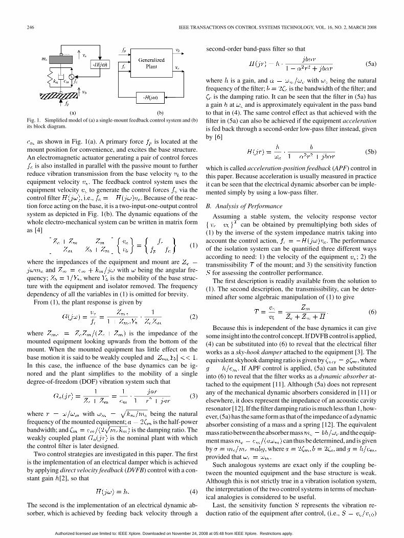
Fig. 1. Simplified model of (a) a single-mount feedback control system and (b)its block diagram.
as shown in Fig. 1(a). A primary force is located at themount position for convenience, and excites the base structure.An electromagnetic actuator generating a pair of control forces
is also installed in parallel with the passive mount to furtherreduce vibration transmission from the base velocity to theequipment velocity . The feedback control system uses theequipment velocity to generate the control forces via thecontrol filter , i.e., . Because of the reac-tion force acting on the base, it is a two-input-one-output controlsystem as depicted in Fig. 1(b). The dynamic equations of thewhole electro-mechanical system can be written in matrix formas [4]
(1)
where the impedances of the equipment and mount areand with being the angular fre-
quency; , where is the mobility of the base struc-ture with the equipment and isolator removed. The frequencydependency of all the variables in (1) is omitted for brevity.
From (1), the plant response is given by
(2)
where is the impedance of themounted equipment looking upwards from the bottom of themount. When the mounted equipment has little effect on thebase motion it is said to be weakly coupled and .In this case, the influence of the base dynamics can be ig-nored and the plant simplifies to the mobility of a singledegree-of-freedom (DOF) vibration system such that
(3)
where with being the naturalfrequency of the mounted equipment; is the half-powerbandwidth; and is the damping ratio. Theweakly coupled plant is the nominal plant with whichthe control filter is later designed.
Two control strategies are investigated in this paper. The firstis the implementation of an electrical damper which is achievedby applying direct velocity feedback (DVFB) control with a con-stant gain [2], so that
(4)
The second is the implementation of an electrical dynamic ab-sorber, which is achieved by feeding back velocity through a
second-order band-pass filter so that
(5a)
where is a gain, and with being the naturalfrequency of the filter; is the bandwidth of the filter; and
is the damping ratio. It can be seen that the filter in (5a) hasa gain at and is approximately equivalent in the pass bandto that in (4). The same control effect as that achieved with thefilter in (5a) can also be achieved if the equipment accelerationis fed back through a second-order low-pass filter instead, givenby [6]
(5b)
which is called acceleration-position feedback (APF) control inthis paper. Because acceleration is usually measured in practiceit can be seen that the electrical dynamic absorber can be imple-mented simply by using a low-pass filter.
B. Analysis of Performance
Assuming a stable system, the velocity response vectorcan be obtained by premultiplying both sides of
(1) by the inverse of the system impedance matrix taking intoaccount the control action, . The performanceof the isolation system can be quantified three different waysaccording to need: 1) the velocity of the equipment ; 2) thetransmissibility of the mount; and 3) the sensitivity function
for assessing the controller performance.The first description is readily available from the solution to
(1). The second description, the transmissibility, can be deter-mined after some algebraic manipulation of (1) to give
(6)
Because this is independent of the base dynamics it can givesome insight into the control concept. If DVFB control is applied,(4) can be substituted into (6) to reveal that the electrical filterworks as a sky-hook damper attached to the equipment [3]. Theequivalent skyhook damping ratio is given by , where
. If APF control is applied, (5a) can be substitutedinto (6) to reveal that the filter works as a dynamic absorber at-tached to the equipment [11]. Although (5a) does not representany of the mechanical dynamic absorbers considered in [11] orelsewhere, it does represent the impedance of an acoustic cavityresonator [12]. If the filter damping ratio is much less than 1, how-ever, (5a) has the same form as that of the impedance of a dynamicabsorber consisting of a mass and a spring [12]. The equivalentmassratiobetweentheabsorbermass andtheequip-ment mass can thus bedetermined, and is givenby , where , , and ,provided that .
Such analogous systems are exact only if the coupling be-tween the mounted equipment and the base structure is weak.Although this is not strictly true in a vibration isolation system,the interpretation of the two control systems in terms of mechan-ical analogies is considered to be useful.
Last, the sensitivity function represents the vibration re-duction ratio of the equipment after control, (i.e., )
Authorized licensed use limited to: IEEE Xplore. Downloaded on November 24, 2008 at 05:48 from IEEE Xplore. Restrictions apply.
KIM et al.: ACTIVE VIBRATION ISOLATION USING AN ELECTRICAL DAMPER OR AN ELECTRICAL DYNAMIC ABSORBER 247
where and are the equipment velocities after and beforecontrol, respectively. The velocity can be obtained by set-ting in (1). Since the sensitivity function is given by
[13], where the open-loop frequency re-sponse function (FRF) is , the vibrationreduction ratio (RR) can be written in decibel form as
dB (7)
Equation (7) is closely related to the robust stability of thesystem which is discussed in Section II-C.
C. Stability Analysis
The stability of the DVFB control system has been dis-cussed previously using the Nyquist stability criterion [4].Since the controller is simply a constant gain, the stabilityis completely determined by the plant response. Due to theadditional phase lag introduced by the first-order low-pass filterterm in (2), the phaseof the complete plant response is within the limits
(8)
provided that . Although one end of the control actuatoris collocated with the error sensor, the plant is not a minimumphase system. However, the control system is always stable intheory and is robust unless an extremely large gain is used witha very highly damped mount installed on a very lightly dampedbase structure [4].
Now consider the APF control system whose open-loop FRFcan be constructed by multiplying (2) and (5a). Since the phaseof the filter in (5a) ranges betweenfor , the system open-loop FRF crosses the negative realaxis. Thus, its stability now strongly depends on the control filterin (5a) and there are optimal control parameters to achieve thebest performance for a given robustness constraint. A strict ro-bust stability criterion is used in this paper by slightly alteringa known model in the literature [13]. A system is defined hereto be robustly stable with the robustness degree if and only ifthe open-loop FRF does not enclose or cross the circle ofradius centered at ( ) point, where , that is
(9a)
Equivalently, combining (7) and (9a) results in the inequality
dB (9b)
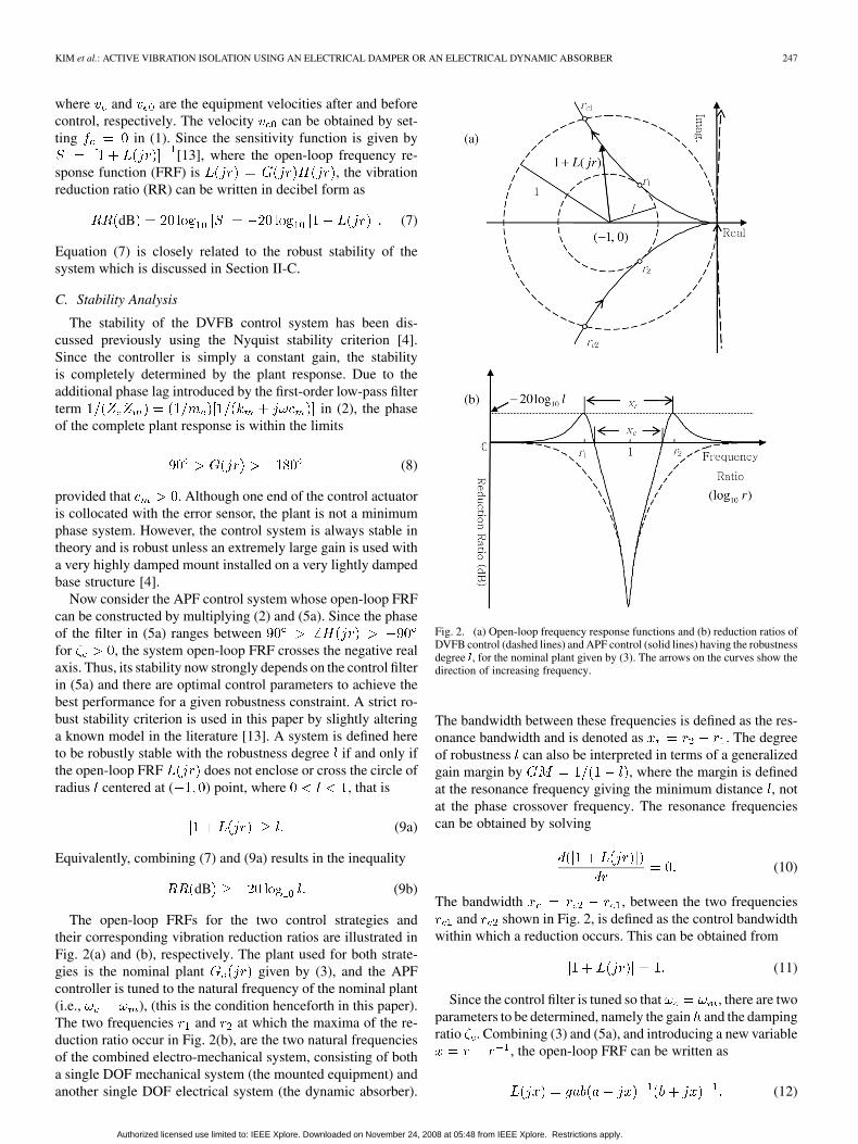
The open-loop FRFs for the two control strategies andtheir corresponding vibration reduction ratios are illustrated inFig. 2(a) and (b), respectively. The plant used for both strate-gies is the nominal plant given by (3), and the APFcontroller is tuned to the natural frequency of the nominal plant(i.e., ), (this is the condition henceforth in this paper).The two frequencies and at which the maxima of the re-duction ratio occur in Fig. 2(b), are the two natural frequenciesof the combined electro-mechanical system, consisting of botha single DOF mechanical system (the mounted equipment) andanother single DOF electrical system (the dynamic absorber).
Fig. 2. (a) Open-loop frequency response functions and (b) reduction ratios ofDVFB control (dashed lines) and APF control (solid lines) having the robustnessdegree l, for the nominal plant given by (3). The arrows on the curves show thedirection of increasing frequency.
The bandwidth between these frequencies is defined as the res-onance bandwidth and is denoted as . The degreeof robustness can also be interpreted in terms of a generalizedgain margin by , where the margin is definedat the resonance frequency giving the minimum distance , notat the phase crossover frequency. The resonance frequenciescan be obtained by solving
(10)
The bandwidth , between the two frequenciesand shown in Fig. 2, is defined as the control bandwidth
within which a reduction occurs. This can be obtained from
(11)
Since the control filter is tuned so that , there are twoparameters to be determined, namely the gain and the dampingratio . Combining (3) and (5a), and introducing a new variable
, the open-loop FRF can be written as
(12)
Authorized licensed use limited to: IEEE Xplore. Downloaded on November 24, 2008 at 05:48 from IEEE Xplore. Restrictions apply.
248 IEEE TRANSACTIONS ON CONTROL SYSTEMS TECHNOLOGY, VOL. 16, NO. 2, MARCH 2008
Substituting (12) into (10) and differentiating gives
(13)
where is the resonance bandwidth and
(14)in which and . It is interesting to notethat and , where . For the controlbandwidth, substituting (12) into (11) gives
(15)
The two corresponding roots and can be similarly ob-tained using the relations and (13).
Now, substituting (12) into (9a) and setting the inequality toan equality gives
(16)
where and again . Substituting (14) into(16) gives
(17)
where , which can be used to determinethe optimum parameters. If the task is to find the optimal gainfor a given bandwidth , (17) can be solved to give
(18)
where . On the other hand, if the task is to find theoptimal damping ratio for a given target gain , the solution canbe written as
(19)
provided that . Equations (18) and (19) can be used todetermine the optimal parameters for the best performance witha prescribed degree of robustness , as defined in (9).
III. EXPERIMENTAL WORK
A. Description of the Control Systems
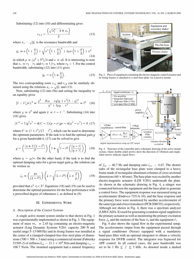
A single active mount system similar to that shown in Fig. 1was experimentally implemented as shown in Fig. 3. The equip-ment of mass 2.45 kg containing an electro-magneticactuator (Ling Dynamic Systems V201: capacity 200 N anduseful range 5–13 000 Hz) and its fixing frames was installed atthe center of a clamped-clamped-free-free steel plate of dimen-sions (700 500 3 mm) using a commercial mount (Fabreeka51505-2) of stiffness 21.1 10 N/m and damping100.7 Ns/m. The mounted equipment had a natural frequency
Fig. 3. Piece of equipment containing the electro-magnetic control actuator andits fixing frames is attached to a steel base plate via a passive mount.
Fig. 4. Structure of the controller and a schematic drawing of the active mountsystem, where double-sided arrows show the direction of vibration and single-sided arrows indicate signal flows.
of 46.7 Hz and damping ratio . The shortersides of the rectangular base plate were clamped to a heavyframe made of rectangular aluminum columns of cross sectionaldimensions (60 60 mm). The base plate was excited by anotherelectro-magnetic actuator (LDS V201) underneath the plate.As shown in the schematic drawing in Fig. 4, a stinger wasconnected between the equipment and the base plate to generatea control force. The equipment response was measured using anaccelerometer (Endevco 7251A-10), and the base response andthe primary force were monitored by another accelerometer ofthesametypeanda force transducer (PCB208C03), respectively.Although not shown in Fig. 4, there was a spectrum analyzer(LMS CADA-X) used for generating a random signal supplied tothe primary actuator as well as monitoring the primary excitationforce and the motions of the base and the equipment .
Fig. 4 also shows the signal flow in the experimental setup.The accelerometer output from the equipment passed througha signal conditioner (Nexus) equipped with a mandatoryband-pass filter with an optional integrator to obtain a velocityresponse for DVFB control. The integrator was bypassed forAPF control. In all control cases, the pass bandwidth wasset to be 1 Hz 3 kHz. As denoted inside a dashed
Authorized licensed use limited to: IEEE Xplore. Downloaded on November 24, 2008 at 05:48 from IEEE Xplore. Restrictions apply.
KIM et al.: ACTIVE VIBRATION ISOLATION USING AN ELECTRICAL DAMPER OR AN ELECTRICAL DYNAMIC ABSORBER 249
block, the control filters were implemented digitally using aMatlab xPC target processor (National Instruments PCI-6040Ecombined with BNC-2090 as a data acquisition front-end). Thedigital processor was used so that the filter parameters couldbe changed easily. The discrete form for DVFB control is thesame as its analog form in (4). The discrete form for the APFcontrol filter for a gain can be determined by applying theimpulse invariant transform method, and is given by [14]
(20)
where , , and the samplingtime is where is the sampling frequency. With thehigh sampling frequency of 32 kHz used, (20) closely resem-bles its analog counterpart, given by (5b), below the Nyquist fre-quency. A low-pass filter (Rockland 432) with cutoff frequency16 kHz was also used to reconstruct an analog signal. The cutofffrequency was set sufficiently high to avoid a large phase delayin the relatively low frequency range of interest. Finally, the fil-tered signal was amplified by an audio power amplifier (HaflerP1500 with a dynamic range of 15 dB) of gain and trans-mitted to the actuator through a safety fuse (250V, 2A) that wasused to protect the actuator from saturation in case of instability.If all the transducers and signal conditioning electronic devicesused perform ideally, the normalized controller gain for DVFBcontrol can be written as
(21)
where in which and are the gains used inthe digital and analog systems, respectively, is the transfor-mation factor from velocity to voltage in the signal conditionerand is the transformation factor from voltage to force inthe electromagnetic actuator. The gain for APF control canbe similarly defined using an appropriate transformation factorfrom acceleration to voltage, instead of .
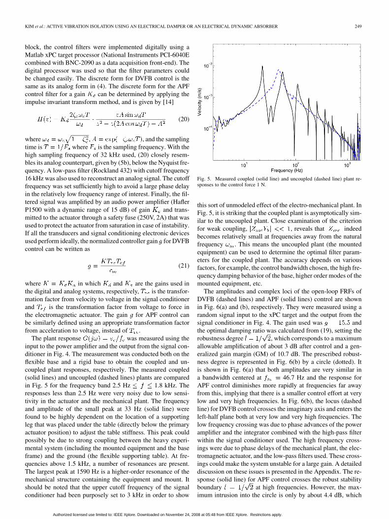
The plant response was measured using theinput to the power amplifier and the output from the signal con-ditioner in Fig. 4. The measurement was conducted both on theflexible base and a rigid base to obtain the coupled and un-coupled plant responses, respectively. The measured coupled(solid lines) and uncoupled (dashed lines) plants are comparedin Fig. 5 for the frequency band 2.5 Hz 1.8 kHz. Theresponses less than 2.5 Hz were very noisy due to low sensi-tivity in the actuator and the mechanical plant. The frequencyand amplitude of the small peak at 33 Hz (solid line) werefound to be highly dependent on the location of a supportingleg that was placed under the table (directly below the primaryactuator position) to adjust the table stiffness. This peak couldpossibly be due to strong coupling between the heavy experi-mental system (including the mounted equipment and the baseframe) and the ground (the flexible supporting table). At fre-quencies above 1.5 kHz, a number of resonances are present.The largest peak at 1590 Hz is a higher-order resonance of themechanical structure containing the equipment and mount. Itshould be noted that the upper cutoff frequency of the signalconditioner had been purposely set to 3 kHz in order to show
Fig. 5. Measured coupled (solid line) and uncoupled (dashed line) plant re-sponses to the control force 1 N.
this sort of unmodeled effect of the electro-mechanical plant. InFig. 5, it is striking that the coupled plant is asymptotically sim-ilar to the uncoupled plant. Close examination of the criterionfor weak coupling, , reveals that indeedbecomes relatively small at frequencies away from the naturalfrequency . This means the uncoupled plant (the mountedequipment) can be used to determine the optimal filter param-eters for the coupled plant. The accuracy depends on variousfactors, for example, the control bandwidth chosen, the high fre-quency damping behavior of the base, higher order modes of themounted equipment, etc.
The amplitudes and complex loci of the open-loop FRFs ofDVFB (dashed lines) and APF (solid lines) control are shownin Fig. 6(a) and (b), respectively. They were measured using arandom signal input to the xPC target and the output from thesignal conditioner in Fig. 4. The gain used was andthe optimal damping ratio was calculated from (19), setting therobustness degree , which corresponds to a maximumallowable amplification of about 3 dB after control and a gen-eralized gain margin (GM) of 10.7 dB. The prescribed robust-ness degree is represented in Fig. 6(b) by a circle (dotted). Itis shown in Fig. 6(a) that both amplitudes are very similar ina bandwidth centered at 46.7 Hz and the response forAPF control diminishes more rapidly at frequencies far awayfrom this, implying that there is a smaller control effort at verylow and very high frequencies. In Fig. 6(b), the locus (dashedline) for DVFB control crosses the imaginary axis and enters theleft-half plane both at very low and very high frequencies. Thelow frequency crossing was due to phase advances of the poweramplifier and the integrator combined with the high-pass filterwithin the signal conditioner used. The high frequency cross-ings were due to phase delays of the mechanical plant, the elec-tromagnetic actuator, and the low-pass filters used. These cross-ings could make the system unstable for a large gain. A detaileddiscussion on these issues is presented in the Appendix. The re-sponse (solid line) for APF control crosses the robust stabilityboundary at high frequencies. However, the max-imum intrusion into the circle is only by about 4.4 dB, which
Authorized licensed use limited to: IEEE Xplore. Downloaded on November 24, 2008 at 05:48 from IEEE Xplore. Restrictions apply.

250 IEEE TRANSACTIONS ON CONTROL SYSTEMS TECHNOLOGY, VOL. 16, NO. 2, MARCH 2008
Fig. 6. Measured open-loop FRFs of DVFB (dashed lines) and APF (solidlines) control of robustness degree represented by a circle of radius l in (b).The arrows in (b) indicate the direction of increasing frequency starting from asingle arrow. (a) Amplitude. (b) Complex domain.
corresponds to a less strict robustness degree of aboutand 6 dB.
B. Control Performance and Robust Stability
Isolation systems with five normalized gains of 0, 5.2,15.5, 27, and 54 were tested. The case corresponds to theoriginal passive system before control. For each gain, DVFB andAPF control were tested successively. The input signal to theprimary shaker was a random signal for all cases. The optimaldamping ratio of the APF controller was obtained from (19) witha robustness degree . The filter parameters and prop-erties are given in Table I. Properties of the analogous electricaldamper and dynamic absorber are also summarized in Table I.The active system was stable for all gains tested, and no fur-ther fine tuning of the controller damping ratio was conducted.Using electrical means, therefore, it was possible to achieve anequivalent skyhook damping ratio of 3.78 and an equivalent ab-sorber mass ratio as high as 64.
Fig. 7(a) shows the predicted and measured equipment veloc-ities of DVFB control for the four gains used, where the original
TABLE ICONTROL FILTER PARAMETERS AND NOMINAL PROPERTIES OF THE ACTIVE
MOUNT SYSTEM HAVING A PASSIVE DAMPING RATIO OF 0.07
where � = g� ; � = m =m = abg with a = 2� and b = 2� , themaximum reduction of the nominal plant is �20 log (1 + g); � is from(19), and x and x are from (14) and (15), respectively.
Fig. 7. Predicted (dashed lines) and measured (solid lines) velocity responsesof the equipment for various gains of (a) DVFB and (b) APF control are com-pared with the original velocity responses before control (predicted: dotted lines,measured: dashed–dotted lines). Those four decreasing responses, after control(solid and dashed lines), at the first resonance frequency correspond to the fourincreasing steps of the gain g = 5.2, 15.5, 27, and 54.
responses before control are also shown for comparison. Re-sponses less than 2.5 Hz are again excluded in the plots. There isgood agreement between the predicted and measured results for
Authorized licensed use limited to: IEEE Xplore. Downloaded on November 24, 2008 at 05:48 from IEEE Xplore. Restrictions apply.
KIM et al.: ACTIVE VIBRATION ISOLATION USING AN ELECTRICAL DAMPER OR AN ELECTRICAL DYNAMIC ABSORBER 251
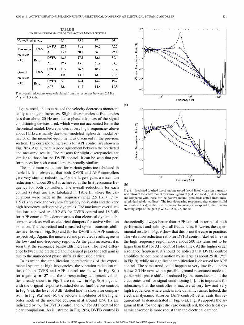
TABLE IICONTROL PERFORMANCE OF THE ACTIVE MOUNT SYSTEM
The overall reductions were calculated from the responses between 2.5 Hz� f � 1.5 kHz.
all gains used, and as expected the velocity decreases monoton-ically as the gain increases. Slight discrepancies at frequenciesless than about 20 Hz are due to phase advances of the signalconditioning devices used, which were not accounted for in thetheoretical model. Discrepancies at very high frequencies aboveabout 1 kHz are mainly due to un-modeled high-order modal be-havior of the mounted equipment, as discussed in the previoussection. The corresponding results for APF control are shown inFig. 7(b). Again, there is good agreement between the predictedand measured results. The reasons for slight discrepancies aresimilar to those for the DVFB control. It can be seen that per-formances for both controllers are broadly similar.
The maximum reductions for various gains are tabulated inTable II. It is observed that both DVFB and APF controllersgive very similar reductions. For the largest gain, a maximumreduction of about 38 dB is achieved at the first resonance fre-quency for both controllers. The overall reductions for eachcontrol system are also tabulated in Table II, where the cal-culations were made in the frequency range 2.5 Hz1.5 kHz to avoid the very low frequency noisy data and the veryhigh frequency undesirable dynamics. The maximum overall re-ductions achieved are 19.2 dB for DVFB control and 18.3 dBfor APF control. This demonstrates that electrical dynamic ab-sorbers work as well as electrical dampers for active vibrationisolation. The theoretical and measured system transmissabili-ties are shown in Fig. 8(a) and (b) for DVFB and APF control,respectively. Again, the measured and predicted results agree inthe low- and mid-frequency regions. As the gain increases, it isseen that the resonance bandwidth increases. The level differ-ence between the predicted and measured peaks for each gain isdue to the unmodeled phase shifts as discussed earlier.
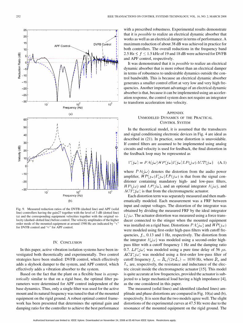
To examine the amplification characteristics of the experi-mental system at high frequencies, the vibration reduction ra-tios of both DVFB and APF control are shown in Fig. 9(a)for a gain and the corresponding equipment veloci-ties already shown in Fig. 7 are redrawn in Fig. 9(b) togetherwith the original response (dashed-dotted line) before control.In Fig. 9(a), the level of 3 dB (dotted line) is shown for compar-ison. In Fig. 9(a) and (b), the velocity amplitudes of the higherorder mode of the mounted equipment at around 1590 Hz areindicated by “ ” for DVFB control and “ ” for APF control forclear comparison. As illustrated in Fig. 2(b), DVFB control is
Fig. 8. Predicted (dashed lines) and measured (solid lines) vibration transmis-sion ratios of the active mount for various gains of (a) DVFB and (b) APF controlare compared with those for the passive mount (predicted: dotted lines, mea-sured: dashed–dotted lines). The four decreasing responses, after control (solidand dashed lines), at the first resonance frequency correspond to the four in-creasing steps of the gain g = 5.2, 15.5, 27, and 54.
theoretically always better than APF control in terms of bothperformance and stability at all frequencies. However, the exper-imental results in Fig. 9 show that this is not the case in practice.The vibration reduction ratio for DVFB control (dashed line) inthe high frequency region above about 500 Hz turns out to belarger than that for APF control (solid line). At the higher orderresonance frequency, it should be noticed that DVFB controlamplifies the equipment motion by as large as about 25 dB (“ ”in Fig. 9), while no significant amplification is observed for APFcontrol. The same trend could happen at very low frequenciesbelow 2.5 Hz now with a possible ground resonance mode to-gether with phase shifts introduced by the transducers and theelectronics used for signal conditioning [4]. It is important forrobustness that the controller is inactive at very low and veryhigh frequencies where undesirable dynamics arise. Indeed, theelectrical dynamic absorber (APF control) better suits this re-quirement as demonstrated in Fig. 6(a). Fig. 9 supports the ar-gument that, for the specific case considered, the electrical dy-namic absorber is more robust than the electrical damper.
Authorized licensed use limited to: IEEE Xplore. Downloaded on November 24, 2008 at 05:48 from IEEE Xplore. Restrictions apply.
252 IEEE TRANSACTIONS ON CONTROL SYSTEMS TECHNOLOGY, VOL. 16, NO. 2, MARCH 2008
Fig. 9. Measured reduction ratios of the DVFB (dashed line) and APF (solidline) controllers having the gain27 together with the level of 3 dB (dotted line)(a) and the corresponding equipment velocities together with the original ve-locity (dashed–dotted line) before control. The velocity amplitudes of the higherorder mode of the mounted equipment at around 1590 Hz are indicated by “x”for DVFB control and “o” for APF control.
IV. CONCLUSION
In this paper, active vibration isolation systems have been in-vestigated both theoretically and experimentally. Two controlstrategies have been studied: DVFB control, which effectivelyadds a skyhook damper to the system, and APF control, whicheffectively adds a vibration absorber to the system.
Based on the fact that the plant on a flexible base is asymp-totically similar to that on a rigid base, the optimal filter pa-rameters were determined for APF control independent of thebase dynamics. Thus, only a single filter was used for the activemount and its natural frequency was tuned to that of the mountedequipment on the rigid ground. A robust optimal control frame-work has been presented that determines the optimal gain anddamping ratio for the controller to achieve the best performance
with a prescribed robustness. Experimental results demonstratethat it is possible to realize an electrical dynamic absorber thatworks as well as an electrical damper in terms of performance. Amaximum reduction of about 38 dB was achieved in practice forboth controllers. The overall reductions in the frequency band2.5 Hz 1.5 kHz of 19 and 18 dB were achieved for DVFBand APF control, respectively.
It was demonstrated that it is possible to realize an electricaldynamic absorber that is more robust than an electrical damperin terms of robustness to undesirable dynamics outside the con-trol bandwidth. This is because an electrical dynamic absorbergenerates a smaller control effort at very low and very high fre-quencies. Another important advantage of an electrical dynamicabsorber is that, because it can be implemented using an acceler-ation response, the control system does not require an integratorto transform acceleration into velocity.
APPENDIX
UNMODELED DYNAMICS OF THE PRACTICAL
CONTROL SYSTEM
In the theoretical model, it is assumed that the transducersand signal conditioning electronic devices in Fig. 4 are ideal asdescribed in (21). In practice, some distortion is unavoidable.If control filters are assumed to be implemented using analogcircuits and velocity is used for feedback, the final distortion inthe feedback loop may be represented as
(A.1)
where denotes the distortion from the audio poweramplifier, is that from the signal con-ditioner containing mandatory high- and low-pass filters,
and , and an optional integrator , andis that from the electromagnetic actuator.
Each distortion term was separately measured and then math-ematically modeled. Each measurement was a FRF betweeninput and output voltages. The distortion of the integrator wasobtained by dividing the measured FRF by the ideal integrator
. The actuator distortion was measured using a force trans-ducer connected to the stinger when the mounted equipmentwas installed on a rigid base. Distortions andwere modeled using first-order high-pass filters with cutoff fre-quencies, , 0.13 and 1 Hz, respectively. The distortion fromthe integrator was modeled using a second-order high-pass filter with a cutoff frequency 1 Hz and the damping ratio0.7. was modeled using a pure time delay of 56 s.
was modeled using a first-order low-pass filter ofcutoff frequency 1030 Hz, where and
are, respectively, the resistance and inductance of the elec-tric circuit inside the electromagnetic actuator [15]. This modelis quite accurate at low frequencies, provided the actuator is sub-jected to a large mechanical load having a high impedance [4],as the one considered in this paper.
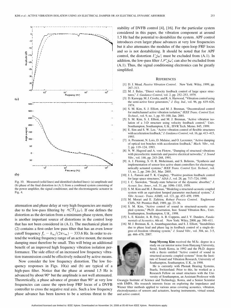
The measured (solid lines) and identified (dashed lines) am-plitude and phase distortions are compared in Fig. 10(a) and (b),respectively. It is seen that the two models agree well. The slightdistortions of the experimental curves at 47.5 Hz were due to theresonance of the mounted equipment on the rigid ground. The
Authorized licensed use limited to: IEEE Xplore. Downloaded on November 24, 2008 at 05:48 from IEEE Xplore. Restrictions apply.
KIM et al.: ACTIVE VIBRATION ISOLATION USING AN ELECTRICAL DAMPER OR AN ELECTRICAL DYNAMIC ABSORBER 253
Fig. 10. Measured (solid lines) and identified (dashed lines): (a) amplitude and(b) phase of the final distortion in (A.1) from a combined system consisting ofthe power amplifier, the signal conditioner, and the electromagnetic actuator inFig. 4.
attenuation and phase delay at very high frequencies are mainlydue to the low-pass filtering by . If one defines thedistortion as the deviation from a minimum phase system, thereis another important source of distortions in the control loopthat has not been considered in (A.1). The mechanical plant in(2) contains a first-order low-pass filter that has an even lowercutoff frequency 333.6 Hz. In order to ex-tend the working frequency range of an active mount, the mountdamping must therefore be small. This will bring an additionalbenefit of an improved high frequency vibration isolation per-formance. The side effect of an increased low frequency vibra-tion transmission could be effectively reduced by active means.
Now consider the low frequency distortion. The low fre-quency responses in Figs. 10(a) and (b) are typical of ahigh-pass filter. Notice that the phase at around 1.5 Hz isadvanced by about 90 but the amplitude is not well attenuated.Theoretically, a phase advance of greater than 90 at very lowfrequencies can cause the open-loop FRF locus of a DVFBcontroller to cross the negative real axis. Such a low frequencyphase advance has been known to be a serious threat to the
stability of DVFB control [4], [16]. For the particular systemconsidered in this paper, the vibration component at around1.5 Hz had the potential to destabilize the system. APF controlintroduces even larger phase advances at very low frequenciesbut it also attenuates the modulus of the open-loop FRF locusand so is not destabilizing. It should be noted that for APFcontrol, the distortion must be excluded from (A.1). Inaddition, the low-pass filter can also be excluded from(A.1). Thus, the signal conditioning electronics can be greatlysimplified.
REFERENCES
[1] D. J. Mead, Passive Vibration Control. New York: Wiley, 1999, pp.267–313.
[2] M. J. Balas, “Direct velocity feedback control of large space struc-tures,” J. Guidance Control, vol. 2, pp. 252–253, 1979.
[3] D. Karnopp, M. J. Crosby, and R. A. Harwood, “Vibration control usingthe semi-active force generators,” J. Eng. Ind., vol. 96, pp. 619–626,1974.
[4] S. M. Kim, S. J. Elliott, and M. J. Brennan, “Decentralized controlfor multichannel active vibration isolation,” IEEE Trans. Control Syst.Technol., vol. 9, no. 1, pp. 93–100, Jan. 2001.
[5] S. M. Kim, S. J. Elliott, and M. J. Brennan, “Active vibration iso-lation of a 3-D structure using velocity feedback control,” Univ.Southampton, Southampton, U.K., ISVR Tech. Memo. 845, 1999.
[6] E. Sim and S. W. Lee, “Active vibration control of flexible structureswith acceleration feedback,” J. Guidance Control, vol. 16, pp. 413–415,1993.
[7] A. Preumont, N. Loix, D. Malaise, and O. Lecrenier, “Active dampingof optical test benches with acceleration feedback,” Mach. Vibr., vol.2, pp. 119–124, 1993.
[8] N. W. Hagood and A. von Flotow, “Damping of structural vibrationswith piezoelectric materials and passive electrical networks,” J. SoundVibr., vol. 146, pp. 243–268, 1991.
[9] A. J. Fleming, S. O. R. Moheimani, and S. Behrens, “Synthesis andimplementation of sensor-less active shunt controllers for electromag-netically actuated systems,” IEEE Trans. Control Syst. Technol., vol.13, no. 2, pp. 246–261, Mar. 2005.
[10] J. L. Fanson and T. K. Caughey, “Positive position feedback controlfor large space structures,” AIAA J., vol. 28, pp. 717–724, 1990.
[11] J. C. Snowdon, “Steady-state behavior of the dynamic absorber,” J.Acoust. Soc. Amer., vol. 31, pp. 1096–1103, 1959.
[12] S. M. Kim and M. J. Brennan, “Modeling a structural-acoustic coupledsystem with an equivalent lumped parameter mechanical system,” J.Vibr. Acoust.- Trans. ASME, vol. 121, pp. 453–459, 1999.
[13] M. Morari and E. Zafiriou, Robust Process Control. EnglewoodCliffs, NJ: Prentice-Hall, 1989, pp. 23–36.
[14] S. M. Kim, “Active control of sound in structural-acoustic cou-pled systems,” Ph.D. dissertation, Inst. Sound Vibration Res., Univ.Southampton, Southampton, U.K., 1998.
[15] L. E. Kinsler, A. R. Frey, A. B. Coppens, and J. V. Danders, Funda-mentals of Acoustics, 4th ed. New York: Wiley, 2000, pp. 390–411.
[16] M. J. Brennan, K. A. Ananthaganeshan, and S. J. Elliott, “Instabilitiesdue to phase lead and phase lag in feedback control of a single-de-gree-of-freedom vibrating system,” J. Sound Vibr., vol. 304, no. 3-5,pp. 466–478, 2007.
Sang-Myeong Kim received the M.Sc. degree in astudy on car interior noise from Hanyang University,Seoul, South Korea, in 1992 and the Ph.D. degreewith a thesis entitled “Active control of sound instructural-acoustic coupled systems” from the Insti-tute of Sound and Vibration Research, University ofSouthampton, Southampton, U.K., in 1998.
He is currently with Phonak Hearing Systems,Staefa, Switzerland. Prior to this, he worked as aResearch Fellow on smart structures with the Uni-versity of Southampton, an Assistant Professor with
Gwangju Institute of Science and Technology, Korea, and a Senior Scientistwith EMPA. His research interests focus on exploring the impedance andWiener filter methods applied to various areas covering acoustics, vibration,electrodynamics of sensors and actuators, hearing instruments, virtual sound,and active control.
Authorized licensed use limited to: IEEE Xplore. Downloaded on November 24, 2008 at 05:48 from IEEE Xplore. Restrictions apply.
254 IEEE TRANSACTIONS ON CONTROL SYSTEMS TECHNOLOGY, VOL. 16, NO. 2, MARCH 2008
Stanislaw Pietrzko received the M.S. degree withhonors in electrical engineering and automatic con-trol from AGH University of Science and Techology,Cracow, Poland, and the Ph.D. degree in mecha-tronics from ETH Zurich, Zurich, Switzerland, in1992.
He is currently the Head of the VibroacousticsGroup, EMPA Swiss Federal Laboratories for Ma-terials Testing and Research in Dübendorf, wherehis research is focused on vibroacoustics, passiveand active control of noise vibration, and damping
phenomena. He has spent sabbaticals with the Institute of Sound and VibrationResearch, Southampton, U.K., and with the University of Adelaide, Adelaide,Australia. He has published numerous papers on noise and vibration control,given invited lectures and short courses on these subjects, and teaches andsupervises students.
Michael J. Brennan graduated from the Open Uni-versity in 1987 while he was serving in the RoyalNavy. He received the M.Sc. degree in sound and vi-bration studies and the Ph.D. degree in the active con-trol of vibration from the University of Southampton,Southampton, U.K., in 1992 and 1995, respectively.
He is currently chairman of the DynamicsResearch Group with the Institute of Sound andVibration Research, University of Southampton, andholds a personal chair in Engineering Dynamics. Hehas a wide-range of research interests, encompassing
vibration, acoustics, vibroacoustics, and rotor dynamics.
Authorized licensed use limited to: IEEE Xplore. Downloaded on November 24, 2008 at 05:48 from IEEE Xplore. Restrictions apply.