PATENTED FIRE DAMPER
56
English Installation type with fire resistance class PATENTED FIRE DAMPER RECTANGULAR SERIES WK45 - 500 Pa / 300 Pa Cert. N° 1812-CPR-1006 Technical Manual WK45
-
Upload
khangminh22 -
Category
Documents
-
view
3 -
download
0
Transcript of PATENTED FIRE DAMPER
English
Installation type with fire resistance class
PATENTED FIRE DAMPERRECTANGULAR SERIES WK45 - 500 Pa / 300 Pa
Cert. N° 1812-CPR-1006
Technical Manual
WK45

This is a 56page manual.

TAbLE oF CoNTENTS WK45
3/56
Overview � � � � � � � � � � � � � � � � � � � � � � � � � � � � � � � � � � � � � � � � � � � � � � � � � � � � p� 4Description � � � � � � � � � � � � � � � � � � � � � � � � � � � � � � � � � � � � � � � � � � � � � � � � � � � � � � p� 4General characteristics � � � � � � � � � � � � � � � � � � � � � � � � � � � � � � � � � � � � � � � � � � � � � � � � p� 4European Standards applied � � � � � � � � � � � � � � � � � � � � � � � � � � � � � � � � � � � � � � � � � � � � � p� 4Certifications and approvals � � � � � � � � � � � � � � � � � � � � � � � � � � � � � � � � � � � � � � � � � � � � � � p� 4Components � � � � � � � � � � � � � � � � � � � � � � � � � � � � � � � � � � � � � � � � � � � � � � � � � � � � � p� 4Available dimensions � � � � � � � � � � � � � � � � � � � � � � � � � � � � � � � � � � � � � � � � � � � � � � � � � p� 5Paired fire dampers wall opening � � � � � � � � � � � � � � � � � � � � � � � � � � � � � � � � � � � � � � � � � � � p� 6Fire dampers pairing � � � � � � � � � � � � � � � � � � � � � � � � � � � � � � � � � � � � � � � � � � � � � � � � � p� 6Performances � � � � � � � � � � � � � � � � � � � � � � � � � � � � � � � � � � � � � � � � � � � � � � � � � � � � p� 8Fire resistance classification according to EN 13501-3-2009 � � � � � � � � � � � � � � � � � � � � � � � � � � � � � � � p� 9Mechanism type � � � � � � � � � � � � � � � � � � � � � � � � � � � � � � � � � � � � � � � � � � � � � � � � � � p� 11
Technical data � � � � � � � � � � � � � � � � � � � � � � � � � � � � � � � � � � � � � � � � � � � � � � � � � p� 13Dimension � � � � � � � � � � � � � � � � � � � � � � � � � � � � � � � � � � � � � � � � � � � � � � � � � � � � � p� 13Weights � � � � � � � � � � � � � � � � � � � � � � � � � � � � � � � � � � � � � � � � � � � � � � � � � � � � � � p� 14
Installation � � � � � � � � � � � � � � � � � � � � � � � � � � � � � � � � � � � � � � � � � � � � � � � � � � p� 15Intended use � � � � � � � � � � � � � � � � � � � � � � � � � � � � � � � � � � � � � � � � � � � � � � � � � � � � p� 15Not allowed uses � � � � � � � � � � � � � � � � � � � � � � � � � � � � � � � � � � � � � � � � � � � � � � � � � � p� 15Blade rotation axis positioning � � � � � � � � � � � � � � � � � � � � � � � � � � � � � � � � � � � � � � � � � � � p� 15Positioning brackets before fixing � � � � � � � � � � � � � � � � � � � � � � � � � � � � � � � � � � � � � � � � � � p� 15Installation of flexible connectors in order to balance out the ventilation ducts expansion � � � � � � � � � � � � � � � p� 15Transfer Application (application not connected to air ducts on one or both sides) � � � � � � � � � � � � � � � � � � p� 17Minimum distances � � � � � � � � � � � � � � � � � � � � � � � � � � � � � � � � � � � � � � � � � � � � � � � � � p� 19Construction supports characteristics � � � � � � � � � � � � � � � � � � � � � � � � � � � � � � � � � � � � � � � � p� 21Installations within vertical rigid wall � � � � � � � � � � � � � � � � � � � � � � � � � � � � � � � � � � � � � � � � p� 22Installations within vertical light wall (plasterboard) � � � � � � � � � � � � � � � � � � � � � � � � � � � � � � � � � p� 24Installations within vertical light wall (gypsum blocks wall) � � � � � � � � � � � � � � � � � � � � � � � � � � � � � � p� 26Installations within floor � � � � � � � � � � � � � � � � � � � � � � � � � � � � � � � � � � � � � � � � � � � � � � p� 27Installations within vertical wall with Fire Batt (Weichschott) sealing � � � � � � � � � � � � � � � � � � � � � � � � � p� 28Installation within floor with Fire Batt (Weichschott) sealing � � � � � � � � � � � � � � � � � � � � � � � � � � � � � p� 29
Electrical connections � � � � � � � � � � � � � � � � � � � � � � � � � � � � � � � � � � � � � � � � � � � � � p� 30Electrical wiring � � � � � � � � � � � � � � � � � � � � � � � � � � � � � � � � � � � � � � � � � � � � � � � � � � p� 30Electrical specifications � � � � � � � � � � � � � � � � � � � � � � � � � � � � � � � � � � � � � � � � � � � � � � � p� 32
Maintenance and inspections � � � � � � � � � � � � � � � � � � � � � � � � � � � � � � � � � � � � � � � � � p� 33Periodic inspection and cleaning � � � � � � � � � � � � � � � � � � � � � � � � � � � � � � � � � � � � � � � � � � p� 33Repair � � � � � � � � � � � � � � � � � � � � � � � � � � � � � � � � � � � � � � � � � � � � � � � � � � � � � � � p� 33Disposal � � � � � � � � � � � � � � � � � � � � � � � � � � � � � � � � � � � � � � � � � � � � � � � � � � � � � � p� 33
Selection � � � � � � � � � � � � � � � � � � � � � � � � � � � � � � � � � � � � � � � � � � � � � � � � � � � p� 34Air flow rates in relation to the diameter � � � � � � � � � � � � � � � � � � � � � � � � � � � � � � � � � � � � � � � p� 34Air flow rates as a function of the pressure drop � � � � � � � � � � � � � � � � � � � � � � � � � � � � � � � � � � � p� 37Air flow rates as a function of generated sound levels � � � � � � � � � � � � � � � � � � � � � � � � � � � � � � � � p� 40Pressure drop and sound level graph for base 400 mm � � � � � � � � � � � � � � � � � � � � � � � � � � � � � � � � p� 43Correction for base different than 400 mm � � � � � � � � � � � � � � � � � � � � � � � � � � � � � � � � � � � � � � p� 44Sound spectrum table � � � � � � � � � � � � � � � � � � � � � � � � � � � � � � � � � � � � � � � � � � � � � � � p� 44
Accessories and spare parts � � � � � � � � � � � � � � � � � � � � � � � � � � � � � � � � � � � � � � � � � � p� 45How to order � � � � � � � � � � � � � � � � � � � � � � � � � � � � � � � � � � � � � � � � � � � � � � � � � � p� 48Motorized fire dampers � � � � � � � � � � � � � � � � � � � � � � � � � � � � � � � � � � � � � � � � � � � � � � � p� 48Fire damper with manual control � � � � � � � � � � � � � � � � � � � � � � � � � � � � � � � � � � � � � � � � � � p� 48Electric motor driven actuators � � � � � � � � � � � � � � � � � � � � � � � � � � � � � � � � � � � � � � � � � � � p� 49
Specification Text � � � � � � � � � � � � � � � � � � � � � � � � � � � � � � � � � � � � � � � � � � � � � � � p� 51Series WK45 rectangular fire damper � � � � � � � � � � � � � � � � � � � � � � � � � � � � � � � � � � � � � � � � p� 51
Revision Index � � � � � � � � � � � � � � � � � � � � � � � � � � � � � � � � � � � � � � � � � � � � � � � � � p� 52
WK45
3/56
ovERvIEW WK45
4/56
ovERvIEW � Description
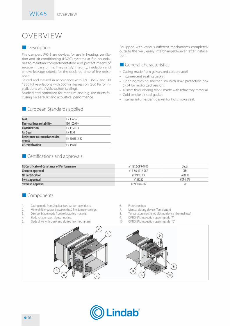
Fire dampers WK45 are devices for use in heating, ventila-tion and air-conditioning (HvAC) systems at fire bounda-ries to maintain compartmentation and protect means of escape in case of fire. They satisfy integrity, insulation and smoke leakage criteria for the declared time of fire resist-ance.Tested and classed in accordance with EN 1366-2 and EN 13501-3 regulations with 500 Pa depression (300 Pa for in-stallations with Weichschott sealing).Studied and optimized for medium and big size ducts fo-cusing on aeraulic and acoustical performance.
Equipped with various different mechanisms completely outside the wall, easily interchangeble even after installa-tion.
� General characteristics• Casing made from galvanized carbon steel.• Intumescent sealing gasket.• opening/closing mechanism with IP42 protection box
(IP54 for motorized version).• 40 mm thick closing blade made with refractory material.• Cold smoke air seal gasket• Internal intumescent gasket for hot smoke seal.
� European Standards applied
Test EN 1366-2Thermal fuse reliability ISO 10294-4Classification EN 13501-3Air Seal EN 1751Resistance to corrosive enviro-ments EN 60068-2-52
CE certification EN 15650
� Certifications and approvals
CE Certificate of Constancy of Performance n° 1812-CPR-1006 EfectisGerman approval n° Z-56.4212-987 DIBtNF certification n° 09/03.03 AFNORSwiss approval n° 23220 VKF-AEAISwedish approval n° SC0185-16 SP
� Components
1. Casing made from 2 galvanized carbon steel ducts.2. Mineral fiber gasket between the 2 fire damper casings.3. Damper blade made from refractoring material4. Blade rotation axis, pivots housing.5. Blade drive with crank and slotted link mechanism
6. Protection box7. Manual closing device (Test button)8. Temperature controlled closing device (thermal fuse)9. OPTIONAL Inspection opening side "A"10. OPTIONAL Inspection opening side "C"
WK45
4/56

ovERvIEW WK45
5/56
� Available dimensions
� Single fire dampersFire dampers are avaible in all base-height combination indicated below, excluded sizes: 200x650, 200x700, 250x700, 200x750, 250x750, 300x750, 350x750, 200x800, 250x800, 300x800, 350x800.
Avaible height mm 200 250 300 350 400 450 500 550 600 650 700 750 800Avaible base mm 200 250 300 350 400 450 500 550 600 650 700 750 800 850
Avaible base mm 900 950 1000 1050 1100 1150 1200 1250 1300 1350 1400 1450 1500
� Fire dampers pairing for big ducts dimensions
1. Side by side paired fire dampers2. Vertically paired fire dampers
Side by side paired fire dampersRequired base mm 1600 1600 1700 1700 1800 1800 1900 1900 2000 2000 2100 2100 2200 2200 2300 2300B tot mm 1570 1620 1670 1720 1770 1820 1870 1920 1970 2020 2070 2120 2170 2220 2270 2320B1 mm 750 800 800 850 850 900 900 950 950 1000 1000 1050 1050 1100 1100 1150B2 mm 750 750 800 800 850 850 900 900 950 950 1000 1000 1050 1050 1100 1100
Side by side paired fire dampersRequired base mm 2400 2400 2500 2500 2600 2600 2700 2700 2800 2800 2900 2900 3000 3000 3100 3100B tot mm 2370 2420 2470 2520 2570 2620 2670 2720 2770 2820 2870 2920 2970 3020 3070 3070B1 mm 1150 1200 1200 1250 1250 1300 1300 1350 1350 1400 1400 1450 1450 1500 1500 1500B2 mm 1150 1150 1200 1250 1250 1250 1300 1300 1350 1350 1400 1400 1450 1450 1500 1500
Vertically paired fire dampersRequired height mm 900 900 1000 1000 1100 1100 1200 1200 1300 1300 1400 1400 1500 1500 1600 1600 1650H tot mm 870 920 970 1020 1070 1120 1170 1220 1270 1320 1370 1420 1470 1520 1570 1620 1670H1 mm 400 450 450 500 500 550 550 600 600 650 650 700 700 750 750 800 800H2 mm 400 400 450 450 500 500 550 550 600 600 650 650 700 700 750 750 800
From the requested dimensions, it is possible to identify the closest effective achievable sizes.
WK45
5/56

ovERvIEW WK45
6/56
1. It is allowed to pair two fire dampers. Maximum paired size: 1670x1500, 3070x800, 1500x1670.2. It is forbidden to pair three or more fire dampers.3. It is forbidden to vertically pair two fire dampers with vertical axis.
� Paired fire dampers wall opening
1. Hole and installation for two fire dampers paired side by side with horizzontal axis2. Hole and installation for two fire dampers paired vertically with horizzontal axis
X1 X2 Y1 Y2vertical rigid wall EI 120 S B1 + 80 mm Btot + 80 mm H1 + 80 mm Htot + 80 mmlight vertical plasterboard wall EI 120 S B1 + 100 mm Btot + 100 mm H1 + 100 mm Htot + 100 mmlight vertical plasterboard wall EI 90 S B1 + 75 mm Btot + 75 mm H1 + 75 mm Htot + 75 mmlight vertical gypsum blocks wall EI 120 S B1 + 80 mm Btot + 80 mm H1 + 80 mm Htot + 80 mmlight vertical gypsum blocks wall EI 90 S B1 + 80 mm Btot + 80 mm H1 + 80 mm Htot + 80 mmhorizontal floor EI 180 S B1 + 130 mm Btot + 130 mm H1 + 130 mm Htot + 130 mmhorizzontal floor EI 120 S B1 + 130 mm Btot + 130 mm H1 + 130 mm Htot + 130 mmhorizzontal floor EI 90 S B1 + 130 mm Btot + 130 mm H1 + 130 mm Htot + 130 mm
� Fire dampers pairingThe WK45 patented rectangular fire dampers can be paired side-by-side or vertically (not more than two) using the custom connection kit (see section Accessories and spare parts p. 45). Two insulating layers must be inserted between the two fire dampers.The pair of dampers, may be installed in vertical wall in the same way as a single damper.
WK45
6/56

ovERvIEW WK45
7/56
1. WK45 Fire damper2. Steel plate3. Fixing screws4. Rock wool strip 100 kg/m³ 80 x 65 x nominal fire damper base + 70
mm (not included in the connection kit WKBA2)
5. Rock wool strip 100 kg/m³ 80 x 65 x nominal fire damper height + 70 mm (not included in the connection kit WKBA2)
6. Nut
• It is forbidden to pair three or more fire dampers.
WK45
7/56

ovERvIEW WK45
8/56
1. WK45 Fire damper2. Steel plate3. Fixing screws
4. Rock wool strip 100 kg/m³ 80 x 65 x nominal fire damper base + 70 mm (not included in the connection kit WKBA2)
5. Nut
• It is forbidden to pair three or more fire dampers. • It is forbidden to vertically pair two fire dampers with ver-tical axis.
� Performances
Performance Reference standard ClassThermal fuse testing ISO 10294-4 CompliantOpen and Close cycle reliability EN 15650 CompliantResistance to corrosion in humid and saline environments EN 60068-2-52 Degree of severity 2Casing tightness EN 1751 Class CBlade seal EN 1751 Class 2 minimum
WK45
8/56
ovERvIEW WK45
9/56
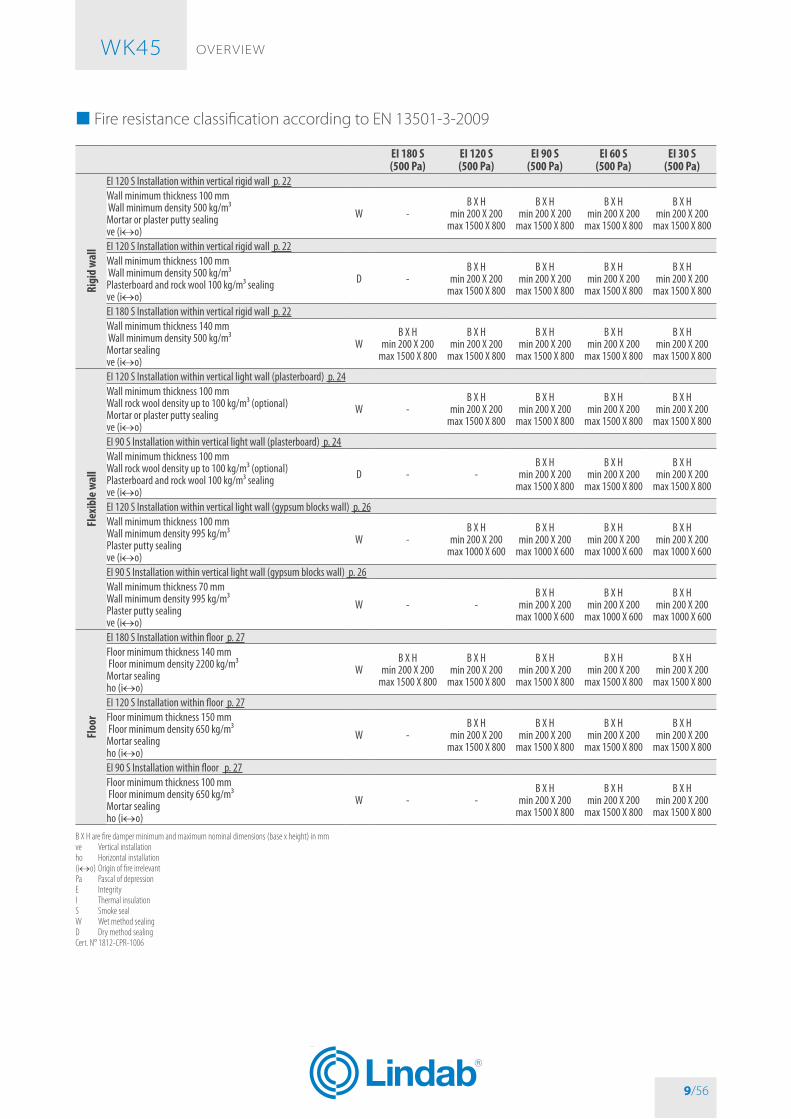
� Fire resistance classification according to EN 13501-3-2009
EI 180 S(500 Pa)
EI 120 S(500 Pa)
EI 90 S(500 Pa)
EI 60 S(500 Pa)
EI 30 S(500 Pa)
Rigi
d w
all
EI 120 S Installation within vertical rigid wall p. 22Wall minimum thickness 100 mm Wall minimum density 500 kg/m³Mortar or plaster putty sealingve (i↔o)
W -B X H
min 200 X 200max 1500 X 800
B X Hmin 200 X 200
max 1500 X 800
B X Hmin 200 X 200
max 1500 X 800
B X Hmin 200 X 200
max 1500 X 800
EI 120 S Installation within vertical rigid wall p. 22Wall minimum thickness 100 mm Wall minimum density 500 kg/m³Plasterboard and rock wool 100 kg/m³ sealingve (i↔o)
D -B X H
min 200 X 200max 1500 X 800
B X Hmin 200 X 200
max 1500 X 800
B X Hmin 200 X 200
max 1500 X 800
B X Hmin 200 X 200
max 1500 X 800
EI 180 S Installation within vertical rigid wall p. 22Wall minimum thickness 140 mm Wall minimum density 500 kg/m³Mortar sealingve (i↔o)
WB X H
min 200 X 200max 1500 X 800
B X Hmin 200 X 200
max 1500 X 800
B X Hmin 200 X 200
max 1500 X 800
B X Hmin 200 X 200
max 1500 X 800
B X Hmin 200 X 200
max 1500 X 800
Flex
ible
wal
l
EI 120 S Installation within vertical light wall (plasterboard) p. 24Wall minimum thickness 100 mmWall rock wool density up to 100 kg/m³ (optional)Mortar or plaster putty sealingve (i↔o)
W -B X H
min 200 X 200max 1500 X 800
B X Hmin 200 X 200
max 1500 X 800
B X Hmin 200 X 200
max 1500 X 800
B X Hmin 200 X 200
max 1500 X 800
EI 90 S Installation within vertical light wall (plasterboard) p. 24Wall minimum thickness 100 mmWall rock wool density up to 100 kg/m³ (optional)Plasterboard and rock wool 100 kg/m³ sealingve (i↔o)
D - -B X H
min 200 X 200max 1500 X 800
B X Hmin 200 X 200
max 1500 X 800
B X Hmin 200 X 200
max 1500 X 800
EI 120 S Installation within vertical light wall (gypsum blocks wall) p. 26Wall minimum thickness 100 mmWall minimum density 995 kg/m³Plaster putty sealingve (i↔o)
W -B X H
min 200 X 200max 1000 X 600
B X Hmin 200 X 200
max 1000 X 600
B X Hmin 200 X 200
max 1000 X 600
B X Hmin 200 X 200
max 1000 X 600
EI 90 S Installation within vertical light wall (gypsum blocks wall) p. 26Wall minimum thickness 70 mmWall minimum density 995 kg/m³Plaster putty sealingve (i↔o)
W - -B X H
min 200 X 200max 1000 X 600
B X Hmin 200 X 200
max 1000 X 600
B X Hmin 200 X 200
max 1000 X 600
Floo
r
EI 180 S Installation within floor p. 27Floor minimum thickness 140 mm Floor minimum density 2200 kg/m³Mortar sealingho (i↔o)
WB X H
min 200 X 200max 1500 X 800
B X Hmin 200 X 200
max 1500 X 800
B X Hmin 200 X 200
max 1500 X 800
B X Hmin 200 X 200
max 1500 X 800
B X Hmin 200 X 200
max 1500 X 800
EI 120 S Installation within floor p. 27Floor minimum thickness 150 mm Floor minimum density 650 kg/m³Mortar sealingho (i↔o)
W -B X H
min 200 X 200max 1500 X 800
B X Hmin 200 X 200
max 1500 X 800
B X Hmin 200 X 200
max 1500 X 800
B X Hmin 200 X 200
max 1500 X 800
EI 90 S Installation within floor p. 27Floor minimum thickness 100 mm Floor minimum density 650 kg/m³Mortar sealingho (i↔o)
W - -B X H
min 200 X 200max 1500 X 800
B X Hmin 200 X 200
max 1500 X 800
B X Hmin 200 X 200
max 1500 X 800
B X H are fire damper minimum and maximum nominal dimensions (base x height) in mmve Vertical installationho Horizontal installation(i↔o) Origin of fire irrelevantPa Pascal of depressionE IntegrityI Thermal insulationS Smoke sealW Wet method sealingD Dry method sealingCert. N° 1812-CPR-1006
WK45
9/56

ovERvIEW WK45
10/56
� Fire Batt (Weichschott) sealings
EI 120 S(300 Pa)
EI 90 S(300 Pa)
EI 60 S(300 Pa)
EI 30 S(300 Pa)
Rigi
d w
all EI 90 S Installation within vertical rigid wall with Fire Batt (Weichschott) sealing p. 28
Wall minimum thickness 100 mm Wall rock wool minimum density 500 kg/m³Rock wool 140 kg/m³ and endothermic varnish sealingve (i↔o)
W -B X H
min 200 X 200max 1500 X 800
B X Hmin 200 X 200
max 1500 X 800
B X Hmin 200 X 200
max 1500 X 800
Flex
ible
wal
l
EI 90 S Installation within vertical light wall (plasterboard) with Fire Batt (Weichschott) sealing p. 28Wall minimum thickness 100 mmWall rock wool density up to 100 kg/m³ (optional)Rock wool density 140 kg/m³ and endothermic varnish sealingve (i↔o)
W -B X H
min 200 X 200max 1500 X 800
B X Hmin 200 X 200
max 1500 X 800
B X Hmin 200 X 200
max 1500 X 800
EI 90 S Installation within vertical light wall (gypsum blocks wall) with Fire Batt (Weichschott) sealing p. 28Wall minimum thickness 100 mm Wall minimum density 995 kg/m³Rock wool 140 kg/m³ and endothermic varnish sealingve (i↔o)
W -B X H
min 200 X 200max 1500 X 800
B X Hmin 200 X 200
max 1500 X 800
B X Hmin 200 X 200
max 1500 X 800
Floo
r
EI 120 S Installation within floor with Fire Batt (Weichschott) sealing p. 29Floor minimum thickness 150 mm Floor minimum density 650 kg/m³Rock wool 140 kg/m³ and endothermic varnish sealingho (i↔o)
WB X H
min 200 X 200max 1500 X 800
B X Hmin 200 X 200
max 1500 X 800
B X Hmin 200 X 200
max 1500 X 800
B X Hmin 200 X 200
max 1500 X 800
B X H are fire damper minimum and maximum nominal dimensions (base x height) in mmve Vertical installationho Horizontal installation(i↔o) Origin of fire irrelevantPa Pascal of depressionE IntegrityI Thermal insulationS Smoke sealW Wet method sealingD Dry method sealingCert. N° 1812-CPR-1006
WK45
10/56
ovERvIEW WK45
11/56
�Mechanism type
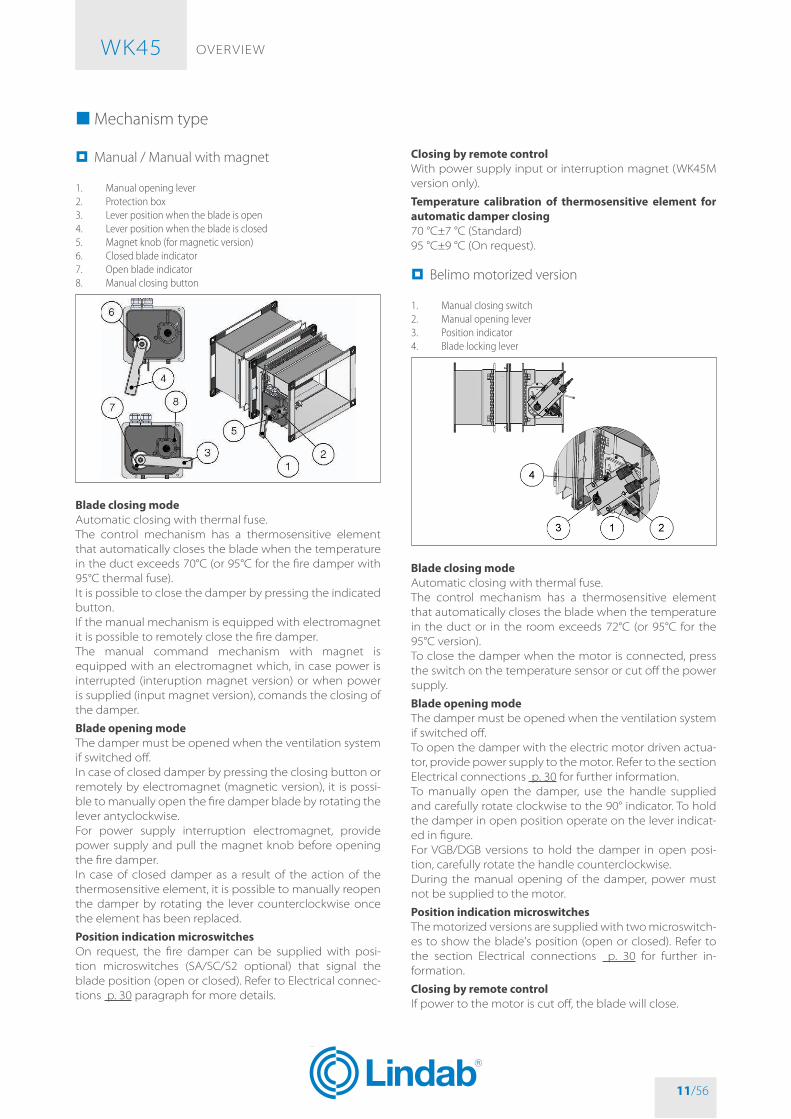
� Manual / Manual with magnet
1. Manual opening lever2. Protection box3. Lever position when the blade is open4. Lever position when the blade is closed5. Magnet knob (for magnetic version)6. Closed blade indicator7. Open blade indicator8. Manual closing button
Blade closing modeAutomatic closing with thermal fuse.The control mechanism has a thermosensitive element that automatically closes the blade when the temperature in the duct exceeds 70°C (or 95°C for the fire damper with 95°C thermal fuse).It is possible to close the damper by pressing the indicated button.If the manual mechanism is equipped with electromagnet it is possible to remotely close the fire damper.The manual command mechanism with magnet is equipped with an electromagnet which, in case power is interrupted (interuption magnet version) or when power is supplied (input magnet version), comands the closing of the damper.
Blade opening modeThe damper must be opened when the ventilation system if switched off.In case of closed damper by pressing the closing button or remotely by electromagnet (magnetic version), it is possi-ble to manually open the fire damper blade by rotating the lever antyclockwise.For power supply interruption electromagnet, provide power supply and pull the magnet knob before opening the fire damper.In case of closed damper as a result of the action of the thermosensitive element, it is possible to manually reopen the damper by rotating the lever counterclockwise once the element has been replaced.
Position indication microswitcheson request, the fire damper can be supplied with posi-tion microswitches (SA/SC/S2 optional) that signal the blade position (open or closed). Refer to Electrical connec-tions p. 30 paragraph for more details.
Closing by remote controlWith power supply input or interruption magnet (WK45M version only).
Temperature calibration of thermosensitive element for automatic damper closing70 °C±7 °C (Standard)95 °C±9 °C (on request).
� Belimo motorized version
1. Manual closing switch2. Manual opening lever3. Position indicator4. Blade locking lever
Blade closing modeAutomatic closing with thermal fuse.The control mechanism has a thermosensitive element that automatically closes the blade when the temperature in the duct or in the room exceeds 72°C (or 95°C for the 95°C version).To close the damper when the motor is connected, press the switch on the temperature sensor or cut off the power supply.
Blade opening modeThe damper must be opened when the ventilation system if switched off.To open the damper with the electric motor driven actua-tor, provide power supply to the motor. Refer to the section Electrical connections p. 30 for further information.To manually open the damper, use the handle supplied and carefully rotate clockwise to the 90° indicator. To hold the damper in open position operate on the lever indicat-ed in figure.For vGb/DGb versions to hold the damper in open posi-tion, carefully rotate the handle counterclockwise.During the manual opening of the damper, power must not be supplied to the motor.
Position indication microswitchesThe motorized versions are supplied with two microswitch-es to show the blade's position (open or closed). Refer to the section Electrical connections p. 30 for further in-formation.
Closing by remote controlIf power to the motor is cut off, the blade will close.
WK45
11/56

ovERvIEW WK45
12/56
Temperature calibration of thermosensitive element for automatic damper closing72 °C±7 °C (Standard)95 °C±9 °C (on request).
� Siemens motorized version
1. Manual closing switch2. Manual opening lever3. Screwdriver4. Position indicator
Blade closing modeAutomatic closing with thermal fuse.The control mechanism has a thermosensitive element that automatically closes the blade when the temperature in the duct or in the room exceeds 72°C (or 95°C for the 95°C version).To close the damper when the motor is connected, press the switch on the temperature sensor or cut off the power supply.
Blade opening modeThe damper must be opened when the ventilation system if switched off.To open the damper with the electric motor driven actua-tor, provide power supply to the motor. Refer to the section Electrical connections p. 30 for further information.To manually open the damper, use the handle supplied and carefully rotate counterclockwise to the 90 °C indica-tor. To hold the damper in open position, rotate the screw anticlockwise as shown in the picture.During the manual opening of the damper, power must not be supplied to the motor.
Position indication microswitchesThe motorized versions are supplied with two microswitch-es to show the blade's position (open or closed). Refer to the section Electrical connections p. 30 for further in-formation.
Closing by remote controlIf power to the motor is cut off, the blade will close.
Temperature calibration of thermosensitive element for automatic damper closing72 °C±7 °C (Standard)95 °C±9 °C (on request).
WK45
12/56

TECHNICAL DATA WK45
13/56
TECHNICAL DATAThe sizes shown are in mm.
� Dimension
H mm 200 250 300 350 400 450 500 550 600 650 700 750 800S blade exposition mm 0 0 0 0 0 0 0 9 34 59 84 109 134
� Manual
� Manual with magnet
� Siemens motorized version
� Belimo motorized version
WK45
13/56

TECHNICAL DATA WK45
14/56
�Weights
BaseHeight 200 250 300 350 400 450 500 550 600
200 9,0 10,0 11,0 12,0 13,0 15,0 16,0 18,0 20,0250 10,0 11,0 12,0 13,0 14,0 16,0 18,0 20,0 22,0300 11,0 12,0 13,0 14,0 17,0 19,0 21,0 22,0 24,0350 12,0 13,0 14,0 15,0 18,0 19,0 22,0 24,0 26,0400 14,0 15,0 16,0 17,0 19,0 21,0 23,0 26,0 28,0450 15,0 16,0 17,0 18,0 21,0 23,0 25,0 27,0 29,0500 17,0 18,0 19,0 20,0 23,0 25,0 27,0 28,0 31,0550 18,0 19,0 20,0 21,0 24,0 26,0 29,0 31,0 33,0600 19,0 20,0 21,0 22,0 25,0 27,0 31,0 33,0 35,0650 20,0 22,0 23,0 24,0 29,0 31,0 33,0 36,0 38,0700 24,0 25,0 31,0 33,0 35,0 38,0 40,0750 32,0 35,0 37,0 40,0 42,0800 34,0 37,0 39,0 42,0 44,0
BaseHeight 650 700 750 800 850 900 950 1000 1050
200 22,0 24,0 25,0 26,0 27,0 27,0 27,0 28,0 30,0250 24,0 26,0 27,0 28,0 28,0 29,0 30,0 31,0 33,0300 26,0 28,0 29,0 30,0 31,0 32,0 33,0 35,0 36,0350 28,0 30,0 31,0 34,0 34,0 34,0 36,0 38,0 39,0400 30,0 32,0 34,0 36,0 37,0 37,0 39,0 41,0 42,0450 32,0 34,0 36,0 38,0 38,0 40,0 42,0 44,0 45,0500 34,0 36,0 38,0 40,0 41,0 43,0 45,0 47,0 49,0550 36,0 38,0 40,0 42,0 44,0 46,0 48,0 50,0 52,0600 38,0 40,0 42,0 44,0 46,0 49,0 51,0 53,0 55,0650 40,0 42,0 45,0 47,0 49,0 51,0 54,0 56,0 58,0700 42,0 45,0 47,0 49,0 52,0 54,0 56,0 59,0 61,0750 45,0 47,0 50,0 52,0 54,0 57,0 59,0 62,0 64,0800 47,0 49,0 52,0 55,0 57,0 60,0 62,0 65,0 67,0
BaseHeight 1100 1150 1200 1250 1300 1350 1400 1450 1500
200 31,0 32,0 33,0 34,0 36,0 37,0 38,0 39,0 40,0250 34,0 35,0 37,0 38,0 39,0 41,0 42,0 43,0 45,0300 37,0 39,0 40,0 42,0 43,0 45,0 46,0 47,0 49,0350 41,0 42,0 44,0 45,0 47,0 48,0 50,0 51,0 53,0400 44,0 46,0 47,0 49,0 51,0 52,0 54,0 56,0 57,0450 47,0 49,0 51,0 53,0 54,0 56,0 58,0 60,0 61,0500 50,0 52,0 54,0 56,0 58,0 60,0 62,0 64,0 66,0550 54,0 56,0 58,0 60,0 62,0 64,0 66,0 68,0 70,0600 57,0 59,0 61,0 63,0 65,0 68,0 70,0 72,0 74,0650 60,0 62,0 65,0 67,0 69,0 71,0 74,0 76,0 78,0700 64,0 66,0 68,0 71,0 73,0 75,0 78,0 80,0 82,0750 67,0 69,0 72,0 74,0 77,0 79,0 82,0 83,0 85,0800 70,0 73,0 75,0 78,0 80,0 83,0 86,0 86,0 88,0
Weights in kgManual version. Motorized version: +1 kg
WK45
14/56

INSTALLATIoN WK45
15/56
INSTALLATIoNThe sizes shown are in mm.It is recommended to perform a functional test before Installation to exclude possible damage during transport and another test immediately after installation to exclude accidental damage to the product and interference with mounting components.
� Intended useThe MP3 fire dampers are “Devices for use in heating, ven-tilation and air conditioning (HvAC) systems at fire bound-aries to mantain compartmentation and protect means of escape in case of fire” according to the 3.1 paragraph of EN 15650:2010 standard.It is compulsory to install the fire damper according to the instructions indicated in the technical data sheet and man-ual to maintain the declared performances and, in particu-lar, the fire classes.The double test (with the mechanism inside and outside the fire area) demonstrated that there is no preferred direc-tion for the position of the damper, both in relation to air flow and the side with the higher probability of exposure to fire, as indicated in standard EN1366-2:2015 (paragraph 6.2).Use permitted in any civil and industrial building.Use permitted in saline atmosphere, for example:• maritime and port enviroments;• fish markets;• slaughterhouses;• cheese makers.
� Not allowed uses• Use with installations different to those described in the
technical data sheet and manual;• use as smoke control damper;• use as shut off damper;• use in external environments without adequate protec-
tion from atmospheric conditions;• use in explosive environments;• use on board of ships;• use in cooker extraction hoods;• use in pneumatic conveying systems of dust or corn;• use in ventilation systems within locations subject to
chemical contamination;• use in non inspectable enviroments;• Installation in suspended ceilings.
� Blade rotation axis positioningThe fire damper can be installed both with the blade axis positioned vertically or horizontally.
� Positioning brackets before fixing
1. WKGY100 fixing brackets (accessory to order separately, one size valid for all fire dampers kind)
WKGY100 fixing brackets are obligatory for intallations within plasterboard walls and suggested for walls with 100 mm thickness.They are not usable for installations with Fire batt (Weich-schott) sealing.
� Installation of flexible connectors in order to balance out the ventilation ducts expansion
CAUTION: Refer anyway to law and national standardiza-tion�Flexible connectors compensate any duct thermal expan-sion and wall bending in case of fire.Flexible connectors are used to limit fire damper stresses due to external forces in case of fire and to preserve fire resistance class.In general it is always appropriate the use of flexible con-nectors for the followings installations:
– light walls;– Plasterboard and rock wool or Fire batt (Weichschott)
sealing;– Applique fixing system.
Flexible connector must be normal flammability and in case of fire the grounding bonding should disconnet to guarantee the complete separation between fire damper and connected air duct.When flexible connectors made of conductive material (e.g. aluminum) are used, no additional grounding bond-ing is required.
WK45
15/56

INSTALLATIoN WK45
16/56
Despite flexible connector installation, the fire damper must be installed in the construction support so that its weight does not affect damper’s installation position both during normal operation and in case of fire.It is recommended not to compress flexible connectors in the installation phase.Flexible connector must be at least 100mm long and in order that possible duct thermal expansions are balanced. Take care that the flexible connector does not interfer with opening / closing movement of the blade.Refer to the section Technical data p. 13 for blade expo-sition values.
WK45
16/56

INSTALLATIoN WK45
17/56
� Transfer Application (application not connected to air ducts on one or both sides)Following tests performed as per EN 1366-2, section 6.3.6 Standard, it is possible to install the fire damper free from air duct from one or both sides.• Attention: fire resistance classification for transfer appli-
cation is conform to section Fire resistance classification according to EN 13501-3-2009 p. 9 limited to EI 120S if the ducted classification is higher.
• End cap with mesh shall be mounted on the side not connected to air duct.
• End cap with mesh is made from galvanized steel sheet and includes nuts and screws for fixing on fire damper.
• End cap with mesh is supplied loose from the fire damp-er.
• Refer to the section How to order (transfer Applica-tion) p. 18 for codes to use.
� Components (Transfer Application)
1. End cap with mesh2. Fire damper
3. M10 nut4. M10 screw
WK45
17/56

INSTALLATIoN WK45
18/56
� Technical data (Transfer Application)
1. Mechanism side2. Mechanism opposite side3. End cap with mesh
L1 End cap length mechanism sideL2 End cap length mechanism opposite sideH Nominal height of fire damper
Length of end cap with mesh depending on fire damper height H.
H L1 L2200 50 50250 50 50300 50 50350 50 50400 50 50450 50 50500 50 50550 50 50600 50 50650 100 100700 100 100750 150 150800 150 150
H Nominal height of fire damperL1 End cap length mechanism sideL2 End cap length mechanism opposite side
� How to order (transfer Application)
Type FMWK005V End cap with mesh with flange 35 mmBase XYZ Nominal base dimension (mm)Height XYZ Nominal height dimension (mm)Length XYZ Length dimension (mm)
Examples CodeEnd cap with mesh length 50 mm for fire damper 400x300 not connected to air ducts on 1 side FMWK005V400-300-050End cap with mesh length 150 mm for fire damper 800x600 not connected to air ducts on 1 side FMWK005V800-600-150End caps with mesh length 50 mm for fire damper 500x400 not connected to air ducts on both sides FMWK005V500-400-050 (x2)
WK45
18/56

INSTALLATIoN WK45
19/56
�Minimum distancesIt is recommended to keep enough space for using the control mechanism or for maintenance.
In accordance with Articles 7 and 13 of EN 1366-2 respect the minimum distances indicated below.
Minimum distances
1. Side vertical wall2. Floora. Distance between fire dampers installed within vertical wall
b. Distance between fire damper and vertical lateral wall / floorc. Distance between fire dampers installed within floord. Distance between fire damper and vertical lateral wall
Fire dampers installed within vertical wall
Fire dampers installed within floor
Installation a [mm] b [mm] c [mm] d [mm] Paired instal-lation
Rigi
d w
all
EI 180 S Installation within vertical rigid wall p. 23Mortar sealing 70 75 - - Yes. One air duct
EI 120 S Installation within vertical rigid wall p. 23Mortar or plaster putty sealing 70 75 - - Yes. One air duct
EI 120 S Installation within vertical rigid wall p. 23Plasterboard and rock wool 100 kg/m³ sealing 70 75 - - Yes. One air duct
Flex
ible
wal
l
EI 120 S Installation within vertical light wall (plasterboard) p. 24Mortar or plaster putty sealing 70 75 - - Yes. Separate air
ductEI 90 S Installation within vertical light wall (plasterboard) p. 24Plasterboard and rock wool 100 kg/m³ sealing 70 75 - - Yes. Separate air
ductEI 120 S Installation within vertical light wall (gypsum blocks wall) p. 26Plaster putty sealing
70 75 - - Yes. Separate air duct
EI 90 S Installation within vertical light wall (gypsum blocks wall) p. 26Plaster putty sealing
200 75 - - No
Floo
r
EI 180 S Installation within floor p. 27Mortar sealing - - 70 75 Yes. Separate air
ductEI 120 S Installation within floor p. 27Mortar sealing - - 70 75 Yes. Separate air
ductEI 90 S Installation within floor p. 27Mortar sealing - - 70 75 Yes. Separate air
ductThe minimum distance between two or more paired installations is 200 mm�It is forbidden to pair three or more fire dampers�
WK45
19/56

INSTALLATIoN WK45
20/56
� Fire Batt (Weichschott) sealings
Fire dampers installed within vertical wall
Fire dampers installed within floor
Installation a [mm] b [mm] c [mm] d [mm] Paired instal-lation
Rigi
d w
all EI 90 S Installation within vertical rigid wall with Fire Batt
(Weichschott) sealing p. 28Rock wool 140 kg/m³ and endothermic varnish sealing
70 50 - - Yes. One air duct
Flex
ible
wal
l EI 90 S Installation within vertical light wall (plasterboard) with Fire Batt (Weichschott) sealing p. 28Rock wool 140 kg/m³ and endothermic varnish sealing
70 50 - - Yes. One air duct
EI 90 S Installation within vertical light wall (gypsum blocks wall) with Fire Batt (Weichschott) sealing p. 28Rock wool 140 kg/m³ and endothermic varnish sealing
70 50 - - Yes. One air duct
Floo
r EI 120 S Installation within floor with Fire Batt (Weichschott) sealing p. 29Rock wool 140 kg/m³ and endothermic varnish sealing
- - 200 75 No
The minimum distance between two or more paired installations is 200 mm�It is forbidden to pair three or more fire dampers�
1. One air duct 2. Separate air ducts
WK45
20/56

INSTALLATIoN WK45
21/56
� Construction supports characteristicsThe European standard for fire dampers foresees a precise correlation between the wall/floor characteristics and the fire resistance class obtained, as well as the correlation be-tween wall/floor used for the test and wall/floor used for the actual installation.The test results obtained on a type of wall/floor are valid also for walls/floor of the same type but with greater thick-ness and/or density than those used in the test.For plasterboard walls, the test results are also valid for walls with a greater number of plasterboard layers on each side.As a result, the indicated thickness and density characteris-tics are to be considered as minimum values.The wall/floor in which the fire dampers are installed must be fire class certified according to the standards foreseen for the structure.
� Rigid wallsCan be made with aerated concrete blocks, poured con-crete, concrete panels, perforated cell elements in concrete or brick in accordance with the following characteristics:• minimum thickness 100 mm;• minimum density 500 kg/m³.The use of a reinforcing beam above the opening is recom-mended for walls made from concrete blocks, bricks or in concrete cell elements.For walls built with perforated elements, it is also recom-mended that the area of the opening be made from full elements (for example aerated concrete blocks) to guaran-tee the correct adhesion of the mortar.
1. Reinforcing beam
� Light plasterboard vertical wallsDuring testing, light plasterboard walls have been used with the following characteristics:• U-shaped horizontal metal frame (50 mm) and C-shaped
vertical frame (49 mm) made from 0,6 mm thick sheet metal;
• vertical profiles placed with a maximum spacing of 625 mm between each other;
• Filling made of rock wool with density up to 100 kg/m³ (optional);
• Each side is made from two plasterboard layers 12,5 mm thick, unalinged to avoid alignment between the joints of the layer above and below.
The following indications are given for the installation walls:• metal profiles minimum width: 49 mm;• metal profiles minimum thickness: 0,6 mm;
• vertical profiles placed with a maximum spacing of 625 mm between each other;
• vertical profile fixing with selfthreading screws or by clinching to the bottom horizontal profile and insertion in the top horizontal profile;
• profiles fixed using self-threading screws or by clinching on every intersection.
• installation of a frame around the damper with base and height where shown in the installation instructions;
• Filling made of rock wool with density up to 100 kg/m³ (optional);
• each side is made from two plasterboard layers 12,5 mm minumum thick, unalinged to avoid alignment between the joints of the layer above and below.
• the front plasterboards layers are fixed using long enough screws to pass through the lower plasterboard and attach to the steel profile underneath.
1. Plasterboard thickness 12,5 mm2. Rock wool density up to 100 kg/m³ (optional)3. Horizontal U-shaped profile4. Vertical C-shaped profile5. Self-drilling screw Ø 3,5 X 25 mm6. Self-drilling screw Ø 3,5 X 35 mm
WK45
21/56

INSTALLATIoN WK45
22/56
� Gypsum blocks light wallsGypsum blocks wall can be built with special solid gypsum blocks with interlocking shaped edges as indicated in the supplier's instructions and according to the following char-acteristics:• minimum thickness 70 or 100 mm according to the type
and resistance class required;• minimum density 995 kg/m³.It is generally advisable to first build the wall and then pro-vide the opening for the fire damper.
� Aerated concrete floorsAerated concrete floors can be built during installation or with preformed slabs with interlocking shaped edges ac-cording to the following characteristics:• minimum thickness 100 or 150 mm according to the
type and resistance class required;• minimum density 650 kg/m³
� Poured concrete floorsPoured concrete floors can be built during installation or with preformed slabs with interlocking shaped edges ac-cording to the following characteristics:• minimum thickness 100 or 150 mm according to the re-
sistance class required;
• minimum density 2200 kg/m³.
� Installations within vertical rigid wallRefer to the section Construction supports characteris-tics p. 21 for further information.Comply with the minimum distances indicated on section Minimum distances p. 19
� Wall openingA opening must be provided in the wall as indicated in the table and in the drawing
� Damper positioningPosition the damper in the opening so that the side of the closing mechanism extends as indicated in the table and in the drawing.
� FillingFill the space between the wall and the damper as indicat-ed in the table and in the drawing.
Fire resistance classi-fication
Hole size “D1 x D2”[mm]
Damper protrusion from the wall “E”
[mm]
Wall minimum thick-ness “S”
[mm]Sealing
EI 120 S Installation within vertical rigid wall
Wall minimum density 500 kg/m³ EI 120 S(500 Pa)
From (B+80) x (H+80)to (B+580) x (H+580) 205 100 Mortar or plaster putty
sealingEI 120 S Installation within vertical rigid wall
Wall minimum density 500 kg/m³ EI 120 S(500 Pa)
From (B+80) x (H+80)to (B+110) x (H+110) 205 100
Rock wool 100 kg/m³ with infill plasterboard
(thickness 12.5 mm)EI 180 S Installation within vertical rigid wall
Wall minimum density 500 kg/m³ EI 180 S(500 Pa)
From (B+80) x (H+80)to (B+110) x (H+110) 185 140 Mortar sealing
B Nominal base of the damperH Nominal height of the damper
WK45
22/56

INSTALLATIoN WK45
23/56
EI 120 S / EI 180 S Installations within vertical rigid wall
1. Sealing indicated in the tableD1 Hole base: see table aboveD2 Hole height: see table above
E Damper protrusion from the wall: see table aboveS Wall minimum thickness: see table above
EI 120S Installation within vertical rigid wall
1. Plasterboard infill panel, thickness 12,5 mm, for rock wool sealing2. Rock wool, 100 kg/m³3. Self-drilling screw Ø 3,5 X 45 mm
D1 Hole base: see table aboveD2 Hole height: see table aboveE Damper protrusion from the wall: see table above
WK45
23/56

INSTALLATIoN WK45
24/56
� Installations within vertical light wall (plasterboard)Refer to the section Construction supports characteris-tics p. 21 for further information.Comply with the minimum distances indicated on section Minimum distances p. 19
� Wall openingA opening must be provided in the wall as indicated in the table and in the drawing
� Damper positioningFix the four flaps code WKGY100 on the four corners of the fire damper (in corrispondence to the longer screws) only for rock wool sealing. See section Accessories and spare parts p. 45 for further details.Position the damper in the opening so that the side of the closing mechanism extends as indicated in the table and in the drawing.
� FillingFill the space between the wall and the damper as indicat-ed in the table and in the drawing.
Fire resistance classi-fication
Hole size “D1 x D2”[mm]
Damper protrusion from the wall “E”
[mm]
Wall minimum thick-ness “S”
[mm]Sealing
EI 90 S Installation within vertical light wall (plasterboard)
Wall rock wool density up to 100 kg/m³ (optional)
EI 90 S(500 Pa)
Da (B+75) x (H+75)a (B+95) x (H+95) 205 100
Rock wool 100 kg/m³ with infill plasterboard
(thickness 12.5 mm)EI 120 S Installation within vertical light wall (plasterboard)Wall rock wool density up to 100 kg/m³ (optional)
EI 120 S(500 Pa)
Da (B+100) x (H+100)to (B+580) x (H+580) 205 100 Mortar or plaster putty
B Nominal base of the damperH Nominal height of the damper
WK45
24/56

INSTALLATIoN WK45
25/56
EI 90 S Installation within vertical light wall (plasterboard)
D1 Hole base: see table aboveD2 Hole height: see table aboveE Damper protrusion from the wall: see table above1. Plasterboard infill panel, thickness 12,5 mm2. Plasterboard infill panel, thickness 12,5 mm3. Rock wool, 100 kg/m³
4. WKGY100 fixing brackets (accessory to order separately, one size valid for all fire dampers kind and wall thickness)
5. Rock wool density up to 100 kg/m³ (optional)6. Plasterboard thickness 12,5 mm7. Self-drilling screw Ø 3,5 X 45 mm8. Metal frame
EI 120 S Installation within vertical light wall (plaster-board)
D1 Hole base: see table aboveD2 Hole height: see table aboveE Damper protrusion from the wall: see table above1. Mortar M-10, EN998-2 or plaster
2. Rock wool density up to 100 kg/m³ (optional)3. Plasterboard thickness 12,5 mm4. Metal frame
WK45
25/56

INSTALLATIoN WK45
26/56
� Installations within vertical light wall (gypsum blocks wall)Refer to the section p. 21 for further information.Comply with the minimum distances indicated on section Minimum distances p. 19
� Wall openingA opening must be provided in the wall as indicated in the table and in the drawing
� Damper positioningPosition the damper in the opening so that the side of the closing mechanism extends as indicated in the table and in the drawing.
� FillingFill the space between the wall and the damper as indicat-ed in the table and in the drawing.
Fire resistance classi-fication
Hole size “D1 x D2”[mm]
Damper protrusion from the wall “E”
[mm]
Wall minimum thick-ness “S”
[mm]Sealing
EI 90 S Installation within vertical light wall (gypsum blocks wall) (paired installation not available)
Wall minimum density 995 kg/m³ EI 90 S(500 Pa)
From (B+80) x (H+80)to (B+110) x (H+110) 220 70 Plaster putty sealing
EI 120 S Installation within vertical light wall (gypsum blocks wall)
Wall minimum density 995 kg/m³ EI 120 S(500 Pa)
From (B+80) x (H+80)to (B+110) x (H+110) 205 100 Plaster putty sealing
B Nominal base of the damperH Nominal height of the damper
1. Plaster puttyD1 Hole base: see table aboveD2 Hole height: see table above
E Damper protrusion from the wall: see table aboveS Wall minimum thickness: see table above
WK45
26/56

INSTALLATIoN WK45
27/56
� Installations within floorRefer to the section Construction supports characteris-tics p. 21 for further information.Comply with the minimum distances indicated on section Minimum distances p. 19
� Floor openingA opening must be provided in the floor as indicated in the table and in the drawing
� Damper positioningPosition the damper in the opening so that the side of the closing mechanism extends as indicated in the table and in the drawing.
� FillingFill the space between the floor and the damper as indicat-ed in the table and in the drawing.
Fire resistance classi-fication
Hole size “D1 x D2”[mm]
Damper protrusion from the wall “E”
[mm]
Floor minimum thickness “S”
[mm]Sealing
EI 90 S Installation within floor
Floor minimum density 650 kg/m³ EI 90 S(500 Pa)
From (B+130) x (H+130)to (B+170) x (H+170) 193 100 Mortar sealing
EI 120 S Installation within floor
Floor minimum density 650 kg/m³ EI 120 S(500 Pa)
From (B+130) x (H+130)to (B+170) x (H+170) 193 150 Mortar sealing
EI 180 S Installation within floor
Floor minimum density 2200 kg/m³ EI 180 S(500 Pa)
From (B+130) x (H+130)to (B+170) x (H+170) 185 140 Mortar sealing
B Nominal base of the damperH Nominal height of the damper
D1 Hole base: see table aboveD2 Hole height: see table aboveE Damper protrusion from the floor: see table above
S Floor minimum thickness: see table above 1. Mortar M-10, EN998-2
WK45
27/56

INSTALLATIoN WK45
28/56
� Installations within vertical wall with Fire Batt (Weichschott) sealingRefer to the section Construction supports characteris-tics p. 21 for further information.Comply with the minimum distances indicated on section Minimum distances p. 19
� Wall openingA opening must be provided in the wall as indicated in the table and in the drawing
� Damper positioningPosition the damper in the opening so that the side of the closing mechanism extends as indicated in the table and in the drawing.
� FillingFill the space between the damper and the wall using Fire batt (Weichschott) sealing made from two rock wool pan-els with minimum thickness of 50 mm and minimum den-sity of 140 kg/m³.The panels must be covered on both faces of the wall with endothermic varnish type PRoMASToP E PASTE or HILTI CFS-CT (minimum thickness of 1 mm) and with an internal perimeter sealant type PRoMASToP E PASTE or HILTI CFS-S ACR (minimum thickness of 1 mm).
Fire resistance classi-fication
Hole size “D1 x D2”[mm]
Damper protrusion from the wall “E”
[mm]
Wall minimum thick-ness “S”
[mm]Sealing
Rigi
d w
all EI 120 S Installation within rigid vertical wall with Fire Batt (Weichschott) sealing
Wall minimum density 500 kg/m³ EI 90 S(300 Pa)
(B+800 max) x (H+800 max) 205 100
Rock wool 140 kg/m³ and endothermic varnish
sealing
Flex
ible
wal
l
EI 120 S Installation within vertical light wall (plasterboard) with Fire Batt (Weichschott) sealing
Wall rock wool density up to 100 kg/m³ (optional)
EI 90 S(300 Pa)
(B+800 max) x (H+800 max) 205 100
Rock wool 140 kg/m³ and endothermic varnish
sealingEI 120 S Installation within vertical light wall (plasterboard) with Fire Batt (Weichschott) sealing
Wall minimum density 995 kg/m³ EI 90 S(300 Pa)
(B+800 max) x (H+800 max) 205 100
Rock wool 140 kg/m³ and endothermic varnish
sealingB Nominal base of the damperH Nominal height of the damper
D1 Hole base indicated in the tableD2 Hole height indicated in the tableE Damper protrusion from the wall indicated in the table
1. Rock wool panel 50 mm thick with 140 kg/m³ density. 2. PROMASTOP E PASTE or HILTI CFS-S ACR type sealant3. PROMASTOP E PASTE or HILTI CFS-CT endothermic varnish
WK45
28/56

INSTALLATIoN WK45
29/56
� Installation within floor with Fire Batt (Weichschott) sealingRefer to the section p. 21 for further information.Comply with the minimum distances indicated on section Minimum distances p. 19
� Floor openingA opening must be provided in the floor as indicated in the table and in the drawing
� Damper positioningPosition the damper in the opening so that the side of the closing mechanism extends as indicated in the table and in the drawing.
� FillingFill the space between the damper and the floor using Fire batt (Weichschott) sealing made from two rock wool panels with minimum thickness of 50 mm and minimum density of 140 kg/m³.The panels must be covered on both faces of the wall with endothermic varnish type PRoMASToP E PASTE or HILTI CFS-CT (minimum thickness of 1 mm) and with an internal perimeter sealant type PRoMASToP E PASTE or HILTI CFS-S ACR (minimum thickness of 1 mm).
Fire resistance classi-fication
Hole size “D1 x D2”[mm]
Damper protrusion from the wall “E”
[mm]
Floor minimum thickness “S”
[mm]Sealing
EI 120 S Installation within floor and Fire Batt (Weichschott) sealing
Floor minimum density 650 kg/m³ EI 120 S(300 Pa)
(B+800 max) x (H+800 max) 205 150
Rock wool 140 kg/m³ and endothermic varnish
sealingB Nominal base of the damperH Nominal height of the damper
D1 Hole base: see table aboveD2 Hole height: see table aboveE Damper protrusion from the floor: see table above
1. Rock wool panel 50 mm thick with 140 kg/m³ density. 2. PROMASTOP E PASTE or HILTI CFS-S ACR type sealant3. PROMASTOP E PASTE or HILTI CFS-CT endothermic varnish
WK45
29/56

ELEC TRICAL CoNNEC TIoNS WK45
30/56
ELEC TRICAL CoNNEC TIoNS � Electrical wiring
Electrical connections must be done by qualified and trained people.Switch off the power supply before starting any work on the electric elements. Never switch on the power supply during electrical connections.
1. SC (closed damper) microswitch - on request2. SA (open damper) microswitch - on request3. Magnet - on request4. Magnet cables for wiring
� SC/SA microswitches position
1. "NC" contact of SC microswitch. When the fire blade is closed the circuit is open.
2. "NO" contact of SC microswitch. When the fire blade is closed the circuit is closed.
3. "NC" contact of SA microswitch. When the fire blade is open the circuit is open.
4. "NO" contact of SA microswitch. When the fire blade is open the circuit is closed.
� 230 V AC magnet wiring
1. 230 V AC power supply2. Magnet3. Rectifier
� 24 V DC magnet wiring
1. 24 V DC power supply2. Magnet
WK45
30/56

ELEC TRICAL CoNNEC TIoNS WK45
31/56
� WK45 - Motorized version
Belimo servomotor:bFL24T, bFN24T, bF24T, bFL230T, bFN230T, bF230T.
Siemens servomotor:GRA126, GNA126, GGA126.
Siemens servomotor:GRA326, GNA326, GGA326.
Motorized fire dampers electical wiringTo connect the dampers to the power supply, proceed as follows:• Check that the voltage and electrical frequency are
equivalent to those of the motor of the servomotor (check the motor's information label);
• Make the connections as shown in the below diagram.
1 Negative (DC) or neutral (AC)2 Positive (DC) or phase (AC)3 Phase4 NeutralS1 Common closed damper microswitchS2 Normally closed, closed damper microswitchS3 Normally opened, closed damper microswitchS4 Common open damper microswitchS5 Normally closed, open damper microswitchS6 Normally opened, open damper microswitch
WK45
31/56

ELEC TRICAL CoNNEC TIoNS WK45
32/56
� Electrical specifications
ManualManual with magnetBelimo motorized versionSiemens motorized version
Voltage and power consumption -
Power interrruption magnet:P=4,5 W (24V DC or 230 V AC version)
Power input magnet:P=4,5 W (24V DC or 230 V AC version)
Motor 24V AC/DC (WK45VMB):Belimo BFN24TOpening: 4 WIn stand-by: 1,4 W
Motor 230V AC (WK45DMB):Belimo BFN230TOpening: 5 WIn stand-by: 2,1 W
Motor 24V AC/DC (WK45VGB):Belimo BF24TOpening: 7 WIn stand-by: 2 W
Motor 230V AC (WK45DGB)Belimo BF230TOpening: 8 WIn stand-by: 3 W
Motor 24V AC/DC (WK45VPS) / (WK45VSS):Siemens GNA126 / GRA126Opening: 3,5 WIn stand-by: 2 W
Motor 230V AC (WK45DPS) / (WK45DSS):Siemens GNA326 / GRA326Opening: 4,5 WIn stand-by: 3,5 W
Motor 24V AC/DC (WK45VGS):Siemens GGA126Opening: 6 WIn stand-by: 1.5 W
Motor 230V AC (WK45DGS):Siemens GGA326Opening: 6 WIn stand-by: 2,5 W
Microswitches position contactsManual control version:15 - 400V1,8 A
Motorized version:Siemens: AC 24V…230V / 6 (2) ABelimo: DC 5V…AC 250V / 1mA…3A (0,5A)
Blade closing time Spring: 1 s motor: < 30 s
Protection degree IP42 IP42 MAGNETIC VERSIONIP54 MOTORIZED VERSION
WK45
32/56

ELEC TRICAL CoNNEC TIoNS WK45
33/56
MAINTENANCE AND INSPEC TIoNSFire dampers and control mechanisms do not require rou-tine maintenance.Extraordinary maintenance (repairs) and periodic inspec-tion operations are the responsibility of the ventilation sys-tem operator.The implementation of a periodic inspection plan allows to guarantee the efficiency and functionality of the fire damp-ers for the fire safety of the building.
� Periodic inspection and cleaningPeriodic inspection shall be performed in accordance with the requirements of the law or by the building regulations or other local regulations.In the absence of specific regulations (or to their comple-ment), in accordance with point 8.3 of the EN 1560 stand-ard, it is recommended to carry out the following control activities at intervals of no more than 6 months:• If the damper is connected to a remote control or com-
mand system (eg bMS or alarm or fire detection), that responds correctly to commands by performing at least one opening and closing test and verifying the correct movement of the blade and the correct functioning of the microswitches (limit switches).
• If the damper is not connected to a remote control or command system, manually execute an opening and closing test and check the correct movement of the blade and the correct functioning of the microswitches (limit switches) if present.
Together with the control activities, it is recommended to visually verify the absence of corrosion, the integrity of the electrical wiring and the sealing of the construction sup-port.Damper cleaning is included in the ordinary maintenance activities of the ventilation ducts.Fire dampers can be cleaned with a dry or wet cloth.In the case of resistant dirt, it is possible to use normal household detergents.If prescribed for the type of building, it is possible to use disinfectant detergents.The use of detergents or mechanical abrasive cleaning sys-tems is not permitted.These indications comply with the standards EN 15650 an-nex D and EN 15423 annex C.
� RepairFor safety reasons, repair activities involving fire-fighting components must be carried out only by qualified person-nel.only original spare parts supplied by the fire damper man-ufacturer must be used.A functional test must be performed after each repair..At the end of the inspection, cleaning or repair operations, check that the fire damper is in the normal operating po-sition.Keep records of all inspections, repair activities, any prob-lems encountered and their resolution.This practice, even when not mandatory, is very useful in practice.
� DisposalDisposal in case of destruction must be carried out in ac-cordance with national legislation. For electrical and elec-tronic parts also refer to EU Directive 2011/65.
WK45
33/56
SELEC TIoN WK45
34/56
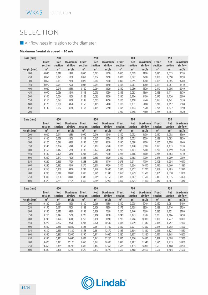
SELEC TIoN � Air flow rates in relation to the diameter
Maximum frontal air speed = 10 m/s
Base (mm) 200 250 300 350Front
sectionNet
sectionMaximum
air flowFront
sectionNet
sectionMaximum
air flowFront
sectionNet
sectionMaximum
air flowFront
sectionNet
sectionMaximum
air flowHeight (mm) m² m² m³/h m² m² m³/h m² m² m³/h m² m² m³/h
200 0,040 0,018 1440 0,050 0,023 1800 0,060 0,029 2160 0,070 0,035 2520250 0,050 0,025 1800 0,063 0,034 2250 0,075 0,042 2700 0,088 0,050 3150300 0,060 0,033 2160 0,075 0,044 2700 0,090 0,055 3240 0,105 0,065 3780350 0,070 0,041 2520 0,088 0,054 3150 0,105 0,067 3780 0,123 0,081 4410400 0,080 0,049 2880 0,100 0,064 3600 0,120 0,080 4320 0,140 0,096 5040450 0,090 0,056 3240 0,113 0,075 4050 0,135 0,093 4860 0,158 0,111 5670500 0,100 0,064 3600 0,125 0,085 4500 0,150 0,106 5400 0,175 0,126 6300550 0,110 0,072 3960 0,138 0,095 4950 0,165 0,118 5940 0,193 0,141 6930600 0,120 0,080 4320 0,150 0,105 5400 0,180 0,131 6480 0,210 0,157 7560650 0,130 0,087 4680 0,163 0,115 5850 0,195 0,144 7020 0,228 0,172 8190700 0,210 0,156 7560 0,245 0,187 8820
Base (mm) 400 450 500 550Front
sectionNet
sectionMaximum
air flowFront
sectionNet
sectionMaximum
air flowFront
sectionNet
sectionMaximum
air flowFront
sectionNet
sectionMaximum
air flowHeight (mm) m² m² m³/h m² m² m³/h m² m² m³/h m² m² m³/h
200 0,080 0,041 2880 0,090 0,046 3240 0,100 0,052 3600 0,110 0,058 3960250 0,100 0,058 3600 0,113 0,067 4050 0,125 0,075 4500 0,138 0,083 4950300 0,120 0,076 4320 0,135 0,087 4860 0,150 0,098 5400 0,165 0,108 5940350 0,140 0,094 5040 0,158 0,107 5670 0,175 0,120 6300 0,193 0,133 6930400 0,160 0,112 5760 0,180 0,127 6480 0,200 0,143 7200 0,220 0,159 7920450 0,180 0,129 6480 0,203 0,147 7290 0,225 0,166 8100 0,248 0,184 8910500 0,200 0,147 7200 0,225 0,168 8100 0,250 0,188 9000 0,275 0,209 9900550 0,220 0,165 7920 0,248 0,188 8910 0,275 0,211 9900 0,303 0,234 10890600 0,240 0,182 8640 0,270 0,208 9720 0,300 0,234 10800 0,330 0,260 11880650 0,260 0,200 9360 0,293 0,228 10530 0,325 0,257 11700 0,358 0,285 12870700 0,280 0,218 10080 0,315 0,249 11340 0,350 0,279 12600 0,385 0,310 13860750 0,300 0,236 10800 0,338 0,269 12150 0,375 0,302 13500 0,413 0,335 14850800 0,320 0,253 11520 0,360 0,289 12960 0,400 0,325 14400 0,440 0,361 15840
Base (mm) 600 650 700 750Front
sectionNet
sectionMaximum
air flowFront
sectionNet
sectionMaximum
air flowFront
sectionNet
sectionMaximum
air flowFront
sectionNet
sectionMaximum
air flowHeight (mm) m² m² m³/h m² m² m³/h m² m² m³/h m² m² m³/h
200 0,120 0,064 4320 0,130 0,069 4680 0,140 0,075 5040 0,150 0,081 5400250 0,150 0,091 5400 0,163 0,100 5850 0,175 0,108 6300 0,188 0,116 6750300 0,180 0,119 6480 0,195 0,130 7020 0,210 0,140 7560 0,225 0,151 8100350 0,210 0,147 7560 0,228 0,160 8190 0,245 0,173 8820 0,263 0,186 9450400 0,240 0,174 8640 0,260 0,190 9360 0,280 0,206 10080 0,300 0,222 10800450 0,270 0,202 9720 0,293 0,220 10530 0,315 0,239 11340 0,338 0,257 12150500 0,300 0,230 10800 0,325 0,251 11700 0,350 0,271 12600 0,375 0,292 13500550 0,330 0,258 11880 0,358 0,281 12870 0,385 0,304 13860 0,413 0,327 14850600 0,360 0,285 12960 0,390 0,311 14040 0,420 0,337 15120 0,450 0,363 16200650 0,390 0,313 14040 0,423 0,341 15210 0,455 0,370 16380 0,488 0,398 17550700 0,420 0,341 15120 0,455 0,372 16380 0,490 0,402 17640 0,525 0,433 18900750 0,450 0,369 16200 0,488 0,402 17550 0,525 0,435 18900 0,563 0,468 20250800 0,480 0,396 17280 0,520 0,432 18720 0,560 0,468 20160 0,600 0,503 21600
WK45
34/56

SELEC TIoN WK45
35/56
Base (mm) 800 850 900 950Front
sectionNet
sectionMaximum
air flowFront
sectionNet
sectionMaximum
air flowFront
sectionNet
sectionMaximum
air flowFront
sectionNet
sectionMaximum
air flowHeight (mm) m² m² m³/h m² m² m³/h m² m² m³/h m² m² m³/h
200 0,160 0,086 5760 0,170 0,092 6120 0,180 0,098 6480 0,190 0,104 6840250 0,200 0,124 7200 0,213 0,132 7650 0,225 0,141 8100 0,238 0,149 8550300 0,240 0,162 8640 0,255 0,173 9180 0,270 0,183 9720 0,285 0,194 10260350 0,280 0,200 10080 0,298 0,213 10710 0,315 0,226 11340 0,333 0,239 11970400 0,320 0,237 11520 0,340 0,253 12240 0,360 0,269 12960 0,380 0,285 13680450 0,360 0,275 12960 0,383 0,293 13770 0,405 0,312 14580 0,428 0,330 15390500 0,400 0,313 14400 0,425 0,334 15300 0,450 0,354 16200 0,475 0,375 17100550 0,440 0,351 15840 0,468 0,374 16830 0,495 0,397 17820 0,523 0,420 18810600 0,480 0,388 17280 0,510 0,414 18360 0,540 0,440 19440 0,570 0,465 20520650 0,520 0,426 18720 0,553 0,454 19890 0,585 0,482 21060 0,618 0,511 22230700 0,560 0,464 20160 0,595 0,494 21420 0,630 0,525 22680 0,665 0,556 23940750 0,600 0,501 21600 0,638 0,535 22950 0,675 0,568 24300 0,713 0,601 25650800 0,640 0,539 23040 0,680 0,575 24480 0,720 0,611 25920 0,760 0,646 27360
Base (mm) 1000 1050 1100 1150Front
sectionNet
sectionMaximum
air flowFront
sectionNet
sectionMaximum
air flowFront
sectionNet
sectionMaximum
air flowFront
sectionNet
sectionMaximum
air flowHeight (mm) m² m² m³/h m² m² m³/h m² m² m³/h m² m² m³/h
200 0,200 0,109 7200 0,210 0,115 7560 0,220 0,121 7920 0,230 0,127 8280250 0,250 0,157 9000 0,263 0,165 9450 0,275 0,174 9900 0,288 0,182 10350300 0,300 0,205 10800 0,315 0,216 11340 0,330 0,226 11880 0,345 0,237 12420350 0,350 0,253 12600 0,368 0,266 13230 0,385 0,279 13860 0,403 0,292 14490400 0,400 0,300 14400 0,420 0,316 15120 0,440 0,332 15840 0,460 0,347 16560450 0,450 0,348 16200 0,473 0,366 17010 0,495 0,384 17820 0,518 0,403 18630500 0,500 0,396 18000 0,525 0,416 18900 0,550 0,437 19800 0,575 0,458 20700550 0,550 0,443 19800 0,578 0,467 20790 0,605 0,490 21780 0,633 0,513 22770600 0,600 0,491 21600 0,630 0,517 22680 0,660 0,543 23760 0,690 0,568 24840650 0,650 0,539 23400 0,683 0,567 24570 0,715 0,595 25740 0,748 0,624 26910700 0,700 0,587 25200 0,735 0,617 26460 0,770 0,648 27720 0,805 0,679 28980750 0,750 0,634 27000 0,788 0,668 28350 0,825 0,701 29700 0,863 0,734 31050800 0,800 0,682 28800 0,840 0,718 30240 0,880 0,754 31680 0,920 0,789 33120
Base (mm) 1200 1250 1300 1350Front
sectionNet
sectionMaximum
air flowFront
sectionNet
sectionMaximum
air flowFront
sectionNet
sectionMaximum
air flowFront
sectionNet
sectionMaximum
air flowHeight (mm) m² m² m³/h m² m² m³/h m² m² m³/h m² m² m³/h
200 0,240 0,132 8640 0,250 0,138 9000 0,260 0,144 9360 0,270 0,149 9720250 0,300 0,190 10800 0,313 0,198 11250 0,325 0,206 11700 0,338 0,215 12150300 0,360 0,248 12960 0,375 0,258 13500 0,390 0,269 14040 0,405 0,280 14580350 0,420 0,305 15120 0,438 0,319 15750 0,455 0,332 16380 0,473 0,345 17010400 0,480 0,363 17280 0,500 0,379 18000 0,520 0,395 18720 0,540 0,410 19440450 0,540 0,421 19440 0,563 0,439 20250 0,585 0,457 21060 0,608 0,476 21870500 0,600 0,479 21600 0,625 0,499 22500 0,650 0,520 23400 0,675 0,541 24300550 0,660 0,536 23760 0,688 0,560 24750 0,715 0,583 25740 0,743 0,606 26730600 0,720 0,594 25920 0,750 0,620 27000 0,780 0,646 28080 0,810 0,671 29160650 0,780 0,652 28080 0,813 0,680 29250 0,845 0,708 30420 0,878 0,737 31590700 0,840 0,710 30240 0,875 0,740 31500 0,910 0,771 32760 0,945 0,802 34020750 0,900 0,767 32400 0,938 0,801 33750 0,975 0,834 35100 1,013 0,867 36450800 0,960 0,825 34560 1,000 0,861 36000 1,040 0,896 37440 1,080 0,932 38880
WK45
35/56

SELEC TIoN WK45
36/56
Base (mm) 1400 1450 1500
Front section Net section Maximum air flow Front section Net section Maximum air
flow Front section Net section Maximum air flow
Height (mm) m² m² m³/h m² m² m³/h m² m² m³/h200 0,280 0,155 10080 0,290 0,161 10440 0,300 0,167 10800250 0,350 0,223 12600 0,363 0,231 13050 0,375 0,239 13500300 0,420 0,291 15120 0,435 0,301 15660 0,450 0,312 16200350 0,490 0,358 17640 0,508 0,372 18270 0,525 0,385 18900400 0,560 0,426 20160 0,580 0,442 20880 0,600 0,458 21600450 0,630 0,494 22680 0,653 0,512 23490 0,675 0,530 24300500 0,700 0,562 25200 0,725 0,582 26100 0,750 0,603 27000550 0,770 0,629 27720 0,798 0,653 28710 0,825 0,676 29700600 0,840 0,697 30240 0,870 0,723 31320 0,900 0,748 32400650 0,910 0,765 32760 0,943 0,793 33930 0,975 0,821 35100700 0,980 0,832 35280 1,015 0,863 36540 1,050 0,894 37800750 1,050 0,900 37800 1,088 0,933 39150 1,125 0,967 40500800 1,120 0,968 40320 1,160 1,004 41760 1,200 1,039 43200
WK45
36/56

SELEC TIoN WK45
37/56
� Air flow rates as a function of the pressure drop∆P = 20 Pa
Base (mm) 200 250 300 350 400 450 500 550 600Q Lw Q Lw Q Lw Q Lw Q Lw Q Lw Q Lw Q Lw Q Lw
Height (mm) m³/h dB(A) m³/h dB(A) m³/h dB(A) m³/h dB(A) m³/h dB(A) m³/h dB(A) m³/h dB(A) m³/h dB(A) m³/h dB(A)200 257 27,5 349 28,5 447 29,3 551 30,0 661 30,6 798 32,7 906 33,5 1016 34,3 1128 34,9250 388 30,3 526 31,3 674 32,2 831 32,8 997 33,4 1204 35,6 1366 36,4 1532 37,1 1701 37,8300 542 33,0 734 33,9 941 34,8 1161 35,5 1393 36,1 1682 38,2 1909 39,0 2141 39,7 2376 40,4350 719 35,4 974 36,4 1248 37,2 1539 37,9 1846 38,5 2231 40,6 2531 41,4 2838 42,1 3151 42,8400 917 37,5 1243 38,5 1593 39,3 1965 40,0 2356 40,6 2847 42,8 3230 43,6 3622 44,3 4021 45,0450 1137 39,5 1540 40,5 1974 41,3 2435 42,0 2921 42,6 3529 44,8 4004 45,6 4490 46,3 4984 46,9500 1377 41,3 1866 42,3 2392 43,2 2950 43,8 3538 44,4 4275 46,6 4851 47,4 5439 48,1 6038 48,8550 1638 43,0 2220 44,0 2845 44,8 3509 45,5 4209 46,1 5085 48,3 5770 49,1 6469 49,8 7182 50,5600 1919 44,6 2600 45,6 3332 46,4 4111 47,1 4930 47,7 5956 49,8 6759 50,6 7578 51,4 8413 52,0650 2219 46,0 3007 47,0 3854 47,9 4754 48,6 5702 49,2 6889 51,3 7817 52,1 8765 52,8 9730 53,5700 4409 49,2 5439 49,9 6523 50,5 7881 52,7 8943 53,5 10028 54,2 11132 54,8750 7393 51,8 8932 53,9 10137 54,7 11365 55,5 12617 56,1800 8312 53,0 10042 55,1 11396 56,0 12777 56,7 14184 57,3
Base (mm) 650 700 750 800 850 900 950 1000 1050Q Lw Q Lw Q Lw Q Lw Q Lw Q Lw Q Lw Q Lw Q Lw
Height (mm) m³/h dB(A) m³/h dB(A) m³/h dB(A) m³/h dB(A) m³/h dB(A) m³/h dB(A) m³/h dB(A) m³/h dB(A) m³/h dB(A)200 1241 35,5 1357 36,1 1474 36,6 1593 37,0 1713 37,5 1835 37,9 1958 38,3 2082 38,7 2208 39,0250 1872 38,3 2047 38,9 2223 39,4 2402 39,9 2584 40,3 2767 40,7 2953 41,1 3140 41,5 3330 41,9300 2616 41,0 2859 41,5 3106 42,0 3357 42,5 3610 43,0 3866 43,4 4126 43,8 4388 44,1 4652 44,5350 3468 43,4 3791 43,9 4118 44,4 4450 44,9 4786 45,3 5126 45,8 5470 46,2 5817 46,5 6168 46,9400 4426 45,5 4838 46,1 5256 46,6 5679 47,1 6108 47,5 6542 47,9 6980 48,3 7423 48,7 7871 49,1450 5487 47,5 5997 48,1 6515 48,6 7040 49,1 7571 49,5 8109 49,9 8652 50,3 9202 50,7 9757 51,1500 6647 49,4 7266 49,9 7893 50,4 8529 50,9 9173 51,3 9824 51,8 10483 52,2 11148 52,5 11821 52,9550 7906 51,0 8642 51,6 9388 52,1 10144 52,6 10910 53,0 11684 53,4 12468 53,8 13260 54,2 14060 54,6600 9261 52,6 10123 53,2 10997 53,7 11883 54,1 12780 54,6 13687 55,0 14605 55,4 15533 55,8 16470 56,1650 10711 54,1 11708 54,6 12718 55,1 13743 55,6 14780 56,0 15830 56,5 16892 56,9 17964 57,2 19048 57,6700 12254 55,4 13394 56,0 14551 56,5 15723 57,0 16910 57,4 18111 57,8 19325 58,2 20552 58,6 21792 59,0750 13889 56,7 15181 57,3 16492 57,8 17821 58,2 19166 58,7 20527 59,1 21903 59,5 23294 59,9 24699 60,2800 15615 57,9 17067 58,5 18541 59,0 20035 59,5 21547 59,9 23077 60,3 24625 60,7 26189 61,1 27768 61,5
Base (mm) 1100 1150 1200 1250 1300 1350 1400 1450 1500Q Lw Q Lw Q Lw Q Lw Q Lw Q Lw Q Lw Q Lw Q Lw
Height (mm) m³/h dB(A) m³/h dB(A) m³/h dB(A) m³/h dB(A) m³/h dB(A) m³/h dB(A) m³/h dB(A) m³/h dB(A) m³/h dB(A)200 2334 39,4 2462 39,7 2591 40,0 2721 40,3 2853 40,6 2985 40,9 3118 41,2 3230 41,2 3341 41,3250 3521 42,2 3714 42,5 3908 42,9 4105 43,2 4303 43,5 4502 43,7 4703 44,0 4872 44,1 5040 44,2300 4919 44,8 5189 45,2 5461 45,5 5735 45,8 6012 46,1 6290 46,4 6571 46,6 6807 46,7 7041 46,8350 6522 47,2 6880 47,6 7240 47,9 7604 48,2 7970 48,5 8340 48,7 8712 49,0 9025 49,1 9336 49,2400 8323 49,4 8779 49,7 9240 50,1 9704 50,4 10171 50,6 10643 50,9 11118 51,2 11517 51,3 11914 51,3450 10317 51,4 10883 51,7 11453 52,0 12028 52,3 12608 52,6 13193 52,9 13781 53,2 14276 53,3 14768 53,3500 12500 53,2 13185 53,6 13876 53,9 14573 54,2 15275 54,5 15983 54,7 16697 55,0 17296 55,1 17892 55,2550 14867 54,9 15682 55,2 16504 55,6 17333 55,9 18168 56,1 19010 56,4 19859 56,7 20571 56,8 21280 56,8600 17415 56,5 18370 56,8 19333 57,1 20304 57,4 21282 57,7 22269 58,0 23263 58,3 24097 58,3 24928 58,4650 20142 57,9 21246 58,3 22359 58,6 23482 58,9 24614 59,2 25755 59,4 26904 59,7 27870 59,8 28831 59,9700 23044 59,3 24307 59,6 25581 59,9 26865 60,2 28160 60,5 29466 60,8 30780 61,1 31885 61,2 32984 61,2750 26118 60,6 27550 60,9 28994 61,2 30450 61,5 31918 61,8 33397 62,1 34887 62,4 36139 62,4 37385 62,5800 29363 61,8 30972 62,1 32596 62,4 34233 62,7 35883 63,0 37546 63,3 39221 63,6 40628 63,7 42029 63,7
WK45
37/56

SELEC TIoN WK45
38/56
∆P = 30 Pa
Base (mm) 200 250 300 350 400 450 500 550 600Q Lw Q Lw Q Lw Q Lw Q Lw Q Lw Q Lw Q Lw Q Lw
Height (mm) m³/h dB(A) m³/h dB(A) m³/h dB(A) m³/h dB(A) m³/h dB(A) m³/h dB(A) m³/h dB(A) m³/h dB(A) m³/h dB(A)200 315 32,7 427 33,7 547 34,5 675 35,2 809 35,8 978 38,0 1110 38,8 1244 39,5 1381 40,2250 475 35,6 644 36,6 825 37,4 1018 38,1 1221 38,7 1475 40,8 1674 41,6 1876 42,3 2083 43,0300 664 38,2 899 39,2 1153 40,0 1422 40,7 1706 41,3 2061 43,4 2338 44,2 2622 45,0 2910 45,6350 880 40,6 1193 41,6 1529 42,4 1885 43,1 2261 43,7 2732 45,8 3100 46,6 3476 47,3 3859 48,0400 1123 42,7 1522 43,8 1951 44,6 2406 45,3 2886 45,9 3486 48,0 3956 48,8 4436 49,5 4924 50,2450 1392 44,7 1887 45,7 2418 46,6 2982 47,2 3577 47,9 4322 50,0 4904 50,8 5499 51,5 6104 52,2500 1687 46,6 2286 47,6 2929 48,4 3613 49,1 4334 49,7 5236 51,8 5942 52,6 6662 53,3 7395 54,0550 2006 48,2 2718 49,3 3484 50,1 4298 50,8 5154 51,4 6227 53,5 7067 54,3 7923 55,0 8796 55,7600 2350 49,8 3184 50,8 4081 51,6 5034 52,3 6038 52,9 7295 55,1 8278 55,9 9282 56,6 10303 57,3650 2718 51,3 3683 52,3 4720 53,1 5823 53,8 6983 54,4 8437 56,5 9574 57,3 10735 58,0 11917 58,7700 5400 54,5 6661 55,2 7989 55,8 9652 57,9 10953 58,7 12281 59,4 13633 60,1750 9055 57,0 10940 59,2 12415 60,0 13920 60,7 15452 61,4800 10180 58,2 12299 60,4 13957 61,2 15649 61,9 >Qmax - -
Base (mm) 650 700 750 800 850 900 950 1000 1050Q Lw Q Lw Q Lw Q Lw Q Lw Q Lw Q Lw Q Lw Q Lw
Height (mm) m³/h dB(A) m³/h dB(A) m³/h dB(A) m³/h dB(A) m³/h dB(A) m³/h dB(A) m³/h dB(A) m³/h dB(A) m³/h dB(A)200 1520 40,7 1662 41,3 1805 41,8 1951 42,3 2098 42,7 2247 43,1 2398 43,5 2550 43,9 2704 44,3250 2293 43,6 2506 44,1 2723 44,6 2942 45,1 3164 45,6 3389 46,0 3616 46,4 3846 46,7 4078 47,1300 3204 46,2 3502 46,8 3804 47,3 4111 47,7 4421 48,2 4735 48,6 5053 49,0 5374 49,4 5698 49,7350 4248 48,6 4643 49,1 5044 49,7 5450 50,1 5862 50,6 6278 51,0 6699 51,4 7124 51,8 7554 52,1400 5421 50,8 5925 51,3 6437 51,8 6955 52,3 7480 52,7 8012 53,2 8549 53,6 9092 53,9 9640 54,3450 6720 52,8 7345 53,3 7979 53,8 8622 54,3 9273 54,7 9931 55,2 10597 55,6 11270 55,9 11950 56,3500 8141 54,6 8899 55,1 9667 55,6 10446 56,1 11234 56,6 12032 57,0 12839 57,4 13654 57,8 14478 58,1550 9683 56,3 10584 56,8 11498 57,3 12424 57,8 13362 58,3 14310 58,7 15270 59,1 16240 59,4 17219 59,8600 11343 57,8 12398 58,4 13468 58,9 14553 59,4 15652 59,8 16763 60,2 17888 60,6 19024 61,0 20171 61,4650 13118 59,3 14339 59,8 15577 60,4 16832 60,8 18102 61,3 19388 61,7 20688 62,1 22002 62,5 23329 62,8700 15008 60,7 16404 61,2 17821 61,7 19256 62,2 20710 62,6 22181 63,1 23668 63,5 25171 63,8 >Qmax - -750 17011 62,0 18593 62,5 20199 63,0 >Qmax - - >Qmax - - >Qmax - - >Qmax - - >Qmax - - >Qmax - -800 >Qmax - - >Qmax - - >Qmax - - >Qmax - - >Qmax - - >Qmax - - >Qmax - - >Qmax - - >Qmax - -
Base (mm) 1100 1150 1200 1250 1300 1350 1400 1450 1500Q Lw Q Lw Q Lw Q Lw Q Lw Q Lw Q Lw Q Lw Q Lw
Height (mm) m³/h dB(A) m³/h dB(A) m³/h dB(A) m³/h dB(A) m³/h dB(A) m³/h dB(A) m³/h dB(A) m³/h dB(A) m³/h dB(A)200 2859 44,6 3016 44,9 3174 45,3 3333 45,5 3494 45,8 3656 46,1 3819 46,4 3956 46,5 4092 46,5250 4312 47,4 4548 47,8 4787 48,1 5027 48,4 5270 48,7 5514 49,0 5760 49,2 5967 49,3 6172 49,4300 6025 50,1 6355 50,4 6688 50,7 7024 51,0 7363 51,3 7704 51,6 8048 51,9 8336 51,9 8624 52,0350 7988 52,5 8426 52,8 8867 53,1 9313 53,4 9762 53,7 10214 54,0 10670 54,2 11053 54,3 11434 54,4400 10194 54,6 10753 55,0 11316 55,3 11885 55,6 12457 55,9 13035 56,2 13616 56,4 14105 56,5 14591 56,6450 12636 56,6 13329 57,0 14027 57,3 14732 57,6 15442 57,9 16158 58,1 16879 58,4 17484 58,5 18087 58,6500 15309 58,5 16148 58,8 16995 59,1 17848 59,4 18709 59,7 19576 60,0 20449 60,2 21183 60,3 21913 60,4550 18208 60,1 19206 60,5 20213 60,8 21228 61,1 22251 61,4 23283 61,7 24322 61,9 25194 62,0 26063 62,1600 21329 61,7 22498 62,0 23678 62,4 24867 62,7 26066 62,9 27274 63,2 28491 63,5 29513 63,6 30530 63,6650 24669 63,2 26021 63,5 27385 63,8 28760 64,1 30146 64,4 31543 64,7 >Qmax - - >Qmax - - >Qmax - -700 >Qmax - - >Qmax - - >Qmax - - >Qmax - - >Qmax - - >Qmax - - >Qmax - - >Qmax - - >Qmax - -750 >Qmax - - >Qmax - - >Qmax - - >Qmax - - >Qmax - - >Qmax - - >Qmax - - >Qmax - - >Qmax - -800 >Qmax - - >Qmax - - >Qmax - - >Qmax - - >Qmax - - >Qmax - - >Qmax - - >Qmax - - >Qmax - -
WK45
38/56

SELEC TIoN WK45
39/56
∆P = 40 Pa
Base (mm) 200 250 300 350 400 450 500 550 600Q Lw Q Lw Q Lw Q Lw Q Lw Q Lw Q Lw Q Lw Q Lw
Height (mm) m³/h dB(A) m³/h dB(A) m³/h dB(A) m³/h dB(A) m³/h dB(A) m³/h dB(A) m³/h dB(A) m³/h dB(A) m³/h dB(A)200 364 36,4 493 37,4 632 38,3 779 38,9 935 39,6 1129 41,7 1281 42,5 1437 43,2 1595 43,9250 549 39,3 743 40,3 953 41,1 1175 41,8 1410 42,4 1703 44,5 1932 45,3 2167 46,0 2405 46,7300 767 41,9 1039 42,9 1331 43,7 1642 44,4 1969 45,0 2379 47,1 2700 47,9 3027 48,7 3361 49,3350 1016 44,3 1377 45,3 1765 46,1 2177 46,8 2611 47,4 3155 49,5 3580 50,3 4014 51,1 4456 51,7400 1297 46,5 1757 47,5 2252 48,3 2778 49,0 3332 49,6 4026 51,7 4568 52,5 5122 53,2 5686 53,9450 1608 48,5 2178 49,4 2792 50,3 3444 51,0 4130 51,6 4990 53,7 5663 54,5 6349 55,2 7048 55,9500 1948 50,3 2639 51,3 3383 52,1 4172 52,8 5004 53,4 6046 55,5 6861 56,3 7692 57,0 8539 57,7550 2317 52,0 3139 53,0 4023 53,8 4963 54,5 5952 55,1 7191 57,2 8160 58,0 9149 58,7 10156 59,4600 2714 53,5 3677 54,5 4713 55,3 5813 56,0 6972 56,6 8423 58,8 9559 59,6 10717 60,3 11897 61,0650 3139 55,0 4253 56,0 5451 56,8 6723 57,5 8063 58,1 9742 60,2 11055 61,0 12395 61,8 13760 62,4700 6236 58,2 7692 58,9 9225 59,5 11145 61,6 >Qmax - - >Qmax - - >Qmax - -750 10456 60,7 >Qmax - - >Qmax - - >Qmax - - >Qmax - -800 >Qmax - - >Qmax - - >Qmax - - >Qmax - - >Qmax - -
Base (mm) 650 700 750 800 850 900 950 1000 1050Q Lw Q Lw Q Lw Q Lw Q Lw Q Lw Q Lw Q Lw Q Lw
Height (mm) m³/h dB(A) m³/h dB(A) m³/h dB(A) m³/h dB(A) m³/h dB(A) m³/h dB(A) m³/h dB(A) m³/h dB(A) m³/h dB(A)200 1756 44,5 1919 45,0 2085 45,5 2252 46,0 2423 46,4 2595 46,8 2769 47,2 2944 47,6 3122 48,0250 2648 47,3 2894 47,8 3144 48,3 3397 48,8 3654 49,3 3913 49,7 4176 50,1 4441 50,5 4709 50,8300 3700 49,9 4044 50,5 4393 51,0 4747 51,4 5105 51,9 5468 52,3 5834 52,7 6205 53,1 6579 53,4350 4905 52,3 5361 52,9 5824 53,4 6293 53,8 6769 54,3 7249 54,7 7735 55,1 8227 55,5 8723 55,8400 6260 54,5 6842 55,0 7433 55,5 8031 56,0 8638 56,5 9251 56,9 9871 57,3 10498 57,7 11132 58,0450 7759 56,5 8481 57,0 9213 57,5 9955 58,0 10707 58,4 11467 58,9 12236 59,3 13013 59,6 13798 60,0500 9401 58,3 10275 58,8 11162 59,4 12061 59,8 12972 60,3 13893 60,7 14825 61,1 15766 61,5 16717 61,8550 11181 60,0 12221 60,5 13276 61,0 14346 61,5 15429 62,0 16524 62,4 17632 62,8 18752 63,2 19883 63,5600 13097 61,6 14316 62,1 15552 62,6 16805 63,1 18073 63,5 19357 63,9 >Qmax - - >Qmax - - >Qmax - -650 15148 63,0 >Qmax - - >Qmax - - >Qmax - - >Qmax - - >Qmax - - >Qmax - - >Qmax - - >Qmax - -700 >Qmax - - >Qmax - - >Qmax - - >Qmax - - >Qmax - - >Qmax - - >Qmax - - >Qmax - - >Qmax - -750 >Qmax - - >Qmax - - >Qmax - - >Qmax - - >Qmax - - >Qmax - - >Qmax - - >Qmax - - >Qmax - -800 >Qmax - - >Qmax - - >Qmax - - >Qmax - - >Qmax - - >Qmax - - >Qmax - - >Qmax - - >Qmax - -
Base (mm) 1100 1150 1200 1250 1300 1350 1400 1450 1500Q Lw Q Lw Q Lw Q Lw Q Lw Q Lw Q Lw Q Lw Q Lw
Height (mm) m³/h dB(A) m³/h dB(A) m³/h dB(A) m³/h dB(A) m³/h dB(A) m³/h dB(A) m³/h dB(A) m³/h dB(A) m³/h dB(A)200 3301 48,3 3482 48,6 3665 49,0 3849 49,3 4034 49,5 4221 49,8 4410 50,1 4568 50,2 4725 50,2250 4979 51,2 5252 51,5 5527 51,8 5805 52,1 6085 52,4 6367 52,7 6651 52,9 6890 53,0 7127 53,1300 6957 53,8 7338 54,1 7723 54,4 8111 54,7 8502 55,0 8896 55,3 9293 55,6 9626 55,6 9958 55,7350 9224 56,2 9729 56,5 10239 56,8 10754 57,1 11272 57,4 11794 57,7 12321 58,0 12763 58,0 13203 58,1400 11771 58,4 12416 58,7 13067 59,0 13723 59,3 14385 59,6 15051 59,9 15723 60,1 16287 60,2 16849 60,3450 14591 60,3 15391 60,7 16197 61,0 17011 61,3 17831 61,6 18657 61,8 19490 62,1 20189 62,2 20885 62,3500 17677 62,2 18646 62,5 19624 62,8 20609 63,1 21603 63,4 22604 63,7 23613 63,9 24460 64,0 25303 64,1550 21025 63,9 22178 64,2 23340 64,5 24512 64,8 25694 65,1 >Qmax - - >Qmax - - >Qmax - - >Qmax - -600 >Qmax - - >Qmax - - >Qmax - - >Qmax - - >Qmax - - >Qmax - - >Qmax - - >Qmax - - >Qmax - -650 >Qmax - - >Qmax - - >Qmax - - >Qmax - - >Qmax - - >Qmax - - >Qmax - - >Qmax - - >Qmax - -700 >Qmax - - >Qmax - - >Qmax - - >Qmax - - >Qmax - - >Qmax - - >Qmax - - >Qmax - - >Qmax - -750 >Qmax - - >Qmax - - >Qmax - - >Qmax - - >Qmax - - >Qmax - - >Qmax - - >Qmax - - >Qmax - -800 >Qmax - - >Qmax - - >Qmax - - >Qmax - - >Qmax - - >Qmax - - >Qmax - - >Qmax - - >Qmax - -
WK45
39/56

SELEC TIoN WK45
40/56
� Air flow rates as a function of generated sound levelsLw = 30 dB(A)
Base (mm) 200 250 300 350 400 450 500 550 600Q ΔP Q ΔP Q ΔP Q ΔP Q ΔP Q ΔP Q ΔP Q ΔP Q ΔP
Height (mm) m³/h Pa m³/h Pa m³/h Pa m³/h Pa m³/h Pa m³/h Pa m³/h Pa m³/h Pa m³/h Pa200 284 24,4 370 22,5 459 21,1 551 20,0 646 19,1 718 16,2 790 15,2 861 14,4 932 13,7250 383 19,5 499 18,0 620 16,9 744 16,0 872 15,3 970 13,0 1067 12,2 1163 11,5 1259 11,0300 483 15,9 630 14,7 782 13,8 939 13,1 1101 12,5 1225 10,6 1347 10,0 1468 9,4 1588 8,9350 584 13,2 761 12,2 945 11,5 1135 10,9 1330 10,4 1480 8,8 1628 8,3 1774 7,8 1919 7,4400 685 11,2 893 10,3 1109 9,7 1331 9,2 1560 8,8 1736 7,4 1909 7,0 2081 6,6 2251 6,3450 786 9,6 1025 8,9 1272 8,3 1528 7,9 1791 7,5 1992 6,4 2191 6,0 2388 5,7 2584 5,4500 887 8,3 1157 7,7 1436 7,2 1725 6,8 2021 6,5 2248 5,5 2473 5,2 2696 4,9 2916 4,7550 989 7,3 1289 6,7 1600 6,3 1922 6,0 2252 5,7 2505 4,9 2755 4,6 3003 4,3 3249 4,1600 1090 6,5 1421 6,0 1764 5,6 2118 5,3 2482 5,1 2761 4,3 3038 4,0 3311 3,8 3582 3,6650 1191 5,8 1553 5,3 1928 5,0 2315 4,7 2713 4,5 3018 3,8 3320 3,6 3619 3,4 3915 3,2700 2092 4,5 2512 4,3 2944 4,1 3275 3,5 3602 3,2 3927 3,1 4248 2,9750 3175 3,7 3532 3,1 3885 2,9 4234 2,8 4581 2,6800 3406 3,4 3788 2,8 4167 2,7 4542 2,5 4914 2,4
Base (mm) 650 700 750 800 850 900 950 1000 1050Q ΔP Q ΔP Q ΔP Q ΔP Q ΔP Q ΔP Q ΔP Q ΔP Q ΔP
Height (mm) m³/h Pa m³/h Pa m³/h Pa m³/h Pa m³/h Pa m³/h Pa m³/h Pa m³/h Pa m³/h Pa200 1003 13,1 1073 12,5 1143 12,0 1212 11,6 1282 11,2 1350 10,8 1419 10,5 1487 10,2 1555 9,9250 1354 10,5 1449 10,0 1544 9,6 1638 9,3 1731 9,0 1824 8,7 1917 8,4 2009 8,2 2101 8,0300 1709 8,5 1829 8,2 1948 7,9 2067 7,6 2185 7,3 2302 7,1 2419 6,9 2535 6,7 2651 6,5350 2065 7,1 2210 6,8 2354 6,5 2498 6,3 2640 6,1 2782 5,9 2923 5,7 3064 5,5 3204 5,4400 2422 6,0 2593 5,7 2762 5,5 2930 5,3 3097 5,1 3263 5,0 3429 4,8 3593 4,7 3758 4,6450 2780 5,1 2975 4,9 3169 4,7 3362 4,6 3554 4,4 3745 4,3 3935 4,1 4124 4,0 4312 3,9500 3138 4,5 3358 4,3 3577 4,1 3795 4,0 4011 3,8 4227 3,7 4441 3,6 4655 3,5 4867 3,4550 3496 3,9 3741 3,7 3985 3,6 4228 3,5 4469 3,4 4709 3,2 4948 3,1 5186 3,1 5423 3,0600 3854 3,5 4125 3,3 4394 3,2 4661 3,1 4927 3,0 5192 2,9 5455 2,8 5717 2,7 5979 2,6650 4213 3,1 4508 3,0 4802 2,9 5094 2,7 5385 2,7 5674 2,6 5962 2,5 6249 2,4 6534 2,4700 4571 2,8 4892 2,7 5211 2,6 5528 2,5 5843 2,4 6157 2,3 6470 2,2 6781 2,2 7090 2,1750 4929 2,5 5275 2,4 5619 2,3 5961 2,2 6301 2,2 6640 2,1 6977 2,0 7312 2,0 7646 1,9800 5288 2,3 5659 2,2 6028 2,1 6395 2,0 6760 2,0 7123 1,9 7484 1,8 7844 1,8 8202 1,7
Base (mm) 1100 1150 1200 1250 1300 1350 1400 1450 1500Q ΔP Q ΔP Q ΔP Q ΔP Q ΔP Q ΔP Q ΔP Q ΔP Q ΔP
Height (mm) m³/h Pa m³/h Pa m³/h Pa m³/h Pa m³/h Pa m³/h Pa m³/h Pa m³/h Pa m³/h Pa200 1623 9,7 1690 9,4 1757 9,2 1824 9,0 1891 8,8 1957 8,6 2024 8,4 2090 8,4 2155 8,3250 2192 7,8 2283 7,6 2374 7,4 2464 7,2 2554 7,0 2644 6,9 2734 6,8 2823 6,7 2912 6,7300 2766 6,3 2881 6,2 2996 6,0 3110 5,9 3224 5,8 3337 5,6 3450 5,5 3562 5,5 3675 5,4350 3343 5,3 3482 5,1 3620 5,0 3758 4,9 3895 4,8 4032 4,7 4169 4,6 4305 4,6 4441 4,5400 3921 4,4 4084 4,3 4246 4,2 4408 4,1 4569 4,0 4730 4,0 4890 3,9 5049 3,8 5208 3,8450 4500 3,8 4687 3,7 4873 3,6 5059 3,5 5243 3,5 5428 3,4 5611 3,3 5795 3,3 5977 3,3500 5079 3,3 5290 3,2 5500 3,1 5710 3,1 5918 3,0 6126 2,9 6334 2,9 6541 2,9 6747 2,8550 5659 2,9 5894 2,8 6128 2,8 6361 2,7 6594 2,6 6826 2,6 7057 2,5 7287 2,5 7517 2,5600 6239 2,6 6498 2,5 6756 2,4 7013 2,4 7270 2,3 7525 2,3 7780 2,2 8034 2,2 8287 2,2650 6819 2,3 7102 2,2 7384 2,2 7665 2,1 7945 2,1 8225 2,0 8503 2,0 8781 2,0 9057 2,0700 7399 2,1 7706 2,0 8012 2,0 8317 1,9 8621 1,9 8924 1,8 9226 1,8 9528 1,8 9828 1,8750 7979 1,9 8310 1,8 8640 1,8 8969 1,7 9297 1,7 9624 1,7 9950 1,6 10275 1,6 10598 1,6800 8559 1,7 8914 1,7 9269 1,6 9621 1,6 9973 1,5 10324 1,5 10673 1,5 11022 1,5 11369 1,5
WK45
40/56

SELEC TIoN WK45
41/56
Lw = 40 dB(A)
Base (mm) 200 250 300 350 400 450 500 550 600Q ΔP Q ΔP Q ΔP Q ΔP Q ΔP Q ΔP Q ΔP Q ΔP Q ΔP
Height (mm) m³/h Pa m³/h Pa m³/h Pa m³/h Pa m³/h Pa m³/h Pa m³/h Pa m³/h Pa m³/h Pa200 418 52,8 545 48,9 676 45,8 812 43,4 951 41,4 1058 35,1 1164 33,0 1269 31,2 1373 29,7250 564 42,3 736 39,2 913 36,7 1097 34,9 1285 33,2 1430 28,2 1573 26,5 1714 25,0 1855 23,8300 712 34,5 928 31,9 1153 30,0 1384 28,4 1622 27,1 1804 23,0 1985 21,6 2163 20,4 2341 19,4350 861 28,7 1122 26,6 1393 24,9 1673 23,6 1960 22,5 2180 19,1 2398 17,9 2614 17,0 2828 16,1400 1010 24,3 1316 22,4 1634 21,1 1962 19,9 2299 19,0 2557 16,1 2813 15,2 3066 14,3 3317 13,6450 1159 20,8 1510 19,2 1875 18,0 2252 17,1 2638 16,3 2935 13,8 3228 13,0 3519 12,3 3807 11,7500 1308 18,0 1704 16,7 2116 15,7 2541 14,8 2978 14,2 3313 12,0 3644 11,3 3972 10,7 4297 10,1550 1457 15,8 1899 14,6 2358 13,7 2831 13,0 3318 12,4 3691 10,5 4060 9,9 4425 9,4 4788 8,9600 1606 14,0 2093 13,0 2599 12,2 3122 11,5 3658 11,0 4069 9,3 4476 8,8 4879 8,3 5278 7,9650 1756 12,5 2288 11,6 2841 10,9 3412 10,3 3998 9,8 4447 8,3 4892 7,8 5332 7,4 5769 7,0700 3083 9,8 3702 9,3 4338 8,8 4826 7,5 5308 7,0 5786 6,7 6260 6,3750 4678 8,0 5204 6,8 5724 6,4 6240 6,0 6751 5,7800 5018 7,3 5582 6,2 6141 5,8 6693 5,5 7241 5,2
Base (mm) 650 700 750 800 850 900 950 1000 1050Q ΔP Q ΔP Q ΔP Q ΔP Q ΔP Q ΔP Q ΔP Q ΔP Q ΔP
Height (mm) m³/h Pa m³/h Pa m³/h Pa m³/h Pa m³/h Pa m³/h Pa m³/h Pa m³/h Pa m³/h Pa200 1477 28,3 1581 27,2 1684 26,1 1786 25,1 1888 24,3 1990 23,5 2091 22,8 2191 22,1 2291 21,5250 1996 22,7 2136 21,8 2275 20,9 2414 20,2 2551 19,5 2688 18,9 2825 18,3 2961 17,8 3096 17,3300 2519 18,5 2695 17,8 2871 17,1 3046 16,5 3220 15,9 3392 15,4 3565 14,9 3736 14,5 3907 14,1350 3043 15,4 3257 14,8 3469 14,2 3681 13,7 3891 13,2 4100 12,8 4308 12,4 4515 12,0 4721 11,7400 3570 13,0 3820 12,5 4069 12,0 4317 11,6 4563 11,2 4808 10,8 5052 10,5 5295 10,2 5537 9,9450 4097 11,2 4384 10,7 4670 10,3 4954 9,9 5237 9,6 5518 9,3 5798 9,0 6077 8,7 6354 8,5500 4624 9,7 4949 9,3 5271 8,9 5592 8,6 5911 8,3 6229 8,0 6545 7,8 6859 7,6 7172 7,4550 5152 8,5 5513 8,1 5873 7,8 6230 7,5 6586 7,3 6939 7,1 7291 6,8 7642 6,6 7991 6,5600 5680 7,5 6078 7,2 6474 6,9 6868 6,7 7260 6,5 7650 6,2 8039 6,1 8425 5,9 8810 5,7650 6208 6,7 6643 6,4 7076 6,2 7507 6,0 7935 5,8 8362 5,6 8786 5,4 9208 5,3 9629 5,1700 6736 6,0 7208 5,8 7678 5,6 8146 5,4 8610 5,2 9073 5,0 9533 4,9 9992 4,7 10448 4,6750 7264 5,5 7774 5,2 8280 5,0 8784 4,9 9285 4,7 9784 4,5 10281 4,4 10775 4,3 11267 4,2800 7792 5,0 8339 4,8 8882 4,6 9423 4,4 9961 4,3 10496 4,1 11028 4,0 11558 3,9 12086 3,8
Base (mm) 1100 1150 1200 1250 1300 1350 1400 1450 1500Q ΔP Q ΔP Q ΔP Q ΔP Q ΔP Q ΔP Q ΔP Q ΔP Q ΔP
Height (mm) m³/h Pa m³/h Pa m³/h Pa m³/h Pa m³/h Pa m³/h Pa m³/h Pa m³/h Pa m³/h Pa200 2391 21,0 2490 20,5 2589 20,0 2688 19,5 2786 19,1 2884 18,7 2982 18,3 3079 18,2 3176 18,1250 3230 16,8 3365 16,4 3498 16,0 3631 15,6 3764 15,3 3896 15,0 4028 14,7 4160 14,6 4291 14,5300 4077 13,7 4246 13,4 4414 13,1 4583 12,8 4750 12,5 4917 12,2 5083 12,0 5249 11,9 5415 11,8350 4926 11,4 5131 11,1 5335 10,9 5538 10,6 5740 10,4 5942 10,2 6143 9,9 6344 9,9 6544 9,8400 5778 9,6 6018 9,4 6257 9,2 6495 9,0 6733 8,8 6969 8,6 7205 8,4 7440 8,3 7675 8,3450 6631 8,3 6906 8,1 7181 7,9 7454 7,7 7726 7,5 7998 7,4 8269 7,2 8539 7,2 8808 7,1500 7484 7,2 7795 7,0 8105 6,8 8414 6,7 8721 6,5 9028 6,4 9333 6,2 9638 6,2 9942 6,2550 8339 6,3 8685 6,1 9030 6,0 9374 5,8 9716 5,7 10058 5,6 10398 5,5 10738 5,4 11076 5,4600 9193 5,6 9575 5,4 9955 5,3 10334 5,2 10712 5,1 11089 5,0 11464 4,9 11838 4,8 12211 4,8650 10048 5,0 10465 4,9 10881 4,7 11295 4,6 11708 4,5 12119 4,4 12530 4,3 12939 4,3 13346 4,3700 10902 4,5 11355 4,4 11806 4,3 12256 4,2 12704 4,1 13150 4,0 13595 3,9 14039 3,9 14482 3,9750 11757 4,1 12245 4,0 12732 3,9 13217 3,8 13700 3,7 14181 3,6 14661 3,5 15140 3,5 15617 3,5800 12612 3,7 13136 3,6 13658 3,5 14178 3,4 14696 3,4 15212 3,3 15727 3,2 16241 3,2 16753 3,2
WK45
41/56

SELEC TIoN WK45
42/56
Lw = 45 dB(A)
Base (mm) 200 250 300 350 400 450 500 550 600Q ΔP Q ΔP Q ΔP Q ΔP Q ΔP Q ΔP Q ΔP Q ΔP Q ΔP
Height (mm) m³/h Pa m³/h Pa m³/h Pa m³/h Pa m³/h Pa m³/h Pa m³/h Pa m³/h Pa m³/h Pa200 507 77,7 661 71,9 821 67,6 986 64,1 1155 61,1 1285 51,8 1413 48,6 1540 46,0 1667 43,7250 685 62,4 893 57,7 1109 54,2 1332 51,4 1560 49,0 1736 41,6 1909 39,0 2081 36,9 2251 35,0300 865 50,9 1127 47,1 1399 44,2 1680 41,9 1969 40,0 2190 33,9 2409 31,8 2626 30,1 2841 28,6350 1045 42,3 1362 39,1 1691 36,7 2031 34,8 2379 33,2 2647 28,2 2911 26,4 3174 25,0 3433 23,7400 1225 35,7 1597 33,0 1983 31,0 2382 29,4 2791 28,1 3105 23,8 3415 22,4 3722 21,1 4027 20,1450 1406 30,6 1833 28,3 2276 26,6 2733 25,2 3203 24,1 3563 20,4 3919 19,2 4272 18,1 4621 17,2500 1587 26,6 2069 24,6 2569 23,1 3085 21,9 3615 20,9 4021 17,7 4423 16,6 4822 15,7 5216 14,9550 1769 23,3 2305 21,6 2862 20,2 3437 19,2 4028 18,3 4480 15,5 4928 14,6 5372 13,8 5812 13,1600 1950 20,7 2541 19,1 3156 17,9 3789 17,0 4440 16,2 4939 13,8 5433 12,9 5922 12,2 6407 11,6650 2131 18,4 2778 17,1 3449 16,0 4142 15,2 4853 14,5 5399 12,3 5938 11,5 6473 10,9 7003 10,4700 3742 14,4 4494 13,7 5266 13,0 5858 11,1 6444 10,4 7024 9,8 7599 9,3750 5679 11,8 6317 10,0 6949 9,4 7574 8,9 8194 8,4800 6092 10,7 6777 9,1 7454 8,6 8125 8,1 8790 7,7
Base (mm) 650 700 750 800 850 900 950 1000 1050Q ΔP Q ΔP Q ΔP Q ΔP Q ΔP Q ΔP Q ΔP Q ΔP Q ΔP
Height (mm) m³/h Pa m³/h Pa m³/h Pa m³/h Pa m³/h Pa m³/h Pa m³/h Pa m³/h Pa m³/h Pa200 1793 41,7 1919 40,0 2044 38,5 2169 37,1 2292 35,8 2415 34,7 2538 33,6 2660 32,6 2782 31,8250 2423 33,5 2593 32,1 2762 30,9 2930 29,8 3097 28,7 3263 27,8 3429 27,0 3594 26,2 3758 25,5300 3057 27,3 3272 26,2 3485 25,2 3697 24,3 3908 23,4 4118 22,7 4327 22,0 4535 21,4 4742 20,8350 3694 22,7 3954 21,8 4211 20,9 4468 20,2 4723 19,5 4976 18,8 5229 18,3 5480 17,7 5731 17,3400 4333 19,2 4637 18,4 4940 17,7 5240 17,0 5539 16,4 5837 15,9 6133 15,4 6428 15,0 6721 14,6450 4973 16,4 5322 15,8 5669 15,1 6014 14,6 6357 14,1 6698 13,6 7038 13,2 7377 12,9 7714 12,5500 5613 14,3 6007 13,7 6399 13,1 6788 12,7 7175 12,2 7561 11,8 7944 11,5 8326 11,2 8707 10,9550 6254 12,5 6693 12,0 7129 11,5 7563 11,1 7994 10,7 8424 10,4 8851 10,1 9277 9,8 9700 9,5600 6894 11,1 7378 10,6 7859 10,2 8338 9,8 8813 9,5 9287 9,2 9758 8,9 10227 8,7 10694 8,4650 7535 9,9 8064 9,5 8590 9,1 9113 8,8 9633 8,5 10150 8,2 10665 8,0 11178 7,7 11688 7,5700 8176 8,9 8750 8,5 9321 8,2 9888 7,9 10452 7,6 11014 7,4 11572 7,2 12129 7,0 12683 6,8750 8817 8,1 9436 7,7 10051 7,4 10663 7,2 11272 6,9 11877 6,7 12480 6,5 13080 6,3 13677 6,1800 9458 7,3 10122 7,0 10782 6,8 11438 6,5 12091 6,3 12741 6,1 13387 5,9 14031 5,7 14671 5,6
Base (mm) 1100 1150 1200 1250 1300 1350 1400 1450 1500Q ΔP Q ΔP Q ΔP Q ΔP Q ΔP Q ΔP Q ΔP Q ΔP Q ΔP
Height (mm) m³/h Pa m³/h Pa m³/h Pa m³/h Pa m³/h Pa m³/h Pa m³/h Pa m³/h Pa m³/h Pa200 2903 30,9 3023 30,1 3143 29,4 3263 28,8 3382 28,1 3501 27,5 3620 27,0 3738 26,8 3856 26,6250 3921 24,8 4084 24,2 4246 23,6 4408 23,1 4569 22,6 4730 22,1 4890 21,6 5050 21,5 5209 21,4300 4948 20,2 5154 19,7 5359 19,3 5563 18,8 5766 18,4 5969 18,0 6171 17,6 6372 17,5 6573 17,4350 5980 16,8 6228 16,4 6476 16,0 6722 15,6 6968 15,3 7213 15,0 7457 14,7 7700 14,6 7943 14,5400 7014 14,2 7305 13,8 7595 13,5 7884 13,2 8173 12,9 8460 12,6 8746 12,4 9032 12,3 9316 12,2450 8049 12,2 8383 11,9 8716 11,6 9048 11,3 9379 11,1 9709 10,8 10037 10,6 10365 10,5 10692 10,5500 9085 10,6 9463 10,3 9839 10,1 10213 9,8 10587 9,6 10959 9,4 11330 9,2 11699 9,2 12068 9,1550 10122 9,3 10543 9,0 10961 8,8 11379 8,6 11795 8,4 12209 8,2 12623 8,1 13035 8,0 13445 8,0600 11159 8,2 11623 8,0 12085 7,8 12545 7,6 13003 7,5 13460 7,3 13916 7,2 14370 7,1 14823 7,1650 12197 7,3 12703 7,1 13208 7,0 13711 6,8 14212 6,7 14712 6,5 15210 6,4 15706 6,4 16201 6,3700 13234 6,6 13784 6,4 14332 6,3 14877 6,1 15421 6,0 15963 5,9 16503 5,7 17042 5,7 17579 5,7750 14272 6,0 14865 5,8 15455 5,7 16044 5,6 16630 5,4 17215 5,3 17797 5,2 18378 5,2 18958 5,1800 15310 5,4 15946 5,3 16579 5,2 17210 5,1 17839 4,9 18466 4,8 19091 4,7 19715 4,7 20336 4,7
WK45
42/56
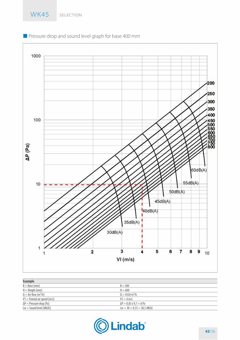
SELEC TIoN WK45
43/56
� Pressure drop and sound level graph for base 400 mm
ExampleB = Base [mm] B = 500H = Height [mm] H = 600Q = Air flow [m³/h] Q = 4320 m³/hV1 = Frontal air speed [m/s] V1 = 4 m/sΔP = Pressure drop [Pa] ΔP = 0,83 x 9,7 = 8 PaLw = Sound level [dB(A)] Lw = 38 + 0,55 = 38,5 dB(A)
WK45
43/56

SELEC TIoN WK45
44/56
� Correction for base different than 400 mm
Correction for base different than 400 mmB in mm 200 250 300 350 400 450 500 550 600 650 700 750 800 850ΔP x ζ x … 1,65 1,40 1,23 1,10 1,00 0,87 0,83 0,80 0,77 0,75 0,73 0,71 0,69 0,67Lw + … 3,35 2,27 1,39 0,65 0,00 0,29 0,55 0,79 1,00 1,17 1,34 1,49 1,63 1,76
Correction for base different than 400 mmB in mm 900 950 1000 1050 1100 1150 1200 1250 1300 1350 1400 1450 1500ΔP x ζ x … 0,66 0,64 0,63 0,62 0,61 0,60 0,59 0,58 0,57 0,56 0,55 0,55 0,55Lw + … 1,89 2,00 2,11 2,22 2,32 2,42 2,51 2,60 2,69 2,77 2,85 2,93 3,00
� Sound spectrum tableCorrection used to estimate the octave band spectrum (values to be added to the noise levels in db(A))
V1 (m/s) F (Hz)63 125 250 500 1000 2000 4000 8000
2 25 9 2 -4 -9 -17 -32 -193 20 8 1 -4 -8 -14 -27 -224 15 6 1 -4 -7 -11 -22 -245 11 5 0 -4 -6 -8 -18 -266 9 4 -1 -4 -5 -7 -15 -257 8 4 -2 -5 -5 -7 -14 -228 7 4 -3 -5 -5 -6 -13 -219 7 4 -3 -6 -5 -6 -12 -20
10 7 3 -3 -6 -5 -6 -12 -19
WK45
44/56

ACCESSoRIES AND SPARE PARTS WK45
45/56
ACCESSoRIES AND SPARE PARTSOpen blade microswitch WHKICKITClosed blade microswitch (necessary according to UNI 10365, art. 4.9) WHKFCKIT
Remote control magnet, optional for manual command fire dampers. Power supply input version: the fire damper blade closes when power is supplied. Power supply 24 V DC - 4,5 W
WHKMA024KIT
Remote control magnet, optional for manual command fire dampers. Power supply input version: the fire damper blade closes when power is supplied. Power supply 230 V DC - 4,5 W - rectifier included
WHKMA230KIT
Remote control magnet, optional for manual command fire dampers. Power supply interruption version: the fire damper blade closes when power is not supplied. Power supply 24 V DC - 4,5 W
WHKMG024KIT
Remote control magnet, optional for manual command fire dampers. Power supply interruption version: the fire damper blade closes when power is not supplied. Power supply 230 V DC - 4,5 W - rectifier included
WHKMG230KIT
WK45 manual mechanism with fuseholder group, cam, lever, protection box and 4 fixing nuts for B X H ≤ 600 X 300
WK45MAN3
WK45 manual mechanism with fuseholder group, cam, lever, protection box and 4 fixing nuts for B X H > 600 X 300
WK45MAN4
WK45 manual mechanism with fuseholder group, cam, lever, protection box 4 fixing nuts and 1 microswitch closed damper for B X H ≤ 600 X 300
WK45MAN3CM
WK45 manual mechanism with fuseholder group, cam, lever, protection box 4 fixing nuts and 1 microswitch closed damper for B X H > 600 X 300
WK45MAN4CM
Red reset lever for WH/WK45 (spare part for manual mechanism) WHK45PLSLEVABlue reset lever for WH/WK45 (spare part for manual mechanism) WHK45PLSLEVAB
Motorized plate WK45/43 for Siemens GGA + fixing screws (motor not included) WK45MTSGMotorized plate WK45/43 for Belimo BF + fixing screws (motor not included) WK45MTB
WK45
45/56

ACCESSoRIES AND SPARE PARTS WK45
46/56
Motorized plate WK45/43 for Belimo BFN + fixing screws (motor not included) WK45SMB
Motorized plate WK45/43 for Siemens GNA / GRA + fixing screws (motor not included) WK45MTSP
Belimo motor for dampers predisposed for use with BFN24T / BF24T, 24 V AC/DC power supply, thermofuse 72 °C
BFN24T/BF24T
Belimo motor for dampers predisposed for use with BFN24T-ST / BF24T-ST, 24 V AC/DC power supply, thermofuse 72 °C with connection plugs for control and monitoring systems
BFN24T-ST / BF24T-ST
Belimo motor Top Line series for dampers predisposed for use with BF24TLT-ST, 24 V AC/DC power supply, thermofuse 72 °C with connection plugs for control and monitoring systems
BF24TLT-ST
Belimo motor for dampers predisposed for use with BFN230T / BF230T, 230 V AC power supply, thermofuse 72 °C
BFN230T / BF230T
Siemens motor for dampers predisposed for use with GGA126 / GNA126 / GRA126, 24 V AC/DC power supply, thermofuse 72 °C
GGA126 / GNA126 / GRA126
Siemens motor for dampers predisposed for use with GGA326 / GNA326 / GRA326, 230 V AC power supply, thermofuse 72 °C
GGA326 / GNA326 / GRA326
Copper mechanical thermofuse 70 °C for manual mechanism WK70Copper mechanical thermofuse 95 °C for manual mechanism WK95Thermofuse 72 °C for Belimo motor BFL, BFN and BF (spare part) WWEZBAT72Thermofuse 95 °C for Belimo motor BFL, BFN and BF (accessory) WWEZBAT95Thermofuse 72 °C for Siemens motors GRA, GNA and GGA (spare part) MT-FUSASK79.4Thermofuse 95 °C for Siemens motors GRA, GNA and GGA (accessory) MT-FUSASK79.5
Set of 4 brackets for plasterboard wall mounting + nuts WKGY100
Set of 4 plates for paired installation + screws + nuts WKBA2
WK45
46/56

ACCESSoRIES AND SPARE PARTS WK45
47/56
Inspection opening side AInspection opening side CInspection opening side A+C (Avaible only during fire damper order)
WKSPAWKSPCWKSPAC
(Inspection opening not available for INOX steel casing)(Refer to the section Components p. 4 for further information about inspection openings)
Matt black epoxy powder painting for WK45 fire damper casing• Corrosion resistance: Excellent• Heat resistance: Very good• Resistance direct impact: ≥2Kg 5cm ISO 6272• Resistance reverse impact: ≥2Kg 5cm ISO 6272• Resistance umidity chamber: after 500 hrs noy blistering ISO 6270• Resistance salt spray test: after 500 hrs creeping at cross-cut <1mm ISO 9227
WK45PAINT[B][H]
Communication and control unit BKS24-1B to control and monitor 1 fire damper with Belimo motor WKBKS241B
Communication and control unit BKS24-9A to control and monitor up to 9 fire dampers with Belimo motor
WKBKS249A
Communication and power supply unit: BKN230-24 for Belimo motors BFL24T-ST, BFN24T-ST e BF24T-ST WKBKN23024LON Communication and power supply unit: BKN230-24LON for Belimo motors BF24TL-T-ST WHKBKN230-24LONModbus Communication and power supply unit: BKN230-24MOD for Belimo motors BFL24T-ST, BFN24T-ST and BF24T-ST
WHKBKN230-24MOD
Communication and power supply unit MPBUS for BKS24-9A or gateways Belimo UK24MOD and UK24BAC: BKN230-24-C-MP for Belimo motors BFL24T-ST, BFN24T-ST and BF24T-ST
WHKBKN230-24-C-MP
Modbus Communication and power supply unit: BKN230MOD for Belimo motors BFL230T, BFN230T and BF230T
WHKBKN230MOD
Gateway UK24BAC Belimo for BACnet communication WHKUK24BAC
WK45
47/56

HoW To oRDER WK45
48/56
HoW To oRDER �Motorized fire dampers
CodeType WK Rectangular fire damperSeries 45 Blade thickness 40 mm - 500 Pa air sealing
Motor type
VSS Siemens motor GRA126 (24V)DSS Siemens motor GRA326 (230V)VPS Siemens motor GNA126 (24V)DPS Siemens motor GNA326 (230V)VGS Siemens motor GGA126 (24V)DGS Siemens motor GGA326 (230V)VMB Belimo motor BFN24T (24V)DMB Belimo motor BFN230T (230V)TMB Belimo motor BFN24T-ST (24V) with connection plugs for integration in control and monitoring systemsVGB Belimo motor BF24T (24V)DGB Belimo motor BF230T (230V)TGB Belimo motor BF24T-ST (24V) with connection plugs for integration in control and monitoring systems
Base XYZ Nominal base dimension (mm)Height XYZ Nominal height dimension (mm)
� Fire damper with manual control
CodeType WK Rectangular fire damperSeries 45 Blade thickness 40 mm - 500 Pa air sealing
Command type B Manual commandM Manual command with magnet
Position indication microswitches
S0 Without position microswitches (not recommended)SA With open blade microswitchSC With closed blade microswitchS2 With two microswitches
Magnet
M0 Without magnet (only for command type “B”)MR With power supply interruption magnet, 24 V DCMI With power supply input magnet, 24 V DCMY With power supply interruption magnet, 230 V ACMZ With power supply input magnet, 230 V AC
Base XYZ Nominal base dimension (mm)Height XYZ Nominal height dimension (mm)
Examples CodeWK45 fire damper with manual control, without microswitch, without magnet, 400x450 WK45B-S0-M0-0400450WK45 fire damper with manual control, with open blade microswitch, with24 V DC power interruption magnet, 1500x800 WK45M-SA-MR-1500800
WK45 Siemens motorized 230V fire damper, 400x450 WK45DPS-0400450
WK45
48/56

HoW To oRDER WK45
49/56
� Electric motor driven actuators
� Siemens servomotors
Base200 250 300 350 400 450 500 550 600 650 700 750 800 850
Height
800 P P P P P P P P P P750 P P P P P P P P P P700 P P P P P P P P P P P P650 P P P P P P P P P P P P P P600 S S S S S S S S S S S S S P550 S S S S S S S S S S S S S P500 S S S S S S S S S S S S S P450 S S S S S S S S S S S S S P400 S S S S S S S S S S S S S P350 S S S S S S S S S S S S S P300 S S S S S S S S S S S S S P250 S S S S S S S S S S S S S P200 S S S S S S S S S S S S S P
Height
900 950 1000 1050 1100 1150 1200 1250 1300 1350 1400 1450 1500800 P P G G G G G G G G G G G750 P P P P G G G G G G G G G700 P P P P P G G G G G G G G650 P P P P P P P G G G G G G600 P P P P P P P P P G G G G550 P P P P P P P P P P P P G500 P P P P P P P P P P P P P450 P P P P P P P P P P P P P400 P P P P P P P P P P P P P350 P P P P P P P P P P P P P300 P P P P P P P P P P P P P250 P P P P P P P P P P P P P200 P P P P P P P P P P P P P
Siemens24 V 230V
S GRA126 GRA326P GNA126 GNA326G GGA126 GGA326
WK45
49/56
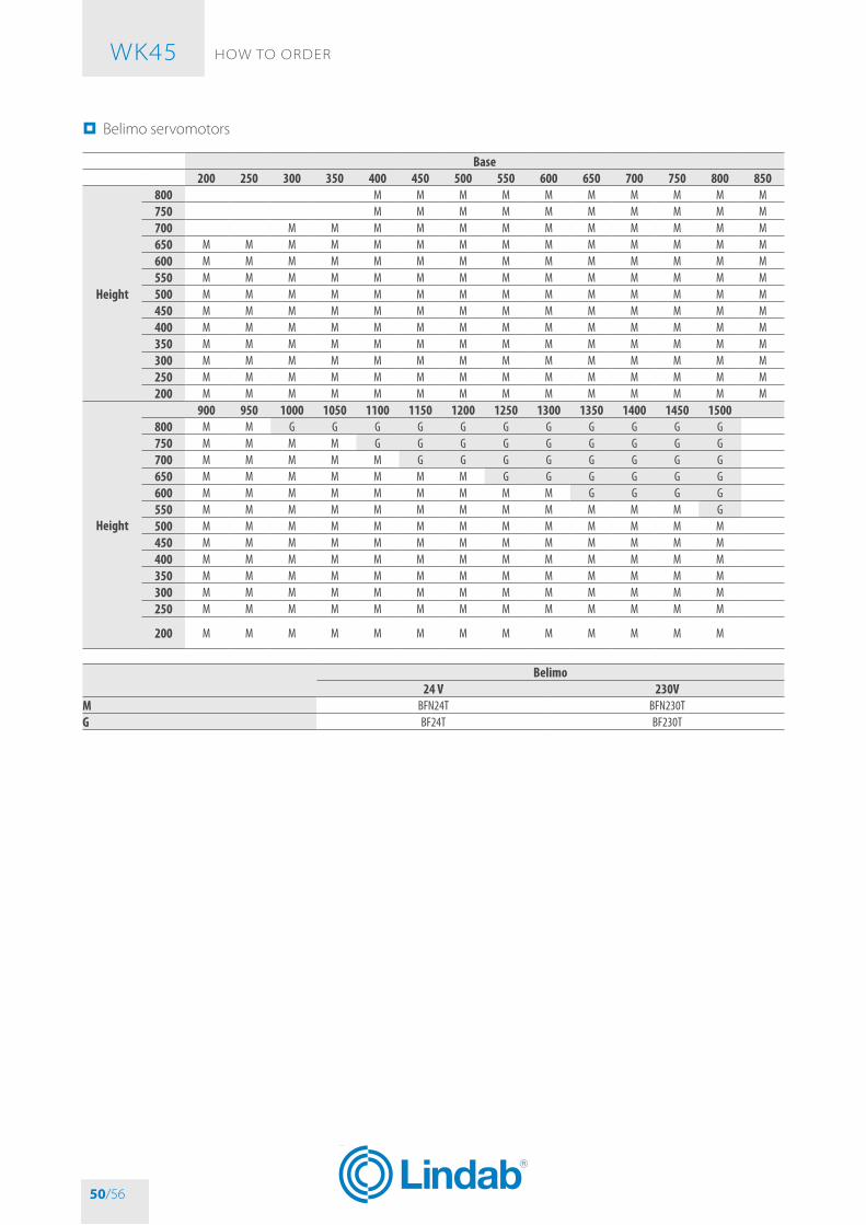
HoW To oRDER WK45
50/56
� Belimo servomotors
Base200 250 300 350 400 450 500 550 600 650 700 750 800 850
Height
800 M M M M M M M M M M750 M M M M M M M M M M700 M M M M M M M M M M M M650 M M M M M M M M M M M M M M600 M M M M M M M M M M M M M M550 M M M M M M M M M M M M M M500 M M M M M M M M M M M M M M450 M M M M M M M M M M M M M M400 M M M M M M M M M M M M M M350 M M M M M M M M M M M M M M300 M M M M M M M M M M M M M M250 M M M M M M M M M M M M M M200 M M M M M M M M M M M M M M
Height
900 950 1000 1050 1100 1150 1200 1250 1300 1350 1400 1450 1500800 M M G G G G G G G G G G G750 M M M M G G G G G G G G G700 M M M M M G G G G G G G G650 M M M M M M M G G G G G G600 M M M M M M M M M G G G G550 M M M M M M M M M M M M G500 M M M M M M M M M M M M M450 M M M M M M M M M M M M M400 M M M M M M M M M M M M M350 M M M M M M M M M M M M M300 M M M M M M M M M M M M M250 M M M M M M M M M M M M M
200 M M M M M M M M M M M M M
Belimo24 V 230V
M BFN24T BFN230TG BF24T BF230T
WK45
50/56

SPECIFICATIoN TExT WK45
51/56
SPECIFICATIoN TExT � Series WK45 rectangular fire damper
DescriptionWK45 rectangular symmetric fire damper tested for fire re-sistance and smoke seal with 500 Pa depression (300 Pa for Weichschott sealing installations) as per EN 1366-2, classi-fied according to EN 13501-3 and CE marked according to European Regulation UE 305/2011 and EN 15650 standard.Allows maximum safety for fire protection inside buildings providing perfect heat insulation and cold and hot smokes tightness. Can be connected to fire protection alarm sys-tem or smokes detection to anticipate blade closure be-fore fire, prevents indirect damages caused by smokes generated by combustion.
Technical characteristics• Available sizes from 200x200 mm to 1500x800 mm• bigger sizes achievable by pairing two fire dampers, only
on vertical rigid wall as per EN 1366-2• Case made from galvanized sheet steel, with a total
length of 510 mm. Comes with flanges for duct connec-tion 35 mm widh with reinforced angle connections
• Closing mechanism built according to UNI 10365, with thermal fuse certified to ISo 10294-4, a test button to check the correct working of the damper, a release sys-tem to block the damper in closed position and a visual signal "open/closed". The closing mechanism can be eas-ily interchanged and substituted:– with mechanical release and manual rearming– with mechanical release and manual rearming, can be
released remotely via a magnet and electric and signal– with electric release and rearming, via and integrat-
ed Siemens or belimo system tested according to EN 15650, composed by an electric thermal fuse and re-mote controlled servomotor via an electrical signal
• blade made from calcium silicate insulating material• blade axis made of steel, patented fixing on casing, with
low friction bearings for high reliability in case of fire.• Silicon lip gasket to cold smoke sealing according to EN
1366-2• Thermal, expanding graphite gasket• Thermal fuse with melting point certified ISo 10294-4 at
70 °C or 95 °C (version with mechanical release) or at 72 °C (version with servo motor)
• Absence of thermal bridge between the wall of installa-tion and the ducts before and after
• Resistance to salt spray, tested with severity 2, according to EN 60068-2-52
• Casing leakage Class C according to EN 1751
Installation• Installation within vertical rigid walls made from aerat-
ed concrete blocks, standard concrete or masonry with a minimum thickness of 140 mm and minimum density of 500 kg/m³ (EI 180 S) or minimum thickness of 100 mm and minimum density of 500 kg/m³ (EI 120 S)Mortar sealing (EI 180 S)Mortar or plaster putty sealing (EI 120 S)Plasterboard and rock wool 100 kg/m³ sealing (EI 120 S)
• Installation within light plasterboard walls with minimum thickness of 100 mm and simplified sealing with rock wool (EI 90 S) or with standard sealing with rock wool or simplified sealing with mortar or plaster putty (EI 120 S)
• Installation within light walls made with gypsum blocks 100 mm thick and minimum density 995 kg/m³ (EI 120 S) or minimum thickness of 70 mm and minimum density 995 kg/m³ (EI 90 S)
• Installation within concrete floors with a minimum thick-ness of 140 mm and minimum denisty of 2200 kg/m³ (EI 180 S) or aerated concrete with minimum thickness 150 mm and minimum density 650 kg/m³ (EI 120 S) or aerated concrete with minimum thickness 100 mm and minimum density 650 kg/m³ (EI 90 S)
• Installation with Weichschott sealing within vertical rigid walls made from aerated concrete blocks, standard con-crete or masonry with minimum thickness 100 mm and minimum density 500 kg/m³, within light plasterboard walls with minimum thickness of 100 mm, within gyp-sum blocks light walls with with minimum thickness 100 mm and minimum density 995 kg/m³ (EI 90 S)
• Installation with Fire batt (Weichschott) sealing within concrete floors or aerated concrete with minimum thick-ness 150 mm and minimum density 650 kg/m³ (EI 120 S)
• Fire resistance characteristics independent from direc-tion of the source of the fire according to EN 1366-2 ar-ticle 6.2
• Installation possible with damper blade placed horizon-tally or vertically, with the mechanism placed in left/right or above/below
Accessories• Motorised version with 24 v or 230 v servomotor in-
stalled on the damper• Set of microswitches with four No/NC position detect-
ing connectors for open and closed damper, as per standard UNI 10365
• Immission and interruption magnet 24 v DC or 230 v AC with rectifier
• Power supply and communication unit LonWorks, MP-bus, Modbus, bacnet
• Inspection doors diameter 140 mm with air sealing gas-ket, no tools required for opening
• Junction for circular ducts connection• WKGY100 installation kit for plasterboard walls, comes
with 4 shaped plates• Fire damper pairing kit WKbA, comes with 4 shaped
plates
WK45
51/56

REvISIoN INDEx WK45
52/56
REvISIoN INDExRevision n° Date of issue Description14/00 2014/11 First issue
15/07 2015/07
Added section:• EI 90 S Installation within vertical rigid wall with Fire Batt (Weichschott) sealing p. 28• EI 90 S Installation within vertical light wall (plasterboard) with Fire Batt (Weichschott) sealing p. 28• EI 90 S Installation within vertical light wall (gypsum blocks wall) with Fire Batt (Weichschott) sealing p. 28• Blade rotation axis positioning p. 15Added table:• Revision Index p. 52Updated drawing:• EI 90 S Installation within vertical light wall (plasterboard) p. 24• Fire dampers pairing for big ducts dimensions p. 5Updated section:• EI 90 S Installation within vertical light wall (plasterboard) p. 24• Belimo motorized version p. 11• Fire dampers pairing for big ducts dimensions p. 5• Specification Text p. 51Updated table:• Performances p. 8General improvements
16/04 2016/04
Added section:• EI 120S Installation within vertical rigid wall p. 22• EI 120 S Installation within floor with Fire Batt (Weichschott) sealing p. 29Updated section:• Fire resistance classification according to EN 13501-3-2009 p. 9• Mechanism type p. 11• Minimum distances p. 19• EI 120 S Installation within vertical rigid wall p. 22• Electrical connections p. 30• How to order p. 48• Specification Text p. 51Updated table:• Accessories and spare parts p. 45General improvements
16/10 2016/10
Added section:• Indications for the correct duct suspension and for damper connection • Positioning brackets before fixing p. 15Updated section:• Mechanism type p. 11• Fire dampers pairing p. 6• Minimum distances p. 19Updated table:• Accessories and spare parts p. 45General improvements
17/04 2017/04
Updated section:• Installations within vertical light wall (plasterboard) p. 24• Installations within vertical wall with Fire Batt (Weichschott) sealing p. 28• Installation within floor with Fire Batt (Weichschott) sealing p. 29• Maintenance and inspections p. 33Updated table:• Electrical specifications p. 32• Motorized fire dampers p. 48• Electric motor driven actuators p. 49• Accessories and spare parts p. 45General improvements
WK45
52/56

REvISIoN INDEx WK45
53/56
19/05 2019/05
Added section:• Installation of flexible connectors in order to balance out the ventilation ducts expansion p. 15• Transfer Application (application not connected to air ducts on one or both sides) p. 17Updated section:• Available dimensions p. 5• Installation p. 15• Not allowed uses p. 15• Minimum distances p. 19• Light plasterboard vertical walls p. 21• Maintenance and inspections p. 33• Accessories and spare parts p. 45Updated table:• Installations within vertical rigid wall p. 22• Installations within vertical light wall (plasterboard) p. 24General improvements
WK45
53/56


As the manufacturer is constantly improving its products, the aesthetic or dimensional features, the technical data, the equipment and accessories indicated could be subject to variations.

via G. La Pira 9 A/b 35012 - Camposampiero (PD) - Italia
phone 049 9303516 – fax 049 9317070 – www.mp3-italia.it
*1MTLWK45EN* rev 19-05*1MTLWK45EN*
Lindab | We simplify construction
www.lindab.com - Fire dampers are manufactured by MP3 Srl www.mp3-italia.it
*1MTLWK45EN-LIND* rev 19-05*1MTLWK45EN-LIND*