Fire Prevention - Strulik
22
U1 Fire Prevention Part V – 4/2007 Differential pressure systems Smoke and heat control of escape routes in accordance with DIN EN 12101-6
-
Upload
khangminh22 -
Category
Documents
-
view
1 -
download
0
Transcript of Fire Prevention - Strulik
U1
Fire Prevention
Part V – 4/2007
Differential pressure systems
Smoke and heat control of escape routes in accordance with DIN EN 12101-6

1
DIN EN 12101-6:2005
Smoke and heat control
Part 6: Provisions for differential pressure
systems – kits
DIN EN 12101-6 is a mandated harmonized standard. Announcement in the Official Journal of the EC: 2005-12-14 / 2006-06-08 Publication in the Federal Official Gazette / Gazette of 2006-03-16 Coexistence phase until 2007-04-01
Thus as from 1st April 2007 DIN EN 12101-6 will be established law and applicable to differential pressure systems.
This means:
Differential pressure systems shall meet the following requirements on principle:
Door opening force:
Differential pressure systems shall be designed such that the door opening force applied at the door handle will not exceed 100 N.
Control-system acting time of 3 seconds:
Within 3 seconds at least 90 % of the volumetric requirements can be determined,
hence: c = 0,9⋅co
Air velocity through the open door: A defined air velocity in accordance with the respective class of system shall be determined for
the open door situation between the pressurized zone and the fire storey.
***
Strulik differential pressure systems with regard to these system classes have already been designed and carried out since 2004.

2
The term "kit":
stabilized axial-flow fan
and control valve
On both sides
On both sides
Damper angle in °
Closing moment
Opening moment
3
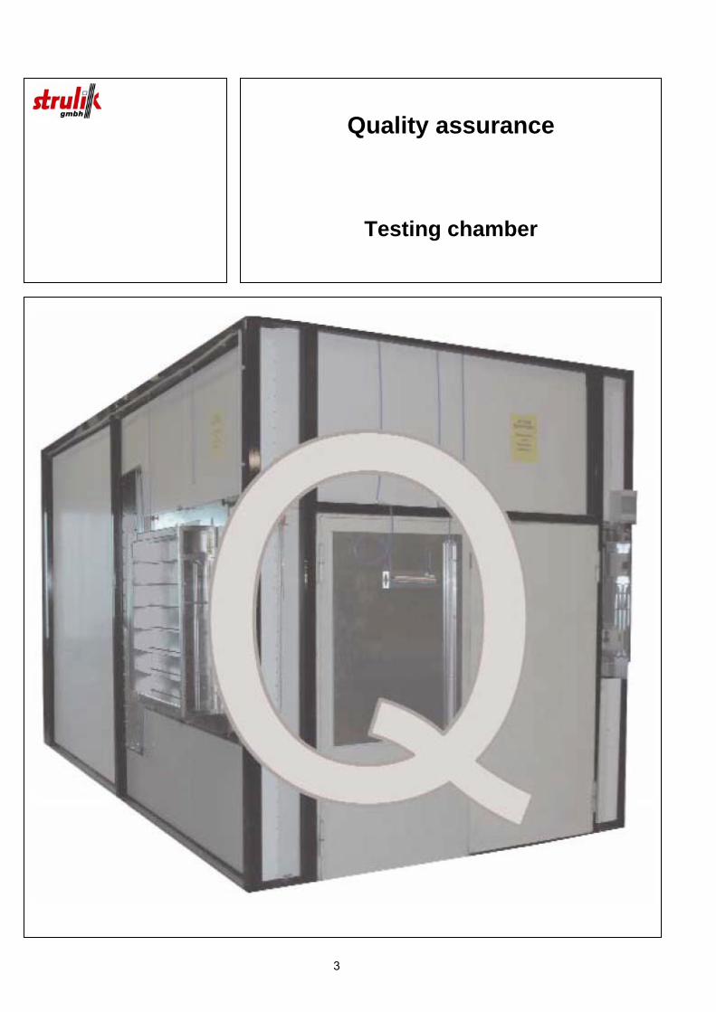
Quality assurance
Testing chamber
4
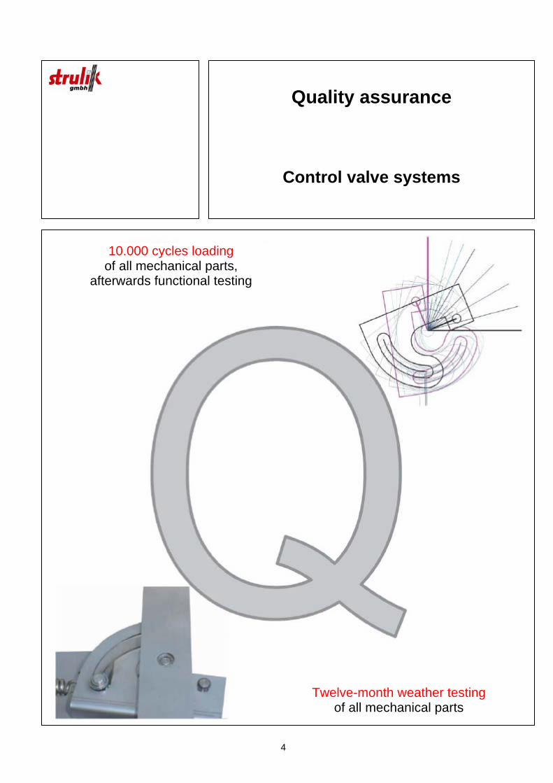
Quality assurance
Control valve systems
10.000 cycles loading of all mechanical parts,
afterwards functional testing
Twelve-month weather testing of all mechanical parts
5
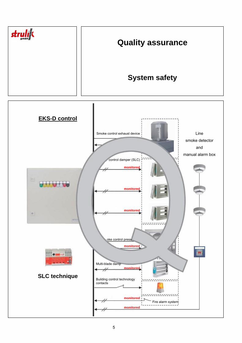
Quality assurance
System safety
EKS-D control
SLC technique
Line
smoke detector
and
manual alarm box
Smoke control exhaust device
control damper (SLC)
monitored
monitored
monitored
oke control press
monitored
Multi-blade damp
monitored
Building control technology contacts
monitored
monitoredFire alarm system
6
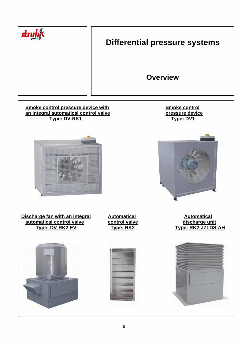
Differential pressure systems
Overview
Smoke control pressure device with Smoke control an integral automatical control valve pressure device Type: DV-RK1 Type: DV1
Discharge fan with an integral Automatical Automatical automatical control valve control valve discharge unit Type: DV-RK2-EV Type: RK2 Type: RK2-JZI-DS-AH
7
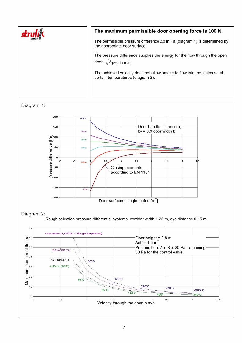
The maximum permissible door opening force is 100 N. The permissible pressure difference Δp in Pa (diagram 1) is determined by the appropriate door surface. The pressure difference supplies the energy for the flow through the open door: Δ The achieved velocity does not allow smoke to flow into the staircase at certain temperatures (diagram 2).
Diagram 1:
Diagram 2:
Rough selection pressure differential systems, corridor width 1,25 m, eye distance 0,15 m
Door handle distance b2 b2 = 0,9 door width b
Closing moments according to EN 1154
Door surfaces, single-leafed [m2]
Pre
ssur
e di
ffere
nce
[Pa]
Velocity through the door in m/s
Max
imum
num
ber o
f flo
ors
Door surface: 1,8 m2 (40 °C flue gas temperature)
Floor height = 2,8 m Aeff = 1,8 m2 Precondition: ΔpTR ≤ 20 Pa, remaining30 Pa for the control valve
p~c in m/s
8
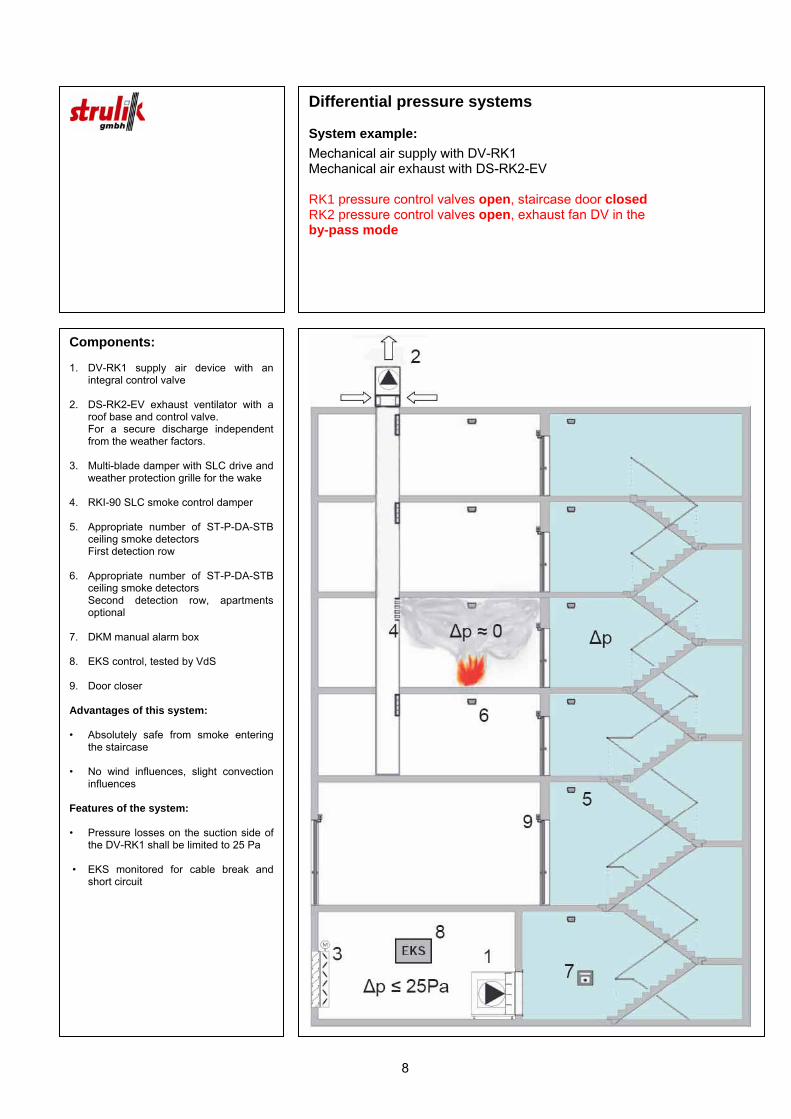
Components: 1. DV-RK1 supply air device with an
integral control valve 2. DS-RK2-EV exhaust ventilator with a
roof base and control valve. For a secure discharge independent
from the weather factors. 3. Multi-blade damper with SLC drive and
weather protection grille for the wake 4. RKI-90 SLC smoke control damper 5. Appropriate number of ST-P-DA-STB
ceiling smoke detectors First detection row 6. Appropriate number of ST-P-DA-STB
ceiling smoke detectors Second detection row, apartments
optional 7. DKM manual alarm box 8. EKS control, tested by VdS 9. Door closer Advantages of this system: • Absolutely safe from smoke entering
the staircase • No wind influences, slight convection
influences Features of the system: • Pressure losses on the suction side of
the DV-RK1 shall be limited to 25 Pa • EKS monitored for cable break and
short circuit
Differential pressure systems System example:
Mechanical air supply with DV-RK1 Mechanical air exhaust with DS-RK2-EV RK1 pressure control valves open, staircase door closed RK2 pressure control valves open, exhaust fan DV in the by-pass mode
9
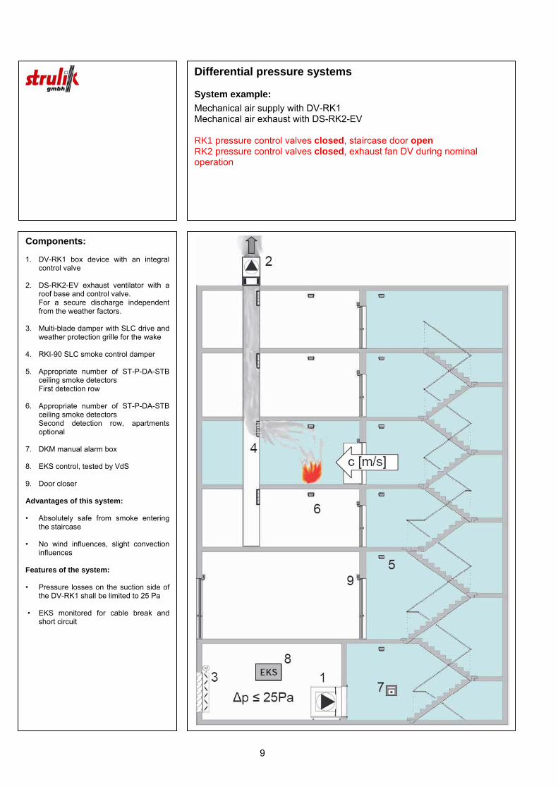
Components: 1. DV-RK1 box device with an integral
control valve 2. DS-RK2-EV exhaust ventilator with a
roof base and control valve. For a secure discharge independent
from the weather factors. 3. Multi-blade damper with SLC drive and
weather protection grille for the wake 4. RKI-90 SLC smoke control damper 5. Appropriate number of ST-P-DA-STB
ceiling smoke detectors First detection row 6. Appropriate number of ST-P-DA-STB
ceiling smoke detectors Second detection row, apartments
optional 7. DKM manual alarm box 8. EKS control, tested by VdS 9. Door closer Advantages of this system: • Absolutely safe from smoke entering
the staircase • No wind influences, slight convection
influences Features of the system: • Pressure losses on the suction side of
the DV-RK1 shall be limited to 25 Pa • EKS monitored for cable break and
short circuit
Differential pressure systems System example:
Mechanical air supply with DV-RK1 Mechanical air exhaust with DS-RK2-EV RK1 pressure control valves closed, staircase door open RK2 pressure control valves closed, exhaust fan DV during nominal operation

10
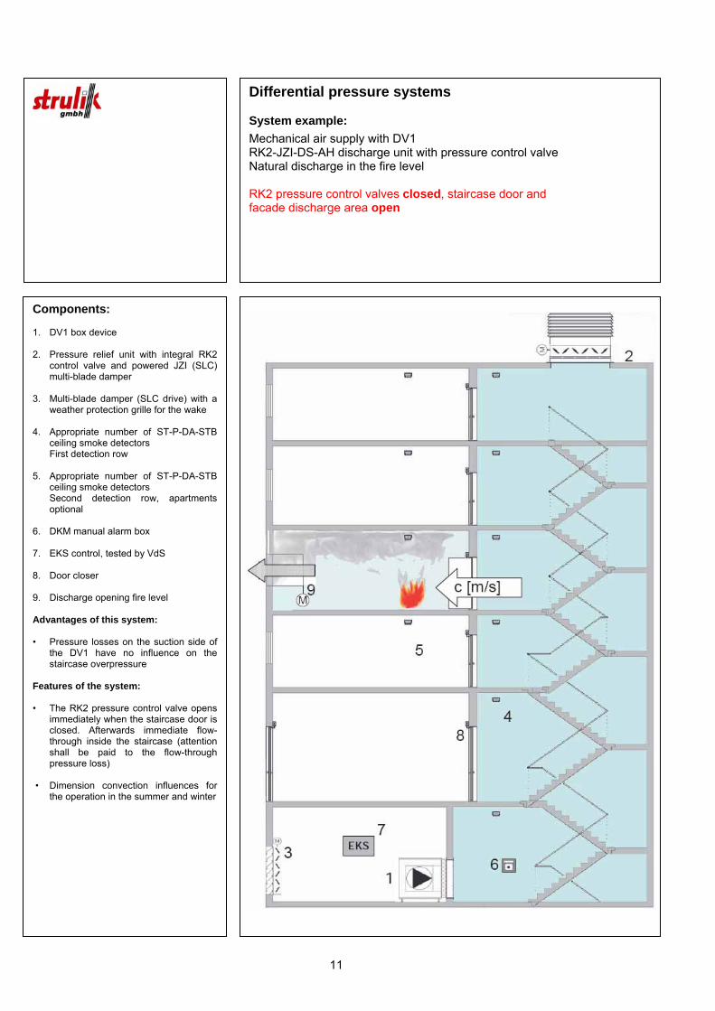
Components: 1. DV1 supply air fan as a box device 2. Pressure relief unit with integral RK2
control valve and powered JZI (SLC) multi-blade damper
3. Multi-blade damper (SLC drive) with a
weather protection grille for the wake 4. Appropriate number of ST-P-DA-STB
ceiling smoke detectors First detection row 5. Appropriate number of ST-P-DA-STB
ceiling smoke detectors Second detection row, apartments
optional 6. DKM manual alarm box 7. EKS control, tested by VdS 8. Door closer 9. Discharge opening fire level Advantages of this system: • Pressure losses on the suction side of
the DV1 have no influence on the staircase overpressure
Features of the system: • The RK2 pressure control valve opens
immediately when the staircase door is closed. Afterwards immediate flow-through inside the staircase (attention shall be paid to the flow-through pressure loss)
• Dimension convection influences for
the operation in the summer and winter
Differential pressure systems System example:
Mechanical air supply with DV1 RK2-JZI-DS-AH discharge unit with pressure control valve Natural discharge in the fire level RK2 pressure control valves open, staircase door closed Facade discharge area open
11
Components: 1. DV1 box device 2. Pressure relief unit with integral RK2
control valve and powered JZI (SLC) multi-blade damper
3. Multi-blade damper (SLC drive) with a
weather protection grille for the wake 4. Appropriate number of ST-P-DA-STB
ceiling smoke detectors First detection row 5. Appropriate number of ST-P-DA-STB
ceiling smoke detectors Second detection row, apartments
optional 6. DKM manual alarm box 7. EKS control, tested by VdS 8. Door closer 9. Discharge opening fire level Advantages of this system: • Pressure losses on the suction side of
the DV1 have no influence on the staircase overpressure
Features of the system: • The RK2 pressure control valve opens
immediately when the staircase door is closed. Afterwards immediate flow-through inside the staircase (attention shall be paid to the flow-through pressure loss)
• Dimension convection influences for
the operation in the summer and winter
Differential pressure systems System example:
Mechanical air supply with DV1 RK2-JZI-DS-AH discharge unit with pressure control valve Natural discharge in the fire level RK2 pressure control valves closed, staircase door and facade discharge area open
12
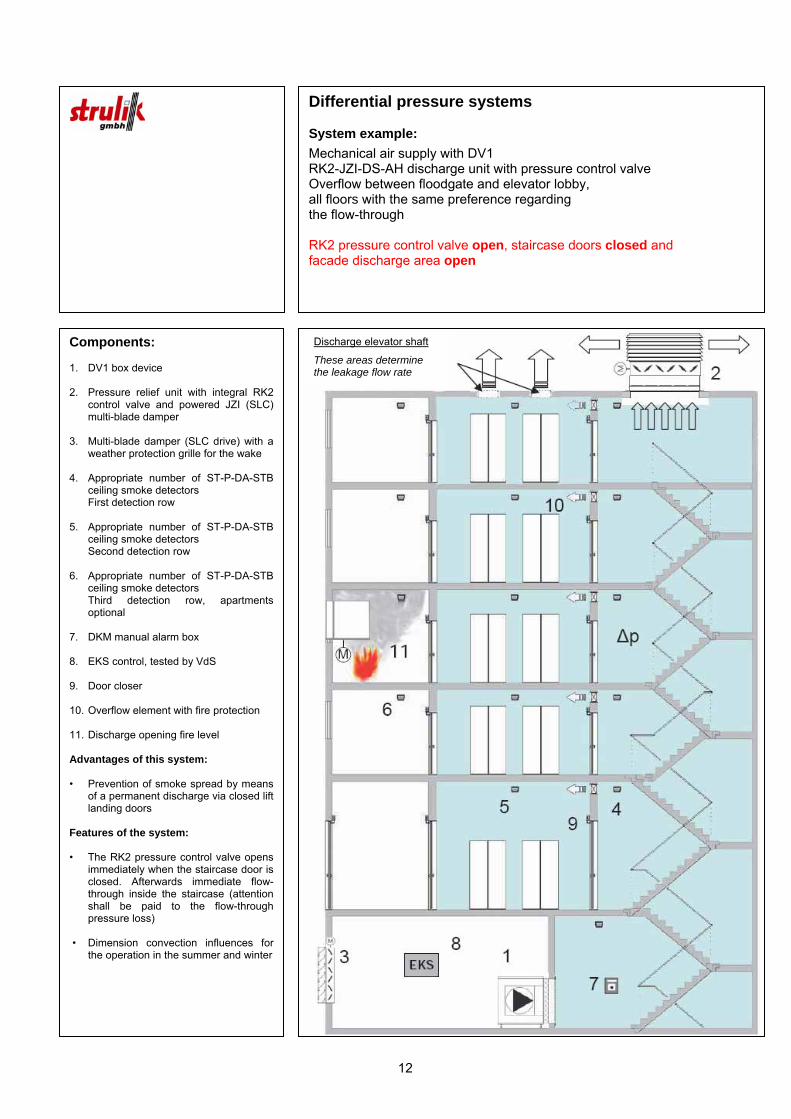
Components: 1. DV1 box device 2. Pressure relief unit with integral RK2
control valve and powered JZI (SLC) multi-blade damper
3. Multi-blade damper (SLC drive) with a
weather protection grille for the wake 4. Appropriate number of ST-P-DA-STB
ceiling smoke detectors First detection row 5. Appropriate number of ST-P-DA-STB
ceiling smoke detectors Second detection row 6. Appropriate number of ST-P-DA-STB
ceiling smoke detectors Third detection row, apartments
optional 7. DKM manual alarm box 8. EKS control, tested by VdS 9. Door closer 10. Overflow element with fire protection 11. Discharge opening fire level Advantages of this system: • Prevention of smoke spread by means
of a permanent discharge via closed lift landing doors
Features of the system: • The RK2 pressure control valve opens
immediately when the staircase door is closed. Afterwards immediate flow-through inside the staircase (attention shall be paid to the flow-through pressure loss)
• Dimension convection influences for
the operation in the summer and winter
Differential pressure systems System example:
Mechanical air supply with DV1 RK2-JZI-DS-AH discharge unit with pressure control valve Overflow between floodgate and elevator lobby, all floors with the same preference regarding the flow-through RK2 pressure control valve open, staircase doors closed and facade discharge area open
Discharge elevator shaft
These areas determine the leakage flow rate

13
Components: 1. DV1 box device 2. Pressure relief unit with integral RK2
control valve and powered JZI (SLC) multi-blade damper
3. Multi-blade damper (SLC drive) with a
weather protection grille for the wake 4. Appropriate number of ST-P-DA-STB
ceiling smoke detectors First detection row 5. Appropriate number of ST-P-DA-STB
ceiling smoke detectors Second detection row 6. Appropriate number of ST-P-DA-STB
ceiling smoke detectors Third detection row, apartments
optional 7. DKM manual alarm box 8. EKS control, tested by VdS 9. Door closer 10. Overflow element with fire protection 11. Discharge opening fire level Advantages of this system: • Prevention of smoke spread by means
of a permanent discharge via closed lift landing doors
Features of the system: • The RK2 pressure control valve opens
immediately when the staircase door is closed. Afterwards immediate flow-through inside the staircase (attention shall be paid to the flow-through pressure loss)
• Dimension convection influences for
the operation in the summer and winter
Differential pressure systems System example:
Mechanical air supply with DV1 RK2-JZI-DS-AH discharge unit with pressure control valve Overflow between floodgate and elevator lobby, all floor with the same preference regarding the flow-through RK2 pressure control valve closed, staircase doors closed and fire room door as well as facade discharge area open
Discharge elevator shaft
These areas determine the leakage flow rate
14
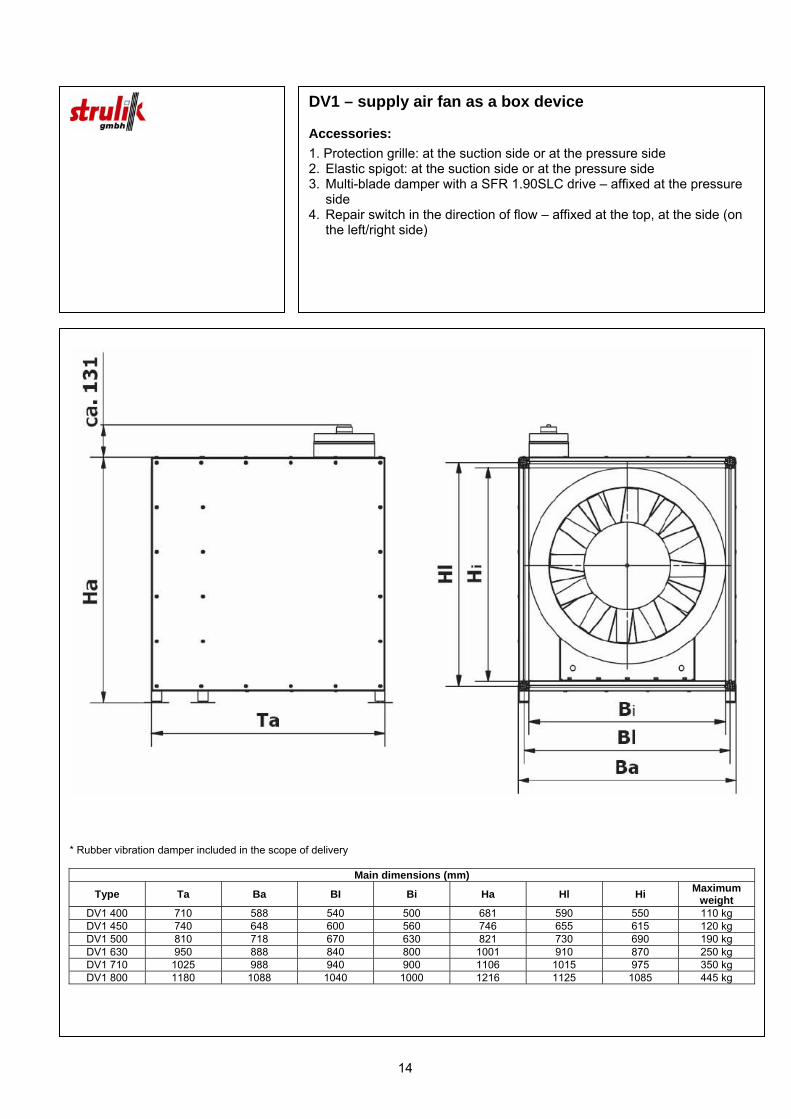
DV1 – supply air fan as a box device Accessories:
1. Protection grille: at the suction side or at the pressure side 2. Elastic spigot: at the suction side or at the pressure side 3. Multi-blade damper with a SFR 1.90SLC drive – affixed at the pressure
side 4. Repair switch in the direction of flow – affixed at the top, at the side (on
the left/right side)
* Rubber vibration damper included in the scope of delivery
Main dimensions (mm)
Type Ta Ba BI Bi Ha Hl Hi Maximum weight
DV1 400 710 588 540 500 681 590 550 110 kg DV1 450 740 648 600 560 746 655 615 120 kg DV1 500 810 718 670 630 821 730 690 190 kg DV1 630 950 888 840 800 1001 910 870 250 kg DV1 710 1025 988 940 900 1106 1015 975 350 kg DV1 800 1180 1088 1040 1000 1216 1125 1085 445 kg
15
DV1 summary table
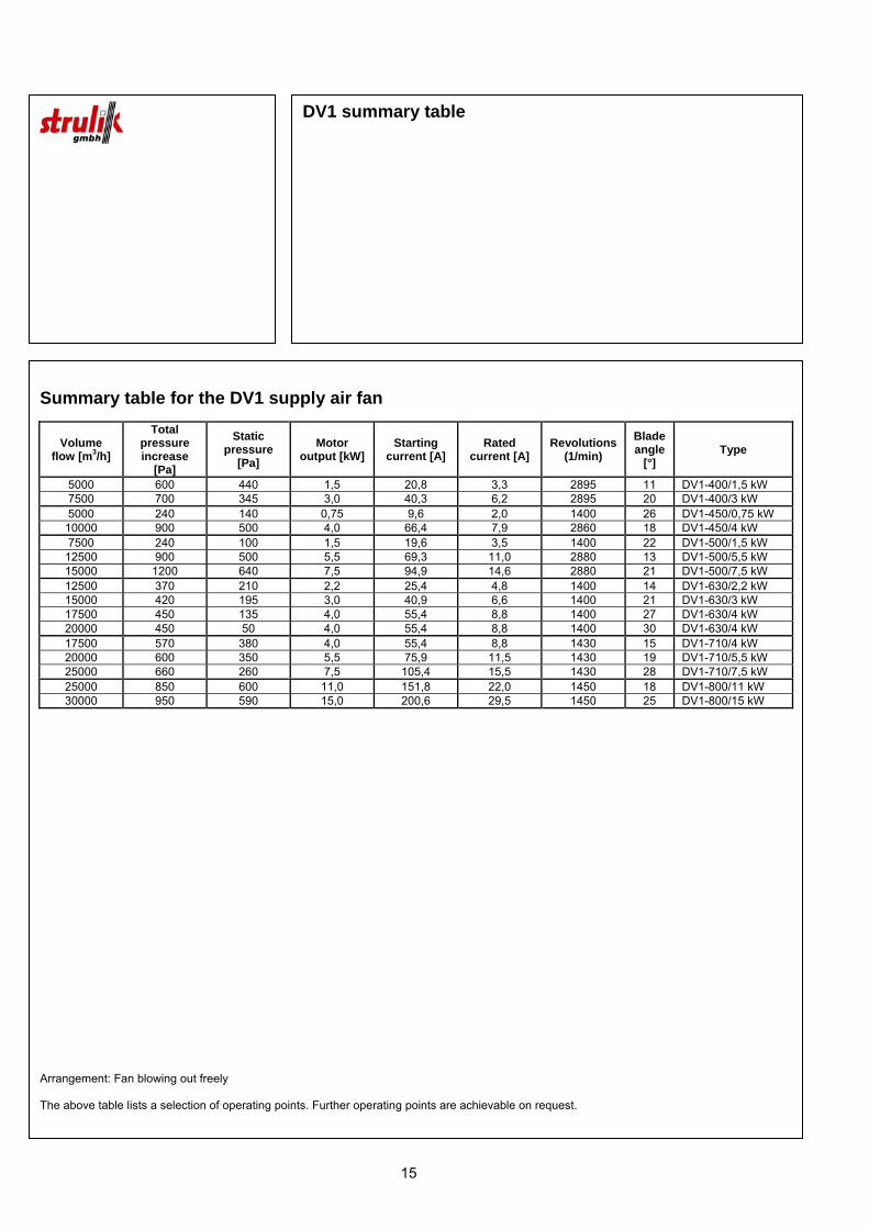
Summary table for the DV1 supply air fan
Volume flow [m3/h]
Total pressure increase
[Pa]
Static pressure
[Pa] Motor
output [kW] Starting
current [A] Rated
current [A] Revolutions
(1/min) Blade angle
[°] Type
5000 600 440 1,5 20,8 3,3 2895 11 DV1-400/1,5 kW 7500 700 345 3,0 40,3 6,2 2895 20 DV1-400/3 kW 5000 240 140 0,75 9,6 2,0 1400 26 DV1-450/0,75 kW
10000 900 500 4,0 66,4 7,9 2860 18 DV1-450/4 kW 7500 240 100 1,5 19,6 3,5 1400 22 DV1-500/1,5 kW
12500 900 500 5,5 69,3 11,0 2880 13 DV1-500/5,5 kW 15000 1200 640 7,5 94,9 14,6 2880 21 DV1-500/7,5 kW 12500 370 210 2,2 25,4 4,8 1400 14 DV1-630/2,2 kW 15000 420 195 3,0 40,9 6,6 1400 21 DV1-630/3 kW 17500 450 135 4,0 55,4 8,8 1400 27 DV1-630/4 kW 20000 450 50 4,0 55,4 8,8 1400 30 DV1-630/4 kW 17500 570 380 4,0 55,4 8,8 1430 15 DV1-710/4 kW 20000 600 350 5,5 75,9 11,5 1430 19 DV1-710/5,5 kW 25000 660 260 7,5 105,4 15,5 1430 28 DV1-710/7,5 kW 25000 850 600 11,0 151,8 22,0 1450 18 DV1-800/11 kW 30000 950 590 15,0 200,6 29,5 1450 25 DV1-800/15 kW
Arrangement: Fan blowing out freely The above table lists a selection of operating points. Further operating points are achievable on request.

16
DV-RK1 – smoke control pressure device with integral control valve Accessories:
1. Protection grille: at the suction side or at the pressure side 2. Elastic spigot: at the suction side or at the pressure side 3. Multi-blade damper with a SFR 1.90SLC drive – affixed at the pressure
side 4. Repair switch in the direction of flow – affixed at the top, at the side (on
the left/right side)
* Rubber vibration damper included in the scope of delivery
Type Ta Ba BI Bi Ha Hl Hi Maximum weight Volume flow rate
DV-RK1 400 768 1014 960 920 782 690 650 150 kg 5000 m3/h DV-RK1 500 869 1114 1060 1020 978 886 846 230 kg 10000 m3/h DV-RK1 630 1027 1239 1185 1145 1254 1162 1122 300 kg 15000 m3/h DV-RK1 630 1027 1239 1185 1145 1392 1300 1260 315 kg 20000 m3/h DV-RK1 710 1096 1304 1250 1210 1668 1576 1536 420 kg 25000 m3/h

17
RK2-JZI-DS-AH
Automatically adjusting pressure relief unit for the installation on top of flat roofs
Volume flow rates and dimensions
A
[mm]
B
[mm]
H
[mm]
Total weight
[kg]
RK2 size
[b x h]
Recommended roof penetration
size [mm]
Volume flow rate at a pressure
difference of 50 Pa [m3/h]
RK2 400/550 JZI-DS-AH 900/900 900 900 1815 260 400/550 800 x 800 5000
RK2 630/688 JZI-DS-AH 1200/1200 1200 1200 1935 350 630/688 1000 x 1000 10000
RK2 800/826 JZI-DS-AH 1500/1500 1500 1500 2115 470 800/826 1300 x 1300 15000
RK2 900/964 JZI-DS-AH 1500/1500 1500 1500 2115 480 900/964 1300 x 1300 20000
RK2 900/1240 JZI-DS-AH 1500/1500 1500 1500 2115 500 900/1240 1300 x 1300 25000
* Basis and lamella hood in galvanized steel, powder coated to RAL 7001; further RAL colors on request. [ 1 ] different height on request.
Inspection opening

18
RK2-H-JZI
Automatically adjusting pressure relief unit for the installation into walls and floors Optional accessory: Baffle plate projecting structure
Volume flow rates and dimensions
B outside
[mm]
H outside
[mm]
L
[mm]
Total weight
[kg]
Size BRK2 x HRK2
[b x h]
Recommended wall penetration
size [mm]
Volume flow rate at a pressure
difference of 50 Pa [m3/h]
RK2-H 400/500 JZI 681 753 506 60 400/550 793 x 721 5000
RK2-H 630/688 JZI 911 891 506 80 630/688 931 x 951 10000
RK2-H 800/826 JZI 1081 1029 506 100 800/826 1069 x 1121 15000
RK2-H 900/946 JZI 1181 1167 506 120 900/964 1207 x 1221 20000
RK2-H 900/1240 JZI 1181 1443 506 140 900/1240 1483 x 1221 25000
Inspection cover
H outside
B o
utsi
de Direction of air flow
Inspection cover
Attention: B wall opening = H outside + min. 40 mm H wall opening = B outside + min. 40 mm
19
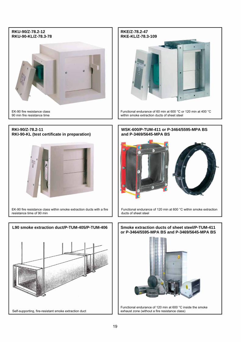
RKU-90/Z-78.2-12 RKU-90-KL/Z-78.3-78 EK-90 fire resistance class 90 min fire resistance time
RKE/Z-78.2-47 RKE-KL/Z-78.3-109 Functional endurance of 60 min at 600 °C or 120 min at 400 °C within smoke extraction ducts of sheet steel
RKI-90/Z-78.2-11 RKI-90-KL (test certificate in preparation) EK-90 fire resistance class within smoke extraction ducts with a fire resistance time of 90 min
WSK-600/P-TUM-411 or P-3464/5595-MPA BS and P-3469/5645-MPA BS Functional endurance of 120 min at 600 °C within smoke extraction ducts of sheet steel
L90 smoke extraction duct/P-TUM-405/P-TUM-406 Self-supporting, fire-resistant smoke extraction duct
Smoke extraction ducts of sheet steel/P-TUM-411 or P-3464/5595-MPA BS and P-3469/5645-MPA BS Functional endurance of 120 min at 600 °C inside the smoke exhaust zone (without a fire resistance class)
20
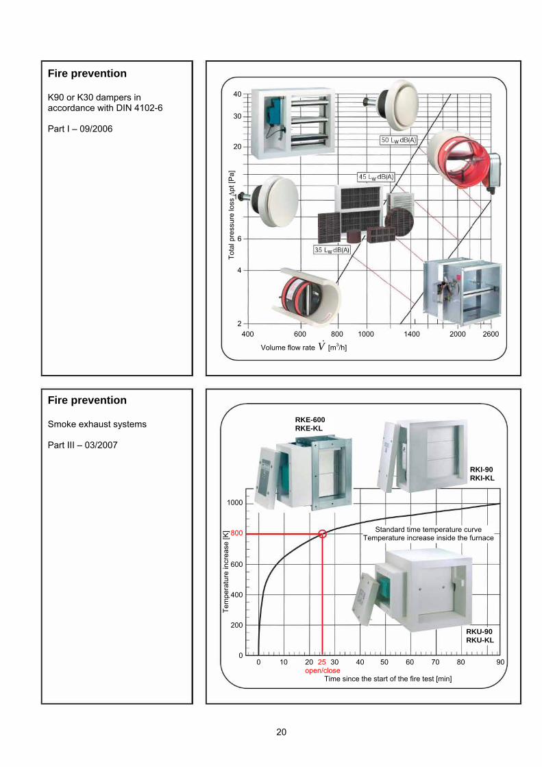
400 600 800 1000 1400 2000 2600
Volume flow rate V& [m3/h]
Fire prevention K90 or K30 dampers in accordance with DIN 4102-6 Part I – 09/2006
Fire prevention Smoke exhaust systems Part III – 03/2007
40
30
20
10
6
4
2
Tota
l pre
ssur
e lo
ss Δ
pt [P
a]
1000
800
600
400
200
0 0 10 20 25 30 40 50 60 70 80 90 open/close Time since the start of the fire test [min]
Tem
pera
ture
incr
ease
[K] Standard time temperature curve
Temperature increase inside the furnace
RKU-90RKU-KL
RKI-90 RKI-KL
RKE-600 RKE-KL
Germany Strulik GmbH, Fire Prevention Neesbacher Str. 13, D-65597 Hünfelden Tel. ++49 (0)6438 839-0, Fax ++49 (0)6438 839-30 [email protected], http://www.strulik.com Strulik GmbH, Air Diffusion Am Alten Viehhof 34, D-47138 Duisburg Tel. ++49 (0)203 429 46-0, Fax ++49 (0)203 42946-66 [email protected], http://www.strulik.com
International Austria Ing. W. Hutfless Klimatechnik, Air Diffusion Steigenteschgasse 13 / 1 / 61, A-1220 Wien Tel. ++43 (0)1 20260170, Fax ++43 (0)1 20260172 [email protected] France Stik Industries, Fire Prevention – Air Diffusion Bât. 6, Z.I. Pierre Barré, F-89100 Gron Tel. ++33 (0)3 86950213, Fax ++33 (0)3 86950358 [email protected], http://www.stik-ind.fr Hungary HvF, Fire Prevention - Air-Diffusion Makói út; Pf. 116, H-6800 Hódmezövásárhely Tel. ++36 (0)6 2241 688, Fax ++36 (0)6 2241 017 [email protected], http://www.delfin.hu/vasfem Irland Aervent Group, Air Diffusion Nangor Road Business Park, Nangor Road, IRL-Dublin 12 Tel. ++353 (0)1 4568200, Fax (++353) (0)1 4568210 [email protected], http://www.aerventgroup.com Iceland Hataekni ehf, Air Diffusion Armuli 26, IS-128 Reykjavik Tel.++354 (0)522 3000, Fax ++354 (0)522 3001 [email protected], http://www.hataekni.is Italy Climaprodukt SRL, Air Diffusion Via delle Gerole, I-20040 Caponago Tel. ++39 02 950071, Fax ++39 02 95007238 [email protected], http://www.climaproduct.com Netherlands Interland Techniek B.V., Air Diffusion Postbus 283, NL-3300 AG Dordrecht Tel. ++31 (0)78 6180600, Fax ++31 (0)78 6178715 [email protected], http://www.interlandtechniek.nl Poland Wojciech Konka, Fire Prevention – Air Diffusion PL - 90-983 Łódz, Skr. Pocztowa 61 Tel./faks: ++48 (0)42 6401560, Tel. kom.: ++48 (0)509 402 007 [email protected], http://www.strulik.pl Switzerland TENEX Automation AG (Strulik GmbH) Eichwiesstrasse 4, CH-8645 Jona Tel. ++41 (0)55 2100938, Fax ++41 (0)55 2100939 [email protected], http://www.strulik.ch Turkey Metes Mühlendislik, Air Diffusion Kaptan Arif Sok. 48/12, TK-34741 Suadiye-Istanbul Tel. ++90 (0)216 3612202, Fax ++90 (0)216 3806909 [email protected], http//www.kombinet.org.tr United Kingdom TES Systems Ltd, Air Diffusion 9 Lyne Place Manor, Bridge Lane, Virginia Water, GB-GU25 4ED Surrey Tel. ++44 (0)1932 568088, Fax ++44 (0)1932 568082 [email protected], http://www.tessystem.co.uk