
Fire alarm installation - Fire & Security Training & Recruitment.
164
Fire alarm installation Day 1 Cube Group Training Limited
-
Upload
khangminh22 -
Category
Documents
-
view
0 -
download
0
Transcript of Fire alarm installation - Fire & Security Training & Recruitment.

Fire alarm installation
Day 1
Cube Group Training Limited

Fire Detection System
A fire detection system consists of manual and automatic alarm-initiating devices that are activated by the presence of fire, smoke, flame, or heat.
The devices then send a signal to a Control Indicating Equipment using or a warning device one of two methods:
a hard-wire system or a generated signal conveyed by radio wave over a special frequency to a radio receiver in the panel.
Day 1
Fire alarm installation course

Basic Components of a Fire Detection System:
• Manual call point • Smoke detectors • Flame detectors • Heat detectors • Combination detectors • Waterflow devices • Communication devices
Day 1
Fire alarm installation course

Notification devices:
Audible notification signaling appliances are the most common types of alarm-signaling systems used for signaling a fire alarm in a structure.
E.g:
• Bells • Buzzers • Horns • Speakers • Strobe lights • Other warning appliances
Day 1
Fire alarm installation course
Notification devices:
Depending on the system’s category or grade, the local alarm may either activate a single notification appliance, notification appliances within a specific zone, designated floor(s), or the entire facility.
Day 1
Fire alarm installation course

Notification devices:
• Audible — Approved sounding devices, such as horns, bells, or speakers, that indicate a fire or emergency condition.
• Visual — Approved lighting devices, such as strobes or flashing lights, that indicate a fire or emergency condition.
• Tactile — Indication of a fire or emergency condition through sense of touch or vibration.
Day 1
Fire alarm installation course

Other Fire Alarm System Outputs:
• Turn off the heating, ventilating, and air-conditioning system • Close smoke dampers and/or fire doors• Pressurized stairwells and/or operate smoke control systems
for evacuation purposes • Unlock doors along the path of egress • Provide elevator recall to the designated floor and prevent
normal operations• Operate heat and smoke vents • Activate special fire suppression systems, such as preaction and
deluge sprinkler systems or a variety of special-agent fire extinguishing systems Day 1
Fire alarm installation course

Fire detection and alarm systems are designed to receive certain types of signals from devices and perform an action based upon the type of signal received.
Some signals may indicate a fire condition, while others may indicate that a device on the system needs to be serviced or replaced.
The CIE should be programmed to respond to different signal types appropriately.
Day 1
Alarm signaling

Alarm Signal — Signal given by a fire detection and alarm system when there is a fire condition detected.
Supervisory Signal — Signal given by a fire detection and alarm system when a monitored condition in the system is off-normal. E.g. calibration required.
Trouble Signal — Signal given by a fire detection and alarm system when a power failure or other system malfunction occurs.
Day 1
Alarm signaling

Control Indicating Equipment (CIE)
CONTROL PANEL STANDARD BS5839 PART 4 AND EN54 PART 2 & 4
European Standard EN54 Part 2 for the Control and Indicating Equipment (c.i.e.) and EN54 Part 4 for the Power Supply Equipment (p.s.e.)
Types of Fire Alarm panels:
● Conventional● Addressable● Intelligent Fire Alarm Detection Systems● Wireless Fire Alarm Detection
10

Basic components of a fire alarm system
Conventional Fire Alarm Panel:
A conventional system is the simplest type of protected premises alarm system. When an alarm-initiating device, such as a smoke detector, sends a signal to the CIE, all of the alarm-signaling devices operates.
Day 1

Basic components of a fire alarm system
Conventional system
Day 1
Zone 1Zone 2
Sounder Circuit 1Sounder Circuit 2

Basic components of a fire alarm system
Addressable system
001
002 003 004 005
009 008 007 006
Day 1
Loop 1
Sounder Circuit 1
Sounder Circuit 2

Fire alarm detectors
When present, humans can be excellent fire detectors.
The healthy person is able to sense multiple aspects of a fire including the heat, flames, smoke, and odors. For this reason, most fire alarm systems are designed with one or more manual alarm activation devices to be used by the person who discovers a fire. Unfortunately, a person can also be an unreliable detection method since they may not be present when a fire starts, may not raise an alarm in an effective manner, or may not be in perfect heath to recognize fire signatures.
It is for this reason that a variety of automatic fire detectors have been developed. Automatic detectors are meant to imitate one or more of the human senses of touch, smell or sight.
Day 1

Smoke detector
Smoke detectors serve the purpose of early detection, notification, and reaction. Some detectors are also used to activate mechanical or electrical systems, such as dampers, doors, and electronic shutdown. Smoke detectors have evolved into two principal types of devices:
Optical smoke detectors
Photoelectric or Optical smoke detection works on all types of fires and usually responds more quickly to smoldering fires than ionization smoke detection. Photoelectric smoke detection is best suited for areas containing overstuffed furniture and other areas where smoldering fires can occur. Day 1

Smoke detector
Ionization Smoke Detection:
An ionization smoke detector contains a sensing chamber consisting of two electrically charged plates (one positive and one negative) and a radioactive source for ionizing the air between the plates. A small amount of Americium 241 that is adjacent to the opening of the chamber ionizes the air particles as they enter. The ionized particles free electrons from the negative electron plate and the electrons travel to the positive plate. Thus, a small ionization current measurable by electronic circuitry flows between the two plates.
Day 1

Smoke detector
Ionization smoke detector:
Day 1
Products of combustion, which are much larger than the ionized air molecules, enter the chamber and collide with the ionized air molecules. As the two interact, they combine and the total number of ionized particles is reduced. This action results in a decrease in the chamber current between the plates. When a predetermined threshold current is crossed, an alarm is initiated

Smoke detector
Optical smoke detector
The Optical Smoke Detector, also referred to as a Photoelectric Type Device, uses a light source to detect smoke.
Day 1

Optical smoke detectors are generally more responsive to fires that begin with a long period of smoldering
Smoke detector
Day 1
Light source Photocell

Ionization smoke detector:
Ionization smoke detectors use an ionization chamber and a source of ionizing radiation to detect smoke. This type of smoke detector is more common because it is inexpensive and better at detecting the smaller amounts of smoke produced by flaming fires.
Inside an ionization detector is a small amount (perhaps 1/5000th of a gram) of americium-241. The radioactive element americium has a half-life of 432 years, and is a good source of alpha particles.
Smoke detector
Day 1

Smoke detector
Ionization smoke detector:
They are generally more responsive to flaming fires.
● They can work in very dusty environment
● No extensive maintenance required
● Battery operated
Day 1

Smoke detector
Ionization smoke detector:
An ionization smoke detector works satisfactorily on all types of fires, although it generally responds more quickly to flaming fires than photoelectric smoke detectors. The ionization detector is an automatic resetting type and is best suited for rooms that contain highly combustible materials, such as the following:
• Cooking fat/grease • Flammable liquids • Newspapers • Paint • Cleaning solutions
Day 1

Smoke detector
Air-sampling smoke detector:
An air-sampling smoke detector is a type of ionization detector that is designed to continuously monitor a small amount of air from the protected area for the presence of smoke particles.
Day 1
Detector Aspiration Pump/Fan
Sampling Ports
Sampling Tubes

In the UK the installation of smoke alarms in new builds must comply with British Standard BS5839 pt6, it recommends that a new-build property consisting of no more than 3 floors, (less than 200 square metres per floor) should be fitted with a Grade D, LD2 system. Building Regulations in England, Wales and Scotland recommend that BS 5839: Pt.6 should be followed, but as a minimum a Grade D, LD3 system should be installed.
Alpha radiation emitted from the foil source will not penetrate beyondthe casing of the smoke detector head. Alpha radiation poses apotential internal hazard only in the event of breakage of the detectorhead and the sealed Am-241 source.
Smoke detector
Day 1

Heat detectors
Most conventional heat detectors operate by using a matched pair of thermistors to sense heat. One thermistor is exposed to the ambient temperature, the other is sealed. In normal conditions the two thermistors register similar temperatures, but, on the development of a fire, the temperature recorded by the exposed thermistor will increase rapidly, resulting in an imbalance of the thermistors, causing the detector to change into alarm state.
Day 1

Heat detector
Day 1
The basic types of automatic initiating devices are those that detect heat, smoke, flame, and water flow. The two categories of heat detectors are fixed temperature and rate of rise.

Heat detector
Day 1
• Fixed-temperature heat detectors • Rate-of-rise heat detectors

Heat detector
Day 1
A Fixed-temperature heat detector that uses solder with a known melting point to separate spring from the contact points. When the heat exceeds a predetermined temperature, the bi-metal deflects and closes the contact, triggering the fire signal.

A heat detector may be more appropriate than a smoke detector where the environment is dirty or smoky under normal conditions.
Heat detector
Day 1

Fixed Heat Temperature Detector:
A Fire detection systems using heat detection devices are among the oldest still in service. They are relatively inexpensive compared to other types of systems, and they are the least prone to nuisance alarms. They are, however, typically slower to activate under fire conditions than other types of detectors.
Heat detector
Day 1

Rate of Rise Heat Detector:
A rate-of-rise heat detector operates on the principle that fires rapidly increase the temperature in a given area. These detectors respond at substantially lower temperatures than fixed-temperature detectors. Typically, rate-of-rise heat detectors are designed to send a signal when the rise in temperature exceeds 12° to 15°F (7°C to 8°C) degrees per minute because temperature changes of this magnitude are not expected under normal, nonfire circumstances.
Heat detector
Day 1

Manual Call Points
MCP, commonly called Manual Call Points, allow occupants to manually initiate the fire alarm signaling system. Manual Call Points may be connected to systems that sound local alarms, off-premise alarm signals, or both.
A manual pull station may be protected by a protective cover in areas where it would be subject to damage or accidental activation. These protective devices are used in gymnasiums, materials handling areas, or in other locations where accidental activation is possible.
Manual Call-Points
Day 1

Carbon Monoxide (CO) is a poisonous gas produced by combustion and a CO fire detector is used to indicate the outbreak of a fire by sensing the level of CO in the air. The detector has an electrochemical cell which senses CO, but not smoke or other combustion products.
Carbon Monoxide (CO) detector
Day 1

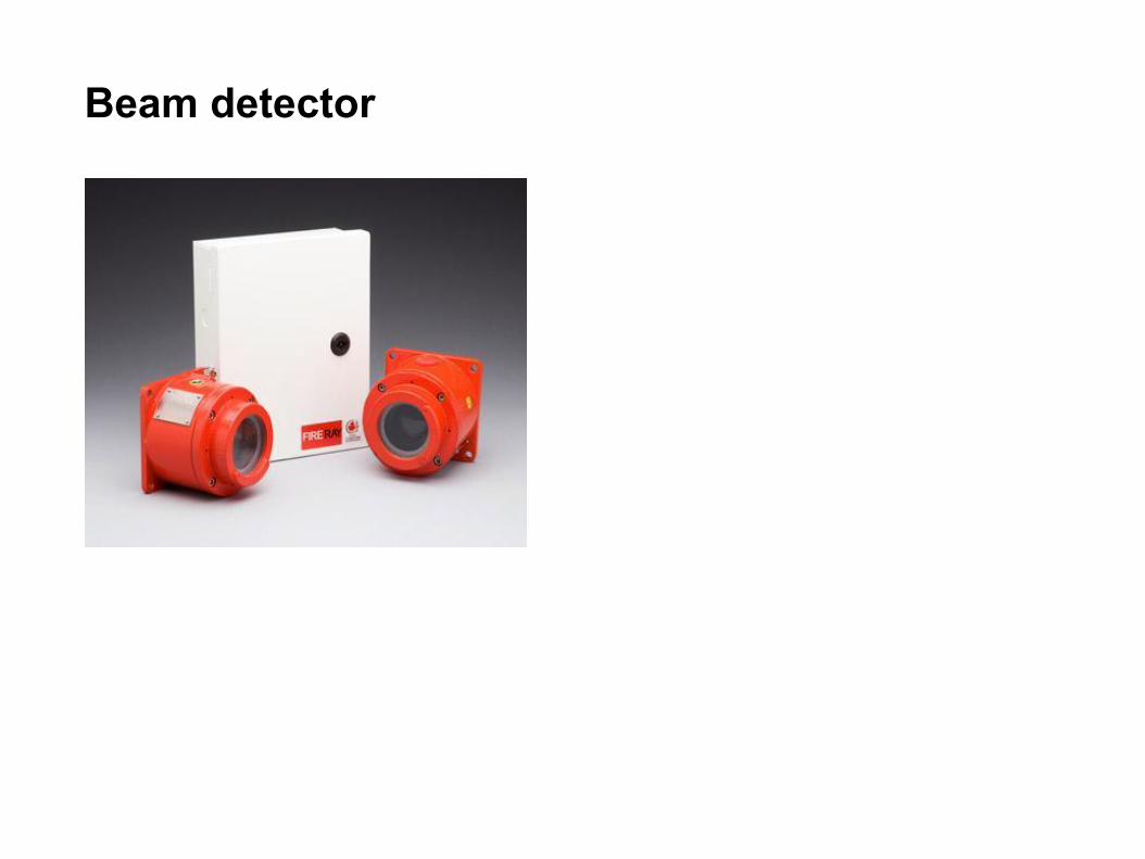
Beam detector
A beam detector is designed to protect large, open spaces and is made up of three main parts: the transmitter, which projects a beam of infra-red light; the receiver which registers the light and produces an electrical signal; and the interface, which processes the signal and generates alarm or fault signals. When a fire develops, smoke particles obstruct the beam of light and, once a pre-set threshold has been exceeded, the detector will go into alarm.
Day 1
Beam detector
Day 1

Flame detector
A flame detector is designed to detect either ultraviolet (UV) or infra-red (IR) radiation emitted by a fire.
This means that the detector can operate even if the lens is contaminated by a layer of oil, dust, water vapour or ice.
Day 1

Flame detector
A flame detector is designed to detect either ultraviolet (UV) or infra-red (IR) radiation emitted by a fire.
This means that the detector can operate even if the lens is contaminated by a layer of oil, dust, water vapour or ice.
Day 1

Electronic components
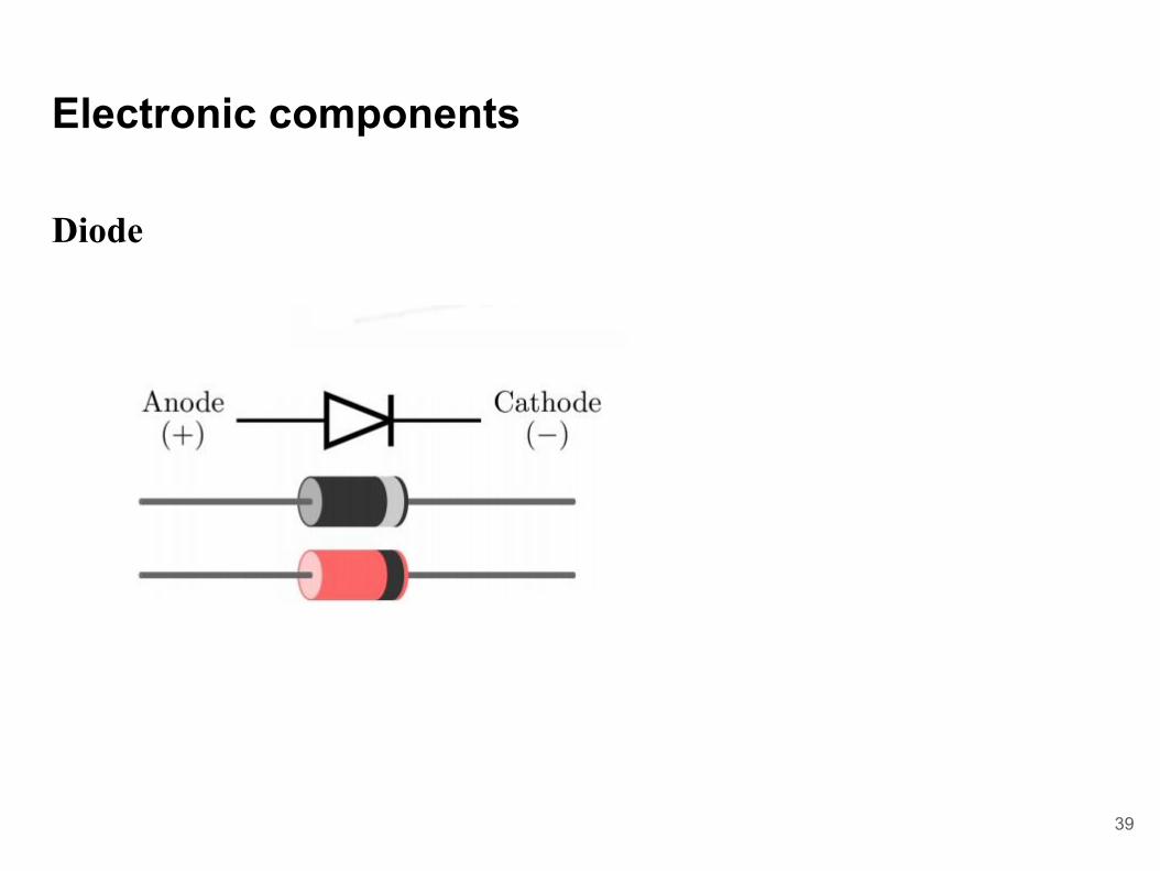
Diode
Diode is a semiconductor device, which conduct the current in one direction only. Two terminals: anode and cathode. When the positive polarity is at the anode – the diode is forward biased and is conducting. When the positive polarity is at the cathode – the diode is reversed biased and is not conducting.
38
Electronic components
Diode
39

Electronic components
Diode Measurement
40
Meter with a “Diode check” function displays the forward voltage drop of 0.548 volts instead of a low resistance.
Electronic components
Resistors
Carbon Composition Resistors:
Made of carbon or graphite mixed with a powdered insulating material.
Metal caps with tinned copper wire (called axial leads) are joined to the ends of the carbon resistance element. They are used for soldering the connections into a circuit
Becoming obsolete because of the development of carbonfilm resistors.
Carbon resistors are small, so their R value in ohms is marked using a color-coding system.
41

ResistorMultiplier
Tolerance1st Digit 2nd Digit
Electronic components

Resistors
Day 2
Electronic components

Resistors
Day 2
Electronic components

45

Day 2
A capacitor is a passive two-terminal electrical component that stores electrical energy in an electric field.
Capacitor
Electronic components
Day 2
Transistors can be either n-p-n or p-n-p. The terminal on the left is called the emitter, the terminal on the right is called the collector, and the region in the middle is called the base.
In operation, the collector is reverse biased, relative to the base, so no current flows, even if the voltage is large. On the other hand, the emitter can be forward biased, in which case a current flows even for a relatively small voltage.
Transistor
Electronic components

Day 2
Transistor
Electronic components
Narrow base region; transistor:

Day 2
Narrow base region; transistor:The negative charges that flow into the base region from the emitter are attracted to the collector before they can flow out the base connection.
Transistor
Electronic components

Day 2
PNP Transistors:
The PNP Transistor is the exact opposite to the NPN Transistor
Transistor
Electronic components

Day 2
PNP Transistors:
Transistor
Electronic components

Smoke detector wiring - Two wire system
Day 1
24 V
0V
Resistor (EOL)

Fire alarm panels
● Conventional:
A conventional Fire Alarm Control Panel employs one or more circuits, connected to sensors wired in parallel. These sensors are devised to dramatically decrease the circuit resistance when the environmental influence on any sensor exceeds a predetermined threshold. In a conventional fire alarm system, the information density is limited to the number of such circuits used.
Day 1

Conventional
Fire alarm panels
Day 1

Fire alarm panels
Day 1

Fire alarm panels
Day 1
Fire Alarm Panel

Addressable panel:
Addressable Fire Alarm Control Panel employ one or more Signaling Line Circuits - usually referred to as loops or SLC loops - ranging between one and thirty. Depending on the protocol used, a Signaling Line Circuit can monitor and control several hundred devices. Some protocols permit any mix of detectors and input/output modules, while other protocols have 50% of channel capacity restricted to detectors/sensors and 50% restricted to input/output modules.
Fire alarm panels
Day 1

Addressable Fire Alarm Panel

Advantages of addressable fire alarms
● Quickly determine the location of a fire.● Specific actions can be programmed by the user.● Reduced likelihood and better handling of false alarms.● More reliability, less likely to lose connection.● Lower overall cost of wiring.● Ability to monitor integrity of the system, with detector health
checks.
Day 1

Detection circuit

Detection circuit

Sounder circuit

END
DAY 1

Fire alarm installationDay 2
Electrical & fire alarm installation

Fire alarm installation course
Fire Offices Committee (FOC)Fire officers' committee was the first body to develop acode of practice for installation of automatic fire detectionand alarm systems in the UK.
CP-1019This is the first code of practice developed by the FOC, but it was
mostly in the interest of insurers
65

BS5839-1
In order to address the shortcomings of CP-1019 and to include new types of fire detectors and panels, BS 5839-1:1980 was introduced by BSI (British standard institution).
Fire alarm installation course
66

BS5839-1
In early 80's, new types of fire detectors were introduced and need to maintain a minimum level of sound ambient were introduced, this led to a whole new code of practice introduced later in 80's.
Another issue was fault conditions, particularly short circuit, this was not addressed by the old code of practice.
Fire alarm installation course
67

BS 5839-1:1988
BS 5839-1:2002
BS 5839-1:2013
BS 5839-1:2017
Fire alarm installation course
68

BS 5839-1:2017
There are seven sections in BS5839-1:2017 and they are:
Section 1: GeneralSection 2: Design considerationsSection 3: Limitation of false alarmsSection 4: InstallationSection 5: Commissioning and handoverSection 6: MaintenanceSection 7: User’s responsibilities
Fire alarm installation course
69

Fire alarm system categories
● Since there are seven sections defined in BS 5839-1, a reference to BS 5839-1 without a reference to a system category, for example, in a purchase specification; enforcement notice under fire safety legislation; or a fire risk assessment would be virtually meaningless.
● Within statutory requirements imposed by enforcing authorities - as part of any requirements imposed by property insurers and in any action plan of a fire risk assessment - the category of system to be installed should always be included in a specification.
● In addition, other than in the case of a Category M, L1, P1 and L4 system, further information needs to be included regarding the areas of the building that are to be protected by automatic fire detection.
70

A guide to BS 5839 Part 1:2017
● Fire alarm system designing● Risk assessment - Before you do anything, you should conduct a
Risk assessment, this is carried out by a competent person.● The outcome of the Risk assessment – The outcome of the risk
assessment will decide the complexity of the fire alarm system or system category
71

Fire alarm system category
● Designing of a fire alarm system will be differ based on the system category.− Fire alarm system categories
● Property Protection Fire Systems− P, P1 & P2
● Life Protection Fire Systems− L1, L2, L3, L4, L5 & M
72
Fire alarm system categories
● In a Category M system, there are no such areas, while all areas are protected in a Category L1 or P1 system, and only the escape routes are protected in a Category L4 system.
● In particular, it should be stressed that the responsibility for determining the appropriate system category for any application does not rest with the designer of the fire alarm system, such as a fire alarm contractor, who is not expected to have sufficient expertise in the principles of fire safety to come to a decision in this respect.
● Although many fire alarm designers may fortuitously have such expertise, the decision rests with the fire safety specialist rather than the fire alarm system specialist.
73

Fire alarm system categories
● Thus, it may be considered that there is something of a “firewall” between the role of the fire safety specialist and the fire alarm system specialist.
● Fire safety specialist : Building Designer, Enforcing Authority for fire safety legislation, Building Control Body, Fire Safety Consultant, Fire Risk Assessors.
74

75

76

Category L -
● This category is designed to primarily protect human life categories:● L1 - Automatic detectors are installed throughout all areas
77

Category L -
● L2 – Automatic detectors are installed in defined areas of higher risk of ignition, in addition to L3
78

Category L -
● L3 – Category M plus automatic detectors are installed in escaperoutes and rooms opening into these routes
79

Category L -
● L4 – Category M plus automatic detectors are installed in escaperoutes comprising circulation areas and space such as corridors and
stairways.
80

Category L - Fire alarm system is designed to primarilyprotect property categories:
● L5 -A non-prescriptive system in which protected area(s) and/orthe location of detectors is designed to satisfy a specific firerisk objective (other than that of L1 to L4)
81

Category M - Fire alarm system is designed to primarilyprotect property categories:
● Manual systems e.g. hand bells, gongs etc, may be purely manual or manual electric, the latter may have call points and sounders. They rely on the occupants of the building discovering the fire and acting to warn others by operating the system. Such systems form the basic requirement for places of employment with no sleeping risk.
82

BS5839 - 6:
The recommendations of BS 5839-6 basically apply to any form offire detection installed in any premises that would, in commonparlance (as opposed to a strict legal context), be described as a houseor dwelling.
The difference between domestic fire systems and commercial fireSystems:
In most dwellings, a fire system has no separate control panel and it isconnected to an intruder alarm system. This type of system is moreattractive and cost-effective.One control panel to control the intrusion system, fire, and the security
system is an attractive selling point.
83

BS 5839-6 : Code of practice
The properties covered by the Code:
The clause 1 of BS 5839 - 6 indicates that these include, but presumably are not restricted to, the following:
• bungalows • multi-storey houses • individual flats • individual maisonettes • mobile homes • premises used as sheltered housing premises.
84

BS 5839-6 : Code of practice
The properties covered by the Code:
The clause 1 of BS 5839 - 6 indicates that these include, but presumably are not restricted to, the following:
• HMOs comprising several self-contained single-family dwelling units • NHS ‘supported living’ housing in the community (e.g. for mentally ill
people) • permanently moored boats used solely as residential
85

BS5839 - 6
Flats and maisonettes used for general housing, the Code makes it quite clear that its recommendations only apply to the individual dwelling units and not to any communal parts.
86

BS5839 - 6
Houses in multiple occupation (HMO)
These properties are usually large single-family houses that have been converted for multiple occupation. In this case, house must be treated as a single protected premises.
BS 5839-6 tends to regard houses shared by not more than six residents, living together as a single household, as equivalent to a single-family dwelling house, in that the recommendations of the Code for single-family dwellings also apply to these dwellings.
87

BS5839 - 6
The Code reflects in clause 3, in which a dwelling is defined,for the purpose of interpreting BS 5839-6, as a: ‘unit of residentialaccommodation occupied (whether or not as a sole or main residence):
a) by a single person or by people living together as a family; or
b) by not more than six residents living together as a single household, including a household where care is provided for residents; or
c) by persons who do not live together as a family, but who live in self-contained single-family flats, maisonettes or bedsits within the unit.’
88

BS5839 - 6
The BS 5839 Pt 6 grades the fire detection system from grade A to grade F.
Grade A: The fire system incorporating control and indicating equipment to BS EN 54-4 and installed to BS 5839 Pt 1 with some exceptions.
Grade B - Fire detection and alarm system comprising fire detectors (other than smoke alarms), fire alarm sounders and control and indicating equipment to either BS EN 54-2 (and power supply to BS EN 54-4).
89

BS 5839 - 6
Grade C: The system consisting of smoke detectors and sounders (which may be smoke alarms) connected to a common power supply, comprising normal mains and standby supply.
Grade D: The system consisting of one or more incorporating mains powered smoke alarms each with an integral standby supply.
Grade E: The system with one or more mains powered smoke alarms and no standby supply.
Grade F: The system with one or more battery powered smoke alarms.
90

Category P - Fire alarm system is designed to primarilyprotect property categories:
● This category comprises of automatic fire detection system, this category can be subdivided into − P1 - Systems installed throughout all areas of the building.
− P2 - Detectors are installed only in defined areas
● The rooms or areas that are to be protected and the typesof detector that are to be installed. This decision may arise
from a form of property protection, or business interruption; risk assessment or may be dictated by the requirements of property or business interruption insurers.
91

Domestic fire alarm installation - BS5839 - 6
● BS5839 - 6 : The code of practice for the design, installation, commissioning and
maintenance of fire alarm systems in domestic dwellings.
● BS 5839 -6:2019 is the latest version of the code of practice, however you should always check BSI website for the latest version.
92

BS5839-6:2019
A fire alarm system for dwelling starts from grade A to grade F, and grade A and grade B are described in BS 5839-1, we start from grade D.
Grades B and E have both now been removed, and D and F have been further split down.
Where as previously Grade D was just a mains powered alarm with a battery back-up, we now have D1 – a mains powered alarm with an integral tamper proof battery back-up and D2 – a mains powered alarm with a replaceable battery backup.
Whereas F was previously a battery only alarm, we now have F1 – an alarm with a tamper proof battery power supply and F2 an alarm with a user-replaceable battery power source.
93

Grade C fire alarm system in the dwelling is normally incorporated with central controlled panel and backup powered rechargeable battery.
The most common fire alarm systems are graded D, E and F.And they don't deploy battery backup.
Grade D : One or more smoke detectors main powered and with battery backup, it may also incorporate heat detectors.
The mains supply to smoke and heat alarms should either be a single independent circuit from the dwelling’s main distribution board or a separately electrically protected regularly used local lighting circuit.
BS5839-6:2019
94

The necessary arrangements should be made to have a backup battery to last at least 72 hours.
D1: A mains powered alarm with an integral tamper proof battery back-up
D2: A mains powered alarm with a replaceable battery backup.
Cables used for unmonitored circuits should be protected against damage
Grade F: One or more smoke detectors main powered and without battery backup, it may also incorporate heat detectors.
F1: An alarm with a tamper proof battery power supply.F2: An alarm with a user-replaceable battery power source.
BS5839-6:2019
95

Grade F: One or more smoke detectors main powered and without battery backup, it may also incorporate heat detectors.
F1: An alarm with a tamper proof battery power supply.F2: An alarm with a user-replaceable battery power source.
Battery operated smoke detectors
The battery operated smoke alarms are easy to install. Battery operated smoke alarms conforming to BS 5446: Pt.1 are recommended.
However, the batteries should replace according to manufacturer recommendation.
BS5839-6:2019
96

These alarms should not be used to protect tenants in properties of more than one storey and the batteries should be sealed-in and have a life in excess of 5 years.
Batteries should have sufficient capacity to give a fire alarm warning signal for at least 4 minutes or, in the absence of a fire, a battery fault warning for at least 30 days.
BS5839-6:2019
97

BS5839-6:2019
98
D1, LD2
LD2: A system where detectors
installed throughout the dwelling, incorporating detectors in all circulation spaces that form part of the escape routes from the dwelling.
And all other areas and rooms that present high risk of fire.

BS5839-6:2019
99
D1, LD3
LD3:
A system where detectors installed throughout the dwelling, incorporating detectors in all circulation spaces that form part of the escape routes from the dwelling.
BS5839-6:2019
100
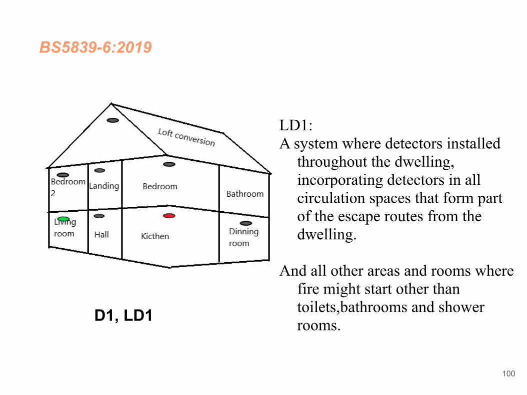
D1, LD1
LD1: A system where detectors installed
throughout the dwelling, incorporating detectors in all circulation spaces that form part of the escape routes from the dwelling.
And all other areas and rooms where fire might start other than toilets,bathrooms and shower rooms.

BS5839 - 6
Categories
For the protection of property
PD1 and PD2
PD1: Comprehensive coverage of all areas.
PD2: Detectors only in areas defined as high risk for fire.
101

BS 5839 - 6
Properties and categories
New buildUp to 3 storey - owner occupied or rentedGrade D, LD2 Smoke detectors - circulation spaceHeat detector - Kitchen
Over 3 storey - owner occupied or rentedGrade B, LD2Smoke detectors - circulation spaceHeat detector - Kitchen
102

BS 5839 - 6
Properties and categories
Existing properties
Single storey - owner occupied Grade E or F, LD3If there is a doubt that the owner will not change the battery, Grade E
should be installed - If the mains supply is not consistent, Grade D should be installed.
103

BS 5839 - 6
Properties and categories
Existing properties
Single storey - rentedGrade F, category LD3The battery should have at least 5 years lifespan and only accessible by
means of special tools.If there is a doubt that the owner will not change the battery, Grade E
should be installed - If the mains supply is not consistent, Grade D should be installed.
104

BS 5839 - 6
Properties and categories
Existing properties
2 or 3 storey house or maisonette- owner occupiedGrade F, category LD3
If there is a doubt that the owner will not change the battery, Grade E should be installed -
If the mains supply is not consistent, Grade D should be installed.
105

BS 5839 - 6
Properties and categories
Existing properties
2 or 3 storey house or maisonette- rentedGrade D, category LD3
Category LD2, if risk assessment justifies additional alarms.
106

BS 5839 - 6
Properties and categories
Houses in multiple occupation
Up to 2 storey - new build
Grade D, category LD2
Smoke alarms in circulation areasHeat alarms in Kitchen and main living room. (Smoke alarms are
acceptable in living rooms.)
107

BS 5839 - 6
Properties and categories
Houses in multiple occupation
Up to 2 storey - existing property
Grade D, category LD3
Category LD2 if the risk assessment justifies it.
All other typesGrade D, category LD3 in individual dwelling, Grade A, Category LD2 in
communal areas.
108

BS 5839 - 6
Where fire precautions are subject to legislative control, the enforcing authorities should be consulted before making the decision on grade and category.
109

Grade D - cabling
Cables used for the mains supply to smoke alarms, any heat alarms and any interconnecting wiring may comprise any cable suitable for domestic mains wiring.
Cables used for interconnecting smoke and heat alarms should be readily distinguishable from those supplying power, (for example by red colour coding). Such cables need not be fire resistant.

Mains requirement
The circuit supplying the smoke and heat alarms should preferably not be protected by an RCD unless one is required for reasons of electrical safety, then either the RCD should serve only the circuit supplying the smoke or heat alarms or the RCD protection of the fire alarm system should operate independently of any RCD protection for circuits supplying socket-outlets or portable equipment.
System zoning
● The following guidelines should be observed:
− If the total floor area of the building is less than 300m2 then the building needs only one zone, regardless of the number of storeys.
112

System zoning
● If the total floor area is greater than 300m2:
− The maximum area for a zone is 2000m2.− If a stairwell (or similar) extends beyond one floor it should be a
separate zone.− If a zone covers more than one fire compartment then the zone
boundaries should follow the compartment boundaries.− The search distance in order to ascertain the position of the fire
should not exceed 60m. Remember that the use of Remote Indicator lamps may help to reduce the distance travelled.
− If a building is divided between occupiers, zones must not be shared between them.
113

Zoning in a Fire alarm system
● The floor area of a single zone should not exceed 2,000m2.● Two faults should not remove protection from an area greater than
10,000m2 (for addressable systems).● If the total floor area of the building is 300m2 or less then it may be
regarded as a single zone.● If the total floor exceeds 300m2 then all zones should be restricted
to a single floor level.● As an exception to the above stairwells, lift shafts or other vertical
shafts (non stop risers) within a single fire compartment● should be considered as one or more separate zones.● The maximum distance travelled within a zone to locate the fire
should not exceed 60 mtrs.
114

Manual call point -
● Manual call points
● A 'Manual Call Point' is a device which enables personnel to raise an alarm in the event of a fire incident by pressing a frangible element to activate the alarm system.
● Manual Call Points should be installed at a height of 1.4m above floor level at easily accessible, conspicuous positions, on exit routes, at the entry to floor landings of staircases and at all exits to the open air.
● Manual Call Points should be spaced so that one may always be found within a maximum distance of 30m apart.
115

Manual call points
● A person should not have to travel more than 45m along an escape route to reach a manual call point, when the layout of the building is known.
● The maximum zone floor area should not exceed 2000m2. A firefighter searching a zone for a fire should not have to travel more than 60m from the zone entrance to identify the source of the fire.
● The centre of the element of the manual call point should be positioned 1.4m (+/-200mm) from floor level (unless a wheelchair user is likely to be the first person to raise the alarm, when this is applicable it should be noted on any certification).
116

Beacon
● Visual alarms such as beacons should always be mounted at a minimum height of 2.1m from floor level, in a position that is likely to attract attention.
117
2.1 m

Beacon
● Unless MICC or armoured cable to BS 7846 standard is used, consideration should be given to the protection against physical damage from floor level to the height of 2m. Except in relatively benign areas, such as shops, offices and similar, where cabling can be clipped to robust walls.
118

Automatic detectors
● When deciding on the type of detector to be used in any area it is important to remember that the detector has to discriminate between a genuine fire and the normal conditions existing therein, e.g. smoking in staff rooms, steam from ensuite bathrooms, kitchen fumes, vehicle and forklift truck fumes in warehouses, etc.
● Generally all types of detectors should be sited on the ceiling at the highest point of the area to be covered. Detectors mounted at greater heights have a reduced efficiency and in these cases further advice should be sought.
119

Smoke detectors
● When mounted on a flat ceiling, smoke detection devices have an individual coverage of 7.5m radius. However these radius must overlap to ensure there are no ‘blind spots’. Therefore individual coverage can be represented by a square measuring 10.6 x 10.6m giving an actual coverage area of 112m2 per device.
120
10.6 m Distance Between Smokes
7.5 m Radius
112m2 Coverage

Heat detector positioning
● When mounted on a flat ceiling, smoke detection devices have an individual coverage of 5.3m radius. However these radii must overlap to ensure there are no ‘blind spots’. Therefore individual coverage can be represented by a square measuring 7.5 x 7.5m giving an actual coverage area of 56.3m2 per device.
121
7.5 m Distance
5.3m Radius
56.3m2 Coverage

Smoke detectors in corridors
● In corridors less than 2m wide the horizontal spacing of detectors can be increased, the area of coverage need not overlap as in the case of a room. Any corridor over 2m wide is deemed as a room and most adhere as specified
122
>2 m
15 m Distance

Heat detectors in corridors
● Heat detectors are not recommended for use in corridors that may be used as escape routes.
123

Air con or air inlets and detectors
● Do not cite detectors less than 1m from air inlets or air circulating systems.
124
Air Inlet
S>1 m Distance

Ceiling height
● For ceilings that feature an apex: As long as the height of the apex from the rest of the ceiling is less than 150mm for heat detectors or less than 600mm for smoke detectors, then these can be treated the same as flat ceilings. For higher apexes, a device should be installed at the highest point. The distance to adjacent devices can be increased by 1% per degree of angle of the roof up to a maximum of 25%.
125
Voids
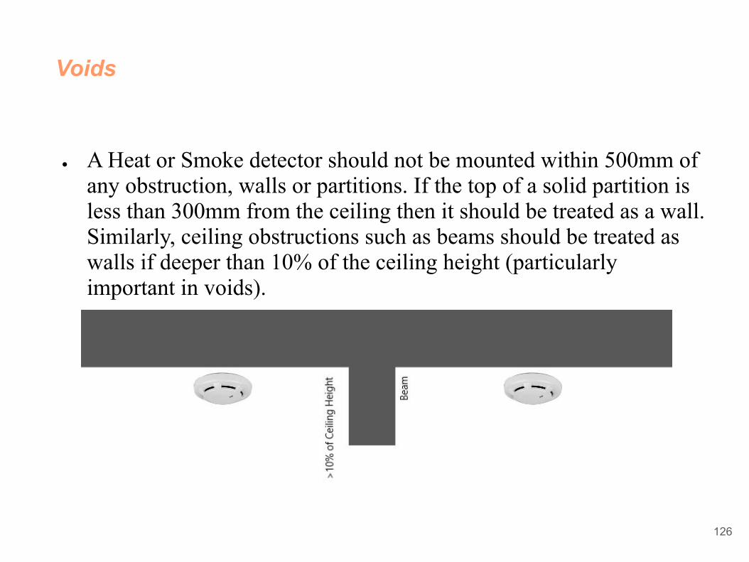
● A Heat or Smoke detector should not be mounted within 500mm of any obstruction, walls or partitions. If the top of a solid partition is less than 300mm from the ceiling then it should be treated as a wall. Similarly, ceiling obstructions such as beams should be treated as walls if deeper than 10% of the ceiling height (particularly important in voids).
126

Obstructions less than 250mm
● For obstructions less than 250mm deep never mount devices closer than twice the depth of light fittings or other obstructions in the ceiling.
● Voids less than 800mm in height are required to have a risk assessment to determine if automatic detector is required. Voids in excess of 800mm do require independent coverage.
● Vertical shafts like lift shafts and stairways should have a device
mounted within 1.5m of any opening.
127

Lift shaft
128

Never mount detectors closer than twice the depth of luminaire
129

Voids less than 800mm in height
130
800 mm or 80 cm

Enclosed stairways should have a detector on the top of the stairway and on each main landing.
131
Top of stairway
Each main landing

Any obstruction greater than 10% of the room height should be treated as a wall. Extra alarms may be needed.
132
If greater than 10% of the room height, treat as a wall

Any obstruction greater than 10% of the room height should be treated as a wall. Extra alarms may be needed.
133
Site 300mm from walls, light fittings or any obstructions

Distance between Apex and sensors (Heat and Smoke)
134
150 mm - Heat
600 mm - Smoke

Manual Call Point
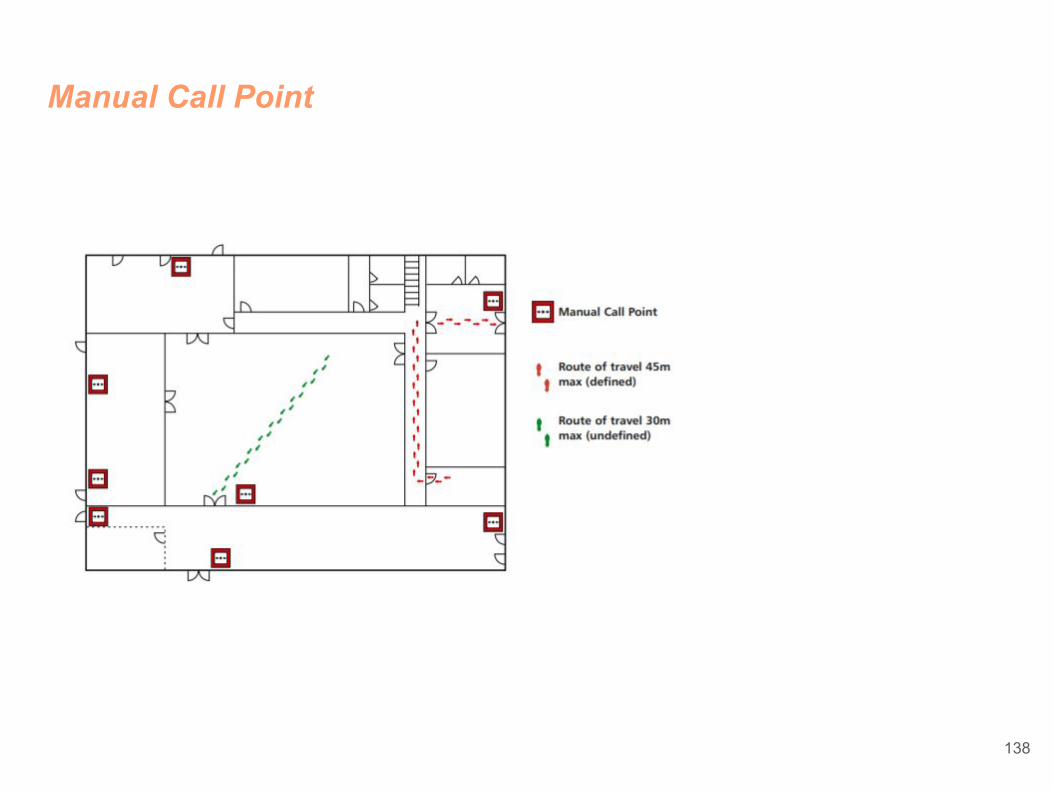
The sitting of a manual call point should comply to BS EN54-11 single action Type A version only and should be located as follows:
On all storey exits and all exits to open air irrespective of whether they are designated fire exits
Nobody should travel more than 45 metres to reach one, except if the exit routes are undefined in which case the direct line distance should not exceed 30 metres
The above distances to be reduced to 25 and 16 metres respectively, if there are persons with limited mobility or there is a likelihood of rapid fire development
135

Manual Call Point
In all areas with potential high fire risk such as kitchens etc
Where phased evacuation is planned, call points will need to be sited on all exits from a particular zone
1.4 metres + or – 200mm above the floor
Call points fitted with protective hinged covers for whatever reason should be listed as a Variation
Note: In order to comply with the requirements of Building Regulations Approved Document M, which requires electrical switches including manual call points to be mounted at between 1M + or – 200mm on wheelchair access routes, these should be listed as a Variation on the certificate as BS requires MCP’s to be mounted at 1.4M + or – 200mm
136

Manual Call Point
In all areas with potential high fire risk such as kitchens etc
Where phased evacuation is planned, call points will need to be sited on all exits from a particular zone
1.4 metres + or – 200mm above the floor
Call points fitted with protective hinged covers for whatever reason should be listed as a Variation
Note: In order to comply with the requirements of Building Regulations Approved Document M, which requires electrical switches including manual call points to be mounted at between 1M + or – 200mm on wheelchair access routes, these should be listed as a Variation on the certificate as BS requires MCP’s to be mounted at 1.4M + or – 200mm
137
Manual Call Point
138

Sounder requirement
It is maintained that to rouse sleeping persons you need to achieve a minimum of 75dB(A) at the bedhead. Sound attenuation is affected by numerous physical structures within a room, including the people, door, furniture and materials used for floor, walls etc.
General internal doors will attenuate at least 20dB(A), whilst heavier fire doors may well attenuate by up to 30dB(A).
To ensure 75dB(A) is achieved within a bedroom it is accepted that the sounder is mounted within the room rather than the corridor outside. Use of sensor sounders ensures an even spread of sound throughout the building without the need for separate louder sounders.
139
Sounder requirement
Visual alarms are generally considered as supplementary rather than the only means of providing an alarm, and are used in areas where the dB(A) level exceeds 90dB(A) or where persons within the area have impaired hearing.
The exception could be where sound of any description is undesirable, for example operating theatres, TV studios and places of entertainment where a discreet staff alarm system is the best option to avoid panic. Visual alarms are also included as a requirement of the Disability Discrimination Act and Approved Document M of the Building Regulations and should be included in all sleeping accommodation where people with a hearing disability may be present.
140

Control equipments and power supplies
The Control panel itself should comply to EN54-2 and any power supply used should comply to EN54-4. Today the majority of fire control panels incorporate their own battery and charger and as long as the guidelines for loading these systems are complied with, the battery should be sufficient to maintain the system for a period of 24 -72 hours with half an hour alarm load thereafter.
Irrespective of the size or type of system the control panel should be sited with the following points in mind;
141

Control equipments and power supplies
● In an area of relatively low fire risk ● On the ground floor entrance which the fire fighters will use ● In buildings of multiple occupancy, the panel should be sited within a
communal area or if this does not exist, a location which is accessible at all times
● Where ambient light levels, ensure visibility at all times ● Fire zonal indication should be clearly displayed by LEDs or an
illuminated mimic diagram – it is not acceptable to simply accept the information from an LCD or VDU display
● If there are several entrances to the building, consideration should be given to the provision of repeat indicators.
142

Installer’s responsibilities
● To install all equipment in accordance with the Standard ● To use the correct types of cable ● To test the cables, continuity and earth, and provide certificates ● To flag up any Variations that affect the Design ● To produce a set of ‘as fitted’ drawings ● To sign off a G2 Installation certificate
143

Cable requirements
● Core size not less than 1mm ● Where exposed cables are below 2m, additional mechanical protection
should be considered, except for cables complying to BS 7629 ● The colour of the outer sheath should preferably be RED although
other colours are permitted as long as it is common throughout the building and does not clash with any other electrical services
144

Cable requirements
Fire cables should:
● be segregated from all other services ● not share the same conduit ● use a separate compartment if common trunking is used ● avoid running alongside high current power lines ● avoid running adjacent to lightning conductors ● avoid electromagnetic interference from ‘extra low voltage (240V)
circuits’
145

Cable requirements
Types of cable and where to use them
● There are two basic grades of cable permitted for use on fire alarm systems. These are known as Standard grade and Enhanced grade designed to meet the new standards BS 8434-1 and BS 8434-2 respectively
● The choice of cable needed is dependant on how long the cable is expected to continue to operate whilst a fire is occurring.
● The integrity of the system is paramount and all interconnections between devices must be considered especially those that affect the signal’s critical path.
146

Cable requirements
Types of cable and where to use them
● Firstly the Standard insists that the mains supplies to the system, the manual call points and the automatic sensor circuits are wired in fire resistant cables.
147

Cable requirements
● What cable? – Standard or Enhanced fire resistant cables?● The Standard fire resistant cable will satisfy most applications
particularly with ‘one out, all out’ fire plans. Enhanced fire resistant cables are required for applications that need communications to continue during a fire incident when the building fabric may be destroyed. Examples of where Enhanced fire resistant cable should be used include:○ In un-sprinklered buildings where the ‘Fire Plan’ involves the
evacuation of occupants in four or more phases○ In un-sprinklered buildings greater than 30 metres in height○ In un-sprinklered buildings or large networked sites where a fire
could affect the cable’s ‘critical path’, particularly where people will remain in occupation during a fire elsewhere on the site
148

Cable requirements
● Examples of where Enhanced fire resistant cable should be used include:○ Where in part, a delayed evacuation may exist and the critical
signal path may pass through an area of high risk○ Where a Risk Assessment has identified a particular need for
Enhanced cable
149

Cable requirements
● The Standard precludes the use of multicore cable where a single fault will cause more than one circuit to fail. This is particularly true with loop wired systems where communication from either end is required and the failure of a 4-core cable will mean that all communication is lost
● Cable joints should be avoided, other than the components themselves ● Cable support should withstand the same temperature as the cable,
which means the use of plastic cable clips, cable ties or trunking, where this is the main means of supporting the cable, should NOT be used
● Cables should not rely on suspended ceilings for their support ● Mains power supplies should also be wired back to the main circuit
breaker in Standard grade fire resistant cable150

Recommendations for mains power supply
● For reasons of electrical safety, the mains supply to the system should be via a separate circuit breaker taken from the load side of the buildings main isolating device.
● This circuit breaker can incorporate a switch if necessary but in either event should be labelled ‘FIRE ALARMS – DO NOT SWITCH OFF’ – this supply should be used for the sole purpose of the fire alarm system.
● In large multiple occupancy buildings it may be necessary to obtain a mains supply via a mains distribution board. However the same arrangements as above apply. The isolation of this local distribution board and the fire isolating device is a minimal requirement and should be inaccessible to unauthorised persons.
151

Recommendations for mains power supply
● Ideally the supply should not be protected by a residual current device unless necessary to comply with requirements of BS 7671. If this is the case then it should not be capable of isolating the mains supply to the fire alarm system.
152

STANDBY BATTERY CALCULATION GUIDE
The standby time of the fire alarm panel, after the Mains has failed, depends on the quiescent loading of the panel, the alarm load of the panel and the capacity of the batteries.
Standby Time in Ah = 1.25 x [(TxA) + H x (P+Z)]
The multiplier 1.25 is present to account for lost capacity over the life of the batteries
153

STANDBY BATTERY CALCULATION GUIDE
H = Number of hours standby required
P = The quiescent current of the panel = 0.025A
This figure is with the Mains failed, internal sounder active and the Power Supply and General Fault lights lit. If there are other quiescent drains on the panel then these must be included.
Z = The total quiescent current of all zone devices
As a guideline, the quiescent current of most modern detectors is typically 0.00005A (50µA), and that of manual call points is zero. To obtain accurate figures consult the device manufacturers’ own specifications
154

STANDBY BATTERY CALCULATION GUIDE
A = The total alarm current of the sounders (plus any other devices connected to other alarm outputs).
T = The amount of time in hours required for the alarm (most commonly being half an hour).
Example 1:
The panel has 70 detectors each consuming 50µA each, 20 sounders at 20mA each, the required standby time is 24 hours and the required alarm time is 0.5 hours.
155

STANDBY BATTERY CALCULATION GUIDE
Z = 70 x 0.00005 = 0.0035A
P = 0.025A
A = 20 x 0.02 = 0.4A
H = 24
T = 0.5
Standby Time in Ah = 1.25 x [(0.5 x 0.4) + 24 x (0.025 + 0.0035)] = 1.1Ah
Therefore, batteries with at least 1.1Ah capacity are required.
156

Inspection and testing of cable
● Prior to any equipment being connected, all installed cables should be subject to a 500V dc insulation test
● These tests should show an insulation value of at least 2M Ohms between conductors and between each conductor and screen or earth
● Earth continuity tests should be carried out on all mains supply circuits as well as an earth loop impedance in accordance with BS 7671. It is important with the Vigilon system that all earth leads or screen cables are terminated and connected through each device.
● The maximum impedance of each loop or radial circuit should be recorded to ensure it meets the manufacturers recommendations. In the case of Vigilon this is determined by not exceeding the recommended maximum cable lengths which for loop circuits should not be greater than 1Km and a maximum of 100 metres for any radial circuit connected on a loop powered interface. 157

Commissioning engineers’ responsibilities.
● Functional testing of all equipment● Confirm fire plan or cause & effect is correct as per design ● Look for any incorrect positioning of sensors or other devices – snag
them or list them as Variations● Record sound level meter readings● Provide a log book and product manuals● Carry out staff training
158

Commissioning engineers’ responsibilities.
● Collate all documents including ○ G1 Design Certificate○ G2 Installation Certificate○ G3 Commissioning Certificate (also sign it!)○ Cable test and wiring certificate○ Specification and drawings○ List of agreed Variations○ Fire Plan or ‘Cause and Effect’○ G4 Acceptance Certificate signed by clients representative
159

Commissioning engineers’ responsibilities.
● It is important that the system is commissioned by a competent person who has attended recognised training courses on the equipment as well as the British Standard.
●○ Every manual call point, sensor, sounder, interface and indicator ○ Check that all devices are correctly sited to cover the area they are
intended to protect – see previous notes on siting of devices○ Check that all devices are correctly labelled and display the correct
information on the control panels○ All sound pressure levels should be measured and recorded○ Any transmission of signals to remote centres or equipment should
be proven○
160

Commissioning engineers’ responsibilities.
● It is important that the system is commissioned by a competent person who has attended recognised training courses on the equipment as well as the British Standard.
●○ The fire plan or cause and effect should be checked from every
device○ All alarm panels and printers display the correct information and
are sited correctly○ A suitable zone plan is mounted adjacent to the control panel○ No changes to the building have affected the siting of equipment or
effectiveness of the system for example an additional partition requiring additional sensors
○161

Commissioning engineers’ responsibilities.
● At this stage the entire system should be inspected and tested, in particular;
○ Mains and standby power supplies are adequate and designed to support the system for a specified period, for example 24, 48 or 72 hours
○ As far as reasonable, ascertain that the installation complies with the standard and certificates are provided by the installer
162
Commissioning engineers’ responsibilities.
● At this stage the entire system should be inspected and tested, in particular;
○ If radio equipment is used, ensure all radio signals are of sufficient strength to ensure reliability
○ Ensure there are no obvious shortcomings with the system as a whole and that all the documentation is correct
○ It is also recommended that the system is soak tested for up to a week, dependant on the system size, so that any teething problems are identified without giving rise to any false alarms.
163

Documentation
● Documentation○ Design, Installation and Commissioning certificates G1,G2
& G3 ○ Cable and insulation resistance test records ○ “As fitted” drawings of the final installation, including
cable run details○ Product manuals and user instructions ○ System log book ○ A copy of the fire plan documentation against which the
commissioning engineer programmed the system ○ The designer’s specification and a written list of agreed
Variations
164