Fire DNF, Fire HSEF - diesel - Grundfos
52
Fire DNF, Fire HSEF - diesel GRUNDFOS INSTRUCTIONS Installation and operating instructions
-
Upload
khangminh22 -
Category
Documents
-
view
1 -
download
0
Transcript of Fire DNF, Fire HSEF - diesel - Grundfos

Fire DNF, Fire HSEF - diesel
GRUNDFOS INSTRUCTIONS
Installation and operating instructions

Declaration of ConformityWe, Grundfos, declare under our sole responsibility that the products Fire DNS and Fire HSEF - diesel, to which this declaration relates, are in conformity with these Council Directives on the approximation of the laws of the EC Member States:— Machinery Directive (98/37/EC)
Standards used: EN 12100-1: 2003, EN 12100-2: 2003 and EN 809: 1998.
— Low Voltage Directive (2006/95/EC)Standards used: EN 60204-1: 2006 and EN 60439-1: 1999.
— EMC Directive (2004/108/EC)Standards used: EN 61000-6-2: 2005 and EN 61000-6-3: 2007.
Wahlstedt, 1st September 2009
Stephan GöttscheGeneral Manager
2

CONTENTSPage
1. Symbols used in this document 32. Applications 43. Delivery, transport, storage 43.1 Delivery 43.2 Transport 43.3 Storage 54. Product description 54.1 Fire pump set 54.2 Pump 74.3 Engine 74.4 Controller 114.5 Functions 154.6 Operating and alarm messages 185. Settings 215.1 Settings via DIP switches 215.2 Settings via display 226. Identification 236.1 Type keys 236.2 Nameplates 267. Technical data 277.1 Complete fire pump set 277.2 Pump 277.3 Engine 287.4 Battery 287.5 Controller 288. Operating conditions 288.1 Minimum inlet pressure 288.2 Maximum inlet pressure 288.3 Minimum flow rate 288.4 Pumped liquids 288.5 Liquid temperature 288.6 Pump speed 288.7 Maximum operating pressure 288.8 Ambient temperature 298.9 Relative air humidity 298.10 Effect of ambient temperature and altitude
on engine output 299. Installation 299.1 Installation site 299.2 Foundation 299.3 Vibration dampening 309.4 Levelling 309.5 Pipework 319.6 Bypass 319.7 Connection to the cooling system 319.8 Connection to the pressure sensor 319.9 Priming tank and test pipe 319.10 Fresh air supply 319.11 Exhaust gas system 329.12 Alignment 329.13 Separate fuel tank 339.14 Separate control cabinet 3410. Electrical connection 3410.1 Controller on base frame 3410.2 Wall- and floor-mounted controller 3410.3 Connection to standard alarm relays 3510.4 Connection to optional alarm relays 3511. Start-up 3611.1 Check before start-up 3611.2 Start-up 3611.3 Setting of cut-in and cut-out pressures 3612. Operation 3612.1 Automatic operation 3612.2 Manual operation 3712.3 Test run 3712.4 Retrieving and printing data 3713. Taking the pump out of operation 3914. Maintenance 3914.1 Fire pump set 3914.2 Maintenance intervals 3914.3 Pump 40
14.4 Diesel engine 4014.5 Coupling 4314.6 Controller 4315. Fault finding 4416. Service, spare parts and accessories 4517. Warranty 4518. Further documentation 4519. Dimensions, weights and engine data 4619.1 Dimensions and weights 4619.2 Engine data 4820. Disposal 49
1. Symbols used in this document
Safety instructions placed directly on the fire pump set:
WarningPrior to installation, read these installation and operating instructions. Installation and operation must comply with local regulations and accepted codes of good practice.
WarningIf these safety instructions are not observed, it may result in personal injury.
WarningIf these instructions are not observed, it may lead to electric shock with consequent risk of serious personal injury or death.
WarningThe surface of the product may be so hot that it may cause burns or personal injury.
WarningThe sound pressure level is so high that hearing protection must be used.
CautionIf these safety instructions are not observed, it may result in malfunction or damage to the equipment.
Note Notes or instructions that make the job easier and ensure safe operation.
WarningThe engine starts automatically.Use hearing protection.
WarningDo not remove safety devices.
WarningFill the engine with a cooling liquid consisting of a mixture of 50 % coolant and 50 % water before start-up.
WarningThe pressure in the equalisation tank must not exceed 60 psi or 4.1 bar.
WarningIn order to prevent damage, the cooling circuit must be connected before making the electrical connection of the cooling water heater.
WARNINGTHIS EQUIPMENT STARTS
AUTOMATICALLY
USE EAR PROTECTION
C13187
WARNINGKEEP
GUARDS
IN PLACE
C13190
WARNINGPREMIXING 50%
TREATED WATER
AND 50% ANTI/FREEZE
COOLANT SOLUTION
PRIOR TO INSTALLING
IS REGUIREDC13185
WARNING60 P.S.I. MAX.
C13182
WARNING
C13187
TO PREVENT HEATER DAMAGE.
INSTALL ENGINE COOLANT BEFORE
HEATHER IS ENERGIZED
120 VAC
+5% -10% SINGLE PHASE1500 W
P/N: C12409112.6 AMPS
3

2. ApplicationsThe Grundfos Fire HSEF and DNF pump sets are designed for fire systems for supplying water to hose reels, fire hydrants and sprinkler systems.
The Grundfos Fire HSEF and DNF pump sets with diesel engine must not be used for ordinary pumping of liquids or common pressure boosting in daily work. They should only be used for fire fighting.The pump controller must not be used as a junction box for supplying other equipment.
3. Delivery, transport, storage
3.1 DeliveryThe fire pump set is delivered from factory in an open wooden box or wooden/cardboard box which is specifically designed for transport by fork-lift truck or similar device.
3.2 TransportFor lifting the entire fire pump set, use the lifting holes of the base frame. When lifting, the lifting point should always be above the centre of gravity of the fire pump set. See fig. 1.
Fig. 1 Correct lifting of fire pump set
WarningIn order to prevent damage, the drive shaft must be lubricated regularly with the correct lubricant.
WarningDo not let the engine run without an air filter.This may cause personal injury or damage to the engine.
WarningThis lifting point is only for lifting the engine, not the entire fire pump set.
WarningHazardous voltages are present in this enclosure. Improper use or failure to take precautions can cause serious injury, electric shock and/or damage to the equipment.
Lifting points for the entire fire pump set.
WarningThe fire pump set must only be used for the applications mentioned. Any other use is considered improper use. Grundfos cannot be held responsible for damage caused by improper use. The liability rests solely with the operator.
DRIVESHAFT MUST BE LUBRICATED
PRIOR TO START UP AND EVERY
12 MONTHS FOLLOWING WITH A
N.L.G.I GRADE 1 OR 2 GREASE.
REFER TO OPERATOR AND MAINTENANCE
MANUAL FOR CORRECT PROCEDURE.
CAUTION
C13258
CAUTIONDO NOT RUN ENGINE WITHOUT
AIR FILTER INSTALLED.
PERSONAL INJURY OR
ENGINE DAMAGE MAY
RESULT.
C13191
!
WARNINGLIFTING BRACKET
IS FOR ENGINE ONLY
C13186
Hazadous voltages are presentinside this enclosure. Seriousinjury, electrocution and/orequipment damage will result ofimproper application or ifprecaution is not used.
Disconnect all supply sources(including any foreign circuits)before working om controller,motor(s) or pump(s).
Only qualified personnel shouldwork on or around thisequipment.
Note
Check the fire pump set carefully on delivery against the papers and inspect for damage incurred during transport. Immediately notify the carrier of any damage or shortage found. Transport and store it correctly before installation.
WarningLifting the fire pump set should only be done by qualified personnel.When lifting the entire fire pump set, never use the lifting eyes of the individual components.Use only suitable lifting equipment in proper condition. See also weight specifications in section 7. Technical data.During transport of the fire pump set, the cabinet door must be closed and locked.Do not stand or place hands under a component in such a way that the component would fall on the hands if dropped.
TM03
777
0 48
06
4

3.3 Storage3.3.1 PumpTo prevent water, dust, etc. from entering the pump, all openings must be covered until pipes are connected. Apply a suitable antirust agent on all machined, non-coated surfaces.The antirust agent must meet these requirements:• It must not attack rubber parts.• It must be easy to remove.• It must be applied according to the instructions of the
manufacturer.If the pump must be stored for more than six months before start-up, it must be protected against corrosion and damage:1. Remove the stuffing box packing.2. Spray the interior part of the pump case and the stuffing box
with a water-soluble type of antirust agent.3. If the pump has not been connected to the pipework, cover the
pump suction and discharge flanges with full natural rubber gasket material, and blank off these openings with metal blanking flanges. Use at least four bolts for fastening.
4. Cover the opening of the stuffing box with a non-hygroscopic tape. The stuffing box gland may be left on the pump shaft, but must be wired or otherwise securely fastened in position.
5. Coat all exposed painted surfaces with an antirust agent that can be readily removed with a petroleum distillate product.
6. Make sure that all exposed painted surfaces are dry, clean and free of grease and other contaminates.
7. Cover the pump with a weather-resistant cover of waterproof paper or plastic material to protect it against dirt and dust.
8. Inspect the pump at regular intervals during storage.9. Rotate the shaft by hand every four to six weeks to prevent
pitting of the bearings.
3.3.2 EngineEngines may be stored for up to 12 months in a dry room after delivery. It is advisable to protect the engine with an air-permeable cover. At least once a month, the engine should be checked for accumulation of dirt or water. Any dirt or water must be removed immediately.If the engine is stored for more than 12 months or stopped for more than six months, it must be protected against corrosion and damage:1. Drain the engine of oil, and replace the oil filter.
See service instructions.2. Fill the engine housing with MIL-L-21260 oil.
See service instructions.3. Replace the fuel filter. See service instructions.4. Separate the engine from the pump by removing the coupling.
See service instructions.5. Turn on the engine. See section 12.2 Manual operation.
Let it run for one or two minutes.6. Drain oil and cooling liquid. See service instructions.7. Drain fuel. To do so, loosen the drain screw in the tank bottom
(fig. 50, pos. A) and collect the diesel fuel in a suitable container. After draining, tighten the drain screw in the tank bottom.
Repeat these steps every six months.
4. Product description
4.1 Fire pump setThe fire pump set consists of a pump, a diesel engine with fuel tank, and a controller. Pump and engine are connected via a drive shaft or a flexible coupling. All components are adapted to each other and mounted on a common base frame ready for installation. The base frame is made of steel channel. The controller and fuel tank can also be placed separately. This is normally done in connection with JW6 and JX6 diesel engines.The fire pump set comes ready for operation. The engine is filled with cooling water, engine oil, etc. The batteries are filled with acid and charged. The fuel system is vented, and the fuel tank has a small quantity of diesel fuel. The correct engine speed has been preset from factory.As an example, the most important components of the fire pump set are shown in figures 2 and 3. They show an HSEF pump set with a Grundfos horizontal split case pump and a 4-cylinder diesel engine, type JUH4, without turbocharger and charge air cooler. Pump and engine are connected by a drive shaft. The controller is mounted on the common base frame, and the fuel tank is placed separately. The fuel tank is not shown.
Caution Put a warning label on the engine: Engine without oil. Do not start the engine.
5
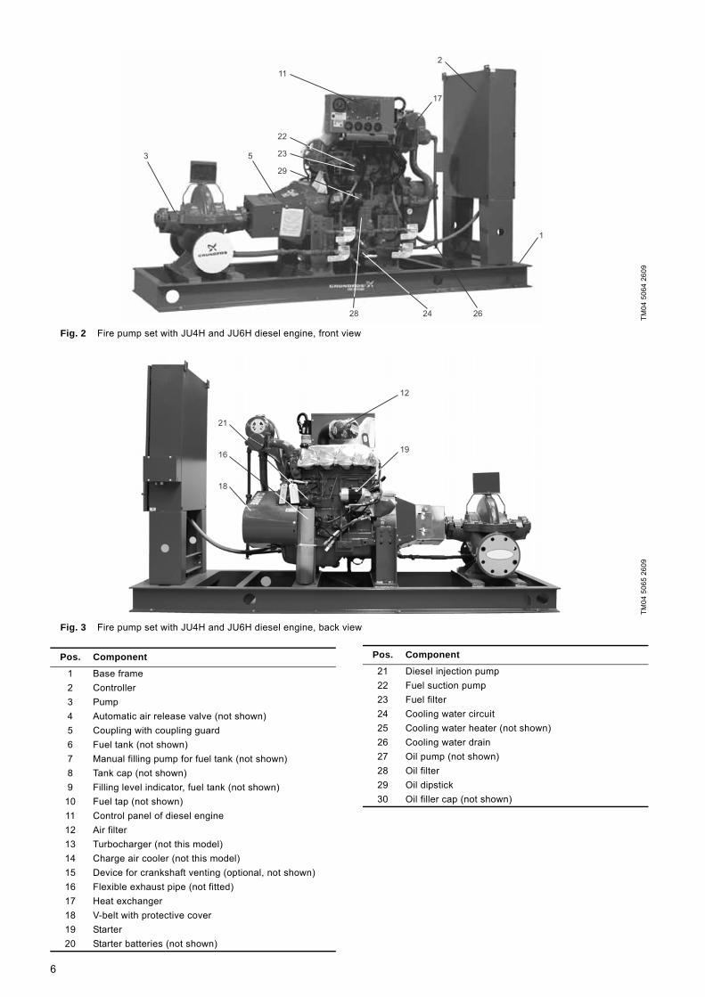
Fig. 2 Fire pump set with JU4H and JU6H diesel engine, front view
Fig. 3 Fire pump set with JU4H and JU6H diesel engine, back viewTM
04 5
064
2609
TM04
506
5 26
09
1
11
22
23
29
53
26
17
2
2428
21
16
12
19
18
Pos. Component
1 Base frame2 Controller3 Pump4 Automatic air release valve (not shown)5 Coupling with coupling guard6 Fuel tank (not shown)7 Manual filling pump for fuel tank (not shown)8 Tank cap (not shown)9 Filling level indicator, fuel tank (not shown)
10 Fuel tap (not shown)11 Control panel of diesel engine12 Air filter13 Turbocharger (not this model)14 Charge air cooler (not this model)15 Device for crankshaft venting (optional, not shown)16 Flexible exhaust pipe (not fitted)17 Heat exchanger18 V-belt with protective cover19 Starter20 Starter batteries (not shown)
21 Diesel injection pump22 Fuel suction pump23 Fuel filter24 Cooling water circuit25 Cooling water heater (not shown)26 Cooling water drain27 Oil pump (not shown)28 Oil filter29 Oil dipstick30 Oil filler cap (not shown)
Pos. Component
6

4.2 PumpThe fire pump set comes with a Grundfos HSEF horizontal split case pump or a Grundfos DNF end-suction pump. The pumps are FM-approved and UL-listed.The impeller diameter of both pumps can be reduced to customise the pump performance to a certain duty point. The actual impeller diameter may therefore deviate from the standard diameters stated in catalogues, data sheets etc. The actual impeller diameter is stated on the pump nameplate.
4.2.1 Split case pumpThe Grundfos HSEF horizontal split case pump is a non-self-priming, single-stage pump. It has inline axial suction and discharge ports with PN 10 or PN 16 ANSI flanges. An adapter flange from ANSI to DIN is available and must be ordered separately. The pumps are equipped with a stuffing box, type SNEA or SNFA (see section 6.1.4 Type key for stuffing box), and with an automatic air release valve making venting unnecessary.
4.2.2 End-suction pumpThe pumps are non-self-priming, single-stage Grundfos DNF standard pumps with spiral housing. The pumps have an axial suction port and a radial discharge port with PN 10 or PN 16 DIN flanges.The DNF pump is equipped with a stuffing box, type SNEA or SNFA. See section 6.1.4 Type key for stuffing box.
4.3 Engine4.3.1 General descriptionThe pump is driven by a stationary 4-stroke diesel engine from John Deere. It has been especially adapted to meet the requirements of fire pumps. The diesel engine is FM-approved and UL-listed.The rated engine power is adapted to the power requirement of the pump. The adaptation takes place via the engine speed, which may therefore not be changed. The combinations of diesel engines and pumps are shown in section 19. Dimensions, weights and engine data. Depending on output, the engines have a turbocharger and, if necessary, also a charge air cooler.
The engine is cooled via a heat exchanger. The water is diverged from the discharge port of the pump. Before the water runs into the heat exchanger, the water flows through a cooling circuit. See fig. 4. The discharge from the heat exchanger is led via an open outlet or a visible waste cone back to the suction reservoir.
Fig. 4 Cooling circuit
If the cooling circuit is faulty, and the temperature of the cooling liquid becomes too high, close isolating valves (pos. A and B), and open isolating valves (pos. C and D).
4.3.2 Control panel of the engineThe engine is equipped with its own control panel. The fire pump set can be operated via the controller or via the control panel of the engine. Normally, operation takes place via the controller. Only if the controller fails, the control panel of the engine should be used.Additionally, the control panel of the engine indicates the main parameters of the engine, such as engine speed, voltage of battery 1 and 2, oil pressure and temperature of cooling liquid.The design of the control panel is shown in fig. 5 for JU/JW engines, and in fig. 6 for JW engines. An explanation of the operating elements and the indicators is given in the table below fig. 5 and 6. How to start the engine via the control panel is described in section 12.2.2 Manual operation via control panel of diesel engine.
CautionThe injection pump has been set from factory, and the setting must not be changed.
TM04
506
6 26
09
C D
A B
7

Fig. 5 Control panel of JU/JW diesel engine
TM04
511
4 26
09
WARNINGTHIS EQUIPMENT STARTS
AUTOMATICALLY
USE EAR PROTECTION
C13187
I24 3 3 6I3 I4 I5
I1 2 5 1
CAUTIONDO NOT RUN ENGINE WITHOUT
AIR FILTER INSTALLED.
PERSONAL INJURY OR
ENGINE DAMAGE MAY
RESULT.C13191
!
Pos. Operating element Description
1 Instructions for emergency operation
Instructions as how to start the engine via the control panel.
2 Selector switch For selection of automatic or manual operation.
3 Manual crank switches, battery 1 or 2
For manual start of engine with battery 1 or 2.
4 Overspeed reset
If the engine has been stopped due to an overspeed condition, the overspeed alarm must be reset with this switch when the problem has remedied.
5 Warning light
Indicates that the selector switch is not set to "AUTOMATIC OR MANUAL STOP".
6 Overspeed verification
For testing if the overspeed function works and the engine stops in case of overspeed. The overspeed signal will be generated at 67 % of the rated speed. Overspeed alarms must be reset with the [OVERSPEED RESET] switch (pos. 4).
Pos. Indicator Description
I1 Tachometer and operating hour counter
Shows engine speed and the number of operating hours.
I2 Oil pressure Shows the oil pressure of the engine.
I3 Voltmeter, battery 1 Shows the voltage supplied by battery 1.
I4 Voltmeter, battery 2 Shows the voltage supplied by battery 2.
I5 Temperature indicator Shows the temperature of the cooling liquid.
8

Fig. 6 Control panel of JX diesel engine
* Electronic control module
TM04
511
5 26
09
9
7
5
3
1
8
6
4
2
10 11 12
Pos. Operating element Description
1 Power view gaugeShows relevant engine parameters and alarm messages.
2 Voltmeter, battery 1 or 2 Shows the voltage supplied by battery 1 or 2.
3 Operating hour counter Shows the number of operating hours.
4 Battery selector switch, voltmeter
For selection of battery voltage to be indicated by the voltmeter.
5 Selector switch For selection of automatic or manual operation.
6 ECM selector switch *
Default position is "PRIMARY ECM". Only in case of a failure of the primary ECM, causing the engine to stops or not to start, manually switch to "ALTERNATE ECM."
7 Warning light, manual operation
Indicates that the selector switch is not set to automatic operation.
8 Warning light, alternative ECM *
Indicates that the ECM selector switch is set to "ALTERNATE ECM".
9 Manual stop switch For manual stop of engine.
10 Manual crank switch, battery 1
For manual start of engine with battery 1.
11 Manual crank switch, battery 2
For manual start of engine with battery 2.
12 Overspeed reset
If the engine has been stopped due to an overspeed condition, the overspeed alarm must be reset with this switch when the problem has remedied.
9
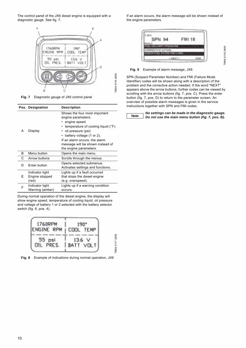
The control panel of the JX6 diesel engine is equipped with a diagnostic gauge. See fig. 7.
Fig. 7 Diagnostic gauge of JX6 control panel
During normal operation of the diesel engine, the display will show engine speed, temperature of cooling liquid, oil pressure and voltage of battery 1 or 2 selected with the battery selector switch (fig. 6, pos. 4).
Fig. 8 Example of indications during normal operation, JX6
If an alarm occurs, the alarm message will be shown instead of the engine parameters.
Fig. 9 Example of alarm message, JX6
SPN (Suspect Parameter Number) and FMI (Failure Mode Identifier) codes will be shown along with a description of the problem and the corrective action needed. If the word "NEXT" appears above the arrow buttons, further codes can be viewed by scrolling with the arrow buttons (fig. 7, pos. C). Press the enter button (fig. 7, pos. D) to return to the parameter screen. An overview of possible alarm messages is given in the service instructions together with SPN and FMI codes.
TM04
511
6 26
09
Pos. Designation Description
A Display
Shows the four most important engine parameters:• engine speed• temperature of cooling liquid (°F)• oil pressure (psi)• battery voltage (1 or 2).If an alarm occurs, the alarm message will be shown instead of the engine parameters.
B Menu button Opens the main menu.C Arrow buttons Scrolls through the menus.
D Enter button Opens selected submenus.Activates settings and functions.
EIndicator lightEngine stopped (red)
Lights up if a fault occurred that stops the diesel engine (e.g. overspeed).
F Indicator lightWarning (amber)
Lights up if a warning condition occurs.
TM04
511
7 26
09
F E
A
D
CB
TM04
511
8 26
09
NoteNo settings can be made in the diagnostic gauge. Do not use the main menu button (fig. 7, pos. B).
10

4.4 Controller4.4.1 General descriptionThe fire pump set is controlled via a Tornatech controller especially sized for diesel engines driving fire pumps. The controller starts the pump automatically and monitors the diesel engine. It is FM-approved.As soon as the sprinklers are activated due to an alarm and water is consumed, the pressure in the discharge pipe will be reduced. If the pressure becomes lower than the cut-in pressure set on the control panel, the pump will start automatically.Normally, the pump is stopped manually via the controller. But automatic stop is also possible if all starting causes have returned to normal.For test run and set-up, manual operation is possible.
4.4.2 Controller designThe controller is placed in a control cabinet mounted on the base frame. The control cabinet can also be delivered separately for wall or floor mounting. The controller is operated by means of the control panel and the switches on the cabinet door. See figures 10 and 11. The control cabinet supplies the engine with the power required for starting and operating the engine. The controller therefore has two battery chargers to keep the engine batteries charged. The two batteries are connected to individual battery chargers and power the control circuit. The control circuit is protected by two circuit breakers (CB3 and CB4, fig. 12, pos. 9 and 10) in the top right of the cabinet. The circuit breakers are not monitored and must both be in position "ON".
Fig. 10 Control cabinet
The design of the control panel in the cabinet door is shown in fig. 11. It consists of a display, 16 indicator lights and six buttons.The display shows the status of the fire pump set and gives access to seven menus for setting.The controller also has two DIP switches on the side of the electronic board fitted on the door. See section 5.1 Settings via DIP switches.The controller has also four standard relays and up to 19 optional relays for indication of operating and alarm status.
Fig. 11 Control panel of controller
TM04
506
7 26
09
Pos. Designation
1 Alarm bell2 Control panel3 Stop button (A5)4 Box with pressure sensor5 RS 232 interface (printer as option)6 Button for manual start, battery 1 (A3)7 Selector switch (AUTO - OFF - HAND) (A2)8 Button for manual start, battery 2 (A4)9 Isolating switch (A1)
1
2
3
5
4
6 7 8 9
TM04
511
9 26
09
Pos. Description
A DisplayB1 [Cut-in]B2 [Cut-out)B3 [Lamp Test/Silence]B4 [Run Test]B5 [Print]B6 [Paper Feed]1 "AC Power On"2 "Main Switch in Auto"3 "Battery #1 Failure"4 "Battery #2 Failure"5 "Charger #1 Failure"6 "Charger #2 Failure"7 "Engine Low Oil Pressure"8 "Engine High Temp."9 "Engine Overspeed"
10 "Engine Run"11 "Engine Fail to start"12 "Fail when Running"13 "Pump Room Alarm"14 "Deluge Valve/Remote Start"15 "Weekly Test"16 "Controller Trouble"
1
3
5
7
9
11
13
15
B1
B4B3
2
4
6
8
10
12
14
16
B2
B5 B6
Max Max
Cut In0
A
11

The internal components of the controller are shown in fig.12.
Fig. 12 Internal components of controller
4.4.3 Operating elementsThe operating elements are placed on the cabinet door and control panel. See fig. 10.
Operating elements on the cabinet door
Isolating switch A1 (fig. 10, pos. 9)The isolating switch interrupts the power supply from the mains.
Main switch A2 (fig. 10, pos. 7)The main switch is behind a breakable and pad-lockable cover. It allows for selecting three positions:
[BATTERY No. 1 MANUAL CRANK] A3 and [BATTERY No. 2 MANUAL CRANK] A4 (fig. 10, pos. 6 and 8) These buttons can be used only when the main switch is set to manual mode. Press [BATTERY No. 1 MANUAL CRANK] to start the engine with battery 1 or [BATTERY No. 2 MANUAL CRANK] to start the engine with battery 2. If both buttons are pressed simultaneously, batteries 1 and 2 are used in parallel to start the engine.
[STOP] A5 (fig. 10, pos. 3)This button can be used to stop the engine only when the main switch is set to automatic operation, and when the system pressure is higher than the cut-out pressure, provided that all starting causes have returned to normal (remote start and deluge valve).
Operating elements on the control panel
[Cut-in] B1 (fig. 11)This button is used to set the pressure limit for starting the diesel engine. It is enabled with DIP switch S10-1. See section 5.1 Settings via DIP switches.
[Cut-out] B2 (fig. 11)This button is used to set the pressure limit for stopping the diesel engine. It is enabled with DIP switch S10-1. See section 5.1 Settings via DIP switches.
[Lamp Test/Silence] B3 (fig. 11)This button has two functions:1. It is used to test the indicator lights of the control panel and the
audible alarm. When activated, the indicator lights of the left column will light up for one second, then the indicator lights of the right column for one second, and finally the alarm bell will ring for one second.
2. It is used to silence the alarm bell in case of "Pump Room Alarm" and "Fail when Running".
[Run Test] B4 (fig. 11)This button is used to release the pressure on the pressure sensor to simulate a drop of pressure.It is also used when setting the controller. See section 5.2 Settings via display.
[Print] B5 (fig. 11)If the controller is equipped with an optional printer, this button is used to print a resume of events of the last 15 days and pressure data of the last seven days. See section 12.4 Retrieving and printing data.It is also used when setting the controller. See section 5.2 Settings via display.
[Paper Feed] B6 (fig. 11)If the controller is equipped with an optional printer, this button is used to feed paper through the printer slot in order to avoid tearing the printout.
TM04
512
0 26
09
Pos. Designation Description
1 AR5 to AR28 Optional alarm relays2 AR1 to AR4 Standard alarm relays3 - Terminals for sensor connections4 - Terminals for engine connections5 XTR1 Transformer for charger 16 XTR2 Transformer for charger 27 CB 1 Circuit breaker for charger 18 CB 2 Circuit breaker for charger 29 CB 3 Circuit breaker for control circuit
10 CB 4 Circuit breaker for control circuit11 - Charger 112 - Charger 213 - Terminals for mains supply
OFF Stops the engine and prevents engine start. It also resets all alarms.
HAND Enables manual start by activating the start fuel solenoid valve.
AUTO
Enables the engine to start in these cases:• a system pressure drop sensed by the pressure
sensor• a remote start signal• a deluge valve signal• a weekly test• activation of a run test• an AC power failure (selectable).
1
2
3
4
9 10 11 12
5
6
7
8
13
12

4.4.4 Display indicationsThe display shows the status of the fire pump set and alarm messages. It also gives access to the setting menus of the controller. See section 5.2 Settings via display.
Fig. 13 Display of control panel of controller
The display is divided into four lines. The top line shows the battery voltage and the charger status of battery 1. The second line shows the battery voltage and the charger status of battery 2. The third line shows the controller date and time or various alarm messages. The date (D/M/Y) and the time are always shown if there is no alarm. If there is more than one alarm, the line will scroll the different messages. The fourth line shows the system pressure. The table below explains the display elements.
The table below shows the charger status in pos. 3 and 6.
The following operating and alarm messages are shown in fig. 13, pos. 7:
*) Optional.
TM04
512
1 26
09
Pos. Description
1 Battery voltage of battery 12 Charger current delivered from charger 1 to battery 13 Charger status of battery 14 Battery voltage of battery 25 Charger current delivered from charger 1 to battery 26 Charger status of battery 27 Date and time or alarm messages8 Cut-out pressure (o)9 Cut-in pressure (i)
10 Actual system pressure
Status Description
BULK The charger is delivering the maximum current for fast recovering of the battery charge.
OVER The charger is in overcharge mode to maximise the battery charge.
FLOAT The charger is maintaining the battery voltage.AC FAIL The charger is not connected to power source.
no ans The charger has lost the communication with the main electronic board.
24.3V
21.6V
14-04-05
o:140
1.3A
10.5A
09:59:08
i:100
FLOAT
BULK
s:174psi
1
4
7
8 9 10
6
2 5 3
Status Description
Crank 1/6Batt#1 10s Status of cranking cycle and timer countdown.
Low System Pressure
The system pressure is lower than 85 % of the cut-in pressure for more than one second.
Remote Start The engine has been started by activation (opening) of the remote contact (21-13).
Remote - Pump Demand
The remote signal is still present, and it is impossible to stop the engine with the [STOP] button.
Automatic Start The engine has been started by detection of a pressure drop (under cut-in pressure).
Auto Start - Pump Demand
The system pressure is still lower than the cut-out pressure, and it is impossible to stop the engine with the [STOP] button.
AC Power Failure The controller is powered only by batteries.
RPT mm:ss The remaining time before automatic stop.Seq. Start Time ss The remaining time before start sequence.
Press Line Failure
The solenoid valve has been activated, but the pressure drop has not been detected, or the pressure sensor is defective.
Low Fuel Level Contact 23-24 is closed for more than one second.
Water Reservoir Low
Contact 23-26 is closed for more than ten seconds.
Water Reservoir Empty
Contact 23-27 is closed for more than ten seconds.
Low Pump Room Temp Contact 23-28 is closed.
High Fuel Level Contact 23-29 is open for more than half a second.
Low Suction Pressure
Contact 23-30 is closed for more than three seconds.
Weekly Test mm:ss The remaining time of the weekly test.
Lockout Signal *) The controller is locked by other equipment and will not start automatically.
Interlock On *) The controller is supplying voltage to other equipment that must be locked.
AC Failure Start mm:ss
The remaining time before automatic start in case of detection of loss of power supply.
Altern. ECM pos. The ECM selector switch is in position "ALTERNATE ECM" (engine type JX 6).
System Overpressure
The system pressure is higher than the limit set.
Fuel Injection There is a malfunction in the fuel injection system. Contact 23-70 is closed.
13

4.4.5 Indicator lights on control panel and alarm bellSixteen indicator lights show the status of the controller and the engine. See the table below.The table also shows when the alarm bell will ring, and whether the fault indication is reset automatically (A) or manually (M) by turning main switch A2 (fig. 10, pos. 7) to "OFF".
*) Overspeed alarms must also be reset on the control panel of the engine by means of the [OVERSPEED RESET] switch (fig. 5, pos. 4, for JU/JW engines, and fig. 6, pos. 12, for JX engines).
Pos. Indicator light Description Bell Reset
1 AC power ON The controller is connected to an external power source. - -
2 Main Switch in Auto The main switch A2 is in position "AUTO". - -
3 Battery #1 Failure
No battery connected.Battery voltage < 50 %.Incorrect battery connection.Problems while charging.
M
4 Battery #2 Failure
No battery connected.Battery voltage < 50 %.Incorrect battery connection.Problems while charging.
M
5 Charger #1 Failure
Internal fault.Charger is not connected to the mains.Current reaches 15 A.Current less than 0.5 A.
M
6 Charger #2 Failure
Internal fault.Charger is not connected to the mains.Current reaches 15 A.Current less than 0.5 A.
M
7 Engine Low Oil Pressure The oil pressure in the oil circuit of the engine is too low. M
8 Engine High Temp. The cooling liquid has reached an abnormal temperature. M
9 Engine Overspeed The engine is running with overspeed, and the corresponding contact of the engine is closed. M *)
10 Engine Run The engine is running. - -
11 Engine Fail to Start Six start attempts have been made, but the engine did not start. M
12 Fail when Running The engine should be running, but is not. The run contact is open. M
13 Pump Room Alarm
Indicates one or more of these conditions:• low inlet pressure• low fuel level• low level in water reservoir• water reservoir empty• low ambient temperature• power failure.
A
14 Deluge Valve/Remote Start Engine has started due to deluge valve or remote signal. - -
15 Weekly Test Weekly test run has started. - -
16 Controller Trouble
Indicates the following faults:• failure, battery #1• failure, battery #2• failure, charger #1• failure, charger #2• failure on pressure side.
M
14

4.5 FunctionsControl and monitoring take place via the functions described in the following subsections.Some of the parameters monitored are shown in the display of the control panel. See section 4.4.4 Display indications. Fault will be indicated if a value is outside the limits set. See section 4.4.4 Display indications and 4.4.5 Indicator lights on control panel and alarm bell. A fault signal can be transferred to a building management system or similar system by means of an optional alarm relay. An overview of alarm relays is given in section 10.3 Connection to standard alarm relays. All operating and alarm messages are shown in section 4.6 Operating and alarm messages.
4.5.1 Operating functions
Automatic operationWhen the main switch is in position "AUTO" and the built-in pressure sensor detects that the system pressure is lower than the cut-in pressure, the engine initiates the automatic engine cranking cycle to start the fire pump set automatically. The cranking cycle provides for activating the fuel solenoid valve and cranking the engine for 15 seconds and then rest for 15 seconds. This sequence is repeated six times. Prior to each new start attempt, a changeover between starting units takes place. The battery changeover is automatic, but if one battery is inoperative, missing or weak, the cranking sequence will use only the remaining battery.If the engine is in automatic operation, indicator light "Main Switch in Auto" (fig. 11, pos. 2) will be on. If the engine is running, indicator light "Engine Run" (fig. 11, pos. 10) will also be on, and the display will show "Automatic Start".If the engine does not start after six attempts, indicator light "Engine Fail to Start" (fig. 11, pos. 11) will be on.The engine can be stopped with [STOP] button A5 (fig. 10, pos. 3) when the system pressure is higher than the cut-out pressure. Otherwise, the display shows "Auto Start - Pump Demand", and the engine can only be stopped by turning the main switch to position "OFF". Automatic stop is also possible. See below.The cut-in and cut-out pressures can be set by means of buttons [Cut-in] B1 and [Cut-out] B2 (fig. 11). See section 11. Start-up.All engine alarm signals are operative but do not prevent the engine from running except for the overspeed signal which stops the engine immediately.
Automatic stopIn automatic operation, the engine stops automatically when all starting causes have returned to normal. To use automatic stop, set DIP switch S10-2 to "ON". See section 5.1 Settings via DIP switches. Normally, the engine is stopped after 30 minutes, but the run time can be changed. See section 5.2 Settings via display. The remaining run time is shown in the display (RPT mm:ss).
Manual operationFor test runs and start-up, manual operation is possible by means of main switch A2 (fig. 10, pos. 7) and buttons [BATTERY No. 1 MANUAL CRANK] and [BATTERY No. 2 MANUAL CRANK].Turn the main switch to "HAND" to start the engine by activating the start fuel solenoid valve.Press [BATTERY No. 1 MANUAL CRANK] to start the engine with battery 1 or [BATTERY No. 2 MANUAL CRANK] to start the engine with battery 2. If both buttons are pressed simultaneously, batteries 1 and 2 are used in parallel to start the engine.To stop the engine, turn the main switch to "OFF" or "AUTO".
If the engine is running, indicator light "Engine Run" (fig. 11, pos. 10) will be on, and the display will show "Automatic Start". The alarms "Engine Fail to Start" (fig. 11, pos. 11) and "Fail when Running" (fig. 11, pos. 12) are not operative in this position. An overspeed condition will stop the engine and sound the alarm bell. All other alarm signals are operative but have no influence on the engine operation.
Emergency operationIf the controller fails, emergency operation will be possible via the control panel of the diesel engine. See section 12.2.2 Manual operation via control panel of diesel engine.
Remote controlThe engine can be started by the momentary opening of a remote contact, independent of the pressure sensor. It can only be manually stopped with [STOP] button A5 (fig. 10, pos. 3), provided that the system pressure is higher than the cut-out pressure.If the engine has been started by a remote control, indicator light "Deluge Valve/Remote Start" (fig. 11, pos. 14) will be on, and the display will show the message "Remote Start". All engine alarm signals are operative but do not prevent the engine from running, except for the overspeed signal that stops the engine immediately.
Control by means of deluge valveIf a deluge valve is provided, the controller can be started by opening of a normally closed contact (fail-safe circuit) coming from the fire protection equipment (deluge valve), independent of the pressure sensor. The engine can only be manually stopped with [STOP] button A5 (fig. 10, pos. 3), but only after the fire protection equipment contact has returned to normal (provided that the system pressure is higher than the cut-out pressure).If the engine has been started by a deluge valve, indicator light "Deluge Valve/Remote Start" (fig. 11, pos. 14) will be on.All engine alarm signals are operative but do not prevent the engine from running except for the overspeed signal which stops the engine immediately.
Automatic weekly testThe controller can be set for a weekly test. See section 5.2 Settings via display. When the weekly test is enabled, the engine starts at the set start time and stops at the set stop time, or when the run time set for automatic stop, whichever is the shortest. The engine can be stopped with [STOP] button A5 (fig. 10, pos. 3) before test is finished (provided that the system pressure is higher than the cut-out pressure).When the automatic weekly test starts, indicator light "Weekly Test" (fig. 11, pos. 15) is on, and the display shows the message "Weekly Test" together with the remaining time. The optional alarm relay AR5 will also be activated if option A1 is ordered. All alarm signals are operative. During automatic weekly test, low oil pressure, high temperature, overspeed, fuel injection malfunction or programmable external signal condition will immediately stop the engine to prevent damage.
Manual test runA test run can also be initiated manually by pressing [Run Test] button B4 (fig. 11). Pressing this button simulates a pressure drop. The engine will stop if [STOP] button A5 (fig. 10, pos. 3) is pressed, or if automatic stop is enabled. All alarm signals are operative. During manual test run, low oil pressure, high temperature, overspeed, fuel injection malfunction or programmable external signal condition will immediately stop the engine to prevent damage.
Start in case of power failureIn case of power failure, the engine will start automatically after a time set. The engine will stop immediately when the AC power supply is re-established. The function can be disabled by setting the time to 0. The function is disabled from factory. See section 5.2 Settings via display.
15

Start delayIn systems with several pumps, it may be necessary to set a start delay to prevent all engines from starting at the same time. The start delay is selectable (5, 10 and 15 seconds). See section 5.1 Settings via DIP switches, subsection Start delay (S10-3+4), and 5.2 Settings via display, subsection Menu 4 (timers). The remaining time before the engine will start is shown in the display ("Seq Start Time ss").
Battery chargingThe controller is equipped with two independent fully automatic battery chargers for 10 A continuous charging, complete with these functions:• AC input filter• current limiter• overcurrent stop• 500 mA trickle charge• dead cell detection• low battery voltage alarm.
Louvres controlTo ensure a sufficient supply of fresh air to the engine and a targeted heat removal, it may be necessary to install louvres. The louvres can be controlled via the control cabinet if the louvres motor powered by an external power source are connected to standard alarm relay AR2, terminals 11 and 12. Standard alarm relay AR2 is activated when the diesel engine is running.
Lockout by other equipment (option C1)When a lockout signal is present, the controller is inhibited to start on water pressure drop detection, weekly test and run test. All other starting causes will produce a starting cycle.If the lockout wires are short-circuited, fuse FU1 will blow, and the lockout function will be inoperative. If the lockout wires are cut, relay CR8 cannot be activated, and the lockout function will be inoperative again.
Interlock of other equipment (option C2)The interlock circuit provides a 12 VDC or 24 VDC voltage on terminals 11-64 in order to prevent other equipment from starting.
Cooling water heater (option C7)Some fire pump sets are equipped with a cooling water heater for the engine. For this purpose, the control cabinet contains a 10 A circuit breaker (CB5). The heater adjusts itself via an external cooling water thermostat.
Anti-condensation heater (option D9A and D9B)To avoid formation of condensation, the control cabinet can be equipped with an anti-condensation heater with thermostat (option D9A) or humidistat (option D9B).
4.5.2 Monitoring functions
Monitoring of engine operationIf the engine is in automatic mode and ready for operation, indicator light "Main Switch in Auto" (fig. 11, pos. 2) will be on. During the cranking process, the display shows the number of current starting attempt and the remaining time ("Crank 1/6 Batt#1 10s"). When the engine is running, indicator light "Engine Run" (fig. 11, pos. 10) is on, and the display shows the message "Automatic start". If the start was initiated by a remote signal or a signal from a deluge valve, indicator light "Deluge Valve/Remote Start" will also be on, and the display will show the message "Remote Start". In all cases, standard alarm relay AR2 will be activated.If the controller does not receive an engine run signal after six start attempts, indicator light "Engine Fail to Start" (fig. 11, pos. 11) will be on, and standard alarm relay AR 1 will be activated. The optional alarm relay AR9 will also be activated if option A5 has been ordered.If there is a pump demand, but the diesel engine is not running, indicator light "Fail when Running" will be on, and standard alarm relay AR 1 will be activated.In both alarm situations, the alarm bell will ring.
The pump-on-demand relay AR28 (option B8) will be activated if a start condition is present (remote start contact open, deluge valve open, pressure under cut-out pressure with engine running) when the engine is running. In this situation, the engine will not stop if [STOP] button is pressed.
Monitoring of batteriesIf the battery voltage falls below the specified value (normally 50 % of the nominal battery voltage), or when the battery does not reach the appropriate voltage after 24 hours in bulk mode, or no battery is connected, or the battery is connected in reverse polarity, a warning will be given by indicator light "Battery #1 Failure" (fig. 11, pos. 3) or "Battery #2 Failure" (fig. 11, pos. 4), and additionally by indicator light "Controller Trouble" (fig. 11, pos. 16). The alarm bell will ring. Standard relay AR4 will be deactivated. The optional alarm relays AR10 and AR11 will also be activated if option A6 has been ordered.Both batteries are monitored. A value for alarm can be set.See section 5.2 Settings via display, subsection Menu 6 (weak battery).In case of battery failure, the charger will initiate an alarm and provide a signal to prevent the use of the defective battery during the start attempt cycle.
Monitoring of battery chargersIf the load current is too low (0.5 A) or too high (15 A), or no charger is connected, or the charger is not powered by the mains for more than five minutes, a warning will be given by indicator light "Charger #1 Failure" (fig. 11, pos. 5) or "Charger #2 Failure" (fig. 11, pos. 6), and additionally by indicator light "Controller Trouble" (fig. 11, pos. 16). The alarm bell will ring. Standard relay AR4 will be deactivated. The optional alarm relays AR12 and AR13 will also be activated if option A7 has been ordered. Both batteries are monitored.
Monitoring of power supplyIf the power supply is missing (indicator light "AC Power On" (fig. 11, pos. 1) is not on), indicator light "Pump Room Alarm" (fig. 11, pos. 13) will be on, and the bell will ring. Standard relay AR1 will be activated. The optional alarm relay AR14 will also be activated if option A8 has been ordered.
Monitoring of engine speedIf an overspeed condition occurs and the overspeed switch contact of the engine has tripped out, indicator light "Engine Overspeed" (fig. 11, pos. 9) will be on, and the alarm bell will ring. Standard relay AR1 will be activated. The optional alarm relay AR6 will also be activated if option A2 has been ordered.
Monitoring of engine oil pressureThe oil pressure is monitored via a pressure sensor on the engine. The oil pressure must be reached no later than eight seconds after the engine run signal was activated, and the contact of the engine must be closed. If an abnormal (too low) pressure in the diesel engine oil-pressure circuit has been detected, indicator light "Engine Low Oil Pressure" (fig. 11, pos. 7) will be on, and the alarm bell will ring. Standard relay AR1 will be activated. The optional alarm relay AR7 will also be activated if option A3 has been ordered.
Monitoring of cooling temperatureThe temperature of the cooling liquid is monitored via a temperature sensor on the engine. If the temperature of the cooling liquid rises to a value causing the contact of the engine to close, indicator light "Engine High Temp." (fig. 11, pos. 8) will be on, and the alarm bell will ring. Standard relay AR1 will be activated. The optional alarm relay AR8 will also be activated if option A4 has been ordered.
Note
Overspeed alarms must be reset on the control panel of the engine by means of the [OVERSPEED RESET] switch (fig. 5, pos. 4, for JU/JW engines, and fig. 6, pos. 12, for JX engines).
16

Monitoring of system pressure on discharge sideIf the system pressure measured by the built-in pressure sensor of the controller is above the set limit, indicator light "Controller Trouble" (fig. 11, pos. 16) will be on, and the alarm bell will ring. The display will show the alarm message "System Overpressure", and standard relay AR4 will be activated. The optional alarm relay AR27 will also be activated if option A9 has been ordered.If the system pressure falls below 85 % of the cut-in pressure for more than one second, indicator light "Controller Trouble" (fig. 11, pos. 16) will be on, and the alarm bell will ring. The display will show the alarm message "Low System Pressure", and standard relay AR4 will be activated. The optional alarm relay AR20 will also be activated if option B6 has been ordered.
Monitoring of fuel levelThe fuel level in the tank is monitored by two float switches (low and high level). If the fuel level falls below two thirds of the fuel tank capacity for more than one second, an alarm will be given. Indicator light "Pump Room Alarm" (fig. 11, pos. 13) will be on, and the alarm bell will ring. The display will show the alarm message "Low Fuel Level", and standard relay AR3 will be activated. The optional alarm relay AR15 will also be activated if option B1 has been ordered, and the contact is closed for more than one second.If the fuel level reaches the high-level float switch for more than 0.5 seconds, the display will show the alarm message "High Fuel Level", and the optional alarm relay AR19 will be activated if option B5 has been ordered.
Monitoring of water reservoir levelThe level in the water reservoir is monitored by two float switches (low level and empty tank). If a low level is detected and contact 23-26 is closed for more than ten seconds, indicator light "Pump Room Alarm" (fig. 11, pos. 13) will be on, and the alarm bell will ring. The display will show the alarm message "Water Reservoir Low", and standard relay AR3 will be activated. The optional alarm relay AR16 will also be activated if option B2 has been ordered.If the water reservoir is empty and contact 23-27 is closed for more than ten seconds, indicator light "Pump Room Alarm" (fig. 11, pos. 13) will be on, and the alarm bell will ring. The display will show the alarm message "Water Reservoir Empty", and standard relay AR3 will be activated. The optional alarm relay AR17 will also be activated if option B3 has been ordered.
Monitoring of ambient temperatureIf a thermostat for measuring the room temperature is installed, an alarm will be given, and contact 23-28 will be closed when the temperature is below 5 °C. Indicator light "Pump Room Alarm" (fig. 11, pos. 13) will be on, and the alarm bell will ring. The display will show the alarm message "Low Pump Room Temp", and standard relay AR3 will be activated. The optional alarm relay AR18 will also be activated if option B4 has been ordered.
Monitoring of inlet pressureIf a pressure switch is installed in the suction pipe, an alarm is given when the pressure on suction side is below a certain value. If contact 23-29 is closed by the pressure switch for more than three seconds, indicator light "Pump Room Alarm" (fig. 11, pos. 13) will be on, and the alarm bell will ring. The display will show the alarm message "Low Suction Pressure", and standard relay AR3 will be activated. The optional alarm relay AR21 will also be activated if option B7 has been ordered.
Recording of events and pressure data The controller records events of the last 15 days and pressure data of the last seven days. The information is accessible either by using the RS232 port (standard, see section 12.4.1 Retrieving data via the RS 232 port), the printer (optional, see section 12.4.2 Printing of data), or the modem (see section 12.4.3 Retrieving data via modem).
17
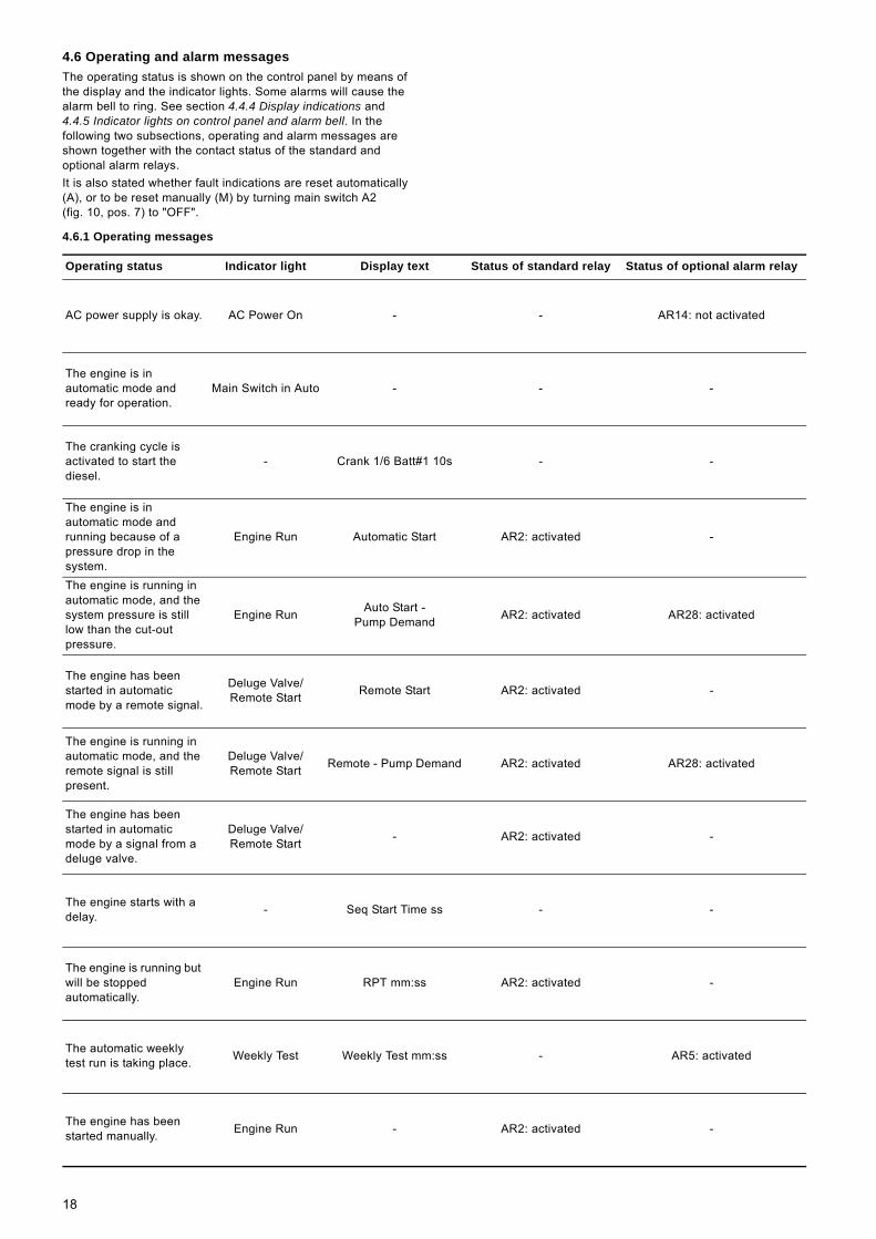
4.6 Operating and alarm messagesThe operating status is shown on the control panel by means of the display and the indicator lights. Some alarms will cause the alarm bell to ring. See section 4.4.4 Display indications and 4.4.5 Indicator lights on control panel and alarm bell. In the following two subsections, operating and alarm messages are shown together with the contact status of the standard and optional alarm relays.It is also stated whether fault indications are reset automatically (A), or to be reset manually (M) by turning main switch A2 (fig. 10, pos. 7) to "OFF".
4.6.1 Operating messages
Operating status Indicator light Display text Status of standard relay Status of optional alarm relay
AC power supply is okay. AC Power On - - AR14: not activated
The engine is in automatic mode and ready for operation.
Main Switch in Auto - - -
The cranking cycle is activated to start the diesel.
- Crank 1/6 Batt#1 10s - -
The engine is in automatic mode and running because of a pressure drop in the system.
Engine Run Automatic Start AR2: activated -
The engine is running in automatic mode, and the system pressure is still low than the cut-out pressure.
Engine Run Auto Start - Pump Demand AR2: activated AR28: activated
The engine has been started in automatic mode by a remote signal.
Deluge Valve/Remote Start Remote Start AR2: activated -
The engine is running in automatic mode, and the remote signal is still present.
Deluge Valve/Remote Start Remote - Pump Demand AR2: activated AR28: activated
The engine has been started in automatic mode by a signal from a deluge valve.
Deluge Valve/Remote Start - AR2: activated -
The engine starts with a delay. - Seq Start Time ss - -
The engine is running but will be stopped automatically.
Engine Run RPT mm:ss AR2: activated -
The automatic weekly test run is taking place. Weekly Test Weekly Test mm:ss - AR5: activated
The engine has been started manually. Engine Run - AR2: activated -
18

4.6.2 Alarm messages
Operating status Indicator light Display text Alarm bell Status of standard relay
Status of optional alarm relay Reset
The engine did not start after six attempts. Engine Fail to Start - AR1: activated AR9: activated M
There is a pump demand, but the engine does not run.
Fail when Running - AR1: activated - M
AC power supply is missing. Pump Room Alarm AC Failure
Start mm:ss AR3: activated AR14: activated M
The voltage of battery 1 is lower than a set value (normally 6 V), or no battery is connected, or the battery is connected in reverse polarity, or the battery does not reach the appropriate voltage after 24 hours in bulk mode.
Battery #1 Failure
Controller Trouble- AR4: deactivated AR10: activated M
The voltage of battery 2 is lower than a set value (normally 6 V), or no battery is connected, or the battery is connected in reverse polarity, or the battery does not reach the appropriate voltage after 24 hours in bulk mode.
Battery #2 Failure
Controller Trouble- AR4: deactivated AR11: activated M
The current has reached 15 A or less than 0.5 A, or charger 1 is not connected to the mains or not powered by the mains for more than five minutes, or the micro-processor of the charger has detected an internal fault.
Charger #1 Failure
Controller Trouble- AR4: deactivated AR12: activated M
The current has reached 15 A or less than 0.5 A, or charger 2 is not connected to the mains or not powered by the mains for more than five minutes, or the micro-processor of the charger has detected an internal fault.
Charger #2 Failure
Controller Trouble- AR4: deactivated AR13: activated M
The engine was running with overspeed and has been stopped.
Engine Overspeed - AR1: activated AR6: activated M*)
The oil pressure in the oil circuit of the engine is too low eight seconds after engine start.
Engine Low Oil Pressure - AR1: activated AR7: activated M
The temperature of the cooling liquid is higher than 93 °C.
Engine High Temp. - AR1: activated AR7: activated M
19

*) Overspeed alarms must also be reset on the control panel of the engine by means of the [OVERSPEED RESET] switch (fig. 5, pos. 4, for JU/JW engines, and fig. 6, pos. 12, for JX engines).
The system pressure measured by the built-in pressure sensor of the controller is above the set value. See section 5.2 Settings via display, Menu 3 (maximum pressure).
Controller Trouble System Overpressure AR4: deactivated AR27: activated M
The system pressure is lower than 85 % of the cut-in pressure.
Controller Trouble Low system pressure AR4: deactivated AR20: activated M
The fuel level in the diesel tank is below two thirds of the capacity.
Pump Room Alarm Low Fuel Level AR3: activated AR15: activated A
The fuel level has reached the upper float switch.
- High Fuel Level - - AR19: activated A
The level in the water reservoir is low. Pump Room Alarm Water Reservoir
low AR3: activated AR16: activated A
The water reservoir is empty. Pump Room Alarm Water Reservoir
empty AR3: activated AR17: activated A
The ambient temperature is low. Pump Room Alarm Low Pump
Room Temp AR3: activated AR18: activated A
The inlet pressure is low. Pump Room Alarm Low Suction Pressure AR3: activated AR21: activated A
Operating status Indicator light Display text Alarm bell Status of standard relay
Status of optional alarm relay Reset
20

5. SettingsSettings are made by means of the two DIP switches and the display menu.
5.1 Settings via DIP switchesPossible settings:• language• locking of control panel buttons for setting of cut-in and cut-out
pressures• automatic or only manual stop• engine start delay• pressure unit, kPa or psi• pressure interval for recording of pressure data.
Fig. 14 Position of DIP switches
The two DIP switches are located on the side of the electronic board mounted on the door. DIP switch S5 is at the top, DIP switch S10 is at the bottom. See fig. 14. The configuration and factory settings are shown below.
DIP switch S5
DIP switch S10
Language (S5/1+2)The display language is English, regardless of the DIP switch setting.
Enabling or locking of buttons for setting of cut-in and cut-out pressures (S10-1)When DIP switch S10-1 is in position "ON", buttons [Cut-in] B1 and [Cut-out] B2 (fig. 11) are enabled. When it is in position "OFF", setting is not possible.
Automatic or manual stop (S10-2) When DIP switch S10-2 is in position "ON", the controller is set to automatic stop. The engine will stop after the minimum run time set to 30 minutes from factory. The time can be changed in the display menu. See section 5.2 Settings via display. When DIP switch S10-2 is in position "OFF", the controller is set to manual stop. The engine can only be stopped with [STOP] button A5 (fig. 10, pos. 3), provided the system pressure is higher than the cut-out pressure.
Start delay (S10-3+4)The controller delays the engine start cycle by five seconds, ten seconds, or another time that can be set in the display menu (see section 5.2 Settings via display) upon a water pressure drop detection, a remote start or a deluge valve detection. The time is factory-set to 15 seconds. All other starting causes will activate the engine immediately. To change the delay, the DIP switch must be set according to the following table.
Pressure unit (S10-5)The pressure can be displayed in kPa or psi. When DIP switch S10-5 is in position "ON", the pressure unit is kPa. In position "OFF", the pressure unit is psi.
Pressure interval for recording of pressure data (S10-6+7)Pressure data are recorded each time the pressure varies more than the pressure interval. The pressure interval can be set to 1, 2, 5 or 10 psi. To change the pressure interval, set the DIP switch according to the following table.
Test mode (S10-8)This DIP switch is for factory use and must remain in position "OFF".
TM04
506
8 26
09
ON OFF Switch Configuration Factory setting
S5-1 LanguageEnglish
S5-2 LanguageS5-3 For factory useS5-4 For factory use
ON OFF Switch Configuration Factory setting
S10-1 Buttons B1 and B2 LockedS10-2 Run time Manual stopS10-3 Start delay
No delayS10-4 Start delayS10-5 Pressure unit PsiS10-6 Pressure interval
5 psiS10-7 Pressure intervalS10-8 For factory use -
S5
S10
Switch ON OFF Time
S10-4S10-3 0 second
S10-45 seconds
S10-3S10-4
10 secondsS10-3S10-4
15 secondsS10-3
Switch ON OFF Pressure interval
S10-7S10-6
5 psi34.475 kPa
S10-7 10 psi68.950 kPaS10-6
S10-7 1 psi6.8950 kPaS10-6
S10-7 2 psi13.790 kPaS10-6
21
5.2 Settings via displaySeven menus enable setting of several parameters:• date and time (menu 1)• time for automatic weekly test (menu 1)• print (menu 2)• maximum pressure (menu 3)• start delay (menu 4)• run time before automatic stop (menu 4)• start delay in case of power failure (menu 4)• calibration of pressure sensor (menu 5)• alarm value for weak battery voltage (menu 6)• erase memory (menu 7).
General procedure• Press [Print] button B5 (fig. 11) for more than 5 seconds to get
access to the setting menus. Keep the button pressed.• To go to the next menu, press [Run Test] button B4 (fig. 11)
repeatedly until the desired menu appears. Then release the [Print] button.
• To select a value, press the [Print] button.• To set a value, press the [Run Test] button.• To save the setting and return to the "normal" display, select
"Save" using the [Print] button, and validate using the [Run Test] button.
• To leave the menu without saving, select "Exit" using the [Print] button, and validate using the [Run Test] button.
• If no button is touched for 30 seconds, the setting will not be saved, and the screen will return to normal mode.
Menu 1 (date and time, and time for automatic weekly test) In this menu, the display shows these pieces of information:• First line: Controller date and time.• Second line: Weekly test activation (Y = yes) or (N = no).• Fourth line: Day of the week when a weekly test will be
performed, and start and stop time.All of these parameters can be changed. Note: During weekly test, the stop time may be overridden by the run time. See section 5.1 Settings via DIP switches, subsection Automatic or manual stop (S10-2).
Menu 2 (print)In this menu, the user can select how pressure data are to be shown when printed:• "Text": Each pressure record is printed on a separate line.• "Graph": The printout is a series of small lines representative
to the pressure. The scaling of the Y axis (pressure) can be changed by entering the Y maximum and Y minimum values. The scaling of the X axis (time) can be changed by selecting between one hour and 15 minutes. Dot lines (0 to 5) can be added to have a better graph reading.
Menu 3 (maximum pressure)In this menu, the maximum pressure can be set in psi or kPa, depending on the selected unit.If the system pressure exceeds this value, "Controller Trouble" alarm relay (AR4), indicator light "Controller Trouble" (fig. 11, pos. 16) and "System Overpressure" alarm relay (option A9) will be triggered.
Menu 4 (timers)In this menu, three different timers can be set:a) Start delayThe delay time can be set from 0 to 60 seconds. The factory setting is 15 seconds.
b) Run time before automatic stopThe engine will stop when the run time has expired, but only if DIP S10-2 switch is in position "ON". See section 5.1 Settings via DIP switches. The time can be set from 1 to 60 minutes. The factory setting is 30 minutes.Note: The time will be reset if the system pressure falls below the cut-out pressure.c) Start in case of power failureIf this function is selected, the engine will start automatically in case of power failure. "AC Fail Start Timer" can be set from 0 to 255 minutes. Note: If 0 is selected, "No" will appear on the screen, and the function will be disabled.The time starts when the AC source is lost. When the time has expired, the engine will be started. The function is disabled from factory.
Menu 5 (calibration of pressure sensor)This menu is used only if the pressure sensor has to be replaced. The function is described in the service instructions.
Menu 6 (weak battery)In this menu, a value for detection of weak battery can be set between 0.0 and 24.0 V. The default value is 6.0 V.
Menu 7 (erase memory)In this menu, pressure data or the event memory can be erased individually. The elapse time meter and the last engine run can not be reset.
Note
The starting sequence will be delayed by the set time only if DIP switches S10-3 and S10-4 are in position "ON". See section 5.1 Settings via DIP switches.
22

6. IdentificationThe fire pump set can be identified by the type designation on the nameplate. See fig. 15.
6.1 Type keysAn explanation of the type designation is given in the following subsections.
6.1.1 Type key for fire pump set
The first example shows a fire pump set with a DNF end-suction pump driven by a diesel engine. The pump with stuffing box with internal barrier fluid is FM-approved and UL-listed. The diameter of its DIN flange on the discharge side is 80 mm, and the impeller diameter is 260 mm. Pump and engine are connected by a spacer coupling. Operation takes place via a controller placed on the common base frame.
Example DNF: Fire DN F 80 -25 /260 D A X A A B B
Example HSEF: Fire HSE F 8 -15 /323 D B X D A B C
Fire: Fire system
Pump typeDN: End-suction pumpHSE: Horizontal split case pump
F : Pump is approved for fire fighting
Nominal diameter of discharge port[mm] for DN[inch] for HSE
Pump housing size[cm] for DN[inch] for HSE
Actual impeller diameter [mm]
DriverD: Diesel engineE: Electric motor, 50 HzF: Electric motor, 60 HzX: Special configuration
Approvals of pumpA: FM/ULB: FMC: ULX: No approval
Approval of fire pump setX: No approval
Pipe connectionA: ANSI flangeD: DIN flange
Control panel A: Mounted on base frameF: For floor mountingW: For wall mountingX: No control panel
Stuffing boxB: SNEAC: SNFA
CouplingA: Standard (only DNF)B: Spacer (only DNF)C: Other typesD: PTO (Power Take-Off shaft)
23

6.1.2 Type key for engine
The example shows a UL-listed John Deere 4-cylinder standard engine with a 4.5 litre cylinder capacity. Cooling takes place via a heat exchanger.
Example J U 4 H UL 2 4
Engine typeJ: John Deere basic engine adapted
by CLARKE UK LTD
Engine seriesU: standard range
4-cylinder engine = 4.5 litres6-cylinder engine = 6.8 litres
W: special range6-cylinder engine = 8.1 litres
X: standard range6-cylinder engine = 12.5 litres
Number of cylinders46
CoolingH: via heat exchanger
Approvals of engineNL: not listedUL: listed
Code for rated power
Code for speed range0: standard speed range4: 2350-3500 rpm (JU only)
24
6.1.3 Type key for controller
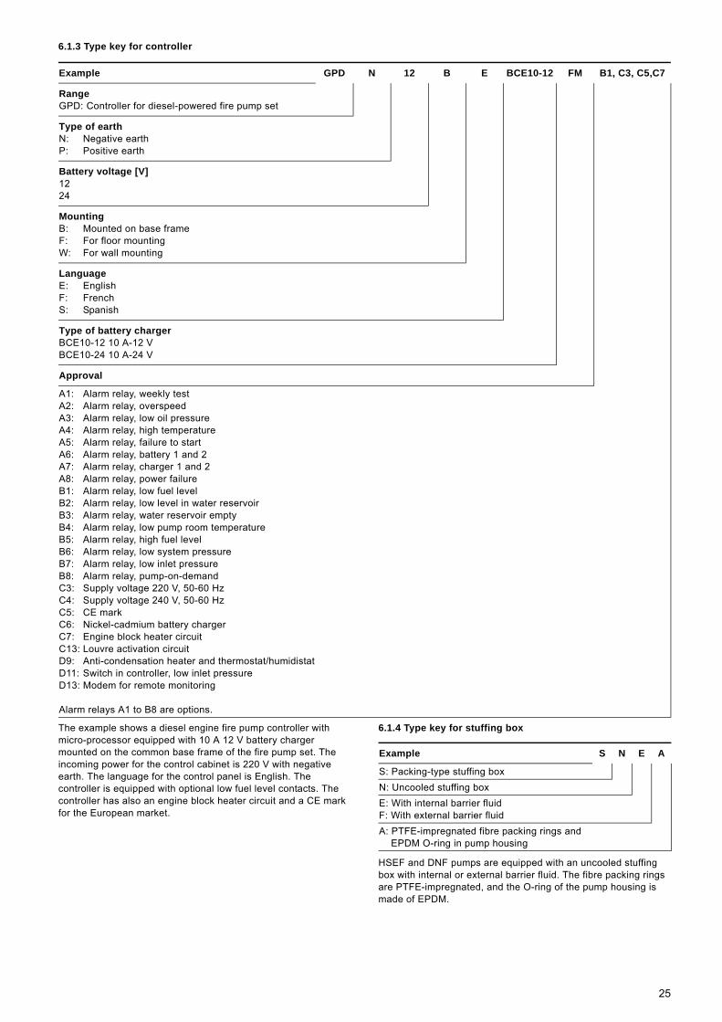
The example shows a diesel engine fire pump controller with micro-processor equipped with 10 A 12 V battery charger mounted on the common base frame of the fire pump set. The incoming power for the control cabinet is 220 V with negative earth. The language for the control panel is English. The controller is equipped with optional low fuel level contacts. The controller has also an engine block heater circuit and a CE mark for the European market.
6.1.4 Type key for stuffing box
HSEF and DNF pumps are equipped with an uncooled stuffing box with internal or external barrier fluid. The fibre packing rings are PTFE-impregnated, and the O-ring of the pump housing is made of EPDM.
Example GPD N 12 B E BCE10-12 FM B1, C3, C5,C7
RangeGPD: Controller for diesel-powered fire pump set
Type of earthN: Negative earthP: Positive earth
Battery voltage [V]1224
MountingB: Mounted on base frameF: For floor mountingW: For wall mounting
LanguageE: EnglishF: FrenchS: Spanish
Type of battery chargerBCE10-12 10 A-12 VBCE10-24 10 A-24 V
Approval
A1: Alarm relay, weekly testA2: Alarm relay, overspeedA3: Alarm relay, low oil pressureA4: Alarm relay, high temperatureA5: Alarm relay, failure to startA6: Alarm relay, battery 1 and 2A7: Alarm relay, charger 1 and 2A8: Alarm relay, power failureB1: Alarm relay, low fuel levelB2: Alarm relay, low level in water reservoirB3: Alarm relay, water reservoir emptyB4: Alarm relay, low pump room temperatureB5: Alarm relay, high fuel levelB6: Alarm relay, low system pressureB7: Alarm relay, low inlet pressureB8: Alarm relay, pump-on-demandC3: Supply voltage 220 V, 50-60 HzC4: Supply voltage 240 V, 50-60 HzC5: CE markC6: Nickel-cadmium battery chargerC7: Engine block heater circuitC13: Louvre activation circuitD9: Anti-condensation heater and thermostat/humidistatD11: Switch in controller, low inlet pressureD13: Modem for remote monitoring
Alarm relays A1 to B8 are options.
Example S N E A
S: Packing-type stuffing boxN: Uncooled stuffing boxE: With internal barrier fluidF: With external barrier fluidA: PTFE-impregnated fibre packing rings and
EPDM O-ring in pump housing
25

6.2 NameplatesAll important data of the fire pump set are stated on the fire pump set nameplate (fig. 15), pump nameplate (fig. 16 and fig. 17), engine nameplate (fig. 18) and controller nameplate (fig. 19).
Nameplate for fire pump set
Fig. 15 Example of nameplate for HSEF/DNF fire pump set
Nameplate for HSEF pump
Fig. 16 Example of nameplate for HSEF pump
Nameplate for DNF pump
Fig. 17 Example of nameplate for DNF pump
TM04
513
1 26
09
Pos. Description
1 Type designation2 Product number3 Serial number4 Type designation of driver5 Actual impeller diameter6 Rated flow rate 7 Power output8 Enclosure class9 Country of origin
10 Rated head11 Speed12 Weight
Type:
part No.
serial No.
Main Supply:
impeller diameter:
Made in Germany 38/200640
VdSpump VdS-approved
Fire NKF 80-250/270-D-F-X-D-B-A-F
XXXXXXXX
XXXXXXXXXX
65
54
21
45
62
45
65
65
54
21
45
62
45
65
JU4H-NL24
270
min2960n:64 kWP2:
kgG:IP
Q: H: 102 m150 m /h3
-1
1
2
3
10
11
124
5
6
7
8
9
TM04
5133
260
9
Pos. Description
1 Pump type2 Approvals3 Type designation4 Number of stages5 Actual impeller diameter6 Serial number7 Rated flow rate8 Rated head9 Rated speed
10 Rated power11 Head at 150 % flow rate12 Maximum head13 Maximum power14 Maximum suction lift15 Manufacturer
TM04
513
0 26
09
Pos. Description
1 Manufacturer2 Approvals3 Type designation4 Serial number5 Rated flow rate6 Rated head7 Maximum head8 Head at 150 % flow rate9 Rated speed
10 Actual impeller diameter11 Number of stages12 Maximum suction lift13 Maximum power at rated speed
CENTRIFUGAL FIRE PUMP
HORIZONTAL SPLIT - CASEFM
HSEF 4 - 10 HSEF 4 - 10
45 100
1 242
170 654
474
2960 40.6
768
Model Stage Imp. DIa. mm Serial
Rated m3/ hr Rated kPa Rated RPM Rated kw
kPa 150% kPa Max. Max. kw Max. Suction kPa
Indianapolis , IN
UL
R921G
LISTED
11 7 12 15 13 14
2 3 4 8 5 9 6 1 10
FMAPPROVED
MODEL DNF 80-25
500
119 92
100
71
2900
1
115
06040002
251
SERIAL NUMMER
RATED NETPRESSURE
NET PRES. AT 150%RATED CAPACITY
IMPELLERDIAMETER
MAXIMUM POSITIVESUCTION PRESSURE
CAPACITY gal/min AT
MAXIMUM NETPRES. DEVELOPED
AV. H. A. CASTELO BRANCO. 630 SAO BERNARDO DO CAMPO - SP - BRASIL
CENTRIFUGAL FIRE PUMPS - END SUCTION 20SV
psi psi
psi
mm
hp
psi
rpmRATEDSPEED RPM.
NUMBER OFSTAGES
MAXIMUM BRAKE-HORSEPOWER REQUIREDAT RATED SPEED AT ANY CAPACITY CONDITION
1
3
5
7
9
11
4
6
8
10
12
13
2
26

Nameplate for diesel engine
Fig. 18 Example of nameplate for diesel engine
Nameplate for controller
Fig. 19 Example of nameplate for controller
7. Technical data
7.1 Complete fire pump setDimensions and weights, see section 19.1.
Sound pressure levelThe sound pressure level depends on the diesel engine. It was measured without a silencer, one metre away from the fire pump set. The sound pressure level for the engine types are given in the table below. The engine type is stated on the nameplate of the diesel engine. See fig. 18, pos. 1.
7.2 PumpSee section 19.1 Dimensions and weights.
TM04
513
2 26
09
Pos. Description
1 Type designation2 Product number3 Serial number4 Date of production5 Maximum power and speed6 Rated power and speed
TM04
512
9 26
09
Pos. Description
1 Type designation2 Mains voltage3 Number of phases4 Maximum load current5 Frequency6 Enclosure class according to NEMA7 Maximum current8 Maximum operating pressure9 Battery voltage
10 Options11 Drawing number12 Serial number13 Date of production
1
2
3
4
5
6
1
2
4
6
8
10
11
12
3
5
7
9
13
Engine type Sound pressure level [dB(A)]
JU4H-UF10 97.2JU4H-UF14 97.2JU4H-UF24 97.2JU4H-UF30 98.1JU4H-UF34 98.1JU4H-UF40 98.6JU4H-UF50 98.6JU4H-UF54 98.6JU6H-UF30 99.2JU6H-UF34 99.2JU6H-UF50 99.2JU6H-UF54 99.4JU6H-UF60 99.4JU6H-UF84 99.4JW6H-UF30 100.3JW6H-UF40 101.4JW6H-UF50 102.3JW6H-UF60 102.7JX6H-UF30 103.1JX6H-UF40 103.1JX6H-UF50 103.4JX6H-UF60 103.7JX6H-UF70 103.7
Note
The dimensions of the silencer delivered from factory are designed to meet the sound pressure level requirements of the installation site. The site or the required sound pressure level must therefore be specified when placing the order.
WarningWhen the engine is running, the sound pressure level is > 70 dB(A). Hearing protection must therefore be worn when working on or near the engine.
27

7.3 Engine
7.4 Battery
7.5 Controller
The standard alarm relays are located on the main I/O board. Additionally, 19 alarm relays can be ordered for connecting remote indicators. All relays have DPDT contacts rated for 8 A, 240 VAC.
8. Operating conditions
8.1 Minimum inlet pressureAt any time, there must be a positive inlet pressure. A minimum inlet pressure of 5 psi is recommended.
8.2 Maximum inlet pressureThe sum of actual inlet pressure plus pump pressure against a closed valve must always be lower than the maximum permissible operating pressure. See section 8.7 Maximum operating pressure. The maximum inlet pressure is 100 psi (approx. 7 bar).
8.3 Minimum flow rate
Only brief periods of operation during start and stop are permissible with a closed discharge valve. Prolonged operation at less than 15 to 20 % of the pump’s rated capacity will cause heating of the pumped liquid, impeller erosion, short life of bearings and packing due to stress or vibration. Some pumps may incur shaft damage and wear on stationary parts.It is therefore advisable to install a bypass pipe to ensure a minimum flow rate of at least 2 % at maximum efficiency. The minimum flow rate helps to dissipate any excessive heat and thus protect the pump against overheating.
How to install a bypass is shown in section 9.6 Bypass.
8.4 Pumped liquidsThe pumps are suitable for clean and non-aggressive water, not containing solid particles or fibres.
8.5 Liquid temperatureMaximum permissible liquid temperature is 40 °C. The pumps can handle temperatures from 0 °C to +120 °C.
8.6 Pump speedThe maximum pump speed is stated on the test report and shown on the nameplate for the fire pump set. See fig. 15, pos. 11.
8.7 Maximum operating pressure10, 16 or 25 bar.The maximum operating pressure is stated on the pump nameplate.
Type: 4-stroke diesel engine.Performance: See section 19.2.Speed: See section 19.2.Weight: See section 19.2.Diameter of exhaust gas pipe: See section 19.2.Discharge heat exchanger: 3/8".Amount of oil: See section 19.2.
Type of oil: API-classification CF4.Viscosity 15W-40.
WarningDuring the initial running time, use "John Deere Break-in" oil (TY22041) for refilling.
Oil pressure: See section 19.2.Amount of cooling liquid: See section 19.2.
Cooling liquid: Mixture of 50 % coolant and 50 % water.
Coolant: Ethylene/glycol-coolant according to ASTM D 4985.
WarningNever use conventional engine vehicle coolants. They can damage the engine due to their high silicate content!
Cooling water temperature: 71 to 93 °C.Fuel filling quantity: See section 19.2.Fuel type: Diesel.Permissible counter-pressure exhaust gas: 0.075 bar.
2 x CLT120-12 with 12 V - 120 Ah.Battery dimensions L x W x H: 410 x 177 x 225 mm.Weight 38 kg.The battery is maintenance-free.
Type: Tornatech GPD.Control cabinet: Sheet steel, red.Enclosure class: IP24.Dimensions W x H x D: 24" x 36" x 8".Weight: Appr. 68 kg.Supply voltage: 1 x 220 V, 50/60 Hz.Voltage tolerance: ± 10 %.Maximum current consumption (incl. cooling water heater): 30 A.
EMC-noise emission: According to EN 61000-6-3.EMC-noise immunity: According to EN 61000-6-2.Degree of contamination: 2.Control voltage: 230 V/12 V.Battery charger power supply: 12 V.Battery voltage: 12 V.Maximum battery capacity: 120 Ah.Battery type: CLT (Pb).Fuse battery charger: SLO-BLO 3AG-32VDC 20A.
WarningDo not operate the pump at any pressure, flow rate or liquid temperature other than those for which the pump was originally purchased. Do not pump any other liquid than the one for which the pump was originally purchased without the consent of Grundfos or its authorised representatives. Disregard of this warning can result in pump failure and serious personal injury or death.
CautionInadequate inlet pressure will result in cavitation damage to the impeller and casing.
Caution
Generally, the pump is not allowed to run against a closed valve, as this may cause an increase in temperature or formation of steam in the pump. This may cause damage to the pump.
CautionOperation of the pump with flow only through the bypass is not allowed.
28

8.8 Ambient temperatureMinimum ambient temperature• +4 °C if the engine includes preheating.• +10 °C if the engine does not include preheating.
Maximum ambient temperatureThe maximum permissible ambient temperature at the air filter inlet is 40 °C.
8.9 Relative air humidityThe relative air humidity must not be too high, to prevent condensation of moisture in the air, as this can lead to damage of the controller or the engine. If humidity is a problem, install a space heater with a humidistat.
8.10 Effect of ambient temperature and altitude on engine output
If the ambient temperature exceeds +25 °C (fig. 20), or if the engine is installed more than 90 metres above sea level (fig. 21), the engine must not be fully loaded due to the low density and consequently low cooling effect of the air. In these cases, it may be necessary to use a larger engine.
Fig. 20 Relation between engine output and ambient temperature
Fig. 21 Relation between engine output and altitude
9. Installation
9.1 Installation sitePlace the fire pump set in a clean, dry, frost-free and well-ventilated location. It must be secured that unauthorised persons do not have access to the location.
Allow sufficient clearance around pump and engine to enable inspection, repair and assembly work.
9.2 FoundationIt is advisable to install the fire pump set on a concrete foundation which is heavy enough to provide permanent and rigid support for the entire fire pump set. The foundation must be capable of absorbing any vibration, normal strain or shock. As a rule of thumb, the weight of the concrete foundation should be 1.5 times the weight of the fire pump set. Ordinarily, the proportions used are one part cement to three parts sand and four parts medium aggregate.
The concrete foundation must have an absolutely level and even surface. Provide the foundation with anchor bolts to fasten the fire pump set.Recommended length and width of the foundation, see fig. 22. Note that the length and width of the foundation must be 200 mm larger than the length and width of the base frame.The minimum height of the foundation (hf) can be calculated as follows if the weight of the foundation is assumed to be 1.5 times that of the pump:
The density (ρ) of the foundation is usually taken as 2,200 kg/m3.In installations where low-noise operation is particularly important, we recommend a foundation with a weight of up to five times that of the pump. The minimum height of the foundation (hf) can then be calculated:
TM03
471
8 26
06TM
03 4
717
2606
20 25 30 35 40 45 50 55 60 65 70 75 80 85 90 95
50
60
70
80
90
100[%]P2
80 100 120 140 160 180 T [°F]
T [°C]
0 500 1000 1500 2000 2500 3000 3500 4000 4500 5000[m]
50
60
70
80
90
100[%]P2
0 2000 4000 6000 8000 10000 12000 14000 [ft]
Caution
The installation must be carried out in accordance with the following instructions. Non-compliance may result in functional faults which will damage the pump components.
WarningEnsure an adequate supply of air for engine combustion and an adequate removal of heat and exhaust gases.Non-compliance or impairment of the ventilation or exhaust gas system may result in danger of suffocation.
WarningDo not store lubricants or other volatile substances near the engine. These should be placed in a designated area having a suitable storage enclosure.
WarningMake sure that weight of the fire pump set and foundation does not exceed the permissible bearing load of the floor.
hfmpump 1.5×
Lf Bf× δconcrete×-----------------------------------------------------=
hfmpump 5×
Lf Bf× δconcrete×-----------------------------------------------------=
29
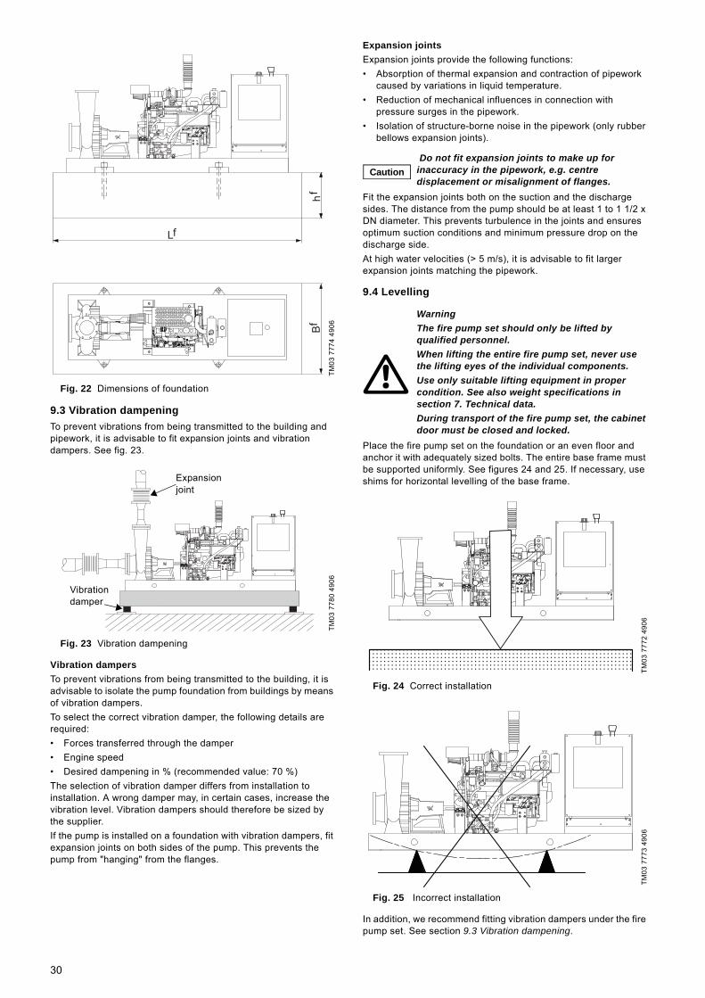
Fig. 22 Dimensions of foundation
9.3 Vibration dampeningTo prevent vibrations from being transmitted to the building and pipework, it is advisable to fit expansion joints and vibration dampers. See fig. 23.
Fig. 23 Vibration dampening
Vibration dampersTo prevent vibrations from being transmitted to the building, it is advisable to isolate the pump foundation from buildings by means of vibration dampers.To select the correct vibration damper, the following details are required:• Forces transferred through the damper• Engine speed• Desired dampening in % (recommended value: 70 %)The selection of vibration damper differs from installation to installation. A wrong damper may, in certain cases, increase the vibration level. Vibration dampers should therefore be sized by the supplier.If the pump is installed on a foundation with vibration dampers, fit expansion joints on both sides of the pump. This prevents the pump from "hanging" from the flanges.
Expansion jointsExpansion joints provide the following functions:• Absorption of thermal expansion and contraction of pipework
caused by variations in liquid temperature.• Reduction of mechanical influences in connection with
pressure surges in the pipework.• Isolation of structure-borne noise in the pipework (only rubber
bellows expansion joints).
Fit the expansion joints both on the suction and the discharge sides. The distance from the pump should be at least 1 to 1 1/2 x DN diameter. This prevents turbulence in the joints and ensures optimum suction conditions and minimum pressure drop on the discharge side.At high water velocities (> 5 m/s), it is advisable to fit larger expansion joints matching the pipework.
9.4 Levelling
Place the fire pump set on the foundation or an even floor and anchor it with adequately sized bolts. The entire base frame must be supported uniformly. See figures 24 and 25. If necessary, use shims for horizontal levelling of the base frame.
Fig. 24 Correct installation
Fig. 25 Incorrect installation
In addition, we recommend fitting vibration dampers under the fire pump set. See section 9.3 Vibration dampening.
TM03
777
4 49
06TM
03 7
780
4906
hf
Bf
Lf
Vibration damper
Expansion joint
Caution Do not fit expansion joints to make up for inaccuracy in the pipework, e.g. centre displacement or misalignment of flanges.
WarningThe fire pump set should only be lifted by qualified personnel.When lifting the entire fire pump set, never use the lifting eyes of the individual components.Use only suitable lifting equipment in proper condition. See also weight specifications in section 7. Technical data.During transport of the fire pump set, the cabinet door must be closed and locked.
TM03
777
2 49
06TM
03 7
773
4906
30

9.5 Pipework
The suction and discharge piping should be arranged for the simplest, most direct layout. The pipes must be of an adequate size, taking also the pump inlet pressure into consideration. The direction of flow is marked with arrows.Install the pipes so that air locks are avoided, especially on the suction side of the pump. See fig. 26.
Fig. 26 Correct and incorrect installation of suction pipe
Fit pipe hangers on the wall, ceiling or floor close to the pump on the suction and the discharge side. See fig. 27.The pipes should lie true against the pump flanges without being stressed. Otherwise, the pump may be damaged.
Fig. 27 Fixing points of the pipes
Isolating valves must be installed on the suction and the discharge side of the pump.
9.6 BypassA bypass to the suction source, if required, should be made as shown in fig. 28. The distance between bypass pipe and pump discharge flange must be at least ten pipe diameters.
Fig. 28 Possible bypass arrangement
9.7 Connection to the cooling systemThe discharge from the heat exchanger is led via an open outlet or a visible waste cone back to the suction reservoir. Connect a tube to the discharge side of the heat exchanger. See fig. 49, pos. A. The connection size is 3/8". The nominal tube diameter must not be smaller than the outlet on the heat exchanger.
9.8 Connection to the pressure sensorThe threaded connection for the pressure sensor (1/4" NPTF) is on the right side of the controller (fig. 10, pos. 4). Run a hose from the discharge pipe to the pressure sensor. Water pipes must be flushed clean before connecting the pressure sensor.
9.9 Priming tank and test pipeIf the fire pump set is supplied from a storage tank, a pump priming tank must be installed on the suction side in accordance with local regulations.Install a test pipe running from the discharge pipe to the storage tank. The discharge pipe and the test pipe must be fitted with isolating valves. If the fire pump set is fed directly from the public water supply, the test pipe must have a free outlet. If the test pipe is led back to the reservoir, it must be equipped with a waste cone.
9.10 Fresh air supplyFigure 29 shows a possible arrangement of supplied and discharged air ensuring a sufficient supply of fresh air.
Fig. 29 Supply and discharge of air
If required, install louvres to open as soon as the engine starts. This will ensure an adequate supply of fresh air and removal of engine heat.
WarningDo not put fingers, hands, arms, etc. into the suction or discharge openings or into any other opening, such as that of the air relief valve. Do not touch the rotating impeller, as this can cause severe injury. Do not remove protective covers or packaging until installation.
CautionThe pipework must not stress the pump housing or transfer any forces to the pump housing. Noncompliance may damage the pump.
TM04
512
2 26
09TM
03 7
775
4906
Air lock
Air lock
Air lock
TM04
512
3 26
09TM
03 5
501
3706
To reservoir
Globe valve
Byp
ass
pipe
Pum
p
Suction side
Discharge side
System
0
90908080
1010
2020
3030 4040
6060
7070
5050
31

9.11 Exhaust gas system
Remove the protective cap (fig. 46, pos. A), and fit the attached flexible exhaust pipe (fig. 3, pos. 16). Install exhaust pipes as straight and with as few bends as possible to enable discharge of combustion gases with a minimum of back-pressure. Install the supplied silencer horizontally and at a sufficient distance to the engine. The exhaust system is to be arranged so that no condensation water can enter the engine.The exhaust system must be fixed to the building. The flexible connection piece must not be used to compensate for misaligned pipework.The minimum diameter of the exhaust pipes must not be smaller than that of the exhaust port of the engine.
9.12 AlignmentPump and engine can be connected by two types of coupling: a drive shaft or a flexible coupling from CENTAFLEX.If a fire pump set comes preassembled from factory, the coupling has been accurately aligned by means of shims inserted under the pump and engine.During transport and installation, the pump-engine alignment may have been affected. It must therefore always be checked when the fire pump set has been installed.
9.12.1 Drive shaftRemove the coupling guard, and check the drive shaft for proper parallel offset and angular tolerance. After the check, fit the coupling guard before connecting the battery cables.
At first, check if the bolts of the drive shaft are tightened with the correct tightening torque. See table below. It may be necessary to use a special torque tool if there is not enough space for a standard socket.
Checking the horizontal parallel offset1. Rotate the shaft so that the reference "AB" on the flywheel
disc or the circumference of the drive shaft flange (against the flywheel) is in 12 o’clock position. See fig. 30.
2. Measure from the rear face of the flywheel drive disc or the drive shaft flange to point A. See fig. 30. The value must be as stated in the table above.
3. If the value is not correct, loosen the screws holding the pump on the base frame and move the pump in the horizontal level.
4. After alignment, tighten the screws, and measure again.
Checking the horizontal angular alignment1. Leave the drive shaft in 12 o’clock position.2. Measure from the front face of the drive shaft flange on the
pump end to point B. See fig. 30. This measurement must be equal to the measurement at point A ± 1 mm.
3. If the value is not correct, loose the screws for tightening the pump on the base frame and insert shims or foil under the pump base.
4. After alignment, tighten the screws, and measure again.
Checking the vertical parallel offset1. Rotate the shaft by 90 ° so that the reference "CD" on the
flywheel disc or the circumference of the drive shaft flange (against the flywheel) is in the position shown in fig. 31.
2. Measure from the rear face of the flywheel drive disc or the drive shaft flange to point C. See fig. 31. The value must be as stated in the table above.
3. If the value is not correct, loosen the screws holding the pump on the base frame and move the pump in the horizontal level.
4. After alignment, tighten the screws, and measure again.
Checking the horizontal angular alignment1. Leave the drive shaft in the previous position.2. Measure from the front face of the drive shaft flange on the
pump end to point D. See fig. 31. This measurement must be equal to the measurement at point C ± 1 mm.
3. If the value is not correct, loosen the screws holding the pump on the base frame and insert shims or foil under the pump base.
4. After alignment, tighten the screws, and measure again.
Fig. 30 Horizontal alignment
WarningThe exhaust gas system must be installed correctly according to local regulations and must have no leaks. Operation without exhaust gas system is not permitted.Exhaust gases are to be directed safely to the open air through the exhaust system. Exhaust fumes must not escape indoors. Danger of suffocation!Hot exhaust pipes must be protected to prevent accidental touch. Danger of burns!
Caution
Careful alignment is important for a long coupling life. This is particularly important with increased engine speed. Follow the instructions of the coupling manufacturer.
WarningBefore removing the coupling guard, disconnect the battery cable.
Engine type Drive-shaft type
Horizontal offset[mm]
Vertical offset[mm]
Tightening torque[Nm]
JU4H-10, 12, 14, 20, 22, 24
SC41SC41A 58 ± 2 60 ± 1 68-75
JU4H-28 and up
SC55SC55A 68 ± 4 71 ± 1 102-112
JU6H SC55L-A 68 ± 1.5 70.5 ± 1 122-134JU6H SC2130 76 ± 3 78 ± 1 122-134JU6H SC2130A 89 ± 1.5 91 ± 1 122-134JW6H SC81A 109 ± 2 112.5 ± 1 122-134JX6H SC2140 87 ± 3 89 ± 1 122-134
TM04
512
4 26
09
B
A AB
Flyw
heel
Flanged pump hub
Viewed from engine control panel
32

Fig. 31 Vertical alignment
9.12.2 Flexible couplingCENTAFEX, the flexible coupling for connecting pump and engine, is shown in fig. 32.
Fig. 32 Flexible coupling
The coupling is bolted axially on the engine flywheel. The pump shaft is pushed in axially and bolted radially with four bolts. See fig. 33.
Fig. 33 Connection and alignment of pump and engine
Checking the alignment
1. Disconnect the battery (negative pole).2. Remove the coupling guard.3. Measure the distance "Z" at the rubber element of all axially
bolted points. See fig. 33. The distance must be 50 mm. If the alignment is correct, proceed with step 4. Otherwise, align pump and engine. See below.
4. Fit the coupling guard.5. Connect the battery.
Aligning pump and engine1. Unscrew axial and radial bolts from the coupling and push
shaft sleeve on the shaft in the direction of the pump.2. Loosen the screws of the pump base.3. Insert shims or foil under the pump base.4. Tighten the screws of the pump base.5. Push the shaft sleeve on the shaft towards the engine and fit
axial and radial bolts. Always fit the axial bolts first. Bolts can be reused a maximum of three times. After that, use new self-locking bolts. Never use threadlocker, as this can damage the rubber compound.
6. Re-check the alignment.
Fig. 34 Axial and radial fixation of the shaft sleeve
9.13 Separate fuel tankThe fuel tank must be located as close as practical to the engine in a dry, well ventilated location. Mount the fuel tank on the floor using the intended fastening holes. Connect the fuel pipes as shown in fig. 35 using both attached connecting pieces (pos. A). The connecting block is marked "SUPPLY" for the incoming pipe and "RETURN" for the return pipe.
Fig. 35 Connecting the fuel pipes
TM04
512
5 26
09TM
03 7
776
4906
TM03
777
7 49
06
D
C CD
Flyw
heel
Flanged pump hub
Viewed from engine control panel
A
A
A-A
ZZWarningBefore removing the coupling guard, disconnect the battery cable.
TM04
005
8 49
07TM
04 5
069
2609
NoteFor sizing and installation of separate fuel tanks, see standard NFPA 20.
A
33
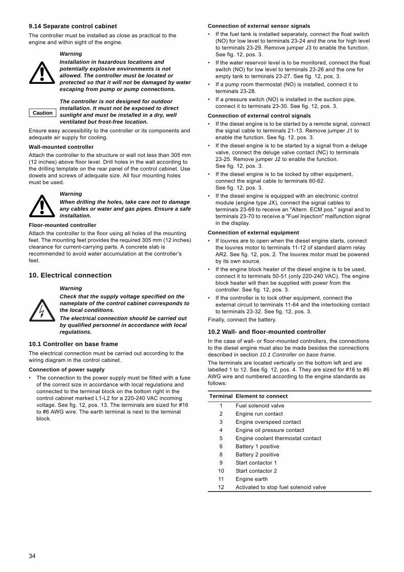
9.14 Separate control cabinetThe controller must be installed as close as practical to the engine and within sight of the engine.
Ensure easy accessibility to the controller or its components and adequate air supply for cooling.
Wall-mounted controllerAttach the controller to the structure or wall not less than 305 mm (12 inches) above floor level. Drill holes in the wall according to the drilling template on the rear panel of the control cabinet. Use dowels and screws of adequate size. All four mounting holes must be used.
Floor-mounted controllerAttach the controller to the floor using all holes of the mounting feet. The mounting feet provides the required 305 mm (12 inches) clearance for current-carrying parts. A concrete slab is recommended to avoid water accumulation at the controller’s feet.
10. Electrical connection
10.1 Controller on base frameThe electrical connection must be carried out according to the wiring diagram in the control cabinet.
Connection of power supply• The connection to the power supply must be fitted with a fuse
of the correct size in accordance with local regulations and connected to the terminal block on the bottom right in the control cabinet marked L1-L2 for a 220-240 VAC incoming voltage. See fig. 12, pos. 13. The terminals are sized for #16 to #6 AWG wire. The earth terminal is next to the terminal block.
Connection of external sensor signals• If the fuel tank is installed separately, connect the float switch
(NO) for low level to terminals 23-24 and the one for high level to terminals 23-29. Remove jumper J3 to enable the function. See fig. 12, pos. 3.
• If the water reservoir level is to be monitored, connect the float switch (NO) for low level to terminals 23-26 and the one for empty tank to terminals 23-27. See fig. 12, pos. 3.
• If a pump room thermostat (NO) is installed, connect it to terminals 23-28.
• If a pressure switch (NO) is installed in the suction pipe, connect it to terminals 23-30. See fig. 12, pos. 3.
Connection of external control signals• If the diesel engine is to be started by a remote signal, connect
the signal cable to terminals 21-13. Remove jumper J1 to enable the function. See fig. 12, pos. 3.
• If the diesel engine is to be started by a signal from a deluge valve, connect the deluge valve contact (NC) to terminals 23-25. Remove jumper J2 to enable the function. See fig. 12, pos. 3.
• If the diesel engine is to be locked by other equipment, connect the signal cable to terminals 60-62. See fig. 12, pos. 3.
• If the diesel engine is equipped with an electronic control module (engine type JX), connect the signal cables to terminals 23-69 to receive an "Altern. ECM pos." signal and to terminals 23-70 to receive a "Fuel Injection" malfunction signal in the display.
Connection of external equipment• If louvres are to open when the diesel engine starts, connect
the louvres motor to terminals 11-12 of standard alarm relay AR2. See fig. 12, pos. 2. The louvres motor must be powered by its own source.
• If the engine block heater of the diesel engine is to be used, connect it to terminals 50-51 (only 220-240 VAC). The engine block heater will then be supplied with power from the controller. See fig. 12, pos. 3.
• If the controller is to lock other equipment, connect the external circuit to terminals 11-64 and the interlocking contact to terminals 23-32. See fig. 12, pos. 3.
Finally, connect the battery.
10.2 Wall- and floor-mounted controllerIn the case of wall- or floor-mounted controllers, the connections to the diesel engine must also be made besides the connections described in section 10.1 Controller on base frame.The terminals are located vertically on the bottom left and are labelled 1 to 12. See fig. 12, pos. 4. They are sized for #16 to #6 AWG wire and numbered according to the engine standards as follows:
WarningInstallation in hazardous locations and potentially explosive environments is not allowed. The controller must be located or protected so that it will not be damaged by water escaping from pump or pump connections.
Caution
The controller is not designed for outdoor installation. It must not be exposed to direct sunlight and must be installed in a dry, well ventilated but frost-free location.
WarningWhen drilling the holes, take care not to damage any cables or water and gas pipes. Ensure a safe installation.
WarningCheck that the supply voltage specified on the nameplate of the control cabinet corresponds to the local conditions.The electrical connection should be carried out by qualified personnel in accordance with local regulations.
Terminal Element to connect
1 Fuel solenoid valve2 Engine run contact3 Engine overspeed contact4 Engine oil pressure contact5 Engine coolant thermostat contact6 Battery 1 positive8 Battery 2 positive9 Start contactor 1
10 Start contactor 211 Engine earth12 Activated to stop fuel solenoid valve
34

10.3 Connection to standard alarm relaysIf operating and alarm messages are to be transferred for instance to a building management system, conductors can be connected to the standard alarm relays (fig. 12, pos. 2). The alarm relays have one NO and one NC contact. The signal can be transferred to maximum two external controllers. If the NO contact is to be used, connect the cable to terminal 14 (24); if the NC contact is to be used, connect the signal cable to terminal 12 (22). The common conductor has to be connected to terminal 11 (21).The table below gives an overview of standard alarm relays:
10.4 Connection to optional alarm relaysIf more detailed information about operating and alarm conditions is required, conductors can be connected to the optional alarm relays for transferring operating and alarm messages to for instance a building management system. The alarm relays have one NO and one NC contact. The signal can be transferred to maximum two external controllers. If the NO contact is to be used, connect the cable to terminal 14 (24); if the NC contact is to be used, connect the signal cable to terminal 12 (22). The common conductor must be connected to terminal 11 (21). The position of the optional alarm relays (pos. 1) is shown in fig. 12.The table below shows the function of the alarm relays.
Relay Function
AR1
Indicates engine fault as a common alarm in these cases:• Engine fails to start after six attempts.• Engine fails when running.• Low oil pressure.• High cooling temperature.• Overspeed.• System overpressure.
AR2 Indicates that the engine is running.
AR3
Indicates pump room fault as a common alarm in these cases:• low inlet pressure• low fuel level• low level in water reservoir• water reservoir empty• low pump room temperature• high fuel level• power failure (no signal "AC Power On").
AR4
Indicates controller fault as a common alarm. The relay is activated when conditions are normal. This fail-safe relay will be deactivated and remain deactivated in these cases:• failure, battery #2• failure, charger #1• failure, charger #2• failure on pressure side.
Option Relay Function
A1 AR5 Weekly testA2 AR6 OverspeedA3 AR7 Low oil pressureA4 AR8 High temperatureA5 AR9 Failure to startA6 AR10 Failure, battery #1A6 AR 11 Failure, battery #2A7 AR12 Failure, charger #1A7 AR13 Failure, charger #2A8 AR14 Power failureA9 AR27 System overpressureB1 AR15 Low fuel levelB2 AR16 Low level in water reservoirB3 AR17 Water reservoir emptyB4 AR18 Low pump room temperatureB5 AR19 High fuel levelB6 AR20 Low system pressureB7 AR21 Low inlet pressureB8 AR28 Pump on-demand
35

11. Start-up
11.1 Check before start-up1. Check oil level. See section 14.4.1 Checking of oil level.2. Check cooling liquid level. See section 14.4.3 Checking of
cooling system.
3. Check V-belt tension. See section 14.4.10 Checking of V-belt.4. Check coupling alignment. See section 9.12 Alignment.5. Check that all bolts are properly tightened.6. Check that pipework has been installed correctly.7. Check all electric connections in and outside the control
cabinet.
11.2 Start-up
1. Fill the fuel tank with diesel. See section 14.4.6 Filling of fuel.2. Switch on the controller by means of the isolating switch A1
(fig. 10, pos. 9).3. Set the cut-in and cut-out pressures. See section 11.3 Setting
of cut-in and cut-out pressures. 4. Open the fuel tap of the fuel tank.5. Close the isolating valve on the discharge side of the pump.
Open the isolating valve on the suction side of the pump. Open the isolating valve to the test pipe.
6. Start the pump manually with the controller or the control panel of the engine. See section 12.2 Manual operation.
7. Slowly open the isolating valve on the discharge side.8. Vent the system.9. When the pump reaches the operating pressure, open the
isolating valve sufficiently to reach the duty point.10.Compare the oil pressure, temperature and speed with the
rated values. See section 7.3 Engine.11.Adjust the stuffing box, if necessary. See section 14.3 Pump.12.Stop the pump manually. See section 12.2 Manual operation.13.Turn both main switch A2 (fig. 10, pos.7) and the selector
switch (fig. 5, pos. 2, for JU/JW engines and fig. 6, pos. 5, for JX engines) to "AUTO".
The fire pump set is now operational and in automatic mode.In connection with the start-up, carry out a final test run.See section 12.3 Test run.
11.3 Setting of cut-in and cut-out pressuresTo enable setting, DIP switch S10-1 must be set to "ON". See section 5.1 Settings via DIP switches.It is important to set the cut-out pressure first. It must be lower than the maximum pressure of the pump; otherwise the engine will never stop. The cut-in pressure must be set according to the system pressure.A quick push on buttons [Cut-in] B1 and [Cut-out] B2 (fig. 11) increases the value by one unit. A long push increases the value by ten units. The value only increases from minimum to maximum. When the maximum value is reached, the value returns to the minimum value.
12. Operation
The important operating parameters are shown in the display of the controller (see section 4.4.4 Display indications) and on the control panel of the diesel engine (see section 4.3.2 Control panel of the engine). If the controller outputs are connected to a building management system, the operation can be remotely monitored.In case of failure, see sections 4.4.4 Display indications, 4.4.5 Indicator lights on control panel and alarm bell, 4.6 Operating and alarm messages and 15. Fault finding.
12.1 Automatic operation
Once the fire pump set has been installed and started up according to the instructions, no further preparation is necessary. The fire pump set starts automatically when the sprinkler system is activated, and the pressure switch detects a pressure drop. The fire pump set will also start automatically if it receives a remote start signal or a signal from a deluge valve, when it is time for the weekly test, or in case of a power failure.When the system pressure reaches the cut-out pressure, the engine will stop if [STOP] button A5 (fig. 10, pos. 3) is pressed, or it will stop automatically if set to automatic stop. See section 4.5.1 Operating functions. If not all starting conditions have been eliminated, turn main switch A2 (fig. 10, pos. 7) to "OFF".
WarningStart-up may only be carried out by authorised personnel.The control cabinet must remain closed during start-up. Danger of electric shock!
Caution
To prevent damage to the engine, it is essential to check the levels of oil and cooling liquid in the engine prior to start-up. If the oil level is too low, fill with oil. See section 14.4.2. If the level of cooling liquid is too low, fill with cooling liquid. See section 14.4.4.
WarningDo not start the engine while fuel fumes remain evident or may be present.
WarningUse hearing protection while engine is running.
NoteIf the engine does not start, check for error messages and instructions in the display. Other causes, see section 15. Fault finding.
NoteIt is important to set DIP switch S10-1 back to "OFF" to prevent unauthorised changes.
WarningThe engine will become hot during normal operation. Its surfaces may remain hot for some time after the engine has been stopped.
Caution
Both main switch A2 (fig. 10, pos. 7) and the selector switch (fig. 5, pos. 2, for JU/JW engines, and fig. 6, pos. 5, for JX engines) must be set to "AUTO" or "AUTOMATIC OR MANUAL STOP" respectively.
Note
If started due to a false alarm, the pump should not operate for more than 48 hours. If the pump has run for more than 48 hours after a false alarm, always dismantle and inspect it for signs of wear or damage. Replace any defective components.
36

12.2 Manual operationThe fire pump set can be started manually for a test run, servicing or temporary switching on or off during start-up, the fire pump set can be started manually by means of the controller and the control panel of the diesel engine. Normal operation is operation via controller.
12.2.1 Manual operation via controllerTurn main switch A2 (fig. 10, pos. 7) to "HAND". Press [BATTERY No. 1 MANUAL CRANK] (fig. 10, pos. 6) to start the engine with battery 1, or button [BATTERY No. 2 MANUAL CRANK] (fig. 10, pos. 8) to start the engine with battery 2. If both buttons are pressed simultaneously, batteries 1 and 2 are used in parallel to start the engine.To stop the engine, turn main switch A2 to "OFF" or "AUTO".
12.2.2 Manual operation via control panel of diesel engineIn case of controller failure, the fire pump set can also be started by the control panel of the engine. Turn the selector switch (fig. 5, pos. 2, for JU/JW engines, and fig. 6, pos. 5, for JX engines) to "MANUAL RUN". Lift [MANUAL CRANK #1] (fig. 5, pos. 3, for JU/JW engines, and fig. 6, pos. 10, for JX engines) for maximum 15 seconds until the engine starts. If the engine does not start, wait for 15 seconds and try to start it with [MANUAL CRANK #2] (fig. 6, pos. 11).To stop the JU/JW engine, turn the selector switch (fig. 5, pos. 2) back to "AUTOMATIC OR MANUAL STOP".To stop the JX engine, lift [MANUAL STOP] (fig. 6, pos. 9) until the engine has stopped. Turn the selector switch (fig. 6, pos. 5) back to "AUTOMATIC".
12.3 Test runTo do a test run, close the fuel tap and activate the automatic start-up command by pressing [Run Test] on the control panel of the controller. Every starting cycle consists of a 15-second starting phase followed by a 15-second pause. After six failed start attempts, a start failure warning must be activated (fig. 11, indicator light 11, and ringing of bell). When the fuel tap has been opened and the fault indication has been removed by turning main switch A2 (fig. 10, pos. 7) to "OFF" and back to "AUTO", the pump should start properly.
12.4 Retrieving and printing data12.4.1 Retrieving data via the RS 232 portAs standard, the controller has an RS 232 port (fig. 10, pos. 5) for reading of data. The port must be connected to a laptop with an RS 232/DB9 port. A communication software, such as HyperTerminal (provided with the latest Windows version), must be installed on the laptop. The procedure for using HyperTerminal as communication software is described below.1. Connect the communication port of your laptop to the
controller using a DB9 male/female cable.2. Select from the Windows toolbar: Start > Program >
Accessories > Communications > HyperTerminal.3. If your HyperTerminal software has not been configured,
double-click on hypertrm.exe. Otherwise, continue with step 6. Note: This procedure may not be available on certain versions of software.
4. In the window "New Connection", enter a connection name, for instance "Tornatech Controller", and click [OK].
5. In the next window, set communication parameters as follows:• bits per second: 9600• data bits: 8• parity: none• stop bits: 1• flow control: hardware.
Click [OK].6. If your HyperTerminal software has already been configured to
communicate with a fire pump controller, select this configuration.
7. Select Transfer > Capture Text.A window opens so that you can select a file. Enter the name of the file using the browse function.
8. If the window "Select Capture File" is open, click [Open] (available with certain HyperTerminal versions only).
9. Click [Start] to begin retrieving or downloading data.
10.To close the session, click on [File] and select "Exit". Click [Yes] to disconnect, and confirm saving with [Yes].
The downloaded data is saved in the file created in step 4 and selected in step 7. This file is a *.txt file and can be read by programs such as Notepad, Word, Lotus and Excel.When the file is opened, the *.txt file type to must be selected to be shown in the file list.
12.4.2 Printing of dataIf the controller is equipped with a printer, it is located behind a plastic cover. The cover protects the printer from humidity and dust. The cover must be lifted when printing. The printer works on demand only. However, in order to prevent a paper drum deformation, the paper drum is activated automatically at regular intervals.
PrintingFirst press [Print] button B5 (fig. 11) to print the resume of events. When it has been printed, press the button again within 15 seconds.
Caution
Do not leave the selector switch (fig. 5, pos. 2, for JU/JW engines, and fig. 6, pos. 5, for JX engines) in position "MANUAL RUN" during automatic operation. The controller will be unable to stop the engine, and damage may result.
NoteRegular test runs to ensure operation efficiency should be limited to a maximum of 30 minutes per week.
Note
The data will not start downloading to your laptop until [Print] button B5 (fig. 11) is pressed on the controller display.The data required for the creation of the pressure graph are both the resume of events and the pressure data. To obtain the resume of events, press the [Print] button once. To obtain the pressure data, press the [Print] button once again within 60 seconds of the first time it was pressed. The data will be saved in the file chosen.
37

Paper replacementThe paper must be thermal paper and be correctly oriented. The following operations must be followed to replace the paper:1. Unscrew the axle and remove the empty roll.2. On the printer, open the top cover to get access to the roller.3. Lift the cover completely.4. Insert the thermal paper in the slot. The thermal side must be
face down.5. Close the cover.
12.4.3 Retrieving data via modemTo use a modem for retrieving data and remote monitoring of the fire pump set, a program delivered together with the controller must be installed on your computer. Go to the Windows Explorer and double-click on [GPD viewer EXE] file. Click on the configuration icon, and enter the phone number of the GPD controller after the equal sign.
Fig. 36 Tornatech GPD.ini - Notepad
Check that USEPORT is the one your computer is connected to and USEMODEM=1. Save and close the file.After the installation is done, the fire pump set can be remotely monitored by clicking [Diesel control]. The following window appears:
Fig. 37 Monitoring of fire pump set
The modem reads the actual status of the controller. The system is not live, i.e. it reads the pressure when the window is open, and each time the [Refresh] button is clicked.Click [Read event logs] to download events of the last 15 days. Depending of the number of events and the speed of the communication, downloading may take several minutes. The events can be saved in *.txt format by clicking [Save in File]. All events can be visualised using the vertical bar that appears after download.Click [Read pressure logs] to download pressure data of the last seven days. Depending of the number of pressure data and the speed of the communication, downloading may take several minutes. The pressure data can be saved in *.txt format by clicking [Save in File]. All pressure data can be visualised using the vertical bar that appears after download.
Weekly testClick [Weekly Test] to access the settings of the weekly test. The following window appears:
Fig. 38 Setting of weekly test
Battery chargersClick [Battery charger] to access the battery charger monitoring. The following window appears:
Fig. 39 Setting of battery charger
By default, the status of battery charger 1 appears in the screen. To access battery charger 2, enter "2" in the bottom window and click [Refresh]. If [Auto] is clicked, the battery charger will be monitored continuously.
Controller statusTo see the status of the display, input contacts and output signals, click [Display Status].
Fig. 40 Reading of status
As the monitoring is not permanent, click [Refresh] to get the actual status of the controller.
TM04
513
4 26
09TM
04 5
135
2609
TM04
513
6 26
09TM
04 5
137
2609
TM04
513
9 26
09
38

13. Taking the pump out of operation
1. Close the isolating valve on the discharge side.2. Close the isolating valve on the suction side.3. Close the fuel tap on the fuel tank.4. Turn main switch A2 (fig. 10, pos. 7) and isolating switch A1
(fig. 10, pos. 9) to "OFF". Secure the isolating switch with a padlock so that the fire pump set cannot be accidentally switched on.
5. Disconnect the battery.During extended periods of inactivity, drain the pump (see figures 41 and 42), and remove and discard the stuffing box packing according to service instructions. Then take the measures listed in section 3.3 Storage.
Fig. 41 Drain plug of HSEF pump
Fig. 42 Drain plug of DNF pump (M2)
To restart the fire pump set, remove all protective covers, fit a new stuffing box packing (see service instructions), fill with engine oil and cooling liquid, and align the coupling. Then continue as described in section 11. Start-up.
14. Maintenance
14.1 Fire pump setA test run should be carried out once a week.See section 12.3 Test run.
14.2 Maintenance intervalsPumpLubrication of bearing: Once a year.
Diesel engine
CouplingLubrication of drive shaft: Once a year.
ControllerTesting of indicator lights: Once a week.Checking of wire connections: Once a year.
Note
This window is the monitoring of the electronic board. As the manual control is independent from the electronic board, this window does not monitor a possible manual crank.
Note The fire pump set must not be running.
TM04
507
0 26
09TM
04 5
126
2609
Drain plug
Note
The operator is responsible for ensuring that all maintenance, inspection and installation work is performed by qualified personnel. A regular maintenance plan will help avoid expensive repairs and contribute to trouble-free, reliable operation. It is recommended to place a maintenance contract with Grundfos.
WarningBefore starting work on the pump, make sure that the fire pump set has been switched off and cannot be accidentally switched on. Maintenance work must only be carried out by qualified personnel.
WarningDo not place tools on or near the batteries. This could result in a short-circuit.
Interval
Inspection Replacement
Oil level Once a week -Oil change with filter - Once a yearCooling system Once a week -Cooling liquid - Once a yearFuel system/filter Once a week Once a yearExhaust system Once a week -Air filter Once a week Every six monthsV-belt Once a month Once a year
39
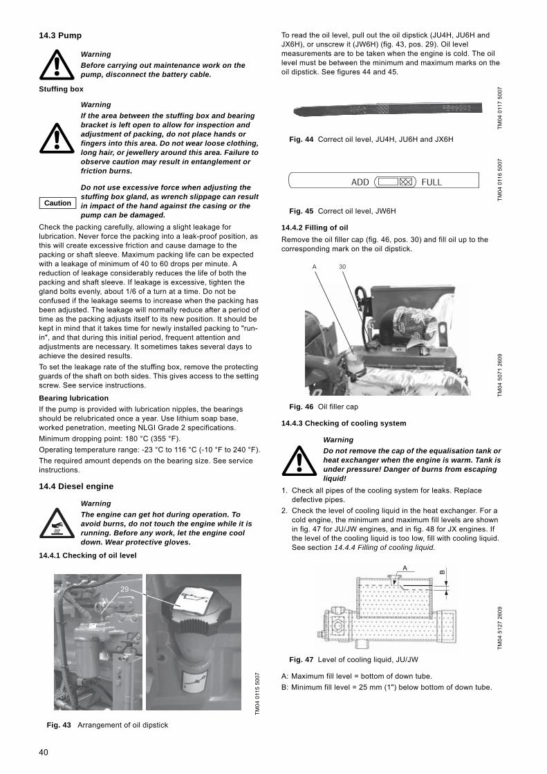
14.3 Pump
Stuffing box
Check the packing carefully, allowing a slight leakage for lubrication. Never force the packing into a leak-proof position, as this will create excessive friction and cause damage to the packing or shaft sleeve. Maximum packing life can be expected with a leakage of minimum of 40 to 60 drops per minute. A reduction of leakage considerably reduces the life of both the packing and shaft sleeve. If leakage is excessive, tighten the gland bolts evenly, about 1/6 of a turn at a time. Do not be confused if the leakage seems to increase when the packing has been adjusted. The leakage will normally reduce after a period of time as the packing adjusts itself to its new position. It should be kept in mind that it takes time for newly installed packing to "run-in", and that during this initial period, frequent attention and adjustments are necessary. It sometimes takes several days to achieve the desired results.To set the leakage rate of the stuffing box, remove the protecting guards of the shaft on both sides. This gives access to the setting screw. See service instructions.
Bearing lubricationIf the pump is provided with lubrication nipples, the bearings should be relubricated once a year. Use lithium soap base, worked penetration, meeting NLGI Grade 2 specifications.Minimum dropping point: 180 °C (355 °F). Operating temperature range: -23 °C to 116 °C (-10 °F to 240 °F).The required amount depends on the bearing size. See service instructions.
14.4 Diesel engine
14.4.1 Checking of oil level
Fig. 43 Arrangement of oil dipstick
To read the oil level, pull out the oil dipstick (JU4H, JU6H and JX6H), or unscrew it (JW6H) (fig. 43, pos. 29). Oil level measurements are to be taken when the engine is cold. The oil level must be between the minimum and maximum marks on the oil dipstick. See figures 44 and 45.
Fig. 44 Correct oil level, JU4H, JU6H and JX6H
Fig. 45 Correct oil level, JW6H
14.4.2 Filling of oilRemove the oil filler cap (fig. 46, pos. 30) and fill oil up to the corresponding mark on the oil dipstick.
Fig. 46 Oil filler cap
14.4.3 Checking of cooling system
1. Check all pipes of the cooling system for leaks. Replace defective pipes.
2. Check the level of cooling liquid in the heat exchanger. For a cold engine, the minimum and maximum fill levels are shown in fig. 47 for JU/JW engines, and in fig. 48 for JX engines. If the level of the cooling liquid is too low, fill with cooling liquid. See section 14.4.4 Filling of cooling liquid.
Fig. 47 Level of cooling liquid, JU/JW
A: Maximum fill level = bottom of down tube.B: Minimum fill level = 25 mm (1") below bottom of down tube.
WarningBefore carrying out maintenance work on the pump, disconnect the battery cable.
WarningIf the area between the stuffing box and bearing bracket is left open to allow for inspection and adjustment of packing, do not place hands or fingers into this area. Do not wear loose clothing, long hair, or jewellery around this area. Failure to observe caution may result in entanglement or friction burns.
Caution
Do not use excessive force when adjusting the stuffing box gland, as wrench slippage can result in impact of the hand against the casing or the pump can be damaged.
WarningThe engine can get hot during operation. To avoid burns, do not touch the engine while it is running. Before any work, let the engine cool down. Wear protective gloves.
TM04
011
5 50
07
29
TM04
011
7 50
07TM
04 0
116
5007
TM04
507
1 26
09
WarningDo not remove the cap of the equalisation tank or heat exchanger when the engine is warm. Tank is under pressure! Danger of burns from escaping liquid!
TM04
512
7 26
09
ADD FULL
A 30
A
B
40

Fig. 48 Level of cooling liquid, JX6H
A: Maximum fill level = 70 mm (2 3/4").B: Minimum fill level = 155 mm (6 1/8").
14.4.4 Filling of cooling liquid
Fig. 49 Heat exchanger
If there is too little cooling liquid in the heat exchanger, remove the cap of the heat exchanger (fig. 49, pos. B) and fill cooling liquid up to the maximum level. See fig. 47 for JU/JW engines, and fig. 48 for JX engines. Put the cap back on.
14.4.5 Checking of fuel system1. Check all fuel pipes for leaks. Replace defective fuel pipes.2. Read the fuel level from the fuel level indicator. See for
instance fig. 51, pos. 9. To prevent damage by condensation and to maintain the system ready for operation, the fuel tank must always be full.
3. Drain the condensate from the fuel filter and fuel tank.
Draining the condensateThe condensate collector of the fuel filter is under the fuel filter (fig. 52, pos. A). Loosen the knurled nuts of the condensate collector. Collect the fuel containing water in a suitable container and dispose of it in an environmentally sound way. Tighten them when the diesel fuel runs clean, i.e. without water.Normally, there is a drain screw in the tank bottom. See fig. 50, pos. A, for an example. Loosen the drain screw, and remove accumulated water and dirt. Collect the diesel fuel in a suitable container and dispose of in an environmentally sound way. Tighten the drain screw when the diesel fuel runs clean, i.e. without water.
Fig. 50 Drain screw of fuel tank
14.4.6 Filling of fuel
An example of a fuel tank is shown in fig. 51.
Fig. 51 Example of a fuel tank
The fuel tank can be filled either from the top using a canister, or using the manual filling pump on the side (fig. 51, pos. 7). For filling quantities, see section 7.3 Engine.To fill using a canister, remove the tank cap (fig. 51, pos. 8) and pour in the fuel. Put the cap back on.To fill using the hand pump, connect the tube from the diesel barrel to the lower connection port of the hand pump (fig. 51, pos. A), and connect a second tube to the upper connection port of the hand pump (fig. 51, pos. B). Remove the tank cap and put the tube from the upper connection port of the hand pump into the tank opening. Operate the hand pump to fill the tank with fuel. When the tank is full, take the tube out of the tank and put the tank cap back on. Disconnect both tubes from the hand pump.
TM04
512
8 26
09
WarningDo not remove the cap of the heat exchanger when the engine is warm. Tank is under pressure! Danger of burns from escaping liquid!
TM04
507
2 26
09
CautionOnly use prescribed coolant. See section 7.3 Engine.
NoteOver time, the coolant in the cooling liquid loses its effect. The cooling liquid must therefore be changed every year. See service instructions.
A
B
B
A
TM04
519
6 28
09
Caution Only use diesel fuel.
WarningFuel fumes are highly flammable! Do not refuel the engine when it is running or still hot from recent running.When refuelling, avoid breathing the fuel fumes, particularly if the pump is installed in an enclosed pump room. Maintain maximum ventilation to clear the fumes quickly.Do not start the engine while fuel fumes remain evident or may be present.
TM04
519
7 28
09
A
A
B
9
7
8
41

14.4.7 Venting of fuel system
JU4H and JU6H
Fig. 52 Venting of fuel system through the fuel filter, JU4H and JU6H
1. Loosen the vent screw (fig. 52, pos. C) of the filter holder by turning it two turns by hand.
2. Operate the lever of the fuel suction pump (fig. 52, pos. 22) until the diesel fuel running out of the vent port does not contain air bubbles. Collect the fuel in a suitable container and dispose of it in an environmentally sound way.
3. Carefully tighten the ventilation port. Keep operating the lever of the fuel suction pump until no resistance is felt. Then push the handle as far as possible in the direction of the cylinder block.
4. Start the engine manually. See section 12.2.1 Manual operation via controller, and check for leaks. Stop the engine by turning main switch A2 to "OFF" or "AUTO".
If the engine does not start, the fuel system may also need to be vented through the fuel injection pump. The procedure is as follows:1. Loosen the connector (fig. 53, pos. A) of the fuel backflow
pipe.2. Operate the lever of the fuel suction pump (fig. 52, pos. 22)
until the diesel fuel running out of the connector does not contain air bubbles. Collect the fuel in a suitable container and dispose of it according to regulations.
3. Tighten the connector with 16 Nm.4. Press the handle as far as possible in the direction of the
cylinder block.5. Start the engine manually. See section 12.2.1 Manual
operation via controller. Check for leaks. Stop the engine by turning main switch A2 to "OFF" or "AUTO".
Fig. 53 Venting of fuel system through the diesel injection pump, JU4H and JU6H
JW6H
Fig. 54 Venting of fuel system through the fuel filter, JW6H
First vent the fuel system through the primary filter:1. Loosen the vent screw (fig. 54, pos. E) of the filter holder.2. Operate the manual venting system (fig. 54, pos. F) until the
diesel fuel running out of the vent port does not contain air bubbles. Collect the fuel in a suitable container and dispose of it in an environmentally sound way.
3. Carefully re-tighten the vent port. Keep the manual venting system pressed downwards.
Then vent the fuel system through the secondary filter:1. Loosen the vent port (fig. 54, pos. C) of the fuel filter holder.2. Operate the manual venting system (fig. 55, pos. A) of the fuel
supply pump until the diesel fuel running out of the vent port does not contain air bubbles. Collect the fuel in a suitable container and dispose of it in an environmentally sound way.
3. Carefully re-tighten the vent port. Keep the manual venting system pressed downwards.
4. Start the engine manually. See section 12.2.1 Manual operation via controller. Check for leaks. Stop the engine by turning main switch A2 to "OFF" or "AUTO".
If the engine does not start, the fuel system may also need to be vented through the fuel injection pump. The procedure is as follows:1. Remove the connector (fig. 55, pos. B) of the fuel pipe from
the first injection nozzle.2. Crank up the engine with the starter until fuel without air
bubbles runs out of the connector. Collect the fuel in a suitable container and dispose of it in an environmentally sound way.
3. Fit the connector.4. Repeat steps 1 to 3 for all injection nozzles.5. Start the engine manually. See section 12.2.1 Manual
operation via controller. Check for leaks. Stop the engine by turning main switch A2 to "OFF" or "AUTO".
Fig. 55 Venting of fuel system through the diesel injection pump, JW6H
WarningFuel expelled under pressure can penetrate the skin and cause serious injuries. The pressure must therefore always be released before the fuel pipes are disconnected. Before repressurising, tighten all pipes securely.
TM04
519
8 28
09TM
04 0
124
5007
A
C
22
A
TM04
519
9 28
09TM
04 0
126
5007
C E F
A
B
42

JX6H
14.4.8 Checking of exhaust systemCheck the entire exhaust pipe system for leaks while the engine is running. Tighten any loose pipe connections. Replace defective pipes immediately.
14.4.9 Checking of air filterExamine the air filter for dirt particles. Replace dirty air filters. To remove the air filter, loosen the brackets and pull off the filter element. Fit a new filter in reverse order. It is advisable to change the air filter every six months.
14.4.10 Checking of V-beltCheck the V-belt and belt pulleys for wear. Check also the V-belt tension.
The V-belt elasticity midway between the two V-belt pulleys must be 1 to 1.5 cm. See arrow in fig. 56. The V-belt tension can be increased by loosening both generator fixing screws (fig. 56, pos. A) and pushing the generator outwards (fig. 56, pos. B). Then retighten the screws.Worn V-belts must be replaced. See service instructions.
Fig. 56 Checking of V-belt
14.5 CouplingFlexible couplingCouplings with elastomer drive parts do not require lubrication.
Drive shaft
1. Remove the top of coupling guard.2. Rotate the engine shaft manually so the U-joint grease fittings
are accessible.3. Use a hand-held grease gun with N.L.G.I. grade 1 or 2 grease
position on grease fitting. Fill with grease until grease is visible at all four cap seals.
4. Check that all drive shaft bolts remain tight.5. Fit the top of guard, and connect negative battery cables.
14.6 Controller
The following maintenance work must be carried out regularly:• Test indicator lights.• Check wire connections.To test the function of the indicator lights on the control panel and the alarm bell, press [Lamp Test/Silence] button B3. If an indicator light fails, please contact Grundfos.All screw connections on the brackets and all frame connections must be checked once a year to ensure a secure fit. Any loose connections must be tightened. Check all cables for visible damage and replace, if necessary. This applies also for the cables of the diesel engine and the signal cables.If the fuse of the charger, on the board charger No 1 or 2, has blown, replace it by the exact fuse model (SLO-BLO 3AG-32VDC-20A).
Note
For venting of JX engines, a fuel priming assist kit is required. See manual. Under normal conditions, however, fuel system bleeding is not required. Priming the system with a hand primer is normally sufficient.
CautionV-belts must be stretched according to regulations to ensure an optimum functioning of the pump and electric generator.
TM04
012
8 50
07
A
B
WarningBefore carrying out maintenance work on the drive shaft, disconnect the battery cable.
WarningBefore opening the control cabinet, switch off the power supply by means of the isolating switch. Risk of electric shock!
43

15. Fault finding
WarningBefore carrying out any service of the pump, make sure that the fire pump set cannot accidentally start.
Fault Cause Remedy
1. Pump delivers no or too little water.
a) Air in suction pipe. Fill storage container with water. Vent pump. Make sure the suction pipe has been installed according to section 9.5 Pipework.
b) Pump draws in air due to defective gaskets. Check the pipe gaskets and pump housing gaskets, and replace if necessary.
c) Counter-pressure too high. Check the system for impurities and blockages.d) Inlet pressure too low. Make sure that the storage tank is filled with
enough water and that the conditions in section 8.1 Minimum inlet pressure are complied with. Open the isolating valve on the suction side completely.
e) Suction pipe or impeller blocked. Clean suction pipe and pump. 2. Pump is noisy and/or
runs unevenly.a) Inlet pressure too low (cavitation). Make sure that the storage tank is filled with
enough water and that the conditions in section 8.1 Minimum inlet pressure are complied with. Open the isolating valve on the suction side completely.
b) Air in suction pipe or pump. Fill storage tank with water. Vent pump. Make sure the suction pipe has been installed according to section 9.5 Pipework.
c) Impeller out of balance. Clean the impeller.d) Inner pump parts worn. Replace defective parts.e) Pump stressed by the pipework. Install the pump so that it is not stressed.
Support the pipes.f) Defective bearings. Replace bearings.g) Defective coupling. Replace coupling.h) Foreign bodies in the pump. Clean the pump.
3. Leakage from pump. a) Pump stressed by the pipework. Install the pump so that it is not stressed. Support the pipes.
b) Pump housing gaskets or pipe gaskets defective. Replace defective gaskets.4. Excessive leakage from
stuffing box.a) Stuffing box packing too loose. Tighten the gland bolts evenly to obtain a
leakage of 40 60 drops per minute.b) Stuffing box packing worn. Replace stuffing box packing. See service
instructions.5. Too high pump
temperature. a) Air in the pump. Fill the storage tank with water.b) Inlet pressure too low. Make sure that the storage tank is filled with
enough water and that all conditions in section 8.1 Minimum inlet pressure are complied with.
c) Bearings lubricated with too little, too much or unsuitable lubricant. Replenish, reduce or replace the lubricant.
d) Pump with bearing seat stressed by pipework. Install the pump so that it is not stressed. Support pipes. Check the alignment of the pump, and correct, if necessary. See section 9.12 Alignment.
e) Axial pressure too high. Check the relief holes of the impeller and the lock rings on the suction side.
6. Engine does not start. a) Fuel tap closed. Open fuel tap on the diesel tank.b) No diesel in the tank. Fill tank with diesel. Vent fuel system, if
necessary. See sections 14.4.6 Filling of fuel and 14.4.7 Venting of fuel system.
c) Fuel filter blocked. Change fuel filter. See service instructions.d) Air in fuel system. Vent fuel system. See section 14.4.7 Venting of
fuel system.e) Water in the fuel. Drain fuel from the fuel tank. Fill new fuel. Vent
the fuel system, if necessary.f) Starter relay defective. Replace starter relay.g) Insufficient power supply. Check power supply to the control cabinet,
batteries and cables of the fire pump set.h) Exhaust pipes blocked. Clean exhaust pipes.
44

16. Service, spare parts and accessories
The installation and/or use of such products may negatively alter and thus impair the specified properties of the fire pump set.The usage of non-original spare parts and accessories renders any liability on behalf of Grundfos for resulting damages null and void.Any malfunctions which cannot be repaired should only be corrected by Grundfos or authorised specialist companies.Please provide an exact description in the event of a malfunction so that our service technician can prepare and provide the appropriate spare parts.Please obtain the technical data for the system from the nameplate.
17. WarrantyThe warranty is governed by the framework of our general terms of delivery. Liability for any damage resulting from incorrect installation, electrical connection or use, as well as liability for consequential damage, is excluded. The start of the warranty period is to be verified.
18. Further documentationThese operating instructions are to be used in conjunction with the following documentation:• wiring diagram of controller• service instructions of the fire pump set.
7. Oil pressure is too high or too low when engine is running.
a) Oil filter blocked. Replace oil filter. See service instructions.b) Water or fuel in the oil. Change oil. See service instructions.c) Oil level too low/too high. Fill or drain oil. See section 14.4.2 Filling of oil.d) Oil pump worn. Replace oil pump.
8. Engine temperature too high.
a) Cooling system faulty. Bypass the cooling circuit. See section 4.3.1 General description.
b) Insufficient cooling liquid. Fill cooling liquid. See section 14.4.4 Filling of cooling liquid.
c) Heat exchanger defective. Replace heat exchanger.9. Engine does not reach
rated speed. a) Incorrect speed setting. Please contact Grundfos.b) Fuel filter partially blocked. Change fuel filter. See service instructions.c) Air in fuel system. Vent fuel system. See section 14.4.7 Venting of
fuel system.d) Traces of water in the fuel. Drain condensate from the fuel filter. See
section 14.4.5 Checking of fuel system.e) Turbocharger or charge air cooler defective. Replace turbocharger or charge air cooler.
10. Battery voltage too low. a) Cell short in starter battery. Replace starter batteries.b) Wiring of the battery charging circuit damaged or
insufficient terminal contact.Check wiring and replace, if necessary. Check terminal connections and tighten, if necessary.
c) Insufficient power supply to the control cabinet. Check power supply.d) V-belt tension too low. Check V-belt tension and correct, if necessary.
See 14.4.10 Checking of V-belt.e) Battery-charging unit defective. Replace battery-charging unit.
11. Strong exhaust gas colouring.
a) Dirty air filter. Replace air filter. See section 14.4.9 Checking of air filter.
Fault Cause Remedy
WarningSpare parts and accessories not supplied by Grundfos are not inspected or approved by Grundfos.
45

19. Dimensions, weights and engine data
19.1 Dimensions and weightsData apply to standard versions.
Fire HSEF
Pump type Engine type
Fire pump set Pump Engine
DimensionsL x W x H
[mm]
Weight[kg]
Suction port
[inch]
Discharge port
[inch]
Height, suction
port [mm]
Height, discharge
port[mm]
Weight[kg]
Exhaust gas port
[mm]
Weight[kg]
HSEF 4-10 JU4H-UF14 2900 x 1310 x 1882 1024 5 4 391 391 143 76 413
HSEF 4-12JU4H-UF14 2900 x 1310 x 1882 1052
5 4391 359
17176 413
JU4H-UF24 2900 x 1310 x 1882 1052 391 359 76 413JU4H-UF34 2900 x 1310 x 1882 1063 391 359 102 424
HESF 5-8 JU4H-UF14 2900 x 1310 x 1882 1024 6 5 410 264 143 76 413
HSEF 5-11JU4H-UF14 2900 x 1310 x 1882 1054
6 5385 385
17276 413
JU4H-UF24 2900 x 1310 x 1882 1054 385 385 76 413JU4H-UF34 2900 x 1310 x 1882 1065 385 385 102 424
HSEF 5-12JU4H-UF54 2900 x 1310 x 1882 1149
6 5353 194
257102 424
JU6H-UF34 3700 x 1310 x 2032 1475 404 391 127 750
HSEF 5-14JU4H-UF10 2900 x 1310 x 1882 1110
6 5378 340
22976 413
JU4H-UF30 2900 x 1310 x 1882 1121 378 340 102 424
HSEF 6-10JU4H-UF34 2900 x 1310 x 1882 1097
8 6366 385
204102 424
JU4H-UF54 2900 x 1310 x 1882 1097 366 385 102 424
HSEF 6-12
JU4H-UF30 2900 x 1310 x 1882 1234
8 6
362 346
342
102 424JU4H-UF54 2900 x 1310 x 1882 1234 362 346 102 424JU6H-UF34 3700 x 1310 x 2032 1560 413 397 127 750JU6H-UF54 3700 x 1310 x 2032 1560 413 397 127 750JU6H-UF84 3700 x 1310 x 2032 1576 413 397 127 766
HSEF 6-14
JU4H-UF30 2900 x 1310 x 1882 1169
8 6
327 315
277
102 424JU4H-UF40 2900 x 1310 x 1882 1169 327 315 102 424JU4H-UF50 2900 x 1310 x 1882 1169 327 315 102 424JU6H-UF30 3700 x 1310 x 2032 1495 378 366 127 750JU6H-UF50 3700 x 1310 x 2032 1495 378 366 127 750JW6H-UF30 2350 x 1000 x 1941 *) 1392 *) 416 404 127 910
HSEF 6-16
JU4H-UF30 2900 x 1310 x 1882 1205
8 6
324 147
313
102 424JU4H-UF40 2900 x 1310 x 1882 1205 324 147 102 424JU4H-UF50 2900 x 1310 x 1882 1205 324 147 102 424JU6H-UF50 3700 x 1310 x 2032 1531 375 334 127 750JU6H-UF60 3700 x 1310 x 2032 1547 375 334 127 766
HSEF 6-18
JU6H-UF50 3700 x 1310 x 2032 1531
8 6
378 340
313
127 750JU6H-UF60 3700 x 1310 x 2032 1547 378 340 127 766JW6H-UF30 2390 x 1000 x 1941 *) 1428 *) 416 378 127 910JW6H-UF40 2390 x 1000 x 1941 *) 1424 *) 416 378 127 906JW6H-UF50 2390 x 1000 x 1941 *) 1447 *) 416 378 152 929
HSEF 8-15
JU4H-UF40 2900 x 1310 x 1882 1278
10 8
327 302
386
102 424JU4H-UF50 2900 x 1310 x 1882 1278 327 302 102 424JU6H-UF30 3700 x 1310 x 2032 1604 378 353 127 750JU6H-UF50 3700 x 1310 x 2032 1604 378 353 127 750JU6H-UF60 3700 x 1310 x 2032 1620 378 353 127 766JW6H-UF30 2370 x 1000 x 1941 *) 1501 *) 416 391 127 910JW6H-UF40 2370 x 1000 x 1941 *) 1497 *) 416 391 127 906JW6H-UF50 2370 x 1000 x 1941 *) 1520 *) 416 391 152 929JW6H-UF60 2370 x 1000 x 1941 *) 1520 *) 416 391 152 929JX6H-UF30 2490 x 1020 x 2190 *) 2020 *) 152 1429
HSEF 8-17
JU6H-UF50 3700 x 1310 x 2032 1677
10 8
353 302
459
127 750JU6H-UF60 3700 x 1310 x 2032 1693 353 302 127 766JW6H-UF30 2470 x 1050 x 1941 *) 1574 *) 391 340 127 910JW6H-UF40 2470 x 1050 x 1941 *) 1570 *) 391 340 127 906JW6H-UF50 2470 x 1050 x 1941 *) 1593 *) 391 340 152 929JW6H-UF60 2470 x 1050 x 1941 *) 1593 *) 391 340 152 929
46
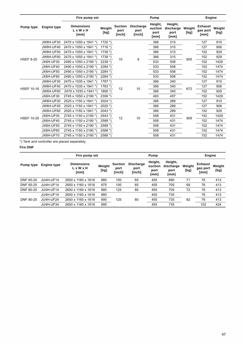
*) Tank and controller are placed separately.
Fire DNF
HSEF 8-20
JW6H-UF30 2470 x 1050 x 1941 *) 1720 *)
10 8
366 315
605
127 910JW6H-UF40 2470 x 1050 x 1941 *) 1716 *) 366 315 127 906JW6H-UF50 2470 x 1050 x 1941 *) 1739 *) 366 315 152 929JW6H-UF60 2470 x 1050 x 1941 *) 1739 *) 366 315 152 929JX6H-UF30 2490 x 1050 x 2190 *) 2239 *) 533 508 152 1429JX6H-UF40 2490 x 1050 x 2190 *) 2284 *) 533 508 152 1474JX6H-UF50 2490 x 1050 x 2190 *) 2284 *) 533 508 152 1474JX6H-UF60 2490 x 1050 x 2190 *) 2284 *) 533 508 152 1474
HSEF 10-16
JW6H-UF30 2470 x 1035 x 1941 *) 1787 *)
12 10
366 340
672
127 910JW6H-UF40 2470 x 1035 x 1941 *) 1783 *) 366 340 127 906JW6H-UF60 2470 x 1035 x 1941 *) 1806 *) 366 340 152 929JX6H-UF30 2745 x 1050 x 2190 *) 2306 *) 483 457 152 1429
HSEF 10-20
JW6H-UF30 2520 x 1150 x 1941 *) 2024 *)
12 10
366 289
909
127 910JW6H-UF40 2520 x 1150 x 1941 *) 2020 *) 366 289 127 906JW6H-UF60 2520 x 1150 x 1941 *) 2043 *) 366 289 152 929JX6H-UF30 2745 x 1150 x 2190 *) 2543 *) 508 431 152 1429JX6H-UF40 2745 x 1150 x 2190 *) 2588 *) 508 431 152 1474JX6H-UF50 2745 x 1150 x 2190 *) 2588 *) 508 431 152 1474JX6H-UF60 2745 x 1150 x 2190 *) 2588 *) 508 431 152 1474JX6H-UF70 2745 x 1150 x 2190 *) 2588 *) 508 431 152 1474
Pump type Engine type
Fire pump set Pump Engine
DimensionsL x W x H
[mm]
Weight[kg]
Suction port
[inch]
Discharge port
[inch]
Height, suction
port [mm]
Height, discharge
port[mm]
Weight[kg]
Exhaust gas port
[mm]
Weight[kg]
Pump type Engine type
Fire pump set Pump Engine
DimensionsL x W x H
[mm]
Weight[kg]
Suction port
[inch]
Discharge port
[inch]
Height, suction
port [mm]
Height, discharge
port[mm]
Weight[kg]
Exhaust gas port
[mm]
Weight[kg]
DNF 65-20 JU4H-UF14 2650 x 1160 x 1619 880 100 65 455 680 71 76 413DNF 65-25 JU4H-UF14 2650 x 1160 x 1619 875 100 65 455 705 69 76 413DNF 80-20 JU4H-UF14 2650 x 1160 x 1619 880 125 80 455 705 72 76 413
DNF 80-25JU4H-UF14 2650 x 1160 x 1619 880
125 80455 735
8276 413
JU4H-UF24 2650 x 1160 x 1619 890 455 735 76 413JU4H-UF34 2650 x 1160 x 1619 890 455 735 102 424
47

19.2 Engine dataFire HSEF
Pump type Engine typeEngine output
Engine speed
Air requirement
Exhaust volume
Oil quantity Oil pressure
Cooling liquid
quantity
Fuel tank volume
[kW] [rpm] [m3/min] [m3/min] [litre] [litre] [litre] [litre]
HESF 4-10 JU4H-UF14 53 2960 6.2 18 8.5 2.5 - 3.4 14.2 605
HSEF 4-12JU4H-UF14 53 2960 6.2 18 8.5 2.5 - 3.4 14.2 605JU4H-UF24 62 2960 6.2 18 8.5 2.5 - 3.4 14.2 605JU4H-UF34 86 2960 10.0 25.8 8.5 2.5 - 3.4 14.2 605
HESF 5-8 JU4H-UF14 53 2960 6.2 18 8.5 2.5 - 3.4 14.2 605
HSEF 5-11JU4H-UF14 53 2960 6.2 18 8.5 2.5 - 3.4 14.2 605JU4H-UF24 62 2960 6.2 18 8.5 2.5 - 3.4 14.2 605JU4H-UF34 86 2960 10.0 25.8 8.5 2.5 - 3.4 14.2 605
HSEF 5-12JU4H-UF54 108 2960 11.7 33.8 8.5 2.5 - 3.4 14.2 605JU6H-UF34 132 2960 17.1 45.7 8.5 2.5 - 3.4 14.2 1155
HSEF 5-14JU4H-UF10 31 1760 4.0 11 8.5 2.5 - 3.4 14.2 605JU4H-UF30 48 1760 4.2 9 8.5 2.5 - 3.4 14.2 605JU4H-UF40 70 1760 4.8 12 8.5 2.5 - 3.4 14.2 605
HSEF 6-10JU4H-UF34 86 2960 10.0 25.8 8.5 2.5 - 3.4 14.2 605JU4H-UF54 108 2960 11.7 33.8 8.5 2.5 - 3.4 14.2 605
HSEF 6-12
JU4H-UF30 48 1760 4.2 9 8.5 2.5 - 3.4 14.2 605JU4H-UF54 108 2960 11.7 33.8 8.5 2.5 - 3.4 14.2 605JU6H-UF34 131 2960 17.1 45.7 8.5 2.5 - 3.4 14.2 1155JU6H-UF54 161 2960 18.3 50.9 8.5 2.5 - 3.4 14.2 1155JU6H-UF84 205 2960 20.3 55.3 8.5 2.5 - 3.4 14.2 1155
HSEF 6-14
JU4H-UF30 48 1760 4.2 9 8.5 2.5 - 3.4 14.2 605JU4H-UF30 59 2100 5.5 13 8.5 2.5 - 3.4 14.2 605JU4H-UF40 70 1760 4.8 12 8.5 2.5 - 3.4 14.2 605JU4H-UF40 78 2100 6.1 15 8.5 2.5 - 3.4 14.2 605JU4H-UF50 82 1760 5.4 16 8.5 2.5 - 3.4 14.2 605JU4H-UF50 97 2100 6.9 20 8.5 2.5 - 3.4 14.2 605JU6H-UF30 104 1760 7.8 21 19.5 2.8 - 4.1 19.0 1155JU6H-UF30 119 2100 10.2 27 19.5 2.8 - 4.1 19.0 1155JU6H-UF50 137 1760 8.9 26 19.5 2.8 - 4.1 19.0 1155JU6H-UF50 157 2100 12.3 34 19.5 2.8 - 4.1 19.0 1155JW6H-UF30 205 2100 21 47 32.0 2.1 - 3.8 21.0 - *)
HSEF 6-16
JU4H-UF30 48 1760 4.2 9 8.5 2.5 - 3.4 14.2 605JU4H-UF40 70 1760 4.8 12 8.5 2.5 - 3.4 14.2 605JU4H-UF50 82 1760 5.4 16 8.5 2.5 - 3.4 14.2 605JU6H-UF50 137 1760 8.9 26 19.5 2.8 - 4.1 19.0 1155JU6H-UF60 149 1760 10.0 27 19.5 2.8 - 4.1 19.0 1155
HSEF 6-18
JU6H-UF50 137 1760 8.9 26 19.5 2.8 - 4.1 19.0 1155JU6H-UF60 149 1760 10.0 27 19.5 2.8 - 4.1 19.0 1155JW6H-UF30 205 2100 21 47 30.0 2.1 - 3.8 21.0 - *)JW6H-UF40 224 2100 22 49 30.0 2.1 - 3.8 22.0 - *)JW6H-UF50 254 2100 25 59 30.0 2.1 - 3.8 22.0 - *)
HSEF 8-15
JU4H-UF40 70 1760 4.8 12 8.5 2.5 - 3.4 14.2 605JU4H-UF50 82 1760 5.4 16 8.5 2.5 - 3.4 14.2 605JU4H-UF50 97 2100 6.1 20 8.5 2.5 - 3.4 14.2 605JU6H-UF30 104 1760 7.8 21 19.5 2.8 - 4.1 19.0 1155JU6H-UF30 119 2100 10.2 27 19.5 2.8 - 4.1 19.0 1155JU6H-UF50 137 1760 8.9 26 19.5 2.8 - 4.1 19.0 1155JU6H-UF50 157 2100 12.3 34 19.5 2.8 - 4.1 19.0 1155JU6H-UF60 149 1760 10.0 27 19.5 2.8 - 4.1 19.0 1155JU6H-UF60 179 2100 14.0 35 19.5 2.8 - 4.1 19.0 1155JW6H-UF30 198 1760 16.0 40 30.0 2.1 - 3.8 21.0 - *)JW6H-UF30 205 2100 21.0 47 30.0 2.1 - 3.8 21.0 - *)JW6H-UF40 224 2100 22.0 49 30.0 2.1 - 3.8 22.0 - *)JW6H-UF50 254 2100 25.0 59 30.0 2.1 - 3.8 22.0 - *)JW6H-UF60 280 2100 27.0 65 30.0 2.1 - 3.8 22.0 - *)JX6H-UF30 322 2100 26.5 65 40.0 3.1 28.0 - *)
48

*) Tank and controller are placed separately.
Fire DNF
20. DisposalThis product or parts of it must be disposed of in an environmentally sound way:1. Use the public or private waste collection service.2. If this is not possible, contact the nearest Grundfos company
or service workshop.
HSEF 8-17
JU6H-UF50 137 1760 8.9 26 19.5 2.8 - 4.1 19.0 1155JU6H-UF50 157 2100 12.3 34 19.5 2.8 - 4.1 19.0 1155JU6H-UF60 149 1760 10.0 27 19.5 2.8 - 4.1 19.0 1155JU6H-UF60 179 2100 14.0 35 19.5 2.8 - 4.1 19.0 1155JW6H-UF30 198 1760 16.0 40 30.0 2.1 - 3.8 21.0 - *)JW6H-UF30 205 2100 21.0 47 30.0 2.1 - 3.8 21.0 - *)JW6H-UF40 216 1760 17.0 43 30.0 2.1 - 3.8 22.0 - *)JW6H-UF40 224 2100 22.0 49 30.0 2.1 - 3.8 22.0 - *)JW6H-UF50 254 2100 25.0 59 30.0 2.1 - 3.8 22.0 - *)JW6H-UF60 268 1760 22.0 56 30.0 2.1 - 3.8 22.0 - *)JW6H-UF60 280 2100 27.0 65 30.0 2.1 - 3.8 22.0 - *)
HSEF 8-20
JW6H-UF30 198 1760 16.0 40 30.0 2.1 - 3.8 21.0 - *)JW6H-UF40 216 1760 17.0 43 30.0 2.1 - 3.8 22.0 - *)JW6H-UF40 224 2100 22.0 49 30.0 2.1 - 3.8 22.0 - *)JW6H-UF50 254 2100 25.0 59 30.0 2.1 - 3.8 22.0 - *)JW6H-UF60 268 1760 22.0 56 30.0 2.1 - 3.8 22.0 - *)JW6H-UF60 280 2100 27.0 65 30.0 2.1 - 3.8 22.0 - *)JX6H-UF30 313 1760 23.0 58 40.0 3.1 28.0 - *)JX6H-UF40 362 2100 31.2 73 40.0 3.1 28.0 - *)JX6H-UF50 380 2100 32.2 76 40.0 3.1 28.0 - *)JX6H-UF60 392 2100 33.2 79 40.0 3.1 28.0 - *)
HESF 10-16
JW6H-UF30 198 1760 16.0 40 30.0 2.1 - 3.8 21.0 - *)JW6H-UF40 216 1760 17.0 43 30.0 2.1 - 3.8 22.0 - *)JW6H-UF60 268 1760 22.0 56 30.0 2.1 - 3.8 22.0 - *)JX6H-UF30 313 1760 23.0 58 40.0 3.1 28.0 - *)JX6H-UF30 322 2100 26.5 65 40.0 3.1 28.0 - *)
HSEF 10-20
JW6H-UF30 198 1760 16.0 40 30.0 2.1 - 3.8 21.0 - *)JW6H-UF40 216 1760 17.0 43 30.0 2.1 - 3.8 22.0 - *)JW6H-UF60 268 1760 22.0 56 30.0 2.1 - 3.8 22.0 - *)JX6H-UF30 313 1760 23.0 58 40.0 3.1 28.0 - *)JX6H-UF40 343 1760 25.4 62 40.0 3.1 28.0 - *)JX6H-UF50 362 1760 27.3 67 40.0 3.1 28.0 - *)JX6H-UF60 380 1760 29.2 72 40.0 3.1 28.0 - *)JX6H-UF70 429 1760 32.1 82 40.0 3.1 28.0 - *)
Pump type Engine typeEngine output
Engine speed
Air requirement
Exhaust volume
Oil quantity Oil pressure
Cooling liquid
quantity
Fuel tank volume
[kW] [rpm] [m3/min] [m3/min] [litre] [litre] [litre] [litre]
Pump type Engine typeEngine output
Engine speed
Air requirement
Exhaust volume Oil quantity Oil
pressure
Cooling liquid
quantity
Fuel tank volume
[kW] [rpm] [m3/min] [m3/min] [litre] [litre] [litre] [litre]
DNF 65-20 JU4H-UF14 53 2960 6.2 18 8.5 2.5 - 3.4 14.2 605DNF 65-25 JU4H-UF14 53 2960 6.2 18 8.5 2.5 - 3.4 14.2 605DNF 80-20 JU4H-UF14 53 2960 6.2 18 8.5 2.5 - 3.4 14.2 605
DNF 80-25JU4H-UF14 53 2960 6.2 18 8.5 2.5 - 3.4 14.2 605JU4H-UF24 62 2960 6.2 18 8.5 2.5 - 3.4 14.2 605JU4H-UF34 86 2960 10.0 25.8 8.5 2.5 - 3.4 14.2 605
Subject to alterations.
49

50
ArgentinaBombas GRUNDFOS de Argentina S.A.Ruta Panamericana km. 37.500 Lote 34A1619 - GarinPcia. de Buenos AiresPhone: +54-3327 414 444Telefax: +54-3327 411 111
AustraliaGRUNDFOS Pumps Pty. Ltd. P.O. Box 2040 Regency Park South Australia 5942 Phone: +61-8-8461-4611 Telefax: +61-8-8340 0155
AustriaGRUNDFOS Pumpen Vertrieb Ges.m.b.H.Grundfosstraße 2 A-5082 Grödig/Salzburg Tel.: +43-6246-883-0 Telefax: +43-6246-883-30
BelgiumN.V. GRUNDFOS Bellux S.A. Boomsesteenweg 81-83 B-2630 Aartselaar Tél.: +32-3-870 7300 Télécopie: +32-3-870 7301
BelorussiaПредставительство ГРУНДФОС в Минске220123, Минск,ул. В. Хоружей, 22, оф. 1105 Тел.: +(37517) 233 97 65, Факс: +(37517) 233 97 69E-mail: [email protected]
Bosnia/HerzegovinaGRUNDFOS SarajevoTrg Heroja 16,BiH-71000 SarajevoPhone: +387 33 713 290Telefax: +387 33 659 079e-mail: [email protected]
BrazilMark GRUNDFOS Ltda.Av. Humberto de Alencar Castelo Branco, 630CEP 09850 - 300São Bernardo do Campo - SPPhone: +55-11 4393 5533Telefax: +55-11 4343 5015
BulgariaGRUNDFOS Pumpen VertriebRepresentative Office - BulgariaBulgaria, 1421 SofiaLozenetz District105-107 Arsenalski blvd. Phone: +359 2963 3820, 2963 5653Telefax: +359 2963 1305
CanadaGRUNDFOS Canada Inc. 2941 Brighton Road Oakville, Ontario L6H 6C9 Phone: +1-905 829 9533 Telefax: +1-905 829 9512
ChinaGRUNDFOS Pumps (Shanghai) Co. Ltd.51 Floor, Raffles CityNo. 268 Xi Zang Road. (M)Shanghai 200001PRCPhone: +86-021-612 252 22Telefax: +86-021-612 253 33
CroatiaGRUNDFOS CROATIA d.o.o.Cebini 37, BuzinHR-10010 ZagrebPhone: +385 1 6595 400 Telefax: +385 1 6595 499www.grundfos.hr
Czech RepublicGRUNDFOS s.r.o.Čajkovského 21779 00 OlomoucPhone: +420-585-716 111Telefax: +420-585-716 299
DenmarkGRUNDFOS DK A/S Martin Bachs Vej 3 DK-8850 Bjerringbro Tlf.: +45-87 50 50 50 Telefax: +45-87 50 51 51 E-mail: [email protected]/DK
EstoniaGRUNDFOS Pumps Eesti OÜPeterburi tee 92G11415 TallinnTel: + 372 606 1690Fax: + 372 606 1691
FinlandOY GRUNDFOS Pumput AB Mestarintie 11 FIN-01730 Vantaa Phone: +358-3066 5650 Telefax: +358-3066 56550
FrancePompes GRUNDFOS Distribution S.A. Parc d’Activités de Chesnes 57, rue de Malacombe F-38290 St. Quentin Fallavier (Lyon) Tél.: +33-4 74 82 15 15 Télécopie: +33-4 74 94 10 51
GermanyGRUNDFOS GMBHSchlüterstr. 3340699 ErkrathTel.: +49-(0) 211 929 69-0 Telefax: +49-(0) 211 929 69-3799e-mail: [email protected] in Deutschland:e-mail: [email protected]
GreeceGRUNDFOS Hellas A.E.B.E. 20th km. Athinon-Markopoulou Av. P.O. Box 71 GR-19002 Peania Phone: +0030-210-66 83 400 Telefax: +0030-210-66 46 273
Hong KongGRUNDFOS Pumps (Hong Kong) Ltd. Unit 1, Ground floor Siu Wai Industrial Centre 29-33 Wing Hong Street & 68 King Lam Street, Cheung Sha Wan Kowloon Phone: +852-27861706 / 27861741 Telefax: +852-27858664
HungaryGRUNDFOS Hungária Kft.Park u. 8H-2045 Törökbálint, Phone: +36-23 511 110Telefax: +36-23 511 111
IndiaGRUNDFOS Pumps India Private Limited118 Old Mahabalipuram RoadThoraipakkamChennai 600 096Phone: +91-44 2496 6800
IndonesiaPT GRUNDFOS Pompa Jl. Rawa Sumur III, Blok III / CC-1 Kawasan Industri, Pulogadung Jakarta 13930 Phone: +62-21-460 6909 Telefax: +62-21-460 6910 / 460 6901
IrelandGRUNDFOS (Ireland) Ltd. Unit A, Merrywell Business ParkBallymount Road LowerDublin 12 Phone: +353-1-4089 800 Telefax: +353-1-4089 830
ItalyGRUNDFOS Pompe Italia S.r.l. Via Gran Sasso 4I-20060 Truccazzano (Milano)Tel.: +39-02-95838112 Telefax: +39-02-95309290 / 95838461
JapanGRUNDFOS Pumps K.K.Gotanda Metalion Bldg., 5F, 5-21-15, Higashi-gotandaShiagawa-ku, Tokyo141-0022 JapanPhone: +81 35 448 1391Telefax: +81 35 448 9619
KoreaGRUNDFOS Pumps Korea Ltd.6th Floor, Aju Building 679-5Yeoksam-dong, Kangnam-ku, 135-916Seoul, KoreaPhone: +82-2-5317 600Telefax: +82-2-5633 725
LatviaSIA GRUNDFOS Pumps Latvia Deglava biznesa centrsAugusta Deglava ielā 60, LV-1035, Rīga,Tālr.: + 371 714 9640, 7 149 641Fakss: + 371 914 9646
LithuaniaGRUNDFOS Pumps UABSmolensko g. 6LT-03201 VilniusTel: + 370 52 395 430Fax: + 370 52 395 431
MalaysiaGRUNDFOS Pumps Sdn. Bhd.7 Jalan Peguam U1/25Glenmarie Industrial Park40150 Shah AlamSelangor Phone: +60-3-5569 2922Telefax: +60-3-5569 2866
MéxicoBombas GRUNDFOS de México S.A. de C.V. Boulevard TLC No. 15Parque Industrial Stiva AeropuertoApodaca, N.L. 66600Phone: +52-81-8144 4000 Telefax: +52-81-8144 4010
NetherlandsGRUNDFOS NetherlandsVeluwezoom 351326 AE AlmerePostbus 220151302 CA ALMERE Tel.: +31-88-478 6336 Telefax: +31-88-478 6332e-mail: [email protected]
New ZealandGRUNDFOS Pumps NZ Ltd.17 Beatrice Tinsley CrescentNorth Harbour Industrial EstateAlbany, AucklandPhone: +64-9-415 3240Telefax: +64-9-415 3250
NorwayGRUNDFOS Pumper A/S Strømsveien 344 Postboks 235, Leirdal N-1011 Oslo Tlf.: +47-22 90 47 00 Telefax: +47-22 32 21 50
PolandGRUNDFOS Pompy Sp. z o.o.ul. Klonowa 23Baranowo k. PoznaniaPL-62-081 PrzeźmierowoTel: (+48-61) 650 13 00Fax: (+48-61) 650 13 50
PortugalBombas GRUNDFOS Portugal, S.A. Rua Calvet de Magalhães, 241Apartado 1079P-2770-153 Paço de ArcosTel.: +351-21-440 76 00Telefax: +351-21-440 76 90
RomâniaGRUNDFOS Pompe România SRLBd. Biruintei, nr 103 Pantelimon county IlfovPhone: +40 21 200 4100Telefax: +40 21 200 4101E-mail: [email protected]
RussiaООО ГрундфосРоссия, 109544 Москва, ул. Школьная 39Тел. (+7) 495 737 30 00, 564 88 00Факс (+7) 495 737 75 36, 564 88 11E-mail [email protected]
Serbia GRUNDFOS Predstavništvo BeogradDr. Milutina Ivkovića 2a/29YU-11000 Beograd Phone: +381 11 26 47 877 / 11 26 47 496Telefax: +381 11 26 48 340
SingaporeGRUNDFOS (Singapore) Pte. Ltd. 24 Tuas West Road Jurong Town Singapore 638381 Phone: +65-6865 1222 Telefax: +65-6861 8402
SloveniaGRUNDFOS PUMPEN VERTRIEB Ges.m.b.H.,Podružnica LjubljanaŠlandrova 8b, SI-1231 Ljubljana-ČrnučePhone: +386 1 568 0610Telefax: +386 1 568 0619E-mail: [email protected]
SpainBombas GRUNDFOS España S.A. Camino de la Fuentecilla, s/n E-28110 Algete (Madrid) Tel.: +34-91-848 8800 Telefax: +34-91-628 0465
SwedenGRUNDFOS AB Box 333 (Lunnagårdsgatan 6) 431 24 Mölndal Tel.: +46(0)771-32 23 00 Telefax: +46(0)31-331 94 60
SwitzerlandGRUNDFOS Pumpen AG Bruggacherstrasse 10 CH-8117 Fällanden/ZH Tel.: +41-1-806 8111 Telefax: +41-1-806 8115
TaiwanGRUNDFOS Pumps (Taiwan) Ltd. 7 Floor, 219 Min-Chuan Road Taichung, Taiwan, R.O.C. Phone: +886-4-2305 0868Telefax: +886-4-2305 0878
ThailandGRUNDFOS (Thailand) Ltd. 92 Chaloem Phrakiat Rama 9 Road,Dokmai, Pravej, Bangkok 10250Phone: +66-2-725 8999Telefax: +66-2-725 8998
TurkeyGRUNDFOS POMPA San. ve Tic. Ltd. Sti.Gebze Organize Sanayi Bölgesi Ihsan dede Caddesi,2. yol 200. Sokak No. 20441490 Gebze/ KocaeliPhone: +90 - 262-679 7979Telefax: +90 - 262-679 7905E-mail: [email protected]
UkraineТОВ ГРУНДФОС УКРАЇНА 01010 Київ, Вул. Московська 8б, Тел.:(+38 044) 390 40 50 Фах.: (+38 044) 390 40 59E-mail: [email protected]
United Arab EmiratesGRUNDFOS Gulf DistributionP.O. Box 16768Jebel Ali Free ZoneDubaiPhone: +971-4- 8815 166Telefax: +971-4-8815 136
United KingdomGRUNDFOS Pumps Ltd. Grovebury Road Leighton Buzzard/Beds. LU7 8TL Phone: +44-1525-850000 Telefax: +44-1525-850011
U.S.A.GRUNDFOS Pumps Corporation 17100 West 118th TerraceOlathe, Kansas 66061Phone: +1-913-227-3400 Telefax: +1-913-227-3500
UsbekistanПредставительство ГРУНДФОС в Ташкенте700000 Ташкент ул.Усмана Носира 1-й тупик 5Телефон: (3712) 55-68-15Факс: (3712) 53-36-35
Addresses revised 15.06.2009

www.grundfos.com
Being responsible is our foundationThinking ahead makes it possible
Innovation is the essence
97502646 0110 GBRepl. 97502646 0210