
CR, CRI, CRN - Grundfos
111
CR, CRI, CRN 50 Hz IEC Vertical, multistage centrifugal pumps GRUNDFOS DATA BOOKLET
-
Upload
khangminh22 -
Category
Documents
-
view
0 -
download
0
Transcript of CR, CRI, CRN - Grundfos

CR, CRI, CRN50 Hz IECVertical, multistage centrifugal pumps
GRUNDFOS DATA BOOKLET

1. Introduction . . . . . . . . . . . . . . . . . . . . . . . . . . 3Typical applications . . . . . . . . . . . . . . . . . . . . . . . 3Pumped liquids. . . . . . . . . . . . . . . . . . . . . . . . . . 4ErP compliant. . . . . . . . . . . . . . . . . . . . . . . . . . . 4
2. Performance range . . . . . . . . . . . . . . . . . . . . 5
3. Product range. . . . . . . . . . . . . . . . . . . . . . . . . 6
4. Applications . . . . . . . . . . . . . . . . . . . . . . . . . . 8
5. Features and benefits . . . . . . . . . . . . . . . . . . 9Pump . . . . . . . . . . . . . . . . . . . . . . . . . . . . . . . . 9Motor . . . . . . . . . . . . . . . . . . . . . . . . . . . . . . . . 9Terminal box positions . . . . . . . . . . . . . . . . . . . . 10Ambient temperature. . . . . . . . . . . . . . . . . . . . . 10Viscosity . . . . . . . . . . . . . . . . . . . . . . . . . . . . . 10
6. Construction. . . . . . . . . . . . . . . . . . . . . . . . . 11CR 1s, 1, 3, 5, 10, 15, 20 . . . . . . . . . . . . . . . . . . 11CRI 1s, 1, 3, 5, 10, 15, 20 . . . . . . . . . . . . . . . . . 12CRN 1s, 1, 3, 5, 10, 15, 20 . . . . . . . . . . . . . . . . . 13CR 32, 45, 64 . . . . . . . . . . . . . . . . . . . . . . . . . . 14CRN 32, 45, 64. . . . . . . . . . . . . . . . . . . . . . . . . 15CR 95, 125, 155, 185, 215, 255 . . . . . . . . . . . . . 16CRN 95, 125, 155, 185, 215, 255 . . . . . . . . . . . . 17
7. Identification. . . . . . . . . . . . . . . . . . . . . . . . . 18Type key . . . . . . . . . . . . . . . . . . . . . . . . . . . . . 18
8. Operating conditions . . . . . . . . . . . . . . . . . . 20Maximum operating pressure and liquidtemperature . . . . . . . . . . . . . . . . . . . . . . . . . . . 20Operating range of the shaft seal . . . . . . . . . . . . 22Maximum inlet pressure. . . . . . . . . . . . . . . . . . . 23
9. Selection. . . . . . . . . . . . . . . . . . . . . . . . . . . . 24Selection of pumps . . . . . . . . . . . . . . . . . . . . . . 24How to read the curve charts . . . . . . . . . . . . . . . 28Guidelines to performance curves . . . . . . . . . . . . 29
10. Performance curves and technical data. . . 30CR 1s . . . . . . . . . . . . . . . . . . . . . . . . . . . . . . . 30CRI, CRN 1s . . . . . . . . . . . . . . . . . . . . . . . . . . 32CR 1 . . . . . . . . . . . . . . . . . . . . . . . . . . . . . . . . 34CRI, CRN 1 . . . . . . . . . . . . . . . . . . . . . . . . . . . 36CR 3 . . . . . . . . . . . . . . . . . . . . . . . . . . . . . . . . 38CRI, CRN 3 . . . . . . . . . . . . . . . . . . . . . . . . . . . 40CR 5 . . . . . . . . . . . . . . . . . . . . . . . . . . . . . . . . 42CRI, CRN 5 . . . . . . . . . . . . . . . . . . . . . . . . . . . 44CR 10 . . . . . . . . . . . . . . . . . . . . . . . . . . . . . . . 46CRI, CRN 10 . . . . . . . . . . . . . . . . . . . . . . . . . . 48CR 15 . . . . . . . . . . . . . . . . . . . . . . . . . . . . . . . 50CRI, CRN 15 . . . . . . . . . . . . . . . . . . . . . . . . . . 52CR 20 . . . . . . . . . . . . . . . . . . . . . . . . . . . . . . . 54
CRI, CRN 20 . . . . . . . . . . . . . . . . . . . . . . . . . . 56CR 32 . . . . . . . . . . . . . . . . . . . . . . . . . . . . . . . 58CRN 32 . . . . . . . . . . . . . . . . . . . . . . . . . . . . . . 60CR 45 . . . . . . . . . . . . . . . . . . . . . . . . . . . . . . . 62CRN 45 . . . . . . . . . . . . . . . . . . . . . . . . . . . . . . 64CR 64 . . . . . . . . . . . . . . . . . . . . . . . . . . . . . . . 66CRN 64 . . . . . . . . . . . . . . . . . . . . . . . . . . . . . . 68CR 95 . . . . . . . . . . . . . . . . . . . . . . . . . . . . . . . 70CRN 95 . . . . . . . . . . . . . . . . . . . . . . . . . . . . . . 72CR 125 . . . . . . . . . . . . . . . . . . . . . . . . . . . . . . 74CRN 125 . . . . . . . . . . . . . . . . . . . . . . . . . . . . . 76CR 155 . . . . . . . . . . . . . . . . . . . . . . . . . . . . . . 78CRN 155 . . . . . . . . . . . . . . . . . . . . . . . . . . . . . 80CR 185 . . . . . . . . . . . . . . . . . . . . . . . . . . . . . . 82CRN 185 . . . . . . . . . . . . . . . . . . . . . . . . . . . . . 84CR 215 . . . . . . . . . . . . . . . . . . . . . . . . . . . . . . 86CRN 215 . . . . . . . . . . . . . . . . . . . . . . . . . . . . . 88CR 255 . . . . . . . . . . . . . . . . . . . . . . . . . . . . . . 90CRN 255 . . . . . . . . . . . . . . . . . . . . . . . . . . . . . 92
11. Motordata . . . . . . . . . . . . . . . . . . . . . . . . . . . 942-pole motors for CR, CRI, CRN, 50 Hz . . . . . . . . 94
12. List of pumped liquids. . . . . . . . . . . . . . . . . 95
13. Accessories . . . . . . . . . . . . . . . . . . . . . . . . . 97Pipe connection . . . . . . . . . . . . . . . . . . . . . . . . 97LiqTec . . . . . . . . . . . . . . . . . . . . . . . . . . . . . 107Sensors. . . . . . . . . . . . . . . . . . . . . . . . . . . . 108
14. Variants. . . . . . . . . . . . . . . . . . . . . . . . . . . 109
15. Grundfos Product Center . . . . . . . . . . . . 110
CR, CRI, CRN
2
Table of contents

1. IntroductionThis data booklet deals with Grundfos CR, CRI and CRNpumps.
GR
5381
CR, CRI and CRN 1s-64
TM06
9062
CR, CRN 95-255
CR pumps are vertical multistage, centrifugal pumps. Thein-line design of the pumps enables installation in ahorizontal one-pipe system where the inlet and outletports are in the same horizontal level and have the samepipe dimensions. This design provides a more compactpump design.The pumps are available in various sizes and variousnumbers of stages to deliver the flow rate and pressurerequired.CR pumps are designed for a variety of applicationsranging from the pumping of potable water to the pumpingof chemicals. The pumps are therefore suitable for a widediversity of pumping systems where the performance andmaterial of the pump meet specific demands.
A CR pump consists of two main components: the motorand the pump unit.The motor is a Grundfos or Siemens motor designed toEN standards.The pump unit consists of optimized hydraulics, varioustypes of connections, a sleeve, a pump head and variousother parts.CR pumps are available in various material versionsaccording to the pumped liquid.
Typical applicationsThe pumps are suitable for numerous applications. Thefollowing applications are some typical examples.Water supply:• Filtration and transport waterworks
• Distribution from waterworks
• Pressure boosting of mains.Industrial:• Pressure boosting
• Process water transfer
• Boiler feed
• Cooling and air conditioning
• Firefighting systems
• Special liquids transfer.Water treatment:• Filtration
• Brackish water reverse osmosis.Commercial building services:• Chilled-water systems
• Hot-water systems
• Pressure boosting
• Boiler feed
• Firefighting systems
• District energy systems.
Related information4. Applications
CR, CRI, CRN 1
3
Intr
oduc
tion

Pumped liquidsCR, CRI and CRN pumps are suitable for pumping liquidswhich are thin, clean, non-flammable, non-combustible ornon-explosive liquids, not containing solid particles orfibres.When pumping liquids with a density and/or viscosityhigher than that of water, use motors with correspondinglyhigher outputs, if required.Whether a pump is suitable for a particular liquid dependson a number of factors of which the most important arechloride content, pH value, temperature, content ofchemicals and oils. Please consult Grundfos forinformation about which pump types are suitable for aspecific liquid.CR and CRICR and CRI pumps are suitable for non-corrosive liquids.Use CR or CRI pumps for liquid transfer, circulation andpressure boosting of cold or hot clean water.CRNCRN pumps are suitable for industrial liquids.Use CRN pumps in systems where all parts in contactwith the liquid must be made of high-grade stainless steel.CRTFor saline or chloride-containing liquids such as sea wateror for oxidising agents such as hypochlorites, we offerCRT pumps made of titanium.
• See the separate data booklet on CRT, CRTEavailable on Grundfos Product Center (http://product-selection.grundfos.com/).
Related information12. List of pumped liquids
ErP compliantThe product is energy-optimized and complies with theecodesign requirements for water pumps specified in theErP Directive (Commission Regulation (EC) No547/2012), which became effective on 1 January 2013. Asfrom this date, all pumps are classified and graduated inthe Minimum Efficiency Index (MEI).
Minimum efficiency indexMinimum efficiency index (MEI) means the dimensionlessscale unit for hydraulic pump efficiency at best efficiencypoint (BEP), part load (PL) and overload (OL). TheCommission Regulation (EU) sets efficiency requirementsto MEI ≥ 0.10 as from 1 January 2013 and MEI ≥ 0.40 asfrom 1 January 2015. An indicative benchmark for best-performing water pump available on the market as from 1January 2013 is determined in the CommissionRegulation.
• The benchmark for most efficient water pumps is MEI≥ 0.70.
• The efficiency of a pump with a trimmed impeller isusually lower than that of a pump with the full impellerdiameter. The trimming of the impeller will adapt thepump to a fixed duty point, leading to reduced energyconsumption. The minimum efficiency index (MEI) isbased on the full impeller diameter.
• The operation of this water pump with variable dutypoints may be more efficient and economic whencontrolled, for example, by the use of a variable-speeddrive that matches the pump duty to the system.
• Information on benchmark efficiency is available athttp://europump.eu/efficiencycharts.
MEI values for CR pumpsPump type MEI
CR 1s-3 0.54
CR 1-3 > 0.70
CR 3-3 > 0.70
CR 5-3 0.57
CR 10-3 > 0.70
CR 15-3 > 0.70
CR 20-3 > 0.70
CR 32-3 > 0.70
CR 45-3 > 0.70
CR 64-3 > 0.70
CR 95-3 > 0.70
CR 125-3 > 0.70
CR 155-3 > 0.70
CR 185-3 > 0.70
CR 215-3 ≥ 0.70
CR 255-3 ≥ 0.70
CR, CRI, CRN1
4
Introduction

2.Performance range
TM02
1192
Performance range for CR, CRI, CRN 50 Hz
- - - - - High-pressure range
CR, CRI, CRN 2
5
Perf
orm
ance
rang
e

3.Product range
CR, CRI, CRN pump size 1s 1 3 5 10 15 20
Rated flow rate [m3/h] 0.8 1 3 5 10 15 20
Flow rate [m3/h] 0.3 - 1.1 0.7 - 2.4 1.2 - 4.5 2.5 - 8.5 5-13 9-24 11-29
Minimum liquid temperature [°C]1) -20 -20 -20 -20 -20 -20 -20
Maximum liquid temperature [°C]1) 120 120 120 120 120 120 120
Maximum pump efficiency [%] 35 48 58 66 70 72 72
Maximum pressure [bar] 21 22 24 24 22 23 25
High pressure [bar], on request (CRN) - 47 41 47 44 47 48
Motor power [kW] 0.37 - 1.1 0.37 - 2.2 0.37 - 3 0.37 - 5.5 0.37 - 7.5 1.1 - 15 1.1 - 18.5
Standard versions
CR:Cast iron and stainless steelEN 10088 1.4301≈AISI 304
● ● ● ● ● ● ●
CRI:Stainless steelEN 10088 1.4301≈AISI 304
● ● ● ● ● ● ●
CRN:Stainless steelEN 10088 1.4401≈AISI 316
● ● ● ● ● ● ●
CRT:Titanium
See the CRT, CRTE data booklet available on Grundfos Product Center at http://product-selection.grund-fos.com or http://net.grundfos.com/qr/i/V7149894
CR pipe connection
Oval flange (BSP) Rp 1 Rp 1 Rp 1 Rp 1 1/4 Rp 1 1/4 Rp 2 Rp 2
Oval flange (BSP), on request Rp 1 1/4 Rp 1 1/4 Rp 1 1/4 Rp 1Rp 1 1/4
Rp 2Rp 2 1/2 Rp 2 1/2
FlangeDN 25/DN 32
DN 25/DN 32
DN 25/DN 32
DN 25/DN 32
DN 40 DN 50 DN 50
Flange, on request - - - - DN 50 - -
CRI pipe connection
Oval flange (BSP) Rp 1 Rp 1 Rp 1 1/4 Rp 1 1/4 Rp 1 1/2 Rp 2 Rp 2
Oval flange (BSP), on request Rp 1 1/4 Rp 1 1/4 Rp 1 Rp 1 Rp 2 - -
FlangeDN 25/DN 32
DN 25/DN 32
DN 25/DN 32
DN 25/DN 32
DN 40 DN 50 DN 50
Flange, on request - - - - DN 50 - -
PJE coupling (Victaulic type)R 1 1/4DN 32
R 1 1/4DN 32
R 1 1/4DN 32
R 1 1/4DN 32
R 2DN 50
R 2DN 50
R 2DN 50
Clamp coupling (L-coupling) ∅48.3 ∅48.3 ∅48.3 ∅48.3 ∅60.3 ∅60.3 ∅60.3
Union (+GF+) G 2 G 2 G 2 G 2 G 2 3/4 G 2 3/4 G 2 3/4
CRN pipe connection
Oval flange (BSP) Rp 1 Rp 1 Rp 1 1/4 Rp 1 1/4 Rp 1 1/2 Rp 2 Rp 2
Oval flange (BSP), on request Rp 1 1/4 Rp 1 1/4 Rp 1 Rp 1 Rp 2 - -
FlangeDN 25/DN 32
DN 25/DN 32
DN 25/DN 32
DN 25/DN 32
DN 40 DN 50 DN 50
Flange, on request - - - - DN 50 - -
PJE coupling (Victaulic type)R 1 1/4DN 32
R 1 1/4DN 32
R 1 1/4DN 32
R 1 1/4DN 32
R 2DN 50
R 2DN 50
R 2DN 50
Clamp coupling (L-coupling) ∅42.2 ∅42.2 ∅42.2 ∅42.2 ∅60.3 ∅60.3 ∅60.3
Union (+GF+) G 2 G 2 G 2 G 2 G 2 3/4 G 2 3/4 G 2 3/4
● Standard.
1) Liquid temperature -40 to +180 °C (oils up to +240 °C) is available on request.
CR, CRI, CRN3
6
Product range

CR, CRN pump size 32 45 64 95 125 155 185 215 255
Rated flow rate [m3/h] 32 45 64 95 125 155 185 215 255
Flow rate [m3/h] 15-40 22-58 30-85 45-120 60-160 75-200 92-240 108-280 128–330
Minimum liquid temperature [°C]1) -30 -30 -30 -20 -20 -20 -20 -20 -20
Maximum liquid temperature [°C]2) 120 120 120 120 120 120 120 120 120
Maximum pump efficiency [%] 78 79 80 81 82 82 82 84 85
Maximum pressure [bar] 28 33 22 23 323) 273) 35 32 28
High pressure [bar], on request (CRN) 50 49 41 - - - - - -
Motor power [kW] 1.5 - 30 3-45 4-45 5.5 - 55 11-110 11-110 18.5 - 200 22-200 30-200
Standard versions
CR:Cast iron and stainless steelEN 10088 1.4301≈AISI 304
● ● ● ● ● ● ● ● ●
CRN:Stainless steelEN 10088 1.4401≈AISI 316
● ● ● ● ● ● ● ● ●
CR pipe connection
Oval flange (BSP) - - - - - - - - -
Oval flange (BSP), on request - - - - - - - - -
Flange DN 65 DN 80 DN 100 DN 100 DN 150 DN 150 DN 200 DN 200 DN 200
Flange, on request DN 80 DN 100 DN 125 - - - - - -
CRN pipe connection
Oval flange (BSP) - - - - - - - - -
Oval flange (BSP), on request - - - - - - - - -
Flange DN 65 DN 80 DN 100 DN 100 DN 150 DN 150 DN 200 DN 200 DN 200
Flange, on request DN 80 DN 100 DN 125 - - - - - -
PJE coupling (Victaulic type) 3" 4" 4" 4" 6" 6" 8" 8" 8"
Clamp coupling (L-coupling) 88.9 114.3 114.3 114.3 168.3 168.3 219.1 219.1 219.1
Union (+GF+) - - - - - - - - -
● Standard.
1) Minimum liquid temperature down to -40 °C is available on request.
2) CR, CRN 32-155: Maximum liquid temperature up to +180 °C (oils up to 240 °C) is available on request.
3) CR pumps: Maximum operating pressure is 25 bar.
CR, CRI, CRN 3
7
Prod
uct r
ange

4.ApplicationsWater supply
CR, CRI CRN
Filtration and transfer at waterworks ● ❍
Distribution from waterworks ● ❍
Pressure boosting in mains ● ❍
Pressure boosting in, for example, high-rise buildings, hotels ● ❍
Pressure boosting for industrial water supply ● ❍
IndustryCR, CRI CRN
Pressure boosting
Process-water systems ● ●
Washing and cleaning systems ● ●
Vehicle-washing tunnels ● ❍
Firefighting systems ● -
Liquid transfer
Cooling and air-conditioning systems (refrigerants) ● ❍
Boiler feed and condensate systems ● ❍
Machine tools (cooling lubricants) ● ●
Aquafarming ● ❍
Special transfer duties
Oils and alcohols ● ●
Acids and alkalis - ●
Glycol and coolants ● -
Water treatmentCR, CRI CRN
Ultra-filtration systems - ●
Reverse osmosis systems - ●
Softening, ionising, demineralising systems - ●
Distillation systems - ●
Separators ● ●
Swimming baths - ●
IrrigationCR, CRI CRN
Field irrigation (flooding) ● ❍
Sprinkler irrigation ● ❍
Drip-feed irrigation ● ❍
● Recommended version.
❍ Alternative version.
Note that for applications involving CIP (clean-in-place) and CR, CRN 95-255 pumps with motors above 55 kW, you mustuse a bearing flange and a base without thrust handling device.
CR, CRI, CRN4
8
Applications

5. Features and benefitsPumpThe CR pumps are non-self-priming, vertical multistagecentrifugal pumps.The pumps are available with a Grundfos or Siemensstandard motor.The pump consists of a base and a pump head. Thechamber stack and the sleeve are secured between thebase and the pump head by means of staybolts. The basehas inlet and outlet ports on the same level (in line). Allpumps are fitted with a maintenance-free mechanicalshaft seal of the cartridge type.
1
2
3
4
5
67
8
9
TM07
8847
CR pump
Pos. Description
1 Motor
2 Coupling
3 Pump head
4 Sleeve
5 Staybolts
6 Base plate
7 Base
8 Impellers
9 Shaft seal (cartridge type)
MotorGrundfos MG and Siemens motorsCR, CRI and CRN pumps are fitted with totally enclosed,fan-cooled, 2-pole standard motors with principaldimensions to EN standards.Electrical tolerances according to EN 60034.CR, CRI, CRN pumps are fitted with three-phase MGmotors as standard up to 22 kW and Siemens motorsfrom 30 to 200 kW.CR, CRI, CRN pumps from 0.37 to 2.2 kW are alsoavailable with single-phase motors (1 x 220-230/240 V).See Grundfos Product Center (http://product-selection.grundfos.com/).
Electrical dataStandard motors
CR, CRI, CRN
Mounting designationUp to 4 kW: B14/V18 tapped-hole flange
From 5.5 kW: B5/V1 free-hole flange
Insulation class F
Efficiency class IE3
Enclosure class IP551)
Supply voltageTolerance: +/- 10 %
3 x 220-240/380-415 V3 x 380-415 V3 x 380-415/660-690 V3 x 380-420/660-725 V
P2: 0.37 - 1.5 kWP2: 2.2 - 5.5 kWP2: 7.5 - 22 kWP2: 30-200 kW
Supply frequency 50 Hz
1) IP44 and IP54 are available on request.
Grundfos E-motorsWe also offer frequency-controlled CRE pumps which arethe ideal choice for a number of applicationscharacterized by a demand for variable flow rate atconstant pressure. These pumps are suited for watersupply systems and pressure boosting as well as forindustrial applications. Depending on the application, thepumps offer energy savings, increased comfort andimproved processing.See the CRE, CRIE, CRNE data booklet available onGrundfos Product Center (http://product-selection.grundfos.com/).
Optional motorsThe Grundfos standard range of motors covers a widevariety of application demands. However, for specialapplications or operating conditions, custom-built motorsolutions can be provided, such as the following:
• ATEX-approved motors
• MG motors with anti-condensation heating unit
• motors with thermal protection.
CR, CRI, CRN 5
9
Feat
ures
and
ben
efits

Motor protection of MG and SiemensmotorsSingle-phase Grundfos motors have a built-in thermaloverload switch (TP 211 according to IEC 34-11).Three-phase motors must be connected to a motor-protective circuit breaker according to local regulations.Three-phase Grundfos motors as from 3 kW have a built-in thermistor (PTC) according to DIN 44082 (TP 211according to IEC 34-11).
Terminal box positionsAs standard, the terminal box is fitted on the inlet side ofthe pump.
1 2 3 4 TM03
3658
Terminal box positions
Pos. Description
1 6 o'clock position (standard)
2 9 o'clock position
3 12 o'clock position
4 3 o'clock position
Ambient temperature
Motorpower[kW]
Motor makeMotor ef-ficiency
class
Maximumambient
temperature[°C]
Maximum alti-tude above sea
level[m]
0.37 - 0.55 MG - 40 1000
0.75 - 22 MG IE3 60 3500
30-200 Siemens IE3 55 2750
If the ambient temperature exceeds the above maximumtemperatures or the pump is installed at an altitudeexceeding the above altitude values, the motor must notbe fully loaded due to the risk of overheating. Overheatingmay result from excessive ambient temperatures or thelow density and consequently low cooling effect of the air.In such cases, it may be necessary to use a motor with ahigher rated output.
20 25 30 35 40 45 50 55 60 65 70 75 805060708090
100
[%]P2
2
1
t [°C]
1000 2250 3500 4750 m
3
TM03
2479
Motor output in relation to temperature and altitude
Pos.Motor power
[kW]Motor make
1 0.37 - 0.55 MG
2 0.75 - 22 MG
3 30-200 Siemens
ViscosityPumping liquids with densities or kinematic viscositieshigher than those of water will cause a considerablepressure drop, a drop in the hydraulic performance and arise in the power consumption.In such situations, the pump must be fitted with a largermotor. If in doubt, contact Grundfos.
CR, CRI, CRN5
10
Features and benefits

6. Construction
CR 1s, 1, 3, 5, 10, 15, 20
1
310
4
5
9
8
67
11
TM02
1194
Materials, CRPos. Designation Materials DIN/EN ≈ AISI/ASTM
1 Pump head Grey cast iron EN 1561 EN-GJL-200 ASTM 25B
3 Shaft Stainless steelEN 10088 1.4401 1)
EN 10088 1.4057 2)AISI 316 1)
AISI 431 2)
4 Impeller Stainless steel EN 10088 1.4301 AISI 304
5 Chamber Stainless steel EN 10088 1.4301 AISI 304
6 Sleeve Stainless steel EN 10088 1.4301 AISI 304
7 O-ring for sleeve EPDM or FKM - -
8 Base Grey cast iron EN 1561 EN-GJL-250 ASTM 25B
9 Neck ring PTFE - -
10 Shaft seal (seal faces) Silicon carbide/silicon carbide - -
11 Bearing ring Silicon carbide/silicon carbide - -
Staybolts Bright steel EN 10277-2 1.0533 -
1) CR 1s, 1, 3, 5.
2) CR 10, 15, 20.
CR, CRI, CRN 6
11
Con
stru
ctio
n

CRI 1s, 1, 3, 5, 10, 15, 20
1
2 10
4
5
9
8
6
3
12
711
TM02
1195
Materials, CRIPos. Designation Materials DIN/EN ≈ AISI/ASTM
1 Motor stool Grey cast iron 1) EN 1563 EN-GJS-450-10 ASTM A536 65-45-12
2 Pump head Stainless steel EN 10283 1.4408 CF 8M equal to AISI 316
3 Shaft Stainless steelEN 10088 1.4401 2)
EN 10088 1.4057 3)AISI 316 2)
AISI 431 3)
4 Impeller Stainless steel EN 10088 1.4301 AISI 304
5 Chamber Stainless steel EN 10088 1.4301 AISI 304
6 Sleeve Stainless steel EN 10088 1.4301 AISI 304
7 O-ring for sleeve EPDM or FKM - -
8 Base Stainless steel EN 10283 1.4408 CF 8M equal to AISI 316
9 Neck ring PTFE - -
10 Shaft seal (seal faces) Silicon carbide/silicon carbide - -
11 Bearing ring Silicon carbide/silicon carbide - -
12 Base plate Grey cast iron 1) EN 1561 EN-GJL-200 3) + 4)
EN 1563 EN-GJS-500-7 5)ASTM 25B 3) + 4)
ASTM A536 65-45-12 5)
Staybolts Bright steel EN 10277-2 1.0533 -
1) Stainless steel available on request.
2) CRI, 1s, 1, 3, 5.
3) CRI, 10, 15, 20.
4) CRI 1s, 1, 3, 5 with FGJ flange connection.
5) CRI 1s, 1, 3, 5 with clamp connections (such as PJE, CA).
CR, CRI, CRN6
12
Construction

CRN 1s, 1, 3, 5, 10, 15, 20
1
2 10
4
5
9
8
6
3
12
711
TM02
1195
Materials, CRNPos. Designation Materials DIN/EN ≈ AISI/ASTM
1 Motor stool Grey cast iron 1) EN 1563 EN-GJS-450-10 ASTM A536 65-45-12
2 Pump head Stainless steel EN 10283 1.4408 CF 8M equal to AISI 316
3 Shaft Stainless steelEN 10088 1.4401 2)
EN 10088 1.4460 3)AISI 316 2)
AISI 329 3)
4 Impeller Stainless steel EN 10088 1.4401 AISI 316
5 Chamber Stainless steel EN 10088 1.4401 AISI 316
6 Sleeve Stainless steel EN 10088 1.4401 AISI 316
7 O-ring for sleeve EPDM or FKM - -
8 Base Stainless steel EN 10283 1.4408 CF 8M equal to AISI 316
9 Neck ring PTFE - -
10 Shaft seal (seal faces) Silicon carbide/silicon carbide - -
11 Bearing ring Silicon carbide/silicon carbide - -
12 Base plate Grey cast iron 1) EN 1561 EN-GJL-200 3) + 4)
EN 1563 EN-GJS-500-7 5)ASTM 25B 3) + 4)
ASTM A536 65-45-12 5)
Staybolts Stainless steelEN 10088 1.4401 2)
EN 10088 1.4057 3)AISI 316 2)
AISI 431 3)
1) Stainless steel available on request.
2) CRN 1s, 1, 3, 5.
3) CRN 10, 15, 20.
4) CRN 1s, 1, 3, 5 with FGJ flange connection.
5) CRN 1s, 1, 3, 5 with clamp connections (such as PJE, CA).
CR, CRI, CRN 6
13
Con
stru
ctio
n

CR 32, 45, 64
3
2
6
4
5
7
8
1
11
10
9
12
TM06
0711
Materials, CRPos. Designation Materials DIN/EN ≈ AISI/ASTM
1 Pump head Ductile cast iron EN 1563 EN-GJS-500-7 ASTM A536 65-45-12
2 Motor stool Grey cast iron EN 1561 EN-GJL-200 ASTM 25B
3 Shaft Stainless steel EN 10088 1.4057 AISI 431
4 Impeller Stainless steel EN 10088 1.4301 AISI 304
5 Chamber Stainless steel EN 10088 1.4301 AISI 304
6 Sleeve Stainless steel EN 10088 1.4301 AISI 304
7 O-ring for sleeve EPDM or FKM - -
8 Base Ductile cast iron EN 1563 EN-GJS-500-7 ASTM A536 65-45-12
9 Neck ring Carbon-graphite-filled PTFE - -
10 Shaft seal (seal faces) Silicon carbide/silicon carbide - -
11 Bearing ring Silicon carbide/silicon carbide - -
12 Support bearing Carbon-graphite-filled PTFE - -
13 Base plate Ductile cast iron EN 1563 EN-GJS-500-7 ASTM A536 65-45-12
Staybolts Bright steel EN 10277-2 1.0533 -
CR, CRI, CRN6
14
Construction

CRN 32, 45, 64
2
3
6
4
5
7
8
1
11
9
13
12
10
TM06
0712
Materials, CRNPos. Designation Materials DIN/EN ≈ AISI/ASTM
1 Pump head Stainless steel EN 10283 1.4408 CF 8M equal to AISI 316
2 Motor stool Grey cast iron 1) EN 1561 EN-GJL-200 ASTM 25B
3 Shaft Stainless steel EN 10088 1.4462 -
4 Impeller Stainless steel EN 10088 1.4401 AISI 316
5 Chamber Stainless steel EN 10088 1.4401 AISI 316
6 Sleeve Stainless steel EN 10088 1.4401 AISI 316
7 O-ring for sleeve EPDM or FKM -
8 Base Stainless steel EN 10283 1.4408 CF 8M equal to AISI 316
9 Neck ring Carbon-graphite-filled PTFE - -
10 Shaft seal (seal faces) Silicon carbide/silicon carbide - -
11 Bearing ring Silicon carbide/silicon carbide - -
12 Support bearing Carbon-graphite-filled PTFE - -
13 Base plate Ductile cast iron 1) EN 1563 EN-GJS-500-7 ASTM A536 65-45-12
Staybolts Stainless steel EN 10088 1.4057 AISI 431
1) Stainless steel available on request.
CR, CRI, CRN 6
15
Con
stru
ctio
n

CR 95, 125, 155, 185, 215, 255
1234
6
8910
12
11
13
5
7
TM06
5161
Materials, CRPos. Designation Materials DIN/EN ≈ AISI/ASTM
1 Motor stool Ductile cast iron EN 1563 EN-GJS-500-7 ASTM A536-84 65-45-12
2 Shaft Stainless steelEN 10088 1.4057 1)
EN 10088 1.4462 2)AISI 431 1)
AISI 318 LN 2)
3 Shaft seal (seal faces) Silicon carbide/silicon carbide - -
4 Pump head Ductile cast iron EN 1563 EN-GJS-500-7 ASTM A536-84 65-45-12
5 Support bearing (bush) Carbon-graphite-filled PTFE
6 Impeller Stainless steelEN 10088 1.4301EN 10088 1.4401 3)
AISI 304AISI 316 3)
7 Neck ring PEEK - -
8 Chamber Stainless steelEN 10088 1.4301EN 10088 1.4401 3)
AISI 304AISI 316 3)
9 Sleeve Stainless steelEN 10088 1.4301 1)
EN 10088 1.4404 2)AISI 304 1)
AISI 316 L 2)
10 Bearing ring Tungsten carbide/tungsten carbide - -
11 Thrust handling device 4)Stainless steel
EN 10088 1.4401EN 10283 1.4408
AISI 316 CF 8M equal to AISI 316
Silicon carbide/tungsten carbide - -
12 Base Ductile cast iron EN 1563 EN-GJS-500-7 ASTM A536-84 65-45-12
13 Base plate Ductile cast iron EN 1563 EN-GJS-500-7 ASTM A536-84 65-45-12
Staybolts Stainless steel EN10088 1.4057 AISI 431
1) CR 95.
2) CR 125, 155, 185, 215, 255. Shaft is made of duplex stainless steel.
3) CR 185, 215, 255.
4) If fitted.
CR, CRI, CRN6
16
Construction

CRN 95, 125, 155, 185, 215, 255
1234
6
8910
12
11
13
5
7
TM06
5161
Materials, CRNPos. Designation Materials DIN/EN ≈ AISI/ASTM
1 Motor stool Ductile cast iron EN 1563 EN-GJS-500-7 ASTM A536-84 65-45-12
2 Shaft Stainless steel EN 10088 1.4462 1) 318 LN
3 Shaft seal (seal faces) Silicon carbide/silicon carbide - -
4 Pump head Stainless steel EN 10283 1.4408 CF 8M
5 Support bearing (bush) Carbon-graphite-filled PTFE - -
6 Impeller Stainless steel EN 10088 1.4401 AISI 316
7 Neck ring PEEK - -
8 Chamber Stainless steel EN 10088 1.4401 AISI 316
9 Sleeve Stainless steel EN 10088 1.4404 AISI 316 L
10 Bearing ring Tungsten carbide/tungsten carbide - -
11 Thrust handling device 2)Stainless steel
EN 10088 1.4401EN 10283 1.4408
AISI 316CF 8M equal to AISI 316
Silicon carbide/tungsten carbide - -
12 Base Stainless steel EN 10283 1.4408 CF 8M
13 Base plate Ductile cast iron EN 1563 EN-GJS-500-7 ASTM A536-84 65-45-12
Staybolts Stainless steel EN10088 1.4057 AISI 431
1) Duplex stainless steel
2) If fitted.
CR, CRI, CRN 6
17
Con
stru
ctio
n

7. IdentificationType keyExampleCRE 32-3-2 A-F-A-E-HQQE
Code Explanation
CR Type range: CR, CRI, CRN, CRT
E Pump with integrated frequency converter
32 Flow rate [m3/h]
3 Number of impellers
2 Number of reduced-diameter impellers
A Code for pump version
F Code for pipe connection
A Code for materials
E Code for rubber parts
HQQE
Code for shaft seal:• Shaft seal type designation• Seal face material (rotating seal face)• Seal face material (stationary seal face)• Secondary seal material (rubber parts)
Key to codesCode Description
Pump version
A Basic version
B Oversize motor
C CR compact
D Pump with pressure intensifier
E Pump with certificate
F Pump for high temperatures (with air-cooled top)
G E-pump without operating panel
H Horizontal version
I Different pressure rating
J E-pump with a different maximum speed
K Pump with low NPSH
L Pump including Grundfos CUE and certificate
M Magnetic drive
N With sensor
O Cleaned and dried
P Undersize motor
Q High-pressure pump with high-speed MGE motor
R Belt-driven pump
S High-pressure pump
T Thrust handling device
U ATEX-approved pump
V Cascade function
W Deep-well pump with ejector
X Special version
Y Electropolished
Z Pumps with bearing flange
Pipe connection
A Oval flange
B NPT thread
CA FlexiClamp
Code Description
CX TriClamp
F DIN flange
FC DIN 11853-2 flange (collar flange)
FE EN 1092-1, type E
G ANSI flange
J JIS flange
N Changed diameter of ports
P PJE coupling (Victaulic type)
X Special version
Materials
A Basic version
C Carbon-free pump
D Carbon-graphite-filled PTFE (bearings)/tungsten carbide
E Pickled and passivated (Only Japan)
H Flanges and base plate EN 1.4408
K Bronze (bearings)/tungsten carbide
L Motor stool, base plate and flanges EN 1.4408
MMotor stool, base plate, coupling and flanges EN 1.4408 andcoupling guards in cobber. Bolts, nuts and spacing pipes EN1.4401 or higher grade
N Flanges EN 1.4408
P PEEK neck ring
Q Silicon carbide/silicon carbide bearing in pump and siliconcarbide/silicon carbide seal faces in thrust handling device
R Silicon carbide/silicon carbide bearing
S PTFE neck rings
T Base plate EN 1.4408
U Silicon carbide/silicon carbide bearing in pump and siliconcarbide/tungsten carbide seal faces in thrust handling device
W Tungsten carbide/tungsten carbide
X Special version
Rubber parts in pump
E EPDM
F FXM (Fluoraz®)
K FFKM (Kalrez®)
N CR (Neoprene)
V FKM (Viton®)
Shaft seal type designation
A O-ring seal with fixed driver
H Balanced cartridge seal with O-ring
O Double seal, back-to-back
P Double seal, tandem
X Special version
Seal face material (rotating and stationary seal face)
B Carbon, synthetic resin-impregnated
U Cemented tungsten carbide
Q Silicon carbide
X Other ceramics
Secondary seal material (rubber parts)
CR, CRI, CRN7
18
Identification

Code Description
E EPDM
F FXM (Fluoraz®)
K FFKM (Kalrez®)
V FKM (Viton®)
CR, CRI, CRN 7
19
Iden
tific
atio
n
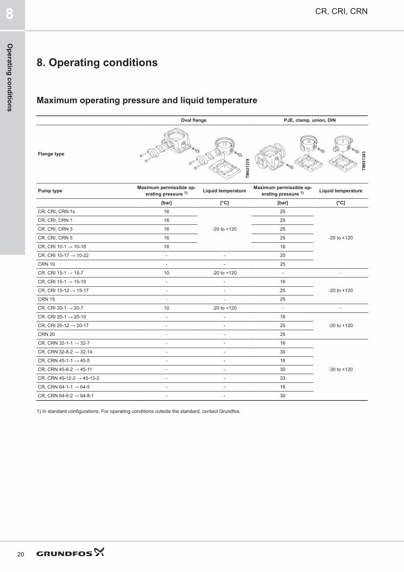
8. Operating conditions
Maximum operating pressure and liquid temperature
Oval flange PJE, clamp, union, DIN
Flange type
TM02
1379
TM02
1383
Pump type Maximum permissible op-erating pressure 1) Liquid temperature Maximum permissible op-
erating pressure 1) Liquid temperature
[bar] [°C] [bar] [°C]
CR, CRI, CRN 1s 16
-20 to +120
25
-20 to +120
CR, CRI, CRN 1 16 25
CR, CRI, CRN 3 16 25
CR, CRI, CRN 5 16 25
CR, CRI 10-1 → 10-16 16 16
CR, CRI 10-17 → 10-22 - - 25
CRN 10 - - 25
CR, CRI 15-1 → 15-7 10 -20 to +120 - -
CR, CRI 15-1 → 15-10 - - 16
-20 to +120CR, CRI 15-12 → 15-17 - - 25
CRN 15 - - 25
CR, CRI 20-1 → 20-7 10 -20 to +120 - -
CR, CRI 20-1 → 20-10 - - 16
-20 to +120CR, CRI 20-12 → 20-17 - - 25
CRN 20 - - 25
CR, CRN 32-1-1 → 32-7 - - 16
-30 to +120
CR, CRN 32-8-2 → 32-14 - - 30
CR, CRN 45-1-1 → 45-5 - - 16
CR, CRN 45-6-2 → 45-11 - - 30
CR, CRN 45-12-2 → 45-13-2 - - 33
CR, CRN 64-1-1 → 64-5 - - 16
CR, CRN 64-6-2 → 64-8-1 - - 30
1) In standard configurations. For operating conditions outside the standard, contact Grundfos.
CR, CRI, CRN8
20
Operating conditions

Oval flange PJE, clamp, union, DIN
Flange type
TM02
1379
TM02
1383
Pump type Maximum permissible op-erating pressure 1) Liquid temperature Maximum permissible op-
erating pressure 1) Liquid temperature
[bar] [°C] [bar] [°C]
CR, CRN 95-1-1 → 95-5 - - 16
-20 to +120 2)
CR, CRN 95-6 → 95-8-2 - - 25
CR, CRN 125-1 → 125-4 - - 16
CR, CRN 125-5 - - 25
CRN 125-6 → 125-7 - - 25
CRN 125-8 → 125-10 - - 40
CR, CRN 155-1-1 → 155-4-1 - - 16
CRN 155-5-2 → 155-6 - - 25
CRN 155-7 → 155-8-2 - - 40
CR, CRN 185-1 → 185-3 - - 16
CR, CRN 185-4-3 → 185-5 - - 25
CR, CRN 185-6-3 → 185-8 - - 40
CR, CRN 215-1-1 → 215-3 - - 16
CR, CRN 215-4-2 → 215-5 - - 25
CR, CRN 215-6-3 → 215-7-2 - - 40
CR, CRN 255-1-1 → 255-3-2 - - 16
CR, CRN 255-3 → 255-4 - - 25
CR, CRN 255-5-3 → 255-6-2 - - 40
1) In standard configurations. For operating conditions outside the standard, contact Grundfos.
2) For operating pressures above 25 bar, see section about operating range of the shaft seal.
CR, CRI, CRN 8
21
Ope
ratin
g co
nditi
ons

Operating range of the shaft sealAll pumps will be delivered with an HQQE/V cartridgeshaft seal as standard.The operating range of the shaft seal depends onoperating pressure, pump type, type of shaft seal andliquid temperature. The range of standard shaft sealsapplies to clean water and water with anti-freeze liquids.For selection of the right shaft seal, see section with list ofpumped liquids. If the operating range is exceeded, thelife of the shaft seal may be reduced.Note that if you pump demineralized water with aconductivity below 2 μS/cm with a pump equipped with asilicon carbide/silicon carbide shaft seal, there is anincreased risk of electrochemical corrosion. Werecommend that you use a silicon carbide/carbon orsilicon carbide/tungsten carbide shaft seal instead.
Related informationShaft seals for CR, CRI, CRN 1s-255
12. List of pumped liquids
14. Variants
Shaft seals for CR, CRI, CRN 1s-255∅12, ∅16 and ∅22 shaft seals (0.37-55 kW)
-40 -20 0 20 120 14040 60 80 1000
10
20
30
40
50
HQQE/VHQBE/V
HQQE/V
HQQEHQBEH
E
t [°C]
p [bar]
TM06
1408
Operating range of standard shaft seals for CR, CRI,CRN 1-255
Standardshaft seal
Motorsize[kW]
DescriptionLiquid temper-
ature[°C]
HQQE
0.37 - 55
O-ring (cartridge) (balancedseal), silicon carbide/siliconcarbide, EPDM
-40 to +120
HQQVO-ring (cartridge) (balancedseal), silicon carbide/siliconcarbide, FKM
-20 to +90
HQBEO-ring (cartridge) (balancedseal), silicon carbide/carbon,EPDM
0 to 120
HQBVO-ring (cartridge) (balancedseal), silicon carbide/carbon,FKM
0 to 90
∅28 and ∅36 shaft seals (75-200 kW)
-40 -20 0 20 120 14040 60 80 1000
10
20
30
40
50
HQQE/VHBQE/V
HQQE/V
HQQEHBQEH
E
p [bar]
t [°C]
TM06
1409
Operating range of standard shaft seals for CR, CRN125-255
Standardshaft seal
Motorsize[kW]
DescriptionLiquid temper-
ature[°C]
HQQE
75-200
O-ring (cartridge) (balancedseal), silicon carbide/siliconcarbide, EPDM
-40 to +120
HQQVO-ring (cartridge) (balancedseal), silicon carbide/siliconcarbide, FKM
-20 to +90
HQBEO-ring (cartridge) (balancedseal), silicon carbide/carbon,EPDM
0 to 120
HQBVO-ring (cartridge) (balancedseal), silicon carbide/carbon,FKM
0 to 90
CR, CRI, CRN8
22
Operating conditions

Maximum inlet pressureThe following table shows the maximum permissible inletpressure. However, the outlet pressure, which is theactual inlet pressure plus the pressure delivered by thepump must always be lower than the maximumpermissible operating pressure.If the maximum permissible operating pressure isexceeded, the conical bearing in the motor may bedamaged and the life of the shaft seal, reduced.
Pump type and stages Maximum inlet pressure[bar]
CR, CRI, CRN 1s
1s-2 → 1s-36 10
CR, CRI, CRN 1
1-2 → 1-36 10
CR, CRI, CRN 3
3-2 → 3-293-31 → 3-36
1015
CR, CRI, CRN 5
5-2 → 5-165-18 → 5-36
1015
CR, CRI, CRN 10
10-1 → 10-610-7 → 10-22
810
CR, CRI, CRN 15
15-1 → 15-315-4 → 15-17
810
CR, CRI, CRN 20
20-1 → 20-17 10
CR, CRN 32
32-1-1 → 32-432-5-2 → 32-1032-11-2 → 32-14
41015
CR, CRN 45
45-1-1 → 45-245-3-2 → 45-545-6-2 → 45-13-2
41015
CR, CRN 64
64-1-1 → 64-2-264-2-1 → 64-4-264-4-1 → 64-8-1
41015
CR, CRN 95
95-1-1 → 95-195-2-2 → 95-3-295-3 → 95-695-7 → 95-8-2
4101520
CR, CRN 125
125-1 → 125-2-1125-2 → 125-4125-5 → 125-10
101520
CR, CRN 155
155-1-1 → 155-1155-2-2 → 155-3155-4-1 → 155-8-2
101520
CR, CRN 185
185-1-1185-1 → 185-2185-3-3 → 185-8
101520
Pump type and stages Maximum inlet pressure[bar]
CR, CRN 215
215-1-1 → 215-2-2215-2-1 → 215-7-2
1520
CR, CRN 255
255-1-1 → 255-1255-2-2 → 255-6-2
1520
Examples of operating and inlet pressuresThe values for operating and inlet pressures must not beconsidered individually and must comply with the belowstatement.The outlet pressure must be equal to or lower than themaximum operating pressure.See the following definitions and examples.DefinitionsPressure type Definition
Maximum operating pressure The maximum pressure is stated onthe nameplate.
Pump differential pressure The difference between the outletpressure and inlet pressure.
Inlet pressure The pressure measured at the pumpinlet.
Outlet pressure The inlet pressure added to the pumpdifferential pressure.
Example 1Pump, see CR 5 curve: CR 5-16 A-A-A
Max. operating pressure: 16 bar
Max. inlet pressure: 10 bar
Pump differential pressure:10.6 bar ** Flow = 0 m3/h
This pump is not allowed to start at an inlet pressure of 10bar, but at an inlet pressure of 16.0 - 10.6 = 5.4 bar.Example 2Pump, see CR 10 curve: CR 10-2 A-A-A
Max. operating pressure: 16 bar
Max. inlet pressure: 8 bar
Pump differential pressure:2 bar ** Flow = 0 m3/h
This pump is allowed to start at an inlet pressure of 8 bar,as the outlet pressure is lower than the maximumoperating pressure. This results in an operating pressureof 8 + 2 = 10 bar.If the inlet or operating pressure exceeds the pressurepermitted, Grundfos variants meeting your specificrequirements may be available on request.
Related information14. Variants
CR, CRI, CRN 8
23
Ope
ratin
g co
nditi
ons

9. SelectionSelection of pumpsBase the selection of pumps on these parameters:
• Duty point of the pump. See section about duty pointof the pump.
• Sizing data such as pressure loss as a result of heightdifferences, friction loss in the pipes, pump efficiency.See section about sizing data.
• Pump materials. See section about pump material.
• Pump connections. See section about pumpconnections.
• Shaft seal. See section about shaft seal.Duty point of the pumpFrom a duty point, you can select a pump on the basis ofthe performance curve charts.Ideally, the duty point should match the best efficiency onthe pump curve.Grundfos Product CenterWe recommend that you size your pump in GrundfosProduct Center. Our easy-to-use virtual guide leads youthrough the selection of the pump for the application inquestion. For further information, see section aboutGrundfos Product Center.Sizing dataWhen sizing a pump, take these parameters into account:
• Required flow rate and pressure at the draw-off point.
• Pressure loss as a result of height differences (Hgeo).
• Friction loss in the pipes (Hf). It may be necessary toaccount for pressure loss in connection with longpipes, bends, valves or similar.
• Best efficiency at the estimated duty point.
• NPSH value. For calculation of the NPSH value, seesection about minimum inlet pressure, NPSH.
1Hr
Hgeo NPSH / NPSHR
TM02
6711
Sizing data
Pos. Description
1 Required flow rate, required pressure
Pump efficiencyBefore determining the best efficiency point, identify theoperation pattern of the pump. If the pump is expected toalways operate at the same duty point, select a pumpwhich is operating at a duty point corresponding to thebest efficiency of the pump.
0 4 8 12 16 20 24 28 32 36 Q [m³/h]0
20
40
60
80
100
120
140
160
180
200
220
240
260
280
H[m]
0 2 4 6 8 10 Q [l/s]
0.0
0.4
0.8
1.2
1.6
2.0
2.4
[MPa]p
CR xx Hz
ISO 9906:2012 Grade 3B
-11-11-2
-12 -12-2
-13 -13-2
-14 -14-2
-1-1-1
-10-10-2
-2-2-2
-3-3-2
-4-4-2
-5-5-2
-6-6-2
-7-7-2
-8-8-2
-9-9-2
0 4 8 12 16 20 24 28 32 36 Q [m³/h]0.0
0.5
1.0
1.5
2.0
P2[kW]
0
20
40
60
80[%]Eta
0.0
0.8
1.6
2.4
[hp]P2
P2 1/1
P2 2/3
Eta
0 4 8 12 16 20 24 28 32 36 Q [m³/h]0
5
10
15
20[m]H
0
2
4
6
8
NPSH[m]
0
40
80
120
160
200[kPa]
p
NPSH
QH 2900 rpm 1/1QH 2900 rpm 2/3
1
2
--
TM07
8851
Example of a CR pump’s duty point
Pos. Description
1 Duty point
2 Best efficiency
As the pump is sized on the basis of the highest possibleflow rate, it is important to always have the duty point tothe right of the best efficiency point on the efficiency curve(eta). This must be considered in order to keep theefficiency high when the flow rate drops.
Eta
Q [m /h]3
1
TM00
9190
Best efficiency
Pos. Description
1 Best efficiency point
CR, CRI, CRN9
24
Selection

Pump materialSelect the material variant on the basis of the liquid to bepumped.The product range covers the following basic types.
• CR, CRI: Use CR, CRI pumps for clean, non-aggressive liquids, such as potable water and oils.
• CRN: Use CRN pumps for industrial liquids and acids.See section about list of pumped liquids, or contactGrundfos.
For saline or chloride-containing liquids, such as seawater, CRT pumps of titanium are available.
TM06
9206
CR pump
Pump connectionsSelection of a pump connection depends on the ratedpressure and the pipes. To meet any requirement, the CR,CRI and CRN pumps offer a wide range of flexibleconnections, such as:
• oval flange A (BSP)
• DIN flange
• PJE coupling (Victaulic type)
• clamp coupling
• union (+GF+)
• other connections on request.
A
F (DIN)
PJE
TM02
1201
Pump connections
Shaft seal
GR
7386
Shaft seal (cartridge type)
As standard, the CR range is fitted with a Grundfos shaftseal (cartridge type), which is suitable for the mostcommon applications.The following key parameters must be taken into accountwhen selecting the shaft seal:
• type of pumped liquid
• liquid temperature
• maximum pressure.We offer a wide range of shaft seal variants to meetspecific demands according to the pumped liquid.Servicing shaft sealsReplacement shaft seals are available as completeservice kits*.Shaft seals fitted on CR, CRN 125-255 pumps with ∅28mm or ∅36 mm shaft ends are serviceable. This meansthat the wear parts in these shaft seals are available asservice kits* and can be replaced without having to renewthe complete shaft seal.* All service kits include detailed instructions on how to carry out thereplacement.
CR, CRI, CRN 9
25
Sele
ctio
n

Thrust handling device
TM06
9669
Thrust handling device
A thrust handling device (THD) is factory-fitted on pumpswith 75 kW motors or larger. The system consists of twoparts. A rotating part mounted on the shaft end below thefirst impeller as well as a non-rotating part mounted in oron the pump base.The THD absorbs the main part of the thrust forcegenerated by the impellers and thereby reduces theresulting axial force the motor bearings must absorb. Thisenables the use of standard ball bearings in the motorinstead of special angular contact ball bearings.Note: For applications involving CIP (clean-in-place) andmotors above 55 kW, use a bearing flange and a basewithout THD.
120a
120b
120g
120h
TM06
9670
Position numbers for THD parts
Pos. Description Material
120a Thrust disc Stainless steel
120b Rotating ring Silicon carbide
120g Stationary ringSilicon carbide *Tungsten carbide
120h Lifting plate Stainless steel
- O-ringsEPDMFKM
* On request for CRN.
Operating pressure and inlet pressureDo not exceed the limit values for these pressures:
• maximum operating pressure
• maximum inlet pressure.Minimum inlet pressure, NPSHWe recommend that you calculate the inlet pressure "H" inthese situations:
• The liquid temperature is high.
• The flow rate is significantly higher than the rated flowrate.
• Water is drawn from depths.
• Water is drawn through long pipes.
• Inlet conditions are poor.To avoid cavitation, make sure that there is a minimumpressure on the inlet side of the pump.Calculate the maximum suction lift "H" in metres head asfollows:
H = pb x 10.2 - NPSH - Hf - Hv
pb =
Barometric pressure in bar.Pb can be set to 1 bar at sea level.In closed systems, pb indicates the system pressure inbar.
NPSH =Net Positive Suction Head in metres head. To be readfrom the NPSH curve at the highest flow rate the pump willbe delivering.
Hf = Friction loss in inlet pipe in metres head at the highest flowrate the pump will be delivering.
Hv =Vapour pressure in metres head. To be read from the va-pour pressure scale.Hv depends on the liquid temperature tm.
If the calculated "H" is positive, the pump can operate at asuction lift of maximum "H" m head.If the calculated "H" is negative, an inlet pressure ofminimum "H" m head is required.
CR, CRI, CRN9
26
Selection

20
1512108,0
6,05,04,03,0
2,0
1,00,80,60,40,30,2
0,1
1,5
120
110
90
100
80
70
60
50
40
30
20
10
0
Hv(m)
tm(°C)
150
130
140
25
35
4540
30
160
170
180
190
62
79
100
126
Hf
H
Hv
Pb NPSH
TM02
7439
Minimum inlet pressure, NPSH
To avoid cavitation, do not select a pump with a duty pointtoo far to the right on the NPSH curve.Always check the NPSH value of the pump at the highestpossible flow rate.
Related information12. List of pumped liquids
15. Grundfos Product Center
CR, CRI, CRN 9
27
Sele
ctio
n

How to read the curve charts
0 4 8 12 16 20 24 28 32 36 Q [m³/h]0
20
40
60
80
100
120
140
160
180
200
220
240
260
280
H[m]
0 2 4 6 8 10 Q [l/s]
0.0
0.4
0.8
1.2
1.6
2.0
2.4
[MPa]p
CR_ _ xx Hz
ISO 9906:2012 Grade 3B
-11-11-2
-12 -12-2
-13 -13-2
-14 -14-2
-1-1-1
-10-10-2
-2-2-2
-3-3-2
-4-4-2
-5-5-2
-6-6-2
-7-7-2
-8-8-2
-9-9-2
0 4 8 12 16 20 24 28 32 36 Q [m³/h]0.0
0.5
1.0
1.5
2.0
P2[kW]
0
20
40
60
80[%]Eta
0.0
0.8
1.6
2.4
[hp]P2
P2 1/1
P2 2/3
Eta
0 4 8 12 16 20 24 28 32 36 Q [m³/h]0
5
10
15
20[m]H
0
2
4
6
8
NPSH[m]
0
40
80
120
160
200[kPa]
p
NPSH
QH 2900 rpm 1/1QH 2900 rpm 2/3
1
3
5
76
4
2
TM07
8855
Pos. Description
1 Pump type. Frequency, poles or speed. ISO or ANSI standard.
2 Number of stages. First figure: number of stages. Second figure: number of reduced-diameter impellers.
3 QH curve for the individual pump. The bold curves indicate the recommended duty range for best efficiency.
4 The power curves indicate pump input power per stage. Curves are shown for full (1/1) and for reduced-diameter (2/3) impellers.
5 The eta curve shows the efficiency of a pump with an average number of stages. The efficiency of pumps with reduced-diameter impellersis approximately 2 % lower than the eta curve shown in the chart.
6 QH curve for each individual impeller. Curves are shown for full (1/1) and for reduced-diameter (2/3) impellers.
7 The NPSH curve is a maximum curve for all the variants shown.
CR, CRI, CRN9
28
Selection

Guidelines to performance curvesThe guidelines below apply to the performance curves:
• Tolerances to ANSI or ISO standards, such as ISO9906:2012, Grade 3B, if indicated on the curve chart.
• The motors used for the measurements are standardGrundfos specified motors.
• Measurements have been made with airless water ata temperature of 20 °C.
• The curves apply to the following kinematic viscosity: υ= 1 mm2/s (1 cSt).
• Due to the risk of overheating, the pumps must not beused at a flow rate below the minimum flow rate.
• The QH curves apply to a rated motor speed of athree-phase mains-operated motor. For realisticcurves, go to Grundfos Product Center (http://product-selection.grundfos.com), and insert data.
The curve below shows the minimum flow rate as apercentage of the rated flow rate in relation to the liquidtemperature. The dotted line shows a CR pump fitted withan air-cooled top assembly.
40 60 80 100 120 140 160 180 t [° C]
0
10
20
30
Qm in[ %]
TM01
2816
Minimum flow rate
CR, CRI, CRN 9
29
Sele
ctio
n

10. Performance curves and technical data
CR 1s
TM02
7424
CR, CRI, CRN10
30
Performance curves and technical data
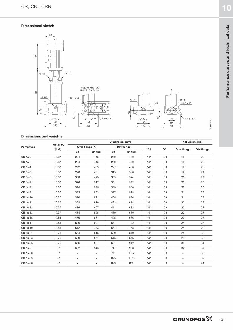
Dimensional sketch
ø35
ø140
75
75
20
180
B1B2
141100
250
ø100
ø89
180220 220
100
160
204 x ø13.5
19 x 24.5G 1/2
22G 1/2
50
4 x ø13.5
D2D1
M10 x 40Rp 1
145
G 1/2 G 1/2
APN 25 / DN 25/32FGJ(DIN-ANSI-JIS)
TM06
9591
Dimensions and weights
Pump typeMotor P2
[kW]
Dimension [mm] Net weight [kg]
Oval flange (A) DIN flangeD1 D2 Oval flange DIN flange
B1 B1+B2 B1 B1+B2
CR 1s-2 0.37 254 445 279 470 141 109 18 23
CR 1s-3 0.37 254 445 279 470 141 109 18 23
CR 1s-4 0.37 272 463 297 488 141 109 19 23
CR 1s-5 0.37 290 481 315 506 141 109 19 24
CR 1s-6 0.37 308 499 333 524 141 109 20 24
CR 1s-7 0.37 326 517 351 542 141 109 20 25
CR 1s-8 0.37 344 535 369 560 141 109 20 25
CR 1s-9 0.37 362 553 387 578 141 109 21 26
CR 1s-10 0.37 380 571 405 596 141 109 21 26
CR 1s-11 0.37 398 589 423 614 141 109 22 26
CR 1s-12 0.37 416 607 441 632 141 109 22 27
CR 1s-13 0.37 434 625 459 650 141 109 22 27
CR 1s-15 0.55 470 661 495 686 141 109 23 27
CR 1s-17 0.55 506 697 531 722 141 109 24 28
CR 1s-19 0.55 542 733 567 758 141 109 24 29
CR 1s-21 0.75 584 815 609 840 141 109 28 33
CR 1s-23 0.75 620 851 645 876 141 109 29 33
CR 1s-25 0.75 656 887 681 912 141 109 30 34
CR 1s-27 1.1 692 943 717 968 141 109 32 37
CR 1s-30 1.1 - - 771 1022 141 109 - 38
CR 1s-33 1.1 - - 825 1076 141 109 - 39
CR 1s-36 1.1 - - 879 1130 141 109 - 41
CR, CRI, CRN 10
31
Perf
orm
ance
cur
ves
and
tech
nica
l dat
a

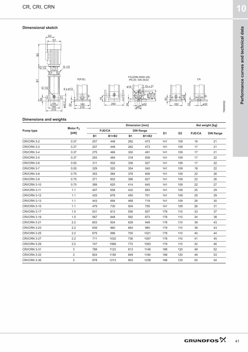
CRI, CRN 1s
TM02
7425
CR, CRI, CRN10
32
Performance curves and technical data

Dimensional sketch
ø59
162 ø32
50
22
G 1/2 G 1/2
ø32
ø140
50
22 180
B1B2
150100
210
ø105
ø89
210
4 x ø13G 1/2
D2D1
250
ø42.
2
75
ø8534
19 x 27ø14
P(PJE) CAPN 25 / DN 25/32FGJ(DIN-ANSI-JIS)
TM06
9592
Dimensions and weights
Pump typeMotor P2
[kW]
Dimension [mm] Net weight [kg]
PJE/CA DIN flangeD1 D2 PJE/CA DIN flange
B1 B1+B2 B1 B1+B2
CRI/CRN 1s-2 0.37 257 448 282 473 141 109 16 20
CRI/CRN 1s-3 0.37 257 448 282 473 141 109 17 21
CRI/CRN 1s-4 0.37 275 466 300 491 141 109 17 21
CRI/CRN 1s-5 0.37 293 484 318 509 141 109 17 22
CRI/CRN 1s-6 0.37 311 502 336 527 141 109 18 22
CRI/CRN 1s-7 0.37 329 520 354 545 141 109 18 22
CRI/CRN 1s-8 0.37 347 538 372 563 141 109 19 23
CRI/CRN 1s-9 0.37 365 556 390 581 141 109 19 23
CRI/CRN 1s-10 0.37 383 574 408 599 141 109 19 24
CRI/CRN 1s-11 0.37 401 592 426 617 141 109 20 24
CRI/CRN 1s-12 0.37 419 610 444 635 141 109 20 24
CRI/CRN 1s-13 0.37 437 628 462 653 141 109 21 25
CRI/CRN 1s-15 0.55 473 664 498 689 141 109 21 25
CRI/CRN 1s-17 0.55 509 700 534 725 141 109 22 26
CRI/CRN 1s-19 0.55 545 736 570 761 141 109 22 27
CRI/CRN 1s-21 0.75 587 818 612 843 141 109 27 31
CRI/CRN 1s-23 0.75 623 854 648 879 141 109 27 32
CRI/CRN 1s-25 0.75 659 890 684 915 141 109 28 32
CRI/CRN 1s-27 1.1 695 946 720 971 141 109 31 35
CRI/CRN 1s-30 1.1 749 1000 774 1025 141 109 32 36
CRI/CRN 1s-33 1.1 803 1054 828 1079 141 109 33 38
CRI/CRN 1s-36 1.1 857 1108 882 1133 141 109 35 39
CR, CRI, CRN 10
33
Perf
orm
ance
cur
ves
and
tech
nica
l dat
a

CR 1
TM02
7290
CR, CRI, CRN10
34
Performance curves and technical data

Dimensional sketch
ø35
ø140
75
75
20
180
B1B2
141100
250
ø100
ø89
180220 220
100
160
204 x ø13.5
19 x 24.5G 1/2
22G 1/2
50
4 x ø13.5
D2D1
M10 x 40Rp 1
145
G 1/2 G 1/2
APN 25 / DN 25/32FGJ(DIN-ANSI-JIS)
TM06
9591
Dimensions and weights
Pump typeMotor P2
[kW]
Dimension [mm] Net weight [kg]
Oval flange (A) DIN flangeD1 D2 Oval flange DIN flange
B1 B1+B2 B1 B1+B2
CR 1-2 0.37 254 445 279 470 141 109 18 23
CR 1-3 0.37 254 445 279 470 141 109 18 23
CR 1-4 0.37 272 463 297 488 141 109 19 23
CR 1-5 0.37 290 481 315 506 141 109 19 24
CR 1-6 0.37 308 499 333 524 141 109 20 24
CR 1-7 0.37 326 517 351 542 141 109 20 25
CR 1-8 0.55 344 535 369 560 141 109 20 25
CR 1-9 0.55 362 553 387 578 141 109 21 25
CR 1-10 0.55 380 571 405 596 141 109 21 25
CR 1-11 0.55 398 589 423 614 141 109 21 26
CR 1-12 0.75 422 653 447 678 141 109 25 29
CR 1-13 0.75 440 671 465 696 141 109 25 30
CR 1-15 0.75 476 707 501 732 141 109 26 30
CR 1-17 1.1 512 763 537 788 141 109 29 33
CR 1-19 1.1 548 799 573 824 141 109 30 34
CR 1-21 1.1 584 835 609 860 141 109 30 35
CR 1-23 1.1 620 871 645 896 141 109 31 36
CR 1-25 1.5 - - 697 978 178 110 - 43
CR 1-27 1.5 - - 733 1014 178 110 - 44
CR 1-30 1.5 - - 787 1068 178 110 - 45
CR 1-33 2.2 - - 841 1162 178 110 - 50
CR 1-36 2.2 - - 895 1216 178 110 - 51
CR, CRI, CRN 10
35
Perf
orm
ance
cur
ves
and
tech
nica
l dat
a

CRI, CRN 1
TM02
7291
CR, CRI, CRN10
36
Performance curves and technical data

Dimensional sketch
ø59
162 ø32
50
22
G 1/2 G 1/2
ø32
ø140
50
22 180
B1B2
150100
210
ø105
ø89
210
4 x ø13G 1/2
D2D1
250
ø42.
2
75
ø8534
19 x 27ø14
P(PJE) CAPN 25 / DN 25/32FGJ(DIN-ANSI-JIS)
TM06
9592
Dimensions and weights
Pump typeMotor P2
[kW]
Dimension [mm] Net weight [kg]
PJE/CA DIN flangeD1 D2 PJE/CA DIN flange
B1 B1+B2 B1 B1+B2
CRI/CRN 1-2 0.37 257 448 282 473 141 109 16 21
CRI/CRN 1-3 0.37 257 448 282 473 141 109 17 21
CRI/CRN 1-4 0.37 275 466 300 491 141 109 17 21
CRI/CRN 1-5 0.37 293 484 318 509 141 109 17 22
CRI/CRN 1-6 0.37 311 502 336 527 141 109 18 22
CRI/CRN 1-7 0.37 329 520 354 545 141 109 18 22
CRI/CRN 1-8 0.55 347 538 372 563 141 109 18 22
CRI/CRN 1-9 0.55 365 556 390 581 141 109 19 23
CRI/CRN 1-10 0.55 383 574 408 599 141 109 19 23
CRI/CRN 1-11 0.55 401 592 426 617 141 109 19 23
CRI/CRN 1-12 0.75 425 656 450 681 141 109 23 27
CRI/CRN 1-13 0.75 443 674 468 699 141 109 24 28
CRI/CRN 1-15 0.75 479 710 504 735 141 109 24 29
CRI/CRN 1-17 1.1 515 766 540 791 141 109 27 31
CRI/CRN 1-19 1.1 551 802 576 827 141 109 28 32
CRI/CRN 1-21 1.1 587 838 612 863 141 109 29 33
CRI/CRN 1-23 1.1 623 874 648 899 141 109 30 34
CRI/CRN 1-25 1.5 675 956 700 981 178 110 36 40
CRI/CRN 1-27 1.5 711 992 736 1017 178 110 37 41
CRI/CRN 1-30 1.5 765 1046 790 1071 178 110 38 43
CRI/CRN 1-33 2.2 819 1140 844 1165 178 110 43 48
CRI/CRN 1-36 2.2 873 1194 898 1219 178 110 45 49
CR, CRI, CRN 10
37
Perf
orm
ance
cur
ves
and
tech
nica
l dat
a

CR 3
TM02
7292
CR, CRI, CRN10
38
Performance curves and technical data

Dimensional sketch
ø35
ø140
75
75
20
180
B1B2
141100
250
ø100
ø89
180220 220
100
160
204 x ø13.5
19 x 24.5G 1/2
22G 1/2
50
4 x ø13.5
D2D1
M10 x 40Rp 1
145
G 1/2 G 1/2
APN 25 / DN 25/32FGJ(DIN-ANSI-JIS)
TM06
9591
Dimensions and weights
Pump typeMotor P2
[kW]
Dimension [mm] Net weight [kg]
Oval flange (A) DIN flangeD1 D2 Oval flange DIN flange
B1 B1+B2 B1 B1+B2
CR 3-2 0.37 254 445 279 470 141 109 18 23
CR 3-3 0.37 254 445 279 470 141 109 18 23
CR 3-4 0.37 272 463 297 488 141 109 19 23
CR 3-5 0.37 290 481 315 506 141 109 19 24
CR 3-6 0.55 308 499 333 524 141 109 19 24
CR 3-7 0.55 326 517 351 542 141 109 20 24
CR 3-8 0.75 350 581 375 606 141 109 23 28
CR 3-9 0.75 368 599 393 624 141 109 23 28
CR 3-10 0.75 386 617 411 642 141 109 24 28
CR 3-11 1.1 404 655 429 680 141 109 26 31
CR 3-12 1.1 422 673 447 698 141 109 27 31
CR 3-13 1.1 440 691 465 716 141 109 27 32
CR 3-15 1.1 476 727 501 752 141 109 28 32
CR 3-17 1.5 528 809 553 834 178 110 35 40
CR 3-19 1.5 564 845 589 870 178 110 36 41
CR 3-21 2.2 600 921 625 946 178 110 41 45
CR 3-23 2.2 636 957 661 982 178 110 41 46
CR 3-25 2.2 - - 697 1018 178 110 - 47
CR 3-27 2.2 - - 733 1054 178 110 - 48
CR 3-29 2.2 - - 769 1090 178 110 - 49
CR 3-31 3 - - 809 1144 198 120 - 54
CR 3-33 3 - - 845 1180 198 120 - 55
CR 3-36 3 - - 899 1234 198 120 - 57
CR, CRI, CRN 10
39
Perf
orm
ance
cur
ves
and
tech
nica
l dat
a

CRI, CRN 3
TM02
7293
CR, CRI, CRN10
40
Performance curves and technical data
Dimensional sketch
ø59
162 ø32
50
22
G 1/2 G 1/2
ø32
ø140
50
22 180
B1B2
150100
210
ø105
ø89
210
4 x ø13G 1/2
D2D1
250
ø42.
2
75
ø8534
19 x 27ø14
P(PJE) CAPN 25 / DN 25/32FGJ(DIN-ANSI-JIS)
TM06
9592
Dimensions and weights
Pump typeMotor P2
[kW]
Dimension [mm] Net weight [kg]
PJE/CA DIN flangeD1 D2 PJE/CA DIN flange
B1 B1+B2 B1 B1+B2
CRI/CRN 3-2 0.37 257 448 282 473 141 109 16 21
CRI/CRN 3-3 0.37 257 448 282 473 141 109 17 21
CRI/CRN 3-4 0.37 275 466 300 491 141 109 17 21
CRI/CRN 3-5 0.37 293 484 318 509 141 109 17 22
CRI/CRN 3-6 0.55 311 502 336 527 141 109 17 22
CRI/CRN 3-7 0.55 329 520 354 545 141 109 18 22
CRI/CRN 3-8 0.75 353 584 378 609 141 109 22 26
CRI/CRN 3-9 0.75 371 602 396 627 141 109 22 26
CRI/CRN 3-10 0.75 389 620 414 645 141 109 22 27
CRI/CRN 3-11 1.1 407 658 432 683 141 109 25 29
CRI/CRN 3-12 1.1 425 676 450 701 141 109 25 29
CRI/CRN 3-13 1.1 443 694 468 719 141 109 26 30
CRI/CRN 3-15 1.1 479 730 504 755 141 109 26 31
CRI/CRN 3-17 1.5 531 812 556 837 178 110 33 37
CRI/CRN 3-19 1.5 567 848 592 873 178 110 34 38
CRI/CRN 3-21 2.2 603 924 628 949 178 110 39 43
CRI/CRN 3-23 2.2 639 960 664 985 178 110 39 43
CRI/CRN 3-25 2.2 675 996 700 1021 178 110 40 44
CRI/CRN 3-27 2.2 711 1032 736 1057 178 110 41 45
CRI/CRN 3-29 2.2 747 1068 772 1093 178 110 42 46
CRI/CRN 3-31 3 788 1123 813 1148 198 120 48 52
CRI/CRN 3-33 3 824 1159 849 1184 198 120 49 53
CRI/CRN 3-36 3 878 1213 903 1238 198 120 50 54
CR, CRI, CRN 10
41
Perf
orm
ance
cur
ves
and
tech
nica
l dat
a

CR 5
TM02
7294
CR, CRI, CRN10
42
Performance curves and technical data

Dimensional sketch
ø35
ø140
75
75
20
180
B1B2
141100
250
ø100
ø89
180220 220
100
160
204 x ø13.5
19 x 24.5G 1/2
22G 1/2
50 4 x ø13.5
D2D1
M10 x 40Rp 1 1/4"
145
G 1/2 G 1/2D3
PN 25 / DN 25/32 AFGJ (DIN-ANSI-JIS)
TM06
9593
Dimensions and weights
Pump typeMotor P2
[kW]
Dimension [mm] Net weight [kg]
Oval flange (A) DIN flangeD1 D2 D3 Oval flange DIN flange
B1 B1+B2 B1 B1+B2
CR 5-2 0.37 254 445 279 470 141 109 - 18 23
CR 5-3 0.55 281 472 306 497 141 109 - 19 23
CR 5-4 0.55 308 499 333 524 141 109 - 19 24
CR 5-5 0.75 341 572 366 597 141 109 - 23 27
CR 5-6 1.1 368 619 393 644 141 109 - 25 30
CR 5-7 1.1 395 646 420 671 141 109 - 26 30
CR 5-8 1.1 422 673 447 698 141 109 - 26 31
CR 5-9 1.5 465 746 490 771 178 110 - 33 38
CR 5-10 1.5 492 773 517 798 178 110 - 34 39
CR 5-11 2.2 519 840 544 865 178 110 - 38 43
CR 5-12 2.2 546 867 571 892 178 110 - 39 44
CR 5-13 2.2 573 894 598 919 178 110 - 40 44
CR 5-14 2.2 600 921 625 946 178 110 - 40 45
CR 5-15 2.2 627 948 652 973 178 110 - 41 45
CR 5-16 2.2 654 975 679 1000 178 110 - 41 46
CR 5-18 3 712 1047 737 1072 198 120 - 48 52
CR 5-20 3 766 1101 791 1126 198 120 - 49 53
CR 5-22 4 820 1192 845 1217 220 134 - 62 66
CR 5-24 4 - - 899 1271 220 134 - - 67
CR 5-26 4 - - 953 1325 220 134 - - 69
CR 5-29 4 - - 1034 1406 220 134 - - 70
CR 5-32 5.5 - - 1145 1536 220 134 300 - 83
CR 5-36 5.5 - - 1253 1644 220 134 300 - 85
CR, CRI, CRN 10
43
Perf
orm
ance
cur
ves
and
tech
nica
l dat
a

CRI, CRN 5
TM02
7295
CR, CRI, CRN10
44
Performance curves and technical data

Dimensional sketch
D3
ø59
162 ø32
50
G 1/2G 1/2
ø32
ø140
50 22 180
B1B2
150100
210
ø105
ø89
210
4 x ø13G 1/2
D2D1
250
ø42.
2
75
ø85
34
19 x 27ø14
22
PN 25 / DN 25/32 CAP (PJE)FGJ (DIN-ANSI-JIS)
TM06
9594
Dimensions and weights
Pump typeMotor P2
[kW]
Dimension [mm]Net weight
[kg]
PJE/CA DIN flangeD1 D2 D3 PJE/CA DIN flange
B1 B1+B2 B1 B1+B2
CRI/CRN 5-2 0.37 257 448 282 473 141 109 - 17 21
CRI/CRN 5-3 0.55 284 475 309 500 141 109 - 17 21
CRI/CRN 5-4 0.55 311 502 336 527 141 109 - 17 21
CRI/CRN 5-5 0.75 344 575 369 600 141 109 - 21 25
CRI/CRN 5-6 1.1 371 622 396 647 141 109 - 24 28
CRI/CRN 5-7 1.1 398 649 423 674 141 109 - 24 29
CRI/CRN 5-8 1.1 425 676 450 701 141 109 - 25 29
CRI/CRN 5-9 1.5 468 749 493 774 178 110 - 31 36
CRI/CRN 5-10 1.5 495 776 520 801 178 110 - 32 36
CRI/CRN 5-11 2.2 522 843 547 868 178 110 - 36 40
CRI/CRN 5-12 2.2 549 870 574 895 178 110 - 37 41
CRI/CRN 5-13 2.2 576 897 601 922 178 110 - 37 42
CRI/CRN 5-14 2.2 603 924 628 949 178 110 - 38 42
CRI/CRN 5-15 2.2 630 951 655 976 178 110 - 39 43
CRI/CRN 5-16 2.2 657 978 682 1003 178 110 - 39 43
CRI/CRN 5-18 3 716 1051 741 1076 198 120 - 46 50
CRI/CRN 5-20 3 770 1105 795 1130 198 120 - 47 51
CRI/CRN 5-22 4 824 1196 849 1221 220 134 - 60 64
CRI/CRN 5-24 4 878 1250 903 1275 220 134 - 61 65
CRI/CRN 5-26 4 932 1304 957 1329 220 134 - 62 66
CRI/CRN 5-29 4 1013 1385 1038 1410 220 134 - 64 68
CRI/CRN 5-32 5.5 1123 1514 1148 1539 220 134 300 76 80
CRI/CRN 5-36 5.5 1231 1622 1256 1647 220 134 300 78 82
CR, CRI, CRN 10
45
Perf
orm
ance
cur
ves
and
tech
nica
l dat
a
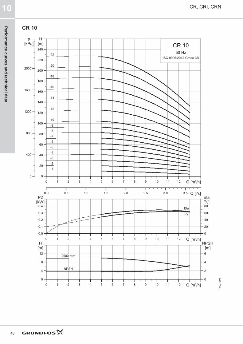
CR 10
0 1 2 3 4 5 6 7 8 9 10 11 12 Q [m³/h]0
20
40
60
80
100
120
140
160
180
200
220
240
H[m]
0.0 0.5 1.0 1.5 2.0 2.5 3.0 3.5 Q [l/s]
0
400
800
1200
1600
2000
p[kPa] CR 10
50 HzISO 9906:2012 Grade 3B
-1
-10
-12
-14
-16
-18
-2
-20
-22
-3
-4-5
-6
-7-8-9
0 1 2 3 4 5 6 7 8 9 10 11 12 Q [m³/h]0.0
0.1
0.2
0.3
0.4
P2[kW]
0
20
40
60
80
Eta[%]
P2
Eta
0 1 2 3 4 5 6 7 8 9 10 11 12 Q [m³/h]0
4
8
12
H[m]
0
2
4
6
NPSH[m]
NPSH
2900 rpm
TM02
7296
CR, CRI, CRN10
46
Performance curves and technical data

Dimensional sketch
B2D2
D1
4 x ø13.5130178
80
G 1/2
280
B1
G 1/2G 1/2
256
18 x 20.2
ø39
20
ø114
ø150
178200
100
Rp 1 1/2"
M16 x 45
4 x ø13.5
27
215ø110
215256
130
80
G 1/2
D3
20
APN 16-25 / DN 40
FJ (DIN-JIS)
TM06
9595
Dimensions and weights
Pump typeMotor P2
[kW]
Dimension [mm] Net weight [kg]
Oval flange (A) DIN flangeD1 D2 D3 Oval flange DIN flange
B1 B1+B2 B1 B1+B2
CR 10-1 0.37 343 534 343 534 141 109 - 31 34
CR 10-2 0.75 347 578 347 578 141 109 - 34 36
CR 10-3 1.1 377 628 377 628 141 109 - 37 39
CR 10-4 1.5 423 704 423 704 178 110 - 44 47
CR 10-5 2.2 453 774 453 774 178 110 - 49 52
CR 10-6 2.2 483 804 483 804 178 110 - 50 53
CR 10-7 3 518 853 518 853 198 120 - 56 59
CR 10-8 3 548 883 548 883 198 120 - 57 60
CR 10-9 3 578 913 578 913 198 120 - 58 61
CR 10-10 4 608 980 608 980 220 134 - 71 74
CR 10-12 4 668 1040 668 1040 220 134 - 73 76
CR 10-14 5.5 760 1151 760 1151 220 134 300 92 94
CR 10-16 5.5 820 1211 820 1211 220 134 300 94 97
CR 10-18 7.5 - - 880 1259 260 159 300 - 109
CR 10-20 7.5 - - 940 1319 260 159 300 - 112
CR 10-22 7.5 - - 1000 1379 260 159 300 - 114
CR, CRI, CRN 10
47
Perf
orm
ance
cur
ves
and
tech
nica
l dat
a

CRI, CRN 10
0 1 2 3 4 5 6 7 8 9 10 11 12 Q [m³/h]0
20
40
60
80
100
120
140
160
180
200
220
240
H[m]
0.0 0.5 1.0 1.5 2.0 2.5 3.0 3.5 Q [l/s]
0
400
800
1200
1600
2000
p[kPa] CRI, CRN 10
50 HzISO 9906:2012 Grade 3B
-1
-10
-12
-14
-16
-18
-2
-20
-22
-3
-4-5
-6
-7-8-9
0 1 2 3 4 5 6 7 8 9 10 11 12 Q [m³/h]0.0
0.1
0.2
0.3
0.4
P2[kW]
0
20
40
60
80
Eta[%]
P2
Eta
0 1 2 3 4 5 6 7 8 9 10 11 12 Q [m³/h]0
4
8
12
H[m]
0
2
4
6
NPSH[m]
NPSH
2900 rpm
TM02
7297
CR, CRI, CRN10
48
Performance curves and technical data

Dimensional sketch
D3
130 ø60.
1
B2D2
D1
200
80
G 1/2
261
B1
G 1/2G 1/2
215248
18.5 x 23.5
26
ø115
280
4 x ø13
26ø150
ø105ø42 ø50
202
ø87
80
26
80
248215
200130 130
200
G 1/2
4 x ø13
248215
PN 16-25 / DN 40 CAP (PJE)FGJ (DIN-ANSI-JIS)
TM06
9596
Dimensions and weights
Pump typeMotor P2
[kW]
Dimension [mm]Net weight
[kg]
PJE/CA DIN flangeD1 D2 D3 PJE/CA DIN flange
B1 B1+B2 B1 B1+B2
CRI/CRN 10-1 0.37 353 544 353 544 141 109 - 29 32
CRI/CRN 10-2 0.75 357 588 357 588 141 109 - 31 35
CRI/CRN 10-3 1.1 387 638 387 638 141 109 - 34 38
CRI/CRN 10-4 1.5 433 714 433 714 178 110 - 42 45
CRI/CRN 10-5 2.2 463 784 463 784 178 110 - 47 50
CRI/CRN 10-6 2.2 493 814 493 814 178 110 - 48 51
CRI/CRN 10-7 3 528 863 528 863 198 120 - 54 58
CRI/CRN 10-8 3 558 893 558 893 198 120 - 55 59
CRI/CRN 10-9 3 588 923 588 923 198 120 - 56 60
CRI/CRN 10-10 4 618 990 618 990 220 134 - 69 73
CRI/CRN 10-12 4 678 1050 678 1050 220 134 - 71 75
CRI/CRN 10-14 5.5 770 1161 770 1161 220 134 300 90 94
CRI/CRN 10-16 5.5 830 1221 830 1221 220 134 300 92 96
CRI/CRN 10-18 7.5 890 1269 890 1269 260 159 300 104 108
CRI/CRN 10-20 7.5 950 1329 950 1329 260 159 300 106 110
CRI/CRN 10-22 7.5 1010 1389 1010 1389 260 159 300 108 112
CR, CRI, CRN 10
49
Perf
orm
ance
cur
ves
and
tech
nica
l dat
a

CR 15
0 2 4 6 8 10 12 14 16 18 20 22 Q [m³/h]0
20
40
60
80
100
120
140
160
180
200
220
240
H[m]
0 1 2 3 4 5 6 Q [l/s]
0
400
800
1200
1600
2000
p[kPa] CR 15
50 HzISO 9906:2012 Grade 3B
-1
-10
-12
-14
-17
-2
-3
-4
-5
-6
-7
-8
-9
0 2 4 6 8 10 12 14 16 18 20 22 Q [m³/h]0.0
0.2
0.4
0.6
0.8
P2[kW]
0
20
40
60
80
Eta[%]
EtaP2
0 2 4 6 8 10 12 14 16 18 20 22 Q [m³/h]0
5
10
15
H[m]
0
2
4
6
NPSH[m]
NPSH
2900 rpm
TM02
7298
CR, CRI, CRN10
50
Performance curves and technical data

Dimensional sketchB2
D2D1
G 1/2
G 1/2 D3
130176
90
G 1/2
300215256
ø6520
ø125
ø165
Rp 2"M16 x 45
ø165
ø65
18 x 21.5
ø127
ø120 130
30
256215
300176130
90
G 1/2
130178200
90
215256
G 1/2B1 4 x ø13.5 ø18.1
20 20
PN 16-25 / DN 50 GJ (ANSI-JIS) AF (DIN)
TM06
9597
Dimensions and weights
Pump typeMotor P2
[kW]
Dimension [mm] Net weight [kg]
Oval flange (A) DIN flangeD1 D2 D3 Oval flange DIN flange
B1 B1+B2 B1 B1+B2
CR 15-1 1.1 400 651 400 651 141 109 - 41 42
CR 15-2 2.2 415 736 415 736 178 110 - 52 53
CR 15-3 3 465 800 465 800 198 120 - 58 59
CR 15-4 4 510 882 510 882 220 134 - 71 72
CR 15-5 4 555 927 555 927 220 134 - 73 74
CR 15-6 5.5 632 1023 632 1023 220 134 300 91 92
CR 15-7 5.5 677 1068 677 1068 220 134 300 93 94
CR 15-8 7.5 - - 722 1101 260 159 300 - 105
CR 15-9 7.5 - - 767 1146 260 159 300 - 107
CR 15-10 11 - - 889 1371 318 204 350 - 149
CR 15-12 11 - - 979 1461 318 204 350 - 153
CR 15-14 11 - - 1069 1551 318 204 350 - 157
CR 15-17 15 - - 1204 1686 318 204 350 - 174
CR, CRI, CRN 10
51
Perf
orm
ance
cur
ves
and
tech
nica
l dat
a

CRI, CRN 15
0 2 4 6 8 10 12 14 16 18 20 22 Q [m³/h]0
20
40
60
80
100
120
140
160
180
200
220
240
H[m]
0 1 2 3 4 5 6 Q [l/s]
0
400
800
1200
1600
2000
p[kPa] CRI, CRN 15
50 HzISO 9906:2012 Grade 3B
-1
-10
-12
-14
-17
-2
-3
-4
-5
-6
-7
-8
-9
0 2 4 6 8 10 12 14 16 18 20 22 Q [m³/h]0.0
0.2
0.4
0.6
0.8
P2[kW]
0
20
40
60
80
Eta[%]
EtaP2
0 2 4 6 8 10 12 14 16 18 20 22 Q [m³/h]0
5
10
15
H[m]
0
2
4
6
NPSH[m]
NPSH
2900 rpm
TM02
7299
CR, CRI, CRN10
52
Performance curves and technical data

Dimensional sketchB2
D2D1
G 1/2
G 1/2 D3
B1
G 1/2
261
215248
18.5 x 21.8
ø127
300
4 x ø13
ø165
ø120.5ø65 ø50
202
ø87
90 26
ø60.
1
200130
248215
215248
G 1/2
130200
130200
26
26
9090
P (PJE) PN 16-25 / DN 50 CA
FGJ (DIN-ANSI-JIS)
TM06
9598
Dimensions and weights
Pump typeMotor P2
[kW]
Dimension [mm]Net weight
[kg]
PJE/CA DIN flangeD1 D2 D3 PJE/CA DIN flange
B1 B1+B2 B1 B1+B2
CRI/CRN 15-1 1.1 397 648 397 648 141 109 - 34 39
CRI/CRN 15-2 2.2 413 734 413 734 178 110 - 45 50
CRI/CRN 15-3 3 463 798 463 798 198 120 - 52 56
CRI/CRN 15-4 4 508 880 508 880 220 134 - 65 70
CRI/CRN 15-5 4 553 925 553 925 220 134 - 67 71
CRI/CRN 15-6 5.5 630 1021 630 1021 220 134 300 85 89
CRI/CRN 15-7 5.5 675 1066 675 1066 220 134 300 86 91
CRI/CRN 15-8 7.5 720 1099 720 1099 260 159 300 98 103
CRI/CRN 15-9 7.5 765 1144 765 1144 260 159 300 100 104
CRI/CRN 15-10 11 887 1369 887 1369 318 204 350 142 147
CRI/CRN 15-12 11 977 1459 977 1459 318 204 350 145 150
CRI/CRN 15-14 11 1067 1549 1067 1549 318 204 350 149 153
CRI/CRN 15-17 15 1202 1684 1202 1684 318 204 350 165 170
CR, CRI, CRN 10
53
Perf
orm
ance
cur
ves
and
tech
nica
l dat
a
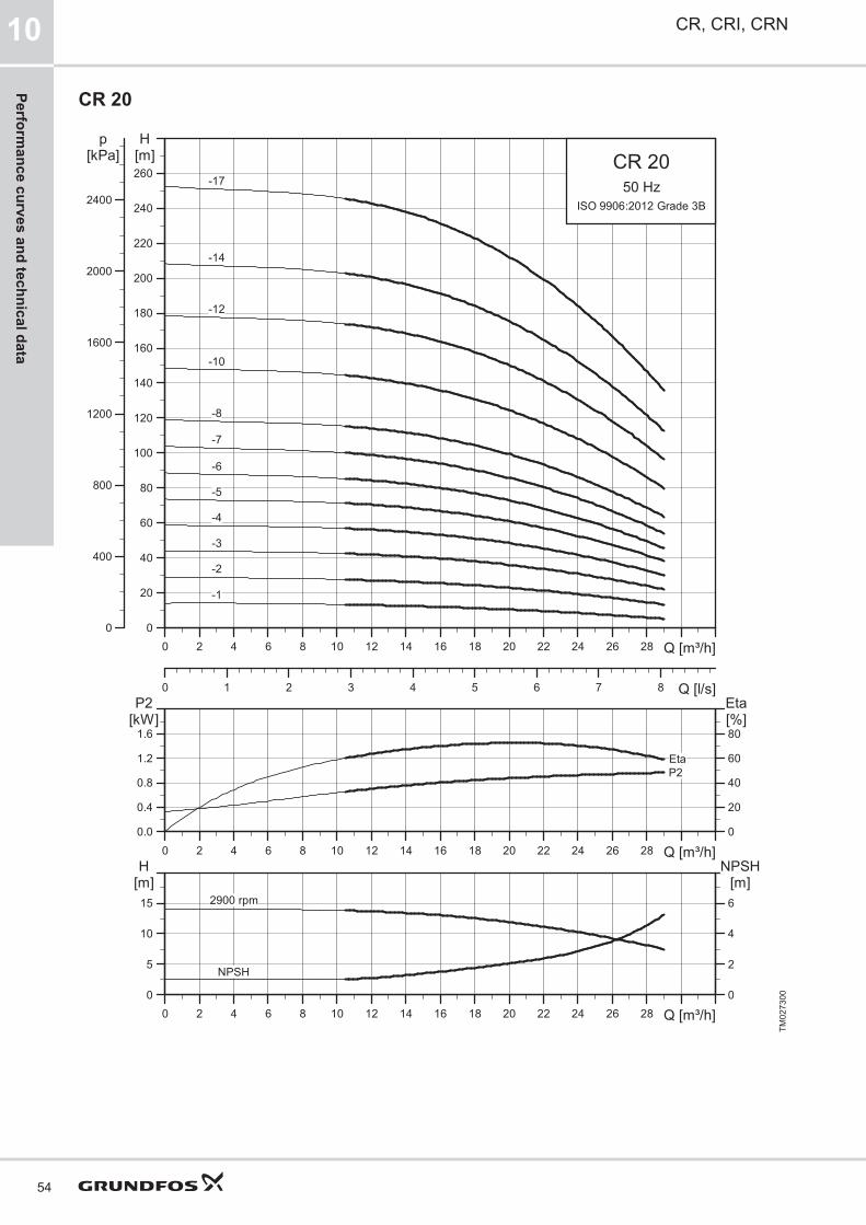
CR 20
0 2 4 6 8 10 12 14 16 18 20 22 24 26 28 Q [m³/h]0
20
40
60
80
100
120
140
160
180
200
220
240
260
H[m]
0 1 2 3 4 5 6 7 8 Q [l/s]
0
400
800
1200
1600
2000
2400
p[kPa] CR 20
50 HzISO 9906:2012 Grade 3B
-1
-10
-12
-14
-17
-2
-3
-4
-5
-6
-7
-8
0 2 4 6 8 10 12 14 16 18 20 22 24 26 28 Q [m³/h]0.0
0.4
0.8
1.2
1.6
P2[kW]
0
20
40
60
80
Eta[%]
EtaP2
0 2 4 6 8 10 12 14 16 18 20 22 24 26 28 Q [m³/h]0
5
10
15
H[m]
0
2
4
6
NPSH[m]
NPSH
2900 rpm
TM02
7300
CR, CRI, CRN10
54
Performance curves and technical data

Dimensional sketchB2
D2D1
G 1/2
G 1/2 D3
130176
90
G 1/2
300215256
ø6520
ø125
ø165
Rp 2"M16 x 45
ø165
ø65
18 x 21.5
ø127
ø120 130
30
256215
300176130
90
G 1/2
130178200
90
215256
G 1/2B1 4 x ø13.5 ø18.1
20 20
PN 16-25 / DN 50 GJ (ANSI-JIS) AF (DIN)
TM06
9597
Dimensions and weights
Pump typeMotor P2
[kW]
Dimension [mm] Net weight [kg]
Oval flange (A) DIN flangeD1 D2 D3 Oval flange DIN flange
B1 B1+B2 B1 B1+B2
CR 20-1 1.1 400 651 400 651 141 109 - 41 42
CR 20-2 2.2 415 736 415 736 178 110 - 52 53
CR 20-3 4 465 837 465 837 220 134 - 70 71
CR 20-4 5.5 542 933 542 933 220 134 300 88 89
CR 20-5 5.5 587 978 587 978 220 134 300 90 90
CR 20-6 7.5 632 1011 632 1011 260 159 300 101 102
CR 20-7 7.5 677 1056 677 1056 260 159 300 103 103
CR 20-8 11 - - 799 1281 318 204 350 - 146
CR 20-10 11 - - 889 1371 318 204 350 - 149
CR 20-12 15 - - 979 1461 318 204 350 - 165
CR 20-14 15 - - 1069 1551 318 204 350 - 169
CR 20-17 18.5 - - 1204 1730 318 204 350 - 186
CR, CRI, CRN 10
55
Perf
orm
ance
cur
ves
and
tech
nica
l dat
a

CRI, CRN 20
0 2 4 6 8 10 12 14 16 18 20 22 24 26 28 Q [m³/h]0
20
40
60
80
100
120
140
160
180
200
220
240
260
H[m]
0 1 2 3 4 5 6 7 8 Q [l/s]
0
400
800
1200
1600
2000
2400
p[kPa] CRI, CRN 20
50 HzISO 9906:2012 Grade 3B
-1
-10
-12
-14
-17
-2
-3
-4
-5
-6
-7
-8
0 2 4 6 8 10 12 14 16 18 20 22 24 26 28 Q [m³/h]0.0
0.4
0.8
1.2
1.6
P2[kW]
0
20
40
60
80
Eta[%]
EtaP2
0 2 4 6 8 10 12 14 16 18 20 22 24 26 28 Q [m³/h]0
5
10
15
H[m]
0
2
4
6
NPSH[m]
NPSH
2900 rpm
TM02
7301
CR, CRI, CRN10
56
Performance curves and technical data

Dimensional sketchB2
D2D1
G 1/2
G 1/2 D3
B1
G 1/2
261
215248
18.5 x 21.8
ø127
300
4 x ø13
ø165
ø120.5ø65 ø50
202
ø87
90 26
ø60.
1
200130
248215
215248
G 1/2
130200
130200
26
26
9090
P (PJE) PN 16-25 / DN 50 CA
FGJ (DIN-ANSI-JIS)
TM06
9598
Dimensions and weights
Pump typeMotor P2
[kW]
Dimension [mm]Net weight
[kg]
PJE/CA DIN flangeD1 D2 D3 PJE/CA DIN flange
B1 B1+B2 B1 B1+B2
CRI/CRN 20-1 1.1 397 648 397 648 141 109 - 34 39
CRI/CRN 20-2 2.2 413 734 413 734 178 110 - 45 50
CRI/CRN 20-3 4 463 835 463 835 220 134 - 63 68
CRI/CRN 20-4 5.5 540 931 540 931 220 134 300 82 86
CRI/CRN 20-5 5.5 585 976 585 976 220 134 300 83 88
CRI/CRN 20-6 7.5 630 1009 630 1009 260 159 300 94 99
CRI/CRN 20-7 7.5 675 1054 675 1054 260 159 300 96 101
CRI/CRN 20-8 11 797 1279 797 1279 318 204 350 138 143
CRI/CRN 20-10 11 887 1369 887 1369 318 204 350 142 147
CRI/CRN 20-12 15 977 1459 977 1459 318 204 350 157 162
CRI/CRN 20-14 15 1067 1549 1067 1549 318 204 350 161 165
CRI/CRN 20-17 18.5 1202 1728 1202 1728 318 204 350 178 183
CR, CRI, CRN 10
57
Perf
orm
ance
cur
ves
and
tech
nica
l dat
a
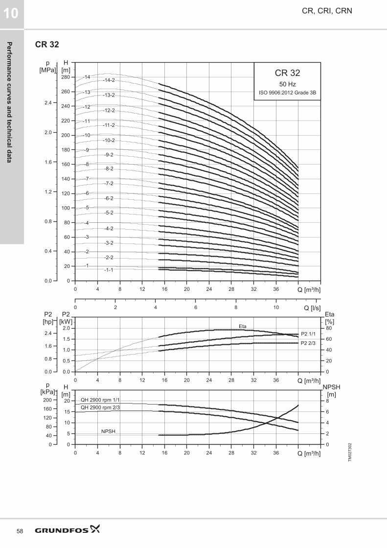
CR 32
0 4 8 12 16 20 24 28 32 36 Q [m³/h]0
20
40
60
80
100
120
140
160
180
200
220
240
260
280
H[m]
0 2 4 6 8 10 Q [l/s]
0.0
0.4
0.8
1.2
1.6
2.0
2.4
[MPa]p
CR 3250 Hz
ISO 9906:2012 Grade 3B
-11-11-2
-12 -12-2
-13 -13-2
-14 -14-2
-1-1-1
-10-10-2
-2-2-2
-3-3-2
-4-4-2
-5-5-2
-6-6-2
-7-7-2
-8-8-2
-9-9-2
0 4 8 12 16 20 24 28 32 36 Q [m³/h]0.0
0.5
1.0
1.5
2.0
P2[kW]
0
20
40
60
80[%]Eta
0.0
0.8
1.6
2.4
[hp]P2
P2 1/1
P2 2/3
Eta
0 4 8 12 16 20 24 28 32 36 Q [m³/h]0
5
10
15
20[m]H
0
2
4
6
8
NPSH[m]
0
40
80
120
160
200[kPa]
p
NPSH
QH 2900 rpm 1/1QH 2900 rpm 2/3
TM02
7302
CR, CRI, CRN10
58
Performance curves and technical data

Dimensional sketch
D2
D1
B2B1
105
170223320
D3
D2D1
B2
ø74240298
G 1/2
G 1/2
G 1/2
ø144 x
ø188 x
ø107
ø145
185
PN 16-25-40 / DN 65
30
F (DIN)
TM06
9605
Dimensions and weights
Pump typeMotor P2
[kW]Dimension [mm] Net weight
[kg]B1 B1+B2 D1 D2 D3
CR 32-1-1 1.5 505 786 178 110 - 63
CR 32-1 2.2 505 826 178 110 - 67
CR 32-2-2 3 575 910 198 120 - 75
CR 32-2 4 575 947 220 134 - 86
CR 32-3-2 5.5 645 1036 220 134 300 97
CR 32-3 5.5 645 1036 220 134 300 97
CR 32-4-2 7.5 715 1094 260 159 300 110
CR 32-4 7.5 715 1094 260 159 300 110
CR 32-5-2 11 895 1377 318 204 350 158
CR 32-5 11 895 1377 318 204 350 158
CR 32-6-2 11 965 1447 318 204 350 161
CR 32-6 11 965 1447 318 204 350 161
CR 32-7-2 15 1035 1517 318 204 350 176
CR 32-7 15 1035 1517 318 204 350 176
CR 32-8-2 15 1105 1587 318 204 350 182
CR 32-8 15 1105 1587 318 204 350 182
CR 32-9-2 18.5 1175 1701 318 204 350 198
CR 32-9 18.5 1175 1701 318 204 350 198
CR 32-10-2 18.5 1245 1771 318 204 350 201
CR 32-10 18.5 1245 1771 318 204 350 201
CR 32-11-2 22 1315 1867 318 204 350 220
CR 32-11 22 1315 1867 318 204 350 220
CR 32-12-2 22 1385 1937 318 204 350 223
CR 32-12 22 1385 1937 318 204 350 223
CR 32-13-2 30 1455 2066 396 315 400 329
CR 32-13 30 1455 2066 396 315 400 329
CR 32-14-2 30 1525 2136 396 315 400 332
CR 32-14 30 1525 2136 396 315 400 332
CR, CRI, CRN 10
59
Perf
orm
ance
cur
ves
and
tech
nica
l dat
a

CRN 32
0 4 8 12 16 20 24 28 32 36 Q [m³/h]0
20
40
60
80
100
120
140
160
180
200
220
240
260
280
H[m]
0 2 4 6 8 10 Q [l/s]
0.0
0.4
0.8
1.2
1.6
2.0
2.4
[MPa]p
CRN 3250 Hz
ISO 9906:2012 Grade 3B
-11-11-2
-12 -12-2
-13 -13-2
-14 -14-2
-1-1-1
-10-10-2
-2-2-2
-3-3-2
-4-4-2
-5-5-2
-6-6-2
-7-7-2
-8-8-2
-9-9-2
0 4 8 12 16 20 24 28 32 36 Q [m³/h]0.0
0.5
1.0
1.5
2.0
P2[kW]
0
20
40
60
80[%]Eta
0.0
0.8
1.6
2.4
[hp]P2
P2 1/1
P2 2/3
Eta
0 4 8 12 16 20 24 28 32 36 Q [m³/h]0
5
10
15
20[m]H
0
2
4
6
8
NPSH[m]
0
40
80
120
160
200[kPa]
p
NPSH
QH 2900 rpm 1/1QH 2900 rpm 2/3
TM02
7303
CR, CRI, CRN10
60
Performance curves and technical data

Dimensional sketch
8 x ø18
G 1/2
ø74240298
ø107
ø145
ø185
D2D1
170226320
B1B2
G 1/2
G 1/2
4 x ø14
105
D3
30G 1/2
D2
D1
B1B2
105
D3
G 1/2
170
226
320
4 x ø14
G 1/2
30
ø89
ø74
240
298
P (PJE)PN 16-25-40 / DN 65
F (DIN)
TM07
8956
Dimensions and weights
Pump typeMotor P2
[kW]Dimension [mm] Net weight
[kg]B1 B1+B2 D1 D2 D3
CRN 32-1-1 1.5 505 786 178 110 - 65
CRN 32-1 2.2 505 826 178 110 - 69
CRN 32-2-2 3 575 910 198 120 - 77
CRN 32-2 4 575 947 220 134 - 89
CRN 32-3-2 5.5 645 1036 220 134 300 99
CRN 32-3 5.5 645 1036 220 134 300 99
CRN 32-4-2 7.5 715 1094 260 159 300 112
CRN 32-4 7.5 715 1094 260 159 300 112
CRN 32-5-2 11 895 1377 318 204 350 160
CRN 32-5 11 895 1377 318 204 350 160
CRN 32-6-2 11 965 1447 318 204 350 163
CRN 32-6 11 965 1447 318 204 350 163
CRN 32-7-2 15 1035 1517 318 204 350 178
CRN 32-7 15 1035 1517 318 204 350 178
CRN 32-8-2 15 1105 1587 318 204 350 184
CRN 32-8 15 1105 1587 318 204 350 184
CRN 32-9-2 18.5 1175 1701 318 204 350 200
CRN 32-9 18.5 1175 1701 318 204 350 200
CRN 32-10-2 18.5 1245 1771 318 204 350 204
CRN 32-10 18.5 1245 1771 318 204 350 204
CRN 32-11-2 22 1315 1867 318 204 350 222
CRN 32-11 22 1315 1867 318 204 350 222
CRN 32-12-2 22 1385 1937 318 204 350 225
CRN 32-12 22 1385 1937 318 204 350 225
CRN 32-13-2 30 1455 2066 396 315 400 331
CRN 32-13 30 1455 2066 396 315 400 331
CRN 32-14-2 30 1525 2136 396 315 400 335
CRN 32-14 30 1525 2136 396 315 400 335
CR, CRI, CRN 10
61
Perf
orm
ance
cur
ves
and
tech
nica
l dat
a

CR 45
0 5 10 15 20 25 30 35 40 45 50 55 Q [m³/h]0
20
40
60
80
100
120
140
160
180
200
220
240
260
280
300
320
340
H[m]
0 2 4 6 8 10 12 14 16 Q [l/s]
0.0
0.4
0.8
1.2
1.6
2.0
2.4
2.8
3.2
[MPa]p
CR 4550 Hz
ISO 9906:2012 Grade 3B
-13-2
-12-2-12
-11-2-11
-1-1
-10-10-2
-2-2-2
-3-3-2
-4-4-2
-5-5-2
-6-6-2
-7-7-2
-8-8-2
-9-9-2
-1
0 5 10 15 20 25 30 35 40 45 50 55 Q [m³/h]0
1
2
3
4
P2[kW]
0
20
40
60
80[%]Eta
0
2
4
[hp]P2
P2 1/1P2 2/3
Eta
0 5 10 15 20 25 30 35 40 45 50 55 Q [m³/h]0
5
10
15
20
25[m]H
0
2
4
6
8
10
NPSH[m]
0
50
100
150
200
[kPa]p
NPSH
QH 2900 rpm 1/1QH 2900 rpm 2/3
TM02
7304
CR, CRI, CRN10
62
Performance curves and technical data

Dimensional sketch
8 x ø18
G 1/2
ø80266331
ø120
ø160
ø200
D2D1
190248365
B1B2
G 1/2
G 1/2
4 x ø14
140
D3
45
PN 16-25-40 / DN 80F (DIN)
TM06
9600
Dimensions and weights
Pump typeMotor P2
[kW]Dimension [mm] Net weight
[kg]B1 B1+B2 D1 D2 D3
CR 45-1-1 3 559 894 198 120 - 82
CR 45-1 4 559 931 220 134 - 93
CR 45-2-2 5.5 639 1030 220 134 300 104
CR 45-2 7.5 639 1018 260 159 300 114
CR 45-3-2 11 829 1311 318 204 350 163
CR 45-3 11 829 1311 318 204 350 163
CR 45-4-2 15 909 1391 318 204 350 179
CR 45-4 15 909 1391 318 204 350 179
CR 45-5-2 18.5 989 1515 318 204 350 195
CR 45-5 18.5 989 1515 318 204 350 195
CR 45-6-2 22 1069 1621 318 204 350 217
CR 45-6 22 1069 1621 318 204 350 217
CR 45-7-2 30 1149 1760 396 315 400 324
CR 45-7 30 1149 1760 396 315 400 324
CR 45-8-2 30 1229 1840 396 315 400 328
CR 45-8 30 1229 1840 396 315 400 328
CR 45-9-2 30 1309 1920 396 315 400 332
CR 45-9 37 1309 1945 396 315 400 357
CR 45-10-2 37 1389 2025 396 315 400 362
CR 45-10 37 1389 2025 396 315 400 362
CR 45-11-2 45 1469 2177 449 338 450 455
CR 45-11 45 1469 2177 449 338 450 455
CR 45-12-2 45 1549 2257 449 338 450 460
CR 45-12 45 1549 2257 449 338 450 460
CR 45-13-2 45 1629 2337 449 338 450 464
CR, CRI, CRN 10
63
Perf
orm
ance
cur
ves
and
tech
nica
l dat
a

CRN 45
0 5 10 15 20 25 30 35 40 45 50 55 Q [m³/h]0
20
40
60
80
100
120
140
160
180
200
220
240
260
280
300
320
340
H[m]
0 2 4 6 8 10 12 14 16 Q [l/s]
0.0
0.4
0.8
1.2
1.6
2.0
2.4
2.8
3.2
[MPa]p
CRN 4550 Hz
ISO 9906:2012 Grade 3B
-13-2
-12-2-12
-11-2-11
-1-1
-10-10-2
-2-2-2
-3-3-2
-4-4-2
-5-5-2
-6-6-2
-7-7-2
-8-8-2
-9-9-2
-1
0 5 10 15 20 25 30 35 40 45 50 55 Q [m³/h]0
1
2
3
4
P2[kW]
0
20
40
60
80[%]Eta
0
2
4
[hp]P2
P2 1/1P2 2/3
Eta
0 5 10 15 20 25 30 35 40 45 50 55 Q [m³/h]0
5
10
15
20
25[m]H
0
2
4
6
8
10
NPSH[m]
0
50
100
150
200
[kPa]p
NPSH
QH 2900 rpm 1/1QH 2900 rpm 2/3
TM02
7305
CR, CRI, CRN10
64
Performance curves and technical data

Dimensional sketch
G 1/2
ø80266331
ø120
ø160
ø200
D2D1
190251365
B1B2
G 1/2 8 x ø18
G 1/2
4 x ø14
140
D3
45
D2
D1
B1B2
G 1/2
G 1/2
G 1/2
P
140
190
251365
266331
ø80
45
4 x ø14
ø114
P (PJE) PN 16-25-40 / DN 80F (DIN)
TM07
8957
Dimensions and weights
Pump typeMotor P2
[kW]Dimension [mm] Net weight
[kg]B1 B1+B2 D1 D2 D3
CRN 45-1-1 3 559 894 198 120 - 82
CRN 45-1 4 559 931 220 134 - 94
CRN 45-2-2 5.5 639 1030 220 134 300 105
CRN 45-2 7.5 639 1018 260 159 300 114
CRN 45-3-2 11 829 1311 318 204 350 164
CRN 45-3 11 829 1311 318 204 350 164
CRN 45-4-2 15 909 1391 318 204 350 179
CRN 45-4 15 909 1391 318 204 350 179
CRN 45-5-2 18.5 989 1515 318 204 350 195
CRN 45-5 18.5 989 1515 318 204 350 195
CRN 45-6-2 22 1069 1621 318 204 350 217
CRN 45-6 22 1069 1621 318 204 350 217
CRN 45-7-2 30 1149 1760 396 315 400 324
CRN 45-7 30 1149 1760 396 315 400 324
CRN 45-8-2 30 1229 1840 396 315 400 328
CRN 45-8 30 1229 1840 396 315 400 328
CRN 45-9-2 30 1309 1920 396 315 400 333
CRN 45-9 37 1309 1945 396 315 400 358
CRN 45-10-2 37 1389 2025 396 315 400 362
CRN 45-10 37 1389 2025 396 315 400 362
CRN 45-11-2 45 1469 2177 449 338 450 455
CRN 45-11 45 1469 2177 449 338 450 455
CRN 45-12-2 45 1549 2257 449 338 450 460
CRN 45-12 45 1549 2257 449 338 450 460
CRN 45-13-2 45 1629 2337 449 338 450 464
CR, CRI, CRN 10
65
Perf
orm
ance
cur
ves
and
tech
nica
l dat
a

CR 64
0 10 20 30 40 50 60 70 80 Q [m³/h]0
20
40
60
80
100
120
140
160
180
200
220
240
H[m]
0 5 10 15 20 Q [l/s]
0.0
0.4
0.8
1.2
1.6
2.0
[MPa]p
CR 6450 Hz
ISO 9906:2012 Grade 3B-8-1
-8-2
-7
-1
-2-2-1
-2-2
-3
-3-1
-3-2
-4-4-1
-4-2
-5
-5-1-5-2
-6-6-1
-6-2
-7-1-7-2
-1-1
0 10 20 30 40 50 60 70 80 Q [m³/h]0
2
4
6
8
P2[kW]
0
20
40
60
80[%]Eta
02468
10
[hp]P2
P2 1/1
P2 2/3
Eta
0 10 20 30 40 50 60 70 80 Q [m³/h]0
8
16
24
32[m]H
0
2
4
6
8
NPSH[m]
0
100
200
300
[kPa]p
NPSH
QH 2900 rpm 1/1
QH 2900 rpm 2/3
TM02
7306
CR, CRI, CRN10
66
Performance curves and technical data

Dimensional sketch
ø100
266
331
ø150
ø180
ø220
D2
D1
190
248
365
B 2
G 1/2 8 x ø 18
G 1/2
G 1/2
4 x ø 14
140
D 3
4545
4 x ø 14
G 1/2
8 x ø 22
ø235
ø190
ø150
331266
ø100
PN 25-40 / DN 100
PN 16 / DN 100F (DIN)
F (DIN)
B 1
TM06
9606
Dimensions and weights
Pump typeMotor P2
[kW]Dimension [mm] Net weight
[kg]B1 B1+B2 D1 D2 D3
CR 64-1-1 4 561 933 220 134 - 96
CR 64-1 5.5 561 952 220 134 300 103
CR 64-2-2 7.5 644 1023 260 159 300 117
CR 64-2-1 11 754 1236 318 204 350 162
CR 64-2 11 754 1236 318 204 350 162
CR 64-3-2 15 836 1318 318 204 350 179
CR 64-3-1 15 836 1318 318 204 350 179
CR 64-3 18.5 836 1362 318 204 350 191
CR 64-4-2 18.5 919 1445 318 204 350 196
CR 64-4-1 22 919 1471 318 204 350 211
CR 64-4 22 919 1471 318 204 350 211
CR 64-5-2 30 1001 1612 396 315 400 318
CR 64-5-1 30 1001 1612 396 315 400 318
CR 64-5 30 1001 1612 396 315 400 318
CR 64-6-2 30 1084 1695 396 315 400 324
CR 64-6-1 37 1084 1720 396 315 400 349
CR 64-6 37 1084 1720 396 315 400 349
CR 64-7-2 37 1166 1802 396 315 400 354
CR 64-7-1 37 1166 1802 396 315 400 354
CR 64-7 45 1166 1874 449 338 450 443
CR 64-8-2 45 1249 1957 449 338 450 448
CR 64-8-1 45 1249 1957 449 338 450 448
CR, CRI, CRN 10
67
Perf
orm
ance
cur
ves
and
tech
nica
l dat
a

CRN 64
0 10 20 30 40 50 60 70 80 Q [m³/h]0
20
40
60
80
100
120
140
160
180
200
220
240
H[m]
0 5 10 15 20 Q [l/s]
0.0
0.4
0.8
1.2
1.6
2.0
[MPa]p
CRN 6450 Hz
ISO 9906:2012 Grade 3B-8-1
-8-2
-7
-1
-2-2-1
-2-2
-3
-3-1
-3-2
-4-4-1
-4-2
-5
-5-1-5-2
-6-6-1
-6-2
-7-1-7-2
-1-1
0 10 20 30 40 50 60 70 80 Q [m³/h]0
2
4
6
8
P2[kW]
0
20
40
60
80[%]Eta
02468
10
[hp]P2
P2 1/1
P2 2/3
Eta
0 10 20 30 40 50 60 70 80 Q [m³/h]0
8
16
24
32[m]H
0
2
4
6
8
NPSH[m]
0
100
200
300
[kPa]p
NPSH
QH 2900 rpm 1/1
QH 2900 rpm 2/3
TM02
7307
CR, CRI, CRN10
68
Performance curves and technical data

Dimensional sketch
ø100266331
ø150
ø180
ø220
D2D1
190251365
B1B2
G 1/2 8 x ø18
G 1/2
G 1/2
4 x ø1414
0
D3
4545
4 x ø14
G 1/2
8 x ø22
ø235
ø190
ø150
331266ø100
D2
D1
B1B2
G 1/2
G 1/2
P
G 1/2
140
190251365
266331
4 x ø14ø80
45
ø114
P (PJE)
PN 25-40 / DN 100
PN 16 / DN 100F (DIN)
F (DIN)
TM07
8958
Dimensions and weights
Pump typeMotor P2
[kW]Dimension [mm] Net weight
[kg]B1 B1+B2 D1 D2 D3
CRN 64-1-1 4 561 933 220 134 - 95
CRN 64-1 5.5 561 952 220 134 300 103
CRN 64-2-2 7.5 644 1023 260 159 300 117
CRN 64-2-1 11 754 1236 318 204 350 162
CRN 64-2 11 754 1236 318 204 350 162
CRN 64-3-2 15 836 1318 318 204 350 178
CRN 64-3-1 15 836 1318 318 204 350 178
CRN 64-3 18.5 836 1362 318 204 350 191
CRN 64-4-2 18.5 919 1445 318 204 350 196
CRN 64-4-1 22 919 1471 318 204 350 211
CRN 64-4 22 919 1471 318 204 350 211
CRN 64-5-2 30 1001 1612 396 315 400 318
CRN 64-5-1 30 1001 1612 396 315 400 318
CRN 64-5 30 1001 1612 396 315 400 318
CRN 64-6-2 30 1084 1695 396 315 400 325
CRN 64-6-1 37 1084 1720 396 315 400 350
CRN 64-6 37 1084 1720 396 315 400 350
CRN 64-7-2 37 1166 1802 396 315 400 354
CRN 64-7-1 37 1166 1802 396 315 400 354
CRN 64-7 45 1166 1874 449 338 450 444
CRN 64-8-2 45 1249 1957 449 338 450 448
CRN 64-8-1 45 1249 1957 449 338 450 448
CR, CRI, CRN 10
69
Perf
orm
ance
cur
ves
and
tech
nica
l dat
a

CR 95
0 10 20 30 40 50 60 70 80 90 100 110 120 Q [m³/h]0
10
20
30
40
50
60
70
80
90
100
110
120
130
140
150
160
170
180
190
200
210
220
230
240
H[m]
0 5 10 15 20 25 30 35 Q [l/s]
0.0
0.2
0.4
0.6
0.8
1.0
1.2
1.4
1.6
1.8
2.0
2.2
[MPa]p
CR 9550 Hz
ISO 9906:2012 Grade 3B
-1-1-1
-2
-2-2
-3
-3-2
-4
-5
-6
-7
-8-2
0 10 20 30 40 50 60 70 80 90 100 110 120 Q [m³/h]0
4
8
12
16[kW]P2
0
20
40
60
80[%]Eta
P21/1 IS 2950 rpm
P22/3 IS 2950 rpm
Eta 2950 rpm
0 10 20 30 40 50 60 70 80 90 100 110 120 Q [m³/h]0
10
20
30
[m]H
0
2
4
6
[m]NPSH
QH1/1 IS 2950 rpm
QH2/3 IS 2950 rpm
NPSH 2950 rpm
TM06
5113
The pump efficiency (ETA) is based on a three-stage pump.
CR, CRI, CRN10
70
Performance curves and technical data

Dimensional sketch
380275
140
B2
D3
D1
D2B1
225
D3
D4
G 1/2G 1/2
G 1/2G 1/2
100
419350
190
235
150
40 40
150
235
190
350419
100
4 x 18.5
8 x 22
4 x 18.5
8 x 22
100
419350
180
220
150
40
4 x 18.5
8 x 18
PN 25 / DN 100 PN 40 / DN 100F (DIN) F (DIN) F (DIN)
PN 16 / DN 100
TM08
0551
Dimensions and weights
Pump typeMotor P2
[kW]Dimension [mm] Net weight
[kg]B1 B1+B2 D1 D2 D3 D4
CR 95-1-1 5.5 689 1080 220 134 300 - 137
CR 95-1 7.5 689 1068 260 159 300 - 147
CR 95-2-2 11 795 1277 318 204 350 - 194
CR 95-2 15 795 1277 318 204 350 - 206
CR 95-3-2 18.5 900 1426 318 204 350 - 224
CR 95-3 22 900 1452 318 204 350 - 239
CR 95-4 30 1009 1620 396 315 400 492 348
CR 95-5 37 1114 1750 396 315 400 492 379
CR 95-6 45 1238 1946 449 338 450 573 480
CR 95-7 55 1342 2089 497 410 550 732 598
CR 95-8-2 55 1446 2193 497 410 550 732 604
CR, CRI, CRN 10
71
Perf
orm
ance
cur
ves
and
tech
nica
l dat
a
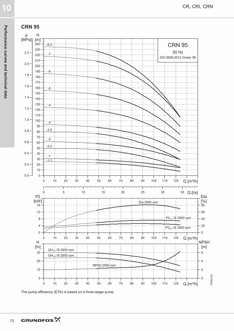
CRN 95
0 10 20 30 40 50 60 70 80 90 100 110 120 Q [m³/h]0
10
20
30
40
50
60
70
80
90
100
110
120
130
140
150
160
170
180
190
200
210
220
230
240
H[m]
0 5 10 15 20 25 30 35 Q [l/s]
0.0
0.2
0.4
0.6
0.8
1.0
1.2
1.4
1.6
1.8
2.0
2.2
[MPa]p
CRN 9550 Hz
ISO 9906:2012 Grade 3B
-1-1-1
-2
-2-2
-3
-3-2
-4
-5
-6
-7
-8-2
0 10 20 30 40 50 60 70 80 90 100 110 120 Q [m³/h]0
4
8
12
16[kW]P2
0
20
40
60
80[%]Eta
P21/1 IS 2950 rpm
P22/3 IS 2950 rpm
Eta 2950 rpm
0 10 20 30 40 50 60 70 80 90 100 110 120 Q [m³/h]0
10
20
30
[m]H
0
2
4
6
[m]NPSH
QH1/1 IS 2950 rpm
QH2/3 IS 2950 rpm
NPSH 2950 rpm
TM06
5125
The pump efficiency (ETA) is based on a three-stage pump.
CR, CRI, CRN10
72
Performance curves and technical data
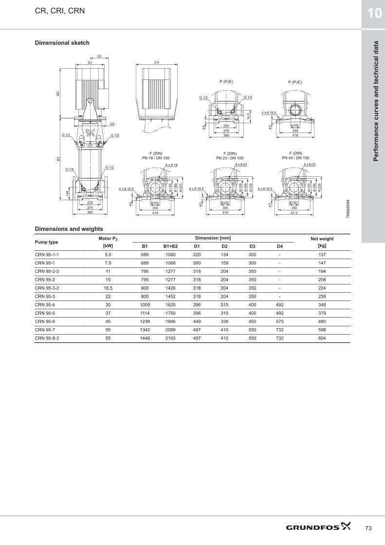
Dimensional sketch
100
419350
190
235
150
150
235
190
350100
40
40
41 9
4 x 18.5
8 x 22
4 x 18.5
8 x 22
140
B2
D3
D1
D2B1
380275225
D4
G 1/2G 1/2
G 1/2G 1/2
380275225
40
140
G 1/2G 1/2
419350100
40
4 x 18.5
100
419350
180
220
150
40
4 x 18.5
8 x 18
F (DIN)PN 16 / DN 100
F (DIN)PN 25 / DN 100
F (DIN)PN 40 / DN 100
P (PJE) P (PJE)
TM06
5094
Dimensions and weights
Pump typeMotor P2
[kW]Dimension [mm] Net weight
[kg]B1 B1+B2 D1 D2 D3 D4
CRN 95-1-1 5.5 689 1080 220 134 300 - 137
CRN 95-1 7.5 689 1068 260 159 300 - 147
CRN 95-2-2 11 795 1277 318 204 350 - 194
CRN 95-2 15 795 1277 318 204 350 - 206
CRN 95-3-2 18.5 900 1426 318 204 350 - 224
CRN 95-3 22 900 1452 318 204 350 - 239
CRN 95-4 30 1009 1620 396 315 400 492 348
CRN 95-5 37 1114 1750 396 315 400 492 379
CRN 95-6 45 1238 1946 449 338 450 573 480
CRN 95-7 55 1342 2089 497 410 550 732 598
CRN 95-8-2 55 1446 2193 497 410 550 732 604
CR, CRI, CRN 10
73
Perf
orm
ance
cur
ves
and
tech
nica
l dat
a

CR 125
0 10 20 30 40 50 60 70 80 90 100 110 120 130 140 150 Q [m³/h]0
10
20
30
40
50
60
70
80
90
100
110
120
130
140
150
160
170
180
H[m]
0 5 10 15 20 25 30 35 40 45 Q [l/s]
0.0
0.2
0.4
0.6
0.8
1.0
1.2
1.4
1.6
[MPa]p
CR 12550 Hz
ISO 9906:2012 Grade 3B
-1
-2
-2-1
-2-2
-3
-3-1
-4
-4-2
-5
0 10 20 30 40 50 60 70 80 90 100 110 120 130 140 150 Q [m³/h]0
4
8
12
16[kW]P2
0
20
40
60
80[%]Eta
P21/1 IS 2950 rpm
P22/3 IS 2950 rpm
Eta 2950 rpm
0 10 20 30 40 50 60 70 80 90 100 110 120 130 140 150 Q [m³/h]0
10
20
30
40[m]H
0
2
4
6
8[m]
NPSH
QH1/1 IS 2950 rpm
QH2/3 IS 2950 rpm
NPSH 2950 rpm
TM06
5114
The pump efficiency (ETA) is based on a three-stage pump.
CR, CRI, CRN10
74
Performance curves and technical data

Dimensional sketch
150
499425
300
250
205
55 55
205
250
300
425499
150
4 x 22.5
8 x 26
4 x 22.5
8 x 26
180
B1
D3
485332275
D2D1
B2D 4
G 1/2 G 1/2
G 1/2 G 1/2
150
499425
285
240
205
55
4 x 22.5
8 x 22
PN 16 / DN 150 PN 25 / DN 150 PN 40 / DN 150F (DIN) F (DIN) F (DIN)
TM08
0549
Dimensions and weights
Pump typeMotor P2
[kW]Dimension [mm] Net weight
[kg]B1 B1+B2 D1 D2 D3 D4
CR 125-1 11 783 1265 318 204 350 - 233
CR 125-2-2 15 905 1387 318 204 350 - 255
CR 125-2-1 18.5 905 1431 318 204 350 - 268
CR 125-2 22 905 1457 318 204 350 - 283
CR 125-3-1 30 1029 1640 396 315 400 492 396
CR 125-3 37 1029 1665 396 315 400 492 421
CR 125-4-2 37 1151 1787 396 315 400 492 432
CR 125-4 45 1174 1882 449 338 450 573 526
CR 125-5 55 1295 2042 497 410 550 732 647
CR, CRI, CRN 10
75
Perf
orm
ance
cur
ves
and
tech
nica
l dat
a

CRN 125
0 10 20 30 40 50 60 70 80 90 100 110 120 130 140 150 Q [m³/h]0
20
40
60
80
100
120
140
160
180
200
220
240
260
280
300
320
340
H[m]
0 5 10 15 20 25 30 35 40 45 Q [l/s]
0.0
0.5
1.0
1.5
2.0
2.5
3.0
[MPa]p
CRN 12550 Hz
ISO 9906:2012 Grade 3B
-10
-6
-7
-8
-9
-9-2
-1
-2
-2-1
-2-2
-3-3-1
-4
-4-2
-5
0 10 20 30 40 50 60 70 80 90 100 110 120 130 140 150 Q [m³/h]0
4
8
12
16[kW]P2
0
20
40
60
80[%]Eta
P21/1 IS 2950 rpm
P22/3 IS 2950 rpm
Eta 2950 rpm
0 10 20 30 40 50 60 70 80 90 100 110 120 130 140 150 Q [m³/h]0
10
20
30
40[m]H
0
2
4
6
8[m]
NPSH
QH1/1 IS 2950 rpm
QH2/3 IS 2950 rpm
NPSH 2950 rpm
TM06
5126
The pump efficiency (ETA) is based on a three-stage pump.
CR, CRI, CRN10
76
Performance curves and technical data
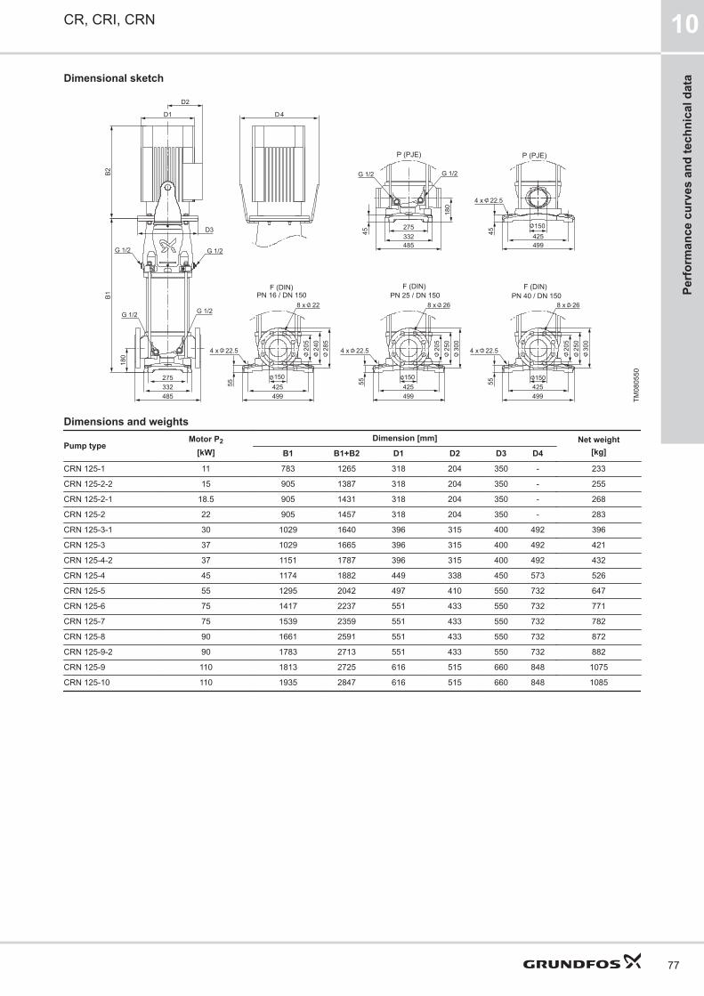
Dimensional sketch
300
250
205
55 55
205
250
300
4 x 22.5
8 x 26
4 x 22.5
8 x 26
150425499
150425499
B1B2
D3
D1
D2
D4
G 1/2 G 1/2
G 1/2 G 1/2
275332485
180
485332275
45
G 1/2 G 1/2
180
150
49942545
4 x 22.5
285
240
205
55
4 x 22.5
8 x 22
150425499
PN 16 / DN 150 PN 25 / DN 150 PN 40 / DN 150
P (PJE) P (PJE)
F (DIN) F (DIN) F (DIN)
TM08
0550
Dimensions and weights
Pump typeMotor P2
[kW]Dimension [mm] Net weight
[kg]B1 B1+B2 D1 D2 D3 D4
CRN 125-1 11 783 1265 318 204 350 - 233
CRN 125-2-2 15 905 1387 318 204 350 - 255
CRN 125-2-1 18.5 905 1431 318 204 350 - 268
CRN 125-2 22 905 1457 318 204 350 - 283
CRN 125-3-1 30 1029 1640 396 315 400 492 396
CRN 125-3 37 1029 1665 396 315 400 492 421
CRN 125-4-2 37 1151 1787 396 315 400 492 432
CRN 125-4 45 1174 1882 449 338 450 573 526
CRN 125-5 55 1295 2042 497 410 550 732 647
CRN 125-6 75 1417 2237 551 433 550 732 771
CRN 125-7 75 1539 2359 551 433 550 732 782
CRN 125-8 90 1661 2591 551 433 550 732 872
CRN 125-9-2 90 1783 2713 551 433 550 732 882
CRN 125-9 110 1813 2725 616 515 660 848 1075
CRN 125-10 110 1935 2847 616 515 660 848 1085
CR, CRI, CRN 10
77
Perf
orm
ance
cur
ves
and
tech
nica
l dat
a

CR 155
0 10 20 30 40 50 60 70 80 90 100 110 120 130 140 150 160 170 180 190 Q [m³/h]0
10
20
30
40
50
60
70
80
90
100
110
120
130
140
150
H[m]
0 5 10 15 20 25 30 35 40 45 50 55 Q [l/s]
0.0
0.2
0.4
0.6
0.8
1.0
1.2
1.4
[MPa]p
CR 15550 Hz
ISO 9906:2012 Grade 3B
-1-1-1
-2
-2-2
-3
-3-2
-4-1
0 10 20 30 40 50 60 70 80 90 100 110 120 130 140 150 160 170 180 190 Q [m³/h]0
5
10
15
20[kW]P2
0
20
40
60
80[%]Eta
P21/1 IS 2950 rpm
P22/3 IS 2950 rpm
Eta 2950 rpm
0 10 20 30 40 50 60 70 80 90 100 110 120 130 140 150 160 170 180 190 Q [m³/h]0
10
20
30
40
50[m]H
0
2
4
6
8
10[m]
NPSH
QH1/1 IS 2950 rpm
QH2/3 IS 2950 rpmNPSH 2950 rpm
TM06
5115
The pump efficiency (ETA) is based on a three-stage pump.
CR, CRI, CRN10
78
Performance curves and technical data

Dimensional sketch
150
499425
300
250
205
55 55
205
250
300
425499
150
4 x 22.5
8 x 26
4 x 22.5
8 x 26
180
B1
D3
485332275
D2D1
B2D 4
G 1/2 G 1/2
G 1/2 G 1/2
150
499425
285
240
205
55
4 x 22.5
8 x 22
PN 16 / DN 150 PN 25 / DN 150 PN 40 / DN 150F (DIN) F (DIN) F (DIN)
TM08
0549
Dimensions and weights
Pump typeMotor P2
[kW]Dimension [mm] Net weight
[kg]B1 B1+B2 D1 D2 D3 D4
CR 155-1-1 11 783 1265 318 204 350 - 234
CR 155-1 15 783 1265 318 204 350 - 245
CR 155-2-2 22 905 1457 318 204 350 - 284
CR 155-2 30 907 1518 396 315 400 492 387
CR 155-3-2 37 1029 1665 396 315 400 492 423
CR 155-3 45 1052 1760 449 338 450 573 517
CR 155-4-1 55 1173 1920 497 410 550 732 637
CR, CRI, CRN 10
79
Perf
orm
ance
cur
ves
and
tech
nica
l dat
a
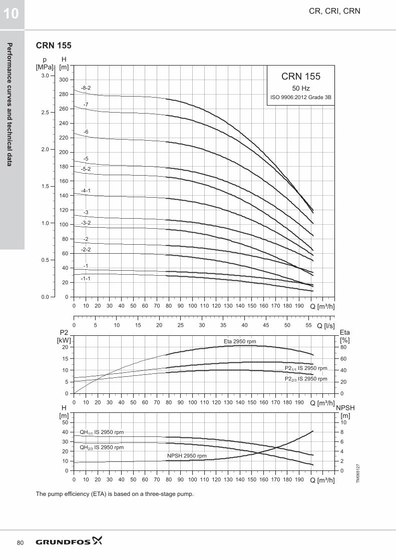
CRN 155
0 10 20 30 40 50 60 70 80 90 100 110 120 130 140 150 160 170 180 190 Q [m³/h]0
20
40
60
80
100
120
140
160
180
200
220
240
260
280
300
H[m]
0 5 10 15 20 25 30 35 40 45 50 55 Q [l/s]
0.0
0.5
1.0
1.5
2.0
2.5
3.0[MPa]
p
CRN 15550 Hz
ISO 9906:2012 Grade 3B
-5
-5-2
-6
-7
-8-2
-1
-1-1
-2
-2-2
-3
-3-2
-4-1
0 10 20 30 40 50 60 70 80 90 100 110 120 130 140 150 160 170 180 190 Q [m³/h]0
5
10
15
20[kW]P2
0
20
40
60
80[%]Eta
P21/1 IS 2950 rpm
P22/3 IS 2950 rpm
Eta 2950 rpm
0 10 20 30 40 50 60 70 80 90 100 110 120 130 140 150 160 170 180 190 Q [m³/h]0
10
20
30
40
50[m]H
0
2
4
6
8
10[m]
NPSH
QH1/1 IS 2950 rpm
QH2/3 IS 2950 rpmNPSH 2950 rpm
TM06
5127
The pump efficiency (ETA) is based on a three-stage pump.
CR, CRI, CRN10
80
Performance curves and technical data

Dimensional sketch
300
250
205
55 55
205
250
300
4 x 22.5
8 x 26
4 x 22.5
8 x 26
150425499
150425499
B1B2
D3
D1
D2
D4
G 1/2 G 1/2
G 1/2 G 1/2
275332485
180
485332275
45
G 1/2 G 1/2
180
150
49942545
4 x 22.5
285
240
205
55
4 x 22.5
8 x 22
150425499
PN 16 / DN 150 PN 25 / DN 150 PN 40 / DN 150
P (PJE) P (PJE)
F (DIN) F (DIN) F (DIN)
TM08
0550
Dimensions and weights
Pump typeMotor P2
[kW]Dimension [mm] Net weight
[kg]B1 B1+B2 D1 D2 D3 D4
CRN 155-1-1 11 783 1265 318 204 350 - 234
CRN 155-1 15 783 1265 318 204 350 - 245
CRN 155-2-2 22 905 1457 318 204 350 - 284
CRN 155-2 30 907 1518 396 315 400 492 387
CRN 155-3-2 37 1029 1665 396 315 400 492 423
CRN 155-3 45 1052 1760 449 338 450 573 517
CRN 155-4-1 55 1173 1920 497 410 550 732 637
CRN 155-5-2 75 1295 2115 551 433 550 732 764
CRN 155-5 75 1295 2115 551 433 550 732 764
CRN 155-6 90 1417 2347 551 433 550 732 854
CRN 155-7 110 1569 2481 616 515 660 848 1058
CRN 155-8-2 110 1691 2603 616 515 660 848 1068
CR, CRI, CRN 10
81
Perf
orm
ance
cur
ves
and
tech
nica
l dat
a

CR 185
TM06
5116
The pump efficiency (ETA) is based on a three-stage pump.
CR, CRI, CRN10
82
Performance curves and technical data

Dimensional sketch
350
B1D2
D1
D3
B2
200
415615
50
260
340
295
510599
200 200
599510
320
375
260
5050
260
360
310
510599
200
G 1/2
G 1/2
4 x 26.5
12 x 22
4 x 26.5
12 x 27
4 x 26.5
12 x 30
D4
G 1/2
G 1/2
PN 16 / DN 200 PN 25 / DN 200 PN 40 / DN 200F (DIN) F (DIN) F (DIN)
TM07
6604
Dimensions and weights
Pump typeMotor P2
[kW]Dimension [mm] Net weight
[kg]B1 B1+B2 D1 D2 D3 D4
CR 185-1-1 18.5 854 1380 318 204 350 - 345
CR 185-1 22 854 1406 318 204 350 - 360
CR 185-2-2 37 986 1622 396 315 400 492 502
CR 185-2 45 1006 1714 449 338 450 573 596
CR 185-3-3 55 1140 1887 497 410 550 732 722
CR 185-3 75 1140 1960 551 433 550 732 836
CR 185-4-3 75 1268 2088 551 433 550 732 855
CR 185-4 90 1268 2198 551 433 550 732 935
CR 185-5-3 110 1420 2332 616 515 660 848 1135
CR 185-5 110 1420 2332 616 515 660 848 1135
CR 185-6-3 132 1548 2625 616 515 660 848 1283
CR 185-6 132 1548 2625 616 515 660 848 1283
CR 185-7-3 160 1676 2753 616 515 660 848 1398
CR 185-7 160 1676 2753 616 515 660 848 1398
CR 185-8-3 200 1804 3036 616 515 660 848 1583
CR 185-8 200 1804 3036 616 515 660 848 1583
CR, CRI, CRN 10
83
Perf
orm
ance
cur
ves
and
tech
nica
l dat
a

CRN 185
TM06
5128
The pump efficiency (ETA) is based on a three-stage pump.
CR, CRI, CRN10
84
Performance curves and technical data

Dimensional sketch
D 4
350415615
D2
D1
D3
B2B1
200
50
260
310
360
510599
50
260
295
340
510599
200
200
50
350415615
50 510599
50 510
320
599
260
G 1/2 G 1/2
G 1/2 G 1/2
4 x 26.5
12 x 27
4 x 26.5
12 x 22
G 1/2 G 1/2
4 x 26.5
12 x 30
4 x 26.5 375
200
200 200
PN 16 / DN 200 PN 25 / DN 200 PN 40 / DN 200
P (PJE) P (PJE)
F (DIN) F (DIN) F (DIN)
TM07
6605
Dimensions and weights
Pump typeMotor P2
[kW]Dimension [mm] Net weight
[kg]B1 B1+B2 D1 D2 D3 D4
CRN 185-1-1 18.5 854 1380 318 204 350 - 345
CRN 185-1 22 854 1406 318 204 350 - 360
CRN 185-2-2 37 986 1622 396 315 400 492 502
CRN 185-2 45 1006 1714 449 338 450 573 596
CRN 185-3-3 55 1140 1887 497 410 550 732 722
CRN 185-3 75 1140 1960 551 433 550 732 836
CRN 185-4-3 75 1268 2088 551 433 550 732 855
CRN 185-4 90 1268 2198 551 433 550 732 935
CRN 185-5-3 110 1420 2332 616 515 660 848 1135
CRN 185-5 110 1420 2332 616 515 660 848 1135
CRN 185-6-3 132 1548 2625 616 515 660 848 1283
CRN 185-6 132 1548 2625 616 515 660 848 1283
CRN 185-7-3 160 1676 2753 616 515 660 848 1398
CRN 185-7 160 1676 2753 616 515 660 848 1398
CRN 185-8-3 200 1804 3036 616 515 660 848 1583
CRN 185-8 200 1804 3036 616 515 660 848 1583
CR, CRI, CRN 10
85
Perf
orm
ance
cur
ves
and
tech
nica
l dat
a

CR 215
TM06
5117
The pump efficiency (ETA) is based on a three-stage pump.
CR, CRI, CRN10
86
Performance curves and technical data
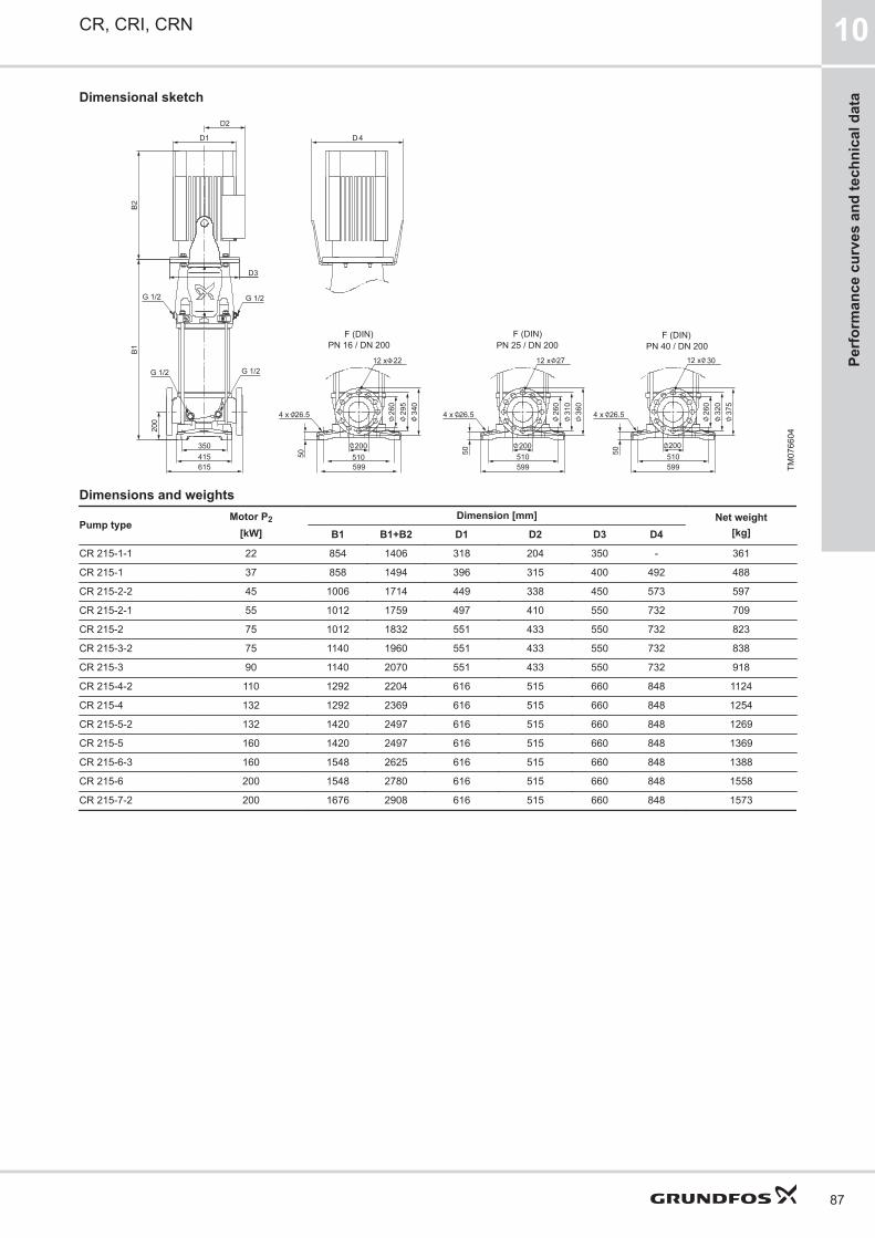
Dimensional sketch
350
B1D2
D1
D3
B2
200
415615
50
260
340
295
510599
200 200
599510
320
375
260
5050
260
360
310
510599
200
G 1/2
G 1/2
4 x 26.5
12 x 22
4 x 26.5
12 x 27
4 x 26.5
12 x 30
D4
G 1/2
G 1/2
PN 16 / DN 200 PN 25 / DN 200 PN 40 / DN 200F (DIN) F (DIN) F (DIN)
TM07
6604
Dimensions and weights
Pump typeMotor P2
[kW]Dimension [mm] Net weight
[kg]B1 B1+B2 D1 D2 D3 D4
CR 215-1-1 22 854 1406 318 204 350 - 361
CR 215-1 37 858 1494 396 315 400 492 488
CR 215-2-2 45 1006 1714 449 338 450 573 597
CR 215-2-1 55 1012 1759 497 410 550 732 709
CR 215-2 75 1012 1832 551 433 550 732 823
CR 215-3-2 75 1140 1960 551 433 550 732 838
CR 215-3 90 1140 2070 551 433 550 732 918
CR 215-4-2 110 1292 2204 616 515 660 848 1124
CR 215-4 132 1292 2369 616 515 660 848 1254
CR 215-5-2 132 1420 2497 616 515 660 848 1269
CR 215-5 160 1420 2497 616 515 660 848 1369
CR 215-6-3 160 1548 2625 616 515 660 848 1388
CR 215-6 200 1548 2780 616 515 660 848 1558
CR 215-7-2 200 1676 2908 616 515 660 848 1573
CR, CRI, CRN 10
87
Perf
orm
ance
cur
ves
and
tech
nica
l dat
a

CRN 215
TM06
5129
The pump efficiency (ETA) is based on a three-stage pump.
CR, CRI, CRN10
88
Performance curves and technical data

Dimensional sketch
D 4
350415615
D2
D1
D3
B2B1
200
50
260
310
360
510599
50
260
295
340
510599
200
200
50
350415615
50 510599
50 510
320
599
260
G 1/2 G 1/2
G 1/2 G 1/2
4 x 26.5
12 x 27
4 x 26.5
12 x 22
G 1/2 G 1/2
4 x 26.5
12 x 30
4 x 26.5 375
200
200 200
PN 16 / DN 200 PN 25 / DN 200 PN 40 / DN 200
P (PJE) P (PJE)
F (DIN) F (DIN) F (DIN)
TM07
6605
Dimensions and weights
Pump typeMotor P2
[kW]Dimension [mm] Net weight
[kg]B1 B1+B2 D1 D2 D3 D4
CRN 215-1-1 22 854 1406 318 204 350 - 361
CRN 215-1 37 858 1494 396 315 400 492 488
CRN 215-2-2 45 1006 1714 449 338 450 573 597
CRN 215-2-1 55 1012 1759 497 410 550 732 709
CRN 215-2 75 1012 1832 551 433 550 732 823
CRN 215-3-2 75 1140 1960 551 433 550 732 838
CRN 215-3 90 1140 2070 551 433 550 732 918
CRN 215-4-2 110 1292 2204 616 515 660 848 1124
CRN 215-4 132 1292 2369 616 515 660 848 1254
CRN 215-5-2 132 1420 2497 616 515 660 848 1269
CRN 215-5 160 1420 2497 616 515 660 848 1369
CRN 215-6-3 160 1548 2625 616 515 660 848 1388
CRN 215-6 200 1548 2780 616 515 660 848 1558
CRN 215-7-2 200 1676 2908 616 515 660 848 1573
CR, CRI, CRN 10
89
Perf
orm
ance
cur
ves
and
tech
nica
l dat
a

CR 255
0 20 40 60 80 100 120 140 160 180 200 220 240 260 280 300 320Q [m³/h]0
20
40
60
80
100
120
140
160
180
200
220
240
260
280
300
H[m]
0 10 20 30 40 50 60 70 80 90 Q [l/s]
0.0
0.5
1.0
1.5
2.0
2.5
3.0[MPa]
p
CR 25550 Hz
-6-2
-4
-4-2
-5
-5-3
-1
-1-1
-2
-2-2
-3
-3-2
0 20 40 60 80 100 120 140 160 180 200 220 240 260 280 300 320Q [m³/h]0
10
20
30
40[kW]P2
0
20
40
60
80[%]Eta
P21/1 IS 2950 rpm
P22/3 IS 2950 rpm
Eta 2950 rpm
0 20 40 60 80 100 120 140 160 180 200 220 240 260 280 300 320Q [m³/h]0
20
40
60
[m]H
0
4
8
12
[m]NPSH
QH1/1 IS 2950 rpm
QH2/3 IS 2950 rpm
NPSH 2950 rpm
TM06
5118
Preliminary performance curves.The pump efficiency (ETA) is calculated and based on a three-stage pump.
CR, CRI, CRN10
90
Performance curves and technical data

Dimensional sketch
350
B1D2
D1
D3
B2
200
415615
50
260
340
295
510599
200 200
599510
320
375
260
5050
260
360
310
510599
200
G 1/2
G 1/2
4 x 26.5
12 x 22
4 x 26.5
12 x 27
4 x 26.5
12 x 30
D4
G 1/2
G 1/2
PN 16 / DN 200 PN 25 / DN 200 PN 40 / DN 200F (DIN) F (DIN) F (DIN)
TM07
6604
Dimensions and weights
Pump typeMotor P2
[kW]Dimension [mm] Net weight
[kg]B1 B1+B2 D1 D2 D3 D4
CR 255-1-1 30 858 1469 396 315 400 492 463
CR 255-1 45 878 1586 449 338 450 573 582
CR 255-2-2 55 1012 1759 497 410 550 732 709
CR 255-2 75 1012 1832 551 433 550 732 823
CR 255-3-2 90 1140 2070 551 433 550 732 918
CR 255-3 110 1164 2076 616 515 660 848 1108
CR 255-4-2 132 1292 2369 616 515 660 848 1254
CR 255-4 160 1292 2369 616 515 660 848 1354
CR 255-5-3 160 1420 2497 616 515 660 848 1372
CR 255-5 200 1420 2652 616 515 660 848 1542
CR 255-6-2 200 1548 2780 616 515 660 848 1558
CR, CRI, CRN 10
91
Perf
orm
ance
cur
ves
and
tech
nica
l dat
a

CRN 255
0 20 40 60 80 100 120 140 160 180 200 220 240 260 280 300 320Q [m³/h]0
20
40
60
80
100
120
140
160
180
200
220
240
260
280
300
H[m]
0 10 20 30 40 50 60 70 80 90 Q [l/s]
0.0
0.5
1.0
1.5
2.0
2.5
3.0[MPa]
p
CRN 25550 Hz
-6-2
-4
-4-2
-5
-5-3
-1
-1-1
-2
-2-2
-3
-3-2
0 20 40 60 80 100 120 140 160 180 200 220 240 260 280 300 320Q [m³/h]0
10
20
30
40[kW]P2
0
20
40
60
80[%]Eta
P21/1 IS 2950 rpm
P22/3 IS 2950 rpm
Eta 2950 rpm
0 20 40 60 80 100 120 140 160 180 200 220 240 260 280 300 320Q [m³/h]0
20
40
60
[m]H
0
4
8
12
[m]NPSH
QH1/1 IS 2950 rpm
QH2/3 IS 2950 rpm
NPSH 2950 rpm
TM06
5130
Preliminary performance curves.The pump efficiency (ETA) is calculated and based on a three-stage pump.
CR, CRI, CRN10
92
Performance curves and technical data

Dimensional sketch
D 4
350415615
D2
D1
D3
B2B1
200
50
260
310
360
510599
50
260
295
340
510599
200
200
50
350415615
50 510599
50 510
320
599
260
G 1/2 G 1/2
G 1/2 G 1/2
4 x 26.5
12 x 27
4 x 26.5
12 x 22
G 1/2 G 1/2
4 x 26.5
12 x 30
4 x 26.5 375
200
200 200
PN 16 / DN 200 PN 25 / DN 200 PN 40 / DN 200
P (PJE) P (PJE)
F (DIN) F (DIN) F (DIN)
TM07
6605
Dimensions and weights
Pump typeMotor P2
[kW]Dimension [mm] Net weight
[kg]B1 B1+B2 D1 D2 D3 D4
CRN 255-1-1 30 858 1469 396 315 400 492 463
CRN 255-1 45 878 1586 449 338 450 573 582
CRN 255-2-2 55 1012 1759 497 410 550 732 709
CRN 255-2 75 1012 1832 551 433 550 732 823
CRN 255-3-2 90 1140 2070 551 433 550 732 918
CRN 255-3 110 1164 2076 616 515 660 848 1108
CRN 255-4-2 132 1292 2369 616 515 660 848 1254
CRN 255-4 160 1292 2369 616 515 660 848 1354
CRN 255-5-3 160 1420 2497 616 515 660 848 1372
CRN 255-5 200 1420 2652 616 515 660 848 1542
CRN 255-6-2 200 1548 2780 616 515 660 848 1558
CR, CRI, CRN 10
93
Perf
orm
ance
cur
ves
and
tech
nica
l dat
a

11. Motor data
2-pole motors for CR, CRI, CRN, 50 Hz
MG
TM03
1711
MotorP2 [kW]
Framesize
Standard voltage[V]
Full-load currentI1/1 [A]
Power factorCos φ1/1
Efficien-cy class
Motor eff.η [%]
Starting currentIstart [%]
Speed[rpm]
0.371) 71A 220-240Δ/380-415Y 1.74 / 1.00 0.80 - 0.70 IE3 73.8 490-530 2850-2880
0.551) 71B 220-240Δ/380-415Y 2.50 / 1.44 0.80 - 0.70 IE3 77.8 580-620 2830-2850
0.751) 80A 220-240Δ/380-415Y 3.30 / 1.90 0.81 - 0.71 IE3 80.7 580-620 2840-2870
1.11) 80C 220-240Δ/380-415Y 4.35 / 2.50 0.83 - 0.76 IE3 82.7 450-500 2840-2870
1.51) 90SD 220-240Δ/380-415Y 5.70 / 3.30 0.84 - 0.78 IE3 84.2 750-820 2890-2910
2.21) 90LE 380-415Δ 4.65 0.86 - 0.80 IE3 85.9 840-920 2890-2910
31) 100LC 380-415Δ 6.30 0.87 - 0.82 IE3 87.1 840-920 2900-2920
42) 112MC 380-415Δ 7.90 0.87 IE3 88.1 1000 2920-2940
5.52) 132SC 380-415Δ 11.00 0.87 - 0.82 IE3 89.2 1080-1180 2920-2940
7.52) 132SB 380-415Δ/660-690Y 14.4 - 14 / 8.3 - 8.1 0.88 - 0.82 IE3 90.1 780-910 2910-2920
112) 160MB 380-415Δ/660-690Y 20.8 - 19.8 / 12 - 11.8 0.88 - 0.84 IE3 91.2 660-780 2940-2950
152) 160MD 380-415Δ/660-690Y 28-26 / 16.2 - 15.6 0.89 - 0.87 IE3 91.9 660-780 2930-2950
18.52) 160LB 380-415Δ/660-690Y 34.5 - 32.5 / 20 - 18.8 0.89 - 0.85 IE3 92.4 830-980 2940-2950
222) 180MB 380-415Δ/660-690Y 39.5 / 22.8 0.90 IE3 92.7 830 2950
Siemens
TM03
1710
302) 200L 380-420Δ/660-725Y 53-51 / 31 - 29.5 0.87 IE3 93.3 700 2955
372) 200L 380-420Δ/660-725Y 65-63 / 37.5 - 36 0.88 IE3 93.7 710 2955
452) 225M 380-420Δ/660-725Y 78-74 / 45-43 0.89 IE3 94.0 690 2960
552) 250M 380-420Δ/660-725Y 95-90 / 55-52 0.89 IE3 94.3 670 2975
751) 280S 380-420Δ/660-725Y 128-125 / 74-72 0.89 IE3 94.7 680 2975
901) 280M 380-420Δ/660-725Y 152-147 / 88-85 0.90 IE3 95.0 720 2975
1101) 315S 380-420Δ/660-725Y 183-176 / 106-102 0.91 IE3 95.2 710 2982
1321) 315M 380-420Δ/660-725Y 220-210 / 127-121 0.91 IE3 95.4 720 2982
1601) 315L 380-420Δ/660-725Y 265-255 / 152-147 0.92 IE3 95.6 780 2982
2001) 315L 380-420Δ/660-725Y 330-310 / 190-179 0.92 IE3 95.8 720 2982
1) Deep-groove ball bearings.
2) Angular contact bearing mounted in drive end.
CR, CRI, CRN11
94
Motor data
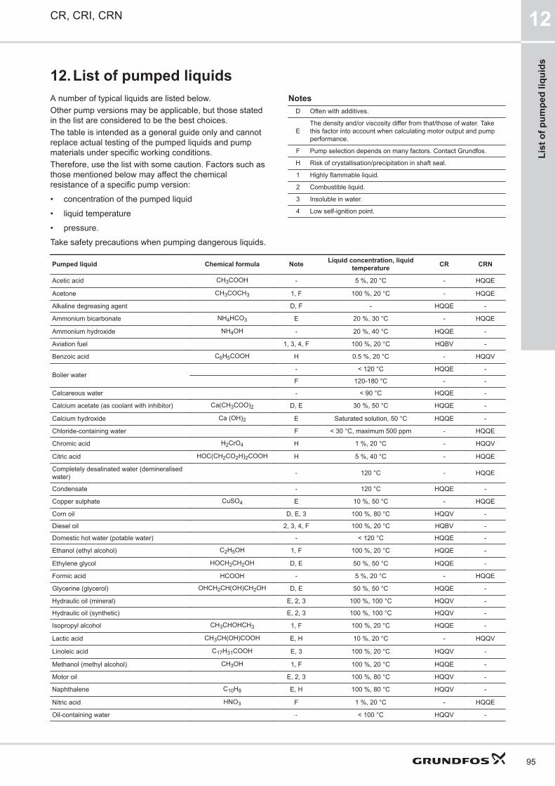
12.List of pumped liquidsA number of typical liquids are listed below.Other pump versions may be applicable, but those statedin the list are considered to be the best choices.The table is intended as a general guide only and cannotreplace actual testing of the pumped liquids and pumpmaterials under specific working conditions.Therefore, use the list with some caution. Factors such asthose mentioned below may affect the chemicalresistance of a specific pump version:
• concentration of the pumped liquid
• liquid temperature
• pressure.Take safety precautions when pumping dangerous liquids.
NotesD Often with additives.
EThe density and/or viscosity differ from that/those of water. Takethis factor into account when calculating motor output and pumpperformance.
F Pump selection depends on many factors. Contact Grundfos.
H Risk of crystallisation/precipitation in shaft seal.
1 Highly flammable liquid.
2 Combustible liquid.
3 Insoluble in water.
4 Low self-ignition point.
Pumped liquid Chemical formula Note Liquid concentration, liquidtemperature CR CRN
Acetic acid CH3COOH - 5 %, 20 °C - HQQE
Acetone CH3COCH3 1, F 100 %, 20 °C - HQQE
Alkaline degreasing agent D, F - HQQE -
Ammonium bicarbonate NH4HCO3 E 20 %, 30 °C - HQQE
Ammonium hydroxide NH4OH - 20 %, 40 °C HQQE -
Aviation fuel 1, 3, 4, F 100 %, 20 °C HQBV -
Benzoic acid C6H5COOH H 0.5 %, 20 °C - HQQV
Boiler water- < 120 °C HQQE -
F 120-180 °C - -
Calcareous water - < 90 °C HQQE -
Calcium acetate (as coolant with inhibitor) Ca(CH3COO)2 D, E 30 %, 50 °C HQQE -
Calcium hydroxide Ca (OH)2 E Saturated solution, 50 °C HQQE -
Chloride-containing water F < 30 °C, maximum 500 ppm - HQQE
Chromic acid H2CrO4 H 1 %, 20 °C - HQQV
Citric acid HOC(CH2CO2H)2COOH H 5 %, 40 °C - HQQE
Completely desalinated water (demineralisedwater) - 120 °C - HQQE
Condensate - 120 °C HQQE -
Copper sulphate CuSO4 E 10 %, 50 °C - HQQE
Corn oil D, E, 3 100 %, 80 °C HQQV -
Diesel oil 2, 3, 4, F 100 %, 20 °C HQBV -
Domestic hot water (potable water) - < 120 °C HQQE -
Ethanol (ethyl alcohol) C2H5OH 1, F 100 %, 20 °C HQQE -
Ethylene glycol HOCH2CH2OH D, E 50 %, 50 °C HQQE -
Formic acid HCOOH - 5 %, 20 °C - HQQE
Glycerine (glycerol) OHCH2CH(OH)CH2OH D, E 50 %, 50 °C HQQE -
Hydraulic oil (mineral) E, 2, 3 100 %, 100 °C HQQV -
Hydraulic oil (synthetic) E, 2, 3 100 %, 100 °C HQQV -
Isopropyl alcohol CH3CHOHCH3 1, F 100 %, 20 °C HQQE -
Lactic acid CH3CH(OH)COOH E, H 10 %, 20 °C - HQQV
Linoleic acid C17H31COOH E, 3 100 %, 20 °C HQQV -
Methanol (methyl alcohol) CH3OH 1, F 100 %, 20 °C HQQE -
Motor oil E, 2, 3 100 %, 80 °C HQQV -
Naphthalene C10H8 E, H 100 %, 80 °C HQQV -
Nitric acid HNO3 F 1 %, 20 °C - HQQE
Oil-containing water - < 100 °C HQQV -
CR, CRI, CRN 12
95
List
of p
umpe
d liq
uids

Pumped liquid Chemical formula Note Liquid concentration, liquidtemperature CR CRN
Olive oil D, E, 3 100 %, 80 °C HQQV -
Oxalic acid (COOH)2 H 1 %, 20 °C - HQQE
Ozone-containing water (O3) - < 100 °C - HQQE
Peanut oil D, E, 3 100 %, 80 °C HQQV -
Petrol 1, 3, 4, F 100 %, 20 °C HQBV -
Phosphoric acid H3PO4 E 20 %, 20 °C - HQQE
Propanol C3H7OH 1, F 100 %, 20 °C HQQE -
Propylene glycol CH3CH(OH)CH2OH D, E 50 %, 90 °C HQQE -
Potassium carbonate K2CO3 E 20 %, 50 °C HQQE -
Potassium formate (as coolant with inhibitor) KOOCH D, E 30 %, 50 °C HQQE -
Potassium hydroxide KOH E 20 %, 50 °C - HQQE
Potassium permanganate KMnO4 - 5 %, 20 °C - HQQE
Rape seed oil D, E, 3 100 %, 80 °C HQQV -
Salicylic acid C6H4(OH)COOH H 0.1 %, 20 °C - HQQE
Silicone oil E, 3 100 % HQQV -
Sodium bicarbonate NaHCO3 E 10 %, 60 °C - HQQE
Sodium chloride (as coolant) NaCl D, E 30 %, < 5 °C, pH > 8 HQQE -
Sodium hydroxide NaOH E 20 %, 50 °C - HQQE
Sodium hypochlorite NaOCl F 0.1 %, 20 °C - HQQV
Sodium nitrate NaNO3 E 10 %, 60 °C - HQQE
Sodium phosphate Na3PO4 E, H 10 %, 60 °C - HQQE
Sodium sulphate Na2SO4 E, H 10 %, 60 °C - HQQE
Softened water - < 120 °C - HQQE
Soya oil D, E, 3 100 %, 80 °C HQQV -
Sulphuric acid H2SO4 F 1 %, 20 °C - HQQV
Sulphurous acid H2SO3 - 1 %, 20 °C - HQQE
Unsalted swimming-pool water - Approx. 2 ppm free chlorine (Cl2) HQQE -
CR, CRI, CRN12
96
List of pumped liquids

13. Accessories
Pipe connectionVarious sets of counterflanges and couplings are available for pipe connection.
Counterflanges for CRA set consists of one counterflange, one gasket, bolts and nuts.
Counterflange Pump type Description Rated pressure Pipe connection Productnumber
TM05
0998
16 bar 25 bar
CR 1sCR 1CR 3CR 5
Threaded 16 bar, EN 1092-2 Rp 1 409901
For welding 25 bar, EN 1092-2 25 mm, nominal 409902
TM05
1003
16 bar 25 bar
CR 1sCR 1CR 3CR 5
Threaded 16 bar, EN 1092-2 Rp 1 1/4 419901
For welding 25 bar, EN 1092-2 32 mm, nominal 419902
TM05
1002
16 bar 25/40 bar
CR 10
Threaded 16 bar, EN 1092-2 Rp 1 1/2 429902
Threaded 16 bar, EN 1092-2 Rp 2 429904
For welding 25 bar, EN 1092-2 40 mm, nominal 429901
For welding 40 bar, special flange 50 mm, nominal 429903
CR, CRI, CRN 13
97
Acc
esso
ries

Counterflange Pump type Description Rated pressure Pipe connection Productnumber
TM05
0999
CR 15CR 20
Threaded 16 bar, EN 1092-2 Rp 2 339903
Threaded 16 bar, special flange Rp 2 1/2 339904
TM05
1005
Threaded 16 bar, special flange Rp 2 1/2 * 96509578
TM05
1000
For welding 25 bar, EN 1092-2 50 mm, nominal 339901
For welding 40 bar, special flange 65 mm, nominal 339902
16 bar 16 bar 16/40 bar 16 bar
CR 32
Threaded 16 bar, EN 1092-2 Rp 2 1/2 349902
Threaded 16 bar, special flange Rp 3 349901
For welding 16 bar, EN 1092-2 65 mm, nominal 349904
For welding 40 bar, DIN 2635 65 mm, nominal 349905
For welding 16 bar, special flange 80 mm, nominal 349903
TM05
0996
16 bar 16/40 bar
CR 45
Threaded 16 bar Rp 3 350540
For welding 16 bar 80 mm, nominal 350541
For welding 40 bar 80 mm, nominal 350542
TM05
0995
16 bar 16 bar 25 bar
CR 64
Threaded 16 bar, EN 1092-2 Rp 4 369901
For welding 16 bar, EN 1092-2 100 mm, nominal 369902
For welding 25 bar, EN 1092-2 100 mm, nominal 369905
18
150 150
TM06
5157
16 bar 25/40 bar
CR 95
For welding 16 bar, EN 1092-2 100 mm, nominal 99432754
For welding 25/40 bar, EN 1092-2 100 mm, nominal 99432755
CR, CRI, CRN13
98
Accessories

Counterflange Pump type Description Rated pressure Pipe connection Productnumber
ø26
ø300
ø250
ø205
ø22
ø285ø240ø205
16 bar 25/40 bar
CR 125CR 155
For welding 16 bar, EN 1563 150 mm, nominal 99432761
For welding 25/40 bar, EN 1563 150 mm, nominal 99432760
ø22
ø340ø295ø260
ø25
ø360ø310ø260
ø28
ø375ø320ø260
16 bar 25 bar 40 bar
CR 185CR 215CR 255
For welding 16 bar, EN 1563 200 mm, nominal 97521270
For welding 25 bar, EN 1563 200 mm, nominal 97739724
For welding 40 bar, EN 1563 200 mm, nominal 97521269
* Flange with 20 mm higher collar. With this collar, the installation dimensions of a CR 20 will be identical to those of a CR 32. If a CR 32 is replaced by aCR 20, the base must be raised by 15 mm.
CR, CRI, CRN 13
99
Acc
esso
ries

Counterflanges for CRNCounterflanges for CRN pumps are made of stainless steel EN 1.4401 (≈AISI 316).A set consists of one counterflange, one gasket, bolts and nuts.
Counterflange Pump type Description Rated pressure Pipe connection Productnumber
TM05
0998
16 bar 25 bar
CRN 1sCRN 1CRN 3CRN 5
Threaded 16 bar, EN 1092-1 Rp 1 405284
For welding 25 bar, EN 1092-1 25 mm, nominal 405285
TM05
1003
16 bar 25 bar
CRN 1sCRN 1CRN 3CRN 5
Threaded 16 bar, EN 1092-1 Rp 1 1/4 415304
For welding 25 bar, EN 1092-1 32 mm, nominal 415305
TM05
1001
CRN 10
Threaded 16 bar, EN 1092-1 Rp 1 1/2 425245
TM05
1006
Threaded 16 bar, EN 1092-1 Rp 2 96509570
TM05
1001
For welding 25 bar, EN 1092-1 40 mm, nominal 425246
TM05
1006
For welding 25 bar, special flange 50 mm, nominal 96509571
CR, CRI, CRN13
100
Accessories

Counterflange Pump type Description Rated pressure Pipe connection Productnumber
TM05
0999
CRN 15CRN 20
Threaded 16 bar, EN 1092-1 Rp 2 335254
TM05
1005
Threaded 16 bar, special flange Rp 2 1/2 96509575
ø19
ø165ø125ø102
TM03
0402
For welding 25 bar, EN 1092-1 50 mm, nominal 335255
ø165ø125ø102
ø127
18.5
19.5
TM02
7203
For welding 25 bar, special flange 65 mm, nominal 96509573
TM05
0994
16 bar 16/40 bar 16/25 bar
CRN 32
Threaded 16 bar Rp 2 1/2 349910
Threaded 16 bar, special flange Rp 3 349911
For welding 16 bar 65 mm, nominal 349906
For welding 40 bar 65 mm, nominal 349908
TM05
0996
16 bar 16/40 bar
CRN 45
Threaded 16 bar Rp 3 350543
For welding 16 bar 80 mm, nominal 350544
For welding 40 bar 80 mm, nominal 350545
TM05
0995
16 bar 16 bar 40 bar
CRN 64
Threaded 16 bar Rp 4 369904
For welding 16 bar 100 mm, nominal 369903
For welding 40 bar 100 mm, nominal 369906
CR, CRI, CRN 13
101
Acc
esso
ries

Counterflange Pump type Description Rated pressure Pipe connection Productnumber
18
150 150
TM06
5157
16 bar 25/40 bar
CRN 95
For welding 16 bar, EN 1.4408 100 mm, nominal 99432731
For welding 25/40 bar, EN 1.4408 100 mm, nominal 99432732
ø26
ø300
ø250
ø205
ø22
ø285ø240ø205
16 bar 25/40 bar
CRN 125CRN 155
For welding 16 bar, EN 1.4408 150 mm, nominal 99432733
For welding 25/40 bar, EN 1.4408 150 mm, nominal 99432734
ø22
ø340ø295ø260
ø25
ø360ø310ø260
ø28
ø375ø320ø260
16 bar 25 bar 40 bar
CRN 185CRN 215CRN 255
For welding 16 bar, EN 1.4408 200 mm, nominal 99432735
For welding 25 bar, EN 1.4408 200 mm, nominal 99432736
For welding 40 bar, EN 1.4408 200 mm, nominal 99432737
CR, CRI, CRN13
102
Accessories

PJE couplings for CRNMaterials in contact with the pumped liquid are made ofstainless steel EN 1.4401 (≈AISI 316) and rubber.A set consists of two coupling halves (Victaulic type 77),one gasket, one pipe stub (for welding or threaded), boltsand nuts.
Coupling Pump type Pipe stub Maximumpressure [bar] A B Pipe connec-
tionRubberparts
Number ofcoupling sets
required
Product num-ber
A
B
CRN 1sCRN 1CRN 3CRN 5
Threaded 69 50 320 R 1 1/4EPDM 2 419911
FKM 2 419905
For welding 69 50 280 DN 32EPDM 2 419912
FKM 2 419904
CRN 10CRN 15CRN 20
Threaded 69 80 377 R 2EPDM 2 339911
FKM 2 339918
For welding 69 80 371 DN 50EPDM 2 339910
FKM 2 339917
CRN 32 For welding 69 105 420 DN 80EPDM 2 98144746
FKM 2 98144749
CRN 45CRN 64
For welding 69 140 465 DN 100EPDM 2 98144752
FKM 2 98144755
CRN 95 For welding 69 140 465 DN 100EPDM
298144752
FKM 98144755
CR, CRI, CRN 13
103
Acc
esso
ries
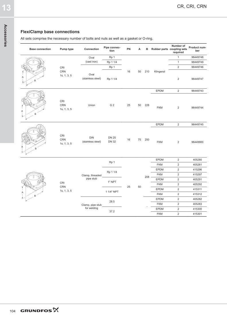
FlexiClamp base connectionsAll sets comprise the necessary number of bolts and nuts as well as a gasket or O-ring.
Base connection Pump type Connection Pipe connec-tion PN A B Rubber parts
Number ofcoupling sets
required
Product num-ber
AB
CRICRN1s, 1, 3, 5
Oval(cast iron)
Rp 1
16 50 210 Klingersil
1 96449748
Rp 1 1/4 1 96449749
Oval(stainless steel)
Rp 1 2 96449746
Rp 1 1/4 2 96449747
BA
CRICRN1s, 1, 3, 5
Union G 2 25 50 228
EPDM 2 96449743
FKM 2 96449744
AB
CRICRN1s, 1, 3, 5
DIN(stainless steel)
DN 25DN 32
16 75 250
EPDM 2 96449745
FKM 2 96449900
AB
CRICRN1s, 1, 3, 5
Clamp, threadedpipe stub
Rp 1
25 50
208
EPDM 2 405280
FKM 2 405281
Rp 1 1/4EPDM 2 415296
FKM 2 415297
1" NPTEPDM 2 405291
FKM 2 405292
1 1/4" NPTEPDM 2 415311
FKM 2 415312
Clamp, pipe stubfor welding
28.5
-
EPDM 2 405282
FKM 2 405283
37.2EPDM 2 415300
FKM 2 415301
CR, CRI, CRN13
104
Accessories

Base connection Pump type Connection Pipe connec-tion PN A B Rubber parts
Number of cou-pling sets re-
quired
Product num-ber
BA
CRI 10CRN 10
Oval(cast iron)
Rp 1 1/4
16 80 260 Klingersil
2 96498775
Rp 1 1/2 2 96498727
Rp 2 2 96498836
Oval(stainless steel)
Rp 1 1/4 2 96498776
Rp 1 1/2 2 96498728
Rp 2 2 96498835
AB
CRI 10CRN 10
Union G 2 3/4 25 80 288
EPDM 2 96500275
FKM 2 96500276
AB
CRI 10CRN 10
FGJ(cast iron)
DN 40
16 80 316
EPDM 2 96498840
FKM 2 96500119
FGJ(stainless steel)
EPDM 2 96500263
FKM 2 96500264
FGJ(cast iron)
DN 50
EPDM 2 96500265
FKM 2 96500266
FGJ(stainless steel)
EPDM 2 96500267
FKM 2 96500269
A
B
CRI 10CRN 10
Clamp, threadedpipe stub
Rp 1 1/2
25 80
259
EPDM 2 425238
FKM 2 425239
Rp 2EPDM 2 335241
FKM 2 335242
Rp 2 1/2 346EPDM 2 96508600
FKM 2 96508601
Clamp, pipe stubfor welding
48.3(DN 40)
-
EPDM 2 425242
FKM 2 425243
60.3(DN 50)
EPDM 2 335251
FKM 2 335252
CR, CRI, CRN 13
105
Acc
esso
ries

Base connection Pump type Connection Pipe connec-tion PN A B Rubber parts
Number ofcoupling sets
required
Product num-ber
BA
CRI 15, 20CRN 15, 20
Oval(cast iron)
Rp 1 1/4
10 90 260 Klingersil
2 96498775
Rp 1 1/2 2 96498727
Rp 2 2 96498836
Oval(stainless steel)
Rp 1 1/4 2 96498776
Rp 1 1/2 2 96498728
Rp 2 2 96498835
AB
CRI 15, 20CRN 15, 20
Union G 2 3/4 25 90 288
EPDM 2 96500275
FKM 2 96500276
AB
CRI 15, 20CRN 15, 20
FGJ(cast iron)
DN 40
10 90 334
EPDM 2 96498840
FKM 2 96500119
FGJ(stainless steel)
EPDM 2 96500263
FKM 2 96500264
FGJ(cast iron)
DN 50
EPDM 2 96500265
FKM 2 96500266
FGJ(stainless steel)
EPDM 2 96500267
FKM 2 96500269
A
B
CRI 15, 20CRN 15, 20
Clamp, threadedpipe stub
Rp 1 1/2
25 90
259
EPDM 2 425238
FKM 2 425239
Rp 2EPDM 2 335241
FKM 2 335242
Rp 2 1/2 346EPDM 2 96508600
FKM 2 96508601
Clamp, pipe stubfor welding
48.3 (DN 40)
-
EPDM 2 425242
FKM 2 425243
60.3 (DN 50)EPDM 2 335251
FKM 2 335252
CR, CRI, CRN13
106
Accessories

LiqTecThe LiqTec dry-running protection unit protects the pumpand process against dry running and temperaturesexceeding 130 ± 5 °C. Connected to the motor PTCsensor, LiqTec also monitors the motor temperature.LiqTec is prepared for DIN rail mounting in controlcabinets.Enclosure class: IPX0.
LiqTec unit Pump typeVoltage
[V]LiqTec
Sensor1/2"
Cable5 m
Extensioncable15 m
Productnumber
TM03
2108
CRCRICRN
200-240 ● ● ● - 96556429
80-130 ● ● ● - 96556430
- - - - ● 96443676
CR, CRI, CRN 13
107
Acc
esso
ries

SensorsSensor Type Supplier Measuring range Product number
Flowmeter
SITRANS FM MAGFLOMAG 5100 W
Siemens
1-5 m3
(DN 25)ID8285
SITRANS FM MAGFLOMAG 5100 W
3-10 m3
(DN 40)ID8286
SITRANS FM MAGFLOMAG 5100 W
6-30 m3
(DN 65)ID8287
SITRANS FM MAGFLOMAG 5100 W
20-75 m3
(DN 100)ID8288
Temperature sensor
TTA (0) 25
Carlo Gavazzi
0-25 °C 96432591
TTA (-25) 25 -25 to +25 °C 96430194
TTA (50) 100 50-100 °C 96432592
TTA (0) 150 0-150 °C 96430195
Accessory for temperature sensor.All with 1/2 RG connection
Protecting tube∅9 x 50 mm
96430201
Protecting tube∅9 x 100 mm
96430202
Cutting ring bush 96430203
Temperature sensor, ambient temperature WR 52tmg
(DK: Plesner)-50 to +50 °C ID8295
Differential-temperature sensorETSD
Honsberg0-20 °C 96409362
ETSD 0-50 °C 96409363
Note: All sensors have 4-20 mA signal output.
Danfoss pressure sensor kits
Content Liquid temperature Pressure[bar] Product number
Danfoss pressure transmitter, type MBS 3000, with 2 m screened cable.Connection: G 1/2 A (DIN 16288 - B6kt)5 cable clips (black)Instructions PT (400212)
-40 to +85 °C
0-4 96428014
0-6 96428015
0-10 96428016
0-16 96428017
0-25 96428018
DPI differential-pressure sensor kit
Content Pressure[bar] Product number
1 sensor incl. 0.9 m screened cable (7/16" connections)1 original DPI bracket for wall mounting1 Grundfos bracket for mounting on motor2 M4 screws for mounting of sensor on bracket1 M6 screw (self-cutting) for mounting on MGE 90/1001 M8 screw (self-cutting) for mounting on MGE 112/1323 capillary tubes (short/long)2 fittings (1/4" - 7/16")5 cable clips (black)Installation and operating instructions (00480675)Service kit instructions.
0 - 0.6 96611522
0 - 1.0 96611523
0 - 1.6 96611524
0 - 2.5 96611525
0 - 4.0 96611526
0 - 6.0 96611527
0-10 96611550
Adapter kit for sensor 1)
Content Type Product number
Adapter for sensorG 1/2 EPDM 99352712
G 1/2 FKM 99352737
1) Applies to CRN 95.
CR, CRI, CRN13
108
Accessories

14.VariantsThe variants are available on request.Although the Grundfos CR, CRI, CRN product rangeoffers a number of pumps for different applications,customers require specific pump solutions to satisfy theirneeds. See the following documents:
• Grundfos CR "Custom-built pumps" data booklet
• Grundfos "CR, CRN high pressure" data booklet.Below please find the range of options available forcustomising the CR pumps to meet the customers’demands.Contact Grundfos for further information or for requestsother than the ones mentioned below.MotorsVariant Description
ATEX-approved mo-tor
For operation in hazardous atmospheres, explo-sion-proof or dust-ignition-proof motors may berequired.
Motor with anti-con-densation heatingunit
For operation in humid environments motors withbuilt-in anti-condensation heating unit may be re-quired.
Motor with thermalprotection
We offer motors with built-in bimetallic thermalswitches or temperature-controlled PTC sensors(thermistors) incorporated in the motor windings.
Oversize motor
Ambient temperatures above 40 °C or installationat altitudes of more than 1000 metres above sealevel require the use of an oversize motor (that isderating).
4-pole motor We offer 4-pole standard motors.
Shaft sealsVariant Description
Shaft seal withFFKM O-ring
We recommend shaft seals with FFKM or FXM O-ring for applications where the pumped liquid maydamage the standard O-ring material.
Seal with flush,quench seal
We recommend this for applications involvingcrystallising, hardening or sticky liquids.
Air-cooled shaftseal system
We recommend this for applications involving ex-tremely high temperatures.No conventional mechanical shaft seal can with-stand liquid temperatures of up to 180 °C for anylength of time.For such applications, we recommend Grundfos’unique air-cooled shaft seal system.In order to ensure a low liquid temperature aroundthe standard shaft seal, the pump is fitted with aspecial air-cooled shaft seal chamber.No separate cooling is required.
Double seal withpressure chamber
We recommend this for applications involving poi-sonous or explosive liquids.It protects the surrounding environment and thepeople working in the vicinity of the pump.It consists of two seals mounted in a "back-to-back" arrangement inside a separate pressureseal chamber. As the pressure in the chamber ishigher than the pump pressure, leakage is pre-vented. A dosing pump or a special pressure in-tensifier generates the seal chamber pressure.
CR MAGdrive
Magnetically driven pumps for industrial applica-tions.Key applications are industrial processes involv-ing the handling of aggressive, environmental,dangerous or volatile liquids, such as organiccompounds and solvents.
PumpsVariant Description
Horizontally moun-ted pump
For safety or height reasons, certain applications,for instance on ships, require the pump to bemounted in horizontal position.For easy installation, the pump is fitted with brack-ets that support motor and pump.
Low-temperaturepump
Exposed to temperatures down to -40 °C, coolantpumps may require neck rings with a different di-ameter in order to prevent impeller drag.
High-pressurepump up to 47 bar
For high-pressure applications, we offer a uniquedouble pump system capable of generating apressure of up to 47 bar.
Low-NPSH pump(improved suction)
We recommend this for boiler-feed applicationswhere cavitation may occur due to poor inlet con-ditions.
Pump with bearingflange
The bearing flange is suitable for applicationswhere the inlet pressure is higher than the maxi-mum pressure recommended.The bearing flange increases the life of motorbearings.We recommend this for standard motors.
Belt-driven pumpBelt-driven pumps are designed to operate in pla-ces with limited space or where no electrical pow-er is available.
Pump for pharma-ceutical and bio-technological appli-cations
CRN pumps are designed for applications requir-ing the sterilisation and CIP capability of pipes,valves and pumps. (CIP = clean-in-place.)
Connections and other variantsVariant Description
Pipe connections
In addition to the wide range of standard flangeconnections, a 16-bar DIN standard clampingflange is available.Customised flanges are available according tospecifications.
TriClamp connec-tion
TriClamp connections are of a hygienic designwith a sanitary coupling for use in the pharma-ceutical and food industry.
Electropolishedpump
To substantially reduce the risk of corrosion of thematerials, we offer electropolished pumps.We recommend this for applications in the phar-maceutical and food industry.
CR, CRI, CRN 14
109
Varia
nts

15.Grundfos Product Center
Online search and sizing tool to help you make the right choice.From the international view, you can select your specific country to view the product range available to you.International view: https://product-selection.grundfos.com
All the information you need in one placePerformance curves, technical specifications, pictures, dimensional drawings, motor curves, wiringdiagrams, spare parts, service kits, 3D drawings, documents, system parts. The Product Center dis-plays any recent and saved items - including complete projects - right on the main page.DownloadsOn the product pages, you can download installation and operating instructions, data booklets, serv-ice instructions, etc., in PDF format.
When you select your country, you will see the menus below. Note that some menus may not be available depending onthe country.Example: https://product-selection.grundfos.com/uk
Pos. Description
1 Products & services enables you to find products and documents by typing a product number or name into the search field.
2 Applications enables you to choose an application to see how Grundfos can help you design and optimise your system.
3 Products A-Z enables you to look through a list of all the Grundfos products.
4 Categories enables you to look for a product category.
5 Liquids enables you to find pumps designed for aggressive, flammable or other special liquids.
6 Product replacement enables you to find a suitable replacement.
7 WWW enables you to select the country, which changes the language, the available product range and the structure of the website.
8 Sizing enables you to size a product based on your application and operating conditions.
CR, CRI, CRN15
110
Grundfos Product C
enter

99301179 09.2021ECM: 1323735
Trad
emar
ks d
ispl
ayed
in th
is m
ater
ial,
incl
udin
g bu
t not
lim
ited
to G
rund
fos,
the
Gru
ndfo
s lo
go a
nd “b
e th
ink
inno
vate
” are
regi
ster
ed tr
adem
arks
ow
ned
by T
he G
rund
fos
Gro
up. A
ll rig
hts
rese
rved
.©
202
1 G
rund
fos
Hol
ding
A/S
, all
right
s re
serv
ed.