Grundfos SQE Pocket Guide - Canpipe Limited
52
Grundfos SQE Pocket Guide Curves and sizing information for SQE pumps and constant pressure systems GRUNDFOS SQE
-
Upload
khangminh22 -
Category
Documents
-
view
2 -
download
0
Transcript of Grundfos SQE Pocket Guide - Canpipe Limited

Grundfos SQE Pocket Guide
Curves and sizing information for SQE pumps and constant pressure systems
GRUNDFOS SQE

2
5 SQE .............................................................................3 - 12
10 SQE ......................................................................... 13 - 18
15 SQE ........................................................................ 19 - 25
22 SQE ....................................................................... 26 - 31
30 SQE .......................................................................32 - 34
1. SQE Sizing Guide ................................................35 - 39
2. Technical Data ................................................... 40 - 45
3. SQE Troubleshooting ............................................... 46
4. Notes ......................................................................47 - 51
Contents
SQE Curves - 3,000 rpm to 10,700 rpm
Sections

3
Grundfos SQE
• Flow up to 36 GPM• Head up to 780 ft.
• HP range from 1/2 to 1 1/2
• Max. acceptable liquid temp: 86°F (30°C)
• Thread connections: NPT 1˝ to NPT 1 1/2˝
• Torque exceeds that of traditional 4” motors
SQE Technical Data & Features
PUMP FEATURES 3" SQ 4’’ CONVENTIONAL PUMP Nominal voltage range 150-280 volts 207-244 volts
Pump weight Under 15 lbs. 22 lbs. and above
Pump diameter 2.9" 3.9"
Soft-start feature Yes No
Integrated dry-run protection Yes No
Integrated overload protection Yes No
Over-temperature protection Yes Thermal switch only
Integrated frequency converter Yes No
Starter box required No Some
High-efficiency permanent magnet motor Yes Yes
Vertical or horizontal installation Yes Yes

4
SQE Performance Curve
5SQE
5SQE05-905S
QE0
3A-9
0
0
100
200
01
23
45
67
8
GPM
TDH(Feet)
Max
imum
Spe
ed C
urve
Min
imum
Spe
ed C
urve

5
5SQE05-140SQE Performance Curve
5SQE
5SQ
E03A
-140
0
100
200
300
01
23
45
67
8
GPM
TDH(Feet)M
axim
um S
peed
Cur
ve
Min
imum
Spe
ed C
urve

6
SQE Performance Curve5SQE05-180
5SQE
5SQ
E05A
-180
0
100
200
300
400
01
23
45
67
8
GPM
TDH(Feet)M
axim
um S
peed
Cur
veM
inim
um S
peed
Cur
ve

7
5SQE07-230SQE Performance Curve
5SQE
5SQ
E05B
-230
050100
150
200
250
300
350
400
01
23
45
67
8G
PM
TDH(Feet)
Max
imum
Spe
ed C
urve
Min
imum
Spe
ed C
urve

8
5SQE
SQE Performance Curve5SQE07-2705S
QE0
5B-2
70
050100
150
200
250
300
350
400
450
500
01
23
45
67
8
GPM
TDH(Feet)M
axim
um S
peed
Cur
veM
inim
um S
peed
Cur
ve

9
5SQE07-320SQE Performance Curve
5SQE
5SQ
E07B
-320
0
100
200
300
400
500
600
01
23
45
67
8
GPM
TDH(Feet)
Max
imum
Spe
ed C
urve
Min
imum
Spe
ed C
urve

10
5SQE
SQE Performance Curve5SQE10-3605S
QE1
0C-3
60
0
100
200
300
400
500
600
700
01
23
45
67
8
GPM
TDH(Feet)M
axim
um S
peed
Cur
ve
Min
imum
Spe
ed C
urve

11
5SQE10-410SQE Performance Curve
5SQE
5SQ
E10C
-410
0
100
200
300
400
500
600
700
01
23
45
67
8
GPM
TDH(Feet)
Max
imum
Spe
ed C
urve
Min
imum
Spe
ed C
urve

12
5SQE
SQE Performance Curve5SQE15-4505S
QE1
0C-4
50
0
100
200
300
400
500
600
700
800
01
23
45
67
8
GPM
TDH(Feet)M
axim
um S
peed
Cur
ve
Min
imum
Spe
ed C
urve

13
10SQE05-110SQE Performance Curve
10SQE
10SQE03A-110
0
100
200
02
46
810
1214
16GPM
TDH(feet)M
axim
um S
peed
Cur
ve
Min
imum
Spe
ed C
urve

14
SQE Performance Curve10SQE05-160
10SQE
10SQ
E05B
-160
0
100
200
300
02
46
810
1214
16G
PM
TDH (Feet)M
axim
um S
peed
Cur
ve
Min
imum
Spe
ed C
urve

15
10SQE07-200SQE Performance Curve
10SQE
10SQ
E05B
-200
0
100
200
300
02
46
810
1214
16GPM
TDH(Feet)M
axim
um S
peed
Cur
ve
Min
imum
Spe
ed C
urve

16
SQE Performance Curve10SQE07-240
10SQE
10SQ
E10C
-240
0
100
200
300
400
02
46
810
1214
16GPM
TDH(Feet)M
axim
um S
peed
Cur
ve
Min
imum
Spe
ed C
urve

17
10SQE10-290SQE Performance Curve
10SQE
10SQ
E10C
-290
0
100
200
300
400
500
02
46
810
1214
16GPM
TDH(Feet)
Max
imum
Spe
ed C
urve
Min
imum
Spe
ed C
urve
18
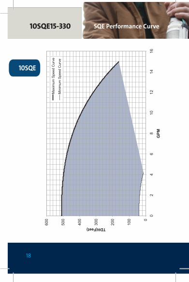
SQE Performance Curve10SQE15-330
10SQE
10SQ
E10C
-330
0
100
200
300
400
500
600
02
46
810
1214
16
GPM
TDH(Feet)M
axim
um S
peed
Cur
ve
Min
imum
Spe
ed C
urve

19
15SQE05-70SQE Performance Curve
15SQE
15SQE03A-70
0
100
200
02
46
810
1214
1618
20GPM
TDH(Feet)M
axim
um S
peed
Cur
ve
Min
imum
Spe
ed C
urve

20
SQE Performance Curve15SQE05-110
15SQE
15SQE05A-110
0
100
200
02
46
810
1214
1618
20GPM
TDH(Feet)M
axim
um S
peed
Cur
ve
Min
imum
Spe
ed C
urve

21
15SQE07-150SQE Performance Curve
15SQE
15SQ
E05B
-150
0
100
200
300
02
46
810
1214
1618
20GPM
TDH(Feet)M
axim
um S
peed
Cur
ve
Min
imum
Spe
ed C
urve

22
SQE Performance Curve15SQE07-180
15SQE
15SQ
E07B
-180
0
100
200
300
400
02
46
810
1214
1618
20GPM
TDH(Feet)M
axim
um S
peed
Cur
ve
Min
imum
Spe
ed C
urve

23
15SQE10-220SQE Performance Curve
15SQE
15SQ
E10C
-220
0
100
200
300
400
02
46
810
1214
1618
20GPM
TDH(Feet)M
axim
um S
peed
Cur
ve
Min
imum
Spe
ed C
urve

24
SQE Performance Curve15SQE10-250
15SQE
15SQ
E10C
-250
0
100
200
300
400
500
02
46
810
1214
1618
20GPM
TDH(Feet)M
axim
um S
peed
Cur
veM
inim
um S
peed
Cur
ve

25
15SQE15-290SQE Performance Curve
15SQE
15SQ
E15C
-290
0
100
200
300
400
500
600
02
46
810
1214
1618
20GPM
TDH(Feet)
Max
imum
Spe
ed C
urve
Min
imum
Spe
ed C
urve

26
SQE Performance Curve22SQE05-40
22SQE
22SQE03A-40
050100
05
1015
2025
3035
GPM
TDH(Feet)
Max
imum
Spe
ed C
urve
Min
imum
Spe
ed C
urve

27
22SQE05-80SQE Performance Curve
22SQE
22SQE05A-80
050100
150
05
1015
2025
3035
GPM
TDH(Feet)M
axim
um S
peed
Cur
ve
Min
imum
Spe
ed C
urve

28
SQE Performance Curve22SQE07-120
22SQE
22SQ
E05B
-120
050100
150
200
05
1015
2025
3035
GPM
TDH(Feet)M
axim
um S
peed
Cur
ve
Min
imum
Spe
ed C
urve

29
22SQE07-160SQE Performance Curve
22SQE
22SQ
E07B
-160
050100
150
200
250
05
1015
2025
3035
GPM
TDH(Feet)
Max
imum
Spe
ed C
urve
Min
imum
Spe
ed C
urve
30
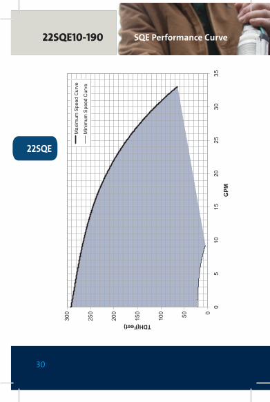
SQE Performance Curve22SQE10-190
22SQE
22SQ
E10C
-190
050100
150
200
250
300
05
1015
2025
3035
GPM
TDH(Feet)M
axim
um S
peed
Cur
ve
Min
imum
Spe
ed C
urve

31
22SQE15-220SQE Performance Curve
22SQE
22SQ
E15C
-220
050100
150
200
250
300
350
400
05
1015
2025
3035
GPM
TDH(Feet)
Max
imum
Spe
ed C
urve
Min
imum
Spe
ed C
urve

32
SQE Performance Curve30SQE05-40
30SQE
30SQE05A-40
050100
05
1015
2025
3035
4045
GPM
TDH(Feet)
Max
imum
Spe
ed C
urve
Min
imum
Spe
ed C
urve

33
30SQE07-90SQE Performance Curve
30SQE
30SQ
E05B
-90
050100
150
05
1015
2025
3035
4045
GPM
TDH(Feet)M
axim
um S
peed
Cur
ve
Min
imum
Spe
ed C
urve

34
SQE Performance Curve30SQE10-130
30SQE
30SQ
E10C
-130
050100
150
200
250
05
1015
2025
3035
4045
GPM
TDH(Feet)M
axim
um S
peed
Cur
veM
inim
um S
peed
Cur
ve

35
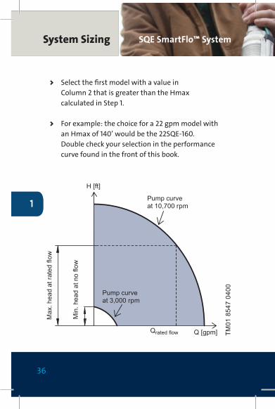
SQE SizingSQE SmartFlo™ System
1
STEP 1 Calculate maximum head requirements at rated flow conditions:
Hmax (required) = dynamic head + system pressure (in feet) + friction loss + above grade elevation.
STEP 2 Select pump from the chart on the following page: > Choose model family based on desired flow rate i.e. 15SQE for a flow rate of 15 gpm.
SQE System SizingSQE SmartFlo™ System Sizing Follow these 2 steps.
Continues on next page >
36
1
SQE SmartFlo™ SystemSystem Sizing
> Select the first model with a value in Column 2 that is greater than the Hmax calculated in Step 1.
> For example: the choice for a 22 gpm model with an Hmax of 140’ would be the 22SQE-160. Double check your selection in the performance curve found in the front of this book.
TM01
854
7 04
00
H [ft]
Q [gpm]
Max
. hea
d at
rate
d flo
w
Min
. hea
d at
no
flow
Pump curve at 10,700 rpm
Pump curve at 3,000 rpm
Qrated flow
37
1
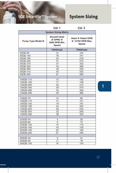
System SizingSQE SmartFlo™ System
Pump Type Model B
Shutoff Head (0 GPM) @
3000 RPM Min. Speed
Head @ Rated GPM @ 10700 RPM Max.
Speed
TDH(Feet) TDH(Feet)
5SQE-90 12 1045SQE-140 18 1615SQE-180 24 2185SQE-230 31 2755SQE-270 37 3325SQE-320 43 3895SQE-360 49 4465SQE-410 55 5035SQE-450 61 560
10SQE-110 12 10210SQE-160 17 15810SQE-200 23 21410SQE-240 29 27010SQE-290 34 32610SQE-330 40 382
15SQE-70 10 8015SQE-110 14 12115SQE-150 19 16115SQE-180 24 20215SQE-220 29 24215SQE-250 33 28315SQE-290 38 323
22SQE-40 5 3522SQE-80 9 7522SQE-120 14 11522SQE-160 18 15522SQE-190 23 19522SQE-220 27 235
30SQE-40 5 3130SQE-90 11 7830SQE-130 16 125
System Sizing Matrix
Col. 1 Col. 2

38
Horizontal / vertical run
TDH
DynamicWater Level
StaticWater Level
Drawdown
Submergence
Pump
Casing / WellDiameter
Piping
Pump Depth
Well Depth
Off bottom of well
Friction
Pressure
Vertical Rise / drop
TankPressure / Control BoxCalculate TDH add
Dynamic Level ________
Vertical Rise/drop ________
Pressure Req. ________
Friction Loss ________
TDH ==== _________
Flow Required _________
Quick ConversationFt PSI / 2.31PSI Ft x 2.31
1
SQE TDH CalculationSystem Sizing

39
Horizontal / vertical run
TDH
DynamicWater Level
StaticWater Level
Drawdown
Submergence
Pump
Casing / WellDiameter
Piping
Pump Depth
Well Depth
Off bottom of well
Friction
Pressure
Vertical Rise / drop
TankPressure / Control BoxCalculate TDH add
Dynamic Level ________
Vertical Rise/drop ________
Pressure Req. ________
Friction Loss ________
TDH ==== _________
Flow Required _________
Quick ConversationFt PSI / 2.31PSI Ft x 2.31
1
System SizingSQE TDH Calculation

40
Technical DataSQE
2
PUMP TYPE HP VOLTAGE
5SQE05-90 1/2 230V/115V5SQE05-140 1/2 230V/115V5SQE05-180 1/2 230V/115V5SQE07-230 3/4 230V5SQE07-270 3/4 230V5SQE07-320 3/4 230V5SQE10-360 1 230V5SQE10-410 1 230V5SQE15-450 1 1/2 230V10SQE05-110 1/2 230V/115V10SQE05-160 1/2 230V/115V10SQE07-200 3/4 230V10SQE7-240 3/4 230V
10SQE10-290 1 230V10SQE15-330 1 1/2 230V15SQE05-70 1/2 230V/115V15SQE05-110 1/2 230V/115V15SQE07-150 3/4 230V15SQE07-180 3/4 230V15SQE10-220 1 230V15SQE10-250 1 230V15SQE15-290 1 1/2 230V22SQE05-40 1/2 230V/115V22SQE05-80 1/2 230V/115V22SQE07-120 3/4 230V22SQE07-160 3/4 230V22SQE10-190 1 230V22SQE15-220 1 1/2 230V30SQE05-40 1/2 230V/115V30SQE07-90 3/4 230V30SQE10-130 1 230V
FULL LOAD AMPS230V 115V
2.1 4.22.9 6.03.7 7.74.65.36.27.28.19.22.9 6.14.1 8.65.36.07.78.92.9 6.04.0 8.35.16.27.48.49.71.9 3.93.4 7.24.96.47.99.52.8 5.75.27.6

41
SQETechnical Data
2
OVERLOAD AMPS MIN. WELL DIA. DISCHARGE
230V 115V5 11 3” 1” NPT5 11 3” 1” NPT5 11 3” 1” NPT8 3” 1” NPT8 3” 1” NPT8 3” 1” NPT11 3” 1” NPT11 3” 1” NPT12 3” 1” NPT5 11 3” 1 1/4” NPT8 11 3” 1 1/4” NPT8 3” 1 1/4” NPT8 3” 1 1/4” NPT11 3” 1 1/4” NPT12 3” 1 1/4” NPT5 11 3” 1 1/4” NPT5 11 3” 1 1/4” NPT8 3” 1 1/4” NPT8 3” 1 1/4” NPT11 3” 1 1/4” NPT11 3” 1 1/4” NPT12 3” 1 1/4” NPT5 11 3” 1 1/2” NPT5 11 3” 1 1/2” NPT8 3” 1 1/2” NPT8 3” 1 1/2” NPT11 3” 1 1/2” NPT12 3” 1 1/2” NPT5 11 3” 1 1/2” NPT8 3” 1 1/2” NPT11 3” 1 1/2” NPT

42
Technical DataCable Sizing
2
Cable length selection tablesThe following table (Fig. 7) lists the recommended copper cable sizes and various cable lengths for SQ motors. Proper wire size will ensure that adequate voltage will be supplied to the motor.
To assure adequate voltage, the maximum cable lengths are calculated for when the motor is running at maximum nameplate amps. Cable sizes larger than specified may always be used and will reduce power loss.
The use of cables smaller than the recommended sizes will void the warranty. Smaller cable sizes may cause under-voltage alarms.

43
Cable SizingTechnical Data
2
Cabl
e le
ngth
is in
feet
Mot
or R
atin
gCo
pper
Wire
Siz
e (A
WG)
Volts
HP
AMPS
1412
108
64
2
1151/
212
140
220
360
550
880
1390
2260
230
1/2
5.264
010
0016
6022
5040
60
230
3/4
8.4
400
620
1030
1580
2510
3970
230
111.
230
046
077
0119
018
9029
8048
50
230
1 1/2
1228
043
072
0111
017
6027
8045
30
SQ W
iring
Siz
ing
Not
e: T
he c
alcu
latio
ns in
the
tabl
e ar
e ba
sed
on su
pply
of 1
15V
or 2
30V
Fig. 7

44
Technical DataFriction Loss
2
Friction Loss Table - SCH 40 Steel Pipe(Friction loss in feet of head per 100 feet of pipe)
6-10
Motor BHP (output) = Input HP x Motor Eff.(%) 100
Where K = Meter constant = watts per revolution of revolvingdisc (value of K is marked on the meter nameplate or on therevolving disc). Where current transformers are used, multiplymeter constant by current transformer ratio.
R = Number of disc revolutions counted.t = Time in seconds for R revolutions.
CALCULATING OPERATING COSTS OF PUMPS:Costs in Cents per 1,000 Gallons:
Cost (¢) = kw Input x r x 1,000GPH
Cost in Cents per Acre-Inch
Cost (¢) = kw Input x r x 452.6GPM
Where: r = cost of power in cents per kw-hr.
1/2" 3/4" 1" 1 1/4" 1 1/2" 2" 2 1/2" 3" 4"ID ID ID ID ID ID ID ID ID
GPM GPH 0.622" 0.824" 1.049" 1.380" 1.610" 2.067" 2.469" 3.068" 4.026"2 120 4.83 180 10 2.54 240 17.1 4.25 300 25.8 6.3 1.96 360 36.5 8.9 2.77 420 48.7 11.8 3.68 480 62.7 15 4.59 540 78.3 18.8 5.7
10 600 95.9 23 6.9 1.812 720 32.6 9.6 2.5 1.214 840 43.5 12.8 3.3 1.516 960 56.3 16.5 4.2 220 1,200 86.1 25.1 6.3 2.925 1,500 38.7 9.6 4.5 1.330 1,800 54.6 13.6 6.3 1.835 2,100 73.3 18.2 8.4 2.440 2,400 95 23.5 10.8 3.1 1.3
1.63.913.529.42,700451.94.716.4363,000502.76.623.2513,60060
1.23.68.931.368.84,200701.64.611.440.589.24,8008025.814.2515,40090
2.47.117.462.26,0001003.410.124.77,200120
1.24.513.533.28,4001401.55.817.5439,6001602.38.92766.312,0002003.714.84515,6002604.919.559.618,000300
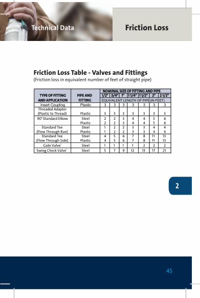
NOMINAL SIZE OF FITTING AND PIPEPIPE AND 1/2" 3/4" 1" 1 1/4" 1 1/2" 2" 2 1/2"TYPE OF FITTING
AND APPLICATION FITTING EQUIVALENT LENGTH OF PIPE(IN FEET) Insert Coupling Plastic 3 3 3 3 3 3 3
Threaded Adapter(Plastic to Thread) Plastic 3 3 3 3 3 3 390o Standard Elbow Steel 2 2 3 4 4 5 6
Plastic 2 2 3 4 4 5 6Standard Tee Steel 1 2 2 3 3 4 4
(Flow Through Run) Plastic 1 2 2 3 3 4 4Standard Tee Steel 4 5 6 7 8 11 13
(Flow Through Side) Plastic 4 5 6 7 8 11 13Gate Valve1 Steel 1 1 1 1 2 2 2
Swing Check Valve1 Steel 5 7 9 12 13 17 21
1/2" 3/4" 1" 1 1/4" 1 1/2" 2" 2 1/2" 3" 4"ID ID ID ID ID ID ID ID ID
GPM GPH 0.622" 0.824" 1.049" 1.380" 1.610" 2.067" 2.469" 3.068" 4.026"2 120 4.13 180 8.7 2.24 240 14.8 3.75 300 22.2 5.7 1.86 360 31.2 8 2.57 420 41.5 10.6 3.38 480 53 13.5 4.29 540 66 16.8 5.2
10 600 80.5 20.4 6.3 1.712 720 28.6 8.9 2.3 1.114 840 38 11.8 3.1 1.416 960 48.6 15.1 4 1.920 1,200 60.5 22.8 6 2.825 1,500 38.7 9.1 4.3 1.330 1,800 12.7 6 1.835 2,100 16.9 8 2.440 2,400 21.6 10.2 3 1.1
1.43.812.5282,700451.74.615.43,000502.36.421.63,60060
1.238.528.74,200701.43.810.936.84,800801.84.813.645.75,400902.25.716.556.66,0001003823.17,200120
1.1410.530.68,4001401.4513.439.39,6001602.17.620.166.312,0002003.412.232.415,6002604.415.842.118,000300
Friction Loss Table – SCH 40 STEEL PIPE(Friction Loss in Feet of Head Per 100 Feet of Pipe)
Friction Loss Table – SCH 40 PVC(Friction Loss in Feet of Head Per 100 Feet of Pipe)
Friction Loss Table – VALVES and FITTINGS(Friction Loss in Equivalent Number of Feet of Straight Pipe)
NOTES:Based on schedule 40 steel and plastic fittings.Figures given are friction losses in terms of EquivalentLenghts of straight pipe.
Friction loss figures are for screwed valves and are basedon equivalent lengths of steel pipe.
FRICTION LOSS TABLES
FORMULAS
45
Friction LossTechnical Data
2
Friction Loss Table - Valves and Fittings(Friction loss in equivalent number of feet of straight pipe)
6-10
Motor BHP (output) = Input HP x Motor Eff.(%) 100
Where K = Meter constant = watts per revolution of revolvingdisc (value of K is marked on the meter nameplate or on therevolving disc). Where current transformers are used, multiplymeter constant by current transformer ratio.
R = Number of disc revolutions counted.t = Time in seconds for R revolutions.
CALCULATING OPERATING COSTS OF PUMPS:Costs in Cents per 1,000 Gallons:
Cost (¢) = kw Input x r x 1,000GPH
Cost in Cents per Acre-Inch
Cost (¢) = kw Input x r x 452.6GPM
Where: r = cost of power in cents per kw-hr.
1/2" 3/4" 1" 1 1/4" 1 1/2" 2" 2 1/2" 3" 4"ID ID ID ID ID ID ID ID ID
GPM GPH 0.622" 0.824" 1.049" 1.380" 1.610" 2.067" 2.469" 3.068" 4.026"2 120 4.83 180 10 2.54 240 17.1 4.25 300 25.8 6.3 1.96 360 36.5 8.9 2.77 420 48.7 11.8 3.68 480 62.7 15 4.59 540 78.3 18.8 5.7
10 600 95.9 23 6.9 1.812 720 32.6 9.6 2.5 1.214 840 43.5 12.8 3.3 1.516 960 56.3 16.5 4.2 220 1,200 86.1 25.1 6.3 2.925 1,500 38.7 9.6 4.5 1.330 1,800 54.6 13.6 6.3 1.835 2,100 73.3 18.2 8.4 2.440 2,400 95 23.5 10.8 3.1 1.3
1.63.913.529.42,700451.94.716.4363,000502.76.623.2513,60060
1.23.68.931.368.84,200701.64.611.440.589.24,8008025.814.2515,40090
2.47.117.462.26,0001003.410.124.77,200120
1.24.513.533.28,4001401.55.817.5439,6001602.38.92766.312,0002003.714.84515,6002604.919.559.618,000300
NOMINAL SIZE OF FITTING AND PIPEPIPE AND 1/2" 3/4" 1" 1 1/4" 1 1/2" 2" 2 1/2"TYPE OF FITTING
AND APPLICATION FITTING EQUIVALENT LENGTH OF PIPE(IN FEET) Insert Coupling Plastic 3 3 3 3 3 3 3
Threaded Adapter(Plastic to Thread) Plastic 3 3 3 3 3 3 390o Standard Elbow Steel 2 2 3 4 4 5 6
Plastic 2 2 3 4 4 5 6Standard Tee Steel 1 2 2 3 3 4 4
(Flow Through Run) Plastic 1 2 2 3 3 4 4Standard Tee Steel 4 5 6 7 8 11 13
(Flow Through Side) Plastic 4 5 6 7 8 11 13Gate Valve1 Steel 1 1 1 1 2 2 2
Swing Check Valve1 Steel 5 7 9 12 13 17 21
1/2" 3/4" 1" 1 1/4" 1 1/2" 2" 2 1/2" 3" 4"ID ID ID ID ID ID ID ID ID
GPM GPH 0.622" 0.824" 1.049" 1.380" 1.610" 2.067" 2.469" 3.068" 4.026"2 120 4.13 180 8.7 2.24 240 14.8 3.75 300 22.2 5.7 1.86 360 31.2 8 2.57 420 41.5 10.6 3.38 480 53 13.5 4.29 540 66 16.8 5.2
10 600 80.5 20.4 6.3 1.712 720 28.6 8.9 2.3 1.114 840 38 11.8 3.1 1.416 960 48.6 15.1 4 1.920 1,200 60.5 22.8 6 2.825 1,500 38.7 9.1 4.3 1.330 1,800 12.7 6 1.835 2,100 16.9 8 2.440 2,400 21.6 10.2 3 1.1
1.43.812.5282,700451.74.615.43,000502.36.421.63,60060
1.238.528.74,200701.43.810.936.84,800801.84.813.645.75,400902.25.716.556.66,0001003823.17,200120
1.1410.530.68,4001401.4513.439.39,6001602.17.620.166.312,0002003.412.232.415,6002604.415.842.118,000300
Friction Loss Table – SCH 40 STEEL PIPE(Friction Loss in Feet of Head Per 100 Feet of Pipe)
Friction Loss Table – SCH 40 PVC(Friction Loss in Feet of Head Per 100 Feet of Pipe)
Friction Loss Table – VALVES and FITTINGS(Friction Loss in Equivalent Number of Feet of Straight Pipe)
NOTES:Based on schedule 40 steel and plastic fittings.Figures given are friction losses in terms of EquivalentLenghts of straight pipe.
Friction loss figures are for screwed valves and are basedon equivalent lengths of steel pipe.
FRICTION LOSS TABLES
FORMULAS

46
SQE I&O
3
Fault Possible cause Remedy
1. No light in the frontcover.
a) The ribbon cable con-nection is loose or de-fective.
• Is the control indicator LED flashing?If not, the CU 301 is defective.
• Check that the ribbon cable connection is secure.
2. The pump does notstart.The green indicatorlight in the On/Off but-ton is on.No alarm is indicated.
a) The CU 301, thepressure sensor orthe pump is defective.
Check • that the control indicator LED is flashing.
If not, the CU 301 is defective.• that the system pressure is 7 psi below the pressure
setting.If so, the pump is supposed to start. Open a tap to besure.If the pump starts, the system is probably OK.The system pressure can be read on the pressuregauge.
• Refer to fault 13 to troubleshoot the pressure sensor.If the pump has not started yet, proceed as follows:• Press the On/Off button for 5 seconds.
If the pump starts, the CU 301 or the sensor may bedefective.Note: The pressure is not controlled and may rise toa high level.
3. The pressure is notconstant.
a) The pump is not ofthe correct type or theprecharge pressure of the diaphragm tank isincorrect.
Check• that the LED for Max. speed or Min. speed is on.
If so, this indicates that the pump has reached alimit.See section 1.3 System sizing.Replace the pump, if necessary.
• the precharge pressure of the diaphragm tank.Note: Remember to stop and drain the systembefore the pressure is checked.
• Make sure the diaphragm tank is the 2 gal. size.• whether the sensor is positioned far away from the
tap.If so, the pressure variations may be caused by fric-tion losses, see section 1.5 Positioning the pressuresensor.
b) No contact betweenSQE pump andCU 301 control unit.
Check that the LED for "No contact to pump" is on.If so, go to fault no. 14.
4. The pump is runningcontinuously.
a) The pump cannot de-liver the set pressure.The CU 301 or thesensor is defective.
• Try to lower the pressure setting, see section1.3 System sizing. Note that the pump may run forabout 15 to 20 seconds before it stops.
• Check that the control indicator LED is flashing.• Check that the pipe end of the sensor is not blocked.
If so, remove the blockage.• Try to stop the pump by means of the On/Off button.
If this is not not possible, possible, the CU 301 isdefective. Replace the CU 301. Refer to fault 13 totroubleshoot the pressure sensor.

47
Fault Possible cause Remedy
1. No light in the frontcover.
a) The ribbon cable con-nection is loose or de-fective.
• Is the control indicator LED flashing?If not, the CU 301 is defective.
• Check that the ribbon cable connection is secure.
2. The pump does notstart.The green indicatorlight in the On/Off but-ton is on.No alarm is indicated.
a) The CU 301, thepressure sensor orthe pump is defective.
Check • that the control indicator LED is flashing.
If not, the CU 301 is defective.• that the system pressure is 7 psi below the pressure
setting.If so, the pump is supposed to start. Open a tap to besure.If the pump starts, the system is probably OK.The system pressure can be read on the pressuregauge.
• Refer to fault 13 to troubleshoot the pressure sensor.If the pump has not started yet, proceed as follows:• Press the On/Off button for 5 seconds.
If the pump starts, the CU 301 or the sensor may bedefective.Note: The pressure is not controlled and may rise toa high level.
3. The pressure is notconstant.
a) The pump is not ofthe correct type or theprecharge pressure of the diaphragm tank isincorrect.
Check• that the LED for Max. speed or Min. speed is on.
If so, this indicates that the pump has reached alimit.See section 1.3 System sizing.Replace the pump, if necessary.
• the precharge pressure of the diaphragm tank.Note: Remember to stop and drain the systembefore the pressure is checked.
• Make sure the diaphragm tank is the 2 gal. size.• whether the sensor is positioned far away from the
tap.If so, the pressure variations may be caused by fric-tion losses, see section 1.5 Positioning the pressuresensor.
b) No contact betweenSQE pump andCU 301 control unit.
Check that the LED for "No contact to pump" is on.If so, go to fault no. 14.
4. The pump is runningcontinuously.
a) The pump cannot de-liver the set pressure.The CU 301 or thesensor is defective.
• Try to lower the pressure setting, see section1.3 System sizing. Note that the pump may run forabout 15 to 20 seconds before it stops.
• Check that the control indicator LED is flashing.• Check that the pipe end of the sensor is not blocked.
If so, remove the blockage.• Try to stop the pump by means of the On/Off button.
If this is not not possible, possible, the CU 301 isdefective. Replace the CU 301. Refer to fault 13 totroubleshoot the pressure sensor.
Notes
4

48
Notes
4

49
Notes
4

50
Notes
4

51
Notes
4

The name Grundfos, the Grundfos logo, and be think innovate are registered trademarks owned by Grundfos Holding A/S or Grundfos A/S, Denmark. All rights reserved worldwide.
GRUNDFOS Canada2941 Brighton Road Oakville, Ontario L6H 6C9 Phone: (905) 829-9533 Fax: (905) 829-9512
www.grundfos.ca
LSQ
EPG
01CA
03
-20