Fire HSEF FM Europe - Grundfos
36
Fire HSEF FM Europe Diesel-powered firefighting system Installation and operating instructions GRUNDFOS INSTRUCTIONS
-
Upload
khangminh22 -
Category
Documents
-
view
0 -
download
0
Transcript of Fire HSEF FM Europe - Grundfos
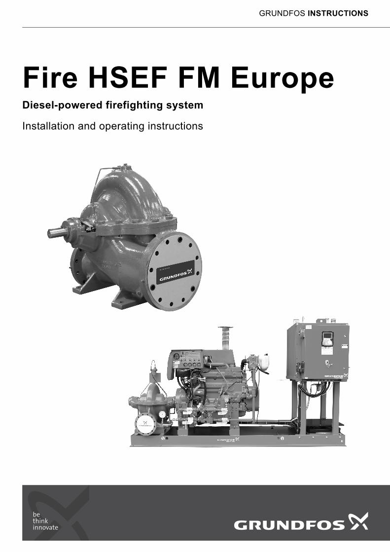
Fire HSEF FM EuropeDiesel-powered firefighting system
Installation and operating instructions
GRUNDFOS INSTRUCTIONS
En
glis
h (G
B)
English (GB) Installation and operating instructions
Original installation and operating instructions.
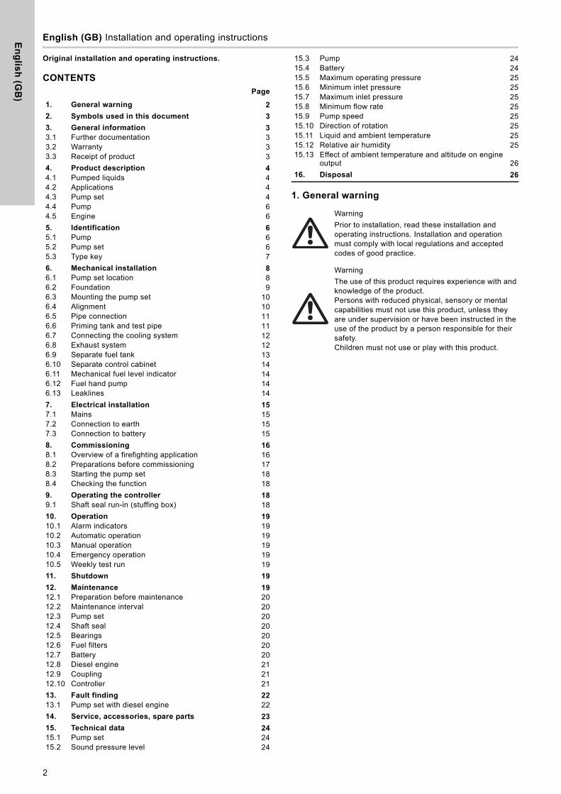
CONTENTSPage
1. General warning
1. General warning 2
2. Symbols used in this document 3
3. General information 33.1 Further documentation 33.2 Warranty 33.3 Receipt of product 3
4. Product description 44.1 Pumped liquids 44.2 Applications 44.3 Pump set 44.4 Pump 64.5 Engine 6
5. Identification 65.1 Pump 65.2 Pump set 65.3 Type key 7
6. Mechanical installation 86.1 Pump set location 86.2 Foundation 96.3 Mounting the pump set 106.4 Alignment 106.5 Pipe connection 116.6 Priming tank and test pipe 116.7 Connecting the cooling system 126.8 Exhaust system 126.9 Separate fuel tank 136.10 Separate control cabinet 146.11 Mechanical fuel level indicator 146.12 Fuel hand pump 146.13 Leaklines 14
7. Electrical installation 157.1 Mains 157.2 Connection to earth 157.3 Connection to battery 15
8. Commissioning 168.1 Overview of a firefighting application 168.2 Preparations before commissioning 178.3 Starting the pump set 188.4 Checking the function 18
9. Operating the controller 189.1 Shaft seal run-in (stuffing box) 18
10. Operation 1910.1 Alarm indicators 1910.2 Automatic operation 1910.3 Manual operation 1910.4 Emergency operation 1910.5 Weekly test run 19
11. Shutdown 19
12. Maintenance 1912.1 Preparation before maintenance 2012.2 Maintenance interval 2012.3 Pump set 2012.4 Shaft seal 2012.5 Bearings 2012.6 Fuel filters 2012.7 Battery 2012.8 Diesel engine 2112.9 Coupling 2112.10 Controller 21
13. Fault finding 2213.1 Pump set with diesel engine 22
14. Service, accessories, spare parts 23
15. Technical data 2415.1 Pump set 2415.2 Sound pressure level 24
15.3 Pump 2415.4 Battery 2415.5 Maximum operating pressure 2515.6 Minimum inlet pressure 2515.7 Maximum inlet pressure 2515.8 Minimum flow rate 2515.9 Pump speed 2515.10 Direction of rotation 2515.11 Liquid and ambient temperature 2515.12 Relative air humidity 2515.13 Effect of ambient temperature and altitude on engine
output 26
16. Disposal 26
Warning
Prior to installation, read these installation and operating instructions. Installation and operation must comply with local regulations and accepted codes of good practice.
Warning
The use of this product requires experience with and knowledge of the product.Persons with reduced physical, sensory or mental capabilities must not use this product, unless they are under supervision or have been instructed in the use of the product by a person responsible for their safety.Children must not use or play with this product.
2
En
gli
sh
(G
B)
2. Symbols used in this documentThe instructions below placed on the fire pump set must be observed and must be legible at all times:
• direction of rotation arrow
• labelling of pipe connections
• stickers with safety instructions.
3. General informationThese installation and operating instructions apply to HSEF pumps approved by FM in accordance with:
• FM class 1311.
Furthermore these installation and operating instructions apply to fire pump sets in accordance with the following standard:
• NFPA 20.
• FM data sheet 3-7.
The document includes the basic information needed for operating the complete pump set and the diesel engine.
See also installation and operating instructions for the controller, engine and coupling.
3.1 Further documentation
This document is to be used together with the following documentation:
• installation and operating instructions for the controller
• installation and operating instructions for the engine
• installation and operating instructions for the coupling
• wiring diagram for the controller
• installation and operating instructions for the pressure transmitter
• service instructions for individual components
• data booklet for pump sets
• data booklet for engine.
3.2 Warranty
The warranty is according to our general terms of delivery. Liability for any damage which is a result of errors during installation, electrical connection or incorrect use is excluded. Liability for consequential damage is excluded. The start of the warranty period is to be verified.
3.2.1 Engine warranty
In order to ensure that warranty issues can be handled correctly, every engine needs to be registered at the manufacturer’s website.
1. Go to http://www.clarkefire.com/.
2. Choose category "SERVICE, PARTS & WARRANTY".
3. Choose "Warranty".
4. Choose between two categories: either "Clarke/John Deere Online Warranty Registration" or "Other Engine Manufacturers Online Warranty Registration" depending on the manufacturer of the engine. You find the name of the manufacturer on the nameplate of the engine.
5. Fill out the form.
6. Submit the registration. When the registration is completed successfully, you will receive an acknowledgement.
3.3 Receipt of product
The pump set is delivered from factory in a wooden crate or in a closed box made of wood/plywood designed for transportation with forklift or a similar vehicle.
Warning
If these safety instructions are not observed, it may result in personal injury.
Warning
If these instructions are not observed, it may lead to electric shock with consequent risk of serious personal injury or death.
Warning
The surface of the product may be so hot that it may cause burns or personal injury.
Warning
The sound pressure level is so high that hearing protection must be used.
Caution If these safety instructions are not observed, it may result in malfunction or damage to the equipment.
NoteNotes or instructions that make the job easier and ensure safe operation.
NoteCheck the pump set carefully for transport damage and missing parts on delivery. Transport and store it correctly before installation.
3
En
glis
h (G
B)
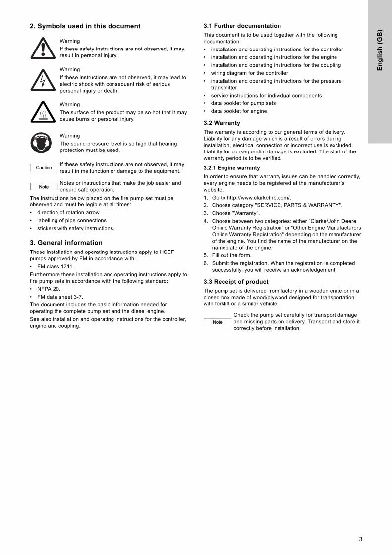
3.3.1 Lifting the pump set
Fig. 1 Lifting the complete pump set
3.3.2 Storage
3.3.3 Pump
Apply a suitable antirust agent on all machined, non-coated surfaces. If the pump is to be stored for more than six months before startup, treat the inner pump components with a suitable antirust agent.
The antirust agent must meet these requirements:
• It must not attack rubber parts.
• It must be easy to remove.
• It must be applied in accordance with the manufacturer's instructions.
In order to prevent water, dust, etc. from penetrating the pump, cover all openings appropriately until the pipes are installed. If this is not followed, it will be very expensive to dismantle the pump to remove foreign bodies after commissioning.
Turn the pump shaft by hand once a month to prevent the shaft seal from seizing up. To do this, disconnect the diesel engine from the pump.
3.3.4 Engine
See the installation and operating instructions for the engine.
3.3.5 Coupling
See the installation and operating instructions for the coupling.
3.3.6 Controller
See the installation and operating instructions for the controller.
4. Product description
4.1 Pumped liquids
The pump is suitable for pumping clean and non-aggressive fire-extinguishing water not containing additives or particles.
4.2 Applications
Grundfos HSEF pumps and Fire HSEF pump sets are designed for firefighting applications for supplying water to hose reels, fire hydrants or sprinkler systems. Do not use the pump sets for ordinary pumping of liquids or pressure boosting.
The control cabinet must not be used to supply voltage to other devices.
4.3 Pump set
The complete pump set consists of a pump, a diesel engine and a controller. A flexible coupling connects engine and pump. All components are adapted to each other and mounted on a common base frame ready for installation. The base frame has holes for fastening lifting equipment and holes for attaching it to the floor. The pump set is delivered ready to use.
The fuel tank can be delivered separately in some options. For installation and connection of fuel pipes, see section 6.9 Separate fuel tank.
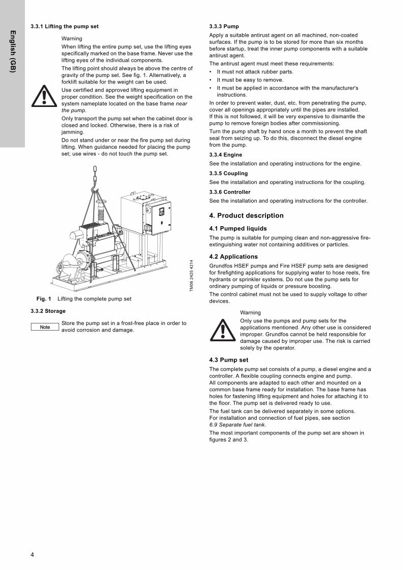
The most important components of the pump set are shown in figures 2 and 3.
Warning
When lifting the entire pump set, use the lifting eyes specifically marked on the base frame. Never use the lifting eyes of the individual components.
The lifting point should always be above the centre of gravity of the pump set. See fig. 1. Alternatively, a forklift suitable for the weight can be used.
Use certified and approved lifting equipment in proper condition. See the weight specification on the system nameplate located on the base frame near the pump.
Only transport the pump set when the cabinet door is closed and locked. Otherwise, there is a risk of jamming.
Do not stand under or near the fire pump set during lifting. When guidance needed for placing the pump set; use wires - do not touch the pump set.
TM
06
24
25
42
14
NoteStore the pump set in a frost-free place in order to avoid corrosion and damage.
Warning
Only use the pumps and pump sets for the applications mentioned. Any other use is considered improper. Grundfos cannot be held responsible for damage caused by improper use. The risk is carried solely by the operator.
4
En
gli
sh
(G
B)
Fig. 2 Example of a diesel-powered Fire HSEF pump set, right view
Fig. 3 Example of a diesel-powered Fire HSEF pump set, left view
TM
06
24
93
43
14
15 23 22 19 24 16 17
7 12 26
27
6
8
9
20
10
18
TM
06
25
36
44
14
2 3 20 11 4 13 5
1142521
Pos. Component Pos. Component
1 Base frame 15 Generator with V-belt and cover
2 Pump 16 Starter
3 Coupling with coupling guard 17 Starter relay
4 Engine, complete 18 Starter batteries
5 Controller 19 Diesel injection pump
6 Fuel tank 20 Fuel filter
7 Tank cap 21 Fuel delivery pump
8 Manual filling pump 22 Speed setting
9 Fuel valve (hidden) 23 Stop lever
10 Drain screw on fuel tank (hidden) 24 Oil dipstick
11 Exhaust pipe 25 Oil filter
12 Heat exchanger 26 Air filter
13 Equalisation tank 27 Automatic air relief valve
14 Cooling circuit
5
En
glis
h (G
B)
4.4 Pump
The pump is a non-self-priming, single-stage Grundfos HSEF standard pump with volute casing. It has an radial suction port and a radial discharge port with ANSI B 16.5 compliant flanges. For technical data see page 24 chapter 15.3.1 Permissible flange forces and flange torques.
The impeller diameter can be reduced to customise the pump performance to a certain duty point. This means that the actual impeller diameter differs from the standard diameter stated in sales catalogues, data sheets, etc. The actual impeller diameter is stated on the pump nameplate.
The HSEF pump is equipped with a stuffing box seal.
4.5 Engine
The pumps are driven by a stationary 4-stroke diesel engine from John Deere or Doosan which has been specially adjusted to the pump drive requirements of Clarke UK Ltd.
The rated engine power is adapted to the power requirement of the pumps. The adjustment is made via the engine speed and consequently this must not be changed. See appendix page 27 and section 1. Dimensions and weights for relationship between the diesel engines and the individual pumps. Depending on performance, the engines have a turbocharger and, if necessary, also a charge air cooler.
The engine is cooled via a heat exchanger in the water-cooled John Deere and Doosan engines. The coolant is led to the heat exchanger via a pipe connected to the discharge port of the pump.
5. Identification
5.1 Pump
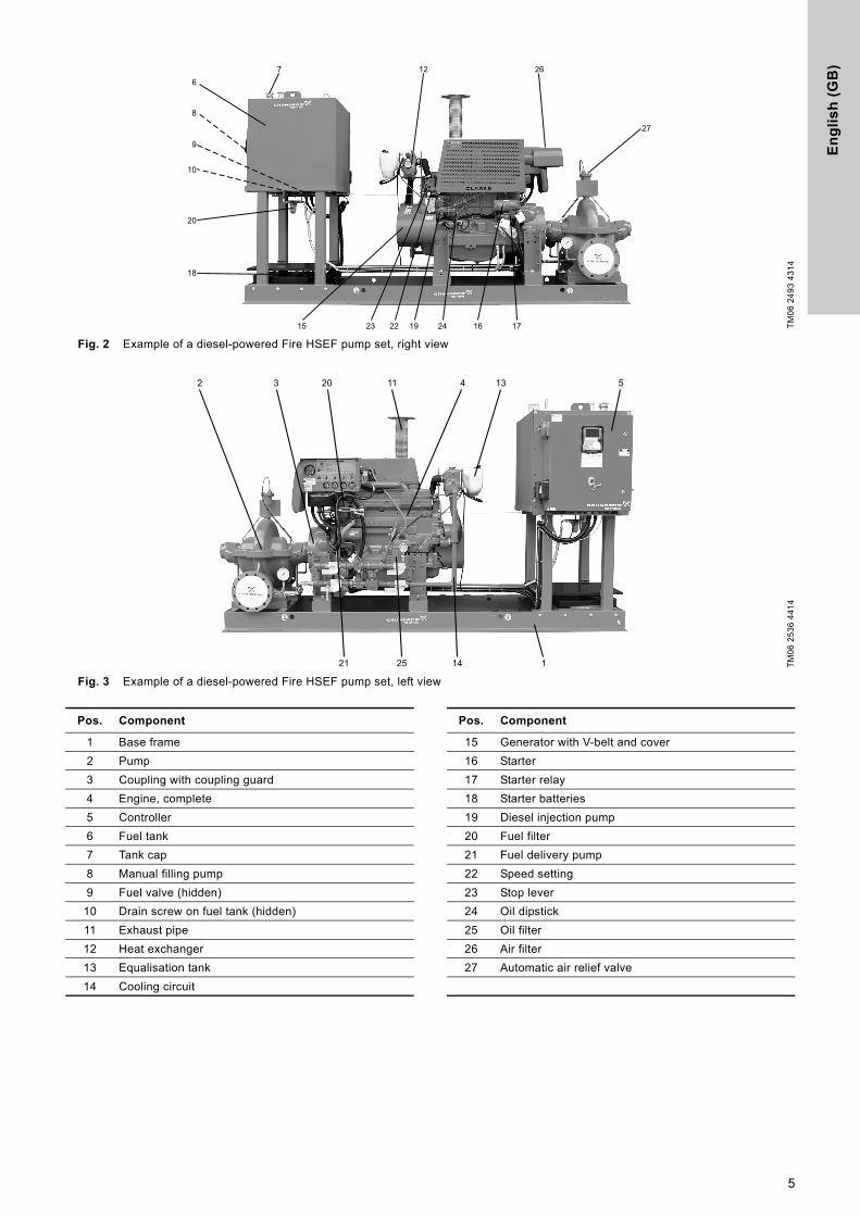
5.1.1 Nameplate
The nameplate shows all important data of the pump. It is attached to top of the pump.
Fig. 4 Nameplate of a HSEF pump with FM approval
5.2 Pump set
5.2.1 Nameplate
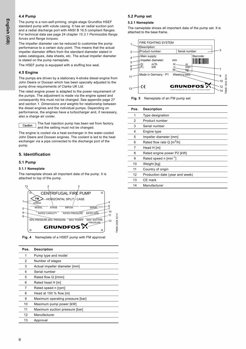
The nameplate shows all important data of the pump set. It is attached to the base frame.
Fig. 5 Nameplate of an FM pump set
Caution The fuel injection pump has been set from factory, and the setting must not be changed.
TM
06
24
28
42
14
Pos. Description
1 Pump type and model
2 Number of stages
3 Actual impeller diameter [mm]
4 Serial number
5 Rated flow Q [l/min]
6 Rated head H [m]
7 Rated speed n [rpm]
8 Head at 150 % flow [m]
9 Maximum operating pressure [bar]
10 Maximum pump power [kW]
11 Maximum suction pressure [bar]
12 Manufacturer
13 Approval
CENTRIFUGAL FIRE PUMPHORIZONTAL SPLIT - CASE
IMP.DIA SERIALMODEL STAGE
RATED CAPACITY RATED PRESSURE RATED APM
MAX. POWER MAX. SUCTIONPRESSURE
150% PRESSURE MAX. PRESSURE
4
3213
5
89
1
710
6
11
12
TM
06
19
43
50
14
Pos. Description
1 Type designation
2 Product number
3 Serial number
4 Engine type
5 Impeller diameter [mm]
6 Rated flow rate Q [m3/h]
7 Head H [m]
8 Rated engine power P2 [kW]
9 Rated speed n [min-1]
10 Weight [kg]
11 Country of origin
12 Production date (year and week)
13 CE mark
14 Manufacturer
FIRE FIGHTING SYSTEMDescription:Product number:Main supply:Impeller diameter:
Made in Germany - P1
Q:P2: kW
Week(yy.ww):
H:n:
W:
m
kg
Serial number:
m /hmm
Barcode:
min-1
3PN
Grundfos Pumpenfabrik GmbH Willy - Pelz - StraBe 1.5 23812 Wahlstedt GERMANY
1
2
4568
11
13
3
7
9
10
1214
6
En
gli
sh
(G
B)
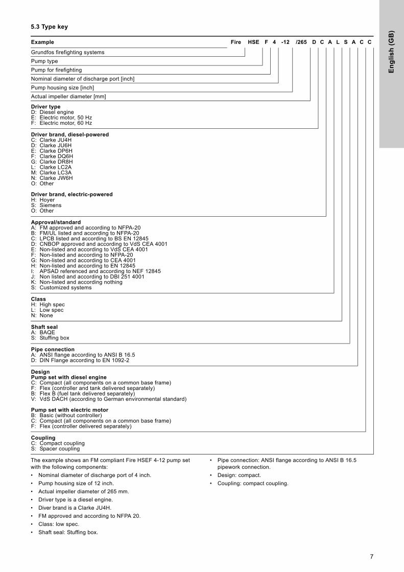
5.3 Type key
The example shows an FM compliant Fire HSEF 4-12 pump set with the following components:
• Nominal diameter of discharge port of 4 inch.
• Pump housing size of 12 inch.
• Actual impeller diameter of 265 mm.
• Driver type is a diesel engine.
• Diver brand is a Clarke JU4H.
• FM approved and according to NFPA 20.
• Class: low spec.
• Shaft seal: Stuffing box.
• Pipe connection: ANSI flange according to ANSI B 16.5 pipework connection.
• Design: compact.
• Coupling: compact coupling.
Example Fire HSE F 4 -12 /265 D C A L S A C C
Grundfos firefighting systems
Pump type
Pump for firefighting
Nominal diameter of discharge port [inch]
Pump housing size [inch]
Actual impeller diameter [mm]
Driver typeD: Diesel engineE: Electric motor, 50 HzF: Electric motor, 60 Hz
Driver brand, diesel-poweredC: Clarke JU4HD: Clarke JU6HE: Clarke DP6HF: Clarke DQ6HG: Clarke DR8HL: Clarke LC2AM: Clarke LC3AN: Clarke JW6HO: Other
Driver brand, electric-poweredH: HoyerS: SiemensO: Other
Approval/standardA: FM approved and according to NFPA-20B: FM/UL listed and according to NFPA-20C: LPCB listed and according to BS EN 12845D: CNBOP approved and according to VdS CEA 4001E: Non-listed and according to VdS CEA 4001F: Non-listed and according to NFPA-20G: Non-listed and according to CEA 4001H: Non-listed and according to EN 12845I: APSAD referenced and according to NEF 12845J: Non listed and according to DBI 251 4001K: Non-listed and according nothingS: Customized systems
ClassH: High specL: Low specN: None
Shaft sealA: BAQES: Stuffing box
Pipe connectionA: ANSI flange according to ANSI B 16.5D: DIN Flange according to EN 1092-2
DesignPump set with diesel engineC: Compact (all components on a common base frame)F: Flex (controller and tank delivered separately)B: Flex B (fuel tank delivered separately)V: VdS DACH (according to German environmental standard)
Pump set with electric motorB: Basic (without controller)C: Compact (all components on a common base frame)F: Flex (controller delivered separately)
CouplingC: Compact couplingS: Spacer coupling
7
En
glis
h (G
B)
6. Mechanical installationThis section describes the installation of a complete pump set.
6.1 Pump set location
Place the pump set in a dry, frost-free, well-illuminated and well-ventilated location. The pump set, primarily the control cabinet, must not be exposed to direct sunlight.
Allow sufficient clearance around pump and engine to enable maintenance and operation.
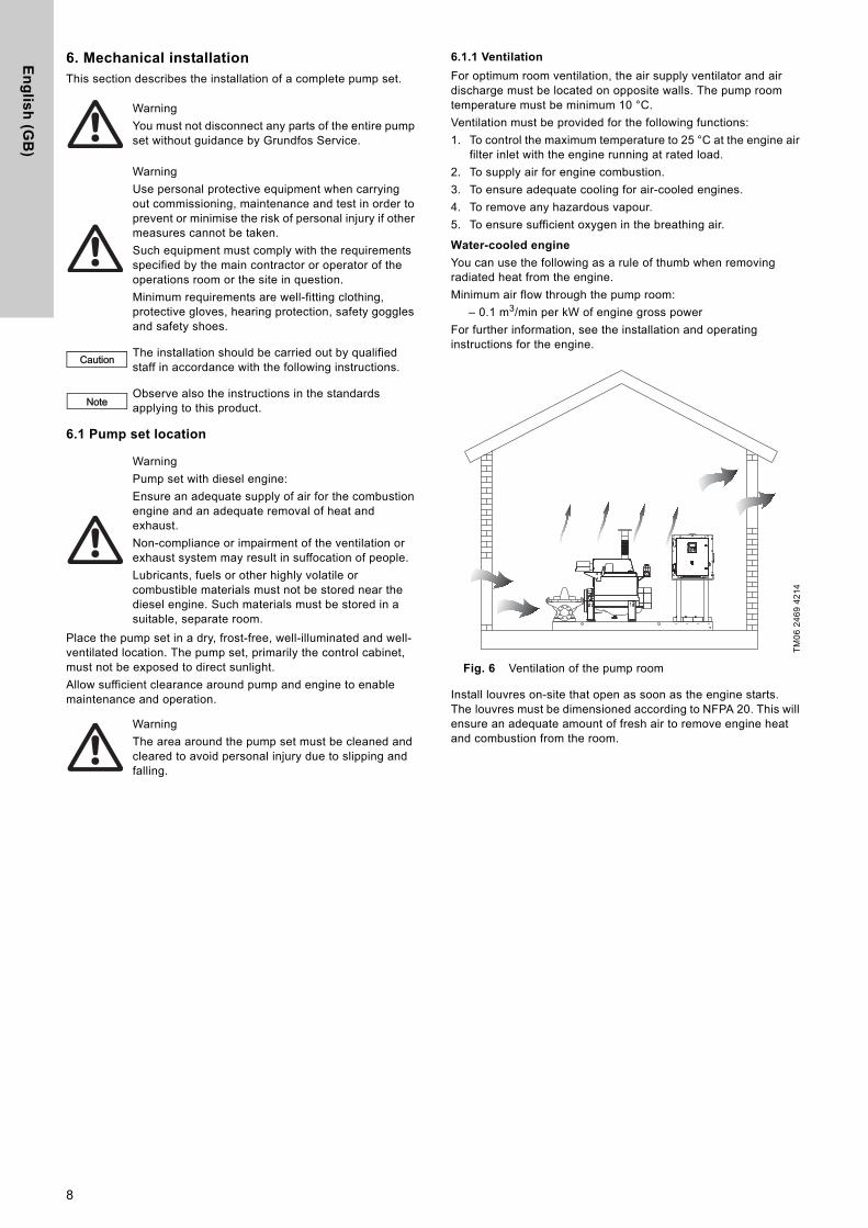
6.1.1 Ventilation
For optimum room ventilation, the air supply ventilator and air discharge must be located on opposite walls. The pump room temperature must be minimum 10 °C.
Ventilation must be provided for the following functions:
1. To control the maximum temperature to 25 °C at the engine air filter inlet with the engine running at rated load.
2. To supply air for engine combustion.
3. To ensure adequate cooling for air-cooled engines.
4. To remove any hazardous vapour.
5. To ensure sufficient oxygen in the breathing air.
Water-cooled engine
You can use the following as a rule of thumb when removing radiated heat from the engine.
Minimum air flow through the pump room:
– 0.1 m3/min per kW of engine gross power
For further information, see the installation and operating instructions for the engine.
Fig. 6 Ventilation of the pump room
Install louvres on-site that open as soon as the engine starts. The louvres must be dimensioned according to NFPA 20. This will ensure an adequate amount of fresh air to remove engine heat and combustion from the room.
Warning
You must not disconnect any parts of the entire pump set without guidance by Grundfos Service.
Warning
Use personal protective equipment when carrying out commissioning, maintenance and test in order to prevent or minimise the risk of personal injury if other measures cannot be taken.
Such equipment must comply with the requirements specified by the main contractor or operator of the operations room or the site in question.
Minimum requirements are well-fitting clothing, protective gloves, hearing protection, safety goggles and safety shoes.
Caution The installation should be carried out by qualified staff in accordance with the following instructions.
NoteObserve also the instructions in the standards applying to this product.
Warning
Pump set with diesel engine:
Ensure an adequate supply of air for the combustion engine and an adequate removal of heat and exhaust.
Non-compliance or impairment of the ventilation or exhaust system may result in suffocation of people.
Lubricants, fuels or other highly volatile or combustible materials must not be stored near the diesel engine. Such materials must be stored in a suitable, separate room.
Warning
The area around the pump set must be cleaned and cleared to avoid personal injury due to slipping and falling.
TM
06
24
69
42
14
8
En
gli
sh
(G
B)
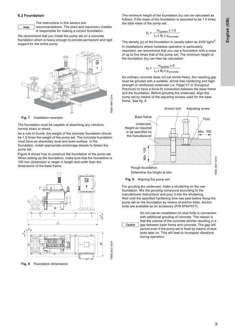
6.2 Foundation
We recommend that you install the pump set on a concrete foundation which is heavy enough to provide permanent and rigid support for the entire pump.
Fig. 7 Installation example
The foundation must be capable of absorbing any vibration, normal strain or shock.
As a rule of thumb, the weight of the concrete foundation should be 1.5 times the weight of the pump set. The concrete foundation must have an absolutely level and even surface. In the foundation, install appropriate anchorage dowels to fasten the pump set.
Figure 8 shows how to construct the foundation of the pump set. When setting up the foundation, make sure that the foundation is 100 mm (dimension x) larger in length and width than the dimensions of the base frame.
Fig. 8 Foundation dimensions
The minimum height of the foundation (hf) can be calculated as follows, if the mass of the foundation is assumed to be 1.5 times the total mass of the pump set:
The density (ρ) of the foundation is usually taken as 2200 kg/m3.
In installations where noiseless operation is particularly important, we recommend that you use a foundation with a mass of up to five times that of the pump set. The minimum height of the foundation (hf) can then be calculated:
As ordinary concrete does not set shrink-freely, the resulting gap must be grouted with a suitable, shrink-free hardening and high-strength or reinforced undercast (i.e. Pagel V1 or Eurogrout Premium) to have a force-fit connection between the base frame and the foundation. Before grouting the undercast, align the pump set by means of the adjusting screws used for the base frame. See fig. 9.
Fig. 9 Aligning the pump set
For grouting the undercast, make a shuttering on the raw foundation. Mix the grouting compound according to the manufacturer instructions and pour it into the shuttering. Wait until the specified hardening time has past before fixing the pump set on the foundation by means of anchor bolts. Anchor bolts are available as an accessory (P/N 97947677).
NoteThe instructions in this section are recommendations. The plant and machinery installer is responsible for making a correct foundation.
TM
06
18
64
33
14
TM
06
24
21
42
14
hfBf
Lf
x
x
hf =msystem x 1.5
Lf x Bf x ρconcrete
hf =msystem x 5
Lf x Bf x ρconcrete
TM
05
25
47
02
12
Caution
Do not use an installation on stud bolts in connection with additional grouting of concrete. The reason is that the volume of the concrete shrinks resulting in a gap between base frame and concrete. The gap will persist even if the pump set is fixed by means of stud bolts later on. This will lead to increased vibrations during operation.
Undercast.Height as requiredor as specified bythe manufacturer
Anchor bolt
Rough foundation.
Determine the height at site.
Foot
Adjusting screw
Min
. 1
30
Min. 100
Base frame
9
En
glis
h (G
B)
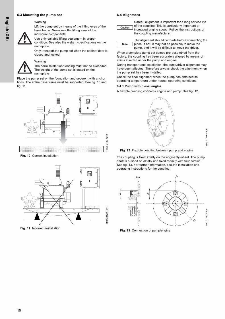
6.3 Mounting the pump set
Place the pump set on the foundation and secure it with anchor bolts. The entire base frame must be supported. See fig. 10 and fig. 11.
Fig. 10 Correct installation
Fig. 11 Incorrect installation
6.4 Alignment
When a complete pump set comes pre-assembled from the factory, the coupling has been accurately aligned by means of shims inserted under the pump and engine.
During transport and installation, the pump/driver alignment may have been affected. Therefore always check the alignment when the pump set has been installed.
Check the final alignment when the pump has obtained its operating temperature under normal operating conditions.
6.4.1 Pump with diesel engine
A flexible coupling connects engine and pump. See fig. 12.
Fig. 12 Flexible coupling between pump and engine
The coupling is fixed axially on the engine fly-wheel. The pump shaft is pushed on axially and fixed radially with four screws. See fig. 13. For further information, see the installation and operating instructions for the coupling.
Fig. 13 Connection of pump/engine
Warning
Lift the pump set by means of the lifting eyes of the base frame. Never use the lifting eyes of the individual components.
Use only suitable lifting equipment in proper condition. See also the weight specifications on the nameplate.
Only transport the pump set when the cabinet door is closed and locked.
Warning
The permissible floor loading must not be exceeded. The weight of the pump set is stated on the nameplate
TM
06
24
19
42
14
TM
06
24
20
42
14
Caution
Careful alignment is important for a long service life of the coupling. This is particularly important at increased engine speed. Follow the instructions of the coupling manufacturer.
NoteThe alignment should be made before connecting the pipes; if not, it may not be possible to move the pump, and it will be difficult to move the driver.
TM
03
77
76
49
06
TM
03
77
77
49
06
A
A
A-A
ZZ
10

En
gli
sh
(G
B)
Checking the alignment
1. Disconnect the negative pole of the starter battery.
2. Remove the coupling guard.
3. Check the alignment according to the installation and operating instructions for the coupling.
4. Refit the coupling guard.
5. Reconnect the negative pole of the starter battery.
Aligning pump and engine
Fig. 14 Axial and radial fixation of the clamping hub of the coupling
6. Align the coupling according to the installation and operating instructions for the coupling.
6.5 Pipe connection
The pipes must be installed as straight as possible and be of an adequate size. Take the pump inlet pressure into consideration.
Install the pipes so that air locks are avoided. This applies especially to the suction side of the pump. See fig. 15.
Fig. 15 Installation of pipes
Secure the pipes close to the pump on the suction and discharge side with pipe brackets attached to the building (wall, ceiling, floor). See fig. 16.
The pipes should lie true against the pump flanges without being stressed. Otherwise, the pump may be damaged.
Fig. 16 Fixing points of the pipes
Install isolating valves on both sides of the pump.
Connect the suction pipe to suction pump port and the discharge pipe to the discharge pump port.
6.6 Priming tank and test pipe
If the pump set is supplied from a storage tank and the suction height is negative, install a pump priming tank on the suction side in accordance with local regulations. See also the standard applying to the pump set.
Install a test pipe running from the discharge pipe to the storage tank. The discharge pipe and the test pipe must be fitted with isolating valves.
If the pump set is fed directly from the public water supply, the test pipe must have a free outlet according to the standard applying to the pump set.
Warning
Disconnect the battery cable before you remove the coupling guard.
Beware of the sharp edges of the coupling guard. Wear protective gloves.
Caution
Axial and radial screws can be reused maximum three times.
Do not use threadlocker as it may damage the rubber material.
TM
04
00
58
49
07
Warning
After checking or adjusting the alignment, fit the coupling guard.
1 4 2 5 3
Caution
The pipework must not stress the pump housing or transfer any forces to the pump housing.
See permissible flange forces and torques in section 15.3 Pump.
NoteThe discharge pipe must have a port for venting and priming the pump. See section 8.2 Preparations before commissioning.
TM
00
22
63
33
93
TM
06
18
64
33
14
Discharge pipe
Suction pipe
11
En
glis
h (G
B)
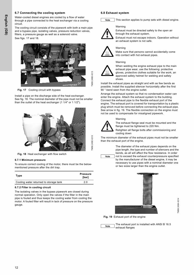
6.7 Connecting the cooling system
Water-cooled diesel engines are cooled by a flow of water through a pipe connected to the heat exchanger via a cooling circuit.
The cooling circuit consists of the pipework with both a main pipe and a bypass pipe, isolating valves, pressure reduction valves, filters, a pressure gauge as well as a solenoid valve.
See figs. 17 and 18.
Fig. 17 Cooling circuit with bypass
Install a pipe on the discharge side of the heat exchanger. See fig. 18. The nominal diameter of the pipe must not be smaller than the outlet of the heat exchanger (1 1/4" or 1 1/2").
Fig. 18 Heat exchanger with flow switch
6.7.1 Minimum pressure
To ensure correct cooling of the motor, there must be the below-mentioned pressure after the dirt trap.
6.7.2 Filter in cooling circuit
The isolating valves in the bypass pipework are closed during normal operation. Only open the valves if the filter in the main pipe is fouled and thus keeps the cooling water from cooling the motor. A fouled filter will result in lack of pressure on the pressure gauge.
6.8 Exhaust system
Install the exhaust pipes as straight and with as few bends as possible. Install the supplied silencer horizontally after the first 90 °-bend seen from the engine outlet.
Arrange the exhaust system so that no condensation water can enter the engine. Attach the exhaust system to the building. Connect the exhaust pipe to the flexible exhaust port of the engine. The exhaust port is covered for transportation by a plastic plug which must be removed before connecting the exhaust pipe. See arrow in fig. 19. The flexible connection on the engine must not be used to compensate for misaligned pipework.
The minimum diameter of the exhaust pipes must not be smaller than the exhaust port of the engine.
Fig. 19 Exhaust port of the engine
TM
06
24
96
43
13
TM
06
24
90
43
13
TypePressure
[bar]
Cooling water returned to storage tank 2.0
Note This section applies to pump sets with diesel engine.
Warning
Exhaust must be directed safely to the open air through the exhaust system.
Exhaust must not escape indoors. Operation without an exhaust system is not safe.
Warning
Make sure that persons cannot accidentally come into contact with hot exhaust pipes.
Warning
When welding the engine exhaust pipe to the main exhaust pipe wear, use the following: protective gloves, protective clothes suitable for the work, an approved safety helmet for welding and safety shoes.
Warning
The exhaust flange seal must be mounted and the flange must be tightened to 220 Nm.
Retighten all flange bolts after commissioning and cooling down
Note
The diameter of the exhaust pipes depends on the pipe length, the type and number of silencers and the bends, as all will affect the flow resistance. In order not to exceed the exhaust counterpressure specified by the manufacturer of the diesel engine, it may be necessary to use pipes with a nominal diameter one or two sizes larger than the engine outlet.
TM
06
24
94
43
14
NoteThe exhaust port is installed with ANSI B 16.5 exhaust flanges
12
En
gli
sh
(G
B)
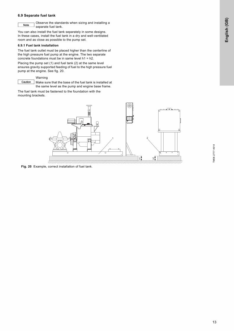
6.9 Separate fuel tank
You can also install the fuel tank separately in some designs. In these cases, install the fuel tank in a dry and well-ventilated room and as close as possible to the pump set.
6.9.1 Fuel tank installation
The fuel tank outlet must be placed higher than the centerline of the high pressure fuel pump at the engine. The two separate concrete foundations must be in same level h1 = h2.
Placing the pump set (1) and fuel tank (2) at the same level ensures gravity supported feeding of fuel to the high pressure fuel pump at the engine. See fig. 20.
The fuel tank must be fastened to the foundation with the mounting brackets.
Fig. 20 Example, correct installation of fuel tank.
NoteObserve the standards when sizing and installing a separate fuel tank.
CautionWarning
Make sure that the base of the fuel tank is installed at the same level as the pump and engine base frame.
TM
06
27
77
46
14
h1 h2
1 2
13

En
glis
h (G
B)
6.9.2 Fuel tank connection
If there is no connecting block, connect the fuel pipes as shown in fig. 21 to the flow pipe (pos. A, from the manual fuel supply pump) and the return pipe (pos. B, from the injection pump).
Fig. 21 Connecting the fuel pipes without connecting block.
If there is a connecting block (see fig. 21, pos. A), connect both fuel pipes to the connecting block. The connecting block is marked "SUPPLY" for the incoming pipe and "RETURN" for the return pipe.
Fig. 22 Connecting the fuel pipes to the connecting block
6.10 Separate control cabinet
6.10.1 Flex version
For the "Flex" version, the control cabinet is mounted onto the separate fuel tank. In this case, place the controller as close to the pump as possible and within view of the pump set. The control cabinet must also be easily accessible.
6.10.2 Flex B version
For the "Flex B" version, the control cabinet is delivered on a separate stand. In this case, place the controller as close to the pump as possible and within view of the pump set. The control cabinet must also be easily accessible.
6.11 Mechanical fuel level indicator
Upon arrival of the fire set, the mechanical fuel level indicator is not pre-installed. The fuel level indicator is stored in the base frame.
Fig. 23 Fuel level indicator
Installing the fuel level indicator
1. Remove the plastic cap from the connection on the top of the fuel tank.
2. Adjust the indicator disc on the display to equal 100 when the weight is in top.
3. Install the mechanical fuel level indicator. Ensure that the display is facing the same direction as the controller.
6.12 Fuel hand pump
The pump set is equipped with a fuel hand pump. See fig. 2. Use the fuel hand pump to manually pump diesel fuel from transportable containers into the fuel tank. The fuel hand pump is designed for this purpose only. Fuel most not remain in the plastic hoses. The plastic hoses are supplied together with the fuel hand pump.
6.13 Leaklines
The Fire HSEF pump is equipped with leaklines. The leaklines drains excessive water from the stuffing box. The leaklines must be connected to drain. See fig. 24.
Fig. 24 Leakline
TM
04
98
51
02
11T
M0
4 5
06
9 2
60
9
NoteSee also installation and operating instructions for the controller.
Caution
Warning
Make sure that water escaping from the pump or pipework cannot damage the control cabinet.
The control cabinet is only intended to be installed indoors and must not be exposed to direct sunlight. Ensure sufficient ventilation for the components in the control cabinet.
Caution Install the fuel level indicator before filling the tank.
TM
06
11
96
19
14
TM
06
24
92
43
14
Fuel level indicator
Leakline
14
En
gli
sh
(G
B)
7. Electrical installation7.1 Mains
Check that the supply voltage and frequency correspond to the values stated on the nameplate of the control cabinet.
• Connect the control cabinet to a power supply which is dimensioned to the fire pump set.
• Connect PE (protective earth) according to the installation and operating instructions for the controller.
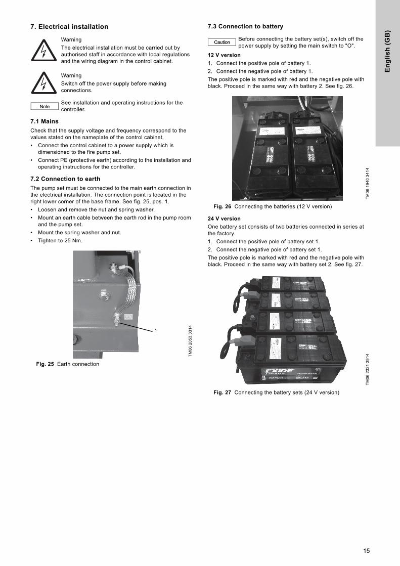
7.2 Connection to earth
The pump set must be connected to the main earth connection in the electrical installation. The connection point is located in the right lower corner of the base frame. See fig. 25, pos. 1.
• Loosen and remove the nut and spring washer.
• Mount an earth cable between the earth rod in the pump room and the pump set.
• Mount the spring washer and nut.
• Tighten to 25 Nm.
Fig. 25 Earth connection
7.3 Connection to battery
12 V version
1. Connect the positive pole of battery 1.
2. Connect the negative pole of battery 1.
The positive pole is marked with red and the negative pole with black. Proceed in the same way with battery 2. See fig. 26.
Fig. 26 Connecting the batteries (12 V version)
24 V version
One battery set consists of two batteries connected in series at the factory.
1. Connect the positive pole of battery set 1.
2. Connect the negative pole of battery set 1.
The positive pole is marked with red and the negative pole with black. Proceed in the same way with battery set 2. See fig. 27.
Fig. 27 Connecting the battery sets (24 V version)
Warning
The electrical installation must be carried out by authorised staff in accordance with local regulations and the wiring diagram in the control cabinet.
Warning
Switch off the power supply before making connections.
NoteSee installation and operating instructions for the controller.
TM
06
20
53
.33
14
1
Caution Before connecting the battery set(s), switch off the power supply by setting the main switch to "O".
TM
06
19
40
34
14
TM
06
23
21
39
14
15
En
glis
h (G
B)
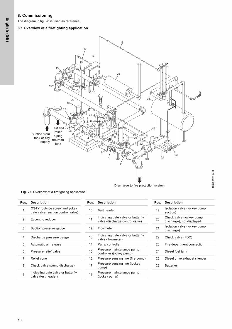
8. CommissioningThe diagram in fig. 28 is used as reference.
8.1 Overview of a firefighting application
Fig. 28 Overview of a firefighting application
TM
06
15
23
24
14
M
10
13
3 6
22
26
23
24
25
17
15
12
16
14
9
2
19
18
21
1
4
5
7
8
9
11
Discharge to fire protection system
Suction fromtank or city
supply
Test and relief piping
return to tank
Pos. Description Pos. Description Pos. Description
1OS&Y (outside screw and yoke) gate valve (suction control valve)
10 Test header 19Isolation valve (jockey pump suction)
2 Eccentric reducer 11Indicating gate valve or butterfly valve (discharge control valve)
20Check valve (jockey pump discharge), not displayed
3 Suction pressure gauge 12 Flowmeter 21Isolation valve (jockey pump discharge)
4 Discharge pressure gauge 13Indicating gate valve or butterfly valve (flowmeter)
22 Check valve (FDC)
5 Automatic air release 14 Pump controller 23 Fire department connection
6 Pressure relief valve 15Pressure maintenance pump controller (jockey pump)
24 Diesel fuel tank
7 Relief cone 16 Pressure sensing line (fire pump) 25 Diesel drive exhaust silencer
8 Check valve (pump discharge) 17Pressure sensing line (jockey pump)
26 Batteries
9Indicating gate valve or butterfly valve (test header)
18Pressure maintenance pump (jockey pump)
16

En
gli
sh
(G
B)
8.2 Preparations before commissioning
The below listed preparation actions are valid for applications with flooded suction conditions.
1. Check that all screws are tight.
2. Check that all pipes and hoses are installed correctly.
3. Check all electrical connections.
4. Check that all fuses in the control cabinet are switched on.
5. Check the alignment of the coupling. See section 6.4 Alignment.
6. Check that the coupling guard is installed correctly and that all screws are tightened to 10 Nm for M6 and 25 Nm for M8.
7. Check that all safety devices are installed.
8. Make sure that any storage tank and pump priming tank are filled with water.
9. Set the pressure switches according to the instructions. System pressure minus 0.5 bar can be used as a reference value.
10. Open the isolating valves on the suction and discharge sides.The static geometric suction pressure from the main water tank will fill the suction pipe, discharge pipe and pump with water.
11. Bleed all air from the pump casing and suction pipe by the opening of the automatic relief valve at the top of the pump. Rotate the shaft a few times if possible to evacuate any air trapped inside the impeller passages.
12. Close the isolating valves on the suction and discharge sides.
Fig. 29 Air relief valve
8.2.1 Pump set with diesel engine
1. Check the V-belt tension.
2. Check the oil level and refill, if necessary.
3. Check the level of coolant and refill, if necessary.
4. Check that all hose connections in the cooling circuit are tight and leakage-free.
5. Fill the fuel tank with diesel fuel and vent the fuel pipes.
Warning
Commissioning must be carried out by authorised staff.
Warning
The control cabinet of the controller must remain closed during commissioning.
Caution Do not start the pump until it has been filled with water and vented.
CautionThe pump must not run against closed valve as this may cause an unacceptable temperature increase or the formation of vapour.
NoteSee also installation and operating instructions for the controller.
Caution You must not change the engine speed setpoint (rpm).
Note
Pump set with Clarke diesel engine:
We recommend that you register the diesel engine before startup. Otherwise, Clarke cannot provide any warranty if the engine is faulty. Go to www.clarkefire.com: SERVICE, PARTS & WARRANTY.
TM
06
24
91
43
14
Caution Check the level of oil and coolant in the engine prior to startup.
NoteSee installation and operating instructions for the diesel engine.
17

En
glis
h (G
B)
8.3 Starting the pump set
Additional safety instructions for pump set with diesel engine
General procedure
1. Open the isolating valve on the suction side (1).
2. Check that the isolating valve on the discharge side is closed (11).
3. Open the isolating valve of the test pipe (9).
4. Switch on the controller (14) and start the pump.See installation and operating instructions for the controller.
5. Slowly open the isolating valve (11) on the discharge side of the pump.
6. When the pump reaches operating pressure, open the isolating valve sufficiently to reach the duty point.
7. Measure and read the relevant operating parameters and compare them with the rated values.
8. Stop the pump via the controller and set the pump set to automatic mode. See installation and operating instructions for the controller.
9. Close the isolating valve of the test pipe (9).
10. Check that the isolating valve at the discharge side (11) is fully open.
The pump set is now operational and in automatic mode.
8.4 Checking the function
In connection with commissioning, perform a final test run according to the standard applying to the pump set:
1. Activate the automatic startup command by lowering the pressure in the discharge pipe with a closed fuel valve.
2. Lower the pressure by opening the isolating valve of the test pipe.
Every starting cycle consists of a starting phase followed by a pause. A failure warning activates after six failed start attempts. When the fuel valve has been opened and the fault indication has been removed, the pump should start properly.
9. Operating the controllerSee installation and operating instructions for the controller.
9.1 Shaft seal run-in (stuffing box)
The pumped liquid lubricates the seal faces, meaning that there will be a certain amount of leakage from the stuffing box.
When the pump is started for the first time, or when a new shaft seal is installed, a certain run-in period is required before the leakage is reduced to an acceptable level. The time required for this depends on the operating conditions, i.e. every time the operating conditions change, a new run-in period will be started.
Warning
Some pump sets have a sound pressure level higher than 70 dB(A). See page 28.
In these cases, wear hearing protection when the pump set is running.
NoteObserve the safety instructions in the installation and operating instructions of the individual components.
NoteSee also installation and operating instructions for the controller and diesel engine.
Warning
Remove the fuel canisters from the room before starting the pump set.
Warning
Fuel vapours are flammable. Do not start the engine if there are fuel vapours in the room.
Warning
Exhaust must be directed safely to the open air through the exhaust system.
Exhaust must not escape indoors.
Operation without an exhaust system is not safe.
Warning
The pump set must not be started without a coupling guard.
Warning
Make sure that persons cannot accidentally come into contact with hot exhaust pipes.
NoteOpen the fuel valve on the fuel tank and vent the fuel system. See installation and operating instructions for the diesel engine.
Warning
Fuel escaping under pressure can penetrate the skin and cause serious injuries. Always release the pressure before disconnecting the fuel pipes. Repressurise when the pipes have been tightened.
Warning
When the pump set is primed, pressurized and the engine is started, check the pump set for any kind of leakage of oil, water or fuel.
Warning
When the engine is started, check for exhaust leakage and abnormal noise level.
Stop the engine immediately if the exhaust system is leaking.
NoteCollect excess fuel in a container and dispose of it in accordance with local regulations.
NoteIf the pump does not start, see the fault indications on the controller and section 13. Fault finding.
Note This section applies to pump sets with diesel engine.
18

En
gli
sh
(G
B)
10. OperationDetailed operation instructions are described in the installation and operating instructions for the controller.
10.1 Alarm indicators
The most important operating and alarm indications are shown via indicator lights and/or the display of the controller. See installation and operating instructions for the controller.
If the controller has outputs for connection to a building management system, you can monitor the pump set remotely.
To remove any faults, see section 13. Fault finding.
The following four operating modes are possible:
10.2 Automatic operation
Once you have installed and commissioned the pump set according to the instructions, no further operation is necessary. The pump set works automatically and switches itself on as soon as water is taken from the sprinkler system and the pressure switch thus detects a pressure drop.
You can stop the pump set manually via the controller.
10.3 Manual operation
You can also start and stop the pump set manually for a functional test, for restarting or after service work.
10.4 Emergency operation
If the diesel engine does not start up in automatic operation after six start attempts, the automatic operation is blocked. You can start the pump set manually via the controller.
10.5 Weekly test run
Test the function of the pump set during a test run. See the standard applying to the pump set.
11. Shutdown
1. Close the isolating valve on the discharge side.
2. Close the isolating valve on the suction side.
3. Switch off the power supply via the controller.
Additional procedure for pump set with diesel engine
1. Close the fuel valve on the fuel tank.
2. Disconnect the positive pole first and then the negative pole of the batteries.
We recommend that you drain the fuel into a suitable container.
12. Maintenance
Note
Observe the safety instructions in section 8. Commissioning and its subsections, as well as in the installation and operating instructions for the individual components.
NoteSee also installation and operating instructions for the controller and diesel engine.
NoteThe pump set will not be shut down in case of disruptions.
Caution
Do not leave the pump room during manual operation. Observe all operating and fault indications as the pump set will not stop automatically in case of fault (e.g. too high cooling water temperature or too low oil pressure).
NoteThis function is only available for pump sets with diesel engine.
Caution
Do not leave the pump room during manual operation. Observe all operating and fault indications as the pump set will not stop automatically in case of fault (e.g. too high cooling water temperature or too low oil pressure).
NoteThis section applies to the complete pump set. See also installation and operating instructions for the controller and diesel engine.
NoteShut down is only possible when the pump is not running. If the pump is running, stop it via the controller.
Warning
Maintenance must be carried out by authorised staff.
Warning
Personal protective equipment must be used when carrying out commissioning, maintenance and test in order to prevent risk of personal injury if other measures cannot be taken.
Such equipment must comply with the requirements specified by the main contractor or operator of the operations room or the site in question.
Minimum requirements are well-fitting clothing, protective gloves, hearing protection, safety goggles and safety shoes.
Warning
Make sure that persons cannot accidentally come into contact with hot surfaces, liquids or exhaust pipes.
Note
The operator is responsible for ensuring that all maintenance, inspection and installation work is performed by qualified staff according to local regulations and the standard applying to the pump set. A regular maintenance plan will help avoid expensive repairs and contribute to trouble-free, reliable operation.
Warning
Before starting work on the pump set, make sure that the pump set has been switched off and cannot be accidentally switched on.
NoteObserve local regulations, the standard applying to the pump set and the installation and operating instructions of the individual components.
NoteSee also installation and operating instructions for the controller and diesel engine.
19
En
glis
h (G
B)
12.1 Preparation before maintenance
1. Close the isolating valve on the discharge side.
2. Close the isolating valve on the suction side.
3. Switch off the power supply via the controller.
Additional procedure for pump set with diesel engine
1. Close the fuel valve on the fuel tank.
2. Disconnect the positive pole first and then the negative pole of the batteries.
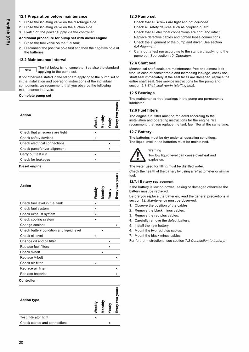
12.2 Maintenance interval
If not otherwise stated in the standard applying to the pump set or in the installation and operating instructions of the individual components, we recommend that you observe the following maintenance intervals:
Complete pump set
Diesel engine
Controller
12.3 Pump set
• Check that all screws are tight and not corroded.
• Check all safety devices such as coupling guard.
• Check that all electrical connections are tight and intact.
• Replace defective cables and tighten loose connections.
• Check the alignment of the pump and driver. See section 6.4 Alignment.
• Carry out a test run according to the standard applying to the pump set. See section 10. Operation.
12.4 Shaft seal
Mechanical shaft seals are maintenance-free and almost leak-free. In case of considerable and increasing leakage, check the shaft seal immediately. If the seal faces are damaged, replace the entire shaft seal. See service instructions for the pump and section 9.1 Shaft seal run-in (stuffing box).
12.5 Bearings
The maintenance-free bearings in the pump are permanently lubricated.
12.6 Fuel filters
The engine fuel filter must be replaced according to the installation and operating instructions for the engine. We recommend that you replace the tank fuel filter at the same time.
12.7 Battery
The batteries must be dry under all operating conditions. The liquid level in the batteries must be maintained.
The water used for filling must be distilled water.
Check the health of the battery by using a refractometer or similar tool.
12.7.1 Battery replacement
If the battery is low on power, leaking or damaged otherwise the battery must be replaced.
Before you replace the batteries, read the general precautions in section 12. Maintenance must be observed.
1. Observe the position of the cables.
2. Remove the black minus cables.
3. Remove the red plus cables.
4. Carefully remove the defect battery.
5. Install the new battery.
6. Mount the two red plus cables.
7. Mount the black minus cables.
For further instructions, see section 7.3 Connection to battery.
NoteThe list below is not complete. See also the standard applying to the pump set.
Action
We
ek
ly
Mo
nth
ly
Ye
arl
y
Ev
ery
tw
o y
ea
rs
Check that all screws are tight x
Check safety devices x
Check electrical connections x
Check pump/driver alignment x
Carry out test run x
Check for leakages x
Action
We
ek
ly
Mo
nth
ly
Ye
arl
y
Ev
ery
tw
o y
ea
rs
Check fuel level in fuel tank x
Check fuel system x
Check exhaust system x
Check cooling system x
Change coolant x
Check battery condition and liquid level x
Check oil level x
Change oil and oil filter x
Replace fuel filters x
Check V-belt x
Replace V-belt x
Check air filter x
Replace air filter x
Replace batteries x
Action type
We
ek
ly
Mo
nth
ly
Ye
arl
y
Ev
ery
tw
o y
ea
rs
Test indicator light x
Check cables and connections x
Warning
Too low liquid level can cause overheat and explosion.
20

En
gli
sh
(G
B)
12.8 Diesel engine
1. Check the fuel level in the fuel tank and add fuel, if necessary.
2. Check the pipes of the fuel system for leakages.
3. Replace defective fuel pipes and tighten loose pipe connections.
4. Fasten the fuel pipes with Norma type torque brackets.
5. Drain condensate from the fuel tank and the fuel filter.
6. Check oil level and add oil, if necessary.
7. Water-cooled diesel engines:Check the level of coolant in the equalisation tank and add coolant, if necessary.
8. Water-cooled diesel engines: Check pipes and hoses of the cooling system for leakages. Replace defective pipes and hoses. Tighten loose pipe and hose connections.
9. Check if the pressure gauge of the cooling circuit, if any, displays a pressure value when the engine is running.
10. Check the entire exhaust pipe system for leaks while the engine is running. Tighten loose pipe connections and replace defective pipes immediately.
11. Check V-belts for wear and correct tension.
12. Check air filter.
12.9 Coupling
Couplings used for pump sets are maintenance-free. However, check the alignment of the pump and driver once a year. See section 6.4 Alignment.
12.10 Controller
NoteSee also installation and operating instructions for the diesel engine.
Warning
During and after operation, surfaces, components and working materials of the diesel engine can be very hot.
Warning
Fuel vapours are flammable. Therefore, never top up fuel when the engine is running or when the engine is warm.
Do not inhale fuel vapours when filling the fuel tank.
Ensure good ventilation of the room during the refuelling so that the fuel vapours dissipate quickly.
Do not start the engine if there are fuel vapours in the room.
Caution Use the diesel fuel specified by the manufacturer of the diesel engine.
NoteCollect water-containing and excess fuel in a container and dispose of it in accordance with local regulations.
Caution
Do not fill oil above the maximum mark. Overfilling may damage the engine.
Use only the type of oil specified by the manufacturer of the diesel engine.
Warning
Do not the remove cap of equalisation tank when the engine is warm. The tank is under pressure.
Caution Use only the type of coolant specified by the manufacturer of the diesel engine.
Warning
A damaged exhaust system may result in suffocation.
NoteSee installation and operating instructions for the controller.
21
En
glis
h (G
B)
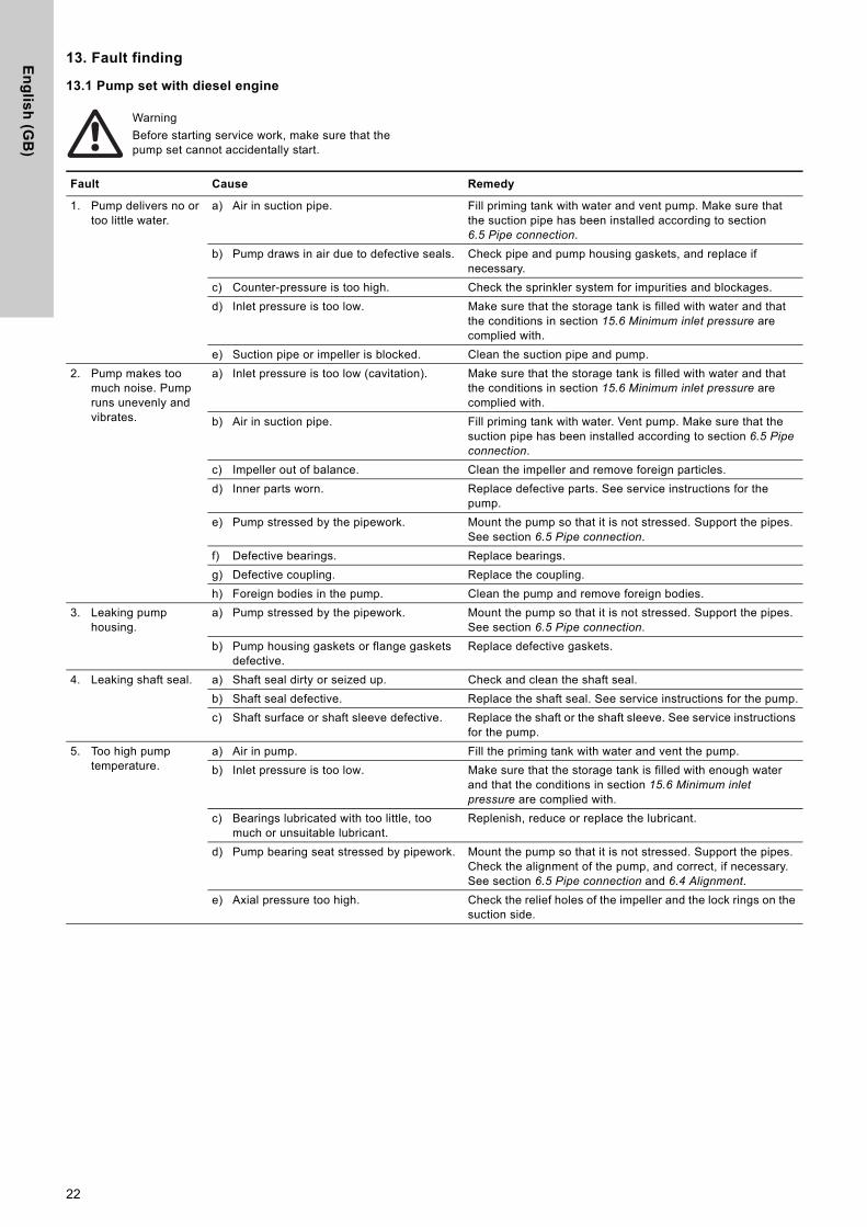
13. Fault finding
13.1 Pump set with diesel engine
Warning
Before starting service work, make sure that the pump set cannot accidentally start.
Fault Cause Remedy
1. Pump delivers no or too little water.
a) Air in suction pipe. Fill priming tank with water and vent pump. Make sure that the suction pipe has been installed according to section 6.5 Pipe connection.
b) Pump draws in air due to defective seals. Check pipe and pump housing gaskets, and replace if necessary.
c) Counter-pressure is too high. Check the sprinkler system for impurities and blockages.
d) Inlet pressure is too low. Make sure that the storage tank is filled with water and that the conditions in section 15.6 Minimum inlet pressure are complied with.
e) Suction pipe or impeller is blocked. Clean the suction pipe and pump.
2. Pump makes too much noise. Pump runs unevenly and vibrates.
a) Inlet pressure is too low (cavitation). Make sure that the storage tank is filled with water and that the conditions in section 15.6 Minimum inlet pressure are complied with.
b) Air in suction pipe. Fill priming tank with water. Vent pump. Make sure that the suction pipe has been installed according to section 6.5 Pipe connection.
c) Impeller out of balance. Clean the impeller and remove foreign particles.
d) Inner parts worn. Replace defective parts. See service instructions for the pump.
e) Pump stressed by the pipework. Mount the pump so that it is not stressed. Support the pipes. See section 6.5 Pipe connection.
f) Defective bearings. Replace bearings.
g) Defective coupling. Replace the coupling.
h) Foreign bodies in the pump. Clean the pump and remove foreign bodies.
3. Leaking pump housing.
a) Pump stressed by the pipework. Mount the pump so that it is not stressed. Support the pipes. See section 6.5 Pipe connection.
b) Pump housing gaskets or flange gaskets defective.
Replace defective gaskets.
4. Leaking shaft seal. a) Shaft seal dirty or seized up. Check and clean the shaft seal.
b) Shaft seal defective. Replace the shaft seal. See service instructions for the pump.
c) Shaft surface or shaft sleeve defective. Replace the shaft or the shaft sleeve. See service instructions for the pump.
5. Too high pump temperature.
a) Air in pump. Fill the priming tank with water and vent the pump.
b) Inlet pressure is too low. Make sure that the storage tank is filled with enough water and that the conditions in section 15.6 Minimum inlet pressure are complied with.
c) Bearings lubricated with too little, too much or unsuitable lubricant.
Replenish, reduce or replace the lubricant.
d) Pump bearing seat stressed by pipework. Mount the pump so that it is not stressed. Support the pipes. Check the alignment of the pump, and correct, if necessary. See section 6.5 Pipe connection and 6.4 Alignment.
e) Axial pressure too high. Check the relief holes of the impeller and the lock rings on the suction side.
22
En
gli
sh
(G
B)
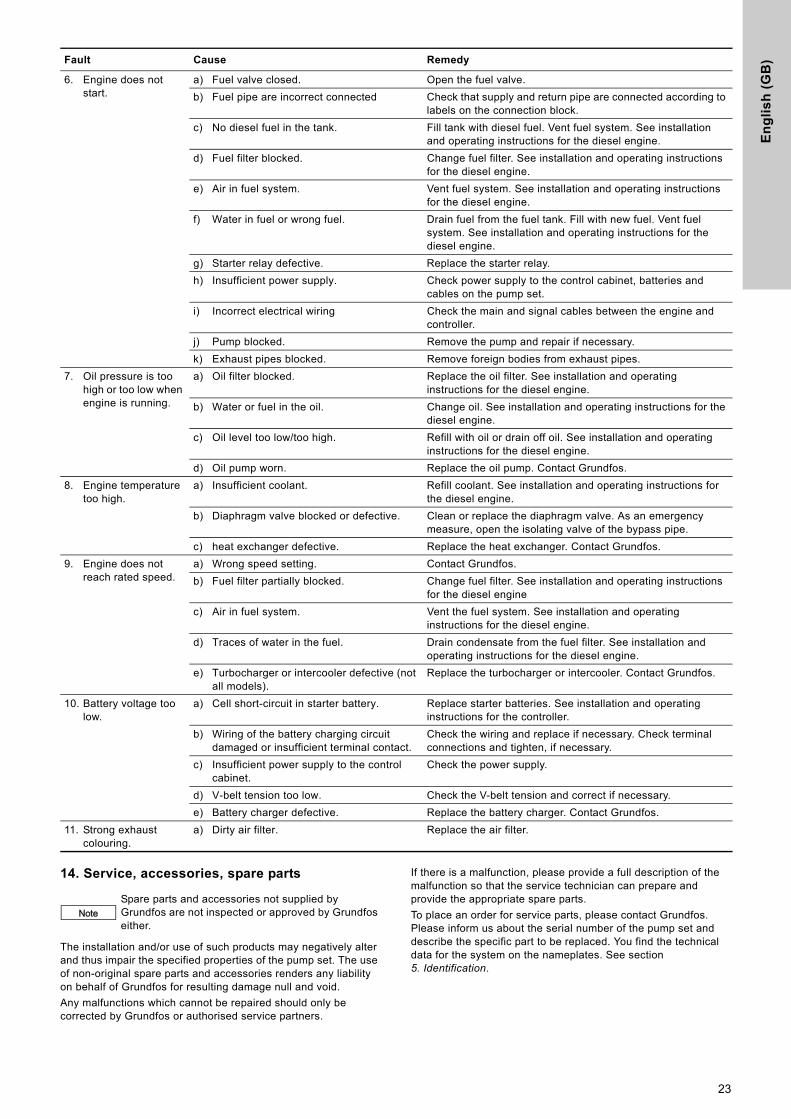
14. Service, accessories, spare parts
The installation and/or use of such products may negatively alter and thus impair the specified properties of the pump set. The use of non-original spare parts and accessories renders any liability on behalf of Grundfos for resulting damage null and void.
Any malfunctions which cannot be repaired should only be corrected by Grundfos or authorised service partners.
If there is a malfunction, please provide a full description of the malfunction so that the service technician can prepare and provide the appropriate spare parts.
To place an order for service parts, please contact Grundfos. Please inform us about the serial number of the pump set and describe the specific part to be replaced. You find the technical data for the system on the nameplates. See section 5. Identification.
6. Engine does not start.
a) Fuel valve closed. Open the fuel valve.
b) Fuel pipe are incorrect connected Check that supply and return pipe are connected according to labels on the connection block.
c) No diesel fuel in the tank. Fill tank with diesel fuel. Vent fuel system. See installation and operating instructions for the diesel engine.
d) Fuel filter blocked. Change fuel filter. See installation and operating instructions for the diesel engine.
e) Air in fuel system. Vent fuel system. See installation and operating instructions for the diesel engine.
f) Water in fuel or wrong fuel. Drain fuel from the fuel tank. Fill with new fuel. Vent fuel system. See installation and operating instructions for the diesel engine.
g) Starter relay defective. Replace the starter relay.
h) Insufficient power supply. Check power supply to the control cabinet, batteries and cables on the pump set.
i) Incorrect electrical wiring Check the main and signal cables between the engine and controller.
j) Pump blocked. Remove the pump and repair if necessary.
k) Exhaust pipes blocked. Remove foreign bodies from exhaust pipes.
7. Oil pressure is too high or too low when engine is running.
a) Oil filter blocked. Replace the oil filter. See installation and operating instructions for the diesel engine.
b) Water or fuel in the oil. Change oil. See installation and operating instructions for the diesel engine.
c) Oil level too low/too high. Refill with oil or drain off oil. See installation and operating instructions for the diesel engine.
d) Oil pump worn. Replace the oil pump. Contact Grundfos.
8. Engine temperature too high.
a) Insufficient coolant. Refill coolant. See installation and operating instructions for the diesel engine.
b) Diaphragm valve blocked or defective. Clean or replace the diaphragm valve. As an emergency measure, open the isolating valve of the bypass pipe.
c) heat exchanger defective. Replace the heat exchanger. Contact Grundfos.
9. Engine does not reach rated speed.
a) Wrong speed setting. Contact Grundfos.
b) Fuel filter partially blocked. Change fuel filter. See installation and operating instructions for the diesel engine
c) Air in fuel system. Vent the fuel system. See installation and operating instructions for the diesel engine.
d) Traces of water in the fuel. Drain condensate from the fuel filter. See installation and operating instructions for the diesel engine.
e) Turbocharger or intercooler defective (not all models).
Replace the turbocharger or intercooler. Contact Grundfos.
10. Battery voltage too low.
a) Cell short-circuit in starter battery. Replace starter batteries. See installation and operating instructions for the controller.
b) Wiring of the battery charging circuit damaged or insufficient terminal contact.
Check the wiring and replace if necessary. Check terminal connections and tighten, if necessary.
c) Insufficient power supply to the control cabinet.
Check the power supply.
d) V-belt tension too low. Check the V-belt tension and correct if necessary.
e) Battery charger defective. Replace the battery charger. Contact Grundfos.
11. Strong exhaust colouring.
a) Dirty air filter. Replace the air filter.
Fault Cause Remedy
NoteSpare parts and accessories not supplied by Grundfos are not inspected or approved by Grundfos either.
23
En
glis
h (G
B)
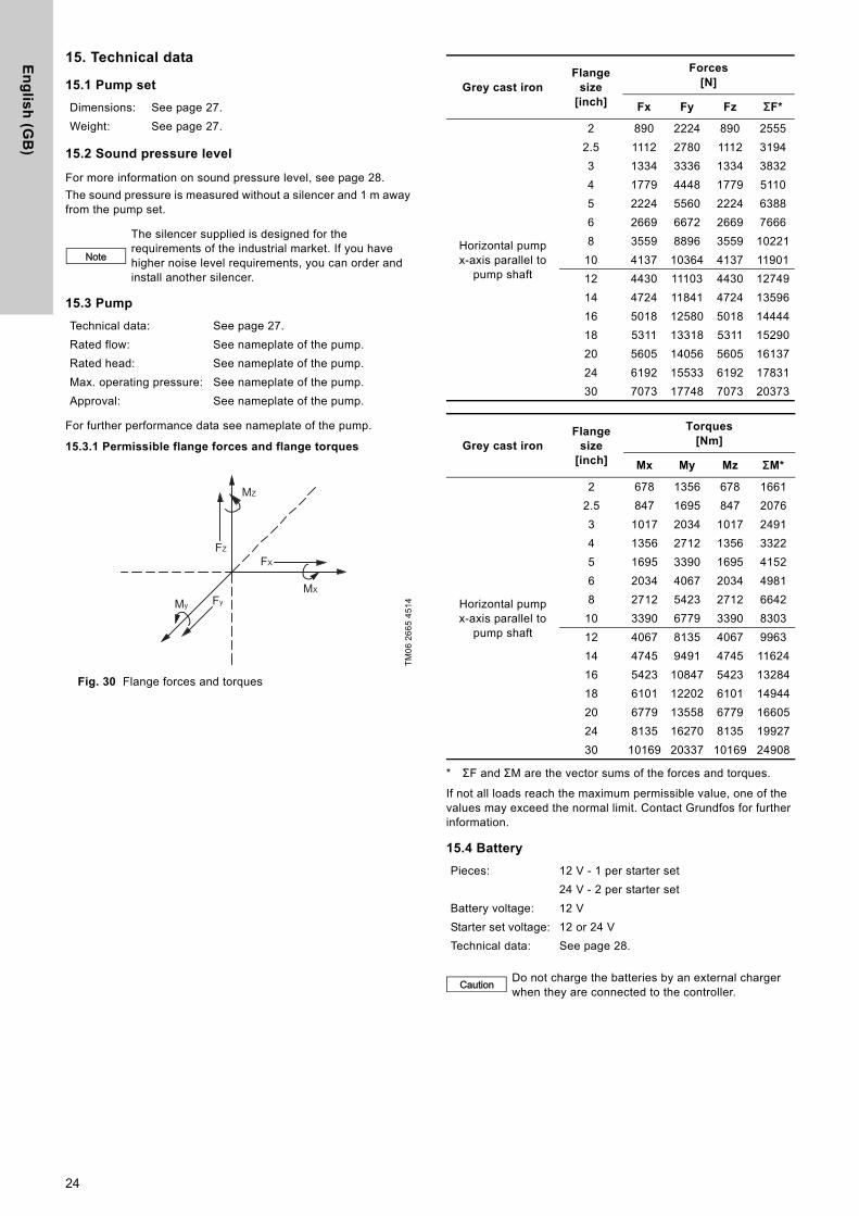
15. Technical data
15.1 Pump set
15.2 Sound pressure level
For more information on sound pressure level, see page 28.
The sound pressure is measured without a silencer and 1 m away from the pump set.
15.3 Pump
For further performance data see nameplate of the pump.
15.3.1 Permissible flange forces and flange torques
Fig. 30 Flange forces and torques
* ΣF and ΣM are the vector sums of the forces and torques.
If not all loads reach the maximum permissible value, one of the values may exceed the normal limit. Contact Grundfos for further information.
15.4 Battery
Dimensions: See page 27.
Weight: See page 27.
Note
The silencer supplied is designed for the requirements of the industrial market. If you have higher noise level requirements, you can order and install another silencer.
Technical data: See page 27.
Rated flow: See nameplate of the pump.
Rated head: See nameplate of the pump.
Max. operating pressure: See nameplate of the pump.
Approval: See nameplate of the pump.T
M0
6 2
66
5 4
51
4
FZ
FX
MXFyMy
MZ
Grey cast ironFlange
size [inch]
Forces[N]
Fx Fy Fz ΣF*
Horizontal pumpx-axis parallel to
pump shaft
2 890 2224 890 2555
2.5 1112 2780 1112 3194
3 1334 3336 1334 3832
4 1779 4448 1779 5110
5 2224 5560 2224 6388
6 2669 6672 2669 7666
8 3559 8896 3559 10221
10 4137 10364 4137 11901
12 4430 11103 4430 12749
14 4724 11841 4724 13596
16 5018 12580 5018 14444
18 5311 13318 5311 15290
20 5605 14056 5605 16137
24 6192 15533 6192 17831
30 7073 17748 7073 20373
Grey cast ironFlange
size [inch]
Torques[Nm]
Mx My Mz ΣM*
Horizontal pumpx-axis parallel to
pump shaft
2 678 1356 678 1661
2.5 847 1695 847 2076
3 1017 2034 1017 2491
4 1356 2712 1356 3322
5 1695 3390 1695 4152
6 2034 4067 2034 4981
8 2712 5423 2712 6642
10 3390 6779 3390 8303
12 4067 8135 4067 9963
14 4745 9491 4745 11624
16 5423 10847 5423 13284
18 6101 12202 6101 14944
20 6779 13558 6779 16605
24 8135 16270 8135 19927
30 10169 20337 10169 24908
Pieces: 12 V - 1 per starter set
24 V - 2 per starter set
Battery voltage: 12 V
Starter set voltage: 12 or 24 V
Technical data: See page 28.
Caution Do not charge the batteries by an external charger when they are connected to the controller.
24
En
gli
sh
(G
B)
15.5 Maximum operating pressure
The pumps are designed for a maximum operating pressure of 12 bar (175 PSI).
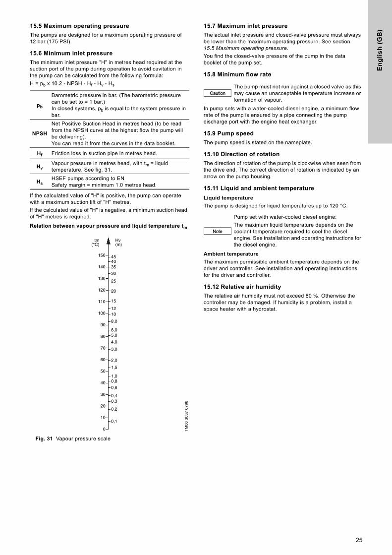
15.6 Minimum inlet pressure
The minimum inlet pressure "H" in metres head required at the suction port of the pump during operation to avoid cavitation in the pump can be calculated from the following formula:
H = pb x 10.2 - NPSH - Hf - Hv - Hs
If the calculated value of "H" is positive, the pump can operate with a maximum suction lift of "H" metres.
If the calculated value of "H" is negative, a minimum suction head of "H" metres is required.
Relation between vapour pressure and liquid temperature tm
Fig. 31 Vapour pressure scale
15.7 Maximum inlet pressure
The actual inlet pressure and closed-valve pressure must always be lower than the maximum operating pressure. See section 15.5 Maximum operating pressure.
You find the closed-valve pressure of the pump in the data booklet of the pump set.
15.8 Minimum flow rate
In pump sets with a water-cooled diesel engine, a minimum flow rate of the pump is ensured by a pipe connecting the pump discharge port with the engine heat exchanger.
15.9 Pump speed
The pump speed is stated on the nameplate.
15.10 Direction of rotation
The direction of rotation of the pump is clockwise when seen from the drive end. The correct direction of rotation is indicated by an arrow on the pump housing.
15.11 Liquid and ambient temperature
Liquid temperature
The pump is designed for liquid temperatures up to 120 °C.
Ambient temperature
The maximum permissible ambient temperature depends on the driver and controller. See installation and operating instructions for the driver and controller.
15.12 Relative air humidity
The relative air humidity must not exceed 80 %. Otherwise the controller may be damaged. If humidity is a problem, install a space heater with a hydrostat.
pb
Barometric pressure in bar. (The barometric pressure can be set to = 1 bar.)In closed systems, pb is equal to the system pressure in bar.
NPSH
Net Positive Suction Head in metres head (to be read from the NPSH curve at the highest flow the pump will be delivering).You can read it from the curves in the data booklet.
Hf Friction loss in suction pipe in metres head.
HvVapour pressure in metres head, with tm = liquid temperature. See fig. 31.
HsHSEF pumps according to ENSafety margin = minimum 1.0 metres head.
TM
00
30
37
07
98
20
15
1210
8,0
6,05,0
4,0
3,0
2,0
1,00,8
0,6
0,40,3
0,2
0,1
1,5
120
110
90
100
80
70
60
50
40
30
20
10
0
Hv(m)
tm(°C)
150
130
140
25
35
4540
30
CautionThe pump must not run against a closed valve as this may cause an unacceptable temperature increase or formation of vapour.
Note
Pump set with water-cooled diesel engine:
The maximum liquid temperature depends on the coolant temperature required to cool the diesel engine. See installation and operating instructions for the diesel engine.
25
En
glis
h (G
B)
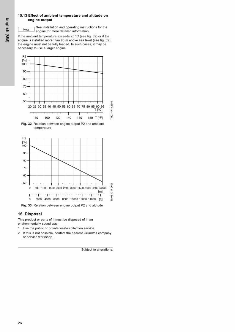
15.13 Effect of ambient temperature and altitude on engine output
If the ambient temperature exceeds 25 °C (see fig. 32) or if the engine is installed more than 90 m above sea level (see fig. 32), the engine must not be fully loaded. In such cases, it may be necessary to use a larger engine.
Fig. 32 Relation between engine output P2 and ambient temperature
Fig. 33 Relation between engine output P2 and altitude
16. DisposalThis product or parts of it must be disposed of in an environmentally sound way:
1. Use the public or private waste collection service.
2. If this is not possible, contact the nearest Grundfos company or service workshop.
Subject to alterations.
NoteSee installation and operating instructions for the engine for more detailed information.
TM
03
47
18
26
06
TM
03
47
17
26
06
20 25 30 35 40 45 50 55 60 65 70 75 80 85 90 95
50
60
70
80
90
100[%]P2
80 100 120 140 160 180 T [°F]
T [°C]
0 500 1000 1500 2000 2500 3000 3500 4000 4500 5000[m]
50
60
70
80
90
100[%]P2
0 2000 4000 6000 8000 10000 12000 14000 [ft]
26

Ap
pe
nd
ix
Appendix 11. Dimensions and weightsThe values apply to compact systems with fuel tank installed on the base frame.
Pump type key Engine type
Pump Engine Fire pump set
Suction flange[inch]
Discharge flange[inch]
Weight**[kg]
Exhaust outlet
Weight**[kg]
DimensionsL x W x H
[mm]
Weight**[kg]
HSEF 4-12 JU4H-UF14 5" 4"171
ANSI 3" 413 53 1210
HSEF 4-12 JU4H-UF24 5" 4" ANSI 3" 413 62 1210
HSEF 5-14N JU4H-UF52 6" 5"
229
ANSI 4" 424 95 1300
HSEF 5-14N JU4H-UF52 6" 5" ANSI 4" 424 95 1300
HSEF 5-14N JU6H-UFD2 6" 5" ANSI 5" 750 110 1660
HSEF 5-14N JU6H-UF32 6" 5" ANSI 5" 750 119 1660
HSEF 4-12 JU4H-UF24 5" 4" 171 ANSI 3" 413 62 1210
HSEF 5-14N JU4H-UF52 6" 5"
229
ANSI 4" 424 95 1300
HSEF 5-14N JU4H-UF52 6" 5" ANSI 4" 424 95 1300
HSEF 5-14N JU6H-UF32 6" 5" ANSI 5" 750 119 1660
HSEF 5-11 JU4H-UF34 6" 5"173
ANSI 4" 424 86 1240
HSEF 5-11 JU4H-UF34 6" 5" ANSI 4" 424 86 1240
HSEF 5-12 JU4H-UF54 6" 5"257
ANSI 4" 424 108 1330
HSEF 5-12 JU4H-UF54 6" 5" ANSI 4" 424 108 1330
HSEF 5-14 JU6H-UFABL2 6" 5"
229
ANSI 5" 750 129 1670
HSEF 5-14 JU6H-UFABL2 6" 5" ANSI 5" 750 129 1670
HSEF 5-14 JU6H-UF52 6" 5" ANSI 5" 750 157 1670
HSEF 6-17 JU6H-UF30 8" 6"
313
ANSI 5" 750 119 1760
HSEF 6-17 JU6H-UF30 8" 6" ANSI 5" 750 119 1760
HSEF 6-17 JU6H-UFABL0 8" 6" ANSI 5" 750 129 1760
HSEF 6-17 JU6H-UFM2 8" 6"
313
ANSI 5" 750 149 1800
HSEF 6-17 JU6H-UF52 8" 6" ANSI 5" 750 157 1760
HSEF 6-17 JU6H-UF62 8" 6" ANSI 5" 766 179 1780
HSEF 6-17 JU6H-UF30 8" 6"
313
ANSI 5" 750 119 1760
HSEF 6-17 JU6H-UF30 8" 6" ANSI 5" 750 118 1760
HSEF 6-17 JU6H-UFABL0 8" 6" ANSI 5" 750 129 1760
HSEF 6-17 JU6H-UF52 8" 6"313
ANSI 5" 750 157 1760
HSEF 6-17 JU6H-UF62 8" 6" ANSI 5" 766 179 1780
HSEF 6-14Q JU6H-UF50 8" 6"
277
ANSI 5" 750 157 1760
HSEF 6-14Q JU6H-UF50 8" 6" ANSI 5" 750 157 1760
HSEF 6-14Q JU6H-UF60 8" 6" ANSI 5" 766 179 1740
HSEF 8-17W JU6H-UFKAS0 10" 8"459
ANSI 5" 766 194 1980
HSEF 8-17W JU6H-UFKAS0 10" 8" ANSI 5" 766 194 1980
HSEF 8-17W DP6H-UFKA50 10" 8"459
ANSI 5" 1020 209 2430
HSEF 8-17W DP6H-UFKA70 10" 8" ANSI 6" 1020 233 2440
HSEF 8-15A DQ6H-UFKA50 10" 8"386
ANSI 6" 1134 254 2480
HSEF 8-15A DQ6H-UFKA50 10" 8" ANSI 6" 1134 254 2480
HSEF 8-17Q DQ6H-UFKA50 10" 8"459
ANSI 6" 1134 254 2560
HSEF 8-17Q DQ6H-UFKA60 10" 8" ANSI 6" 1134 268 2560
HSEF 8-20G DQ6H-UFKA60 10" 8"
605
ANSI 6" 1134 257 2720
HSEF 8-20G DQ6H-UFKA88 10" 8" ANSI 6" 1134 280 2720
HSEF 8-20G DQ6H-UFKA98 10" 8" ANSI 6" 1134 306 2730
HSEF 8-15A DP6H-UFKA70 10" 8"
386
ANSI 6" 1020 233 2350
HSEF 8-15A DQ6H-UFKA50 10" 8" ANSI 6" 1134 254 2480
HSEF 8-15A DR8H-UFKA40 10" 8" ANSI 5" 1225 365 2670
HSEF 10-20 DQ6H-UFKA60 12" 10"
909
ANSI 6" 1134 257 3020
HSEF 10-20 DQ6H-UFKA88 12" 10" ANSI 6" 1134 280 3020
HSEF 10-20 DQ6H-UFKA98 12" 10" ANSI 6" 1134 306 3030
HSEF 10-20 DR8H-UFKA40 12" 10" ANSI 5" 1225 343 3200
HSEF 10-20 DR8H-UFKA68 12" 10" ANSI 5" 1225 369 3220
27
Ap
pe
nd
ix
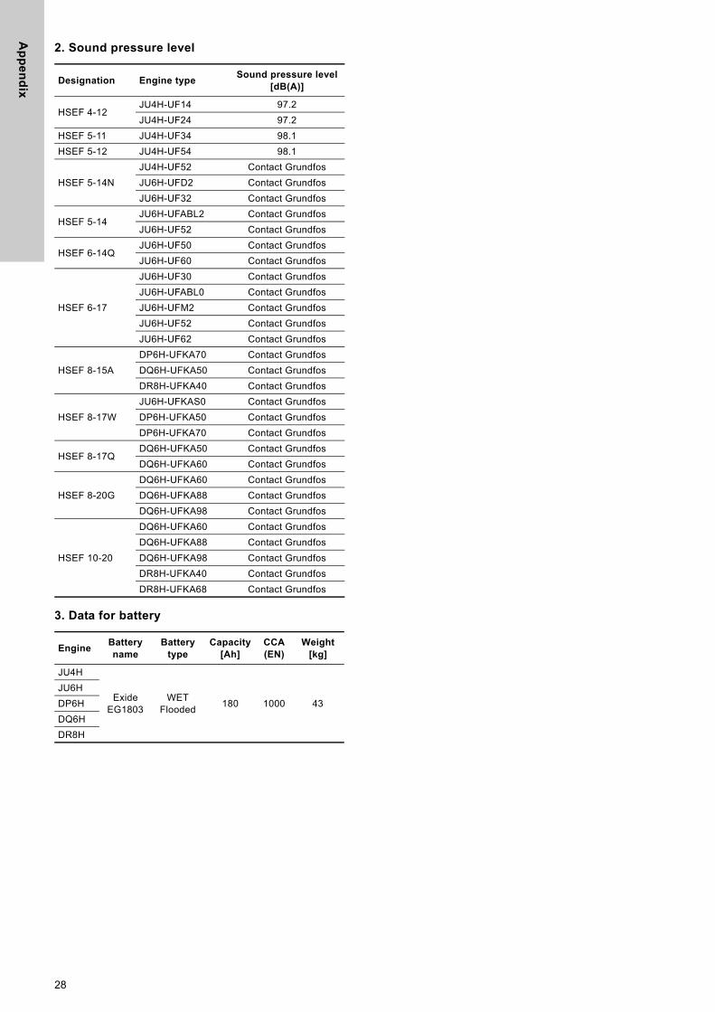
2. Sound pressure level
3. Data for battery
Designation Engine typeSound pressure level
[dB(A)]
HSEF 4-12JU4H-UF14 97.2
JU4H-UF24 97.2
HSEF 5-11 JU4H-UF34 98.1
HSEF 5-12 JU4H-UF54 98.1
HSEF 5-14N
JU4H-UF52 Contact Grundfos
JU6H-UFD2 Contact Grundfos
JU6H-UF32 Contact Grundfos
HSEF 5-14 JU6H-UFABL2 Contact Grundfos
JU6H-UF52 Contact Grundfos
HSEF 6-14QJU6H-UF50 Contact Grundfos
JU6H-UF60 Contact Grundfos
HSEF 6-17
JU6H-UF30 Contact Grundfos
JU6H-UFABL0 Contact Grundfos
JU6H-UFM2 Contact Grundfos
JU6H-UF52 Contact Grundfos
JU6H-UF62 Contact Grundfos
HSEF 8-15A
DP6H-UFKA70 Contact Grundfos
DQ6H-UFKA50 Contact Grundfos
DR8H-UFKA40 Contact Grundfos
HSEF 8-17W
JU6H-UFKAS0 Contact Grundfos
DP6H-UFKA50 Contact Grundfos
DP6H-UFKA70 Contact Grundfos
HSEF 8-17QDQ6H-UFKA50 Contact Grundfos
DQ6H-UFKA60 Contact Grundfos
HSEF 8-20G
DQ6H-UFKA60 Contact Grundfos
DQ6H-UFKA88 Contact Grundfos
DQ6H-UFKA98 Contact Grundfos
HSEF 10-20
DQ6H-UFKA60 Contact Grundfos
DQ6H-UFKA88 Contact Grundfos
DQ6H-UFKA98 Contact Grundfos
DR8H-UFKA40 Contact Grundfos
DR8H-UFKA68 Contact Grundfos
EngineBattery name
Battery type
Capacity[Ah]
CCA (EN)
Weight [kg]
JU4H
Exide EG1803
WET Flooded
180 1000 43
JU6H
DP6H
DQ6H
DR8H
28
Ap
pe
nd
ix
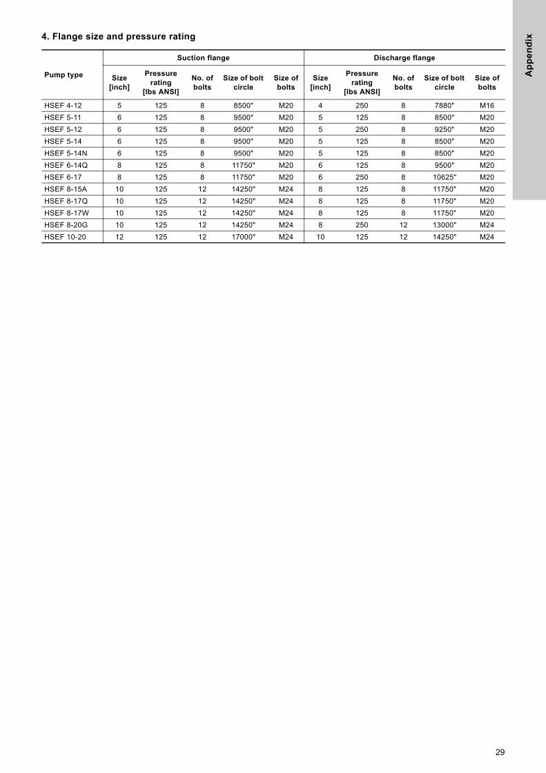
4. Flange size and pressure ratingPump type
Suction flange Discharge flange
Size [inch]
Pressure rating
[lbs ANSI]
No. of bolts
Size of bolt circle
Size of bolts
Size [inch]
Pressure rating
[lbs ANSI]
No. of bolts
Size of bolt circle
Size of bolts
HSEF 4-12 5 125 8 8500" M20 4 250 8 7880" M16
HSEF 5-11 6 125 8 9500" M20 5 125 8 8500" M20
HSEF 5-12 6 125 8 9500" M20 5 250 8 9250" M20
HSEF 5-14 6 125 8 9500" M20 5 125 8 8500" M20
HSEF 5-14N 6 125 8 9500" M20 5 125 8 8500" M20
HSEF 6-14Q 8 125 8 11750" M20 6 125 8 9500" M20
HSEF 6-17 8 125 8 11750" M20 6 250 8 10625" M20
HSEF 8-15A 10 125 12 14250" M24 8 125 8 11750" M20
HSEF 8-17Q 10 125 12 14250" M24 8 125 8 11750" M20
HSEF 8-17W 10 125 12 14250" M24 8 125 8 11750" M20
HSEF 8-20G 10 125 12 14250" M24 8 250 12 13000" M24
HSEF 10-20 12 125 12 17000" M24 10 125 12 14250" M24
29

Ap
pe
nd
ix
5. Parts list and sectional drawing
Fig. 1 Packed type cross sectional drawing
TM
06
09
79
13
14
Item No. Description Item No. Description
1A, 1B, 41, 43 Upper and lower casings 31 Inboard bearing housing
2 Impeller 32 Impeller key
6 Shaft 33 Outboard bearing housing
7 Casing ring 35 In-board bearing housing cover
8 Impeller ring (optional) 37 Outboard bearing housing cover
13 Packing ring 40A In-board deflector
14, 14A Shaft sleeveRHLH
40B Out-board deflector
14B Shaft sleeve O-ring 46 Coupling key
16 In-board ball bearing 47 In-board bearing cover seal
17 Packing gland 63 Stuffing box bushing
17A Gland clip (when used) 73A Casing gasket (nNot shown)
17B Gland bolt 73B Bearing cover gasket
18 Outboard ball bearing 123 Bearing end cover
18A Bearing lock washer 127 Water seal piping
29 Lantern ring (optional) 169 Bearing housing seal
- Casing hardware
30
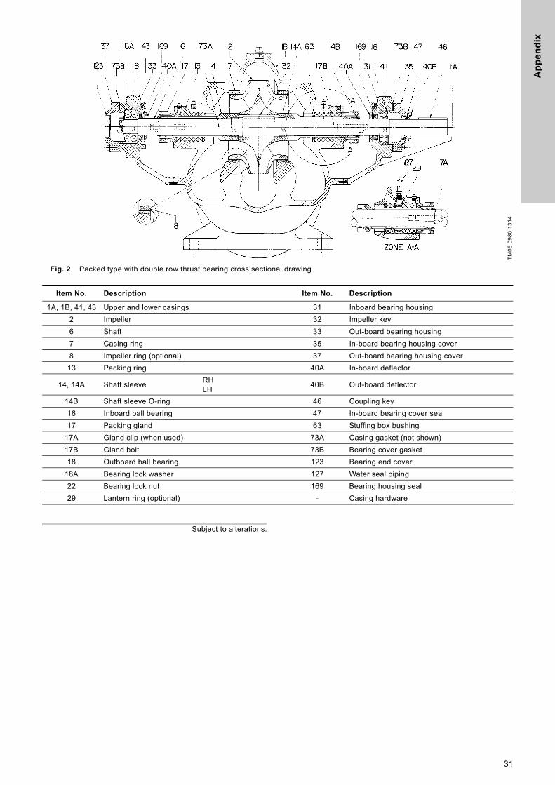
Ap
pe
nd
ix
Fig. 2 Packed type with double row thrust bearing cross sectional drawing
Subject to alterations.
TM
06
09
80
13
14
Item No. Description Item No. Description
1A, 1B, 41, 43 Upper and lower casings 31 Inboard bearing housing
2 Impeller 32 Impeller key
6 Shaft 33 Out-board bearing housing
7 Casing ring 35 In-board bearing housing cover
8 Impeller ring (optional) 37 Out-board bearing housing cover
13 Packing ring 40A In-board deflector
14, 14A Shaft sleeveRHLH
40B Out-board deflector
14B Shaft sleeve O-ring 46 Coupling key
16 Inboard ball bearing 47 In-board bearing cover seal
17 Packing gland 63 Stuffing box bushing
17A Gland clip (when used) 73A Casing gasket (not shown)
17B Gland bolt 73B Bearing cover gasket
18 Outboard ball bearing 123 Bearing end cover
18A Bearing lock washer 127 Water seal piping
22 Bearing lock nut 169 Bearing housing seal
29 Lantern ring (optional) - Casing hardware
31
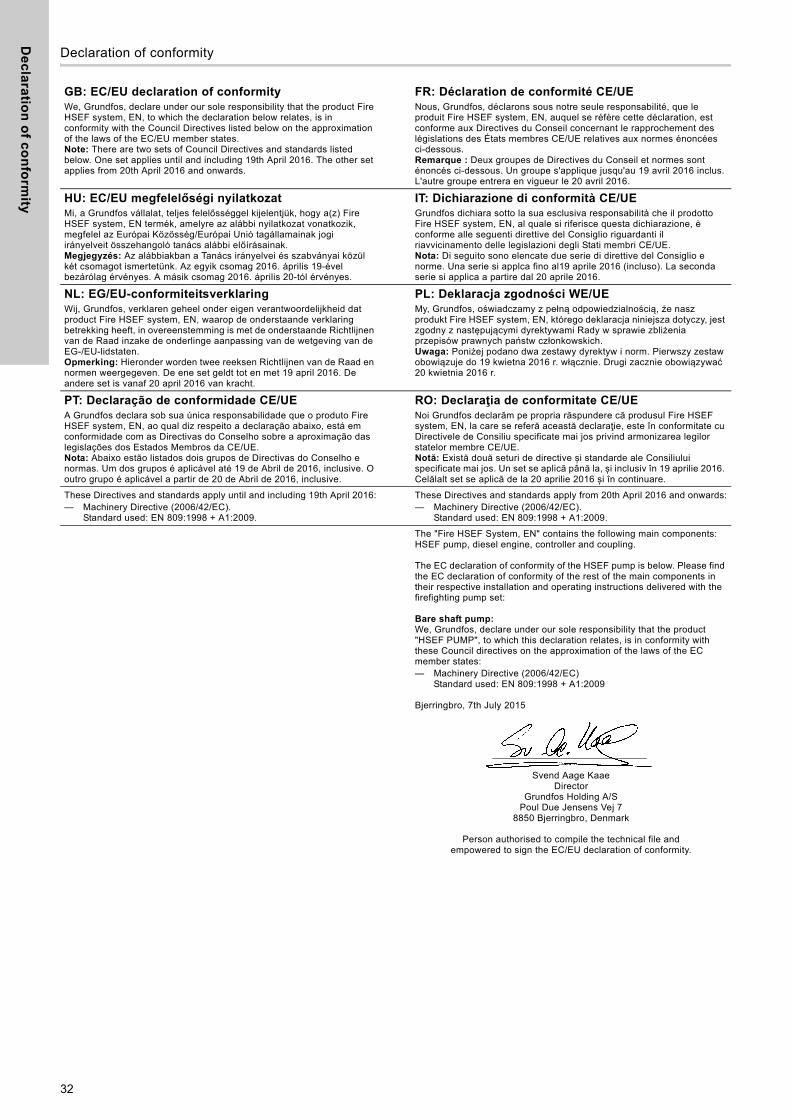
De
cla
ratio
n o
f co
nfo
rmity
32
Declaration of conformity 2
GB: EC/EU declaration of conformityWe, Grundfos, declare under our sole responsibility that the product Fire HSEF system, EN, to which the declaration below relates, is in conformity with the Council Directives listed below on the approximation of the laws of the EC/EU member states.Note: There are two sets of Council Directives and standards listed below. One set applies until and including 19th April 2016. The other set applies from 20th April 2016 and onwards.
FR: Déclaration de conformité CE/UENous, Grundfos, déclarons sous notre seule responsabilité, que le produit Fire HSEF system, EN, auquel se réfère cette déclaration, est conforme aux Directives du Conseil concernant le rapprochement des législations des États membres CE/UE relatives aux normes énoncées ci-dessous.Remarque : Deux groupes de Directives du Conseil et normes sont énoncés ci-dessous. Un groupe s'applique jusqu'au 19 avril 2016 inclus. L'autre groupe entrera en vigueur le 20 avril 2016.
HU: EC/EU megfelelőségi nyilatkozatMi, a Grundfos vállalat, teljes felelősséggel kijelentjük, hogy a(z) Fire HSEF system, EN termék, amelyre az alábbi nyilatkozat vonatkozik, megfelel az Európai Közösség/Európai Unió tagállamainak jogi irányelveit összehangoló tanács alábbi előírásainak.Megjegyzés: Az alábbiakban a Tanács irányelvei és szabványai közül két csomagot ismertetünk. Az egyik csomag 2016. április 19-ével bezárólag érvényes. A másik csomag 2016. április 20-tól érvényes.
IT: Dichiarazione di conformità CE/UEGrundfos dichiara sotto la sua esclusiva responsabilità che il prodotto Fire HSEF system, EN, al quale si riferisce questa dichiarazione, è conforme alle seguenti direttive del Consiglio riguardanti il riavvicinamento delle legislazioni degli Stati membri CE/UE.Nota: Di seguito sono elencate due serie di direttive del Consiglio e norme. Una serie si applca fino al19 aprile 2016 (incluso). La seconda serie si applica a partire dal 20 aprile 2016.
NL: EG/EU-conformiteitsverklaringWij, Grundfos, verklaren geheel onder eigen verantwoordelijkheid dat product Fire HSEF system, EN, waarop de onderstaande verklaring betrekking heeft, in overeenstemming is met de onderstaande Richtlijnen van de Raad inzake de onderlinge aanpassing van de wetgeving van de EG-/EU-lidstaten.Opmerking: Hieronder worden twee reeksen Richtlijnen van de Raad en normen weergegeven. De ene set geldt tot en met 19 april 2016. De andere set is vanaf 20 april 2016 van kracht.
PL: Deklaracja zgodności WE/UEMy, Grundfos, oświadczamy z pełną odpowiedzialnością, że nasz produkt Fire HSEF system, EN, którego deklaracja niniejsza dotyczy, jest zgodny z następującymi dyrektywami Rady w sprawie zbliżenia przepisów prawnych państw członkowskich.Uwaga: Poniżej podano dwa zestawy dyrektyw i norm. Pierwszy zestaw obowiązuje do 19 kwietna 2016 r. włącznie. Drugi zacznie obowiązywać 20 kwietnia 2016 r.
PT: Declaração de conformidade CE/UEA Grundfos declara sob sua única responsabilidade que o produto Fire HSEF system, EN, ao qual diz respeito a declaração abaixo, está em conformidade com as Directivas do Conselho sobre a aproximação das legislações dos Estados Membros da CE/UE.Nota: Abaixo estão listados dois grupos de Directivas do Conselho e normas. Um dos grupos é aplicável até 19 de Abril de 2016, inclusive. O outro grupo é aplicável a partir de 20 de Abril de 2016, inclusive.
RO: Declaraţia de conformitate CE/UENoi Grundfos declarăm pe propria răspundere că produsul Fire HSEF system, EN, la care se referă această declaraţie, este în conformitate cu Directivele de Consiliu specificate mai jos privind armonizarea legilor statelor membre CE/UE.Notă: Există două seturi de directive și standarde ale Consiliului specificate mai jos. Un set se aplică până la, și inclusiv în 19 aprilie 2016. Celălalt set se aplică de la 20 aprilie 2016 și în continuare.
These Directives and standards apply until and including 19th April 2016:— Machinery Directive (2006/42/EC).
Standard used: EN 809:1998 + A1:2009.
These Directives and standards apply from 20th April 2016 and onwards:— Machinery Directive (2006/42/EC).
Standard used: EN 809:1998 + A1:2009.
The "Fire HSEF System, EN" contains the following main components: HSEF pump, diesel engine, controller and coupling.
The EC declaration of conformity of the HSEF pump is below. Please find the EC declaration of conformity of the rest of the main components in their respective installation and operating instructions delivered with the firefighting pump set:
Bare shaft pump:We, Grundfos, declare under our sole responsibility that the product "HSEF PUMP", to which this declaration relates, is in conformity with these Council directives on the approximation of the laws of the EC member states:— Machinery Directive (2006/42/EC)
Standard used: EN 809:1998 + A1:2009
Bjerringbro, 7th July 2015
Svend Aage KaaeDirector
Grundfos Holding A/SPoul Due Jensens Vej 7
8850 Bjerringbro, Denmark
Person authorised to compile the technical file and empowered to sign the EC/EU declaration of conformity.

33

34
Gru
nd
fos
co
mp
anie
s
ArgentinaBombas GRUNDFOS de Argentina S.A.Ruta Panamericana km. 37.500 Centro Industrial Garin1619 Garín Pcia. de B.A.Phone: +54-3327 414 444Telefax: +54-3327 45 3190
AustraliaGRUNDFOS Pumps Pty. Ltd. P.O. Box 2040 Regency Park South Australia 5942 Phone: +61-8-8461-4611 Telefax: +61-8-8340 0155
AustriaGRUNDFOS Pumpen Vertrieb Ges.m.b.H.Grundfosstraße 2 A-5082 Grödig/Salzburg Tel.: +43-6246-883-0 Telefax: +43-6246-883-30
BelgiumN.V. GRUNDFOS Bellux S.A. Boomsesteenweg 81-83 B-2630 Aartselaar Tél.: +32-3-870 7300 Télécopie: +32-3-870 7301
BelarusПредставительство ГРУНДФОС в Минске220125, Минскул. Шафарнянская, 11, оф. 56, БЦ «Порт»Тел.: +7 (375 17) 286 39 72/73Факс: +7 (375 17) 286 39 71E-mail: [email protected]
Bosna and HerzegovinaGRUNDFOS SarajevoZmaja od Bosne 7-7A,BH-71000 SarajevoPhone: +387 33 592 480Telefax: +387 33 590 465www.ba.grundfos.come-mail: [email protected]
BrazilBOMBAS GRUNDFOS DO BRASILAv. Humberto de Alencar Castelo Branco, 630CEP 09850 - 300São Bernardo do Campo - SPPhone: +55-11 4393 5533Telefax: +55-11 4343 5015
BulgariaGrundfos Bulgaria EOODSlatina DistrictIztochna Tangenta street no. 100BG - 1592 SofiaTel. +359 2 49 22 200Fax. +359 2 49 22 201email: [email protected]
CanadaGRUNDFOS Canada Inc. 2941 Brighton Road Oakville, Ontario L6H 6C9 Phone: +1-905 829 9533 Telefax: +1-905 829 9512
ChinaGRUNDFOS Pumps (Shanghai) Co. Ltd.10F The Hub, No. 33 Suhong RoadMinhang DistrictShanghai 201106PRCPhone: +86 21 612 252 22Telefax: +86 21 612 253 33
CroatiaGRUNDFOS CROATIA d.o.o.Buzinski prilaz 38, BuzinHR-10010 ZagrebPhone: +385 1 6595 400 Telefax: +385 1 6595 499www.hr.grundfos.com
Czech RepublicGRUNDFOS s.r.o.Čajkovského 21779 00 OlomoucPhone: +420-585-716 111Telefax: +420-585-716 299
DenmarkGRUNDFOS DK A/S Martin Bachs Vej 3 DK-8850 Bjerringbro Tlf.: +45-87 50 50 50 Telefax: +45-87 50 51 51 E-mail: [email protected]/DK
EstoniaGRUNDFOS Pumps Eesti OÜPeterburi tee 92G11415 TallinnTel: + 372 606 1690Fax: + 372 606 1691
FinlandOY GRUNDFOS Pumput AB Trukkikuja 1 FI-01360 Vantaa Phone: +358-(0) 207 889 500Telefax: +358-(0) 207 889 550
FrancePompes GRUNDFOS Distribution S.A. Parc d’Activités de Chesnes 57, rue de Malacombe F-38290 St. Quentin Fallavier (Lyon) Tél.: +33-4 74 82 15 15 Télécopie: +33-4 74 94 10 51
GermanyGRUNDFOS GMBHSchlüterstr. 3340699 ErkrathTel.: +49-(0) 211 929 69-0 Telefax: +49-(0) 211 929 69-3799e-mail: [email protected] in Deutschland:e-mail: [email protected]
GreeceGRUNDFOS Hellas A.E.B.E. 20th km. Athinon-Markopoulou Av. P.O. Box 71 GR-19002 Peania Phone: +0030-210-66 83 400 Telefax: +0030-210-66 46 273
Hong KongGRUNDFOS Pumps (Hong Kong) Ltd. Unit 1, Ground floor Siu Wai Industrial Centre 29-33 Wing Hong Street & 68 King Lam Street, Cheung Sha Wan Kowloon Phone: +852-27861706 / 27861741 Telefax: +852-27858664
HungaryGRUNDFOS Hungária Kft.Park u. 8H-2045 Törökbálint, Phone: +36-23 511 110Telefax: +36-23 511 111
IndiaGRUNDFOS Pumps India Private Limited118 Old Mahabalipuram RoadThoraipakkamChennai 600 096Phone: +91-44 2496 6800
IndonesiaPT. GRUNDFOS POMPAGraha Intirub Lt. 2 & 3Jln. Cililitan Besar No.454. Makasar, Jakarta TimurID-Jakarta 13650Phone: +62 21-469-51900Telefax: +62 21-460 6910 / 460 6901
IrelandGRUNDFOS (Ireland) Ltd. Unit A, Merrywell Business ParkBallymount Road LowerDublin 12 Phone: +353-1-4089 800 Telefax: +353-1-4089 830
ItalyGRUNDFOS Pompe Italia S.r.l. Via Gran Sasso 4I-20060 Truccazzano (Milano)Tel.: +39-02-95838112 Telefax: +39-02-95309290 / 95838461
JapanGRUNDFOS Pumps K.K.Gotanda Metalion Bldg., 5F, 5-21-15, Higashi-gotandaShiagawa-ku, Tokyo141-0022 JapanPhone: +81 35 448 1391Telefax: +81 35 448 9619
KoreaGRUNDFOS Pumps Korea Ltd.6th Floor, Aju Building 679-5Yeoksam-dong, Kangnam-ku, 135-916Seoul, KoreaPhone: +82-2-5317 600Telefax: +82-2-5633 725
LatviaSIA GRUNDFOS Pumps Latvia Deglava biznesa centrsAugusta Deglava ielā 60, LV-1035, Rīga,Tālr.: + 371 714 9640, 7 149 641Fakss: + 371 914 9646
LithuaniaGRUNDFOS Pumps UABSmolensko g. 6LT-03201 VilniusTel: + 370 52 395 430Fax: + 370 52 395 431
MalaysiaGRUNDFOS Pumps Sdn. Bhd.7 Jalan Peguam U1/25Glenmarie Industrial Park40150 Shah AlamSelangor Phone: +60-3-5569 2922Telefax: +60-3-5569 2866
MexicoBombas GRUNDFOS de México S.A. de C.V. Boulevard TLC No. 15Parque Industrial Stiva AeropuertoApodaca, N.L. 66600Phone: +52-81-8144 4000 Telefax: +52-81-8144 4010
NetherlandsGRUNDFOS NetherlandsVeluwezoom 351326 AE AlmerePostbus 220151302 CA ALMERE Tel.: +31-88-478 6336 Telefax: +31-88-478 6332E-mail: [email protected]
New ZealandGRUNDFOS Pumps NZ Ltd.17 Beatrice Tinsley CrescentNorth Harbour Industrial EstateAlbany, AucklandPhone: +64-9-415 3240Telefax: +64-9-415 3250
NorwayGRUNDFOS Pumper A/S Strømsveien 344 Postboks 235, Leirdal N-1011 Oslo Tlf.: +47-22 90 47 00 Telefax: +47-22 32 21 50
PolandGRUNDFOS Pompy Sp. z o.o.ul. Klonowa 23Baranowo k. PoznaniaPL-62-081 PrzeźmierowoTel: (+48-61) 650 13 00Fax: (+48-61) 650 13 50
PortugalBombas GRUNDFOS Portugal, S.A. Rua Calvet de Magalhães, 241Apartado 1079P-2770-153 Paço de ArcosTel.: +351-21-440 76 00Telefax: +351-21-440 76 90
RomaniaGRUNDFOS Pompe România SRLBd. Biruintei, nr 103 Pantelimon county IlfovPhone: +40 21 200 4100Telefax: +40 21 200 4101E-mail: [email protected]
RussiaООО Грундфос Россия109544, г. Москва, ул. Школьная, 39-41, стр. 1Тел. (+7) 495 564-88-00 (495) 737-30-00Факс (+7) 495 564 88 11E-mail [email protected]
Serbia Grundfos Srbija d.o.o.Omladinskih brigada 90b11070 Novi Beograd Phone: +381 11 2258 740Telefax: +381 11 2281 769www.rs.grundfos.com
SingaporeGRUNDFOS (Singapore) Pte. Ltd.25 Jalan Tukang Singapore 619264 Phone: +65-6681 9688 Telefax: +65-6681 9689
SlovakiaGRUNDFOS s.r.o.Prievozská 4D 821 09 BRATISLAVA Phona: +421 2 5020 1426sk.grundfos.com
SloveniaGRUNDFOS d.o.o.Šlandrova 8b, SI-1231 Ljubljana-ČrnučePhone: +386 31 718 808Telefax: +386 (0)1 5680 619E-mail: [email protected]
South AfricaGRUNDFOS (PTY) LTDCorner Mountjoy and George Allen RoadsWilbart Ext. 2Bedfordview 2008Phone: (+27) 11 579 4800Fax: (+27) 11 455 6066E-mail: [email protected]
SpainBombas GRUNDFOS España S.A. Camino de la Fuentecilla, s/n E-28110 Algete (Madrid) Tel.: +34-91-848 8800 Telefax: +34-91-628 0465
SwedenGRUNDFOS AB Box 333 (Lunnagårdsgatan 6) 431 24 Mölndal Tel.: +46 31 332 23 000Telefax: +46 31 331 94 60
SwitzerlandGRUNDFOS Pumpen AG Bruggacherstrasse 10 CH-8117 Fällanden/ZH Tel.: +41-44-806 8111 Telefax: +41-44-806 8115
TaiwanGRUNDFOS Pumps (Taiwan) Ltd. 7 Floor, 219 Min-Chuan Road Taichung, Taiwan, R.O.C. Phone: +886-4-2305 0868Telefax: +886-4-2305 0878
ThailandGRUNDFOS (Thailand) Ltd. 92 Chaloem Phrakiat Rama 9 Road,Dokmai, Pravej, Bangkok 10250Phone: +66-2-725 8999Telefax: +66-2-725 8998
TurkeyGRUNDFOS POMPA San. ve Tic. Ltd. Sti.Gebze Organize Sanayi Bölgesi Ihsan dede Caddesi,2. yol 200. Sokak No. 20441490 Gebze/ KocaeliPhone: +90 - 262-679 7979Telefax: +90 - 262-679 7905E-mail: [email protected]
UkraineБізнес Центр ЄвропаСтоличне шосе, 103м. Київ, 03131, Україна Телефон: (+38 044) 237 04 00 Факс.: (+38 044) 237 04 01E-mail: [email protected]
United Arab EmiratesGRUNDFOS Gulf DistributionP.O. Box 16768Jebel Ali Free ZoneDubaiPhone: +971 4 8815 166Telefax: +971 4 8815 136
United KingdomGRUNDFOS Pumps Ltd. Grovebury Road Leighton Buzzard/Beds. LU7 4TL Phone: +44-1525-850000 Telefax: +44-1525-850011
U.S.A.GRUNDFOS Pumps Corporation 17100 West 118th TerraceOlathe, Kansas 66061Phone: +1-913-227-3400 Telefax: +1-913-227-3500
UzbekistanGrundfos Tashkent, Uzbekistan The Repre-sentative Office of Grundfos Kazakhstan in Uzbekistan38a, Oybek street, TashkentТелефон: (+998) 71 150 3290 / 71 150 3291Факс: (+998) 71 150 3292
Addresses Revised 29.09.2015

98662706 1015
ECM: 1169060 The
nam
e G
rund
fos,
the
Gru
ndfo
s lo
go, a
nd b
e t
hin
k i
nn
ov
ate
are
regi
ster
ed tr
adem
arks
ow
ned
by G
rund
fos
Hol
ding
A/S
or G
rund
fos
A/S,
Den
mar
k. A
ll rig
hts
rese
rved
wor
ldw
ide.
© C
opyr
ight
Gru
ndfo
s H
oldi
ng A
/S
www.grundfos.com