MAGNA3 - Grundfos
70
MAGNA3 Installation and operating instructions GRUNDFOS INSTRUCTIONS
-
Upload
khangminh22 -
Category
Documents
-
view
5 -
download
0
Transcript of MAGNA3 - Grundfos

MAGNA3Installation and operating instructions
GRUNDFOS INSTRUCTIONS
En
glis
h (G
B)
English (GB) Installation and operating instructions
Original installation and operating instructions
These installation and operating instructions describe MAGNA3 model D.Sections 1-5 give the information necessary to be able to unpack, install and start up the product in a safe way.Sections 6-13 give important information about the product, as well as information on service, fault finding and disposal of the product.
CONTENTSPage
1. General information 31.1 Hazard statements 31.2 Notes 31.3 Safety symbols on the pump 32. Receiving the product 32.1 Inspecting the product 32.2 Scope of delivery 32.3 Lifting the pump 43. Installing the product 53.1 Location 53.2 Tools 53.3 Mechanical installation 53.4 Positioning the pump 63.5 Control box positions 63.6 Pump head position 73.7 Changing the control box position 73.8 Electrical installation 93.9 Wiring diagrams 103.10 Connecting the power supply, plug-connected versions 123.11 Connecting the power supply, terminal-connected
versions 133.12 Connecting the external control 144. Starting up the product 154.1 Single-head pump 154.2 Twin-head pump 165. Handling and storing the product 165.1 Frost protection 166. Product introduction 176.1 Applications 176.2 Pumped liquids 176.3 Pump heads in twin-head pumps 186.4 Identification 186.5 Model type 196.6 Radio communication 196.7 Closed valve operation 196.8 Insulating shells 196.9 Non-return valve 197. Control functions 207.1 Quick overview of control modes 207.2 Operating modes 227.3 Control modes 227.4 Additional control mode features 267.5 Multipump modes 277.6 Flow estimation accuracy 277.7 External connections 287.8 Priority of settings 287.9 Input and output communication 298. Setting the product 338.1 Operating panel 338.2 Menu structure 348.3 Startup guide 348.4 Menu overview 358.5 "Home" menu 378.6 "Status" menu 378.7 "Settings" menu 388.8 "Assist" menu 478.9 "Description of control mode" 488.10 "Assisted fault advice" 48
9. Servicing the product 499.1 Differential-pressure and temperature sensor 499.2 External sensor condition 499.3 Disassembling the plug 4910. Fault finding the product 5010.1 Grundfos Eye operating indications 5010.2 Fault finding 5110.3 Fault finding table 5211. Accessories 5311.1 Grundfos GO 5311.2 Communication interface module, CIM 5311.3 Pipe connections 5811.4 External sensors 5911.5 Cable for sensors 6011.6 Blanking flange 6011.7 Insulating kits for applications with ice buildup 6012. Technical data 6112.1 Sensor specifications 6213. Disposing of the product 62
Read this document and the quick guide before installing the product. Installation and operation must comply with local regulations and accepted codes of good practice.
This appliance can be used by children aged from 8 years and above and persons with reduced physical, sensory or mental capabilities or lack of experience and knowledge if they have been given supervision or instruction concerning use of the appliance in a safe way and understand the hazards involved.Children shall not play with the appliance. Cleaning and user maintenance shall not be made by children without supervision.
2

En
gli
sh
(G
B)
1. General information1.1 Hazard statements
The symbols and hazard statements below may appear in Grundfos installation and operating instructions, safety instructions and service instructions.
The hazard statements are structured in the following way:
1.2 Notes
The symbols and notes below may appear in Grundfos installation and operating instructions, safety instructions and service instructions.
1.3 Safety symbols on the pump
2. Receiving the product
2.1 Inspecting the product
Check that the product received is in accordance with the order.Check that the voltage and frequency of the product match the voltage and frequency of the installation site. See section 6.4.1 Nameplate.
2.2 Scope of delivery
2.2.1 Plug-connected single-head pump
The box contains the following items:• MAGNA3 pump• insulating shells• gaskets• quick guide• safety instructions• one ALPHA plug.
DANGER
Indicates a hazardous situation which, if not avoided, will result in death or serious personal injury.
WARNING
Indicates a hazardous situation which, if not avoided, could result in death or serious personal injury.
CAUTION
Indicates a hazardous situation which, if not avoided, could result in minor or moderate personal injury.
SIGNAL WORD
Description of hazard
Consequence of ignoring the warning.- Action to avoid the hazard.
Observe these instructions for explosion-proof products.
A blue or grey circle with a white graphical symbol indicates that an action must be taken.
A red or grey circle with a diagonal bar, possibly with a black graphical symbol, indicates that an action must not be taken or must be stopped.
If these instructions are not observed, it may result in malfunction or damage to the equipment.
Tips and advice that make the work easier.
Check the position of the clamp before you tighten it. Incorrect position of the clamp will cause leakage from the pump and damage the hydraulic parts in the pump head.
Fit and tighten the screw that holds the clamp to 8 Nm ± 1 Nm.Do not apply more torque than specified even though water is dripping from the clamp. The condensed water is most likely coming from the drain hole under the clamp.
Pumps tested with water containing anticorrosive additives are taped on the inlet and outlet ports to prevent residual test water from leaking into the packaging. Remove the tape before installing the pump.
TM06
722
4 32
16
8Nm!
3

En
glis
h (G
B)
2.2.2 Plug-connected twin-head pump
The box contains the following items:• MAGNA3 pump• gaskets• quick guide• safety instructions• two ALPHA plugs.
2.2.3 Terminal-connected single-head pump
The box contains the following items:• MAGNA3 pump• insulating shells•• quick guide• safety instructions• box with terminal and M20 cable gland.
2.2.4 Terminal-connected twin-head pump
The box contains the following items:• MAGNA3 pump•• quick guide• safety instructions• two boxes with terminals and M 20 cable glands.
2.3 Lifting the pump
Always lift directly on the pump head or the cooling fins when handling the pump. See fig. 1.For large pumps, it may be necessary to use lifting equipment. Position the lifting straps as illustrated in fig. 1.
Fig. 1 Correct lifting of pump
Fig. 2 Incorrect lifting of pump
TM06
722
5 32
16TM
05 8
159
2013
TM06
679
1 23
16
Observe local regulations concerning limits for manual lifting or handling.
TM05
582
0 32
16
Do not lift the pump head by the control box, i.e. the red area of the pump. See fig. 2.
TM05
582
1 32
16
4

En
gli
sh
(G
B)
3. Installing the product3.1 Location
The pump is designed for indoor installation.Always install the pump in an dry environment where it will not be exposed to drops or splashes, for example water, from surrounding equipment or structures.As the pump contains stainless-steel parts, it is important that it is not installed directly in environments, such as:• Indoor swimming pools where the pump would be exposed to
the ambient environment of the pool.• Locations with direct and continuous exposure to a marine
atmosphere.• In rooms where hydrochloric acid (HCl) can form acidic
aerosols escaping from, for example, open tanks or frequently opened or vented containers.
The above applications do not disqualify for installation of MAGNA3. However, it is important that the pump is not installed directly in these environments.Stainless steel variants of MAGNA3 can be used to pump pool water. See section 6.2 Pumped liquids.To ensure sufficient cooling of motor and electronics, observe the following requirements:• Position the pump in such a way that sufficient cooling is
ensured.• The ambient temperature must not exceed 40 °C.
3.1.1 Cooling applications
In cooling applications condensation may occur on the surface of the pump. In certain cases it is necessary to mount a drip tray.
3.2 Tools
Fig. 3 Recommended tools
3.3 Mechanical installation
The pump range includes both flanged and threaded versions. These installation and operating instructions apply to both versions, but give a general description of flanged versions. If the versions differ, the threaded version will be described separately.Install the pump so that it is not stressed by the pipes. For maximum permissible forces and moments for pipe connections acting on the pump flanges or threaded connections, see page 63.You can suspend the pump directly in the pipes, provided that the pipes support the pump.Twin-head pumps are prepared for installation on a mounting bracket or base plate. The pump housing has a M12 thread.
TM05
647
2 47
12
Pos. Tool Size
1 Screwdriver, straight slot 0.6 x 3.5 mm2 Screwdriver, straight slot 1.2 x 8.0 mm3 Screwdriver, torx bit TX104 Screwdriver, torx bit TX205 Hexagon key 5.0 mm6 Side cutter7 Open-end spanner Depending on DN size
8 Pipe wrench Only used for pumps with unions
0.6 x 3.5
5.0
1.2 x 8.0
TX20
TX10
2
3
4
5
6
7
8
1
Step Action Illustration
1
Arrows on the pump housing indicate the flow direction through the pump. The flow direction can be horizontal or vertical, depending on the control box position.
TM05
286
2 32
16 -
TM05
845
6 32
16
2
Close the isolating valves and make sure that the system is not pressurised during the installation of the pump.
TM05
286
3 32
16
3 Mount the pump with gaskets in the pipes.
TM05
286
4 32
16
5
En
glis
h (G
B)
As an alternative to insulating shells, you can insulate the pump housing and pipes as illustrated in fig. 4.
Fig. 4 Insulating the pump housing and pipe in a heating system
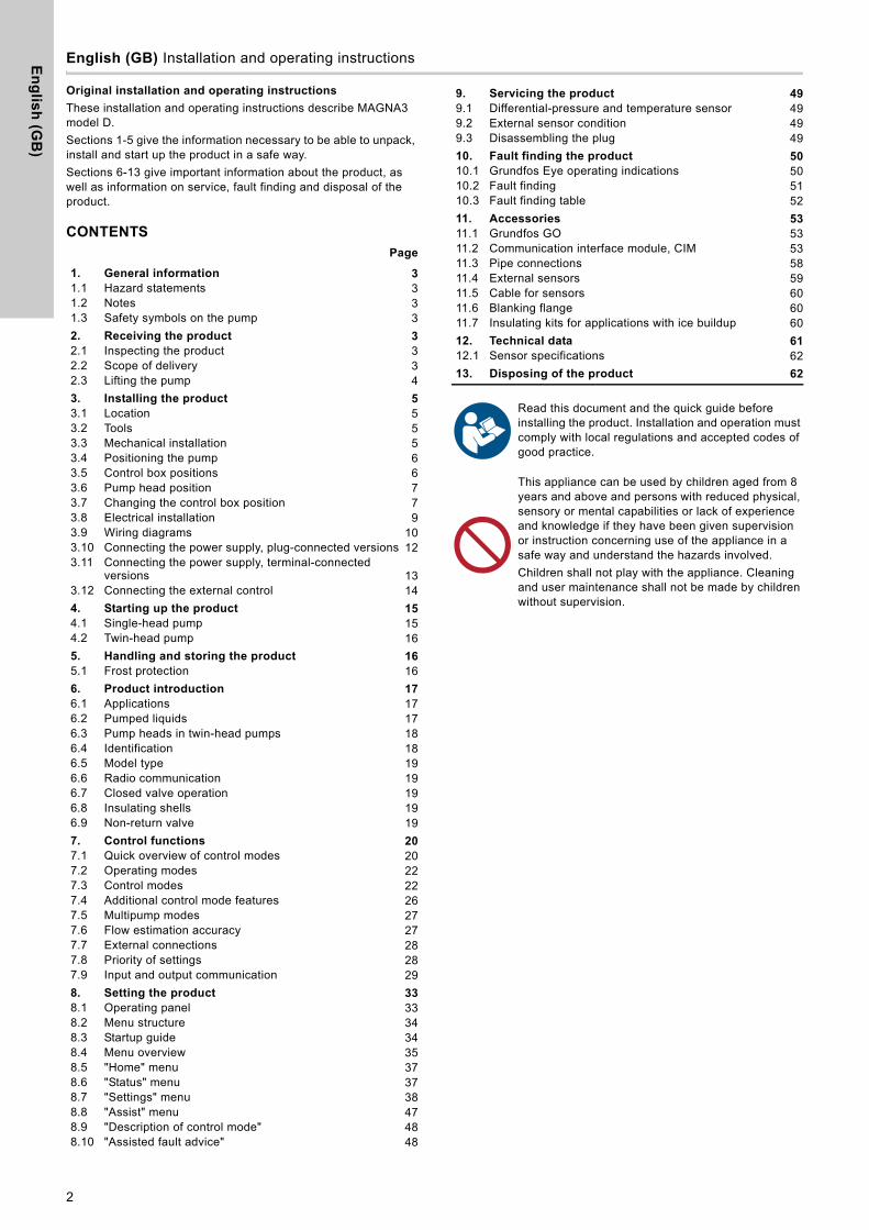
3.4 Positioning the pump
Always install the pump with horizontal motor shaft.• Pump installed correctly in a vertical pipe. See fig. 5 (A).• Pump installed correctly in a horizontal pipe. See fig. 5 (B).• Do not install the pump with vertical motor shaft. See fig. 5 (C
and D).
Fig. 5 Pump installed with horizontal motor shaft
3.5 Control box positions
To ensure adequate cooling, make sure that the control box is in horizontal position with the Grundfos logo in vertical position. See fig. 6.
Fig. 6 Pump with control box in horizontal position
4
Flanged version:Fit bolts and nuts. Use the right size of bolts according to system pressure.For further information about torques, see page 63.
Threaded version:Tighten the union nuts.
TM05
286
5 32
16 -
TM05
845
5 32
165 Fit the insulating shells.
TM05
287
4 32
16
In heating systems, do not insulate the control box or cover the operating panel.
TM05
288
9 32
16
Step Action Illustration
TM05
286
6 32
16
Make sure that the isolating valves are closed before rotating the control box.
TM05
291
5 32
16
For twin-head pumps installed in horizontal pipes, air may be trapped in the pump housing. Therefore, an automatic vent, Rp 1/4 thread, must be installed in the upper part of the pump housing. See fig. 7.
BA
DC
6

En
gli
sh
(G
B)
Fig. 7 Automatic vent
3.6 Pump head position
If you remove the pump head before installing the pump in the pipes, pay special attention when fitting the pump head to the pump housing:1. Visually check that the floating ring in the sealing system is
centred. See figs 8 and 9.2. Gently lower the pump head with rotor shaft and impeller into
the pump housing.3. Make sure that the contact face of the pump housing and that
of the pump head are in contact before you tighten the clamp. See fig. 10.
Fig. 8 Correctly centred sealing system
Fig. 9 Incorrectly centred sealing system
Fig. 10 Fitting the pump head to the pump housing
3.7 Changing the control box positionTM
05 6
061
3216
TM05
665
0 32
16TM
05 6
651
3216
Observe the position of the clamp before you tighten it. Incorrect position of the clamp will cause leakage from the pump and damage the hydraulic parts in the pump head. See fig. 10.
TM05
583
7 32
16
The warning symbol on the clamp holding the pump head and pump housing together indicates that there is a risk of personal injury. See specific warnings below.
CAUTION
Pressurised system
Minor or moderate personal injury- Pay special attention to any escaping vapour
when loosening the clamp.
CAUTION
Crushing of feet
Minor or moderate personal injury- Do not drop the pump head when loosening the
clamp.
Fit and tighten the screw that holds the clamp to 8 Nm ± 1 Nm. Do not apply more torque than specified even though water is dripping from the clamp. The condensed water is most likely coming from the drain hole under the clamp.
Check the position of the clamp before you tighten the clamp. Incorrect position of the clamp will cause leakage from the pump and damage the hydraulic parts in the pump head.
Make sure that the isolating valves are closed before rotating the control box.The pump must be pressureless before the control box is rotated. Drain the system or relieve the pressure inside the pump housing by loosening the thread or flange.
8Nm!
7

En
glis
h (G
B)
Step Action Illustration
1
Loosen the screw in the clamp that holds the pump head and pump housing together.If you loosen the screw too much, the pump head will be completely disconnected from the pump housing. TM
05 2
867
3216
2
Carefully turn the pump head to the desired position.If the pump head is stuck, loosen it with a light blow of a rubber mallet.
TM05
286
8 32
16
3
Place the control box in horizontal position so that the Grundfos logo is in vertical position. The motor shaft must be in horizontal position.
TM05
286
9 32
16
4
Due to the drain hole in the stator housing, position the gap of the clamp as shown in step 4a or 4b.
TM05
287
0 06
12
4a
Single-head pump.Position the clamp so that the gap points towards the arrow. It can be in position 3, 6, 9 or 12 o'clock.
TM05
291
8 32
16
5.0
4b
Twin-head pump.Position the clamps so that the gaps point towards the arrows.They can be in position 3, 6, 9 or 12 o'clock.
TM05
291
7 32
16
5
Fit and tighten the screw that holds the clamp to 8 Nm ± 1 Nm.Do not retighten the screw if condensed water is dripping from the clamp.
TM05
287
2 06
12
6
Fit the insulating shells.The insulating shells for pumps in air-conditioning and cooling systems must be ordered separately.
TM05
287
4 32
16
Step Action Illustration
8 Nm5.0
8

En
gli
sh
(G
B)
3.8 Electrical installation
Carry out the electrical connection and protection according to local regulations.Check that the supply voltage and frequency correspond to the values stated on the nameplate.
• Make sure that the pump is connected to an external main switch.
• The pump requires no external motor protection.• The motor incorporates thermal protection against slow
overloading and blocking (TP 211 according to IEC 60034-11).• When switched on via the power supply, the pump starts after
approximately 5 seconds.
3.8.1 Supply voltage
1 x 230 V ± 10 %, 50/60 Hz, PE.The voltage tolerances are intended for mains-voltage variations. Do not use the voltage tolerances for running pumps at other voltages than those stated on the nameplate.
WARNING
Electric shock
Death or serious personal injury- Before starting any work on the product, make
sure that the power supply has been switched off. Lock the main switch in position 0. Type and requirements as specified in EN 60204-1, 5.3.2.
WARNING
Electric shock
Death or serious personal injury- Connect the pump to an external main switch with
a minimum contact gap of 3 mm in all poles.- Use earthing or neutralisation for protection
against indirect contact.- For plug-connected versions: In case of an
insulation fault, the fault current may be a pulsating DC. Observe national legislation about requirements for and selection of Residual Current Device (RCD) when installing the pump.For terminal-connected versions: In case of an insulation fault, the fault current may be a DC or pulsating DC. Observe national legislation about requirements for and selection of Residual Current Device (RCD) when installing the pump.
Make sure that the fuse is dimensioned according to the nameplate and local legislation.
Connect all cables in accordance with local regulations.
Make sure that all cables are heat-resistant up to 70 °C.Install all cables in accordance with EN 60204-1 and EN 50174-2.
9

En
glis
h (G
B)
3.9 Wiring diagrams
3.9.1 Connection to power supply, plug-connected versions
Fig. 11 Example of plug-connected motor with main switch, backup fuse and additional protection
3.9.2 Connection to external controllers, plug-connected versions
Fig. 12 Example of connections in the control box of plug-connected versions
The connection terminals of plug-connected versions (fig. 12) differ from those of terminal-connected versions (fig. 13), but they have the same function and connection options.
TM05
527
7 37
12
External switch
Fuse
RCD
TM07
038
0 15
18
NC NO CNC NO CS/SMA
MI24V IN
Relay 1 Relay 2Digital inputAnalog input
Sensor
Vcc Signal
Operation Alarm
Start/stopOn/off timer
Use C and NC for fault signals as this enables serial connections of more relays and detection of signal cable defects.
10
En
gli
sh
(G
B)
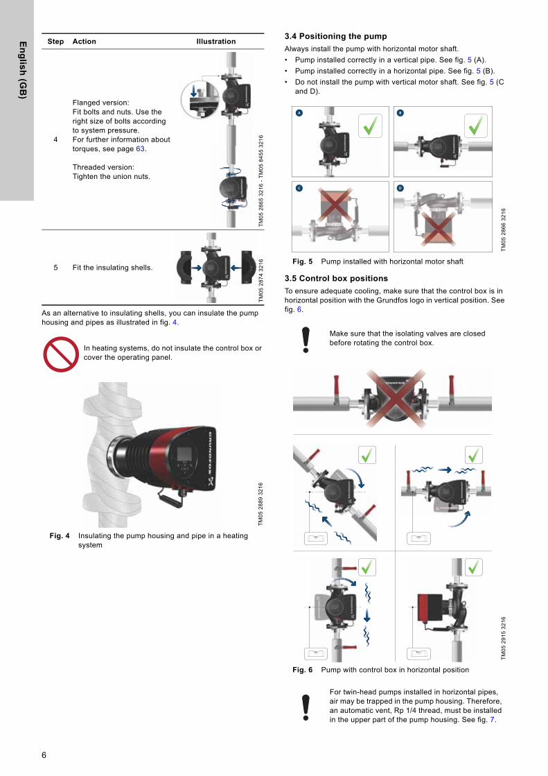
3.9.3 Connections in the control box, terminal-connected versions
Fig. 13 Example of connections in the control box of terminal-connected versions
For further information on digital and analog inputs, see sections 7.9.3 Digital inputs and 7.9.4 Analog input.For information on relay outputs, see section 7.9.2 Relay outputs.
TM07
036
4 15
18
L N
L
N
NC NO CNC NO CS/SMA
MI
24V IN
Power
Operation
Start/stopOn/off timer
Analog input
Relay 1 Relay 2
Alarm
Digital input
Sensor
Vcc Signal
RCD
Use C and NC for fault signals as this enables serial connections of more relays and detection of signal cable defects.
11
En
glis
h (G
B)
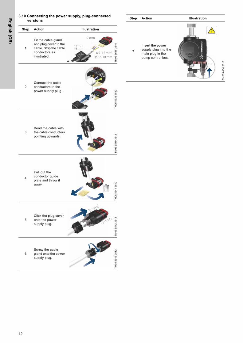
3.10 Connecting the power supply, plug-connected versions
Step Action Illustration
1
Fit the cable gland and plug cover to the cable. Strip the cable conductors as illustrated.
TM05
553
8 32
16
2Connect the cable conductors to the power supply plug.
TM05
553
9 38
12
3Bend the cable with the cable conductors pointing upwards.
TM05
554
0 38
12
4
Pull out the conductor guide plate and throw it away.
TM05
554
1 38
12
5Click the plug cover onto the power supply plug.
TM05
554
2 38
12
6Screw the cable gland onto the power supply plug.
TM05
554
3 38
12
12 mm17 mm
7 mm
Ø 5.5 - 10 mm
0.5 - 1.5 mm2
Click
Click
7
Insert the power supply plug into the male plug in the pump control box.
TM05
845
4 23
13
Step Action Illustration
Click
12

En
gli
sh
(G
B)
3.11 Connecting the power supply, terminal-connected versions
Step Action Illustration
1
Remove the front cover from the control box.Do not remove the screws from the cover.
TM05
287
5 34
16
2
Locate the power supply plug and cable gland in the small cardboard box supplied with the pump.
TM05
287
6 34
16
3Connect the cable gland to the control box.
TM05
287
7 34
16
4Pull the power supply cable through the cable gland.
TM05
287
8 34
16
5Strip the cable conductors as illustrated.
TM05
287
9 34
16
6Connect the cable conductors to the power supply plug.
TM05
288
0 34
16
7
Insert the power supply plug into the male plug in the pump control box.
TM05
288
1 34
16
8Tighten the cable gland.Fit the front cover.
TM05
288
2 34
16
Step Action Illustration
7 mm20 mm
Min. Ø 7 mm
Max. Ø 14 mm
13

En
glis
h (G
B)
3.12 Connecting the external control
The example is based on a MAGNA3 terminal-connected version. The connection terminals of plug-connected versions differ from those of terminal-connected versions, but they have the same function and connection options. See sections 3.9 Wiring diagrams and 7.9 Input and output communication.
Step Action Illustration
1
Remove the front cover from the control box.Do not remove the screws from the cover.
TM07
038
1 15
18
2Locate the digital input terminal connector.
TM07
038
2 15
18
3
Pull the cable through a M16 cable gland and one of the cable entries on the pump.
Take out the desired terminal, connect the cable conductors and reinsert the terminal.
See sections 7.7 External connections and 7.9 Input and output communication for instructions on how to connect the cable to the different terminals in the pump. TM
07 0
383
1518
4 Tighten the cable gland.
TM07
140
7 15
18
5 Refit the front cover to the control box.
TM07
038
4 15
18
Step Action Illustration
14

En
gli
sh
(G
B)
4. Starting up the product4.1 Single-head pump
Do not start the pump until the system has been filled with liquid and vented. Furthermore, the required minimum inlet pressure must be available at the pump inlet. See section 12. Technical data. Flush the system with clean water to remove all impurities before you start the pump.The pump is self-venting through the system, and the system must be vented at the highest point.
The number of starts and stops via the power supply must not exceed four times per hour.
Step Action Illustration
1Switch on the power supply to the pump.The pump has been factory set to "AUTOADAPT" mode, which starts after approximately 5 seconds.
TM05
288
4 06
12
2Operating panel at first startup.After a few seconds, the pump display changes to the startup guide.
TM05
288
5 32
16
3
The startup guide guides you through the general settings of the pump, such as language, date and time.
If you do not touch the buttons on the operating panel for 15 minutes, the display goes into sleep mode. When you touch a button, the "Home" display appears.
TM05
288
6 32
16
4
When you have made the general settings, select the desired control mode or let the pump run in AUTOADAPT mode.For additional settings, see section 7. Control functions.
TM05
288
7 32
16
0/Off
1/On
15

En
glis
h (G
B)
4.2 Twin-head pump
Fig. 14 MAGNA3 D
The pumps are paired from factory. When switching on the power supply, the heads will establish connection. Please allow approximately 5 seconds for this to happen.Flush the system with clean water to remove all impurities before you start the pump.
4.2.1 Multipump pairing
Note: Available for pumps with production code from 1838.After turning on the power supply, the pump’s initial setup menu asks you whether or not you want to keep multipump system activated. Several scenarios can play out.
Keep multipump system
• Only one pump head is connected to the power supply.If you have not connected both pump heads to the power supply and you choose to keep the multipump system, warning 77 appears in the display. See fig. 15. Connect the second pump head. Once both pumps are on, the pump heads will establish connection and the warning deactivates.
• Both pump heads are connected to the power supply.Configuring is only necessary from one of the pump heads.
Dissolve multipump system
• Only one pump head is connected to the power supply.If you have not connected both pump heads to the power supply and you choose to dissolve the multipump system, the second pump head, if connected to the power supply, will ask you whether or not you want to keep the multipump system. Choose to dissolve the multipump system.
• Both pump heads are connected to the power supply.Configuring is only necessary from one of the pump heads.
Fig. 15 Warning 77
See sections 7.9.3 Digital inputs, 7.9.2 Relay outputs and 7.5 Multipump modes for additional twin-head pump setup options.
4.2.2 Configuring twin-head pumps
If you replace a pump head of a twin-head pump, the twin-head pump will function as two single pumps until you have configured the pump heads and warning 77 is shown in the pump display. See fig. 15. To establish communication between the pump heads, run the multipump setup via the "Assist" menu. The pump from which you run the setup will be the master pump. See section 8.8.3 "Multipump setup".
5. Handling and storing the product
5.1 Frost protection
TM05
889
4 28
132.
1.5.
1.0.
0 St
atus
If the pump is not used during periods of frost, take the necessary steps to prevent frost bursts.
16

En
gli
sh
(G
B)
6. Product introductionMAGNA3 is a complete range of circulator pumps with integrated controller enabling adjustment of pump performance to the actual system requirements. In many systems, this reduces the power consumption considerably, reduces noise from thermostatic radiator valves and similar fittings and improves the control of the system.You can set the desired head on the operating panel.
6.1 Applications
The pump is designed for circulating liquids in the following systems:• heating systems• domestic hot-water systems• air-conditioning and cooling systems.You can also use the pump in the following systems:• ground-source heat-pump systems• solar-heating systems.
6.2 Pumped liquids
The pump is suitable for thin, clean, non-aggressive and non-explosive liquids, not containing solid particles or fibres that may attack the pump mechanically or chemically.In heating and cooling systems, the water must meet the requirements of accepted standards, codes, and any authority having jurisdiction (AHJ) requirements.In heating systems, the water must meet the requirements of accepted standards on water quality in heating systems, for example the German standard VDI 2035.The pumps are also suitable for domestic hot-water systems.
Stainless steel variants of MAGNA3 can be used to pump pool water with the one of the following properties:• Chloride (Cl-) ≤ 150 mg/l and free chlorine ≤ 1.5 mg/l at
temperatures ≤ 30 °C• Chloride (Cl-) ≤ 100 mg/l and free chlorine ≤ 1.5 mg/l at
temperatures from 30 to 40 °C.We strongly recommend that you use stainless-steel pumps in domestic hot-water applications to avoid corrosion.In domestic hot-water systems, we recommend that you use the pump only for water with a degree of hardness lower than approximately 14 °dH. In domestic hot-water systems, we recommend that you keep the liquid temperature below 65 °C to eliminate the risk of lime precipitation.
6.2.1 Glycol
You can use the pump for pumping water-ethylene-glycol mixtures up to 50 %.Example of a water-ethylene-glycol mixture:Maximum viscosity: 50 cSt ~ 50 % water / 50 % ethylene-glycol mixture at -10 °C.The pump has a power-limiting function that protects it against overload.The pumping of water-ethylene-glycol mixtures affects the maximum curve and reduces the performance, depending on the water-ethylene-glycol mixture and the liquid temperature.To prevent the ethylene-glycol mixture from degrading, avoid temperatures exceeding the rated liquid temperature and minimise the operating time at high temperatures. Clean and flush the system before you add the ethylene-glycol mixture.To prevent corrosion or lime precipitation, check and maintain the ethylene-glycol mixture regularly. If further dilution of the supplied ethylene-glycol is required, follow the glycol supplier's instructions.
Fig. 16 Pumped liquids, threaded version
Observe local legislation regarding pump housing material.
Do not pump aggressive liquids.
Do not pump flammable, combustible or explosive liquids.
Additives with a density and/or kinematic viscosity higher than those/that of water reduce the hydraulic performance.
TM05
845
7 23
13
17
En
glis
h (G
B)
6.3 Pump heads in twin-head pumps
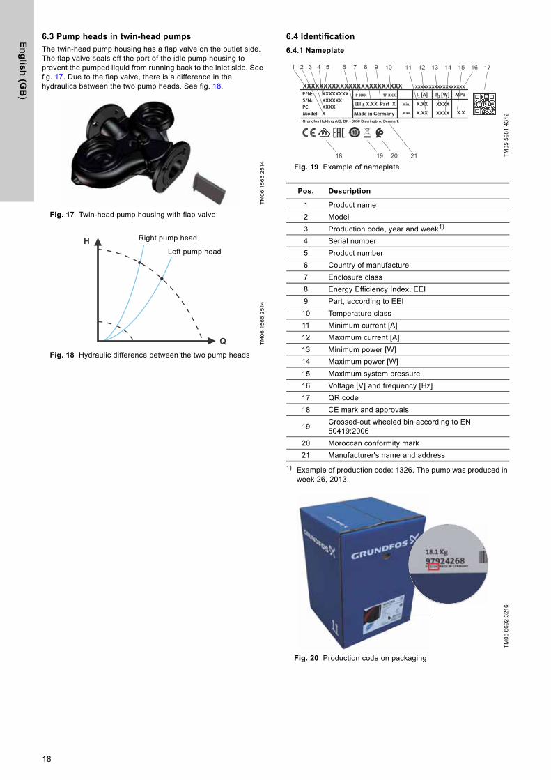
The twin-head pump housing has a flap valve on the outlet side. The flap valve seals off the port of the idle pump housing to prevent the pumped liquid from running back to the inlet side. See fig. 17. Due to the flap valve, there is a difference in the hydraulics between the two pump heads. See fig. 18.
Fig. 17 Twin-head pump housing with flap valve
Fig. 18 Hydraulic difference between the two pump heads
6.4 Identification
6.4.1 Nameplate
Fig. 19 Example of nameplate
1) Example of production code: 1326. The pump was produced in week 26, 2013.
Fig. 20 Production code on packaging
TM06
156
5 25
14TM
06 1
566
2514
H
Q
Right pump head
Left pump head
TM05
598
1 43
12
Pos. Description
1 Product name2 Model3 Production code, year and week1)
4 Serial number5 Product number6 Country of manufacture7 Enclosure class8 Energy Efficiency Index, EEI9 Part, according to EEI
10 Temperature class11 Minimum current [A]12 Maximum current [A]13 Minimum power [W]14 Maximum power [W]15 Maximum system pressure16 Voltage [V] and frequency [Hz]17 QR code18 CE mark and approvals
19 Crossed-out wheeled bin according to EN 50419:2006
20 Moroccan conformity mark21 Manufacturer's name and address
TM06
669
2 32
16
2119 20
18

En
gli
sh
(G
B)
6.5 Model type
These installation and operating instructions cover all models. The model version is stated on the nameplate. See fig. 21.
Fig. 21 Model type on the product
You can see the different model versions in the MAGNA3 data booklet.
6.6 Radio communication
The radio part of this product is a class 1 device and can be used anywhere in the EU member states without restrictions.
Intended use
This pump incorporates a radio for remote control.The pump can communicate with Grundfos GO and with other MAGNA3 pumps of the same type via the built-in radio.
6.7 Closed valve operation
MAGNA3 pumps can operate at any speed against a closed valve for several days without damage to the pump. However, Grundfos recommends to operate at the lowest possible speed curve to minimise energy losses. There are no minimum flow requirements.
6.8 Insulating shells
Insulating shells are available for single-head pumps only.
Reduce the heat loss by insulating the pump housing and the pipes. See figs 22 and 4.• Insulating shells for pumps in heating systems are supplied
with the pump.• Insulating shells for applications with ice buildup are available
as an accessory. See section 11.7 Insulating kits for applications with ice buildup.
The fitting of insulating shells increases the pump dimensions.
Fig. 22 Insulating shells
Pumps for heating systems are factory-fitted with insulating shells. Remove the insulating shells before installing the pump.
6.9 Non-return valve
If a non-return valve is fitted in the pipe system, make sure that the set minimum outlet pressure of the pump is always higher than the closing pressure of the valve. See fig. 23. This is especially important in proportional-pressure control mode with reduced head at low flow.
Fig. 23 Non-return valve
TM05
879
8 50
18
Do not close inlet and outlet valves simultaneously, always keep one valve open when the pump is running to avoid pressure buildup.Media- and ambient temperatures must never exceed the specified temperature range.
MAGNA3 32-40 F 220
98333834 X4D 11
100014060.18
1848
D
Limit the heat loss from the pump housing and pipes.
TM05
285
9 32
16TM
05 3
055
0912
19

En
glis
h (G
B)
7. Control functions
7.1 Quick overview of control modes
AUTOADAPT• Recommended for most heating systems.• During operation, the pump automatically makes the necessary
adjustment to the actual system characteristic.
For further information, see section 7.3.2 AUTOADAPT.
FLOWADAPTThe FLOWADAPT control mode combines a control mode and a function:• The pump is running in AUTOADAPT
• The delivered flow from the pump will never exceed a selected FLOWLIMIT.
For further information, see section 7.3.3 FLOWADAPT.
Proportional pressure• Used in systems with relatively large pressure losses in the
distribution pipes.• The head of the pump will increase proportionally to the flow in the
system to compensate for the large pressure losses in the distribution pipes.
For further information, see section 7.3.4 Proportional pressure.
Constant pressure• We recommend this control mode in systems with relatively small
pressure losses.• The pump head is kept constant, independent of the flow in the
system.
For further information, see section 7.3.5 Constant pressure.
Constant temperatureIn systems with a fixed system characteristic, for example domestic hot-water systems, the control of the pump according to a constant return-pipe temperature is relevant.
For further information, see section 7.3.6 Constant temperature.
Differential temperature• Ensures a constant differential temperature drop across heating
and cooling systems.• The pump will maintain a constant differential temperature
between the pump and the external sensor.
For further information, see section 7.3.7 Differential temperature.
Constant flowNote: Available for pumps with production code from 1838.• The pump maintains a constant flow in the system independently
of the head.• It is not possible to use an external sensor, instead, the pump
uses its internal sensor.
For further information, see section 7.3.8 Constant flow.
H
Q
Hauto_min
A1
A3 A2
Hset1
Hset2
H
Q
Qmax90 %Qmax25 %
Hauto_min
Hfac
Qfac
H
Q
Hset
Hset
2
H
Q
H
Q
H
Q
Δt
H
QQset
20
En
gli
sh
(G
B)
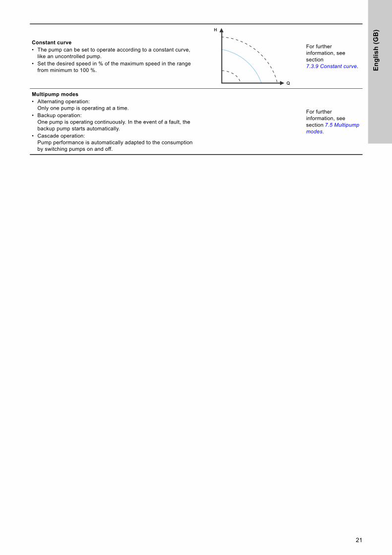
Constant curve• The pump can be set to operate according to a constant curve,
like an uncontrolled pump. • Set the desired speed in % of the maximum speed in the range
from minimum to 100 %.
For further information, see section 7.3.9 Constant curve.
Multipump modes• Alternating operation:
Only one pump is operating at a time.• Backup operation:
One pump is operating continuously. In the event of a fault, the backup pump starts automatically.
• Cascade operation:Pump performance is automatically adapted to the consumption by switching pumps on and off.
For further information, see section 7.5 Multipump modes.
H
Q
21

En
glis
h (G
B)
7.2 Operating modes
Normal
The pump runs according to the selected control mode.
Stop
The pump stops.
Min.
You can use the minimum curve mode in periods in which a minimum flow is required. This operating mode is for instance suitable for manual night setback if automatic night setback is not desired.The minimum curve can be adjusted. See section 8.7.2 "Operating mode".
Max.
You can use the maximum curve mode in periods in which a maximum flow is required. This operating mode is for instance suitable for hot-water priority.The maximum curve can be adjusted. See section 8.7.2 "Operating mode".
Fig. 24 Maximum and minimum curves
7.3 Control modes
7.3.1 Factory setting
The pumps have been factory-set to AUTOADAPT without automatic night setback, which is suitable for most installations.The setpoint has been factory-set.
7.3.2 AUTOADAPTWe recommend the AUTOADAPT control mode for most heating systems, especially in systems with relatively large pressure losses in the distribution pipes, and in replacement situations where the proportional-pressure duty point is unknown.This control mode has been developed specifically for heating systems and we do not recommend it for air-conditioning and cooling systems.
Characteristics and key benefits
• Automatically adjusts the pump to actual system characteristics.
• Ensures minimum energy consumption and a low noise level.• Reduced operating costs and increased comfort.
Technical specifications
Fig. 25 AUTOADAPT control
The AUTOADAPT control mode is a form of proportional-pressure control where the control curves have a fixed origin, Hauto_min.When you have enabled AUTOADAPT, the pump will start with the factory setting, Hset1, corresponding to approx. 55 % of its maximum head, and then adjust its performance to A1. See fig. 25.When the pump registers a lower head on the maximum curve, A2, the AUTOADAPT function automatically selects a correspondingly lower control curve, Hset2. If the valves in the system close, the pump adjusts its performance to A3. See fig. 25.
You can select the control mode and setpoint even if the pump is not running in Normal mode.
TM05
244
6 51
11
H
Q
Max.
Min.
TM05
245
2 13
12
A1: Original duty point.A2: Lower registered head on the max. curve.A3: New duty point after AUTOADAPT control.Hset1: Original setpoint setting. Hset2: New setpoint after AUTOADAPT control.Hauto_min: A fixed value of 1.5 m.
Manual setting of the setpoint is not possible.
H
Q
Hauto_min
A1
A3 A2
Hset1
Hset2
22

En
gli
sh
(G
B)
7.3.3 FLOWADAPT
The FLOWADAPT control mode combines AUTOADAPT and FLOWLIMIT, meaning that the pump runs AUTOADAPT while at the same time ensuring that the flow never exceeds the entered FLOWLIMIT value. This control mode is suitable for systems where a maximum flow limit is desired and where a steady flow through the boiler in a boiler system is required. Here, no extra energy is used for pumping too much liquid into the system.In systems with mixing loops, you can use FLOWADAPT to control the flow in each loop.
Characteristics and key benefits
• The dimensioned flow for each zone (required heat energy) is determined by the flow from the pump. This flow can be set precisely in the FLOWADAPT control mode without using throttling valves.
• When the flow is set lower than the balancing valve setting, the pump will ramp down instead of losing energy by pumping against a balancing valve.
• Cooling surfaces in air-conditioning systems can operate at high pressure and low flow.
Note: The pump cannot reduce the flow on the inlet side, but is able to control that the flow on the outlet side is at least the same as on the inlet side. This is due to the fact that the pump has no built-in valve.
Technical specifications
Fig. 26 FLOWADAPT control
The factory setting of the FLOWADAPT is the flow where the AUTOADAPT factory setting meets the maximum curve. See fig. 26.The typical pump selection is based on the required flow and calculated pressure losses. The pump is typically oversized by 30 to 40 % to ensure that it can overcome the pressure losses in the system. Under these conditions, the full benefit of AUTOADAPT cannot be obtained.To adjust the maximum flow of this "oversized" pump, balancing valves are built into the circuit to increase the resistance and thus reduce the flow. The FLOWADAPT function reduces the need for a pump throttling valve, see fig. 27, but does not eliminate the need for balancing valves in heating systems.
Fig. 27 Reduced need for a pump throttling valve
7.3.4 Proportional pressure
Proportional pressure is suitable in systems with relatively large pressure losses in the distribution pipes and in air-conditioning and cooling systems:• Two-pipe heating systems with thermostatic valves and the
following:– very long distribution pipes– strongly throttled pipe balancing valves– differential-pressure regulators– large pressure losses in those parts of the system where the
total quantity of water flows (for example boiler, heat exchanger and distribution pipe up to the first branching).
• Primary circuit pumps in systems with large pressure losses in the primary circuit.
• Air-conditioning systems with the following:– heat exchangers (fan coils)– cooling ceilings– cooling surfaces.
Characteristics and key benefits
• The head of the pump increases proportionally to the flow in the system.
• Compensates for large pressure losses in the distribution pipes.
Technical specifications
Fig. 28 Proportional-pressure control
The head is reduced at decreasing flow demand and increased at rising flow demand. The head against a closed valve is half the setpoint Hset. You can set the setpoint with an accuracy of 0.1 metre.
TM05
333
4 13
12TM
05 2
685
1212
H
Q
Qmax90 %Qmax25 %
Hauto_min
Hfac
Qfac
Setting range
TM05
244
8 12
12
H
Q
Hset
Hset
2
23
En
glis
h (G
B)
7.3.5 Constant pressure
A constant pressure is advantageous in systems with relatively small pressure losses in the distribution pipes:• Two-pipe heating systems with thermostatic valves:
– dimensioned for natural circulation– small pressure losses in those parts of the system where the
total quantity of water flows (for example boiler, heat exchanger and distribution pipe up to the first branching)
– modified to a high differential temperature between flow pipe and return pipe (for example district heating).
• Underfloor heating systems with thermostatic valves.• One-pipe heating systems with thermostatic valves or pipe
balancing valves.• Primary circuit pumps in systems with small pressure losses in
the primary circuit.
Characteristics and key benefits
• The pump pressure is kept constant, independent of the flow in the system.
Technical specifications
Fig. 29 Constant-pressure control
7.3.6 Constant temperature
This control mode is suitable in systems with a fixed system characteristic, for example domestic hot-water systems, where control of the pump according to a constant return-pipe temperature is relevant.The pump is from factory set to operate in a heating system with a controller gain, Kp, equal to 1. If the pump operates in a cooling system, the gain must be changed to a negative value, for example -1. See section 8.7.4 "Controller settings".
Characteristics and key benefits
• The temperature is kept constant.• Use FLOWLIMIT to control the maximum circulation flow.
Technical specifications
Fig. 30 Constant-temperature control
When you use this control mode, do not install any balancing valves in the system.The inverse control for cooling application is available from model B.
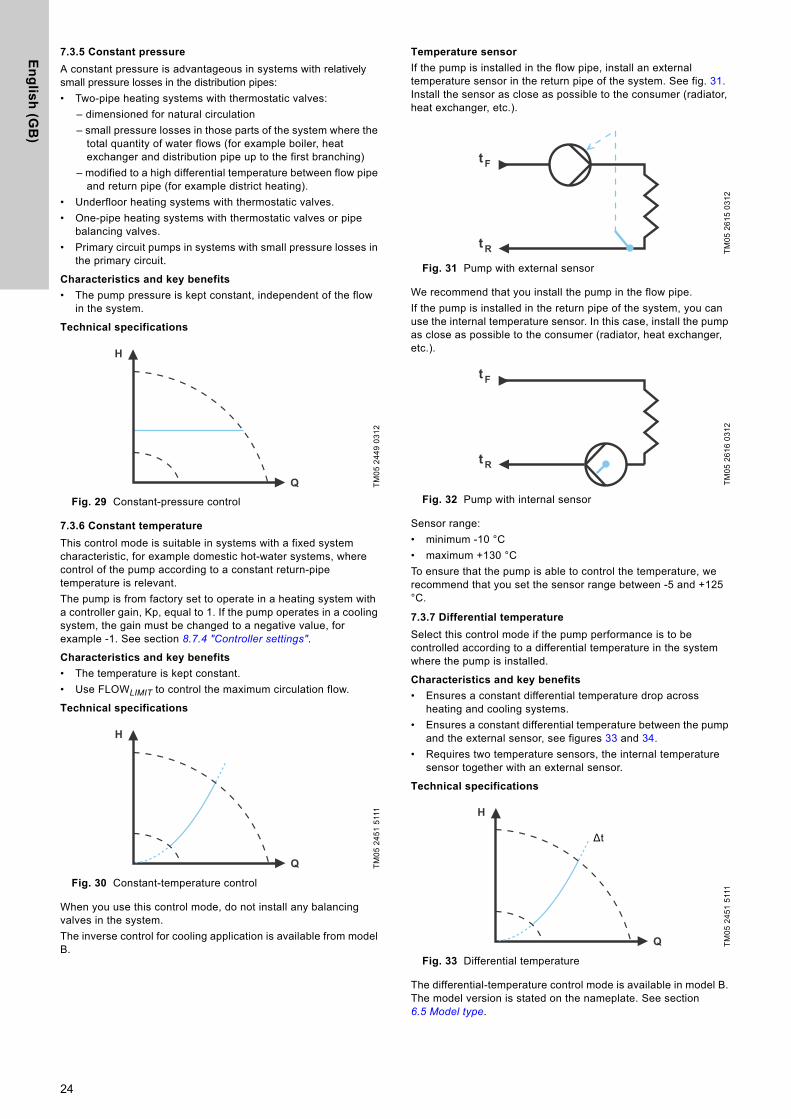
Temperature sensor
If the pump is installed in the flow pipe, install an external temperature sensor in the return pipe of the system. See fig. 31. Install the sensor as close as possible to the consumer (radiator, heat exchanger, etc.).
Fig. 31 Pump with external sensor
We recommend that you install the pump in the flow pipe.If the pump is installed in the return pipe of the system, you can use the internal temperature sensor. In this case, install the pump as close as possible to the consumer (radiator, heat exchanger, etc.).
Fig. 32 Pump with internal sensor
Sensor range:• minimum -10 °C• maximum +130 °CTo ensure that the pump is able to control the temperature, we recommend that you set the sensor range between -5 and +125 °C.
7.3.7 Differential temperature
Select this control mode if the pump performance is to be controlled according to a differential temperature in the system where the pump is installed.
Characteristics and key benefits
• Ensures a constant differential temperature drop across heating and cooling systems.
• Ensures a constant differential temperature between the pump and the external sensor, see figures 33 and 34.
• Requires two temperature sensors, the internal temperature sensor together with an external sensor.
Technical specifications
Fig. 33 Differential temperature
The differential-temperature control mode is available in model B. The model version is stated on the nameplate. See section 6.5 Model type.
TM05
244
9 03
12TM
05 2
451
5111
H
Q
H
Q
TM05
261
5 03
12TM
05 2
616
0312
TM05
245
1 51
11
t F
t R
t F
t R
H
Q
Δt
24

En
gli
sh
(G
B)
Temperature sensor
To measure the temperature difference of the flow and return pipe, you must use both the internal sensor and an external sensor.If the pump is installed in the flow pipe, the external sensor must be installed in the return pipe and vice versa. Always install the sensor as close as possible to the consumer (radiator, heat exchanger, etc.). See fig. 34.
Fig. 34 Differential temperature
7.3.8 Constant flow
Note: Available for pumps with production code from 1838.The pump maintains a constant flow in the system independently of the head. See fig. 35.Constant flow is suitable in applications such as air handling units, hot-water systems and ground-source heating systems.
Characteristics and key benefits
• It is not possible to use an external sensor, instead, the pump uses its internal sensor.
• In multipump systems constant flow is only available in alternating and backup operation, not cascade operation.
Fig. 35 Constant flow rate
7.3.9 Constant curve
A constant curve is suitable for systems where there is a demand for both constant flow and constant head, i.e.:• heating surfaces• cooling surfaces• heating systems with 3-way valves• air-conditioning systems with 3-way valves• chiller pumps.
Characteristics and key benefits
• If an external controller is installed, the pump is able to change from one constant curve to another, depending on the value of the external signal.
• Depending on your preferences, the pump can be controlled according to either a maximum or minimum curve.
Technical specifications
Fig. 36 Constant-curve duty
The pump can be set to operate according to a constant curve, like an uncontrolled pump. See fig. 36. Depending on the pump model, you can set the desired speed in % of the maximum speed. The span of control depends on the minimum speed, power and pressure limitation of the pump.If the pump speed is set in the range between minimum and maximum, the power and pressure are limited when the pump is running on the maximum curve. This means that the maximum performance can be achieved at a speed lower than 100 %. See fig. 37.
Fig. 37 Power and pressure limitations influencing the maximum curve
You can also set the pump to operate according to the maximum or minimum curve, like an uncontrolled pump:• You can use the maximum curve mode in periods in which a
maximum flow is required. This operating mode is for instance suitable for hot-water priority.
• You can use the minimum curve mode in periods in which a minimum flow is required. This operating mode is for instance suitable for manual night setback if automatic night setback is not desired.
You can select these two operating modes via the digital inputs.In the control mode constant curve, you can obtain constant flow by choosing a setpoint at 100 % and choosing the desired value for the flow with the flow limit function FLOWLIMIT. Take the accuracy of the flow estimation into consideration.
TM05
823
6 21
13TM
05 7
955
1713
t
H
QQset
TM05
244
6 51
11TM
05 4
266
2212
H
Q
H
Q
Min.
30%
50%
70%
90%
Limited max. curve
Speed setting from 0 to 100 %
25
En
glis
h (G
B)
7.4 Additional control mode features
MAGNA3 offers additional features for the control modes to meet specific demands.
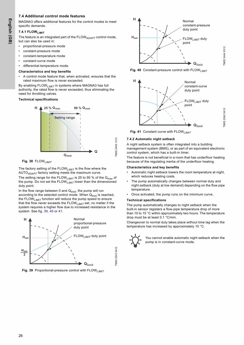
7.4.1 FLOWLIMIT
The feature is an integrated part of the FLOWADAPT control mode, but can also be used in: • proportional-pressure mode• constant-pressure mode• constant-temperature mode• constant-curve mode• differential-temperature mode.
Characteristics and key benefits
• A control mode feature that, when activated, ensures that the rated maximum flow is never exceeded.
By enabling FLOWLIMIT in systems where MAGNA3 has full authority, the rated flow is never exceeded, thus eliminating the need for throttling valves.
Technical specifications
Fig. 38 FLOWLIMIT
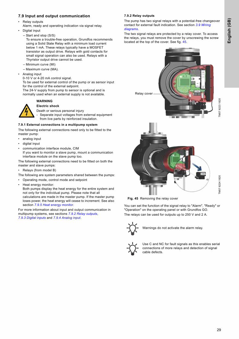
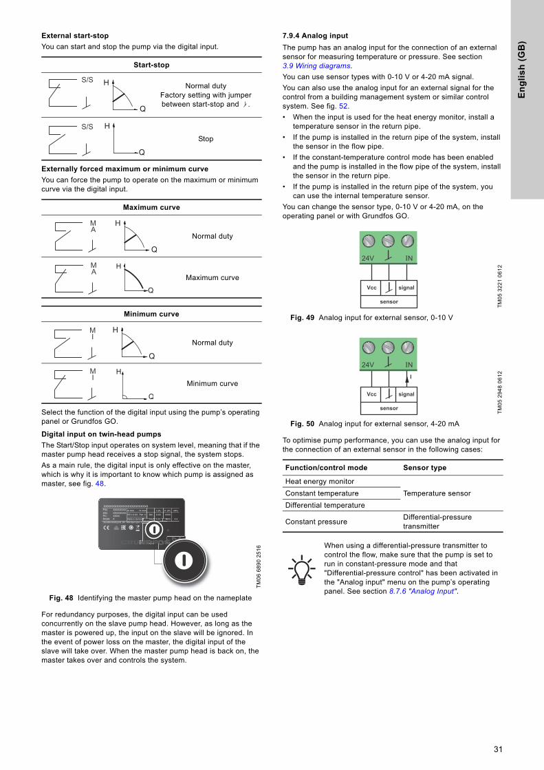
The factory setting of the FLOWLIMIT is the flow where the AUTOADAPT factory setting meets the maximum curve.The setting range for the FLOWLIMIT is 25 to 90 % of the Qmax of the pump. Do not set the FLOWLIMIT lower than the dimensioned duty point.In the flow range between 0 and Qlimit, the pump will run according to the selected control mode. When Qlimit is reached, the FLOWLIMIT function will reduce the pump speed to ensure that the flow never exceeds the FLOWLIMIT set, no matter if the system requires a higher flow due to increased resistance in the system. See fig. 39, 40 or 41.
Fig. 39 Proportional-pressure control with FLOWLIMIT
Fig. 40 Constant-pressure control with FLOWLIMIT
Fig. 41 Constant curve with FLOWLIMIT
7.4.2 Automatic night setback
A night setback system is often integrated into a building management system (BMS), or as part of an equivalent electronic control system, which has a built-in timer.The feature is not beneficial in a room that has underfloor heating because of the regulating inertia of the underfloor heating.
Characteristics and key benefits
• Automatic night setback lowers the room temperature at night, which reduces heating costs.
• The pump automatically changes between normal duty and night setback (duty at low demand) depending on the flow pipe temperature.
• Once activated, the pump runs on the minimum curve.
Technical specifications
The pump automatically changes to night setback when the built-in sensor registers a flow-pipe temperature drop of more than 10 to 15 °C within approximately two hours. The temperature drop must be at least 0.1 °C/min.Changeover to normal duty takes place without time lag when the temperature has increased by approximately 10 °C.
TM05
244
5 13
12TM
05 2
543
0412
H
Q
Qmax
Qlimit
90 %Qmax25 %
Setting range
H
Q
2
Hset
Hset
Normal proportional-pressure duty point
FLOWLIMIT duty point
TM05
244
4 03
12TM
05 2
542
0412
You cannot enable automatic night setback when the pump is in constant-curve mode.
H
Q
Hset
Normal constant-pressure duty point
FLOWLIMIT duty point
H
Q
Normal constant-curve duty point
FLOWLIMIT duty point
26

En
gli
sh
(G
B)
7.5 Multipump modes
7.5.1 Multipump function
The multipump function enables the control of single-head pumps connected in parallel and twin-head pumps without the use of external controllers. The pump is designed for multipump connection via the wireless GENIair connection. The built-in wireless GENIair module enables communication between pumps and with Grundfos GO without the use of add-on modules. See sections 9. Servicing the product and 11.1 Grundfos GO.Pump system:• Twin-head pump.• Two single-head pumps connected in parallel. The pumps
must be of equal size and type. Each pump requires a non-return valve in series with the pump.
A multipump system is set via a selected pump, i.e. the master pump (first selected pump). The multipump functions are described in the following sections. Configuration of twin-head pumps is described in section 4.2 Twin-head pump.For information about input and output communication in a multipump system, see section 7.9.1 External connections in a multipump system.
7.5.2 Alternating operation
Only one pump is operating at a time. The change from one pump to the other depends on time or energy. If a pump fails, the other pump will take over automatically.
7.5.3 Backup operation
One pump is operating continuously. The backup pump is operating at intervals to prevent seizing up. If the duty pump stops due to a fault, the backup pump will start automatically.
7.5.4 Cascade operation
Cascade operation ensures that the pump performance is automatically adapted to the consumption by switching pumps on or off. The system thus runs as energy-efficiently as possible with a constant pressure and a limited number of pumps.The slave pump will start when the master pump either runs at 90 % of the maximum speed or runs on the maximum curve.The slave pump stops if one of the following conditions are fulfilled:• One of the two pumps runs on minimum curve. • One of the two pumps runs below 50 % of the maximum speed
and at the same time runs below 50 % of the maximum power consumption.
Cascade operation is available in constant speed and constant pressure. You can with advantage choose a twin-head pump, as the backup pump will start for a short period in peak-load situations. All pumps in operation will run at equal speed. Pump changeover is automatic and depends on speed, operating hours and faults.
7.6 Flow estimation accuracy
The internal sensor estimates the difference in pressure between the inlet and outlet port of the pump. The measurement is not a direct differential-pressure measurement, but by knowing the hydraulic design of the pump, you can estimate the differential pressure across the pump. The speed and power give a direct estimation of the actual duty point at which the pump is running.The calculated flow rate has a typical accuracy of ± 5 % of Qmax. The less flow through the pump, the less accurate the reading will be. In worst case scenarios, such as closed valve operation, the accuracy can be up to 10 % of Qmax.See also section 7.9.5 Heat energy monitor.Example:
Fig. 42 Qmax
1. MAGNA3 65-60 has a Qmax of 40 m3/h.Typically 5 % accuracy means 2 m3/h inaccuracy of Qmax ± 2 m3/h.
2. This accuracy is valid for the entire QH area. If the pump indicates 10 m3/h, the measurement is 10 ± 2 m3/h.
3. The flow rate can be from 8-12 m3/h.The use of a mixture of water and ethylene-glycol will reduce the accuracy.If the flow is less than 10 % of Qmax, the display shows a low flow.
TM05
244
8 51
11
H
Q
Max.
Min.
Qmax
27

En
glis
h (G
B)
7.7 External connections
The connection terminals of plug-connected versions differ from those of terminal-connected versions, but they have the same function and connection options.Concerning demands on signal wires and signal transmitters, see section 12. Technical data.Use screened cables for external on-off switch, digital input, sensor and setpoint signals.Connect screened cables to the earth connection as follows:• Terminal-connected versions:
Connect the cable screen to earth via the digital-input terminal. See fig. 43.
• Plug-connected versions:Connect the cable screen to earth via cable clamp. See fig. 44.
Fig. 43 Connection of cable screen, terminal-connected versions
Fig. 44 Connection of cable screen, plug-connected versions
7.8 Priority of settings
The external forced-control signals influence the settings available on the pump operating panel or with Grundfos GO. However, you can always set the pump to maximum-curve duty or stop the pump on the operating panel or with Grundfos GO.If two or more functions are enabled at the same time, the pump operates according to the setting with the highest priority.The priority of the settings is as shown in the table below.Example: If the pump has been forced to stop via an external signal, the operating panel or Grundfos GO can only set the pump to maximum curve.
WARNING
Electric shock
Minor or moderate personal injury- Separate wires connected to supply terminals,
outputs NC, NO, C and start-stop input from each other and from the supply by reinforced insulation.
Make sure that all cables are heat-resistant up to 70 °C.Install all cables in accordance with EN 60204-1 and EN 50174-2.
Connect all cables in accordance with local regulations.
TM05
606
0 23
13 -
TM07
150
7 15
18
TM05
853
9 24
13
Priority
Possible settings
Operating panel or
Grundfos GO
External signals
Bus signal
1 "Stop" 2 "Max. curve"3 "Stop"4 "Stop"5 "Max. curve"6 "Min. curve"7 "Start"8 "Max. curve"9 "Min. curve"
10 "Min. curve"11 "Start"
28
En
gli
sh
(G
B)
7.9 Input and output communication• Relay outputsAlarm, ready and operating indication via signal relay.
• Digital input– Start and stop (S/S)
To ensure a trouble-free operation, Grundfos recommends using a Solid State Relay with a minimum load current below 1 mA. These relays typically have a MOSFET transistor as output drive. Relays with gold contacts for small signal operation can also be used. Relays with a Thyristor output drive cannot be used.
– Minimum curve (MI)– Maximum curve (MA).
• Analog input0-10 V or 4-20 mA control signal.To be used for external control of the pump or as sensor input for the control of the external setpoint.The 24-V supply from pump to sensor is optional and is normally used when an external supply is not available.
7.9.1 External connections in a multipump system
The following external connections need only to be fitted to the master pump:• analog input• digital input• communication interface module, CIM
If you want to monitor a slave pump, mount a communication interface module on the slave pump too.
The following external connections need to be fitted on both the master and slave pumps:• Relays (from model B)The following are system parameters shared between the pumps:• Operating mode, control mode and setpoint• Heat energy monitor:
Both pumps display the heat energy for the entire system and not only for the individual pump. Please note that all calculations are made in the master pump. If the master pump loses power, the heat energy will cease to increment. See also section 7.9.5 Heat energy monitor.
For more information about input and output communication in multipump systems, see sections 7.9.2 Relay outputs, 7.9.3 Digital inputs and 7.9.4 Analog input.
7.9.2 Relay outputs
The pump has two signal relays with a potential-free changeover contact for external fault indication. See section 3.9 Wiring diagrams.The two signal relays are protected by a relay cover. To access the relays, you must remove the cover by unscrewing the screw located at the top of the cover. See fig. 45.
Fig. 45 Removing the relay cover
You can set the function of the signal relay to "Alarm", "Ready" or "Operation" on the operating panel or with Grundfos GO.The relays can be used for outputs up to 250 V and 2 A.
WARNING
Electric shock
Death or serious personal injury- Separate input voltages from external equipment
from live parts by reinforced insulation.
TM07
622
3 18
20TM
07 6
224
1820
Warnings do not activate the alarm relay.
Use C and NC for fault signals as this enables serial connections of more relays and detection of signal cable defects.
Relay cover
29

En
glis
h (G
B)
Fig. 46 Relay output
The functions of the signal relays appear from the table below:
Factory settings of relays:
Relay output in twin-head pumps
The relay output for both the "Alarm", "Ready" and "Operation" functions operates independently on each pump head. If, for example, a fault occurs in one of the pumps, its respective relay is triggered.
7.9.3 Digital inputs
The pump has a digital input for external control of start-stop or forced maximum or minimum curve. See section 3.9 Wiring diagrams.If no external on-off switch is connected, the jumper between terminals start-stop (S/S) and frame ( ) must be maintained. This connection is the factory setting.
Fig. 47 Digital input
TM05
333
8 12
12
Contact symbol Function
NC Normally closedNO Normally openC Common
Signal relay Alarm signal
Not activated:• The power supply has been switched off.• The pump has not registered a fault.
Activated:• The pump has registered a fault.
Signal relay Ready signal
Not activated:• The pump has registered a fault and is
unable to run.• The power supply has been switched off.Activated:• The pump has been set to stop, but is
ready to run.• The pump is running.
Signal relay Operating signal
Not activated:• The power supply has been switched off.
Activated:• The pump is running.
Relay Function
1 Operating signal2 Alarm signal
NC NO C NC NO C
Operation
Alarm
Relay 1 Relay 2
1 32NC NO C1 32
NC NO C
1 2 3NC NO C
1 32NC NO C1 32
NC NO C
1 2 3NC NO C
1 32NC NO C1 32
NC NO C
1 2 3NC NO C
TM05
333
9 12
12
Contact symbol Function
MA
Maximum curve100 % speed
MI Minimum curve
S/S Start-stop
Frame connection
S/SMI
MA
On-off timer
Start-stop
30
En
gli
sh
(G
B)
External start-stop
You can start and stop the pump via the digital input.
Externally forced maximum or minimum curve
You can force the pump to operate on the maximum or minimum curve via the digital input.
Select the function of the digital input using the pump’s operating panel or Grundfos GO.
Digital input on twin-head pumps
The Start/Stop input operates on system level, meaning that if the master pump head receives a stop signal, the system stops.As a main rule, the digital input is only effective on the master, which is why it is important to know which pump is assigned as master, see fig. 48.
Fig. 48 Identifying the master pump head on the nameplate
For redundancy purposes, the digital input can be used concurrently on the slave pump head. However, as long as the master is powered up, the input on the slave will be ignored. In the event of power loss on the master, the digital input of the slave will take over. When the master pump head is back on, the master takes over and controls the system.
7.9.4 Analog input
The pump has an analog input for the connection of an external sensor for measuring temperature or pressure. See section 3.9 Wiring diagrams.You can use sensor types with 0-10 V or 4-20 mA signal. You can also use the analog input for an external signal for the control from a building management system or similar control system. See fig. 52.• When the input is used for the heat energy monitor, install a
temperature sensor in the return pipe.• If the pump is installed in the return pipe of the system, install
the sensor in the flow pipe.• If the constant-temperature control mode has been enabled
and the pump is installed in the flow pipe of the system, install the sensor in the return pipe.
• If the pump is installed in the return pipe of the system, you can use the internal temperature sensor.
You can change the sensor type, 0-10 V or 4-20 mA, on the operating panel or with Grundfos GO.
Fig. 49 Analog input for external sensor, 0-10 V
Fig. 50 Analog input for external sensor, 4-20 mA
To optimise pump performance, you can use the analog input for the connection of an external sensor in the following cases:
Start-stop
Normal dutyFactory setting with jumper between start-stop and .
Stop
Maximum curve
Normal duty
Maximum curve
Minimum curve
Normal duty
Minimum curve
TM06
689
0 25
16
S/S
Q
H
S/S
Q
H
MA
Q
H
MA
Q
H
MI
Q
H
MI
Q
H
XXXXXXXXXXXXXXXXXXXXXXXXP/N: XXXXXXXXS/N: XXXXXXXXPC: XXXXModel: X
IP XXX TF XXX
Grundfos Holding A/S, DK - 8850 Bjerringbro, Denmark
Made in Germany
XXXX
XXXX
I1 [A] P1 [W] MPa
enmarkrkrkrkk
y XX
TM05
322
1 06
12TM
05 2
948
0612
Function/control mode Sensor type
Heat energy monitorTemperature sensorConstant temperature
Differential temperature
Constant pressure Differential-pressure transmitter
When using a differential-pressure transmitter to control the flow, make sure that the pump is set to run in constant-pressure mode and that "Differential-pressure control" has been activated in the "Analog input" menu on the pump’s operating panel. See section 8.7.6 "Analog Input".
signal
sensor
Vcc
24V IN
signal
sensor
Vcc
24V IN
signal
sensor
Vcc
I
24V IN
31

En
glis
h (G
B)
Fig. 51 Examples of external sensors
For further details, see section 11.4 External sensors.
Fig. 52 Examples of external signal for the control via BMS or PLC
Analog input on twin-head pumps
For redundancy purposes, the analog input can be used concurrently on the slave pump head. As long as the master is powered up, the input on the slave will be ignored. However, in the event of power loss on the master, the analog input of the slave will take over. When the master pump head is back on, the master takes over and controls the system.
7.9.5 Heat energy monitor
The heat energy monitor calculates the heat energy consumption within the system. The built-in flow estimation needed for the calculation has a typical accuracy of ± 5 % of Qmax. The less flow through the pump, the less accurate the reading will be. In worst case scenarios, such as closed valve operation, the accuracy can be up to 10 % of Qmax. The actual accuracy in a duty point will be shown in the MAGNA3 display (available for pumps with production code from 1838). The temperature measurement accuracy also depends on the sensor type. Therefore, you cannot use the heat energy value for billing purposes. However, the value is perfect for optimisation purposes in order to prevent excessive energy costs. See also section 7.6 Flow estimation accuracy.To counterbalance any inaccuracy on either the internal and external sensor it is possible to manually enter a temperature offset. The offset is entered in integers, for example 2 degrees. The offset range is within ± 20 °C. To set the temperature offset, see section 8.7.4 "Controller settings".Note: Temperature sensor offset is available for pumps with production code from 1838.The flow and volume accuracy is calculated and shown in the display, see sections "Estimated flow rate, accuracy", page 38, and "Accuracy of values", page 38.
Fig. 53 MAGNA3 with built-in heat energy monitor
You can measure both heating and cooling in the same system. If a system is used for both heating and cooling, two counters are automatically shown in the display. See section "Heat energy", page 38.
Monitoring heat energy in multipump systems
In a multipump system, the master pump calculates the heat energy regardless of which pump, master or slave, is running. If the master loses power or has a fault on the external sensor, the accumulation of heat energy will not be counted until the master is powered back on or the external sensor error is remedied. If the master is replaced, the heat energy values for the system is reset.
7.9.6 External setpoint function
You can use the analog input to influence the setpoint externally. The external setpoint function can be used in two different ways:• "Linear with Min."• "Linear with Stop" (available for pumps with production code
from 1838)In both modes the input signal range is influenced linearly.
TM06
723
7 34
16
Pos. Sensor type
1Combined temperature and pressure sensor, Grundfos type RPI T2.1/2" connection and 0-10 V signal.
2 Pressure sensor, Grundfos type RPI.1/2" connection and 4-20 mA signal.
TM05
288
8 06
12
24V IN
Vcc Signal
1
2
24V
BMSPLC
The heat energy monitor requires an additional temperature sensor installed in the flow pipe or return pipe depending on where the pump is installed.
TM05
536
7 36
12
t
kWh
F
t R
32

En
gli
sh
(G
B)
"Linear with Min."
Here, a 0-10 V or 4-20 mA signal controls the pump speed range in a linear function. The range of control depends on the minimum speed, power and pressure limits of the pump. See figs 54 and 55.
Fig. 54 "Linear with Min.", 0-10 V
Fig. 55 Control range and setpoint
The external setpoint function operates differently depending on the model. For models A, B and C, the maximum speed is often obtained at voltages lower than 10 V, as the span of control is limited.In models newer than A, B and C, the internal scaling has been optimised making the dynamic area bigger, thus giving a better control of the pump speed when using the external setpoint function.The same applies if the pump is receiving a setpoint from Building Management Systems.
"Linear with Stop"
Note: Available for pumps with production code from 1838.Here, if the input signal is below 10 %, the pump changes to operating mode "Stop". If the input signal is increased above 15 %, the operating mode is changed back to "Normal".
Fig. 56 "Linear with Stop", 0-10 V
8. Setting the product
8.1 Operating panel
Fig. 57 Operating panel
TM06
914
9 21
17Control
0-2 V (0-20 %) Resulting setpoint is equal to minimum.
2-10 V (20-100 %) Resulting setpoint is between minimum and user setpoint.
TM06
914
9 21
17
V1020
H (user setpoint)
Analog input
Resultingsetpoint
10 V20 mA
20
H
4
Stop
Normal
CAUTION
Hot surface
Minor or moderate personal injury- At high liquid temperatures, the pump housing may
be so hot that only the operating panel may be touched to avoid burns.
TM05
382
0 16
12
Button Function
Goes to the "Home" menu.Returns to the previous display.
Navigates between main menus, displays and digits.When the menu is changed, the display always shows the top display of the new menu.
Navigates between submenus.Saves changed values, resets alarms and expands the value field.
33

En
glis
h (G
B)
8.2 Menu structure
"Home"
This menu shows up to four user-defined parameters with shortcuts or a graphical illustration of a performance curve. See section 8.5 "Home" menu.
Status
This menu shows the status of the pump and system as well as warnings and alarms. See section 8.6 "Status" menu.
"Settings"
This menu gives access to all setting parameters. You can make a detailed setting of the pump in this menu. See section 8.7 "Settings" menu.
"Assist"
This menu enables assisted pump setup, provides a short description of the control modes and offers fault advice. See section 8.8 "Assist" menu.• Shortcut to "Control mode" settings• Shortcut to "Setpoint" settings• "Estimated flow"• "Head".
8.3 Startup guide
At first startup you are asked to choose a language after which a startup guide helps you set the date and time.Follow the instructions given by the display and use the arrows to navigate.
8.3.1 "Multipump pairing", twin-head pumps
Note: Available for pumps with production code from 1838.Twin-head pumps are paired from factory. When starting up a twin-head pump for the first time, the startup guide will ask whether or not to keep the multipump system enabled.
Setting
1. Select "Keep multipump system" or "Dissolve multipump system" with or .
2. Press [OK] followed by .3. Press [OK] to confirm.The multipump system can be reestablished in the "Assist" menu. See section 8.8.3 "Multipump setup".
8.3.2 "Setting of pump"
Fig. 58 Startup guide: Setting of the pump
"Run with AUTOADAPT"
If you choose "Run with AUTOADAPT", the pump operates according to its factory settings. See section 7.3.1 Factory setting.
"Go to "Application wizard""
Note: Available for pumps with production code from 1838.The "Application wizard" helps you choose the correct control mode for your application and includes the following:• Boiler pump• Radiator• Fan coil unit• Air handling unit• Underfloor/ceiling• Hot water• Ground source• Chiller pump.You can exit the wizard by pressing the "Home" button .You can also launch the wizard in the "Assist" menu. See section 8.8.1 "Application wizard".
"External speed control"
Note: Available for pumps with production code from 1838.When selecting the "External speed control", you can choose between the following:• "0-10 V input" and "4-20 mA input"
Allows you to select either "Linear with Min." or "Linear with Stop. See also section 7.9.6 External setpoint function.
• "Bus controlled"When selected and when the startup guide has completed, go to the "Settings" menu to configure the "Bus communication". See section 8.7.10 "Bus communication".
You cannot make settings in this menu.
Data is stored once per hour. If the pump is turned off and on via the power supply more frequently than that, the data will be incorrect.If you need to start and stop the pump more than once per hour, we recommend that you use the operating modes "Stop" and "Normal".
Und
ef-0
10
Star
tupg
uide
_Aut
o_A
dapt
_1
34

En
gli
sh
(G
B)
8.4 Menu overview
"Home" Status "Settings" "Assist"
Control mode Operating status Setpoint Application wizard1)
Setpoint Operating mode, from Operating mode Boiler pumpEstimated flow Control mode Normal RadiatorLow flow1), 2) Pump performance Stop Fan coil unitHead Max. curve and duty point Min. Air handling unit
Resulting setpoint Max. Underfloor/ceilingTemperature Control mode Hot waterSpeed AUTOADAPT Ground sourceOperating hours FLOWADAPT Chiller pump
Power and energy consumption Prop. press. Setting of date and timePower consumption Const. press. Date format, date and timeEnergy consumpt. Const. temp. Date only
Warning and alarm Diff. temp. Time onlyActual warning or alarm Constant flow1) Multipump setupWarning log Constant curve Setup, analog input
Warning log 1 to 5 Controller settings (not model A) Description of control modeAlarm log Controller gain Kp AUTOADAPT
Alarm log 1 to 5 Control. integr. action time Ti FLOWADAPT
Heat energy monitor Temperature sensor offset1) Prop. press.Heat power FLOWLIMIT Const. press.Heat energy Enable FLOWLIMIT function Const. temp.Estimated flow Not active Differential temp.Volume Active Constant curveHours counter Set FLOWLIMIT Assisted fault adviceTemperature 1 Automatic Night Setback Blocked pumpTemperature 2 Not active Pump communication faultDifferential temp. Active Internal faultAccuracy of values Analog Input Internal sensor fault
Estimated flow Function of analog input Forced pumpingVolume Not active Undervoltage
Operating log Differential-pressure control OvervoltageOperating hours Constant-temperature control High motor temperatureTrend data Differential-temperature control External sensor fault
Duty point over time Heat energy monitor High liquid temperature3D showing (Q, H, t) External setpoint influence Comm. fault, twin-head pump3D showing (Q, T, t) Unit3D showing (Q, P, t) °C3D showing (T, P, t) °F
Fitted modules Sensor range, min. valueDate and time Sensor range, max. value
Date Electrical signalTime 0-10 V
Pump identification 4-20 mAMultipump system Relay outputs
Operating status Relay output 1Operating mode, from Not activeControl mode Ready
System performance AlarmDuty point OperationResulting setpoint Relay output 2System identification Not active
Power and energy consumption ReadyPower consumption AlarmEnergy consumpt. Operation
Other pump, multipump system Operating rangeOperating mode, from Set min. speedSpeed Set max. speedOperating hours Setpoint influencePump identification External setpoint functionPower consumption Not activeActual warning or alarm Linear with Min.
Linear with Stop1)
35

En
glis
h (G
B)
1) Available for pumps with production code from 1838.2) Activated when the pump experiences a flow below 10 %. See section 8.5.1 Low-flow indication.
Temperature influenceNot activeActive, Tmax. = 50 °CActive, Tmax. = 80 °C
Bus communicationPump numberForced local mode
EnableDisable
Multipump profile selectionCompatibility for models A, B, CGeneric Grundfos profileAutomatic
General settingsLanguageSet date and time
Select date formatSet dateSelect time formatSet time
UnitsSI or US unitsCustomised units
Differential pressureHeadLevelFlow rateVolumeTemperatureDifferential temp.Electrical powerElectrical energyHeat powerHeat energy
Enable/disable settingsEnableDisable
Alarm and warning settingsInternal sensor fault (88)
EnableDisable
Internal fault (157)EnableDisable
Delete historyDelete operating logDelete heat energy dataDelete energy consumption
Define Home displaySelect Home display type
List of dataGraphical illustration
Define Home display contentsList of dataGraphical illustration
Display brightnessBrightness
Return to factory settingsRun start-up guide
"Home" Status "Settings" "Assist"
36

En
gli
sh
(G
B)
8.5 "Home" menu
Navigation
"Home"Press to go to the "Home" menu.
This menu offers the following (factory setting):
• Shortcut to "Control mode" settings• Shortcut to "Setpoint" settings• Estimated flow• Head.Navigate in the display with or , and change between the two shortcuts with or .
Display icons
You can define the "Home" display. See section "Define Home display", page 46.
8.5.1 Low-flow indication
Note: Available for pumps with production code from 1838.The pump can experience low flow due to for example valves being shut. In cases where the flow is below 10 %, thus too low for the pump’s internal sensor to measure, it will be stated in the "Home" menu. The speed below the low-flow indication tells you that the pump is still running.When the flow is high enough for the pump to measure, the "Home" display will return back to normal.
8.6 "Status" menu
Navigation
"Home" > "Status"Press and go to the "Status" menu with .
This menu offers status information on the following:
• Operating status• Pump performance• Power and energy consumption• Warning and alarm• Heat energy monitor• Operating log• Fitted modules• Date and time• Pump identification• Multipump system.
Navigation
1. Navigate between the submenus with or .2. Choose a submenu with [OK] or .3. Return to the Status menu with .Detailed information on "Heat energy monitor" is available in the following section 8.6.1 "Heat energy monitor".
Fig. 59 Example of the submenu "Operating status" showing the pump running in normal operation in a multipump system.
Und
ef-0
10
Symbol Description
Automatic night setback function is enabled.
Settings are locked. You cannot adjust settings from the display.The pump is in remote mode, for example from fieldbus.
The multipump system is active.
Master pump in a multipump system.
Slave pump in a multipump system.
Forced local mode is active.You cannot set the pump to remote mode, for example from fieldbus.
Hom
e_Lo
wFl
ow a
nd S
oeed
2.1.
0.0.
0.0
Stat
us
Data is stored once per hour. If the pump is turned off and on via the power supply more frequently than that, the data will be incorrect.If you need to start and stop the pump more than once per hour, we recommend that you use the operating modes "Stop" and "Normal".
2.1.
1.0.
0.0
Ope
ratin
g m
ode
37
En
glis
h (G
B)
8.6.1 "Heat energy monitor"
Navigation
"Home" > Status > "Heat energy monitor"The "Heat energy monitor" calculates the heat energy consumption within a system. For detailed information, see section 7.9.5 Heat energy monitor.Learn how to set an input temperature sensor for monitoring heat energy in section 8.8.4 "Setup, analog input".
The following submenus are explored in the following:
• Heat energy• Estimated flow• Accuracy of values.
"Heat energy"
Navigation
"Home" > Status > "Heat energy monitor" > "Heat energy"You can measure both heating and cooling in the same system. If a system is used for both heating and cooling, two counters are automatically shown in the display.The time stamp of the date indicates the latest use of the specific counter.The value of "Latest year (2):" represents the last 52 consecutive weeks where the pump has been supplied with power. The user can reset the value manually. See section "Delete history", page 46.
"Estimated flow rate, accuracy"
Navigation
"Home" > Status > "Heat energy monitor" > "Estimated flow"The internal sensor estimates the difference in pressure between the inlet and outlet ports of the pump. The measurement is not a direct differential-pressure measurement, but by knowing the hydraulic design of the pump, you can estimate the differential pressure across the pump. For further information, see section 7.6 Flow estimation accuracy.
"Accuracy of values"
Navigation
"Home" > Status > "Heat energy monitor" > "Accuracy of values"This menu offers the following options:• Estimated flow• Volume.Select submenu with or .This menu allows you to view the current flow rate tolerance and the average volume accuracy over the last 52 consecutive weeks ("Latest year:") and the pump’s entire life span.
8.7 "Settings" menu
Navigation
"Home" > "Settings"Press and go to the "Settings" menu with .
This menu offers the following options:
• Setpoint• Operating mode• Control mode• Controller settings, not model A• FLOWLIMIT
• Automatic Night Setback• Analog Input• Relay outputs• Setpoint influence• Bus communication• General settings.Navigate between the submenus with or .
2.1.
6.0.
0.0.
a - S
tatu
s_H
eatE
nerg
yMon
itor
2.1.
6.2.
0.0
Hea
t ene
rgy
2.1.
6.10
.1.0
- St
atus
_Hea
tEne
rgyM
onito
r_Ac
cura
cy_E
stim
ated
...
2.1.
6.10
.0.0
- St
atus
_Hea
tEne
rgyM
onito
r_Ac
cura
cyS
ettin
gs
38

En
gli
sh
(G
B)
8.7.1 "Setpoint"
Navigation
"Home" > "Settings" > "Setpoint"
Setting
1. Press [OK].2. Select digit with and and adjust with or . 3. Press [OK] to save. You can set the setpoint with an accuracy of 0.1 metre. The head against a closed valve is the setpoint.Set the setpoint so that it matches the system. A too high setting may result in noise in the system whereas a too low setting may result in insufficient heating or cooling in the system.
8.7.2 "Operating mode"
Navigation
"Home" > "Settings" > "Operating mode"
This menu offers the following options:
• Normal• Stop• Min.• Max.
Setting
1. Select operating mode with or .2. Press [OK] to save.For detailed information about the operating modes, see section 7.2 Operating modes.
8.7.3 "Control mode"
Navigation
"Home" > "Settings" > "Control mode"
This menu offers the following setting options:
• AUTOADAPT (the pump starts with the factory setting)• FLOWADAPT
• Prop. press. (proportional pressure)• Const. press. (constant pressure)• Const. temp. (constant temperature)• Differential temp. (differential temperature)• Constant flow (available for pumps with production code from
1838)• Constant curve.
Setting
1. Select control mode with or .2. Press [OK] to enable the control mode.For details on the different control modes, see section 7.3 Control modes.
Setpoint
When you have selected the desired control mode, you can change the setpoint for all control modes, except AUTOADAPT and FLOWADAPT, in the "Setpoint" submenu. See section 8.7.1 "Setpoint".
Control mode features
You can combine all control modes, except "Constant curve", with automatic night setback. See section "Automatic Night Setback".You can also combine the FLOWLIMIT function with the control modes mentioned above. See section 8.7.5 "FLOWLIMIT".
3.1.
1.0.
0.0
Set
poin
t
Control mode Measuring unit
Proportional pressure m, ftConstant pressure m, ftConstant temperature °C, °F, KConstant curve %
3.1.
2.0.
0.0
Ope
ratin
g m
ode
3.1.
3.0.
0.0
Con
trol m
ode
Set the operating mode to "Normal" before you enable a control mode.
39

En
glis
h (G
B)
8.7.4 "Controller settings"
Not available for MAGNA3 model A.
Navigation
"Home" > "Settings" > "Controller settings"
This menu offers the following options:
• Controller gain Kp• Control. integr. action time Ti• Temperature sensor offset (available for pumps with
production code from 1838).
Setting
1. Select "Controller settings" with or and press [OK].2. Choose either "Controller gain Kp", "Control. integr. action
time Ti" or "Temperature sensor offset" with or . Press [OK].
3. Press [OK] to start the setting.4. Select digit with and and adjust with or .5. Press [OK] to save.A change of the gain and integral-time values affects all control modes. If you change the control mode to another control mode, change the gain and integral-time values to the factory settings.Factory settings for all other control modes:The gain, Kp, is equal to 1.The integral time, Ti, is equal to 8.The table below shows the suggested controller settings:If you use a built-in temperature sensor as one of the sensors, you must install the pump as close as possible to the consumer.
1) In heating systems, an increase in pump performance results in a rise in temperature at the sensor.
2) In cooling systems, an increase in pump performance results in a drop in temperature at the sensor.
3) Built-in temperature sensor.
L1: Distance in metres between pump and consumer.L2: Distance in metres between consumer and sensor.
Guidelines for setting of PI controller
For most applications, the factory setting of the controller constants, gain and integral time, ensures optimum pump operation. However, in some applications an adjustment of the controller may be required.You find the setpoint displayed in figs 60 and 61.
Fig. 60 "Controller gain Kp"
Fig. 61 "Control. integr. action time Ti"
Proceed as follows:1. Increase the gain until the motor becomes unstable. Instability
can be seen by observing if the measured value starts to fluctuate. Furthermore, instability is audible as the motor starts hunting up and down.Some systems, such as temperature controls, are slow-reacting, meaning that it may be several minutes before the motor becomes unstable.
2. Set the gain to half the value of the value which made the motor unstable.
3. Reduce the integral time until the motor becomes unstable.4. Set the integral time to twice the value which made the motor
unstable.
Rules of thumb
If the controller is too slow-reacting, increase the gain.If the controller is hunting or unstable, dampen the system by reducing the gain or increasing the integral time.Model A:Use Grundfos GO to change the controller constants, gain and integral time. You can only set positive values.Models B, C and D:Change the control settings by means of the display or Grundfos GO. You can set both positive and negative values.
Con
trolle
r_se
tting
_men
u_w
ith_t
empe
ratu
re_o
ffset
System/application
Kp
TiHeating system1)
Cooling system2)
0.5 - 0.5 10 + 5(L1 + L2)
- 0.5 10 + 5(L1 + L2)
0.5 - 0.5 30 + 5L2
t
L2 [m]
Δt3)
L2 [m]
L2 [m]
t
unde
f-079
3.1.
4.2.
0.0
40

En
gli
sh
(G
B)
8.7.5 "FLOWLIMIT"
Navigation
"Home" > "Settings" > "FLOWLIMIT"
This menu offers the following options:
• Enable FLOWLIMIT function• Set FLOWLIMIT.
Setting
1. To enable the function, select "Enable FLOWLIMIT function" with or and press [OK].
2. To set the FLOWLIMIT, press [OK].3. Select digit with and and adjust with or . 4. Press [OK] to save.You can combine the FLOWLIMIT function with the following control modes:• FLOWADAPT
• Prop. press.• Const. press.• Const. temp.• Constant curve• Differential temp.For more information about FLOWLIMIT, see section 7.4.1 FLOWLIMIT.
"Automatic Night Setback"
Navigation
"Home" > "Settings" > "Automatic Night Setback"
Setting
To enable the function, select "Active" with or and press [OK].For more information about Automatic Night Setback, see section 7.4.2 Automatic night setback.
8.7.6 "Analog Input"
Navigation
"Home" > "Settings" > "Analog Input"
This menu offers the following options:
• Function of analog input• Unit• Sensor range, min. value• Sensor range, max. value• Electrical signal.
Setting
1. Choose "Function of analog input" with or and press [OK].
2. Choose the function of input with or :Not activeDifferential-pressure controlConstant-temperature controlDifferential-temperature controlHeat energy monitorExternal setpoint influence
3. Press [OK] to enable the function mode.When you have selected the desired function, specify the sensor parameters:4. Return to the "Analog Input" menu with .5. Now adjust the sensor parameters "Unit", "Sensor range, min.
value", "Sensor range, max. value" and "Electrical signal".6. Choose the desired parameter with or and press [OK].7. Select value or adjust digits with or and press [OK].8. Return to the "Analog Input" menu with .Note: You can also use the "Assist" menu to set the analog input. Here a wizard guides you through each step of the configuration. See section 8.8.4 "Setup, analog input".For more information on "Analog Input", see section 7.9.4 Analog input.For further information on "Heat energy monitor" see section 7.9.5 Heat energy monitor.
3.1.
5.0.
0.0
FLO
WL
IMIT
3.1.
6.0.
0.0
Auto
mat
ic N
ight
Set
back
3.1.
7.0.
0.0
Anal
og in
put
41

En
glis
h (G
B)
8.7.7 "Relay outputs"
Navigation
"Home" > "Settings" > "Relay outputs"
This menu offers the following options:
• Relay output 1• Relay output 2.
Setting
1. Choose "Relay output 1" with or and press [OK].2. Choose the function of input with or :
"Not active": The signal relay is deactivated."Ready": The signal relay is active when the pump is running or has been set to stop, but is ready to run."Alarm": The signal relay is activated together with the red indicator light on the pump."Operation": The signal relay is activated together with the green indicator light on the pump.
3. Press [OK] to save.Repeat steps 1-3 for "Relay output 2".For detailed information on "Relay outputs", see section 7.9.2 Relay outputs.The duty ranges for proportional-pressure and constant-pressure control appear from the data sheets in the MAGNA3 data booklet.In constant-curve duty, you can control the pump from minimum to 100 %. The range of control depends on the minimum speed, power and pressure limits of the pump.
8.7.8 Operating range
Navigation
"Home" > "Settings" > "Operating range"
This menu offers the following options:
• Set min. speed• Set max. speed.
Setting
The minimum and maximum curve can be adjusted. Do as follows:1. Choose "Set min. speed" with or and press [OK].2. Press [OK].3. Select digit with and and adjust with or .4. Press [OK] to save.Repeat steps 1 to 4 for "Set max. speed".
8.7.9 "Setpoint influence"
Navigation
"Home" > "Settings" > "Setpoint influence"
This menu offers the following options:
• External setpoint function• Temperature influence.
"External setpoint function"
Navigation
"Home" > "Settings" > "Setpoint influence" > "External setpoint function"
Setting
1. Select "Linear with Min." or "Linear with Stop" (available for pumps with production code from 1838) with or and press [OK].
Note: The analog input must be set to "External setpoint influence" before the "External setpoint function" can be enabled.If the analog input is set to external setpoint influence, the external setpoint function is automatically activated with "Linear with Min.". See section 7.9.4 Analog input.For detailed information on "External setpoint function", see section 7.9.6 External setpoint function.
"Temperature influence"
Navigation
"Home" > "Settings" > "Setpoint influence" > "Temperature influence"
This menu offers the following options:
• Not active• Active, Tmax. = 50 °C• Active, Tmax. = 80 °C.
3.1.
12.0
.0.0
Rel
ay o
utpu
tsO
pera
ting
rang
e
3.1.
15.0
.0.0
Set
poin
t inf
luen
ceE
xter
nal_
Set
poin
t_Fu
nctio
n
42

En
gli
sh
(G
B)
Setting
1. Select "Temperature influence" with or and press [OK].2. Choose the desired maximum temperature with or and
press [OK].When this function is enabled in proportional- or constant-pressure control mode, the setpoint for head is reduced according to the liquid temperature. You can set the temperature influence to function at liquid temperatures below 80 or 50 °C. These temperature limits are called Tmax. The setpoint is reduced in relation to the head set which is equal to 100 %, according to the characteristics below.
Fig. 62 "Temperature influence"
In the above example, Tmax., which is equal to 80 °C, has been selected. The actual liquid temperature, Tactual, causes the setpoint for head to be reduced from 100 % to Hactual.
Requirements
The temperature influence function requires the following:• proportional-pressure, constant-pressure or constant-curve
control mode• pump installed in flow pipe• system with flow-pipe temperature control.Temperature influence is suitable for the following systems:• Systems with variable flows for example two-pipe heating
systems, in which the enabling of the temperature influence function ensures a further reduction of the pump performance in periods with small heating demands and consequently a reduced flow-pipe temperature.
• Systems with almost constant flows, for example one-pipe heating systems and underfloor heating systems, in which variable heating demands cannot be registered as changes in the head as is the case with two-pipe heating systems. In such systems, you can only adjust the pump performance by enabling the temperature influence function.
Selection of maximum temperature
In systems with a dimensioned flow-pipe temperature:• Up to and including 55 °C, select a maximum temperature
equal to 50 °C.• Above 55 °C, select a maximum temperature equal to 80 °C.You cannot use the temperature influence function in air-conditioning and cooling systems.
8.7.10 "Bus communication"
Navigation
"Home" > "Settings" > "Bus communication"
This menu offers the following options:
• Pump number• Forced local mode• Multipump profile selection
"Pump number"
Navigation
"Home" > "Settings" > "Bus communication" > "Pump number"
Setting
1. Press [OK] to start the setting. The pump allocates a unique number to the pump.
The unique number enables you to distinguish between the pumps in connection with bus communication.
"Forced local mode"
Navigation
"Home" > "Settings" > "Bus communication" > "Forced local mode"
Setting
To enable the function, choose "Enable" with or and press [OK]. To disable the function, choose "Disable" with or and press [OK].You can temporarily override remote commands from a building management systems to make local settings. Once you have disabled "Forced local mode", the pump reconnects to the network when it receives a remote command from the building management system.
TM05
302
2 12
12
H
T [°C]
30 %
20 50 80
100 %
Hactual
Tactual
H
Q
3.1.
18.3
.0.0
- Se
tting
s_B
usC
omm
unic
atio
n3.
1.18
.1.0
.0 P
ump
num
ber
3.1.
18.2
.0.0
For
ced
loca
l mod
e
43

En
glis
h (G
B)
"Multipump profile selection"
Navigation
"Home" > "Settings" > "Bus communication" > "Multipump profile selection"
This menu offers the following options:
• Compatibility for models A, B, C• Generic Grundfos profile• Automatic.
Setting
Select mode with and and press [OK].All settings must be done from the master pump.The MAGNA3 model D pump is able to automatically detect and adjust itself to an existing system with older version pumps or an older BMS. You enable this function by choosing "Automatic" in the display. "Generic Grundfos profile" overrules auto detection, and the pump runs as a model D. However, if your BMS system or existing pumps are older versions, we recommend that you choose either "Automatic" or "Compatibility for models A, B, C".See section 11.2.4 Auto detection of CIM modules for further information on auto detection.
8.7.11 "General settings"
Navigation
"Home" > "Settings" > "General settings"
This menu offers the following options:
• Language• Set date and time• Units• Enable/disable settings• Alarm and warning settings• Delete history• Define Home display• Display brightness• Return to factory settings• Run start-up guide.
"Language"
Navigation
"Home" > "Settings" > "General settings" > "Language"
Setting
1. Select language with and . 2. Press [OK] to enable the language.The display can be shown in any of the following languages:• Bulgarian• Croatian• Czech• Danish• Dutch• English• Estonian• Finnish• French• German• Greek• Hungarian• Italian• Japanese• Korean• Latvian• Lithuanian• Polish• Portuguese• Romanian• Russian• Serbian• Simplified Chinese• Slovak• Slovenian• Spanish• Swedish• Turkish• Ukrainian.Measuring units are automatically changed according to the selected language.
3.1.
18.3
.0.0
- Se
tting
s_B
usC
omm
unic
atio
n_M
ulti.
..3.
1.19
.0.0
.0.a
- S
ettin
gs_G
enSe
tting
s
3.1.
19.1
.0.0
Lan
guag
e
44

En
gli
sh
(G
B)
"Set date and time"
Navigation
"Home" > "Settings" > "General settings" > "Set date and time"
This menu offers the following options:
• Select date format• Set date• Select time format• Set time.
Setting the date
1. Choose "Select date format" with or and press [OK]. Choose either "YYYY-MM-DD", "DD-MM-YYYY" or "MM-DD-YYYY".
2. Press to return to "Set date and time".3. Select "Set date" with or and press [OK].4. Select digit with and and adjust with or . 5. Press [OK] to save.
Setting the time
1. Choose "Select time format" with or and press [OK]. Choose either "HH:MM 24-hour clock" or "HH:MM am/pm 12-hour clock".
2. Press to return to "Set date and time".3. Select "Set time" with or and press [OK]. 4. Select digit with and and adjust with or . 5. Press [OK] to save.
"Units"
Navigation
"Home" > "Settings" > "General settings" > "Units"
This menu offers the following:
• SI or US units• Customised units.In this menu you can select between SI and US units. The setting can be made generally for all parameters or customised for each individual parameter:• Pressure• Differential pressure• Head• Level• Flow rate• Volume• Temperature• Differential temp.• Power• Energy.
Setting, general
1. Select "SI or US units" with or and press [OK].2. Choose either SI or US units with or and press [OK].
Setting, customised
1. Select "Customised units" with or and press [OK].2. Select parameter and press [OK]. 3. Select unit with or . Press [OK]. 4. Return to parameters with . Repeat steps 2-4 if necessary.If you have selected SI or US units, the customised units are reset.
"Enable/disable settings"
Navigation
"Home" > "Settings" > "General settings" > "Enable/disable settings"
Setting
5. Select "Disable" with or and press [OK].The pump is now locked for settings. Only the "Home" display is available.
In this display, you can disable the possibility of making settings. To unlock the pump and allow settings, press and simultaneously for at least 5 seconds or enable the settings again in the menu.
3.1.
19.2
.0.0
Set
dat
e an
d tim
e3.
1.19
.3.0
.0 U
nits
3.1.
19.4
.0.0
Ena
ble/
disa
ble
setti
ngs
45

En
glis
h (G
B)
"Alarm and warning settings"
Navigation
"Home" > "Settings" > "General settings" > "Alarm and warning settings"
This menu offers the following:
• Dry running (57)• Internal sensor fault (88)• Internal fault (157).
"Internal sensor fault (88)"
Navigation
"Home" > "Settings" > "General settings" > "Internal sensor fault (88)"
Setting
1. Select either "Enable" or "Disable" with or and press [OK].
In case of a sensor problem related to the quality of the liquid, the pump is able to continue operation with satisfactory performance in most situations. In such situations, you can disable "Internal sensor fault (88)".
"Internal fault (157)"
Navigation
"Home" > "Settings" > "General settings" > "Internal fault (157)"
Setting
1. Select either "Enable" or "Disable" with or and press [OK].
If the real-time clock is out of order, for example due to a dead battery, a warning is shown. You can disable the warning.
"Delete history"
Navigation
"Home" > "Settings" > "General settings" > "Delete history"
This menu offers the following:
• Delete operating log• Delete heat energy data• Delete energy consumption.
Setting
1. Select submenu with or and press [OK]. 2. Select "Yes" with or and press [OK] or press to
cancel. You can delete data from the pump, for example if the pump is moved to another system or if new data are required due to changes to the system.
"Define Home display"
Navigation
"Home" > "Settings" > "General settings" > "Define Home display"
This menu offers the following:
• Select Home display type– List of data– Graphical illustration
• Define Home display contents.– List of data.
In this menu, you can set the "Home" display to show up to four user-set parameters or a graphical illustration of a performance curve.
Setting: "Select Home display type"
1. Choose "Select Home display type" with or and press [OK].
2. Select "List of data" with or . Press [OK].3. A list of parameters appears in the display. Select or deselect
with [OK].4. Return to "Select Home display type" with .5. Select "Graphical illustration" with or and press [OK].6. Select the desired curve. Press [OK] to save.To specify the contents, go to "Define Home display contents".
Setting: "Define Home display contents"
1. Choose "Define Home display contents" with or and press [OK].
2. To set "List of data" with or .. Press [OK]. 3. A list of parameters appears in the display. Select or deselect
with [OK]. The selected parameters are now visible in the "Home" menu. See fig. 63. The arrow indicates that the parameter links to the "Settings" menu and works as a shortcut for quick settings.
Fig. 63 Example: "Home" menu parameters
3.1.
19.1
2.0.
0 - S
ettin
gs_G
enS
ettin
gs_A
larm
...3.
1.19
.5.0
.0 D
elet
e hi
stor
y
3.1.
19.6
.0.0
Def
ine
Hom
e di
spla
yD
efin
e H
ome
disp
lay
cont
ents
46

En
gli
sh
(G
B)
"Display brightness"
Navigation
"Home" > "Settings" > "General settings" > "Display brightness"
Setting
1. Press [OK].2. Set brightness with and . 3. Press [OK] to save.
"Return to factory settings"
Navigation
"Home" > "Settings" > "General settings" > "Return to factory settings"
Setting
To overwrite the current settings with the factory settings, select "Yes" with or and press [OK].You can recall the factory settings and overwrite the current settings. All user settings in the "Settings" and "Assist" menus are set back to the factory settings. This also includes language, units, setup of analog input, multipump function, etc.
"Run start-up guide"
Navigation
"Home" > "Settings" > "General settings" > "Run start-up guide"
Setting
To run the startup guide, select "Yes" with or and press [OK].The startup guide automatically starts when you start the pump for the first time; however, you can always run the startup guide later via this menu.The startup guide guides you through the general settings of the pump, such as language, date and time.
8.8 "Assist" menu
Navigation
"Home" > "Assist"Press and go to the "Assist" menu with .
The menu guides you through and offers the following:
• Application wizard (available for pumps with production code from 1838)
• Setting of date and time• Multipump setup• Setup, analog input• Description of control mode• Assisted fault advice.The "Assist" menu guides the user through the setting of the pump. In each submenu, there is a guide that guides the user through the setting of the pump.
8.8.1 "Application wizard"
Available for pumps with production code from 1838.
Navigation
"Home" > "Assist" > "Application wizard"This menu guides you through a complete pump setup and helps you set the correct control mode.
Applications available in this menu:
• Boiler pump• Radiator• Fan coil unit• Air handling unit• Underfloor/ceiling• Hot water• Ground source• Chiller pump.
Setting
1. Choose the system that applies to the function of your pump with or and press [OK] followed by .
2. Select the characteristics applicable to your system with or and press [OK] followed by .
3. Continue this process until the setup has been completed.If you wish to change the selected control mode, either launch the "Application wizard" again or choose a control mode in the "Settings" menu. See section 8.7.3 "Control mode".
3.1.
19.7
.1.0
Brig
htne
ss3.
1.19
.10.
1.0
Ret
urn
to fa
ctor
y se
tting
s3.
1.19
.11.
0.0
Run
sta
rt-up
gui
de
Ass
ist_
men
u_W
ith_A
pplic
atio
n_W
izar
dA
ssis
t_A
pplic
atio
n_W
izar
d_M
ain_
Men
u
47

En
glis
h (G
B)
8.8.2 "Setting of date and time"
Navigation
"Home" > "Assist" > "Setting of date and time"This menu guides you through the setup of time and date. See also section "Set date and time".
8.8.3 "Multipump setup"
Navigation
"Home" > "Assist" > "Multipump setup"
This menu offers the following:
• Alternating operation• Back-up operation• Cascade operation• No multipump function.
Setting: "Alternating operation", "Back-up operation" and "Cascade operation"
1. Select the desired operating mode with or and press [OK].
2. Follow the step-by-step guide to complete the multipump setup.
3. Check the entered values.4. Press [OK] to confirm and enable the settings.You can set a multipump system from a selected pump, which will then be the master pump. Check the display to identify the master pump in a multipump system. See fig. 64 and section Display icons, page 37.
Fig. 64 Identify the master pump in a multipump system
A twin-head pump is set to multipump function from factory. Here pump head I is defined as master pump. Check the nameplate to identify the master pump. See fig. 65.
Fig. 65 Identify the master pump on a twin-head pump
For detailed information on the control modes, see section 7.5 Multipump modes.
Setting: "No multipump function"
1. Select the "No multipump function" with or and press [OK].
2. The pumps run as single-head pumps.
8.8.4 "Setup, analog input"
Navigation
"Home" > "Assist" > "Setup, analog input"
Setting, example: "Analog Input" > "Heat energy monitor"
1. To enable the sensor input, select "Heat energy monitor" with or and press [OK].
2. Follow the step-by-step guide to complete the sensor-input setup. Start with selecting the unit of the sensor, see fig. 66, and end with the summary display.
3. Check the entered values.4. Press [OK] to confirm and enable the settings.
Fig. 66 Unit display
Learn more about "Heat energy monitor" in section 7.9.5 Heat energy monitor and "Heat energy" in "Heat energy", page 38.
8.9 "Description of control mode"
Navigation
"Home" > "Assist" > "Description of control mode"This menu describes the possible control modes.
8.10 "Assisted fault advice"
Navigation
"Home" > "Assist" > "Assisted fault advice"This menu gives guidance and corrective actions in case of pump failures.
Und
ef-0
83 S
elec
t mul
ti pu
mp
func
tion
TM06
749
9 35
16TM
06 6
890
2516
XXXXXXXXXXXXXXXXXXXXXXXXP/N: XXXXXXXXS/N: XXXXXXXXPC: XXXXModel: X
IP XXX TF XXX
Grundfos Holding A/S, DK - 8850 Bjerringbro, Denmark
Made in Germany
XXXX
XXXX
I1 [A] P1 [W] MPa
enmarkrkrkrkk
y XX
I is defined as master.
Hea
t ene
rgy
mon
itor
unde
f-147
48

En
gli
sh
(G
B)
9. Servicing the productBefore dismantling
9.1 Differential-pressure and temperature sensor
The pump incorporates a differential-pressure and temperature sensor. The sensor is located in the pump housing in a channel between the inlet and outlet ports. The sensors of twin-head pumps are connected to the same channel and the pumps therefore register the same differential pressure and temperature.Via a cable, the sensor sends an electrical signal for the differential pressure across the pump and for the liquid temperature to the controller in the control box.If the sensor fails, the pump continues using the last measurement from the sensor and operate based on this. In earlier software versions, model A, the pump runs at maximum speed in case of a sensor fault.When the fault has been corrected, the pump continues operating according to the parameters set.The differential-pressure and temperature sensor offers substantial benefits:• direct feedback on the pump display• complete pump control• measurement of the pump load for precise and optimum
control resulting in higher energy efficiency.
9.2 External sensor condition
In case of missing sensor signal:• Pumps produced before week 4, 2016: The pump runs at
maximum speed.• Pumps produced after week 4, 2016: The pump runs at 50 %
of the nominal speed.
9.3 Disassembling the plug
WARNING
Electric shock
Death or serious personal injury- Switch off the power supply for at least 3 minutes
before you start any work on the product. - Lock the main switch in position 0. Type and
requirements as specified in EN 60204-1, 5.3.2.
WARNING
Electric shock
Death or serious personal injury- Make sure that other pumps or sources do not
force flow through the pump even if the pump is stopped. This will cause the motor to act like a generator, resulting in voltage on the pump.
WARNING
Magnetic field
Death or serious personal injury- Persons with pacemakers disassembling this
product must exercise care when handling the magnetic materials embedded in the rotor.
Step Action Illustration
1Loosen the cable gland and remove it from the plug.
TM05
554
5 38
12
2Pull off the plug cover while pressing on both sides.
TM05
554
6 38
12
3
Loosen the cable conductors one by one by pressing a screwdriver gently into the terminal clip.
TM05
554
7 38
12
4
The plug has now been removed from the power supply plug.
TM05
554
8 38
12
x 3
Max 0.8 x 4
49
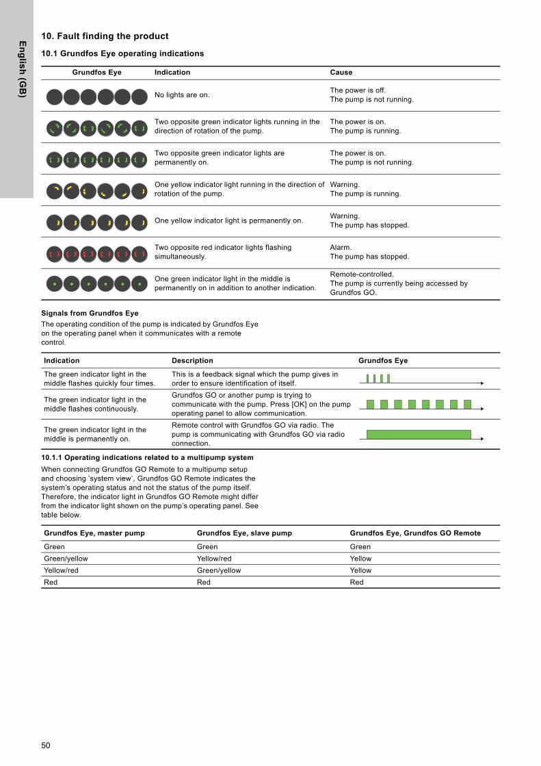
En
glis
h (G
B)
10. Fault finding the product
10.1 Grundfos Eye operating indications
Signals from Grundfos Eye
The operating condition of the pump is indicated by Grundfos Eye on the operating panel when it communicates with a remote control.
10.1.1 Operating indications related to a multipump system
When connecting Grundfos GO Remote to a multipump setup and choosing ’system view’, Grundfos GO Remote indicates the system’s operating status and not the status of the pump itself. Therefore, the indicator light in Grundfos GO Remote might differ from the indicator light shown on the pump’s operating panel. See table below.
Grundfos Eye Indication Cause
No lights are on. The power is off.The pump is not running.
Two opposite green indicator lights running in the direction of rotation of the pump.
The power is on.The pump is running.
Two opposite green indicator lights are permanently on.
The power is on.The pump is not running.
One yellow indicator light running in the direction of rotation of the pump.
Warning.The pump is running.
One yellow indicator light is permanently on. Warning. The pump has stopped.
Two opposite red indicator lights flashing simultaneously.
Alarm.The pump has stopped.
One green indicator light in the middle is permanently on in addition to another indication.
Remote-controlled.The pump is currently being accessed by Grundfos GO.
Indication Description Grundfos Eye
The green indicator light in the middle flashes quickly four times.
This is a feedback signal which the pump gives in order to ensure identification of itself.
The green indicator light in the middle flashes continuously.
Grundfos GO or another pump is trying to communicate with the pump. Press [OK] on the pump operating panel to allow communication.
The green indicator light in the middle is permanently on.
Remote control with Grundfos GO via radio. The pump is communicating with Grundfos GO via radio connection.
Grundfos Eye, master pump Grundfos Eye, slave pump Grundfos Eye, Grundfos GO Remote
Green Green GreenGreen/yellow Yellow/red YellowYellow/red Green/yellow YellowRed Red Red
50

En
gli
sh
(G
B)
10.2 Fault finding
Reset a fault indication in one of the following ways:• When you have eliminated the fault cause, the pump reverts to
normal duty.• If the fault disappears by itself, the fault indication is
automatically reset.The fault cause is stored in the pump alarm log.
WARNING
Electric shock
Death or serious personal injury- Switch off the power supply for at least 3 minutes
before you start any work on the product. Lock the main switch in position 0. Type and requirements as specified in EN 60204-1, 5.3.2.
WARNING
Electric shock
Death or serious personal injury- Make sure that other pumps or sources do not
force flow through the pump even if the pump is stopped.
CAUTION
Pressurised system
Minor or moderate personal injury- Before dismantling the pump, drain the system or
close the isolating valve on either side of the pump. The pumped liquid may be scalding hot and under high pressure.
If the power supply cable is damaged, it must be replaced by the manufacturer, the manufacturer's service partner or a similarly qualified person.
51

En
glis
h (G
B)
10.3 Fault finding table
Warning and alarm codes FaultAutomatic reset
and restartRemedy
"Pump communication fault" (10)"Alarm"
Communication fault between different parts of the electronics.
YesContact Grundfos Service, or replace the pump.Check if the pump is running in turbine operation. See code (29) "Forced pumping".
"Forced pumping" (29)"Alarm"
Other pumps or sources force flow through the pump even if the pump is stopped and switched off.
Yes
Switch off the pump on the main switch. If the light in Grundfos Eye is on, the pump is running in forced-pumping mode.Check the system for defective non-return valves and replace the valves, if necessary.Check the system for correct position of non-return valves, etc.
"Undervoltage" (40, 75)"Alarm"
The supply voltage to the pump is too low. Yes Make sure that the power supply is within the
specified range.
"Blocked pump" (51)"Alarm" The pump is blocked. Yes
Dismantle the pump, and remove any foreign matter or impurities preventing the pump from rotating.
"High motor temperature" (64)"Alarm"
The temperature in the stator windings is too high. No Contact Grundfos Service, or replace the pump.
"Internal fault" (72 and 155)"Alarm"
• Internal fault in the pump electronics.
• Irregularities in the voltage supply can cause alarm 72.
• Overload of the 24 VDC output can cause alarm 72. See section Input and output communication.
Yes
There might be turbine flow in the application that forces a flow through the pump.Check if the sensor is blocked by sediments. This can occur if the media is impure.Replace the pump, or contact Grundfos Service.
"Overvoltage" (74)"Alarm"
The supply voltage to the pump is too high. Yes Make sure that the power supply is within the
specified range."Comm. fault, twin-head pump" (77)"Warning"
The communication between pump heads was disturbed or broken.
- Make sure that the second pump head is powered on or connected to the power supply.
"Internal fault" (84, 85 and 157)"Warning" Fault in the pump electronics. - Contact Grundfos Service, or replace the pump.
"Internal sensor fault" (88)"Warning"
The pump is receiving a signal from the internal sensor which is outside the normal range.
-
Make sure that the plug and cable are connected correctly in the sensor. The sensor is located on the back of the pump housing. Replace the sensor, or contact Grundfos Service.
"External sensor fault" (93)"Warning"
The pump is receiving a signal from the external sensor which is outside the normal range.
-
Does the electrical signal set (0-10 V or 4-20 mA) match the sensor output signal?If not, change the setting of the analog input, or replace the sensor with one that matches the setup.Check the sensor cable for damage.Check the cable connection at the pump and at the sensor. Correct the connection, if required. See section 9.1 Differential-pressure and temperature sensor.The sensor has been removed, but the analog input has not been disabled.Replace the sensor, or contact Grundfos Service.
Warnings do not activate the alarm relay.
52

En
gli
sh
(G
B)
11. Accessories11.1 Grundfos GO
The pump is designed for wireless radio or infrared communication with Grundfos GO. Grundfos GO enables setting of functions and gives access to status overviews, technical product information and actual operating parameters.
Grundfos GO is available in Apple App Store and Google Play.Grundfos GO replaces the Grundfos R100 remote control. This means that all products supported by R100 are now supported by Grundfos GO.You can use Grundfos GO for the following:• Reading of operating data.• Reading of warning and alarm indications.• Setting of control mode.• Setting of setpoint.• Selection of external setpoint signal.• Allocation of pump number to distinguish between pumps that
are connected via GENIbus.• Selection of function for digital input.• Generation of reports in PDF.• Assist function.• Multipump setup.• Display of relevant documentation.For function and connection to the pump, see separate installation and operating instructions for the desired type of Grundfos GO setup.
11.2 Communication interface module, CIM
The pump can communicate via the wireless GENIair connection or a communication module.This enables the pump to communicate with other pumps and with different types of network solutions.The Grundfos communication interface modules enable the pump to connect to standard fieldbus networks.
Fig. 67 Building management system, BMS, with two pumps connected in parallel
A communication interface module is an add-on communication interface module.The communication interface module enables data transmission between the pump and an external system, for example a building management system or SCADA system.The communication interface module communicates via fieldbus protocols.
Pumps older than model C must have a CIM module mounted in both the slave and master pump. Pumps from model C have an integrated booster profile, which enables data in the slave to be monitored by the master. This booster profile supports newer versions of CIM modules, making it possible only to mount the CIM module on the master pump. The CIM modules supporting the booster profile are indicated in the overview below.
Available communication interface modules
The radio communication between the pump and Grundfos GO is encrypted to protect against misuse.
TM05
271
0 06
12
A gateway is a device that facilitates the transfer of data between two different networks based on different communication protocols.
Module Fieldbus protocol Product number
CIM 050 GENIbus 96824631CIM 100 LonWorks 96824797CIM 150 PROFIBUS DP 96824793CIM 200 Modbus RTU 96824796CIM 260 EU 3G/4G cellular 99439302 CIM 280 GRM 3G/4G 99439724CIM 300 BACnet MS/TP 96893770CIM 500 Ethernet 98301408
Use booster functional profiles for twin-head pumps.
Gateway
BMS
53

En
glis
h (G
B)
11.2.1 Description of communication interface modules
Module Fieldbus protocol Description Functions
CIM 050
TM06
723
8 34
16
GENIbus
CIM 050 is a Grundfos communication interface module used for communication with a GENIbus network.
CIM 050 has terminals for the GENIbus connection.
CIM 100
TM06
727
9 34
16
LonWorks
CIM 100 is a Grundfos communication interface module used for communication with a LonWorks network.
CIM 100 has terminals for the LonWorks connection.Two LEDs are used to indicate the actual status of the CIM 100 communication.One LED is used for indication of correct connection to the pump, and the other is used to indicate LonWorks communication status.
CIM 150
TM06
728
0 34
16
PROFIBUS DP
CIM 150 is a Grundfos communication interface module used for communication with a PROFIBUS network.
CIM 150 has terminals for the PROFIBUS DP connection.DIP switches are used to set line termination.Two hexadecimal rotary switches are used to set the PROFIBUS DP address.Two LEDs are used to indicate the actual status of the CIM 150 communication.One LED is used for indication of correct connection to the pump, and the other is used to indicate PROFIBUS communication status.
CIM 200
TM06
728
1 34
16
Modbus RTU
CIM 200 is a Grundfos communication interface module used for communication with a Modbus RTU network.
CIM 200 has terminals for the Modbus connection.DIP switches are used to select parity and stop bits, to select transmission speed and to set line termination.Two hexadecimal rotary switches are used to set the Modbus address.Two LEDs are used to indicate the actual status of the CIM 200 communication.One LED is used for indication of correct connection to the pump, and the other is used to indicate Modbus communication status.
CIM 260
EU 3G/4G cellular
CIM 260 is a Grundfos communication interface module which communicates using Modbus TCP via cellular data transmission to a SCADA system or SMS communication to mobile phones.
CIM 260 has a SIM-card slot and an SMA connection to the cellular antenna.CIM 260 can be fitted with a lithium-ion battery.Two LEDs are used to indicate the actual status of the CIM 260 communication. One LED is used for indication of correct connection to the pump, and the other is used to indicate cellular communication status.Note: The SIM card is not supplied with CIM 260.
CIM 280
GRM 3G/4G
CIM 280 is a Grundfos communication interface module which communicates via cellular network to Grundfos Remote Management.
CIM 280 has a SIM-card slot and an SMA connection to the cellular antenna.CIM 280 can be fitted with a lithium-ion battery.Two LEDs are used to indicate the actual status of the CIM 280 communication. One LED is used for indication of correct connection to the pump, and the other is used to indicate cellular communication status.Note: The SIM card is not supplied with CIM 280.
54
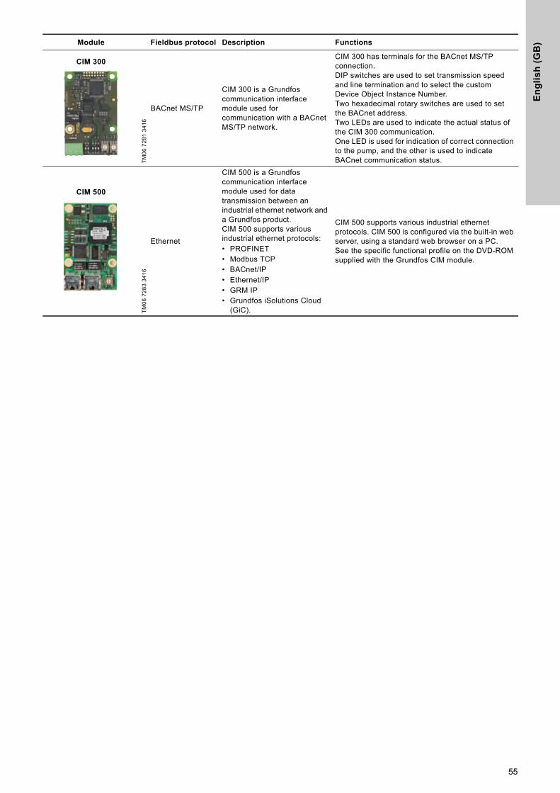
En
gli
sh
(G
B)
CIM 300
TM06
728
1 34
16
BACnet MS/TP
CIM 300 is a Grundfos communication interface module used for communication with a BACnet MS/TP network.
CIM 300 has terminals for the BACnet MS/TP connection. DIP switches are used to set transmission speed and line termination and to select the custom Device Object Instance Number.Two hexadecimal rotary switches are used to set the BACnet address.Two LEDs are used to indicate the actual status of the CIM 300 communication. One LED is used for indication of correct connection to the pump, and the other is used to indicate BACnet communication status.
CIM 500
TM06
728
3 34
16
Ethernet
CIM 500 is a Grundfos communication interface module used for data transmission between an industrial ethernet network and a Grundfos product.CIM 500 supports various industrial ethernet protocols:• PROFINET• Modbus TCP• BACnet/IP• Ethernet/IP• GRM IP• Grundfos iSolutions Cloud
(GiC).
CIM 500 supports various industrial ethernet protocols. CIM 500 is configured via the built-in web server, using a standard web browser on a PC.See the specific functional profile on the DVD-ROM supplied with the Grundfos CIM module.
Module Fieldbus protocol Description Functions
55

En
glis
h (G
B)
11.2.2 Installing a communication interface module
WARNING
Electric shock
Death or serious personal injury- Make sure that other pumps or sources do not
force flow through the pump even if the pump is stopped. This will cause the motor to act like a generator, resulting in voltage on the pump.
WARNING
Electric shock
Death or serious personal injury- Switch off the power supply for at least 3 minutes
before you start any work on the product. Make sure that the power supply cannot be accidentally switched on.
- It must be possible to lock the main switch in position 0. Type and requirements as specified in EN 60204-1, 5.3.2.
Pumps older than model C must have a CIM module mounted in both the slave and master pump.Pumps from model C together with newer versions of CIM modules only require for the CIM module to be mounted on the master pump, not on the slave. See section 11.2 Communication interface module, CIM.
Step Action Illustration
1
A. Terminal-connected versions:Remove the front cover from the control box.
B. Plug-connected versions:Open the front cover.
A
B
TM05
287
5 34
16TM
05 8
458
3416
2 Unscrew the earth connection.
TM06
690
7 34
16
56

En
gli
sh
(G
B)
3 Fit the communication interface module as illustrated and click it on.
TM05
291
4 34
16
4 Tighten the screw holding the communication interface module and secure the earth connection.
TM05
291
2 34
16
5For connection to fieldbus networks, see the installation and operating instructions for the desired communication interface module.
TM05
291
3 34
16
Step Action Illustration
57

En
glis
h (G
B)
11.2.3 Reuse of communication interface modules
You can reuse a communication interface module in a CIU unit used together with Grundfos MAGNA Series 2000 in MAGNA3. Before you use the CIM module in the pump, reconfigure the module. Contact your nearest Grundfos company.
Fig. 68 Reuse of communication interface module
11.2.4 Auto detection of CIM modules
If a pump in a system with multiple pumps is replaced with a newer version (model D), the new pump automatically detects if the existing pump(s) and/or BMS system are older and adjusts itself accordingly.Auto detection in twin-head pumps happens if one of the pumps is replaced and paired with a newer model than the existing one, i.e. MAGNA3 model D. The new pump automatically detects the model version of the existing pump. If the old pump is an older model, the new pump will adjust itself making it compatible with the old system.Auto detection can be manually overruled if the system is controlled by a SCADA system. However, when integrating a newer model with an older setup, we recommend that you choose compatibility mode. For more information on how to manage auto detection directly on the pump, see section "Multipump profile selection", page 44.
11.2.5 Grundfos Remote Management
Grundfos Remote Management is an easy-to-install, low-cost solution for wireless monitoring and management of Grundfos products. It is based on a centrally hosted database and a web server with wireless data collection via GSM or GPRS modem. The system only requires an internet connection, a web browser, a Grundfos Remote Management modem and an antenna as well as a contract with Grundfos allowing you to monitor and manage Grundfos pump systems.You have wireless access to your account anywhere and anytime you have an internet connection, for example via a mobile device. Warnings and alarms can be sent by e-mail or SMS to your mobile device.
For Grundfos Remote Management contract, contact your local Grundfos company.
11.3 Pipe connections
Adapters for threads and flanges are available as accessories, making it possible to install the pump in any pipe. See data booklet for MAGNA3, Accessories section, for the right dimension and product number.
TM05
291
1 13
12
Application DescriptionProduct number
CIM 280Grundfos Remote ManagementRequires a contract with Grundfos and a SIM card.
99439724
GSM antenna for roof-mounting
Antenna for use on top of metal cabinets.Vandal-proof. 2-metre cable. Quad band for global use.
97631956
GSM antenna for desk-mounting
Antenna for general-purpose application, for example inside plastic cabinets.To be fixed with the double-adhesive tape supplied.4-metre cable.Quad band for global use.
97631957
58

En
gli
sh
(G
B)
11.4 External sensors
11.4.1 Temperature sensor
11.4.2 Pressure sensor
11.4.3 DPI V.2 transmitter
Combined differential-pressure and temperature transmitter
Scope of delivery:• DPI V.2 transmitter• open 2 m cable with M12 connection in one end• capillary tube with fitting• quick guide.
Fig. 69 DPI V.2 transmitter
1) Note: EPDM: approved for potable water.
Sensor TypeMeasuring
range[bar]
Measuring range[°C]
Transmitter output[VDC]
Power supply[VDC]
Process connection
Product number
Combined pressure and temperature sensor RPI T2 0-16 -10 to +120 2 x 0 - 10
4 wires 16.6 - 30 G 1/2 98355521
Sensor Type SupplierMeasuring
range[bar]
Sensor output [mA]
Power supply[VDC]
Process connectionProduct number
Pressure sensor RPI Grundfos
0 - 0.6
4-20 12-30 G 1/2
977489070 - 1.0 977489080 - 1.6 977489090 - 2.5 977489100 - 4.0 977489210 - 6.0 977489220-12 977489230-16 97748924
TM04
786
6 25
10
SensorMeasuring
range[bar]
Measuring range[°C]
Transmitter output
Power supply [VDC]
Temperature measurement
O-ring EPDM1)
Process connection
Product number
Grundfos DPI 0 - 0.6 0-100
4-20 mA 12.5 - 30 ● 977471940-10 VDC 16.5 - 30 ● ● 97747202
Grundfos DPI 0 - 1.0 0-100
4-20 mA 12.5 - 30 ●G 1/2
977471950-10 VDC 16.5 - 30 ● ● 97747203
Grundfos DPI 0 - 1.6 0-100
4-20 mA 12.5 - 30 ●G 1/2
977471960-10 VDC 16.5 - 30 ● ● 97747204
Grundfos DPI 0 - 2.5 0-100
4-20 mA 12.5 - 30 ●G 1/2
977471970-10 VDC 16.5 - 30 ● ● 97747205
59

En
glis
h (G
B)
11.5 Cable for sensors
11.6 Blanking flange
The accessory is used to blank off the opening when one of the pump heads of a twin-head pump is removed for service to enable uninterrupted operation of the other pump. The accessory set consists of a blanking flange and a fastener set.
Fig. 70 Position of blanking flange
11.7 Insulating kits for applications with ice buildup
The accessory is for single-head MAGNA pumps used in applications with ice buildup. The accessory set consists of two polyurethane (PUR) shells and metal clamps to ensure tight assembly.
* If the control box of the pump is turned, the insulating shells are not applicable. Contact Grundfos for assistance.
Specifications:• Specific volume resistance greater than or equal to 1015 Ωcm,
DIN 60093• thermal conductivity at 10 °C 0.036 W/mK and at 40 °C 0.039
W/mK, DIN 52612• density 33 ± 5 kg/m3, ISO 845• working temperature range -40 to +90 °C, ISO 2796.
DescriptionLength
[m]Product number
Screened cable 2.0 98374260Screened cable 5.0 98374271
TM06
851
8 08
17
Pump type Product number
MAGNA3 32-40/60/80/100 (F)MAGNA3 40-40/60 F 98159373
MAGNA3 32-120 FMAGNA3 40-/80/100/120/150/180 FMAGNA3 50-40/60/80/100/120/150/180 FMAGNA3 65-40/60/80/100/120/150 FMAGNA3 80-40/60/80/100/120 FMAGNA3 100-40/60/80/100/120 F
98159372
Pump type Product number
MAGNA3 25-40/60/80/100/120 (N) 98354534MAGNA3 32-40/60/80/100/120 (N) 98354535MAGNA3 32-40/60/80/100 F (N) 98354536MAGNA3 32-120 F (N) 98063287MAGNA3 40-40/60 F (N) 98354537MAGNA3 40-80/100 F (N) 98063288MAGNA3 40-120/150/180 F (N) 98145675MAGNA3 50-40/60/80 F (N) 98063289MAGNA3 50-100/120/150/180 F (N) 98145676MAGNA3 65-40/60/80/100/120 F (N) 96913593MAGNA3 65-150 F (N)* 99608813MAGNA3 80-40/60/80/100/120 F 98134265MAGNA3 100-40/60/80/100/120 F 96913589
60

En
gli
sh
(G
B)
12. Technical dataSupply voltage
1 x 230 V ± 10 %, 50/60 Hz, PE.
Motor protection
The pump requires no external motor protection.
Enclosure class
IPX4D (EN 60529).
Insulation class
F.
Relative humidity
Maximum 95 %.
Ambient temperature
0 to 40 °C.
Ambient temperature during transport: -40 to +70 °C.
Temperature class
TF110 (EN 60335-2-51).
Liquid temperature
Continuously: -10 to +110 °C. Stainless-steel pumps in domestic hot-water systems: In domestic hot-water systems, we recommend that you keep the liquid temperature below 65 °C to eliminate the risk of lime precipitation.
System pressure
The maximum permissible system pressure is stated on the pump nameplate: PN 6: 6 bar / 0.6 MPaPN 10: 10 bar / 1.0 MPaPN 12: 12 bar / 1.2 MPaPN 16: 16 bar / 1.6 MPa.Note: Not all variants are available in all markets.
Test pressure
The pumps can withstand test pressures as indicated in EN 60335-2-51. See below.• PN 6: 7.2 bar / 0.72 MPa• PN 10: 12 bar / 1.2 MPa• PN 6/10: 12 bar / 1.2 MPa• PN 12: 12 bar / 1.2 MPa• PN 16: 19.2 bar / 1.92 MPa.Not all variants are available in all markets.During normal operation, do not use the pump at higher pressures than those stated on the nameplate.The pressure test has been made with water containing anticorrosive additives at a temperature of 20 °C.
Minimum inlet pressure
The following relative minimum inlet pressure must be available at the pump inlet during operation to avoid cavitation noise and damage to the pump bearings.
In the case of cascade operation, the required relative inlet pressure must be increased by 0.1 bar / 0.01 MPa compared to the stated values for single-head pumps or twin-head pumps in single-head operation.The relative minimum inlet pressures apply to pumps installed up to 300 metres above sea level. For altitudes above 300 metres, the required relative inlet pressure must be increased by 0.01 bar / 0.001 MPa per 100 metres altitude. The MAGNA3 pump is only approved for an altitude of 2000 metres above sea level.
Sound pressure level
The sound pressure level of the pump is dependent on the power consumption. Levels are determined in accordance with ISO 3745 and ISO 11203, method Q2.
Ambient temperatures below 0 °C require the following conditions:• The media temperature is 5 °C.• The media contains glycol.• The pump runs continuously and does not stop.• For twin-head pumps cascade operation every 24
hours is mandatory.
The actual inlet pressure and the pump pressure against a closed valve must be lower than the maximum permissible system pressure.
The values in the table below apply to single-head pumps and twin-head pumps in single-head operation.
MAGNA3
Liquid temperature
75 °C 95 °C 110 °C
Inlet pressure[bar] / [MPa]
25-40/60/80/100/120 0.10 / 0.01 0.35 / 0.035 1.0 / 0.1032-40/60/80/100/120 0.10 / 0.01 0.35 / 0.035 1.0 / 0.1032-40/60/80/100/120 F 0.10 / 0.01 0.35 / 0.035 1.0 / 0.1032-120 F 0.10 / 0.01 0.20 / 0.020 0.7 / 0.0740-40/60 F 0.10 / 0.01 0.35 / 0.035 1.0 / 0.1040-80/100/120/150/180 F 0.10 / 0.01 0.50 / 0.05 1.0 / 0.1050-40/60/80 F 0.10 / 0.01 0.40 / 0.04 1.0 / 0.1050-100/120 F 0.10 / 0.01 0.50 / 0.05 1.0 / 0.1050-150/180 F 0.70 / 0.07 1.20 / 0.12 1.7 / 0.1765-40/60/80/100/120/150 F 0.70 / 0.07 1.20 / 0.12 1.7 / 0.1780-40/60/80/100/120 F 0.50 / 0.05 1.00 / 0.10 1.5 / 0.15100-40/60/80/100/120 F 0.70 / 0.07 1.20 / 0.12 1.7 / 0.17
Pump size Max. [dB(A)]
25-40/60/80/100/12032-40/60/80/100/12040-40/6050-40
39
32-120 F40-80/10050-60/8065-40/6080-40
45
40-120/150/18050-100/120/150/18065-80/100/12080-60/80100-40/60
50
65-15080-100/120100-80/100/120
55
61

En
glis
h (G
B)
Leakage current
The mains filter will cause a leakage current to earth during operation. The leakage current is less than 3.5 mA.
Consumption when the pump is stopped
4 to 10 W, depending on activity, such as reading the display, use of Grundfos GO, interaction with modules.4 W when the pump is stopped and there is no activity.
Input and output communication
Cable glands
Use M16 cable glands for the input and output connections (not supplied with the pump).
Power factor
The terminal-connected versions have built-in an active power factor correction which gives a cos φ from 0.98 to 0.99.The plug-connected versions have built-in passive PFC, with coil and resistors which ensures that the current drawn from the grid is in phase with the voltage. The current is approximately sinusoidal which gives a cos φ from 0.55 to 0.98.
12.1 Sensor specifications
12.1.1 Temperature
13. Disposing of the productThis product has been designed with focus on the disposal and recycling of materials. The following average disposal values apply to all variants of pumps:• 85 % recycling• 10 % incineration• 5 % depositing.This product or parts of it must be disposed of in an environmentally sound way:1. Use the public or private waste collection service.2. If this is not possible, contact the nearest Grundfos company
or service workshop.The crossed-out wheelie bin symbol on a product means that it must be disposed of separately from household waste. When a product marked with this symbol reaches its end of life, take it to a collection point designated by the local waste disposal
authorities. The separate collection and recycling of such products will help protect the environment and human health.See also end-of-life information at www.grundfos.com/product-recycling.
Two digital inputs
External potential-free contact.Contact load: 5 V, 10 mA.Screened cable.Loop resistance: Maximum 130 Ω.
Analog input 4-20 mA, load: 150 Ω.0-10 VDC, load: Greater than 10 kΩ.
Two relay outputs
Internal potential-free changeover contact. Maximum load: 250 V, 2 A, AC1.Minimum load: 5 VDC, 20 mA.Screened cable, depending on signal level.
24 VDC supply Maximum load: 22 mA.Capacitive load: Less than 470 μF.
Temperature range during operation Accuracy
-10 to +35 °C ± 2 °C+35 to +90 °C ± 1 °C+90 to +110 °C ± 2 °C
WARNING
Magnetic field
Death or serious personal injury- Persons with pacemakers disassembling this
product must exercise care when handling the magnetic materials embedded in the rotor.
62

Ap
pe
nd
ix
Appendix 1
Dimensions
Fig. 1 Dimensions, single-head pumps, threaded versions
Fig. 2 Dimensions, single-head pumps, flanged versions TM
05 7
938
2013
Pump typeDimensions [mm]
L1 L5 L6 B1 B2 B4 B6 B7 H1 H2 H3 H4 D1 G
MAGNA3 25-40 (N) 180 158 190 58 111 69 90 113 54 185 239 71 25 1 1/2MAGNA3 25-60 (N) 180 158 190 58 111 69 90 113 54 185 239 71 25 1 1/2MAGNA3 25-80 (N) 180 158 190 58 111 69 90 113 54 185 239 71 25 1 1/2MAGNA3 25-100 (N) 180 158 190 58 111 69 90 113 54 185 239 71 25 1 1/2MAGNA3 25-120 (N) 180 158 190 58 111 69 90 113 54 185 239 71 25 1 1/2MAGNA3 32-40 (N) 180 158 190 58 111 69 90 113 54 185 239 71 32 2MAGNA3 32-60 (N) 180 158 190 58 111 69 90 113 54 185 239 71 32 2MAGNA3 32-80 (N) 180 158 190 58 111 69 90 113 54 185 239 71 32 2MAGNA3 32-100 (N) 180 158 190 58 111 69 90 113 54 185 239 71 32 2MAGNA3 32-120 (N) 180 158 190 58 111 69 90 113 54 185 239 71 32 2
TM05
793
8 20
13
Pump typeDimensions [mm]
L1 L5 L6 B1 B2 B4 B6 B7 H1 H2 H3 H4 D1 D2 D3 D4 D5
MAGNA3 32-40 F (N) 220 158 220 58 111 69 100 110 65 185 250 82 32 76 90/100 140 14/19MAGNA3 32-60 F (N) 220 158 220 58 111 69 100 110 65 185 250 82 32 76 90/100 140 14/19MAGNA3 32-80 F (N) 220 158 220 58 111 69 100 110 65 185 250 82 32 76 90/100 140 14/19MAGNA3 32-100 F (N) 220 158 220 58 111 69 100 110 65 185 250 82 32 76 90/100 140 14/19MAGNA3 40-40 F (N) 220 158 220 58 111 69 105 105 65 199 264 83 40 84 100/110 150 14/19MAGNA3 40-60 F (N) 220 158 220 58 111 69 105 105 65 199 264 83 40 84 100/110 150 14/19
63

Ap
pe
nd
ix
Fig. 3 Dimensions, single-head pumps, flanged versions
TM05
529
1 20
13
Pump typeDimensions [mm]
L1 L5 B1 B2 B4 B6 B7 H1 H2 H3 H4 D1 D2 D3 D4 D5
MAGNA3 32-120 F (N) 220 204 84 164 73 106 116 65 301 366 86 32 76 90/100 140 14/19MAGNA3 40-80 F (N) 220 204 84 164 73 106 128 65 304 369 83 40 84 100/110 150 14/19MAGNA3 40-100 F (N) 220 204 84 164 73 106 128 65 304 369 83 40 84 100/110 150 14/19MAGNA3 40-120 F (N) 250 204 84 164 73 106 128 65 304 369 83 40 84 100/110 150 14/19MAGNA3 40-150 F (N) 250 204 84 164 73 106 128 65 304 369 83 40 84 100/110 150 14/19MAGNA3 40-180 F (N) 250 204 84 164 73 106 128 65 304 369 83 40 84 100/110 150 14/19MAGNA3 50-40 F (N) 240 204 84 164 73 127 127 71 304 374 97 50 102 110/125 165 14/19MAGNA3 50-60 F (N) 240 204 84 164 73 127 127 71 304 374 97 50 102 110/125 165 14/19MAGNA3 50-80 F (N) 240 204 84 164 73 127 127 71 304 374 97 50 102 110/125 165 14/19MAGNA3 50-100 F (N) 280 204 84 164 73 127 127 72 304 376 97 50 102 110/125 165 14/19MAGNA3 50-120 F (N) 280 204 84 164 73 127 127 72 304 376 97 50 102 110/125 165 14/19MAGNA3 50-150 F (N) 280 204 84 164 73 127 127 72 304 376 97 50 102 110/125 165 14/19MAGNA3 50-180 F (N) 280 204 84 164 73 127 127 72 304 376 97 50 102 110/125 165 14/19MAGNA3 65-40 F (N) 340 204 84 164 73 133 133 74 312 386 94 65 119 130/145 185 14/19MAGNA3 65-60 F (N) 340 204 84 164 73 133 133 74 312 386 94 65 119 130/145 185 14/19MAGNA3 65-80 F (N) 340 204 84 164 73 133 133 74 312 386 94 65 119 130/145 185 14/19MAGNA3 65-100 F (N) 340 204 84 164 73 133 133 74 312 386 94 65 119 130/145 185 14/19MAGNA3 65-120 F (N) 340 204 84 164 73 133 133 74 312 386 94 65 119 130/145 185 14/19MAGNA3 65-150 F (N) 340 204 84 164 73 133 133 74 312 386 94 65 119 130/145 185 14/19MAGNA3 80-40 F 360 204 84 164 73 163 163 96 318 413 115 80 128 150/160 200 19MAGNA3 80-60 F 360 204 84 164 73 163 163 96 318 413 115 80 128 150/160 200 19MAGNA3 80-80 F 360 204 84 164 73 163 163 96 318 413 115 80 128 150/160 200 19MAGNA3 80-100 F 360 204 84 164 73 163 163 96 318 413 115 80 128 150/160 200 19MAGNA3 80-120 F 360 204 84 164 73 163 163 96 318 413 115 80 128 150/160 200 19MAGNA3 100-40 F 450 204 84 164 73 178 178 103 330 433 120 100 160 170 220 19MAGNA3 100-60 F 450 204 84 164 73 178 178 103 330 433 120 100 160 170 220 19MAGNA3 100-80 F 450 204 84 164 73 178 178 103 330 433 120 100 160 170 220 19MAGNA3 100-100 F 450 204 84 164 73 178 178 103 330 433 120 100 160 170 220 19MAGNA3 100-120 F 450 204 84 164 73 178 178 103 330 433 120 100 160 170 220 19
64

Ap
pe
nd
ix
Fig. 4 Dimensions, twin-head pumps, threaded versions
Fig. 5 Dimensions, twin-head pumps, flanged versions
TM05
793
9 20
13
Pump typeDimensions [mm]
L1 L5 L7 B1 B3 B4 B5 H1 H2 H3 D1 G M3
MAGNA3 D 32-40 180 158 35 58 400 179 221 54 185 239 32 2 1/4MAGNA3 D 32-60 180 158 35 58 400 179 221 54 185 239 32 2 1/4MAGNA3 D 32-80 180 158 35 58 400 179 221 54 185 239 32 2 1/4MAGNA3 D 32-100 180 158 35 58 400 179 221 54 185 239 32 2 1/4
TM05
529
4 36
12
Pump typeDimensions [mm]
L1 L2 L3 L4 L5 L7 B1 B3 B4 B5 B6 B7 H1 H2 H3 D1 D2 D3 D4 D5 M M3
MAGNA3 D 32-40 F 220 73 120 85 158 35 58 400 179 221 130 260 69 185 254 32 76 90/100 140 14/19 M12 Rp 1/4
MAGNA3 D 32-60 F 220 73 120 85 158 35 58 400 179 221 130 260 69 185 254 32 76 90/100 140 14/19 M12 Rp 1/4
MAGNA3 D 32-80 F 220 73 120 85 158 35 58 400 179 221 130 260 69 185 254 32 76 90/100 140 14/19 M12 Rp 1/4
MAGNA3 D 32-100 F 220 73 120 85 158 35 58 400 179 221 130 260 69 185 254 32 76 90/100 140 14/19 M12 Rp 1/4
MAGNA3 D 32-120 F 220 97 90 50 204 50 84 502 210 294 130 260 68 300 368 32 76 90/100 140 14/19 M12 Rp 1/4
MAGNA3 D 40-40 F 220 53 140 60 158 15 58 452 211 241 130 260 76 199 275 40 84 100/110 150 14/19 M12 Rp1/4
MAGNA3 D 40-60 F 220 53 140 60 158 15 58 452 211 241 130 260 76 199 275 40 84 100/110 150 14/19 M12 Rp1/4
MAGNA3 D 40-80 F 220 53 140 60 204 15 84 502 210 294 130 260 76 303 379 40 84 100/110 150 14/19 M12 Rp 1/4
MAGNA3 D 40-100 F 220 53 140 60 204 15 84 502 210 294 130 260 76 303 379 40 84 100/110 150 14/19 M12 Rp 1/4
MAGNA3 D 50-40 F 240 48 160 45 204 45 84 515 221 294 130 260 75 304 379 50 102 110/125 165 14/19 M12 Rp 1/4
MAGNA3 D 50-60 F 240 48 160 45 204 45 84 515 221 294 130 260 75 304 379 50 102 110/125 165 14/19 M12 Rp 1/4
MAGNA3 D 50-80 F 240 48 160 45 204 45 84 515 221 294 130 260 75 304 379 50 102 110/125 165 14/19 M12 Rp 1/4
65
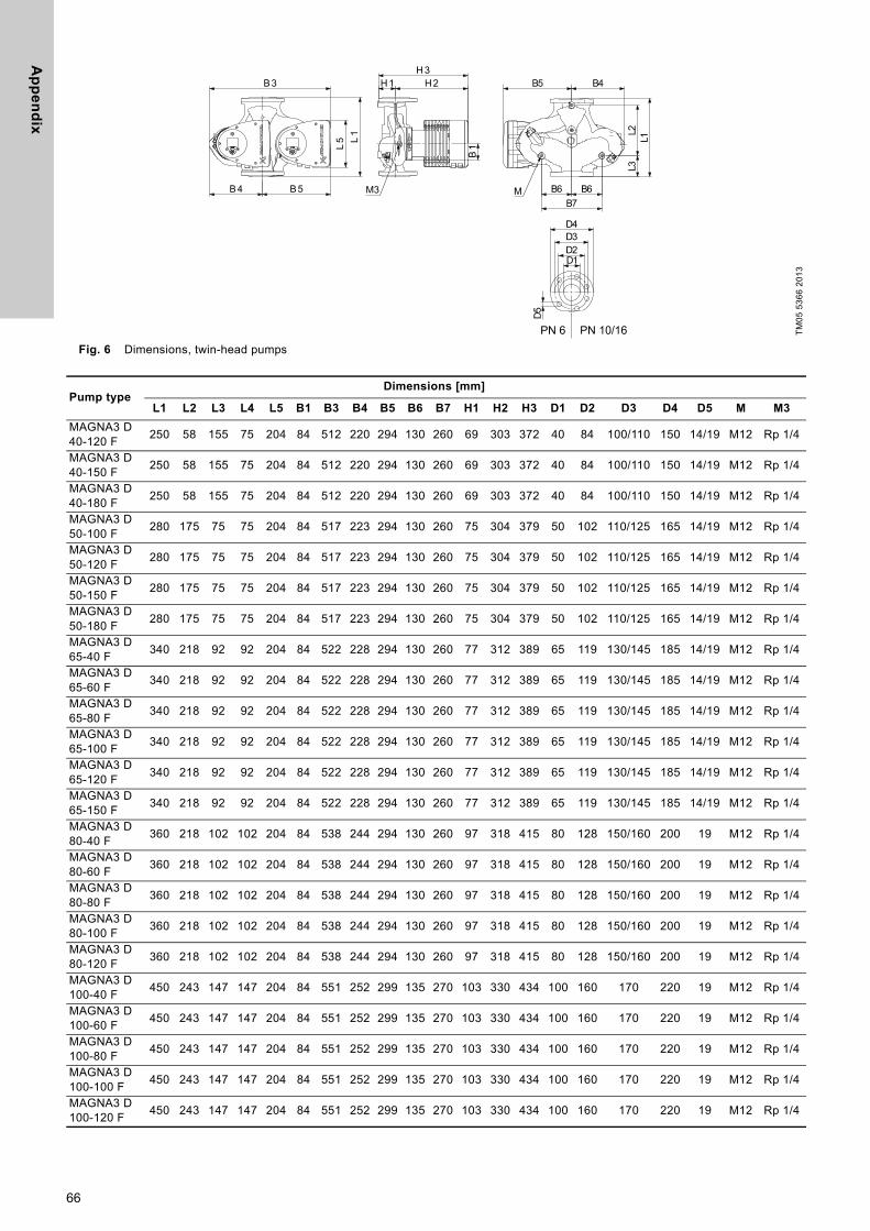
Ap
pe
nd
ix
Fig. 6 Dimensions, twin-head pumps
TM05
536
6 20
13
Pump typeDimensions [mm]
L1 L2 L3 L4 L5 B1 B3 B4 B5 B6 B7 H1 H2 H3 D1 D2 D3 D4 D5 M M3
MAGNA3 D 40-120 F 250 58 155 75 204 84 512 220 294 130 260 69 303 372 40 84 100/110 150 14/19 M12 Rp 1/4
MAGNA3 D 40-150 F 250 58 155 75 204 84 512 220 294 130 260 69 303 372 40 84 100/110 150 14/19 M12 Rp 1/4
MAGNA3 D 40-180 F 250 58 155 75 204 84 512 220 294 130 260 69 303 372 40 84 100/110 150 14/19 M12 Rp 1/4
MAGNA3 D 50-100 F 280 175 75 75 204 84 517 223 294 130 260 75 304 379 50 102 110/125 165 14/19 M12 Rp 1/4
MAGNA3 D 50-120 F 280 175 75 75 204 84 517 223 294 130 260 75 304 379 50 102 110/125 165 14/19 M12 Rp 1/4
MAGNA3 D 50-150 F 280 175 75 75 204 84 517 223 294 130 260 75 304 379 50 102 110/125 165 14/19 M12 Rp 1/4
MAGNA3 D 50-180 F 280 175 75 75 204 84 517 223 294 130 260 75 304 379 50 102 110/125 165 14/19 M12 Rp 1/4
MAGNA3 D 65-40 F 340 218 92 92 204 84 522 228 294 130 260 77 312 389 65 119 130/145 185 14/19 M12 Rp 1/4
MAGNA3 D 65-60 F 340 218 92 92 204 84 522 228 294 130 260 77 312 389 65 119 130/145 185 14/19 M12 Rp 1/4
MAGNA3 D 65-80 F 340 218 92 92 204 84 522 228 294 130 260 77 312 389 65 119 130/145 185 14/19 M12 Rp 1/4
MAGNA3 D 65-100 F 340 218 92 92 204 84 522 228 294 130 260 77 312 389 65 119 130/145 185 14/19 M12 Rp 1/4
MAGNA3 D 65-120 F 340 218 92 92 204 84 522 228 294 130 260 77 312 389 65 119 130/145 185 14/19 M12 Rp 1/4
MAGNA3 D 65-150 F 340 218 92 92 204 84 522 228 294 130 260 77 312 389 65 119 130/145 185 14/19 M12 Rp 1/4
MAGNA3 D 80-40 F 360 218 102 102 204 84 538 244 294 130 260 97 318 415 80 128 150/160 200 19 M12 Rp 1/4
MAGNA3 D 80-60 F 360 218 102 102 204 84 538 244 294 130 260 97 318 415 80 128 150/160 200 19 M12 Rp 1/4
MAGNA3 D 80-80 F 360 218 102 102 204 84 538 244 294 130 260 97 318 415 80 128 150/160 200 19 M12 Rp 1/4
MAGNA3 D 80-100 F 360 218 102 102 204 84 538 244 294 130 260 97 318 415 80 128 150/160 200 19 M12 Rp 1/4
MAGNA3 D 80-120 F 360 218 102 102 204 84 538 244 294 130 260 97 318 415 80 128 150/160 200 19 M12 Rp 1/4
MAGNA3 D 100-40 F 450 243 147 147 204 84 551 252 299 135 270 103 330 434 100 160 170 220 19 M12 Rp 1/4
MAGNA3 D 100-60 F 450 243 147 147 204 84 551 252 299 135 270 103 330 434 100 160 170 220 19 M12 Rp 1/4
MAGNA3 D 100-80 F 450 243 147 147 204 84 551 252 299 135 270 103 330 434 100 160 170 220 19 M12 Rp 1/4
MAGNA3 D 100-100 F 450 243 147 147 204 84 551 252 299 135 270 103 330 434 100 160 170 220 19 M12 Rp 1/4
MAGNA3 D 100-120 F 450 243 147 147 204 84 551 252 299 135 270 103 330 434 100 160 170 220 19 M12 Rp 1/4
66

Ap
pe
nd
ix
Flange forces and moments
Maximum permissible forces and moments from the pipe connections acting on the pump flanges or threaded connections are indicated in fig. 7.
Fig. 7 Forces and moments from the pipe connections acting on the pump flanges or threaded connections
* The values also apply to pumps with threaded connection.
Forces are static.The above values apply to cast-iron versions. For stainless-steel versions, the values can be multiplied by two according to the ISO 5199 standard.
Tightening torques for bolts
Recommended tightening torques for bolts used in flanged connections:
TM05
563
9 40
12
Force[N]
Moment[Nm]
Diameter DN Fy Fz Fx ΣFb My Mz Mx ΣMb
25* 350 425 375 650 300 350 450 65032* 425 525 450 825 375 425 550 80040 500 625 550 975 450 525 650 95050 675 825 750 1300 500 575 700 102565 850 1050 925 1650 550 600 750 110080 1025 1250 1125 1975 575 650 800 1175100 1350 1675 1500 2625 625 725 875 1300
Bolt dimension Torque
M12 27 NmM16 66 Nm
67

Gru
nd
fos
co
mp
an
ies
YETKİLİ GRUNDFOS SERVİSLERİ
Firma AdresTelefon
Cep telefonuFaks
İlgili KişiEposta
GRUNDFOS POMPA KOCAELİ
GEBZE ORGANİZE SANAYİ BÖLGESİ. İHSAN DEDE CADDESİ.2.YOL 200.SOKAK.NO:204 GEBZE KOCAELİ
0262 679 79 790553 259 51 630262 679 79 05
EMRAH ŞİMŞ[email protected]
SUNPO ELEKTRİK ADANA
YEŞİLOBA MAH. 46003 SOK. ARSLANDAMI İŞ MERK. C BLOK NO:6/2-I SEYHAN ADANA
0322 428 50 140533 461 71 140322 428 48 49
LEVENT [email protected]
ARDA POMPA ANKARA
26 NOLU İŞ MERKEZİ 1120.SOKAK NO:5/1,5/5 OSTİM/ANKARA
0312 385 98 930541 805 89 440312 385 8904
METİN ENGİN CANBAZ [email protected]
UĞUR SU POMPALARI ANKARA
AHİ EVRAN MAHALLESİ ÇAĞRIŞIM CADDESİ NO:2/15 SİNCAN /ANKARA
0312 394 37 520532 505 12 620312 394 37 19
UĞUR YETİŞ ÖCAL [email protected]
GROSER A.Ş. ANTALYA
ŞAFAK MAHALLESİ.5041.SOKAK.SANAYİ 28 C BLOK NO:29 KEPEZ ANTALYA
0242 221 43 430532 793 89 740242 221 43 42
DOĞAN YÜ[email protected]
KOÇYİĞİTLER ELEKTRİK BOBİNAJ ANTALYA
ORTA MAH. SERİK CAD. NO.116 SERİK ANTALYA
0242 722 48 460532 523 29 340242 722 48 46
BİLAL KOÇYİĞİT [email protected]
TEKNİK BOBİNAJ BURSA
ALAADDİN BEY MH.624.SK MESE 5 İŞ MERKEZİ NO:26 D:10 NİLÜFER/BURSA
0224 443 78 830507 311 19 080224 443 78 95
GÜLDEN MÜÇEOĞLU [email protected]
ASİN TEKNOLOJİ GAZİANTEP
MÜCAHİTLER MAHALLESİ 54 NOLU SOKAK.GÜNEYDOĞU İŞ MERKEZİ NO:10/A ŞEHİTKAMİL
0342 321 69 660532 698 69 660342 321 69 61
MEHMET DUMAN [email protected]
ARI MOTOR İSTANBUL
ORHANLI MESCİT MH.DEMOKRASİ CD.BİRMES SAN.SİT.A-3 BLOK NO:9 TUZLA İSTANBUL
0216 394 21 670532 501 47 690216 394 23 39
EMİN [email protected]
SERİ MEKANİK İSTANBUL
SEYİTNİZAM MAH. DEMİRCİLER SİT. 7.YOL . NO:6 ZEYTİNBURNU İSTANBUL
0212 679 57 230532 740 18 020212 415 61 98
TAMER ERÜNSAL [email protected]
DAMLA POMPA İZMİR 1203/4 SOKAK NO:2/E YENİŞEHİR İZMİR
0232 449 02 48 0532 277 96 44 0232 459 43 05
NEVZAT KIYAK [email protected]
ÇAĞRI ELEKTRİK KAYSERİ
ESKİ SANAYİ BÖLGESİ 3.CADDE NO;3-B KOCASİNAN-KAYSERİ
0352 320 19 64 0532 326 23 25 0352 330 37 36
ADEM ÇAKICI [email protected]
MAKSOM OTOMASYON SAMSUN
19 MAYIS MAHALLESİ.642.SOKAK.NO:23 TEKKEKÖY SAMSUN
0362 256 23 560532 646 61 42
-
MUSTAFA SARI [email protected]
DETAY MÜHENDİSLİK TEKİRDAĞ
ZAFER MAHALLESİ ŞEHİT YÜZBAŞI YÜCEL KENTER CADDESİ 06/A BLOK NO:5-6 ÇORLU TEKİRDAĞ
0282 673 51 330549 668 68 680282 673 51 35
EROL KARTOĞ[email protected]
ROTATEK ENDÜSTRİYEL TEKİRDAĞ
ZAFER MH. ŞEHİT YÜZBAŞI YÜCEL KENTER CD. YENİ SANAYİ SİTESİ 08-A BLOK NO:14 ÇORLU / TEKİRDAĞ
0282 654 51 990532 788 11 390282 654 51 81
ÖZCAN AKBAŞ [email protected]
İLDEM TEKNİK ISITMA VAN
ŞEREFİYE MAH ORDU CAD ARAS AP NO 75 İPEKYOLU VAN
0432 216 20 830532 237 54 590432 216 20 83
BURHAN DEMİREKİ[email protected]
BARIŞ BOBİNAJ K.K.T.C.
LARNAKA YOLU ÜZERİ.PAPATYA APT.NO:3-4 GAZİMAĞUSA
0542 884 06 620542 854 11 350533 884 06 62
BARIŞ KIZILKILINÇ [email protected]

Gru
nd
fos
co
mp
anie
s
ArgentinaBombas GRUNDFOS de Argentina S.A.Ruta Panamericana km. 37.500 Centro Industrial Garin1619 Garín Pcia. de B.A.Phone: +54-3327 414 444Telefax: +54-3327 45 3190
AustraliaGRUNDFOS Pumps Pty. Ltd.P.O. Box 2040 Regency Park South Australia 5942 Phone: +61-8-8461-4611 Telefax: +61-8-8340 0155
AustriaGRUNDFOS Pumpen Vertrieb Ges.m.b.H.Grundfosstraße 2 A-5082 Grödig/Salzburg Tel.: +43-6246-883-0 Telefax: +43-6246-883-30
BelgiumN.V. GRUNDFOS Bellux S.A. Boomsesteenweg 81-83 B-2630 Aartselaar Tél.: +32-3-870 7300 Télécopie: +32-3-870 7301
BelarusПредставительство ГРУНДФОС в Минске220125, Минскул. Шафарнянская, 11, оф. 56, БЦ «Порт»Тел.: +375 17 397 397 3
+375 17 397 397 4Факс: +375 17 397 397 1E-mail: [email protected]
Bosnia and HerzegovinaGRUNDFOS SarajevoZmaja od Bosne 7-7A,BH-71000 SarajevoPhone: +387 33 592 480Telefax: +387 33 590 465www.ba.grundfos.come-mail: [email protected]
BrazilBOMBAS GRUNDFOS DO BRASILAv. Humberto de Alencar Castelo Branco, 630CEP 09850 - 300São Bernardo do Campo - SPPhone: +55-11 4393 5533Telefax: +55-11 4343 5015
BulgariaGrundfos Bulgaria EOODSlatina DistrictIztochna Tangenta street no. 100BG - 1592 SofiaTel. +359 2 49 22 200Fax. +359 2 49 22 201email: [email protected]
CanadaGRUNDFOS Canada Inc. 2941 Brighton Road Oakville, Ontario L6H 6C9 Phone: +1-905 829 9533 Telefax: +1-905 829 9512
ChinaGRUNDFOS Pumps (Shanghai) Co. Ltd.10F The Hub, No. 33 Suhong RoadMinhang DistrictShanghai 201106PRCPhone: +86 21 612 252 22Telefax: +86 21 612 253 33
COLOMBIAGRUNDFOS Colombia S.A.S.Km 1.5 vía Siberia-Cota Conj. Potrero Chico,Parque Empresarial Arcos de Cota Bod. 1A.Cota, CundinamarcaPhone: +57(1)-2913444Telefax: +57(1)-8764586
CroatiaGRUNDFOS CROATIA d.o.o.Buzinski prilaz 38, BuzinHR-10010 ZagrebPhone: +385 1 6595 400 Telefax: +385 1 6595 499www.hr.grundfos.com
GRUNDFOS Sales Czechia and Slovakia s.r.o.Čajkovského 21779 00 OlomoucPhone: +420-585-716 111
DenmarkGRUNDFOS DK A/S Martin Bachs Vej 3 DK-8850 Bjerringbro Tlf.: +45-87 50 50 50 Telefax: +45-87 50 51 51 E-mail: [email protected]/DK
EstoniaGRUNDFOS Pumps Eesti OÜPeterburi tee 92G11415 TallinnTel: + 372 606 1690Fax: + 372 606 1691
FinlandOY GRUNDFOS Pumput AB Trukkikuja 1 FI-01360 Vantaa Phone: +358-(0) 207 889 500
FrancePompes GRUNDFOS Distribution S.A. Parc d’Activités de Chesnes 57, rue de Malacombe F-38290 St. Quentin Fallavier (Lyon) Tél.: +33-4 74 82 15 15 Télécopie: +33-4 74 94 10 51
GermanyGRUNDFOS GMBHSchlüterstr. 3340699 ErkrathTel.: +49-(0) 211 929 69-0 Telefax: +49-(0) 211 929 69-3799e-mail: [email protected] in Deutschland:e-mail: [email protected]
GreeceGRUNDFOS Hellas A.E.B.E. 20th km. Athinon-Markopoulou Av. P.O. Box 71 GR-19002 Peania Phone: +0030-210-66 83 400 Telefax: +0030-210-66 46 273
Hong KongGRUNDFOS Pumps (Hong Kong) Ltd. Unit 1, Ground floor Siu Wai Industrial Centre 29-33 Wing Hong Street & 68 King Lam Street, Cheung Sha Wan Kowloon Phone: +852-27861706 / 27861741 Telefax: +852-27858664
HungaryGRUNDFOS Hungária Kft.Tópark u. 8H-2045 Törökbálint, Phone: +36-23 511 110Telefax: +36-23 511 111
IndiaGRUNDFOS Pumps India Private Limited118 Old Mahabalipuram RoadThoraipakkamChennai 600 096Phone: +91-44 2496 6800
IndonesiaPT. GRUNDFOS POMPAGraha Intirub Lt. 2 & 3Jln. Cililitan Besar No.454. Makasar, Jakarta TimurID-Jakarta 13650Phone: +62 21-469-51900Telefax: +62 21-460 6910 / 460 6901
IrelandGRUNDFOS (Ireland) Ltd. Unit A, Merrywell Business ParkBallymount Road LowerDublin 12 Phone: +353-1-4089 800 Telefax: +353-1-4089 830
ItalyGRUNDFOS Pompe Italia S.r.l. Via Gran Sasso 4I-20060 Truccazzano (Milano)Tel.: +39-02-95838112 Telefax: +39-02-95309290 / 95838461
JapanGRUNDFOS Pumps K.K.1-2-3, Shin-Miyakoda, Kita-ku, Hamamatsu431-2103 JapanPhone: +81 53 428 4760Telefax: +81 53 428 5005
KoreaGRUNDFOS Pumps Korea Ltd.6th Floor, Aju Building 679-5Yeoksam-dong, Kangnam-ku, 135-916Seoul, KoreaPhone: +82-2-5317 600Telefax: +82-2-5633 725
LatviaSIA GRUNDFOS Pumps Latvia Deglava biznesa centrsAugusta Deglava ielā 60, LV-1035, Rīga,Tālr.: + 371 714 9640, 7 149 641Fakss: + 371 914 9646
LithuaniaGRUNDFOS Pumps UABSmolensko g. 6LT-03201 VilniusTel: + 370 52 395 430Fax: + 370 52 395 431
MalaysiaGRUNDFOS Pumps Sdn. Bhd.7 Jalan Peguam U1/25Glenmarie Industrial Park40150 Shah AlamSelangor Phone: +60-3-5569 2922Telefax: +60-3-5569 2866
MexicoBombas GRUNDFOS de México S.A. de C.V. Boulevard TLC No. 15Parque Industrial Stiva AeropuertoApodaca, N.L. 66600Phone: +52-81-8144 4000 Telefax: +52-81-8144 4010
NetherlandsGRUNDFOS NetherlandsVeluwezoom 351326 AE AlmerePostbus 220151302 CA ALMERE Tel.: +31-88-478 6336 Telefax: +31-88-478 6332E-mail: [email protected]
New ZealandGRUNDFOS Pumps NZ Ltd.17 Beatrice Tinsley CrescentNorth Harbour Industrial EstateAlbany, AucklandPhone: +64-9-415 3240Telefax: +64-9-415 3250
NorwayGRUNDFOS Pumper A/S Strømsveien 344 Postboks 235, Leirdal N-1011 Oslo Tlf.: +47-22 90 47 00 Telefax: +47-22 32 21 50
PolandGRUNDFOS Pompy Sp. z o.o.ul. Klonowa 23Baranowo k. PoznaniaPL-62-081 PrzeźmierowoTel: (+48-61) 650 13 00Fax: (+48-61) 650 13 50
PortugalBombas GRUNDFOS Portugal, S.A. Rua Calvet de Magalhães, 241Apartado 1079P-2770-153 Paço de ArcosTel.: +351-21-440 76 00Telefax: +351-21-440 76 90
RomaniaGrundfos Pompe România SRLS-PARK BUSINESS CENTER, Clădirea A2,etaj 2, Str. Tipografilor, Nr. 11-15, Sector 1, Cod 013714, Bucuresti, Romania,Tel: 004 021 2004 100E-mail: [email protected]
RussiaООО Грундфос Россияул. Школьная, 39-41Москва, RU-109544, Russia Тел. (+7) 495 564-88-00 (495) 737-30-00Факс (+7) 495 564 8811E-mail [email protected]
Serbia Grundfos Srbija d.o.o.Omladinskih brigada 90b11070 Novi Beograd Phone: +381 11 2258 740Telefax: +381 11 2281 769www.rs.grundfos.com
SingaporeGRUNDFOS (Singapore) Pte. Ltd.25 Jalan Tukang Singapore 619264 Phone: +65-6681 9688 Telefax: +65-6681 9689
SlovakiaGRUNDFOS s.r.o.Prievozská 4D 821 09 BRATISLAVA Phona: +421 2 5020 1426sk.grundfos.com
SloveniaGRUNDFOS LJUBLJANA, d.o.o.Leskoškova 9e, 1122 LjubljanaPhone: +386 (0) 1 568 06 10Telefax: +386 (0)1 568 06 19E-mail: [email protected]
South AfricaGrundfos (PTY) Ltd.16 Lascelles Drive, Meadowbrook Estate1609 Germiston, JohannesburgTel.: (+27) 10 248 6000Fax: (+27) 10 248 6002E-mail: [email protected]
SpainBombas GRUNDFOS España S.A. Camino de la Fuentecilla, s/n E-28110 Algete (Madrid) Tel.: +34-91-848 8800 Telefax: +34-91-628 0465
SwedenGRUNDFOS AB Box 333 (Lunnagårdsgatan 6) 431 24 Mölndal Tel.: +46 31 332 23 000Telefax: +46 31 331 94 60
SwitzerlandGRUNDFOS Pumpen AG Bruggacherstrasse 10 CH-8117 Fällanden/ZH Tel.: +41-44-806 8111 Telefax: +41-44-806 8115
TaiwanGRUNDFOS Pumps (Taiwan) Ltd. 7 Floor, 219 Min-Chuan Road Taichung, Taiwan, R.O.C. Phone: +886-4-2305 0868Telefax: +886-4-2305 0878
ThailandGRUNDFOS (Thailand) Ltd. 92 Chaloem Phrakiat Rama 9 Road,Dokmai, Pravej, Bangkok 10250Phone: +66-2-725 8999Telefax: +66-2-725 8998
TurkeyGRUNDFOS POMPA San. ve Tic. Ltd. Sti.Gebze Organize Sanayi Bölgesi Ihsan dede Caddesi,2. yol 200. Sokak No. 20441490 Gebze/ KocaeliPhone: +90 - 262-679 7979Telefax: +90 - 262-679 7905E-mail: [email protected]
UkraineБізнес Центр ЄвропаСтоличне шосе, 103м. Київ, 03131, Україна Телефон: (+38 044) 237 04 00 Факс.: (+38 044) 237 04 01E-mail: [email protected]
United Arab EmiratesGRUNDFOS Gulf DistributionP.O. Box 16768Jebel Ali Free ZoneDubaiPhone: +971 4 8815 166Telefax: +971 4 8815 136
United KingdomGRUNDFOS Pumps Ltd. Grovebury Road Leighton Buzzard/Beds. LU7 4TL Phone: +44-1525-850000 Telefax: +44-1525-850011
U.S.A.GRUNDFOS Pumps Corporation 9300 Loiret Blvd.Lenexa, Kansas 66219Phone: +1-913-227-3400 Telefax: +1-913-227-3500
UzbekistanGrundfos Tashkent, Uzbekistan The Representative Office of Grundfos Kazakhstan in Uzbekistan38a, Oybek street, TashkentТелефон: (+998) 71 150 3290 / 71 150 3291Факс: (+998) 71 150 3292
Addresses Revised 09.09.2020

98091805 02.2021
ECM: 1306777 Trad
emar
ks d
ispl
ayed
in th
is m
ater
ial,
incl
udin
g bu
t not
lim
ited
to G
rund
fos,
the
Gru
ndfo
s lo
go a
nd “b
e th
ink
inno
vate
” are
regi
ster
ed tr
adem
arks
ow
ned
by T
he G
rund
fos
Gro
up. A
ll rig
hts
rese
rved
.©
202
1 G
rund
fos
Hol
ding
A/S
, all
right
s re
serv
ed.
www.grundfos.com