
Cummins MerCruiser Diesel
238
Page i © 2009 Mercury Marine 90-866927080 FEBRUARY 2009 Cummins MerCruiser Diesel Mercury, Mercury Marine, MerCruiser, Mercury MerCruiser, Mercury Racing, MotorGuide, Mercury Precision Parts, Mercury Propellers, Mariner, Quicksilver, #1 On The Water, Alpha, Bravo One, Bravo Two, Bravo Three, Pro Max, OptiMax, Sport-Jet, K-Planes, MerCathode, RideGuide, SmartCraft, Zero Effort, VesselView, Zeus, Axius, Total Command, Skyhook, SeaCore, M with Waves logo, Mercury with Waves logo, and SmartCraft logo are all trademarks or registered trademarks of Brunswick Corporation. Mercury Product Protection logo is a registered service mark of Brunswick Corporation. CMD DIESEL ZEUS DRIVE MODELS INSTALLATION MANUAL Notice Models Covered Drive Models Engine Model Serial Number HH Zeus 3500 OM956937 – OM962469 Zeus 3800 IH Zeus 3500 OM962528 and above Zeus 3800 JH Zeus 3500 Not available at time of printing Zeus 3800 NOTICE Predelivery preparation procedures must be performed before delivering the boat to the product owner. Notice to the Boat Manufacturer and Installer This publication uses dangers, warnings, cautions, and notices (accompanied by the international hazard symbol) to alert the manufacturer or installer about special instructions concerning a particular service or operation that may be hazardous if it is performed incorrectly or carelessly. These safety alerts follow ANSI standard Z535.6‑2006 for product and safety information in product manuals, instructions, and other collateral materials. Observe them carefully. These safety alerts alone cannot eliminate the hazards that they signal. Strictly comply with these special instructions and use common sense when performing service to prevent accidents. ! DANGER Indicates a hazardous situation which, if not avoided, will result in death or serious injury. ! WARNING Indicates a hazardous situation which, if not avoided, could result in death or serious injury. ! CAUTION Indicates a hazardous situation which, if not avoided, could result in minor or moderate injury. NOTICE Indicates a situation which, if not avoided, could result in engine or major component failure.
-
Upload
khangminh22 -
Category
Documents
-
view
0 -
download
0
Transcript of Cummins MerCruiser Diesel

Page i © 2009 Mercury Marine 90-866927080 FEBRUARY 2009
Cummins MerCruiser DieselMercury, Mercury Marine, MerCruiser, Mercury MerCruiser, Mercury Racing, MotorGuide, Mercury Precision Parts, Mercury Propellers, Mariner, Quicksilver, #1 On The Water, Alpha,Bravo One, Bravo Two, Bravo Three, Pro Max, OptiMax, Sport-Jet, K-Planes, MerCathode, RideGuide, SmartCraft, Zero Effort, VesselView, Zeus, Axius, Total Command, Skyhook,SeaCore, M with Waves logo, Mercury with Waves logo, and SmartCraft logo are all trademarks or registered trademarks of Brunswick Corporation. Mercury Product Protection logois a registered service mark of Brunswick Corporation.
CMD DIESEL ZEUS DRIVE MODELSINSTALLATION MANUALNoticeModels Covered
Drive Models Engine Model Serial Number
HHZeus 3500
OM956937 – OM962469Zeus 3800
IHZeus 3500
OM962528 and aboveZeus 3800
JHZeus 3500
Not available at time of printingZeus 3800
NOTICEPredelivery preparation procedures must be performed before delivering the boat to the productowner.
Notice to the Boat Manufacturer and InstallerThis publication uses dangers, warnings, cautions, and notices (accompanied by theinternational hazard symbol) to alert the manufacturer or installer about special instructionsconcerning a particular service or operation that may be hazardous if it is performedincorrectly or carelessly. These safety alerts follow ANSI standard Z535.6‑2006 for productand safety information in product manuals, instructions, and other collateral materials.Observe them carefully.These safety alerts alone cannot eliminate the hazards that they signal. Strictly comply withthese special instructions and use common sense when performing service to preventaccidents.
! DANGERIndicates a hazardous situation which, if not avoided, will result in death or serious injury.
! WARNINGIndicates a hazardous situation which, if not avoided, could result in death or seriousinjury.
! CAUTIONIndicates a hazardous situation which, if not avoided, could result in minor or moderateinjury.
NOTICEIndicates a situation which, if not avoided, could result in engine or major componentfailure.

Page ii
IMPORTANT: Identifies information essential to the successful completion of the task.NOTE: Indicates information that helps in the understanding of a particular step or action.NOTE: Refer to the appropriate Cummins MerCruiser Diesel applications manual forapplication recommendations.This installation manual has been written and published by Cummins MerCruiser Diesel(CMD®) to aid the boat manufacturer (OEM) in the installation of the products describedherein.This manual assumes that OEM personnel are familiar with marine product installation andare familiar with, if not trained in, the recommended installation procedures of CumminsMerCruiser Diesel products.We cannot anticipate all conceivable installations and their possible hazards or results.Therefore, the OEM is responsible for any installation that does not fulfill the requirementsof this manual.It is the responsibility of the boat manufacturer to select the appropriate engine‑drivepackage (including the correct propellers) for a given boat. Cummins MerCruiser Dieselrecommends that any new or unique hull–power package combination be thoroughlywater‑tested before sale to verify that the boat performs as desired and that the engineoperates in the appropriate RPM range.For assistance contact a Cummins MerCruiser Diesel distributor applications engineer.All information, illustrations, and specifications contained in this manual are based on thelatest product information available at time of publication. Cummins MerCruiser Dieselreserves the right to make changes at any time without obligation.

Page iii
Manual Outline
1 - Important Information
2 - Boat Construction
3 - Exhaust System Overview
4 - Cooling System Overview
5 - Drive System Installation and Alignment
6 - Remote Control and Electrical
7 - Predelivery Preparation and Storage
Important Information 1Boat Construction 2Exhaust System Overview 3Cooling System Overview 4Drive System Installation andAlignment 5Remote Control and Electrical 6Predelivery Preparation andStorage 7

Page iv

SECTION - 1 IMPORTANT INFORMATION
90-866927080 FEBRUARY 2009 Page 1 / 8
SECTION 1 - IMPORTANT INFORMATIONTable of ContentsImportant Information.............................................................................................................................................. 2
Sales and Technical Assistance........................................................................................................................2Product Accessories..........................................................................................................................................2Special Installation Tools...................................................................................................................................2
Engine Mount Fixture ................................................................................................................................. 2Drive‑to‑Engine Alignment Tool ................................................................................................................. 3
Ring Drill and Router Fixture.............................................................................................................................4Drive Serial Number and Decal Placement.......................................................................................................5
Corrosion................................................................................................................................................................. 5Corrosion Protection..........................................................................................................................................5Anodes and the MerCathode System ..............................................................................................................5Reference Electrode Wire of the MerCathode System.....................................................................................6Painting the Boat...............................................................................................................................................7
1

IMPORTANT INFORMATION SECTION - 1
Page 2 / 8 90-866927080 FEBRUARY 2009
Important InformationSales and Technical Assistance
The Cummins MerCruiser Diesel (CMD) distributor network of trained individuals can assist youwith sales and technical issues, including application engineering and service.If you have an issue with the application of our product that cannot be resolved, contact your CMDOEM account Application Engineer for assistance. All requests for assistance should be directedto your local CMD distributor.To find the local CMD distributor for your area use the service locator on the Cummins website(www.cmdmarine.com) or by contacting 1‑800‑DIESELS (1‑800‑343‑7357). For further technicalassistance contact us at our email address, [email protected].
Product AccessoriesOther accessories are available for this product. Contact your Cummins Distributor for a completelisting.Outside of U.S.A., order parts through your distribution center or distributor.
Special Installation ToolsENGINE MOUNT FIXTURE
We recommend you build an engine mount fixture based on design information we supply. Contactyour CMD OEM account Application Engineer for assistance. This fixture saves installation timeby allowing you to drill and tap engine mounting holes in the engine bed before installing theengine. The fixture also permits preliminary adjustment of the engine bed or stringer height beforeengine installation.The special fixture drawings are found in Cummins drawing 4953853 and described andreferenced in the Engine Mount Alignment Fixture Drawings table.
b
a
26770
Typical engine mount fixture toola - Front mountsb - Rear mounts

SECTION - 1 IMPORTANT INFORMATION
90-866927080 FEBRUARY 2009 Page 3 / 8
Engine Mount Alignment Fixture Drawings
Models Driveshaft LengthDrawing
Reference PartNumber
QSB
Without drop box26.21 cm (10.32 in.)
91‑8M0032105With drop box 91‑8M0032112Without drop box
47.65 cm (18.76 in.)91‑8M0032618
With drop box 91‑8M0032617Without drop box
72.1 cm (28.375 in.)91‑8M0032364
With drop box 91‑8M0032363
QSC With drop box47.65 cm (18.76 in.) 91‑8M0032403‑1872.1 cm (28.375 in.) 91‑8M0032403
DRIVE-TO-ENGINE ALIGNMENT TOOLWe recommend building a drive‑to‑engine alignment tool to accurately check the engine and drivealignment on the Zeus power package. Use this tool during initial installation of the engine anddrive or when removing and installing the drive or engine. You may also use a Service AlignmentTool.The part number for the drive‑to‑engine alignment tool is different, depending on driveshaft lengthand whether the tool is adjustable or non‑adjustable. Adjustable fixtures can be converted to andfrom the 26.21 cm (10.32 in.) to 72.1 cm (28.375 in.) in length. Non‑adjustable fixtures areone‑piece welded units.The alignment tool drawings are found in Cummins drawing 4953853 and described andreferenced in the Drive-to-Engine Alignment Fixture Drawings table.
29799
a
bc
ed
A typical drive‑to‑engine alignment tool in usea - Drive input flangeb - Alignment tool flangec - Marking
d - Hand‑held drive‑to‑engine alignmenttool
e - Sliding shaft in slot

IMPORTANT INFORMATION SECTION - 1
Page 4 / 8 90-866927080 FEBRUARY 2009
Drive‑to‑Engine Alignment Fixture Drawings
Type Driveshaft Length Drawing Reference PartNumber
Not adjustable 26.21 cm (10.32 in.) 91‑8M0032115Not adjustable 47.65 cm (18.76 in.) 91‑8M0032682Not adjustable
72.1 cm (28.375 in.)91‑8M0032117
Adjustable 91‑8M0032187Adjustable 26.21 cm (10.32 in.) 91‑8M0032186Fixture Adapter(kit to convert from26.21 cm (10.32 in.)" to72.1 cm (28.375 in.)(includes 4 bolts andnuts)
72.1 cm (28.375 in.) 91‑8M0032185(with bolts and nuts)
The Service Alignment Tool uses an engine‑side and drive‑side flange that allows a string to bestrung between the flanges. The flanges are graduated with angle marks to allow the user todetermine the angle of the U‑joints.
Description Cummins Part Number
Service Alignment ToolEngine side 4919096Drive side 4919097
Ring Drill and Router FixtureWe recommend building a fixture to accurately position a drill or router when preparing to installthe interface ring. Use this tool during initial installation of the drive.The special fixture tool drawings are found in Cummins part number 4953853 and described andreferenced in the following table.
Description Drawing Reference Part Number
Ring Drill and Router FixtureWithout offset 91‑8M0031410With 3.2 mm (0.125 in.) offset 91‑8M0032956

SECTION - 1 IMPORTANT INFORMATION
90-866927080 FEBRUARY 2009 Page 5 / 8
Drive Serial Number and Decal PlacementSerial numbers are the manufacturer's key to numerous engineering details that apply to yourdrive.
27495
a
b
Drive serial number locationsa - Transmission serial number plateb - Drive serial number decal and stamping
Refer to the engine operation and maintenance manual, available from the engine manufacturer,for the location of the engine data tag that contains the engine serial number and model number.
CorrosionCorrosion Protection
These power packages have anodes as standard equipment to help protect them from galvaniccorrosion under moderate conditions. However, for severe conditions, we recommended theQuicksilver Anti‑Corrosion Anode Kit. Refer to the Diesel Parts and Accessories Guide( 90‑892645005) or the Mercury Accessories Guide (90‑420000006) for part numbers.The MerCathode System and sacrificial anodes will provide corrosion protection under normalusage. However, boats connected to AC shore power require additional protection to preventdestructive low‑voltage galvanic currents from passing through the shore‑power ground wire. AQuicksilver Galvanic Isolator can be installed to block the passage of these currents whileproviding a path to ground for dangerous fault (shock) currents. Refer to the Diesel Parts andAccessories Guide (90‑892645005) or the Mercury Accessories Guide (90‑420000006) for partnumbers.IMPORTANT: If AC shore power is not isolated from boat ground, the MerCathode System andanodes may be unable to handle the increased galvanic corrosion potential.
Anodes and the MerCathode SystemThe following sacrificial anodes are installed at different locations on the power package. Theseanodes help protect against galvanic corrosion by sacrificing their metal to be slowly erodedinstead of the metal components on the power package.The MerCathode system is an electrode controller and anode assembly. Test the MerCathodesystem where the boat is moored to ensure adequate output using the Quicksilver ReferenceElectrode and Test Meter.Refer to the appropriate Cummins MerCruiser Diesel Drive Service Manual..IMPORTANT: Replace the sacrificial anodes if they are eroded 50 percent or more.

IMPORTANT INFORMATION SECTION - 1
Page 6 / 8 90-866927080 FEBRUARY 2009
Anodes and MerCathode System LocationsDescription Location Figure
Trim tab anodeplate On the trim tab
25261
MerCathodeSystem
The MerCathodereference electrodeand anode on thecomposite cover onthe bottom of thedrive. TheMerCathodecontroller is on thetransmission. Thecontroller harnessconnects thecomponents.
27955
Anode kit (ifequipped) On the boat transom.
20341
Reference Electrode Wire of the MerCathode SystemNOTICE
Washing the MerCathode assembly can damage components and lead to rapid corrosion. Donot use any cleaning equipment such as brushes or high‑pressure washers to clean theMerCathode assembly.
IMPORTANT: Do not pressure‑wash the reference electrode of the MerCathode assembly. Doingso will damage the coating on the reference electrode wire and decrease the corrosion protection.
b
a
25885
a - Anodeb - Reference electrode (not visible in this view)

SECTION - 1 IMPORTANT INFORMATION
90-866927080 FEBRUARY 2009 Page 7 / 8
Painting the BoatIMPORTANT: The limited warranty does not cover corrosion damage as a result of improper paintapplication.IMPORTANT: Paint renders anodes and the MerCathode system ineffective as inhibitors ofgalvanic corrosion.When painting the boat hull with anti‑fouling paint, you may paint the underwater sections of thedrive if you observe the following:• Use high‑quality, anti‑fouling paint designed for marine use.• Avoid using anti‑fouling paint that contains copper material, which could conduct electrical
current.• If using copper‑based or tin‑based paints is necessary, comply with all local and federal laws
prohibiting their use.• Do not paint drain holes or items as specified by the boat manufacturer.• Do not paint any anodes or the MerCathode system components.

IMPORTANT INFORMATION SECTION - 1
NOTES:
Page 8 / 8 90-866927080 FEBRUARY 2009

SECTION - 2 BOAT CONSTRUCTION
90-866927080 FEBRUARY 2009 Page 1 / 14
SECTION 2 - BOAT CONSTRUCTIONTable of ContentsBoat Construction.................................................................................................................................................... 2
Fiberglass Boats................................................................................................................................................2Tunnel Design ............................................................................................................................................ 2Method of Tunnel Installation ..................................................................................................................... 3Tunnel Opening and Drive Mounting ......................................................................................................... 3
Models with Fabricated (Molded‑In) Tunnel Openings......................................................................................4Models with Pre‑Made Interface Rings ............................................................................................................5Models with Tunnel Cut‑out Openings..............................................................................................................5
General Information ................................................................................................................................... 5Cutting Out the Tunnel Opening ................................................................................................................ 5
Hull Specifications and Drive Interface............................................................................................................11Engine Foundation Design.................................................................................................................................... 11
Engine Bed......................................................................................................................................................11Drop Box and Engine Installed Height............................................................................................................12
2

BOAT CONSTRUCTION SECTION - 2
Page 2 / 14 90-866927080 FEBRUARY 2009
Boat Construction! WARNING
Improper boat design and construction may result in serious injury or death. Adhere to allapplicable marine regulations (United States Coast Guard [USCG], European Union–Recreational Craft Directive [EU‑RCD], etc.) and the standards they reference (American Boatand Yacht Council [ABYC], Society of Automotive Engineers [SAE], International StandardsOrganization [ISO], etc.) when designing and constructing the boat and other components, suchas the engine compartment, fuel delivery system, or exhaust system.
For additional boat construction information, refer to the appropriateCummins MerCruiser DieselApplications Manual.
! WARNINGFailure to comply with regulations can result in injury from fire or explosion. Electrical systemcomponents on this engine are not rated as external ignition–protected (EIP). Do not store oruse gasoline on boats equipped with these engines, unless provisions have been made toexclude gasoline vapors from the engine compartment (REF: 33 CFR).
If you have an issue with the application of our product that cannot be resolved, contact your CMDdistributor application engineer. Direct all requests for assistance to your local CMD distributor.Find the distributor for your area by using the service locator on the Cummins website(www.cmdmarine.com) or by contacting 1‑800‑DIESELS (1‑800‑343‑7357). If you need furthertechnical assistance, contact us at our email address: [email protected].
Fiberglass BoatsTUNNEL DESIGN
The integrated tunnel recess for fiberglass (fiberglass reinforced plastic or FRP) hulls, is formedusing a removable mold insert, which is built from design information provided by your CMDdistributor's Factory Application Engineer.
a
23829
Typical hull undersidea - Integrated tunnel
If you need further technical assistance regarding tunnel design information, refer to the ZeusDrive Application Manual for more information, contact your authorized CMD Distributor, or contactCMD at their email address: [email protected] .

SECTION - 2 BOAT CONSTRUCTION
90-866927080 FEBRUARY 2009 Page 3 / 14
METHOD OF TUNNEL INSTALLATIONThe tunnel method of installation provides some flexibility of position and allows the CumminsMerCruiser Diesel Zeus drive to be installed in almost all hull types.The following outlines a typical method of tunnel installation:1. Trim the aft section of the fiberglass mold to match the transom angle, so the fiberglass mold
insert sits neatly in the hull mold and squarely against the vessel transom.2. Place the tunnel mold in the hull mold, parallel to the vessel keel or baseline to ensure drive
alignment with the engine.3. Prepare the hull for lay‑up.4. Place the fiberglass tunnel mold into the female hull mold.5. Secure the fiberglass mold insert temporarily into the female hull mold.6. Ensure the center line of the mold is aligned within specification to the boat.
Mold Alignment SpecificationAngular alignment relative to boat keel ± 1°Lateral spacing (distance from keel) ± 6.35 mm (± 0.25 in.)
7. Coat the surface with mold release to ensure removal after laminating.IMPORTANT: Laminate thickness in the interface ring mounting area must meet specificationsdepending upon the application. Refer to the product application manual for additional information.8. Follow the supplier's instructions for the laminate schedule. The schedule is dependent on the
tunnel opening and mounting method used in the application:• Fabricated (molded‑in) interface rings.• Pre‑made interface rings laminated into the hull molding.• Bolt‑on interface rings in openings cut out of the tunnel.
TUNNEL OPENING AND DRIVE MOUNTINGThe drive is mounted in a tunnel opening that is the result of a fabricated (molded‑in) interfacering, a pre‑made interface ring laminated into the hull, or a bolt‑on interface ring.NOTE: The following application methods apply to twin Zeus drive installations in V‑bottomvessels.Models with a fabricated (molded-in) interface ring.The interface ring is formed into the hull using cut fiberglass sheets, layered to specific dimensionsand laminated into the hull with increased laminate thickness, extending outward to the tunnel, thestringers, and the transom. The controlled thickness and the precise shape of the pre‑molded ringprovides the sealing surface for the Zeus drive.
a
b
23825
Fabricated (molded‑in) interface ringa - Hull and surrounding areab - Close molded fiberglass ring
Models with a pre-made interface ring laminated into the hull.

BOAT CONSTRUCTION SECTION - 2
Page 4 / 14 90-866927080 FEBRUARY 2009
The pre‑made interface ring is laminated into the hull using cut fiberglass sheets, layered to specificdimensions and laminated into the hull with increased laminate thickness extending outward tothe tunnel, the stringers, and the transom. The controlled thickness and the precise shape of thepre‑made molded ring provides the sealing surface for the Zeus drive.
40328
Pre‑made interface ring laminated into the hull moldingModels with a bolt-on interface ring in an opening cut out of the tunnel.A one‑piece interface ring made of composite material is sealed and bolted onto the hull arounda cut‑out opening in the hull tunnel where the Zeus drive mounts. The process is similar to cuttingout the transom on a sterndrive model. Cutting the hull precisely, using a special tool and thecontrolled thickness provided by the bolted‑on interface ring, creates the sealing surface for theZeus drive.
26701
cd
b
a
Bolt‑on interface ringa - Interface ring with stainless steel studsb - Section of hull and formed openingc - Stainless steel washerd - M12 locknut
Models with Fabricated (Molded‑In) Tunnel OpeningsSome boat designs have fabricated (molded‑in) fiberglass openings cast into the hull tunnels,where the drives are installed. In this molded‑in design the hull lamination forms the sealing andmounting surface for the drive.Refer to the product application manual for procedures and laminate specifications required tofabricate molded‑in tunnel openings.

SECTION - 2 BOAT CONSTRUCTION
90-866927080 FEBRUARY 2009 Page 5 / 14
IMPORTANT: Laminate thickness in the interface ring mounting area must meet specificationsdepending upon the application. Refer to the product application manual for additional information.Check the tunnel opening thickness and surface before installing the drive. Refer to Section 5.
Models with Pre‑Made Interface RingsSome boat designs have pre‑made composite interface rings molded into the hull tunnels to createthe openings where the drives are installed. In this molded‑in design, additional laminations sealthe pre‑made interface ring and mounting surface for the drive into the hull.Refer to the product application manual for procedures and laminate specifications required tomold in pre‑made tunnel openings.IMPORTANT: Laminate thickness around the pre‑made interface ring mounting area must meetspecifications depending upon the application. Refer to the product application manual foradditional information.
Models with Tunnel Cut‑out OpeningsUnless the boat has fabricated (molded‑in) tunnel openings or pre‑made tunnel openings, youmust cut openings in the hull tunnels for the drives and mount bolt‑on interface rings to the hull.
GENERAL INFORMATIONObserve the following information.• Ensure that the final dimensions of the opening are within specifications after the tunnel
opening is cut out of the hull.• Use the ring drill and router fixture to ensure the interface ring assembly mounting holes are
drilled perpendicular to the hull. Improper drilling could prevent the interface ring assemblyfrom sealing properly and in extreme cases could cause assembly binding or damage.
23014
ab
Typicala - Hullb - Cutout
The ring drill and router fixture consists of an upper clamping ring (inside the boat) and a lowerclamping ring (under the boat) to make the cutout for the interface ring.
Description Part Number
Ring Drill and Router FixtureWithout offset 91‑8M0031410With 3.2 mm (0.125 in.) offset 91‑8M0032956
CUTTING OUT THE TUNNEL OPENINGNOTE: To assist in aligning the cutout for the openings, you must have precisely located andmolded front drill points into the hull. Refer to the appropriate Zeus product application manual foradditional information.1. Check the location of the molded‑in port and starboard front drill points to be as specified.

BOAT CONSTRUCTION SECTION - 2
Page 6 / 14 90-866927080 FEBRUARY 2009
Drill Point Alignment SpecificationLateral spacing (distance from keel)
± 6.35 mm (± 0.25 in.)Longitudinal location relative to transom
2. Working outside the boat, position the locating bar of the ring drill and router fixture over thefront molded‑in drill point on the bottom of the boat tunnel.
3. Drill the front hole for the locating bar.
a
b
c
d
23021
Typical hull tunnela - Hullb - Tunnelc - Locating bard - Front locating hole
Locating Bar SpecificationFront locating hole drill size 16 mm (5/8 in.)
4. Insert the quick‑release pin in the drilled hole and through the locating bar to align the front ofthe ring drill and router fixture.
b
a
c23025
a - Front drilled holeb - Quick release pinc - Locating bar
5. Working outside the boat, align the locating bar as specified to establish the rear drill point inthe tunnel.
Top plate alignment SpecificationAngular alignment relative to boat keel ± 1°

SECTION - 2 BOAT CONSTRUCTION
90-866927080 FEBRUARY 2009 Page 7 / 14
6. Drill the rear hole for the locating bar of the drill bushing fixture tool.
a
b
c
d 23026
Typical hull tunnel with locating bar in placea - Hullb - Tunnelc - Locating bard - Rear hole
Locating Bar SpecificationRear locating hole drill size 16 mm (5/8 in.)
7. Remove the quick‑release pin and the locating bar from the bottom of the hull.8. Working inside the boat, install the upper clamping ring of the ring drill and router fixture for
routing the drive cut out.a. Align the ring drill and router fixture upper clamping ring with the front and rear pre‑drilled
fixture holes.b. Insert the two flat‑head bolts in pre‑drilled fixture holes.
c
ab
23413
Upper clamping ring for drive cut‑outa - Upper clamping ringb - Flat‑head boltsc - Inside of boat hull
9. Working outside the boat, install the lower clamping ring of the ring drill and router fixture.a. Install the lower clamping ring onto the two fixture bolts extending through the hull.
BOAT CONSTRUCTION SECTION - 2
Page 8 / 14 90-866927080 FEBRUARY 2009
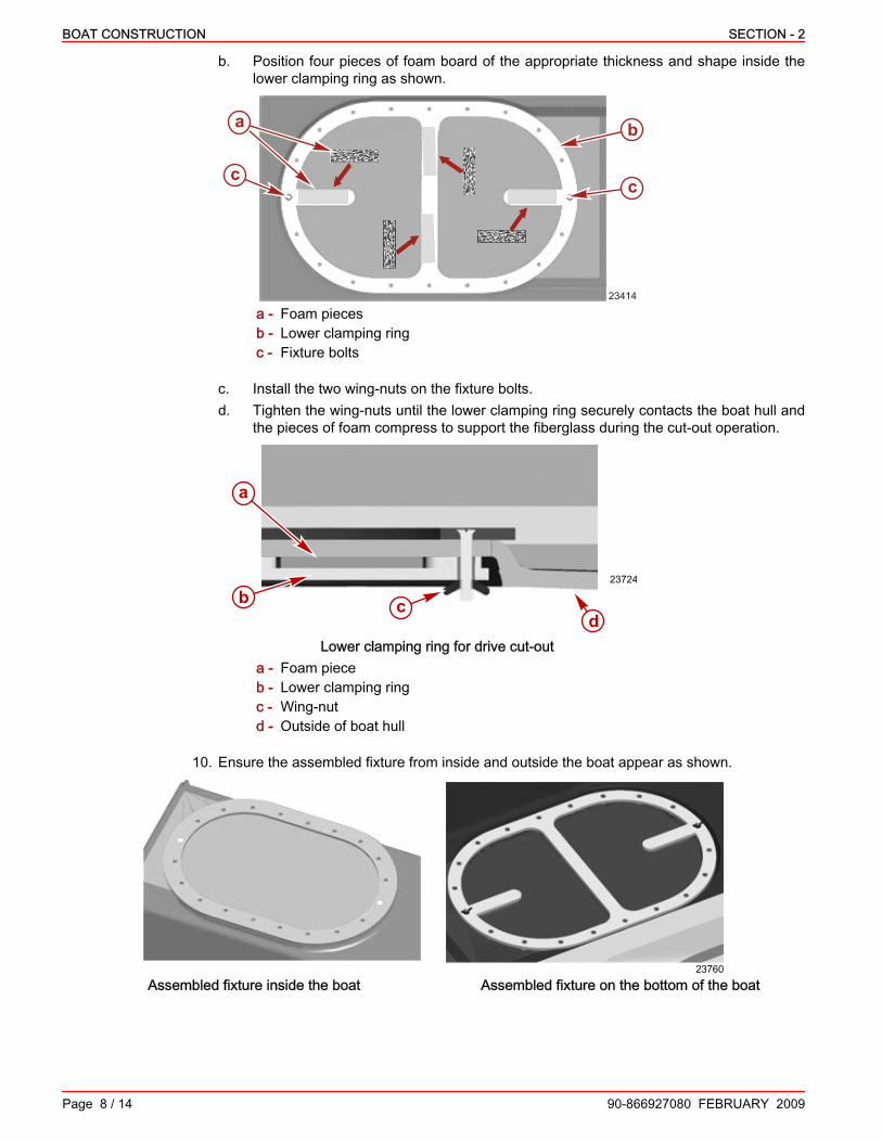
b. Position four pieces of foam board of the appropriate thickness and shape inside thelower clamping ring as shown.
23414
b
cc
a
a - Foam piecesb - Lower clamping ringc - Fixture bolts
c. Install the two wing‑nuts on the fixture bolts.d. Tighten the wing‑nuts until the lower clamping ring securely contacts the boat hull and
the pieces of foam compress to support the fiberglass during the cut‑out operation.
23724
cbd
a
Lower clamping ring for drive cut‑outa - Foam pieceb - Lower clamping ringc - Wing‑nutd - Outside of boat hull
10. Ensure the assembled fixture from inside and outside the boat appear as shown.
23760
Assembled fixture inside the boat Assembled fixture on the bottom of the boat

SECTION - 2 BOAT CONSTRUCTION
90-866927080 FEBRUARY 2009 Page 9 / 14
11. Working outside the boat drill the remaining holes in the hull for mounting the interface ringassembly according to specification.
23768
a
b
a - Fixture on bottom of boatb - Drilling locations
Interface Ring SpecificationMounting hole drill size 16 mm (5/8 in.)
12. Install a carbide, top‑guide bearing, pattern‑cutting bit into a suitable router. The diameter ofthe guide bearing in relation to the bit diameter is determined by the drill and router fixtureused—with 3.2 mm (0.125 in.) offset or no offset.
NOTE: If using the ring drill and router fixture with the 3.2 mm (0.125 in.) offset, the guide bearingmust have a 6.4 mm (0.250 in.) larger diameter than the bit. If the ring drill and router fixture withno offset is used, the guide bearing and bit must be the same diameter.13. Working inside the boat, align the router with the appropriate bit to the inner edge of the top
plate as indicated. Using the router, as recommended by the router manufacturer, cut the holefor the Zeus drive.
NOTE: Ensure that the router bit is only long enough to cut through the hull but not contact thedrill bushing fixture bottom plate under the boat. When the cut is complete, the fiberglass cut‑outpiece will be supported on the four foam pieces on the fixture under the boat.
d
c
a
b
23766
a - Routerb - Router bitc - Guide or bearingd - Upper clamping ring inner edge
14. Remove and discard the cut‑out fiberglass.15. Disassemble and remove the ring drill and router fixture.

BOAT CONSTRUCTION SECTION - 2
Page 10 / 14 90-866927080 FEBRUARY 2009
NOTE: Some hull construction materials may require sealing the inside edge of cutout openingwith a gel‑coat or suitable sealant to prevent water absorption and deterioration of the hull.16. Check that the final dimensions of the opening are within specifications.
28499
a
b
Dimensions of a tunnel cut‑out openinga - 90.10 cm ± 0.76 mm (35.474 in. ± 0.030 in.)b - 54.50 cm ± 0.76 mm (21.459 in. ± 0.030 in.)
17. Using a suitable material, fabricate an inspection gauge with the measurements indicated.
b
24926
a
c
d
a
a - 38 mm (1.50 in.)b - 38.10 mm (1.50 in.)c - 30.98 mm (1.22 in.)d - 51 mm (2 in.)
18. After the tunnel opening is cut out of the hull, verify the final dimensions of the opening arewithin specification by placing the fabricated inspection gauge at all points around the opening.
Hull Final Thickness Around Tunnel Opening SpecificationNominal 31.75 mm (1.25 in.)Maximum 38.1 mm (1.50 in.)Minimum 30.98 mm (1.22 in.)
NOTE: If you use a router to remove material, do not create sharp edges that could damage theinterface ring (drive grommet).19. If the thickness of the opening is greater than specified, sand (or router) the irregular area to
specification and apply a gel coat.

SECTION - 2 BOAT CONSTRUCTION
90-866927080 FEBRUARY 2009 Page 11 / 14
20. If the thickness of the opening is less than specified, sand the irregular area and fill with amarine grade epoxy. Apply a gel coat.
21. Check that the final dimensions of the tunnel opening are within specification beforeproceeding.
Hull Specifications and Drive InterfaceNOTICE
The thickness of the hull and interface ring must comply with the specifications for proper powerpackage operation. Failure to comply may allow the hull to deflect during propeller operation,causing failure of the engine coupler; may result in improper engagement of clamping ringassembly fasteners, causing improper mating of the drive assembly and engine components;or may cause leaks resulting from improper hull surface finish. Use proper materials and followall thickness and hull finish specifications.
All measurements shown in the Hull and Interface Ring table are taken in the interface ringassembly area. See the product application manual for additional information on hull thicknessand lay‑up techniques near the stringers, the various tunnel openings (molded, pre‑made, orcut‑out), and the transom.
Hull and Interface Ring(See the product application manual foradditional information.)
Specification
Construction material CompositeHull thickness at the fabricated molded‑in tunnelopenings 24.60 mm (0.97 in.) to 26.10 mm (1.03 in.)
Hull thickness at the pre‑made interface rings Minimum 25.40 mm (1 in.)Hull thickness at the tunnel opening cut‑outs 38.10 mm (1.50 in.) to 30.98 mm (1.22 in.)
Surface finish at molded‑in tunnel openingsHull outside surface: conventional FRP production
practice; hull inside and bull‑nose surface:125 RMS afterfinish gel coat
Surface finish of pre‑made interface ringopenings As supplied—125 RMS
Surface finish at tunnel cut‑out openings forbolt‑on interface rings
Hull outside surface: conventional FRP productionpractice
IMPORTANT: Measure hull thickness on every installation after making the interface ring cutoutor after forming the interface ring area of the hull. Fabricate and use the recommended inspectiongauge for each type of installation.
Engine Foundation DesignEngine Bed
The engine bed and the stringers must be designed to support the gravitational forces imposedby the engine during the most severe duty for which the boat is intended. It must also handle thetorque produced by the engine. Deflection of the engine bed could cause engine misalignmentand possible engine coupler failure. The proper design of the engine bed varies considerably fromone boat design to the next. Therefore, Cummins MerCruiser Diesel makes no attempt to providedetailed engine bed design requirements to cover all possible applications. The proper design ofthe engine bed is the responsibility of the boat manufacturer.Observe the following general guidelines.• Refer to the latest Cummins Marine Installation Drawings for engine mount spacing and
other dimensions at the website: www.cmdmarine.com.

BOAT CONSTRUCTION SECTION - 2
Page 12 / 14 90-866927080 FEBRUARY 2009
• The engine bed must be firmly affixed to the boat and should be made as large as possibleto distribute the load evenly. Reinforcements should be used where necessary. Mount padlocations should be as large as possible.
• The front engine mount isolators must rest squarely on the engine bed so that the rubberisolator is not loaded in one direction or the other. Improper loading of the engine mount willcause increased vibration.
• Engine mount isolators have provisions for 13 mm (1/2 in.) fasteners for securing mounts tothe engine bed. Fasteners should be selected as appropriate for the type of engine bedmaterial being used and the gravitational forces to be encountered.
• Do not install engine mount fasteners at an angle.• The engine bed must position the engine in approximately the middle of the mounting stud
after performing the final engine alignment. If necessary, shim the mount height to the middleof the mounting stud to allow for realignment in the future. Engine mount isolators willcompress slightly over time.
• The engine bed design must incline the installed engine at 0° ± 1° fore and aft with boat atrest in the water.
• The engine bed must position the engine aligned to the center of the drive input shaft andparallel to the vessel centerline.
IMPORTANT: Engine mount isolators must be located as close as possible to the vertical heightof the engine crank centerline for proper isolation of vibration. The engine mounts provided withthe engine are designed to achieve proper isolation and must not be modified to change isolatorheight.• The engine bed height for the mounts should be the same on both sides. This can be checked
by tying a string from the right front mount location to the left rear mount location, and anotherstring from the left front to the right rear. The strings should just touch where they cross.
a
b
c
24325
Typical engine beda - Front mount locationb - Rear mount locationc - Strings cross
Drop Box and Engine Installed HeightPart of the Computer Aided Design (CAD) effort of the hull, with assistance from the CMD NavalArchitect, determines if the drive needs to be equipped with a drop box.Using the drop box sets the engine lower in the vessel, relative to the drive. The drop box, requiredfor Zeus 3800 (QSC) and optional for Zeus 3500 (QSB), is available in two ratios. Contact yourCMD Distributor application engineer for proper drop box application.
Engine Model Gear Ratio Available
QSB—drop box optional1.8
2.06

SECTION - 2 BOAT CONSTRUCTION
90-866927080 FEBRUARY 2009 Page 13 / 14
Engine Model Gear Ratio Available
QSC—drop box required1.8
1.96
Refer to the Cummins MerCruiser Diesel Zeus Drive Application Manual for additionalinformation.
b
a27942
Lower engine installed height possible using a drive equipped with a drop boxa - Lower output couplingb - Drop box

BOAT CONSTRUCTION SECTION - 2
NOTES:
Page 14 / 14 90-866927080 FEBRUARY 2009

SECTION - 3 EXHAUST SYSTEM OVERVIEW
90-866927080 FEBRUARY 2009 Page 1 / 6
SECTION 3 - EXHAUST SYSTEM OVERVIEWTable of ContentsImportant Information.............................................................................................................................................. 2Exhaust System Description.................................................................................................................................... 2
3

EXHAUST SYSTEM OVERVIEW SECTION - 3
Page 2 / 6 90-866927080 FEBRUARY 2009
Important Information! WARNING
Improper boat design and construction may result in serious injury or death. Adhere to allapplicable marine regulations (United States Coast Guard [USCG], European Union–Recreational Craft Directive [EU‑RCD], etc.) and the standards they reference (American Boatand Yacht Council [ABYC], Society of Automotive Engineers [SAE], International StandardsOrganization [ISO], etc.) when designing and constructing the boat and other components, suchas the engine compartment, fuel delivery system, or exhaust system.
Exhaust System DescriptionThe exhaust for Zeus is an integral, seawater cooled system. A 12.7 cm (5 in.) (QSB) or15.2 cm (6 in.) (QSC) diameter exhaust connection, mounted directly to the turbocharger, injectsthe seawater to cool the exhaust gases. The exhaust connection also serves to split a portion ofthe seawater flow for use in the primary fluid cooler and drop box cooler, if equipped, that aremounted on the drive.The main flow of exhaust passes through a 12.7 cm (5 in.) diameter fiberglass‑reinforced plastic(FRP) tube, to a 14 cm (5.5 in.) 90° elbow mounted to the drive. It then passes through the drivehousing and exits through the propeller hub. The secondary flow path is an idle bypass, whichreduces back pressure, noise, and vibration at idle and low speed operation.

SECTION - 3 EXHAUST SYSTEM OVERVIEW
90-866927080 FEBRUARY 2009 Page 3 / 6
The idle bypass begins with a 7.6 cm (3 in.) diameter (QSB) or 10 cm (4 in.) diameter (QSC) shorttube, angling off of the FRP tube. The other end of the idle bypass hose connects to a water liftmuffler system with a design dictated by the boatbuilder.
a b
a c
d
ef
g h
j
kb
lb
m
n
o
p
i
q
40053
r
Exploded‑view of typical exhaust systema - T‑bolt clamp (2)b - Lower bellows hosec - FRP exhaust tube O‑ring (brown)d - FRP exhaust tubee - Seawater bypass hosef - Hose clampg - Gasketh - Water supply hosei - Hose clamp (2)
j - Washer (4)k - Screw (4)l - Upper bellows hosem - Hose clampn - Idle bypass hoseo - Lower elbow clamp ringp - Screw (6)q - Lower elbowr - Exhaust flange O‑ring (black)

EXHAUST SYSTEM OVERVIEW SECTION - 3
Page 4 / 6 90-866927080 FEBRUARY 2009
Some of the major components of the exhaust system are shown installed.
abc
d
e f g
h
ij
kl
m
29976
abc
d
e f g
h
ij
kl
m
Typical flange connection exhaust system installationa - Lower portion of FRP exhaust tubeb - Lower bellows hosec - Lower elbowd - Water overboard hosee - Primary fluid coolerf - Location of exhaust flange O‑ring
(black)g - Water supply hose
h - Upper elbow/riseri - Upper bellows hosej - Fitting for idle bypass hosek - Idle bypass hose to water lift mufflerl - Upper portion of FRP exhaust tubem - Seawater bypass hose
The FRP tube connected to the lower elbow incorporates an O‑ring seal and a bellows (hump)hose connection. The O‑ring supports the tube within the lower elbow and provides a secondaryseal. The O‑ring design can accommodate up to approximately 30 mm (1.2 in) of lateral offset atthe top of the main FRP tube. The offset accounts for the variation in exhaust outlet locationbetween engine models.These components require lubrication during assembly with special consideration to properplacement of the FRP tube in the cuff of the bellows.
a
c
e
b
d
fg40052
a - Lower elbowb - Cuff sectionc - Bellows (hump) sectiond - Lower bellows hose
e - FRP tubef - Brown O‑ringg - Silicone grease applied during
installation

SECTION - 3 EXHAUST SYSTEM OVERVIEW
90-866927080 FEBRUARY 2009 Page 5 / 6
The boatbuilder selects the water lift muffler and related components, depending on theapplication. A typical water lift muffler installation is shown.
a
bc
d
26862
Typical water lift muffler installationa - Typical water lift mufflerb - Idle bypass hose from FRP tube to muffler inletc - Seawater overboard hose from muffler outletd - Typical seawater overboard fitting

EXHAUST SYSTEM OVERVIEW SECTION - 3
NOTES:
Page 6 / 6 90-866927080 FEBRUARY 2009

SECTION - 4 COOLING SYSTEM OVERVIEW
90-866927080 FEBRUARY 2009 Page 1 / 6
SECTION 4 - COOLING SYSTEM OVERVIEWTable of ContentsSpecifications—Cooling System............................................................................................................................. 2Seawater Connections............................................................................................................................................ 2
Seacock.............................................................................................................................................................2Seawater Hoses—Supply (Inlet).......................................................................................................................3
Requirements ............................................................................................................................................ 3Installation .................................................................................................................................................. 3
Seawater Strainer..............................................................................................................................................3Requirements ............................................................................................................................................ 3Installation .................................................................................................................................................. 3
Auxiliary Heating Circuits .................................................................................................................................4Seawater Bypass Hose.....................................................................................................................................4
4

COOLING SYSTEM OVERVIEW SECTION - 4
Page 2 / 6 90-866927080 FEBRUARY 2009
Specifications—Cooling SystemDescription All Models
Seawater pickup Integrated into driveunit
Seacock size (internal cross‑sectional area) 51 mm (2 in.) or63.5 mm (2.5 in.)
Seawater inlet hoseinner diameter
QSB engines Minimum 51 mm (2 in.)QSC engines Minimum 64 mm (2‑1/2 in.)
Seawater strainer flowrate
QSB engine 265 liter/min.(70 U.S.gal/min.)
QSC engine 303 liter/min.(80 US gal/min.)
Seawater inletrestriction. Maximum 125 mm Hg (5 in Hg)
Seawater pump flowrates
QSB engine 265 liter/min.(70 U.S.gal/min.)
QSC engine 303 liter/min.(80 US gal/min.)
Seawater ConnectionsSeacock
A 51 mm (2 in.) or 63.5 mm (2.5 in.) diameter seacock for seawater inlet is provided with the Zeusdrive.Zeus drives have two seacock designs.
24091
a b
Early designa - Seacock (provided)b - 90° fitting, if required (obtain locally)

SECTION - 4 COOLING SYSTEM OVERVIEW
90-866927080 FEBRUARY 2009 Page 3 / 6
a
b
39927
Late designa - Seacock (provided)b - Fitting (provided)
Depending on the application, you may have to locally obtain fittings for the proper routing andconnection of the seawater inlet hose.
Seawater Hoses—Supply (Inlet)REQUIREMENTS
Seawater hoses are not provided with the product. Refer to the appropriate engine specificinstallation directions for additional information on seawater inlet hose connections.IMPORTANT: Use a marine‑grade, wire‑reinforced seawater hose to avoid collapsing the hosewhen suction is created by the seawater pump impeller.The minimum size seawater inlet hose for each engine can be no smaller than the inlet connectionon the seawater pump. Larger hose is required if the seawater inlet hose is especially long or hasmultiple bends which increase water inlet restriction.Secure the connections for the wire‑reinforced hose with double hose clamps.Secure the hoses to prevent contact with any hot or moving parts.See Specifications—Cooling System.
INSTALLATIONSee Section 5—Drive System Mounting and Alignment for installation procedures.
Seawater StrainerREQUIREMENTS
The seawater strainer used must be large enough to ensure an adequate supply of water forcooling the engine. See Specifications—Cooling System.
INSTALLATIONRefer to manufacturer's instructions for installation, operation, and maintenance.IMPORTANT: Read and observe the following when mounting and connecting a seawater strainer.• Never mount the seawater strainer on the engine.• Mount the seawater strainer in an easily accessible location.• Hoses must not be kinked.• Hoses must not be allowed to contact hot or moving parts.1. Position the seawater strainer in an appropriate location.2. Ensure that the arrow that indicates the direction of seawater flow points toward the seawater
pump.

COOLING SYSTEM OVERVIEW SECTION - 4
Page 4 / 6 90-866927080 FEBRUARY 2009
3. Install the seawater strainer using appropriate flat washers and lag bolts or thru‑bolts and nuts.
23797
ba
Typical seawater strainer installationa - Seawater strainerb - Mounting screw hole location (screws not visible)
Auxiliary Heating CircuitsNOTICE
Prevent engine damage from overheating. In models equipped with closed cooling, low coolantlevels may allow an air pocket to form when the hot water heater or cabin heater is mountedhigher than the fill cap on the heat exchanger. Mount the heater lower than the fill cap of theheat exchanger and maintain the recommended coolant level.
Auxiliary heating circuits (such as hot water heaters) must be installed according to the informationand procedures found in the Marine Recreational High Output Propulsion Units B and CSeries Installation Directions manual available from the manufacturer of the engine.
Seawater Bypass HoseThe upper exhaust elbow directs (bypasses) a portion of the seawater flow to the fluid cooler, orcoolers, on the drive for cooling the drive transmission and steering system lubricants.A 38 mm (1.5 in.) diameter marine‑grade, reinforced seawater hose is provided with the QSBpackage, while a 51 mm (2 in.) diameter seawater hose is provided with the QSC. Ensure properrouting of the seawater bypass hose from the fitting on the upper exhaust elbow to the oil cooleron the drive. For drives without a drop box, the hose connects to the primary oil cooler. For drivesequipped with a drop box, the hose connects to a secondary cooler that is connected to the primarycooler with an additional short hose.
b
ca
26736
Shown without a drop box, all similara - Seawater bypass hoseb - Upper exhaust elbow fittingc - Primary fluid cooler

SECTION - 4 COOLING SYSTEM OVERVIEW
90-866927080 FEBRUARY 2009 Page 5 / 6
Seawater is routed overboard (returned) from the primary oil cooler through a separate seacock.
ab
d
e
c
24420
a - Seawater overboard (return) fittingb - Seacockc - Seacock leverd - Seawater hose from primary oil coolere - Primary oil cooler

COOLING SYSTEM OVERVIEW SECTION - 4
NOTES:
Page 6 / 6 90-866927080 FEBRUARY 2009

SECTION - 5 DRIVE SYSTEM INSTALLATION AND ALIGNMENT
90-866927080 FEBRUARY 2009 Page 1 / 70
SECTION 5 - DRIVE SYSTEM INSTALLATION ANDALIGNMENT
Table of ContentsChecking the Tunnel Opening Alignment, Thickness, and Surface........................................................................ 3
On Models with a Tunnel Cut‑Out Opening—Using a Bolt‑On Interface Ring..................................................3On Models with a Fabricated (Molded‑In) Tunnel Opening...............................................................................4
Installing the Bolt‑on Interface Ring........................................................................................................................ 5Engine Mounting..................................................................................................................................................... 9
Crankshaft Center Lines....................................................................................................................................9Installing the Engine Mounts.............................................................................................................................9
Tool Selection ............................................................................................................................................ 9Initial Engine Mount Alignment .................................................................................................................. 9
Zeus Drive Installation........................................................................................................................................... 11Identifying the Drives.......................................................................................................................................11Installing the Interface Ring Seal.....................................................................................................................11Installing the Drive Using the Shipping Container...........................................................................................12Positioning the Drive in the Hull......................................................................................................................13
Mounting the Drive................................................................................................................................................ 17Positioning the Drive in the Hull......................................................................................................................17Installing the Clamp Ring................................................................................................................................22Completing the Mounting of the Drive.............................................................................................................25
Installing and Aligning the Engine—Using a Hand‑Held Drive‑to‑Engine Alignment Tool.................................... 27Installing the Engine........................................................................................................................................27Final Engine Alignment...................................................................................................................................28
Installing and Aligning the Engine—Using a Two‑Piece Alignment Tool and Indicator Line................................. 30Preparation......................................................................................................................................................30Engine Alignment............................................................................................................................................30
Completing the Installation.................................................................................................................................... 34Driveshaft Installation......................................................................................................................................34Installing the Exhaust System and Seawater Return Hoses...........................................................................37Connecting the Seawater Inlet and Strainer....................................................................................................41Connecting the Engine Mounted Oil Cooler, If Equipped................................................................................42Installing the Drive Skeg..................................................................................................................................45Corrosion Continuity Circuit Connections........................................................................................................45
5

DRIVE SYSTEM INSTALLATION AND ALIGNMENT SECTION - 5
Page 2 / 70 90-866927080 FEBRUARY 2009
Electrical Connections........................................................................................................................................... 50Connecting the Wiring.....................................................................................................................................51Continuity Wire Connections...........................................................................................................................51Drive Application Extension Harness..............................................................................................................52Installing the Drive Application Extension Harness.........................................................................................53Vessel Interface Panel (VIP)...........................................................................................................................54Mounting the Vessel Interface Panel (VIP).....................................................................................................54T‑Harness........................................................................................................................................................55Installing the T‑Harness..................................................................................................................................55Engine‑to‑VIP Extension Harness...................................................................................................................56Installing the Engine‑to‑VIP Extension Harness..............................................................................................56TVM (Thrust Vector Module) Extension Harness............................................................................................57Installing the TVM Extension Harness............................................................................................................58Vessel Sensor Harness (Optional)..................................................................................................................59Installing the Vessel Sensor Harness..............................................................................................................60Vessel Sensor Extension Harness (Optional).................................................................................................61Installing the Vessel Sensor Extension Harness.............................................................................................61Connecting the Vessel Sensors......................................................................................................................61Power Supply and Distribution........................................................................................................................62VIP and ECM Power Harnesses.....................................................................................................................63Installing the VIP Unswitched Power Harness................................................................................................63Installing the ECM Switched Power Harness..................................................................................................64Installing the MUS ID Jumper Plugs................................................................................................................64Power Harness for the Steering Backup Pump, If Equipped...........................................................................65Installing the Power Harness for the Steering Backup Pump..........................................................................65
Installing the Drive Cover, If Equipped.................................................................................................................. 66

SECTION - 5 DRIVE SYSTEM INSTALLATION AND ALIGNMENT
90-866927080 FEBRUARY 2009 Page 3 / 70
Lubricants, Sealants, AdhesivesTube Ref No. Description Where Used Part No.
BoatLIFE® 1033, or equivalent Interface ring to hull Obtain Locally
7 Loctite 271 Threadlocker Flange-head screws for seacock adapter 92-809819
10 Loctite 277 Driveshaft shield retaining screw and nut Obtain Locally
25 Liquid Neoprene Exposed electrical terminals 92- 25711 3
34 Special Lubricant 101 Stainless steel studs and locknutsClamp ring flange-head screws 92-802865Q02
42 U-joint and Gimbal BearingGrease
Driveshaft slip-jointDriveshaft U-joints 92-802870A1
66 Loctite 242 Threadlocker Threads of flange-head screws for hydraulicmanifold cover 92-809821
95 2-4-C with Teflon Seacock adapter and O-rings 92-802859A 1
138 Synthetic Power Steering FluidSAE 0W-30 Transmission and drop box 92-858076K01
Checking the Tunnel Opening Alignment, Thickness, and SurfaceOn Models with a Tunnel Cut‑Out Opening—Using a Bolt‑On Interface Ring
1. Using a suitable material, fabricate an inspection gauge (mandrel) with the measurementsindicated.
b
24926
a
c
d
a
a - 51 mm (2 in.)b - 38.10 mm (1.50 in.)c - 30.98 mm (1.22 in.)d - 51 mm (2 in.)

DRIVE SYSTEM INSTALLATION AND ALIGNMENT SECTION - 5
Page 4 / 70 90-866927080 FEBRUARY 2009
2. After cutting out the tunnel opening, ensure that the final dimensions of the opening are withinspecification by placing the fabricated inspection gauge at all points around the opening.
ab
28358
a - Inspection gaugeb - Tunnel opening
Hull Final Thickness Around Tunnel Opening SpecificationNominal 31.75 mm (1.25 in.)Maximum 38.10 mm (1.50 in.)Minimum 30.98 mm (1.22 in.)
3. Refer to Section 2—Boat Construction for additional information if required.
On Models with a Fabricated (Molded‑In) Tunnel Opening1. Using a suitable material, fabricate an inspection gauge (mandrel) with the measurements
indicated.
b
24926
a
c
d
a
a - 51 mm (2 in.)b - 26.1 mm (1.03 in.)c - 24.6 mm (0.97 in.)d - 51 mm (2 in.)

SECTION - 5 DRIVE SYSTEM INSTALLATION AND ALIGNMENT
90-866927080 FEBRUARY 2009 Page 5 / 70
2. Ensure the final dimensions of the fabricated (molded‑in) tunnel opening and interface lip arewithin specification by placing the fabricated inspection gauge at all points around the opening.
ab
28358
a - Inspection gaugeb - Tunnel opening
Hull Final Thickness Around Tunnel Opening SpecificationMaximum 26.1 mm (1.03 in.)Minimum 24.6 mm (0.97 in.)
3. Refer to Section 2—Boat Construction for additional information if required.
Installing the Bolt‑on Interface Ring1. Ensure that the hull surface flatness and thickness at the drive mounting location are within
specifications. See Checking the Hull Surface and Thickness.2. Ensure that the inside hull surface flatness around each stud hole where the stainless steel
washers will seat is within specification. Sand or fill any irregularity that would affect the seatingof the stainless steel washers. See Section 2—Boat Construction if necessary.
3. Ensure that the mounting stud holes are the specified size.
Interface Ring Mounting SpecificationStud hole size 16 mm (5/8 in.)
4. Test fit the interface ring into the mounting stud holes to ensure a correct fit, then remove theinterface ring.
5. Clean any debris from around the upper and lower surfaces of the formed opening.NOTE: Refer to the manufacturer of the sealant you have selected for sealing the interface ring(as outlined later in this procedure) and use the cleaners and solvents recommended.
DRIVE SYSTEM INSTALLATION AND ALIGNMENT SECTION - 5
Page 6 / 70 90-866927080 FEBRUARY 2009
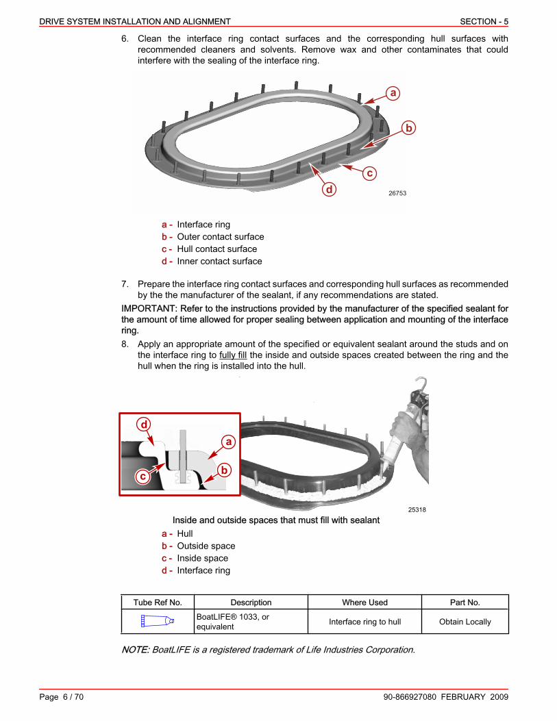
6. Clean the interface ring contact surfaces and the corresponding hull surfaces withrecommended cleaners and solvents. Remove wax and other contaminates that couldinterfere with the sealing of the interface ring.
a
cd
b
26753
a - Interface ringb - Outer contact surfacec - Hull contact surfaced - Inner contact surface
7. Prepare the interface ring contact surfaces and corresponding hull surfaces as recommendedby the the manufacturer of the sealant, if any recommendations are stated.
IMPORTANT: Refer to the instructions provided by the manufacturer of the specified sealant forthe amount of time allowed for proper sealing between application and mounting of the interfacering.8. Apply an appropriate amount of the specified or equivalent sealant around the studs and on
the interface ring to fully fill the inside and outside spaces created between the ring and thehull when the ring is installed into the hull.
25318
a
b
d
c
Inside and outside spaces that must fill with sealanta - Hullb - Outside spacec - Inside spaced - Interface ring
Tube Ref No. Description Where Used Part No.BoatLIFE® 1033, orequivalent Interface ring to hull Obtain Locally
NOTE: BoatLIFE is a registered trademark of Life Industries Corporation.

SECTION - 5 DRIVE SYSTEM INSTALLATION AND ALIGNMENT
90-866927080 FEBRUARY 2009 Page 7 / 70
9. Position the trim tab recess in the interface ring assembly to the rear of the opening in theboat.
10. From beneath the boat, lift the interface ring up and into the mounting holes of the cut‑outopening.
11. Clamp or suitably retain the interface ring to the bottom of the hull.12. From the inside and outside the boat, tool and smooth any sealant that may have pushed out
from the space between the interface ring and the hull.IMPORTANT: Be careful when installing the stainless steel fasteners. Hand tighten only, withoutthe use of pneumatic tools. Use the specified lubricant to prevent galling the stainless steel studsand locknuts.13. Apply the specified lubricant to the stainless steel studs and locknuts.
Tube Ref No. Description Where Used Part No.
34 Special Lubricant 101 Stainless steel studs andlocknuts 92-802865Q02
14. Install the 20 stainless steel washers and locknuts, as shown.
c
d
b
a
f
e
26761
a
b
c
de
f
c
Interface ring installation showna - Studb - Interface ringc - Sealant smoothed around opening
d - Hull tunnele - Washerf - Locknut
15. Hand‑tighten each locknut in small increments until the interface ring surface contacts the hull.Do not use pneumatic tools.

DRIVE SYSTEM INSTALLATION AND ALIGNMENT SECTION - 5
Page 8 / 70 90-866927080 FEBRUARY 2009
16. Initially tighten the interface ring locknuts to specification in the sequence shown. Tighten eachlocknut several times in small increments to obtain the specified torque.
1
2
3
4
5
6
7
8
9
10 11
12
13
14
15
16
17
18
19
20
24392
Torque sequence for initial tightening of interface ring to hull
Description Nm lb. in. lb. ft.Initial torque on interface ring locknut 7 60 –
17. Continue to torque the interface ring locknuts in the torque sequence shown. Tighten eachlocknut until the specified first pass torque is achieved. Make a final pass torque check oneach locknut at the specified torque.
1
2
3
4
5
6
7
8
9
10 11
12
13
14
15
16
17
18
19
20
24392
Torque sequence for final tightening of interface ring to hull
Description Nm lb. in. lb. ft.
Interface ring locknutsFirst pass 33.8 – 25Final pass 40.6 – 30
IMPORTANT: Check the final pass torque on the interface ring locknuts before boat delivery. Referto the boat manufacturer for additional information.

SECTION - 5 DRIVE SYSTEM INSTALLATION AND ALIGNMENT
90-866927080 FEBRUARY 2009 Page 9 / 70
Engine MountingCrankshaft Center Lines
The vertical height of the engine crankshaft varies according to whether the power package hasa drop box and the length of the driveshaft. Refer to Cummins MerCruiser Diesel InstallationDrawings for more information. The drop box is standard equipment on QSC engines, optionalfor QSB engines.The engine‑to‑drive center line vertical offset is dictated by the requirement that the driveshaftconnecting the two be installed at a 1° to 3° angle from the horizontal. Both flanges on the driveshaft must be at the same angle.
Installing the Engine MountsTOOL SELECTION
To determine the correct location for the engine mounts, choose one of the following methods:• Install the engine complete with engine mounts attached.• Fabricate a special engine mount fixture based on design information from CMD.Contact your Cummins MerCruiser Diesel application engineer for additional part numbers orassistance.
Engine Mount Alignment FixturesModels Driveshaft Length Part Number
QSB
Without drop box26.21 cm (10.32 in.)
91‑8M0032105With drop box 91‑8M0032112Without drop box
47.65 cm (18.76 in.)91‑8M0032618
With drop box 91‑8M0032617Without drop box
72.1 cm (28.375 in.)91‑8M0032364
With drop box 91‑8M0032363QSC With drop box 72.1 cm (28.375 in.) 91‑8M0032403
INITIAL ENGINE MOUNT ALIGNMENTIMPORTANT: Engine mounts (vibration isolators) are provided by the engine manufacturer.Engine mounts must be preliminarily adjusted to center the mount and establish a uniform heighton all mounts. Refer to the Marine Recreational High Output Propulsion Units B and C SeriesInstallation Directions manual for additional information.IMPORTANT: Engine mounting studs are not for lifting the engine. Support the engine with a liftinghoist when adjusting the engine mounts.

DRIVE SYSTEM INSTALLATION AND ALIGNMENT SECTION - 5
Page 10 / 70 90-866927080 FEBRUARY 2009
1. Install four separate engine mounts onto the engine mount fixture. If four separate enginemounts are not available, remove and install the four engine mounts provided with the enginepower package.
b
a
26770
a - Front mountsb - Rear mounts
2. Adjust the four engine mounts so that equal amounts of up and down adjustment are availableon the vibration isolator adjusting nuts.
3. Inside the boat, position the engine mount fixture on the hull over the opening in the tunnel.4. Lift the clamp ring up from under the boat to the engine mount fixture in the tunnel opening.
Install the screws.5. Ensure that the engine mount fixture is properly seated in the opening and parallel to the center
line of the boat.6. Securely tighten the four screws to attach the engine mount fixture firmly to the clamp ring.
a
b
c
d26769
Typical settinga - Engine mount fixtureb - Hullc - Clamp ringd - Screws
IMPORTANT: The finished boat stringer must position the engine so that a minimum of 6 mm(1/4 in.) up or down adjustment exists after the mount is adjusted to contact the stringer. Thisallows for future engine alignment or adjustments. Make alterations to the boat stringer (structure)height to obtain the 6 mm (1/4 in.) dimension.7. If the mounts contact the stringers, mark the position of the mounting holes for the four engine
mounts. If the mounts do not contact the stringer, appropriately shim the mounts, modify thestringers, or adjust the mounts (within specification) until they rest on the boat stringers. Thenmark the position of the mounting holes.

SECTION - 5 DRIVE SYSTEM INSTALLATION AND ALIGNMENT
90-866927080 FEBRUARY 2009 Page 11 / 70
8. Drill the stringers appropriately for the type of mounting hardware used for the engine mounts.9. Remove the engine mount fixture.10. Loosen and remove the mounts from the engine mount fixture and install them on the engine,
if necessary.
Zeus Drive InstallationIdentifying the Drives
The design of the Zeus drive results in a unique port and starboard drive. The drives will have theletters "PORT" or "STBD" stamped in the metal of the center section near the drive serial numberand decal.1. Identify if the drive is a port ("PORT") or starboard ("STBD") drive.2. Install the drive on the side of the vessel indicated by the stamped‑in marking.
31665
a
b
a - Stamped‑in identification lettersb - Center section
Installing the Interface Ring Seal1. Ensure that the interface ring opening in the hull or the bolted‑on interface ring assembly,
mounted in the tunnel, is complete and ready to accept installation of the Zeus drive assembly.See Installing the Bolt-on Interface Ring.
2. Clean the hull or bolted‑on interface ring surfaces with a suitable, wax‑removing solvent. Allowthe surfaces to dry completely.
! WARNINGThe rubber interface ring seal has an outside coating that protects the inner core. Tears, cuts,scrapes, or exposure to lubricants or sealing compounds can damage this coating and the innercore causing water to leak into the boat. Use caution when installing and working around theinterface ring seal to prevent damage. Do not use any lubricants or sealing compounds duringinstallation.
NOTE: The rubber interface ring seal is symmetrical. There is not a specific top, bottom, front, orrear of the seal.3. Install the rubber interface ring seal (grommet). Do not use any lubricants, solvents, or sealing
compounds. Install the seal into the boat hull molded‑in opening or into the bolted‑on interfacering assembly, depending upon the type of installation. Do not tear, scrape, cut, or similarlydamage the seal.

DRIVE SYSTEM INSTALLATION AND ALIGNMENT SECTION - 5
Page 12 / 70 90-866927080 FEBRUARY 2009
IMPORTANT: Fully seat the entire length of the seal in the opening.
40303
Interface ring seal installed
Installing the Drive Using the Shipping ContainerThe drive may be installed using the shipping container and a forklift or overhead hoist.1. Carefully remove all shipping hardware.
a. Remove the clips and pins holding the four cross braces to the shipping container frameand pallet.
b. Remove the ten screws holding the upper and lower shipping container frames together.
27441
e
f
d
a
bca - Upper frame screwb - Clips and pinsc - Shipping container pallet
d - Lower frame screwe - Cross bracef - Shipping container
c. Remove the frames from the shipping container pallet.
27444
Shipping container pallet

SECTION - 5 DRIVE SYSTEM INSTALLATION AND ALIGNMENT
90-866927080 FEBRUARY 2009 Page 13 / 70
2. Read and remove all tags attached to the drive assembly.NOTE: The Zeus drive with gearcase and skeg mounted on the shipping container requires aminimum ground‑to‑tunnel total clearance as specified in the following chart. The specifieddistance allows ample clearance to be able to slide the drive under the tunnel in the shippingcontainer. The shipping container adds about 76 mm (3 in.) to the total height of the drive with theskeg installed.3. Ensure the boat fixture provides the specified mounting clearance between the ground and
the boat tunnel for the drive in the shipping container.
Mounting Clearance for Boat Fixture SpecificationGround‑to‑tunnel (with Zeus drive in the shipping container) 165.1 cm (65 in.)
Positioning the Drive in the Hull
! WARNINGThe rubber interface ring seal has an outside coating that protects the inner core. Tears, cuts,scrapes, or exposure to lubricants or sealing compounds can damage this coating and the innercore causing water to leak into the boat. Use caution when installing and working around theinterface ring seal to prevent damage. Do not use any lubricants or sealing compounds duringinstallation.
1. On HH and IH models with an early seacock design, to increase clearance during installation:a. Remove the seacock and adapter by removing the two screws.
28814
abc
a - Front screwb - Aft screwc - Seacock and adapter
b. Pull the seacock and adapter out of the recess in the center section plate. Note theposition of the two adapter O‑rings.
28828
a
bc
d
a - O‑rings (2)b - Adapter
c - Screw (2)d - Seacock

DRIVE SYSTEM INSTALLATION AND ALIGNMENT SECTION - 5
Page 14 / 70 90-866927080 FEBRUARY 2009
2. To avoid component damage during installation, detach the primary and secondary harnessconnectors from the steering sensors.
28832
b
a
c
d
Typicala - Secondary steering sensorb - Secondary steering sensor harness
connector
c - Primary steering sensord - Primary steering sensor harness
connector
3. To mount the drive using a forklift:a. Move the drive and installation stand (or shipping container pallet) into position under
the boat.b. Ensure that the interface ring mounting surface on the drive is parallel to the hull of the
boat and to the interface ring opening when supported.
23962
a
b
d
c
Typical with installation stand, similar with shipping container palleta - Hull of boatb - Drive assembly
c - Installation standd - Lift fork in installation stand—locked in
place
4. To mount the drive using a overhead hoist:a. Position the shipping container or installation stand under the drive opening in the craft.b. From inside the boat and using an appropriate sling, attach an overhead hoist to the
lifting rings of the transmission. The overhead hoist must be capable of lifting the weightof the drive with an reasonable safety margin.
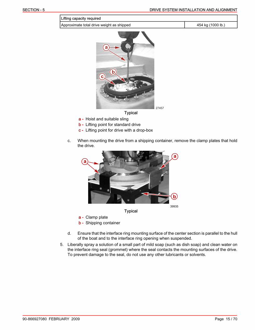
SECTION - 5 DRIVE SYSTEM INSTALLATION AND ALIGNMENT
90-866927080 FEBRUARY 2009 Page 15 / 70
Lifting capacity requiredApproximate total drive weight as shipped 454 kg (1000 lb.)
27457
bc
a
Typicala - Hoist and suitable slingb - Lifting point for standard drivec - Lifting point for drive with a drop‑box
c. When mounting the drive from a shipping container, remove the clamp plates that holdthe drive.
a
b
a
39935
Typicala - Clamp plateb - Shipping container
d. Ensure that the interface ring mounting surface of the center section is parallel to the hullof the boat and to the interface ring opening when suspended.
5. Liberally spray a solution of a small part of mild soap (such as dish soap) and clean water onthe interface ring seal (grommet) where the seal contacts the mounting surfaces of the drive.To prevent damage to the seal, do not use any other lubricants or solvents.

DRIVE SYSTEM INSTALLATION AND ALIGNMENT SECTION - 5
Page 16 / 70 90-866927080 FEBRUARY 2009
6. Lift or hoist the drive assembly into the interface ring opening. Do not tear, scrape, cut orsimilarly damage, the inner core of the interface ring seal. Do not use any lubricants, solvents,or sealing compounds on the interface ring seal except for a solution of a small part of mildsoap (such as dish soap) and clean water.
23975
Raising a typical drive into position
NOTE: Aligning the drive may require tilting the drive side‑to‑side or fore and aft as it is raised intoposition.7. Align the drive so that it is parallel to the hull bottom and the center line of the boat.8. Raise or lift the drive into the final position in the center of the interface ring seal (grommet).
27466
Drive in final position using an overhead hoist

SECTION - 5 DRIVE SYSTEM INSTALLATION AND ALIGNMENT
90-866927080 FEBRUARY 2009 Page 17 / 70
9. Hold the drive firmly in place using the overhead hoist or with the forklift firmly supporting theinstallation stand.
ab
23976
Drive firmly supported using an installation stand and forklift trucka - Drive parallel and fully seatedb - Installation stand
10. Lower the shipping container or stand and pull it away from the boat hull.
Mounting the DrivePositioning the Drive in the Hull
! WARNINGThe rubber interface ring seal has an outside coating that protects the inner core. Tears, cuts,scrapes, or exposure to lubricants or sealing compounds can damage this coating and the innercore causing water to leak into the boat. Use caution when installing and working around theinterface ring seal to prevent damage. Do not use any lubricants or sealing compounds duringinstallation.
1. On HH and IH models with an early seacock design, to increase clearance during installation:a. Remove the seacock and adapter by removing the two screws.
28814
abc
a - Front screwb - Aft screwc - Seacock and adapter

DRIVE SYSTEM INSTALLATION AND ALIGNMENT SECTION - 5
Page 18 / 70 90-866927080 FEBRUARY 2009
b. Pull the seacock and adapter out of the recess in the center section plate. Note theposition of the two adapter O‑rings.
28828
a
bc
d
a - O‑rings (2)b - Adapter
c - Screw (2)d - Seacock
2. To avoid component damage during installation, detach the primary and secondary harnessconnectors from the steering sensors.
28832
b
a
c
d
Typicala - Secondary steering sensorb - Secondary steering sensor harness
connector
c - Primary steering sensord - Primary steering sensor harness
connector
3. To mount the drive using a forklift:a. Move the drive and installation stand (or shipping container pallet) into position under
the boat.

SECTION - 5 DRIVE SYSTEM INSTALLATION AND ALIGNMENT
90-866927080 FEBRUARY 2009 Page 19 / 70
b. Ensure that the interface ring mounting surface on the drive is parallel to the hull of theboat and to the interface ring opening when supported.
23962
a
b
d
c
Typical with installation stand, similar with shipping container palleta - Hull of boatb - Drive assembly
c - Installation standd - Lift fork in installation stand—locked in
place
4. To mount the drive using a overhead hoist:a. Position the shipping container or installation stand under the drive opening in the craft.b. From inside the boat and using an appropriate sling, attach an overhead hoist to the
lifting rings of the transmission. The overhead hoist must be capable of lifting the weightof the drive with an reasonable safety margin.
Lifting capacity requiredApproximate total drive weight as shipped 454 kg (1000 lb.)
27457
bc
a
Typicala - Hoist and suitable slingb - Lifting point for standard drivec - Lifting point for drive with a drop‑box

DRIVE SYSTEM INSTALLATION AND ALIGNMENT SECTION - 5
Page 20 / 70 90-866927080 FEBRUARY 2009
c. When mounting the drive from a shipping container, remove the clamp plates that holdthe drive.
a
b
a
39935
Typicala - Clamp plateb - Shipping container
d. Ensure that the interface ring mounting surface of the center section is parallel to the hullof the boat and to the interface ring opening when suspended.
5. Liberally spray a solution of a small part of mild soap (such as dish soap) and clean water onthe interface ring seal (grommet) where the seal contacts the mounting surfaces of the drive.To prevent damage to the seal, do not use any other lubricants or solvents.
6. Lift or hoist the drive assembly into the interface ring opening. Do not tear, scrape, cut orsimilarly damage, the inner core of the interface ring seal. Do not use any lubricants, solvents,or sealing compounds on the interface ring seal except for a solution of a small part of mildsoap (such as dish soap) and clean water.
23975
Raising a typical drive into position
NOTE: Aligning the drive may require tilting the drive side‑to‑side or fore and aft as it is raised intoposition.7. Align the drive so that it is parallel to the hull bottom and the center line of the boat.

SECTION - 5 DRIVE SYSTEM INSTALLATION AND ALIGNMENT
90-866927080 FEBRUARY 2009 Page 21 / 70
8. Raise or lift the drive into the final position in the center of the interface ring seal (grommet).
27466
Drive in final position using an overhead hoist9. Hold the drive firmly in place using the overhead hoist or with the forklift firmly supporting the
installation stand.
ab
23976
Drive firmly supported using an installation stand and forklift trucka - Drive parallel and fully seatedb - Installation stand
10. Lower the shipping container or stand and pull it away from the boat hull.

DRIVE SYSTEM INSTALLATION AND ALIGNMENT SECTION - 5
Page 22 / 70 90-866927080 FEBRUARY 2009
Installing the Clamp Ring1. Install the dowel pins, if not already installed, on the rear clamp ring (the smaller of the two
clamp rings).
23996
ab
a - Rear clamp ringb - Dowel pin
2. Spray the upper surface of the interface ring seal (grommet) with a solution made from asolution of a small part of mild soap (such as dish soap) and clean water. To prevent damageto the seal, do not use any other lubricants or solvents.
3. With the clamp ring dowel pins installed, position the rear clamp ring (the smaller of the twoclamp rings) around the back of the center section of the drive.
a
b
c
27471
a - Rear of center sectionb - Rear clamp ringc - Dowel pin

SECTION - 5 DRIVE SYSTEM INSTALLATION AND ALIGNMENT
90-866927080 FEBRUARY 2009 Page 23 / 70
4. Move the front clamp ring (the larger of the two clamp rings) into position and align with therear clamp ring dowel pins.
a
b
c
27479
a - Rear clamp ringb - Dowel pinc - Front clamp ring
5. Join the front and rear clamp rings together by pressing the dowel pins into the dowel pinholes. Then, press down evenly on the clamp ring assembly to seat the assembly in theinterface ring seal and around the drive.
23986
ba
b
a
c c
Clamp rings seated in a typical installationa - Front clamp ringb - Rear clamp ringc - Joint between front and rear clamp ring
IMPORTANT: Carefully install the clamp ring stainless steel flange‑head screws and hardware.Hand tighten only, without the use of pneumatic tools. Apply the specified lubricant to preventgalling.6. Apply lubricant to the threads of the clamp ring flange‑head screws.
Tube Ref No. Description Where Used Part No.
34 Special Lubricant 101 Clamp ring flange-headscrews 92-802865Q02
7. Install a washer under the head of each clamp ring flange‑head screw and install the screws.Start all the screws by hand before beginning to tighten them with a tool.
IMPORTANT: Ensure that the clamp ring assembly is slowly and evenly seated into the interfacering seal and onto the center section.

DRIVE SYSTEM INSTALLATION AND ALIGNMENT SECTION - 5
Page 24 / 70 90-866927080 FEBRUARY 2009
8. Read and follow the instructions on the information decal affixed to each clamp plate. Tighteneach flange‑head screw evenly one turn maximum per fastener in a sequential or crisscrosspattern until the clamp ring assembly is completely seated on the center section.
24000
b
a
ca - Rear clamp ringb - Clamp ring flange‑head screw and washerc - Front clamp ring
9. Tighten the flange‑head screws to specification in a sequential or crisscross pattern takingseveral passes to achieve the specified value, following the instructions on the decal on theclamp ring.
27483a
b
a - Flange screwb - Torque wrench
Description Nm lb. in. lb. ft.Clamp ring flange‑head screw 88 – 65

SECTION - 5 DRIVE SYSTEM INSTALLATION AND ALIGNMENT
90-866927080 FEBRUARY 2009 Page 25 / 70
Completing the Mounting of the Drive1. Attach the primary and secondary harness connector to the appropriate steering sensor. Do
not interchange the connectors.
28832
b
a
c
d
Plastic cover not shown on hydraulic manifold—all similara - Secondary steering sensorb - Secondary steering sensor harness
connector
c - Primary steering sensord - Primary steering sensor harness
connector
2. Apply sealant to the threads of the two flange‑head screws for the cover, if equipped, on thehydraulic manifold.
Tube Ref No. Description Where Used Part No.
66 Loctite 242 ThreadlockerThreads of flange-head
screws for hydraulic manifoldcover
92-809821
3. Install the cover, if equipped, on the hydraulic manifold. Tighten the screws to specification.
ba
39948
a - Flange screw b - Cover
Description Nm lb‑in. lb‑ftFlange screw for hydraulic manifold cover 5.4 48 –
4. Check the seacock adapter O‑rings for damage. Replace damaged O‑rings.5. Apply lubricant to the O‑rings and the adapter flange.
Tube Ref No. Description Where Used Part No.
95 2-4-C with Teflon Seacock adapter and O-rings 92-802859A 1
6. On HH and IH models with an early seacock design install the seacock and adapter.

DRIVE SYSTEM INSTALLATION AND ALIGNMENT SECTION - 5
Page 26 / 70 90-866927080 FEBRUARY 2009
a. Push the seacock and adapter into the recess in the center section plate. Ensure theadapter O‑rings are in position.
28828
a
bc
d
a - O‑rings (2)b - Adapter flangec - Screw (2)d - Seacock
b. Install and torque the screws for the seacock adapter.
28814
abc
a - Front screwb - Aft screwc - Seacock and adapter
Description Nm lb. in. lb. ft.Seacock adapter screws—HH and IH models 20.3 180 –
7. On JH models with a late seacock design, install the seacock and adapter on the center plate,unless you are using a through‑hull seawater pickup.
NOTE: Refer to the manufacturer's instructions when installing a through‑hull seawater pickup.a. Remove the three screws securing the block‑off plate over the seawater inlet passage
on the front of the center section. Retain the O‑ring.b. Remove and discard the block‑off plate.

SECTION - 5 DRIVE SYSTEM INSTALLATION AND ALIGNMENT
90-866927080 FEBRUARY 2009 Page 27 / 70
c. Ensure the sealing surfaces are clean and the O‑ring is seated in the groove.
39944
Seacock adapter O‑ring in grooved. Apply adhesive to the threads of the three flange‑head screws.
Tube Ref No. Description Where Used Part No.
7 Loctite 271 Threadlocker Flange-head screws forseacock adapter 92-809819
NOTE: The seacock and adapter are available in 50 mm (2 in.) or 64 mm (2‑1/2 in.) diameter.Ensure you have the correct size for your application.
e. Install the adapter and seacock. Orient the seacock outlet to the port or starboarddepending upon the application. Tighten the screws evenly to specification.
a
b c
39946
Port orientation shown—similar if starboarda - Flange screw (3)b - Adapterc - Seacock
Description Nm lb‑in. lb‑ftSeacock adapter screws—JH models 20 180 –
Installing and Aligning the Engine—Using a Hand‑HeldDrive‑to‑Engine Alignment ToolInstalling the Engine
For engine installation information and procedures refer to the Marine Recreational High OutputPropulsion Units B and C Series Installation Directions manual (CMD 3884649).Before installing the engine, it is recommended that the hand‑held drive‑to‑engine alignment toolbe attached to the engine.
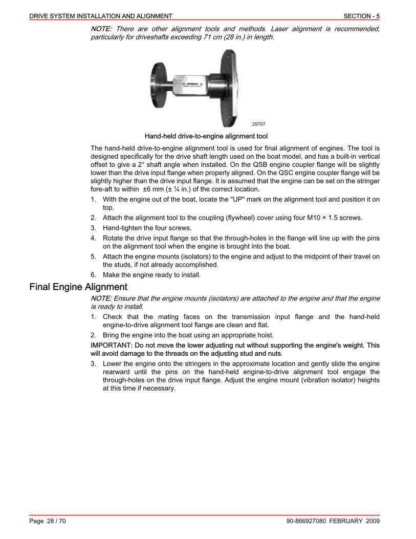
DRIVE SYSTEM INSTALLATION AND ALIGNMENT SECTION - 5
Page 28 / 70 90-866927080 FEBRUARY 2009
NOTE: There are other alignment tools and methods. Laser alignment is recommended,particularly for driveshafts exceeding 71 cm (28 in.) in length.
29797
Hand‑held drive‑to‑engine alignment tool
The hand‑held drive‑to‑engine alignment tool is used for final alignment of engines. The tool isdesigned specifically for the drive shaft length used on the boat model, and has a built‑in verticaloffset to give a 2° shaft angle when installed. On the QSB engine coupler flange will be slightlylower than the drive input flange when properly aligned. On the QSC engine coupler flange will beslightly higher than the drive input flange. It is assumed that the engine can be set on the stringerfore‑aft to within ±6 mm (± ¼ in.) of the correct location.1. With the engine out of the boat, locate the "UP" mark on the alignment tool and position it on
top.2. Attach the alignment tool to the coupling (flywheel) cover using four M10 × 1.5 screws.3. Hand‑tighten the four screws.4. Rotate the drive input flange so that the through‑holes in the flange will line up with the pins
on the alignment tool when the engine is brought into the boat.5. Attach the engine mounts (isolators) to the engine and adjust to the midpoint of their travel on
the studs, if not already accomplished.6. Make the engine ready to install.
Final Engine AlignmentNOTE: Ensure that the engine mounts (isolators) are attached to the engine and that the engineis ready to install.1. Check that the mating faces on the transmission input flange and the hand‑held
engine‑to‑drive alignment tool flange are clean and flat.2. Bring the engine into the boat using an appropriate hoist.IMPORTANT: Do not move the lower adjusting nut without supporting the engine's weight. Thiswill avoid damage to the threads on the adjusting stud and nuts.3. Lower the engine onto the stringers in the approximate location and gently slide the engine
rearward until the pins on the hand‑held engine‑to‑drive alignment tool engage thethrough‑holes on the drive input flange. Adjust the engine mount (vibration isolator) heightsat this time if necessary.

SECTION - 5 DRIVE SYSTEM INSTALLATION AND ALIGNMENT
90-866927080 FEBRUARY 2009 Page 29 / 70
4. Adjust the fore‑aft location of the engine so that the sliding shaft in the alignment tool isapproximately centered in the slot when the flanges are in contact. There are reference marksat the slot to assist. The slot is designed so that the sliding shaft can move up to 13 mm(½ in.) forward or aft of this center line.
29799
a
bc
ed
Engine‑to‑drive alignment—typicala - Drive input flangeb - Alignment tool flangec - Marking
d - Hand‑held engine‑to‑drive alignmenttool
e - Sliding shaft in slot
Description Cummins Part Number
Hand‑held engine‑to‑drive alignment toolfor 26 cm (10‑1/4 in.) shaft 4980379for 72 cm (26‑3/8 in.) shaft Not available at time of printing.
5. After positioning the engine as required in step 4, extend the shaft fully from the fixture suchthat the fixture flange and drive flange are in contact (if not already in contact).
NOTE: The engine mounts (vibration isolators) must be parallel to the engine crankshaftlongitudinal center line.6. Check the gap around the flange circumference with a feeler gauge. Adjust the engine mount
(vibration isolator) nuts, engine mount position in the mount slots, or position of the engine onthe stringers to achieve the specified parallel alignment of the flanges.
Flange parallel alignmentAlignment tool flange‑to‑transmission input flange 0.05–0.10 mm (0.002–0.004 in.)
NOTICEOperating the engine with the driveshaft installed at an incorrect angle will result in damage tothe driveshaft and the universal joint bearings. Align the engine correctly before operating.
7. If the flange faces are not aligned as specified, readjust the position of the engine until withinspecification.
8. If not already accomplished, fasten the engine mounts (isolators) to the boat stringer usingthe appropriate hardware (lag bolts or thru‑bolts, etc.).
9. Remove the lifting hoist.10. Torque all of the locking nuts on the engine mounts (vibration isolators).
Description Nm lb. in. lb. ft.Engine mount (vibration isolator) locking nuts 108–135 – 80–100
NOTE: If operating in a saltwater environment, apply Quicksilver Perfect Seal to the engine mountstud threads and nuts to help protect against corrosion to allow for easier loosening in the futureif readjustment becomes necessary.11. Remove the alignment tool.

DRIVE SYSTEM INSTALLATION AND ALIGNMENT SECTION - 5
Page 30 / 70 90-866927080 FEBRUARY 2009
Installing and Aligning the Engine—Using a Two‑Piece AlignmentTool and Indicator LinePreparation
You can use the two‑piece drive‑to‑engine alignment tool (Alignment Kit—CMD Part Number4919082) in place of the hand‑held drive‑to‑alignment tool for final alignment of engine and drive.The tool is designed to work with all driveshaft lengths. Markings assist in establishing thehorizontal and vertical shaft angle (offset) when installed. Using a length of suitable line or stringto indicate the offset is required on driveshafts longer than 25.4 cm (10 in.).1. Check that the mating surfaces and magnets are clean and flat on the coupler flanges of the
engine, transmission, and alignment tool.2. Remove any dirt or debris that could prevent proper seating of the tools.3. Attach the engine mounts (isolators) to the engine and adjust to the midpoint of their travel on
the studs, if not already accomplished.4. Make the engine ready to install.5. Bring the engine into the boat using an appropriate hoist.6. Lower the engine onto the stringers in the approximate mounting location.
Engine Alignment1. On the coupler flange of the engine, install the part of the alignment tool marked "ENGINE"
with the blade parallel to the ground, as shown.
a b
39995
a - Coupler flange (not visible in this view)b - "ENGINE" part of alignment tool
Description CMD Part NumberAlignment tool (marked "ENGINE") 4919096

SECTION - 5 DRIVE SYSTEM INSTALLATION AND ALIGNMENT
90-866927080 FEBRUARY 2009 Page 31 / 70
2. Install the part of the alignment tool marked "GEAR" on the coupler flange of the transmission.Ensure the blade is parallel to the ground as shown.
39996
ab
c
a - Transmissionb - Coupler flangec - "GEAR" part of alignment tool
Description CMD Part NumberAlignment tool (marked "GEAR") 4919097
IMPORTANT: Ensure the tools are firmly attached and do not move on their flanges. To avoiddamaging the tools, do not attempt to pry the tools off of their mountings. Engage (pull‑out) therelease lever to change the tool position or before removal.3. On models with a 25.4 cm (10 in.) long driveshaft, the alignment tool blades overlap. Ensure
that the blades of the alignment tools are not resting against or interfering with each other.
39999
Tool blades overlapping4. On models with a driveshaft longer than 25.4 cm (10 in.), the blades do not overlap and an
indicator line is necessary. Insert an indicator line into the holes in the tool blades. Use thepegs to hold the line tight. Do not allow the line and tool to interfere with each other.

DRIVE SYSTEM INSTALLATION AND ALIGNMENT SECTION - 5
Page 32 / 70 90-866927080 FEBRUARY 2009
IMPORTANT: Make certain the indicator line is stretched tight and does not sag.
39992
ba
"GEAR" end shown, "ENGINE" end similara - Pegb - Indicator line
5. Check the horizontal alignment of the engine and drive.a. On models with a 25.4 cm (10 in.) long driveshaft, read the degrees at the end of the
tool where the tool centerlines overlap.b. On models with a driveshaft over 25.4 cm (10 in.) long, read the degrees where the
indicator line crosses the degree scale.
39997
a
b
Reading the horizontal alignmenta - Indicator lineb - Degree scale
6. Adjust the nuts on the vibration‑isolator engine mounts to align the drive and engine tospecification on the stringers.
7. Move the engine side‑to‑side or move the engine mount position in the mount slots to set thehorizontal drive‑to‑engine alignment as specified.
NOTE: Set the alignment as close to 0° as possible.
Drive‑to‑engine alignment SpecificationHorizontal measurement 0° ± 1°

SECTION - 5 DRIVE SYSTEM INSTALLATION AND ALIGNMENT
90-866927080 FEBRUARY 2009 Page 33 / 70
8. Pull out on the release lever to release the tools for changing the position.
39993
Release lever pulled out (unlocked)9. Rotate the blades 180° and push in the release lever.
39994
Release lever pushed in (locked)10. Confirm that the measurements are the same as previous. If different, check the way to the
tools fit on the flanges and make corrections. Check the measurement.11. After the horizontal measurement is correct, if not already accomplished, fasten the engine
mounts (isolators) to the boat stringer using the appropriate hardware (lag bolts orthrough‑bolts, etc.). Check the measurement.
12. Pull out on the release lever and rotate the tool blades 90° degrees so they are perpendicularto the ground.
13. Check the vertical drive‑to‑engine measurement as specified. The measurement is takenwhere the indicator line crosses the scales at the ends of the blades or where the toolcenterlines cross the scales. The readings on scales of the engine and transmission end toolsshould be nearly the same.
40000
b
a
Checking vertical alignment with overlapping toolsa - Tools in vertical positionb - Tool centerline crosses the scale

DRIVE SYSTEM INSTALLATION AND ALIGNMENT SECTION - 5
Page 34 / 70 90-866927080 FEBRUARY 2009
39998
a
b
Checking vertical alignment with indicator linea - "ENGINE" end tool in vertical position ("GEAR" end similar)b - Indicator line crosses the scale
.
Drive‑to‑engine alignment SpecificationVertical measurement 2° ± 1°
14. Adjust the engine mount (vibration isolator) nuts, engine mount position in the mount slots, orposition of the engine on the stringers to achieve the specified alignment of the drive andengine.
40001
Typical engine mount (vibration isolator)
Completing the InstallationDriveshaft Installation
NOTE: We recommend a digital electronic level or universal protractor for measuring angles inthe following steps. In these procedures the terms should be considered interchangeable anddependent upon the tool used.IMPORTANT: The following procedure applies to driveshafts supplied by CMD. When using adriveshaft from a different manufacturer or supplier, follow the specific installation proceduresprovided with the driveshaft.1. Push the driveshaft together to fully collapse the splined portion.2. Attach the driveshaft to the transmission input shaft flange and the engine coupler.

SECTION - 5 DRIVE SYSTEM INSTALLATION AND ALIGNMENT
90-866927080 FEBRUARY 2009 Page 35 / 70
3. Tighten the locknuts on the transmission input shaft flange bolts to specification.
24052
b
a
d c
a - Locknutb - Transmission input shaft flangec - Bolt, 1/2‑20 × 1‑1/2 in. long (4 per flange)d - Driveshaft
Description Nm lb. in. lb. ft.Transmission input shaft flange locknuts 150 – 110
4. Tighten the screws on the engine coupler to specification.
ca
b24054
a - Screw, 1/2‑20 × 2‑1/4 in. long (4 per flange)b - Engine couplerc - Driveshaft
Description Nm lb. in. lb. ft.Engine coupler‑to‑drive shaft flange screws 150 – 110
NOTE: Measure the inclination of the engine at the valve cover after the boat is made level.5. The driveshaft angle should be as specified with the boat and the engine level (0°). Position
a protractor on the driveshaft and check the angle of inclination. If the driveshaft angle is notwithin specification, see Final Engine Alignment and repeat the appropriate steps.
DriveshaftAngle of inclination 1°–3°(2° preferred)

DRIVE SYSTEM INSTALLATION AND ALIGNMENT SECTION - 5
Page 36 / 70 90-866927080 FEBRUARY 2009
6. Lubricate the driveshaft slip‑joint. Pump grease into the grease fitting for the slip‑joint untilgrease is expelled from the pressure relief hole in the cap plug.
34012
a
b
c
a - Grease fittingb - Cap plugc - Expelled grease
Tube Ref No. Description Where Used Part No.
42 U-joint and Gimbal BearingGrease Driveshaft slip-joint 92-802870A1
7. Lubricate the driveshaft U‑joints through the grease fitting by applying approximately 3‑4pumps of specified grease from a typical handheld mechanical grease gun.
36722
Typical driveshaft U‑joint grease fittings
Tube Ref No. Description Where Used Part No.
42 U-joint and Gimbal BearingGrease Driveshaft U-joints 92-802870A1
8. Apply adhesive to the threads of the screws and bolts of the shields on the engine andtransmission ends.
Tube Ref No. Description Where Used Part No.
10 Loctite 277 Driveshaft shield retainingscrew and nut Obtain Locally

SECTION - 5 DRIVE SYSTEM INSTALLATION AND ALIGNMENT
90-866927080 FEBRUARY 2009 Page 37 / 70
9. Install the engine end driveshaft shield onto the flywheel housing cover. Tighten the driveshaftshield retaining screws to specification.
a
cb
34052
Typical driveshaft shielda - Top shieldb - Flange head screw (4)c - Engine end
Description Nm lb. in. lb. ft.Driveshaft shield retaining screw—engine end 36 – 27
10. Install the top and bottom driveshaft shields on the transmission end as shown. Tighten thedriveshaft shield retaining screws and nuts on the transmission end to specification.
c
a
c
36689
cd
b
Typical top shield and bottom shield at transmission enda - Bottom shieldb - Driveshaft shield upper‑to‑lower
retaining screw, nut, and washer (2)
c - Top shieldd - Socket‑head driveshaft
shield‑to‑transmission screw andwasher (4)
Description Nm lb. in. lb. ft.Driveshaft shield retaining screw and nut—transmission end 36 – 27Driveshaft shield upper‑to‑lower retaining screw and nut—transmission end 17 – 23
Installing the Exhaust System and Seawater Return HosesNOTE: Refer to the Marine Recreational High Output Propulsion Units B and C SeriesInstallation Directions manual (available from CMD) for information on exhaust elbowconnections at the turbocharger if not already installed.IMPORTANT: Secure the exhaust hoses and tubes at each connection with at least 2 hose clamps.Refer to Section 3 for more information on the exhaust system.

DRIVE SYSTEM INSTALLATION AND ALIGNMENT SECTION - 5
Page 38 / 70 90-866927080 FEBRUARY 2009
1. Install the black O‑ring into the groove on the exhaust flange of the drive center section.
ab
29979
a - Exhaust flangeb - O‑ring
2. Insert the lower elbow into the two halves of the lower elbow clamp ring and assemble thelower elbow loosely to the exhaust flange with the provided screws. Ensure the O‑ring remainsproperly seated in the groove on the exhaust flange.
3. Using the gasket between the elbow and the turbocharger outlet, install the upper elbow/riserloosely to the turbocharger with the provided washers and screws.
4. Place two T‑bolt clamps of the correct size loosely over each end of the bellows hoses.5. Slide the 14 cm (5.5 in.) to 12.7 cm (5 in.) (QSB and QSC) bellows hose onto the lower end
of the main fiberglass‑reinforced plastic (FRP) exhaust tube past the O‑ring groove with the14 cm (5.5 in.) end toward the lower elbow.
6. Slide the upper bellows hose 12.7 cm (5 in.) to 12.7 cm (5 in.) (QSB) or 12.7 cm (5 in.) to15.2 cm (6 in.) (QSC) onto the upper end of the FRP tube.
7. With the upper bellows hose on the upper end of the FRP tube, adjust the position of thebellows hose so that the FRP tube extends fully into the cuff section, but does not protrudeinto the raised bellows or humped section of the hose.
8. Mark the position of the bellows hose on outside of the FRP tube. This will serve as a referencemark for the proper position of the bellows hose for final assembly.
IMPORTANT: After final assembly, the upper FRP tube end should not extend past the cuff sectionof the bellows hose. Otherwise, the water injection from the upper elbow can be disrupted leadingto increased exhaust temperature within the tube.9. Install the brown O‑ring into the groove in the FRP tube.10. Lubricate the O‑ring and the inner periphery of the lower elbow with the specified grease.
Description Part NumberSilicone grease Obtain locally
11. Insert the FRP tube into the lower elbow, being careful not to move the O‑ring out of the groove.The tube should fully seat into the elbow.

SECTION - 5 DRIVE SYSTEM INSTALLATION AND ALIGNMENT
90-866927080 FEBRUARY 2009 Page 39 / 70
12. Slide the lower bellows hose onto the lower elbow.
a
c
e
b
d
fg40052
a - Lower elbowb - Cuff sectionc - Bellows (hump) sectiond - Lower bellows hose
e - FRP tubef - Brown O‑ringg - Silicone grease applied
13. Slide the upper bellows hose onto the upper elbow. Position the hose on the FRP tube at thereference mark made in step 6.
IMPORTANT: For proper seawater return flow the idle bypass connection must be properlyoriented.14. Rotate the FRP tube so that the lower fitting for the idle bypass connection is in the proper
orientation.
Idle Bypass Connection SpecificationOrientation within ± 20° of straight down
15. Position and tighten the lower bellows hose T‑bolt clamps.16. Tighten the lower elbow screws to specification.
a b
cd
ed29980
a - Lower 90° exhaust elbowb - Screwsc - FRP tube
d - Two T‑bolt clampse - Bellows hose
Description Nm lb‑in. lb‑ftLower elbow screws 24 – 18

DRIVE SYSTEM INSTALLATION AND ALIGNMENT SECTION - 5
Page 40 / 70 90-866927080 FEBRUARY 2009
17. Tighten the upper elbow/riser screws to specification.
d
a
bc
ed
f
hg
29984
a - Water supply hose and clampsb - Engine heat exchangerc - Upper exhaust elbowd - Double T‑bolt clamps
e - Upper bellows hosef - Idle bypass hose and clampg - Exhaust pipeh - Seawater bypass hose and clamp
Description Nm lb‑in. lb‑ftUpper elbow/riser screws 24 – 18
18. Position and tighten upper bellows hose T‑bolt clamps to specification.
Description Nm lb. in. lb. ft.Exhaust system T‑bolt hose clamp 3.4–6.8 30–60 –
19. Position a hose clamp on each end of the water supply hose.20. Install the water supply hose (seawater overboard) from the engine heat exchanger to the
upper 90° exhaust elbow.21. Install a hose clamp on the upper end of the seawater bypass hose (to oil cooler).22. Install the seawater bypass hose onto the fitting of the upper 90° exhaust elbow.23. On models with a drop box, install the seawater bypass hose from the upper exhaust elbow
on the inlet of the secondary cooler.24. On models without a drop box, install the seawater bypass hose from the upper exhaust elbow
on the inlet of the primary cooler.
b
c
ad
28060
Typical with drop box, all similara - Drop boxb - Inlet of secondary coolerc - Inlet of primary coolerd - Secondary cooler assembly and hose with clamps (on models with a drop box)
25. Install a hose clamp on the upper end of the idle bypass hose.

SECTION - 5 DRIVE SYSTEM INSTALLATION AND ALIGNMENT
90-866927080 FEBRUARY 2009 Page 41 / 70
26. Install the idle bypass hose (to water lift muffler) onto the fitting pointing straight (± 20°) downon the FRP tube.
27. Install the idle bypass hose to the water lift muffler.
a
bc
d
26862
Typical water lift muffler installationa - Typical water lift mufflerb - Idle bypass hose from FRP tubec - Seawater overboard hose from muffler outletd - Typical seawater overboard fitting
28. Check and tighten all exhaust system hose clamps as specified, unless otherwise indicated.
Description Nm lb. in. lb. ft.Exhaust system T‑bolt hose clamp 3.4–6.8 30–60 –Seawater hose clamp (all) 3.4–6.8 30–60 –
29. Keep the return (overboard) seacock closed until the engine must be operated.
Connecting the Seawater Inlet and StrainerIMPORTANT: Use wire‑reinforced seawater hose to avoid collapsing the hose when suction iscreated by the seawater pump impeller.1. Cut the wire reinforced seawater hose to the required length to make the appropriate
connections.2. Fit hose clamps on the hose ends.3. Install the seawater hose from the seawater inlet fitting to the seawater strainer.
b
ac d
24378
Typical HH and IH model seacock installation shown, all similara - Seawater hoseb - Inlet fittingc - Hose clampsd - To seawater strainer

DRIVE SYSTEM INSTALLATION AND ALIGNMENT SECTION - 5
Page 42 / 70 90-866927080 FEBRUARY 2009
a
b
39927
Typical JH model seacocka - Seacock (provided)b - Seawater inlet fitting (to seawater strainer)
4. Install the seawater hose from the strainer to the seawater inlet fitting on the seawater pumpof the engine.
5. Tighten the hose clamps securely.
24372
a bc
a - Seawater hoseb - Strainerc - Inlet Fitting
Connecting the Engine Mounted Oil Cooler, If EquippedThe capacity of the primary oil cooler mounted on the drive is not sufficient for the QSC enginepower rating. The QSC engine is equipped with an added engine mounted cooler and additionalhoses to connect between the drive and the engine. The secondary, horizontal cooler (on the drivefor QSB engines equipped with a drop box) is removed in the QSC applications.NOTE: The hoses included in the engine mounted cooler option are specifically long enough foruse with the 71 cm (28 in.) driveshaft .1. Remove the debris plugs from the sleeve nuts on the blue‑colored, additional hydraulic hoses.

SECTION - 5 DRIVE SYSTEM INSTALLATION AND ALIGNMENT
90-866927080 FEBRUARY 2009 Page 43 / 70
2. Attach the long blue hose to the front port and the short blue hose to the rear port on the enginemounted cooler.
a
c40242
b
a - Front port (long hose)b - Rear port (short hose)
c - Location of cooler on port side ofengine
IMPORTANT: Ensure the hydraulic hoses do not contact with the couplers or driveshaft. Avoidcausing stress on the hose fittings and do not allow kinks in the hoses.3. Route these hoses to the rear of the engine and to the starboard front of the drop box.4. Using the screws, washers, and J‑clips attach the two blue hoses (shorter hose on top clip,
longer hose on bottom clip). Using the P‑clip attach the seawater hose to the drive.Hand‑tighten the screws.
NOTE: Clip the longer fluid hose and the seawater hose in the lower threaded hole of the bracket.IMPORTANT: Make hydraulic connections as quickly as possible to prevent fluid leaks.5. Remove the existing hose from the transmission to the cooler.
40047
Existing oil hose from transmission to primary cooler6. Attach the shorter hose to the transmission fitting.7. Attach the longer hose to the cooler fitting.

DRIVE SYSTEM INSTALLATION AND ALIGNMENT SECTION - 5
Page 44 / 70 90-866927080 FEBRUARY 2009
8. Tighten the hydraulic hose sleeve nuts to specification.
a b
d
c
35877
a - Clamps and hoseb - Transmission oil outlet to engine mounted cooler (short hose)c - Screw and J‑clip (P‑clip not shown)d - Transmission oil return from engine mounted cooler (long hose)
Description Nm lb‑in. lb‑ftHose sleeve nut to cooler fitting 27 – 20Hose sleeve nut to transmission fitting 47 – 35
9. Tighten the screws for the P‑clip and J‑clips to specification.
c
a
b
40048
a - Lower J‑clip and screwb - P‑clip (on lower screw)c - Upper J‑clip and screw
Description Nm lb‑in. lb‑ftJ‑clip and P‑clip screw 33.5 – 25
IMPORTANT: Always use the dipstick to determine the exact quantity of oil required.10. After the entire Zeus installation is complete and ready to run, fill the transmission fluid level
to the upper mark on the dipstick. Use only the specified fluid. Screw the dipstick in fully beforereading the level.
Tube Ref No. Description Where Used Part No.
138 Synthetic Power SteeringFluid SAE 0W-30 Transmission and drop box 92-858076K01
11. With the boat in the water, or a suitable clean water source provided for the engines’ seawaterpumps, run the engines for five minutes to fill the cooler and lines. Shut down the engines,wait five minutes, then check the transmission fluid level and top off as necessary with thespecified oil.

SECTION - 5 DRIVE SYSTEM INSTALLATION AND ALIGNMENT
90-866927080 FEBRUARY 2009 Page 45 / 70
NOTE: The cooler on the engine and hoses hold approximately 0.47 liters (1/2 qt.) more fluid thanthe normal capacity of the transmission and drop box.
Installing the Drive Skeg1. Clear the slot where the skeg attaches to the drive gearcase of dirt or debris.
24026
b
a
a - Slotb - Drive gearcase
2. Insert the skeg into the slot on the drive gearcase.NOTE: If necessary use a block of wood and a hammer to seat the skeg.3. Install the two roll pins into the retaining passages until they are flush with the outside of the
housing.
ab
c
d
e
24017
a - Slotb - Skegc - Gearcase
d - Roll pine - Roll pin flush with outside
Corrosion Continuity Circuit ConnectionsGood continuity must be maintained between the Zeus drive components for the galvaniccorrosion protection systems to function effectively. CMD Zeus drives are equipped with acontinuity circuit to ensure good continuity. One circuit from the king pin to the steering actuatorhousing is an internal circuit and not shown in the following images. Ensure that the corrosionprotection systems and external continuity wires are installed.1. Check that the trim tab anode is installed on the trim tab.

DRIVE SYSTEM INSTALLATION AND ALIGNMENT SECTION - 5
Page 46 / 70 90-866927080 FEBRUARY 2009
NOTE: Some models have two anodes on the trim tab. Ensure that both are installed.
25883
Typical, all similar2. Check that the trim tab ground (‑) continuity wires are connected.
29068
a
d
a
c b
a - Trim tab hinge blockb - Trim tabc - Screwd - Continuity wire
3. Ensure that black/green ground wire from the MerCathode controller is securely attached tothe ground connection lug on the rear of the drive center section.
27488
Connection lug for drive ground (–) continuity wire

SECTION - 5 DRIVE SYSTEM INSTALLATION AND ALIGNMENT
90-866927080 FEBRUARY 2009 Page 47 / 70
a
26299
b
c
a - Black/green ground (‑) wireb - Ground (‑) connection lugc - Drive center section
IMPORTANT: Both the engine block and the grounding (‑) connection lug should be connected tothe bonding bus of the vessel with a minimum of an 8mm² (8 AWG) wire.4. Ensure that the factory installed MerCathode anode system is properly mounted and
connected.
b
a
25885
MerCathode system anodea - Anodeb - Reference electrode (not visible in this view)
5. If not already, connect the wiring to the MerCathode controller.

DRIVE SYSTEM INSTALLATION AND ALIGNMENT SECTION - 5
Page 48 / 70 90-866927080 FEBRUARY 2009
a. Remove the nut from the positive (+) post on the MerCathode controller.
a
c
b
39309
a - MerCathode controllerb - Positive (+) postc - Nut
b. Attach the ring terminal end of the harness wire (with the protective cover) to thecontroller. Tighten the nut securely.
c. Apply sealant to the exposed nut and ring terminal connection.d. Install the protective cover over the connection.
a
b
39310
a - Harness wireb - Protective cover
Tube Ref No. Description Where Used Part No.
25 Liquid Neoprene Exposed electrical terminals 92- 25711 3

SECTION - 5 DRIVE SYSTEM INSTALLATION AND ALIGNMENT
90-866927080 FEBRUARY 2009 Page 49 / 70
e. Route the harness according the the guidelines. When installing a 24‑volt harness,ensure that the segment of the harness identified as containing the resistors (near thefuse holder) is free of stress and not kinked.
b
a
39395
a - Fuse holderb - Resistors
f. Attach the ring terminal end of the harness (near the fuse holder) to the positive (+)battery terminal or an unswitched positive (+) battery bus bar or terminal strip.
39396
ab
c
Typical unswitched connectiona - Typical unswitched positive (+) bus barb - Ring terminal connectionc - Harness (12‑volt shown, 24‑volt similar)

DRIVE SYSTEM INSTALLATION AND ALIGNMENT SECTION - 5
Page 50 / 70 90-866927080 FEBRUARY 2009
g. Connect the remaining wires to the MerCathode controller as shown.
29037
a
b
fed
c
MerCathode system controllera - MerCathode controllerb - Reference electrode wirec - Controller ground wire (–) to battery
negative, negative terminal strip, ornegative DC bus bar
d - Anode wiree - Controller positive wire (+) with fuse to
battery positive, unswitched side ofbattery disconnect, or (with circuitbreaker) to unswitched positive DCbus bar
f - Controller black/green ground wire (–)to ground lug, with connectioncontinuing to the negative DC bus bar
6. Ensure that required vessel corrosion protection systems and appropriate continuity wires areinstalled.
25887
Typical transom mounted anode (continuity wire and connections inside the hull are not shown)
IMPORTANT: Good continuity must be maintained between other anodes, if equipped, and thenegative DC bus bar for the vessel galvanic corrosion protection systems to function effectively.
Electrical ConnectionsNOTE: Refer to Section 6 Electrical System Architecture diagrams and for additional electricalinformation.

SECTION - 5 DRIVE SYSTEM INSTALLATION AND ALIGNMENT
90-866927080 FEBRUARY 2009 Page 51 / 70
IMPORTANT: To avoid damage to the electrical system, refer to the following precautions whenworking on or around the electrical harness or when adding other electrical accessories.• Do not tap accessories into the engine harness.• Do not puncture wires for testing (probing).• Do not reverse the battery leads.• Do not splice wires into the harness.• Do not route harness near sharp edges, hot surfaces, or moving parts.• Fasten cables away from and sharp edges, fasteners, or objects that could wear into the
harness or pinch the harness.• Avoid sharp bends in a data harness. Minimum bend radius should be 7.6 cm (3 in.) for
installation.• Fasten harnesses to the boat at least every 45.7cm (18 in.), using appropriate fasteners.• Do not attempt diagnostics without the proper, approved service tools.• Disconnect both the negative (–) and positive (+) battery cables from the battery before electric
arc welding on the vessel. Attach the welder ground cable no more than 0.61 meters [2 feet]from the part being welded. Do not connect the ground cable of the welder to any ECM coolingplate or ECM. Welding on the engine, drive, or engine or drive mounted components is notrecommended or damage to the engine or drive or related components can result.
Connecting the WiringThe wiring to the various electrical components on the vessel may not always be connected directlyto the positive or negative side of a battery.On large vessels some power supply wires may connect indirectly to the positive (+) batteryterminal through a battery switch (battery disconnect switch), a positive terminal strip, or to a fusepanel. The position of the wire connection to the battery switch determines if the power is switched(will be off with the switch) or unswitched (is on constantly).Negative wiring or ground (–) wires may connect indirectly to the negative (–) battery terminalthrough a negative terminal strip or a neutral bus bar.Here are two examples of positive wire connections. The type of terminal strip shown could alsobe used for negative wire connections if it was connected only to the negative battery terminal.
a b
31677
a - Battery switchb - Positive terminal strip (similar for negative)
Continuity Wire ConnectionsIMPORTANT: Do not attach any accessory ground (–) wires to drive ground connection. Accessoryground wires can only be attached to the ground stud on the engine or to the battery.

DRIVE SYSTEM INSTALLATION AND ALIGNMENT SECTION - 5
Page 52 / 70 90-866927080 FEBRUARY 2009
1. Ensure that the black/green ground wire (–) from the MerCathode controller is securelyattached to the ground (–) connection lug on the rear of the drive center section.
a
26299
b
c
Drive shown with covera - Black/green ground (–) wireb - Ground (–) connection lugc - Drive center section
IMPORTANT: Both the engine block and the grounding (–) connection lug should be connectedto the bonding bus of the vessel with a minimum of a 8 mm² (8 AWG) wire.
Drive Application Extension HarnessThe drive application extension harness connects between the engine and the drive. This harnesscontains the power and ground connections for the solenoids on the drive. Pressure sensors,transmission speed sensors, and temperature sensors are also powered and grounded throughthis harness.One drive application extension harness is required for each drive.
31279
a
bc
a - Drive application extension harnessb - Engine connectorc - Drive connector

SECTION - 5 DRIVE SYSTEM INSTALLATION AND ALIGNMENT
90-866927080 FEBRUARY 2009 Page 53 / 70
Installing the Drive Application Extension Harness1. Connect the drive application extension harness to the 19‑pin connector on the electrical
bracket of the drive. Fully engage and tighten the threaded connector collars.
26312
b
a
Shown with cover installed, same withouta - Drive application harness connectorb - Electrical bracket
.2. Connect the drive application extension harness to the 19‑pin connector on the engine.
a
b
26113
a - Drive application harnessb - Drive application harness connector on engine harness

DRIVE SYSTEM INSTALLATION AND ALIGNMENT SECTION - 5
Page 54 / 70 90-866927080 FEBRUARY 2009
Vessel Interface Panel (VIP)The Vessel Interface Panel (VIP), one per engine, must be located on a bulkhead with easy accessand free from excessive heat. Numerous extension harnesses are available for the spans betweenthe engine and the VIP, and between the VIP and the various sensors, to account for location.The space claim for these units is shown in the graphic below.
25540
a b
c
d
One of the two VIPs requireda - Height 19.1 cm ( 7‑½ in.)b - Height with connections 41.9 cm ( 16‑½ in.)c - Width 29.2 cm ( 11‑½ in.)d - Depth 15.3 cm ( 6 in.)
Electrical wiring requirements from the helm to engine room should be planned at this time basedon the electrical system architecture diagram. Wiring connections will also be made between theVIP, engine, and drive. Allow 22.8 cm (9 in.) below the VIP for wire connections.NOTE: Leave full access to the front of the VIP for resetting breakers and performing diagnostics.The VIP is an integral part of the Zeus system architecture. The VIP is a required component ofthe system and contains the following.• The system integration module (SIM)• The SmartCraft power protection devices (circuit breakers)• Mounting locations for 9‑pin diagnostic connector• Connection points for the helm harness, VIP power harness, and engine harness, plus an
interface for the manual start and stop of the engine.• Connection points for the vessel sensor harnessThe VIP option is dependent on the system integration module (SIM) contained within the VIP.When ordering the engine, the corresponding VIP must also be ordered based on the configurationof the drive system.
Mounting the Vessel Interface Panel (VIP)The Vessel Interface Panel (VIP) is intended for mounting on the bulkhead of the vessel in theengine compartment.IMPORTANT: Mount the VIP with the connectors oriented downward, to the port or starboard side,or laid down. Do not mount the VIP with the connectors facing upward.Mount the VIP:• In an easily accessible location.• Above the waterline at rest and not near any moving parts.• Clear of deck water run‑off and engine compartment water spray.• So that the circuit breakers are easily accessible.

SECTION - 5 DRIVE SYSTEM INSTALLATION AND ALIGNMENT
90-866927080 FEBRUARY 2009 Page 55 / 70
• In an area that is free of excessive heat and a minimum 30.5 cm (12 in.) distance from allexhaust components.
• With a minimum of 22.9 cm (9 in.) of free space directly below the VIP for wire harness routing.• Free from excessive vibration and not directly or indirectly mounted to the engine.1. Using a template, or the VIP itself, mark the location of the six mounting holes.2. Drill the appropriate size holes for the mounting screws.3. Install and securely tighten the mounting screws.
31456
a
b
b
b
Typical VIP, all similara - VIPb - Mounting screw (6 total, 2 not visible)
T‑HarnessThe T‑harness allows the helm extension harness and TVM extension harness to be connectedto the VIP.One T‑harness is required for each VIP.
31295
a b
d
c
a - T‑harnessb - Helm extension harness connectorc - TVM extension harness connectord - VIP connector
Installing the T‑Harness1. Connect the T‑harness to the connector on the VIP marked "HELM". Make this connection on
the port and starboard VIP.

DRIVE SYSTEM INSTALLATION AND ALIGNMENT SECTION - 5
Page 56 / 70 90-866927080 FEBRUARY 2009
2. Fully engage and tighten the threaded connector collars.
31296
a
b
One VIP shown, both similara - VIPb - T‑harness connector
Engine‑to‑VIP Extension HarnessThe engine‑to‑VIP extension harness interfaces the engine with the VIP.One engine‑to‑VIP extension harness is required for each engine.
acb
d
40046
a - Zeus‑to‑VIP connectorb - Engine‑to‑VIP extension harnessc - Jumper wire loopsd - Zeus‑to‑engine connector
Installing the Engine‑to‑VIP Extension HarnessIMPORTANT: The engine‑to‑VIP extension harness can be mounted in two different orientations.To avoid problems in the control system, ensure that the harness ends with tags stating"Zeus‑to‑VIP" are connected to the VIP and the harness ends with the tags stating "Zeus‑to‑Eng"are connected at the engine. The jumper wire loops will be at the engine‑end of the harness whencorrectly installed.NOTE: The socket head screws used to retain the harness ends require a 4mm Allen key andsocket (not provided).
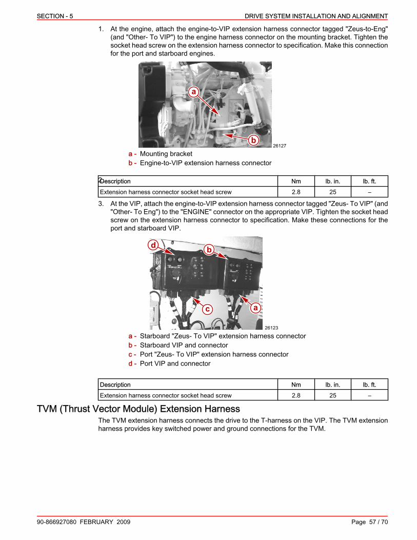
SECTION - 5 DRIVE SYSTEM INSTALLATION AND ALIGNMENT
90-866927080 FEBRUARY 2009 Page 57 / 70
1. At the engine, attach the engine‑to‑VIP extension harness connector tagged "Zeus‑to‑Eng"(and "Other‑ To VIP") to the engine harness connector on the mounting bracket. Tighten thesocket head screw on the extension harness connector to specification. Make this connectionfor the port and starboard engines.
26127
a
ba - Mounting bracketb - Engine‑to‑VIP extension harness connector
2.Description Nm lb. in. lb. ft.Extension harness connector socket head screw 2.8 25 –
3. At the VIP, attach the engine‑to‑VIP extension harness connector tagged "Zeus‑ To VIP" (and"Other‑ To Eng") to the "ENGINE" connector on the appropriate VIP. Tighten the socket headscrew on the extension harness connector to specification. Make these connections for theport and starboard VIP.
b
c a
d
26123
a - Starboard "Zeus‑ To VIP" extension harness connectorb - Starboard VIP and connectorc - Port "Zeus‑ To VIP" extension harness connectord - Port VIP and connector
Description Nm lb. in. lb. ft.Extension harness connector socket head screw 2.8 25 –
TVM (Thrust Vector Module) Extension HarnessThe TVM extension harness connects the drive to the T‑harness on the VIP. The TVM extensionharness provides key switched power and ground connections for the TVM.

DRIVE SYSTEM INSTALLATION AND ALIGNMENT SECTION - 5
Page 58 / 70 90-866927080 FEBRUARY 2009
One TVM extension harness is required for each drive.
31279
a
bc
a - TVM extension harnessb - Drive connectorc - T‑harness connector
Installing the TVM Extension HarnessNOTE: The required aluminum retainer nut and washer are shipped in the hardware bag thatcomes with the drive.1. Insert the threaded end of the TVM extension harness through the electrical bracket on the
drive.2. Install the washer and thread the retainer nut onto the TVM extension harness. Torque the
nut.3. Connect the 14‑pin TVM connector from the drive to the 14‑pin TVM extension harness
connector on the electrical bracket. Connector collars must be fully engaged and secure.Tighten the threaded connector collar.
26304
ab
cd
e
Shown with cover installed, same withouta - Washerb - Retainer nutc - TVM connector from drive
d - TVM extension harness threadedconnector
e - Electrical bracket
Description Nm lb. in. lb. ft.Retainer nut 5.6 50 –
NOTE: There are two connectors available on the T‑harness at the VIP. The TVM extensionharness can be connected to either connector.4. Make the following port and starboard connections.

SECTION - 5 DRIVE SYSTEM INSTALLATION AND ALIGNMENT
90-866927080 FEBRUARY 2009 Page 59 / 70
a. Connect the TVM extension harness to one end of the T‑harness.
b
c
a
d
26120e
f
g
h
a - Starboard TVM extension harness toT‑harness
b - Starboard T‑harness connector onVIP
c - Starboard T‑harness to main station(helm) extension harness
d - Starboard VIP
e - Port TVM extension harness toT‑harness
f - Port T‑harness connector on VIPg - Port T‑harness to main station (helm)
extension harnessh - Port VIP
Vessel Sensor Harness (Optional)The vessel sensor harness is a key component in the Zeus system architecture. The vessel sensorharness allows the vessel manufacturer to easily interface to key signal inputs and outputs thatare available in the SmartCraft system. The vessel sensor harness contains connections forvarious sensors that are monitored by the engine. These include water‑in‑fuel (WIF), halon firesuppression breakout, CAN P, accessory relay, steering, pitot, tank level, and paddle wheel, Thisis an optional harness.The vessel sensor harness comes as two different options. One option is the complete harnessthat includes all connectors to the various sensors. The other available option is a kit that includesonly the connectors previously mentioned to allow building the harness, as required to meet theexact input/output requirements of that particular vessel.If the vessel manufacturer does not choose to interface with any of the sensor inputs available onthe vessel sensor harness then this connection on the VIP will contain a blank connector (includedwith the VIP) with only two pins connected by a jumper. Connection of these two pins completesthe fire suppression breakout circuit. It is required that this circuit be complete for the engine tooperate correctly. The blank connector also contains a breakout for the WIF sensors.We recommend that the vessel manufacturer implement the prefabricated vessel sensor harnessto avoid issues that may arise due to poor fabrication techniques. This harness connects directlyto the vessel interface panel and will typically reside in the engine compartment area. This harnesspotentially could be subjected to an extremely harsh operating environment. The CMD suppliedoptions have been designed, tested and refined to survive in this type of operating environment.CMD will not warrant failures due to an improperly constructed vessel sensor harness.
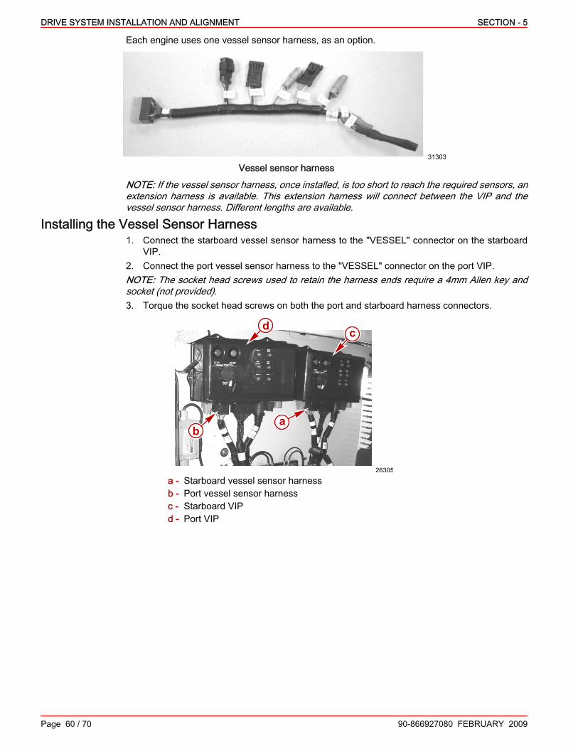
DRIVE SYSTEM INSTALLATION AND ALIGNMENT SECTION - 5
Page 60 / 70 90-866927080 FEBRUARY 2009
Each engine uses one vessel sensor harness, as an option.
31303
Vessel sensor harness
NOTE: If the vessel sensor harness, once installed, is too short to reach the required sensors, anextension harness is available. This extension harness will connect between the VIP and thevessel sensor harness. Different lengths are available.
Installing the Vessel Sensor Harness1. Connect the starboard vessel sensor harness to the "VESSEL" connector on the starboard
VIP.2. Connect the port vessel sensor harness to the "VESSEL" connector on the port VIP.NOTE: The socket head screws used to retain the harness ends require a 4mm Allen key andsocket (not provided).3. Torque the socket head screws on both the port and starboard harness connectors.
b
c
a
d
26305
a - Starboard vessel sensor harnessb - Port vessel sensor harnessc - Starboard VIPd - Port VIP

SECTION - 5 DRIVE SYSTEM INSTALLATION AND ALIGNMENT
90-866927080 FEBRUARY 2009 Page 61 / 70
Vessel Sensor Extension Harness (Optional)The vessel sensor extension harness connects between the vessel sensor harness and the VIP.This allows the vessel sensor harness to be extended beyond the VIP. The extension harnesscomes in multiple lengths. This is an optional harness and not required to be used.
31306
a b
ccd
a - Vessel sensor extension harnessb - Vessel sensor harness connectorc - Protective capd - VIP connector
Installing the Vessel Sensor Extension Harness1. Connect the starboard vessel sensor extension harness to the "VESSEL" connector on the
starboard VIP.2. Connect the port vessel sensor harness to the "VESSEL" connector on the port VIP.NOTE: The socket head screws used to retain the harness ends require a 4 mm Allen key andsocket (not provided).3. Torque the socket head screws on both the port and starboard harness connectors.
b
c
a
d
26305
a - Starboard vessel sensor extension harnessb - Port vessel sensor extension harnessc - Starboard VIPd - Port VIP
Description Nm lb. in. lb. ft.Harness connector socket head screw 2.8 25 –
4. Connect the port and starboard vessel sensor extension harness to the corresponding portand starboard vessel sensor harness.
Connecting the Vessel Sensors1. If equipped, connect the fuel tank level sensor, or sensors, to the vessel sensor harness. See
the specifications for the fuel tank level sensors.NOTE: For your reference, pins 3 and 4 are for tank 1 and pins 1 and 2 are for tank 2.

DRIVE SYSTEM INSTALLATION AND ALIGNMENT SECTION - 5
Page 62 / 70 90-866927080 FEBRUARY 2009
Fuel Tank Level Sensor Specification
240–33 ohm senderFull: 33 ohms
Empty: 240 ohms
2. On boats equipped with fire suppression systems and fire detection sensors, remove the halonbreak‑out jumper, and connect any fire detection sensor, or sensors, to the vessel sensorharness. Refer to the applicable fire suppression system documentation for furtherinstructions.
NOTE: WIF (water in fuel) sensors are integrated into the engine control system via a WIFharness. Refer to Section 6—Zeus Engine And Drive System Architecture for the location toconnect the WIF harness to the engine control system. CMD offers several WIF sensor andharness options to meet the customers needs. WIF harnesses have provisions for two WIFsensors for dual water separating primary filter installations. A Y‑harness is used at the connectionfor two WIF sensors. If only one primary filter is installed, a 220 kΩ biasing resistor plug, suppliedwith the appropriate WIF harness option, must be installed in the vacant WIF harness sensor plug.Failure to terminate both WIF harness sensor plug with either a WIF sensor or resistor plug willresult in WIF related fault codes and alarms.3. Connect the wiring for the water in fuel (WIF) sensor or sensors, if equipped, to the WIF wiring
extension of the vessel sensor harness. For connector identification refer to the tags on theWIF sensor Y‑harness.
31693
WIF sensor Y‑harness
Power Supply and DistributionThe Zeus system requires dedicated power supplies to the following components: MerCathode,Vessel Integration Panel (VIP), steering back‑up pump, engine ECM, and helm. All power suppliesexcept the helm are duplicated for port and starboard and must be connected to their respectivebattery bank. The power supply for the helm is connected to the starboard battery bank.All supplied power must be circuit protected in accordance with the local regulations or standardsto which the boatbuilder must comply. Circuit breaker and fuse sizes for each power supply areprovided below. It is the boatbuilder's option how to achieve proper circuit protection. However,we recommend integrating power supply circuit protection devices into one or two easilyaccessible distribution panels. We recommend sizing the conductors for a 3% voltage drop.

SECTION - 5 DRIVE SYSTEM INSTALLATION AND ALIGNMENT
90-866927080 FEBRUARY 2009 Page 63 / 70
How the power supplies connect to the battery bank is important. All connections require clean,uninterrupted power directly from the battery or bus, fed directly from the battery. Connect thepower supplies for the MerCathode and VIP directly to the battery or bus, so that the power supplyis not interrupted during operation or non‑usage. All other power supplies may be connected tothe battery through a battery disconnect switch, so that electrical connection will not be interruptedduring operation.
5A 30A 35A 30A 20A 30A 35A 30A 5A
a b
c d e f g h i j k
l m n o40061
Example of typical power supply protection and distributiona - Portb - Starboardc - MerCathode controller (port)d - VIP (port)e - Steering back‑up pump, if equipped
(port)f - Engine ECM (port)g - Helm (starboard)h - Engine ECM (starboard)
i - Steering back‑up pump, if equipped(starboard)
j - VIP (starboard)k - MerCathode controller (starboard)l - Port unswitched power supplym - Port switched power supplyn - Starboard switched power supplyo - Starboard unswitched power supply
VIP and ECM Power HarnessesAn unswitched power harness provides constant power from the battery to the VIP. A switchedpower harness provides power from the battery to the ECM.Each power harness is protected by an in‑line 30‑amp fuse (provided) or a 30‑amp circuit breaker(obtain locally).Two harnesses—one for the ECM and one for the VIP—are required for both the port and thestarboard power packages.
31297
BAT
TER
Y –
BAT
TER
Y +
TO V
IP/E
NG
INE
Typical VIP or ECM power harness
Installing the VIP Unswitched Power HarnessNOTE: VIP power should be powered ON at all times to maintain the system time clock. The VIPrequires minimal battery power and will not drain the battery.

DRIVE SYSTEM INSTALLATION AND ALIGNMENT SECTION - 5
Page 64 / 70 90-866927080 FEBRUARY 2009
1. Using the 30‑amp fuse (provided) or a 30‑amp circuit breaker (obtain locally), connect the redwire ring terminal labeled "+" to the unswitched side of a battery disconnect or to a terminalstrip connected to an unswitched battery positive (+) terminal.
2. Connect the black wire ring terminal labeled " –" to a negative terminal strip or ground (‑) busbar connected to the negative (–) battery terminal.
3. Connect the 4‑pin connector to the mating power connector located on the bottom side of theVIP. Fully seat the connector.
Installing the ECM Switched Power HarnessIMPORTANT: Do not use the ECM switched power harness circuit breaker switch to shut downthe engine.1. Using the 30‑amp fuse (provided) or a 30‑amp circuit breaker (obtain locally), connect the red
wire ring terminal labeled " +" to the switched side of a battery disconnect or to a terminal stripconnected to the battery positive (+) terminal.
2. Connect the black wire ring terminal labeled " –" to a negative terminal strip or ground (‑) busbar that is connected to the negative (–) battery terminal.
3. Connect the 4‑pin connector to the mating connector located on the ECM. Fully seat theconnector.
Installing the MUS ID Jumper PlugsMost applications are a single or dual engine. The primary engine for a SmartCraft system is thestarboard engine in all applications. Configure the engine as a starboard or primary engine. Thesecondary engine is the port engine. The engines are addressed using MUS ID jumper plugs withpins assigned as shown.
33635
a
b
MUS ID jumper plug pin assignmentsa - Primaryb - Secondary
The secondary engine jumper plug must be placed on the port engine for proper operation.After properly placing the ID jumper plugs, you must cycle the engine key switch two times for theproper configuration process to be completed. The first key switch application allows the SIM toread the ID jumper plugs and the power down and second key switch cycle allows the SIM to storethe module address. If a SIM is ever moved from port to starboard, two key switch cycles arerequired to complete the configuration change process.The connection point is on the OEM harness assembly, located just below the ECM harnessconnector. A label on the jumper plug connector will be indicate that it is a primary or secondaryjumper plug.1. Locate the OEM harness assembly and MUS ID connector.2. Note the label on the jumper plug connector, and attach the primary MUS ID jumper plug to
the starboard engine MUS ID connector.
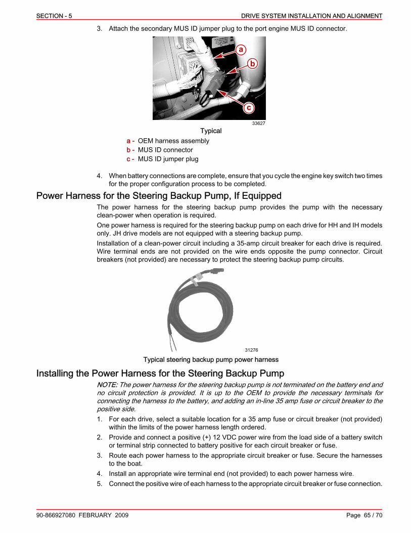
SECTION - 5 DRIVE SYSTEM INSTALLATION AND ALIGNMENT
90-866927080 FEBRUARY 2009 Page 65 / 70
3. Attach the secondary MUS ID jumper plug to the port engine MUS ID connector.
a
b
c
33627
Typicala - OEM harness assemblyb - MUS ID connectorc - MUS ID jumper plug
4. When battery connections are complete, ensure that you cycle the engine key switch two timesfor the proper configuration process to be completed.
Power Harness for the Steering Backup Pump, If EquippedThe power harness for the steering backup pump provides the pump with the necessaryclean‑power when operation is required.One power harness is required for the steering backup pump on each drive for HH and IH modelsonly. JH drive models are not equipped with a steering backup pump.Installation of a clean‑power circuit including a 35‑amp circuit breaker for each drive is required.Wire terminal ends are not provided on the wire ends opposite the pump connector. Circuitbreakers (not provided) are necessary to protect the steering backup pump circuits.
31276
Typical steering backup pump power harness
Installing the Power Harness for the Steering Backup PumpNOTE: The power harness for the steering backup pump is not terminated on the battery end andno circuit protection is provided. It is up to the OEM to provide the necessary terminals forconnecting the harness to the battery, and adding an in‑line 35 amp fuse or circuit breaker to thepositive side.1. For each drive, select a suitable location for a 35 amp fuse or circuit breaker (not provided)
within the limits of the power harness length ordered.2. Provide and connect a positive (+) 12 VDC power wire from the load side of a battery switch
or terminal strip connected to battery positive for each circuit breaker or fuse.3. Route each power harness to the appropriate circuit breaker or fuse. Secure the harnesses
to the boat.4. Install an appropriate wire terminal end (not provided) to each power harness wire.5. Connect the positive wire of each harness to the appropriate circuit breaker or fuse connection.

DRIVE SYSTEM INSTALLATION AND ALIGNMENT SECTION - 5
Page 66 / 70 90-866927080 FEBRUARY 2009
6. Connect the negative wire of each harness to a negative (–) terminal strip or bus bar connectedto the negative side of the battery.
7. Connect each power harness to the connector on the steering backup pump labeled "BatteryConnection."
Installing the Drive Cover, If Equipped1. Remove and retain the two lifting rings, if installed.NOTE: Store the lifting rings in an appropriate location for use when required.
39371
Lifting rings on a typical drive2. Carefully install the top cover on the drive. Align the cover with the two threaded holes in the
transmission where the lifting rings were removed.
a
b39497
a - Top coverb - Threaded holes
3. Install one large washer on each of the top cover screws.4. Install the two screws. Tighten the screws to specification.
ca
b
39498
a - Top cover screwb - Washerc - Torque wrench

SECTION - 5 DRIVE SYSTEM INSTALLATION AND ALIGNMENT
90-866927080 FEBRUARY 2009 Page 67 / 70
Description Nm lb‑in. lb‑ftTop cover screw 61 – 45
5. Assemble the three grommets and flange bushings into the starboard and port cover lowerholes, as shown.
39503
c
a
b d
Starboard side cover shown, port similara - Starboard coverb - Grommet
c - Flange bushingd - Completed assembly
6. Using six flange‑head screws, install the single starboard and two port L‑brackets on theclamping ring. Tighten the screws to specification.
a
bb
39561
c
Starboard L‑bracket
a
c
bb
39562
Port L‑bracketsa - Clamping ringb - Screwsc - L‑bracket
Description Nm lb‑in. lb‑ftL‑bracket flange head screws 22 195 –

DRIVE SYSTEM INSTALLATION AND ALIGNMENT SECTION - 5
Page 68 / 70 90-866927080 FEBRUARY 2009
NOTE: An alternative method of installing the H‑trim is to wait until both side covers are installed,spray the grooves of the H‑trim with a solution made from a small part of mild soap (such as dishsoap) and clean water, and slide the trim between the side covers.7. Install the section of H‑trim on the vertical end of the port cover.
a
b39589
a - Port coverb - H‑trim
8. Install the starboard side cover using four screws.
a
b
b
39590
a - Starboard coverb - Screw (4)
9. Align and insert the starboard cover into the groove of the H‑trim section on the port cover.10. Install the port side cover using five screws.
b
a
ac
39591
a - Screw (5)b - Port coverc - H‑trim
11. Tighten the three lower and six upper cover screws to specification.

SECTION - 5 DRIVE SYSTEM INSTALLATION AND ALIGNMENT
90-866927080 FEBRUARY 2009 Page 69 / 70
Description Nm lb‑in. lb‑ftCover upper screws 10 89 –Cover lower screws 27 – 20
12. Install the hatch cover.a. Insert the molded clip on the aft end of the hatch cover under the indented‑edge of the
cover top.
a
c
b
39506
a - Hatch coverb - Molded clipc - Indented‑edge
b. Align the hatch cover with the opening in the top cover.c. Press down evenly on the front end of the hatch cover. The hatch cover snaps into its
installed position.
39514
Completing the hatch cover installation

DRIVE SYSTEM INSTALLATION AND ALIGNMENT SECTION - 5
NOTES:
Page 70 / 70 90-866927080 FEBRUARY 2009

SECTION - 6 REMOTE CONTROL AND ELECTRICAL
90-866927080 FEBRUARY 2009 Page 1 / 98
SECTION 6 - REMOTE CONTROL AND ELECTRICALTable of ContentsZeus Electronic System Architecture....................................................................................................................... 6
Zeus Engine and Drive System Architecture.....................................................................................................6Zeus Helm (Main Station) System Architecture................................................................................................8
Wiring Guidelines.................................................................................................................................................. 11Wiring Guidelines for Electrical Boat Accessories ......................................................................................... 12Harness Installation Guidelines ...................................................................................................................... 12
System Components............................................................................................................................................. 12Drive Components...........................................................................................................................................12Engine Components........................................................................................................................................12VIP Components.............................................................................................................................................13Helm Components...........................................................................................................................................13Helm Harness Connections.............................................................................................................................13CAN V Components........................................................................................................................................15
Vessel Interface Panels (VIP)............................................................................................................................... 16Main Station Extension Harness........................................................................................................................... 16
Installation ...................................................................................................................................................... 16Second Station T‑Harness.................................................................................................................................... 17Helm Harness........................................................................................................................................................ 17
Installation ...................................................................................................................................................... 17Helm Connections .......................................................................................................................................... 17
Command and Control Module (CCM).................................................................................................................. 18Installation ...................................................................................................................................................... 18
Single or Main Helm Installation ............................................................................................................. 19Second Helm Installation, If Equipped ..................................................................................................... 20
Standard 6‑way or 8‑way Junction Box................................................................................................................. 21Installation ...................................................................................................................................................... 21
Autopilot Module.................................................................................................................................................... 22Installation ...................................................................................................................................................... 22
Smart Junction Boxes............................................................................................................................................ 23Smart Junction Box Connectors ..................................................................................................................... 24Installation ...................................................................................................................................................... 25
SmartCraft Data Extension Harness..................................................................................................................... 26Dual‑Handle Electronic Remote Control............................................................................................................... 26
Locating and Drilling Mounting Area for Dual‑Handle Electronic Remote Control..........................................26Dual‑Handle Electronic Remote Control Cut‑Out Template............................................................................27Installing the Dual‑Handle Electronic Remote Control with DTS Trackpad.....................................................27
Electronic Steering Column................................................................................................................................... 30Manual Tilt Steering Column Installation.........................................................................................................30
Steering Column Location ....................................................................................................................... 30Drilling Steering Column Holes Using the Special Tool ........................................................................... 30Drilling Steering Column Holes Using the Template ................................................................................ 32Installing the Steering Column ................................................................................................................. 34
Steering Wheel Installation..............................................................................................................................38Electronic Steering Helm Connections............................................................................................................38
Joystick.................................................................................................................................................................. 38Joystick Location Requirements......................................................................................................................38Joystick Installation.........................................................................................................................................40
Trim Tab................................................................................................................................................................ 42Trim Tab Panel................................................................................................................................................42Trim Tab Smart Multiplex Module (SMM)........................................................................................................43
Installation ................................................................................................................................................ 43
6

REMOTE CONTROL AND ELECTRICAL SECTION - 6
Page 2 / 98 90-866927080 FEBRUARY 2009
Key Switch............................................................................................................................................................. 44Preparation......................................................................................................................................................44Standard Mounting ‑ With Housing.................................................................................................................45Optional Mounting ‑ Without Housing..............................................................................................................47Key Switch Extension Harness.......................................................................................................................47
Installation ................................................................................................................................................ 48Start/Stop Panel.................................................................................................................................................... 48
Preparation ..................................................................................................................................................... 48Installation ...................................................................................................................................................... 49
Precision Pilot Track Pad...................................................................................................................................... 49Installation with Supplied Nut ......................................................................................................................... 50Installation with Four Mounting Screws .......................................................................................................... 50
Guidance Equipment Installation........................................................................................................................... 51Inertial Measurement Unit (IMU).....................................................................................................................51
IMU Mounting Considerations ................................................................................................................. 51Installation ................................................................................................................................................ 52
Horizontal Surface ............................................................................................................................. 52Vertical Surface ................................................................................................................................. 53
Global Positioning Sensor (GPS) ...................................................................................................................54GPS Mounting Considerations ................................................................................................................ 54Installation ................................................................................................................................................ 54Horizontal Surface ................................................................................................................................... 55Marine Pole Mount ................................................................................................................................... 55Navigation System Extension Harness .................................................................................................... 56Installation ................................................................................................................................................ 56IMU Connection ....................................................................................................................................... 56GPS Connection ...................................................................................................................................... 57
Navigation System Y‑Harness........................................................................................................................57Installation ................................................................................................................................................ 57
E‑Stop Switch, If Equipped.................................................................................................................................... 58Installation ...................................................................................................................................................... 58
Installation Recommendations: ................................................................................................................ 58Starboard Helm Power Harness............................................................................................................................ 59
Installation ...................................................................................................................................................... 59MerCathode Controller Harness Asssembly......................................................................................................... 59
Installing the Harness......................................................................................................................................59VesselView Installation.......................................................................................................................................... 61
VesselView......................................................................................................................................................61VesselView Harness Connection....................................................................................................................61
CAN V Components.............................................................................................................................................. 62CAN V Genset Adaptor Harness.....................................................................................................................62
Installation ................................................................................................................................................ 62CAN V Termination Harness...........................................................................................................................62
Installation of the CAN V Device .............................................................................................................. 62CAN V Terminator ................................................................................................................................... 62Smart Junction Box .................................................................................................................................. 62
CAN V Extension Harness..............................................................................................................................63Skyhook Warning Labels....................................................................................................................................... 63Pre‑Calibration Requirements............................................................................................................................... 64Initial VesselView Configuration............................................................................................................................ 64
Import Configuration........................................................................................................................................65Vessel Configuration............................................................................................................................................. 66
Vessel Configuration (VesselConfig)...............................................................................................................66Accessing Vessel Configuration Functions.....................................................................................................66Loading Vessel Configuration Libraries...........................................................................................................68Initial Out of the Water Drive Alignment..........................................................................................................71
Drive Alignment—Without Using the Drive Alignment Tool ..................................................................... 71

SECTION - 6 REMOTE CONTROL AND ELECTRICAL
90-866927080 FEBRUARY 2009 Page 3 / 98
Drive Alignment—Using the Drive Alignment Tool .................................................................................. 73Electronic Remote Control Configuration—Including Second Station.............................................................75Trackpad Configuration...................................................................................................................................83Steering Wheel Configuration.........................................................................................................................85Zeus Drive Initialization...................................................................................................................................87Import Vessel Personality File.........................................................................................................................90Zeus Drive Alignment......................................................................................................................................92Compass Calibration.......................................................................................................................................94Exiting Vessel Configuration...........................................................................................................................96

REMOTE CONTROL AND ELECTRICAL SECTION - 6
Page 4 / 98 90-866927080 FEBRUARY 2009
Lubricants, Sealants, AdhesivesTube Ref No. Description Where Used Part No.
25 Liquid Neoprene Exposed electrical terminals 92- 25711 3

SECTION - 6 REMOTE CONTROL AND ELECTRICAL
NOTES:
90-866927080 FEBRUARY 2009 Page 5 / 98

REMOTE CONTROL AND ELECTRICAL SECTION - 6
Page 6 / 98 90-866927080 FEBRUARY 2009
Zeus Electronic System ArchitectureZeus Engine and Drive System Architecture
35A
20A+12VDC
FUSE
GND
30A FUSE
30A FUSE
20A+12VDC
CBGND
35A
20A+12VDC
FUSE
GND
30A FUSE
30A FUSE
+-
+-
2
3
45 6
7
8
9
1011
12
1314
1516
17181920
2122
23
24 25
2627
28
29
3031 32
3334 35
36
37 38
39
40
41
4243
4445
46
47
4849
505152
53
54 55 56 57
58
59a
b
c
d
25479
1
+12VDC
+12VDC

SECTION - 6 REMOTE CONTROL AND ELECTRICAL
90-866927080 FEBRUARY 2009 Page 7 / 98
1 - Port Vessel Interface Panel (VIP)2 - Main station extension harness—
port3 - Port VIP unswitched power harness4 - 30A fuse5 - Port battery6 - 30A fuse7 - Port engine unswitched power
harness8 - Port engine9 - CAN V extension harness10 - Starboard helm power harness11 - Circuit breaker wiring—starboard
helm power harness12 - Starboard VIP13 - Not used (starboard throttle)14 - Main station extension harness—
starboard15 - T‑harness16 - Starboard VIP unswitched power
harness17 - 30A fuse18 - Battery19 - 30A fuse20 - Starboard engine unswitched power
harness21 - Starboard engine22 - Starboard drive application
extension harness23 - Starboard Thrust Vector Module
(TVM) extension harness24 - Starboard MerCathode power
harness25 - Starboard drive26 - Starboard backup pump clean
power harness27 - Starboard backup pump clean
power circuit breaker wiring28 - Starboard WIF (water‑in‑fuel) bias
resistor29 - Starboard WIF sensor30 - Starboard WIF sensor harness
31 - Starboard halon breakout32 - Starboard accessory relay33 - Starboard steering position34 - Starboard tank level35 - Starboard paddle wheel36 - CAN P37 - Vessel sensor harness—starboard38 - Vessel sensor extension harness—
starboard (optional)39 - Genset40 - CAN V terminator41 - Port MerCathode power harness42 - Port backup pump clean power circuit
breaker wiring43 - Port backup pump clean power
harness44 - Port drive45 - Port drive application extension
harness46 - Port Thrust Vector Module (TVM)
extension harness47 - Port CAN P48 - Port paddle wheel49 - Port tank level50 - Port steering position51 - Port accessory relay52 - Port halon breakout53 - Port WIF bias resistor54 - Port WIF sensor55 - Port WIF sensor harness56 - Vessel sensor harness—port57 - Vessel sensor extension harness—
port (optional)58 - Not used (port throttle)59 - T‑harness
Refer to the Zeus Helm System Architecture diagram for the continuation of the harnessesindicated by the callouts a–d.

REMOTE CONTROL AND ELECTRICAL SECTION - 6
Page 8 / 98 90-866927080 FEBRUARY 2009
Zeus Helm (Main Station) System Architecture
Port Starbo
AU
TO
E-S
TOP
40238
12
3
4
5
6 7 89
10
11
12
13
14
15
1617
19
20
2223
2425
26
27
2829
30313233
3435
36
37
38
40
42 43
4547
44
49
51 52
55
57
58
59
60
61
62
64
63
6567
68
69
39
a b c d
18
71
70
41
46 48
50
54
53
56
66
21
73
74
e f
72 72Helm Harness and Components

SECTION - 6 REMOTE CONTROL AND ELECTRICAL
90-866927080 FEBRUARY 2009 Page 9 / 98
1 - Global position sensor (GPS)2 - Navigation system extension
harness3 - Navigation system Y‑harness4 - Standard junction box (J‑box)5 - Precision Pilot pad6 - System Tachometer7 - Starboard link gauges8 - Port link gauges9 - VesselView10 - USB extension harness11 - Starboard link gauges12 - VesselView harness13 - Ambient air temperature sensor14 - NMEA0183 extension harness15 - Starboard second station Link
Gauge16 - Port 2nd station Link Gauge17 - Audio warning alarm horn18 - SystemTach harness19 - Alarm horn20 - Harness carrying starboard engine
data21 - Zeus twin engine helm harness22 - CAN X terminator23 - Starboard CCM (Command Control
Module)24 - Switched load connector25 - Starboard main power relay26 - Starboard ECU main power
disconnect27 - Starboard helm power harness28 - Starboard main power disconnect29 - Alarm horn30 - Second station starboard levers31 - Second station port levers32 - Alarm horn33 - Port ECU main power disconnect34 - Starboard main power disconnect35 - Port main power relay36 - Switched load connector37 - Port CCM
38 - CAN X terminator39 - Zeus twin engine extension harness40 - Halon breakout41 - Key switch extension harness42 - Key switch43 - Start/Stop panel44 - E‑Stop switch45 - Key switch46 - Key switch extension harness47 - Halon breakout48 - Steering tilt actuator wiring49 - Force‑feedback steering column50 - Steering motor wiring51 - Harness carrying port engine data52 - Port ERC (Electronic Remote Control)
lever53 - Port ERC lever 1 wiring54 - Starboard ERC lever 1 wiring55 - Starboard ERC lever56 - DTS pad (mounted in ERC head [see
number 64])57 - Joystick58 - CAN V terminator59 - Smart junction box60 - Alarm horn61 - Port link gauges62 - System Tachometer63 - Trim tab panel64 - DTS pad (mounted in ERC head [see
number 56])65 - Trim tab Smart Multiplex Module
(SMM)66 - Trim tab SSM harness67 - Navigation system extension harness68 - Inertial Measurement Unit (IMU)69 - CAN V extension harness70 - Port E‑Stop wiring71 - Starboard E‑Stop wiring72 - T‑harness73 - Starboard second station extension
harness74 - Port second station extension
harness
Refer to the Zeus Engine and Drive System Architecture diagram for the origin of the harnessesindicated by the callouts a–d.Refer to the Zeus Second Station System Architecture diagram for the continuation of theharnesses indicated by the callouts e and f.

REMOTE CONTROL AND ELECTRICAL SECTION - 6
Page 10 / 98 90-866927080 FEBRUARY 2009
Zeus Second Station System Architecture
40164
e f
1
2
3
4 56 7
8 9
10
1112
1314
16
18
19
20
2122
23
2425
26
27
28
2930
31
32
34
33
35
36
37
3839
40 41
4243
44
46
47
48
4950
51
53
545556
57
17
15
45
52

SECTION - 6 REMOTE CONTROL AND ELECTRICAL
90-866927080 FEBRUARY 2009 Page 11 / 98
1 - Port second station extensionharness
2 - CAN X terminator3 - Port CCM4 - Switched load connector5 - Port main power relay6 - Port main power disconnect7 - Port ECU main power disconnect8 - Not used—port CCM alarm horn9 - Not used—port lever three10 - Not used11 - Start/stop panel12 - Not used13 - Trim (not applicable)14 - Port ERC lever one wiring15 - DTS trackpad16 - ERC (control head) levers17 - Starboard ERC level one wiring18 - Harness carrying port engine data19 - Smart junction box (with repeater
and termination)20 - Precision Pilot trackpad21 - DTS trackpad22 - Trim tab panel23 - Trim tab SMM (Smart Multiplex
Module)24 - GPS (Global Position Sensor)25 - Navigation system extension
harness26 - Navigation system Y‑harness27 - Standard junction box (J‑box)28 - Port link gauges29 - VesselView
30 - USB extension harness31 - Starboard link gauges32 - VesselView harness33 - NMEA 0183 extension harness34 - Ambient air temperature sensor35 - Starboard 2 link gauges36 - Port 2 link gauges37 - Audio warning alarm horn38 - Joystick39 - Skyhook output40 - Skyhook warning harness41 - LED power42 - E‑stop switch (with port and starboard
wiring)43 - Steering motor44 - Force‑feedback steering column45 - Harness carrying starboard engine
data46 - Starboard second station extension
harness47 - CAN X terminator48 - Starboard CCM49 - Switched load connector50 - Starboard main power relay51 - Starboard ECU main power
disconnect52 - Circuit breaker wiring—starboard
helm power harness53 - Starboard helm power harness54 - Starboard main power disconnect55 - Not used—starboard CCM alarm horn56 - Note used—starboard lever three57 - Zeus helm harness
Refer to the Zeus Helm System Architecture diagram for the origin of the harnesses indicatedby the callouts e and f.
Wiring GuidelinesIMPORTANT: Refer to the following precautions when working on or around the electrical harness,or when adding other electrical accessories, to avoid damage to the electrical system.• Do not tap accessories into the engine harness.• Do not puncture wires for testing (probing).• Do not reverse the battery leads.• Do not splice wires into the harness.• Do not attempt diagnostics without the proper, approved service tools.• Never attempt to connect, network, tie into, switch, sink source voltage or current from the
wiring harnesses.• Never attempt to connect any type of communication or navigation equipment into the wiring
harnessing other than at the designated connection point.• Always install boat accessory equipment using an appropriate power source connection, such
as a fuse panel or junction box.

REMOTE CONTROL AND ELECTRICAL SECTION - 6
Page 12 / 98 90-866927080 FEBRUARY 2009
• Never attempt to tap directly into any of the electrical wiring harnesses for a source of power.
Wiring Guidelines for Electrical Boat AccessoriesIMPORTANT: Do not connect boat accessories to ignition key switch circuits. Use a separate,switched 12‑volt source for wiring boat accessories.Splicing or connecting accessories to the ignition key switch circuits could cause an open circuitat the fuse or overload circuits, causing intermittent or complete loss of operation.
Harness Installation Guidelines• Ensure the total length of installed CAN V harnessing is less than 70 m ( 229 ft. 8 in.). Locate
an appropriate path for routing the harness connections to their installation points.• Inspect the routing path to ensure that surfaces are free of any sharp edges or burrs that could
cut the harness.• Fasten and support the harness with clamps or cable ties along the routing path. A clamp or
cable tie must be used within 25.4 cm (10 in.) of any connection and every 45.8 cm (18 in.)along the routing path.
• Ensure that all connections are tight.• Seal all unused connectors with weather caps.• Route the harness at least 1 m (3 ft. 3 in.) from any EMC device such as VHF radio and radar
equipment.
System ComponentsDrive Components
Backup Pump (if equipped) Power Harness—The backup pump power harness provides thebackup hydraulic pump with the necessary power. It is protected by an inline 35 Amp fuse locatedclose to the positive battery terminal. Only the HH and IH models are equipped with a backuppump and harness.MerCathode Power Harness—The MerCathode power harness provides power to theMerCathode system on the drive. Use of the MerCathode system minimizes galvanic corrosion ofthe drive.Drive Application Extension Harness—The drive application extension harness is an interfacebetween the Vessel Interface Panel and the drive. This harness contains power and groundconnections for solenoids on the drive. Pressure sensors, transmission speed sensors, andtemperature sensors are also powered and grounded through this harness.Thrust Vector Module (TVM) —The TVM monitors and controls the lower unit of the drive. TVMinputs include drive position, tab position, and various pressure sensors. The TVM sendscommands to the steering coils, tab coils, and pump pressure control coil.Thrust Vector Module (TVM) Extension Harness—The TVM extension harness carries the CANbus signals between the drive, Vessel Interface Panel (VIP), and helm command and controlmodule. It also provides power and ground for the TVM. The extension harness is offered inmultiple lengths. Check with CMD for the availability of a specific length.
Engine ComponentsEngine-to-VIP Extension Harness—The engine extension harness interfaces engine with theVIP. This allows engine parameters to be read by the VIP and on system gages at the helm. Theengine extension harness comes in multiple Check with CMD for specific length availability.ECM Unswitched Power Harness—The ECM Unswitched Power Harness provides constantpower from the battery to the engine control module. The harness is by an inline 30 Amp fuse,located close to the positive battery terminal.

SECTION - 6 REMOTE CONTROL AND ELECTRICAL
90-866927080 FEBRUARY 2009 Page 13 / 98
VIP ComponentsVessel Interface Panel (VIP)—The VIP contains the components that interact with the engineand controls at the helm, various circuit breakers, and start / stop buttons for cranking the engine.The VIP houses the System Integration Module (SIM).System Integration Module (SIM)—The SIM processes inputs from the helm components andsends command to the engine and drive. Engine and drive data is read by the SIM and sent todisplay devices at the helm.VIP Unswitched Power Harness—The VIP Unswitched Power Harness provides constant powerfrom the battery to the Vessel Interface Panel. The harness is protected by an inline 30 Amp fuse,located close to the positive battery terminal.T-Harness—The T‑harness allows the helm extension harness and Thrust Vector Module (TVM)extension harness (both described in this document) to be connected to the Vessel InterfacePanel.Vessel Sensor Harness—The vessel sensor harness contains connection points for varioussensors that are read by the engine. Some of these sensor inputs include tank levels, water‑in‑fuel,and Halon (fire suppression) breakout.Vessel Sensor Extension Harness—The vessel sensor extension harness connects betweenthe vessel sensor harness and the VIP. This allows the vessel sensor harness to be extendedbeyond the VIP. The extension harness comes in multiple lengths. Check with CMD for specificlength availability.Main Station Extension Harness—The main station extension harness extends the CAN bus,power, ground, and switched power from the VIP to the helm. This allows control interfaces tointeract with the rest of the system in the engine compartment.
Helm ComponentsZeus Twin Engine Helm Harness—The Zeus twin engine helm harness contains all of theconnectors to connect the control interfaces to the control system. The specific connections arelisted below.• CAN X Termination Resistor (both PORT and STBD)• PORT and STBD CCM• Switched load (for accessories)• PORT and STBD main power relay STBD• Clean power / STBD power disconnect• PORT and STBD Lever 3 (not used)• PORT and STBD key switches (only at main station)• Start/Stop Panel (required at second station)• Steering Motor (electronic feedback steering column)• Control Head (Electronic Remote Control [ERC])• Joystick• Smart junction box• Skyhook activation warning harness• Halon (fire suppression) system
Helm Harness ConnectionsCommand and Control Module (CCM)—The CCM processes inputs created by vessel controls(joystick, steering wheel, electronic remote control) and sends these commands to the necessarysystem components. The CCM interacts with navigation system components, and also containsdata that is used for auto pilot functionality.

REMOTE CONTROL AND ELECTRICAL SECTION - 6
Page 14 / 98 90-866927080 FEBRUARY 2009
Smart Junction Box—The Smart junction box provides LED indication of key switch and CANbus activity, and a single connection point for both port and starboard control systems and othercomponents. There are also connections available for CAN V devices, VesselView, SystemTachometer / Speedometer. There are two types of the Smart J‑box: a black‑colored one with arepeater, and a yellow‑colored one without a repeater that is used only in dual helm installations.Standard Junction Box—A standard junction box allows multiple SmartCraft components toconnect to the SmartCraft network in one box. These components include but are not limited toPrecision Pilot, IMU/GPS, DTS track pad, and Tab SMUX. The Standard Junction Box also servesas an additional multi‑ignition SmartCraft component connection point.SmartCraft Data Harness—The SmartCraft data harness is a yellow cable with a 10 pin connectoron each end that connects the Smart Junction Box to the Standard Junction Box. This allowscomponents that are connected to the Standard Junction Box to share data with the rest of thecontrol system, and serves as an additional multi‑ignition SmartCraft component connection point.Control Head (Electronic Remote Control [ERC])—The electronic remote control providesengine throttle and shift input to the control system, and houses the DTS track pad.DTS Track Pad—The DTS Track Pad, which is mounted in the control head, allows the user tocontrol certain system features. These features are Troll, Engine Synchronization, Docking Mode,Throttle Only, Helm Control Transfer, and Single‑Lever Mode. The track pad contains buttonscorresponding to these functions.Electronic Steering—Electronic steering is a motor, sensor, and actuator assembly that mateswith a steering wheel to provide directional input to the control system. This direction input istranslated into commands and sent to the TVM on the drives.Joystick—The joystick provides directional input to the control system, which in turn commandsthe pods. This control is provided on three axes; fore to aft, side to side, and yaw (twisting thejoystick).Trim Tab Panel—The trim tab panel consists of three switches which interlock to form a smallpanel. These switches are port bow (up/down), starboard bow (up/down), and auto tab enable.The switches allow for manually setting/adjusting the starboard trim tab and port trim tab, andenabling the auto tab function that controls the trim tabs automatically.Trim Tab Smart Multiplex Module (SMM)—The Trim Tab Smart Multiplex Module (SMM) readsthe switch settings from the trim tab panel and converts these inputs to data that can be read bythe SmartCraft network.Tab SMM Harness—The Tab SMM harness connects the Tab SMM to the trim tab panel and tothe standard junction box.Key Switch—The key switch provides switched power to the control system, and can be used tostart and/or stop an engine. There will be one key switch for each engine, and they are onlyinstalled at one helm. For a boat that is equipped with two helms, the main helm will have the keyswitches, the other helm will only have a Start/Stop panel.Key Switch Extension Harness—In the event that the key switch is not located close to the helmharness, a key switch extension harness can be used. However, when using a key switchextension harness a Start/Stop panel will be required at the main station. This is because the keyswitch extension harness removes the crank circuit from the key switches.Start/Stop Panel—The Start/Stop Panel allows the operator to start and/or stop the engines withthe press of a single button. Each engine is controlled independently. For the Start/Stop panel tofunction, the key switch must be in the ON position. This is an optional component at the mainstation, if key switches are installed within the operators reach. Otherwise, this is a mandatorycomponent on secondary stations where no key switches are installed (i.e. second station).Precision Pilot Track Pad—Using the Precision Pilot track pad, the user is able to enter waypointsalong a desired path and the boat will navigate itself along this path. Skyhook is another featureof the Precision Pilot track pad. By enabling Skyhook, the control system uses a set of coordinates(longitude and latitude) read from the GPS and holds the boat at this approximate location. ThePrecision Pilot track pad is also used for heading control.

SECTION - 6 REMOTE CONTROL AND ELECTRICAL
90-866927080 FEBRUARY 2009 Page 15 / 98
Autopilot Module—The Autopilot Module (APM) is used for all Precision Pilot Functionality. Onlyone is required per vessel.Inertial Measurement Unit (IMU)—The Inertial Measurement Unit (IMU) is a solid state, rate gyroelectronic compass that detects the direction of the earth’s magnetic field using solid statemagnetometers and indicates the vessel heading relative to magnetic north. Additionally, solidstate accelerometers and angular rate sensors indicate the vessel’s attitude and rate of turn.Global Positioning System (GPS)—Global Positioning System (GPS) is a system specific devicethat provides the location, speed, and direction of the vessel. This information comes fromsatellites that transmit radio signals to the GPS unit.Navigation System Extension Harness—The navigation system extension harness allows thenavigation system components such as the GPS and IMU to be mounted in remote locations withregards to the helm harness. In a dual station installation, the IMU can be connected at the main(lower) station and the GPS connected at the second (upper) stationNavigation System Y-Harness—The navigation system Y‑harness connects the InertialMeasurement Unit and the Global Positioning Sensor to the SmartCraft Network, through astandard junction box. This allows the data from the guidance components to be read by the controlsystem. The control system uses this data for the Precision Pilot track pad, joystick docking, autotab, and more.E-Stop Switch—The E‑Stop switch offers a redundant emergency shutdown method in the eventthat the key switch fails. The E‑Stop switch is mounted at the helm, and connects to the helmharness.Starboard Power Harness—The starboard power harness provides clean battery power to thehelm harness.Second Station T-Harness—Used only in dual helm installations. Allows the connection of thesecond station to the main station extension harness.VesselView—The VesselView is a SmartCraft based digital display. Some of the data displayedby the VesselView is engine information, trim tab position, drive position, tank levels, andnavigational information (if connected to GPS). When ordered as an option the VesselView comeswith an interface harness, bezel, sun cover, temperature sensor, operation manual, installationmanual, USB extension harness, NMEA 0183 extension harness, port ignition jumper harness,and installation hardware. VesselView is required for fault reporting and alarm annunciation.VesselView Harness—The VesselView harness connects the VesselView display unit to theSmart Junction Box for displaying data and configuring the control system. There are connectionpoints on the harness for NMEA 0183, air temperature sensor, SmartCraft link gauges, alarm horn,and Smart Junction Box.Halon Breakout Harness—The halon breakout harness provides for the connection of an optionalcommercial fire suppression system.Skyhook Notification Harness—The Skyhook notification harness provides for the connectionof an audio notification system, supplied by the OEM, to inform vessel occupants that Skyhook isactivated.
CAN V ComponentsCAN V Genset Adaptor Harness—The CAN V adaptor harness interfaces with SmartCraftcompatible generator sets, and allows generator data to be broadcast over the CAN V data bus.CAN V Termination Harness—The CAN V Termination Harness provides a termination resistorfor one end to the CAN V data bus.CAN V Terminator—The CAN V Terminator is a short harness that provides a termination resistorfor one end of the CAN V data bus.CAN V Extension Harness—The CAN V Extension Harness extends the CAN V data bus beyondthe Smart Junction Box to a SmartCraft compatible CAN V device. The CAN V Extension Harnessconnects between the CAN V Termination Harnesses, located on each end of the CAN V bus.

REMOTE CONTROL AND ELECTRICAL SECTION - 6
Page 16 / 98 90-866927080 FEBRUARY 2009
Vessel Interface Panels (VIP)VIPs are engine‑specific. Care should be taken to keep port and starboard continuity through theharness connections. By this point the engine connections should be made. Refer to the chartprinted on the front of the VIP for the proper connections.1. Connect the station extension harness to the T‑harness that already connects the drive to the
VIP.2. Confirm the following port and starboard harness connections:
Appropriate vessel sensor harnessAppropriate engine harnessAppropriate 14 pin T‑harnessPower supply harness
26174
a b c d e
Port shown, starboard similara - Vessel sensor harnessb - Engine harnessc - T‑harness
d - Not used in this applicatione - Unswitched power harness
Main Station Extension HarnessThe main station extension harness extends the CAN bus data, power, ground, and switchedpower from the T‑Harness on the VIP to the helm. It comes in various lengths to facilitateinstallation.One main station extension harness is required per engine, per station.
31330
Not to scale
Installation1. Connect the main station extension harness to the remaining connection on the 14 pin
T‑harness at the VIP. Tighten the connector collars. Ensure connector collars are fullyengaged and secure.
2. Route the main station extension harness to the helm. The station extension harness willconnect to the helm harness, covered later.
3. If a second helm is being installed, install the second helm to the station extension harnesswith a T‑harness.

SECTION - 6 REMOTE CONTROL AND ELECTRICAL
90-866927080 FEBRUARY 2009 Page 17 / 98
Second Station T‑HarnessThe second (2nd) station T‑harness is used only on dual helm installations. The T‑harnesscontains all of the connections necessary to connect a second station to the main station extensionharness.One second station harness is required for a vessel when equipped with a second station.
31295
a b
d
c
a - Second station T‑harnessb - Connection to main station
c - Connection to second stationextension harness
d - Connection to main station connectionharness
Helm HarnessThe helm harness contains all the connectors to connect all control interfaces to the control system.The specific connections are listed below.One helm harness is required per station.
InstallationNOTE: Ensure the helm components are laid out with respect to the helm harness breakouts.Some breakouts are extremely short, and require components to be mounted in close proximitywith each other.
31058
1. Connect the 14 pin connector on the helm harness labeled "PORT" to the port engine StationExtension Harness. Ensure connector collars are fully engaged and secure.
2. Connect the 14 pin connector on the helm harness labeled "STARBOARD" to the starboardStation Extension Harness. Ensure connector collars are fully engaged and secure.
Helm ConnectionsThe following connections will be made to the helm harness.

REMOTE CONTROL AND ELECTRICAL SECTION - 6
Page 18 / 98 90-866927080 FEBRUARY 2009
• CAN X termination resistor (both PORT and STBD)• PORT and STBD CCM• Switched load (for accessories)• PORT and STBD main power relay• STBD clean power and STBD power disconnect• PORT and STBD Lever 3 (not used)• PORT and STBD key switches (only at main station)• Start and stop panel (required at second station)• Steering motor (Electronic feedback steering column)• Control head• Joystick• Smart junction box• Tilt actuator (future feature)• Tilt position (future feature)
Command and Control Module (CCM)The command and control module processes inputs created by vessel controls (joystick, steeringwheel, electronic remote control) and sends these commands to the necessary systemcomponents.• One CCM required for PORT• One CCM required for STBD• Software is side specific
31059
InstallationOne set of CCMs (port and starboard) are required for each helm. If installing two helms, installthe second helm first.NOTE: To minimize vibration, mount the command module with the supplied rubber grommets /bushings according to the following guidelines and template:• Mount in an area that is accessible• Mount in an area where the wiring connections will not be stepped on or disturbed• Mount in an area that stays relatively dry.• Fasten the harness to prevent flexing at the CCM connection.• Do not over torque mounting screws.• Use standoffs as required to avoid bending the moduleDo this for both port and starboard CCMs.NOTE: Due to the breakouts on the helm harness, the CCMs are required to be mounted withina certain distance of the helm harness and Smart Junction Box.

SECTION - 6 REMOTE CONTROL AND ELECTRICAL
90-866927080 FEBRUARY 2009 Page 19 / 98
SINGLE OR MAIN HELM INSTALLATION1. Mount the CCMs to the predetermined location using the dimensions provided.
31066
33 mm(1.3 in.)
147 mm(5.8 in.)
84 mm(3.3 in.)
58 mm(2.3 in.)
2X 6 mm (0.2 in.)
5.45 mm(0.21 in.)3X
153.4 mm(6.1 in.)
138.3 mm(5.4 in.)
5.8mm(0.23 in.)
5.75 mm(0.6 in.)
Template is NOT to scale. Top units are in millimeters, bottom units are in inches.2. Plug connectors A and B, on the helm harness, into the appropriate CCM. Do this for both
port and starboard CCMs.3. Connect the 14 pin Deutsch connector on the helm 1 harness marked "PORT" to the port
engine station extension harness, or dual helm T‑harness if equipped with a second helm.4. Connect the 14 pin Deutsch connector on the helm 1 harness marked "STARBOARD" to the
starboard engine station extension harness, or dual helm T‑harness if equipped with a secondhelm.

REMOTE CONTROL AND ELECTRICAL SECTION - 6
Page 20 / 98 90-866927080 FEBRUARY 2009
SECOND HELM INSTALLATION, IF EQUIPPED1. Mount the CCMs to the predetermined location using the dimensions provided.
31066
33 mm(1.3 in.)
147 mm(5.8 in.)
84 mm(3.3 in.)
58 mm(2.3 in.)
2X 6 mm (0.2 in.)
5.45 mm(0.21 in.)3X
153.4 mm(6.1 in.)
138.3 mm(5.4 in.)
5.8mm(0.23 in.)
5.75 mm(0.6 in.)
Template is NOT to scale. Top units are in millimeters, bottom units are in inches.2. Plug connectors A and B, on the helm harness, into the appropriate CCM. Do this for both
port and starboard CCMs.3. Connect one T‑harness to each main station extension harness coming from the engine.4. Connect the 14 pin Deutsch connector on the helm 1 harness marked "PORT" to the port
engine T‑harness.5. Connect the 14 pin Deutsch connector on the helm 1 harness marked "STARBOARD" to the
starboard engine T‑harness.6. Remove the CAN‑X terminator resistor from the helm 1 harness. Seal the unused connectors
with weather caps.7. Connect the "ENGINE" end of a second data harness to each T‑harness, and route the station
extension harnesses to the second helm.8. Connect the 14 pin Deutsch connector on the helm 2 harness marked "PORT" to the port
station extension harness.9. Connect the 14 pin Deutsch connector on the helm 2 harness marked "STARBOARD" to the
station extension data harness.10. Ensure the CAN‑X connectors at helm 2 have terminator resistors installed.

SECTION - 6 REMOTE CONTROL AND ELECTRICAL
90-866927080 FEBRUARY 2009 Page 21 / 98
Standard 6‑way or 8‑way Junction BoxA standard junction box works as a breakout point for additional SmartCraft components to connectto the multi‑ignition input from the Smart junction box. The standard junction box serves as theconnection point for the Tab Smart Multiplex Module, Inertial Measurement Unit, Global PositionSensor, Precision Pilot, and DTS Track Pad to the Smart junction box.
31075
Typical standard junction box
InstallationIMPORTANT: Careful considerations must be made when deciding where to mount the standardjunction box.
• Unobstructed access of about 102 mm (4 in.) needs to be available to all connections on thejunction box
• The mounting location needs to be free of excessive moisture and heat.• The standard junction box should be mounted in the same general area as the Smart Junction
Box.NOTE: The standard junction box must be mounted near the remainder of the helm componentsto allow harness connections.

REMOTE CONTROL AND ELECTRICAL SECTION - 6
Page 22 / 98 90-866927080 FEBRUARY 2009
1. Using the dimensions provided, mark and drill the holes necessary to install the 6‑way or 8‑waystandard junction box depending upon your application.
37.62 mm(1.48 in.)
163.8 mm(6.45 in.)
146.5 mm(5.75 in.)
186.69 mm(7.35 in.)
204.47 mm(8.05 in.)
7.44 mm(0.29 in.)
84.33 mm(3.32 in.)
44.5 mm(1.75 in.)
44.5 mm(1.75 in.)
84.33 mm(3.32 in.)
39742
6‑way and 8‑way standard junction box (not to scale)2. Mount the appropriate standard junction box to the predetermined location. Do not over‑tighten
the mounting screws.
Autopilot ModuleThe auto pilot module (APM) processes vessel movement and position data for Precision Pilotoperation.One APM is required per vessel.
31059
InstallationThe APM connects to the standard junction box with a short, one branch harness.It is recommended that the APM be installed at the main station according to the followingguidelines.• Mount in an area that is accessible.• Mount in an area where the wiring connections will not be stepped on or disturbed.

SECTION - 6 REMOTE CONTROL AND ELECTRICAL
90-866927080 FEBRUARY 2009 Page 23 / 98
• Mount in an area that stays relatively dry.• Fasten the harness to prevent flexing at the APM connection.• Do not over tighten mounting screws.• Use standoffs as required to avoid bending the module.NOTE: To minimize vibration, mount the APM with the supplied rubber bushings.1. Mount the APM at the predetermined location using the dimensions provided.
31066
33 mm(1.3 in.)
147 mm(5.8 in.)
84 mm(3.3 in.)
58 mm(2.3 in.)
2X 6 mm (0.2 in.)
5.45 mm(0.21 in.)3X
153.4 mm(6.1 in.)
138.3 mm(5.4 in.)
5.8mm(0.23 in.)
5.75 mm(0.6 in.)
Template is NOT to scale.2. Connect the APM harness to connector A of the APM and the standard junction box.3. Fasten the APM harness to prevent harness chaffing and flexing of the connectors at the APM.
Smart Junction BoxesEach helm station requires a Smart junction box (J‑box). For single helm installations, a singleSmart J‑box with a repeater (black molded housing) is required. For dual helm installations twoSmart J‑boxes are required: one without a repeater (yellow molded housing) at the main stationand one with a repeater (black molded housing) at the second station.Unlike a 6‑way J‑box, there are ten connectors on a Smart J‑box. The ten connectors are inputspecific and labeled accordingly on the cover of the Smart J‑box.

REMOTE CONTROL AND ELECTRICAL SECTION - 6
Page 24 / 98 90-866927080 FEBRUARY 2009
The Smart J‑box with a repeater (black molded housing) is required on all installations andprovides an LED indication of key switch and CAN bus activity. There is a single connector forboth port and starboard control systems and connectors for CAN V devices, VesselView, andSystem Tachometer/Speedometer.
31070
Typical Smart junction box
NOTE: The black‑housing Smart J‑box contains termination resistors for CAN P and CAN H. Theyellow‑housing Smart J‑box does not contain termination resistors. Refer to the CANBUSTermination Strategy table.
CANBUS Termination StrategyConfiguration At Main station At Second Station
Single station / twinengine
CAN X terminator on helm harness andSmart J‑box with repeater and termination –
Dual station / twinengine
Weathercap on helm harness and SmartJ‑box without repeater and termination
CAN X terminator on helm harness andSmart J‑box with repeater and termination
Smart Junction Box Connectors• "Port SmartCraft Display" —Broadcasts engine data with port key switch enable• "SmartCraft Display Multi-Ignition"—Used to add more components to the SmartCraft
network via a standard junction box. Contains all key switches (powers up on any key switchenable)
• "Starboard SmartCraft Display"—Broadcasts engine data with starboard key switch enable• "Port Engine"—Connects to port CCM through the helm harness. Communication to / from
the port engine is transmitted through this connector.• "Multi-Ignition"—Contains multiple key switch circuits for additional devices, or another
VesselView• "CAN V"—This allows data from SmartCraft compatible CAN V devices to be displayed on
SmartCraft display devices. Generator sets are connected to the SmartCraft network throughthis connector.
• "Vessel View Multi-Ignition"—This connector allows the VesselView to be powered ON viamultiple key switches independently.
• "Starboard Engine"—Connects to starboard CCM through the helm harness.Communication to and from the starboard engine is transmitted through this connection.

SECTION - 6 REMOTE CONTROL AND ELECTRICAL
90-866927080 FEBRUARY 2009 Page 25 / 98
InstallationIMPORTANT: Due to the importance of the Smart junction box to the overall functionality of thecontrol system:• Mount the component after careful consideration of available mounting places.• Ensure unobstructed access of about 102 mm (4 in.) to all connections on the junction box.• Ensure the mounting location is free of excessive moisture and heat.• Mount the Smart junction box as far from EMI sources as practical for your installation.• Do not over‑tighten the mounting screws.NOTE: Due to the breakouts on the helm harness, the Smart junction box is required to be mountedwithin a certain distance of the helm harness and CCMs.1. Using the dimensions provided, mark and drill the holes necessary to install the Smart junction
box.
31074
2. Mount the Smart junction box to the predetermined location. Do not over‑tighten the fourmounting screws.
3. The helm harness has a breakout labeled "STARBOARD JUNCTION BOX." The connectoris keyed so that it will only fit into the appropriate connector on the Smart junction box. Connectthis breakout to the connector labeled "STARBOARD ENGINE" on the Smart junction box.
4. The helm harness has a breakout labeled "PORT JUNCTION BOX." The connector is keyedso that it will only fit into the appropriate connector on the Smart junction box. Connect thisbreakout to the connector labeled "PORT ENGINE" on the Smart junction box.
5. Ensure that each unused connector is properly covered with a weathercap.

REMOTE CONTROL AND ELECTRICAL SECTION - 6
Page 26 / 98 90-866927080 FEBRUARY 2009
SmartCraft Data Extension HarnessThe SmartCraft data extension harness is a yellow cable with a 10 pin connector on each end thatconnects the Smart Junction Box to the Standard Junction Box. This allows components that areconnected to the Standard Junction Box to share data with the rest of the SmartCraft Network. Itis available in various lengths.
31080
Not to scale
1. Connect one end of the data extension harness to the Smart Junction Box connector labeled"SmartCraft Display Multi‑Ignition."
2. Connect the other end of the data extension harness to the standard junction box, on anyunused connector.
Dual‑Handle Electronic Remote ControlLocating and Drilling Mounting Area for Dual‑Handle Electronic Remote Control
The electronic remote control provides engine throttle and shift input to the control system, andhouses the DTS Track Pad.NOTE: Refer to the supplied kit instructions for templates and other mounting instructions.1. Locate area of boat where the remote control is to be mounted. Allow sufficient clearance for
handle movement and clearance for the wiring.2. Select the correct template for mounting application.3. Place the template over the mounting area. Cut and drill as instructed on the template.IMPORTANT: After cutting mounting area, remove any sharp edges.
a
3508
a - Template

SECTION - 6 REMOTE CONTROL AND ELECTRICAL
90-866927080 FEBRUARY 2009 Page 27 / 98
Dual‑Handle Electronic Remote Control Cut‑Out Template
19.00 mm(0.750 in.)
55.88 mm(2.20 in.)
53.18 mm(2.094 in.)
9.50 mm(0.375 in.)
69.85 mm(2.750 in.)
89.00 mm(3.50 in.)
98.42 mm(3.875 in.)
19.00 mm(0.750 in.)
6.35 mm(0.250 in.)
3593
a - Front of boat
NOTE: Due to variances in the printing process, this image may not be to scale. Verify the accuracyof the template, using the remote control mounting bracket, before cutting the mounting holes.
Installing the Dual‑Handle Electronic Remote Control with DTS Trackpad1. Ensure the opening is free of sharp edges.

REMOTE CONTROL AND ELECTRICAL SECTION - 6
Page 28 / 98 90-866927080 FEBRUARY 2009
2. Route the wiring for the ERC through the opening.
31333
3. Match the colors on the harness to the colors on the ERC to assure proper orientation. Connectthe lever connectors on the harness to the levers on the ERC's.
28083
a b c
d
a - For starboard engine harnessb - For port engine harnessc - DTS trackpad connectiond - Bracket with holes for bayonet ends
4. Insert the bayonet ends of the two lever harnesses into the bracket holes to preventdisconnection.
5. Connect the Digital Throttle and Shift (DTS) trackpad connector to the standard 6‑way junctionbox.
IMPORTANT: Allow some slack in the trim button harness going to the control handle. Thisharness will flex and move during movement of the control handle.

SECTION - 6 REMOTE CONTROL AND ELECTRICAL
90-866927080 FEBRUARY 2009 Page 29 / 98
6. Place the remote control over the opening.
28093
7. Securely fasten the remote control with four M6 × 40 screws, washers, and self‑locking nuts.
! CAUTIONOvertightening the detent tension adjustment screw can damage the control module. Do not turnthis screw more than 11 turns from the initial point of hex head contact with bracket.
8. Set the control handle tension adjustment screw to increase or decrease the overall effort tomove the control handle through its range of motion. Proper adjustment will help preventunwanted handle motion in rough water. Turn the screw clockwise for more tension, orcounterclockwise for less tension.
9. Set the handle detent tension adjustment screw to increase or decrease the overall effortneeded to move the control handle out of its detent positions. Proper adjustment will helpprevent the handles from moving out of their detents until desired. Turn the screw clockwisefor more resistance, or counterclockwise for less resistance.
28087
a b
a - Detent tension adjustment (Marked "De")b - Control handle tension adjustment (Marked "Fr")

REMOTE CONTROL AND ELECTRICAL SECTION - 6
Page 30 / 98 90-866927080 FEBRUARY 2009
10. Install the side covers with attaching screws. Ensure ears on side covers are hooked underthe main shell before tightening screws.
a
b b28084
Starboard shown, port similara - Side cover (2)b - Attaching screws (4) M4 x 20
Electronic Steering ColumnManual Tilt Steering Column Installation
The electronic steering column is a motor sensor and actuator assembly that mates with a steeringwheel to provide directional input into the control system. This directional input is translated intocommands and sent to the TVM on the drives by the CCM.
STEERING COLUMN LOCATION1. Identify the desired mounting location on the dash for the steering wheel. Ensure that there is
sufficient clearance behind the dash for all components and wiring. Consult the ZeusApplication Manual for dimensions and clearances.
24499
a
a - Mounting location for the steering wheel
2. The steering mechanism can be mounted on horizontal or vertical surfaces. See theappropriate horizontal or vertical mount template on the following pages for proper holelocation.
DRILLING STEERING COLUMN HOLES USING THE SPECIAL TOOL1. Drill the 7.4 cm (2‑7/8in.) center hole with a hole saw at the center of where the steering wheel
will be located.2. Insert the special tool into the hole and orient the tool with the center bolt hole down for vertical
mounting or with the center bolt hole up for horizontal mounting.

SECTION - 6 REMOTE CONTROL AND ELECTRICAL
90-866927080 FEBRUARY 2009 Page 31 / 98
Steering wheel special tool Part number not available at time of printing
3. Place a level on the flat surface of the tool and make the tool parallel to a level surface on theboat.
24501
a
b
c
Vertical mounting showna - Special toolb - Level (digital shown)c - Drill guide holes
4. Drill the 10 mm (0.4 in.) mounting holes through the three guide holes.5. Remove the tool.
24503
b
a
Vertical mounting showna - 7.4 cm ( 2‑7/8 in.) diameterb - 10 mm (0.4 in.)

REMOTE CONTROL AND ELECTRICAL SECTION - 6
Page 32 / 98 90-866927080 FEBRUARY 2009
DRILLING STEERING COLUMN HOLES USING THE TEMPLATE1. Locate the appropriate template for the chosen location of the steering wheel.
a b
c
d
e
f
g
24756
Not to scale–for use with horizontal mountinga - 12.8 cm (5.0 in.) diameter overall dimensionb - 10mm (0.4 in.) diameter ×3 holesc - 4.75 cm (1.9 in.)d - 10.2cm (4.0 in.) minimume - Underside of deckingf - 9.5 cm (3.74 in.)g - 7.4 cm ( 2‑7/8 in.) diameter

SECTION - 6 REMOTE CONTROL AND ELECTRICAL
90-866927080 FEBRUARY 2009 Page 33 / 98
ab
c
d
e
f
g
24757
Not to scale–for use with vertical mountinga - 12.8 cm (5.0 in.) diameter overall dimensionb - 7.4 cm ( 2‑7/8 in.) diameterc - 10.2cm (4.0 in.) minimumd - 9.5 cm (3‑75 in.)e - 4.75 cm (1.9 in.)f - 10mm (0.4 in.) diameter ×3 holesg - Underside of decking
2. Drill the three 10 mm (0.4 in.) holes and one 7.4 cm ( 2‑7/8 in.) hole in the appropriate locationsfor vertical or horizontal mounting.
24503
b
a
Vertical mounting showna - 7.4 cm ( 2‑7/8 in.) diameterb - 10 mm (0.4 in.) diameter

REMOTE CONTROL AND ELECTRICAL SECTION - 6
Page 34 / 98 90-866927080 FEBRUARY 2009
INSTALLING THE STEERING COLUMN1. Install the base mount and gasket to the dashboard using the three M8×45 bolts, washers and
self‑locking nuts. Tighten securely.
24504
a
Gasket not visible between mount and dashboarda - M8 × 45 bolts
NOTE: The actuator can be rotated in 45° increments to allow proper clearance for the motor.2. Insert the steering mechanism from the back of the mount plate. The space must be large
enough to fit the steering mechanism, wire lead, and motor. Note that the motor can be rotatedin 45° increments to ease installation.
a
b
cd24779
e
f
Rear view with the motor in the right‑hand horizontal positiona - 4.33 cm (1.69 in.)b - 6.58 cm (2.6 in.)c - 17.10 cm (6.73 in.)
d - 3.94 cm (1.55 in.)e - Wire leadf - 8 mounting positions possible in 45°
increments

SECTION - 6 REMOTE CONTROL AND ELECTRICAL
90-866927080 FEBRUARY 2009 Page 35 / 98
3. Attach the steering mechanism to the base mount using four M8 × 55 bolts and self‑lockingnuts. Torque the bolts.
24505
a
b
c
d
a - Base mountb - M8 × 55 bolts and self‑locking nuts
c - Motord - Steering actuator
Description Nm lb. ft.Bolts 30‑35 22‑26
4. Insert the four plugs into the unused steering actuator holes.
24506
a
b
a - Plugs b - M8 × 55 Bolts
5. Rotate the steering shaft to allow access to the set screws in the universal joint. Loosen theset screws.
a
24507
a - Set screws
6. Align and link the universal joint in the tilt mechanism to the steering shaft of the steeringactuator.

REMOTE CONTROL AND ELECTRICAL SECTION - 6
Page 36 / 98 90-866927080 FEBRUARY 2009
7. Orient the tilt mechanism so that the manual tilt lever is on the bottom of the unit. Fasten thetilt mechanism to the base using four each M6 × 15 recessed head bolts. Torque bolts.
24508
aa
b
a - M6 × 15 recessed head bolts b - Manual tilt lever
Description Nm lb. in.M6 × 15 recessed head bolts 6 43
.8. Torque the two set screws in the universal joint.
24512
a
b
a - Large set screw (M6)b - Small set screw (M4)
Description Nm lb. in.Small set screw (M4 × 30) 2.5‑3 22‑26Large set screw (M6 × 30) 7‑7.5 61‑65

SECTION - 6 REMOTE CONTROL AND ELECTRICAL
90-866927080 FEBRUARY 2009 Page 37 / 98
9. Align the cutout on the fixed covering to the tilt lever and mount the fixed covering to the tiltmechanism using two self tapping (ST) 3.5 × 25 screws.
24509
a a
a - 3.5 × 25 self tapping screws
10. Align the movable cover to the tilt mechanism mounting holes and secure with three ST 3.5 ×16 screws.
24510
a
a - 3.5 × 16 self tapping screws
11. Install the gasket with the smaller interior groove of the gasket mating with the ridge on thefixed cover.
24511
a
b
a - Larger grooveb - Smaller groove
12. Connect the steering mechanism connector to the helm harness connector marked "SteeringMotor."

REMOTE CONTROL AND ELECTRICAL SECTION - 6
Page 38 / 98 90-866927080 FEBRUARY 2009
Steering Wheel Installation1. Insert the woodruff key into the steering wheel shaft of the tilt mechanism.
25413
ab
a - Woodruff keyb - Steering wheel shaft
2. Align the keyway of the steering wheel to the woodruff key. Ensure that the woodruff key is inplace after fully seating the steering wheel.
3. Secure the steering wheel using a flat washer and the M12 stop nut. Tighten securely.
25414
a b
Typical steering wheel showna - Flat washerb - M12 stop nut
4. Install the center trim plate or cover, if equipped.5. Ensure that the steering wheel turns freely and that the tilt operates fully.
Electronic Steering Helm Connections1. Ensure the appropriate steering connector on the helm harness is connected to the electronic
steering helm.2. Ensure the appropriate power tilt pigtail on the helm harness is covered by a weather cap.
JoystickJoystick Location Requirements
The joystick provides directional input to the control system, which in turn commands the pods.This control is provided on three axes; fore to aft, side to side, and yaw (rotating the joystick cap).NOTE: Do not mount the VHF radio near the joystick.• The preferred location is to mount the joystick starboard of the steering wheel and aft so that
it can be comfortably actuated while sitting or standing.
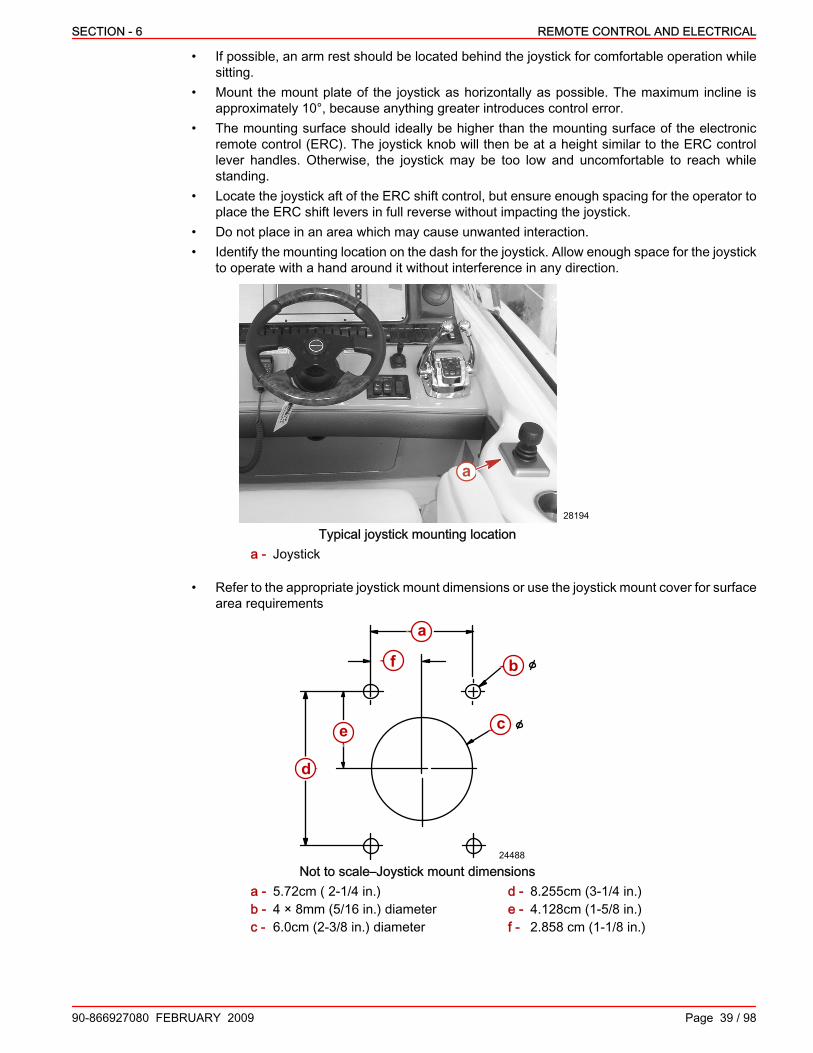
SECTION - 6 REMOTE CONTROL AND ELECTRICAL
90-866927080 FEBRUARY 2009 Page 39 / 98
• If possible, an arm rest should be located behind the joystick for comfortable operation whilesitting.
• Mount the mount plate of the joystick as horizontally as possible. The maximum incline isapproximately 10°, because anything greater introduces control error.
• The mounting surface should ideally be higher than the mounting surface of the electronicremote control (ERC). The joystick knob will then be at a height similar to the ERC controllever handles. Otherwise, the joystick may be too low and uncomfortable to reach whilestanding.
• Locate the joystick aft of the ERC shift control, but ensure enough spacing for the operator toplace the ERC shift levers in full reverse without impacting the joystick.
• Do not place in an area which may cause unwanted interaction.• Identify the mounting location on the dash for the joystick. Allow enough space for the joystick
to operate with a hand around it without interference in any direction.
a
28194
Typical joystick mounting locationa - Joystick
• Refer to the appropriate joystick mount dimensions or use the joystick mount cover for surfacearea requirements
24488
a
b
d
e
f
c
Not to scale–Joystick mount dimensionsa - 5.72cm ( 2‑1/4 in.)b - 4 × 8mm (5/16 in.) diameterc - 6.0cm (2‑3/8 in.) diameter
d - 8.255cm (3‑1/4 in.)e - 4.128cm (1‑5/8 in.)f - 2.858 cm (1‑1/8 in.)

REMOTE CONTROL AND ELECTRICAL SECTION - 6
Page 40 / 98 90-866927080 FEBRUARY 2009
• Allow a minimum of 15.25 mm (6 in.) of clearance underneath the entire mounting area forthe joystick body and wiring.
Joystick Installation1. Identify the joystick mounting location.2. Use the joystick mounting template to locate and mark the required holes.
24488
a
b
d
e
f
c
Joystick mounting dimensions (not to scale)a - 5.72 cm ( 2‑1/4 in.)b - 4 × 8 mm (5/16 in.) Diameterc - 6.0 cm (2‑3/8 in.) Diameter
d - 8.255 cm (3‑1/4 in.)e - 4.128 cm (1‑5/8 in.)f - 2.858 cm (1‑1/8 in.)
3. Drill the four 8 mm (5/16 in.) holes and one 6.0 cm (2‑3/8 in.) hole in the appropriate locations.
24493
a
b
a - 8 mm (5/16 in.) holesb - 60 mm (2‑3/8 in.) hole

SECTION - 6 REMOTE CONTROL AND ELECTRICAL
90-866927080 FEBRUARY 2009 Page 41 / 98
4. Place the gasket over the mounting hole and insert the joystick with the mounting plate.
24485
ab
a - Gasketb - Joystick with mounting plate
5.6. Ensure that the "Front" mark on the mounting plate is facing the bow of the boat and the
harness exiting the joystick assembly is oriented (when viewed from above) on the port sideat the 9 o'clock position.
24484
a
a - Front mark
39799
a
b
a - Harness in 9 o'clock positionb - Front
7. Secure the mounting plate to the dash using the four bolts, washers, and self‑locking nuts.8. Tighten the self‑locking nuts to specification.

REMOTE CONTROL AND ELECTRICAL SECTION - 6
Page 42 / 98 90-866927080 FEBRUARY 2009
Description Nm lb. in. lb. ft.Self‑locking nuts 0.9‑1.4 8‑12 –
9. Carefully snap the cover on the mounting plate.
24494
a
a - Cover
10. Connect the joystick connector to the appropriate helm harness connector.
Trim TabTrim Tab Panel
The Trim Tab Panel consists of three switches which interlock to form a small panel. Theseswitches are port bow (up/down), starboard bow (up/down), and auto tab enable. The switchesallow for manually setting/adjusting the starboard trim tab and port trim tab, and enabling theauto‑tab function that controls the trim tabs automatically.The port/starboard trim tab control switches will also be able to make tab adjustments when inautomatic trim control mode. The tabs can be adjusted independently to allow for externalconditions or personal preferences.The trim tab panel, when used, should be mounted on the helm within easy reach of the operator.Manual trim tab control overrides the automatic system.The manual trim tab control also makes offset adjustments when the boat is in automatic trimcontrol mode. Tabs can be adjusted independently.
a b c31081
Typicala - Port trim switchb - Starboard trim switchc - Automatic trim override
Use the panel available through the Zeus accessories guide.

SECTION - 6 REMOTE CONTROL AND ELECTRICAL
90-866927080 FEBRUARY 2009 Page 43 / 98
1. Cut the mounting hole for the trim tab panel using the dimensions provided.
77.48 mm(3.05 in.)
48.5 mm(1.91 in.)
31092
Cutout dimensions2. Snap the trim tab panel into the mounting hole.3. Connect the trim tab panel harness to the SMM harness.
31701
Trim tab SMM harness4. Connect the SMM harness to the standard 6‑way J‑box or junction box.5. If using a trim tab panel other than that provided, contact a CMD distributor applications
engineer for wiring diagrams to properly connect all wires to the harness.
Trim Tab Smart Multiplex Module (SMM)The Trim Tab Smart Multiplex Module reads the switch settings from the Trim Tab Panel andconverts them to data that can be read by the SmartCraft Network.
INSTALLATION1. Using the dimensions below, carefully locate a mounting location for the SMM.
31999
45mm(1.77 in) 6 mm (0.024 in) X 3
135 mm (5.31 in)
90 mm (3.54 in)

REMOTE CONTROL AND ELECTRICAL SECTION - 6
Page 44 / 98 90-866927080 FEBRUARY 2009
2. Insert the supplied rubber grommets into each of the feet of the SMM.3. Insert the supplied metal standoffs into the rubber grommets.4. Mount the SMM to the predetermined location, being careful to not over tighten the mounting
screws.5. Connect the Trim Tab SMM Harness to the SMM. Ensure the connectors are securely seated.
Key SwitchThe key switch provides switched power to the control system, and can be used to start and/orstop an engine. There will be one key switch for each engine, and they are only installed at themain station. For a boat that is equipped with two stations the main station will have the keyswitches, the other station will have a Start/Stop Panel. In the event that a Key Switch ExtensionHarness is used, a Start/Stop panel will have to be used at the main station due to the crank circuitbeing absent from the Key Switch Extension Harness.
31093
Preparation
! WARNINGPerforming service or maintenance without first disconnecting the battery can cause productdamage, personal injury, or death due to fire, explosion, electrical shock, or unexpected enginestarting. Always disconnect the battery cables from the battery before maintaining, servicing,installing, or removing engine or drive components.
1. Ensure battery cables are disconnected.
! CAUTIONAvoid injury or product damage. Obstructions, such as braces and wiring, may be unseen whenlooking at the front of the dashboard. Before drilling or cutting any holes in the dashboard, checkthe area behind the dashboard for obstructions. Do not drill or cut when obstructions are present.
IMPORTANT: To ensure that water does not collect at the key switch and drains from the housing,install the key switch a minimum of 10° from vertical.2. Select a location for the key switch on the dashboard that meets the following requirements:
• unobstructed behind the dashboard• within harness length limits• able to orient the switch a minimum of 10° from a vertical position• adequate clearance between the components to install bezels, if equipped
3. If the dashboard is fiberglass, prevent the dashboard from chipping by applying masking tapeto the area that is to be drilled or cut.
4. If the dashboard is vinyl covered, keep the vinyl from tearing by removing the vinyl from thearea to be drilled or cut.
5. The keyswitches can also be mounted in a remote panel, such as in the salon, using optionalextension harnesses available from CMD. Follow the instructions included with your keyswitch.

SECTION - 6 REMOTE CONTROL AND ELECTRICAL
90-866927080 FEBRUARY 2009 Page 45 / 98
Standard Mounting ‑ With Housing1. Cut or drill a 54 mm (2‑1/8 in.) diameter hole through the dashboard at the selected location.
2 -1/8 in.(54mm)
4316
2. Install the key switch housing assembly onto the key switch assembly.IMPORTANT: Ensure the drain opening notch, with the white plastic showing, points down forproper draining after installation.3. Align the upper notch of the key switch assembly and housing. Ensure the drain opening notch,
with the white plastic showing, points down for proper draining after installation.
a
4693
a - Drain opening notch with white plastic showing
4. Install and torque the key switch nut.
Description Nm lb. in. lb. ft.Key switch nut 2.2 20 –
5. Install the cover and the bezel onto the key switch housing.6. Install the gasket onto the key switch housing.
ab
4403
a - Gasketb - Key switch housing

REMOTE CONTROL AND ELECTRICAL SECTION - 6
Page 46 / 98 90-866927080 FEBRUARY 2009
7. Insert the key switch electrical connector, wiring, and key switch housing through the dashopening.
4058
a
a - Key switch housing
NOTE: The ring mounting nut is threaded so that it can be installed to fit a thick or thin dashboard.8. Install the ring mounting nut, depending on dash thickness, so that the most threads are
engaged when threaded onto the key switch housing.
3893a
b
a - Thin dashboardb - Ring mounting nut orientation
a
b
3894
a - Thick dashboardb - Ring mounting nut orientation
9. Position the key switch properly in the dash.NOTE: The ring mounting nut must be tight so the assembly will not rotate during use.10. Tighten the ring mounting nut securely.11. Connect the key switch electrical connector to the appropriate port / starboard key switch
connectors on the helm harness.

SECTION - 6 REMOTE CONTROL AND ELECTRICAL
90-866927080 FEBRUARY 2009 Page 47 / 98
Optional Mounting ‑ Without Housing1. Cut a 22.5 mm (7/8 in.) oblong shaped hole that matches the key switch assembly threaded
end with the opposing top and bottom flat surfaces. This hole shape will keep the assemblyfrom rotating during use.
b
a
4734
a
a - Distance between the flat surfaces ‑20 mm (25/32 in.)
b - Diameter of the hole ‑ 22.5 mm (7/8 in.)
2. Install one nut onto the key switch assembly with the flat flange of the nut toward the key endof the switch. Thread this nut on as needed until the key switch will extend through thedashboard with enough threads exposed for the second nut to be installed.
IMPORTANT: There are two notches in the key switch assembly. The notch with white plasticshowing is a drain opening. To properly drain the key switch, this notch must point down wheninstalled.3. Install the key switch assembly into the dashboard oblong hole. Ensure the drain opening
notch, with the white plastic showing, points down for proper draining after installation.
a
4693
a - Drain opening notch with white plastic showing
4. Install and torque the remaining key switch nut.
Description Nm lb. in. lb. ft.Key switch nut 2.2 20
5. Connect the key switch electrical connector to the command module harness.
Key Switch Extension HarnessIn the event that the key switch is not located close to the helm harness, a key switch extensionharness can be used. This harness extends the key switch circuits in various lengths. However,when using a Key Switch Extension Harness a Start/Stop Panel will be required to operate theengine. This is because the Key Switch Extension Harness removes the crank circuit from the keyswitches.
31095

REMOTE CONTROL AND ELECTRICAL SECTION - 6
Page 48 / 98 90-866927080 FEBRUARY 2009
INSTALLATION1. Connect one end of the Key Switch Extension Harness to the appropriate key switch connector
on the Helm Harness.2. Connect the other end of the Key Switch Extension Harness to the appropriate key switch.
Start/Stop PanelThe Start/Stop Panel allows the operator to start and/or stop the engines with the press of a singlebutton. Each engine is controlled independently. For the Start/Stop Panel to function, the keyswitch must be in the ON position. This is an optional component at the main station, if key switchesare installed within the operators reach. Otherwise, this is a mandatory component on secondarystations where no key switches are installed (i.e. second station).
28082
Preparation
! WARNINGPerforming service or maintenance without first disconnecting the battery can cause productdamage, personal injury, or death due to fire, explosion, electrical shock, or unexpected enginestarting. Always disconnect the battery cables from the battery before maintaining, servicing,installing, or removing engine or drive components.
1. 1. Ensure battery cables are disconnected.
! CAUTIONAvoid injury or product damage. Obstructions, such as braces and wiring, may be unseen whenlooking at the front of the dashboard. Before drilling or cutting any holes in the dashboard, checkthe area behind the dashboard for obstructions. Do not drill or cut when obstructions are present.
2. Select a location for the Start/Stop Panel on the dashboard that meets the followingrequirements:• Unobstructed access behind the dashboard.• Within harness length limits.• With enough clearance between the components to install bezels, if equipped.
3. If the dashboard is fiberglass, prevent the dashboard from cracking by applying masking tapeto the area that is to be drilled or cut.
4. If the dashboard is vinyl covered, keep the vinyl from tearing by removing the vinyl from thearea to be drilled or cut.

SECTION - 6 REMOTE CONTROL AND ELECTRICAL
90-866927080 FEBRUARY 2009 Page 49 / 98
Installation1. Using the dimensions below, cut or drill a 54 mm (2‑1/8 in.) diameter hole through the
dashboard at the selected location.
2 -1/8 in.(54mm)
4316
2. Insert the Start/Stop Panel electrical connector, wiring, and Start/Stop Panel housing throughthe dash opening.
a
b31096
c
Behind the dashboard or panela - Port connectorb - Starboard connectorc - Back of switch housing
NOTE: The ring mounting nut is threaded so that it can be installed to fit a thick or thin dashboard.3. Install the ring mounting nut so that most threads are engaged when threaded onto the key
switch housing. The amount of engaged threads will depend on the thickness of the dash.4. Position the Start/Stop Panel in the correct orientation on the dash.NOTE: The ring mounting nut must be tight so the assembly will not rotate during use.5. Tighten the ring mounting nut securely.6. Connect the Start/Stop Panel electrical connectors to the respective "START/STOP"
connections on the helm harness.
Precision Pilot Track PadPrecision Pilot (Pilot) functions are controlled through the Pilot track pad. The track pad iscomprised of multiple buttons that control features such as: Skyhook, Auto Heading, andWaypoint.Install the Precision Pilot track pad appropriately for your application.
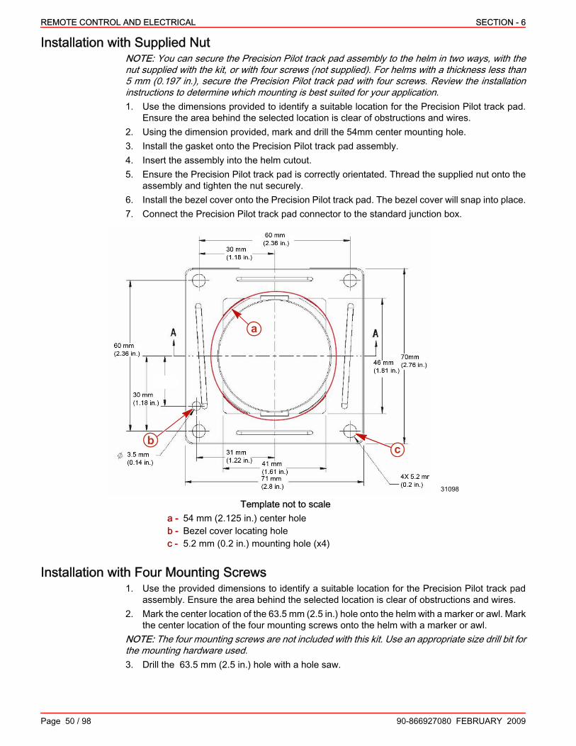
REMOTE CONTROL AND ELECTRICAL SECTION - 6
Page 50 / 98 90-866927080 FEBRUARY 2009
Installation with Supplied NutNOTE: You can secure the Precision Pilot track pad assembly to the helm in two ways, with thenut supplied with the kit, or with four screws (not supplied). For helms with a thickness less than5 mm (0.197 in.), secure the Precision Pilot track pad with four screws. Review the installationinstructions to determine which mounting is best suited for your application.1. Use the dimensions provided to identify a suitable location for the Precision Pilot track pad.
Ensure the area behind the selected location is clear of obstructions and wires.2. Using the dimension provided, mark and drill the 54mm center mounting hole.3. Install the gasket onto the Precision Pilot track pad assembly.4. Insert the assembly into the helm cutout.5. Ensure the Precision Pilot track pad is correctly orientated. Thread the supplied nut onto the
assembly and tighten the nut securely.6. Install the bezel cover onto the Precision Pilot track pad. The bezel cover will snap into place.7. Connect the Precision Pilot track pad connector to the standard junction box.
a
bc
31098
Template not to scalea - 54 mm (2.125 in.) center holeb - Bezel cover locating holec - 5.2 mm (0.2 in.) mounting hole (x4)
Installation with Four Mounting Screws1. Use the provided dimensions to identify a suitable location for the Precision Pilot track pad
assembly. Ensure the area behind the selected location is clear of obstructions and wires.2. Mark the center location of the 63.5 mm (2.5 in.) hole onto the helm with a marker or awl. Mark
the center location of the four mounting screws onto the helm with a marker or awl.NOTE: The four mounting screws are not included with this kit. Use an appropriate size drill bit forthe mounting hardware used.3. Drill the 63.5 mm (2.5 in.) hole with a hole saw.

SECTION - 6 REMOTE CONTROL AND ELECTRICAL
90-866927080 FEBRUARY 2009 Page 51 / 98
IMPORTANT: Do not drill mounting holes for use with screws larger in diameter than 5 mm(0.2 in.).4. Drill the four mounting screw holes with an appropriate size drill bit for the mounting hardware
used.5. Install the gasket onto the Precision Pilot track pad assembly.6. Insert the assembly into the helm cutout.IMPORTANT: Do not use screws larger in diameter than 5 mm (0.2 in.).7. Ensure the Precision Pilot track pad is correctly orientated. Align the screw holes and secure
the assembly to the helm with four screws. Do not over‑tighten the screws.8. Install the bezel cover onto the assembly. The bezel cover snaps into position.
31100
9. Connect the Precision Pilot track pad connector to the standard junction box.
Guidance Equipment InstallationInertial Measurement Unit (IMU)
The Inertial Measurement Unit (IMU) is a solid state, rate gyro electronic compass that detects thedirection of the earth’s magnetic field using solid state magnetometers and indicates the vesselheading relative to magnetic north. Additionally, solid state accelerometers and angular ratesensors indicate the vessel’s attitude and rate of turn.
31110
IMU MOUNTING CONSIDERATIONSThe selection of a suitable mounting location is important for the optimal performance of the IMU.The mounting location and orientation of the IMU should be:• Level with the earth’s horizontal plane – It is best to mount the compass as level as possible
to maximize its pitch and roll operational range. The unit can be mounted in other orientations,although this requires an additional configuration step.
• Oriented with arrow pointing to bow, parallel to vessel centerline – It is best to mount thecompass pointed towards the bow and parallel to the vessel centerline. The unit can bemounted in other orientations, although this requires an additional configuration step.

REMOTE CONTROL AND ELECTRICAL SECTION - 6
Page 52 / 98 90-866927080 FEBRUARY 2009
• Near the Center of Gravity (CG) of the vessel – The compass experiences the least amountof movement when located at the CG, which allows the most accurate readings. This is similarto a traditional card/needle compass, where the farther the compass is from the CG, the morethe fluid sloshes around, making accurate readings more difficult.
• Away from structures containing ferrous metals – The earth’s lines of magnetic flux tendto become distorted in the vicinity of ferrous metals, which can potentially cause errors in theindicated heading of the compass. The IMU can be calibrated to compensate for these errors,but it is best to minimize the errors by placing the compass as far from ferrous metals aspractical.
• Away from magnetic field sources – Power or ignition cables, electric motors, and otherelectronic equipment can create magnetic fields. The earth’s lines of magnetic flux tend tobecome distorted in the vicinity of magnetic fields sources, which can potentially cause errorsin the indicated heading of the compass. The magnetic fields tend to come and go as poweris switched on and off, which makes compensation impractical. Therefore, you should try tomount the IMU as far away as possible from these magnetic field sources (doubling thedistance between the magnetic field source and the compass will reduce the field strength bya factor of approximately 8).
• Minimal vibration – Although the IMU is more tolerant of vibration than a fluxgate compass,it is best to mount the compass in a location free of vibration as opposed to a location withvibration.
INSTALLATIONNOTE: The IMU must be calibrated for proper functioning. Refer to the installation instructionsincluded with the unit.The IMU can be mounted to a horizontal surface, such as a floor or a deck, or to a vertical surface,such as a wall or bulkhead.
HORIZONTAL SURFACEAttaching the IMU to the top of a horizontal surface is the customary way of mounting the IMU.However, you can mount the IMU to the underside of a horizontal surface provided that the IMUis programmed to recognize that it is mounted this way.1. Using the dimensions provided, mark and drill the holes necessary to mount the IMU to a
horizontal surface.98.3mm(3.97 in.)
36.1mm(1.4 in.) a
b c 31111
Template is not to scalea - Bow of boatb - 5 Pin SmartCraftc - 9 Pin NMEA 0183
2. Attach the mounting brackets to the bottom of the IMU using the provided brass flat headscrews. Do not over torque.

SECTION - 6 REMOTE CONTROL AND ELECTRICAL
90-866927080 FEBRUARY 2009 Page 53 / 98
3. Attach the IMU to the horizontal surface using the four mounting screws provided with the unit.
31112
a
b
c
d
a - Mounting screwsb - IMUc - Mounting bracketsd - Brass flat head screws
4. Connect the Navigation System Extension Harness to the IMU 5 pin connector.VERTICAL SURFACE
Customarily the IMU is mounted to a vertical surface by attaching the unit to the forward side ofthe surface, so that the side of the compass with the connectors is facing the bow of the boat.However, you can mount the IMU to the stern side of a vertical surface, so the side of the IMUwith the connectors is facing the stern of the boat, provided that the IMU is programmed torecognize that it is mounted this way.1. Using the dimensions provided, mark and drill the holes necessary to mount the IMU to a
vertical surface.
36.1 mm1.42 in.
70 mm2-3/4 in.
31113
Template is not to scale2. Attach the mounting brackets to the side of the IMU using the provided brass flat head screws.

REMOTE CONTROL AND ELECTRICAL SECTION - 6
Page 54 / 98 90-866927080 FEBRUARY 2009
3. Attach the IMU to the vertical surface using the four mounting screws provided with the unit.Refer to the figure below. Do not over torque the mounting screws.
b
cd
a
31114
a - Brass flat head screwsb - Mounting bracketsc - Mounting screwsd - IMU
Global Positioning Sensor (GPS)Global Positioning Sensor (GPS) is a device that provides the location, speed, and direction of thevessel.
GPS MOUNTING CONSIDERATIONSThe selection of a suitable mounting location is important for the optimal performance of the GPSunit. The mounting location and orientation of the GPS should be:• Level with the earth’s horizontal plane. This gives the GPS antenna the optimal view of
satellites from all directions.• High enough to have a clear view of the sky to the horizon in all directions unblocked by masts
or antennas. The GPS provides the best readings when it has access to as many satellitesas possible.
• As far as possible from VHF, satellite, or radar antennas. Radio frequency transmissions fromthese antennas can interfere with the proper reception of the GPS satellite signals.
INSTALLATIONLocate the GPS antenna in clear view of the sky. Hardtop or radar arch mounting is typical. Theantenna can be mounted either flush to the surface or on a 25.4 mm (1.0 in.) 14 threads per inchstandard marine pole mount.

SECTION - 6 REMOTE CONTROL AND ELECTRICAL
90-866927080 FEBRUARY 2009 Page 55 / 98
HORIZONTAL SURFACE1. Using the dimensions provided, mark and drill the necessary holes for mounting the GPS to
a horizontal surface.
53.6 mm(2.1 in.)
25.4 mm(1.0 in.)
a b
31115
View from bottom. Template is not to scalea - Connector for harnessb - Holes for fasteners (3×)
2. Attach the GPS to the horizontal surface using the included brass mounting screws and lockwashers.
b
a
c
de
31116
a - GPS antennab - 25.4 mm (1 in.) holec - Washer
d - Screwe - Harness
MARINE POLE MOUNT1. Screw the included GPS antenna mount base to the standard marine mount pole.2. Thread the Navigation System extension harness through the standard marine mount and the
antenna mount base from the bottom to the top.3. Connect the Navigation System extension harness to the GPS connector.
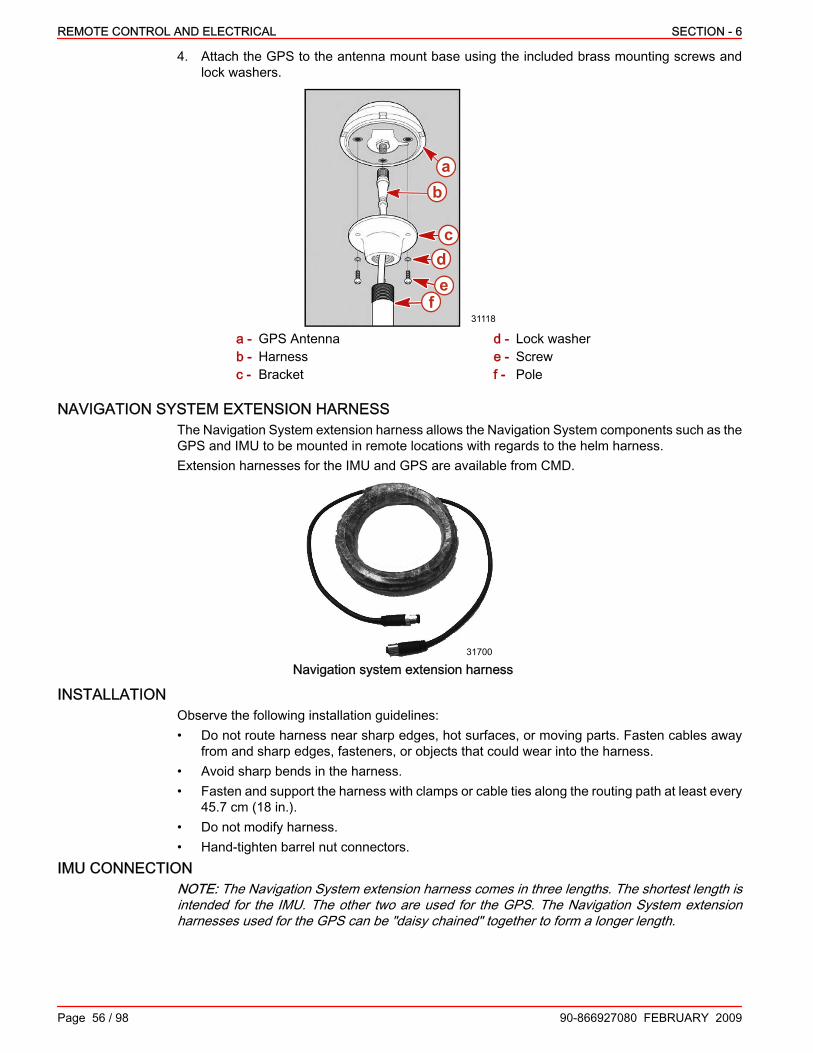
REMOTE CONTROL AND ELECTRICAL SECTION - 6
Page 56 / 98 90-866927080 FEBRUARY 2009
4. Attach the GPS to the antenna mount base using the included brass mounting screws andlock washers.
31118
ab
cde
f
a - GPS Antennab - Harnessc - Bracket
d - Lock washere - Screwf - Pole
NAVIGATION SYSTEM EXTENSION HARNESSThe Navigation System extension harness allows the Navigation System components such as theGPS and IMU to be mounted in remote locations with regards to the helm harness.Extension harnesses for the IMU and GPS are available from CMD.
31700
Navigation system extension harness
INSTALLATIONObserve the following installation guidelines:• Do not route harness near sharp edges, hot surfaces, or moving parts. Fasten cables away
from and sharp edges, fasteners, or objects that could wear into the harness.• Avoid sharp bends in the harness.• Fasten and support the harness with clamps or cable ties along the routing path at least every
45.7 cm (18 in.).• Do not modify harness.• Hand‑tighten barrel nut connectors.
IMU CONNECTIONNOTE: The Navigation System extension harness comes in three lengths. The shortest length isintended for the IMU. The other two are used for the GPS. The Navigation System extensionharnesses used for the GPS can be "daisy chained" together to form a longer length.

SECTION - 6 REMOTE CONTROL AND ELECTRICAL
90-866927080 FEBRUARY 2009 Page 57 / 98
Connect the Navigation System extension harness to the 5‑pin circular connector on the IMU. Theother end of the Navigation System extension harness will connect to the Navigation SystemY‑harness.
31119
IMU 5‑pin connection
GPS CONNECTIONConnect the Navigation System extension harness to the 5‑pin circular connector on the GPS.The other end of the Navigation System extension harness connects to the Navigation SystemY‑harness.NOTE: In a dual station application, connect the Navigation System Y‑harness to the standardJ‑box at the second station. It is not necessary to connect the GPS to the standard J‑box at themain station, except in single station applications.
a
b31122
a - Screw mounting holesb - 5‑pin connection
Navigation System Y‑HarnessThe Navigation System Y‑Harness connects the IMU and the GPS to the SmartCraft Network,through a standard junction box. This allows the data from the guidance components to be readby the control system.
31123
INSTALLATION1. Connect one end of the Navigation System Y‑Harness to the Navigation System Extension
Harness going to the IMU.2. Connect the other end of the Navigation System Y‑Harness to the Navigation System
Extension Harness going to the GPS.

REMOTE CONTROL AND ELECTRICAL SECTION - 6
Page 58 / 98 90-866927080 FEBRUARY 2009
3. Connect the 10 pin connector on the Navigation System Y‑Harness to the Standard JunctionBox.
E‑Stop Switch, If EquippedThe E‑stop switch offers a redundant emergency shutdown method if the key switch fails. Theswitch itself is a normally open, single‑pole, single‑throw rocker switch.The E‑stop switch is mounted at the helm, and connects to the helm harness. An E‑stop switch isonly required at helms where the key switches are not within reach of the operator.
31992
InstallationINSTALLATION RECOMMENDATIONS:
Install the E‑stop switch in a place that is easy to access, but where it will not be accidentallyactivated.1. Install the E‑stop switch in the dash using the dimensions provided below.
31994
36.83 mm(1.45 in.)
21.08mm(0.83 in.)
2. Connect the 2‑pin connector on the E‑stop switch harness labeled "STBD HELM" to theconnector on the helm harness labeled "STBD E‑STOP."
3. Connect the 2‑pin connector on the E‑stop switch harness labeled "PORT" to the connectoron the helm harness labeled "PORT E‑STOP."

SECTION - 6 REMOTE CONTROL AND ELECTRICAL
90-866927080 FEBRUARY 2009 Page 59 / 98
Starboard Helm Power HarnessThe starboard helm power harness provides clean battery power for the main power relay on thehelm harness.
31276
Starboard helm power harness
InstallationNOTE: The starboard helm power harness wires are not terminated on the battery end and nocircuit protection is provided. It is up to the OEM to provide the necessary terminals for connectingthe harness to the battery, and adding an in‑line 20 amp fuse or circuit breaker to the positive side.1. Install a 20 amp circuit protection device in the positive side of the starboard helm power
harness, close to the battery terminal.2. Install the appropriate wire terminals to the ends of the starboard helm power harness.3. Find the connector on the helm harness labeled "Starboard Power Disconnect." If this
connector is plugged into another connector on the helm harness disconnect the connectors.4. Connect the starboard helm power harness to the helm harness connector labeled "STBD
ECU Main Power Disconnect". Place a weather cap on the connector labeled "STBD 14‑PinMain Power Disconnect."
5. Connect the positive side of the starboard helm power harness to the load side of a batteryswitch or terminal strip connected to the positive side of the battery.
6. Connect the negative side of the starboard helm power harness to a negative (–) terminal stripor bus bar connected to the negative side of the battery.
MerCathode Controller Harness AsssemblyThe MerCathode system requires a constant power source—12 volt or 24 volt—depending on theapplication.Harness assemblies in 12 volt or 24 volt are available in kit form.
Description Part Number12 volt 84‑879148T4124 volt 84‑879345T63
IMPORTANT: Splicing or connecting accessories to the harness assembly could cause a fuse tofail or overload a circuit, causing intermittent or complete loss of MerCathode controller operationand loss of corrosion protection.
Installing the Harness
! CAUTIONDisconnecting or connecting the battery cables in the incorrect order can cause injury fromelectrical shock or can damage the electrical system. Always disconnect the negative (‑) batterycable first and connect it last.

REMOTE CONTROL AND ELECTRICAL SECTION - 6
Page 60 / 98 90-866927080 FEBRUARY 2009
1. Disconnect the battery cables from the battery.2. Remove the nut from the positive (+) post on the MerCathode controller.
a
c
b
39309
a - MerCathode controllerb - Positive (+) postc - Nut
3. Attach the ring terminal end of the harness wire (with the protective cover) to the controller.Tighten the nut securely.
4. Apply sealant to the exposed nut and ring terminal connection.5. Install the protective cover over the connection.
a
b
39310
a - Harness wireb - Protective cover
Tube Ref No. Description Where Used Part No.
25 Liquid Neoprene Exposed electrical terminals 92- 25711 3

SECTION - 6 REMOTE CONTROL AND ELECTRICAL
90-866927080 FEBRUARY 2009 Page 61 / 98
6. Route the harness according the the guidelines. When installing a 24‑volt harness, ensurethat the segment of the harness identified as containing the resistors (near the fuse holder) isfree of stress and not kinked.
b
a
39395
a - Fuse holderb - Resistors
7. Attach the ring terminal end of the harness (near the fuse holder) to the positive (+) batteryterminal or an unswitched positive (+) battery bus bar or terminal strip.
39396
ab
c
Typical unswitched connectiona - Typical unswitched positive (+) bus barb - Ring terminal connectionc - Harness (12‑volt shown, 24‑volt similar)
8. Apply sealant to the exposed electrical terminals.
Tube Ref No. Description Where Used Part No.
25 Liquid Neoprene Exposed electrical terminals 92- 25711 3
9. Connect the battery cables to the battery.
VesselView InstallationVesselView
Refer to the installation manual provided with the product for installation requirements andinstructions.
VesselView Harness Connection1. Connect the the VesselView harness to the starboard display connector on the Smart J‑box.
See Wiring Connections for diagrams.2. Connect the VesselView harness to the VesselView unit.

REMOTE CONTROL AND ELECTRICAL SECTION - 6
Page 62 / 98 90-866927080 FEBRUARY 2009
3. VesselView harness assembly has an 8‑plug connector that plugs into the "VesselViewMulti‑Ignition" port.
4. If the back of the VesselView is hard to get to, the USB extension harness can be used.a. Remove and retain the USB (universal serial bus) port cover.b. Connect the USB extension harness to the appropriate port on the back of the
VesselView display. Mount the other end so that it can be accessed from the dashboard.c. Use the USB cover from the back of the VesselView display to cover the USB port.
5. Ensure that the VesselView unit receives power when any key switch is in the "ON" position.
CAN V ComponentsCAN V Genset Adaptor Harness
The CAN V Genset Adaptor Harness interfaces with SmartCraft compatible generator sets, andallows generator data to be broadcast over the CAN V data bus. The CAN Adaptor Harness isrequired on SmartCraft version 1 Onan e‑QD generator sets.
INSTALLATION1. Attach the connector with the label "To Genset" to the generator. Ensure connector is fully
seated.2. The connector labeled "To Ext Harn" will either attach to the CAN V Termination Harness, or
to the CAN V Extension Harness.3. Connect +12V key switch, or enable, supply to the wake signal input on the adaptor harness.
CAN V Termination HarnessThe CAN V Termination Harness provides a termination resistor for one end of the CAN V databus. A termination resistor is required at each end of the CAN V data bus to ensure propercommunication.
31133
CAN V termination harness
INSTALLATION OF THE CAN V DEVICENOTE: If this is a SmartCarft Version 1 Onan generator set, the CAN V Adaptor Harness will beinstalled. Connect the CAN V Termination Harness female connector to the CAN V AdaptorHarness labeled "To Ext Harn".If this is the last device on the CAN V data bus, plug the CAN V device into the CAN V TerminationHarness. If not, then plug into the CAN V Extension Harness (covered next).
CAN V TERMINATORThe CAN V Terminator is a short 2‑wire harness that contains a termination resistor for CAN V.
SMART JUNCTION BOXConnect the CAN V Termination Harness female connector to the Smart Junction Box connectorlabeled "CAN V".

SECTION - 6 REMOTE CONTROL AND ELECTRICAL
90-866927080 FEBRUARY 2009 Page 63 / 98
CAN V Extension HarnessThe CAN V Extension Harness extends the CAN V data bus beyond the Smart Junction Box to aSmartCraft compatible CAN V device. The CAN V Extension Harness connects between the CANV Termination Harnesses, located on each end of the CAN V bus.
31135
1. Connect the connector labeled "To Terminator Harness" to the CAN V Termination Harnessconnector labeled "CAN V Extension Harness". Ensure connectors are fully seated.
2. Route the CAN V Extension Harness to the Smart Junction Box, at the helm.3. Connect the connector labeled "To J‑Box" to the CAN V Termination Harness connector
labeled "CAN V Extension Harness".
Skyhook Warning LabelsSkyhook warning labels for the operator and passengers must be affixed in appropriate locationsbefore Skyhook is used.NOTE: Refer to the installation instructions (90‑899883259) for information on how to select alocation and apply the warning labels.Ensure the warning labels are affixed in the appropriate locations.
33798
8M0034159
34111
Example locations for the warning label for the operator (captain)

REMOTE CONTROL AND ELECTRICAL SECTION - 6
Page 64 / 98 90-866927080 FEBRUARY 2009
33824
34349
Example locations for the warning label for the passengers
Pre‑Calibration RequirementsSeveral actions need to be taken before initial power‑up and calibration to avoid damage to theengines or equipment, and to avoid improper calibration. Carefully complete these steps beforestarting calibration.1. Align both drives to the straight back position. Use the drive‑to‑drive parallelism alignment
tool, if available, or the steps for initial alignment as described in the drive alignment procedurein this section of the manual.
2. Align the steering wheel to the straight forward position. Use the steps for initial alignment asdescribed in the steering wheel alignment procedure in this section of the manual.
3. Check all the fluid levels. Additional mounting and operation information is available in theinstallation manuals provided with each component.
4. Prime the fuel in all engines including the generator, if equipped. Refer to the appropriateinstallation and owners manuals for the proper priming procedure.
5. Open the appropriate seacocks or have adequate cooling water available before starting eachengine.
Initial VesselView ConfigurationTurning the key switch to the on position activates all VesselView units connected to the system.Complete the initial setup process using the "Import Configuration" method when starting up aVesselView unit for the first time. This process calibrates each VesselView to the vessel’s desiredengine, sensor, and instrument configuration.A VesselView configuration file is normally created on the first boat of a new model and saved toa USB memory stick. This USB memory stick will be used to import the configuration file intosubsequent boats of the same model.NOTE: The configuration file must be located on the root directory of the USB memory stick (notwithin any folders)NOTE: If more than one VesselView is used per boat, a different configuration file will be used foreach VesselView. These configuration files must each be stored on separate USB memory sticks,since the file names will be identical but the files are different.If the VesselView configuration file is available, use the Import Configuration procedure belowto configure each VesselView on the boat.

SECTION - 6 REMOTE CONTROL AND ELECTRICAL
90-866927080 FEBRUARY 2009 Page 65 / 98
If a VesselView configuration file has not been created for the boat model, the "Setup Wizard"method must be used to configure the VesselView. Refer to the VesselView manual for details ofthis procedure.
Import ConfigurationIMPORTANT: The import configuration option is used to import configuration settings that weresaved to a USB memory stick. The VesselView unit will recognize USB memory sticks of version1.1 or 2.0 that is stated to be backwards compatible to version 1.1. The VesselView unit will notrecognize memory sticks that are only version 2.0 compatible.IMPORTANT: Configuration settings saved to a USB memory stick are compiled into one datafile. Only one file can exist in the root of the USB memory stick. VesselView will not recognizemultiple import files.1. The "IMPORT CONFIG" screen instructs you to insert a USB memory stick and wait for
instructions.
IMPORT CONFIG
TO IMPORT CONFIGURATION, INSERT
MEMORY STICK AND WAIT FOR INSTRUCTIONS.
27304
2. Insert a USB memory stick into the USB port on the back of the VesselView unit.
c
a
b
27329
a - Ethernet port (for future option)b - USB portc - USB memory stick
IMPORTANT: Do not remove the USB memory stick until the import process is complete.3. When the memory stick is detected, the "IMPORT CONFIG" screen will display "MEMORY
STICK READY."

REMOTE CONTROL AND ELECTRICAL SECTION - 6
Page 66 / 98 90-866927080 FEBRUARY 2009
IMPORTANT: If you attempt to load a configuration setting that was not saved to the USB memorystick, the import of the data file will not be successful and a yellow pop‑up message will appearstating "IMPORT UNSUCCESSFUL." If you can recall the configuration setting that was not saved,select "SKIP" for that particular configuration setting. That particular configuration setting will needto be setup and calibrated accordingly.4. Press the check button to import the saved configuration.
IMPORT CONFIG
TO IMPORT CONFIGURATION, INSERT
MEMORY STICK AND WAIT FOR INSTRUCTIONS.
MEMORY STICK READY TO IMPORT
27309
5. VesselView will restart and import the configuration.
Vessel ConfigurationVessel Configuration (VesselConfig)
VesselConfig is a separate application designed to allow calibration of the Zeus modules anddrives from the VesselView display. This function will reside within VesselView for the purpose ofcalibrating the drives and controls. Access to this function is limited to trained technicians.The technician should get the special key sequence from their application engineer or servicemanager so that they can calibrate the controls.
Accessing Vessel Configuration FunctionsIMPORTANT: Perform this procedure with the VesselView installed at the primary helm station.NOTE: Pressing the arrow trackpad up and down will highlight menu options for selection.1. Turn both key switches to the "ON" position, but do not start the engines.

SECTION - 6 REMOTE CONTROL AND ELECTRICAL
90-866927080 FEBRUARY 2009 Page 67 / 98
2. Simultaneously press and hold the "Cancel", "Enter", "Alarm", and "Menu" buttons on theVesselView keypad to access the application selection screen.
39804
a b
cd
a - "Cancel"b - "Enter"
c - "Alarm"d - "Menu"
3. Highlight "VesselConfig" and press enter to continue.
39806
"VesselConfig" menu selection
NOTE: The VesselView will restart and enter "VesselConfig" mode.4. Some software versions include a prompt screen warning the operator that they are accessing
a service only mode. Press the enter key to continue.
39809

REMOTE CONTROL AND ELECTRICAL SECTION - 6
Page 68 / 98 90-866927080 FEBRUARY 2009
5. When the "VesselConfig" main menu screen appears, select the appropriate routine. Refer toLoading "VesselConfig" Libraries, Electronic Remote Control Configuration, TrackpadConfiguration, Steering Wheel Configuration, Import Vessel Personality File, orCompass Calibration as needed.
NOTE: After the "VesselConfig" libraries are loaded a "Sea Trail" option will be available from the"VesselConfig" main menu.
39808
Loading Vessel Configuration LibrariesThe vessel configuration libraries contain files and software needed to communicate to the variouscontrol modules you will be configuring and updating. They are provided with the software packagerelease for your application.1. Access the "VesselConfig" main menu. Refer to Accessing Vessel Configuration
Functions.2. Highlight the "Import/Export/Load Libraries" function and press the enter button to select and
continue.
39811
3. Highlight the "Load Libraries " function and press the enter button to select and continue.
39816

SECTION - 6 REMOTE CONTROL AND ELECTRICAL
90-866927080 FEBRUARY 2009 Page 69 / 98
4. Insert a USB drive into the USB port on the rear of the VesselView unit or into the USBextension harness connection point (optional).
39814
5. Press the enter button to load the library files from the USB drive.
39818
NOTE: Pressing the cancel button will terminate the current process and return you to the mainmenu.6. USB drive connection error:
a. If the USB drive is not properly connected the following error message will appear.
39820
b. Remove then reconnect the USB drive and press the enter button to retry.7. Us the trackpad up and down arrows to select the appropriate file folder.

REMOTE CONTROL AND ELECTRICAL SECTION - 6
Page 70 / 98 90-866927080 FEBRUARY 2009
IMPORTANT: In this example the folder name is generically named "Libraries"; yours may differ.Refer to the literature provided with your software release package for the correct folder and filename for your application.
39821
NOTE: To back up within the folder directory tree, press the cancel button.8. Press the enter key to load the selected library file.9. Press the enter key to confirm.
39824
IMPORTANT: Do not remove the USB drive until after the VesselView has restarted and returnedto the main menu.10. Once the libraries have been successfully loaded, press the enter button to restart the device.
This will allow Vessel View to reboot and load the new libraries into "VesselConfig".
39826
11. Remove the USB drive.NOTE: After the "VesselConfig" libraries are loaded a "Sea Trail" option will be available from the"VesselConfig" main menu. The Factory Configuration menu will also have additional optionsavailable.

SECTION - 6 REMOTE CONTROL AND ELECTRICAL
90-866927080 FEBRUARY 2009 Page 71 / 98
Initial Out of the Water Drive AlignmentWhenever the drives are installed during the initial boat build (or a drive is replaced for service)the drive alignment should be checked and adjusted if necessary.Follow one of these procedures to set the drives parallel to each other and approximately parallelto the boat.NOTE: These procedures must be performed with the boat out of the water.
DRIVE ALIGNMENT—WITHOUT USING THE DRIVE ALIGNMENT TOOL1. Remove the propellers, if installed. Refer to Propellers.2. Using a tape measure, measure and record the distance between the centers of the port and
starboard propeller shafts.
40093
Distance between propeller shafts3. Measure and record the distance between the centers of the port and starboard drive
nosecones.
40094
Distance between nosecones4. Subtract the distance between the nosecones from the distance between the propeller shafts
to determine the drive misalignment. This difference must be less than specified.
Drive Misalignment SpecificationDifference between nosecone and propeller shaft distance Less than 13 mm (1/2 in.)

REMOTE CONTROL AND ELECTRICAL SECTION - 6
Page 72 / 98 90-866927080 FEBRUARY 2009
5. Measure and record the distance between the port propeller shaft and center of the vesselkeel.
40096
Distance between the port propeller shaft and the center of the vessel keel6. Measure and record the distance between the starboard propeller shaft and the center of the
vessel keel.
40097
Distance between the starboard propeller shaft and the center of the vessel keel7. Subtract the port distance from the starboard distance to determine the misalignment to the
vessel keel. This difference must be less than specified.
Misalignment to Keel SpecificationDifference between port and starboard propeller shaft‑to‑keel measurement Less than 6 mm (1/4 in.)
8. If the drive alignment is not within specification, select "Manual Drive Alignment" in VesselViewto unlock the hydraulic steering and allow the drives to be manually aligned.
9. Under "Factory Configuration", highlight the manual drive alignment menu and press the Enter(check mark) button.
40098

SECTION - 6 REMOTE CONTROL AND ELECTRICAL
90-866927080 FEBRUARY 2009 Page 73 / 98
10. Dismiss the warning screen stating the boat must be out of the water to perform the manualcalibration by pressing the Enter button.
40104
11. Ensure the drives are aligned to specification.12. When alignment is complete press the Enter button to save the setting and lock the drives.
40105
13. Dismiss the manual alignment confirmation screen by pressing the Enter button.
40107
DRIVE ALIGNMENT—USING THE DRIVE ALIGNMENT TOOL1. Remove the rear propellers, if installed. Refer to Propellers.2. Hand‑thread a drive alignment tool onto the port and starboard drive inner (rear) propeller
shaft until the tool is snug against the propeller shaft thrust surface.
Description Part NumberDrive alignment tool 8M0029055
3. Rotate the tools and propeller shafts until the tools are horizontal and the roll pins on the drivealignment tools are below the propeller shafts.

REMOTE CONTROL AND ELECTRICAL SECTION - 6
Page 74 / 98 90-866927080 FEBRUARY 2009
4. Place a locally obtained straight edge (or carpenter's level) between the drives and on top ofthe roll pins.
c
a
28032b
a - Drive alignment toolb - Pinsc - Straight edge
5. At the helm, turn the port and starboard key switches to the on position. Do not start theengines.
6. Select the "Manual Drive Alignment" VesselView screen7. Follow the directions on the screen to unlock the drives.
29754
8. From under the boat, rotate the drives by hand until the the straight edge contacts squarely(is parallel) along the 152 mm (6 in.) long alignment surface of both of the tools.
28033
ac
b
Port drive shown, same at starboarda - Tool alignment surfaceb - Straight edgec - Parallel
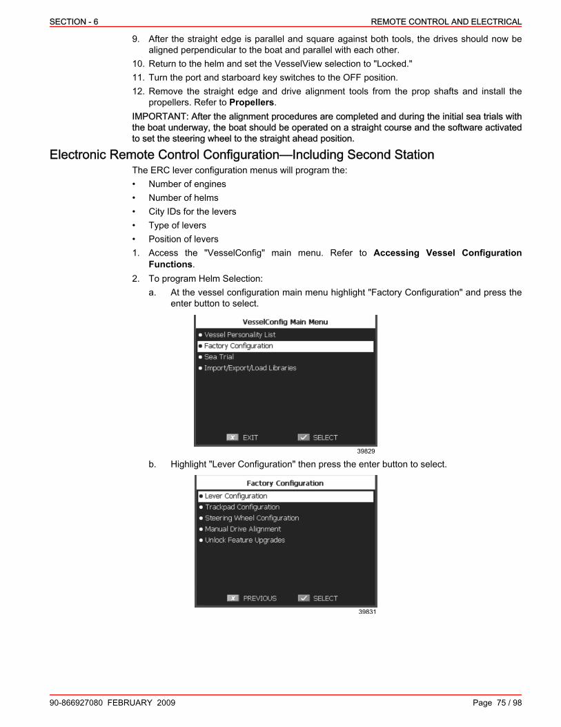
SECTION - 6 REMOTE CONTROL AND ELECTRICAL
90-866927080 FEBRUARY 2009 Page 75 / 98
9. After the straight edge is parallel and square against both tools, the drives should now bealigned perpendicular to the boat and parallel with each other.
10. Return to the helm and set the VesselView selection to "Locked."11. Turn the port and starboard key switches to the OFF position.12. Remove the straight edge and drive alignment tools from the prop shafts and install the
propellers. Refer to Propellers.IMPORTANT: After the alignment procedures are completed and during the initial sea trials withthe boat underway, the boat should be operated on a straight course and the software activatedto set the steering wheel to the straight ahead position.
Electronic Remote Control Configuration—Including Second StationThe ERC lever configuration menus will program the:• Number of engines• Number of helms• City IDs for the levers• Type of levers• Position of levers1. Access the "VesselConfig" main menu. Refer to Accessing Vessel Configuration
Functions.2. To program Helm Selection:
a. At the vessel configuration main menu highlight "Factory Configuration" and press theenter button to select.
39829
b. Highlight "Lever Configuration" then press the enter button to select.
39831

REMOTE CONTROL AND ELECTRICAL SECTION - 6
Page 76 / 98 90-866927080 FEBRUARY 2009
c. Highlight "Helm Selection" and press the enter button to select.
39832
NOTE: The "Helm Selection" screen identifies the number of engines and helms installed in thevessel.
d. Use the trackpad up and down arrows to navigate to the "Number of Engines" field. Usethe trackpad left and right arrows to change the quantity.
39833
e. Using the trackpad up and down arrows navigate to the "Number of Helms" field. Usethe trackpad left and right arrows to change the quantity.
NOTE: Changes can be canceled and this menu exited by pressing the cancel button.f. Press the enter key to complete and save the selections and return to the "Lever
Configuration" menu.3. To program Helm Setup:
a. Using the trackpad arrows, highlight "Helm Setup" under the "Lever Configuration" menuand press the enter button to select.
39834

SECTION - 6 REMOTE CONTROL AND ELECTRICAL
90-866927080 FEBRUARY 2009 Page 77 / 98
b. Press enter to dismiss the informational pop‑up screen and continue.
39835
c. Move all ERC levers (for all helms) to their neutral detent position. Press enter to calibrateand continue.
39837
d. Move the "Helm 1" starboard lever to maximum reverse and press enter to calibrate andcontinue.
39838

REMOTE CONTROL AND ELECTRICAL SECTION - 6
Page 78 / 98 90-866927080 FEBRUARY 2009
e. Move the "Helm 1" port lever to maximum reverse and press enter to calibrate andcontinue.
39842
f. If the vessel is configured with a second station helm, repeat steps d and e for "Helm 2"starboard and port levers as prompted by the VesselView display.
g. Once all of the levers have been identified, return all of the levers to their neutral position,cycle the key switches off then on, then press the enter button.
39840
IMPORTANT: This calibration procedure must be completed successfully before proceeding.h. An error message will display if the calibration procedure fails. Cycle the key switches
off then on again, press the enter key, and follow the on screen prompts to retry theprocedure.
39843

SECTION - 6 REMOTE CONTROL AND ELECTRICAL
90-866927080 FEBRUARY 2009 Page 79 / 98
i. A confirmation screen will display after successful calibration.
39845
4. To program Lever Setup:a. Using the trackpad arrows, highlight "Lever Setup" under the "Lever Configuration" menu
and press the enter button to select.
39848
NOTE: Both ERC levers can be configured from the "Multiple Lever Configuration" screen.b. From the "Lever Setup" menu highlight "Multiple Lever Configuration" and press enter
to select.
39849

REMOTE CONTROL AND ELECTRICAL SECTION - 6
Page 80 / 98 90-866927080 FEBRUARY 2009
c. Use the trackpad up and down arrows to highlight "Helm to Configure" , then select "Helm1" using the left and right arrows.
39850
d. Use the trackpad up and down arrows to highlight "Lever to Configure," then select"Lever 1" using the left and right arrows.
e. Use the trackpad up and down arrows to highlight "Lever Type," then select"ConsoleStbd" using the left and right arrows.
f. Use the trackpad up and down arrows to highlight "Shift Polarity," then select "Normal"using the left and right arrows.
g. Use the trackpad up and down arrows to highlight "Lever to Configure," then select"Lever 2" using the left and right arrows.
h. Use the trackpad up and down arrows to highlight "Lever Type," then select"ConsolePort" using the left and right arrows.
i. Use the trackpad up and down arrows to highlight "Shift Polarity," then select "Normal"using the left and right arrows.
j. If the vessel is configured with a second station helm, repeat steps c through i for "Helm2" starboard and port levers.
k. After all of the above configuration selections have been set, press enter to continue tothe lever configuration procedure.
39850

SECTION - 6 REMOTE CONTROL AND ELECTRICAL
90-866927080 FEBRUARY 2009 Page 81 / 98
l. A warning prompt stating "Engines will only start after a successful lever configuration"will pop up. Press enter to continue.
39852
IMPORTANT: If you receive a prompt that states that a CCM was not found or is not able tocommunicate or if the lever configuration procedure fails at any point, cycle the key switches andretry the procedure.
m. Following the on screen prompts, move all levers at Helm 1 to their maximum reverseposition and press enter.
39851
n. Following the on screen prompts, move all levers at Helm 1 to their reverse detentposition and press enter.
39853

REMOTE CONTROL AND ELECTRICAL SECTION - 6
Page 82 / 98 90-866927080 FEBRUARY 2009
o. Following the on screen prompts, move all levers at Helm 1 to their neutral detent positionand press enter.
39854
p. Following the on screen prompts, move all levers at Helm 1 to their forward detentposition and press enter.
39855
q. Following the on screen prompts, move all levers at Helm 1 to their maximum forwardposition and press enter.
39856
r. If the vessel is equipped with a second station helm, repeat steps m through q for Helm2.

SECTION - 6 REMOTE CONTROL AND ELECTRICAL
90-866927080 FEBRUARY 2009 Page 83 / 98
s. Press enter on the "Lever Configuration Successful" screen to continue back to the leverconfiguration menu.
39857
t. When the levers have been configured successfully, "Adapted" will be displayed on thetop status bar of the display.
39858
u. Cycle the port and starboard key switches one time, then depress the cancel button fourtimes to return to the "VesselConfig Main Menu".
Trackpad Configuration1. Access the "VesselConfig" main menu. Refer to Accessing Vessel Configuration
Functions.2. At the vessel configuration main menu highlight "Factory Configuration" and press enter to
select.
39829

REMOTE CONTROL AND ELECTRICAL SECTION - 6
Page 84 / 98 90-866927080 FEBRUARY 2009
3. From the "Factory Configuration" screen highlight "Trackpad Configuration" and press enterto select.
39859
4. VesselView will blink the lights on all DTS trackpads except for the Precision Pilot trackpadthen display an information screen. Press enter to continue.
39860
5. Press any button on one of the trackpads with blinking lights, then press the VesselView enterkey. This will set the individual trackpad's ID.
39861

SECTION - 6 REMOTE CONTROL AND ELECTRICAL
90-866927080 FEBRUARY 2009 Page 85 / 98
6. Repeat step 5 for each trackpad with blinking lights.
39862
7. Press cancel on the VesselView keypad to configure trackpads at Helm 2.
39863
8. Repeat step 5 for each trackpad with blinking lights at Helm 2.9. Press enter on the VesselView when all trackpads are configured.10. Press enter to save the trackpad configurations.
39864
Steering Wheel Configuration1. Access the "VesselConfig" main menu. Refer to Accessing Vessel Configuration
Functions.

REMOTE CONTROL AND ELECTRICAL SECTION - 6
Page 86 / 98 90-866927080 FEBRUARY 2009
2. At the vessel configuration main menu highlight "Factory Configuration" and press enter toselect.
39829
3. From the "Factory Configuration" screen highlight "Steering Wheel Configuration" and pressenter to select.
39846
4. Select the helm station to configure.5. Turn the steering wheel until it is visually centered and the logo is correctly orientated.IMPORTANT: Do not move the centered steering wheel until prompted.6. Press the enter button to confirm steering wheel centering and continue.
39844

SECTION - 6 REMOTE CONTROL AND ELECTRICAL
90-866927080 FEBRUARY 2009 Page 87 / 98
7. Do not move the steering wheel during the calibration process.
39841
8. After the "Calibration Successful" screen displays, press enter and cycle all key switches.
39839
9. If steering wheel calibration is unsuccessful VesselView will display an error screen.
39836
10. To retry steering wheel calibration from the error screen:a. Press enter on the VesselView to return to the factory configuration menu.b. Cycle the key switches.c. Rotate the steering wheel 360° then center.d. Repeat steps 3 through 8.
Zeus Drive InitializationIMPORTANT: This procedure must be performed with the engines running with the vessel in thewater or adequate cooling water supplied to the seawater inlets.

REMOTE CONTROL AND ELECTRICAL SECTION - 6
Page 88 / 98 90-866927080 FEBRUARY 2009
NOTICEWithout sufficient cooling water, the engine, the water pump, and other components will overheatand suffer damage. Provide a sufficient supply of water to the water inlets during operation.
The drive initialization procedure identifies and validates important drive parameters including thecapture of drive and tab position sensor calibration data.NOTE: If the VesselView is in the "Factory Configuration" menu press the cancel button to returnto the "VesselConfig" main menu.1. Access the "VesselConfig" main menu. Refer to Accessing Vessel Configuration
Functions.2. At the vessel configuration main menu highlight "Sea Trial" and press enter to select.
39866
3. From the "Sea Trial" screen highlight "Drive Initialization" and press enter to select.
39867
IMPORTANT: The vessel will not be operational during the drive initialization process. Ensure thatthe areas around the drives and around a vessel in the water are free of obstructions or hazards.4. Verify that the area around the drives is free of obstructions or hazards.5. Verify that the remote control levers are in neutral and start both engines.

SECTION - 6 REMOTE CONTROL AND ELECTRICAL
90-866927080 FEBRUARY 2009 Page 89 / 98
6. Select the drives for initialization using the left or right arrow keys and then press enter tobegin.
39868
7. Respond to the warning screen and then press enter to begin drive initialization.
39869
IMPORTANT: Do not remove power, key off, or shut down the engines until this procedure iscomplete.8. Monitor the drive initialization process. A timer display counts the time remaining until
completion.
39870

REMOTE CONTROL AND ELECTRICAL SECTION - 6
Page 90 / 98 90-866927080 FEBRUARY 2009
9. When successful, a confirmation screen is displayed. Press the enter button to close theprompt and return to the Sea Trial menu.
39871
10. In the event the drive initialization fails, cycle the key switches and attempt the procedureagain. If the procedure continues to fail exit Vessel Config, display any active fault codes, anddetermine the cause of the failure.
Import Vessel Personality FileThe "Import/Export/Load Libraries" menu allows you to import the vessel personality file of anidentical boat model and variation from a USB drive. The current personality file can also beexported to a USB drive.Vessel personality files ( *.vsl format) are provided to the OEM after the first model and variationspecific vessel personality is created by a CMD Application Engineer. The file selected for importis dependant on the boat model and variation.Standard file naming conventions are used to help identify specific vessel personality files. Eachfile name field is separated by an underscore and include in order:• "Z" for Zeus or "A" for Axius• Vessel manufacturer (Sea Ray, Cobalt for example)• Boat model• Boat length• Engine (QSB 380, QSD 4.2L for example)• Important modifications (SP—large hydraulic swim platform, No WPT—no waypoint tracking,
No SH—no Skyhook for example)• Version number (concludes naming string)Example: Z_CMD Yachts_46_QSB480_SP_v0.vsl1. Access the "VesselConfig" main menu. Refer to Accessing Vessel Configuration
Functions.

SECTION - 6 REMOTE CONTROL AND ELECTRICAL
90-866927080 FEBRUARY 2009 Page 91 / 98
2. At the vessel configuration main menu highlight "Import/Export/Load Libraries" and pressenter to select.
39830
3. Highlight "Import" and press enter to select.
39827
4. Insert a USB drive containing the required files into the USB port on the rear of the VesselViewunit or into the USB extension harness connection point (if installed).
5. Confirm, then highlight the appropriate vessel personality file for your specific vessel modeland variation.
39825

REMOTE CONTROL AND ELECTRICAL SECTION - 6
Page 92 / 98 90-866927080 FEBRUARY 2009
6. Verify that the correct file is selected at the file confirmation screen.
39823
Generic example7. Press the enter button to import the vessel personality file from the USB drive or press cancel
and return to the file selection screen.8. Monitor the file transfer process until "Import Successful" is displayed and highlighted or
respond to any additional prompts.
39822
9. If the "Items Need Review" message appears press enter and continue to the next prompt.10. If the file import is not successful or fails entirely, cycle the key switches and retry the
procedure.11. Once the vessel personality file has been imported successfully, remove the USB drive, cycle
the key switches. Press the enter button to refresh the VesselView and return to the"VesselConfig" main menu.
39819
Zeus Drive AlignmentIMPORTANT: This procedure must be performed with the vessel in the water and adequaterunning room to complete the alignment process.

SECTION - 6 REMOTE CONTROL AND ELECTRICAL
90-866927080 FEBRUARY 2009 Page 93 / 98
This drive alignment procedure establishes parallel lines of drive thrust to maximize efficiency andtracking when the vessel is on a straight course. The drives are adjusted in 0.5° increments.NOTE: If the VesselView is in the "Factory Configuration" menu press the cancel button to returnto the "VesselConfig" main menu.1. Access the "VesselConfig" main menu. Refer to Accessing Vessel Configuration
Functions.2. At the vessel configuration main menu highlight "Sea Trial" and press enter to select.
39866
3. From the "Sea Trial" screen highlight "Drive Alignment" and press enter to select.
39872
IMPORTANT: Pilot the vessel to an open area of water prior to beginning the calibration process.4. Bring the vessel up to cruise speed and confirm both engines are running at the same RPM.
The use of DTS synchronize mode is preferred. When ready, press the enter button to begin.
39873

REMOTE CONTROL AND ELECTRICAL SECTION - 6
Page 94 / 98 90-866927080 FEBRUARY 2009
5. Center the steering wheel, then use the arrow buttons on VesselView to adjust the vessel'sheading so that it is on a straight course.
39874
6. Verify the vessel is on a straight course and that the alignment indicator is centered, then pressenter to save.
7. Dismiss the confirmation screen and return to the Sea Trial menu by pressing the enter button.
39875
Compass CalibrationIMPORTANT: Compass calibration must be performed on the water.The compass calibration procedure requires a calm expanse of water large enough to completeseveral continuous 360° turns at slow speeds. It may take up to 30 minutes to complete thisprocedure.1. Access the "VesselConfig" main menu. Refer to Accessing Vessel Configuration
Functions.2. At the vessel configuration main menu highlight "Sea Trial" and press enter to select.
39847

SECTION - 6 REMOTE CONTROL AND ELECTRICAL
90-866927080 FEBRUARY 2009 Page 95 / 98
3. Highlight "Calibrate Maretron Compass" and press enter to select.
39817
4. Confirm that operating conditions will allow for the safe completion of the calibration processthen press enter to begin. Press cancel to return to the "Sea Trial" menu.
39815
Confirmation screen5. Proceed by turning the vessel in circles at a slow speed while maintaining a turn rate within
the target range of 4 to 12. The calibration screen will display the vessels actual turn rate anda progress bar during calibration. The progress bar will turn blue as the process is completed.
39813
IMPORTANT: Use a calibrated chart‑plotter, GPS, or magnetic compass to maintain an accurateheading.
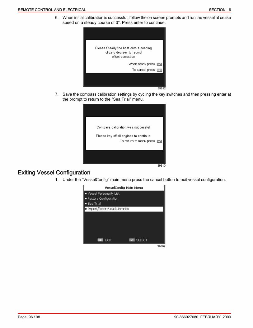
REMOTE CONTROL AND ELECTRICAL SECTION - 6
Page 96 / 98 90-866927080 FEBRUARY 2009
6. When initial calibration is successful, follow the on screen prompts and run the vessel at cruisespeed on a steady course of 0°. Press enter to continue.
39812
7. Save the compass calibration settings by cycling the key switches and then pressing enter atthe prompt to return to the "Sea Trial" menu.
39810
Exiting Vessel Configuration1. Under the "VesselConfig" main menu press the cancel button to exit vessel configuration.
39807

SECTION - 6 REMOTE CONTROL AND ELECTRICAL
90-866927080 FEBRUARY 2009 Page 97 / 98
2. Press the enter button to confirm.
39805
3. A screen will appear asking you whether or not you would like to remove the libraries. Pressthe cancel button to keep the library files for future use.
39803
4. Confirm that VesselView reboots properly and returns to the VesselView interface.

REMOTE CONTROL AND ELECTRICAL SECTION - 6
NOTES:
Page 98 / 98 90-866927080 FEBRUARY 2009

SECTION - 7 PREDELIVERY PREPARATION AND STORAGE
90-866927080 FEBRUARY 2009 Page 1 / 32
SECTION 7 - PREDELIVERY PREPARATION ANDSTORAGE
Table of ContentsPredelivery Preparation........................................................................................................................................... 3Coolant Level........................................................................................................................................................... 3Drive Gear Lube...................................................................................................................................................... 4
Checking...........................................................................................................................................................4Filling.................................................................................................................................................................5
Transmission Fluid.................................................................................................................................................. 6Checking...........................................................................................................................................................6Filling.................................................................................................................................................................8
Steering Actuator and Trim Fluid (Oil)—Low‑Pressure Filter System..................................................................... 9Checking...........................................................................................................................................................9
Steering Actuator and Trim Fluid (Oil)—High‑Pressure Filter System.................................................................. 10Checking.........................................................................................................................................................10Filling...............................................................................................................................................................11
Fluid Level of Steering Backup Pump, If Equipped............................................................................................... 12General Information.........................................................................................................................................12Checking.........................................................................................................................................................13Filling...............................................................................................................................................................14Changing.........................................................................................................................................................14
Data System Wiring............................................................................................................................................... 15Data Cable ..................................................................................................................................................... 15Smart Junction box ......................................................................................................................................... 15Non‑Mercury Supplied Ignition Key Switch .................................................................................................... 15VesselView Harness ...................................................................................................................................... 15
Propellers.............................................................................................................................................................. 15Propeller Selection..........................................................................................................................................15Propeller Installation........................................................................................................................................16
Battery Connections.............................................................................................................................................. 18Skyhook Warning Labels....................................................................................................................................... 20Operational Tests.................................................................................................................................................. 21
Operational Tests of the Engine and Drive.....................................................................................................21Preparation .............................................................................................................................................. 21System Calibration ................................................................................................................................... 22Operation Test ......................................................................................................................................... 22
Steering Wheel Operational Tests..................................................................................................................23Boat in the Water Tests...................................................................................................................................23
Wide Open Throttle Test .......................................................................................................................... 23Dual‑Handle Electronic Remote Control (ERC) with DTS Trackpad Features and Operation........................23
Operation ................................................................................................................................................. 23Helm Transfer..................................................................................................................................................25Requesting Helm Transfer..............................................................................................................................25Helm Transfer and Precision Pilot...................................................................................................................26Synchronizing Engines....................................................................................................................................26Basic Joystick Operation.................................................................................................................................26Trim Tab System.............................................................................................................................................27Trim Tab Control Operational Tests................................................................................................................27
Freezing‑Weather Storage and Seasonal Storage............................................................................................... 27Storage Descriptions.......................................................................................................................................27Freezing‑Weather Storage Instructions...........................................................................................................28Seasonal Storage Instructions........................................................................................................................29
OEM Delivery Preparation—General Information................................................................................................. 29
7

PREDELIVERY PREPARATION AND STORAGE SECTION - 7
Page 2 / 32 90-866927080 FEBRUARY 2009
Cummins MerCruiser Diesel Zeus Drive Initial Start‑Up and Sea Trial Checklist................................................. 30Out of the Water—Key Switches Off...............................................................................................................30Out of the Water—Key Switches On...............................................................................................................30In the Water—Key Switches On, Engines Not Running..................................................................................31In the Water, at the Dock—Key Switches On, Engines Running....................................................................31During the Sea Trial........................................................................................................................................32After the Sea Trial...........................................................................................................................................32

SECTION - 7 PREDELIVERY PREPARATION AND STORAGE
90-866927080 FEBRUARY 2009 Page 3 / 32
Lubricant, Sealant, AdhesivesTube Ref No. Description Where Used Part No.
25 Liquid Neoprene
Exposed electrical terminals andconnections
Exposed electrical terminals andconnections
92- 25711 3
34 Special Lubricant 101 Propeller shaft splines 92-802865Q02
87 High Performance Gear Lube Gear lube monitor 92-858064K01
94 Anti-Corrosion Grease Propeller shaft splines 92-802867Q 1
95 2-4-C Marine Lubricant withTeflon Propeller shaft splines 92-802859A 1
138 Synthetic Power Steering FluidSAE 0W-30 Hydraulic system 92-858076K01
Special ToolsPropeller Nut Tool 91‑805457T 1
10677
Aids in the removal and installation of the front propeller nut.
Predelivery PreparationNOTICE
Before starting the Predelivery procedures, read this manual thoroughly. If you do not understandany portion of the manual, contact your local distributor of Cummins MerCruiser Diesel products.
Take the following final steps to prepare the power package for delivery to the customer after thepower package installation is complete. It is the boat manufacturer's responsibility to perform theseprocedures or to have the dealer complete these procedures.
Coolant Level1. Refer to the appropriate QSB or QSC Operation and Maintenance Manual and check the
engine coolant level. Add the specified coolant, if necessary.
Description Where Used Part NumberFleetguard Compleat withDCA4
Closed cooling system Fleetguard Part Number: CC2825Obtain Locally
2. Recheck the coolant level after the first WOT boat test and add the specified coolant, ifnecessary.

PREDELIVERY PREPARATION AND STORAGE SECTION - 7
Page 4 / 32 90-866927080 FEBRUARY 2009
Drive Gear LubeNOTICE
Discharge of oil, coolant, or other engine/drive fluids into the environment is restricted by law.Use caution not to spill oil, coolant, or other fluids into the environment when using or servicingyour boat. Be aware of the local restrictions governing the disposal or recycling of waste, andcontain and dispose of fluids as required.
CheckingIMPORTANT: The gear lube level in the gear lube monitor rises and falls during drive operation.Check the gear lube level when the drive is cool and the engine is off.NOTE: After the drive has been operated and the gear lube is hot, the fluid expands and may beup to the "MAX OPERATING LEVEL" (hot full line).To check the drive gear lube with the drive cover installed:1. Remove the access cover from the drive cover.2. Remove the cap from the gear lube monitor.
bc
a
25878
a - Access coverb - Capc - Gear lube monitor
3. Inspect the gear lube level in the gear lube monitor. The gear lube level should be at the "COLDFILL LEVEL" (cold full line).
27837
a
b
c
Shown with drive cover removeda - Capb - "COLD FILL LEVEL" linec - "MAX OPERATING LEVEL" line
4. If the level is low, see Filling.

SECTION - 7 PREDELIVERY PREPARATION AND STORAGE
90-866927080 FEBRUARY 2009 Page 5 / 32
5. If the level is correct, install the access cover.To check the drive gear lube with the drive cover removed:1. Remove the drive cover. See Removing the Drive Cover.2. Inspect the gear lube level in the gear lube monitor. The gear lube level should be at the "COLD
FILL LEVEL" (cold full line) when the drive and fluid are cold.
27853
ab
a - "COLD FILL LEVEL" lineb - Gear lube level
IMPORTANT: If any water is visible at the bottom of the gear lube monitor or appears at the filland drain plug hole, or if the gear lube appears discolored, contact your Cummins MerCruiserDiesel Authorized Repair Facility immediately. Both conditions may indicate a water leak in thedrive.3. If the level is low, see Filling.4. If the level is correct, install the drive cover. See Installing the Drive Cover.
FillingIMPORTANT: If more than 59 mL (2 fl. oz.) of High Performance Gear Lube is required to fill thegear lube monitor, a seal may be leaking. Lack of lubrication will damage the drive. Contact yourCummins MerCruiser Diesel Authorized Repair Facility .If the gear lube level is below the "COLD FILL LEVEL" line, add the specified gear lube.1. Remove the cap from the gear lube monitor.2. Fill the gear lube monitor with the specified gear lube so that the gear lube is level with the
"COLD FILL LEVEL" line (cold full line). Do not overfill.
27853
ab
Shown with drive cover removeda - "COLD FILL LEVEL" lineb - Gear lube level
Tube Ref No. Description Where Used Part No.
87 High Performance Gear Lube Gear lube monitor 92-858064K01

PREDELIVERY PREPARATION AND STORAGE SECTION - 7
Page 6 / 32 90-866927080 FEBRUARY 2009
NOTE: After the drive has been operated and the gear lube is hot, the fluid expands and may beup to the "MAX OPERATING LEVEL" line (hot full line).
27837
a
b
c
a - Capb - "COLD FILL LEVEL" linec - "MAX OPERATING LEVEL" line
3. Ensure that the rubber gasket is inside the cap for the gear lube monitor and install the cap.Do not overtighten.
27851
ab
a - Gear lube monitorb - Cap
Transmission FluidChecking
You can check the transmission fluid level through the access cover on the drive cover or with thedrive cover removed.1. If the drive cover is removed, go to step 3.

SECTION - 7 PREDELIVERY PREPARATION AND STORAGE
90-866927080 FEBRUARY 2009 Page 7 / 32
2. If the drive cover is installed, remove the access cover from the drive cover; then, go to step3.
bc
a
25914
a - Access coverb - Transmissionc - Transmission dipstick
3. Remove the dipstick. Wipe the dipstick with a clean, lint‑free cloth.4. Insert the dipstick, resting it on the top of the threaded hole.5. Remove the dipstick and check the fluid level indicated. The fluid level should be between the
maximum and minimum marks on the dipstick.NOTE: Fluid from the transmission fluid cooler and hoses may drain into the transmission, causinga fluid level slightly above the maximum mark.
28080
d
cab
Checking—dipstick rested on top of threaded holea - Maximum markb - Minimum markc - Top of threaded holed - Dipstick
6. If the level is correct, install the dipstick.7. If the fluid level is low, add the specified transmission fluid through the dipstick threaded hole
to bring the level up to the maximum mark on the dipstick.
Description Fluid Type Fluid Part Number
Transmission and drop box Synthetic Power Steering Fluid SAE0W‑30 92‑858077K01
NOTE: If the transmission fluid level is extremely low, see your local Cummins MerCruiser DieselAuthorized Repair Facility.
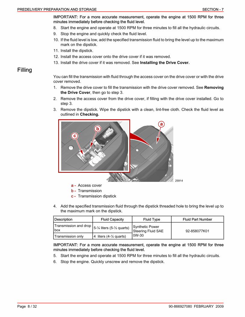
PREDELIVERY PREPARATION AND STORAGE SECTION - 7
Page 8 / 32 90-866927080 FEBRUARY 2009
IMPORTANT: For a more accurate measurement, operate the engine at 1500 RPM for threeminutes immediately before checking the fluid level.8. Start the engine and operate at 1500 RPM for three minutes to fill all the hydraulic circuits.9. Stop the engine and quickly check the fluid level.10. If the fluid level is low, add the specified transmission fluid to bring the level up to the maximum
mark on the dipstick.11. Install the dipstick.12. Install the access cover onto the drive cover if it was removed.13. Install the drive cover if it was removed. See Installing the Drive Cover.
FillingYou can fill the transmission with fluid through the access cover on the drive cover or with the drivecover removed.1. Remove the drive cover to fill the transmission with the drive cover removed. See Removing
the Drive Cover, then go to step 3.2. Remove the access cover from the drive cover, if filling with the drive cover installed. Go to
step 3.3. Remove the dipstick. Wipe the dipstick with a clean, lint‑free cloth. Check the fluid level as
outlined in Checking.
bc
a
25914
a - Access coverb - Transmissionc - Transmission dipstick
4. Add the specified transmission fluid through the dipstick threaded hole to bring the level up tothe maximum mark on the dipstick.
Description Fluid Capacity Fluid Type Fluid Part NumberTransmission and dropbox 5‑¼ liters (5‑½ quarts) Synthetic Power
Steering Fluid SAE0W‑30
92‑858077K01Transmission only 4 liters (4‑¼ quarts)
IMPORTANT: For a more accurate measurement, operate the engine at 1500 RPM for threeminutes immediately before checking the fluid level.5. Start the engine and operate at 1500 RPM for three minutes to fill all the hydraulic circuits.6. Stop the engine. Quickly unscrew and remove the dipstick.
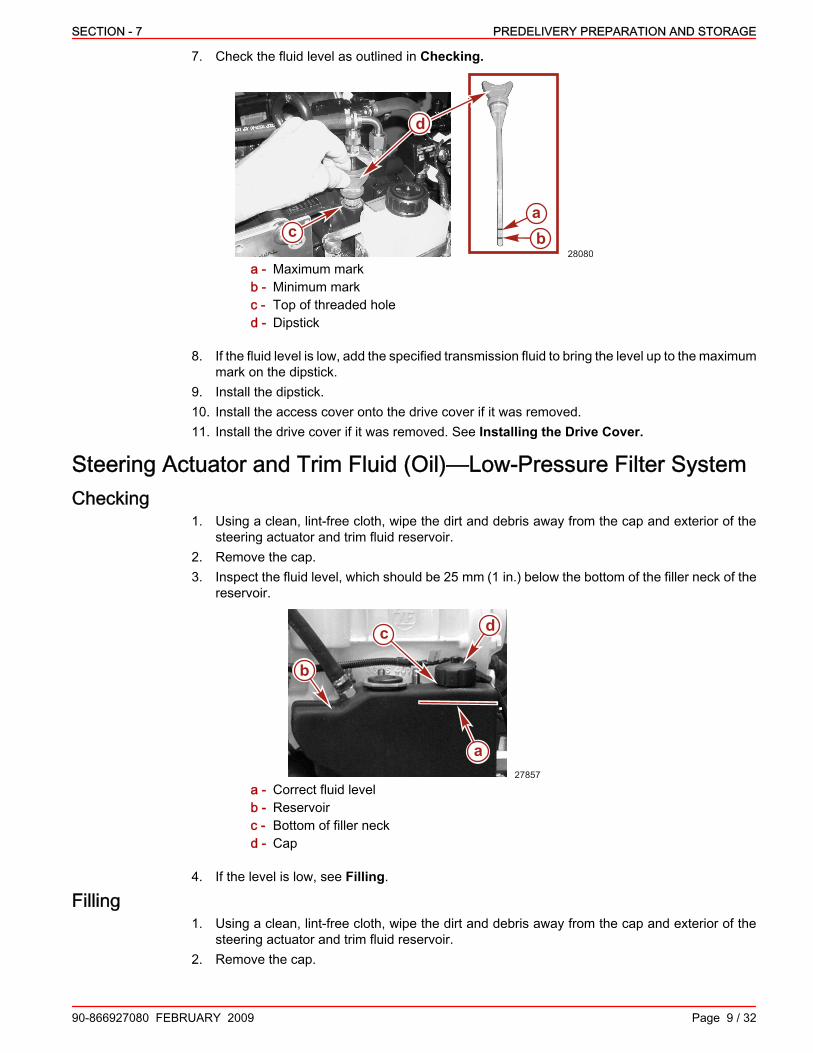
SECTION - 7 PREDELIVERY PREPARATION AND STORAGE
90-866927080 FEBRUARY 2009 Page 9 / 32
7. Check the fluid level as outlined in Checking.
28080
d
cab
a - Maximum markb - Minimum markc - Top of threaded holed - Dipstick
8. If the fluid level is low, add the specified transmission fluid to bring the level up to the maximummark on the dipstick.
9. Install the dipstick.10. Install the access cover onto the drive cover if it was removed.11. Install the drive cover if it was removed. See Installing the Drive Cover.
Steering Actuator and Trim Fluid (Oil)—Low‑Pressure Filter SystemChecking
1. Using a clean, lint‑free cloth, wipe the dirt and debris away from the cap and exterior of thesteering actuator and trim fluid reservoir.
2. Remove the cap.3. Inspect the fluid level, which should be 25 mm (1 in.) below the bottom of the filler neck of the
reservoir.
a
b
c
27857
d
a - Correct fluid levelb - Reservoirc - Bottom of filler neckd - Cap
4. If the level is low, see Filling.
Filling1. Using a clean, lint‑free cloth, wipe the dirt and debris away from the cap and exterior of the
steering actuator and trim fluid reservoir.2. Remove the cap.

PREDELIVERY PREPARATION AND STORAGE SECTION - 7
Page 10 / 32 90-866927080 FEBRUARY 2009
3. Fill the reservoir with the specified fluid until the fluid is 25 mm (1 in.) below the bottom of thefiller neck of the reservoir. Do not overfill.
4. Install the cap.
a
b
c
27857
d
a - Correct fluid levelb - Reservoirc - Bottom of filler neckd - Cap
Description Fluid Capacity Fluid Type Fluid Part NumberSteering actuator andtrim system(approximate totalcapacity)
5‑3/4 to 6 liters(6 to 6‑1/3 quarts)
Synthetic PowerSteering Fluid SAE0W‑30
92‑858077K01
Steering Actuator and Trim Fluid (Oil)—High‑Pressure Filter SystemChecking
1. Using a clean, lint‑free cloth, wipe the dirt and debris away from the cap and exterior of thesteering actuator and trim fluid reservoir.
NOTE: The direction to rotate the cap to open or close is imprinted on the top of the cap.2. Push down and turn the reservoir cap and dipstick about 1/3 turn in the open direction.
bca
40235
a - Reservoir cap and dipstickb - Open directionc - Close direction
3. Lift the cap and dipstick from the neck of the reservoir.

SECTION - 7 PREDELIVERY PREPARATION AND STORAGE
90-866927080 FEBRUARY 2009 Page 11 / 32
4. Inspect the fluid level, which should be at the full‑cold mark.
b
ca
40243
d
a - Cap and dipstickb - Full‑cold mark
c - Low‑cold markd - Add
5. If the level is low, see Filling.6. If the level is correct, insert the cap and dipstick into the neck of the reservoir. Push down and
turn the reservoir cap in the close direction.
bca
40235
a - Cap and dipstickb - Open directionc - Close direction
Filling1. Using a clean, lint‑free cloth, wipe the dirt and debris away from the cap and exterior of the
steering actuator and trim fluid reservoir.NOTE: The direction to rotate the cap to open or close is imprinted on the top of the cap.

PREDELIVERY PREPARATION AND STORAGE SECTION - 7
Page 12 / 32 90-866927080 FEBRUARY 2009
2. Remove the cap and dipstick. Push down and turn the reservoir cap and dipstick about 1/3turn in the open direction.
bca
40235
a - Reservoir cap and dipstickb - Open directionc - Close direction
IMPORTANT: Always use the dipstick to determine the exact quantity of oil required.3. Fill the hydraulic reservoir with the specified oil to bring the level up to the full‑cold mark. Do
not overfill.
b
ca
40243
d
a - Cap and dipstickb - Full‑cold mark
c - Low‑cold markd - Add
Tube Ref No. Description Where Used Part No.
138 Synthetic Power SteeringFluid SAE 0W-30 Hydraulic system 92-858076K01
4. Insert the cap and dipstick into the neck of the reservoir. Push down and turn the reservoircap in the close direction.
Fluid Level of Steering Backup Pump, If EquippedGeneral Information
There are two designs for the steering backup pump:• Pumps with a return hose and without a dipstick.• Pumps with a dipstick.

SECTION - 7 PREDELIVERY PREPARATION AND STORAGE
90-866927080 FEBRUARY 2009 Page 13 / 32
On pumps with a return hose and without a dipstick, no service is required.
b
a
37837
Steering backup pump with return hose and without a dipsticka - Return hoseb - Steering backup pump
On steering backup pumps with a dipstick, the procedures for checking, filling, and changing thefluid are covered.
Checking1. Using a clean, lint‑free cloth, wipe the dirt and debris away from the screw and exterior of the
reservoir for the steering backup pump.2. Using a screwdriver, unscrew the dipstick from the reservoir of the backup pump. Remove the
dipstick.
33789
a
c
b
d
c
d
a - Steering backup pumpb - Reservoir
c - Dipstickd - Screwdriver

PREDELIVERY PREPARATION AND STORAGE SECTION - 7
Page 14 / 32 90-866927080 FEBRUARY 2009
3. Check the fluid level. The fluid must be between the upper marks ("FULL") on the dipstick.
33790
a
c
ba
a - Dipstickb - Upper marks—"FULL"
c - Lower marks—"ADD"
4. If the fluid level is low, see Filling.5. Install and securely tighten the dipstick.
Filling1. Using a clean, lint‑free cloth, wipe the dirt and debris away from the screw and exterior of the
reservoir for the steering backup pump.2. Remove the dipstick. See Checking.3. Fill the reservoir with clean lubricant until the fluid is between the upper marks ("FULL") on the
dipstick. Do not overfill.IMPORTANT: If the fluid level is below the lower marks on the dipstick in two consecutive servicechecks, contact your Authorized Cummins MerCruiser Diesel Repair Facility for assistance.
33790
a
c
ba
a - Dipstickb - Upper marks—"FULL"
c - Lower marks—"ADD"
Description Fluid Capacity Fluid Type Fluid Part NumberSteering backup pumpsystem (approximatetotal capacity)
414 mL to (14 fl oz)Synthetic PowerSteering Fluid SAEOW‑30
92‑858077K01
4. Install and securely tighten the dipstick.
ChangingThe steering backup pump fluid does not require changing unless it becomes contaminated. Seeyour Authorized Cummins MerCruiser Diesel Repair Facility if necessary.

SECTION - 7 PREDELIVERY PREPARATION AND STORAGE
90-866927080 FEBRUARY 2009 Page 15 / 32
Data System WiringData Cable
1. Verify that the data harness has a terminator/resistor connected at the engine end.2. Verify that the data harness is not routed near sharp edges, hot surfaces or moving parts.3. Verify that the data harness is not routed near ignition components (coils, spark plugs, spark
plug leads.4. Verify that the harness is fastened and supported along the routing path.
Smart Junction box1. Verify that all connectors are locked in their receptacle.2. Check to make sure are harness connections are fastened within 25.4 cm (10 in.) of the
junction box.3. Verify that all not used receptacles are covered with a weather cap (859318T‑2).
Non‑Mercury Supplied Ignition Key Switch1. If a non‑Mercury Marine ignition key switch in used, check with the manufacturer to verify that
it passes the ingress protection testing per IEC IP66 specification minimum. Ignition switchesmust pass this specification.
VesselView Harness1. Verify that all connectors are properly inserted and locked in their receptacles (remote control,
key switch, VesselView, air temperature sensor, lanyard stop switch and junction box.2. Verify that the harness to the remote control handle has unobstructed freedom of movement
during control handle movement (full forward and full reverse).3. Verify that the lanyard switch is wired into the system correctly.4. Verify that all engine battery cables are connected to the correct terminals.5. Verify that the power harness leads are connected to the starting battery.6. Verify that the harness is fastened along the routing path.
PropellersPropeller Selection
IMPORTANT: The installed propellers must allow the engine to reach Engine Rated RPM with theboat fully loaded and with all customer stores on board. With the boat less than fully loaded theengines should reach Engine Rated RPM with less than 100 percent load.It is the responsibility of the boat manufacturer or the selling dealer to equip the power packagewith the correct propellers. Refer to the engine Information Data Tag located on the engine for thespecified Engine Rated RPM. Information for the location of the engine data tag can be found inthe engine Owners manual.If full throttle engine RPM is below the Engine Rated RPM, the propellers will have to be changedto prevent loss of performance and possible engine damage.It is usually desirable, with a new, fully loaded boat, that the engines reach Engine Rated RPMwith less than 100 percent load. This will allow tolerance for customer stores and some minorfouling of the hull or running gear.

PREDELIVERY PREPARATION AND STORAGE SECTION - 7
Page 16 / 32 90-866927080 FEBRUARY 2009
Propeller Installation
! WARNINGRotating propellers can cause serious injury or death. Never operate the boat out of the waterwith a propeller installed. Before installing or removing a propeller, remove the key from the keyswitch, place the drive in neutral, and engage the E‑stop switch to prevent the engine fromstarting.
1. Liberally coat the propeller shaft spline with one of the following Quicksilver lubricants.NOTE: Anti‑corrosion grease is for saltwater applications only.
Tube Ref No. Description Where Used Part No.
34 Special Lubricant 101 Propeller shaft splines 92-802865Q02
95 2-4-C Marine Lubricant withTeflon Propeller shaft splines 92-802859A 1
94 Anti-Corrosion Grease Propeller shaft splines 92-802867Q 1
24029
Lubricating the propeller shaft splines
IMPORTANT: Check that both the front and aft propeller part numbers match for port and starboarddrives.2. Slide the front thrust hub onto the propeller shaft with the tapered side toward the propeller
hub.3. Align the splines and place the front propeller on the propeller shaft. The propeller must fit
freely on the propeller shaft splines.

SECTION - 7 PREDELIVERY PREPARATION AND STORAGE
90-866927080 FEBRUARY 2009 Page 17 / 32
4. Install the front propeller nut.
a
b
24031
a - Front propellerb - Nut
5. Place a block of wood between the trim tab and the propeller.6. Torque the front propeller nut using the propeller nut tool.
b
a
c 24035
a - Block of woodb - Trim tabc - Propeller nut tool
Propeller Nut Tool 91‑805457T 1
Description Nm lb. in. lb. ft.Front propeller nut 136 – 100
7. Check the propeller for rotation. The propeller must not contact the lower drive housing.NOTE: The drives require an alignment procedure to make them parallel. This procedure must beperformed with the aft propellers either not mounted or removed. Depending upon yourmanufacturing processes, you may delay installation of the aft propellers until after the alignmentof the drives. Refer to Section 6—Initial Drive and Steering Wheel Alignment andCalibration.8. Slide the rear thrust hub onto the propeller shaft with the tapered side toward the propeller
hub.9. Align the splines and place the rear propeller on the propeller shaft. The propeller must fit
freely on the propeller shaft splines.

PREDELIVERY PREPARATION AND STORAGE SECTION - 7
Page 18 / 32 90-866927080 FEBRUARY 2009
10. Install the rear propeller nut.11. Place a block of wood between the trim tab and the propeller.12. Torque the rear propeller nut.
ab
24037
a - Block of woodb - Trim tab
25876
a
bcde
f
Zeus drive propeller assemblya - Front thrust hubb - Front propellerc - Front propeller nut
d - Rear thrust hube - Rear propellerf - Rear propeller nut
Description Nm lb. in. lb. ft.Rear propeller nut 81 – 60
Battery Connections1. At the VIP. Attach the connector of the unswitched power harness to the VIP receptacle
labeled "POWER".2. At the battery, battery bus or battery switch.
a. Connect the unswitched power harness wire (usually red) with the 30 A fuse to positive(+) terminal.
b. Connect the other wire (usually black) to the negative (–) terminal.3. At the engine. Attach the connector of the unswitched power harness to the appropriate
engine connector.4. At the battery, battery bus or battery switch.

SECTION - 7 PREDELIVERY PREPARATION AND STORAGE
90-866927080 FEBRUARY 2009 Page 19 / 32
a. Connect the unswitched power harness wire (usually red) with the 30 A fuse to positive(+) terminal.
b. Connect the other wire (usually black) to the negative (–) terminal.
f c
a
b
de
g
29881
Battery connection shown, similar with battery bus or battery switch connectiona - Unswitched power harness
connector at VIPb - 30 A fusec - Positive terminald - 30 A fuse
e - Unswitched power harness connectorat engine
f - Negative terminalg - Battery, battery bus bar, or battery
switch connection
5.IMPORTANT: The power supply for the MerCathode controller wire must be connected directly tothe battery positive (+) terminal. Do not connect it to a switched positive (+) circuit. The MerCathodesystem must function continuously for proper corrosion protection.NOTE: To ensure that the MerCathode system always remains energized in the event that thebattery switch (if equipped) is turned off, the MerCathode system positive (+) battery lead andnegative battery lead should be connected directly to the battery with an in‑line 20A fuse.6. Remove the cable tie on the bundled harness wires from the MerCathode controller.7. Connect the ring terminal of the red/purple wire (with the in‑line 20 A fuse) from the
MerCathode controller assembly to the battery positive (+) terminal or using a circuit breakerto an unswitched positive (+) DC bus bar.
8. Connect the ring terminal of the black wire from the MerCathode controller assembly to thebattery negative (–) terminal or an unswitched negative DC bus bar.
29384
c
b
a
a - Cable tieb - Bundled wire with ring terminalc - Positive (+) terminal wire with in‑line 20 A fuse
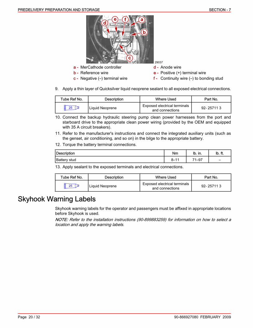
PREDELIVERY PREPARATION AND STORAGE SECTION - 7
Page 20 / 32 90-866927080 FEBRUARY 2009
29037
a
b
fed
c
a - MerCathode controllerb - Reference wirec - Negative (–) terminal wire
d - Anode wiree - Positive (+) terminal wiref - Continuity wire (–) to bonding stud
9. Apply a thin layer of Quicksilver liquid neoprene sealant to all exposed electrical connections.
Tube Ref No. Description Where Used Part No.
25 Liquid Neoprene Exposed electrical terminalsand connections 92- 25711 3
10. Connect the backup hydraulic steering pump clean power harnesses from the port andstarboard drive to the appropriate clean power wiring (provided by the OEM and equippedwith 35 A circuit breakers).
11. Refer to the manufacturer's instructions and connect the integrated auxiliary units (such asthe genset, air conditioning, and so on) in the bilge to the appropriate battery.
12. Torque the battery terminal connections.
Description Nm lb. in. lb. ft.Battery stud 8–11 71–97 –
13. Apply sealant to the exposed terminals and electrical connections.
Tube Ref No. Description Where Used Part No.
25 Liquid Neoprene Exposed electrical terminalsand connections 92- 25711 3
Skyhook Warning LabelsSkyhook warning labels for the operator and passengers must be affixed in appropriate locationsbefore Skyhook is used.NOTE: Refer to the installation instructions (90‑899883259) for information on how to select alocation and apply the warning labels.

SECTION - 7 PREDELIVERY PREPARATION AND STORAGE
90-866927080 FEBRUARY 2009 Page 21 / 32
Ensure the warning labels are affixed in the appropriate locations.
33798
8M0034159
34111
Example locations for the warning label for the operator (captain)
33824
34349
Example locations for the warning label for the passengers
Operational TestsOperational Tests of the Engine and DrivePREPARATION
NOTE: Refer to appropriate QSB or QSC Operation and Maintenance Manual for engine operatingspecifications and engine fluid capacity information. Refer to the appropriate Cummins MerCruiserDiesel Operation, Maintenance, and Warranty Manual for drive related fluid capacity information.1. Check for the proper installation of cooling system drain plugs, drain valves and hoses.2. Check the closed cooling system fluid level.3. Check the engine oil level.NOTE: The fluid level may be somewhat over the maximum mark, as some of the fluid from thetransmission fluid cooler and hoses may have drained back into the transmission.4. Verify the following fluids are at the proper level:
• Coolant level• Steering actuator and trim pump fluid level• Drive unit gear lube monitor• Transmission fluid level

PREDELIVERY PREPARATION AND STORAGE SECTION - 7
Page 22 / 32 90-866927080 FEBRUARY 2009
• Steering backup pump fluid level (HH and IH models without a return hose )SYSTEM CALIBRATION
1. Complete the calibration procedures outlined in Section 6 before proceeding to the operationaltests.
2. Test the on‑board electronics and warning systems in accordance with instructions providedby the manufacturer of the equipment.
OPERATION TEST1. If testing the engine and drive with the boat out of the water, supply water to the seawater
pickup pump as indicated in the following steps.
! WARNINGRotating propellers can cause serious injury or death. Never operate the boat out of the waterwith a propeller installed. Before installing or removing a propeller, remove the key from the keyswitch, place the drive in neutral, and engage the E‑stop switch to prevent the engine fromstarting.
! WARNINGPerforming tests with the engine running may cause the propeller to rotate and result in seriousinjury or death. Use caution when performing a test that requires the engine running, and removethe propeller to avoid injury.
NOTICEOperating the engine out of the water at high speeds creates suction, which can collapse thewater supply hose and overheat the engine. Do not operate the engine above 1400 RPM out ofthe water and without sufficient cooling water supply.
a. Install a flushing attachment to the seawater inlet hose.b. Connect a hose between the flushing attachment and a water source.
2. If testing the engine and drive with the boat in the water, open the seawater inlet seacock andensure a sufficient supply of cooling water to the seawater pickup pump.
3. Open the seawater outlet seacock.
! WARNINGLeaving the helm unattended while performing tests with the boat in the water may result in lossof boat control causing serious injury or death. Ensure someone is at the helm at all times, unlessthe boat is secured to a dock.
NOTICEOperating the engine out of the water at high speeds creates suction, which can collapse thewater supply hose and overheat the engine. Do not operate the engine above 1400 RPM out ofthe water and without sufficient cooling water supply.
4. Place the remote control in the neutral, idle position..5. Refer to the Marine Recreational High Output Propulsion Units QSB and QSC Operation
and Maintenance Manual and start the engine according to the manufacturer's instructions.6. Check for seawater flow at the exhaust idle bypass outlet.7. Watch all gauges for normal readings.8. Inspect the engine compartment for water, oil, fuel and exhaust leaks.9. Turn the key switch OFF. Remove the key from the key switch.10. If the engine does not turn off with the key switch, use the emergency stop switch on the VIP
panel. Identify the problem and correct.

SECTION - 7 PREDELIVERY PREPARATION AND STORAGE
90-866927080 FEBRUARY 2009 Page 23 / 32
Steering Wheel Operational TestsWith the electrical system is in the on position, the steering wheel should turn freely to the endstops in both directions. Ensure that the wheel turns and stops as expected in all tilt positions.1. Observe that the steering wheel turns the drives in the appropriate directions.
a. Out of the water. With the key switch in the on position, observe that the drives turn inthe appropriate direction when the steering wheel is turned.
b. In the water. With the boat properly secured to the dock and the engines operating,observe that the thrust moves in the appropriate direction when the steering wheel isturned.
Boat in the Water TestsWIDE OPEN THROTTLE TEST
IMPORTANT: To operate engine at full throttle before the break‑in period is complete:1. Place the remote control in the neutral, idle position.2. Refer to the Marine Recreational High Output Propulsion Units QSB or QSC Operation
and Maintenance Manual available from the engine manufacturer and start the engineaccording to the manufacturer's instructions.
3. Check the steering system, the ERC shift control and throttle control levers, and the joystickfor proper operation before departing from the dock.
4. Slowly advance the throttle until the engine reaches 1300 RPM (+/‑100 RPM).5. Watch all gauges for normal readings.6. When engines reaches normal operating temperature, run the boat up on plane.7. Advance engine RPM (in 200 RPM increments) until engine reaches its maximum rated RPM.8. Test if propellers with the correct pitch have been installed. Operate the boat (with a maximum
load on board) at wide open throttle (WOT) and check the RPM. Engine RPM must not beless than the rated RPM. If engine speed is too high, replace the propellers with propellers ofhigher pitch. If engine speed is too low, replace the propellers with propellers of lower pitch.
NOTE: If necessary, contact CMD or the supporting distributor application engineer for assistancewith propping.
Dual‑Handle Electronic Remote Control (ERC) with DTS Trackpad Features andOperationOPERATION
The electronic remote control (ERC) handle controls the operation of shift and throttle. Push thecontrol handle forward from neutral to the first detent for forward gear. Continue pushing the handleforward to increase speed. Pull the control handle from the forward position to the neutral positionto decrease speed and eventually stop. Pull the control handle back from neutral to the first detentfor reverse gear. Continue pulling the handle back to increase speed in reverse.

PREDELIVERY PREPARATION AND STORAGE SECTION - 7
Page 24 / 32 90-866927080 FEBRUARY 2009
NOTE: In certain modes, gear position is determined by the position of the shift valves on thetransmission, not the position of the ERC levers. When using the joystick or while in Skyhook, thecomputer moves the transmission in and out of gear even though the handles are in neutral.
a
bc
28086
d
a - Neutralb - Forwardc - Reversed - Bow of boat
The amount of force needed to move the ERC handles and to move the ERC handles through thedetents is adjustable to help prevent unwanted motion of the handle in rough water.To adjust ERC handle tension:1. Remove the side cover.2. Turn the screw clockwise to increase tension on the control handle and counter‑clockwise to
decrease tension.3. Adjust to tension desired.To adjust ERC handle detent tension:1. Remove the side cover.2. Turn the screw clockwise to increase tension on the control handle and counter‑clockwise to
decrease tension.3. Adjust to tension desired.
28087
a b
Starboard side with side cover removed.a - ERC handle tension screwb - ERC handle detent tension screw
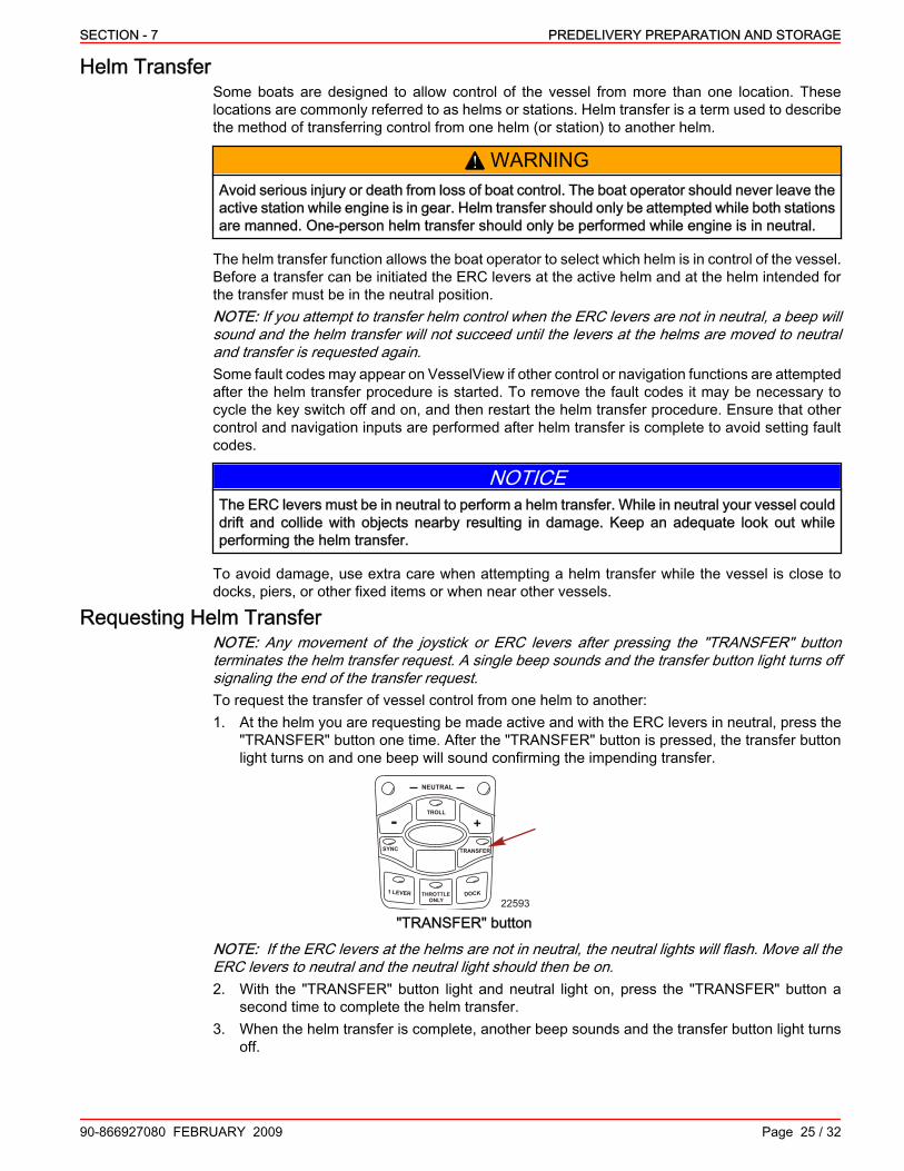
SECTION - 7 PREDELIVERY PREPARATION AND STORAGE
90-866927080 FEBRUARY 2009 Page 25 / 32
Helm TransferSome boats are designed to allow control of the vessel from more than one location. Theselocations are commonly referred to as helms or stations. Helm transfer is a term used to describethe method of transferring control from one helm (or station) to another helm.
! WARNINGAvoid serious injury or death from loss of boat control. The boat operator should never leave theactive station while engine is in gear. Helm transfer should only be attempted while both stationsare manned. One‑person helm transfer should only be performed while engine is in neutral.
The helm transfer function allows the boat operator to select which helm is in control of the vessel.Before a transfer can be initiated the ERC levers at the active helm and at the helm intended forthe transfer must be in the neutral position.NOTE: If you attempt to transfer helm control when the ERC levers are not in neutral, a beep willsound and the helm transfer will not succeed until the levers at the helms are moved to neutraland transfer is requested again.Some fault codes may appear on VesselView if other control or navigation functions are attemptedafter the helm transfer procedure is started. To remove the fault codes it may be necessary tocycle the key switch off and on, and then restart the helm transfer procedure. Ensure that othercontrol and navigation inputs are performed after helm transfer is complete to avoid setting faultcodes.
NOTICEThe ERC levers must be in neutral to perform a helm transfer. While in neutral your vessel coulddrift and collide with objects nearby resulting in damage. Keep an adequate look out whileperforming the helm transfer.
To avoid damage, use extra care when attempting a helm transfer while the vessel is close todocks, piers, or other fixed items or when near other vessels.
Requesting Helm TransferNOTE: Any movement of the joystick or ERC levers after pressing the "TRANSFER" buttonterminates the helm transfer request. A single beep sounds and the transfer button light turns offsignaling the end of the transfer request.To request the transfer of vessel control from one helm to another:1. At the helm you are requesting be made active and with the ERC levers in neutral, press the
"TRANSFER" button one time. After the "TRANSFER" button is pressed, the transfer buttonlight turns on and one beep will sound confirming the impending transfer.
SYNC
1 LEVER
NEUTRAL
TROLL
THROTTLE ONLY
DOCK
TRANSFER
+-
22593
"TRANSFER" button
NOTE: If the ERC levers at the helms are not in neutral, the neutral lights will flash. Move all theERC levers to neutral and the neutral light should then be on.2. With the "TRANSFER" button light and neutral light on, press the "TRANSFER" button a
second time to complete the helm transfer.3. When the helm transfer is complete, another beep sounds and the transfer button light turns
off.

PREDELIVERY PREPARATION AND STORAGE SECTION - 7
Page 26 / 32 90-866927080 FEBRUARY 2009
NOTE: If the helm transfer is not completed in ten seconds the request is automatically cancelledand a double beep sounds. Control will remain at the existing active helm. Press the "TRANSFER"button again to restart helm transfer.4. The helm where the transfer request was initiated is now active and controls the vessel.
Helm Transfer and Precision PilotTransferring control from an active helm to an inactive helm (from one station to another station)affects the functionality of Precision Pilot modes. Some of the affects are listed.• Auto Heading mode is disengaged when the ERC levers are moved to neutral for helm
transfer. You must re‑engage Auto Heading at the newly active helm.• Requesting a helm transfer causes Pilot to go to Standby mode. You will need to input
information at the new helm in control.• If engaged, Skyhook will disengage when the "TRANSFER" button is pressed the second time.
You must engage Skyhook at the the newly active helm.• The Resume feature for Auto Heading does not transfer automatically. After engaging the
previous Auto Heading course at the newly active helm, the resume feature works the sameas at any active station.
• In Track Waypoint mode the control of the route and display of route data on your chart plotterdoes not automatically transfer to the chart plotter at the requested helm. You must turn onthe chart plotter at the newly active helm, input the waypoint or waypoint route to be tracked,and re‑engage Track Waypoint.
Synchronizing EnginesThe auto‑synchronizing feature, when engaged, will automatically adjust all engine speeds tomatch the speed of the starboard engine.Press the "SYNC" button on the DTS trackpad to turn auto‑synchronization on or off. When thesync LED is yellow, the "SYNC" button has been pressed, but the conditions are not right for autosynchronization to engage. When the sync LED turns red, engine synchronization has beenengaged. The engines will remain synchronized as long as engine speed is over 900 RPM for twoseconds, remote control handles are positioned within 10% of each other, and the engines arebelow 95% throttle opening.To disengage the auto synchronization feature, press the "SYNC" button.
SYNC
1 LEVER
NEUTRAL
TROLL
THROTTLE ONLY
DOCK
TRANSFER
+-
22590
Basic Joystick OperationThe joystick offers precise, intuitive control of your boat during low speed and docking maneuvers.The joystick translates the movement of the joystick into similar movement in the boat. Enginespeed is limited in this mode to prevent unacceptable boat dynamics during maneuvers.While operation with the joystick is easy to learn, we recommend that you drive the boat in thetraditional way until you can spend time in an open area free of obstructions and traffic to learnhow your boat responds to inputs. Further, we recommend that you occasionally practicemaneuvering in the traditional way to maintain your traditional drive docking skills in case joystickcontrol is temporarily not available.

SECTION - 7 PREDELIVERY PREPARATION AND STORAGE
90-866927080 FEBRUARY 2009 Page 27 / 32
Trim Tab SystemThe trim tabs on the Zeus drive are fully integrated into the drive. There are no additional systemsto bolt on. The trim tabs are usually automatically controlled for optimum performance. Manualtrim tab control will override the automatic system when conditions or personal preferencesrequire.
Trim Tab Control Operational TestsWhen auto tab control is activated, the tabs move to a trim position based on boat speed andengine RPM. The manual switches can be activated when in auto mode to compensate forconditions such as additional passengers to one side causing a list.Manual offsets are held until changed again through the panel, or until the electronic remotecontrols are moved into the neutral position, returning the trim tabs to their default factory settings.The following tests should take place in a clear and open water area without obstructions or otherboats.1. From a stop, start the boat moving in a straight line and operate the trim tabs while moving
onto plane. Observe that the boat responds appropriately to the inputs. Push the forward endof the rockers to bring the tabs down. Push on the aft end of the rockers to bring the tabs up.
25578
a b c
a - Port rockerb - Starboard Rockerc - Manual/automatic selector
2. After the boat is on plane, adjust the trim tabs for proper visibility from the helm, but not somuch that the boat speed or engine RPM is lowered.
Freezing‑Weather Storage and Seasonal StorageStorage Descriptions
IMPORTANT: We strongly recommend that this service be performed by a Cummins MerCruiserDiesel Authorized Repair Facility. Damage caused by freezing is not covered by the CumminsMerCruiser Diesel Limited Warranty.
NOTICEWater trapped in the seawater section of the cooling system can cause corrosion or freezedamage. Drain the seawater section of the cooling system immediately after operation or beforeany length of storage in freezing temperatures. If the boat is in the water, keep the seacockclosed until restarting the engine to prevent water from flowing back into the cooling system. Ifthe boat is not fitted with a seacock, leave the water inlet hose disconnected and plugged.
NOTE: As a precaution, attach a tag to the key switch or steering wheel of the boat to remind theoperator to open the seacock or unplug and reconnect the water inlet hose before starting theengine.

PREDELIVERY PREPARATION AND STORAGE SECTION - 7
Page 28 / 32 90-866927080 FEBRUARY 2009
The power package must be protected from freeze damage, corrosion damage, or both types ofdamage during storage. Storage is any length of time the product is not operated. Based on thelength of storage certain precautions and procedures must be observed to protect the powerpackage.Freeze damage can happen when water trapped in the seawater cooling system freezes. Forexample, after operating the boat, exposure to freezing temperatures for even a brief period oftime could result in freeze damage.Corrosion damage is the result of saltwater, polluted water, or water with a high mineral contenttrapped in the seawater cooling system. Saltwater should not stay in an engine's cooling systemfor even a brief storage time; drain and flush the seawater cooling system after each outing.Freezing‑weather (freezing temperature) operation refers to operating the boat whenever freezingtemperatures are possible. Likewise, freezing‑weather storage refers to whenever the boat is notbeing operated and freezing temperatures are possible. In such cases, the seawater section ofthe cooling system must be completely drained immediately after operation.Seasonal storage refers to when the boat is not being operated for one month or more. Theduration varies according to the geographic location. Seasonal storage precautions andprocedures include all the steps for freezing‑weather storage and some additional steps that mustbe taken when storage will last longer than the short time of freezing‑weather storage.
Freezing‑Weather Storage InstructionsIMPORTANT: We recommend the use of propylene glycol antifreeze in the seawater section ofthe cooling system for freezing‑weather (freezing temperatures), seasonal storage, or extendedstorage. Make sure that the propylene glycol antifreeze contains a rust inhibitor and isrecommended for use in marine engines. Be certain to follow the propylene glycol manufacturer'srecommendations.
NOTICEWater trapped in the seawater section of the cooling system can cause corrosion or freezedamage. Drain the seawater section of the cooling system immediately after operation or beforeany length of storage in freezing temperatures. If the boat is in the water, keep the seacockclosed until restarting the engine to prevent water from flowing back into the cooling system. Ifthe boat is not fitted with a seacock, leave the water inlet hose disconnected and plugged.
NOTE: As a precaution, attach a tag to the key switch or steering wheel of the boat to remind theoperator to open the seacocks before starting the engine.1. Close all seacocks.2. Read all precautions and perform all procedures found in the QSB or QSC Operation and
Maintenance Manual supplied by the engine manufacturer including the following.a. Drain all the water separating fuel filters.b. Drain the seawater section of the cooling system, including the water lift mufflers.c. Remove the hoses from the seawater strainer and drain the hoses completely.d. Drain and empty the seawater strainer according to the manufacturer's instructions.e. Reconnect the hoses to the seawater strainer and tighten the hose clamps securely.
3. Place a caution tag at the helm advising the operator to open the seacocks before operatingthe boat.
4. For additional assurance against freezing and corrosion fill the heat exchanger with a solutionof propylene glycol antifreeze and tap water mixed to protect the power package to the lowesttemperature to which it will be exposed during storage. Refer to the QSB or QSC Operationand Maintenance Manual supplied by the engine manufacturer.
5. Follow the battery manufacturer's instructions for battery storage.

SECTION - 7 PREDELIVERY PREPARATION AND STORAGE
90-866927080 FEBRUARY 2009 Page 29 / 32
Seasonal Storage Instructions1. Read all precautions and perform all procedures found in the Cold Weather (Freezing
Temperature) Storage section.2. Refer to the QSB or QSC Operation and Maintenance Manual supplied by the engine
manufacturer and fill the heat exchanger with a solution of propylene glycol antifreeze and tapwater mixed to protect the power package to the lowest temperature to which it will be exposedduring storage.
3. Follow the battery manufacturer's instructions for battery storage.
OEM Delivery Preparation—General InformationAfter the power package installation is complete, the OEM boat manufacturer has the responsibilityof performing the following checklists prior to delivery of the product to the customer.Completing these checklists prepares the power package for delivery to the customer, but is nota substitute for the maintenance schedules listed in this manual. If you have not been trained inthe recommended application, installation, and service procedures for this product, contact anauthorized Cummins MerCruiser Distributor to have the checks performed. Improper OEM deliverypreparation and storage of this Cummins MerCruiser Diesel product could result in damage to theproduct or personal injury to those servicing and operating the product.Some of the checks in the lists pertain to the OEM supplying the customer with the vessel'sliterature and related documents as shown in these tables.
General
Publication Name Publication Part NumberQSB Owners Manual 4024182QSC Owners Manual 4021481Zeus Operation, Maintenance, and Warranty Manual 90‑866938071VesselView Operation Manual 90‑898279Captain's Briefing Information Brochure 3381956CMD zipper bag 4078737Warranty Registration Card 90‑842801002
Skyhook (If Equipped)
Publication Name Publication Part NumberSkyhook Operational DVD 90‑899883257Skyhook Quick Reference Card 90‑899883258Skyhook Warning Label Placement instructions 90‑899883259Skyhook Helm Label 8M0034159SKyhook Passenger Label 8M0034160

PREDELIVERY PREPARATION AND STORAGE SECTION - 7
Page 30 / 32 90-866927080 FEBRUARY 2009
Cummins MerCruiser Diesel Zeus Drive Initial Start‑Up and Sea TrialChecklistOut of the Water—Key Switches Off
Out of Water – Key Off CheckInstall engine master and slave MUS ID connectors Remove drive covers Coolant level expansion tank – Check / Fill Coolant recovery bottle – Check / Fill Engine oil dipstick – dipsticks, calibrate if necessary Drive gear lube – Check / Fill Transmission fluid – Check / Fill Steering actuator and trim fluid – Check / Fill Steering backup pump fluid – Check / Fill (if equipped) Confirm polarity of power supplies Open seacocks Fuel connections tight – Check Electrical connections secure – Check Exhaust system hose clamps tight – Check Seawater system hose clamps tight – Check Battery fully charged – Test Battery secured and connections tight – Check Skegs installed – Check / Install Verify the warning labels are properly positioned for Skyhook, if equipped
Out of the Water—Key Switches OnOut of Water – Key Switch On CheckTurn on ignitions Prime fuel system Import vessel personality from USB memory stick Import VesselView configuration from USB memory stick Check for correct personality version for vessel type Perform lever (ERC) configuration Configure steering wheel Unlock feature upgrades, if necessary Manually align drives Propellers installed – Check / Install Confirm Autopilot mode in VesselView

SECTION - 7 PREDELIVERY PREPARATION AND STORAGE
90-866927080 FEBRUARY 2009 Page 31 / 32
In the Water—Key Switches On, Engines Not RunningIn the Water – Key Switch On, Engines Not Running CheckSteering wheel centers with key switch on – Check Audio warning system operational – Check Audio warning system cancel operational – Check Note any alarms and repair until clear VesselView operation – Check Both neutral lights on lever assembly on and not blinking – Check
In the Water, at the Dock—Key Switches On, Engines RunningNOTE: Only operate the vessel in areas with adequate running room and water depth.
In the Water, at the Dock – Key Switch On, Engines Running CheckStart engines Confirm proper engine and gear oil pressure Analog gauges operation – Check Seawater flow – Check Run the engine for 5 minutes before Start/Stop and E‑stop checks Start/Stop key switch/button operation – Check E‑Stop button operation – Check Transmission oil level with the engine shut down – Check Restart the engines Check for oil, fluid, and exhaust leaks Perform drive initialization Steering operation – Check Forward and reverse gear operation – Check Joystick operation – Check MerCathode operation – Check

PREDELIVERY PREPARATION AND STORAGE SECTION - 7
Page 32 / 32 90-866927080 FEBRUARY 2009
During the Sea TrialDuring Sea Trial CheckFollow break‑in procedures Calibrate Maretron compass Perform sea trial drive alignment, if necessary Confirm port and starboard WOT RPM are above rated speed Idle increase and decrease button operation – Check Single lever mode operation – Check Sync mode operation – Check Throttle only mode operation – Check Troll system operation – Check Docking mode operation – Check Cruise control mode operation – Check Trim tab operation, manual mode – Check Trim tab operation, automatic mode – Check Joystick operation – Check Autopilot auto heading operation – Check Autopilot turn button operation – Check Autopilot joystick turn operation – Check Autopilot resume button operation – Check Autopilot waypoint tracking operation – Check Skyhook operation – Check Safe boat handling – Check
After the Sea TrialAfter Sea Trial CheckCheck for oil or fluid leaks Coolant level (after engine cool down) – Check Engine oil level – Check Drive gear lube level – Check Transmission fluid level – Check Steering actuator and trim fluid level – Check Steering backup pump fluid level (HH and IH models) – Check Grease driveshaft slip‑joints Apply Quicksilver Corrosion Guard to power package Install drive cover, if equipped Confirm VesselView Manual, Engine Operators Manual, Zeus Drive Operation,Maintenance, and Warranty Manual, Skyhook Operation DVD, and registration card areon the vessel
Verify Skyhook Quick Reference Guide is attached to the helm