CFP30E SERIES - Cummins
111
CFP30E SERIES www.cumminsfirepower.com Operation & Maintenance Manual Fire Pump Drive Engines Doc 22484 Rel 06/2016 English Version
-
Upload
khangminh22 -
Category
Documents
-
view
0 -
download
0
Transcript of CFP30E SERIES - Cummins

CFP30E SERIES
www.cumminsfirepower.com
Operation & Maintenance Manual
Fire Pump Drive Engines
Doc 22484
Rel 06/2016 English Version

This manual contains proprietary information to equipment produced by Cummins Fire Power or Cummins Inc. and is being supplied solely for the purpose of operating,
maintaining, and servicing the fire pump drive engine purchased from Cummins Fire Power.
© Copyright 2016, Cummins Inc.
Warranty Information
Cummins Fire Power 875 Lawrence Drive De Pere, WI 54115 Phone 920 337 9750 www.cumminsfirepower.com
Cummins Fire Power Limited Warranty
Fire Pump Package This limited warranty applies to all Cummins Fire Power (hereinafter referred to as “Cummins Fire Power” branded fire pump driver and associated accessories (hereinafter referred to as "Product"). This warranty covers any failures of the Product, under normal use and service, which result from a defect in material or factory workmanship. Warranty Period: The warranty start date for stationary Product is the date of initial start up, demonstration or 18 months after factory ship date, whichever is sooner. Base Warranty Duration (whichever occurs first): 2 years/2000 hours. Cummins Fire Power Responsibilities: In the event of a failure of the Product during the warranty period due to defects in material or workmanship, Cummins Fire Power will only be responsible for the following costs:
� All parts and labor required to repair the Product. � Reasonable travel expenses to and from the Product site location. � Maintenance items that are contaminated or damaged by a warrantable failure.
Owner Responsibilities: The owner will be responsible for the following:
� Notifying Cummins Fire Power distributor or dealer within 30 days of the discovery of failure. � Installing, operating, commissioning and maintaining the Product in accordance with Cummins
Fire Power’s published policies and guidelines. � Providing evidence for date of commissioning. � Providing sufficient access to and reasonable ability to remove the Product from the installation in
the event of a warrantable failure. In addition, the owner will be responsible for:
� Incremental costs and expenses associated with Product removal and reinstallation resulting from difficult or non-standard installations.
� Costs associated with Fire Watch Protection during Product being repaired. � Costs associated with labor overtime and premium shipping requested by the owner. � All downtime expenses, fines, all applicable taxes, and other losses resulting from a warrantable
failure. Limitations: This limited warranty does not cover Product failures resulting from:
� Inappropriate use relative to designated power rating or application guidelines. � Normal wear and tear, negligence, accidents or misuse. � Improper and/or unauthorized installation. � Lack of maintenance or unauthorized repair. � Noncompliance with any Cummins Fire Power published guideline or policy. � Use of improper or contaminated fuels, coolants or lubricants. � Improper storage before and after commissioning. � Owner’s delay in making Product available after notification of potential Product problem. � Replacement parts and accessories not authorized by Cummins Fire Power. � Owner or operator abuse or neglect such as: operation without adequate coolant or lubricants;
over-fueling; over-speeding; lack of maintenance to lubricating, cooling or air intake systems; late servicing and maintenance; improper storage, starting, warm-up, run-in or shutdown practices, or for progressive damage resulting from a defective warning device.
� Damage to parts, fixtures, housings, attachments and accessory items that are not part of the fire pump package.
C 8 11 920 33 9 0 f
Limitations (cont.): This limited warranty does not apply to:
� Costs of maintenance, adjustments, installation, commissioning or start-up. � Starting batteries and enclosures. � Components added to the Product after shipment from Cummins Fire Power. � Block heaters are warranted for 1 year from date in service Please contact your local Cummins NPower Distributor for clarification concerning these limitations.
Extended Warranty Cummins Inc offers several levels of Extended Warranty Coverage (Base Engine Only). Please contact your local Cummins Distributor for details.
Cummins Fire Power Right to Failed Components: Failed components claimed under warranty remain the property of Cummins Fire Power. Cummins Fire Power has the right to reclaim any failed component that has been replaced under warranty.
THE WARRANTIES SET FORTH HEREIN ARE THE SOLE WARRANTIES MADE BY CUMMINS FIRE POWER IN REGARD TO THE PRODUCT. CUMMINS FIRE POWER MAKES NO OTHER WARRANTIES, EXPRESS OR IMPLIED, OR OF MERCHANTABILITY OR FITNESS FOR A PARTICULAR PURPOSE. IN NO EVENT IS CUMMINS FIRE POWER LIABLE FOR INCIDENTAL OR CONSEQUENTIAL DAMAGES.
This limited warranty shall be enforced to the maximum extent permitted by applicable law. This limited warranty gives the owner specific rights that may vary from state to state or from jurisdiction to jurisdiction.


Table of Contents
Section 1 - Safety
1.1 Introduction. . . . . . . . . . . . . . . . . . . . . . . . . . . . . . . . . . . . . . . . . . . . . . . . . . . . . . . . . . . . . . . . . . . . . . . 1-11.2 General Safety Precautions . . . . . . . . . . . . . . . . . . . . . . . . . . . . . . . . . . . . . . . . . . . . . . . . . . . . . . . . . . 1-11.3 Use of Advisory and Cautionary Statements . . . . . . . . . . . . . . . . . . . . . . . . . . . . . . . . . . . . . . . . . . . . . 1-1
1.3.1 Advisory Statements . . . . . . . . . . . . . . . . . . . . . . . . . . . . . . . . . . . . . . . . . . . . . . . . . . . . . . . . . . . 1-11.3.2 Cautionary Statements . . . . . . . . . . . . . . . . . . . . . . . . . . . . . . . . . . . . . . . . . . . . . . . . . . . . . . . . . . 1-2
Section 2 - Description
2.1 Introduction. . . . . . . . . . . . . . . . . . . . . . . . . . . . . . . . . . . . . . . . . . . . . . . . . . . . . . . . . . . . . . . . . . . . . . . 2-12.2 Fire Pump Digital Panel (FPDP). . . . . . . . . . . . . . . . . . . . . . . . . . . . . . . . . . . . . . . . . . . . . . . . . . . . . . . 2-12.3 Fire Pump Controller . . . . . . . . . . . . . . . . . . . . . . . . . . . . . . . . . . . . . . . . . . . . . . . . . . . . . . . . . . . . . . . 2-12.4 Air Intake . . . . . . . . . . . . . . . . . . . . . . . . . . . . . . . . . . . . . . . . . . . . . . . . . . . . . . . . . . . . . . . . . . . . . . . . 2-42.5 Cooling Water System . . . . . . . . . . . . . . . . . . . . . . . . . . . . . . . . . . . . . . . . . . . . . . . . . . . . . . . . . . . . . . 2-52.6 Fuel Supply and Drain . . . . . . . . . . . . . . . . . . . . . . . . . . . . . . . . . . . . . . . . . . . . . . . . . . . . . . . . . . . . . . 2-72.7 High Pressure Injector (HPI) Fuel System . . . . . . . . . . . . . . . . . . . . . . . . . . . . . . . . . . . . . . . . . . . . . . . 2-72.8 Engine Oil System . . . . . . . . . . . . . . . . . . . . . . . . . . . . . . . . . . . . . . . . . . . . . . . . . . . . . . . . . . . . . . . . . 2-92.9 Exhaust System . . . . . . . . . . . . . . . . . . . . . . . . . . . . . . . . . . . . . . . . . . . . . . . . . . . . . . . . . . . . . . . . . . 2-10
Section 3 - Installation
3.1 Introduction. . . . . . . . . . . . . . . . . . . . . . . . . . . . . . . . . . . . . . . . . . . . . . . . . . . . . . . . . . . . . . . . . . . . . . . 3-13.2 Receiving and Handling . . . . . . . . . . . . . . . . . . . . . . . . . . . . . . . . . . . . . . . . . . . . . . . . . . . . . . . . . . . . . 3-13.3 Site Preparation . . . . . . . . . . . . . . . . . . . . . . . . . . . . . . . . . . . . . . . . . . . . . . . . . . . . . . . . . . . . . . . . . . . 3-13.4 Drive Shaft Installation . . . . . . . . . . . . . . . . . . . . . . . . . . . . . . . . . . . . . . . . . . . . . . . . . . . . . . . . . . . . . . 3-13.5 Fuel Supply Installation . . . . . . . . . . . . . . . . . . . . . . . . . . . . . . . . . . . . . . . . . . . . . . . . . . . . . . . . . . . . . 3-23.6 Cooling Water Supply Installation. . . . . . . . . . . . . . . . . . . . . . . . . . . . . . . . . . . . . . . . . . . . . . . . . . . . . . 3-33.7 Battery Installation . . . . . . . . . . . . . . . . . . . . . . . . . . . . . . . . . . . . . . . . . . . . . . . . . . . . . . . . . . . . . . . . . 3-43.8 Signal and Control Installation . . . . . . . . . . . . . . . . . . . . . . . . . . . . . . . . . . . . . . . . . . . . . . . . . . . . . . . . 3-53.9 Coolant System Preparation. . . . . . . . . . . . . . . . . . . . . . . . . . . . . . . . . . . . . . . . . . . . . . . . . . . . . . . . . . 3-63.10 Charge Air Cooler (CAC) Inspection . . . . . . . . . . . . . . . . . . . . . . . . . . . . . . . . . . . . . . . . . . . . . . . . . . 3-73.11 Lubricating Oil System Preparation . . . . . . . . . . . . . . . . . . . . . . . . . . . . . . . . . . . . . . . . . . . . . . . . . . . 3-73.12 Pre-Start Inspections . . . . . . . . . . . . . . . . . . . . . . . . . . . . . . . . . . . . . . . . . . . . . . . . . . . . . . . . . . . . . . 3-73.13 Engine Monitoring. . . . . . . . . . . . . . . . . . . . . . . . . . . . . . . . . . . . . . . . . . . . . . . . . . . . . . . . . . . . . . . . . 3-83.14 Field Acceptance Testing . . . . . . . . . . . . . . . . . . . . . . . . . . . . . . . . . . . . . . . . . . . . . . . . . . . . . . . . . . . 3-8
Section 4 - Controls
4.1 Fire Pump Digital Panel (FPDP). . . . . . . . . . . . . . . . . . . . . . . . . . . . . . . . . . . . . . . . . . . . . . . . . . . . . . . 4-14.1.1 Warning Lamp. . . . . . . . . . . . . . . . . . . . . . . . . . . . . . . . . . . . . . . . . . . . . . . . . . . . . . . . . . . . . . . . . 4-14.1.2 Fault Indicator Lamp . . . . . . . . . . . . . . . . . . . . . . . . . . . . . . . . . . . . . . . . . . . . . . . . . . . . . . . . . . . . 4-14.1.3 Scroll UP and DOWN Buttons . . . . . . . . . . . . . . . . . . . . . . . . . . . . . . . . . . . . . . . . . . . . . . . . . . . . 4-14.1.4 ENTER Button . . . . . . . . . . . . . . . . . . . . . . . . . . . . . . . . . . . . . . . . . . . . . . . . . . . . . . . . . . . . . . . . 4-14.1.5 MENU Button . . . . . . . . . . . . . . . . . . . . . . . . . . . . . . . . . . . . . . . . . . . . . . . . . . . . . . . . . . . . . . . . . 4-14.1.6 Overspeed RESET/STOP Switch . . . . . . . . . . . . . . . . . . . . . . . . . . . . . . . . . . . . . . . . . . . . . . . . . . 4-14.1.7 Battery “A” and “B” Voltmeters . . . . . . . . . . . . . . . . . . . . . . . . . . . . . . . . . . . . . . . . . . . . . . . . . . . . 4-24.1.8 Tachometer. . . . . . . . . . . . . . . . . . . . . . . . . . . . . . . . . . . . . . . . . . . . . . . . . . . . . . . . . . . . . . . . . . . 4-24.1.9 Hour Meter . . . . . . . . . . . . . . . . . . . . . . . . . . . . . . . . . . . . . . . . . . . . . . . . . . . . . . . . . . . . . . . . . . . 4-24.1.10 ECM A/B Selector Switch and Indicator Lamps - Applicable on Electronic Engines . . . . . . . . . . 4-2
Fire Power Pump Engine CFP30EDoc. 22484, Rev. 06/2016
TOC-i

Table of Contents
4.1.11 Crank Battery A and B Momentary Start Buttons . . . . . . . . . . . . . . . . . . . . . . . . . . . . . . . . . . . . . 4-24.1.12 Automatic or Manual Mode of Operation Indicator . . . . . . . . . . . . . . . . . . . . . . . . . . . . . . . . . . . . 4-24.1.13 Coolant Temperature Gauge. . . . . . . . . . . . . . . . . . . . . . . . . . . . . . . . . . . . . . . . . . . . . . . . . . . . . 4-24.1.14 Engine Oil Pressure Gauge. . . . . . . . . . . . . . . . . . . . . . . . . . . . . . . . . . . . . . . . . . . . . . . . . . . . . . 4-24.1.15 Engine Overspeed Warning Lamp . . . . . . . . . . . . . . . . . . . . . . . . . . . . . . . . . . . . . . . . . . . . . . . . 4-24.1.16 ECM Fault Code Lamps - Applicable on Electronic Engines . . . . . . . . . . . . . . . . . . . . . . . . . . . . 4-24.1.17 Engine STOP Button . . . . . . . . . . . . . . . . . . . . . . . . . . . . . . . . . . . . . . . . . . . . . . . . . . . . . . . . . . . 4-34.1.18 Engine Communications Port . . . . . . . . . . . . . . . . . . . . . . . . . . . . . . . . . . . . . . . . . . . . . . . . . . . . 4-34.1.19 Contractor Access Port . . . . . . . . . . . . . . . . . . . . . . . . . . . . . . . . . . . . . . . . . . . . . . . . . . . . . . . . . 4-34.1.20 Engine ECM Power Supply . . . . . . . . . . . . . . . . . . . . . . . . . . . . . . . . . . . . . . . . . . . . . . . . . . . . . . 4-34.1.21 Engine Harness Connection . . . . . . . . . . . . . . . . . . . . . . . . . . . . . . . . . . . . . . . . . . . . . . . . . . . . . 4-3
4.2 Electronic Control Module (ECM) - Applicable on Electronic Engines . . . . . . . . . . . . . . . . . . . . . . . . . . 4-3
Section 5 - Operation
5.1 Introduction . . . . . . . . . . . . . . . . . . . . . . . . . . . . . . . . . . . . . . . . . . . . . . . . . . . . . . . . . . . . . . . . . . . . . . . 5-15.2 Starting and Stopping Procedures . . . . . . . . . . . . . . . . . . . . . . . . . . . . . . . . . . . . . . . . . . . . . . . . . . . . . 5-1
5.2.1 Local Starting/Stopping Procedure . . . . . . . . . . . . . . . . . . . . . . . . . . . . . . . . . . . . . . . . . . . . . . . . . 5-15.2.2 Emergency Starting/Stopping Procedure . . . . . . . . . . . . . . . . . . . . . . . . . . . . . . . . . . . . . . . . . . . . 5-1
5.3 Fire Pump Digital Panel (FPDP) Screens and Adjustments . . . . . . . . . . . . . . . . . . . . . . . . . . . . . . . . . . 5-25.3.1 Engine Setup Screen . . . . . . . . . . . . . . . . . . . . . . . . . . . . . . . . . . . . . . . . . . . . . . . . . . . . . . . . . . . 5-35.3.2 Overspeed Test Screen . . . . . . . . . . . . . . . . . . . . . . . . . . . . . . . . . . . . . . . . . . . . . . . . . . . . . . . . . 5-35.3.3 Parameter Units Screen . . . . . . . . . . . . . . . . . . . . . . . . . . . . . . . . . . . . . . . . . . . . . . . . . . . . . . . . . 5-45.3.4 Display Settings Screen . . . . . . . . . . . . . . . . . . . . . . . . . . . . . . . . . . . . . . . . . . . . . . . . . . . . . . . . . 5-45.3.5 Analog Values Screen. . . . . . . . . . . . . . . . . . . . . . . . . . . . . . . . . . . . . . . . . . . . . . . . . . . . . . . . . . . 5-45.3.6 Autoswitch Screen. . . . . . . . . . . . . . . . . . . . . . . . . . . . . . . . . . . . . . . . . . . . . . . . . . . . . . . . . . . . . . 5-5
5.4 Active Fault Codes Display . . . . . . . . . . . . . . . . . . . . . . . . . . . . . . . . . . . . . . . . . . . . . . . . . . . . . . . . . . . 5-5
Section 6 - Maintenance
6.1 Introduction . . . . . . . . . . . . . . . . . . . . . . . . . . . . . . . . . . . . . . . . . . . . . . . . . . . . . . . . . . . . . . . . . . . . . . . 6-16.2 Engine Operation Reports . . . . . . . . . . . . . . . . . . . . . . . . . . . . . . . . . . . . . . . . . . . . . . . . . . . . . . . . . . . 6-16.3 Weekly Maintenance. . . . . . . . . . . . . . . . . . . . . . . . . . . . . . . . . . . . . . . . . . . . . . . . . . . . . . . . . . . . . . . . 6-4
6.3.1 General . . . . . . . . . . . . . . . . . . . . . . . . . . . . . . . . . . . . . . . . . . . . . . . . . . . . . . . . . . . . . . . . . . . . . . 6-46.3.2 Air Cleaner Filter and Piping . . . . . . . . . . . . . . . . . . . . . . . . . . . . . . . . . . . . . . . . . . . . . . . . . . . . . . 6-46.3.3 Cooling System . . . . . . . . . . . . . . . . . . . . . . . . . . . . . . . . . . . . . . . . . . . . . . . . . . . . . . . . . . . . . . . . 6-46.3.4 Engine Oil System. . . . . . . . . . . . . . . . . . . . . . . . . . . . . . . . . . . . . . . . . . . . . . . . . . . . . . . . . . . . . . 6-56.3.5 Fuel System . . . . . . . . . . . . . . . . . . . . . . . . . . . . . . . . . . . . . . . . . . . . . . . . . . . . . . . . . . . . . . . . . . 6-66.3.6 Engine Exhaust System . . . . . . . . . . . . . . . . . . . . . . . . . . . . . . . . . . . . . . . . . . . . . . . . . . . . . . . . . 6-66.3.7 Electrical Supply and Controls . . . . . . . . . . . . . . . . . . . . . . . . . . . . . . . . . . . . . . . . . . . . . . . . . . . . 6-66.3.8 Crankcase Ventilation Hose . . . . . . . . . . . . . . . . . . . . . . . . . . . . . . . . . . . . . . . . . . . . . . . . . . . . . . 6-66.3.9 Cooling Water Strainers . . . . . . . . . . . . . . . . . . . . . . . . . . . . . . . . . . . . . . . . . . . . . . . . . . . . . . . . . 6-66.3.10 Batteries . . . . . . . . . . . . . . . . . . . . . . . . . . . . . . . . . . . . . . . . . . . . . . . . . . . . . . . . . . . . . . . . . . . . 6-76.3.11 Engine Test Run . . . . . . . . . . . . . . . . . . . . . . . . . . . . . . . . . . . . . . . . . . . . . . . . . . . . . . . . . . . . . . 6-76.3.12 Engine Operation Checks . . . . . . . . . . . . . . . . . . . . . . . . . . . . . . . . . . . . . . . . . . . . . . . . . . . . . . . 6-8
Crank Termination Set Point 86.3.13 Engine Coolant Heater . . . . . . . . . . . . . . . . . . . . . . . . . . . . . . . . . . . . . . . . . . . . . . . . . . . . . . . . . 6-9
6.4 Annual Maintenance . . . . . . . . . . . . . . . . . . . . . . . . . . . . . . . . . . . . . . . . . . . . . . . . . . . . . . . . . . . . . . . . 6-96.4.1 Electrical Components . . . . . . . . . . . . . . . . . . . . . . . . . . . . . . . . . . . . . . . . . . . . . . . . . . . . . . . . . . 6-96.4.2 Turbocharger Mounting Nuts. . . . . . . . . . . . . . . . . . . . . . . . . . . . . . . . . . . . . . . . . . . . . . . . . . . . . . 6-96.4.3 Engine Supports . . . . . . . . . . . . . . . . . . . . . . . . . . . . . . . . . . . . . . . . . . . . . . . . . . . . . . . . . . . . . . 6-106.4.4 Fuel Pumps and Filters . . . . . . . . . . . . . . . . . . . . . . . . . . . . . . . . . . . . . . . . . . . . . . . . . . . . . . . . . 6-106.4.5 Engine Oil and Filter . . . . . . . . . . . . . . . . . . . . . . . . . . . . . . . . . . . . . . . . . . . . . . . . . . . . . . . . . . . 6-116.4.6 Drive Shaft. . . . . . . . . . . . . . . . . . . . . . . . . . . . . . . . . . . . . . . . . . . . . . . . . . . . . . . . . . . . . . . . . . . 6-126.4.7 Coolant Pump/Alternator Belt . . . . . . . . . . . . . . . . . . . . . . . . . . . . . . . . . . . . . . . . . . . . . . . . . . . . 6-12
Fire Power Pump Engine CFP30EDoc. 22484, Rev. 06/2016
TOC-ii

Table of Contents
6.4.8 Raw Water Zinc Anode. . . . . . . . . . . . . . . . . . . . . . . . . . . . . . . . . . . . . . . . . . . . . . . . . . . . . . . . . 6-136.4.9 Heat Exchanger . . . . . . . . . . . . . . . . . . . . . . . . . . . . . . . . . . . . . . . . . . . . . . . . . . . . . . . . . . . . . . 6-146.4.10 Turbocharger . . . . . . . . . . . . . . . . . . . . . . . . . . . . . . . . . . . . . . . . . . . . . . . . . . . . . . . . . . . . . . . 6-14
6.5 Every Two Years . . . . . . . . . . . . . . . . . . . . . . . . . . . . . . . . . . . . . . . . . . . . . . . . . . . . . . . . . . . . . . . . . 6-146.5.1 Coolant Pump . . . . . . . . . . . . . . . . . . . . . . . . . . . . . . . . . . . . . . . . . . . . . . . . . . . . . . . . . . . . . . . . 6-146.5.2 Cooling System. . . . . . . . . . . . . . . . . . . . . . . . . . . . . . . . . . . . . . . . . . . . . . . . . . . . . . . . . . . . . . . 6-14
6.6 Every Four Years . . . . . . . . . . . . . . . . . . . . . . . . . . . . . . . . . . . . . . . . . . . . . . . . . . . . . . . . . . . . . . . . . 6-166.6.1 Coolant Thermostat Removal/Installation . . . . . . . . . . . . . . . . . . . . . . . . . . . . . . . . . . . . . . . . . . . 6-176.6.2 Coolant Pump/Alternator Belt Replacement . . . . . . . . . . . . . . . . . . . . . . . . . . . . . . . . . . . . . . . . . 6-176.6.3 Charge Air Cooler (CAC) Heat Exchanger Cleaning . . . . . . . . . . . . . . . . . . . . . . . . . . . . . . . . . . 6-18
Section 7 - Troubleshooting
7.1 Introduction. . . . . . . . . . . . . . . . . . . . . . . . . . . . . . . . . . . . . . . . . . . . . . . . . . . . . . . . . . . . . . . . . . . . . . . 7-17.2 Engine Will Not Start . . . . . . . . . . . . . . . . . . . . . . . . . . . . . . . . . . . . . . . . . . . . . . . . . . . . . . . . . . . . . . . 7-27.3 Engine Cranks But Will Not Start . . . . . . . . . . . . . . . . . . . . . . . . . . . . . . . . . . . . . . . . . . . . . . . . . . . . . . 7-37.4 Engine Starts But Continues to Crank . . . . . . . . . . . . . . . . . . . . . . . . . . . . . . . . . . . . . . . . . . . . . . . . . . 7-57.5 Engine Will Not Stop. . . . . . . . . . . . . . . . . . . . . . . . . . . . . . . . . . . . . . . . . . . . . . . . . . . . . . . . . . . . . . . . 7-67.6 Low Battery Voltage . . . . . . . . . . . . . . . . . . . . . . . . . . . . . . . . . . . . . . . . . . . . . . . . . . . . . . . . . . . . . . . . 7-77.7 Fault Code Charts . . . . . . . . . . . . . . . . . . . . . . . . . . . . . . . . . . . . . . . . . . . . . . . . . . . . . . . . . . . . . . . . . 7-9
Section 8 - Component Parts and Assemblies
8.1 Ordering Parts . . . . . . . . . . . . . . . . . . . . . . . . . . . . . . . . . . . . . . . . . . . . . . . . . . . . . . . . . . . . . . . . . . . . 8-18.2 Routine Service and Parts . . . . . . . . . . . . . . . . . . . . . . . . . . . . . . . . . . . . . . . . . . . . . . . . . . . . . . . . . . . 8-18.3 Emergency Repairs and Technical Service . . . . . . . . . . . . . . . . . . . . . . . . . . . . . . . . . . . . . . . . . . . . . . 8-18.4 Recommended Spare Parts Inventory . . . . . . . . . . . . . . . . . . . . . . . . . . . . . . . . . . . . . . . . . . . . . . . . . . 8-18.5 Assembly Drawings . . . . . . . . . . . . . . . . . . . . . . . . . . . . . . . . . . . . . . . . . . . . . . . . . . . . . . . . . . . . . . . . 8-7
Fire Power Pump Engine CFP30EDoc. 22484, Rev. 06/2016
TOC-iii

Table of Contents
Fire Power Pump Engine CFP30EDoc. 22484, Rev. 06/2016
TOC-iv
Section 1 - Safety
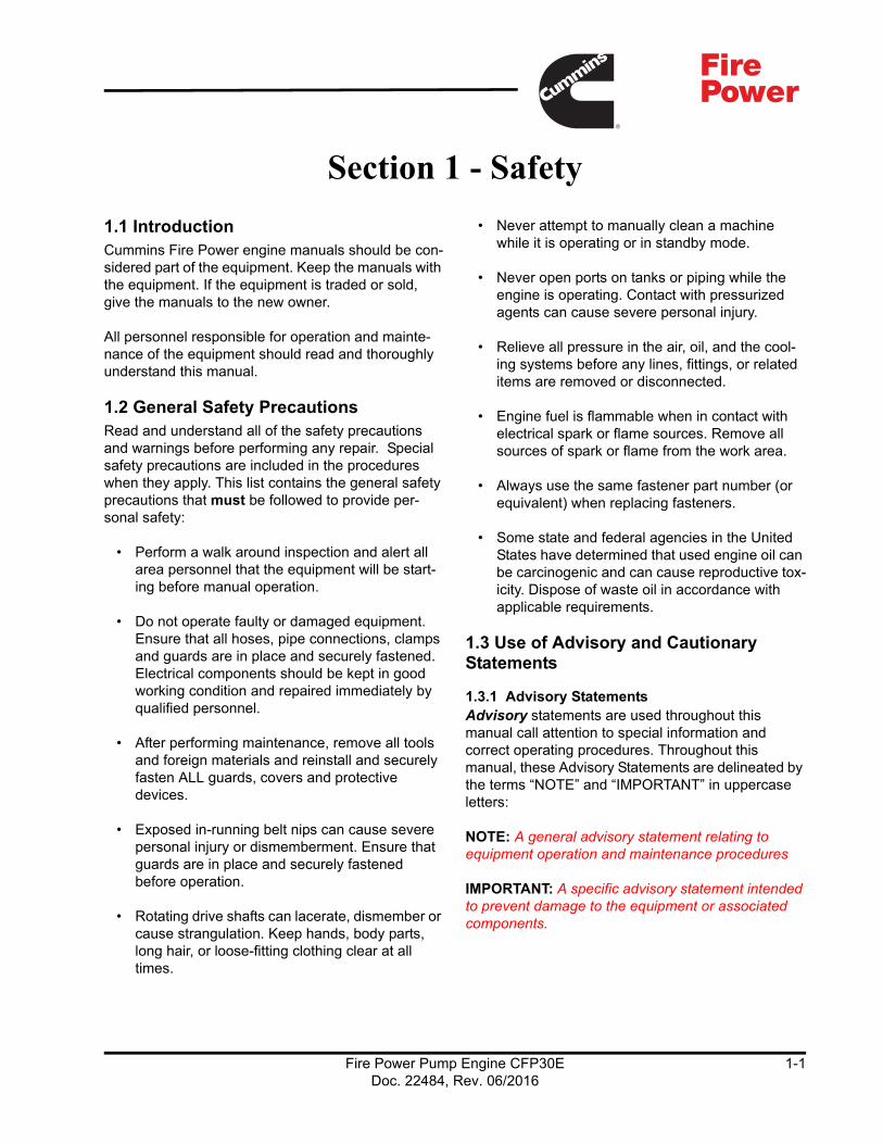
1.1 IntroductionCummins Fire Power engine manuals should be con-sidered part of the equipment. Keep the manuals with the equipment. If the equipment is traded or sold, give the manuals to the new owner.
All personnel responsible for operation and mainte-nance of the equipment should read and thoroughly understand this manual.
1.2 General Safety PrecautionsRead and understand all of the safety precautions and warnings before performing any repair. Special safety precautions are included in the procedures when they apply. This list contains the general safety precautions that must be followed to provide per-sonal safety:
• Perform a walk around inspection and alert all area personnel that the equipment will be start-ing before manual operation.
• Do not operate faulty or damaged equipment. Ensure that all hoses, pipe connections, clamps and guards are in place and securely fastened. Electrical components should be kept in good working condition and repaired immediately by qualified personnel.
• After performing maintenance, remove all tools and foreign materials and reinstall and securely fasten ALL guards, covers and protective devices.
• Exposed in-running belt nips can cause severe personal injury or dismemberment. Ensure that guards are in place and securely fastened before operation.
• Rotating drive shafts can lacerate, dismember or cause strangulation. Keep hands, body parts, long hair, or loose-fitting clothing clear at all times.
• Never attempt to manually clean a machine while it is operating or in standby mode.
• Never open ports on tanks or piping while the engine is operating. Contact with pressurized agents can cause severe personal injury.
• Relieve all pressure in the air, oil, and the cool-ing systems before any lines, fittings, or related items are removed or disconnected.
• Engine fuel is flammable when in contact with electrical spark or flame sources. Remove all sources of spark or flame from the work area.
• Always use the same fastener part number (or equivalent) when replacing fasteners.
• Some state and federal agencies in the United States have determined that used engine oil can be carcinogenic and can cause reproductive tox-icity. Dispose of waste oil in accordance with applicable requirements.
1.3 Use of Advisory and Cautionary Statements
1.3.1 Advisory StatementsAdvisory statements are used throughout this manual call attention to special information and correct operating procedures. Throughout this manual, these Advisory Statements are delineated by the terms “NOTE” and “IMPORTANT” in uppercase letters:
NOTE: A general advisory statement relating to equipment operation and maintenance procedures
IMPORTANT: A specific advisory statement intended to prevent damage to the equipment or associated components.
Fire Power Pump Engine CFP30EDoc. 22484, Rev. 06/2016
1-1
Safety
1.3.2 Cautionary StatementsCautionary Statements highlight particular safety precautions pertaining to personal injury and/or damage to the equipment. Cautionary Statements are always preceded by the following symbols:
WARNINGIndicates the presence of a hazard which CAN cause severe personal injury.
CAUTIONIndicates the presence of a hazard which CAN cause personal injury, or cause equipment damage.
Fire Power Pump Engine CFP30EDoc. 22484, Rev. 06/2016
1-2

Section 2 - Description
2.1 IntroductionThis manual contains information for the correct oper-ation and maintenance of a Cummins fire pump drive engine. Read and follow all safety instructions in Section 1 - Safety. Keep this manual with the equip-ment. If the equipment is traded or sold, give the manual to the new owner.
Cummins fire pump drive engines have been designed and tested in accordance with National Fire Protection Association (NFPA) 20 guidelines.
No deviations are permitted without prior written approval. These engines are to be used only for fire protection applications. Figure 2-1 and Figure 2-2 provide visual descriptions of the engine components for this fire pump drive engine.
NOTE: Refer to the Engine Data Sheet in Section 8 - Component Parts and Assemblies for emission levels.
Cummins Fire Power, Cummins NPower, and Cummins Inc. reserve the right to make changes at any time. If any differences are found between an engine and the information in this manual, contact the local Cummins Authorized Repair Location.
The latest technology and the highest quality compo-nents were used to produce this engine. When replacement parts are needed, we recommend using
only genuine Cummins or ReCon® exchange parts.
WARNINGInjury may result and warranty is voided if fuel rate, revolutions per minute (RPM), or altitudes exceed published maximum values for this model and application.
2.2 Fire Pump Digital Panel (FPDP)The Fire Pump Digital Panel (FPDP) is mounted on the left hand side (or right hand side - optional) on the flywheel end of the engine and contains controls for starting the engine, monitoring engine performance, and controlling fire pump drive engine operation. Section 4 - Controls illustrates the FPDP in detail.
Each engine is equipped with an electronic over-speed control which activates the fuel pump solenoid valve or the Engine Control Module (ECM) ignition to shut off the engine when the RPM exceeds a preset limit of 115% of rated speed. The overspeed control senses engine speed during the start cycle and stops the starting motor cranking cycle.
All Cummins fire pump drive engines are shipped from the factory adjusted to the requested operating speed (in RPM). Final operating speed adjustment must be made during the in-service inspection to obtain the required operating speed specified by the pump manufacturer.
2.3 Fire Pump ControllerThe fire pump controller starts the engine automati-cally when a remote fire demand signal is initiated and automatically shuts down the engine when the fire demand signal is discontinued. The engine may also be started locally in the MANUAL mode and shut down using the FPDP STOP button. The fire pump controller is not supplied by Cummins Fire Power or Cummins Inc.
Fire Power Pump Engine CFP30EDoc. 22484, Rev. 06/2016
2-1
Description
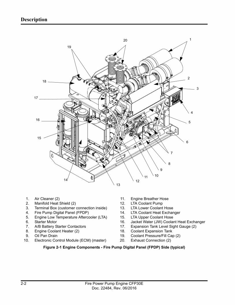
1. Air Cleaner (2)2. Manifold Heat Shield (2)3. Terminal Box (customer connection inside)4. Fire Pump Digital Panel (FPDP)5. Engine Low Temperature Aftercooler (LTA)6. Starter Motor7. A/B Battery Starter Contactors8. Engine Coolant Heater (2)9. Oil Pan Drain
10. Electronic Control Module (ECM) (master)
11. Engine Breather Hose12. LTA Coolant Pump13. LTA Lower Coolant Hose14. LTA Coolant Heat Exchanger15. LTA Upper Coolant Hose16. Jacket Water (JW) Coolant Heat Exchanger17. Expansion Tank Level Sight Gauge (2)18. Coolant Expansion Tank19. Coolant Pressure/Fill Cap (2)20. Exhaust Connection (2)
Figure 2-1 Engine Components - Fire Pump Digital Panel (FPDP) Side (typical)
1
2
3
4
5
6
7
8
9
101112
13
14
15
16
17
18
20
19
Fire Power Pump Engine CFP30EDoc. 22484, Rev. 06/2016
2-2
Description
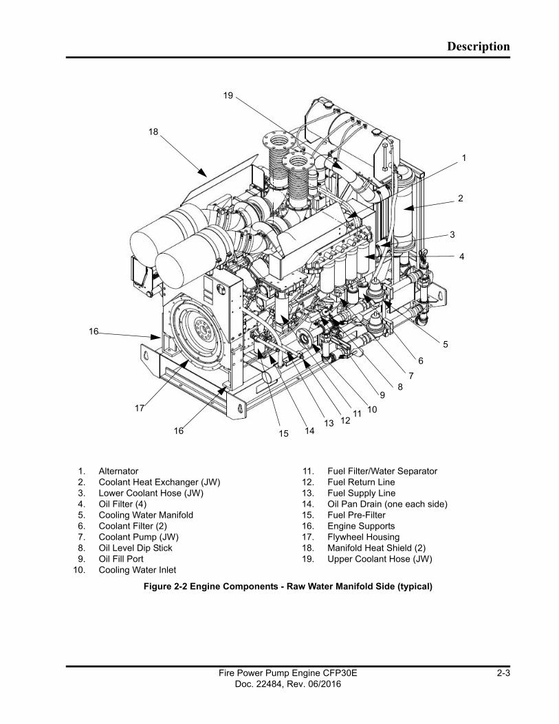
1. Alternator2. Coolant Heat Exchanger (JW)3. Lower Coolant Hose (JW)4. Oil Filter (4)5. Cooling Water Manifold6. Coolant Filter (2)7. Coolant Pump (JW)8. Oil Level Dip Stick9. Oil Fill Port
10. Cooling Water Inlet
11. Fuel Filter/Water Separator12. Fuel Return Line13. Fuel Supply Line14. Oil Pan Drain (one each side)15. Fuel Pre-Filter16. Engine Supports17. Flywheel Housing18. Manifold Heat Shield (2)19. Upper Coolant Hose (JW)
Figure 2-2 Engine Components - Raw Water Manifold Side (typical)
1
2
3
4
5
6
78
9
10111213
141516
17
16
18
19
Fire Power Pump Engine CFP30EDoc. 22484, Rev. 06/2016
2-3
Description
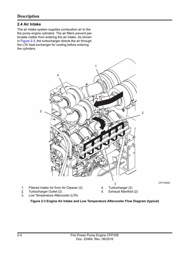
2.4 Air IntakeThe air intake system supplies combustion air to the fire pump engine cylinders. The air filters prevent par-ticulate matter from entering the air intake. As shown in Figure 2-3, the turbocharger directs the air through the LTA heat exchanger for cooling before entering the cylinders.
1. Filtered Intake Air from Air Cleaner (2)2. Turbocharger Outlet (2)3. Low Temperature Aftercooler (LTA)
4. Turbocharger (2)5. Exhaust Manifold (2)
Figure 2-3 Engine Air Intake and Low Temperature Aftercooler Flow Diagram (typical)
1
2
3
4
5
CFP-00069
Fire Power Pump Engine CFP30EDoc. 22484, Rev. 06/2016
2-4

Description
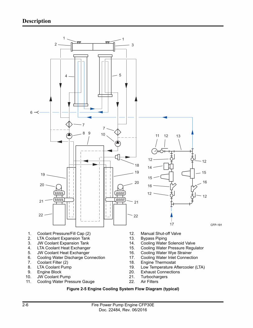
2.5 Cooling Water SystemThe fire pump cooling water supply provides cooling water for the LTA heat exchanger and the JW coolant heat exchanger.
As shown in Figure 2-4 and Figure 2-5, cooling water entering the cooling system through the cooling water inlet circulates through the heat exchanger for the LTA system, cooling the compressed air from the tur-bocharger before it enters the combustion chamber. The cooling water from the LTA heat exchanger then enters the JW heat exchanger for the engine cooling system. The cooling water exits the JW heat exchanger (engine) through the drain line. Figure 2-5 shows the path of water through the engine cooling system.
NOTE: The cooling water supply must be immedi-ately available when the engine is started.
IMPORTANT: Cooling water piping will be supplied by Cummins Fire Power as shown in the drawings in Section 8 - Component Parts and Assemblies. Refer to NFPA 20 for installation requirements.
When the cooling water piping is installed:
1. Adjust both pressure regulator set points of the cooling water manifold before operating the pump.
2. Ensure that the cooling water bypass line valve is closed.
1. Bypass Water Pressure Regulator2. Bypass Water Strainer3. Pre Strainer Pressure Sensor4. Cooling Water Inlet5. Normal Water Inlet Valve6. Bypass Water Inlet Valve7. Normal Water Strainer
8. Post Strainer Pressure Sensor9. Normal Water Pressure Regulator
10. Normal Water Solenoid Valve11. Outlet to Heat Exchanger12. Temperature Sensor13. Pressure Gauge Isolation Valve14. Water Supply Pressure Gauge
Figure 2-4 Cooling Water Manifold (typical)
Fire Power Pump Engine CFP30EDoc. 22484, Rev. 06/2016
2-5
Description
1. Coolant Pressure/Fill Cap (2)2. LTA Coolant Expansion Tank3. JW Coolant Expansion Tank4. LTA Coolant Heat Exchanger5. JW Coolant Heat Exchanger6. Cooling Water Discharge Connection7. Coolant Filter (2)8. LTA Coolant Pump9. Engine Block
10. JW Coolant Pump11. Cooling Water Pressure Gauge
12. Manual Shut-off Valve13. Bypass Piping14. Cooling Water Solenoid Valve15. Cooling Water Pressure Regulator16. Cooling Water Wye Strainer17. Cooling Water Inlet Connection18. Engine Thermostat19. Low Temperature Aftercooler (LTA)20. Exhaust Connections21. Turbochargers22. Air Filters
Figure 2-5 Engine Cooling System Flow Diagram (typical)
20
21
22
18
19
20
21
22
19
14
1515
17
4 5
6
79
7
10 118
1 12 3
12
12 12
1212
1616
13
CFP-191
Fire Power Pump Engine CFP30EDoc. 22484, Rev. 06/2016
2-6
Description
3. Ensure that the normal water inlet line valve is open.The line with the solenoid valve is the normal inlet line.
4. Ensure that the pressure gauge isolation valve is open.
IMPORTANT: Monitor the oil pressure and coolant temperature gauges frequently. Refer to Lubricating Oil System Specifications or Cooling System Specifi-cations in the Engine Data Sheet in Section 8 - Com-ponent Parts and Assemblies for recommended operating pressures and temperatures. Shut off the engine if any pressure or temperature does not meet the specifications.
NOTE: Maximum engine coolant temperature should not exceed the temperature listed on the Engine Data Sheet found in Section 8 - Component Parts and Assemblies. The coolant expansion pressure/fill cap must meet the minimum pressure of 10 kPa (15 psi).
The engine coolant system contains a mixture of at least 50% antifreeze and 50% water. The coolant level should be maintained so it is visible in the coolant level sight gauge.
CAUTIONContinuous operation with low coolant tempera-ture (below 71° C [160° F]) or high coolant tem-perature (above 100° C [212° F]) can damage the engine. Verify cooling water pressure and flow to maintain a consistent operating temperature.
2.6 Fuel Supply and DrainThe fuel supply and return connections are centrally located on the FPDP side. Refer to the Engine Data Sheet in Section 8 - Component Parts and Assem-blies for the maximum allowable fuel tank supply locations above the fuel pump.
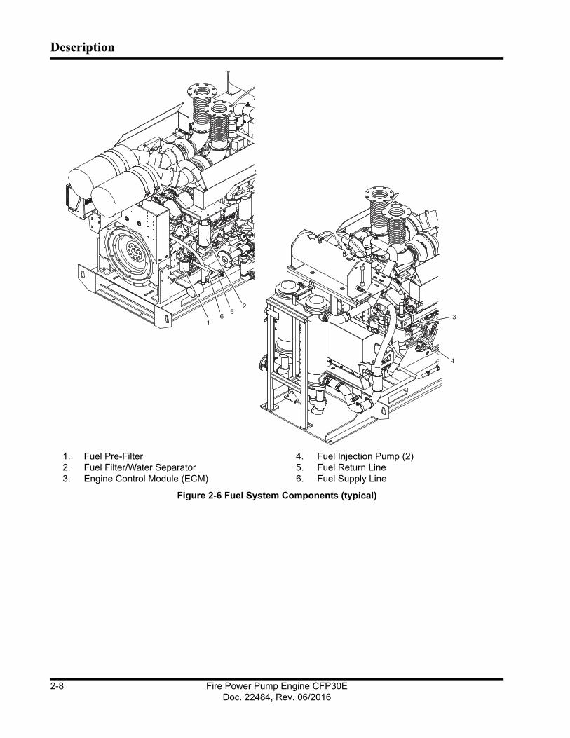
2.7 High Pressure Injector (HPI) Fuel Sys-tem The CFP30E comes with a gear type fuel pump driven by the engine.
As shown in Figure 2-6, the fire pump drive engine is equipped with an electronic fuel system that delivers precise fuel quantities with precise injection timing at high injection pressures. The system consists of six (6) high-pressure unit injectors and the fuel supply system uses various system monitoring sensors. The system is controlled by engine control modules (ECMs) for fueling and timing based on temperature, altitude, pressure, and throttle position.
With the HPI fuel system, fuel priming is required for conditions such as: initial start-up, running out of fuel, and maintenance of fuel system components (i.e., filter change).
Fire Power Pump Engine CFP30EDoc. 22484, Rev. 06/2016
2-7
Description
1. Fuel Pre-Filter2. Fuel Filter/Water Separator3. Engine Control Module (ECM)
4. Fuel Injection Pump (2)5. Fuel Return Line6. Fuel Supply Line
Figure 2-6 Fuel System Components (typical)
25
61
3
4
Fire Power Pump Engine CFP30EDoc. 22484, Rev. 06/2016
2-8

Description
2.8 Engine Oil SystemFigure 2-7 illustrates how the engine oil system lubri-cates moving internal engine parts (pistons, piston arms, valves, cam shafts, shafts, and bearings). The oil pump circulates oil from the oil pan, through the oil filter, and into engine areas where friction may develop. Refer to the Cummins Engine Operation and Maintenance Manual for additional information.
NOTE: Typically engine oil has been added during manufacture and testing procedures; however, shipping restrictions can affect whether the oil is maintained in the engine or drained for shipping. Check the oil level at the dipstick. Add oil as neces-sary to bring the oil level to the H (high) mark on the dipstick.
1. Oil Pump2. Pressure Regulator Valve3. Oil Return to Pan4. High Pressure Relief Valve5. Oil Return to Pan6. Oil Thermostat
7. Oil Cooler8. Combination Oil Filter9. Filter Bypass Gears
10. Idler Gears11. Viscosity Sensor12. Turbocharger
Figure 2-7 Engine Lubricating Oil System Flow Diagram (typical)
1234
7
5
8
9
10
12
6
11
CFP-010
Fire Power Pump Engine CFP30EDoc. 22484, Rev. 06/2016
2-9

Description
This page is intentionally left blank.
2.9 Exhaust SystemFigure 2-8 shows how the exhaust system removes engine exhaust from the cylinders after the combus-
tion process. The exhaust discharges from the exhaust manifold, passes through (drives) the turbo-charger, and exits through the exhaust connection.
1. Exhaust Manifold2. Turbocharger Turbine Housing
3. To Exhaust Connection
Figure 2-8 Flow Diagram - Exhaust System (typical)
2
1
3
CFP-192
Fire Power Pump Engine CFP30EDoc. 22484, Rev. 06/2016
2-10

Section 3 - Installation
3.1 IntroductionThis section provides instructions for the initial installation, adjustment, and testing of the Cummins fire pump drive engine. Appropriate portions of this section should be used when returning the engine to operation after overhaul or major maintenance.
3.2 Receiving and HandlingCummins Fire Power fire pump drive engines are pre-assembled and tested before shipment. Parts not shipped attached to the engine are sometimes shipped individually. The equipment was thoroughly inspected and prepared for shipping before it was turned over to the carrier. Upon receipt of the fire pump drive engine from the shipper:
1. Inspect the equipment for damage that may have occurred in shipping; and
2. Check each item carefully against the shipping manifest or bill of lading.
3.3 Site PreparationThe site should be clean and relatively level. Clear the proposed equipment area of overhanging obstructions and obstacles protruding from the floor.
CAUTIONAvoid installation in a dusty or dirty environment. Provide adequate physical protection from other physical damage as may be present in the specific location.
3.4 Drive Shaft InstallationDrive shaft installation should be done by trained technicians familiar with local, state, and federal codes and regulations.
Refer to National Fire Protection Association (NFPA) 20 for installation and applicable local code require-ments and NFPA 25 for inspection, testing, and main-tenance requirements.
Follow these steps to install the drive shaft:
CAUTIONEnsure that the lifting device is capable of safely lifting the weight of the engine or the combined weight of the assembled pump base, drive line, and pump. Do not use the engine lifting points for assembly!
1. Ensure that the engine and pump are correctly aligned.
a. Ensure that the engine position is centered on the frame side to side within ± .76 mm (.03 in) by measuring outside of the frame side to the engine support leg mounting pad. (Com-pare the two front engine supports and two back engine supports.)
b. As shown in Figure 3-1, align the engine center line to the pump center line within ± .76 mm (.03 in).
c. Ensure that the pump center line to the engine crankshaft center line (in vertical plane) is 2° +/- 1°.
d. Ensure that the drive shaft mounting flanges are parallel.
2. As illustrated in Figure 3-2, lubricate the grease fittings on the drive shaft universal joint.
3. Check that the fire pump drive engine is properly installed per the pump manufacturer’s specifica-tions.
Fire Power Pump Engine CFP30EDoc. 22484, Rev. 06/2016
3-1

Installation
1. Planes must be parallel2. Align both mounting center lines to ± .76 mm
(.03 in)3. Distance to equal half of total travel4. 2° +/- 1°
Figure 3-1 Drive Shaft Alignment
Figure 3-2 Drive Shaft Universal Joint Grease Fit-tings
NOTE: Cummins Fire Power or Cummins Inc. recom-mends using a good quality semi-synthetic, molybde-num-fortified National Lubricating Grease Institute (NLGI) #2 lithium complex grease.
NOTE: Some lubrication loss may occur during trans-port and storage. It is recommended that the drive shaft be re-lubricated upon installation.
3.5 Fuel Supply InstallationThe following sections outline proper installation and connection of the fuel supply.
NOTE: It is the responsibility of the customer to provide and install a properly-rated fuel tank per NFPA 20 guidelines.
To properly install a fuel supply, follow these intstruc-tions:
1. Install an elevated no. 2 diesel fuel tank or other fuel supply arrangement which is compatible with American Society of Testing and Materials (ASTM) no. 2 diesel fuel specifications.
NOTE: The fuel supply line at the fuel tank must be higher than the fuel intake port on the engine fuel filter. Ensure that the fuel system is installed in a safe and effective manner.
2. Size the fuel tank for the maximum expected full-load engine operation period with the initial fuel level at the minimum level for refueling.
3. Install a fuel return line and route this line to the bottom of the fuel tank in order to minimize the return head.
4. Install a fuel supply line to the fire pump drive engine.
NOTE: For fuel line specifications, refer to the Engine Data Sheet in Section 8 - Component Parts and Assemblies.
NOTE: DO NOT use copper or galvanized pipe for the fuel return or supply lines.
The fire pump drive engine fuel system has been primed during manufacturing and test procedures. The engine is equipped with an engine driven (gear) fuel pump.
An optional fuel pre-filter and a fuel filter/water sep-arator is integrated into the fuel delivery system of the fire pump drive engine. To ensure that the filter/sep-arator is free of water, open the fuel filter/water sep-arator drain at the bottom of the filter and drain the fuel into a container until no water is present. Dispose
2
4
1
3
90°
TOP
SIDE
90°
CFP-013
CFP-015CFP-015
Fire Power Pump Engine CFP30EDoc. 22484, Rev. 06/2016
3-2

Installation
of the contaminated fuel in accordance with local environmental regulations.
CAUTIONDue to the precise tolerances of diesel injection systems, it is extremely important that the fuel be kept clean and free of dirt or water. Dirt or water in the system can cause severe damage to both the fuel pump and the fuel injectors.
WARNINGDo not mix gasoline, alcohol, gasohol, ethanol, or methanol with diesel fuel. This mixture will cause severe engine damage or explosion.
CAUTIONUse ONLY no. 2 diesel (ASTM no. 2D) fuel. Any adjustment to compensate for reduced perfor-mance with a fuel system using alternate fuel is not warrantable.
3.6 Cooling Water Supply Installation IMPORTANT: The cooling water supply must be immediately available when the engine is started. Ensure that the supply line valves are in the OPEN position.
NOTE: The velocity of the cooling water should be as great as possible without exceeding the maximum allowable pressure shown in the Engine Data Sheet in Section 8 - Component Parts and Assemblies.
To install the cooling water supply:
1. Provide a cooling water discharge line at the out-let of the engine coolant heat exchanger and provide a cooling water supply line to the cooling water inlet per the Engine Data Sheet in Section 8 - Component Parts and Assemblies.
NOTE: The cooling water outlet piping from the heat exchanger should be one pipe size larger than the supply piping.
2. Check the pressure regulator setting on the cooling loop with water flowing through the heat exchanger. The cooling loop is supplied by Cummins Fire Power; both water pressure regu-lators have been set at 207 kPa (30 psi) (or slightly less) water pressure during manufacture and testing.
IMPORTANT: The manual water valves for the auto-matic loop should remain OPEN at ALL times. The manual valves for the bypass loop should be CLOSED during automatic (pump controller) opera-tion. When running, the engine should stabilize between temperatures identified on the Engine Data Sheet. The flow rate may need to be adjusted to maintain the desired engine temperature.
NOTE: Excessively cold (4 °C to 23 °C [40 °F to 75 °F]) cooling water flow can cause condensation inside the charge air cooler.
IMPORTANT: Continuous operation with low coolant temperature (below 70 °C [158 °F]) or high coolant temperature (above 107 °C [225 °F]) can damage the engine.
3. Adjust the cooling water based on the water flow rather than the water pressure. The flow is dependent on the cooling water temperature. Refer to the Engine Data Sheet in Section 8 - Component Parts and Assemblies for details.
4. To measure the water flow, use an appropriate-sized container to measure the amount of water and the elapsed time of the water to flow from the discharge pipe and then formulate the calcu-lations:
Flow rate = container size/ time to fill container.
Example:
Time to fill a 20 gallon container = 15 seconds.
20 gallons divided by 15 seconds = 1.33 gallons per second.
Multiply by 60 seconds = 80 gallons per minute (gpm) (FLOW RATE)
5. Adjust both pressure regulators to a pressure that will provide a flow rate at or above the spec-ifications listed in the Engine Data Sheet.
CAUTIONWhen the cooling water piping is installed, adjust both of the pressure regulator set points before operating the pump. Damage to the heat exchanger may occur from improperly regulated cooling water supply pressure.
Fire Power Pump Engine CFP30EDoc. 22484, Rev. 06/2016
3-3
Installation
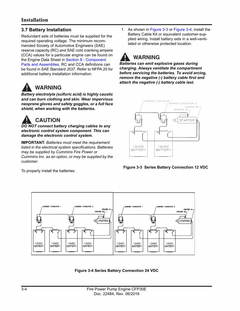
3.7 Battery InstallationRedundant sets of batteries must be supplied for the required operating voltage. The minimum recom-mended Society of Automotive Engineers (SAE) reserve capacity (RC) and SAE cold cranking ampere (CCA) values for a particular engine can be found on the Engine Data Sheet in Section 8 - Component Parts and Assemblies. RC and CCA definitions can be found in SAE Standard J537. Refer to NFPA 20 for additional battery installation information.
WARNINGBattery electrolyte (sulfuric acid) is highly caustic and can burn clothing and skin. Wear impervious neoprene gloves and safety goggles, or a full face shield, when working with the batteries.
CAUTIONDO NOT connect battery charging cables to any electronic control system component. This can damage the electronic control system.
IMPORTANT: Batteries must meet the requirement listed in the electrical system specifications. Batteries may be supplied by Cummins Fire Power or Cummins Inc. as an option, or may be supplied by the customer.
To properly install the batteries:
1. As shown in Figure 3-3 or Figure 3-4, install the Battery Cable Kit or equivalent customer-sup-plied wiring. Install battery sets in a well-venti-lated or otherwise protected location.
WARNINGBatteries can emit explosive gases during charging. Always ventilate the compartment before servicing the batteries. To avoid arcing, remove the negative (-) battery cable first and attach the negative (-) battery cable last.
Figure 3-3 Series Battery Connection 12 VDC
Figure 3-4 Series Battery Connection 24 VDC
Fire Power Pump Engine CFP30EDoc. 22484, Rev. 06/2016
3-4

Installation
2. Provide adequate room for servicing or replacing the batteries. Provide protection from extremes of temperature and weather.
3. Locate the batteries near the engine or increase the size of the conductors as required by appli-cable codes. Ensure that the batteries are con-figured properly for 12 - or 24 - VDC standard operations.
4. Check the battery cables and connections.
NOTE: Coat the terminals with petroleum jelly to prevent corrosion. Install the cables and tighten the battery connections.
3.8 Signal and Control InstallationThe fire pump controller wires must be connected to the terminal blocks (TBs) on the FPDP Interface Ter-minal Strip (shown in Figure 3-5). To complete the signal and control installation:
1. Ensure that the fire pump controller is properly installed and configured per the manufacturer’s instructions.
2. Complete the fire pump controller wiring (cus-tomer-supplied) per the manufacturer’s instruc-tions.
3. Ensure electrical continuity and adequate insula-tion resistance for the installed wiring.
4. The TBs between the fire pump controller and the FPDP Interface Strip are standard UL and FM controller terminals and follow a direct one-to-one correspondence (some TBs are optional):
a. TB-1 [Run Solenoid Circuit]: This power source is necessary for fire pump operations while in the AUTO mode.
b. TB-2 [Crank Termination Switch]: This signal is present when the engine is running. This signal indicates that the engine has started and that the crank command from the fire pump controller should stop immediately.
c. TB-3 [Overspeed Switch]: This signal is present when the overspeed control module has operated. If this event occurs, the fire pump drive engine will stop.
Figure 3-5 FPDP Interface Terminal Strip
d. TB-4 [Low Lubricant Pressure Switch]: This zero VDC grounded signal is present when the oil pressure has dropped below the 83 ± 13 kPa (12 ± 2 psi) set point.
e. TB-5 [High Engine Temperature Signal]: This zero VDC grounded signal is activated when the engine is running and the coolant temperature is at or above 93 °C (200 °F). The alarm will deactivate when the engine is
Fire Power Pump Engine CFP30EDoc. 22484, Rev. 06/2016
3-5

Installation
running and the coolant temperature drops below 88 °C (190 °F).
f. TB-6 [Battery One Positive]: The fire pump controller senses Battery A charge state and charges Battery A through this heavy gauge wire.
g. TB-8 [Battery Two Positive]: The fire pump controller senses Battery B charge state and charges Battery B through this heavy gauge wire.
h. TB-9 [Main Battery Contactor One Coil or Battery Relay One Coil]: The battery posi-tive signal is driven from the fire pump con-troller to contactor A when desiring to crank from Battery A. Current in this circuit shall not exceed 10A continuous.
i. TB-10 [Main Battery Contactor Two Coil or Battery Relay Two Coil]: The battery posi-tive signal is driven from the fire pump con-troller to contactor B when desiring to crank from Battery B. Current in this circuit shall not exceed 10A continuous.
j. TB-11: Connect the common ground and battery negative for both Battery A and Battery B from between the fire pump control-ler and engine. This is not intended to create a fully isolated battery negative or ground system. Current in this circuit shall not exceed 20A continuous.
NOTE: Terminals 301 through 312 shall be electri-cally isolated from the ECM.
k. TB-301 [Electronic Control Module Switch]: Battery negative signal driven from the FPDP when the engine is operating on Engine Control Module (ECM) B.
l. TB-302 [Fuel Injection Malfunction]: Battery negative signal driven from the FPDP when either of the ECMs triggers a fault code which can affect performance of the Fuel Injection System. See Section 7 - Trouble-shooting for possible fault causes and solu-tions.
m. TB-303 [Electronic Control Module Warning]: Battery negative signal driven
from the FPDP when a single ECM has failed.
n. TB-304 [Electronic Control Module Failure]: Battery negative signal driven from the FPDP when both ECMs have failed.
o. TB-310 [Raw Water High Inlet Tempera-ture]: Battery negative signal driven from the FPDP when high raw water temperature is sensed.
p. TB-311 [Clogged Raw Water Coolant Loop Strainer] - not applicable on radiator-cooled models: Battery negative signal driven from the FPDP when the raw water supply restric-tion is sensed.
q. TB-312 [Low Engine Temperature Signal]: Battery negative signal driven from an engine temperature switch when engine coolant reaches or falls below 43.3 ± 2.78 °C (110 ± 5 °F). The signal will be removed when the coolant temperature reaches or exceeds 60 ± 2.78 °C (140 ± 5 °F).
5. Provide the initial charge on the redundant bat-teries per the battery charger’s instructions.
6. Check that both voltmeters on the FPDP indicate the approximate battery voltage. Both sets of batteries can be used for starting the engine in the event that one set is low.
3.9 Coolant System PreparationThe fire pump drive engine cooling and lubrication system was initially filled during manufacture and testing. To properly prepare the coolant system:
CAUTIONEnsure that all coolant systems have been filled to the proper level before operation by checking the coolant level sight gauge on the heat exchanger.
1. Inspect the engine coolant hoses and hose clamps and ensure that all coolant hoses and clamps are properly installed and water tight.
2. Ensure that the engine coolant heater maintains an engine coolant temperature of 49 °C (120 °F) or above.
Fire Power Pump Engine CFP30EDoc. 22484, Rev. 06/2016
3-6

Installation
3. Ensure that coolant is present in the engine coolant heater before plugging the heater element into a dedicated circuit.
WARNINGDo not remove the pressure/fill cap from a hot engine. Wait until the coolant temperature is below 50 °C (122 °F) before removing the pres-sure/fill cap. Heated coolant spray or steam can cause personal injury.
3.10 Charge Air Cooler (CAC) InspectionThe charge air cooler (CAC) system reduces the tem-perature of the compressed combustion air from the turbocharger before entering the air intake manifold.
Inspect the CAC piping and hoses for loose/missing hose clamps, hose punctures, leaking manifold seals, or corrosion. Torque the hose clamps to the recom-mended torque value. Refer to the Engine Data Sheet in Section 8 - Component Parts and Assem-blies.
3.11 Lubricating Oil System PreparationThe fire pump drive engine and turbocharger were initially lubricated during manufacture and testing. To prepare the lubricating oil system for operation:
1. Check the oil level using the dip stick before operating the fire pump drive engine.
2. Fill the oil fill port to the “H” mark on the dipstick with lubricating oil.
NOTE: Do not use special “break-in” lubricating oils for new or rebuilt Cummins engines. Use the same type of oil during the “break-in” as used during normal operation.
CAUTIONSome regulatory and shipping restrictions may require that all lubricants, fuels, and coolants be drained for transport. Ensure that all cooling and lubrication systems have been filled to the proper level before operation.
NOTE: Using multi-viscosity lubricating oil can improve oil consumption control and improve engine cranking in cold temperatures while maintaining lubri-
cation at high operating temperatures. Cummins Inc. recommends Premium Blue® 15W-40 oil for most cli-mates.
CAUTIONEnsure that all cooling and lubrication systems have been filled to the proper level before opera-tion.
3.12 Pre-Start InspectionsPrior to starting the fire pump drive engine for the first time, perform a visual inspection:
1. Check that there is no apparent damage and that all components are installed.
2. Check that the drive belt is properly installed.
3. Check that all hoses and tubes are properly installed.
4. Check that all electrical connections are properly installed.
5. Check that the fire pump drive engine is properly installed per the pump manufacturer’s instruc-tions, is correctly aligned, and is free to rotate.
6. Lubricate the grease fittings on the auxillary drive shaft.
NOTE: Use the same type of oil as used in normal operation. Cummins Inc. recommends Premium Blue® 15W-40 oil for most climates.
After completing preliminary set-up procedures, perform the engine start test as outlined in detail in Section 5 - Operation.
WARNINGBefore operating the equipment, complete all safety checks, remove all tools and foreign objects from the equipment, and ensure that all guards are in place and securely fastened. Alert area personnel that the equipment will be start-ing. Unintentional equipment start-up or contact with exposed or moving components can cause personal injury or equipment damage.
Fire Power Pump Engine CFP30EDoc. 22484, Rev. 06/2016
3-7

Installation
CAUTIONIf the oil pressure is not displayed on the gauge or if the low oil pressure message is displayed within fifteen seconds, STOP THE ENGINE IMME-DIATELY! Continued operation without proper lubrication will cause engine damage.
3.13 Engine MonitoringWhen the engine starts, it is important to monitor the displays:
1. Immediately check that water flow is established through the coolant heat exchanger. The water flow should be established immediately, but some delay may occur before the flow exits the heat exchanger drain connection.
NOTE: Ensure that cooling water is flowing through the heat exchanger and the water pressure shown on the local pressure gauge is no more than 414 kPa (60 psi). The minimum cooling water flow rate is identified in the Engine Data Sheet in Section 8 - Component Parts and Assemblies.
2. Ensure that the engine operating temperature stabilizes between applicable ranges as identi-fied in the Engine Data Sheet in Section 8 - Component Parts and Assemblies.
3. Operate the engine for eight to ten minutes.
4. Inspect the engine for leaks, unusual noises, or other indications of incorrect operation.
5. Shut off the engine by pressing and holding the overspeed RESET/STOP switch.
6. Shortly after the engine stops, check that the water flow stops automatically.
7. Correct any problems found during the inspec-tion before proceeding.
8. Check the engine lubricating oil level at the dip stick. Add oil, if necessary.
9. Check the coolant expansion tank level. Add coolant, if necessary.
10. Check the cooling water strainers. Clean the strainers according to the maintenance schedule in Section 6 - Maintenance.
11. Perform engine speed control and safety system tests per the instructions in Section 5 - Opera-tion.
3.14 Field Acceptance TestingThe required installation tests are outlined in the NFPA 20 Standards and shall be performed to vali-date automatic and manual operational requirements for field acceptance testing.
Fire Power Pump Engine CFP30EDoc. 22484, Rev. 06/2016
3-8
Section 4 - Controls
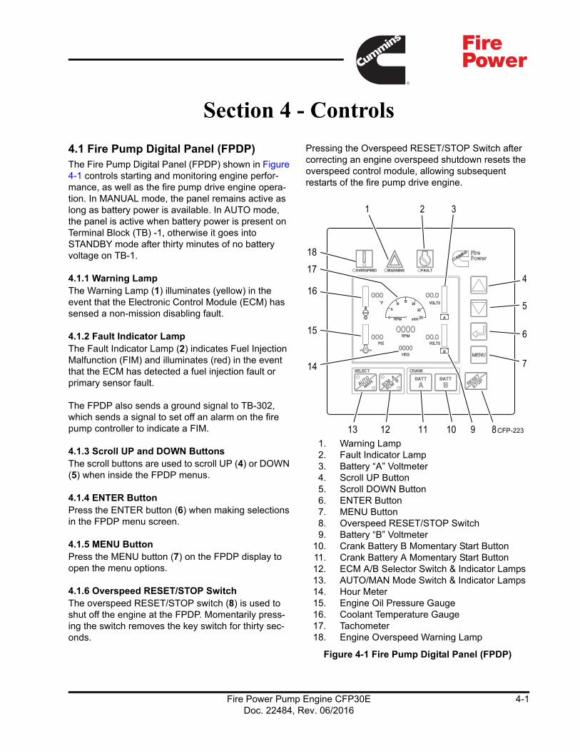
4.1 Fire Pump Digital Panel (FPDP)The Fire Pump Digital Panel (FPDP) shown in Figure 4-1 controls starting and monitoring engine perfor-mance, as well as the fire pump drive engine opera-tion. In MANUAL mode, the panel remains active as long as battery power is available. In AUTO mode, the panel is active when battery power is present on Terminal Block (TB) -1, otherwise it goes into STANDBY mode after thirty minutes of no battery voltage on TB-1.
4.1.1 Warning LampThe Warning Lamp (1) illuminates (yellow) in the event that the Electronic Control Module (ECM) has sensed a non-mission disabling fault.
4.1.2 Fault Indicator LampThe Fault Indicator Lamp (2) indicates Fuel Injection Malfunction (FIM) and illuminates (red) in the event that the ECM has detected a fuel injection fault or primary sensor fault.
The FPDP also sends a ground signal to TB-302, which sends a signal to set off an alarm on the fire pump controller to indicate a FIM.
4.1.3 Scroll UP and DOWN ButtonsThe scroll buttons are used to scroll UP (4) or DOWN (5) when inside the FPDP menus.
4.1.4 ENTER ButtonPress the ENTER button (6) when making selections in the FPDP menu screen.
4.1.5 MENU ButtonPress the MENU button (7) on the FPDP display to open the menu options.
4.1.6 Overspeed RESET/STOP SwitchThe overspeed RESET/STOP switch (8) is used to shut off the engine at the FPDP. Momentarily press-ing the switch removes the key switch for thirty sec-onds.
Pressing the Overspeed RESET/STOP Switch after correcting an engine overspeed shutdown resets the overspeed control module, allowing subsequent restarts of the fire pump drive engine.
1. Warning Lamp2. Fault Indicator Lamp3. Battery “A” Voltmeter4. Scroll UP Button 5. Scroll DOWN Button6. ENTER Button7. MENU Button8. Overspeed RESET/STOP Switch9. Battery “B” Voltmeter
10. Crank Battery B Momentary Start Button11. Crank Battery A Momentary Start Button12. ECM A/B Selector Switch & Indicator Lamps13. AUTO/MAN Mode Switch & Indicator Lamps14. Hour Meter15. Engine Oil Pressure Gauge16. Coolant Temperature Gauge17. Tachometer18. Engine Overspeed Warning Lamp
Figure 4-1 Fire Pump Digital Panel (FPDP)
CFP-22310111213
18
17
16
15
4
5
6
7
31
8
2
9
14
Fire Power Pump Engine CFP30EDoc. 22484, Rev. 06/2016
4-1

Controls
4.1.7 Battery “A” and “B” VoltmetersThe Battery “A” (3) and Battery “B” (9) Voltmeters display the charge status - or Voltage Direct Current (VDC) - of the relative battery connections.
4.1.8 TachometerThe Tachometer (17) displays the engine speed in revolutions per minute (RPM) whenever the engine is operating.
4.1.9 Hour MeterThe Hour Meter (14) maintains a running total of the hours of operation (run time).
4.1.10 ECM A/B Selector Switch and Indicator Lamps - Applicable on Electronic EnginesThe ECM A/B selector switch and indicator lamps (12) illuminate in yellow, indicating which ECM is being used to control the engine.
If ECM A (normal position) is selected, ECM A is con-trolling the engine.
If ECM B (alternate position) is selected, ECM B is controlling the engine, and the FPDP will send a ground signal to TB-301, which will send a signal to set off an alarm on the fire pump controller to indicate that the engine is operating on the alternate ECM.
4.1.11 Crank Battery A and B Momentary Start ButtonsThe Crank Battery A (11) and Crank Battery B (10) momentary start buttons initiate an immediate engine start (momentary start) using the selected A or B crank battery.
Crank A energizes battery contactor A and Crank B energizes battery contactor B, depending on which one is selected.
Both Crank A and Crank B buttons can be energized at the same time in the event both batteries are weak.
4.1.12 Automatic or Manual Mode of Operation Indicator The AUTO/MAN mode switch and indicator lamps (13) show whether the engine starts and is controlled by the operator (MANUAL) or by an automatic signal from the fire pump controller (AUTO). The lamp (yel-low) is illuminated on which mode is selected.
The MANUAL mode is typically used for engine setup, testing, and emergency and maintenance pro-cedures.
The AUTO mode is used to start the engine by the fire pump controller. In the AUTO mode, the fire pump drive engine shuts down upon loss of signal power from the fire pump controller.
4.1.13 Coolant Temperature GaugeThe Coolant Temperature Gauge (16) displays the engine coolant temperature in degrees Fahrenheit.
4.1.14 Engine Oil Pressure GaugeThe Engine Oil Pressure Gauge (15) displays the engine oil pressure in pounds per square inch (PSI). This gauge is independent of the low oil pressure alarm.
4.1.15 Engine Overspeed Warning LampThe overspeed control module monitors engine speed. If the engine RPM exceed 115% rated speed, the Engine Overspeed Warning Lamp (18) is illumi-nated (yellow).
The FPDP will send a power signal to TB-3, which will send a signal to set off an alarm on the fire pump con-troller, indicating that an overspeed condition has occurred.
The FPDP will automatically switch to MANUAL mode and will shut the engine down. After the over-speed has been reset by using the RESET/STOP switch on the FPDP, the engine operation will revert to the original AUTO mode position.
NOTE: The engine will not be allowed to restart auto-matically from the fire pump controller until the FPDP is reset.
4.1.16 ECM Fault Code Lamps - Applicable on Electronic EnginesThe amber engine warning lamp and the red engine shutdown lamp alert the operator of an engine mal-function:
• An illuminated amber lamp indicates an engine malfunction that requires timely operator atten-tion.
• An illuminated red lamp indicates an engine mal-function that requires immediate and decisive operator response.
Fire Power Pump Engine CFP30EDoc. 22484, Rev. 06/2016
4-2
Controls
A three- or four-digit diagnostic fault code will display on the FPDP which can then be used to help describe the engine malfunction. Refer to the Fault Code Chart in Section 7 - Troubleshooting.
4.1.17 Engine STOP ButtonThe Engine STOP Button is located on the left side of the FPDP enclosure and is used to stop the operation of the engine in either manual or automatic mode. The button must be pressed and held until the engine has shut down.
4.1.18 Engine Communications PortThe Engine Communications Port plug-in is located on the left side of the FPDP enclosure and is used for the communications connection port for Cummins InsiteTM.
NOTE: InsiteTM is a Cummins Inc. computer software tool used to monitor or report engine performance cri-teria.
4.1.19 Contractor Access PortThe contractor access knock-out is located on the lower side of the FPDP enclosure. This is the only 25.4 cm (1 in) knock-out provided for the installing contractor to connect the fire pump controller to the FPDP.
IMPORTANT: If this port is not used for the installa-tion, all warranty on the fire pump drive engine will be void.
4.1.20 Engine ECM Power Supply The Engine ECM Power Supply plug-in is located on the lower side of the FPDP enclosure. The power supply port supplies unswitched battery power to both ECM A and ECM B.
4.1.21 Engine Harness ConnectionLocated on the lower side of the FPDP, the Engine Harness Connection plug-in connects the panel to the
power source, start contactors, magnetic pick-up, alternator, and other engine-related functions con-trolled by the FPDP.
4.2 Electronic Control Module (ECM) - Applicable on Electronic EnginesThe ECM is an electronically operated fuel control system that also provides many operator and vehicle or equipment features. It processes all of the inputs and sends commands to the fuel system vehicle and engine control devices. The base functions of the control system include fueling and timing control, lim-iting the engine speed operating range between the low- and high-idle set points, and reducing exhaust emissions while optimizing engine performance.
The ECM uses inputs from the operator and its sensors to determine the fueling and timing required to operate at the desired engine speed.
The ECM performs diagnostic tests on most of its cir-cuits and will activate a fault code if a problem is detected in one of these circuits. Along with the fault code identifying the problem, a snapshot of the engine’s operating parameters at the time of fault activation is also stored in memory. Some fault codes will cause a diagnostic lamp to activate to signal the driver.
The ECM also communicates with service tools and some other controllers.
CAUTIONNormally, Cummins engines with ECMs have derate and shutdown protection calibrated into the ECM. However, when the ECM on a Cummins engine has no derate or shutdown protection, the engine will run to destruction. Therefore, preven-tive maintenance is essential.
Fire Power Pump Engine CFP30EDoc. 22484, Rev. 06/2016
4-3

Controls
This page is intentionally left blank.
Fire Power Pump Engine CFP30EDoc. 22484, Rev. 06/2016
4-4

Section 5 - Operation
5.1 IntroductionThis section outlines general operating information for starting and stopping the fire pump drive engine, as well as instructions for navigating the menu screens of the Fire Pump Digital Panel (FPDP). This manual is provided for your specific equipment and should be considered a part of that equipment. All personnel responsible for the operation and mainte-nance of the equipment should read and thoroughly understand this manual.
WARNINGBefore preparing the equipment for normal ser-vice, complete all safety checks, remove all tools and foreign objects from the equipment, ensure all guards are in place and securely fastened, and alert area personnel that the equipment will be starting.
5.2 Starting and Stopping ProceduresBy default, the fire pump will turn on automatically in the event of low system water pressure. The engine will continue to operate as long as the RUN signal is present. When the RUN signal is terminated by the fire pump controller, the engine will stop.
For testing purposes, the fire pump drive engine can be turned on and off locally using the buttons on the FPDP (see Figure 4-1), If the engine fails to start automatically in the event of a fire emergency, follow the Emergency Starting/Stopping Procedure outlined in Section 5.2.2.
5.2.1 Local Starting/Stopping ProcedureTo start the engine locally from the FPDP:
1. Press the AUTO/MAN mode switch on the FPDP to place the engine in MANUAL mode.
2. Press either the CRANK BATT A or CRANK BATT B button to start the engine.
The engine may be stopped locally by pressing the RESET/STOP button on the FPDP or by holding down the red ENGINE STOP button on the left side of the FPDP.
5.2.2 Emergency Starting/Stopping ProcedureThe engine will start automatically in the event of a fire emergency. However, if it fails to start automati-cally, the engine can be started locally. The following procedure outlines an emergency manual mode electrical start:
1. As shown in Figure 5-1, open the water bypass valves in the cooling water supply piping or the emergency cooling supply.
Figure 5-1 Fire Pump Drive Engine Bypass Valve
2. Verify that water is being discharged.
3. Press the AUTO/MAN mode switch on the FPDP to place the engine in MANUAL mode.
4. As shown in Figure 5-2, open the FPDP panel door and slide the keyswitch override to the “UP” position. Verify that the green LED next to the override switch is lit.
Fire Power Pump Engine CFP30EDoc. 22484, Rev. 06/2016
5-1

Operation
.
Figure 5-2 FPDP Override Switch
CAUTIONTo prevent damage to the starter, do not engage the starting motor more than fifteen seconds. Wait fifteen seconds between each attempt to start, up to six attempts.
5. As shown in Figure 5-4, press downward on either the Battery A or Battery B contactor lever to start the engine.
a. If crank contactor lever A does not engage the starter, repeat using crank contactor lever B.
b. Release the contactor lever immediately after the engine starts.
IMPORTANT: If the engine does not start after three attempts, check the fuel supply system. Absence of blue or white exhaust smoke during cranking indi-cates that no fuel is being delivered.
6. Check that the engine starts and operates at the rated speed.
NOTE: Engine oil pressure must be indicated on the gauge within fifteen seconds after starting.
The engine may be stopped locally by pressing the RESET/STOP button on the FPDP or by holding down the red ENGINE STOP button on the left side of the FPDP.
Figure 5-3 Do not switch to the alternate Electronic Control Module (ECM) while the engine is running.
1. Battery A Starter Contactor2. Battery B Starter Contactor
Figure 5-4 Manual Starter Contactors
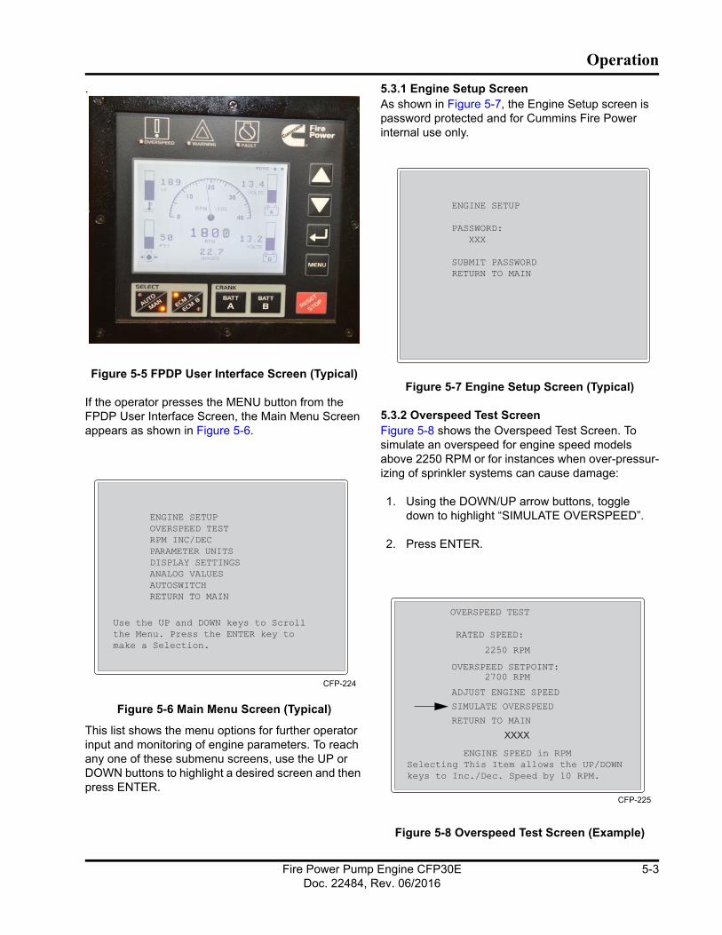
5.3 Fire Pump Digital Panel (FPDP) Screens and AdjustmentsAs shown in Figure 5-5, the FPDP User Interface Screen (main screen) shows the fire pump drive engine tachometer, coolant temperature, oil pressure, Battery A voltage, Battery B voltage, hour meter, and fault codes (when present). The “MORE /\ \/” indica-tor at the top right of the screen signals the user to toggle the UP or DOWN buttons to switch easily between the FPDP User Interface Screen and the Analog Values Screen (see Section 5.3.6).
NOTE: Electronic engines display J1939 tachometer, engine temperature, and oil pressure. Mechanical engines display parameters via sensors added by Cummins Fire Power.
NOTE: When the key switch is not on, the coolant temperature defaults to “0 °F” (or “-18 °C”) and the oil pressure defaults to “0 PSI” (or “0 kPa”).
1
2
Battery Contactor Levers
Fire Power Pump Engine CFP30EDoc. 22484, Rev. 06/2016
5-2
Operation
.
Figure 5-5 FPDP User Interface Screen (Typical)
If the operator presses the MENU button from the FPDP User Interface Screen, the Main Menu Screen appears as shown in Figure 5-6.
Figure 5-6 Main Menu Screen (Typical)
This list shows the menu options for further operator input and monitoring of engine parameters. To reach any one of these submenu screens, use the UP or DOWN buttons to highlight a desired screen and then press ENTER.
5.3.1 Engine Setup ScreenAs shown in Figure 5-7, the Engine Setup screen is password protected and for Cummins Fire Power internal use only.
Figure 5-7 Engine Setup Screen (Typical)
5.3.2 Overspeed Test ScreenFigure 5-8 shows the Overspeed Test Screen. To simulate an overspeed for engine speed models above 2250 RPM or for instances when over-pressur-izing of sprinkler systems can cause damage:
1. Using the DOWN/UP arrow buttons, toggle down to highlight “SIMULATE OVERSPEED”.
2. Press ENTER.
Figure 5-8 Overspeed Test Screen (Example)
CFP-224
XXXX
CFP-225
Fire Power Pump Engine CFP30EDoc. 22484, Rev. 06/2016
5-3

Operation
3. A six-second timer will begin a countdown at the bottom of the screen and all buttons will be locked out, except for RESET/STOP.
4. The simulation test temporarily lowers the FPDP overspeed setpoint to below the engine speed. Upon completion of the overspeed simulation, the FPDP reverts back to its previous operating parameters.
The RPM INC/DEC Screen shown in Figure 5-9 allows the operator to make on-site adjustments by incrementing or decrementing the engine operating speed for electronic engines.
Figure 5-9 Electronic RPM INC/DEC Screen (Typi-cal)
The engine operating speed was factory set during manufacturing and test procedures. If the speed does not match the engine RPM shown on the factory setting plate, follow these steps to adjust the speed setting:
1. Using the DOWN/UP arrow buttons, toggle down to highlight “ADJUST ENGINE SPEED”.
2. Press ENTER.
3. Press the UP or DOWN arrow to increment the engine speed to match the field setting plate. Each increment is ten RPMs.
4. Press ENTER.
5.3.3 Parameter Units ScreenThe Parameter Units Screen shown in Figure 5-10 allows the operator to select Imperial or Metric units.
The default units of measure are degrees in Fahrenheit and pounds per square inch (PSI).
Figure 5-10 Parameter Units Screen (Typical)
5.3.4 Display Settings ScreenThe Display Settings Screen (shown in Figure 5-11) enables adjustments to the backlight and contrast for optimal viewing in varying lighting environments. The version number of the FPDP software will also be indicated on this screen.
Figure 5-11 Display Settings Screen (Typical)
5.3.5 Analog Values ScreenThe Analog Values Screen shown in Figure 5-12 provides analog output values for battery voltages, engine speed, water temperature, oil pressure, exhaust temperature, cooling loop temperature, cooling loop differential pressure, and hours of opera-tion. The Analog Values Screen may be accessed either by toggling down and selecting ANALOG VALUES from the Main Menu Screen (Figure 5-6) or
XXXX
CFP-226
:
CFP-228
Fire Power Pump Engine CFP30EDoc. 22484, Rev. 06/2016
5-4

Operation
by using the UP and DOWN buttons from the FPDP User Interface Screen (Figure 5-5).
Figure 5-12 Analog Values Screen (Typical)
NOTE: The choice of Metric or Imperial values is made using the Parameter Units screen.
NOTE: For exhaust temperature values less than 93 °C (200 °F) or not monitored, the value will be displayed as 0°. For oil temperature values less than 24 °C (75 °F) or not monitored, the value will be displayed as 0°.
5.3.6 Autoswitch ScreenThe National Fire Protection Association (NFPA) 20 Standard, as well as Underwriters Laboratories (UL) and Factory Mutual (FM) Standards, requires redun-dancy for fire safety systems. If the autoswitch is enabled and the selected ECM fails to start, the fire pump drive engine will automatically switch to the other ECM and restart. As shown in Figure 5-13, the Autoswitch Setting Screen allows the operator to disable or enable this autoswitch capability.
Figure 5-13 Autoswitch Screen (Typical)
5.4 Active Fault Codes DisplayOperation irregularities are displayed as fault codes on the bottom of the User Interface Screen of the FPDP (see Figure 5-14). For a complete listing of Fault Codes and their meanings, see Section 7 - Troubleshooting.
Figure 5-14 Fault Code Display
In the event that the FPDP experiences a loss of the pressure signal, the engine will default to the rated speed.
ANALOG VALUES
R
B A:B B:E :W :O :E :
:
H :
0.0 Volts14.0 Volts 0 RPM 70° F 0 PSI 0° F 0° F
0.1 Hrs
0 PSI0 PSI
LocationofFault Code
Fire Power Pump Engine CFP30EDoc. 22484, Rev. 06/2016
5-5
Operation
This page is intentionally left blank.
Fire Power Pump Engine CFP30EDoc. 22484, Rev. 06/2016
5-6

Section 6 - Maintenance
6.1 IntroductionBefore performing maintenance procedures, read and understand Section 1 - Safety of this manual. Improper performance or lack of critical information could result in personal injury or equipment damage.
Cummins encourages our customers to perform maintenance and repairs whenever necessary. However, servicing complex components within the normal warranty period may void the Cummins war-ranty and any specified warranty extended by the manufacturer of Original Equipment Manufacturer (OEM) products. See the Warranty Information section at the beginning of this manual.
Maintenance procedures should be performed by skilled technicians who are familiar with the equip-ment, local regulations, and service procedures for fire pump drive engine and pump systems. Improper maintenance can damage the engine or the fire pump drive engine, or cause severe personal injury.
The National Fire Protection Association (NFPA) 25 Standard outlines the maintenance tests to be per-formed to validate automatic and manual operational requirements for field acceptance testing.
Cummins recommends that the engine be maintained according to the Cummins Operation and Mainte-nance Manual for that engine family.
NOTE: If your engine is equipped with a component or accessory not manufactured by Cummins Inc, refer to the component manufacturer’s vendor supplied literature for specific maintenance recommendations.
6.2 Engine Operation ReportsThe engine must always be maintained in top mechanical condition. The maintenance department requires regular running reports to include the follow-ing:
• Low engine oil pressure.
• Engine surge.
• Erratic operation or frequent shutdowns.
• Any warning lamps flashing or staying illu-minated.
• Abnormal coolant or oil temperature.
• Unusual engine noise or vibration.
• Excessive smoke.
• Excessive use of coolant, fuel, or engine oil.
• Any fluid leaks.
• Loose, worn, or damaged parts.
The weekly running report also helps to make provisions for more extensive maintenance, as the reports indicate the necessity.
The Fault Codes displayed on the Fire Pump Digital Panel (FPDP) assist in recording operation irregulari-ties. See Section 7 - Troubleshooting for a listing of Fault Codes.
Fire Power Pump Engine CFP30EDoc. 22484, Rev. 06/2016
6-1
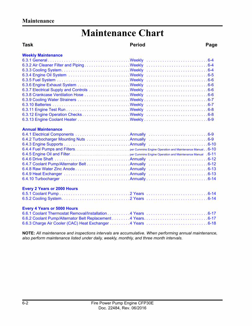
Maintenance
Maintenance ChartTask Period Page
Weekly Maintenance6.3.1 General . . . . . . . . . . . . . . . . . . . . . . . . . . . . . . . . . . . .Weekly . . . . . . . . . . . . . . . . . . . . . . . . . . .6-46.3.2 Air Cleaner Filter and Piping . . . . . . . . . . . . . . . . . . . .Weekly . . . . . . . . . . . . . . . . . . . . . . . . . . .6-46.3.3 Cooling System. . . . . . . . . . . . . . . . . . . . . . . . . . . . . .Weekly . . . . . . . . . . . . . . . . . . . . . . . . . . .6-46.3.4 Engine Oil System . . . . . . . . . . . . . . . . . . . . . . . . . . .Weekly . . . . . . . . . . . . . . . . . . . . . . . . . . .6-56.3.5 Fuel System . . . . . . . . . . . . . . . . . . . . . . . . . . . . . . . .Weekly . . . . . . . . . . . . . . . . . . . . . . . . . . .6-66.3.6 Engine Exhaust System . . . . . . . . . . . . . . . . . . . . . . .Weekly . . . . . . . . . . . . . . . . . . . . . . . . . . .6-66.3.7 Electrical Supply and Controls . . . . . . . . . . . . . . . . . .Weekly . . . . . . . . . . . . . . . . . . . . . . . . . . .6-66.3.8 Crankcase Ventilation Hose . . . . . . . . . . . . . . . . . . . .Weekly . . . . . . . . . . . . . . . . . . . . . . . . . . .6-66.3.9 Cooling Water Strainers . . . . . . . . . . . . . . . . . . . . . . .Weekly . . . . . . . . . . . . . . . . . . . . . . . . . . . .6-76.3.10 Batteries . . . . . . . . . . . . . . . . . . . . . . . . . . . . . . . . . .Weekly . . . . . . . . . . . . . . . . . . . . . . . . . . .6-76.3.11 Engine Test Run . . . . . . . . . . . . . . . . . . . . . . . . . . . .Weekly . . . . . . . . . . . . . . . . . . . . . . . . . . .6-86.3.12 Engine Operation Checks . . . . . . . . . . . . . . . . . . . . .Weekly . . . . . . . . . . . . . . . . . . . . . . . . . . .6-86.3.13 Engine Coolant Heater . . . . . . . . . . . . . . . . . . . . . . .Weekly . . . . . . . . . . . . . . . . . . . . . . . . . . . .6-9
Annual Maintenance6.4.1 Electrical Components . . . . . . . . . . . . . . . . . . . . . . . .Annually . . . . . . . . . . . . . . . . . . . . . . . . . .6-96.4.2 Turbocharger Mounting Nuts . . . . . . . . . . . . . . . . . . .Annually . . . . . . . . . . . . . . . . . . . . . . . . . .6-96.4.3 Engine Supports . . . . . . . . . . . . . . . . . . . . . . . . . . . . .Annually . . . . . . . . . . . . . . . . . . . . . . . . . .6-106.4.4 Fuel Pumps and Filters. . . . . . . . . . . . . . . . . . . . . . . . . . . . . . . . . . per Cummins Engine Operation and Maintenance Manual . .6-106.4.5 Engine Oil and Filter . . . . . . . . . . . . . . . . . . . . . . . . . . . . . . . . . . . . . per Cummins Engine Operation and Maintenance Manual .6-116.4.6 Drive Shaft . . . . . . . . . . . . . . . . . . . . . . . . . . . . . . . . .Annually . . . . . . . . . . . . . . . . . . . . . . . . . .6-126.4.7 Coolant Pump/Alternator Belt . . . . . . . . . . . . . . . . . . .Annually . . . . . . . . . . . . . . . . . . . . . . . . . .6-126.4.8 Raw Water Zinc Anode . . . . . . . . . . . . . . . . . . . . . . . .Annually . . . . . . . . . . . . . . . . . . . . . . . . . .6-136.4.9 Heat Exchanger . . . . . . . . . . . . . . . . . . . . . . . . . . . . .Annually . . . . . . . . . . . . . . . . . . . . . . . . . .6-136.4.10 Turbocharger . . . . . . . . . . . . . . . . . . . . . . . . . . . . . .Annually . . . . . . . . . . . . . . . . . . . . . . . . . . .6-14
Every 2 Years or 2000 Hours6.5.1 Coolant Pump . . . . . . . . . . . . . . . . . . . . . . . . . . . . . . .2 Years . . . . . . . . . . . . . . . . . . . . . . . . . . .6-146.5.2 Cooling System. . . . . . . . . . . . . . . . . . . . . . . . . . . . . .2 Years . . . . . . . . . . . . . . . . . . . . . . . . . . .6-14
Every 4 Years or 5000 Hours6.6.1 Coolant Thermostat Removal/Installation . . . . . . . . . .4 Years . . . . . . . . . . . . . . . . . . . . . . . . . . .6-176.6.2 Coolant Pump/Alternator Belt Replacement . . . . . . . .4 Years. . . . . . . . . . . . . . . . . . . . . . . . . . . .6-176.6.3 Charge Air Cooler (CAC) Heat Exchanger . . . . . . . . .4 Years . . . . . . . . . . . . . . . . . . . . . . . . . . .6-18
NOTE: All maintenance and inspections intervals are accumulative. When performing annual maintenance, also perform maintenance listed under daily, weekly, monthly, and three month intervals.
Fire Power Pump Engine CFP30EDoc. 22484, Rev. 06/2016
6-2

Maintenance
Maintenance Record FormTable 6-1.
Engine Serial Number: Engine Model:
Owner’s Name: Equipment Name/Number:
DateHours or Time
IntervalActual Hours
Check Performance
Performed By Comments
Fire Power Pump Engine CFP30EDoc. 22484, Rev. 06/2016
6-3

Maintenance
6.3 Weekly MaintenanceWhen the engine is running, be alert for mechanical problems that could create unsafe or hazardous con-ditions.
6.3.1 GeneralEach week, a general walk-around inspection should include the following areas:
1. Check fluid levels before starting the engine. Check oil pressure and coolant temperatures frequently. Most engine problems give an early warning.
2. Look and listen for changes in engine perfor-mance, sound, or appearance that will indicate that service or repair is needed. Be alert for mis-fires, vibration, excessive exhaust smoke, loss of power, or increases in oil or fuel consumption.
3. Check the engine appearance for excessive heat, wiring short circuits, excessive end-play, vibrations, excessive wear, excessive abrasion, damaged electrical wiring, or loose electrical wiring.
4. Check the engine for odors of diesel fuel, burning rubber, electrical system failure, exhaust fumes, or smoke.
WARNINGEngine fuel is highly flammable and represents an extreme hazard for fire or explosion when exposed to electrical sparks or open flame. Clean up spilled fuel immediately. Keep sources of elec-trical spark or open flame away from a fuel source.
6.3.2 Air Cleaner Filter and PipingThe frequency of cleaning or replacing the air cleaner filter element is determined by the conditions in which the engine operates. On a weekly basis, perform the following inspections:
1. Visually inspect the air intake filter and piping daily for blockage, damage to piping, loose clamps, or punctures that can allow debris to enter the engine. If there is a blockage, the ser-vice indicator will be activated. Refer to Figure 2-2.
NOTE: Turbocharged engines must be operated at rated revolutions per minute (RPM) and full load to check maximum intake air restriction.
NOTE: Cummins recommends using an air cleaner filter element as listed on the Engine Data Sheet in Section 8 - Component Parts and Assemblies.
CAUTIONNever operate the engine without an air cleaner. Intake air must be filtered to prevent dirt and debris from entering the engine and causing pre-mature wear. Dirt or foreign objects could cause engine damage.
a. If the red indicator flag is at the raised posi-tion in the window, clean or replace the air fil-ter per the manufacturer’s recommendation as required. Do not remove the felt washer from the indicator. The felt washer absorbs moisture.
b. After the air cleaner has been serviced, push the flag in to reset the service indicator.
IMPORTANT: See the Engine Data Sheet in Section 8 - Component Parts and Assemblies for maximum intake air restriction.
2. Check for corrosion under the clamps and hoses of the intake system piping. Corrosion can allow corrosive products and dirt to enter the intake system. Disassemble and clean as required.
3. Replace any damaged air filter or hoses and tighten loose clamps, as necessary, to prevent the air system from leaking. Torque hose clamps to the recommended torque value. Refer to the torque chart in Section 8 - Component Parts and Assemblies.
6.3.3 Cooling System
CAUTIONDo not remove a coolant pressure/fill cap from a hot engine. Shut down the engine and wait until the coolant temperature is below 50 °C (120 °F) before removing the pressure cap. Heated coolant spray or steam can cause severe per-sonal injury.
Fire Power Pump Engine CFP30EDoc. 22484, Rev. 06/2016
6-4

Maintenance
On a weekly basis, perform the following inspections on the cooling system:
1. Inspect the cooling water piping, coolant heat exchanger tanks, charge air cooling system, engine coolant hoses, and hose clamps for loose fittings, leaks, damage, and corrosion.
a. Tighten the hose clamps as necessary.
b. Check for cracks, holes, or other damage. Repair or replace as necessary.
CAUTIONNever use a sealing additive to stop leaks in the cooling system. This can result in cooling system plugging and inadequate coolant flow, causing the engine to overheat.
2. With the coolant expansion tank at ambient tem-perature, press down, unscrew, and remove the pressure cap as shown in Figure 2-1.
a. Ensure that the coolant level is visible by checking the coolant level sight gauge.
b. Add coolant, as required. DO NOT OVER-FILL!
NOTE: Supplemental engine coolant should be a mixture of 50% ethylene glycol antifreeze and 50% water to avoid engine damage.
3. Check the antifreeze concentration at least six times a year or whenever coolant is added to the cooling system by using a refractometer.
4. Drain a small amount of coolant from the return line petcock and inspect the coolant for exces-sive rust or particulate matter. Change the coolant more frequently if particles are present.
CAUTIONDo not mix coolant brands or chemical solutions, as this could damage the cooling system. Keep a record of the coolant concentration and manufac-turer with the engine maintenance records.
5. Check for soft, overly-pliant hoses, oxidation, and loose hose clamps. Torque hose clamps to the recommended torque value. Refer to the torque chart in Section 8 - Component Parts and
Assemblies. Replace damaged hoses and clamps as required.
6. Check the heat exchanger for leaks, damage, and dirt buildup. Clean and repair as required.
6.3.4 Engine Oil System
WARNINGPerform the specific checks in this section only after the engine is fully stopped. Unless tests require engine operation, disconnect the battery leads from the batteries (negative terminal first). Contact with exposed or moving components can cause severe personal injury.
Inspect the engine oil system on a weekly basis fol-lowing these steps:
1. For accurate dipstick readings, shut off the engine and wait approximately ten minutes to allow the oil in the upper portions of the engine to drain back into the crankcase.
2. As shown in Figure 6-1, check the oil level at the engine dipstick.
1. Oil Fill Port (on valve cover)2. Oil Level Dipstick3. Engine Oil Filter
Figure 6-1 Oil Level Dipstick
a. If the oil level is greater than the high mark (H), drain the excess oil and recheck the level.
CFP-046
Fire Power Pump Engine CFP30EDoc. 22484, Rev. 06/2016
6-5
Maintenance
b. If the oil level is consistently below normal after a fill, check for leaks, loose or damaged gaskets, or oil in the coolant system. If the oil level is below the low mark (L), add the equivalent type oil.
NOTE: Cummins recommends using Premium Blue S.A.E. 15W-40 Multi-viscosity Lubricating Oil or equivalent.
6.3.5 Fuel System
WARNINGEngine fuel is highly flammable and represents an extreme hazard for fire or explosion when exposed to electrical sparks or open flame. Clean up spilled fuel immediately. Keep sources of elec-trical spark or open flame away from a fuel source.
To inspect the fuel system:
1. Shut off the engine.
2. Inspect the fuel supply line, return line, filter and fittings for cracks or abrasions.
a. Ensure the lines are not rubbing against any-thing that could damage the fuel system hoses. Repair any leaks or alter line routing to eliminate wear immediately.
b. Relieve fuel line pressure by carefully loosening the fuel inlet line.
NOTE: Refer to the Engine Data Sheet in Section 8 - Component Parts and Assemblies for Cummins rec-ommended replacement components.
6.3.6 Engine Exhaust SystemWith the engine operating, inspect the entire exhaust system: exhaust manifold, exhaust flex pipe, muffler, and piping.
Check for leaks at all connections, welds, gaskets, and joints. Make sure that the exhaust pipes are not heating surrounding areas excessively. Repair any leaks immediately.
6.3.7 Electrical Supply and ControlsCheck the terminals on the starting batteries for clean and tight connections. Loose or corroded connections create resistance which can hinder starting. Inspect the FPDP harness connections to be sure they are secure.
6.3.8 Crankcase Ventilation HoseInspect the crankcase ventilation hose for wear, damage, sludge, blockage, or dirt buildup (refer to Figure 2-1). Clean the ventilation hose, if obstructed or blocked. Replace a worn or damaged hose.
6.3.9 Cooling Water StrainersAs shown in Figure 6-2, the (two) cooling water strainers should be cleaned weekly to remove sedi-ment.
To clean the normal line strainer, ensure that the normal line valves are closed and the bypass line valves are open.
To clean the bypass line strainer, ensure that the bypass line valves are closed and the normal line valves are open.
For each cooling water strainer:
1. Remove the plug.
2. Inspect and remove any debris.
3. Install the strainer plugs.
4. When finished, open the normal line valves and close the bypass line valves for normal opera-tion.
Fire Power Pump Engine CFP30EDoc. 22484, Rev. 06/2016
6-6

Maintenance
1. Bypass Water Line Strainer2. Normal Water Line Strainer
Figure 6-2 Cooling Water Strainer (typical)
6.3.10 Batteries
CAUTIONBatteries can emit explosive gases during charging. To reduce the possibility of personal injury, always ventilate the battery compartment before servicing the batteries.
CAUTIONTo reduce the possibility of arcing, remove the negative (-) battery cable first and attach the neg-ative (-) battery cable last.
For proper weekly maintenance of the batteries:
1. Keep the batteries clean by wiping them with a damp cloth whenever dirt appears excessive.
2. Use a battery hydrometer to check the specific gravity of the electrolyte in each battery cell. A fully-charged battery will have a specific gravity of 1.260. Charge the battery if the specific gravity reading is below 1.215.
3. Check the battery wiring and cable connections for loose, corroded, worn, or damaged cables. Check both connectors at the alternator, battery connections, and engine grounding lug (near the starter motor).
a. If the battery cables are corroded, remove the battery cable clamps, starting with the negative (-) battery cable.
b. Use a fine emery cloth or a wire brush to clean the cable clamps and battery cables. The metal should be shiny.
c. Wash the battery terminals with a solution of baking soda and water (2 oz (1/4 cup) baking soda to 0.94 liter (1 qt) of water).
d. Be careful to prevent the solution from enter-ing the battery cells, and flush the batteries with clean water when done.
e. After cleaning the connections, coat the ter-minals with a light application of petroleum jelly.
f. Reinstall and tighten the cable clamps.
WARNINGBattery electrolyte (sulfuric acid) is highly caustic and can burn clothing and skin, or cause blind-ness. Wear protective clothing, impervious neo-prene gloves, safety goggles, or full-face shield when working with the batteries.
4. Check the electrolyte level in the batteries monthly. If low, fill the battery cells to the bottom of the filler neck with distilled water.
5. Check for continuity between terminals using a digital multimeter or other test equipment. Also check the insulation resistance to ground. Correct any electrical faults.
6. Reinstall the battery cables; attach the negative (-) battery cable last.
6.3.11 Engine Test RunStart the engine at least once a week for a minimum of thirty minutes with as much load as possible. Periods of no-load operation should be held to a min-imum, because unburned fuel tends to accumulate in the exhaust system. Refer to the operating instruc-tions in Section 5 - Operation.
Check that the engine starts and operates at the rec-ommended fire pump drive engine speed specifica-tion and inspect the following:
1
2
Fire Power Pump Engine CFP30EDoc. 22484, Rev. 06/2016
6-7

Maintenance
1. Check that the engine oil pressure is indicated on the gauge within fifteen seconds after start-ing.
2. Check that the engine has attained a normal running temperature after running the engine for a minimum of thirty minutes.
3. Observe that the engine is operating at the proper operating speed. (If the engine is not operating at the proper speed, see Section 6.3.12 Engine Operation Checks.)
4. Check for unusual engine noise. Listen for any unusual engine noise which can indicate that service is required.
5. Ensure that the oil pressure is greater than 69 kPa (10 psi).
6. Check that the coolant temperature is between 70 °C (158 °F) and 107 °C (225 °F).
7. Check that both battery voltmeters indicate 12 VDC for standard or 24 VDC for optional operating systems.
8. Check that the air filter service indicator has not popped-up, indicating an air filter blockage. Replace the air filter as required.
End the test run by pressing and holding the over-speed RESET/STOP switch until the engine stops.
6.3.12 Engine Operation ChecksThe following service inspections ensure that the engine starts and operates properly under normal conditions.
WARNINGBefore equipment operation, ALL guards, covers, and protective devices MUST BE in place and securely fastened. Serious personal injury could result from contact with exposed or moving com-
ponents.
6.3.12.1 Crank Termination Set Point
The speed switch crank termination set point is factory-set at 600 RPM and should not be changed from this value.
Engine Speed CalibrationIf the speed does not match the engine RPM shown on the factory settings plate, calibrate the correct speed using the controls on the FPDP:
1. Set the ECM to “ECM A”.
2. Start the engine locally from the FPDP:
a. Press the AUTO/MAN mode switch on the FPDP to place the engine in MANUAL mode.
b. Press either the CRANK BATT A or CRANK BATT B button to start the engine.
3. Check to verify that the engine starts and accel-erates to the speed set point listed on the factory settings plate.
4. Monitor the engine speed on the tachometer. Record the observed engine speed.
5. If the speed does not match the engine RPM shown on the factory setting plate, follow these steps to adjust the speed setting:
a. As shown in Figure 6-3, using the DOWN/UP arrow buttons, toggle down to highlight “ADJUST ENGINE SPEED”.
b. Press ENTER.
c. Press the UP or DOWN arrow to increment the engine speed to match the field setting plate. Each increment is ten RPMs.
d. Press ENTER.
Fire Power Pump Engine CFP30EDoc. 22484, Rev. 06/2016
6-8
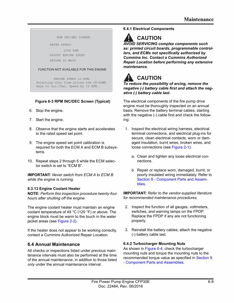
Maintenance
Figure 6-3 RPM INC/DEC Screen (Typical)
6. Stop the engine.
7. Start the engine.
8. Observe that the engine starts and accelerates to the rated speed set point.
9. The engine speed set point calibration is required for both the ECM A and ECM B subsys-tems.
10. Repeat steps 2 through 6 while the ECM selec-tor switch is set to “ECM B”.
IMPORTANT: Never switch from ECM A to ECM B while the engine is running.
6.3.13 Engine Coolant HeaterNOTE: Perform this inspection procedure twenty-four hours after shutting off the engine.
The engine coolant heater must maintain an engine coolant temperature of 49 °C (120 °F) or above. The engine block must be warm to the touch in the water jacket areas (see Figure 2-2).
If the heater does not appear to be working correctly, contact a Cummins Authorized Repair Location.
6.4 Annual MaintenanceAll checks or inspections listed under previous main-tenance intervals must also be performed at the time of the annual maintenance, in addition to those listed only under the annual maintenance interval.
6.4.1 Electrical Components
CAUTIONAVOID SERVICING complex components such as: printed circuit boards, programmable control-lers, and ECMs not specifically authorized by Cummins Inc. Contact a Cummins Authorized Repair Location before performing any extensive maintenance.
CAUTIONTo reduce the possibility of arcing, remove the negative (-) battery cable first and attach the neg-ative (-) battery cable last.
The electrical components of the fire pump drive engine must be thoroughly inspected on an annual basis. Remove the battery terminal cables, starting with the negative (-) cable first and check the follow-ing:
1. Inspect the electrical wiring harness, electrical terminal connections, and electrical plug-ins for secure, clean electrical contacts, worn or dam-aged insulation, burnt wires, broken wires, and loose connections (see Figure 2-1).
a. Clean and tighten any loose electrical con-nections.
b. Repair or replace worn, damaged, burnt, or poorly insulated wiring immediately. Refer to Section 8 - Component Parts and Assem-blies.
IMPORTANT: Refer to the vendor-supplied literature for recommended maintenance procedures.
2. Inspect the function of all gauges, voltmeters, switches, and warning lamps on the FPDP. Replace the FPDP if any are not functioning properly.
3. Reinstall the battery cables; attach the negative (-) battery cable last.
6.4.2 Turbocharger Mounting NutsAs shown in Figure 6-4, check the turbocharger mounting nuts and torque the mounting nuts to the recommended torque value as specified in Section 8 - Component Parts and Assemblies.
XXXX
CFP-226
Fire Power Pump Engine CFP30EDoc. 22484, Rev. 06/2016
6-9
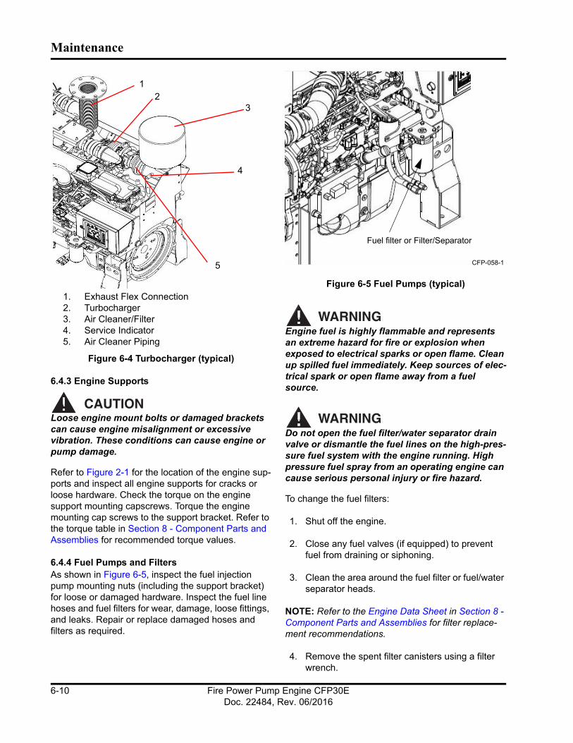
Maintenance
1. Exhaust Flex Connection2. Turbocharger3. Air Cleaner/Filter4. Service Indicator5. Air Cleaner Piping
Figure 6-4 Turbocharger (typical)
6.4.3 Engine Supports
CAUTIONLoose engine mount bolts or damaged brackets can cause engine misalignment or excessive vibration. These conditions can cause engine or pump damage.
Refer to Figure 2-1 for the location of the engine sup-ports and inspect all engine supports for cracks or loose hardware. Check the torque on the engine support mounting capscrews. Torque the engine mounting cap screws to the support bracket. Refer to the torque table in Section 8 - Component Parts and Assemblies for recommended torque values.
6.4.4 Fuel Pumps and FiltersAs shown in Figure 6-5, inspect the fuel injection pump mounting nuts (including the support bracket) for loose or damaged hardware. Inspect the fuel line hoses and fuel filters for wear, damage, loose fittings, and leaks. Repair or replace damaged hoses and filters as required.
Figure 6-5 Fuel Pumps (typical)
WARNINGEngine fuel is highly flammable and represents an extreme hazard for fire or explosion when exposed to electrical sparks or open flame. Clean up spilled fuel immediately. Keep sources of elec-trical spark or open flame away from a fuel source.
WARNINGDo not open the fuel filter/water separator drain valve or dismantle the fuel lines on the high-pres-sure fuel system with the engine running. High pressure fuel spray from an operating engine can cause serious personal injury or fire hazard.
To change the fuel filters:
1. Shut off the engine.
2. Close any fuel valves (if equipped) to prevent fuel from draining or siphoning.
3. Clean the area around the fuel filter or fuel/water separator heads.
NOTE: Refer to the Engine Data Sheet in Section 8 - Component Parts and Assemblies for filter replace-ment recommendations.
4. Remove the spent filter canisters using a filter wrench.
12
3
4
5 CFP-058-1
Fuel filter or Filter/Separator
Fire Power Pump Engine CFP30EDoc. 22484, Rev. 06/2016
6-10
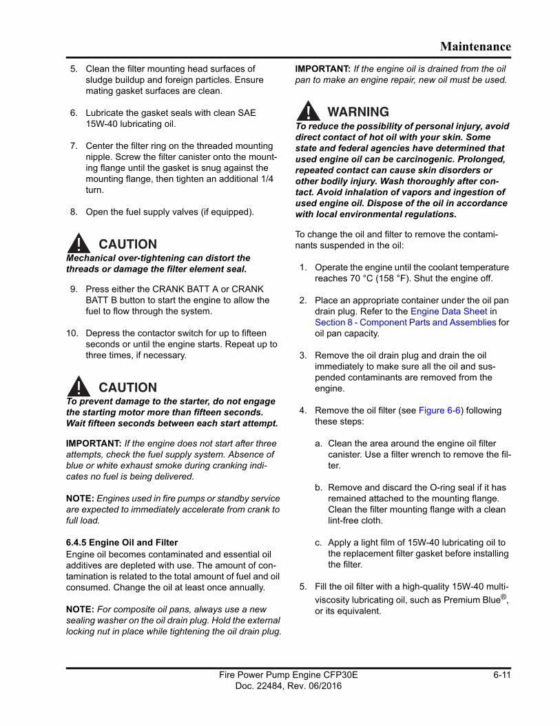
Maintenance
5. Clean the filter mounting head surfaces of sludge buildup and foreign particles. Ensure mating gasket surfaces are clean.
6. Lubricate the gasket seals with clean SAE 15W-40 lubricating oil.
7. Center the filter ring on the threaded mounting nipple. Screw the filter canister onto the mount-ing flange until the gasket is snug against the mounting flange, then tighten an additional 1/4 turn.
8. Open the fuel supply valves (if equipped).
CAUTIONMechanical over-tightening can distort the threads or damage the filter element seal.
9. Press either the CRANK BATT A or CRANK BATT B button to start the engine to allow the fuel to flow through the system.
10. Depress the contactor switch for up to fifteen seconds or until the engine starts. Repeat up to three times, if necessary.
CAUTIONTo prevent damage to the starter, do not engage the starting motor more than fifteen seconds. Wait fifteen seconds between each start attempt.
IMPORTANT: If the engine does not start after three attempts, check the fuel supply system. Absence of blue or white exhaust smoke during cranking indi-cates no fuel is being delivered.
NOTE: Engines used in fire pumps or standby service are expected to immediately accelerate from crank to full load.
6.4.5 Engine Oil and FilterEngine oil becomes contaminated and essential oil additives are depleted with use. The amount of con-tamination is related to the total amount of fuel and oil consumed. Change the oil at least once annually.
NOTE: For composite oil pans, always use a new sealing washer on the oil drain plug. Hold the external locking nut in place while tightening the oil drain plug.
IMPORTANT: If the engine oil is drained from the oil pan to make an engine repair, new oil must be used.
WARNINGTo reduce the possibility of personal injury, avoid direct contact of hot oil with your skin. Some state and federal agencies have determined that used engine oil can be carcinogenic. Prolonged, repeated contact can cause skin disorders or other bodily injury. Wash thoroughly after con-tact. Avoid inhalation of vapors and ingestion of used engine oil. Dispose of the oil in accordance with local environmental regulations.
To change the oil and filter to remove the contami-nants suspended in the oil:
1. Operate the engine until the coolant temperature reaches 70 °C (158 °F). Shut the engine off.
2. Place an appropriate container under the oil pan drain plug. Refer to the Engine Data Sheet in Section 8 - Component Parts and Assemblies for oil pan capacity.
3. Remove the oil drain plug and drain the oil immediately to make sure all the oil and sus-pended contaminants are removed from the engine.
4. Remove the oil filter (see Figure 6-6) following these steps:
a. Clean the area around the engine oil filter canister. Use a filter wrench to remove the fil-ter.
b. Remove and discard the O-ring seal if it has remained attached to the mounting flange. Clean the filter mounting flange with a clean lint-free cloth.
c. Apply a light film of 15W-40 lubricating oil to the replacement filter gasket before installing the filter.
5. Fill the oil filter with a high-quality 15W-40 multi-
viscosity lubricating oil, such as Premium Blue®, or its equivalent.
Fire Power Pump Engine CFP30EDoc. 22484, Rev. 06/2016
6-11
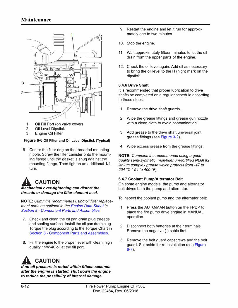
Maintenance
1. Oil Fill Port (on valve cover)2. Oil Level Dipstick3. Engine Oil Filter
Figure 6-6 Oil Filter and Oil Level Dipstick (Typical)
6. Center the filter ring on the threaded mounting nipple. Screw the filter canister onto the mount-ing flange until the gasket is snug against the mounting flange. Then tighten an additional 1/4 turn.
CAUTIONMechanical over-tightening can distort the threads or damage the filter element seal.
NOTE: Cummins recommends using oil filter replace-ment parts as outlined in the Engine Data Sheet in Section 8 - Component Parts and Assemblies.
7. Check and clean the oil pan drain plug threads and sealing surface. Install the oil pan drain plug. Torque the plug according to the Torque Chart in Section 8 - Component Parts and Assemblies.
8. Fill the engine to the proper level with clean, high quality 15W-40 oil at the fill port.
CAUTIONIf no oil pressure is noted within fifteen seconds after the engine is started, shut down the engine to reduce the possibility of internal damage.
9. Restart the engine and let it run for approxi-mately one to two minutes.
10. Stop the engine.
11. Wait approximately fifteen minutes to let the oil drain from the upper parts of the engine.
12. Check the oil level again. Add oil as necessary to bring the oil level to the H (high) mark on the dipstick.
6.4.6 Drive ShaftIt is recommended that proper lubrication to drive shafts be completed on a regular schedule according to these steps:
1. Remove the drive shaft guards.
2. Wipe the grease fittings and grease gun nozzle with a clean cloth to avoid contamination.
3. Add grease to the drive shaft universal joint grease fittings (see Figure 3-2).
4. Wipe excess grease from the grease fittings.
NOTE: Cummins Inc recommends using a good quality semi-synthetic, molybdenum-fortified NLGI #2 lithium complex grease which protects from -47 to 204 °C (-54 to 400 °F).
6.4.7 Coolant Pump/Alternator BeltOn some engine models, the pump and alternator belt drives both the pump and alternator.
To inspect the coolant pump and the alternator belt:
1. Press the AUTO/MAN button on the FPDP to place the fire pump drive engine in MANUAL operation.
2. Disconnect both batteries at their terminals. Remove the negative (-) cable first.
3. Remove the belt guard capscrews and the belt guard. Set aside for re-installation (see Figure 6-7).
Fire Power Pump Engine CFP30EDoc. 22484, Rev. 06/2016
6-12
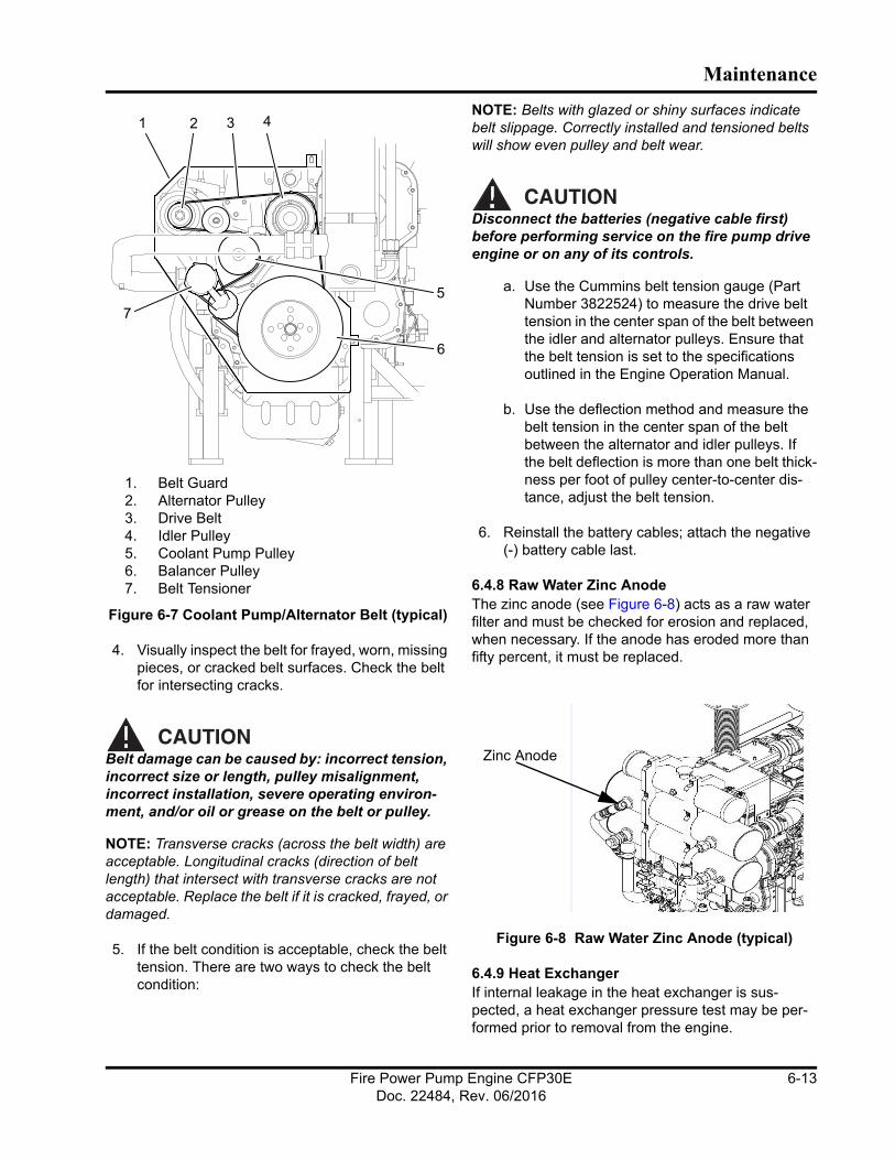
Maintenance
1. Belt Guard2. Alternator Pulley3. Drive Belt4. Idler Pulley5. Coolant Pump Pulley6. Balancer Pulley7. Belt Tensioner
Figure 6-7 Coolant Pump/Alternator Belt (typical)
4. Visually inspect the belt for frayed, worn, missing pieces, or cracked belt surfaces. Check the belt for intersecting cracks.
CAUTIONBelt damage can be caused by: incorrect tension, incorrect size or length, pulley misalignment, incorrect installation, severe operating environ-ment, and/or oil or grease on the belt or pulley.
NOTE: Transverse cracks (across the belt width) are acceptable. Longitudinal cracks (direction of belt length) that intersect with transverse cracks are not acceptable. Replace the belt if it is cracked, frayed, or damaged.
5. If the belt condition is acceptable, check the belt tension. There are two ways to check the belt condition:
NOTE: Belts with glazed or shiny surfaces indicate belt slippage. Correctly installed and tensioned belts will show even pulley and belt wear.
CAUTIONDisconnect the batteries (negative cable first) before performing service on the fire pump drive engine or on any of its controls.
a. Use the Cummins belt tension gauge (Part Number 3822524) to measure the drive belt tension in the center span of the belt between the idler and alternator pulleys. Ensure that the belt tension is set to the specifications outlined in the Engine Operation Manual.
b. Use the deflection method and measure the belt tension in the center span of the belt between the alternator and idler pulleys. If the belt deflection is more than one belt thick-ness per foot of pulley center-to-center dis-tance, adjust the belt tension.
6. Reinstall the battery cables; attach the negative (-) battery cable last.
6.4.8 Raw Water Zinc AnodeThe zinc anode (see Figure 6-8) acts as a raw water filter and must be checked for erosion and replaced, when necessary. If the anode has eroded more than fifty percent, it must be replaced.
Figure 6-8 Raw Water Zinc Anode (typical)
6.4.9 Heat ExchangerIf internal leakage in the heat exchanger is sus-pected, a heat exchanger pressure test may be per-formed prior to removal from the engine.
Zinc Anode
Fire Power Pump Engine CFP30EDoc. 22484, Rev. 06/2016
6-13
Maintenance
NOTE: Use Teflon™ tape or other pipe sealant when installing the test setup in order to prevent leaks.
NOTE: The size of fittings required on the water outlets and inlets are listed on the Engine Data Sheet in Section 8 - Component Parts and Assemblies.
To test the heat exchanger pressure:
1. Install an adapter at the cooling water outlet of the heat exchanger.
2. Install a pressure test setup with 689 kPa (100 psi) pressure gauge at the cooling water inlet to the heat exchanger.
3. Apply air pressure at 414 kPa (60 psi).
a. Isolate the pressure source and monitor the pressure gauge for five minutes.
b. There should be no change in pressure for the duration of the test.
4. After testing, release the pressure. Remove the tubing adapters, plug, and test equipment.
5. If leakage is detected, the heat exchanger must be replaced.
6.4.10 TurbochargerAs shown in Figure 6-4, follow these steps to thor-oughly inspect the turbocharger:
1. Visually inspect the air intake filter and piping according to the steps outlined in Section 6.3.2.
NOTE: Turbocharged engines must be operated at rated revolutions per minute (RPM) and full load to check maximum intake air restriction.
NOTE: Cummins recommends using an air cleaner filter element as listed on the Engine Data Sheet in Section 8 - Component Parts and Assemblies.
CAUTIONNever operate the engine without an air cleaner. Intake air must be filtered to prevent dirt and debris from entering the engine and causing pre-mature wear. Dirt or foreign objects could cause engine damage.
2. Remove the air intake and exhaust piping from the turbocharger.
3. Inspect the turbocharger turbine wheel for cracks in the housing or turbine blades, missing blades, mechanical binding, eccentric motion, or excessive end-play.
4. Replace the turbocharger if damage, excessive end-play, binding, wear, or eccentric motion is found. Contact a Cummins Authorized Repair Location for replacement.
IMPORTANT: The turbocharger must be removed for replacement or rebuild if the clearance is beyond the limits, the housing is cracked, or the turbine wheel is damaged.
5. Reinstall the air intake filter and exhaust piping. Tighten the clamps. Torque loosened clamps to the recommended torque value. Refer to the torque table in Section 8 - Component Parts and Assemblies.
6.5 Every Two YearsAll checks or inspections listed under daily or previ-ous maintenance intervals must also be performed at this time, in addition to those listed under this mainte-nance interval.
6.5.1 Coolant PumpInspect the coolant pump for eccentric motion, mechanical binding, excessive end play, seal damage, and excessive grease or coolant leakage around the pump shaft.
Replace with a new or rebuilt pre-lubricated unit, as necessary. Contact a Cummins Authorized Repair Location for replacement.
6.5.2 Cooling SystemFigure 6-9 illustrates the cooling system. The cooling system must be clean to work properly. If the system shows excessive mineral buildup, particulate matter, scale, oxidation, or oil contamination, drain and flush the cooling system. If the coolant is excessively dirty or is mixed with oil, contact a Cummins Authorized Repair Facility.
WARNINGDo not remove the pressure/fill cap from a hot engine. Shut down the engine and wait until the
Fire Power Pump Engine CFP30EDoc. 22484, Rev. 06/2016
6-14

Maintenance
coolant temperature is below 50 °C (120 °F) before removing the pressure cap. Heated coolant spray or steam can cause severe per-sonal injury.
1. Press the AUTO/MAN button on the FPDP to place the fire pump drive engine in MANUAL operation.
2. Disconnect both batteries at their terminals. Remove the negative (-) cable first.
3. Press down, unscrew, and remove the coolant expansion tank pressure/fill cap. The cap must be removed to allow air to vent the cooling system during the draining process.
4. Disconnect the engine coolant heater power supply before draining the cooling system.
5. Place a container that will hold at least 57 liters (15 gal) of liquid under the coolant drain valve.
6. Ensure that the coolant filter shut-off valves are OPEN.
7. Open the drain petcock on the lower coolant tube, allowing the coolant to drain into the waste container.
8. When the system is empty, move the container under the engine coolant heater.
9. Disconnect either end of the engine heater coolant hose and drain the engine heater.
CAUTIONCoolant is toxic. Avoid prolonged and repeated skin contact with used antifreeze - wash thor-oughly after contact. Prolonged, repeated contact can cause skin disorders. Dispose of waste anti-freeze in accordance with local environmental regulations.
10. Flush with clean fresh water or heavy-duty heat exchanger cleaner. Follow the manufacturer’s directions on the product container.
NOTE: Some cooling system cleaners or commercial solvents require a soapy water rinse after use. Follow the directions on the cleaning solution or solvent.
1. Lower Coolant Tube2. Coolant Drain Petcock3. Coolant Filter4. Coolant Filter Shut-off Valve5. Engine Coolant Heater
Figure 6-9 Engine Coolant Drain
CAUTIONOver-concentration of antifreeze or use of high-silicate antifreeze can damage the engine. Do not use more than 50% antifreeze in the mixture unless additional freeze protection is required. Antifreeze at 68% concentration provides the maximum freeze protection, and must never be exceeded under any condition. Antifreeze protec-tion decreases above 68%.
11. When the flushing water has fully drained, use a filter wrench to remove the water coolant filter from the filter housing.
a. Clean the filter housing gasket mount of dirt buildup, oxidation, or particulate matter with a clean cloth.
b. Coat the replacement filter gasket with a light coating of 15W-40 lubrication oil.
12. Center the filter ring on the threaded mounting nipple. Screw the filter canister onto the mount-ing flange until the gasket is snug against the
1
2
345
Fire Power Pump Engine CFP30EDoc. 22484, Rev. 06/2016
6-15
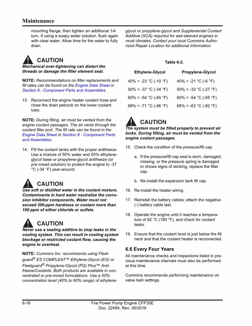
Maintenance
mounting flange, then tighten an additional 1/4 turn. If using a soapy water solution, flush again with clear water. Allow time for the water to fully drain.
CAUTIONMechanical over-tightening can distort the threads or damage the filter element seal.
NOTE: Recommendations on filter replacements and fill rates can be found on the Engine Data Sheet in Section 8 - Component Parts and Assemblies.
13. Reconnect the engine heater coolant hose and close the drain petcock on the lower coolant tube.
NOTE: During filling, air must be vented from the engine coolant passages. The air vents through the coolant filler port. The fill rate can be found in the Engine Data Sheet in Section 8 - Component Parts and Assemblies.
14. Fill the coolant tanks with the proper antifreeze. Use a mixture of 50% water and 50% ethylene-glycol base or propylene-glycol antifreeze (or pre-mixed solution) to protect the engine to -37 °C (-34 °F) year-around.
CAUTIONUse soft or distilled water in the coolant mixture. Contaminants in hard water neutralize the corro-sion inhibitor components. Water must not exceed 300-ppm hardness or contain more than 100 ppm of either chloride or sulfate.
CAUTIONNever use a sealing additive to stop leaks in the cooling system. This can result in cooling system blockage or restricted coolant flow, causing the engine to overheat.
NOTE: Cummins Inc. recommends using Fleet-
guard® ES COMPLEAT™ Ethylene-Glycol (EG) or
Fleetguard® Propylene-Glycol (PG) Plus™ Anti-freeze/Coolants. Both products are available in con-centrated or pre-mixed formulations. Use a 50% concentration level (40% to 60% range) of ethylene-
glycol or propylene-glycol and Supplemental Coolant Additive (SCA) required for wet-sleeved engines in most climates. Contact your local Cummins Autho-rized Repair Location for additional information.
CAUTIONThe system must be filled properly to prevent air locks. During filling, air must be vented from the engine coolant passages.
15. Check the condition of the pressure/fill cap.
a. If the pressure/fill cap seal is worn, damaged, missing, or the pressure spring is damaged or shows signs of sticking, replace the filler cap.
b. Re-install the expansion tank fill cap.
16. Re-install the heater wiring.
17. Reinstall the battery cables; attach the negative (-) battery cable last.
18. Operate the engine until it reaches a tempera-ture of 82 °C (180 °F), and check for coolant leaks.
19. Ensure that the coolant level is just below the fill neck and that the coolant heater is reconnected.
6.6 Every Four YearsAll maintenance checks and inspections listed in pre-vious maintenance intervals must also be performed at this time.
Cummins recommends performing maintenance on valve lash settings.
Table 6-2.
Ethylene-Glycol Propylene-Glycol
40% = -23 °C (-10 °F) 40% = -21 °C (-6 °F)
50% = -37 °C (-34 °F) 50% = -33 °C (-27 °F)
60% = -54 °C (-65 °F) 60% = -54 °C (-65 °F)
68% = -71 °C (-96 °F) 68% = -63 °C (-82 °F)
Fire Power Pump Engine CFP30EDoc. 22484, Rev. 06/2016
6-16
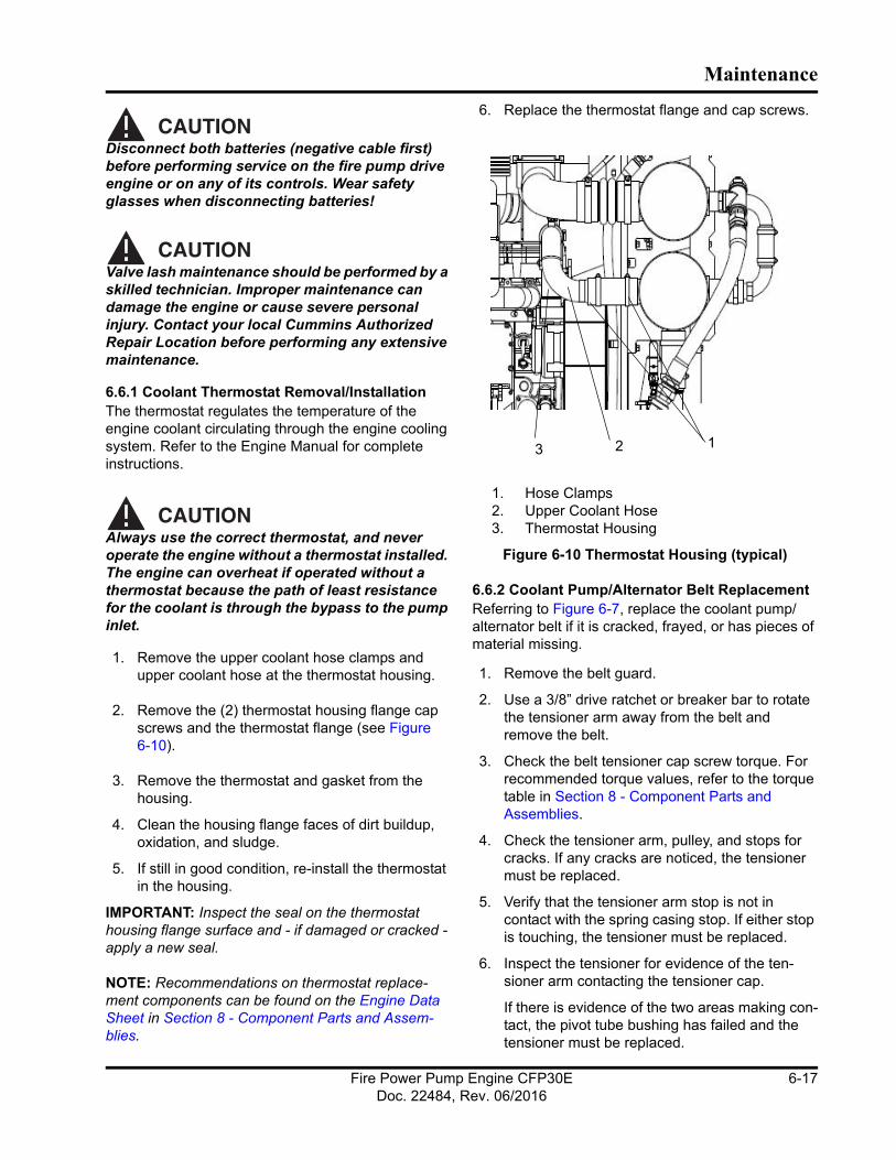
Maintenance
CAUTIONDisconnect both batteries (negative cable first) before performing service on the fire pump drive engine or on any of its controls. Wear safety glasses when disconnecting batteries!
CAUTIONValve lash maintenance should be performed by a skilled technician. Improper maintenance can damage the engine or cause severe personal injury. Contact your local Cummins Authorized Repair Location before performing any extensive maintenance.
6.6.1 Coolant Thermostat Removal/InstallationThe thermostat regulates the temperature of the engine coolant circulating through the engine cooling system. Refer to the Engine Manual for complete instructions.
CAUTIONAlways use the correct thermostat, and never operate the engine without a thermostat installed. The engine can overheat if operated without a thermostat because the path of least resistance for the coolant is through the bypass to the pump inlet.
1. Remove the upper coolant hose clamps and upper coolant hose at the thermostat housing.
2. Remove the (2) thermostat housing flange cap screws and the thermostat flange (see Figure 6-10).
3. Remove the thermostat and gasket from the housing.
4. Clean the housing flange faces of dirt buildup, oxidation, and sludge.
5. If still in good condition, re-install the thermostat in the housing.
IMPORTANT: Inspect the seal on the thermostat housing flange surface and - if damaged or cracked - apply a new seal.
NOTE: Recommendations on thermostat replace-ment components can be found on the Engine Data Sheet in Section 8 - Component Parts and Assem-blies.
6. Replace the thermostat flange and cap screws.
1. Hose Clamps2. Upper Coolant Hose3. Thermostat Housing
Figure 6-10 Thermostat Housing (typical)
6.6.2 Coolant Pump/Alternator Belt ReplacementReferring to Figure 6-7, replace the coolant pump/alternator belt if it is cracked, frayed, or has pieces of material missing.
1. Remove the belt guard.
2. Use a 3/8” drive ratchet or breaker bar to rotate the tensioner arm away from the belt and remove the belt.
3. Check the belt tensioner cap screw torque. For recommended torque values, refer to the torque table in Section 8 - Component Parts and Assemblies.
4. Check the tensioner arm, pulley, and stops for cracks. If any cracks are noticed, the tensioner must be replaced.
5. Verify that the tensioner arm stop is not in contact with the spring casing stop. If either stop is touching, the tensioner must be replaced.
6. Inspect the tensioner for evidence of the ten-sioner arm contacting the tensioner cap.
If there is evidence of the two areas making con-tact, the pivot tube bushing has failed and the tensioner must be replaced.
123
Fire Power Pump Engine CFP30EDoc. 22484, Rev. 06/2016
6-17

Maintenance
7. Check the tensioner bearing.
a. Rotate the belt tensioner pulley. The pulley should spin freely with no mechanical bind-ing, eccentric motion, or excessive end-play.
b. If the arm rotates with mechanical binding, eccentric movement, or excessive end play, replace the tensioner.
8. Inspect the clearance between the tensioner spring case and the tensioner arm for uneven bearing wear.
If the clearance exceeds 3 mm (0.12 in) at any point, the tensioner must be replaced as a com-plete assembly. Contact a Cummins Authorized Repair Location for replacement.
NOTE: Experience has shown that tensioners gener-ally will show a larger clearance gap near the lower portion of the spring case, resulting in the upper portion rubbing against the tensioner arm. Always replace the belt when a tensioner is replaced.
9. After checking the torque, use a 3/8” drive ratchet or breaker bar to rotate the tensioner slowly away from the area of belt contact.
10. Install the replacement drive belt.
CAUTIONTo prevent pulley or belt damage, do not roll a belt over the pulley or pry it on with a tool. Move the tensioner arm away from the belt area before installing the drive belt.
11. Check the location of the drive belt on the belt tensioner pulley. The belt should be centered on, or centered close to, the middle of the pulley.
12. Reinstall the belt guard.
CAUTIONUnaligned belts, either too far forward or back-ward, can cause belt wear, belt roll-off failures or increase uneven tensioner bushing wear.
6.6.3 Charge Air Cooler (CAC) Heat Exchanger Cleaning
The CAC heat exchanger should be removed and cleaned internally at least once every four years.
1. Press the AUTO/MAN button on the FPDP to place the fire pump drive engine in MANUAL operation.
2. Disconnect both batteries at their terminals. Remove the negative (-) cable first.
3. Shut off the manual cooling water and bypass water hand valves on the cooling loop water supply.
4. Open the coolant filter shut-off valve.
5. Drain the coolant system per the instructions in Section 6.5.2
6. When the tanks are empty, disconnect the inlet and outlet piping from the CAC tubing to the heat exchanger (see Figure 2-1).
7. Disconnect the cooling water inlet and outlet fit-tings from the charge air heat exchanger and the coolant heat exchanger.
WARNINGDo not use caustic cleaners to clean the CAC as these types of cleaners cause damage to the CAC. Follow the directions provided by the clean-ing solution manufacturer.
WARNINGCleaning chemicals may be caustic and cause skin irritation. Follow the instructions on cleaning containers. Wear protective clothing, eye wear, and rubber gloves when working with cleaning solutions. Dispose of solvents and cleaning solu-tions properly.
8. Remove the heat exchanger mounting bracket bolts from the mounting bracket and set aside for later reuse.
9. Provide support for the heat exchanger in order to avoid dropping it. Remove the charge air heat exchanger from the mounting plates.
10. Flush the CAC internally with cleaning solution in the opposite direction of normal air flow.
11. Shake the CAC and lightly tap on the tank ends with a rubber mallet to dislodge trapped debris. Continue flushing until all debris or oil is removed.
Fire Power Pump Engine CFP30EDoc. 22484, Rev. 06/2016
6-18

Maintenance
CAUTIONWear appropriate eye and face protection when using compressed air. Flying debris and dirt can cause personal injury.
12. After the CAC has been thoroughly cleaned of all oil and debris with solvent, wash the CAC internally with hot, soapy water to remove the remaining solvent.
13. Rinse thoroughly with clean water.
14. Blow compressed air into the CAC in the oppo-site direction of normal air flow until the CAC is dry internally.
15. Depending on the condition of the heat exchanger, perform the pressure test outlined in Section 6.4.10.
16. Reassemble the coolant heat exchangers, coolant tubing, clamps, and cooling water lines per the instructions outlined in Section 6.5.2.
17. Provide support for the coolant heat exchanger assembly in order to avoid dropping it.
18. Position the heat exchanger assembly on the engine’s mounting bracket and hand-tighten the mounting bolts (see Figure 2-1 and Figure 2-2).
19. Align the cooling loop assembly with the required hose connections and hand tighten the hose clamp fasteners.
20. Reinstall all water supply and drain fittings. Use Teflon™ pipe tape to prevent leaks. Torque the hose clamp screws to the recommended torque value. Refer to the torque table in Section 8 - Component Parts and Assemblies.
21. When the heat exchanger cooling assembly is secured, re-tighten the mounting bracket fasten-ers, hose clamps, and cooling water lines according to the Torque Chart in Section 8 - Component Parts and Assemblies.
22. Open the cooling loop cooling water supply manual valves and check for leaks.
23. Reinstall the battery cables; attach the negative (-) battery cable last.
24. After completing and inspecting all service work, start the engine and check for air leaks, loose clamps, and blowby.
Fire Power Pump Engine CFP30EDoc. 22484, Rev. 06/2016
6-19

Maintenance
This page is intentionally left blank.
Fire Power Pump Engine CFP30EDoc. 22484, Rev. 06/2016
6-20

Section 7 - Troubleshooting
7.1 IntroductionThe following information is intended as a guide for some common non-technical equipment problems. The first part of this section includes troubleshooting charts that cross-reference the problem, the possible cause, and the solution. The second section includes complete Fault Code charts outlining a numerical listing of fault codes and their descriptions.
Many problems can be resolved using corrective maintenance, adjustment, or minor repair. Refer to the vendor supplied literature, electrical schematics, and mechanical prints for additional information.
For engine-related issues, refer to the engine Opera-tion and Maintenance Manual or contact the Cummins Customer Assistance Center at 1-800-DIESELS (1-800-343-7357).
WARNINGThe status checks should be performed ONLY by a qualified technician. Contact with exposed elec-trical components could cause extreme personal injury or death.
CAUTIONAVOID SERVICING complex components such as: printed circuit boards, programmable controllers, and ECMs not specifically authorized by Cummins Inc. Contact the Cummins Fire Power Customer Service Department toll free at 1-800-343-7357 before performing any extensive maintenance.
CAUTIONNever climb or stand on the equipment frame, guards, or enclosures. Contact with exposed or moving components can cause personal injury or equipment damage.
Fire Power Pump Engine CFP30EDoc. 22484, Rev. 06/2016
7-1
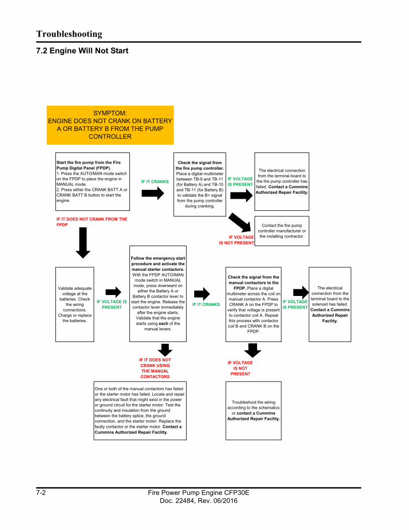
Troubleshooting
This page is intentionally left blank.
7.2 Engine Will Not Start
Fire Power Pump Engine CFP30EDoc. 22484, Rev. 06/2016
7-2

Troubleshooting
7.3 Engine Cranks But Will Not Start
Fire Power Pump Engine CFP30EDoc. 22484, Rev. 06/2016
7-3

Troubleshooting
Engine Cranks But Will Not Start (continued)
Fire Power Pump Engine CFP30EDoc. 22484, Rev. 06/2016
7-4

Troubleshooting
7.4 Engine Starts But Continues to Crank
Fire Power Pump Engine CFP30EDoc. 22484, Rev. 06/2016
7-5

Troubleshooting
7.5 Engine Will Not Stop
hold
Fire Power Pump Engine CFP30EDoc. 22484, Rev. 06/2016
7-6

Troubleshooting
7.6 Low Battery Voltage
Fire Power Pump Engine CFP30EDoc. 22484, Rev. 06/2016
7-7
Troubleshooting
This page is intentionally left blank.
Fire Power Pump Engine CFP30EDoc. 22484, Rev. 06/2016
7-8

Troubleshooting
7.7 Fault Code Charts
111 629(Red) 12112 635
(Red) 7113 635
(Yellow) 3114 635
(Yellow) 4115 190
(Red) 2116 156
(Red) 3117 156
(Red) 4118 135
(Yellow) 3119 135
(Yellow) 4121 190
(Yellow) 10122 102
(Yellow) 3123 102
(Yellow) 4131 91
(Red) 3132 91
(Red) 4133 974
(Red) 3133 29
(Red) 3134 974
(Red) 4134 29
(Red) 4135 100
(Yellow) 3141 100
(Yellow) 4143 100
(Yellow) 18143 100
(White) 1144 110
(Yellow) 3145 110
(Yellow) 4
Accelerator Pedal Position Sensor Circuit - Shorted Low
Accelerator Pedal Position Sensor Circuit - Shorted High
Remote Accelerator Pedal Position Sensor Circuit - Shorted High
Remote Accelerator Pedal Position Sensor Circuit - Shorted Low
Engine Oil Pressure Low - Warning
Engine Coolant Temperature Sensor Circuit - Shorted Low
FFAULT CODE (LAMP) CCummins DESCRIPTION
Engine Control Module - Critical Internal Failure
SPNFMI
Engine Speed/Position Sensor Circuit - Lost One of Two Signals from the Magnetic Pickup Sensor
Intake Manifold Pressure Sensor #1 Circuit - Shorted High
Intake Manifold Pressure Sensor #1 Circuit - Shorted Low
Engine Oil Pressure Sensor Circuit - Shorted High
Remote Accelerator Pedal Position Sensor Circuit - Shorted High
Engine Oil Pressure Sensor Circuit - Shorted Low
Fuel Pump Delivery Pressure Sensor Circuit - Shorted Low
Engine Timing Actuator is not Responding to ECM Commands
Engine Timing Actuator Circuit - Shorted High
Fuel Timing Pressure Sensor Circuit - Shorted High
Fuel Timing Pressure Sensor Circuit - Shorted Low
Engine Speed/Position Sensor Circuit - Lost Both of Two Signals from the Magnetic Pickup Sensor
Fuel Pump Delivery Pressure Sensor Circuit - Shorted High
Engine Timing Actuator Circuit - Shorted Low
Engine Coolant Temperature Sensor Circuit - Shorted High
Engine Oil Pressure Low - Warning
Remote Accelerator Pedal Position Sensor Circuit - Shorted Low
Fire Power Pump Engine CFP30EDoc. 22484, Rev. 06/2016
7-9
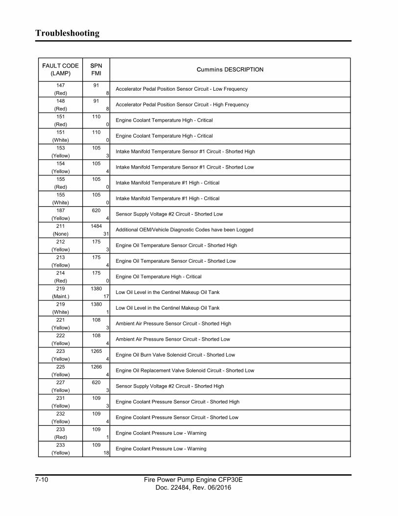
Troubleshooting
This page is intentionally left blank.
147 91(Red) 8148 91
(Red) 8151 110
(Red) 0151 110
(White) 0153 105
(Yellow) 3154 105
(Yellow) 4155 105
(Red) 0155 105
(White) 0187 620
(Yellow) 4211 1484
(None) 31212 175
(Yellow) 3213 175
(Yellow) 4214 175
(Red) 0219 1380
(Maint.) 17219 1380
(White) 1221 108
(Yellow) 3222 108
(Yellow) 4223 1265
(Yellow) 4225 1266
(Yellow) 4227 620
(Yellow) 3231 109
(Yellow) 3232 109
(Yellow) 4233 109
(Red) 1233 109
(Yellow) 18
FFAULT CODE (LAMP)
SSPNFMI CCummins DESCRIPTION
Intake Manifold Temperature Sensor #1 Circuit - Shorted Low
Accelerator Pedal Position Sensor Circuit - High Frequency
Accelerator Pedal Position Sensor Circuit - Low Frequency
Engine Coolant Pressure Sensor Circuit - Shorted High
Engine Coolant Temperature High - Critical
Intake Manifold Temperature Sensor #1 Circuit - Shorted High
Additional OEM/Vehicle Diagnostic Codes have been Logged
Engine Oil Temperature Sensor Circuit - Shorted High
Engine Oil Temperature Sensor Circuit - Shorted Low
Intake Manifold Temperature #1 High - Critical
Engine Coolant Pressure Low - Warning
Engine Oil Replacement Valve Solenoid Circuit - Shorted Low
Engine Coolant Pressure Low - Warning
Sensor Supply Voltage #2 Circuit - Shorted Low
Intake Manifold Temperature #1 High - Critical
Low Oil Level in the Centinel Makeup Oil Tank
Engine Oil Temperature High - Critical
Sensor Supply Voltage #2 Circuit - Shorted High
Ambient Air Pressure Sensor Circuit - Shorted High
Ambient Air Pressure Sensor Circuit - Shorted Low
Engine Oil Burn Valve Solenoid Circuit - Shorted Low
Engine Coolant Pressure Sensor Circuit - Shorted Low
Low Oil Level in the Centinel Makeup Oil Tank
Engine Coolant Temperature High - Critical
Fire Power Pump Engine CFP30EDoc. 22484, Rev. 06/2016
7-10

Troubleshooting
234 190(Red) 0235 111
(Red) 1235 111
(White) 1237 644
(Yellow) 2241 84
(Yellow) 2242 84
(Yellow) 10245 647
(Yellow) 4254 632
(Red) 4254 632
(None) 4255 632
(Yellow) 3259 632
(Red) 7261 174
(White) 0263 174
(Yellow) 3265 174
(Yellow) 4284 1043
(Yellow) 4285 639
(Yellow) 9286 639
(Yellow) 13287 91
(Red) 19288 974
(Red) 19292 1083
(White) 14293 1083
(Yellow) 3294 1083
(Yellow) 4295 108
(Yellow) 2296 1084
(White) 14
FFAULT CODE (LAMP)
SSPNFMI CCummins DESCRIPTION
Auxiliary Temperature Sensor Input #1 Circuit - Shorted High
Auxiliary Temperature Sensor Input #1 Circuit - Shorted Low
Fuel Temperature Sensor Circuit - Shorted High
Fuel Temperature Sensor Circuit - Shorted Low
Fuel Shut-off Valve Circuit - Shorted High
Engine Speed/Position Sensor #1 (Crankshaft) Supply Voltage Circuit - Shorted Low
SAE J1930 Multiplexing PGN Timeout Error
Engine Speed High - Critical
Fuel Temperature High - Warning
Fuel Shut-off Valve Circuit - Shorted Low
Engine Coolant Level Low - Critical
External Speed Input (Multiple Unit Sychronization) - Data Incorrect
Fuel Shut-off Valve - Stuck Open
Auxiliary Temperature Sensor Input #1 Engine Protection - Critical
Engine Coolant Level Low - Critical
Fuel Shut-off Valve Circuit - Shorted Low
Vehicle Speed Sensor Circuit - Data Incorrect
Vehicle Speed Sensor Circuit - Tampering has been Detected
Fan Clutch Circuit - Shorted Low
SAE J1930 Multiplexing PGN Configuration Error
SAE J1930 Multiplexing Accelerator Pedal Sensor System Error
SAE J1930 Multiplexing Remote Throttle Data Error
Ambient Air Pressure Sensor Circuit - Data Incorrect
Auxiliary Pressure Sensor Input #2 Engine Protection - Critical
Fire Power Pump Engine CFP30EDoc. 22484, Rev. 06/2016
7-11
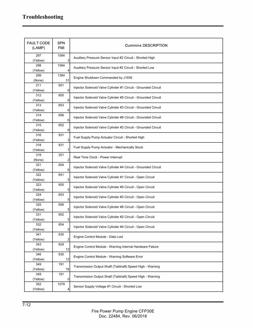
Troubleshooting
297 1084(Yellow) 3
298 1084(Yellow) 4
299 1384(None) 31
311 651(Yellow) 6
312 655(Yellow) 6
313 653(Yellow) 6
314 656(Yellow) 6
315 652(Yellow) 6
316 931(Yellow) 3
318 931(Yellow) 7
319 251(None) 2
321 654(Yellow) 6
322 651(Yellow) 5
323 655(Yellow) 5
324 653(Yellow) 5
325 656(Yellow) 5
331 652(Yellow) 5
332 654(Yellow) 5
341 630(Yellow) 2
343 629(Yellow) 12
346 630(Yellow) 12
349 191(Yellow) 16
349 191(Yellow) 0
352 1079(Yellow) 4
Injector Solenoid Valve Cylinder #3 Circuit - Grounded Circuit
Injector Solenoid Valve Cylinder #6 Circuit - Grounded Circuit
Injector Solenoid Valve Cylinder #1 Circuit - Grounded Circuit
Injector Solenoid Valve Cylinder #5 Circuit - Grounded Circuit
Auxiliary Pressure Sensor Input #2 Circuit - Shorted Low
Transmission Output Shaft (Tailshaft) Speed High - Warning
Auxiliary Pressure Sensor Input #2 Circuit - Shorted High
CCummins DESCRIPTION
Engine Shutdown Commanded by J1939
Fuel Supply Pump Actuator Circuit - Shorted High
Engine Control Module - Warning Software Error
Fuel Supply Pump Actuator - Mechanically Stuck
Injector Solenoid Valve Cylinder #4 Circuit - Open Circuit
Injector Solenoid Valve Cylinder #2 Circuit - Grounded Circuit
Real Time Clock - Power Interrupt
Injector Solenoid Valve Cylinder #4 Circuit - Grounded Circuit
Injector Solenoid Valve Cylinder #1 Circuit - Open Circuit
Injector Solenoid Valve Cylinder #5 Circuit - Open Circuit
Injector Solenoid Valve Cylinder #3 Circuit - Open Circuit
Injector Solenoid Valve Cylinder #6 Circuit - Open Circuit
Injector Solenoid Valve Cylinder #2 Circuit - Open Circuit
Engine Control Module - Warning Internal Hardware Failure
Engine Control Module - Data Lost
Transmission Output Shaft (Tailshaft) Speed High - Warning
FAULT CODE (LAMP)
SPNFMI
Sensor Supply Voltage #1 Circuit - Shorted Low
Fire Power Pump Engine CFP30EDoc. 22484, Rev. 06/2016
7-12

Troubleshooting
378 633(Yellow) 5
379 633(Yellow) 6
384 626(Yellow) 11
386 1079(Yellow) 3
387 1043(Yellow) 3
394 635(Yellow) 5
395 635(Yellow) 6
396 1244(Yellow) 5
397 1244(Yellow) 6
398 1245(Yellow) 5
399 1245(Yellow) 6
415 100(Red) 1418 97
(None) 15422 111
(Yellow) 2423 156
(Yellow) 2426 639
(None) 2426 639
(Yellow) 2427 639
(None) 9428 97
(Yellow) 3429 97
(Yellow) 4431 558
(Yellow) 2431 91
(Yellow) 2432 558
(Red) 13432 91
(Red) 13
FFAULT CODE (LAMP)
SSPNFMI CCummins DESCRIPTION
Water in Fuel Sensor Circuit - Shorted High
Water in Fuel Sensor Circuit - Shorted Low
Accelerator Pedal Idle Validation Circuit - Out of Calibration
Fueling Actuator #2 Circuit - Open Circuit
Fueling Actuator #2 Circuit - Grounded Circuit
Timing Actuator #2 Circuit - Open Circuit
Timing Actuator #2 Circuit - Grounded Circuit
Water in Fuel Indicator High - Maintenance
Fuel Timing Pressure or Timing Actuator Stuck
Fueling Actuator #1 Circuit - Grounded Circuit
Sensor Supply Voltage #1 Circuit - Shorted High
Accelerator Pedal Position Sensor Supply Voltage Circuit - Shorted High
Tiiming Actuator #1 Circuit - Open Circuit
Fueling Actuator #1 Circuit - Open Circuit
Engine Coolant Level Sensor Circuit - Data Incorrect
Engine Oil Pressure Low - Critical
Start Assist Device Control Circuit Error (Ether Injection)
Tiiming Actuator #1 Circuit - Grounded Circuit
SAE J1939 Datalink - Cannot Transmit
SAE J1939 Not Fast Enough
Accelerator Pedal Idle Validation Circuit - Data Incorrect
Accelerator Pedal Idle Validation Circuit - Data Incorrect
Accelerator Pedal Idle Validation Circuit - Out of Calibration
SAE J1939 Datalink - Cannot Transmit
Fire Power Pump Engine CFP30EDoc. 22484, Rev. 06/2016
7-13

Troubleshooting
433 102(Yellow) 2
434 627(Yellow) 2
435 100(Yellow) 2
441 168(Yellow) 18
441 168(None) 1
442 168(Yellow) 16
442 168(Yellow) 0
443 1043(Yellow) 4
449 94(Yellow) 16
451 157(Yellow) 3
452 157(Yellow) 4
455 633(Red) 3466 1188
(Yellow) 4467 635
(Yellow) 2468 633
(Yellow) 2482 94
(Yellow) 18483 1349
(Yellow) 3484 1349
(Yellow) 4485 1349
(Yellow) 16486 1349
(Yellow) 18487 626
(None) 1489 191
(Yellow) 18489 191
(Yellow) 1496 1043
(Yellow) 11
FFAULT CODE (LAMP)
SSPNFMI CCummins DESCRIPTION
Injector Metering Rail #2 Pressure Sensor Circuit - Shorted Low
Injector Metering Rail #2 Pressure High - Warning
Injector Metering Rail #2 Pressure Low - Warning
Engine Speed/Position Sensor #2 (Camshaft) Supply Voltage
Start Assist Device - Canister Empty (Ether Injection)
Accelerator Pedal Position Sensor Supply Voltage Circuit - Shorted Low
Fuel Pressure High - Warning
Turbocharger #1 Wastegate Control Circuit - Shorted Low
Fuel Control Valve Circuit - Shorted High
Timing Rail Actuator Circuit - Data Incorrect
Injector Metering Rail #2 Pressure Sensor Circuit - Shorted High
Fuel Pressure Low - Warning
Engine Oil Pressure Sensor Circuit - Data Incorrect
Battery #1 Voltage Low - Warning
Transmission Output Shaft (Aux Gov) Speed Low - Warning
Transmission Output Shaft (Tailshaft) Speed Low - Warning
Injector Metering Rail #1 Pressure Sensor Circuit - Shorted High
Fuel Rail Actuator Circuit - Data Incorrect
Injector Metering Rail #1 Pressure Sensor Circuit - Shorted Low
Battery #1 Voltage Low - Warning
Battery #1 Voltage High- Warning
Intake Manifold Pressure Sensor Circuit - Data Incorrect
Power Lost without Ignition Off
Battery #1 Voltage High- Warning
Fire Power Pump Engine CFP30EDoc. 22484, Rev. 06/2016
7-14

Troubleshooting
497 1377(Yellow) 2
514 633(Red) 7527 702
(Yellow) 3528 93
(Yellow) 2529 703
(Yellow) 3546 94
(Yellow) 3547 94
(Yellow) 4551 558
(Yellow) 4551 91
(Red) 4553 157
(Yellow) 16553 157
(Red) 0554 157
(Yellow) 2555 1264
(Yellow) 16555 1264
(White) 0581 1381
(Yellow) 3582 1381
(Yellow) 4583 1381
(Yellow) 18595 103
(Yellow) 16596 167
(Yellow) 16597 167
(Yellow) 18598 167
(Red) 1611 1383
(None) 31649 1378
(None) 0719 1264
(Yellow) 3
FFAULT CODE (LAMP)
SSPNFMI CCummins DESCRIPTION
Fuel Supply Pump Inlet Pressure Sensor Low - Warning Level
Turbocharger #1 Speed High - Warning Level
Electrical Charging System Voltage High - Warning Level
Electrical Charging System Voltage Low - Warning Level
Electrical Charging System Voltage Low - Critical Level
OEM Alternate Torque Validation Switch - Data Incorrect
Fuel Delivery Pressure Sensor Circuit - Shorted High
Fuel Delivery Pressure Sensor Circuit - Shorted Low
Accelerator Pedal Idle Validation Circuit - Shorted Low
Engine Blowby - Warning Level
Fuel Supply Pump Inlet Pressure Sensor Circuit - Shorted High
Fuel Control Valve - Mechanically Stuck
Multiple Unit Sychronization Switch Circuit - Data Incorrect
Injector Metering Rail #1 Pressure High - Warning Level
Crankcase Blowby Pressure Sensor Circuit - Shorted High
Accelerator Pedal Idle Validation Circuit - Shorted Low
Change Lubricating Oil and Filter
Fuel Pressure Sensor Error
Engine Blowby - Warning Level
Injector Metering Rail #1 Pressure High - Warning Level
Engine Hot Shutdown
Fuel Supply Pump Inlet Pressure Sensor Circuit - Shorted Low
Auxiliary Input/Output #3 Circuit - Shorted High
Auxiliary Input/Output #2 Circuit - Shorted High
Fire Power Pump Engine CFP30EDoc. 22484, Rev. 06/2016
7-15

Troubleshooting
729 1264(Yellow) 4
753 723(None) 2
755 157(Yellow) 7
758 1349(Yellow) 7
951 166(None) 2
FFAULT CODE (LAMP)
SSPNFMI CCummins DESCRIPTION
Engine Speed/Position #2 - Cam Sync Error
Injector Metering Rail #2 Pressure Malfunction
Cylinder Power Imbalance Between Cylinders
Injector Metering Rail #1 Pressure Malfunction
Crankcase Blowby Pressure Sensor Circuit - Shorted Low
Fire Power Pump Engine CFP30EDoc. 22484, Rev. 06/2016
7-16

Section 8 - Component Parts and Assemblies
8.1 Ordering PartsReplacement parts for the Cummins Inc. equipment are manufactured to the same quality standards and specifications as the original equipment. Unapproved substitution may result in poor performance, reduced service life, lost production, or unsafe operation.
Cummins Inc. relies on the best and most cost effec-tive shipping methods, unless specific instructions or requirements are requested by the customer. When ordering parts, please be prepared to provide the fol-lowing information:
• Model and serial number.
• Part description by name or number.
• Quantity required.
• Purchase order number.
NOTE: A purchase order number is desirable, even if the part(s) are supplied on a Returned Goods Autho-rization (RGA) issue number. A purchase order number helps Cummins and its customer track the parts and necessary credits.
8.2 Routine Service and Parts Personnel at Cummins Authorized Repair Locations can assist you with the correct operation and service of your engine. Cummins has a worldwide service network of more than 5,000 Distributors and Dealers who have been trained to provide sound advice, expert service, and complete parts support.
Check the telephone directory yellow pages or refer to the directory in this section for the nearest Cummins Authorized Repair Location.
8.3 Emergency Repairs and Technical Service The Cummins Customer Assistance Center provides a 24-hour, toll free telephone number to aid in techni-cal and emergency service when a Cummins Autho-rized Repair Location cannot be reached or is unable to resolve an issue with a Cummins product.
If assistance is required, call Toll-Free: 1-800-DIESELS (1-800-343-7357). Includes all 50 states, Bermuda, Puerto Rico, Virgin Islands, and the Baha-mas.
Outside of North America contact your Regional Office. Telephone numbers and addresses are listed in the International Directory.
Refer also to the Cummins Inc. web site at www.cum-mins.com.
8.4 Recommended Spare Parts InventoryTo minimize downtime and increase productivity, Cummins Inc. recommends maintaining a stock of spare parts critical to uninterrupted engine operation. Shipping costs can be lower using ground transporta-tion rather than overnight or next day air freight. For this reason, Cummins Inc. can provide a list of recom-mended spare parts. Contact a Cummins Authorized Repair Location for additional information.
Fire Power Pump Engine CFP30EDoc. 22484, Rev. 06/2016
8-1

Component Parts and Assemblies
CFP30E Engine Data Sheet
Fire Power Pump Engine CFP30EDoc. 22484, Rev. 06/2016
8-2

Component Parts and Assemblies
CFP30E Engine Data Sheet (Continued)
Fire Power Pump Engine CFP30EDoc. 22484, Rev. 06/2016
8-3

Component Parts and Assemblies
CFP30E Engine Data Sheet (Continued)
Mike Dawson
Fire Power Pump Engine CFP30EDoc. 22484, Rev. 06/2016
8-4
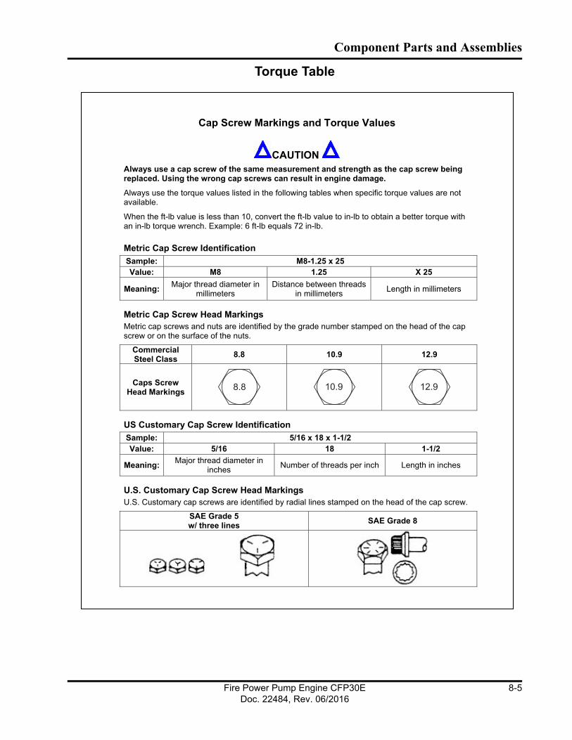
Component Parts and Assemblies
Torque Table
Cap Screw Markings and Torque Values
CAUTION
Always use a cap screw of the same measurement and strength as the cap screw being replaced. Using the wrong cap screws can result in engine damage.
Always use the torque values listed in the following tables when specific torque values are not
available.
When the ft-lb value is less than 10, convert the ft-lb value to in-lb to obtain a better torque with
an in-lb torque wrench. Example: 6 ft-lb equals 72 in-lb.
Metric Cap Screw Identification
Sample: M8-1.25 x 25
Value: M8 1.25 X 25
Meaning:Major thread diameter in
millimeters
Distance between threads
in millimeters Length in millimeters
Metric Cap Screw Head Markings
Metric cap screws and nuts are identified by the grade number stamped on the head of the cap
screw or on the surface of the nuts.
Commercial Steel Class
8.8 10.9 12.9
Caps Screw Head Markings
8.8 10.9 12.9
US Customary Cap Screw Identification
Sample: 5/16 x 18 x 1-1/2
Value: 5/16 18 1-1/2
Meaning:Major thread diameter in
inchesNumber of threads per inch Length in inches
U.S. Customary Cap Screw Head Markings
U.S. Customary cap screws are identified by radial lines stamped on the head of the cap screw.
SAE Grade 5 w/ three lines
SAE Grade 8
Fire Power Pump Engine CFP30EDoc. 22484, Rev. 06/2016
8-5
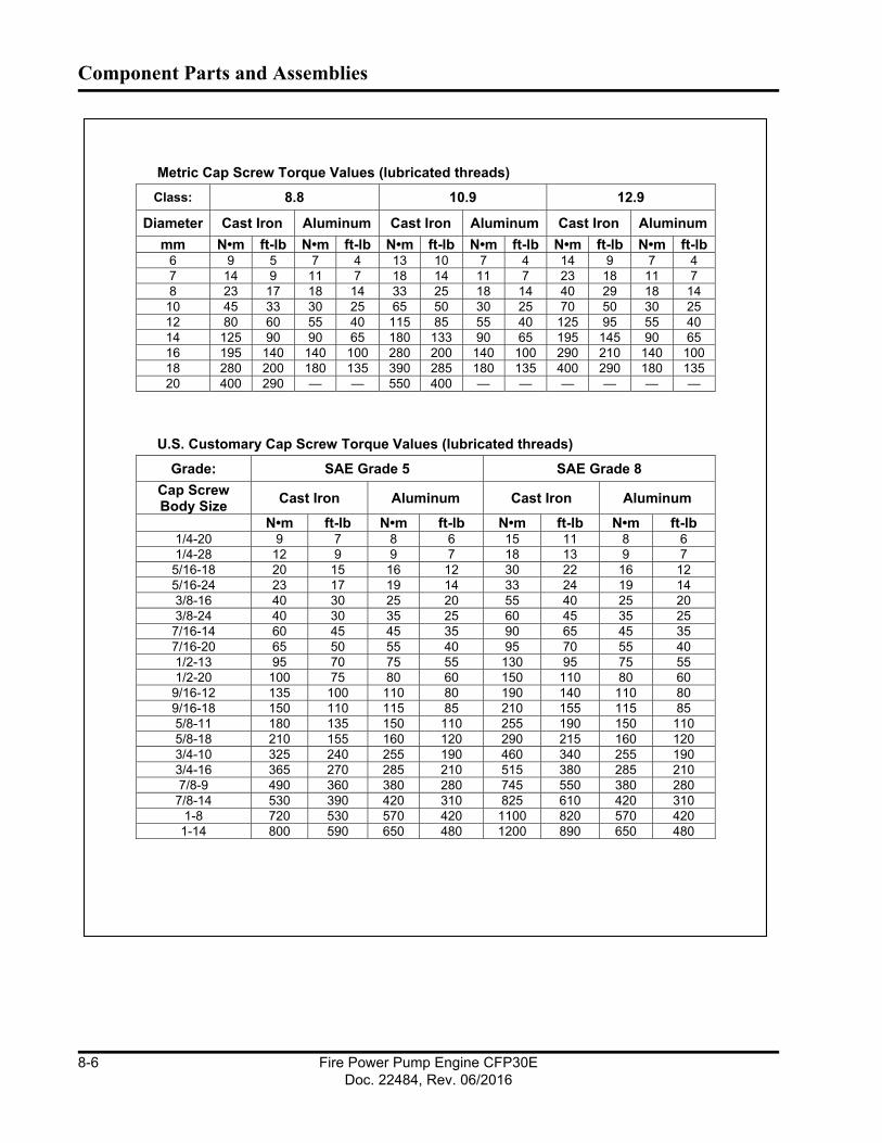
Component Parts and Assemblies
Metric Cap Screw Torque Values (lubricated threads)
Class: 8.8 10.9 12.9
Diameter Cast Iron Aluminum Cast Iron Aluminum Cast Iron Aluminum
mm N•m ft-lb N•m ft-lb N•m ft-lb N•m ft-lb N•m ft-lb N•m ft-lb6 9 5 7 4 13 10 7 4 14 9 7 4
7 14 9 11 7 18 14 11 7 23 18 11 7
8 23 17 18 14 33 25 18 14 40 29 18 14
10 45 33 30 25 65 50 30 25 70 50 30 25
12 80 60 55 40 115 85 55 40 125 95 55 40
14 125 90 90 65 180 133 90 65 195 145 90 65
16 195 140 140 100 280 200 140 100 290 210 140 100
18 280 200 180 135 390 285 180 135 400 290 180 135
20 400 290 — — 550 400 — — — — — —
U.S. Customary Cap Screw Torque Values (lubricated threads)
Grade: SAE Grade 5 SAE Grade 8
Cap Screw Body Size
Cast Iron Aluminum Cast Iron Aluminum
N•m ft-lb N•m ft-lb N•m ft-lb N•m ft-lb1/4-20 9 7 8 6 15 11 8 6
1/4-28 12 9 9 7 18 13 9 7
5/16-18 20 15 16 12 30 22 16 12
5/16-24 23 17 19 14 33 24 19 14
3/8-16 40 30 25 20 55 40 25 20
3/8-24 40 30 35 25 60 45 35 25
7/16-14 60 45 45 35 90 65 45 35
7/16-20 65 50 55 40 95 70 55 40
1/2-13 95 70 75 55 130 95 75 55
1/2-20 100 75 80 60 150 110 80 60
9/16-12 135 100 110 80 190 140 110 80
9/16-18 150 110 115 85 210 155 115 85
5/8-11 180 135 150 110 255 190 150 110
5/8-18 210 155 160 120 290 215 160 120
3/4-10 325 240 255 190 460 340 255 190
3/4-16 365 270 285 210 515 380 285 210
7/8-9 490 360 380 280 745 550 380 280
7/8-14 530 390 420 310 825 610 420 310
1-8 720 530 570 420 1100 820 570 420
1-14 800 590 650 480 1200 890 650 480
Fire Power Pump Engine CFP30EDoc. 22484, Rev. 06/2016
8-6

Component Parts and Assemblies
8.5 Assembly DrawingsNOTE: The most current revisions to these drawings and related documents are accessible at: http://www.cumminsfirepower.com/products.html.
Description Drawing No.Revision
LevelGeneral Arrangement, Custom Fire Pump, CFP30E A042G348 AAssembly, Fire Pump, CFP30E 26783 AOptions, Engine, G-Drive, CFP30E (QST30) 13207 EAssembly, Heat Exchanger 13760 FAssembly, Air Intake Heavy Duty A042G162 -Assembly, Guarding 13638 CAssembly, Coolant Heater 13568 DAssembly, Sensor Package A042A499 BAssembly, Control Panel Mounting 21249 -Assembly, All Component Top-level: CFP30E-2013 Assembly, Panel, Digital Electronic 22791 A Assembly, Harness 22347 C Cables, Battery Contactors 23939 A Battery Contactors 24V 8824-24 A Kit, Fuel Lines 22394 A Option, Oil Drain with Valve 15338 A Assembly, Oil/Air Temperature 21477 A Assembly, DPEM and Mounting 21662 A Assembly, DPEM Harness A042G443 -Misc. Piping, Cooling Loop A042A568 AAssembly, Sea Water Cooling Loop, 2" Horizontal 24V A042D794 -Shaft , Drive APT225 U3200 Series 13508 -
Assembly, Guard Shaft A042A569 -Schematic, Control Panel, Electronic A042G984
Fire Power Pump Engine CFP30EDoc. 22484, Rev. 06/2016
8-7

Component Parts and Assemblies
Fire Power Pump Engine CFP30EDoc. 22484, Rev. 06/2016
8-8

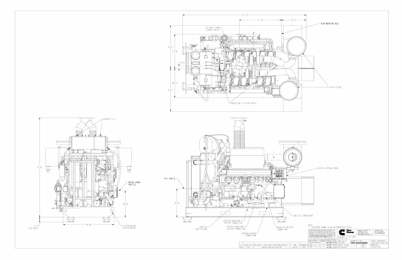
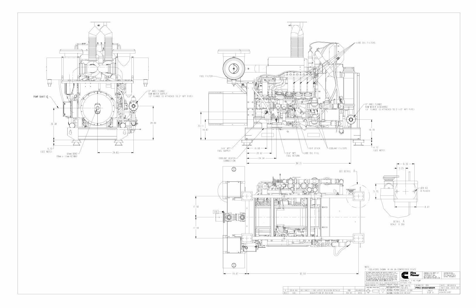

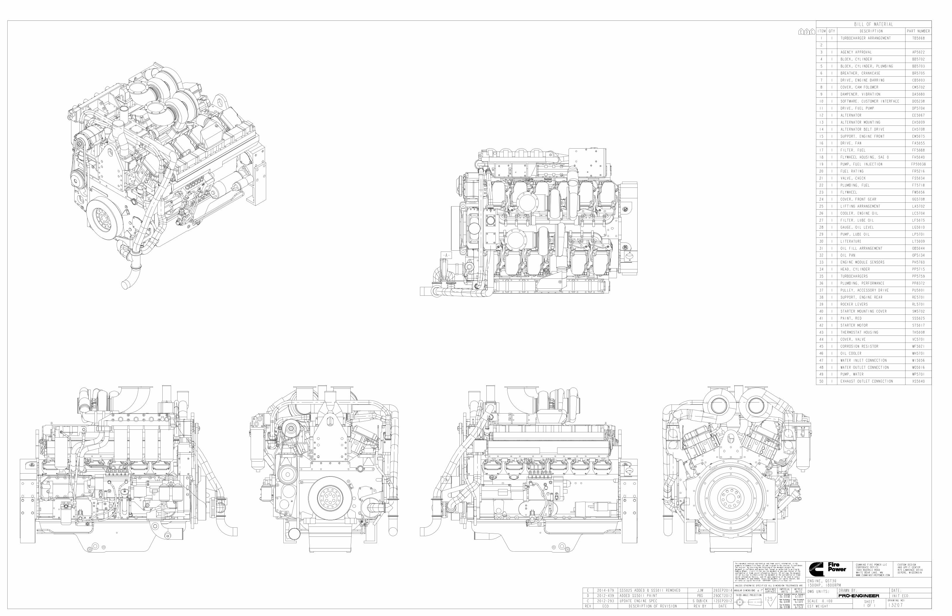
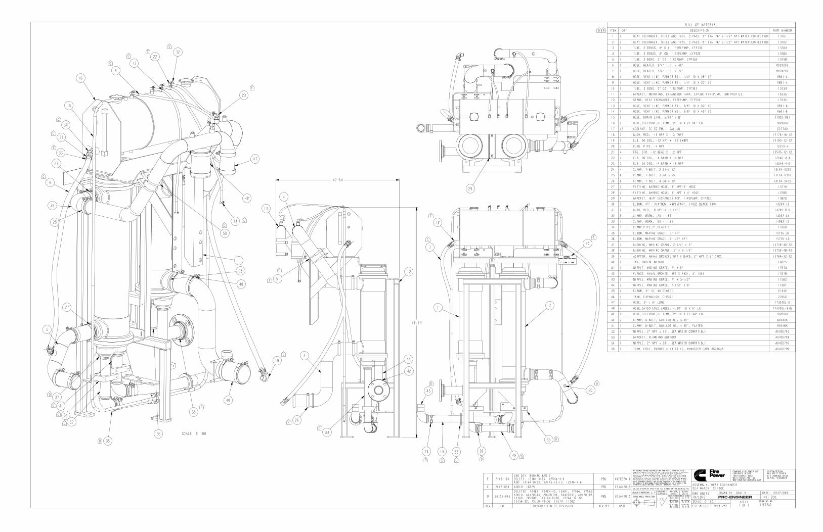
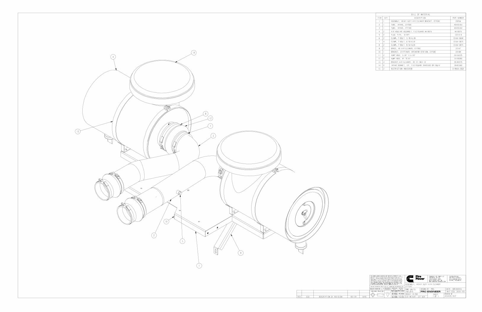

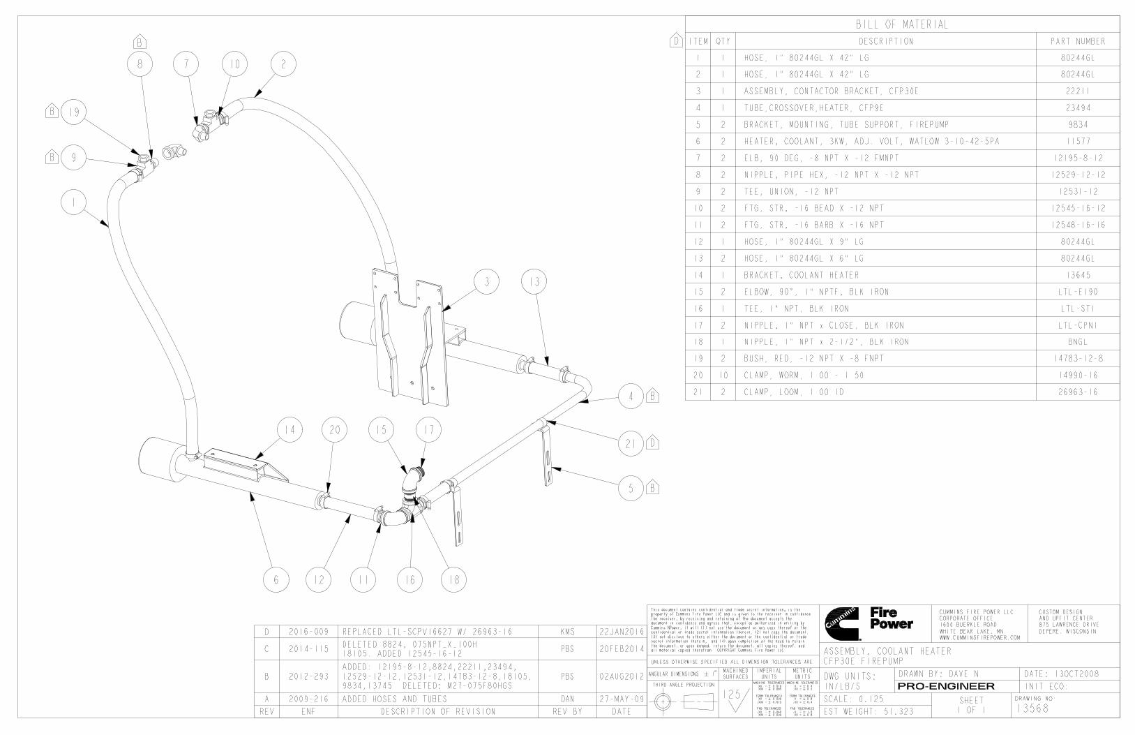
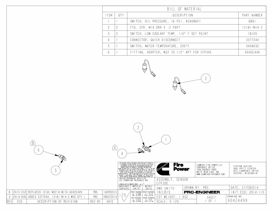


KIT INCLUDES
1. 22348 - HARNESS, POWER WIRES
2. 22349 - HARNESS, INTERFACE
3. 22350 - HARNESS, ECM A
4. 22324 - HARNESS, J1587 INTERCONNECT
AUTO CADITEM 2 - REV A - ADDED 2ND LCL SWITCH.
A2012-532 BG
12 NOV 2012
UPDATE 22348,22349,22350
B2014-333 RMJ 14MAY2014
UPDATE 22350
C2016-015 KAK 22JAN2016
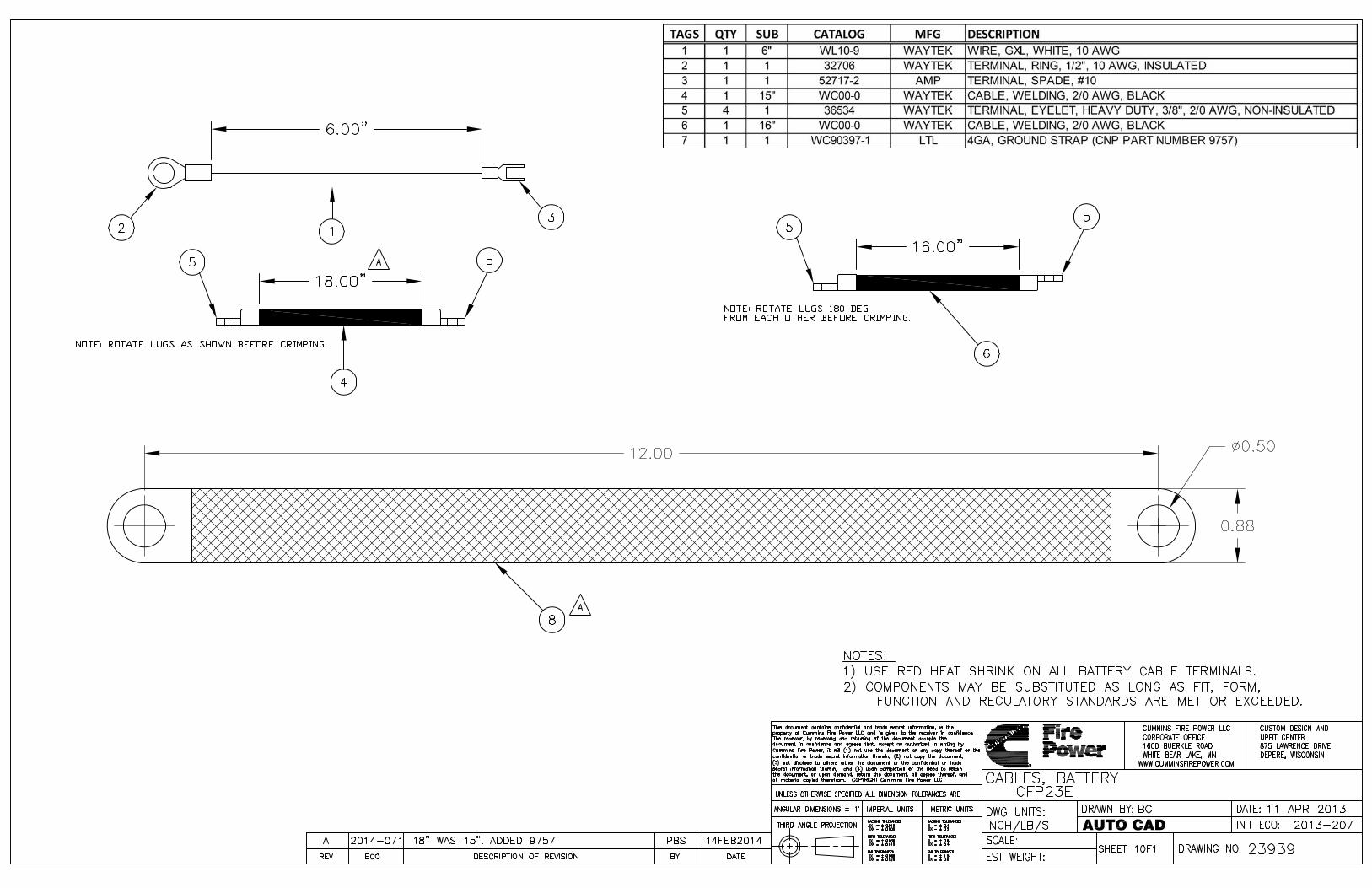
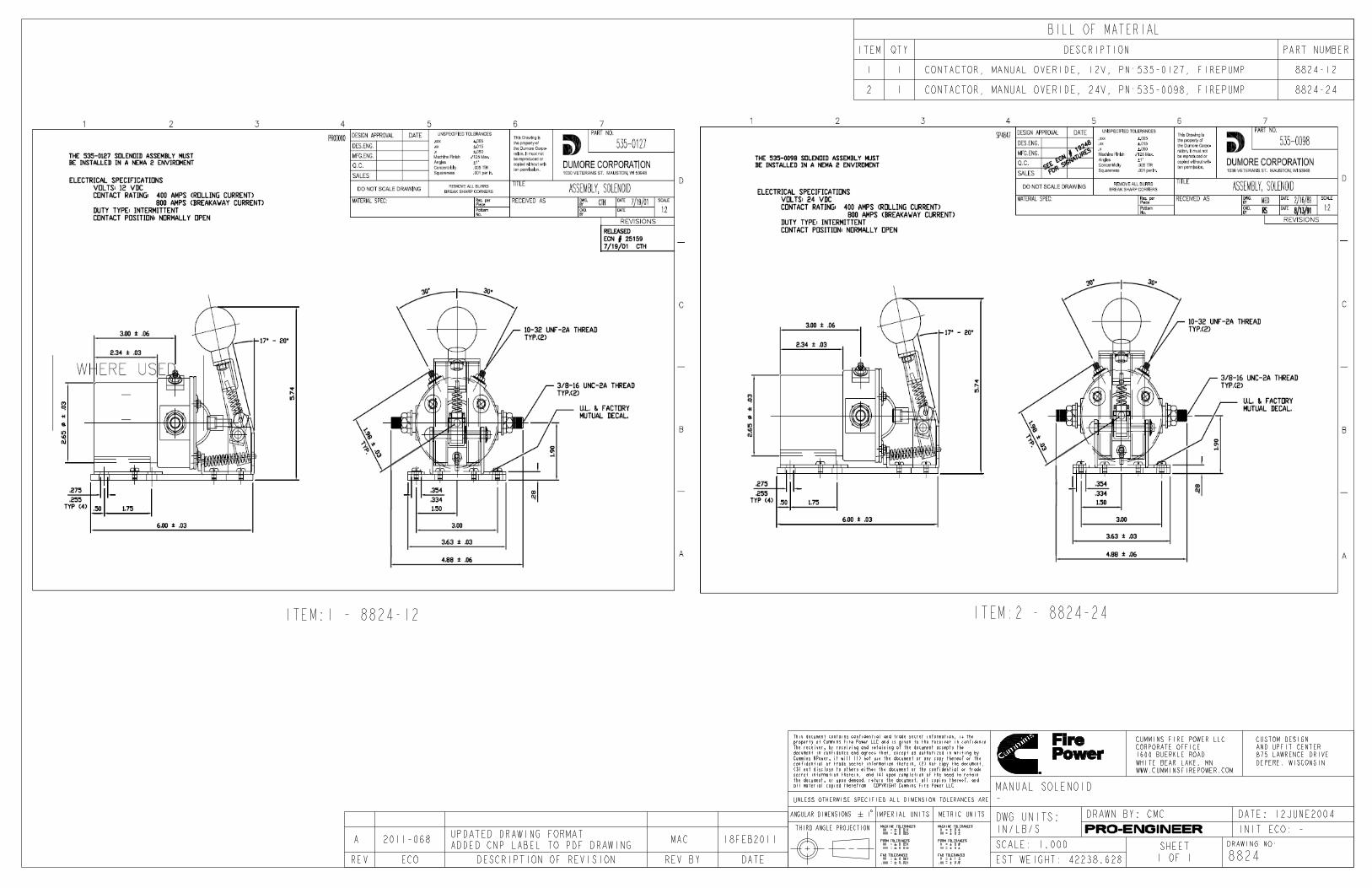

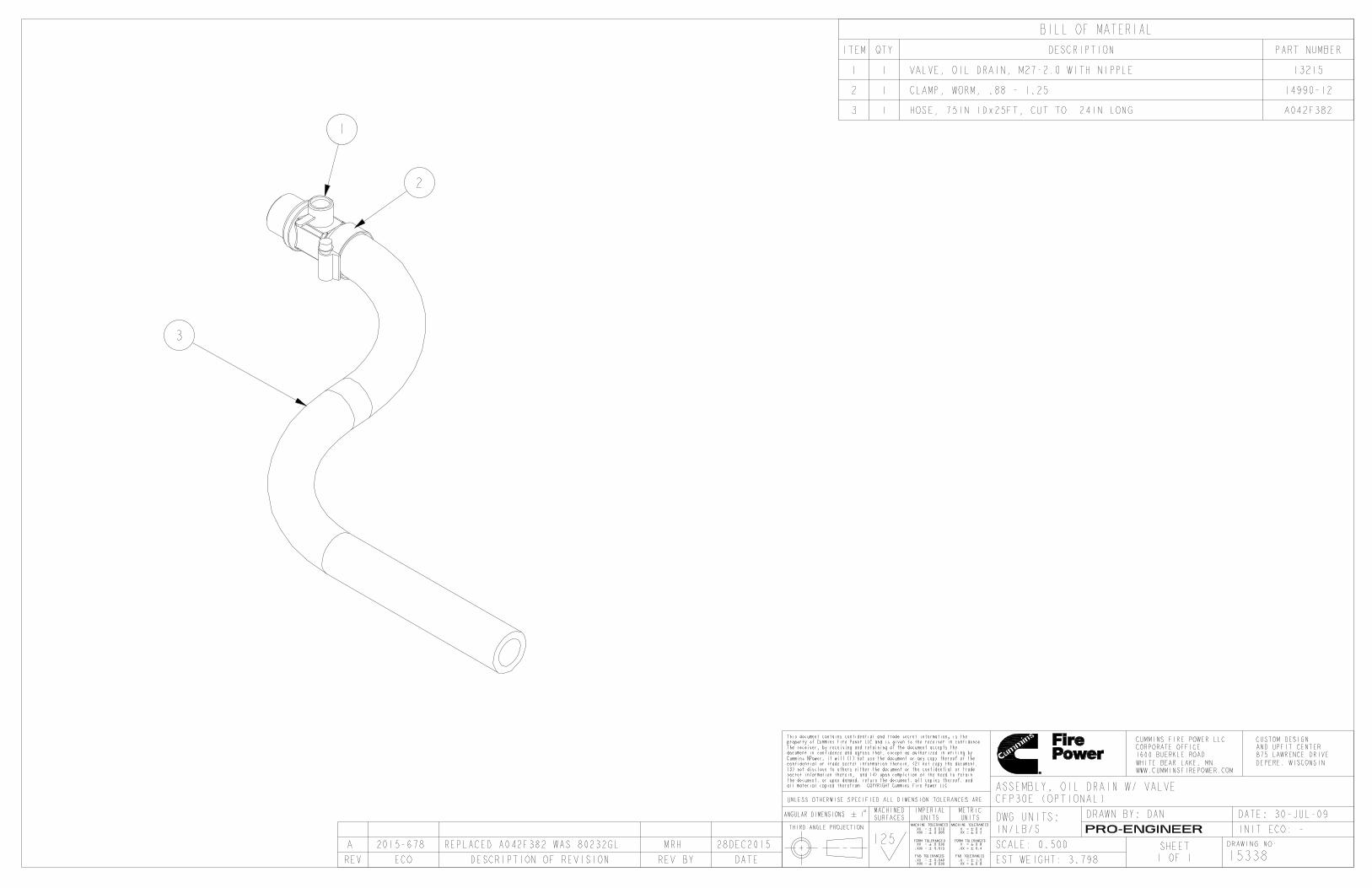
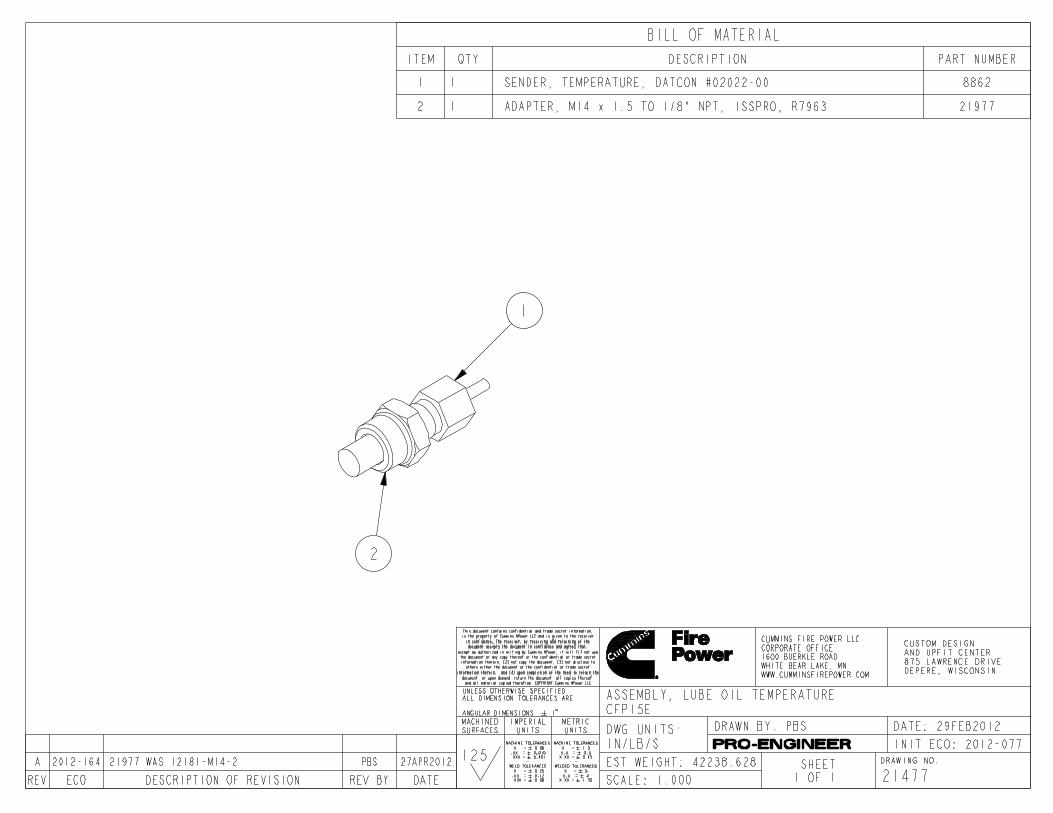
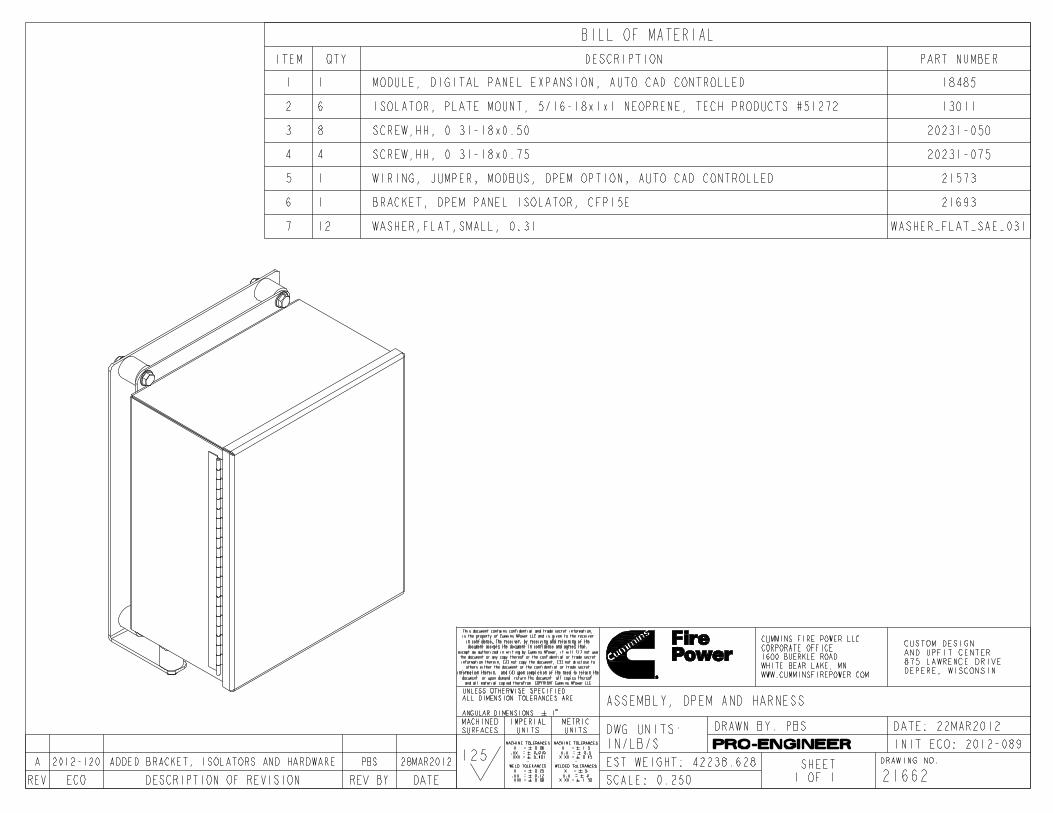
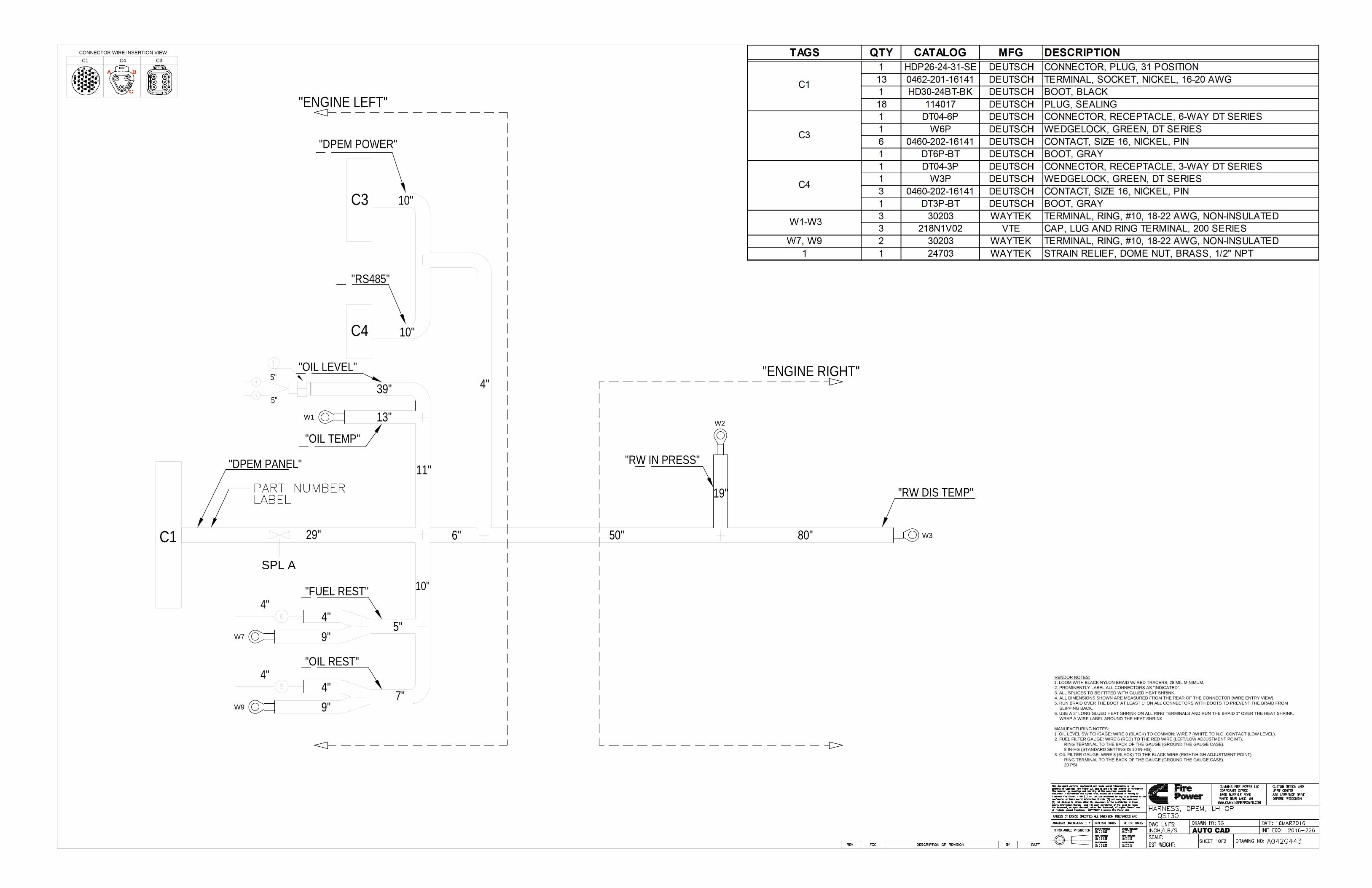
C1 C4 C3
AUTO CAD
CONNECTOR WIRE INSERTION VIEW
C1
SPL A
6"29"
"DPEM PANEL"
4"
4"
10"
"FUEL REST"
W7
4"
9"
"RW DIS TEMP"
4"
"OIL REST"
W9
4"
9"
"ENGINE LEFT"
C3
C4
10"
10"
"DPEM POWER"
"RS485"
"ENGINE RIGHT"
80"
5"
7"
50"
11"
W1
"OIL TEMP"
"OIL LEVEL"
13"
39"
19"
"RW IN PRESS"
W2
W3
VENDOR NOTES:
1. LOOM WITH BLACK NYLON BRAID W/ RED TRACERS, 28 MIL MINIMUM.
2. PROMINENTLY LABEL ALL CONNECTORS AS "INDICATED".
3. ALL SPLICES TO BE FITTED WITH GLUED HEAT SHRINK.
4. ALL DIMENSIONS SHOWN ARE MEASURED FROM THE REAR OF THE CONNECTOR (WIRE ENTRY VIEW).
5. RUN BRAID OVER THE BOOT AT LEAST 1" ON ALL CONNECTORS WITH BOOTS TO PREVENT THE BRAID FROM
SLIPPING BACK.
6. USE A 3" LONG GLUED HEAT SHRINK ON ALL RING TERMINALS AND RUN THE BRAID 1" OVER THE HEAT SHRINK.
WRAP A WIRE LABEL AROUND THE HEAT SHRINK
MANUFACTURING NOTES:
1. OIL LEVEL SWITCHGAGE: WIRE 8 (BLACK) TO COMMON; WIRE 7 (WHITE TO N.O. CONTACT (LOW LEVEL).
2. FUEL FILTER GAUGE: WIRE 6 (RED) TO THE RED WIRE (LEFT/LOW ADJUSTMENT POINT).
RING TERMINAL TO THE BACK OF THE GAUGE (GROUND THE GAUGE CASE).
8 IN-HG (STANDARD SETTING IS 10 IN-HG)
3. OIL FILTER GAUGE: WIRE 8 (BLACK) TO THE BLACK WIRE (RIGHT/HIGH ADJUSTMENT POINT).
RING TERMINAL TO THE BACK OF THE GAUGE (GROUND THE GAUGE CASE).
20 PSI
5"
5"

C1
21
DPEM PANEL
28
27
22
26
23
24
B
C4
A
RS485
C
1
C3
3
DPEM
POWER
4
2
SPL A
BATTERY A
GROUND
BATTERY B
GROUND
5
RS485A
RS485B
SHIELD
11
6
13
9
AUTO CAD
4
3
OIL TEMPERATURE [ALARM HIGH]W1
RAW WATER INPUT PRESSUREW3
OIL DIFFERENTIAL PRESSURE
W9
SWITCHGAUGE CASE
FUEL DIFFERENTIAL PRESSURE
W7
SWITCHGAUGE CASE
OIL LEVEL
5
RAW WATER DISCHARGE TEMPERATURE [ALARM HIGH]W2
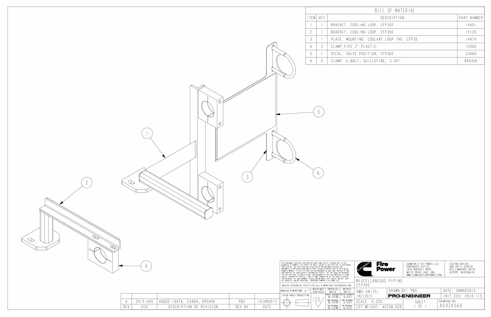
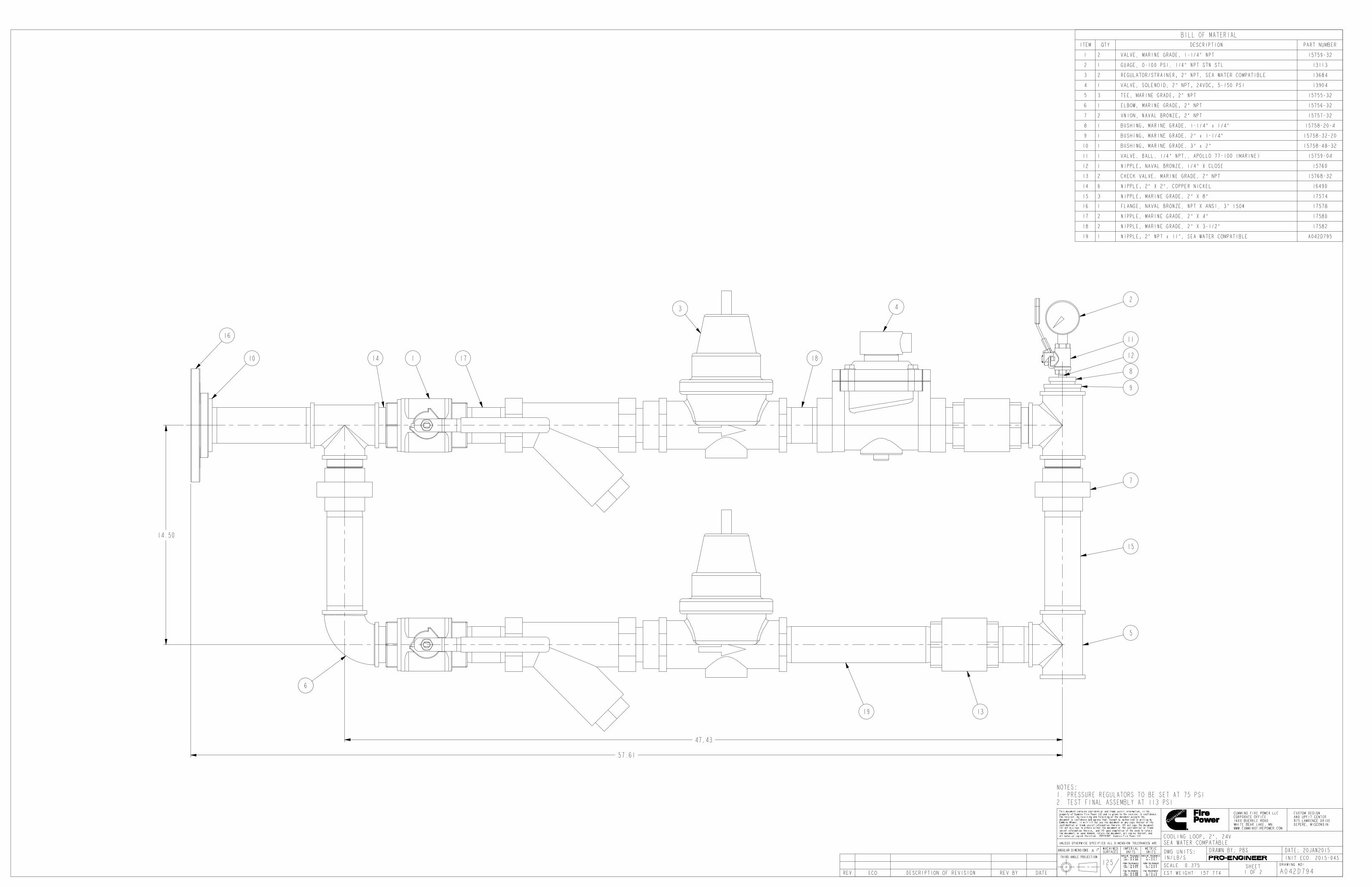

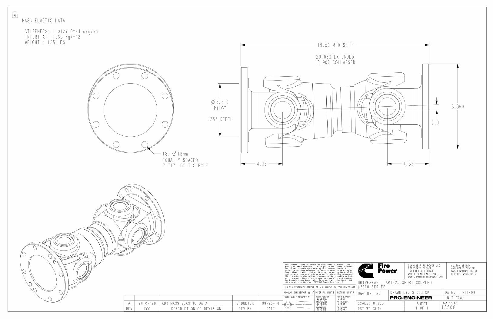


A
B
C
14
A
B
C
B+
D
S
ALT
1 2 3 4 5 6 8 9
10
11
301
302
312
303
304
310
311
POWER BOARD
15153
I2C
I/O
XPDR
OSS
CTS
MBC1
MBC2
MANUAL
KEYSWITCH
Vr
B+
EXCITE
Vr B+
Vr B+
12
MCB1
B+ B+
13
MCB2
AUTO
NON-ISOLATED
CPU
PUMP CONTROLLER CONNECTIONS
CTS
OSS
LCT19
LOP
10
LCT
LOP
HCT
HCT
11
DISPLAY BOARD
15152
I2C
I2C
I2C
15
RWS
3
SYS GND
B+
BATT A
BATT B
2
1
4
CONTROL PANEL ENCLOSURE
CHARGE GND
CONNECTOR
C1
RWS
SHOWN IN "LOW OIL PRESS" STATE
(OR ENGINE NOT RUNNING)
SHOWN IN "NORMAL TEMP" STATE
(OR ENGINE NOT RUNNING)
LOP
HCT
BAT A
POS NEG
BAT B
POS NEG
SYS GND
BATTERY ISOLATOR
EXCITE
MCB1
MCB2
BATT A
BATT B
CHARGE GND
NC
(ENERGIZE TO RUN)
AU
TO
CT
S
OS
S
LO
P
HC
T
BA
TT
A
BA
TT
B
MB
C1
MB
C2
GN
D
LC
T
ECM B
FIM
EC
M B
FIM
Vr
INC
DEC
ECM SWITCH BOARD
15154
ECM SWITCH
KEYSWITCH
ECM SELECT
ECM RETURN
INC
DEC
ECM POWER BOARD
15155
J1939
ECM A
BATT A
BATT B
ENGINE CONNECTIONS
NOTES: 1) SEE SHEET 2 FOR CFP30E ECM SWITCH SCHEMATIC
AUTO CAD
16
22
RS485+
21
RS485-
GROUND
TO OPTIONAL DIGITAL PANEL EXPANSION MODULE
RS485
LCT
LEGEND:
OSS = OVER SPEED SWITCH
CTS = CRANK TERMINATION SWITCH
MBC1 = MAIN BATTERY CONTACTOR 1
MBC2 = MAIN BATTERY CONTACTOR 2
LCT = LOW COOLANT TEMPERATURE
HCT = HIGH COOLANT TEMPERATURE
LOP = LOW OIL PRESSURE
RWS = RAW WATER SOLENOID
RWHIT = RAW WATER HIGH INLET TEMP
CRWCLS= CLOGGED RAW WATER COOLING LOOP
STRAINER
ECMW = ELECTRONIC CONTROL MODULE WARNING
ECMF = ELECTRONIC CONTROL MODULE FAILURE
ECMW
ECMF
RWHIT
CRWCLS
EC
MW
EC
MF
RW
HIT
CR
WC
LS
20
J1587-
23
J1587S
18
J1587+
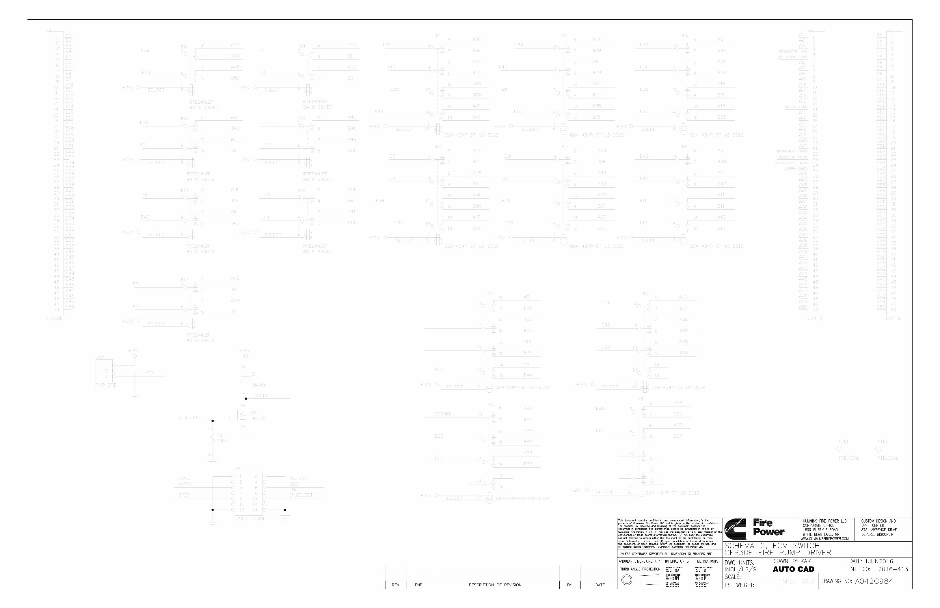
AUTO CAD