Rehab – Series
94
0197 Rehab – Series USER MANUAL www.nutekmedical.com
-
Upload
khangminh22 -
Category
Documents
-
view
7 -
download
0
Transcript of Rehab – Series

0197
Rehab – SeriesUSER MANUAL
www.nutekmedical.com

1 Foreword................................................................................................... 31.1 Intended User/Operator............................................................................ 32 Product Description...................................................................................... 33 Precautionary Instructions............................................................................. 94 Intended Use............................................................................................... 114.1 Intended Use Electrotherapy....................................................................... 114.1.1 Pain Management.................................................................................. 114.1.2 Muscle Stimulation................................................................................. 144.1.3 Description Current Waveforms............................................................... 164.2 Intended Use Ultrasound therapy................................................................ 274.2.1 Indications Ultrasound............................................................................ 274.2.2 Contra-indications Ultrasound................................................................. 274.2.3 Precautions And Warnings Ultrasound..................................................... 284.2.4 Relevant Hazards Ultrasound.................................................................. 284.2.5 Potential Adverse Effects Ultrasound......................................................... 284.2.6 Parameters Ultrasound Therapy............................................................... 284.3 Combination Therapy................................................................................ 294.4 EMG Therapy........................................................................................... 295 Package Contents........................................................................................ 315.1 CT2200................................................................................................... 315.2 MT2200................................................................................................... 325.3 UT2200................................................................................................... 335.4 MTM200.................................................................................................. 335.5 BTM200................................................................................................... 345.6 VAM200.................................................................................................. 345.7 EMG200.................................................................................................. 346 Installation................................................................................................... 356.1 Installation Of Functional Modules............................................................. 356.1.1 Rehab Series With or Without A Pre-install Module.................................... 356.1.2 Rehab Series With A Module (VAM200/ BTM200/ MTM200).................... 356.1.3 Rehab Series With Two Modules.............................................................. 356.2 Connection To Mains Supply...................................................................... 356.3 Disconnection From Mains Supply.............................................................. 366.4 Operation From The Battery Module (BTM200)........................................... 367 Application Information................................................................................ 37
Contents

7.1 Electrotheraphy......................................................................................... 377.1.1 Before Treatment..................................................................................... 377.1.2 Flexible Rubber Electrodes....................................................................... 377.1.3 Vacuum Electrodes................................................................................. 387.1.4 Self-Adhesive Electrodes......................................................................... 387.1.5 Electrolytic Effects................................................................................... 387.1.6 Current Density...................................................................................... 387.1.7 Connection And Disconnection Reactions................................................. 397.2 Ultrasound................................................................................................ 397.2.1 Contact Control..................................................................................... 397.2.2 The Contact Medium.............................................................................. 407.2.3 Before Treatment.................................................................................... 407.2.4 During Treatment................................................................................... 407.2.5 After Treatment...................................................................................... 417.3 Vacuum.................................................................................................... 417.4 EMG ....................................................................................................... 417.4.1 41 7.4.2 Probes................................................................................................... 428 Operating Instructions.................................................................................. 438.1 Operator Controls..................................................................................... 438.2 Symbol..................................................................................................... 458.3 Basic Operation........................................................................................ 468.3.1 Device Turn on....................................................................................... 468.3.2 Display Organization.............................................................................. 468.3.3 Sign...................................................................................................... 478.3.4 Navigation............................................................................................. 498.3.5 Shutting Device Down............................................................................. 638.3.6 Operating Details................................................................................... 639 Maintenance And Troubleshooting................................................................. 659.1 Cleaning.................................................................................................. 659.1.1 Cleaning Of The Device......................................................................... 659.1.2 Cleaning Of Display Panel...................................................................... 659.1.3 Cleaning The Electrodes......................................................................... 659.1.4 Cleaning The Lead Wires And Cables...................................................... 669.1.5 Ultrasound Applicator............................................................................. 669.1.6 Vacuum Electrodes And Sponge.............................................................. 669.1.7 Vacuum Cables...................................................................................... 669.1.8 Cleaning Vaginal/Rectal Probes............................................................... 679.1.9 Cleaning The Water Reservoir And Hoses................................................. 67
Skin Electrodes/Probe Placement...............................................................

9.2 Warning Messages, Error Messages........................................................... 689.3 Maintenance............................................................................................ 709.3.1 User Maintenance................................................................................. 709.4 Troubleshooting....................................................................................... 719.5 End Of Life.............................................................................................. 7210 Specifications............................................................................................ 7310.1 Ultrasound Parameters........................................................................... 7310.2 Stimulator Output Parameters................................................................. 7410.2.1 IFC-4P:IFC(Interferential) Traditional (4 Pole)...................................... 7410.2.2 IF-2P:IFC(Interferential) Premodulated (2 Pole).................................... 7410.2.3 Biphasic (TENS).............................................................................. 7510.2.4 Russian............................................................................................... 7710.2.5 Microcurrent....................................................................................... 7710.2.6 Faradic.............................................................................................. 7710.2.7 Diadynamic........................................................................................ 7810.2.8 High Voltage....................................................................................... 7910.2.9 NMS.................................................................................................. 7910.2.10 Galvanic.......................................................................................... 7910.3 Parameter Limit...................................................................................... 8010.4 Technical Data....................................................................................... 8010.5 Safety And Performance Standards........................................................... 8010.6 EMC Details.......................................................................................... 8111 Ordering Information................................................................................ 8711.1 CT2200................................................................................................ 8711.2 MT2200................................................................................................ 8811.3 UT2200................................................................................................ 8811.4 MTM200............................................................................................... 8911.5 BTM200................................................................................................ 8911.6 VAM200............................................................................................... 8911.7 EMG200............................................................................................... 90

Declaration of conformityShenzhen Dongdixin Technology Co.,LTD.declares that the ComboRehab-Series,
StimRehab-Series and UltraRehab-Series complies with following normative documents:
IEC60601-1,IEC60601-1-2,IEC60601-2-10,IEC60601-2-5,ISO7010IEC61689,ISO14971,ISO10993-1,ISO10993-5,ISO10993-10
Complies with MDD 93/42/EEC and Amended by directive 2007/47/EC requirements
2
Rehab-SeriesRehab-Series
This manual is valid for the the ComboRehab-Series,StimRehab-Series and UltraRehab-Series
This user manual is published by Shenzhen Dongdixin Technology Co., Ltd. and reserves
the right to improve and amend it at any time without prior notice. Amendments may however be published in new editions of this manual.
All Rights Reserved.Rev.V1.2 © 2015, 20151023

This manual has been written for the users of the Rehab-Series include ComboRehab-Series, StimRehab- Series and UltraRehab-Series. It contains general information on the operation, precautionary practices,and maintenance information. In order to maximize its use, efficiency,and the life of the system, please read this manual thoroughly and become familiar with the controls, as well as the accessories before operating the system.This device is designed to only be used by or under the supervision of persons using the medical device in the course of their work and in the framework of a professional health-care activity, who understand the benefits and limitations of electrotherapy and ultra-sound therapy.
WARNING (USA only):
U.S.A. Federal Law restricts these devices to sale by, or on the orderof, a physician or licensed practitioner. This device should be used only under the continued supervision of a physician or licensed practitioner.
Specifications put forth in this manual were in effect at the time of publication. However, owing to manufacturer her policy of continual improvement, changes to these specifica-tions may be made at any time without obligation on the part of manufacturer.
The Rehab-Series is a family of products for physical therapy, the Rehab-Series offers the practitioner a wide range of treatment options. The devices share an identical con-trol panel equipped with a full colour touch panel means treatment setup has never been easier. A few simple key presses are all you need to quickstart a treatment. The User Interface intuitively groups and displays all the options for a modality setup on the large touch screen to ensure that treatment parameters can easily be selected and adjusted. The devices are mains powered and can optionally be equipped with a bat-tery for mains independent operation. The family comprises the products described below.
1. Foreword
2. Product Description
1.1 Intended User/Operator
3
Rehab-Series
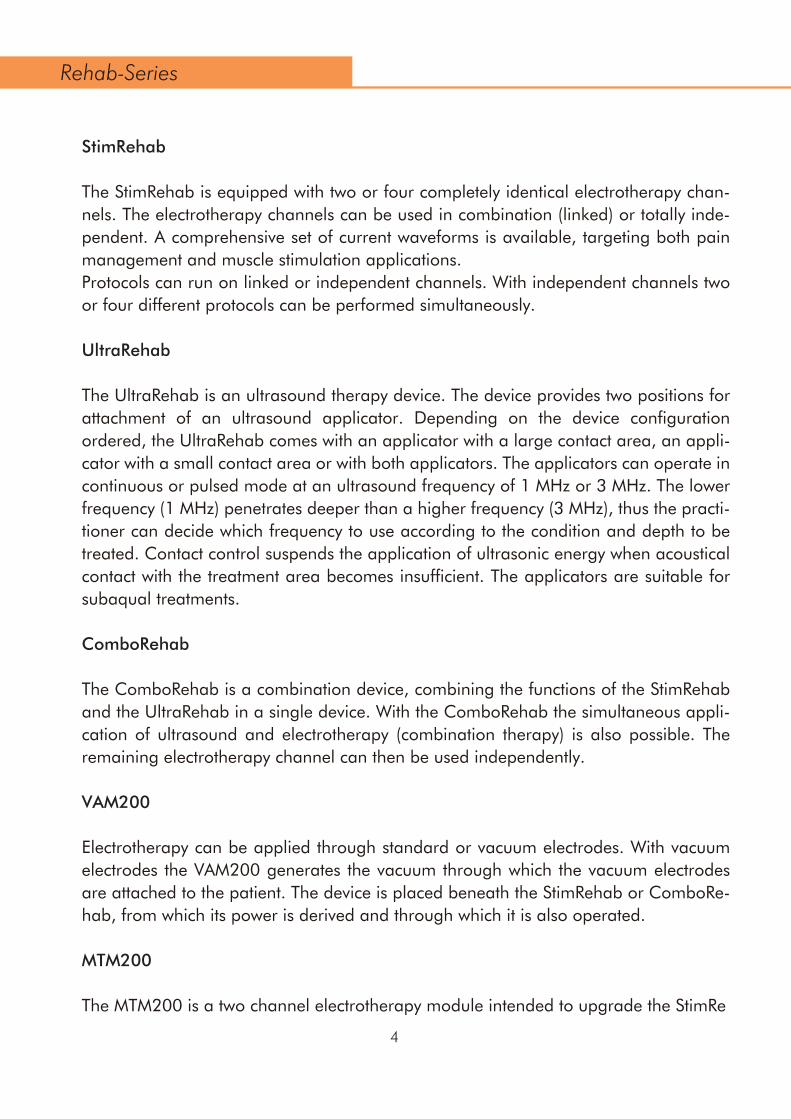
StimRehab
The StimRehab is equipped with two or four completely identical electrotherapy chan-nels. The electrotherapy channels can be used in combination (linked) or totally inde-pendent. A comprehensive set of current waveforms is available, targeting both pain management and muscle stimulation applications. Protocols can run on linked or independent channels. With independent channels two or four different protocols can be performed simultaneously.
UltraRehab
The UltraRehab is an ultrasound therapy device. The device provides two positions for attachment of an ultrasound applicator. Depending on the device configuration ordered, the UltraRehab comes with an applicator with a large contact area, an appli-cator with a small contact area or with both applicators. The applicators can operate in continuous or pulsed mode at an ultrasound frequency of 1 MHz or 3 MHz. The lower frequency (1 MHz) penetrates deeper than a higher frequency (3 MHz), thus the practi-tioner can decide which frequency to use according to the condition and depth to be treated. Contact control suspends the application of ultrasonic energy when acoustical contact with the treatment area becomes insufficient. The applicators are suitable for subaqual treatments.
ComboRehab
The ComboRehab is a combination device, combining the functions of the StimRehab and the UltraRehab in a single device. With the ComboRehab the simultaneous appli-cation of ultrasound and electrotherapy (combination therapy) is also possible. The remaining electrotherapy channel can then be used independently.
VAM200
Electrotherapy can be applied through standard or vacuum electrodes. With vacuum electrodes the VAM200 generates the vacuum through which the vacuum electrodes are attached to the patient. The device is placed beneath the StimRehab or ComboRe-hab, from which its power is derived and through which it is also operated.
MTM200
The MTM200 is a two channel electrotherapy module intended to upgrade the StimRe
4
Rehab-Series
hab and ComboRehab to Four Channel Electrotherapy or Combination Therapy Sys-tems. This module is designed for use with the StimRehab or ComboRehab only.
EMG200
The EMG200 is designed for use with the StimRehab and the ComboRehab. With EMG electrodes the EMG200 generates the sEMG (Surface Electromyography) , ETS (Surface Electromyography with Triggered Stimulation) through which the EMG electrodes are attached to the patient.
BTM200
The BTM200 Battery Module is designed for use with the Rehab-Series systems to create a battery powered Therapy System. No additional Software is required for the Module as the System automatically recognizes its presence and activates all necessary software inherent in the System.
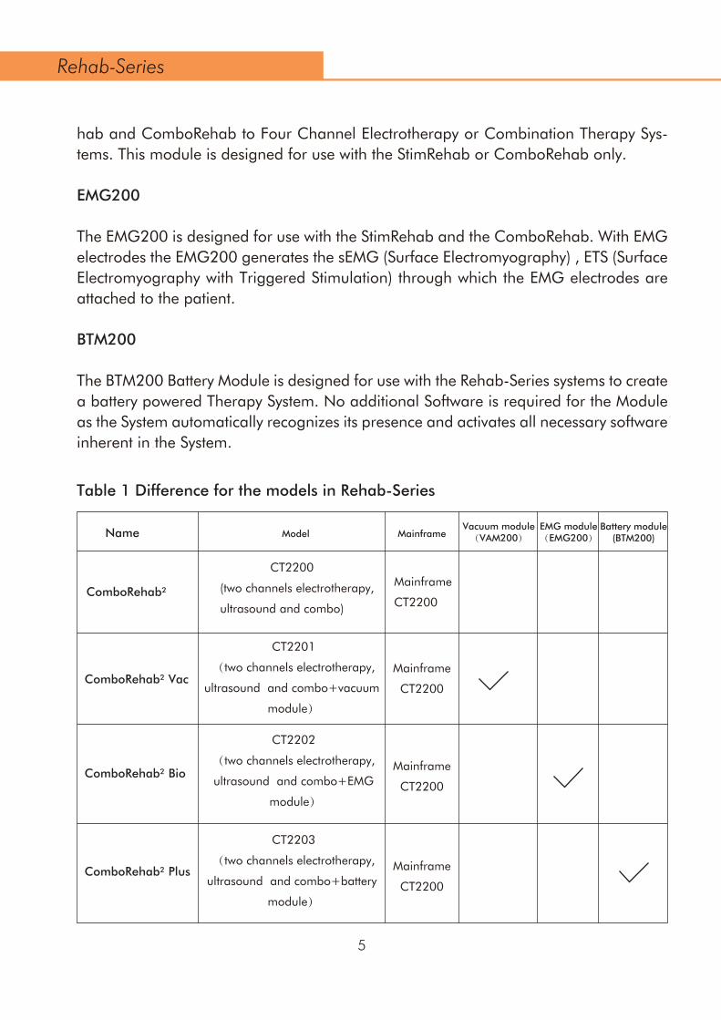
CT2200
(two channels electrotherapy,
ultrasound and combo)
CT2201
(two channels electrotherapy,
ultrasound and combo+vacuum
module)
CT2202
(two channels electrotherapy,
ultrasound and combo+EMG
module)
Mainframe
CT2200
Mainframe
CT2200
Mainframe
CT2200
Mainframe
CT2200
CT2203
(two channels electrotherapy,
ultrasound and combo+battery
module)
ComboRehab²
ComboRehab² Vac
ComboRehab² Bio
ComboRehab² Plus
Name Model MainframeVacuum module(VAM200)
EMG module(EMG200)
Battery module(BTM200)
5
Rehab-Series
Table 1 Difference for the models in Rehab-Series

Mainframe
CT2200
Mainframe
CT2200
Mainframe
CT2200
Mainframe
CT2400
(CT2200
+MTM200)
Mainframe
CT2400
(CT2200
+MTM200)
Mainframe
CT2400
(CT2200
+MTM200)
Mainframe
CT2400
(CT2200
+MTM200)
CT2204
(two channels electrotherapy,
ultrasound and combo+vacuum
module +EMG module)
CT2205
(two channels electrotherapy,
ultrasound andcombo+vacuum
module+ battery module)
CT2206
(two channels electrotherapy,
ultrasound and combo+battery
module + EMG module)
CT2400
(four channels electrotherapy,
ultrasound and combo)
Name
ComboRehab² VB
ComboRehab² Vac Plus
ComboRehab² Bio Plus
Model MainframeVacuum module(VAM200)
EMG module(EMG200)
Battery module(BTM200)
StimRehab²
CT2401
(four channels electrotherapy,
ultrasound and combo+vacuum
module)
CT2402
(four channels electrotherapy,
ultrasound and combo+EMG
module)
CT2403
(four channels electrotherapy,
ultrasound and combo+battery
module)
Mainframe
MT2200
MT2000
(two channels electrotherapy)
6
ComboRehab4
ComboRehab Plus4
ComboRehab Bio4
ComboRehab Vac4
Rehab-Series

Mainframe
MT2400
(MT2200
+MTM200)
Mainframe
MT2400
(MT2200
+MTM200)
Name
Stim Rehab² Vac
Stim Rehab² Bio
Stim Rehab² Plus
Stim Rehab² VB
Model MainframeVacuum module(VAM200)
EMG module(EMG200)
Battery module(BTM200)
Stim Rehab² Vac
Stim Rehab² Bio Plus
Mainframe
MT2200
Mainframe
MT2200
Mainframe
MT2200
Mainframe
MT2200
MT2201
(two channels electrotherapy
+vacuum module)
MT2202
(two channels electrotherapy
+EMG module)
MT2203
(two channels electrotherapy
+battery module)
MT2204
(two channels electrotherapy
+vacuum module+EMG
module)
MT2205
(two channels electrotherapy
+vacuum module+battery
module)
MT2206
(two channels electrotherapy
+battery module+EMG
module)
MT2400
(four channels electrotherapy)
Mainframe
MT2200
Mainframe
MT2200
MT2401
(four channels
electrotherapy +vacuum module)
7
Stim Rehab Vac4
Stim Rehab 4
Rehab-Series

Mainframe
MT2400
(MT2200
+MTM200)
Mainframe
MT2400
(MT2200
+MTM200)
Name
UltraRehab
UltraRehab Plus
Note:Remarks: “√” means that the device is equipped with these module.
Model MainframeVacuum module(VAM200)
EMG module(EMG200)
Battery module(BTM200)
Mainframe
UT2200
Mainframe
UT2200
MT2402
(four channels
electrotherapy +EMG module)
MT2403
(four channels
electrotherapy +battery module)
UT2200
(two channels ultrasound)
UT2201
(two channels ultrasound
+battery module)
8
Stim Rehab Plus4
Stim Rehab Bio4
Rehab-Series

In this section general Warnings and Precautions are listed, that you should be aware of when using the Rehab-Series. See also chapter 4.1 for Warnings and Precautions that are application specific.
WARNING:
Federal law (USA only) restricts this device to sale by, or on the order of, a physi-cian or licensed practitioner. This device should be used only under the continued supervision of a physician or licensed practitioner.Make certain that the unit is electrically grounded by connecting only to a grounded electrical service receptacle conforming to the applicable national and local electrical codes.Do not operate the unit in an environment of short-wave or micro-wave diathermy.The device is designed for indoor use only.It is prohibited to use the device in a location where explosion or water intrusion risk are present and in dusty or humid environment.It is prohibited to use the device in spaces where flammable anaes-thetics oxidizing gases(O2,N2O) and other flammable gases or vapors are pres-ent.This device should be kept out of the reach of children.Place the device out of direct sunlight and strong electromagnetic fields of sur-rounding devices(diathermy,X-rays,mobile phones and other radio-frequence equipment) to prevent unwanted interference.If unwanted interference occurs,place the device farther from the source of interference or contact the Nu-Tek authoried service.Before administering any treatment to a patient you should become acquainted with the operating procedures for each mode of treatment available, as well as the indications, contraindications, warnings and precautions. Consult other resources for additional information regarding the application of electrotherapy and Ultra-sound. No modification of this equipment is allowed! Do not try to open or remove the protective covers or disassembly the device for any reason.There is a danger of electric shock and serious injury.All service actions must be done by an autho-rized Nu-Tek service only;otherwise Nu-Tek bear no responsibility for further operation of the device.
•
•
••
••
•
•
3. Precautionary Instructions
9
Rehab-Series
CAUTION:
Keep yourself informed of the contraindications.Read the User’s Manual carefully and become familiar with all its safety require-ments, operating procedures and maintenance instruction prior to use of the device.It is prohibited to use the device and its accessory in any manner that is not in accordance with the User’s Manual. Know the limitations and hazards associ-ated with using any electrical stimulation device. Observe the precautionary and operational stickers placed on the unit.DO NOT use sharp objects such as a pencil point or ballpoint pen to operate the buttons on the control panel.Before each therapy check carefully the device and its accessories (cables,connectors,electrodes,ultrasound heads,controls,touch screen) for any mechanical, functional or other damage.If any faults or anomalies in the device function are found, stop using the device immediately .Handle the ultrasound applicator with care. Inappropriate handling of the ultra-sound applicator may adversely affect its characteristics.Inspect the ultrasound applicator for cracks which may allow the ingress of con-ductive fluid before each use.This unit should be operated in temperatures between 10 °C and 40 °C (50 °F and 104 °F), with a Relative Humidity ranging from 30%-85% non condensing.Do not expose the unit to direct sunlight, heat radiated from a heat radiator, excessive amounts of dust, moisture, vibrations and mechanical shocks. The device has applied parts of the BF (Body Floating) type-i.e. parts which come into direct physical contact with the patient during normal device use.This includes the electrodes for electrotherapy and applicators for ultrasound therapy.The device heats up during operation and therefore must not be located near devices that heat up or produce heat.The device is cooled by forced air circulation.The cooling vents are located on the rear and side panel of the device and they must not be covered.When placing the device,leave at least 10 cm of space behind the rear panel.
••
•
•
•
•
•
•
•
•
10
Rehab-Series
This device is not designed to be use in an MRI Environment and should be removed prior to MRI exposure.
Never use the accessories connector and other connectors to plug in anything else except transducers and cables sold by the manufacturer as replacement parts for internal components.There is a serious risk of electric shock and serious damage to the device!
•
•

The device is designed to only be used by or under the supervision of persons using the medical device in the course of their work and in the framework of a pro-fessional healthcare activity, who understand the benefits and limitations of elec-trotherapy and ultrasound therapy. I.e.“professional users”.
Do not use this device on patients who have a cardiac pacemaker, implanted defi-brillator, or other implanted metallic or electronic device, because this may cause electric shock, burns, electrical interference, or death.
•
•
4.1 Intended Use Electrotherapy
4.1.1 Pain Management
Pain Management is the use of electrical stimulation for pain relief.
4.1.1.1 Indications Pain Management
Symptomatic relief and management of chronic, intractable pain. Management of pain associated with post- traumatic or postoperative conditions.
4.1.1.2 Contra-indications Pain Management
Do not use this device on patients whose pain syndromes are undiagnosed.
4. Intended Use
11
Rehab-Series
Before administering any treatment to a patient you should become acquainted with the operating procedures for each mode of treatment available, as well as the indications, contra-indications, warnings and precautions. Consult other resources for additional information regarding the application of electrotherapy and ultrasound therapy.
•
It is prohibited to place any objects that produce heat or objects that contain water or other liquid on the device. If in the case of ingress of liquids, unplug the unit from the mains supply and have it checked by an authorized person (see the paragraph on maintenance).
•

Do not apply stimulation over the patient’s neck because this could cause severe muscle spasms resulting in closure of the airway, difficulty in breathing, or adverse effects on heart rhythm or blood pressure;Do not apply stimulation across the patient’s chest, because the introduction of electrical current into the chest may cause rhythm disturbances to the patient’s heart, which could be lethal;
•
•
Do not apply stimulation over open woundsor rashes, or over swollen, red, infected, or inflamed areas or skin eruptions (e.g., phlebitis, thrombophlebitis, varicose veins);Do not apply stimulation over, or in proximity to, cancerous lesions;Do not apply stimulation in the presence of electronic monitoring equipment (e.g., cardiac monitors, ECG alarms), which may notoperate properly when the electri-cal stimulation device is in use;Do not apply stimulation when the patient is in the bath or shower;Do not apply stimulation while the patient is sleeping;Do not apply stimulation while the patient is driving, operating machinery, or during any activity in which electrical stimulation can put the patient at risk of injury.Consult with the patient’s physician beforeusing this device, because the device may cause lethal rhythm disturbances to the heart in susceptible individuals;Apply stimulation only to normal,intact, clean, healthy skin.See also chapter 3, Precautionary Instructions, for general Warnings and Precau-tions.
•
••
•••
•••
TENS is not effective for pain of central origin, including headache;TENS is not a substitute for pain medications and other pain management thera-pies; TENS devices have no curative value;TENS is a symptomatic treatment and, as such, suppresses the sensation of pain that would otherwise serve as a protective mechanism;Effectiveness is highly dependent upon patient selection by a practitioner qualified in the management of pain patients;
••
••
•
12
4.1.1.4 Precautions Pain Management
Rehab-Series
4.1.1.3 Warnings Pain Management
Do not use this device on patients whose pain syndromes are undiagnosed.•
Use caution if stimulation is applied over the menstruating or pregnant uterus;Use caution if stimulation is applied over areas of skin that lack normal sensation.Isolated cases of skin rash may occur at the site of electrode placement following long-term applications. The irritation may be reduced by use of an alternate con-ductive medium or an alternative electrode placement.See also chapter 3, Precautionary Instructions, for general Warnings and Precau-
•••
•
13
Patients may experience skin irritation and burns beneath the stimulation elec-trodes applied to the skin;Patients may experience headache and other painful sensations during or follow-ing the application of electrical stimulation near the eyes and to the head and face;Patients should stop using the device and should consult with their physicians if they experience adverse reactions from the device.
•
•
•
•
4.1.1.5 Adverse Effects Pain Management
Add:
4.1.1.6 Current Waveforms Pain Management
For pain management the following current waveforms are recommended 4.1.3.1, 4.1.3.2,4.1.3.3, 4.1.3.5, 4.1.3.6, 4.1.3.7, 4.1.3.8, 4.1.3.10.
Rehab-Series
Patients with suspected or diagnosed epilepsy should follow precautions recommended by their physicians;Use caution when the patient has a tendency to bleed internally, such as following an injury or fracture;Use caution following recent surgical procedures when stimulation may disrupt the patient’s healing process;
•
•
•
The safety of electrical stimulation during pregnancy has not been established;Some patients may experience skin irritation orhypersensitivity dueto the electrical stimulation or electrical conductive medium (gel);Patients with suspected or diagnosed heart disease should follow precautions recommended by their physicians;
••
•
Since the effects of stimulation of the brain are unknown, stimulation should not be applied across the head, and electrodes should not be placed on opposite sides of
•The long-term effects of electrical stimulation are unknown;•

Relaxation of muscle spasmsPrevention or retardation of disuse atrophyIncreasing local blood circulationMuscle re-education
••••
4.1.2 Muscle Stimulation
4.1.2.1 Indications Muscle Stimulation
Do not use this device on patients who have a cardiac pacemaker, implanted defi-brillator, or other implanted metallic or electronic device, because this may cause electric shock, burns, electrical interference, or death.
•
14
If you are in the care of a physician, consult with your physician before using this device;Do not apply stimulation over your neck because this could cause severe muscle spasms resulting in closure of your airway, difficulty in breathing, or adverse effects on heart rhythm or blood pressure;Do not apply stimulation across your chest because the introduction of electrical current into the chest may cause rhythm disturbances to your heart, which could be lethal;Do not apply stimulation over painful areas. If you have painful areas, you should consult with your physician before using this device;Do not apply stimulation over open woundsor rashes, or over swollen, red, infected, or inflamed areas or skin eruptions (e.g., phlebitis, thrombophlebitis, varicose veins);Do not apply stimulation over, or in proximity to, cancerous lesions;Do not apply stimulation in the presence of electronic monitoring equipment (e.g., cardiac monitors, ECG alarms), which may notoperate properly when the electri-cal stimulation device is in use;
•
•
•
•
•
••
4.1.2.2 Contra-indications Muscle Stimulation
4.1.2.3 Warnings Muscle Stimulation
Rehab-Series
Immediate post-surgical stimulation of calf muscles to prevent venous thrombosisMaintaining or increasing range of motionincreasing the stimulated muscle’s strengthincreasing the stimulated muscle’s resistance to fatigueDysphagia
•••••
The long-term effects of electrical stimulation are unknown;•
4.1.2.4 Precautions Muscle Stimulation
15
Since the effects of stimulation of the brain are unknown, stimulation should not be applied across your head, and electrodes should not be placed on opposite sides of your head;The safety of electrical stimulation during pregnancy has not been established;You may experience skin irritation or hypersensitivity due to the electrical stimula-tion or electrical conductive medium (gel);If you have suspected or diagnosed heart disease, you should follow precautions recommended by your physician;If you have suspected or diagnosed epilepsy, you should follow precautions rec-ommended by your physician.Use caution if you have a tendency to bleed internally, such as following an injury or fracture;Consult with your physician prior to using the device after a recent surgical proce-dure, because stimulation may disrupt the healing process;Use caution if stimulation is applied over the menstruating or pregnant uterus;Use caution if stimulation is applied over areas of skin that lack normal sensation;Keep this device out of the reach of children;Use this device only with the leads, electrodes, and accessories recommended by the manufacturer.Some patients may experience skin irritation or hypersensitivity due to electrical stimulation or electrical conductive medium. The irritation can usually be reduced by using an alternative conductive medium, or alternate electrode placement.See also chapter 3, Precautionary Instructions, for general Warnings and Precau-
•
••
•
•
•
•
••••
•
•
4.1.2.5 Adverse Effects Muscle Stimulation
Rehab-Series
Apply stimulation only to normal,intact, clean, healthy skin.See also chapter 3, Precautionary Instructions, for general Warnings and Precautions.
••
Do not apply stimulation while driving, operating machinery, or during any activity in which electrical stimulation canput you at risk of injury;Do not use the device on children, if it has not been evaluated for pediatric use;Consult with your physician before using this device, because the device may cause lethal rhythm disturbances to the heart in susceptible individuals;
•
••
Do not apply stimulation whenin the bath or shower;Do not apply stimulation while sleeping;
••

For muscle stimulation the following current waveforms are recommended 4.1.3.1, 4.1.3.2, 4.1.3.3, 4.1.3.4, 4.1.3.5 , 4.1.3.9
•
You may experience skin irritation and burns beneath the stimulation electrodes applied to your skin;
•
•
•
4.1.2.6 Current Waveforms Muscle Stimulation
These waveforms are often applied in combination with a surge program, which con-sists of a sequence of exercise and rest periods. Two options are available here:
Interferential Current is a medium frequency waveform. Current is distributed through
Reciprocal application, where stimulation alternates between agonists and antagonists. This is accomplished through asynchronous stimulation over two cur-rent channels with an appropriate delay between the two channels.Co-contract application, where two channels operate synchronously to co-contract agonist and antagonist or different sections of a larger muscle group.
•
•
16
CC — Constant current output mode.CV — Constant voltage output mode.F.M. — Frequency ModulationBurst— Burst FrequencyFreq. — FrequencyC.F — Carrier FrequencyDuty — Duty CycleBeat H. — Sweep High Beat FrequencyBeat L . — Sweep Low Beat FrequencyA.M. — Amplitude ModulationP.Dur. — Phase Duration Cycle— Cycle timeRamp— Ramp time
•••••••••••••
4.1.3 Description Current Waveforms
4.1.3.1 IF-4P:IFC(Interferential) Traditional (4 Pole)
Rehab-Series
Remark:
You may experience headache and other painful sensations during or following the application of electrical stimulation near your eyes and toyour head and face;You should stop using the device and should consult with your physician if youexperience adverse reactions from the device.

Premodulated Current is a medium frequency waveform. Current comes out of one channel (two electrodes). The current intensity is modulated: it increases and decreases at a regular frequency (the Amplitude Modulation Frequency).
Carrier frequency: Carrier frequency is the base frequency of the alternating current.Beat Frequency: The frequency at which the amplitude is modulated. This is the effec-tive therapeutic frequency.Vector-Auto: Vector-Auto is a form of amplitude modulation and is a percentage of the interferential amplitude (intensity) and will decrease from its maximum level over 6 sec-onds. Vector-Manual:Vector-Manual is a form of amplitude modulation. When Vector-Manual set to a different Angle, the output intensities of two channels are different. The rhythmical varying of the current amplitude of each channel produces the perceived movement of the interferential field by the patient.
17
4.1.3.2 IFC(Interferential) Premodulated (2 Pole)
Parameters:
Carrier frequency: Carrier frequency is the base frequency of the alternating current.Beat Frequency: The frequency at which the amplitude is modulated. This is the effective therapeutic frequency. Cycle Time: refers to the time that the current is On and Off (in seconds). Example: for a Cycle Time of 10/50, the current will be flowing for 10 seconds and resting for 50 seconds.Ramp Time: the time that the current will take to increase to the set intensity level. Ramps occur at the beginning and ending of a timed On cycle.
Parameters:
The Asymmetrical Biphasic and the Symmetrical Biphasic waveform are often used in TENS (Transcutaneous Electrical Nerve Stimulation) applications. The TENS has a short pulse duration. It is capable of strong stimulation of the nerve fibers in the skin as well
4.1.3.3 Biphasic (TENS)
Rehab-Series
of two channels (four electrodes). The currents cross each other in the body at the area requiring treatment. The two currents interfere with each other at this crossing point, resulting in a modulation of the intensity (the current intensity increases and decreases at a regular frequency).

18
Russian Current is a rectangle waveform, delivered in bursts or series of pulses. This method was claimed by its author (Kots) to produce maximal muscle strengthening effects without significant discomfort to the patient.
4.1.3.4 Russian Stimulation
The High Volt waveform has a very brief pulse duration characterized by 2 distinct 4.1.3.5 High Volt
Phase Duration: expressed in µs, is the elapsed time from the beginning to the end of the initial pulse phase.Frequency: In a pulsed current the Frequency refers to the number of pulses that occur in a one second period of time and is denoted as in Hz or Pulses Per Second (pps). Frequency Modulation: expressed in Hz, defines a variable frequency range that is summed to the Pulse frequency i.e when the Pulse frequency is set to 80 Hz and the Frequency modulation is set to 40 Hz, the final frequency will vary from 80 – 120 Hz.Amplitude Modulation: Rhythmical fluctuation of the intensity to prevent accommo-dation.Burst Frequency: expressed in Hz or bps, defines the repetition rate of bursts of pulses. A Burst (an interrupted train) is a finite series of pulses that are delivered at a specific frequency and are separated by interburst intervals.
Parameters:
Carrier Frequency: Carrier frequency is the base frequency of the alternating current.Frequency: In a pulsed current the Frequency refers to the number of pulses that occur in a one second period of time and is denoted as in Hz or Pulses Per Second (pps). Duty: The percentage of the total treatment time that the current is actually flowing.Cycle Time: refers to the time that the current is On and Off (in seconds). Example: for a Cycle Time of 10/50, the current will be flowing for 10 seconds and resting for 50 seconds.Ramp: The time that the current will take to increase to the set intensity level. Ramps occur at the beginning and ending of a timed On cycle.
Parameters:
Rehab-Series
as of muscle tissue. Because of its short pulse, the patient typically tolerates the current well, even at relatively high intensities. The Alternating Rectangular waveform is an interrupted biphasic current with a rectangular pulse shape. This waveform is commonly used as a pain management application.
WARNING:
Federal law (USA only) restricts this device to sale by, or on the order of, a physi-cian or licensed practitioner. This device should be used only under the continued supervision of a physician or licensed practitioner.Make certain that the unit is electrically grounded by connecting only to a grounded electrical service receptacle conforming to the applicable national and local electrical codes.Do not operate the unit in an environment of short-wave or micro-wave diathermy.The device is designed for indoor use only.It is prohibited to use the device in a location where explosion or water intrusion risk are present and in dusty or humid environment.It is prohibited to use the device in spaces where flammable anaes-thetics oxidizing gases(O2,N2O) and other flammable gases or vapors are pres-ent.This device should be kept out of the reach of children.Place the device out of direct sunlight and strong electromagnetic fields of sur-rounding devices(diathermy,X-rays,mobile phones and other radio-frequence equipment) to prevent unwanted interference.If unwanted interference occurs,place the device farther from the source of interference or contact the Nu-Tek authoried service.Before administering any treatment to a patient you should become acquainted with the operating procedures for each mode of treatment available, as well as the indications, contraindications, warnings and precautions. Consult other resources for additional information regarding the application of electrotherapy and Ultra-sound. No modification of this equipment is allowed! Do not try to open or remove the protective covers or disassembly the device for any reason.There is a danger of electric shock and serious injury.All service actions must be done by an autho-rized Nu-Tek service only;otherwise Nu-Tek bear no responsibility for further operation of the device.
19
Microcurrent is a monophasic waveform of very low intensity. The literature reports beneficial effects of this waveform in the treatment of wounds. The physiological work-ing mechanism of this effect is as yet not clearly understood. It is thought to stimulate tissue healing by stimulating the 'current of injury', a current which naturally occurs in
4.1.3.6 Micro Current
The High Volt waveform is frequently used to increase local blood circulation and relax muscles in spasm.
Frequency: In a pulsed current the Frequency refers to the number of pulses that occur in a one second period of time and is denoted as in Hz or Pulses Per Second (pps).Polarity: This refers to the polarity (+/-) of the red lead wire; connect the lead wire to the active electrode. Cycle Time: refers to the time that the current is On and Off (in seconds). Example: for a Cycle Time of 10/50, the current will be flowing for 10 seconds and resting for 50 seconds.Ramp: The time that the current will take to increase to the set intensity level. Ramps occur at the beginning and ending of a timed On cycle.
Frequency: In a pulsed current the Frequency refers to the number of pulses that occur in a one second period of time and is denoted as in Hz or Pulses Per Second (pps).Polarity: This refers to the polarity (+/-) of the red lead wire; connect the lead wire to the active electrode.
Parameters:
It is a monophasic waveform with a phase duration of 2 ms and a pause of 5 ms result-ing in a frequency of approximately 143 Hz.
4.1.3.7 Trabert
Polarity: This refers to the polarity (+/-) of the red lead wire; connect the lead wire to the active electrode.
Parameters:
Rehab-Series
peaks delivered at high voltage. The waveform is monophasic (current flows in one direction only).The high voltage causes a decreased skin resistance making the current comfortable and easy to tolerate. The very short pulse duration followed by a very long interpulse interval eliminates the formation of any appreciable chemical or thermal effects in the tissue.
CAUTION:
Keep yourself informed of the contraindications.Read the User’s Manual carefully and become familiar with all its safety require-ments, operating procedures and maintenance instruction prior to use of the device.It is prohibited to use the device and its accessory in any manner that is not in accordance with the User’s Manual. Know the limitations and hazards associ-ated with using any electrical stimulation device. Observe the precautionary and operational stickers placed on the unit.DO NOT use sharp objects such as a pencil point or ballpoint pen to operate the buttons on the control panel.Before each therapy check carefully the device and its accessories (cables,connectors,electrodes,ultrasound heads,controls,touch screen) for any mechanical, functional or other damage.If any faults or anomalies in the device function are found, stop using the device immediately .Handle the ultrasound applicator with care. Inappropriate handling of the ultra-sound applicator may adversely affect its characteristics.Inspect the ultrasound applicator for cracks which may allow the ingress of con-ductive fluid before each use.This unit should be operated in temperatures between 10 °C and 40 °C (50 °F and 104 °F), with a Relative Humidity ranging from 30%-85% non condensing.Do not expose the unit to direct sunlight, heat radiated from a heat radiator, excessive amounts of dust, moisture, vibrations and mechanical shocks. The device has applied parts of the BF (Body Floating) type-i.e. parts which come into direct physical contact with the patient during normal device use.This includes the electrodes for electrotherapy and applicators for ultrasound therapy.The device heats up during operation and therefore must not be located near devices that heat up or produce heat.The device is cooled by forced air circulation.The cooling vents are located on the rear and side panel of the device and they must not be covered.When placing the device,leave at least 10 cm of space behind the rear panel.
••
•
•
•
•
•
•
•
•
20
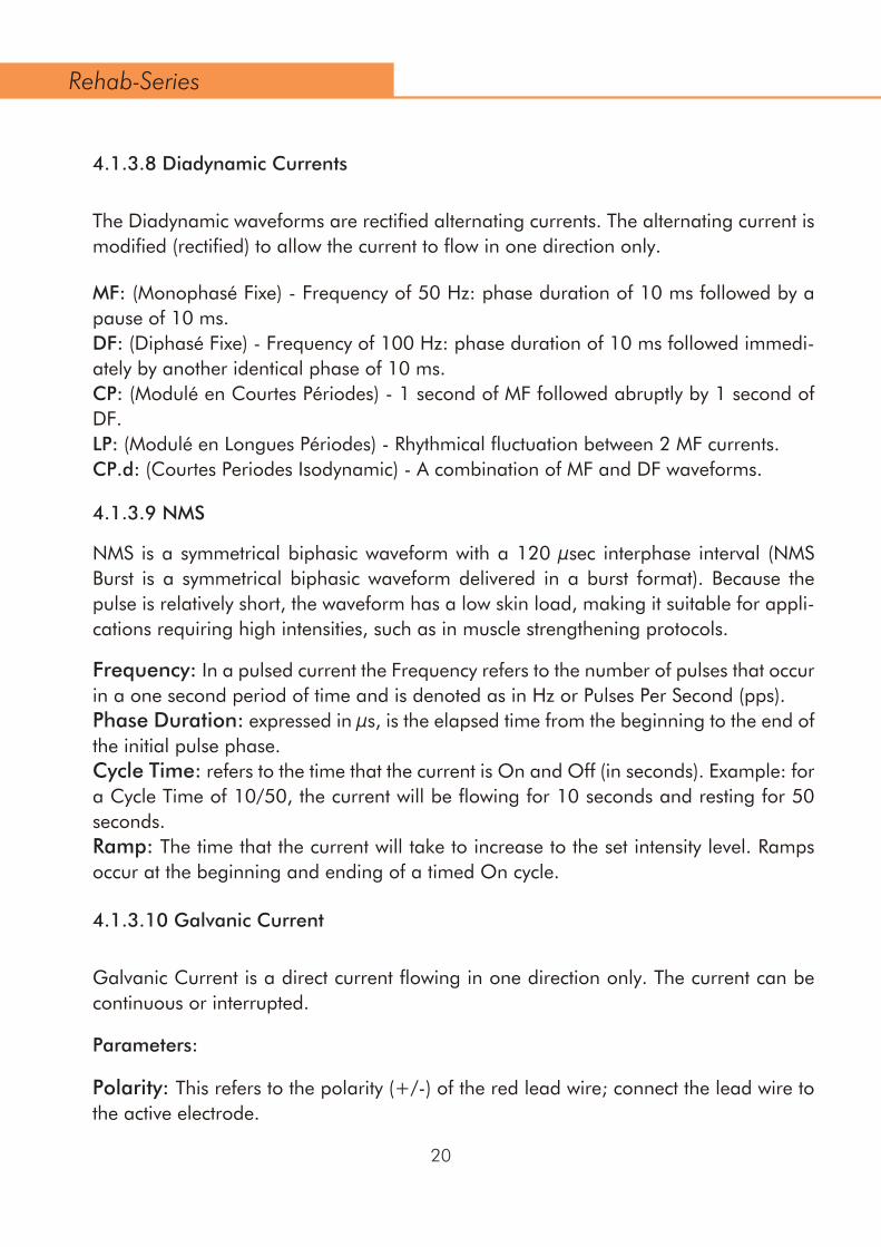
MF: (Monophasé Fixe) - Frequency of 50 Hz: phase duration of 10 ms followed by a pause of 10 ms.DF: (Diphasé Fixe) - Frequency of 100 Hz: phase duration of 10 ms followed immedi-ately by another identical phase of 10 ms. CP: (Modulé en Courtes Périodes) - 1 second of MF followed abruptly by 1 second of DF.LP: (Modulé en Longues Périodes) - Rhythmical fluctuation between 2 MF currents.CP.d: (Courtes Periodes Isodynamic) - A combination of MF and DF waveforms.
Polarity: This refers to the polarity (+/-) of the red lead wire; connect the lead wire to the active electrode.
Parameters:
The Diadynamic waveforms are rectified alternating currents. The alternating current is modified (rectified) to allow the current to flow in one direction only.
4.1.3.8 Diadynamic Currents
Frequency: In a pulsed current the Frequency refers to the number of pulses that occur in a one second period of time and is denoted as in Hz or Pulses Per Second (pps).Phase Duration: expressed in µs, is the elapsed time from the beginning to the end of the initial pulse phase. Cycle Time: refers to the time that the current is On and Off (in seconds). Example: for a Cycle Time of 10/50, the current will be flowing for 10 seconds and resting for 50 seconds.Ramp: The time that the current will take to increase to the set intensity level. Ramps occur at the beginning and ending of a timed On cycle.
NMS is a symmetrical biphasic waveform with a 120 µsec interphase interval (NMS Burst is a symmetrical biphasic waveform delivered in a burst format). Because the pulse is relatively short, the waveform has a low skin load, making it suitable for appli-cations requiring high intensities, such as in muscle strengthening protocols.
4.1.3.9 NMS
Galvanic Current is a direct current flowing in one direction only. The current can be continuous or interrupted.
4.1.3.10 Galvanic Current
Rehab-Series

f Carrier frequencyfb Beat frequency
f Carrier frequencyfb Beat frequency
f Beat frequency
Premod
IFC-4P
Russian
21
Polarity: This refers to the polarity (+/-) of the red lead wire; connect the lead wire to the active electrode.Cycle Time: refers to the time that the current is On and Off (in seconds). Example: for a Cycle Time of 10/50, the current will be flowing for 10 seconds and resting for 50 seconds.Ramp: The time that the current will take to increase to the set intensity level. Ramps occur at the beginning and ending of a timed On cycle.
4.1.4 Illustrations Current Waveforms
1/f
CH1:
CH2:
Beat:
100mA max.
1/f
Rehab-Series

TENS is not effective for pain of central origin, including headache;TENS is not a substitute for pain medications and other pain management thera-pies; TENS devices have no curative value;TENS is a symptomatic treatment and, as such, suppresses the sensation of pain that would otherwise serve as a protective mechanism;Effectiveness is highly dependent upon patient selection by a practitioner qualified in the management of pain patients;
••
••
•
Biphasic Pulsed Current TENS
t Phase durationf Pulse frequency
t Phase durationf Pulse frequency
t Phase durationf Pulse frequency
f Burst frequency
f Burst frequency
Asymmetrical
Alternating
Symmetrical
Burst Asymmetrical
Burst Symmetrical
22
200mA max.
1/f
200mA max.
1/f
200mA max.
t 1/f
200mA max.
1/f
200mA max.
1/f
Rehab-Series

NMS
23
f Burst frequency
fp Phase duration: 2 msti Phase interval: 5 ms
tp Phase durationf Pulse frequency
tp Phase durationf Pulse frequency
t Phase durationf Pulse frequency
Burst Alternating
Träbert, 2 – 5 Current
Rectangular Pulsed current
Triangular Pulsed Current
NMS
200mA max.
1/f
tp ti
80mA max.
80mA max.
1/ftp
tp1/f
80mA max.
200mA max.
1/f
t
120µs
Rehab-Series

If you are in the care of a physician, consult with your physician before using this device;Do not apply stimulation over your neck because this could cause severe muscle spasms resulting in closure of your airway, difficulty in breathing, or adverse effects on heart rhythm or blood pressure;Do not apply stimulation across your chest because the introduction of electrical current into the chest may cause rhythm disturbances to your heart, which could be lethal;Do not apply stimulation over painful areas. If you have painful areas, you should consult with your physician before using this device;Do not apply stimulation over open woundsor rashes, or over swollen, red, infected, or inflamed areas or skin eruptions (e.g., phlebitis, thrombophlebitis, varicose veins);Do not apply stimulation over, or in proximity to, cancerous lesions;Do not apply stimulation in the presence of electronic monitoring equipment (e.g., cardiac monitors, ECG alarms), which may notoperate properly when the electri-cal stimulation device is in use;
•
•
•
•
•
••
24
Galvanic Current
f Burst frequency
f Carrier frequency - 8 kHz fixed
Duty cycle - 90 % fixed
t Peak interval - 100 µs fixedf Pulse frequency
f Frequency
NMS Burst
Galvanic Interrupted
Galvanic Continuous
High Voltage
Micro Current
200mA max.
1/f
80mA max.
1/f
80mA max.
500V max.
1/f
1000uA max.
1/f
Rehab-Series
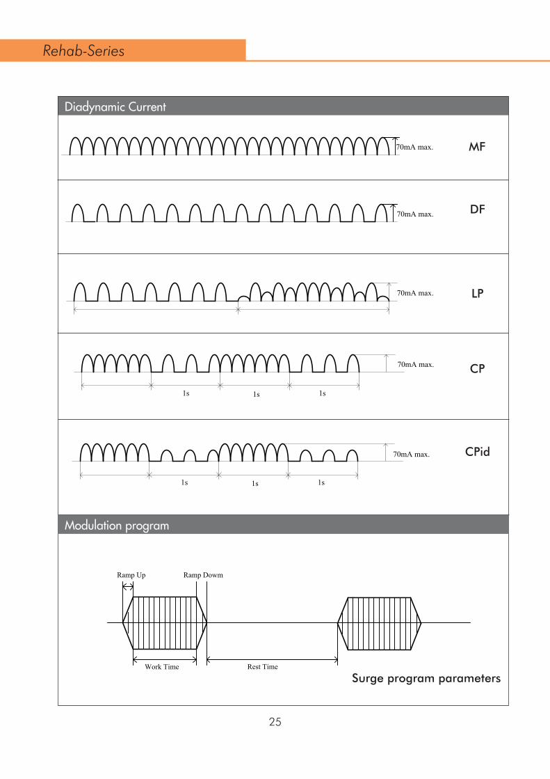
Diadynamic Current
Modulation program
CPid
Surge program parameters
CP
LP
DF
MF
25
70mA max.
70mA max.
70mA max.
1s 1s 1s
70mA max.
1s 1s 1s
70mA max.
Rest Time
Ramp Up Ramp Dowm
Rehab-Series
Work Time

26
Frequence Modulation
IPC-4P/Premod
Channel Mode
Co-Cont Both(ON:10/OFF:10)
Reciprocal(ON:10/OFF:10)
TENS
1/Freq. Mod.+Frequency 1/Frequency
Beat LowBeat High
CH1:
CH2:
10s 10s
CH1:
CH2:
10s 10s 10s
Rehab-Series

The established contra-indications to heat therapy itself.In an area of the body where a malignancy is known to be present.Over or near bone growth centers until bone growth is complete.Over the thoracic area if the patient is using a cardiac pacemaker.Over a healing fracture.Over ischemic tissues in individuals with vascular disease where the blood supply would be unable to follow the increase in metabolic demand and tissue necrosis might result.In the presence of metal implants of any type.Patients with sensory loss on the area to be treated.The gonads or to the developing fetus.The heart.The brains.The testicles.The eyes.Facial sinus as this exposes the eyes to the same hazards.Ultrasound should not be used on unconscious patients.
••••••
•••••••••
27
Ultrasound is a mechanical energy consisting of high-frequency vibrations applied by means of an ultrasound applicator. These vibrations pass through the tissue of the body and are gradually absorbed and transformed into heat. The resulting temperature increase triggers biological changes to occur in the tissue for the relief of pain, relax-ation of muscle spasms and reduction of joint contractures.
Ultrasound is indicated for conditions that benefit from the application of deep heat: relief of pain, muscle spasms and joint contractures. The objective of therapeutic ultra-sound in the treatment of selected medical conditions associated with the chronic and sub chronic conditions of bursitis/ capsulitis, epicondylitis, ligament sprains, tendinitis, scar tissue healing and muscle strain, is to reduce pain.
4.2 Intended Use Ultrasound therapy
4.2.1 Indications Ultrasound
4.2.2 Contra-indications Ultrasound
Rehab-Series

Precaution should be taken when using therapeutic ultrasound on patients with hemorrhagic diatheses.Ultrasound treatment presents a potential safety hazard in patients whose pain response has been decreased because of disease, previous surgery, ionizing radiation therapy, chemotherapy, general or regional anaesthesia. It may cause burns. Do not use on insensitive areas or in the presence of poor circulation.Large thermal doses may result in regions of thermal aseptic necrosis which may not be apparent on inspection of the skin.See also chapter 3, Precautionary Instructions, for general Warnings and Precau-tions.
•
•
•
•
28
4.2.3 Precautions and Warnings Ultrasound
Use of ultrasound in treating areas above the shoulders may pose relevant haz-ards. While it is recognized that certain specific conditions involving the eyes can and have been treated by specialists qualified by training, knowledge and experi-ence to administer such treatments, such application carries with it recognized hazards of applying heat to the eyes.Treatment of the facial sinus exposes the eyes to the same hazards.Treatment of the thyroid, as well as lymph nodes in the neck, may expose the patient to as yet undetermined effects, in as much as the safety of such treatments has not yet been established.
•
••
4.2.4 Relevant Hazards Ultrasound
Cataracts. Male sterility.Enhanced drug activity. Thermal stress.
••
••
4.2.5 Potential Adverse Effects Ultrasound
4.2.6 Parameters Ultrasound THerapy
Ultrasound Frequency: expressed in MHz, is the frequency of the ultrasound waves. The ultrasound frequency determines the penetration depth, which has the largest value at 1 MHz. The ultrasound frequency can be set at 1 MHz or 3 MHz.Duty Cycle: expressed in %, defines the ratio of the pulse duration to the pulse repetition time. Ultrasound can be applied in pulsed or in continuous mode. When the Duty Cycle is set to 100%, the apparatus operates in continuous mode.
Rehab-Series
29
the activation of the muscle;the muscle’s capacity for relaxation;coordination between muscles;the tiredness of a muscle;
••••
Combination therapy is the combined application of ultrasound and electrical stimula-tion. With combination therapy the metal surface of the ultrasound applicator becomes the negative electricalstimulation electrode, while the lead wire with the red connector remains the positive electrical stimulation electrode. Combination therapy is available with all current waveforms, but limited to channel 2. Combination therapy is typically used for the reduction of muscle spasm.The combined Contra-indications and Adverse Effects of paragraph 4.1 and 4.2 apply
4.3 Combination Therapy
Myofeedback is a form of feedback, in which the patient receives electronically recorded information about his own physiological processes. The electromyographic recording used in the diagnostics and treatment of the moving mechanism is an indis-pensable supplement to the study of movement. When we place electrodes on the skin to obtain information from an EMG signal about the underlying musculature, we must be acquainted with the development of the EMG signal and the construction and func-tion of the motor mechanism. Thus, properties and mutations in the musculature, the joints system, the sensory and the neural system can be found in the motor system and also in the EMG recording. Surface EMG provides us with detailed information about the organ-specific properties of a muscle, such as:
4.4 EMG Therapy
Effective Radiation Area (ERA): expressed in cm², defines the cross-sectional area of the ultrasound beam (See technical specifications for details). The Effective Radiation Area is fixed and defined by the size of the ultrasound applicator.Ultrasound Power: is the ultrasound output expressed in Watt. The ultrasound output display can be toggled between Watt and Watt/cm². In pulsed mode the power during the pulse is displayed. The time averaged power can be obtained by multiplying this value with the Duty Cycle.Ultrasound Amplitude: expressed in Watt/cm², is the quotient of Ultrasound Power and Effective Radiation Area. The ultrasound output display can be toggled between Watt and Watt/cm². In pulsed mode the Amplitude during the pulse is displayed. The time-averaged Amplitude can be obtained by multiplying this value by the Duty Cycle.
Rehab-Series

30
the capacity of a muscle to lengthen; •
This makes Myofeedback especially suitable as a measuring instrument for charting our locomotive operations.
4.4.1 Parameters
Program time
Threshold (µV)
Filter
Biofeedback
Max:99mins
0.6-2000µV, During work period the patient is prompted to contract above the
Threshold. In the rest phase the patient is prompted to relax their pelvic muscle.
Wide/Narrow
Above/Below/Continue/OFF:
Above the threshold, Below the threshold, Continue-full scale, OFF-no bar
graph sound
2-99 sec
Auto/Manual
4.4.2 Indications/Contraindications and Adverse Effects for Biofeedback
Indications
• Loss of coordination (voluntary muscles) • Craniomandibular dysfunction • Tension headache / Migraine • Stress-related disorders • Low-Back Pain • Respiratory diseases • Orthopedic, post-traumatic and post-surgical disorders • Peripheral nerve lesions • Mimic (Facial) Rehabilitation • Pelvic Floor Reeducation (Incontinence) • Dysphagia
Rehab-Series
Work/Rest time (s)
Threshold setting
Trial
Threshold setting
STIM time(s)
Frequency (Hz)
Pulse width (µS) Ramp up/down time(s) 0.1-9.9sec
50-450 µS
2-100Hz
Auto/Manual
1-99sec
Number of work/rest repetitions, 2-99
5 Package Contents
31
Contraindications
Because Biofeedback therapy does not “do” anything to the body, few contraindica-tions exist. Biofeedback therapy is not recommended for persons with severe psychosis, depression, or obsessional neurosis, nor for debilitated patients or those with psycho-pathic personalities. However, because resulting functional improvements can require strenuous physical effort, individuals interested in Biofeedback may need to be aerobi-cally fit.
Precautions and Warnings:
Biofeedback is dangerous for diabetics and others with endocrine disorders, as it can change the need for insulin and other medications. Please check with the doctor to see whether this is an appropriate treatment for you.
Device model:
The package contents depend on the device model ordered. The following models are avail-able:
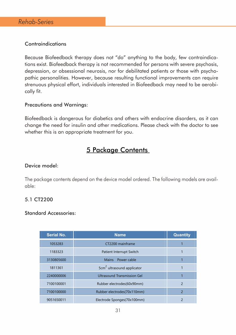
5.1 CT2200
Standard Accessories:
Serial No. Name Quantity
1053283 CT2200 mainframe 1
1183323 Patient Interrupt Switch 1
3130805600 Mains Power cable 1
1811361 5cm2 ultrasound applicator 1
2240000006 Ultrasound Transmission Gel 1
7100100001 Rubber electrodes(60x90mm) 2
7100100000 Rubber electrodes(70x110mm) 2
9051650011 Electrode Sponges(70x100mm) 2
Rehab-Series
32
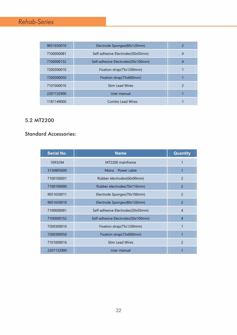
5.2 MT2200
Standard Accessories:
9051650010 Electrode Sponges(80x120mm) 2
7100000081 Self-adhesive Electrodes(50x50mm) 4
7100000152 Self-adhesive Electrodes(50x100mm) 4
7200300010 Fixation strap(75x1200mm) 1
7200300050 Fixation strap(75x600mm) 1
7101000016 Stim Lead Wires 2
2201132900 1
1181149000
User manual
1
Serial No. Name Quantity
1
3130805600 Mains Power cable 1
7100100001 Rubber electrodes(60x90mm) 2
7100100000 Rubber electrodes(70x110mm) 2
9051650011 Electrode Sponges(70x100mm) 2
9051650010 Electrode Sponges(80x120mm) 2
7100000081 Self-adhesive Electrodes(50x50mm) 4
7100000152 Self-adhesive Electrodes(50x100mm) 4
7200300010 Fixation strap(75x1200mm) 1
7200300050 Fixation strap(75x600mm) 1
7101000016 Stim Lead Wires 2
2201132900 User manual 1
Rehab-Series
MT2200 mainframe1093294
Combo Lead Wires

Serial No. Name Quantity
1043305 UT2200 mainframe 1
3130805600 Mains Power cable 1
1811361 5cm2 ultrasound applicator 1
2240000006 Ultrasound Transmission Gel 1
2201132900 User manual 1
33
Serial No. Name Quantity
1
7100100001 Rubber electrodes(60x90mm) 2
7100100000 Rubber electrodes(70x110mm) 2
9051650011 Electrode Sponges(70x100mm) 2
9051650010 Electrode Sponges(80x120mm) 2
7100000081 Self-adhesive Electrodes(50x50mm) 4
7100000152 Self-adhesive Electrodes(50x100mm) 4
7200300010 Fixation strap(75x1200mm) 1
7200300050 Fixation strap(75x600mm) 1
7101000016 Stim Lead Wires 2
5.3 UT2200
Standard Accessories:
5.4 MTM200
Standard Accessories:
Rehab-Series
1223317 MTM200 mainframe
Serial No. Name Quantity
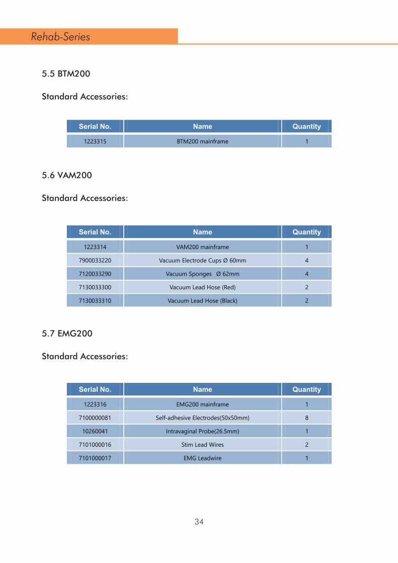
1223315 BTM200 mainframe 1
Serial No. Name Quantity
1223314 VAM200 mainframe 1
7900033220 Vacuum Electrode Cups Ø 60mm 4
7120033290 Vacuum Sponges Ø 62mm 4
7130033300 Vacuum Lead Hose (Red) 2
7130033310 Vacuum Lead Hose (Black) 2
Serial No. Name Quantity
1223316 EMG200 mainframe 1
7100000081 Self-adhesive Electrodes(50x50mm) 8
10260041 Intravaginal Probe(26.5mm) 1
7101000016 Stim Lead Wires 2
7101000017 EMG Leadwire 1
34
5.5 BTM200
Standard Accessories:
5.6 VAM200
Standard Accessories:
5.7 EMG200
Standard Accessories:
Rehab-Series

35
•
•
•
••
•
•
6 Installation
6.1 Installation of functional modules
6.1.1 Rehab series with or without a pre-install module
Remove the Rehab series device and any additional items ordered from the carton and inspect for damage that may have occurred during shipment. the device on a desk or Cart200. Ensure that there is sufficient air flow below the device (do not place the device on a table-cover).
6.1.2 Rehab series with a module (VAM200/ EMG200/ BTM200/ MTM200)
Remove the functional module and any additional items ordered from the carton and inspect for damage that may have occurred during shipment. Place the functional module on a desk or Cart200. Ensure that there is sufficient air flow below the device (do not place the device on a table-cover). Remove the Rehab2 series device and any additional items ordered from the carton and inspect for damage that may have occurred during shipment. Place the main device on top of the functional module. Carefully lift the main device at the front and insert flat cable into connector.
6.1.3 Rehab series with two modules
Remove the bottom functional module and any additional items ordered from the carton and inspect for damage that may have occurred during shipment. Place the bottom functional module on a desk or Cart200. Ensure that there is sufficient air flow below the device (do not place the device on a table-cover) and the white gap on front panel is upward. Remove the top functional module and any additional items ordered from the carton and inspect for damage that may have occurred during shipment. Place the top functional module on top of the bottom functional module and ensure the white gap on front panel is downward. Carefully lift the top functional module at the front and insert flat cable into connector. Place the main device on top of functional modules. Carefully lift the main device at the front and insert flat cable into connector.
6.2 Connection to mains supply
Rehab-Series
•
•
•
•
•
••
36
•
•
••
••
•
•
••••
•
••
Insert the mains cable into socket and connect it to a wall socket.
CAUTION: Do not place the device in a location where the power cord could be tripped over or pulled out during treatment. Do not attempt to use the device if it is not properly grounded. Make certain that the device is electrically grounded by connecting it only to a grounded electrical service receptacle conformable with the applicable national and local electrical codes regarding medical environments. Set power line switch On(1). Power LED indicator is lit green indicating that the device is connected to the mains supply. The device will initialize and perform a self test. This may take a while. At the end of the self test the device enters the Home menu and is ready for use.
6.3 Disconnection from mains supply
Systems without a battery: When you have finished treatments turn the device off by setting the power line switch to Off(0). The device is now disconnected from the mains supply.Systems with a battery: Turn off the device with push button Set power line switch Off (0) to stop charging and to disconnect the unit from the mains supply.
6.4 Operation from the battery module (BTM200)
Leave power line switch in the Off position (0) and turn on the device on using push button. Power LED indicator is lit orange, indicating that the device is operating from the battery. The charge status of the battery is indicated in the right hand top corner of the display. When you have finished treatments turn off the device using push button With the power line switch On (1), the battery is automatically charged, independent of the state of the on/off push button. We recommend to use the apparatus from the powerline whenever possible. This will increase the service life of the battery.
Rehab-Series

37
7 Application Information
7.1 Electrotheraphy
CAUTION: Connection of accessories other than the ones specified by the manufacturer can adversely affect the safety of the patient and correct functioning of the equipment, and is therefore not permitted. To prevent infection, electrodes and sponge pads should not be used on broken
7.1.1 Before treatment Check the patient for contra-indications and warnings as described in paragraph 4 Test the heat sensibility of the treatment area. Rinse the treatment area. Shaving hairy skin is recommended.
7.1.2 Flexible rubber electrodesWe recommend using the flexible rubber electrodes in combination with the supplied sponge pads. When properly moistened, the sponge pads ensure low impedance between the skin and the stimulator during treatment and they are easily cleaned after-wards. Follow the guidelines below when using these electrodes.
Prior to initial use thoroughly rinse the sponge pads in warm tap water to remove the impregnating agent. Before application saturate the sponge pads with tap water. In areas with soft tap water use a saline solution instead. This will improve electrical conduction. The supplied sponge pads have three layers. With AC currents, apply one sponge layer between the skin and the electrode for minimum resistance. With DC currents, apply two sponge layers between the skin and the electrode. Two layers provide more absorbing capacity for electrolysis by-products. Fix the electrode/sponge pad assembly to the patient using the supplied fixation straps. Depending on the electrode size, use two or three wraps to maximize the contact surface. See the illustrations below. Use the stimulator in the Constant Current (CC) mode. This will maintain the set current amplitude, even when the impedance of the sponge pads increases during treatment caused by water evaporation.
•
•
•
•
•
•
•
•
•
•
•
Rehab-Series
skin.
38
7.1.3Vacuum electrodes
There is a choice of large and small electrodes. The areas of the electrodes correspond to those of the 4 x 6cm and 6 x 8cm flexible rubber electrodes. The vacuum electrodes are sufficiently flexible to ensure optimum contact with the skin, but rigid enough to pre-vent any changes in the contour of the part being treated, allowing full advantage to be taken of the massage effect of the pulsed vacuum.
Keep the sponge pads well moistened during treatment.
After use clean the sponge pads as described in the User Maintenance instructions.
7.1.4 Self-adhesive electrodes
Self-adhesive electrodes have higher series impedance than flexible rubber electrodes. This can cause the stimulator to terminate treatment at higher current amplitudes. When this occurs it is recommended to continue the treatment with flexible rubber elec-trodes, combined with properly moistened sponge pads.
Self-adhesive electrodes are not recommended for use with currents that contain a DC component.
CAUTION:
Do not use electrodes on open wounds.
7.1.5 Electrolytic effectsElectrolysis occurs under the electrodes when current types with a DC component are applied. Because the largest concentration of electrolytic by-products caused by ion migration occur under the electrodes, we recommend the use of the supplied sponges to keep the effects to a minimum. Make sure that the sponges are kept well moistened and place the thick side of the sponge between the flexible rubber electrode and the patient.
7.1.6 Current density
Rehab-Series
After use clean the sponge pads as described in the User Maintenance instructions. •
Keep the sponge pads well moistened during treatment, especially with DC currents. If the current display starts blinking, it is an indication of poor electrical contact.
•

39
For symmetrical TENS currents, the Phase duration should be multiplied by 2. The value of the peak current Ipeak can be taken from the current display.
Electrodes should be placed with care, ensuring good electrical contact over the entire electrode surface.
7.1.7 Connection and disconnection reactions
Constant Current (CC) output characteristics may cause unpleasant connection and disconnection reactions if the electrodes are not securely placed or lose contact with the skin. Make sure the current amplitude is set to 0 mA when you apply or remove the electrodes. Use the Constant Voltage (CV) output mode with dynamic electrode appli-cations.
7.2 Ultrasound
7.2.1 Contact control
The ultrasound applicator has a contact control function that suspends treatment when the acoustical contact with the body drops below a certain level. The indicator light on the applicator is turned on to signal this situation, the ultrasound Amplitude display will start blinking and the treatment timer will stop counting down. During this situation the applicator emits a small amount of energy to sense restoration of acoustical contact.
Rehab-Series
In the particular standard for Electrical Nerve and Muscle Stimulators, IEC 60601-2-10, it is recommended not to exceed a current density of 2 mA r.m.s. / cm², otherwise skin irritations or burns can occur. For current types that contain a DC component we recommend not to exceed a current density of 0.2 mA / cm².
To find the maximum recommended current amplitude in mA for the Interferential, Premodulated and Russian Stimulation current waveforms, multiply the electrode surfacein cm² by two. For all other current waveforms the stimulator output current can never exceed 50 mA r.m.s. This implies that with an electrode surface of 25 cm² the current density can never exceed 2 mA r.m.s. / cm². As a rule of thumb for smaller electrodes,such as the 3.2mm self adhesives, the maximum current setting available on the stimulator for a given current waveform should proportionally be reduced.
For a precise calculation of the r.m.s. value of a pulsed current waveform the following formula can be used: IRMS = Ipeak √ ( Phase duration [µs] * pulse frequency [Hz] * 106 )

40
7.2.2 The contact medium
To ensure efficient transfer of energy, a contact medium is required between the ultra-sound applicator and the body. Air causes virtually total reflection of the ultrasound energy. The best medium for the transfer of ultrasound energy is a gel.
The gel should be applied to the part of the body to be treated and then spread out with the ultrasound applicator. Never apply the gel to the ultrasound applicator. The applicator will register this as acoustical contact and may emit ultrasound energy, which could damage the applicator.
If the body surface is very irregular, making it difficult to obtain good contact between the ultrasound applicator and the body, or if direct contact must be avoided (e.g. due to pain), the affected area may be treated under water (subaqual method). The water should be degassed (by previous boiling) in order to prevent air bubbles arising on the ultrasound applicator and the body.
7.2.3 Before treatment
Check the patient for contra-indications. See section 4.2.2 for details. Test the warmth sensibility of the treatment area. To optimize ultrasound transmission, clean the skin of the treatment area with soap or a 70% alcohol solution. Strong hair growth has to be shaved.
7.2.4 During treatment
The ultrasound applicator has to be moved constantly, also with the semi-static method. During treatment the displayed ultrasound Amplitude can vary around the set value, caused by fluctuations in acoustical coupling. Ask the patient regularly for his/her findings. If necessary the treatment will have to be adapted. The Amplitude can be reduced or the continuous mode can be changed to pulsed mode or vice versa.
•
•
•••
•
•
•
Rehab-Series
The contact control function does not work at Amplitudes below 0.2 Watt/cm².
You may experience this when the applicator only partially contacts the body. When contact restoration is sensed the treatment is resumed at the set Amplitude.
41
CAUTION:
The ultrasound applicator is a precision instrument. Great care has been taken during the development and in production to obtain the best possible beam characteristics. Rough treatment (jarring or dropping) can adversely affect these characteristics, and must therefore be avoided.
7.2.5 After treatment
Clean the skin of the patient and the ultrasound applicator with a towel or tissue. Clean the applicator with a 70% alcohol solution. Check for the effects that can be expected (for example pain, circulation and mobility). Ask the patient to inform the therapist of any reactions.
7.3 Vacuum
Vacuum electrodes make good contact with the skin, which means that effective use is made of the whole electrode area. The massage effect resulting from the pulsed vacuum ensures a good blood flow through the skin under the electrodes. This reduces the resistance of the skin and increases he effectiveness of the stimulation current.
7.4.1 Skin electrodes/Probe placement
If using the EMG or ETS phase,connect the EMG reference lead to a surface skin elec-trode and place it appropriately on the body, making sure the skin is free from grease and dirt; repeat the above procedure with the other two skin electrodes. If using a probe, place the single surface skin electrode on the thigh area and then insert the probe.Always use Reference wire (REF) for the precise EMG measurement!
•
•
•
•
••
Rehab-Series
See paragraph 7.1.3 for the application of the vacuum electrodes.When you use only one vacuum channel, close the other channel with one of the vacuum cables not in use.
7.4 EMG
When there are signs that the ultrasound transmission is bad, add more contact gel or spread it with the applicator.
•

42
7.4.2 Probes
Vaginal / Rectal Probes: Check if the connectors connected with the probe. We advice you to use NU-TEK’s Probe. Cleaning: Remember! The Vaginal or Rectal probe is for use with one patient only! Carefully clean the Probe after use. Wash the probe gently in mild soapy water, rinse and make sure the probe is completely dry before returning to storage in the plastic bag. Read carefully the probe instruction of use, originally attached to the probe package.
NOTE:
Only NU-TEK, or appointed distributors /importers are approved to undertake servic-ing. Please contact us about our Vaginal /Rectal Probe.
•••
AC4001(24.5x97mm) NT1041(26.5x97mm)
AC4000(29.5x97mm) NT1011(14x132mm)
Rehab-Series
Place reference electrode anywhere on your skin.When using with Vaginal probe, you can place the reference electrode on your thigh.
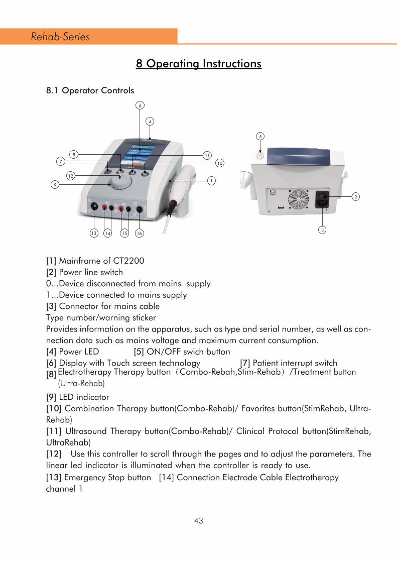
9
121
1413
4
6
1615
78
10
11
3
2
5
43
8 Operating Instructions
8.1 Operator Controls
[1] Mainframe of CT2200[2] Power line switch0...Device disconnected from mains supply1...Device connected to mains supply[3] Connector for mains cableType number/warning stickerProvides information on the apparatus, such as type and serial number, as well as con-nection data such as mains voltage and maximum current consumption. [4] Power LED [5] ON/OFF swich button[6] Display with Touch screen technology [7] Patient interrupt switch[8]
[9] LED indicator[10] Combination Therapy button(Combo-Rehab)/ Favorites button(StimRehab, Ultra-Rehab)[11] Ultrasound Therapy button(Combo-Rehab)/ Clinical Protocol button(StimRehab, UltraRehab)[12] CUse this controller to scroll through the pages and to adjust the parameters. The linear led indicator is illuminated when the controller is ready to use.entral controller with light ring
Rehab-Series
Electrotherapy Therapy button(Combo-Rebah,Stim-Rehab)/Treatment button(Ultra-Rehab)
[13] Emergency Stop button [14] Connection Electrode Cable Electrotherapy channel 1

44
[17] MTM200 module[18] Connection Electrode Cable Electrotherapy channel 4[19] Connection Electrode Cable Electrotherapy channel 3[20] BTM200[21] VAM200 module[22] Connections Vacuum Cables Electrotherapy channel 1[23] Connections Vacuum Cables Electrotherapy channel 2[24] EMG200 module[25] Reference Electrode Cable channel[26] EMG Electrode Cable channel 1[27] EMG Electrode Cable channel 2
Rehab-Series
[15] Connection Electrode Cable Electrotherapy channel 2[16] Connection Ultrasound applicator

45
CAUTION:
Connection of accessories other than the ones specified by the manufacturer can adversely affect the safety of the patient and correct functioning of the equipment, and is therefore not permitted. For combined applications only use Nu-Tek type BF equipment. The very low leakage current of this type of equipment ensures absolute safe therapy. The ultrasound applicator is a precision instrument. Great care has been taken during the development and in production to obtain the best possible beam characteristics. Rough treatment (jarring or dropping) can adversely affect these characteristics, and must therefore be avoided.
CAUTION:
Connections[13] [14] [15] [16] [18] [19] [22] [23] [25] [26] [27]are intended for the connection of type BF applied parts complying with the leakage current requirements of IEC 60601-1.8.2 Symbol
•
•
Symbol SymbolMeaning Meaning
Connection Electrode Cable Electrotherapy
Transportation and storage temperature limits.
Transportation and storage humidity limits.
Transportation and storage atmospheric pressure limits.
The name and address of manufacturer
Complies with the European Medical Device Directive (93/42/EEC) and amended by directive 2007/47/EC requirements. Notified body TÜV Rheinland (CE0197)
Disposal in accordance with Directive 2012/19/EU (WEEE)
BF appliation part
Connection Ultrasound applicator
Connection Emergency Stop button
Please refer to instruction manual because of the higher levels of output.
Rehab-Series
0197
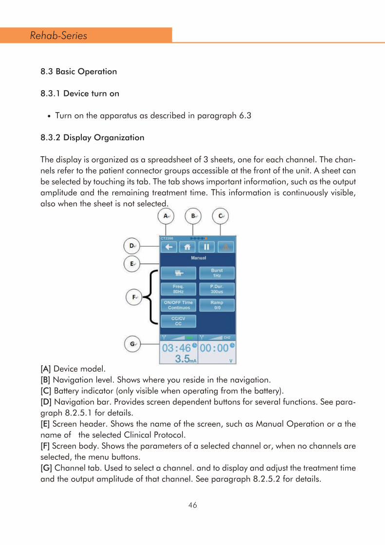
46
•
8.3 Basic Operation
8.3.1 Device turn on
Turn on the apparatus as described in paragraph 6.3
8.3.2 Display Organization
The display is organized as a spreadsheet of 3 sheets, one for each channel. The chan-nels refer to the patient connector groups accessible at the front of the unit. A sheet can be selected by touching its tab. The tab shows important information, such as the output amplitude and the remaining treatment time. This information is continuously visible, also when the sheet is not selected.
[A] Device model.[B] Navigation level. Shows where you reside in the navigation.[C] Battery indicator (only visible when operating from the battery).[D] Navigation bar. Provides screen dependent buttons for several functions. See para-graph 8.2.5.1 for details.[E] Screen header. Shows the name of the screen, such as Manual Operation or a the name of the selected Clinical Protocol.[F] Screen body. Shows the parameters of a selected channel or, when no channels are selected, the menu buttons.[G] Channel tab. Used to select a channel. and to display and adjust the treatment time and the output amplitude of that channel. See paragraph 8.2.5.2 for details.
Rehab-Series

47
A selected sheet gives an overview of the parameters belonging to that channel. A parameter can be selected by touching it, which causes its sheet to be lit and the strip lamp in the bottom of the screen bar is to be illuminated. The parameter can now be adjusted with the central controller [12]. The parameter can be closed by touching another parameter.
To adjust the output amplitude of a channel, touch the tab of the selected channel again. Its colour will change into orange. The output amplitude can now be adjusted with the central controller [12].
For some applications, such as interferential therapy and combination therapy, two adjacent channels can be linked. Linked channels are indicated by a combined tab. The tab halves show the output amplitude of each channel, while the parameters on the remainder of the sheet apply to both channels.
When you turn on the unit, you will first enter the Home menu. In the Home menu none of the channels are selected. The Home menu provides a structured access to all thera-pies available within the unit, with appropriate parameter defaults. Just select a menu item by touching the button to navigate to the next screen. You can navigate back to the previous screen by touching the back arrow at the top of the screen. Anywhere in the navigation, you can jump back to the Home menu, by touching the home button.
8.3.3 Sign
8.3.3.1 Navigation Bar
Icon name Meaning
Back return to previous screen.
return to Home screen.
Page number / number of pages in multi page menu screens or treatment step number
ed sequential protocol in a favorite.
Delete Favorite.
Pause treatment. The output current decreases to 0 and the treatment timer suspends counting down.
Home
Page number
favorite
Delete
Pause
Rehab-Series

7.1.3Vacuum electrodes
There is a choice of large and small electrodes. The areas of the electrodes correspond to those of the 4 x 6cm and 6 x 8cm flexible rubber electrodes. The vacuum electrodes are sufficiently flexible to ensure optimum contact with the skin, but rigid enough to pre-vent any changes in the contour of the part being treated, allowing full advantage to be taken of the massage effect of the pulsed vacuum.
Keep the sponge pads well moistened during treatment.
After use clean the sponge pads as described in the User Maintenance instructions.
7.1.4 Self-adhesive electrodes
Self-adhesive electrodes have higher series impedance than flexible rubber electrodes. This can cause the stimulator to terminate treatment at higher current amplitudes. When this occurs it is recommended to continue the treatment with flexible rubber elec-trodes, combined with properly moistened sponge pads.
Self-adhesive electrodes are not recommended for use with currents that contain a DC component.
CAUTION:
Do not use electrodes on open wounds.
7.1.5 Electrolytic effectsElectrolysis occurs under the electrodes when current types with a DC component are applied. Because the largest concentration of electrolytic by-products caused by ion migration occur under the electrodes, we recommend the use of the supplied sponges to keep the effects to a minimum. Make sure that the sponges are kept well moistened and place the thick side of the sponge between the flexible rubber electrode and the patient.
7.1.6 Current density
A
B
C
D
E
Channel Tab Illustration Of Electrotherapy
Output Indicator
Channel Indicator
Output valueUnit of Output value: mA, V
Standard electrodes
Remaining treatment time. When a sequential protocol has been loaded, the value ndicates the total remaining treatment time of the sequential protocol.
Channel 1
Channel 2
F
G
H
Channel Tab Illustration Of Ultrasound
Remaining treatment time. When a sequential protocol has been loaded, the value indicates the total remaining treatment time of the sequential protocol.Output value
Unit of Output value: Watt、Watt/cm²
48
Icon name MeaningStart/Continue treatment. The output current increases to the previous value and the treatment timer resumes counting down.
Accept the selected option.
Stop the treatment,reset the treatment time and intensity.
Start/Continue
Accept
Stop
8.3.3.2 Channel Tab Information
Rehab-Series

Home
The Home menu gives access to all functions of the unit. Select the desired function or therapy by touching the button.The next screen appears.
8.2.4.1 Electrotherapy
49
8.3.4 Navigation
I
J
K
L
Channel Tab Illustration Of Combination
Output Indicator
Output Indicator
Standard electrodes
Ultrasound Applicator
Remaining treatment time. When a sequential protocol has been loaded, the value indicates the total remaining treatment time of the sequential protocol.Output value
M
N
O
Unit of Output value: mA, V
Output valueUnit of Output value: Watt、Watt/cm²
Rehab-Series

Electrotherapy “Clinical Protocols”
The electrotherapy menu gives access to functions • Clinical Protocols • Favorites • Manual OperationSelect Clinical Protocols by touching the button.The next screen appears.
Use the central controller to scroll through the list and select the clinical protocol by touching the button. The channel selection screen appears.
For therapy information touch the info button on the left side of the protocol and the therapy info will appear.
Therapy information
Use the central controller to scroll through the pages,in most cases the first page is text followed by one or more illustrations.
50
Rehab-Series

Channel Selection
Here you can select the channels for electrotherapy.When channel 1 is selected, channel 2 is still available for another therapy.When Channel 1+2 is selected both channels have the same parameters. Only the intensity can be set differently.
Parameter screen (therapy screen)
In this screen the user can adjust the intensity or change the parameter by touching the button and changing the value with the central controller .
Treatment time adjustment
Touch the timer button, the color changes into orange and adjust the treatment time with the central controller [12].
Repeat this for all other parameters.
51
Rehab-Series
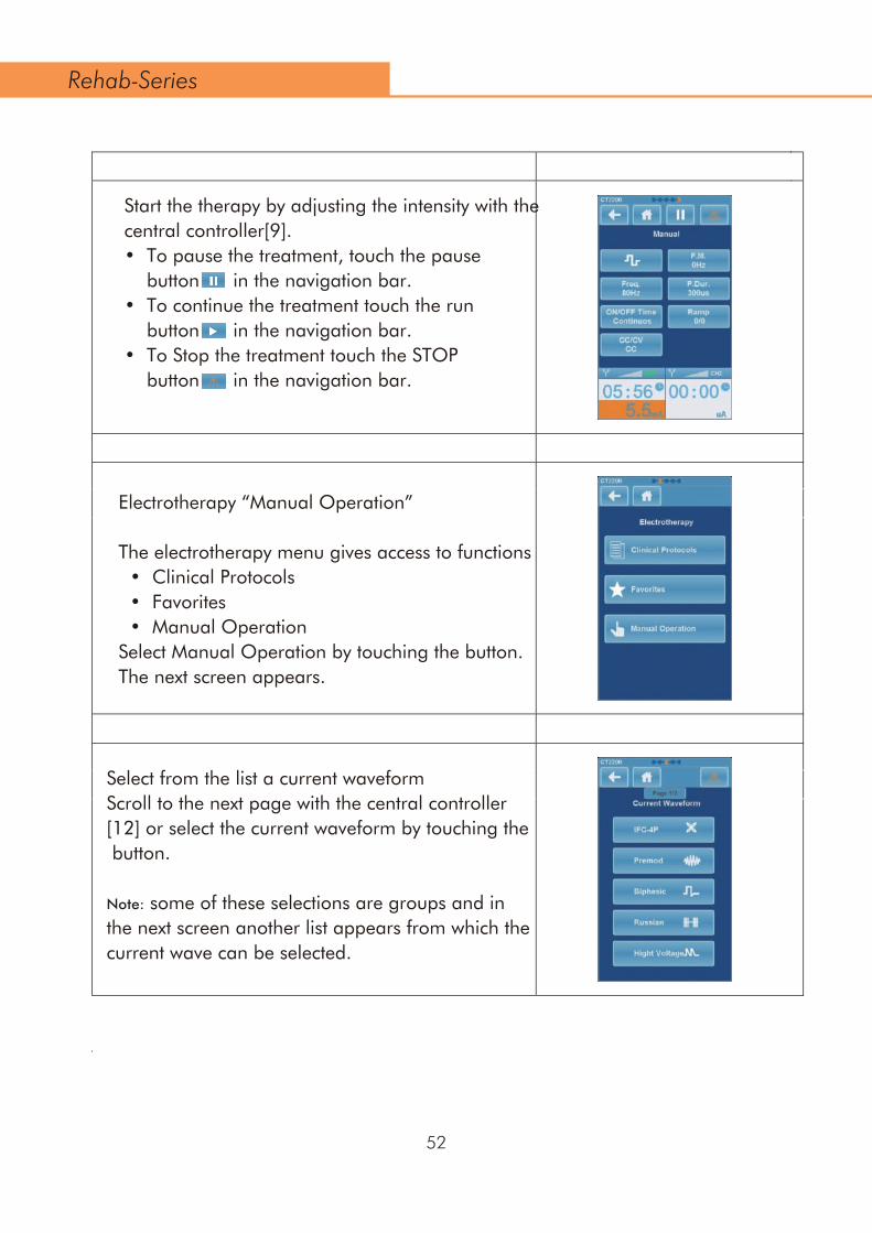
Start the therapy by adjusting the intensity with the central controller[9].• To pause the treatment, touch the pause button in the navigation bar.• To continue the treatment touch the run button in the navigation bar.• To Stop the treatment touch the STOP button in the navigation bar.
Electrotherapy “Manual Operation”
The electrotherapy menu gives access to functions • Clinical Protocols • Favorites • Manual OperationSelect Manual Operation by touching the button.The next screen appears.
Select from the list a current waveformScroll to the next page with the central controller [12] or select the current waveform by touching the button.
Note: some of these selections are groups and in the next screen another list appears from which the current wave can be selected.
52
Rehab-Series

Channel Selection
Here you can select the channels for electrotherapy.When channel 1 is selected, channel 2 is still available for another therapy.
When Channel 1+2 is selected both channels have the same parameters. Only the intensity can be set differently.
Parameter screen
Adjust the parameters by touching the button and change the value with the central controller [12].
Note: some parameters are grouped and in the next screen the settings can be changed the same way as above.
Treatment time adjustment
Touch the timer button, the color changes into orange and adjust the treatment time with the central controller [12].Repeat this for all other parameters.
53
Rehab-Series

Start the therapy by adjusting the intensity with the central controller[12].
• To pause the treatment, touch the pause button in the navigation bar. • To continue the treatment touch the run button in the navigation bar. • To Stop the treatment touch the STOP button in the navigation bar.
The Home menu gives access to all functions of the unit.
Select in the Home menu ultrasound therapy by touching the button “ Ultrasound”.
The next screen appears.
Ultrasound Therapy “Clinical Protocols”
The Ultrasound Therapy menu gives access to functions. • Clinical Protocols • Favorites • Manual OperationSelect Clinical Protocols by touching the buttonThe next screen appears.
8.2.4.2 Ultrasound Therapy
54
Rehab-Series

55
Use the central controller to scroll through the ist and select the clinical protocol by touching the button.
For therapy information touch the info button left of the protocol and the therapy info will appear.
Therapy information
Use the central controller [12] to scroll through the pages, in most cases the first page is text followed by one or more illustrations.
The count-down starts when the contact control is de-activated.Parameters can always be changed, before or during the treatment.
Rehab-Series
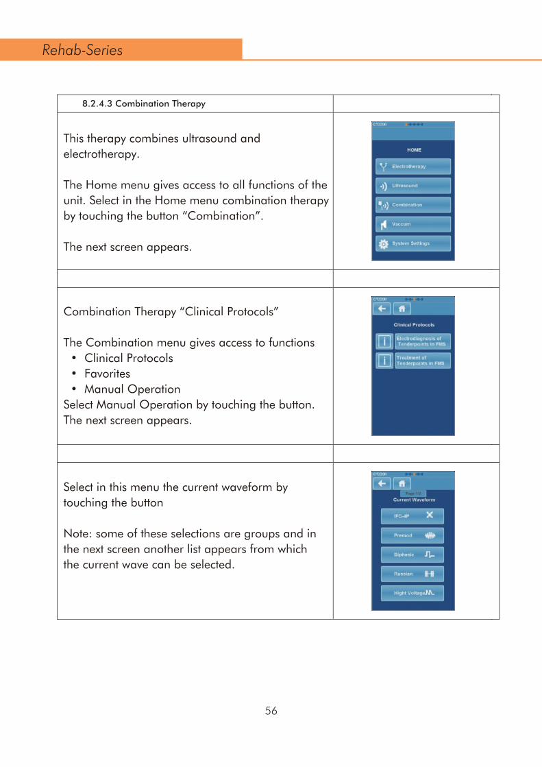
8.2.4.3 Combination Therapy
This therapy combines ultrasound and electrotherapy.
The Home menu gives access to all functions of the unit. Select in the Home menu combination therapy by touching the button “Combination”.
The next screen appears.
Combination Therapy “Clinical Protocols”
The Combination menu gives access to functions • Clinical Protocols • Favorites • Manual OperationSelect Manual Operation by touching the button.The next screen appears.
Select in this menu the current waveform by touching the button
Note: some of these selections are groups and in the next screen another list appears from which the current wave can be selected.
56
Rehab-Series

Adjust the current parameters and treatment time • Touch the parameter button and adjust with the central controller [12].
• Select the ultrasound button to adjust the ultrasound parameters.
• Touch the electrotherapy button to return to the previous screen.
• Touch the ultrasound read-out and adjust the intensity with the central controller [12]. • Touch the current read-out channel 2 to adjust the current intensity. (electrode and treatment head need to be in contact with the patient).
8.2.4.3 Combination Therapy
57
Rehab-Series

Continuous – Pulsed mode
• Touch the button and select the desired massage rhythm using the central controller [12]. You can choose between Continuous, Pulsed mode 1 s and Pulsed mode 2 s.
• Touch the button and adjust the pressure using the central controller [12]. The vacuum cups are automatically selected when the pump starts to run.
The Home menu gives access to all functions of the unit.
Select in the Home menu vaccum therapy by touching the button “Vacuum” if a unit is equipped with a Vacotron it’s possible to select either.
The next screen appears.
8.2.4.4 Vacuum
58
Rehab-Series
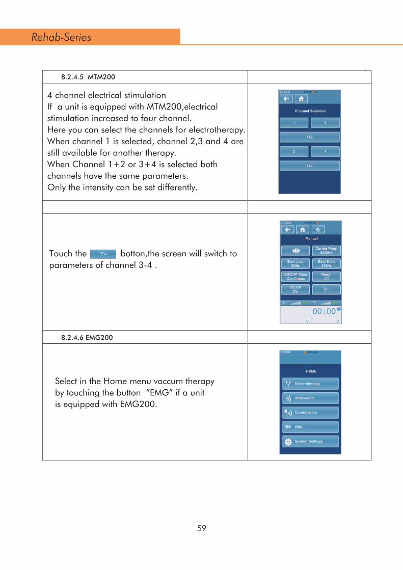
4 channel electrical stimulationIf a unit is equipped with MTM200,electrical stimulation increased to four channel.Here you can select the channels for electrotherapy.When channel 1 is selected, channel 2,3 and 4 are still available for another therapy.When Channel 1+2 or 3+4 is selected both channels have the same parameters. Only the intensity can be set differently.
Touch the botton,the screen will switch to parameters of channel 3-4 .
8.2.4.6 EMG200
Select in the Home menu vaccum therapy by touching the button “EMG” if a unit is equipped with EMG200.
8.2.4.5 MTM200
59
Rehab-Series

The Combination menu gives access to functions • EMG • ETS
Select ETS by touching the button.The next screen appears.
The EMG menu gives access to functions. • Clinical Protocols • Favorites • Manual Operation
Select Manual Operation by touching the buttonThe next screen appears.
Select from the list a current waveformScroll to the next page with the central controller [12] or select the current waveform by touching the button.
60
Rehab-Series
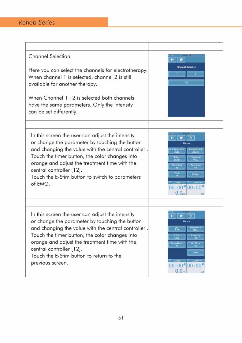
Channel Selection
Here you can select the channels for electrotherapy.When channel 1 is selected, channel 2 is still available for another therapy.
When Channel 1+2 is selected both channels have the same parameters. Only the intensity can be set differently.
In this screen the user can adjust the intensity or change the parameter by touching the button and changing the value with the central controller .Touch the timer button, the color changes into orange and adjust the treatment time with the central controller [12].Touch the E-Stim button to switch to parameters of EMG.
In this screen the user can adjust the intensity or change the parameter by touching the button and changing the value with the central controller .Touch the timer button, the color changes into orange and adjust the treatment time with the central controller [12].Touch the E-Stim button to return to the previous screen.
61
Rehab-Series

Enter the name of your favorite using the keyboard.Touch to store your favorite under the name just entered.Notes:Once saved, favorites can be retrieved from the Electrotherapy, Ultrasound Therapy and Combination Therapy menus.4-polar treatments are automatically saved and loaded as a dual channel treatment.Vacuum settings are not saved.
When a treatment screen is completely set as required, its settings can be stored in a favorite for later use: • As long as the treatment has not been started, a Store button is available on the navigation bar. To store your settings,touch the Store button .
8.2.4.8 System Settings
The Home menu gives access to all functions of the unit. Select in the Home menu System Settings by touching the button “System Settings”
The next screen appears.
8.2.4.7 Storing Favorites
62
Rehab-Series

•
•
•
•
•
•
8.3.5 Shutting device down
Turn off the device as described in paragraph 6.4.
8.3.6 Operating Details
8.3.6.1 Shortcut Button
Electrotherapy Therapy button:Pressing this button can enter Electrotherapy Therapy screen which is selected last time. Ultrasound Therapy button: Pressing this button can enter Ultrasound Therapy screen which is selected last time. Combination Therapy button: Pressing this button can enter Combination Therapy screen which is selected last time. Treatment button: Pressing this button can enter Treatment screen which is selected last time. Favorites button: Pressing this button can enter Favorites screen which is selected last time. Clinical Protocols button: Pressing this button can enter Clinical Protocols screen which is selected last time.
In this screen you can personalize the unit. Several settings can be changed or adjusted. • Language, touch the language button and select the desired langue using the central controller [12]. Touch the language button again or touch another button to confirm. • Brightness, here you can change the intensity of the backlight of the screen. • Repeat this for all other options in the System Settings menu. • Touch the Back arrow in the navigation bar to return to the Home menu.
63
Rehab-Series

8.3.6.2 Adjusting current amplitude
To adjust the output current, touch the tab of the selected channel. Its colour will change to orange, after which the current amplitude can be set with the central controller [12].
The current amplitude can only be adjusted when the clock has been set.
With 4 polar interferential current waveforms the current amplitude operates on both channels simultaneously. In this case a balance facility is available for the classical interferential current waveform (see paragraph 4.1.3 for details).
The unity of the displayed current amplitude depends on the previously selected current waveform and can be expressed in mA, µA or V.
A treatment is started by adjusting the current amplitude, unless a surge program has been selected. To start a surge program, touch the Start/Continue button in the naviga-tion bar.
8.3.6.3 CC/CV mode
Depending on the selected current waveform, the electrotherapy channels can be used in the Constant Current or Constant Voltage mode. It is advised to use the CV mode with dynamic electrode applications. In CV mode the output current depends on the electrical contact with the patient and can therefore vary. You can change the CC/CV setting in the parameter menu.
8.3.6.4 Current polarity
When DC currents are used, the red connection is the positive connection and the black one the negative connection.
64
Rehab-Series

••
•
•
•
9.1 Cleaning
9.1.1 Cleaning of the device
Switch off the device and disconnect it from the power supply.The apparatus can be cleaned with a damp cloth. Use lukewarm water and a non-abrasive liquid household cleaner (no abrasive, no alcohol content solution). If a more sterile cleaning is needed, use a cloth moistened with an antimicrobial cleaner.
CAUTION:
Do not submerse the apparatus in liquids. Should the unit accidentally become sub-mersed, contact the dealer or Authorized Service center immediately .Do not attempt to use a system that has been wet inside until inspected and tested by a Service Technician Certified by Authorized Service center . Do not allow liquids to enter the ventilation holes.
9.1.2 Cleaning of display panel
Use a soft and dry cotton cloth or micro fiber tissue to clean the panel. To remove fingerprints or grease, use a non-abrasive glass cleaning agent. Apply a small amount of the cleaning agent to a soft cotton cloth and then carefully clean the panel.
CAUTION:
Do not spray the cleaning agent directly on the glass panel. Do not use cleaning agents that contain strong alkalis, lye, acid, detergents with fluoride or detergents with ammonia.
9.1.3 Cleaning the electrodes
Apply the protective backing to the tacky side of the electrode. Place the electrode on the side of the protective backing that is labeled with the word on. It may be helpful to improve repeated application by spreading a few drops of cold water over the adhesive and turn the surface up to air dry . Over Saturation with water will reduce the adhesive properties. Between uses, store the electrodes in the reusable bag in a cool dry place.
9. Maintenance and Troubleshooting
65
Rehab-Series

•••
CAUTION:
The electrodes are intended for single patient use only . If irritation occurs, discontinue use and consult your clinician. Always use the electrodes with CE mark, or are legally marketed in the US under 510(K) procedure.
9.1.4 Cleaning the lead wires and cables
Periodically wipe the lead wires clean with a cloth dampened in a mild soap solution, and then gently wipe them dry . Use of rubbing alcohol on the lead wires will damage the insulation and dramatically shorten their life.
9.1.5 Ultrasound applicator
To prevent corrosion,clean and dry the contact surface immediately after use.Make sure that no ultrasound gel remains on the applicator.We further recommend cleaning the applicator and cable daily,using lukewarm water.The applicator can be disinfected using a cloth moistened with a 70% alcohol solution.Check the applicator and cable regularly for damage.
9.1.6 Vacuum electrodes and sponges
The vacuum electrodes and sponges should be cleaned with lukewarm water. In the case of persistent dirt, and for disinfection, a 70% alcohol solution may be used.
Sponges should be replaced regularly. It is recommended to keep sponges and a spare electrode in stock.
Calcium scale can be deposited on the metal surfaces of the electrodes. This has an insulating effect. In order to maintain optimum conductivity, these surfaces should be regularly cleaned and polished.
9.1.7 Vacuum cables
Clean the vacuum cable with a damp cloth. Use lukewarm water and a non-abrasive household cleaning agent. Do not use an alcohol solution. Check the cable regularly for damages and/or bad electrical contact. We advise, keeping a spare vacuum cable in stock.
66
Rehab-Series
9.1.8 Cleaning Vaginal/Rectal probes
Carefully clean the probe after use.Wash the probe gently in mild soapy water,rinse and make sure the probe is completely dry before returning to storage in the plastic bag.
9.1.9 Cleaning the water reservoir and hoses Detach the vacuum cups from the vacuum cables. Place a container filled with a cleaning liquid below the system. Place the peripheral ends of the cables in the container. Go to System Settings and select Tank Cleaning. The water reservoir will be filled with the cleaning liquid until the water reservoir is full.
67
Rehab-Series
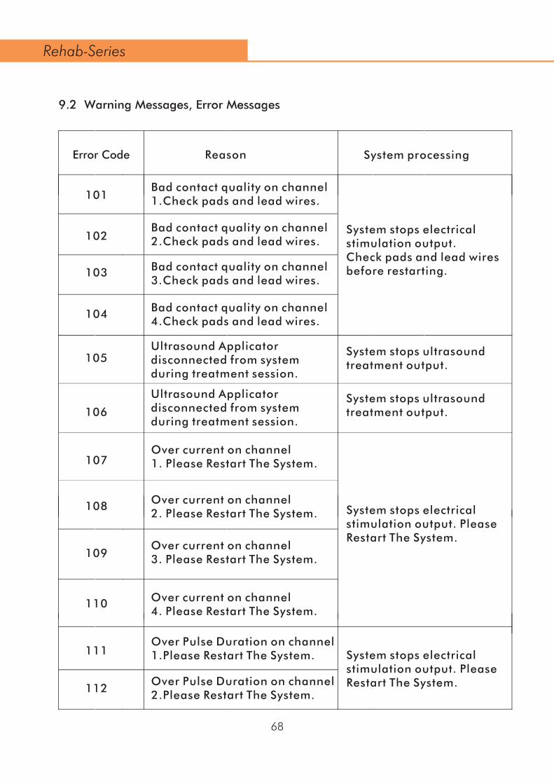
68
Rehab-Series
ReasoError Code n System processing
101Bad contact quality on channel 1.Check pads and lead wires.
System stops electrical stimulation output. Check pads and lead wires before restarting.
102Bad contact quality on channel 2.Check pads and lead wires.
103
104
Bad contact quality on channel 3.Check pads and lead wires.
Bad contact quality on channel 4.Check pads and lead wires.
105Ultrasound Applicator disconnected from system during treatment session.
System stops ultrasound treatment output.
106
Ultrasound Applicator disconnected from system during treatment session.
System stops ultrasound treatment output.
107Over current on channel 1. Please Restart The System.
System stops electrical stimulation output. PleaseRestart The System.
108
109
110
111
Over current on channel 2. Please Restart The System.
Over current on channel 3. Please Restart The System.
Over current on channel 4. Please Restart The System.
Over Pulse Duration on channel 1.Please Restart The System. System stops electrical
stimulation output. PleaseRestart The System.112
Over Pulse Duration on channel 2.Please Restart The System.
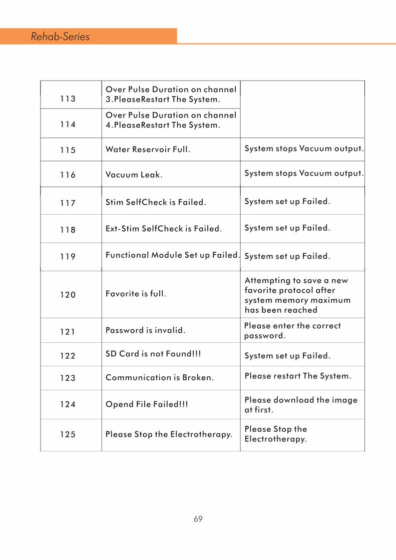
69
Rehab-Series
113Over Pulse Duration on channel 3.PleaseRestart The System.
114Over Pulse Duration on channel 4.PleaseRestart The System.
115 Water Reservoir Full. System stops Vacuum output.
116
117
118
119
120
121
122
123
124
125
Vacuum Leak.
Stim SelfCheck is Failed.
Ext-Stim SelfCheck is Failed.
Functional Module Set up Failed.
Favorite is full.
Attempting to save a new favorite protocol after system memory maximum has been reached
Password is invalid.
SD Card is not Found!!!
Communication is Broken.
Opend File Failed!!!
Please Stop the Electrotherapy.Please Stop the Electrotherapy.
Please download the image at first.
System stops Vacuum output.
System set up Failed.
System set up Failed.
System set up Failed.
Please enter the correct password.
System set up Failed.
Please restart The System.

•
•
•
9.3 Maintenance
9.3.1 User Maintenance
9.3.1.1 Technical Maintenance
On request a service manual can be made available containing: spare part list, descriptions, calibration instructions and other information which will assist the user’s qualified technical personnel to repair those parts of the equipment which are desig-nated by the manufacturer as repairable.
CAUTION:
Electrical safety of the device relies on a properly earthed electrical connection via the power cord. It is therefore necessary to have this connection checked annually. To ensure continued compliance with the 21 CFR 1050.10 standard, this unit should be adjusted and safety tested once each year. Procedures laid down in the service manual should be followed. This may be carried out by your supplier, or by another agency, authorized by the manufacturer. It is also recommended that a service history record is maintained. In some countries this is even obliga tory. Use of controls or adjustments or performance of procedures other than those specified herein may result in hazardous exposure to ultrasonic energy.
70
Rehab-Series
126
127
128
SD Slot ERR!!!
Please Stop the Combination First.
Ultrasound Applicator is too hot.System stops ultrasound treatment output.
Please Stop the Combination First.
System set up Failed.

•
••
••
WARNING:
This unit operates with high voltages. No attempt should be made to disassemble the unit.Maintenance and repair should be carried out by authorized personnel only. The manufacturer will not be held responsible for the results of maintenance or repairs by unauthorized persons.
All other technical maintenance is restricted to authorized Nu-Tek maintenance person-nel. Authorized service personnel can make use of 1498770 Service manual REHAB SERIES
9.4 Troubleshooting
Replace lead wires annually. Please follow the directions on the electrode packaging for the care of electrodes. The life of the electrodes varies, depending on skin conditions, skin preparation, storage and climate. Replace electrodes. that no longer stick. NOTE: If the following measures fail to alleviate the problem, please call the authorized agency or your supplier
Ensure adapter is connect.Check the following contacts:• All contacts are in place. • All contacts are not broken.• Ensure that adapter is Connected.
Adapter contact failureDisplays fail to light up
Displays fail to light up
Stimulation stops
Problem Possible cause Solution
Electrodes1. Dried out or contaminated2. Placement
1. Replace.2. Electrodes must be a minimum of 2 inches apart.
Lead wires Old/worn/damaged
Reapply electrodes, secure firmly
Lead wires Old/worn/damaged
Poor electrode contact
Damaged or worn electrodes or lead wires Replace
71
Rehab-Series
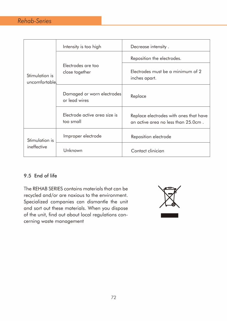
9.5 End of life
The REHAB SERIES contains materials that can be recycled and/or are noxious to the environment. Specialized companies can dismantle the unit and sort out these materials. When you dispose of the unit, find out about local regulations con-cerning waste management
Stimulation is uncomfortable.
Stimulation isineffective
Intensity is too high
Electrodes are too close together
Damaged or worn electrodes or lead wires
Electrode active area size is too small
Improper electrode
Unknown
Decrease intensity .
Reposition the electrodes.
Electrodes must be a minimum of 2 inches apart.
Replace electrodes with ones that have an active area no less than 25.0cm .
Reposition electrode
Contact clinician
Replace
72
Rehab-Series

10.1 Ultrasound parameters
Frequency.........................................................................1MHZ,±10%;3 MHZ,±10%Duty Cycles.............................................................10%-100%,Continues,stepping 10%Pulse duration...........................................................1 – 56 ms ± 10 % (set by duty cycle)PulseFrequency....................................................................................16,48,100Hz
Output Power
Duty factor ≥80% for 5cm²........................................................................0.5W-10.0WDuty factor ≤70% for 5cm²........................................................................0.5W-15.0WDuty factor ≥80% for 1cm²..........................................................................0.1W-2.0WDuty factor ≤70% for 1cm²..........................................................................0.1W-3.0WOutput accuracy........................................± 20% (for any level above 10% of maximum)
Peak out Amplitude Duty
Duty factor≥80%...........................................................................................2.0W/cm²Duty factor≤70%...........................................................................................3.0W/cm²Treatment timer.............................................................................0 - 30 min ± 0.1 min
5 cm² Applicator
ERA (Effective Radiation Area) ................................................................................5cm²Beam type:1 MHz.........................................................................................................Collimating3 MHz.........................................................................................................CollimatingBNR (Beam Non-uniformity Ratio)...............................................................5:1 maximum
1cm² Applicator
ERA (Effective Radiation Area).................................................................................1cm²Beam type:1 MHz..................................................................................................................1cm²3 MHz..................................................................................................................1cm²BNR (Beam Non-uniformity Ratio)...............................................................5:1 maximum
10. Specifications
73
Rehab-Series
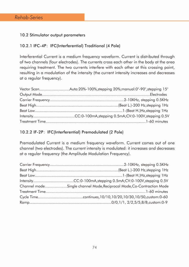
10.2 Stimulator output parameters
10.2.1 IFC-4P:IFC(Interferential) Traditional (4 Pole)
Interferential Current is a medium frequency waveform. Current is distributed through of two channels (four electrodes). The currents cross each other in the body at the area requiring treatment. The two currents interfere with each other at this crossing point, resulting in a modulation of the intensity (the current intensity increases and decreases at a regular frequency).
Vector Scan...........................Auto:20%-100%,stepping 20%;manual:0°-90°,stepping 15°Output Mode................................................................................................ElectrodesCarrier Frequency..................................................................2-10KHz, stepping 0.5KHzBeat High.........................................................................(Beat L.)-200 Hz,stepping 1HzBeat Low..............................................................................1-(Beat H.)Hz,stepping 1HzIntensity.....................................CC:0-100mA,stepping 0.5mA;CV:0-100V,stepping 0.5VTreatment Time.........................................................................................1-60 minutes
10.2.2 IF-2P:IFC(Interferential) Premodulated (2 Pole)
Premodulated Current is a medium frequency waveform. Current comes out of one channel (two electrodes). The current intensity is modulated: it increases and decreases at a regular frequency (the Amplitude Modulation Frequency).
Carrier Frequency..................................................................2-10KHz, stepping 0.5KHzBeat High.........................................................................(Beat L.)-200 Hz,stepping 1HzBeat Low..............................................................................1-(Beat H.)Hz,stepping 1HzIntensity....................................CC:0-100mA,stepping 0.5mA;CV:0-100V,stepping 0.5VChannel mode....................Single channel Mode,Reciprocal Mode,Co-Contraction ModeTreatment Time.........................................................................................1-60 minutesCycle Time........................................continues,10/10,10/20,10/30,10/50,custom:0-60Ramp.........................................................................0/0,1/1, 2/2,5/5,8/8,custom:0-9
74
Rehab-Series
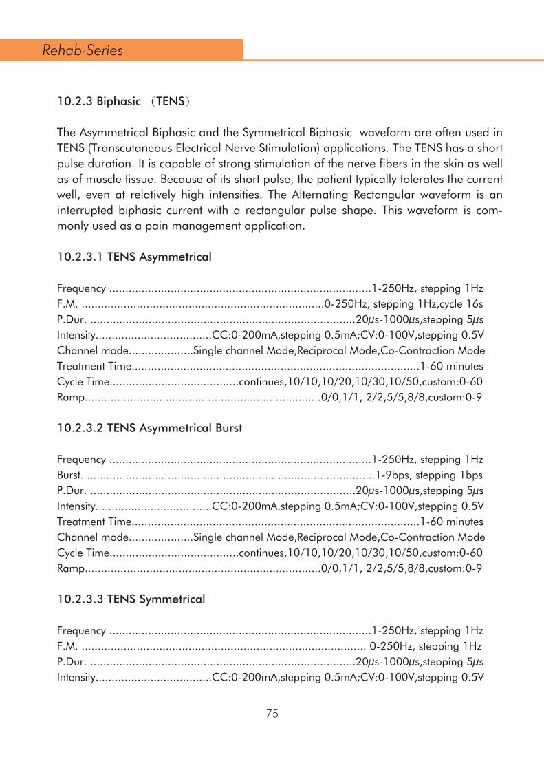
10.2.3 Biphasic (TENS)
The Asymmetrical Biphasic and the Symmetrical Biphasic waveform are often used in TENS (Transcutaneous Electrical Nerve Stimulation) applications. The TENS has a short pulse duration. It is capable of strong stimulation of the nerve fibers in the skin as well as of muscle tissue. Because of its short pulse, the patient typically tolerates the current well, even at relatively high intensities. The Alternating Rectangular waveform is an interrupted biphasic current with a rectangular pulse shape. This waveform is com-monly used as a pain management application.
10.2.3.1 TENS Asymmetrical
Frequency .................................................................................1-250Hz, stepping 1HzF.M. ...........................................................................0-250Hz, stepping 1Hz,cycle 16sP.Dur. ..................................................................................20µs-1000µs,stepping 5µsIntensity....................................CC:0-200mA,stepping 0.5mA;CV:0-100V,stepping 0.5VChannel mode....................Single channel Mode,Reciprocal Mode,Co-Contraction ModeTreatment Time.........................................................................................1-60 minutesCycle Time........................................continues,10/10,10/20,10/30,10/50,custom:0-60Ramp.........................................................................0/0,1/1, 2/2,5/5,8/8,custom:0-9
10.2.3.2 TENS Asymmetrical Burst
Frequency .................................................................................1-250Hz, stepping 1HzBurst. .........................................................................................1-9bps, stepping 1bpsP.Dur. ..................................................................................20µs-1000µs,stepping 5µsIntensity....................................CC:0-200mA,stepping 0.5mA;CV:0-100V,stepping 0.5VTreatment Time.........................................................................................1-60 minutesChannel mode....................Single channel Mode,Reciprocal Mode,Co-Contraction ModeCycle Time........................................continues,10/10,10/20,10/30,10/50,custom:0-60Ramp.........................................................................0/0,1/1, 2/2,5/5,8/8,custom:0-9
10.2.3.3 TENS Symmetrical
Frequency .................................................................................1-250Hz, stepping 1HzF.M. ........................................................................................ 0-250Hz, stepping 1HzP.Dur. ..................................................................................20µs-1000µs,stepping 5µsIntensity....................................CC:0-200mA,stepping 0.5mA;CV:0-100V,stepping 0.5V
75
Rehab-Series

Channel mode....................Single channel Mode,Reciprocal Mode,Co-Contraction ModeTreatment Time.........................................................................................1-60 minutesCycle Time........................................continues,10/10,10/20,10/30,10/50,custom:0-60Ramp.........................................................................0/0,1/1, 2/2,5/5,8/8,custom:0-9
10.2.3.4 TENS Symmetrical Burst
Frequency..................................................................................1-250Hz, stepping 1HzBurst ..........................................................................................1-9bps, stepping 1bpsP.Dur....................................................................................20µs-1000µs,stepping 5µsIntensity....................................CC:0-200mA,stepping 0.5mA;CV:0-100V,stepping 0.5VChannel mode....................Single channel Mode,Reciprocal Mode,Co-Contraction ModeTreatment Time.........................................................................................1-60 minutesCycle Time........................................continues,10/10,10/20,10/30,10/50,custom:0-60Ramp.........................................................................0/0,1/1, 2/2,5/5,8/8,custom:0-9
10.2.3.4 TENS Alternating Rec.
Frequency .................................................................................1-250Hz, stepping 1HzF.M...........................................................................................0-250Hz, stepping 1HzP.Dur....................................................................................20µs-1000µs,stepping 5µsIntensity....................................CC:0-200mA,stepping 0.5mA;CV:0-200V,stepping 0.5VChannel mode....................Single channel Mode,Reciprocal Mode,Co-Contraction ModeTreatment Time.........................................................................................1-60 minutesCycle Time........................................continues,10/10,10/20,10/30,10/50,custom:0-60Ramp.........................................................................0/0,1/1, 2/2,5/5,8/8,custom:0-9
10.2.3.5 TENS Alternating Rec.Burst
Frequency .................................................................................1-250Hz, stepping 1HzBurst...........................................................................................1-9bps, stepping 1bpsP.Dur....................................................................................20µs-1000µs,stepping 5µsIntensity....................................CC:0-200mA,stepping 0.5mA;CV:0-200V,stepping 0.5VChannel mode....................Single channel Mode,Reciprocal Mode,Co-Contraction ModeTreatment Time.........................................................................................1-60 minutesCycle Time........................................continues,10/10,10/20,10/30,10/50,custom:0-60Ramp.........................................................................0/0,1/1, 2/2,5/5,8/8,custom:0-9
76
Rehab-Series

10.2.4 Russian
Russian Current is a rectangle waveform, delivered in bursts or series of pulses. This method was claimed by its author (Kots) to produce maximal muscle strengthening effects without significant discomfort to the patient.
Carrier Freq....................................................................................................2-10KHzBurst Frequency.........................................................................20-100Hz,stepping 5HzDuty cycle.................................................................................10%-50%,stepping 10%Intensity....................................CC:0-100mA,stepping 0.5mA;CV:0-100V,stepping 0.5VChannel mode....................Single channel Mode,Reciprocal Mode,Co-Contraction ModeTreatment Time.........................................................................................1-60 minutesCycle Time........................................continues,10/10,10/20,10/30,10/50,custom:0-60Ramp.........................................................................0/0,1/1, 2/2,5/5,8/8,custom:0-9
10.2.5 Microcurrent
Microcurrent is a monophasic waveform of very low intensity. The literature reports beneficial effects of this waveform in the treatment of wounds. The physiological work-ing mechanism of this effect is as yet not clearly understood. It is thought to stimulate tissue healing by stimulating the 'current of injury', a current which naturally occurs in healing tissue.
Frequency....................................................................0.1-1000Hz,stepping 0.1Hz/1HzPolarity................................................................................................Positive,negativeIntensity..............................................................................CC:0-1000µA,stepping 5µAChannel mode....................Single channel Mode,Reciprocal Mode,Co-Contraction ModeTreatment Time.........................................................................................1-60 minutesCycle Time........................................continues,10/10,10/20,10/30,10/50,custom:0-60Ramp..........................................................................0/0,1/1,2/2,5/5,8/8,custom:0-9
10.2.6 Faradic
10.2.6.1 Trabert
It is a monophasic waveform with a phase duration of 2 ms and a pause of 5 ms result-ing in a frequency of approximately 143 Hz.
Polarity................................................................................................Positive,negative
77
Rehab-Series

Phase Duration.....................................................................................Positive,negativePhase Duration.......................................................................................................2msInterval..................................................................................................................5msIntensity.........................................CC:0-80mA,stepping 0.5mA;CV:0-80V,stepping 0.5VTreatment Time.........................................................................................1-60 minutes
10.2.6.2 Rectanglar
Frequency..................................................................0.2Hz-200Hz.stepping 0.1Hz/1HzPolarity................................................................................................Positive,negativeP.Dur......................................................................100µs-1000ms,steping 100µs-100msIntensity.........................................CC:0-80mA,stepping 0.5mA;CV:0-80V,stepping 0.5VChannel mode....................Single channel Mode,Reciprocal Mode,Co-Contraction ModeTreatment Time.........................................................................................1-60 minutesCycle Time........................................continues,10/10,10/20,10/30,10/50,custom:0-60Ramp.........................................................................0/0,1/1, 2/2,5/5,8/8,custom:0-9
10.2.6.3 Triangular
Frequency..................................................................0.2Hz-200Hz.stepping 0.1Hz/1HzPolarity................................................................................................Positive,negativeP.Dur......................................................................100µs-1000ms,steping 100µs-100msIntensity.........................................CC:0-80mA,stepping 0.5mA;CV:0-80V,stepping 0.5VChannel mode....................Single channel Mode,Reciprocal Mode,Co-Contraction ModeTreatment Time.........................................................................................1-60 minutesCycle Time........................................continues,10/10,10/20,10/30,10/50,custom:0-60Ramp.........................................................................0/0,1/1, 2/2,5/5,8/8,custom:0-9
10.2.7 Diadynamic
The Diadynamic waveforms are rectified alternating currents. The alternating current is modified (rectified) to allow the current to flow in one direction only.
Mode...............................................................................................MF,dF,LP,CP,CP.idPolarity................................................................................................Positive,negativeIntensity........................................CC:0-70mA,stepping 0.5mA; CV:0-70V,stepping 0.5VChannel mode....................Single channel Mode,Reciprocal Mode,Co-Contraction ModeTreatment Time.........................................................................................1-60 minutes
78
Rehab-Series
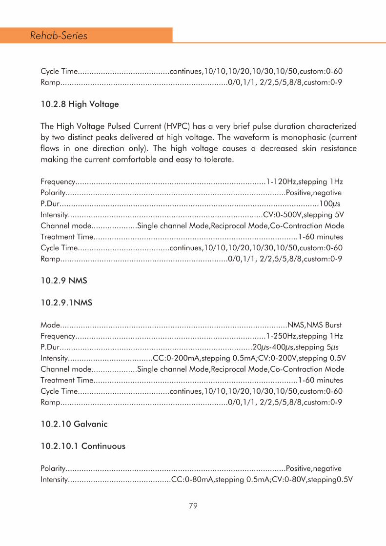
Cycle Time........................................continues,10/10,10/20,10/30,10/50,custom:0-60Ramp.........................................................................0/0,1/1, 2/2,5/5,8/8,custom:0-9
10.2.8 High Voltage
The High Voltage Pulsed Current (HVPC) has a very brief pulse duration characterized by two distinct peaks delivered at high voltage. The waveform is monophasic (current flows in one direction only). The high voltage causes a decreased skin resistance making the current comfortable and easy to tolerate.
Frequency...................................................................................1-120Hz,stepping 1HzPolarity................................................................................................Positive,negativeP.Dur.................................................................................................................100µsIntensity.....................................................................................CV:0-500V,stepping 5VChannel mode....................Single channel Mode,Reciprocal Mode,Co-Contraction ModeTreatment Time.........................................................................................1-60 minutesCycle Time........................................continues,10/10,10/20,10/30,10/50,custom:0-60Ramp.........................................................................0/0,1/1, 2/2,5/5,8/8,custom:0-9
10.2.9 NMS
10.2.9.1NMS
Mode...................................................................................................NMS,NMS BurstFrequency...................................................................................1-250Hz,stepping 1HzP.Dur....................................................................................20µs-400µs,stepping 5µsIntensity.....................................CC:0-200mA,stepping 0.5mA;CV:0-200V,stepping 0.5VChannel mode....................Single channel Mode,Reciprocal Mode,Co-Contraction ModeTreatment Time.........................................................................................1-60 minutesCycle Time........................................continues,10/10,10/20,10/30,10/50,custom:0-60Ramp.........................................................................0/0,1/1, 2/2,5/5,8/8,custom:0-9
10.2.10 Galvanic
10.2.10.1 Continuous
Polarity................................................................................................Positive,negativeIntensity.............................................CC:0-80mA,stepping 0.5mA;CV:0-80V,stepping0.5V
79
Rehab-Series

10.2.10.2 Interrupted
Frequency.....................................................................................................8KHz fixedPolarity................................................................................................Positive,negativeDuty cycle......................................................................................................90% fixedIntensity.............................................CC:0-80mA,stepping 0.5mA;CV:0-80V,stepping0.5V
10.3 Parameter Limit
For security, the device has some some limited for electrotherapy.The maximum inten-sity has a relationship with the frequency and pulse duration following below table:
10.4 Technical Data
Power supply..................................................................100V-240V, 50/60Hz, 1.0-0.4APower output............................................................................................15V , 4A MaxDimensions............................................................................256x180x124mm(LxWxH)Operating Environmental: Temperature......................................................5°C(41°F) to 40°C(104°F) Relative humidity........................................................................15%-93% Atmosphere pressure.......................................................700hPa-1060hPa Storage Environmental: Temperature....................................................-10°C(14°F) to 55°C(131°F) Relative humidity........................................................................10%-90% Atmosphere pressure.......................................................700hPa-1060hPa
80
Rehab-Series
Pulse frequency phase duration Max Current output
<100 <300µS 200mA
<100 300-500µSec 150mA
<100 500-1000µSec 100mA
100-250 <500µSec 100mA
100-250 500-1000µSec 70mA

10.5 Safety and Performance standards
IEC 60601-1General requirements for the safety of electrical medical systems, including Annex 1, national differences for Australia, Canada and the United States.
Safety class according to IEC 60601-1class I type BF
IEC 60601-2-5Particular requirements for the safety of ultrasonic therapy equipment.
IEC 60601-2-10Particular requirements for the safety of nerve and muscle stimulators.
This equipment complies with all requirements of the Medical Device Directive (93/42/EEC).
Medical device classificationIIa
21 CFR 1050.10This equipment complies with all requirements of 21 CFR1050.10, Performance Stan-dard for Ultrasonic Therapy devices.
21 CFR 898This equipment complies with all requirements of 21 CFR 898, Performance Standard for electrode lead wires and patient leads.
10.6 EMC detailsMedical electrical devices such as the Rehab-series are subject to special precautions with regard to electromagnetic compatibility (EMC) and must be installed and commis-sioned in accordance with the EMC advice given in the instructions for use and accom-panying documents.
Portable and mobile RF communication systems (e.g. mobile phones) may interfere with medical electrical Rehab-series.
81
0197
Rehab-Series

The Rehab-series should only be operated with the original mains cable specified in the list of contents delivered.
Operating the device with any other mains cable can lead to increased emissions or reduced interference immunity of the device.
The device should not be used when placed immediately next to or stacked on top of other devices. If operation is necessary when immediately next to or stacked on top of other devices, the device should be monitored to ensure it is operating as intended in this arrangement.
Guidelines and manufacturer's declaration – electromagnetic interference
The REHAB SERIES device is intended for operation in an electromagnetic environment as indicated below. The customer or user of the REHAB SERIES unit should ensure that it is operated in such an environment.
Interference tests Conformity Electromagnetic environment guideline
RF emissions according to CISPR 11
RF emissions according to CISPR 11
Harmonic emissions according to IEC 61000-3-2
Voltage fluctuation emissions and flicker according to IEC 61000-3-3
Group 1
ClassA
Class A
Conforms
The Rehab-series device uses RF energy solely for its internal functioning. It RF emission is therefore very low and it is unlikely that this will cause interference to neighbouring electronic Rehab-series
The Rehab-series device is suitable for use in all establishments other than domestic and those directly connected to the public low-voltage power supply network that supplies buildings used for domestic purposes.
82
Rehab-Series

Guidance and manufacturer’s declaration – Electromagnetic immunity
The REHAB SERIES device is intended for use in the electromagnetic environment specified below. The customer or the user of the REHAB SERIES device should assure that it is used in such an environment.
Immunity test
Electrostatic discharge (ESD) to IEC 61000-4-2
Electrical fast transient / burst to IEC 61000-4-4
Surge IEC 6100-4-5
Voltage dips, short interruptions and voltage variations on power supply input lines IEC 61000-4-11
± 6 kV contact± 8 kV air
± 2 kV for power supply lines± 1 kV for input /output lines
± 2 kV for power supply linesnot applicable
± 1 kV differential mode± 2 kV common mode
<5% UT(>95% dip in UT for0.5 cycle) 40% UT(60% dip in UT for5 cycles) 70% UT(30% dip in UT for25 cycles) <5% UT(>95% dip in UT for5 seconds)
<5% UT(>95% dip in UT for0.5 cycle) 40% UT(60% dip in UT for 5cycles) 70% UT(30% dip in UT for 25cycles) <5% UT(>95% dip in UT for 5seconds)
± 6 kV contact± 8 kV air
IEC 60601 test level
Compliance level
Electromagnetic environment - Guidance
Power frequency (50/60 Hz) magnetic field to IEC 61000-4-8
Note: UT is the AC mains voltage prior to application of the test level.
3 A/m 3 A/m
Power frequency magnetic fields should be at levels characteristic of a typical location in a typical commerical or hospital environment.
Mains power quality should be that of a typical commercial or hospital environment. If the use of the REHAB SERIES device requires continued operation during mains power interruptions, it is recommended to install a battery.
Mains power quality should be that of a typical commercial or hospital environment.
Mains power quality should be that of a typical commercial or hospital environment.
Floors should be wood, concrete or ceramic tile. If floors are covered with synthetic material, the relative humidity should be at least 30%.
± 1 kV differential mode± 2 kV common mode
83
Rehab-Series

The main features of the REHAB SERIES devices are as follows: interference-free delivery of shockwaves, interference-free control of all functions. Uninterrupted operation is not required with the use intended.
Portable and mobile radio should not be used any closer to the REHAB SERIES devices, including cables, than the recommended separation distance calculated from the equation applicable to the transmission frequency.Recommended separation distance:d= 1.2 √Pd= 0.35 √P for 80 MHz to 800 MHz d= 0,7 √P for 800 MHz to 2.5 GHzWhere P is the rated power of the transmitter in Watts (W) according to the transmitter manufacturer and d is the recommended sepa-ration distance in meters (m).According to an investigation in situa, the field strength of station-ary radio transmitters should be less than the compliance level at all frequencies.Interference may occur in the vicin-
The REHAB SERIES device is intended for operation in the electromagnetic environment specified below. The customer or user of the REHAB SERIES should ensure that it is used in such an environment.
Guidelines and manufacturer's declaration – electromagnetic interference immunity
Interference immunity tests
IEC 60601-test level
Compliance levelElectromagnetic environment-guidelines
Conducted RF disturbance variables according to IEC 61000-4-6Radiated RF disturbance variables according to IEC 61000-4-3
3 Veffective value 150 kHz to 80MHz3 V/m 80 MHz to 2.5GHz
3 Veffective value150 kHz to 80 MHz3 V/m80 MHz to 2.5 GHz
84
Rehab-Series

The REHAB SERIES device is intended for operation in an electromagnetic environment where RF disturbances are monitored. The customer or user of the REHAB SERIES device can help pre-vent electromagnetic interference by maintaining a minimum distance between portable and mobile RF telecommunications 4- series (transmitters) and the REHAB SERIES device – accord-ing to the output power of the communications device, as indicated below.
Recommended separation distances between portable and mobile RF telecommunica-tions 4- series and the REHAB SERIES device
Theoretically, it is not possible to exactly predict the field strengths of fixed transmitters such as base stations for radio telephones and land mobile radios, amateur radio stations, AM and FM radio and TV broadcasting. To determine the electromagnetic environment in relation to the fixed transmitters, an electromagnetic site survey should be considered. If the measured field strength in the location where the REHAB SERIES device is to be used exceeds the above com-pliance levels, the REHAB SERIES device should be monitored in order to ensure that it is func-tioning as intended. If unusual features are noticed, additional measures may be necessary such as re-orienting or relocating the REHAB SERIES device.Above the frequency range from 150 kHz to 80 MHz the field strength should be less than 3 V/m.
NOTE 1 At 80 MHz and 800 MHz the higher frequency range is applicable.NOTE 2 These guidelines may not be applicable in all cases. Electromagnetic propagation is affected by absorption and reflection from structures, objects and people.
85
Rehab-Series
Rated output of transmitter W
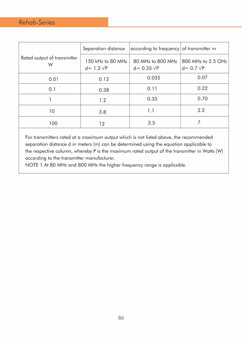
For transmitters rated at a maximum output which is not listed above, the recommended separation distance d in meters (m) can be determined using the equation applicable to the respective column, whereby P is the maximum rated output of the transmitter in Watts (W) according to the transmitter manufacturer.NOTE 1 At 80 MHz and 800 MHz the higher frequency range is applicable.
Separation distance according to frequency of transmitter m
150 kHz to 80 MHzd= 1.2 √P
80 MHz to 800 MHzd= 0.35 √P
800 MHz to 2.5 GHzd= 0.7 √P
Rated output of transmitter W
0.01 0.0350.12 0.07
0.220.38
1.2 0.35 0.70
0.11
1.1 2.2
12 3.5
3.8
7
0.1
1
10
100
86
Rehab-Series
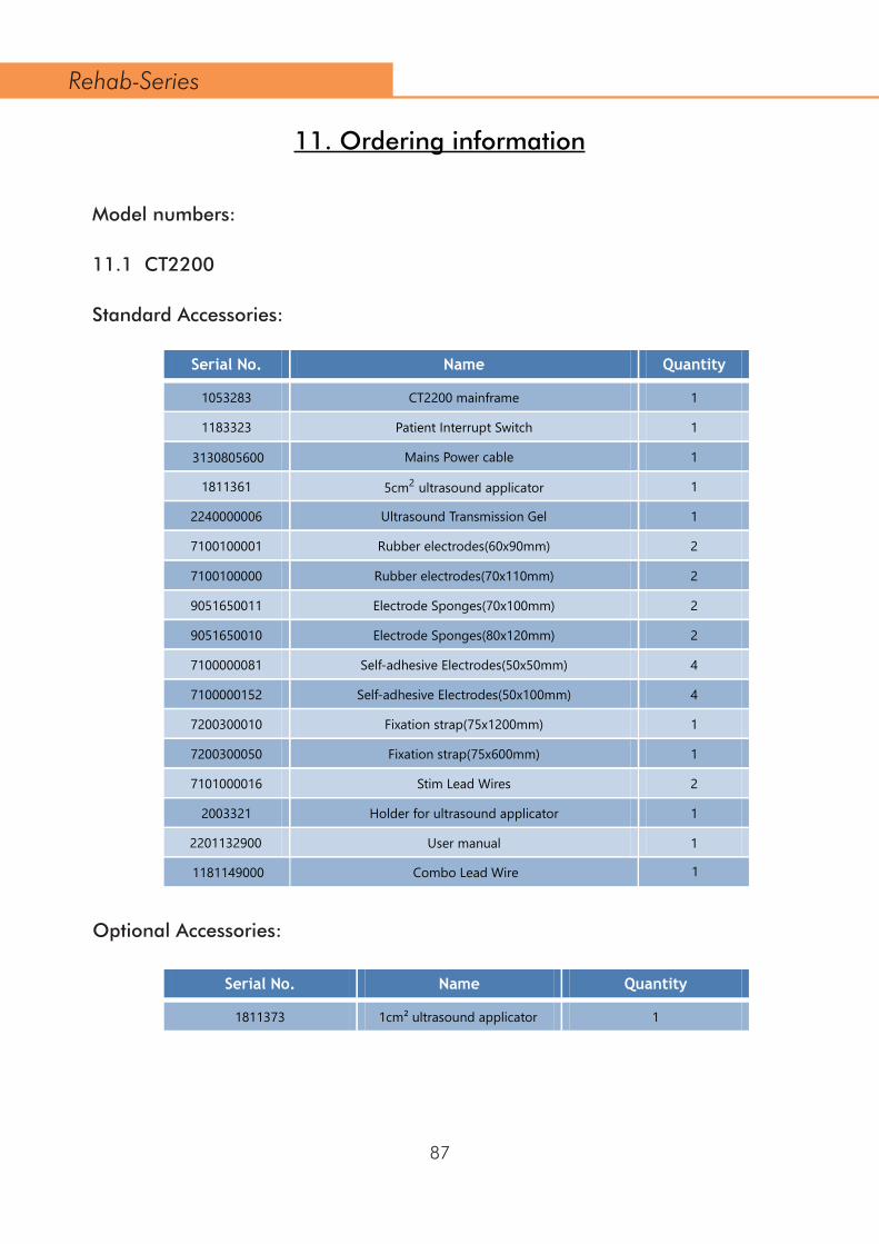
Model numbers:
11.1 CT2200
Standard Accessories:
Optional Accessories:
11. Ordering information
Serial No. Name Quantity
1053283 CT2200 mainframe 1
1183323 Patient Interrupt Switch 1
Mains Power cable 1
1811361 5cm2 ultrasound applicator 1
2240000006 Ultrasound Transmission Gel 1
7100100001 Rubber electrodes(60x90mm) 2
7100100000 Rubber electrodes(70x110mm) 2
9051650011 Electrode Sponges(70x100mm) 2
9051650010 Electrode Sponges(80x120mm) 2
7100000081 Self-adhesive Electrodes(50x50mm) 4
7100000152 Self-adhesive Electrodes(50x100mm) 4
7200300010 Fixation strap(75x1200mm) 1
7200300050 Fixation strap(75x600mm) 1
7101000016 Stim Lead Wires 2
2003321 Holder for ultrasound applicator 1
User manual 1
Serial No. Name Quantity
1811373 1cm² ultrasound applicator 1
87
Rehab-Series
3130805600
2201132900
1181149000 Combo Lead Wire 1
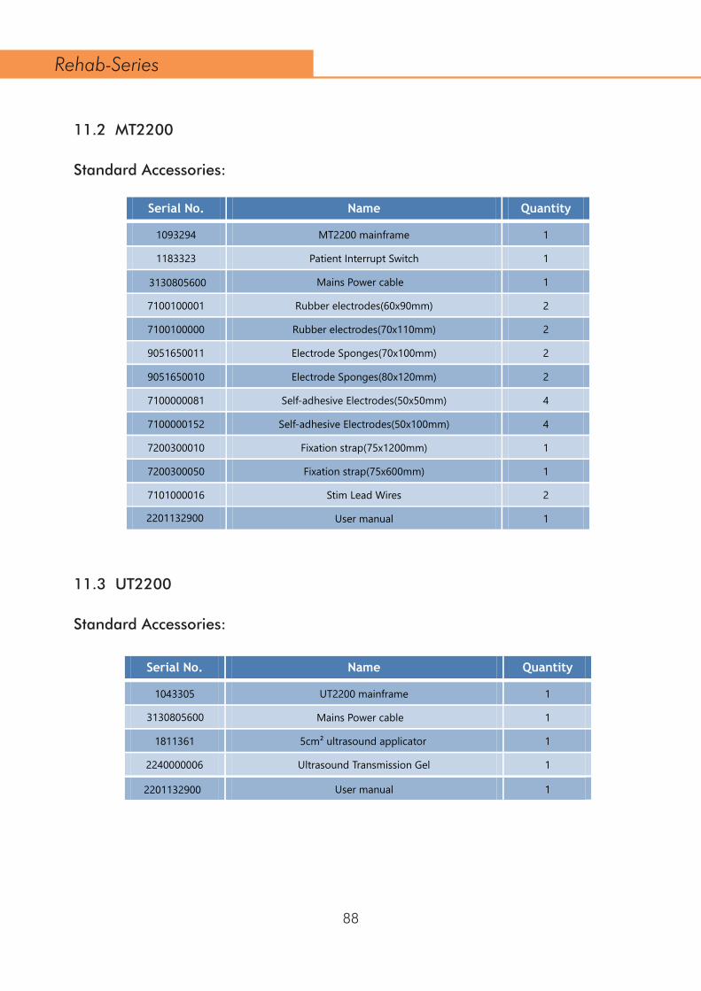
11.2 MT2200
Standard Accessories:
11.3 UT2200
Standard Accessories:
Serial No. Name Quantity
1093294 MT2200 mainframe 1
1183323 Patient Interrupt Switch 1
Mains Power cable 1
7100100001 Rubber electrodes(60x90mm) 2
7100100000 Rubber electrodes(70x110mm) 2
9051650011 Electrode Sponges(70x100mm) 2
9051650010 Electrode Sponges(80x120mm) 2
7100000081 Self-adhesive Electrodes(50x50mm) 4
7100000152 Self-adhesive Electrodes(50x100mm) 4
7200300010 Fixation strap(75x1200mm) 1
7200300050 Fixation strap(75x600mm) 1
7101000016 Stim Lead Wires 2
User manual 1
Serial No. Name Quantity
1043305 UT2200 mainframe 1
Mains Power cable 1
1811361 5cm² ultrasound applicator 1
2240000006 Ultrasound Transmission Gel 1
User manual 1
88
Rehab-Series
3130805600
2201132900
3130805600
2201132900

11.4 MTM200
Standard Accessories
11.5 BTM200
Standard Accessories:
11.6 VAM200
Standard Accessories:
Serial No. Name Quantity
1
7100100001 Rubber electrodes(60x90mm) 2
7100100000 Rubber electrodes(70x110mm) 2
9051650011 Electrode Sponges(70x100mm) 2
9051650010 Electrode Sponges(80x120mm) 2
7100000081 Self-adhesive Electrodes(50x50mm) 4
7100000152 Self-adhesive Electrodes(50x100mm) 4
7200300010 Fixation strap(75x1200mm) 1
7200300050 Fixation strap(75x600mm) 1
7101000016 Stim Lead Wires 2
Serial No. Name Quantity
1223315 BTM200 mainframe 1
Serial No. Name Quantity
1223314 VAM200 mainframe 1
7900033220 Vacuum Electrode Cups Ø 60mm 4
7120033290 Vacuum Sponges Ø 62mm 4
7130033300 Vacuum Lead Hose (Red) 2
7130033310 Vacuum Lead Hose (Black) 2
89
Rehab-Series
1223317 MTM200 mainframe

Serial No. Name Quantity
11811670 Intravaginal Probe(29.5mm) 1
10660042 Anal Probe 1
11.7 EMG200
Standard Accessories
Optional Accessories:
11.8 Cart:
Serial No. Name Quantity
1223316 EMG200 mainframe 1
7100000081 Self-adhesive Electrodes(50x50mm) 8
10260041 Intravaginal Probe(26.5mm) 1
7101000016 Stim Lead Wires 2
7101000017 EMG Leadwire 1
Serial No. Name Quantity
1243319 Therapy System Cart 1
90
Rehab-Series
91
0197
Manufacturer: Name: Shenzhen Dongdixin Technology Co., Ltd. Add: No.3 Building,Fanshen Xusheng Industrial Estate,XilixiaoBaimang,Nanshan,Shenzhen 518108,China. Tel: 0086-755-27652316 E-mail: [email protected]
Authorized EC-representative: Shanghai International Holding Corp. GmbH (Europe) Eiffestraße 80, 20537 Hamburg Germany Tel: 0049-40-2513175 Fax: 0049-40-255726
Rehab-Series