Series PCD3
134
Document 26-789 │ Edition ENG21 │ 2021-10-01 Manual Series PCD3
-
Upload
khangminh22 -
Category
Documents
-
view
0 -
download
0
Transcript of Series PCD3

Document 26-789 │ Edition ENG21 │ 2021-10-01
Manual
Series PCD3

Saia-Burgess Controls AG
Hardware manual for PCD3 series │ Document 26-789 ENG21 │ 2021-10-01
Contents
0-1
00 Content0 Content
0.1 Document versions ......................................................................................... 0-40.2 Trademarks .................................................................................................... 0-5
1 Graphical table of contents
2 Orientation guide2.1 Introduction ..................................................................................................... 2-22.2 Connection of Saia PCD® controllers to the internet ...................................... 2-32.3 ePLAN® macros ............................................................................................. 2-32.4 Planning an application .................................................................................. 2-42.5 E/A module cabling ......................................................................................... 2-72.5.1 Cable layout ................................................................................................. 2-72.5.2 Cable routing ............................................................................................... 2-82.5.3 Overvoltage protection for long distances or external cables ...................... 2-8
2.6 Series cabling ................................................................................................. 2-92.7 Addressing ...................................................................................................... 2-102.8 Labeling of the module carriers and I/O slot modules .................................... 2-122.8.1 Module carrier .............................................................................................. 2-122.8.2 I/O slot module ............................................................................................. 2-13
3 PCD3.Mxxx0 Classic CPU and module carrier3.1 System overview ............................................................................................ 3-23.1.1 SBC S-Net networking concept ................................................................... 3-23.1.2 Saia PCD® Web server ............................................................................... 3-3
3.2 General technical data .................................................................................... 3-43.3 System resources ........................................................................................... 3-63.3.1 Program blocks ............................................................................................ 3-63.3.2 Value range of the number types ................................................................. 3-63.3.3 Media ........................................................................................................... 3-6
3.4 PCD3 CPU ..................................................................................................... 3-73.4.1 Block diagram PCD3.Mxxx0 ........................................................................ 3-73.4.2 PCD3.M3x20 / PCD3.M3x30 and PCD3.M5x40 / PCD3.M6x40 ................... 3-83.4.3 PCD3.Mxx60 ................................................................................................ 3-103.4.4 Hardware and firmware versions of the PCD3.Mxxx0 ................................. 3-12
3.5 Extension with PCD3 components ................................................................. 3-133.6 Module carrier ................................................................................................. 3-153.6.1 The module carriers (LIO) ............................................................................ 3-163.6.2 Calculation of the possible load ................................................................... 3-203.6.3 Module carrier connections .......................................................................... 3-20
3.7 Installation of the CPU and module carrier ..................................................... 3-213.7.1 Mounting position and ambient temperature ............................................... 3-213.7.2 Assembly / disassembly .............................................................................. 3-213.7.3 Insertion of I/O modules ............................................................................... 3-22
3.8 Dimensions ..................................................................................................... 3-23

Saia-Burgess Controls AG
Hardware manual for PCD3 series │ Document 26-789 ENG21 │ 2021-10-01
Contents
0-2
03.9 Power supply and connection plan ................................................................. 3-243.9.1 External power supply ................................................................................. 3-243.9.2 Internal power supply ................................................................................... 3-263.9.3 Internal power supply for more than one module carrier ............................. 3-263.9.4 Grounding and connection concept ............................................................. 3-28
3.10 Data retention in the event of power failure .................................................... 3-293.10.1 Battery module PCD3.R010 for PCD3.M3xxx ............................................. 3-29
3.11 Operating states ............................................................................................. 3-313.11.1 LEDs and their meaning .............................................................................. 3-32
3.12 Operating mode (Run/Stop) ........................................................................... 3-333.12.1 Run/Stop push-button .................................................................................. 3-333.12.2 Run/Stop switch ........................................................................................... 3-34
3.13 Manual control and emergency operation ...................................................... 3-353.14 Connections of the PCD3.Mxxx0 .................................................................... 3-373.15 Connections on orange terminal block ........................................................... 3-383.15.1 RS-485 (Port 2) ............................................................................................ 3-383.15.2 Interrupt inputs ............................................................................................. 3-393.15.3 Hardware Watchdog .................................................................................... 3-413.15.4 Supply .......................................................................................................... 3-43
3.16 Software watchdog ......................................................................................... 3-443.17 Hardware Clock (Real Time Clock) ................................................................ 3-453.18 Storage space on the PCD3 ........................................................................... 3-463.18.1 Storage types in the Saia PCD® systems .................................................... 3-463.18.2 Memory management (PCD3 without integrated μSD flash card) ............... 3-483.18.3 Memory management (PCD3 with integrated μSD flash card) .................... 3-513.18.4 Memory structure of the SaiaPCD3 systems ............................................... 3-53
3.19 Optional memory upgrades ............................................................................ 3-553.19.1 Overview ...................................................................................................... 3-573.19.2 Storage module PCD3.R600 for Flash cards (FC) ...................................... 3-603.19.3 SD flash memory cards ............................................................................... 3-643.19.4 Micro-SD flash memory card PCD7.R-MSD1024 ........................................ 3-66
4 RIO (Remote Input Output) head stations4.1 The RIO (Remote Input Output) head stations ............................................... 4-24.2 Internal power of the PCD3.T76x head stations ............................................. 4-34.3 Connections of the RIO head station PCD3.T76x for 4 modules ................... 4-44.3.1 Meaning of the connections ......................................................................... 4-44.3.2 Power LED ................................................................................................... 4-5
4.4 Diagnosis Information of the RIOs .................................................................. 4-64.4.1 LED meaning ............................................................................................... 4-64.4.2 Diagnosis module ........................................................................................ 4-8
4.5 Terminating resistors of Profibus-DP or Profi S-net network ......................................................................................... 4-12
Saia-Burgess Controls AG
Hardware manual for PCD3 series │ Document 26-789 ENG21 │ 2021-10-01
Contents
0-3
05 Communications interfaces5.1 General ........................................................................................................... 5-25.2 Serial interface logs ........................................................................................ 5-35.2.1 Serial S-Net ................................................................................................. 5-45.2.2 Profi S-Net ................................................................................................... 5-45.2.3 Ether S-Net .................................................................................................. 5-45.2.4 Logs implemented in the user program ....................................................... 5-4
5.3 Onboard interfaces ......................................................................................... 5-55.3.1 Summary table ............................................................................................. 5-55.3.2 RS-232 connector (port 0) as communication interface and
as programmer connection (only PCD3.M5xx0 / M6xx0) ............................ 5-65.3.3 RS-485 / RS-422 (port 3) ............................................................................. 5-85.3.4 RS-485 / S-Net / MPI (port 10) .................................................................... 5-85.3.5 CAN (port 10) ............................................................................................... 5-95.3.6 Profibus DP Master (port 10) ....................................................................... 5-95.3.7 USB PGU interface for programming device connection ............................. 5-105.3.8 Ethernet RJ-45 and Profibus ....................................................................... 5-115.3.9 RS-485 / Profi S-net/DP slave (port 2) ......................................................... 5-12
5.4 Plug-in interface modules on I/O slot 0…3 ..................................................... 5-135.4.1 Overview slot interface modules .................................................................. 5-135.4.2 Serial Interfaces on I/O module slot 0 (port 1) ............................................. 5-145.4.3 Serial interfaces on the I/O module slots 0 - 3 ............................................. 5-14
5.5 LIO and RIO ................................................................................................... 5-155.4.1 Interfaces of PCD3.Cxxx and PCD3.Txxx ................................................... 5-15
6 Input/output (I/O) modules
7 Configuration7.1 CPU processor units ....................................................................................... 7-27.2 RIO - Remote Input Output module carrier PCD3.T76x* ................................ 7-37.3 Smart-RIO PCD3.T665 and PCD3.T666 ........................................................ 7-4
8 Maintenance8.1 Battery change at the PCD3.M5xx0/M6xx0 .................................................... 8-28.2 Battery change at the PCD3.M3xx0 with PCD3.R010 .................................... 8-3
9 Product status of the CPU-moduls
A AppendixA.1 Symbols for notes etc. .................................................................................... A-2A.1.1 Note symbols ............................................................................................... A-2A.1.2 Mass designation, symbols and meaning .................................................... A-2
A.2 Definitions for the serial interfaces ................................................................. A-3A.2.1 RS-232 ......................................................................................................... A-3A.2.2 RS-485/422 .................................................................................................. A-4A.2.3 TTY/current loop .......................................................................................... A-6
A.3 Glossary ......................................................................................................... A-7A.4 Contact, support and repair addresses .......................................................... A-9
Saia-Burgess Controls AG
Hardware manual for PCD3 series │ Document 26-789 ENG21 │ 2021-10-01
Contents
0-4
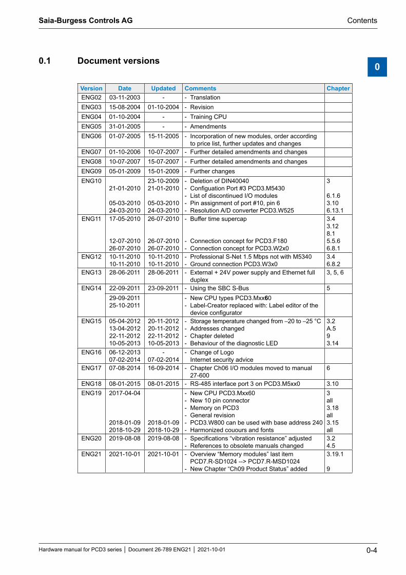
00.1 Document versions
Version Date Updated Comments ChapterENG02 03-11-2003 - - TranslationENG03 15-08-2004 01-10-2004 - RevisionENG04 01-10-2004 - - Training CPUENG05 31-01-2005 - - AmendmentsENG06 01-07-2005 15-11-2005 - Incorporation of new modules, order according
to price list, further updates and changesENG07 01-10-2006 10-07-2007 - Further detailed amendments and changesENG08 10-07-2007 15-07-2007 - Further detailed amendments and changesENG09 05-01-2009 15-01-2009 - Further changesENG10
21-01-2010
05-03-2010 24-03-2010
23-10-2009 21-01-2010
05-03-2010 24-03-2010
- Deletion of DIN40040 - Configuation Port #3 PCD3.M5430 - List of discontinued I/O modules - Pin assignment of port #10, pin 6 - Resolution A/D converter PCD3.W525
3
6.1.63.106.13.1
ENG11 17-05-2010
12-07-2010 26-07-2010
26-07-2010
26-07-2010 26-07-2010
- Buffer time supercap
- Connection concept for PCD3.F180 - Connection concept for PCD3.W2x0
3.43.128.15.5.66.8.1
ENG12 10-11-201010-11-2010
10-11-201010-11-2010
- Professional S-Net 1.5 Mbps not with M5340 - Ground connection PCD3.W3x0
3.46.8.2
ENG13 28-06-2011 28-06-2011 - External + 24V power supply and Ethernet full duplex
3, 5, 6
ENG14 22-09-2011 23-09-2011 - Using the SBC S-Bus 529-09-201125-10-2011
- New CPU types PCD3.Mxx60 - Label-Creator replaced with: Label editor of the
device configuratorENG15 05-04-2012
13-04-201222-11-201210-05-2013
20-11-2012 20-11-201222-11-201210-05-2013
- Storage temperature changed from –20 to –25 °C - Addresses changed - Chapter deleted - Behaviour of the diagnostic LED
3.2A.593.14
ENG16 06-12-2013 07-02-2014
- 07-02-2014
- Change of Logo Internet security advice
ENG17 07-08-2014 16-09-2014 - Chapter Ch06 I/O modules moved to manual 27-600
6
ENG18 08-01-2015 08-01-2015 - RS-485 interface port 3 on PCD3.M5xx0 3.10ENG19 2017-04-04
2018-01-092018-10-29
2018-01-092018-10-29
- New CPU PCD3.Mxx60 - New 10 pin connector - Memory on PCD3 - General revision - PCD3.W800 can be used with base address 240 - Harmonized couours and fonts
3all3.18all3.15all
ENG20 2019-08-08 2019-08-08 - Specifications “vibration resistance” adjusted - References to obsolete manuals changed
3.24.5
ENG21 2021-10-01 2021-10-01 - Overview “Memory modules” last item PCD7.R-SD1024 --> PCD7.R-MSD1024
- New Chapter “Ch09 Product Status” added
3.19.1
9

Saia-Burgess Controls AG
Hardware manual for PCD3 series │ Document 26-789 ENG21 │ 2021-10-01
Contents
0-5
00.2 Trademarks
Saia PCD® and Saia PG5® are registered trademarks of Saia-Burgess Controls AG.
ePlan® is the registered trademark of ePlan Software & Service GmbH & Co. KG.
Technical changes based on the current technical state of the art.
Saia-Burgess Controls AG, 2003. © All rights reserved.
Published in Switzerland

Saia-Burgess Controls AG
Hardware manual for PCD3 series │ Document 26-789 ENG21 │ 2021-10-01
Graphic list of contents
1-1
1
5560Saia PCD3.M
1 Graphical table of contents
The graphical table of contents picks out some key aspects of the hardware manual of the PCD3 series and allows you to jump to the appropriate chapter by clicking on the labeled frame or directly on the component/connector. From the table of contents you can jump to all chapters.
Plug-in serial interfaces in slot 0…3, chapter 5.3
Battery changechapter 8
Flash memory module, chapter
3.18
Run/StopSwitch, chapter 3.12.2
RS-485, chapter 5USB interface, chapter 5.3.7
Ethernet, chapter 5 Earthing, chapter 3.9.4
Extension, chapter 3.5
RS-485 / S-Net (Port 10),
chapter 5.3.4
LEDs for operating status, chapter 3.11.1
Terminal block for power supply, watchdog, interrupt
inputs and Port 2, chapter 3.15
LEDs for operating status, chapter 3.11.1
Operation mode key,
chapter 3.12.1
RS-232 / PGU
(Port 0),chapter 5.3.2

Saia-Burgess Controls AG
Hardware manual for PCD3 series │ Document 26-789 ENG21 │ 2021-10-01
Guidance
2-1
2
2 Orientation guide
2.1 Introduction2.2 Connection of Saia PCD® controllers to the internet2.3 ePlan® macros2.4 Planning an application2.5 E/A module cabling2.6 Series cabling2.7 Addressing2.8 Labeling of the module carriers and I/O slot modules

Saia-Burgess Controls AG
Hardware manual for PCD3 series │ Document 26-789 ENG21 │ 2021-10-01
Introduction
Guidance
2-2
2
2.1 Introduction
Symbols used in this manual for notes, definitions for the serial interfaces, explanation of terms (glossary) and the company address and address for repairs are added to the appendix.
You are welcome to submit supplements and suggested improvements to the following e-mail address [email protected]
This manual explains the technical aspects of the PCD3 components. The following terms are commonly used:
CPU Central processing units: the heart of the Saia PCD®
RIOs Remote I/Os: inputs and outputs that are connected to the CPU via a fieldbus such as Profibus
LIOs Local I/Os: these are connected to the CPU or RIO via the I/O bus (i.e. using very short cables)
Modules Input/output modules mounted in a housing matched to the PCD3 system
Module holders
CPU, RIOs or LIOs that can hold modules
The purpose of this chapter is to demonstrate the essentials in the planning and installation of control systems with PCD3 components.
The following topics are relevant in this regard:
Planning of an application (chapter 2.4)
I/O module cabling (chapter 2.5)
Series cabling (chapter 2.6)
Addressing (chapter 2.7)
Details about hardware, software, configuration, maintenance, and troubleshooting are described in separate chapters.
All PCD3 I/O modules are described in the 27-600 Manual I/O Modules PCD2 and PCD3.
The aforementioned manual and further documentation can be found on our homepage under documentation or at the respective system groups: www.sbc-support.com/en/documents/manuals/

Saia-Burgess Controls AG
Hardware manual for PCD3 series │ Document 26-789 ENG21 │ 2021-10-01
Connections to the internet │ EPLAN macros
Guidance
2-3
2
2.2 Connection of Saia PCD® controllers to the internet
When Saia PCD controllers are connected directly to the internet, they are also a potential target for cyber attacks. Appropriate protective measures must always be taken to ensure secure operation.
PCD controllers include simple, integrated protection features. However, se-cure operation on the internet is only guaranteed using external routers with a firewall and encrypted VPN connections.
For more information, please refer to our support site: www.sbc-support.com/security
2.3 ePLAN® macros
ePLAN® macros are available for project planning and engineering.
The ePLAN® electric P8 macros are available on the support page www.sbc-support.com
The macros and article data are also provided on the ePLAN® data portal. www.eplandataportal.de

Saia-Burgess Controls AG
Hardware manual for PCD3 series │ Document 26-789 ENG21 │ 2021-10-01
Planning an application
Guidance
2-4
2
2.4 Planning an application
The following aspects should be considered when planning PCD3 applica-tions: - The internal load current taken by the I/O modules from the +5V and +V supply
must not exceed the maximum supply current specified for the CPUs, RIOs or LIOs (PCD3.C200)
- The CPU or RIO type specifies the maximum number of module carriers and modules
- After five PCD3.C100 module carriers, use a PCD3.C200 base unit as I/O bus amplifier.
- In keeping with lean automation, it is recommended to leave the first slot in the CPU basic module free for any subsequent expansions. Both simple I/O mod-ules and communication modules can be used in this slot.
- The total length of the I/O bus is limited to 15 LIO modules by technical factors; the shorter, the better.
The PCD3.C200 is used to extend the I/O bus or for the internal power sup-ply (+5V and +V (24V)) to a module segment. Please note the following rules: - Do not use more than six PCD3.C200s in a single configuration, or the time
delay will exceed the I/O access time.
- A maximum of five cables PCD3.K106 / .K116 may be used.
100Saia PCD3.C100Saia PCD3.C200Saia PCD3.C
6860
ETH 2.1 ETH 2.2
Ethernet 2
USB
Saia PCD3.M 100Saia PCD3.C 100Saia PCD3.C
Extension plug PCD3.K010
Extension cable PCD3.K106/PCD3.K116
Series 0
Series 1
- Insert a PCD3.C200 after each cable (at the start of a row). Exception: In a small configuration with no more than 3 PCD3.C1xxs, these can be supplied from the PCD3.Mxxxx. A PCD3.C200 is not required.
Saia-Burgess Controls AG
Hardware manual for PCD3 series │ Document 26-789 ENG21 │ 2021-10-01
Planning an application
Guidance
2-5
2
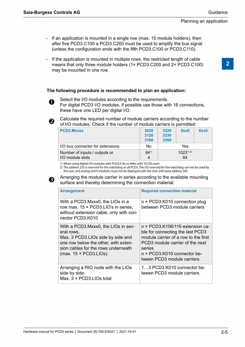
- If an application is mounted in a single row (max. 15 module holders), then after five PCD3.C100 a PCD3.C200 must be used to amplify the bus signal (unless the configuration ends with the fifth PCD3.C100 or PCD3.C110).
- If the application is mounted in multiple rows, the restricted length of cable means that only three module holders (1× PCD3.C200 and 2× PCD3.C100) may be mounted in one row.
The following procedure is recommended to plan an application:
Select the I/O modules according to the requirements. For digital PCD3 I/O modules, if possible use those with 16 connections, these have one LED per digital I/O.
Calculate the required number of module carriers according to the number of I/O modules. Check if the number of module carriers is permitted: PCD3.Mxxxx 3020
3120 3160
3320 3330 3360
5xx0 6xx0
I/O bus connector for extensions No YesNumber of inputs / outputs or I/O module slots
641) 4
10231) 2) 64
1) When using digital I/O modules with PCD3.E16x or A46x with 16 I/Os each2) The address 255 is reserved for the watchdog on all PCD3. The I/O reserved for the watchdog can not be used by
the user, and analog and H modules must not be deployed with the slots with base address 240
Arranging the module carrier in series according to the available mounting surface and thereby determining the connection material:
Arrangement Required connection material
With a PCD3.Mxxx0, the LIOs in a row max. 15 × PCD3.LIO's in series, without extension cable, only with con-nector PCD3.K010
n × PCD3.K010 connection plug between PCD3 module carriers
With a PCD3.Mxxx0, the LIOs in sev-eral rows. Max. 3 PCD3.LIOs side by side and one row below the other, with exten-sion cables for the rows underneath (max. 15 × PCD3.LIOs)
n × PCD3.K106/116 extension ca-ble for connecting the last PCD3 module carrier of a row to the first PCD3 module carrier of the next series. n × PCD3.K010 connector be-tween PCD3 module carriers.
Arranging a RIO node with the LIOs side by side. Max. 3 × PCD3.LIOs total
1…3 PCD3.K010 connector be-tween PCD3 module carriers

Saia-Burgess Controls AG
Hardware manual for PCD3 series │ Document 26-789 ENG21 │ 2021-10-01
Planning an application
Guidance
2-6
2
The easiest way to compile this is with the Device Configurator of the PG5 Saia Project Manager (SPM).
Calculate the load current at the internal + 5 V supply with the table in the 27-600 I / O Modules for PCD1 / PCD2 manual under chapter Power con-sumption of the modules. Comment: Use the worst or highest values.
Verify if the max. supply current of the CPU, RIO or PCD3.C200 is suffi-cient. To supply one module segment separately, use PCD3.C200 instead of PCD3.C1xx. Verify whether the load current of all segments does not exceed the max. supply current of the CPU / RIO / PCD3.C200. The max. supply currents can be found in chapter 3.9.2 Internal power supply
Calculate current consumption at 24 V supply. The current consumption of the PCD3 configuration can be determined in chapter 3.6.2 power con-sumption of the modules (use the worst or highest values)
Determine the corresponding connection cables for the module carriers
Calculate the number of required connector blocks for the I/O modules and order them separately. Screw terminals or spring terminals can be ordered as required. Not all modules require the same type of connectors.
Please note that in most applications, the load currents of the outputs are the heavi-est burden on the 24 V supply. With 16 outputs with a load current of 0.5 A each, this is already 8 A, if all outputs are switched on.

Saia-Burgess Controls AG
Hardware manual for PCD3 series │ Document 26-789 ENG21 │ 2021-10-01
Cabling
Guidance
2-7
2
2.5 E/A module cabling
It is recommended to wire the I/O modules from a cable duct.
2.5.1 Cable layout
In order to have enough space, a distance of at least two fingers between the module carrier and the cable channel is recommended. This is very helpful in troubleshooting (wiring) and a possible module change.
100Saia PCD3.C5560Saia PCD3.M 110
E160
E160
A400
A400
W340
W340
W340
W340
F281
F210
In particular cables to connections on the lower part of the module carrier (supply, grounding) should preferably be wired under the module carriers with a cable duct.
Following these rules ensures the visibility of the LEDs and access to the bus ports.

Saia-Burgess Controls AG
Hardware manual for PCD3 series │ Document 26-789 ENG21 │ 2021-10-01
Cabling
Guidance
2-8
2
2.5.2 Cable routing
230 V supply lines and signal lines must be laid in separate cables with a mini-mum distance of 10 cm. It is also advisable to ensure a spatial separation of the mains and signal lines within the control cabinet
Digital signal lines / bus lines and analog signal lines / sensor lines must be laid in separate cables
It is recommended to use shielded cables for the analog signal cables
The shield must be earthed at the control cabinet entry or exit point. The shields must be laid with the shortest route and with the largest possible cross section. The central earthing point is to be connected to the protective conductor PE by >10 mm² by the shortest route
As a rule, the shield is only placed on one side of the control cabinet, unless there is an equipotential bonding, which has much lower impedance than the shield resistance
Inductors installed in the same cabinet, e.g. contactor coils must be provided with suitable interference suppression circuits (RC elements)
Control cabinet parts with high field strengths, e.g. transformers or frequency inverters should be shielded with dividing plates that have a good ground con-nection.
2.5.3 Overvoltage protection for long distances or external cables
If cables are laid outside the building or over longer distances, suitable overvoltage protection measures must be provided. Especially with bus cables, these measures are indispensable.
In the case of cables laid outside, the shield must be current-carrying and grounded on both sides.
The surge arresters must be installed at the entrance to the control cabinet input.

Saia-Burgess Controls AG
Hardware manual for PCD3 series │ Document 26-789 ENG21 │ 2021-10-01
Series cabling
Guidance
2-9
2
2.6 Series cabling
While the expansion connector connects the module carriers neighbourly, the extension cables take over the connection of the module carriers at the right end of one series with the first module carrier on the left side of the next series.
100Saia PCD3.C100Saia PCD3.C200Saia PCD3.C
6860
ETH 2.1 ETH 2.2
Ethernet 2
USB
Saia PCD3.M 100Saia PCD3.C 100Saia PCD3.C
Extension plug PCD3.K010
0 17616 1286432 48
192 368
Extension cable PCD3.K106
Ordering information: Type Description
PCD3.K010 Extension plug
PCD3.K106 Extension cable 0.7 mPCD3.K116 Extension cable 1.2 m

Saia-Burgess Controls AG
Hardware manual for PCD3 series │ Document 26-789 ENG21 │ 2021-10-01
Addressing
Guidance
2-10
2
2.7 Addressing
The address of an I/O slot module is determined by its module slot in the configuration.
Each PCD3 I/O slot module has 16 addresses (numbered from 0 to 15), regardless of the actual number of inputs / outputs (16, 8, 6 or 4).
CPU: CPUs serve LIOs as well as RIOs. The addressing of the modules on a CPU looks like this: Module slot 0 has the base address 0 (zero) Module slot 1 has the base address 16 Module slot 2 has the base address 32 Module slot 3 has the base address 48 Each slot provides 16 addresses, regardless of the number of inputs / outputs (16, 8, 6 or 4) per module. Additionally, 64 addresses are available for the 4 slots.
RIOs: RIOs are module carriers with standalone functions and are detatched from the CPU through a network. There is no direct access to the I/Os. The configuration of the RIO is communicated (defined) by the PG5 network configurator of the CPU. RIOs receive their function from the CPU over the network and can use LIOs. Addressing: For addressing, the same applies as described under CPU.
LIOs: LIOs are supplementary module carriers (PCD3.C100 / C110 / C200) to a CPU or a RIO, thus expanding the number of module slots.
The address of the slot module is determined by the base address of the module carrier within a configuration and its location on the module carrier itself.
Addressing: Module slot number >= 4 I/O base address >= 64

Saia-Burgess Controls AG
Hardware manual for PCD3 series │ Document 26-789 ENG21 │ 2021-10-01
Addressing
Guidance
2-11
2
100Saia PCD3.C100Saia PCD3.C200Saia PCD3.C
6860
ETH 2.1 ETH 2.2
Ethernet 2
USB
Saia PCD3.M 100Saia PCD3.C 100Saia PCD3.C
Extension cable PCD3.K106
further series up to max. Address 1023
0 17616 1286432 48
192 368
The address of the first module in a second or third series is determined by the address of the last module in the previous series +16.
For easier wiring, the module slots of the PCD3 module carriers are labeled with the numbers 0 to 3. For more precise addressing, each module carrier and also each module additionally has an address field in the lower right corner of the housing. How these address fields are used is described in the next chapter.
Address 255 is reserved for the watchdog relay. Modules using this address must not be inserted in module slot 16. For additional details, please see chapter 3.15.3 Hardware watchdog.
Each additional module carrier PCD3.C100 / C200 offers space for 4 additional I/O modules, at the end of the bus a PCD3.C110 provides space for 2 additional I/O modules. The connection to the next series is made via the 26-wire extension cable PCD3.K106 / K116.
Forces that occur at too small radii of the cable (smaller than the natural radius, so buckling), can cause damage to the connector!
The extension cables must not be connected or disconnected while the controller is under voltage!

Saia-Burgess Controls AG
Hardware manual for PCD3 series │ Document 26-789 ENG21 │ 2021-10-01
Labeling of the module carriers and I/O plug-in modules
Guidance
2-12
2
2.8 Labeling of the module carriers and I/O slot modules
2.8.1 Module carrier
The I/O module slots in the module carrier are labelled with highlighted digits:
0…3 (PCD3.Mxxxx, /T76x, /T66x, /C200, /C100)
0…1 (PCD3.C110
100Saia PCD3.C
Viewed from the front, each module carrier housing and each module slot has an address field in the lower right corner.
Example:
100Saia PCD3.C
0-L1 1-L1 2-L1 3-L1
L1 100Saia PCD3.C
0-L2 1-L2 2-L2 3-L2
L2
Slot module carrier no.
0-L2
1-L2
2-L2
3-L2
0-L1
1-L1
2-L1
3-L1
v
All PCD3 module carriers and the extension cable PCD3.K106 / 116 are accompanied by a matching set of labels as an additional option for labeling.
64 64 80 96 112 0128 128 144 160 176 0192 192 208 224 240 16256 256 272 288 304 32320 320 336 352 368 48384 384 400 416 432448 448 464 480 496512 512 528 544 560576 576 592 608 624640 640 656 672 688704 704 720 736 752768 768 784 800 816832 832 848 864 880896 896 912 928 944960 960 976 992 1008
4 310 8686 0

Saia-Burgess Controls AG
Hardware manual for PCD3 series │ Document 26-789 ENG21 │ 2021-10-01
Labeling of the module carriers and I/O plug-in modules
Guidance
2-13
2
2.8.2 I/O slot module
Saia PCD3 input and output modules in cassette designThe functions of the Saia PCD3 can be expanded as required using a wide range of plug-in I/O modules and can be adapted to specific requirements. This not only ensures that a project can be implemented quickly, but also provides the option of expanding or modifying the system at any time.
Plug-in terminals
Nameplate with connection description
LED for status indication Module type
Label holder
System propertiesSlot direct in the Saia PCD3 basic
CPU or in the module holderFull integration in the Saia PCD3
housingStable cartridge constructionNumerous variants availableConnection to the I/O level via
plug-in spring terminal blocks or ribbon cables and adapters
I/O terminal blocks are supplied as standard
No tools required for replacing modules
Clips
Additionalprotectionwith screw
Guideway
PCD3 with 4 module positions (slots)
Label holder

Saia-Burgess Controls AG
Hardware manual for PCD3 series │ Document 26-789 ENG21 │ 2021-10-01
Labeling of the module carriers and I/O plug-in modules
Guidance
2-14
2
The small label holders (see outside right) are plugged into the front of the I/O module at the bottom right and serve as an address field.
With the labels shown on the right (4 310 8686 0), the modules can be assigned according to their module slot. Order type 4 329 4819 1
Since mid-2005, all PCD3 I/O modules have been fitted with a mounting option for a labeling clip. The clips can be equipped with pre-punched labels and snapped on the right of the connector.
Additional labelling on the frontThe clips including pre-punched labels (A4 sheet) are available as accessories under the order type 4 310 8723 0.
With clip Order type 4 310 8723 0
( 4 310 8 723 0)
Older module housing without clip mounting option
New module housing with clip mounting option

Saia-Burgess Controls AG
Hardware manual for PCD3 series │ Document 26-789 ENG21 │ 2021-10-01
Labeling of the module carriers and I/O plug-in modules
Guidance
2-15
2
Module labelling on the side
The circuit diagram printed on the side of each I/O module makes wiring easier and also helps during commissioning.
On the opposite side of the module, it is possible to attach individual labels using the supplied non-printed adhesive labels.
The pre-punched labels can be labeled using the device configurator of the PG5 programming tool from version V2.0 onwards.
Fast labeling of I/O modules with the LabelEditor
This software tool is used to label PCD3 label clips efficiently.
Saia-Burgess Controls AG
Hardware manual for PCD3 series │ Document 26-789 ENG21 │ 2021-10-01
Labeling of the module carriers and I/O plug-in modules
Guidance
2-16
2
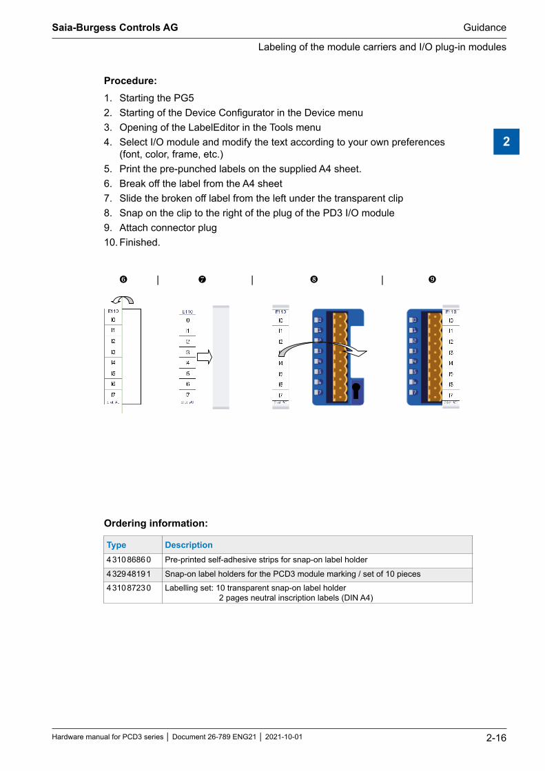
Procedure:1. Starting the PG52. Starting of the Device Configurator in the Device menu 3. Opening of the LabelEditor in the Tools menu4. Select I/O module and modify the text according to your own preferences
(font, color, frame, etc.)5. Print the pre-punched labels on the supplied A4 sheet. 6. Break off the label from the A4 sheet 7. Slide the broken off label from the left under the transparent clip 8. Snap on the clip to the right of the plug of the PD3 I/O module 9. Attach connector plug 10. Finished.
| | |
Ordering information:
Type Description4 310 8686 0 Pre-printed self-adhesive strips for snap-on label holder
4 329 4819 1 Snap-on label holders for the PCD3 module marking / set of 10 pieces4 310 8723 0 Labelling set: 10 transparent snap-on label holder
2 pages neutral inscription labels (DIN A4)
Saia-Burgess Controls AG
Hardware manual for PCD3 series │ Document 26-789 ENG21 │ 2021-10-01
PCD3.Mxxx0 Classic CPU and expansion enclosure
3-1
3
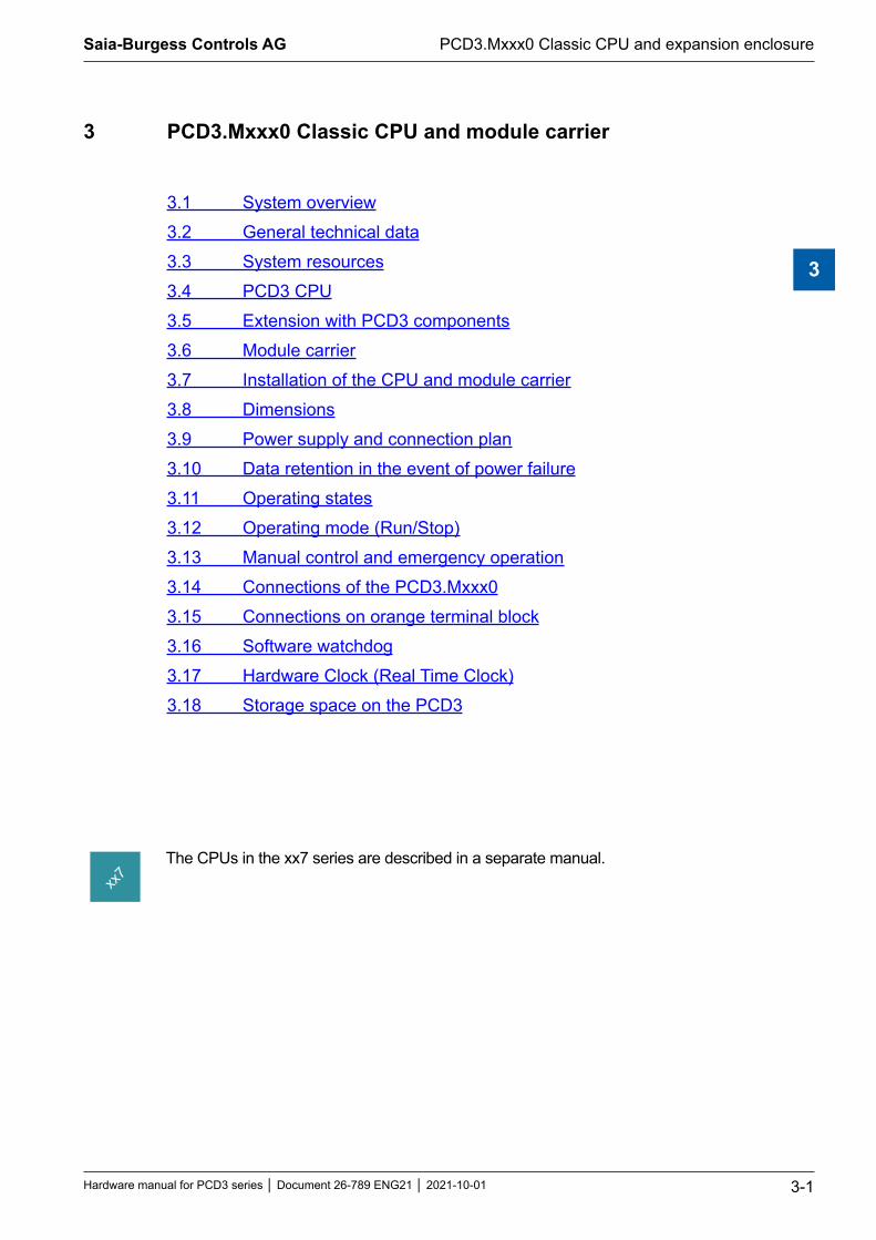
3 PCD3.Mxxx0 Classic CPU and module carrier
3.1 System overview3.2 General technical data3.3 System resources3.4 PCD3 CPU3.5 Extension with PCD3 components3.6 Module carrier3.7 Installation of the CPU and module carrier3.8 Dimensions3.9 Power supply and connection plan3.10 Data retention in the event of power failure3.11 Operating states3.12 Operating mode (Run/Stop)3.13 Manual control and emergency operation3.14 Connections of the PCD3.Mxxx03.15 Connections on orange terminal block3.16 Software watchdog3.17 Hardware Clock (Real Time Clock)3.18 Storage space on the PCD3
The CPUs in the xx7 series are described in a separate manual.

Saia-Burgess Controls AG
Hardware manual for PCD3 series │ Document 26-789 ENG21 │ 2021-10-01
System overview
PCD3.Mxxx0 Classic CPU and expansion enclosure
3-2
3
3.1 System overview
PCD3.RIO PCD3.LIO
PCD3.LIOPCD3.CPU
RIO for decentralized tasks
CPU for centralized tasks
SBC-S-Net
3.1.1 SBC S-Net networking concept
SBC S-Net is the name of the new flexible networking concept for innovative and economical automation solutions with SaiaPCD.
Based on the open standards Ethernet-TCP/IP (Ether S-net) and Profibus (Profi S-net): Utilization of existing network infrastructure no double ca-bling required
Supports multivendor and multi-protocol operation: Reduce costs for project planning, programming, commissioning and mainte-nance thanks to end-to-end use of Ethernet TCP / IP and Profibus with S-Net for the Private Control Network (PCN) for SaiaPCD
Consistent use of web technologies via Ethernet TCP / IP and Profibus for com-missioning, operation, monitoring and diagnostics
Integrated programming and commissioning via Ethernet TCP / IP and Profibus
Integrated network connections in the base unit Profibus interface integrated in the operating system of the new PCD3 controllers and PCD3 RIO (included in the base unit at no extra cost)
Profi-S-Net with optimized protocols and services for the efficient operation of PCD3 RIO and PCD3 controllers on Profibus
Multi-protocol operation: The new PCD3 controllers and PCD3 RIOs support Profibus-DP and S-Net on the same connector
Continuity and investment protection: Alle Saia PCD systems can be integrated in the concept with the existing Profi-bus and Ethernet TCP / IP connections.

Saia-Burgess Controls AG
Hardware manual for PCD3 series │ Document 26-789 ENG21 │ 2021-10-01
System overview
PCD3.Mxxx0 Classic CPU and expansion enclosure
3-3
3
3.1.2 Saia PCD® Web server
All PCD3 controllers and PCD3 RIOs have an integrated web server as standard:
Web browser as a tool for commissioning, service and visualization: Access to the SBC web server is via standard web browsers such as Internet Explorer. As a result, the web browser, which can be operated intuitively by any-one, is used as a standard tool for commissioning, service, support and visu-alization of machines, devices and systems. The user can access predefined device and system-specific HTML pages and has access to all controller and RIO data. Graphical elements (pictures, graphics, etc.) as well as text docu-ments (operating and repair instructions) can also be integrated in the HTML pages and make a personalized user interface possible
Continuous access via any interfaces and networks: Access to the web server can be achieved not only over Ethernet TCP / IP but also via cost-effective standard serial interfaces (RS-232, RS-485, modem, etc.) and via Profibus networks and consistently across different network levels. This means that web technology can be used economically even in the smallest applications for operator control and monitoring
The Saia PCD web server is integrated with all products: Thanks to the standard integrated web server, there is no need for run-time li-censes or additional modules. In all new PCD3 controllers and PCD3 RIOs, the web server is already included in the base units at no extra cost.

Saia-Burgess Controls AG
Hardware manual for PCD3 series │ Document 26-789 ENG21 │ 2021-10-01
General technical data
PCD3.Mxxx0 Classic CPU and expansion enclosure
3-4
3
3.2 General technical data
Supply (external and internal)Supply voltage 24 VDC –20… + 25% smoothed or
19 VAC ± 15% two way rectified (18 VDC)
Loss/power consumption1) typically 15 W for 64 I/Os
Load capacity of internal 5 V Bus2)
600 mA
Load capacity of internal + V Bus (16..24 V)2)
The load capacity of the + V bus depends on the load of the 5V bus as follows (the more accurate the 24V, the higher the possible load):
24 V – 25 %: 100 [mA]
+30 %
24 V– 20 %
: 150 – I bus 5 V [mA] +25 % 15
24 V– 10 %
: 260 – I bus 5 V [mA] +10 % 4.8
1) The loads and other loads connected to the outputs are usually more important for sizing the feed than the internal power dissipation of the controller
2) When planning PCD3 systems, it must be checked whether the two internal power supplies are not overloaded. This control is particularly important when using analog, counting and positioning modules, as these sometimes have a fairly large power consumption. To calculate the power consumption, we recommend using the Device Configurator, which is part of the PG5 V2.0.
Climatic conditionsOperating environment temperature
0 … +55 °C When mounted on a vertical surface with vertically arranged connection terminals.
0 … +40 °C Reduced temperature range in all other mounting positions.
Storage temperature –25…+85 °C
Relative humidity 10…95% Without condensation
Vibration resistanceSwing - Sine Vibration according to IEC 60068-2-6:2007, Test Fc
5…8.4 Hz constant amplitude ±3.5 mm8.4…150 Hz constant acceleration (1 g)Test duration: 10 sweeps per axis, along 3 axes
Electrical safetyProtection type IP 20 according to EN60529
Clearances and creepage according to EN61131-2 and EN50178 between circuits and bodies as well as between isolated circuits according to overvoltage category II, pollution degree 2
Test voltage VAC 350 V / 50 Hz for nominal device voltage 24 VDC

Saia-Burgess Controls AG
Hardware manual for PCD3 series │ Document 26-789 ENG21 │ 2021-10-01
General technical data
PCD3.Mxxx0 Classic CPU and expansion enclosure
3-5
3
Electromagnetic compatibilityElectrostatic discharge according to EN61000-4-2: 8 kV: Contact discharge
Electromagneticfields according to EN61000-4-3: Field strength 10V/m, 80...1000 MHz
Fast transients (burst) according to EN61000-4-4: 4 kV on DC supply lines, 4 kV on I/O signal lines, 1 kV on interface lines
Interference emission according to EN61000-4-6: Limit class A (for industrial environment). A guide to the correct use of these controls in the residential or living area is available at www.sbc-support.com (additional measures)
Immunity according to EN61000-6-4
Mechanics and assemblyHousing material Module holders: PC/ABS, light grey, RAL7035
I/O-module: PC, transparent blue Rest Hinge: PAM, orange, RAL2003 Light guide: PC, crystal clear
Mounting rail DIN rail according to DIN EN60715 TH35 (formerly DIN EN50022) (1 × 35mm)
ConnectionsTerminal blocks
Spring-clamp10-pin, 4-pin
Screw clamps10-pin
Spring-clamp14-pin, 12-pin, 8-pin
Spring-clamp24-pin, 6-pin
Ground terminal1-pin
Spring terminal2-pin power supply
Cross-section fine-strandedsolid
0.5…2.5 mm² 0.5…2.5 mm²
0.5…2.5 mm² 0.5…2.5 mm²
0.5…1.5 mm² 0.5…1.5 mm²
0.5…1.0 mm² 0.5…1.0 mm²
0.08…2.5 mm²
0.5…1.5 mm²
The terminal blocks may only be inserted 20 times. After that they have to be replaced to guarantee a reliable contact.
Stripping length
7 mm 7 mm 7 mm 7 mm 5…6 mm 7 mm
Standards/approvalsEN/IEC EN / IEC61131-2
Programmable logic controllers
Shipbuilding ABS, BV, DNV, GL, LRS, PRS. Veify at www.sbc-support.com, whether the selected product is listed in the list of relevant test centers.
cULus-listed Veify at www.sbc-support.com, whether the selected product already has a relevant certificate. The condition for cULus approval is listed on the product flyer or can be downloaded from www.sbc-support.com.

Saia-Burgess Controls AG
Hardware manual for PCD3 series │ Document 26-789 ENG21 │ 2021-10-01
System resources
PCD3.Mxxx0 Classic CPU and expansion enclosure
3-6
3
3.3 System resources
More detailed descriptions of the following three subsections can be found in manual 26-732.
3.3.1 Program blocks
Type Number Addresses NotesCyclical organization blocks (COB) 32
(16)*0…31(0...15)*
Main program components
Exception/system dependent organization blocks (XOB)
32 0…31 Accessed by the system
Program blocks (PB) 1000(300)*
0...999(0…299)*
Subprograms
Function blocks (FB) 2000(1000)*
0...1999(0…999)*
Subprograms with parameters
Sequential blocks (SB) a total of 6000 steps and 6000 transitions (withPG5≥1.3andfirmwareversion≥1.10.16)
96(32)*
0…95(0…31)*
For Graftec programming of sequential processes
* This information is valid for firmware 1.10.16 and later versions. Prior to this release, 16 COBs, 300 PBs and 1000 FBs were supported.
3.3.2 Value range of the number types
Type Range NotesWhole numbers – 2’147’483’648 to + 2’147’483’647 Format: Decimal, binary, BCD or hexadecimal
Floating point numbers
– 9.223’37 × 1018 to – 5.421’01 × 10-20
+ 9.223’37 × 1018 to + 5.421’01 × 10-20 Commands for converting values in SBC (Motorola Fast Floating Point, FFP) format to IEEE 754 format and vice versa are available
3.3.3 Media
Type Number Addresses NotesFlags (1 bit) *14‘336
(8192)F0…14‘335(F0…8191)
By default, all flags are non-volatile, but a volatile range starting at address 0 can be configured
Register (32 bit) 16‘383 R 0…16‘383 For integer or flow point values
Text/data blocks 8191 X or DB0…8191
Texts 0…3999 are always stored in the same memory area as the user program. If the user memory is expanded, the base memory can be configured to store RAM texts and DBs. The available texts and DBs have addresses ≥ 4000
Timer/counter (31 bit) 16001) T/C 0…1599 The breakdown of timers and counters can be configured. The timers are periodically decremented by the operating system, the time base can be set in the range of 10 ms to 10 s
Constants with media code K Any Value range 0…16‘383 can be used in commands instead of registers
Constants without media code Any Value range –2’147’483’648 to +2’147’483’647. Can only be loaded into a register with an LD command and not used in place of registers in commands
1) The number of timers should only be configured as high as necessary, otherwise there will be an unnecessary CPU load.** From firmware 1.14.23, 14’336 flags are supported, prior to that is was 8192. To use more > 8191 flags, PG5 2.0.150 is required.

Saia-Burgess Controls AG
Hardware manual for PCD3 series │ Document 26-789 ENG21 │ 2021-10-01
PCD3 CPUs
PCD3.Mxxx0 Classic CPU and expansion enclosure
3-7
3
3.4 PCD3 CPU
PCD3.M3xxx PCD3.M5xxx and PCD3.M6xxx
The redundant CPU PCD3.M6880 and the matching smart RIO PCD3.T668 are described in the manual 27-645 Standby Controllers.
3.4.1 Block diagram PCD3.Mxxx0
ME
MA
EEPROM
DB
TX
P
TvolR
Fvol M
ORY
P
Cnvol
nvol Fnvol
S-Net/MPI
RS-485 COM/PGUEthernetTCP/IP
FeedI/O in base device
Slots 0…3Addresses 0…63
I/O in extensionsPCD3.C100/.C110/.C200
Addresses 64…1023
F1xx + F2xx ModuleSlots 0…3
Serial data interfaces Fieldbus switching
CPU
E/A-Bus
Backup
Usermemory
USER MEMORY
E/A-Bus
USER MEMORY
RegisterTimer(Counter)(Flag)(volatile)non volatileProgramsTextsData blocks
RTCF
volnvol
PTXDBModem RS-232
“Full Handshaking”
Interruptinputs
Date-Timenvol
Watch-Dog
USB connection for theprogramming device
E/A-Bus
STOP
RUN
1)
2)
3)3) 3)4)
1) Connection for the programming unit 2) except PCD3.M3020/3120 3) only PCD3.M5xx0/PCD3.M6xx0 4) with PCD3.M3330 or PCD3.M5540
I/O modules and I/O terminal blocks may only be pulled out or inserted when the Saia PCD® is in a de-energised state. The external +24 V power supply of the modules must also be switched off. To avoid data loss, a battery change must be carried out with the power switched on.

Saia-Burgess Controls AG
Hardware manual for PCD3 series │ Document 26-789 ENG21 │ 2021-10-01
PCD3 CPUs
PCD3.Mxxx0 Classic CPU and expansion enclosure
3-8
3
3.4.2 PCD3.M3x20 / PCD3.M3x30 and PCD3.M5x40 / PCD3.M6x40
3020 5540Saia PCD3.M
DifferenceofthePCD3basic devices Basic Extended CAN
ProfibusDP
MasterPCD3.M 3020 3230 5340 5440 6240 6440
PCD3.M 3120 3330 5540 6340 6540
General features
I/O bus extension -
In-/Outputs or I/O module slots to 641) 4 bis 10231) 2)
64
Processor (Motorola) CF 5272 / 66 MHz
Processing time Bit command word command
0.3…1.5 µs3)
0.9 µs3)
Firmware update Download with PG5 possible
Can be programmed with PG5
from 1.3.1002 M3120 from 1.4.100
from 1.4.120
from 1.3.1002
from 1.4.100
from 1.4.120
Memory for user program / text / DB (RAM)
128 KByte 512 KByte 4) 1 MByte 4)
Backup memory onboard (Flash) 128 KByte 512 KByte 4) 1 MByte 4)
1 MByte Flash Card (optional)
Date-clock accuracy , better than 1 min./month
Data backup4 hours with Super Cap
(after 10 minutes of charging time)
Lithium Battery Renata CR 2032 1-3 years 5)
Interrupt inputs max. Input frequency
2 1 kHz 6)
Interfaces
Programming interface USB 7)
Programming interface (PGU) or as a serial interface
-Port 0
RS-232 to 115 kBit/s
Optional serial data interfaces
Port 1 RS-232, RS-422/485 or TTY current loop 20mA,
pluggable (PCD3.F1xx modules), up to 115 kBit / s

Saia-Burgess Controls AG
Hardware manual for PCD3 series │ Document 26-789 ENG21 │ 2021-10-01
PCD3 CPUs
PCD3.Mxxx0 Classic CPU and expansion enclosure
3-9
3
DifferenceofthePCD3basic devices Basic Extended CAN
ProfibusDP
MasterPCD3.M 3020 3230 5340 5440 6240 6440
PCD3.M 3120 3330 5540 6340 6540
Serial data interface Port 2 RS-485 to 115 kBit/s
Profi-S-Net interfece
Port 2 to 187.5 kBit/s
Port 10 to 1.5 MBit/s
Port 2 to 187.5 kBit/s
Ether S-Net interface
only M3120
only M3330
only M5540
only M6340
only M6540
Fieldbus connections
Serial S-Net
ProfiS-Net
Ether-S-Net (TCP/IP) only M3120
only M3330
only M5540
only M6340
only M6540
1) When using digital I/O modules with PCD3.E16x or A46x with 16 I/Os each2) The address 255 is reserved for the watchdog on all PCD3. The I/O reserved for the watchdog can not be used
by the user, and analog and H modules must not be deployed with the slots with base address 2403) Typical values, the processing time depends on the load on the communication interfaces4) From HW version D and the matching FW, see detailed explanation in chapter 3.195) The specified duration is a buffer time, it depends on the ambient temperature (a higher temperature means
a shorter buffer time)6) The 1kHz apply to a pulse/pause ratio of 1:1 and refer to the sum of the frequencies of the two inputs7) The USB port is of type USB 1.1 Slave Device 12 MBit/s and can only be used for programming and in
combination with certain software products (Web-Connect, ViSi-PLUS with S-Driver) as S-Bus slave. The download works twice as fast with a USB 2.0 hub. Can also be used as serial data interface e.g. used for connecting a terminal, however, this makes the commissioning and debugging with the debugger difficult.
Saia-Burgess Controls AG
Hardware manual for PCD3 series │ Document 26-789 ENG21 │ 2021-10-01
PCD3 CPUs
PCD3.Mxxx0 Classic CPU and expansion enclosure
3-10
3
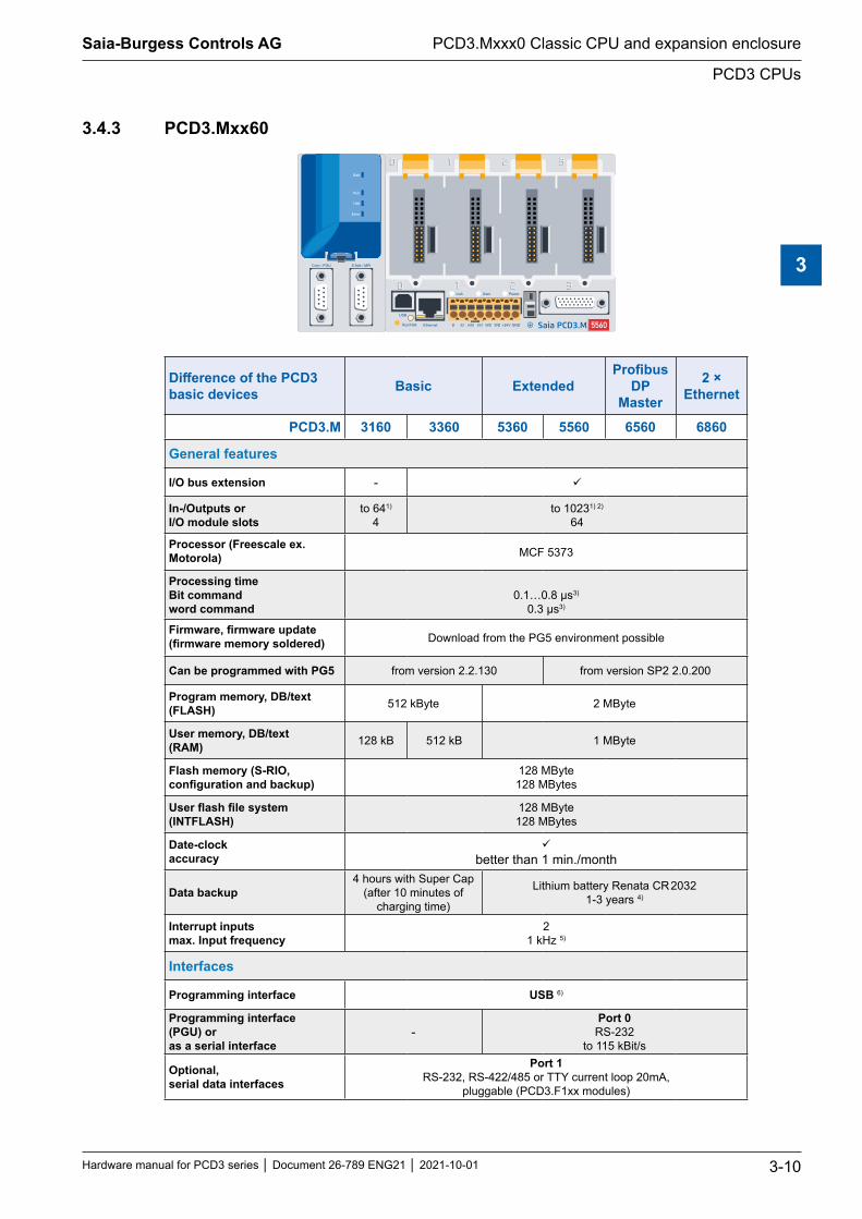
3.4.3 PCD3.Mxx60
5560Saia PCD3.M
DifferenceofthePCD3basic devices Basic Extended
ProfibusDP
Master
2 × Ethernet
PCD3.M 3160 3360 5360 5560 6560 6860
General features
I/O bus extension -
In-/Outputs or I/O module slots
to 641)
4to 10231) 2)
64
Processor (Freescale ex. Motorola) MCF 5373
Processing time Bit command word command
0.1…0.8 µs3)
0.3 µs3)
Firmware,firmwareupdate(firmwarememorysoldered) Download from the PG5 environment possible
Can be programmed with PG5 from version 2.2.130 from version SP2 2.0.200
Program memory, DB/text (FLASH) 512 kByte 2 MByte
User memory, DB/text (RAM) 128 kB 512 kB 1 MByte
Flash memory (S-RIO, configurationandbackup)
128 MByte128 MBytes
Userflashfilesystem(INTFLASH)
128 MByte128 MBytes
Date-clock accuracy
better than 1 min./month
Data backup4 hours with Super Cap
(after 10 minutes of charging time)
Lithium battery Renata CR 2032 1-3 years 4)
Interrupt inputs max. Input frequency
21 kHz 5)
Interfaces
Programming interface USB 6)
Programming interface (PGU) or as a serial interface
-Port 0
RS-232 to 115 kBit/s
Optional, serial data interfaces
Port 1 RS-232, RS-422/485 or TTY current loop 20mA,
pluggable (PCD3.F1xx modules)
Saia-Burgess Controls AG
Hardware manual for PCD3 series │ Document 26-789 ENG21 │ 2021-10-01
PCD3 CPUs
PCD3.Mxxx0 Classic CPU and expansion enclosure
3-11
3
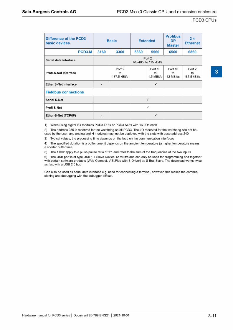
DifferenceofthePCD3basic devices Basic Extended
ProfibusDP
Master
2 × Ethernet
PCD3.M 3160 3360 5360 5560 6560 6860
Serial data interface Port 2 RS-485, to 115 kBit/s
Profi-S-NetinterfecePort 2
to 187.5 kBit/s
Port 10 to
1.5 MBit/s
Port 10 to
12 MBit/s
Port 2 to
187.5 kBit/s
Ether S-Net interface -
Fieldbus connections
Serial S-Net
ProfiS-Net
Ether-S-Net (TCP/IP) -
1) When using digital I/O modules PCD3.E16x or PCD3.A46x with 16 I/Os each2) The address 255 is reserved for the watchdog on all PCD3. The I/O reserved for the watchdog can not be used by the user, and analog and H modules must not be deployed with the slots with base address 2403) Typical values, the processing time depends on the load on the communication interfaces4) The specified duration is a buffer time, it depends on the ambient temperature (a higher temperature means a shorter buffer time)5) The 1 kHz apply to a pulse/pause ratio of 1:1 and refer to the sum of the frequencies of the two inputs6) The USB port is of type USB 1.1 Slave Device 12 MBit/s and can only be used for programming and together with certain software products (Web-Connect, ViSi.Plus with S-Driver) as S-Bus Slave. The download works twice as fast with a USB 2.0 hub Can also be used as serial data interface e.g. used for connecting a terminal, however, this makes the commis-sioning and debugging with the debugger difficult.

Saia-Burgess Controls AG
Hardware manual for PCD3 series │ Document 26-789 ENG21 │ 2021-10-01
PCD3 CPUs
PCD3.Mxxx0 Classic CPU and expansion enclosure
3-12
3
3.4.4 HardwareandfirmwareversionsofthePCD3.Mxxx0
The firmware versions of the PCD3.Mxxx0 are usually downward compatible in terms of hardware, so that even old CPUs can be equipped with new firmware to benefit from new functions. This property is highly valued, and we try to keep it as long as possible; however, we cannot guarantee it.
The firmware of the PCD3.Mxxx0 is stored in a flash EPROM, which is soldered to the motherboard. A firmware update is possible by downloading a new version with the PG5. The procedure is as follows:
● Download the current firmware version from www.sbc-support.com
● Establish a connection between the PG5 and the CPU, as for the download of an application (depending on the available options such as serially with PGU cable, modem1), USB, Ethernet)
● Open the online configurator and go offline
● In the Tools menu, select Download Firmware, then use the browse function to select the path to the file of the new firmware version. Make sure only one file is selected for download
● Start the download
● After the download, the power supply of the Saia PCD® must not be interrupted for 2 minutes (CPLD programming sequence). Otherwise it may happen that the CPU is blocked in such a way that it has to be returned to the factory. While the Run/Stop LED flashes slowly, the download process is not yet com-pleted. Only when it flashes fast, the programming is finished.
1) A modem connection is not reliable. It may be that a modem is blocked in such a way that remote access is no longer possible. In such cases, local intervention will be necessary. The other connection options are preferred.

Saia-Burgess Controls AG
Hardware manual for PCD3 series │ Document 26-789 ENG21 │ 2021-10-01
Extension with PCD3 components
PCD3.Mxxx0 Classic CPU and expansion enclosure
3-13
3
3.5 Extension with PCD3 components
The PCD3.Mxxxx can be extended with extension module carrier PCD3.Cxxx so that additional module slots are available (chapter 3.6 Module carrier). Up to 15 PCD3.Cxxx module carriers with PCD3.K010 connectors and/or PCD3.K106 or PCD3K116 cables can be connected to the PCD3.Mxxx0 (PCD3.M3020 / 3120 are not expandable). This allows the user to connect a maximum of 64 I/O modules or 1023 digital inputs/outputs.
PCD3.M.. 3020 3120
3230 3330
5xx0 6xx0
Maximum number of inputs / outputs or I/O module slots of the system:
641) 4
10231) 2) 64
10231) 2) 64
1) When using digital I/O modules PCD3.E16x or PCD3.A46x with 16 I/Os each2) The address 255 is reserved for the watchdog on all PCD3. The I/O reserved for the watchdog can not be used
by the user, and analog and H modules must not be deployed with the slots with base address 240
PCD3.M5560 PCD3.C100 PCD3.C110
100Saia PCD3.C C110Saia PCD3.C5560Saia PCD3.M
E160
E160
A400
A400
W340
W340
W340
W340
F281
F210
For details see 3.6 Module carrier

Saia-Burgess Controls AG
Hardware manual for PCD3 series │ Document 26-789 ENG21 │ 2021-10-01
Extension with PCD3 components
PCD3.Mxxx0 Classic CPU and expansion enclosure
3-14
3
Addressing
100Saia PCD3.C100Saia PCD3.C200Saia PCD3.C
6860
ETH 2.1 ETH 2.2
Ethernet 2
USB
Saia PCD3.M 100Saia PCD3.C 100Saia PCD3.C
Extension cable PCD3.K106
Further series up to max. Address 1023
0 17616 1286432 48
192 368
For local expansion, the PCD3 LIOs (Local I/O) modules are used.
For remote expansion via Profibus the PCD3 RIOs (Remote I/O) modules are used.
The maximum number of I/Os depends on the controller used.
When selecting the I/O modules, care must be taken that the internal 5 V and + V supply are not overloaded (see chapter 3.9.2).

Saia-Burgess Controls AG
Hardware manual for PCD3 series │ Document 26-789 ENG21 │ 2021-10-01
Module carrier
PCD3.Mxxx0 Classic CPU and expansion enclosure
3-15
3
3.6 Module carrier
Overview of the module carriers
Short name Advertised Type Example image
CPU Central Processor Unit PCD3.Mxxxx
RIO Remote Input Output(see chapter 4)
PCD3.Txxx
LIO Local Input Output PCD3.Cxxx

Saia-Burgess Controls AG
Hardware manual for PCD3 series │ Document 26-789 ENG21 │ 2021-10-01
Module carrier
PCD3.Mxxx0 Classic CPU and expansion enclosure
3-16
3
3.6.1 The module carriers (LIO)
The PCD3.LIO (Local Input/Output = LIO) is used to acquire central I/O signals. The compact PCD3.LIO snap onto a 35 mm DIN rail and can be equipped with PCD3 I/O modules. PCD3.LIOs can be connected as an I/O extension to a PCD2 CPU, PCD3 CPU or PCD3.RIO.
Three different module carriers are available for receiving I/O modules:
Module carrier / LIO PCD3.C100 PCD3.C110 PCD3.C200
Number of module slots 4 2 4
Description 4 I/O modules 2 I/O modules
4 I/O modules, serves as I/O bus repeater and internally provides + 5 V and V + for one segment
of I/O modules (for calculation of possible load see 3.18.3)
Ext. Supply - - 24 VDCInt. Supply I to +5 V 10 mA 10 mA -
PCD3.C100 for 4 modules
● For 4 pluggable PCD3 I/O modules (freely selectable)
● Can be connected to PCD2.Mxxx, PCD3.Mxxx0, PCD3.RIO and PCD3.LIO
● Expandable with further PCD3.LIO (PCD3.C100 /... C110 /... C200)
Connections PCD3.C100 for 4 modules
Saia PCD3.C100
Bus connection to module carrier
EarthLED power ok
Bus connection from CPU or module carrier

Saia-Burgess Controls AG
Hardware manual for PCD3 series │ Document 26-789 ENG21 │ 2021-10-01
Module carrier
PCD3.Mxxx0 Classic CPU and expansion enclosure
3-17
3
PCD3.C110 for 2 modules
● For 2 pluggable PCD3 I/O modules (freely selectable)
● Can be connected to PCD2.Mxxx, PCD3.Mxxx0, PCD3.RIO and PCD3.LIO
● Not expandable
Connections
C110Saia PCD3.C
EarthLED power ok
Bus connection from CPU or module carrier

Saia-Burgess Controls AG
Hardware manual for PCD3 series │ Document 26-789 ENG21 │ 2021-10-01
Module carrier
PCD3.Mxxx0 Classic CPU and expansion enclosure
3-18
3
PCD3.C200 for 4 modules with power supplyThe PCD3.C200 supplies the following module carriers PCD3.C100 and PCD3.C110 with current up to a certain load limit. The load is calculated by the power consumption of the I/O modules used. If this load is exceeded, a PCD3.C200 I/O Bus Repeater will continue to help to secure the internal +5 V and V + for another I/O bus segment.
Comment: The term I/O bus segment refers to all module carriers from the current CPU or PCD3.C200 to another PCD3.C200 repeater.
● For 4 pluggable PCD3 I/O modules (freely selectable)
● Can be connected to PCD2.Mxxx, PCD3.Mxxx0, PCD3.RIO and PCD3.LIO
● Expandable with PCD3.LIO (PCD3.C100, .C110, .C200)
● Serves as a bus repeater and internally provides + 5 V and V + for a segment of I/O modules
Connections
200Saia PCD3.C
Bus connection from CPU or module carrier
Bus connection to module carrier
Earth Supply 24 VDC
LED power ok

Saia-Burgess Controls AG
Hardware manual for PCD3 series │ Document 26-789 ENG21 │ 2021-10-01
Module carrier
PCD3.Mxxx0 Classic CPU and expansion enclosure
3-19
3
Internal supply of the LIO module carrier PCD3.C200
GND
+5V
CLR
0V
+V(16...24V)
LED24V
39V
PTCPCD3
+24 V
Voltage-monitor
5V
PCD-BusS
uppl
y 24
VD
C DCDC
DCDC
The PCD3.C200 module carriers provide the following internal supply currents for the plugged or connected modules:
Type + 5V V + The load capacity of the + V bus depends on the load of the 5 V bus as follows (the more precisely the 24 VDC are maintained, the higher the possible load)
PCD3.C200 HW version A and B
1000 mA 100 mA
PCD3.C200 HW version C
1500 mA
- 10%: 630 - I 5 V Bus [mA] +10% 3.8
- 20%: 310 - I 5 V Bus [mA] +25% 15
- 25%: 200 [mA]
+30% 24 V
24 V
24 V
When planning PCD3 systems, it must be checked whether the two internal power supplies are not overloaded. This control is especially important when using analog, counting, and positioning and other special modules, as some of them consume a relatively large amount of power.
It is recommended that you use the PG5 Device Configurator
Saia-Burgess Controls AG
Hardware manual for PCD3 series │ Document 26-789 ENG21 │ 2021-10-01
Module carrier
PCD3.Mxxx0 Classic CPU and expansion enclosure
3-20
3
3.6.2 Calculation of the possible load
The PG5 Device Configurator automatically calculates the load of the power supplying devices through the I/O modules used. This indicates whether one or more I/O bus repeaters PCD3.C200 should be used.
Comment: I/O bus segment means all module carriers from the current CPU or PCD3.C200 to another PCD3.C200 repeater.
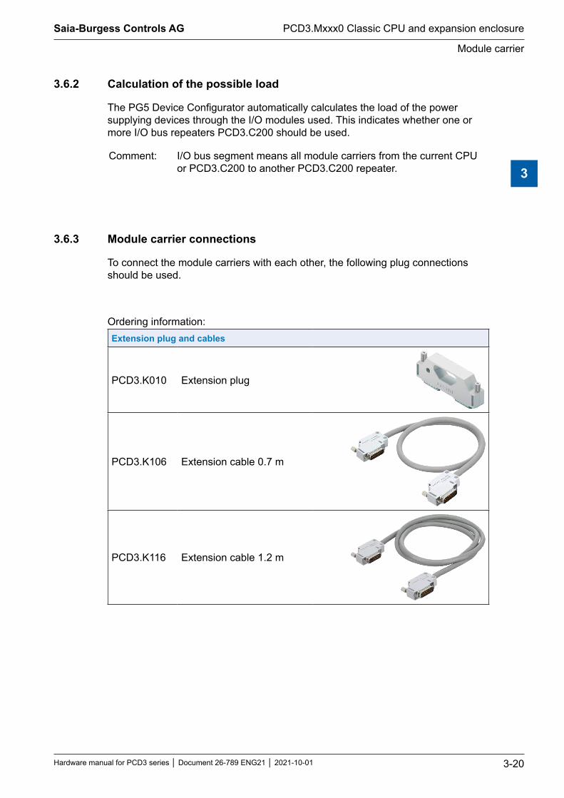
3.6.3 Module carrier connections
To connect the module carriers with each other, the following plug connections should be used.
Ordering information: Extension plug and cables
PCD3.K010 Extension plug
PCD3.K106 Extension cable 0.7 m
PCD3.K116 Extension cable 1.2 m

Saia-Burgess Controls AG
Hardware manual for PCD3 series │ Document 26-789 ENG21 │ 2021-10-01
Installation of the CPU and module carrier
PCD3.Mxxx0 Classic CPU and expansion enclosure
3-21
3
3.7 Installation of the CPU and module carrier
3.7.1 Mounting position and ambient temperature
Normally, a vertical surface is used to mount the module carriers, and the I/O connections of the modules also run vertically. In this mounting position, the ambient temperature may be 0 ° C to 55 ° C.
In all other positions, the air convection works less efficiently, therefore an ambient temperature of 40 ° C must not be exceeded.
3.7.2 Assembly / disassembly
The PCD3 CPU and module carrier are snapped onto a mounting rail according to DIN EN60715 TH35 (formerly DIN EN50022, DIN rail 1 × 35mm).
Mounting on DIN rail
Press lower part of housing onto mounting rail
Push up against the spring force up to the stop
Hook in over the upper edge of the mounting rail and yield to the spring force.
For safety, push the housing into the mounting rail from top to bottom
Check if the device is securly fixed.
Dismounting from DIN rail
Push the housing upward to unhook and pull it forwards
Disconnect above the upper edge of the mounting rail and yield to the spring force.
Disconnect the lower part of the housing from the mounting rail from top to bottom.

Saia-Burgess Controls AG
Hardware manual for PCD3 series │ Document 26-789 ENG21 │ 2021-10-01
Installation of the CPU and module carrier
PCD3.Mxxx0 Classic CPU and expansion enclosure
3-22
3
3.7.3 Insertion of I/O modules
Label holder
Lock snap
Guiding groove
PCD3with 4 module places
Additionalprotectionwith screw
Insert the module in the appropriate module slot and press until the bottom of the housing of the CPU or the module carrier is reached. Make sure that the orange latch is engaged
For safety, a guide groove is provided to prevent the module from being inserted the wrong way round. In difficult environmental conditions, the modules can be additionally secured with a screw. Screw type: self-tapping 3 × 8 mm, standard type available in the metal trade
Number of module slots in the module carrier: ● 4 places (labeling 0, 1, 2 and 3) PCD3.Mxxx0, C100 / C200 / T760 ● 2 places (label 0 and 1). The PCD3.C110 can only be used as the last
module carrier in the bus

Saia-Burgess Controls AG
Hardware manual for PCD3 series │ Document 26-789 ENG21 │ 2021-10-01
Dimensions
PCD3.Mxxx0 Classic CPU and expansion enclosure
3-23
3
3.8 Dimensions
PCD3.M5xx0/M6xx0 PCD3.M3xx0
180 130
PCD3.C100/C200/T76x PCD3.C110
130 66
28.5
63.8
125.8
139
67.3
100.
5
3532
.832
.7

Saia-Burgess Controls AG
Hardware manual for PCD3 series │ Document 26-789 ENG21 │ 2021-10-01
Power supply and connection plan
PCD3.Mxxx0 Classic CPU and expansion enclosure
3-24
3
3.9 Power supply and connection plan
Differenceexternalandinternalpowersupply ● External
External power supply means the feeding of the inputs and outputs at the terminal block of the respective module or compact CPU, (analog, relay, transistor etc.). This common method allows far higher currents than would be possible within the controller and does not necessarily require qualitative stabilization.
● Internal Internal power supply means the supply of the CPU, RIOs and the switching electronics of the I/O plug-in modules without inputs/outputs on the terminal block of the module. The advantage of the internal supply unit is its more advanced processing and therefore the quality of the DC voltage as it would have to been supplied via the external, since the user does not have to worry about the quality of a clean power supply. Except for fast counter and stepper motor modules of type PCD3.Hxxx.
3.9.1 External power supply
Simple little installations
+18V
0V
GNDL N
19VAC±15%
Trafo min. 50VA
● Sensors: Electromechanical switches
● Actuators: Relays, lamps, small valves with switching currents <0.5A
● Suitable for PCD3.Mxxxx module: PCD3.E1xx, E5xx, E6xx, A2xx, A4xx, B1xx, PCD3.W1xx, W2xx, W3xx, W4xx, W5xx, W6xx

Saia-Burgess Controls AG
Hardware manual for PCD3 series │ Document 26-789 ENG21 │ 2021-10-01
Power supply and connection plan
PCD3.Mxxx0 Classic CPU and expansion enclosure
3-25
3
Small to medium installations
+18V
0V
GND
+24V =
0V
L N
L
N
19VAC±15%
Trafo min. 50VA
24VDC±20%Controller
● Sensors Electromechanical and proximity switches, photoelectric barriers
● Actuators Relays, lamps, displays, small valves with switching currents <0.5 A
● Suitable for PCD3.Mxxxx module PCD3. E1xx, E5xx, E6xx, A2xx, A4xx, B1xx PCD3.W1xx, W2xx, W3xx, W4xx, W5xx, W6xx PCD3. H1xx*), H2xx*), H3xx*) PCD7.D2xx*)
*) These modules must be powered with smoothed 24VDC

Saia-Burgess Controls AG
Hardware manual for PCD3 series │ Document 26-789 ENG21 │ 2021-10-01
Power supply and connection plan
PCD3.Mxxx0 Classic CPU and expansion enclosure
3-26
3
3.9.2 Internal power supply
5540Saia PCD3.M
Saia
PCD
3Sa
ia P
CD3
Saia
PCD
3Sa
ia P
CD3
Saia
PCD
3Sa
ia P
CD3
Saia
PCD
3Sa
ia P
CD3
Terminals for power supply 24 VDC
GND
+5V
CLR
0V
+V(16...24V)
LED24V
39V
PTCPCD3
+24 V
Voltage-monitor
5V
PCD-Bus
Sup
ply
24 V
DC DC
DC
DCDC
Resilience of the internal power supply
+5 V 600 mA+V (16…24V) 100 mA (the Device Configurator included in the PG5 helps to
determine the exact possible current loads).
3.9.3 Internal power supply for more than one module carrier
The power supplies of the CPU and RIOs are intended for internal electronics. The internal power supply of the I/O plug-in modules does not apply to the assignment and supply of the outputs of any kind. These must be supplied per I/O module at the terminal block.
As soon as the number of inputs / outputs exceeds the four module slots per CPU or RIO, the additional power requirement for the planned expansion must be calculated for expansion with module carriers.
The PG5 Device Configurator helps to calculate how many PCD3.C200 module carriers should be used per system.
The PCD3.C200 module carriers have a power supply that is generally sufficient for its plug-in modules and 1 to 2 module carriers, depending on which I/O plug-in modules are used. If the system structure increases again, additional PCD3.C200s need to be deplayed. Generally, 1 to 2 module carriers of type PCD3.C100 and/or PCD3C110 can be supplied with power per PCD3.Mxxx, RIO PCD3.T6xx and PCD3.C200 CPU, depending on the I/O module types used.

Saia-Burgess Controls AG
Hardware manual for PCD3 series │ Document 26-789 ENG21 │ 2021-10-01
Power supply and connection plan
PCD3.Mxxx0 Classic CPU and expansion enclosure
3-27
3
100Saia PCD3.C 200Saia PCD3.C 200Saia PCD3.C
W800
W800
W800
W800
W800
W800
W800
W800
A866
A866
A866
A866
6860
ETH 2.1 ETH 2.2
Ethernet 2
USB
Saia PCD3.M 100Saia PCD3.C 100Saia PCD3.C
A866
A866
A866
A866
A810
A810
A810
A810
A810
A810
A810
A810
Extension cable PCD3.K106
0
16
Slot 84
12 20
The example shown above looks in the Device Configurator regarding internal power supply as follows:
The module carriers have 2 or 4 slots. The last, empty line with only a +, indicates that no further module carrier follows, i.e., the end of the system structure.
Total current of the I/O modules in the CPU and all following in the PCD3.C100 or PCD3.C110 module carriers.As soon as a PCD3.C200 module carrier with power supply is used, the calculation starts again until the next PCD3.C200 etc.Once the current limit is exceeded, the configurator will reports this.
The Device Configurator shows the power con-sumption according to the modules used.
The CPU supplies slot 0 ... 11 (with two PCD3.C100), i.e. a total of 12 I/O modules with internal current of 412 mA [5V]. 188 mA are reserve.
The last entry in the module carrier stands for the following, in this case, a power-supplying PCD3.C200 module carrier. The configurator displays the power consumption of the next I/O modules up to another PCD3.C200.
Saia-Burgess Controls AG
Hardware manual for PCD3 series │ Document 26-789 ENG21 │ 2021-10-01
Power supply and connection plan
PCD3.Mxxx0 Classic CPU and expansion enclosure
3-28
3
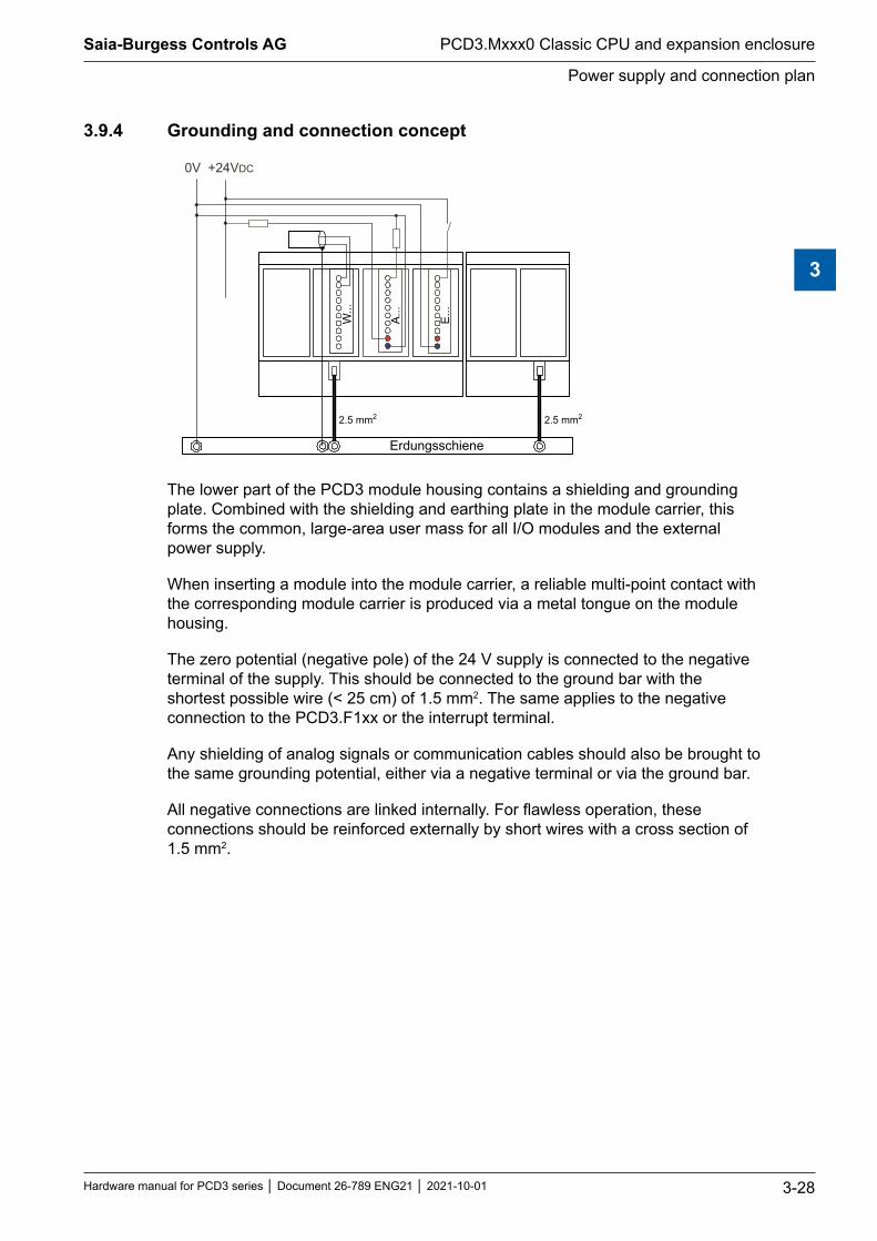
3.9.4 Grounding and connection concept
2.5 mm2 2.5 mm2
W...
A...
E...
0V +24VDC
Erdungsschiene
The lower part of the PCD3 module housing contains a shielding and grounding plate. Combined with the shielding and earthing plate in the module carrier, this forms the common, large-area user mass for all I/O modules and the external power supply.
When inserting a module into the module carrier, a reliable multi-point contact with the corresponding module carrier is produced via a metal tongue on the module housing.
The zero potential (negative pole) of the 24 V supply is connected to the negative terminal of the supply. This should be connected to the ground bar with the shortest possible wire (< 25 cm) of 1.5 mm2. The same applies to the negative connection to the PCD3.F1xx or the interrupt terminal.
Any shielding of analog signals or communication cables should also be brought to the same grounding potential, either via a negative terminal or via the ground bar.
All negative connections are linked internally. For flawless operation, these connections should be reinforced externally by short wires with a cross section of 1.5 mm2.

Saia-Burgess Controls AG
Hardware manual for PCD3 series │ Document 26-789 ENG21 │ 2021-10-01
Data retention in the event of power failure
PCD3.Mxxx0 Classic CPU and expansion enclosure
3-29
3
3.10 Data retention in the event of power failure
The resources (registers, flags, timers, counters, etc.) and partly, also the user program and texts/DBs, are stored in the RAM. To ensure that they do not get lost during a power failure and (if any) the hardware clock continues to run, the PCD3 is equipped with a buffer capacitor (SuperCap) or a buffer battery:
CPU type Buffertype BuffertimePCD3.M3xx0 Super Cap (soldered, maintenance free) 4 hours1)
PCD3.M5xx0/M6xx0 Lithium battery Renata CR 2032 1-3 years2)
1) The total charge time is about 10 minutes. For buffer times> = 4 hours, see battery module PCD3.R010.2) Depending on the ambient temperature, the higher the temperature, the shorter the buffering time
For new controllers, the batteries are included in the package and must be used during commissioning. Note the polarity of the batteries:The positive pole symbol + of the button batteries Renata CR 2032 must be visible!The CPU with lithium batteries are not maintenance free. The battery voltage is monitored by the CPU.
For the following criteria the LED BATT is activated and the XOB 2 is called: ● the battery voltage is less than 2.4 V ● the battery is discharged or has an interruption ● the battery is missing
To avoid data loss, it is recommended to change the battery while the Saia PCD® is under voltage.
3.10.1 Battery module PCD3.R010 for PCD3.M3xxx
Since the PCD3.M3xxx is only buffered by the Super Cap (up to 4 hours), a battery module that has the same buffer time as the batteries in the PCD3.M5xxx/M6xxx is optionally available. The battery module may only be plugged into slot #3 of the PCD3.M3xxx. The other slots do not cover RAM (Program/Data Memory) or Clock. This can damage the Saia PCD®.
Internal current draw: 10 mA an +5 V
Warning: When unpacking and during assembly● Do not touch the power circuit board (PBC) at the LED holder! ● Do not touch the electronic side of the PCB! ● Before plugging the PCB into the Saia PCD®, switch off the PCD!
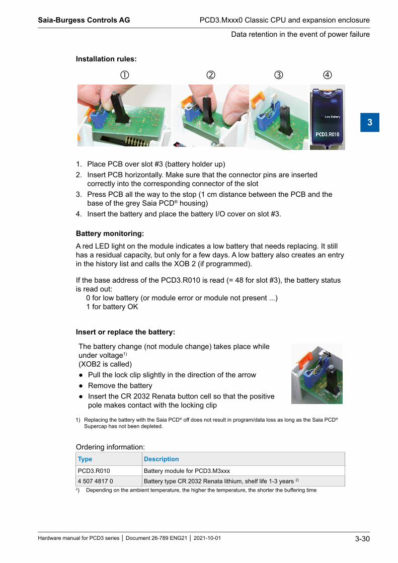
Saia-Burgess Controls AG
Hardware manual for PCD3 series │ Document 26-789 ENG21 │ 2021-10-01
Data retention in the event of power failure
PCD3.Mxxx0 Classic CPU and expansion enclosure
3-30
3
Installation rules:
1. Place PCB over slot #3 (battery holder up)2. Insert PCB horizontally. Make sure that the connector pins are inserted
correctly into the corresponding connector of the slot3. Press PCB all the way to the stop (1 cm distance between the PCB and the
base of the grey Saia PCD® housing)4. Insert the battery and place the battery I/O cover on slot #3.
Battery monitoring:A red LED light on the module indicates a low battery that needs replacing. It still has a residual capacity, but only for a few days. A low battery also creates an entry in the history list and calls the XOB 2 (if programmed).
If the base address of the PCD3.R010 is read (= 48 for slot #3), the battery status is read out: 0 for low battery (or module error or module not present ...) 1 for battery OK
Insert or replace the battery:
The battery change (not module change) takes place while under voltage1) (XOB2 is called)
● Pull the lock clip slightly in the direction of the arrow ● Remove the battery ● Insert the CR 2032 Renata button cell so that the positive
pole makes contact with the locking clip
1) Replacing the battery with the Saia PCD® off does not result in program/data loss as long as the Saia PCD® Supercap has not been depleted.
Ordering information: Type Description
PCD3.R010 Battery module for PCD3.M3xxx
4 507 4817 0 Battery type CR 2032 Renata lithium, shelf life 1-3 years 2)
2) Depending on the ambient temperature, the higher the temperature, the shorter the buffering time

Saia-Burgess Controls AG
Hardware manual for PCD3 series │ Document 26-789 ENG21 │ 2021-10-01
Operating states
PCD3.Mxxx0 Classic CPU and expansion enclosure
3-31
3
3.11 Operating states
The CPU knows the following operating states:
Operating condition Short description
Start Self-diagnosis during approx. 1s after starting up or after a restart
Run Normal execution of the user program after start. If a programming device is connected via a PCD8.K11x in PGU mode (for example, PG5 in PGU mode), the CPU does not automatically go to the Run status for safety reasons, but to the Stop status instead
Run conditional Conditional run operation. A condition was set in the debugger (Run Until...) that has not yet been fulfilled
Run with error Same as under Run, but with an error message
Run conditional with error
Same as under conditional run, but with error message
Stop The Stop status occurs in the following cases: - Programmer connected in PGU mode when starting up the CPU - PGU stopped with programmer - A conditional run requirement has been fulfilled
Stop with error Same as under Stop, but with error message
Stop The stop status occurs in the following cases: - Command stop processed - A fatal error in the user program - Hardware error - No program loaded - Missing communication mode for a S-Bus PGU or Gateway Master
Port
System diagnostics If the PLC does not enter RUN mode after 2 minutes, it must be returned for repair
Reset The reset status has the following causes: - Supply voltage is too low - Firmware does not start
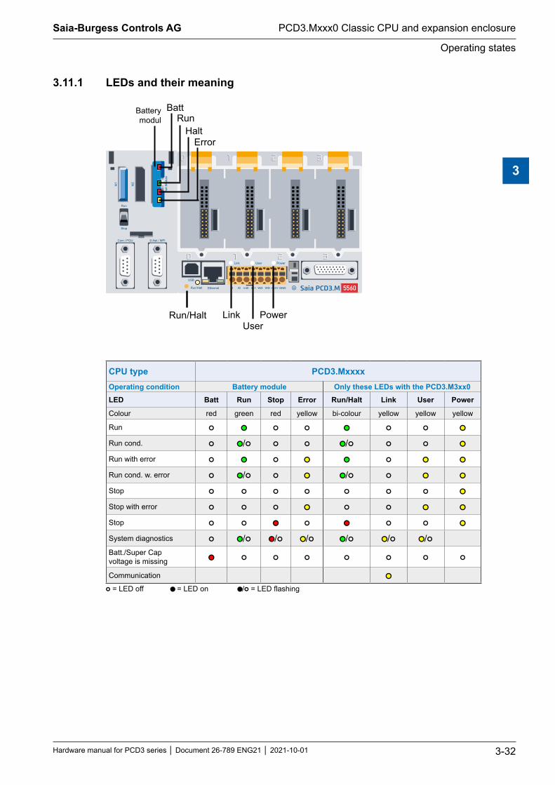
Saia-Burgess Controls AG
Hardware manual for PCD3 series │ Document 26-789 ENG21 │ 2021-10-01
Operating states
PCD3.Mxxx0 Classic CPU and expansion enclosure
3-32
3
3.11.1 LEDs and their meaning
5560Saia PCD3.M
BattRun
HaltError
PowerUser
LinkRun/Halt
Batterymodul
CPU type PCD3.MxxxxOperating condition Battery module Only these LEDs with the PCD3.M3xx0 LED Batt Run Stop Error Run/Halt Link User Power
Colour red green red yellow bi-colour yellow yellow yellow
Run ● ●● ● ● ●● ● ● ●●Run cond. ● ●●/● ● ● ●●/● ● ● ●●Run with error ● ●● ● ●● ●● ● ●● ●●Run cond. w. error ● ●●/● ● ●● ●●/● ● ●● ●●Stop ● ● ● ● ● ● ● ●●Stop with error ● ● ● ●● ● ● ●● ●●Stop ● ● ●● ● ●● ● ● ●●System diagnostics ● ●●/● ●●/● ●●/● ●●/● ●●/● ●●/●Batt./Super Cap voltage is missing ●● ● ● ● ● ● ● ●
Communication ●●● = LED off ●● = LED on ●●/● = LED flashing

Saia-Burgess Controls AG
Hardware manual for PCD3 series │ Document 26-789 ENG21 │ 2021-10-01
Operating mode (Run/Stop)
PCD3.Mxxx0 Classic CPU and expansion enclosure
3-33
3
3.12 Operating mode (Run/Stop)
3.12.1 Run/Stop push-button
Behaviour at .... start up
● If the Run/Stop push-button is pressed during start-up and released during one of the sequences described below, the following actions can be started:
5540Saia PCD3.M
Saia
PCD
3Sa
ia P
CD3
Saia
PCD
3Sa
ia P
CD3
Saia
PCD
3Sa
ia P
CD3
Saia
PCD
3Sa
ia P
CD3
LED sequence Action
Orange None
Green, flashing (1 Hz)
Changes to the boot status and waits for FW download
Red, flashing rapidly: from FW > V01.08.45 (4 Hz)
The system starts as if with discharged Super CAP or missing battery. i.e. Medias (flags, registers, ...), user program, HW settings are deleted. The clock is set to 00:00:00 01.01.1990. The backup on the onboard flash will not be deleted. If a backup exists, the program will be restored.
Red, flashing slowly (2Hz)
The PLC does not start and goes into stop mode.
Run/Stop-LED: flashing in orange (2 Hz) Batteriehalter-LED: Red/green, flashing (2 Hz)
Saved data is deleted. i.e. Medias (flags, tabs, ...), user program, HW settings and the backup on the onboard flash are deleted. If an external flash card is inserted (with a backup), the backup will not be deleted; but the program will be restored and copied to the onboard flash.
.. during operation ● If the push-button is pressed in the operating mode for
more than half a second and less than three seconds, the control will enter the stop mode and vice versa.
● If the push-button is pressed for more than 3 seconds, the last saved user program is loaded from the flash. 5540Saia PCD3.M
Saia
PCD
3Sa
ia P
CD3
Saia
PCD
3Sa
ia P
CD3
Saia
PCD
3Sa
ia P
CD3
Saia
PCD
3Sa
ia P
CD3
The operating mode can be changed at any time.

Saia-Burgess Controls AG
Hardware manual for PCD3 series │ Document 26-789 ENG21 │ 2021-10-01
Operating mode (Run/Stop)
PCD3.Mxxx0 Classic CPU and expansion enclosure
3-34
3
3.12.2 Run/Stop switch
With the PCD3.M5xx0 it is furthermore possible to influence the operating status with a switch accessible on the front under the blue cover.
If the control is switched to Stop, this results in a change from Run to Stop. When switching to Run, a cold start is executed.
To enable the switch, check the options in the hardware settings of the PG5.
5540Saia PCD3.M
Saia
PCD
3Sa
ia P
CD3
Saia
PCD
3Sa
ia P
CD3
Saia
PCD
3Sa
ia P
CD3
Saia
PCD
3Sa
ia P
CD3

Saia-Burgess Controls AG
Hardware manual for PCD3 series │ Document 26-789 ENG21 │ 2021-10-01
Manual control and emergency operation
PCD3.Mxxx0 Classic CPU and expansion enclosure
3-35
3
3.13 Manual control and emergency operation
The manual control and emergency operation required in building automation can be implemented with a PCD3.C2001) module carrier and the PCD3.A810 (digital) and PCD3.W800 (analog) manual control modules. These manual control modules are based on digital and analog output modules, which can be activated either via the user program or via the manual switch.
● For emergency operation, the manual control modules must be operated in a PCD3.C200 module carrier with external power supply. The external power supply is required in order to continue operating the manual control modules in emergency operation in the event of a cable break or during maintenance work on the CPU.
● In this module carrier PCD3.C200 (from HW version C) and possibly other module carriers, manual control modules may be operated mixed with other data point modules!
● When configuring a PCD3 system, attention must be paid to the power requirements of the data point modules in the PCD3.C200 and the following module carriers. It is recommended to use the PG5 Device Configurator for this purpose.
Manual control modules(for a detailed description, see 27-600 Manual I/O Modules PCD2 and PCD3)
PCD3.A810 Digital local control module with 4 relays outputs - 2 ‘changeover’ contacts - 2 ‘make’ contacts Connection with PCD3.K810 (connector type F included)
PCD3.A860 Light and shade control module with - 2 relays outputs 250 VAC/12 A - 2 digital inputs 24 VDC Connection with PCD3.K86x (connector type G and H included)
PCD3.W800 Analogue local control module with 4 channels - 3 outputs 0…10 V with local control - 1 output 0…10 V without local control Connection with PCD3.K800 (connector type J included)

Saia-Burgess Controls AG
Hardware manual for PCD3 series │ Document 26-789 ENG21 │ 2021-10-01
Manual control and emergency operation
PCD3.Mxxx0 Classic CPU and expansion enclosure
3-36
3
Application example
100Saia PCD3.C 200Saia PCD3.C 200Saia PCD3.C
W800
W800
W800
W800
W800
W800
W800
W800
A866
A866
A866
A866
6860
ETH 2.1 ETH 2.2
Ethernet 2
USB
Saia PCD3.M 100Saia PCD3.C 100Saia PCD3.C
A866
A866
A866
A866
A810
A810
A810
A810
A810
A810
A810
A810
Extension cable PCD3.K106
further series up to max. Address 1023
0 17616 1286432 48
192 368
1) from HW version C: no restrictions HW version A and B: - see restrictions regarding power consumption, chapter 3.9.2 Internal power supply - PCD3.C200 only at the end of the I/O bus - PCD3.C200 for emergency operation and any other module carriers may only be operated with manual
control modules

Saia-Burgess Controls AG
Hardware manual for PCD3 series │ Document 26-789 ENG21 │ 2021-10-01
Connections of the PCD3.Mxxx0
PCD3.Mxxx0 Classic CPU and expansion enclosure
3-37
3
3.14 Connections of the PCD3.Mxxx0
3330Saia PCD3.M5540Saia PCD3.M
S-Net/MPI (Port 10)
PGU/RS-232 (Port 0)
PCD3.M3330
Ethernet (Port 9)
PCD3.M5540
USB
RS-485 (Port 2), Int, WD, 24VDC
Slot 0 (Port 1)
Ground terminal I/O expansion
Details about the connections
Connection Port Chapter TitelPGU/RS-232 0 5.3.2 RS-232 connector (port 0) as communication
interface and as programmer connection (only PCD3.M5xx0/M6xx0)
S-Net/MPI 10 5.3.3 RS-485/RS-422USB --- 5.3.7 USB PGU interface for programming device
connectionEthernet 9 5.3.8 Ethernet RJ-45RS-485 2 5.3.9 RS-485 / Profi-S-Net/DP SlaveGround terminal --- 3.9.4 Grounding and connection planI/O expansion --- 3.5 Expansion with PCD3 componentSlot 0 1 5.4.2 Serial Interfaces on I/O Module Slot #0

Saia-Burgess Controls AG
Hardware manual for PCD3 series │ Document 26-789 ENG21 │ 2021-10-01
Connections on orange terminal block
PCD3.Mxxx0 Classic CPU and expansion enclosure
3-38
3
3.15 Connections on orange terminal block
For all CPU typesTerminal block(Item no. 440549950) for power supply, watchdog, interrupt inputs and port 2 Profibus
Pin Signal Explanation Signal Wiring
1 D Port 2 RS-485 up to 115.2kbit / s as free user interface or Profi-S-Bus up to
187.5kbits / s (except PCD3.M5440 and PCD3.M5540)
RxD/TxD-N Agreen
2 /D RxD/TxD-P Bred
3 Int0 2 interrupt inputs 24VDC or 1 quick counter 24 VDC 4 Int1
5 WDWatchdog
6 WD7 +24V
Power supply8 GND
RS-485 terminator switch
Switch position Description Explanation
left O without terminatorsright C with terminators
3.15.1 RS-485 (Port 2)
See chapter 5.3.9 General information and chapter 5.1 General information.

Saia-Burgess Controls AG
Hardware manual for PCD3 series │ Document 26-789 ENG21 │ 2021-10-01
Connections on orange terminal block
PCD3.Mxxx0 Classic CPU and expansion enclosure
3-39
3
3.15.2 Interrupt inputs
5540Saia PCD3.M
Saia
PCD
3Sa
ia P
CD3
Saia
PCD
3Sa
ia P
CD3
Saia
PCD
3Sa
ia P
CD3
Saia
PCD
3Sa
ia P
CD3
Terminal 3 and 4 for interrupts inputs Int0 and Int1
BasicsThe digital input modules are not suitable for immediate reaction to events or fast counting because of the input filters and the influence of the cycle time of the user program. Most CPUs have 24 VDC interrupt inputs for this purpose.
Two interrupt inputs are located on the main PCB and can be connected via the 8-pin, pluggable terminal block (terminals 3 and 4). Source operation is used.
Interrupt inputs
Called XOB on positive edge
Plug terminal
Direct input queryBase and
standard CPUPower CPU
PCD3.Mxx60INT0 XOB 20 3 I 8100 ---*INT1 XOB 21 4 I 8101 ---** available via media mapping in the device configurator
An associated XOB is called (e.g. XOB 20) on a positive edge on the interrupt input. The code in this XOB determines how the event responds, e.g. by incrementing a counter.
The code in XOBs, which are called by interrupt inputs, must be kept as short as possible so that sufficient time remains between the interrupts to process the rest of the user program.
Many FBoxes are intended for cyclic calling and are therefore not or only partially suitable for use in XOBs. Exception: The FBoxes of the Graftec family (standard library) are well suited.

Saia-Burgess Controls AG
Hardware manual for PCD3 series │ Document 26-789 ENG21 │ 2021-10-01
Connections on orange terminal block
PCD3.Mxxx0 Classic CPU and expansion enclosure
3-40
3
10k
10k
4k7
µCCF 5272
WD+24V
WD
1234567
GND
INT1INT0
4.7 nF
/DD
8
Input signals source mode:H = 15...30 VL = -30...+ 5 V or unconnected
Source mode
PCD3.Mxxx0 Periphery
Do not connect to D and /D. The RS-485 interface works with 5VDC and can thus be destroyed!
Function description: With a positive edge at the input INT0 the XOB 20 is called. The reaction time up to the call of XOB 20 is a maximum of 1 ms. The code of these XOBs determines how to respond to the events, e.g. by incrementing a counter (input frequency max. 1 kHz with pulse / pause 50% each, sum of the two frequencies (INT0 and INT1) max. 1 kHz). Regardless of whether the XOB is programmed, input 8100 is set (the same applies to INT1 with XOB21 and input 8101, see table above).
The interrupt inputs to the following CPU do not work directly:PCD3.M3160 PCD3.M5360 PCD3.M6360 PCD3.M3360 PCD3.M5560 PCD3.M6560 PCD3.M6860Both Interrupt inputs can be mapped to 2 flags in the Device Configurator.

Saia-Burgess Controls AG
Hardware manual for PCD3 series │ Document 26-789 ENG21 │ 2021-10-01
Connections on orange terminal block
PCD3.Mxxx0 Classic CPU and expansion enclosure
3-41
3
3.15.3 Hardware Watchdog
5540Saia PCD3.M
Saia
PCD
3Sa
ia P
CD3
Saia
PCD
3Sa
ia P
CD3
Saia
PCD
3Sa
ia P
CD3
Saia
PCD
3Sa
ia P
CD3
Terminal 5 and 6 for watchdog relay contact
The PCD3 CPU are equipped with a hardware watchdog as standard. A relay can be triggered on the I/O address 255 which remains energized as long as the state of the O 255 changes periodically at least every 200 ms.
FBoxes are available in the PG5 FBoxes for this purpose.
FunctionIf for some reason the program part with the Watchdog FBox is no longer processed in sufficiently short intervals, the watchdog relay drops out. For further details abour these FBoxes, please read the online help.
The same function can also be realized with AWL. This example works regardless of the cycle time of the user program.
Example: COB 0 ; or 1 … 15 0 STL WD_Flag ; invert help flag OUT WD_Flag OUT O 255 ; flash watchdog output 255 : : : : ECOB
With the code, according to the example, the watchdog drops out in the case of infinite loops caused by the programmer. The following, however, must be observed with regard to the cycle time of the user program:
For cycle times of more than 200 ms, the code sequence must be repeated several times in the user program to prevent the Watchdog from dropping in normal mode.

Saia-Burgess Controls AG
Hardware manual for PCD3 series │ Document 26-789 ENG21 │ 2021-10-01
Connections on orange terminal block
PCD3.Mxxx0 Classic CPU and expansion enclosure
3-42
3
Restrictions
Since the address 255 is in the normal I/O range, there are restrictions regarding the permissible I/O modules in certain slots:
Typo RestrictionsPCD3.Mxxx0 1. No analog, counting and positioning modules in the slot with
base address 240 (except PCD3.W3x5, PCD3.W6x5 and PCD3.W800, these are not influenced by the watchdog)
2. Output 255 can not be used for digital I/O modules either
Watchdog - connection scheme
WD
+24V
0V
5 6 7 8 0 1+
PCD3
+24V GNDWD WD
Supply
Start
Bridging switchfor
CPU-Start
Process
Main switchA-Modul
1) Switching power of the Watchdog contact: 1 A, 48 VAC/DC
The status of the watchdog relay can be read in via I 8107. Status: 1 = watchdog relay energized (Not with the Power CPUs).
With the Power CPU PCD3.Mxx60 as of firmware version 1.28.xx, the status of the watchdog relay can be read via media mapping.

Saia-Burgess Controls AG
Hardware manual for PCD3 series │ Document 26-789 ENG21 │ 2021-10-01
Connections on orange terminal block
PCD3.Mxxx0 Classic CPU and expansion enclosure
3-43
3
3.15.4 Supply
See also under 3.9 Power supply and connection concept!

Saia-Burgess Controls AG
Hardware manual for PCD3 series │ Document 26-789 ENG21 │ 2021-10-01
Software watchdog
PCD3.Mxxx0 Classic CPU and expansion enclosure
3-44
3
3.16 Software watchdog
The hardware watchdog provides a maximum of safety. For uncritical applications, a software watchdog can be adequate, whereby the processor monitors itself and the CPU is restarted in the case of a faulty function or a loop.
The core of the software watchdog is the SYSWR K 1000 command. The software watchdog function is activated when it is first called up. Thereafter, the named command must be called at least every 200 ms, otherwise the watchdog triggers and restarts the control.
Command: SYSWR K 1000 ; Software watchdog command
R/K x ; Parameters according to the table below, ; K-Konstante oder Wert in Register; x = 0 The software watchdog will be
deactivated
; x = 1 The software watchdog will be activated; if the command is not repeated within 200ms, a cold start takes place
; x = 2 The software watchdog will be activated; if the command is not repeated within 200ms, the XOB 0 will be called up first, followed by a cold start. XOB 0 call-ups are entered in the Saia PCD® history as follows:
“XOB 0 WDOG START” if XOB 0 was called by the software watchdog
“XOB 0 START EXEC” if XOB 0 was called because of a supply error

Saia-Burgess Controls AG
Hardware manual for PCD3 series │ Document 26-789 ENG21 │ 2021-10-01
Hardware Clock (Real Time Clock)
PCD3.Mxxx0 Classic CPU and expansion enclosure
3-45
3
3.17 Hardware Clock (Real Time Clock)
The PCD3 CPU are equipped with a hardware clock on the basis print:
The presence of a hardware clock is imperative when using the timers HVAC library.

Saia-Burgess Controls AG
Hardware manual for PCD3 series │ Document 26-789 ENG21 │ 2021-10-01
Storage space on the PCD3
PCD3.Mxxx0 Classic CPU and expansion enclosure
3-46
3
3.18 Storage space on the PCD3
3.18.1 Storage types in the Saia PCD® systems
A user program may contain various data types. This includes data that is relevant for a fast regulation process and data records that must be collected over a long period or saved permanently. Data and web pages to the PCD internal web server are also to be stored. A backup function for program and data is also important, e.g. in the file system.
All these data types have different requirements in terms of hardware. For example, a regulation-relevant process requires a fast memory to calculate and provide current values. However, historical data records require sufficient remanent mass memory to cover a long period of time.
Depending on the PCD system, storage is available for all this data in the form of RAM, FRAM, SRAM, Flash (see glossary in the appendix for details) system-internally and in the form of pluggable memory.
User memory = RAMThe user memory, which ensures fast access for reading and writing, contains time-critical content such as media, RAM-DB and RAM texts. However, this memory is not a programmable read-only memory (PROM) and is buffered by a battery.
Flash memory
To prevent the loss of the program, a flash memory for the backup of the User Program Memory is available as standard onboard each PCD3 CPU.
It is also possible to save DBs to Flash during runtime (data backup or extension memory backup). Thus, important values of registers and flags can be saved to the fash memory at runtime and than later be reloaded.
On Flash, a file system may exist, which is available for web pages and log files (CSV).
In addition to the flash memory installed on-board, a corresponding flash memory for the user backup memory can also be used (see chapter 3.19.1 Optional memory expansions). The use of these cards makes it possible to transfer the user program as well as the configuration from one controller to another.

Saia-Burgess Controls AG
Hardware manual for PCD3 series │ Document 26-789 ENG21 │ 2021-10-01
Storage space on the PCD3
PCD3.Mxxx0 Classic CPU and expansion enclosure
3-47
3
Despite backup to the flash card, the source files of the project must be retained, as the application is only stored in machine code in the Saia PCD®.
If the RAM memory is corrupted when the PCD3 starts up (for example, after a power failure with a discharged or missing battery), the application is automatically reloaded from the flash backup memory. This can be checked with the STL Test instruction and the 400 operand.All hardware settings are also stored on the Flash Backup Memory (onboard or on a Flash Card) during a backup.

Saia-Burgess Controls AG
Hardware manual for PCD3 series │ Document 26-789 ENG21 │ 2021-10-01
Storage space on the PCD3
PCD3.Mxxx0 Classic CPU and expansion enclosure
3-48
3
3.18.2 Memorymanagement(PCD3withoutintegratedμSDflashcard)
In the case of automation devices with no integrated μSD card and which are equipped with the COSinus system, the user application is copied directly to the user memory from Saia PG5®. If no valid program is detected in the user program when the controller is started up, a search is executed for a backup program in the onboard flash or an optional memory module.
PCD3.Mxx4x PCD3.M3xxx
PCD3.M2x30
PCD7.R562Loading of the user program from PG5® onto Saia PCD® automation devices and allocation of different data between the storage media.
On-Board Flash
save if required
RAM TEXT/DB
SRAMUser programROM TEXT/DB
Media (R, T, F)
File system
Flash memory modules
PCD3.M3xxx, PCD3.M554x, PCD3.M2130, PCD3.M2330
PCD7.R5xxPCD7.R6xxPCD7.R-SDPCD7.R5xxPCD7.R6xxPCD7.R-MSD
RAM TEXT/DB
SRAMUser programROM TEXT/DB
Media (R, T, F)
File system
RAM
Memory = User Program Memory (RAM)
In these systems, the User Program Memory consists of a RAM (Random Access Memory) and includes the program code and a range of text and DB memory (addresses 0…3999). Furthermore, it contains the extension memory, which also contains texts and DBs (addresses ≥ 4000) as well as the media R, T, F.
All texts and DBs are always in RAM on this PCD3. The main difference between the texts and DBs in the text/DB memory segment and those in the extension memory is the higher maximum capacity of the DBs and texts.

Saia-Burgess Controls AG
Hardware manual for PCD3 series │ Document 26-789 ENG21 │ 2021-10-01
Storage space on the PCD3
PCD3.Mxxx0 Classic CPU and expansion enclosure
3-49
3
Element Media Operand Operand extension memory
DATA
TEXT DATABLOCK
XDB 0 … 3999 4000 … 8191
per data block max. 383 register(Each DB in the extension store can
hold 16383 registers)
To run an application on this PCD3, it is sufficient to load only the User Program Memory. Since this is RAM, the program and the contents of the texts and DBs (as well as the other medias, registers, flags, etc.) may be lost if there is no voltage and the battery is empty or not inserted. If no battery module is present, such data loss can also occur with a discharged supercap.
Splitting of the user backup memory
User backup memory is divided into two parts for these systems:
● The first part is available for the user program backup and is always present. In the PG5 hardware configurator, this memory is accordingly called User Program Backup.
● The second part, optionally configurable in the PG5 called extension memory backup (data backup), can be used to back up DBs and texts to the Flash at runtime.
If a part of the backup memory is used as an extension memory backup, the available user program backup memory will be reduced by twice the size of the extension memory backup used. In parallel with the reduction of the user program backup memory, the user program memory is also adjusted, so that the entire User Program Memory can always be copied to the Backup Flash.
Available user backup memory on the onboard memoryThe different versions of the PCD3 CPU have different sized user program memories (and accordingly also user backup memories). The actually usable memories are inherently PCD3 type dependent. As the available memory on the PCD3 has been increased over time, there is a dependency on hardware and firmware version (the larger memory is configurable from version 030).

Saia-Burgess Controls AG
Hardware manual for PCD3 series │ Document 26-789 ENG21 │ 2021-10-01
Storage space on the PCD3
PCD3.Mxxx0 Classic CPU and expansion enclosure
3-50
3
Available user memory with FW version <030
System HW Rev. RAM user program memory
Flash user backup (prg + data)
Default memory configuration
M3020 M3120 - 128 Kbytes Only flash onboard 12 k prg lines,
16 k txt, 64 k ext.
M3230 M3330 - 256 Kbytes Only flash onboard 24 k prg lines,
32 k txt, 128 k ext.
M5340 M5440 - 256 Kbytes flash onboard 24 k prg lines,
32 k txt, 128 k ext.
M5540 M6340 M6540
- 512 Kbytes Flash card required 48 k prg lines, 64 k txt, 256 k ext.
Available user memory with FW version ≥ 030 as well as 1.xx.yy
System HW Rev. RAM user program memory
Flash user back-up (prg + data)
Default memory configuration
M3020 M3120
- 128 Kbytes 256 Kbytes 12 k prg lines, 16 k txt, 64 k ext.
M3230 M3330
- 512 Kbytes 512 Kbytes 48 k prg lines, 64 k txt, 256 k ext.
M5340 M5440
HW < D 512 Kbytes 512k onboard 1024k FlashCard1)
48 k prg lines, 64 k txt, 256 k ext.
M5540 M6340 M6540
HW ≥ D M5440 3) 1024 Kbytes 2) 1024 Kbytes2) 96 k prg lines,
128 k txt, 384 k ext.
1) If a Flash Card for Flash User Backup is used on a PCD3.M5xx0 or M6xx0 with HW version < D, the 512 KB user program backup can be saved on the Flash and 256 KB are additionally available for the backup of DBs runtime.
2) For a PCD3.M5xx0 to be configured with hardware version ≥D and firmware version ≥030, PG5 SP1.4.120 or higher is required!
3) The PCD3.M5440 has from HW version D with modification 2 8 over 1024 Kbytes user backup memory.
It should be noted that in the default memory configuration each program line requires 4 bytes.

Saia-Burgess Controls AG
Hardware manual for PCD3 series │ Document 26-789 ENG21 │ 2021-10-01
Storage space on the PCD3
PCD3.Mxxx0 Classic CPU and expansion enclosure
3-51
3
3.18.3 Memorymanagement(PCD3withintegratedμSDflashcard)
The μSD flash card on the system board must not be removed under any circumstances (it includes the firmware etc.)!
The Saia PCD3 Plus automation devices (red type plate, PCD3.Mxx60) are equipped with an onboard μSD flash card. When loading a user application with Saia PG5®, all the necessary files are stored on the μSD card.
If the operating voltage is connected to the automation device and there is no executable program in the user memory, COSinus attempts to load a valid program from the μSD flash card into the main memory on startup.
Saia PCD3.Mxx6x
Loading of the user program from PG5® onto Saia PCD® auto-mation devices and allocation of different data between the storage media.
SRAM
Media (R, T, F)
PCD3.Mxx6x
File system
Configuration
SRAM data
User program
RIO applicationload as required
RAMμSD flash card
secure on demand (backup)
User memory= RAM text/DB memory
In these systems, the RAM (Random Access Memory) includes text and DB memory as well as the media (R, T, F). The address of the first RAM text/DB is set in the PG5 build options.
All texts and DBs have a maximum size of 16383 elements (DBs) respectively 65535 bytes.
ROM text/DB cannot be written to the PCD3 power CPUs, whereas it was still possible on earlier systems. The program is always loaded on these systems on flash in the PCD and is therefore always available even if there is no battery The program is always loaded on these systems on flash in the PCD and is therefore always available even if there is no battery.

Saia-Burgess Controls AG
Hardware manual for PCD3 series │ Document 26-789 ENG21 │ 2021-10-01
Storage space on the PCD3
PCD3.Mxxx0 Classic CPU and expansion enclosure
3-52
3
If the contents of the RAM are lost due to an empty battery/SuperCap in the event of a power failure, the media, texts and DB are initialized with the current backup values before startup.
Available extension memory backup (data backup) sizeThe extension memory backup can be used to copy contents of DB and texts to Flash during runtime (using the instructions SYSWR K 3x00).
The size of the extension memory backup is independent of the size of the user program and is always available. The maximum size of the DBs that can be copied to it is half of the extension memory backup size.

Saia-Burgess Controls AG
Hardware manual for PCD3 series │ Document 26-789 ENG21 │ 2021-10-01
Storage space on the PCD3
PCD3.Mxxx0 Classic CPU and expansion enclosure
3-53
3
3.18.4 Memory structure of the SaiaPCD3 systems
Colour legend
RAM μSDflashmemory(internal)Program memory + DB/Text (ROM) a File system f
DB / Text (RAM) b Flash memory expansions (optional)File system (user area / alarming) c Extension module f
Data / media (R/F/T/C, clock, history, etc.) d
Operating system (OS, init data) e DB backup
The sizes of the colour blocks on this page and on the next page do not match the effective memory size ratio!
PCD3.M2130V6
Flash memory internally
RAMSRAM db ca e
Backup DB
PCD3.M2330 A4T5 WAC
f Extension module
Flash memory
Flash memory extensions
RAMSRAM db ca e
DB
f Backup DB
PCD3.M3120, PCD3.M3330
DB
Activity
Busy
Write
Diag
User
Flash ROM expan-sions
Flash memory internally
RAMSRAM db ca e
=
Slot0 Slot1 Slot2 Slot3
DB DB DB
f Backup DB
PCD3.M3160, PCD3.M3360
DBFlash memoryμSD card internal
db c
fa b e Backup
Activity
Busy
Write
Diag
User
Flash ROM expansions
RAMSRAM
=DB
Slot0 Slot1 Slot2 Slot3
DB DB DB

Saia-Burgess Controls AG
Hardware manual for PCD3 series │ Document 26-789 ENG21 │ 2021-10-01
Storage space on the PCD3
PCD3.Mxxx0 Classic CPU and expansion enclosure
3-54
3
PCD3.M5x40
Activity
Busy
Write
Diag
User
Flash ROM expansions
Flash memory internally
Flash memory extensions(e.g. Slot M1 / M2)
RAMSRAM db ca e
=DB
Slot0 Slot1 Slot2 Slot3
DB DB DB
f Backup DB
f Extension module DB
PCD3.M5x60, PCD3.M6x60, PCD3.M6880
Flash memory μSD card internal
db c
fa b e Backup
Activity
Busy
Write
Diag
User
Flash ROM expansions
Flash memory extensions(e.g. Slot M1 / M2)
RAMSRAM
=DB
Slot0 Slot1 Slot2 Slot3
DB DB DB
DB
f Extension module DB

Saia-Burgess Controls AG
Hardware manual for PCD3 series │ Document 26-789 ENG21 │ 2021-10-01
Optional memory upgrades
PCD3.Mxxx0 Classic CPU and expansion enclosure
3-55
3
3.19 Optional memory upgrades
Flash memory module
For the PCD3, different flash memory modules exist for different applications. Partly, these modules are explicitly intended for one purpose (e.g. file system memory). There are modules which provide different types of memory (e.g. the PCD7.R562, which includes 1 Mbyte of disk space for the DB backup, 128 Mbytes for the file system, and memory for BACnet).
5540Saia PCD3.M
Flash
Most flash memory modules exist as a simple card (PCD7.Rxxx) which can be plugged into slot M1 or M2 on a PCD3.M5xx0 or PCD3.M6xx0 communication extension.
To enable use on a PCD3.M3xx0, the memory modules PCD3.Rxxx are available, which contain a PCD7.Rxxx and can be plugged into an I/O slot (0 … 3) of a PCD3 CPU.
5540Saia PCD3.M
PCD3.Rxxx
R550
Can only be used on the CPU modules!
SlotNo.
Any flash memory module that is suitable for user program backup (such as a PCD7.R500) can be used as a flash card. If several suitable modules are plugged in, the first module from the left is used for backup (slot M1, M2, I/O slots 0, 1, 2, 3).

Saia-Burgess Controls AG
Hardware manual for PCD3 series │ Document 26-789 ENG21 │ 2021-10-01
Optional memory upgrades
PCD3.Mxxx0 Classic CPU and expansion enclosure
3-56
3
Flashmemorymoduleforfilesystem
In addition to the above flash memories for backing up the user program memory and DBs, another type of flash memory is available for files. These memory modules can store PC readable files such as web pages, images or log files. The content of these flash memory modules can be accessed through the web server, the FTP server (only for PCD3 with Ethernet interface) and the user program.
Flash memory module for BACnet
If the controllers PCD3.M5560, PCD3.M5540, PCD3.M3360, PCD3.M3330, PCD3.M3160 or PCD3.M3120 are equipped with a flash memory module for BACnet, the controllers also have a BACnet stack. These modules contain the firmware extension for the BACnet. In addition, the configuration of the BACnet server and client is stored on these modules.

Saia-Burgess Controls AG
Hardware manual for PCD3 series │ Document 26-789 ENG21 │ 2021-10-01
Optional memory upgrades
PCD3.Mxxx0 Classic CPU and expansion enclosure
3-57
3
3.19.1 Overview
Module Description
for P
CD
3..
Syst
em
DB
bac
kup*
*
File
sys
tem
BA
Cne
t
Lon-
IP
Slot
PCD7.R500* Flash card module as backup for the user program.
M5x
x0 /
M6x
x0
(exc
ept M
xx6x
)
1 M
Byte
M1
/ M2
PCD3.R500* Flash memory module as backup for the user program.The module contains a PCD7.R500.
Mxx
x0(e
xcep
t Mxx
6x)
1 M
Byte
I/O S
lot 0
…3
PCD7.R550M04* Flash card module with file system. Storage of files e.g. for the web server. The files can be accessed via the FTP or HTTP direct server of the PCD3. The Saia PCD® can also write PC readable files (*.csv files) directly to the module.
M5x
x0M
6xx0
4 M
Byte
M1
/ M2
PCD3.R550M04* Flash memory module with file system. Storage of files e.g. for the web server. The files can be accessed via the FTP or HTTP direct server of the PCD3. The Saia PCD® can also write PC readable files (*.csv files) directly to the module.The module contains a PCD7.R550M04. M
xxx0
4 M
Byte
I/O S
lot 0
…3
PCD7.R551M04* Flash Card Module with file system and as backup for the user program. The files can be accessed via the FTP or the web server of the PCD3. The Saia PCD® can also write PC readable files (*.csv files) directly to the module.
M5x
x0M
6xx0
1 M
Byte
3 M
Byte
M1
/ M2
PCD3.R551M04* Flash memory module with file system and as backup for the user program. The files can be accessed via the FTP or the web server of the PCD3. The Saia PCD® can also write PC readable files (*.csv files) directly to the module.The module contains a PCD7.R551M04. M
xxx0
1 M
Byte
3 M
Byte
I/O S
lot 0
…3
PCD7.R560* Flash card module with BACnet FW. The module contains both the FW extension for BACnet and the configuration files for the BACnet application.
M5x
x0,
M6x
x0
M1
/ M2
PCD3.R560* Flash memory module with BACnet FW. The module contains both the FW extension for BACnet and the configuration files for the BACnet application.The module contains a PCD7.R560.
Mxx
x0
I/O S
lot 0
…3
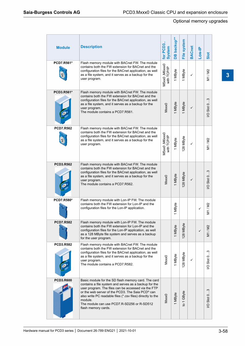
Saia-Burgess Controls AG
Hardware manual for PCD3 series │ Document 26-789 ENG21 │ 2021-10-01
Optional memory upgrades
PCD3.Mxxx0 Classic CPU and expansion enclosure
3-58
3
Module Description
for P
CD
3..
Syst
em
DB
bac
kup*
*
File
sys
tem
BA
Cne
t
Lon-
IP
Slot
PCD7.R561* Flash memory module with BACnet FW. The module contains both the FW extension for BACnet and the configuration files for the BACnet application, as well as a file system, and it serves as a backup for the user program.
M5x
x0 ,M
6xxx
0 w
ith T
CP/
IP
1 M
Byte
1 M
Byte
M1
/ M2
PCD3.R561* Flash memory module with BACnet FW. The module contains both the FW extension for BACnet and the configuration files for the BACnet application, as well as a file system, and it serves as a backup for the user program.The module contains a PCD7.R561. M
xxx0
1 M
Byte
1 M
Byte
I/O S
lot 0
…3
PCD7.R562 Flash memory module with BACnet FW. The module contains both the FW extension for BACnet and the configuration files for the BACnet application, as well as a file system, and it serves as a backup for the user program.
M5x
x0 ,M
6xxx
0 w
ith T
CP/
IP
1 M
Byte
128
MBy
te
M1
/ M2
PCD3.R562 Flash memory module with BACnet FW. The module contains both the FW extension for BACnet and the configuration files for the BACnet application, as well as a file system, and it serves as a backup for the user program.The module contains a PCD7.R562. M
xxx0
1 M
Byte
128
MBy
te
I/O S
lot 0
…3
PCD7.R580* Flash memory module with Lon-IP FW. The module contains both the FW extension for Lon-IP and the configuration files for the Lon-IP application.
1 M
Byte
M
1 / M
2
PCD7.R582 Flash memory module with Lon-IP FW. The module contains both the FW extension for Lon-IP and the configuration files for the Lon-IP application, as well as a 128 MByte file system and serves as a backup for the user program. 1
MBy
te
128
MBy
te
M1
/ M2
PCD3.R582 Flash memory module with BACnet FW. The module contains both the FW extension for BACnet and the configuration files for the BACnet application, as well as a file system, and it serves as a backup for the user program.The module contains a PCD7.R582. M
xxx0
1 M
Byte
128
MBy
te
I/O S
lot 0
…3
PCD3.R600 Basic module for the SD flash memory card. The card contains a file system and serves as a backup for the user program. The files can be accessed via the FTP or the web server of the PCD3. The Saia PCD® can also write PC readable files (*.csv files) directly to the module.The module can use PCD7.R-SD256 or R-SD512 flash memory cards.
Mxx
x0
1 M
Byte
to 1
GBy
te
I/O S
lot 0
…3

Saia-Burgess Controls AG
Hardware manual for PCD3 series │ Document 26-789 ENG21 │ 2021-10-01
Optional memory upgrades
PCD3.Mxxx0 Classic CPU and expansion enclosure
3-59
3
Module Description
for P
CD
3..
Syst
em
DB
bac
kup*
*
File
sys
tem
BA
Cne
t
Lon-
IP
Slot
PCD7.R-SD256 PCD7.R-SD512
PCD7.R-SD1024
SBC SD flash memory card with 256 or 512 MBytes file system for PCD3.R600.This card can be read a on a PC with a card reader and the corresponding SW (SBC file system explorer).
PCD
3.R
600
PCD7.R610 Adapter module for microSD flash memory card (without µSD-card).
Mxx
x0
M1
/ M2
PCD7.R-MSD1024 MicroSD memory card 1 GB, PCD formatted
Mxx
x0
1 M
Byte
1 G
Byte
PCD
7.R
610
* no longer available** at FW before version 1.16.xx the user progam backup was also found in the partition labeled DB backup.
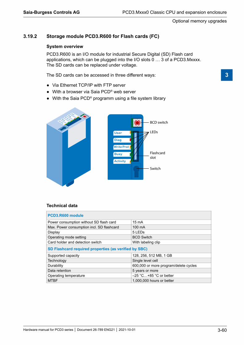
Saia-Burgess Controls AG
Hardware manual for PCD3 series │ Document 26-789 ENG21 │ 2021-10-01
Optional memory upgrades
PCD3.Mxxx0 Classic CPU and expansion enclosure
3-60
3
3.19.2 Storage module PCD3.R600 for Flash cards (FC)
System overviewPCD3.R600 is an I/O module for industrial Secure Digital (SD) Flash card applications, which can be plugged into the I/O slots 0 … 3 of a PCD3.Mxxxx. The SD cards can be replaced under voltage.
The SD cards can be accessed in three different ways:
● Via Ethernet TCP/IP with FTP server ● With a browser via Saia PCD® web server ● With the Saia PCD® programm using a file system library
Activity
Busy
Write Prot
Diag
User
BCD switch
LEDs
Flashcardslot
Switch
Activity
Busy
Write Prot
Diag
User
Technical data
PCD3.R600 modulePower consumption without SD flash card 15 mAMax. Power consumption incl. SD flashcard 100 mADisplay 5 LEDsOperating mode setting BCD SwitchCard holder and detection switch With labeling clip
SDFlashcardrequiredproperties(asverifiedbySBC)Supported capacity 128, 256, 512 MB, 1 GBTechnology Single level cellDurability 600,000 or more program/delete cyclesData retention 5 years or moreOperating temperature –25 °C…+85 °C or betterMTBF 1,000,000 hours or better

Saia-Burgess Controls AG
Hardware manual for PCD3 series │ Document 26-789 ENG21 │ 2021-10-01
Optional memory upgrades
PCD3.Mxxx0 Classic CPU and expansion enclosure
3-61
3
Operation
The PCD3.R600 are intended for the I/O slots 0…3 in a PCD3.Mxxxx. The modules do not work in the module carriers PCD3.C1xx, PCD3.C2xx or PCD3.Txxx.
Up to 4 PCD3.R600 can be used in a PCD3 system.
5560
Saia PCD3.M
Activity
Busy
Write
Diag
User
Activity
Busy
Write Prot
Diag
User
Activity
Busy
Write Prot
Diag
User
Data access
PG5
PCD3.Mxxxx
Ethernet-TCP/IP
User program, Web pages Web pages Any
data/files User programwith new CSF,SFB instruc-tions
PCD datamemoryDB/X, R, F, ...
Flash memory with file system PCDx.R55xM04, PCD3.R600(4 Mbyte - 1 GByte max.)
Onboard memory,and PCD7.R500for backup(512 kbyte max)
FTP-Client
FTP-ServerWeb-Server
Browser Explorer
FTP server and file system access can only be achieved with the pluggable flash memory module. Access via FTP server can only take place via the Ethernet TCP/IP interface.
Due to given requirements SBC uses its own file system. The SBC file system is embedded in a FAT (PC compatible file system) framework to visualize the restricted processes when used in a commercial SD card reader/writer with standard PC tools. The SBC file system is named SBCNTFS.FFS.
Access to individual files in SBCNTFS.FFS is possible with a SBC-provided software tool for PCs.

Saia-Burgess Controls AG
Hardware manual for PCD3 series │ Document 26-789 ENG21 │ 2021-10-01
Optional memory upgrades
PCD3.Mxxx0 Classic CPU and expansion enclosure
3-62
3
Since 10% of the SD card capacity is reserved for the FAT, this extraction PC tool can be copied there. In this way, data stored in the SBC file system can be quickly executed on any PC that is equipped with a standard SD card reader. The SBC PC tool also executes any copies of SBCNTFS.FFS on any drive. The remaining FAT memory can be used to store documentation or for other purposes.
The PCD3.R600 can be used as PCD3 program backup in the same way as the PCD7.R500. The PCD3 program backup is stored in the file backup.sei in a defined area and marked as a hidden read-only file in the FAT.
With the SD card inserted in the PCD3, files can not be accessed in the FAT area, except for the files SBCNTFS.FFS and backup.sei. During formatting, a file containing SD card properties is created in the FAT area. File access in a commercial SD card reader/writer is faster than in a PCD3.
LEDThe storage module is equipped with 5 LEDs:
LED Meaning
User User LED is switched on by the user program with the base address of the module (SET = off; RES = on)
Diag The diagnostic LED turns on when the SD card is not recognizable (for example, SD card not formatted with FT16, bad boot sector or badly plugged in). Once the SD card is properly inserted, it may take 5 seconds for the LED to turn off
Write Prot Active when a read-only condition is detected (SD switch, BCD switch or software read-only)
Busy Do not pull the module while this LED is litActivity Function as with a hard disk drive, flashes during data processing
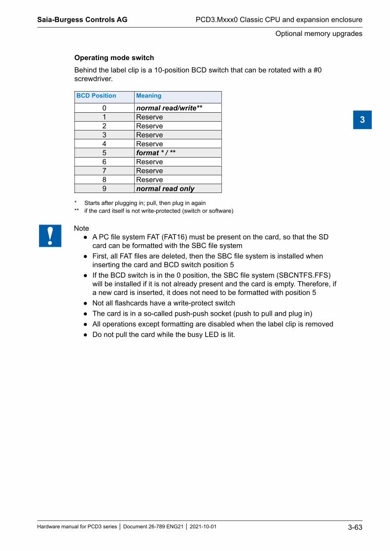
Saia-Burgess Controls AG
Hardware manual for PCD3 series │ Document 26-789 ENG21 │ 2021-10-01
Optional memory upgrades
PCD3.Mxxx0 Classic CPU and expansion enclosure
3-63
3
Operating mode switchBehind the label clip is a 10-position BCD switch that can be rotated with a #0 screwdriver.
BCD Position Meaning
0 normal read/write**1 Reserve2 Reserve3 Reserve4 Reserve5 format * / **6 Reserve7 Reserve8 Reserve9 normal read only
* Starts after plugging in; pull, then plug in again ** if the card itself is not write-protected (switch or software)
Note ● A PC file system FAT (FAT16) must be present on the card, so that the SD
card can be formatted with the SBC file system ● First, all FAT files are deleted, then the SBC file system is installed when
inserting the card and BCD switch position 5 ● If the BCD switch is in the 0 position, the SBC file system (SBCNTFS.FFS)
will be installed if it is not already present and the card is empty. Therefore, if a new card is inserted, it does not need to be formatted with position 5
● Not all flashcards have a write-protect switch ● The card is in a so-called push-push socket (push to pull and plug in) ● All operations except formatting are disabled when the label clip is removed ● Do not pull the card while the busy LED is lit.

Saia-Burgess Controls AG
Hardware manual for PCD3 series │ Document 26-789 ENG21 │ 2021-10-01
Optional memory upgrades
PCD3.Mxxx0 Classic CPU and expansion enclosure
3-64
3
3.19.3 SDflashmemorycards
The SD Flash cards are not part of the PCD3.R60x and must be ordered separately.It is important that the SD cards are of good quality (industry standard, as tested by SBC). Other flash cards can also be used, however they are not supported and are excluded from any warranty.
To increase the lifetime, the flash cards should be filled in read-only applications to not more than 80%. For read/write applications, it should not be more than 50% of the disk space.
The PCD3 uses a non-standard file system (SBC FS). Therefore, the flash cards need to be formatted before first use. This happens automatically when a new FAT 16 flash card is inserted in the PCD3.R60x.
Flash cards handling
Activity
Busy
Write
Diag
User
The card is in a so-called push-push socket (to pull and plug in), which is located under the label clip. It can be pulled out without switching off the PCD3.
Toremovethelabelclip,pulloffthebottomendfirst.
A mechanism detects the removal of the label clip. If necessary, unsaved data is saved to the flash card. The busy LED will light up.
InserttheflashcardWhen inserting the flash card, press until resistance is felt, a soft click might sound. Relieve pressure until the card is at the same height as the slot.
RemovaloftheflashcardIf the busy LED is off, press the card into the module housing until resistance is felt. Decrease the pressure until the flash card slides out.

Saia-Burgess Controls AG
Hardware manual for PCD3 series │ Document 26-789 ENG21 │ 2021-10-01
Optional memory upgrades
PCD3.Mxxx0 Classic CPU and expansion enclosure
3-65
3
UserprogrammbackuponflashcardIt is possible to save a backup of the user program (see chapter 3.13.1) to the flash card in the PCD3.R60x.
The storage locations for the user program (save and recall) are queried in the following order:
1. M1 slot 2. M2 slot 3. I/O Slot 0…3 4. Onboard flash memory (if available)
I/O bus functionsSome states are recognized by the user program.
I/O Bus offset
Write Read Meaning
+0 User LED BCD switch position bit 0 (lsb)
Position (non-inverted) of the BCD switch
+1 do not use BCD switch position bit 1+2 do not use BCD switch position bit 2+3 do not use BCD switch position bit 3 (msb)+4 do not use /Labeling clip available 1 = removed+5 do not use -+6 do not use /Flash card available 1 = card removed
+7 do not use SD write-protect switch 1 = SD locked/removed 0 = MMC or SD released
Ordering information
Ordering information Description Weight
PCD3.R600 Basic module with slot for SD flash memory cards PCD7.R-SDxxx (up to 4 modules in I/O slots 0…3 on a PCD3) 60 g
PCD7.R-SD256 SD memory flash card 256 MB 2 gPCD7.R-SD512 SD memory flash card 512 MB 2 gPCD7.R-SD1024 SD memory flash card 1 GB 2 g

Saia-Burgess Controls AG
Hardware manual for PCD3 series │ Document 26-789 ENG21 │ 2021-10-01
Optional memory upgrades
PCD3.Mxxx0 Classic CPU and expansion enclosure
3-66
3
3.19.4 Micro-SDflashmemorycardPCD7.R-MSD1024
At this point the same applies as under the previous chapter 3.19.3 SD flash memory cards, except for the one mentioned below.
Type Description ImagePCD7.R-MSD1024 Micro SD memory card with 1 GB
memory, PCD formatted, with PC adapter.
PCD7.R610 Adapter module for Micro-SD card PCD7.R-MSD1024 for use in the appropriate SD slots of the PCD families.
The micro SD card PCD7.R-MSD1024 requires a PCD7.R610 adapter module for use in the appropriate SD slots of the PCD families.
Saia-Burgess Controls AG
Hardware manual for PCD3 series │ Document 26-789 ENG21 │ 2021-10-01
RIO (Remote Input Output) head stations
4-1
4
4 RIO (Remote Input Output) head stations
4.1 The RIO (Remote Input Output) head stations4.2 Internal power of the PCD3.T76x head stations4.3 Connections of the RIO head station PCD3.T76x for 4 modules4.4 Diagnosis Information of the RIOs4.5 Terminating resistors of Profibus-DP or Profi S-net network

Saia-Burgess Controls AG
Hardware manual for PCD3 series │ Document 26-789 ENG21 │ 2021-10-01
The RIO head stations module carrier
RIO (Remote Input Output) head stations
4-2
4
4.1 The RIO (Remote Input Output) head stations
The PCD3.RIO (Remote I/Os =RIOs) are used to acquire decentralized I/O signals. PCD3.RIOs communicate with Profibus-DP with any master PLC, the .gsd file is included in the Saia PG5® (version 1.2 or higher) or can be found at [email protected] integrated web server in the PCD3.RIO provides the user with the greatest usage for commissioning, diagnosis and service. Access is via a widely known, easy-to-operate standard web browsers. The states of all I/O signals (digital/analog/counters) can easily be checked, and the output states can be modified selectively.PCD3.T760*
● Integrated Profibus DP and S-Net connection up to 1.5 MBit/s
● 4 pluggable PCD3 I/O modules (freely selectable) ● Expandable with PCD3.LIO ● Web server for, diagnostics, service and
commissioning ● Provides internally + 5V and V + for the I/O
modules on the PCD3.T760 and the connected PCD3.C1x0
RIO head stations
Module places Description External
power supplyPCD3.T760 4 for 4 I/O modules with Profibus DP and S-Net interface.
Power supply for integrated + 5V and V + bus for one segment of I/O modules available (for calculation of possible load see 4.2)
24 VDC
Max. RIO head station extension option with up to 3 LIOsNumber of inputs/outputs or I/O module slots
256 16
100Saia PCD3.C
W800
W800
W800
W800
760Saia PCD3.T 100Saia PCD3.C 100Saia PCD3.C
A866
A866
A866
A866
A810
A810
A810
A810
A810
A810
A810
A810
*outphased: this product is no longer produced.

Saia-Burgess Controls AG
Hardware manual for PCD3 series │ Document 26-789 ENG21 │ 2021-10-01
Internal power of the PCD3.T76x head stations
RIO (Remote Input Output) head stations
4-3
4
4.2 Internal power of the PCD3.T76x head stations
GND
+5V
CLR
0V
+V(16...24V)
LED24V
39V
PTCPCD3
+24 V
Voltage-monitor
5V
PCD-BusS
uppl
y 24
VD
C DCDC
DCDC
The PCD3.T76x head stations provide the following internal supply currents for the plugged or connected modules:
Type +5V V+ The load capacity of the + V bus depends on the load of the 5 V bus as follows (the more accurate the 24 VDC, the higher the possible load):
PCD3.T76x 650 mA
- 10%: 275 - I 5 V Bus [mA] +10% 4
- 20%: 150 - I 5 V Bus [mA] +25% 15
- 25%: 100 [mA]
+30% 24 V
24 V
24 V
When planning PCD3 systems, it must be checked whether the two internal power supplies are not overloaded. This control is particularly important when using analog, counting and positioning modules, as these sometimes have a fairly large power consumption. It is recommended to use the PG5 device configurator.

Saia-Burgess Controls AG
Hardware manual for PCD3 series │ Document 26-789 ENG21 │ 2021-10-01
Connections of the RIO head station PCD3.T76x for 4 modules
RIO (Remote Input Output) head stations
4-4
4
4.3 Connections of the RIO head station PCD3.T76x for 4 modules
760Saia PCD3.T
Bus connection to PCD3.LIOs module carrier
Earth
LED power ok
RS-232
Profibus Profibus address
24VDC supply
LEDs for operating states
4.3.1 Meaning of the connections
NetworkconnectionProfibusDPorProfiS-Net
760Saia PCD3.T
The bus is designed for a baud rate of up to 1.5 Mbps. More detailed specifications of the Profibus communication can be found in the manual 26/765, Profibus DP.
On a PCD3.M3 or PCD3.M6 (orange terminal block) the /D corresponds to pin 3 (RxD / TxD-P, red) and D to pin 8 (RxD / TxD-N, green).
1 PGND2 GND3 B = RxD/TxD-P | red = /D4 CNTR-P5 SGND6 +5V-Ext7 24 VDC8 A = RxD/TxD-N | green = D9 NC
Serial interfaces RS-232
760Saia PCD3.T
This connection allows configuration with a browser such as Internet Explorer or Netscape Navigator (with connection cable PCD3.K225).
1 TXD2 RTS3 RXD4 CTS5 PGND6 DSR

Saia-Burgess Controls AG
Hardware manual for PCD3 series │ Document 26-789 ENG21 │ 2021-10-01
Connections of the RIO head station PCD3.T76x for 4 modules
RIO (Remote Input Output) head stations
4-5
4
Profibusaddress
LSB
MS
B1 2 3 4 5 6 7 8
ON
760Saia PCD3.T
The Profibus address is set to binary on the PCD3.T76x by means of a DIP switch.
The numbers on the DIP switch are assigned the following values :
Vale
nce
1 2 4 8 16 32 64 Unu
sed
| | | | | | | |No. 1 2 3 4 5 6 7 8
Example for address 73: DIP switch no. 1 + 4 + 7 on ON.
Expansion connection
760Saia PCD3.T
This connector can be used to add up to 3 LIO module carriers to the RIO (with PCD3.K010 connector). This way, 256 I/Os can be realized per RIO.
4.3.2 Power LED
Supply
760Saia PCD3.T●● = LED on = supply available, OK

Saia-Burgess Controls AG
Hardware manual for PCD3 series │ Document 26-789 ENG21 │ 2021-10-01
Diagnosis Information of the RIO
RIO (Remote Input Output) head stations
4-6
4
4.4 Diagnosis Information of the RIOs
4.4.1 LED meaning
760Saia PCD3.T
The three LEDs on the PCD3.T76x head station indicate the operating states such as errors, alarms, diagnostics etc. The LEDs mean:
Diag = Diagnosis is running: permanently on - more than 4 I/O modules configured,
but no PCD3.Cxxx - Profibus address is 0 2 × flashing Load EPROM with configuration5 × flashing A min. I/O is lockedBF = bus failureRun = RIO processor running
RUN BF DIAG Explanation
●● ● ● RIO works correctly
●● ● ●● Diagnosis / alarm from the slave
●● ● ●●/● 2×Applied configuration derives from the EEPROM, master has the same configuration and is connected
● ●● ● Bus error, slave not assigned to a master
● ●● ●● Bus error, slave not assigned to master, but configured and in diagnostic state
● ●● ●●/● 2× Applied configuration derives from the EEPROM or web server
X X ●●/● 5× At least one lock is active● = LED off ●● = LED on ●●/● = LED flashes X = on or off
DP diagnosisThe PCD3.T76x provides the Profibus-DP with the standard diagnosis in octets *) 1 … 6. See also DIN 19245 part 3 *) In DIN 19245 a byte is called octet, therefore the same expression is used here.

Saia-Burgess Controls AG
Hardware manual for PCD3 series │ Document 26-789 ENG21 │ 2021-10-01
Diagnosis Information of the RIO
RIO (Remote Input Output) head stations
4-7
4
Standard diagnosis
Byte Bit Abbreviation Explanation
1
0 non_exist Slave does not exist (master set)1 station_not_ready Slave not ready for data exchange
2 cfg_faultConfiguration data of master and slave differentiate
3 ext_diag Extended diagnostic bytes4 Reserve5 invalid_slave_response Always set to 0 by the slave6 prm_fault Wrong parameter7 master_lock Slave parameterized by a master
2
0 prm_req Slave must be reparameterized1 stat_diag Static diagnosis2 Always 13 wd_on Watchdog monitoring active4 freeze_mode Freeze instruction active5 sync_mode Sync instruction active6 Reserve7 slave_deactivated 1 when slave deactivated by master
30 … 6 Reserve
7 ext_diag_overflow Diagnostic data overflow in the master or slave4 Master address
5, 6 ID (0xCD32)
Extended diagnosis1) Power failure with a PCD3.C200 or defective cable to a PCD3.C1x0
Byte Bit Explanation7 0x02 Device related diagnostics, 2 bytes (including the header byte)8 0xFF External power failure, defective cable to a PCD3.C1x0 or power failure in
a PCD3.C200
2) Error accessing an I/O moduleByte Bit Explanation7 (9) 0x43 Identification-related diagnosis, 3 bytes (including the header byte)
8 (10) 0 : 7
Error accessing module 0 : Error accessing module 7
9 (11) 0 : 7
Error accessing module 8 : Error accessing module 15
It is possible that both diagnostic messages are sent in the same telegram. In this case, the entries described above are packed into a frame, e.g. the identification-related diagnosis starts with octet 9 and ends with octet 11.

Saia-Burgess Controls AG
Hardware manual for PCD3 series │ Document 26-789 ENG21 │ 2021-10-01
Diagnosis Information of the RIO
RIO (Remote Input Output) head stations
4-8
4
4.4.2 Diagnosis module
In addition to the DP-compliant diagnostic information, the PCD3.RIO also supports a diagnosis module used in the DP configuration. This slave diagnostic information is stored in the master resources. The use of a diagnosis module is not mandatory. This diagnostic module must however be configured after the last I/O module (exception: plug-ins must be configured after the diagnosis module). It requires 4 input bytes and 4 output bytes. The exact definition of request and answer is as followed:
Master→RIO
Byte 0 Byte 1 Byte 2 Byte3Query
RIO→Master
Byte 0 Byte 1 Byte 2 Byte3Reply
The contents of bytes 0 to 2 depend on the request command. The master always checks if the response command matches the request command, ensuring that the data is correct and belongs to the requested information.
NOP command (command 0)This command is for synchronization only. The RIO returns the received data bytes without modification.
Master→RIO
Byte 0 Byte 1 Byte 2 Byte3X Y Z 0
RIO→Master
Byte 0 Byte 1 Byte 2 Byte3X Y Z 0
Queryfirmwareversion(command1)This function returns the current firmware version of the RIO.
Master→RIO
Byte 0 Byte 1 Byte 2 Byte3irrelevant irrelevant irrelevant 1
RIO→Master
Byte 0 Byte 1 Byte 2 Byte3highest version lowest version
MSBlowest version LSB 1

Saia-Burgess Controls AG
Hardware manual for PCD3 series │ Document 26-789 ENG21 │ 2021-10-01
Diagnosis Information of the RIO
RIO (Remote Input Output) head stations
4-9
4
Query RIO status (command 2)This function returns the current status of the RIO
Master→RIO
Byte 0 Byte 1 Byte 2 Byte3irrelevant irrelevant irrelevant 2
RIO→Master
Byte 0 Byte 1 Byte 2 Byte3Status 0 Status 1 Status 2 2
Coding of bits in status 0:Bit Explanation7 DIAG LED: Set when diagnostic information is due6 Set, in the event of power failure on the external I/O-bus5 Set if valid configuration exists in EEPROM4 Set, when a clear com from the slave is due3 Set, as soon as a lock is active2 Reserve1 Reserve0 Reserve
Coding of the bits in status 1 and 2 are not yet defined.

Saia-Burgess Controls AG
Hardware manual for PCD3 series │ Document 26-789 ENG21 │ 2021-10-01
Diagnosis Information of the RIO
RIO (Remote Input Output) head stations
4-10
4
Status of the outputs in the event of a bus fault (command 3)Master→RIO
Byte 0 Byte 1 Byte 2 Byte3Value MSB Value LSB Module slot 3
RIO→Master
Byte 0 Byte 1 Byte 2 Byte3Status 0 Module slot 3
Function 3 defines the preferred state of the outputs. This preferred state is chosen when
● the connection to the bus is interrupted ● the master is in the STOP/PAUSE state
The status is 0 if the selection was accepted, otherwise it contains 0xFF.
The coding of the module space field is the following:
Bit Meaning
0…3 Module space (0…15)4…6 Channel number (0…7) For analog outputs, this is the analogue
channel number7 When set to (continue), the last status of the outputs is retained.
In which case bytes 0 and 1 are irrelevant.
Example: Module position = 0x82 → The outputs (if 16 digital outputs, then the 8 LSBs) of module position 2 (3rd place) are retained.
In the event of a bus error or in STOP mode, the default switch-off status sets all outputs to 0.
For analog outputs, this does not mean that the value of all outputs is 0.

Saia-Burgess Controls AG
Hardware manual for PCD3 series │ Document 26-789 ENG21 │ 2021-10-01
Diagnosis Information of the RIO
RIO (Remote Input Output) head stations
4-11
4
Resetthepreferredswitch-offstateoftheoutputs(command4)Master→RIO
Byte 0 Byte 1 Byte 2 Byte3irrelevant irrelevant irrelevant 4
RIO→Master
Byte 0 Byte 1 Byte 2 Byte3irrelevant irrelevant irrelevant 4
Function 4 sets the preferred switch-off state of all outputs to a predetermined value, e. g. 0
SaveI/OconfigurationtoEEPROM(command5)Master→RIO
Byte 0 Byte 1 Byte 2 Byte3irrelevant irrelevant irrelevant 5
RIO→Master
Byte 0 Byte 1 Byte 2 Byte3irrelevant irrelevant irrelevant 0x85/0x05
Function 5 saves the configuration to the EEPROM, so that users can go online with the web browser after having turned on the power without a master and can test the configuration without redefining it first.
This asynchronous function takes a few milliseconds, depending on the extend of the configuration. While writing to the EEPROM, the value 0x85 is displayed in the diagnostic module. During command processing, no new command is accepted.

Saia-Burgess Controls AG
Hardware manual for PCD3 series │ Document 26-789 ENG21 │ 2021-10-01
Terminating resistors of the Profibus-DP
RIO (Remote Input Output) head stations
4-12
4
4.5 TerminatingresistorsofProfibus-DPor ProfiS-netnetwork
To avoid reflections at the line ends, each segment must be terminated where its physical line ends. As a result, the lines are also biased to a rest potential. According to the Profibus standard, this must not be done directly on the Profibus devices, but must be achieved by means of external components.
Both the termination box PCD7.T16x or standard 9-pin Profibus D-sub connectors are suitable here. For further information, see manual 26-740 "installation components for RS-485 networks" and manual 26-860 "Profibus-DP".
The network termination must look like this:
12345
6789Frontview
R220
R39
0
R39
0
1 Shield3 RxD/TxD-P4 CNTR-P5 DP GND6 DP +5V8 RxD/TxD-N9 CNTR-N
Supplier of 9-pin Profibus D-Sub connectors for connection of Saia PCD® Controllers with Profibus networks:
ERNI Elektroincs AG, Brüttisellen Zurich, Switzerland http://www.erni.com → search for Erni reference number:
ERbic connection, horizontal grey: (Connection equipped with series inductions of 110 nH)
Erni Ref. 103648
ERbic connection, horizontal, gray with PG connector: (Connection equipped with series inductions of 110 nH)
Erni Ref. 103663
ERbic termination, horizontal yellow: (Connection equipped with series inductances of 110 nH plus termination resistors of 390 Ω and 220 Ω)
Erni Ref. 103649
ERNI ERbic connector

Saia-Burgess Controls AG
Hardware manual for PCD3 series │ Document 26-789 ENG21 │ 2021-10-01
Communication interfaces
5-1
5
5 Communications interfaces
5.1 General5.2 Serial interface logs5.3 Onboard interfaces5.4 Plug-in interface modules on I/O slot 0 - 35.5 LIO and RIO

Saia-Burgess Controls AG
Hardware manual for PCD3 series │ Document 26-789 ENG21 │ 2021-10-01
Communication interfaces
5-2
General
5
5.1 General
SBC S-Net, the network concept by Saia Burgess Controls, is based on the open standard Profibus and Ethernet. Ethernet includes layers 1 and 2 of the ISO/OSI layer model. Based on layer 2, a variety of different protocols and applications can be operated in parallel in the same network.
Additionally, the Profibus layer 2 (Field Data Link, FDL) also allows parallel operation of various application protocols such as DP, FMS and others. By using this option, Profi-S-Net can create a Private Control Network (PCN) on the Profibus. This will make all SBC devices active network participants.
Profibus Layer 2 (FDL) is integrated in the operating system of the CPU PCD3.Mxxx0 and the RIOs PCD3.T76x. These devices thereby have a professional S-Net connection with transfer rates of up to 1.5 Mbit/s.
The devices support Profibus DP and S-Net on the same port. This allows setting up networks based on Profibus in a cost-effective and flexible manner (more detailed information can be found in the TI PP26-381).
Since the summer of 2010, the full-duplex mode and Auto-MDIX can be operated via the Ethernet connection of the PCD3 family (PCD3.M2xxx, PCD3.M3xxx, PCD3.M5xxx and PCD3.M6xxx).
The easiest way to determine if your PCD3 already supports these functions, is to verify that the RJ-45 connectors are equipped with LEDs. If this is tha case, the Saia PCD® supports the full-duplex mode and auto-MDIX (auto-crossing of the signals).
The following hardware version or higher is required for full Duplex and Auto MDIX support:
● PCD3.M3xxx, PCD3.M5xxx and PCD3.M6xxx from hardware F ● PCD3.M2x30A4T1 and PCD3.M2x30A4T3 from hardware B ● PCD3.M2x30A4T5 from hardware C
Using the SBC S-Bus
The SBC S-Bus is essentially designed for communication with engineering and debugging tools and to connect the management levels/process control systems.
Itisnotsuitableorapprovedforconnectingthefielddevicesofothermanufacturers.Anopen,manufacturer-independentfieldbusisthepurposehere.

Saia-Burgess Controls AG
Hardware manual for PCD3 series │ Document 26-789 ENG21 │ 2021-10-01
Communication interfaces
5-3
Serial interfaces log
5
5.2 Serial interface logs
Protocol overview and support by the firmwarethroughthedifferentCPUs
Purpose Supported on
PCD
3.M
3020
, /M
3230
PCD
3.M
3120
, /M
3160
, PC
D3.
M33
30, /
M33
60
PCD
3.M
5440
, /M
6440
PCD
3.M
5340
, /M
5360
, PC
D3.
M55
40, /
M55
60,
PCD
3.M
6540
, /M
6560
S-Bus PGU on USB plug with USB or PGU port
Programming, debugging, visualization. Also allows access via gateway to stations in another S-Bus network
S-Bus PGU on the PGU-RS-232 connector
PGU Stecker pin 6 (DSR) on logic 0 (data, full protocol) 1).programming, debugging, visualization. Also allows access via gateway to stations in another S-Bus network
2)
2)
Serial-S-Bus protocol (data, parity) 3) 6)
Supports the S-Bus protocol on serial interfaces (RS-232, RS-485/422, USB, modem) in master/slave operation.
Character mode (MC0 to MC5) 4)
Sending of characters or texts via serial interfaces, basis for the creation of own protocols in the user program
Profi-S-Busprotocol Data exchange with multimaster communication between controllers. Also allows access with PG5 programmer, SBC OPC server or web browser
Profi-S-IOprotocol For the operation of the PCD3.T760. Allows configuration and diagnostics.
Ether-S-Bus protocol Data exchange with multimaster communication between controllers. Also allows access with PG5 programmer, SBC OPC server or web browser.
Ether-S-IO protocol 5) For the operation of the PCD3.T66x. Allows configuration and diagnostics.
MPI Multi-point protocol for data exchange with other devices (SBC-xx7 controllers, HMI, SCADA systems)
1) Requires the use of the programming cable PCD8.K1112) Requires a corresponding configuration in the hardware settings3) Requires an assignment of the port in the user program (SASI). For new applications, the data mode should
always be selected. 4) RS-485 with immediate release of the data line after sending the last character5) In preparation6) S-Bus parity master mode (SM1) not supported on ports 2 and 3 (from FW 010)

Saia-Burgess Controls AG
Hardware manual for PCD3 series │ Document 26-789 ENG21 │ 2021-10-01
Communication interfaces
5-4
Serial interfaces log
5
5.2.1 Serial S-Net
Supports the S-Bus protocol on serial interfaces (RS-232, RS-485/422, modem) in master/slave operation. The SBC S-Bus S-Bus with its simple and secure protocol is already available as standard on all Saia PCD®s.
Technical data Transmission rates: up to 115 kbps protocol S-Bus, high net data rates thanks
to low protocol overheadNumber of stations: up to 254 stations in segments of 32 stations eachPort in the PG5: 0, 1, 2, 3,100, 101, 110, 111, 120, 121, 130, 131
5.2.2 ProfiS-Net
Private Control Network (PCN) includes all protocols and services for the operation of SBC devices (PLC, RIO, HMI, PG) on Profibus. Multi-protocol operation is supported on the same connector and cable.
Technical data Transmission rates: up to 1.5 Mbit/s Number of stations: up to 124 stations in segments of 32 stations each Logs: Profi S-Bus, Profi S-I/O, DP slave, HTTP Port in the PG5: 2 and 10
5.2.3 Ether S-Net
Private Control Network (PCN) includes all protocols and services for the operation of SBC devices (PLC, RIO, HMI, PG) on Ethernet supports multi-protocol operation (S-Bus, S-IO, HTTP, SMTP) on the same connector and cable.
Technical data Connection: 10 Base-T/100 Base TX (RJ-45) Speed: 10/100 MBit/s (autosensing) Logs: TCP/IP or UDP/IP, Ether S-Bus, Ether-S-I/O, HTTP,
SMTPPort in the PG5: 9
5.2.4 Logs implemented in the user program
Based on the character mode, various protocols can be implemented (with very good knowledge of STL programming).
Our system partners have already done this for a large number of protocols, allowing our controllers to communicate with components from a wide range of manufacturers, e.g. via Modbus, M-Bus etc.
Please refer to the link page www.sbc-support.com for links to the system partners.

Saia-Burgess Controls AG
Hardware manual for PCD3 series │ Document 26-789 ENG21 │ 2021-10-01
Communication interfaces
5-5
Onboard interfaces
5
5.3 Onboard interfaces
RS-232/PGU (Port 0)
5560Saia PCD3.M 3330Saia PCD3.M
USBEthernet (Port 9) RS-485 (Port 2)
S-Net/MPI (Port 10)
5.3.1 Summary table
Con
nec-
tion
type
D-S
ub #
1 (P
GU
)
D-S
ub #
2
Term
inal
bl
ock
Ethe
rnet
USB
Onb
oard
in
terfa
ces
RS-
232
RS-
485
(ser
ial)
RS-
422
(ser
ial)
Profi
S-N
et/
DP
slav
e
CAN
Profi
bus
DP
Mas
ter
RS-
485
Profi
S-N
et/
DP
slav
e
USB
1.1
sl
ave
(PG
U)
PortNo 0 3 3 10 10 10 2 2 9
Max. baud rate
115.2 kbit/s
115.2 kbit/s
115.2 kbit/s
1.5 Mbit/s
12 Mbit/s
115.2 kbit/s
187 kbit/s
10/100 Mbit/s
PCD3.M3020
PCD3.M3120
PCD3.M3160
PCD3.M3230
PCD3.M3330
PCD3.M3360
PCD3.M5340
PCD3.M5360
PCD3.M5440
PCD3.M5540
PCD3.M5560
PCD3.M6240
PCD3.M6340
PCD3.M6440
PCD3.M6540
PCD3.M6560
PCD3.M6860 2×

Saia-Burgess Controls AG
Hardware manual for PCD3 series │ Document 26-789 ENG21 │ 2021-10-01
Communication interfaces
5-6
Onboard interfaces
5
5.3.2 RS-232 connector (port 0) as communication interface and as programmer connection (only PCD3.M5xx0 / M6xx0)
This interface is routed to a 9-pin D-sub connector (female) and is of type RS-232.
5560
S-Net / MPI
Saia PCD3.M
PCD3.M5xx0 PCD3.M6xx0
54321
9876
RS-232 / PGU Port 0
D-Sub pin
Signal Meaning
1 DCD Data carrier detect Data carrier detected2 RXD Receive data Receive data3 TXD Transmit data Send data4 DTR Data terminal ready Terminal ready5 GND Signal ground Signal ground6 DSR PGU Connected PGU detection7 RTS Request to send Start up transmitter8 CTS Clear to send Ready to send9 n.c. not connected ---Port 0 Port 10
1) Obligatory signals (it is imperative that the user makes this available)2) The signal is provided by the controller
The interface can be used for the following purposes:
(see next page)

Saia-Burgess Controls AG
Hardware manual for PCD3 series │ Document 26-789 ENG21 │ 2021-10-01
Communication interfaces
5-7
Onboard interfaces
5
Option 1 Configuration with the desired protocol (S-Bus PGU configuration)
Option 2 Assignment (SASI) in the user program (the port must not be configured as S-Bus PGU port)
If a programming device is connected again instead of the peripheral device during operation, the mode is automatically switched over to PGU (pin 6 logic 1 (DSR), in PGU mode: DSR PING = 1)
In order to be able to use the interface again for the connection of a peripheral device, Port 0 must be reconfigured with the SASI command
21
43
65
87
9
GND SGN
TXRX
RTS 1)
CTS 1)CTS
RTS
TXDRXDPGND PGND
PGU-PlugD-SUB 9 pol.
(female)
PeripheralCable
+5V (just for PGU)
1) When communicating with terminals, check whether certain connections are to be bridged or to be set by the command SOCL on 1 or 0. Generally the use of handshake (RTS / CTS) is recommended (see also manual 26/795, series PCD7.D23x, graphics terminals).
Option 3 Port 0 can also be used as a modem interface with a 1 to 1 ca-ble. As described in chapter 7.1.2 Hardware options, the check box Full RS-232 handshaking on port 0 must be selected.
Option 4 With connection cable PCD8.K111, this interface can be used as a programming device connection.
21
43
65
87
9
21
43
65
87
9
SGNDSRSGN
TXRX
RTSCTSCTS
RTS
TXRX
DTR
PC PCD
D-SUB 9 pol.(female)
D-SUB 9 pol.(male)
Connection cable PCD8.K111

Saia-Burgess Controls AG
Hardware manual for PCD3 series │ Document 26-789 ENG21 │ 2021-10-01
Communication interfaces
5-8
Onboard interfaces
5
5.3.3 RS-485 / RS-422 (port 3)
This interface is routed to a 9-pin D-sub connector (socket) and is of type RS-485 / RS-422.
5560
S-Net / MPI
Saia PCD3.M
PCD3.M5340, PCD3.M5360 PCD3.M5xx0
54321
9876
10
11
RS-422Port 3
RS-485Port 3
D-Sub pin
Signal Explanation Signal Explanation
1 /RXD Receive data - --- ---2 /CTS Ready to send - --- ---3 /TXD Send data + /RxD /TxD Receive/Send +4 /RTS Send request - --- ---5 PGND Data ground PGND Data ground6 RXD Receive data + --- ---7 CTS Ready to send + --- ---
8 TXD Send data - RxD TxD Receive / Send -
9 RTS Send request + --- ---
Port 0 Port 3 10/11*) PGND Shield dimensions PGND Shield dimensions *)
*) Mounting screws of the D-Sub female connector housing
5.3.4 RS-485 / S-Net / MPI (port 10)
This interface is routed to a 9-pin D-sub connector (female) and is of type RS-485.
5560
S-Net / MPI
Saia PCD3.M
PCD3.M5xx0 (except PCD3.M5340 and PCD3.M5360)
54321
9876
10
11
S-Net / MPI / RS-485Port 10
D-Sub pin
Signal Explanation
1 GND GND2 M24 0V of the 24V power supply3 RxD/TxD-P1) Receive/Transmit data pos.4 CNTR-P Control signal for repeaters (direction control)5 DGND1) Data transmission potential (volume to 5V)6 VP2) Supply voltage of the terminating resistors-P7 P24 Output voltage plus 24V8 RxD/TxD-N1) Receive/Transmit data neg.9 n.c. ---
10/11*) PGND Shield dimensions *)Port 0 Port 10*) Mounting screws of the D-Sub female connector housing1) Obligatory signals (it is imperative that the user makes this available)2) The signal is provided by the controller

Saia-Burgess Controls AG
Hardware manual for PCD3 series │ Document 26-789 ENG21 │ 2021-10-01
Communication interfaces
5-9
Onboard interfaces
5
5.3.5 CAN (port 10)
This interface is connected to a 9-pin D-sub (plug) connector and is of type RS-485.
6240
PCD3.M6240, PCD3.M6340 and PCD3.M6360
6360Saia PCD3.M
Saia
PCD
3Sa
ia P
CD3
Saia
PCD
3Sa
ia P
CD3
Saia
PCD
3Sa
ia P
CD3
Saia
PCD
3Sa
ia P
CD3
54321
9876
CANPort 10
D-Sub pin
Signal Explanation
1 n.c. ---2 CAN_L1) Receiving/sending neg.
3 GND Data transfer pot. Dimensions
4 n.c. ---5 n.c. ---6 n.c.7 CAN_H1) Receiving/sending pos.8 n.c. ---9 n.c. ---Port 0 Port 10
1) Electrically isolated
5.3.6 ProfibusDPMaster(port10)
This interface is routed to a 9-pin D-sub connector (socket) and is of type RS-485.
6440
Profibus DP
PCD3.M6440, PCD3.M6540 und PCD3.M6560
6540
Profibus DP
Saia PCD3.M
Saia
PCD
3Sa
ia P
CD3
Saia
PCD
3Sa
ia P
CD3
Saia
PCD
3Sa
ia P
CD3
Saia
PCD
3Sa
ia P
CD3
54321
9876
ProfibusDPMasterPort 10
D-Sub pin
Signal Explanation
1 ---2 GND2) Shield dimensions3 B red Receiving/sending pos.
4 En ---5 GND_BUS For terminators6 +5 V_BUS For terminators7 24 V2) ---8 A green Receiving/sending neg.9 n.c. ---Port 0 Port 10
2) not electrically isolated

Saia-Burgess Controls AG
Hardware manual for PCD3 series │ Document 26-789 ENG21 │ 2021-10-01
Communication interfaces
5-10
USB PGU interface for programming device connection
5
5.3.7 USB PGU interface for programming device connection
For the USB interface (type B) of the PCD3.Mxxx0 to be used, PG5 version 1.3.100 or later must be installed.
3330Saia PCD3.M
When a PCD3.Mxxxx is connected to a PC for the first time via the USB interface, the operating system of the PC automatically installs the relevant USB driver.
To establish a connection with a Saia PCD® via USB, the following settings must be made in the online settings of the PG5 project:
The activation of the PGU option ensures that the PCD3.Mxxxx connected directly to the PC can be communicated independently of the configured S-Bus address.

Saia-Burgess Controls AG
Hardware manual for PCD3 series │ Document 26-789 ENG21 │ 2021-10-01
Communication interfaces
5-11
USB PGU interface for programming device connection
5
5.3.8 EthernetRJ-45andProfibus
SBC S-Net, the network concept by Saia Burgess Controls, is based on the open standard Profibus and Ethernet. Ethernet includes layers 1 and 2 of the ISO/OSI layer model. Based on layer 2, a variety of different protocols and applications can be operated in parallel in the same network.
3330Saia PCD3.M
Additionally, the Profibus layer 2 (Field Data Link, FDL) also allows parallel operation of various application protocols such as DP, FMS and others. By using this option, Profi-S-Net can create a Private Control Network (PCN) on the Profibus. This will make all SBC devices active network participants.
Profibus layer 2 (FDL) is integrated in the operating system of the CPU PCD3.Mxxx0 and the RIOs PCD3.T76x. These devices thereby have a Profi-S-Net connection with transfer rates of up to 1.5 Mbit/s.
The devices support Profibus DP and S-Net on the same port. In this way networks based on Profibus can be set up in a cost-effective and flexible way (detailed information can be found in TI 26-381).
Since the summer of 2010, the full-duplex mode and Auto-MDIX can be operated via the Ethernet connection of the PCD3 family (PCD3.M2xxx, PCD3.M3xxx, PCD3.M5xxx and PCD3.M6xxx).
The easiest way to determine if your PCD3 already supports these functions, is to verify that the RJ-45 connectors are equipped with LEDs. If this is tha case, the Saia PCD® supports the full-duplex mode and auto-MDIX (auto-crossing of the signals).
The following hardware version or higher is required for full Duplex and Auto MDIX support:
● PCD3.M3xxx, PCD3.M5xxx and PCD3.M6xxx from hardware F ● PCD3.M2x30A4T1 and PCD3.M2x30A4T3 from hardware B ● PCD3.M2x30A4T5 from hardware C
Devices with Ethernet full-duplex mode can be recognized by the two LEDs on the RJ-45 connector (left image).
3330Saia PCD3.M 3330Saia PCD3.MEthernet connection equipped with LEDs Ethernet connection without LEDs

Saia-Burgess Controls AG
Hardware manual for PCD3 series │ Document 26-789 ENG21 │ 2021-10-01
Communication interfaces
5-12
USB PGU interface for programming device connection
5
5.3.9 RS-485/ProfiS-net/DPslave(port2)
On the same terminal block for power supply, the port 2 interface with two terminal connections (D and /D) is arranged on the left side of the plug.
3330Saia PCD3.M
For all CPU typesTerminal block (item no. 440549950) for power supply, watchdog, interrupt inputs and port 2 Profibus
Cabel Pin Signal Explanation Signal Wiring
Rx - Tx 1 D Port 2 RS-485 to 115.2 kbit/s as a free user
interface or Profi S-bus up to 187.5kbits/s (except PCD3.M5440 and PCD3.M5540)
RxD/TxD-N Agreen
/Rx - /Tx 2 /D RxD/TxD-P Bred
3 Int0 2 interrupt inputs 24VDC or 1 quick counter 24 VDC 4 Int1
5 WDWatchdog / closed relay contact
6 WD7 +24V
Power supply8 GND
RS-485 terminating resistors
Switch position Description Explanation
3330Saia PCD3.M
left O without terminators
right C with terminators
Example of a RS-485 network setup with terminating resistors:
+5 V
/RX - /TX
n n
29 n
/n
/n/n
28
RX - TX
+5 V
Pull up 330 Ohm
AbschlussWiderstand150 Ohm
Segmentlänge max. 1200 mmax. 32 Stationen
Bus RS-485
Anfangsstation Zwischenstationen Endstation
Pull down 330 Ohm

Saia-Burgess Controls AG
Hardware manual for PCD3 series │ Document 26-789 ENG21 │ 2021-10-01
Communication interfaces
5-13
Plug-in interface modules on I/O slot 0 - 3
5
5.4 Plug-in interface modules on I/O slot 0…3
5560
S-Net / MPI
Saia PCD3.M 3330Saia PCD3.M
Slot 0 … 3
...
5.4.1 Overview slot interface modules
I/O communication modules on slot ..
3330Saia PCD3.M
Slot 0...3
Port100------Port101
Port110------Port111
Port120------Port121
Port130------Port131
Port 10Port 0
USB
Port 2
Port 1
Port 9
0 1 2 3 Slot
Port 3 (M5340)
0 1 2 3
PCD3.F110 PCD3.F121 PCD3.F130 PCD3.F150 PCD3.F180
Port1
PCD3.F210 PCD3.F221 PCD3.F24x PCD3.F26x PCD3.F27x PCD3.F281 Po
rt100
…10
1
Port1
10…
111
Port1
20…
121
Port1
30…
131

Saia-Burgess Controls AG
Hardware manual for PCD3 series │ Document 26-789 ENG21 │ 2021-10-01
Communication interfaces
5-14
Plug-in interface modules on I/O slot 0 - 3
5
Slot interface modules made for the following control unitsModule (excluding
Ethernet)* Module Power module RIO
PCD3.M3020* PCD3.M3120 PCD3.M3160 PCD3.T660PCD3.M3230* PCD3.M3330 PCD3.M3360 PCD3.T664
PCD3.M5340 PCD3.M5360 PCD3.T665PCD3.M5440* PCD3.M5540 PCD3.M5560 PCD3.T666
PCD3.M6340 PCD3.M6360PCD3.M6540 PCD3.M6560
PCD3.M6860PCD3.M6880 PCD3.T668
* not recommended for new projects
5.4.2 Serial Interfaces on I/O module slot 0 (port 1)
RS-232 / RS-422 / RS-485, Belimo, current loop 20 mA with PCD3.F1xxThe communication modules PCD3.F1xx are described in manual: 26-857 PCD3.F1xx and PCD3.F2xx serial interface modules.
5.4.3 Serial interfaces on the I/O module slots 0 - 3
RS-232 / RS-422 / RS-485, Belimo, current loop 20 mA on PCD3.F2xxThe communication modules PCD3.F2xx are described in manual: 26-857 PCD3.F1xx and PCD3.F2xx serial interface modules.
DALI interface module PCD3.F261The Dali communication modules are described in manual: 27-606 DALI modules PCD2.F2610 & PCD3.F261.
The description of the software library can be found in manual: 27-607 StarterGuide DALI-F26x,
LON interface module PCD3.F240The LON communication modules are described in the manual: 27-636 LON communication module for TP / FT-10 channel
Relevant manual 26-767 LonWorks® networks with Saia PCD®
M-Bus interface module PCD3.F27xThe M-Bus communication modules are described in the manual: 27-603 M-Bus Master Interface Module PCD2.F27x0 and PCD3.F27x

Saia-Burgess Controls AG
Hardware manual for PCD3 series │ Document 26-789 ENG21 │ 2021-10-01
Communication interfaces
5-15
LIO and RIO
5
5.5 LIO and RIO
5.4.1 Interfaces of PCD3.Cxxx and PCD3.Txxx
The description of the interfaces of the PCD3.Cxxx and PCD3.Txxx are included in the chapters of this manual:
Extension with PCD3 components Chapter 3RIO (Remote Input Output) head ends Chapter 4

Saia-Burgess Controls AG
Hardware manual for PCD3 series │ Document 26-789 ENG21 │ 2021-10-01
Input/Output (I/O) module
6-1
6
6 Input/output (I/O) modules
Document 27-600; Release ENG08 │ 2018-07-11
Manual
I/O-modules for PCD1 / PCD2 series
and for PCD3 series
All I/O modules for the PCD1 | PCD2 and PCD3 are described in manual 27-600.

Saia-Burgess Controls AG
Hardware manual for PCD3 series │ Document 26-789 ENG21 │ 2021-10-01
Configuration
7-1
7
7 Configuration
7.1 CPU processor units7.2 RIO - Remote Input Output module carrier PCD3.T76x7.3 Smart-RIO PCD3.T665 and PCD3.T666

Saia-Burgess Controls AG
Hardware manual for PCD3 series │ Document 26-789 ENG21 │ 2021-10-01
CPU processor units
Configuration
7-2
7
7.1 CPU processor units
The commissioning of the PCD-CPU is described in 26-732 PG5 User Manual, which is included in the PG5 software package as a PDF file.
Manual
User manual PG5.
Document 26-732 / Version ENG12 / 21.08.2018
After the standard installation of the PG5 package on the local computer, the manuals are usually found in four languages under the following directory path
c:\Program Files (x86)\SBC\PG5 Version\Manuals\
The shortest route is via PG5 itself.
Programmstart PG5 -> Help -> PG5 User Manual
Saia-Burgess Controls AG
Hardware manual for PCD3 series │ Document 26-789 ENG21 │ 2021-10-01
RIO - Remote Input Output module carrier PCD3.T76x
Configuration
7-3
7
7.2 RIO - Remote Input Output module carrier PCD3.T76x*
Commissioning instructions for a PCD3.T7xx can be found in 26-732 PG5 User Manual under chapter 15 Profi-S-IO.
Manual
User manual PG5.
Document 26-732 / Version ENG12 / 21.08.2018
Another more up-to-date option is the PG5 help of the latest PG5 suite under S-Net Network Configurator Introduction.
* outphased. This product is no longer produced.

Saia-Burgess Controls AG
Hardware manual for PCD3 series │ Document 26-789 ENG21 │ 2021-10-01
Smart-RIO PCD3.T665 and PCD3.T666
Configuration
7-4
7
7.3 Smart-RIO PCD3.T665 and PCD3.T666
A quick start guide for configuring, programming and commissioning the Smart RIOs (PCD3.T665 and PCD3.T666) with PCDx.Mxxxx Smart Automation Managers can be found in document 26-892 Smart-RIO PCD3.T66x.
Document-No. 26-892 | Edition ENG06 | 2015-06-11
Manual
Smart RIOs PCD3.T66x
Further details can be found in the PG5 help of the latest PG5 suite under RIO Network Configurator.

Saia-Burgess Controls AG
Hardware manual for PCD3 series │ Document 26-789 ENG21 │ 2021-10-01
Maintenance
8-1
8
8 Maintenance
8.1 Battery change at the PCD3.M5xx0/M6xx08.2 Battery change at the PCD3.M3xx0 with PCD3.R010

Saia-Burgess Controls AG
Hardware manual for PCD3 series │ Document 26-789 ENG21 │ 2021-10-01
Battery change at the PCD3.M5xx0/M6xx0
Maintenance
8-2
8
8.1 Battery change at the PCD3.M5xx0/M6xx0
PCD3 components are maintenance-free, except for a few CPUs (PCD3.Mxxx0), where the battery needs to be replaced from time to time.
PCD3 components contain no parts that can be replaced by the user. If hardware problems occur, the components should be returned to Saia Burgess Controls.
The resources (registers, flags, timers, counters, etc.) and partly, also the user program and texts/DBs, are stored in the RAM. To ensure that they do not get lost during a power failure and (if any) the hardware clock continues to run, the PCD3 is equipped with a buffer capacitor (SuperCap) or a buffer battery:
CPU type Puffer BuffertimePCD3.M3xx0 Super Cap (soldered, maintenance free) 4 hours1)
PCD3.M5xx0/M6xx0 Lithium Battery Renata CR 2032 + Super Cap (soldered in)
1…3 years2)
1) The total charge time is about 10 minutes 2) Depending on the ambient temperature, the higher the temperature, the shorter the buffering time
- For new controllers, the batteries are included in the package and must be used during commissioning. Note the polarity of the batteries:
- Insert button batteries CR 2032 from Renata so that the positive pole is visible
The CPU with lithium batteries are not maintenance free. The battery voltage is monitored by the CPU.
The LED BATT lights up and the XOB 2 is activated when:
● the battery voltage is below 2.4 V or higher than 3.5 V ● the battery is discharged or has an interruption ● the battery is missing
We recommend changing the battery while the Saia PCD® is live, so no data loss occurs.
Ordering information: Type Description
4 507 4817 0 Lithium battery for PCD processor units (RENATA button type CR 2032) 2)
2) Shelf life 1…3 years. Depending on the ambient temperature, the higher the temperature, the shorter the buffering time

Saia-Burgess Controls AG
Hardware manual for PCD3 series │ Document 26-789 ENG21 │ 2021-10-01
Battery change at the PCD3.M3xx0 with PCD3.R010
Maintenance
8-3
8
8.2 Battery change at the PCD3.M3xx0 with PCD3.R010
The resources (registers, flags, timers, counters, etc.) and partly, also the user program and texts/DBs, are stored in the RAM. To ensure that they do not get lost during a power failure and (if any) the hardware clock continues to run, the PCD3 is equipped with a buffer capacitor (SuperCap) or a buffer battery:
- For new controllers, the batteries are included in the package and must be used during commissioning. Note the polarity of the batteries:
- Insert button batteries Renata CR 2032 so that the positive pole is visible
The CPU with lithium batteries are not maintenance free. The battery voltage is monitored by the CPU.
The LED BATT lights up and the XOB 2 is activated when:
● the battery voltage is below 2.4 V or higher than 3.5 V ● the battery is discharged or has an interruption ● the battery is missing
We recommend changing the battery while the Saia PCD® is live, so no data loss occurs.
Ordering information: Type Description
PCD3.R010 Battery module for PCD3.M3xxx, plug-in onto I/O Slot #3
4 507 4817 0 Lithium battery for PCD processor units (RENATA button type CR 2032) 2)
2) Shelf life 1…3 years. Depending on the ambient temperature, the higher the temperature, the shorter the buffering time

Saia-Burgess Controls AG
Hardware manual for PCD3 series │ Document 26-789 ENG21 │ 2021-10-01
Product status
9-1
9
9 Product status of the CPU-moduls
Article PCD2.
Active Outphased (no longer produced)
Repair phase until:
Follow-up product:
PCD3.M3020 × 2021-12-31 PCD3.M3160PCD3.M3120 × 2024-12-31 PCD3.M3160PCD3.M3160 ×PCD3.M3230 × 2021-12-31 PCD3.M3360PCD3.M3330 × 2024-12-31 PCD3.M3360PCD3.M3360 ×PCD3.M5340 × 2024-12-31 PCD3.M5360PCD3.M5360 ×PCD3.M5440 × 2021-12-31 PCD3.M5560PCD3.M5540 × 2024-12-31 PCD3.M5560PCD3.M5560 ×PCD3.M6240 × Expired PCD3.M6360PCD3.M6340 × 2021-12-31 PCD3.M6360PCD3.M6360 ×PCD3.M6440 × 2021-12-31 PCD3.M6560PCD3.M6540 × 2021-12-31 PCD3.M6560PCD3.M6560 ×PCD3.M6860 ×* not recommended for new projects

Saia-Burgess Controls AG
Hardware manual for PCD3 series │ Document 26-789 ENG21 │ 2021-10-01
Appendix
A
A-1
Icons
A Appendix
A.1 Symbols for notes etc.A.2 Definitions for the serial interfacesA.3 GlossaryA.4 Contact, support and repair addresses

Saia-Burgess Controls AG
Hardware manual for PCD3 series │ Document 26-789 ENG21 │ 2021-10-01
Appendix
A
A-2
Symbols
A.1 Symbols for notes etc.
A.1.1 Note symbols
This symbol refers the reader to further information in this or another manual or in technical information brochures. There is generally no direct link to these documents.
This symbol appears next to instructions that require strict compliance.
This symbol warns the reader of the risk of electric discharge upon contact. Recommendation: You should at least touch the negative terminal (PGU port casing) on the system before coming into contact with the electronic components. It is preferable to be permanently connected to an earthing lug on the wrist with the negative terminal.
The explanations next to this symbol are valid for the Saia PCD® Classic series only.
The explanations next to this symbol are valid for the Saia PCD® xx7 series only.
A.1.2 Mass designation, symbols and meaning
Description Symbol Meaning
GNDGround(ground)
DGND D digital galvanic isolated ground (digital galvanic isolated ground)
AGND A analog galvanic isolated ground (analog galvanic isolated ground)
SGND S signal ground (signal mass)

Saia-Burgess Controls AG
Hardware manual for PCD3 series │ Document 26-789 ENG21 │ 2021-10-01
Appendix
A
A-3
Definitions for the serial interfaces
A.2 Definitionsfortheserialinterfaces
A.2.1 RS-232
Designation of the signal lines
Data linesTXD Transmit data Send dataRXD Receive data Receive data
Signal and message lines
RTS Request to send Activate transmitterCTS Clear to send Ready to sendDTR Data terminal ready Terminal readyDSR Data set ready ReadyRI Ring indicator Incoming callDCD Data carrier detect Partner ready
Signals to RS-232
Signal type Logical status Setpoint value Nominal valueData signal 0 (space)
1 (mark)+3 V to +15 V -15 V to -3 V
+7 V -7 V
Control/ message signal
0 (off) 1 (on)
-15 V to -3 V +3 V to +15 V
-7 V +7 V
The idle state of the - data signals = mark - control and message signals = off

Saia-Burgess Controls AG
Hardware manual for PCD3 series │ Document 26-789 ENG21 │ 2021-10-01
Appendix
A
A-4
Definitions for the serial interfaces
A.2.2 RS-485/422
Signals to RS-485 (RS-422)
5V
2.5V
0V
4V
3V
2V
1VVO
H
VOL
VOZ
not active e.g. Startbit
/TX
TX
mark space
= mark
VOZ = 0.9 V min. … 1.7 V VOH = 2 V min. (with load) … 5 V max. (without load) VOL = –2 V … -5 V
RS-422 is in active condition in mark position
RS-422
Signal type Logical status PolarityData signal 0 (space)
1 (mark)TX positive for /TX /TX positive for TX
Control/ message signal
0 (off) 1 (on)
/RTS positive for RTS RTS positive for /RTS
RS-485
Signal type Logical status PolarityData signal 0 (space)
1 (mark)RX-TX positive for /RX-/TX /RX-/TX positive for RX-TX

Saia-Burgess Controls AG
Hardware manual for PCD3 series │ Document 26-789 ENG21 │ 2021-10-01
Appendix
A
A-5
Definitions for the serial interfaces
RS-485 wiringDepending on the manufacturer, there are different names for the connection allocation.
ConverterProducts from other manufacturers (RS-232 - RS-485) are usually presented in reverse. Therefore, the data lines must be crossed in certain cases.
Converter PCDRx-Tx /Rx-/Tx//Rx-/Tx/ Rx-Tx
ProfibusandProfi-SI/O
Profibus Colour PCD7.T160 D-Sub 9-pin on PCD Port 2 on PCD3.M3 and M6A=RxD /TxD-N green D pin 8 DB=RxD /TxD-P red D/ pin 3 /D
Not all manufacturers use the same connection allocation, therefore the data lines must be crossed in certain cases.
To guarantee an error-free operation of an RS-485 network, the network must be terminated at both ends. Cables and terminating resistors should be selected in accordance with manual section 26/740 Installation of components for RS-485 networks.
The drivers work with 5 VDC. If a higher voltage is applied, the drivers may be destroyed!

Saia-Burgess Controls AG
Hardware manual for PCD3 series │ Document 26-789 ENG21 │ 2021-10-01
Appendix
A
A-6
Definitions for the serial interfaces
A.2.3 TTY/current loop
Signals to TTY/current loop
Connection 1 TS Transmitter source
SenderConnection 3 TA Transmitter anodeConnection 6 TC Transmitter cathodeConnection 8 TG Transmitter groundConnection 2 RS Receiver source
ReceiversConnection 4 RA Receiver anodeConnection 7 RC Receiver cathodeConnection 9 RG Receiver ground
Signal type Setpoint value Nominal valueCurrent for logical L (space) –20 mA to + 2 mA 0 mA
Current for logical H (mark) +12 mA to +24 mA +20 mANo-load voltage on TS, RS +16 V to +24 V +24 VShort circuit current on TS, RS +18 mA bis +29.6 mA +23.2 mA
The idle status for data signals is mark. The operator uses wire bridges on the screw terminal blocks to select the switching type active or passive.
The max. transmission rate for TTY/current loops at 20 mA is 9600 bit/s.

Saia-Burgess Controls AG
Hardware manual for PCD3 series │ Document 26-789 ENG21 │ 2021-10-01
Appendix
A
A-7
Glossary
A.3 Glossary
AWL Statement list (program code line for line).Backup Data backup (for example, copy to additional data carriers)Basic address First numeric address of the IO module slot.Buffer battery The buffer battery supplies the energy for maintaining memory
contents and to enable the clock to continue working after switching off the power supply.
Builder Combines different work steps to load a programme in the PCD.Compiler A compiler is a program that translates the source code of a
program into the strings understandable to the target computer.CPU Central Processing Unit. Here the main housing with central unit
is designed for the Saia PCD® family.Device Device → controller (part of a project in the Saia PG5® Project
Manager).Download Abbr. DnLd → Save data in PCDElement Here, the inputs and outputs, flag, register, counter, timer, etc. are
designed for the Saia PCD® family.Flash memory Digital, non-volatile memory. Retains its data in the off state.FRAM Ferroelectric Random Access Memory
(requires no power supply for data retention)IL Instruction list → PCD program codeLinker After the compiler has done its work, the linker merges the
individual data for a program.LIO (Local Input Output) Inputs/outputs on the CPU board (on-board).Media This indicates inputs/outputs, flag, register, etc. in the PCD family.Media mapping Software assignment of digital and analog I/O electronics to flags
and registers.Module holders CPU, LIO or RIO devices that can accept I/O modules (e.g.
PCD3.C100, etc.)Modules Carrier cards for input/output electronics with suitable connection
technology.Motherboard Main board (CPU)NT New technology → subsequent generation of the first PCD
generation.On-Board Denotes as much as permanently installed “on the CPU
motherboard”.Parse A parser is a program which, in computer engineering, is
responsible for the decomposition and conversion of any input (text, e.g. AWL) into a format useful for further processing.
PCD3.M6xxx x in the product description stands for a number 0...9. In this case, it is an additional three-digit number, e.g. PCD3.M6560.
PGU Programmable UnitPLC Process Logic ControllerPort Interface descriptionPWM PWM stands for Pulse Width Modulation. Pulse width modulation
works with a constant pulse rate and a constant pulse amplitude, only the pulse width is variable. Because the pulse rate is constant, but the pulse width changes, the pulse duty factor changes. With a PWM output, it is possible to output analog values without expensive A / D converters

Saia-Burgess Controls AG
Hardware manual for PCD3 series │ Document 26-789 ENG21 │ 2021-10-01
Appendix
A
A-8
Glossary
RAM Random Access Memory → digital, volatile RAM of the computer. Loses its data in the off state.
Resources Resources → Inputs/outputs, flag, register, counter, timer, etc. Restore Load saved data from the backup data carrier.RIO Remote Input Output → Inputs/outputs on module carriers that
can be accessed by the CPU via profibus/ethernet lines.ROM Read only memory → Digital memory which keeps its data in the
off state.SD card Secure Digital Memory Card → Digital memory which keeps its
data in the off state.Sink operation Ground switching with DCSlot Slot for I/O, communication and memory modules.Source operation Plus switching with DCSource text or source code With an ASCII editor created (original) program, therefore no
word processing program. Word processing programs include characters for bold text etc., which a compiler might misinterpret.
SPM Saia PG5® Project Manager, main program of the Saia PG5® software package.
SRAM Static Random Access MemorySuperCap Electronic component (capacitor) that can store electrical energy.
Preservation of memory contents and clock function after switching off the power supply for a few hours to days.
Terminated Electrical reflections at the line ends are prevented using termination (e.g. with terminating resistors).
Saia-Burgess Controls AG
Hardware manual for PCD3 series │ Document 26-789 ENG21 │ 2021-10-01
Appendix
A
A-9
Contact, support and repair
A.4 Contact, support and repair addresses
Contact
Saia-Burgess Controls AG Bahnhofstrasse 18 3280 Murten, Switzerland
Telephone switchboard ........... +41 26 580 30 00Telephone SBC Support ......... +41 26 580 31 00Fax .......................................... +41 26 580 34 99
Support
E-mail Support: ...................... [email protected] site: ........................... www.sbc-support.comSBC site: ................................ www.saia-pcd.com
International representations & SBC sales companies: ........... www.saia-pcd.com/contact
Repair
Postal address for customers to return products in Switzerland:Saia-Burgess Controls AG After sales service Bahnhofstrasse 18 3280 Murten, Switzerland