Series 2600
138
Series 2600 Pressure Relief Valves 304C Farris Engineering Products and Services © 2006 Farris Engineering Printed in USA R1 10M 0806 10195 Brecksville Road, Brecksville, OH 44141 USA • Telephone: 440-838-7690 • Fax: 440-838-7699 • www.farrisengineering.com Facilities: Brecksville, OH USA, E. Farmingdale NY USA, Brantford, Ontario CANADA, Bridport, UK Offices worldwide. For a listing of our global sales network, visit our website at www.farrisengineering.com. While this information is presented in good faith and beleived to be accurate, Farris Engineering does not guarantee satisfactory results from reliance upon such information. Nothing contained herein is to be construed as a warranty or guarantee, expressed or implied, regarding the performance, merchantability, fitness or any other matter with respect to the products, nor as a recommendation to use any product or process in conflict with any patent. Farris Engineering reserves the right, without notice, to alter or improve the designs or specifications of the products described herein. Process Pressure Relief Valves Series 2600 ASME NB Certified for Air, Steam, and Water Series 3800 ASME NB Certified for Air, Steam, and Water Series 2700 ASME NB Certified for Air, Steam, and Water Series 1890/1896M ASME NB Certified for Air, Steam, and Water Series 2850/2856 ASME NB Certified for Air and Steam Steam Safety Valves Series 4200 ASME NB Certified for Steam – Section I & VIII Series 6400/6600 ASME NB Certified for Steam – Section I & VIII Universal Test Stand Tests Valves on Air and Water SizeMaster ™ Mark IV Pressure Relief Valve Engineering Software for Sizing and Selection The following is a list of Farris approvals currently on record: • ASME “V”, “UV” and “NV” approvals • National Board “NB” approval • ISO 9001-2000 • US Coast Guard approval • PED 97/23/EC (European Pressure Equipment Directive) • ATEX 94/9/EC (European Potentially Explosive Atmospheres) • Canadian TSSA Registration • China Safety Quality License • Russian GOSH-R and GGNT (Russian Certification and Permits) • First Point Assessment Limited FAST Centers (Farris Authorized Service Team) "Understanding what the Customer wants...making it happen!" • Worldwide Network of Service Centers with Factory Trained Technicians • Local Inventory with 24 hour a day / 7 day a week support • Access to Worldwide Farris Inventory through the Web • ASME/National Board approved Assembly & Test Facilities • Application and Sizing & Selection Support
-
Upload
khangminh22 -
Category
Documents
-
view
0 -
download
0
Transcript of Series 2600

Series 2600
Pressure Relief Valves
304C
Farris Engineering Products and Services
© 2006 Farris EngineeringPrinted in USAR1 10M 0806
10195 Brecksville Road, Brecksville, OH 44141 USA • Telephone: 440-838-7690 • Fax: 440-838-7699 • www.farrisengineering.comFacilities: Brecksville, OH USA, E. Farmingdale NY USA, Brantford, Ontario CANADA, Bridport, UKOffices worldwide. For a listing of our global sales network, visit our website at www.farrisengineering.com.
While this information is presented in good faith and beleived to be accurate, Farris Engineering does not guarantee satisfactory results from reliance upon such information. Nothing contained herein is to be construed as a warranty or guarantee, expressed or implied, regarding the performance, merchantability, fitness or any other matter with respect to the products, nor as a recommendation to use any product or process in conflict with any patent. Farris Engineering reserves the right, without notice, to alter or improve the designs or specifications of the products described herein.
Process Pressure Relief ValvesSeries 2600 ASME NB Certified for Air, Steam, and WaterSeries 3800 ASME NB Certified for Air, Steam, and WaterSeries 2700 ASME NB Certified for Air, Steam, and WaterSeries 1890/1896M ASME NB Certified for Air, Steam, and WaterSeries 2850/2856 ASME NB Certified for Air and Steam
Steam Safety ValvesSeries 4200 ASME NB Certified for Steam – Section I & VIIISeries 6400/6600 ASME NB Certified for Steam – Section I & VIII
Universal Test StandTests Valves on Air and Water
SizeMaster™ Mark IVPressure Relief Valve Engineering Software for Sizing and Selection
The following is a list of Farris approvals currently on record:• ASME “V”, “UV” and “NV” approvals• National Board “NB” approval• ISO 9001-2000• US Coast Guard approval• PED 97/23/EC (European Pressure Equipment Directive)• ATEX 94/9/EC (European Potentially Explosive Atmospheres)• Canadian TSSA Registration• China Safety Quality License• Russian GOSH-R and GGNT (Russian Certification and Permits)• First Point Assessment Limited
FAST Centers (Farris Authorized Service Team)"Understanding what the Customer wants...making it happen!"• Worldwide Network of Service Centers with Factory Trained Technicians• Local Inventory with 24 hour a day / 7 day a week support• Access to Worldwide Farris Inventory through the Web• ASME/National Board approved Assembly & Test Facilities• Application and Sizing & Selection Support
�
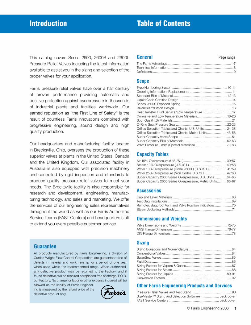
General Page range
The Farris Advantage .....................................................................1-7Technical Information ........................................................................8Definitions .........................................................................................9
ScopeType Numbering System ............................................................ 10-11Ordering Information, Replacements .............................................. 11Standard Bills of Material ........................................................... 12-13Liquid Code Certified Design .......................................................... 14Series 2600S Exposed Spring ........................................................15BalanSeal®/Piston Design ...............................................................16Heat Transfer Fluid Service/Low Temperature ................................ 17Corrosive and Low Temperature Materials .................................18-20Sour Gas (H2S) Materials ................................................................21O-Ring Seat Pressure Seal ........................................................22-23Orifice Selection Tables and Charts, U.S. Units ........................ 24-38Orifice Selection Tables and Charts, Metric Units ..................... 43-56Super Capacity Valve Scope ..........................................................61Super Capacity Bills of Materials............................................... 62-63Valve Pressure Limits (Special Materials) .................................. 79-83
CapacityTablesAir 10% Overpressure (U.S./S.I.) ............................................... 39/57Steam 10% Overpressure (U.S./S.I.) ......................................... 40/58Water 10% Overpressure (Code 2600L) (U.S./S.I.) ....................41/59Water 25% Overpressure (Non Code) (U.S./S.I.) ...................... 42/60Super Capacity 2600 Series Overpressure, U.S. Units ............. 64-65Super Capacity 2600 Series Overpressure, Metric Units .......... 66-67
AccessoriesCap and Lever Materials .................................................................68Test Gag Installations ......................................................................69Remoter, Bugproof Vent and Valve Position Indicators ...................70Steam Jacketing Methods ..............................................................71
DimensionsandWeightsValve Dimensions and Weights ..................................................72-75ANSI Flange Dimensions ...........................................................76-77DIN Flange Dimensions ...................................................................78
SizingSizing Equations and Nomenclature ...............................................84Conventional Valves ........................................................................84BalanSeal Valves .............................................................................85Fluid Data ........................................................................................86Sizing Factors for Vapors & Gases ..................................................87Sizing Factors for Steam .................................................................88Sizing Factors for Liquids .......................................................... 89-91Conversion Factors .........................................................................92
OtherFarrisEngineeringProductsandServicesPressure Relief Valves and Test Stand ............................................93SizeMaster™ Sizing and Selection Software .................... back coverFAST Service Centers ....................................................... back cover
GuaranteeAll products manufactured by Farris Engineering, a division of Curtiss-Wright Flow Control Corporation, are guaranteed free of defects in material and workmanship for a period of one year when used within the recommended range. When authorized, any defective product may be returned to the Factory, and if found defective, will be repaired or replaced free of charge, F.O.B. our Factory. No charge for labor or other expense incurred will be allowed as the liability of Farris Engineer-ing is measured by the refund price of the defective product only.
Table of Contents
© Farris Engineering 2006
This catalog covers Series 2600, 2600S and 2600L Pressure Relief Valves including the latest information available to assist you in the sizing and selection of the proper valves for your application.
Farris pressure relief valves have over a half century of proven performance providing automatic and positive protection against overpressure in thousands of industrial plants and facilities worldwide. Our earned reputation as “the First Line of Safety” is the result of countless Farris innovations combined with progressive engineering, sound design and high quality production.
Our headquarters and manufacturing facility located in Brecksville, Ohio, oversees the production of these superior valves at plants in the United States, Canada and the United Kingdom. Our associated facility in Australia is also equipped with precision machinery and controlled by rigid inspection and standards to produce quality pressure relief valves to meet your needs. The Brecksville facility is also responsible for research and development, engineering, manufac-turing technology, and sales and marketing. We offer the services of our engineering sales representatives throughout the world as well as our Farris Authorized Service Teams (FAST Centers) and headquarters staff to extend you every possible customer service.
Introduction

�
Farris pressure relief valves are designed to automatically protect your equipment against excessive overpressure. Every care is taken in the development, design and production of these valves to ensure com-plete dependability in performance. Our constant objective is to provide a superior valve that will assure ultimate protection at the lowest cost, both initially and throughout its service life.
WhatistheFarrisAdvantage?
• Easy sizing and selection of valves using Farris catalogs and/or SizeMaster™ Sizing and Selection software.
• A method of specification and ordering that is simple, accurate and complete.
• Accurate and timely shipments in accordance with our computerized inventories.
• Factory-trained engineering/sales staff to assist you in solving your pressure relief valve problems.
• Streamlined design to allow you maximum flexibility in the use and repair of your Farris pressure relief valves.
• Assurance of the utmost safety of your equipment when protected by a Farris valve.
• Maximum seat tightness in accordance with stringent inspection and testing.
• Complete repair and maintenance information that affords you repairs in your own maintenance shop.
• Maximum interchangeability of parts.
• Continuous availability of replacement parts at our plants and authorized service centers for immediate shipment to meet your emergency requirements.
• Long service life of a soundly-designed pressure relief valve made from materials suited to your service.
• Twenty-four hour/seven-day customer support is achieved via our FAST Centers and our Web-based CW Commerce Program accessible to all Farris Representatives.
The Farris Advantage
�
ValveSelectionThis catalog simplifies the sizing and selection of Series �600 process pressure relief valves. The pressure relief valves are presented here in an easy-to-understand format. Unless otherwise stated, references made to the Code refer specifically to ASME Section VIII, Division �.
CertifiedCapacityCodeComplianceThe Series �600 pressure relief valves have been carefully constructed and tested in accordance with the requirements of the ASME Pressure Vessel Code, Section VIII. Their capacity rating for the applicable fluids is certified by the National Board of Boiler and Pressure Vessel Inspectors.
RangeofServiceApplicationSeries �600 pressure relief valves are designed to function equally well on air, gases and steam or in liquid service. For specific Code applications in liquid service, Farris �600L relief valves offer superior performance. This catalog covers orifice ranges “D” through “Z”.
NozzleDesignThe Farris full nozzle pressure relief valve design (Fig �) incorporates a nozzle shape to provide:
�. A high stable flow coefficient.
�. Greater strength to resist possible discharge piping strains.
�. Wrenching provisions on raised face nozzles where they will not interfere with the flow path.
The superior design allows easy maintenance by simplifying nozzle removal and assembly.
BalancedBellowsDesignBoth the Farris BalanSeal balanced bellows (Fig �A) and the BalanSeal/Piston pressure relief valve provide consistent capacity, set pressure and blow down at elevated backpressure encountered when valves discharge into headers or where other devices produce variable backpressure in the relief manifold system. Nozzle can be removed from Body with the Blowdown Ring attached.
The Farris BalanSeal design permits simple conversion of conventional construction valves to BalanSeal balanced bellows construction by adding a bellows and bellows gasket for orifice sizes “F” through “T”.
The “D” and “E” orifices are available with balanced bellows through the class 600 inlet, with higher class valves available in an unbalanced bellows design (Fig �B). The unbalanced bellows is used for corrosion isolation applications, and can also be used where constant backpressure is encountered. Spring setting compensation is made for constant backpressure applications.
Figure No. 1
Wrenching Provision
Approx. Opening Pressure
Approx. Closing Pressure
% o
f Set
Pre
ss. 100
90
80
% of Back Pressure
Balanced Farris Bellows
Figure No. 2A
Figure No. 2B
Approx. Opening Pressure
Approx. Closing Pressure
% o
f Set
Pre
ss. 100
90
80
% of Back Pressure
Unbalanced Bellows
Design

�
ResistancetoDischargePipingStrainsFor most pressure relief valves, and particularly for those from which the discharge must be piped away to a remote location, it is almost impossible to keep piping strains away from the valve. The superior Farris pressure relief valve design incorporates several features which allow this valve to take a maximum amount of piping strain without hampering the functional characteristics of the valve or contributing to serious leakage.
�. The threaded connection between the valve nozzle and the valve inlet flange is located low in the flange so that any distortion which may take place at the inlet neck of the body is not transmitted to the valve nozzle. This eliminates the effect of the distortion on the nozzle seating surface and the subsequent serious leakage through the valve (Fig �).
�. The accurate guiding in the Farris design, using the double universal ball joint construction above and below the sleeve guide, will allow the disc seat to align itself positively with the nozzle seat in cases where the discharge piping strains cannot be avoided and have forced the upper portion of the valve out of exact alignment (Fig � & 5).
�. The superior strength built into the body of the Farris pressure relief valve to resist these discharge piping strains materially reduces the deflection and distortion in the valve and reduces the leakage encountered, when at times discharge piping strains become excessive.
In spite of these features, however, it is advisable to minimize the discharge piping strain on any pressure relief valve. It is our recommendation that piping engineers eliminate these discharge piping strains as much as possible under all operating conditions. Additional information on allowable external loads is provided in the Farris Technical Recommendations publication.
IsolationofBonnetSpringChamberThe Farris pressure relief valve huddling chamber is engineered to extract the flow forces required to overcome the force of the spring as well as the forces resulting from the body and bonnet pressure when the valve is open. In other designs, the use of eductor tubes, venting the guide directly into the valve body, or other techniques are used in an attempt to keep the huddling chamber or body pressure away from the topside of the disc to obtain full lift and capacity. These designs may have undesirable effects on valve performance, life and maintenance. Special attention should be given in the following cases:
�. High Temperature. In Farris pressure relief valves on high temperature service, there is no induced or forced flow of the hot lading fluid into the bonnet spring chamber, so relaxation of the spring due to high temperature does not occur as rapidly as it does in other valve designs. As a result, blow down in the Farris valve is stabilized for longer flowing periods than in competitive designs.
�. Corrosive Service. In Farris pressure relief valves on corrosive service, there is no induced or forced flow of the corrosive lading fluid past the guiding surfaces during valve operation. This reduces the corrosive effect of the lading fluid on the guiding surfaces and valve spring, so lowering the frequency of galling and spring failure with the accompanying reduction of maintenance costs and unscheduled downtime.
�. Dirty Service. Where small foreign particles can be carried in the gas or vapor stream, there is no induced or forced flow in the Farris design carrying these small particles between the guiding surfaces. Galling of the guide surfaces, which frequently causes the valve to “hang” or “freeze” in either an open or closed position, is eliminated.
The Farris design avoids all these difficulties by discharging directly from the huddling chamber into the valve body without inducing flow past the guiding surfaces into the spring chamber or forcing flow past the guiding surfaces because of the large pressure drop between the huddling chamber and the valve body.
Construction
Vessel
Threaded connection of nozzle located in inlet flange to avoid distortion on the nozzle seating surface.
If connected to a closed system, specific care should be taken to keep piping strains away from the pressure relief valve under all conditions of process operation.
Long radius elbow
Pressure relief valve
Support to resist weight and reaction forces
Cap may be required for weather protection
Figure No. 3
Figure No. 4

5
Metallurgy
IntegralSleeveGuideThe Farris pressure relief valve design incorporates an integral sleeve guide (Fig 5), assuring continual positive alignment after the part has been manufactured, and including the same high corrosion resistant properties in the guide flange that are present in the sleeve portion of the guide. The sleeve guide is extended above the top of the guide flange, minimizing the possibility of corrosive or other foreign particles washing onto the guiding surfaces when the valve is relieving or when it is “breathing” as a result of atmospheric temperature changes. Openings are provided in the guide flange to allow these solid particles to leave the bonnet, preventing them from passing between the guiding surfaces and causing galling.
TightnessIn a spring loaded pressure relief valve, the force exerted by the system pressure under the valve disc approaches the opposing spring force on top of the valve disc as the system operating pressure nears the set pressure of the valve. Since the operating pressure of the system is often 90% of the valve set pressure, the differential force holding the seats together is quite small.
There are several factors which affect the tightness of the spring loaded pressure relief valve, including alignment, disc strength, thermal distortion, and preparation of seating surfaces. The Farris valve is engineered for exceptional tightness because of positive alignment, a high strength disc design, the elimination of thermal distortion and optimum seating surface finish.
Positive Alignment. Using the double universal joint, ��⁄� to � guiding ratio, and self-aligning disc, positive alignment of internal parts is achieved. Mis-alignment is avoided, improving tightness and eliminating other undesirable effects such as long blow down.
High Strength Disc Design. In the Farris valve, the thickness of the self- aligning disc (Fig 6) is no greater than necessary; however, the same thickness is maintained for all catalog materials. For purposes of strength, the disc is strong enough in bending moment for all materials shown in the catalog. Valves constructed with hardened discs are exceptional in withstanding the effects of impact, an advantage where installation or process conditions may cause chatter.
Elimination of Thermal Distortion. In a pressure relief valve, especially on high or low temperature service, a single large disc, with its top surface exposed to atmospheric temperature when the valve is closed, has a temperature gradient between the surface contacted by the lading fluid and the surface contacted by the ambient temperature in the valve body or bonnet. This temperature gradient induces thermal stresses in a heavy disc that can cause deformation of the seating surfaces and consequent leakage of the valve.
The Farris self-aligning disc is essentially encased in a disc holder with contact at only one central point, so that the conduction or convection of heat around the disc is quite low. As a result, the thermal stresses at the seating surface practically disappear. This gives further assurance of tightness over the range of temperatures used in various operations.
Optimum Seating Surface Finish. Seat surfaces are machine lapped and polished to produce flatness (as measured with optical flats) that deviates less than eleven millionths of an inch from a true plane, with a surface finish of five micro inches or less. Regardless of the seating surfaces, maximum tightness will not be achieved unless positive alignment and elimination of thermal distortion are integral design features of the valve.
Integral Sleeve Guide
Figure No. 5
High Strength Disc
Figure No. 6
Self-aligning disc
Sleeve guide flange
Sleeveguide
All stainless steel stem
construction
Positive connection of parts
Positive connection of parts
Drainage openings

6
Operation
AllStainlessSteelStemConstructionThe Farris pressure relief valve design features an all stainless steel stem. This construction cost-effectively eliminates dangerous sticking due to galvanic corrosion at the upper guiding point in the spring adjusting screw. The careful design of this upper bearing also ensures proper alignment and optimum freedom from galling and erratic popping.
PositiveConnectionofPartsThe Farris design incorporates a positive connection be-tween the valve stem and the stem retainer as well as be-tween the disc and disc holder (Fig 7). These connections are made with a male threaded head which threads into a portion of a female socket through which it drops free into an undercut chamber to make bearing contact on a spher-ical surface. This allows complete freedom of action for alignment purposes while retaining the positive connec-tion of the threads. It also eliminates the need to use snap ring connections which, in some cases, are not sufficiently positive during valve operations and may be inadvertently left out during maintenance.
The Farris two-piece design of disc holder and stem retainer features a positive locking device called the disc holder lock screw. Any attempt to disassemble these parts causes the lock screw to lock tighter, unless first disen-gaged. The lock screw provides a positive lock between these two parts that makes them equivalent to a single part but without the associated disadvantages. The two-piece assembly allows conversion to bellows construction at a minimal investment. The two-piece design also allows the stem retainer to be constructed of less corrosion-resistant material than the disc holder, when a bellows is installed to isolate the moving parts. When maintenance requires parts replacement, the entire assembly will not need re-placement if only one piece is damaged.
ConvertibilityofDesignThe Farris pressure relief valve is available as a conven-tional valve and as a BalanSeal (balanced bellows) valve. The conversion of this valve from conventional to Balan-Seal, or vice versa, requires only the addition or removal of the balanced bellows and bellows gasket in the valve, and the coincidental removal or replacement of a pipe plug in the valve bonnet vent. No other parts are required and all other parts are completely interchangeable. This unique feature is offered in orifices “F” through “T”.
In addition, the bonnet of the valve is constructed so that all valves can be equipped with a plain screwed cap, bolted cap, an open lever or packed lifting lever without changing any other valve parts or fully disassembling the valve.
BodyandBonnetofEqualMaterialsAlthough the Farris pressure relief valve does not induce circulation of the lading fluid through the bonnet, the bonnet and the valve body are made of the same high quality steel. It is important that both the body and bonnet be made of materials suitable for the service in which the valve will be used, especially in the case of high temperature services.
Positive Connection of Parts
Figure No. 7
All Stainless Steel Stem Construction
Positive Connection of Parts
Drainage Openings
Positive Connection of PartsSleeve Guide
Sleeve GuideFlange
7
Operation
SteamJacketingforBetterHeatTransferIn modern process plants, it is necessary to keep some valves and lines warm at all times to avoid solidification of the lading fluid and to guarantee the safety of equipment. Farris offers a steam jacket (Fig 8) to substantially increase the rate of heat transfer into the valve and, at the same time, simplify the problem of removing or dismantling the valve for maintenance. This design offers a separate two-piece jacket that installs on a standard valve body. See details on page 7�.
Simple,AccurateAdjustmentsThe single Blow Down Ring construction of the Farris pressure relief valve allows simple shop or field setting, something not possible with multiple ring valve types.
In most process plants, it is not possible or economical to test the pressure relief valve in place on the process equipment, so the valve is tested while mounted on a maintenance shop test stand where the pressure and volume for testing are often limited. With the Farris design, the single Blow Down Ring is adjusted in the maintenance shop so that the set pressure point can be observed. After the set pressure is established, the Blow Down Ring is adjusted to a lower empirically predetermined or field established position depending on set pressure, size and lading fluid (Figs 9A, 9B). Blow Down Ring settings and test equipment recommendations are detailed in maintenance manuals published by Farris Engineering.
InterchangeabilityofPartsIn the Farris pressure relief valve design, maximum inter-changeability of parts is maintained in order to reduce the number of spare parts needed and keep spare parts inven-tories to a minimum.
Steam Jacketed Body
Figure No. 8
Blow Down Ring Adjustment For Set Pressure Test
Figure No. 9A
Blow Down Ring Adjustment For Service Operation – Vapors
Figure No. 9B

8
the set pressure at ambient conditions to compensate for higher operating temperatures as indicated in the following table.
AllServiceFluids
Operating %IncreaseinSetPressure Temperature AtAtmosphericTemperature
-�50° F to �00° F None �0�° F to 600° F �% 60�° F to 900° F �% 90�° F to ��00° F �%
Steam service valves are tested on steam by the manufacturer and require no additional temperature compensation. Where the set pressure is above the production steam test facility limits, Section VIII steam valves may be tested on air. When steam valves are tested on air, compensation shown in the All Service Fluids Table should be used.
LowPressureSettingsLow set pressure limits are indicated in the following table. These limits apply to both metal-to-metal and O-ring seat construction. Low pressure settings may be governed by valve design and performance and/or Code application limits. Pressure vessels having operating pressures not exceeding �5 psig are not considered within the scope of the ASME Code, Section VIII. Accordingly, pressure relief valve requirements for such applications are governed by other Codes and Standards that should be consulted.
The sizing equations for compressible fluids provided herein are valid for sonic flow conditions and should not be used to size pressure relief valves for applications in which subsonic (below �5 psig) flow conditions may exist. Low pressure applications can be reviewed by the Factory and special valves provided to meet those requirements.
LowSetPressure ValveSeries Construction Limit(psig)
�600 �600S Conventional �5 �600L
�600 �600S BalanSeal �5* �600L BalanSeal/Piston �600 Bal/Piston
*Low set pressure limit for “D” and “E” orifice BalanSeal (balanced bellows) valves are 50 psig and 25 psig respectively.
General Technical Information
StandardFlangedConnections�. All steel raised face flanges are supplied with a serrated
spiral finish with �5 to 55 grooves per inch and a finish between ��5 and �60 AARH.
�. All ring joint flanged facings are supplied for octagonal or oval gaskets.
�. Facings other than raised face or large male can be supplied at additional cost.
�. Flange ratings that conform to ANSI B�6.5 are indicated on each Orifice Selection Table. Heavier outlet flanges can be supplied at additional cost. For flange dimen-sions, see ANSI Dimension Table, page 77.
5. Drilling of all flanges always straddles the valve center line.
ValveTrimTrim is a term that generally refers to internal parts of a pressure relief valve. Unless noted, valve trim in a Farris pressure relief valve specifically includes the nozzle and disc only. Standard bills of materials for all �600 Series valves are located on pages �� and ��. For low tempera-ture and corrosive service materials, see pages �7 through ��. If other than standard trim or metallurgy is required, this must be specified.
DifferentialBetweenOperatingandSetPressureFor best performance in process applications, we recom-mend pressure relief valves be set to open at a minimum of �0% or �5 psig above the operating pressure. A suit-able margin above the operating pressure should be pro-vided in order to prevent any unintended operation of the pressure relief valve. Refer to ASME Section VIII Pressure Vessel Code, Appendix M, Paragraph M-�0, Pressure Dif-ferentials for Pressure Relief Valves as well as to Farris Technical Recommendations for complete information.
In the case of pump and compressor discharge lines, a greater differential is recommended if possible, since pulsations within the system can result in faulty valve operation. Consequently, the pressure relief valve should be set as high above the discharge line pressure as possible.
SetPressureCompensationforTemperatureAn increase in temperature causes a reduction of valve set pressure as a result of the direct effect of temperature on the spring and expansion of body and bonnet which reduces spring loading. Since pressure relief valves are invariably tested at atmospheric temperature, it is customary to adjust

9
SAFETy VAlVE – an automatic pressure relieving device actuated by the static pressure upstream of the valve, and characterized by rapid full opening or pop action. Used for steam, gas or vapor service.
REliEF VAlVE – an automatic pressure relieving device actuated by the static pressure upstream of the valve, which opens in proportion to the increase in pressure over the opening pressure.
SAFETy REliEF VAlVE – an automatic pressure actuated relieving device suitable for use as either a safety or relief valve, depending on the application.
PRESSuRE REliEF VAlVE – a pressure relief device designed to re-close and prevent the further flow of fluid after normal conditions have been restored.
SET PRESSuRE – in pounds per square inch gage, the inlet pressure at which the pressure relief valve is adjusted to open under service conditions. In a safety or safety relief valve in gas, vapor or steam service, the set pressure is the inlet pressure at which the valve pops under service conditions. In a relief or safety relief valve in liquid service, the set pressure is the inlet pressure at which the first steady steam flows from the valve perpendicular to the outlet.
DiFFERENTiAl SET PRESSuRE – the pressure differential, in pounds per square inch between the set pressure and the constant superimposed back pressure. It is applicable only when a conventional type safety relief valve is being used in service against a constant superimposed back pressure.
COlD DiFFERENTiAl TEST PRESSuRE – in pounds per square inch gage is the inlet static pressure at which the pressure relief valve is adjusted to open on the test stand. This pressure includes the corrections for service conditions of back pressure or temperature, or both.
OPERATiNg PRESSuRE – the pressure, in pounds per square inch gage to which the vessel is usually sub-jected in service. A vessel is usually designed for a maxi-mum allowable working pressure, in pounds per square inch gage, which will provide a suitable margin above the operating pressure in order to prevent any undesirable operation of the relief device. It is suggested that this margin be as great as possible consistent with economical vessel and other equipment design, system operation and the performance characteristics of the pressure relieving device.
MAxiMuM AllOwABlE wORkiNg PRESSuRE– the maximum gage pressure permissible in the top of a completed vessel in its operating position for a designated temperature. This pressure is based on calculations for each element in a vessel using nominal thicknesses, exclusive of allowances for corrosion and thicknesses required for loadings other than pressure. It is the basis for the pressure setting of the pressure relieving devices protecting the vessel. The design pressure may be used in place of maximum allowable working pressure in cases where calculations are not made to determine the value of the latter.
OVERPRESSuRE – a pressure increase over the set pressure of a pressure relief valve, usually expressed as a percentage of the set pressure.
ACCuMulATiON – the pressure increase over the maximum allowable working pressure of the vessel during discharge through the pressure relief valve, expressed as a percent of that pressure or in pounds per square inch.
BlOw DOwN – the difference between actual popping pressure of a pressure relief valve and actual reseating pressure, expressed as a percentage of set pressure or in pressure units.
liFT – the actual travel of the disc away from closed position when a valve is relieving.
BACk PRESSuRE – the static pressure existing at the outlet of a pressure relief device due to pressure in the discharge system.
CONSTANT BACk PRESSuRE – back pressure that does not change appreciably under any condition of operation whether the pressure relief valve is closed or open.
VARiABlE BACk PRESSuRE – refer to the discus-sion on BalanSeal valves on page 85.
BuilT-uP BACk PRESSuRE – pressure existing at the outlet of a pressure relief device occasioned by the flow through that particular device into a discharge system.
SuPERiMPOSED BACk PRESSuRE – the static pressure existing at the outlet of a pressure relief device at the time the device is required to operate. It is the result of pressure in the discharge system from other sources.
Definitions

�0
Numbering System
Our type numbering
system simplifies
the selection and
specifying of Farris
pressure relief valves
because the digits that
comprise a specific
type number have a
distinct significance.
The digits describe
the basic valve series,
orifice, seat and
internal construction,
inlet temperature
range, body, bonnet
and spring material,
inlet flange class and
Code liquid design.
Prefix (ifapplicable)
HDesignates high pressure versions. Used for “Q”, “R”, & “T” orifices only.
26Series
NumberDesignates Series 2600 cast steel flanged pressure relief valves
DOrificeAreas
Orifice Area,Sq.In. Area,Sq.mm*
Letter API Actual API ActualD 0.110 0.150 71 97E 0.196 0.225 126 145F 0.307 0.371 198 239G 0.503 0.559 325 361H 0.785 0.873 506 563J 1.287 1.430 830 923K 1.838 2.042 1186 1317L 2.853 3.170 1841 2045M 3.60 4.000 2323 2581N 4.34 4.822 2800 3111P 6.38 7.087 4116 4572Q 11.05 12.27 7129 7916R 16.0 17.78 10323 11471T 26.0 28.94 16774 18671U — 31.5 — 203.2W — 63.62 — 410.2W2 — 104.0 — 670.8X — 113.1 — 729.5Y — 143.1 — 923.0Z — 176.7 — 1139.7
Note: The “U” through “Z” orifices are not API Standard Sizes. * “U” through “Z” metric areas in square centimeters.
AConstruction
AConventional construction
BBalanSeal construction
CConventional with O-ring seat pressure seal
DBalanSeal with O-ring seat pressure seal
EBalanSeal with auxiliary balancing piston
FBalanSeal with auxiliary balancing piston and O-ring seat pressure seal
TTeflon seat, conventional
UTeflon seat, BalanSeal
1Temperatures&Materials
Material
Inlet
Temperature
Body& Spring Range°F Bonnet
1
-20 to 800 Carbon Chrome
Steel Alloy
2** 451 to 800 Carbon Chrome
Steel Alloy
3 801 to 1000 Chrome Moly High Temp.
Steel Alloy 4* 1001 to 1200 — — 5* 1201 to 1500 — — 1 -21 to -75 Use “S3” Trim Options 1 -76 to -450 Use “S4” Trim Options
* Temperature ranges 4 and 5 are beyond the scope of this catalog. Consult the Factory.
** Temperature range 2 is no longer used as the standard range valve handles temperatures to 800°F.
Ordering Information
To process your order properly and promptly, please specify the following:1. Quantity*2. Inlet and outlet size3. Farris type number*4. Inlet and outlet flange class and facing5. Materials of construction, if other than standard6. O-ring seat pressure seal material, if required7. Set pressure*8. Maximum inlet temperature*9. Allowable overpressure*10. Fluid and fluid state*11. Back pressure, superimposed constant and/or
variable and built-up*12. Required capacity*13. Accessories (a) Bolted cap, open or packed lever (b) Test gag (c) Remoter14. Code requirements, if any
*As a customer service, we verify your selection and sizing. If you want this service, you must include this information.
Parts Replacement
Valves – If an exact replacement valve is re-quired, then the valve type, size and serial number must be specified to ensure proper dimensions and material being supplied. If a specific valve is obsolete, a recommendation of the current equivalent will be made if possible.
Spare Parts – When ordering parts, use part names as listed in the bills of materials. Specify valve type, size and serial number. If the serial number is not available, the original Farris factory order number will help us supply the proper part and material.
Springs– Order as an assembly to include spring with upper and lower spring buttons. Specify valve type, size, serial number, set pressure and backpressure, if any.
Note: If valve modification or set pressure changes are required, consideration must be given to correct the nameplate and other data.
Des
igna
tion

��
2InletClass
ANSI
NominalInlet FlangeClass
0 150
1 300 lightweight valve
2 300 heavyweight valve
3 600
4 900
5 1500
6 2500
LSpecialConstruction*
(ifapplicable)
A– Expanded API sizes: air, steam and gas service
B– Expanded API sizes: ASME liquid valve
C– Expanded API sizes: ASME Code Section VIII exposed spring design
D– Valve suitable for heat transfer service-vapor
E– Valve suitable for heat transfer service-liquid
F– Expanded API size valves suitable for heat transfer service-vapor
G– Expanded API size valves suitable for heat transfer service-liquid
L– ASME Code certified for liquid service only
S– ASME Code Section VIII exposed spring design
*Letter suffixes for expanded API sizes where 2 1/2” inlet or outlet has been replaced.
1InletFacing
Special (Note 2) ....................0Raised Face, ANSI Std. (125 to 160 AARH) ............1Large Female, ANSI Std. .......2Small Male, ANSI Std. ...........3Small Female, ANSI Std. .......4Large Tongue, ANSI Std. .......5Large Groove, ANSI Std. .......6Small Tongue, ANSI Std. .......7Small Groove, ANSI Std. .......8Ring Joint (octagonal), ANSI Std. ...........................963-83 AARH Smooth Finish RF ........................... H
Although not applicable to theInlet facing only, the followingfirst digit letters are also used:63 to 83 AARH (outlet only) ....................... J63 to 83 AARH (inlet & outlet) ....................K
2CapConstruction
Screwed Cap ........................2Bolted Cap ............................3Packed Lever ........................4Open Lever ...........................7Remoter (with Packed Lever) ................................8
0TestGag
Without Gag .........0With Gag ....1
/S4SpecialMaterial
See Materials for Corrosive Service Table below.
Numbering SystemD
esig
natio
n
-
MaterialsforCorrosiveService
Designation SpecialMaterialDescription
Body InternalParts
Bonnet,Cap Nozzle&Disc Other Springs&Buttons
/S1 Standard 316 316* 316 buttons, Chrome Alloy or High Temperature Alloy Nickel Plated spring
/S3 316 316 316 316 buttons, Chrome Alloy or High
Temperature Alloy Nickel Plated spring S4 316 316 316 316
/H1 Standard Hastelloy C Standard Standard /H2 Standard Hastelloy C Hastelloy C & Monel 316 buttons, Chrome Alloy or High Temperature Alloy Nickel Plated spring
/H3 Hastelloy C Hastelloy C Hastelloy C 316 buttons, Chrome Alloy or High Temperature Alloy Nickel Plated spring /H4 Hastelloy C Hatelloy C Hastelloy C Hastelloy C /M1 Standard Monel Standard Standard /M2 Standard Monel Monel 316 buttons, Chrome Alloy or High Temperature Alloy Nickel Plated spring /M3 Monel Monel Monel 316 buttons, Chrome Alloy or High Temperature Alloy Nickel Plated spring /M4 Monel Monel Monel Inconel spring, Monel buttons /N1 Carbon Steel (NACE) 316 (NACE) 316* Standard3 /N4 316 (NACE) 316 (NACE) 316* 3163
* Spring adjusting screw in standard material
GeneralNotes:1. Other special materials, such as 316L stainless steel and Alloy 20, as well as non-standard outlet flange classes are available upon request. In these instances, suffix code “/SP” is used with a brief description of
the special requirements.2. Special inlet facings include, but are not limited to, socket or butt weld ends, lens joint and Grayloc® fittings. Grayloc is a registered trademark of Grayloc Products, a division of ABB Vetco Gray Inc.3. The springs shown assumes bellows construction. For conventional construction, use Inconel X750.®

��
BillofMaterials–ConventionalItem PartName Material
26( )A10 SA-216 GR. WCB
1
Body thru 26( )A16 Carbon Steel
26( )A32 SA-217 GR. WC6, Alloy St. thru 26( )A36 (11⁄4 CR–1⁄2 Moly)
26( )A10 SA-216 GR. WCB
2
Bonnet thru 26( )A16 Carbon Steel
26( )A32 SA-217 GR. WC6, Alloy St. thru 26( )A36 (11⁄4 CR–1⁄2 Moly)
3 Cap. Plain Screwed Carbon Steel 4 Disc 316 St. St. 5 Nozzle 316 St. St. 6 Disc Holder 316 St. St. 7 Blow Down Ring 316 St. St. 8 Sleeve Guide 316 St. St. 9 Stem 316 St. St. 10 Spring Adjusting Screw Stainless Steel 11 Jam Nut (Spr. Adj. Screw) 316 St. St. 12 Lock Screw (B.D.R.) 316 St. St. 13 Lock Screw Stud 316 St. St. 14 Stem Retainer* 17-4-PH St. St.
15 Spring Button Carbon St., Rust proofed or
316 St. St
16 Body Stud ASME SA-193
GR. B7 Alloy St.
17 Hex Nut (Body) ASME SA-194
GR. 2H Alloy St. 26( )A10 Chrome Alloy
Spring thru 26( )A16 Rust Proofed
18
26( )A32 High Temperature Alloy thru 26( )A36 Rust Proofed 19 Cap Gasket 316 St. St. 20 Body Gasket 316 St. St. 21 Bonnet Gasket 316 St. St. 22 Lock Screw Gasket 316 St. St. 23 Hex Nut (B.D.R.L.S.) Stainless Steel 24 Lock Screw (D.H.) Stainless Steel 25 Pipe Plug (Bonnet) Steel 26 Pipe Plug (Body) Steel
GeneralNotes:1. Parentheses in type number indicate orifice designation, as in 26FA10.2. For corrosive and low temperature materials, see pages 17 through 21.3. For open and packed lever materials and test gags, see accessories on
pages 68 & 69.4. For capacities, see pages 39-42 U.S. Units, 57-60 Metric Units.5. For dimensions and weights, see pages 72-75.6. Also suitable for liquid service where ASME Code Certification is not
required. For ASME Code Certified liquid service, use the 2600L Series as illustrated on page 14.
*For 316 Stem Retainer add S1 suffix to Type #.
2600SeriesConventional
Built in conformance to ASME Code Section VIII, capacity certified by National Board (air, gas, steam6)
��
BillofMaterials–BalanSealItem PartName Material
26( )B10 SA-216 GR. WCB
1 Body thru 26( )B16 Carbon Steel
26( )B32 SA-217 GR. WC6, Alloy St. thru 26( )B36 (11⁄4 CR–1⁄2 Moly)
26( )B10 SA-216 GR. WCB
2 Bonnet thru 26( )B16 Carbon Steel
26( )B32 SA-217 GR. WC6, Alloy St. thru 26( )B36 (11⁄4 CR–1⁄2 Moly)
3 Cap. Plain Screwed Carbon Steel 4 Disc 316 St. St. 5 Nozzle 316 St. St. 6 Disc Holder 316 St. St. 7 Blow Down Ring 316 St. St. 8 Sleeve Guide 316 St. St. 9 Stem 316 St. St. 10 Spring Adjusting Screw Stainless Steel 11 Jam Nut (Spr. Adj. Screw) 316 St. St. 12 Lock Screw (B.D.R.) 316 St. St. 13 Lock Screw Stud 316 St. St. 14 Stem Retainer 17-4-PH St. St. 15 Bellows Inconel Composite 16 Bellows Gasket Non-Asbestos
17 Spring Button Carbon St., Rust proofed or
316 St. St
18 Body Stud ASME SA-193
GR. B7 Alloy St.
19 Hex Nut (Body)
ASME SA-194 GR. 2H Alloy St.
26( )B16 Chrome Alloy 20 Spring thru 26( )B26 Rust Proofed
26( )B32 High Temperature Alloy thru 26( )B36 Rust Proofed 21 Cap Gasket 316 St. St. 22 Body Gasket 316 St. St. 23 Bonnet Gasket 316 St. St. 24 Lock Screw Gasket 316 St. St. 25 Hex Nut (B.D.R.L.S.) Stainless Steel 26 Lock Screw (D.H.) Stainless Steel 27 Pipe Plug (Body) Steel
GeneralNotes:1. Parentheses in type number indicate orifice designation, as in 26FB10.2. For corrosive and low temperature materials, see pages 17 through 21.3. For open and packed lever materials and test gags, see accessories on
pages 68 & 69.4. For capacities, see pages 39-42 U.S. Units, 57-60 Metric Units.5. For dimensions and weights, see pages 72-75.6. Also suitable for liquid service where ASME Code Certification is not
required. For ASME Code Certified liquid service, use the 2600L Series as illustrated on page 14.
2600SeriesBalanSeal
Built in conformance to ASME Code Section VIII, capacity certified by National Board (air, gas, steam6)

��
The �600L Series liquid relief valves are for use on ASME Section VIII Code applications and offer a superior valve with greater capacity at �0% overpressure than the traditional �600 Series.
The �600L Series complements a full line of pressure relief valves in orifices “D” through “T” to meet the ASME Code requirements for incompressible fluid services. The Code stamped construction requires liquid relief valves that have been capacity certified on water at �0% overpressure to carry the ASME UV and National Board NB symbols.
For compressible fluid services, the standard �600 Series should be used. Liquid service applications that do not require the use of Code stamped liquid relief valves can still be satisfied with the standard �600 series line. In most cases the standard �600 should only be used in liquid service where an existing installation pipe size / orifice combination does not match the �600L design.
The �600L Series is also certified under ASME Code Section VIII for use in air, gas, steam, and vapor services. It may be used in those applications or where two phase or flashing fluid service is anticipated. The �600L is certified as a fixed blow down design whether used in compressible or non-compressible services.
The type number is differentiated from the existing �600 Series design by adding the letter “L” as a suffix. The letter “L” is used to specify all liquid trim type numbers and always appears in the seventh position of the type number, just before the three-digit option code for inlet facing/cap construction/test gag. Example: �6GA�0L-��0.
Optional trim material classes and other accessories are available, as with the �600 Series, with the exceptions of the H�600. All types within the �600L Series follow the size, pressure-temperature ratings, and center-to-face dimensions of the �600 Series (API Std. 5�6).
Traditional Farris convertibility between conventional and bellows is maintained, as is the interchange- ability of parts.
2600L Series
Built in conformance to ASME Code Section VIII, capacity certified by National Board

�5
The �600S Series safety valves with exposed springs represent an enhancement of the standard �600 Series and are designed to offer improved performance in steam service. They are built in conformance to Section VIII of the ASME Code and have capacities certified at �0% overpressure by the National Board of Boiler and Pressure Vessel Inspectors. Series �600S is available in the same “D” through “Z” orifices and flange classes as the standard �600 Series, and have the same center-to-face dimensions (API Std. 5�6).
In steam service, you can encounter galling of the guiding surfaces. To minimize this problem, the guide and stem retainer are made from different materials: ��6 stainless steel for the guide and hardened stainless steel for the stem retainer. Since the open bonnet is made from a standard �600 Series bonnet, all other parts are identical to the �600 Series to provide maximum interchangeability of parts and to reduce inventory costs.
An open lifting lever, required by ASME Code for steam and air service, is standard with the �600S Series. Chrome alloy springs are used to �000° F. They can also be used on air service or on other clean gases. Most other �600 Series options can be supplied, including O-ring seats and bellows. For weather protection of the spring, use the stardard �600 vapor service valve with open lever.
The type number is differentiated from the �600 Series by the addition of the suffix letter “S” in the seventh digit of the type number. Example: �6JA�0S-�70.
Built in conformance to ASME Code Section VIII, capacity certified by National Board
2600S Series
�6
BalancedBellowswithAuxiliaryBalancingPiston
Under back pressure conditions, rupture of the bellows can cause an increase in set pressure of the pressure re-lief valve. Consistent with safety, Farris Engineering offers a BalanSeal/piston design to compensate for a broken or ruptured bellows. The valve features a piston guide that has an inside diameter equal to the average diameter of the bellows convolutions.
If the bellows fails, the effect of the back pressure is nul-lified by the use of the piston. Since there is a slight dia-metrical clearance between the piston and the guide, a small amount of lading fluid is permitted to pass through the bonnet vent, indicating a bellows rupture. Although the valve will continue to function as a Farris bellows pressure relief valve, the damaged bellows should be replaced to avoid further product loss.
When the proper orifice and corresponding letter designa-tion have been determined, refer to the selection charts and choose the conventional pressure and temperature required. Sizes, set pressure, back pressure, temperature ratings and capacity data are the same as the BalanSeal construction.
To convert the conventional valve type number to the cata-log number for balanced bellows valve with auxiliary bal-ancing piston, insert the letter “E” in place of “A”. Example: �6FA��-��0 conventional valve becomes �6FE��-��0.
Built in conformance to ASME Code Section VIII, capacity certified by National Board
2600/2600L Balanced Piston

�7
Built in conformance to ASME Code Section VIII, capacity certified by National Board
The inherent features of engineering design in the Farris nozzle pressure relief valve make it ideal for heat transfer fluid service. Heat transfer fluids form solid on relief to atmosphere and exhibit non-lubricating qualities. Consequently the valve requires the ultimate in tightness and perfect guiding beyond that of a valve used in other services.
The Farris design includes a ��⁄�-to-� guiding ratio, self-aligning, flat, easily replaceable disc and double universal joint for exact alignment. These valves have been proven in thousands of installations and are accepted as the industry standard for heat transfer fluid service.
For additional protection against deposit build-up on the guiding surfaces, a BalanSeal bellows can be provided to isolate internal working parts.
All heat transfer fluid service valves receive particular attention in the Farris assembly and testing departments. Special lapping, gasketing and sealing compounds are used to assure maximum tightness for this hard-to-hold service.
Standard materials of construction for corrosive service and low temperature service are listed on pages �8-��. Our selection of these materials is a result of many years of research in metallurgy and, while not all-inclusive, covers the most frequently used construction materials. In the case of a special application that requires materials not listed in this catalog, consult the Farris Factory.
Note that Farris Engineering cannot guarantee valve service life, as there are many factors that can affect the life of any material and that are beyond our control.
Corrosive Service. A pressure relief valve is not expected to operate frequently; therefore, standard materials should prove satisfactory. Where severe corrosive conditions exist, the nozzle and disc, which are always exposed to the lading fluid, are available in more corrosive-resistant materials such as Monel (/M�) and Hastelloy C (/H�).
Where specific applications require complete internals to be more corrosion resistant due to frequent valve operation and where parts beyond the nozzle and disc are exposed to corrosive lading fluid, complete internals and the complete valve are available in ��6, Monel and Hastelloy (/S�, /S�, /N�, /N�, /M�, /M�, /M�, /H�, /H�, /H�).
low Temperature Service. For low temperature applications, Farris offers S� and S� trim categories, depending on the degree of sub-zero temperatures involved. Materials cover special metallurgy to maintain adequate impact resistance on all stressed parts at sub-zero temperatures.
Materials for Corrosive and Low Temperature Service
2600 Series Heat Transfer Fluid Service

�8
Standard Material for Corrosive Service 316 St. St. 6
S3 S4 COMPLETEVALVEEXCEPT COMPLETEVALVE PartName SPRINGASSEMBLY
-75°FTO800°F -450°FTO450°F(Note3)
Conventional BalanSeal Conventional BalanSeal
SA-351 Gr. SA-351 Gr. SA-351 Gr. SA-351 Gr.Body CF8M St. St. CF8M St. St. CF8M St. St. CF8M St. St. (316 St. St.) (316 St. St.) (316 St. St.) (316 St. St.)
SA-351 Gr. SA-351 Gr. SA-351 Gr. SA-351 Gr.Bonnet CF8M St. St. CF8M St. St. CF8M St. St. CF8M St. St. (316 St. St.) (316 St. St.) (316 St. St.) (316 St. St.)
Cap,PlainScrewed 316 St. St. 316 St. St. 316 St. St. 316 St. St.
Disc — — — —
Nozzle — — — —
DiscHolder — — — —
BlowDownRing — — — —
SleeveGuide — — — —
Stem — — — —
SpringAdj.Screw 316 St. St. 316 St. St. 316 St. St. 316 St. St.
JamNut(Spr.Adj.Scr.) — — — —
BlowDownRing — — — —LockScrew
LockScrewStud — — — —
StemRetainer 316 St. St. 316 St. St. 316 St. St. 316 St. St.
Bellows None — None —
BellowsGasket None Teflon Composite None Teflon Composite
SpringButton 316 St. St. 316 St. St. 316 St. St. 316 St. St.
BodyStud ASTM A193 Gr. B8M St. St. ASTM A193 Gr. B8M St. St. ASTM A193 Gr. B8M St. St. ASTM A193 Gr. B8M St. St.
BodyHexNut ASTM A194 Gr. 8M St. St. ASTM A194 Gr. 8M St. St. ASTM A194 Gr. 8M St. St. ASTM A194 Gr. 8M St. St.
Spring Chrome Alloy, Chrome Alloy,
316 St. St. 316 St. St. Nickel Plated Nickel Plated
CapGasket — — — —
BonnetGasket — — — —
BodyGasket — — — —
LockScrewGasket — — — —
Hex.Nut(LockScrew) — — — —
DiscHolderLockScrew — — — —
PipePlug(Bonnet) 316 St. St. None 316 St. St. None
PipePlug(Body) 316 St. St. 316 St. St. 316 St. St. 316 St. St.
GeneralNotes:1. Any part denoted with a dash is standard material.2. Maximum set pressures for S1 trim are equal to the carbon steel valves in the selection tables.3. Maximum set and back pressures for the S3 and S4 trim are equal to the 316 stainless valve limits shown on pages 24-37, 43-56, 79 and 80.
4. To designate valves with 316 stainless construction, add the appropriate suffix to the type number. Example: 26FA10-120 becomes 26FA10-120/S4.5. For open and packed lever materials, see page 68.6. Specify S1 trim to select a valve with a 316 St. St. stem retainer and standard carbon steel body and bonnet.
�9
M1 M2 M3 M4
PARTNAME
NOZZLE&DISC INTERNALPARTSEXCEPT COMPLETEVALVEEXCEPT COMPLETEVALVE SPRINGASSEMBLY SPRINGASSEMBLY
-20°FTO800°F(Note2) -20°FTO800°F(Note2) -75°FTO800°F(Note3) -325°FTO900°F(Note3)
Convent’l BalanSeal Convent’l BalanSeal Convent’l BalanSeal Convent’l BalanSeal
Body — — — — Monel Monel Monel Monel
Bonnet — — — — Monel Monel Monel Monel
Cap,PlainScrewed — — — — Monel Monel Monel Monel
Disc Monel Monel Monel Monel Monel Monel Monel Monel
Nozzle Monel Monel Monel Monel Monel Monel Monel Monel
DiscHolder — — Monel Monel Monel Monel Monel Monel
BlowDownRing — — Monel Monel Monel Monel Monel Monel
SleeveGuide — — Monel — Monel Monel Monel Monel
Stem — — Monel — Monel Monel Monel Monel
SpringAdj.Screw — — Monel — Monel Monel Monel Monel
JamNut — — Monel — Monel Monel Monel Monel(SpringAdj.Screw)
BlowDownRing — — Monel Monel Monel Monel Monel Monel
LockScrew
LockScrewStud — — Monel Monel Monel Monel Monel Monel
StemRetainer — — Monel Monel Monel Monel Monel Monel
Bellows None — None Monel None Monel None Monel
BellowsGasket
None —
None Teflon
None Teflon
None Teflon
Composite Composite Composite
SpringButton — — 316 St. St. — 316 St. St. 316 St. St. Monel Monel
BodyStud — — — — Hastelloy C Hastelloy C Hastelloy C Hastelloy C
BodyHexNut — — — — Hastelloy C Hastelloy C Hastelloy C Hastelloy C
Spring
— — Chrome Alloy
— Chrome Alloy Chrome Alloy Inconel X Inconel X
Nickel Plated Nickel Plated Nickel Plated
CapGasket — — Monel — Monel Monel Monel Monel
BonnetGasket — — Monel — Monel Monel Monel Monel
BodyGasket — — Monel Monel Monel Monel Monel Monel
LockScrewGasket — — Monel Monel Monel Monel Monel Monel
HexNut(LockScrew) — — Monel Monel Monel Monel Monel Monel
DiscHolderLockScrew — — Monel Monel Monel Monel Monel Monel
PipePlug(Bonnet) — None — None Monel None Monel None
PipePlug(Body) — — — — Monel Monel Monel Monel
Standard Material for Corrosive Service Monel
GeneralNotes:1. Any part denoted with a dash is standard material.2. Maximum set pressures for M1 and M2 trim are equal to the Monel flange limits as
shown on page 83. Consult the factory for higher pressures.3. Maximum set and back pressures for the M3 and M4 trim are equal to the Monel
valve limits as shown on page 83.
4. To designate valves with Monel construction, add the appropriate suffix to the type number. Example: 26FA10-120 becomes 26FA10-120/M1.
5. For open and packed lever materials, see page 68.6. Monel, Inconel and Inconel X are registered trademarks of Inco Alloys International.
We reserve the right to substitute comparable materials from other manufacturers.
�0
H1 H2 H3 H4 NOZZLE&DISC INTERNALPARTSEXCEPT COMPLETEVALVEEXCEPT COMPLETEVALVE SPRINGASSEMBLY SPRINGASSEMBLY
PARTNAME
-20°FTO500°F(Note2) -20°FTO500°F(Note2) -75°FTO500°F(Note3) -325°FTO500°F(Note3)
Convent’l BalanSeal Convent’l BalanSeal Convent’l BalanSeal Convent’l BalanSeal
Body — — — — Hastelloy C Hastelloy C Hastelloy C Hastelloy C
Bonnet — — — — Hastelloy C Hastelloy C Hastelloy C Hastelloy C
Cap,PlainScrewed — — — — Hastelloy C Hastelloy C Hastelloy C Hastelloy C
Disc Hastelloy C Hastelloy C Hastelloy C Hastelloy C Hastelloy C Hastelloy C Hastelloy C Hastelloy C
Nozzle Hastelloy C Hastelloy C Hastelloy C Hastelloy C Hastelloy C Hastelloy C Hastelloy C Hastelloy C
DiscHolder — — Hastelloy C Hastelloy C Hastelloy C Hastelloy C Hastelloy C Hastelloy C
BlowDownRing — — Hastelloy C Hastelloy C Hastelloy C Hastelloy C Hastelloy C Hastelloy C
SleeveGuide — — Hastelloy C — Hastelloy C Hastelloy C Hastelloy C Hastelloy C
Stem — — Monel — Hastelloy C Hastelloy C Hastelloy C Hastelloy C
SpringAdj.Screw — — Monel — Hastelloy C Hastelloy C Hastelloy C Hastelloy C
JamNut — — Monel — Hastelloy C Hastelloy C Hastelloy C Hastelloy C
(SpringAdj.Screw)
BlowdownRing — — Monel Monel Hastelloy C Hastelloy C Hastelloy C Hastelloy C
LockScrew
LockScrewStud — — Monel Monel Hastelloy C Hastelloy C Hastelloy C Hastelloy C
StemRetainer — — Hastelloy C Hastelloy C Hastelloy C Hastelloy C Hastelloy C Hastelloy C
Bellows(SeeNote5) None — None Inconel Composite
None Inconel Composite
None Inconel Composite
Teflon Coated Teflon Coasted Teflon Coated
BellowsGasket None — None Teflon
None Teflon
None Teflon
Composite Composite Composite
SpringButton — — 316 St. St. — 316 St. St. 316 St. St. Hastelloy C Hastelloy C
BodyStud — — — — Hastelloy C Hastelloy C Hastelloy C Hastelloy C
BodyHexNut — — — — Hastelloy C Hastelloy C Hastelloy C Hastelloy C
Spring — — Chrome Alloy
— Chrome Alloy Chrome Alloy
Hastelloy C Hastelloy C Nickel Plated Nickel Plated Nickel Plated
CapGasket — —
Monel
— Teflon Teflon Teflon Teflon
Composite Composite Composite Composite
BonnetGasket — —
Monel
— Teflon Teflon Teflon Teflon
Composite Composite Composite Composite
BodyGasket — —
Monel
Monel Teflon Teflon Teflon Teflon
Composite Composite Composite Composite
LockScrewGasket — —
Monel
Monel Teflon Teflon Teflon Teflon
Composite Composite Composite Composite
HexNut — — Monel Monel Hastelloy C Hastelloy C Hastelloy C Hastelloy C(LockScrew)
DiscHolder — — Monel Monel Hastelloy C Hastelloy C Hastelloy C Hastelloy CLockScrew
PipePlug(Bonnet) — None — None Hastelloy C None Hastelloy C None
PipePlug(Body) — — — — Hastelloy C Hastelloy C Hastelloy C Hastelloy C
Standard Material for Corrosive Service Hastelloy C
GeneralNotes:1. Any part denoted with a dash is standard material.2. Maximum set pressures for H1 and H2 trim are equal to the carbon steel valves in the
Selection Tables.3. Maximum set and back pressures for the H3 and H4 trim are equal to the Hastelloy C
valve limits shown on pages 81 and 82.
4. To designate valves with Hastelloy C construction, add the appropriate suffix to the type number. Example: 26FA10-120 becomes 26FA10-120/H1.
5. For open and packed lever materials, see page 68.6. Hastelloy and Hastelloy C are registered trademarks of Haynes International. We
reserve the right to substitute comparable materials from other manufacturers.

��
NACE International (formerly The National Association of Corrosion Engineers) publishes two standards covering the use of equipment in environments containing H�S (Hydrogen Sulfide). The standards are: MR0�0�, Standard Material Requirements – Materials Resistant to Sulfide Stress Cracking in Corrosive Petroleum Refining Environments; and MR0�75/ISO �5�56, Petroleum and natural gas industries – Materials for use in H�S-containing Environments in oil and gas production.
The material requirements of the NACE Standards have resulted in various constructions. �600 Series valves constructed of standard carbon steel (SA��6 Grade WCB) and ��6 stainless steel (SA�5� Grade CF8M or SA�79 Type ��6) will be dual certified to NACE MR0�0� and NACE MR0�75/ISO �5�56. For non-standard materials,
Farris Engineering will have to review the materials on a case-by-case basis to determine NACE compliance.
The customer must decide whether his application requires a valve in compliance with NACE standards. Farris Engineering is responsible for supplying materials in compliance with the applicable NACE specification. As part of the order requirement, Farris will verify that material hardness values are in compliance with the NACE standard on the body, bonnet, nozzle and disc as applicable. Additionally, we will offer bolting and springs (for conventional and pilot operated valves only) in compliance with NACE specifications.
To specify a valve with materials compliant to NACE specifications, add the suffix /N� or /N� to the standard type number. Example: �6LB��-��0/N�.
Pressure Relief Valves for Sour Gas Service NACE MR0103 and MR0175/ISO 15156
PartNameN1Suffix N4Suffix
Conventional Bellows Conventional BellowsBody SA216 Gr. WCB (NACE) SA216 Gr. WCB (NACE) SA351 Gr. CF8M (NACE) SA351 Gr. CF8M (NACE)Bonnet SA216 Gr. WCB (NACE) SA216 Gr. WCB (NACE) SA351 Gr. CF8M (NACE) SA351 Gr. CF8M (NACE)Cap,PlainScrewed — — — —Disc 316 Stainless Steel (NACE) 316 Stainless Steel (NACE) 316 Stainless Steel (NACE) 316 Stainless Steel (NACE)Nozzle 316 Stainless Steel (NACE) 316 Stainless Steel (NACE) 316 Stainless Steel (NACE) 316 Stainless Steel (NACE)DiscHolder — — — —BlowDownRing — — — —SleeveGuide — — — —Stem — — — —SpringAdj.Screw — — — 316 SSJamNut(Spr.Adj.Scr.) — — — —BlowDownRing — — — —LockScrew — — — —LockScrewStud — — — —StemRetainer 316 Stainless Steel 316 Stainless Steel 316 Stainless Steel 316 Stainless SteelBellows — — — —BellowsGasket — — — —SpringButton — — — —
BodyStud ASME SA-193 Gr. B7M Alloy Steel
ASME SA-193 Gr. B7M Alloy Steel
ASME SA-193 Gr. B8MA Stainless Steel
ASME SA-193 Gr. B8MA Stainless Steel
BodyHexNut ASME SA-194 Gr. 2HM Alloy Steel
ASME SA-194 Gr. 2HM Alloy Steel
ASME SA-194 Gr. 8MA Stainless Steel
ASME SA-194 Gr. 8MA Stainless Steel
Spring Inconel — Inconel 316 SSCapGasket — — — —BonnetGasket — — — —BodyGasket — — — —LockScrewGasket — — — —Hex.Nut(LockScrew) — — — —DiscHolderLockScrew — — — —PipePlug(Bonnet) None — None —PipePlug(Body) — — — —
Notes:1. Any part denoted with a dash is standard material.2. For open and packed lever materials, see page 68.3. For a valve with complete Inconel bellows, use “N1/SP” type number suffix. Example: 26JB10-120/N1/SP.4. For a valve in complete stainless steel, add “N4” to suffix. Example: 26HB10-120/N4. For optional complete Inconel bellows, add “N4/SP”. Example: 26HB10-120/N4/SP.

��
The O-ring seat pressure seal minimizes leakage and costly product loss as well as reduces downtime and maintenance on troublesome applications such as:
• Operation too close to set pressure
• Light, hard-to-hold fluids• Entrained foreign particles and
solids• Vibratory applications• Corrosive fluids• Nozzle icing conditions• Discharge piping strains
Recognizing the need for a resilient seat in a pressure relief valve for extreme tightness, Farris Engineering first produced an O-ring seat in early �950. The O-ring design received and continues to receive phenomenal acceptance and use because it makes possible complete tightness at pressures much closer to valve set pressure. This tightness is not possible with the standard metal-to-metal seat.
The present Farris O-ring seat seal permits set pressure as high as �500 psig. Equally important, the spring load is carried solely by the metal-to-metal portion of the seat with the O-ring becoming a pressure seal within its recessed chamber, assuring maximum tightness.
The O-ring seat seal option is available for the �600/�600L/�600S Series of flanged pressure relief valves in the conventional, BalanSeal, and BalanSeal/piston constructions. Refer to the Selection Tables on pages �� through �7. Substitute a “C” for the fourth digit “A” in the type number for the conventional valve, a “D” for the fourth digit “B” in the type number for a BalanSeal valve, and an “F” for the fourth digit in the type number for the BalanSeal/piston construction when an O-ring seat seal is required. Valves with Teflon seat seals are available on application.
The same type number changes apply to the �600L Series. Examples:
�6FA�0 becomes �6FC�0 (conventional).�6FB�0 becomes �6FD�0 (BalanSeal).�6FA�0L becomes �6FC�0L (conventional–liquid service).�6FE�0L becomes �6FF�0L (BalanSeal/piston–liquid service).
The set pressure limits of the conventional, BalanSeal, and BalanSeal/piston valves covered in the Selection Tables are the same for the O-ring design in all type numbers and orifices with the class �50, �00, and 600 inlet flanges. Above class 600 inlet flanges, �500 psig is the limit for the O-ring design, not the conventional limit shown in the Selection Charts and Tables. Refer to the O-Ring Material Selection Chart on page �� for temperature and pressure ratings of the various elastomeric O-ring materials available.
Farris O-Ring Seat Pressure Seal for Conventional or BalanSeal
2600 D Through k OrificeO-Ring Details
2600 l Through T OrificeO-Ring Details
��
WhyuseanO-ringseatpressureseal?In the normal operation of a pressure relief valve, the disc must lift off the nozzle very slightly to simmer, allowing pressure build-up within the secondary orifice (huddling chamber), causing the valve to pop fully open. Simmering occurs many times in the process industries where, as a result of process changes, minor upsets, etc., operating pressure fluctuates higher than normal, causing pressure relief valves to simmer but not fully open. This can cause serious misalignment in the valve, and after the pressure drops, the valve will very often continue to leak below the normal operating pressure. The leaking can be overcome by actually popping the valve, but sometimes this is not possible. Use of a Farris O-ring seat pressure seal will always correct this problem.
Frequently operating pressures are too close to valve set pressures. As the operating pressure nears the set pressure, seat loading is diminished, reducing the force that affects tightness. The Farris O-ring seat pressure seal ensures that tightness is achieved at relatively higher operating pressures, much more so than with metal-to-metal or other soft seat pressure relief valves.
On light, hard-to-hold fluids such as hydrogen, helium, light hydrocarbon, anhydrous ammo-nia, and others, metal-to-metal seats are often penetrated, causing leakage problems. The Farris O-ring seat pressure seal overcomes leakage on these hard-to-hold fluids.
In applications where heavy vibrations occur such as barges, tankers, pumps, and compressors, leakage of metal-to-metal seats develops. This occurs because, as the set pressure nears, the spring force is equalized and the vibration reduces the effect of seat loading, causing leakage. The Farris O-ring seat pressure seal maintains tightness because the spring force is not a factor in the tightness of the O-ring design.
Where occasional minute foreign particles are carried in the flowing medium, metal-to-metal seats are usually marred or scratched when the valve is blowing. This creates leakage problems after the valve closes. The Farris O-ring seat pressure seal absorbs the impact of these particles without damage, and eliminates disc separation from the mating metal seating surface on the nozzle as the valve closes. This reduces the incidence
of leakage on most process units. When necessary, simply replace the Farris O-ring to maintain tightness.
Due to corrosion, metal-to-metal seats can eventually leak. With the proper selection of the Farris O-ring seat pressure seal, tightness can be improved and maintained.
Nozzle icing results from the refrigerant effect of the flowing media when a valve relieves. Ice actually forms on the seat, causing leakage. The Farris O-ring seat pressure seal reduces this type of leakage.
“O”RINGMATERIALSELECTIONTABLE
Material
Temperature DtoKOrifice LtoTOrifice
Range°F
SetPressure Durometer SetPressure Durometer (psig) (ShoreA) (psig) (ShoreA)
-20 to 450 15 to 100 50 15 to 150 50 -20 to 450 101 to 650 75 150 to 450 75Viton4 -20 to 125
650 to 950 75
450 to 750 75
125 to 450 90 90 -20 to 450 950 to 1500 90 750 to 1500 90 0 to 350 15 to 100 50 15 to 150 50 0 to 350 101 to 650 70 150 to 450 70EthylenePropylene 0 to 125
650 to 950 70
450 to 750 70
125 to 350 80 80 0 to 350 950 to 1500 80 750 to 1500 80 0 to 200 15 to 100 50 15 to 100 50 0 to 200 101 to 650 70 100 to 450 70BunaN 0 to 125
650 to 950 70
150 to 750 70
125 to 200 90 90 0 to 200 950 to 1500 90 750 to 1500 90 -150 to 450 15 to 100 50 15 to 100 50 -150 to 0
101 to 600 50
100 to 200 50
0 to 450 70 70Silicone -150 to 450 600 to 850 70 200 to 450 70 -150 to 125
850 to 1100 70
450 to 750 70
125 to 450 80 80 -150 to 450 1100 to 1500 80 750 to 1500 80 -20 to 550 15 to 200 65 15 to 150 65 -20 to 550 201 to 650 80 150 to 450 80Kalrez4 -20 to 200
650 to 950 80
450 to 750 80
200 to 550 90 90 -20 to 550 950 to 1500 90 750 to 1500 90
Neoprene -45 to 300 50 to 750 70 50 to 750 70
-45 to 300 751 to 1500 80 751 to 1500 80
GeneralNotes:1. Standard seat tightness for “O” ring valves is no bubbles at 90% of set pressure for both conventional
and bellows valves. At set pressures of 50 psig and below, leakage test shall be made at 5 psig below set pressure.
2. Ethylene Propylene is acceptable for steam service up to 350°F.3. Teflon seat seats available on an application basis. Consult the factory.4. Viton and Kalrez are registered trademarks of E. I. Dupont. We reserve the right to substitute comparable
materials from other manufacturers.5. Teflon seat seals are available on application. Consult the factory.
��
TYPENUMBER VALVE ANSI
MAXIMUMSETPRESSURE,PSIG BACKPRESSURELIMITMATERIAL SIZE FLANGECLASS PSIG@100°F
INLET
INLET INLET OUTLET -450°F -75°F -20°F CONVENTIONAL BALANSEAL BODY&TEMP.
CONVENTIONAL BALANSEAL
OUTLET RFORRJ RF -76°F -21°F 100°F450°F 800°F
1000°F
TYPE TYPE BONNETSPRING
RANGE
26DA10 26DB10 1 x 2 150# 150# — — 285 185 80 — 285 230 26DA11 26DB11 1 x 2 300# 150# — — 285 285 285 — 285 230 26DA12 26DB12 1 x 2 300# 150# — — 740 615 410 — 285 230
CARBON CHROME -20°F
26DA13 26DB13 1 x 2 600# 150# — — 1480 1235 825 — 285 230 STEEL ALLOY
to 26DA14 — 1 1/2 x 2 900# 300# — — 2220 1845 1235 — 600 500 800°F 26DA15 — 1 1/2 x 2 1500# 300# — — 3705 3080 2060 — 600 500 26DA16A — 1 1/2 x 3 2500# 300# — — 6000 5135 3430 — 740 500 26DA32 26DB32 1 x 2 300# 150# — — — — 510 225 285 230 26DA33 26DB33 1 x 2 600# 150# — — — — 1015 445 285 230 CHROME HIGH 801°F 26DA34 — 1 1/2 x 2 900# 300# — — — — 1525 670 600 500 MOLY TEMP. to 26DA35 — 1 1/2 x 2 1500# 300# — — — — 2540 1115 600 500 STEEL ALLOY 1000°F 26DA36A — 1 1/2 x 3 2500# 300# — — — — 4230 1860 740 500 26DA10/S3 26DB10/S3 1 x 2 150# 150# — 275 — — — — 275 230 26DA11/S3 26DB11/S3 1 x 2 300# 150# — 275 — — — — 275 230 CHROME 26DA12/S3 26DB12/S3 1 x 2 300# 150# — 720 — — — — 275 230
316 ALLOY -21°F
26DA13/S3 26DB13/S3 1 x 2 600# 150# — 1440 — — — — 275 230 ST. ST.
NICKEL to 26DA14/S3 — 1 1/2 x 2 900# 300# — 2160 — — — — 600 500 PLATED -75°F 26DA15/S3 — 1 1/2 x 2 1500# 300# — 3600 — — — — 600 500 26DA16A/S3 — 1 1/2 x 3 2500# 300# — 6000 — — — — 720 500 26DA10/S4 26DB10/S4 1 x 2 150# 150# 275 — — — — — 275 230 26DA11/S4 26DB11/S4 1 x 2 300# 150# 275 — — — — — 275 230 26DA12/S4 26DB12/S4 1 x 2 300# 150# 720 — — — — — 275 230
316 316 -76°F
26DA13/S4 26DB13/S4 1 x 2 600# 150# 1440 — — — — — 275 230 ST. ST. ST. ST.
to 26DA14/S4 — 1 1/2 x 2 900# 300# 2160 — — — — — 600 500 -450°F 26DA15/S4 — 1 1/2 x 2 1500# 300# 3600 — — — — — 600 500 26DA16A/S4 — 1 1/2 x 3 2500# 300# 4000 — — — — — 720 500
D Orifice APIArea: 0.110sq.in.ActualArea: 0.150sq.in.
Selection Chart
General Notes:1. The type numbers
shown on the Selection Chart indicate conventional valves. For BalanSeal, O-ring construction, balanced piston design and other valve options, see the type numbering system on pages 10 and 11.
2. Outlet pressure for temperatures above 100° F should not exceed the rating in ANSI B16.5.
3. For applications above 1000° F, consult the Farris Factory.

�5
TYPENUMBER VALVE ANSI
MAXIMUMSETPRESSURE,PSIG BACKPRESSURELIMITMATERIAL SIZE FLANGECLASS PSIG@100°F
INLET
INLET INLET OUTLET -450°F -75°F -20°F CONVENTIONAL BALANSEAL BODY&TEMP.
CONVENTIONAL BALANSEAL
OUTLET RFORRJ RF -76°F -21°F 100°F450°F 800°F
1000°F
TYPE TYPE BONNETSPRING
RANGE
26EA10 26EB10 1 x 2 150# 150# — — 285 185 80 — 285 230 26EA11 26EB11 1 x 2 300# 150# — — 285 285 285 — 285 230 26EA12 26EB12 1 x 2 300# 150# — — 740 615 410 — 285 230 CARBON CHROME - 20°F 26EA13 26EB13 1 x 2 600# 150# — — 1480 1235 825 — 285 230 STEEL ALLOY to 26EA14 — 1 1/2 x 2 900# 300# — — 2220 1845 1235 — 600 500 800°F 26EA15 — 1 1/2 x 2 1500# 300# — — 3705 3080 2060 — 600 500 26EA16A — 1 1/2 x 3 2500# 300# — — 6000 5135 3430 — 740 500 26EA32 26EB32 1 x 2 300# 150# — — — — 510 225 285 230 26EA33 26EB33 1 x 2 600# 150# — — — — 1015 445 285 230 CHROME
HIGH TEMP. 801°F
26EA34 — 1 1/2 x 2 900# 300# — — — — 1525 670 600 500 MOLY ALLOY
to 26EA35 — 1 1/2 x 2 1500# 300# — — — — 2540 1115 600 500 STEEL 1000°F 26EA36A — 1 1/2 x 3 2500# 300# — — — — 4230 1860 740 500 26EA10/S3 26EB10/S3 1 x 2 150# 150# — 275 — — — — 275 230 26EA11/S3 26EB11/S3 1 x 2 300# 150# — 275 — — — — 275 230 CHROME 26EA12/S3 26EB12/S3 1 x 2 300# 150# — 720 — — — — 275 230 316 ALLOY -21°F 26EA13/S3 26EB13/S3 1 x 2 600# 150# — 1440 — — — — 275 230 ST. ST. NICKEL to 26EA14/S3 — 1 1/2 x 2 900# 300# — 2160 — — — — 600 500 PLATED -75°F 26EA15/S3 — 1 1/2 x 2 1500# 300# — 3600 — — — — 600 500 26EA16A/S3 — 1 1/2 x 3 2500# 300# — 6000 — — — — 720 500 26EA10/S4 26EB10/S4 1 x 2 150# 150# 275 — — — — — 275 230 26EA11/S4 26EB11/S4 1 x 2 300# 150# 275 — — — — — 275 230 26EA12/S4 26EB12/S4 1 x 2 300# 150# 720 — — — — — 275 230 316 316 -76°F 26EA13/S4 26EB13/S4 1 x 2 600# 150# 1440 — — — — — 275 230 ST. ST. ST. ST. to 26EA14/S4 — 1 1/2 x 2 900# 300# 2160 — — — — — 600 500 -450°F 26EA15/S4 — 1 1/2 x 2 1500# 300# 3600 — — — — — 600 500 26EA16A/S4 — 1 1/2 x 3 2500# 300# 4000 — — — — — 720 500
E Orifice APIArea: 0.196sq.in.ActualArea: 0.225sq.in.
Selection Chart
General Notes:1. The type numbers
shown on the Selection Chart indicate conventional valves. For BalanSeal, O-ring construction, balanced piston design and other valve options, see the type numbering system on pages 10 and 11.
2. Outlet pressure for temperatures above 100° F should not exceed the rating in ANSI B16.5.
3. For applications above 1000° F, consult the Farris Factory.
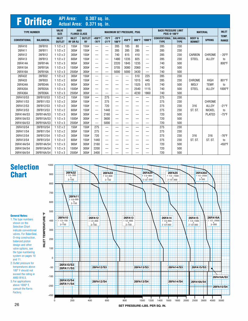
�6
TYPENUMBER VALVE ANSI
MAXIMUMSETPRESSURE,PSIG BACKPRESSURELIMITMATERIAL SIZE FLANGECLASS PSIG@100°F
INLET
INLET INLET OUTLET -450°F -75°F -20°F CONVENTIONAL BALANSEAL BODY&TEMP.
CONVENTIONAL BALANSEAL
OUTLET RFORRJ RF -76°F -21°F 100°F450°F 800°F
1000°F
TYPE TYPE BONNETSPRING
RANGE
26FA10 26FB10 1 1/2 x 2 150# 150# — — 285 185 80 — 285 230 26FA11 26FB11 1 1/2 x 2 300# 150# — — 285 285 285 — 285 230 26FA12 26FB12 1 1/2 x 2 300# 150# — — 740 615 410 — 285 230 CARBON CHROME - 20°F 26FA13 26FB13 1 1/2 x 2 600# 150# — — 1480 1235 825 — 285 230 STEEL ALLOY to 26FA14A 26FB14A 1 1/2 x 3 900# 300# — — 2220 1845 1235 — 740 500 800°F 26FA15A 26FB15A 1 1/2 x 3 1500# 300# — — 3705 3080 2060 — 740 500 26FA16A 26FB16A 1 1/2 x 3 2500# 300# — — 5000 5000 3430 — 740 500 26FA32 26FB32 1 1/2 x 2 300# 150# — — — — 510 225 285 230 26FA33 26FB33 1 1/2 x 2 600# 150# — — — — 1015 445 285 230 CHROME HIGH 801°F 26FA34A 26FB34A 1 1/2 x 3 900# 300# — — — — 1525 670 740 500 MOLY TEMP. to 26FA35A 26FB35A 1 1/2 x 3 1500# 300# — — — — 2540 1115 740 500 STEEL ALLOY 1000°F 26FA36A 26FB36A 1 1/2 x 3 2500# 300# — — — — 4230 1860 740 500 26FA10/S3 26FB10/S3 1 1/2 x 2 150# 150# — 275 — — — — 275 230 26FA11/S3 26FB11/S3 1 1/2 x 2 300# 150# — 275 — — — — 275 230 CHROME 26FA12/S3 26FB12/S3 1 1/2 x 2 300# 150# — 720 — — — — 275 230 316 ALLOY -21°F 26FA13/S3 26FB13/S3 1 1/2 x 2 600# 150# — 1440 — — — — 275 230 ST. ST. NICKEL to 26FA14A/S3 26FB14A/S3 1 1/2 x 3 900# 300# — 2160 — — — — 720 500 PLATED -75°F 26FA15A/S3 26FB15A/S3 1 1/2 x 3 1500# 300# — 3600 — — — — 720 500 26FA16A/S3 26FB16A/S3 1 1/2 x 3 2500# 300# — 5000 — — — — 720 500 26FA10/S4 26FB10/S4 1 1/2 x 2 150# 150# 275 — — — — — 275 230 26FA11/S4 26FB11/S4 1 1/2 x 2 300# 150# 275 — — — — — 275 230 26FA12/S4 26FB12/S4 1 1/2 x 2 300# 150# 720 — — — — — 275 230 316 316 -76°F 26FA13/S4 26FB13/S4 1 1/2 x 2 600# 150# 1440 — — — — — 275 230 ST. ST. ST. ST. to 26FA14A/S4 26FB14A/S4 1 1/2 x 3 900# 300# 2160 — — — — — 720 500 -450°F 26FA15A/S4 26FB15A/S4 1 1/2 x 3 1500# 300# 2200 — — — — — 720 500 26FA16A/S4 26FB16A/S4 1 1/2 x 3 2500# 300# 3400 — — — — — 720 500
F Orifice APIArea: 0.307sq.in.ActualArea: 0.371sq.in.
Selection Chart
General Notes:1. The type numbers
shown on the Selection Chart indicate conventional valves. For BalanSeal, O-ring construction, balanced piston design and other valve options, see the type numbering system on pages 10 and 11.
2. Outlet pressure for temperatures above 100° F should not exceed the rating in ANSI B16.5.
3. For applications above 1000° F, consult the Farris Factory.

�7
TYPENUMBER VALVE ANSI
MAXIMUMSETPRESSURE,PSIG BACKPRESSURELIMITMATERIAL SIZE FLANGECLASS PSIG@100°F
INLET
INLET INLET OUTLET -450°F -75°F -20°F CONVENTIONAL BALANSEAL BODY&TEMP.
CONVENTIONAL BALANSEAL
OUTLET RFORRJ RF -76°F -21°F 100°F450°F 800°F
1000°F
TYPE TYPE BONNETSPRING
RANGE
26GA10A 26GB10A 1 1/2 x 3 150# 150# — — 285 185 80 — 285 230 26GA11A 26GB11A 1 1/2 x 3 300# 150# — — 285 285 285 — 285 230 26GA12A 26GB12A 1 1/2 x 3 300# 150# — — 740 615 410 — 285 230
CARBON CHROME - 20°F
26GA13A 26GB13A 1 1/2 x 3 600# 150# — — 1480 1235 825 — 285 230 STEEL ALLOY
to 26GA14A 26GB14A 1 1/2 x 3 900# 300# — — 2220 1845 1235 — 740 470 800°F 26GA15 26GB15 2 x 3 1500# 300# — — 3705 3080 2060 — 740 470 26GA16 26GB16 2 x 3 2500# 300# — — 3705 3705 3430 — 740 470 26GA32A 26GB32A 1 1/2 x 3 300# 150# — — — — 510 225 285 230 26GA33A 26GB33A 1 1/2 x 3 600# 150# — — — — 1015 445 285 230 CHROME HIGH 801°F 26GA34A 26GB34A 1 1/2 x 3 900# 300# — — — — 1525 670 740 470 MOLY TEMP. to 26GA35 26GB35 2 x 3 1500# 300# — — — — 2540 1115 740 470 STEEL ALLOY 1000°F 26GA36 26GB36 2 x 3 2500# 300# — — — — 3705 1860 740 470 26GA10A/S3 26GB10A/S3 1 1/2 x 3 150# 150# — 275 — — — — 275 230 26GA11A/S3 26GB11A/S3 1 1/2 x 3 300# 150# — 275 — — — — 275 230
CHROME 26GA12A/S3 26GB12A/S3 1 1/2 x 3 300# 150# — 720 — — — — 275 230
316 ALLOY -21°F
26GA13A/S3 26GB13A/S3 1 1/2 x 3 600# 150# — 1440 — — — — 275 230 ST. ST. NICKEL
to 26GA14A/S3 26GB14A/S3 1 1/2 x 3 900# 300# — 2160 — — — — 720 470
PLATED -75°F
26GA15/S3 26GB15/S3 2 x 3 1500# 300# — 3600 — — — — 720 470 26GA16/S3 26GB16/S3 2 x 3 2500# 300# — 3600 — — — — 720 470 26GA10A/S4 26GB10A/S4 1 1/2 x 3 150# 150# 275 — — — — — 275 230 26GA11A/S4 26GB11A/S4 1 1/2 x 3 300# 150# 275 — — — — — 275 230 26GA12A/S4 26GB12A/S4 1 1/2 x 3 300# 150# 720 — — — — — 275 230 316 316 -76°F 26GA13A/S4 26GB13A/S4 1 1/2 x 3 600# 150# 1440 — — — — — 275 230 ST. ST. ST. ST. to 26GA14A/S4 26GB14A/S4 1 1/2 x 3 900# 300# 1600 — — — — — 600 470 -450°F 26GA15/S4 26GB15/S4 2 x 3 1500# 300# 2450 — — — — — 600 470 26GA16/S4 26GB16/S4 2 x 3 2500# 300# 2600 — — — — — 720 470
G Orifice APIArea: 0.503sq.in.ActualArea: 0.559sq.in.
Selection Chart
General Notes:1. The type numbers
shown on the Selection Chart indicate conventional valves. For BalanSeal, O-ring construction, balanced piston design and other valve options, see the type numbering system on pages 10 and 11.
2. Outlet pressure for temperatures above 100° F should not exceed the rating in ANSI B16.5.
3. For applications above 1000° F, consult the Farris Factory.

�8
TYPENUMBER VALVE ANSI
MAXIMUMSETPRESSURE,PSIG BACKPRESSURELIMITMATERIAL SIZE FLANGECLASS PSIG@100°F
INLET
INLET INLET OUTLET -450°F -75°F -20°F CONVENTIONAL BALANSEAL BODY&TEMP.
CONVENTIONAL BALANSEAL
OUTLET RFORRJ RF -76°F -21°F 100°F450°F 800°F
1000°F
TYPE TYPE BONNETSPRING
RANGE
26HA10 26HB10 1 1/2 x 3 150# 150# — — 285 185 80 — 285 230 26HA11 26HB11 1 1/2 x 3 300# 150# — — 285 285 285 — 285 230 26HA12 26HB12 2 x 3 300# 150# — — 740 615 410 — 285 230 CARBON CHROME
- 20°F
26HA13 26HB13 2 x 3 600# 150# — — 1480 1235 825 — 285 230 STEEL ALLOY to
26HA14 26HB14 2 x 3 900# 150# — — 2220 1845 1235 — 285 230 800°F
26HA15 26HB15 2 x 3 1500# 300# — — 2750 2750 2060 — 740 415 26HA32 26HB32 2 x 3 300# 150# — — — — 510 225 285 230
CHROME HIGH
26HA33 26HB33 2 x 3 600# 150# — — — — 815 445 285 230 MOLY TEMP.
801°F
26HA34 26HB34 2 x 3 900# 150# — — — — 1225 670 285 230 STEEL ALLOY
to
26HA35 26HB35 2 x 3 1500# 300# — — — — 2040 1115 740 415 1000°F
26HA10/S3 26HB10/S3 1 1/2 x 3 150# 150# — 275 — — — — 275 230 26HA11/S3 26HB11/S3 1 1/2 x 3 300# 150# — 275 — — — — 275 230 CHROME 26HA12/S3 26HB12/S3 2 x 3 300# 150# — 720 — — — — 275 230 316 ALLOY
-21°F
26HA13/S3 26HB13/S3 2 x 3 600# 150# — 1440 — — — — 275 230 ST. ST. NICKEL to
26HA14/S3 26HB14/S3 2 x 3 900# 150# — 2160 — — — — 275 230 PLATED -75°F
26HA15/S3 26HB15/S3 2 x 3 1500# 300# — 2750 — — — — 720 415 26HA10/S4 26HB10/S4 1 1/2 x 3 150# 150# 275 — — — — — 275 230 26HA11/S4 26HB11/S4 1 1/2 x 3 300# 150# 275 — — — — — 275 230 26HA12/S4 26HB12/S4 2 x 3 300# 150# 720 — — — — — 275 230 316 316
-76°F
26HA13/S4 26HB13/S4 2 x 3 600# 150# 1440 — — — — — 275 230 ST. ST. ST. ST. to
26HA14/S4 26HB14/S4 2 x 3 900# 150# 1485 — — — — — 275 230 -450°F
26HA15/S4 26HB15/S4 2 x 3 1500# 300# 1600 — — — — — 720 415
H Orifice APIArea: 0.785sq.in.ActualArea: 0.873sq.in.
Selection Chart
General Notes:1. The type numbers
shown on the Selection Chart indicate conventional valves. For BalanSeal, O-ring construction, balanced piston design and other valve options, see the type numbering system on pages 10 and 11.
2. Outlet pressure for temperatures above 100° F should not exceed the rating in ANSI B16.5.
3. For applications above 1000° F, consult the Farris Factory.

�9
TYPENUMBER VALVE ANSI
MAXIMUMSETPRESSURE,PSIG BACKPRESSURELIMITMATERIAL SIZE FLANGECLASS PSIG@100°F
INLET
INLET INLET OUTLET -450°F -75°F -20°F CONVENTIONAL BALANSEAL BODY&TEMP.
CONVENTIONAL BALANSEAL
OUTLET RFORRJ RF -76°F -21°F 100°F450°F 800°F
1000°F
TYPE TYPE BONNETSPRING
RANGE
26JA10 26JB10 2 x 3 150# 150# — — 285 185 80 — 285 230 26JA11 26JB11 2 x 3 300# 150# — — 285 285 285 — 285 230 26JA12A 26JB12A 3 x 4 300# 150# — — 740 615 410 — 285 230 CARBON CHROME -20°F
26JA13A 26JB13A 3 x 4 600# 150# — — 1480 1235 825 — 285 230 STEEL ALLOY to
26JA14 26JB14 3 x 4 900# 150# — — 2220 1845 1235 — 285 230 800°F
26JA15 26JB15 3 x 4 1500# 300# — — 2700 2700 2060 — 600 230 26JA32A 26JB32A 3 x 4 300# 150# — — — — 510 225 285 230 26JA33A 26JB33A 3 x 4 600# 150# — — — — 815 445 285 230
CHROME HIGH 801°F
26JA34A 26JB34A 3 x 4 900# 150# — — — — 1225 670 285 230 MOLY TEMP. to
26JA35 26JB35 3 x 4 1500# 300# — — — — 2040 1115 600 230 STEEL ALLOY 1000°F
26JA10/S3 26JB10/S3 2 x 3 150# 150# — 275 — — — — 275 230 26JA11/S3 26JB11/S3 2 x 3 300# 150# — 275 — — — — 275 230 CHROME 26JA12A/S3 26JB12A/S3 3 x 4 300# 150# — 720 — — — — 275 230 316 ALLOY
-21°F
26JA13A/S3 26JB13A/S3 3 x 4 600# 150# — 1440 — — — — 275 230 ST. ST. NICKEL to
26JA14/S3 26JB14/S3 3 x 4 900# 150# — 2160 — — — — 275 230 PLATED -75°F
26JA15/S3 26JB15/S3 3 x 4 1500# 300# — 2700 — — — — 600 230 26JA10/S4 26JB10/S4 2 x 3 150# 150# 275 — — — — — 275 230 26JA11/S4 26JB11/S4 2 x 3 300# 150# 275 — — — — — 275 230 26JA12A/S4 26JB12A/S4 3 x 4 300# 150# 500 — — — — — 275 230
316 316 -76°F
26JA13A/S4 26JB13A/S4 3 x 4 600# 150# 625 — — — — — 275 230 ST. ST. ST. ST. to
26JA14/S4 26JB14/S4 3 x 4 900# 150# 800 — — — — — 275 230 -450°F
26JA15/S4 26JB15/S4 3 x 4 1500# 300# 800 — — — — — 600 230
J Orifice APIArea: 1.287sq.in.ActualArea: 1.430sq.in.
Selection Chart
General Notes:1. The type numbers
shown on the Selection Chart indicate conventional valves. For BalanSeal, O-ring construction, balanced piston design and other valve options, see the type numbering system on pages 10 and 11.
2. Outlet pressure for temperatures above 100° F should not exceed the rating in ANSI B16.5.
3. For applications above 1000° F, consult the Farris Factory.

�0
TYPENUMBER VALVE ANSI
MAXIMUMSETPRESSURE,PSIG BACKPRESSURELIMITMATERIAL SIZE FLANGECLASS PSIG@100°F
INLET
INLET INLET OUTLET -450°F -75°F -20°F CONVENTIONAL BALANSEAL BODY&TEMP.
CONVENTIONAL BALANSEAL
OUTLET RFORRJ RF -76°F -21°F 100°F450°F 800°F
1000°F
TYPE TYPE BONNETSPRING
RANGE
26KA10 26KB10 3 x 4 150# 150# — — 285 185 80 — 285 150 26KA11 26KB11 3 x 4 300# 150# — — 285 285 285 — 285 150 26KA12 26KB12 3 x 4 300# 150# — — 740 615 410 — 285 150 CARBON CHROME
-20°F
26KA13 26KB13 3 x 4 600# 150# — — 1480 1235 825 — 285 200 STEEL ALLOY to
26KA14 26KB14 3 x 6 900# 150# — — 2220 1845 1235 — 285 200 800°F
26KA15 26KB15 3 x 6 1500# 300# — — 2220 2220 2060 — 600 200 26KA32 26KB32 3 x 4 300# 150# — — — — 510 225 285 150 26KA33 26KB33 3 x 4 600# 150# — — — — 815 445 285 200
CHROME HIGH 801°F
26KA34A 26KB34A 3 x 6 900# 150# — — — — 1225 670 285 200 MOLY TEMP. to
26KA35 26KB35 3 x 6 1500# 300# — — — — 2040 1115 600 200 STEEL ALLOY 1000°F
26KA10/S3 26KB10/S3 3 x 4 150# 150# — 275 — — — — 275 150 26KA11/S3 26KB11/S3 3 x 4 300# 150# — 275 — — — — 275 150 CHROME 26KA12/S3 26KB12/S3 3 x 4 300# 150# — 720 — — — — 275 150 316 ALLOY
-21°F
26KA13/S3 26KB13/S3 3 x 4 600# 150# — 1440 — — — — 275 200 ST. ST. NICKEL to
26KA14/S3 26KB14/S3 3 x 6 900# 150# — 2160 — — — — 275 200 PLATED -75°F
26KA15/S3 26KB15/S3 3 x 6 1500# 300# — 2220 — — — — 600 200 26KA10/S4 26KB10/S4 3 x 4 150# 150# 275 — — — — — 275 150 26KA11/S4 26KB11/S4 3 x 4 300# 150# 275 — — — — — 275 150 26KA12/S4 26KB12/S4 3 x 4 300# 150# 525 — — — — — 275 150 316 316
-76°F
26KA13/S4 26KB13/S4 3 x 4 600# 150# 600 — — — — — 275 200 ST. ST. ST. ST. to
26KA14/S4 26KB14/S4 3 x 6 900# 150# 600 — — — — — 275 200 -450°F
26KA15/S4 26KB15/S4 3 x 6 1500# 300# 750 — — — — — 600 200
K Orifice APIArea: 1.838sq.in.ActualArea: 2.042sq.in.
Selection Chart
General Notes:1. The type numbers
shown on the Selection Chart indicate conventional valves. For BalanSeal, O-ring construction, balanced piston design and other valve options, see the type numbering system on pages 10 and 11.
2. Outlet pressure for temperatures above 100° F should not exceed the rating in ANSI B16.5.
3. For applications above 1000° F, consult the Farris Factory.

��
TYPENUMBER VALVE ANSI
MAXIMUMSETPRESSURE,PSIG BACKPRESSURELIMITMATERIAL SIZE FLANGECLASS PSIG@100°F
INLET
INLET INLET OUTLET -450°F -75°F -20°F CONVENTIONAL BALANSEAL BODY&TEMP.
CONVENTIONAL BALANSEAL
OUTLET RFORRJ RF -76°F -21°F 100°F450°F 800°F
1000°F
TYPE TYPE BONNETSPRING
RANGE
26LA10 26LB10 3 x 4 150# 150# — — 285 185 80 — 285 100 26LA11 26LB11 3 x 4 300# 150# — — 285 285 285 — 285 100 26LA12 26LB12 4 x 6 300# 150# — — 740 615 410 — 285 170 CARBON CHROME -20°F 26LA13 26LB13 4 x 6 600# 150# — — 1000 1000 825 — 285 170 STEEL ALLOY to 26LA14 26LB14 4 x 6 900# 150# — — 1500 1500 1235 — 285 170 800°F 26LA15 26LB15 4 x 6 1500# 150# — — 1500 1500 1500 — 285 170 26LA32 26LB32 4 x 6 300# 150# — — — — 510 225 285 170 26LA33 26LB33 4 x 6 600# 150# — — — — 1000 445 285 170
CHROME HIGH TEMP. 801°F
26LA34 26LB34 4 x 6 900# 150# — — — — 1500 670 285 170 MOLY ALLOY to
26LA35 26LB35 4 x 6 1500# 150# — — — — 1500 1115 285 170 STEEL 1000°F
26LA10/S3 26LB10/S3 3 x 4 150# 150# — 275 — — — — 275 100 26LA11/S3 26LB11/S3 3 x 4 300# 150# — 275 — — — — 275 100 316 CHROME -21°F 26LA12/S3 26LB12/S3 4 x 6 300# 150# — 720 — — — — 275 170 ST. ST.
ALLOY to
26LA13/S3 26LB13/S3 4 x 6 600# 150# — 1000 — — — — 275 170 NICKEL
-75°F 26LA14/S3 26LB14/S3 4 x 6 900# 150# — 1500 — — — — 275 170
PLATED
26LA10/S4 26LB10/S4 3 x 4 150# 150# 275 — — — — — 275 170 26LA11/S4 26LB11/S4 3 x 4 300# 150# 275 — — — — — 275 170 316 316 -76°F 26LA12/S4 26LB12/S4 4 x 6 300# 150# 535 — — — — — 275 170 ST. ST. ST. ST. to 26LA13/S4 26LB13/S4 4 x 6 600# 150# 535 — — — — — 275 170 -450°F 26LA14/S4 26LB14/S4 4 x 6 900# 150# 700 — — — — — 275 170
L Orifice APIArea: 2.853sq.in.ActualArea: 3.170sq.in.
Selection Chart
General Notes:1. The type numbers
shown on the Selection Chart indicate conventional valves. For BalanSeal, O-ring construction, balanced piston design and other valve options, see the type numbering system on pages 10 and 11.
2. Outlet pressure for temperatures above 100° F should not exceed the rating in ANSI B16.5.
3. For applications above 1000° F, consult the Farris Factory.

��
TYPENUMBER VALVE ANSI
MAXIMUMSETPRESSURE,PSIG BACKPRESSURELIMITMATERIAL SIZE FLANGECLASS PSIG@100°F
INLET
INLET INLET OUTLET -450°F -75°F -20°F CONVENTIONAL BALANSEAL BODY&TEMP.
CONVENTIONAL BALANSEAL
OUTLET RFORRJ RF -76°F -21°F 100°F450°F 800°F
1000°F
TYPE TYPE BONNETSPRING
RANGE
26MA10 26MB10 4 x 6 150# 150# — — 285 185 80 — 285 80 26MA11 26MB11 4 x 6 300# 150# — — 285 285 285 — 285 80
CARBON CHROME -20°F
26MA12 26MB12 4 x 6 300# 150# — — 740 615 410 — 285 160 STEEL ALLOY
to 26MA13 26MB13 4 x 6 600# 150# — — 1100 1100 825 — 285 160 800°F 26MA14 26MB14 4 x 6 900# 150# — — 1100 1100 1100 — 285 160 26MA32 26MB32 4 x 6 300# 150# — — — — 510 225 285 160 CHROME
HIGH TEMP. 801°F
26MA33 26MB33 4 x 6 600# 150# — — — — 1015 445 285 160 MOLY ALLOY
to 26MA34 26MB34 4 x 6 900# 150# — — — — 1100 670 285 160 STEEL 1000°F 26MA10/S3 26MB10/S3 4 x 6 150# 150# — 275 — — — — 275 80 CHROME 26MA11/S3 26MB11/S3 4 x 6 300# 150# — 275 — — — — 275 80 316 ALLOY
-21°F
26MA12/S3 26MB12/S3 4 x 6 300# 150# — 720 — — — — 275 160 ST. ST. NICKEL to
26MA13/S3 26MB13/S3 4 x 6 600# 150# — 1000 — — — — 275 160 PLATED -75°F
26MA10/S4 26MB10/S4 4 x 6 150# 150# 275 — — — — — 275 80 26MA11/S4 26MB11/S4 4 x 6 300# 150# 275 — — — — — 275 80 316 316
-76°F
26MA12/S4 26MB12/S4 4 x 6 300# 150# 525 — — — — — 275 160 ST. ST. ST. ST. to
26MA13/S4 26MB13/S4 4 x 6 600# 150# 600 — — — — — 275 160 -450°F
M Orifice APIArea: 3.60sq.in.ActualArea: 4.000sq.in.
Selection Chart
General Notes:1. The type numbers
shown on the Selection Chart indicate conventional valves. For BalanSeal, O-ring construction, balanced piston design and other valve options, see the type numbering system on pages 10 and 11.
2. Outlet pressure for temperatures above 100° F should not exceed the rating in ANSI B16.5.
3. For applications above 1000° F, consult the Farris Factory.

��
TYPENUMBER VALVE ANSI
MAXIMUMSETPRESSURE,PSIG BACKPRESSURELIMITMATERIAL SIZE FLANGECLASS PSIG@100°F
INLET
INLET INLET OUTLET -450°F -75°F -20°F CONVENTIONAL BALANSEAL BODY&TEMP.
CONVENTIONAL BALANSEAL
OUTLET RFORRJ RF -76°F -21°F 100°F450°F 800°F
1000°F
TYPE TYPE BONNETSPRING
RANGE
26NA10 26NB10 4 x 6 150# 150# — — 285 185 80 — 285 80 26NA11 26NB11 4 x 6 300# 150# — — 285 285 285 — 285 80
CARBON CHROME -20°F
26NA12 26NB12 4 x 6 300# 150# — — 740 615 410 — 285 160 STEEL ALLOY
to 26NA13 26NB13 4 x 6 600# 150# — — 1000 1000 825 — 285 160 800°F 26NA14 26NB14 4 x 6 900# 150# — — 1000 1000 1000 — 285 160 26NA32 26NB32 4 x 6 300# 150# — — — — 510 225 285 160 CHROME
HIGH TEMP. 801°F
26NA33 26NB33 4 x 6 600# 150# — — — — 1000 445 285 160 MOLY ALLOY
to 26NA34 26NB34 4 x 6 900# 150# — — — — 1000 670 285 160 STEEL 1000°F 26NA10/S3 26NB10/S3 4 x 6 150# 150# — 275 — — — — 275 80 CHROME 26NA11/S3 26NB11/S3 4 x 6 300# 150# — 275 — — — — 275 80 316 ALLOY
-21°F
26NA12/S3 26NB12/S3 4 x 6 300# 150# — 720 — — — — 275 160 ST. ST. NICKEL to
26NA13/S3 26NB13/S3 4 x 6 600# 150# — 1000 — — — — 275 160 PLATED -75°F
26NA10/S4 26NB10/S4 4 x 6 150# 150# 275 — — — — — 275 80 26NA11/S4 26NB11/S4 4 x 6 300# 150# 275 — — — — — 275 80 316 316
-76°F
26NA12/S4 26NB12/S4 4 x 6 300# 150# 450 — — — — — 275 160 ST. ST. ST. ST. to
26NA13/S4 26NB13/S4 4 x 6 600# 150# 500 — — — — — 275 160 -450°F
N Orifice APIArea: 4.34sq.in.ActualArea: 4.822sq.in.
Selection Chart
General Notes:1. The type numbers
shown on the Selection Chart indicate conventional valves. For BalanSeal, O-ring construction, balanced piston design and other valve options, see the type numbering system on pages 10 and 11.
2. Outlet pressure for temperatures above 100° F should not exceed the rating in ANSI B16.5.
3. For applications above 1000° F, consult the Farris Factory.

��
TYPENUMBER VALVE ANSI
MAXIMUMSETPRESSURE,PSIG BACKPRESSURELIMITMATERIAL SIZE FLANGECLASS PSIG@100°F
INLET
INLET INLET OUTLET -450°F -75°F -20°F CONVENTIONAL BALANSEAL BODY&TEMP.
CONVENTIONAL BALANSEAL
OUTLET RFORRJ RF -76°F -21°F 100°F450°F 800°F
1000°F
TYPE TYPE BONNETSPRING
RANGE
26PA10 26PB10 4 x 6 150# 150# — — 285 185 80 — 285 80 26PA11 26PB11 4 x 6 300# 150# — — 285 285 285 — 285 80 CARBON CHROME -20°F 26PA12 26PB12 4 x 6 300# 150# — — 525 525 410 — 285 150 STEEL ALLOY to 26PA13 26PB13 4 x 6 600# 150# — — 1000 1000 825 — 285 150 800°F 26PA14 26PB14 4 x 6 900# 150# — — 1000 1000 1000 — 285 150 26PA32 26PB32 4 x 6 300# 150# — — — — 510 225 285 150 CHROME HIGH 801°F 26PA33 26PB33 4 x 6 600# 150# — — — — 1000 445 285 150 MOLY TEMP. to 26PA34 26PB34 4 x 6 900# 150# — — — — 1000 670 285 150 STEEL ALLOY 1000°F 26PA10/S3 26PB10/S3 4 x 6 150# 150# — 275 — — — — 275 80 CHROME 26PA11/S3 26PB11/S3 4 x 6 300# 150# — 275 — — — — 275 80 316 ALLOY
-21°F
26PA12/S3 26PB12/S3 4 x 6 300# 150# — 720 — — — — 275 150 ST. ST. NICKEL to
26PA13/S3 26PB13/S3 4 x 6 600# 150# — 1000 — — — — 275 150 PLATED -75°F
26PA10/S4 26PB10/S4 4 x 6 150# 150# 175 — — — — — 175 80 26PA11/S4 26PB11/S4 4 x 6 300# 150# 175 — — — — — 175 80 316 316
-76°F
26PA12/S4 26PB12/S4 4 x 6 300# 150# 300 — — — — — 275 150 ST. ST. ST. ST. to
26PA13/S4 26PB13/S4 4 x 6 600# 150# 480 — — — — — 275 150 -450°F
P Orifice APIArea: 6.38sq.in.ActualArea: 7.087sq.in.
Selection Chart
General Notes:1. The type numbers
shown on the Selection Chart indicate conventional valves. For BalanSeal, O-ring construction, balanced piston design and other valve options, see the type numbering system on pages 10 and 11.
2. Outlet pressure for temperatures above 100° F should not exceed the rating in ANSI B16.5.
3. For applications above 1000° F, consult the Farris Factory.

�5
TYPENUMBER VALVE ANSI
MAXIMUMSETPRESSURE,PSIG BACKPRESSURELIMITMATERIAL SIZE FLANGECLASS PSIG@100°F
INLET
INLET INLET OUTLET -450°F -75°F -20°F CONVENTIONAL BALANSEAL BODY&TEMP.
CONVENTIONAL BALANSEAL
OUTLET RFORRJ RF -76°F -21°F 100°F450°F 800°F
1000°F
TYPE TYPE BONNETSPRING
RANGE
26QA10 26QB10 6 x 8 150# 150# — — 165 165 80 — 115 70
26QA11 26QB11 6 x 8 300# 150# — — 165 165 165 — 115 70 CARBON CHROME -20°F
26QA12 26QB12 6 x 8 300# 150# — — 300 300 300 — 115 115 STEEL ALLOY to
26QA13 26QB13 6 x 8 600# 150# — — 600 600 600 — 115 115 800°F
H26QA13 H26QB13 6 x 8 600# 150# — — 900 900 825 — 285 200
26QA32 26QB32 6 x 8 300# 150# — — — — 165 165 115 70 CHROME HIGH 801°F
26QA33 26QB33 6 x 8 600# 150# — — — — 600 445 115 70 MOLY TEMP. to
H26QA33 H26QB33 6 x 8 600# 150# — — — — 900 445 285 200 STEEL ALLOY 1000°F
26QA10/S3 26QB10/S3 6 x 8 150# 150# — 165 — — — — 115 70 CHROME
26QA11/S3 26QB11/S3 6 x 8 300# 150# — 165 — — — — 115 70 316 ALLOY -21°F
26QA12/S3 26QB12/S3 6 x 8 300# 150# — 300 — — — — 115 115 ST. ST. NICKEL to
26QA13/S3 26QB13/S3 6 x 8 600# 150# — 600 — — — — 115 115 PLATED -75°F
26QA10/S4 26QB10/S4 6 x 8 150# 150# 165 — — — — — 115 70
26QA11/S4 26QB11/S4 6 x 8 300# 150# 165 — — — — — 115 70 316 316 -76°F
26QA12/S4 26QB12/S4 6 x 8 300# 150# 250 — — — — — 115 115 ST. ST. ST. ST. to
26QA13/S4 26QB13/S4 6 x 8 600# 150# 300 — — — — — 115 115 -450°F
Q Orifice APIArea: 11.05sq.in.ActualArea: 12.27sq.in.
Selection Chart
General Notes:1. The type numbers
shown on the Selection Chart indicate conventional valves. For BalanSeal, O-ring construction, balanced piston design and other valve options, see the type numbering system on pages 10 and 11.
2. Outlet pressure for temperatures above 100° F should not exceed the rating in ANSI B16.5.
3. For applications above 1000° F, consult the Farris Factory.

�6
TYPENUMBER VALVE ANSI
MAXIMUMSETPRESSURE,PSIG BACKPRESSURELIMITMATERIAL SIZE FLANGECLASS PSIG@100°F
INLET
INLET INLET OUTLET -450°F -75°F -20°F CONVENTIONAL BALANSEAL BODY&TEMP.
CONVENTIONAL BALANSEAL
OUTLET RFORRJ RF -76°F -21°F 100°F450°F 800°F
1000°F
TYPE TYPE BONNETSPRING
RANGE
26RA10 26RB10 6 x 8 150# 150# — — 100 100 80 — 60 60 26RA11 26RB11 6 x 8 300# 150# — — 100 100 100 — 60 60
CARBON CHROME -20°F
26RA12 26RB12 6 x 10 300# 150# — — 230 230 230 — 100 100 STEEL ALLOY
to 26RA13 26RB13 6 x 10 600# 150# — — 300 300 300 — 100 100 800°F H26RA13 H26RB13 6 x 10 600# 150# — — 600 600 600 — 285 200 26RA32 26RB32 6 x 8 300# 150# — — — — 100 100 60 60 CHROME HIGH 801°F 26RA33 26RB33 6 x 10 600# 150# — — — — 300 300 100 100 MOLY TEMP. to H26RA33 H26RB33 6 x 10 600# 150# — — — — 600 445 285 200 STEEL ALLOY 1000°F 26RA10/S3 26RB10/S3 6 x 8 150# 150# — 100 — — — — 60 60 CHROME 26RA11/S3 26RB11/S3 6 x 8 300# 150# — 100 — — — — 60 60 316
ALLOY
-21°F
26RA12/S3 26RB12/S3 6 x 10 300# 150# — 230 — — — — 100 100 ST. ST.
NICKEL to
26RA13/S3 26RB13/S3 6 x 10 600# 150# — 300 — — — — 100 100 PLATED -75°F
26RA10/S4 26RB10/S4 6 x 8 150# 150# 55 — — — — — 55 55 26RA11/S4 26RB11/S4 6 x 8 300# 150# 55 — — — — — 55 55 316 316
-76°F
26RA12/S4 26RB12/S4 6 x 10 300# 150# 150 — — — — — 100 100 ST. ST. ST. ST. to
26RA13/S4 26RB13/S4 6 x 10 600# 150# 200 — — — — — 100 100 -450°F
R Orifice APIArea: 16.00sq.in.ActualArea: 17.78sq.in.
Selection Chart
General Notes:1. The type numbers
shown on the Selection Chart indicate conventional valves. For BalanSeal, O-ring construction, balanced piston design and other valve options, see the type numbering system on pages 10 and 11.
2. Outlet pressure for temperatures above 100° F should not exceed the rating in ANSI B16.5.
3. For applications above 1000° F, consult the Farris Factory.

�7
TYPENUMBER VALVE ANSI
MAXIMUMSETPRESSURE,PSIG BACKPRESSURELIMITMATERIAL SIZE FLANGECLASS PSIG@100°F
INLET
INLET INLET OUTLET -450°F -75°F -20°F CONVENTIONAL BALANSEAL BODY&TEMP.
CONVENTIONAL BALANSEAL
OUTLET RFORRJ RF -76°F -21°F 100°F450°F 800°F
1000°F
TYPE TYPE BONNETSPRING
RANGE
26TA10 26TB10 8 x 10 150# 150# — — 65 65 65 — 30 30 26TA11 26TB11 8 x 10 300# 150# — — 65 65 65 — 30 30 CARBON CHROME
-20°F
26TA12 26TB12 8 x 10 300# 150# — — 120 120 120 — 60 60 STEEL ALLOY to
H26TA12 H26TB12 8 x 10 300# 150# — — 300 300 300 — 100 100 800°F
26TA32 26TB32 8 x 10 300# 150# — — — — 120 120 60 60
CHROME
HIGH 801°F
H26TA32 H26TB32 8 x 10 300# 150# — — — — 300 225 100 100
MOLY ST. TEMP. to
ALLOY 1000°F 26TA10/S3 26TB10/S3 8 x 10 150# 150# — 65 — — — — 30 30
316 CHROME -21°F
26TA11/S3 26TB11/S3 8 x 10 300# 150# — 65 — — — — 30 30 ST. ST.
ALLOY to 26TA12/S3 26TB12/S3 8 x 10 300# 150# — 120 — — — — 60 60 NICKEL PLTD. -75°F 26TA10/S4 26TB10/S4 8 x 10 150# 150# 50 — — — — — 30 30
316
316 -76°F
26TA11/S4 26TB11/S4 8 x 10 300# 150# 50 — — — — — 30 30 ST. ST.
ST. ST.
to 26TA12/S4 26TB12/S4 8 x 10 300# 150# 65 — — — — — 60 60 -450°F
T Orifice APIArea: 26.00sq.in.ActualArea: 28.94sq.in.
Selection Chart
General Notes:1. The type numbers
shown on the Selection Chart indicate conventional valves. For BalanSeal, O-ring construction, balanced piston design and other valve options, see the type numbering system on pages 10 and 11.
2. Outlet pressure for temperatures above 100° F should not exceed the rating in ANSI B16.5.
3. For applications above 1000° F, consult the Farris Factory.
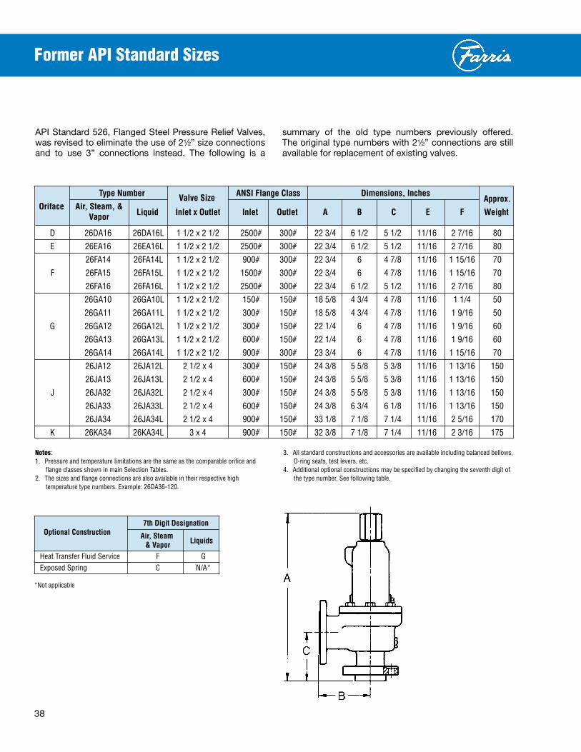
38
Former API Standard Sizes
API Standard 526, Flanged Steel Pressure Relief Valves, was revised to eliminate the use of 21⁄2” size connections and to use 3” connections instead. The following is a
summary of the old type numbers previously offered. The original type numbers with 21⁄2” connections are still available for replacement of existing valves.
TypeNumber ValveSize ANSIFlangeClass Dimensions,InchesApprox.
Oriface Air,Steam,&Liquid InletxOutlet Inlet Outlet A B C E F
Weight
Vapor
D 26DA16 26DA16L 11/2x21/2 2500# 300# 223/4 61/2 51/2 11/16 27/16 80
E 26EA16 26EA16L 11/2x21/2 2500# 300# 223/4 61/2 51/2 11/16 27/16 80
26FA14 26FA14L 11/2x21/2 900# 300# 223/4 6 47/8 11/16 115/16 70
F 26FA15 26FA15L 11/2x21/2 1500# 300# 223/4 6 47/8 11/16 115/16 70
26FA16 26FA16L 11/2x21/2 2500# 300# 223/4 61/2 51/2 11/16 27/16 80
26GA10 26GA10L 11/2x21/2 150# 150# 185/8 43/4 47/8 11/16 11/4 50
26GA11 26GA11L 11/2x21/2 300# 150# 185/8 43/4 47/8 11/16 19/16 50
G 26GA12 26GA12L 11/2x21/2 300# 150# 221/4 6 47/8 11/16 19/16 60
26GA13 26GA13L 11/2x21/2 600# 150# 221/4 6 47/8 11/16 19/16 60
26GA14 26GA14L 11/2x21/2 900# 300# 233/4 6 47/8 11/16 115/16 70
26JA12 26JA12L 21/2x4 300# 150# 243/8 55/8 53/8 11/16 113/16 150
26JA13 26JA13L 21/2x4 600# 150# 243/8 55/8 53/8 11/16 113/16 150
J 26JA32 26JA32L 21/2x4 300# 150# 243/8 55/8 53/8 11/16 113/16 150
26JA33 26JA33L 21/2x4 600# 150# 243/8 63/4 61/8 11/16 113/16 150
26JA34 26JA34L 21/2x4 900# 150# 331/8 71/8 71/4 11/16 25/16 170
K 26KA34 26KA34L 3x4 900# 150# 323/8 71/8 71/4 11/16 23/16 175
Notes:1. Pressureandtemperaturelimitationsarethesameasthecomparableorificeand
flangeclassesshowninmainSelectionTables.2. Thesizesandflangeconnectionsarealsoavailableintheirrespectivehigh
temperaturetypenumbers.Example:26DA36-120.
3. Allstandardconstructionsandaccessoriesareavailableincludingbalancedbellows,O-ringseats,testlevers,etc.
4. Additionaloptionalconstructionsmaybespecifiedbychangingtheseventhdigitofthetypenumber.Seefollowingtable.
7thDigitDesignation
OptionalConstruction Air,SteamLiquids &Vapor
HeatTransferFluidService F GExposedSpring C N/A*
*Notapplicable

39
SetPressure OrificeLetterDesignation&Areas,Sq.Inches (psig) ArEAS D E F G H J K L M N P Q r T API 0.110 0.196 0.307 0.503 0.785 1.287 1.838 2.853 3.60 4.34 6.38 11.05 16.0 26.0 Actual 0.150 0.225 0.371 0.559 0.873 1.43 2.042 3.170 4.000 4.822 7.087 12.27 17.78 28.94 15 77 115 190 287 448 735 1050 1630 2057 2479 3644 6310 9144 14884 20 88 133 219 331 517 847 1210 1879 2371 2859 4202 7275 10542 17159 30 112 168 278 419 654 1072 1531 2378 3000 3617 5316 9205 13339 21711 40 138 207 342 516 805 1320 1885 2926 3692 4451 6542 11328 16415 26718 50 164 246 406 612 957 1567 2238 3475 4384 5286 7769 13450 19491 31725 60 190 285 470 709 1108 1815 2591 4023 5076 6120 8995 15573 22567 36732 70 216 324 535 806 1259 2062 2945 4571 5769 6954 10221 17696 25643 41738 80 242 363 599 902 1410 2309 3298 5120 6461 7788 11447 19819 28719 46745 90 268 402 663 999 1561 2557 3651 5668 7153 8623 12673 21942 31795 51752 100 294 441 727 1096 1712 2804 4004 6217 7845 9457 13899 24064 34871 56759 150 423 635 1048 1579 2467 4041 5771 8959 11305 13628 20030 34678 50251 81793 200 553 830 1369 2063 3222 5278 7537 11701 14765 17799 26160 45293 65632 106827 250 683 1025 1690 2547 3977 6515 9304 14443 18225 21970 32291 55907 81012 131862 300 813 1219 2011 3030 4732 7752 11070 17185 21685 26142 38421 66521 96393 156896 350 942 1414 2332 3514 5488 8989 12836 19928 25145 30313 44552 77135 111773 — 400 1072 1609 2653 3997 6243 10226 14603 22670 28606 34484 50682 87749 127154 — 450 1202 1803 2974 4481 6998 11463 16369 25412 32066 38655 56813 98363 142534 — 500 1332 1998 3295 4964 7753 12700 18136 28154 35526 42827 62943 108977 157914 — 550 1461 2192 3616 5448 8508 13937 19902 30896 38986 46998 69074 119591 173295 — 600 1591 2387 3936 5931 9263 15174 21669 33639 42446 51169 75204 130205 188675 — 650 1721 2582 4257 6415 10019 16411 23435 36381 45906 55340 81335 140819 — — 700 1851 2776 4578 6899 10774 17648 25201 39123 49367 59511 87466 151433 — — 750 1981 2971 4899 7382 11529 18885 26968 41865 52827 63683 93596 162047 — — 800 2110 3166 5220 7866 12284 20122 28734 44607 56287 67854 99727 172661 — — 850 2240 3360 5541 8349 13039 21359 30501 47349 59747 72025 105857 183275 — — 900 2370 3555 5862 8833 13795 22596 32267 50092 63207 76196 111988 193889 — — 950 2500 3750 6183 9316 14550 23833 34033 52834 66667 80368 118118 — — — 1000 2629 3944 6504 9800 15305 25070 35800 55576 70127 84539 124249 — — — 1050 2759 4139 6825 10283 16060 26307 37566 58318 73588 — — — — — 1100 2889 4333 7146 10767 16815 27544 39333 61060 77048 — — — — — 1150 3019 4528 7467 11251 17570 28781 41099 63802 — — — — — — 1200 3148 4723 7788 11734 18326 30018 42865 66545 — — — — — — 1250 3278 4917 8109 12218 19081 31255 44632 69287 — — — — — — 1300 3408 5112 8429 12701 19836 32492 46398 72029 — — — — — — 1350 3538 5307 8750 13185 20591 33729 48165 74771 — — — — — — 1400 3667 5501 9071 13668 21346 34966 49931 77513 — — — — — — 1450 3797 5696 9392 14152 22102 36203 51698 80256 — — — — — — 1500 3927 5891 9713 14635 22857 37440 53464 82998 — — — — — — 1550 4057 6085 10034 15119 23612 38677 55230 — — — — — — — 1600 4186 6280 10355 15603 24367 39914 56997 — — — — — — — 1650 4316 6474 10676 16086 25122 41151 58763 — — — — — — — 1700 4446 6669 10997 16570 25877 42388 60530 — — — — — — — 1750 4576 6864 11318 17053 26633 43625 62296 — — — — — — — 1800 4705 7058 11639 17537 27388 44862 64062 — — — — — — — 1850 4835 7253 11960 18020 28143 46099 65829 — — — — — — — 1900 4965 7448 12281 18504 28898 47336 67595 — — — — — — — 2000 5224 7837 12922 19471 30409 49810 71128 — — — — — — — 2100 5484 8226 13564 20438 31919 52284 74661 — — — — — — — 2200 5743 8615 14206 21405 33429 54758 78194 — — — — — — — 2300 6003 9005 14848 22372 34940 57232 — — — — — — — — 2400 6262 9394 15490 23339 36450 59706 — — — — — — — — 2500 6522 9783 16132 24307 37960 62180 — — — — — — — — 2600 6781 10172 16774 25274 39471 64654 — — — — — — — — 2700 7041 10562 17415 26241 40981 67128 — — — — — — — — 2800 7301 10951 18057 27208 — — — — — — — — — — 2900 7560 11340 18699 28175 — — — — — — — — — — 3000 7820 11730 19341 29142 — — — — — — — — — — 3500 9117 13676 22550 33978 — — — — — — — — — — 3700 9636 14454 23834 35912 — — — — — — — — — — 4000 10415 15622 25760 — — — — — — — — — — — 4500 11712 17569 28969 — — — — — — — — — — — 5000 13010 19515 32178 — — — — — — — — — — — 5500 14307 21461 — — — — — — — — — — — — 6000 15605 23408 — — — — — — — — — — — —
ASMEPrESSUrEVESSELCODE(UV) CAPACITIESINSTANDArDCUBICFEETPErMINUTEAT60°F
GeneralNotes:1. Abovecapacitiesshouldalsobeusedfor
2600Lserieswhenusedinairservice.2. Capacitiesat30PSIGandbelowarebasedon
3PSIoverpressure.3. Forsizingpurposestheeffectivecoefficientof
dischargeKdforair,gas,andsteamis0.953whensizingusingtheAPIeffectiveareas.WhensizingusingtheASMEactualareas,thecertifiedcoefficientofdischargeKforair,gas,andsteamserviceis0.858.
Air Capacities: 10% Overpressure

40
SetPressure OrificeLetterDesignation&Areas,Sq.Inches (psig) ArEAS D E F G H J K L M N P Q r T API 0.110 0.196 0.307 0.503 0.785 1.287 1.838 2.853 3.60 4.34 6.38 11.05 16.0 26.0 Actual 0.150 0.225 0.371 0.559 0.873 1.43 2.042 3.170 4.000 4.822 7.087 12.27 17.78 28.94 15 216 325 536 807 1261 2066 2950 4580 5779 6967 10240 17729 25690 41815 20 249 374 618 931 1454 2382 3401 5280 6663 8032 11805 20439 29618 48209 30 316 474 781 1178 1840 3014 4303 6681 8430 10163 14937 25861 37475 60997 40 389 583 962 1449 2264 3709 5296 8222 10375 12507 18382 31825 46117 75063 50 461 692 1142 1721 2688 4404 6289 9763 12319 14850 21826 37789 54759 89130 60 534 802 1322 1993 3113 5099 7281 11303 14263 17194 25271 43753 63401 103196 70 607 911 1503 2265 3537 5794 8274 12844 16207 19538 28716 49717 72043 117263 80 680 1021 1683 2536 3961 6489 9266 14385 18152 21882 32160 55681 80685 131329 90 753 1130 1863 2808 4386 7184 10259 15926 20096 24226 35605 61645 89327 145396 100 826 1239 2044 3080 4810 7879 11251 17467 22040 26569 39050 67609 97969 159462 150 1191 1786 2945 4438 6931 11354 16214 25171 31761 38288 56273 97428 141180 229795 200 1555 2333 3847 5797 9053 14830 21176 32875 41482 50007 73497 127248 184390 300127 250 1920 2880 4749 7155 11175 18305 26139 40579 51203 61726 90720 157067 227601 370460 300 2284 3427 5650 8514 13296 21780 31102 48283 60925 73445 107943 186887 270811 440792 350 2649 3973 6552 9872 15418 25256 36064 55987 70646 85163 125167 216707 314022 — 400 3013 4520 7454 11231 17540 28731 41027 63691 80367 96882 142390 246526 357232 — 450 3378 5067 8355 12589 19661 32206 45990 71395 90088 108601 159614 276346 400443 — 500 3742 5614 9257 13948 21783 35681 50952 79099 99809 120320 176837 306165 443653 — 550 4107 6161 10158 15306 23905 39157 55915 86803 109530 132039 194061 335985 486864 — 600 4471 6707 11060 16665 26026 42632 60878 94507 119251 143758 211284 365805 530074 — 650 4836 7254 11962 18023 28148 46107 65840 102211 128973 155476 228507 395624 — — 700 5201 7801 12863 19382 30269 49583 70803 109915 138694 167195 245731 425444 — — 750 5565 8348 13765 20741 32391 53058 75766 117619 148415 178914 262954 455263 — — 800 5930 8895 14667 22099 34513 56533 80728 125323 158136 190633 280178 485083 — — 850 6294 9441 15568 23458 36634 60009 85691 133027 167857 202352 297401 514903 — — 900 6659 9988 16470 24816 38756 63484 90653 140731 177578 214071 314625 544722 — — 950 7023 10535 17372 26175 40878 66959 95616 148435 187299 225789 331848 — — — 1000 7388 11082 18273 27533 42999 70435 100579 156139 197020 237508 349071 — — — 1050 7752 11629 19175 28892 45121 73910 105541 163843 206742 — — — — — 1100 8117 12176 20076 30250 47243 77385 110504 171547 216463 — — — — — 1150 8481 12722 20978 31609 49364 80860 115467 179251 — — — — — — 1200 8846 13269 21880 32967 51486 84336 120429 186955 — — — — — — 1250 9211 13816 22781 34326 53608 87811 125392 194659 — — — — — — 1300 9575 14363 23683 35684 55729 91286 130355 202363 — — — — — — 1350 9940 14910 24585 37043 57851 94762 135317 210067 — — — — — — 1400 10304 15456 25486 38401 59972 98237 140280 217771 — — — — — — 1450 10669 16003 26388 39760 62094 101712 145242 225475 — — — — — — 1500 11088 16633 27426 41324 64537 105714 150956 234345 — — — — — — 1550 11489 17234 28417 42817 66868 109532 156409 — — — — — — — 1600 11891 17838 29413 44318 69212 113372 161891 — — — — — — — 1650 12309 18464 30444 45872 71640 117348 167569 — — — — — — — 1700 12728 19093 31483 47438 74083 121352 173287 — — — — — — — 1750 13152 19728 32529 49013 76545 125383 179043 — — — — — — — 1800 13564 20347 33549 50551 78947 129316 184661 — — — — — — — 1850 14006 21010 34643 52197 81518 133530 190677 — — — — — — — 1900 14438 21657 35711 53807 84031 137645 196553 — — — — — — — 2000 15325 22987 37903 57111 89191 146098 208625 — — — — — — — 2100 16240 24360 40167 60522 94517 154823 221084 — — — — — — — 2200 17202 25803 42546 64107 100118 163996 234181 — — — — — — — 2300 18182 27272 44970 67758 105819 173335 — — — — — — — — 2400 19214 28821 47523 71605 111826 183175 — — — — — — — — 2500 20285 30427 50171 75596 118059 193386 — — — — — — — — 2600 21416 32124 52970 79811 124643 204168 — — — — — — — — 2700 22631 33947 55975 84339 131714 215753 — — — — — — — — 2800 23916 35874 59154 89129 — — — — — — — — — — 2900 25318 37978 62622 94355 — — — — — — — — — —
ASMEPrESSUrEVESSELCODE(UV) CAPACITIESINPOUNDSPErHOUrATSATUrATIONTEMPErATUrE
Steam Capacities, 10% Overpressure
GeneralNotes:1. Abovecapacitiesshouldalsobeusedfor
2600Lserieswhenusedinsteamservice.2. Capacitiesat30PSIGandbelowarebasedon
3PSIoverpressure.3. Forsizingpurposestheeffectivecoefficientof
dischargeKdforair,gas,andsteamis0.953whensizingusingtheAPIeffectiveareas.WhensizingusingtheASMEactualareas,thecertifiedcoefficientofdischargeKforair,gas,andsteamserviceis0.858.

41
SetPressure OrificeLetterDesignation&Areas,Sq.Inches (psig) ArEAS D E F G H J K L M N P Q r T API 0.110 0.196 0.307 0.503 0.785 1.287 1.838 2.853 3.600 4.34 6.38 11.05 16.0 26.0 Actual 0.150 0.225 0.371 0.559 0.873 1.43 2.042 3.170 4.000 4.822 7.087 12.27 17.78 28.94 15 16 24 39 59 92 150 214 333 420 507 745 1289 1868 3041 20 18 27 44 66 104 170 242 376 475 573 842 1457 2112 3438 30 21 32 53 80 124 204 290 451 569 686 1008 1746 2530 4118 40 25 37 61 92 143 235 335 521 657 792 1164 2016 2921 4756 50 28 41 68 103 160 263 375 582 734 886 1302 2254 3266 5317 60 30 45 75 112 176 288 411 638 805 970 1426 2469 3578 5825 70 33 49 81 122 189 311 443 689 869 1048 1540 2667 3865 6292 80 35 52 86 130 203 332 474 736 929 1120 1647 2851 4132 6726 90 37 55 91 137 215 352 503 781 986 1188 1747 3024 4382 7134 100 39 58 96 145 227 372 530 823 1039 1252 1841 3188 4620 7520 150 48 72 118 177 278 455 649 1008 1272 1534 2255 3904 5658 9210 200 55 83 136 205 320 525 750 1164 1469 1771 2604 4508 6533 10635 250 62 92 152 229 358 587 838 1302 1643 1981 2911 5041 7304 11890 300 67 101 167 252 392 644 919 1426 1800 2170 3189 5522 8002 13025 350 73 109 180 271 424 695 992 1541 1944 2344 3445 5964 8643 — 400 78 117 193 290 453 743 1061 1647 2078 2505 3683 6376 9240 — 450 83 124 204 308 481 788 1125 1747 2204 2657 3906 6763 9800 — 500 87 131 215 325 507 831 1186 1841 2324 2801 4117 7129 10330 — 550 91 137 226 341 531 871 1244 1931 2437 2938 4318 7477 10834 — 600 95 143 236 356 555 910 1299 2017 2545 3069 4510 7809 11316 — 650 99 149 245 370 578 947 1352 2100 2649 3194 4694 8128 — — 700 103 154 255 384 600 983 1403 2179 2749 3315 4872 8435 — — 750 107 160 264 398 621 1018 1453 2255 2846 3431 5043 8731 — — 800 110 165 272 411 641 1051 1500 2329 2939 3543 5208 9017 — — 850 114 170 281 423 661 1083 1546 2401 3030 3653 5368 9295 — — 900 117 175 289 436 680 1115 1591 2471 3118 3758 5524 9564 — — 950 120 180 297 448 699 1145 1635 2538 3203 3861 5675 — — — 1000 123 185 304 459 717 1175 1677 2604 3286 3962 5823 — — — 1050 126 189 312 470 735 1204 1719 2669 3367 — — — — — 1100 129 194 319 482 752 1232 1759 2731 3447 — — — — — 1150 132 198 326 492 769 1260 1799 2793 — — — — — — 1200 135 202 333 503 785 1287 1838 2853 — — — — — — 1250 137 206 340 513 802 1313 1875 2912 — — — — — — 1300 140 210 347 524 817 1340 1913 2969 — — — — — — 1350 143 214 354 533 833 1365 1949 3026 — — — — — — 1400 146 218 360 543 848 1390 1985 3082 — — — — — — 1450 148 222 367 553 863 1414 2020 3136 — — — — — — 1500 151 226 373 562 878 1439 2055 3190 — — — — — — 1550 153 230 379 571 893 1462 2088 — — — — — — — 1600 155 233 385 581 907 1486 2122 — — — — — — — 1650 158 237 391 590 921 1509 2155 — — — — — — — 1700 160 241 397 598 935 1532 2187 — — — — — — — 1750 163 244 403 607 948 1554 2219 — — — — — — — 1800 165 248 409 616 962 1576 2251 — — — — — — — 1850 167 251 414 624 975 1598 2282 — — — — — — — 1900 169 254 420 633 988 1619 2312 — — — — — — — 2000 174 261 431 649 1014 1661 2372 — — — — — — — 2100 178 267 441 665 1039 1702 2431 — — — — — — — 2200 182 274 452 681 1063 1742 2488 — — — — — — — 2300 186 280 462 696 1087 1782 — — — — — — — — 2400 190 286 472 711 1111 1820 — — — — — — — — 2500 194 292 482 726 1134 1857 — — — — — — — — 2600 198 298 491 740 1156 1894 — — — — — — — — 2700 202 303 500 754 1178 1930 — — — — — — — — 2800 206 309 510 768 — — — — — — — — — — 2900 209 314 519 782 — — — — — — — — — — 3000 213 320 528 795 — — — — — — — — — — 3500 230 345 570 859 — — — — — — — — — — 3700 237 355 586 883 — — — — — — — — — — 4000 246 369 609 — — — — — — — — — — — 4500 261 392 646 — — — — — — — — — — — 5000 275 413 681 — — — — — — — — — — — 5500 289 433 — — — — — — — — — — — — 6000 301 452 — — — — — — — — — — — —
Water Capacities - 2600L: 10% Overpressure
ASMEPrESSUrEVESSELCODE(UV) CAPACITIESINGALLONSPErMINUTEAT70°F
GeneralNotes:1. Capacitiesat30PSIGandbelowarebasedon3PSI
overpressure.2. Forsizingpurposestheeffectivecoefficientof
dischargeKdforliquidsis0.724whensizingusingtheAPIeffectiveareas.WhensizingusingtheASMEactualareas,thecertifiedcoefficientofdischargeKforwateris0.652.

42
SetPressure OrificeLetterDesignation&Areas,Sq.Inches (psig) ArEAS D E F G H J K L M N P Q r T API 0.110 0.196 0.307 0.503 0.785 1.287 1.838 2.853 3.600 4.34 6.38 11.05 16.0 26.0 Actual 0.150 0.225 0.371 0.559 0.873 1.43 2.042 3.170 4.000 4.822 7.087 12.27 17.78 28.94 15 14 21 35 53 82 136 193 300 379 457 672 1163 1685 2743 20 16 24 40 61 95 156 223 347 438 528 776 1342 1946 3167 30 20 30 49 75 117 192 274 425 536 646 950 1644 2383 3879 40 23 35 57 86 135 221 316 491 619 746 1097 1899 2752 4479 50 26 39 64 97 151 247 353 548 692 834 1226 2123 3076 5007 60 28 42 70 106 165 271 387 601 758 914 1343 2325 3370 5485 70 30 46 76 114 179 293 418 649 819 987 1451 2512 3640 5925 80 33 49 81 122 191 313 447 694 875 1055 1551 2685 3892 6334 90 35 52 86 130 203 332 474 736 929 1119 1645 2848 4128 6718 100 37 55 91 137 214 350 499 776 979 1180 1734 3002 4351 7082 150 45 71 111 168 261 428 611 950 1198 1445 2124 3677 5328 8673 200 52 77 128 193 302 495 706 1097 1384 1669 2452 4246 6153 10015 250 58 92 143 216 337 553 790 1226 1547 1866 2742 4747 6879 11197 300 64 95 157 237 370 606 865 1344 1695 2044 3004 5200 7536 12266 350 69 103 169 256 399 655 934 1451 1831 2208 3244 5617 8139 — 400 73 110 181 274 427 700 999 1551 1958 2360 3468 6005 8702 — 450 78 116 192 290 453 742 1060 1645 2076 2503 3678 6369 9229 — 500 82 123 203 306 477 782 1117 1734 2189 2638 3878 6713 9729 — 550 86 129 213 321 501 821 1171 1819 2295 2767 4067 7041 10204 — 600 90 135 222 335 523 857 1223 1900 2398 2890 4248 7354 10657 — 650 94 140 231 349 544 892 1273 1978 2495 3008 4421 7655 — — 700 97 146 240 362 565 926 1322 2052 2590 3122 4588 7944 — — 750 100 151 248 375 585 958 1368 2124 2681 3232 4749 8222 — — 800 104 156 257 387 604 990 1413 2194 2768 3337 4905 8492 — — 850 107 160 264 399 623 1020 1456 2262 2854 3440 5056 8753 — — 900 110 165 272 410 641 1050 1499 2327 2936 3540 5203 9007 — — 950 113 170 280 422 658 1078 1540 2391 3016 3637 5345 — — — 1000 116 174 287 432 675 1106 1580 2453 3095 3731 5484 — — — 1050 118 178 294 443 692 1133 1619 2513 3171 — — — — — 1100 122 182 301 454 708 1160 1657 2573 3246 — — — — — 1150 124 186 307 463 724 1186 1694 2630 — — — — — — 1200 127 191 314 474 740 1212 1730 2687 — — — — — — 1250 129 194 320 483 755 1237 1766 2742 — — — — — — 1300 132 198 327 493 770 1262 1801 2797 — — — — — — 1350 134 202 333 502 784 1285 1835 2850 — — — — — — 1400 137 206 339 512 799 1309 1869 2902 — — — — — — 1450 139 209 345 520 813 1332 1902 2953 — — — — — — 1500 142 213 351 530 827 1355 1935 3004 — — — — — — 1550 144 216 357 538 841 1377 1967 — — — — — — — 1600 147 220 363 547 854 1400 1998 — — — — — — — 1650 149 223 368 555 867 1421 2029 — — — — — — — 1700 151 227 374 564 880 1443 2060 — — — — — — — 1750 153 230 379 572 893 1463 2090 — — — — — — — 1800 156 233 385 580 906 1484 2120 — — — — — — — 1850 157 236 390 588 918 1505 2149 — — — — — — — 1900 160 239 395 596 931 1525 2178 — — — — — — — 2000 164 246 406 612 955 1564 2234 — — — — — — — 2100 168 252 416 627 978 1603 2289 — — — — — — — 2200 172 258 425 642 1002 1641 2343 — — — — — — — 2300 176 264 435 656 1024 1678 — — — — — — — — 2400 180 270 444 670 1046 1714 — — — — — — — — 2500 184 275 454 684 1068 1749 — — — — — — — — 2600 187 281 463 698 1089 1784 — — — — — — — — 2700 191 286 471 711 1110 1818 — — — — — — — — 2800 194 291 480 724 — — — — — — — — — — 2900 198 296 488 737 — — — — — — — — — — 3000 201 301 497 749 — — — — — — — — — — 3500 217 325 537 809 — — — — — — — — — — 3700 223 334 552 832 — — — — — — — — — — 4000 232 348 574 — — — — — — — — — — — 4500 246 369 609 — — — — — — — — — — — 5000 260 389 641 — — — — — — — — — — — 5500 272 408 — — — — — — — — — — — — 6000 284 426 — — — — — — — — — — — —
Water Capacities, 25% Overpressure
NON-CODE CAPACITIESINGALLONSPErMINUTEAT70°F
Water Capacities - 2600: 25% Overpressure
GeneralNotes:1. Capacitiesat30PSIGandbelowarebasedon
3PSIoverpressure.2. Forsizingpurposestheeffectivecoefficientof
dischargeKdforliquidsis0.64whensizingusingtheAPIeffectiveareas.Whensizingusingtheactualareas,thecoefficientofdischargeKforwateris0.576.

43
TYPENUMBEr VALVE ANSI
MAXIMUMSETPrESSUrE,BArG BACKPrESSUrELIMITMATErIAL SIZE FLANGECLASS BArG@38°C
INLET
INLET INLET OUTLET -268°C -59°C -29°C CONVENTIONAL BALANSEAL BODY&TEMP.
CONVENTIONAL BALANSEAL
OUTLET rFOrrJ rF -60°C -30°C +38°C+232°C +427°C
+538°C
TYPE TYPE BONNETSPrING
rANGE
26DA10 26DB10 1x2 150# 150# — — 19.6 12.7 5.5 — 19.6 15.8 26DA11 26DB11 1x2 300# 150# — — 19.6 19.6 19.6 — 19.6 15.8 26DA12 26DB12 1x2 300# 150# — — 51.0 42.4 28.2 — 19.6 15.8
CARBON CHROME -29°C
26DA13 26DB13 1x2 600# 150# — — 102 85.1 56.8 — 19.6 15.8STEEL ALLOY
to 26DA14 — 11/2x2 900# 300# — — 153 127 85.1 — 41.3 34.5 427°C 26DA15 — 11/2x2 1500# 300# — — 255 212 142 — 41.3 34.5 26DA16A — 11/2x3 2500# 300# — — 413 354 236 — 51 34.5 26DA32 26DB32 1x2 300# 150# — — — — 35.1 15.5 19.6 15.8 26DA33 26DB33 1x2 600# 150# — — — — 69.9 30.6 19.6 15.8 CHROME HIGH 428°C 26DA34 — 11/2x2 900# 300# — — — — 105 46.2 41.3 34.5 MOLY TEMP. to 26DA35 — 11/2x2 1500# 300# — — — — 175 76.8 41.3 34.5 STEEL ALLOY 538°C 26DA36A — 11/2x3 2500# 300# — — — — 291 128 51 34.5 26DA10/S3 26DB10/S3 1x2 150# 150# — 18.9 — — — — 18.9 15.8 26DA11/S3 26DB11/S3 1x2 300# 150# — 18.9 — — — — 18.9 15.8 CHROME 26DA12/S3 26DB12/S3 1x2 300# 150# — 49.6 — — — — 18.9 15.8
316 ALLOY -30°C 26DA13/S3 26DB13/S3 1x2 600# 150# — 99.2 — — — — 18.9 15.8
ST.ST. NICKEL to 26DA14/S3 — 11/2x2 900# 300# — 149 — — — — 41.3 34.5 PLATED -59°C 26DA15/S3 — 11/2x2 1500# 300# — 248 — — — — 41.3 34.5 26DA16A/S3 — 11/2x3 2500# 300# — 413 — — — — 49.6 34.5 26DA10/S4 26DB10/S4 1x2 150# 150# 18.9 — — — — — 18.9 15.8 26DA11/S4 26DB11/S4 1x2 300# 150# 18.9 — — — — — 18.9 15.8 26DA12/S4 26DB12/S4 1x2 300# 150# 49.6 — — — — — 18.9 15.8
316 316 -60°C
26DA13/S4 26DB13/S4 1x2 600# 150# 99.2 — — — — — 18.9 15.8ST.ST. ST.ST.
to 26DA14/S4 — 11/2x2 900# 300# 149 — — — — — 41.3 34.5 -268°C 26DA15/S4 — 11/2x2 1500# 300# 248 — — — — — 41.3 34.5 26DA16A/S4 — 11/2x3 2500# 300# 276 — — — — — 49.6 34.5
D Orifice APIArea: 71sq.mmActualArea: 97sq.mm
Notes:1.Thetypenumbers
shownontheselectionchartindicateconventionalvalves.ForBalanSeal,“O”ringconstruction,balancedpistondesignandothervalveoptions,seethetypenumberingsystemonpages10and11.
2.Outletpressurefortemperatureabove38°CshouldnotexceedtheratinginANSIB16.5.
3.Forapplicationsabove538°C,consulttheFarrisFactory.
Selection Chart

44
TYPENUMBEr VALVE ANSI
MAXIMUMSETPrESSUrE,BArG BACKPrESSUrELIMITMATErIAL SIZE FLANGECLASS BArG@38°C
INLET
INLET INLET OUTLET -268°C -59°C -29°C CONVENTIONAL BALANSEAL BODY&TEMP.
CONVENTIONAL BALANSEAL
OUTLET rFOrrJ rF -60°C -30°C +38°C+232°C +427°C
+538°C
TYPE TYPE BONNETSPrING
rANGE
26EA10 26EB10 1x2 150# 150# — — 19.6 12.7 5.5 — 19.6 15.8 26EA11 26EB11 1x2 300# 150# — — 19.6 19.6 19.6 — 19.6 15.8 26EA12 26EB12 1x2 300# 150# — — 51.0 42.4 28.2 — 19.6 15.8
CARBON CHROME -29°C
26EA13 26EB13 1x2 600# 150# — — 102 85.1 56.8 — 19.6 15.8STEEL ALLOY
to 26EA14 — 11/2x2 900# 300# — — 153 127 85.1 — 41.3 34.5 427°C 26EA15 — 11/2x2 1500# 300# — — 255 212 142 — 41.3 34.5 26EA16A — 11/2x3 2500# 300# — — 413 354 236 — 51 34.5 26EA32 26EB32 1x2 300# 150# — — — — 35.1 15.5 19.6 15.8 26EA33 26EB33 1x2 600# 150# — — — — 69.9 30.6 19.6 15.8 CHROME HIGH 428°C 26EA34 26EB34* 11/2x2 900# 300# — — — — 105 46.2 41.3 34.5 MOLY TEMP. to 26EA35 26EB35* 11/2x2 1500# 300# — — — — 175 76.8 41.3 34.5 STEEL ALLOY 538°C 26EA36A 26EB36A* 11/2x3 2500# 300# — — — — 291 128 51 34.5 26EA10/S3 26EB10/S3 1x2 150# 150# — 18.9 — — — — 18.9 15.8 26EA11/S3 26EB11/S3 1x2 300# 150# — 18.9 — — — — 18.9 15.8
CHROME 26EA12/S3 26EB12/S3 1x2 300# 150# — 49.6 — — — — 18.9 15.8
316 ALLOY -30°C 26EA13/S3 26EB13/S3 1x2 600# 150# — 99.2 — — — — 18.9 15.8
ST.ST. NICKEL to 26EA14/S3 — 11/2x2 900# 300# — 149 — — — — 41.3 34.5 PLATED -59°C 26EA15/S3 — 11/2x2 1500# 300# — 248 — — — — 41.3 34.5 26EA16A/S3 — 11/2x3 2500# 300# — 413 — — — — 49.6 34.5 26EA10/S4 26EB10/S4 1x2 150# 150# 18.9 — — — — — 18.9 15.8 26EA11/S4 26EB11/S4 1x2 300# 150# 18.9 — — — — — 18.9 15.8 26EA12/S4 26EB12/S4 1x2 300# 150# 49.6 — — — — — 18.9 15.8 316 316 -60°C 26EA13/S4 26EB13/S4 1x2 600# 150# 99.2 — — — — — 18.9 15.8 ST.ST. ST.ST. to 26EA14/S4 — 11/2x2 900# 300# 149 — — — — — 41.3 34.5 -268°C 26EA15/S4 — 11/2x2 1500# 300# 248 — — — — — 41.3 34.5 26EA16A/S4 — 11/2x3 2500# 300# 276 — — — — — 49.6 34.5
E Orifice APIArea: 126sq.mmActualArea: 145sq.mm
Notes:1.Thetypenumbers
shownontheselectionchartindicateconventionalvalves.ForBalanSeal,“O”ringconstruction,balancedpistondesignandothervalveoptions,seethetypenumberingsystemonpages10and11.
2.Outletpressurefortemperatureabove38°CshouldnotexceedtheratinginANSIB16.5.
3.Forapplicationsabove538°C,consulttheFarrisFactory.
Selection Chart

45
TYPENUMBEr VALVE ANSI
MAXIMUMSETPrESSUrE,BArG BACKPrESSUrELIMITMATErIAL SIZE FLANGECLASS BArG@38°C
INLET
INLET INLET OUTLET -268°C -59°C -29°C CONVENTIONAL BALANSEAL BODY&TEMP.
CONVENTIONAL BALANSEAL
OUTLET rFOrrJ rF -60°C -30°C +38°C+232°C +427°C
+538°C
TYPE TYPE BONNETSPrING
rANGE
26FA10 26FB10 11/2x2 150# 150# — — 19.6 12.7 5.5 — 19.6 15.8 26FA11 26FB11 11/2x2 300# 150# — — 19.6 19.6 19.6 — 19.6 15.8 26FA12 26FB12 11/2x2 300# 150# — — 51.0 42.4 28.2 — 19.6 15.8
CARBON CHROME -29°C
26FA13 26FB13 11/2x2 600# 150# — — 102 85.1 56.8 — 19.6 15.8STEEL
ALLOY
to 26FA14A 26FB14A 11/2x3 900# 300# — — 153 127 85.1 — 51.0 34.5 427°C 26FA15A 26FB15A 11/2x3 1500# 300# — — 255 212 142 — 51.0 34.5 26FA16A 26FB16A 11/2x3 2500# 300# — — 345 345 236 — 51.0 34.5 26FA32 26FB32 11/2x2 300# 150# — — — — 35.1 15.5 19.6 15.8 26FA33 26FB33 11/2x2 600# 150# — — — — 69.9 30.6 19.6 15.8 CHROME HIGH 428°C 26FA34A 26FB34A 11/2x3 900# 300# — — — — 105 46.2 51.0 34.5 MOLY TEMP. to 26FA35A 26FB35A 11/2x3 1500# 300# — — — — 175 76.8 51.0 34.5 STEEL ALLOY 538°C 26FA36A 26FB36A 11/2x3 2500# 300# — — — — 291 128 51.0 34.5 26FA10/S3 26FB10/S3 11/2x2 150# 150# — 18.9 — — — — 18.9 15.8 26FA11/S3 26FB11/S3 11/2x2 300# 150# — 18.9 — — — — 18.9 15.8
CHROME 26FA12/S3 26FB12/S3 11/2x2 300# 150# — 49.6 — — — — 18.9 15.8
316 ALLOY -30°C 26FA13/S3 26FB13/S3 11/2x2 600# 150# — 99.2 — — — — 18.9 15.8
ST.ST. NICKEL to 26FA14A/S3 26FB14A/S3 11/2x3 900# 300# — 149 — — — — 49.6 34.5 PLATED -59°C 26FA15A/S3 26FB15A/S3 11/2x3 1500# 300# — 248 — — — — 49.6 34.5 26FA16A/S3 26FB16A/S3 11/2x3 2500# 300# — 345 — — — — 49.6 34.5 26FA10/S4 26FB10/S4 11/2x2 150# 150# 18.9 — — — — — 18.9 15.8 26FA11/S4 26FB11/S4 11/2x2 300# 150# 18.9 — — — — — 18.9 15.8 26FA12/S4 26FB12/S4 11/2x2 300# 150# 49.6 — — — — — 18.9 15.8 316 316 -60°C 26FA13/S4 26FB13/S4 11/2x2 600# 150# 99.2 — — — — — 18.9 15.8 ST.ST. ST.ST. to 26FA14A/S4 26FB14A/S4 11/2x3 900# 300# 149 — — — — — 49.6 34.5 -268°C 26FA15A/S4 26FB15A/S4 11/2x3 1500# 300# 152 — — — — — 49.6 34.5 26FA16A/S4 26FB16A/S4 11/2x3 2500# 300# 234 — — — — — 49.6 34.5
F Orifice APIArea: 198sq.mmActualArea: 239sq.mm
Notes:1.Thetypenumbers
shownontheselectionchartindicateconventionalvalves.ForBalanSeal,“O”ringconstruction,balancedpistondesignandothervalveoptions,seethetypenumberingsystemonpages10and11.
2.Outletpressurefortemperatureabove38°CshouldnotexceedtheratinginANSIB16.5.
3.Forapplicationsabove538°C,consulttheFarrisFactory.
Selection Chart
26FA12

46
TYPENUMBEr VALVE ANSI
MAXIMUMSETPrESSUrE,BArG BACKPrESSUrELIMITMATErIAL SIZE FLANGECLASS BArG@38°C
INLET
INLET INLET OUTLET -268°C -59°C -29°C CONVENTIONAL BALANSEAL BODY&TEMP.
CONVENTIONAL BALANSEAL
OUTLET rFOrrJ rF -60°C -30°C +38°C+232°C +427°C
+538°C
TYPE TYPE BONNETSPrING
rANGE
26GA10A 26GB10A 11/2x3 150# 150# — — 19.6 12.7 5.5 — 19.6 15.8 26GA11A 26GB11A 11/2x3 300# 150# — — 19.6 19.6 19.6 — 19.6 15.8 26GA12A 26GB12A 11/2x3 300# 150# — — 51.0 42.4 28.2 — 19.6 15.8 CARBON CHROME -29°C 26GA13A 26GB13A 11/2x3 600# 150# — — 102 85.1 56.8 — 19.6 15.8 STEEL ALLOY to 26GA14A 26GB14A 11/2x3 900# 300# — — 153 127 85.1 — 51.0 32.4 427°C 26GA15 26GB15 2x3 1500# 300# — — 255 212 142 — 51.0 32.4 26GA16 26GB16 2x3 2500# 300# — — 255 255 236 — 51.0 32.4 26GA32A 26GB32A 11/2x3 300# 150# — — — — 35.1 15.5 19.6 15.8 26GA33A 26GB33A 11/2x3 600# 150# — — — — 69.9 30.6 19.6 15.8 CHROME HIGH 428°C 26GA34A 26GB34A 11/2x3 900# 300# — — — — 105 46.2 51.0 32.4 MOLY TEMP. to 26GA35 26GB35 2x3 1500# 300# — — — — 175 76.8 51.0 32.4 STEEL ALLOY 538°C 26GA36 26GB36 2x3 2500# 300# — — — — 255 128 51.0 32.4 26GA10A/S3 26GB10A/S3 11/2x3 150# 150# — 18.9 — — — — 18.9 15.8 26GA11A/S3 26GB11A/S3 11/2x3 300# 150# — 18.9 — — — — 18.9 15.8
CHROME 26GA12A/S3 26GB12A/S3 11/2x3 300# 150# — 49.6 — — — — 18.9 15.8 316 ALLOY -30°C 26GA13A/S3 26GB13A/S3 11/2x3 600# 150# — 99.2 — — — — 18.9 15.8 ST.ST. NICKEL to 26GA14A/S3 26GB14A/S3 11/2x3 900# 300# — 149 — — — — 49.6 32.4 PLATED -59°C 26GA15/S3 26GB15/S3 2x3 1500# 300# — 248 — — — — 49.6 32.4 26GA16/S3 26GB16/S3 2x3 2500# 300# — 248 — — — — 49.6 32.4 26GA10A/S4 26GB10A/S4 11/2x3 150# 150# 18.9 — — — — — 18.9 15.8 26GA11A/S4 26GB11A/S4 11/2x3 300# 150# 18.9 — — — — — 18.9 15.8 26GA12A/S4 26GB12A/S4 11/2x3 300# 150# 49.6 — — — — — 18.9 15.8 316 316 -60°C 26GA13A/S4 26GB13A/S4 11/2x3 600# 150# 99.2 — — — — — 18.9 15.8 ST.ST. ST.ST. to 26GA14A/S4 26GB14A/S4 11/2x3 900# 300# 110 — — — — — 49.6 32.4 -268°C 26GA15/S4 26GB15/S4 2x3 1500# 300# 169 — — — — — 49.6 32.4 26GA16/S4 26GB16/S4 2x3 2500# 300# 179 — — — — — 49.6 32.4
G Orifice APIArea: 325sq.mmActualArea: 361sq.mm
Notes:1.Thetypenumbers
shownontheselectionchartindicateconventionalvalves.ForBalanSeal,“O”ringconstruction,balancedpistondesignandothervalveoptions,seethetypenumberingsystemonpages10and11.
2.Outletpressurefortemperatureabove38°CshouldnotexceedtheratinginANSIB16.5.
3.Forapplicationsabove538°C,consulttheFarrisFactory.
Selection Chart

47
TYPENUMBEr VALVE ANSI
MAXIMUMSETPrESSUrE,BArG BACKPrESSUrELIMITMATErIAL SIZE FLANGECLASS BArG@38°C
INLET
INLET INLET OUTLET -268°C -59°C -29°C CONVENTIONAL BALANSEAL BODY&TEMP.
CONVENTIONAL BALANSEAL
OUTLET rFOrrJ rF -60°C -30°C +38°C+232°C +427°C
+538°C
TYPE TYPE BONNETSPrING
rANGE
26HA10 26HB10 11/2x3 150# 150# — — 19.6 12.7 5.5 — 19.6 15.8 26HA11 26HB11 11/2x3 300# 150# — — 19.6 19.6 19.6 — 19.6 15.8 26HA12 26HB12 2x3 300# 150# — — 51.0 42.4 28.2 — 19.6 15.8 CARBON CHROME
-29°C
26HA13 26HB13 2x3 600# 150# — — 102 85.1 56.8 — 19.6 15.8 STEEL ALLOYto
26HA14 26HB14 2x3 900# 150# — — 153 127 85.1 — 19.6 15.8 427°C
26HA15 26HB15 2x3 1500# 300# — — 189 189 142 — 51.0 28.6 26HA32 26HB32 2x3 300# 150# — — — — 35.1 15.5 19.6 15.8 26HA33 26HB33 2x3 600# 150# — — — — 56.2 30.6 19.6 15.8
CHROME HIGH 428°C
26HA34 26HB34 2x3 900# 150# — — — — 84.4 46.2 19.6 15.8MOLY TEMP. to
26HA35 26HB35 2x3 1500# 300# — — — — 141 76.8 51.0 28.6STEEL ALLOY 538°C
26HA10/S3 26HB10/S3 11/2x3 150# 150# — 18.9 — — — — 18.9 15.8 26HA11/S3 26HB11/S3 11/2x3 300# 150# — 18.9 — — — — 18.9 15.8 CHROME 26HA12/S3 26HB12/S3 2x3 300# 150# — 49.6 — — — — 18.9 15.8 316 ALLOY -30°C 26HA13/S3 26HB13/S3 2x3 600# 150# — 99.2 — — — — 18.9 15.8 ST.ST. NICKEL to 26HA14/S3 26HB14/S3 2x3 900# 150# — 149 — — — — 18.9 15.8 PLATED -59°C 26HA15/S3 26HB15/S3 2x3 1500# 300# — 189 — — — — 49.6 28.6 26HA10/S4 26HB10/S4 11/2x3 150# 150# 18.9 — — — — — 18.9 15.8 26HA11/S4 26HB11/S4 11/2x3 300# 150# 18.9 — — — — — 18.9 15.8 26HA12/S4 26HB12/S4 2x3 300# 150# 49.6 — — — — — 18.9 15.8 316 316
-60°C
26HA13/S4 26HB13/S4 2x3 600# 150# 99.2 — — — — — 18.9 15.8 ST.ST. ST.ST.to
26HA14/S4 26HB14/S4 2x3 900# 150# 102 — — — — — 18.9 15.8 -268°C
26HA15/S4 26HB15/S4 2x3 1500# 300# 110 — — — — — 49.6 28.6
H Orifice APIArea: 506sq.mmActualArea: 563sq.mm
Notes:1.Thetypenumbers
shownontheselectionchartindicateconventionalvalves.ForBalanSeal,“O”ringconstruction,balancedpistondesignandothervalveoptions,seethetypenumberingsystemonpages10and11.
2.Outletpressurefortemperatureabove38°CshouldnotexceedtheratinginANSIB16.5.
3.Forapplicationsabove538°C,consulttheFarrisFactory.
Selection Chart
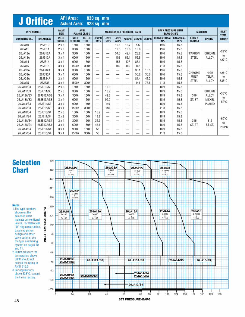
48
TYPENUMBEr VALVE ANSI
MAXIMUMSETPrESSUrE,BArG BACKPrESSUrELIMITMATErIAL SIZE FLANGECLASS BArG@38°C
INLET
INLET INLET OUTLET -268°C -59°C -29°C CONVENTIONAL BALANSEAL BODY&TEMP.
CONVENTIONAL BALANSEAL
OUTLET rFOrrJ rF -60°C -30°C +38°C+232°C +427°C
+538°C
TYPE TYPE BONNETSPrING
rANGE
26JA10 26JB10 2x3 150# 150# — — 19.6 12.7 5.5 — 19.6 15.8 26JA11 26JB11 2x3 300# 150# — — 19.6 19.6 19.6 — 19.6 15.8 26JA12A 26JB12A 3x4 300# 150# — — 51.0 42.4 28.2 — 19.6 15.8 CARBON CHROME
-29°C
26JA13A 26JB13A 3x4 600# 150# — — 102 85.1 56.8 — 19.6 15.8 STEEL ALLOYto
26JA14 26JB14 3x4 900# 150# — — 153 127 85.1 — 19.6 15.8 427°C
26JA15 26JB15 3x4 1500# 300# — — 186 186 142 — 41.3 15.8 26JA32A 26JB32A 3x4 300# 150# — — — — 35.1 15.5 19.6 15.8 26JA33A 26JB33A 3x4 600# 150# — — — — 56.2 30.6 19.6 15.8 CHROME HIGH 428°C
26JA34A 26JB34A 3x4 900# 150# — — — — 84.4 46.2 19.6 15.8MOLY TEMP. to
26JA35 26JB35 3x4 1500# 300# — — — — 141 76.8 41.3 15.8STEEL ALLOY 538°C
26JA10/S3 26JB10/S3 2x3 150# 150# — 18.9 — — — — 18.9 15.8 26JA11/S3 26JB11/S3 2x3 300# 150# — 18.9 — — — — 18.9 15.8 CHROME 26JA12A/S3 26JB12A/S3 3x4 300# 150# — 49.6 — — — — 18.9 15.8 316 ALLOY
-30°C
26JA13A/S3 26JB13A/S3 3x4 600# 150# — 99.2 — — — — 18.9 15.8 ST.ST. NICKELto
26JA14/S3 26JB14/S3 3x4 900# 150# — 149 — — — — 18.9 15.8 PLATED-59°C
26JA15/S3 26JB15/S3 3x4 1500# 300# — 186 — — — — 41.3 15.8 26JA10/S4 26JB10/S4 2x3 150# 150# 18.9 — — — — — 18.9 15.8 26JA11/S4 26JB11/S4 2x3 300# 150# 18.9 — — — — — 18.9 15.8 26JA12A/S4 26JB12A/S4 3x4 300# 150# 34.5 — — — — — 18.9 15.8 316 316
-60°C
26JA13A/S4 26JB13A/S4 3x4 600# 150# 43.1 — — — — — 18.9 15.8 ST.ST. ST.ST.to
26JA14/S4 26JB14/S4 3x4 900# 150# 55 — — — — — 18.9 15.8 -268°C
26JA15/S4 26JB15/S4 3x4 1500# 300# 55 — — — — — 41.3 15.8
J Orifice APIArea: 830sq.mmActualArea: 923sq.mm
Notes:1.Thetypenumbers
shownontheselectionchartindicateconventionalvalves.ForBalanSeal,“O”ringconstruction,balancedpistondesignandothervalveoptions,seethetypenumberingsystemonpages10and11.
2.Outletpressurefortemperatureabove38°CshouldnotexceedtheratinginANSIB16.5.
3.Forapplicationsabove538°C,consulttheFarrisFactory.
Selection Chart
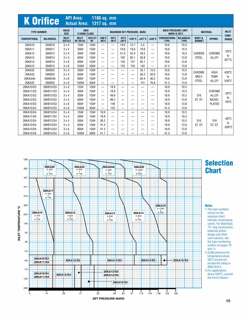
49
TYPENUMBEr VALVE ANSI
MAXIMUMSETPrESSUrE,BArG BACKPrESSUrELIMITMATErIAL SIZE FLANGECLASS BArG@38°C
INLET
INLET INLET OUTLET -268°C -59°C -29°C CONVENTIONAL BALANSEAL BODY&TEMP.
CONVENTIONAL BALANSEAL
OUTLET rFOrrJ rF -60°C -30°C +38°C+232°C +427°C
+538°C
TYPE TYPE BONNETSPrING
rANGE
26KA10 26KB10 3x4 150# 150# — — 19.6 12.7 5.5 — 19.6 10.3 26KA11 26KB11 3x4 300# 150# — — 19.6 19.6 19.6 — 19.6 10.3 26KA12 26KB12 3x4 300# 150# — — 51.0 42.4 28.2 — 19.6 10.3 CARBON CHROME
-29°C
26KA13 26KB13 3x4 600# 150# — — 102 85.1 56.8 — 19.6 13.8 STEEL ALLOYto
26KA14 26KB14 3x6 900# 150# — — 153 127 85.1 — 19.6 13.8 427°C
26KA15 26KB15 3x6 1500# 300# — — 153 153 142 — 41.3 13.8 26KA32 26KB32 3x4 300# 150# — — — — 35.1 15.5 19.6 10.3 26KA33 26KB33 3x4 600# 150# — — — — 56.2 30.6 19.6 13.8
CHROME HIGH 428°C
26KA34A 26KB34A 3x6 900# 150# — — — — 84.4 46.2 19.6 13.8MOLY TEMP. to
26KA35 26KB35 3x6 1500# 300# — — — — 141 76.8 41.3 13.8STEEL ALLOY 538°C
26KA10/S3 26KB10/S3 3x4 150# 150# — 18.9 — — — — 18.9 10.3 26KA11/S3 26KB11/S3 3x4 300# 150# — 18.9 — — — — 18.9 10.3 CHROME 26KA12/S3 26KB12/S3 3x4 300# 150# — 49.6 — — — — 18.9 10.3 316 ALLOY
-30°C
26KA13/S3 26KB13/S3 3x4 600# 150# — 99.2 — — — — 18.9 13.8 ST.ST. NICKELto
26KA14/S3 26KB14/S3 3x6 900# 150# — 149 — — — — 18.9 13.8 PLATED-59°C
26KA15/S3 26KB15/S3 3x6 1500# 300# — 153 — — — — 41.3 13.8 26KA10/S4 26KB10/S4 3x4 150# 150# 18.9 — — — — — 18.9 10.3 26KA11/S4 26KB11/S4 3x4 300# 150# 18.9 — — — — — 18.9 10.3 26KA12/S4 26KB12/S4 3x4 300# 150# 36.2 — — — — — 18.9 10.3 316 316
-60°C
26KA13/S4 26KB13/S4 3x4 600# 150# 41.3 — — — — — 18.9 13.8 ST.ST. ST.ST.to
26KA14/S4 26KB14/S4 3x6 900# 150# 41.3 — — — — — 18.9 13.8 -268°C
26KA15/S4 26KB15/S4 3x6 1500# 300# 51.7 — — — — — 41.3 13.8
K Orifice APIArea: 1186sq.mmActualArea: 1317sq.mm
Notes:1.Thetypenumbers
shownontheselectionchartindicateconventionalvalves.ForBalanSeal,“O”ringconstruction,balancedpistondesignandothervalveoptions,seethetypenumberingsystemonpages10and11.
2.Outletpressurefortemperatureabove38°CshouldnotexceedtheratinginANSIB16.5.
3.Forapplicationsabove538°C,consulttheFarrisFactory.
Selection Chart

50
TYPENUMBEr VALVE ANSI
MAXIMUMSETPrESSUrE,BArG BACKPrESSUrELIMITMATErIAL SIZE FLANGECLASS BArG@38°C
INLET
INLET INLET OUTLET -268°C -59°C -29°C CONVENTIONAL BALANSEAL BODY&TEMP.
CONVENTIONAL BALANSEAL
OUTLET rFOrrJ rF -60°C -30°C +38°C+232°C +427°C
+538°C
TYPE TYPE BONNETSPrING
rANGE
26LA10 26LB10 3x4 150# 150# — — 19.6 12.7 5.5 — 19.6 6.9 26LA11 26LB11 3x4 300# 150# — — 19.6 19.6 19.6 — 19.6 6.9 26LA12 26LB12 4x6 300# 150# — — 51.0 42.4 28.2 — 19.6 11.7 CARBON CHROME
-29°C
26LA13 26LB13 4x6 600# 150# — — 68.9 68.9 56.8 — 19.6 11.7 STEEL ALLOYto
26LA14 26LB14 4x6 900# 150# — — 103 103 85.1 — 19.6 11.7 427°C
26LA15 26LB15 4x6 1500# 150# — — 103 103 103 — 19.6 11.7 26LA32 26LB32 4x6 300# 150# — — — — 35.1 15.5 19.6 11.7 26LA33 26LB33 4x6 600# 150# — — — — 68.9 30.6 19.6 11.7
CHROME HIGH 428°C
26LA34 26LB34 4x6 900# 150# — — — — 103 46.2 19.6 11.7MOLY TEMP. to
26LA35 26LB35 4x6 1500# 150# — — — — 103 76.8 19.6 11.7STEEL ALLOY 538°C
26LA10/S3 26LB10/S3 3x4 150# 150# — 18.9 — — — — 18.9 6.9 CHROME
26LA11/S3 26LB11/S3 3x4 300# 150# — 18.9 — — — — 18.9 6.9316
ALLOY
-30°C 26LA12/S3 26LB12/S3 4x6 300# 150# — 49.6 — — — — 18.9 11.7
ST.ST.
NICKEL to
26LA13/S3 26LB13/S3 4x6 600# 150# — 68.9 — — — — 18.9 11.7 PLATED
-59°C 26LA14/S3 26LB14/S3 4x6 900# 150# — 103 — — — — 18.9 11.7 26LA10/S4 26LB10/S4 3x4 150# 150# 18.9 — — — — — 18.9 6.9 26LA11/S4 26LB11/S4 3x4 300# 150# 18.9 — — — — — 18.9 6.9
316 316 -60°C
26LA12/S4 26LB12/S4 4x6 300# 150# 36.9 — — — — — 18.9 11.7ST.ST. ST.ST.
to 26LA13/S4 26LB13/S4 4x6 600# 150# 36.9 — — — — — 18.9 11.7 -268°C 26LA14/S4 26LB14/S4 4x6 900# 150# 48.2 — — — — — 18.9 11.7
L Orifice APIArea: 1841sq.mmActualArea: 2045sq.mm
Notes:1.Thetypenumbers
shownontheselectionchartindicateconventionalvalves.ForBalanSeal,“O”ringconstruction,balancedpistondesignandothervalveoptions,seethetypenumberingsystemonpages10and11.
2.Outletpressurefortemperatureabove38°CshouldnotexceedtheratinginANSIB16.5.
3.Forapplicationsabove538°C,consulttheFarrisFactory.
Selection Chart

51
TYPENUMBEr VALVE ANSI
MAXIMUMSETPrESSUrE,BArG BACKPrESSUrELIMITMATErIAL SIZE FLANGECLASS BArG@38°C
INLET
INLET INLET OUTLET -268°C -59°C -29°C CONVENTIONAL BALANSEAL BODY&TEMP.
CONVENTIONAL BALANSEAL
OUTLET rFOrrJ rF -60°C -30°C +38°C+232°C +427°C
+538°C
TYPE TYPE BONNETSPrING
rANGE
26MA10 26MB10 4x6 150# 150# — — 19.6 12.7 5.5 — 19.6 5.5 26MA11 26MB11 4x6 300# 150# — — 19.6 19.6 19.6 — 19.6 5.5
CARBON CHROME -29°C
26MA12 26MB12 4x6 300# 150# — — 51.0 42.4 28.2 — 19.6 11.0STEEL ALLOY
to 26MA13 26MB13 4x6 600# 150# — — 75.8 75.8 56.8 — 19.6 11.0 427°C 26MA14 26MB14 4x6 900# 150# — — 75.8 75.8 75.8 — 19.6 11.0 26MA32 26MB32 4x6 300# 150# — — — — 35.1 15.5 19.6 11.0 CHROME HIGH 428°C 26MA33 26MB33 4x6 600# 150# — — — — 69.9 30.6 19.6 11.0 MOLY TEMP. to 26MA34 26MB34 4x6 900# 150# — — — — 75.8 46.2 19.6 11.0 STEEL ALLOY 538°C 26MA10/S3 26MB10/S3 4x6 150# 150# — 18.9 — — — — 18.9 5.5 CHROME 26MA11/S3 26MB11/S3 4x6 300# 150# — 18.9 — — — — 18.9 5.5 316 ALLOY
-30°C
26MA12/S3 26MB12/S3 4x6 300# 150# — 49.6 — — — — 18.9 11.0 ST.ST. NICKELto
26MA13/S3 26MB13/S3 4x6 600# 150# — 68.9 — — — — 18.9 11.0 PLATED-59°C
26MA10/S4 26MB10/S4 4x6 150# 150# 18.9 — — — — — 18.9 5.5 26MA11/S4 26MB11/S4 4x6 300# 150# 18.9 — — — — — 18.9 5.5 316 316
-60°C
26MA12/S4 26MB12/S4 4x6 300# 150# 36.2 — — — — — 18.9 11.0 ST.ST. ST.ST.to
26MA13/S4 26MB13/S4 4x6 600# 150# 41.3 — — — — — 18.9 11.0 -268°C
M Orifice APIArea: 2323sq.mmActualArea: 2581sq.mm
Notes:1.Thetypenumbers
shownontheselectionchartindicateconventionalvalves.ForBalanSeal,“O”ringconstruction,balancedpistondesignandothervalveoptions,seethetypenumberingsystemonpages10and11.
2.Outletpressurefortemperatureabove38°CshouldnotexceedtheratinginANSIB16.5.
3.Forapplicationsabove538°C,consulttheFarrisFactory.
Selection Chart

52
TYPENUMBEr VALVE ANSI
MAXIMUMSETPrESSUrE,BArG BACKPrESSUrELIMITMATErIAL SIZE FLANGECLASS BArG@38°C
INLET
INLET INLET OUTLET -268°C -59°C -29°C CONVENTIONAL BALANSEAL BODY&TEMP.
CONVENTIONAL BALANSEAL
OUTLET rFOrrJ rF -60°C -30°C +38°C+232°C +427°C
+538°C
TYPE TYPE BONNETSPrING
rANGE
26NA10 26NB10 4x6 150# 150# — — 19.6 12.7 5.5 — 19.6 5.5 26NA11 26NB11 4x6 300# 150# — — 19.6 19.6 19.6 — 19.6 5.5
CARBON CHROME -29°C
26NA12 26NB12 4x6 300# 150# — — 51.0 42.4 28.2 — 19.6 11.0STEEL ALLOY
to 26NA13 26NB13 4x6 600# 150# — — 68.9 68.9 56.8 — 19.6 11.0 427°C 26NA14 26NB14 4x6 900# 150# — — 68.9 68.9 68.9 — 19.6 11.0 26NA32 26NB32 4x6 300# 150# — — — — 35.1 15.5 19.6 11.0 CHROME HIGH 428°C 26NA33 26NB33 4x6 600# 150# — — — — 68.9 30.6 19.6 11.0 MOLY TEMP. to 26NA34 26NB34 4x6 900# 150# — — — — 68.9 46.2 19.6 11.0 STEEL ALLOY 538°C 26NA10/S3 26NB10/S3 4x6 150# 150# — 18.9 — — — — 18.9 5.5 CHROME 26NA11/S3 26NB11/S3 4x6 300# 150# — 18.9 — — — — 18.9 5.5 316 ALLOY
-30°C
26NA12/S3 26NB12/S3 4x6 300# 150# — 49.6 — — — — 18.9 11.0 ST.ST. NICKELto
26NA13/S3 26NB13/S3 4x6 600# 150# — 68.9 — — — — 18.9 11.0 PLATED-59°C
26NA10/S4 26NB10/S4 4x6 150# 150# 18.9 — — — — — 18.9 5.5 26NA11/S4 26NB11/S4 4x6 300# 150# 18.9 — — — — — 18.9 5.5 316 316
-60°C
26NA12/S4 26NB12/S4 4x6 300# 150# 31.0 — — — — — 18.9 11.0 ST.ST. ST.ST.to
26NA13/S4 26NB13/S4 4x6 600# 150# 34.5 — — — — — 18.9 11.0 -268°C
N Orifice APIArea: 2800sq.mmActualArea: 3111sq.mm
Notes:1.Thetypenumbers
shownontheselectionchartindicateconventionalvalves.ForBalanSeal,“O”ringconstruction,balancedpistondesignandothervalveoptions,seethetypenumberingsystemonpages10and11.
2.Outletpressurefortemperatureabove38°CshouldnotexceedtheratinginANSIB16.5.
3.Forapplicationsabove538°C,consulttheFarrisFactory.
Selection Chart

53
TYPENUMBEr VALVE ANSI
MAXIMUMSETPrESSUrE,BArG BACKPrESSUrELIMITMATErIAL SIZE FLANGECLASS BArG@38°C
INLET
INLET INLET OUTLET -268°C -59°C -29°C CONVENTIONAL BALANSEAL BODY&TEMP.
CONVENTIONAL BALANSEAL
OUTLET rFOrrJ rF -60°C -30°C +38°C+232°C +427°C
+538°C
TYPE TYPE BONNETSPrING
rANGE
26PA10 26PB10 4x6 150# 150# — — 19.6 12.7 5.5 — 19.6 5.5 26PA11 26PB11 4x6 300# 150# — — 19.6 19.6 19.6 — 19.6 5.5
CARBON CHROME -29°C
26PA12 26PB12 4x6 300# 150# — — 36.2 36.2 28.2 — 19.6 10.3STEEL ALLOY
to 26PA13 26PB13 4x6 600# 150# — — 68.9 68.9 56.8 — 19.6 10.3 427°C 26PA14 26PB14 4x6 900# 150# — — 68.9 68.9 68.9 — 19.6 10.3 26PA32 26PB32 4x6 300# 150# — — — — 35.1 15.5 19.6 10.3 CHROME HIGH 428°C 26PA33 26PB33 4x6 600# 150# — — — — 68.9 30.6 19.6 10.3 MOLY TEMP. to 26PA34 26PB34 4x6 900# 150# — — — — 68.9 46.2 19.6 10.3 STEEL ALLOY 538°C 26PA10/S3 26PB10/S3 4x6 150# 150# — 18.9 — — — — 18.9 5.5 CHROME 26PA11/S3 26PB11/S3 4x6 300# 150# — 18.9 — — — — 18.9 5.5 316 ALLOY
-30°C
26PA12/S3 26PB12/S3 4x6 300# 150# — 49.6 — — — — 18.9 10.3 ST.ST. NICKELto
26PA13/S3 26PB13/S3 4x6 600# 150# — 68.9 — — — — 18.9 10.3 PLATED-59°C
26PA10/S4 26PB10/S4 4x6 150# 150# 12.1 — — — — — 12.0 5.5 26PA11/S4 26PB11/S4 4x6 300# 150# 12.1 — — — — — 12.0 5.5 316 316
-60°C
26PA12/S4 26PB12/S4 4x6 300# 150# 20.7 — — — — — 18.9 10.3 ST.ST. ST.ST.to
26PA13/S4 26PB13/S4 4x6 600# 150# 33.1 — — — — — 18.9 10.3 -268°C
P Orifice APIArea: 4116sq.mmActualArea: 4572sq.mm
Notes:1.Thetypenumbers
shownontheselectionchartindicateconventionalvalves.ForBalanSeal,“O”ringconstruction,balancedpistondesignandothervalveoptions,seethetypenumberingsystemonpages10and11.
2.Outletpressurefortemperatureabove38°CshouldnotexceedtheratinginANSIB16.5.
3.Forapplicationsabove538°C,consulttheFarrisFactory.
Selection Chart
54
TYPENUMBEr VALVE ANSI
MAXIMUMSETPrESSUrE,BArG BACKPrESSUrELIMITMATErIAL SIZE FLANGECLASS BArG@38°C
INLET
INLET INLET OUTLET -268°C -59°C -29°C CONVENTIONAL BALANSEAL BODY&TEMP.
CONVENTIONAL BALANSEAL
OUTLET rFOrrJ rF -60°C -30°C +38°C+232°C +427°C
+538°C
TYPE TYPE BONNETSPrING
rANGE
26QA10 26QB10 6x8 150# 150# — — 11.4 11.4 5.5 — 7.9 4.8 26QA11 26QB11 6x8 300# 150# — — 11.4 11.4 11.4 — 7.9 4.8
CARBON CHROME -29°C
26QA12 26QB12 6x8 300# 150# — — 20.7 20.7 20.7 — 7.9 7.9STEEL ALLOY
to 26QA13 26QB13 6x8 600# 150# — — 41.3 41.3 41.3 — 7.9 7.9 427°C H26QA13 H26QB13 6x8 600# 150# — — 62.0 62.0 56.8 — 19.6 13.8 26QA32 26QB32 6x8 300# 150# — — — — 11.4 11.4 7.9 4.8 CHROME HIGH 428°C 26QA33 26QB33 6x8 600# 150# — — — — 41.3 30.6 7.9 4.8 MOLY TEMP. to H26QA33 H26QB33 6x8 600# 150# — — — — 62.0 30.7 19.6 13.8 STEEL ALLOY 538°C 26QA10/S3 26QB10/S3 6x8 150# 150# — 11.4 — — — — 7.9 4.8 CHROME 26QA11/S3 26QB11/S3 6x8 300# 150# — 11.4 — — — — 7.9 4.8 316 ALLOY
-30°C
26QA12/S3 26QB12/S3 6x8 300# 150# — 20.7 — — — — 7.9 7.9 ST.ST. NICKELto
26QA13/S3 26QB13/S3 6x8 600# 150# — 41.3 — — — — 7.9 7.9 PLATED-59°C
26QA10/S4 26QB10/S4 6x8 150# 150# 11.4 — — — — — 7.9 4.8 26QA11/S4 26QB11/S4 6x8 300# 150# 11.4 — — — — — 7.9 4.8 316 316
-60°C
26QA12/S4 26QB12/S4 6x8 300# 150# 17.2 — — — — — 7.9 7.9 ST.ST. ST.ST.to
26QA13/S4 26QB13/S4 6x8 600# 150# 20.7 — — — — — 7.9 7.9 -268°C
Q Orifice APIArea: 7129sq.mmActualArea: 7916sq.mm
Notes:1.Thetypenumbers
shownontheselectionchartindicateconventionalvalves.ForBalanSeal,“O”ringconstruction,balancedpistondesignandothervalveoptions,seethetypenumberingsystemonpages10and11.
2.Outletpressurefortemperatureabove38°CshouldnotexceedtheratinginANSIB16.5.
3.Forapplicationsabove538°C,consulttheFarrisFactory.
Selection Chart

55
TYPENUMBEr VALVE ANSI
MAXIMUMSETPrESSUrE,BArG BACKPrESSUrELIMITMATErIAL SIZE FLANGECLASS BArG@38°C
INLET
INLET INLET OUTLET -268°C -59°C -29°C CONVENTIONAL BALANSEAL BODY&TEMP.
CONVENTIONAL BALANSEAL
OUTLET rFOrrJ rF -60°C -30°C +38°C+232°C +427°C
+538°C
TYPE TYPE BONNETSPrING
rANGE
26RA10 26RB10 6x8 150# 150# — — 6.9 6.9 5.5 — 4.1 4.1 26RA11 26RB11 6x8 300# 150# — — 6.9 6.9 6.9 — 4.1 4.1
CARBON CHROME -29°C
26RA12 26RB12 6x10 300# 150# — — 15.8 15.8 15.8 — 6.9 6.9STEEL ALLOY
to 26RA13 26RB13 6x10 600# 150# — — 20.7 20.7 20.7 — 6.9 6.9 427°C H26RA13 H26RB13 6x10 600# 150# — — 41.3 41.3 41.3 — 19.6 13.8 26RA32 26RB32 6x8 300# 150# — — — — 6.9 6.8 4.1 4.1 CHROME HIGH 428°C 26RA33 26RB33 6x10 600# 150# — — — — 20.7 20.7 6.9 6.9 MOLY TEMP. to H26RA33 H26RB33 6x10 600# 150# — — — — 41.3 30.7 19.6 13.8 STEEL ALLOY 538°C 26RA10/S3 26RB10/S3 6x8 150# 150# — 6.9 — — — — 4.1 3.8 CHROME 26RA11/S3 26RB11/S3 6x8 300# 150# — 6.9 — — — — 4.1 3.8 316 ALLOY
-30°C
26RA12/S3 26RB12/S3 6x10 300# 150# — 15.8 — — — — 6.9 6.9 ST.ST. NICKELto
26RA13/S3 26RB13/S3 6x10 600# 150# — 20.7 — — — — 6.9 6.9 PLATED-59°C
26RA10/S4 26RB10/S4 6x8 150# 150# 3.8 — — — — — 4.1 3.8 26RA11/S4 26RB11/S4 6x8 300# 150# 3.8 — — — — — 4.1 3.8 316 316
-60°C
26RA12/S4 26RB12/S4 6x10 300# 150# 10.3 — — — — — 6.9 6.9 ST.ST. ST.ST.to
26RA13/S4 26RB13/S4 6x10 600# 150# 13.8 — — — — — 6.9 6.9 -268°C
R Orifice APIArea: 10323sq.mmActualArea: 11471sq.mm
Notes:1.Thetypenumbers
shownontheselectionchartindicateconventionalvalves.ForBalanSeal,“O”ringconstruction,balancedpistondesignandothervalveoptions,seethetypenumberingsystemonpages10and11.
2.Outletpressurefortemperatureabove38°CshouldnotexceedtheratinginANSIB16.5.
3.Forapplicationsabove538°C,consulttheFarrisFactory.
Selection Chart

56
TYPENUMBEr VALVE ANSI
MAXIMUMSETPrESSUrE,BArG BACKPrESSUrELIMITMATErIAL SIZE FLANGECLASS BArG@38°C
INLET
INLET INLET OUTLET -268°C -59°C -29°C CONVENTIONAL BALANSEAL BODY&TEMP.
CONVENTIONAL BALANSEAL
OUTLET rFOrrJ rF -60°C -30°C +38°C+232°C +427°C
+538°C
TYPE TYPE BONNETSPrING
rANGE
26TA10 26TB10 8x10 150# 150# — — 4.5 4.5 4.5 — 2.1 2.1 26TA11 26TB11 8x10 300# 150# — — 4.5 4.5 4.5 — 2.1 2.1 CARBON CHROME
-29°C
26TA12 26TB12 8x10 300# 150# — — 8.3 8.3 8.3 — 4.1 4.1 STEEL ALLOYto
H26TA12 H26TB12 8x10 300# 150# — — 20.7 20.7 20.7 — 6.9 6.9 232°C
26TA32 26TB32 8x10 300# 150# — — — — 8.3 8.2 4.1 4.1 CHROME HIGH 428°C
H26TA32 H26TB32 8x10 300# 150# — — — — 20.7 15.5 6.9 6.9MOLY TEMP. to
STEEL ALLOY 538°C 26TA10/S3 26TB10/S3 8x10 150# 150# — 4.5 — — — — 2.1 2.1
316CHROME -30°C
26TA11/S3 26TB11/S3 8x10 300# 150# — 4.5 — — — — 2.1 2.1ST.ST.
ALLOY to 26TA12/S3 26TB12/S3 8x10 300# 150# — 8.3 — — — — 4.1 4.1 NICKELPLTD. -59°C 26TA10/S4 26TB10/S4 8x10 150# 150# 3.4 — — — — — 2.1 2.1
316
316 -60°C
26TA11/S4 26TB11/S4 8x10 300# 150# 3.4 — — — — — 2.1 2.1ST.ST.
to 26TA12/S4 26TB12/S4 8x10 300# 150# 4.5 — — — — — 4.1 4.1
ST.ST. -268°C
T Orifice APIArea: 16774sq.mmActualArea: 18671sq.mm
Notes:1.Thetypenumbers
shownontheselectionchartindicateconventionalvalves.ForBalanSeal,“O”ringconstruction,balancedpistondesignandothervalveoptions,seethetypenumberingsystemonpages10and11.
2.Outletpressurefortemperatureabove38°CshouldnotexceedtheratinginANSIB16.5.
3.Forapplicationsabove538°C,consulttheFarrisFactory.
Selection Chart

57
SetPressure OrificeLetterDesignation&Areas,Sq.mm (barg) ArEAS D E F G H J K L M N P Q r T API 71 126 198 325 506 830 1186 1841 2323 2800 4116 7129 10323 16774 Actual 97 145 239 361 563 923 1317 2045 2581 3111 4572 7916 11471 18671 1 2.1 3.2 5.3 8.0 12.5 20.5 29.2 45.4 57.3 69.1 101 176 255 415 2 3.1 4.6 7.7 11.6 18.1 29.7 42.5 65.9 83.2 100 147 255 370 602 3 4.1 6.2 10.3 15.5 24.3 39.8 56.9 88.3 111 134 197 342 495 806 4 5.2 7.8 12.9 19.5 30.5 50.0 71.4 110 139 168 247 429 622 1012 5 6.3 9.4 15.6 23.5 36.7 60.2 85.9 133 168 203 298 516 748 1218 6 7.3 11.0 18.2 27.5 42.9 70.3 100 156 196 237 348 603 875 1424 7 8.4 12.6 20.8 31.4 49.1 80.5 115 178 225 271 399 691 1001 1630 8 9.0 14.2 23.5 35.4 55.3 90.7 129 201 253 305 449 778 1127 1835 9 10.5 15.8 26.1 39.4 61.5 100 144 223 282 340 499 865 1254 2041 10 11.6 17.4 28.8 43.4 67.7 111 158 246 310 374 550 952 1380 2247 12 13.7 20.6 34.0 51.3 80.2 131 187 291 367 443 651 1127 1633 2659 14 15.9 23.8 39.3 59.3 92.6 151 216 336 424 511 751 1301 1886 3070 16 18.0 27.0 44.6 67.2 105 172 245 381 481 580 852 1476 2139 3482 18 20.1 30.2 49.9 75.2 117 192 274 426 538 648 953 1650 2392 3893 20 22.3 33.4 55.1 83.1 129 212 303 471 595 717 1054 1825 2645 4305 22 24.4 36.6 60.4 91.1 142 233 332 516 651 785 1155 1999 2898 — 24 26.5 39.8 65.7 99.0 154 253 361 561 708 854 1255 2174 3150 — 26 28.7 43.0 71.0 107 167 273 390 606 765 923 1356 2348 3403 — 28 30.8 46.2 76.2 114 179 294 419 651 822 991 1457 2523 3656 — 30 32.9 49.4 81.5 122 191 314 448 697 879 1060 1558 2697 3909 — 32 35.1 52.6 86.8 130 204 334 478 742 936 1128 1659 2872 4162 — 34 37.2 55.8 92.1 138 216 355 507 787 993 1197 1759 3046 4415 — 36 39.3 59.0 97.4 146 229 375 536 832 1050 1266 1860 3221 4668 — 38 41.5 62.2 102 154 241 395 565 877 1107 1334 1961 3395 4920 — 40 43.6 65.4 107 162 254 416 594 922 1163 1403 2062 3570 5173 — 42 45.7 68.6 113 170 266 436 623 967 1220 1471 2163 3745 — — 44 47.9 71.8 118 178 278 456 652 1012 1277 1540 2263 3919 — — 46 50.0 75.0 123 186 291 477 681 1057 1334 1608 2364 4094 — — 48 52.1 78.2 129 194 303 497 710 1102 1391 1677 2465 4268 — — 50 54.3 81.4 134 202 316 517 739 1147 1448 1746 2566 4443 — — 60 64.9 97.4 160 242 378 619 884 1373 1732 2088 3070 5315 — — 70 75.6 113 187 281 440 721 1029 1598 2017 — — — — — 80 86.3 129 213 321 502 822 1175 1824 — — — — — — 90 96.9 145 239 361 564 924 1320 2049 — — — — — — 100 107 161 266 401 626 1026 1465 2274 — — — — — — 110 118 177 292 440 688 1127 1610 — — — — — — — 120 128 193 319 480 750 1229 1755 — — — — — — — 130 139 209 345 520 812 1331 1901 — — — — — — — 140 150 225 371 560 874 1433 2046 — — — — — — — 150 160 241 398 599 936 1534 2191 — — — — — — — 160 171 257 424 639 999 1636 — — — — — — — — 170 182 273 450 679 1061 1738 — — — — — — — — 180 192 289 477 719 1123 1839 — — — — — — — — 190 203 305 503 758 — — — — — — — — — — 200 214 321 530 798 — — — — — — — — — — 210 224 337 556 838 — — — — — — — — — — 220 235 353 582 878 — — — — — — — — — — 230 246 369 609 917 — — — — — — — — — — 240 256 385 635 957 — — — — — — — — — — 250 267 401 661 997 — — — — — — — — — — 260 278 417 688 — — — — — — — — — — — 270 288 433 714 — — — — — — — — — — — 280 299 449 741 — — — — — — — — — — — 290 310 465 767 — — — — — — — — — — — 300 320 481 793 — — — — — — — — — — — 310 331 497 820 — — — — — — — — — — — 320 342 513 846 — — — — — — — — — — — 330 352 529 873 — — — — — — — — — — — 340 363 545 899 — — — — — — — — — — — 350 374 561 — — — — — — — — — — — 360 384 577 — — — — — — — — — — — — 370 395 593 — — — — — — — — — — — — 380 406 609 — — — — — — — — — — — — 390 416 625 — — — — — — — — — — — — 400 427 641 — — — — — — — — — — — — 410 438 657 — — — — — — — — — — — —
ASMEPrESSUrEVESSELCODE(UV) CAPACITIESINSTANDArDCUBICMETErSPErMINUTEAT15.6°C
GeneralNotes:1. Abovecapacitiesshouldalsobeusedfor2600L
serieswhenusedinairservice.2. Capacitiesat2.0Bargsetpressureandbelow
arebasedon0.2Baroverpressure.3. Forsizingpurposestheeffectivecoefficientof
dischargeKdforair,gas,andsteamis0.953whensizingusingtheAPIeffectiveareas.WhensizingusingtheASMEactualareas,thecertifiedcoefficientofdischargeKforair,gas,andsteamserviceis0.858.
Air Capacities: 10% Overpressure

58
SetPressure OrificeLetterDesignation&Areas,Sq.mm (barg) ArEAS D E F G H J K L M N P Q r T API 71 126 198 325 506 830 1186 1841 2323 2800 4116 7129 10323 16774 Actual 97 145 239 361 563 923 1317 2045 2581 3111 4572 7916 11471 18761 1 96 145 239 360 563 923 1318 2046 2582 3113 4575 7922 11479 18685 2 140 210 347 523 817 1339 1912 2968 3746 4516 6637 11491 16652 27104 3 188 282 465 701 1095 1794 2561 3977 5018 6049 8891 15394 22307 36308 4 236 354 584 880 1374 2251 3215 4991 6298 7592 11159 19320 27996 45569 5 284 426 702 1059 1653 2709 3868 6005 7578 9135 13427 23246 33686 54829 6 332 498 821 1237 1933 3166 4522 7020 8858 10678 15694 27173 39375 64090 7 380 570 940 1416 2212 3624 5175 8034 10138 12221 17962 31099 45064 73351 8 428 642 1059 1595 2492 4082 5829 9049 11418 13764 20230 35025 50754 82611 9 476 714 1177 1774 2771 4539 6482 10063 12698 15307 22498 38952 56443 91872 10 524 786 1296 1953 3050 4997 7135 11077 13978 16850 24766 42878 62133 101132 11 572 858 1415 2132 3330 5454 7789 12092 15258 18393 27033 46804 67822 110393 12 620 930 1533 2311 3609 5912 8442 13106 16538 19936 29301 50731 73512 119654 13 668 1002 1652 2490 3888 6370 9096 14120 17818 21479 31569 54657 79201 128914 14 716 1074 1771 2668 4168 6827 9749 15135 19098 23022 33837 58583 84891 138175 15 764 1146 1890 2847 4447 7285 10403 16149 20378 24565 36104 62509 90580 147435 16 812 1218 2008 3026 4726 7742 11056 17164 21658 26108 38372 66436 96270 156696 17 860 1290 2127 3205 5006 8200 11709 18178 22938 27651 40640 70362 101959 165957 18 908 1362 2246 3384 5285 8657 12363 19192 24218 29194 42908 74288 107649 175217 19 956 1434 2364 3563 5564 9115 13016 20207 25498 30737 45176 78215 113338 184478 20 1004 1506 2483 3742 5844 9573 13670 21221 26778 32280 47443 82141 119028 193738 22 1100 1650 2721 4099 6403 10488 14977 23250 29337 35366 51979 89994 130407 — 24 1196 1794 2958 4457 6961 11403 16283 25279 31897 38452 56515 97846 141786 — 26 1292 1938 3195 4815 7520 12318 17590 27307 34457 41538 61050 105699 153165 — 28 1388 2082 3433 5173 8079 13233 18897 29336 37017 44624 65586 113552 164544 — 30 1484 2226 3670 5530 8637 14149 20204 31365 39577 47710 70121 121404 175923 — 32 1580 2370 3908 5888 9196 15064 21511 33394 42137 50796 74657 129257 187302 — 34 1676 2514 4145 6246 9755 15979 22818 35422 44697 53883 79193 137110 198681 — 36 1772 2658 4383 6604 10313 16894 24125 37451 47257 56969 83728 144962 210059 — 38 1868 2802 4620 6962 10872 17809 25431 39480 49817 60055 88264 152815 221438 — 40 1964 2946 4858 7319 11431 18724 26738 41509 52377 63141 92799 160667 232817 — 42 2060 3090 5095 7677 11990 19640 28045 43537 54937 66227 97335 168520 — — 44 2156 3234 5332 8035 12548 20555 29352 45566 57497 69313 101870 176373 — — 46 2252 3378 5570 8393 13107 21470 30659 47595 60057 72399 106406 184225 — — 48 2348 3522 5807 8750 13666 22385 31966 49624 62617 75485 110942 192078 — — 50 2444 3666 6045 9108 14224 23300 33272 51652 65177 78571 115477 199931 — — 52 2540 3810 6282 9466 14783 24216 34579 53681 67737 81657 120013 207783 — — 54 2636 3954 6520 9824 15342 25131 35886 55710 70297 84743 124548 215636 — — 56 2732 4098 6757 10181 15901 26046 37193 57739 72857 87829 129084 223489 — — 58 2828 4242 6994 10539 16459 26961 38500 59767 75417 90915 133620 231341 — — 60 2924 4386 7232 10897 17018 27876 39807 61796 77976 94001 138155 239194 — — 62 3020 4530 7469 11255 17577 28791 41114 63825 80536 97087 142691 247046 — — 64 3116 4674 7707 11612 18135 29707 42420 65854 83096 100173 147226 — — — 66 3212 4818 7944 11970 18694 30622 43727 67883 85656 103259 151762 — — — 68 3308 4962 8182 12328 19253 31537 45034 69911 88216 106345 156298 — — — 70 3404 5106 8419 12686 19812 32452 46341 71940 90776 — — — — — 72 3500 5250 8656 13043 20370 33367 47648 73969 93336 — — — — — 74 3596 5394 8894 13401 20929 34283 48955 75998 95896 — — — — — 76 3692 5538 9131 13759 21488 35198 50262 78026 — — — — — — 78 3788 5682 9369 14117 22046 36113 51568 80055 — — — — — — 80 3884 5826 9606 14474 22605 37028 52875 82084 — — — — — — 82 3980 5970 9844 14832 23164 37943 54182 84113 — — — — — — 84 4076 6114 10081 15190 23722 38858 55489 86141 — — — — — — 86 4172 6258 10319 15548 24281 39774 56796 88170 — — — — — — 88 4268 6402 10556 15905 24840 40689 58103 90199 — — — — — — 90 4364 6546 10793 16263 25399 41604 59410 92228 — — — — — — 92 4460 6690 11031 16621 25957 42519 60716 94256 — — — — — — 94 4556 6834 11268 16979 26516 43434 62023 96285 — — — — — — 96 4652 6978 11506 17336 27075 44350 63330 98314 — — — — — — 98 4748 7122 11743 17694 27633 45265 64637 100343 — — — — — — 100 4844 7266 11981 18052 28192 46180 65944 102371 — — — — — — 110 5324 7986 13168 19841 30986 50756 72478 — — — — — — — 120 5804 8706 14355 21629 33779 55332 79012 — — — — — — — 130 6284 9426 15542 23418 36573 59908 85547 — — — — — — — 140 6764 10146 16729 25207 39366 64484 92081 — — — — — — — 150 7244 10866 17916 26996 42160 69059 98615 — — — — — — — 160 7724 11586 19104 28784 44953 73635 — — — — — — — — 170 8204 12306 20291 30573 47747 78211 — — — — — — — — 180 8684 13026 21478 32362 50540 82787 — — — — — — — — 190 9164 13746 22665 34151 — — — — — — — — — — 200 9643 14465 23852 35939 — — — — — — — — — —
ASMEPrESSUrEVESSELCODE(UV) CAPACITIESINKILOGrAMSPErHOUrATSATUrATIONTEMPErATUrE
Steam Capacities, 10% Overpressure
GeneralNotes:1. Abovecapacitiesshouldalsobeusedfor2600L
serieswhenusedinsteamservice.2. Capacitiesat2.0Bargsetpressureandbeloware
basedon0.2Baroverpressure.3. Forsizingpurposestheeffectivecoefficientof
dischargeKdforair,gas,andsteamis0.953whensizingusingtheAPIeffectiveareas.WhensizingusingtheASMEactualareas,thecertifiedcoefficientofdischargeKforair,gas,andsteamserviceis0.858.

59
SetPressure OrificeLetterDesignation&Areas,Sq.mm (barg) ArEAS D E F G H J K L M N P Q r T API 71 126 198 325 506 830 1186 1841 2323 2800 4116 7129 10323 16774 Actual 97 145 239 361 563 923 1317 2045 2581 3111 4572 7916 11471 18761 1 58.8 88.2 145 219 342 561 801 1244 1569 1892 2781 4815 6977 11357 2 79.6 119 196 296 463 758 1083 1682 2122 2559 3761 6511 9435 15358 3 97.3 146 240 362 566 928 1325 2057 2595 3129 4599 7962 11538 18781 4 112 168 278 418 654 1071 1530 2375 2997 3613 5310 9194 13323 21686 5 125 188 310 468 731 1198 1710 2655 3351 4040 5937 10280 14896 24246 6 137 206 340 513 801 1312 1874 2909 3671 4425 6504 11261 16318 26561 7 148 223 367 554 865 1417 2024 3142 3965 4780 7025 12163 17625 28689 8 158 238 393 592 925 1515 2164 3359 4239 5110 7510 13003 18842 30670 9 168 252 417 628 981 1607 2295 3563 4496 5420 7966 13792 19985 32530 10 177 266 439 662 1034 1694 2419 3756 4739 5713 8397 14538 21066 34290 12 194 292 481 725 1133 1856 2650 4114 5191 6258 9198 15925 23077 37562 14 210 315 520 783 1223 2004 2862 4444 5607 6760 9935 17202 24926 40572 16 224 337 556 837 1308 2143 3060 4751 5995 7226 10621 18389 26647 43373 18 238 357 589 888 1387 2273 3246 5039 6358 7665 11265 19505 28264 46005 20 251 377 621 936 1462 2396 3421 5311 6702 8080 11875 20560 29793 — 22 263 395 652 982 1534 2513 3588 5571 7029 8474 12455 21563 31247 — 24 275 413 681 1026 1602 2624 3748 5818 7342 8851 13008 22522 32636 — 26 286 429 708 1067 1667 2732 3901 6056 7642 9212 13540 23442 33969 — 28 297 446 735 1108 1730 2835 4048 6285 7930 9560 14051 24327 35251 — 30 307 461 761 1147 1791 2934 4190 6505 8209 9895 14544 25181 36489 — 32 317 476 786 1184 1850 3030 4328 6719 8478 10220 15021 26006 — — 34 327 491 810 1221 1907 3124 4461 6925 8739 10535 15483 26807 — — 36 337 505 834 1256 1962 3214 4590 7126 8992 10840 15932 27584 — — 38 346 519 856 1291 2016 3302 4716 7321 9238 11137 16369 28340 — — 40 355 533 879 1324 2068 3388 4839 7512 9478 11426 16794 29076 — — 42 364 546 900 1357 2119 3472 4958 7697 9713 11709 17209 29794 — — 44 372 559 922 1389 2169 3554 5075 7878 9941 11984 17614 — — — 46 381 571 942 1420 2218 3634 5189 8055 10165 12253 18009 — — — 48 389 584 963 1451 2266 3712 5300 8229 10383 — — — — — 50 397 596 982 1481 2312 3788 5410 8398 10597 — — — — — 60 435 653 1076 1622 2533 4150 5926 9200 — — — — — — 70 470 705 1163 1752 2736 4482 6401 9937 — — — — — — 80 502 754 1243 1873 2925 4792 6843 10623 — — — — — — 90 533 799 1318 1987 3103 5083 7258 11268 — — — — — — 100 562 843 1390 2094 3271 5358 7651 11877 — — — — — — 110 589 884 1457 2196 3430 5619 8024 12457 — — — — — — 120 615 923 1522 2294 3583 5869 8381 13011 — — — — — — 130 640 961 1584 2388 3729 6109 8723 13542 — — — — — — 140 665 997 1644 2478 3870 6339 9052 — — — — — — — 150 688 1032 1702 2565 4006 6562 9370 — — — — — — — 160 710 1066 1758 2649 4137 6777 9678 — — — — — — — 170 732 1099 1812 2730 4264 6986 9975 — — — — — — — 180 754 1131 1865 2810 4388 7188 10265 — — — — — — — 190 774 1162 1916 2887 4508 7385 10546 — — — — — — — 200 794 1192 1965 2962 4625 7577 10820 — — — — — — — 210 814 1221 2014 3035 4740 7764 11087 — — — — — — — 220 833 1250 2061 3106 4851 7947 11348 — — — — — — — 230 852 1278 2108 3176 4960 8125 11603 — — — — — — — 240 870 1306 2153 3244 5067 8300 11853 — — — — — — — 250 888 1332 2197 3311 5171 8471 — — — — — — — — 260 906 1359 2241 3377 5274 8639 — — — — — — — — 270 923 1385 2284 3441 5374 8804 — — — — — — — — 280 940 1410 2326 3504 5473 8965 — — — — — — — — 290 957 1435 2367 3566 5570 9124 — — — — — — — — 300 973 1460 2407 3627 — — — — — — — — — — 310 989 1484 2447 3687 — — — — — — — — — — 320 1005 1508 2486 3746 — — — — — — — — — — 330 1020 1531 2525 3804 — — — — — — — — — — 340 1036 1554 2563 3862 — — — — — — — — — — 350 1051 1577 2600 — — — — — — — — — — — 360 1066 1599 2637 — — — — — — — — — — — 370 1081 1621 2673 — — — — — — — — — — — 380 1095 1643 — — — — — — — — — — — — 390 1109 1664 — — — — — — — — — — — — 400 1124 1686 — — — — — — — — — — — — 410 1138 1707 — — — — — — — — — — — —
Water Capacities - 2600L, 10% Overpressure
ASMEPrESSUrEVESSELCODE(UV) CAPACITIESINLITErSPErMINUTEAT21°C
GeneralNotes:1. Capacitiesat2.0Bargsetpressureand
belowarebasedon0.2Baroverpressure.2. Forsizingpurposestheeffective
coefficientofdischargeKdforliquidsis0.724whensizingusingtheAPIeffectiveareas.WhensizingusingtheASMEactualareas,thecertifiedcoefficientofdischargeKforwateris0.652.

60
SetPressure OrificeLetterDesignation&Areas,Sq.mm (barg) ArEAS D E F G H J K L M N P Q r T API 71 126 198 325 506 830 1186 1841 2323 2800 4116 7129 10323 16774 Actual 97 145 239 361 563 923 1317 2045 2581 3111 4572 7916 11471 18761 1 52.9 79.3 130 197 308 504 720 1118 1411 1701 2500 4329 6273 10211 2 74.8 112 185 278 435 713 1019 1581 1996 2406 3536 6122 8872 14441 3 91.6 137 226 341 533 873 1248 1937 2444 2947 4331 7499 10866 17687 4 105 158 261 394 616 1009 1441 2237 2822 3402 5001 8659 12547 20423 5 118 177 292 441 688 1128 1611 2501 3156 3804 5591 9681 14028 22834 6 129 194 320 483 754 1235 1764 2739 3457 4167 6125 10605 15367 25013 7 140 210 346 521 815 1335 1906 2959 3734 4501 6616 11455 16599 27017 8 149 224 370 557 871 1427 2038 3163 3992 4812 7073 12245 17745 28883 9 158 238 392 591 924 1513 2161 3355 4234 5104 7502 12988 18821 30635 10 167 251 413 623 974 1595 2278 3537 4463 5380 7907 13691 19839 32292 12 183 275 453 683 1067 1747 2496 3874 4889 5894 8662 14998 21733 35374 14 198 297 489 738 1152 1888 2696 4185 5281 6366 9356 16199 23474 38209 16 211 317 523 788 1232 2018 2882 4474 5645 6805 10002 17318 25095 40847 18 224 336 555 836 1306 2140 3057 4745 5988 7218 10609 18368 26617 43325 20 236 355 585 882 1377 2256 3222 5002 6312 7609 11183 19362 28057 — 22 248 372 614 925 1444 2366 3379 5246 6620 7980 11729 20307 29427 — 24 259 388 641 966 1509 2471 3529 5479 6914 8335 12251 21210 30735 — 26 269 404 667 1005 1570 2572 3674 5703 7196 8675 12751 22076 31990 — 28 280 420 692 1043 1630 2670 3812 5918 7468 9003 13232 22910 33198 — 30 289 434 717 1080 1687 2763 3946 6126 7730 9319 13697 23714 34363 — 32 299 449 740 1115 1742 2854 4076 6327 7984 9625 14146 24491 — — 34 308 462 763 1150 1796 2942 4201 6522 8230 9921 14581 25245 — — 36 317 476 785 1183 1848 3027 4323 6711 8468 10208 15004 25977 — — 38 326 489 806 1215 1898 3110 4441 6895 8700 10488 15415 26689 — — 40 334 502 827 1247 1948 3191 4557 7074 8926 10761 15815 27382 — — 42 343 514 848 1278 1996 3270 4669 7249 9147 11026 16206 28059 — — 44 351 526 868 1308 2043 3347 4779 7419 9362 11286 16587 — — — 46 358 538 887 1337 2089 3422 4886 7586 9572 11540 16960 — — — 48 366 550 906 1366 2134 3495 4992 7749 9778 — — — — — 50 374 561 925 1394 2178 3568 5095 7909 9980 — — — — — 60 409 614 1014 1527 2386 3908 5581 8664 — — — — — — 70 442 664 1095 1650 2577 4221 6028 9358 — — — — — — 80 473 710 1170 1764 2755 4513 6444 10004 — — — — — — 90 502 753 1241 1871 2922 4786 6835 10611 — — — — — — 100 529 793 1309 1972 3080 5045 7205 11185 — — — — — — 110 555 832 1373 2068 3230 5292 7557 11731 — — — — — — 120 579 869 1434 2160 3374 5527 7893 12253 — — — — — — 130 603 905 1492 2248 3512 5753 8215 12753 — — — — — — 140 626 939 1548 2333 3644 5970 8525 — — — — — — — 150 648 972 1603 2415 3772 6179 8824 — — — — — — — 160 669 1004 1655 2495 3896 6382 9114 — — — — — — — 170 690 1035 1706 2571 4016 6579 9394 — — — — — — — 180 710 1065 1756 2646 4132 6769 9667 — — — — — — — 190 729 1094 1804 2718 4246 6955 9931 — — — — — — — 200 748 1122 1851 2789 4356 7136 10190 — — — — — — — 210 767 1150 1897 2858 4464 7312 10441 — — — — — — — 220 785 1177 1941 2925 4569 7484 10687 — — — — — — — 230 802 1204 1985 2991 4671 7652 10927 — — — — — — — 240 819 1229 2028 3055 4772 7817 11162 — — — — — — — 250 836 1255 2069 3118 4870 7978 — — — — — — — — 260 853 1280 2110 3180 4967 8136 — — — — — — — — 270 869 1304 2151 3241 5061 8291 — — — — — — — — 280 885 1328 2190 3300 5154 8443 — — — — — — — — 290 901 1352 2229 3359 5245 8592 — — — — — — — — 300 916 1375 2267 3416 — — — — — — — — — — 310 931 1397 2304 3472 — — — — — — — — — — 320 946 1420 2341 3528 — — — — — — — — — — 330 961 1442 2378 3583 — — — — — — — — — — 340 975 1463 2413 3637 — — — — — — — — — — 350 990 1485 2449 — — — — — — — — — — — 360 1004 1506 2483 — — — — — — — — — — — 370 1018 1527 2518 — — — — — — — — — — — 380 1031 1547 — — — — — — — — — — — — 390 1045 1567 — — — — — — — — — — — — 400 1058 1587 — — — — — — — — — — — — 410 1071 1607 — — — — — — — — — — — —
CAPACITIESINLITErSPErMINUTEAT21°C
Water Capacities - 2600: 25% Overpressure
GeneralNotes:1. Capacitiesat2.0Bargsetpressureandbelow
arebasedon0.2Baroverpressure.2. Forsizingpurposestheeffectivecoefficient
ofdischargeKdforliquidsis0.64whensizingusingtheAPIeffectiveareas.WhensizingusingtheASMEactualareas,thecertifiedcoefficientofdischargeKforwateris0.576.
NON-CODE

61
ActualOrificeArea TypeNumber
Maximum
MaximumSet MaximumSet BackPressure
OrificeValveSize
Pressure,PSIG Pressure,BArG
AllDesigns
Square SquareInletX
-20°Fto +451°Fto -29°Cto +233°Cto PSIG@ BArG@ Inches Centimeters
Conventional BalanSeal
Outlet(inches) +450°F +800°F +232°C +427°C 100°F 38°C
26UA10 26UB10 65 65 4.5 4.5 30 2.1
U 31.5 203.2
26UA11 26UB118x10
65 65 4.5 4.5 30 2.1
26UA12 26UB12 120 120 8.3 8.3 60 4.1
H26UA12 H26UB12 300 300 20.7 20.7 100 6.9
W 63.6 410.2 26WA12 26WB12 12x16 300 300 20.7 20.7 100 6.9
W2 104.0 670.8 26W2A12 26W2B12 16x18 300 300 20.7 20.7 100 6.9
X 113.1 729.5 26XA12 26XB12 16x20 300 300 20.7 20.7 100 6.9
Y 143.1 923.0 26YA12 26YB12 18x24 300 300 20.7 20.7 100 6.9
Z 176.7 1139.7 26ZA12 26ZB12 20x24 300 200 20.7 13.8 100 6.9
Farris Engineering offers a complete line of large orifice, spring-loaded safety relief valves for applications requiring flows larger than the standard API “T” orifice. These large orifice valves offer the same superior design, construc-tion, metallurgy, and options as the standard 2600 Series. Features include full nozzle, balanced bellows, isolation of bonnet spring chamber, integral one-piece sleeve guide, temperature equalizing disc, and positive connection of in-ternal parts. Six sizes with inlets ranging from 8” to 20” and effective orifice areas from 31.5 to 176.7 square inches are available.
The 2600 Series large orifice valves are offered in both conventional and BalanSeal construction with ANSI Class 300 RF flanged inlet by ANSI Class 150 RF flanged outlet, and temperature range from -20° to 800° F. They are designed and built in accordance with the ASME Boiler and Pressure Vessel Code, Section VIII. Capacity ratings are certified by the National Board of Boiler and Pressure Vessel Inspectors.
Materials of Construction: Carbon steel body and bonnet, stainless steel trim and chrome alloy spring. Other materials available on application. Consult the factory.
Connections: ANSI Class 300#RF inlet x 150#RF. Other connection types available on application. Consult the factory.
GeneralNotes:1. Allvalvessuppliedwithplaincapsunlessotherwisespecified.Standardsuffix
fortypenumberis“-120”.Forothercapconstruction,refertopage69.2. Forsetpressuresunder20psig(1.4barg)consultthefactory.3. ASMEBoilerandPressureVesselCodeSectionVIIIrequiresallvalveshavea
liftingleverwhenusedforair,steamandhotwater(over140°F).4. Forcorrosive,lowandhightemperaturematerials,ANSIClass150inletflange
andopenyokedesigns,consulttheFactory.
5. Standardflangefinishisserratedunlessotherwisespecified.6. Optionalequipmentincludes:airsetdeviceforsetpressuretesting,extralarge
lappingglassforvalveseatmaintenance,springcompressiondeviceforsetpressureadjustment,andspecialdisassemblyandreassemblyequipment.
7. The“U”orificewith300#inletflangeisavailableupto1000°F.Setpressuresarethesameasthecomparable“T”orifice.
2600 Series Super Capacity Pressure Relief Valves

62
VALVE ANSIFLANGETYPE
DIMENSIONS,IN./MM. SIZE CLASS
NUMBEr
APPrOX.
INLETX INLET OUTLETCONV.
A B C E FWEIGHT
OUTLET rF rF (max.) Lbs./Kg
8U10 300 150 26UA12 541⁄2 11 107⁄8 13⁄16 27⁄16 650 1385 279 276 21 62 29512W16 300 150 26WA12 701⁄2 16 141⁄8 13⁄16 213⁄16 2800 1791 406 359 21 71 1270
16W218 300 150 26W2A12 903⁄4 20 16 11⁄4 31⁄2 4200 2305 508 406 32 89 1905
16X20 300 150 26XA12 931⁄2 21 17 11⁄4 31⁄2 5500 2375 533 432 32 89 2495
18Y24 300 150 26YA12 971⁄2 25 20 11⁄4 35⁄8 7000 2477 635 508 32 92 3175
20Z24 300 150 26ZA12 109 25 20 11⁄4 33⁄4 7500 2769 635 508 32 95 3402
2600 Series Large Orifice Conventional
Bill of Materials–ConventionalITEM PArTNAME MATErIAL 1 Body26()A12 ASTMA216Gr.WCB.Carb.St. 2 Bonnet26()A12 ASTMA216Gr.WCB.Carb.St. 3 Cap,PlainScrewed ASTMA216Gr.WCB.Carb.St. 4 Disc StainlessSteel 5 Nozzle 316St.St. 6 DiscHolder StainlessSteel 7 BlowdownRing StainlessSteel 8 SleeveGuide26()A12 StainlessSteel 9 Stem StainlessSteel 10 SpringAdjustingScrew StainlessSteel 11 JamNut(Spr.Adj.Screw) StainlessSteel 12 LockScrew(B.D.R.) StainlessSteel 13 LockScrewStud StainlessSteel 14 StemRetainer StainlessSteel 15 SpringButton,Lower CarbonSt.RustProofed 16 SpringButton,Upper CarbonSt.RustProofed 17* Insert,SpringButtonUpper StainlessSteel 18 StemInsert StainlessSteel 19* RetainingRing StainlessSteel 20* Back-UpRing Teflon 21* CylinderPlug StainlessSteel 22* O-Ring,CylinderPlug EthylenePropylene 23 BodyStud ASTMA193Gr.B7,AlloySt. 24 HexNut(Body) ASTMA194Gr.2H,AlloySt. 25 Spring26()A12 ChromeAlloy,RustProofed 26* RollerThrustBearing HardenedAlloySteel 27 CapGasket SoftIronorSteel 28 BodyGasket SoftIronorSteel 29 BonnetGasket SoftIronorSteel 30 LockScrewGasket SoftIronorSteel 31 HexNut(B.D.R.L.S.) StainlessSteel 32 LockScrew(D.H.) StainlessSteel 33 PipePlug(Bonnet) Steel 34 PipePlug(Body) Steel 35* ForgedEyeBolt Steel,Galvanized
*NotsuppliedonU&Worifice
Note:The“U”orificeweightsanddimensionsareidenticaltothe“T”orificeonpage75.
3
3591011
16
212722
262022533
1719
1518
232924
28
3214
6
54
7
8
1230
31
13341
B
F
C
A
E

63
VALVE ANSIFLANGETYPE
DIMENSIONS,IN./MM. SIZE CLASS
NUMBEr
APPrOX.
INLETX INLET OUTLETCONV.
A B C E FWEIGHT
OUTLET rF rF (max.) Lbs./Kg
8U10 300 150 26UB12 541⁄2 11 107⁄8 13⁄16 27⁄16 700 1385 279 276 21 62 31712W16 300 150 26WB12 701⁄2 16 141⁄8 13⁄16 213⁄16 2850 1791 406 359 21 71 1293
16W218 300 150 26W2B12 903⁄4 20 16 11⁄4 31⁄2 4250 2305 508 406 32 89 1927 16X20 300 150 26XB12 931⁄2 21 17 11⁄4 31⁄2 5550 2375 533 432 32 89 2517 18Y24 300 150 26YB12 971⁄2 25 20 11⁄4 35⁄8 7050 2477 635 508 32 92 3197 20Z24 300 150 26ZB12 109 25 20 11⁄4 33⁄4 7550 2769 635 508 32 95 3424
Bill of Materials–BalanSealITEM PArTNAME MATErIAL 1 Body26()B12 ASTMA216Gr.WCB.Carb.St. 2 Bonnet26()B12 ASTMA216Gr.WCB.Carb.St. 3 Cap,PlainScrewed ASTMA216Gr.WCB.Carb.St. 4 Disc StainlessSteel 5 Nozzle 316St.St. 6 DiscHolder StainlessSteel 7 BlowdownRing StainlessSteel 8 SleeveGuide26()B12 StainlessSteel 9 Stem StainlessSteel 10 SpringAdjustingScrew StainlessSteel 11 JamNut(Spr.Adj.Screw) StainlessSteel 12 LockScrew(B.D.R.) StainlessSteel 13 LockScrewStud StainlessSteel 14 StemRetainer StainlessSteel 15 SpringButton,Lower CarbonSt.RustProofed 16 SpringButton,Upper CarbonSt.RustProofed 17* Insert,SpringButtonUpper StainlessSteel 18 StemInsert StainlessSteel 19* RetainingRing StainlessSteel 20* Back-UpRing Teflon 21* CylinderPlug StainlessSteel 22* O-Ring,CylinderPlug EthylenePropylene 23 BodyStud ASTMA193Gr.B7,AlloySt. 24 HexNut(Body) ASTMA194Gr.2H,AlloySt. 25 Spring26()B12 ChromeAlloy,RustProofed 26* RollerThrustBearing HardenedAlloySteel 27 CapGasket SoftIronorSteel 28 BodyGasket SoftIronorSteel 29 BonnetGasket SoftIronorSteel 30 LockScrewGasket SoftIronorSteel 31 HexNut(B.D.R.L.S.) StainlessSteel 32 LockScrew(D.H.) StainlessSteel 33 PipePlug(Body) Steel 34 Bellows InconelComposite 35* BellowsGasket FlexibleGraphite 36* ForgedEyeBolt Steel,Galvanized*NotsuppliedonU&Worifice
2600 Series Large Orifice BalanSeal
Note:The“U”orificeweightsanddimensionsareidenticaltothe“T”orificeonpage75.
3
3691011
16
212722
2620225VENT
1719
1518
34
232924
28
3235
14
65
4
7
8
1230
31
13331
B
F
C
A
E

64
AIR CAPACITIES 10% OVERPRESSURE. ASMEPrESSUrEVESSELCODE(UV)CAPACITIESINSTANDArDCUBICFEETPErMINUTEAT60°F
OrificeLetterDesignation&Areas,Sq.Inches SetPressure (psig) U W W2 X Y Z 31.5 63.62 104.0 113.1 143.1 176.7 20 18677 37723 61666 67062 84850 104773 30 23632 47729 78023 84850 107357 132564 40 29081 58736 96016 104417 132114 163135 50 34531 69742 114009 123984 156872 193705 60 39981 80749 132001 143552 181629 224276 70 45431 91756 149994 163119 206387 254846 80 50880 102763 167987 182686 231144 285417 90 56330 113769 185980 202253 255901 315987 100 61780 124776 203973 221820 280659 346558 125 75404 152293 248955 270738 342552 422984 150 89029 179810 293937 319656 404446 499410 175 102653 207327 338919 368574 466340 575837 200 116277 234844 383901 417492 528233 652263 250 143526 289878 473865 515328 652020 805116 300 170775 344912 563829 613164 775808 957968
STEAM CAPACITIES 10% OVERPRESSURE ASMEPrESSUrEVESSELCODE(UV)CAPACITIESINPOUNDSPErHOUrATSATUrATIONTEMPErATUrE
OrificeLetterDesignation&Areas,Sq.Inches SetPressure (psig) U W W2 X Y Z 31.5 63.62 104.0 113.1 143.1 176.7 20 52474 105981 173248 188407 238383 294355 30 66393 134093 219202 238383 238383 372434 40 81703 165016 269752 293356 371169 458320 50 97014 195939 320302 348329 440724 544206 60 112325 226861 370852 403302 510278 630092 70 127636 257784 421402 458275 579833 715979 80 142947 288707 471952 513248 649388 801865 90 158257 319630 522502 568221 718943 887751 100 173568 350553 573052 623194 788498 973638 125 211845 427861 699427 760627 962384 1188353 150 250122 505168 825802 898059 1136271 1403069 175 288399 582475 952176 1035492 1310158 1617785 200 326676 659783 1078551 1172924 1484045 1832500 250 403230 814397 1331301 1447790 1831819 2261932 300 479784 969012 1584050 1722655 2179593 2691363
2600 Series Super Capacity Pressure Relief Valves - U.S. Units

65
WATER CAPACITIES 25% OVERPRESSURE 4
CAPACITIESINGALLONSPErMINUTEAT70°F NONCODE
OrificeLetterDesignation&Areas,Sq.Inches SetPressure (psig) U W W2 X Y Z 31.5 63.62 104.0 113.1 143.1 176.7 20 3742 6962 11381 12377 15660 19337 30 4483 8527 13939 15159 19179 23683 40 5176 9846 16095 17504 22147 27347 50 5787 11008 17995 19570 24761 30575 60 6340 12059 19713 21438 27124 33493 70 6848 13025 21292 23155 29297 36177 80 7320 13924 22762 24754 31320 38674 90 7765 14769 24143 26256 33220 41020 100 8185 15568 25449 27676 35017 43239 125 9151 17405 28453 30943 39150 48343 150 — 19067 31169 33896 42887 52957 175 — 20594 33666 36612 46324 57200 200 — 22016 35991 39140 49522 61150 250 — 24615 40239 43760 55367 68368 300 — 26965 44080 47937 60652 74893
2600 Series Super Capacity Pressure Relief Valves - U.S. Units
GeneralNotes:1. Capacitiesat30PSIGandbelowarebasedon3PSIoverpressure.2. ForsizingpurposesusingtheASMEactualareas,thecertifiedcoefficientofdischargeKforair,gas,andsteamserviceis0.858.3. Forsizingpurposesusingtheactualareas,thecoefficientofdischargeKforwateris0.576.4. The“U”orificemeetstherequirementsofASMECodeSectionVIII.Capacitieslistedinthetableforthe“U”orificearebasedon10%overpressure.

66
AIR CAPACITIES 10% OVERPRESSURE ASMEPrESSUrEVESSELCODE(UV)CAPACITIESINSTANDArDCUBICMETErSPErMINUTEAT15.6°C
OrificeLetterDesignation&Areas,Sq.cm SetPressure (barg) U W W2 X Y Z 203.2 410.2 670.8 729.5 923.0 1139.7 1.4 533 1077 1761 1915 2423 2992 2 655 1324 2164 2353 2978 3677 3 878 1773 2899 3153 3989 4926 4 1102 2226 3639 3957 5007 6183 5 1326 2678 4378 4761 6024 7439 6 1550 3131 5118 5566 7042 8696 7 1774 3583 5857 6370 8060 9952 8 1998 4035 6597 7174 9077 11209 9 2222 4488 7336 7978 10095 12465 10 2446 4940 8076 8783 11113 13722 12 2894 5845 9555 10391 13148 16235 14 3342 6750 11034 12000 15183 18748 16 3790 7655 12513 13608 17218 21261 18 4238 8559 13993 15217 19253 23774 20.7 4843 9781 15989 17388 22001 27167
STEAM CAPACITIES 10% OVERPRESSURE ASMEPrESSUrEVESSELCODE(UV)CAPACITIESINKILOGrAMSPErHOUrATSATUrATIONTEMPErATUrE
OrificeLetterDesignation&Areas,Sq.cm SetPressure (barg) U W W2 X Y Z 203.2 410.2 670.8 729.5 923.0 1139.7 1.4 24003 48480 79251 86185 109046 134650 2 29501 59584 97403 105926 134023 165492 3 39520 79818 130480 141897 179535 221690 4 49600 100176 163759 178088 225326 278233 5 59679 120534 197038 214279 271117 334776 6 69759 140892 230317 250470 316908 391319 7 79839 161250 263597 286662 362699 447861 8 89919 181608 296876 322853 408490 504404 9 99999 201966 330155 359044 454281 560947 10 110078 222324 363435 395235 500072 617490 12 130238 263040 429993 467618 591654 730576 14 150398 303756 496552 540000 683237 843661 16 170557 344472 563111 612383 774819 956747 18 190717 385188 629669 684765 866401 1069833 20.7 217932 440154 719523 782482 990037 1222498
2600 Series Super Capacity Pressure Relief Valves - Metric Units
67
WATER CAPACITIES 25% OVERPRESSURE 4
CAPACITIESINLITErSPErMINUTEAT21°CNONCODE
Orifice Letter Designation & Areas, Sq. cm Set Pressure (barg) U W W2 X Y Z 203.2 410.2 670.8 729.5 923.0 1139.7 20 14166 25276 41319 44935 56854 70203 30 16968 30276 49493 53824 68101 84091 40 19593 9236 15099 16420 20775 25654 50 21906 39087 63895 69486 87918 108561 60 23997 42817 69994 76119 96309 118923 70 25920 46248 75602 82217 104026 128451 80 27709 49441 80822 87894 111208 137320 90 29390 52440 85725 93226 117954 145650 100 30980 55277 90362 98269 124335 153529 125 34637 61802 101028 109868 139011 171651 150 37943 67700 110671 120354 152279 188034 175 40983 73125 119538 129997 164480 203100 200 43813 78174 127791 138973 175836 217123 250 48984 87401 142875 155377 196591 242751 300 53660 95743 156512 170207 215355 265920
2600 Series Super Capacity Pressure Relief Valves - Metric Units
GeneralNotes:1. Capacitiesat30PSIGandbelowarebasedon3PSIoverpressure.2. ForsizingpurposesusingtheASMEactualareas,thecertifiedcoefficientofdischargeKforair,gas,andsteamserviceis0.858.3. Forsizingpurposesusingtheactualareas,thecoefficientofdischargeKforwateris0.576.4. The“U”orificemeetstherequirementsofASMECodeSectionVIII.Capacitieslistedinthetableforthe“U”orificearebasedon10%overpressure.

68
CapConstructionsStandardMaterialforCorrosiveService-Monel&HastelloyC
Monel HastelloyC
M2 M3&M4 H2 H3&H4CapDescription
PartName
-20°Fto800°F -20°Fto800°F -20°Fto500°F -20°Fto500°F
Conventional BalanSeal Conventional&BalanSeal Conventional BalanSeal Conventional&BalanSeal
Cap — — Monel — — HastelloyC TestLever — — — — — — Cam Monel — Monel Monel — HastelloyC CamShaft Monel — Monel Monel — HastelloyC Gland Monel — Monel Monel — HastelloyC PackedLever StemJamNut Monel — Monel Monel — HastelloyC StemTestNut Monel — Monel Monel — Graphite PackingRing Graphite — Graphite Graphite — NotUsed PlainWasher — — — — — — LeverHex.JamNut — — — — — — CapStud — — HastelloyC — — HastelloyC CapHex.Nut — — HastelloyC — — HastelloyC Cap — — — — — — TestLever — — — — — — OpenLever TestLeverFork — — — — — — (Singleor StemJamNut Monel — Monel Monel — HastelloyC DoubleActing) StemTestNut Monel — Monel Monel — HastelloyC CapScrew — — — — — — ForkRd.Hd.Rivet — — — — — — LeverRd.Hd.Rivet — — — — — — CotterPin — — — — — —
CapConstructionsStandardMaterial&MaterialforCorrosive/LowTemperatureService-StainlessSteel
Std.Materials 316St.St. CapDescription PartName S1,N1 S3 S4 -20°Fto800°F -75°Fto800°F -450°Fto450°F Cap CarbonSteel 316St. 316St. TestLever CarbonSteel — — Cam 316St.St. — — CamShaft 316St.St. — — Gland 316St.St. — — PackedLever StemJamNut 316St.St. — — StemTestNut 316St.St. — — PackingRing Graphite — — PlainWasher Steel — — LeverHex.JamNut Steel — — CapStud AlloySteel StainlessSteel StainlessSteel CapHex.Nut AlloySteel StainlessSteel StainlessSteel Cap Iron — — TestLever Iron — — TestLeverFork Iron — — OpenLever StemJamNut 316St.St. — — (SingleorDoubleActing) StemTestNut 316St.St. — — CapScrew Steel,Plated — — ForkRd.Hd.Rivet Steel — — LeverRd.Hd.Rivet Steel — — CotterPin Steel,Plated — —
Accessories
Notes:1.Anypartdenotedwithadashisstandard.CapassemblymaterialsarestandardinM1&H1trim.2.CapassemblymaterialsN1&N4arethesameasstandardBalanSealdesign,exceptthecapstudsandhexnutsareB7M&2HM(N1trim)andB8MA&8MA(N4trim)respectively.

69
Packed Lever2600 Series, All Sizes
Open Lever(Single Acting Lever)
2600 Series, Types 26( )A10, A11, A20, A21,
All Sizes Except 8x10
Open Lever(Double Acting Lever)
2600 Series, Sizes 1x2 Thru 6x10 Except
Types 26( )A10, A11, A20, A21,Sizes 8x10, All Types
Plain Screwed Cap2600 Series, All Sizes
Packed Lever2600 Series, All Sizes
Open Lever(Single Acting Lever)
2600 Series, Types 26( )A10, A11, A20, A21,
All Sizes Except 8x10
Open Lever(Double Acting Lever)
2600 Series, Sizes 1x2 Thru 6x10 Except
Types 26( )A10, A11Sizes 8x10, All Types
TestGagInstallations
Accessories
Removable Plug for Use of Test Gag
Removable Plug for Use of Test Gag
Hex Jam Nut
Plain Washer
Gland
Packing Ring
Cam Shaft
Stem Jam Nut
Stem Test Nut
Cap
Cam
Cap Hex Nut
Cap Stud
Test Lever
Cap
Stem Jam Nut
Stem Test Nut
Cotter Pin
Lever RD. HD. Rivet
Cap Screw
Test Lever
Cap
Stem Jam Nut
Stem Test Nut
Cotter Pin
Fork RD. HD. Rivet
Cap Screw
Test Lever Fork
Lever RD. HD. Rivet
Test Lever
70
Accessories
remotorThe Farris Remotor air operated depressuring unit is an economical way to rapidly depressurize vessels in the event of an emergency, combining pressure relief and drop out service in one installation.
• Operates by air pressure from remote point.
• Rapidly depressurizes vessels in service to predeter-mined limit or to zero psig.
• Extra power motor affords one regulated power supply for series of valve installations.
• Rolling diaphragm withstands greater pressures at con-stant effective area.
• Weatherproof and maintenance free.
• Compact design for easy installation.
• Allows normal use of test lever.
ValvePositionIndicators(notshown)Limit or proximity switch accessories are available. These devices mount on any cap construction and provide a signal locally or to remote locations to indicate the valve has operated. Consult Factory for details.
BugproofVentThis option is available for use on all BalanSeal bellows designs.
Remotor
SupportPlate
SupportBracket
RemotorPackedCap
TestLever
Yoke
YokePin
RemoteControlLever
71
SteamJacketingViscous or heavy residual processes that tend to freeze in relief valve nozzles can create hazardous operating conditions. Jacketing or tracing of adjacent inlet piping and the pipe-away may not be enough to prevent product solidification under the valve seat or even in the valve inlet nozzle. If a pressure surge causes the valve to relieve, some of the solidified material can stick to the seat, preventing the valve from completely re-seating. This usually results in continuous process weepage around the valve seating surface.
The solution is to keep the valve warm enough to prevent build-ups of these high-melting processes.
ControHeatBolt-OnJacketThis valve jacket is easy to install and maintain. It covers the valve flange to flange, providing uniform heat to all process wetted surfaces. The jacket consists of two aluminum castings with steel pressure chambers cast into the aluminum. The steel pressure chambers receive the heating fluid (steam, hot water or hot oil) and rapidly transfer the heat through the aluminum to the valve body. The pressure chambers are designed and tested in accordance with ASME BPV Code, Section XIII.
Standard service ratings for the jacket are 150 psig (10 barg) and 500ºF (260ºC). Higher ratings are available for service to 600 psig (40 barg) and 750ºF (400ºC). The jacket may be ordered with adjacent flange coverage.
Installation1. Install the Farris safety relief valve in the line.2. Verify the fit of the jacket on the valve.3. Spread heat transfer mastic (HTM) on valve body and
surfaces of jacket.4. Bolt jacket halves onto valve. Clean excess HTM from
jacket.5. Make heating medium connections to jacket.
Accessories

72
Dimensions & Weights
Size Type U.S.Standard Metric Inlet Dimensions(inches) Approx. Dimensions(millimeters) Approx.
x AB C E F
Weight A Weight
Outlet
Conventional
Vapor Liquid Lbs. Vapor LiquidB C E F
kg
1x2 26DA10 19 19 41/2 41/8 1/2 13/16 42 483 483 115 105 13 31 20 1x2 26DA11 19 19 41/2 41/8 1/2 13/16 42 483 483 115 105 13 31 20 1x2 26DA12 19 19 41/2 41/8 1/2 13/16 42 483 483 115 105 13 31 20 1x2 26DA13 19 19 41/2 41/8 1/2 13/16 42 483 483 115 105 13 31 20 11/2x2 26DA14 231/2 231/2 51/2 41/8 11/16 115/16 50 597 597 140 105 18 50 23 11/2x2 26DA15 231/2 231/2 51/2 41/8 11/16 115/16 50 597 597 140 105 18 50 23 11/2x21/2 26DA16 231/2 231/2 61/2 51/2 11/16 27/16 80 597 597 166 140 18 62 37 11/2x3 26DA16A 231/2 231/2 7 51/2 11/16 25/8 80 597 597 178 140 18 67 37 1x2 26DA20 19 19 41/2 41/8 1/2 13/16 42 483 483 115 105 13 31 20 1x2 26DA21 19 19 41/2 41/8 1/2 13/16 42 483 483 115 105 13 31 20 1x2 26DA22 19 19 41/2 41/8 1/2 13/16 42 483 483 115 105 13 31 20 1x2 26DA23 19 19 41/2 41/8 1/2 13/16 42 483 483 115 105 13 31 20 11/2x2 26DA24 231/2 231/2 51/2 41/8 11/16 115/16 50 597 597 140 105 18 50 23 11/2x2 26DA25 231/2 231/2 51/2 41/8 11/16 115/16 50 597 597 140 105 18 50 23 11/2x21/2 26DA26 231/2 231/2 61/2 51/2 11/16 27/16 80 597 597 166 140 18 62 37 11/2x3 26DA26A 231/2 231/2 7 51/2 11/16 25/8 80 597 597 178 140 18 67 37 1x2 26DA32 19 19 41/2 41/8 1/2 13/16 42 483 483 115 105 13 31 20 1x2 26DA33 19 19 41/2 41/8 1/2 13/16 42 483 483 115 105 13 31 20 11/2x2 26DA34 231/2 231/2 51/2 41/8 11/16 115/16 50 597 597 140 105 18 50 23 11/2x2 26DA35 231/2 231/2 51/2 41/8 11/16 115/16 50 597 597 140 105 18 50 23 11/2x21/2 26DA36 231/2 231/2 61/2 51/2 11/16 27/16 80 597 597 166 140 18 62 37 11/2x3 26DA36A 231/2 231/2 7 51/2 11/16 25/8 80 597 597 178 140 18 67 37 1x2 26EA10 19 19 41/2 41/8 1/2 13/16 42 483 483 115 105 13 31 20 1x2 26EA11 19 19 41/2 41/8 1/2 13/16 42 483 483 115 105 13 31 20 1x2 26EA12 19 19 41/2 41/8 1/2 13/16 42 483 483 115 105 13 31 20 1x2 26EA13 19 19 41/2 41/8 1/2 13/16 42 483 483 115 105 13 31 20 11/2x2 26EA14 231/2 231/2 51/2 41/8 11/16 115/16 50 597 597 140 105 18 50 23 11/2x2 26EA15 231/2 231/2 51/2 41/8 11/16 115/16 50 597 597 140 105 18 50 23 11/2x21/2 26EA16 231/2 231/2 61/2 51/2 11/16 27/16 80 597 597 166 140 18 62 37 11/2x3 26EA16A 231/2 231/2 7 51/2 11/16 25/8 80 597 597 178 140 18 67 37 1x2 26EA20 19 19 41/2 41/8 1/2 13/16 42 483 483 115 105 13 31 20 1x2 26EA21 19 19 41/2 41/8 1/2 13/16 42 483 483 115 105 13 31 20 1x2 26EA22 19 19 41/2 41/8 1/2 13/16 42 483 483 115 105 13 31 20 1x2 26EA23 19 19 41/2 41/8 1/2 13/16 42 483 483 115 105 13 31 20 11/2x2 26EA24 231/2 231/2 51/2 41/8 11/16 115/16 50 597 597 140 105 18 50 23 11/2x2 26EA25 231/2 231/2 51/2 41/8 11/16 115/16 50 597 597 140 105 18 50 23 11/2x21/2 26EA26 231/2 231/2 61/2 51/2 11/16 27/16 80 597 597 166 140 18 62 37 11/2x3 26EA26A 231/2 231/2 7 51/2 11/16 25/8 80 597 597 178 140 18 67 37 1x2 26EA32 19 19 41/2 41/8 1/2 13/16 42 483 483 115 105 13 31 20 1x2 26EA33 19 19 41/2 41/8 1/2 13/16 42 483 483 115 105 13 31 20 11/2x2 26EA34 231/2 231/2 51/2 41/8 11/16 115/16 50 597 597 140 105 18 50 23 11/2x2 26EA35 231/2 231/2 51/2 41/8 11/16 115/16 50 597 597 140 105 18 50 23 11/2x21/2 26EA36 231/2 231/2 61/2 51/2 11/16 27/16 80 597 597 166 140 18 62 37 11/2x3 26EA36A 231/2 231/2 7 51/2 11/16 25/8 80 597 597 178 140 18 67 37

73
Size Type U.S.Standard Metric Inlet Dimensions(inches) Approx. Dimensions(millimeters) Approx.
x AB C E F
Weight A Weight
Outlet
Conventional
Vapor Liquid Lbs. Vapor LiquidB C E F
kg
11/2x2 26FA10 191/2 191/2 43/4 47/8 11/16 11/4 44 496 496 121 124 18 32 20 11/2x2 26FA11 191/2 191/2 43/4 47/8 11/16 19/16 44 496 496 121 124 18 40 20 11/2x2 26FA12 23 23 6 47/8 11/16 19/16 50 585 585 153 124 18 40 23 11/2x2 26FA13 23 23 6 47/8 11/16 19/16 50 585 585 153 124 18 40 23 11/2x21/2 26FA14 231/2 231/2 6 47/8 11/16 115/16 70 597 597 153 124 18 50 32 11/2x3 26FA14A 231/2 231/2 61/2 47/8 11/16 115/16 70 597 597 166 124 18 50 32 11/2x21/2 26FA15 231/2 231/2 6 47/8 11/16 115/16 70 597 597 153 124 18 50 32 11/2x3 26FA15A 231/2 231/2 61/2 47/8 11/16 115/16 70 597 597 166 124 18 50 32 11/2x21/2 26FA16 231/2 231/2 61/2 51/2 11/16 27/16 80 597 597 166 140 18 62 37 11/2x3 26FA16A 231/2 231/2 7 51/2 11/16 27/16 80 597 597 178 140 18 62 37 11/2x2 26FA20 191/2 191/2 43/4 47/8 11/16 11/4 44 496 496 121 124 18 32 20 11/2x2 26FA21 191/2 191/2 43/4 47/8 11/16 19/16 44 496 496 121 124 18 40 20 11/2x2 26FA22 23 23 6 47/8 11/16 19/16 50 585 585 153 124 18 40 23 11/2x2 26FA23 23 23 6 47/8 11/16 19/16 50 585 585 153 124 18 40 23 11/2x21/2 26FA24 231/2 231/2 6 47/8 11/16 115/16 70 597 597 153 124 18 50 32 11/2x3 26FA24A 231/2 231/2 61/2 47/8 11/16 115/16 70 597 597 166 124 18 50 32 11/2x21/2 26FA25 231/2 231/2 6 47/8 11/16 115/16 70 597 597 153 124 18 50 32 11/2x3 26FA25A 231/2 231/2 61/2 47/8 11/16 115/16 70 597 597 166 124 18 50 32 11/2x21/2 26FA26 231/2 231/2 61/2 51/2 11/16 27/16 80 597 597 166 140 18 62 37 11/2x3 26FA26A 231/2 231/2 7 51/2 11/16 27/16 80 597 597 178 140 18 62 37 11/2x2 26FA32 23 23 6 47/8 11/16 19/16 50 585 585 153 124 18 40 23 11/2x2 26FA33 23 23 6 47/8 11/16 19/16 50 585 585 153 124 18 40 23 11/2x21/2 26FA34 231/2 231/2 6 47/8 11/16 115/16 70 597 597 153 124 18 50 32 11/2x3 26FA34A 231/2 231/2 61/2 47/8 11/16 115/16 70 597 597 166 124 18 50 32 11/2x21/2 26FA35 231/2 231/2 6 47/8 11/16 115/16 70 597 597 153 124 18 50 32 11/2x3 26FA35A 231/2 231/2 61/2 47/8 11/16 115/16 70 597 597 166 124 18 50 32 11/2x21/2 26FA36 231/2 231/2 61/2 51/2 11/16 27/16 80 597 597 166 140 18 62 37 11/2x3 26FA36A 231/2 231/2 7 51/2 11/16 27/16 80 597 597 178 140 18 62 37 11/2x21/2 26GA10 191/2 191/2 43/4 47/8 11/16 11/4 50 496 496 121 124 18 32 23 11/2x3 26GA10A 191/2 191/2 43/4 47/8 11/16 11/4 50 496 496 121 124 18 32 23 11/2x21/2 26GA11 191/2 191/2 43/4 47/8 11/16 19/16 50 496 496 121 124 18 40 23 11/2x3 26GA11A 191/2 191/2 43/4 47/8 11/16 19/16 50 496 496 121 124 18 40 23 11/2x21/2 26GA12 23 23 6 47/8 11/16 19/16 50 585 585 153 124 18 40 23 11/2x3 26GA12A 23 23 6 47/8 11/16 19/16 50 585 585 153 124 18 40 23 11/2x21/2 26GA13 231/2 231/2 6 47/8 11/16 19/16 50 597 597 153 124 18 40 23 11/2x3 26GA13A 231/2 231/2 6 47/8 11/16 19/16 50 597 597 153 124 18 40 23 11/2x21/2 26GA14 231/2 231/2 6 47/8 11/16 115/16 70 597 597 153 124 18 50 32 11/2x3 26GA14A 231/2 231/2 61/2 47/8 11/16 115/16 70 597 597 166 124 18 50 32 2x3 26GA15 24 24 63/4 61/8 11/16 23/16 85 610 610 172 156 18 56 39 2x3 26GA16 24 24 63/4 61/8 11/16 211/16 95 610 610 172 156 18 69 44 11/2x21/2 26GA20 191/2 191/2 43/4 47/8 11/16 11/4 50 496 496 121 124 18 32 23 11/2x3 26GA20A 191/2 191/2 43/4 47/8 11/16 11/4 50 496 496 121 124 18 32 23 11/2x21/2 26GA21 191/2 191/2 43/4 47/8 11/16 19/16 50 496 496 121 124 18 40 23 11/2x3 26GA21A 191/2 191/2 43/4 47/8 11/16 19/16 50 496 496 121 124 18 40 23 11/2x21/2 26GA22 23 23 6 47/8 11/16 19/16 50 585 585 153 124 18 40 23 11/2x3 26GA22A 23 23 6 47/8 11/16 19/16 50 585 585 153 124 18 40 23 11/2x21/2 26GA23 231/2 231/2 6 47/8 11/16 19/16 50 597 597 153 124 18 40 23 11/2x3 26GA23A 231/2 231/2 6 47/8 11/16 19/16 50 597 597 153 124 18 40 23 11/2x21/2 26GA24 231/2 231/2 6 47/8 11/16 115/16 70 597 597 153 124 18 50 32 11/2x3 26GA24A 231/2 231/2 61/2 47/8 11/16 115/16 70 597 597 166 124 18 50 32 2x3 26GA25 24 24 63/4 61/8 11/16 23/16 85 610 610 172 156 18 56 39 2x3 26GA26 24 24 63/4 61/8 11/16 211/16 95 610 610 172 156 18 69 44 11/2x21/2 26GA32 23 23 6 47/8 11/16 19/16 50 585 585 153 124 18 40 23 11/2x3 26GA32A 23 23 6 47/8 11/16 19/16 50 585 585 153 124 18 40 23 11/2x21/2 26GA33 231/2 231/2 6 47/8 11/16 19/16 50 597 597 153 124 18 40 23 11/2x3 26GA33A 231/2 231/2 6 47/8 11/16 19/16 50 597 597 153 124 18 40 23 11/2x21/2 26GA34 231/2 231/2 6 47/8 11/16 115/16 70 597 597 153 124 18 50 32 11/2x3 26GA34A 231/2 231/2 61/2 47/8 11/16 115/16 70 597 597 166 124 18 50 32 2x3 26GA35 24 24 63/4 61/8 11/16 23/16 85 610 610 172 156 18 56 39 2x3 26GA36 24 24 63/4 61/8 11/16 211/16 95 610 610 172 156 18 69 44 11/2x3 26HA10 20 20 47/8 51/8 11/16 11/4 54 508 508 124 131 18 32 25 11/2x3 26HA11 20 20 47/8 51/8 11/16 11/2 54 508 508 124 131 18 39 25 2x3 26HA12 23 23 47/8 51/8 11/16 111/16 70 585 585 124 131 18 43 32 2x3 26HA13 24 24 63/8 61/16 11/16 111/16 70 610 610 162 154 18 43 32 2x3 26HA14 24 24 63/8 61/16 11/16 23/16 85 610 610 162 154 18 56 39 2x3 26HA15 24 24 63/8 61/16 11/16 23/16 85 610 610 162 154 18 56 39
Dimensions & Weights

74
Size Type U.S.Standard Metric Inlet Dimensions(inches) Approx. Dimensions(millimeters) Approx.
x AB C E F
Weight A Weight
Outlet
Conventional
Vapor Liquid Lbs. Vapor LiquidB C E F
kg
11/2x3 26HA20 20 20 47/8 51/8 11/16 11/4 54 508 508 124 131 18 32 25 11/2x3 26HA21 20 20 47/8 51/8 11/16 11/2 54 508 508 124 131 18 39 25 2x3 26HA22 23 23 47/8 51/8 11/16 111/16 70 585 585 124 131 18 43 32 2x3 26HA23 24 24 63/8 61/16 11/16 111/16 70 610 610 162 154 18 43 32 2x3 26HA24 24 24 63/8 61/16 11/16 23/16 85 610 610 162 154 18 56 39 2x3 26HA25 24 24 63/8 61/16 11/16 23/16 85 610 610 162 154 18 56 39 2x3 26HA32 23 23 47/8 51/8 11/16 111/16 70 585 585 124 131 18 43 32 2x3 26HA33 23 23 63/8 61/16 11/16 111/16 70 585 585 162 154 18 43 32 2x3 26HA34 24 24 63/8 61/16 11/16 23/16 85 610 610 162 154 18 56 39 2x3 26HA35 24 24 63/8 61/16 11/16 23/16 85 610 610 162 154 18 56 39 2x3 26JA10 23 23 47/8 53/8 11/16 15/16 58 585 585 124 137 18 34 27 2x3 26JA11 23 23 47/8 53/8 11/16 111/16 58 585 585 124 137 18 43 27 21/2x4 26JA12 25 27 55/8 53/8 11/16 113/16 150 635 686 143 137 18 47 69 3x4 26JA12A 26 281/2 71/8 71/4 11/16 21/8 150 661 724 181 185 18 54 69 21/2x4 26JA13 271/2 341/2 63/4 61/8 11/16 113/16 150 699 877 172 156 18 47 69 3x4 26JA13A 281/2 351/2 71/8 71/4 11/16 21/8 150 724 902 181 185 18 54 69 3x4 26JA14 36 36 71/8 71/4 11/16 23/16 175 915 915 181 185 18 56 80 3x4 26JA15 36 36 71/8 71/4 11/16 29/16 175 915 915 181 185 18 66 80 2x3 26JA20 23 23 47/8 53/8 11/16 15/16 58 585 585 124 137 18 34 27 2x3 26JA21 23 23 47/8 53/8 11/16 111/16 58 585 585 124 137 18 43 27 21/2x4 26JA22 25 27 55/8 53/8 11/16 113/16 150 635 686 143 137 18 47 69 3x4 26JA22A 26 281/2 71/8 71/4 11/16 21/8 150 661 724 181 185 18 54 69 21/2x4 26JA23 271/2 341/2 63/4 61/8 11/16 113/16 150 699 877 172 156 18 47 69 3x4 26JA23A 281/2 351/2 71/8 71/4 11/16 21/8 150 724 902 181 185 18 54 69 3x4 26JA24 36 36 71/8 71/4 11/16 23/16 175 915 915 181 185 18 56 80 3x4 26JA25 36 36 71/8 71/4 11/16 23/16 175 915 915 181 185 18 56 80 21/2x4 26JA32 25 27 55/8 53/8 11/16 113/16 150 635 686 143 137 18 47 69 3x4 26JA32A 26 281/2 71/8 71/4 11/16 21/8 150 661 724 181 185 18 54 69 21/2x4 26JA33 271/2 341/2 55/8 53/8 11/16 113/16 150 699 877 143 137 18 47 69 3x4 26JA33A 281/2 351/2 71/8 71/4 11/16 21/8 150 724 902 181 185 18 54 69 21/2x4 26JA34 25 25 63/4 61/8 11/16 25/16 175 635 635 172 156 18 59 80 3x4 26JA34A 26 26 71/8 71/4 11/16 23/8 175 661 661 181 185 18 61 80 3x4 26JA35 36 36 71/4 71/8 11/16 29/16 175 915 915 185 181 18 66 80 3x4 26KA10 261/2 281/2 63/8 61/8 11/16 11/2 145 674 724 162 156 18 39 66 3x4 26KA11 261/2 281/2 63/8 61/8 11/16 115/16 145 674 724 162 156 18 50 66 3x4 26KA12 281/2 32 63/8 61/8 11/16 115/16 160 724 813 162 156 18 50 73 3x4 26KA13 34 34 71/8 71/4 11/16 115/16 160 864 864 181 185 18 50 73 3x6 26KA14 371/2 371/2 81/2 713/16 11/16 23/16 230 953 953 216 199 18 56 105 3x6 26KA15 371/2 371/2 81/2 73/4 11/16 29/16 230 953 953 216 197 18 66 105 3x4 26KA20 261/2 281/2 63/8 61/8 11/16 11/2 145 674 724 162 156 18 39 66 3x4 26KA21 261/2 281/2 63/8 61/8 11/16 115/16 145 674 724 162 156 18 50 66 3x4 26KA22 281/2 32 63/8 61/8 11/16 115/16 160 724 813 162 156 18 50 73 3x4 26KA23 34 34 71/8 71/4 11/16 115/16 160 864 864 181 185 18 50 73 3x6 26KA24 371/2 371/2 81/2 713/16 11/16 23/16 230 953 953 216 199 18 56 105 3x6 26KA25 371/2 371/2 81/2 73/4 11/16 29/16 230 953 953 216 197 18 66 105 3x4 26KA32 281/2 32 63/8 61/8 11/16 115/16 160 724 813 162 156 18 50 73 3x4 26KA33 281/2 281/2 63/8 61/8 11/16 115/16 160 724 724 162 156 18 50 73 3x4 26KA34 34 34 71/8 71/4 11/16 23/16 230 864 864 181 185 18 56 105 3x6 26KA34A 34 34 81/2 713/16 11/16 23/8 175 864 864 216 199 18 61 80 3x6 26KA35 371/2 371/2 81/2 73/4 11/16 29/16 230 953 953 216 197 18 66 105 3x4 26LA10 261/2 281/2 61/2 61/8 11/16 11/2 145 674 724 166 156 18 39 66 3x4 26LA11 261/2 281/2 61/2 61/8 11/16 115/16 145 674 724 166 156 18 50 66 4x6 26LA12 371/2 371/2 71/8 71/16 11/16 115/16 230 953 953 181 180 18 50 105 4x6 26LA13 371/2 371/2 8 71/16 11/16 23/16 230 953 953 204 180 18 56 105 4x6 26LA14 43 43 83/4 73/4 11/16 27/16 250 1093 1093 223 197 18 62 114 3x4 26LA20 261/2 281/2 61/2 61/8 11/16 11/2 145 674 724 166 156 18 39 66 3x4 26LA21 261/2 281/2 61/2 61/8 11/16 115/16 145 674 724 166 156 18 50 66 4x6 26LA22 371/2 371/2 71/8 71/16 11/16 115/16 230 953 953 181 180 18 50 105 4x6 26LA23 371/2 371/2 8 71/16 11/16 23/16 230 953 953 204 180 18 56 105 4x6 26LA24 43 43 83/4 73/4 11/16 27/16 250 1093 1093 223 197 18 62 114 4x6 26LA25 43 43 83/4 73/4 11/16 213/16 250 1093 1093 223 197 18 72 114 4x6 26LA32 371/2 371/2 71/8 71/16 11/16 115/16 230 953 953 181 180 18 50 105 4x6 26LA33 371/2 371/2 8 71/16 11/16 23/16 230 953 953 204 180 18 56 105 4x6 26LA34 43 43 83/4 73/4 11/16 27/16 250 1093 1093 223 197 18 62 114 4x6 26LA35 43 43 83/4 73/4 11/16 213/16 250 1093 1093 223 197 18 72 114
Dimensions & Weights

75
Size Type U.S.Standard Metric Inlet Dimensions(inches) Approx. Dimensions(millimeters) Approx.
x AB C E F
Weight A Weight
Outlet
Conventional
Vapor Liquid Lbs. Vapor LiquidB C E F
kg
4x6 26MA10 311/2 371/2 71/4 7 11/16 115/16 190 801 953 185 178 18 50 87 4x6 26MA11 311/2 371/2 71/4 7 11/16 115/16 190 801 953 185 178 18 50 87 4x6 26MA12 371/2 371/2 71/4 7 11/16 115/16 230 953 953 185 178 18 50 105 4x6 26MA13 43 43 8 7 11/16 23/16 250 1093 1093 204 178 18 56 114 4x6 26MA20 311/2 371/2 71/4 7 11/16 115/16 190 801 953 185 178 18 50 87 4x6 26MA21 311/2 371/2 71/4 7 11/16 115/16 190 801 953 185 178 18 50 87 4x6 26MA22 371/2 371/2 71/4 7 11/16 115/16 230 953 953 185 178 18 50 105 4x6 26MA23 43 43 8 7 11/16 23/16 250 1093 1093 204 178 18 56 114 4x6 26MA24 43 43 83/4 73/4 11/16 27/16 250 1093 1093 223 197 18 62 114 4x6 26MA32 371/2 371/2 71/4 7 11/16 115/16 230 953 953 185 178 18 50 105 4x6 26MA33 371/2 371/2 8 7 11/16 23/16 250 953 953 204 178 18 56 114 4x6 26MA34 43 43 83/4 73/4 11/16 27/16 250 1093 1093 223 197 18 62 114 4x6 26NA10 311/2 371/2 81/4 73/4 11/16 115/16 190 801 953 210 197 18 50 87 4x6 26NA11 311/2 371/2 81/4 73/4 11/16 115/16 190 801 953 210 197 18 50 87 4x6 26NA12 371/2 371/2 81/4 73/4 11/16 115/16 230 953 953 210 197 18 50 105 4x6 26NA13 43 43 83/4 73/4 11/16 23/16 250 1093 1093 223 197 18 56 114 4x6 26NA14 43 43 83/4 73/4 11/16 27/16 250 1093 1093 223 197 18 62 114 4x6 26NA20 311/2 371/2 81/4 73/4 11/16 115/16 190 801 953 210 197 18 50 87 4x6 26NA21 311/2 371/2 81/4 73/4 11/16 115/16 190 801 953 210 197 18 50 87 4x6 26NA22 371/2 371/2 81/4 73/4 11/16 115/16 230 953 953 210 197 18 50 105 4x6 26NA23 43 43 83/4 73/4 11/16 215/16 250 1093 1093 223 197 18 75 114 4x6 26NA24 43 43 83/4 73/4 11/16 27/16 250 1093 1093 223 197 18 62 114 4x6 26NA32 371/2 371/2 81/4 73/4 11/16 115/16 230 953 953 210 197 18 50 105 4x6 26NA33 371/2 43 83/4 73/4 11/16 23/16 250 953 1093 223 197 18 56 114 4x6 26NA34 43 43 83/4 73/4 11/16 27/16 250 1093 1093 223 197 18 62 114 4x6 26PA10 311/2 371/2 9 71/8 11/16 15/8 190 801 953 229 181 18 42 87 4x6 26PA11 311/2 371/2 9 71/8 11/16 115/16 190 801 953 229 181 18 50 87 4x6 26PA12 371/2 371/2 10 87/8 11/16 23/16 230 953 953 254 226 18 56 105 4x6 26PA13 43 43 10 87/8 11/16 23/16 250 1093 1093 254 226 18 56 114 4x6 26PA14 43 43 10 87/8 11/16 27/16 250 1093 1093 254 226 18 62 114 4x6 26PA20 311/2 371/2 9 71/8 11/16 15/8 190 801 953 229 181 18 42 87 4x6 26PA21 311/2 371/2 9 71/8 11/16 115/16 190 801 953 229 181 18 50 87 4x6 26PA22 371/2 371/2 10 87/8 11/16 23/16 230 953 953 254 226 18 56 105 4x6 26PA23 43 43 10 87/8 11/16 23/16 250 1093 1093 254 226 18 56 114 4x6 26PA24 43 43 10 87/8 11/16 27/16 250 1093 1093 254 226 18 62 114 4x6 26PA32 371/2 371/2 10 87/8 11/16 23/16 230 953 953 254 226 18 56 105 4x6 26PA33 43 43 10 87/8 11/16 23/16 250 1093 1093 254 226 18 56 114 4x6 26PA34 43 43 10 87/8 11/16 27/16 250 1093 1093 254 226 18 62 114 6x8 26QA10 401/2 51 91/2 97/16 13/16 17/8 345 1029 1296 242 240 21 48 157 6x8 26QA11 401/2 51 91/2 97/16 13/16 21/4 345 1029 1296 242 240 21 58 157 6x8 26QA12 45 51 91/2 97/16 13/16 21/4 430 1143 1296 242 240 21 58 196 6x8 26QA13 51 51 91/2 97/16 13/16 211/16 430 1296 1296 242 240 21 69 196 6x8 26QA20 401/2 51 91/2 97/16 13/16 17/8 345 1029 1296 242 240 21 48 157 6x8 26QA21 401/2 51 91/2 97/16 13/16 21/4 345 1029 1296 242 240 21 58 157 6x8 26QA22 45 51 91/2 97/16 13/16 21/4 430 1143 1296 242 240 21 58 196 6x8 26QA23 51 51 91/2 97/16 13/16 211/16 430 1296 1296 242 240 21 69 196 6x8 26QA32 45 51 91/2 97/16 13/16 21/4 430 1143 1296 242 240 21 58 196 6x8 26QA33 51 51 91/2 97/16 13/16 211/16 430 1296 1296 242 240 21 69 196 6x8 H26QA13,23,33 51 51 91/2 97/16 13/16 211/16 530 1296 1296 242 240 21 69 241 6x8 26RA10 401/2 51 91/2 97/16 13/16 17/8 345 1029 1296 242 240 21 48 157 6x8 26RA11 401/2 51 91/2 97/16 13/16 21/4 345 1029 1296 242 240 21 58 157 6x10 26RA12 45 51 101/2 97/16 13/16 21/4 500 1143 1296 267 240 21 58 227 6x10 26RA13 51 51 101/2 97/16 13/16 211/16 500 1296 1296 267 240 21 69 227 6x8 26RA20 401/2 51 91/2 97/16 13/16 17/8 345 1029 1296 242 240 21 48 157 6x8 26RA21 401/2 51 91/2 97/16 13/16 21/4 345 1029 1296 242 240 21 58 157 6x10 26RA22 45 51 101/2 97/16 13/16 21/4 500 1143 1296 267 240 21 58 227 6x10 26RA23 51 51 101/2 97/16 13/16 211/16 500 1296 1296 267 240 21 69 227 6x8 26RA32 45 51 91/2 97/16 13/16 21/4 430 1143 1296 242 240 21 58 196 6x10 26RA33 51 51 101/2 97/16 13/16 211/16 500 1296 1296 267 240 21 69 227 6x10 H26RA13,23,33 51 51 101/2 97/16 13/16 211/16 600 1296 1296 267 240 21 69 273 8x10 26TA10 49 541/2 11 107/8 13/16 27/16 600 1245 1385 280 277 21 62 273 8x10 26TA11 49 541/2 11 107/8 13/16 27/16 650 1245 1385 280 277 21 62 295 8x10 26TA12 49 541/2 11 107/8 13/16 27/16 650 1245 1385 280 277 21 62 295 8x10 26TA20 49 541/2 11 107/8 13/16 27/16 600 1245 1385 280 277 21 62 273 8x10 26TA21 49 541/2 11 107/8 13/16 27/16 650 1245 1385 280 277 21 62 295 8x10 26TA22 49 541/2 11 107/8 13/16 27/16 650 1245 1385 280 277 21 62 295 8x10 26TA32 49 541/2 11 107/8 13/16 27/16 650 1245 1385 280 277 21 62 295 8x10 H26TA12,22,32 541/2 541/2 11 107/8 13/16 27/16 750 1385 1385 280 277 21 62 341
Dimensions & Weights

76
ANSI Flange Images
FullNozzleValveFlangeChangesAlteringCenter-to-FaceDimensions1. Ring Joint Inlet face and other facings have the same
dimension from center line of outlet to face of inlet flange as the raised face inlet flange.
2. Ring Joint Outlet face and other facings increase the dimensions from center line of inlet to face of outlet flange by the difference in ANSI total flange thickness.
3. Heavier Than Standard Outlet flanges increase the dimension from center line of inlet to face of outlet flange by the difference in ANSI total flange thickness.
4. Heavier Than Standard Inlet flanges have the same dimension from center line of outlet to face of inlet flange as the standard inlet flanges.
Note:Optionalconnectionsshownmaynotbeavailableinallsizes.ConsulttheFactory.
Detail of Flanges on Farris Nozzle Valves
Full Nozzle Inlet Facings (Reference ANSI B16.5)
Ring Joint - 9 ( ) ( ) Large Female - 2 ( ) ( )Small Female - 4 ( ) ( )
Large Tongue - 5 ( ) ( )Small Tongue - 7 ( ) ( )
Large Groove - 6 ( ) ( )Small Groove - 8 ( ) ( )
Small Male - 3 ( ) ( )
Steel flanges conform to ANSI Standard B16.5-2003.
DepthofGroove+0.016,-0

77
CLAS
S15
0FL
ANG
ESCL
ASS
300
FLAN
GES
CLAS
S60
0FL
ANG
ESCL
ASS
900
FLAN
GES
CLAS
S15
00FL
ANG
ESCL
ASS
2500
FLAN
GES
DimensionsofANSIraisedFaceFlangeFacings(inches) DimensionsofringJointFacings(inches)
ODof Min. Diam.of Diam.of Number Diam. Diam.of Diam.of Pitch Depthof Widthof ring Class Size Flange Thickness BoltCircle Bolt ofBolts ofBolts raised raised Diam. Groove Groove Number O ofFlange W Holes Face Face P E tf r K
1 4.25 0.56 3.120.62
2.00 2.50 1.875 R15 1½ 5.00 0.69 3.88
1/2 2.88 3.25 2.562 R19
2 6.00 0.75 4.75
0.75
4 3.62 4.00 3.250 R22 2½ 7.00 0.88 5.50
5/8 4.12 4.75 4.000 R25
3 7.500.94
6.00 5.00 5.25 4.500 0.250 0.344 R29 4 9.00 7.50 6.19 6.75 5.875 R36 6 11.00 1.00 9.50
0.88 8
3/4 8.50 8.62 7.625 R43
8 13.50 1.12 11.75 10.62 10.75 9.750 R48 10 16.00 1.19 14.25 1.00 12 7/8 12.75 13.00 12.000 R52 1 4.88 0.69 3.50 0.75
4 5/8 2.00
1½ 6.12 0.81 4.50 0.88 3/4 2.88 2 6.50 0.88 5.00 0.75 5/8 3.62 2½ 7.50 1.00 5.88 8 4.12 3 8.25 1.12 6.62
0.88 3/4 5.00 UseClass600dimensionsinthesesizes
4 10.00 1.25 7.88 6.19 6 12.50 1.44 10.62
12 8.50
8 15.00 1.62 13.00 1.00 7/8 10.62 10 17.50 1.88 15.25 1.12 16 1 12.75 1 4.88 0.69 3.50 0.75
4 5/8 2.00 2.75 2.000
0.250 0.344 R16
1½ 6.12 0.88 4.50 0.88 3/4 2.88 3.56 2.688 R20 2 6.50 1.00 5.00 0.75 5/8 3.62 4.25 3.250 R23 2½ 7.50 1.12 5.88
0.88
8
3/4 4.12 5.00 4.000 R26
3 8.25 1.25 6.62 5.00 5.75 4.6250.312 0.469
R30 4 10.75 1.50 8.50 1.00 7/8 6.19 6.88 5.875 R37 6 14.00 1.88 11.50 1.12
12 1 8.50 9.50 8.312 R45
8 16.50 2.19 13.75 1.25 1-1/8 10.62 11.88 10.625 R49 10 20.00 2.50 17.00 1.38 16 1-1/4 12.75 14.00 12.750 R53 1 1½
UseClass1500dimensionsinthesesizes 2 2½ 3 9.50 1.50 7.50 1.00
8 7/8 5.00 6.12 4.875
0.312 0.469 R31
4 11.50 1.75 9.251.25
1-1/8
6.19 7.12 5.875 R37 6 15.00 2.19 12.50 12 8.50 9.50 8.312 R45 1 5.88 1.12 4.00 1.00
4 7/8 2.00 2.81 2.000
0.250 0.344 R16
1½ 7.00 1.25 4.88 1.12 1 2.88 3.62 2.688 R20 2 8.50 1.50 6.50 1.00 7/8 3.62 4.88 3.750 R24 2½ 9.62 1.62 7.50 1.12
8 1 4.12 5.38 4.250
0.312 0.469 R27
3 10.50 1.88 8.00 1.25 1-1/8 5.00 6.62 5.375 R35 4 12.25 2.12 9.50 1.38 1-1/4 6.19 7.62 6.375 R39 6 15.50 3.25 12.50 1.50 12 1-3/8 8.50 9.75 8.312 0.375 0.531 R46 1 6.25 1.38 4.25 1.00
4 7/8 2.00 3.25 2.375 0.250 0.344 R18
1½ 8.00 1.75 5.75 1.25 1-1/8 2.88 4.50 3.2500.312 0.469
R23 2 9.25 2.00 6.75 1.12 1 3.62 5.25 4.000 R26 2½ 10.50 2.25 7.75 1.25 8 1-1/8 4.12 5.88 4.375
0.375 0.531 R28
3 12.00 2.62 9.00 1.38 1-1/4 5.00 6.62 5.000 R32
ANSI Flange Dimensions
GeneralNotes:1. FeatureC’appliestoflangeclass600andabove,class150and300useC.2. FeatureHequals0.06inchesforclass150and300flanges;0.25inchesforclass600andabove.3. DimensionstakenfromASME/ANSIB16.4forflangedfittings.
Page 77

78
DimensionsofDINFlangeFacings(millimeters)
Flange raisedFace Bolts
Class
Size(DN)
ODof Min.Thickness Dia.of Dia.of raisedFace NumberThread
Dia.ofBolt FlangeD ofFlangeb BoltCirclek raisedFaced4 Heightf ofBolts Holesd2 25 40 50 65 Usenominalpressure16dimensionsforthesesizes 80 100 150 200 340 24 295 268 3 8 M20 22 250 395 26 350 320 12 25 40 Usenominalpressure40dimensionsforthesesizes 50 65 185 18 145 122 4 80 200 20 160 138 M16 18 100 220 20 180 158 3 8 150 285 22 240 212 M20 22 200 340 24 295 268 12 250 405 26 355 320 M24 26 25 40 50 65 Usenominalpressure40dimensionsforthesesizes 80 100 150 200 350 30 310 278 3 12 M24 26 250 425 32 370 335 M27 30 25 115 18 85 68 2 M12 14 40 150 18 110 88 4 50 165 20 125 102 M16 18 65 185 22 145 122 80 200 24 160 138 3 8 100 235 24 190 162 M20 22 150 300 28 250 218 M24 26 200 375 34 320 285 12 M27 30 250 450 38 385 345 M30 33 25 Usenominalpressure160dimensionsforthesesizes 40 50 180 26 135 102 4 65 205 26 160 122 M20 22 80 215 28 170 138 3 8 100 250 30 200 162 M24 26 150 345 36 280 218 M30 33 25 40 50 Usenominalpressure160dimensionsforthesesizes 65 80 100 150 355 44 290 218 3 12 M30 33 25 140 24 100 68 2 M16 18 40 170 28 125 88 4 M20 22 50 195 30 145 102 65 220 34 170 122 3 M24 26 80 230 36 180 138 8 100 265 40 210 162 M27 30 150 355 50 290 218 12 M30 33
DIN Flange DimensionsN
OM
INAL
Pr
ESSU
rE
10N
OM
INAL
Pr
ESSU
rE
16N
OM
INAL
Pr
ESSU
rE
25N
OM
INAL
Pr
ESSU
rE
40N
OM
INAL
Pr
ESSU
rE
64N
OM
INAL
Pr
ESSU
rE
100
NO
MIN
AL
PrES
SUr
E16
0
Page 78

79
AusteniticStainlessSteel:ASMESA-351GradeCF8M1--316St.St
MaximumPressure(psig)
Orifice
ValveSize ANSIFlangeClass Temperaturerange BackPressureLimit6
Letter
Inletby Orifice Inlet Outlet
-450°Fto -75°Fto450°F
800°F
1000°F
Conventional BalanSeal
byOutlet -76°F 100°F Type Type
1D2 150 150 275 275 180 80 20 275 230 1D22 300 150 275 275 275 275 275 275 230 1D2 300 150 720 720 495 420 350 275 230 D 1D2 600 150 1440 1440 990 845 700 275 230 1½D2 900 300 2160 2160 1485 1265 1050 600 500 1½D2 1500 300 3600 3600 2480 2110 1750 600 500 1½D3 2500 300 4000 6000 4130 3520 2915 720 500 1E2 150 150 275 275 180 80 20 275 230 1E22 300 150 275 275 275 275 275 275 230 1E2 300 150 720 720 495 420 350 275 230 E 1E2 600 150 1440 1440 975 845 700 275 230 1½E2 900 300 2160 2160 1485 1265 1050 600 500 1½E2 1500 300 3600 3600 2480 2110 1750 600 500 1½E3 2500 300 4000 6000 4130 3520 2915 720 500 1½F2 150 150 275 275 180 80 20 275 230 1½F22 300 150 275 275 275 275 275 275 230 1½F2 300 150 720 720 495 420 350 275 230 F 1½F2 600 150 1440 1440 975 845 700 275 230 1½F3 900 300 2160 2160 1485 1265 1050 600 500 1½F3 1500 300 2200 3600 2480 2110 1750 600 500 1½F3 2500 300 3400 5000 4130 3520 2915 720 500 1½G3 150 150 275 275 180 80 20 275 230 1½G32 300 150 275 275 275 275 275 275 230 1½G3 300 150 720 720 495 420 350 275 230 G 1½G3 600 150 1440 1440 975 845 700 275 230 1½G3 900 300 2160 2160 1485 1265 1050 600 470 2G3 1500 300 2450 3600 2480 2110 1750 600 470 2G3 2500 300 2600 3600 3600 3520 2915 720 470 1½H3 150 150 275 275 180 80 20 275 230 1½H32 300 150 275 275 275 275 275 275 230
H 2H3 300 150 720 720 495 420 350 275 230
2H3 600 150 1440 1440 975 845 700 275 230 2H3 900 150 1485 2160 1485 1265 1050 275 230 2H3 1500 300 1600 2750 2480 2110 1750 600 415 2J3 150 150 275 275 180 80 20 275 230 2J32 300 150 275 275 275 275 275 275 230
J 3J4 300 150 500 720 495 420 350 275 230
3J4 600 150 625 1440 975 845 700 275 230 3J4 900 150 800 2160 1485 1265 1050 275 230 3J4 1500 300 800 2700 2480 2110 1750 600 230
Valve Pressure Limits
GeneralNotes:1. Materiallimitedto1500°F.2. Pressurelessthanratingfor300#classflangetodesignatemaximumpressure
limitwhenusedonFarris300#lightweightdesignvalves.3. Highpressureversion
4. Materialcommonlydesignatedas316StainlessSteel.5. PressuresshownrepresentvaluesshowninAPIStandard526and/orASMEB16.34.6. Backpressurelimitsbasedontemperatureof100°F.

80
AusteniticStainlessSteel:ASMESA-351GradeCF8M1--316St.St
MaximumPressure(psig)
Orifice
ValveSize ANSIFlangeClass Temperaturerange BackPressureLimit6
Letter Inletby Orifice Inlet Outlet
-450°Fto -75°Fto450°F
800°F
1000°F
Conventional BalanSeal
byOutlet -76°F 100°F Type Type
3K4 150 150 275 275 180 80 20 275 150 3K42 300 150 275 275 275 275 275 275 150 3K4 300 150 525 720 495 420 350 275 150
K 3K4 600 150 600 1440 975 845 700 275 200
3K6 900 150 600 2160 1485 1265 1050 275 200 3K6 1500 300 750 2220 2220 2110 1750 600 200 3L4 150 150 275 275 180 80 20 275 100 3L42 300 150 275 275 275 275 275 275 100
L 4L6 300 150 535 720 495 420 350 275 170
4L6 600 150 535 1000 975 845 700 275 170 4L6 900 150 700 1500 1485 1265 1050 275 170 4L6 1500 150 700 1500 1500 1500 1500 275 170 4M6 150 150 275 275 180 80 20 275 80 4M62 300 150 275 275 275 275 275 275 80 M 4M6 300 150 525 720 495 420 350 275 160 4M6 600 150 600 1000 975 845 700 275 160 4M6 900 150 600 1100 1100 1100 1050 275 160 4N6 150 150 275 275 180 80 20 275 80 4N62 300 150 275 275 275 275 275 275 80 N 4N6 300 150 450 720 495 420 350 275 160 4N6 600 150 500 1000 975 845 700 275 160 4N6 900 150 500 1000 1000 1000 1000 275 160 4P6 150 150 175 275 180 80 20 275 80 4P62 300 150 175 275 275 275 275 275 80 P 4P6 300 150 300 525 495 420 350 275 150 4P6 600 150 480 1000 975 845 700 275 150 4P6 900 150 480 1000 1000 1000 1000 275 150 6Q8 150 150 165 165 165 80 20 115 70 6Q82 300 150 165 165 165 165 165 115 70 Q 6Q8 300 150 250 300 300 300 300 115 115 6Q8 600 150 300 600 600 600 600 115 115 6Q83 600 150 300 900 900 845 700 275 200 6R8 150 150 55 100 100 80 20 60 60 6R82 300 150 55 100 100 100 100 60 60 r 6R10 300 150 150 230 230 230 230 100 100 6R10 600 150 200 300 300 300 300 100 100 6R103 600 150 200 600 600 600 600 275 200 8T10 150 150 50 65 65 65 20 30 30
T 8T102 300 150 50 65 65 65 65 30 30
8T10 300 150 65 120 120 120 120 60 60 8T103 300 150 65 300 300 300 300 100 100
GeneralNotes:1. Materiallimitedto1500°F.2. Pressurelessthanratingfor300#classflangetodesignatemaximumpressure
limitwhenusedonFarris300#lightweightdesignvalves.3. Highpressureversion
4. Materialcommonlydesignatedas316StainlessSteel.5. PressuresshownrepresentvaluesshowninAPIStandard526and/orASMEB16.34.6. Backpressurelimitsbasedontemperatureof100°F.
Valve Pressure Limits

81
Valve Pressure Limits
NickelAlloy:ASMESA-494GradeCX2MW1--HastelloyC
MaximumPressure(psig) Orifice ValveSize ANSIFlangeClass Temperaturerange BackPressureLimit6
Letter InletbyInlet Outlet -20°Fto100°F 450°F 500°F
ConventionalBalanSealType
OrificebyOutlet Type
1D2 150 150 230 180 170 230 230 1D22 300 150 230 230 230 230 230 1D2 300 150 600 477 465 230 230 D 1D2 600 150 1200 952 925 230 230 1½D2 900 300 1800 1430 1390 600 500 1½D2 1500 300 3000 2382 2315 600 500 1½D3 2500 300 5000 3970 3860 600 500 1E2 150 150 230 180 170 230 230 1E22 300 150 230 230 230 230 230 1E2 300 150 600 477 465 230 230 E 1E2 600 150 1200 952 925 230 230 1½E2 900 300 1800 1430 1390 600 500 1½E2 1500 300 3000 2382 2315 600 500 1½E3 2500 300 5000 3970 3860 600 500 1½F2 150 150 230 180 170 230 230 1½F22 300 150 230 230 230 230 230 1½F2 300 150 600 477 465 230 230 F 1½F2 600 150 1200 952 925 230 230 1½F3 900 300 1800 1430 1390 600 500 1½F3 1500 300 3000 2382 2315 600 500 1½F3 2500 300 5000 3970 3860 600 500 1½G3 150 150 230 180 170 230 230 1½G32 300 150 230 230 230 230 230 1½G3 300 150 600 477 465 230 230 G 1½G3 600 150 1200 952 925 230 230 1½G3 900 300 1800 1430 1390 600 470 2G3 1500 300 3000 2382 2315 600 470 2G3 2500 300 3705 3705 3705 600 470 1½H3 150 150 230 180 170 230 230 1½H32 300 150 230 230 230 230 230
H 2H3 300 150 600 477 465 230 230
2H3 600 150 1200 952 925 230 230 2H3 900 150 1800 1430 1390 230 230 2H3 1500 300 2750 2382 2315 600 415 2J3 150 150 230 180 170 230 230 2J32 300 150 230 230 230 230 230 J 3J4 300 150 600 477 465 230 230 3J4 600 150 1200 952 925 230 230 3J4 900 150 1800 1430 1390 230 230 3J4 1500 300 2700 2382 2315 600 230
GeneralNotes:1. Valvelimitedto500°F.2. Pressurelessthanratingfor300#classflangetodesignatemaximumpressure
limitwhenusedonFarris300#lightweightdesignvalves.3. Highpressureversion.
4. MaterialcommonlysoldunderthetradenameofHastelloyC™.5. PressureshownrepresentthecarbonsteelvalvelimitsorHastelloyCflangelimit
(perASMEB16.34),whicheverislower.6. Backpressurelimitsbasedontemperatureof100°F.

82
NickelAlloy:ASMESA-494GradeCX2MW1--HastelloyC
MaximumPressure(psig) Orifice
ValveSize ANSIFlangeClass Temperaturerange BackPressureLimit6
Letter InletbyInlet Outlet -20°Fto100°F 450°F 500°F
ConventionalBalanSealType
OrificebyOutlet Type
3K4 150 150 230 180 170 230 150 3K42 300 150 230 230 230 230 150
K 3K4 300 150 600 477 465 230 150
3K4 600 150 1200 952 925 230 200 3K6 900 150 1800 1430 1390 230 200 3K6 1500 300 2220 2220 2220 600 200 3L4 150 150 230 180 170 230 100 3L42 300 150 230 230 230 230 100 L 4L6 300 150 600 477 465 230 170 4L6 600 150 1000 952 925 230 170 4L6 900 150 1500 1430 1390 230 170 4L6 1500 150 1500 1500 1500 230 170 4M6 150 150 230 180 170 230 80 4M62 300 150 230 230 230 230 80 M 4M6 300 150 600 477 465 230 160 4M6 600 150 1100 952 925 230 160 4M6 900 150 1100 1100 1100 230 160 4N6 150 150 230 180 170 230 80 4N62 300 150 230 230 230 230 80 N 4N6 300 150 600 477 465 230 160 4N6 600 150 1000 952 925 230 160 4N6 900 150 1000 1000 1000 230 160 4P6 150 150 230 180 170 230 80 4P62 300 150 230 230 230 230 80 P 4P6 300 150 525 477 465 230 150 4P6 600 150 1000 952 925 230 150 4P6 900 150 1000 1000 1000 230 150 6Q8 150 150 165 165 140 140 70 6Q82 300 150 165 165 165 115 70 Q 6Q8 300 150 300 300 300 115 115 6Q8 600 150 600 600 600 115 115 6Q83 600 150 900 900 900 230 200 6R8 150 150 100 100 100 100 60 6R82 300 150 100 100 100 60 60 r 6R10 300 150 230 230 230 100 100 6R10 600 150 300 300 300 100 100 6R103 600 150 600 600 600 230 200 8T10 150 150 65 65 65 65 30
T 8T102 300 150 65 65 65 30 30
8T10 300 150 120 120 120 60 60 8T103 300 150 300 300 300 100 100
Valve Pressure Limits
GeneralNotes:1. Valvelimitedto500°F.2. Pressurelessthanratingfor300#classflangetodesignatemaximumpressure
limitwhenusedonFarris300#lightweightdesignvalves.3. Highpressureversion.
4. MaterialcommonlysoldunderthetradenameofHastelloyC™.5. PressuresshownrepresentthecarbonsteelvalvelimitsorHastelloyCflangelimit
(perASMEB16.34),whicheverislower.6. Backpressurelimitsbasedontemperatureof100°F.

83
Nickel/CopperAlloy:ASMESA-494GradeM-35-11–Monel
MaximumPressure(psig) Orifice
ValveSize ANSIFlangeClass Temperaturerange BackPressureLimit5
Letter InletbyOrificeInlet Outlet -20°Fto100°F 450°F 800°F 900°F
Conventional BalanSeal byOutlet Type Type 1D2 150 150 230 175 80 50 230 230 D 1D22 300 150 230 230 230 230 230 230 1D2 300 150 600 475 460 275 230 230 1D2 600 150 1200 945 915 550 230 230 1E2 150 150 230 175 80 50 230 230 E 1E22 300 150 230 230 230 230 230 230 1E2 300 150 600 475 460 275 230 230 1E2 600 150 1200 945 915 550 230 230 1½F2 150 150 230 175 80 50 230 230 F 1½F22 300 150 230 230 230 230 230 230 1½F2 300 150 600 475 460 275 230 230 1½F2 600 150 1200 945 915 550 230 230 1½G3 150 150 230 175 80 50 230 230 G 1½G32 300 150 230 230 230 230 230 230 1½G3 300 150 600 475 460 275 230 230 1½G3 600 150 1200 945 915 550 230 230 1½H3 150 150 230 175 80 50 230 230 H 1½H32 300 150 230 230 230 230 230 230 2H3 300 150 600 475 460 275 230 230 2H3 600 150 1200 945 915 550 230 230 2J3 150 150 230 175 80 50 230 230 J 2J32 300 150 230 230 230 230 230 230 3J4 300 150 600 475 460 275 230 230 3J4 600 150 1200 945 915 550 230 230 3K4 150 150 230 175 80 50 230 150 K 3K42 300 150 230 230 230 230 230 150 3K4 300 150 600 475 460 275 230 150 3K4 600 150 1200 945 915 550 230 200 3L4 150 150 230 175 80 50 230 100 L 3L42 300 150 230 230 230 230 230 100 4L6 300 150 600 475 460 275 230 170 4L6 600 150 1200 945 915 550 230 170 4M6 150 150 230 175 80 50 230 80 M 4M62 300 150 230 230 230 230 230 80 4M6 300 150 600 475 460 275 230 160 4M6 600 150 1100 945 915 550 230 160 4N6 150 150 230 175 80 50 230 80 N 4N62 300 150 230 230 230 230 230 80 4N6 300 150 600 475 460 275 230 160 4N6 600 150 1000 945 915 550 230 160 4P6 150 150 230 175 80 50 230 80 P 4P62 300 150 230 230 230 230 230 80 4P6 300 150 600 475 460 275 230 160 4P6 600 150 1000 945 915 550 230 160 6Q8 150 150 140 165 80 50 115 70 Q 6Q82 300 150 140 165 165 165 115 70 6Q8 300 150 300 300 300 275 115 115 6Q8 600 150 600 600 600 550 115 115 6R8 150 150 100 100 80 50 60 60 r 6R82 300 150 100 100 100 100 60 60 6R10 300 150 230 230 230 230 100 100 6R10 600 150 300 300 300 300 100 100 8T10 150 150 65 65 65 65 30 30 T 8T102 300 150 65 65 65 65 30 30 8T10 300 150 120 120 120 120 60 60
Valve Pressure Limits
GeneralNotes:1. Valvemateriallimitedto900°F.2. Pressurelessthanratingfor300#classflangetodesignatemaximumpressure
limitwhenusedonFarris300#lightweightdesignvalves.3. MaterialcommonlysoldunderthetradenameofMonel™.
4. PressureandtemperaturelimitsperAPIStandard526.5. Backpressurelimitsbasedontemperatureof100°F.

84
Orifice Area Calculations
VAPORS or GASES – Lbs./hr. –
A = W √T√Z CKdP√M Kb
VAPORS or GASES – S.C.F.M. –
A = V √G√T√Z 1.175 CKdP Kb
STEAM – Lbs./hr. –
A = Ws
51.5 KdP Kb Ksh Kn
AIR – S.C.F.M. –
A = Va √T 418 KdPKb
LIQUIDS – G.P.M –ASME Code (2600L Series)
A = VL√G 38.0 Kd√∆P Ku
Non-ASME Code (2600 Series)
A = VL√G 38.0 Kd√1.25 P1-P2 Kp Ku
Sizing
GeneralEquationsBefore beginning any calculations, it is necessary to establish the general category of the pressure relief valve to be used. This section covers conventional spring-loaded types and BalanSeal spring-loaded types. Pilot-operated valves are covered in a separate catalog.
Given the rate of fluid flow to be relieved, the usual procedure is to first calculate the minimum area required in the valve orifice for the conditions contained in one of the following equations. In the case of steam, air or water, the selection of an orifice may be made directly from the capacity tables.
The second step is to select the specific type of valve that meets the pressure and temperature requirements.
General equations are given first, to identify the basic terms that correlate with ASME Pressure Vessel Code, Section VIII.
Since these equations are conservative, it is recommended that computations of relieving loads avoid cascading of safety factors or multiple contingencies beyond the reasonable flow needed to protect the pressure vessel.
ConventionalValvesConstantBackPressureOnlyThe conventional valve may be used when the variation in back pressure does not exceed 10% of the set pressure, provided the corresponding variation in set pressure is acceptable.
NomenclatureA = Required orifice area in square inches. This value may
be compared with the API effective areas included in this catalog and defined in ANSI/API Standard 526 or the ASME actual area.
W = Required vapor capacity in pounds per hour.
Ws = Required steam capacity in pounds per hour.
V = Required gas capacity in S.C.F.M.
Va = Required air capacity in S.C.F.M.
VL = Required liquid capacity in U.S. gallons per minute.
G = Specific gravity of gas (air=1) or specific gravity of liquid (water=1) at actual discharge temperature will obtain a safe valve size.
M = Average molecular weight of vapor.
P = Relieving pressure in pounds per square inch absolute=set pressure+overpressure+14.7. Minimum overpressure is 3 psi.
P1 = Set pressure at inlet, psig.
P2 = Back pressure at outlet, psig.
∆P = Set pressure + overpressure, psig – back pressure, psig. At 10% overpressure ∆P=1.1P1 -P2. Below 30 psig set, ∆P=P1 +3-P2.
T = Inlet temperature absolute (°F+460).
Z = Compressibility factor corresponding to T and P (if this factor is not available, compressibility correction can be safely ignored by using a value of Z=1.0).
C = Gas or vapor flow constant. Select from table on page 86 or use the curve and table on page 85.
k = Ratio of specific heats, Cp/Cv. This value is constant for an ideal gas. If this ratio is unknown, the value k=1.001, C=315 will result in a safe valve size. Isentropic coefficient n may be used instead of k. See curve and table on page 85.
Kp = Liquid capacity correction factor for overpressures lower than 25%. See curve on page 89. Non-Code equations only.
Kb = Vapor or gas flow correction factor for constant back pressures above critical pressure. See curve on page 87.
Kv = Vapor or gas flow factor for variable back pressures. See curve on page 87. BalanSeal valves only.
Kw = Liquid flow factor for variable and constant back pressures. See curve on page 89. BalanSeal valves only.
Ku = Liquid viscosity correction factor. See chart on page 90 or curve on page 91.
Ksh = Steam superheat correction factor. See table on page 88.
Kn = Napier steam correction factor for set pressures between 1500 and 2900 psig. See table on page 88.
Kd = CONSTANT BACK PRESSUREKp = 1 at 25% overpressureKu = 1 at normal viscosities
CONSTANT BACK PRESSUREKb = 1 when back pressure
is below 55% of abs. relieving pressure.
CONSTANT BACK PRESSUREKb = 1 when back pressure is below 55% of abs. relieving pressure.
CONSTANT BACK PRESSUREKb = 1 when back pressure is below 55% of abs. relieving pressure.Ksh = 1 for Sat. Steam
CONSTANT BACK PRESSUREKb = 1 when back pressure is below 55% of abs. relieving pressure.
ServiceFluid
CoeffcientofDischargeWhenSizingUsing
APIEffectiveAreas
ASMEActualAreas
Air,Steam,Vapor&Gas 0.953 0.858
Liquid(2600L,ASMECode) 0.724 0.652
Liquid(2600NonCode) 0.640 0.576

85
Capacity Correction Factors
Kg = Sizing Factor for specific gravity
= 1 √G Kg = 1 for air and water
Km = Sizing Factor for molecular weight
= √M
Kt = Sizing Factor for temperature
= √520 √T
Kc = Sizing Factor for specific heat ratio
= C
315
*If specific heat ratio is unknown, use conservative value of Kc = 1.
BalanSealValvesVariableorConstantBackPressureThe BalanSeal (balanced bellows) valve is used to prevent corrosion of the guiding surfaces of a pressure relief valve, to confine the lading fluid and prevent contamination, or to make the valve suitable for variable back pressure service. When the BalanSeal valve is under constant or variable back pressure conditions, the valve capacity is affected. Depending on the percentage of maximum back pressure to the flowing pressure of the valve, a factor for the correction of valve capacity is necessary. The effect on valve capacity is different in liquid service than in vapor and gas service, so correction factors vary. In the calculations that follow, use Kv for vapors and gases as shown on page 87 and Kw for liquids as shown on page 89.
When sizing and selecting a BalanSeal valve, follow the same procedures as for conventional valves, but use the following equations that incorporate the correction factors Kv and Kw.
The BalanSeal valve must be used when the variation in back pressure exceeds 10% of set pressure.
Orifice Area Calculations
VAPORS or GASES – Lbs./hr. –
A = W √T√Z CKdP√M Kv
VAPORS or GASES – S.C.F.M. –
A = V √G√T√Z 1.175 CKdP Kv
STEAM – Lbs./hr. –
A = Ws
51.5 KdP Kv Ksh Kn
AIR – S.C.F.M. –
A = Va √T 418 KdPKv
LIQUIDS – G.P.M –ASME Code (2600L Series)
A = VL√G
38.0 Kd√∆P Kw Ku
Non-ASME Code (2600 Series)
A = VL√G 38.0 Kd√1.25 P1-P2 Kp Kw Ku
Note:WhenbackpressureP2isvariable,usethemaximumvalue.
GasorVaporFlowConstantCforGasorVaporrelatedtoratioofSpecificHeats
(k=Cp/Cv) Constant Constant Constant k C k C k C
1.00 315 1.26 343 1.52 366 1.02 318 1.28 345 1.54 368 1.04 320 1.30 347 1.56 369 1.06 322 1.32 349 1.58 371 1.08 324 1.34 351 1.60 372 1.10 327 1.36 352 1.62 374 1.12 329 1.38 354 1.64 376 1.14 331 1.40 356 1.66 377 1.16 333 1.42 358 1.68 379 1.18 335 1.44 359 1.70 380 1.20 337 1.46 361 2.00 400 1.22 339 1.48 363 2.20 412 1.24 341 1.50 364 — —
ConstantCforGasorVaporrelatedtoratioofSpecificHeats(k=Cp/Cv)
Sizing

86
Fluid Data
Liquid GasAcetic Acid HC2H3O2 60.05 1.049 2.073 1.15 332
Acetone C3H6O 58.08 0.791 - - -
Acetylene C2H2 26.04 0.62 0.899 1.26 343
Air - 28.97 0.86 1 1.4 356
Ammonia NH3 17.03 0.817 0.588 1.33 350
Argon A 39.94 1.65 1.388 1.67 378
Benzene C6H6 78.11 0.879 2.696 1.12 329
Butane/n-Butane C4H10 58.12 0.579 2.006 1.094 326
Carbon Dioxide CO2 44.01 1.101 1.519 1.3 347
Carbon Disulfide CS2 76.13 1.263 2.628 1.21 338
Carbon Monoxide CO 28 0.814 0.966 1.4 356
Chlorine Cl2 70.9 1.58 2.45 1.36 353
Cyclohexane C6H12 84.16 0.779 2.905 1.09 326
Dowtherm A - 165 1.064 - - -
Dowtherm J - 134 0.931 - - -
Ethane C2H6 30.07 0.546 1.04 1.22 339
Ethyl Alcohol (Ethanol) C2H6 46.07 0.789 1.59 1.13 330
Ethyl Chloride C2H5Cl 64.52 0.903 2.227 1.19 336
Ethylene (Ethene) C2H4 28.05 0.566 0.968 1.26 343
Freon 12 CCl2F2 120.9 1.35 4.17 1.14 331
Helium He 4 - 0.138 1.66 377
Hexane C6H14 86.17 0.659 2.974 1.06 322
Hydrochloric Acid HCl 36.5 1.64 - - -
Hydrofluoric Acid HF 20.01 0.92 - - -
Hydrogen H2 2.016 0.0709 0.069 1.41 357
Hydrogen Sulfide H2S 34.07 0.79 1.176 1.32 349
Kerosene C9H2O 128.3 0.815 - - -
Methane CH4 16.04 0.415 0.554 1.31 348
Methyl Alcohol CH4O 32.04 0.792 1.11 1.2 337
Methyl Chloride CH3Cl 50.49 0.952 1.743 1.2 337
Natural Gas (typical) - 19 0.45 0.656 1.27 344
Nitric Acid HNO3 63.02 1.502 - - -
Nitrogen N2 28 1.026 0.967 1.4 356
Nitrous Oxide N2O 44 1.226 1.519 1.3 347
Oxygen O2 32 1.426 1.104 1.4 356
Pentane C5H12 72.15 0.631 2.49 1.07 323
Propane C3H8 44.09 0.585 1.522 1.13 330
Styrene C8H8 104.14 0.906 3.6 1.07 323
Sulfur Dioxide SO2 64.06 1.434 2.21 1.29 346
Sulfuric Acid H2SO4 98.08 1.83 - - -
Therminol D-12 - 162 0.76 - - -
Therminol VP-1 - 166 1.061 - - -
Toluene C7H8 92.1 0.87 3.18 1.1 327
Water H2O 18.02 1 0.622 1.31 348
k(Cp/Cv)
C(Constant)
Fluid FormulaMolecular
WeightSpecific Gravity
O

87
BackPressureSizingFactorKv
BalanSealValvesOnly-VaporsandGases
Sizing Factors for Vapors and Gases
BackPressureSizingFactorKb
BackPressure,psigSetPressure,psig
%GaugeBackPressure=
BackPressure=Zeroto50psig
KV
=Ca
paci
tyw
ithB
ack
Pres
sure
r
ated
Cap
acity
with
outB
ack
Pres
sure

88
Sizing Factors for Steam
Set Set Set Set Set Set Set Set Set SetPress. Kn Press. Kn Press. Kn Press. Kn Press. Kn Press. Kn Press. Kn Press. Kn Press. Kn Press. Kn psig psig psig psig psig psig psig psig psig psig 1500 1.005 1640 1.014 1780 1.025 1920 1.037 2060 1.050 2200 1.066 2340 1.083 2480 1.104 2620 1.128 2760 1.157 1510 1.005 1650 1.015 1790 1.026 1930 1.038 2070 1.051 2210 1.067 2350 1.085 2490 1.105 2630 1.130 2770 1.159 1520 1.006 1660 1.016 1800 1.026 1940 1.039 2080 1.052 2220 1.068 2360 1.086 2500 1.107 2640 1.132 2780 1.161 1530 1.007 1670 1.016 1810 1.027 1950 1.040 2090 1.053 2230 1.069 2370 1.087 2510 1.109 2650 1.134 2790 1.164 1540 1.007 1680 1.017 1820 1.028 1960 1.040 2100 1.054 2240 1.070 2380 1.089 2520 1.110 2660 1.136 2800 1.166 1550 1.008 1690 1.018 1830 1.029 1970 1.041 2110 1.055 2250 1.072 2390 1.090 2530 1.112 2670 1.138 2810 1.169 1560 1.009 1700 1.019 1840 1.030 1980 1.042 2120 1.057 2260 1.073 2400 1.092 2540 1.114 2680 1.140 2820 1.171 1570 1.009 1710 1.019 1850 1.031 1990 1.043 2130 1.058 2270 1.074 2410 1.093 2550 1.115 2690 1.142 2830 1.174 1580 1.010 1720 1.020 1860 1.031 2000 1.044 2140 1.059 2280 1.075 2420 1.095 2560 1.117 2700 1.144 2840 1.176 1590 1.011 1730 1.021 1870 1.032 2010 1.045 2150 1.060 2290 1.077 2430 1.096 2570 1.119 2710 1.146 2850 1.179 1600 1.011 1740 1.022 1880 1.033 2020 1.046 2160 1.061 2300 1.078 2440 1.098 2580 1.121 2720 1.148 2860 1.181 1610 1.012 1750 1.023 1890 1.034 2030 1.047 2170 1.062 2310 1.079 2450 1.099 2590 1.122 2730 1.150 2870 1.184 1620 1.013 1760 1.023 1900 1.035 2040 1.048 2180 1.063 2320 1.081 2460 1.101 2600 1.124 2740 1.152 2880 1.187 1630 1.014 1770 1.024 1910 1.036 2050 1.049 2190 1.064 2330 1.082 2470 1.102 2610 1.126 2750 1.155 2890 1.189 2900 1.192
KnNapierCorrectionFactorforSetPressuresBetween1500and2900psigat10%Overpressure
Equation: Where
Kn = 0.1906P-1000 P = relieving
0.2292P-1061 pressure, psia
KshSuperheatCorrectionFactor Set. Saturated TotalTemperatureinDegreesFahrenheit Press Steam psig Temp.°F. 280 300 320 340 360 380 400 420 440 460 480 500 520 540 560 580 600 620 640 660 680 700 720 740 760 780 800 820 840 860 880 900 920 940 960 980 1000
15 250 1.00 1.00 1.00 .99 .99 .98 .98 .97 .96 .95 .94 .93 .92 .91 .90 .89 .88 .87 .86 .86 .85 .84 .83 .83 .82 .81 .81 .80 .79 .79 .78 .78 .77 .76 .76 .75 .75 20 259 1.00 1.00 1.00 .99 .99 .98 .98 .97 .96 .95 .94 .93 .92 .91 .90 .89 .88 .87 .86 .86 .85 .84 .83 .83 .82 .81 .81 .80 .79 .79 .78 .78 .77 .77 .76 .75 .75 40 287 – 1.00 1.00 1.00 .99 .99 .98 .97 .96 .95 .94 .93 .92 .91 .90 .89 .88 .87 .87 .86 .85 .84 .84 .83 .82 .82 .81 .80 .79 .79 .78 .78 .77 .77 .76 .75 .75 60 308 – – 1.00 1.00 .99 .99 .98 .97 .96 .95 .94 .93 .92 .91 .90 .89 .88 .87 .87 .86 .85 .84 .84 .83 .82 .82 .81 .80 .80 .79 .78 .78 .77 .77 .76 .76 .75 80 324 – – – 1.00 1.00 .99 .99 .98 .97 .96 .94 .93 .92 .91 .90 .89 .89 .88 .87 .86 .85 .84 .84 .83 .82 .82 .81 .80 .80 .79 .78 .78 .77 .77 .76 .76 .75 100 338 – – – – 1.00 1.00 .99 .98 .97 .96 .95 .94 .93 .92 .91 .90 .89 .88 .87 .86 .85 .85 .84 .83 .82 .82 .81 .80 .80 .79 .78 .78 .77 .77 .76 .76 .75 120 350 – – – – 1.00 1.00 .99 .98 .97 .96 .95 .94 .93 .92 .91 .90 .89 .88 .87 .86 .85 .85 .84 .83 .82 .82 .81 .80 .80 .79 .78 .78 .77 .77 .76 .76 .75 140 361 – – – – – 1.00 1.00 .99 .98 .96 .95 .94 .93 .92 .91 .90 .89 .88 .87 .86 .85 .85 .84 .83 .82 .82 .81 .80 .80 .79 .78 .78 .77 .77 .76 .76 .75 160 371 – – – – – 1.00 1.00 .99 .98 .97 .95 .94 .93 .92 .91 .90 .89 .88 .87 .86 .86 .85 .84 .83 .82 .82 .81 .80 .80 .79 .79 .78 .77 .77 .76 .76 .75 180 380 – – – – – – 1.00 .99 .98 .97 .96 .95 .93 .92 .91 .90 .89 .88 .87 .86 .86 .85 .84 .83 .82 .82 .81 .80 .80 .79 .79 .78 .77 .77 .76 .76 .75 200 388 – – – – – – 1.00 .99 .99 .97 .96 .95 .93 .92 .91 .90 .89 .88 .87 .86 .86 .85 .84 .83 .83 .82 .81 .81 .80 .79 .79 .78 .77 .77 .76 .76 .75 220 395 – – – – – – 1.00 1.00 .99 .98 .96 .95 .94 .93 .92 .91 .90 .89 .88 .87 .86 .85 .84 .84 .83 .82 .81 .81 .80 .79 .79 .78 .78 .77 .76 .76 .75 240 403 – – – – – – – 1.00 .99 .98 .97 .95 .94 .93 .92 .91 .90 .89 .88 .87 .86 .85 .84 .84 .83 .82 .81 .81 .80 .79 .79 .78 .78 .77 .76 .76 .75 260 409 – – – – – – – 1.00 .99 .98 .97 .96 .94 .93 .92 .91 .90 .89 .88 .87 .86 .85 .85 .84 .83 .82 .81 .81 .80 .79 .79 .78 .78 .77 .76 .76 .75 280 416 – – – – – – – 1.00 1.00 .99 .97 .96 .95 .93 .92 .91 .90 .89 .88 .87 .86 .85 .85 .84 .83 .82 .82 .81 .80 .80 .79 .78 .78 .77 .77 .76 .75 300 422 – – – – – – – – 1.00 .99 .98 .96 .95 .93 .92 .91 .90 .89 .88 .87 .86 .86 .85 .84 .83 .82 .82 .81 .80 .80 .79 .78 .78 .77 .77 .76 .75 350 436 – – – – – – – – 1.00 1.00 .99 .97 .96 .94 .93 .92 .91 .90 .89 .88 .87 .86 .85 .84 .83 .83 .82 .81 .81 .80 .79 .78 .78 .77 .77 .76 .76 400 448 – – – – – – – – – 1.00 .99 .98 .96 .95 .93 .92 .91 .90 .89 .88 .87 .86 .85 .84 .84 .83 .82 .81 .81 .80 .79 .79 .78 .77 .77 .76 .76 450 460 – – – – – – – – – – 1.00 .99 .97 .96 .94 .93 .92 .91 .89 .88 .87 .86 .86 .85 .84 .83 .82 .82 .81 .80 .79 .79 .78 .78 .77 .76 .76 500 470 – – – – – – – – – – 1.00 .99 .98 .96 .94 .93 .92 .91 .90 .89 .88 .87 .86 .85 .84 .83 .82 .82 .81 .80 .79 .79 .78 .78 .77 .76 .76 550 480 – – – – – – – – – – – 1.00 .99 .97 .95 .94 .92 .91 .90 .89 .88 .87 .86 .85 .84 .83 .82 .82 .81 .80 .80 .79 .78 .78 .77 .76 .76 600 489 – – – – – – – – – – – 1.00 .99 .98 .96 .94 .93 .92 .90 .89 .88 .87 .86 .85 .84 .84 .83 .82 .81 .80 .80 .79 .78 .78 .77 .76 .76 650 497 – – – – – – – – – – – – 1.00 .99 .97 .95 .94 .92 .91 .90 .89 .87 .86 .86 .85 .84 .83 .82 .81 .81 .80 .79 .78 .78 .77 .77 .76 700 506 – – – – – – – – – – – – 1.00 .99 .97 .96 .94 .93 .91 .90 .89 .88 .87 .86 .85 .84 .83 .82 .81 .81 .80 .79 .79 .78 .77 .77 .76 750 513 – – – – – – – – – – – – 1.00 1.00 .98 .96 .95 .93 .92 .90 .89 .88 .87 .86 .85 .84 .83 .83 .82 .81 .80 .79 .79 .78 .77 .77 .76 800 520 – – – – – – – – – – – – – 1.00 .99 .97 .95 .94 .92 .91 .90 .88 .87 .86 .85 .84 .84 .83 .82 .81 .80 .80 .79 .78 .78 .77 .76 850 527 – – – – – – – – – – – – – 1.00 .99 .98 .96 .94 .93 .92 .90 .89 .88 .87 .86 .85 .84 .83 .82 .81 .81 .80 .79 .78 .78 .77 .76 900 533 – – – – – – – – – – – – – 1.00 1.00 .99 .97 .95 .93 .92 .90 .89 .88 .87 .86 .85 .84 .83 .82 .81 .81 .80 .79 .79 .78 .77 .77 950 540 – – – – – – – – – – – – – – 1.00 .99 .97 .95 .94 .92 .91 .89 .88 .87 .86 .85 .84 .83 .82 .82 .81 .80 .79 .79 .78 .77 .77 1000 546 – – – – – – – – – – – – – – 1.00 .99 .98 .96 .94 .93 .91 .90 .89 .87 .86 .85 .84 .83 .83 .82 .81 .80 .79 .79 .78 .77 .77 1050 552 – – – – – – – – – – – – – – 1.00 1.00 .99 .97 .95 .93 .92 .90 .89 .88 .87 .86 .85 .84 .83 .82 .81 .80 .80 .79 .78 .77 .77 1100 558 – – – – – – – – – – – – – – – 1.00 .99 .98 .95 .94 .92 .91 .89 .88 .87 .86 .85 .84 .83 .82 .81 .81 .80 .79 .78 .78 .77 1150 563 – – – – – – – – – – – – – – – 1.00 .99 .98 .96 .94 .92 .91 .90 .88 .87 .86 .85 .84 .83 .82 .81 .81 .80 .79 .78 .78 .77 1200 569 – – – – – – – – – – – – – – – 1.00 .99 .98 .97 .95 .93 .91 .90 .89 .87 .86 .85 .84 .83 .82 .81 .81 .80 .79 .78 .78 .77 1250 574 – – – – – – – – – – – – – – – – 1.00 .99 .97 .95 .93 .92 .90 .89 .88 .87 .85 .85 .84 .83 .82 .81 .80 .79 .79 .78 .77 1300 579 – – – – – – – – – – – – – – – – 1.00 .99 .98 .96 .94 .92 .91 .89 .88 .87 .86 .85 .84 .83 .82 .81 .80 .79 .79 .78 .77 1350 584 – – – – – – – – – – – – – – – – 1.00 .99 .98 .96 .94 .93 .91 .90 .88 .87 .86 .85 .84 .83 .82 .81 .80 .80 .79 .78 .78 1400 588 – – – – – – – – – – – – – – – – 1.00 1.00 .99 .97 .95 .93 .92 .90 .89 .88 .86 .85 .84 .83 .82 .81 .81 .80 .79 .78 .78 1450 593 – – – – – – – – – – – – – – – – – 1.00 .99 .97 .95 .94 .92 .90 .89 .88 .86 .85 .84 .83 .82 .81 .81 .80 .79 .78 .78 1500 597 – – – – – – – – – – – – – – – – – 1.00 .99 .97 .96 .94 .92 .91 .89 .88 .87 .86 .84 .84 .83 .82 .81 .80 .79 .78 .78 1600 606 – – – – – – – – – – – – – – – – – 1.00 .98 .97 .96 .94 .93 .91 .89 .88 .86 .85 .84 .83 .82 .81 .80 .79 .78 .78 .77 1700 615 – – – – – – – – – – – – – – – – – 1.00 .99 .97 .96 .95 .93 .91 .89 .88 .86 .85 .84 .83 .82 .81 .79 .79 .78 .77 .77 1800 622 – – – – – – – – – – – – – – – – – – .99 .98 .97 .95 .93 .91 .89 .88 .86 .85 .84 .82 .81 .80 .79 .79 .78 .77 .76 1900 630 – – – – – – – – – – – – – – – – – – 1.00 .98 .97 .96 .93 .91 .89 .88 .86 .85 .84 .82 .81 .80 .79 .78 .78 .77 .76 2000 636 – – – – – – – – – – – – – – – – – – – 1.00 .98 .96 .93 .91 .89 .87 .86 .84 .83 .82 .81 .80 .79 .78 .77 .76 .76 2100 644 – – – – – – – – – – – – – – – – – – – 1.00 .98 .95 .93 .91 .89 .87 .86 .84 .83 .82 .81 .79 .78 .77 .77 .76 .75 2200 650 – – – – – – – – – – – – – – – – – – – 1.00 .98 .95 .93 .91 .89 .87 .85 .84 .82 .81 .80 .79 .78 .77 .76 .75 .74 2300 658 – – – – – – – – – – – – – – – – – – – 1.00 .98 .95 .93 .91 .89 .87 .85 .84 .82 .81 .79 .78 .77 .76 .75 .75 .74 2400 663 – – – – – – – – – – – – – – – – – – – – .98 .95 .93 .91 .89 .87 .85 .83 .82 .80 .79 .78 .77 .76 .75 .74 .73 2500 669 – – – – – – – – – – – – – – – – – – – – .98 .95 .93 .90 .88 .86 .84 .83 .81 .80 .78 .77 .76 .75 .74 .73 .72 2600 675 – – – – – – – – – – – – – – – – – – – – 1.00 .96 .93 .90 .88 .85 .84 .82 .80 .79 .77 .76 .75 .74 .73 .72 .71 2700 680 – – – – – – – – – – – – – – – – – – – – – 1.00 .95 .90 .88 .85 .83 .81 .79 .78 .76 .75 .74 .73 .72 .71 .70 2800 686 – – – – – – – – – – – – – – – – – – – – – 1.00 .95 .90 .88 .85 .82 .80 .78 .76 .75 .74 .73 .72 .71 .70 .69 2900 691 – – – – – – – – – – – – – – – – – – – – – – 1.00 .90 .87 .84 .82 .80 .78 .76 .75 .73 .72 .71 .70 .69 .68

89
Sizing Factors for Liquids
Note:Pressurereliefvalveliquidcapacitiescannotbepredictedbyageneralcurveforoverpressuresbelow10%.
VariableorConstantBackPressureSizingFactorKw(BalanSealValvesOnly)
OverpressureSizingFactorKpOtherThan25%Overpressure
Conventional and BalanSeal Valves: Non-Code Liquids Only

90
Theviscosityoftheliquidmayreducethevelocityandcapacityenoughtorequirealargerorificesizethantheusualliquidservicecapacityequationwouldindicate.UsethissimplifiedviscositychartandtheKuviscositycorrectionfactorsobtainablefromittoproperlysizereliefvalvesintendedforviscousliquidservice.Equationsandgraphsusedinpreparingthischartreflectconservativeengineeringdataonthissubject.
Forviscousliquidservice,itisadvisabletoallow25%over-pressurewherepermissible,tosizeconservatively,andtoconsidertheuseofthebellowsand/orsteamjacketedbodiesforthepurposeofisolatingthemovingpartsandtopreventfreezingoftheladingfluid.
Sizing MethodSince the viscosity correction factor depends on the actual orifice area, direct solution is not possible and a trial orifice size must be found before the Ku can be determined accurately.
Example (ASME Code liquid application. If non-ASME Code is required, substitute appropriate equation):
Viscosity-Saybolt Universal Secs. .........1250 SSU@100°FCapacity Required ...............................................800 gpmSet Pressure ........................................................ 100 psigConstant Back pressure ........................................ 10 psigDifferential Pressure (1.25 P1 -P2) ........................ 115 psigAllowable Overpressure..............................................25%Specific Gravity ..............................................0.98@100°FRelieving Temperature ..............................................100°F
Step 1 Calculate Trial Orifice: Calculate the trial orifice area from the liquid equation on page 84:
A= Vl √G
= 800(0.99)
= 2.98sq.in. 38.0Kd√∆PKu 38.0(0.652)√124.7-10(1) ActualArea
If BalanSeal valve construction is used and variable back pressure conditions exist, use the maximum back pressure to determine P2 in the equation, and correct Kw factor. See curve on page 89. Use the following equation:
A = VL√G
38.0 Kd√∆P Kw Ku
Select the next larger orifice size or an M orifice with 4.0 sq. in. orifice area (this should be about 20% greater than the calculated area to allow for reduction of capacity due to viscosity correction factor Ku).
Step 2 Use Chart to Find Ku: Enter the Viscosity Correction Chart from the left, reading 1250 SSU. Follow the example line horizontally to the required 800 gpm. Drop vertically to the selected trial orifice M, and proceed horizontally right to the Ku scale, reading Ku = 0.955.
Step 3 Verify Orifice Selection: This chart is designed to minimize the trial and error required for solution. Note that the exit from the chart is from the orifice line to the Ku scale. By looking vertically, the next larger or smaller orifice show alternate values of the A term and the corresponding Ku term without repeating all the steps.
For further information, see the API RP520 method described on the following page.
Sizing Factors for Liquids
ViscosityCorrectionUsingChartMethod

91
ViscosityCorrectionUsingreynold’sNumberMethodofAPIrP520As an alternative to the sizing method discussed on the previous page, you may use the method given in API RP520 for sizing viscous liquids.
When a relief valve is sized for viscous liquid services, it is suggested that it be sized first as a nonviscous type application in order to obtain a preliminary required discharge area, A. From manufacturer’s standard orifice sizes, the next larger orifice size should be used to determine the Reynold’s number R from either one of the following:
R =
VL (2800G) µ √A
or
*R =
12700 VL
U √A
*Useofthisequationisnotrecommendedforviscositieslessthan100SSU.
After the value of R is determined, the factor KV** is obtained from the graph. Factor KV is applied to correct the preliminary required discharge area. If the corrected area exceeds the chosen standard orifice area, the calculations should be repeated using the next larger standard orifice size.
**KV of API = Ku of Farris Engineering
Nomenclature
VL = Flow rate at the flowing temperature in the U.S. gallon per minute.
G = Specific gravity of the liquid at the flowing temperature referred to water = 1.00 at 70ºF.
µ = Absolute viscosity at the flowing temperature in centipoises.
A = Discharge area in square inches from manufacturer’s standard orifice areas1.
U = Viscosity at the flowing temperature in Saybolt Universal Seconds.
Sizing Factors for Liquids
GeneralNotes:1.SelectusingeitherAPIeffectiveareaorASMEactualareadependingonthesizingmethodbeingused.
Kv= (.9935)+ 2.878
+ 342.75
-1.0
R0.5 R1.5

92
Conversion Factors
Given psi kPa Bar kg/cm2 Given gpm bbl/day l/min m3/hr
psi 1 6.8948 0.0689 0.0703 gpm 1 34.29 3.785 0.2271
kPa 0.145 1 0.01 0.0102 bbl/day 0.02917 1 0.1104 0.006624
Bar 14.504 100 1 1.0197 l/min 0.2642 9.057 1 0.06
kg/cm2 14.223 97.905 0.9 1 m3/hr 4.403 151 16.667 1
Given lb tons kg tonnes Given cP g/cm-s centistoke SSU
lb 1 0.0005 0.4536 0.00045 cP 1 0.01 1/G 4.63/G
tons 2000 1 907.18 0.90718 g/cm-s 100 1 100/G 463/G
kg 2.2046 0.0011 1 0.001 centistoke G (0.01)G 1 4.63
tonnes 2204.6 1.102 1000 1 SSU (0.216)G (21.6)G 0.216 1
where G is liquid specific gravity
Given ft3 m3 gal liter Given lb/ft3 kg/m3g/cm3 lb/gal
ft3 1 0.02832 7.481 28.32 lb/ft3 1 16.018 0.016 0.1337
m3 35.31 1 264.2 1000 kg/m3 0.0624 1 0.001 0.0083
gal 0.1337 0.00379 1 3.785 g/cm3 62.428 1000 1 8.345
liter 0.03532 0.001 0.2642 1 lb/gal 7.481 119.83 0.1198 1
Given in2 ft2 mm2 cm2 (1.8 x C) + 32
in2 1 0.00694 645.16 6.4516 0.555 x (F - 32)
ft2 144 1 92903 929.03 F + 459.67
mm2 0.00155 1.08E-05 1 0.01 C + 273.15
cm2 0.155 0.0011 100 1
Given ft in mm m Multiply By
ft 1 12 304.8 0.3048 28.97
in 0.0833 1 25.4 0.0254 1/( Water)
mm 0.0033 0.0394 1 0.001
m 3.281 39.37 1000 1
To find desired value, multiply "Given" value by factor below
Pressure Conversion Liquid Flow Rate Conversion
Mass Conversion Viscosity Conversion
Volume Conversion Density Conversion
Area Conversion Temperature Conversion
Fahrenheit (F) =
Celsius (C) =
Rankin (R) =
Kelvin (K) =
Length Conversion Miscellaneous Conversions
Density-Liq Specific Gravity-Liq
From To
Specific Gravity-Gas Molecular Wt-Gas

10195 Brecksville Road, Brecksville, OH 44141 USA • Telephone: 440-838-7690 • Fax: 440-838-7699 • www.farrisengineering.comFacilities: Brecksville, OH USA, E. Farmingdale NY USA, Brantford, Ontario CANADA, Bridport, UKOffices worldwide. For a listing of our global sales network, visit our website at www.farrisengineering.com.
While this information is presented in good faith and believed to be accurate, Farris Engineering does not guarantee satisfactory results from reliance upon such informa-tion. Nothing contained herein is to be construed as a warranty or guarantee, expressed or implied, regarding the performance, merchantability, fitness or any other matter with respect to the products, nor as a recommendation to use any product or process in conflict with any patent. Farris Engineering reserves the right, without notice, to alter or improve the designs or specifications of the products described herein.
Farris Engineering Products Process Pressure Relief Valves
Test Stands
Special Purpose Pressure Relief Valves
Steam Safety Valves
MODELS T1500 & T6000• Air & Water Testing• Maximum Pressures of 1500 psig and
6000 psig• Test Valves to 8" Inlet Size• Stainless Steel Test Drum & Test Table• Digital Test Gauge
SERIES 6400/6600• ASME NB Section I & VIII Certified:
Steam & Air• Sizes: 1" x 2" to 4" x 6"• Pressure Range: 15 psig to 1500 psig• Temperature Range: -20°F to +1000°F• Materials: Carbon and Stainless Steel• Options: Exposed Spring & Closed
Bonnet
SERIES 1890/1896M• ASME NB Certified: Air, Steam & Water• Sizes: 1/2" x 1" & 3/4" x 1" (1890)
1/2" x 3/4" & 3/4" x 3/4" (1896M)• Pressure Range:
15 psig to 800 psig (1890) 15 psig to 300 psig (1896M)
• Temperature Range: -20°F to +750°F (1890) -450°F to +400°F (1896M)
• Materials: Stainless Steel Body & Trim (1890) Brass Body & Trim, Bronze Bonnet (1896M)
SERIES 4200• ASME NB Section I & VIII Certified:
Steam & Air• Sizes 1 1/4" x 1 1/2" to 6" x 8"• Pressure Range: 15 psig to 1000 psig• Temperature Range: -20°F to +1000°F• Materials: Carbon / Alloy St. &
Stainless Steel.
SERIES 3800 Pilot Operated• ASME NB Certified: Air, Steam &
Water• Sizes: 1" x 2" to 12" x 16"• Pressure Range: 15 psig to 6170 psig• Temperature Range: -450°F to +500°F• Materials: Steel Body & Bonnet,
Stainless Steel Trim• Options: Modulating Pilot Control,
Complete 316 Stainless Steel Construction
SERIES 2700• ASME NB Certified: Air, Steam & Water• Sizes: 1/2" x 1" to 1-1/2" x 2-1/2"• Pressure Range: 15 psig to 6500 psig• Temperature Range: -450°F to +750°F• Materials: Stainless Steel Body & Trim,
Carbon Steel Bonnet• Options: Stainless Steel, Monel &
Hastelloy Materials, O-Ring Seats, Flanged, Socket Weld, Welding Nipple, & Sanitary Connections
SERIES 2850/2856• ASME NB Certified: Air & Steam• Sizes: 3/4" x 1" to 1-1/2" x 2" (2850)
3/4" x 1-1/4" to 2" x 3" (2856)• Pressure Range: 15 psig to 300 psig• Temperature Range:
-20° F to +750°F (2850) -450° F to +400°F (2856)
• Materials: Stainless Steel Body & Trim Steel Bonnet (2850) Brass Body & Trim, Bronze Bonnet (2856)
SERIES 2600/2600L• ASME NB Certified: Air, Steam & Water• Sizes: 1" x 2" to 20" x 24"• Pressure Range: 15 psig to 6000 psig• Temperature Range: -450°F to +1500°F• Materials: Carbon Steel, Stainless,
Monel & Hastelloy C• Options: Balanced Bellows, O-Ring
Seat, Open Bonnet

Series 2700
197C
Flanged Sanitary Inlet and OutletFemale NPT Inlet
Sanitary Inlet
Pressure Relief Valves
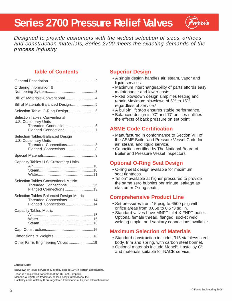
Series 2700 Pressure Relief Valves
2
Designed to provide customers with the widest selection of sizes, orificesand construction materials, Series 2700 meets the exacting demands of theprocess industry.
Superior Design• A single design handles air, steam, vapor and
liquid services.• Maximum interchangeability of parts affords easy
maintenance and lower costs.• Fixed blowdown design simplifies testing and
repair. Maximum blowdown of 5% to 15% regardless of service.1
• A built-in lift stop ensures stable performance.• Balanced design in “C” and “D” orifices nullifies
the effects of back pressure on set point.
ASME Code Certification• Manufactured in conformance to Section VIII of
the ASME Boiler and Pressure Vessel Code for air, steam, and liquid service.
• Capacities certified by The National Board of Boiler and Pressure Vessel Inspectors.
Optional O-Ring Seat Design• O-ring seat design available for maximum
seat tightness.• Teflon® available at higher pressures to provide
the same zero bubbles per minute leakage as elastomer O-ring seats.
Comprehensive Product Line• Set pressures from 15 psig to 6500 psig with
orifice areas from 0.068 to 0.573 sq. in.• Standard valves have MNPT inlet X FNPT outlet.
Optional female thread, flanged, socket weld, welding nipple, and sanitary connections available.
Maximum Selection of Materials• Standard construction includes 316 stainless steel
body, trim and spring, with carbon steel bonnet.• Optional materials include Monel®, Hastelloy C®,
and materials suitable for NACE service.
Table of Contents
General Description.............................................2
Ordering Information & Numbering System..............................................3
Bill of Materials-Conventional.............................4
Bill of Materials-Balanced Design.......................5
Selection Table: O-Ring Design..........................6
Selection Tables: Conventional U.S. Customary Units
Threaded Connections ..........................6Flanged Connections.............................7
Selection Tables-Balanced DesignU.S. Customary Units
Threaded Connections...........................8Flanged Connections.............................8
Special Materials.................................................9
Capacity Tables-U.S. Customary UnitsAir.........................................................10Steam...................................................10Water....................................................11
Selection Tables-Conventional-MetricThreaded Connections.........................12Flanged Connections ...........................13
Selection Tables-Balanced Design-MetricThreaded Connections.........................14Flanged Connections...........................14
Capacity Tables-MetricAir.........................................................15Water....................................................15Steam...................................................16
Cap Constructions............................................16
Dimensions & Weights......................................18
Other Farris Engineering Valves .......................19
General Note:
1Blowdown on liquid service may slightly exceed 15% in certain applications.
Teflon is a registered trademark of the DuPont Company.Monel is a registered trademark of Inco Alloys International Inc.Hastelloy and Hastelloy C are registered trademarks of Haynes International Inc.
© Farris Engineering 2006

SeriesNumber
27
Orifice/Area
C 0.068
D 0.125
E 0.223
F 0.350
G 0.573
SeatConstruction
A Metal Seat
C Soft Seat
T Teflon Seat
Inlet Size1
1 1/2”
2 3/4”
3 1”
4 1 1/2”
OutletSize1
3 1”
4 1 1/2”
5 2”
6 2 1/2”
InletConnections
M MNPT
F FNPT
1 Flanged-150RF
2 Flanged-300RF
3 Flanged-600RF
4 Flanged-900RF
5 Flanged-1500RF
6 Flanged-2500RF
O Special
S Socket Weld
T Sanitary
W Welding Nipple
Special Variations
H High pressurevariationsof standard types
B Balanceddesign3
D Heat transferfluid standardpressure
E Heat transferfluid high pressure
CapConstruction
2 Plain
4 Packed Lever
7 Open Lever
TestGag
0 No Gag
1 Test Gag
27 D A 2 3 H M 2 0 S4
Numbering System
Ordering Information
3
Selecting and specifying Farris pressure relief valves is simple using the numberingsystem that follows. Each digit of the part number has a distinct significance. Thedigits describe the basic valve series, orifice, seat design, inlet temperature range,body, bonnet and spring material, inlet type and pressure rating.
General Notes:
1. Not all combinations of inlet and outlet sizes shown are available.Consult the selection tables of pages 6 and 7.
2. Test gag option is not available with open lever cap.
3. Available in O-ring seat design only. Consult the Farris Factory.
1 Quantity.*2 Inlet and outlet sizes.3 Farris type number.*4 Inlet and outlet connections: MNPT, FNPT,
flanged, socket weld, sanitary inlet orweld nipple.
5 Materials of construction if other than standard.
6 O-ring seat pressure seal material, if required.7 Set pressure.*
Please specify the following so that we may process your order as quick ly as possible.
*As a customer service, we verify your selection and sizing. In order to do this, we must have this information.
8 Operating and relieving temperatures.*9 Allowable overpressure.*
10 Fluid and fluid state.*11 Backpressure, superimposed constant and/or
variable, and built-up.*12 Required capacity.*13 Accessories: open or packed lever if required;
test gag.14 Code requirements, if any.
SpecialMaterials
S4 Complete 316 St. St.
N1 NACE Trim: Standard
N4 NACE Trim: All St. St.
M1 Monel Body & Disc
M2 Monel Trim
M4 Complete Monel
H1 Hastelloy C Body & Disc
H2 Hastelloy C Trim
H4 Complete Hastelloy C

Item No. Part Name Standard Material
SA-351, Gr. CF8M St. St.1 Body or
SA-479 Type 316 St. St.
2 Bonnet SA-216, Gr. WCB, Carb. St.
3 Disc 316 St. St.
4 Guide 316 St. St.
5 Disc Holder 316 St. St.
6 Stem 316 St. St.
7 Spring Adj. Screw 316 St. St.
8 Jam Nut 316 St. St.
9 Cap, Plain Screwed Carbon Steel
10 Cap Gasket 316 St. St.
11 Body Gasket 316 St. St.
12 Guide Gasket 316 St. St.
13 Spring (-50°F to +750°F) Stainless Steel
14 Spring Buttons 316 St. St.
15 Wire Seal St. St. Wire / Lead Seal
16 Nameplate (Not Shown) Stainless Steel
17 Welding Nipple (Inlet) 316 St. St.
18 Welding Nipple (Outlet) Carbon Steel
19 Lap Joint Stub End (Inlet) 316 St. St.
20 Lap Joint Stub End (Outlet) Carbon Steel
21 Lap Joint Flange (Inlet) Carbon Steel
22 Lap Joint Flange (Outlet) Carbon Steel
5
3
4
6
1211
1
13
2
7
8
15
9
10
14
O-Ring Design(Optional)
17
18
19
21
22
20
O-Ring Retainer
O-RingSeat Seal
Retainer Lockscrew
Bill of Materials - Conventional
4
Complies withASME Boiler& PressureVessel Code,Section VIII

1
13
2
7
9
8
4
6
5
3
Bonnet Vent
10
14
18
17
16
15
5
ItemNo. Part Name Standard Material
1 Body SA-351, Gr. CF8M St. St.or
SA-479 Type 316 St. St.2 Bonnet SA-216, Gr. WCB, Carb. St. 3 O-ring Retainer 316 St. St.4 O-ring Seat Seal Viton®
5 Retainer Lock Screw 304 St. St.6 Guide 316 St. St.7 Guide Seal Viton8 Disc Holder 316 St. St.9 Disc Holder Seal Viton
10 Stem 316 St. St.11 Spring Adj. Screw 316 St. St.12 Jam Nut 316 St. St.13 Cap, Plain Screwed Carbon Steel14 Cap Gasket 316 St. St.15 Body Gasket 316 St. St.16 Guide Gasket 316 St. St.17 Spring Stainless Steel18 Spring Buttons 316 St. St.19 Wire Seal St. St. Wire/Lead Seal20 Nameplate (Not Shown) Stainless Steel
General Notes:1. Other O-ring materials available. Consult the Factory.2. Flanged, socket weld, welding nipple and female threaded designs available.3. Temperature for balanced or O-ring seat design is limited by the elastomerselected. See page 6.
Viton is a registered trademark of DuPont Dow Elastomers.
1.2
1
0.8
0.6
0.4
0.2
00% 5% 10% 15% 20% 25% 30% 35% 40% 45% 50% 55% 60% 65% 70% 75% 80%
Series 2700 Back Pressure CorrectionFactors Balanced Design
Percent Back Pressure
Kb
(Gas
) K
w(L
iqu
id)
Bac
k P
ress
ure
Co
rrec
tio
n F
acto
r
Complies withASME Boiler& PressureVessel Code,Section VIII
Do you have variable back pressure? Can’t use a balanced bellows design? Farris has the solution with the Series 2700 balanced design pressure relief valve. The balanced effect isachieved by isolating the upper valve chamber and eliminatingany back pressure build-up in the bonnet effecting valve set pressure.
These valves are available in 1/2”, 3/4” and 1” inlet sizes with a1” outlet and two orifice areas. Pressure ranges from 15 to 1480psig, standard soft seat design. Flanged and welded inlet andoutlet connections are available with the same material options as the standard design.
Bill of Materials - Balanced Design
11
12
19

O-ring Selection
The 2700 Series is available with an optional O-ringseat which minimizes fugitive emissions and costlyproduct loss. This optional seat construction provides zero bubbles per minute leakage at 90%
of set pressure per API Standard 527. The Tablesbelow list the set pressure and temperature rangefor both the elastomer and Teflon seat options.
U.S . CUSTOMARY UNITS : THREADED CONNECTIONS-MNPT X FNPT
PRESSURE & TEMPERATURE L IMITS O -RING SEAT VALVE
General Notes:
1. Maximum O-ring set pressure limit cannot exceed the pressure limit for a given type number and size as indicated in the metalseat selection tables.
2. Temperature range may vary depending on service fluid.
3. Ethylene propylene is suitable for steam service up to 350°F, Teflon up to 500°F.
4. Consult the Farris Factory for other materials.
M A T E R I A L A V A I L A B I L I T Y
Pressure Range, PSIG1 Pressure Range, Bar G2
Orifice Elastomer Seat Teflon Seat Elastomer Seat Teflon Seat
C 15 to 1480 800 to 2500 1.00 to 102 55.1 to 172High Pressure — 2501 to 5000 — 172.1 to 345
D 15 to 1480 800 to 1600 1.00 to 102 55.1 to 110High Pressure — 1601 to 5000 — 110.1 to 345
E 15 to 1480 600 to 2500 1.0 to 102 41.3 to 172
F 15 to 1480 600 to 1600 1.0 to 102 41.3 to 110
G 15 to 1000 200 to 1000 1.0 to 69 14 to 69
0.068
0.125
0.223
0.350
0.573
Orifice AreaSq. In.
Valve SizeInlet x Outlet Type Number
Maximum SetPressure, PSIG
Max. Back Pressure
PSIG at 100˚FMaterials
Body/Bonnet Spring-50˚F to 750˚F1/2 x 13/4 x 13/4 x 11 x 11 x 1
1/2 x 13/4 x 13/4 x 11 x 11 x 1
1 x 1 1/2
1 1/2 x 2
1 1/2 x 2 1/2
27CA13-M2027CA23-M20
27CA23H-M2027CA33-M20
27CA33H-M2027DA13-M2027DA23-M20
27DA23H-M2027DA33-M20
27DA33H-M20
27EA34-M20
27FA45-M20
27GA46-M20
1600250050002500650016001600500016005000
2500
1600
1000
400
400
400
400
400
316 St. St. /Carb. St.
316 St. St. /Carb. St.
316 St. St. /Carb. St.
316 St. St. /Carb. St.
316 St. St. /Carb. St.
StainlessSteel
StainlessSteel
StainlessSteel
StainlessSteel
StainlessSteel
6
Selection Table
Viton®
Buna NEPR
SiliconeKalrez®
Teflon
Material°F
Temperature Range1
-20° to +450°-20° to +250°0° to +350°
-150° to +450°-20° to +550°-300° to +500°
-29° to +232°-29° to +121°-18° to +177°-101° to +232°-29° to +289°-184° to +260°
°C
Viton and Kalrez are registered trademarks of DuPont Dow Elastomers.

Selection TablesU.S . CUSTOMARY UNITS : FLANGED CONNECTIONS
OrificeArea
Sq. In.
Valve SizeInlet xOutlet
ANSI Flange Class
Inlet RF Outlet RFType Number
Maximum Set Pressure, PSIG
-50˚F to100˚F 400˚F 750˚F
Max. BackPressure PSIG at 100˚F
Materials
Body /Bonnet Spring
0.068
0.125
0.223
0.350
0.573
150#300#600#900#1500#2500#
150#300#600#900#1500#2500#
150#300#600#900#1500#2500#
150#300#600#900#
150#300#600#900#1500#2500#
150#300#600#900#1500#2500#
150#300#600#900#
150#300#600#
150#300#600#
150#150#150#300#300#300#
150#150#150#300#300#300#
150#150#150#300#300#300#
150#150#150#300#
150#150#150#300#300#300#
150#150#150#300#300#300#
150#150#150#300#
150#150#150#
150#150#150#
27CA13-12027CA13-22027CA13-32027CA13-420
27CA13H-52027CA13H-620
27CA23-12027CA23-22027CA23-32027CA23-420
27CA23H-52027CA23H-620
27CA33-12027CA33-22027CA33-32027CA33-420
27CA33H-52027CA33H-620
27DA13-12027DA13-22027DA13-320
27DA13H-420
27DA23-12027DA23-22027DA23-320
27DA23H-42027DA23H-52027DA23H-620
27DA33-12027DA33-22027DA33-320
27DA33H-42027DA33H-52027DA33H-620
27EA34-12027EA34-22027EA34-32027EA34-420
27FA45-12027FA45-22027FA45-320
27GA46-12027GA46-22027GA46-320
2857401480222037055000
2857401480222037055000
285740
1480222037056170
28574014802220
2857401480222037055000
2857401480222037056170
28574014802220
2857401480
2857401000
2006351270190031705000
2006351270190031705000
2006351270190031705280
20063512701900
2006351270190031705000
2006351270190031705280
20063512701900
2006351270
2006351000
955051010151025204200
955051010151025204200
955051010151025204200
9550510101510
955051010151025204200
955051010151025204200
9550510101510
955051010
955051000
285285285400400400
285285285400400400
285285285400400400
285285285400
285285285400400400
285285285400400400
285285285400
285285285
285285285
316 St. St./Carb. St.
316 St. St./Carb St.
316 St. St./Carb. St.
316 St. St./Carb. St.
316 St. St./Carb. St.
316 St. St./Carb. St.
316 St. St./Carb St.
316 St. St./Carb. St.
316 St. St./Carb St.
StainlessSteel
StainlessSteel
StainlessSteel
StainlessSteel
StainlessSteel
StainlessSteel
StainlessSteel
StainlessSteel
StainlessSteel
1/2 x 1
3/4 x 1
1 x 1
1/2 x 1
3/4 x 1
1 x 1
1 x 1 1/2
1 1/2 x 2
1 1/2 x 2 1/2
General Notes:1. Available with optional elastomer or Teflon seat design as illustrated. Change
the fourth digit of the type number from “A” to “C” for soft seat, “A” to “T” for Teflon. Example: 27DC23-M20 for soft seat, 27DT23-M20 for Teflon. See Selection Table for pressure and temperature limits.
2. Above type numbers indicate standard materials of construction. To select corrosive or low temperature materials, add type number suffix as indicated on pages 3 and 9.
3. Available in materials suitable for sour gas (H2S) service to NACE Standards MR0103 and MR0175 / ISO 15156. Add "N1" (standard materials) or "N4" 7
(all stainless construction) to the type number. Example 27DA23-M20/N1 & 27DA23-M20/N4.
4. For open or packed levers, change the second digit of the type number suffix.Examples: 27FA45-M70 for open lever, 27GA46-M40 for packed lever.
5. For socket weld or welding nipple connections, change the first digit of the typenumber suffix to “S” for socket weld or “W” for welding nipple inlet and outlet.Examples: 27DA33-S20 for socket weld, 27DA33-W20 fo welding nipple.6. Female threaded inlet available. Change first digit of type number suffix to “F”. Example: 27EA-34-F20.
7. For set pressures below 15 psig, consult the Farris Factory.
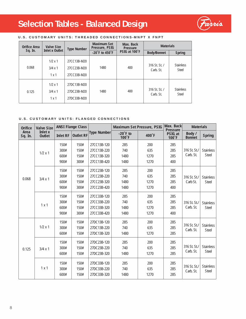
Selection Tables - Balanced Design
U.S . CUSTOMARY UNITS : FLANGED CONNECTIONS
OrificeArea
Sq. In.
Valve SizeInlet xOutlet
ANSI Flange Class
Inlet RF Outlet RFType Number
Maximum Set Pressure, PSIG
-20˚F to100˚F 400˚F
Max. BackPressure PSIG at 100˚F
Materials
Body /Bonnet Spring
0.068
0.125
150#300#600#900#
150#300#600#900#
150#300#600#900#
150#300#600#
150#300#600#
150#300#600#
150#150#150#300#
150#150#150#300#
150#150#150#300#
150#150#150#
150#150#150#
150#150#150#
27CC13B-12027CC13B-22027CC13B-32027CC13B-420
27CC23B-12027CC23B-22027CC23B-32027CC23B-420
27CC33B-12027CC33B-22027CC33B-32027CC33B-420
27DC13B-12027DC13B-22027DC13B-320
27DC23B-12027DC23B-22027DC23B-320
27DC33B-12027DC33B-22027DC33B-320
28574014801480
28574014801480
28574014801480
2857401480
2857401480
2857401480
20063512701270
20063512701270
20063512701270
2006351270
2006351270
2006351270
285285285400
285285285400
285285285400
285285285
285285285
285285285
316 St. St./Carb. St.
316 St. St./Carb St.
316 St. St./Carb. St.
316 St. St./Carb. St.
316 St. St./Carb. St.
316 St. St./Carb. St.
StainlessSteel
StainlessSteel
StainlessSteel
StainlessSteel
StainlessSteel
StainlessSteel
1/2 x 1
3/4 x 1
1 x 1
1/2 x 1
3/4 x 1
1 x 1
U.S . CUSTOMARY UNITS : THREADED CONNECTIONS-MNPT X FNPT
0.068
0.125
Orifice AreaSq. In.
Valve SizeInlet x Outlet Type Number
Maximum SetPressure, PSIG
Max. Back Pressure
PSIG at 100˚FMaterials
Body/Bonnet Spring-20˚F to 450˚F
1/2 x 1
3/4 x 1
1 x 1
1/2 x 1
3/4 x 1
1 x 1
27CC13B-M20
27CC23B-M20
27CC33B-M20
27DC13B-M20
27DC23B-M20
27DC33B-M20
1480
1480
400
400
316 St. St. /Carb. St.
316 St. St. /Carb. St.
StainlessSteel
StainlessSteel
8
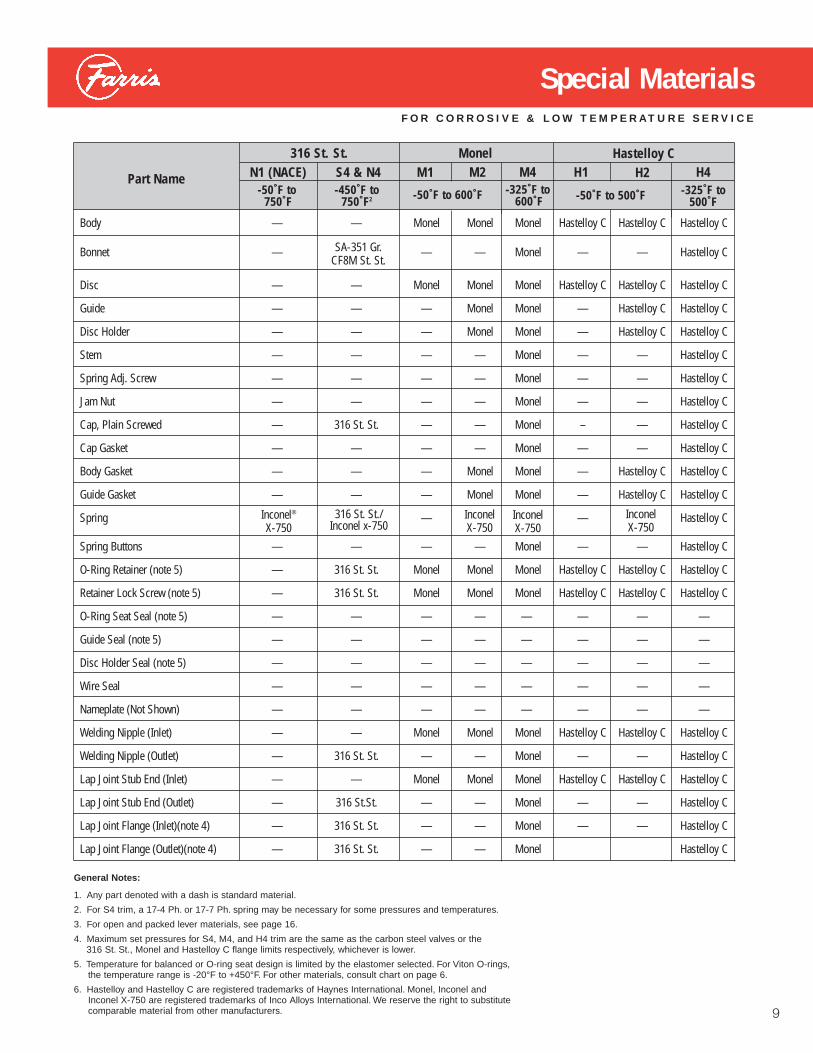
Body — — Monel Monel Monel Hastelloy C Hastelloy C Hastelloy C
Bonnet — — — Monel — — Hastelloy C
Disc — — Monel Monel Monel Hastelloy C Hastelloy C Hastelloy C
Guide — — — Monel Monel — Hastelloy C Hastelloy C
Disc Holder — — — Monel Monel — Hastelloy C Hastelloy C
Stem — — — — Monel — — Hastelloy C
Spring Adj. Screw — — — — Monel — — Hastelloy C
Jam Nut — — — — Monel — — Hastelloy C
Cap, Plain Screwed — 316 St. St. — — Monel – — Hastelloy C
Cap Gasket — — — — Monel — — Hastelloy C
Body Gasket — — — Monel Monel — Hastelloy C Hastelloy C
Guide Gasket — — — Monel Monel — Hastelloy C Hastelloy C
Spring — — Hastelloy C
Spring Buttons — — — — Monel — — Hastelloy C
O-Ring Retainer (note 5) — 316 St. St. Monel Monel Monel Hastelloy C Hastelloy C Hastelloy C
Retainer Lock Screw (note 5) — 316 St. St. Monel Monel Monel Hastelloy C Hastelloy C Hastelloy C
O-Ring Seat Seal (note 5) — — — — — — — —
Guide Seal (note 5) — — — — — — — —
Disc Holder Seal (note 5) — — — — — — — —
Wire Seal — — — — — — — —
Nameplate (Not Shown) — — — — — — — —
Welding Nipple (Inlet) — — Monel Monel Monel Hastelloy C Hastelloy C Hastelloy C
Welding Nipple (Outlet) — 316 St. St. — — Monel — — Hastelloy C
Lap Joint Stub End (Inlet) — — Monel Monel Monel Hastelloy C Hastelloy C Hastelloy C
Lap Joint Stub End (Outlet) — 316 St.St. — — Monel — — Hastelloy C
Lap Joint Flange (Inlet)(note 4) — 316 St. St. — — Monel — — Hastelloy C
Lap Joint Flange (Outlet)(note 4) — 316 St. St. — — Monel Hastelloy C
General Notes:
1. Any part denoted with a dash is standard material.
2. For S4 trim, a 17-4 Ph. or 17-7 Ph. spring may be necessary for some pressures and temperatures.
3. For open and packed lever materials, see page 16.
4. Maximum set pressures for S4, M4, and H4 trim are the same as the carbon steel valves or the 316 St. St., Monel and Hastelloy C flange limits respectively, whichever is lower.
5. Temperature for balanced or O-ring seat design is limited by the elastomer selected. For Viton O-rings,the temperature range is -20°F to +450°F. For other materials, consult chart on page 6.
6. Hastelloy and Hastelloy C are registered trademarks of Haynes International. Monel, Inconel and Inconel X-750 are registered trademarks of Inco Alloys International. We reserve the right to substitute comparable material from other manufacturers.
FOR CORROSIVE & LOW TEMPERATURE SERVICE
Part Name-50˚F to -450˚F to
750˚F 750˚F2 -50˚F to 600˚F -325˚F to 600˚F -50˚F to 500˚F -325˚F to
500˚F
SA-351 Gr.CF8M St. St.
Inconel®
X-750316 St. St./
Inconel x-750InconelX-750
InconelX-750
InconelX-750
316 St. St.N1 (NACE) S4 & N4
MonelM1 M2 M4
Hastelloy CH1 H2 H4
Special Materials
9
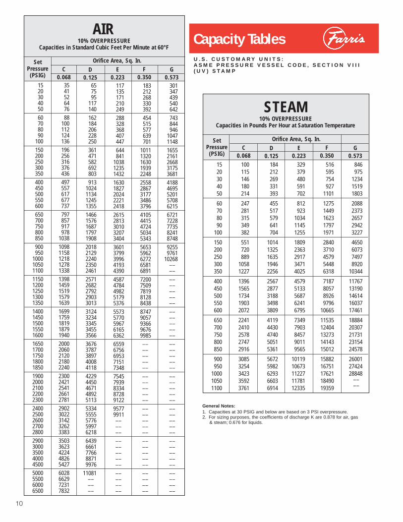
Capacity TablesU.S . CUSTOMARY UNITS :ASME PRESSURE VESSEL CODE, SECTION VI I I(UV) STAMP
General Notes:1. Capacities at 30 PSIG and below are based on 3 PSI overpressure.2. For sizing purposes, the coefficients of discharge K are 0.878 for air, gas
& steam; 0.676 for liquids.
10
152030405060708090
100150200250300350400450500550600650700750800850900950
1000105011001150120012501300135014001450150015501600165017001750180018501900200021002200230024002500260027002800290030003500400045005000550060006500
354152647688
100112124136196256316376436497557617677737797857917978
1038109811581218127813381398145915191579163916991759181918791940200020602120218022402300242125412661278129023022314232623383350336234224482654276028662972317832
657595
117140162184206228250361471582692803913
10241134124513551466157616871797190820182129224023502461257126822792290330133124323433453455356636763787389740084118422944504671489251135334555557765997621864396661776688719976
11081––––––
117135171210249288328368407447644841
1038123514321630182720242221241826152813301032073404360137993996419343904587478449825179537655735770596761656362655967566953715173487545793983348728912295779911––––––––––––––––––––––––
183212268330392454515577639701
101113201630193922482558286731773486379641054415472450345343565359626272658168917200750978198128843887479057936696769985––––––––––––––––––––––––––––––––––––––––––––––––
301347439540642743844946
1047114816552161266831753681418846955201570862156721722877358241874892559761
10268––––––––––––––––––––––––––––––––––––––––––––––––––––––––––––––––––––––––
Orifice Area, Sq. In.SetPressure(PSIG)
C0.068
D0.125
E0.223
F0.350
G0.573
Orifice Area, Sq. In.SetPressure(PSIG)
C0.068
D0.125
E0.223
F0.350
G0.573
10% OVERPRESSURECapacities in Standard Cubic Feet Per Minute at 60°F
AIR
10% OVERPRESSURECapacities in Pounds Per Hour at Saturation Temperature
STEAM
184212269331393
455517579641704
10141325163519462256
25672877318834983809
41194430474050515361
56725982629366036914
100115146180214
247281315349382
551720889
10581227
13961565173419032072
22412410257827472916
30853254342335923761
1520304050
60708090
100
150200250300350
400450500550600
650700750800850
900950
100010501100
846975
123415191803
20882373265729423227
4650607374978920
10344
1176713190146141603717461
1888420307217312315424578
260012742428848
––––
516595754927
1101
12751449162317971971
28403710457954486318
7187805789269796
10665
1153512404132731414315012
1588216751176211849019359
329379480591702
812923
103411451255
18092363291734714025
45795133568762416795
73497903845790119565
1011910673112271178112335

Capacity TablesU.S . CUSTOMARY UNITS :ASME PRESSURE VESSEL CODE, SECTION VI I I (UV) STAMP
General Notes:1. Capacities at 30 PSIG and below are based on 3 PSI overpressure.
2. For sizing purposes, the coefficients of discharge K are 0.878 for air, gas & steam; 0.676 for liquids.
3. To determine capacity at 25% overpressure, multiply the capacity at 10% by 1.066.
11
152030405060708090
100150200250300350400450500550600650700750800850900950
1000105011001150120012501300135014001450150015501600165017001750180018501900200021002200230024002500260027002800290030003500400045005000550060006500
7.48.3
10.011.512.914.115.316.317.318.322.425.928.931.734.236.638.840.942.944.846.748.450.151.853.454.956.457.959.360.762.163.464.766.067.368.569.770.972.173.274.475.576.677.778.779.881.983.985.987.889.791.593.495.196.998.6100108115122129135141147
13.615.318.421.223.826.028.130.131.933.641.247.653.258.363.067.371.475.378.982.485.889.092.295.298.1101103106109111114116119121123126128130132134136138140142144146150154157161164168171174178181184199212225238––––––
24.327.432.937.942.446.550.253.756.960.073.584.994.9104112120127134140147153158164169175180185189194199203208212216220224228232236240244247251254258261268275281288294300––––––––––––––––––––––––
38.143.151.659.666.673.078.884.389.494.2115133149163176188200210221230240249258266274282290298305312319326333339346352359365371377––––––––––––––––––––––––––––––––––––––––––––––––
62.470.584.597.6109119129138146154189218244267288308327345362378393408422436450463475488––––––––––––––––––––––––––––––––––––––––––––––––––––––––––––––––––––––––
Orifice Area, Sq. In.SetPressure(PSIG)
C0.068
D0.125
E0.223
F0.350
G0.573
10% OVERPRESSURECapacities in U.S. Gallons Per Minute at 70°F3
WATER
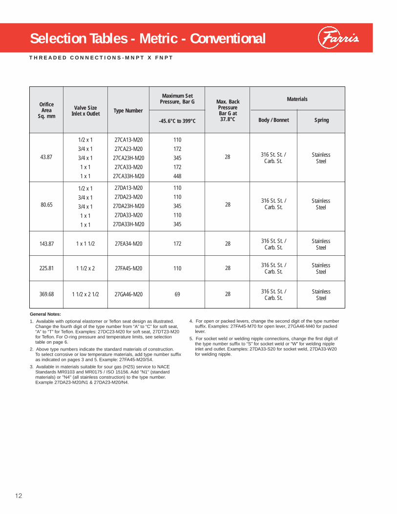
Orifice Area
Sq. mmValve Size
Inlet x Outlet
Maximum SetPressure, Bar G Max. Back
PressureBar G at37.8°C-45.6°C to 399°C
Type Number
Materials
Body / Bonnet Spring
THREADED CONNECTIONS - MNPT X FNPT
General Notes:
1. Available with optional elastomer or Teflon seat design as illustrated.Change the fourth digit of the type number from “A” to “C” for soft seat, “A” to “T” for Teflon. Examples: 27DC23-M20 for soft seat, 27DT23-M20 for Teflon. For O-ring pressure and temperature limits, see selection table on page 6.
2. Above type numbers indicate the standard materials of construction.To select corrosive or low temperature materials, add type number suffix as indicated on pages 3 and 5. Example: 27FA45-M20/S4.
3. Available in materials suitable for sour gas (H2S) service to NACE Standards MR0103 and MR0175 / ISO 15156. Add "N1" (standard materials) or "N4" (all stainless construction) to the type number.Example 27DA23-M20/N1 & 27DA23-M20/N4.
12
Selection Tables - Metric - Conventional
1/2 x 1
3/4 x 1
3/4 x 1
1 x 1
1 x 1
1/2 x 1
3/4 x 1
3/4 x 1
1 x 1
1 x 1
1 x 1 1/2
1 1/2 x 2
1 1/2 x 2 1/2
27CA13-M20
27CA23-M20
27CA23H-M20
27CA33-M20
27CA33H-M20
27DA13-M20
27DA23-M20
27DA23H-M20
27DA33-M20
27DA33H-M20
27EA34-M20
27FA45-M20
27GA46-M20
110
172
345
172
448
110
110
345
110
345
172
110
69
43.87
80.65
143.87
225.81
369.68
28
28
28
28
28
316 St. St. /Carb. St.
316 St. St. /Carb. St.
316 St. St. /Carb. St.
316 St. St. /Carb. St.
316 St. St. /Carb. St.
StainlessSteel
StainlessSteel
StainlessSteel
StainlessSteel
StainlessSteel
4. For open or packed levers, change the second digit of the type number suffix. Examples: 27FA45-M70 for open lever, 27GA46-M40 for packed lever.
5. For socket weld or welding nipple connections, change the first digit of the type number suffix to “S” for socket weld or “W” for welding nipple inlet and outlet. Examples: 27DA33-S20 for socket weld, 27DA33-W20 for welding nipple.

FLANGED CONNECTIONS
Orifice AreaSq. mm
Valve SizeInlet x Outlet
ANSI Flange Class
Inlet RF
Outlet RF
Type Number
Maximum Set Pressure, Bar G
-45.6˚C to37.8˚C 204˚C 399˚C
Max. BackPressure Bar G at 37.8˚C
Materials
Body /Bonnet Spring
43.87
80.65
143.87
225.81
369.68
150#300#600#900#1500#2500#150#300#600#900#1500#2500#150#300#600#900#1500#2500#150#300#600#900#150#300#600#900#1500#2500#150#300#600#900#1500#2500#150#300#600#900#150#300#600#150#300#600#
150#150#150#300#300#300#150#150#150#300#300#300#150#150#150#300#300#300#150#150#150#300#150#150#150#300#300#300#150#150#150#300#300#300#150#150#150#300#150#150#150#150#150#150#
27CA13-12027CA13-22027CA13-32027CA13-420
27CA13H-52027CA13H-62027CA23-12027CA23-22027CA23-32027CA23-420
27CA23H-52027CA23H-62027CA33-12027CA33-22027CA33-32027CA33-420
27CA33H-52027CA33H-62027DA13-12027DA13-22027DA13-320
27DA13H-42027DA23-12027DA23-22027DA23-320
27DA23H-42027DA23H-52027DA23H-62027DA33-12027DA33-22027DA33-320
27DA33H-42027DA33H-52027DA33H-62027EA34-12027EA34-22027EA34-32027EA34-42027FA45-12027FA45-22027FA45-32027GA46-12027GA46-22027GA46-320
20511021532553452051102153255345205110215325542520511021532051102153255345205110215325542520511021532051102205169
144488131218345144488131218345144488131218364144488131144488131218345144488131218364144488131144488144469
635691041742906356910417429063569104174290635691046356910417429063569104174290635691046356963569
2020202828282020202828282020202828282020202820202028282820202028282820202028202020202020
316 St. St./Carb. St.
316 St. St./Carb St.
316 St. St./Carb. St.
316 St. St./Carb. St.
316 St. St./Carb. St.
316 St. St./Carb. St.
316 St. St./Carb St.
316 St. St./Carb. St.
316 St. St./Carb St.
StainlessSteel
StainlessSteel
StainlessSteel
StainlessSteel
StainlessSteel
StainlessSteel
StainlessSteel
StainlessSteel
StainlessSteel
1/2 x 1
3/4 x 1
1 x 1
1/2 x 1
3/4 x 1
1 x 1
1 x 1 1/2
1 1/2 x 2
1 1/2 x 2 1/2
13
Selection Tables - Metric - Conventional
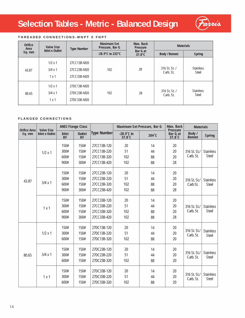
Selection Tables - Metric - Balanced DesignTHREADED CONNECTIONS - MNPT X FNPT
FLANGED CONNECTIONS
Orifice AreaSq. mm
Valve SizeInlet x Outlet
ANSI Flange Class
Inlet RF
Outlet RF
Type Number
Maximum Set Pressure, Bar G
-28.9˚C to37.8˚C 204˚C
Max. BackPressure Bar G at 37.8˚C
Materials
Body /Bonnet Spring
43.87
80.65
150#300#600#900#
150#300#600#900#
150#300#600#900#
150#300#600#
150#300#600#
150#300#600#
150#150#150#300#
150#150#150#300#
150#150#150#300#
150#150#150#
150#150#150#
150#150#150#
27CC13B-12027CC13B-22027CC13B-32027CC13B-420
27CC23B-12027CC23B-22027CC23B-32027CC23B-420
27CC33B-12027CC33B-22027CC33B-32027CC33B-420
27DC13B-12027DC13B-22027DC13B-320
27DC23B-12027DC23B-22027DC23B-320
27DC33B-12027DC33B-22027DC33B-320
2051102102
2051102102
2051102102
2051102
2051102
2051102
14448888
14448888
14448888
144488
144488
144488
20202028
20202028
20202028
202020
202020
202020
316 St. St./Carb. St.
316 St. St./Carb St.
316 St. St./Carb. St.
316 St. St./Carb. St.
316 St. St./Carb. St.
316 St. St./Carb. St.
StainlessSteel
StainlessSteel
StainlessSteel
StainlessSteel
StainlessSteel
StainlessSteel
1/2 x 1
3/4 x 1
1 x 1
1/2 x 1
3/4 x 1
1 x 1
Orifice Area
Sq. mmValve Size
Inlet x Outlet
Maximum SetPressure, Bar G
Max. BackPressureBar G at37.8°C-28.9°C to 232°C
Type NumberMaterials
Body / Bonnet Spring
1/2 x 1
3/4 x 1
1 x 1
1/2 x 1
3/4 x 1
1 x 1
27CC13B-M20
27CC23B-M20
27CC33B-M20
27DC13B-M20
27DC23B-M20
27DC33B-M20
102
102
43.87
80.65
28
28
316 St. St. /Carb. St.
316 St. St. /Carb. St.
StainlessSteel
StainlessSteel
14

General Notes:1. Capacities at 2.0 BarG set pressure and below are based on 0.2 Bar overpressure.2. For sizing purposes, the coefficients of discharge K are 0.878 for air, gas & steam; 0.676 for liquids.3. To determine water capacity at 25% overpressure, multiply the capacity at 10% by 1.066.
ASME PRESSURE VESSEL CODE, SECTION VI I I (UV) STAMP
15
123456789
101214161820253035404550556065707580859095
100105110115120125130135140145150155160165170175180185190195200220240260280300320340360380400420440448
27.637.445.752.859.064.669.874.679.283.591.498.8105112118132144156167177186195204212220228236243250257264270276283289295301306312318323328334339344349354359364368373391409425441457472486501514528541553558
50.868.784.097.0108118128137145153168181194205217242265287307325343360376391406420434447460473485497509520531542553564574584594604614623632642651660669677686720752782812840868895––––––––––––
90.7122150173193212229244259273300324346367387433474512547580612642670698724750774798821844866887908928948968987
10061024104210601078109511121129––––––––––––––––––––––––––––––––––––––
142192235271303332359384407429470508543576607679744804859911961
100810521095113711771215125312891324135913921425
––––––––––––––––––––––––––––––––––––––––––––––––––––––––––––––
233315385445497545588629667703770832890944995
1112121813161407149215731650172317941861
––––––––––––––––––––––––––––––––––––––––––––––––––––––––––––––––––––––––––––––
Orifice Area, Sq. mm.SetPressure(BarG)
C43.87
D80.65
E143.87
F225.81
G369.68
10% OVERPRESSURECapacities in Litres Per Minutes at 21°C3
WATER
123456789
101214161820253035404550556065707580859095
100105110115120125130135140145150155160165170175180185190195200220240260280300320340360380400420440448
1.01.41.92.42.93.43.94.44.95.46.47.48.49.3
10.312.815.317.720.222.725.127.630.132.535.037.540.042.444.947.449.852.354.857.259.762.264.767.169.672.174.577.079.581.984.486.989.391.894.396.899.2
109.1119.0128.9138.7148.6158.5168.4178.2188.1198.0207.9217.8221.7
1.82.73.64.55.46.37.28.19.09.9
11.713.515.417.219.023.528.132.637.241.746.250.855.359.964.468.973.578.082.587.191.696.2
100.7105.2109.8114.3118.9123.4127.9132.5137.0141.6146.1150.6155.2159.7164.3168.8173.3177.9182.4200.6218.7236.9255.1273.2291.4309.5––––––––––––
3.34.76.38.09.6
11.212.814.516.117.720.924.227.430.633.942.050.158.266.374.482.590.698.7
106.8114.9123.0131.1139.2147.3155.4163.5171.6179.7187.8195.9204.0212.1220.2228.3236.4244.5252.6260.7268.8276.9
––––––––––––––––––––––––––––––––––––––
5.17.4
10.012.515.117.620.122.725.227.832.837.943.048.153.265.978.691.3
104.0116.7129.5142.2154.9167.6180.3193.0205.7218.4231.1243.9256.6269.3282.0
––––––––––––––––––––––––––––––––––––––––––––––––––––––––––––––
8.412.216.320.524.628.833.037.141.345.553.862.170.478.887.1
107.9128.7149.5170.3191.1211.9232.7253.6274.4295.2
––––––––––––––––––––––––––––––––––––––––––––––––––––––––––––––––––––––––––––––
Orifice Area, Sq. mm.SetPressure(BarG)
C43.87
D80.65
E143.87
F225.81
G369.68
10% OVERPRESSURECapacities in Standard Cubic Meters Per Minute at 15.6°C
AIR
Capacity Tables - Metric Units

General Notes:1. Capacities at 2.0 BarG set pressure and
below are based on 0.2 Bar overpressure.
2. For sizing purposes, the coefficients of discharge K are 0.878 for air, gas & steam;0.676 for liquids.
General Notes:1. Any part denoted with a dash is standard material. 2. “S4” trim suitable for cryogenic service.
ASME PRESSURE VESSEL CODE, SECTION VI I I (UV) STAMP
CapConstruction
ItemNo.
Part Name
StandardMaterials
316 St. St.
S4 & N4 N1
Monel
M1 & M2 M4
Hastelloy C
H1 & H2 H4
M70Open Lever
M40PackedLever
12
3
4567891011121314
15
16
Test LeverCap, O.L.Stem TestWasher
Stem Jam NutButton Head Rivet
Set ScrewTest Lever
Cap, PackedStem Test Washer
Stem Jam NutCamGland
Gland NutPacking Ring
Gland Nut Gasket
Groove Pin
IronIron
St. St.
St. St.SteelSteelSteelSteelSt. St.St. St.St. St.St. St.St. St.
GraphiteFlexibleGraphite
Steel Plt’d
––––
316 St. St.
316 St. St.––––––
316 St. St.316 St. St.316 St. St.316 St. St.316 St. St.316 St. St.
––PTFE,Filled
––
––––
––
––––––––––––––––––––––
PTFE,Filled
––
––––
––
––––––––––––––––––––––
––
––
––––
Monel
Monel––––––
MonelMonelMonelMonelMonelMonel
––PTFE,Filled
––
––––
––
––––––––––––––––––––––
––––
––––
Hast. C
Hast. C––––––
Hast. CHast. CHast. CHast. CHast. CHast. C
––PTFE,Filled
––
16
Capacity Tables - Metric Units
Cap Constructions
Orifice Area, Sq. mm.SetPressure(BarG)
C43.87
D80.65
E143.87
F225.81
G369.68
10% OVERPRESSURECapacities in Kilograms Per Hour at Saturation Temperature
STEAM
82119160201242
283323364405446
528610691773
855105912631467
1672187620802284
2489269328983102
446587
109132
154176198220243
287332376420
465576687798
909102111321243
1354146515761687
12345
6789
10
12141618
20253035
40455055
60657075
378548734921
1109
12961483167118582045
2420279431693544
3918485457916727
766486009537
10473
11409123461328214219
231335448563677
792906
102011351249
1478170719362165
2393296535374109
4681525358256397
6969754181138685
147213286358431
504577650723796
942108712331379
1525188922532618
2982334737114076
4440480551695533

1/2 x 11/2 x 1 H.P
3/4 x 1 3/4 x 1 H.P.
1 x 11 x 1 H.P.
1 x 1 1/2
1 1/2 x 2
1 1/2 x 2 1/2
1/2 x 11/2 x 1 H.P
3/4 x 1 3/4 x 1 H.P.
1 x 11 x 1 H.P.
1 x 1 1/2
1 1/2 x 2
1 1/2 x 2 1/2
3.63.66.33.66.3
7.2
7.7
8.1
9191959595
89
98
105
4545644564
64
76
76
3 9/163 9/163 3/43 3/43 3/4
3 1/2
3 7/8
4 1/8
11 1/411 1/413 5/811 1/213 5/8
13 5/8
14 9/16
14 9/16
1/2 x 13/4 x 1
3/4 x 1 H.P.1 x 1
1 x 1 H.P.
1 x 1 1/2
1 1/2 x 2
1 1/2 x 2 1/2
T H R E A D E D C O N N E C T I O N S ( M N P T X F N P T )
W E L D I N G N I P P L E C O N N E C T I O N S
S O C K E T W E L D & F N P T X F N P T C O N N E C T I O N S
Note: H.P. designates thehigh pressure version of agiven inlet size.
Valve Size
Inletx
Outlet
US Customary Units(Inches)
AMax.
All CapConst.
B C
Metric Units(millimeters)
ApproximateWeight
Lbs. Kgs.A
Max.All CapConst.
B C
C and D Orifice
E Orifice
F Orifice
G Orifice
1 3/41 3/42 1/21 3/41 1/2
2 1/2
3
3
282286346292346
346
370
370
8814814
16
17
18
915915915
17
18
19
330386329384327383
376
403
403
1315 3/1612 15/1615 1/812 7/815 1/16
14 13/16
15 7/8
15 7/8
46.84
6.84
6.8
7.7
8.1
8.6
133135132133130132
125
132
128
5 1/45 5/165 3/165 1/45 1/85 3/16
4 15/16
5 3/16
5 7/16
3 3/163 15/163 3/163 15/163 3/163 15/16
3 13/16
5 3/16
5 3/16
Valve Size
Inletx
Outlet
US Customary Units(Inches)
AMax.
All CapConst.
B C
Metric Units(millimeters)
ApproximateWeight
Lbs. Kgs.A
Max. All CapConst.
B C
C and D Orifice
E Orifice
F Orifice
G Orifice
811008110081100
97
132
132
814814814
16
17
18
11 7/1613 5/811 7/1613 5/811 7/1613 5/8
13 3/8
14 9/16
14 9/16
3.66.33.66.33.66.3
7.2
7.7
8.1
949594959495
89
98
105
3 11/163 3/4
3 11/163 3/4
3 11/163 3/4
3 1/2
3 7/8
4 1/8
1 3/42 1/21 3/42 1/21 3/42 1/2
2 1/2
3
3
Valve Size
Inletx
Outlet
US Customary Units(Inches)
AMax.
All CapConst.
B C
Metric Units(millimeters)
ApproximateWeight
Lbs. Kgs.A
Max.All CapConst.
B C
C and D Orifice
E Orifice
F Orifice
G Orifice
291346291346291346
340
370
370
456445644564
64
76
7617

Dimensions & Weights
1/2 x 1
3/4 x 1
1 x 1
1 x 1 1/2
1 1/2 x 2
1 1/2 x 2 1/2
F L A N G E D C O N N E C T I O N S
(MNPT, FNPT, & SW)
(FLANGED) (WELDING NIPPLE)
Orifice AreaSq. In.
Valve SizeInlet x Outlet
ANSI Flange Class
Inlet RF
Outlet RF
US Customary Units(Inches)
A(Max.) B C
Weight
Lbs. Kgs.
Metric Units(millimeters)
A(Max.) BC G1
(MNPT)
0.068&
0.125
0.223
0.350
0.573
6.8
9.9
6.8
9.9
6.8
9.9
11.7
13.6
14.5
15
22
15
22
15
22
26
30
32
159
159
157
159
181
183
176
183
189
356
410
354
410
378
433
427
454
435
6 1/4
6 1/4
6 3/16
6 1/4
7 1/8
7 3/16
6 15/16
7 3/16
7 7/16
1
1
1 1/4
1 1/4
1 1/2
1 1/2
1 1/2
2
2
5 3/16
5 15/16
5 3/16
5 15/16
5 3/16
5 15/16
5 13/16
8 3/16
8 3/16
14
16 1/8
13 15/16
16 1/8
14 7/8
17 1/16
16 13/16
17 7/8
17 1/8
132
151
132
151
132
151
148
208
208
150#150#150#300#300#300#150#150#150#300#300#300#300#150#150#150#300#300#300#300#150#150#150#300#150#150#150#150#150#150#
150#300#600#900#1500#2500#150#300#600#900#900#1500#2500#150#300#600#900#900#1500#2500#150#300#600#900#150#300#600#150#300#600#
A
B
C
A
B
C
A
B
C
G (MNPT)
18
General Note:1. Same pipe thread connections also used on socket weld models with corresponding inlet sizes.2. Tolerance for "B" and "C" dimensions is ±1/8".

19
Farris Engineering Products
Process Pressure Relief Valves
SERIES 2600/2600L• ASME NB Certified: Air, Steam & Water• Sizes: 1″ x 2″ to 20″ x 24″• Pressure Range: 15 psig to 6000 psig• Temperature Range: -450°F to +1500°F• Materials: Carbon Steel, Stainless,
Monel & Hastelloy C• Options: Balanced Bellows, O-Ring
Seat, Open Bonnet
Steam Safety Valves
SERIES 4200• ASME NB Section I & VIII Certified:
Steam & Air• Sizes 1 1/4" x 1 1/2" to 6" x 8"• Pressure Range: 15 psig to 1000 psig• Temperature Range: -20°F to +1000°F• Materials: Carbon / Alloy St. &
Stainless Steel.
Special Purpose Pressure Relief Valves
Test Stands
MODELS T1500 & T6000• Air & Water Testing• Maximum Pressures of 1500 psig and
6000 psig• Test Valves to 8” Inlet Size• Stainless Steel Test Drum & Test Table• Digital Test Gauge
SERIES 1890/1896M• ASME NB Certified: Air, Steam & Water• Sizes: 1/2″ x 1″ & 3/4″ x 1″ (1890)
1/2″ x 3/4″ & 3/4″ x 3/4″ (1896M)• Pressure Range:
15 psig to 800 psig (1890)15 psig to 300 psig (1896M)
• Temperature Range: -20°F to +750°F (1890)-450°F to +400°F (1896M)
• Materials: Stainless Steel Body & Trim (1890)Brass Body & Trim, Bronze Bonnet (1896M)
SERIES 2850/2856• ASME NB Certified: Air & Steam• Sizes: 3/4″ x 1″ to 1-1/2″ x 2″ (2850)
3/4″ x 1-1/4″ to 2″ x 3″ (2856)• Pressure Range: 15 psig to 300 psig• Temperature Range:
-20° F to +750°F (2850)-450° F to +400°F (2856)
• Materials: Stainless Steel Body & TrimSteel Bonnet (2850)Brass Body & Trim, Bronze Bonnet (2856)
SERIES 2700• ASME NB Certified: Air, Steam & Water• Sizes: 1/2″ x 1″ to 1-1/2″ x 2-1/2″• Pressure Range: 15 psig to 6500 psig• Temperature Range: -450°F to +750°F• Materials: Stainless Steel Body & Trim,
Carbon Steel Bonnet• Options: Stainless Steel, Monel &
Hastelloy Materials, O-Ring Seats,Flanged, Socket Weld, Welding Nipple,& Sanitary Connections
SERIES 6400/6600• ASME NB Section I & VIII Certified:
Steam & Air• Sizes: 1″ x 2″ to 4″ x 6″• Pressure Range: 15 psig to 1500 psig• Temperature Range: -20°F to +1000°F• Materials: Carbon and Stainless Steel• Options: Exposed Spring & Closed
Bonnet
SERIES 3800 Pilot Operated• ASME NB Certified: Air, Steam & Water• Sizes: 1″ x 2″ to 12″ x 16″• Pressure Range: 15 psig to 6170 psig• Temperature Range: -450°F to +500°F• Materials: Steel Body & Bonnet,
Stainless Steel Trim• Options: Modulating Pilot Control,
Complete 316 Stainless Steel Construction

While this information is presented in good faith and believed to be accurate, Farris Engineering does not guarantee satisfactory results from reliance upon suchinformation. Nothing contained herein is to be construed as a warranty or guarantee, expressed or implied, regarding the performance, merchantability, fitness orany other matter with respect to the products, nor as a recommendation to use any product or process in conflict with any patent. Farris Engineering reservesthe right, without notice, to alter or improve the designs or specifications of the products described herein.
© 2006 Farris EngineeringPrinted in USAR4 10M 05/06
10195 Brecksville Road, Brecksville, OH 44141 USA • Telephone: 440-838-7690 • Fax: 440-838-7699 • www.cwfc.comFacilities: Brecksville, OH USA, E. Farmingdale, NY USA, Brantford, Ontario Canada, Bridport, UK.Offices: worldwide. For a listing of our global sales network, visit our website at www.cwfc.com.
Farris Engineering Products & Services
Process Pressure Relief ValvesSeries 2600 ASME NB Certified for Air, Steam and WaterSeries 3800 ASME NB Certified for Air, Steam and WaterSeries 2700 ASME NB Certified for Air, Steam and WaterSeries 1890/1896M ASME NB Certified for Air, Steam and WaterSeries 2850/2856 ASME NB Certified for Air and Steam
Steam Safety ValvesSeries 4200 ASME NB Certified for Steam – Section I & VIIISeries 6400/6600 ASME NB Certified for Steam – Section I & VIII
Universal Test StandTests Valves on Air and Water
SizeMaster™ Mark IVPressure Relief Valve Engineering Softwarefor Sizing and Selection
FAST Centers (Farris Authorized Service Team)“Understanding what the Customer wants...making it happen!”• Worldwide Network of Service Centers with Factory Trained Technicians• Local Inventory with 24 hour a day / 7 day a week support• Access to Worldwide Farris Inventory through the Web• ASME/National Board approved Assembly & Test Facilities• Application and Sizing & Selection Support
The following is a list of Farris approvalscurrently on record:• ASME “V”, “UV” and “NV” approvals• National Board “NB” approval• ISO 9001-2000• US Coast Guard approval• PED 97/23/EC (European Pressure Equipment Directive)• ATEX 94/9/EC (European Potentially Explosive Atmospheres)• Canadian TSSA Registration• China Safety Quality License• Russian GOSH-R and GGNT (Russian Certification and Permits)• First Point Assessment Limited

Series 3800Pilot Operated Pressure Relief Valves
Pilot Operated Pressure Relief Valves
494C

Table of ContentsIntroduction .............................................................................. 2
Principles of Operation .............................................................. 3
Main Valve Advantages/Bill of Materials ................................. 4-5
Pilot Control Valve Advantages/Bill of Materials ..................... 6-7
Selection Table for API Nozzle Design .................................... 8-9
Selection Tables for Full Port and Dual Outlet Designs ............ 10
Air Capacity Tables ............................................................. 11-12
Natural Gas Capacity Tables ............................................... 13-14
Water Capacity Table ............................................................... 15
Numbering System ........................................................... 16-17
Sizing Information ................................................................... 18
Back Pressure Sizing Factor Kb .............................................. 18
Accessories ............................................................................. 19
Dimensions and Weights for API Nozzle Design ................ 20-21
Dimensions and Weights for Full Port Design ......................... 22
Other Farris Engineering Valves .............................................. 23
Piloting the Way to Precision Control
All Series 3800 valves are actuated by our PCF3, HPCF3 or PCL pilot controls with 316 stainless steel primary components as standard. The main valve body is carbon steel with 316 stain-less steel trim. The main valve is also available in a full 316 stainless steel “S4” option, a NACE standard MR0175 “S7” option, and a cryogenic service valve.
Viton® soft goods are standard in both pilot control and main valves. Buna N, Neoprene, ethylene propylene, silicone and Tefl on® soft goods are available as options; contact Factory for more information.
2
The innovative, integrally cast, fl anged semi-nozzle valves of Series 3800 are provided as self-contained units actuated by the snap-acting, non-fl owing PCF3 (standard), HPCF3 (high pressure), and PCL (liquid service) pilot valves. All valves in the series are certifi ed under Section VIII of the ASME Code for Air, Gas, Vapor and Liquid Service.
Available in API Orifi ces D through T as well as full bore mod-els, Series 3800 valves are provided with raised face or ring joint inlet fl anges from 150# through 2500# ANSI classes with 150# and 300# outlets. Set pressures range from 15 to 6170 psig with temperatures of -450°F to 450°F for standard options. Contact Factory about higher temperature and pressure requirements.
Viton is a registered trademark of DuPont Dow Elastomers
Tefl on is a registered trademark of the DuPont Company

Principles of Operation
Closed Valve Position: as the system approaches set pressure, the pressure pick-up transmits the pressure from the inlet of the main valve through the pilot control and into the dome of the main valve. This pressure acts upon the top of the piston in the dome, holding the piston fi rmly against the seat on the nozzle in the main valve. The surface area of the piston in the dome of the main valve is greater than the seat area, so the greater the system pressure, the greater the force holding the piston on the main valve seat. As a result, the pilot operated relief valve gets tighter as the system pressure approaches set pressure.
Relieving Cycle: at the point that the inlet pressure, acting on the surface area of the pilot control disc, overcomes the spring force in the pilot valve, the pilot valve lifts. The PCF3 is a non-fl owing pilot control valve. As the seat assembly in the pilot control begins to lift, it seals off the fl ow of pressure to both the vent and the main valve dome. At the same time, the pressure in the dome is released through the pilot vent. Since the pressure in the dome has been released, the system pres-sure acting on the bottom of the piston will lift the piston and will relieve system overpressure.
Re-Closing Cycle: at the point where the system pressure blows down, the spring force in the pilot valve overcomes the force of system pressure acting on the pilot control seat as-sembly. The pilot control redirects system pressure back into the main valve dome, closing the main valve. Blowdown can be precisely adjusted externally by raising and lowering the blowdown adjuster position in the pilot valve.
Operating AdvantagesBubble-tight closer to set pressure: Series 3800 valves oper-ate bubble tight at higher operating pressure to set pressure ratios, allowing operators to run very close to the system’s maximum allowable working pressure. While protecting the system from overpressure, Series 3800 allows maximum product throughput, increased system profi tability, and reduced fugitive emissions.
Unaffected by back pressure: unlike a direct spring loaded valve, the pilot operated valve’s set pressure is not affected by back pressure. The pilot control valve, isolated from the infl uence of downstream pressure, controls the main valve’s opening and closing.
3
Closed Position
Relieving Position

4
Main Valve: Advantage Farris
Convertible Design: the unique convertible design mini-mizes the number of components and maximizes their inter-changeability, reducing parts inventories and overall costs.
Convertible Nozzle: threaded convertible nozzles can be removed and replaced easily without factory service. They can be installed with common tools while the valve is in line, saving time and money.
Fewer Internal Components: the valve design requires no lift stops and the main valve opens fully at set pressure. The orifi ce area is controlled by the nozzle, eliminating the need for additional parts to restrict lift.
One Piece Body: integrally cast fl anges assure the highest material integrity and eliminate problems that may occur with welding.
Full 316 Stainless Steel Trim: this trim is standard and includes nozzle, piston, retainer and guide for long and versa-tile service life.
Main Valve Soft Seat: unlike metal seated valves which require costly machining and lapping procedures, the main valve soft seat is easily maintained and repaired.
Less Weight, Lower Profi le: system pressure provides the seating force in pilot operated relief valves so pilot valves are smaller in size and weight than direct spring loaded valves.
Convertible to NACE Service: with the high quality of construction materials, conversion for NACE Service to MR0175 is simple.
Convertible to Cryogenic Service: easy conversion for low temperature applications.
Full Bore Option: the full bore option provides maximum capacity per inlet size.
Built in conformance to ASME Code Section VIII for Air, Gas, Vapor, and Liquid Service.** ASME Code stamping not * available on full port * * * design in liquid service.
15 5 4 7 6 1189
3
18
14
16
12
2
13
17
10
1

5
General Notes:
1. Part used on 3″ inlet sizes and larger. 2. Materials certifi ed in compliance with NACE hardness requirements. 3. Tefl on for seals required in main valve for temperatures below -20°F. Consult the Factory. 4. Tefl on used for O-Ring Seat Seal (Item 12) for all valves with 900#, 1500#, and 2500# inlet fl anges.
Series 3800 Main Valve Bill of Materials
Inconel is a registered trademark of Inco Alloys International, Inc.
Item No. Part Name Standard MaterialS7 NACEMR0175
S4 Complete 316 St. St.
1 Body SA-216 Gr. WCBCarbon Steel
SA-216 Gr. WCB Carbon Steel (Note 2)
SA-351 Gr. CF8MSt. St.
(316 St. St.)
2 Nozzle 316 St. St. 316 St. St. 316 St. St.
3 Piston 316 St. St. 316 St. St. 316 St. St.
4 Seat Retainer 316 St. St. 316 St. St. 316 St. St.
5 Guide / Cover 316 St. St. 316 St. St. 316 St. St.
Not Shown Guide (Note 1) 316 St. St. 316 St. St. 316 St. St.
Not Shown Cover (Note 1) SA-216 Gr. WCB Carbon Steel
SA-216 Gr. WCBCarbon Steel (Note 2)
SA-351 Gr. CF8M St. St.
Not Shown Cover Seal (Note 1) Viton Ethylene Propylene Viton (Note 3)
6 Retainer Screw 316 St. St. 316 St. St. 316 St. St.
7 Preload Spring 316 St. St. Inconel® X750 316 St. St.
8 Body Stud ASTM A193 Gr. B7Alloy Steel
ASTM A193 Gr. B7M Alloy Steel
ASTM A193 Gr. B8MSt. St.
9 Hex Nut (Body) ASTM A194 Gr. 2H Alloy Steel
ASTM A194 Gr. 2HMAlloy Steel
ASTM A194 Gr. 8MSt. St.
10 Pressure Pickup 316 St. St. 316 St. St. 316 St. St.
11 Male Elbow (2) 316 St. St. 316 St. St. 316 St. St.
12 Seat Seal Viton Ethylene Propylene Viton (Note 3)
13 Nozzle Seal Viton Ethylene Propylene Viton (Note 3)
14 Piston Seal Viton Ethylene Propylene Viton (Note 3)
15 Guide Seal Viton Ethylene Propylene Viton (Note 3)
16 Tubing 316 St. St. 316 St. St. 316 St. St.
17 Male Connector 316 St. St. 316 St. St. 316 St. St.
18 Pilot Control 316 St. St. 316 St. St.(Inconel X750 Spring) 316 St. St.

6
PCF3, HPCF3 & PCL Pilot Control Valves: Advantage Farris
Snap-Acting, Non-Flowing: the PCF3, HPCF3 and PCL pilot control valves are snap acting and non-fl owing, minimiz-ing the fl ow of line media through the pilot for reduced fugitive emissions and extended valve life.
Full 316 Stainless Steel Construction: resists corro-sion and extends the life and versatility of the PCF3, HPCF3 and PCL valves.
Adjustable Blowdown: allows setting blowdown between 3% and 7% of set pressure so that product loss is minimized and fugitive emissions reduced.
Viton Seats and Seals: these corrosion-resistant seals and seats enhance valve life. Neoprene, ethylene propylene, silicone, and Buna N soft goods are optional and extend tem-perature ranges from -65°F to 450°F. Kalrez® available when maximum resistance to chemical attack is required. Contact factory for more information.
Set Pressures and Blowdown Set at Pilot Control Valve: in line service, settings and blowdown adjustmentsare completed quickly and easily without main valve intrusion. Subsequent reduction in product loss and fugitive emissions add to system profi tability.
Field Test Capable: the use of a fi eld test connection allows cycling the pilot valve without interrupting system protection or removing the valve from the line. Field testing verifi es system integrity in accordance with the requirements of the Code.
Remote Sensing Capable: the pilot sensing line can be installed directly into the pressure vessel when the main valve is placed in the most ergonomic location. The relief valve, while remote from the vessel, operates on actual system pressure regardless of inlet piping losses.
Convertible to NACE Service: with the high quality of construction materials, conversion for NACE Service to MR0175 is simple.
Kalrez is a registered trademark of DuPont Dow Elastomers
Built in conformance to ASME Code Section VIII for Air, Gas, Vapor, and Liquid Service.** ASME Code stamping not * available on full port * * design in liquid service.
3
18
14
16
12
2
13
17
10
1
1921
26
27
25
22
23
20
15
11
8
7
6
4
9
5
24
29
28

7
Series 3800 Pilot Control Valve Bill of Materials
General Notes: 1. For NACE Service (S7 Trim), substitute ethylene propylene.
Item No. Part Name Standard Material
1 Body SA-479, 316 St. St.
2 Bonnet SA-479, 316 St. St.
3 Cap 316 St. St.
4 Spring Adjusting Screw 316 St. St.
5 Upper Spring Button 316 St. St.
6Spring - Standard 316 St. St.
Spring - NACE Inconel X750
7 Lower Spring Button 316 St. St.
8 Disc 316 St. St.
9 Jam Nut 18-8 St.
10 Guide 316 St. St.
11 Upper Seat Seal Viton (Note 1)
12 Upper Seat 316 St. St.
13 Static Seal, Body Viton (Note 1)
14 Blowdown Relay 316 St. St.
15 Lower Seat 316 St. St.
16 Retainer, Lower Seat Seal 316 St. St.
17 Lower Seat Seal Viton (Note 1)
18 Static Seal, Adjuster Viton (Note 1)
19 Blowdown Adjuster A479, 316 St. St.
20 Static Seal, Filter Viton (Note 1)
21 Filter 300 Series St. St.
22 Filter Housing 316 St. St.
23 Poppet 316 St. St.
24 Adjuster Cap Seal Viton (Note 1)
25 Blowdown Adjuster Cap 316 St. St.
26 Thread Seal Tefl on
27 Blowdown Adjuster Lock Nut 18-8 St. St.
28 Bug Vent Housing Commercial Grade
29 Wire Seal St. St. Wire/Lead Seal
30 Nameplate (Not Shown) Stainless Steel

8
Selection Table:API Nozzle Design
Orifi ceValve Size
Inlet x Outlet
ANSI Flange Class
Type Number
MaximumSet Pressure, psig Maximum
Back Pressurepsig at 100° F Letter
APIArea
Sq. In.
ActualArea
Sq. In.Inlet
RF or RJOutlet
RF-20° F100° F
500° F(Note 1)
D 0.110 0.150
1 x 2
150#300#600#
150#38DC10-12038DC12-12038DC13-120
2857401480
170 6001200
285
900#1500#2500#
300#38DC14-12038DC15-12038DC16-120
222037056170
179529954990
740
1 1/2 x 2
150#300#600#
150#38DC10X-12038DC12X-12038DC13X-120
2857401480
170 6001200
285
900#1500#2500#
300#38DC14X-12038DC15X-12038DC16X-120
222037056170
179529954990
740
E 0.196 0.225
1 x 2
150#300#600#
150#38EC10-12038EC12-12038EC13-120
2857401480
170 6001200
285
900#1500#2500#
300#38EC14-12038EC15-12038EC16-120
222037056170
179529954990
740
1 1/2 x 2
150#300#600#
150#38EC10X-12038EC12X-12038EC13X-120
2857401480
170 6001200
285
900#1500#2500#
300#38EC14X-12038EC15X-12038EC16X-120
222037056170
179529954990
740
F 0.307 0.371
1 x 2
150#300#600#
150#38FC10-12038FC12-12038FC13-120
2857401480
170 6001200
285
900#1500#2500#
300#38FC14-12038FC15-12038FC16-120
222037056170
179529954990
740
1 1/2 x 2
150#300#600#
150#38FC10X-12038FC12X-12038FC13X-120
2857401480
170 6001200
285
900#1500#2500#
300#38FC14X-12038FC15X-12038FC16X-120
222037056170
179529954990
740
G 0.503 0.559
1 1/2 x 3
150#300#600#
150#38GC10-12038GC12-12038GC13-120
2857401480
170 6001200
285
900#1500#2500#
300#38GC14-12038GC15-12038GC16-120
222037056170
179529954990
740
2 x 3
150#300#600#
150#38GC10X-12038GC12X-12038GC13X-120
2857401480
170 6001200
285
900#1500#2500#
300#/600#(Note 2)
38GC14X-12038GC15X-12038GC16X-120
222037056170
179529954990
1480
H 0.785 0.873
1 1/2 x 3
150#300#600#
150#38HC10-12038HC12-12038HC13-120
2857401480
1706001200
286
900#1500#2500#
300#38HC14-12038HC15-12038HC16-120
222037056170
179529954990
740
2 x 3
150#300#600#
150#38HC10X-12038HC12X-12038HC13X-120
2857401480
170 6001200
285
900#1500#2500#
300#/600#(Note 2)
38HC14X-12038HC15X-12038HC16X-120
222037056170
179529954990
1480

9
Selection Table: API Nozzle Design
Orifi ceValve Size
Inlet x Outlet
ANSI Flange Class
Type Number
Maximum Set Pressure, psig Maximum
Back Pressure psig at 100° FLetter
APIArea
Sq. In.
ActualArea
Sq. In.Inlet
RF or RJOutlet
RF-20° F100° F
500° F(Note 1)
J 1.287 1.430
2 x 3
150#300#600#
150#38JC10-12038JC12-12038JC13-120
2857401480
170 600 1200
285
900#1500#2500#
300#/600#(Note 2)
38JC14-12038JC15-12038JC16-120
222037056170
17952995 4990
1480
3 x 4
150#300#600#
150#38JC10X-12038JC12X-12038JC13X-120
2857401480
170 6001200
285
900#1500# 300# 38JC14X-120
38JC15X-12022203705
17952995 740
K 1.838 2.042 3 x 4
150#300#600#
150#38KC10-12038KC12-12038KC13-120
2857401480
170 600 1200
285
900#1500# 300# 38KC14-120
38KC15-12022203705
17952995 740
L 2.853 3.170
3 x 4
150#300#600#
150#38LC10-12038LC12-12038LC13-120
2857401480
170 6001200
285
900#1500# 300# 38LC14-120
38LC15-12022203705
17952995 740
4 x 6150#300#600#
150#38LC10X-12038LC12X-12038LC13X-120
2857401480
170 6001200
285
M 3.60 4.000 4 x 6150#300#600#
150#38MC10-12038MC12-12038MC13-120
2857401480
170 6001200
285
N 4.34 4.822 4 x 6150#300#600#
150#38NC10-12038NC12-12038NC13-120
2857401480
170 6001200
285
P 6.38 7.087 4 x 6150#300#600#
150#38PC10-12038PC12-12038PC13-120
2857401480
170 6001200
285
Q 11.05 12.27 6 x 8150#300#600#
150#38QC10-12038QC12-12038QC13-120
2857401480
170 6001200
285
R 16.0 17.78 6 x 8150#300#600#
150#38RC10-12038RC12-12038RC13-120
2857401480
170 6001200
285
T 26.0 28.94 8 x 10 150#300#600#
150#38TC10-12038TC12-12038TC13-120
2857401480
170 6001200
285
General Notes: 1. Standard elastomer is Viton which is suitable to a maximum temperature of 450°F. For temperatures above 450°F, the O-Ring Note1 : Seals must be specifi ed as Kalrez®. Consult the Factory. 2. The 300# and 600# fl anges have identical drilling with fl ange thickness equal to the 600# class. 3. For liquid service applications, add “L” to the type number for valves with standard size connections and “Y” for valves Notwith oversize connections. Example: 38FC10L-120 and 38FC10Y-120. 4. Valves with ring joint inlet connections available on application only. Consult the Factory.

10
Selection Table: Full Port Design
General Notes:
1. Standard elastomer is Viton which is suitable to a maximum tempera- ture of 450°F. For temperatures above 450°F, the O-Ring Seals must be specifi ed as Kalrez. Consult the Factory. 2. The 300# and 600# fl anges have identical drilling with fl ange thickness equal to the 600# class. 3. Full port design suitable for use on air, gas, and vapor services only.
Selection Table: Dual Port Design
4. A 1″ X 2″ valve is available with an “A” orifi ce (0.719 sq. in.) provided remote sensing is specifi ed.5. Valves with ring joint inlet connections available on application only. Consult the Factory. 6. For dual outlet API Orifi ce types, liquid service valves are designated by changing the seventh digit from “D” to “E”. The full bore design is not availble for use on liquid service.
Orifi ceValve Size
Inlet x Outlet
ANSIFlange Class
Type Number
MaximumSet Pressure, psig Maximum
Back Pressurepsig at 100° F Letter Actual Area
Sq. In.Inlet
RF or RJ Outlet
RF-20° F100° F
500° F(Note 1)
1 1.767
1 1/2 x 2
150#300#600#
150#381C10-120381C12-120381C13-120
285 7401480
170 6001200
285
900#1500#2500#
300#381C14-120381C15-120381C16-120
222037056170
179529954990
740
1 1/2 x 3
150#300#600#
150#381C10X-120381C12X-120381C13X-120
2857401480
170 6001200
285
900#1500#2500#
300#381C14X-120381C15X-120381C16X-120
222037056170
17952995 4990
740
2 2.953 2 x 3
150#300#600#
150#382C10-120382C12-120382C13-120
2857401480
170 6001200
285
900#1500#2500#
300#/600#(Note 2)
382C14-120382C15-120382C16-120
222037056170
1795 29954990
1480
3 6.605 3 x 4
150#300#600#
150#383C10-120383C12-120383C13-120
2857401480
170 6001200
285
900#1500# 300# 383C14-120
383C15-12022203705
17952995 740
4 11.50 4 x 6150#300#600#
150#384C10-120384C12-120384C13-120
2857401480
170 6001200
285
6 26.07 6 x 8150#300#600#
150#386C10-120386C12-120386C13-120
2857401480
170 6001200
285
8 45.66 8 x 10 150#300#600#
150#388C10-120388C12-120388C13-120
2857401480
170 6001200
285
Orifi ceValve Size
Inlet x Outlet
ANSIFlange Class
Type Number
MaximumSet Pressure, psig Maximum
Back Pressurepsig at 100° F Letter API Area
Sq. In.Actual Area
Sq. In.Inlet
RF or RJ Outlet
RF-20° F100° F
500° F(Note 1)
Q 11.05 12.27 6 x 8 x 8150#300#600#
150# 38QC10D-12038QC12D-12038QC13D-120
285 7401480
170 6001200
285
R 16.0 17.78 6 x 8 x 8150#300#600#
300#38RC10D-12038RC12D-12038RC13D-120
285 7401480
170 6001200
285
T 26.0 28.94 8 x 10 x 10150#300#600#
150#38TC10D-12038TC12D-12038TC13D-120
2857401480
170 6001200
285
#6 – 26.07 6 x 8 x 8150#300#600#
300#386C10D-120386C12D-120386C13D-120
285 7401480
170 6001200
285
#8 – 45.66 8 x 10 x 10150#300#600#
150#388C10D-120388C12D-120388C13D-120
2857401480
170 6001200
285

11
Air Capacities: API Nozzle, 10% Overpressure
General Notes: 1. Capacities at 30 psig and below are based on 3 psi overpressure.
ASME PRESSURE VESSEL CODE (UV) CAPACITIES IN STANDARD CUBIC FEET PER MINUTE AT 60°F
SetPressure
(psig)
Orifi ce Area, Sq. InchesD E F G H J K L M N P Q R T
0.110 0.196 0.307 0.503 0.785 1.287 1.838 2.853 3.60 4.34 6.38 11.05 16.0 26.0 1520304050
7789112138164
115133168207246
191220278342407
287331419516613
449518655806958
736848107413211569
10511212153318872241
16321881238029303479
20592374300436974390
2482 2862 3621 4457 5292
36494207 5323 6550 7778
63177283 9215 1134113466
9155 10554 13354 16434 19513
14901 17179 21736 26749 31762
60708090100
190216242268294
285324363402441
471535599664728
71080790310001097
11091260141115621714
18172064231225602807
25942948330236554009
40284577512656756224
50825775646871617854
6127 69627797 8633 9468
9005 10233 11460 12688 13915
15591 17717 19842 2196724092
22593 25673 28752 3183234912
36774 41787 46800 51812 56825
150200250300350
424554684814944
636831102612211416
10491371169220132335
15812065254930343518
24703226398247385494
40465284652377619000
5778754693151108312851
896911715144601720519951
1131814782182462171125175
13644 17820 21996 26172 30348
20053 26191 32328 38466 44604
34719 4534555972 66598 77225
50310 65708 81107 96505 111903
81889 106952 132015 157079 182142
400450500550600
10731203133314631593
16101805200021952390
26562977329836203941
40024486497054545938
62507006776285189274
1023811477127151395315192
1462016388181571992521694
2269625442281873093233678
2863932103355673903242496
34524 38700 42876 47053 51229
50741 56879 63017 69154 75292
87851 98477 109104 119730 130357
127302 142700 158098 173497 188895
207206 232269 257333 282396 307459
650700750800850
17231853198321132243
25852780297431693364
42624584490552265548
64226907739178758359
1003010786115421229913055
1643017669189072014621384
2346225231269992876830536
3642339168419144465947405
4596049424528885635259817
5540559581 63757 6793372109
81430 87567 93705 99843 105981
140983 151609 162236 172862 183489
204293 219692 235090 250488 265887
332523 357586 382650 407713 432777
900950100010501100
23732502263227622892
35593754394941444339
58696190651168337154
8843932798111029510780
1381114567153231607916835
2262323861250992633827576
3230534073358423761039379
5015052895556415838661131
6328166745702097367377138
7628580461 84637 88813 92989
112118 118256124394 130531 136669
194115204741 215368 225994 236621
281285 296683 312082 327480 342878
457840 482903 507967 533030 558094
11501200125013001350
30223152328234123542
45334728492351185313
74757797811884398761
1126411748122321271613200
1759118347191031985920615
2881530053312923253033769
4114742915446844645248221
6387766622693687211374858
8060284066875309099494459
97166 101342 105518 109694113870
142807 148944 155082 161220 167357
247247 257873 268500 279126 289753
358277 373675 389073 404472 419870
583157 608221 633284 658348 683411
14001450150015501600
36723802393140614191
55085703589760926287
9082940397241004610367
1368414168146531513715621
2137122127228832363924395
3500736246374843872239961
4998951758535265529557063
7760480349830948584088585
97923101387 ——————
118046 122222 —— —— ——
173495 179633 —— —— ——
300379 311006 —— —— ——
435268 450667 —— —— ——
708474 733538 —— —— ——
16501700175018001850
43214451458147114841
64826677687270677261
1068811010113311165211974
1610516589170731755718041
2515225908266642742028176
4119942438436764491546153
5883260600623696413765906
91331940769682199567102312
——————————
—— —— —— —— ——
—— —— —— —— ——
—— —— —— —— ——
—— —— —— —— ——
—— —— —— —— ——
19002000210022002300
49715231549057506010
74567846823686259015
1229512938135801422314865
1852519494204622143022398
2893230444319563346834980
4739249868523455482257299
6767471211747487828581822
105057110548116039121530127020
——————————
—— —— —— —— ——
—— —— —— —— ——
—— —— —— —— ——
—— —— —— —— ——
—— —— —— —— ——
24002500260027002800
62706530678970497309
94059795101841057410964
1550816151167931743618078
2336724335253032627127240
3649238005395174102942541
5977662253647306720769684
8535988896924339597099506
132511138002143493148983154474
——————————
—— —— —— —— ——
—— —— —— —— ——
—— —— —— —— ——
—— —— —— —— ——
—— —— —— —— ——
29003000350040004500
7569782991281042711726
1135411743136921564017589
1872119364225772579029003
2820829176340173885943700
4405345565531266068668247
72161746378702299406111791
103043 106580 124265 141950 ——
159965165456192909220363 ——
——————————
—— —— —— —— ——
—— —— —— —— ——
—— —— —— —— ——
—— —— —— —— ——
—— —— —— —— ——
5000550060006170
13025143241562316065
19538214862343524097
32216354293864239734
48541533825822359869
75808833689092993499
124175 136560 148944 153155
————————
—— —— —— ——
————————
—— —— —— ——
—— —— —— ——
—— —— —— ——
—— —— —— ——
—— —— —— ——
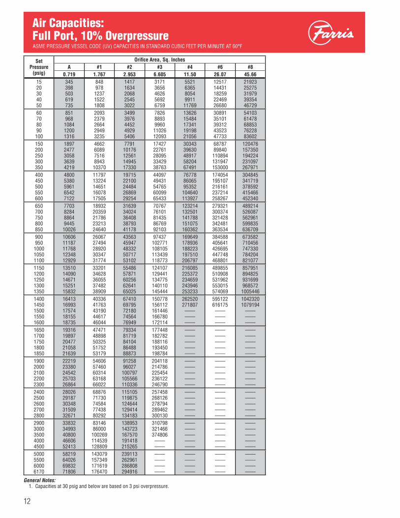
12
Air Capacities: Full Port, 10% Overpressure
General Notes: 1. Capacities at 30 psig and below are based on 3 psi overpressure.
ASME PRESSURE VESSEL CODE (UV) CAPACITIES IN STANDARD CUBIC FEET PER MINUTE AT 60°F
SetPressure
(psig)
Orifi ce Area, Sq. InchesA #1 #2 #3 #4 #6 #8
0.719 1.767 2.953 6.605 11.50 26.07 45.66 1520304050
345398503619735
848978123715221808
14171634206825453022
31713656462656926759
552163658054991111769
1251714431182592246926680
21923 25275 31979 39354 46729
60708090100
851968108412001316
20932379266429493235
34993976445249295406
7826889399601102612093
1362615484173411919821056
3089135101393124352347733
54103 61478 68853 76228 83602
150200250300350
18972477305836394219
466260897516894310370
779110176125611494517330
1742722761280953342938763
3034339630489175820467491
6878789840110894 131947 153000
120476 157350 194224 231097 267971
400450500550600
48005380596165427122
1179713224146511607817505
1971522100244842686929254
4409749431547656009965433
767788606595352104640 113927
174054 195107 216161 237214 258267
304845 341719 378592 415466 452340
650700750800850
770382848864944510026
1893220359217862321324640
3163934024364083879341178
7076776101814358676992103
123214 132501 141788 151075 160362
279321 300374 321428 342481 363534
489214 526087 562961 599835 636709
900950100010501100
1060611187117681234812929
2606727494289203034731774
4356345947483325071753102
97437102771 108105 113439 118773
169649 178936 188223 197510 206797
384588 405641 426695 447748 468801
673582 710456 747330 784204 821077
11501200125013001350
1351014090146711525115832
3320134628360553748238909
5548657871602566264165025
124107 129441 134775 140110 145444
216085 225372 234659 243946 253233
489855 510908 531962 553015 574069
857951 894825 931699 968572 1005446
14001450150015501600
1641316993175741815518735
4033641763431904461746044
6741069795721807456476949
150778 156112 161446166780172114
262520 271807 ——————
595122 616175 ——————
1042320 1079194
—— —— ——
16501700175018001850
1931619897204772105821639
4747148898503255175253179
7933481719841048648888873
177448182782188116193450198784
——————————
——————————
—— —— —— —— ——
19002000210022002300
2221923380245422570326864
5460657460603146316866022
9125896027100797 105566 110336
204118214786225454236122246790
——————————
——————————
—— —— —— —— ——
24002500260027002800
2802629187303483150932671
6887671730745847743880292
115105 119875 124644 129414 134183
257458268126278794289462300130
——————————
——————————
—— —— —— —— ——
29003000350040004500
3383234993408004660652413
8314686000100269 114539 128809
138953 143723 167570 191418215265
310798321466374806————
——————————
——————————
—— —— —— —— ——
5000550060006170
58219640266983271806
143079 157349 171619 176470
239113262961286808294916
————————
————————
————————
—— —— —— ——

13
Natural Gas Capacities: API Nozzle
General Notes: 1. Minimum set pressure for 1″ x 2″ size valves in any orifi ce is 20 psig. 2. Capacities based on a specifi c gravity of 0.65 at a temperature of 60°F. 3. Capacities at 30 psig and below are based on 3 psi overpressure.
ASME PRESSURE VESSEL CODE (UV) CAPACITIES IN STANDARD CUBIC FEET PER MINUTE AT 60°F
SetPressure
(psig)
Orifi ce Area, Sq. InchesD E F G H J K L M N P Q R T
0.110 0.196 0.307 0.503 0.785 1.287 1.838 2.853 3.60 4.34 6.38 11.05 16.0 26.0 1520304050
93107135167198
139161203250297
230265336413491
347400506623740
5426257919731155
8881024129515941893
12681462185022772703
19692270287235354197
24842864362444605296
2995345343695377 6385
4402 5075 6422 7903 9384
7622 8788 11119 13683 16247
11045 12734 16112 19827 23543
17978 20727 26225 32273 38320
60708090100
229261292324355
344391438486533
568646723801878
857973109012071324
13381520170318852068
21922491279030883387
31303557398444104837
48605522618468477509
61326968780486409476
7392 8400 9408 10415 11423
10865 12346 13827 15308 16789
18811 21375 23939 26503 29068
27259 30974 34690 38405 42121
44368 50416 56464 62512 68559
150200250300350
5126688259821139
7681003123814731708
12661654204124292817
19082492307636604244
29803892480457166629
488163767870936410858
69719104112381337215505
1082214134174462075824071
1365517835220142619430373
1646121500 26538 31577 36615
24194 31599 39004 46409 53814
41888 54709 67530 80350 93171
60699 79277 97855 116433 135011
98798 129037 159276 189515 219754
400450500550600
12951452160917651922
19432178241326482884
32043592398043674755
48285412599765817165
7541845393651027711190
1235213847153411683518329
1763919773219062404026174
2738330695340083732040632
3455338732429124709151271
41654 46692 5173056769 61807
61219 68625 76030 83435 90840
105992 118813 131633 144454 157275
153589 172167 190745 209323 227901
249993 280232 310471 340710 370949
650700750800850
20792236239225492706
31193354358938244059
51435530591863066693
774983338917950110085
1210213014139261483815750
1982321317228122430625800
2830730441325753470836842
4394447257505695388157194
5545159630638106798972169
66846 71884 76923 81961 86999
98245 105650 113055 120460 127865
170096 182916 195737 208558 221378
246479 265057 283635 302213 320791
401188 431427 461666 491905 522143
900950100010501100
28633019317633333490
42944529476449995235
70817468785682448631
1066911253118371242213006
1666317575184871939920311
2729428788302833177733271
3897641109432434537647510
6050663818671307044373755
7634880528847078888793066
92038 97076 102115 107153 112192
135270 142675 150081 157486 164891
234199 247020 259841 272661 285482
339370 357948 376526 395104 413682
552382 582621 612860 643099 673338
11501200125013001350
36463803396041164273
54705705594061756410
9019940797941018210570
1359014174147581534215926
2122422136230482396024872
3476536259377533924840742
4964451777539115604558178
7706780380836928700490316
97246101425 105605 109784 113964
117230 122268 127307 132345 137384
172296 179701 187106 194511 201916
298303 311124 323944 336765 349586
432260 450838 469416 487994 506572
703577 733816 764055 794294 824533
14001450150015501600
44304587474349005057
66456880711573507585
1095711345117331212012508
1651017094176781826218846
2578426697276092852129433
4223643730452244671948213
6031262446645796671368847
9362996941100253103566106878
118144 122323 ——————
142422 147461 —— —— ——
209321 216726 —— —— ——
362406 375227 —— —— ——
525150 543728 —— —— ——
854772 885011 —— —— ——
16501700175018001850
52145370552756845840
78218056829185268761
1289613283136711405914446
1943120015205992118321767
3034531258321703308233994
4970751201526955418955684
7098073114752487738179515
110190113502116815120127123439
——————————
—— —— —— —— ——
—— —— —— —— ——
—— —— —— —— ——
—— —— —— —— ——
—— —— —— —— ——
19002000210022002300
59976311662469387251
8996946699361040710877
1483415609163841716017935
2235123519246872585627024
3490636731385554037942204
5717860166631556614369131
8164985916901839445098718
126751133376140001146625153250
——————————
—— —— —— —— ——
—— —— —— —— ——
—— —— —— —— ——
—— —— —— —— ——
—— —— —— —— ——
24002500260027002800
75657878819185058818
1134711817122871275813228
1871019486202612103621812
2819229360305283169632865
4402845852476774950151326
7212075108780968108584073
102985 107252 111520 115787 120054
159874166499173123179748186373
——————————
—— —— —— —— ——
—— —— —— —— ——
———— —— —— ——
—— —— —— —— ——
—— —— —— —— ——
29003000350040004500
91329445110131258014147
1369814168165191887021221
2258723362272393111534992
3403335201410424688352724
5315054974640967321882340
8706290050104992 119934 134875
124322 128589 149925 171262 ——
192997199622232745265867 ——
——————————
—— —— —— —— ——
—— —— —— —— ——
—— —— —— —— ——
—— —— —— —— ——
—— —— —— —— ——
5000550060006170
15715172821884919382
23572259232827429074
38868427454662147939
58565644067024672232
91462100583 109705 112807
149817 164759 179701 184781
————————
—— —— —— ——
————————
—— —— —— ——
—— —— —— ——
—— —— —— ——
—— —— —— ——
—— —— —— ——

14
General Notes: 1. Minimum set pressure for 1″ x 2″ size valves in any orifi ce is 20 psig. 2. Capacities based on a specifi c gravity of 0.65 at a temperature of 60°F. 3. Capacities at 30 psig and below are based on 3 psi overpressure.
Natural Gas Capacities: Full Port ASME PRESSURE VESSEL CODE (UV) CAPACITIES IN STANDARD CUBIC FEET PER MINUTE AT 60°F
SetPressure
(psig)
Orifi ce Area, Sq. Inches A #1 #2 #3 #4 #6 #8
0.719 1.767 2.953 6.605 11.50 26.07 45.66 1520304050
416480607747887
10231180149318372181
17101972249530703646
38264411558168688155
6661768097171195814199
1510117411220292710932189
26450 30494 38583 47480 56378
60708090100
10271168130814481588
25262870321435593903
42214797537259476523
944210729120161330314590
1644018681209222316325404
3726942350474305251057590
65276 74173 83071 91968 100866
150200250300350
22882989368943905091
5625734690681079012511
940012277151551803220909
2102627461338974033246768
3660947814590187022381428
82991108392 133793 159194 184594
145354 189842 234330 278818 323306
400450500550600
57916492719278938593
1423315954176761939821119
2378626663295413241835295
5320359639660747251078945
92633103838 115043 126247 137452
209995 235396 260797 286198 311599
367794 412282 456770 501258 545746
650700750800850
92949994106951139512096
2284124563262842800629728
3817241049439274680449681
853819181698252104687 111122
148657 159862 171067 182271 193476
337000 362400 387801 413202 438603
590234 634723 679211 723699 768187
900950100010501100
1279713497141981489815599
3144933171348933661438336
5255855435583136119064067
117558 123993 130429 136864 143300
204681 215886 227091 238296 249500
464004 489405 514806 540206 565607
812675 857163 901651 946139 990627
11501200125013001350
1629917000177001840119101
4005841779435014522246944
6694469821726997557678453
149735 156171 162606 169042 175477
260705 271910 283115 294320 305525
591008 616409 641810 667211 692612
1035115 1079603 1124091 1168579 1213067
14001450150015501600
1980220503212032190422604
4866650387521095383155552
8133084207870858996292839
181913 188348 194784201219207655
316729 327934 ——————
718012 743413 ——————
1257555 1302043
—— —— ——
16501700175018001850
2330524005247062540626107
5727458996607176243964161
9571698593101471 104348 107225
214090220525 226961233396239832
——————————
——————————
—— —— —— —— ——
19002000210022002300
2680728209296103101132412
6588269325727697621279655
110102 115857 121611 127366 133120
246267 259138 272009284880297751
——————————
——————————
—— —— —— —— ——
24002500260027002800
3381335214366153801639417
8309986542899859342996872
138874 144629 150383 156138 161892
310622323493 336364349235362106
——————————
——————————
—— —— —— —— ——
29003000350040004500
4081842219492255623063236
100315 103758 120975 138191 155408
167646 173401 202173 230945 259717
374977387848452202516557——
——————————
——————————
—— —— —— —— ——
5000550060006170
70241772478425286634
172624 189841 207057 212911
288489 317261 346033 355816
————————
————————
————————
—— —— —— ——

15
General Notes: 1. Capacities at 30 psig and below are based on 3 psi overpressure.
Water Capacities: API Nozzle, 10% Overpressure
ASME PRESSURE VESSEL CODE (UV) CAPACITIES IN US GALLONS PER MINUTE AT 70°F
SetPressure
(psig)
Orifi ce Area, Sq. InchesD E F G H J K L M N P Q R T
0.110 0.196 0.307 0.503 0.785 1.287 1.838 2.853 3.60 4.34 6.38 11.05 16.0 26.0 1520304050
18.921.325.629.533.0
28.332.038.444.349.5
46.752.863.373.181.7
70.479.695.4110123
110124149172192
180203244281315
257291348402450
399451541624698
504 570 682 788 881
607 687 823 950 1062
893 1009 1209 1396 1561
1546 1748 2094 2418 2703
2241 2533 3035 3504 3918
3648 4124 4940 5704 6377
60708090100
36.239.141.844.346.7
54.358.662.766.570.1
89.596.7103109115
134145155165174
210227243258272
345372398422445
492532569603636
765826883937987
965 1042 1115 1182 1246
1164 1257 1344 1425 1502
1710 1847 1975 2095 2208
2962 3199 3420 3627 3824
4292 4636 4956 5256 5541
6986 7546 8067 8556 9019
150200250300350
57.266.173.980.987.4
85.899.1110121131
141163182200216
213246275301325
333384430471509
545630704771833
779900100611021190
12091397156217111848
1526 1762 1971 2159 2332
1840 2125 2376 2602 2811
2705 3123 3492 3825 4132
4683 5407 6046 6623 7154
6786 7836 8761 9597 10366
11046 12755 14260 15621 16873
400450500550600
93.499.1104109114
140148156164171
231245258271283
348369389408426
544577608638666
89194599610451091
12721350142314921558
19752095220923162419
2493 2644 2787 2923 3053
3005 3187 3360 3524 3681
4417 4685 4938 5179 5410
7648 8111 8550 8968 9366
1108211754 12390 12995 13573
18038 19132 20167 21152 22092
650700750800850
119123128132136
178185192198204
294305316327337
444460477492507
693719745769793
11361179122012601299
16221683174218001855
25182613270527942880
3178 3298 3414 3525 3634
3831 3976 4115 4250 4381
5631 5843 6048 6247 6439
9749 10117 10472 10815 11148
14127 14660 15175 15672 16155
22994 23862 24700 25510 26295
900950100010501100
140144147151155
210216221227232
346356365374383
522536550564577
816838860881902
13361373140914441478
19091961201220622110
29633045312432013276
3739 3842 3942 4039 4134
4508 4631 4752 4869 4984
6626 6807 6984 7156 7325
11472 11786 12092 12391 12682
16623 17079 17522 17955 18378
27057 27799 28521 29225 29913
11501200125013001350
158161165168171
237242247252257
392400408416424
590603615628640
922942961980999
15111543157516061637
21582204225022942338
33503422349235623629
4227 4318 4407 4494 4580
5096 5205 5313 5418 5521
7490 7651 7808 7963 8115
12967 13246 13519 13787 14050
18791 19195 19591 19979 20359
30585 31243 31887 32519 33138
14001450150015501600
174178181184186
262267271276280
432440447455462
651663674685696
10181036105310711088
16671697172617541782
23812423246425052545
36963761382638893951
4664 4746 —— —— ——
5622 5722 —— —— ——
8264 8410 —— —— ——
14308 14561 —— —— ——
20733 21100 —— —— ——
33747 34344 —— —— ——
16501700175018001850
189192195198201
284289293297301
469476483490497
707718728739749
11051121113811541170
18101837186418901916
25852623266227002737
40134073413241914249
—— —— —— —— ——
—— —— —— —— ——
—— —— —— —— ——
—— —— —— —— ——
—— —— —— —— ——
—— —— —— —— ——
19002000210022002300
203209214219224
305313321328336
503517529542554
759779798817835
11851216124612761304
19421993204220902137
27732846291629843052
43064418452746334738
—— —— —— —— ——
—— —— —— —— ——
—— —— —— —— ——
—— —— —— —— ——
—— —— —— —— ——
—— —— —— —— ——
24002500260027002800
229233238242247
343350357364371
566578589600611
853871888905921
13321360138714131439
21832228227223152358
31173181324533063367
48394939503751335227
—— —— —— —— ——
—— —— —— —— ——
—— —— —— —— ——
—— —— —— —— ——
—— ———— —— ——
—— —— —— —— ——
29003000350040004500
251256276295313
377384414443470
622633684731775
938954103011011168
14651490160917201825
23992441263628182989
3427348537644024 ——
5320541158446248 ——
—— —— —— —— ——
—— —— —— —— ——
—— —— —— —— ——
—— —— —— —— ——
—— —— —— —— ——
—— —— —— —— ——
5000550060006170
330346362367
495520543550
817857895908
1231129213491368
1923201721072137
3151330534523500
—— —— —— ——
—— —— —— ——
—— —— —— ——
—— —— —— ——
—— —— —— ——
—— —— —— ——
—— —— —— ——
—— —— —— ——

16
1Temperatures & Materials
Des
igna
tion
Numbering System
CConstruction
C Elastomer O-Ring Seat Seal
T Tefl on O-Ring* Seat & Seals(Main Valve Only)*For cryogenic *applications to *-450° F, add S4 to *the type number. *Consult the Factory.
DOrifi ce Area
Designation API Actual & Orifi ce Orifi ce Area Orifi ce Area Letter Sq. In. Sq. In.
D 0.110 0.150 E 0.196 0.225 F 0.307 0.371 G 0.503 0.559 H 0.785 0.873 J 1.287 1.430 K 1.838 2.042 L 2.853 3.170 M 3.60 4.000 N 4.34 4.822 P 6.38 7.087 Q 11.05 12.27 R 16.00 17.78 T 26.00 28.94 A – 0.719 1 – 1.767 2 – 2.953 3 – 6.605 4 – 11.50 6 – 26.07 8 – 45.66
38Series Number
38
To simplify the selection and specifying of Farris pressure relief valves, use the following type numbering system. The type number-ing system is ideal as the digits which comprise a specifi c type number have a distinct signifi cance. The digits describe the basic valve series, orifi ce, seat and internal construction, inlet temperature range, body, and spring material, inlet fl ange class as well as Code liquid design.
Ordering InformationTo properly process your order and avoid delay please specify the following:
11. Backpressure, Superimposed Constant and/or Variable and Built-up*.
12. Required Capacity*.13. Physical Properties of Fluid (Molecular Wt., Specifi c Gravity,
etc.).14. Accessories
a) Manual or Remote Blowdownb) Field Test Connectionc) Reverse Flow Preventerd) Auxiliary Filters
15. Code Requirements, if any.
1. Quantity2. Inlet and Outlet Size.3. Farris Type Number*.4. Inlet and Outlet Flange Class and Facing.5. Materials of Construction, if other than Standard.6. O-Ring Seal Material (Viton is Standard).7. Set Pressure*.8. Maximum Inlet Temperature*.9. Allowable Overpressure*.10. Fluid and Fluid State*.
* As a customer service we verify your selection and sizing. If this service is desired, you must include this information.Note: If valve modifi cation or set pressure changes are required, consideration must be given to correct the nameplate and other data.
Inlet Material
Temperature Body Range °F & Cover Spring
1 -20 to 450 Carbon Stainless Steel Steel
1 -20 to -450 Consult Consult Factory Factory

17
0Options
No Options ...........0Dual PilotControls ...............2Auxiliary Filter ......3Manual Depressurizing .....4Field Test Connections .........5Automatic Reverse Flow Preventer .............6Pressure Spike Snubbers .............7RemoteDepressurizing .....8Four Auxiliary Functions* ...........9Specify Combination of Options Following Complete Type Number ................CRemote Sensing ............... R
2PilotControl
Snap Acting Pilot Control ........2Modulating Pilot Control ...... M
2Inlet Class
ANSI
Nominal Inlet Flange Class
0 150 2 300 3 600 4 900 5 1500 6 2500
Des
igna
tion
XSpecialConstruction
(If applicable)L-Liquid Service
(Standard Connections)
X-Air & Vapor Service (Oversize Connections)
Y-Liquid Service (Oversize Con-nections)
D-Air & VaporService(Dual Outlet)1
E-Liquid Service (Dual Outlet)1
1. Available on 6 ″ and 8″ inlet size valves only.
1Inlet Facing
Special ................0Raised Face, ANSI Std. (125 to 160 AARH) .........1Ring Joint ANSI Std. (Octagonal) .........963 AARH Smooth Finish RF ............ HAlthough not applicable to the inlet facing only, the following fi rst digit letters are also used:63 to 83 AARH (Outlet only) ........J63 to 83 AARH (Inlet and outlet) ................ K
-
Parts ReplacementValves: If an exact replacement valve is required, the valve type, size and serial number must be specifi ed to assure proper dimensions and material being supplied. If a specifi c valve has become obsolete, a recommendation for the current equivalent, if any, will be made.
Spare Parts: When ordering parts, use part names as listed in the bills of material in this catalog. Specify valve type, size and serial number. If serial number is not available, the original Far-ris factory order number will assist in our supplying the proper part and material.
Springs: Order as an assembly to include spring with upper and lower spring buttons. Specify valve type, size, serial num-ber, set pressure and back pressure, if any.
* Includes a combination * of 4, 5, 6 & 8.
Guarantee All products manufactured by Farris Engineering are warranted free of defects in material and workmanship when used within the range recommended for a period of one year after installa-tion or eighteen months from delivery. When authorized, any defective product may be returned to the factory and if found defective will be repaired or replaced free of charge, solely at the discretion of Farris Engineering, ex-works our factory. No charge for labor or other expense incurred will be allowed, as the liability of Farris Engineering is measured by the refund price of the defective product only. All warranties are based on the product being used within the range recommended.
This warranty does not cover the performance of valves tested at site on test equipment that is not to the same technical stan-dard as that used by the manufacturer.
/S4SpecialMaterial
S4 Complete 316 St. St.
S7 NACE Construction
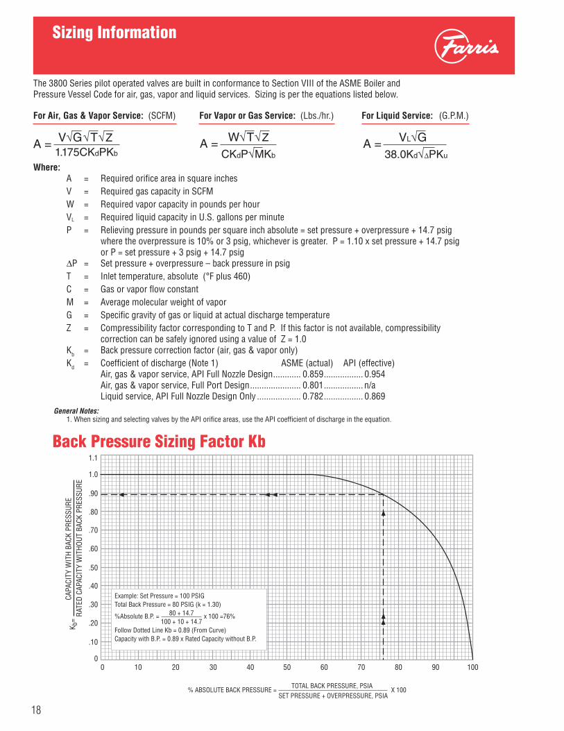
0 10 20 30 40 50 60 70 80 90 1000
.10
.20
.30
.40
.50
.60
.70
.80
.90
1.0
1.1
K b=
CAP
ACIT
Y W
ITH
BAC
K PR
ESSU
RE
RAT
ED C
APAC
ITY
WIT
HO
UT
BACK
PR
ESSU
RE
% ABSOLUTE BACK PRESSURE = TOTAL BACK PRESSURE, PSIA
SET PRESSURE + OVERPRESSURE, PSIA X 100
Example: Set Pressure = 100 PSIGTotal Back Pressure = 80 PSIG (k = 1.30)
%Absolute B.P. = 80 + 14.7 x 100 =76% 100 + 10 + 14.7Follow Dotted Line Kb = 0.89 (From Curve)Capacity with B.P. = 0.89 x Rated Capacity without B.P.
Back Pressure Sizing Factor Kb
18
The 3800 Series pilot operated valves are built in conformance to Section VIII of the ASME Boiler and Pressure Vessel Code for air, gas, vapor and liquid services. Sizing is per the equations listed below.
For Air, Gas & Vapor Service: (SCFM) For Vapor or Gas Service: (Lbs./hr.) For Liquid Service: (G.P.M.)
Where: A = Required orifi ce area in square inches V = Required gas capacity in SCFM W = Required vapor capacity in pounds per hour
VL = Required liquid capacity in U.S. gallons per minute P = Relieving pressure in pounds per square inch absolute = set pressure + overpressure + 14.7 psig where the overpressure is 10% or 3 psig, whichever is greater. P = 1.10 x set pressure + 14.7 psig or P = set pressure + 3 psig + 14.7 psig ΔP = Set pressure + overpressure – back pressure in psig T = Inlet temperature, absolute (°F plus 460) C = Gas or vapor fl ow constant M = Average molecular weight of vapor
G = Specifi c gravity of gas or liquid at actual discharge temperature Z = Compressibility factor corresponding to T and P. If this factor is not available, compressibility correction can be safely ignored using a value of Z = 1.0 Kb = Back pressure correction factor (air, gas & vapor only)
Kd = Coeffi cient of discharge (Note 1) ASME (actual) API (effective) Air, gas & vapor service, API Full Nozzle Design ............ 0.859 ................. 0.954 Air, gas & vapor service, Full Port Design ...................... 0.801 ................. n/a Liquid service, API Full Nozzle Design Only ................... 0.782 ................. 0.869
A = V√G√T√Z
1.175CKdPKbA = W√T√Z
CKdP√MKb
Sizing Information
A = VL√G
38.0Kd√ΔPKu
General Notes: 1. When sizing and selecting valves by the API orifi ce areas, use the API coeffi cient of discharge in the equation.

19
A full line of accessories is available to meet your service requirements.
Manual or Remote Blowdown: the main valve can be cycled to the open position by venting the pressure in the dome above the piston. The optional manual valve for this purpose mounts directly on the main valve. By installing a solenoid valve, the main valve can be cycled remotely. Neither the manual or remote blowdown system will interfere with the normal overpressure protection provided by the main valve and pilot.
Reverse Flow Preventer: in a system where back pressure exceeds system pressure, it is possible for the main valve to open and allow fl ow from the discharge system to enter the inlet side. A reverse fl ow preventer assures that the back pressure, as a minimum, is maintained in the dome area so that the main valve remains closed.
Field Test Connection: the set pressure of Farris pilot operated relief valves can be verifi ed without interrupting system protection and does not require overpressure of the system. An auxiliary source of pressure, such as a nitrogen bottle, is connected to the pilot sensing line through a stop valve. Pressure applied to the pilot valve reacts the way it would if the pilot were sensing overpressure in the main valve sensing line. A check valve restricts the source pressure from back-fl owing into the main inlet. Both pilot and main valves will cycle at set pressure, verifying the set pressure and validating that the system is in compliance with ASME Section VIII, UG-136(a)(3).
Spike Snubbers: a spike snubber installed in the pilot valve sensing line will eliminate the negative effects of pressure pulsation caused by a positive displacement compressor. It assures that the pilot valve is sensing and reacting to mean pressure to protect the system and not to cyclic pressure that can be caused by a com-pressor.
Auxiliary Filters: every PCF3 pilot valve is manufactured with an internal fi lter to reduce the fl ow of erosive particlesthrough the pilot control. Auxiliary fi lters for the pilot valve sensing line are available to complement the internal fi lter for special services.
PILOTCONTROL
EXHAUST
EXHAUST
MANUAL BLOWDOWN VALVE(OPEN TO DEPRESSURE)
CHECK VALVE FORREMOTE CONTROL ONLY
INLET PRESSURECONNECTION
INLET PRESSURECONNECTION
DOUBLE ACTINGCHECK VALVE
PILOTCONTROL
EXHAUST
PILOTCONTROL
EXHAUST
INLET PRESSURECONNECTION
CHECK VALVEBLEED VALVECHECK VALVE
AUXILIARYPRESSURE
SOURCE
AUXILIARYINPUT LINE
PRESSURE REGULATOR AND/ORMANUAL METERING VALVE FOR TESTING
MANUAL STOP VALVE(OPEN FULLY BEFORE
TESTING SAFETY VALVE)
Accessories
Manual or Remote Blowdown
Reverse Flow Preventer
Field Test Connection

Dimensions and Weights: API Nozzle
20
Valve SizeInlet x Outlet Type Number
ANSIFlange Class
Dimension(Inches) Approx.
WeightLbs. Inlet
RFOulet
RF A B C E F
1 x 2
38DC10-12038DC12-12038DC13-120
150#300#600#
150# 12 1/812 3/812 3/8
4 1/24 1/24 1/2
4 1/84 3/84 3/8
1/161/161/4
11/1615/1615/16
30 30 30
38DC14-12038DC15-12038DC16-120
900#1500#2500#
300# 12 7/812 7/8
13
4 3/44 3/44 3/4
4 15/16 4 15/164 15/16
1/41/41/4
1 7/161 7/161 11/16
49 49 55
1 x 2
38EC10-120 38EC12-120 38EC13-120
150#300#600#
150# 12 1/812 3/812 3/8
4 1/24 1/24 1/2
4 1/84 3/84 3/8
1/161/161/4
11/1615/1615/16
30 30 30
38EC14-120 38EC15-120 38EC16-120
900#1500#2500#
300# 12 7/812 7/8
13
4 3/44 3/44 3/4
4 15/16 4 15/16 4 15/16
1/41/41/4
1 7/161 7/161 11/16
49 49 55
1 x 2
38FC10-120 38FC12-120 38FC13-120
150#300#600#
150# 12 1/812 3/812 3/8
4 1/24 1/24 1/2
4 1/84 3/84 3/8
1/161/161/4
11/1615/1615/16
30 30 30
38FC14-120 38FC15-120 38FC16-120
900#1500#2500#
300# 12 7/812 7/8
13
4 3/44 3/44 3/4
4 15/16 4 15/16 4 15/16
1/41/41/4
1 7/161 7/161 11/16
49 49 55
1 1/2 x 2
38DC10X-12038DC12X-12038DC13X-120
150#300#600#
150# 13 1/213 1/213 1/2
4 3/44 3/44 3/4
4 7/84 7/84 7/8
1/161/161/4
1 1/81 1/81 1/8
32 32 32
38DC14X-12038DC15X-12038DC16X-120
900#1500#2500#
300# 14 1/214 1/214 5/8
5 1/25 1/25 1/2
5 7/85 7/85 7/8
1/41/41/4
1 9/161 9/162 1/8
71 71 85
1 1/2 x 2
38EC10X-12038EC12X-12038EC12X-120
150#300#600#
150# 13 1/213 1/213 1/2
4 3/44 3/44 3/4
4 7/84 7/84 7/8
1/161/161/4
1 1/81 1/81 1/8
32 3232
38EC14X-12038EC15X-12038EC16X-120
900#1500#2500#
300# 14 1/214 1/214 5/8
5 1/25 1/25 1/2
5 7/85 7/85 7/8
1/41/41/4
1 9/16 1 9/162 1/8
7171 85
1 1/2 x 2
38FC10X-12038FC12X-12038FC13X-120
150#300#600#
150# 13 1/213 1/213 1/2
4 3/44 3/44 3/4
4 7/84 7/84 7/8
1/161/161/4
1 1/81 1/81 1/8
32 32 32
38FC14X-12038FC15X-12038FC16X-120
900#1500#2500#
300# 14 1/214 1/214 5/8
5 1/25 1/25 1/2
5 7/85 7/85 7/8
1/41/41/4
1 9/161 9/162 1/8
71 71 85
1 1/2 x 3
38GC10-12038GC12-12038GC13-120
150#300#600#
150# 13 1/213 1/213 1/2
4 7/84 7/84 7/8
5 1/85 1/85 1/8
1/161/161/4
1 3/161 3/161 3/16
40 40 42
38GC14-12038GC15-12038GC16-120
900#1500#2500#
300# 14 3/414 3/414 7/8
6 3/46 3/46 3/4
6 3/86 3/86 3/8
1/41/41/4
1 9/161 9/162 1/8
81 81 96
1 1/2 x 3
38HC10-12038HC12-12038HC13-120
150#300#600#
150# 13 1/213 1/213 1/2
4 7/84 7/84 7/8
5 1/85 1/85 1/8
1/161/161/4
1 3/161 3/161 3/16
40 40 42
38HC14-12038HC15-12038HC16-120
900#1500#2500#
300# 14 3/414 3/414 7/8
6 3/46 3/46 3/4
6 3/86 3/86 3/8
1/41/41/4
1 9/161 9/162 1/8
81 81 96
2 x 3
38GC10X-12038GC12X-12038GC13X-120
150#300#600#
150# 14 1/214 1/214 1/2
4 7/84 7/84 7/8
5 3/85 3/85 3/8
1/161/161/4
1 1/41 1/41 1/4
45 55 75
38GC14X-12038GC15X-12038GC16X-120
900#1500#2500#
300#/600# 15 5/815 5/816 1/4
6 3/46 3/46 3/4
6 9/166 9/16
7
1/41/41/4
1 7/81 7/82 3/8
102 102 124
2 x 3
38HC10X-12038HC12X-12038HC13X-120
150#300#600#
150# 14 1/214 1/214 1/2
4 7/84 7/84 7/8
5 3/85 3/85 3/8
1/161/161/4
1 1/41 1/41 1/4
45 55 75
38HC14X-12038HC15X-12038HC16X-120
900#1500#2500#
300#/600# 15 5/815 5/816 1/4
6 3/46 3/46 3/4
6 9/166 9/16
7
1/41/41/4
1 7/81 7.82 3/8
102 102 124

A
B
C
E F
21
Dimensions and Weights: API Nozzle
General Notes: 1. For liquid service valves with standard size connections (L in the type number), use the standard type number dimensions, i.e. 38HC10-120. For liquid service valves with oversize connections (Y in the type number), use the oversize type number dimensions, i.e. 38DC10X-120.2. Valves with ring joint inlet connections available on application only. Consult the Factory.3. For modulating valves, add 2 1/2″ to the A dimension.
Valve SizeInlet x Outlet Type Number
ANSI Flange Class
Dimension(Inches) Approx.
Weight Lbs. Inlet
RFOulet
RF A B C E F
2 x 3
38JC10-12038JC12-12038JC13-120
150#300#600#
150# 14 1/214 1/214 1/2
4 7/84 7/84 7/8
5 3/85 3/85 3/8
1/161/161/4
1 1/41 1/41 1/4
45 55 75
38JC14-12038JC15-12038JC16-120
900#1500#2500#
300#/600#15 5/815 5/816 1/4
6 3/46 3/46 3/4
6 9/166 9/16
7
1/41/41/4
1 7/81 7/82 3/8
102 102 124
3 x 4
38JC10X-12038JC12X-12038JC13X-120
150#300#600#
150#17 1/817 1/817 3/8
6 3/86 3/86 3/8
6 1/86 1/86 3/8
1/161/161/4
1 1/41 1/41 1/2
85 95 100
38JC14X-12038JC15X-120
900#1500# 300# 18 5/8
18 5/87 1/87 1/8
7 1/27 1/2
1/41/4
2 1/42 1/4
172 187
3 x 4
38KC10-12038KC12-12038KC13-120
150#300#600#
150#17 1/817 1/817 3/8
6 3/86 3/86 3/8
6 1/86 1/86 3/8
1/161/161/4
1 1/41 1/41 1/2
95 105 110
38KC14-12038KC15-120
900#1500# 300# 18 5/8
18 5/87 1/87 1/8
7 1/27 1/2
1/41/4
2 1/42 1/4
172 187
3 x 4
38LC10-12038LC12-12038LC13-120
150#300#600#
150#17 1/817 1/817 3/8
6 3/86 3/86 3/8
6 1/86 1/86 3/8
1/161/161/4
1 1/41 1/41 1/2
105 115 125
38LC14-12038LC15-120
900#1500# 300# 18 5/8
18 5/87 1/87 1/8
7 1/27 1/2
1/41/4
2 1/42 1/4
172 187
4 x 638LC10X-12038LC12X-12038LC13X-120
150#300#600#
150#19 3/4 19 3/419 3/4
8 1/48 1/48 1/4
7 3/47 3/47 3/4
1/161/161/4
1 3/41 3/41 3/4
120 140 145
4 x 638MC10-12038MC12-12038MC13-120
150#300#600#
150#19 3/4 19 3/419 3/4
8 1/48 1/48 1/4
7 3/47 3/47 3/4
1/161/161/4
1 3/41 3/41 3/4
130 140 150
4 x 638NC10-12038NC12-12038NC13-120
150#300#600#
150#19 3/4 19 3/419 3/4
8 1/48 1/48 1/4
7 3/47 3/47 3/4
1/161/161/4
1 3/41 3/41 3/4
130 140 155
4 x 638PC10-12038PC12-12038PC13-120
150#300#600#
150#19 3/4 19 3/419 3/4
8 1/48 1/48 1/4
7 3/47 3/47 3/4
1/161/161/4
1 3/41 3/41 3/4
130 140 155
6 x 838QC10-12038QC12-12038QC13-120
150#300#600#
150#24 1/8 24 1/824 3/8
9 1/29 1/29 1/2
9 7/16 9 7/16 9 11/16
1/161/161/4
1 7/81 7/82 1/4
200 220 270
6 x 838RC10-12038RC12-12038RC13-120
150#300#600#
150#24 1/8 24 1/824 3/8
9 1/29 1/29 1/2
9 7/16 9 7/16 9 11/16
1/161/161/4
1 7/81 7/82 1/4
230 270 300
8 x 10 38TC10-12038TC12-12038TC13-120
150#300#600#
150#28 1/228 1/2 29 3/8
11 1111
10 7/8 10 7/8
11 11/16
1/161/161/4
1 5/81 5/82 3/16
450 500 700

3800 Series Full Port Design: Dimensions & Weights
A
B
C
E F
22
General Notes: 1. For liquid service valves with standard size connections (L in the type number), use the standard type number dimensions, i.e. 38HC10-120. For liquid service valves with oversize connections (Y in the type number), use the oversize type number dimensions, i.e. 38DC10X-120.2. Valves with ring joint inlet connections available on application only. Consult the Factory.3. For modulating valves, add 2 1/2″ to the A dimension.
Valve SizeInlet x Outlet Type Number
ANSIFlange Class
Dimension(Inches) Approx.
Weight Lbs. Inlet
RFOulet
RF A B C E F
1 1/2 x 2
381C10-120381C12-120381C13-120
150#300#600#
150#13 1/213 1/213 1/2
4 3/44 3/44 3/4
4 7/84 7/84 7/8
1/161/161/4
1 1/81 1/81 1/8
35 35 40
381C14-120381C15-120381C16-120
900#1500#2500#
300#14 1/214 1/214 5/8
5 1/25 1/25 1/2
5 7/85 7/85 7/8
1/41/41/4
1 9/161 9/162 1/8
71 71 85
1 1/2 x 3
381C10X-120381C12X-120381C13X-120
150#300#600#
150#13 1/213 1/213 1/2
4 7/84 7/84 7/8
5 1/85 1/85 1/8
1/161/161/4
1 3/161 3/161 3/16
35 35 40
381C14X-120381C15X-120381C16X-120
900#1500#2500#
300#14 3/414 3/414 7/8
6 3/46 3/46 3/4
6 3/86 3/86 3/8
1/41/41/4
1 9/161 9/162 1/8
81 81 96
2 x 3
382C10-120382C12-120382C13-120
150#300#600#
150#14 1/214 1/214 1/2
4 7/84 7/84 7/8
5 3/85 3/85 3/8
1/161/161/4
1 1/41 1/41 1/4
50 60 80
382C14-120382C15-120382C16-120
900#1500#2500#
300#/600#15 5/815 5/816 1/4
6 3/46 3/46 3/4
6 9/166 9/16
7
1/41/41/4
1 7/81 7/82 3/8
102 102 124
3 x 4
383C10-120383C12-120383C13-120
150#300#600#
150#17 1/817 1/817 3/8
6 3/86 3/86 3/8
6 1/86 1/86 3/8
1/161/161/4
1 1/41 1/41 1/2
90 100 105
383C14-120383C15-120
900#1500# 300# 18 5/8
18 5/87 1/87 1/8
7 1/27 1/2
1/41/4
2 1/42 1/4
172 187
4 x 6384C10-120384C12-120384C13-120
150#300#600#
150#19 3/4 19 3/419 3/4
8 1/48 1/48 1/4
7 3/47 3/47 3/4
1/161/161/4
1 3/41 3/41 3/4
135 145 160
6 x 8386C10-120386C12-120386C13-120
150#300#600#
150#24 1/8 24 1/824 3/8
9 1/29 1/29 1/2
9 7/16 9 7/16 9 11/16
1/161/161/4
1 7/81 7/82 1/8
235 275 305
8 x 10 388C10-120388C12-120388C13-120
150#300#600#
150#28 1/228 1/2 29 1/4
11 1111
10 7/8 10 7/8
11 11/16
1/161/161/4
1 5/81 5/82 3/16
460 510 710

23
Farris Engineering Products
Process Pressure Relief Valves
Test Stands
Special Purpose Pressure Relief Valves
Steam Safety Valves
MODELS T1500 & T6000 • Air & Water Testing• Maximum Pressures of 1500 psig and
6000 psig• Test Valves to 8" Inlet Size• Stainless Steel Test Drum & Test Table• Digital Test Gauge
SERIES 6400/6600 • ASME NB Section I & VIII Certifi ed:
Steam & Air• Sizes: 1" x 2" to 4" x 6"• Pressure Range: 15 psig to 1500 psig• Temperature Range: -20°F to +1000°F• Materials: Carbon and Stainless Steel• Options: Exposed Spring & Closed
Bonnet
SERIES 1890/1896M • ASME NB Certifi ed: Air, Steam & Water• Sizes: 1/2" x 1" & 3/4" x 1" (1890)
1/2" x 3/4" & 3/4" x 3/4" (1896M)• Pressure Range:
15 psig to 800 psig (1890) 15 psig to 300 psig (1896M)
• Temperature Range: -20°F to +750°F (1890) -450°F to +400°F (1896M)
• Materials: Stainless Steel Body & Trim (1890)Brass Body & Trim, Bronze Bonnet (1896M)
SERIES 4200 • ASME NB Section I & VIII Certifi ed:
Steam & Air• Sizes 1 1/4" x 1 1/2" to 6" x 8"• Pressure Range: 15 psig to 1000 psig• Temperature Range: -20°F to +1000°F• Materials: Carbon / Alloy St. &
Stainless Steel.
SERIES 3800 Pilot Operated • ASME NB Certifi ed: Air, Steam
& Water• Sizes: 1" x 2" to 12" x 16"
• Pressure Range: 15 psig to 6170 psig• Temperature Range: -450°F to +500°F• Materials: Steel Body & Bonnet,
Stainless Steel Trim• Options: Modulating Pilot Control,
Complete 316 Stainless Steel Construction
SERIES 2700 • ASME NB Certifi ed: Air, Steam & Water• Sizes: 1/2" x 1" to 1-1/2" x 2-1/2"• Pressure Range: 15 psig to 6500 psig• Temperature Range: -450°F to +750°F• Materials: Stainless Steel Body & Trim,
Carbon Steel Bonnet• Options: Stainless Steel, Monel &
Hastelloy Materials, O-Ring Seats, Flanged, Socket Weld, Welding Nipple, & Sanitary Connections
SERIES 2850/2856 • ASME NB Certifi ed: Air & Steam• Sizes: 3/4" x 1" to 1-1/2" x 2" (2850)
3/4" x 1-1/4" to 2" x 3" (2856)• Pressure Range: 15 psig to 300 psig• Temperature Range:
-20° F to +750°F (2850) -450° F to +400°F (2856)
• Materials: Stainless Steel Body & TrimSteel Bonnet (2850)Brass Body & Trim, Bronze Bonnet (2856)
SERIES 2600/2600L • ASME NB Certifi ed: Air, Steam & Water• Sizes: 1" x 2" to 20" x 24"• Pressure Range: 15 psig to 6000 psig• Temperature Range: -450°F to +1500°F• Materials: Carbon Steel, Stainless,
Monel & Hastelloy C• Options: Balanced Bellows, O-Ring
Seat, Open Bonnet

Farris Engineering Products & Services
© 2008 Farris EngineeringPrinted in USA
10/08 5M-3800 R6
Process Pressure Relief ValvesSeries 2600 ASME NB Certifi ed for Air, Steam and WaterSeries 2700 ASME NB Certifi ed for Air, Steam and WaterSeries 3800 ASME NB Certifi ed for Air, Steam and WaterSeries 1890/1896M ASME NB Certifi ed for Air, Steam and WaterSeries 2850/2856 ASME NB Certifi ed for Air and SteamSeries 69 Liquid ServiceSeries 88/89 ASME NB Certifi ed for Air and SteamSeries 140 Air ServiceSeries 570 ASME NB Certifi ed for Air and Steam
Steam Safety ValvesSeries 4200 ASME NB Certifi ed for Steam – Section I & VIIISeries 6400/6600 ASME NB Certifi ed for Steam – Section I & VIIISeries 560 ASME NB Certifi ed for Steam – Section I & VIII
Universal Test StandPRV Test Stands with Air and Water Test Capability
SizeMaster™ Mark IVPressure Relief Valve Engineering Software for Sizing and Selection
The following is a list of Farris approvals currently on record:• ASME “V”, “UV” and “NV” • National Board “NB” • ISO 9001-2000• US Coast Guard • PED 97/23/EC (European Pressure Equipment Directive)• ATEX 94/9/EC (European Potentially Explosive Atmospheres)• Canadian TSSA Registration• CSQL (China Safety Quality License)• GOST-R and GGNT (Russian Certifi cation and Permits)• First Point Assesment Limited
10195 Brecksville Road, Brecksville, OH 44141 USA • Telephone: 440-838-7690 • Fax: 440-838-7699 • www.farrisengineering.comFacilities: Brecksville, Ohio USA; Brantford, Ontario; Edmonton, Alberta, Canada; Kettering, Northants, UK; Delhi, India; Tianjin, ChinaOffi ces Worldwide: For a listing of our global sales network, visit our website at www.farrisengineering.com.
While this information is presented in good faith and believed to be accurate, Farris Engineering, division of Curtiss-Wright Flow Control Corporation, does not guarantee satisfactory results from reliance on such information. Nothing contained herein is to be construed as a warranty or guarantee, expressed or implied, regarding the performance, merchantability, fi tness or any other matter with respect to the products, nor as a recommendation to use any product or process in confl ict with any patent. Farris Engineering, division of Curtiss-Wright Flow Control Corporation, reserves the right, without notice, to alter or improve the designs or specifi cations of the products described herein.
FAST Centers (Farris Authorized Service Team)“Understanding what the Customer wants…making it happen!”
• Worldwide Network of Service Centers with Factory Trained Technicians• Local Inventory with 24 hour a day / 7 day a week support• Access to Worldwide Farris Inventory through the Web• ASME/National Board approved Assembly & Test Facilities• Application, Sizing & Selection Support
Farris Engineering
division of Curtiss-Wright Flow Control Corporation