series - Yanmar
74
6SY series OPERATION MANUAL P/N: 0ASYM-G00101 MARINE ENGINE
-
Upload
khangminh22 -
Category
Documents
-
view
5 -
download
0
Transcript of series - Yanmar

6SYseries
OPERATION MANUAL
P/N: 0ASYM-G00101
MARINEENGINE

Disclaimers:We reserve the right to change specifications and to improve our products without notice orobligation.All information, illustrations and specifications in this manual are based on the latestinformation available at the time of publishing. The illustrations used in this manual areintended as representative reference views only. Moreover, because of our continuousproduct improvement policy, we may modify information, illustrations and / or specificationsto explain and / or exemplify a product, service or maintenance improvement. We reservethe right to make any change at any time without notice. Yanmar and areregistered trademarks of Yanmar Co., Ltd. in Japan, the United States and / or othercountries.All Rights Reserved:No part of this publication may be reproduced or used in any form by any means - graphic,electronic, or mechanical, including photocopying, recording, taping, or information storageand retrieval systems - without the written permission of Yanmar Marine International.© 2006 Yanmar Marine International
1006
ii 6SY Operation Manual

INTRODUCTIONWelcome to the world of Yanmar Marine!Yanmar Marine offers engines, drivesystems and accessories for all types ofboats, from runabouts to sailboats, and fromcruisers to mega yachts. In marine leisureboating, the worldwide reputation of YanmarMarine is second to none. We design ourengines to respect nature. This meansquieter engines, with minimal vibrations,cleaner than ever. All of our enginesdesigned after 1996 meet most of thepresent and future emission regulations,such as BSO II, SAV, EPA II, IMO and RCD.To help you enjoy your Yanmar 6SY enginefor many years to come, please follow theserecommendations:
• Read and understand this OperationManual before you operate the machineto ensure that you follow safe operatingpractices and maintenance procedures.
• Keep this Operation Manual in aconvenient place for easy access.
• If this Operation Manual is lost ordamaged, order a new one from yourauthorized Yanmar marine dealer ordistributor.
• Make sure this manual is transferred tosubsequent owners. This manual shouldbe considered a permanent part of theengine and remain with it.
• Constant efforts are made to improve thequality and performance of Yanmarproducts, so some details included in thisOperation Manual may differ slightly fromyour engine. If you have any questionsabout these differences, please contactyour authorized Yanmar marine dealer ordistributor.
• The specifications and components(instrument panel, fuel tank, etc.)described in this manual may differ fromones installed on your vessel. Please referto the manual provided by themanufacturer of these components.
6SY Operation Manual iii

RECORD OF OWNERSHIPTake a few moments to record the information you need when you contact Yanmar forservice, parts or literature.
Engine Model:
Engine Serial No.:
Date Purchased:
Dealer:
Dealer Phone:
INTRODUCTION
iv 6SY Operation Manual

TABLE OFCONTENTS
PageSafety ....................................................................... 1
Safety Precautions . . . . . . . . . . . . . . . . . . . . . . . . . . . . . . . . . . . . . . . . . . . . . . . . . 2General Information . . . . . . . . . . . . . . . . . . . . . . . . . . . . . . . . . . . . . . . . . 2Before You Operate . . . . . . . . . . . . . . . . . . . . . . . . . . . . . . . . . . . . . . . . . 2During Operation and Maintenance . . . . . . . . . . . . . . . . . . . . . 2
Safety Decals . . . . . . . . . . . . . . . . . . . . . . . . . . . . . . . . . . . . . . . . . . . . . . . . . . . . . . . 7Product Overview ...................................................... 9
Yanmar 6SY Features and Applications . . . . . . . . . . . . . . . . . . . . . . 9Component Identification . . . . . . . . . . . . . . . . . . . . . . . . . . . . . . . . . . . . . . . . 10Nameplate . . . . . . . . . . . . . . . . . . . . . . . . . . . . . . . . . . . . . . . . . . . . . . . . . . . . . . . . . . 12
Engine Nameplate (Typical) . . . . . . . . . . . . . . . . . . . . . . . . . . . . . 12Function of Major Components . . . . . . . . . . . . . . . . . . . . . . . . . . . . . . . . 13Engine Management System (EMS S6) . . . . . . . . . . . . . . . . . . . . . 14
Positions of Sensors for EMS with S6 . . . . . . . . . . . . . . . . . 14Rotation Speeds . . . . . . . . . . . . . . . . . . . . . . . . . . . . . . . . . . . . . . . . . . . . 15Redundant Throttle Mode . . . . . . . . . . . . . . . . . . . . . . . . . . . . . . . . 15Coolant Temperature . . . . . . . . . . . . . . . . . . . . . . . . . . . . . . . . . . . . . . 15Oil Pressure . . . . . . . . . . . . . . . . . . . . . . . . . . . . . . . . . . . . . . . . . . . . . . . . . . 15
Before You Operate .................................................. 17Diesel Fuel . . . . . . . . . . . . . . . . . . . . . . . . . . . . . . . . . . . . . . . . . . . . . . . . . . . . . . . . . . 17
Diesel Fuel Specifications . . . . . . . . . . . . . . . . . . . . . . . . . . . . . . . . 17Filling the Fuel Tank . . . . . . . . . . . . . . . . . . . . . . . . . . . . . . . . . . . . . . . . 18Bleeding the Fuel System . . . . . . . . . . . . . . . . . . . . . . . . . . . . . . . . 19
Engine Oil . . . . . . . . . . . . . . . . . . . . . . . . . . . . . . . . . . . . . . . . . . . . . . . . . . . . . . . . . . . 20Engine Oil Specifications . . . . . . . . . . . . . . . . . . . . . . . . . . . . . . . . . 20Engine Oil Viscosity . . . . . . . . . . . . . . . . . . . . . . . . . . . . . . . . . . . . . . . . 20Checking the Engine Oil . . . . . . . . . . . . . . . . . . . . . . . . . . . . . . . . . . 21Adding Engine Oil . . . . . . . . . . . . . . . . . . . . . . . . . . . . . . . . . . . . . . . . . . 21Selection of Marine Gear Oil . . . . . . . . . . . . . . . . . . . . . . . . . . . . . 21
6SY Operation Manual v

Engine Coolant . . . . . . . . . . . . . . . . . . . . . . . . . . . . . . . . . . . . . . . . . . . . . . . . . . . . . 22Engine Coolant Specifications . . . . . . . . . . . . . . . . . . . . . . . . . . . 22Coolant (Closed Cooling System) . . . . . . . . . . . . . . . . . . . . . . 22Checking the Coolant Level . . . . . . . . . . . . . . . . . . . . . . . . . . . . . . 22
Daily Checks . . . . . . . . . . . . . . . . . . . . . . . . . . . . . . . . . . . . . . . . . . . . . . . . . . . . . . . 23Visual Checks . . . . . . . . . . . . . . . . . . . . . . . . . . . . . . . . . . . . . . . . . . . . . . . 23Check for Fuel, Engine Oil and Engine CoolantLeaks . . . . . . . . . . . . . . . . . . . . . . . . . . . . . . . . . . . . . . . . . . . . . . . . . . . . . . . . . . 24Check Diesel Fuel, Engine Oil and Engine CoolantLevels . . . . . . . . . . . . . . . . . . . . . . . . . . . . . . . . . . . . . . . . . . . . . . . . . . . . . . . . . . 24Checking and Refilling Marine Gear Oil . . . . . . . . . . . . . . . 24Checking the Battery Charge . . . . . . . . . . . . . . . . . . . . . . . . . . . . 24Cleaning the Battery . . . . . . . . . . . . . . . . . . . . . . . . . . . . . . . . . . . . . . . 25Checking the Battery Electrolyte Level . . . . . . . . . . . . . . . . 25Checking the Alternator Belt . . . . . . . . . . . . . . . . . . . . . . . . . . . . 25Checking the Alarm Indicators . . . . . . . . . . . . . . . . . . . . . . . . . . . 25Preparing Fuel, Oil and Coolant in Reserve . . . . . . . . . . 25
Engine Operation ...................................................... 27Starting the Engine . . . . . . . . . . . . . . . . . . . . . . . . . . . . . . . . . . . . . . . . . . . . . . . . 29
Starting at Low Temperatures . . . . . . . . . . . . . . . . . . . . . . . . . . . 29Shutting Down the Engine . . . . . . . . . . . . . . . . . . . . . . . . . . . . . . . . . . . . . . . 30Checking the Engine After Operation . . . . . . . . . . . . . . . . . . . . . . . . . 30
Periodic Maintenance ................................................ 31Safety Precautions . . . . . . . . . . . . . . . . . . . . . . . . . . . . . . . . . . . . . . . . . . . . . . . . 31Precautions . . . . . . . . . . . . . . . . . . . . . . . . . . . . . . . . . . . . . . . . . . . . . . . . . . . . . . . . . 33
The Importance of Periodic Maintenance . . . . . . . . . . . . . 33Performing Periodic Maintenance . . . . . . . . . . . . . . . . . . . . . . 33The Importance of Daily Checks . . . . . . . . . . . . . . . . . . . . . . . . 33Keep a Log of Engine Hours and Daily Checks . . . . . 33Yanmar Replacement Parts . . . . . . . . . . . . . . . . . . . . . . . . . . . . . . 33Tools Required . . . . . . . . . . . . . . . . . . . . . . . . . . . . . . . . . . . . . . . . . . . . . . 33Tightening Fasteners . . . . . . . . . . . . . . . . . . . . . . . . . . . . . . . . . . . . . . 33Ask Your Authorized Yanmar Marine Dealer orDistributor For Help . . . . . . . . . . . . . . . . . . . . . . . . . . . . . . . . . . . . . . . . 33Required EPA Maintenance USA Only . . . . . . . . . . . . . . . . 34EPA Requirements USA Only . . . . . . . . . . . . . . . . . . . . . . . . . . . 34
EPA Requirements . . . . . . . . . . . . . . . . . . . . . . . . . . . . . . . . . . . . . . . . . . . . . . . . 34Conditions to Ensure Compliance with EPAEmission Standards . . . . . . . . . . . . . . . . . . . . . . . . . . . . . . . . . . . . . . . . 34Inspection and Maintenance . . . . . . . . . . . . . . . . . . . . . . . . . . . . . 35
Periodic Maintenance Schedule . . . . . . . . . . . . . . . . . . . . . . . . . . . . . . . 35Engines with Low Operating Hours . . . . . . . . . . . . . . . . . . . . . 36
TABLE OF CONTENTS
vi 6SY Operation Manual

Inspection and Maintenance for EPA Emission-Related Parts . . . . . . . . . . . . . . . . . . . . . . . . . . . . . . . . . . . . . . . . . . . . . . . . 39
Maintenance Procedures . . . . . . . . . . . . . . . . . . . . . . . . . . . . . . . . . . . . . . . . 40After Initial 50 Hours of Operation . . . . . . . . . . . . . . . . . . . . . . 40Every 50 Hours of Operation . . . . . . . . . . . . . . . . . . . . . . . . . . . . . 46Every 250 Hours of Operation . . . . . . . . . . . . . . . . . . . . . . . . . . . 47Every 500 Hours of Operation . . . . . . . . . . . . . . . . . . . . . . . . . . . 56Every 1000 Hours of Operation . . . . . . . . . . . . . . . . . . . . . . . . . 57Every 2000 Hours of Operation . . . . . . . . . . . . . . . . . . . . . . . . . 58
Long-Term Storage ................................................... 59Prepare Engine for Long-Term Storage . . . . . . . . . . . . . . . . . . . . . . 59
Specifications .......................................................... 61Principal Engine Specifications . . . . . . . . . . . . . . . . . . . . . . . . . . . . . . . . 61
EPA Warranty USA Only ............................................ 63Yanmar Co., Ltd. Limited Emission Control SystemWarranty - USA Only . . . . . . . . . . . . . . . . . . . . . . . . . . . . . . . . . . . . . . . . . . . . . 63
Your Warranty Rights and Obligations: . . . . . . . . . . . . . . . . 63Warranty Period: . . . . . . . . . . . . . . . . . . . . . . . . . . . . . . . . . . . . . . . . . . . . 63Warranty Coverage: . . . . . . . . . . . . . . . . . . . . . . . . . . . . . . . . . . . . . . . . 64Exclusions: . . . . . . . . . . . . . . . . . . . . . . . . . . . . . . . . . . . . . . . . . . . . . . . . . . . 64Owner’s Responsibility: . . . . . . . . . . . . . . . . . . . . . . . . . . . . . . . . . . . 64Customer Assistance: . . . . . . . . . . . . . . . . . . . . . . . . . . . . . . . . . . . . . 64
TABLE OF CONTENTS
6SY Operation Manual vii

This Page Intentionally Left Blank
TABLE OF CONTENTS
viii 6SY Operation Manual

SAFETYYanmar considers safety of greatimportance and recommends that anyonethat comes into close contact with itsproducts, such as those who install,operate, maintain or service Yanmarproducts exercise care, common sense andcomply with the safety information in thismanual and on the machine’s safety decals.Keep the decals from becoming dirty or tornand replace them if they are lost ordamaged. Also, if you need to replace a partthat has a decal attached to it, make sureyou order the new part and decal at the sametime.
!
This safety alert symbol appearswith most safety statements. Itmeans attention, become alert,your safety is involved! Pleaseread and abide by the messagethat follows the safety alertsymbol.
! DANGERIndicates a hazardous situation which, ifnot avoided, will result in death orserious injury.
! WARNINGIndicates a hazardous situation which, ifnot avoided, could result in death orserious injury.
! CAUTIONIndicates a hazardous situation which, ifnot avoided, could result in minor ormoderate injury.
NOTICEIndicates a situation which can causedamage to the machine, personal propertyand / or the environment or cause theequipment to operate improperly.
6SY Operation Manual 1

SAFETY PRECAUTIONSGeneral InformationThere is no substitute for common senseand careful practices. Improper practices orcarelessness can cause burns, cuts,mutilation, asphyxiation, other bodily injuryor death. This information contains generalsafety precautions and guidelines that mustbe followed to reduce risk to personal safety.Special safety precautions are listed inspecific procedures. Read and understandall of the safety precautions before operationor performing repairs or maintenance.Before You Operate
! DANGERThe safety messages that follow haveWARNING level hazards.
NEVER permit anyone toinstall or operate theengine without propertraining.
• Read and understand this OperationManual before you operate or service theengine to ensure that you follow safeoperating practices and maintenanceprocedures.
• Safety signs and decals are additionalreminders for safe operating andmaintenance techniques.
• See your authorized Yanmar marinedealer or distributor for additional training.
During Operation andMaintenance
! DANGERThe safety message that follows hasDANGER level hazards.
Crush HazardNEVER stand under hoistedengine. If the hoist mechanismfails, the engine will fall on you.
SAFETY
2 6SY Operation Manual

! WARNINGThe safety messages that follow haveWARNING level hazards.
Explosion HazardAvoid serious personal injuryor equipment damage. Whilethe engine is running or thebattery is charging, hydrogengas is being produced and can
be easily ignited. Keep the area around thebattery well-ventilated and keep sparks,open flames and any other form of ignitionout of the area.
Fire and Explosion HazardDiesel fuel is flammable and explosiveunder certain conditions.
NEVER use a shop rag to catch the fuel.
Wipe up all spills immediately.
NEVER refuel with the engine running.
Store any containers containing fuel in awell-ventilated area, away from anycombustibles or sources of ignition.
NEVER place diesel fuel or other flammablematerial such as oil, hay or dried grass closeto the engine during engine operation orshortly after shut down.
Fire HazardAvoid injury or equipmentdamage from fire. Undersizedwiring systems can cause anelectrical fire.
Sever HazardRotating parts can causesevere injury or death. NEVERwear jewelry, unbuttonedcuffs, ties or loose fittingclothing and ALWAYS tie long
hair back when working near moving /rotating parts such as the flywheel or PTOshaft. Keep hands, feet and tools away fromall moving parts.
Alcohol and Drug HazardNEVER operate the enginewhile under the influence ofalcohol or drugs or feeling ill.
Exposure HazardTo avoid injury, ALWAYSwear personal protectiveequipment includingappropriate clothing, gloves,work shoes, eye and hearing
protection as required by the task at hand.
SAFETY
6SY Operation Manual 3

! WARNINGEntanglement Hazard
NEVER leave the key in thekey switch when you areservicing the engine.Someone may accidentallystart the engine and not realize
you are servicing it.
Avoid personal injury. NEVER operate theengine while wearing a headset to listen tomusic or radio because it will be difficult tohear the warning signals.
Stop the engine before you begin to serviceit.
If you must service the engine while it isoperating, remove all jewelry, tie back longhair, and keep your hands, other body partsand clothing away from moving / rotatingparts.
Piercing HazardAvoid skin contact with highpressure diesel fuel spraycaused by a fuel system leaksuch as a broken fuel injectionline. High pressure fuel can
penetrate your skin and result in seriousinjury. If you are exposed to high pressurefuel spray, obtain prompt medical treatment.
NEVER check for a fuel leak with yourhands. ALWAYS use a piece of wood orcardboard. Have your authorized Yanmarmarine dealer or distributor repair thedamage.Avoid skin contact with high pressurehydraulic fluid spray caused by a systemleak. High pressure hydraulic fluid canpenetrate your skin and result in seriousinjury. If you are exposed to high pressurehydraulic fluid spray, obtain prompt medicaltreatment.
Burn HazardAvoid serious injury. Some ofthe engine surfaces becomevery hot during operation andshortly after shut-down. Keephands and other body partsaway from hot engine
surfaces.
Sudden Movement HazardAvoid personal injury. ALWAYS stop theengine before beginning service.
Exhaust HazardAvoid serious injury or death.NEVER block windows, ventsor other means of ventilation ifthe engine is operating in anenclosed area. All internal
combustion engines create carbonmonoxide gas during operation and specialprecautions are required to avoid carbonmonoxide poisoning.
SAFETY
4 6SY Operation Manual
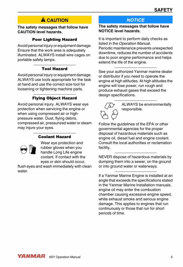
! CAUTIONThe safety messages that follow haveCAUTION level hazards.
Poor Lighting HazardAvoid personal injury or equipment damage.Ensure that the work area is adequatelyilluminated. ALWAYS install wire cages onportable safety lamps.
Tool HazardAvoid personal injury or equipment damage.ALWAYS use tools appropriate for the taskat hand and use the correct size tool forloosening or tightening machine parts.
Flying Object HazardAvoid personal injury. ALWAYS wear eyeprotection when servicing the engine orwhen using compressed air or high-pressure water. Dust, flying debris,compressed air, pressurized water or steammay injure your eyes.
Coolant HazardWear eye protection andrubber gloves when youhandle Long Life enginecoolant. If contact with theeyes or skin should occur,
flush eyes and wash immediately with cleanwater.
NOTICEThe safety messages that follow haveNOTICE level hazards.It is important to perform daily checks aslisted in the Operation Manual.Periodic maintenance prevents unexpecteddowntime, reduces the number of accidentsdue to poor engine performance and helpsextend the life of the engine.
See your authorized Yanmar marine dealeror distributor if you need to operate theengine at high altitudes. At high altitudes theengine will lose power, run rough andproduce exhaust gases that exceed thedesign specifications.
ALWAYS be environmentallyresponsible.
Follow the guidelines of the EPA or othergovernmental agencies for the properdisposal of hazardous materials such asengine oil, diesel fuel and engine coolant.Consult the local authorities or reclamationfacility.
NEVER dispose of hazardous materials bydumping them into a sewer, on the groundor into ground water or waterways.
If a Yanmar Marine Engine is installed at anangle that exceeds the specifications statedin the Yanmar Marine Installation manuals,engine oil may enter the combustionchamber causing excessive engine speed,white exhaust smoke and serious enginedamage. This applies to engines that runcontinuously or those that run for shortperiods of time.
SAFETY
6SY Operation Manual 5

NOTICEIf you have an installation with two or threeengines and only one engine is operating,the water pickup (thru-hull) of the non-running engine(s) should be closed. This willprevent water from being forced past theseawater pump and eventually finding itsway into the engine. The result of waterentering the engine could cause seizure orother serious problems.
If you have an installation with two or threeengines and only one engine is operating,please note that if the propeller shaft thru-hull (stuffing box) is lubricated by enginewater pressure and the engines areinterconnected, care must be taken thatwater from the running engine does notenter the exhaust of the non-running engine(s). This water could cause seizure of thenon-running engine(s). See your authorizedYanmar marine dealer or distributor for acomplete explanation of this condition.
If you have an installation with two or threeengines and only one engine is operating, itis important to limit the amount of throttleapplied to the running engine. If you observeblack smoke or movement of the throttledoes not increase engine rpm, you areoverloading the engine that is running.Immediately throttle back to approximately2/3 throttle or to a setting where the engineperforms normally. Failure to do so maycause the running engine to overheat orcause excess carbon buildup which mayshorten the engine's life.
SAFETY
6 6SY Operation Manual

SAFETY DECALS
securely attached.
CAUTION !When connecting the seawater
pipes make sure they are
0004481
DANGER
DANGERCAUTION
CAUTION
Figure 1
SAFETY
6SY Operation Manual 7

This Page Intentionally Left Blank
SAFETY
8 6SY Operation Manual

PRODUCT OVERVIEWYANMAR 6SY FEATURESAND APPLICATIONSThe 6SY is a four-stroke, six-cylinder directinjection diesel engine. The engine isturbocharged and equipped with a chargeair cooler containing a liquid cooling system.The engine has a heat exchanger which iscooled by a seawater coolant system.The engine is designed for pleasure craftuse.In order to obtain full performance from yourengine, it is imperative that you check thesize and structure of the hull and use apropeller of the appropriate size. As newboats are used, owners add additionalequipment and completely fill the fuel andwater tanks adding to the overalldisplacement (weight) of the vessel. Extracanvas enclosures, bottom paint, andbottom fouling can add additional hullresistance. It is recommended that a newvessel be propped so the engine canoperate at 100 rpm above maximum rpm toallow for some added weight and hullresistance. Failure to do so can lead toreduced vessel performance, increasedsmoke levels and cause permanentdamage to your engine.
The engine must be installed correctly withcoolant lines, exhaust gas lines andelectrical wiring. Any auxiliary equipmentattached to the engine should be easy to useand accessible for service. To handle thedrive equipment, propulsion systems(including the propeller) and other on-boardequipment, always observe the instructionsand cautions given in the operation manualssupplied by the shipyard and equipmentmanufacturers.The laws of some countries may require hulland engine inspections, depending on theuse, size and cruising area of the boat. Theinstallation, fitting and surveying of thisengine all require specialized knowledgeand engineering skills. See Yanmar's localsubsidiary in your region or your authorizedYanmar marine dealer or distributor.
6SY Operation Manual 9

COMPONENT IDENTIFICATIONFigure 1 illustrates a typical version of a 6SY engine. Your engine may have differentequipment from that illustrated.
0004473
(25)
(23)
(24)
(22)
(21)
(18)
(10)
(9)
(7)
(4)(3)(2)
(5)(6)
(16)
(14)
(13)
(26)
(1)
(11)(12)
(17) (19)
(27)
(20)
(15)
(8)
Figure 1
PRODUCT OVERVIEW
10 6SY Operation Manual

1 – Air Filter2 – Coolant Filler Cap3 – Coolant Recovery Tank4 – Engine Oil Filler Cap5 – Engine Number, Stamped into the
Engine Block6 – Nameplate7 – Coolant Pump8 – Coolant Drain9 – Engine Oil Filter10 – Engine Oil Cleaner11 – Engine Oil Dipstick12 – Engine Oil Drain13 – Heat Exchanger14 – Seawater Outlet
15 – Seawater Inlet16 – Seawater Pump17 – Charge Air Cooler18 – Closed Crankcase Ventilation Filter19 – Turbocharger (Water-Cooled)20 – Fuel Filter21 – Fuel Pump22 – Starter Motor23 – Alternator (1 Standard, 2nd Optional)24 – Engine Oil Pressure Sensor25 – Control Unit (EMS S6)26 – Marine Gear Oil Cooler27 – Charge Air Cooler
PRODUCT OVERVIEW
6SY Operation Manual 11

NAMEPLATEFigure 2 shows the location of regulatoryinformation on Yanmar 6SY marine engines.Engine Nameplate (Typical)
6SY Engines
MODELCONT. RATING kW rpm
rpmMAX OUTPUT kWENGINE NO.
YANMAR DIESEL ENGINE
0003496
Figure 2
PRODUCT OVERVIEW
12 6SY Operation Manual

FUNCTION OF MAJORCOMPONENTS
Name of part FunctionFuel Filter Removes dirt and water from the fuel. Drain the filter periodically. The filter element
should be replaced periodically. See Draining or Replacing the Fuel Filter Elementand Fuel Filter / Water Separator on page 40.
Fuel Feed Pump Pumps fuel from the tank to the fuel injection system.Engine Oil Fill Port Fill port for engine oil.Engine Oil Filter Filters fine metal fragments and carbon from the engine oil. Filtered engine oil is
distributed to the engine's moving parts.Coolant System There are two coolant systems: closed cooling with coolant and seawater. The
engine's combustion heat is cooled by the closed cooling circuit. The closed circuitis cooled by seawater using a heat exchanger. The seawater also cools theengine / marine gear oil.
Heat Exchanger The heat exchanger cools the closed cooling circuit with seawater.Closed CoolingCirculation Pump
The centrifugal water pump circulates coolant inside the engine. The circulatingpump is driven by a belt.
Seawater Pump The rubber impeller-type pump pumps seawater for cooling. Never operate itwithout seawater, as this will damage the impeller.
Coolant Filler Cap The filler cap on the coolant tank has a pressure regulating valve. When the coolanttemperature rises, the pressure rises inside the fresh water system.
Coolant Recovery Tank The pressure regulating valve releases vapor and hot water overflow to the coolantrecovery tank. When the engine stops and the coolant cools, the pressure in thecoolant tank drops. The filler cap valve then opens to send water back from thecoolant recovery tank. This minimizes coolant consumption. The closed coolingsystem coolant level can easily be checked and refilled in this tank.
Oil Cooler A heat exchanger that cools high temperature engine oil using seawater.Turbocharger The turbocharger pressurizes the air coming into the engine. It is driven by a turbine
that is energized by exhaust gases.Anode The metal area of the seawater coolant system is prone to electrical corrosion. The
anodes are installed to prevent this corrosion. The anodes are reduced over timeby electrical corrosion and must be replaced before it is completely consumed inorder to ensure that the metal area of the seawater coolant system remains fullyprotected.
Nameplates Nameplates are provided on the engine and the marine gear and have the model,serial number and other data.
Starter Starter motor for the engine. Powered by the battery.Alternator Driven by belt and generates electricity and charges the battery.
PRODUCT OVERVIEW
6SY Operation Manual 13

ENGINE MANAGEMENTSYSTEM (EMS S6)This engine has an Electronic ManagementSystem (EMS) with unit injectors whichprovide each cylinder with the right amountof fuel at the right time in all operatingsituations.The EMS system consists of a control unit(S6) and sensors for speed, charge airtemperature and pressure, coolanttemperature, oil pressure and throttleactuation. These sensors constantly sendsignals to the control unit. With this inputdata and the programmed control software,the correct fuel amount and correct injectiontime are calculated for each unit injectorunder the specific operating conditions.The EMS system sensors are also used tosend signals to the digital display in theinstrument panel.The control unit constantly checks thesensors to make sure they are operational.The control unit contains monitoringfunctions to protect the engine in the eventof a fault which would otherwise damage it.In the event of a fault, an alarm for low oilpressure or high coolant temperature forexample, the S6 control unit sends amessage to the digital display.Only authorized personnel are allowed tocarry out diagnostic procedures andprogram changes.The positions of the sensors which sendsignals to the control unit are shown(Figure 3).
Positions of Sensors for EMSwith S6
(4)
(3)
(2)(1)
Figure 31 – Oil Pressure Sensor2 – Charge Air Temperature and
Pressure Sensor3 – Coolant Temperature Sensor4 – Engine Speed Sensors (2 used)
PRODUCT OVERVIEW
14 6SY Operation Manual

Rotation SpeedsCheck instruments at regular intervals.
Rotation Speed0 - 500 rpm Prohibited engine speed,
passed through whenstopping and starting.
500 - 700rpm
Low idle. Engine idling iscontrolled by the EMS / S6control system.
700 - 2300rpm
Normal operating speed.The engine operating speedrange is controlled by theEMS / S6 control system.
2400 - 2600rpm
Unsuitable operating speed.
2600 - 3000rpm
Prohibited engine speed.
Redundant Throttle ModeIf there is a fault with the normal throttle or ifCAN communication is interrupted, aredundant throttle system is provided.In the event of a CAN open circuit or throttlefault:• The EMS automatically switches to the
redundant throttle located on the keyswitch panel.
• The redundant throttle must be set at zeroto be activated.
• A light will illuminate on the panelindicating the redundant throttle isactivated.
Coolant TemperatureNormal coolant temperature when theengine is running is 70˚ to 90˚C(158˚ to 194˚F).The EMS / S6 control system has thefollowing alarm levels:
• If the temperature is high, 98˚ to 103˚C,(208˚ to 217˚F) for one second, the S6control will send a CAN message whichactivates a warning.
• If the temperature exceeds 103˚C(217˚F), a warning is activated.
• A fault code is generated in the controlunit.
After an alarm, approved values must beregistered for more than two seconds beforeresetting the alarm.NOTICE: Excessively high coolanttemperature can damage the engine.If running for extended periods under anextremely light load, the engine may havedifficulty in maintaining normal operatingtemperature. However, the temperature willrise to a normal level again when the load onthe engine is increased.Oil PressureThe EMS has the following alarm levels:• At a speed of less than 1000 rpm and an
oil pressure of less than 1.0 bar (15 psi)• At a speed of more than 1000 rpm and an
oil pressure of less than 2.3 bar (33 psi)for longer than five seconds
The following functions are available if thereis an alarm:• Alarm which only switches on a warning.• Alarm which switches on a warning and
reduces the power if this function isactivated (maximum available is 70% offull power).
• A fault code is generated in the controlunit.
After an alarm, approved values must beregistered for more than two seconds beforeresetting the alarm.
PRODUCT OVERVIEW
6SY Operation Manual 15

This Page Intentionally Left Blank
PRODUCT OVERVIEW
16 6SY Operation Manual

BEFORE YOU OPERATEThis section of the Operation Manualdescribes the diesel fuel, engine oil, andengine coolant specifications and how toreplenish them. It also describes the dailyengine checkout.
DIESEL FUELDiesel Fuel SpecificationsDiesel fuel should comply with the followingspecifications. The table lists severalworldwide specifications for diesel fuels.
DIESEL FUELSPECIFICATION
LOCATION
No. 2-D, No. 1-D,ASTM D975-94
USA
EN590:96 European UnionISO 8217 DMX InternationalBS 2869-A1 or A2 United KingdomJIS K2204 Grade No.2 Japan
6SY Operation Manual 17

Additional Technical FuelRequirements• The fuel cetane number should be equal
to 45 or higher.• The sulfur content must not exceed 0.5%
by volume. Less than 0.05% is preferred.• NEVER mix kerosene, used engine oil or
residual fuels with the diesel fuel.• Water and sediment in the fuel should not
exceed 0.05% by volume.• Keep the fuel tank and fuel-handling
equipment clean at all times.• Poor-quality fuel can reduce engine
performance and / or cause enginedamage.
• Fuel additives are not recommended.Some fuel additives may cause poorengine performance. See your authorizedYanmar marine dealer or distributor formore information.
• Ash content not to exceed 0.01% byvolume.
• Carbon residue content not to exceed0.35% by volume. Less than 0.1% ispreferred.
• Total aromatics content should notexceed 35% by volume. Less than 30% ispreferred.
• PAH (polycyclic aromatic hydrocarbons)content should be below 10% by volume.
Diesel Fuel LinesInstall the lines between the fuel tank and thefuel injection pump.Be sure to install a drain cock(Figure 1, (6)) at the bottom of the fuel tankto remove water and contaminants.Install a fuel filter / water separator(Figure 1, (3)) and a fuel filter between thefuel tank and the fuel injection pump.
0002050
(1) (4)
(5)
(7)(8)
(9)
(10)
(2) (3)
(6)
Figure 11 – Fuel Filter2 – Fuel Priming Pump3 – Fuel Filter / Water Separator4 – Fuel Return Line5 – Fuel Tank6 – Fuel Tank Drain Cock7 – Approximately 50 mm (1.96 in.)8 – Fuel Shutoff Valve9 – Less than 500 mm (19.68 in.)10 – To Fuel Injection Pump
Filling the Fuel TankWARNING! Hold the hose nozzle firmlyagainst the filler port while filling. Thisprevents static electricity buildup whichcould cause sparks and ignite fuelvapors. NEVER place diesel fuel or otherflammable material such as oil, hay ordried grass close to the engine duringengine operation or shortly after shut-down.NOTICE: Only use diesel fuelsrecommended by Yanmar for the bestengine performance, to prevent enginedamage and to comply with EPA warrantyrequirements. Only use clean diesel fuel.1. Clean the area around the fuel cap.
WARNING! Only fill the fuel tankwith diesel fuel. Filling the fuel tankwith gasoline may result in a fire andwill damage the engine.
BEFORE YOU OPERATE
18 6SY Operation Manual

2. Remove the fuel cap from the fuel tank.WARNING! Wipe up all spillsimmediately. Keep sparks, openflames or any other form of ignition(match, cigarette, static electricsource) far away when refueling.
3. Stop fueling when the gauge shows thefuel tank is full. NOTICE: NEVER overfillthe fuel tank.
4. Replace the fuel cap and hand-tighten.Over-tightening the fuel cap willdamage it. WARNING! Store anycontainers containing fuel in a well-ventilated area, away from anycombustibles or sources of ignition.
Bleeding the Fuel SystemThe fuel system needs to be bled under thefollowing conditions:• Before starting the engine for the first time.• After running out of fuel and fuel has been
added to the fuel tank.• After fuel system maintenance. such as
changing the fuel filter and draining thefuel filter / water separator, or replacing afuel system component.
(1)
(2)
0004474
Figure 21. Install a transparent plastic hose on the
fuel rail bleeder valve (Figure 2, (1)).Place the hose in an appropriatecontainer.
2. WARNING! ALWAYS wear safetyglasses when bleeding the fuelsystem. Open the bleeder valve andoperate the hand pump(Figure 2, (2)) until fuel flows withoutair bubbles. This may take 130 to 150pump strokes.
3. Close the bleeder valve and remove thehose.
4. Continue hand pumping until there isresistance:• Approximately 20 strokes after
replacing the fuel filter• Approximately 50 strokes after
replacing a fuel injector5. Start the engine and check for leaks.
NOTICE: NEVER hold the key in theSTART position for longer than 15seconds or the starter motor willoverheat.
If the engine fails to start afterbleeding:• Open the bleeder valve again and operate
the hand pump until fuel without airbubbles flows out.
• Tighten the bleeder valve. Start theengine and check for leaks.
BEFORE YOU OPERATE
6SY Operation Manual 19

ENGINE OILEngine Oil SpecificationsNOTICE: Only use the engine oil specified.Other engine oils may affect warrantycoverage, cause internal enginecomponents to seize, or shorten engine life.NEVER mix different types of engine oil.This may adversely affect the lubricatingproperties of the engine oil.Use an engine oil that meets or exceeds thefollowing guidelines and classifications:Service Categories• API Service Categories CH-4 and CI-4 or
higher. TBN is 12 or higher.• ACEA Service Categories E-3, E-4 or E-5• JASO Service Category DH-1Definitions• API Classification (American Petroleum
Institute)• ACEA Classification (Association des
Constructeurs Européensd’Automobilies)
• JASO (Japanese Automobile StandardsOrganization)
NOTICE: Be sure the engine oil, engine oilstorage containers and engine oil fillingequipment are free of sediment and water.Select the oil viscosity based on the ambienttemperature where the engine is beingoperated. See the SAE Service GradeViscosity Chart. Yanmar does notrecommend the use of engine oil “additives.”Additional Technical Engine OilRequirements:The engine oil must be changed when theTotal Base Number (TBN) has beenreduced to 2.0. TBN (mgKOH/g) testmethod; JIS K-201-5.2-2 (HCI), ASTMD4739 (HCI).
Engine Oil ViscositySelect the appropriate engine oil viscositybased on the ambient temperature shown inthe SAE Service Grade Viscosity Chart(Figure 3).SAE 15W40 is the recommended oilviscosity.
-4°F 14°F 32°F 50°F 68°F 86°F 104°F (-20°C) (-10°C) (0°C) (10°C) (20°C) (30°C) (40°C)
SAE 10W
SAE 20W
SAE 10W-30
SAE 15W-40
SAE 20SAE 30
SAE 40
0000005
Figure 3Maximum Angles of InclinationDuring OperationMaximum permissible angles duringoperation vary, depending on the type of oilsump (Figure 4).Note: The specified angle may only occurintermittently.
35° 35°
0004382
25°
25°
Figure 4
BEFORE YOU OPERATE
20 6SY Operation Manual

Checking the Engine Oil
0004604(1)
Figure 5
(2)(3)
(1)
0004383
Figure 61. Remove dipstick (Figure 6, (1)) and
(Figure 5, (1)) and wipe with cleancloth. NOTICE: Prevent dirt and debrisfrom contaminating the engine oil.Carefully clean the oil cap / dipstick andthe surrounding area before youremove the cap.
2. Fully reinsert dipstick.3. Remove dipstick. The oil level should
be between upper (Figure 6, (2)) andlower (Figure 6, (3)) lines on thedipstick.
4. Fully reinsert dipstick.
Adding Engine Oil1. Remove the oil fill port cap and fill with
engine oil.2. Fill with oil to the upper limit
(Figure 6, (2)) on the dipstick(Figure 6, (1)). Insert the dipstick fullyto check the level. NOTICE: NEVERoverfill. Overfilling may result in whiteexhaust smoke, engine overspeed orinternal damage. ALWAYS keep the oillevel between upper and lower lines onthe oil cap / dipstick.
3. Tighten the fill port cap securely byhand.
Selection of Marine Gear OilRefer to the operation manual for the marinegear.
BEFORE YOU OPERATE
6SY Operation Manual 21

ENGINE COOLANTEngine Coolant SpecificationsUse a Long Life Coolant (LLC) that meets orexceeds the following guidelines andspecifications: NOTICE: Only use theengine coolant specified. Other enginecoolants may affect warranty coverage,cause an internal buildup of rust and scaleand / or shorten engine life. NEVER mixdifferent types of engine coolants. This mayadversely affect the properties of the enginecoolant.• BASF G48 or D542, Glycol - 30% or
higher• ASTM D6210, D4985 (US)• JIS K-2234 (Japan)• SAE J814C, J1941, J1034 or J2036
(International)Note: In the U.S., LLC is required for thewarranty to be valid.Coolant (Closed Cooling System)NOTICE: Always add LLC to soft water - especially when operating in cold weather.Without LLC, cooling performance willdecrease due to scale and rust in the coolingsystem. Water alone may freeze and formice; it expands approximately 9% in volume.Use the proper amount of coolantconcentrate for the ambient temperature asspecified by the LLC manufacturer. LLCconcentration should be a minimum of 30%to a maximum of 60%. Too much LLC willalso decrease the cooling efficiency. Do notmix different types or brands of LLC or aharmful sludge may form.Do not use hardwater. Water should be clean and free fromsludge or particles.
Following the manufacturer’srecommendations, use a proper LLC whichwill not have any adverse effects on thematerials (cast iron, aluminum, copper, etc.)of the engine’s fresh water cooling system.See Engine Coolant Specifications on page22.Replace engine coolant periodically,according to the maintenance schedule inthis Operation Manual.Remove scale from the cooling systemperiodically by flushing the system.Checking the Coolant Level1. Open the coolant recovery tank filler
cap and check the coolant level.WARNING! NEVER remove thecoolant filler cap if the engine is hot.Steam and hot engine coolant willescape and seriously burn you.Allow the engine to cool sufficientlybefore attempting to remove thefiller cap.WARNING! Wear eye protection andrubber gloves when you handleLong Life engine coolant. If contactwith the eyes or skin should occur,flush eyes and wash immediatelywith clean water.
2. The correct level for a cold engine isapproximately 50 mm (2 in.) below thefull line.
3. Add coolant as necessary. Do not addwater. See Engine Coolant on page22. WARNING! Securely tighten thefiller cap after checking the coolantlevel. Steam can escape duringengine operation if the cap is loose.
BEFORE YOU OPERATE
22 6SY Operation Manual

CAUTION! When adding large amountsof coolant, NEVER pour cold coolantinto a hot engine. NOTICE: Only use theengine coolant specified. Other enginecoolants may affect warranty coverage,cause an internal buildup of rust and scaleand / or shorten engine life.Prevent dirt anddebris from contaminating engine coolant.Carefully clean the heat exchanger cap andthe surrounding area before you remove thecap. NEVER mix different types of enginecoolants. This may adversely affect theproperties of the engine coolant.
DAILY CHECKSBefore you head out for the day, make surethe Yanmar engine is in good operatingcondition. Make sure you check thefollowing items.Visual Checks1. Check for damaged or missing parts.2. Check for loose, missing or damaged
fasteners.3. Check the electrical harnesses for
cracks, abrasions, and damaged orcorroded connectors.
4. Check hoses for cracks, abrasions anddamaged, loose or corroded clamps.
5. Check the fuel filter / water separator forpresence of water and contaminants. Ifyou find any water or contaminants,drain the fuel filter / water separator.See Draining or Replacing the FuelFilter / Water Separator on page 40.If you have to drain the fuel filter / waterseparator frequently, drain the fuel tankand check for the presence of water inyour fuel supply. See Draining the FuelTank on page 47 .
NOTICE: If any problem is noted during thevisual check, the necessary correctiveaction should be taken before you operatethe engine.
BEFORE YOU OPERATE
6SY Operation Manual 23

Check for Fuel, Engine Oil andEngine Coolant LeaksVisually check the engine for fuel, engine oilor engine coolant leakage. WARNING!Avoid skin contact with high-pressurediesel fuel spray caused by a fuelsystem leak such as a broken fuelinjection line. High-pressure fuel canpenetrate your skin and result in seriousinjury. If you are exposed to high-pressure fuel spray, obtain promptmedical treatment. NEVER check for afuel leak with your hands. ALWAYS usea piece of wood or cardboard. Have yourauthorized Yanmar marine dealer ordistributor repair the damage.1. Start the engine.2. Check for oil, coolant, fuel, air and
exhaust leaks.3. Tighten or replace leaking connections.
0004401(1)
(1)
Figure 74. Check the overflow holes
(Figure 7, (1)) in the block. Leakagefrom these holes indicates that theO-rings between the cylinder liners andthe crankcase are leaking.• If coolant is running out, the O-ring is
leaking.• If oil is running out, the liner shelf is
leaking.5. Check that there are no leaks from the
coolant pump. If a leak occurs, replacethe pump seal or the coolant pumpassembly.
6. A small amount of leakage from theoverflow holes during the engine break-in period is normal. Seals and O-ringsmust be lubricated with soap or oil wheninstalled. This leakage normally stopsafter time.
Check Diesel Fuel, Engine Oil andEngine Coolant LevelsFollow the procedures in Filling the FuelTank on page 18, Checking the Engine Oilon page 21 and Checking the CoolantLevel on page 22 to check these levels.Checking and Refilling MarineGear OilRefer to the operation manual for the marinegear.Checking the Battery ChargeMeasure the specific gravity of the batterywith a hydrometer. WARNING! Batteriescontain sulfuric acid. NEVER allowbattery fluid to come in contact withclothing, skin or eyes. Severe burnscould result. ALWAYS wear safetyglasses and protective clothing whenservicing the battery. If battery fluidcontacts the eyes and / or skin,immediately flush the affected area witha large amount of clean water and obtainprompt medical treatment.When the specific gravity of the fluid is 1.28at 20˚C (68˚F), 1.294 at 0˚C (32˚F), 1.308 at-20˚C (-4˚F) the battery is fully charged.When the specific gravity is below 1.20,charge the battery.A discharged battery will freeze at -5˚C(23˚F). If the specific gravity cannot beraised by charging, the battery must bereplaced.Do not rapid-charge the battery. Rapid-charging eventually results in damage to thebattery.
BEFORE YOU OPERATE
24 6SY Operation Manual

Note: The capacities of the standardalternator and the recommended batteryassume only the power necessary forregular operation. If the power is also usedfor lighting or other purposes, the generatingand charging capacities may be insufficient.In such cases, see your authorized Yanmarmarine dealer or distributor.Maintenance-free batteries can be checkedusing a battery tester. See your authorizedYanmar marine dealer or distributor.WARNING! Avoid injury or death due toexplosion or fire. NEVER check thebattery charge by shorting out theterminals. ALWAYS use a hydrometer tocheck the battery charge. Avoid seriousinjury. NEVER recharge a frozen battery.If the electrolyte is frozen, slowly warmthe battery before recharging it.Cleaning the BatteryWARNING! Turn off the battery switch (ifequipped) or disconnect the negativebattery cable before servicing theelectrical system.1. Clean batteries, cables and cable
terminals. WARNING! Batteriescontain sulfuric acid. NEVER allowbattery fluid to come in contact withclothing, skin or eyes. Severe burnscould result. ALWAYS wear safetygoggles and protective clothingwhen servicing the battery. Ifbattery fluid comes into contactwith the eyes and / or skin,immediately flush the affected areawith a large amount of clean waterand obtain prompt medicaltreatment.
2. Check that all cable terminals are firmlytightened.
3. Apply petroleum jelly to battery terminalposts and cable terminals. WARNING!Check the electrical harnesses forcracks, abrasions, and damaged orcorroded connectors. ALWAYSkeep the connectors and terminalsclean.
Checking the Battery ElectrolyteLevelBe sure to check the battery electrolyte levelbefore use. See Checking the BatteryElectrolyte Level (Serviceable BatteriesOnly) on page 46.Checking the Alternator BeltBe sure to check the belt tension before use.See Checking and Adjusting the AlternatorBelt on page 45.Checking the Alarm IndicatorsCheck the instruments and alarm indicatorsat regular intervals.Preparing Fuel, Oil and Coolant inReservePrepare sufficient fuel for the day’soperation. Always store engine oil andcoolant in reserve (for at least one refill) onboard, to be ready for emergencies.
BEFORE YOU OPERATE
6SY Operation Manual 25

This Page Intentionally Left Blank
BEFORE YOU OPERATE
26 6SY Operation Manual

ENGINE OPERATIONThis section of the Operation Manualdescribes the procedures for starting theengine, checking engine performanceduring operation and shutting the enginedown.
! WARNINGFire and Explosion Hazard
Avoid serious personal injury.NEVER jump start the engine.Sparks caused by shorting thebattery to the starter terminalsmay cause a fire or explosion.
ONLY use the key switch to start the engine.
Diesel fuel is flammable and explosiveunder certain conditions. NEVER put dieselfuel or other flammable material such as oil,hay or dried grass near the engine duringengine operation or shortly after shutdown.
Sudden Movement HazardBe sure the boat is in open water away fromother boats, docks or other obstructionsbefore increasing rpm.
Avoid unexpected equipment movement.Shift the marine gear into the NEUTRALposition any time the engine is at idle.
To prevent accidental equipmentmovement, NEVER start the engine in gear.
6SY Operation Manual 27

! WARNINGSever HazardRotating parts can causesevere injury or death. NEVERoperate the engine without theguards in place.
Before starting the engine, ALWAYS makesure that all bystanders are clear of the area.
Keep children and pets away while theengine is operating.
Exhaust HazardAvoid serious injury or death.NEVER block windows, ventsor other means of ventilation ifthe engine is operating in anenclosed area. All internal
combustion engines create carbonmonoxide gas during operation and specialprecautions are required to avoid carbonmonoxide poisoning.
Piercing HazardAvoid injury fromescaping fuel underpressure. NEVER checkfor a fuel leak with yourhands. ALWAYS use a
piece of wood or cardboard.
! CAUTIONAvoid serious personalinjury or equipmentdamage. ALWAYS turnoff the battery switch (ifequipped) or disconnect
the negative battery cable before servicingthe equipment.
ENGINE OPERATION
28 6SY Operation Manual

NOTICEIf any indicator illuminates during engineoperation, stop the engine immediately.Determine the cause and repair the problembefore you continue to operate the engine.
Observe the following environmentaloperating conditions to maintain engineperformance and avoid premature enginewear:• Avoid operating in extremely dusty
conditions.• Avoid operating in the presence of
chemical gases or fumes.• NEVER run the engine if the ambient
temperature is above +40˚C (+104˚F) orbelow -16˚C (+5˚F).
• If the ambient temperature exceeds+40˚C (+104˚F), the engine may overheatand cause the engine oil to break down.
• If the ambient temperature is below -16˚C(+5˚F), rubber components such asgaskets and seals will harden causingpremature engine wear and damage.
• Contact your authorized Yanmar marineengine dealer or distributor if the enginewill be operated outside of this standardtemperature range.
NEVER engage the starter motor while theengine is running. Damage to the startermotor pinion and / or ring gear will result.
STARTING THE ENGINENOTICE: If the vessel is equipped with awater lift (water lock) muffler, excessivecranking could cause seawater to enter thecylinders and damage the engine. If theengine does not start after cranking for 15seconds, close the thru-hull water intakevalve to avoid filling the muffler with water.Crank for 15 seconds or until the enginestarts. When the engines does start, stop theengine immediately and press the switch tothe OFF position.1. Open the seacock (if equipped).2. Open the fuel tank cock.3. Put transmission in neutral.4. Turn the battery master switch (if
equipped) ON.5. Press the ENG ON switch (if equipped)
or turn key switch to ON. NOTICE:NEVER hold the key in the STARTposition for longer than 15 seconds orthe starter motor will overheat.
Starting at Low TemperaturesComply with local environmentalrequirements. Use engine heaters to avoidstarting problems and white smoke.NOTICE: NEVER use an engine starting aidsuch as ether. Engine damage will result.To limit white smoke, run the engine at lowspeed and under moderate load until theengine reaches normal operatingtemperature. A light load on a cold engineprovides better combustion and fasterengine warm-up than no load.Avoid running the engine at idling speed anylonger than necessary.
ENGINE OPERATION
6SY Operation Manual 29

SHUTTING DOWN THEENGINENOTICE: For maximum engine life, Yanmarrecommends that when shutting the enginedown, you allow the engine to run, withoutload, for five minutes. This will allow theengine components that operate at hightemperatures, such as the exhaust system,to cool slightly before the engine itself is shutdown.1. Check to see that there are no active
faults.2. Push the OFF switch (if equipped) or
turn the key switch to OFF. NOTICE:NEVER use the emergency stop switchfor a normal engine shutdown. Use thisswitch only when stopping the enginesuddenly in an emergency.
3. Turn the battery master switch (ifequipped) OFF.
4. Close the fuel tank cock.5. Close the seacock (if equipped).
NOTICE: ALWAYS close the seacockwhen you shut down the engine.Neglecting to close the seacock couldallow water to leak into the boat andmay cause it to sink.
CHECKING THE ENGINEAFTER OPERATION• Check that the key switch is in the OFF
position and battery master switch (ifequipped) is OFF.
• Fill the fuel tank. Make sure that the fillercap and the area around the fill openingare clean to avoid contamination of thefuel. See Filling the Fuel Tank on page18.
• Turn off the inlet valve (seacock) for theseawater system (if equipped).
• If there is a risk of freezing, check that theclosed coolant system contains enoughcoolant. See Engine Coolant on page 22.
• If there is a risk of freezing, empty theseawater system. See Prepare Engine forLong-Term Storage on page 59.
• At temperatures below 0˚C (32˚F),connect the engine heater (if equipped).
ENGINE OPERATION
30 6SY Operation Manual

PERIODIC MAINTENANCESAFETY PRECAUTIONS
! WARNINGCrush Hazard
If you need to transport anengine for repair have ahelper assist you attach itto a hoist and load it on atruck.
Avoid personal injury or equipment damage.The engine lifting eyes are engineered to liftthe weight of the marine engine only.ALWAYS use the engine lifting eyes whenlifting the engine.
Avoid serious personal injury. Additionalequipment is necessary to lift the marineengine and marine gear together. ALWAYSuse lifting equipment with sufficient capacityto lift the marine engine.
Welding HazardMake welding repairs safely.• ALWAYS turn off the battery switch (if
equipped) or disconnect the negativebattery cable and the leads to thealternator when welding on theequipment.
• Remove the multi-pin connector to theengine control unit. Connect the weldclamp to the component to be welded andas close as possible to the welding point.
• NEVER connect the weld clamp to theengine or in a manner which would allowcurrent to pass through a mountingbracket.
• When welding is completed, reconnectthe leads to the alternator and enginecontrol unit prior to reconnecting thebatteries.
Exhaust HazardAvoid serious injury or death.ALWAYS ensure that allconnections are tightened tospecifications after repair ismade to the exhaust system.
All internal combustion engines createcarbon monoxide gas during operation andspecial precautions are required to avoidcarbon monoxide poisoning.
6SY Operation Manual 31

! WARNINGShock Hazard
Avoid serious personalinjury or equipmentdamage. ALWAYS turnoff the battery switch (ifequipped) or disconnect
the negative battery cable before servicingthe equipment.
Avoid personal injury or equipment damage.ALWAYS keep the electrical connectorsand terminals clean. Check the electricalharnesses for cracks, abrasions, anddamaged or corroded connectors.
NOTICEAny part which is found defective as a resultof inspection or any part whose measuredvalue does not satisfy the standard or limitmust be replaced.
Modifications may impair the engine’ssafety and performance characteristics andshorten the engine’s life. Any alterations tothis engine may void its warranty. Be sure touse Yanmar genuine replacement parts.
PERIODIC MAINTENANCE
32 6SY Operation Manual

PRECAUTIONSThe Importance of PeriodicMaintenanceEngine deterioration and wear occur inproportion to the length of time the enginehas been in service and the conditions theengine is subjected to during operation.Periodic maintenance prevents unexpecteddowntime, reduces the number of accidentsdue to poor machine performance and helpsextend the life of the engine.Performing PeriodicMaintenancePerform periodic maintenance proceduresin an open, level area free from traffic. Ifpossible, perform the procedures indoors toprevent environmental conditions such asrain, wind, or snow, from damaging theengine. WARNING! NEVER blockwindows, vents, or other means ofventilation if the engine is operating inan enclosed area. All internalcombustion engines create carbonmonoxide gas during operation.Accumulation of this gas within anenclosure could cause illness or evendeath.The Importance of Daily ChecksPeriodic Maintenance Schedules assumethat the daily checks are performed on aregular basis. Make it a habit of performingdaily checks before the start of eachoperating day. See Daily Checks on page23.
Keep a Log of Engine Hours andDaily ChecksKeep a log of the number of hours the enginehas run each day and a log of the dailychecks performed. Also note the date, typeof repair (e.g., replaced alternator) and partsused for any service needed between theperiodic maintenance intervals. Periodicmaintenance intervals are every 50, 250,500, 750, 1000 and 2000 engine hours.Failure to perform periodic maintenance willshorten the life of the engine.Yanmar Replacement PartsYanmar recommends that you use genuineYanmar parts when replacement parts areneeded. Genuine replacement parts helpensure long engine life. NOTICE: Only usereplacement parts specified. Otherreplacement parts may affect warrantycoverage, cause internal engine damage orshorten engine life.Tools RequiredBefore you start any periodic maintenanceprocedure make sure you have the tools youneed to perform all of the required tasks.Tightening FastenersUse the correct amount of torque when youtighten fasteners on the machine. Applyingexcessive torque may damage the fasteneror component and not enough torque maycause a leak or component failure. NOTICE:Always tighten to the specified torque.Loose parts can cause equipment damageor cause the engine to operate improperly.Ask Your Authorized YanmarMarine Dealer or Distributor ForHelpOur professional service technicians havethe expertise and skills to help you with anymaintenance or service related procedures.
PERIODIC MAINTENANCE
6SY Operation Manual 33

Required EPA Maintenance USAOnlyTo maintain optimum engine performanceand compliance with the EnvironmentalProtection Agency (EPA) RegulationEngines, it is essential that you follow thePeriodic Maintenance Schedule on page35.EPA Requirements USA OnlyThe following are the installationrequirements for the EPA. Unless theserequirements are met, the exhaust gasemissions will not be within the limitsspecified by the EPA.• Permissible value for intake negative
pressure: 3.9 kPa (400 mmAq) or lower• Permissible value for exhaust back
pressure: 9.8 kPa (1000 mmAq) or lower
EPA REQUIREMENTSThe EPA emission regulation is applicableonly in USA.Conditions to EnsureCompliance with EPA EmissionStandardsThis product is an EPA-approved engine.The following are the conditions that must bemet in order to ensure that the emissionsduring operation meet the EPA standards.Be sure to follow these:The operating conditions should be asfollows:• Ambient temperature: -20˚ to 40˚C
(-4˚ to 104˚F)• Relative humidity: 80% or lower• Permissible value for intake negative
pressure: 3.9 kPa (400 mmAq) or lower• Permissible value for exhaust back
pressure: 9.8 kPa (1000 mmAq) or lowerThe fuel and lubricating oil used should beas follows:• Diesel fuel oil: ASTM D975 No. 1-D or No.
2-D or equivalent (minimum of cetane No.45)
• Lubricating oil: ACEA Class E3, E4 or E5;Type API, Class CH-4, CI-4
Be sure to perform inspections as outlinedin Inspection and Maintenance for EPAEmission-Related Parts on page 39 andkeep a record of the results.
PERIODIC MAINTENANCE
34 6SY Operation Manual

Pay particular attention to these importantpoints:• Replacing the engine oil• Replacing the lube oil filter• Replacing the fuel filter• Cleaning the intake silencer (air cleaner)Note: Inspections are divided into twosections in accordance with who isresponsible for performing the inspection:the user or the maker.Inspection and MaintenanceSee Inspection and Maintenance for EPAEmission-Related Parts on page 39 for theEPA emission-related parts. Inspection andmaintenance procedures not shown in theInspection and Maintenance for EPAEmission-Related Parts on page 39section are covered in PeriodicMaintenance Schedule on page 35.This maintenance must be performed tokeep the emission values of your engine inthe standard values during the warrantyperiod. The warranty period is determinedby the age of the engine or the number ofhours of operation.
PERIODIC MAINTENANCESCHEDULEDaily and periodic maintenance is importantto keep the engine in good operatingcondition. The following is a summary ofmaintenance items by periodicmaintenance intervals. Periodicmaintenance intervals vary depending onengine application, loads, diesel fuel andengine oil used and are hard to establishdefinitively. The following should be treatedonly as a general guideline.CAUTION! Establish a periodicmaintenance plan according to theengine application and make sure youperform the required periodicmaintenance at intervals indicated.Failure to follow these guidelines willimpair the engine’s safety andperformance characteristics, shortenthe engine’s life and may affect thewarranty coverage on your engine. Seeyour authorized Yanmar marine dealeror distributor for assistance whenchecking items marked with a ●.
PERIODIC MAINTENANCE
6SY Operation Manual 35

Engines with Low OperatingHoursRun the engine until it reaches operatingtemperature and then perform the followingmaintenance procedures:• Check the engine oil level. See Checking
the Engine Oil on page 21.• Check the coolant level. See Checking
the Coolant Level on page 22.• Check the low pressure indicator. See
Checking the Alarm Indicators on page25.
• Check the fuel level. See Filling the FuelTank on page 18.
• Check the battery electrolyte level. SeeChecking the Battery Electrolyte Level(Serviceable Batteries Only) on page46.
• Clean the battery. See Cleaning theBattery on page 25.
• Check for any leakage, repair asnecessary.
PERIODIC MAINTENANCE
36 6SY Operation Manual

○: Check or Clean ◊: Replace ●: Contact your authorized Yanmar marine dealer or distributor
System Item Daily
Periodic Maintenance IntervalEvery
50 hoursor onemonthwhich-
evercomes
first
Every250
hours orone yearwhich-
evercomes
first
Every500
hours or2 yearswhich-
evercomes
first
Every1000
hours or4 yearswhich-
evercomes
first
Every2000
hours or8 yearswhich-
evercomes
firstWhole Visual inspection of
engine exterior ○
Fuel System
Check the fuel level,and refill ○ Drain the fuel tank ○ Drain the fuel filter andthe fuel / waterseparator
○(Initial 50)
Replace the fuel filterelement ◊
Check the unit injector/rocker arms
●*(Initial250)
●*
Overhaul and checkthe fuel feed pump ●Replace the rubber fuelhoses Replace every 2 years or every 2000 hours, whichever comes first.
LubricatingSystem
Check the engine oillevel ○
Change the engine oil ◊(Initial 50) ◊
Replace the engine oilfilter element ◊
(Initial 50) ◊ Replace the closedcrankcase ventilationfilter element
◊
Clean the centrifugal oilcleaner ○
(Initial 50) ○ Clean the engine oilcooler ●
CoolingSystem
Check the seawateroutlet
○During
Operation
Check the coolant level ○ Check or replace theseawater pumpimpeller
○ ◊
Change the enginecoolant
Every yearWhen long life coolant is used, replace every two years. See Engine
Coolant Specifications on page 22.Clean and check theseawater passages ● Clean the seawaterand engine coolingsystem
●
Check or replace theanodes ◊ Clean the closedcooling system(internal)
○
Air Intake andExhaustSystem
Clean or replace the airintake filter element ○ Clean the exhaust/water mixing elbow ●
PERIODIC MAINTENANCE
6SY Operation Manual 37

○: Check or Clean ◊: Replace ●: Contact your authorized Yanmar marine dealer or distributor
System Item Daily
Periodic Maintenance IntervalEvery
50 hoursor onemonthwhich-
evercomes
first
Every250
hours orone yearwhich-
evercomes
first
Every500
hours or2 yearswhich-
evercomes
first
Every1000
hours or4 yearswhich-
evercomes
first
Every2000
hours or8 yearswhich-
evercomes
firstClean the turbocharger ●* Clean charge air cooler ●
ElectricalSystem
Check the alarmindicators ○ Check the batterycharge ○ Clean the battery ○ Check batteryelectrolyte level ○ Adjust the tension ofthe alternator belt orreplace belt
○(Initial 50) ○ ◊
Check the wiringconnectors ○ ●
EngineCylinderHead andBlock
Check for leakage offuel, engine oil andengine coolant
○After starting
Tighten all major nutsand bolts ● Adjust theintake / exhaust valveclearance
●
(Initial250)
●
Miscel-laneousItems
Check the electroniccontrol system (EMS)operation
○ ○(Initial 50)
Adjust the propellershaft alignment ●
(Initial 50) ● Check or replace theflexible engine mounts ○ ◊
* Required to conform to U.S. EPA regulations. See EPA Requirements USA Only on page 34.Note: These procedures are considerednormal maintenance and are performed atthe owner’s expense.
PERIODIC MAINTENANCE
38 6SY Operation Manual

Inspection and Maintenance for EPA Emission-Related PartsParts IntervalClean fuel injection nozzle 1500 hoursCheck fuel injection nozzle pressure and spray pattern 3000 hoursCheck fuel injection pump adjustmentCheck turbocharger adjustment (if equipped)Check electronic engine control unit (ECU) and its associated sensors andactuators
Note: The inspection and maintenance items shown above to be performed at your Yanmardealer or distributor.
PERIODIC MAINTENANCE
6SY Operation Manual 39

MAINTENANCEPROCEDURESAfter Initial 50 Hours ofOperation
Perform the following maintenance after theinitial 50 hours of operation.• Draining the Fuel Filter and Fuel /
Water Separator• Changing Engine Oil and Replacing
the Engine Oil Filter Element• Cleaning the Centrifugal Oil Cleaner• Checking and Adjusting Alternator
Belt• Checking Electronic Management
System (EMS) Operation• Adjusting Propeller Shaft AlignmentDraining or Replacing the Fuel FilterElement and Fuel Filter / WaterSeparatorDraining or Replacing the Fuel FilterElement1. Close the fuel tank cock.
0004393
Figure 12. Loosen the drain plug. Drain off any
water or dirt. WARNING! NEVER usea shop rag to catch the fuel. Vaporsfrom the rag are flammable andexplosive. Wipe up any spillsimmediately.
3. Clean the outside of the filter andremove it by turning itcounterclockwise. NOTICE: Put anapproved container under the openingwhen removing any fuel systemcomponent to perform maintenance(such as changing the fuel filter).Dispose of waste properly.
4. Install a new filter and hand-tighten.5. Drain the fuel filter / water separator.
See Draining or Replacing the FuelFilter / Water Separator on page 40.
Draining or Replacing the Fuel Filter /Water Separator1. Make sure the fuel tank cock
(Figure 2, (1)) is closed.
(3)
(2)
(1)
0004394
Figure 2
PERIODIC MAINTENANCE
40 6SY Operation Manual

2. Loosen the drain plug (Figure 2, (3)) atthe bottom of the fuel filter / waterseparator and drain off any water or dirt.WARNING! ALWAYS wear eyeprotection. The fuel system is underpressure and fuel could spray outwhen any fuel system componentsare removed.
Note: If the fuel filter / water separator ispositioned higher than the fuel level in thefuel tank, water may not drip out when thefuel filter / water separator drain cock isopened. If this happens, turn the air ventscrew (if equipped) on the top of the fuelfilter / water separator 2–3 turnscounterclockwise. Be sure to tighten the airvent screw after the water has drained out.3. Turn the filter container
(Figure 2, (2)) counterclockwise toremove. NOTICE: Put an approvedcontainer under the opening whenremoving any fuel system componentto perform maintenance (such aschanging the fuel filter). Dispose ofwaste properly.
4. Remove the filter element.5. Lubricate the seal and install a new filter
element into the container.6. Install filter container and hand-tighten.7. Open the fuel tank cock
(Figure 2, (1)).8. After reinstalling the fuel filter and the
fuel filter / water separator, bleed airfrom the fuel system. See Bleeding theFuel System on page 19.
Changing Engine Oil and Replacingthe Engine Oil Filter ElementThe engine oil on a new engine becomescontaminated from the initial break-in ofinternal parts. It is very important that theinitial oil replacement is performed asscheduled.
It is easiest and most effective to drain theengine oil after operation while the engine isstill warm. WARNING! If you must drainthe engine oil while it is still hot, stayclear of the hot engine oil to avoid beingburned. ALWAYS wear eye protection.1. Remove the engine oil dipstick. Attach
the oil drain pump (if equipped) andpump out the oil. Dispose of wasteproperly. NOTICE: Prevent dirt anddebris from contaminating engine oil.Carefully clean the oil cap / dipstick andthe surrounding area before youremove the cap.For easier draining, remove the engineoil filler cap.
(1)0004475
Figure 32. Remove the filter (Figure 3, (1)) with a
filter wrench.3. Install a new filter.Note: If the deposits in the centrifugalcleaner are more than 20 mm (3/4 in.) thick,replace the oil filter more often. The same istrue for cleaning the centrifugal oil cleanerand changing the oil. See Cleaning theCentrifugal Engine Oil Cleaner on page42.
PERIODIC MAINTENANCE
6SY Operation Manual 41

4. Fill with new engine oil. See AddingEngine Oil on page 21. NOTICE: Onlyuse the engine oil specified. Otherengine oils may affect warrantycoverage, cause internal enginecomponents to seize, or shorten enginelife. NEVER mix different types ofengine oil. This may adversely affectthe lubricating properties of the engineoil.
5. Perform a trial run and check for oilleaks.
6. Approximately 10 minutes afterstopping the engine, remove the oildipstick and check the oil level. Add oilif the level is too low. NOTICE: NEVERoverfill. Overfilling may result in whiteexhaust smoke, engine overspeed orinternal damage. ALWAYS keep the oillevel between upper and lower lines onthe oil cap / dipstick.
Cleaning the Centrifugal Engine OilCleanerClean the centrifugal engine oil cleanerevery time the oil is changed.1. Clean the oil cleaner cover. Turn the nut
counterclockwise to remove. Carefullyremove the cover in case the oil is hot.
2. Lift out the rotor and turn the nut on therotor bowl counterclockwise three turns(Figure 4).
0002376
Figure 4• If the nut is jammed, clamp the nut in
a vise and turn the rotor three turnscounterclockwise by hand or with awrench (Figure 5). NOTICE: Neverclamp the rotor in a vise or strike therotor bowl. Doing so may causedamage resulting in imbalance.
PERIODIC MAINTENANCE
42 6SY Operation Manual
0002377
M20
0002377
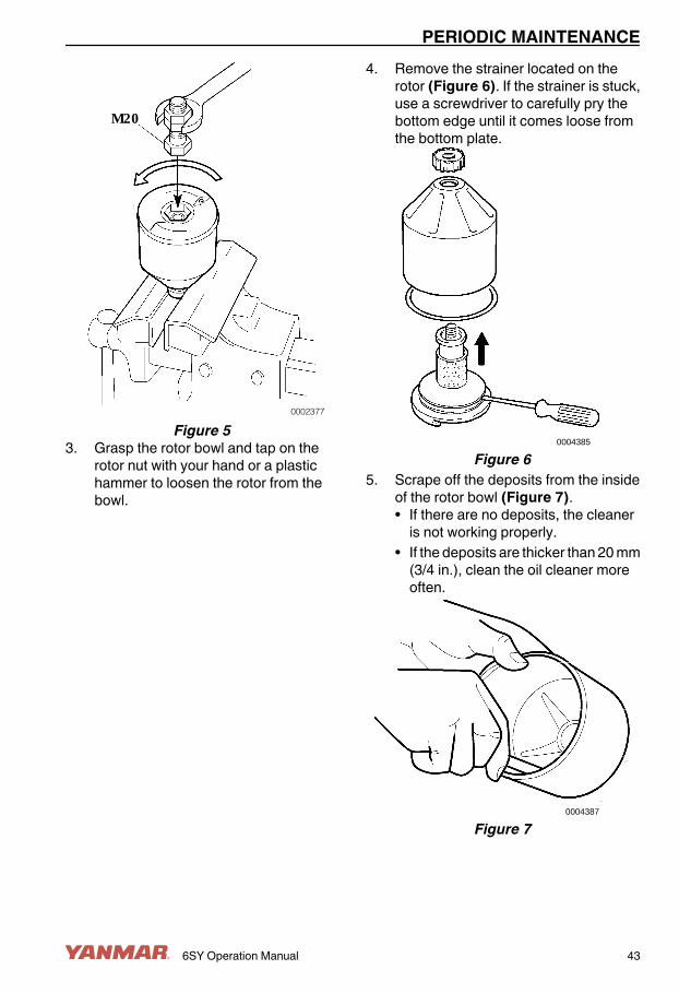
Figure 53. Grasp the rotor bowl and tap on the
rotor nut with your hand or a plastichammer to loosen the rotor from thebowl.
4. Remove the strainer located on therotor (Figure 6). If the strainer is stuck,use a screwdriver to carefully pry thebottom edge until it comes loose fromthe bottom plate.
0004385
Figure 65. Scrape off the deposits from the inside
of the rotor bowl (Figure 7).• If there are no deposits, the cleaner
is not working properly.• If the deposits are thicker than 20 mm
(3/4 in.), clean the oil cleaner moreoften.
0004387
Figure 7
PERIODIC MAINTENANCE
6SY Operation Manual 43

6. Wash all of the parts in suitable partscleaning solvent. CAUTION! Avoidpersonal injury. Always wearpersonal protective equipmentwhen using solvents or chemicals.
7. Make sure the nozzles on the rotor arenot blocked or damaged.
8. Make sure the bearings are notdamaged.
9. Inspect the O-ring in the rotor bowl fordamage and replace if necessary.
10. Install the O-ring in the rotor bowl(Figure 8).
0004386
Figure 8Reassembling the Rotor1. Tighten the rotor nut firmly by hand
Figure 9.
0004389
Figure 9
2. Make sure the shaft is not loose. If theshaft is loose, see your authorizedYanmar marine dealer or distributor.
3. Install the rotor. Turn the rotor by handto make sure that it rotates easily(Figure 10).
0004388
Figure 104. Install the bowl and tighten the lock nut
to 15 N·m (133 in.-lb) (Figure 11, (1)).Be careful not to damage the rotorshaft, nut and bowl when tightening thelock nut.
(1)
0004390
Figure 11Functional InspectionThe rotor spins very fast and shouldcontinue to turn when the engine hasstopped.
PERIODIC MAINTENANCE
44 6SY Operation Manual

To check rotor rotation:1. Stop the engine after it is warm.2. Listen for a whirring sound from the
rotor or check if the cleaner housing isvibrating.• The rotor normally continues
spinning for 30 - 60 seconds after theengine has stopped.
• If the rotor does not spin for 30 - 60seconds after the engine hasstopped, disassemble it and inspectthe parts for damage.
Checking and Adjusting theAlternator Belt1. Stop the engine before checking the
alternator belt.2. Check the belt by pushing on the middle
of the belt (Figure 12, (1)) with yourfinger, exerting a force of approximately98 N, 10 kgf (22 lbf).With proper tension, the belt shoulddeflect 8 - 10 mm (approximately3/8 in.).
0004391
Figure 12
3. If the belt deflection is not tospecification, see your authorizedYanmar dealer or distributor for beltreplacement. NOTICE: Do not get anyoil on the belt(s). Oil on the belt causesslipping and stretching. Replace thebelt if it is damaged.
Checking Electronic ManagementSystem (EMS) OperationCheck for fault codes. Refer to separatemanual provided by the digital displaymanufacturer.Adjusting Propeller Shaft AlignmentRefer to reverse gear manufacturerliterature for alignment procedure.
PERIODIC MAINTENANCE
6SY Operation Manual 45

Every 50 Hours of OperationAfter you complete the initial 50 hourmaintenance procedures, perform thefollowing procedures every 50 hours ormonthly whichever comes first.• Draining the Fuel Filter and the Fuel
Filter / Water Separator• Checking the Battery Electrolyte
LevelDraining the Fuel Filter and the FuelFilter / Water SeparatorSee Draining or Replacing the Fuel FilterElement and Fuel Filter / Water Separator onpage 40.Checking the Battery ElectrolyteLevel (Serviceable Batteries Only)NOTICE: NEVER attempt to remove thecovers or fill a maintenance-free battery.1. Do not operate with insufficient battery
electrolyte as the battery will bedestroyed.
2. Remove the plugs and check theelectrolyte level in all cells. WARNING!Batteries contain sulfuric acid.NEVER allow battery fluid to comein contact with clothing, skin oreyes. Severe burns could result.ALWAYS wear safety glasses andprotective clothing when servicingthe battery. If battery fluid contactsthe eyes and / or skin, immediatelyflush the affected area with a largeamount of clean water and obtainprompt medical treatment.
3. If the level is lower than the minimum filllevel (Figure 13, (1)), fill with distilledwater (Figure 13, (2)) (available in thegrocery store) up to the upper limit(Figure 13, (3)) of the battery.
(1)(2)
(3)
0002388
Figure 13NOTICE: Battery fluid tends to evaporate inhigh temperatures, especially in summer. Insuch conditions, inspect the battery earlierthan specified.Note: The maximum fill level isapproximately 10 - 15 mm(3/8 - 9/16 in.) above the plates.
PERIODIC MAINTENANCE
46 6SY Operation Manual

Every 250 Hours of OperationPerform the following maintenance every250 hours of operation or yearly whichevercomes first.• Adjusting Intake / Exhaust Valve
Clearance (Initial 250 Hours)• Adjusting Unit Injectors / Rocker Arms
(Initial 250 Hours)• Draining the Fuel Tank• Replacing the Fuel Filter Element• Changing the Engine Oil• Replacing the Engine Oil Filter
Element• Replacing the Closed Crankcase
Ventilation Filter Element• Cleaning the Centrifugal Engine Oil
Cleaner• Checking the Seawater Pump Impeller• Checking or Replacing the Anodes• Cleaning the Closed Cooling System• Cleaning or Replacing the Air Intake
Filter Element• Cleaning Exhaust / Water Mixing
Elbow• Cleaning the Turbocharger• Cleaning the Charge Air Cooler• Checking the Wiring Connectors• Tighten All Major Nuts and Bolts• Checking or Replacing the Flexible
Engine Mounts• Draining, Flushing and Refilling the
Engine CoolantAdjusting the Intake / Exhaust ValveClearance (Initial 250 Hours)Proper adjustment is necessary to maintainthe correct timing for opening and closingthe valves. Improper adjustment will causethe engine to run noisily, resulting in poorengine performance and engine damage.See your authorized Yanmar marine dealeror distributor to adjust the intake / exhaustvalve clearance.
Checking and Adjusting the UnitInjector / Rocker Arms (Initial 250Hours)Proper adjustment is necessary. See yourauthorized Yanmar marine dealer ordistributor to adjust the unit injector rockerarms.Draining the Fuel TankSee the boat manufacturer’s literature forprocedure.Replacing the Fuel Filter ElementSee Draining or Replacing the Fuel FilterElement on page 40.Changing the Engine Oil andReplacing the Engine Oil FilterElementSee Changing Engine Oil and Replacing theEngine Oil Filter Element on page 41.Replacing the Closed CrankcaseVentilation Filter Element1. Remove the drain line at the filter base.
0004476
Figure 14
PERIODIC MAINTENANCE
6SY Operation Manual 47

(3)
(2)
(1)0004392
Figure 152. Release the clamps (Figure 15, (2))
holding the filter container(Figure 15, (1)) to the filter head.
3. Remove the filter container(Figure 15, (1)) carefully, there may beoil in the bottom of the container.
4. Remove the filter element.5. Install a new O-ring at the base of the
head and check that there is an O-ringon the top of the new filter.
6. Install the new filter into the center of thefilter head and press firmly.
7. Replace the container and lock theclamps (Figure 15, (2)).
8. If the restriction indicator(Figure 15, (3)) on the top of the filteris red, remove the plastic cover andreset the restriction indicator button.
9. Install the drainage line.Cleaning the Centrifugal Engine OilCleanerSee Cleaning the Centrifugal Engine OilCleaner on page 42.Checking or Replacing the SeawaterPump ImpellerDepending on use, the inside parts of theseawater pump deteriorate and dischargeperformance drops.
At the specified interval or when the volumeof seawater discharged is reduced, inspectthe seawater pump:1. Close the sea valve (seacock) if the
marine water pump is under water.2. Drain the seawater circuit. WARNING!
Wait until the engine cools beforedraining seawater from the coolingsystem. Hot seawater may splashand cause burns.
3. Remove the marine water pump cap.4. Check the impeller vanes for wear or
damage.NOTICE: If the impeller must bechanged frequently, the seawaterstrainer must be replaced with a unithaving better filtering capabilities.
PERIODIC MAINTENANCE
48 6SY Operation Manual

Checking or Replacing the Anodes
(1)
(2)(3)
(4)
0004395
Figure 161. Drain the seawater cooling circuit and
check the anodes (Figure 16).2. Scrape off all loose material on the
anodes.3. A new anode is 63 mm (2.50 in.) long
with a diameter of 17 mm (11/16 in.).Replace an anode if less than half of theanode remains. NOTICE: NEVER usethread sealer or thread sealing tapewhen installing zinc anodes. Anodesmust make good metal-to-metalcontact to perform properly.NOTICE: If operation is continued withan anode less than half of the newanode length, corrosion of the seawatercoolant system will occur and waterleakage or parts breakage will result.
Note: If the anodes are extremely corroded,check them more frequently.
PERIODIC MAINTENANCE
6SY Operation Manual 49

This Page Intentionally Left Blank
PERIODIC MAINTENANCE
50 6SY Operation Manual
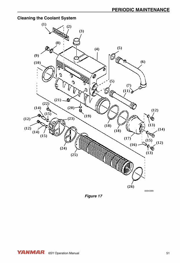
Cleaning the Coolant System(1) (2)
(3)
(9)
(8)
(4) (5)
(6)
(7)(5)
(11)
(12)
(13)(14)
(15)
(13)
(12)(17)
(16)
(18)(18)
(21)
(20)
(19)
(10)
(22)
(15)
(14)
(12)
(12)(14)
(15)
(23)
(24)
(25)
(26)0004399
Figure 17
PERIODIC MAINTENANCE
6SY Operation Manual 51

1 – Screw2 – Nameplate3 – Filler Cap4 – Heat Exchanger Housing5 – O-Ring6 – Return Pipe to Coolant Pump7 – Bolt8 – Gasket9 – Plug10 – Gasket11 – Outlet from Engine12 – Bolt13 – Seal
14 – Bolt15 – Seal16 – Anode (3 used)17 – Front Cover18 – O-Ring19 – Drain Plug20 – Gasket21 – Flange Nut22 – Bolt23 – Rear Cover24 – Gasket25 – Cooler Core26 – O-Ring
Internal Cleaning - Heat ExchangerCAUTION! ALWAYS wear eye protectionand rubber gloves when you handleLong Life engine coolant. If contact withthe eyes or skin should occur, flusheyes and wash immediately with cleanwater.1. Drain the coolant from the engine and
from the heat exchanger. See Draining,Flushing and Refilling the EngineCoolant on page 55.
2. Drain the seawater circuit by removingthe cover from the seawater pump andthe connections from the heatexchanger outlet. WARNING! Waituntil the engine cools beforedraining seawater from the coolingsystem. Hot seawater may splashand cause burns.
3. Disconnect the coolant pipes from thecharge air cooler. Disconnect the pipebetween the front cover and the heatexchanger.
4. Remove the connection housing at thecoolant pump inlet together with thereturn pipe from the heat exchanger.
5. Remove the thermostat housing coverand the outlet pipe to the heatexchanger.
6. Remove the seawater inlet flange fromthe heat exchanger.
7. Remove the vent pipe from the coolantrecovery tank.
8. Remove the flange nuts and lift off thecomplete heat exchanger assembly.
9. Remove the rear cover and pull out thecooler element.
10. Use paraffin-based engine detergent toclean the element. NOTICE: NEVERclean the coolant system with causticsoda. The aluminum parts may bedamaged.
11. Any internal deposits in the pipes canbe removed with a round rod.
12. Lubricate and install a new O-ring(Figure 17, (26)) inside the housingand install the cooler core.
13. Install the front and rear covers usingnew O-rings and gaskets.
14. Install the heat exchanger assembly onthe engine. Tighten the flange nuts to50 N·m (37 ft-lb).
15. Install the coolant inlet and outlet pipes,thermostat housing cover, connectionhousing, charge air cooler coolantpipes and thermostat housing.
16. Fill the system with coolant. SeeDraining, Flushing and Refilling theEngine Coolant on page 55.
17. Start the engine and check for coolantleaks. Check the level of the coolantand fill as necessary.
PERIODIC MAINTENANCE
52 6SY Operation Manual

Flushing the Closed Cooling System1. If possible, run the engine until it has
reached operating temperature andthen drain the coolant system. SeeDraining, Flushing and Refilling theEngine Coolant on page 55.
2. Remove the thermostats.3. Fill the system (including the heat
exchanger, if equipped) with clean, hotwater mixed with liquid dishwasherdetergent designed for household useor a product intended to cleanautomotive cooling systems, andapproved for use with aluminumcomponents. NOTICE: NEVER cleanthe coolant system with caustic soda.The aluminum parts may be damaged.Concentration: 1% (0.1 / 10 L)(0.1 / 10 qt).
4. Run the engine until warm (about20 - 30 minutes).
5. Drain the coolant system. See Draining,Flushing and Refilling the EngineCoolant on page 55.
6. Fill the system again using clean, hotwater and run the engine for about20 - 30 minutes.
7. Drain the water from the system.8. Reinstall the thermostats.9. Fill the system with new coolant. See
Engine Coolant on page 22 for refillingcoolant.
10. Refill the system with hot water and runthe engine for about 20 - 30 minutes.
11. Drain the water from the system.12. Reinstall the thermostats.13. Fill the system with new coolant. See
Check Diesel Fuel, Engine Oil andEngine Coolant Levels on page 24 forrefilling coolant.
Cleaning or Replacing the Air IntakeFilter ElementNOTICE: ALWAYS use genuine Yanmarreplacement parts (super-fine mesh filter).Using anything except genuine Yanmarparts can cause engine damage, unevenengine performance and shorten engine life.Note: Replace the air cleaner filter soonerthan every 500 hours if the restrictionindicator is red.1. Loosen clamps.2. Remove the filter element.3. Carefully blow the filter element clean
from the inside with dry compressed airor install new filter element in housing.CAUTION! ALWAYS wear eyeprotection when using compressedair. Dust, flying debris orcompressed air may injure youreyes. NOTICE: There is a risk ofdamaging the filter when it is cleaned.The filter can only be cleaned amaximum of four times. A cleaned filterdoes not perform as well as a new filter.
4. Insert a flashlight into the filter andcheck from the outside that there are noholes or cracks in the filter paper.
5. Replace the filter if it has the slightestdamage.
6. Mark the date the filter has beencleaned.
7. Reassemble the air cleaner in reverseorder.
8. Tighten clamps securely.
PERIODIC MAINTENANCE
6SY Operation Manual 53

9. Press the button to reset the red plunger(Figure 18) in the restriction indicator.
0004396
Figure 18Cleaning the Exhaust / Water MixingElbowSee your authorized Yanmar marine dealeror distributor.Cleaning the TurbochargerContamination of the turbocharger causesrevolutions to drop and engine output to fall.If a significant drop in engine output is noted(10% or more), clean the turbocharger.Cleaning should only be done by a trainedand qualified technician. See yourauthorized Yanmar marine dealer ordistributor.
Cleaning the Charge Air Cooler
(4)
(5)
(2)
(3)(6)(7)
(1)
(8)
(9) (9)
0004471
Figure 191 – Air Intake Manifold, Lower2 – Gasket3 – Charge Air Cooler Element4 – Air Intake Manifold, Upper5 – Gasket6 – V-Ring7 – Cover with Thermostat Housing and
Thermostat8 – Connection Pipe9 – O-Ring1. Drain the coolant from the engine. See
Draining, Flushing and Refilling theEngine Coolant on page 55.CAUTION! ALWAYS wear eyeprotection and rubber gloves whenyou handle Long Life enginecoolant. If contact with the eyes orskin should occur, flush eyes andwash immediately with clean water.
2. Remove the connection pipe betweenupper intake manifold housings.
3. Disconnect the pipe between intakemanifold and turbocharger.
PERIODIC MAINTENANCE
54 6SY Operation Manual

4. Disconnect inlet and outlet water linesfrom charge air cooler fittings. Seal thefittings with caps or plugs to preventcoolant spillage.
5. Remove the upper intake manifoldhousing.
6. Remove the charge air coolerassembly from the intake manifold.NOTICE: Take care to ensure that nocoolant spills from the element into theintake manifold.
7. Clean the element using paraffin-basedengine detergent only. NOTICE:NEVER clean the coolant system withcaustic soda. The aluminum parts maybe damaged.
8. Clean and degrease the sealingsurfaces on the upper and lower intakemanifold housing.
9. Install charge air cooler(s) using a newgasket. Tighten bolts to 20 N·m(177 in.-lb).
10. Install upper intake manifold(s).Tighten bolts to 50 N·m (37 ft-lb).
11. Install connection pipe between intakemanifolds.
12. Connect coolant hoses to charge aircoolers.
13. Install and secure all remaining air inletpipes and hoses. Tighten V-clamps to:• M6 Screw - 8 N·m (71 in.-lb)• M8 Screw - 20 N·m (177 in.-lb)
14. Fill the system with coolant. SeeDraining, Flushing and Refilling theEngine Coolant on page 55.
15. Start the engine and check for coolantleaks. Check the level of the coolantand fill as necessary.
Checking the Wiring ConnectorsSee your authorized Yanmar marine dealeror distributor.Tighten All Major Nuts and BoltsSee your authorized Yanmar marine dealeror distributor.
Checking or Replacing the FlexibleEngine MountsSee your authorized Yanmar marine dealeror distributor.Draining, Flushing and Refilling theEngine CoolantCooling performance drops when coolant iscontaminated with rust and scale. Thecoolant must be replaced periodicallybecause its properties deteriorate over time.1. WARNING! NEVER remove the
coolant filler cap if the engine is hot.Steam and hot engine coolant willescape and can cause seriousburns. Allow the engine to coolsufficiently before attempting toremove the filler cap. NOTICE:Prevent dirt and debris fromcontaminating engine coolant.Carefully clean the heat exchanger capand the surrounding area before youremove the cap.Remove the filler cap from the coolantrecovery tank.
PERIODIC MAINTENANCE
6SY Operation Manual 55

2. Drain the coolant:• from the two drain taps on the lower
right side of the block(Figure 20, (2))
• from the drain tap (Figure 20, (1))located on the lower left side of theblock
• from the two holes (remove theplugs) below the heat exchanger (ifequipped)
(3)
(2)(1)
0004398
Figure 203. Close the drain taps
(Figure 20, (1 and 2)) and replace theheat exchanger plugs (if equipped).
4. Fill the coolant recovery tank withcoolant through the expansion tank fillhole (Figure 20, (3)). See EngineCoolant on page 22 for refilling coolant.WARNING! ALWAYS tighten thefiller cap securely after checkingthe coolant level. Steam can escapeduring engine operation if the cap isloose.
Every 500 Hours of OperationPerform the following maintenance every500 hours of operation or every 2 years,whichever comes first.• Replacing the Seawater Pump
Impeller• Checking the Alternator Belt Tension• Adjusting the Propeller Shaft
AlignmentChecking or Replacing the SeawaterPump ImpellerDepending on use, the inside parts of theseawater pump deteriorate and dischargeperformance drops.At the specified interval or when the volumeof seawater discharged is reduced, inspectthe seawater pump:1. Close the sea valve (seacock) if the
marine water pump is under water.2. Drain the seawater circuit. WARNING!
Wait until the engine cools beforedraining seawater from the coolingsystem. Hot seawater may splashand cause burns.
3. Remove the marine water pump cap.4. Check the impeller vanes for wear or
damage.NOTICE: If the impeller must bechanged frequently, the seawaterstrainer must be replaced with a unithaving better filtering capabilities.
PERIODIC MAINTENANCE
56 6SY Operation Manual

Replacing the Seawater Pump Impeller1. Remove the impeller with an impeller
removal tool (Figure 21, (1)).2. Install a new impeller and cap. If the cap
seal is hard or damaged, replace it.
(1)
0004400
Figure 21Note: A spare impeller should be kept on-board.The impeller can become deformed duringlong periods of inactivity. Replace or removethe impeller before long periods of storage.See Prepare Engine for Long-TermStorage on page 59.Checking the Alternator BeltTensionSee Checking and Adjusting the AlternatorBelt on page 45.Adjusting the Propeller ShaftAlignmentSee Adjusting Propeller Shaft Alignment onpage 45.
Every 1000 Hours of OperationPerform the following maintenance every1000 hours of operation or every 4 years,whichever comes first.• Adjusting the Unit Injectors / Rocker
Arms• Cleaning and Checking the Seawater
Passages• Replacing the Alternator Belt• Adjusting the Intake / Exhaust Valve
Clearance• Replacing the Flexible Engine MountsAdjusting the Unit Injectors / RockerArmsSee your authorized Yanmar marine dealeror distributor.Cleaning and Checking theSeawater PassagesSee your authorized Yanmar marine dealeror distributor.Replacing the Alternator BeltSee your authorized Yanmar marine dealeror distributor.Adjusting the Intake / Exhaust ValveClearanceSee Adjusting the Intake / Exhaust ValveClearance (Initial 250 Hours) on page 47.Replacing the Flexible EngineMountsSee your authorized Yanmar marine dealeror distributor.
PERIODIC MAINTENANCE
6SY Operation Manual 57

Every 2000 Hours of OperationPerform the following maintenance every2000 hours of operation or every 8 years,whichever comes first.• Overhauling and Checking the Fuel
Feed Pump• Replacing the Rubber Fuel Hoses• Cleaning the Engine Oil Cooler• Cleaning the Seawater and Engine
Coolant System• Checking the Wiring ConnectorsOverhauling and Checking the FuelFeed PumpSee your authorized Yanmar marine dealeror distributor.Replacing the Rubber Fuel HosesSee your authorized Yanmar marine dealeror distributor.NOTICE: Replace rubberized fuel hosesevery 2 years or every 2000 hours of engineoperation, whichever comes first, even if theengine has been out of service.Cleaning the Engine Oil CoolerSee your authorized Yanmar marine dealeror distributor.Cleaning the Seawater and EngineCoolant SystemSee Cleaning the Coolant System on page51.Checking the Wiring ConnectorsSee your authorized Yanmar marine dealeror distributor.
PERIODIC MAINTENANCE
58 6SY Operation Manual

LONG-TERM STORAGEIf the engine is not to be used for anextended period of time, special measuresshould be taken to protect the coolantsystem, fuel system and combustionchamber from corrosion and the exteriorfrom rusting.The engine can normally stand idle for up tosix months. If it remains unused for longerthan this, please contact your authorizedYanmar marine dealer or distributor.
PREPARE ENGINE FORLONG-TERM STORAGENote: If the engine is close to a periodicmaintenance interval, perform thosemaintenance procedures before putting theengine into long-term storage.1. Wipe off any dust or oil from the outside
of engine.2. Drain water from fuel filters.3. Drain fuel tank completely or fill the tank
to prevent condensation. To reduce therisk of condensation in the fuel tankduring winter storage, fill the tank withfuel and treat with diesel fuel stabilizer.
4. Grease the exposed areas and joints ofthe remote control cables and thebearings of the remote control handle.
5. Seal the air intake, exhaust pipe, etc. toprevent moisture or contamination fromentering engine.
6. Completely drain bilge in hull bottom.7. Waterproof the engine room to prevent
rain or seawater from entering.8. Charge the battery once a month to
compensate for battery’s self-discharge.
9. Remove key from key switch and coverthe key switch with moisture cap.
NOTICE: If seawater is left inside of theengine, it may freeze and damage parts ofthe cooling system when the ambienttemperature is below 0˚C (32˚F).
6SY Operation Manual 59

This Page Intentionally Left Blank
LONG-TERM STORAGE
60 6SY Operation Manual

SPECIFICATIONSPRINCIPAL ENGINE SPECIFICATIONS
Engine Model 6SY-STP2 / 6SY655Number of Cylinders In-line 6Type Water-cooled, turbochargedCombustion System Direct injectionAspiration Turbocharged with intercoolerBore x Stroke 127 mm x 154 mm (5.0 in. x 6.1 in.)Displacement 11.7 L (714 cu in.)Firing Order 1-5-3-6-2-4Compression Ratio 16:1Rated output at crankshaft Output at rev speed 6SY–STP2: 530 kW (720 hp) at 2300 rpm
6SY655: 481 kW (655 hp) at 2300 rpm Break mean effective pressure 1.97 MPa (287.5 psi)Idle Speed High idle 2400 rpm Low idle 600 rpmRotation Direction Counterclockwise (viewed from flywheel)No. of Valves Inlet 2 Exhaust 2Turbocharger Single water-cooledElectrical System 2-pole, 24 V*
Starter 6.7 kW (9.0 hp)Charging System 65 A at 24V*
Battery Capacity - Recommended 160 AhInjection Timing Variable (EMS controlled)Permissible Value for Exhaust Back Pressure 9.8 kPa (1000 mmAq)Cooling System Closed cooling system with seawater heat
exchanger Coolant capacity with expansion tank 40 L (10.5 gal)
6SY Operation Manual 61

Engine Model 6SY-STP2 / 6SY655Thermostats Coolant thermostat type and opening temperature Dual - 75˚C (167˚F) Charge air cooler type and opening temperature Single - 50˚C (122˚F)Seawater Pump Rubber impeller, gear driven Capacity 315 L / min at 2300 rpm
(83 gpm at 2300 engine rpm)Gear Oil Cooler Restriction 150 mbar (0.03495 psi)Lubrication System Totally enclosed, forced lube system Oil cooler Closed coolant system Lube oil pressure - Rated speed 300 - 600 kPa (44 - 87 psi) Lube oil pressure - Idling speed 150 kPa (22 psi) Lube system capacity (with filters) 21 - 31 L (6 - 8.2 gal) approximateCrankcase Ventilation Closed, with filterEngine Size Height 1038 mm (40.9 in.) Length Overall - 1559 mm (50.9 in.)
Front Bell Housing - 1366 mm (53.8 in.) Width 867 mm (34.1 in.) Weight 1150 kg (2535 lb)
* Optional dual 65 A alternators available
SPECIFICATIONS
62 6SY Operation Manual

EPA WARRANTY USAONLY
YANMAR CO., LTD. LIMITEDEMISSION CONTROLSYSTEM WARRANTY - USAONLYTHIS EMISSION WARRANTY APPLIES TOTHE ENGINES CERTIFIED TO UNITEDSTATES EPA 40 CFR 94 AND SOLD BYYANMAR THAT ARE INSTALLED INVESSELS FLAGGED OR REGISTERED INTHE UNITED STATES.Your Warranty Rights andObligations:Yanmar warrants to the first user and eachsubsequent purchaser the emission controlsystem on your engine for periods of timelisted below provided the engine has beeninstalled according to Yanmar installationrequirements and there has been no abuse,neglect, or improper maintenance of yourYanmar marine engine.Yanmar warrants that the engine isdesigned, built and tested using genuineparts and equipped so as to conform to allapplicable emission requirements of theU.S. Environmental Protection Agency andis free from defects in material andworkmanship which would cause thisengine to fail to conform to the applicableemission regulations over its limitedemission control system warranty period.
Where a warrantable emissions conditionexists, Yanmar will repair your engine at nocharge to you for diagnosis, parts, and labor.Warranty service or repair will be providedat authorized Yanmar marine dealers ordistributors.It is recommended that any replacementparts used for maintenance, repair orreplacement of emission control systemsare Yanmar parts. The owner may elect tohave maintenance, replacement or repair ofthe emission control components andsystems performed by any repairestablishment or individual and may elect touse parts other than Yanmar parts for suchmaintenance, replacement or repair.However, the cost of such service or partsand subsequent failures from such serviceor parts will not be covered under thisemission control system warranty:Warranty Period:The warranty starts on either the date ofdelivery to the first end-user, or the date theunit is first leased, rented, or loaned.For Pleasure Use: The warranty period isfive (5) years or 2000 hours of use,whichever occurs first. In the absence of adevice to measure hours of use, the enginehas a warranty period of five (5) years.
6SY Operation Manual 63
Warranty Coverage:Repair or replacement of any warrantedparts will be performed at an authorizedYanmar dealer or distributor. This limitedemission control system warranty coversengine components that are a part of theemission control system of the engine asdelivered by Yanmar to the original retailpurchaser. Such components may includethe following:1. Fuel Injection System2. Turbocharger System3. Aftercooler4. Electronic Engine Control Units and its
associated Sensor and ActuatorsExclusions:Failures other than those arising fromdefects in material and / or workmanship arenot covered by this limited emissionswarranty. This warranty does not extend tothe following: malfunction caused by abuse,misuse, improper adjustment, modification,alteration, tampering, disconnection,improper or inadequate maintenance,improper storage or use of non-recommended fuels and lubricating oils,accident-caused damage, and replacementof expendable and / or consumable itemsmade in connection with scheduledmaintenance.Yanmar disclaims any responsibility forincidental or consequential damages suchas loss of time, inconvenience, loss of useof marine vessel / engine or commercialloss.
Owner’s Responsibility:As the Yanmar marine engine owner, youare responsible for the performance of therequired maintenance listed in yourOperation Manual. Yanmar recommendsthat you retain all documentation, includingreceipts, covering maintenance on yourmarine engine, but Yanmar cannot denywarranty solely for the lack of receipts or foryour failure to ensure the performance of allscheduled maintenance.Your engine is designed to operate on dieselfuel only. Use of any other fuel may result inyour engine no longer operating incompliance with applicable emissionrequirements. You are responsible forinitiating the warranty process. You mustpresent your marine engine to an authorizedYanmar dealer or distributor as soon as aproblem exists.Customer Assistance:If you have any questions regarding yourwarranty rights and responsibilities or wouldlike information on the nearest authorizedYanmar dealer or distributor, you shouldcontact Yanmar Marine USA Corporation forassistance.Yanmar Marine USA Corporation101 International ParkwayAdairsville, GA 30103USA Telephone: 770-877-9894Fax: 770-877-7567
EPA WARRANTY USA ONLY
64 6SY Operation Manual

EPA WARRANTY USA ONLY
6SY Operation Manual 65

This Page Intentionally Left Blank
EPA WARRANTY USA ONLY
66 6SY Operation Manual