RICE TRANSPLANTER - Yanmar
136
OPERATOR’S MANUAL RICE TRANSPLANTER VP7D25 Original instructions en
-
Upload
khangminh22 -
Category
Documents
-
view
0 -
download
0
Transcript of RICE TRANSPLANTER - Yanmar

OPERATOR’S MANUAL
RICE TRANSPLANTER
VP7D25
Original instructions
en

(EN)
INTRODUCTION
Thank you for purchasing the Yanmar transplanter.
Please read the operator’s manual before you use the transplanter.
It contains the operation procedures and notes of use.
It is necessary to read the manual carefully and understand it thoroughly in order to use the transplanter correctly.
After reading, put the manual near the machine so that the operator can always refer to it.
Requirements
• Do not use the product before understanding the instructions.
• Lend or transfer the manual together with the product.
• If this manual or a safety label are lost or damaged, contact a Yanmar dealer and order a replacement.
• Chapter 1 “Precautions for Safe Operation” contains important information on how to operate the machine safely.
Read it before using the machine.
• If you are uncertain or concerned about a point, contact your Yanmar dealer for assistance.
Declarations
• Because the components of the machine may be changed for product improvement purposes, the contents and
illustrations in this manual may differ from the actual product.
• Every effort has been made to ensure that the contents of this manual are complete and accurate. If any mistake
or omission is found, it may not be corrected immediately.
According to road traffic regulations, the transplanter is a non-road vehicle. It may not be driven on a public road.
Use a truck to transport the transplanter on public roads.
The truck must comply to the applicable road traffic regulations.
All information, descriptions, specifications, drawings, illustrations, and pictures in this manual are based on the
latest information available at the time this manual was published. YANMAR reserves the right to make changes at
any time without prior notice.
© 2014 YANMAR CO., LTD.
1

(EN)
SAFETY ALERT SYMBOLS
Safety-alert symbol
This is the safety-alert symbol. When you see this symbol on
your transplanter or in this manual, be alert to the possibility of
personal injury and carefully read the messages that follow.
Signal words
The signal words “DANGER”, “WARNING”, and “CAUTION”
are used with the safety-alert symbol.
“DANGER” indicates a hazardous situation which, if not
avoided, will result in death or serious injury.
“WARNING” indicates a hazardous situation which, if not
avoided, could result in death or serious injury.
“CAUTION” indicates a hazardous situation which, if not
avoided, could result in minor or moderate injury.
It is also used to alert against unsafe practices.
DANGER
WARNING
CAUTION
IMPORTANT
“IMPORTANT” calls attention to instructions which must be
followed precisely to avoid damaging the product, process, or
its surroundings.
Reference
This is supplementary information to improve efficiency or to
avoid wrong operation.
These symbols refer to an object of explanation and the viewing
direction.
refers to the object
refers to the viewing direction
IMPORTANT
Intended use of the product
The function of this product is to transplant seedlings into a paddy field.
Do not use the product for other operations or purposes.
The use of the product for other operations or purposes is not covered by the warranty. (For more details, refer to
the warranty.)
2
TABLE OF CONTENTS
INTRODUCTION ............................................................................... 1
(EN)
1 PRECAUTIONS FOR SAFE OPERATION ………………………… 9
Operator ………………………………………………………………………………… 9
Transplanter in operation……………………………………………………………… 10
Caution during operation ……………………………………………………………… 10
Caution for movement in sloping fields and in and out of the fields ……………… 13
Caution for truck transportation ……………………………………………………… 14
Caution for operation ………………………………………………………………… 16
Caution for storing……………………………………………………………………… 16
Caution for inspection, oiling and maintenance …………………………………… 17
Location of the safety labels ………………………………………………………… 20
Maintenance of the safety labels …………………………………………………… 22
2 SERVICE AND WARRANTY …………………………………………… 23
Keep the warranty card in a safe place ……………………………………………… 23
Accepting the after service …………………………………………………………… 23
Supplying period for replacement parts……………………………………………… 23
Genuine replacement parts and oil ………………………………………………… 23
3 SEEDLINGS AND PADDY FIELDS APPROPRIATE FOR THE
TRANSPLANTER ……………………………………………………… 24
Seedlings ……………………………………………………………………………… 24
Bed soil ………………………………………………………………………… 24
Seedling mat …………………………………………………………………… 24
The condition of the seedlings and undesirable results when planting…… 25
Paddy fields …………………………………………………………………………… 25
Rough plough …………………………………………………………………… 25
Pudding soil …………………………………………………………………… 25
Hardness of the paddy field surface ………………………………………… 26
Depth of the water ……………………………………………………………… 26
Depth of the paddy field ……………………………………………………… 26
4 NAME OF THE COMPONENTS ……………………………………… 27
Appearance …………………………………………………………………………… 27
Controls and instruments ……………………………………………………………… 29
5 FUNCTION OF EACH OPERATIONAL PART ……………………… 31
Engine control ………………………………………………………………………… 31
Key switch ……………………………………………………………………… 31
Accelerator lever ……………………………………………………………… 31
Fuel strainer, Water separator ……………………………………………… 32
Electric system ………………………………………………………………………… 32
Head light switch ……………………………………………………………… 32
Horn button …………………………………………………………………… 32
Buzzer stop/display select switch …………………………………………… 32
Instrument panel ……………………………………………………………………… 33
Seedling adding lamp ………………………………………………………… 33
Unit clutch pilot lamp …………………………………………………………… 33
LED panel ……………………………………………………………………… 33
Preheater pilot lamp (glow lamp)……………………………………………… 33
Engine coolant warning lamp ………………………………………………… 34
3

(EN)
Engine oil pressure warning lamp …………………………………………… 34
Battery charging lamp ………………………………………………………… 34
Working and operating parts ………………………………………………………… 34
Steering wheel ………………………………………………………………… 34
Main shift lever ………………………………………………………………… 35
Planting lifting lever …………………………………………………………… 36
Speed control pedal …………………………………………………………… 36
Speed setting lever …………………………………………………………… 37
Hydraulic sensing adjustment lever ………………………………………… 38
Planting depth control lever …………………………………………………… 38
Automatic planting depth control switch……………………………………… 38
Brake pedal …………………………………………………………………… 38
Parking brake lever …………………………………………………………… 39
Differential lock pedal (front wheels) ………………………………………… 39
Planting number changing lever ……………………………………………… 39
Hydraulic stop lever …………………………………………………………… 40
Planting part …………………………………………………………………………… 40
Vertical feed adjusting lever…………………………………………………… 40
Lateral feed adjusting lever …………………………………………………… 40
Unit clutch lever ………………………………………………………………… 41
Automatic balance UFO ……………………………………………………… 41
Seedling rack …………………………………………………………………………… 42
Line marker……………………………………………………………………… 42
Seedling feed stopper ………………………………………………………… 42
Seedling mat stopper ………………………………………………………… 43
Seedling press board……………………………………………………… 44
Side bumper and stand…………………………………………………………
44
Other devices ………………………………………………………………………… 44
Side marker……………………………………………………………………… 44
Driver’s seat …………………………………………………………………… 44
Center marker ………………………………………………………………… 45
Fuel supply port ………………………………………………………………… 45
Bonnet open lever ……………………………………………………………… 45
Cup holder ……………………………………………………………………… 45
6 PREPARATIONS BEFORE OPERATING …………………………… 46
Inspection before operating…………………………………………………………… 46
7 OPERATION METHOD ………………………………………………… 47
Adjusting the driver’s seat …………………………………………………………… 47
Adjusting by using the fulcrum pin …………………………………………… 47
Adjusting by using the adjusting lever ……………………………………… 47
Starting the engine …………………………………………………………………… 48
Checks and preparation before starting the engine ………………………… 48
Starting and operating the engine …………………………………………… 49
Warming up the machine …………………………………………………………… 50
Stopping the machine ………………………………………………………………… 51
Starting and speed adjusting ………………………………………………………… 51
Operating the main shift lever ………………………………………………………… 52
Turning ………………………………………………………………………………… 53
Stopping ………………………………………………………………………………… 53
Parking ………………………………………………………………………………… 54
Moving and driving …………………………………………………………………… 54
Preparing the machine for traveling ………………………………………… 55
4

(EN)
Put the seedling rack to the middle of the machine ………………………… 56
Starting, moving and speed adjusting ……………………………………… 56
Transporting by truck ………………………………………………………………… 57
Ramp …………………………………………………………………………… 57
Preparations of the truck ……………………………………………………… 58
Loading the machine…………………………………………………………… 58
After loading on the truck ……………………………………………………… 59
Unloading the transplanter …………………………………………………… 60
Re-starting the engine during loading and unloading ……………………… 60
8 PLANTING ……………………………………………………………… 68
Preparations before entering the paddy field ……………………………………… 68
Check the amount of fuel ……………………………………………………… 68
Getting in or out of the paddy field …………………………………………………… 68
Preparations after entering the paddy field ………………………………………… 69
Loading new seedlings………………………………………………………………… 71
Transplanting operation ……………………………………………………………… 73
Working in fields with deep water …………………………………………………… 76
Planting on the side of the field ridge………………………………………………… 77
Consider the condition of the field before starting your work ……………… 77
Using the line marker ………………………………………………………………… 78
Turning ………………………………………………………………………………… 78
Driving in reverse first and then turn around ………………………………… 78
Turning without reverse ……………………………………………………… 79
Adding seedlings ……………………………………………………………………… 80
Removing remaining seedlings ……………………………………………………… 81
Automatically balancing with the UFO ……………………………………………… 82
During normal planting operation …………………………………………… 82
Adjusting a tilted planting part ………………………………………………… 83
Adjusting to the conditions of the seedlings, paddy fields and operations ……… 83
Adjusting the amount of seedlings …………………………………………… 83
Adjusting the hydraulic sensitivity …………………………………………… 84
Adjusting the depth of planting ……………………………………………… 84
The operational method of the automatic depth adjusting mechanism … 85
Adjusting the number of seedlings taken (vertical) ………………………… 85
Adjusting the lateral feed ……………………………………………………… 86
Adjusting the seedling press board and the seedling mat stopper ……… 86
Freeing a sunken-in machine when the plowing chassis is too deep …………… 88
The rear wheels starts sinking during driving ……………………………… 88
The front wheels sink in when you drive in reverse ………………………… 88
The machine sinks in when you make a turn ……………………………… 88
Towing the transplanter with a rope ………………………………………………… 89
Turning the rotor case ………………………………………………………………… 89
Operating with the safety clutch engaged…………………………………………… 90
5

(EN)
9 DISMANTLING AND INSTALLING THE ENGINE COVER
AND THE STEP ………………………………………………………… 91
Dismantling and installing of the engine cover……………………………………… 91
Dismantling the engine cover ………………………………………………… 91
Installing the front and rear engine covers…………………………………… 92
Dismantling and installing the front step …………………………………………… 92
Dismantling and installing the right and left step …………………………… 93
10 MAINTENANCE AND STORAGE AFTER WORK ………………… 94
Cleaning the machine ………………………………………………………………… 94
Components that need oiling and greasing ………………………………………… 95
Storing ……………………………………………………………………………… 100
11 INSPECTION AND MAINTENANCE ……………………………… 101
Intervals of regular inspections and maintenance ……………………………… 101
Table of regular inspections and maintenance ………………………………… 102
Table for adding oil, water and grease …………………………………………… 103
Adding fuel oil ……………………………………………………………………… 103
Adding fuel oil ……………………………………………………………… 103
Discharging the fuel oil …………………………………………………………… 104
Discharge of the fuel oil in the fuel tank …………………………………… 104
Inspection, adding and replacing oil ……………………………………………… 104
Engine oil……………………………………………………………………… 104
Transmission case oil ……………………………………………………… 106
Rear axle case ……………………………………………………………… 107
Air bleeding of the fuel system …………………………………………………… 108
Cleaning the filter element of the air filtration machine ………………………… 109
Cleaning the fuel filter ……………………………………………………………… 110
Cleaning the water separator ……………………………………………………… 110
Replacing the oil filter of the transmission case ………………………………… 111
Replacing the filter…………………………………………………………… 111
Replacing the engine oil filter ……………………………………………………… 111
Replacing the engine oil filter ……………………………………………… 111
Inspection, adding and replacing of cooling water ……………………………… 112
Adding cooling water ……………………………………………………… 112
Replacing cooling water …………………………………………………… 112
Inspection and adjusting of the cooling fan belt ………………………………… 113
Inspection and adjusting of the engine belt ……………………………………… 114
Adjusting the engine belt …………………………………………………… 114
Inspecting the operation of the UFO device …………………………………… 115
Inspecting the horizontal control of the planting part ……………………
Inspection and adjusting of the gap between the seedling fetching guide rail
115
and planting tines …………………………………………………………………… 116
Inspection and adjusting of the gap between the push rod
and the planting tines ……………………………………………………………… 117
Inspection and replacing of the planting tine …………………………………… 118
Replacing the planting tines ……………………………………………… 118
Inspection and adjusting of the vertical seedling fetching quantity …………… 119
Inspection and maintenance of the battery ……………………………………… 120
Removing the battery ……………………………………………………… 121
Maintenance of the battery ………………………………………………………… 122
Charging the battery ………………………………………………………… 122
6

(EN)
Battery maintenance ………………………………………………………… 122
Natural discharge of the battery …………………………………………… 122
Inspection and replacement of the fuse ………………………………………… 123
Fuse box ……………………………………………………………………… 123
Slow blow fuse ……………………………………………………………… 124
Replacing the slow blow fuse of 80A ……………………………………… 124
Inspection of the oil pipe …………………………………………………………… 124
12 TROUBLESHOOTING ……………………………………………… 125
Missing plants ……………………………………………………………………… 125
Floating seedlings (every seedling is floating) …………………………………… 127
Floating seedlings (only one seedling is floating) ……………………………… 130
Floating seedlings (only for leaves with bad roots) ……………………………… 131
Toppling of the seedling …………………………………………………………… 132
Lifting of the seedling ……………………………………………………………… 133
Tilting forward of the seedling ……………………………………………………… 133
The float presses the soil…………………………………………………………… 134
Up and down movement of the lifter / UFO movement is faulty
(UFO auto diagnosis with LED flashing) ………………………………………… 135
Emergency repair of a faulty UFO ………………………………………… 135
13 OTHERS ……………………………………………………………… 136
Specifications………………………………………………………………………… 136
Parts susceptible to wear…………………………………………………………… 137
How to set the lateral sending time and longitudinal getting quantity ………… 138
Standard Accessories ……………………………………………………… 139
7

1. PRECAUTIONS FOR SAFE OPERATION
• Observe the following instructions as they contain important
safety information.
• Any violation of the precautions may cause accidents that lead
to death or injury or damage to the machine.
Operator
(EN)
WARNING
Use the machine only after carefully reading and
understanding the instructions for use and the safety signs.
• Operate the machine carefully and observe the safety
cautions stated in the manual.
Children or people who have no knowledge of the operator’s
manual and the safety labels on the machine are not allowed
to operate the transplanter.
People who are physically unfit or otherwise not able to
operate the machine are not allowed to operate the
transplanter.
• People who are tired, sick, under the influence of drugs or
otherwise not able to concentrate are not allowed to
operate the transplanter.
• People under the influence of alcohol
• Pregnant women
• Tired people
• People under 16 years of age
• The people mentioned above are not allowed to operate the
transplanter.
The operator and the assistants must be dressed
appropriately for operation.
• Do not wear loose clothing or clothing with laces. Tighten
the cuffs. Loose garments are easily dragged into the
machine or catch on operation devices which may lead to
an accident.
• Wear boots with anti-slipping soles (e.g. safety shoes);
otherwise you may slip and fall. Put on a safety helmet. Do
not put a towel around your head, neck or waist. It may be
dragged into the machine and cause an accident.
CAUTION When lending or transferring the transplanter, hand the
operator’s manual to the receiver, explain safety procedures
and let the receiver read the operator’s manual.
9

(EN)
Transplanter in operation
CAUTION Before operating, do an inspection.
Operating a badly maintained transplanter will cause
accidents and malfunctions.
• Replace lost or damaged parts.
• Do an inspection on the clutch, brake, steering wheel and
safety device. Make sure to replace damaged parts.
• Check the bolts and nuts regularly.
• Each day before the operation, do an inspection of the
electric wires to check whether they are connected to the
other parts, the coating has damage or the connector is
loose.
Clean the transplanter from time to time.
Dirt and fuel around the battery, electric wire, sound
absorber, and engine will cause a fire.
Do not modify the transplanter. Any obstructions to the safety
features of the transplanter may cause personal accidents,
degradation of performance and shortening of the lifespan.
Caution during operation
WARNING
The transplanter only can be started and operated after the
cap (cover) of the filter element of the air cleaner is installed,
otherwise tempering can cause flames to shoot out.
CAUTION Before starting the transplanter, sit in the driver’s seat and
make sure that the brake is in the right place with the main
shift lever at "N" (neutral) and the planting lifting lever at "N"
(middle); otherwise the transplanter will run forward, turn
over suddenly or collide with other objects.
• If you stand beside the transplanter and start the engine,
you cannot take any measure to avoid these accidents if the
transplanter runs forward.
10

(EN)
WARNING
The exhaust gas of the engine is harmful, so open the doors
and windows for ventilation when starting the engine in a
warehouse or garage.
• Starting the engine indoors or in a room with poor
ventilation will lead to death caused by the exhaust gas.
• Start the engine outside with good ventilation.
CAUTION Before driving forward, check the position of the main shift
lever and whether the transplanter is in the correct state of
operation.
• Fold the side marker to avoid accidents with nearby
objects.
• Lift the planting part, and set the hydraulic stop lever to
“Stop”. Lowering the planting part during driving will lead
to injury and damage to the machine.
When starting and driving forward, make sure that the
surroundings are safe.
• When starting and driving forward, inform all nearby
persons.
• When driving forward, after making sure there is no person
or obstacle nearby, depress the speed control pedal to
make the machine run slowly. Pay attention to the blind
spot of the machine and make sure that there are no people,
especially children.
• When stopping the machine, first set the main shift lever to
“Seedling feed”, and then depress the brake pedal.
11

(EN)
WARNING
The transplanter is not allowed to run on public roads.
The transplanter does not meet the requirements on basic
equipments stated in road traffic regulations, so it is not
allowed to run on public roads. When moving on a road, a
truck is needed for transportation.
The truck for transportation must comply with road traffic
regulations.
If driving a long distance on the road, the transmission may
be damaged by fire.
Drive slowly to avoid collision with nearby objects, especially
pay attention to any contact of the seedling rack.
When driving, focus on where you are driving and keep your
hands in the appropriate place.
Any inattention will lead to accidents.
If operating the machine for the first time, drive slowly until
you learn to handle it.
Do not drive at high speeds, stop suddenly or make a sudden
turn which may cause the transplanter to turn over and fall.
In a curve, turn-around, on a bumpy road and sloping field,
slow down in advance and turn or drive carefully.
The transplanter can only transport one person. No other
person except the operator is allowed to ride the transplanter.
It is not allowed to place goods on the pre-seedling rack.
Pay attention to the road shoulder. Farm roads often have
ditches and slopes on both sides. The road shoulder can
break off.
Get off the transplanter to check dangerous places, for
example places where the road shoulder is not visible
because of high grass or where the ground is not visible
because of water puddles. Turn off the engine when you get
off the transplanter.
When you come to an intersection, do not drive on the road
shoulder, but rather stop and let other vehicles pass.
12

Caution for movement in sloping fields and in and out of the fields
(EN)
WARNING
When driving on sloping fields, pay attention to the following
matters to ensure safe driving.
Do not run at high speeds or stop suddenly, the transplanter
may turn over.
Slow down when driving on a sloping field.
Do not operate the gear shift lever in a way that can cause the
transplanter to run downhill uncontrolled.
If you need to operate the speed shift, first step on the brake
and then use the main shift lever.
If you need to stop on a sloping field, step on the brake.
Reckless driving on a slope can cause the transplanter to turn
over.
Do not turn the steering wheel abruptly.
Movements of the side clutch of the rear wheel on the
steering side and the machine can turn the transplanter over.
If the slope is very steep, climb the slope in reverse and with
the lowest speed. If you try climbing the slope by driving
forward, the transplanter will turn over.
WARNING
When crossing a ridge or ditch, lower the planting part, step
on the differential lock device with the lowest speed and make
the transplanter run forward slowly at a right angle to the
ridge. When the rear wheel reaches the ridge, lift the planting
part.
When running on a slope with a huge gap, a ramp is needed
to cross the ridge and ditch.
Standards of the spring board
Length At least 3.5 times of the height of the truck
Width At least 30 cm
Strength Each plate can withstand 750 kg at least
Surface Anti-slip processing
13
Yamar
Highlight
(EN)
Do not forget to step on the differential lock pedal before
driving on the spring board.
When you lay the spring board, make sure that the
transplanter is at a right angle with the ridge and ditch. The
two spring boards must align with the wheels of the
transplanter and be parallel to each other.
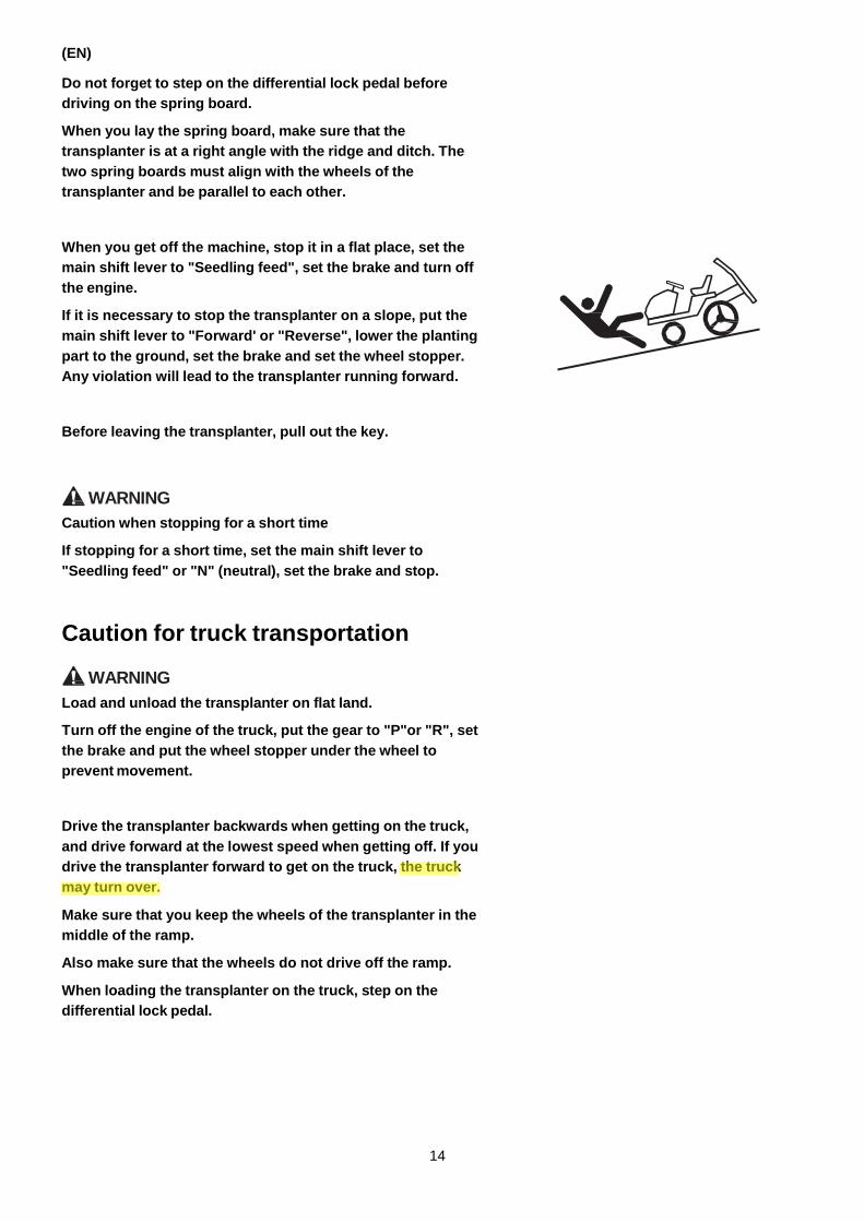
When you get off the machine, stop it in a flat place, set the
main shift lever to "Seedling feed", set the brake and turn off
the engine.
If it is necessary to stop the transplanter on a slope, put the
main shift lever to "Forward' or "Reverse", lower the planting
part to the ground, set the brake and set the wheel stopper.
Any violation will lead to the transplanter running forward.
Before leaving the transplanter, pull out the key.
WARNING
Caution when stopping for a short time
If stopping for a short time, set the main shift lever to
"Seedling feed" or "N" (neutral), set the brake and stop.
Caution for truck transportation
WARNING
Load and unload the transplanter on flat land.
Turn off the engine of the truck, put the gear to "P"or "R", set
the brake and put the wheel stopper under the wheel to
prevent movement.
Drive the transplanter backwards when getting on the truck,
and drive forward at the lowest speed when getting off. If you
drive the transplanter forward to get on the truck, the truck
may turn over.
Make sure that you keep the wheels of the transplanter in the
middle of the ramp.
Also make sure that the wheels do not drive off the ramp.
When loading the transplanter on the truck, step on the
differential lock pedal.
14
Yamar
Highlight

(EN)
WARNING
Do not operate the main shift lever when the transplanter is
on the ramp.
If you step on the brake when the transplanter is on the ramp,
the transplanter will move forward without control.
If you must change the gear in order to avoid danger, depress
the brake pedal quickly, and use the main shift lever to
change the gear. Do not set it to "Neutral" or "Seedling feed"
at this time.
In order to avoid danger when stopping the transplanter
during loading or unloading, depress the brake pedal quickly.
If the engine stops running during loading or unloading,
depress the brake pedal immediately and start the engine
again.
Do not turn the steering wheel abruptly when the transplanter
is on the ramp.
This causes the side clutch of the rear wheel on the steering
side and the machine to move.
If the transplanter has been loaded on the truck, put the main
shift lever to "Forward" or "Reverse", set the parking brake,
and fix the machine on the truck with strong ropes. If fixed
insufficiently, the transplanter will fall from the truck's cargo
area.
Unload the objects on the seedling rack and space seeding
rack; otherwise they can fall and cause an accident.
Fold the side lineation lever, line marker and land preparation
roller, make sure that the land preparation roller and seedling
rack are folded; otherwise a collision with nearby objects may
happen.
CAUTION An assistant is needed when loading and unloading the
transplanter to make sure that the nearby environment is
safe.
The assistant is not allowed to stand directly in front or
directly behind the transplanter.
15
Yamar
Highlight
(EN)
Caution for operation
WARNING
When adding seedlings to the transplanter, slow down the
engine speed with the accelerator lever, set the main shift
lever to "Seedling feed" and let the engine stop.
WARNING
During operation, do not touch any rotating parts, operation
parts or parts with high temperature. They can pull your hand
in or burn your hand.
If there are foreign objects in the planting tine, first stop the
engine, and then remove the contamination after making sure
that all of the parts have stopped moving. If the machine
starts to operate, your hand may be pulled into the machine.
CAUTION When turning on a ridge, pay attention to the people and
objects on the ridge.
During operation, people are not allowed to enter the paddy
field or come close to the transplanter, especially children.
Do not use people or objects as an additional balance weight
on the transplanter.
Do not operate at night, poor sight can lead to accidents.
Caution for storing
WARNING
When covering the transplanter, make sure that all hot parts
of the transplanter have cooled. Covering the transplanter
when it is hot may cause a fire.
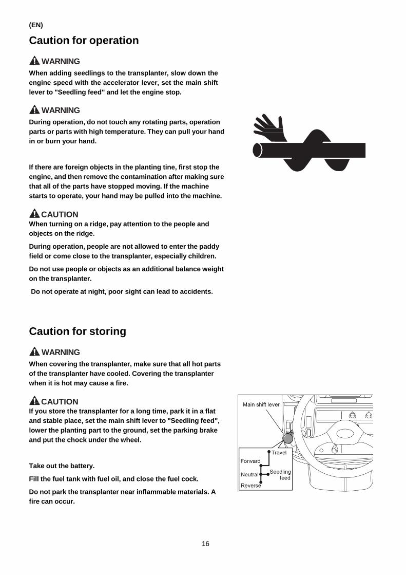
CAUTION If you store the transplanter for a long time, park it in a flat
and stable place, set the main shift lever to "Seedling feed",
lower the planting part to the ground, set the parking brake
and put the chock under the wheel.
Take out the battery.
Fill the fuel tank with fuel oil, and close the fuel cock.
Do not park the transplanter near inflammable materials. A
fire can occur.
16
Caution for inspection, oiling and maintenance
(EN)
DANGER
When adding fuel, do not smoke or light a flame.
After adding fuel, make sure that the tank has been covered
appropriately and wipe up the overflowing fuel. If the fuel
ignites, a fire can happen and cause injury.
DANGER
Do not start the engine when the dilute sulfuric acid index of
the battery is transparent.
Otherwise the flames caused by starting the engine may burst
out and ignite the gas in the battery, resulting in a malfunction
of the battery.
WARNING
During inspection, oiling, maintenance and repairing, park the
transplanter in a flat and stable place without danger from
traffic, and turn off the engine.
Set the hydraulic stopping lever to "Stop" and set the parking
brake.
When stopped, set the main shift lever to "Seedling feed".
When lifting the planting part for inspection and maintenance
of the planting tines, set the hydraulic stop lever to "Stop"
and use the rack to support the planting part and prevent it
from falling.
When inspecting and adjusting the planting tines, pay
attention to the planting tines to avoid injury.
WARNING
During inspection and battery maintenance, follow the
precautions for safe operation stated below.
When unloading the battery, first remove the electric cable of
the negative terminal. When loading the battery, first install
the electric cable of the positive terminal.
Any violation may cause a short circuit which may lead to
burn injury and fire.
When handling the battery, be careful of flames and other
sources of fire. The hydrogen in the battery can ignite and
cause an explosion.
17
(EN)
CAUTION When doing an inspection, oiling, maintenance and repairing,
people are not allowed to come close to the transplanter,
especially children. It is very dangerous if a person is near the
blind area of the machine.
Install the cover that you disassembled from the machine
during inspection and maintenance. If operating without the
cover, you may be pulled into the machine.
CAUTION Inspection, oiling and maintenance can only be carried out
after the hot parts of the sound depressor and engine have
cooled; otherwise burn injury can occur.
CAUTION Do an inspection of the silencer and connecting pipe.
Before operating, make sure that there are no cracks, corrosion
and other abnormal conditions on the sound depressor and
connecting pipe and that there is no dirt build-up on their high-
temperature parts. Any violation may lead to fire.
The fuel pipe, oil discharging pipe and other rubber pipes
must be replaced every two years. The electrical wire must be
checked every 50 hours or every year (whichever is earlier).
The rubber pipe deteriorates over time.
Any violation may cause accidents and mechanical
malfunction.
CAUTION Do an inspection on the axle and the wheels.
Check whether the wheels are loose. If they are, adjust the
tightening bolts and nuts, because loose wheels will lead to
accidents.
Check whether there are cracks, brittle parts on the axle and
wheels (on the rubber). They will lead to injury and
malfunction of the machine.
18

(EN)
WARNING
Use the battery only for starting the engine, not for other
uses.
Before charging or replacing the battery, read the
precautionary labels on the battery.
The battery needs to be unloaded from the transplanter for
charging. Charging in a badly ventilated area may cause the
battery to break.
Be careful because the battery electrolyte is dilute sulfuric
acid.
If the electrolyte splashes into your eyes, flush the eyes with
running water and go to a hospital for treatment.
If you ingest the electrolyte, drink a lot of water and go to the
hospital for treatment. If you get electrolyte on your clothes or
skin, wash it with soap immediately. Any violation will lead to
blindness and burn injury.
When you replace the battery, replace it with a battery that
has the volume specified in the operating manual. Any
violation will lead to burn injury and fire caused by short
circuiting.
19

(EN)
Location of the safety labels
The safety labels must not be damaged. If damaged or lost, order and attach new safety labels.
5
2
7 8
5
6
10
20

1. 1C739C-95700 Caution (cover)
(EN)
2. 1C739C-95770 Caution (brake) 3. 1C739C-95860 Caution (hydraulic lock)
5. 1C739C-95940 Warning (planting part)
6. 1E6B35-97660 Caution (hot part)
21

(EN)
7. 1C739C-95710 Safety label (overall)
8. 1C739C-95740 Warning (rotating shaft)
9. 1E6B35-97610 Danger (radiator)
9. 1C739C-95780 Warning
Maintenance of the safety labels
The safety labels must be clean and without damage. If one is
dirty, wipe it with a cloth soaked with soap water first and then wipe
off the water with a soft cloth.
Do not wash the label with a high pressure cleaner. The label can
peel off.
If lost or damaged, order a new label from your dealer and attach it
in the original position.
22

2. SERVICE AND WARRANTY
Keep the warranty card in a safe place
The warranty card is necessary to claim the warranty. After
reading, take good care of it.
Accepting the after service
If the machine runs abnormally, do an inspection and repair
according to Page 125 "TROUBLESHOOTING". If the machine
still runs abnormally, prepare the following information and then
contact your dealer.
Damage report details
• Type and manufacturing number
• Working condition (speed, working content)
• Service life (about ---- hours)
• Explain the details of the abnormal condition
Remove the front cover of the engine, and check the engine
number on the front part of the engine body.
Supplying period for replacement parts
The supplying period for replacement parts extends five years after
the termination of production. But the delivery date of some
special parts can only be decided after consultation. The supplying
period for replacement parts is in principle as stated above. But if
the replacement parts are needed after the supplying period, the
delivery date and price can be discussed.
Genuine replacement parts and oil
The replacement parts and oil have undergone a number of tests
and are qualified after strict quality testing to make them safe for
the users.
When replacing parts and oil, only use genuine replacement parts
and oil.
(EN)
23

(EN)
3. SEEDLINGS AND PADDY FIELDS APPROPRIATE FOR THE TRANSPLANTER
If the seedlings and paddy fields are not appropriate for the
transplanter, the further growth of the seedlings is directly effected.
Read the following conditions to understand and identify seedlings
and paddy fields suitable for the transplanter.
Seedlings
Seedlings that meet the following
requirements are suitable for the transplanter.
In seedling culturing, the condition of the bet soil, culturing method
and the condition of the seedling mat are very important.
Item Unit Conformability
Culturing method Box and frame culturing
Types of seedling Young seedling Middle seedling
Leafage Leaf 2.0 to 2.5 2.5 to 4.5
Height of seedling cm 10 to 15 15 to 25
Size of the seedbed cm Length 58 width 28 depth 2 to 3
Bed soil
Choose a soil that is suitable for the seedling culturing.
The soil for the bed soil must be screened with a filter or sieve.
Any violation may cause foreign objects to jam the machine. In that
case, you have to stop the machine for cleaning which may effect
the operation efficiency. Severe cases can result in damage to the
machine.
For more details, consult with the promotion center for planting
with a transplanter.
Seedling mat
Before planting, water the seedbed, and pay attention that no
water drops from the seedlings when taken out from the nursery
box.
If the seedling mat is too dry, the sliding movement is hindered
which causes vacancy of the seedlings.
If the seedling mat is too wet, it will become loose which may
cause seedling floating.
24

The condition of the seedlings and undesirable
results when planting
Seedlings in a bad condition will cause the following undesirable
results.
Possible undesirable results
Condition of the seedlings
Undesirable results
Uneven seedling Uneven sprouting
• Serious deviation of a single hole or vacancy
Weak seedlings Old seedlings
• Serious deviation of a single hole or vacancy.
• The seedling is badly injured, the planting
posture is not straight.
The seedbed is too thick or thin. (correct thickness is 2 cm to 3 cm)
• Serious deviation of a single hole or vacancy.
• The planting posture is not straight.
• Breaking of the seedbed (too thin).
• The seedlings or the roots are cut.
The roots in the seedbed are entangled and break
• Serious deviation of a single hole or vacancy.
• Floating seedlings and the planting posture is
not straight.
• Serious deviation of a single hole or vacancy
• Seedlings fall.
• The consumption of seedlings of each row
varies greatly.
The leaf of the grain is not straight
• Cut seedlings
• Floating seedlings
Paddy fields
Plough the fields evenly, turn the soil and flatten it to the
appropriate hardness. A water depth of 1 cm to 2 cm is suitable for
the transplanter.
Plough and soil aeration and water control are very important to
prepare the paddy fields.
Rough plough
The rough plough must be even, and all wheat straws and crop
residue should be removed or deeply ploughed under.
A lot of wheat straws and crop residue will influence the planting
and can cause seedling floating, irregular order of the seedlings,
and seedling damage.
Pudding soil
The pudding soil must be even and without bumps.
If the soil pudding is rough with a lot of wheat straws and soil block,
it will cause irregular planting of the seedlings which may affect
their further growth.
The soil may not be over-pudding.
Over-pudding soil has a negative influence on operation.
(EN)
25

(EN)
Approximate aeration date based on the planting date
Soil property Date of aeration
Sandy soil The same day or 1 day before
Silty loam 2 days to 3 days before
Soil-planting soil (standard paddy field)
4 days to 5 days before
Clay soil 5 days to 6 days before
Volcanic soil 6 days to 7 days before
The date of aeration further varies by weather and region.
Hardness of the paddy field surface
The hardness of the paddy field surface is shown in the following
figures. The images show a piece of earth the size of a golf ball
dropped from a height of 1 m.
If the surface is too hard, seedling floating and falling will occur. If
the surface is too soft, the seedlings will be planted in disorder,
and soil will get into the machine.
Depth of the water
The water depth should be 1 cm to 2 cm to be suitable for seedling
planting.
Deep water will cause the seedlings to be planted in disorder and
floating seedlings.
Shallow water will cause the seedlings to be planted in disorder.
Depth of the paddy field
• The plough depth of the paddy field should be under 25 cm.
• If the paddy field is too deep and the machine sinks to the axle of
the rear wheel, install wheel aids (choosing the accessory parts).
If the paddy field is too deep, it will affect the operation efficiency
and even damage the machine.
• If there are open trenches or blind trenches in the fields, make
sure that the wheels do not sink into the trenches, otherwise the
machine will be damaged.
• If the front wheel is floating, the machine will be underpowered
and difficult to drive.
Install a balance weight (choosing the accessory parts) on the
installing set in the front of the machine to prevent the front
wheel from floating.
26

4. NAME OF THE COMPONENTS For more details on the function and using methods of each device, refer to the related reference page.
Appearance
(EN)
Reference page Reference page
1. Driver’s seat .................................... 44
2. Rear view mirror
3. Center marker ................................ 45
4. Head light
5. Engine
6. Fuel strainer .................................... 32
7. Fuel supply port............................... 45
8. Step
9. Assist bar
10. Line marker .......................................... 42
11. Vertical feed adjusting lever ................. 40
12. Planting depth control lever ................. 38
13. Lateral feed adjusting lever ................. 40
27

(EN)
Reference page Reference page
1. Seedling rack .................................. 42
2. Seedling mat stopper
3. Seedling feed stopper
4. Float
5. Planting tine
6. Seedling press rod .......................... 44
7. Side bumper and stand ......................... 44
8. Spare seeding rack
9. Side marker ........................................... 44
10. Front wheel
11. Rear wheel
28

Controls and instruments
(EN)
Reference page Reference page
1. Steering wheel ........................................ 34
2. Main shift lever ....................................... 35
3. Differential lock pedal ............................. 39
4. Key switch .............................................. 31
5. UFO automatic adjustment knob ........... 41
6. Speed setting lever ................................ 37
7. Planting lifting lever ................................ 36
8. Parking brake lever ................................ 39
9. Speed control pedal ....................................... 36
10. Brake pedal.................................................. 38
11. Accelerator lever .......................................... 31
12. Sub planting number changing lever ........... 39
13. Planting number changing lever .................. 39
14. Hydraulic stop lever .......................................... 40
15. Hydraulic sensing adjustment lever ............. 38
29
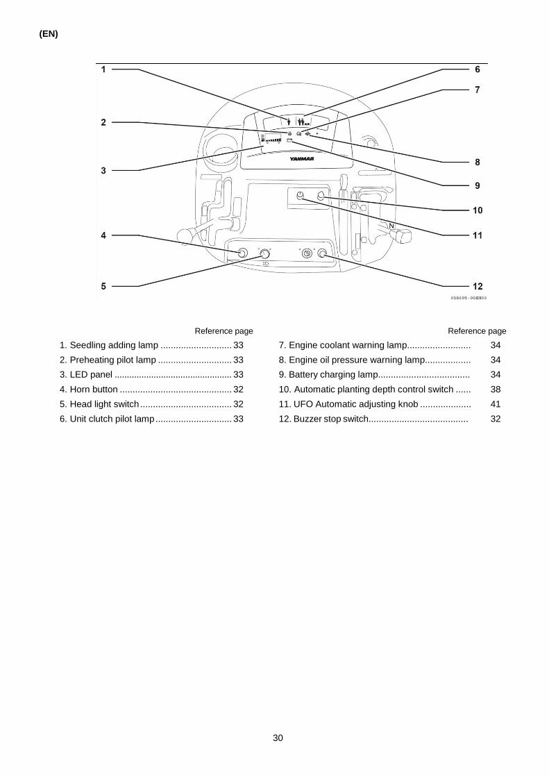
(EN)
Reference page Reference page
1. Seedling adding lamp ............................ 33
2. Preheating pilot lamp ............................. 33
3. LED panel ................................................ 33
4. Horn button ............................................ 32
5. Head light switch .................................... 32
6. Unit clutch pilot lamp .............................. 33
7. Engine coolant warning lamp......................... 34
8. Engine oil pressure warning lamp.................. 34
9. Battery charging lamp.................................... 34
10. Automatic planting depth control switch ...... 38
11. UFO Automatic adjusting knob .................... 41
12. Buzzer stop switch....................................... 32
30

5. FUNCTION OF EACH OPERATIONAL PART
Engine control
Key switch
The key switch is used for starting and stopping the engine.
(EN)
"OFF" position: The engine stops, and all electric current is
stopped. (You can remove the key.)
"ON" position: Voltage is supplied to the electrical
components.
"Start" position: The starter motor runs to start the engine.
Once the engine has started, take your hand
off the key. The key will automatically return to
the “ON” position.
Reference
• When the key switch is moved to “ON”, the LED panel will
display “Overheating” for 3 seconds.
• After this, the hour meter and fuel meter start to work. (For more
details, refer to Page 33.)
• 6 seconds after the key switch is set to “ON” and if there are no
seedlings on the seedling rack, the seedling adding alarm starts
to illuminate. (For more details, refer to Page 33.)
• 10 seconds after the key switch is set to “ON” and if the engine
has not been started, the LED panel displays “NO CHANGE”
and “Err: Eng/Oil PRESSURE”.
Accelerator lever
This lever is used to adjust the engine speed.
"High speed" (pull down): increase the engine speed
"Low speed" (pull up): decrease the engine speed
Reference
When working in a paddy field with deep water, increase the
engine speed in advance in order to prevent the engine from
stopping due to the slow operation on the speed control pedal.
31

(EN)
Fuel strainer, Water separator
The Fuel strainer is located on the left side of the engine. The
water separator is under the left of the machine. They are used to
control the fuel supply and stopping supply.
"Open": Fuel is supplied to the engine.
(While the engine is running)
“Closed”: Fuel is not supplied to the engine. (When the
machine will be stored for a long period of time)
Electric system
Head light switch
This switch is used to control the head light.
Turn the key switch to "ON", and then turn the head light switch to
the right to "ON": the head light turns on. Turn the switch to the left
to "OFF": the head light turns off.
Horn button
This button is used to sound the horn.
Turn the key switch to "ON" and press the horn button to sound the
horn.
Buzzer stop/display select switch
This switch is used to stop the alarm buzzer. It is also used to
change the display on the LCD panel.
The alarm buzzer will sound when either of the following happens.
• When the remaining seedlings in the planting part are running low.
• When the planting lifting lever is in the “DOWN” position, the unit
clutch lever is in the “Stop” position and the planting lifting lever
is first put in the “OFF” position and then back in the “ON”
position again.
OFF ON
32
START
Horn button
OFF OFF ON
ON
Buzzer Stop
START
Buzzer stop/display select switch
OFF OFF ON
ON
Buzzer Stop

Instrument panel
The panel is mainly used to display information necessary for
(EN)
operation and planting. The LED panel also displays fuel
consumption and time.
Seedling adding lamp (1)
The alarm lamp turns on and the buzzer makes a sound to remind
you when you need to add more seedlings to the seedling rack.
When you need to add more seedlings to the seedling rack, the
LED panel shows "SEEDLING EMPTY" and the buzzer makes a
sound.
Unit clutch pilot lamp (2)
When the unit clutch lever is put in the "Stop" position, this lamp
will come on. When the unit clutch lever is put in the planting "ON"
position, the alarm buzzer will sound to prevent you from forgetting
to engage the unit clutch. Then, the lamp will flash, and "OFF:
UNIT CLUTCH" will be displayed on the LCD panel.
LED panel (3)
■ Hour meter
The hour meter displays the accumulative operation time of
the transplanter, accurate to 1/10 hour.
The meter only counts the time while the engine is running.
The meter display changes every 6 minutes.
Reference
The accumulated time cannot be reset.
■ Fuel meter
The fuel meter displays the amount of fuel left.
(LED)
(LED)
5.3
Hour meter
Fuel quantity
Preheater pilot lamp (glow lamp) (4)
If the key switch is set to "ON", the light turns on, indicating that the
glow lamp operates.
After the lamp goes out and the switch is set back to "Start", the
engine is started.
The preheater pilot lamp lasts for 3-4 seconds.
33
5.3
(EN)
Engine coolant warning lamp (5)
The lamp turns on when the temperature of the cooling water
rises.
Engine oil pressure warning lamp (6)
When the key switch is set to "ON", the indicating lamp turns on
and it turns off after starting the engine. If the oil pressure is not
sufficient during operation or if there is some abnormality
regarding the lubricating oil, the light turns on.
Battery charging lamp (7)
When the key switch is set to "ON" or the engine stops charging
the battery, the lamp turns on.
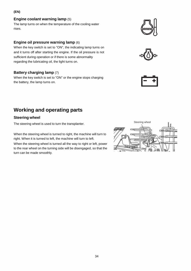
Working and operating parts
Steering wheel
The steering wheel is used to turn the transplanter.
When the steering wheel is turned to right, the machine will turn to
right. When it is turned to left, the machine will turn to left.
When the steering wheel is turned all the way to right or left, power
to the rear wheel on the turning side will be disengaged, so that the
turn can be made smoothly.
34
Steering wheel

Main shift lever
The lever is used to change the running direction and speed. You
can shift to 2 forward gears, neutral, reverse and seedling feed.
Change the position of the lever after pushing the brake pedal to
the bottom and stopping the machine.
"Travel":
Run at a high speed on farm roads.
Do not use in the paddy fields, because the transmission
may be damaged.
"N":
Cut the power of the wheel and stop the machine. Use when
operating the planting part only.
"Forward" (moving in the paddy field):
Use when planting and moving in the paddy field, loading
and unloading from the truck, in and out of the paddy fields,
and driving at a low speed on farm roads.
"Seedling feed":
Use when getting off the machine and adding seedlings, the
power of the running and planting part is cut off and the
machine is stopped.
"Reverse" (moving in the paddy field):
Use to drive the machine backwards.
Reference
<Backup mechanism>
When the main shift lever is put in the "Reverse" position
with the planting part lowered, the power to the planting part
is stopped and the planting part is lifted at the same time.
Reference
Take the following measures when you want the machine to drive
slowly with the planting part in the higher position.
1. Use the planting lifting lever to adjust the planting part to the
desired height and set the hydraulic stop lever to “Stop”.
2. Put the main shift lever to “Reverse”.
(EN)
35

(EN)
Planting lifting lever
The lever is used for lifting the planting part, disengaging and
engaging of planting and to control the line marker.
■ Lifting
This is used to lift, lower or fix the planting part.
"Up": Lift the planting part
"Neutral": Fix the planting part at any arbitrary height
"Down": Lower the planting part, adjust the hydraulic sensitivity
automatically
■ Planting
This is used to start or stop the operation of the planting part.
"Engage": Power is sent to the planting part.
"Disengage": The planting part stops.
■ Line marker
This lever moves the line marker.
"Left": The left line marker is lowered and it is ready to use.
"Right":The right line marker is lowered and it is ready to use.
Speed control pedal
This pedal is used to control the traveling speed when planting or
traveling and to stop traveling.
"Press down":
The traveling speed is increased. The variable speed
transmission goes to the high speed side and the engine
speed is increased at the same time.
"Release":
The traveling speed decreases and the machine stops.
When the variable speed transmission is on the low speed
side and the speed control pedal is returned all the way up,
the variable speed transmission stops and the engine speed
decreases.
IMPORTANT
• When pressing down or releasing the speed control pedal,
operate it gradually.
• Once the machine has stopped, put the main shift lever in the
“N” (Neutral) or “Seedling feed” position. If you take your foot off
the speed control pedal with the main shift lever still in the
“Travel”, “Forward” or “Reverse” position, the machine may
creep slowly due to the oil temperature at the time. However,
this is normal.
36
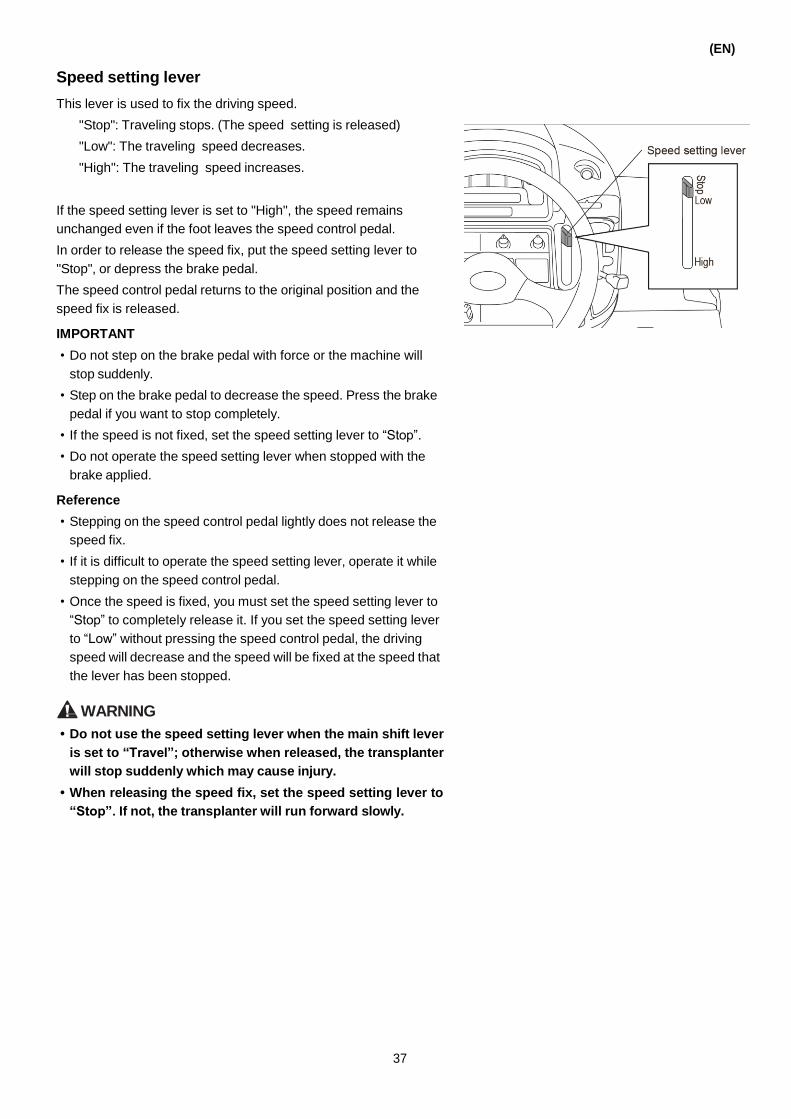
Speed setting lever
This lever is used to fix the driving speed.
"Stop": Traveling stops. (The speed setting is released)
"Low": The traveling speed decreases.
"High": The traveling speed increases.
(EN)
If the speed setting lever is set to "High", the speed remains
unchanged even if the foot leaves the speed control pedal.
In order to release the speed fix, put the speed setting lever to
"Stop", or depress the brake pedal.
The speed control pedal returns to the original position and the
speed fix is released.
IMPORTANT
• Do not step on the brake pedal with force or the machine will
stop suddenly.
• Step on the brake pedal to decrease the speed. Press the brake
pedal if you want to stop completely.
• If the speed is not fixed, set the speed setting lever to “Stop”.
• Do not operate the speed setting lever when stopped with the
brake applied.
Reference
• Stepping on the speed control pedal lightly does not release the
speed fix.
• If it is difficult to operate the speed setting lever, operate it while
stepping on the speed control pedal.
• Once the speed is fixed, you must set the speed setting lever to
“Stop” to completely release it. If you set the speed setting lever
to “Low” without pressing the speed control pedal, the driving
speed will decrease and the speed will be fixed at the speed that
the lever has been stopped.
Ṇ
WARNING
• Do not use the speed setting lever when the main shift lever
is set to “Travel”; otherwise when released, the transplanter
will stop suddenly which may cause injury.
• When releasing the speed fix, set the speed setting lever to
“Stop”. If not, the transplanter will run forward slowly.
37

(EN)
Hydraulic sensing adjustment lever
When the float is needed to level off the paddy field, this lever is
used to adjust the hydraulic control sensitivity according to the
hardness of the field.
It can be adjusted steplessly.
"Soft paddy field": The sensitivity increases.
(Sensitive: float rises)
"Hard paddy field": The sensitivity decreases.
(Slow: float lowers)
Reference
Step on the speed control pedal to accelerate the planting speed.
Then adjust the hydraulic sensitivity to "Hard paddy field" and the
component can ensure the appropriate planting depth.
Planting depth control lever
This lever is used to adjust the planting depth.
Reference
The planting depth can be set to 6 levels.
Automatic planting depth control switch
This switch is used to adjust the planting depth automatically.
"ON": The automatic control of planting depth starts.
"OFF": The automatic control of planting depth stops.
(Automatic adjusting planting depth component )
Set the automatic control switch of the planting depth to "ON",
depress on the speed control pedal and the planting speed is
accelerated.
The part can adjust the planting depth automatically.
Brake pedal
This pedal is used to stop or park the transplanter when driving or
operating.
Reference
When the brake pedal is pressed down, the main clutch will be
disengaged and the power from the engine will not be transferred
to the transmission.
38
90
75
65
55
40
Hydraulic sensing adjustment lever
Fine adjustment
Left-Down Right-Down
Planting Depth Fit Synchro LEVELING DEVICE
Yamar
Highlight

Parking brake lever
This lever is used to park the machine.
Push the brake pedal to the bottom and set the parking brake lever
to "Stop" and the parking brake will be engaged.
To release the parking brake, press the brake pedal softly and set
the parking brake lever to "Release".
Differential lock pedal (front wheels)
This pedal is used when the transplanter crosses a ridge, moves in
the paddy field and the front wheel on one side slips. This makes it
difficult to drive the transplanter forward.
This differential lock only affects the front wheel.
"Lock":
Connects the axles on the left and right side of the front
wheel which makes the axles rotate synchronously and
protects the axle on one side from idling and slipping. To
lock, step on the brake pedal continually.
"Release":
Releases the connection of the left and right axles
automatically.
• Decrease the speed when operating the differential lock.
• Even if you step on it, the differential lock cannot work when its
salient points inside the transmission are opposite to each other.
Only when the speed of the left and right axle differs from each
other can the differential lock take effect.
• For more details on the practical use of the differential lock, refer
to Page 68 "Getting in or out of the paddy field".
Planting number changing lever
The lever is used to adjust the planting number.
(It is on the right side of the operating space.)
The control is composed of 2 levers and 6 grades.
Reference
The planting number varies with the paddy field. Adjust it
according to the desired planting.
(EN)
39
Yamar
Highlight

(EN)
Hydraulic stop lever
This lever is used to stop and prevent the planting part from
dropping when moving, repairing and storing the transplanter.
"Stop": Stops the lifting hydraulic of the planting part. No matter
whether the planting lifting lever is set to "Up" or
"Down", the planting part will not be lifted or lowered.
"Release": Set the planting lifting lever to "Up" or "Down" and
the planting part will be lifted or lowered
accordingly.
IMPORTANT
• Put the hydraulic stop lever to the two ends of the guide slot. If it
is placed in the middle, the machine may run abnormally.
• Put the hydraulic stop lever to “Stop”. No matter if the planting
lifting lever is set to “Up” or “Down”, the planting part will not be
lifted or lowered.
• Do not set the planting lifting lever to “Up” on the planting lifting
when setting the hydraulic stop lever to “Stop”, otherwise the oil
temperature of the transmission will increase which may cause
damage.
Planting part
Vertical feed adjusting lever
This lever is used to adjust the seeding number in a hill.
The seedling number for each hole can be adjusted in 10 grades
hill according to the status of the seedlings. (Refer to Page 85.)
"More": Increase the seedling number in each hill.
"Less": Decrease the seedling number in each hill.
Lateral feed adjusting lever
This lever is used to adjust the amount the seedling mat is fed
laterally.
The seedling amount of the lateral feed can be adjusted in 3
levels.
Reference
If the seedling amount of the lateral feed is reduced, the planting
fingers chucks the seedling. The seedling will not be pressed into
the soil by the seedling prevention block, but it is cut and floats on
the water.
Lateral feed adjusting lever
M S
22 times
(11mm)
16 times
(14mm)
15 times
(15mm)
40
90 75
65
55
40
Hydraulic stop lever
L

4
Unit clutch lever
This lever is used to stop the operation of the planting fingers in 6
rows (every 2 rows). It also stops the operation of the seedling
feed belt.
This lever is used to stop planting fingers and the seedling feed
belt in use in a previous process and to adjust the number of rows,
so that all the rows can be planted in the final process.
“Planting”: The planting fingers and the seedling feed belt
operate normally.
“Stop”: Stops the planting fingers and the seedling feed belt.
IMPORTANT
Do not operate the unit clutch lever when the planting section is
running at high speed. It may cause the machine to malfunction.
Reference
• When the unit clutch lever and the seedling feed stopper are
used together, the number of rows can be adjusted by stopping
the planting fingers and the seedling feed belt used in a previous
process.
• Move the unit clutch lever all the way to the “Planting” or “Stop”
position.
Automatic balance UFO
■ UFO automatic adjusting knob
This knob is used to balance the planting part when it leans to
the left or right. Besides this, it is also used when the planting
part leans on the ridge.
Reference
When setting the planting lifting lever to “Down”, the UFO
adjusts the horizontal action.
(EN)
■ Manual operation of the UFO
Set the planting lifting lever to “Up”. After putting the planting
part to the original place, turn the UFO automatic adjusting
knob to “Manual range”, then you can adjust the planting part
to the desired position manually.
41
(EN)
Seedling rack
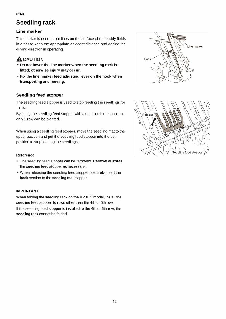
Line marker
This marker is used to put lines on the surface of the paddy fields
in order to keep the appropriate adjacent distance and decide the
driving direction in operating.
CAUTION • Do not lower the line marker when the seedling rack is
lifted; otherwise injury may occur.
• Fix the line marker feed adjusting lever on the hook when
transporting and moving.
Seedling feed stopper
The seedling feed stopper is used to stop feeding the seedlings for
1 row.
By using the seedling feed stopper with a unit clutch mechanism,
only 1 row can be planted.
When using a seedling feed stopper, move the seedling mat to the
upper position and put the seedling feed stopper into the set
position to stop feeding the seedlings.
Reference
• The seedling feed stopper can be removed. Remove or install
the seedling feed stopper as necessary.
• When releasing the seedling feed stopper, securely insert the
hook section to the seedling mat stopper.
IMPORTANT
When folding the seedling rack on the VP8DN model, install the
seedling feed stopper to rows other than the 4th or 5th row.
If the seedling feed stopper is installed to the 4th or 5th row, the
seedling rack cannot be folded.
42

Seedling mat stopper
Hold the seedling mat so that the mat will not break.
Adjust the seedling mat stopper depending on the seedling
condition or the seedling mat thickness.
When adjusting the seedling mat stopper position or releasing the
lock, hold the seedling mat stopper as shown in the figure to the
right.
Releasing the seedling mat stopper will allow you to remove the
remaining seedlings on the seedling rack after planting.
The seedling mat stopper can be released from the upper side.
<How to release the seedling mat stopper>
Release the seedling mat stopper from the seedling mat lock
bracket located on the upper side.
(EN)
062454-00EN00
Seedling mat stopper

43

(EN)
Seedling press board
Side bumper and stand
The side bumper and stand can be used as support to protect the
planting part. Unfold it when operating.
Release the lock by pulling out the fixed pin of the bumper, then
turn the bumper to fold and unfold it.
Other devices
Side marker
When it is difficult to see the line drawn by the line marker while
planting seedling near the ridge, this marker is used as a guide to
maintain the appropriate distance between adjacent rows.
Reference
Before transporting and traveling, rotate the side marker forward to
store it facing the front.
Driver’s seat
The seat can be adjusted by sliding forward or backward to ensure
that the operator is in a comfortable position.
The position of the seat can be adjusted by adjusting the hole
position of the fulcrum pin and using the adjusting lever.
Besides this, the seat can be tilted forward.
44

Center marker
When planting with the center marker aligned with the line in the
field drawn by the line marker, the center marker provides a guide
to let you travel straight ahead and maintain the appropriate
distance between adjacent rows.
Also, since the center marker can rotate forward, it can be
adjusted to a position where the driver can see it easily.
Fuel supply port
This port is used to add fuel.
Tilt the seat forward to find it.
Bonnet open lever
The lever is used to remove the bonnet.
Cup holder
The cup holder is used to hold a cup or other beverage container.
(EN)
45

(EN)
6. PREPARATIONS BEFORE OPERATING
DANGER • When fueling, do not smoke or use open flames for illumination.
• After fueling, tighten the cover and wipe off the spilled oil; otherwise a fire can occur.
WARNING
When doing an inspection, park the transplanter in a flat and safe area, and turn off the engine.
CAUTION • Install the covers that you removed during checking or disassembling the transplanter to their original
position. If driving with the cover disassembled, your hand may be dragged into the machine.
• Clean the transplanter. Any dirt or fuel on the battery, line, sound depressor and engine may cause a fire
or accident.
Inspection before operating
Do the inspection according to the following order before operating and working.
Checking order Checking part Page for reference
Abnormalities of the day before The abnormal part in the operation of the day before
Check around the machine
• Whether there is deformation, damage, dirt marks, whether the bolts are loose
• The quantity of the fuel, whether there is fuel leakage, oil leakage
• Whether there is damage or wear on the wheel
• Whether there is wear on the planting fingers
Check inside the bonnet • Whether the surface of the wire is peeled off, whether the joint parts are loose 113 • Whether there is damages on the belt
• The quantity of the engine oil, the amount of dirt, whether there is oil leakage 104
• Whether the air filter element is dirty 109
Check on the driver’s seat
• Whether the position of the driver’s seat is comfortable
• Effect and play in the brake pedal
• Play in the steering wheel
Start the engine
• Whether the engine makes an abnormal sound
• Whether the color of the exhaust gas is normal
• Whether the light works normally
• Whether the levers function normally
• Whether there is abnormal information displayed on the LED panel
Start slowly • Whether the brake functions normally 38
• Whether the main shift lever functions normally 35
• Whether the speed control pedal functions normally 36
46

7. OPERATION METHOD
(EN)
WARNING
• Read Chapter 1 “Precautions for Safe Operation” and the
safety labels on the machine, and start the machine only
after fully understanding the precautions.
• When starting the engine, make sure that you are properly
seated in the driver’s seat, set the parking brake, and that
the main shift lever is set to “Seedling feed”; otherwise any
wrong operation on the speed control pedal may cause the
transplanter to drive forward, turn over or collide.
• Set the parking brake before getting off the transplanter,
otherwise any wrong operation on the speed control pedal
may cause the transplanter to drive forward, turn over or
collide.
• Make sure that the surrounding is safe when getting on or
off the transplanter.
Adjusting the driver’s seat
The position of the seat can be adjusted by adjusting the hole
position of the fulcrum pin and using the lever.
Adjusting by using the fulcrum pin
1. Take down the cotter and pull out the fulcrum pin.
2. Move the seat, insert the cotter and fix the fulcrum pin.
Adjusting by using the adjusting lever
1. Pull up the adjusting lever in the direction of the arrow.
2. Adjust the seat forward or backward.
3. Release the adjusting lever, then the seat is fixed.
47

(EN)
Starting the engine
Checks and preparation before starting the engine
1. Set the cock of fuel strainer and water separator to “Open”.
2. Set the main shift lever to “Seedling feed”.
Set the accelerator lever between “High speed” and “Low
speed”.
48
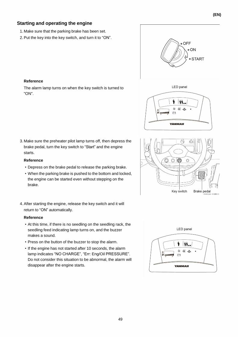
Starting and operating the engine
1. Make sure that the parking brake has been set.
2. Put the key into the key switch, and turn it to “ON”.
(EN)
Reference
The alarm lamp turns on when the key switch is turned to
"ON".
3. Make sure the preheater pilot lamp turns off, then depress the
brake pedal, turn the key switch to “Start” and the engine
starts.
Reference
• Depress on the brake pedal to release the parking brake.
• When the parking brake is pushed to the bottom and locked,
the engine can be started even without stepping on the
brake.
058624-00EN00
4. After starting the engine, release the key switch and it will
return to “ON” automatically.
Reference
• At this time, if there is no seedling on the seedling rack, the
seedling feed indicating lamp turns on, and the buzzer
makes a sound.
• Press on the button of the buzzer to stop the alarm.
• If the engine has not started after 10 seconds, the alarm
lamp indicates “NO CHARGE”, “Err: Eng/Oil PRESSURE”.
Do not consider this situation to be abnormal, the alarm will
disappear after the engine starts.
49

(EN)
5. Set the accelerator lever back to “Low speed”.
If the engine has not started within 10 seconds when the key
switch is set to “Start”.
1- Set the key switch back to “OFF”.
2- After one minute, set the key switch to “Start”.
IMPORTANT
• Do not turn the key switch to “Start” for more than 10
seconds. The engine consumes a lot of electricity during
starting. Turning the key switch for too long can lead to
damage to the electric system, the battery may cause a fire.
After turning the key switch to “Start” for 10 seconds, set it to
“Off”, let the battery rest for one minute and then start the
engine.
• Do not use an external power supply to start the engine, it
will damage the electric system and lead to a malfunction.
• When the engine is working, do not turn the key switch to
“Start”; otherwise the electric system may be damaged.
Warming up the machine
CAUTION • The exhaust gas of the engine is harmful to the human
body, so open doors and windows for good ventilation
when starting the engine inside a warehouse or garage.
• When heating the engine, set the parking brake and set the
main shift lever to “Seedling feed”.
1. Set the parking brake after starting the engine.
2. Make sure that the accelerator lever is set to “Low speed” and
decrease the rotation speed of the engine.
3. Make the engine idle for 5 minutes (to heat the machine).
50
Yamar
Highlight
Yamar
Highlight

Stopping the machine
1. Set the main shift lever to “Seedling feed”.
Make sure that the accelerator lever is set to “Low speed”.
2. Set the key switch to “OFF”, and stop the engine.
Reference
When driving in the paddy field, lift the planting part, and set
the hydraulic stop lever to "Stop", and then start the engine.
Starting and speed adjusting
(EN)
WARNING
• Do not operate the main shift lever during operation.
Operate it quickly because the transplanter slides
backwards easily on slopes.
• For safety, put on your safety helmet when operating and
moving.
1. Start the engine.
Reference
When working in deep paddy fields, raise the rotation speed of
the engine to "High speed" in advance to prevent the engine
from stopping when you operate the speed control pedal.
2. Set the planting lifting lever to “Lift” to lift the plating part to the
highest position.
3. Set the hydraulic stop lever to “Stop”.
51
90 75
65
55
40
Hydraulic stop lever

(EN)
4. Set the main shift lever to the appropriate position.
Important points
When moving in a paddy field, only use "Forward" and
"Reverse", do not use "Travel"; otherwise the transmission
may be damaged.
5. Release the brake pedal.
6. Depress on the speed control pedal slowly to start the
transplanter.
7. Adjust the speed by applying force on the speed control pedal.
Operating the main shift lever
WARNING
When it is necessary to change the speed on the slope,
depress the brake pedal to the bottom, set the parking brake
first, and then change the speed. Do not set the main shift
lever to "Neutral" or "Seedling feed"; otherwise the machine
may move which will lead to an accident.
CAUTION When driving in reverse, make sure that the area behind the
transplanter is safe.
1. Release your foot from the speed control pedal and then
depress the brake pedal to stop the machine.
2. Change the speed with the main shift lever.
IMPORTANT
Make sure that the machine has stopped before you change
the speed. Operating when the machine has not stopped will
damage the transmission.
52

Turning
(EN)
WARNING
When driving at a high speed, do not turn suddenly;
otherwise the machine may turn over or fall.
1. Move your foot slowly from the speed control pedal to lower
the speed.
2. Turn the steering wheel to turn the transplanter.
Stopping
CAUTION • Move your foot slowly from the speed control pedal to stop
the machine.
• If stepping on the brake pedal suddenly while driving, the
machine will stop suddenly.
Pay attention and operate carefully.
1. Move your foot from the speed control pedal slowly and then
depress on the brake pedal to make the machine stop.
Reference
When the accelerator lever is set to "High speed", set it to
"Slow speed" to lower the rotation the engine speed.
2. Set the main shift lever to “Seedling feed”.
Reference
• If stopping the machine during operation, make sure to set
the main shift lever to “Seedling feed” or “N” (neutral) and
depress the brake pedal.
• When the main shift lever is set to “Forward” or “Reverse”,
the machine may drive forward slowly depending on the oil
temperature and the engine speed. This is normal.
3. Set the key switch to “OFF” and the engine stops.
4. After making sure that the machine has stopped, set the
parking brake.
53
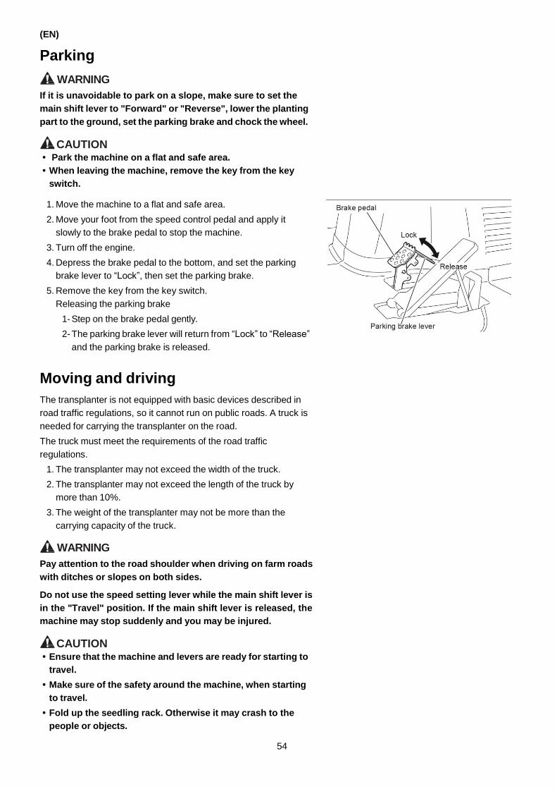
(EN)
Parking
WARNING
If it is unavoidable to park on a slope, make sure to set the
main shift lever to "Forward" or "Reverse", lower the planting
part to the ground, set the parking brake and chock the wheel.
CAUTION • Park the machine on a flat and safe area.
• When leaving the machine, remove the key from the key
switch.
1. Move the machine to a flat and safe area.
2. Move your foot from the speed control pedal and apply it
slowly to the brake pedal to stop the machine.
3. Turn off the engine.
4. Depress the brake pedal to the bottom, and set the parking
brake lever to “Lock”, then set the parking brake.
5. Remove the key from the key switch.
Releasing the parking brake
1- Step on the brake pedal gently.
2- The parking brake lever will return from “Lock” to “Release”
and the parking brake is released.
Moving and driving
The transplanter is not equipped with basic devices described in
road traffic regulations, so it cannot run on public roads. A truck is
needed for carrying the transplanter on the road.
The truck must meet the requirements of the road traffic
regulations.
1. The transplanter may not exceed the width of the truck.
2. The transplanter may not exceed the length of the truck by
more than 10%.
3. The weight of the transplanter may not be more than the
carrying capacity of the truck.
WARNING
Pay attention to the road shoulder when driving on farm roads
with ditches or slopes on both sides.
Do not use the speed setting lever while the main shift lever is
in the "Travel" position. If the main shift lever is released, the
machine may stop suddenly and you may be injured.
CAUTION • Ensure that the machine and levers are ready for starting to
travel.
• Make sure of the safety around the machine, when starting
to travel.
• Fold up the seedling rack. Otherwise it may crash to the
people or objects.
54

Preparing the machine for traveling
1. Fold the center marker and side marker to the back.
Reference
The side marker should be folded.
2. Put the side marker arm to the hook of the line marker and fix
it. Refer to the following figure.
Reference
Even if folded, the line marker may extend outside the
seedling rack, and it may catch on other objects. In that case,
you may remove the line marker.
3. Set the main shift lever to “Seedling feed”.
4. Start the engine.
5. Operate the planting lifting lever to “Lift” to lift the seedling rack
to the highest position.
6. Set the hydraulic stop lever to “Stop”.
(EN)
55

(EN)
Put the seedling rack to the middle of the machine
1. Start the engine.
2. Set the parking brake.
3. Set the main shift lever to “Neutral”.
4. Set the accelerator lever to “Low speed”.
5. Set the planting lifting lever to “Engage”.
6. Step on the speed control pedal lightly and the planting part
starts running and the seedling rack moves left and right.
WARNING • The moving of the seedling rack is driven by a rotating
shaft, so pay attention not to be pulled in.
• Set the accelerator lever to “Low speed” when moving
the seedling rack.
7. When moving the seedling rack to the middle, release your
foot from the speed control pedal and the planting part stops
moving.
8. Put the planting lifting lever to “Disengage”.
9. The planting clutch disengages and the planting part stops
working.
Starting, moving and speed adjusting
1. Set the main shift lever to “Forward” or “Travel”.
2. Release the parking brake.
3. Step on the speed control pedal slowly and pay attention to the
safety of the surrounding. The transplanter starts moving
slowly. Adjust the running speed by applying force on the
speed control pedal.
56
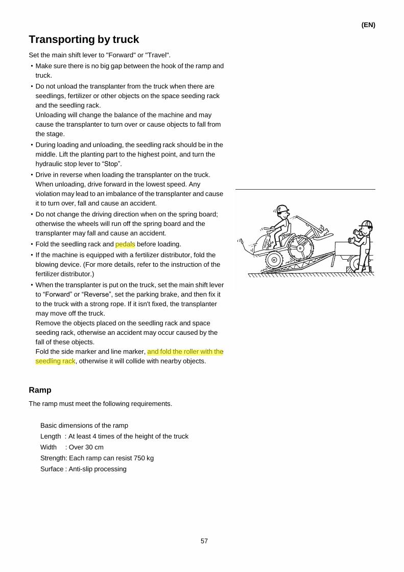
Transporting by truck
Set the main shift lever to "Forward" or "Travel".
• Make sure there is no big gap between the hook of the ramp and
truck.
• Do not unload the transplanter from the truck when there are
seedlings, fertilizer or other objects on the space seeding rack
and the seedling rack.
Unloading will change the balance of the machine and may
cause the transplanter to turn over or cause objects to fall from
the stage.
• During loading and unloading, the seedling rack should be in the
middle. Lift the planting part to the highest point, and turn the
hydraulic stop lever to “Stop”.
• Drive in reverse when loading the transplanter on the truck.
When unloading, drive forward in the lowest speed. Any
violation may lead to an imbalance of the transplanter and cause
it to turn over, fall and cause an accident.
• Do not change the driving direction when on the spring board;
otherwise the wheels will run off the spring board and the
transplanter may fall and cause an accident.
• Fold the seedling rack and pedals before loading.
• If the machine is equipped with a fertilizer distributor, fold the
blowing device. (For more details, refer to the instruction of the
fertilizer distributor.)
• When the transplanter is put on the truck, set the main shift lever
to “Forward” or “Reverse”, set the parking brake, and then fix it
to the truck with a strong rope. If it isn't fixed, the transplanter
may move off the truck.
Remove the objects placed on the seedling rack and space
seeding rack, otherwise an accident may occur caused by the
fall of these objects.
Fold the side marker and line marker, and fold the roller with the
seedling rack, otherwise it will collide with nearby objects.
Ramp
The ramp must meet the following requirements.
Basic dimensions of the ramp
Length : At least 4 times of the height of the truck
Width : Over 30 cm
Strength: Each ramp can resist 750 kg
Surface : Anti-slip processing
(EN)
57
Yamar
Highlight
Yamar
Highlight

(EN)
Preparations of the truck
The truck is parked in a flat, safe and open area.
• Set the gear of the truck to “P” or “R”, and set the parking brake.
• Chock the wheels of the truck.
• Make sure there is no big gap between the hook of the ramp and
truck, and that the spring board has been connected to the truck
well.
Loading the machine
Drive in reverse when loading the transplanter onto the truck.
1. The transplanter is in the walking position.
2. Move the transplanter near the spring board, and make sure
that the spring board and the front and rear wheels of the
transplanter are in a straight line and that the wheels are in the
middle of the spring board.
3. Set the main shift lever to “Reverse”.
4. Set the accelerator lever to “Low speed”.
5. Release the parking brake.
6. Step on the speed control pedal slowly and make the
transplanter move back slowly.
IMPORTANT
If the side bumper and stand touches the baffle of the truck
during loading, the bumper can be folded to the inside for one
grade.
58

After loading on the truck
Fix the transplanter on the truck according to the following method.
1. Lift the planting part to the highest point and then set the
hydraulic stop lever to “Stop”.
2. Stop the engine.
3. Set the parking brake of the transplanter.
4. Fold the line marker to the hook.
5. Fasten the rope to the rope hook to fix it.
(Two points in the front, and the rear wheels on the left and
right side.)
<Front>
(EN)
The figure only shows the rear wheel on the right side, fasten
the left one in the same method.
IMPORTANT
• Do not fasten the rope to other places besides the rope hook
and the rear wheels; otherwise the machine may be
damaged.
• Do not fasten the rope to the side bumper of the
transplanter, it may cause deformation and damage.
• Do not move the machine when the side bumper is folded
and supports the planting part, it may cause deformation and
damage.
• Do not fasten the rope anywhere except the rope hook. The
machine may be damaged.
• Never fasten the rope to the preparation seedling tray, assist
bar, studded side bumper or rotor. It may cause deformation
and damage.
• In principle, the transplanter should be loaded to the truck by
driving in reverse, but if it is unavoidable to be loaded by
driving forward, pay attention to the following points.
Set the main shift lever to “Forward”.
Set the accelerator lever to “Low speed”.
Do not load the transplanter on the tail board of the truck; it
will lead to damage and malfunction.
Lift the planting part to the highest position and set the
hydraulic stop lever to “Stop”.
Because the seedling rack is vulnerable to wind, the truck
should run at a low speed; otherwise the seedling rack may
be damaged.
<Rear (Left side)>
<Rear (Right side)>
59
Yamar
Highlight

(EN)
Unloading the transplanter
Drive the transplanter forward when unloading from the truck.
1. Detach and stow away the rope used to fix the machine.
2. Start the engine.
3. Set the main shift lever to “Forward”.
4. Set the accelerator lever to “Low speed”.
5. Lift the planting part.
6. Release the parking brake.
7. Step on the speed control pedal slowly and make the
transplanter move. The transplanter must align with the spring
board in order to avoid steering when on the spring board.
Re-starting the engine during loading and
unloading
Operate according to the following methods if the engine turns off
during loading and unloading.
1. Depress the brake pedal to the bottom.
2. Start the engine again on the spring board.
3. Release the brake pedal slowly after the engine is started.
4. Step on the speed control pedal slowly and run at the lowest
speed.
60

(EN)
8. PLANTING
Preparations before entering the paddy field
Check the amount of fuel
When the key switch is set to "ON", the LED panel shows the fuel
meter.
Getting in or out of the paddy field
WARNING
• If the edge of the field ridge and paddy field is steep, use the
spring board. Drive forward when entering the field and
drive in reverse when going out of the field. Any violation of
this rule will cause the transplanter to turnover or suffer
damage.
• When getting in or out of a paddy field, passing the field
ridge or sloping field and driving on a farm way, remove the
seedbed on the stage of seedlings and the preparatory
stage of seedlings. Otherwise the transplanter may turnover
because of imbalance.
1. Start the engine.
2. Set the planting lifting lever to “Up”, raise the planting part to
the highest position, and set the hydraulic stop lever to “Stop”.
3. Set the main shift lever to “Forward” or “Reverse”.
4. Set the accelerator lever to “Low speed”.
5. Depress on the speed control pedal gradually and drive at a
slow speed.
68
90 75
65
55
40
Hydraulic stop lever
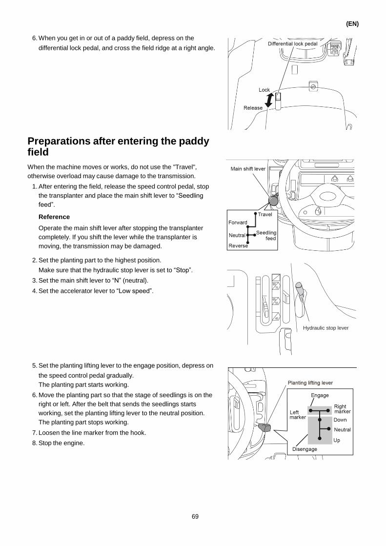
(EN)
6. When you get in or out of a paddy field, depress on the
differential lock pedal, and cross the field ridge at a right angle.
Preparations after entering the paddy field
When the machine moves or works, do not use the "Travel",
otherwise overload may cause damage to the transmission.
1. After entering the field, release the speed control pedal, stop
the transplanter and place the main shift lever to “Seedling
feed”.
Reference
Operate the main shift lever after stopping the transplanter
completely. If you shift the lever while the transplanter is
moving, the transmission may be damaged.
2. Set the planting part to the highest position.
Make sure that the hydraulic stop lever is set to “Stop”.
3. Set the main shift lever to “N” (neutral).
4. Set the accelerator lever to “Low speed”.
5. Set the planting lifting lever to the engage position, depress on
the speed control pedal gradually.
The planting part starts working.
6. Move the planting part so that the stage of seedlings is on the
right or left. After the belt that sends the seedlings starts
working, set the planting lifting lever to the neutral position.
The planting part stops working.
7. Loosen the line marker from the hook.
8. Stop the engine.
69
90 75
65
55
40
Hydraulic stop lever

(EN)
9. Take the seedlings to the stage of seedlings. Fix the seedling
mat stopper and the seeding press rod.
Reference
• The distance between the seedling press rod and the
seedling mat is adjusted to the condition of the seedlings.
• Make sure that the press rod of the seedbed is on an equal
footing with the stage of seedlings.
10. Set the hydraulic stop lever to “Release” and the planting lifting
lever to “Down” and lower the planting part.
11. Move the preparatory seedlings to the preparatory stage of
seedlings in advance.
When it is set, make sure that the preparatory stage of
seedlings is balanced.
12. Attach the center marker and side marker in the correct
position so that the driver can see them well.

70

Loading new seedlings
When loading new seedlings, move the stage of seedlings to the
right or left according to the following method.
1. Set the number of plants to 55.
2. Set the lateral feed adjusting lever to the returning position.
3. Lift the planting part to the highest position.
Make sure that the hydraulic stop lever is set to “Stop”.
4. Set the main shift lever to “N” (neutral).
5. Set the accelerator lever to “Low speed”.
Reference
Do not step on the parking brake.
6. Step on the speed control pedal and the seedling section
moves horizontally.
7. When the seedling rack moves to the right or left position, the
horizontal moving stops automatically. At this time, release the
speed control pedal.
Reference
After the horizontal feed stops, the one key indicator light turns
off and the engine goes into idling. At this time, the indicator
light turns off.
8. Stop the engine.
(EN)
71
90
75
65
55
40
Hydraulic sensing adjustment lever
Yamar
Highlight

(EN)
9. Adjust the seedling press board of the seedlings and start
loading the seedlings.
Reference
Do not load seedlings when the press board is loose.
10. After loading the seedlings, check the gap between the
seedbed and the press board of the seedbed.
Reference
• The standard clearance is 1 cm to 1.5 cm, but it should be
adjusted according to the condition of the seedlings.
• Ensure the seedling mat stopper will be parallel with the
seedling rack.
11. Remove the line marker from the marker hook.
12. Set the hydraulic lock to “Lock”. Set the planting lifting lever to
“Down” to lower the stage of seedlings.
13. Load the preparatory seedlings on the preparatory stage of
seedlings. There is only one seedling on every stage. Keep the
right and left stage balanced.
90 75
65
55
40
Hydraulic stop lever
Line marker
Hook of the line marker

72

(EN)
14. Move the center marker and the side marker to the position
where they can be seen easily.
Transplanting operation
The following describes the main planting operations.
Refer to the section "Circle planting" for an example of how to use
the special circle planting feature of this machine.
1. Adjust the sensitivity of the hydraulic according to the condition
of the field.
2. Confirm the condition of the paddy field.
Set the hydraulic stop lever to the “Stop” position.
3. Set the automatic adjustment of the planting depth to “OFF” to adjust the position of the planting depth control lever.
73
Fine adjustment
Left-Down Right-Down
Planting Depth Fit Synchro LEVELING DEVICE
90
75
65
55
40
Hydraulic sensing adjustment lever
90 75
65
55
40
Hydraulic stop lever

(EN)
4. Move the planting depth control lever to the middle position.
5. Set the vertical feed adjusting lever to the desired position.
6. Adjust the transfer of the lateral feed adjusting lever to the
desired delivery value.
Lateral feed adjusting lever
M S
22 times
(11mm)
16 times
(14mm)
15 times
(15mm)
7. Start the engine.
Reference
• When working in deep water, in order to prevent the engine
from turning off, adjust the revolving speed of the engine in
advance to a high speed.
• If the seedling fill alarm indicates seedling floating when you
load the seedlings, confirm the position of the press rod of
the seedbed.
74
L

8. Put the main shift lever to “Forward”.
9. Move the planting lifting lever to the planting position. Then
move it to the right or left marker. Lower the line marker as
necessary.
Reference
When you want to lower the side marker, move the planting
lifting lever to the appropriate side. Then lift and fold the line
marker.
10. Step on the speed control pedal to start moving and planting.
11. After planting for 4-5 meters, stop the machine, confirm the
planting, and adjust the following if necessary.
• Planting amount
• Sensitivity of hydraulic
• Planting depth
• Seedling number in a hill
12. Observe the condition of the planting and the paddy field,
depress on the speed control pedal, and then start planting at
the high speed.
(EN)
75
Yamar
Highlight
Yamar
Sticky Note
line marker
Yamar
Highlight
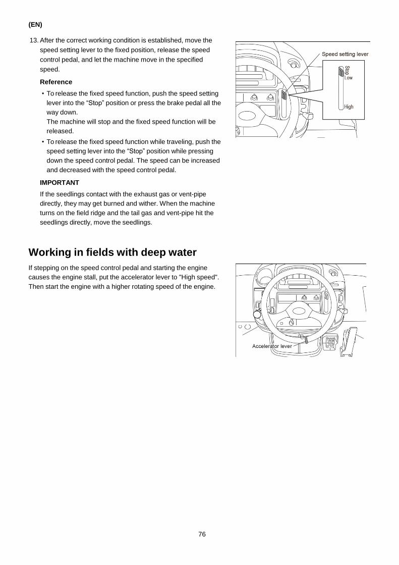
(EN)
13. After the correct working condition is established, move the
speed setting lever to the fixed position, release the speed
control pedal, and let the machine move in the specified
speed.
Reference
• To release the fixed speed function, push the speed setting
lever into the “Stop” position or press the brake pedal all the
way down.
The machine will stop and the fixed speed function will be
released.
• To release the fixed speed function while traveling, push the
speed setting lever into the “Stop” position while pressing
down the speed control pedal. The speed can be increased
and decreased with the speed control pedal.
IMPORTANT
If the seedlings contact with the exhaust gas or vent-pipe
directly, they may get burned and wither. When the machine
turns on the field ridge and the tail gas and vent-pipe hit the
seedlings directly, move the seedlings.
Working in fields with deep water
If stepping on the speed control pedal and starting the engine
causes the engine stall, put the accelerator lever to "High speed".
Then start the engine with a higher rotating speed of the engine.
76

Planting on the side of the field ridge
<When row ordering is not required>
(EN)
Consider the condition of the field before starting
your work
IMPORTANT
• Allow for more space on the head land when turning.
• When coming close to the edge, consider how many rows
remain. Adjust the rows so that the machine can plant 7 rows in
the round.
Example:
When there are 9 rows left on the edge of the field, use the unit
clutch lever to plant 2 rows in one pass before the final pass. Then
do the last round planting 7 rows.
IMPORTANT
Use the unit clutch and seedling feed stopper according to the
condition of the seedlings.
Reference
• The seedling feed stopper can stop 1 row of planting.
• The seedling feed stopper can be used on any row.
Finish
Entrance
and exit
No planting
Planting start position
<When row ordering is required>
Using the unit clutch or seedling stopper
Finish
Entrance
and exit
No planting
Planting start position
When the front wheel hits the ridge of the field, there is space for 7
rows left. But the final position can deviate. So when turning to plant,
the gap to the adjacent rows can become narrower or wider. The gap
between the rows near the ridge can become 30 cm or more.
Reference
If the front wheel almost hits the field, move the main shift lever to
neutral, step on the speed control pedal slightly and turn up the
planting arm. This makes it easier to align the final row.
Finish
Entrance
and exit
Planting start position
77
Yamar
Sticky Note
7 rows length

(EN)
Using the line marker
Use the line marker on the first run to mark off the side of the field.
On the next run, use the center marker to align the row forward,
keeping a straight line and an even row width.
IMPORTANT
If the water is too deep, it is hard to see the mark made by the line
marker clearly, so lower down the water to around 1 to 2 cm.
When it is not easy to see the line clearly, align the side stem to the
adjacent planted row. And keep the gap between each row at
about 25 cm.
Turning
Driving in reverse first and then turn around
1. When close to the end of the field, reduce the speed.
2. Before the front wheel hits the ridge of the field, move your foot
from the speed control pedal and depress the parking brake.
3. Move the main shift lever to “Reverse”.
The planting part rises automatically.
4. Step on the speed control pedal slowly, and drive in reverse to
get in position for turning.
Reference
Do not let the front wheel hit the ridge of the field to stop. The
wheel gear can block and make the main shift lever difficult to
operate.
5. Set the main shift lever to “Forward”, step on the speed control
pedal and turn the steering wheel. Make sure that the
transplanter does not hit the ridge of the field.
6. Use the side marker to aim at the adjacent row and adjust the
machine to a straight line.
7. Move the planting lifting lever to “Down” and lower the planting
part.
Retreat a little to get
in position for turning
Set the main sift
lever to “Forward”.
Depress the speed control
pedal, turn the steering wheel.
78

(EN)
8. When staring to plant, use the planting lifting lever to lower the
line marker.
9. Then step on the speed control pedal to continue working.
Turning without reverse
1. When you are close to the field ridge, use the speed control
pedal to reduce the speed.
2. Move the planting lifting lever to the “Up” position and lift the
planting part.
3. Step on the speed control pedal and turn the steering wheel.
Set the planting lifting
lever to “Down”.
Line marker
Center marker
Side marker
Depress the speed
control pedal , turn
the steering wheel.
4. Use the side marker and center marker to aim at the adjacent
gap. Make the machine run forward.
5. Set the planting lifting lever to “Down”, lower the planting part.
6. Adjust the position; use the planting lifting lever to lower the
line marker.
7. Then step on the speed control pedal to continue working.
Reference
When you turn without reversing, you allow more space
between rows compared to reversing and then turning.
Set the planting lifting
lever to “Down”.
Line marker
Center marker
Side marker
79

(EN)
Adding seedlings
When the amount of seedlings on the seedling rack has decreased
to a number that requires adding new seedlings, the seedling
adding alarm lamp turns on. Add seedlings according to the
following method.
The fertilizer jam call and the fertilizer filling call are only used
when the machine is equipped with a fertilizer.
1. Press down the buzzer switch.
(LED)
2. Move your foot from the speed control pedal.
Step on the brake pedal, stop the machine, and move the main
shift lever to “Seedling feed”.
3. Add seedlings to the row that requires new seedlings.
4. Move the main shift lever from “Seedling feed” to “Forward”.
5. Step on the speed control pedal and the machine starts
moving and working again.
IMPORTANT
When lifting the planting part to add seedlings, set the planting
lifting lever to "ON", and then set the main shift lever to
"Forward".
80
Yamar
Highlight
Seedling feed
Yamar
Sticky Note
UP
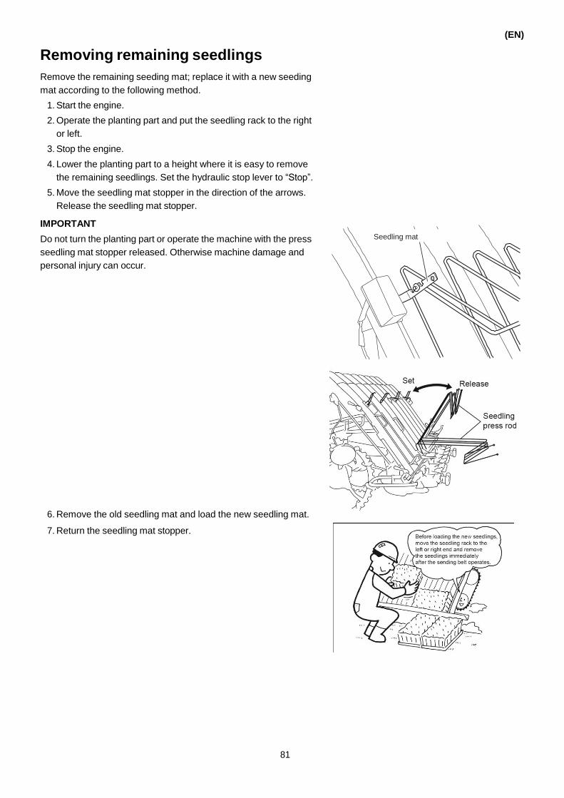
Removing remaining seedlings
Remove the remaining seeding mat; replace it with a new seeding
mat according to the following method.
1. Start the engine.
2. Operate the planting part and put the seedling rack to the right
or left.
3. Stop the engine.
4. Lower the planting part to a height where it is easy to remove
the remaining seedlings. Set the hydraulic stop lever to “Stop”.
5. Move the seedling mat stopper in the direction of the arrows.
Release the seedling mat stopper.
IMPORTANT
Do not turn the planting part or operate the machine with the press
seedling mat stopper released. Otherwise machine damage and
personal injury can occur.
6. Remove the old seedling mat and load the new seedling mat.
7. Return the seedling mat stopper.
(EN)
81
Seedling mat stopper

(EN)
Automatically balancing with the UFO
When the planting lifting lever is set to "Down" or "ON", the UFO of
the planting part is turned on and keeps out the horizontal balance
automatically. Even if the machine leans to one side on uneven
ground, the planting part remains balanced.
During normal planting operation
Turn the knob of the UFO to the central position.
When the planting lifting lever is set to "Down" or "ON", the UFO
starts to work.
82
Yamar
Highlight

Adjusting a tilted planting part
When planting, adjust the planting part to align it with the paddy
field when it leans to the left or right according to the following
method.
(The left of the planting part is raised)
Turn the knob of the UFO towards "Lower left" to adjust the
planting part to an even, horizontal position.
(The right of the planting part is raised)
Turn the knob of the UFO towards "Lower right" to adjust the
planting part to an even, horizontal position.
Left side down
(EN)
Right side down
Reference
Put the automatic adjusting knob to "Manual range". Then you can
tilt the planting part to the desired angle.
Manual range Manual range
Adjusting to the conditions of the seedlings, paddy fields and operations
Adjusting the amount of seedlings
Adjust the number of plants with the Planting number changing
lever and the Sub planting number changing lever at the lower
right of the driver's seat.
Reference
• With the combination of the 2 levers, it is possible to adjust the
number of seedlings in the range of 6 gears.
• When it is difficult to shift the levers, start the engine, put the
main shift lever into neutral (“N”), keep the brake pedal
unlocked, and push the speed control pedal to adjust. Adjust the
number of seedlings before getting into the paddy field.
According to the condition of the paddy fields, the number of
plants varies, so the amount should be confirmed again after
moving forward for about 4 meters to 5 meters. Make the
necessary adjustments.
83

(EN)
Reference list for the planting number (30 cm rows)
Planting number 60 70 80 95 105 125
Row spacing (cm) 22 18 16 14 12 10
Reference
The row spacing and the planting number varies with the sliding
rate. The table is only for reference.
Adjusting the hydraulic sensitivity
To adjust the sensitivity automatically according to the softness of
the paddy fields, turn the hydraulic sensing adjustment lever until
the floating boat touches the ground.
Referring standards of the adjustment
Condition of the paddy field Position of the rod
Soft paddy field (the float presses the mud)
“Soft paddy field”
Normal condition 1 scale apart from “Hard paddy field”
Hard paddy field (using the float to eliminate the difference between the fields, the body of the float should not touch the ground)
“Hard paddy field”
IMPORTANT
• When you turn the hydraulic sensing adjustment lever to “Soft
paddy fields”, the planting depth becomes shallow. When you
turn it to “Hard paddy fields”, it becomes deep. Use it together
with the planting depth control lever.
• If the hydraulic sensing adjustment lever lies within 1 scale from
“Soft fields” and the cultivation ends, the head of the machine
rises up abruptly. Use it when the floating boat has accumulated
too much mud.
However, when you turn the hydraulic sensing adjustment lever
to “Soft paddy fields”, check the planting depth and set the
planting depth control lever to “Deep”.
Adjusting the depth of planting
A planting depth of 3 cm is appropriate.
Switch to the proper depth based on the conditions of the paddy
field and seedlings.
The depth of planting should be confirmed after working about 4
meters to 5 meters. When necessary, make adjustments.
If the planting depth adjusting lever is set to 'Shallow', the depth
will be shallow, and vice versa.
IMPORTANT
• When you adjust the depth, the planting part should be lifted. If
not, the machine will be damaged.
• The proper position of the planting depth adjusting lever varies
with the working condition, so consider changing it for low-speed
operation and high-speed operation. If not, the seedlings will
float and the machine will carry mud.
84
90
75
65
55
40
Hydraulic sensing adjustment lever

The operational method of the automatic depth
adjusting mechanism
Set the automatic depth adjusting lever mechanism to "Standard"
and start planting.
Step on the speed control pedal. When the planting speed
increases, the automatic adjusting mechanism responds to the
speed change and automatically changes the depth.
IMPORTANT
• If there is very little water in the field, the floating boat floats less
and the seedlings are planted deeper. When this happens, set
the automatic depth adjusting switch to “OFF” to turn off the
device.
• Do not put the automatic depth adjusting switch to “OFF” during
operation. Otherwise, the machine will continue to plant deeply.
IMPORTANT
• If the switch of the mode selector of the paddy field is set to
“Standard”, the automatic adjusting mechanism will
automatically turn off,. But if it is set to “Paddy field” or “Deep
water”, the machine will automatically enter the “ON” state (the
pilot light turns on).
• If there is not enough water in the field, the float does not float
and the seedlings are planted deeper. Set it to “Switch” and turn
off the automatic adjusting part (the indicating lamp turns off).
Adjusting the number of seedlings taken (vertical)
The number of plants is controlled by the vertical feed adjusting
lever. It varies with the condition of the seedbed and the sowing
amount.
The adjustment has 11 steps and ranges from 8 mm to 18 mm.
3 or 4 seedlings can be planted in a hill.
Set the vertical feed adjusting lever for the number of transplanting
to "Middle", and then confirm the amount after working about 4 or 5
meters.
If necessary, adjust the number.
If the vertical feed adjusting lever is set to "More", the number of
seedlings increase, and vice versa.
Make the adjustment together with the adjusting method of the
horizontal feed.
Reference
The approximate amount of boxes (the amount of seedlings) per
10a that is needed depends on the number of seedlings, the
amount of the lateral and vertical feed and the planting rate of the
seedbed and is indicated on page 138 ”Setting the frequency of
the lateral feed and the number of seedlings taken vertically”.
(EN)
85

(EN)
Adjusting the lateral feed
Adjust the amount of seedlings planted in every hill based on the
condition of the seedbed. Adjust it by controlling the amount of the
lateral feed on the seedling rack.
Operate the adjusting lever of the horizontal feed to change the
amount.
Adjust the seedling rack as necessary.
To adjust, move the lateral feed adjusting lever to the position
shown in the following illustration.
Lateral feed adjusting lever
M S
22 times
(11mm)
16 times
(14mm)
15 times
(15mm)
Lever position 22 times 16 times 15 times
Cutting width 11 mm 14 mm 15 mm
Number of hill Short Middle Large
Adjusting the seedling press rod and the seedling
mat stopper
WARNING
• When you adjust the seedling press rod and the seedling
mat stopper, the engine must be turned off and the
hydraulic stop lever should be set to “Stop”, otherwise a
sudden start of planting may cause accidents.
• Adjust the seedling press rod and the seedling mat stopper
according to the seedling height and planting posture.
86
L
Seedling mat stopper
Yamar
Highlight

• Set the seedling mat stopper 1 cm to 1.5 cm above the surface
of the seeding mat.
(EN)
• When the leaves of the seedlings get caught and the seedlings
do not slide down well, lift the seedling mat stopper little.
Reference
The standard position of the seedling mat stopper is 1 cm to
1.5 cm away from the surface of the seedling mat, but should
be adjusted according to the condition of the seedling mat.
• Usually the seedling press board is set at the second or the
third notch (factory setting).
• If the seedlings are tender and long, and the leaves hang down,
move the seedling press rod to the first or the second notch so
that the leaves do not touch the planting tines.
• If the seedlings are short (under 12 cm) or the posture is
backwards, set the seedling press rod to the first or the second
notch.
87

(EN)
Freeing a sunken-in machine when the plowing chassis is too deep
Choose the method that is most appropriate to the situation to lift
the machine.
The rear wheels starts sinking during driving
Keep the planting parts lowered, depress the differential lock pedal
and drive the machine out at a slow speed.
IMPORTANT
• Turning the steering wheel makes the transplanter sink in
further. If you drive the machine in reverse, the front wheels sink
in further.
• In order to reduce the weight of the machine, unload the spare
seedling rack and the seedlings on the seedling rack.
• At first, push the speed control pedal slowly.
If you push it abruptly, the engine will stop.
• When the transplanter cannot be pulled out by its own power,
fasten a rope to the rope hook and drag the machine with a
tractor. Start the engine of the transplanter, drive slowly and
advance straight forward, otherwise the machine will be
deformed and damaged.
The front wheels sink in when you drive in reverse
• Unload the seedlings on the spare seedling rack to reduce the
weight in the front.
• Retreat at a low speed.
The machine sinks in when you make a turn
When you turn the front wheels, but the machine does not turn,
tread the differential lock pedal and turn the machine at a low
speed. (Because after the steering wheel stops working, the one-
sided driving force of the rear wheels is cut off and the force is
halved.)
If this does not work, stop turning and return the steering wheel to
the straight direction.
Depress the differential lock pedal and drive the machine out.
IMPORTANT
When you pull the machine out by its own power, do not place the
board lights under the wheels or the machine will be damaged.
Reference
In paddy fields where the machine is likely to sink in, attaching
auxiliary wheels can help the machine work properly. Please
consult with your dealer.
88
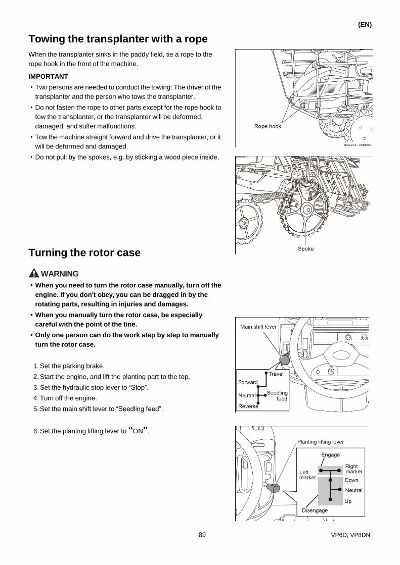
Towing the transplanter with a rope
When the transplanter sinks in the paddy field, tie a rope to the
rope hook in the front of the machine.
IMPORTANT
• Two persons are needed to conduct the towing: The driver of the
transplanter and the person who tows the transplanter.
• Do not fasten the rope to other parts except for the rope hook to
tow the transplanter, or the transplanter will be deformed,
damaged, and suffer malfunctions.
• Tow the machine straight forward and drive the transplanter, or it
will be deformed and damaged.
• Do not pull by the spokes, e.g. by sticking a wood piece inside.
Turning the rotor case
(EN)
WARNING
• When you need to turn the rotor case manually, turn off the
engine. If you don't obey, you can be dragged in by the
rotating parts, resulting in injuries and damages.
• When you manually turn the rotor case, be especially
careful with the point of the tine.
• Only one person can do the work step by step to manually
turn the rotor case.
1. Set the parking brake.
2. Start the engine, and lift the planting part to the top.
3. Set the hydraulic stop lever to “Stop”.
4. Turn off the engine.
5. Set the main shift lever to “Seedling feed”.
6. Set the planting lifting lever to “ON”.
89 VP6D, VP8DN

(EN)
7. Turn the rotor case in the direction of the arrows.
Reference
Set the planting number changing lever to "Middle". This
makes it easier for the rotor case to turn.
Operating with the safety clutch engaged
WARNING
• During the inspection, turn off the engine and set the
hydraulic stop lever to “Stop”. If the engine is not shut
down, the planting part can operate unintentionally and
cause injuries and accidents.
To prevent the planting part from damage, install the safety
clutch. The safety clutch operates in the following
situations.
• There are obstacles, e.g. stones, in the paddy field.
• There are obstacles in the seedling opening.
• The seedling mat is very hard.
The safety clutch will make a rattle noise when it operates.
1. Stop planting immediately when the planting clutch operates.
2. Raise the planting part, set of the hydraulic stop lever to “Stop”
and turn off the engine to find the cause.
3. After fixing the problem, start the engine, confirm that the
planting part works normally and begin to plant.
90
Yamar
Sticky Note
cần chính hay phụ

9. DISMANTLING AND INSTALLING THE ENGINE
COVER AND THE STEP
(EN)
WARNING
Turn off the engine and let it cool down sufficiently, then start
working. Otherwise, burn injuries will occur.
WARNING
Be sure to re-install the covers that were removed. you oper-
ate the machine with a cover removed, you may be injured.
Dismantling and installing of the engine cover
Dismantling the engine cover
1. Pull the removal handle of the engine cover. (The hooks in the
upper right and left)
2. Remove the front cover.
3. Pull the four fixed claws of the left rear cover, and remove the
cover to the front and up.
At the same time, remove the right rear cover.
91 VP6D, VP8DN

(EN)
Installing the front and rear engine covers
1. Put the cover at the rear right into the groove, and insert the
four claws above into the holes to install the cover.
At the same time, install the cover at the left behind.
2. Insert the hook parts of the front cover into the groove of the
front bumper.
3. Press the fix claws on both sides of the front cover to lock it.
Dismantling and installing the front step
1. Set on the parking brake.
2. Dismantle the front and rear right and left cover of the engine.
3. Remove the two screws fixing the front step, and then remove
the step.
4. Install the front step in the reverse order of dismantling.
92
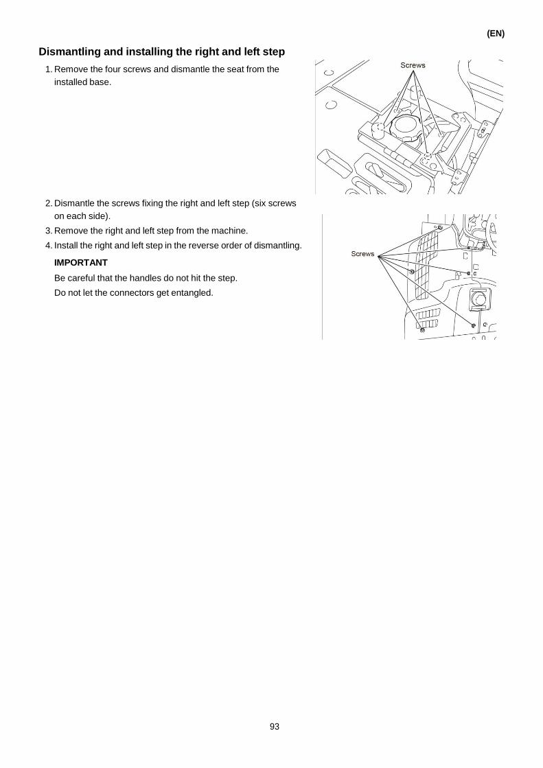
Dismantling and installing the right and left step
1. Remove the four screws and dismantle the seat from the
installed base.
2. Dismantle the screws fixing the right and left step (six screws
on each side).
3. Remove the right and left step from the machine.
4. Install the right and left step in the reverse order of dismantling.
IMPORTANT
Be careful that the handles do not hit the step.
Do not let the connectors get entangled.
(EN)
93

(EN)
10. MAINTENANCE AND STORAGE AFTER WORK
DANGER Do not allow open flames or fires when discharging fuel from
the machine.
WARNING
Before you cover the transplanter, make sure that the heated
parts of the engine have cooled down. If the machine is still
hot, the cover will catch fire and cause an accident.
CAUTION • Turn off the engine and apply the parking brake when you
lift the planting part or check and maintain the planting
tines and rotor case. Set the hydraulic stop lever to “Stop”
and use the rack to support the planting part so that it does
not fall down.
• Clean the machine on an even and steady surface.
Cleaning the machine
Wash the machine after operation. Clean the dirt drawn into the
rotating parts and dry the machine. Then, apply oil to the rotating
and sliding parts, and apply grease to the rusty parts.
IMPORTANT
• Do not let the engine or electrical devices (e.g. switches,
sensors) get in touch with water.
• After cleaning, all engine parts which need oiling should be
oiled. If not, the machine may not work correctly next time it is
used.
• Clean the dirt and straws stuck in the rotating parts. If not, the
grease seals and bearings can be damaged.
• Clean the machine in a flat and even place.
94
Yamar
Highlight
machine part
Yamar
Sticky Note

Components that need oiling and greasing
Oil Injection: Lubricant:
Grease Gun:
(EN)
Check the amount of the remaining grease in the planting arm
and inject grease if the amount is less than 1 cc to 15 cc.
IMPORTANT
If the amount of grease is excessive, the movement of the push
rod will slow down, the posture of planting will be bad or the
seedlings will remain on the tine. Remove excessive grease.
Reference
When the push rod moves unevenly, inject the planting arm with
a little gear lubricant (where the grease is injected).
Planting arm
Pushing rod
95
Yamar
Highlight
Yamar
Highlight

(EN)
Tension arm pivot Steering portion
Rotating part of the installing pivot of the lift cylinder Shifting part of the row spacing
Operational lever of the steering clutch (front) Operational lever of the steering clutch (rear)
96

(EN)
Output shaft of the real axle Support of differential lock pedal
Brake pedal Rotating support of speed control pedal
Rotating part of main shift lever Operating part of gear shift
Cam part of seedling delivery belt Support of connecting rod
97
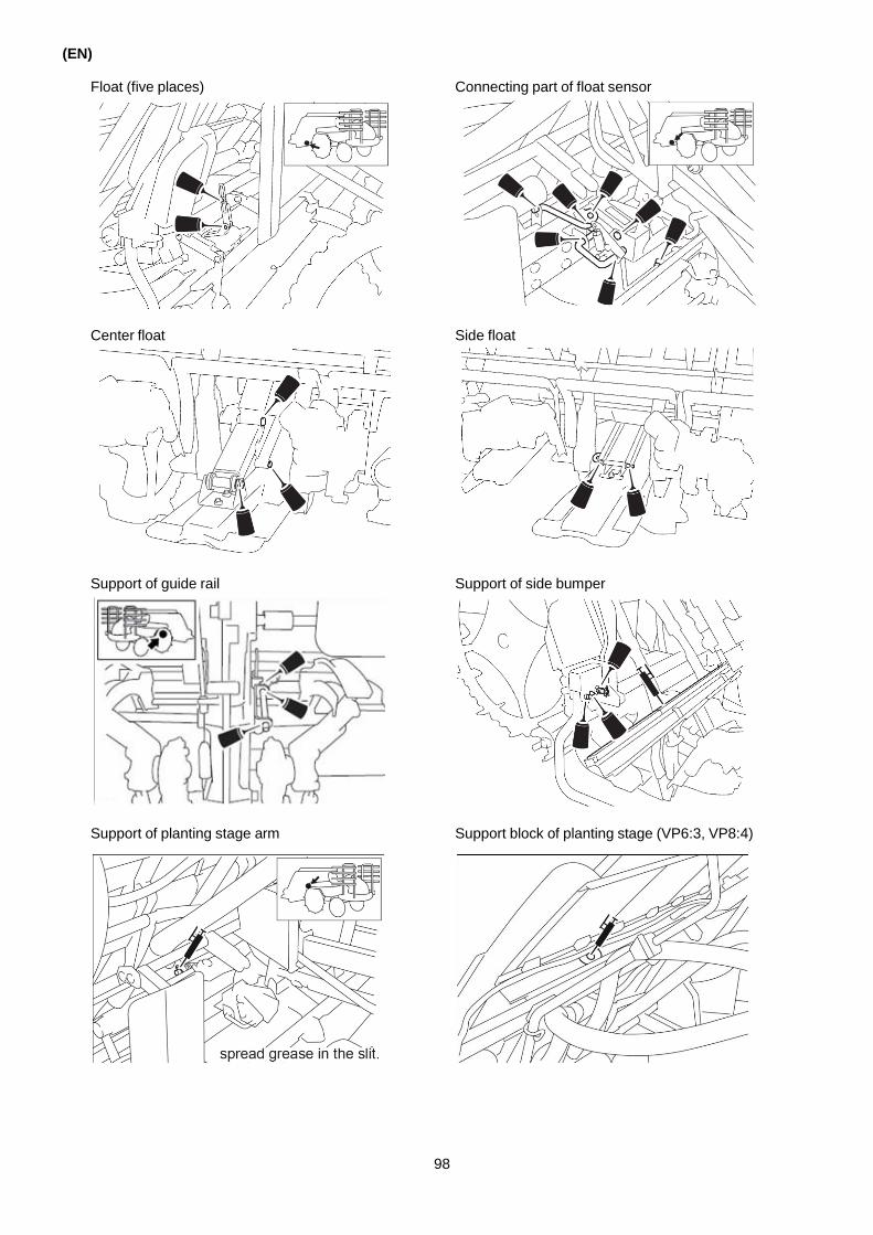
(EN)
Float (five places) Connecting part of float sensor
Center float Side float
Support of guide rail Support of side bumper
Support of planting stage arm Support block of planting stage (VP6:3, VP8:4)
98

(EN)
Top of guide rail Linkage steel wire of vertical feed
Rotating portion of the planting drive shaft Support part of seedling delivery belt
Sleeve of the vertical sending screw Tray slide of the guide rail
Turning pivot of the planting stop arm Folding the seedling rack (Only for VP8)
99

(EN)
Storing
If the transplanter is not used for a long time, do an inspection and
all necessary adjustments, then store it according to the following
method.
1. Store it in a place that is not exposed to direct sunlight, water
or has poor ventilation.
2. Fold the side bumper and use it as a support.
Lower the planting part. Set the hydraulic stop lever to “Stop”.
3. Set the planting lifting lever to “Middle”.
Set the main shift lever to “Seedling feed”. Then pull out the
key from the key switch.
4. Remove the battery from the electric system and store it in a
dark, well-ventilated place. If the transplanter is stored with the
battery installed, make sure that the terminals of the battery
are disconnected from the battery.
5. Completely fill the fuel tank with oil. Put the cock of the fuel
strainer and the water separator to C (Closed).
IMPORTANT
• Fill the fuel tank, otherwise water drops will form and lead to
rust.
• If the transplanter is stored for a long time, fill the fuel tank, and
put the fuel cock to “C” (closed).
6. Apply rust preventive oil, engine oil or lubricating oil on the
outside parts that rust easily.
100
Yamar
Highlight
Neutral
Yamar
Highlight
Fuel

11. INSPECTION AND MAINTENANCE
(EN)
WARNING
• During inspections, oiling, maintenance and repair, park the
machine in a flat and stable place without traffic dangers
and stop the engine.
• When lifting the planting part to inspect and maintain the
planting tines and rotor case, set the hydraulic stop lever to
“Stop” and use the stage to prevent the planting part from
falling.
CAUTION • Do an inspection, repair and maintenance on each part once
a year, especially the oil pipe, hydraulic oil pipe, other
rubber pipes and electrical wire. If not, the machine will suf-
fer damage and malfunction.
• If you remove a cover or board during your work, install it
back to the same position.
If not, you may be dragged in the machine and suffer injury.
On disposal of waste oil, do not pour waste oil directly into
a river or sewer. You will pollute the environment.
Contact a specialized shop or your dealer for proper waste
oil disposal.
Intervals of regular inspections and maintenance
Do an inspection and maintenance in the off-season, so that the
machine can operate and perform best in the busy season. In
order to avoid hidden dangers caused by negligent maintenance,
do the inspection and maintenance of the transplanter in a repair
workshop to ensure its safety after the season.
Replace especially the rubber pipes, e.g. oil pipes and hydraulic
pipes, every two years. Do an inspection on the electric wire every
year and if the coating is damaged, replace the wire.
Otherwise the machine will not be in the best condition and safe
operation cannot be guaranteed.
101

(EN)
Table of regular inspections and maintenance
Item Content Time of inspection and replacing Reference
page
Inspection and maintenance on fuel tank
Quantity (37.0L) After operation and before storing 103
Inspection on engine oil
Quantity and dirt mark, add if necessary (2.9 L: replacing the engine oil only)
Inspection: before operating Replacing: the first time after 50h, then every 200h
105
Inspection and maintenance on transmission case
Quantity and dirt mark (11.0 L)
Inspection: every season Replacing: the first time after 50h, then every 300h
106
Inspection and maintenance on rear axle case
Quantity and dirt mark (7.0 L)
Inspection: every season Replacing: the first time after 50h, then every 300h
107
Planting arm
Quantity and dirt mark Adding oil: within 1-15cc, out of the factory 15cc.
Everyday Identify the remaining quantity of lubricating oil, add within 1cc to 15cc
95
Oil on sliding parts Engine oil and gear oil After operation and before storing -
Fuel filter Cleaning it and replacing the filter element
Replacing: the first time after 50h, then every 300h
110
Water separator
Cleaning it and replacing the filter element
Inspection: Before operating Cleaning: every season Replacing the filter element: every 300h
110
Filter element of transmission case oil
Replacing Replacing: the first time after 50h, then every 300h
111
Filter element of engine oil Replacing Replacing: the first time after 50h, then every 100h
111
Cleaning the filter of the air cleaner Filter element, blowing with air Clean every 150h Replace every 400h
109
Inspection of cooling water Quantity and adding After operation and before storing 112
Inspection of belts of fan
Quantity and adjusting on tension
Inspection: The first time after 50h, then every 100h replacing when damaged
113
Battery After liquid level and ratio inspection, charge if necessary
Everyday, before operating 120
Inspection of electric wire Damage of the cover, loosening of the connection
Replacing when parts are abnormal 120
Oil pipe and its connection Inspection Replacing every two years 124
Inspection of engine and starting electric system
Starting Inspection every season -
Inspection of hydraulic devices Oil leakage Inspection every season -
Hydraulic pipe and its connection Inspection Replacing every 2 years -
Inspection of tightness of turning parts
Tighten After operation and before storing -
Inspection of steel wire Freedom After operation and before storing -
Inspection of important bolts and nuts
Tighten After operation and before storing -
Planting tines Inspection, replacing if worn After operation and before storing 117-118
V-belt Damage After operation and before storing -
Vertical feed bearing Inspection After operation and before storing -
Support of seeding carrying stage Inspection After operation and before storing -
Long guide rail F Inspection After operation and before storing -
102
Yamar
Highlight
every day
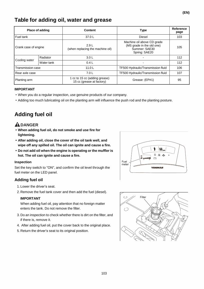
Table for adding oil, water and grease
IMPORTANT
• When you do a regular inspection, use genuine products of our company.
• Adding too much lubricating oil on the planting arm will influence the push rod and the planting posture.
Adding fuel oil
(EN)
DANGER • When adding fuel oil, do not smoke and use fire for
lightening.
• After adding oil, close the cover of the oil tank well, and
wipe off any spilled oil. The oil can ignite and cause a fire.
• Do not add oil when the engine is operating or the muffler is
hot. The oil can ignite and cause a fire.
Inspection
Set the key switch to "ON", and confirm the oil level through the
fuel meter on the LED panel.
Adding fuel oil
1. Lower the driver’s seat.
2. Remove the fuel tank cover and then add the fuel (diesel).
IMPORTANT
When adding fuel oil, pay attention that no foreign matter
enters the tank. Do not remove the filter.
3. Do an inspection to check whether there is dirt on the filter, and
if there is, remove it.
4. After adding fuel oil, put the cover back to the original place.
5. Return the driver’s seat to its original position.
103
Place of adding Content Type Reference page
Fuel tank 37.0 L Diesel 103
Crank case of engine
2.9 L
(when replacing the machine oil)
Machine oil above CD grade (MS grade in the old one)
Summer: SAE30 Spring: SAE20
105
Cooling water Radiator 3.0 L - 112
Water tank 0.4 L - 112
Transmission case 11.0 L TF500 Hydraulic/Transmission fluid 106
Rear axle case 7.0 L TF500 Hydraulic/Transmission fluid 107
Planting arm 1 cc to 15 cc (adding grease)
15 cc (grease at factory) Grease: (EP#1) 95

(EN)
Discharging the fuel oil
Discharge of the fuel oil in the fuel tank
1. Prepare a container to hold the discharged fuel.
2. Remove the flexible pipe on the water separator, and drain the
fuel into the container. Do not spill any fuel.
3. After discharging, connect the flexible pipe and turn it to “C”
(closed).
Inspection, adding and replacing oil
Reference
When doing an inspection or adding and replacing oil, park the
transplanter in a flat area, otherwise the oil quantity cannot be
measured accurately.
Engine oil
Doing an inspection
1. Starting the engine and warm it for 1 minute to 2 minutes. Then
stop the engine and let it cool for 2 minutes to 3 minutes.
2. Remove the front cover of the engine.
3. Remove the dipstick and clean the dipping part.
4. Insert the dipstick into the filler to the bottom of the tank and
then pull it out. Check whether the oil level is between the
upper limit and the lower limit of the dipstick.
5. If the oil level is between the upper limit and lower limit of the
dipstick, the oil quantity is within the specified quantity. If it is
not sufficient, add according to the method stated below.
6. After the inspection, install the dipstick as it was.
7. During the inspection, make sure that there is no oil leakage.
104
Yamar
Highlight

■ Adding oil
1. Open the oil filler.
2. Add the oil from the filler port to the specified quantity
(between the upper and lower limit).
3. After adding oil, put the cap on the filler port back to its original
place.
Reference
To make adding oil more comfortable, use the hopper which is
attached to the machine.
■ Replacing oil
1. Remove the front cover of the engine.
2. Put the container under the drain plug on the bottom of the
engine.
3. Remove the cap on the filler port and drain plug, and discharge
the oil.
4. After discharging the oil into the container, install the drain plug
back to its original place.
5. Add oil according to the method stated above.
6. Close the cap on the filler port.
7. Install the front cover of the engine.
(EN)
105

(EN)
Transmission case oil
When replacing the transmission case oil, replace its filter element
too.
Inspection
1. Lower the planting part to the lowest point, and set the
hydraulic stop lever to “Stop”.
2. Open the cover.
3. Remove the cap on the filler port, and clean the dipstick.
4. Insert the dipstick into the filler port to the bottom of the tank,
then pull it out and check whether the oil level is between the
upper limit and lower limit of the dipstick.
Do not twist the cover when inserting the dipstick into the filler
port.
5. If the oil level is between the upper limit and lower limit, the oil
has the specified quantity. If it is less than the lower limit, add
oil according to “Adding oil” stated below.
6. Put the cap on the filler port.
7. During inspection, check whether there is oil leakage.
■ Adding oil
1. Remove the cap on the filler port, and insert the hopper
(accessory of the machine) into the filler port.
2. Add oil by the hopper to the specified quantity (between the
upper limit and the lower limit of the dipstick).
3. After adding oil, put the cap on the filler port.
■ Replacing oil
1. Lower the planting part to the lowest point.
2. Put a container under the drain plug of the transmission case.
3. Remove the cap on the filler port and drain plug, then drain the
oil into the container.
4. After draining the oil into the container, put the drain plug back
as it was.
5. Add oil for the transmission case oil from the filler port.
6. Add the oil according to “Adding oil”.
7. Put the cap on the filler port as it was.
IMPORTANT
When doing an inspection, make sure to lift the planting part to
the highest point, because it is impossible to determine the
accurate oil quantity when the planting part is
lowered down. (This may cause lack of oil.)
The machine will suffer damage when used in this condition.
106

Rear axle case
Inspection
1. Move the planting part upward to the up end position, and set
the hydraulic stop lever to “Stop”.
2. Remove the cap on the oil supply port that on the upper portion
of the rear axle case, and clean the dipstick by a clean cloth.
3. Put the cap back on the oil supply port and remove it again.
See whether the oil level is between the upper and lower lines.
4. If the oil level is low, add oil until the oil level is between the
lower and upper lines.
■ Adding oil
1. Remove the cap on oil supply port, and insert the funnel into
the oil supply port.
2. Fill the oil through the funnel until the oil level reaches the
specified level.
■ Replacing oil
1. Set a container below the drain plugs that are located under
the lower part of the rear axle case. (One for each side.)
2. Drain the oil by removing the cap on the oil supply port and
loosening the drain plugs.
3. After the oil has been drained, put the drain plug back in place.
4. Fill the oil until the oil level reaches the specified level.
(EN)
107

(EN)
Air bleeding of the fuel system
Do an air bleeding of the fuel system if the engine stops because
the fuel runs out or during inspections and maintenance. Remove
the water separator, fuel filter and fuel pipe, and remove the air
according to the following procedures.
1. Add fuel to the fuel tank.
2. Set the fuel cock of the water separator and fuel filter to “O”.
3. Turn the key switch to “ON” for 10 seconds.
The fuel filter is filled with fuel automatically.
Then check the condition of the fuel filter.
4. Set the accelerator lever to “High speed”, and set the main
shift lever to “Seedling feed”.
5. Step on the brake pedal, and put the key switch to “Start”.
IMPORTANT
Do not start the engine continuously for more than 10 seconds;
otherwise the electric wire and engine may be damaged.
Reference
If the air has not been removed completely, repeat the
procedures for 3 - 5 times to remove the air completely.
108

Cleaning the filter element of the air filtration machine
(EN)
CAUTION Clean the filter element of the air filtration machine only after
the engine has cooled, otherwise you may get burned.
Using a dirty filter element will decrease the engine power and
result in malfunction. Clean the filter element according to the
following methods.
1. Remove the front cover of the engine.
2. Unfasten the rubber band, pull up the air filtration machine,
then attach the draw latch on the cover of the air filtration
machine, and pull out the filter element.
3. The filter element is made of filter paper.
Clean it by tapping it gently or blowing the dirt away with an air
gun. (Tapping too strongly will damage the filter paper.)
4. Lock the cover of the air filtration machine with the two draw
latches and then attach the rubber band back as it was.
Install it so that the TOP mark is at the top.
5. Install the front cover of the engine as it was before.
109
Filter element Part number: 1C727C-12530

(EN)
Cleaning the fuel filter
The fuel filter removes water and contamination from the oil.
Clean it regularly according to the following method.
Replace the filter element inside the oil filter every 300 hours.
1. Remove the front cover of the engine.
2. Set the fuel cock to “C”.
3. Turn the bolts, and then remove the fuel filter. Remove the
water and contamination from the filter.
4. After cleaning the filter, install it back to its original position. Set
the fuel cock to “O”, and turn the key switch to “On” for 5-10
seconds, then the air bleeding is complete.
5. Install the front cover of the engine as it was.
Cleaning the water separator
The filter inside the water separator should be replaced every 300
hours.
1. Set the cock of the sediment cup to “C”.
2. Remove the water separator. Then remove the water and
contamination from it.
3. After cleaning, install the filter back as it was. Set the cock
lever of the water separator to “O”, and then turn the key
switch to “ON” for 5-10 seconds. The air bleeding is complete.
110
Filter element Part number: 171081-55910
Filter element (fuel filter) Part number: 119810-55650

Replacing the oil filter of the transmission case
The filter of the transmission case is a cylinder type. It is not
possible to clean it.
When replacing the oil of the transmission case, also replace the
filter.
Replacing the filter
1. Discharge the oil of the transmission case.
2. Use the same procedure as described for replacing the oil.
3. Turn the filter in the direction of the arrow and then remove the
filter.
4. Apply oil to the rubber ring on the bottom of the new filter.
5. Turn the oil filter for 2/3 of a turn after the rubber ring touches
the installation surface of the filter.
IMPORTANT
• After replacing, carry out an inspection to check whether
there is oil leakage on the installation surface.
• Use a genuine filter produced by YANMAR.
Replacing the engine oil filter
The engine oil filter is a cartridge type. It is not possible to clean it.
When replacing the engine oil, also replace the filter.
Replacing the engine oil filter
1. Remove the front cover of the engine.
2. Drain the engine oil with the same method as described for
replacing the oil.
3. Turn the element of the engine oil filter in the direction of the
arrow, and then remove it.
4. Apply oil to the rubber ring on the bottom of the new filter of the
engine.
5. Turn the oil filter of the engine for 2/3 of a turn after the rubber
ring touches the installation surface of the filter.
6. Install the front cover of the engine back as it was.
INPORTANT
• After replacing, carry out an inspection to check whether
there is oil leakage on the installation surface.
• Use a genuine filter produced by YANMAR.
(EN)
111
Engine oil filter Part number: 119305-35151
Filter Part number: 1C731C-53650

(EN)
Inspection, adding and replacing of cooling water
DANGER
Do not open the cover of the radiator when the engine is
operating or shortly after it stops operating. Hot water can
spurt out and burn you. Open the cover only after the engine
stopped operating and cooled down sufficiently.
The inspection, adding and replacing of cooling water are
carried out after the front cover of the engine is taken off.
After the task, re-assemble the machine to its original
condition.
Inspection
Check whether the water level of the water tank is in the range
between FULL and LOW.
Reference
During the inspection, check whether there is water leakage.
Adding cooling water
When the amount of cooling water is not adequate, remove the
cap of the water tank, and then add pure water to the tank.
Replacing cooling water
1. Remove the radiator cap.
2. Remove the water drain pipe from the hook (three parts), and
turn it face down.
3. Open the cock on the water drain pipe and then remove the
water from the radiator.
4. Clean the radiator with pure water until you do not see any rust
flowing out.
Reference
When cleaning the radiator, we recommend adding a cleaning
agent to the water. Start the engine after 15 minutes and then
drain the water.
112
Yamar
Highlight

(EN)
5. Install the water drain cock on the pipe, and then put the pipe
back on the hook as it was (two parts).
6. Add the required amount of antifreeze and then add pure water
until the water flows out.
7. Install the cover of the radiator.
8. Start the engine and run it in idle for 5 minutes to mix the
antifreeze.
9. Stop the engine, and then check again whether the cooling
water meets the required quantity.
Use of antifreeze
The antifreeze has the function to reduce the freezing temperature
of the water, which may vary with the ratio of antifreeze. Refer to
the following table for cold areas and safe concentrations.
Mixture ratio table of antifreeze
Outdoor temperature -5 -10 -15 -20 -25 -30
Ratio Water (%) 82 73 66 61 55 49
Antifreeze (%) 18 27 34 39 45 51
• The ratio of the antifreeze may differ for different manufacturers,
refer to their instructions for correct use.
• Add tap water when the cooling water decreases. Determine the
relative density for permanent type products.
• The antifreeze is good for only one year, so replace it every year.
IMPORTANT
Do not drain antifreeze directly into the nature. Deliver all waste oil,
fuel, cooling water, dissolvent, filters, batteries and other harmful
substances to the seller or an industrial waste disposal company
for disposal.
Inspection and adjusting of the cooling fan belt
Inspection
Remove the front cover of the engine. Press the middle of the
cooling fan belt to check the tension. The deflection of the belt
should be 10 mm to 15 mm. Also check the belt for damage.
Adjusting the cooling fan belt
1. If the deflection is not appropriate, loosen the fixing bolts of the
engine and adjust the tension by moving the engine.
2. Tighten the fixing bolts of the engine.
3. Move the engine to the bottom, replace the belt if it is still
slippery.
IMPORTANT
Do an inspection 50 hours after replacing the belt.
113
V Belt Part number: 119127-42310
Yamar
Highlight
Yamar
Highlight
Alternator
Yamar
Highlight
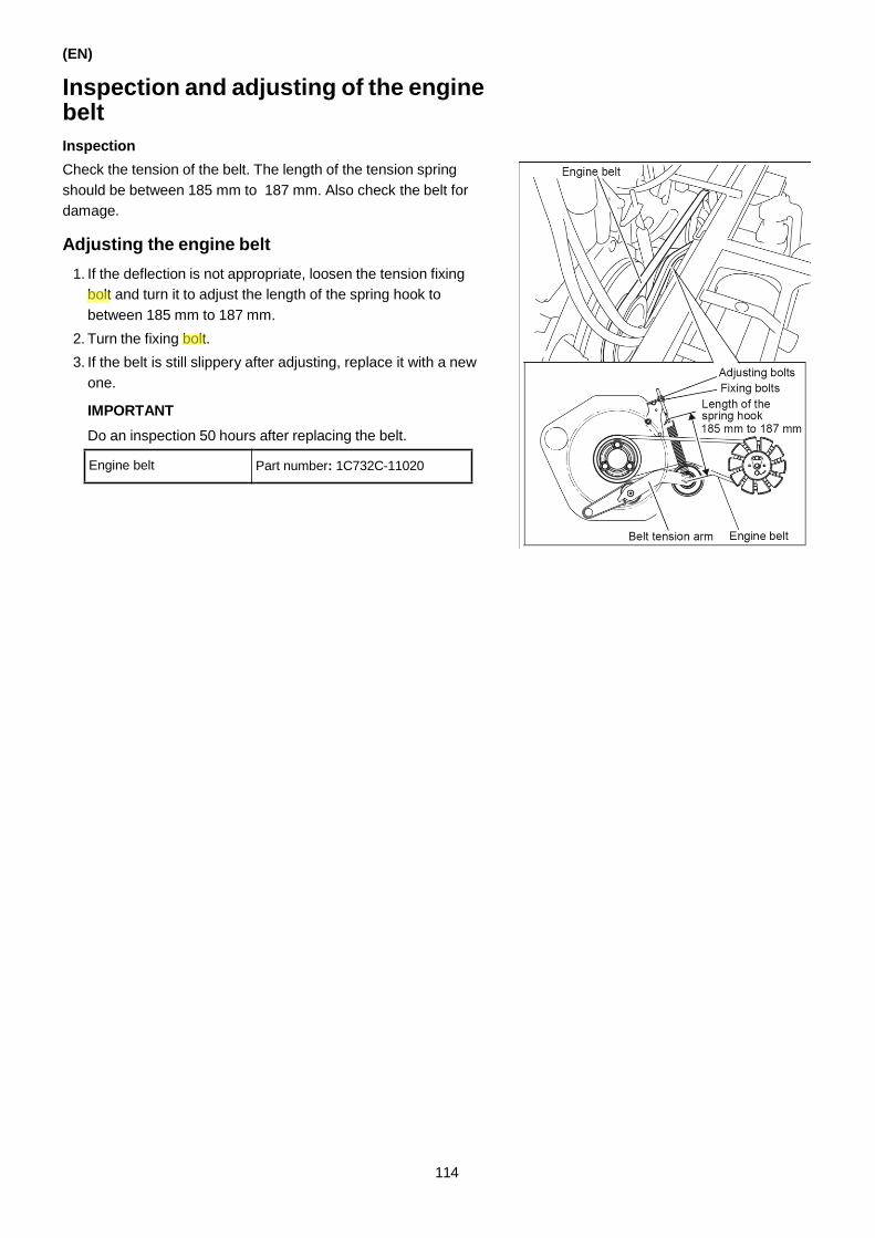
(EN)
Inspection and adjusting of the engine belt
Inspection
Check the tension of the belt. The length of the tension spring
should be between 185 mm to 187 mm. Also check the belt for
damage.
Adjusting the engine belt
1. If the deflection is not appropriate, loosen the tension fixing
bolt and turn it to adjust the length of the spring hook to
between 185 mm to 187 mm.
2. Turn the fixing bolt.
3. If the belt is still slippery after adjusting, replace it with a new
one.
IMPORTANT
Do an inspection 50 hours after replacing the belt.
114
Engine belt Part number: 1C732C-11020
Yamar
Highlight
Yamar
Highlight
nut

Inspecting the operation of the UFO device
During planting, check whether the horizontal control of the
planting part operates normally by the following procedures.
Inspecting the horizontal control of the planting
part
1. Start the engine.
2. Put the planting part 30 cm over the ground by using the
planting lifting lever.
3. Set the hydraulic stop lever to “Stop”.
4. Set the planting lifting lever to “Lower” and the UFO device
starts to operate.
5. Turn the UFO automatic adjusting knob to “Lower right” and
the right side of the planting part is lowered. Turn the knob to
“Lower left” and the left side is lowered.
6. After inspecting, return the UFO automatic adjusting knob to
“Middle”.
7. Set the panting lifting lever to “Up” and the planting part returns
to a central position that is parallel with the machine body.
8. Stop the engine.
This finishes the inspection of the horizontal control.
(EN)
Left side down Right side down
115
90 75
65
55
40
Hydraulic stop lever

(EN)
Inspection and adjusting of the gap between the seedling fetching guide rail and planting tines
Inspection
1. Install the tine set gauge on the seedling fetching mouth.
Installing the seeding gauge
Install the tine set gauge after it aligns with the width of the
seedling fetching mouth.
Reference
The tine set gauge cannot be inserted when the seedling rack
is at the extreme left or right position. Move the stage to the
central position.
If the width of the seedling
fetching mouth is 19 mm,
this side is installed
If the width of the seedling
fetching mouth is 17 mm,
this side is installed
Width of the seedling
fetching mouth
2. Turn the rotor case to make sure that the front part of the
planting tines aligns with the vertical gutter of the tine set
gauge.
Proper position of the planting tines
(when viewed from A)
The front part of the planting tines aligns with the tine set
gauge as shown in the figure above. This is the proper
position.
Reference
Turn the rotor case by hand according to Page 89 "Turning the
rotor case".
Tine set gauge
Middle
Planting tine
116
Tine set gauge
Planting tine

Adjusting
1. Loosen the installing bolt of the rotor case to the top.
2. Tap the top surface of the bolt gently, and then loosen the taper
pin.
3. Install the tine set gauge on the seedling fetching mouth, turn
the rotor case and make the front part of the planting tines
align with the vertical gutter of the seedling gauge.
4. Screw in the installing bolt of the rotor case to fix it.
IMPORTANT
Make sure that you install the taper pin in the correct direction.
Insert it in the turning direction of the rotor case. (An arrow on
the rotor case indicates the direction.)
Inspection and adjusting of the gap between the push rod and the planting tines
Inspection
Turn the rotor case by hand, move the push rod to the front part of
the planting tines and then check whether the push rod and the
planting tines interfere with each other.
Adjusting
If the push rod and the planting tines interfere with each other,
loosen the fixing nut of the planting tines, and adjust. After
adjusting, tighten the fixing nut.
(EN)
117
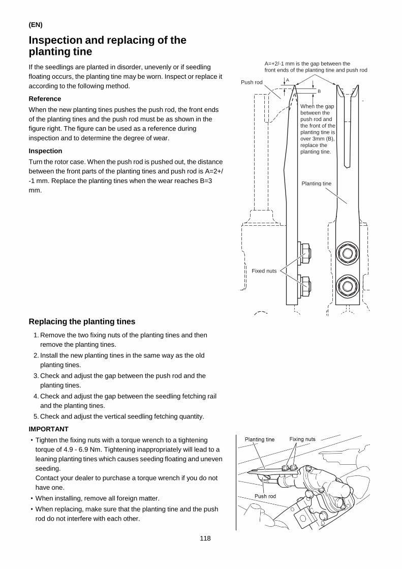
(EN)
Inspection and replacing of the planting tine
If the seedlings are planted in disorder, unevenly or if seedling
floating occurs, the planting tine may be worn. Inspect or replace it
according to the following method.
Reference
When the new planting tines pushes the push rod, the front ends
of the planting tines and the push rod must be as shown in the
figure right. The figure can be used as a reference during
inspection and to determine the degree of wear.
Inspection
Turn the rotor case. When the push rod is pushed out, the distance
between the front parts of the planting tines and push rod is A=2+/
-1 mm. Replace the planting tines when the wear reaches B=3
mm.
Replacing the planting tines
1. Remove the two fixing nuts of the planting tines and then
remove the planting tines.
2. Install the new planting tines in the same way as the old
planting tines.
3. Check and adjust the gap between the push rod and the
planting tines.
4. Check and adjust the gap between the seedling fetching rail
and the planting tines.
5. Check and adjust the vertical seedling fetching quantity.
IMPORTANT
• Tighten the fixing nuts with a torque wrench to a tightening
torque of 4.9 - 6.9 Nm. Tightening inappropriately will lead to a
leaning planting tines which causes seeding floating and uneven
seeding.
Contact your dealer to purchase a torque wrench if you do not
have one.
• When installing, remove all foreign matter.
• When replacing, make sure that the planting tine and the push
rod do not interfere with each other.
A=+2/-1 mm is the gap between the
front ends of the planting tine and push rod
118
Push rod A
B
When the gap
between the
push rod and
the front of the
planting tine is
over 3mm (B),
replace the
planting tine.
Planting tine
Fixed nuts
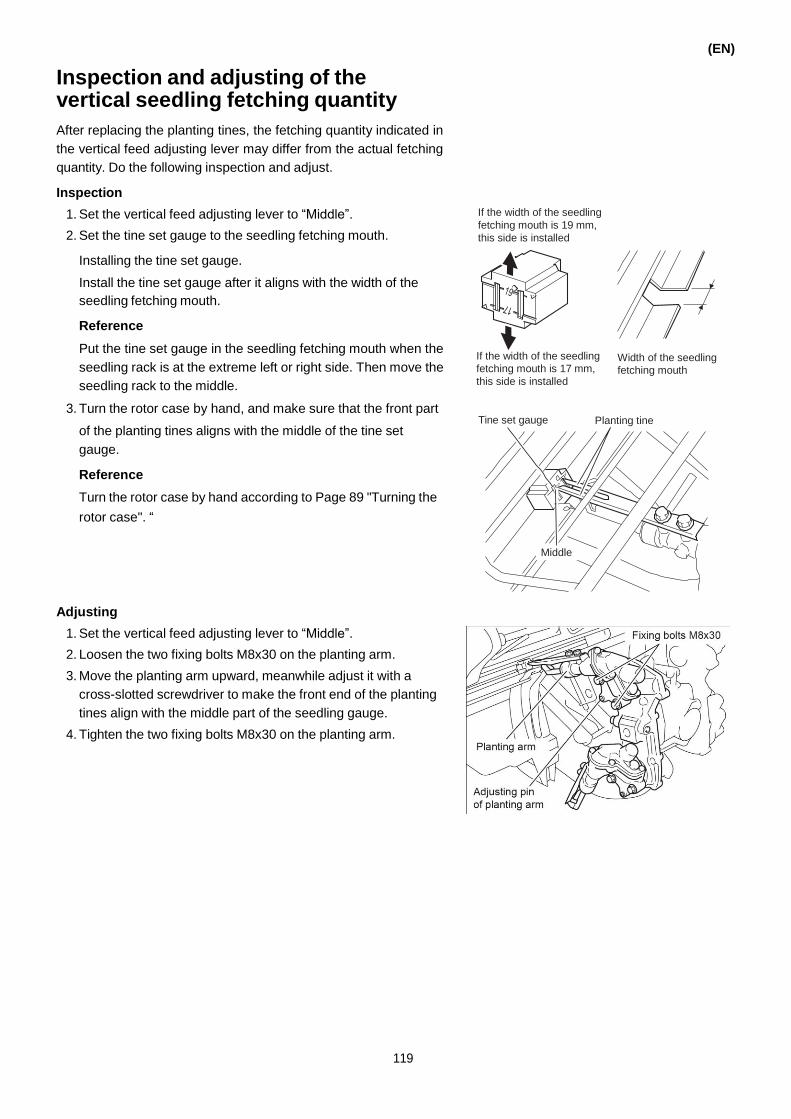
Inspection and adjusting of the vertical seedling fetching quantity
After replacing the planting tines, the fetching quantity indicated in
the vertical feed adjusting lever may differ from the actual fetching
quantity. Do the following inspection and adjust.
Inspection
1. Set the vertical feed adjusting lever to “Middle”.
2. Set the tine set gauge to the seedling fetching mouth.
Installing the tine set gauge.
Install the tine set gauge after it aligns with the width of the
seedling fetching mouth.
Reference
Put the tine set gauge in the seedling fetching mouth when the
seedling rack is at the extreme left or right side. Then move the
seedling rack to the middle.
3. Turn the rotor case by hand, and make sure that the front part
If the width of the seedling
fetching mouth is 19 mm,
this side is installed
If the width of the seedling
fetching mouth is 17 mm,
this side is installed
(EN)
Width of the seedling
fetching mouth
of the planting tines aligns with the middle of the tine set
gauge.
Reference
Turn the rotor case by hand according to Page 89 "Turning the
rotor case". “
Tine set gauge Planting tine
Middle
Adjusting
1. Set the vertical feed adjusting lever to “Middle”.
2. Loosen the two fixing bolts M8x30 on the planting arm.
3. Move the planting arm upward, meanwhile adjust it with a
cross-slotted screwdriver to make the front end of the planting
tines align with the middle part of the seedling gauge.
4. Tighten the two fixing bolts M8x30 on the planting arm.
119

(EN)
Inspection and maintenance of the battery
The battery used in this product does not have a filler hole.
Therefore it is not necessary to fill with distilled water. (No distilled
water is required since the battery is the sealed type.) Normally,
you can check the battery condition from the brightness of the
lights and the sound level of the horn.
(+) Terminal (-) Terminal
Exhaust port
WARNING
• During inspection of the battery, wear protective goggles
and rubber gloves.
• Never let children close to the battery.
• Before/after inspection, remove any dust or unwanted
material around the battery. If dust or unwanted material are
attached to the terminals or ground cable connection, this
can cause ignition or fires.
• Do not close the exhaust port of the battery. The gas
generated inside the battery may increase the internal
pressure and burst.
• When replacing the battery, use a battery with the same
specifications as detailed in the instructions.
• In order to protect the environment, do not throw the
replaced battery away. Return the battery to the battery
manufacturer or dealer for recycling.
Recharging the battery
Recharge the battery under the following conditions.
• When the battery has not been used for a long time.
• When the devices have not been used for a long time.
• When the battery cannot be recharged successfully and runs out
due to generator malfunction.
1. Remove the battery.
2. Connect the positive terminal of the charger to the positive
terminal of the battery, then connect the negative terminals in
the same way.
3. Make sure that the battery terminal is clean and the charging
circuit is securely connected.
4. We recommend the constant voltage charging method. When
charging the battery, use a charger that does not exceed the
maximum control voltage at 16.0V (max. 16.2V)
5. Charge the battery by the constant current charging method if
the battery can not be charged by the constant voltage
charging method.
(a)- Charge the battery with a current of 1/10 of the 20-hour
rate capacity. (For example, charge with a current of 6A if
the battery has 60AH capacity.)
Exhaust port
120
Designated battery 6-QW-45LT1HD

(b)- Charging time per voltage (reference)
Battery Voltage V Charging Time
12.65-12.55V 1hour
12.55-12.45V 2hours
12.45-12.35V 3hours
12.35-12.20V 4hours
12.20-12.05V 5hours
12.05-11.95V 6hours
11.95-11.80V 7hours
11.80-11.65V 8hours
11.65-11.50V 9hours
11.50-11.30V 10hours
11.30-11.00V 12hours
11.00Vor less 14hours
(c)- Measure the charging voltage of the battery every hour
during charging. When the battery charging voltage
exceeds16.2Vor the battery temperature exceeds 45 °C,
decrease the charging voltage but extend the charging
time. Otherwise the battery may fail.
(d)- After charging is complete, perform the discharge load test.
If the open circuit voltage reaches 14.4V, the battery is fully
charged. When the open circuit voltage is below 14.4V,
charge the battery with a current of the 20-hour rate capacity
for 2 to 3 hours until the charging voltage approaches 0A.
6. If the battery voltage falls below 11.0V, the battery may not
charge during the early stages charging. This is due to the
battery running-out and the specific gravity of the sulfuric acid
in the battery becoming close to pure water because the
internal resistance increases. Connect the battery in parallel to
the fully charged battery. As the battery is being charged, the
specific gravity of the sulfuric acid increases and the charging
voltage returns to normal. Disconnect the fully charged battery.
Removing the battery
1. Remove the rubber band from the cover.
2. First disconnect the negative terminal of the battery, then
disconnect the positive terminal.
3. Remove the battery.
4. Install the battery by reversing the removal procedure.
(EN)
121
Upper cover
Rubber band

(EN)
Maintenance of the battery
1. Before operating the rice transplanter (after more than 15 days
in warehouse or transportation), do not install the battery to the
machine to maintain voltage in the battery. Once the battery is
installed in the machine, operate the engine for more than 20
minutes every 15 days.
2. Inspect the battery voltage every month. If the voltage falls
below 12.45V, charge the battery immediately.
3. When storing the battery for a long time, fully charge the
battery every 3 to 6 months.
4. If the battery is not charged during long-term storage for more
than 1 year, dispose of it according to the disposal procedure.
5. Be sure to use, store and transport the battery in a well-
ventilated area.
If the battery has been running out for a long term, it cannot be
charged effectively and this can cause irreversible damage to the
battery. Dispose of the battery if the service life becomes shorter.
These problems can be avoided if you perform maintenance
according to the maintenance procedure.
Charging the battery
• Charge the battery if:
• The sulfuric acid indicator is black.
• Used in a very cold area.
• It is difficult to start the engine.
• It is difficult to start the engine because of natural discharge.
• The lights of the transplanter become weak.
1. Remove the battery.
2. Connect the positive terminal of the battery with the positive
terminal of the charger, and the negative terminal of the battery
with the negative terminal of the charger.
3. Charge the battery for 8-10 hours with 3A. The battery is
charged when the sulfuric acid indicator turns green.
IMPORTANT
• Do not use quick charging.
• When connecting the terminals of the battery, clean the oil
on the terminals. After connecting, apply solid lubricant on
the terminals.
• Cover the terminals with the rubber covers.
Battery maintenance
If a terminal of the battery is corroded and there is white powder on
it, clean it with distilled water and then apply oil on it.
Natural discharge of the battery
The battery will discharge naturally when the engine has not been
started for a long time. Even if you do not use it for a long time,
start the engine regularly to check the battery and charge it if
necessary.
122
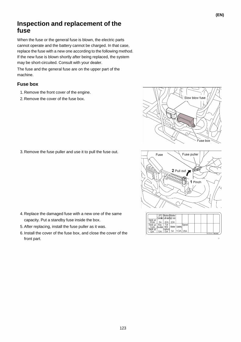
Inspection and replacement of the fuse
When the fuse or the general fuse is blown, the electric parts
cannot operate and the battery cannot be charged. In that case,
replace the fuse with a new one according to the following method.
If the new fuse is blown shortly after being replaced, the system
may be short-circuited. Consult with your dealer.
The fuse and the general fuse are on the upper part of the
machine.
Fuse box
1. Remove the front cover of the engine.
2. Remove the cover of the fuse box.
3. Remove the fuse puller and use it to pull the fuse out.
4. Replace the damaged fuse with a new one of the same
capacity. Put a standby fuse inside the box.
5. After replacing, install the fuse puller as it was.
6. Install the cover of the fuse box, and close the cover of the
front part.
(EN)
123

(EN)
Slow blow fuse
The slow blow fuse is a fuse with a higher capacity to protect the
electric circuit of the machine.
Bolts (2)
Replacing the slow blow fuse of 80A
1. Detach the negative terminal of the battery.
2. Remove the two bolts that fix the box.
3. Open the covers on the two sides of the fuse box, and then
remove the two bolts that fix the slow blow fuse box.
4. After replacing the slow blow fuse, install the bolts and cover
as they were.
Inspection of the oil pipe
WARNING
Before operating, do an inspection to check whether there is
oil leakage caused by damaged or aging pipes. If you find
any, replace the oil pipe. If not, a fire can occur.
1. Remove the front cover of the engine and the front, left and
right boards.
2. Check whether there is damage on the oil pipe, loosening of
the connected parts or oil leakage.
3. If the oil pipe is damaged, contact your dealer for repair.
4. Install the front cover and the front, left, right boards as they
were.
124

12. TROUBLESHOOTING
(EN)
When the mechanical parts show any abnormalities, turn off the engine, set the parking brake and find the cause.
If not, you may be dragged into the machine and injured. If the parts still do not function after taking the
recommended measure, contact your dealer.
Missing plants
Reasons Measure
1 If the seeds are too few and not properly placed,
sprouting will be faulty with many dead seedlings.
The missing seedlings cannot be placed by the seedling planting
machine. (Place them manually.)
2 • The seedling mat is too thin.
• The seedling mat is too soft.
• The root of the seedling is spread poorly and the seedbed collapses easily.
If the seedling on the seedling mat topple over, they
bundle together and cannot be planted.
Adjust the Seedling mat stopper prevent the seedlings from
toppling over.
• The seedlings should be handled slowly and carefully.
• The seedling board should be used to take the seedlings to
prevent the seedling bed from collapsing.
Seedling board
3 The machine planting tines does not work well and
the transplanting of the seedling fails.
• The planting tines is broken.
• The planting tines is badly adjusted.
Adjust or change the planting tines.
Vertical gutter Planting tine
Tine set gauge
125

(EN)
Reasons Measure
4 The seedling mat do not slide well. They get stuck at the seeding mat stopper.
• If the seedling mat is too dry, water it.
• Adjust the seedling mat stopper so that it does not block the
seedling.
• Press the two sides of the seedbed with your hands to make the
width of the seedbed more narrow.
5 A missing plant appears after every 18, 20 or 26
seedlings.
• The seedling mat is too heavy to slip. Adjust the seedbed stopper
to the proper position (0.5 cm to 1 cm).
• If the above does not help, the time synchronization might be
faulty. Contact your dealer.
6 • The bottom soil has a lot of clay and is sticky.
The seedling does not leave the machine
planting fingers properly, resulting in missing
plants or floating seedlings.
• The seedling is stuck in the machine planting
fingers resulting in poor pickup.
• Put the seedling into water.
• Install the push piece on the machine planting tines.
Push piece
Install tightly
Push rod shaft
• Set the seedling depth to “Deep planting”.
• Adjust the depth of the field from 1 cm to 2 cm (or a little deeper).
7 The movement of the push rod is not smooth. • Remove excessive grease from the arm.
• If the push rod is bent, repair or replace it.
• If the push rod is engaged with the planting tines, loosen the fixed
bolt of the planting tines to adjust the planting tines.
8 Is the problem occurring just after using the unit
clutch lever?
• Remove the remaining, unplanned seedlings from the seedling
mat. Then start planting fresh seedlings in the next row.
• When planting for many hours without using the unit clutch lever
and the remaining seedlings have collapsed, remove the
collapsed seedlings and supply new seedlings. (The seedlings
you remove can be used for supplemental planting.)
9 Are not enough seedlings remaining? If not enough seedlings remain, supply new seedlings.
126

Floating seedlings (every seedling is floating)
(EN)
Reasons Measure
1 The field is too hard and seedlings cannot be planted deep
enough?
• The field is a clay field.
• The field has too much sand. (2 or 3 days after plowing, the
field becomes too hard to transplant seedlings.)
If the hole of the planting fingers is not fully filled with the
seedling, water may come in and make the seedlings float.
• Put more water into the field to make the field softer.
• Transplant seedlings immediately after plowing.
• Set the hydraulic indicator to “Plowing”.
• Set the depth of transplanting to “Deep planting”.
• Transplant the seedlings when the field has the
proper strength.
2 The root of the seedling is not good resulting in toppled
seedlings.
The seedling leaves the planting fingers too quickly, making
the seedling topple over.
• Transplant the seedlings slowly.
• Press the seedling mat with the seeding press rod.
3 If the water is over 3 cm deep, the transplanting is not
possible.
If the float body is floating on the water, the transplanting is
not firm.
• Set the switch to “Deep water”.
• Set the liquid indicator to “Hard field”.
• Transplant slowly.
• Reduce the depth of the water to 1 cm to 2 cm.
• Set the transplanting depth to “Deep planting”.
• When the depth is set to “Changing”, set the
transplanting depth device to “ON”.
4 If the field is to soft, the transplanting is not firm. • Transplant the seedling after the soil has settled after
plowing.
• Set the transplanting depth to “Deep planting”.
• Transplant slowly.
127

(EN)
Reasons Measure
5 The float presses the soil.
The float pushes down the seedling.
The float leaves a deep trace, and the seedlings tilt or float to
the inside.
• Set the hydraulic sensing adjustment lever to “Soft
field” to avoid pressing the soil.
• Lower the water level of the field to make the surface
harder or make the surface even.
• Transplant slowly.
6 The float is not in contact with the ground.
If the float is floating on the water, the transplanting is not
firm.
Set the hydraulic sensing adjustment lever to "Hard
field" and make sure that it does not press the soil.
7 Unwanted objects interfere with the float. Remove the interfering objects.
128

(EN)
Reasons Measure
8 The long guide and the planting tine are too far apart. Adjust the clearance between the long guide and the
planting tine.
How to adjust the clearance
1. Put the planting number changing lever to
“Middle”.
2. Loosen the two bolts of the long guide.
3. Adjust the clearance between the end of the
long guide and the tip of the planting tine to
between 5±1 mm.
4. Tighten the two bolts to lock the long guide.
129

(EN)
Floating seedlings (only one seedling is floating)
Reasons Processing Measure
1 The root of the seedbed is not good. • Transplant slowly.
• Put the seedbed into water.
• Adjust the push rod to the pushing-seedling side. 2 The seedbed is too dry (seedlings topple over easily).
• When the planting tines takes the seedling with one not-cut
seedling sticking to it, the push-in cannot work. The
remaining seedling will float.
Push rod
3 The seedling is between the planting tines. Remove it when holding.
4 The distance between the planting and the two ports is the
same.
a b
Port
a=b
Planting tine
Loosen the bolt to make the distance similar.
5 The surface of the field is hard (the strength of the surface).
The appropriate field hardness for machine-transplanting
hardness is as follows: Drop a ball of mud the size of a golf
ball from one meter height. The below figure shows the field
hardness.
If the field is too hard, transplanting becomes too difficult,
resulting in the collapsing or floating of the seedling. If the
field is too soft, transplanting is not uniform resulting in the
pressing of the clay.
If the field is too hard, transplanting becomes too
difficult, resulting in the collapsing or floating of the
seedling.
Plow the field again.
6 The distance between the long guide rail and the planting
tines is too long.
(Relationship between the guide rail and the planting tines)
Two bolts Planting Long bolt Planting tine through the tine
middle of
Long the planting
guide rail tine
5±1 mm Viewed from A
Put the guide rail through the middle of the planting
tines.
Adjusting:
1. Loosen the two bolts of the long guide rail.
2. Adjust the long guide rail to the proper position.
- The long guide rail passes through the middle of
the planting tines.
- The end of the planting tines overlap the end of
the guide rail by 5±1 mm.
3. Tighten the two bolts.
130

Floating seedlings (only for leaves with bad roots)
(EN)
Reasons Processing Measure
1 The leaves block the seeding port.
The leaves touch the planting fingers, breaking the leaves.
• Adjust the seedling press rod to unblock the seedling
port.
• Adjust the seedling press rod to the pushing-
seedling side.
2 Adopt the seedbed that has not enough soil.
If the rice hull emerges, the planting fingers will damage the
leaves.
3 The planting tines does not pass through the middle of the
seedling port.
a b
Port
a=b
Planting tine
In order to make the planting tines pass through the
middle of the seedling port, loosen the taper pin of
the rotor case and adjust it.
4 Seedlings are fed with the seedling mat stopper released.
• When the seedling mat stopper is installed, the seedlings
under the stopper are broken or bent.
Feed seedlings with the seedling mat stopper
installed.
131

(EN)
Toppling of the seedling
Reasons Measure
1 If the field is too hard, the seedling cannot be transplanted
firmly.
The float presses on the adjacent rows.
The trace of the float becomes deeper, and the seedlings
topple over or float towards the inside.
• Set the planting depth control lever to “Deep
planting”.
• Reduce the water and increase the strength of the
field surface or flatten the surface of the field.
• Transplant slowly.
• Set the hydraulic indicator to “Soft field”.
• Adjust the press rod to the pressing-seedling side.
2 The seedling mat is too thick and the quantity of seedlings is
unbalanced.
• Cut the seedling mat to 3 cm.
• Transplant slowly.
3 The field is too hard.
• Plow the field carefully.
• Set the planting depth control lever to “Deep
planting”.
• Transplant slowly.
• Set the hydraulic indicator to “Hard field”
4 The field has a lot of weed and other objects. • Remove the obstacles.
• Set the planting depth control lever to “Deep
planting”.
• Transplant slowly.
• Set the hydraulic sensing adjustment lever to “Hard
field”.
132
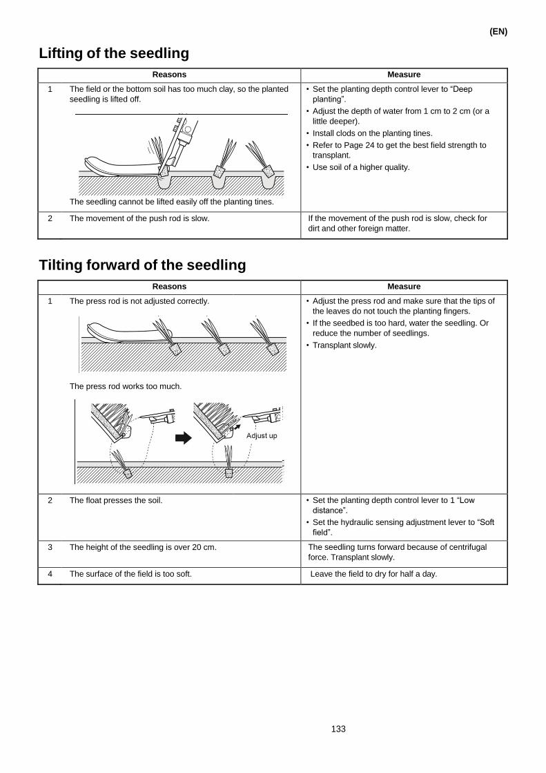
Lifting of the seedling
Tilting forward of the seedling
(EN)
133
Reasons Measure
1 The field or the bottom soil has too much clay, so the planted
seedling is lifted off.
The seedling cannot be lifted easily off the planting tines.
• Set the planting depth control lever to “Deep
planting”.
• Adjust the depth of water from 1 cm to 2 cm (or a
little deeper).
• Install clods on the planting tines.
• Refer to Page 24 to get the best field strength to
transplant.
• Use soil of a higher quality.
2 The movement of the push rod is slow. If the movement of the push rod is slow, check for
dirt and other foreign matter.
Reasons Measure
1 The press rod is not adjusted correctly.
The press rod works too much.
Adjust up
• Adjust the press rod and make sure that the tips of
the leaves do not touch the planting fingers.
• If the seedbed is too hard, water the seedling. Or
reduce the number of seedlings.
• Transplant slowly.
2 The float presses the soil. • Set the planting depth control lever to 1 “Low
distance”.
• Set the hydraulic sensing adjustment lever to “Soft
field”.
3 The height of the seedling is over 20 cm. The seedling turns forward because of centrifugal
force. Transplant slowly.
4 The surface of the field is too soft. Leave the field to dry for half a day.

(EN)
The float presses the soil
Reasons Processing Measure
1 The hydraulic indicator is not adjusted to a position suitable
for the strength of the field.
• Adjust the hydraulic sensing adjustment lever to
“Soft field”.
• Remove all contamination.
• Remove the soil or water on the float. 2 There is a lot of contamination.
3 The soil piles up on the float.
4 The surface of the field is too thin or too soft • Reduce the water and strengthen the field surface or
flatten the surface of the field.
• Transplant slowly.
5 The transplanting part is turning right and left. If the machine is equipped with an UFO, set the UFO
to "Lower right" or "Lower left" to make the
transplanting part horizontal.
Left side down
Right side down
6 The front of the side float sinks down. Find and eliminate the reasons for the sinking (e.g.
the installing of the grain, manure drill and pipes
which press the float), and transplant horizontally.
134

Up and down movement of the lifter / UFO movement is faulty (UFO auto diagnosis with LED flashing)
Emergency repair of a faulty UFO
Open the by-pass valve next to the rolling cylinder, and adjust the
seeding rack horizontally to make the rolling cylinder work
temporarily without the UFO.
1. Loosen the bolts of the by-pass valve.
2. Move slowly.
When the seedling rack moves right and left, it can be adjusted
through the rolling spring and continue work as usual.
(EN)
135
Confirmed Methods Measure
You can control the UFO manually, but it does not work
automatically.
Check if the controller or sensor is faulty. Contact
your dealer.
1 The UFO does not work.
2 The up and down handle does not work.
3 Even after adjusting the transplanting distance, the distance
does not change.
• Check the fuse.
• Check if the controller or hydraulic device is faulty.
Contact your dealer.
The up and down handle is at the "Down" position with the
transplanting position turning forward, and cannot be set to
horizontal.
• Check if the controller or sensor is faulty. Contact
your dealer.
The up and down handle is at the "Middle" position with the
transplanting position turning forward.
Check the fault of the control return switch that is
attached to the left of the rolling cylinder. Contact
your dealer.
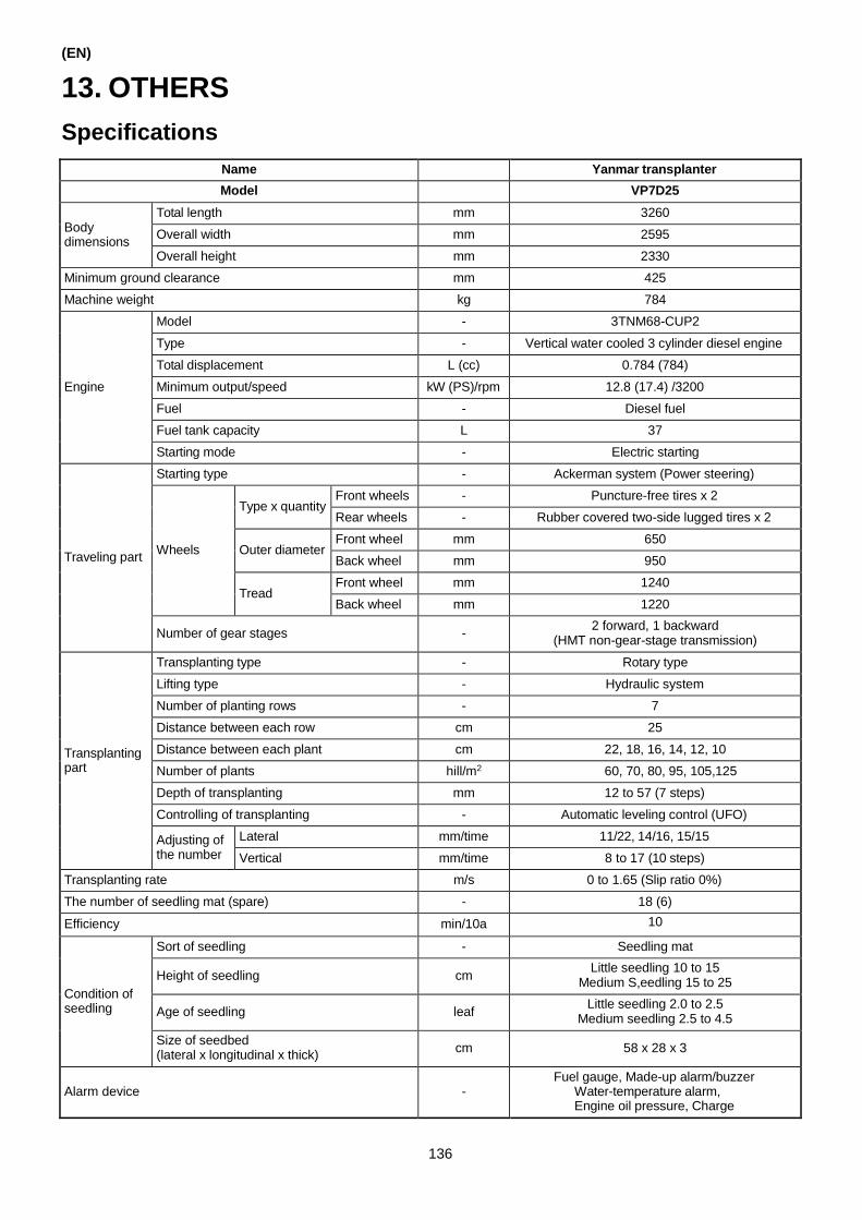
(EN)
13. OTHERS
Specifications
Name Yanmar transplanter
Model VP7D25
Body dimensions
Total length mm 3260
Overall width mm 2595
Overall height mm 2330
Minimum ground clearance mm 425
Machine weight kg 784
Engine
Model - 3TNM68-CUP2
Type - Vertical water cooled 3 cylinder diesel engine
Total displacement L (cc) 0.784 (784)
Minimum output/speed kW (PS)/rpm 12.8 (17.4) /3200
Fuel - Diesel fuel
Fuel tank capacity L 37
Starting mode - Electric starting
Traveling part
Starting type - Ackerman system (Power steering)
Wheels
Type x quantity Front wheels - Puncture-free tires x 2
Rear wheels - Rubber covered two-side lugged tires x 2
Outer diameter Front wheel mm 650
Back wheel mm 950
Tread Front wheel mm 1240
Back wheel mm 1220
Number of gear stages - 2 forward, 1 backward
(HMT non-gear-stage transmission)
Transplanting part
Transplanting type - Rotary type
Lifting type - Hydraulic system
Number of planting rows - 7
Distance between each row cm 25
Distance between each plant cm 22, 18, 16, 14, 12, 10
Number of plants hill/m2 60, 70, 80, 95, 105,125
Depth of transplanting mm 12 to 57 (7 steps)
Controlling of transplanting - Automatic leveling control (UFO)
Adjusting of the number
Lateral mm/time 11/22, 14/16, 15/15
Vertical mm/time 8 to 17 (10 steps)
Transplanting rate m/s 0 to 1.65 (Slip ratio 0%)
The number of seedling mat (spare) - 18 (6)
Efficiency min/10a 10
Condition of seedling
Sort of seedling - Seedling mat
Height of seedling cm Little seedling 10 to 15
Medium S,eedling 15 to 25
Age of seedling leaf Little seedling 2.0 to 2.5
Medium seedling 2.5 to 4.5
Size of seedbed (lateral x longitudinal x thick)
cm 58 x 28 x 3
Alarm device
-
Fuel gauge, Made-up alarm/buzzer Water-temperature alarm, Engine oil pressure, Charge
136

Parts susceptible to wear
(EN)
No Name Number No Name Number
1 Planting tine 1C731C-66622 9 Transmission oil filter 1C731C-53650
2 Planting support platform 1C727C-86100 10 Filter assy (Engine) 119305-35151
3 Axle bed 1C726C-83650 11 Hydraulic pipe -
4 Guide rail support 1C723C-85400 12 Wire -
5 V-belt (Fan) 119127-42310 13 Battery 1E8510-83050
6 V-belt LC-52 AG-COG4 1C732C-11020 14 FO filter 119810-55650
7 Steel wire - 15 Long guide F 1C731C-85900
8 Oil pipe - 16 Element assy outer 1C727C-12530
1
1. Planting tine 2. Planting support platform 3. Axle bed 4.Guide rail support
5. V-belt (Fan) 6. V-belt LB-52 AG-8A 7. Steel wire 8. Oil pipe
9.Transsmission oil filter 10. Filter assy (Engine) 11. Hydraulic pipe 12. Wire
13. Battery 14. FO filter 15. Long guide F 16. Element assy outer
Reference
If the triangle ditch of the guide rail support is badly worn, replace it. If the planting support platform is moved, you
can see the guide rail support.
137

(EN)
How to set the lateral sending time and longitudinal getting quantity
105/3.3m2
50 90/3.3m2
40
30
20
(3)
(1)
10
0
(2) (2)
80/3.3m2
70/3.3m2
65/3.3m2
60/3.3m2
55/3.3m2
50/3.3m2
45/3.3m2
40/3.3m2
38/3.3m2
37/3.3m2
Longitudinal sending quantity set
(Planting numbers adjusting lever)
18 8 (S)
20
9 10 11 12 13
(M)
14 15 16 17 (L)
8 (S)
26
9 10 11 12 13 (M)
14 15 16 17 (L)
8 9 10 11 12 13 14 15 16 17
0
2
(3) 4
(1) 6
8
10
12
(S) (M) (L)
Seed quantity
100cc (62.5g)
200cc (125g)
300cc (187.5g)
400cc (250g)
Example 1
When the seedlings are for 300 cc sowing quantity, the seedling is transplanted with 16 boxes for 10a and 60
seedlings for 3.3m2.
1. Because 10a can use 16 boxes seedlings, we can make a mark on the right and find out the first cross point with
60 cc.
2. Go from the first cross point down, and find out the second cross point with 300 cc.
3. Make a mark from the second cross point to the left, and we can find out that the seedling number of one hill is 4.
Lateral sending and longitudinal getting can be set as:
Lateral sending 18 times, longitudinal getting 9 mm
The seedling number of one hill is 4.
138
Seedlin
g n
um
ber
of
hill
Late
ral sendin
g t
ime
s s
ett
ing
(Late
ral sendin
g c
hange lever)
Seedbed f
or
each 1
0a

Example 2
1. The same condition as in example 1, considering that the seedling number of one hill is 4.
(EN)
Because the seedling number of one hill is 4, make a mark from the right and find out the cross point with 300 cc.
2. Go from the first cross point down, and find out the second cross point with 60 cc.
3. Make a mark from the second cross point to the left, and we can find out that the seedbed number of 1.5 mu is
16 boxes.
Lateral sending and longitudinal getting can be set as:
Lateral sending 18 times, longitudinal getting 9 mm
Seedbed number is 16 boxes.
Standard Accessories
No
Name Quantity
Note
1 Push piece 14
2 Seedling pick plate 7
3 Tool bag 1
4 Tine set gauge 1
5 Funnel 1
6 Pipe 12x300 1
7 Oil feeder 1
8 Spanner 10x12 1
9 Spanner 12x14 1
10 Double offset ring spanner 1
11 Ejector pad instructions 1
12 Operating instructions 1
13 Accessory atlas 1
14 Extra key 1
15 Rod packing 14
16 Rod scraper 14
17 Planting tines 14
18 Seedling rack support sliding block 3
19 Long guide F 7
20 FO filter 1
21 V-belt 1
22 Oil seal 7
23 Spring 2
Note: The accessory of your machine may be different depending on its use. Check the delivery list.
139